studio sound APr;11972 25p - World Radio History
56
studio sound APr;11972 25p MICROPHONE STANDS COMPARED CROWN DC300 REVIEW INSIDE ZONAL AROUND THE STUDIOS: THEATRE PROJECTS IMPROVING A REVOX A77 www.americanradiohistory.com
-
Upload
khangminh22 -
Category
Documents
-
view
1 -
download
0
Transcript of studio sound APr;11972 25p - World Radio History

studio sound APr;11972 25p
MICROPHONE STANDS COMPARED CROWN DC300 REVIEW INSIDE ZONAL
AROUND THE STUDIOS: THEATRE PROJECTS IMPROVING A REVOX A77
www.americanradiohistory.com
the critical stage in the birth of great recordings
-the stage when highly skilled craftsmen, working under the direction of top project engineers, jam build sound control equipment under laboratory conditions.
J Every Neve console is designed to meet the client's individual requirements and
built to meet the most exacting standards.
Rupert Neve Et Company Ltd., Cambridge House, Melbonrn, Royston, Hertfordshire, SG8 6AU, England. Tel : Royston (0763) 60776 Telex :81381
Rupert Neve of Canada Ltd., Rupert Neve Incorporated, P.0.ß 182. Park, Etobicoke, betlwl, Ontario, Connecticut 06801, Canada. U.S.A. Tel:416 -677 6611 Tel: (203) 7446230 Telex:969638
www.americanradiohistory.com

J studio sound INCORPORATING TAPE RECORDER
APRIL 1972 VOLUME 14 NUMBER 4
EDITOR DAVID KIRK
CONSULTING EDITOR JOHN CRABBE
ADVERTISEMENT MANAGER TONY NEWMAN
AUDIO GROUP ADVERTISEMENT MANAGER ROBIN WELLS
Editorial and Advertising Offices: LINK HOUSE, DINGWALL AVENUE, CROYDON CR9 2TA. Telephone: 01 -686 2599
Link House Publications Ltd 1972. All rights reserved.
BY THE TIME this issue appears, the power strike is likely either to be an unpleasant memory or to have brought industry to its knees. Sooner or later, a compromise will be reached and we can all settle down again until next year. If the accelerating rise in house prices is any guide to inflation, there is little likelihood of the electrical power workers submitting as easily in their 1973 pay negotiations as they did early in 1972. What the mining industry may demand next year is another matter entirely.
A few recording studios will have overcome power cuts by resorting to their own electricity generators. This year should see a considerable expansion in sales of such equipment. The vagaries of ̀ horse -power' disguise the practical merits of petrol- driven generators. It is not generally apprecia- ted that a small car engine produces 25 kW of power. This should not be confused with the much lower power available from a car dynamo. Allowing for mechanical losses, a useful few kilowatts can be derived from a purpose -built petrol- driven generator. This would meet the needs of a reasonably large audio chain. Multitrack systems have remarkably high power consumption though these again should not be beyond the means of an internal combustion engine.
There is no shortage of companies catering for the specialised needs of the audio industry. We notice, however, some lack of imagination leading to a large scale duplication of effort. Consider, for example, the many concerns engaged in producing audio mixers which, to all intents and purposes, are virtually identical. It makes a pleasant change to read of an altogether new device, in this case aimed at partially automating that most time -consuming of tasks: tape editing. Perhaps the Hodge 900 (see page 10) will be followed by a Hodge 1000 that actually gets down to the donkey work of unthreading, cutting, joining and relacing. The helical -scan principle offers an excellent model for a continuous -scan audio editor which would eliminate the tedious rocking involved in finding an elusive edit point.
Returning to power difficulties, considerable financial reward awaits the first company to market a compact gas -powered electricity generator. Fortunately for the consumer, gas cannot be switched on and off at the whim of a power engineer. If gas were subjected to the interruptions experienced with electricity, we could lose a considerable fraction of the population whenever supplies were restarted. That at least might solve the inflation problem.
3
FEATURE ARTICLES
15 INSIDE ZONAL By John Dwyer
18 COMPARISON; MICROPHONE STANDS By Peter Self
21 SURVEY: AUDIO BOOKS
23 SOUND '72 PREVIEW
37 IMPROVING A REVOX A77 Part Two By Angus McKenzie
39 MEASURING LOUDSPEAKER PERFORMANCE By John Shuttleworth
43 DESIGNING A STUDIO MIXER Part Eight By Peter Levesley
REGULAR COLUMNS
9 PRECIS
10 NEWS
12 PATENTS REVIEW
27 RECORDING STUDIO TECHNIQUES By Angus McKenzie
31 AROUND THE STUDIOS Theatre Projects By Keith Wicks
35 STUDIO DIARY By Keith Wicks
EQUIPMENT REVIEWS
47 CROWN DC300 By P. A. Lomas
49 EDISON PHONOGRAPH By T. T. Wittering
COVER PICTURE
A Concert by Lorenzo Costa (c 1460 to 1535) reproduced by permission of the National Gallery, London. Note the foreground fiddle, or kit, bearing a feature sadly absent from modern violins: frets.
CORRESPONDENCE AND ARTICLES All STUDIO SOUND correspondence should be sent to the address printed on this page. Technical queries should be concise and must include a stamped addressed envelope. Matters relating to more than one department should occupy separate sheets of paper or delay will occur in replying.
Articles or suggestions for features on all aspects of communications engineering and music will be received sympathetically. Manuscripts shoud be typed or clearly handwritten and submitted with rough drawings when appropriate. We are happy to advise potential authors on matters of style. Payment Is negotiated on acceptance.
SUBSCRIPTION RATES Annual UK subscription rate for STUDIO SOUND is £3 (overseas £3.80, $8 or equivalent). Our associate publication Hi -Fi News costs £3.12 (overseas £3.66, $8.64 or equivalent). Six monthly home subscriptions are £1.50 (STUDIO SOUND) and £1.56 (Hi -Fi News).
STUDIO SOUND is published on the 14th of the preceding month unless that date falls on a Sunday, when it appears on the Saturday.
PAST ISSUES A small number of certain past issues may still be purchased from Link House, price 31p each including postage.
Photostat copies of any STUDIO SOUND article are available at 25p including postage.
BINDERS Loose -leaf binders for annual volumes of STUDIO SOUND are available from Modern Bookbinders, Chadwick Street, Blackburn, Lancashire. Please quote the volume number or date when ordering.
www.americanradiohistory.com

SAIT p1
SAIT SOUND MIXERS ALLOTROPE LIMITED 5B.Thame Industrial Estate,Thame Oxon. Sales Office Te1.01 -229 4965
WOW and FLUTTER METERS
Illustrated is the ME30I, a mains -operated silicon transistorized active Wave Analyser with constant "percentage" bandwidth, particularly suitable for narrow (width) band noise and vibration investiga- tions in the 1 -330 c/s range. Fuller details on application.
LENNARD DEVELOPMENTS LTD. LOCKFIELD AVE., BRIMSDOWN, ENFIELD, M I D D X. Tel. 01 -804 8425
4
DATE YOUR DIARY
APRS 72 EXHIBITION OF PROFESSIONAL
RECORDING EQUIPMENT
JUNE 22 -23 ORGANISERS
ASSOCIATION OF PROFESSIONAL RECORDING STUDIOS
SEC: E. L, MASER, 23 CHESTNUT AVENUE, CHORLEYWOOD, HERTS.
www.americanradiohistory.com

MEET THE FAMILY. We've been in the microphone
business for over 40 years now. And in all that time we've built
up quite a family. Ribbon mikes, moving coil mikes,
headphones, stands, accessories, the lot.
Over 50 in fact. All these products, made to the
40000orma'
same high acoustic quality that has set standards all over the world.
All these products are shown and explained in detail in the Beyer Dynamic Catalogue.
Which, if you are at all interested in better equipment, is something you should send for.
w ..-,- ....
fs,
st:a;.: ,_
,r ,,.,. ..---.s. - ,. . _ .t* ii¡' ~: wt ,,,,........ °"w. t r,ar1wasst
OWN* aá # #t,
.:fflAYVA
BEYER DYNAMIC
'I'o: Beyer Dynamic (GB) Ltd., 1 Clair Road, Haywards heath, Sussex. Telephone flay vv ards Heath 51003
Please send me full particulars and illustrated lrrchur the Beyer Dynamic products.
Name '
\ddress
1
www.americanradiohistory.com

NEED A
SYNTHESISER ?
PHASOR ELECTRONICS Ltd. Proudly announce the opening of their electronic music studio where one can
see, hear, purchase or hire any of the fabulous range of E.M.S. products. Items
include the Synthi 100 (see photograph above), V.C.S.3, Digital Sequence 256 (for use with Moog and ARP Synthesisers),
and Synthi "A" (the "Briefcase" Synth-
esiser). For further details of the complete range of products contact :-
PHASOR ELECTRONICS 19 DOLLIS AVENUE
FINCHLEY, LONDON, N.3
Telephone: 01 -349 1806
(i
THE PACE ELECTRONICS 5 CHANNEL PORTABLE MIXER
10-
f y . ,oymo ....
o * * * * ,¡lip
/H . ... .._,
Features:
1. NOTCH FILTER FOR REJECTION OF UNWANTED SIGNALS
2. ANNOUNCEMENTS VIA BUILT -IN MICROPHONE WITH AUTOMATIC GAIN CONTROL
3. TRANSFORMERLESS OPERATION FOR WIDE FREQUENCY RANGE
4. COMPREHENSIVE EQUALISATION ON EACH CHANNEL
5. MICROPHONE COMPARISON SWITCH 6. REMOTE OPERATION OF RECORDER 7. MONITORING DIRECT OR OFF TAPE 8. EASY ACCESS TO CONNECTORS FROM OPER-
ATING POSITION 9, THREE INDEPENDENTLY CONTROLLED MONITOR
OUTPUTS 10. WILL OPERATE WITH INTERNAL RECHARGE-
ABLE BATTERIES OR U2 TYPE DRY CELLS
TELEPHONE BOWMANS GREEN 3452
Video Spray 90 cleans tape heads-
in operation r.
4
A quick squirt of Video -spray 90 and your tape heads and gaps are rapidly cleaned. And you can use Video -spray 90 whilst the machine is in operation. It dissolves even hardened dirt by simultaneous physical and mechanical action. 99.8",, pure, Video -spray 90 can be used safely with any video or sound record- ing machine. The spray doesn't attack plastics, is electrically non -conductive and is not inflammable. Supplied in 2.5 oz and 6 oz. cans. Available through your retailer or direct from
&SO-° ^........._.___"
Special Products Distributors Ltd. 81 Piccadilly, London, WIV OHL. Tel: 01 -629 9556
www.americanradiohistory.com
FOR TECHNICAL SOUND RECORDING
EVERYTHING POINTS TO
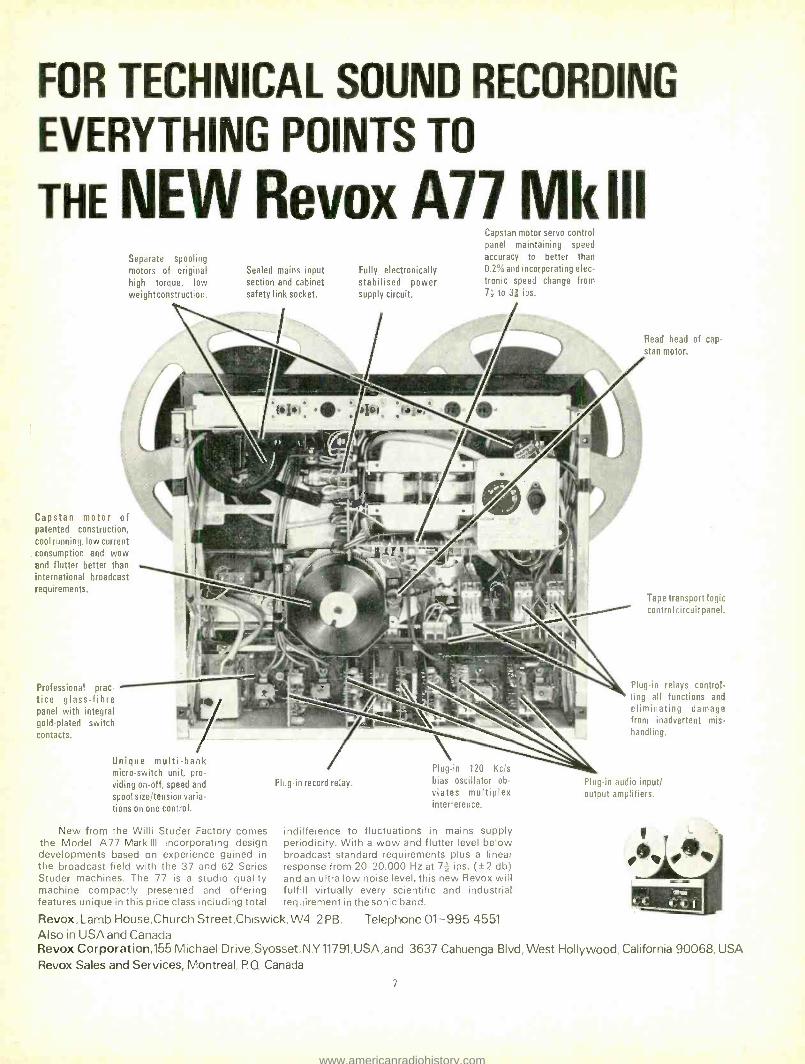
THE NEW Revox A77 MkIII Separate spooling
Capstan motor servo control panel maintaining speed
accuracy to better than
motors of original Sealed mains input Fully electronically 0.2% and incorporating elec-
high torque, low section and cabinet stabilised power tronic speed change from
weightconstruction. safety link socket. supply circuit. 71 to 3; ips.
Read head of cap-
stan motor.
Capstan motor of patented construction, cool running, low current
. consumption and wow and flutter better than international broadcast
requirements.
Professional prac- tice glass -fibre panel with integral gold -plated switch contacts.
Unique multi -bank micro -switch unit, pro-
viding on -off, speed and
spool size /tension varia- tions on one control.
New from the Willi Studer Factory comes the Model A77 Mark Ill incorporating design developments based on experience gained in the broadcast field with the 37 and 62 Series Studer machines. The 77 is a studio quality machine compactly presented and offering features unique in this price class including total
Plug -in record relay.
Plug -in 120 Kc/s
bias oscillator ob-
viates multiplex interference.
indifference to fluctuations in mains supply periodicity. With a wow and flutter level below broadcast standard requirements plus a linear response from 20- 20,000 Hz at 72 ips. (±2 db) and an ultra low noise level, this new Revox will fulfill virtually every scientific and industrial requirement in the sonic band.
Revox, Lamb House,ChurchStreet,Chiswick,W4 2PB. Telephone 01 -995 4551 Also in USA and Canada Revox Corporation,155 Michael Drive, Syosset,N.Y11791,USA,and 3637 Cahuenga Blvd, West Hollywood, California 90068, USA Revox Sales and Services, Montreal, P. Q Canada
Tape transport logic control circuit panel.
Plug -in relays control- ling all functions and
eliminating damage from inadvertent mis- handling.
Plug -in audio input/ output amplifiers.
7
www.americanradiohistory.com

"The alternative to QUAD is not a colour television set but a seat in the concert hall"
QUAD for the closest approach to the original sound
Send postcard for illustrated leaflet to Dept SS Acoustical Manufacturing Co. Ltd., Huntingdon, Tel: (0480; QUAD is a Registered Trade Mark.
8
www.americanradiohistory.com

Pr¢cis
ARTICLES PRINCIPAUX 15 A L'INTERIEUR DE ZONAL
John Dwyer visite l'usine Racal -Zonal de ruban magnétique à Redhill, Surrey. Il
décrit quelques uns des problèmes posés par la fabrication de bandes audio et d'ordinateur et indique les autre activités de la compagnie -y compris la fabrication de transmetteurs enregistreurs et playback.
19 COMPARAISON: PIEDS DE MICROPHONE
Peter Self décrit les vertues et qualités des pieds de microphone de studio.
21 SON '72 25 REVUE: LIVRES AUDIO
Livres écrits en anglais sur la technique du son. Certains titres sont aussi disponi- bles dans d'autres langues, l'éditeur concerne doit être contacté pour détails supplémentaires.
37 PERFECTIONNEMENT DE REVOX A77
Par A. McKenzie 39 MESURE DE PERFORMANCE D'UN HAUT -
PARLEUR John Shuttleworth évalue la qualité des mesures prises par réaction de fréquence pour juger les différences de valuer des haut -parleurs. Il conclue que les critiques que l'on peut faire à de telles mesures sont soit l'emploi d'un équipement d'essai peu satisfaisant soit le manque d'experience dans l'interprétation des informations mesurées.
43 AFFECTANT UN MELANGEUR DE STUDIO
Partie 7
RUBRIQUES REGULIERES 10 INFORMATIONS
12 REVUE DE FACRICATIONS BREVETEES
27 TECHNIQUES D'ENREGISTREMENT EN STUDIO
Angus McKenzie esquisse les utilisations originales du système Dolby de réduction de bruit.
31 A L'ENTOUR DES STUDIOS
35 JOURNAL DES STUDIOS
Par Keith Wicks
SPEZIALARTIKEL 15 BESUCH BEI ZONAL
John Dwyer besucht die Racal- Zonal- Magnettonband -Fabrik, die sich in Red - hill, Surrey, befindet. Er beschreibt einige der bei der Herstellung von Ton -und Computer -Band auftretenden Probleme und gibt einen Überblick über andere Tätigkeits -bereiche der Firma -darunter die Herstellung von Aufnahme -und Wie - dergabe -Übertragungsgeräten.
19 VERGLEICH: MIKROPHONSTANDER
Peter Self beschreibt die Vor -und Nach- teile von Studio -Mikrophonständern.
21 TON '72
25 RUNDSCHAU: AUDIO- BUCHER
Bücher in englischer Sprache, die das Thema der Audiotechnik behandeln. Einige dieser Bücher sind auch in anderen Sprachen erhältlich, weitere Einzelheiten können von dem entrsprechenden Verlag angefragt werden.
37 ÓERBESSERUNG DES REVOX A77 Von A. McKenzie
39 MESSEN VON LAUTSPRECHERSTARKEN
John Shuttleworth beurteilt den Wert der Frequenzwiedergabe - Messungen auf Grund vergleichender Betrachtungen der Lautsprecherstärken. Er ist davon über- zeugt, dass die Leute, die diese Messungen beurteilen, entweder unzulängliche Prüf- geräte verwenden oder nicht die Erfahrung haben, die Messwerte richtig auszulegen.
43 ENTWORF EINES STUDIOMISCHERS
Teil 8
Von Peter Levesley
STANDIGE RUBRIKEN 10 NEUIGKEITEN
12 PATENT RUNDSCHAU
27 AUFNAHMESTUDIO- TECHNIKEN
Von Angus McKenzie werden ungewöhn- liche anwendungsmethoden der Dolby - geräuschverminderungsanlage behandelt.
31 VON STUDIO ZU STUDIO
35 STUDIO TAGEBUCH
Von Keith Wicks
ARTICOLI SPECIALI 15 DENTRO ALLA ZONAL
John Dwyer in visita alla fabbrica di nastri magnetici Racal -Zonal a Redhill nel Surrey. Egli descrive alcuni dei problemi sorti nella fabbricazione di nastri audio e per computer; allo stesso tempo, descrive brevemente le altre attività della ditta tra le quali la produzione di tranducers per registrazione ed ascolto.
19 PARAGONE: PORTA- MICROFONI
Peter Self descrive i pregi ed i difetti dei porta- microfoni da studio.
21 SUONO '72 25 RAPPORTO: TESTI AUDIO
Testi in Inglese inerenti alla meccanica dell' audio. Alcuni libri sono disponibili in altre lingue: per ulteriori dettagli rivol- gersi ai rispettivi editori.
37 MIGLIOMORAMENTO DI UN REVOX A77
Di A. McKenzie 39 MISURAZIONE DELLA PERFORMANCE DEGLI
ALTOPARLANTI
John Shuttleworth prende in esame il
valore delle misurazioni del segnale di risposta nello stabilire la qualità paragon- abile degli altoparlanti. Egli conclude che i critici di tali misurazioni o usano
9
apparecchiature di prova insoddisfacenti, oppure non posseggono abbastanza esperieza per interpretare le informazioni registrate.
43 PROGETTAZIONE DI MISCELATORE DA STUDIO
Di Peter Levesley
ARTICOLI REGOLARI 10 NOTIZARIO 12 RIVISTA DEI BREVETTI
27 TECNICHE DI REGISTRAZIONE IN STUDIO
Angus McKenzie passa in rassegna gli usi non convenzionali del systema Dolby per la riduzione del fruscio.
31 IN GIRI PER GLI STUDI
35 DIARIO STUDIO
Di Keith Wicks
ARTICULOS SELECCIONADOS 15 DENTRO DE ZONAL
John Dwyer visita a la fábrica de cintas magnéticas Racal- Zonal, situada en Red - hill, Surrey. Describe algunos de los problemas que occurren en la fabricación de cintas auditivas y computadoras - incluido la produccíon de transducidroes de registro y de tocar de vuelta.
19 COMPARACION: SOPORTES DE MICRÓFONOS
21 SONIDO '72 25 EXAMEN: LIBROS SOBRE EL TEMA AUDITIVO
Libros en idioma inglés sobre el tema de la ingeniería auditiva. Pueden conseguirse también ciertos titulos en otros idiomas y
hay que dirigirse al publicador respectivo para datos sobre ellos.
37 EL MEJORAMIENTO DE UN REVOX A77
Por A. McKenzie 39 MIDIENDO EL COMPORTAMIENTO DEL
ALTAVOZ
John Shuttleworth asesa el valor de las medidas de frecuencia de respuesta al juzgar la calidad comparativa de los altavoces. Concluye que las criticas de tales medidas, o emplean equipo de ensayo que no sea satisfactorio, o carecen de la
experiencia para interpretar la información medida.
43 DELINEACION DE UN MEZCLADOR PARA EL
ESTUDIO
8 Por Peter Levesley
ARTICULOS DE SERIE 10 NOTICIAS
12 REVISTA DE LOS PATENTES
27 TECNICAS REGISTRADORAS DE ESTUDIO
Usos no convencionales del sistema de reducción de ruido Dolby son explicados por Angus McKenzie.
31 ALDREDOR DE LOS ESTUDIOS
35 DIARIO DE LOS ESTUDIOS
Por Keith Wicks
www.americanradiohistory.com

Electronic equipment servicing A NEW ORGANISATION has been formed within EMI Electronics to offer comprehensive servicing of magnetic recorders, audio, tele- vision and test equipment. EMI Service are able to calibrate and maintain virtually any brand of electronic equipment, imported or locally made. Facilities include standards laboratories approved by the British Calibra- tion Service, ultrasonic cleaning equipment and environmental testing laboratories. Over 50,000 mechanical and electronic spares are held, together with a library of operating and servicing manuals. A detailed brochure is available from EMI Service, EMI Electronics Ltd, Hayes, Middlesex.
Beldfoil cables THE BELDFOIL range of ISO -Shield cables has been expanded by the introduction of a wide selection of multiple pair individually shielded audio and data cables. These complement the existing quad and triplet shielded cables. Where subminiatunsation is required, three pair individually shielded cable is available within an overall diameter of 370 sm. Beldfoil agents are Leonard Wadsworth & Co (Electronics) Ltd, PO Box 423, Broadway House, Broadway, Wimbledon, London SW19 IRW.
EMI release quadraphonic cartridges QUADRAPHONIC TAPE cartridges (quadridges ?) were released by EMI Records Ltd on March 3. Among the first 12 titles were a sample tape entitled This is Quadraphonic Sound and a John Lennon album Imagine.
Portable mixer
TEN INPUT channels, each with echo, pan, three - band equalisers, low frequency filter and gain preselectors, feeding two output groups: the outline features of Calrec's IOMXSV mixing unit. Retail price is £630, subject to normal trade terms, though units down to four input channels are available to special order. Further data: Calder Recordings Ltd, Regent Street, Hebden Bridge, Yorkshire.
Editing system ALLOTROPE LTD, 5B Thame Industrial Estate, Thame, Oxfordshire, have been appointed sole UK agents for the Hodge Engineering Edit 900 electronic data editing system. The 900 is capable of indexing a magnetic tape at pre- determined points and subsequently searching for a selected item. Search speed may be varied to suit the operator since the system is self - clocking and speed independent. A three digit numerical d isplay shows either the demanded or the true index point, allowing the tape position to be monitored on playback. The 900 will act as a full remote control unit, governing record, playback, spooling and stopping.
Jumbled tape PINEWOOD STUDIOS' Ken (brother of James) Cameron correctly estimated the length of a jumbled tape at a recent Racal -Zonal reception. He is here seen receiving a cardboard box from Racal -Zonal's joint managing director, Mr H. Hutchings.
Record sales THE DEPARTMENT of Trade and Industry Business Monitor, published in December, gave details of trends in record sales over the last ten years up to September 1971. Yearly figures over the last decade show that production of 45 rpm records reached a peak in 1964 of 72,841,000 pressings, after which there was a steady and continuing decline to the 1970 figure of just under 47,000,000. Long playing records were not affected by this sales trend. In 1961, the figure was 19,388,000. In 1964 sales leapt 5,562,000 over the 1963 figure to 27,829,000, increasing to 37,949,000 in 1967 and 49,184,000 during 1968. The 1970 figure for Ip pressings was 65,857,000. The total number of pressings over the last ten years has thus been rising since the beginning of the sixties, though a peak reached in 1964 attained a level only regained in 1969. From 1961 to 1970 the yearly figures (in millions) were as follows: 76, 77.5, 85.4, 101,
10
94, 85, 90, 98.5, 106.4, 112.9. Total sales showed the same marked increase
in 1964, from £21,767,000 in the previous year to £25,602,000. These figures exclude trade discounts, commissions and purchase tax. The average previous increase was something like one or two million pounds. Thereafter the figure declines until 1967, after which sales increased again. Sales of £32,000,000 were made in 1969 and £39,333,000 in 1970. The export total has been far steadier than any of the other figures. From an initial £2,700,000 in 1961, total export sales have risen steadily to the 1970 figure of £6,494,000.
Helical pots A NEW RANGE of three and five turn wirewound helical potentiometers is announced by Penny & Giles Ltd, Mudeford, Christchurch, Hamp- shire BH23 4AT. Like the existing ten turn units, they operate from 15052 to 100 k52. Full data is available on request.
Future Film and TB Technical move CHANGE OF address for Future Film Develop- ments and TB Technical. The two concerns are now at 90 Wardour Street, London W1V 3LE (Tel. 437 1892/3).
Crown fire THANKSGIVING DAY (November 25) was the unfortunate date of a fire which caused severe damage to the Crown International works at Elkhart, USA. Some 60 per cent of the factor) was lost but production was restarted within a week. Staff assisted over the weekend on a no -pay basis and recovery was accelerated by rapid compensation from Crown's insurers. Supplies are understood now to be normal.
Obituary: Sidney Brown SIDNEY A. BROWN, managing director of Vortexion, died on Wednesday, January 19. Since founding Vortexion Ltd in 1932, Mr Brown was responsible for the technical design of their tape recorders, mixers and amplifiers. Many of the designs he initiated are to be found in the field of broadcasting, education and public address.
Low frequency loudspeaker research described at the AES THE AUDIO Engineering Society lecture of January 11 was given at Imperial College by H. D. Harwood (BBC Research Department), with P. J. Baxandall as chairman. It was sub- divided into three sections, each dealing with a
continued 12
www.americanradiohistory.com

How much of a control amplifier do you really need?
Depending on your power requirements and your budget, Sansui offers a full line of control ampli- fiers with one tailor -made to fit your needs. This is the 180 watt AU -999, Sansui's largest. Direct - coupled circuitry, triple tone controls, separable pre- and power amplifier sections, high and low filters, and stereo balance check and muting cir- cuits are a few of dozens of features. It offers a
power bandwidth of 10 to 30,000Hz, distortion of 0.4% or less and 5 to 100,000Hz frequency response. Connects up to two tape decks and turntables, drives up to three pairs of speaker systems. Also connects matching TU -999 AM /FM stereo tuner.
AU -888 140 watt amplifier /direct -coupled circuitry /triple tone controls /separable pre- and main amplifier sections /connects two decks, two turntables, three pairs of speaker systems /power bandwidth: 10 to 40,030Hz /distortion: less than 0.4% /frequency response: 10 to 70,000Hz( matching TU -888
AM /FM stereo tuner
AU -666 100 watt amplifier /direct -coupled circuitry /triple tone controls /separable pre - and main amplifier sections /power bandwidth: 10 to 40,000Hz /distortion: less than 0.5% /frequency response: 10 to 40,000Hz /matching TU -666 AM /FM stereo tuner
AU -555A 85 watt amplifier /direct- coupled circuitry /triple tone controls /separable pre- and main amplifier sections /connects two turntables, two pairs of speaker systems /power bandwidth: 20 to 40,000Hz/
distortion: less than 0.5% /frequency response: 20 to 40,000Hz /matching TU-666 AM /FM stereo tuner
AU -222 46 watt ampli fier/NF circuitry /six inputs, including two phono /protector circuit /power bandwidth: 20 to 20,000Hz /distortion: less than 0.8% /frequency response: 20 to 30,000Hz /matching TU -555
AM /FM stereo tuner
This is the AU -101, Sansui's 50 watt control ampli- fier offering adjustment -free circuitry, front panel inputs for DIN connector, headphones and micro- phone, and loudness control. Its power band- width stretches from 25 to 40,000Hz, it holds dis- tortion to 0.8% or less and its frequency response is 20 to 60,000Hz. For complete details on this or any Sansui control amplifier, stop in and see
your nearest authorized dealer soon.
England: VERNITRON LTD. Thornhill Southampton S09 SQF Tel: Southampton 44811 / Ireland: INTERNATIONAL TRADING GROUP LTD. 5 Cope Street. Manie
Street, Dublin 2 / West Germany: COMPO HI -FI G.M.B.H. 6 Frankfurt am Main, Reuterweg 65 / France: HENRI COTTE & CIE 77, Rue 1. -R. Thorelle, 77, 92-Bourg-la- Reine Luxembourg: LUX Hi -Fi 3, rue Glesener, Luxembourg / Austria: THE VIENNA HIGH FIDELITY & STEREO CO. A 1070 Wien 7, Burggasse 114 / Belgium:
MATELECTRIC S.P.R.L. Boulevard Leopold II, 199, 1080 Brussels / Netherlands: TEMPOFOON N.V. Tilburg, Kapitein Hatterasstraat 8, Postbus 540 / Switzerland: SONOVOX AG Wallstrasse 11, 4051 Basel Greece: ELINA LTD. 59 & 59A Tritis Septemvriou Street, Athens 103 / Italy: GILBERTO GAUDI S.A.S. Corso Di Porta
Nuova, 48 20121 Milano / Cyprus: ELECTROACOUSTIC SUPPLY CO., LTD., P.O. Box 625, Limassol / Portugal: CENTELEC LDA. Avenida Fontes Pereira de Melo, 47,
4.odto., Lisboa -1 / Malta: R. BRIZZI 293, Kingsway, Valletta / Canary Islands: R. HASSARAM Calle la Naval, 87, Las Palmas / South Africa: GLENS IPTY) LTD. P.O.
Box 6406 Johannesburg / SANSUI AUDIO EUROPE S.A. Diacem Bldg., Vestingstraat 53 -55, 2000 Antwerp, Belgium / SANSUI AUDIO EUROPE S.A. FRANKFURT
OFFICE 6 Frankfurt am Main, Reuterweg 93, West Germany / SANSUI ELECTRIC CO., LTD. 14 -1, 2- chome, Izumi, Suginami -ku, Tokyo 168, Japan
11
www.americanradiohistory.com
1 Patents Review
NEWS
continued
special aspect of low frequency loudspeaker design or operation.
Mr Harwood began by describing research undertaken to discover the significance or otherwise of Doppler' distortion (sometimes referred to as `mud factor'), a topic of perennial dissent. This type of distortion arises mostly in if direct radiators of relatively small dia- phragm area, since appreciable amplitudes (and therefore peak velocities) can develop. As a consequence, the velocities associated with tones of higher frequency carried by the diaphragm are cyclically modulated by those lower in frequency, and alarmingly high percentage Doppler distortion figures can be produced even with high quality loudspeakers, especially where the If unit covers a moderate bandwidth. However, despite the audibility of Doppler distortion using steady tones (giving sideband products identical to those from amplitude intermodulation distortion, except
for their phase, which seems to render it audibly distinguishable), on actual programme material some 30 dB less aural sensitivity is experienced and several tens per cent can remain inaudible. Some graphical results were shown and illustrated that even using a diaphragm of only 100 mm diameter, producing levels at 40 Hz of over 100 dB in a typical listening room, Doppler distortion remained unnoticed under critical programme conditions. It was pointed out that it might become significant with mid -range units if the associated high pass filter had a slope of less than 12 dB /octave.
The second section dealt with the lecturer's work on coil and magnetic field design for If drive units, and in particular a technique using non -linear suspension characteristics in order to linearise the overall acoustic output. It was shown that in the region of the fundamental resonance of the system, where maximum amplitudes are most likely to occur, the driving force for constant rms voltage input to the coil tends to be greater at the ends of its excursion. This is because the reduced magnetic flux linked with it gives rise to a reduced electrical imped- ance and hence increased driving current and
force, despite the reduction of the flux itself. By employing a suspension that stiffened suit- ably in the appropriate regions, it was shown that for a given third harmonic distortion the overall fundamental power output could be increased by 6 dB, or 400 per cent.
Finally, Mr Harwood covered some investigations made on the characteristics of vented enclosures, ranging from those using a simple orifice, to the types having a relatively long tunnel or pipe. It was shown that the measured distortion due to turbulence (odd harmonics) was very low for rms particle velocities up to about 1 m/s and tests suggested that it was inaudible on programme material even at 5 m /s. The distortion in pipes was proportional to both length and frequency and generally pipes below a diameter of about 70 mm gave inferior results to a simple orifice.
Of the three subjects covered, the first two raised considerable discussion, in which Mr J. Moir showed the results of some of his Doppler distortion investigations, while some doubts were aired on the general validity of the non- linear suspension technique when complex signals were involved.
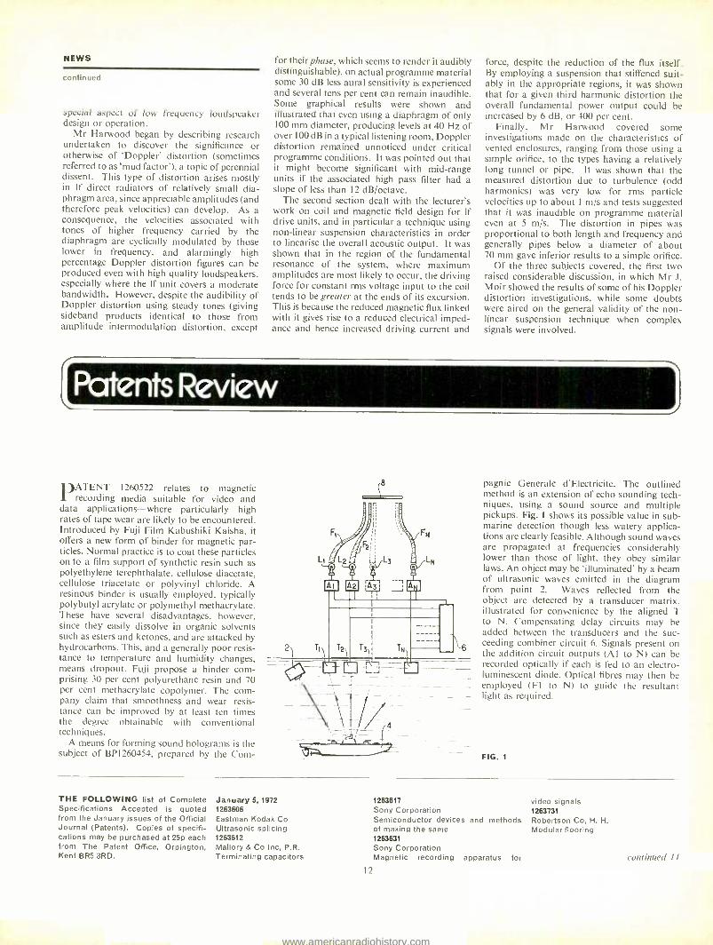
PATENT 1260522 relates to magnetic recording media suitable for video and
data applications -where particularly high rates of tape wear are likely to be encountered. Introduced by Fuji Film Kabushiki Kaisha, it offers a new form of binder for magnetic par- ticles. Normal practice is to coat these particles on to a film support of synthetic resin such as polyethylene terephthalate, cellulose diacetate, cellulose triacetate or polyvinyl chloride. A resinous binder is usually employed, typically polybutyl acrylate or polymethyl methacrylate. These have several disadvantages, however, since they easily dissolve in organic solvents such as esters and ketones, and are attacked by hydrocarbons. This, and a generally poor resis- tance to temperature and humidity changes, means dropout. Fuji propose a binder com- prising 30 per cent polyurethane resin and 70 per cent methacrylate copolymer. The com- pany claim that smoothness and wear resis- tance can be improved by at least ten times the degree obtainable with conventional techniques.
A means for forming sound holograms is the subject of BP1260454, prepared by the Corn-
pagnie Generale d'Electricite. The outlined method is an extension of echo sounding tech- niques, using a sound source and multiple pickups. Fig. l shows its possible value in sub- marine detection though less watery applica- tions are clearly feasible. Although sound waves are propagated at frequencies considerably lower than those of light, they obey similar laws. An object may be 'illuminated' by a beam of ultrasonic waves emitted in the diagram from point 2. Waves reflected from the object are detected by a transducer matrix. illustrated for convenience by the aligned T to N. Compensating delay circuits may be added between the transducers and the suc- ceeding combiner circuit 6. Signals present on the addition circuit outputs (Al to N) can be recorded optically if each is fed to an electro- luminescent diode. Optical fibres may then be employed (Fl to N) to guide the resultant light as required.
FIG. 1
THE FOLLOWING list of Complete Specifications Accepted is quoted from the January issues of the Official Journal (Patents). Copies of specifi- cations may be purchased at 25p each from The Patent Office, Orpington, Kent BR5 3RD.
January 5, 1972 1263606 Eastman Kodak Co Ultrasonic splicing 1263612 Mallory & Co Inc, P.R. Terminating capacitors
12
1263617 Sony Corporation Semiconductor devices and of making the same 1263631 Sony Corporation Magnetic recording apparatus for
video signals 1263731
methods Robertson Co, H. H. Modular flooring
continued 14
www.americanradiohistory.com

STANTON CARTRIDGES:
the starting point of fine hi-fl
Sound reproduction from a record can only be as good as the cartridge which tracks it:
with the Stanton 681 EE you ensure the best. The Stanton 681 EE meets the most exacting requirements of the professional
user and the discriminating enthusiast. The Stanton 681 Calibration Series has an
amazingly low -mass moving magnetic system which weighs only 1/5 or 1/10 of
ordinary pickups. Its frequency response from 10 to 20,000 Hz is virtually a straight line.
Every 681 is guaranteed to meet the specifications within exacting limits and the
most meaningful warranty possible - individual calibration test results -
comes packed with each unit. Ask for a demonstration of the Stanton 681 EE at your local dealer, or write for
details and specifications, plus information about the Stanton 500 Broadcast Standard
Series. Trade enquiries welcome.
WILMEX LTD Stanton Division, 24/26 Ensign Street, London El Telephone: 01 -949 2545
13
Unlimited Limitation The new TELETRONIX LA -3A is the solid state successor to the well known LA -2A, and retains the unique characteristics of the T4A electro- optical attenuator. Characteristics can be changed from those of a limiter to those of a compressor by simple switching. Its small size permits two units to be installed side - by -side in 34" of 19" rack space.
Peak signals, limited to any desired value without distortion : : simple, quickly and visually, with the 1176 LN Universal Audio Limiter.
FET gain reduction ahead of first -stage amplifier; push- button selection of four different compression ratios; ultra fast attack and adjustable release times. Plus superb modern solid -state circuitry for reliable low -noise operation. The recognised approach to peak sound problems for all broadcasting, recording and professional applications.
Ex -stock - write now for details. i
F.W O. BAUCH LIMITED 49 Theobald Street, Boreham Wood, Herts. Tel: 01 -953 0091 Telex: 27502
www.americanradiohistory.com

PATENTS REVIEW
continued
1263749 Holotron Corporation Acoustic lenses 1263758 Philips Electronic & Associated Indus- tries Ltd Audio -visual playback and projection apparatus 1263785 Marconi Co Ltd Multi -image colour television cameras 1263789 Selden, O. C. Key controlled pulse generator 1263796 Mullard Ltd Analogue store 1263853 General Electric Co Multiphase generator and bus system 1263861 Lenco AG Electronic commutating circuits 1263876 Solartron Electronic Group Ltd Dynamic readout of pulse counters 1263928 Plessey Co Ltd Frequency synthesisers 1263981 Westinghouse Electric Corporation Method and system for band corn - pression for video signals 1263982 Westinghouse Electric Corporation Method and system for recording sampled signals on a continuous recording medium 1263991 Minnesota Mining & MFG Co Magnetic recording document having validating means 1263994 Philips Electronic & Associated Indus- tries Ltd Input circuit arrangements for tran- sistors 1264131 Wyvern Church Organs Ltd Frequency dividing circuits 1264143 Philips Electronic & Associated Indus- tries Ltd Electronic musical instrument 1264176 Biondi, E and Biondi, L Method of and apparatus for trans- forming voice frequency sound signals into a form audible and comprehen- sible to severely deaf 1264181 Starkstrom- Analgenbau Karl -Marx- Stadt, Veb Reversible pulse counter 1264226 Marconi Co Ltd Television camera equipments 1264229 Rca Corporation Oscillators 1264230 Montanari, S Sound effect generator
January 12, 1972 1264385 Philips Electronic & Associated Indus- tries Ltd
Recording and /or playback apparatus 1264390 Hitachi Ltd Temperature compensating device of a solid state oscillator 1264412 Garrod, N. J. Gramophone record sleeves 1264453 AKG Akustische U Kinogerate GmbH Microphone assembly having a noise - damping mounting 1264572 Sony Corporation Display systems 1264617 Plessey Co Ltd Automatically tunable resonant circuits 1264659 Orban, R.A. Stereo synthesiser 1264688 International Business Machines Corporation Speech synthesiser 1264829 Fibre -Optics Industries Inc Recording device 1264862 Western Electric Co Inc Signal transmission devices having portions operating at different direct - current potentials 1264903 Mullard Ltd Frequency synthesisers 1264956 Plessey Co Ltd Bandwidth compression systems
January 19, 1972 1265013 International Business Machines Cor- poration Error detecting circuitry 1265018 Matsushita Electronics Corporation Pressure -sensitive semiconductor devices 1265027 France, Minister of Armed Forces Ultrasonic doppler frequency detection devices 1265034 Xerox Corporation Circuitry for distinguishing between background and intelligence areas of a document 1265067 Texas Instruments Inc Stereoscopic display apparatus for three -dimensional data display 1265079 British Insulated Callenders' Cables Ltd Sealing the ends of electric cables 1265087 Nippon Selfoc KK Optical image transmitting structure 1265090 Institut Fiziki An Latviiskoi SSR Method of orientating with a magnetic field asymmetrical in plane nonmag- netic electrically conducting bodies and apparatus for effecting same 1265101 Hellermann GmbH Paul Tape tensioning tools 1265111 Shaw, A N
Electronic organs 1265126 NSM- Apparatebau GmbH KG Automatic phonographs having means
14
of Indicating the frequency of use of various records 1265157 RCA Corporation Signal translating circuit 1265161 Glanvill, K B Devices for superimposing optical images 1265200 Sony Corporation Magnetic recording and reproducing devices for video signals 1265221 RCA Corporation Information storage systems 1265236 Paillard SA Cinematographic apparatus for use with films of different sizes 1265249 RCA Corporation Colour television picture tube 1265276 North American Rockwell Corporation Digital time multiplexed bidirectional communications system 1265322 Agfa -Gevaert Photographic information -recording method and materials 1265326 Standard Telephones & Cables Ltd Communication along pipe lines by ultrasonics 1265402 RCA Corporation System for generating clock pulses from a digital information signal 1265416 Westinghouse Electric Corporation Pulse width modulated amplifiers 1265441 Sonictron Corporation Device for frightening rats 1265504 Memorex Corporation Magnetic coating composition and manufacture of recording discs coated therewith 1265560 Singer Co Frequency divider circuit 1265569 Siemens AG DC Voltage regulating circuits 1265576 Braun AG Pickup arm for record players 1265697 International Business Machines Cor- poration Frequency memory
January 26, 1972 1265701 Holzer- Patent AG System for regulating the speed of an alternating- current motor 1265798 Marconi Co Ltd Carry generators 1265799 Partridge Wilson & Co Ltd Timing device for use in charging electrical storage batteries 1265825 Ball Bros Research Corporation Automatic gain control video amplifier 1265852 Fernseh GmbH Colour television camera system 1265992 Data Efficiency Ltd Method of and means for reeling tapes
1266011/2 Matsushita Electric Industrial Co Ltd Magnetic recording and reproducing apparatus 1266021 Telefunken Patentverwertungs GmbH Record carrier and method of produc- ing the record carrier and playing back of the recording on the record carrier 1266022 Telefunken Patentverwertungs GmbH System for recording and sensing picture signals 1266025 RCA Corporation Magnetic head 1266028 RCA Corporation Voltage regulator for use in a tele- vision receiver 1266034 English Electric Valve Co Ltd Electron Discharge camera tube apparatus 1266039 Polaroid Corporation Motion picture systems and cassettes for use therein 1266042 Dana Laboratories Inc Harmonic- insensitive AC to DC converter 1266075 Allmanna Svenska Elektriska AB Frequency discriminator 1266077 Fuji Photo Film Co Ltd Magnetic recording media 1266130 Kirk Electric A/S DC to AC Converters 1266143/4/5 Atomic Energy Authority (UK) Ultrasonic transducer devices 1266202/3 Allgemeine Elektricitats - Ges AEG - Telefunken and Teldec Telefunken - Decca Schallplatten GmbH System for recording and reproducing signals 1266232 Southern Pacific Transportation Co Bandwidth reduction technique for analog signals 1266268 International Business Machines Cor- poration Fundamental frequency detection 1266270 Columbia Broadcasting System Inc Apparatus for recording and repro- ducing electric signals representing colour information 1266278 Philips Electronic & Associated Indus- tries Ltd Magnetic recording / reproducing apparatus 1266289 Foxboro- Yoxall Ltd Apparatus for producing a continuous departure from its datum value of the squared reciprocal of a frequency 1266310 Industrie Pirelli Spa Flame -proof cable 1266312 Thomson -CSF Brushless direct voltage generator 1266336 Marconi Co Ltd Colour television cameras 1266415 Bendix Corporation Fluidic digital speed control apparatus
www.americanradiohistory.com

`side 2onal
By John Dwyer
EVER since the late 1920s, when a German named Pfleumer conducted experiments
with plastic and paper tapes, improvement in the methods of manufacture involved has been a constant preoccupation of those engaged in audio tape manufacture. Racal -Zonal have been highly research oriented since starting in 1954, and most of the present managerial staff have worked their way up from the laboratory.
Zonal began by specialising in sound striping for the cinema industry, at which time they were linked with RCA. In 1956 the operation was split into two: Zonal Facilities (who carried on with the film work) and Zonal Film (Magnetic Coatings) Ltd, with whom this article is concerned. The latter firm were for a time associated with Pyral (France) but Ilford acquired Zonal in 1964. It was during this period that the manufacture of computer tapes and industrial 6.25 mm audio tapes really got under way. Ilford's close association with ICI was of considerable value to Zonal, in both resin chemistry and the deeper understanding of polyester base.
CIBA GEIGY, the giant Swiss chemical combine, who now own Ilford and are largely responsible for their policy decisions, decided to rationalise their diverse activities. Ilford were obliged to opt out of the responsibility of running a magnetic coating operation (Zonal), and the two parted company in October 1971. Zonal found a ready buyer in the large conglomerate, Racal Electronics Ltd. Racal were started 21 years ago by Ray Brown and Calder Cunningham and now have interests in seven countries, some 4,000 employees pro- ducing an annual turnover of around £20,000,000.
Early in 1970, market research was carried out in Britain and on Zonal's behalf by Todd Ao in the United States. As a direct result of these studies and of close contact with BBC technical departments, two new film products and the Spectrum range of audio tapes were produced. Over46,000 km of the latter tape products are now produced every week.
Considerable importance is attached to market research, here and in the States. Todd Ao market and distribute Racal -Zonal tape and film under their own label. The BBC have ordered to date some 100,000 km of Spectrum low print and have a sizeable forward commitment.
One distinction between low noise and low print Spectrum (an overall improvement of 4 dB at two per cent distortion is claimed for both products) is the type of backing used. The low noise tape has a matt backing which combines a number of advantages but the low print version is generally more popular for machines which employ pressure pads.
Research is carried out constantly at Zonal
Checking physical dimensions to ensure machine compatibility.
on all the parameters crucial to the production of high quality tape. These include width, overall thickness, tendency to cup, bias and curl, slit edge quality, coating quality, blocking, friction, stretching, breaking strain, remanence, frequency response, coercivity, noise character- istics, print- through phenomena and uniform- ity. Because of the multitude of such variables, quality control checks have to be made constantly at all stages of production. The laboratories at Racal -Zonal have a staff of some 30 people, a fair proportion usually being engaged in taking measurements on the shop floor.
The laboratories are equipped with much that has been manufactured in situ, but there are commercially made BH loop testers, infra- red spectrometers, humidity and temperature cycle cabinets, spectrum analysers, XY plotters, and pen recorders in abundance. Practical tests are carried out on tape and film transports by Westrex, RCA and Ampex, vtrs by Ampex, Sony and Shibaden, and a wideband instru- mentation recorder for which the heads alone cost £3,000. As well as this, all the processes involved in tape manufacture can be repro- duced on a pilot production line.
In addition to the careful scrutiny given to the tape while it is being made (Spectrum is batch tested at a rate of ten per cent and the entire output of computer tape is full length tested), further checks are carried out by an end of line inspection panel. The members, who have no contact with one another, are sent sample tapes selected at random from batch boxes. These people, some half dozen, test the tape to their own standards and act, in effect, as 'artificial consumers' to see if the end product is as good as the measurements made indicate it should be.
The basic manufacturing process is as follows. The raw materials are received into the factory and the first 26 of a production total of 80 quality control checks are carried out. The chemical raw materials, including oxides, solvents and resins, undergo 18 of these 26, including checks for coercivity and purity. The base undergoes the remaining checks for gauge roughness, and so on. Most of the polyester base used is Dupont Mylar but a
continued 17
Physical inspection of multitrack head assemblies.
15
www.americanradiohistory.com
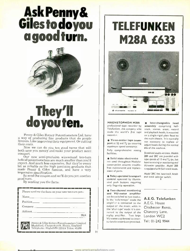
Ask Penny& Giles to doyou a good turn.
They'll do you ten.
Penny & Giles Rotary Potentiometers Ltd. have a way of producing fine products that do people favours. Like improving their equipment. Or cutting their costs.
Now we can do you ten good turns that will both save you money and make your product more compact.
Our new semi -precision wirewound ten -turn helical potentiometers are much smaller than you'd expect. And much less expensive. But they're every bit as reliable as the high precision products that made Penny & Giles famous, and have a very impressive specification.
So send the coupon and we'll do you yet another good turn.
By sending you the facts.
rim Please send me the facts on your new ten -turn pots.
Name
Position
Company
Address
PG Penny & Giles Rotary Potentiometers Limited Mudeford, Christchurch, Hants, England Telephone: Highcliffe 2233/4 Telex: 41266
I
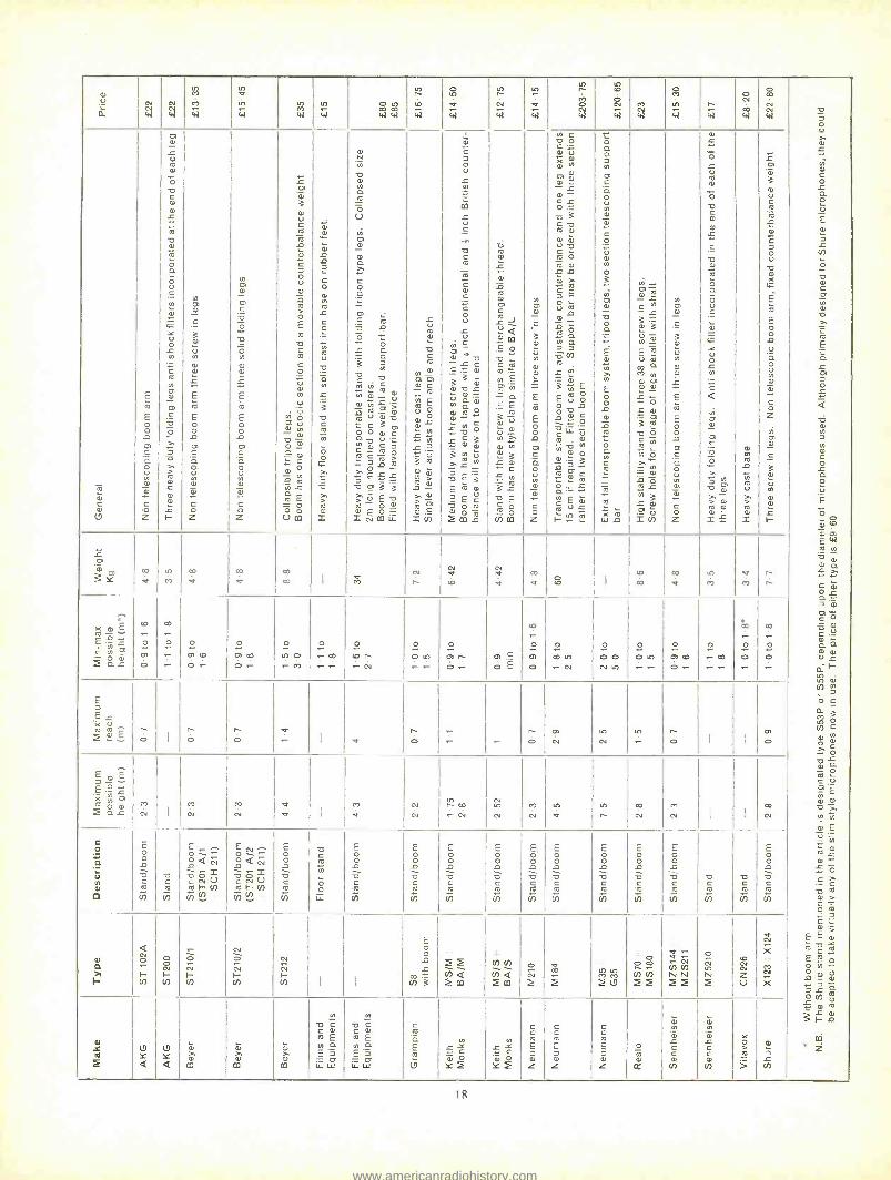
TELEFUNKEN
M28A E633
MAGNETOPHON M28A professional tape recorder by Telefunken. the company who made the world's first tape recorder.
Three -motor tape trans- port at 3 ** and 7; ips ensuring maximum speed constancy.
Fully comprehensive mixing facilities.
Solid state electronics re used throughout Modular construction ensures trouble - free maintenance and replace- ment of parts.
Relay operated transport control operated by illumin- ated push buttons requiring only fingertip operation.
Two -channel monitoring and VU -meter amplifier can be switched to two modes. In the 'before -tape' mode the amplifier is connected to the output on the mixer, while in the 'after-tape' mode it is con- nected to the output of the replay amplifier. Two large VU- meters calibrated to inter- la tionalstandardsareprovided.
Interchangeable head assembly comprising half - track, stereo, erase, record and playback heads, is mounted on a single rigid plate fixed to the main chassis. It is normally not necessary to replace or adjust heads during the normal life of the machine.
Broadcast studio versions. Models 28B and 28C are provided with tape speeds of I5 and 71 ips, but have no mixing or monitoring and VU -meter amplifier. Model 288 is equipped with full -track heads.
Model 28C has two -track heads
and track selector switch.
Q.E.G. Telefunken A.E.G. House Chichester Rents, Chancery Lane,
London WC2 Tel: 01-242 9944
www.americanradiohistory.com

INSIDE ZONAL
continued
small proportion of the firm's needs is met by Melinex, evidence of the firm's previous links with ICI. All the multitrack tapes, those in 12.5, 25 and 50 mm widths, are produced with a polyester base, as are all the low noise spectrum tapes. The remainder of the 6.25 mm tapes are available in polyester, vinyl or acetate. The remaining items, sundries such as spools, are also checked. After this the chemicals are milled, or mixed, and the result- ing mix is given ten quality control checks, typically for viscosity, clumping and dispersion.
Storage vessels, in which the final magnetic `lacquer' is stored, are considerably larger than necessary to produce any one batch of tape. In this way, several lacquer batches are blended together at the same time, thus smoothing out batch inconsistencies. Should the measure- ments, conducted on the final product, show trends away from the midpoint standard, then adjustments are made in following batch additions. Thus the amount by which the batch is likely to vary is very small indeed.
The coating process follows, in which the magnetic lacquer is spread on to the base. At this stage, 17 checks are performed including measurements on the coating surface, coating thickness and consistency, solvent retention and so on. After the coating has been cured, which involves five quality control checks, there follows a polishing stage. There are 12 checks at this stage, most of them optical.
Until now the tape has been produced in widths up to 450 mm and the various pro- cesses have been conducted at a speed of about 60 m /s. At this point the tape is slit to 6.25 mm, or whatever is required. This is a critical pro- cess, particularly with regard to dropouts and skew.
The slitting blades are regularly checked and changed, in some cases at least once a day. Checks on the tape at this stage include surface quality, base distortion, slit quality, skew, curl and cupping. The tape is cleaned and then enters the inspection and test department. Here it is tested electronically and mechanic- ally. Its mechanical properties are investigated by testing for excessive head wear which may be expected when using the tape, and the magnetic properties are also fully investigated. Head wear is a very important consideration, of course, and the tape is passed over a metal shim until the shim breaks. It may well seem that the most desirable situation is one such that the tape does not break the shim at all, or at least not for far more passes than the head would expect to get during its useful life. This would be the condition for minimum head wear and would be produced by a smooth coated, frictionless tape. But an ultrasmooth tape produces a loss in frequency response after a certain period of use. This is because such a tape allows dirt and debris to accumulate on the surface of the head itself, moving the magnetic coating away from the gap. Thus Racal -Zonal try to compromise between low head wear and good tape cleaning characteristics.
The magnetic properties of the tape are tested by machines giving pen recorded read-
out. The batch testing of 6.25 mm tape is conducted on an Ampex two channel pen recorder which checks the electromagnetic recording and playback parameters of each sample. The recorder needle is the heated tip type which contacts a heat sensitive chart paper. The recorder reaction time is in the region of 1 ms, allowing very sensitive detection of output level variations. The tapes are sub- jected to 310 flux reversals for every centimetre of tape. If a length of tape betrays a 6 dB loss of a single half cycle caused by dropout due to dust, debris and so on, then the tape is rejected. Output cycling or multi dropouts of less than 6 dB also cause rejection. Pass rate is between 90 and 95 per cent. Strict observation is made on winding characteristics and stacking. Coat- ing fault checks are made automatically using photocells. Testing before winding is conducted on the basis of ten per cent for Spectrum tapes and System 2 films, and 100 per cent for digital (computer) and video tapes. After testing, the entire batch is bulk erased and packed and a sample of one per cent is sent to the end of the inspection panel.
The complete packages of tape do not always look the same. Some are labelled for leading computer manufacturers or for distributors. Examples are Todd Ao, Film House (Canada), Honeywell, TBS (Germany) and ICL.
One of the most striking things about the factory is the elaborate care taken to ensure cleanliness. The system by which air is circula- ted through each arm of the production area ensures a slightly higher pressure inside than outside. Thus the air will run outwards in every case if a door is opened. To the same end, air is pumped down to the spooling area under laminar flow conditions so that any dust is carried away and cleaned before being re- circulated. This is also true of the packing area, which is situated downstream but in the same clean room as the main manufacturing activities. Each reel of tape is heat sealed on the spot in a polythene container. One feature which will emphasise the extent to which cleanliness is considered important is that everyone in the room wears a 'clean suit', hapless visitors included. These garments never leave the premises; when they need changing they are laundered in a room at the entrance to the main production department.
Another impressive feature is that the
17
Close examination of coating defects
premises are so extensive. ('All that you can see is Racal -Zonal,' as Tony Pitter put it.) The reason for this is that Zonal seem to be expand- ing all the time. Zonal have grown from a single building (Factory One) until there is now a Factory Eight. There would seem to be solid reasoning behind their belief that Racal -Zonal will continue to grow. The writer found three reasons why the firm should prosper. The first. one of the most interesting features of the whole visit, was the discovery that Racal -Zonal market a large range of tape heads, and are willing to quote for any quantity from one upwards. Over 300 standard silver nickel heads are being offered, besides those manufactured to order, in all track widths and configurations from eight to 70 mm.
Another feature of Racal -Zonal is a free advisory service available to recording studios. whether they are Zonal customers or not. Any electronic or servicing problems which arise can be dealt with, and advice on the purchase. maintenance and alignment of machines given. The third sidelight on Zonal activities is the fact that they now manufacture cassettes. Cassette blanks are bought in for assembly under the same conditions of manufacture as the more critical products. Zonal have an arrangement with Fraser Peacock, the latter distributing all the cassettes manufactured at Redhill, under the Zonal -FPA label.
Thanks are due to Tony Pitter at Redhill for his hospitality and co- operation, as a result of which we hope to publish a test report on Spectrum tapes in the near future.
Making the iron oxide dispersion.
www.americanradiohistory.com
N 4_,' el
44 Ñ 44
to m CI
w
tn a
w M 44
M
44
0 W CO
44 44
to r O w
o to
w
tn r cu,._
to
v w
I tI
I I
N 01 N
C
3
u N a>
íL-
E R
E o O d co O1 c Q
Ñ Ql
.°.'
C o z
Ñ 44
o N w
Ñ 44
o co
tn
w r w
O
CO 44
0 co
Ñ 44
a -5 o T o
.L-.
ui N C o L Q O
`J
J L
O a o c O) tO
N a T - m
E Q ¿ at J
Q
-ó at N J V,
c O
p ú
E
OO
a' '0
Ñ tan
E`*4 N
N
o Q r C O ¿ Q.. J OI Q
v o C.V Q Q N a L d H
a i (n N
J o c a 3
tn C rn
á C O aL o ° m 2 C U E a>, N Ñ m E V N
R m ¿ N w O (: - -o o O T C_ o_ m
= c t °' E o Y
"5- -c;° ß o
° co a -0 :F J ¿ Q
o u) R L a .J N R
F- 4
m *
;.°_
o c N
(9
E
R
E
0o
9 OI C Q O u
N c o z
0 o ¿ U
Ñ
O
a N
ia -o °' N
O á o u Ç
o
ó U o N - c o N
rn ç a ó0 >'
>`
Ñ 2 aoi
L F-
N
C
N Ol á
r E R
E
o d iA C_
Q O
N
r c o Z
d 0 C '- a
a - N
O d
r E R
E o o d 0 C Q O
N
c o z
L 0 3
c co
R ._ r C
ó u
d R
> O E R a R C o
V ÿ °
+ ó aOi ÿ - N a O..V. Q
Ol
.`- C O
1] N N L m E - o O o U00
.
w s-
_o
c O
N R fl C ó '- m U
-°
tn r a Ñ ... N
00 , J -o
> R N I
u ti
N a N
Ó R - U
OI
O) Q
c
Q r 0 E R a ó t
° o. .y Q
3 J a N
C á
áL ú o ÿ m> R,
R u v- ó c 3 an
o o O> c a -0 u'L N at C J C R R c ia ° J L - O J E. -o m 3 3 > o E a R - O r O> E O - S NOOw
L m °i
á R
N o
Ñ C
i6 R E U°
a 2.!)
o
_Ern N J â
3 R
2> - T a-'
p °t a! C =án
C J
Ú
L N
Qi`
L u = _µ.
a c R
m
N
E C o U
c . c N.- m
d a L c .E = o 3 3 o
ú ó.v N Q O d
L N .. a ¿ C 3 . N
Q)
3 N U T L N - a E 3 E t0 a)
E c a O R °o a 203_0
-6
`)
.L..
o
R
Ól
ti L Q o CO c p
a c@ R- N E
m
Q Ç E 3 ú o
N u- N Q) N
a' 3 L O ... C
L N
3 L -0,_E
O O
fAm
N C a ó C ' N V X R O N N
a0j
o r OC
w
a 3 c a R O>
O) Ñ
c-ó R O R O) a á
C E OJ ._ V R
L
m° ÿ á J J o R L N 7- cu."
Et?,?) O.o .O
c a '.=
°-
c w Ú R O)
N-O o d'= 3
d `
R d R OQ -.- w N E á C u¿
1- `,2 E
ó Q j N O c a ° tVil
° á?
O
U N N o 3
N O1 O)
O °.
E d Ñ N
ó 2 o 2
O
N C R
.- t `
w d
O) R
C y - L 3~ 2 GO
d
E U R co Q m O) NOf
s- °
.L.. O o, R
a O C R N ..
N° T .. N
d O r L N 3 ¿ d 0
S V)
N O N
.
C
3 d u N d o
r E ti
E
o 4 0 E Q
u d
°= c
Z
o
° L ° d
° -o aci
w c a o R o O.
O u = :.'
w x p L N ._.
<
rn N
0 C
a
j N a > o R N
S.L..
I
O)
N
9 N
ú
> R I
t O O
I 3 N U
Ñ 2 á o C J ° u -o o
E N
E o ñ ° Q ° ° Ñ
.°:
ó
Z Ñ co O)
=
Ñ
a'
I'-
L 0 o
Y co
xr to co
co co
R O O I M
N r I a I t0
R cv
< co
V t00 I
O O
O <
to M
v co
r r
,t o É Co °a R 7.-v.- Ç 'y o
0 E ó ', O 2 Q¿ o
.- o
'-
o o tA t0 Of CD
o .- o .-
o O O .- co
o O
,- .-
o
O r ,-- N
o
O tp .- ,-
o
CO r o -
I
tT = O E
to - o
O o
o
O to ,-. fU
O
O O N to
o O tn .- ,-
o O1 CO
O.-
o
CO
1- -
óo
.- o O .-
co
o O -
E J E
L m m^ r i
M d-t o I
I
I
r r O O
v I R
r O
r O
CD
N n
N n r
O I I
rn O
E o v J_ ¿ tXO
ON M
2 Q L N Ì
I
I
M m N
7 I
m N I
I
I r co tNn m tn tn O M I I
O
o E Ç O
C O _ L ÿ a N C I
y i 0 N I
a c R
tn
E .7.", ¡ E
O o t- O Q Ñ O Q á Q L 76-'5I a 0= C N U c N U I
R F- (n R F- fn tn N (n
E O O L a C R-
to
C R
p p
E
E O O L_
a C R
Ñ
E O O _ a C
.R-
tn
E O O 9 a C R
V)
E O O L a C R
tn
E O O
S] a C R
!n
E O O L a C «
N
E O O 4 a c 2 tn
E O O d a c R
(ñ
E o O L a C R
(n
a c R
up
a C R
N
E O O L a c R
(n
tot
c.
T F- Co
FN-
Co
I
FN- Ñ Co Co
F Co I I
E
° o
co L n 3
tn Q 2 m
tn Q 2 m
O Ñ 2
I
O CO
2 M M
tn
2 ( tA tn î 2
v.- V N
N Ñ 2 2
Ñ î Z U
N X
N X
U Y
E Q I
(9 Y Q
ä d T d d m 00
á T QI
00
a C
R E N Q E'J ii w
N a C
R E N Q E 3 ü. w
C
a E R
(7
N ¿ Y .. C N ° Y î
N L: ^" c O) ° Y2
C
R E J N Z
C
R E J O)
Z
c R E J N Z
° Ñ N z
N N
O c C Ol
CO
a) N
O
c C o
Co
ó R
> J
N
1
www.americanradiohistory.com
kuI11p8rson; illicrophane Stands
By Peter Self
MICROPHONE stands fall into various categories depending on the user. Con-
ventional recording studios desire, as all users, strength, simplicity in operation, durability and compactness. TV studios require for 'in -shot' work slim anti -glare designs and, for normal coverage, large boom systems arranged to operate in conjunction with camera dollies. As well as these facilities, a film studio will require hand -held 'fishpoles' such as the new Sennheiser boom which is of an all- fibreglass design for lightness. Location recording produces other requirements where tall or extra long -range stands may be desirable.
Probably the most extensively used stand/ boom combination is the one supplied by AKG as ST102A, by Beyer as ST210/1 (ST201A /1 with SCH211), by Neumann as M210, and by Sennheiser as MZS144 with MZS211. The question of who manufactures the design would seem to be answered by studying the accompanying survey. One finds that Beyer's price is by far the lowest for an equivalent stand. Various versions of this style are available, one having folding rather than screw - type legs. As opposed to most other folding leg designs, the system is very robust and the stand remains solid after continued rough use. These are especially recommended for mobile work where the engineer has three less parts to deal with while setting up. One further variant of this design can be obtained with a telescopic boom arm. Although the boom has only a 75 cm reach normally, there might be instances, possibly when making a live stage recording, when the further shortening (to about 35 cm) would be visually desirable.
One good design, which unfortunately is no longer available, was marketed by Keith Monks (Audio) Ltd. This consisted of a conventional stand and boom arm but, instead of the usual friction clamp to support the boom, a large cam rested on the top of a knurled threaded ring which could be screwed up and down the stand. There are two advantages to this design, the first being that it is impossible to loosen or knock the ring inadvertently, so letting the boom fall down; secondly the arm may be lifted away by a musician and will always return to the same position, a definite advantage when close -miking in the studio. Possibly such a design with a few improvements could be re- marketed with success.
The majority of floor stands do not possess anti -vibration mounts, although most corn - panies produce one model with some form of shock isolation. The most effective of these appears to be the one marketed by AKG as ST200 and Sennheiser as MZS210 although using the appropriate elastic microphone sling should get over any problem with any stand.
For any type of recording other than close - miking, a studio will usually require long reach
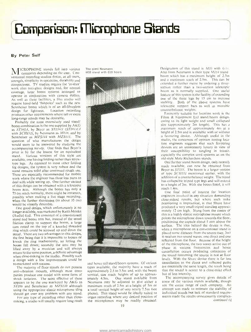
The giant Neumann M35 stand with G35 boom
and hence tall stand /boom systems. Of various types available, the majority have a reach of approximately 2.5 to 3.5m and, with the boom vertical, can reach heights of up to approx- imately 4.5m. One stand available from Neumann may be adjusted to give either a maximum reach of 2.5m at a height of 5m or a total vertical height of very nearly 7.5m (see photo). This stand would be ideally suited to organ recording where any desired position of the microphones may be readily obtained.
19
Designation of this stand is M3 with G3 Also from Neumann is their type MLs't stand boom which has a maximum height of 2.5m and a maximum reach of 2.9m. This can be extended a further metre by ordering a three - section rather than a two- section telescopic boom as is normally supplied. One useful feature of this system is the facility of extending one of the three legs by 15 cm to increase stability. Both of the above systems have telescopic support bars as well as movable counterbalance weights.
Eminently suitable for location work is the Films & Equipment Ltd stand /boom design, owing to its light weight and small collapsed size (approximately 2m length). This has a maximum reach of approximately 4m at a height of 2.5m and is available with or without a favouring device. Although useful in the studio, the concensus of opinion among loca- tion engineers suggests that such favouring devices are an unnecessary luxury in view of their susceptibility to tangling in transit, especially the complex cord systems as on the old -style Mole Richardson stands.
One further stand /boom design, only recently made available, can now be obtained from Beyer as ST212. The boom is a larger version of type SCH211 mentioned earlier, with the addition of a counterbalance weight. The stand has collapsible tripod type legs and will extend to a height of 3m. With the boom fitted, it will reach I.4m.
One final point of interest for location engineers involved in any situation demanding close -miked results, but where such mike positioning is impractical, is that Shure have produced a very small tripod standing approxi- mately 12 cm high. Slung from the centre of this is a highly elastic microphone mount which points the microphone down towards the floor, positioning the capsule about 5 mm above the surface. The idea behind the device is that, when a microphone on a conventional stand is
placed some distance from the source (say, 3m) it receives two sound waves, one direct and one reflected from the floor. Because of the height of the microphone, the two waves arrive out of phase at various frequencies and hence cancellation occurs producing coloration of the sound (assuming the source is not at floor level). With the Shure device there is far less cancellation as the direct and reflected paths are essentially the same length, the result being that the sound is nearer to a close -mike effect but of less intensity.
The accompanying survey gives details of some of the various stands available, though not the entire range of each company. An attempt was made to estimate the stability of individual stands but lack of standard require- ments made the results unnecessarily complica-.
continued 2J
www.americanradiohistory.com

The ubiquitourJfT153.
The Shure SM53 professional unidirectional microphone is seen with increas- ing frequency in the best of company because it affords eight distinct perform- ance advantages: (1) a wider front working angle with uniform tonal quality; (2) effective noise rejection through a true cardioid pickup characteristic; (3) a built -in shock mount for effective mechanical noise isolation; (4) extraor- dinary ruggedness for performance consistency after severe shocks; (5) a superior hum rejection system; (6) an integral breath "pop" filter; (7) a min- imized proximity effect for constant tonal quality; and (8) full field serviceability. Interested?
Shure Electronics Limited 84 Blackfriars Road London SE1 8HA, England
Ira S H V R E www.americanradiohistory.com

P1kJdEJ Books
ACOUSTICS OF STUDIOS AND AUDITORIA. V. S. Mankovsky. £5. Focal Press Ltd, 31 Fitzroy Square, London W.1 BBC PROGRAMME OPERATIONS TRAINING MANUAL: HIGH QUALITY SOUND PRO- DUCTION AND REPRODUCTION. H. Burrell Hadden. £2.10 (case) or 75p (limp). BBC Publica- tions, 35 Marylebone High Street, London WIM 4AA BBC ENGINEERING MONOGRAPHS. (40p) THE SUPPRESSED FRAME SYSTEM OF TELERECORDING. C. B. B. Wood, A. V. Lord, E. R. Rout and R. F. Vigurs (1955) THE DESIGN OF A RIBBON TYPE PRESSURE GRADIENT MICROPHONE FOR BROAD- CAST TRANSMISSION. D. E. L. Shorter and H. D. Harwooci (1955) THE DESIGN OF A HIGH QUALITY COMMEN- TATOR'S MICROPHONE INSENSITIVE TO AMBIENT NOISE. H. D. Harwood (1956) AN AUTOMATIC INTEGRATOR FOR DETER- MINING THE MEAN SPHERICAL RESPONSE OF LOUDSPEAKERS AND MICROPHONES. A. Gee and D. E. L. Shorter (1956) THE APPLICATION OF PHASE -COHERENT DETECTION AND CORRELATION METHODS TO ROOM ACOUSTICS. C. L. S. Gilford and M. W. Greenway (1956) ANALYSIS AND MEASUREMENT OF PRO- GRAMME LEVELS. D. E. L. Shorter, W. I. Manson and E. R. Wigan (1958) THE BBC's MARK 2 MOBILE STUDIO AND CONTROL ROOM FOR THE SOUND BROAD- CASTING SERVICE. L. E. H. O'Neill (1958) THE ENGINEERING FACILITIES OF THE BBC MONITORING SERVICE. C. J. W. Hill and H. S. Bishop (1958) TRANSISTOR AMPLIFIERS FOR SOUND BROADCASTING. S. D. Berry (1959) PROGRAMME SWITCHING, CONTROL, AND MONITORING IN SOUND BROADCASTING. R. D. Petrie and J. C. Taylor (1960) A SUMMARY OF THE PRESENT POSITION OF STEREOPHONIC BROADCASTING. D. E.
L. Shorter, and G. J. Philips (1960) THE APPLICATION OF TRANSISTORS TO SOUND BROADCASTING. S. D. Berry (1963) RADIOPHONICS IN THE BBC. F. C. Brooker (1963) STEREOPHONY: THE EFFECT OF CROSS- TALK BETWEEN LEFT AND RIGHT CHAN- NELS. H. D. Harwood and D. E. L. Shorter (1964)
STEREOPHONY: THE EFFECT OF INTER-
CHANNEL DIFFERENCES IN THE PHASE/ FREQUENCY AND AMPLITUDE /FREQUENCY CHARACTERISTICS. D. E. L. Shorter, H. D. Harwood and W. I. Manson (1964) THE ACOUSTIC DESIGN AND PERFOR- MANCE OF A NEW FREE -FIELD SOUND MEASUREMENT ROOM. D. E. L. Shorter, C. L. S. Gilford and H. D. Harwood (1965) DATA FOR THE ACOUSTIC DESIGN OF STUDIOS. A. N. Burd, C. L. S. Gilford and N. F.
Spring (1966) A SUBJECTIVE INVESTIGATION INTO PREFERRED MICROPHONE BALANCES. D. K. Jones THE DESIGN OF A LOW- FREQUENCY UNIT FOR MONITORING LOUDSPEAKERS. H. D. Harwood (1967) THE DYNAMIC CHARACTERISTICS OF LIMITERS FOR SOUND PROGRAMME CIR- CUITS. D. E. L. Shorter, W. I. Manson and D. W. Stebbings (1967) THE PROGRAMME EFFECTS GENERATOR. H. Davies (1967) PULSE -CODE MODULATION FOR HIGH - QUALITY SOUND DISTRIBUTION. D. E. L.
Shorter J. R. Crew, D. Howorth, J. R. Sanders (1968) THE AUTOMATIC CONTROL OF SOUND - SIGNAL LEVEL IN BROADCASTING STU- DIOS. D. E. L. Shorter and W. I. Manson (1969) ASPECTS OF HIGH -QUALITY MONITORING LOUDSPEAKERS. H. D. Harwood, S. A. Hughes, and C. L. S. Gilford (1969) AN AUTOMATIC METHOD FOR THE MEAS- UREMENT OF REVERBERATION TIME. M. E.
B. Moffat and N. F. Spring (1969) BBC Publications, 35 Marylebone High Street, London W1M 4AA DICTIONARY OF RADIO AND TELEVISION. W. E. Pannett. £1.80. The Butterworth Group, 88
Kingsway, London WC2B 6AB ELECTRONIC MUSIC AND MUSIC CON- CRETE. F. C. Judd. 80p. Neville Spearman Pub- lishers Ltd, 112 Whitfield Street, London WIP 6DP FOUNDATIONS OF WIRELESS AND ELEC- TRONICS (eighth edition). M. G. Scroggie. £3 (case) or £1.80 (limp). The Butterworth Group, 88
Kingsway, London WC2B 6AB GUIDE TO BROADCASTING STATIONS (16th edition). 50p. The Butterworth Group, 88
Kingsway, London WC2B 6AB HIGH FREQUENCY COMMUNICATIONS. J. A. Betts. £1.25. The English Universities Press
Ltd, St Pauls House, Warwick Lane, London EC4P 4AH LABORATORY MANUAL FOR PRINCIPLES OF ELECTRICITY AND ELECTRONICS. E. C.
Halliday and B. P. Morris. 55p. The English Univer- sities Press Ltd, St Pauls House, Warwick Lane, London EC4P 4AH LOW NOISE ELECTRONICS. W. P. Jolly. £1.25.
The English Universities Press Ltd, St Pauls House. Warwick Lane, London EC4P 4AH MANUAL OF SOUND RECORDING (second edition). John Aldred. £3.50. Fountain Press, 46 -47 Chancery Lane, London WC2 MICROPHONES (second edition). A. E. Robert- son. £3.75 (case) or £1.50 (limp). BBC Publications, 35 Marylebone High Street, London WIM 4AA PRINCIPLES OF ELECTRICAL MEASURE- MENTS. H. Buckingham and E. M. Price. £2.15.
The English Universities Press Ltd, St Pauls House, Warwick Lane, London EC4P 4AH PRINCIPLES OF ELECTRICAL SCIENCE IN SI UNITS (Volume 1). G. D. Perkins. £1.05. The English Universities Press Ltd, St Pauls House, Warwick Lane, London EC4P 4AH PRINCIPLES OF FREQUENCY MODULATION. B. S. Camies. £1.50. The Butterworth Group, 88
Kingsway, London WC2B 6AB RADIO AND ELECTRONIC LABORATORY HANDBOOK (eighth edition). M. G. Scroggie. £4.75. The Butterworth Group, 88 Kingsway, London WC2B 6AB SIGNAL PROCESSING, MODULATION AND NOISE. J. A. Betts. £3.50 (case) or £2.10 (limp). The English Universities Press Ltd, St Pauls House, Warwick Lane, London EC4P 4AH SIGNALS AND INFORMATION. C. C. Good- year. £4.20 (case) or £2.80 (limp). The Butterworth Group, 88 Kingsway, London WC2B 6AB SOUND AND TELEVISION BROADCASTING: GENERAL PRINCIPLES. K. R. Sturley. £2.75. BBC Publications, 35 Marylebone High Street, London WIM 4AA TECHNIQUE OF THE SOUND STUDIO (second edition). A. Nisbett. £3.50. Focal Press Ltd, 31
Fitzroy Square, London W1 ULTRASONICS: THEORY AND APPLICA- TION. G. L. Gooberman. £2.25. The English Universities Press Ltd, St Pauls House, Warwick Lane, London EC4P 4AH WIDE- SCREEN CINEMA AND STEREO- PHONIC SOUND. M. Z. Wysotsky. £4. Focal Press Ltd, 31 Fitzroy Square, London W1
MICROPHONE STANDS
continued
ted. Generalising, the stability of all the stands was such that a (1871, possibly one of the heaviest single microphones to be used on a small stand, could always be safely supported at full boom reach providing the boom was in line with one of the legs. This prompts the thought that in studios the floor is flat and usually thickly carpeted. Such a surface lends itself equally to four -legged as well as three - legged stands, yet nearly all the studio quality stands produced possess only three legs. This
seems a pity as, for example, Keith Monks' stands, which have four legs, are far more stable than their three -legged counterparts. I have found that the weight of the stand itself takes up any small irregularities in the floor. Surely worth considering with £98 of microphone at stake?
All boom stands should, I feel, be equipped with some form of cable clamp, both at the base and either on the top of the boom or on the microphone mount itself; the former to ensure that any jerk on the cable pulls the base of the stand rather than the top, so toppling it over; the latter allowing a loop to
21
be formed to prevent shock travelling up the cable to the microphone and by- passing an expensive anti -vibration mount.
The accompanying survey serves not to show all stands but merely a cross section of what is available to studios. It is of interest that the stand /boom combination mentioned at the start of this article is available in a very similar form from Eagle International and Henry's Radio at slightly lower prices than listed above. Having . used one of these stands, I found no inferior design or workmanship. This makes one query the large difference in prices between the companies involved in marketing the design.
www.americanradiohistory.com
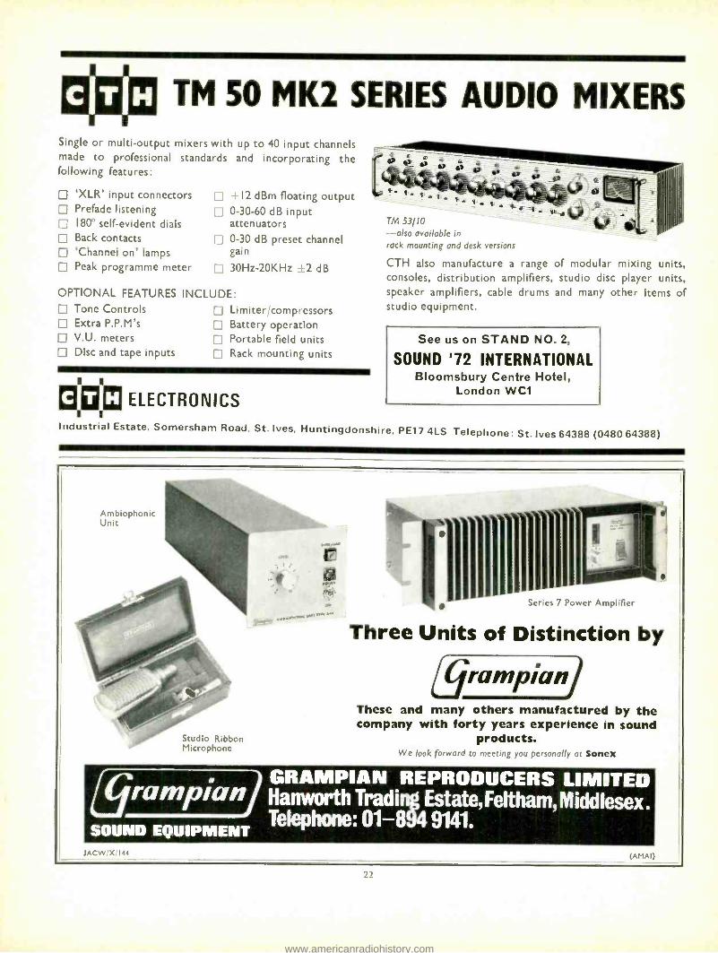
0* TM 50 MK2 SERIES AUDIO MIXERS Single or multi- output mixers with up to 40 input channels made to professional standards and incorporating the following features:
'XLR' input connectors Prefade listening 180° self- evident dials Back contacts 'Channel on' lamps Peak programme meter
-i 12 dBm floating output 0 -30 -60 dB input attenuators 0 -30 dB preset channel gain
Li 30Hz -20KHz +2 dB
OPTIONAL FEATURES INCLUDE: Tone Controls Extra P.P.M's V.U. meters Disc and tape inputs
Limiter /compressors Battery operation Portable field units Rack mounting units
1
Ei © ELECTRONICS 1 1
Industrial Estate, Somersham Road, St. Ives, Huntingdonshire, PE17 4LS Telephone: St. Ives 64388 (0480 64388)
TM 53/10 -also available in rack mounting and desk versions
CTH also manufacture a range of modular mixing units, consoles, distribution amplifiers, studio disc player units, speaker amplifiers, cable drums and many other items of studio equipment.
See us on STAND NO. 2,
SOUND '72 INTERNATIONAL Bloomsbury Centre Hotel,
London WC1
Ambiophonic Unit
Studio Ribbon Microphone
¡ .r.R+^..-
* 11111111111111 wer Amplifier
Three Units of Distinction by
These and many others manufactured by the company with forty years experience in sound
products. We look forward to meeting you personally at Sones
GRAMPIAN REPRODUCERS LIMITED ramplanj Hanworth Trad i Estate, Feltham Middlesex.
SOUND EQUIPMENT Telephone: 01 -8 9141.
T. 144 (AMAI)
22
www.americanradiohistory.com

Sound'12 Freuw
IN 1950, the newly formed Association of Public Address Engineers held their first
exhibition -at the Horseshoe Hotel, Tottenham Court Road. The Association prospered well enough to return in 1951 and '52. Not until 1960 was another APAE Exhibition organised. however, this time at the Kings Head Hotel. Harrow on the Hill. There the event became firmly established, returning annually until 1970 when it was again moved to Central London - the very lovely Camden Town Hall. After two years at this venue, the organisers have turned to the Bloomsbury Centre Hotel, Coram Street, Russell Square, WC1. Though slightly smaller than Camden Town Hall, the Bloomsbury Centre is said to offer greatly improved facilities for exhibitors.
The APAE is supported by some 252 profes- sional members, 62 manufacturers, 240 associa- tes, 230 traders and 17 trainees. Subscriptions are proportional to each member's turnover, ranging from annual contributions of £8 to £15
from most trader members and £8 to £35 from commercial members. Individual membership is £4 per annum (Professional) or £3 (Associate).
A significant service offered by the APAE to their members is a co- operative effort to pro- mote British audio equipment at overseas exhibitions. The aim is to attend at least two such functions each year. This is by no means a national association, however. The APAE already have members in Australia, Ireland, Malaysia, New Zealand and South Africa. Having no equivalent on the European mainland, they see Britain's integration with the EEC as a promising aid to their own expansion.
Which brings us back to the Bloomsbury Centre. Opening times of Sound '72 are Tuesday and Wednesday, March 14 and 15
from 10.00 to 18.00, and Thursday, March 16,
from 10.00 to 16.00. Tickets are available free from the APAE Head Office, 394 Northolt Road, South Harrow, Middlesex HA2 8EY (Tel. 01 -864 3405/6).
Two new microphones will be introduced on Stand 7A, where Beyer Dynamic will be show- ing their full range of ribbon and moving coil
microphones, headsets and accessories. The two microphones are the omni M550LM and cardioid M810N, both moving coil, the latter costing £19.20. Also displayed will be the M111N lavalier, introduced since Sound '71, and the highly directional M411NT.
Mains and battery powered public address equipment is the CTH Electronics speciality. The TM53110 is a ten input, single output mixing unit incorporating a ppm. This will be
exhibited alongside the smaller six input TM61
and the MA30 amplifier. CTH straddle both the pa and sound record-
ing industries, producing a range of studio mixer circuit modules. These include a power supply (with or without monitor amplifier),
23
output boards ( 12 or +20 dBm maximum), microphone amplifier, amplified ppm (Ernest Turner 702 or 703 movement) and gram amplifiers. Also of possible interest is the EL1
emergency lighting unit, costing £27. The Electrovoice RE20 cardioid dynamic
microphone and Eliminator loudspeaker will
be displayed by Gulton Europe Ltd. Who or what the latter eliminates is not clear. Listen- ers, perhaps, since the Eliminator 2 generates a
sound pressure level of up to 124 dB at 1.25m distance. It is designed for musical instrument amplification.
Stand 13 will be occupied by EMI with items from their Entisound series of modular public address units and accessories. This includes mixers, amplifiers, tuners, microphones, loud- speakers and disc turntables. The amplifier range consists of 30, 50 and 100W modules which are available in three or five input versions and with a range of 14 different equaliser cards to suit the purchaser's particular requirements. There is another version of the amplifier which is a power unit with one linear
Left: Equipment being marketed under the Emisound scheme.
Below: Crown 0150 power amplifier.
input, two basic sensitivities by input socket pin selection, preset bass and treble lift controls, master gain and a vu meter. Further informa- tion about these and all the other items, which are marketed by the Television Equipment Division of EMI, will be available from Mr B. Pratt.
Stand 30 will be occupied by Grampian Reproducers, who will be showing a variety of amplifiers designed to cater for all classes of installation. Series 7 50 and 100W amplifiers will be featured together with associated combinations of logic circuitry and modules designed to provide a wide range of input facilities.
Grampian Atnbiophonic units provide a
simple means of creating quadraphonic sound from normal two channel sources, and the unit is now selling well to the domestic market. The well known reverberation unit will also be
available for inspection as will items from the Grampian range of microphones.
Stand 49 will be occupied by Hayden Laboratories. E. J. Barrett will be on hand to give further details about the Sennheiser micro- phones which will be on show. Those of
continued 25
www.americanradiohistory.com

Celestion Loudspeaker Engineering advances the state of the art to a new plateau.
Ditton 66 Studio Monitor
Illustrated above is the Ditton 66 showing the beautiful appearance of the acoustic enclosure.
Celestion Ditton Series
Loudspeakers for the Perfectionist RO LA CE L E ST I ON LI M I T E D DITTON WORKS, FOXHALL ROAD, IPSWICH, SUFFOLK
1.) Celestion's new super tweeter. 2.) New design 'pressure' mid -range unit. 3.) Ultra Linear 12" Bass drive unit. 4.) A.B.R. ensures controlled bass down to 16 Hz 5.) Precision crossover for perfect system integration.
Section of the new Celestion mid -range unit giving superb power handling and detail.
www.americanradiohistory.com

SOUND '72 PREVIEW
continued
particular interest to public address engineers range in price from just over £20 to just under £60. The MD408N sells for £23 and has a super -cardioid pattern. It is a gooseneck unit and has an on /off switch. The MD421 studio cardioid has an 18 dB front to back ratio and a variable bass attenuator. Its price is £37.50. There is a less expensive version of the MD421, the MD21, which claims a frequency range from 40 Hz to 18 kHz and has an omnidirec- tional pattern. It sells for £27. The MD441, price of which is £57, has a super -cardioid characteristic and is designed to be virtually free of handling noise. A range of switchable low frequency characteristics are featured.
Macinnes Laboratories intend to display the complete range of Crown amplifiers, including the new D -60 which replaces the D -40. Whereas the latter developed a mere 4OW per channel, the D -60 will provide 60W. Price of the new unit is £97, which represents a reduction on the price of the D -40. Ian Marshall will be manning the stand and he tells us that although he was hoping to show the new M600 amplifier -a virile wee thing that will deliver 1 kW into a 40 load at a distortion level of 0.1 per cent -a fire at the Crown factory destroyed the first batch of production models. Deliveries are thus a little late but full details of the unit will be available on Stand 38.
Several new products will be introduced by Sussex -based Millbank Electronics. These include a totally waterproof loudspeaker: five 200 mm plasticised drive units in a reinforced glassfibre cabinet. Universal mountings permit
Above: Contents and (right) exterior of the Celestion PM4 monitor loudspeaker.
Left: Microphone mount from Keith Monks Audio.
Below: Audix SP704 limiter.
pole or wall fixing. Cabinet height is about 1.5m.
MCC Mk3 is a ten input mixer with more comprehensive monitoring and metering facili- ties than the now superseded Mkt.
In the event of mains power failure, which at the time of writing looks like becoming a national winter sport, Millbank's new 10OW amplifier will switch automatically to a ten or 24V dc supply. Features include battery polarity protection, particularly low quiescent current consumption, full short circuit protec- tion, plug -in equaliser facilities and a ppm monitoring either the output level or amplifier supply voltage. The recently introduced Disco 3 mixer will receive its first public demonstration.
A wide selection of microphone floor stands, boom arms and microphone accessories will be exhibited by Keith Monks Audio Ltd. Fifteen different versions of the Melodium C133 micro- phone are to be shown along with a new microphone /40W amplifier /column loudspeaker system.
Particular attention will be drawn by Shure to their series of In line' microphone attenua- tors, equalisers, phase reverser, and bridging
continued 52
)5
www.americanradiohistory.com

FOR FULL DETAILS OF ALL OUR MIXING EQUIPMENT CONTACT DAVID RIVETT AT :
AUDIO DEVELOPMENTS
HALL LANE, WALSALL WOOD, STAFFORDSHIRE.
BROWNHILLS 5351-3
26
The World's Finest POWER AMPLIFIER DC300
DC- coupled throughout, the DC300 offers unequalled reproduction of frequen- cies from DC to 20,000 Hz. Users in the UK include The Post Office, CEGB, CERL, National Physical Lab., Road Research Lab., Queen Mary College, Universities at Bath, Salford, Manchester and Southampton, and the Institute of Sound and Vibration. Laboratory uses include driving Vibrators, Stimulators and Motors, Servo loops, and many more. Full data available on request. Frequency Response ±0.1 db Zero 20 KHz at I watt into 8 ohms. ±- 0.6db
Zero -100 KHz. Phase Response Less than 5° 0 -10 KHz. Power Response ± I db Zero -20KHz at 150 watts RMS into 8 ohms. Power at Clip Point Typically 190 watts RMS into 8 ohms, 340 watts RMS
into 4 ohms per channel. Total Output (IHF) Typically 420 watts RMS into 8 ohms, 800 watts RMS
into 4 ohms. T.H.D. Better than 0.03 at I KHz at 190 watts level. I.M. Distortion Less than 0.1 from 0.01 watt to 150 watts RMS into
(60 -7 KHz 4:1) 8 ohms, typically below 0.05 ",,. Damping Factor Greater than 200 (Zero to I KHz into 8 ohms at 150 watts RMS).
Hum and Noise 100 db below 150 watts RMS output (unweighted, (20 -20 KHz) typical 110 db).
Slewing Rate 8 volts per micro- second. S -R is the maximum value of the first derivative of the output signal. Dimensions Sin standard rack mount (W.E. hole spacing), 7in height, 9 }in deep (from mounting surface). Weight 40 pound net weight.
Finish Bright- anodised brushed aluminium front panel with black- anodised front extrusion, access door and chassis.
PRICE £360
Sole Agents: MACINNES LABORATORIES LTD 71 Oakley Rd., Chinnor, Oxon. Tel. Kingston Blount (0844) 52061
SOUND 72 INTERNATIONAL THE ONLY EXHIBITION IN EUROPE
EXCLUSIVELY FEATURING
PUBLIC ADDRESS AND
ALLIED EQUIPMENT Bloomsbury Centre Hotel, Coram Street,
Russell Square, London, W.C.1
14 -16th MARCH, 1972 1000 -1800 hrs. DAILY (FINAL DAY 1000 -1600 hrs.)
Sponsored by: THE ASSOCIATION OF PUBLIC ADDRESS
ENGINEERS LTD. 6 Conduit Street, London, WIR 9TG
Telephone: 01 -493 5256
www.americanradiohistory.com
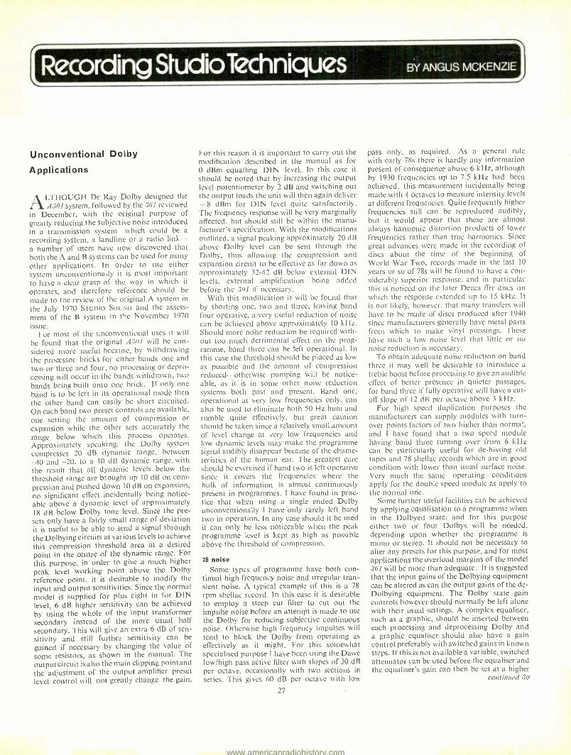
Recording Studio Techniques BY ANGUS MCKENZIE
C
Unconventional Dolby
Applications
ALTHOUGH Dr Ray Dolby designed the A301 system, followed by the 361 reviewed
in December, with the original purpose of greatly reducing the subjective noise introduced in a transmission system -which could be a recording system, a landline or a radio link - a number of users have now discovered that both the A and B systems can be used for many other applications. In order to use either system unconventionally it is most important to have a clear grasp of the way in which it
operates, and therefore reference should be
made to the review of the original A system in
the July 1970 STUDIO SOUND and the assess- ment of the B system in the November 1970
issue. For most of the unconventional uses it will
be found that the original A301 will be con- sidered more useful because, by withdrawing the processor bricks for either bands one and two or three and four, no processing or depro- cessing will occur in the bands withdrawn, two bands being built onto one brick. If only one band is to be left in its operational mode then the other band can easily be short circuited. On each band two preset controls are available, one setting the amount of compression or expansion while the other sets accurately the range below which this process operates. Approximately speaking, the Dolby system compresses 20 dB dynamic range, between -40 and -20, to a 10 dB dynamic range, with the result that all dynamic levels below the threshold range are brought up 10 dB on com- pression and pushed down 10 dB on expansion, no significant effect incidentally being notice- able above a dynamic level of approximately 18 dB below Dolby tone level. Since the pre- sets only have a fairly small range of deviation it is useful to be able to send a signal through the Dolbying circuits at various levels to achieve this compression threshold area at a desired point in the centre of the dynamic range. For this purpose, in order to give a much higher peak level working point above the Dolby reference point, it is desirable to modify the input and output sensitivities. Since the normal model is supplied for plus eight in for DIN level, 6 dB higher sensitivity can be achieved by using the whole of the input transformer secondary instead of the more usual half secondary. This will give an extra 6 dB of sen- sitivity and still further sensitivity can be gained if necessary by changing the value of some resistors, as shown in the manual. The output circuit is also the main clipping point and the adjustment of the output amplifier preset level control will not greatly change the gain.
For this reason it is important to carry out the modification described in the manual as for 0 dBm equalling DIN level. In this case it
should be noted that by increasing the output level potentiometer by 2 dB and switching out the output loads the unit will then again deliver +8 dBm for DIN level quite satisfactorily. The frequency response will be very marginally affected, but should still be within the manu- facturer's specification. With the modifications outlined, a signal peaking approximately 20 dB above Dolby level can be sent through the Dolby, thus allowing the compression and expansion circuit to be effective as far down as approximately 32 -42 dB below external DIN levels, external amplification being added before the 301 if necessary.
With this modification it will be found that by shorting one, two and three, leaving band four operative, a very useful reduction of noise can be achieved above approximately 10 kHz. Should more noise reduction be required with- out too much detrimental effect on the prog- ramme, band three can be left operational. In this case the threshold should be placed as low as possible and the amount of compression reduced -otherwise pumping will be notice- able, as it is in some other noise reduction systems both past and present. Band one, operational at very low frequencies only, can also be used to eliminate both 50 Hz hum and rumble quite effectively, but great caution should be taken since a relatively small amount of level change at very low frequencies and low dynamic levels may make the programme signal audibly disappear because of the charac- teristics of the human ear. The greatest care should be exercised if band two is left operative since it covers the frequencies where the bulk of information is almost continuously present in programmes. I have found in prac- tice that when using a single ended Dolby unconventionally I have only rarely left band two in operation. In any case should it be used it can only be less noticeable when the peak programme level is kept as high as possible above the threshold of compression.
78 noise Some types of programme have both con-
tinual high frequency noise and irregular tran- sient noise. A typical example of this is a 78
rpm shellac record. In this case it is desirable to employ a steep cut filter to cut out the impulse noise before an attempt is made to use the Dolby for reducing subjective continuous noise. Otherwise high frequency impulses will tend to block the Dolby from operating as effectively as it might. For this somewhat specialised purpose I have been using the Dawe low /high pass active filter with slopes of 30 dB per octave, occasionally with two sections in series. This gives 60 dB per octave with low
27
pass only, as required. As a general rule with early 78s there is hardly any information present of consequence above 6 kHz, although by 1930 frequencies up to 7.5 kHz had been achieved, this measurement incidentally being made with octaves to measure intensity levels at different frequencies. Quite frequently higher frequencies still can be reproduced audibly, but it would appear that these are almost always harmonic distortion products of lower frequencies rather than true harmonics. Since great advances were made in the recording of discs about the time of the beginning of World War Two, records made in the last 10
years or so of 78s will be found to have a con- siderably superior response, and in particular this is noticed on the later Decca ffrr discs on which the response extended up to 15 kHz. It is not likely, however, that many transfers will have to be made of discs produced after 1940 since manufacturers generally have metal parts from which to make vinyl pressings. These have such a low noise level that little or no noise reduction is necessary.
To obtain adequate noise reduction on band three it may well be desirable to introduce a treble boost before processing to give an audible effect of better presence in quieter passages, for band three if fully operative will have a cut- off slope of 12 dB per octave above 3 kHz.
For high speed duplication purposes the manufacturers can supply modules with turn- over points factors of two higher than normal, and I have found that a two speed module having band three turning over from 6 kHz can be particularly useful for de- hissing old tapes and 78 shellac records which are in good condition with lower than usual surface noise. Very much the same operating conditions apply for the double speed module as apply to the normal one.
Some further useful facilities can be achieved by applying equalisation to a programme when in the Dolbyed state, and for this purpose either two or four Dolbys will be needed, depending upon whether the programme is mono or stereo. It should not be necessary to alter any presets for this purpose, and for most applications the overload margins of the model 361 will be more than adequate. It is suggested that the input gains of the Dolbying equipment can be altered as can the output gains of the de- Dolbying equipment. The Dolby state gain controls however should normally be left alone with their usual settings. A complex equaliser, such as a graphic, should be inserted between each processing and deprocessing Dolby and a graphic equaliser should also have a gain control preferably with switched gains in known steps. If this is not available a variable, switched attenuator can be used before the equaliser and the equaliser's gain can then be set at a higher
continued 30
www.americanradiohistory.com
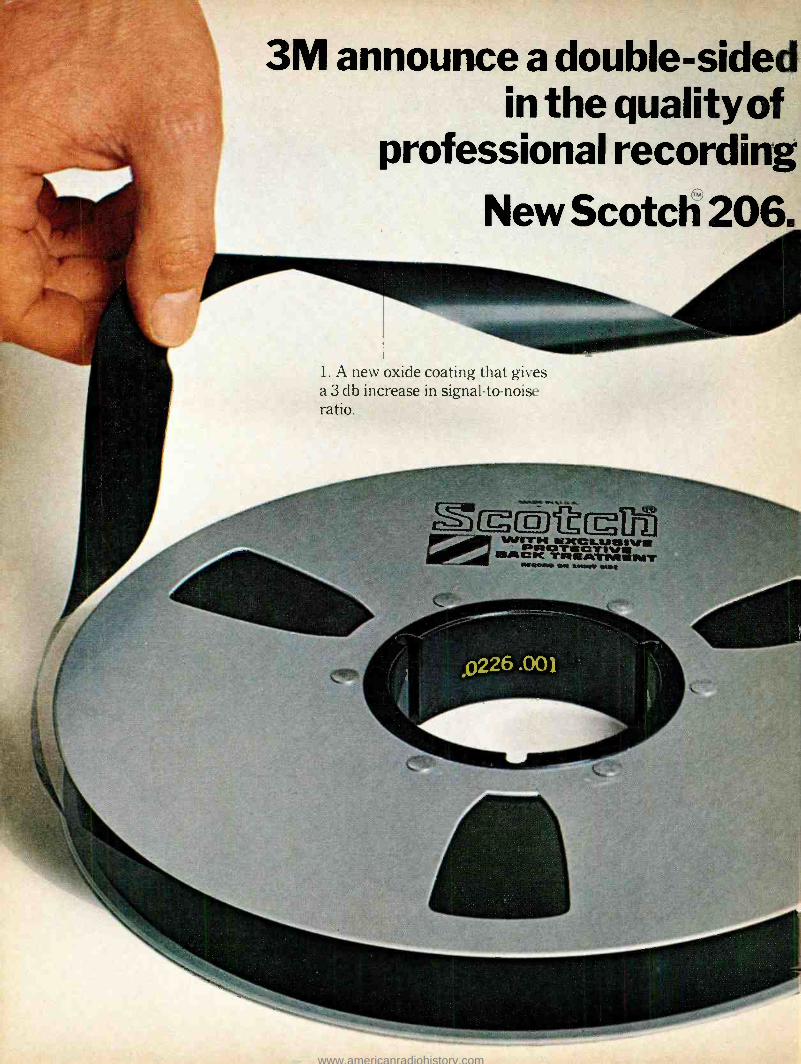
3M announce a double -sided in the quality of
professional recording New Scotch 206.
1. A new oxide coating that gives a 3 db increase in signal -to -noise ratio.
Org(P-J-t[g U J wu7rrs 'CC a.anelvs 113I" NC TRÁTMNT
/tááMñl OM **WY', M#i
www.americanradiohistory.com

mprovement
.ape.
2. A new matt back coating which ensures better handling and reduces head wear.
The unique back coating gives Scotch 206 tape a more even wind. Compare it yourself with the ordinary tape on the right, above.
3M have been at the forefront of recording tape development for many years. Now they offer a new dimension in recording perfection with their new Scotch 206 professional tape.
This remarkable product is the result of technological breakthroughs in the coatings on the recording and backing surfaces.
1. A new oxide recording surface After several years of laboratory research
3M have developed a proprietary oxide which makes possible a 3 db increase in signal -to -noise ratio. This means you have the latitude to capture the extremes of frequency and output without sacrificing any pure sound quality.
+10 No 206
J`rJ
Premium Low Noise Tape
-50
-60
.11 ra., \ere.
Premium Low Noise No 206 Tape
Erased Norse Output by di/7 Octanes
1 I I I I I II I 1 1 1
100 300 500 1K OK 5K 10K 15K
FREOUENCY,H.
DYNAMIC RANGE; Recording at 15 ips.
No 206 and Premium Low Noise
Scotch 206 tape also considerably reduces accumulated noise on multitrack recordings - a major problem up to now.
It is also very tough. resists scratching and prevents drop outs caused by tape debris.
2. A new matt back coating The new back coating improves the tape's
handling characteristics, prevents slipping and ensures more uniform xvinding.
It also helps to guide the tape more accurately across the recording heads, reducing expensive head wear.
The backing is tougher, more scratch - resistant than its rivals. And since it is electrically conductive, dust and dirt are not attracted and held to it.
Scotch 206 tape is compatible with any professional recording system and is available in ; "" '. 1, and 2" widths.
For further details fill in the coupon below.
r-To: Mr. R. Haworth, Magnetic Products, 3 \1 l'nited Kingdom Limited, :3\1 House, \Vigniore Street, London, \\'1A 1IsT.
Please send me further details about Scotch 206 professional recording tape.
Name Position Address
3m www.americanradiohistory.com

RECORDING STUDIO TECHNIQUES
continued
level. Preferably the switchable gain control should be set to 6 dB loss with the equaliser gain brought up so that Dolby level remains constant through the system at these settings. A further equaliser can then be inserted in the chain after deprocessing to make up losses or gains introduced in the Dolbyed state. This type of system in fact works conversely to the way that one might think. If it is required to subjectively reduce noise in a system, keeping brilliance in the middle of the dynamic range, it will be necessary to boost upper, middle and high frequencies in the Dolbyed state and cut them down afterwards. In this way the hiss level will remain the same, as will high energy sounds, but lower intensity high frequencies will come up in level and tend, subjectively, to mask hiss. Since this process can make a pro- gramme sound more toppy further top cut can be introduced after de- Dolbying to cut both hiss and brilliance. Conversely an overbright and perhaps close miked tape can be made to sound more backward if treble cut is introduced in the Dolbyed state. In this case treble boost will become necessary after deprocessing.
A few measurements may be found useful here and as a rough guide a reduction of level of x dB, using a graphic equaliser, in the dynamic range from 20 dB below Dolby level to approximately 34 dB below Dolby level will be found to give a reduction of 2x dB in the same range when x is smaller than 10 dB. The effect then is to shift down in range, by a con- siderable amount, frequencies which are attenuated by a small amount. If they are then boosted by further deprocessing the shift remaining will be approximately the amount of shift introduced in the Dolbyed state, whereas frequencies outside the compression threshold range will not be materially affected. For treble boosting the converse effect will be noticeable from dynamic range levels of -40 to -24 dB. Levels near the edges of compres- sion thresholds incidentally are of course changed by a smaller amount. Above 10 kHz a change of approximately 3x will be noted because of the extra processing of band four.
It will be seen from the above that an incor- rectly response- aligned tape recorder, or one that is out of azimuth, can produce noticeable effects in the alteration of dynamic levels on a programme at frequencies where there is a deviation from flat response. It is probably badly aligned tape recorders that are respon- sible for some engineers claiming that they can
hear Dolbys operating, or alternatively claim- ing that they affect sound quality. I find myself that an error of 2 dB in Dolby level is almost undetectable, but an error in tape response of 2 dB is just noticeable, more so when there is a loss of high frequencies rather than a gain, although theoretically either should be equally noticeable. This error would also explain the unusual dullness in some foreign tapes which are being transferred to disc in this country, especially if they are played back with the wrong equalisation. For example an NAB Dolbyed tape played back on a DIN machine at 38 cm /s will sound very dull, and vice versa.
The Dolby B system also has uses in addition to being used as for the A system. In general the use of a single Dolby B deprocessor will reduce treble at too low a frequency to give useful noise reduction without affecting the programme. Using them back to back, how- ever, with similar techniques to those for the A system, can be useful. A more interesting use for the B system is in the improvement of intelligibility of speech over transmission systems which have very poor noise levels or high interference. A Dolby B processor intro- duced into the line feed circuit of a medium or short wave transmitter will give far more punch to the programme than any amount of treble boosting and limiting such as I under- stand is being used by Radio Sweden. Experi- ments along these lines were first made by Austrian Radio, and later, fairly recently, by myself for amateur short wave communication. I found a gain of between one and two s points (an s point equalling approximately 4 -6 dB in radio amateur parlance), the gain being particularly useful when my transmission was subject to interference from adjacent trans- missions or was subject to flutter in poor atmospheric conditions. Having often tried to receive the BBC medium wave services abroad, frequently with difficulty when over 720 km from the English coast, I feel that experiments could begin with advantage with Dolby type processing on broadcasts of speech, particularly news broadcasts. So often a transmission has a wide frequency response but the receiver, using a ceramic filter, rather a narrow one. The use of a Dolby B processor would therefore emphasise intelligibility of consonants, which concentrate their main energy between 1 and 4 kHz. Vowel sounds, incidentally, should not be affected for they are at lower frequencies.
Although the Dolby B is most effective when used, in the processing mode only, for AM broadcasting, the Dolby A system can also be used nevertheless, but probably only channel
three should be left operational. For FM broad- casting, the Dolby B system is currently being used by over a dozen American stations trans- mitting a substantial quantity of programmes in the Dolby B state. Listeners who have Dolby B deprocessing equipment have been astonished at the improvement in subjective distortion and lower hiss levels. Fringe area reception of stereo under these circumstances can be very greatly improved, and the transmitter can have a useable service area of up to 10 times greater than normal. For example, a low power local radio station normally covering 100 km2 could, if they Dolby their transmission and their listeners have Dolbys for deprocessing, achieve a 1,000 km= coverage, provided listeners who would normally be outside the fringe area provide themselves with good aerial systems. The same effect could only be achieved by the radio station by increasing their effective radiated power by 10 times, giving 10 dB more signal.
From experiments that I have been carrying out at length over some months I have come to the conclusion that there should be a demand for a stereo playback only Dolby which has normal and special switching to allow the unit to be used at the turn of a switch for playing back normal Dolbyed tapes or for noise reducing tapes. In which case I would propose that controls could be made available having a considerably wider range than the presets in the 301. It would be useful to be able to set the threshold of operation as low as 50 dB below Dolby level, and possibly to have a greater amount of expansion available. It should not be at all difficult to make such a model, and it is possible that should there be sufficient demand the manufacturers could consider such a project. To noise reduce a programme really effectively, however, at least 10, and possibly as many as 25, separate bands are really desirable, the normal Dolby A system band overlapping for roll -offs of only 12 dB per octave. It should be quite simple to make octave circuits with the minimum of components giving 18 or even 24 dB per octave roll -offs, and although such a piece of equipment may at first appear unworkable I am personally con- vinced that it could be fairly easily built and could solve many difficult problems that beset recording engineers today. With 25 bands available to him and with thresholds set at lower levels it might be possible to gain a full 10 dB of noise reduction on old tapes with the minimum of audible effect. Pumping would be almost unnoticeable with this large number of bands, and perhaps such a system may be performing miracles for old tapes in a few years time.
NEWS
continued
EMS appoint UK agent
UK SALES OF Electronic Music Studios Ltd synthesisers will in future be handled by Phasor Electronics, 19 Dollis Avenue, Finchley, London N3 (Tel. 01 -349 1806). This newly- formed company is equipped to demonstrate,
sell or supply on hire any of the EMS range of systems, including the comparatively large Synthi 100.
AES European Convention
A LIST OF companies exhibiting at the second AES European Convention has been supplied to us by the Central European Secretary, Herman A. O. Wilms. As stated in our Febru-
30
ary issue, the exhibition opens in Munich on March 14 at the Holiday Inn Hotel. Exhibitors will comprise AEG- Telefunken, Echolette - Vertrieb Hans Bauer, Kudelski (Austerlitz Electronic), Beyer, Helios Electronics, Sansui, Spectrasound, AKG, Staar SA, N. Tq,nnes Pedersen A /S, Klein & Hummel, Neumann, Ortofon, EMT, Philips, Rupert Neve, Studer Franz, Dolby Laboratories, GTC Peter Wolfert, Nortronic A /S, Spectra Sonics, Schlumberger, Bruel & Kjaer, Elko and Schalltechn i k ISchoeps.
www.americanradiohistory.com

[Around the Studios BY KEITH WICKS
Theatre Projects
IN 1958, Richard Pilbrow established Theatre Projects as a firm of lighting designers. It
has since expanded into a group of companies embracing all the technical aspects of theatre, including sound. David Collison, managing director of Theatre Projects Sound, is responsi- ble for the running of the studio. He explained to me how he joined the firm and how the studio came into being. DC In 1959, Richard Pilbrow was at the Lyric Theatre, Hammersmith, lightirg his first big season of shows. I was doing the sound using a
borrowed Ferrograph and a portable Decca gramophone. Before that, there had not been
such a thing as a sound consultant in the theatre. I joined forces with Richard later the same year, and started recording sound effects. Effects were
available from various libraries, but they were
not particularly good because people recorded them just for the library and were not involved in what the production company were doing. You could get the dog bark, or the car starting, but the sound didn't necessarily match up with the action.
When we started recording sound effects, the
idea was to give a personal service. We would read the script, go to rehearsals, talk to produ- cers, and in that way become part of what was
going on. Nobody had done that before. At that time, we had to hire a studio when we wanted to
record a crowd or a piece of music, but by the mid 60's we had built what we called The Hutch, a small basement studio which we made from timber. It really was quite grotty, but we had Sir Laurence Olivier, Bernard Miles and all sorts of people down there.
In 1968 we built a new studio, designed in conjunction with Theatre Projects Consultancy. We had some builders in to do the brickwork and we did the rest ourselves, taking around nine months to complete the project and spending around £20,000. The original plan was to do recording for the theatre using a relatively cheap mixing desk, but there were so many facilities we needed that we ended up with a fully profes- sional desk. Then we thought that we might as
well get a studio engineer in to do other work. Michael Moor, who was second engineer at Radio Luxembourg Studios, came to work for us, and the studio business started to expand. We started off with two track equipment, but our customers started asking for four track, so
we organised it. Our desk was built by Electrosonic. We had
specified a desk and approached three firms including Neve, who were quite expensive. To save money, we ended up designing a lot of it ourselves and doing a lot of development work with Electrosonic engineers as it was the first sound control desk they had built. Fortunately, it had four main output groups, so was readily adaptable to four track working. By the time
Andy Cole (centre) at the Theatre Projects desk.
we had installed four track in 1969, our customers said: 'Thank God you've got it at last, but what we really need is eight track'. So we are now in the process of going eight track. KW I am surprised you didn't go straight to 16 track. DC Well, we are only a small studio. We can
get a dozen musicians in quite happily, hut we
could never accommodate an orchestra. A lot of people like the sound here so they come in to do four track demos, then go off to Olympic or Trident to do the master. For the small groups, four track is not enough, but eight track is.
Eight track facilities are cheaper than 16 track, and the reduction time is less.
Considering that we started off from scratch, with hardly any money, the studio has been extremely successful, although at the beginning
Percussion booth.
3 I
I suppose we were very green, because we got caught out a number of times. When we opened. we advertised in the musical press. In the first two months, at least half a dozen people came to us and said: ' You've got the studio, I've got the talent. Together we can really go places.' Being new to the gaine, we were quite interested in
some kind of .10/50 deal like this. The artists bring either a tape or the group into the studio and, when it's all new to you, you think it's fabulous. The next thing is that you have got two 1ps made, nobody wants to buy them, and the group's manager disappears. We found out about that pretty quickly but we still get people trying it on. KW I suppose you just might be turning away someone who could make you both a fortune. DC Well, this is it, you see. There is a certain singer who writes his own material, and used to work with Mike Moor at the Luxembourg studios. He came to us and said that he woc .'d like to make an 1p, but couldn't pay for it, although he had somebody to back him in the promotions. Mike thought that he was very talented, so we decided that it was worth a go. We made the whole 1p, but having been bitten before we kept the master tape, and gave him a 19 cm /s copy to play to prospective buyers. We
didn't hear anything for a long time, until ive
found that Philips had issued one of the titles that we had recorded. We actually went out and bought the record -paid good money for it-and it's our recording, made from the 19 cm /s copy.
And we still can't get the money. Philips say: 'Very interesting, hut we bought a tape from this gentleman in all good faith, so it's nothing to do with us'.
There is also a production company who, in the last year, have had a number one in the charts as well as several runners -up. They did a
lot of work with us when we were starting up,
and although they are now supposed to be very
rich people, they still owe us about £800, and it's impossible to get it out of them.
You get a lot of groups who, when they see an
advertisement for a new studio, go along to see
what they can get away with. Sometimes, they come in to do a session with a reputable publish- ing company, and there is no problem. The
session is paid for but, a few weeks later, we get a phone call booking in the same group for the same company. In comes the group and, as we
know them, we do the session and send in the bill to the production company. The company then get in touch with us and say: `What's all this? We didn't authorise this session.' It's terrible getting caught out in this way. I think this must happen a lot because several publishing companies have written to us saying they will not pay for anything that has not been confirmed in writing. So now we know. We started off
continued .33
www.americanradiohistory.com
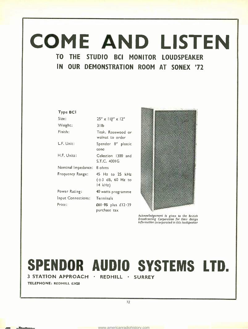
COME AND LISTEN TO THE STUDIO BCI MONITOR LOUDSPEAKER
IN OUR DEMONSTRATION ROOM AT SONEX '72
Type BC I
Size:
Weight:
Finish:
L.F. Unit:
H.F. Units:
Nominal Impedance:
Frequency Range:
Power Rating:
Input Connections:
Price:
25"x Ili" x12" 311b
Teak. Rosewood or walnut to order
Spendor 8" plastic cone
Celestion 1300 and
S.T.C. 4001 G
8 ohms
45 Hz to 25 kHz (H -3 dB, 60 Hz to 14 kHz)
40 watts programme
Terminals
£61.95 plus £12.39 purchase tax
Acknowledgement is given to the British Broadcasting Corporation for their design information incorporated in this loudspeaker
SPENDOR AUDIO SYSTEMS LTD. 3 STATION APPROACH REDHILL SURREY TELEPHONE: REDHILL 63428
32
www.americanradiohistory.com

AROUND THE STUDIOS
continued
doing theatre work, and not realising what we
were letting ourselves in for when we began
doing pop, commercials, jingles, and that sort of thing. KW Have you had many problems with equipment? DC In our sound effects dubbing room, we have
got three new Brenell professional tape decks. Tony Horder, who runs that department, has
been having certain teething problems with them.
Snatch on take -up, flap, that sort of thing. Tensions that are wrong, and pressure pads that are so vicious they wear out the heads.
KW I am surprised that a `professional' machine has pressure pads. TH So were we. They showed us the alleged prototype of this model, and that did not have
pressure pads. KW I suppose they said that pads make the machine even better than it was before. TH They haven't commented on that at all. KW It sounds as if they haven't got enough tension there. TH They haven't got enough torque. We did ask them to put on four heads instead of three. This may have led them into trouble but they reckoned they could do it. DC I gather they have altered the design since
this one but it's only six months old. However, we get a good recording from it; there is no
doubt about that. KW Do the tension problems occur just near the end of a reel? DC Yes. And if, when you are editing, you lace
up the machine the easiest way, it just doesn't take up. They say that we should lace it properly but really that is not good enough. Also, if you wind back without the hub screw in place, you get enough static build-up on the spool to send
you across the room. The spools fit on to plastic hub adaptors which are insulating, and allow the
static to build up. We do a lot of editing in here, and can't keep putting the hub lock on.
Vertically mounted Brenells and horizontal Leevers -Rich, all with Richardson circuitry.
KW If you scribble on the plastic with a graphite pencil it may solve the problem, but it is not the sort of thing you expect to have to do on a professional machine. DC On the other hand, the electronics for these
machines are extremely good, and are by Richardson. KW Can't Brenell build amplifiers? DC When we got these decks, they did not have the electronics available for them. They were
talking about supplying the electronics, but I don't know if they do it yet. KW Who built the dubbing room? It looks remarkably like a BBC technical area because of the grey panels, Post Office jackfields, and the ppms. DC Yes. Our consulting department who
designed this area are ex -BBC staff. KW You also have ppms in the control room, which is rather unusual in a recording studio. DC 1 don't really want to enter into that, it's just that they are quicker than vus, and you can
see what is actually happening. When Mike Moor arrived, we had already ordered the desk.
He said: `Oh dear, I don't like that. You can't possibly do pop sessions with them.' He is now converted, and wouldn't like to use vu meters.
KW Yes. I think it is good to be able to see the peak levels. That is what tape recording is
all about. DC As for aural monitoring, at the moment we
are using Goodman Magnums in the dubbing room. These are entirely adequate for sound effects but, when we start to do studio dubbing in here, we'll put in a monitoring system compatible with the one in the studio. There, we
were until recently using Tannoy Golds, housed in Lockwood cabinets, and driven by Quad amplifiers. Now we are going eight track, so
we have to be able to get four speakers in the
control room. The Lockwoods are too large. We started listening to smaller speakers and
found that there was nothing to compare with the Klein & Hummel O Y monitors. We had four or five different speakers down here, and found that the Klein & Humrnels were much
better than the rest. In fact, we think they are much better than the Monitor Golds we've got. TH They sound quite incredible. If you heard them without seeing them, you wouldn't believe it was possible -they are only about 980 x 300
x 230 mm. DC They are imported by Bauch, and cost
around £200 each. That is rather a lot, but they are very good, and contain two 30W amplifiers; one for the low frequencies, and one for the mid to high frequencies. KW I must admit that when i heard these speakers in your control room, I found it very difficult to believe that such good quality can be obtained from such small speakers. In fact, I had to put my hand in front of the Lockwoods to reassure myself that they were not switched on, because the sound was of the standard one always associates with much larger speakers than the Klein & Hummels. Obviously, these are the ideal speakers for your control room but why do you consider it essential to have four monitors? Some studios prefer to use just two monitors so that they have a much better idea of what the final reduction will sound like. DC Well, we didn't want to do this. Mike and various producers we work with feel that you can't do four track on two speakers, so we're getting four.
33
Suzy Cole in the vocal booth.
KW What proportion of the work you do no'. is for the theatre? DC Probably less than a quarter. Originally. most of our work was for the theatre but now it is mostly pop. That is why we are expanding. Our new eight track deck, like the four track, is
by Leevers -Rich, with electronics by Richardson. We use Leevers Rich because they were the only people who could supply us rvitli just a deck at a reasonable price. We are also installing an EMT plate. We have for some time been using a plate we bought from Star Sound Studios, which was built by their own engineers, and is pretty successful.
Above the control room is a projection room, and we have facilities for recording on to sep
mag machines. We have five 16 nun recorders and one 35 mm, but the latter is just used for dubbing as we don't have 35 mm projection facilities.
The studio, cubicle, projection rooms and lobby are discontinuous structures, and because we
have a lighting store upstairs, with very heavy equipment being moved around, the ceiling has four tons of sand in it. By using sand, we got the mass we wanted without having to put in concrete. We put the sand in by hand, using shovels, and although it weighs four tons, the layer is only 25 mm thick. incredible. We have one very dead area in the studio, and in other parts curtains on the walls allow the acoustics to be varied. KW Looking at your rate card, your terms and conditions seem most reasonable. Cancellation within 24 hours is only 25 per cent of the booking, whereas it is 100 per cent at many studios. Another thing I like is the fact that you invite clients to use the studio for playbacks free of charge when it is not booked for record- ing. You are probably the only studio to do this. Your track recording is £12 per hour,
continued 41
www.americanradiohistory.com
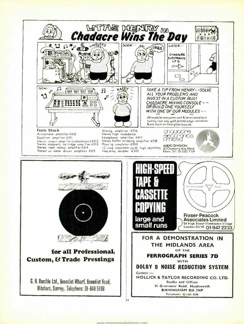
40 44
'W4VNiR HENRY Chadacre Wigs The .Day
SED 5ooN-.
From Stock Microphone amplifier 4310 Equalizer amplifier 4311 Stereo output amplifier (unbalanced) 4312 Stereo magnetic cartridge amplifier4313 Stereo tape replay amplifier 4314 Stereo vu meter driver amplifier 4315
TAKE A TIP FROM HENRY- -SOLVE Al L YOUR PROBLEMS AND INVEST IN CUSTOM BUILT CHADACRE MIXING CONSOLE - - OR BUILD ONE YOURSELF WITH ONE OF OUR MODULES - -
All modules are polarised & terminated by a twenty two way gold plated edge connector &are built on fibre glass boards.
Mixing amplifier 4316 anaaaare Stereo high impedance i5 headphone amplifier 4317
L(mG Stereo buffer bridging amplifier 4318 Phasing simulator 4300 AUDIO DIVISION I.C. ring modulator (with high rejection) 43ChadacreAve,1lford frequency doubler 6301 Essex. Tel: 01 550 7119
for all Professional, Custom, f3 Trade Pressings
C. H. Rumble Ltd., Benedict Wharf, Benedict Road,
Mitcham, Surrey. Telephone: 01 -648 5106
1-1
HIGOSPEED
TAPE U
CASSETTE
COPYING large and small runs
Fraser- Peacock
7 Associates Limited 94 High Street Wimbledon Village London SW 19 01.947 2233j
FOR A DEMONSTRATION IN THE MIDLANDS AREA
OF THE
FERROGRAPH SERIES 7D WITH
DOLBY B NOISE REDUCTION SYSTEM Contact :- HOLLICK & TAYLOR RECORDING CO. LTD.
Studio and Offices 16 Grosvenor Road, Handsworth
BIRMINGHAM B20 3NP Telephone: 021 -356 4246
www.americanradiohistory.com
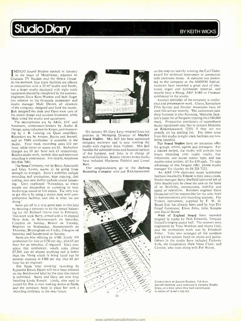
studio Diary BY KEITH WICKS
ND1GO Sound Studios opened in January in the heart of Manchester, adjacent to
Granada TV Studios and the Opera House. At the moment, four track facilities are offered in conjunction with a 35 m2 studio and booth, but a larger studio equipped with eight track equipment should be completed by the summer. Engineers Dave Kent -Watson and Bob Auger (no relation to his Granada namesake) and studio manager Malc Davies, all directors of the company, designed and built the studio. Bob designed the desk and Dave took care of the studio design and acoustic treatment, while Malc wired the studio and equipment.
The microphones are by AKG, STC and Neumann, compressor /limiters by Audio & Design, noise reduction by Kepex, and monitor- ing by J. B. Lansing via Quad amplifiers. Recorders are by Ampex, Revox and Brenell, and an EMS synthesiser is available in the studio. Four track recording costs £12 per hour, while stereo or mono are £6. Reduction charges are £8 per hour and £3 respectively. Besides studio work, mobile, film and television recording is undertaken. For details, telephone 061 -834 7001.
The Sann Company, run by Barry Ainsworth and Gary Lyons, seems to be going from strength to strength. Sarm's activities include recording and production, tape copying, disc cutting, and now public address sound balanc- ing. Gary explained: `Nowadays, so many people are demanding or expecting to hear studio -type sound at live shows. The only way to get this is by using a studio desk with com- prehensive facilities and this is what we are doing.'
Sarm got off to a very good start in this field by securing a contract to do the sound balanc- ing for the Richard Harris tour in February. This work took Barry, armed with a 16 channel Neve desk, to Bournemouth on Saturday, Croydon on Sunday, Bristol on Tuesday, Brighton on Wednesday, Hammersmith on Thursday, Birmingham on Friday, Glasgow on Saturday and Sunderland on Sunday.
Sarm are now offering an EMS Synthi 100 synthesiser for hire at £150 per day, plus £5 per hour for an operator, if required. Gary con- siders this synthesiser, which costs about £7,500, can do almost anything and is better than the Moog which is being hired out by another concern at £300 per day plus £8 per hour for an engineer.
The Sarm `stop smoking' recording by hypnotist Edwin Heath will have been released on the Beechwood label by the time this report is published. Barry and Gary are now busy handling Linda Russell. Linda, who used to record for Pye, is now making demos at Sarm, and the company hope to place her with a recording company in the near future.
On January 19, Gary Levy resigned from his position as Managing Director of Mayfair Sound Studios. Mrs Bell has been appointed company secretary and is now running the studio with engineer John Hudson. Mrs Bell handles the administration and financial aspects of the business, and John is in charge of technical facilities. Recent visitors to the studio have included Marianne Faithful and Lionel Bart.
Our congratulations go to the Jackson Recording Company who put Rickmansworth
35
on the map (at last) by winning the Carl Fisher award for technical innovation in connection with electronic music. A statuette was presen- ted to the company at the MIDEM festival. Jacksons have recorded a great deal of elec- tronic organ and synthesiser material, and usually have a Moog, ARP, EMS or Freeman synthesiser in the studio.
Another speciality of the company is confer- ence and presentation work. Glaxo, Samuelson Film Service and Sinclair Associates have all used this service recently. The Jacksonian junk shop business is also booming, Malcolm Jack- son's latest list of bargains topping the £100,000 mark. Prospective purchasers of secondhand studio equipment may like to contact Malcolm on Rickmansworth 72351 if they are not already on his mailing list. The latest news from this studio is eight track facilities are now being installed.
Pan Sound Studios have an attractive offer for groups, artists, agents and managers. For a limited period, the studio will provide two hours recording time (eight track), free reductions, one stereo master tape, and one double -sided acetate, all for £30 cash. To take advantage of this bargain offer, phone studio manager Vic Hawley on 01 -328 7222.
An ARP 2500 electronic music synthesiser has been installed by Trident in their remix room. Studio manager Barry Sheffield (pictured left of John Bauch) said he chose the unit on the basis of its flexibility, compactness, stability and speed of operation. Resident engineer Dave Hentschel will be responsible for the unit, both in demonstrations and recording sessions. The Trident instrument, supplied by F. W. O. Bauch Ltd, has already been used by Van Der Graaf Generator, Elton John, John Kongos and David Bowie.
West of England Sound have recorded original Ip tracks by Dick Edwards, Torquay United's singing centre half. The sessions were engineered by Tony Waldron and Harry Hall, and the production work was by Elizabeth Usher. Tony also arranged all the numbers and led the session band on piano and guitar. Others in the studio have included Faraway Folk, the Gospelaires Male Voice Choir, and Carrion, who went along with Fat Worm.
Control desk at Garrett Studios, Tel Aviv. Garrett facilities were outlined in January Studio Diary, at a time when they had contributed to seven of Israel's top ten.
www.americanradiohistory.com
LIMITER TYPE 704
SF 704 0> 1
INPUT GAIN RELEASE
THRESH
CONTROL
EXT.
10 DB
SLAVE THRESHOLD
POWER
SPECIFICATION
INPUT
OUTPUT
MAX ¡O /P
NOISE DISTORTION (at 500 Hz) RESPONSE
RATIO THRESHOLD
10K balanced and floating, 0 dBm to -IS dBm by 3 dB steps. I ohm source unbalanced. 0 dBm into 600 ohm or higher (40 ohm balanced also available.) +20 dBm into 600 ohm. -80 dBm 0.03,0 residual. Less than 0.1% operating.
20 Hz to 20 kHz ±0.3 dB. 8 nominal. +4 dBm to + 12 dBm by 2 dB steps, and off.
ATTACK RELEASE
INDICATORS
5 mS.
0.1, 0.2, 0.5, 1, 2 secs. and auto. Lamps at threshold and at 10 dB gain reduction
Change -over switches provide for independent or slave working and for internal or external drive to the side chain. TERMINATIONS By screw terminations -Cannon XLR series con-
nectors can be supplied on request.
POWER SUPPLY 110- 120/220 -240 volts. 50 -60 Hz.
DIMENSIONS Two unit standard P.O. dimensions. 3¡," (89 mm) high x 19" (483 mm) wide.
Facia Panel: Satin anodised extruded aluminium with engraved control indicators.
FINISH
I a LI X SOUND S ANIS ESSEX D
SYSTEMS(STD
02NSDT'D 31323437
FRANCIS OF STREATHAM DECKS WITH PRE -AMPS
(Microphone extra) Akai 8 Tr. Cartridge CR.800 Akai 4000D Stereo Brenell Mk.6 Stereo Ferrograph 702'4 Philips N.4500 3 sp. 4 Tr. Stereo Revox 1102;4 2 sp. Stereo Sharp RD 712D 3 sp. 4 Tr. Stereo Sony 366D 3 sp. 4 Tr. Stereo Sony 630D 3 sp. 4 Tr. Stereo Sony 266D 3 sp. 4 Tr. Stereo Sony 255 Stereo Tandberg 1800 4 Tr. Stereo Tandberg 3000X 3 sp. 2/4 Tr. Stereo Tandberg 6000X 3 sp. 2/4 Tr. Stereo Telefunken 205 3 sp. 4 Tr. Stereo Telefunken 203 Studio
KELLAR BLACK BOX Dolby Unit
MAINS SPOOL RECORDERS *Akai 1710L 2 sp. 4 Tr. Stereo *Akai 4000 3 sp. 4 Tr. Stereo *Brenell Mk. 6 *Ferrograph 713 Ferrograph 722/4 Grundig 141 4 Tr. Mono Grundig TK.121 2 Tr. Mono Grundig 146 4 Tr. Mono Auto. * Grundig TK248 2 sp. 4 Tr. Stereo Philips 4307 4 Tr. Single Speed Mono Philips 4308 2 sp. 4 Tr. Mono Philips Stereo 4404 2 sp. 4 Tr. Philips 4407 3 sp. 4 Tr. Stereo ' Revox 1222/4 Stereo Sharp 708 3 sp. 4 Tr. Stereo Sharp 71 13 sp. 4 Tr. Stereo Sony 630 3 sp. 2/4 Tr. Sony 540 3 sp. 4 Tr. Stereo Sony 252 3 sp. 4 Tr. Stereo *Tandberg IS 2 or 4 Tr. /3 sp. /Mono
*Tandberg 4000 3 sp. 2/4 Tr. Stereo *Telefunken M207 2 sp. 4 Tr. Stereo Telefunken 203 Stereo /Mono 2sp. 4Tr. Telefunken 201 Mono 4 Tr. *Uher 714 4 Tr. Mono *Uher Royal de Luxe 4 Tr. 4 sp. St. *Uher Varicord 263 Stereo *Uher 724 4 Tr. 2 sp. Stereo
MAINS CASSETTE MODELS *Philips RH882 Stereo Tuner /Amp *Sony HST399 Stereo Tuner /Amp Sony TC 330 Stereo Cass./Spool
*Rank Wharfedale Dolby Stereo Philips 2400 Stereo Philips 2401 Autochange w. ski -slope
*Sony TC 127 Deck and Pre -amp *Sony TC 122 Deck and Pre -amp *Philips 2503 Deck and Pre -amp
BATTERY MAINS CASSETTE Philips 2204 Sony TC. 80 Philips 2205 Sony TC. 100 Sony TC. 60 Philips TT 392 with AM /FM Philips RR 290 with AM Sony CF 100 with AM /FM Sony CF 200 with AM /FM
BATTERY CASSETTES Philips EL3302 Philips N2202 Sony TC. 12
Sony TC. 40 Sharp 418 GrundigC.200
BATTERY SPOOL MODELS *Tandberg Series 11-2 Sharp 514 2 Tr. 2 sp. (BM) Sony TC. 800 B 2 Tr. 4 sp. (BM) Telefunken 302 4 Tr. 2 sp. *Uher 4000L 2 Tr. 4 sp. *Uher 4200/4400 4 sp. Stereo
*Microphones extra
FOR A FAIR AND DEPENDABLE DEAL IN
TAPE ami 11141 * NO INTEREST OR SERVICE CHARGES ON H.P. UP TO 18 MONTHS * Free Service during Guarantee period * Fair Part Exchange Allowance on your old Recorder * Reconditioned Recorders available to personal shoppers only
AMPEX TAPE OFFERS (P- Polyester: M- Mylar: A- Acetate) Compact Cassettes C.60 -53p; C.90 -75p; C.120 -EI -O5 (pp 3p each).
LI. 50 LI.OS
88p 75p 63p 88p 63p
7" D.P. 2400ft. (P) ... 7" L.P. 1800ft. (P) ... 51" I.P. 1150ft. (M) ... 51" L.P. I150ft. (A) Sr Standard 8SOft. (A) S" D.P. 1200ft. (P) ... 5" L.P. 900ft. (P) .. 5" Standard 600ft. (P) .. 50p Postage on orders under E3 add 10p, orders over E3 sent post paid U.K. Splicers, Defluxers, Bulk Erasers, Accessories of all kinds.
MIXERS by Uher, Eagle, Sony, Grundig, etc.
MICROPHONES by AKG, Gram- pian, Reslo, Acos, Beyer, Sennheiser, Telefunken, etc. HEADPHONES by AKG, Nikko, Philips, Koss, Eagle, TTC, Beyer, Akai. MUSICASSETTES. All leading makes. Pre -recorded 8 -track car- tridges and tapes. BASF Chromium Dioxide Cassettes. TAPES and CASSETTES by TDK and all leading makes.
111 -FI DEPT. AMPLIFIERS
Quad, Rogers, Arena, Philips, Goodman, Nikko, Armstrong, Leak, Tripletone, Tandberg, Teleton.
TUNERS Quad, Rogers, Leak, Arm- strong, Tripletone, Arena, Nikko, Goodman, Huldra.
LOUDSPEAKERS Quad, Rogers, Kef, Wharfe- dale, Goodman, Tannoy, Lowther, Leak, Tandberg, Arena, Celestion, Kelestron.
MOTORS, PICK -UPS GARRARD inc. S.P.25 Mk. III Goldring BSR Connoisseur Thorens Audiotec Shure Neat Sonotone Acos SME Dual Pickering
Diamond styli, Microlifts, Press ure Gauges, Cleaning Accessories, Cabinets, etc.
169 -173 STREATHAM HIGH ROAD, LONDON, S.W.I6 Between St. Leonard's Church
01 -769 0466: 01-769 0192 and Streatham Station
Please note this is our only address. Free parking Prentis Road, 2 mins away OPEN ALL DAY SATURDAY -CLOSED ALL DAY WEDNESDAY
36
www.americanradiohistory.com

kìiprnuri a F1eUUH EM
Part Two
By Angus McKenzie
IDESCRIBED last month some modifica- tions which will greatly improve the flexi-
bility of the Revox 77. This article describes the lining up procedure which should be employed to achieve the best overall results, a procedure also suitable for unmodified machines.
Before carrying out any adjustments what- soever, the machine should be thoroughly de- magnetised. This is best done by holding a bulk eraser over the tape transport rather than by using the normal small head demagnetiser which may well not have sufficient ac flux. Such demagnetising almost always removes the `bubble' sometimes noticed with this machine when thick oxide standard play tapes are used. The replay amplifier should then be set up with the appropriate test tape. For this adjustment, the replay volume control should be set at maximum, the mode switch to stereo, the balance control to central and the correct equalisation position chosen. The replay preset gain controls should then be adjusted so that the peak level recorded at the beginning of the test tape gives a level at the auxiliary output phono socket of either +8 dBm or +4 dBm depending whether the test tape is DIN standard or Ampex standard operating level. Should a BASF NAB test tape be used, the peak level for some inexplicable reason is 320 pWb /mm and the level for this should there- fore be set to read +8 dBm out. Test tapes produced to the American standard, or Dolby operating level test tapes, have the peak recording level at 185 pWb /mm and should thus be set to give +4 dBm. The reel of tape for which the machine is to be biased and equalised should then be loaded and the machine set to record with the record volume controls at minimum and both record track buttons down.
With the a/b switch in the replay position, the replay bias traps should be adjusted to give a minimum reading across the output sockets. Track Two usually has noticeably worse bias break -through than Track One, this being caused by the position of the printed circuit boards. This can only be improved by screening the bias reject coil with Mumetal (such as Telshield) and is frankly not worth bothering about. All preset adjustments for the replay
traps should be done with the front metal cover screwed on and the cutouts punched through the paper label. If this cover is removed, the bias trap frequency will be changed due to the difference in capacitance.
The record bias traps may be checked by measuring the bias voltage chosen at the output of the record head driver stage (emitter /col- lector junction). The preset should be adjusted for minimum breakthrough at this point. Since I have never found the dummy loads incorrect, these are best left alone. A 10 kHz signal should now be applied to the auxiliary input and the recording level control increased with the a/b switch in the before tape position so that the output is -12 dBm with the replay gain at maximum. The a/b switch should be changed to the after tape position with the required equalisation. The bias should then be adjusted (labelled oscillator) at the appropriate speed. As a rule, the bias should be increased beyond the peak output at 10 kHz such that the output from the tape drops by between 2.5 and 3 dB. The difference in output between 1 kHz and 10
kHz should then be checked to make sure that the tape has been biased over peak rather than under peak at 10 kHz, the position giving the higher reading at 1 kHz being the correct one. After the bias has been set, the record equalisa- tion should be adjusted to give the best overall response and this should be done under the same conditions with, again, an output from the machine of -12 dBm.
Record preset The record preset level control should then
be adjusted so that the same output level is obtained in both positions of the a/b monitor switch. A frequency of 1 kHz should then be applied to give a level of =4 dBm out in the after position of the a/b switch. At this level, the vu meter presets should be adjusted for zero. Both the a/b balance and the vu meter sensitivity should be adjusted at the speed where the calibration is most important since at the other speed an error of up to 2 dB or so may be noticeable, especially if the Revox has been lined up for two different types of tape for the two speeds. A plastic, or metal tipped
37
plastic, screwdriver should be used to adjust the meter sensitivity since a short circuit between the preset and the metal round the adjustment hole will short the ht supply and damage the main regulation power transistor.
As a rough guide, the treble response should be held to within +1 dB at 38 and 19 cm /s and the same tolerance can be achieved for 9.5 on good quality tape up to 17 kHz, although par- ticularly at the latter speed the accuracy of azimuth should be checked before setting up the record amplifier. The replay azimuth should be adjusted after the replay gains have been set with the replay mode switch in mono for the best compromise of accurate azimuth on both tracks. The record azimuth should be set by sending a 10 kHz signal, or better still white noise, such that the same intensity is replayed from each track separately, and at a playback level of not more than -6 dBm out. After adjusting the gains, the replay mode switch should be left in mono for the record head azimuthing.
It is hoped that these articles will encourage readers to improve the standards achieved on their Revox recorders and also facilitate the use of this model more generally in studios. With modifications described last month, the machine's performance approaches that of machines costing many times more, although careful maintenance may well be necessary if the machine is to work hard. As a rule, it will be found that the record and replay heads and the capstan will wear rather faster than would be normal with higher price machines. Wear is noticeable as a groove in the capstan where the tape passes over it. Both head and capstan wear are accelerated by the use of double play tape, which should be avoided for best results.
One final word of warning. My colleague Ren Hunter recently found that, if the machine is in the playback mode and the left hand spooling button lightly knocked by accident, the machine will sometimes go into the record mode. This is quite definitely not a sample fault since five different machines all produce the same result. It is therefore recommended that the record track buttons should be in their off positions when in replay mode.
www.americanradiohistory.com

Vortexion This is a high fidelity amplifier with bass cut controls on each of the three low impedance balanced line microphone stages and a high impedance (1.5 meg.) gram stage with bass and treble controls, plus the usual line or tape input. All the input stages are protected against overload by back to back low self capacity diodes and all use F.E.T's for low noise, low intermodulation distortion and freedom from radio breakthrough.
50/70 WATT ALL SILICON AMPLIFIER WITH BUILT -IN 5 -WAY MIXER USING F.E.T.'s
.Mp. ,VÓr)O:lOw .rEt b.
A voltage stabilised supply is used for the pre -amplifiers making it independent of mains supply fluctuations and another stabilised supply for the driver stages is arranged to cut off when the output is overloaded or over temperature. The output is 75 % efficient and 100 V balanced line or 8 -16 ohms output are selected by means of a rear panel switch which has a locking plate indicating the output impedance selected.
The mixer section has an additional emitter follower output for driving a slave amplifier, phones or tape recorder, output 0.3 V out on 600 ohms upwards.
50/70 WATT ALL SILICON AMPLIFIER WITH BUILT -IN 4 -WAY MIXER (0.3 % intermodulation distortion) using the circuit of our 100 % reliable 100 Watt Amplifier with its elaborate protection against short and overload, etc. To this is allied our latest development of F.E.T. Mixer Amplifier, again fully protected against overload and completely free from radio breakthrough. The mixer is arranged for 2- 30/60o balanced line microphones, 1 -HiZ gram input and 1- auxiliary input followed by bass and treble controls. 100 volt balanced line output or 5 -1512 and 100 volt line.
100 WATT ALL SILICON AMPLIFIER. A high quality amplifier with 8 ohms -15 ohms or 100 volt line output for A.C. Mains. Protection is given for short and open circuit output over driving and over temperature. Input 0.4 V on 100 K ohms.
TILE 100 WATT MIXER AMPLIFIER with specification as above is here combined with a 4 channel F.E.T. mixer. 2- 30/601 balanced microphone inputs, 1 -HiZ gram input and 1- auxiliary input with tone controls and mounted in a standard robust stove enamelled steel case. A stabilised voltage supply feeds the tone controls and pre amps, compensating for a mains voltage drop of over 25 % and the output transistor biasing compensates for a wide range of voltage and tempera- ture. Also available in rack panel form.
20/30 WATT MIXER AMPLIFIER. High fidelity all silicon model with F.E.T. input stages to reduce inter- modulation distortion to a fraction of normal transistor input circuits. The response is level 20 to 20,000 cps within 2 dB and over 30 times damping factor. At 20 watts output there is less than 0.2 % intermodulation even over the microphone stage at full gain with the treble and bass controls set level. Standard model 1 -low mic. balanced input and HiZ gram. Outputs available 8/15 ohms OR 100 volt line.
CP50 AMPLIFIER. An all silicon transistor 50 watt amplifier for mains and 12 volt battery operation, charging its own battery and automatically going to battery if mains fail. Protected inputs, and overload and short circuit protected outputs for 8 ohms -15 ohms and 100 volt line. Bass and treble control fitted. Models available with 1 gram and 2 low mic. inputs, 1 gram and 3 low mic. inputs or 4 low mic. inputs.
200 WATT AMPLIFIER. Can deliver its full audio power at any frequency in the range of 30 c /s -20 Kcls ±I dB. Less than 0.2 % distortion at 1 Kc /s. Can be used to drive mechanical devices for which power is over 120 watt on continuous sine wave. Input 1 mW 600 ohms. Output 100 -120 V or 200 -240 V. Additional matching transformers for other impedances are available.
F.E.T. MIXERS and PPM's. Various types of mixers available. 3, 4, 6 and 8 channel with Peak Programme Meter 4, 6, 8 and 10 Way Mixers. Twin 3, 4 and 5 channel Stereo, also twin 4 and 5 channel Stereo with 2 PPM's.
VORTEXION LTD., 257 -263 The Broadway, Wimbledon, S.W.19 ISF
Telephone: 01 -542 2814 and 01 -542 6242/3/4 Telegrams: "Vortexion London S.W.19"
www.americanradiohistory.com

[fleasurn Loudspeaker FErIornlanoe
By John Shuttleworth
EVER since I became interested in sound reproduction, I have heard over and over
again the following statements: 1. Choice of a loudspeaker is purely personal and the only correct way to choose is to have them on trial, listen to them in your own surroundings for at least a week, and then choose the one that pleases you most. 2. It is not possible to measure speakers in the same way that one can amplifiers and, since a speaker with a flat response curve isn't neces- sarily a good speaker, response curves are either meaningless or misleading.
Since I have heard this so often, I suppose there are many people who really believe it, which is very convenient for speaker manufac- turers unable or unwilling to make speakers that do measure well. It also suits reviewers who either haven't access to the equipment needed to take the measurements or the time or inclination to take them the hard way.
It seemed strange to me that the same people who stated that the choice of a speaker was purely personal and that response curves were meaningless, were also prepared to state with equal conviction that measurements clearly defined which was the better of two amplifiers or other pieces of equipment.
My doubts were further increased when comparing two tape recorders some years ago, a Ferrograph Series 4 and a Balmoral, now no longer with us.
On measurements of the usual parameter, the Balmoral was better than the Ferrograph, but there was no doubt to any listener that the Ferrograph recordings were vastly superior to those made on the Balmoral.
I have since met this phenomenon in ampli- fiers. The one that, on the usual measurements, should have been the best did not always give the best sound. It was not until unweighted measurements were made and other aspects of performance studied that I discovered why.
This did not mean that measuring, say, the frequency response of the two items was meaningless, but merely that this had to be taken in conjunction with all the other factors affecting performance.
I decided that, if the pundits could be wrong about amplifiers, they might be equally wrong about speakers, and therefore that I would look into the matter further. My first move was to attempt to design speakers myself and I quickly discovered that it is very easy to design a reasonable speaker but very difficult to design a good one.
Having met and attempted to solve some of the problems, I started to look into the ways the manufacturers had tackled them and found to my surprise that most of them had done no better than I had; many had done considerably worse. A handful of manufacturers had,
however, achieved so much more than I that it
was obvious I had a lot to learn. I was fortunate enough to come across the
series of papers by Mr Harwood (BBC Research Department) on loudspeaker design. Reading these, it soon became obvious that to design speakers properly one needed very elaborate measuring equipment, a good source of live
sound for comparison, and an intelligent and lively approach, coupled with a deep knowledge of the principles involved and a wide experience of past successes and failures. It was no wonder that I (and many of the speaker manufacturers) fell so far short of the ideal.
Further investigation and study over a period of time have convinced me that careful measurements of loudspeaker performance parameters are invaluable in the design and evaluation stages, and that a good standard for comparison is essential.
One of the parameters measured is the frequency response of the system, and it is this that I want to discuss in greater detail. Those who oppose publication of response curves do
Let us take the second point first. If we
assume that distortion of the speaker response by room acoustics matters, I fail to see why this should imply that distortion from the speaker itself does not matter. Surely what we
are after is sound distorted as little as possible from the original, and our only hope is to produce speakers giving as flat a response as possible and to look at room acoustics separa- tely. It is rather naive to assume that faults in
a speaker are likely to compensate for faults in
room acoustics; they at least are equally likely
to reinforce them and make matters worse. All this, however, leaves out of the argument
the fact that our ears make automatic adjust- ments for room acoustics and, except in very
extreme cases, do this remarkably well. Few
of us have difficulty in recognising a friend's voice when we accompany it from room to room in a house. A really good loudspeaker generally sounds better than the others, whichever room we try it in.
What it all amounts to is this. All rooms colour all sounds in their own way, and except
ae
1 0
2O
-!;.:1.!,.'%i ./\
lY! i
1 r11 1 1
1,
5
e III
7\',!'1. Ii'- e
5
i5
m /,li/
1-a¡ RI/V0i
IiC.11
./AI I
r
NOTCLSRGEHENOÚGH
T
T
_ GROUNO REFLECTIOI
AT DIFFERENT HEIGHTS
}
1 ÌI I
I
`
,,- - 1 20 00 100 200
FREOUENCV IN Hz
w
so on three main grounds. They claim that, since one can obtain different results by
measuring in different ways and in different environments, that all ways of measuring in
any environment must be suspect. secondly, since speakers are listened to in a room with its own acoustics that distort the sound, then a
response curve taken elsewhere gives no indica- tion of what the speaker will sound like to the listener. Thirdly, since a speaker with a flat response curve can sound awful, a good response curve does not mean a good speaker.
39
in extreme cases the brain compares all sounds in the room with known sounds and makes the necessary adjustment, so a good speaker with a flat response curve will sound less unbalanced in the majority of rooms than a similarly `good' speaker with a less flat response curve.
Let us now consider the third objection raised against response curves: `since a speaker with a good curve can sound bad, therefore the curve is meaningless'.
continued 41
www.americanradiohistory.com
An example of the Midas modular system mixers. Medium scale chassis, with space for sixteen inputs. The input modules shown include, sensitivity control and fader, pan and output group switch, fold back with pre- fade /post -fade switch, bass, treble, presence equalisation and reverb/ echo mix.
The top level has four output modules with PPM calibrated Vu Meters and compressors.
The middle level accommodates the fold back output, talk back and headphone facilities, acoustic compensation filters and triple range crossover network. The lower level also includes a send and return panel.
Specifications Inputs 0.2 mV into 200 ohms, 10 mV into 50K ohms. Outputs normally OdbM into 600 ohms. Overload range 60 db, low and high Z, channel outputs 16 db above Odb, Vu indication. Line outputs Max level t 16 dbM Signal to noise Ratio At maximum channel gain 66db, Typically 80db at normal gain settings Distortion Less than 0.1% THD
Midas Professional Amplication. 87, North Grove, London, N.15. Telephone 01 -444 7707
LEVEL CONTROL EQUIPMENT Superb Performance -moderate cost
E800
Line /Channel
Equaliser
A versatile equaliser divided into three independently operating ranges. Each range has nine frequencies, any one of which may be selected to PEAK or DIP up to 20dB. The range covering the Mid -frequencies overlaps the ranges either side providing optional broad or sharp peaking. I2dB /octave LF filter and 6dB /octave HF Boost is also included. Noise- 85dBm. Normal operating level -0 to - I JJB-n. also available
F600 & F700 Compressor /Limiters.
Audio & Design (Recording) Ltd. St. Michaels, Shinfield Road, Shinfield Green, Reading, Berks. Tel: 0734 84487
-ll
STUDIO INSTALLATIONS T. B. Technical, Audio Systems Consultants, can pro- vide engineers for planning, installation, and mainten- ance of all professional audio equipment.
Also
Audio Test Equipment Hire
T. B. TECHNICAL LTD. 90 Wardour Street, W I V 3LE
01 -437 1892/3
High speed, high quality cassette and reel to reel duplicating
AUDIONICS 160 Ewell Rd Surbiton Surrey Tel:01-390 0291
www.americanradiohistory.com

LOUDSPEAKER PERFORMANCE
continued
This argument leaves out of consideration the fact that, while a speaker with a good curve may not be a good speaker, one with a poor curve cannot be a good speaker, as it is bound to sound unbalanced.
I have never heard any of the objectors use the same argument about amplifiers, though it would be equally true to say if an amplifier had a flat response curve but was deficient in other respects it would not be a good amplifier. In my view, therefore, speaker response curves are meaningful as a speaker with a poor curve cannot be good, while one with a flat curve may be good. Except for speakers designed for special situations, it is better to design a speaker with a flat response and deal with room acoustics when we know where we are going to use it.
If we accept these arguments, it now remains to discuss the first objection, namely that different curves can be obtained by measuring in different ways. First it is obvious from what has just been said about listening rooms that any attempt to measure speakers therein is
doomed to failure, whether the microphone is
placed near the speaker or in the listening position. The measuring microphone lacks any facility to allow for room acoustics. Experi- ments made with sound level meters in rooms. concert halls and churches showing the different spI at different frequencies in differing positions merely reinforce what I have said about the brain's ability to compensate for this. They do not demonstrate that a flat speaker response is
unimportant, as often suggested. Speaker response curves should therefore be taken in a free air environment, on a windless day in the middle of a quiet field, or in a suitably designed anechoic chamber. Both these methods present difficulties, as both the number of calm days and of suitably designed anechoic chambers are strictly limited.
There are a number of small anechoic rooms around which give reasonably good results
down to about 150 Hz but, to get good results below this, the chamber must be large and hence beyond the resources of most manufac- turers.
The ideal place for measuring speaker response curves is at the top of a mast in the middle of a field on a quiet windless day. The practical problems are obviously considerable and it is not surprising that most people settle for simpler alternatives. The first move is to dispense with the mast and measure the speaker on the ground. We immediately run into difficulties with ground reflections, particularly at low frequencies. We can compensate for these to some extent by measuring at different lengths and noting the effect of ground reflec- tions in each case from the curves produced. These can then be compensated for in the final curve and a more accurate estimate of the correct response made.
While this makes measurements outside less irksome, it still does not provide a satisfactory supply of quiet windless days, and most of us in the end have to fall back on the use of an anechoic chamber. A good one of sufficient size can give excellent results down to 30 Hz.
if we accept that a field or anechoic chamber of sufficient size are the only possible places in which to measure speakers, this disposes of the 'different environment' objection. We now have to decide how we are going to take the actual measurements.
In my view it is essential to measure the complete system, i.e. all units in the enclosure and grill cloth in position.
Dead room or burial? One manufacturer at least measures the
response of a bass unit buried in the ground, and the treble units in the cabinet with the grill cloth removed. They publish the integrated curves as the response of the system. Their excuse is that 'people don't listen to speakers in a dead room with their ears an inch away on tweeter axis'.
i suggest that neither do people listen with one ear in a field and the other in a dead room,
and that the real reason the speaker is measured in this way is that it gives a better looking curve for publication and hides the nasty effects of the particular grill cloth and moulding.
Measuring only the treble units in a dead room permits a smaller and cheaper environ- ment than we need to measure the complete system.
Having found a suitable environment for measuring the speaker, it is now necessary to decide where to put the microphone. Common practice is to place it 25 mm away on tweeter axis. in most systems this is the kindest place to put the microphone, as it is the treble unit that is most directional. In multi -unit systems, there will be certain frequencies at which outputs from the different units will reach the microphone out of phase and this will give small troughs in the curve. if we do not take too much notice of the odd squiggles in regions where we know this likely to occur, then the curve we obtain in this way gives a pretty good idea of the general balance of the speaker and certainly shows up any faults in this respect. Of all the speakers I have tested those with the flattest response curves measured in this way sound the best.
The diagram shows a series of curves pub- lished in a consumer hi -fi magazine of a speaker's response curves taken in an anechoic chamber and out of doors at different heights from the ground and used to illustrate the uselessness of response curves. They in fact show that the chamber is not reliable at the very low frequencies. Otherwise, if readings are taken at different heights from the ground and the curves integrated, a consistent response is obtained. Far from showing how unreliable the various ways of measuring can be, the curves in fact show that we can get a very satisfactory idea of the general balance of a
speaker system from these measurements. provided we know what to look for.
I believe therefore that speaker response curves do tell us something if sensibly interpre- ted and that this fully justifies their publication in loudspeaker reviews.
AROUND THE STUDIOS
continued
stereo £8, and mono £7, and I see that you charge only £6 for mono demo recording with up to five musicians. Why is this? DC When we started, we thought we ought to charge less for demo sessions, where we were using old tape, and running back on tape during the session. Then 1 found that we were getting 15 musicians coming in to do a demo at reduced rates, and Mike was sweating his guts out. This was ludicrous. It is all right doing piano, bass,
drums and voice at a reduced rate but, with so
many people in the .studio, all the facilities were
being used. This is why we have restricted the numbers on cheap demo sessions. KW Tell me about your sound effects library, and how you built it up. Is it mostly purchased, or recorded by you? DC Various things have happened. When I started building it up, I had to record everything myself. Then we had a tie -up with a filin company who used to go out and record material
for their films, and then let us have the tapes for a small fee. Now, we have got all the basic sounds: cars, dogs, babies, everything. With over 3,000 effects, I think we have got one of the
best effects libraries. Obviously, the BBC has
the best. For all the shows we do, most of the ef/ects we need are in the library, but there is
usually something that we have to record. We
do all the sound and lighting for Madame Tussauds, and have three areas with taped sound and pulse controlled lighting. The sound for the
battle of Trafalgar could really have been done
from stock, but we wanted the recording to be
as authentic as possible. In the end, we managed to get the navy to fire one of the guns on the
Victory. We actually had the naval ratings lined up. the gun drill done, the guns run out, and had bugles and drums and all the r "st of it. It took us six months to get them to do it. The recording I used for the biggest bang was made on an old EMI L2, using a cheap Grampian moving coil microphone.
One thing we often record is crowd noises.
Every time we do a show with a crowd in it, we
41
find that we have to record the crowd, because
every crowd is different and has to be integrated with the show. If you pull out a crowd effect from stock, it is usually not quite right. Sound effects are really a part of the action. KW Finally, what plans for the future? DC One day, we hope to build a bigger studio, and turn this one over solely to filin and theatre work. We would like to have a new studio with all the facilities for producers, musicians and visiting clients. Facilities like telephones and a
room that producers can use as an office. Refreshments should be available, and there should be proper parking facilities. It's amazing to think that studios have been built in the past year without these things. At our present studio, musicians have to go down one flight of stairs, which is a nuisance if you are bringing in organs or drum kits. We apologise to musicians when
they corne puffing down the stairs but they say
that it is nothing compared with the problems at other studios. At one, it takes them three
quarters of an hour to get in, and then they have
to go and park the car.
www.americanradiohistory.com

J. J. Francis THE PROFESSIONAL FOR PROFESSIONALS
NAGRA Ill's
URGENTLY REQUIRED
FOR CASH
We are the acknowledged off - the - shelf stockists of NAG RAS and accessories
for immediate delivery
IMMEDIATE
DELIVERY
ON ALL PRODUCTS
We carry an extensive range of SENNHEISER, A.K.G. and Audio Radio microphones and have knowledgeable sound sense and are ready to give
unbiased advice on every aspectof sound recording and repro - duction. If you want to talk professional
s., - come to the Ì`
professionals.
The professional equipment stockist for SENNHEISER, A.K.G., BEYER, AUDIO -RADIO
MICROPHONES, PERFECTORS, etc.
J. J. FRANCIS (WOOD GREEN) LTD 123 ALEXANDRA RD., HORNSEM, LONDON N.8. Tel: 01- 8881662
42
CROWN INTERNATIONAL
1C150 Pre -Amplifier Designed to team with the fabulous DC300 Power Amplifier
Frequency Response: Hi- Level: -. 0.6 dB 3 Hz -100 kHz with high impedance load. -_0.1 dB l0 Hz -20 kHz with IHF load; Phono: +0.5 dB of RIAA, calibrated.
Phase Response: High -level: typically - 1° to -12° 20 Hz -20 kHz with IHF load; Phono: typically -r5' 20 Hz -20 kHz additional phase shift. Hum and Noise: 20 Hz -20 kHz inputs shorted; High -level: 90 dB below rated output (typically 100 dB with IHF "A" weighted measurement; Phono: 80 dB below I0V input) typically 0.5;-íV input noise. Distortion THD: Essentially unmeasurable; IM: less than 0.0I'',, at rated out- put with IHF measurement (typically under 0.002';,). Inputs: Five high -level inputs (I tuner, 2 auxiliary, 2 tape), two equalised
phonos. Input Gain and Impedance: High -level 20.8 dB 0.2 dB, 100 Kohms; Phono:
50 -70 dB (adjustable), 47 Kohms. Phono Input Capability: 33 -330 mV at 1 kHz, depending on gain (100 mV when set to 60 dB total preamp gain.) Output: 10 V maximum before overload, 2.5 rated, 600 ohms output impedance. Phono Output and Impedance: (At tape out.) 600 ohms with typical maximum output of 9 V RMS at I kHz into high- impedance load Filters: Rumble -3 dB at 50 Hz with 6 dB per octave cut -off; Scratch: -3 dB
at 5 kHz with 12 dB per octave cut -off. AC Outlets: Four switched with 25A switch, one unswitched. Power requirements: About 2 watts at 120 V or 240 V 50-400 Hz AC.
PRICE £128
Sole Agents: MACINNES LABORATORIES Ltd. 71 Oakley Rd., Chinnor, Oxon. Tel. Kingston Blount (0844) 52061
APOLLO ELECTRONICS We proudly present our complete range of eleven Plug -in Units for Professional Sound Mixing Consoles.
A great deal of research has gone into the development of this range, to bring you equipment of the highest quality and flexibility at a very reasonable cost.
MA80 Microphone Amplifier PE16 Presence Equaliser CL36 Compressor- Limiter M112 12in /I Output Mixer EPF4 Echo /Pan -pot /Foldback LA26 Line -out Amplifier
Electronics housed in
specially designed. very rigid castings Not just a
pretty face!
PAIO Monitor Amplifier TB90 Talkback Amplifier MP62 Magnetic P -U Amplifier SG56 Test Oscillator PS24 Stabiliser Power Supply
And they are all quiet!
96 MILL LANE, LONDON N.W.6 Telephone: 01 -794 8326
www.americanradiohistory.com
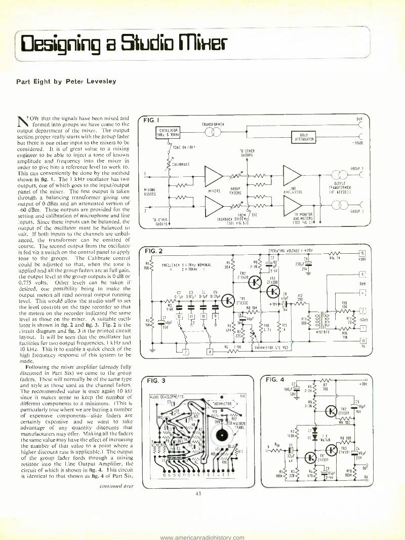
Designing a SikJdO I I liHel
Part Eight by Peter Levesley
NOW that the signals have been mixed and formed into groups we have come to the
output department of the mixer. The output section proper really starts with the group fader but there is one other input to the mixers to be considered. It is of great value to a mixing engineer to be able to inject a tone of known amplitude and frequency into the mixer in order to give him a reference level to work to. This can conveniently be done by the method shown in fig. 1. The 1 kHz oscillator has two outputs, one of which goes to the input /output panel of the mixer. The first output is taken through a balancing transformer giving one output of 0 dBm and an attenuated version of -60 dBm These outputs are provided for the setting and calibration of microphone and line inputs. Since these inputs can be balanced, the output of the oscillator must be balanced to suit. If both inputs to the channels are unbal- anced, the transformer can be omitted of course. The second output from the oscillator is fed via a switch on the control panel to apply tone to the groups. The Calibrate control could be adjusted so that, when the tone is
applied and all the group faders are at full gain, the output level at the group outputs is 0 dB or 0.775 volts. Other levels can be taken if desired, one possibility being to make the output meters all read normal output running level. This would allow the studio staff to set the level controls on the tape recorder so that the meters on the recorder indicated the same level as those on the mixer. A suitable oscil- lator is shown in fig. 2 and fig. 3. Fig. 2 is the circuit diagram and fig. 3 is the printed circuit layout. It will be seen that the oscillator has facilities for two output frequencies, 1 kHz and 10 kHz. This is to enable a quick check of the high frequency response of this system to be made.
Following the mixer amplifier (already fully discussed in Part Six) we come to the group faders. These will normally be of the same type and style as those used as the channel faders. The recommended value is once again 10 kt2 since it makes sense to keep the number of different components to a minimum. (This is
particularly true where we are buying a number of expensive components -slide faders are certainly expensive -and we want to take advantage of any quantity discounts that manufacturers may offer. Making all the faders the same value may have the effect of increasing the number of that value to a point where a higher discount rate is applicable.) The output of the group fader feeds through a mixing resistor into the Line Output Amplifier, the circuit of which is shown in fig. 4. This circuit is identical to that shown as fig. 4 of Part Six,
continued over
l'FIG. I
OSCILLATOR
1KHz & IOKHz
TRANSFORMER
DdB
C
TONE ON / OFF
CALIBRATE
TO OTHER
GROUPS
-5aá9
GROUP I
MIXING
BLSSES
LIKE AMPLIFIERS
OUTPUT
TRANSFORMER
(IF NEEDED)
TO OTHER
GROUPS
FROM SIC
TALKBACK SYSTEM (SEE FIG. 5)
TO MONITOR
ANO METERS
(SEE FIG. 6)+
GROUP 2
FIG. 2
Al
5K It 2 =101(Hz FREQUENCY 1 = 1KHz NOMINAL
R2
15K
C2 C3 CL CS
0.1yF 0.01yF 0.1yF 0.01yFrp
R3
1.51(
R5
39K
Ct
LOyF
165
R9
2.2K
TR2
111500
TR1
211300
AB 10K
OPERATING VOLTAGE _ +20V
C9
250pF
25I
CB LOyF 390
1--AAP` 16V
R10 R11
4.7K 1K
220
RL 1 5K
RUM +30V
11K
THERMISTOR STC R53 05
FIG. 3
AUDIO DEVELOPMENTS DSC
-- -- THERMISTOR >
TR3
GAt_IED MSC1829
TRANS.
11,R1 BLU
15 1E. 13 12 11 10 9 6' 6 5 L 3 2
r R17
43
www.americanradiohistory.com

STUDIO MIXER
continued
only the component values having been changed to give more output power. The Component layout is thus the same as that in fig. 5 Part Six, for the GPA.
We have used the mixing facilities offered by the GPA to give the facility of injecting an output from the Talkback system direct to the groups. To see the reason for this, we must first see what the purpose of Talkback is.
Talkback The circuit diagram of the specimen mixer which was published in the first part of this series did not include a talkback facility but it is so useful that I think that we should bring it in now. We have already seen how important it is that there should be as complete an acoustic isolation between the studio and control room as possible. This is because the input to the mixer should only be derived from sounds generated internally in the studio, therefore it is most undesirable that activity and conver- sation in the control room should affect the microphones in the studio. To prevent this, considerable trouble is taken with the design of the doors and window which separate these two rooms to reduce sound leakage to a minimum.
The sound mixing engineer frequently wants to communicate with the performers in the stu- dio, however, and the talkback system is intro- duced to enable him to do this. Fig. 5 shows the main features of the arrangement and how it is related to the studio and control room. In most studios, except the very largest ones, an ampli- fier output of 20 watts should be adequate. In this case, the amplifier could well be accom- modated within the mixer. Where larger powers are required, the Talkback output could be at 0 dB level, the amplifier being mounted externally.
It also illustrates the reason for the precau- tions that have to be taken. There are two people who may have reason to want to communicate with the performer in the studio. These are the mixing engineer and the producer. They each have a microphone, the outputs of which arecombined in a hybrid transformer and amplified by the talkback amplifier. Both the engineer and the producer have access to the talkback switch S1. This switch, which activates
r
FIG. 5
MILS PRODUCERS
TALKBACK
HYBRID TRANSFORMER
L -
M NINA LS
1
AMP
20W 0/P
SIC
TALKBACK
LS
MI ER
SIB
__J
STU010
MIO
WALL
the talkback, has three contacts. The first (Sla) completes the circuit from the output of the amplifier to the loudspeaker, enabling the studio to hear what the engineer or control room says. The second (Sib) breaks the circuit from the mixer to the control room monitor loudspeaker. If this second contact were not included the dotted line shows what would happen. Sounds originating in the control room pass to the studio loudspeaker, enabling them to be picked up by the studio microphones. These microphones cause . an input to the mixer which would operate the control room monitor loudspeaker. Sounds from this speaker would be detected by the talkback microphone and a feedback loop would be formed, giving rise to `howl round'. The second contact, in series with the monitor loudspeaker, breaks this loop. S1c enables a direct injection to groups.
In modern studio technique, the likelihood of the talkback loudspeaker signal picking up on the studio microphones is reduced. The reason for this is that it has become customary, particularly when recording Pop or light music, to place the microphones very close to the instruments being recorded and to separate the instruments with acoustic shielding panels. This is called 'close microphone technique' and it is used so that each microphone only picks up the sounds in its immediate vicinity, giving great separation between microphones. This gives greater freedom to the sound engineer when he reduces the recording later from say a sixteen track master recording to a two track stereo tape for disc manufacture. Having the microphones so close to the instruments means inevitably that the amplification needed in the mixer is reduced and so the pickup of ambient sounds is also reduced. Since the talkback system is used for identifying the 'takes' (individual passages of recording) as well as giving messages to the studio performers, it is necessary that the talkback should record clearly on the tape. Since we cannot be certain that an adequate recording can be made via the pickup of the message on the studio microphones, we must inject a portion of the talkback signal direct into the group output amplifiers, which brings us back to fig. 1. This injection will take place irrespective of the setting of the group fader and thus whatever is said in the control room will be recorded if the talkback key is pressed.
It is most essential, from the point of view of the studio proprietors, that whatever the producer says to the performers is recorded. This is because in the event of a dispute arising, due to a spoiled recording for example, it may be necessary to determine the extent to which the producer is responsible. His com- ments and instructions via the talkback system may be vital and should be recorded. This is why it is not a good idea to give the producer an individual means of communicating with the studio unless it can be tied into the mixer for recording.
Fold back
In Part One we looked briefly at the purpose of ' foldback' and it will be as well to say a bit more about it now. Foldback is used to enable the studio performers to hear:
1. What their fellow performers are doing. This need arises directly out of the use of the
44
close mie technique since the acoustic separa- tion of instruments leads to similar separa- tion of instrumentalists. The method usually employed is to relay to each musician on headphones a signal derived from selective outputs of the microphones of his neighbours. Wearing the headphones further increases his isolation and he is therefore largely dependent on them.
2. Information previously recorded. With a multitrack recording it is sometimes desirable to record some of the tracks on one occasion and more later. To enable this to be done, the musicians must be able to hear what was recorded previously and this is achieved by replaying to them, via the self synchronising facility on the tape machine, certain of the original material. This enables them to make the new recordings in synchronism with those previously made.
In both of these situations, the wearing of headphones reduces the performer's ability to hear the instructions from the talkback loud- speaker and it is thus a good idea to arrange for a direct injection to the foldback system from the talkback department.
Metering and Monitoring Before the signals leave the mixer to be fed
to the following equipment, be it tape recorder, amplifier or whatever, they must be checked to see that they are up to the correct standard. This means that some form of continuous evaluation of the performance of the mixer must be provided for and it can take two forms,
FIG. 8
www.americanradiohistory.com

J
visual and audible. The visual evaluation is provided for by meters while loudspeakers or headphones enable listening checks to be made. Generally speaking, both forms of evaluation are used simultaneously because, while the ear is the better judge of the quality of the sound, a meter is much better at measuring its level, and both factors are important.
Fig. 6 shows how provision may be made for this evaluation. Here, we have departed some- what from the arrangement as suggested in Part One to improve the versatility of the monitoring system. Firstly though, we can consider the metering aspect which is just the same as before. Fig. 6 shows the meters connected to the output lines and, since there are no level controls after this point within the mixer, the meters indicate the actual level sent down the line.
Metering There are two systems of metering in com-
mon use. The most widely used displays the level of the signal on a meter scaled in `volume units'. This type of meter is called a vu meter. In my time, I have heard many suggestions as to what the letters vu stood for. One of the more pointable suggestions came from a man who had a leaning towards the other type of meter; this was `Very Unsatisfactory'. The other type is one which concerns itself with the instantaneous maximum value of the signal. Since it measures the peak level, it is called a peak programme meter or ppm.
Much controversy has always surrounded the question of which is the better type of meter, ppm or vu? Each type of meter has adherents who seem to be blind to the advantages of the other system. In reality this is a non- question because each meter is best for the application for which it is intended -we might as well ask ourselves which is best; a horse or a cow? The answer would depend on whether you wanted to ride it or milk it.
Let us look at the different meters and we shall see what they are good at and what their shortcomings are.
Vu Meter This is the simpler type of meter, consisting
as it does of a moving coil meter fitted with a rectifier and a series resistor. The moving coil meter is specially constructed to have certain 'ballistics'. Ballistics govern the way in which the movement of the pointer follows the input signal. If the pointer movement was too sluggish, the meter would not respond to fast changes in signal level and short duration, high level signals would pass by unnoticed. On the other hand, if the movement was very rapid, the pointer could go jumping all over the scale, making interpretation very difficult. Some compromise is therefore necessary and the ballistics chosen have been arrived at by years of experience and experiment by sound engineers. One word of warning is that just because a meter has vu printed on the scale, that does not make it a vu meter. It is quite easy to do the printing -it is not so easy to get the correct ballistics or the correct sensitivity and linearity.
The standard ballistics are taken from the American Standards Association C16.5 -1942. These state that if a sinusoidal voltage of frequency between 35 Hz and 10 kHz at such an amplitude as to give a certain reference
deflection under steady state conditions is suddenly applied, the pointer will reach 99 per cent of the reference deflection in 300 milli- seconds ( ±10 per cent) and should then over - swing by between one and 1.5 per cent. The scale is marked in percentage modulation and decibels, the decibel scale generally being more prominently marked, for use on tape recorders and mixing desks. This is known as scale A marking. In Britain, the normal calibration is that 0 vu is equivalent to +4 dBm while in the USA it is more usual to find that 0 vu is +8 dBm. When using American equipment destined for the US market, be careful there- fore to check the calibration and recalibrate if necessary, otherwise the levels on domestic equipment will read 4 vu too high. A typical vu meter scale is shown in fig. 7, and it can be seen that a deflection range of 80 per cent of the scale is taken up with a volume range of only 13 dB. Compare this with the ppm. Since the vu meter is a rectifier type meter, it displays the average level of the signal input and, because of this fact, the meter reading corres- ponds fairly well to the overall loudness of the sound as perceived by the ear. This implies that the vu meter is best suited to situations where the loudness of a sound is more important than its instantaneous maximum level. Such an application might be monitoring the signal level to an auditorium where the mixer is
driving amplifiers for public address. As has already been explained, the response time of the pointer movement is such that it tends to under - read on brief large amplitude signals and in situations where it is most undesirable to overdrive the following equipment the vu meter is Very Unsatisfactory.
Peak programme meter It was to cope with this type of situation that
the Peak Programme Meter was developed. Long before tape recording was ever thought of, broadcasting companies had the problem of ensuring that the transmitter and aerial system was protected from overloads. Since systems were tending to be operated near the limit of their performance overloads could cause breakdowns which were expensive and embar- rassing. The ppm thus became a standard method of checking signal levels and the BBC are probably responsible for the widespread use that it has today. With advent of tape recording, it soon became clear that here
again we had a system which had to be operated near the limit of its capability if signal to noise ratios were to be good. Some method of monitoring the peak level that responded very rapidly was needed and several methods were employed in early days. Prominent was the magic eye type indicator, which was a form of modulated electron beam device in which the angle of a shadow on a fluorescent screen gave an indication of the voltage input. This gave a very rapid response since no moving parts were involved but it had a poor dynamic range and had a limited life. Other more elegant ideas were tried, one of which was a cathode ray tube where the sound level showed up as the size of a square patch of light. The ppm is clearly well qualified for use in this application and it is slowly gaining acceptance. The main problems are undoub- tedly higher cost and the fact that it fails to give a good idea of the overall loudness of a
sound. Fig. 8 shows a typical ppm meter scale
according to BS 4297:1968 and it can be seen that we have a simple scale consisting of seven marks. The range between marks is 4 dB and the instrument is calibrated so that 0 dBm (.775 volts) reads four. This means that the useful operating range of the meter in this case extends from +12 dB to 12 dB or a range of 24 dB, that is about twice the useful dynamic range of the vu meter. In order to make the reading of short duration signals easier for the operator, the meter, together with its elec- tronics, is arranged so that the pointer deflects rapidly to higher readings and falls slowly to lower ones.
To give some idea of the speed of response of the ppm to short duration signals as compared to the vu meter, we can consider its response to a tone burst. If we have a 5 kHz sinewaNe signal of such an amplitude as to give a reading of six, we can apply it as a burst of signal and the following table results.
Burst Duration
Steady State. 100 ms 10 ms
5 ms 1.5 ms
Indicated reading (relative to mark 6)
o dB 0 dB
-2.5 dB -4 dB -9 dB
continued .5?
FIG. 6
MONITOR
MIX LEVEL
FROM FIG 1 METER SYSTEM
GUTou"
FROM OTHER
GROUPS
TO OTHER
MONITORS
SELECTION
BUTTONS
MONITOR
MIXERS
GANGED
LEVEL CONTROL
MONITOR
AMPLIFIERS
MUTING
SWITCH
45
www.americanradiohistory.com

Heco P.6000. the professiona one.
As used in leading German Recording and Broadcasting Studios SPECIFICATION Frequency Response: 20- 25.000 Hz Power Handling: 60 watts RMS. Impedance: 8 ohms. Cross -over Frequency: 250/800/3,000 Hz. Speaker Assembly: One 12" woofer. One 5 mid -range speaker. One upper mid -range hemispheric dome radiator. One ultra -high hemispheric dome radiator. Recommended Retail Price £110.00
P /ease send me full colour literature and test reports on Heco Speakers, also name and address of my nearest stockist. NAME ADDRESS
S.S. Dept. SS, Acoustico Enterprises Ltd, 6 -8 Union Street, Kingston- upon- Thames, Surrey Tel: 01- 5493471/3(3 lines)
46
SONIFEX
:...r........, {Yr1l
SOUND EQUIPMENT
93 STANWELL WAY
WELLI NGBOROUGH
Telephone Redwells 2142
* Portable six channel monophonic studio mixer type BI000.
* Amplifier assemblies providing microphone to line amplification, equalisation, virtual earth mixing, and high level output functions
* Studio intercommunication units and systems designed and manufactured,tospecific requirements.
* Broadcast type jackfield assemblies.
* Specialised sound equipment designed and manufactured to individual requirements.
UNBEATABLE - UNREPEATABLE
OFFER SHIBADEN SV700E 625 and 405 LINE
VIDEO TAPERECORDER
at under HALF PRICE
SAVE f200 ON
EX- DISTRIBUTORS
REDUNDANT STOCK
ONLY f198 EACH
Guaranteed full working order and compatible with latest machines.
ORDER NOW WHILE LIMITED STOCKS LAST
(TRADE ENQUIRIES WELCOME
AUDIO ADVERTISING (DEPT. IVS) 43 MALDEN WAY, NEW MALDEN, SURREY
01 -942 9635/6
www.americanradiohistory.com
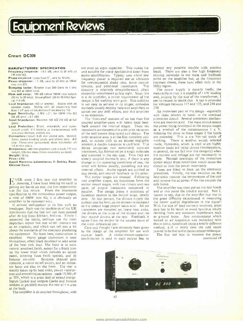
Equipment Reviews
Crown DC300
MANUFACTURERS' SPECIFICATION Frequency response: ±0.1 dB, zero to 20 kHz at
1W into 852.
Phase response: Less than 5 °, zero to 10 kHz. Power response: .L 1 dB, zero to 20 kHz at 150W
rms into 852.
Damping factor: Greater than 200 (zero to 1 kHz into 852 at 150W rms).
Hum and noise: 100 dB below 150W rms output (20 Hz to 20 kHz). Uriweighted: (20 to 20 kHz) typi- cal 110 dB.
Load Impedance: an or greater. Stable with all speaker loads. Stable with all capacitors less than 1µF and all capacitors if isolated by 152.
Input Sensitivity: 1.75V ±2 for 150W into 852
(26 dB gain -0.1 dB). Input Impedance: Nominal 100 kû (10 k52 at full
gain). Load Protection: Short, mismatch, and open -
circuit proof, V -I limiting is instantaneous with minimum thumps, cutout, etc.
Connectors: Input: 6.25 mm phone jack. Output: Color coded binding posts and phone jack. AC line: Three -wire (grounded) male connector on 1.5 m min cable.
Dimensions: 480 mm standard rack mount, 177 mm height, 235 mm deep (from mounting surface).
Weight: 18 kg. Price: £360. Agent Maccines Laboratories 71 Oakley Road, Chinnor Oxon.
FVER since I first saw this amplifier in America, I have been looking forward to
getting my hands on one; the first opportunity was for this review. From the impressive specification to the tremendous power output, a total of 600W into 4n, it is obviously an amplifier to be reckoned with.
It arrived well -packed in its box with no breakages. Such was the confidence of the UK distributors that the box had not been opened after its trip from Elkhart, Indiana. Firstly I
inspected the inside, perhaps not the most important aspect but one which interests me as an engineer, and which can tell you a lot about the standards of the company producing the equipment. No fears here; construction is excellent. Heavy gauge aluminium is used throughout, often black anodised to take some of the heat sink load. The front is in satin natural anodised finish, except for a black trim on the lower third which includes an access panel, covering fuses (with spares), and dc balance controls. Separate channel gain controls, a mains on /off switch, and an indica- tor lamp are also on the front. The rear is mainly taken up by heat sinks, power transfor- mer and smoothing capacitors each 13,500µF at 70V, which is a great deal of stored energy. Inputs (jacks) and outputs (jacks and banana sockets in parallel) occupy the rest of the area at the back.
The amplifier is dc coupled throughout, with
not even an input capacitor. This makes the unit suitable for many applications apart from audio amplification. Typical uses where low frequency power is required are as vibrators for environmental shake tests, servo control systems, and positional transducers. The circuitry is relatively straightforward, albeit somewhat complicated at first sight. Since this is a dc amplifier, a prime requirement of the design is for stability with gain. This stability is not easy to achieve in do stages; orthodox methods usually employ balanced amplifiers to cancel out any drift effects, and this amplifier is no exception.
The `front -end' consists of no less than five coupled amplifier -pairs with heavy local feed- back around the internal stages. These ten transistors are connected in a complex variation of the well known long tailed pair design. The most sensitive area is at the first transistor pair and, to reduce drift to an almost negligible amount, a double transistor is used here. This device comprises two completely separate transistors, but fabricated on a single substrate and mounted in the one case. Thus they are closely coupled thermally and, if there is any change in the operating conditions of one, the other will follow exactly, cancelling out any internal effects. Audio signals are applied to one device, and overall feedback to the other.
The output stages are unusual. Following two amplifier stages, six transistors form the output power stages, with two drivers and two pairs of output transistors connected in parallel. The design draws a minimum of quiescent current in the output stage, ideally zero. At low powers, the drivers supply the current into the load; as the demand is increased so the output stage proper takes over. All six transistors are mounted on heavy heat sinks, the drivers at the sides of the chassis and the four output devices at the rear. Feedback is taken from the output to the unused input of the input differential pair.
Care and thought have obviously been given to the design of the amplifier for use with unusual loads. A choke -resistor- capacitor combination is used in each output line to
prevent any possible trouble with reactive loads. There are also a few high frequency shaping networks in the main and feedback paths on the amplifier but, as the frequency response shows, these have effect only in the MHz region.
The power supply is equally beefy; the makers claim that it is capable of I kW loading and, judging by the size of the transformer, I see no reason to doubt this. A tap is provided for voltages between 117 and 125, and 234 and 250.
An important part of the design -especially with these powers to hand -is the overload protection circuit. Several protection mechan- isms are incorporated. The main circuit senses the power being developed in the output stages as a product of the instantaneous I x V, reducing the drive to these stages if the limits are exceeded. This is the Normal mode of working. There is another switch selected mode, Hysteresis, which is used when highly reactive loads are being driven (loudspeakers, in general, do not fall into this category) when the current and voltage are not necessarily in phase. Normal operation of the protection circuit under these conditions would cause the circuit to limit the power incorrectly.
Fuses are fitted to back up the electronic protection. Finally, thermal switches on the heat sinks monitor the temperature of the unit and remove the ac power if the rise exceeds the safe limits.
The amplifier was then put on the test bench and at this point the trouble started. Not I, hasten to say, due to the amplifier but due to the great difficulty experienced in measuring the power and /or degradation in the signal! With the size of load currents involved, great care has to be taken to avoid spurious results deriving from any common impedances such as ground loops. Any measurement which looked at all suspicious was rechecked with this in mind, sometimes using a totally different method, and in every case the odd result proved to be due to the measurement technique.
The first test was to measure the power continued 49
47
www.americanradiohistory.com

Bring you pro essional quality on a budget!
LARGEST RANGE OF MONITOR SPEAKERS IN UK ALWAYS
ON DEMONSTRATION
FRIEW. REFERENCE STANDARD
Studio Monitor Speakers IM R.E.W. have been appointed exclusive U.K. Distributors for the top IMF Monitor Loudspeaker. This Speaker has previously been reserved specifically for critical profes- sional markets. It features improved low frequency stability and increased power handling capacity. Send for detailed specifications.
MAIN AGENTS FOR
SPENDOR & ROGERS monitor loudspeakers
NOW ON DEMONSTRATION AT CHARING CROSS ROAD SHOWROOMS
Ferrograph TAPE RECORDERS
NOW ON DEMONSTRATION New models with built -in Dolby System, avail- able from stock. ALSO -the superlative new Ferrograph Speaker at Charing Cross Road Showrooms now.
Shur, e,Beyer, AKG MICROPHONES
Ask our advice on the model to suit your requirements from these famous makes. Over 150 microphones in stock from L7 to £170. Also boom arms, stands, windshields. etc.
HIRE A REVOX ! If you are a musician or have a studio or agency, you might like to take advantage of our special Hire Facilities for Revox, Uher portables, microphones, etc. Ring Ray at 836 3365 for full
details.
MIXERS We now have in stock a limited supply of the Sony MX 12 and Uher A 121 in our range of less expensive mixers. Also available. mixers in the higher price b racket.
REVOX, B. & O., SONY Full ranges in stock r .11 e _ mi Swi!
1 PROFESSIONAL SHOWROOMS: S. LONDON SHOWROOMS 11146 Charing Cross Road, London WC2 265 -8 Upper Tooting Rd., London SW Telephone: 01 -836 3365 Telephone: 01 -672 4471/2 and 9175
Please send me full details of your services NAME ADDRESS
1 7.1
1
1
1 48
AUDIO CONNECTORS BROADCAST PATTERN JACKFIELDS, JACKCORDS PLUGS & JACKS. QUICK- DISCONNECT MICROPHONE CONNECTORS. AMPHENOL (TUCHEL) MINIATURE CONNECTORS WITH COUPLING NUT. HIRSCHMANN BANANA PLUGS & TEST PROBES. XLR COMPATIBLE IN -LINE ATTENUATORS. LOW COST SLIDER FADERS BY RUF.
FUTURE FILM DEVELOPMENTS LTD. 90 Wardour Street W I V 3LE
01 -437 1892 3
EST. 12 YEARS BRAND NEW- SUITABLE FOR ALL MACHINES
RECORDING TAPES & CASSETTES ALL TOP QUALITY 100°,, TESTED
BY SUPERIOR AMERICAN AND BRITISH MANUFACTURERS GENEROUS QUANTITY DISCOUNTS
BASE -TENSILISED POLYESTER and PVC EXTRAS -NO CHARGE -FITTED LEADERS EX 3"
FREE ROLL OF LEADER WITH ALL TAPE ORDERS 24 HOUR DESPATCH SERVICE
St'rd Play Long Play Double Play 3 " 150' 10p 210' Ilp 320' 20p 4" 300' 20p 420' 24p 550' 30p 5" 600' 30p 900' 40p 1200' 56p 511 900' 37p 1200' 49p 1800' 78p 7" 1200' 44p 1800' 64p 2400' 95p
Empty Spools 4p 9p
I I p I2p
3v and 4" APPROX LENGTHS
CASSETTES MANUFACTURED by EMI MASTERTAPE ALL IN PLASTIC LIBRARY CASES
C60 EMI PLAYRITE C90 MASTERTAPE
C120 MASTERTAPE
34p Sop 65p
3 for LI 3 for LI.45 3 for LI-90 1P
P/P on all orders
If any goods are found at fault in any way money refunded in full.
SPECIAL OFFER -EMI AFONIC LOW NOISE REEL TAPES and PRE -RECORDED CASSETTES AT LESS THAN HALF PRICE
CALLERS WELCOME
WALKERS 16 WOODTHORPE ROAD, ASHFORD, MIDDLESEX
ASHFORD 52136
To Studio Sound, Classifieds. Link House, Dingwall Avenue, Croydon CR9 2TA.
Please publish the advertisement indicated below for insertion /s under the heading
Name
Address
Cheque /P.O. enc osed i Is a Box No. required Yes /No. If no please include remittance to cover name and address and /or Tel No. Please write in block capitals.
www.americanradiohistory.com
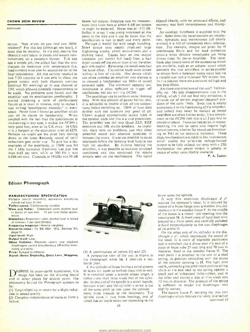
CROWN DC300 REVIEW
continued
output. Now where do you find two 300W resistors? For this test (although not later), it must also be resistive. In the end, electric fire elements were taken to pieces and wound non - inductively on a porcelain former. This was not a simple job; the added fact that the wire changes its resistance with temperature (i.e. load current) must also be accounted for in the final calculations. All this activity resulted in two 7.512 resistors so I was able to check the power output with both channels working (nominal 852 working) or in one channel at 150, which allowed crosstalk measurements to be made. No problems were found, and the amplifier met its specification comfortably. I started preparing a table of performance figures as is usual in reviews, only to realise I was writing `specification exceeded' in every space. Never have I found an amplifier which met all its claims so handsomely. When coupled with the fact that the specification is outstanding in any case, it makes the DC300 a very good buy, even at its UK price. In USA it is a bargain at the equivalent price of £270. Perhaps we might see the price here coming down as the latest Kennedy round of tariff reductions gets under way. To give but a few examples of the excellence, at 150W into 852
the 1 kHz harmonic distortion was just less than 0.03 per cent, while at 500 Hz it was 0.008 per cent. Crosstalk at 10 kHz was 95 dB
below full output, dropping into my measure- ment limit from here at about 6 dB per octave as might be expected. Noise was at 113 dB. Suffice it to say I was pretty impressed at this point in the tests and it can be taken that the specification is met in each and every point.
Perhaps it would fail with rough handling. Short circuit tests merely produced large frightening sparks, pitted screwdrivers and a shaking hand. Excess heat on one output transistor pair (under full load) from a hair dryer turned off the power even when the other pair was cooled. Reversing the conditions had the same effect. Capacitive loads were driven without a hint of trouble. One device which can often provoke an amplifier into distress is to connect a loudspeaker via 100m of coiled screened cable. The combined capacity and inductance is often sufficient to trigger off oscillations, but not with the DC300.
The next stage was to perform some listening tests. With this amount of power behind you, it is advisable to double check all the connec- tions before switching on. 150W of hum does neither ears nor speakers any good at all. Crown suggest appropriately scaled fuses in the speaker leads and this is a wise precaution. The amplifier was fed into Quad ELS, KEF monitors and JBL studio speakers. As expec- ted, there were no problems, just very clean powerful sound and absolute quietness in between the music. It was not possible to cause overloads before the listening level became too high for comfort. By dummy loading the amplifier, it was possible to simulate overload conditions and this confirmed the results already seen on the oscilloscope. The signal
clipped cleanly, with no untoward effects, and recovery was both instantaneous and thump - free.
An excellent handbook is supplied with the unit. Apart from the usual sections on installa- tion, operation and maintenance (all clearly written) it is full of unexpected extra informa- tion. For example, designs are given for rf interference filters and for load protection circuits when delicate transducers are being driven from the power amplifier. The hand- book also details some of the accessories which are available, such as an adapter panel which connects the two amplifiers in series -parallel to obtain both a balanced mono input line via a transformer and a balanced 70V output line. In this adapter there are also switched high and low pass filters.
Are there any criticisms of the unit? Technic- ally, no. My sole disappointment was in the styling, which I did not find very attractive; it reminds me of certain engineer -designed pro- ducts of the early 1960s. Since this is totally unimportant to the functioning of the amplifier, and indeed may never be noticed as power amplifiers are often hidden away, it is a compli- ment to the DC300 that this is all I can find to complain about. I have no hesitation in recom- mending the unit to users who require high output powers, whether for sound use (monitor- ing or PA) or for scientific purposes. These days, loudspeakers are made in low impedances which enable the otherwise voltage -limited output to be fully utilised, but even with a 250 loudspeaker the power output is greatly in excess of other units readily available.
P. A. Lomas
Edison Phonograph
MANUFACTURERS' SPECIFICATION Portable sound recording apparatus employing
cylindrical -scan tinfoil. Tinfoil speed: Continuously variable. Wow and flutter: Dependent upon alcohol level
in blood of operator. 15 per cent (total abstin- ence).
Distortion: Dependent upon alcohol level in blood of listener: 1 per cent (blotto).
Frequency response: Heavily weighted. Signal -to- noise: To BS 0001: 1812, Section XII,
page IV. Input level: High. Output level: Low. Other features: Separate record and playback
diaphragms permit simultaneous off- tinfoil moni- toring and echo.
Price: Subject to inflation. Agent: Sonic Sophistry, Dock Lane, Wapping.
DESPITE its avant -gardé appearance, this design has been on the drawing board
and in other places for several years. The philosophy behind the Phonograph appears to be: (1) Total reliability in return for a slight reduc- tion in sound quality. (2) Complete independence of mains or battery failure.
(3) A combination of points (1) and (2). A perspective view of the unit is shown in
the photograph while fig. 1 provides a sec- tional plan.
C is a cylinder of brass having a spiral groove or screw cut upon its surface from end to end. It is mounted upon a spindle whose length is
rather more than three times that of the cylin- der. At one end of the spindle is a winch handle, between which and the cylinder a screw is cut of the same pitch as that upon the cylinder - some three threads to the centimetre. The spindle turns in two brass bearings, one of which has an inside screw corresponding to the
49
screw upon the spindle. A very thin sheet -iron diaphragm d d'
receives the operator's voice. It is secured by means of a brass flange over a shallow circular recess cut in the wooden frame F. In the middle of the recess is a round hole opening into the mouthpiece M. A short piece of hard steel wire ground to a blunt point and carefully polished is fixed perpendicularly to the iron diaphragm at its centre O.
On the other side of the cylinder is the dia- phragm p p', which reproduces the sound of the voice. It is made of vegetable parchment and is stretched like a drum over the end of a piece of brass tube 25 mm long and 70 mm in diameter, fixed in the wooden frame H. The steel point t is attached to the end of a steel spring, its position coinciding with the centre of the circular opening in H. The light pine rod K, connecting the parchment and the spring abuts at the end next to the spring against a small pad of vulcanised india- rubber, and at the other end carries a disc of thin sheet iron 12 mm in diameter. The pressure of the spring is sufficient to render the diaphragm very slightly convex.
The square frame F, carrying the thin iron diaphragm which receives the voice, is attached
continued 51
www.americanradiohistory.com

AVOMETERS BARRIER STRIPS BULBS pilot LES. MES. BIASED LEVER SWITCHES CABLES cc -axial mains microphone r.f. screened multi -core wiring compensating CAPACITORS ceramic electrolytic mixed diolectric paper polycarbonate polyester polystyrene silver mica suppressor tantalum trimmer CAPACITOR MOUNTING CLIPS CASES instrument CHOKES smoothing and suppressor CROSSOVER UNITS CLIPS crocodile CO -AXIAL CONNECTORS CONNECTORS audio battery car radio co -axial jack mains multi -pole printed circuit screened wander plugs CRYSTALS CRYSTALS /OVENS EARPIECES
C. T. ELECTRONICS 267 ACTON LANE, LONDON W.4 01- 9946275
EDGE CONNECTORS FERRITE RODS (AERIAL) FERRITE CORES /RINGS FLEX CONNECTORS FUSES FU SE HOLDE RS GROMMET GROUP PANELS HARDWARE KITS HEATSINKS INSULATING SLEEVING INSULATING TAPE INTEGRATED CIRCUITS JACK PLUGS AND SOCKETS KEYSWITCHES KNOBS AND FITTINGS LACING CORD LAMP HOLDERS LOUDSPEAKERS METERS MOUNTING STRIPS NEON BULBS AND HOLDERS NUMERICATOR TUBES PANEL METERS P.V.C. TAPE MICROSWITCHES PILOT BULBS PILOT LAMP HOLDERS PLUGS POTENTIOMETERS carbon multi -turn servo sine /tan stereo wirewound 360 degree PRE -SET CONTROLS PUSH BUTTON SWITCHES INTERLOCKING /ILLUMINATED PUSH ON CONNECTORS RECTIFIERS germanium selenium silicon RECORDING TAPE
RELAYS miniature plastic covered heavy duty high speed latching RESISTORS carbon carbon film high stability metal oxide metal film wirewound variable
ROTARY SWITCHES SCREENING CANS VALVE SEMICONDUCTORS SLEEVING SOCKETS SOLDER SPADE TERMINALS SPINDLE COUPLING SPINDLE LOCKS STRIP BOARD STU DING SUPPRESSORS SWITCHES lever micro reed toggle wafer push button ILLUMINATED PUSH BUTTON TAG MOUNTING STRIPS TAGS TAGS, SOLDERING TAPE, INSULATING TAPE, RECORDING TERMINALS TEST METERS TEST CLIPS THERMISTORS TINNED COPPER WIRE
TRANSFORMERS auto C.R.T. rf. filament filament inte rvalve isolating mains matching microphone output TRANSISTORS TRANSISTOR MOUNTING CLIPS TRANSISTOR MOUNTING PADS TRIMMING TOOL TURRET TAGS TWEETERS VALVE HOLDERS VALVE PLUGS VERO BOARD VOLUME CONTROLS mono stereo slide switched WIRES ZENER DIODES
This list represents a fraction of our component range.
TEST EQUIPMENT OSCILLOSCOPES COUNTERS SIGNAL GENERATORS A.F. R.F. MULTIMETERS MILLIVOLTMETERS VALVE VOLTMETERS WATTMETERS POWER SUPPLIES MEASURING EQUIPMENT etc. etc.
DOES YOUR STUDIO SUFFER FROM CROSSTALK ?
11111111110
ii.
Alice Crosstalk and Noise Suppressor offers up to 20 dB of suppression with minimal side effects.
The unit is a sophisticated Integrated Circuit device, sensitive to level and frequency, and without the switching and thumping effects normally associated with gate circuitry. Designed primarily for multi -track reductions, the unit substantially reduces mic -to -mic crosstalk, studio noise and channel noise.
Price £93 each or £390 for 4 units rack mounted with power supply.
ALICE (STANCOIL LTD) IS SHEET STREET,
WINDSOR WINDSOR 61308
50
I`,
1 1
free to all Hi -Fi
enthusiasts!
SKYWAY HOTEL Bath Road. Hayes. Middlesex MARCH 24, 25 ANO 26
Ii il,,:,,i.;
3rd International Exhibitor
www.americanradiohistory.com

EDISON PHONOGRAPH REVIEW TABLE 1 OVERALL FREQUENCY RESPONSE
continued
by hinges to a piece of wood, which is connec- ted rigidly with O, O again being connected by hinges B with X. By means of these hinges, and the screw S, the point O may be made to approach the cylinder, so as to dip into the groove upon its surface. The arrangement on the other side of the cylinder Is almost iden- tical. At I and J are hinges and at N a screwnut and spring for regulating the depth to which t enters the groove.
The method of using the instrument is as follows. The two diaphragms being turned back, the cylinder is covered with a piece of stout tinfoil, fixed by gum, and is then moved, by turning the handle, as far to the right as possible. The stud at O is turned so as to allow the point O to press upon the tinfoil, and the cylinder is made to perform half a revolution. d d' is once more raised and, if the smooth furrow formed by the motion of the tinfoil against the point should be found too deep or too shallow, the nut S is turned slightly to the right or left. When the proper depth is attained -a point only to be learnt by experience-the same process is gone through with the other diaphragm, and the instrument is in working order. The point o is again dropped upon the tinfoil, the diaphragm p p' being kept raised as in the figure. The handle is then regularly turned at the rate of about one revolution per second, words being at the same time distinctly spoken into the mouthpiece M. When the speech is completed, d d' is removed from the tinfoil, when the furrow it has traced is found indented by the movements of the point in responding to the vibrations of the voice. The cylinder is then turned back to its original position and the point t, at the other side of the cylinder, dropped upon the furrow. Again the handle is turned, the undulations on the foil being caused to pass under the point. The original process is thus reversed, the indenta- tions imparting to the second point move- ments precisely similar to those which the first point performed while producing the indentations. The vibrations of t are conveyed by the rod K to the parchment diaphragm p p', and by it to the air, producing sounds
TTW Mrs TTW TTW Jnr 50 Hz inaudible inaudible inaudible
200 Hz -5 dB something yes 500 Hz +10 dB yes loud 1 kHz 0 dB 0 dB 0 dB 5 kHz +20 dB yes yes 10 kHz -5 dB no yes 15 kHz inaudible inaudible inaudible
Distortion: Yes. Noise: Hiss and a once -per -cylinder revolution
scroink.
FIG. 1
2 PHONOGRAPH SPEED CONTROL LOGIC
1
EXTERNAL
MEMORIES
r SILENCER
HEXTERNAL MOTORS
I
-{ MEMORY I- CON FUSER
MOTOR
_1 OUTPUT
CYLINDER SPEED
closely approximating in pitch and quality to those by which the iron diaphragm was set in motion. A cone of stout drawing -paper about 30 cm long can be slipped over the tube p p' to reinforce and give body to the sound.
The non -electric nature of this recorder is both a blessing and a source of difficulty. Blessed is the fact that it may be placed in front of a musician (or optimally located near group of same) with nothing to twiddle but the driving handle. Problems arise only when multimiking or dubbing to or from an elec- trical machine. In an effort to increase `presence' one might employ gas tube coupling between the instruments and the input diaphragm. Experiments were undertaken in this direction to record a brass band, our signal being derived by elastic tubes attached direct to the instru- ment bells. Recorded quality, in the few seconds before the equipment exploded, was probably good.
The absence of any erase facility led me to investigate the properties of cooking foil as a recording medium, since Sonic Sophistry were unable to provide replacements. Results were acceptable but improved when the foil was lubricated with warm chicken fat.
Table 1 shows frequency response measure- ments undertaken with a toothed wheel tone generator of known toothed wheel workman- ship precision. The published readings are sub- jective estimates and may vary fractionally from one listener to another. Note the 1 kHz reference level, which is exactly 0 dB.
Lowest wow and flutter readings were obtained after a moderate lunch, in an ambient temperature of 20 °C with jacket and cuff -link removed, the shirt sleeves being folded back towards the elbow. Speed control is effected by a servo system which, for complexity, variability and sophistication, is second to none. Fig. 2 shows the basic logic system employed on replay. The Phonograph design acknowledges the universal feature of all recording machines: that any similarity between record and reproducing speed is purely coin- cidental. Here all control is placed firmly in the hands of the operator and, to a larger or smaller extent, neighbouring listeners.
In conclusion I would say, if I knew the price, that the Phonograph represents good value, particularly at the discount probably offered to bona fide studios, but I don't.
T. T. Wittering
51
www.americanradiohistory.com

SOUND '72 PREVIEW
,nt nii..r:
Left: Sennheiser MD408N.
Right: Sennheiser MD441.
transformer, suitable for permanent or tempor- ary installation and permitting easy last minute modification. In addition to their compact mixers, Shure will display their `unique' Vocal Master sound system, VA302E control console, PM300E booster amplifier, and VA -300S/ VA301S speaker columns. Public address microphones are a Shure speciality and a wide selection will be exhibited.
The Japanese Toa range of valve and transis- tor amplifiers, with maximum outputs from 15 to 100W rms, will be displayed by Goldring. Type TMP1SK reflex horn speaker has the considerable advantage of being `explosion proof'. It is rated at 15W and has been approved by BASEEFA. Another Toa
transducer is a hermetically sealed unit which, when mounted on a wall or ceiling, is claimed to transform `the whole into a useful loud- speaker'.
Trusound variation on the pa theme is a monitoring system which sounds an alarm when the sound level in a sub -normal patient's dormitory exceeds a predetermined level. The same network allows a warden to overhear or automatically record the patient's emotions. Two -way page systems are produced for more general applications, including baby alarms.
A new range of modular public address equipment will be demonstrated by Westrex. Clean and simple styling and robust construc- tion are claimed for the equipment, which will be accompanied on Stand 17 by audio systems developed specifically for fire stations.
Late information from Audix and SNS: The Audix SP704 is a rack mounting limiter origin- ally designed for studios and now available for public address applications. Several of these units have been installed, together with Audix noise sensing equipment, in the Intercontinental Terminal at Heathrow. Four other new pro- ducts are the MXT200 modular audio mixer, PA175 rack mounting amplifier (175W rms), and the A18. The latter accepts two low impe- dance microphones and one music input, feeding a 15W amplifier stage.
SNS will be showing a new discotheque system, new range of amplifiers, new power supply equipment and new series of audio mixers. The mixers vary from a simple six input unit to a 36 channel modular design with the usual basic studio facilities.
STUDIO MIXER
continued
We can see that the 100 per cent condition is achieved in 100 ms compared to the 300 ms of a vu meter. In addition, due to the fact that the pointer of the ppm falls much more slowly than it rises, the reading will be held on the ppm much longer, giving the eye a better chance of registering the reading.
Let us look at a simple illustration and we can highlight the difference, between the two systems. In fig. 9 we have a signal which consists of bursts of signal separated by quiet interludes. In a the length of the signal burst is about the same as the space between bursts. The other two show long burst -short space and short burst -long space. This is not the type of signal that we come across to record on tape every day but let us consider how the recorder would handle it, what it would sound like, and what the meters would tell us.
The diagram shows us that the bursts of 10 kHz signal are repeated every one hundredth of a second and that the amplitude of the signal remains constant as the mark to space ratio (as it is called) is varied. If such a signal were fed into a loudspeaker I think we can agree that b would be loudest, c quietest and a somewhere in between. The vu Meter, as we have already seen, responds to the average level and the reading indicated therefore will vary with the mark -space ratio, b would give the highest reading and c the lowest, which corresponds well with what the ear would register.
The ppm would read exactly the same,
irrespective of the mark /space ratio because it is concerned only with the peak level. Since the tape recorder is also concerned with peak level, the ppm would give a better indication of the signal level as far as this is concerned. Think what would happen if we used a vu Meter. If we originally set up our signal level for maximum modulation with signal b, then for the same level reading with signal c we would need a peak level of about four times the amplitude. This would undoubtedly lead to severe distortion which would be avoided by the use of a ppm. It is quite clear that there is nothing to choose between the two systems with a steady signal level as from an oscillator
FIG. 9 SIGNALS ARE BLOCKS OF 10KHz SINEWAVE AMPLITUDE IS CONSTANT
Om S--.1
(b)
(c)
52
but sound signals are not like that and the choice of meter depends on the application.
It will be seen by reference to fig. 6 that the input to the monitoring system is via controls marked `monitor mix level'. The output of these controls can be routed to the individual monitor mixers by a push- button arrangement which allows any group to be routed to any monitor output. In fact we have made a sub -mixer for the group outputs and this is done for the following reason. When the original recording is being made, all tracks on the tape recorder must be recorded, at as high a level as practicable, so that the signal to noise ratio of the recording is not degraded. Thus if we were monitoring all tracks (groups) at the same level a flute would sound as loud as a trumpet, which is nonsense. In order that the correct proportions may be re- established for the sake of the monitoring system, we tap off the signal for the sub -mixer through a set of faders. These can be small rotary controls since they are not part of the main system. Following the monitor mixers, we have the monitor level controls which enable the volume of the loudspeaker output to be adjusted. The muting switch following the monitor amplifiers has already been discussed with reference to the talkback system (see reference to Slb on fig. 5).
We have now just about finished with the internal workings of the mixer system but there are still a few loose ends to be tied up. In Part Nine I shall give suitable circuits for a peak programme meter driver and for a small power amplifier.
www.americanradiohistory.com
Classified Advertisements
Advertisements for this section must be pre -paid. The rate is 6p per word, minimum 60p. Box Nos. 20p
extra. Semi -display £3.00 per inch. Copy and remittance for advertisements in MAY 1972 issue must reach these offices by 17th MARCH 1972 addressed to: The Advertisement Manager, Studio Sound, Link House, Dingwall Avenue, Croydon CR9 2TA. NOTE: Advertisement copy must be clearly printed in block capitals or typewritten. Replies to Box Nos. should be addressed to the Advertisement Manager, Studio Sound, Link House, Dingwall Avenue, Croydon CR9 2TA, and the Box No. quoted on the outside of the envelope. The district after Box
No. Indicates Its locality.
SITUATIONS VACANT Young Balance Engineer with considerable
working experience of 16 -track recording required by major London studio -Millard 01- 486 6466.
Career Girl Friday Major London Recording Studio requires Receptionist /Typist to assist Studio Mana- ger. Salary up to £2,000. Written appli- cations only to: Mr. R. F. Thompson, Wessex Sound Studios, 106 Highbury New Park, N.5.
GRANADA TELEVISION
Trainee Sound Engineers We are looking for bright young men to train as
Assistant Engineers (Sound) in our Manchester Studios. The people we appoint will be electronics engineers in the age range 20 to 25 years, possessing at least a physics 'A' level or an ONC in physics or electrical engineering. Although short on practical experience at a professional level, they wil Ibe know- ledgeable about the theory of sound studio techniques and equipment. They will also be able to demon- strate an informed interest in some field of music.
Appointments will be at a salary of [1670 per annum, increasing to [2117 upon satisfactory completion of a nine month training period.
We offer excellent working conditions, including four weeks paid holiday and generous Granada Group pension and life assurance benefits.
Write with full details co:
Robert Connell Granada Television MANCHESTER M60 9EA
FOR SALE -TRADE Lancashire. Tandberg, Ferrograph Tape
Recorders, etc. Plus over 10,000 high fidelity systems. After -sales service. Holdings Photo - Audio Centre, 39-41 Mincing Lane, Blackburn BBA 2AF. Tel. 59595/6.
Tame those dB's ... Plug in professional quality FET compressor module £15.50. For the `slick operator' ... `Voice over' module £15.50. S.A.E. details. Cathedral Sound SS, "Fourways," Morris Lane, Halsall, Lancs L39 8SX.
Copyright Free Sound Effects Discs. 7" E.P's and 12" L.P's. Catalogue from Rapid Record- ing Services, 21 Bishops Close, London, E.17.
FOR SALE -TRADE (Contd.)
RAC MIXERS Join other satisfied customers. Build a mixer using our printed circuit modules -prices from L1.75. Or let us custom build a unit to your exact requirements -ask for a quote. Export enquiries welcome.
RUGBY AUTOMATION CONSULTANTS 220 ALWYN ROAD, RUGBY 0788- 810367
If quality matters consult first our 105 -page illustrated Hi -fi catalogue with technical speci- fications (60p). Members enjoy unbiased advisory service, preferential terms. Member- ship (40p) p.a. Our associates also manufacture records from your own tapes, or record the Master at our studios (Steinway Grand). Bulk terms for choirs, fund -raising. Please specify requirements. Audio Supply Association, 18 Blenheim Road, London, W.4. Tel. 01 -995 1661.
Professional tape only 35p. 1200ft. Agfa on hubs, no joins (p. & p. one box 20p, each additional box 8p). We handle 99 % of all s/h professional recording equipment. Send for list. Jackson Studios, Rickmansworth, Herts. Tel. Rickmansworth 72351.
UNIMIXER 4S Mixing unit for professionals in studio and on location. (I stereo pair and 2 pan controlled mics.) Any input imp. 25 -600 ohms. S/n ratio greater chan 55 dB with an input signal of 180 1í.V at 200 ohms or 70 itV at 30 ohms. Individual test certifi- cate. Price £45, Power Pack £875. Recent reviews from leading hi -fi magazines available on request from:
SOUNDEX LTD 18 Blenheim Road, London, W4. Tel. 01 -995 1661
Complete 805 Outfit including case. Normal price £250. Special offer £180. Sennheiser MD211 Microphone, new and boxed. Normal price £44, special offer £32. AKG D109 Microphone, special offer £9. AKG D19C Microphone, special offer £12. J. J. Francis (Wood Green) Ltd., 123 Alexandra Road, Hornsey, London, N.8. Tel. 01 -888 1662.
Audio Developments Custom Built Stereo Mixer. Six module unit, wired for twelve. Echo, F /B, T/B and monitor channels. Full equalisa- tion. Faders for 10 mics, 2 mic /echo, f /b, echo send. 3 -way Gram replay unit, equaliser, pre - fade listen, mounted in desk. 1 Westrex acoustilens loudspeaker. Contact: Hollick and Taylor Recording Co. Ltd., 16 Grosvenor Road, Handsworth, Birmingham B20 3NP. Tel. 021- 356 4246.
53
FOR SALE -TRADE ( contd.)
Semi Professional PA Amplifiers, 70 watts, 6 inputs, slider pots, VU meter, 25 units available. £1250 the lot. Box No. 624 (Hems).
Aricon Pro 600 as new, complete with 10 -1 Angenieux, Mags, Filters, Shoulder Pod, Sound Channel, Changing Bag, etc. £1,250.00. Nagra III 4" Deck £190.00. Nagra III Neopilot Recorders from £275.00. J. J. Francis (Wood Green) Ltd., 123 Alexandra Road, Hornsey, London, N.8. Tel. 01 -888 1662.
Monitor systems for the smaller studio, based on Quad, Spendor and Rogers speakers. If you have an existing hissy programme source you need a Philips DNL. We are demonstrating a prototype and taking orders for delivery later this year. Cost will be about £15. Why not come and judge for yourself? Open until 8 p.m. on Wednesdays and Saturdays and 9 p.m. on Fridays. Good parking facilities. Sound Maintenance Co., 179 Torridan Road, Catford, London, S.E.6.
STUDIO FACILITIES
ROGER SQUIRE DJ STUDIOS
Our specialist studio is available for record- ing D1 programmes, audition tapes, sound commercials, and jingles. Can we help you?
01 -722 8111
J & B Recordings. Tape to disc -latest high level disc cutting, all speeds. Mastering press- ings, studio, mobile. 14 Willows Avenue, Morden, Surrey. MlTcham 9952.
Graham Clark Records. Tape to disc press- ings. P.F.A. House, 182A Station Road, Addlestone, Weybridge, Surrey. Tel. Wey- bridge 43367.
RAPID RECORDING
SERVICE LPs FROM YOUR OWN TAPES
48 -HOUR SERVICE MASTER DISCS AND PRESSINGS
RECORDING STUDIO DEMONSTRATION DISCS
MOBILE RECORDINGS -ANY DISTANCE
Multi- channel facilities for transfer to 8 or 16 mm film tracks. Sound effects library on discs.
Brochure on request from
Rapid Recording Service 21 BISHOPS CLOSE, LONDON, Eli
C.C. T.V. Studio, Central London. 625 line. Complete studio facilities. Sound - vision - rehearsals - promotions. Unit Video Systems. 01-402 4321.
Fanfare Records. Tape - disc pressings, demo's, masters, any quantity. Studio /mobile. Neumann disc cutter. S.A.E. brochure. 1
Broomfield Close, Rydes Hill, Guildford. Telephone 0483 -61684.
KEEP IN TOUCH with STUDIO SOUND
2Sp Place a regular order with your Newsagent or take advantage of a
POST FREE Annual Subscription.
www.americanradiohistory.com

46 8
16
50 4
42 26
4
46 40 26
STUDIO FACILITIES (Contd.)
County Recording Service. Demodiscs, mono and stereo pressings. 7" vinyl discs pressed on our own plant. Delivery approx. 14 -21 days. S.A.E. for leaflet and price list. Tel. Bracknell 4935. London Road, Binfield, Berks.
mjb recording and transcription service
Vinyl pressings and acetate demodiscs. Limiting, compression and equalisation facilities; high undis- torted cutting levels with feedback cutter heads. Booklet available.
ST. MICHAEL'S, SHINFIELD ROAD, SHINFIELD GREEN, READING, BERKS.
Reading (07341 84487 Member A.P.R.S.
YOUR TAPES TO DISC
Records made to order -7in from LI.50, 12ín from £4.00. 4 day postal service. Vinyl pressings, photo sleeves, labels. Tax free for schools, choirs, etc. We cut records for many Recording Studios, Record Companies, etc and use the same equipment for you: -
3 NEUMANN DISC CUTTING LATHES including auto stereo system, Philips and Telefunken professional studio tape machines with Ferrite play- back heads. DOLBY A301 system. 200W Radford amps into Lockwood monitor speakers. Teletronix and Ortofon Limiters. Revox domestic T /R. Send SAE for photo leaflet.
DEROY STUDIOS Hawk Street, CARNFORTH, Lancs. Tel. 2273
FOR SALE -PRIVATE High quality tape -to -disc cutting unit for sale
complete. Connoisseur varigroove disc cutting lathe (40- 16,000 hz on L.P.$) with stylus heating unit and swarf suction pump, rack mounted amplifier, Brenell professional tape unit, reflex speaker, blanks and accessories. Mint condi- tion. £275. Box No. 626 (Surrey).
TAPE EXCHANGES Every Recorder Owner should possess "Tips
for Tapespondents- International Message Making Price 15p. Worldwide Tapetalk, 35 The Gardens, Harrow.
WANTED Lee Electronics. The Tape Recorder and
Hi -Fi Specialists wish to purchase good quality Tape and Hi -Fi equipment for cash. 400 Edgware Road, W.2. Phone PAD 5521.
WANTED (Contd.)
Highest possible cash prices for Revox, Ferro - graph, Brenell, Vortexion, Tandberg, Akai, B. & O., Sanyo, Sony, Uher. 9.30 -5.00. Tel. 01 -242 7401.
Complete Recording Studios purchased for cash. Also all types of Professional Recorders and associated equipment. J. J. Francis (Wood Green) Ltd., 123 Alexandra Road, Hornsey, London, N.8. Tel. 01 -888 1662.
Professional and quality tape recorders and accessories, also hi -fi equipment purchased for cash. R.E.W. Audio Visual Co., 146 Charing Cross Road, W.C.2. Tel. 01 -836 3365. 266/8 Upper Tooting Road, S.W.17. 01- 672 4472, 01 -672 9175.
Studio Sound for Otcober 1971 wanted. £1 paid if condition good. Box No. 625 (Surrey).
Projection Television wanted, black and white, 625 lines, receiver or monitor. Please state model, age, condition, price. Harris & Sons, 5 Glenferness Avenue, Bournemouth. i
All types of Nagra Recorders. Immediate cash settlement. Tel. 01 -888 1662.
MISCELLANEOUS Ladders. 24 1ft. £9.80, carr. 80p. Leaflet.
Callers welcome (Dept. SOS), Home Sales, Baldwin Road, Stourport, Worcs. Phone 02- 993 2574:5222. Order c.o.d. Ansafone instal- led 5222.
Synthesiser modules for voltage -controlled synthesiser construction. Send S.A.E. or 15p for full musical catalogue. D.E.W. Ltd., 254 Ringwood Road, Ferndown, Dorset.
Tape and Cassette Recorder Repairs by Specialists. The Tape Recorder Centre, 82 High Holborn, London, W.C.1.
Repairs. Our modern service department equipped with the latest test equipment includ- ing a wow and flutter meter and multiplex stereo signal generator is able to repair hi -fi and tape recording equipment to manufac- turer's standards. Telesconic Ltd., 92 Totten- ham Court Road, London, W.1. Tel. 01 -636 8177.
INDEX TO ADVERTISERS Acoustico Enterprises .. .. . .
Acoustical Manufacturing Co. Ltd. .. A.E.G. Telefunken Ltd. Alice (Stancoil) Ltd. .. Allotrope Ltd. .. Apollo Electronics .. .. .. Association of Public Address Engineers Association of Professional Recording
Studios ..
Audio Advertising .. .. . .
Audio and Design (Recording) Ltd. .. Audio Developments Ltd. Audionics.. . .
Audix (B.B.) Ltd. Bauch, F.W.O., Ltd. Beyer Dynamic Ltd. Cave, F. .. .. . .
Chadacre Electronics Ltd. C.T. Electronics .. ..
CTH Electronics . .
Francis, J. J. (Wood Green) Ltd. Francis of Streatham .. . .
Fraser -Peacock Associates Ltd. Future Film Developments Ltd. Grampian Reproducers Ltd. .. Helios Electronics Ltd. .. .. . .
Hollick & Taylor Recording Co. Ltd. Lennard Developments Ltd. Macinnes Labs Ltd. .. Midas Sound .. .. .. .. Minnesota Mining & Mfg. Co. Ltd. ..
40 36 13
5
55
34
50 22 42
.. 36
Neve & Co. Ltd., R. .. Pace Electronics .. . .
Penny & Giles Ltd. .. Phasor Electronics Ltd. Revox .. .. ..
R.E.W. Audio Visual Co. Rola Celestion Ltd. .. Rumble, C. H., Ltd. .. Sansui . . .. ..
Shure Electronics Ltd., .. Sonex ..
Sonifex .. .. .. Special Products Distributors Ltd. Spendor Audio Ltd. Starman Tapes .. T.B. Technical Ltd. Vortexion Ltd. .. Walker, N. .. Wilmex Ltd.
.. 34. 54
.. 48 22 56 34
.. 4
.. 26, 42 40
28, 29 2 6
16 6
48
24
34 11
20 50 46
6
32 54 40 38 48
13
Highspeed Tape
Copying
Equipment
Reel to cassette
fpa
Reel to reel
FraserPeacock Associates Limited 94 High Street Wimbledon Village London SW19
01.947 2233 sole UK distributors of Infonics
WE SPECIALISE IN BRAND NEW
TOP QUALITY BRITISH P.V.C. MYLAR & POLYESTER
RECORDING TAPES WITH FITTED LEADERS, Etc., EX 3"
Thanks to bulk purchase we can offer tensilised HI -FI tapes, manufactured by a British firm of world repute. All boxed individually (sealed if required) in polythene. Our tapes are not to be confused with imported sub -standard or used tapes. Full money refund if not delighted.
This month: - "DRY SPLICE" (19p) given FREE with every order.
Std. L.P. D.P. Boxed
Length ea. 3 for Length ea. 3 for Length ea. 3 for empty spis 3' 150' 10p 29p 3' 220' I21p 35p 3° 400' 221p 65p 3' 3p 4' 300' 20p 4' 450' 25p 70p 4" 600' 34p 971p 4' 8p 5' 51'
600' 900'
30p 35p
87íp Eí021
5' 900' 40p El 171 51'1200' 521p E1521
5" 1200' 51 '1800'
621p £1.85 5" 9p 85p E2.50 51" 9p
7' 1200' 45p E1.271 7" 1800' 65p El .921 7' 2400' L10S E3.0S 7" 10p
All orders despatched by return. Postage and Packing 9p per order
STARMAN TAPES, 421 Staines Road, Bedfont, Middlesex
Published by the Proprietors, Link House Publications !Limited, 10 -12 South Crescent, Store Street, London W.C.1, and Printed by Arthurs Press Limited, Woodchestet Stroud, Glos. GL5 5PB.
www.americanradiohistory.com

LOW DEPOSIT CREDIT ASK FOR DETAILS!
PAYBONDS NO DEPOSIT CREDIT
Diners Club Er BarclayCard
gr A If Tape Recorders & i Fi
at much LOWER PRICES!
303-33 f89.95 _f62.95
ersonal shoppers only The renowned A77 series SEND FOR CAVE'S PRICES! also frbe precision built REVQA amplifier &tuner
Ferrograph TECHNICAL EXCELLENCE
See our prices below -Ask for details of Dolby units
theAmazing RICHMOND38 18x11 x8 veneer cabinet
OTir' 1IPE% Unbeatable CAuEtE VALUE ßARpINs
ROTEL AMPLIFIERS, TUNERS AND RECEIVERS OFFER MANY OUTSTANDING FEATURES NORMAL FOUND ONLY ON MORE EXPENSIVE EQUIPMENT
ointed stockists
SEND FOR LISTS!
PHILIPS 5.75'SP 125p 7' SP 1459
5" LP 1100 5.75"LP 135p 7' LP 190p
5" DP 145p 5.75"DP 215p 7" DP 300p
6000X
SUPERB QUALITY SPEAKERS 10 WATTS
PER PAIR
£18.95
Sansui BEST BUYat SIÇCAVE'S
LISTS
CR80 8track unit
AMPLIFIERS ALPHA F212 129.40
F2oo 123.50 FÁ300 131.50 FÁ400 135.50
AMSTRAD 2000 127.95 8000 116 94
CAMBRIDGE P40 £65.95 P50 171.50
DUETTE 5A616 116.50
SA400 L26.50
SA500 132.95 F. GRAPH F307/2 CH 147.95
F307/2 C £45.95
GRUNDIG 5985 1112.50
LEAK DELTA 30 £49.95
DELTA 70 L62.95 30 £47.75 70 159.25
LUX 77T £54.00 1220 179.50
METROSOUND ST20 £26.95 ST20E 127.95 S760 £52.50
:AKSOUND 840A 138.95 PIONEER 5A500 142.90
SA600 167 00
SA700 £78.30
SA800 íe7.35 SA900 +107.00
QUAD 303/33 189.95 ROTA 2200 `211.95
1500 £17.95
ROTEL RA210A £27.90 RA310 137.95 RA610 159.60
SANSUI AÚ101 *41222
7Ú555A AÚ666
SINCLAIR 2000 Mk2..125. 95 3000 132 95
SUGOEN A21 155.25
TELETON 206 119 95
2068 119.
WHARFEDALE LINTON £114.95
PUA
TUNER AMPLIFIERS i
G AKAI 718500 180.00 AA6600 111.50
G A86300 1100 75
AA6200 174.50 E ALPHA R150 £48.95 E R200 £57.50
E R500 165.75 E FA3000 C70.75
E FA4000 [80.75
E DUETTE SAT260X í63.70 E SAT460X £83.50 E SAT4370X L41.75 E SAT555T L52.75
G GOODMANS MOD 80 175 00
G ONE TEN 1112.50
G GRUNDIG RTV400 L142.50 G RTV650 L197.95 F LEAK DELTA 75 1135.00
F PIONEER 5X440 £86.43 F L%11Y0 193.60
F SX770 1115.50
G 5X990 £139.25
E ROTEL RX150 - 157.95
E RX200 £72.50 E 130 157.50
E 8%400 /82.95
G SAMSUI 2000X. G G 6001x y1L25a
350... ba1v1C.S 300... alVr
D
E
TANDBERG 1171 183.25 TR200 178.85
E TR200MPX £88.75
D TELETON GRIOT £19.95 D F2000 128.75
TFS50 158.95
TFSSOLA 161.50
F WHARFEDALE 100.1 £102.50
TURNTABLES C:SSEUF 8D2'SAL2...:26 40
802 C..03 75
B01 KIT.- 111 25
DUAL 1219 CH 152.85 1218 CH 143.29 1215 CH 00 95 1214 CH 127.95 1209 CH 0365
GARRARO 401 ZERO 100S 145.25 ZERO 100 L49 25 SL95B £42.20 SL72B £27 95 AP76 124.40 SP25 Mk3111.95
GOLDRING GL69 CH £22.50 GL69'P/C 133.50
GL7.5 CH 133.50 0175/P/C--141.95 GL72 CH 123.85 GL72iP/C E34.70 G185 CH £51.95 GL85;P/C 166.50
MACDONALD 810 L36.75
MP60 CH 111.95
MP60 Wired on P7C (16.75 610 Wired on P/C E22.75 310 ...L10.90 310 Wired on P/C...116.95 8770 Mired on P/C..124.25
PHILIPS GA202 156.70 PIONEER PL12A P/C 140.20
PL15C 156.15 PLA25 169.50
SANSUI SR1050C SR2050C PUA
MORDIS TD125 CH 160.95 TD150 CH. L29.95 TD150A 136.25 TD150AB 139.95
TRAMSCRIPTOR SATURN Mk2 156.95
REFERENCE 179.35
REFERENCE with ARM.193.95
REFERENCE for SME-182.90
F
F
TUNERS ALPHA FT150 136 95
LEAK DELTA FM £60 50
DELTA AMJM £71 25
PIONEER TX500 154.85 7X600 174 60 7X700 £91 90
QUAD 9,13 166 75
AM3 EUR 142 75
M13 OSS £42.75
D ROTEL RT320 145 50 E SANSUI TU666 E TU777.1 PUA D TU555
PICK UPARMS AUDIO TECHNICA
1005 £16.85
CIS5EUR 5AU2 112.85
GOLDRING L75 L11.65 L69 £8.40
SME 3009 /SHELL 125.95 3012 /SHELL £27.50
TRAASVRIPTOR 9/10 £21.95
SPEAKERS E AR 4K Pine 33 95 E 4X T'W 39 45
E 6 T 159.65 E 6 P 149.20
D BAW DM1 133.50 F DM3.T W x48.50 F DM3.R'W 154.95 X SERIES 70 í.12H.95
H CAMBRIDGE R50 £80.95
G R40 £53.50
G DITTON 44 [44.50 D 120 £23.95
E 15 £30.50 G 25 £55.25
G000MAN S E MEZZO 3 F MAGNUM K2 E HAVANT G MINISTER H MAGISTER G DIMENSION 8
D KEF CRESTA E CELESTE E CHORALE E CADENZA
COMPARE 4/. COMPARE
TAPE RECORDERS AKA; GXC2200 :175 50
Gjgg.228 95
D :232 95
1720L 162.50
X18DOSD +117.85 F X2000 :112.50 E 40000 6' 95 G M101. 117`.95
DYNARANGE 5' SP B4p
5 75"SP 113p SP 142p
5' LP 111p
5 75"LP 140p 7 LP. 195p 8.75'LP 273p 10 5'LP 411p
3'. DP 63p u' DP 96p
5" DP 156p
5.75-DP 2060
BASF LN
5" LP 1241
5.75'LP 1431
7' LP 204p
8.75'LP 268p 10" LP 365p 10.5'LP 452p
5" DP 142p 5.75"DP 204p 7" DP 250p 5" TP 203p 5.75'TP 250p 7" TP 310p
AGFA 5.75'LP 150p 7" LP 210p
5.75-DP 21(4 7' DP 265p
8.75"DP 3501.
5.75"TP 265p
7" TP 375p 10.5"LP 4359
CASSETTES C60
BASF 46p
AGFA 50p
PHILIPS 50p
SCOTCH 46p
C90 C120 65p 959 70p 100p 70p 100p 65p 95p
PIC CASSETTES...3p EACH
PAC REELS 1 -lop 3 -25p 5 -40p
125.50 132.90 £22.00 £20.13 142.95 151 50 1.21 95 124 50 [28 00 04.00
F CONCERTO 3 1119.50
F KELETRON K81000 113 75 F KN1100 £15 30 f 1011600 118.80 E LEAK MINI SANDWICN £19 95 E 200 £20.50
126 90 139.95
E 300 F 600 F QUAD ELS E TAMNOY 11112 £33.95 F 15' LANC 157.95 G 15 YORK 173.50 F 12 CHATS /W 148.50 E TANDBERG T125 T 129.75
E TL25 R 133.70
E T150 T 155.25 E 7150 R £60.35 WHARFEDALE
G ROSEDALE E TRITON 1
E MELTON 1
D DENTON 2
E LINTON 2
E TRITON 3 E MELTON 3 F DOVEDALE
£48 50 £26 50 £26.95 115 75 £19.75 £26.50 128 00
3 133 50
8 TRACK STEREO
D AKAI GXC40D 182.95
CR80 187.50 CR800 169.95
C METROSOUND 448 146.13 C Mk3 £39.95 D X530 £69.75
D PIONEER HR82 £74.85 D 882 142.95 E TELETON STP800 141.95
E STP801 £43.95 C
FERP.OGRAPH
H 702 HW t184.50 H 724 P
H 704 P i3204.90 .177.95
H 704 W 1.177.95
H 702 P i177.95
E GRUNDIG TK121 i47.50
E 11(141 L51 25
E TK1116 155.95
D TK3200....3118.00 E TK147 í81.50
E TK2116 "310.50
D PHILIPS NY303 3.33.75
E 1111307 £39.75
E 1143oe C48.60
F N4407 [88.115
F NY11011 £76.30
F N4408 E TAIDBERG 1541 C.'9.20
E :721 £58.65 E 1741 162.60
F 4021X £115.00 11041% £145.00 121110 1121.50 6111 £119.50 18Y1 158.50 3021X 089.50 6041X L158.00
REG PRICE CASH
5211------E59.00 144.25 523
224 -842.17 132.75
526 -í1Ó5.72 882.50
F
F
F F
F
CASSETTE RECORDERS
E AKAI CS50 £102.95
D CS50D 187.50 C PIE 9109 115.95
D CORONADO `33.50 C 1MARFEDALE DOL8Y..._94.95 C TELETON CR1201 29.95
C GRUNDIG C2005L "28.95 C 222!224....£47.35
C C401 £37.95
C PHILIPS 113302 £17.50
C 82202 119.90
C 82204 L26.85
C 82205 134.60
C C
N2400 154.55 N2401 £64.95 N2503 43.30
SPEAKER CHASSIS EMI 350
KIT 7 [0
450 KIT :3 50
215 KIT 111.88 315 KIT £18.25 750 KIT £8 48
150 ENC KIT E6.75 215 EMC KIT....E16 95
315 ENC KIT....125 10
350 ENC KIT....£11.90 450 ENC KIT....1111 45
750 KIT íl6.95 GOODMANS AUD 51 110 75
100....19.90 12p 110 20
15p 116.50
í8p £28.05
TANNOY 11112 126 35 12' MON £30.95 15' MON 136 75
KEF 727 NF 14 25
T15 HF £5.10
8110 MID £6 80
8200 LF í7.90
8139 LF £9 90 D N9 CROSSOVER Li 35 D N12 CROSSOVER £3 95
WhARFEDALE UNIT 3 i9 95
UNIT 11..£12 50
UNIT 5..,18 59
Cariage charges ....12p D..50p G...125p ....25p E..75p H...175p ....40p F.100p X...2509
ALL PRICES SUBJECT TO CHANGE WITHOUT NOTICE DOE
F. CAVE DÌSCOUNTS WEST END 21 Old Compton St W1 01 437 9369
RICHMOND SY 5BridgeSt 01-948 1441 KINGSTON SY 27 Eden St 01.546 7845 ROMFORD ESSEX 84 86 South St ROMFORD 20218/9
TOTTENHA.M CTflDi
e D iL' e,°
aH e EC YK4p6 `PICLADILLYCIfl
WEST END STORE
5 MINS FROM Tottenham Ct.Rd.
Leicester S11./1
Piccadilly Circus Stations
www.americanradiohistory.com

Europe's first 16 track mobile studio built for The Rolling Stones -equipped by Helios Electronics.
WHAT'S YOUR PROBLEM ?... .... whatever it is the chances are that Helios
can solve it -fast. Helios are in business to deal with your problems. The name of the game is service -personalised ser- vice- before, during and after your equipment is installed. Helios thrive on the challenge of answering com- plex or difficult needs. They talk your language - and they're international ...they're at the Central Europe A.E.S. Convention in Munich from March 14
to 16 -look for them on stands 5 and 6.
Helios have already solved problems for -amongst others -A & M Records Hollywood, Apple Records London, Island Studios London, Paul McCartney, Leon Russell and The Rolling Stones.
They've got the know -how. You have the need. Why not start a dialogue? So -just pick up the phone and talk to Richard Swettenham on 01 -977 7841 or 01 -977 7877. If you want to write to him for further details, he's at Helios Electronics Limited, 161 High Street, Teddington, Middlesex, England.
(ÓiheI i os J1
www.americanradiohistory.com


![[Apr 7] - ERIC](https://static.fdokumen.com/doc/165x107/6319f0515d5809cabd0f32ec/apr-7-eric.jpg)