
Mar-Apr - World Radio History
48
-
Upload
khangminh22 -
Category
Documents
-
view
3 -
download
0
Transcript of Mar-Apr - World Radio History
2 D-I-Y RADIO March-April 1996
AnotherBumperEditionINCORPORATING
AnotherBumperEditionINCORPORATING
3 NEWSNovice Licensee Helps SeaRescue Amateur RadioNews from the RSGB.
6 CONSTRUCTION70CM QUAD ANTENNAA do-it-yourself beam an-tenna for 432MHz.
8 CONSTRUCTIONA UHF FIELDSTRENGTH METERCheck how well your home-built beam works.
9 CONSTRUCTIONTHE LIGHT MEASURINGPHOTOMETERExperiment with plotting fieldstrength by using light.
10 FEATUREESSENTIAL READINGFROM THE RSGB
11 REVIEWCOMMUNICATE BYINVISIBLE LIGHTThe infra-red light beam kitfrom Ramsey.
13 FEATUREAMATEUR RADIO ANDTHE RSGB
15 CONSTRUCTION80M TRANSMITTERby Rev George Dobbs,G3RJV.
Managing Editor: Mike Dennison; Production Editor: Jennifer Crocker; Technical Editor: Peter Dodd; Technical Illustrator: Bob Ryan; News Ed: Steve Lowe; Prod Asst: Wai-Yee Man; Secretary: Samantha Ralph.D-i-Y RADIO is published six times a year by the Radio Society of Great Britain, Lambda House, Cranborne Road, Potters Bar, Herts. Filmset by JJ Typographics Ltd. Printed by Southernprint(Web Offset) Ltd. © Radio Society of Great Britain, 1996. All rights reserved. No part of this publication may be reproduced, stored in a retrieval system, or transmitted, in any form or by any means,electronic, mechanical, photocopying, recording or otherwise, without the prior written permission of the RSGB. All reasonable precautions are taken by the Radio Society to ensure that the adviceand data given to our readers are reliable. We cannot however, guarantee it and we cannot accept legal responsibility for it. Prices quoted are those current as we go to press. ISSN No: 0959-843X.
17 CONSTRUCTIONA 7-ELEMENT LOWPASS FILTERby Rev George Dobbs,G3RJV.
19 REVIEWRECEIVE MORSE / RTTYON YOUR PCThe RSD 116 Interface fromCommSLab.
21 FEATURESHORTWAVEBROADCAST LISTENINGTune-in to internationalradio broadcasts.
23 POSTERAMATEUR RADIO ANDTHE SUN
25 POSTERAMATEUR RADIO ANDTHE HF SPECTRUM
27 CONSTRUCTIONTHE NICKY RECEIVERA simple short wave radioby Rev George Dobbs,G3RJV.
31 FEATUREGET INVOLVED WITHYOUR CLUB!
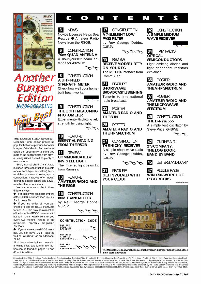
The Margate Lifeboat which rescued fishermen in distress, thanks to radio (seemain story opposite).
32 CONSTRUCTIONA SIMPLE MEDIUMWAVE RECEIVER
34 HAM FACTSOPTICALSEMICONDUCTORSLight emitting diodes andlight dependant resistorsexplained.
35 POSTERAMATEUR RADIO ANDTHE VHF SPECTRUM
37 POSTERAMATEUR RADIO ANDTHE MICROWAVESPECTRUM
40 CONSTRUCTIONTHE D-i-YER 555A simple test oscillator bySteve Price, G4BWE.
42 ON THE AIR2’S COMPANY,THE LOG BOOK,BAND BY BAND
45 LETTERS AND DIARY
47 PUZZLE PAGEWIN £50-WORTH OFRSGB BOOKS
A n o t h e rB u m p e rE d i t i o nI N C O R P O R A T I N G
THE DOUBLE-SIZED November-December 1995 edition proved sopopular that we’ve produced anotherbumper D-i-Y Radio. And we havetaken the opportunity to bring youmore of the best projects from previ-ous magazines as well as plenty ofnew material.
Every normal-sized D-i-Y Radioincludes three construction projects(one of each type - see below), tech-nical theory, a colour poster, a prizecompetition, a special offer, news,operating details, letters and a two-month calendar of events.
You can now subscribe in threedifferent ways. For those who are not membersof the RSGB, a subscription to D-i-YRadio costs £9. If you are under 18, you canchoose to join the RSGB HamClubfor just £10. This provides almost allof the benefits of RSGB membershipbut with D-i-Y Radio sent to youevery two months instead of themembers’ monthly magazineRadCom. If you are already an RSGB mem-ber, you can have D-i-Y Radio aswell as RadCom for an additional£7.65.All of these subscriptions come witha joining pack, and further informa-tion can be found on pages 10 and46 of this edition.
PHOTOGRAPH: RNLI
3
6
8
9
10
1111111111
13
15
17
19
21
23
25
27
32
31
34
35
37
40
42
45
47
3D-I-Y RADIO March-April 1996
NewsRSGB
Novice LicenseeHelps Sea Rescue
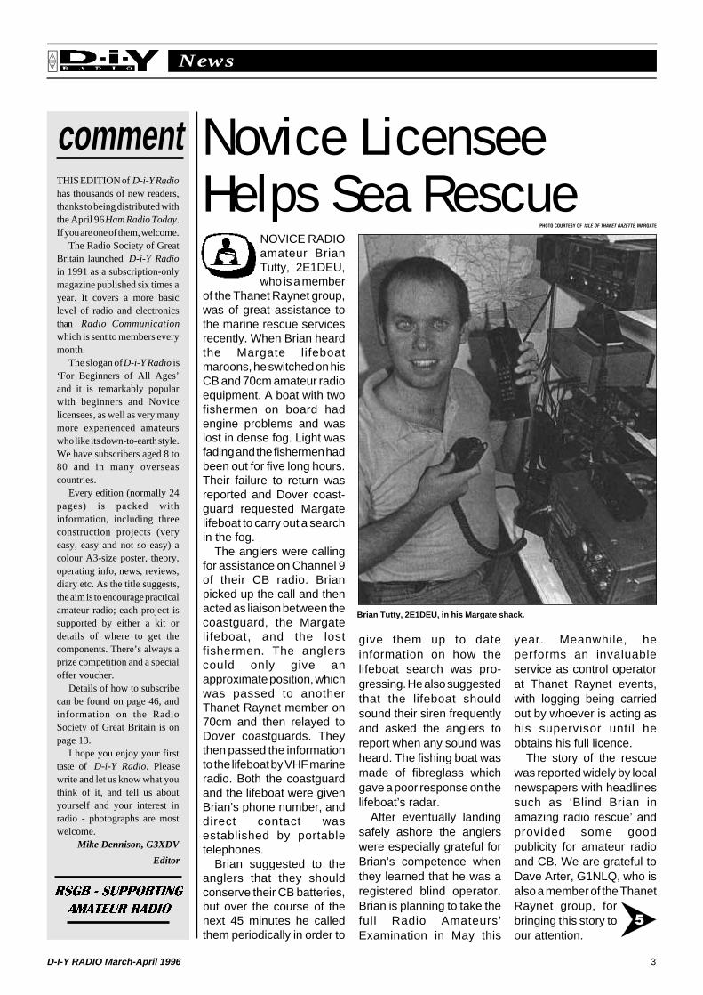
NOVICE RADIOamateur BrianTutty, 2E1DEU,who is a member
of the Thanet Raynet group,was of great assistance tothe marine rescue servicesrecently. When Brian heardthe Margate lifeboatmaroons, he switched on hisCB and 70cm amateur radioequipment. A boat with twofishermen on board hadengine problems and waslost in dense fog. Light wasfading and the fishermen hadbeen out for five long hours.Their failure to return wasreported and Dover coast-guard requested Margatelifeboat to carry out a searchin the fog.
The anglers were callingfor assistance on Channel 9of their CB radio. Brianpicked up the call and thenacted as liaison between thecoastguard, the Margatelifeboat, and the lostfishermen. The anglerscould only give anapproximate position, whichwas passed to anotherThanet Raynet member on70cm and then relayed toDover coastguards. Theythen passed the informationto the lifeboat by VHF marineradio. Both the coastguardand the lifeboat were givenBrian’s phone number, anddirect contact wasestablished by portabletelephones.
Brian suggested to theanglers that they shouldconserve their CB batteries,but over the course of thenext 45 minutes he calledthem periodically in order to
Brian Tutty, 2E1DEU, in his Margate shack.
PHOTO COURTESY OF ISLE OF THANET GAZETTE, MARGATE
give them up to dateinformation on how thelifeboat search was pro-gressing. He also suggestedthat the lifeboat shouldsound their siren frequentlyand asked the anglers toreport when any sound washeard. The fishing boat wasmade of fibreglass whichgave a poor response on thelifeboat’s radar.
After eventually landingsafely ashore the anglerswere especially grateful forBrian’s competence whenthey learned that he was aregistered blind operator.Brian is planning to take thefull Radio Amateurs’Examination in May this
year. Meanwhile, heperforms an invaluableservice as control operatorat Thanet Raynet events,with logging being carriedout by whoever is acting ashis supervisor until heobtains his full licence.
The story of the rescuewas reported widely by localnewspapers with headlinessuch as ‘Blind Brian inamazing radio rescue’ andprovided some goodpublicity for amateur radioand CB. We are grateful toDave Arter, G1NLQ, who isalso a member of the ThanetRaynet group, forbringing this story toour attention.
commentTHIS EDITION of D-i-Y Radiohas thousands of new readers,thanks to being distributed withthe April 96 Ham Radio Today.If you are one of them, welcome.
The Radio Society of GreatBritain launched D-i-Y Radioin 1991 as a subscription-onlymagazine published six times ayear. It covers a more basiclevel of radio and electronicsthan Radio Communicationwhich is sent to members everymonth.
The slogan of D-i-Y Radio is‘For Beginners of All Ages’and it is remarkably popularwith beginners and Novicelicensees, as well as very manymore experienced amateurswho like its down-to-earth style.We have subscribers aged 8 to80 and in many overseascountries.
Every edition (normally 24pages) is packed withinformation, including threeconstruction projects (veryeasy, easy and not so easy) acolour A3-size poster, theory,operating info, news, reviews,diary etc. As the title suggests,the aim is to encourage practicalamateur radio; each project issupported by either a kit ordetails of where to get thecomponents. There’s always aprize competition and a specialoffer voucher.
Details of how to subscribecan be found on page 46, andinformation on the RadioSociety of Great Britain is onpage 13.
I hope you enjoy your firsttaste of D-i-Y Radio. Pleasewrite and let us know what youthink of it, and tell us aboutyourself and your interest inradio - photographs are mostwelcome.
Mike Dennison, G3XDV
Editor
RSGB - SUPPORTING
AMATEUR RADIO5

Advertisement
5D-I-Y RADIO March-April 1996
NewsRSGB
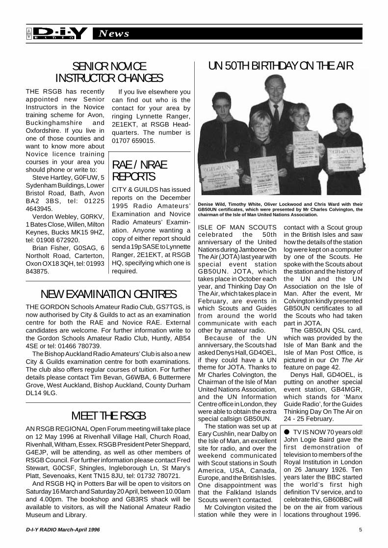
ISLE OF MAN SCOUTScelebrated the 50thanniversary of the UnitedNations during Jamboree OnThe Air (JOTA) last year withspecial event stationGB50UN. JOTA, whichtakes place in October eachyear, and Thinking Day OnThe Air, which takes place inFebruary, are events inwhich Scouts and Guidesfrom around the worldcommunicate with eachother by amateur radio.
Because of the UNanniversary, the Scouts hadasked Denys Hall, GD4OEL,if they could have a UNtheme for JOTA. Thanks toMr Charles Colvington, theChairman of the Isle of ManUnited Nations Association,and the UN InformationCentre office in London, theywere able to obtain the extraspecial callsign GB50UN.
The station was set up atEary Cushlin, near Dalby onthe Isle of Man, an excellentsite for radio, and over theweekend communicatedwith Scout stations in SouthAmerica, USA, Canada,Europe, and the British Isles.One disappointment wasthat the Falkland IslandsScouts weren’t contacted.
Mr Colvington visited thestation while they were in
contact with a Scout groupin the British Isles and sawhow the details of the stationlog were kept on a computerby one of the Scouts. Hespoke with the Scouts aboutthe station and the history ofthe UN and the UNAssociation on the Isle ofMan. After the event, MrColvington kindly presentedGB50UN certificates to allthe Scouts who had takenpart in JOTA.
The GB50UN QSL card,which was provided by theIsle of Man Bank and theIsle of Man Post Office, ispictured in our On The Airfeature on page 42.
Denys Hall, GD4OEL, isputting on another specialevent station, GB4MGR,which stands for ‘ManxGuide Radio’, for the GuidesThinking Day On The Air on24 - 25 February.
UN 50TH BIRTHDAY ON THE AIR
Denise Wild, Timothy White, Oliver Lockwood and Chris Ward with theirGB50UN certificates, which were presented by Mr Charles Colvington, thechairman of the Isle of Man United Nations Association.
TV IS NOW 70 years old!John Logie Baird gave thefirst demonstration oftelevision to members of theRoyal Institution in Londonon 26 January 1926. Tenyears later the BBC startedthe world’s first highdefinition TV service, and tocelebrate this, GB60BBC willbe on the air from variouslocations throughout 1996.
MEET THE RSGBAN RSGB REGIONAL Open Forum meeting will take placeon 12 May 1996 at Rivenhall Village Hall, Church Road,Rivenhall, Witham, Essex. RSGB President Peter Sheppard,G4EJP, will be attending, as well as other members ofRSGB Council. For further information please contact FredStewart, G0CSF, Shingles, Ingleborough Ln, St Mary’sPlatt, Sevenoaks, Kent TN15 8JU, tel: 01732 780721.
And RSGB HQ in Potters Bar will be open to visitors onSaturday 16 March and Saturday 20 April, between 10.00amand 4.00pm. The bookshop and GB3RS shack will beavailable to visitors, as will the National Amateur RadioMuseum and Library.
NEW EXAMINATION CENTRESTHE GORDON Schools Amateur Radio Club, GS7TGS, isnow authorised by City & Guilds to act as an examinationcentre for both the RAE and Novice RAE. Externalcandidates are welcome. For further information write tothe Gordon Schools Amateur Radio Club, Huntly, AB544SE or tel: 01466 780739.
The Bishop Auckland Radio Amateurs’ Club is also a newCity & Guilds examination centre for both examinations.The club also offers regular courses of tuition. For furtherdetails please contact Tim Bevan, G6WBA, 6 ButtermereGrove, West Auckland, Bishop Auckland, County DurhamDL14 9LG.
RAE / NRAEREPORTSCITY & GUILDS has issuedreports on the December1995 Radio Amateurs’Examination and NoviceRadio Amateurs’ Examin-ation. Anyone wanting acopy of either report shouldsend a 19p SASE to LynnetteRanger, 2E1EKT, at RSGBHQ, specifying which one isrequired.
THE RSGB has recentlyappointed new SeniorInstructors in the Novicetraining scheme for Avon,Buckinghamshire andOxfordshire. If you live inone of those counties andwant to know more aboutNovice licence trainingcourses in your area youshould phone or write to:
Steve Hartley, G0FUW, 5Sydenham Buildings, LowerBristol Road, Bath, AvonBA2 3BS, tel: 012254643945.
Verdon Webley, G0RKV,1 Bates Close, Willen, MiltonKeynes, Bucks MK15 9HZ,tel: 01908 672920.
Brian Fisher, G0SAG, 6Northolt Road, Carterton,Oxon OX18 3QH, tel: 01993843875.
If you live elsewhere youcan find out who is thecontact for your area byringing Lynnette Ranger,2E1EKT, at RSGB Head-quarters. The number is01707 659015.
SENIOR NOVICEINSTRUCTOR CHANGES
6 D-I-Y RADIO March-April 1996
Construction FeatureRSGB
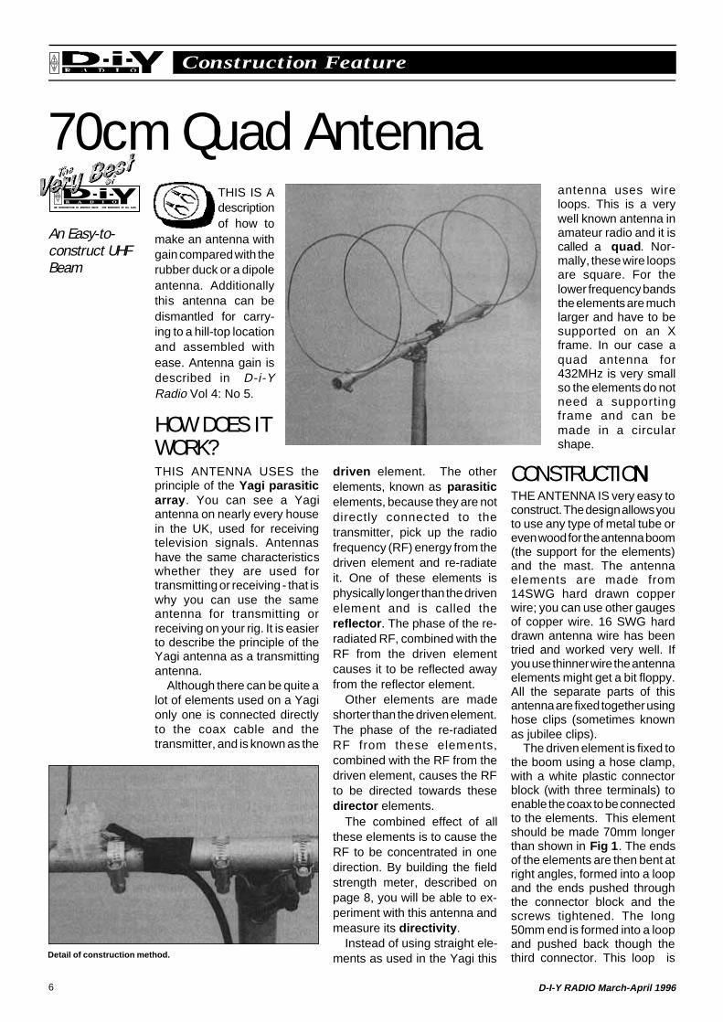
70cm Quad AntennaTHIS IS Adescriptionof how to
make an antenna withgain compared with therubber duck or a dipoleantenna. Additionallythis antenna can bedismantled for carry-ing to a hill-top locationand assembled withease. Antenna gain isdescribed in D-i-YRadio Vol 4: No 5.
HOW DOES ITWORK?THIS ANTENNA USES theprinciple of the Yagi parasiticarray . You can see a Yagiantenna on nearly every housein the UK, used for receivingtelevision signals. Antennashave the same characteristicswhether they are used fortransmitting or receiving - that iswhy you can use the sameantenna for transmitting orreceiving on your rig. It is easierto describe the principle of theYagi antenna as a transmittingantenna.
Although there can be quite alot of elements used on a Yagionly one is connected directlyto the coax cable and thetransmitter, and is known as the
driven element. The otherelements, known as parasiticelements, because they are notdirectly connected to thetransmitter, pick up the radiofrequency (RF) energy from thedriven element and re-radiateit. One of these elements isphysically longer than the drivenelement and is called thereflector . The phase of the re-radiated RF, combined with theRF from the driven elementcauses it to be reflected awayfrom the reflector element.
Other elements are madeshorter than the driven element.The phase of the re-radiatedRF from these elements,combined with the RF from thedriven element, causes the RFto be directed towards thesedirector elements.
The combined effect of allthese elements is to cause theRF to be concentrated in onedirection. By building the fieldstrength meter, described onpage 8, you will be able to ex-periment with this antenna andmeasure its directivity .
Instead of using straight ele-ments as used in the Yagi this
antenna uses wireloops. This is a verywell known antenna inamateur radio and it iscalled a quad . Nor-mally, these wire loopsare square. For thelower frequency bandsthe elements are muchlarger and have to besupported on an Xframe. In our case aquad antenna for432MHz is very smallso the elements do notneed a supportingframe and can bemade in a circularshape.
CONSTRUCTIONNNNNTHE ANTENNA IS very easy toconstruct. The design allows youto use any type of metal tube oreven wood for the antenna boom(the support for the elements)and the mast. The antennaelements are made from14SWG hard drawn copperwire; you can use other gaugesof copper wire. 16 SWG harddrawn antenna wire has beentried and worked very well. Ifyou use thinner wire the antennaelements might get a bit floppy.All the separate parts of thisantenna are fixed together usinghose clips (sometimes knownas jubilee clips).
The driven element is fixed tothe boom using a hose clamp,with a white plastic connectorblock (with three terminals) toenable the coax to be connectedto the elements. This elementshould be made 70mm longerthan shown in Fig 1 . The endsof the elements are then bent atright angles, formed into a loopand the ends pushed throughthe connector block and thescrews tightened. The long50mm end is formed into a loopand pushed back though thethird connector. This loop isDetail of construction method.
An Easy-to-construct UHFBeam
7D-I-Y RADIO March-April 1996
Construction FeatureRSGB
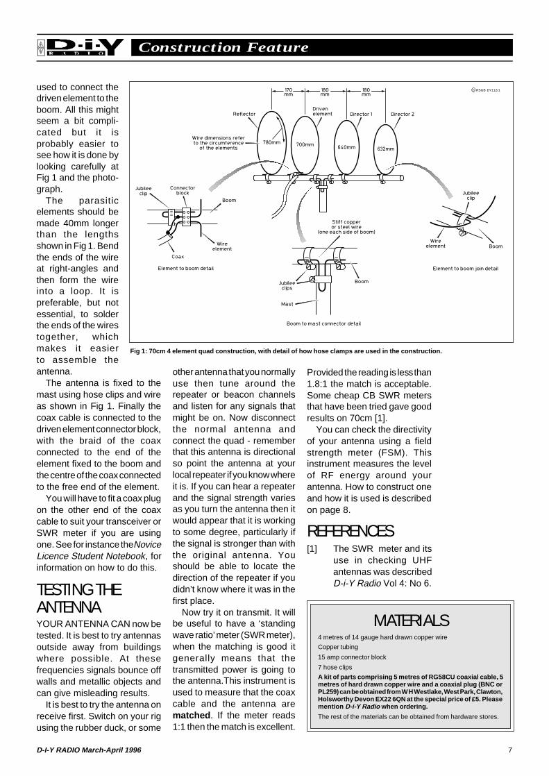
used to connect thedriven element to theboom. All this mightseem a bit compli-cated but it isprobably easier tosee how it is done bylooking carefully atFig 1 and the photo-graph.
The parasiticelements should bemade 40mm longerthan the lengthsshown in Fig 1. Bendthe ends of the wireat right-angles andthen form the wireinto a loop. It ispreferable, but notessential, to solderthe ends of the wirestogether, whichmakes it easierto assemble theantenna.
The antenna is fixed to themast using hose clips and wireas shown in Fig 1. Finally thecoax cable is connected to thedriven element connector block,with the braid of the coaxconnected to the end of theelement fixed to the boom andthe centre of the coax connectedto the free end of the element.
You will have to fit a coax plugon the other end of the coaxcable to suit your transceiver orSWR meter if you are usingone. See for instance the NoviceLicence Student Notebook, forinformation on how to do this.
TESTING THEANTENNAYOUR ANTENNA CAN now betested. It is best to try antennasoutside away from buildingswhere possible. At thesefrequencies signals bounce offwalls and metallic objects andcan give misleading results.
It is best to try the antenna onreceive first. Switch on your rigusing the rubber duck, or some
other antenna that you normallyuse then tune around therepeater or beacon channelsand listen for any signals thatmight be on. Now disconnectthe normal antenna andconnect the quad - rememberthat this antenna is directionalso point the antenna at yourlocal repeater if you know whereit is. If you can hear a repeaterand the signal strength variesas you turn the antenna then itwould appear that it is workingto some degree, particularly ifthe signal is stronger than withthe original antenna. Youshould be able to locate thedirection of the repeater if youdidn’t know where it was in thefirst place.
Now try it on transmit. It willbe useful to have a ‘standingwave ratio’ meter (SWR meter),when the matching is good itgenerally means that thetransmitted power is going tothe antenna.This instrument isused to measure that the coaxcable and the antenna arematched . If the meter reads1:1 then the match is excellent.
Fig 1: 70cm 4 element quad construction, with detail of how hose clamps are used in the construction.
Provided the reading is less than1.8:1 the match is acceptable.Some cheap CB SWR metersthat have been tried gave goodresults on 70cm [1].
You can check the directivityof your antenna using a fieldstrength meter (FSM). Thisinstrument measures the levelof RF energy around yourantenna. How to construct oneand how it is used is describedon page 8.
REFERENCES[1] The SWR meter and its
use in checking UHFantennas was describedD-i-Y Radio Vol 4: No 6.
C RSGB DY112/1
MATERIALS4 metres of 14 gauge hard drawn copper wire
Copper tubing
15 amp connector block
7 hose clips
A kit of parts comprising 5 metres of RG58CU coaxial cable, 5metres of hard drawn copper wire and a coaxial plug (BNC orPL259) can be obtained from W H Westlake, West Park, Clawton,Holsworthy Devon EX22 6QN at the special price of £5. Pleasemention D-i-Y Radio when ordering.
The rest of the materials can be obtained from hardware stores.
8 D-I-Y RADIO March-April 1996
Construction FeatureRSGB
A UHF Field Strength Metersometimes called anAbsorption Wave-meter , which is usefulfor measuring thefrequencies of anyspurious signals, suchas harmonics, radiatingfrom a transmitter.Because we want aninstrument for checking
the performance of a UHFantenna we want an FSM that issensitive around 433MHz. Youcan use this instrument forcomparing the signal strengthof the rubber duck antenna onyour rig with any experimentalantenna that you might like tomake.
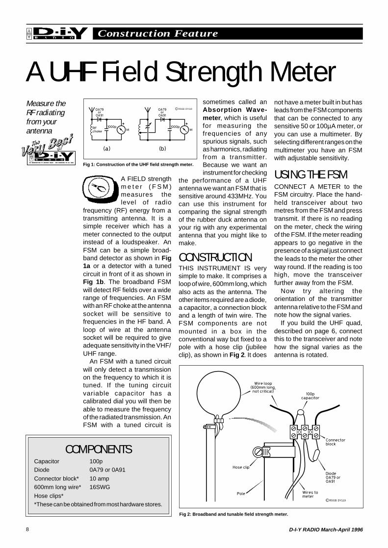
CONSTRUCTIONTHIS INSTRUMENT IS verysimple to make. It comprises aloop of wire, 600mm long, whichalso acts as the antenna. Theother items required are a diode,a capacitor, a connection blockand a length of twin wire. TheFSM components are notmounted in a box in theconventional way but fixed to apole with a hose clip (jubileeclip), as shown in Fig 2. It does
Fig 2: Broadband and tunable field strength meter.
not have a meter built in but hasleads from the FSM componentsthat can be connected to anysensitive 50 or 100µA meter, oryou can use a multimeter. Byselecting different ranges on themultimeter you have an FSMwith adjustable sensitivity.
USING THE FSMCONNECT A METER to theFSM circuitry. Place the hand-held transceiver about twometres from the FSM and presstransmit. If there is no readingon the meter, check the wiringof the FSM. If the meter readingappears to go negative in thepresence of a signal just connectthe leads to the meter the otherway round. If the reading is toohigh, move the transceiverfurther away from the FSM.
Now try altering theorientation of the transmitterantenna relative to the FSM andnote how the signal varies.
If you build the UHF quad,described on page 6, connectthis to the transceiver and notehow the signal varies as theantenna is rotated.
Measure theRF radiatingfrom yourantenna
A FIELD strengthm e t e r ( F S M )measures thelevel of radio
frequency (RF) energy from atransmitting antenna. It is asimple receiver which has ameter connected to the outputinstead of a loudspeaker. AnFSM can be a simple broad-band detector as shown in Fig1a or a detector with a tunedcircuit in front of it as shown inFig 1b . The broadband FSMwill detect RF fields over a widerange of frequencies. An FSMwith an RF choke at the antennasocket will be sensitive tofrequencies in the HF band. Aloop of wire at the antennasocket will be required to giveadequate sensitivity in the VHF/UHF range.
An FSM with a tuned circuitwill only detect a transmissionon the frequency to which it istuned. If the tuning circuitvariable capacitor has acalibrated dial you will then beable to measure the frequencyof the radiated transmission. AnFSM with a tuned circuit is
C RSGB DY119
C RSGB DY118
Fig 1: Construction of the UHF field strength meter.
COMPONENTSCapacitor 100pDiode 0A79 or 0A91
Connector block* 10 amp600mm long wire* 16SWG
Hose clips**These can be obtained from most hardware stores.
9D-I-Y RADIO March-April 1996
Construction FeatureRSGB
The Light Measuring PhotometerBEFORE THEdays of automaticcameras a photo-grapher would use
a light meter (Photometer) tomeasure the light level and thenmanually convert the lightreading to shutter speed andlens aperture settings to ensurethat the film exposure wascorrect.
Most modern cameras havea light measuring meter built in,which controls the aperturesetting of the camera lensautomatically.
HOW DOES ITWORK?THE OPERATION OF the circuitin Fig 1 is based on a componentcalled a Light DependantResistor (LDR). In bright lightthe resistance of the LDR is low- about 1kΩ. In the dark itsresistance is high, up to 10MΩ.When an LDR is connected inseries with a battery and a meterthe rate of current flowing willdepend on the light intensity atthe LDR. In this circuit a variableresistor, RV1, is connected inseries with the LDR, battery and
Fig 1: Circuit diagram of photometer.
C RSGB DY122
meter. This is so that the rangeof the meter can be set. In otherwords you want the meter toread full scale deflection whenthe light intensity is at maximumand to read zero when the lightlevel is very low.
This instrument is very simpleto make. The items required arean LDR, 50kΩ variable resistorand any sensitive 50 or 100µAmeter. You could use amultimeter for M1. Theconnections of RV1 are thecentre tab and the left-hand tab,viewed from the rear.
THE PHOTOMETERWHEN THE PHOTOMETER isconnected up you will find that itwill probably give a readingstraight away due to daylightreducing the resistance of the
LDR. This instrument is quitesensitive to light. You willprobably have to find a darkroom where the light is lowenough for the meter to readzero.
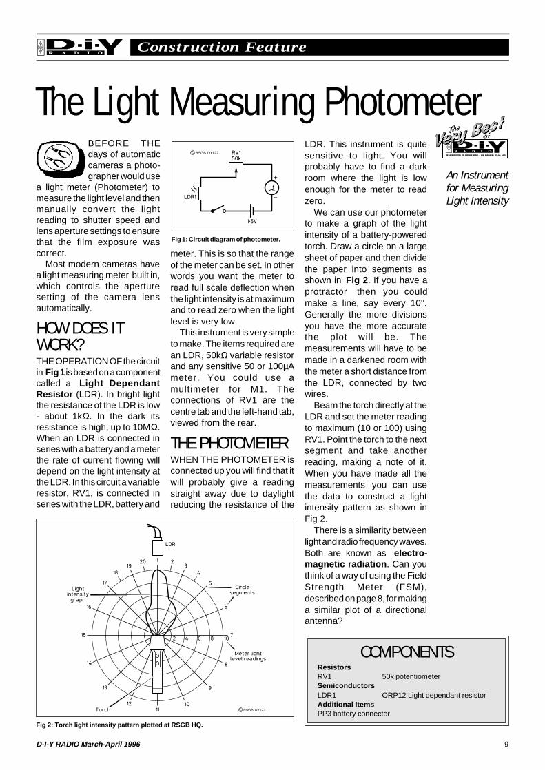
We can use our photometerto make a graph of the lightintensity of a battery-poweredtorch. Draw a circle on a largesheet of paper and then dividethe paper into segments asshown in Fig 2 . If you have aprotractor then you couldmake a line, say every 10°.Generally the more divisionsyou have the more accuratethe plot will be. Themeasurements will have to bemade in a darkened room withthe meter a short distance fromthe LDR, connected by twowires.
Beam the torch directly at theLDR and set the meter readingto maximum (10 or 100) usingRV1. Point the torch to the nextsegment and take anotherreading, making a note of it.When you have made all themeasurements you can usethe data to construct a lightintensity pattern as shown inFig 2.
There is a similarity betweenlight and radio frequency waves.Both are known as electro-magnetic radiation . Can youthink of a way of using the FieldStrength Meter (FSM),described on page 8, for makinga similar plot of a directionalantenna?
Fig 2: Torch light intensity pattern plotted at RSGB HQ.
COMPONENTSResistorsRV1 50k potentiometerSemiconductorsLDR1 ORP12 Light dependant resistorAdditional ItemsPP3 battery connector
C RSGB DY123
An Instrumentfor MeasuringLight Intensity

Advertisement
11D-I-Y RADIO March-April 1996
Equipment ReviewRSGB
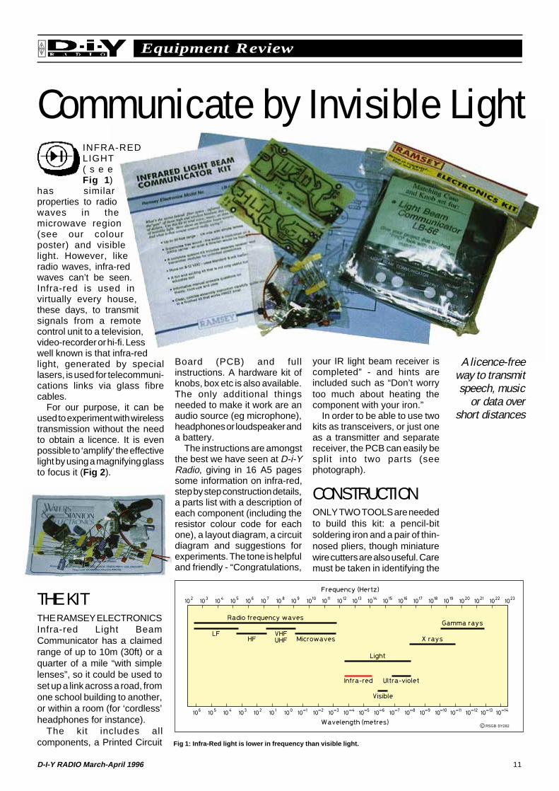
Communicate by Invisible LightINFRA-REDLIGHT( s e eFig 1 )
has similarproperties to radiowaves in themicrowave region(see our colourposter) and visiblelight. However, likeradio waves, infra-redwaves can’t be seen.Infra-red is used invirtually every house,these days, to transmitsignals from a remotecontrol unit to a television,video-recorder or hi-fi. Lesswell known is that infra-redlight, generated by speciallasers, is used for telecommuni-cations links via glass fibrecables.
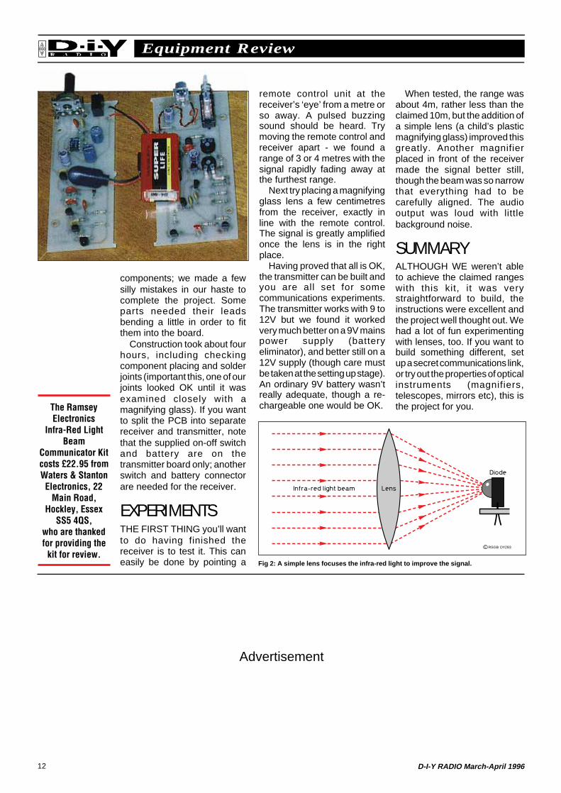
For our purpose, it can beused to experiment with wirelesstransmission without the needto obtain a licence. It is evenpossible to ‘amplify’ the effectivelight by using a magnifying glassto focus it (Fig 2 ).
Fig 1: Infra-Red light is lower in frequency than visible light.
Board (PCB) and fullinstructions. A hardware kit ofknobs, box etc is also available.The only additional thingsneeded to make it work are anaudio source (eg microphone),headphones or loudspeaker anda battery.
The instructions are amongstthe best we have seen at D-i-YRadio, giving in 16 A5 pagessome information on infra-red,step by step construction details,a parts list with a description ofeach component (including theresistor colour code for eachone), a layout diagram, a circuitdiagram and suggestions forexperiments. The tone is helpfuland friendly - “Congratulations,
your IR light beam receiver iscompleted” - and hints areincluded such as “Don’t worrytoo much about heating thecomponent with your iron.”
In order to be able to use twokits as transceivers, or just oneas a transmitter and separatereceiver, the PCB can easily besplit into two parts (seephotograph).
CONSTRUCTIONONLY TWO TOOLS are neededto build this kit: a pencil-bitsoldering iron and a pair of thin-nosed pliers, though miniaturewire cutters are also useful. Caremust be taken in identifying the
A licence-freeway to transmitspeech, music
or data overshort distances
THE KITTHE RAMSEY ELECTRONICSInfra-red Light BeamCommunicator has a claimedrange of up to 10m (30ft) or aquarter of a mile “with simplelenses”, so it could be used toset up a link across a road, fromone school building to another,or within a room (for ‘cordless’headphones for instance).
The kit includes allcomponents, a Printed Circuit
C RSGB DY282
12 D-I-Y RADIO March-April 1996
Equipment ReviewRSGB
components; we made a fewsilly mistakes in our haste tocomplete the project. Someparts needed their leadsbending a little in order to fitthem into the board.
Construction took about fourhours, including checkingcomponent placing and solderjoints (important this, one of ourjoints looked OK until it wasexamined closely with amagnifying glass). If you wantto split the PCB into separatereceiver and transmitter, notethat the supplied on-off switchand battery are on thetransmitter board only; anotherswitch and battery connectorare needed for the receiver.
EXPERIMENTSTHE FIRST THING you’ll wantto do having finished thereceiver is to test it. This caneasily be done by pointing a
remote control unit at thereceiver’s ‘eye’ from a metre orso away. A pulsed buzzingsound should be heard. Trymoving the remote control andreceiver apart - we found arange of 3 or 4 metres with thesignal rapidly fading away atthe furthest range.
Next try placing a magnifyingglass lens a few centimetresfrom the receiver, exactly inline with the remote control.The signal is greatly amplifiedonce the lens is in the rightplace.
Having proved that all is OK,the transmitter can be built andyou are all set for somecommunications experiments.The transmitter works with 9 to12V but we found it workedvery much better on a 9V mainspower supply (batteryeliminator), and better still on a12V supply (though care mustbe taken at the setting up stage).An ordinary 9V battery wasn’treally adequate, though a re-chargeable one would be OK.
When tested, the range wasabout 4m, rather less than theclaimed 10m, but the addition ofa simple lens (a child’s plasticmagnifying glass) improved thisgreatly. Another magnifierplaced in front of the receivermade the signal better still,though the beam was so narrowthat everything had to becarefully aligned. The audiooutput was loud with littlebackground noise.
SUMMARYALTHOUGH WE weren’t ableto achieve the claimed rangeswith this kit, it was verystraightforward to build, theinstructions were excellent andthe project well thought out. Wehad a lot of fun experimentingwith lenses, too. If you want tobuild something different, setup a secret communications link,or try out the properties of opticalinstruments (magnifiers,telescopes, mirrors etc), this isthe project for you.
Fig 2: A simple lens focuses the infra-red light to improve the signal.
The RamseyElectronics
Infra-Red LightBeam
Communicator Kitcosts £22.95 fromWaters & StantonElectronics, 22
Main Road,Hockley, Essex
SS5 4QS,who are thankedfor providing the
kit for review.C RSGB DY283
Advertisement

13D-I-Y RADIO March-April 1996
FeatureRSGB
Amateur Radio and the RSGBHow your
national societyhas supportedamateur radiofor more than
80 years.
THE RADIO Societyof Great Britainrepresents all UK
radio amateurs nationally (infrequent meetings with theRadiocommunications Agency)and internationally (as amember of the InternationalAmateur Radio Union - IARU);it has done so since 1913.Protecting our bands is evenmore important in today’scrowded spectrum, but theRSGB aims not only to protectbut to expand; the Class Blicence and the 6 metre bandare two examples of licenceimprovements brought about byRSGB initiatives.
A full-time staff of 30, backedup by more than a thousandspecialist volunteers, providesadvice, assistance and technicalpublications to some 30,000members worldwide.
LICENSINGTHE RSGB CARRIES out allNovice licence training andMorse testing, and issuesspecial event (GB) callsigns. Itprovides news broadcasts andMorse practice transmissionsunder the callsigns GB2RS andGB2CW. Many on-the-airactivities are co-ordinated bythe RSGB, such as awards,contests and repeaters.
It also provides the Britishpart of the worldwide QSL
Bureau system. RSGBmembers send QSL cards inbulk to RSGB Headquarters forsorting and onward distributionto amateurs all round theworld. Incoming QSL cards areposted to UK amateurs in packsof 20 or so, using envelopeswhich they provide. An activeoperator can save aconsiderable amount in post-age by using the Society’s QSLBureau.
INFORMATIONAND ADVICEAS WELL AS being the country’slargest publisher of amateurradio books (see page 10), theRSGB also stocks more than
100 books from other sources.In addition, there’s RadCom -which is, a monthly 100-pagecolour magazine sent free to allmembers - D-i-Y Radio, andspecialist newsletters for the HFand Microwave enthusiast.
Expert volunteers are on handto advise not only the Society’snegotiating teams, but alsoindividual members. Specialistcommittees cover HF, VHF,Microwaves, Licensing,Propagation, MembershipServices, IARU, DirectionFinding, Data Communications,EMC (interference), Exhibitions,Contests, Planning Permission,Repeaters, Education andPublications.
Each county has a RSGBLiaison Officer who is availableto provide members with adviceor tell them how to contact theappropriate expert.
RSGB - WE’REHERE TO HELP
YOU
RSGB Headquarters at Potters Bar, justoff the M25 north of London, houses theadministrative offices, the publishing andsales operations, the QSL Bureau, anextensive bookshop, the National AmateurRadio Museum and Library, and a well-equipped radio station using the callsignGB3RS. Guided tours of the whole buildingare on offer at the Annual Open Day (4 Maythis year).
At your service: part of the bookshop and reception area at RSGB Headquarters. Theshop is open on weekdays (9.15am to 5.15pm) and every third Saturday in each monthbetween 10.00am and 4.00pm.
14 D-I-Y RADIO March-April 1996
FeatureRSGB
AMATEUR RADIOTHE HOBBY of amateur radio is as old as Marconi. Yet it remains asexciting as ever with the use of computers and satellites. There are over60,000 amateurs in the UK and well over two million worldwide, and thisnumber is increasing.
Radio amateurs are qualified radio operators. They are enthusiasts whohave passed a City and Guilds examination in radio theory and practicewhich allows them to hold a transmitting licence issued by theRadiocommunications Agency of the DTI. The licence, which allocates aunique callsign, lists the rules under which radio amateurs are allowed totransmit. This includes the permitted frequencies (depending on the classof licence held) - there are more than 25 bands of frequencies allocated tothe Amateur Service, covering the short waves, VHF bands and Microwaves.
There are four types of licence: two for the beginner - the NoviceLicence, and two for the more qualified operator. A Morse test must bepassed to qualify for a Class A licence which allows the use of frequencieswhere worldwide contacts are available, but lots of fun can still be had witha Class B licence which doesn’t need a Morse pass.
Although a wide range of types of transmission can be made, fromMorse code (still widely used) to computer data and even televisionpictures, radio amateurs may not transmit such things as music, commercialor political messages. There’s still plenty to talk about, though, including ofcourse radio itself.
Radio amateurs are the only users of the radio spectrum who arepermitted to build their own transmitters. This is because they are exam-qualified. Most amateur radio stations have a mix of home-built andcommercial equipment.
Amateurs are frequently called upon to assist in times of disaster. Theircompact and simple equipment is frequently more suitable in an emergencythan today’s complex commercial gear. Help has been provided atearthquake sites, train disasters, plane crashes, and so on. In recent years,amateurs provided the only means of communication to and from some ofthe besieged towns in Bosnia.
Radio amateurs have designed and built over 25 communicationssatellites. Astronauts and cosmonautsfrequently operate amateur radio stationsfrom space and many schools have beenable to talk directly to space in this way.
I am interested in joining the RSGB and receiving the full benefits of membership.
Name: ............................................................................................................................................................................
Address: ........................................................................................................................................................................
I enclose £36 (Corporate Membership) £27 (Senior Citizen) £22 (Student) £12 (under 18s HamClub)
Credit Card No. Expiry Date:
Please send me details of how to subscribe by Direct Debit.
WHY SHOULD IJOIN THE RSGB?IN ADDITION to helping tosupport the only organisationin the UK representing amateurradio nationally and inter-nationally, members enjoymany privileges:
RadCom: A minimum of 100pages every month, deliveredto your door, and packed withconstruction projects, the verylatest news, special interestarticles, an extensive Diary ofevents and the largest selectionof commercial and smalladvertisements.
Advice when you need it:Help with technical problems,planning permission orinterference is available fromthe country’s top specialists -absolutely free to members.
Save money: Use of the QSLBureau cuts out the huge costof individually mailing yourcards.
Save more money: Everymember receives a 15 per centdiscount on more than 150books or items of software.
Insurance: This essentialsafeguard has been arrangedspecially for members atadvantageous rates.
WHAT DOESMEMBERSHIPCOST?FULL CORPORATE member-ship costs just £34 per year(UK or overseas) including a
subscription to RadCom. Otherrates are: Senior Citizens £27and Full-time Students £20.
If you are under 18, wecan offer you membershipof the RSGB HamClubat just £10 a year andwe’ll send you D-i-YRadio instead ofRadCom.
Activeamateurs andlisteners need
the RSGB
Activeamateurs andlisteners join
the RSGB
15D-I-Y RADIO March-April 1996
Construction FeatureRSGB
Simple 80m TransmitterIN THE EARLYdays of radiomany items ofequipment where
built on a wooden baseboard.All the parts were screwed downto the board. These were calledbreadboard radios becauseoften that is what was used.
Recently I had need to knockup a simple amateur bandstransmitter for display purposes.I turned to a well known amateurradio circuit called the ONER. Itwas so called because theoriginal design, by George Burt,GM3OXX, was built on a oneinch square circuit board. Thecircuit appeared in the G QRPClub journal SPRAT and sincethat time many hundreds ofONER kits have been boughtand used on the air. This is awell proven circuit.
This simple transmitter circuithas no selective tuned circuitsin the power amplifier. Thismeans that the output from thetransmitter has rather a highharmonic content and must beused with a low-pass filter suchas that described on page 17. Ifa low-pass filter is not used,interference will be caused toother stations.
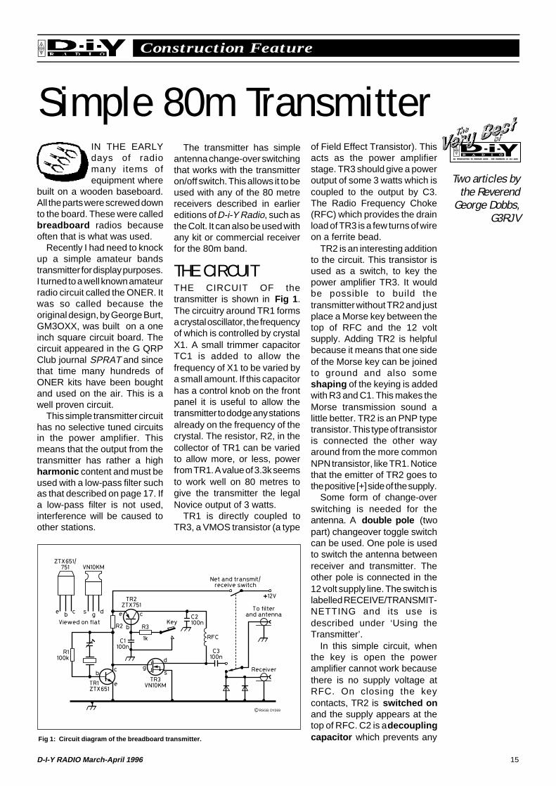
of Field Effect Transistor). Thisacts as the power amplifierstage. TR3 should give a poweroutput of some 3 watts which iscoupled to the output by C3.The Radio Frequency Choke(RFC) which provides the drainload of TR3 is a few turns of wireon a ferrite bead.
TR2 is an interesting additionto the circuit. This transistor isused as a switch, to key thepower amplifier TR3. It wouldbe possible to build thetransmitter without TR2 and justplace a Morse key between thetop of RFC and the 12 voltsupply. Adding TR2 is helpfulbecause it means that one sideof the Morse key can be joinedto ground and also someshaping of the keying is addedwith R3 and C1. This makes theMorse transmission sound alittle better. TR2 is an PNP typetransistor. This type of transistoris connected the other wayaround from the more commonNPN transistor, like TR1. Noticethat the emitter of TR2 goes tothe positive [+] side of the supply.
Some form of change-overswitching is needed for theantenna. A double pole (twopart) changeover toggle switchcan be used. One pole is usedto switch the antenna betweenreceiver and transmitter. Theother pole is connected in the12 volt supply line. The switch islabelled RECEIVE/TRANSMIT-NETTING and its use isdescribed under ‘Using theTransmitter’.
In this simple circuit, whenthe key is open the poweramplifier cannot work becausethere is no supply voltage atRFC. On closing the keycontacts, TR2 is switched onand the supply appears at thetop of RFC. C2 is a decouplingcapacitor which prevents anyFig 1: Circuit diagram of the breadboard transmitter.
C RSGB DY269
The transmitter has simpleantenna change-over switchingthat works with the transmitteron/off switch. This allows it to beused with any of the 80 metrereceivers described in earliereditions of D-i-Y Radio, such asthe Colt. It can also be used withany kit or commercial receiverfor the 80m band.
THE CIRCUITTHE CIRCUIT OF thetransmitter is shown in Fig 1 .The circuitry around TR1 formsa crystal oscillator, the frequencyof which is controlled by crystalX1. A small trimmer capacitorTC1 is added to allow thefrequency of X1 to be varied bya small amount. If this capacitorhas a control knob on the frontpanel it is useful to allow thetransmitter to dodge any stationsalready on the frequency of thecrystal. The resistor, R2, in thecollector of TR1 can be variedto allow more, or less, powerfrom TR1. A value of 3.3k seemsto work well on 80 metres togive the transmitter the legalNovice output of 3 watts.
TR1 is directly coupled toTR3, a VMOS transistor (a type
Two articles bythe Reverend
George Dobbs,G3RJV
16 D-I-Y RADIO March-April 1996
Construction FeatureRSGB
radio frequency signals gettinginto the line between RFC andTR2.
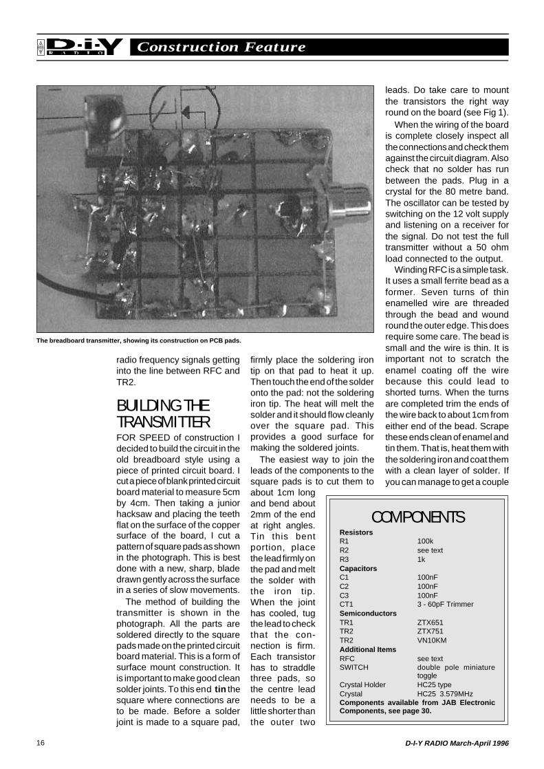
BUILDING THETRANSMITTERFOR SPEED of construction Idecided to build the circuit in theold breadboard style using apiece of printed circuit board. Icut a piece of blank printed circuitboard material to measure 5cmby 4cm. Then taking a juniorhacksaw and placing the teethflat on the surface of the coppersurface of the board, I cut apattern of square pads as shownin the photograph. This is bestdone with a new, sharp, bladedrawn gently across the surfacein a series of slow movements.
The method of building thetransmitter is shown in thephotograph. All the parts aresoldered directly to the squarepads made on the printed circuitboard material. This is a form ofsurface mount construction. Itis important to make good cleansolder joints. To this end tin thesquare where connections areto be made. Before a solderjoint is made to a square pad,
firmly place the soldering irontip on that pad to heat it up.Then touch the end of the solderonto the pad: not the solderingiron tip. The heat will melt thesolder and it should flow cleanlyover the square pad. Thisprovides a good surface formaking the soldered joints.
The easiest way to join theleads of the components to thesquare pads is to cut them toabout 1cm longand bend about2mm of the endat right angles.Tin this bentportion, placethe lead firmly onthe pad and meltthe solder withthe iron tip.When the jointhas cooled, tugthe lead to checkthat the con-nection is firm.Each transistorhas to straddlethree pads, sothe centre leadneeds to be alittle shorter thanthe outer two
leads. Do take care to mountthe transistors the right wayround on the board (see Fig 1).
When the wiring of the boardis complete closely inspect allthe connections and check themagainst the circuit diagram. Alsocheck that no solder has runbetween the pads. Plug in acrystal for the 80 metre band.The oscillator can be tested byswitching on the 12 volt supplyand listening on a receiver forthe signal. Do not test the fulltransmitter without a 50 ohmload connected to the output.
Winding RFC is a simple task.It uses a small ferrite bead as aformer. Seven turns of thinenamelled wire are threadedthrough the bead and woundround the outer edge. This doesrequire some care. The bead issmall and the wire is thin. It isimportant not to scratch theenamel coating off the wirebecause this could lead toshorted turns. When the turnsare completed trim the ends ofthe wire back to about 1cm fromeither end of the bead. Scrapethese ends clean of enamel andtin them. That is, heat them withthe soldering iron and coat themwith a clean layer of solder. Ifyou can manage to get a couple
The breadboard transmitter, showing its construction on PCB pads.
COMPONENTSResistorsR1 100kR2 see textR3 1kCapacitorsC1 100nFC2 100nFC3 100nFCT1 3 - 60pF TrimmerSemiconductorsTR1 ZTX651TR2 ZTX751TR2 VN10KMAdditional ItemsRFC see textSWITCH double pole miniature
toggleCrystal Holder HC25 typeCrystal HC25 3.579MHzComponents available from JAB ElectronicComponents, see page 30.
17D-I-Y RADIO March-April 1996
Construction FeatureRSGB
The answer is harmonicfiltering: adding a circuit that willreduce the harmonics without alot of reduction of the requiredsignal. Even when using a lowpower transmitter, a low passharmonic filter should be used.
A low pass filter is a circuitwhich allows frequencies belowa chosen frequency to passthrough but greatly reduces(attenuates ) signals above thatfrequency. This is called thecut-off frequency and isusually designed to be just
A 7-Element Low Pass Filter
of extra turns through the bead,do so, a little extra inductancecan be helpful. Who says radiois an exact science!
USING THETRANSMITTERCONNECT THE antenna to thetransmitter’s ANTENNA socketvia the filter (see opposite).Connect the receiver to thetransmitter RECEIVER socket.
Set the RECEIVE/TRANSMIT-NETTING switch toReceive. You should hear somesignals on the receiver.
Set the RECEIVE/TRANSMIT-NETTING switch toTransmit-Netting but do notpress the key. The signals onthe receiver should have almostdisappeared because theantenna will have beendisconnected by the antennachangeover contacts on theswitch.
Tune the receiver until a loudsignal from your own transmitteris heard on the receiver. This isknown as NETTING, which is aterm used to describe tuningyour transmitter and receiver tothe same frequency.
Your station is now set up toenable you to call any stationon, or close to, your crystalfrequency. To transmit just pressthe key with the RECEIVE/TRANSMIT-NETTING switch inthe Transmit-Netting positionand switch to Receive for signalscoming back to you.
A KIT ISAVAILABLEKANGA PRODUCTS sell a kitof parts for this transmitter in itsoriginal ONER form. That is, allthe parts and a one inch squareprinted circuit board. It mightsound difficult to build on such a
small board but the layout issuch that anyone capable ofmaking good solder jointsshould have no problems.
Kanga can also supply asuitable crystal in the 80 metreNovice Band.
Kanga Products, SeaviewHouse, Crete Road East,Folkestone, CT18 7EG. Tele-phone: 01303 891106.
SIMPLE LITTLEtransmitters oftenuse circuit short-cuts
which result in not only therequired frequency beinggenerated and amplified but alsoharmonics: the signal times two,the signal times three, the signaltimes four . . . . and so on. Theseharmonics can be quite strongand it may be possible for astation which is transmitting on3.5MHz to be heard on the 7MHzamateur band; both at the sametime!
above the required frequencyof the transmitter.
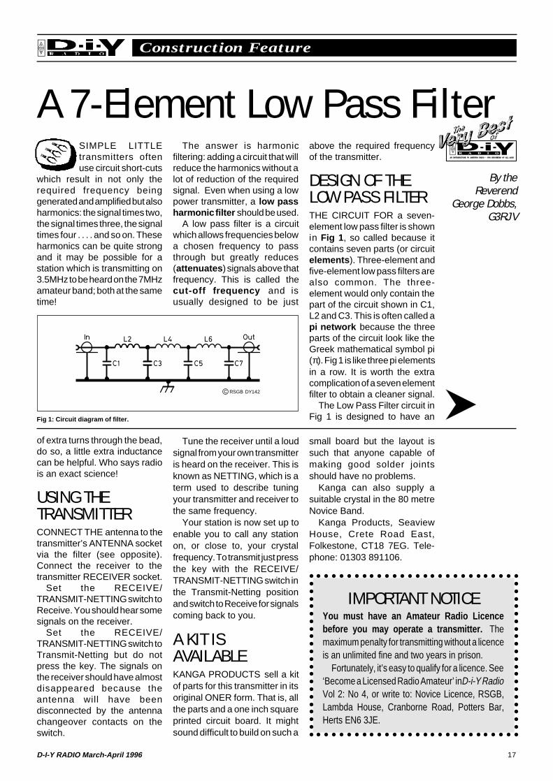
DESIGN OF THELOW PASS FILTERTHE CIRCUIT FOR a seven-element low pass filter is shownin Fig 1 , so called because itcontains seven parts (or circuitelements ). Three-element andfive-element low pass filters arealso common. The three-element would only contain thepart of the circuit shown in C1,L2 and C3. This is often called api network because the threeparts of the circuit look like theGreek mathematical symbol pi(π). Fig 1 is like three pi elementsin a row. It is worth the extracomplication of a seven elementfilter to obtain a cleaner signal.
The Low Pass Filter circuit inFig 1 is designed to have an
IMPORTANT NOTICEYou must have an Amateur Radio Licencebefore you may operate a transmitter. Themaximum penalty for transmitting without a licenceis an unlimited fine and two years in prison.
Fortunately, it’s easy to qualify for a licence. See‘Become a Licensed Radio Amateur’ in D-i-Y RadioVol 2: No 4, or write to: Novice Licence, RSGB,Lambda House, Cranborne Road, Potters Bar,Herts EN6 3JE.
Fig 1: Circuit diagram of filter.
C RSGB DY142
By theReverend
George Dobbs,G3RJV
18 D-I-Y RADIO March-April 1996
Construction FeatureRSGB
input and output impedance of50Ω which means it can matchany common transmitter. Itsimply connects to thetransmitter’s antenna socket.Working out the correct valuesfor a low pass filter can be quitecomplex. Not only has the filtergot to have the correct cut-offfrequency but it also has tohave the correct input and outputimpedance and at the sametime reduce the required signalas little as possible. To makelife even more difficult, cheapcapacitors come in a limitedrange of preferred values.
Some years ago EdWetherhold, W3NQN, who isthe Filter Consultant for theAmerican Amateur RadioRelay League (ARRL),designed a very useful set ofseven element low pass filters.His computer calculations usedpreferred capacitor values togive good filter characteristicsand cut-off frequencies for theamateur bands.
They have become astandard for many builders ofamateur radio equipment. The
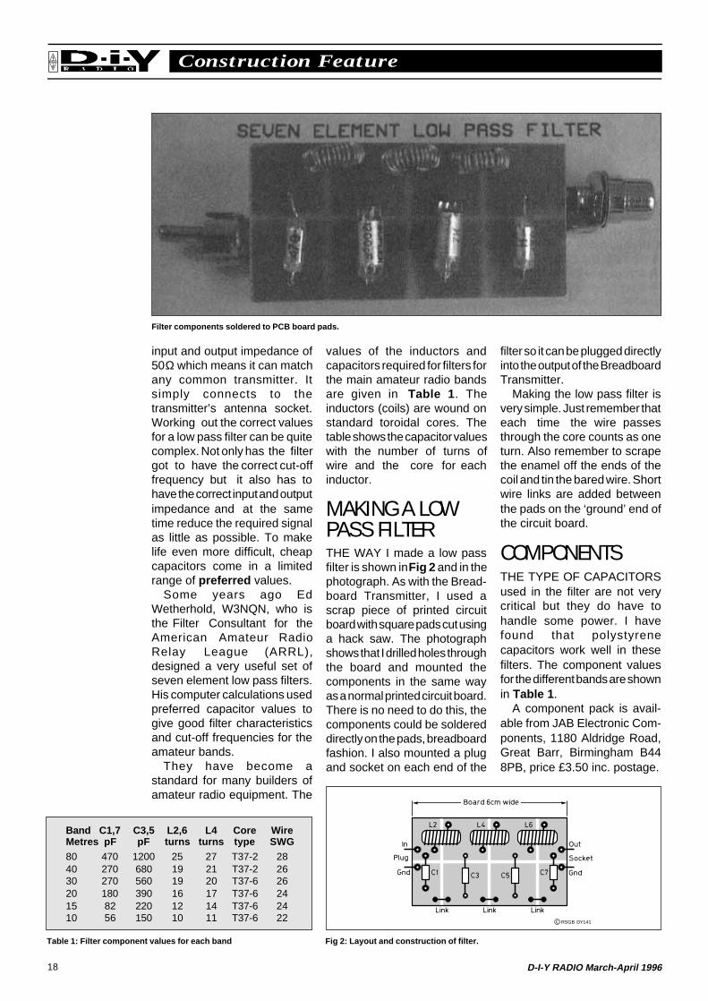
Band C1,7 C3,5 L2,6 L4 Core WireMetres pF pF turns turns type SWG80 470 1200 25 27 T37-2 2840 270 680 19 21 T37-2 2630 270 560 19 20 T37-6 2620 180 390 16 17 T37-6 2415 82 220 12 14 T37-6 2410 56 150 10 11 T37-6 22
Table 1: Filter component values for each band Fig 2: Layout and construction of filter.
filter so it can be plugged directlyinto the output of the BreadboardTransmitter.
Making the low pass filter isvery simple. Just remember thateach time the wire passesthrough the core counts as oneturn. Also remember to scrapethe enamel off the ends of thecoil and tin the bared wire. Shortwire links are added betweenthe pads on the ‘ground’ end ofthe circuit board.
COMPONENTSTHE TYPE OF CAPACITORSused in the filter are not verycritical but they do have tohandle some power. I havefound that polystyrenecapacitors work well in thesefilters. The component valuesfor the different bands are shownin Table 1 .
A component pack is avail-able from JAB Electronic Com-ponents, 1180 Aldridge Road,Great Barr, Birmingham B448PB, price £3.50 inc. postage.
Filter components soldered to PCB board pads.
values of the inductors andcapacitors required for filters forthe main amateur radio bandsare given in Table 1 . Theinductors (coils) are wound onstandard toroidal cores. Thetable shows the capacitor valueswith the number of turns ofwire and the core for eachinductor.
MAKING A LOWPASS FILTERTHE WAY I made a low passfilter is shown in Fig 2 and in thephotograph. As with the Bread-board Transmitter, I used ascrap piece of printed circuitboard with square pads cut usinga hack saw. The photographshows that I drilled holes throughthe board and mounted thecomponents in the same wayas a normal printed circuit board.There is no need to do this, thecomponents could be soldereddirectly on the pads, breadboardfashion. I also mounted a plugand socket on each end of the
C RSGB DY141
19D-I-Y RADIO March-April 1996
User ReviewRSGB
Decode Morse / RTTY on Your PCWHILST TUNINGon the HF (short-wave) amateurbands you are likely
to have come across Morsecode, and perhaps wished youcould have a machine whichwould read it for you. Or perhapsyou’ve heard strange buzzingor warbling noises andwondered what they are. NowCommSLab have produced theRSD 116 Interface which willsolve these problems for you ata very reasonable price. All youneed is a PC with a 3.5in diskdrive, and a receiver. In manycases the most basic computeris suitable - and you can pick upan XT for a few tens of poundsthese days.
The Interface is a tiny unitbuilt into a 25-way ‘D’ plug whichcan be connected directly to theRS-232 (serial) socket on theback of your computer, or via acable (beware not all 25-waycables are suitable, for instance,a ‘null modem’ cable which hasthe transmit/receive pinsreversed). It requires no powersupply or battery, taking itspower from the computer itself.
Wires from the back of theInterface connect to your radio.There are three screened leads:receiver audio (a low level isrequired so this can come froman auxiliary socket if fitted onyour radio), transmitter audioand a transmit/receive switch.Plugs need to be fitted to suityour radio.
SOFTWARESUPPLIED WITH the RSD 116is the necessary software, on a3.5in diskette. Some is‘shareware’ which means thatyou can try out the programs fora while but that you are expectedto make a small payment ($30)to the author if you want to usethem long-term. Threeprograms are provided:
HamComm for Morse and RTTY(teleprinter) signals; JVFAX forFAX signals; and PKTMON forpacket data. PKTMON isreceive-only, the others will workon transmit as well. This reviewdeals mainly with HamComm.
It makes a refreshing changefor software to be easy to install,and you will be pleased to hearthat HamComm and PKTMONcouldn’t be easier. JVFAX wasnot tested.
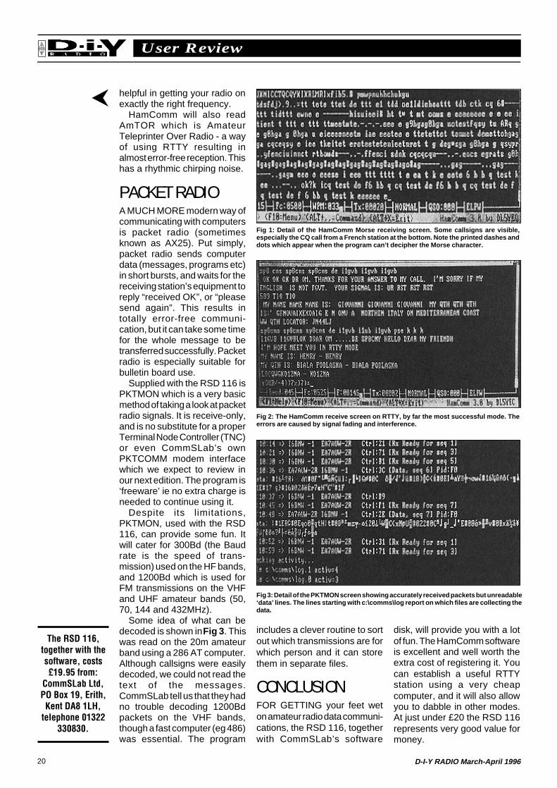
HamComm, written by aGerman amateur, DL5YEC, hasa number of screens. The mainone (Figs 1 and 2 ) showsreceived messages on the lowerpart and transmitted messageson the upper part. It contains anumber of drop-down menuscovering modes of trans-mission, speeds and so on.
Other screens display theincoming signal graphically,and these are extremelyuseful when setting up theequipment.
MORSEBECAUSE MOST Morse codeis sent by hand it is far fromperfect and this makes it verydifficult for a machine to read it.The human brain, on the otherhand, is extremely complexand is quite capable of sortingout badly sent Morse in thepresence of stronginterference.
For this reason, don’t expectthis set-up to be a substitute forlearning Morse code. It does,however, decode well-sentMorse, especially if it is sent athigh speed and it is a strongsignal. The spectrum displayscreen is useful for tuning in thesignal initially. HamComm andthe RSD 116 transmit Morsewell.
RTTYRTTY STANDS FOR RadioTeleTYpe, or the sort oftransmission that was once sentand received on hugetypewriters known asteleprinters. Nowadays,although RTTY is still a veryreliable method of having a radiocontact by typing, the teleprinterhas given way to the computer.RTTY signals have acharacteristic “diddle-diddle-diddle” warbling sound.
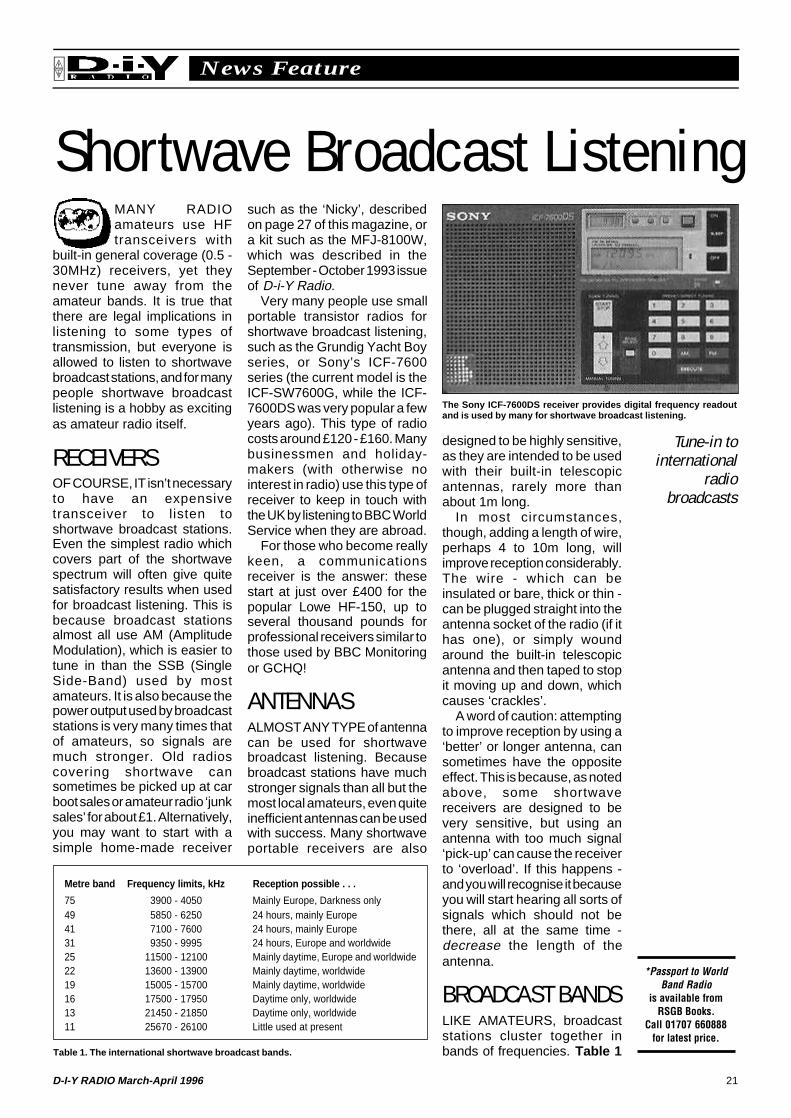
In contrast to hand-sentMorse, all RTTY is sent bymachine and is very easilydecoded automatically. Ham-Comm performs very well onRTTY (see Fig 2). Again thevarious additional screens are
EQUIPMENT REQUIREDHamComm
Computer: Any IBM-compatible:PC, XT, 286, 386 etc with a 3.5indrive. Hard disk is useful but notessential. 370kB or spare RAM isrequired. A mouse is not needed.Screen: Mono or colour, MDA,CGA, EGA, VGA or Hercules.Operating System: DOS, notWindows.Radio: Communications receiveror transceiver capable of SSBreception.
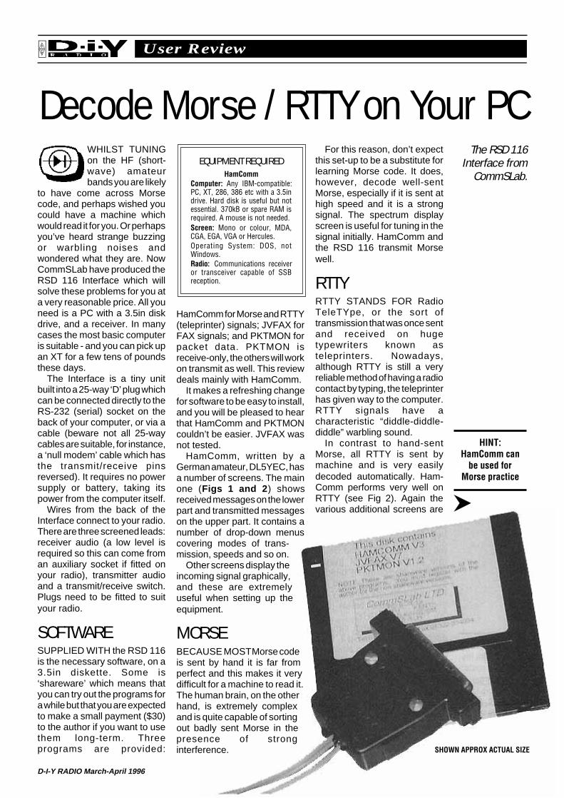
SHOWN APPROX ACTUAL SIZE
The RSD 116Interface from
CommSLab.
HINT:HamComm can
be used forMorse practice
20 D-I-Y RADIO March-April 1996
User ReviewRSGB
helpful in getting your radio onexactly the right frequency.
HamComm will also readAmTOR which is AmateurTeleprinter Over Radio - a wayof using RTTY resulting inalmost error-free reception. Thishas a rhythmic chirping noise.
PACKET RADIOA MUCH MORE modern way ofcommunicating with computersis packet radio (sometimesknown as AX25). Put simply,packet radio sends computerdata (messages, programs etc)in short bursts, and waits for thereceiving station’s equipment toreply “received OK”, or “pleasesend again”. This results intotally error-free communi-cation, but it can take some timefor the whole message to betransferred successfully. Packetradio is especially suitable forbulletin board use.
Supplied with the RSD 116 isPKTMON which is a very basicmethod of taking a look at packetradio signals. It is receive-only,and is no substitute for a properTerminal Node Controller (TNC)or even CommSLab’s ownPKTCOMM modem interfacewhich we expect to review inour next edition. The program is‘freeware’ ie no extra charge isneeded to continue using it.
Despite its limitations,PKTMON, used with the RSD116, can provide some fun. Itwill cater for 300Bd (the Baudrate is the speed of trans-mission) used on the HF bands,and 1200Bd which is used forFM transmissions on the VHFand UHF amateur bands (50,70, 144 and 432MHz).
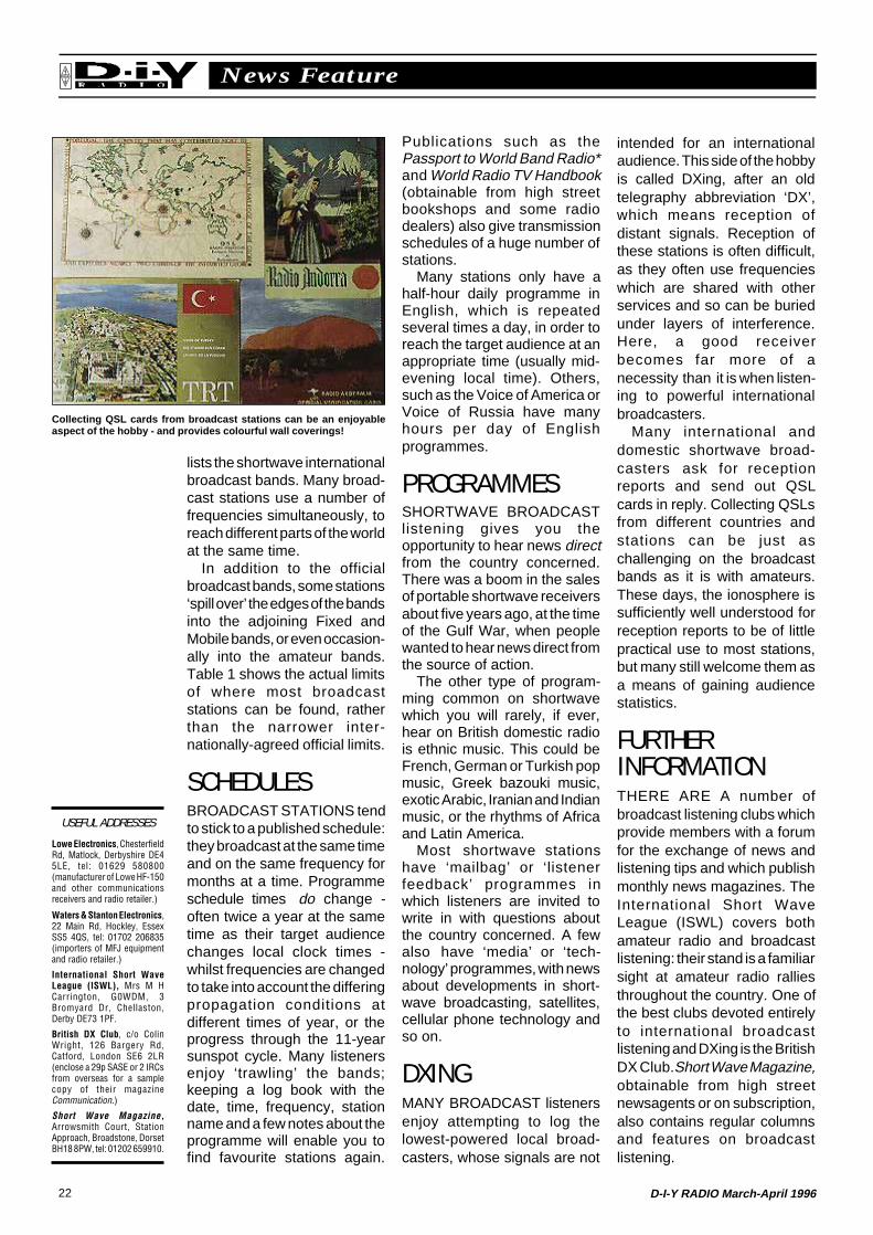
Some idea of what can bedecoded is shown in Fig 3 . Thiswas read on the 20m amateurband using a 286 AT computer.Although callsigns were easilydecoded, we could not read thetext of the messages.CommSLab tell us that they hadno trouble decoding 1200Bdpackets on the VHF bands,though a fast computer (eg 486)was essential. The program
The RSD 116,together with thesoftware, costs£19.95 from:
CommSLab Ltd,PO Box 19, Erith,Kent DA8 1LH,
telephone 01322330830.
Fig 1: Detail of the HamComm Morse receiving screen. Some callsigns are visible,especially the CQ call from a French station at the bottom. Note the printed dashes anddots which appear when the program can’t decipher the Morse character.
Fig 2: The HamComm receive screen on RTTY, by far the most successful mode. Theerrors are caused by signal fading and interference.
includes a clever routine to sortout which transmissions are forwhich person and it can storethem in separate files.
CONCLUSIONFOR GETTING your feet weton amateur radio data communi-cations, the RSD 116, togetherwith CommSLab’s software
disk, will provide you with a lotof fun. The HamComm softwareis excellent and well worth theextra cost of registering it. Youcan establish a useful RTTYstation using a very cheapcomputer, and it will also allowyou to dabble in other modes.At just under £20 the RSD 116represents very good value formoney.
Fig 3: Detail of the PKTMON screen showing accurately received packets but unreadable‘data’ lines. The lines starting with c:\comms\log report on which files are collecting thedata.
21D-I-Y RADIO March-April 1996
News FeatureRSGB
Shortwave Broadcast Listeningsuch as the ‘Nicky’, describedon page 27 of this magazine, ora kit such as the MFJ-8100W,which was described in theSeptember - October 1993 issueof D-i-Y Radio.
Very many people use smallportable transistor radios forshortwave broadcast listening,such as the Grundig Yacht Boyseries, or Sony’s ICF-7600series (the current model is theICF-SW7600G, while the ICF-7600DS was very popular a fewyears ago). This type of radiocosts around £120 - £160. Manybusinessmen and holiday-makers (with otherwise nointerest in radio) use this type ofreceiver to keep in touch withthe UK by listening to BBC WorldService when they are abroad.
For those who become reallykeen, a communicationsreceiver is the answer: thesestart at just over £400 for thepopular Lowe HF-150, up toseveral thousand pounds forprofessional receivers similar tothose used by BBC Monitoringor GCHQ!
ANTENNASALMOST ANY TYPE of antennacan be used for shortwavebroadcast listening. Becausebroadcast stations have muchstronger signals than all but themost local amateurs, even quiteinefficient antennas can be usedwith success. Many shortwaveportable receivers are also
MANY RADIOamateurs use HFtransceivers with
built-in general coverage (0.5 -30MHz) receivers, yet theynever tune away from theamateur bands. It is true thatthere are legal implications inlistening to some types oftransmission, but everyone isallowed to listen to shortwavebroadcast stations, and for manypeople shortwave broadcastlistening is a hobby as excitingas amateur radio itself.
RECEIVERSOF COURSE, IT isn’t necessaryto have an expensivetransceiver to listen toshortwave broadcast stations.Even the simplest radio whichcovers part of the shortwavespectrum will often give quitesatisfactory results when usedfor broadcast listening. This isbecause broadcast stationsalmost all use AM (AmplitudeModulation), which is easier totune in than the SSB (SingleSide-Band) used by mostamateurs. It is also because thepower output used by broadcaststations is very many times thatof amateurs, so signals aremuch stronger. Old radioscovering shortwave cansometimes be picked up at carboot sales or amateur radio ‘junksales’ for about £1. Alternatively,you may want to start with asimple home-made receiver
designed to be highly sensitive,as they are intended to be usedwith their built-in telescopicantennas, rarely more thanabout 1m long.
In most circumstances,though, adding a length of wire,perhaps 4 to 10m long, willimprove reception considerably.The wire - which can beinsulated or bare, thick or thin -can be plugged straight into theantenna socket of the radio (if ithas one), or simply woundaround the built-in telescopicantenna and then taped to stopit moving up and down, whichcauses ‘crackles’.
A word of caution: attemptingto improve reception by using a‘better’ or longer antenna, cansometimes have the oppositeeffect. This is because, as notedabove, some shortwavereceivers are designed to bevery sensitive, but using anantenna with too much signal‘pick-up’ can cause the receiverto ‘overload’. If this happens -and you will recognise it becauseyou will start hearing all sorts ofsignals which should not bethere, all at the same time -decrease the length of theantenna.
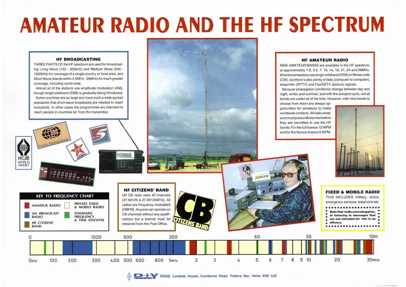
BROADCAST BANDSLIKE AMATEURS, broadcaststations cluster together inbands of frequencies. Table 1Table 1. The international shortwave broadcast bands.
Metre band Frequency limits, kHz Reception possible . . .
75 3900 - 4050 Mainly Europe, Darkness only49 5850 - 6250 24 hours, mainly Europe41 7100 - 7600 24 hours, mainly Europe31 9350 - 9995 24 hours, Europe and worldwide25 11500 - 12100 Mainly daytime, Europe and worldwide22 13600 - 13900 Mainly daytime, worldwide19 15005 - 15700 Mainly daytime, worldwide16 17500 - 17950 Daytime only, worldwide13 21450 - 21850 Daytime only, worldwide11 25670 - 26100 Little used at present
The Sony ICF-7600DS receiver provides digital frequency readoutand is used by many for shortwave broadcast listening.
Tune-in tointernational
radiobroadcasts
*Passport to WorldBand Radio
is available fromRSGB Books.
Call 01707 660888for latest price.
22 D-I-Y RADIO March-April 1996
News FeatureRSGB
Publications such as thePassport to World Band Radio*and World Radio TV Handbook(obtainable from high streetbookshops and some radiodealers) also give transmissionschedules of a huge number ofstations.
Many stations only have ahalf-hour daily programme inEnglish, which is repeatedseveral times a day, in order toreach the target audience at anappropriate time (usually mid-evening local time). Others,such as the Voice of America orVoice of Russia have manyhours per day of Englishprogrammes.
PROGRAMMESSHORTWAVE BROADCASTlistening gives you theopportunity to hear news directfrom the country concerned.There was a boom in the salesof portable shortwave receiversabout five years ago, at the timeof the Gulf War, when peoplewanted to hear news direct fromthe source of action.
The other type of program-ming common on shortwavewhich you will rarely, if ever,hear on British domestic radiois ethnic music. This could beFrench, German or Turkish popmusic, Greek bazouki music,exotic Arabic, Iranian and Indianmusic, or the rhythms of Africaand Latin America.
Most shortwave stationshave ‘mailbag’ or ‘listenerfeedback’ programmes inwhich listeners are invited towrite in with questions aboutthe country concerned. A fewalso have ‘media’ or ‘tech-nology’ programmes, with newsabout developments in short-wave broadcasting, satellites,cellular phone technology andso on.
DXINGMANY BROADCAST listenersenjoy attempting to log thelowest-powered local broad-casters, whose signals are not
intended for an internationalaudience. This side of the hobbyis called DXing, after an oldtelegraphy abbreviation ‘DX’,which means reception ofdistant signals. Reception ofthese stations is often difficult,as they often use frequencieswhich are shared with otherservices and so can be buriedunder layers of interference.Here, a good receiverbecomes far more of anecessity than it is when listen-ing to powerful internationalbroadcasters.
Many international anddomestic shortwave broad-casters ask for receptionreports and send out QSLcards in reply. Collecting QSLsfrom different countries andstations can be just aschallenging on the broadcastbands as it is with amateurs.These days, the ionosphere issufficiently well understood forreception reports to be of littlepractical use to most stations,but many still welcome them asa means of gaining audiencestatistics.
FURTHERINFORMATIONTHERE ARE A number ofbroadcast listening clubs whichprovide members with a forumfor the exchange of news andlistening tips and which publishmonthly news magazines. TheInternational Short WaveLeague (ISWL) covers bothamateur radio and broadcastlistening: their stand is a familiarsight at amateur radio ralliesthroughout the country. One ofthe best clubs devoted entirelyto international broadcastlistening and DXing is the BritishDX Club. Short Wave Magazine,obtainable from high streetnewsagents or on subscription,also contains regular columnsand features on broadcastlistening.
lists the shortwave internationalbroadcast bands. Many broad-cast stations use a number offrequencies simultaneously, toreach different parts of the worldat the same time.
In addition to the officialbroadcast bands, some stations‘spill over’ the edges of the bandsinto the adjoining Fixed andMobile bands, or even occasion-ally into the amateur bands.Table 1 shows the actual limitsof where most broadcaststations can be found, ratherthan the narrower inter-nationally-agreed official limits.
SCHEDULESBROADCAST STATIONS tendto stick to a published schedule:they broadcast at the same timeand on the same frequency formonths at a time. Programmeschedule times do change -often twice a year at the sametime as their target audiencechanges local clock times -whilst frequencies are changedto take into account the differingpropagation conditions atdifferent times of year, or theprogress through the 11-yearsunspot cycle. Many listenersenjoy ‘trawling’ the bands;keeping a log book with thedate, time, frequency, stationname and a few notes about theprogramme will enable you tofind favourite stations again.
USEFUL ADDRESSES
Lowe Electronics, ChesterfieldRd, Matlock, Derbyshire DE45LE, tel: 01629 580800(manufacturer of Lowe HF-150and other communicationsreceivers and radio retailer.)
Waters & Stanton Electronics,22 Main Rd, Hockley, EssexSS5 4QS, tel: 01702 206835(importers of MFJ equipmentand radio retailer.)
International Short WaveLeague (ISWL), Mrs M HCarrington, G0WDM, 3Bromyard Dr, Chellaston,Derby DE73 1PF.
British DX Club, c/o ColinWright, 126 Bargery Rd,Catford, London SE6 2LR(enclose a 29p SASE or 2 IRCsfrom overseas for a samplecopy of their magazineCommunication.)
Short Wave Magazine,Arrowsmith Court, StationApproach, Broadstone, DorsetBH18 8PW, tel: 01202 659910.
Collecting QSL cards from broadcast stations can be an enjoyableaspect of the hobby - and provides colourful wall coverings!
Page intentionally left blankGo to next page

Page intentionally left blankGo to next page
27D-I-Y RADIO March-April 1996
Construction FeatureRSGB
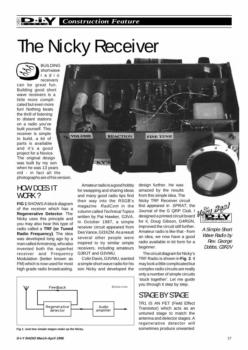
The Nicky ReceiverBUILDINGshort waver a d i oreceivers
can be great fun.Building good shortwave receivers is alittle more compli-cated but even morefun! Nothing beatsthe thrill of listeningto distant stationson a radio you’vebuilt yourself. Thisreceiver is simpleto build, a kit ofparts is availableand it’s a goodproject for a Novice.The original designwas built by my sonwhen he was 13 yearsold - in fact all thephotographs are of his version.
HOW DOES ITWORK ?FIG 1 SHOWS A block diagramof the receiver which has aRegenerative Detector . TheNicky uses this principle andyou may also hear this type ofradio called a TRF (or TunedRadio Frequency) . The ideawas developed long ago by aman called Armstrong, who alsoinvented both the superhetreceiver and FrequencyModulation (better known asFM) which is now used for mosthigh grade radio broadcasting.
Fig 1: Just two simple stages make up the Nicky.
Amateur radio is a good hobbyfor swapping and sharing ideasand many good radio tips findtheir way into the RSGB’smagazine RadCom in thecolumn called Technical Topicswritten by Pat Hawker, G3VA.In October 1987, a simplereceiver circuit appeared fromDes Vance, GI3XZM. As a resultseveral other people wereinspired to try similar simplereceivers, including amateursG3RJT and G3VMU.
Colin Davis, G3VMU, wanteda simple short wave radio for hisson Nicky and developed the
design further. He wasamazed by the resultsfrom this simple idea. TheNicky TRF Receiver circuitfirst appeared in SPRAT, theJournal of the G QRP Club. Idesigned a printed circuit boardfor it, Doug Gibson, G4RGN,improved the circuit still further.Amateur radio is like that - froman idea, we now have a goodradio available in kit form for abeginner.
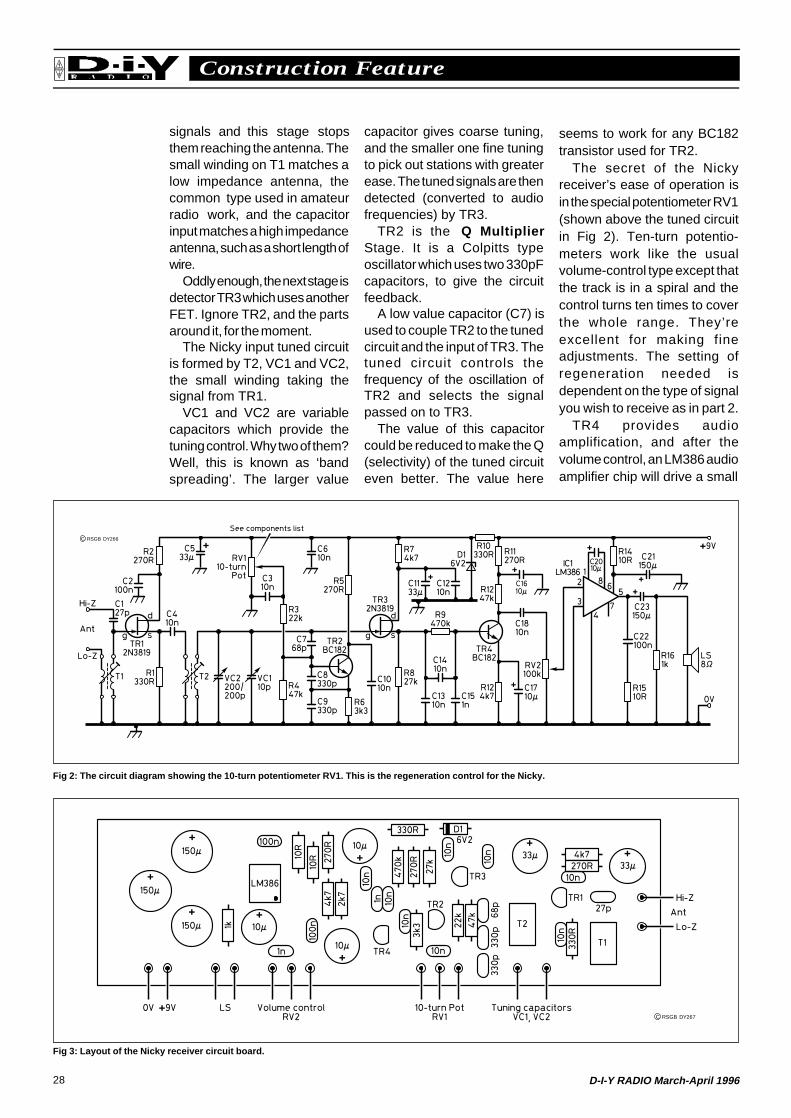
The circuit diagram for Nicky’sTRF Radio is shown in Fig 2 . Itmay look a little complicated butcomplex radio circuits are reallyonly a number of simple circuits‘stuck together’. Let me guideyou through it step by step.
STAGE BY STAGETR1 IS AN FET (Field EffectTransistor) which acts as anuntuned stage to match theantenna and detector stages. Aregenerative detector willsometimes produce unwanted
A Simple ShortWave Radio by
Rev. GeorgeDobbs, G3RJV
C RSGB DY265
28 D-I-Y RADIO March-April 1996
Construction FeatureRSGB
signals and this stage stopsthem reaching the antenna. Thesmall winding on T1 matches alow impedance antenna, thecommon type used in amateurradio work, and the capacitorinput matches a high impedanceantenna, such as a short length ofwire.
Oddly enough, the next stage isdetector TR3 which uses anotherFET. Ignore TR2, and the partsaround it, for the moment.
The Nicky input tuned circuitis formed by T2, VC1 and VC2,the small winding taking thesignal from TR1.
VC1 and VC2 are variablecapacitors which provide thetuning control. Why two of them?Well, this is known as ‘bandspreading’. The larger value
capacitor gives coarse tuning,and the smaller one fine tuningto pick out stations with greaterease. The tuned signals are thendetected (converted to audiofrequencies) by TR3.
TR2 is the Q MultiplierStage. It is a Colpitts typeoscillator which uses two 330pFcapacitors, to give the circuitfeedback.
A low value capacitor (C7) isused to couple TR2 to the tunedcircuit and the input of TR3. Thetuned circuit controls thefrequency of the oscillation ofTR2 and selects the signalpassed on to TR3.
The value of this capacitorcould be reduced to make the Q(selectivity) of the tuned circuiteven better. The value here
seems to work for any BC182transistor used for TR2.
The secret of the Nickyreceiver’s ease of operation isin the special potentiometer RV1(shown above the tuned circuitin Fig 2). Ten-turn potentio-meters work like the usualvolume-control type except thatthe track is in a spiral and thecontrol turns ten times to coverthe whole range. They’reexcellent for making fineadjustments. The setting ofregeneration needed isdependent on the type of signalyou wish to receive as in part 2.
TR4 provides audioamplification, and after thevolume control, an LM386 audioamplifier chip will drive a small
Fig 3: Layout of the Nicky receiver circuit board.
Fig 2: The circuit diagram showing the 10-turn potentiometer RV1. This is the regeneration control for the Nicky.
C RSGB DY266
C RSGB DY267
29D-I-Y RADIO March-April 1996
Construction FeatureRSGB
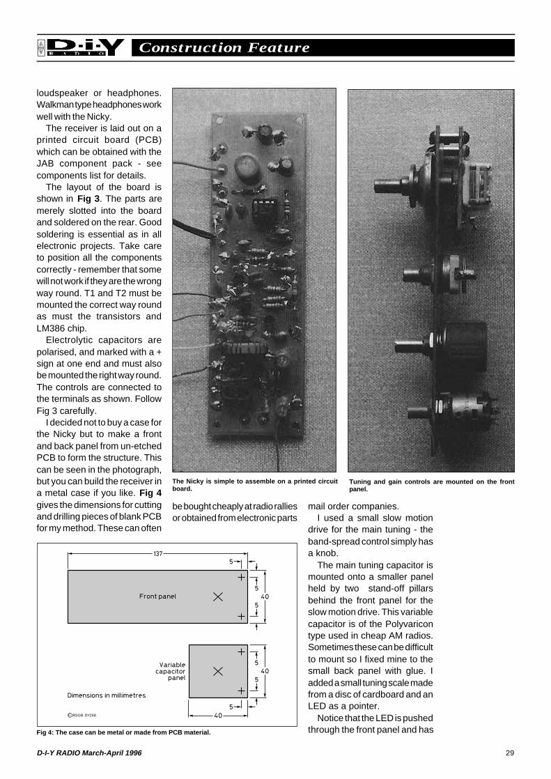
loudspeaker or headphones.Walkman type headphones workwell with the Nicky.
The receiver is laid out on aprinted circuit board (PCB)which can be obtained with theJAB component pack - seecomponents list for details.
The layout of the board isshown in Fig 3 . The parts aremerely slotted into the boardand soldered on the rear. Goodsoldering is essential as in allelectronic projects. Take careto position all the componentscorrectly - remember that somewill not work if they are the wrongway round. T1 and T2 must bemounted the correct way roundas must the transistors andLM386 chip.
Electrolytic capacitors arepolarised, and marked with a +sign at one end and must alsobe mounted the right way round.The controls are connected tothe terminals as shown. FollowFig 3 carefully.
I decided not to buy a case forthe Nicky but to make a frontand back panel from un-etchedPCB to form the structure. Thiscan be seen in the photograph,but you can build the receiver ina metal case if you like. Fig 4gives the dimensions for cuttingand drilling pieces of blank PCBfor my method. These can often
mail order companies.I used a small slow motion
drive for the main tuning - theband-spread control simply hasa knob.
The main tuning capacitor ismounted onto a smaller panelheld by two stand-off pillarsbehind the front panel for theslow motion drive. This variablecapacitor is of the Polyvaricontype used in cheap AM radios.Sometimes these can be difficultto mount so I fixed mine to thesmall back panel with glue. Iadded a small tuning scale madefrom a disc of cardboard and anLED as a pointer.
Notice that the LED is pushedthrough the front panel and hasFig 4: The case can be metal or made from PCB material.
Tuning and gain controls are mounted on the frontpanel.
The Nicky is simple to assemble on a printed circuitboard.
be bought cheaply at radio ralliesor obtained from electronic parts
C RSGB DY268
30 D-I-Y RADIO March-April 1996
Construction FeatureRSGB
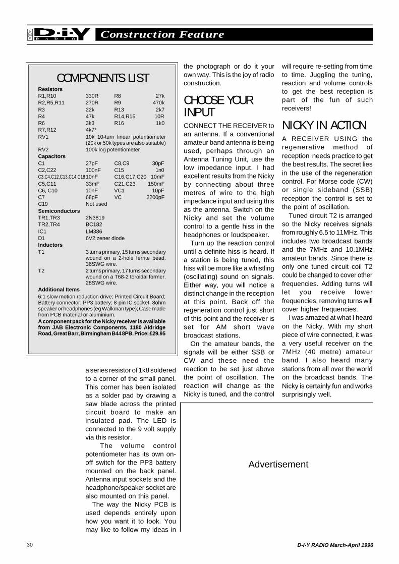
COMPONENTS LISTResistorsR1,R10 330R R8 27kR2,R5,R11 270R R9 470kR3 22k R13 2k7R4 47k R14,R15 10RR6 3k3 R16 1k0R7,R12 4k7*RV1 10k 10-turn linear potentiometer
(20k or 50k types are also suitable)RV2 100k log potentiometerCapacitorsC1 27pF C8,C9 30pFC2,C22 100nF C15 1n0C3,C4,C12,C13,C14,C1810nF C16,C17,C20 10mFC5,C11 33mF C21,C23 150mFC6, C10 10nF VC1 10pFC7 68pF VC 2200pFC19 Not usedSemiconductorsTR1,TR3 2N3819TR2,TR4 BC182IC1 LM386D1 6V2 zener diodeInductorsT1 3 turns primary, 15 turns secondary
wound on a 2-hole ferrite bead.36SWG wire.
T2 2 turns primary, 17 turns secondarywound on a T68-2 toroidal former.28SWG wire.
Additional Items6:1 slow motion reduction drive; Printed Circuit Board;Battery connector; PP3 battery; 8-pin IC socket; 8ohmspeaker or headphones (eg Walkman type); Case madefrom PCB material or aluminium.A component pack for the Nicky receiver is availablefrom JAB Electronic Components, 1180 AldridgeRoad, Great Barr, Birmingham B44 8PB. Price: £29.95
the photograph or do it yourown way. This is the joy of radioconstruction.
CHOOSE YOURINPUTCONNECT THE RECEIVER toan antenna. If a conventionalamateur band antenna is beingused, perhaps through anAntenna Tuning Unit, use thelow impedance input. I hadexcellent results from the Nickyby connecting about threemetres of wire to the highimpedance input and using thisas the antenna. Switch on theNicky and set the volumecontrol to a gentle hiss in theheadphones or loudspeaker.
Turn up the reaction controluntil a definite hiss is heard. Ifa station is being tuned, thishiss will be more like a whistling(oscillating) sound on signals.Either way, you will notice adistinct change in the receptionat this point. Back off theregeneration control just shortof this point and the receiver isset for AM short wavebroadcast stations.
On the amateur bands, thesignals will be either SSB orCW and these need thereaction to be set just abovethe point of oscillation. Thereaction will change as theNicky is tuned, and the control
a series resistor of 1k8 solderedto a corner of the small panel.This corner has been isolatedas a solder pad by drawing asaw blade across the printedcircuit board to make aninsulated pad. The LED isconnected to the 9 volt supplyvia this resistor.
The volume controlpotentiometer has its own on-off switch for the PP3 batterymounted on the back panel.Antenna input sockets and theheadphone/speaker socket arealso mounted on this panel.
The way the Nicky PCB isused depends entirely uponhow you want it to look. Youmay like to follow my ideas in
will require re-setting from timeto time. Juggling the tuning,reaction and volume controlsto get the best reception ispart of the fun of suchreceivers!
NICKY IN ACTIONA RECEIVER USING theregenerative method ofreception needs practice to getthe best results. The secret liesin the use of the regenerationcontrol. For Morse code (CW)or single sideband (SSB)reception the control is set tothe point of oscillation.
Tuned circuit T2 is arrangedso the Nicky receives signalsfrom roughly 6.5 to 11MHz. Thisincludes two broadcast bandsand the 7MHz and 10.1MHzamateur bands. Since there isonly one tuned circuit coil T2could be changed to cover otherfrequencies. Adding turns willlet you receive lowerfrequencies, removing turns willcover higher frequencies.
I was amazed at what I heardon the Nicky. With my shortpiece of wire connected, it wasa very useful receiver on the7MHz (40 metre) amateurband. I also heard manystations from all over the worldon the broadcast bands. TheNicky is certainly fun and workssurprisingly well.
Advertisement
31D-I-Y RADIO March-April 1996
News FeatureRSGB
Get Involved with your Club!How radioclubs are
bringing morepeople into
amateur radio
THE FEATUREabout radio clubswhich appeared in
the November - December 1995edition of D-i-Y Radio, Let’s AllClub Together, certainly createda lot of interest! We receivedseveral letters telling us of moreclubs’ activities, and even oneor two mildly telling us off for notincluding their club amongstthose “which particularlywelcome youngsters andbeginners”! Unfortunately, in thespace available, it can never bepossible to include details of allthe clubs which are doing sucha great job to introduce newpeople to amateur radio. How-ever, most radio clubs dowelcome newcomers, so if youwant to find out more about yourlocal radio club, either look inthe RSGB Call Book, or giveLynnette Ranger, 2E1EKT, acall at RSGB HQ on 01707659015.
GREAT YARMOUTHTHE GREAT YARMOUTHRadio Society has now trainedover 20 Novices, including thevery first Novice licensees inNorfolk. They were trained byDavid Buddery, G3OEP, theRSGB Senior Novice Instructorfor Norfolk, and his ‘right-handman’ Leo Balls, G3YYQ.Another four plan to take theNovice Radio Amateurs’ Exam-ination in May.
J B Barnard, G7RPJ, and N IBrown, G7RPY, are formerNovices who have gone on totake out a full licence. G7RPJ isinvolved with Raynet, providingan emergency communicationsservice, whilst G7RPY hasbecome a valued instructorhimself. Stan Wells, 2E0ABQ,had wanted to become an
amateur all his life, but doubtedhis own ability. He only took outhis Novice licence afterretirement, but, according toDavid Buddery, Stan’s Morse isnow “excellent” and he is beingencouraged to take out a fulllicence. Last year Stan waselected Chairman of the club.
Lest it be thought that theclub is only for older people,Aaron Lockton, G0VDC,received his full licence whilst inhis early teens!
THANET KEN SMITH, G3JIX, has spent“half a lifetime” in education andrunning youth groups. For thelast 16 years he has been leaderof the Thanet Electronics Clubfor Youth (TEC), which hasintroduced well over 150 boysand girls to amateur radio. Quitea few callsigns have originatedthrough this work - includingseveral mums who are now onthe air! Nicholas Bray is one offive who recently passed theNovice Radio Amateurs’Examination, and was going onto take the full RAE course.
The club has its own callsign,G3SRE. Club members haveput on exhibitions at local village
CONTACT NUMBERS:
Reading and DistrictAmateur Radio ClubSecretary: Peter Swynford,G0PUB, 219 Wykeham Rd,Earley, Reading RG6 1PL, tel:01734 617388.
Great Yarmouth / NorfolkNovice Instructor:David Buddery, G3OEP, 33Addison Rd, Gorleston, GtYarmouth, Norfolk NR31 0PA,tel: 01493 662323.
Thanet ElectronicsClub for YouthLeader: Ken Smith, G3JIX,Staple Farmhouse, Staple,Canterbury, Kent CT3 1JX(please enclose an SASE), tel:01304 812723.
Three members of the Thanet ElectronicsClub for Youth communicating by radiofrom the Marconi monument at Poldhu inCornwall - the very spot where Marconicarried out some of his early experiments.
Leo Balls, G3YYQ, instructing a Novicestudent at the Great Yarmouth RadioSociety. Note the familiar RSGB NoviceLicence Student’s Notebook being usedas a text book!
fetes and helped Ken Smithduring his lecture at the KingsCollege Radio Days by assistingwith demonstrations. They havecycled for 250 miles, stoppingat Youth Hostels and visitinginteresting radio sites. Theyhave developed and tradedradio kits. They have carried outre-enactments of MichaelFaraday’s pioneering electro-magnetic work. And much more.
The success of TEC andthese other clubs doesn’thappen by accident. It requirescommitted leaders like KenSmith, David Buddery and theothers. But we are delighted tosee that there are radio clubsabout who are encouragingyoungsters - and the not-so-young! - to take up thisfascinating hobby of amateurradio.
READINGSINCE OUR LAST clubsfeature, the Reading and DistrictAmateur Radio Club, held itsAGM. The new committeeincludes a Novice, Eddie Milton,2E1BDO, amongst its ranks,and the average age of theincoming committee is now lessthan 30! Exciting eventsorganised by this club includeproviding communications forthe Three Towers Hike on 16March. This is a major radioexercise which the club hashandled for many years.

32 D-I-Y RADIO March-April 1996
Construction FeatureRSGB
Fig 1: Simple medium -wave radio, circuit diagram. Note that the pin connections toIC1 and TR1 are shown from below.
A Simple Medium Wave ReceiverA design for asimplemedium-wavereceiver basedon the ZN414Zradio chip.
THE ZN414Z IC(integrated circuit)used in this design
contains an RF (Radio Freq-uency) amplifier, detector andAGC circuit and requires only afew external components tomake a complete AM (AmplitudeModulation) radio. The audiooutput from the ZN414Z chip israther low under normaloperating conditions so an audioamplifier is used to boost theaudio to a level that will drive apair of Walkman headphones.
In this design the audio isamplified using a BC109transistor. The circuit diagramis shown in Fig 1 .
Two different ways ofconstructing this receiver aredescribed below, one using a
PCB and the other using a tagstrip.
USING APCBAN EXAMPLE OFconstruction using aPCB, designed bySteve Ortmayer,G4RAW, is shown inFig 2 . This type ofconstruction is smalland neat. Methods ofmaking printedcircuits is describedin the Radio Com-munication Hand-book, available fromthe RSGB book-shop, as advertisedin this magazine.
The componentsare soldered intoplace as shown in Fig2.
Note that the IC1and TR2 are viewedfrom the top in Fig 2;connection pins areshown viewed fromthe bottom.
The arrangementshown in the photo-
graph is preset; that is it istuned to your favouriteprogramme with a presetcapacitor using a screwdriver.The preset capacitor could bereplaced with a polyvaricon orair-spaced variable capacitor,with a dial, if you want the optionof being able to tune to otherstations.
The antenna is made bywinding a coil of wire on a ferriterod 9mm in diameter and 60mmlong. This can be cut to sizefrom a longer length ifnecessary. The ferrite rod iswound with 60 turns of 26 SWGenamelled copper wire; eachturn is wound side-by-side andheld fast with clear sticky tape.The completed rod is fixed tothe board with plastic ties. Thebattery holder is fixed to theboard using double-sidedsticky tape.
The radio could also beprovided with an on/off switchbut it is convenient to switchthe radio on and off by justconnecting or disconnectingthe battery. When completethe radio can be tested byinserting a battery and Walkmanphones.Fig 2: Component layout using PCB board.
C RSGB DY278
C RSGB DY279
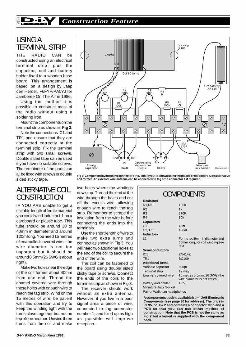
33D-I-Y RADIO March-April 1996
Construction FeatureRSGB
USING ATERMINAL STRIPTHE RADIO CAN beconstructed using an electricalterminal strip , plus thecapacitor, coil and batteryholder fixed to a wooden baseboard. This arrangement isbased on a design by Jaapden Herder, F6FYP/PA0YJ forJamboree On The Air in 1986.
Using this method it ispossible to construct most ofthe radio without using asoldering iron.
Mount the components on theterminal strip as shown in Fig 3 .
Note the connections IC1 andTR1 and ensure that they areconnected correctly at theterminal strip. Fix the terminalstrip with two small screws.Double sided tape can be usedif you have no suitable screws.The remainder of the parts canall be fixed with screws or doublesided sticky tape.
ALTERNATIVE COILCONSTRUCTIONIF YOU ARE unable to get asuitable length of ferrite materialyou could wind inductor L1 on acardboard or plastic tube. Thistube should be around 30 to40mm in diameter and around120m long. You need 15 metresof enamelled covered wire - thewire diameter is not tooimportant but it should bearound 0.5mm (26 SWG is aboutright).
Make two holes near the edgeof the coil former about 40mmfrom one end. Thread theenamel covered wire throughthese holes with enough wire toreach the tag strip. Wind on the15 metres of wire; be patientwith this operation and try tokeep the winding tight with theturns close together but not ontop of one another. Unwind threeturns from the coil and make
two holes where the windingsnow stop. Thread the end of thewire through the holes and cutoff the excess wire, allowingenough wire to reach the tagstrip. Remember to scrape theinsulation from the wire beforeconnecting the ends into theterminals.
Use the short length of wire tomake two extra turns andconnect as shown in Fig 3. Youwill need two additional holes atthe end of the coil to secure theend of the wire.
The coil can be fastened tothe board using double sidedsticky tape or screws. Connectthe ends of the coils to theterminal strip as shown in Fig 3.
The receiver should workwithout an extra antenna.However, if you live in a poorsignal area a piece of wire,connected to tag connectornumber 1, and fixed up as highas possible will improvereception.
Fig 3: Component layout using connector strip. This layout is shown using the plastic or cardboard tube alternativecoil former. An external wire antenna can be connected to tag strip connector 1 if required.
COMPONENTSResistorsR1,R5 100kR2 1kR3 270RR4 10kCapacitorsC1 10nFC2, C3 100nFInductorsL1 Ferrite rod 9mm in diameter and
60mm long, for coil winding seetext
SemiconductorsIC1 ZN414ZTR1 BC109Additional ItemsVariable capacitor 500pFTerminal strip 12 wayEnamel covered wire 15 metres 0.5mm, 26 SWG (the
wire diameter is not critical).Battery and holder 1.5VMiniature Jack SocketPair of Walkman headphones
A components pack is available from: JAB ElectronicComponents (see page 30 for address). The price is£9.95 inc. P&P and contains a connector strip and aPCB so that you can use either method ofconstruction. Note that the PCB is not the same asFig 2 but a layout is supplied with the componentpack.
C RSGB DY280
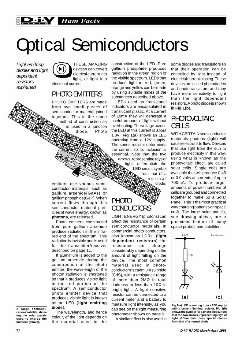
34 D-I-Y RADIO March-April 1996
Ham FactsRSGB
Optical SemiconductorsLight emittingdiodes and lightdependantresistorsexplained
some diodes and transistors sothat their operation can becontrolled by light instead ofelectrical current biasing. Thesedevices are called photodiodesand phototransistors and theyhave more sensitivity to lightthan the light dependantresistors. A photo diode is shownin Fig 1(b ).
PHOTOVOLTAICCELLSWITH CERTAIN semiconductormaterials photons (light) willcause electrons to flow. Devicesthat use light from the sun toproduce electricity in this way,using what is known as thephotovoltaic effect, are calledsolar cells. Single cells areavailable that will produce 0.45or 0.9 volts at currents of up to700mA. To produce largeramounts of power numbers ofcells are grouped and connectedtogether to make up a SolarPanel. This is the most practicalway charging batteries on spacecraft. The large solar panels,see drawing above, are aprominent feature of manyspace probes and satellites.
THESE AMAZINGdevices can coverteletrical current intolight, or light into
electrical current.
PHOTO EMITTERSPHOTO EMITTERS are madefrom two small pieces ofsemiconductor material joinedtogether. This is the same
method of construction asis used in a junction
diode. Photo
emitters use various semi-conductor materials, such asgallium arsenide(GaAs) orgallium phosphide(GaP). Whencurrent flows through thissemiconductor material part-icles of wave energy, known asphotons , are released.
Photo emitters constructedfrom pure gallium arsenideproduce radiation in the infra-red end of the spectrum. Thisradiation is invisible and is usedfor the transmitter/receiverdescribed on page 11.
If aluminium is added to thegallium arsenide during theconstruction of the photoemitter, the wavelength of thephoton radiation is shortenedso that it produces visible lightin the red portion of thespectrum. A semiconductorphoto emitter device thatproduces visible light is knownas an LED (light emittingdiode ).
The wavelength, and hencecolour, of the light depends onthe material used in the
construction of the LED. Puregallium phosphide producesradiation in the green region ofthe visible spectrum. LEDs thatproduce light in red, green,orange and yellow can be madeby using suitable mixes of thesubstances described above.
LEDs used as front-panelindicators are encapsulated intranslucent plastic. At a currentof 10mA they will generate auseful amount of light withoutoverheating. The voltage acrossthe LED at this current is about1.8V. Fig 1(a) shows an LEDoperating from a 12V supply.The series resistor determinesthe current so its inclusion isessential. Note that the two
arrows, representing rays oflight differentiate the
LED circuit symbolfrom that of a
n o r m a ldiode.
PHOTOCONDUCTORSLIGHT ENERGY (photons) canaffect the resistance of certainsemiconductor materials. Incommercial photo conductors,also known as LDRs (lightdependant resistors ) theresistance can changeconsiderably depending on theamount of light falling on thedevice. The most commonmaterial used in photo-conductors is cadmium sulphide(CdS), with a resistance rangeof more than 2MΩ in totaldarkness to less than 10Ω inbright light. A light sensitiveresistor can be connected to acurrent meter and a battery tomeasure light intensity, as youcan see on the light measuringphotometer shown on page 9.
A similar effect is also used in
Fig 1(a) LED operating from a 12V supplywith a current limiting resistor. Fig 1(b)shows the symbol for a photo diode. Notethat the two arrows, representing rays oflight, differentiate these special diodesfrom that of a normal diode.
C RSGB DY284
A large communi-cations satellite, show-ing the solar panelsused to charge thebatteries (above).
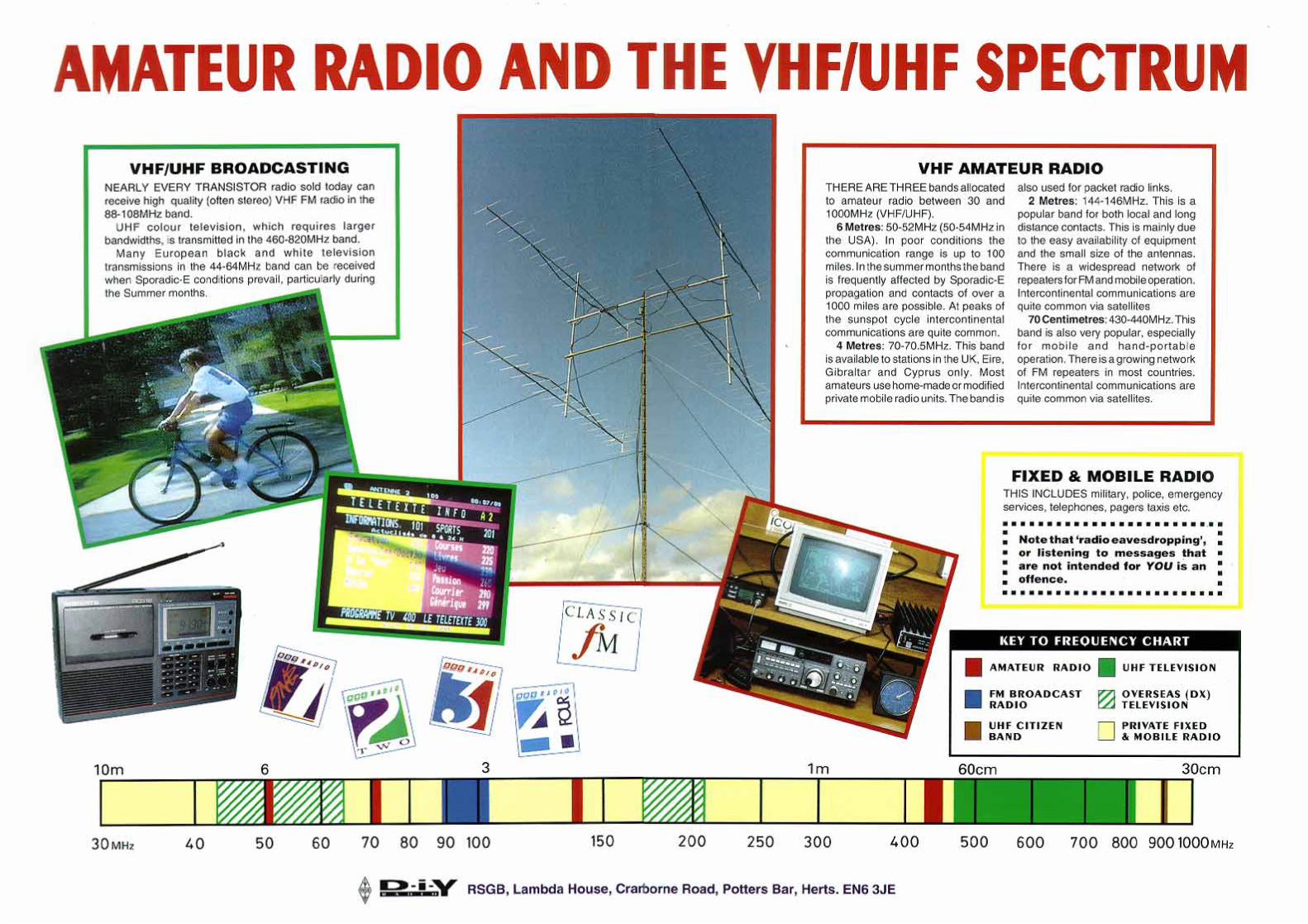

Page intentionally left blankGo to next page
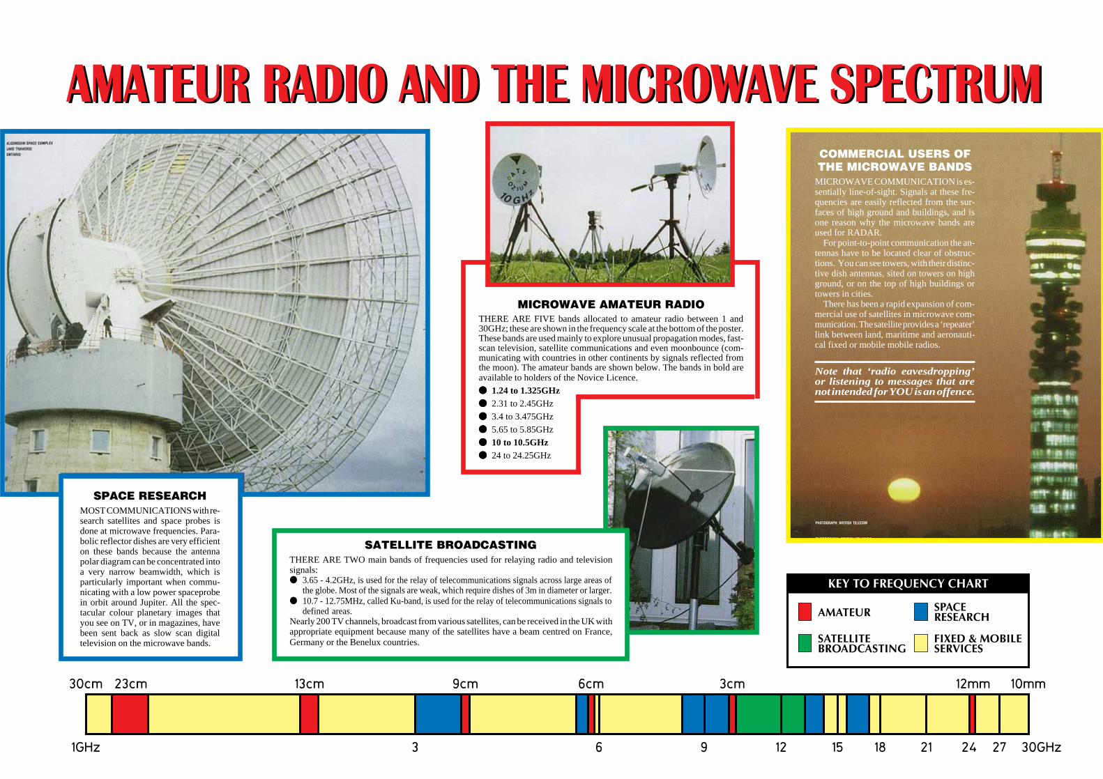
AMATEUR RADIO AND THE MICROWAVE SPECTRUMAMATEUR RADIO AND THE MICROWAVE SPECTRUM
SPACE RESEARCHMOST COMMUNICATIONS with re-search satellites and space probes isdone at microwave frequencies. Para-bolic reflector dishes are very efficienton these bands because the antennapolar diagram can be concentrated intoa very narrow beamwidth, which isparticularly important when commu-nicating with a low power spaceprobein orbit around Jupiter. All the spec-tacular colour planetary images thatyou see on TV, or in magazines, havebeen sent back as slow scan digitaltelevision on the microwave bands.
COMMERCIAL USERS OFTHE MICROWAVE BANDS
MICROWAVE COMMUNICATION is es-sentially line-of-sight. Signals at these fre-quencies are easily reflected from the sur-faces of high ground and buildings, and isone reason why the microwave bands areused for RADAR.
For point-to-point communication the an-tennas have to be located clear of obstruc-tions. You can see towers, with their distinc-tive dish antennas, sited on towers on highground, or on the top of high buildings ortowers in cities.
There has been a rapid expansion of com-mercial use of satellites in microwave com-munication. The satellite provides a ‘repeater’link between land, maritime and aeronauti-cal fixed or mobile mobile radios.
Note that ‘radio eavesdropping’or listening to messages that arenot intended for YOU is an offence.
MICROWAVE AMATEUR RADIOTHERE ARE FIVE bands allocated to amateur radio between 1 and30GHz; these are shown in the frequency scale at the bottom of the poster.These bands are used mainly to explore unusual propagation modes, fast-scan television, satellite communications and even moonbounce (com-municating with countries in other continents by signals reflected fromthe moon). The amateur bands are shown below. The bands in bold areavailable to holders of the Novice Licence.
1.24 to 1.325GHz 2.31 to 2.45GHz
3.4 to 3.475GHz
5.65 to 5.85GHz
10 to 10.5GHz 24 to 24.25GHz
PHOTOGRAPH: BRITISH TELECOM
SATELLITE BROADCASTINGTHERE ARE TWO main bands of frequencies used for relaying radio and televisionsignals: 3.65 - 4.2GHz, is used for the relay of telecommunications signals across large areas of
the globe. Most of the signals are weak, which require dishes of 3m in diameter or larger. 10.7 - 12.75MHz, called Ku-band, is used for the relay of telecommunications signals to
defined areas.Nearly 200 TV channels, broadcast from various satellites, can be received in the UK withappropriate equipment because many of the satellites have a beam centred on France,Germany or the Benelux countries.

Page intentionally left blankGo to next page

Advertisement
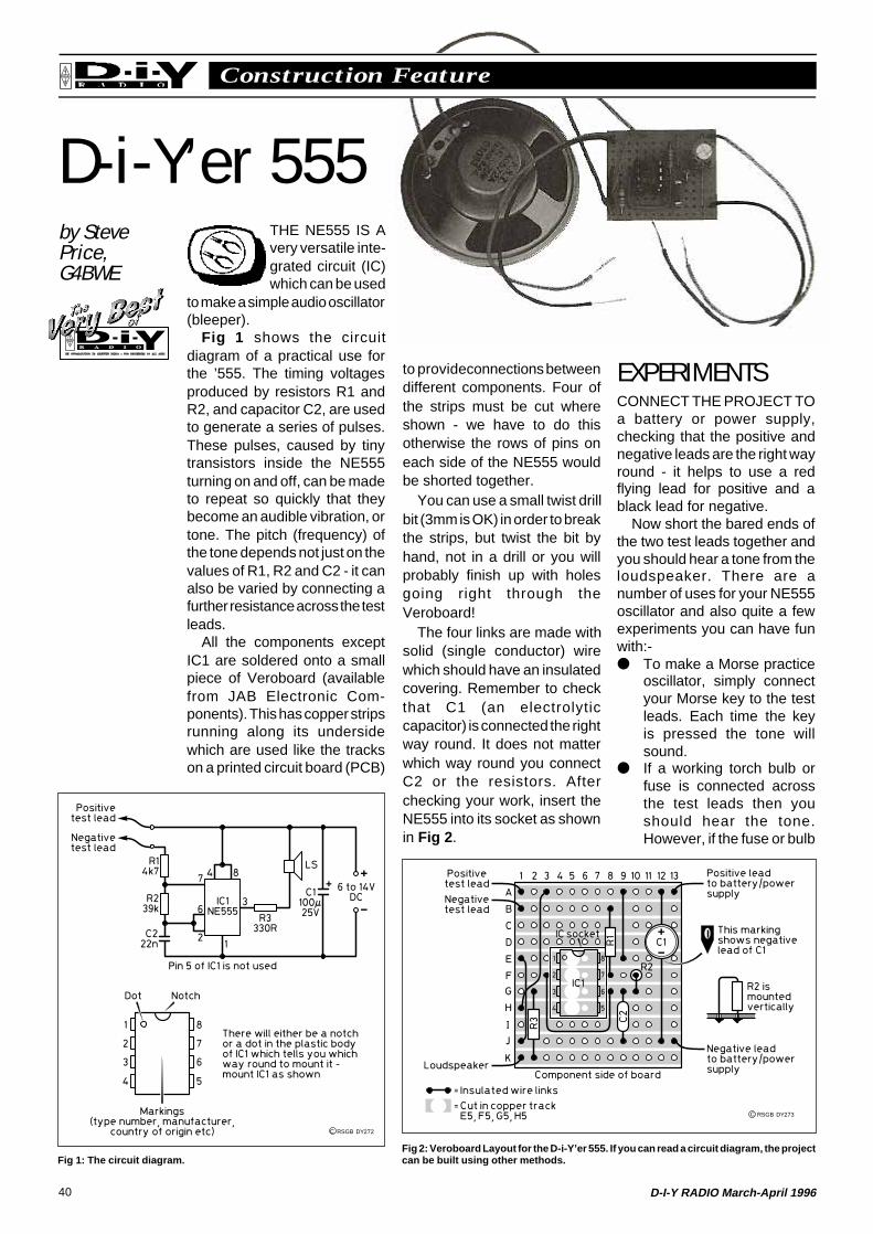
40 D-I-Y RADIO March-April 1996
Construction FeatureRSGB
D-i-Y’er 555by StevePrice,G4BWE
THE NE555 IS Avery versatile inte-grated circuit (IC)which can be used
to make a simple audio oscillator(bleeper).
Fig 1 shows the circuitdiagram of a practical use forthe ’555. The timing voltagesproduced by resistors R1 andR2, and capacitor C2, are usedto generate a series of pulses.These pulses, caused by tinytransistors inside the NE555turning on and off, can be madeto repeat so quickly that theybecome an audible vibration, ortone. The pitch (frequency) ofthe tone depends not just on thevalues of R1, R2 and C2 - it canalso be varied by connecting afurther resistance across the testleads.
All the components exceptIC1 are soldered onto a smallpiece of Veroboard (availablefrom JAB Electronic Com-ponents). This has copper stripsrunning along its undersidewhich are used like the trackson a printed circuit board (PCB)
to provide connections betweendifferent components. Four ofthe strips must be cut whereshown - we have to do thisotherwise the rows of pins oneach side of the NE555 wouldbe shorted together.
You can use a small twist drillbit (3mm is OK) in order to breakthe strips, but twist the bit byhand, not in a drill or you willprobably finish up with holesgoing right through theVeroboard!
The four links are made withsolid (single conductor) wirewhich should have an insulatedcovering. Remember to checkthat C1 (an electrolyticcapacitor) is connected the rightway round. It does not matterwhich way round you connectC2 or the resistors. Afterchecking your work, insert theNE555 into its socket as shownin Fig 2 .
EXPERIMENTSCONNECT THE PROJECT TOa battery or power supply,checking that the positive andnegative leads are the right wayround - it helps to use a redflying lead for positive and ablack lead for negative.
Now short the bared ends ofthe two test leads together andyou should hear a tone from theloudspeaker. There are anumber of uses for your NE555oscillator and also quite a fewexperiments you can have funwith:- To make a Morse practice
oscillator, simply connectyour Morse key to the testleads. Each time the keyis pressed the tone willsound.
If a working torch bulb orfuse is connected acrossthe test leads then youshould hear the tone.However, if the fuse or bulb
Fig 1: The circuit diagram.Fig 2: Veroboard Layout for the D-i-Y’er 555. If you can read a circuit diagram, the projectcan be built using other methods.
C RSGB DY272
C RSGB DY273

41D-I-Y RADIO March-April 1996
Construction FeatureRSGB
has ‘blown’ the oscillatorwill remain silent.
The pitch of the tone isaffected by the resistanceconnected between thetest leads. Increasing theresistance will lower thetone. This effect can beused to estimate the valueof resistance and alsomonitor any changes in it.For instance, if you holdthe bare ends of the testleads in your hands a lowpitched sound will be heardbecause of the highresistance in your body.However, if you squeezethe wires harder the pitchwill increase as the contactimproves (now try this withdamp hands).
Connect a potentiometer(variable resistor, like avolume control) to the testleads using the centrecontact and one of the outercontacts - a linear type witha value of between 100and 470kΩ will give thebest effect.Rotating the potentio-meter’s spindle alters thepitch. The highest value offixed resistor that will workis 10MΩ (ten million Ohms- colour code brown black
blue). This resistance is sohigh that you can hear theindividual pulses producinga repetitive clicking soundwhich is too low in freq-uency to be heard as atone.
Diodes can also bechecked. Connect thecathode (that’s the endmarked with a ring) of asmall silicon diode (such asa type 1N4148 or 1N914) tothe negative test lead, andconnect the anode to thepositive test lead. The diodewill be ‘forward biased’ andthe oscillator should soundas the diode conducts.Now swap the test leadsaround - as the diode isnow reverse biased theoscillator is silenced. Thediode’s one-way effect isused a lot in radio.
A cadmium sulphidephotoconductive cell typeORP12 (available fromJAB) may be connected tothe test leads. Shielding thecell from the light (try placingan upturned cup over it) willincrease the cell’sresistance and this lowersthe pitch.
There are many more uses
COMPONENTS LISTResistors - 0.25 Watt carbon film types
R1 4.7k (yellow, violet, red)
R2 39k (orange, white, orange)R3 330Ω (orange, orange, brown)
CapacitorsC1 100µF 25V electrolytic (radial type)
C2 22nF Polyester (10mm leadspacing)
The value of C2 may be marked as‘22n’ or ‘.022’
Integrated circuit (chip)IC1 NE555
Other parts Miniature loudspeaker (preferably 35, 40 or 80ohm but any type will work) 8 DIL IC socket
0.1 inch Veroboard (‘stripboard’) minimum size 11strips by 13 holes
PVC covered stranded conductor cable for testleads, battery/power supply and loudspeakerconnections This project requires a DC power source of between6 and 14 Volts, such as a 9 Volt battery.
COMPONENT SOURCEJAB Electronic Components, 1180 Aldridge Rd,Great Barr, Birmingham, B44 8PE. Tel: 0121 3666928.
How the NE555 WorksD-i-Y RADIO often has projects usingthe NE555 integrated circuit (chip). Itcan be used for many different projectsbut all of them use the ’555 as a timer.This is how it does it.
If we connect a battery across acapacitor via a resistor (see A) thecapacitor will be charged - in fact acapacitor is just like a re-chargeablebattery. The resistor limits the currentflowing into the capacitor so that ittakes time to charge - see curve A,which shows the voltage across thecapacitor.
If the charged capacitor is now
connected across a resistor (see B)current will flow through the resistorand discharge the capacitor. Thecapacitor’s voltage now drops - seecurve B. The higher the value of theresistor, the longer it takes to charge,or discharge, the capacitor.
In the project on, the NE555 worksby controlling the regular chargingand discharging of a capacitor [C2]connected to it using the two externalresistors [R1 & R2]. Short charge/discharge times will produce a high-pitched note, and long times willproduce a low note.
for the D-i-Y 555 project - canyou discover any? Send usyour ideas. They could bepublished in a future issue ofD-i-Y Radio.
C RSGB DY274
42 D-I-Y RADIO March-April 1996
On The AirRSGB
THE LOG BOOKTHE THREE YOUNG Novice operators
2E1DWK, 2E1CXE and 2E1EFS (see 2’s
Company above) contacted ON6RM/P, a
portable station in Belgium , during the
fourth RSGB 144MHz Backpackers
contest. The Novices were operating under
supervision as G6XRS/P. The contact was
at a distance of over 400km, which is good
‘DX’ considering the Novices were using
just 3W of SSB. They were using a 17-
element Yagi antenna, which provides a lot
of gain.
Large numbers of HF operators from all
over the world are becoming interested in
the RSGB’s Islands on the Air (IOTA) awards.
which are listed and given a reference
number in the IOTA Directory (available for
£6.00 from RSGB Sales). Some amateurs go
to island groups specifically to activate them
for IOTA: two such are Phil Whitchurch,
G3SWH, and Chris Burbanks, G3SJJ, who
plan to operate as F/G3SWH from Iles
Chausey , which are located between
Jersey and the French coast. Phil and Chris
will be on the air on 23/24 March CW only,
from 80 to 17 metres.
Listen out from 1 April for the first ‘M’
callsigns . Subscription Services Ltd (SSL),
which issues amateur radio licences in the
UK on behalf of the Radiocommunications
To qualify for an IOTA award, you must
contact at least 100 islands or island groups
2’s CompanyNews and Reports from Novice Licensees
WITH THE Dec-ember 1995 NoviceRadio Amateurs’
Examination results out, therewill now be a new influx of 2*1and 2*0 callsigns on the air. Weare pleased to see that Noviceswho have now been licensedfor a while are featuring in RSGBoperating awards and RSGBcontest results.
AWARDSFOR EXAMPLE, E P Williams,2E1AFN, of Stroud, Gloucester-shire, has recently providedevidence of having contacted20 countries on the 6 metreband and has been presentedwith the RSGB 50MHz 20Countries Award.
HF ACTIVITYIN THE SERIES of 1995 LFCumulative Contests, in whichcontacts are made over severalshort operating sessions ondifferent days in the 160, 80 and
40 metre bands, P A Williams,2E0AJE, was in overall 32ndplace and T Cannon, 2E0ACYin 43rd place out of a total of 64entries. There were also otherNovices who appeared in thelogs but who did not submitlogs: please do so this year ifyou took part. Contacts withNovices count 20 points each,so are much sought after bythose taking part in thesecontests.
2E0AJE also figured in thesecond ‘RoPoCo’ (Rotating PostCode) contest, which took placein August last year. In this CW(Morse) contest, you send yourown post code as part of thecontest exchange in your firstcontact, then the post code youhave just received for the nextcontact (hence the name‘Rotating Post Code’) and soon. This is a real test of bothsending and receiving ability.2E0AJE, who was the onlyNovice to submit a log for thiscontest, scored a highly
creditable 500 points and endedup in 27th place out of the 51entries.
VHF CONTESTALTHOUGH NOVICES are notpermitted to use the 2 metre(144MHz) band, they may ofcourse use this or any bandunder the supervision of (andusing the callsign of) a suitably-qualified full licensee. Threeyoung Novice operators,2E1DWK (aged 15), 2E1CXEand 2E1EFS (both 13), tookpart in the fourth 144MHz‘Backpackers’ contest asG6XRS/P, representing theLeicester Radio Society. The‘Backpackers’ are a series ofVHF contests in whichparticipants set up a portablestation by literally backpackingto their chosen location. Theyoungsters came out on top oftheir section, well ahead of theirnearest rivals.
QSL card from special event station GB50UNwhich operated from the Isle of Man duringJamboree on the Air to celebrate the 50thanniversary of the United Nations (see page 5).
Essential reading forNovices and beginnersof all licence classes!This book gives good,practical advice onmany types of antenna,and is available fromRSGB Sales.
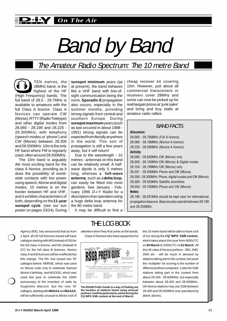
43D-I-Y RADIO March-April 1996
On The AirRSGB
THE LOG BOOK
The Amateur Radio Spectrum: The 10 metre Band
Band by Band
Agency (RA), has announced that as from
1 April, all UK full licences issued will have
callsigns starting with M0 (instead of G0) for
the full class A licence, and M1 (instead of
G7) for the full class B licences. Novice
class A and B licences will be unaffected by
this change. The RA has issued two ‘M’
callsigns before: M0RSE, which was used
on Morse code only to celebrate Samuel
Morse’s birthday, and M1OOG, which was
used last year to celebrate the 100th
anniversary of the invention of radio by
Guglielmo Marconi. But the new ‘M’
callsigns, starting with M0AAA and M1AAA ,
will be sufficiently unusual to attract a lot of
attention when they first come on the bands.
Class A Novices who have equipment for
TEN metres, the28MHz band, is thehighest of the HF
(High Frequency) bands. Thefull band of 28.0 - 29.7MHz isavailable to amateurs with thefull Class A licence. Class ANovices can operate CW(Morse), RTTY (Radio Teletype)and other digital modes from28.060 - 28.190 and 28.225 -28.300MHz; with telephony(speech modes or ‘phone’) andCW (Morse) between 28.300and 28.500MHz. 10m is the onlyHF band where FM is regularlyused, often around 29.500MHz.
The 10m band is arguablythe most exciting band for theclass A Novice, providing as itdoes the possibility of world-wide contacts with low powerusing speech, Morse and digitalmodes. 10 metres is on theborder between HF and VHF,and it exhibits characteristics ofboth, depending on the 11-yearsunspot cycle (see our sunposter on pages 23/24). During
sunspot minimum years (asat present), the band behaveslike a VHF band with line-of-sight communication being thenorm. Sporadic-E propagationalso occurs, especially in thesummer months, providingstrong signals from central andsouthern Europe. Duringsunspot maximum years (suchas last occured in about 1988 -1991) strong signals can beexpected from literally anywherein the world. This sort ofpropagation is still a few yearsaway, but it will return!
Due to the wavelength - 10metres - antennas on this bandcan be relatively small. A half-wave dipole is only 5 metreslong, whereas a full-waveantenna , such as a delta loop ,can easily be fitted into mostgardens. See January - Feb-ruary 1996 D-i-Y Radio for adescription of an operation usinga huge delta loop antenna forthe 80 metre band.
It may be difficult to find a
cheap receiver kit covering10m. However, just about allcommercial transceivers orreceivers cover 28MHz andsome can now be picked up forreal bargain prices at ‘junk sales’and bring and buy stalls atamateur radio rallies.
BAND FACTSAllocation:28.000 - 29.700MHz (Full A licence)28.060 - 28.190MHz (Novice A licence)28.225 - 28.500MHz (Novice A licence)Activity:28.000 - 28.050MHz CW (Morse) only28.050 - 28.150MHz CW (Morse) & Digital modes28.150 - 28.199MHz CW (Morse) only28.201 - 29.200MHz Phone and CW (Morse)29.200 - 29.300MHz Phone, digital modes and CW (Morse)29.300 - 29.550MHz Satellite downlinks29.550 - 29.700MHz Phone and CW (Morse)Notes:28.199 - 28.201MHz should be kept clear for internationalpropagation beacons. Beacons also operate between 28.190and 28.255MHz.
The RSGB Prefix Guide is a way of finding outthe location of stations heard using unusualprefixes. It will be particularly useful during theCQ WPX SSB contest at the end of March.
the 10 metre band will be able to have a lot
of fun during the CQ ‘WPX’ SSB contest ,
which takes place this year from 0000UTC
on 30 March to 2400UTC on 31 March . All
the UK class A Novice prefixes - 2E0, 2M0,
2W0 etc - will be much in demand by
stations taking part in the contest, because
the ‘multiplier’ for scoring is the number of
different prefixes contacted. Listen for SSB
stations taking part in the contest from
about 28.200 - 28.600MHz, but especially
between about 28.400 and 28.500MHz.
UK Novice stations may use SSB between
28.300 and 28.500MHz only (see Band by
Band, above).
Published by the Radio Society of Great BritainLambda House, Cranborne Road, POTTERS BAR,Hertfordshire, Great Britain EN6 3JE
DXCC Listing by PrefixOther Prefixes UsedITU Prefix AllocationCountry NameUnusual Prefixes - Which DXCCWhat Continent
What CQ ZoneWhat ITU ZoneHours + and - on UTCLatitude and LongitudeDate to Count FromEarlier Prefixes
Previous Country NameDeleted CountriesRussian & C.I.S. CountriesUSA States, CQ/ITU Zones and Call AreaDXCC Additions and Deletions UpdateNotes
C
Edition 1: March 1995

Advertisement
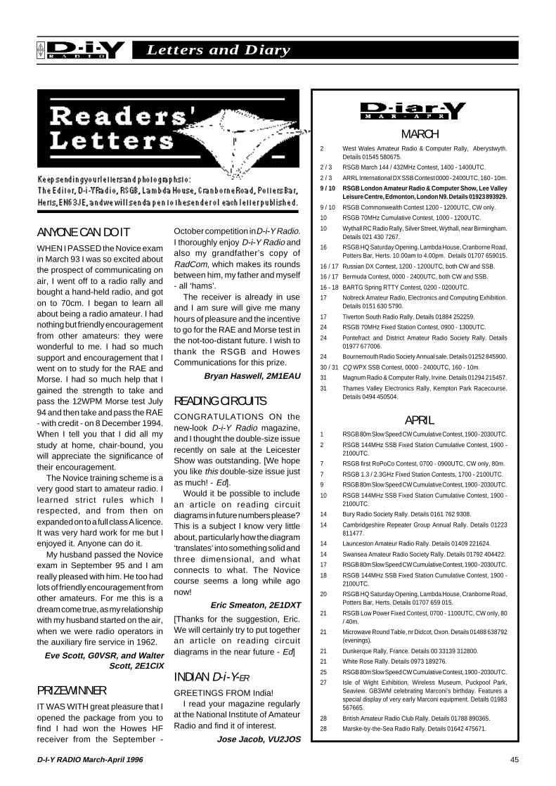
45D-I-Y RADIO March-April 1996
RSGB Letters and Diary
ANYONE CAN DO ITWHEN I PASSED the Novice examin March 93 I was so excited aboutthe prospect of communicating onair, I went off to a radio rally andbought a hand-held radio, and goton to 70cm. I began to learn allabout being a radio amateur. I hadnothing but friendly encouragementfrom other amateurs: they werewonderful to me. I had so muchsupport and encouragement that Iwent on to study for the RAE andMorse. I had so much help that Igained the strength to take andpass the 12WPM Morse test July94 and then take and pass the RAE- with credit - on 8 December 1994.When I tell you that I did all mystudy at home, chair-bound, youwill appreciate the significance oftheir encouragement.
The Novice training scheme is avery good start to amateur radio. Ilearned strict rules which Irespected, and from then onexpanded on to a full class A licence.It was very hard work for me but Ienjoyed it. Anyone can do it.
My husband passed the Noviceexam in September 95 and I amreally pleased with him. He too hadlots of friendly encouragement fromother amateurs. For me this is adream come true, as my relationshipwith my husband started on the air,when we were radio operators inthe auxiliary fire service in 1962.
Eve Scott, G0VSR, and WalterScott, 2E1CIX
PRIZEWINNERIT WAS WITH great pleasure that Iopened the package from you tofind I had won the Howes HFreceiver from the September -
October competition in D-i-Y Radio.I thoroughly enjoy D-i-Y Radio andalso my grandfather’s copy ofRadCom, which makes its roundsbetween him, my father and myself- all ‘hams’.
The receiver is already in useand I am sure will give me manyhours of pleasure and the incentiveto go for the RAE and Morse test inthe not-too-distant future. I wish tothank the RSGB and HowesCommunications for this prize.
Bryan Haswell, 2M1EAU
READING CIRCUITSCONGRATULATIONS ON thenew-look D-i-Y Radio magazine,and I thought the double-size issuerecently on sale at the LeicesterShow was outstanding. [We hopeyou like this double-size issue justas much! - Ed].
Would it be possible to includean article on reading circuitdiagrams in future numbers please?This is a subject I know very littleabout, particularly how the diagram‘translates’ into something solid andthree dimensional, and whatconnects to what. The Novicecourse seems a long while agonow!
Eric Smeaton, 2E1DXT
[Thanks for the suggestion, Eric.We will certainly try to put togetheran article on reading circuitdiagrams in the near future - Ed]
INDIAN D-i-Y-ER
GREETINGS FROM India!I read your magazine regularly
at the National Institute of AmateurRadio and find it of interest.
Jose Jacob, VU2JOS
MARCH2 West Wales Amateur Radio & Computer Rally, Aberystwyth.
Details 01545 580675.
2 / 3 RSGB March 144 / 432MHz Contest, 1400 - 1400UTC.
2 / 3 ARRL International DX SSB Contest 0000 - 2400UTC, 160 - 10m.
9 / 10 RSGB London Amateur Radio & Computer Show, Lee ValleyLeisure Centre, Edmonton, London N9. Details 01923 893929.
9 / 10 RSGB Commonwealth Contest 1200 - 1200UTC, CW only.
10 RSGB 70MHz Cumulative Contest, 1000 - 1200UTC.
10 Wythall RC Radio Rally, Silver Street, Wythall, near Birmingham.Details 021 430 7267.
16 RSGB HQ Saturday Opening, Lambda House, Cranborne Road,Potters Bar, Herts. 10.00am to 4.00pm. Details 01707 659015.
16 / 17 Russian DX Contest, 1200 - 1200UTC, both CW and SSB.
16 / 17 Bermuda Contest, 0000 - 2400UTC, both CW and SSB.
16 - 18 BARTG Spring RTTY Contest, 0200 - 0200UTC.
17 Nobreck Amateur Radio, Electronics and Computing Exhibition.Details 0151 630 5790.
17 Tiverton South Radio Rally. Details 01884 252259.
24 RSGB 70MHz Fixed Station Contest, 0900 - 1300UTC.
24 Pontefract and District Amateur Radio Society Rally. Details01977 677006.
24 Bournemouth Radio Society Annual sale. Details 01252 845900.
30 / 31 CQ WPX SSB Contest, 0000 - 2400UTC, 160 - 10m.
31 Magnum Radio & Computer Rally, Irvine. Details 01294 215457.
31 Thames Valley Electronics Rally, Kempton Park Racecourse.Details 0494 450504.
APRIL1 RSGB 80m Slow Speed CW Cumulative Contest, 1900 - 2030UTC.
2 RSGB 144MHz SSB Fixed Station Cumulative Contest, 1900 -2100UTC.
7 RSGB first RoPoCo Contest, 0700 - 0900UTC, CW only, 80m.
7 RSGB 1.3 / 2.3GHz Fixed Station Contests, 1700 - 2100UTC.
9 RSGB 80m Slow Speed CW Cumulative Contest, 1900 - 2030UTC.
10 RSGB 144MHz SSB Fixed Station Cumulative Contest, 1900 -2100UTC.
14 Bury Radio Society Rally. Details 0161 762 9308.
14 Cambridgeshire Repeater Group Annual Rally. Details 01223811477.
14 Launceston Amateur Radio Rally. Details 01409 221624.
14 Swansea Amateur Radio Society Rally. Details 01792 404422.
17 RSGB 80m Slow Speed CW Cumulative Contest, 1900 - 2030UTC.
18 RSGB 144MHz SSB Fixed Station Cumulative Contest, 1900 -2100UTC.
20 RSGB HQ Saturday Opening, Lambda House, Cranborne Road,Potters Bar, Herts. Details 01707 659 015.
21 RSGB Low Power Fixed Contest, 0700 - 1100UTC, CW only, 80/ 40m.
21 Microwave Round Table, nr Didcot, Oxon. Details 01488 638792(evenings).
21 Dunkerque Rally, France. Details 00 33139 312800.
21 White Rose Rally. Details 0973 189276.
25 RSGB 80m Slow Speed CW Cumulative Contest, 1900 - 2030UTC.
27 Isle of Wight Exhibition, Wireless Museum, Puckpool Park,Seaview. GB3WM celebrating Marconi’s birthday. Features aspecial display of very early Marconi equipment. Details 01983567665.
28 British Amateur Radio Club Rally. Details 01788 890365.
28 Marske-by-the-Sea Radio Rally. Details 01642 475671.

Advertisement

Advertisement

Advertisement
![arXiv:2104.06862v1 [nlin.AO] 14 Apr 2021](https://static.fdokumen.com/doc/165x107/6317ad0d71e3f2062906e291/arxiv210406862v1-nlinao-14-apr-2021.jpg)


![arXiv:2010.05214v2 [math.GT] 29 Apr 2021](https://static.fdokumen.com/doc/165x107/630b8fed28a97ac56004b407/arxiv201005214v2-mathgt-29-apr-2021.jpg)


![arXiv:2004.09754v2 [cs.CV] 23 Apr 2020](https://static.fdokumen.com/doc/165x107/631e44425ff22fc745069d67/arxiv200409754v2-cscv-23-apr-2020.jpg)

![arXiv:1704.04987v1 [math.AP] 13 Apr 2017](https://static.fdokumen.com/doc/165x107/6318b1f44cd7b3442408bb9e/arxiv170404987v1-mathap-13-apr-2017.jpg)
![arXiv:0910.4928v2 [math.AG] 4 Apr 2011](https://static.fdokumen.com/doc/165x107/6314f17fb1e0e0053b0eeaa3/arxiv09104928v2-mathag-4-apr-2011.jpg)