STUCTURAL ANALYSIS AND DESIGN REPORT
32
REPUBLIC OF RWANDA PROJECT: CONSTRUCTION OF RESIDENTIAL BUILDING Structure 3D View STUCTURAL ANALYSIS AND DESIGN REPORT PROJECT OWNER: ABBAS MUKAMA Eng BIRASA ALEXIS Design code: BS 8110-1997 Software: ROBOT APRIL 2018
-
Upload
khangminh22 -
Category
Documents
-
view
0 -
download
0
Transcript of STUCTURAL ANALYSIS AND DESIGN REPORT

REPUBLIC OF RWANDA
PROJECT: CONSTRUCTION OF RESIDENTIAL BUILDING
Structure 3D View
STUCTURAL ANALYSIS AND DESIGN REPORT
PROJECT OWNER: ABBAS MUKAMA
Eng BIRASA ALEXIS
Design code: BS 8110-1997
Software: ROBOT
APRIL 2018
2
1. GENERAL
1.1 SCOPE
The numerical values of actions on buildings and civil Engineering works
to be taken into account in the design are applicable to the various types of
construction.
1.2 The purpose of the building is, residential building. the materials used
are R.C structures of framed type, Solid two way slabs and cement blocks for wall
elevation, whereas the roof is made up with wood trusses covered with metal
sheets.
1.3 The execution of construction of this building is covered by various
code of designs to the extent that is necessary to indicate the quality of
construction materials and products which should be used and the standard of
workmanship on site needed to be supervised by qualified and experienced
Engineer .Some lab test like compressive strength test for concrete should be done
as far as the importance of building structure is concerned.
1.4 The method of design is Limit state design method accordingly to BS
8110-1997, and the use of ROBOT ® Structural software for all members except
to slab design where we use Prokon structure software.

3
DESIGN INFORMATION
UWAMAHORO Faustin Client
The structural use of Concrete
British Standard (BS 8110-1997)
Relevant Building
Regulations and
Design Code
Public Building. Intended use of the
building
following codes: BS 648, BS 649, and BS 6399.
Self-weight of Bac Autoportant Sheet = 0.11 KN/m2, Self-weight of
truss: 0.15 KN/m2, Ceiling: 0.1KN/m2, Services: 0.2 KN/m2
and Finishes: 0.01 KN/m2. Dead load (Gk) = 0.11+0.1+0.2+0.01 =
0.42 KN/m2
Floor –Imposed (3 )and partitions(1) 1.5 kN/m2 (BS 6399)
- Finishes 1.0 kN/m2
Stairs –Imposed 4 kN/m2
- Finishes 1.0 kN/m2
General loading
conditions
Severe (external ) and Mild (internal) Exposure
conditions
Compact sandy-gravel
Allowable bearing pressure Calculated to 200kN/ m2
Subsoil conditions
Reinforced Concrete footing to columns. Foundation type
4
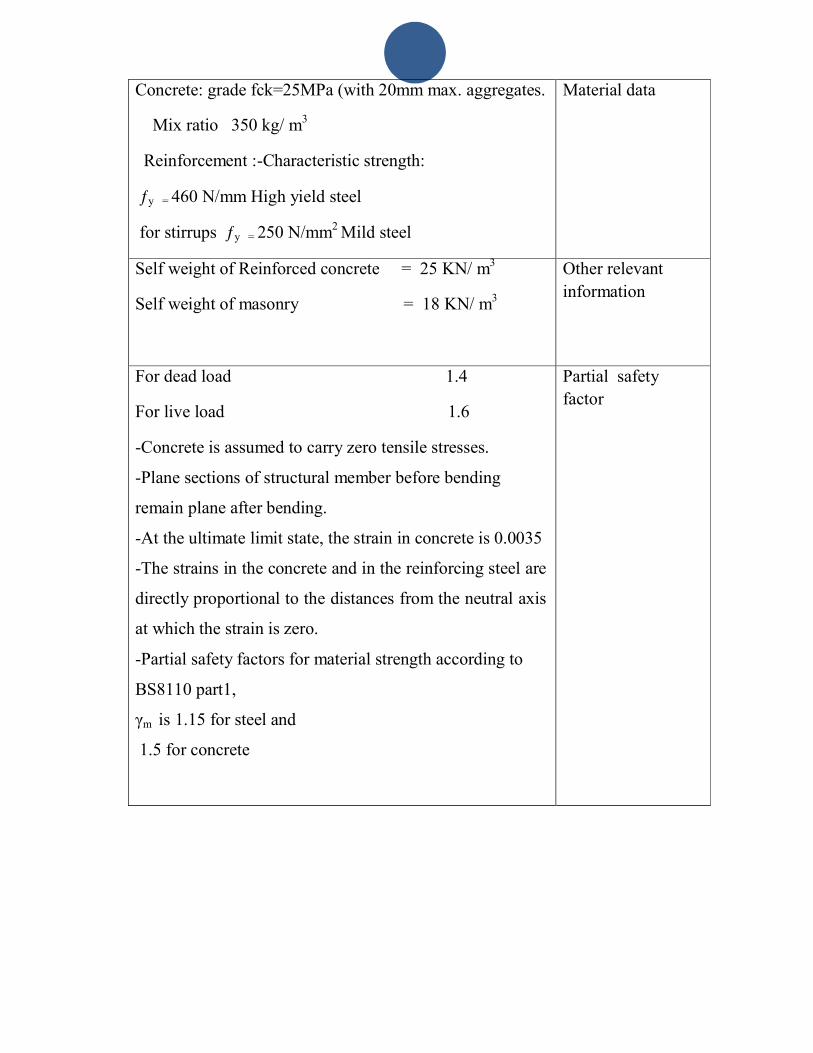
Concrete: grade fck=25MPa (with 20mm max. aggregates.
Mix ratio 350 kg/ m3
Reinforcement :-Characteristic strength:
ƒy = 460 N/mm High yield steel
for stirrups ƒy = 250 N/mm2 Mild steel
Material data
Self weight of Reinforced concrete = 25 KN/ m3
Self weight of masonry = 18 KN/ m3
Other relevant
information
For dead load 1.4
For live load 1.6
-Concrete is assumed to carry zero tensile stresses.
-Plane sections of structural member before bending
remain plane after bending.
-At the ultimate limit state, the strain in concrete is 0.0035
-The strains in the concrete and in the reinforcing steel are
directly proportional to the distances from the neutral axis
at which the strain is zero.
-Partial safety factors for material strength according to
BS8110 part1,
γm is 1.15 for steel and
1.5 for concrete
Partial safety
factor

5
2. ANALYSIS AND DIMENSION OF SLAB
2.1. Analysis of slab
During our calculations the following notations are going to be used:
hs = thickness of the slab
d = efficient thickness of the slab
Lx = short span
ly = long span
Ly/lx > 2 one way span
Ly/lx <2 two way span
Figure 1.1 Plan view show slab , beam and Column, foundation

6
2.1.1. Dimension of slab
2.1.1.1. Preliminary dimension
Efficient thickness of slab = Po rtee(lx )
2 0*2.0
The value of the small range (lx) is lx = 4.63m
hs 3.20 *10 3
1115.75mm; 20 * 2.0
Let take a slab of thickness hs = 120mm for the whole slab
Let assume h (the overall depth of slab) to be 120mm so that construction reinforcement bar
being easy on site. We will only consider the fire resistance of 1.5 hour to get the cover. From
table 3.4 given in the BS 8110, the cover for 1.5 hour fire resistance is 20mm.
2.2 Panel on floor
2.2.1Checking slab
The ratio of = 5.21/4.63=1.125 < 2.0
Slab is designed as two ways
We assumed 10Ø bar
Cover =20mm
2.2.2 Load distribution
-Thickness of slab 120mm
-Self weight of slab = 25×0.12 = 3 kN/m2
Finishes 1.5 kN/m2
Dead load = 3+1.5 = 4.5 kN/m2
Imposed load = 1.5 kN/m2
Design load = 1.4 Gk+1.6Qk= 1.4×4.5+1.6x 1.5 = 8.7 kN/m
7
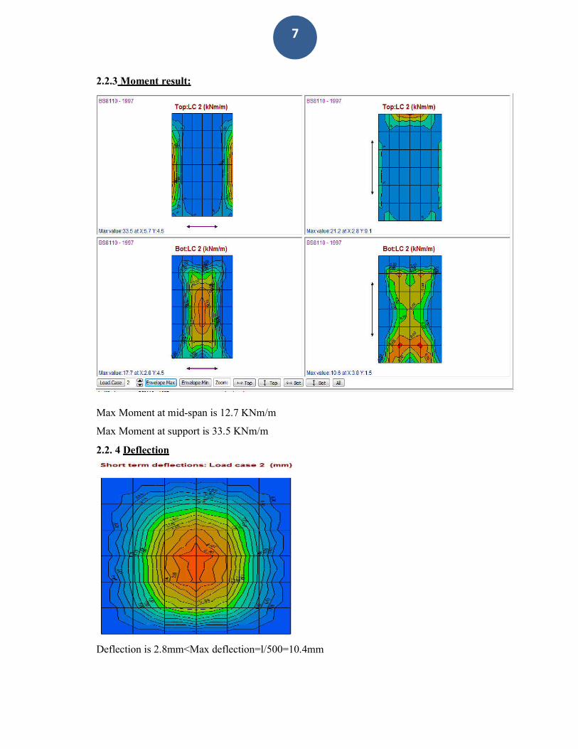
2.2.3 Moment result:
Max Moment at mid-span is 12.7 KNm/m
Max Moment at support is 33.5 KNm/m
2.2. 4 Deflection
Deflection is 2.8mm<Max deflection=l/500=10.4mm

8
Reinforcement area
Maximum Reinforcement areas:
At support is 555.6 mm2/m and Reinforcement is Y10@150 mm (T1 and T2)
At mid span is 284.2 mm2/m and Reinforcement is Y 10@150 mm (B1 and B2)

9
3. ANALYSIS AND DESIGN OF BEAM
3.0 BEAM 1
Fire rating : 1.5 (h)
Maximum cracking: 0.30 (mm)
Environment class : moderate Concrete creep coefficient : p = 2.00
3.1 Material properties:
Concrete: CONCR fcu = 25 (KN)
Longitudinal reinforcement : T fy = 460 (N/mm2)
Transversal reinforcement : R fy = 250 (N/mm2)
3.2 Geometry:
2.2.1 Span Position L.supp. L R.supp. (m) (m) (m) P1 Span 0.20 4.80 0.20
Span length: Lo = 5.00 (m) Section from 0.00 to 4.80 (m)
20 x 35 (cm) without left slab without right slab
3.3 Calculation options:
Regulation of combinations : BS5950 Calculations according to : BS 8110
Precast beam : no Cover : bottom c = 3 (cm)
: side c1 = 3 (cm) : top c2 = 3 (cm)
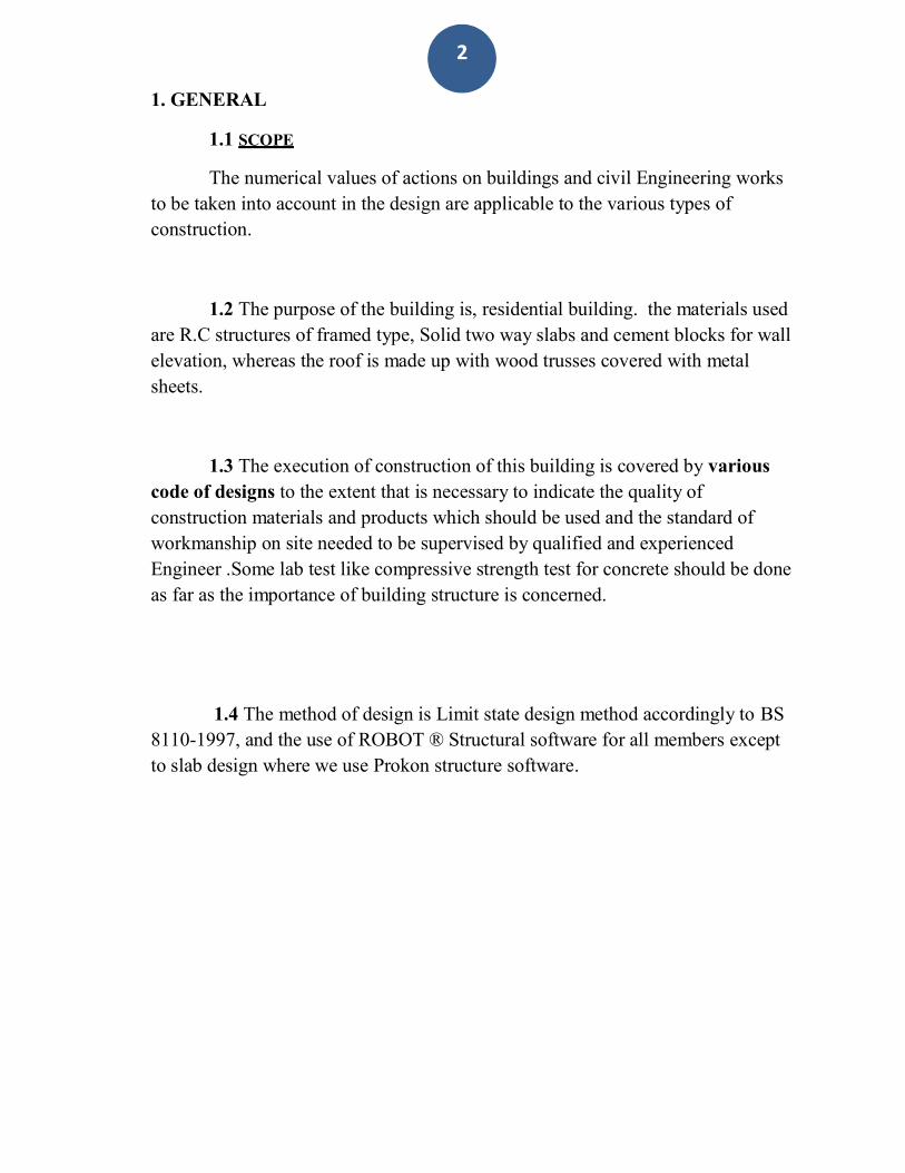
3.4 Calculation results:
3.4.1 Internal forces in ULS
Span Mtmax. Mtmin. Ml Mr Ql Qr (kN*m) (kN*m) (kN*m) (kN*m) (kN) (kN) P1 34.75 -0.00 -43.12 -5.23 60.61 -28.20

10
-60
-50
-40
-30
-20
-10
0
10
20
30
40
50
[kN*m]
[m]
0 1 2 3 4 5
Bending Moment ULS: M Mr Mc
150
100
[kN]
50
0
-50
-100
-150
[m]
0 1 2 3 4 5
Shear Force ULS: V Vr Vc(stirrups) Vc(total)
3.4.2 Internal forces in SLS
Span Mtmax. Mtmin. Ml Mr Ql Qr (kN*m) (kN*m) (kN*m) (kN*m) (kN) (kN) P1 0.00 0.00 0.00 0.00 0.00 0.00
3.4.3 Required reinforcement area
500
400
300
200
100
0
100
200
300
400
[mm2]
Span Span (mm2) Left support (mm2) Right support (mm2) bottom top bottom top bottom top
P1 292 0 0 374 11 42
[m]
0 1 2 3 4 5
Reinforcement Area for Bending: Abt Abr Abmin
1000
800
600
400
200
0
200
400
600
800
1000
[mm2/m]
[m]
0 1 2 3 4 5
Reinforcement Area for Shear: Ast Asr AsHang

11
Abscissa
ULS M max.
M min.
SLS M max.
M min.
A bottom
A top
(m) (kN*m) (kN*m) (kN*m) (kN*m) (mm2) (mm2) 0.20 0.00 -43.12 0.00 0.00 0 374 0.60 0.00 -19.59 0.00 0.00 0 157 1.10 4.01 -0.00 0.00 0.00 32 0 1.60 19.83 -0.00 0.00 0.00 159 0 2.10 29.51 -0.00 0.00 0.00 244 0 2.60 34.75 -0.00 0.00 0.00 292 0 3.10 33.29 -0.00 0.00 0.00 279 0 3.60 27.97 -0.00 0.00 0.00 230 0 4.10 17.88 -0.00 0.00 0.00 143 0 4.60 6.66 -0.00 0.00 0.00 53 0 5.00 1.33 -5.23 0.00 0.00 11 42
Abscissa
ULS Q max.
SLS Q max.
Cw
(m) 0.20
(kN) 60.61
(kN) 0.00
(mm) 0.00
0.60 55.81 0.00 0.00 1.10 34.64 0.00 0.00 1.60 28.64 0.00 0.00 2.10 13.55 0.00 0.00 2.60 0.07 0.00 0.00 3.10 -5.93 0.00 0.00 3.60 -17.17 0.00 0.00 4.10 -23.18 0.00 0.00
3.4.4 Deflection and cracking
at(s-t) - initial deflection due to total load ap(s-t) - initial deflection due to long-term load ap(l-t) - long-term deflection due to long-term load a - total deflection aall - allowable deflection
Cw - width of perpendicular cracks
-20
-15
-10
[mm]
Span at(s-t) ap(s-t) ap(l-t) a aall Cw (mm) (mm) (mm) (mm) (mm) (mm)
P1 0 0 0 0=(L0/--) -20 0.00
-5
0
5
10
15 [m]
20 0 1 2 3 4 5
Deflections: ap(s-t) ap(l-t) at(s-t) a a adm
0.3
0.2
[mm]
0.1
0
0.1
0.2
0.3
[m]
0 1 2 3 4 5
Cracking: Cw Cw adm
3.5 Theoretical results - detailed results:
3.5.1 P1 : Span from 0.20 to 5.00 (m)
12
(mm) (m) (kG) (No.) (kG) 8 0.79 0.31 44 13.77
4.60 -23.40 0.00 0.00 5.00 -28.20 0.00 0.00
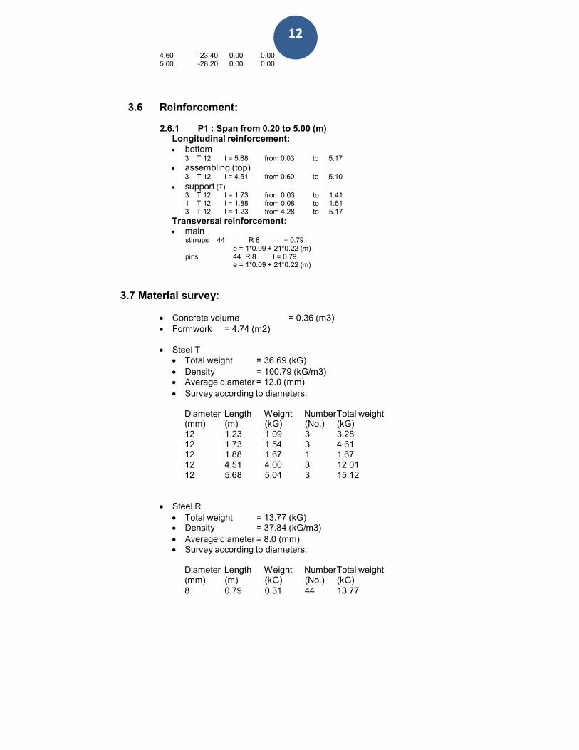
3.6 Reinforcement:
2.6.1 P1 : Span from 0.20 to 5.00 (m) Longitudinal reinforcement: bottom
3 T 12 l = 5.68 from 0.03 to 5.17
assembling (top) 3 T 12 l = 4.51 from 0.60 to 5.10
support (T) 3 T 12 l = 1.73 from 0.03 to 1.41 1 T 12 l = 1.88 from 0.08 to 1.51 3 T 12 l = 1.23 from 4.28 to 5.17
Transversal reinforcement: main
stirrups 44 R 8 l = 0.79 e = 1*0.09 + 21*0.22 (m)
pins 44 R 8 l = 0.79 e = 1*0.09 + 21*0.22 (m)
3.7 Material survey:
Concrete volume = 0.36 (m3)
Formwork = 4.74 (m2)
Steel T Total weight = 36.69 (kG)
Density = 100.79 (kG/m3) Average diameter = 12.0 (mm)
Survey according to diameters:
Diameter Length Weight NumberTotal weight (mm) (m) (kG) (No.) (kG) 12 1.23 1.09 3 3.28 12 1.73 1.54 3 4.61 12 1.88 1.67 1 1.67 12 4.51 4.00 3 12.01 12 5.68 5.04 3 15.12
Steel R
Total weight = 13.77 (kG) Density = 37.84 (kG/m3)
Average diameter = 8.0 (mm) Survey according to diameters:
Diameter Length Weight NumberTotal weight
13
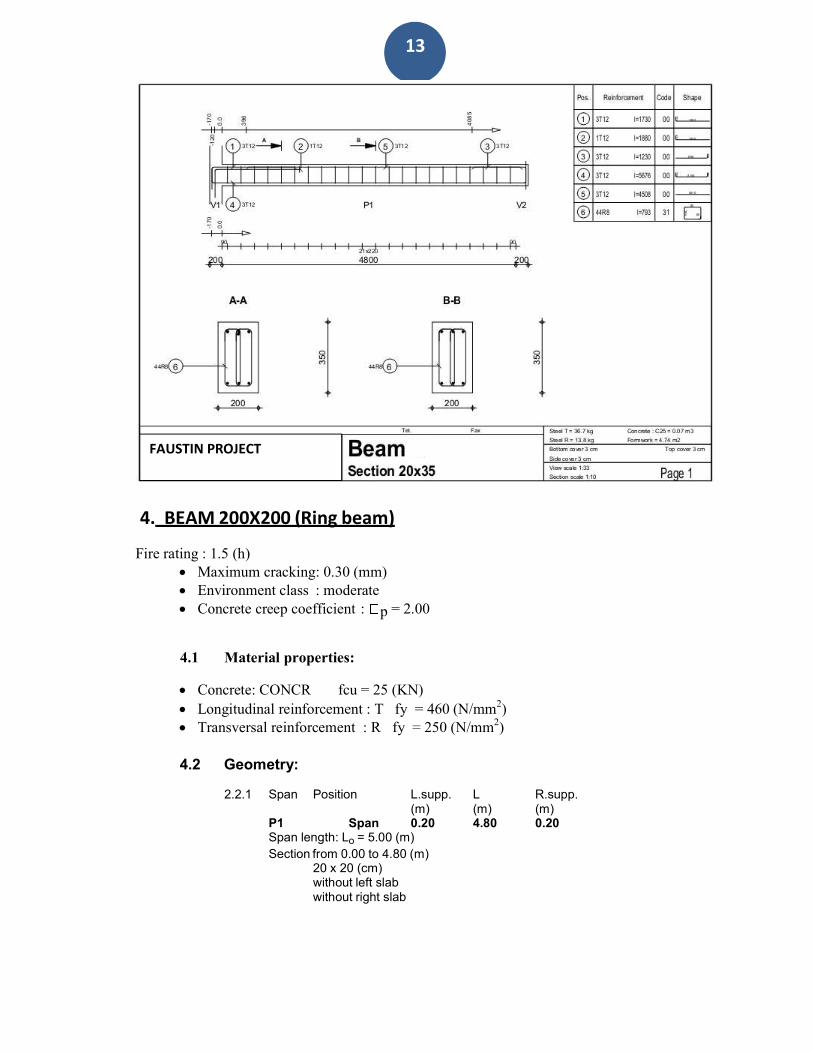
4. BEAM 200X200 (Ring beam)
Fire rating : 1.5 (h) Maximum cracking: 0.30 (mm) Environment class : moderate Concrete creep coefficient : p = 2.00
4.1 Material properties:
Concrete: CONCR fcu = 25 (KN)
Longitudinal reinforcement : T fy = 460 (N/mm2)
Transversal reinforcement : R fy = 250 (N/mm2)
4.2 Geometry:
2.2.1 Span Position L.supp. L R.supp. (m) (m) (m) P1 Span 0.20 4.80 0.20
Span length: Lo = 5.00 (m) Section from 0.00 to 4.80 (m)
20 x 20 (cm) without left slab without right slab
FAUSTIN PROJECT

14
Span Mtmax. Mtmin. Ml Mr Ql Qr (kN*m) (kN*m) (kN*m) (kN*m) (kN) (kN)
P1 11.68 -0.00 -17.72 -5.00 21.35 -15.96
[kN*m]
4.3 Calculation options:
Regulation of combinations : BS5950 Calculations according to : BS 8110
Precast beam : no Cover : bottom c = 3 (cm)
: side c1 = 3 (cm) : top c2 = 3 (cm)
4.4 Calculation results:
4.4.1 Internal forces in ULS
-25
-20
-15
-10
-5
0
5
10 [m]
15 0 1 2 3 4 5
Bending Moment ULS: M Mr Mc
80
[kN] 60
40
20
0
-20
-40
-60
-80
[m]
0 1 2 3 4 5
Shear Force ULS: V Vr Vc(stirrups) Vc(total)
4.4.2 Internal forces in SLS
Span Mtmax. Mtmin. Ml Mr Ql Qr (kN*m) (kN*m) (kN*m) (kN*m) (kN) (kN) P1 0.00 0.00 0.00 0.00 0.00 0.00
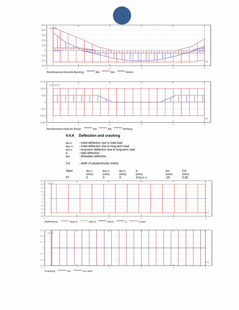
4.4.3 Required reinforcement area
Span Span (mm2) Left support (mm2) Right support (mm2) bottom top bottom top bottom top P1 205 0 8 349 4 80
15
500
400
300
[mm2]
200
100
0
100
200
300
[m]
0 1 2 3 4 5
Reinforcement Area for Bending: Abt Abr Abmin
1500
1000
[mm2/m]
500
0
500
1000
1500
[m]
0 1 2 3 4 5
Reinforcement Area for Shear: Ast Asr AsHang
4.4.4 Deflection and cracking
at(s-t) - initial deflection due to total load ap(s-t) - initial deflection due to long-term load ap(l-t) - long-term deflection due to long-term load a - total deflection aall - allowable deflection
Cw - width of perpendicular cracks
-25
-20
-15
-10
-5
0
5
10
15
20
25
[mm]
Span at(s-t) ap(s-t) ap(l-t) a aall Cw (mm) (mm) (mm) (mm) (mm) (mm)
P1 0 0 0 0=(L0/--) -20 0.00
[m]
0 1 2 3 4 5
Deflections: ap(s-t) ap(l-t) at(s-t) a a adm
0.3
0.2
[mm]
0.1
0
0.1
0.2
0.3
[m]
0 1 2 3 4 5
Cracking: Cw Cw adm

16
4.5 Theoretical results - detailed results:
4.5.1 P1 : Span from 0.20 to 5.00 (m) Abscissa
ULS M max.
M min.
SLS M max.
M min.
A bottom
A top
A compressive
(m) (kN*m) (kN*m) (kN*m) (kN*m) (mm2) (mm2) (mm2) 0.20 0.00 -17.72 0.00 0.00 8 349 8 0.60 0.00 -9.64 0.00 0.00 0 164 0 1.10 0.00 -1.49 0.00 0.00 0 24 0 1.60 4.72 -0.00 0.00 0.00 76 0 0 2.10 8.98 -0.00 0.00 0.00 152 0 0 2.60 11.30 -0.00 0.00 0.00 197 0 0 3.10 11.68 -0.00 0.00 0.00 205 0 0 3.60 10.11 -0.00 0.00 0.00 174 0 0 4.10 6.60 -0.00 0.00 0.00 108 0 0 4.60 1.15 -0.00 0.00 0.00 18 0 0 5.00 0.23 -5.00 0.00 0.00 4 80 0
Abscissa
ULS Q max.
SLS Q max.
Cw
(m) 0.20
(kN) 21.35
(kN) 0.00
(mm) 0.00
0.60 18.25 0.00 0.00 1.10 14.36 0.00 0.00 1.60 10.47 0.00 0.00 2.10 6.58 0.00 0.00 2.60 2.70 0.00 0.00 3.10 -1.19 0.00 0.00 3.60 -5.08 0.00 0.00 4.10 -8.96 0.00 0.00 4.60 -12.85 0.00 0.00 5.00 -15.96 0.00 0.00
4.6 Reinforcement:
4.6.1 P1 : Span from 0.20 to 5.00 (m) Longitudinal reinforcement: bottom
2 T 12 l = 5.80 from 0.03 to 5.17
assembling (top) 2 T 12 l = 4.01 from 1.10 to 5.10
support (T) 2 T 12 l = 2.10 from 0.03 to 1.78 2 T 12 l = 1.25 from 0.08 to 0.88 2 T 12 l = 1.10 from 4.42 to 5.17
Transversal reinforcement: main
stirrups 48 R 8 l = 0.61 e = 1*0.05 + 47*0.10 (m)
pins 48 R 8 l = 0.61 e = 1*0.05 + 47*0.10 (m)
4.7 Material survey:
Concrete volume = 0.21 (m3) Formwork = 3.12 (m2)
Steel T
Total weight = 25.29 (kG) Density = 121.60 (kG/m3)
Average diameter = 12.0 (mm) Survey according to diameters:
Diameter Length Weight NumberTotal weight
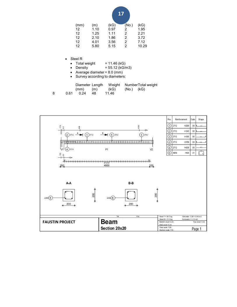
17
(mm) (m) (kG) (No.) (kG) 12 1.10 0.97 2 1.95 12 1.25 1.11 2 2.21 12 2.10 1.86 2 3.72 12 4.01 3.56 2 7.12 12 5.80 5.15 2 10.29
Steel R
Total weight = 11.46 (kG) Density = 55.12 (kG/m3)
Average diameter = 8.0 (mm) Survey according to diameters:
Diameter Length Weight NumberTotal weight (mm) (m) (kG) (No.) (kG)
8 0.61 0.24 48 11.46
FAUSTIN PROJECT
18
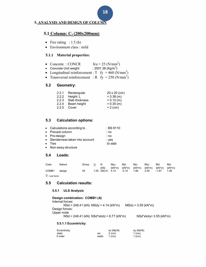
5. ANALYSIS AND DESIGN OF COLUMN
5.1 Column: C1 (200x200mm)
Fire rating : 1.5 (h)
Environment class : mild
5.1.1 Material properties:
Concrete : CONCR fcu = 25 (N/mm2) Concrete Unit weight : 2501.36 (Kg/m3)
Longitudinal reinforcement : T fy = 460 (N/mm2)
Transversal reinforcement : R fy = 250 (N/mm2)
5.2 Geometry:
2.2.1 Rectangular 20 x 20 (cm) 2.2.2 Height: L = 3.38 (m) 2.2.3 Slab thickness = 0.12 (m) 2.2.4 Beam height = 0.35 (m) 2.2.5 Cover = 2 (cm)
5.3 Calculation options:
Calculations according to : BS 8110 Precast column : no Pre-design : no Slenderness taken into account : yes Ties :to slab Non-sway structure
5.4 Loads:
Case Nature Group f N Myu Myl Myi Mzu Mzl Mzi (kN) (kN*m) (kN*m) (kN*m) (kN*m) (kN*m) (kN*m) COMB1 design 45 1.00 248.41 4.14 -2.15 1.66 3.55 -1.67 1.46 f - load factor
5.5 Calculation results:
5.5.1 ULS Analysis
Design combination: COMB1 (A) Internal forces:
NSd = 248.41 (kN) MSdy = 4.14 (kN*m) MSdz = 3.55 (kN*m) Design forces: Upper node
NSd = 248.41 (kN) NSd*etotz = 6.77 (kN*m) NSd*etoty= 3.55 (kN*m)
5.5.1.1 Eccentricity:
Eccentricity: static
ee:
ez (My/N) 2 (cm)
ey (Mz/N) 1 (cm)
II order eadd: 1 (cm) 1 (cm)

19
Minimal emin: 1 (cm) 1 (cm) total etot: 3 (cm) 1 (cm)
5.5.1.2 Detailed analysis-Direction Y:
5.5.1.2.1 Slenderness analysis
Non-sway structure lo (m) le (m)
3.20 1.00 3.20
ley/h = 16.00 > 15.00 (10-7) lez/b = 16.00 > 15.00 (10-7) Slender column
5.5.1.2.2 Buckling analysis
M2 = 4.14 (kN*m) M1 = -2.15 (kN*m) Case: Cross-section at the column end (Upper node), Slenderness taken into account M = 4.14 (kN*m) emin = max (20mm ; 0.05 *hy) = 1 (cm) (3.8.2.4)
hy = 20 (cm) Mmin = N*emin = 2.48 (kN*m) au/2 = a*K*h/2 = 1 (cm) (32)
a = 0.13 (34) K = min((Nuz-N)/(Nuz-Nbal) ; 1) = 0.83 (33)
Nuz = 2/3*fcu/c*Ac+fy/s*Asc = 642.63 (kN) Ac = 0.04 (m2) Asc = 452 (mm2)
Nbal = 165.82 (kN) h = 20 (cm)
Madd/2 = au/2 * N = 2.63 (kN*m) (35) Md = max (Mmin;M+Madd/2) = 6.77 (kN*m)
5.5.1.3 Detailed analysis-Direction Z:
M2 = 3.55 (kN*m) M1 = -1.67 (kN*m) Case: Cross-section at the column end (Upper node), Slenderness not taken into account M = 3.55 (kN*m) emin = max (20mm ; 0.05 *hz) = 1 (cm) (3.8.2.4)
hz = 20 (cm) Mmin = N*emin = 2.48 (kN*m) Md = max (Mmin;M) = 3.55 (kN*m)
5.5.2 Reinforcement:
Real (provided) area Asr = 452 (mm2)
Ratio: = 1.13 %
5.6 Reinforcement:
Main bars:
4 T 12 l = 3.25 (m)
Transversal reinforcement: stirrups: 21 R 8 l = 0.61 (m)
pins 21 R 8 l = 0.61 (m)

20
5.7 Material survey:
Concrete volume = 0.12 (m3)
Formwork = 2.34 (m2)
Steel T Total weight = 11.53 (kG)
Density = 98.53 (kG/m3)
Average diameter = 12.0 (mm) Reinforcement survey:
Diameter Length Weight Number Total weight (m) (kG) (No.) (kG) 12 3.25 2.88 4 11.53
Steel R
Total weight = 5.02 (kG) Density = 42.87 (kG/m3)
Average diameter = 8.0 (mm) Reinforcement survey:
Diameter Length Weight Number Total weight (m) (kG) (No.) (kG) 8 0.61 0.24 21 5.02
FAUSTIN PROJECT

21

24
A = 0.90 (m) a = 0.20 (m) B = 0.90 (m) b = 0.20 (m) h1 = 0.30 (m) ex = 0.00 (m) h2 = 0.60 (m) ey = 0.00 (m) h4 = 0.05 (m)
7. ANALYSIS AND DESIGN OF FOUNDATION
7.1 Basic data
7.1.1 Assumptions
Geotechnic calculations according to : BS 8004 Concrete calculations according to : BS 8110 Shape selection : without limits
7.1.2 Geometry:
a' = 20 (cm) b' = 20 (cm) c1 = 5 (cm) c2 = 5 (cm)
7.1.3 Materials
Concrete : C25; Characteristic strength = 25000.00 kPa
Unit weight = 2501.36 (kG/m3) Longitudinal reinforcement
460000.00 kPa : type T Characteristic strength =
Transversal reinforcement 250000.00 kPa
: type R Characteristic strength =
7.1.4 Loads:
Foundation loads: Case Nature Group N Fx Fy Mx My (kN) (kN) (kN) (kN*m) (kN*m) COMB1 design ---- 257.38 -1.96 -1.63 1.05 1.39
Backfill loads: Case Nature Q1
25
(kN/m2)
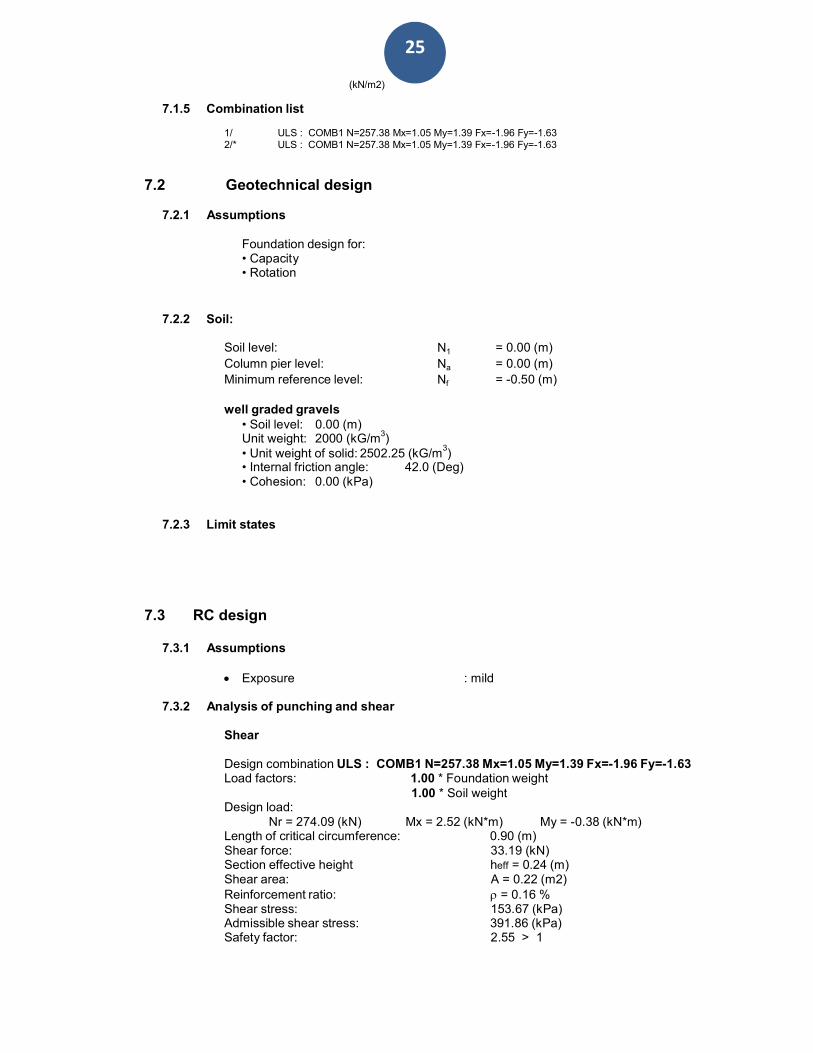
7.1.5 Combination list
1/ ULS : COMB1 N=257.38 Mx=1.05 My=1.39 Fx=-1.96 Fy=-1.63 2/* ULS : COMB1 N=257.38 Mx=1.05 My=1.39 Fx=-1.96 Fy=-1.63
7.2 Geotechnical design
7.2.1 Assumptions
Foundation design for: • Capacity • Rotation
7.2.2 Soil:
Soil level: N1 = 0.00 (m) Column pier level: Na = 0.00 (m) Minimum reference level: Nf = -0.50 (m)
well graded gravels • Soil level: 0.00 (m) Unit weight: 2000 (kG/m
3)
• Unit weight of solid: 2502.25 (kG/m3)
• Internal friction angle: 42.0 (Deg) • Cohesion: 0.00 (kPa)
7.2.3 Limit states
7.3 RC design
7.3.1 Assumptions
Exposure : mild
7.3.2 Analysis of punching and shear
Shear
Design combination ULS : COMB1 N=257.38 Mx=1.05 My=1.39 Fx=-1.96 Fy=-1.63 Load factors: 1.00 * Foundation weight
1.00 * Soil weight Design load:
Nr = 274.09 (kN) Mx = 2.52 (kN*m) My = -0.38 (kN*m) Length of critical circumference: 0.90 (m) Shear force: 33.19 (kN) Section effective height heff = 0.24 (m) Shear area: A = 0.22 (m2) Reinforcement ratio: = 0.16 % Shear stress: 153.67 (kPa) Admissible shear stress: 391.86 (kPa) Safety factor: 2.55 > 1

26
7.3.3 Required reinforcement
Spread footing:
bottom:
ULS : COMB1 N=257.38 Mx=1.05 My=1.39 Fx=-1.96 Fy=-1.63 My = 17.65 (kN*m) Asx = 390 (mm2/m)
ULS : COMB1 N=257.38 Mx=1.05 My=1.39 Fx=-1.96 Fy=-1.63 Mx = 18.37 (kN*m) Asy = 390 (mm2/m)
As min = 390 (mm2/m)
top: A'sx = 0 (mm2/m)
A'sy = 0 (mm2/m)
As min = 0 (mm2/m)
Column pier: Longitudinal reinforcement A = 160 (mm2) A min. = 160 (mm2)
A = 2 * (Asx + Asy) Asx = 30 (mm2) Asy = 50 (mm2)
7.3.4 Provided reinforcement
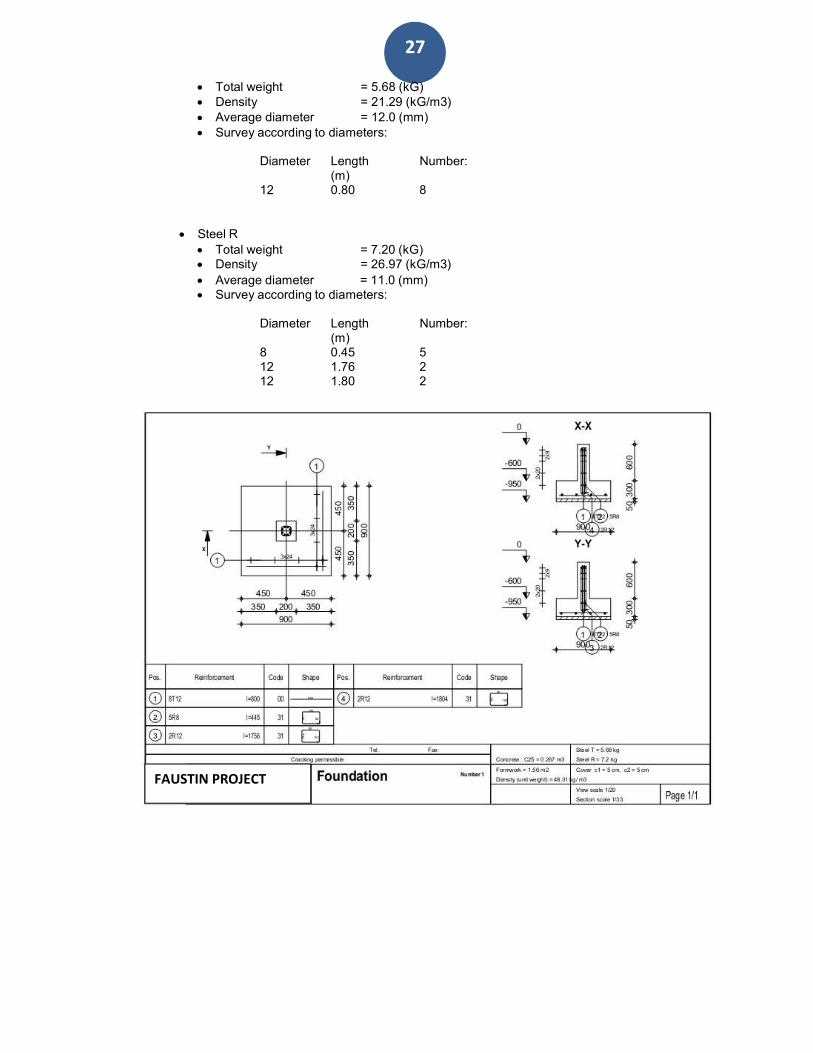
2.3.1 Spread footing: Bottom: Along X axis:
4 T 12 l = 0.80 (m) e = 1*-0.40
Along Y axis: 4 T 12 l = 0.80 (m) e = 0.24
Top:
2.3.2 Pier Longitudinal reinforcement Along X axis:
2 T 12 l = 1.76 (m) e = 1*-0.02 + 1*0.03
Along Y axis: 2 T 12 l = 1.80 (m) e = 1*-0.05
Transversal reinforcement 5 R 8 l = 0.45 (m) e = 1*0.05
7.4Material survey:
Concrete volume = 0.27 (m3)
Formwork = 1.56 (m2)
Steel T
27
Total weight = 5.68 (kG) Density = 21.29 (kG/m3) Average diameter = 12.0 (mm) Survey according to diameters:
Diameter Length Number: (m) 12 0.80 8
Steel R
Total weight = 7.20 (kG) Density = 26.97 (kG/m3)
Average diameter = 11.0 (mm) Survey according to diameters:
Diameter Length Number: (m) 8 0.45 5 12 1.76 2 12 1.80 2
FAUSTIN PROJECT

28
A = 1.20 (m)
a1 = 0.20 (m) a2 = 0.20 (m)
B = 1.20 (m) b1 = 0.20 (m) b2 = 0.20 (m) h1 = 0.30 (m) e1 = 0.40 (m) h2 = 0.60 (m) e2 = 0.20 (m) ey = 0.20 (m) h4 = 0.05 (m)
Case Nature Group Pier N Fx Fy Mx My (kN) (kN) (kN) (kN*m) (kN*m) COMB1 design ---- 1 -44.57 -5.05 0.24 -0.25 -5.35 2 185.26 -5.62 0.02 -0.01 -5.95
8. FOUNDATION ANALYSIS & DESIGN DOUBLE COLUMN (F2)
8.1 Basic data
8.1.1 Assumptions
Geotechnic calculations according to : BS 8004 Concrete calculations according to : BS 8110 Shape selection : without limits
8.1.2 Geometry:
a1' b1'
= 20 (cm) = 20 (cm)
a2' b2'
= 20 (cm) = 20 (cm)
c1 c2
= 5 (cm) = 5 (cm)
8.1.3
Materials
Concrete : C25; Characteristic strength = 25000.00 kPa Unit weight = 2501.36 (kG/m3)
Longitudinal reinforcement 460000.00 kPa
: type T Characteristic strength =
Transversal reinforcement 250000.00 kPa
: type R Characteristic strength =
8.1.4 Loads:
Foundation loads:

29
Backfill loads: Case Nature Q1
(kN/m2)
8.1.5 Combination list
1/ ULS : COMB1 N=140.69 Mx=-0.26 My=11.68 Fx=-10.67 Fy=0.25 2/* ULS : COMB1 N=140.69 Mx=-0.26 My=11.68 Fx=-10.67 Fy=0.25
8.2 Geotechnical design
8.2.1 Assumptions
Foundation design for: • Capacity • Rotation
8.2.2 Soil:
Soil level: N1 = 0.00 (m) Column pier level: Na = 0.00 (m) Minimum reference level: Nf = -0.50 (m)
Silty sand • Soil level: 0.00 (m) • Unit weight:2000 (kG/m
3)
• Unit weight of solid: 2502.25 (kG/m3)
• Internal friction angle: 42.0 (Deg) • Cohesion: 0.00 (kPa)
8.2.3 Limit states
8.3 RC design
8.3.1 Assumptions
Exposure : mild
8.3.2 Analysis of punching and shear
Shear
Design combination ULS : COMB1 N=140.69 Mx=-0.26 My=11.68 Fx=-10.67 Fy=0.25 Load factors: 1.00 * Foundation weight
1.00 * Soil weight Design load:
Nr = 170.41 (kN) Mx = -28.65 (kN*m) My = 2.08 (kN*m) Length of critical circumference: 1.20 (m) Shear force: 44.07 (kN) Section effective height heff = 0.24 (m) Shear area: A = 0.29 (m2) Reinforcement ratio: = 0.16 % Shear stress: 153.02 (kPa)

30
Along X axis: 5 T 12
l = 1.10 (m)
e = 1*-0.55
Along Y axis: 5 T 12
l = 1.10 (m)
e = 0.25
Top: Along X axis:
5 T 12
l = 1.10 (m)
e = 1*-0.55 Along Y axis:
3 T 12
l = 1.10 (m)
e = 0.45
Admissible shear stress: 391.86 (kPa) Safety factor: 2.561 > 1
8.3.3 Required reinforcement
Spread footing:
bottom:
ULS : COMB1 N=140.69 Mx=-0.26 My=11.68 Fx=-10.67 Fy=0.25 My = 37.10 (kN*m) Asx = 390 (mm2/m)
ULS : COMB1 N=140.69 Mx=-0.26 My=11.68 Fx=-10.67 Fy=0.25 Mx = 10.88 (kN*m) Asy = 390 (mm2/m)
As min = 390 (mm2/m)
top:
My = 0.00 (kN*m) A'sx = 390 (mm2/m)
A'sy = 0 (mm2/m)
As min = 0 (mm2/m)
Column pier: 1 Longitudinal reinforcement A = 672 (mm2) A min. = 320 (mm2)
A = 2 * (Asx1 + Asy1) Asx1 = 223 (mm2) Asy1 = 113 (mm2)
Column pier: 2 Longitudinal reinforcement A = 160 (mm2) A min. = 160 (mm2)
A = 2 * (Asx2 + Asy2) Asx2 = 30 (mm2) Asy2 = 50 (mm2)
8.3.4 Provided reinforcement
8.3.1 Spread footing: Bottom:
8.3.2 Pier
Column pier: 1 Longitudinal reinforcement Along X axis:
2 T 12 l = 1.76 (m) e = 1*-0.12 + 1*0.03
Along Y axis: 2 T 12 l = 1.80 (m) e = 1*-0.15
Transversal reinforcement

31
5 R 8 l = 0.45 (m) e = 1*-0.05
Column pier: 2 Longitudinal reinforcement Along X axis:
2 T 12 l = 1.76 (m) e = 1*0.08 + 1*0.03
Along Y axis: 2 T 12 l = 1.80 (m) e = 1*0.05
Transversal reinforcement 5 R 8 l = 0.45 (m) e = 1*0.15
8.4 Material survey:
Concrete volume Formwork =
= 0.48 (m3) 2.40 (m2)
Steel T Total weight = 17.58 (kG) Density = 36.63 (kG/m3) Average diameter = 12.0 (mm)
Survey according to diameters:
Diameter
12
Length (m) 1.10
Number:
18
Steel R Total weight = 14.40 (kG) Density = 30.00 (kG/m3)
Average diameter = 11.0 (mm) Survey according to diameters:
Diameter Length Number: (m) 8 0.45 10 12 1.76 4 12 1.80 4 12 1.80 4
FAUSTIN PROJECT

32
4
00
600
800
00
20
40
60
80
00
20
40
60
80
00
20
40
60
80
00
20
40
60
80
00
.400
.600
.800
1.00
1.20
1.40
1.60
1.80
2.00
2.20
2.40
2.60
2.80
3.00
3.20
3.40
3.60
3.80
4.00
4.20
4.40
4.60
4.80
5.00
.200
.400
.600
.800
1.00
1.20
1.40
1.60
1.80
2.00
2.20
2.40
2.60
2.80
3.00
3.20
3.40
3.60
3.80
4.00
4.20
4.40
4.60
4.80
5.00
.200
.200
9. ANALYSIS & DESIGN OF STAIR
6. DESIGN OF STAIR CASE
The waist is dl = 15cm and riser is H1 = 14.6cm.
Tread is h dl
2
H1 15
2x14.6
28.9cm cos 3
a) Load on stair:
0.7826 3
- Self weight of slab : 1.4 x 0.289 x 1 x 1 x 25 = 10.115 KN/m - Finishes = 1.4x1.6=2.24KN/m - Live load : 1.6 x 5 = 8 KN/m
Total design load: P = 20.36 KN/m
tg = H /L = 175 /220 = 0.9 et = 38.5o
b) Shear forces and moment on stair
1.40 2.20 1.40
40.0
35.0
30.0
25.0
20.0
15.0
10.0 5.00
SHEAR FORCE V m ax = 38.1kN @ 0.00m
13.7
17.3
13.7
13.7
-5.00
-10.0
-15.0
-20.0
-25.0
-30.0
-35.0
I = 10.0E-3 m 4̂ E = 206E6 kPa
DEFLECTIONS D m ax = -.063m m @ 2.50m BENDING MOMENT M m ax = 50.5kNm @ 2.50m
-.005
-.010
-.015
-.020
-.025
-.030
-.035
-.040
-.045
-.050
-.055
-.060
Mmax= 50.5KNm
Vmax =38.1KN
c) Reinforcement design
5.00
10.0
15.0
20.0
25.0
30.0
35.0
40.0
45.0
50.0
- Effective depth of tread: h – 2.5cm = 28.9-2.5 = 26.4cm - Parameters corresponding on slab : -
k M max
50.5x1000000
0.0289 0.05 b.d 2 Fcu 1000x(264)2 x25
Z {0.5 (0.25 k / o.9) 1̂/ 2}d 0.95d
renforcementt section on top bars:
A M max
50.5x1000000
460.77mm2 / m S
0.95ZFy 0.95x0.95x264x460
Asmin=0.13xbxh/100=0.13x1000x264=375.7mm2/m
We take 5Ф12/m and As provided is 565.2mm2with spacing 150mm in principle direction and We take 5Ø10/m and As provided is 392.5mm
2 spacing 150mm in second direction.

33
7. RECAPTILATION OF REINFORCEMENTS DESIGN RESULTS
7.1.1 COLUMNS SUMMARY
Floor Internal/
Edge
Column dimensions Column reinforcement Stirrups
Square circular
0 Internal 20X20 4 Ф 12 Ф8@20 cm c/c
Edge 20X20 4Ф 12 Ф8@20 cm c/c
1 Internal 20X20 4Ф12 Ф8@20 cm c/c
Edge 20X20 4Ф 12 Ф8@20 cm c/c
7.1.2 FOOTING SUMMARY
Footing type Dimensions Reinforcement in X-
direction
Reinforcement in Y-
direction
Starter column
reinforcement
Type 1 Internal 120x120x30 Ф12@200 mm c/c Ф12@200 mm c/c 4Ф14
Type 2 Edge 110x110x30 Ф12@200 mm c/c Ф12@200 mm c/c 4Ф 12
7.1.3 BEAMS SUMMARY
Beam type Dimensions Top reinforcement (at
support)
Bottom reinforcement
(mid-span)
Stirrups near
support/Mid span
Longitudinal
beams
40x20 4Φ12 4Φ14 Ф8@18cm c/c
Ф8@20cm c/c
Transversal
beams
40x20 4Φ12 4Φ14 Ф8@18cm c/c
Ф8@20cm c/c
7.1.4 SLAB SUMMARY
Element Dimensions Top
x-direction
Top
y-direction
Bottom
x-direction
Bottom
y-direction
Suspended
slab
13cm thick Ф12@18cm c/c Ф12@18cm c/c Ф10@18cm c/c Ф10@18cm c/c

34
Done at Rubavu, APRIL 2018
Eng BIRASA Alexis