Preliminary Report on the Harbour Basilica, or the Great Basilica in the Ancient City of Olympos
Upload
independentCategory
view
1download
0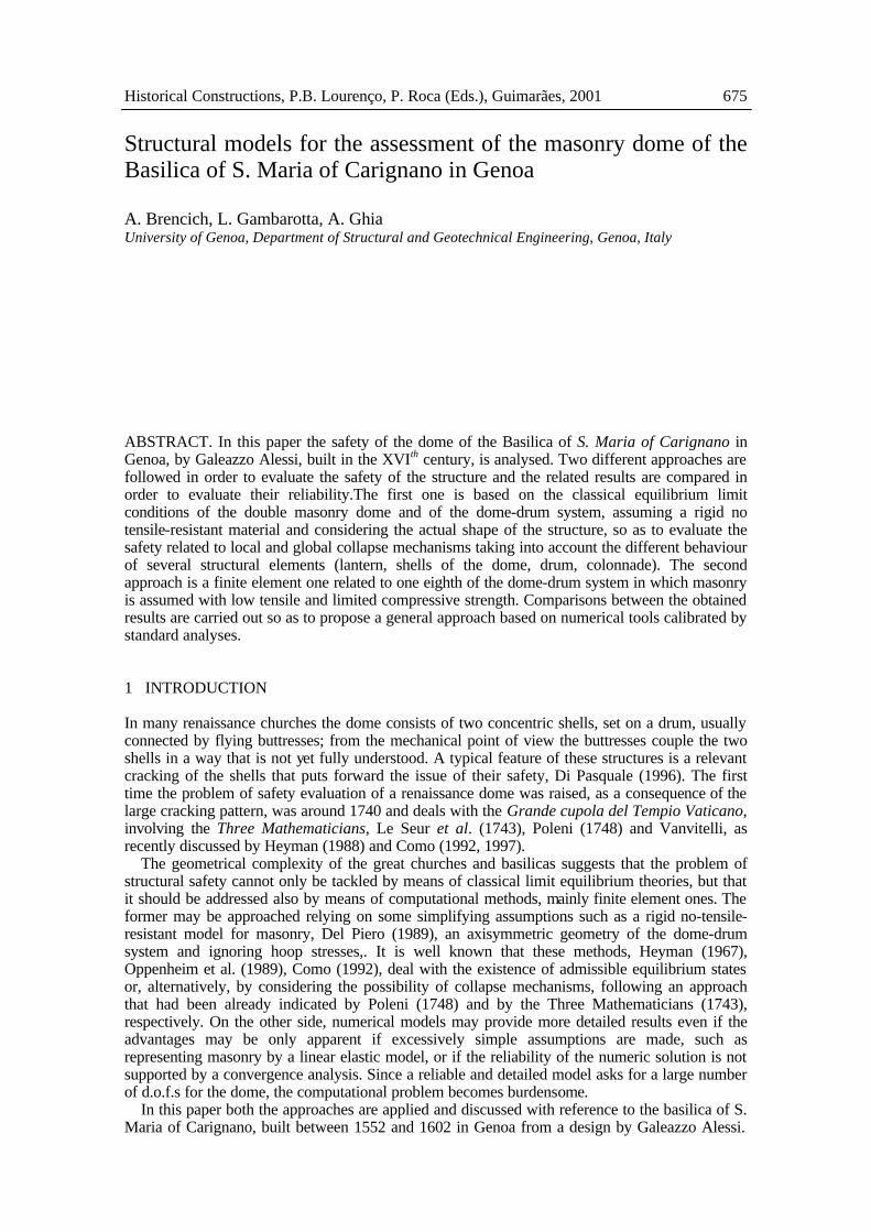
Historical Constructions, P.B. Lourenço, P. Roca (Eds.), Guimarães, 2001 675
ABSTRACT. In this paper the safety of the dome of the Basilica of S. Maria of Carignano in Genoa, by Galeazzo Alessi, built in the XVIth century, is analysed. Two different approaches are followed in order to evaluate the safety of the structure and the related results are compared in order to evaluate their reliability.The first one is based on the classical equilibrium limit conditions of the double masonry dome and of the dome-drum system, assuming a rigid no tensile-resistant material and considering the actual shape of the structure, so as to evaluate the safety related to local and global collapse mechanisms taking into account the different behaviour of several structural elements (lantern, shells of the dome, drum, colonnade). The second approach is a finite element one related to one eighth of the dome-drum system in which masonry is assumed with low tensile and limited compressive strength. Comparisons between the obtained results are carried out so as to propose a general approach based on numerical tools calibrated by standard analyses. 1 INTRODUCTION In many renaissance churches the dome consists of two concentric shells, set on a drum, usually connected by flying buttresses; from the mechanical point of view the buttresses couple the two shells in a way that is not yet fully understood. A typical feature of these structures is a relevant cracking of the shells that puts forward the issue of their safety, Di Pasquale (1996). The first time the problem of safety evaluation of a renaissance dome was raised, as a consequence of the large cracking pattern, was around 1740 and deals with the Grande cupola del Tempio Vaticano, involving the Three Mathematicians, Le Seur et al. (1743), Poleni (1748) and Vanvitelli, as recently discussed by Heyman (1988) and Como (1992, 1997).
The geometrical complexity of the great churches and basilicas suggests that the problem of structural safety cannot only be tackled by means of classical limit equilibrium theories, but that it should be addressed also by means of computational methods, mainly finite element ones. The former may be approached relying on some simplifying assumptions such as a rigid no-tensile-resistant model for masonry, Del Piero (1989), an axisymmetric geometry of the dome-drum system and ignoring hoop stresses,. It is well known that these methods, Heyman (1967), Oppenheim et al. (1989), Como (1992), deal with the existence of admissible equilibrium states or, alternatively, by considering the possibility of collapse mechanisms, following an approach that had been already indicated by Poleni (1748) and by the Three Mathematicians (1743), respectively. On the other side, numerical models may provide more detailed results even if the advantages may be only apparent if excessively simple assumptions are made, such as representing masonry by a linear elastic model, or if the reliability of the numeric solution is not supported by a convergence analysis. Since a reliable and detailed model asks for a large number of d.o.f.s for the dome, the computational problem becomes burdensome.
In this paper both the approaches are applied and discussed with reference to the basilica of S. Maria of Carignano, built between 1552 and 1602 in Genoa from a design by Galeazzo Alessi.
Structural models for the assessment of the masonry dome of the Basilica of S. Maria of Carignano in Genoa
A. Brencich, L. Gambarotta, A. Ghia University of Genoa, Department of Structural and Geotechnical Engineering, Genoa, Italy
676 Historical Constructions
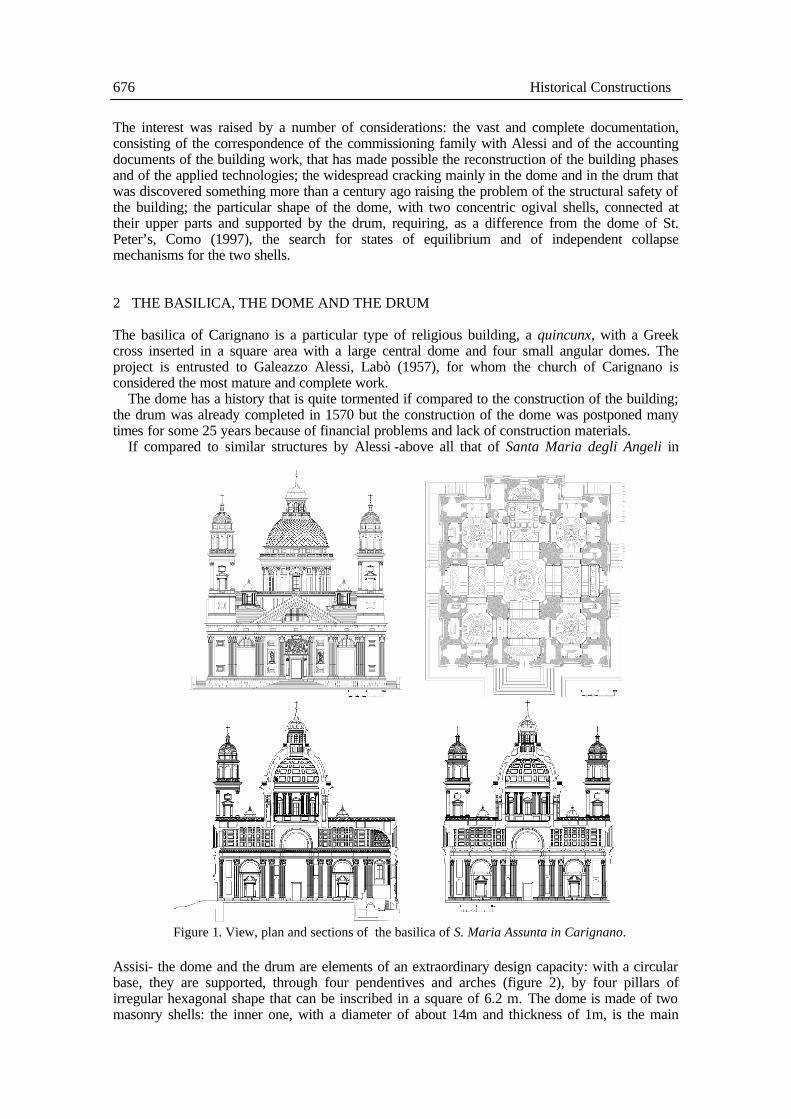
The interest was raised by a number of considerations: the vast and complete documentation, consisting of the correspondence of the commissioning family with Alessi and of the accounting documents of the building work, that has made possible the reconstruction of the building phases and of the applied technologies; the widespread cracking mainly in the dome and in the drum that was discovered something more than a century ago raising the problem of the structural safety of the building; the particular shape of the dome, with two concentric ogival shells, connected at their upper parts and supported by the drum, requiring, as a difference from the dome of St. Peter’s, Como (1997), the search for states of equilibrium and of independent collapse mechanisms for the two shells. 2 THE BASILICA, THE DOME AND THE DRUM The basilica of Carignano is a particular type of religious building, a quincunx, with a Greek cross inserted in a square area with a large central dome and four small angular domes. The project is entrusted to Galeazzo Alessi, Labò (1957), for whom the church of Carignano is considered the most mature and complete work.
The dome has a history that is quite tormented if compared to the construction of the building; the drum was already completed in 1570 but the construction of the dome was postponed many times for some 25 years because of financial problems and lack of construction materials.
If compared to similar structures by Alessi -above all that of Santa Maria degli Angeli in
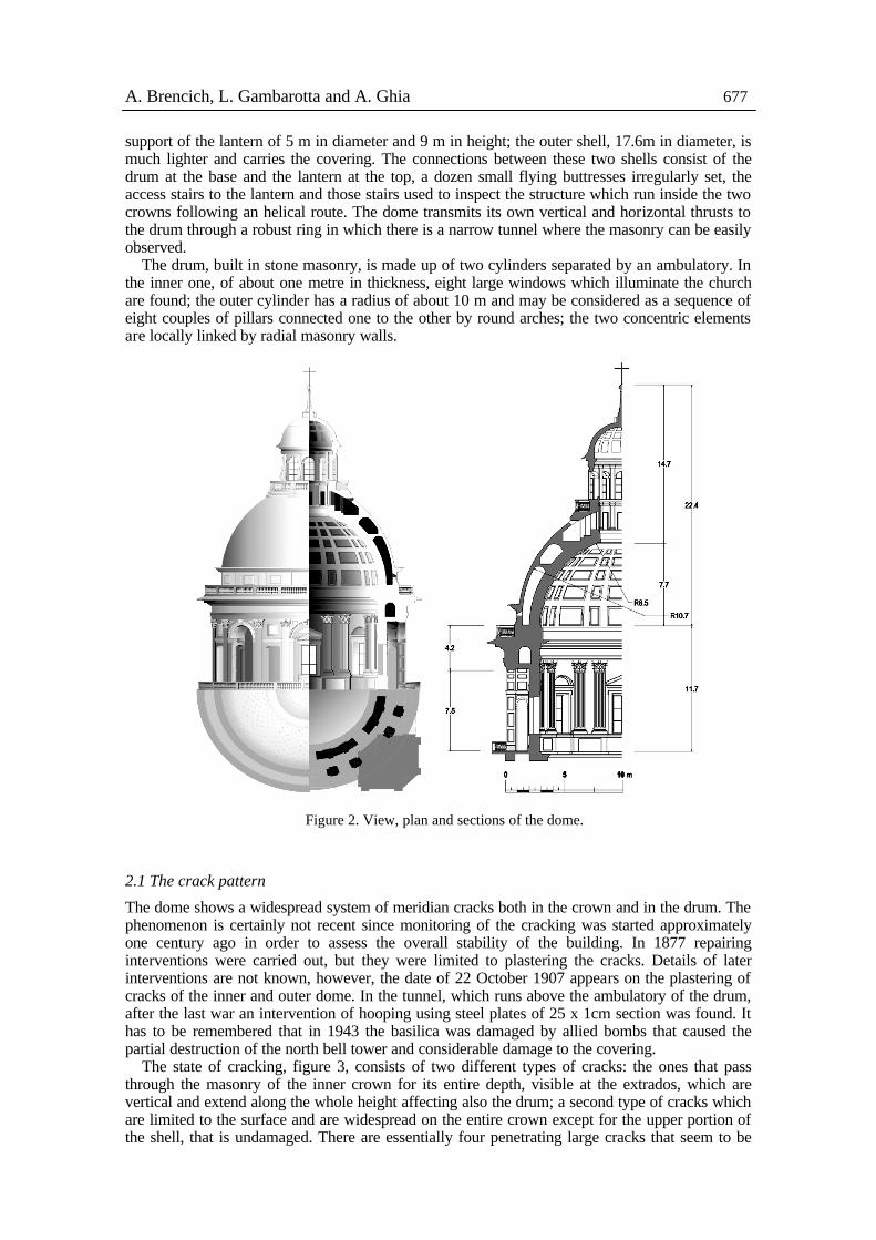
Assisi- the dome and the drum are elements of an extraordinary design capacity: with a circular base, they are supported, through four pendentives and arches (figure 2), by four pillars of irregular hexagonal shape that can be inscribed in a square of 6.2 m. The dome is made of two masonry shells: the inner one, with a diameter of about 14m and thickness of 1m, is the main
Figure 1. View, plan and sections of the basilica of S. Maria Assunta in Carignano.
A. Brencich, L. Gambarotta and A. Ghia 677
support of the lantern of 5 m in diameter and 9 m in height; the outer shell, 17.6m in diameter, is much lighter and carries the covering. The connections between these two shells consist of the drum at the base and the lantern at the top, a dozen small flying buttresses irregularly set, the access stairs to the lantern and those stairs used to inspect the structure which run inside the two crowns following an helical route. The dome transmits its own vertical and horizontal thrusts to the drum through a robust ring in which there is a narrow tunnel where the masonry can be easily observed.
The drum, built in stone masonry, is made up of two cylinders separated by an ambulatory. In the inner one, of about one metre in thickness, eight large windows which illuminate the church are found; the outer cylinder has a radius of about 10 m and may be considered as a sequence of eight couples of pillars connected one to the other by round arches; the two concentric elements are locally linked by radial masonry walls.
2.1 The crack pattern
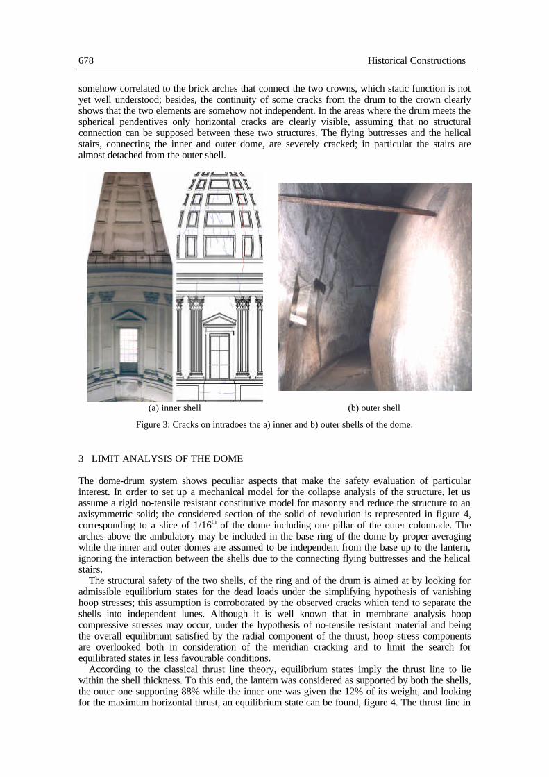
The dome shows a widespread system of meridian cracks both in the crown and in the drum. The phenomenon is certainly not recent since monitoring of the cracking was started approximately one century ago in order to assess the overall stability of the building. In 1877 repairing interventions were carried out, but they were limited to plastering the cracks. Details of later interventions are not known, however, the date of 22 October 1907 appears on the plastering of cracks of the inner and outer dome. In the tunnel, which runs above the ambulatory of the drum, after the last war an intervention of hooping using steel plates of 25 x 1cm section was found. It has to be remembered that in 1943 the basilica was damaged by allied bombs that caused the partial destruction of the north bell tower and considerable damage to the covering.
The state of cracking, figure 3, consists of two different types of cracks: the ones that pass through the masonry of the inner crown for its entire depth, visible at the extrados, which are vertical and extend along the whole height affecting also the drum; a second type of cracks which are limited to the surface and are widespread on the entire crown except for the upper portion of the shell, that is undamaged. There are essentially four penetrating large cracks that seem to be
Figure 2. View, plan and sections of the dome.
678 Historical Constructions
somehow correlated to the brick arches that connect the two crowns, which static function is not yet well understood; besides, the continuity of some cracks from the drum to the crown clearly shows that the two elements are somehow not independent. In the areas where the drum meets the spherical pendentives only horizontal cracks are clearly visible, assuming that no structural connection can be supposed between these two structures. The flying buttresses and the helical stairs, connecting the inner and outer dome, are severely cracked; in particular the stairs are almost detached from the outer shell.
(a) inner shell (b) outer shell
Figure 3: Cracks on intradoes the a) inner and b) outer shells of the dome.
3 LIMIT ANALYSIS OF THE DOME
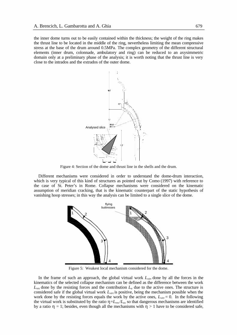
The dome-drum system shows peculiar aspects that make the safety evaluation of particular interest. In order to set up a mechanical model for the collapse analysis of the structure, let us assume a rigid no-tensile resistant constitutive model for masonry and reduce the structure to an axisymmetric solid; the considered section of the solid of revolution is represented in figure 4, corresponding to a slice of 1/16th of the dome including one pillar of the outer colonnade. The arches above the ambulatory may be included in the base ring of the dome by proper averaging while the inner and outer domes are assumed to be independent from the base up to the lantern, ignoring the interaction between the shells due to the connecting flying buttresses and the helical stairs.
The structural safety of the two shells, of the ring and of the drum is aimed at by looking for admissible equilibrium states for the dead loads under the simplifying hypothesis of vanishing hoop stresses; this assumption is corroborated by the observed cracks which tend to separate the shells into independent lunes. Although it is well known that in membrane analysis hoop compressive stresses may occur, under the hypothesis of no-tensile resistant material and being the overall equilibrium satisfied by the radial component of the thrust, hoop stress components are overlooked both in consideration of the meridian cracking and to limit the search for equilibrated states in less favourable conditions.
According to the classical thrust line theory, equilibrium states imply the thrust line to lie within the shell thickness. To this end, the lantern was considered as supported by both the shells, the outer one supporting 88% while the inner one was given the 12% of its weight, and looking for the maximum horizontal thrust, an equilibrium state can be found, figure 4. The thrust line in
A. Brencich, L. Gambarotta and A. Ghia 679
the inner dome turns out to be easily contained within the thickness; the weight of the ring makes the thrust line to be located in the middle of the ring, nevertheless limiting the mean compressive stress at the base of the drum around 0.5MPa. The complex geometry of the different structural elements (inner drum, colonnade, ambulatory and ring) can be reduced to an axysimmetric domain only at a preliminary phase of the analysis; it is worth noting that the thrust line is very close to the intrados and the extrados of the outer dome.
Figure 4: Section of the dome and thrust line in the shells and the drum.
Different mechanisms were considered in order to understand the dome-drum interaction,
which is very typical of this kind of structures as pointed out by Como (1997) with reference to the case of St. Peter’s in Rome. Collapse mechanisms were considered on the kinematic assumption of meridian cracking, that is the kinematic counterpart of the static hypothesis of vanishing hoop stresses; in this way the analysis can be limited to a single slice of the dome.
1 2
3
4 4
3
1 2
flyingbuttresses
Figure 5: Weakest local mechanism considered for the dome.
In the frame of such an approach, the global virtual work Lvirt done by all the forces in the
kinematics of the selected collapse mechanism can be defined as the difference between the work Lres done by the resisting forces and the contribution La due to the active ones. The structure is considered safe if the global virtual work Lvirt is positive, being the mechanism possible when the work done by the resisting forces equals the work by the active ones, Lvirt = 0. In the following the virtual work is substituted by the ratio η=Lres /La, so that dangerous mechanisms are identified by a ratio η = 1; besides, even though all the mechanisms with η > 1 have to be considered safe,
Analysed slice
680 Historical Constructions
the structure will be assumed more likely to collapse according to the mechanism characterised by the lower value of the ratio η.
Local mechanisms are related to the collapse of some part of the structure only. The local mechanisms with the lower value for η was found to foresee the collapse of the outer shell, i.e. the weakest and most slender structural element of the dome, when four hinges are activated, figure 5. In this case the ratio is η=Lres /La ≈ 1.4.
It is worthwhile noting that the most dangerous local mechanism, figure 5, needs the outer shell to move towards the inner one in the upper part, hinge 2. In this precise position the designer asked for a row of flying buttresses, not considered in this analysis, which stabilise the outer shell, prevent such a mechanism from activation and rise the actual ratio for this local mechanism over the 1.4 computed value. It is not known whether the flying buttresses where foreseen in the original project or they were added during construction in order to stabilise the outer dome. Similarly, in the lower part of the dome, the helical stairs are detached from the outer shell, which seems to be in agreement with the local mechanism of figure 5.
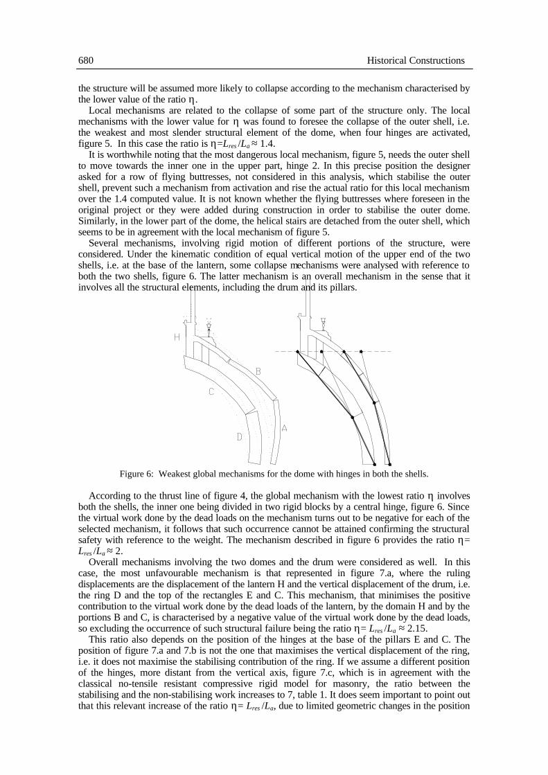
Several mechanisms, involving rigid motion of different portions of the structure, were considered. Under the kinematic condition of equal vertical motion of the upper end of the two shells, i.e. at the base of the lantern, some collapse mechanisms were analysed with reference to both the two shells, figure 6. The latter mechanism is an overall mechanism in the sense that it involves all the structural elements, including the drum and its pillars.
Figure 6: Weakest global mechanisms for the dome with hinges in both the shells.
According to the thrust line of figure 4, the global mechanism with the lowest ratio η involves
both the shells, the inner one being divided in two rigid blocks by a central hinge, figure 6. Since the virtual work done by the dead loads on the mechanism turns out to be negative for each of the selected mechanism, it follows that such occurrence cannot be attained confirming the structural safety with reference to the weight. The mechanism described in figure 6 provides the ratio η= Lres /La ≈ 2.
Overall mechanisms involving the two domes and the drum were considered as well. In this case, the most unfavourable mechanism is that represented in figure 7.a, where the ruling displacements are the displacement of the lantern H and the vertical displacement of the drum, i.e. the ring D and the top of the rectangles E and C. This mechanism, that minimises the positive contribution to the virtual work done by the dead loads of the lantern, by the domain H and by the portions B and C, is characterised by a negative value of the virtual work done by the dead loads, so excluding the occurrence of such structural failure being the ratio η= Lres /La ≈ 2.15.
This ratio also depends on the position of the hinges at the base of the pillars E and C. The position of figure 7.a and 7.b is not the one that maximises the vertical displacement of the ring, i.e. it does not maximise the stabilising contribution of the ring. If we assume a different position of the hinges, more distant from the vertical axis, figure 7.c, which is in agreement with the classical no-tensile resistant compressive rigid model for masonry, the ratio between the stabilising and the non-stabilising work increases to 7, table 1. It does seem important to point out that this relevant increase of the ratio η= Lres /La, due to limited geometric changes in the position
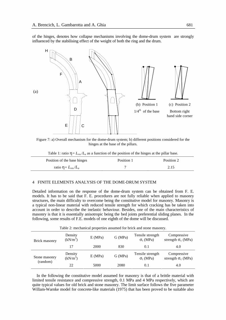
A. Brencich, L. Gambarotta and A. Ghia 681
of the hinges, denotes how collapse mechanisms involving the dome-drum system are strongly influenced by the stabilising effect of the weight of both the ring and the drum.
(a)
H
B
C
A
D
E
F
(b) Position 1
1/4th of the base
(c) Position 2
Bottom right hand side corner
Figure 7: a) Overall mechanism for the dome-drum system; b) different positions considered for the hinges at the base of the pillars.
Table 1: ratio η= Lres /La as a function of the position of the hinges at the pillar base.
Position of the base hinges Position 1 Position 2
ratio η= Lres /La 7 2.15
4 FINITE ELEMENTS ANALYSIS OF THE DOME-DRUM SYSTEM Detailed information on the response of the dome-drum system can be obtained from F. E. models. It has to be said that F. E. procedures are not fully reliable when applied to masonry structures, the main difficulty to overcome being the constitutive model for masonry. Masonry is a typical non-linear material with reduced tensile strength for which cracking has be taken into account in order to describe the inelastic behaviour. Besides, one of the main characteristics of masonry is that it is essentially anisotropic being the bed joints preferential sliding planes. In the following, some results of F.E. models of one eighth of the dome will be discussed.
Table 2: mechanical properties assumed for brick and stone masonry.
Density (kN/m3) E (MPa) G (MPa) Tensile strength
σt (MPa) Compressive
strength σc (MPa) Brick masonry
17 2000 830 0.1 4.0
Density (kN/m3) E (MPa) G (MPa) Tensile strength
σt (MPa) Compressive
strength σc (MPa) Stone masonry (random)
22 5000 2080 0.1 4.0
In the following the constitutive model assumed for masonry is that of a brittle material with
limited tensile resistance and compressive strength, 0.1 MPa and 4 MPa respectively, which are quite typical values for old brick and stone masonry. The limit surface follows the five parameter Willam-Warnke model for concrete-like materials (1975) that has been proved to be suitable also
682 Historical Constructions
for brick masonry (Page, 1981 and 1983). In this way the anisotropic behaviour of masonry cannot be represented, but if this is a limit of the model for brick masonry, it is not for stone masonry that, in Genoese building tradition, is a random fabric of stone with random dimensions with lime mortar. The response after cracking is perfectly brittle. Table 2 summarises the mechanical properties assumed for masonry.
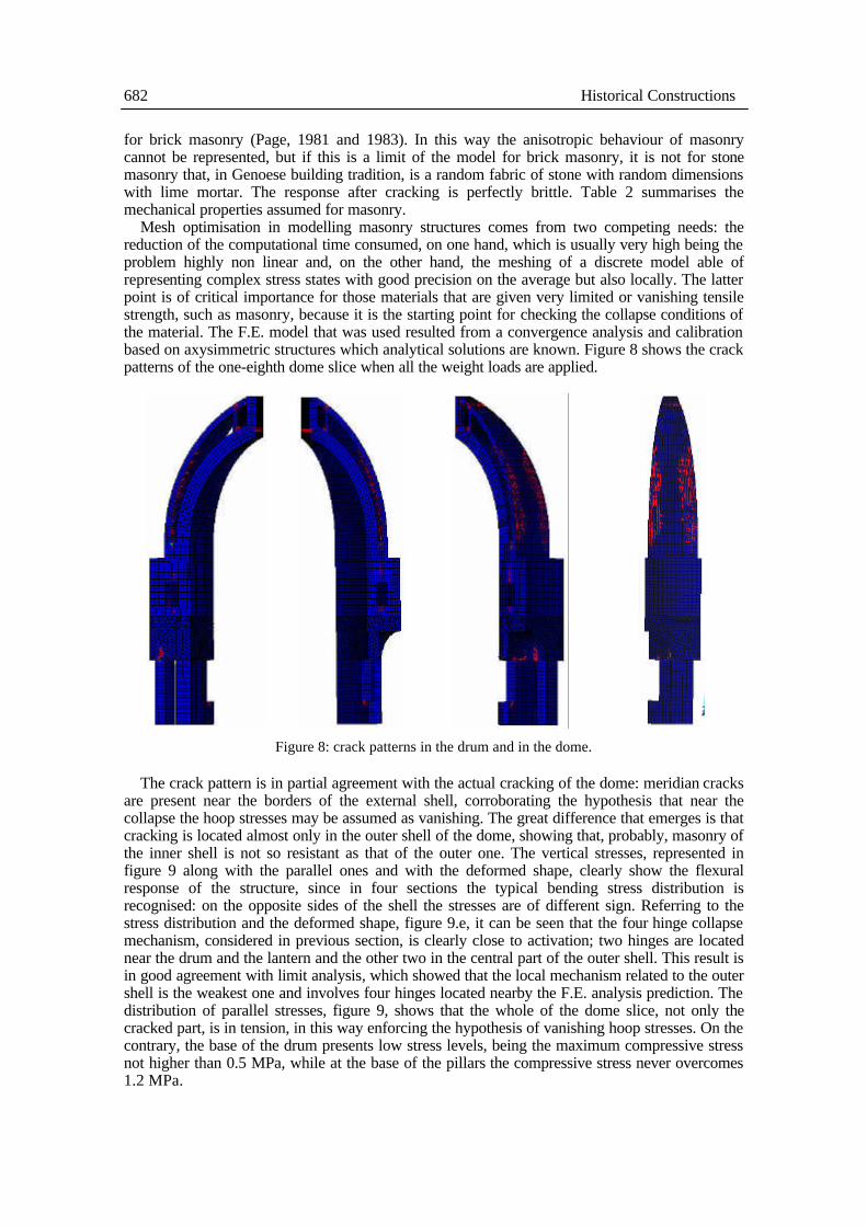
Mesh optimisation in modelling masonry structures comes from two competing needs: the reduction of the computational time consumed, on one hand, which is usually very high being the problem highly non linear and, on the other hand, the meshing of a discrete model able of representing complex stress states with good precision on the average but also locally. The latter point is of critical importance for those materials that are given very limited or vanishing tensile strength, such as masonry, because it is the starting point for checking the collapse conditions of the material. The F.E. model that was used resulted from a convergence analysis and calibration based on axysimmetric structures which analytical solutions are known. Figure 8 shows the crack patterns of the one-eighth dome slice when all the weight loads are applied.
Figure 8: crack patterns in the drum and in the dome.
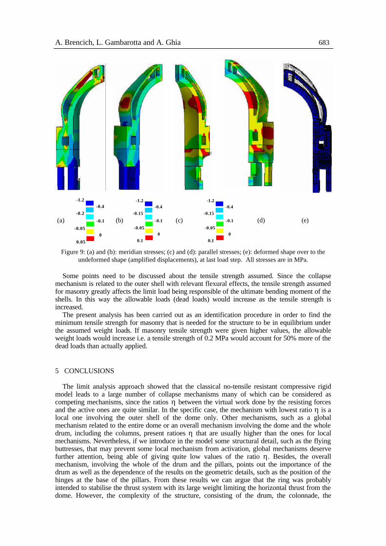
The crack pattern is in partial agreement with the actual cracking of the dome: meridian cracks are present near the borders of the external shell, corroborating the hypothesis that near the collapse the hoop stresses may be assumed as vanishing. The great difference that emerges is that cracking is located almost only in the outer shell of the dome, showing that, probably, masonry of the inner shell is not so resistant as that of the outer one. The vertical stresses, represented in figure 9 along with the parallel ones and with the deformed shape, clearly show the flexural response of the structure, since in four sections the typical bending stress distribution is recognised: on the opposite sides of the shell the stresses are of different sign. Referring to the stress distribution and the deformed shape, figure 9.e, it can be seen that the four hinge collapse mechanism, considered in previous section, is clearly close to activation; two hinges are located near the drum and the lantern and the other two in the central part of the outer shell. This result is in good agreement with limit analysis, which showed that the local mechanism related to the outer shell is the weakest one and involves four hinges located nearby the F.E. analysis prediction. The distribution of parallel stresses, figure 9, shows that the whole of the dome slice, not only the cracked part, is in tension, in this way enforcing the hypothesis of vanishing hoop stresses. On the contrary, the base of the drum presents low stress levels, being the maximum compressive stress not higher than 0.5 MPa, while at the base of the pillars the compressive stress never overcomes 1.2 MPa.
A. Brencich, L. Gambarotta and A. Ghia 683
(a) -0.1
-0.050
0.05
-1.2-0.4
-0.2
(b) -0.1
-0.050
0.1
-1.2-0.4
-0.15
(c) -0.1
-0.050
0.1
-1.2-0.4
-0.15
(d) (e)
Figure 9: (a) and (b): meridian stresses; (c) and (d): parallel stresses; (e): deformed shape over to the undeformed shape (amplified displacements), at last load step. All stresses are in MPa.
Some points need to be discussed about the tensile strength assumed. Since the collapse
mechanism is related to the outer shell with relevant flexural effects, the tensile strength assumed for masonry greatly affects the limit load being responsible of the ultimate bending moment of the shells. In this way the allowable loads (dead loads) would increase as the tensile strength is increased.
The present analysis has been carried out as an identification procedure in order to find the minimum tensile strength for masonry that is needed for the structure to be in equilibrium under the assumed weight loads. If masonry tensile strength were given higher values, the allowable weight loads would increase i.e. a tensile strength of 0.2 MPa would account for 50% more of the dead loads than actually applied. 5 CONCLUSIONS
The limit analysis approach showed that the classical no-tensile resistant compressive rigid model leads to a large number of collapse mechanisms many of which can be considered as competing mechanisms, since the ratios η between the virtual work done by the resisting forces and the active ones are quite similar. In the specific case, the mechanism with lowest ratio η is a local one involving the outer shell of the dome only. Other mechanisms, such as a global mechanism related to the entire dome or an overall mechanism involving the dome and the whole drum, including the columns, present ratioes η that are usually higher than the ones for local mechanisms. Nevertheless, if we introduce in the model some structural detail, such as the flying buttresses, that may prevent some local mechanism from activation, global mechanisms deserve further attention, being able of giving quite low values of the ratio η. Besides, the overall mechanism, involving the whole of the drum and the pillars, points out the importance of the drum as well as the dependence of the results on the geometric details, such as the position of the hinges at the base of the pillars. From these results we can argue that the ring was probably intended to stabilise the thrust system with its large weight limiting the horizontal thrust from the dome. However, the complexity of the structure, consisting of the drum, the colonnade, the
684 Historical Constructions
ambulatory and the ring, makes the vertical and horizontal motion of the rigid elements in the collapse mechanism rather uncertain and affects the assessment of the structural safety, with particular reference to the virtual work done by the external loads and to the corresponding ratio η. Besides, from collapse analysis we can argue that the dome-drum system is safe, being the lowest ratio η= Lres /La equal to approximately 1.4.
The FEM analysis shows that the minimum tensile strength for the structure to be in equilibrium is 0.1 MPa, a value that could be considered as average for brick as well as for random stone masonry. From the structural point of view this means that the dome is safe provided that the degradation effects on mortar do not make the tensile strength fall down below 0.1 MPa. The dome is affected by relevant cracking damage which seems to be neither recent nor in development, allowing the assumption that the average tensile strength is not lower than 0.1 MPa. Besides, the FEM model makes it possible to recognise the weakest parts of the domes, to be strengthened, and shows the beneficial effect of the drum, specifically of its massive part, which undergoes cracking but does not collapse, performing a confining effect at the basis of the two shells of the dome.
Since the crack pattern given by the FEM model does not entirely suit the actual damage, it can be argued that some of its causes have been neglected in the present study, such as a reduced tensile strength for the inner shell and the displacement of the big arches sustaining the drum or some kind of non-symmetrical loading, both causes that cannot be studied by means of a reduced model, such as the one-eighth slice.
REFERENCES Como, M. 1992. Equilibrium and collapse analysis of masonry bodies, Meccanica, 27, p. 185-194. Como, M. 1997. Un antico restauro statico della dome di San Pietro a Roma, in Lo specchio del cielo, p.
245-259, Electa, Milan. Del Piero, G. 1989. Constitutive equations and compatibility of the outer loads for linear elastic
masonry-like materials, Meccanica, 24, p. 150-162. Di Pasquale, S. 1996. L’arte del costruire, Marsilio, Venice. Heyman, J. 1967. On shell solutions for masonry domes, J. Sol. Str., 3, p. 227-241. Heyman, J. 1988. Poleni’s Problem, Proc. Inst. Civ. Engrs., 84. Labò, M. 1957. Galeazzo Alessi in Genoa, in Proc. V National Congress of the history of architecture,
23 September 1948, Florence. Le Seur, T., Jacquier, F. and Boscovich, R.G. 1743. Parere di tre mattematici sopra i danni che si sono
trovati nella cupola di S. Pietro sul fine dell’anno 1742, dato per ordine di N.S. Benedetto XIV, Roma.
Oppenheim, I.J., Gunaratnam, D.J. and Allen R.H. 1989. Limit state analysis of masonry domes, ASCE, J. Str. Eng., 115, p. 868-882.
Page, A.W. 1981. The biaxial compressive strength of brick masonry, Proc. Inst. Civ. Eng.rs, 71, p. 893-906.
Page, A.W. 1983. The strength of brick masonry under biaxial compression-tension, Int. Jnl. Mas. Constr., 3, p. 26-31.
Poleni, G. 1748. Memorie istoriche della gran cupola del tempio vaticano e de' danni di essa, e de' ristoramenti loro, Padua.
Willam, K.J., Warnke, E.D. 1975. Constitutive model for the triaxial behaviour of concrete, Atti di I.A.B.S.E., ISMES, Bergamo.
Copyright © 2022 FDOKUMEN