Design Tools for Sketching of Dome Productions in ... - DiVA
44
Department of Science and Technology Institutionen för teknik och naturvetenskap Linköping University Linköpings universitet g n i p ö k r r o N 4 7 1 0 6 n e d e w S , g n i p ö k r r o N 4 7 1 0 6 - E S LiU-ITN-TEK-A--18/036--SE Design Tools for Sketching of Dome Productions in Virtual Reality Andreas Kihlström 2018-08-28
-
Upload
khangminh22 -
Category
Documents
-
view
0 -
download
0
Transcript of Design Tools for Sketching of Dome Productions in ... - DiVA

Department of Science and Technology Institutionen för teknik och naturvetenskap Linköping University Linköpings universitet
gnipökrroN 47 106 nedewS ,gnipökrroN 47 106-ES
LiU-ITN-TEK-A--18/036--SE
Design Tools for Sketching ofDome Productions in Virtual
RealityAndreas Kihlström
2018-08-28

LiU-ITN-TEK-A--18/036--SE
Design Tools for Sketching ofDome Productions in Virtual
RealityExamensarbete utfört i Medieteknik
vid Tekniska högskolan vidLinköpings universitet
Andreas Kihlström
Handledare Patric LjungExaminator Daniel Jönsson
Norrköping 2018-08-28

Upphovsrätt
Detta dokument hålls tillgängligt på Internet – eller dess framtida ersättare –under en längre tid från publiceringsdatum under förutsättning att inga extra-ordinära omständigheter uppstår.
Tillgång till dokumentet innebär tillstånd för var och en att läsa, ladda ner,skriva ut enstaka kopior för enskilt bruk och att använda det oförändrat förickekommersiell forskning och för undervisning. Överföring av upphovsrättenvid en senare tidpunkt kan inte upphäva detta tillstånd. All annan användning avdokumentet kräver upphovsmannens medgivande. För att garantera äktheten,säkerheten och tillgängligheten finns det lösningar av teknisk och administrativart.
Upphovsmannens ideella rätt innefattar rätt att bli nämnd som upphovsman iden omfattning som god sed kräver vid användning av dokumentet på ovanbeskrivna sätt samt skydd mot att dokumentet ändras eller presenteras i sådanform eller i sådant sammanhang som är kränkande för upphovsmannens litteräraeller konstnärliga anseende eller egenart.
För ytterligare information om Linköping University Electronic Press seförlagets hemsida http://www.ep.liu.se/
Copyright
The publishers will keep this document online on the Internet - or its possiblereplacement - for a considerable time from the date of publication barringexceptional circumstances.
The online availability of the document implies a permanent permission foranyone to read, to download, to print out single copies for your own use and touse it unchanged for any non-commercial research and educational purpose.Subsequent transfers of copyright cannot revoke this permission. All other usesof the document are conditional on the consent of the copyright owner. Thepublisher has taken technical and administrative measures to assure authenticity,security and accessibility.
According to intellectual property law the author has the right to bementioned when his/her work is accessed as described above and to be protectedagainst infringement.
For additional information about the Linköping University Electronic Pressand its procedures for publication and for assurance of document integrity,please refer to its WWW home page: http://www.ep.liu.se/
© Andreas Kihlström

Linköpings universitetSE–581 83 Linköping
+46 13 28 10 00 , www.liu.se
Linköping University | Department of Science and Technology
Master thesis, 30 ECTS | Medieteknik
2018 | LIU-ITN/LITH-EX-A--18/2018--SE
Design Tools for Sketching ofDome Productions in VirtualRealityDesignverktyg för Sketchning av Dom Produktioner i VirtuellVerklighet
Andreas Kihlström
Supervisor : Patric LjungExaminer : Daniel Jönsson

Upphovsrätt
Detta dokument hålls tillgängligt på Internet – eller dess framtida ersättare – under 25 årfrån publiceringsdatum under förutsättning att inga extraordinära omständigheter uppstår.Tillgång till dokumentet innebär tillstånd för var och en att läsa, ladda ner, skriva ut enstakakopior för enskilt bruk och att använda det oförändrat för ickekommersiell forskning och förundervisning. Överföring av upphovsrätten vid en senare tidpunkt kan inte upphäva dettatillstånd. All annan användning av dokumentet kräver upphovsmannens medgivande. Föratt garantera äktheten, säkerheten och tillgängligheten finns lösningar av teknisk och admin-istrativ art. Upphovsmannens ideella rätt innefattar rätt att bli nämnd som upphovsman iden omfattning som god sed kräver vid användning av dokumentet på ovan beskrivna sättsamt skydd mot att dokumentet ändras eller presenteras i sådan form eller i sådant sam-manhang som är kränkande för upphovsmannens litterära eller konstnärliga anseende elleregenart. För ytterligare information om Linköping University Electronic Press se förlagetshemsida http://www.ep.liu.se/.
Copyright
The publishers will keep this document online on the Internet – or its possible replacement– for a period of 25 years starting from the date of publication barring exceptional circum-stances. The online availability of the document implies permanent permission for anyone toread, to download, or to print out single copies for his/hers own use and to use it unchangedfor non-commercial research and educational purpose. Subsequent transfers of copyrightcannot revoke this permission. All other uses of the document are conditional upon the con-sent of the copyright owner. The publisher has taken technical and administrative measuresto assure authenticity, security and accessibility. According to intellectual property law theauthor has the right to be mentioned when his/her work is accessed as described above andto be protected against infringement. For additional information about the Linköping Uni-versity Electronic Press and its procedures for publication and for assurance of documentintegrity, please refer to its www home page: http://www.ep.liu.se/.
© Andreas Kihlström

Abstract
This report presents the problem of designers working on new productions for full-domes. The back and forth process of moving between a work station and the fulldomeis time consuming, a faster alternative would be useful. This thesis presents an option, avirtual reality application where a user can sketch the new environment directly on a vir-tual representation of a fulldome. The result would then be exported directly to the realfulldome to be displayed.
The application is developed using Unreal Engine 4. The virtual dome is constructedusing a procedurally generated mesh, with a paintable material assigned to it. All paintingfunctionality is implemented manually, as is all other tools.
The final product is fully useable, but requires additional work if it is to be used com-mercially. Additional features can be added, including certain features discussed that werecut due to time constraints, as well as improvements to existing features. Application sta-bility is currently a concern that needs to be addressed, as well as optimizations to thesoftware.
Keywords
VR, Virtual Reality, Procedural Generation, 3D Computer Graphics, Unreal Engine 4.

Contents
Abstract iii
1 Introduction 1
1.1 Background . . . . . . . . . . . . . . . . . . . . . . . . . . . . . . . . . . . . . . . 11.2 Purpose . . . . . . . . . . . . . . . . . . . . . . . . . . . . . . . . . . . . . . . . . . 11.3 Workflow . . . . . . . . . . . . . . . . . . . . . . . . . . . . . . . . . . . . . . . . . 11.4 Methods . . . . . . . . . . . . . . . . . . . . . . . . . . . . . . . . . . . . . . . . . 21.5 Question formulations . . . . . . . . . . . . . . . . . . . . . . . . . . . . . . . . . 21.6 Limitations . . . . . . . . . . . . . . . . . . . . . . . . . . . . . . . . . . . . . . . . 3
2 Theoretical Background 4
2.1 Computer Graphics . . . . . . . . . . . . . . . . . . . . . . . . . . . . . . . . . . . 42.2 Painting Theory . . . . . . . . . . . . . . . . . . . . . . . . . . . . . . . . . . . . . 10
3 Execution 21
3.1 Unreal Engine 4 . . . . . . . . . . . . . . . . . . . . . . . . . . . . . . . . . . . . . 213.2 Procedural Mesh Generation . . . . . . . . . . . . . . . . . . . . . . . . . . . . . 223.3 Dynamic Textures and Materials . . . . . . . . . . . . . . . . . . . . . . . . . . . 223.4 Saving and Exporting . . . . . . . . . . . . . . . . . . . . . . . . . . . . . . . . . . 243.5 Virtual Reality . . . . . . . . . . . . . . . . . . . . . . . . . . . . . . . . . . . . . . 253.6 Sketching Controls and Implementation . . . . . . . . . . . . . . . . . . . . . . . 26
4 Results 27
4.1 Workflow . . . . . . . . . . . . . . . . . . . . . . . . . . . . . . . . . . . . . . . . . 274.2 Mesh Generation . . . . . . . . . . . . . . . . . . . . . . . . . . . . . . . . . . . . 274.3 Interaction . . . . . . . . . . . . . . . . . . . . . . . . . . . . . . . . . . . . . . . . 284.4 Painting . . . . . . . . . . . . . . . . . . . . . . . . . . . . . . . . . . . . . . . . . 30
5 Discussion 32
5.1 Questions . . . . . . . . . . . . . . . . . . . . . . . . . . . . . . . . . . . . . . . . 325.2 Future Work . . . . . . . . . . . . . . . . . . . . . . . . . . . . . . . . . . . . . . . 33
6 Conclusion 34
Bibliography 35
iv

List of Figures
2.1 A sphere represented by triangles. . . . . . . . . . . . . . . . . . . . . . . . . . . . . 52.2 Possible UV unwraps of a sphere. . . . . . . . . . . . . . . . . . . . . . . . . . . . . . 62.3 Mapping comparisons between the standard and custom formats. . . . . . . . . . . 72.4 Sphere with cubic vertex mapping. . . . . . . . . . . . . . . . . . . . . . . . . . . . . 72.5 Cubesphere UVW mapping. . . . . . . . . . . . . . . . . . . . . . . . . . . . . . . . . 82.6 Triangle refinement grid. Left side is before subdivision, right side is after. . . . . . 82.7 Types of subdivision. . . . . . . . . . . . . . . . . . . . . . . . . . . . . . . . . . . . . 92.8 Vertex position weights. . . . . . . . . . . . . . . . . . . . . . . . . . . . . . . . . . . 92.9 Two different examples of the normal blending mode. . . . . . . . . . . . . . . . . . 112.10 Two different examples of the multiply blending mode. . . . . . . . . . . . . . . . . 112.11 Two different examples of the screen blending mode. . . . . . . . . . . . . . . . . . 122.12 Two different examples of the overlay blending mode. . . . . . . . . . . . . . . . . . 122.13 Two different examples of the darken blending mode. . . . . . . . . . . . . . . . . . 132.14 Two different examples of the lighten blending mode. . . . . . . . . . . . . . . . . . 132.15 Two different examples of the colour dodge blending mode. . . . . . . . . . . . . . 142.16 Two different examples of the colour burn blending mode. . . . . . . . . . . . . . . 142.17 Two different examples of the hard light blending mode. . . . . . . . . . . . . . . . 152.18 Two different examples of the soft light blending mode. . . . . . . . . . . . . . . . . 152.19 Two different examples of the difference blending mode. . . . . . . . . . . . . . . . 162.20 Two different examples of the exclusion blending mode. . . . . . . . . . . . . . . . 162.21 Illustrations of the simple marking tools. . . . . . . . . . . . . . . . . . . . . . . . . 172.22 Illustrations of the wand marking tool, using different threshold values. . . . . . . 172.23 A before and after comparison of a gaussian blur operation. . . . . . . . . . . . . . 202.24 A before and after comparison of a sharpen operation. . . . . . . . . . . . . . . . . . 20
3.1 Blueprint nodes. When the L key is pressed, the program executes according tothe nodes connected to the event. . . . . . . . . . . . . . . . . . . . . . . . . . . . . . 21
3.2 Material template. The resulting material is interpolated depending on the Alphavalue of the lower texture parameter. . . . . . . . . . . . . . . . . . . . . . . . . . . . 22
4.1 The mesh used for the dome. . . . . . . . . . . . . . . . . . . . . . . . . . . . . . . . 284.2 Both controllers and their menus. . . . . . . . . . . . . . . . . . . . . . . . . . . . . . 284.3 Menu screens. . . . . . . . . . . . . . . . . . . . . . . . . . . . . . . . . . . . . . . . . 294.4 Different brush colours, some with different opacity values. . . . . . . . . . . . . . 304.5 The Canvas texture used, and how it looks on the virtual dome. . . . . . . . . . . . 314.6 Two layers displayed on the menu. . . . . . . . . . . . . . . . . . . . . . . . . . . . . 31
v

Chapter 1
Introduction
A fulldome is a dome based video projection environment, consisting of a spherical projectionsurface surrounding the viewer and filling their entire field of view. The fulldome can beused to immerse the viewer in a virtual environment. The design process for creating newenvironments for a fulldome production is not without its fair share of obstacles however.This chapter will describe these, and possible solutions as well.
1.1 Background
When a new production is to be made for a fulldome, a vital part of the design process isto sketch a mock-up of the environment and display it on the fulldome itself. This usuallyinvolves sketching the environment on a flat surface, likely a digital arts program on a desk-top [1], then exporting the texture, applying a half-cube distortion to it and display it in thefulldome. The problem with this method is that the designers will be unable to see any errorsthey make in the sketch until it is displayed on the fulldome surface. Therefore, the design-ers have to repeatedly go between the sketching workstation and the fulldome to repeatedlycorrect any errors made [2][1].
This is a time consuming process, and it also requires physical access to the fulldomeitself to complete. Most fulldome environments are fully booked during most days, eitherdisplaying existing productions or being used for other projects. Also, not all designers canbe physically present themselves at all times. Because of these issues, there is no way to makethis work portable. Therefore, the design process takes more time than it needs to. If theseissues could be solved, then much time could be saved, and used for other purposes [2].
1.2 Purpose
The purpose of this project is to find, and create a solution for the issues describes in sec-tion 1.1. An alternative sketching surface is required to solve the first issue, that of the backand forth between the work station and the fulldome itself. Preferably, the surface providedshould produce a result that looks identical on the actual fulldome itself. And finally, thesolution needs to be portable. The designer should not require access to the fulldome at allduring the design process. The optimal scenario is if the designers can work from completelydifferent locations on the same production.
1.3 Workflow
A schedule with project deadlines will be created at the start of the thesis work. This schedulewill provide all necessary information about when features should be implemented. It also
1

1.4. Methods
determines the order of when features should be implemented. Work on one deadline shouldbe fully completed before moving on to the next.
As for the development itself, the best way to approach this issue is to have continuousfeedback from a designer that requires such a solution. Their input would provide not onlythe list of features that is required, but also whether or not their implementation is satisfac-tory. They will provide their opinions on each step of the implementation.
Therefore, every other friday during the project a meeting will be held with the designerand the thesis supervisor. Both the designer and the supervisor can provide feedback on thecurrent state of the project. When the application is ready, a proper demonstration will beheld.
This development model borrows ideas from both agile development and the waterfallmodel [3]. While the development schedule itself is more akin to the waterfall model of de-velopment, the constant communication with a designer is more similar to certain aspects ofScrum [3], where a functional piece of software is to be provided to the customer for feedbackat regular intervals.
1.4 Methods
With these necessities in mind, the proposed solution is to create a Virtual Reality applicationfor the HTC Vive, allowing designers to paint on a virtual dome surface. This provides aportable solution, allowing the user to paint on a virtual dome surface. It can also producea result that would look identical on both surfaces, assuming that the virtual dome uses thesame texture mapping as the fulldome uses for projection.
Creating an application for the HTC Vive headset requires a programming platform ableto interface with it. The two main prospects being considered for this thesis work is the Unitygame engine and Unreal Engine 4. Both of these game engines make it very easy to developapplications for the HTC Vive, with many tools and assets already available.
For this project, the engine chosen in Unreal engine 4. Its internal scripting language,called Blueprints, can be used for rapid prototyping, and it can also be combined with regularprogramming to create more advanced features quickly.
1.5 Question formulations
The following questions were posed in the beginning of this thesis work:
• Can the fulldome be represented by an arbitrary spherical shape?
• What type of navigation is optimal for the virtual fulldome environment?
• What kind of controls should be available other than the sketching tool, and how shouldthey be implemented?
Not all fulldomes are created the same way. Different fulldome environments use dif-ferent sizes, and have varying degrees of visible surface for the audience. Some fulldomeproductions have more than 180° of visible surface area, and thus it would be beneficial if thevirtual dome can be represented by an arbitrary spherical shape. This way, the surface can beprocedurally generated, and fit potentially any fulldome setup.
Navigation can often pose a significant problem for virtual reality applications. In thiscase, the application is meant to be portable, so that a design sketch can continue on multiplelocations, potentially in places where space is limited. Since the dome is meant to be proce-durally generated, its resulting size may not correspond to the room setup available. Thus,another way of navigating the environment is needed.
2

1.6. Limitations
Most painting and sketching programs come with many features other than the basicsmost people associate with painting. The virtual environment also offer additional opportu-nities, as full 3D movement can assist in changing the perspective of the sketch. This posesthe question, what kind of features should be added to the application? What can be addedwithin the time constraints of the project?
1.6 Limitations
The first limitation for a user is that they require a HTC Vive virtual reality headset to use theapplication. The headset, while portable, is not perfectly so. In order to use it the user mustset up trackers in a sufficiently large room before the headset can be used. They must then beconnected to a desktop powerful enough to handle virtual reality applications. Laptops arein general not powerful enough for this task.
3

Chapter 2
Theoretical Background
Before work can begin, understanding of the theory behind it is required. There are severalaspects that need explaining, especially in the realm of 3D computer graphics. These will beexplained below.
2.1 Computer Graphics
The first question posed was whether or not the fulldome could be represented by an ar-bitrary spherical shape. The means of answering this is to create a procedurally generatedsphere, where the user can control all necessary parameters relevant to the application. Pro-cedural generation within Unreal Engine 4 requires a set of parameters in order to create anyshape. These parameters are as follows:
• A list of vertices.
• A list of triangle indices. This list must be three times as long as the list of vertices.
• A list of normal vectors, one for each vertex.
• A list of tangent vectors, one for each vertex.
• A list of 2D texture coordinates, one for each vertex.
All of these lists provide all the necessary information to create a procedural mesh.
Procedural Generation
Assigning each vertex individually is a time consuming process and altogether unnecessaryfor this project. Since the mesh to be generated is a sphere, each vertex can be calculatedusing the mathematical definition of a sphere, as shown in Equation 2.1.
(x ´ x0)2 + (y ´ y0)
2 + (z ´ z0)2 = r2 (2.1)
where (x, y, z) refers to three-dimensional coordinates, (x0, y0, z0) is the centre of thesphere and r is the radius. Using this equation, the vertex locations can be calculated andassigned.
In computer graphics, a sphere is defined by a pair of poles, a number of horizontal ringswhere vertices are located and a number vertical slices intersecting the rings. On these inter-sections, the vertices will be placed. This can be seen in Figure 2.1.
The detail level of the sphere is determined by the number of rings and the number ofslices intersecting them. In order to make the sphere look symmetrical, the number of slicesshould be twice that of the number of rings. The rings closest to the two poles will have all oftheir vertices connected to the pole vertices.
4

2.1. Computer Graphics
Figure 2.1: A sphere represented by triangles.
The creation of each vertex will be done one ring at a time. The vertices have to be assignedin a specific order. When creating the list of triangle indices, each triangle needs to be definedby the vertices in proper order, in order to define which side of the triangle points out of thesphere. The rings will be defined by Equation 2.2, a formula to calculate the radius of a spherecap [4].
rr =a
2 ˚ h ˚ rs ´ h2
h = rs ´ py = 2 ˚ rs ´ (Ns ´ kr + 1
Ns) ˚ (2 ˚ rs)
Ns = Nr + 1
(2.2)
The radius of the ring is represented by rr, while the radius of the sphere is representedby rs. The variable h is the height of the spherical cap created by clipping the sphere usingthe selected ring. The variable Ns represents the number of segments created by the rings,always the number of rings, Nr, plus one. Finally, kr shows which ring is being worked on.
Most of the other lists can be applied at the same time. The normal vectors, the tangentvectors and the texture coordinates can be assigned simultaneously to make sure that they allcorrespond to the appropriate vertex.
The normal vector is calculated by drawing a vector from the centre of the sphere to thevertex being assigned. This way, the normal vector will always point out from the sphere.
The tangent calculation is done a different way. A tangent vector is defined as any vectorparallel to the surface, implying that the tangent is always 90° rotated from the normal vector.This tangent vector can be used by calculating the cross-product of the normal vector, and anyother vector not on the same line. These two vectors will define a plane, the normal of whichwill always be 90° rotated from both vectors.
vt = vn ˆ vo (2.3)
5

2.1. Computer Graphics
The terms are defined as vt, the tangent vector, vn, the normal vector and vo, the othervector used. The final parameter to set at this point is the texture coordinate for the vertex.
Texture Mapping
Textures are saved in a strictly quadratic format, usually in an image file the size of whichis a power of 2. Usually this does not present a problem when mapping the texture to aflat surface, but gets considerably more difficult for more complex shapes. The sphere hasalways been a problem, due to the inevitable distortions created when mapping flat texturesto a curved surface.
The way that texture mapping works in Unreal Engine 4, is that each vertex representsa point on the texture being applied. In order to apply a texture onto an entire object, allpolygons need to be mapped onto the texture with texture coordinates, a process called UVMapping [5]. Since the application requires painting, all polygons need to be attached to eachother in the UV map in order to maintain a consistent stroke. Otherwise, the stroke will capoff when close to an edge in the UV mapped texture. However, since this is a sphere, this isnot a possibility. There is no way to UV map a sphere to a texture in a way that allows forsimple continuous painting across the entire surface. Examples can be seen in Figure 2.2.
(a) Single side unwrap of asphere
(b) Both sides of a sphere un-wrapped, disconnected fromeach other.
(c) Complex Unwrap, au-tomatically generated byBlender.
Figure 2.2: Possible UV unwraps of a sphere.
Another feature evident by these UV mappings is that polygons near the poles are smallerthan polygons near the edges. Unless the texture used compensates for this, it will result indistortion near these areas, where the texture is warped. This kind of distortion is calledpincushion distortion.
Both of these issues must be considered for the application of texture coordinates. Mosttextures are applied to spheres using spherical mapping, a method that calculates the texturecoordinates for each vertex by converting their positions from Cartesian coordinates to po-lar coordinates. The resulting texture map puts the poles the top and bottom middle, withall polygons in the middle. While this approach produces a visually superior result, it is adifficult approach for the purposes of this project. Painting at the poles themselves is a dif-ficult task, as all triangles at these location are located far away from each other. The brushonly affects a small subset of triangles this way. A side by side comparison of the single sideapproach and the spherical mapping can be seen in Figure 2.3.
Attempting to compensate for the standard mapping would be difficult, as in order topaint around the pole itself, the brush would have to expand its width to cover all trianglesat the top of the texture. This means that in order for the brush to look uniform as it paintson the sphere, it would have to adapt its width depending on where on the sphere it waspainting. Even then, the result may not look especially pleasing.
6

2.1. Computer Graphics
(a) Single side mapping. The texture is mir-rored on both sides.
(b) Spherical mapping. The standard formatused in most programs.
Figure 2.3: Mapping comparisons between the standard and custom formats.
A More Complex Sphere
With some of the issues brought up in the previous sections in mind, it becomes clear thatthe regular type of sphere has some problems when used for painting. Since the size of eachpolygon is not uniform, especially not at the pole, the brush size would not stay constantacross the entire sphere. However, there exists alternative forms of spheres with differentkinds of vertex mapping. These alternatives attempt to deal with these issues by removingthe pole altogether. The example examined here will be the Cube Sphere, illustrated in Figure2.4.
Figure 2.4: Sphere with cubic vertex mapping.
Instead of a central pole at the top and the bottom, this alternative sphere maps its verticesin a way that mimics that of a cube. The corners of the cube is where each side is joined, withthe polygons mimicking that of squares instead of triangles. The resulting UV Wrap has amuch more uniform size across the polygons, reducing the amount of distortion. This can beseen in Figure 2.5.
While this type of sphere is better suited, it is also harder to procedurally generate. Sincethe vertices do not follow a simple ring pattern, placement is more difficult. There exists awork-around however. If a cube is created with a sufficient amount of vertices, its vertices
7

2.1. Computer Graphics
Figure 2.5: Cubesphere UVW mapping.
can be displaced, creating a sphere with the correct vertex mapping. In order for this to work,a cube must be created with several iterations of mesh subdivision [6].
Mesh Subdivision
Mesh Subdivision is a method used to easily increase the level of detail for any mesh, regard-less of shape. This is done by subdividing existing polygons into smaller ones. If all trianglesare divided equally, a single triangle turns into four new triangles. The effect of of this can beseen in Figure 2.6, with new vertices inside a triangle shown in green on the right side.
Figure 2.6: Triangle refinement grid. Left side is before subdivision, right side is after.
The simplest of subdivision schemes leave it at that, creating more polygons and leavingthe mesh itself unchanged. While this method could indeed be used, since all vertices willbe displaced into a sphere anyway, the vertex placement on the sphere may not be optimalas a result. A comparison is made in Figure 2.7, where the result from a simple subdivisionalgorithm results in greater distortion along the lines that used to be corners. The complexsubdivision algorithm displayed on the right side is a better option for painting in this case.
More complex subdivision schemes will not only add more vertices to the mesh, theywill also transform existing vertices in order to create a smoother surface. There have beenmultiple different subdivision algorithms implemented over the years, some working withsplines and others with triangles. Since the procedural mesh is triangle based, it would bebest to utilise a triangle based subdivision algorithm.
8

2.1. Computer Graphics
(a) Simple subdivision, verticesare not moved with each itera-tion.
(b) Complex subdivision, ver-tices are moved with each iter-ation.
Figure 2.7: Types of subdivision.
Such an algorithm was proposed by C. Loop [6]. This method can be used to smoothenan arbitrary triangle based surface, which is what is needed here. The algorithm consists oftwo parts: adding new vertices to the mesh along the edges of each triangle, and moving theold vertices to create a smoother surface. The new positions are calculated using weightedaverages of previous locations. These weighted averages are calculated before any new pointsare added. The value of the weights depend on the number of connecting edges of the vertex,the so called valence value. The general idea behind it is illustrated in Figure 2.8.
Figure 2.8: Vertex position weights.
There are two different cases displayed here, either a point is an interior point (top leftand right), or a boundary points (bottom left and right). The left side displays new pointsin green, while the right side displays the calculated weight values for existing points. If themesh being subdivided is a so called manifold surface, with no holes in it, all vertices areinterior points. If this is not the case, the boundary rules has to be considered. Since thesubdivision is to be used on a cube, the mesh is a manifold surface and only the interior ruleswill be applied.
The value for β is calculated using the following equation, where k is the valence value ofthe vertex.
β =
#
38k if: k ą 33
16 if: k = 3(2.4)
Cube To Sphere
With a subdivided cube, all that is left is to displace cubes vertices to create a sphere. Thecentre of the cube will be used as the centre of the sphere. For each vertex, a vector will becreated, pointing fro the centre to the vertex. Then the vertex will be moved to the point
9

2.2. Painting Theory
on the vector, where the distance between the vertex and the centre equals the radius of thesphere. This process can be seen in Equation 2.5.
VCtPo= Po ´ C
Pn = VCtPo˚ r
(2.5)
An explanation of the terms are as follows: VCtPois the vector going from the centre to the
old point on the cube. As such, Po is the old point and C is the centre point. This means thatPn is the new point, and r is the radius of the new sphere.
2.2 Painting Theory
In order to implement more advanced features than simple painting, brought up in the thirdquestion, more research is required for various other features and tools. There are manyadvanced tools that can be implemented, some of which are listed below.
• Layers and blending modes.
• Opacity.
• Marking tools.
• Filters.
Some of these tools are easier to implement than others. Opacity is intrinsically tied withblending modes, but is also used when painting normally, when the user wants to apply alighter overlay of colour instead of replacing whatever lies beneath.
Layers and Blend Modes
Whenever different elements need to be separated from each other in a picture, layers areused. Using these layers, a designer can pick and choose which parts of the image to ma-nipulate, leaving others unaffected. Layers are implemented as separate images with uniquesettings that can blend with other layers to produce different effects. There are multiple typesof blend modes [7] that can be used, picked at will by the designer.
The resulting image displayed depends of the Blend Function that is used, described herewith B(Cb, Cs) = Cr. In this blend function, the term Cb represents the backdrop layer, Cs
represents the source layer and Cr represents the result. This means that the source layer issituated above the backdrop. The various kinds of blend functions are displayed below.
Normal
The normal blend function simply selects the source colour as the result, as displayed inEquation 2.6.
B(cb, cs) = cs (2.6)
Assuming that the opacity value for the layer is at 100%, the displayed colour will alwaysbe picked from the source layer. If this is not the case, then Equation 2.7 will be used instead.The resulting value is calculated depending on the opacity of the two layers , known as the α
value. This method is known as Alpha Compositing [8].
B(cb, cs) = alpha(cs, cb)
alpha(cs, cb) = cs(α) ˚ cs + (1 ´ cs(α)) ˚ cb(α) ˚ cb
(2.7)
The effect of this blending mode can be seen in Figure 2.9.
10

2.2. Painting Theory
(a) With a solid red background. (b) With a blue gradient background.
Figure 2.9: Two different examples of the normal blending mode.
Multiply
This blend function multiplies the backdrop and source colour values.
B(cb, cs) = cb ˆ cs (2.8)
The resulting colour is always at least as dark one of the two used layers. Multiplicationwith black produces black colour, and multiplication with white leaves the colour unchanged.Multiplication with any other colour results in a darker colour. The effect of this blendingmode can be seen in Figure 2.10.
(a) With a solid red background. (b) With a blue gradient background.
Figure 2.10: Two different examples of the multiply blending mode.
Screen
This blend function multiplies the complements of the backdrop and source colour values,and then complements the result.
B(cb, cs) = 1 ´ [(1 ´ cb) ˆ (1 ´ cs)] = cb + cs ´ (cb ˆ cs) (2.9)
This blend function has the opposite effect compared to Multiply, in that the result is atleast as light as either of the two used layers. Screening with white always produces a whiteresult, and screening with black leaves the colour unchanged. The effect of this blendingmode can be seen in Figure 2.11.
11

2.2. Painting Theory
(a) With a solid red background. (b) With a blue gradient background.
Figure 2.11: Two different examples of the screen blending mode.
Overlay
This blend function either uses Multiply or Screening, depending on the colour value of thebackdrop. Source colours overlay the backdrop while preserving its highlights and shadows.Therefore, the result is a mix with the source colour to reflect the luminosity of the backdrop.
B(cb, cs) = HardLight(cs, cb) (2.10)
The effect of this blending mode can be seen in Figure 2.12.
(a) With a solid red background. (b) With a blue gradient background.
Figure 2.12: Two different examples of the overlay blending mode.
Darken
This blend function selects the darker colour when comparing the source with the backdrop.
B(cb, cs) = min(cb, cs) (2.11)
If the source is darker, the backdrop is replaced. Otherwise, the result is unchanged. Theeffect of this blending mode can be seen in Figure 2.13.
12

2.2. Painting Theory
(a) With a solid red background. (b) With a blue gradient background.
Figure 2.13: Two different examples of the darken blending mode.
Lighten
This blend function selects the lighter colour when comparing the source with the backdrop.
B(cb, cs) = max(cb, cs) (2.12)
If the source is lighter, the backdrop is replaced. Otherwise, the result is unchanged. Theeffect of this blending mode can be seen in Figure 2.14.
(a) With a solid red background. (b) With a blue gradient background.
Figure 2.14: Two different examples of the lighten blending mode.
Colour dodge
This blend function brightens the backdrop to reflect the source layer. Painting with blackproduces no changes.
B(cb, cs) =
#
min(1, cb1´cs
), if cs ą 0
1, if cs = 0(2.13)
The effect of this blending mode can be seen in Figure 2.15.
13

2.2. Painting Theory
(a) With a solid red background. (b) With a blue gradient background.
Figure 2.15: Two different examples of the colour dodge blending mode.
Colour burn
This blend function darkens the backdrop colour to reflect the source colour. Painting withwhite produces no change.
B(cb, cs) =
#
1 ´ min(1, 1´cbcs
), if cs ą 0
0, if cs = 0(2.14)
The effect of this blending mode can be seen in Figure 2.16.
(a) With a solid red background. (b) With a blue gradient background.
Figure 2.16: Two different examples of the colour burn blending mode.
Hard light
This blend function Multiplies or Screens the colours, depending on the source colour value.
B(cb, cs) =
#
Multiply(cb, 2 ˆ cs) if cs ď 0.5
Screen(cb, 2 ˆ cs ´ 1) if cs ą 0.5(2.15)
The effect of this blending mode can be seen in Figure 2.17.
14

2.2. Painting Theory
(a) With a solid red background. (b) With a blue gradient background.
Figure 2.17: Two different examples of the hard light blending mode.
Soft light
This blend function Darkens or Lightens the colours, depending on the source colour value.
B(cb, cs) =
#
cb ´ (1 ´ 2 ˆ cs) ˆ cb ˆ (1 ´ cb) if cs ď 0.5
cb + (2 ˆ cs ´ 1) ˆ (D(cb) ´ cb) if cs ą 0.5
where Dx =
#
((16 ˆ x ´ 12) ˆ x + 4) ˆ x if x ď 0.25?
x if x ą 0.25
(2.16)
The effect of this blending mode can be seen in Figure 2.18.
(a) With a solid red background. (b) With a blue gradient background.
Figure 2.18: Two different examples of the soft light blending mode.
Difference
This blend function subtracts the darker of the two layer colours from the lighter colour.
B(cb, cs) = |cb ´ cs| (2.17)
Painting with black produces no change, while painting with white inverts the colour ofthe backdrop. The effect of this blending mode can be seen in Figure 2.19.
15

2.2. Painting Theory
(a) With a solid red background. (b) With a blue gradient background.
Figure 2.19: Two different examples of the difference blending mode.
Exclusion
This blend function produces a similar effect to that of Difference, but lower in contrast. Paint-ing with black produces no change, while painting with white inverts the colour of the back-drop.
B(cb, cs) = cb + cs ´ 2 ˆ cb ˆ cs (2.18)
The effect of this blending mode can be seen in Figure 2.20.
(a) With a solid red background. (b) With a blue gradient background.
Figure 2.20: Two different examples of the exclusion blending mode.
Marking tools
The marking tool is a simple concept. The designer marks a section of the image that theywant to paint on. If they try to paint or manipulate any part of the image outside the markedarea, nothing happens. This way, the designer can focus on a section on the image withoutfear of accidentally applying something on another part of the image.
There are four main tools used for marking, with some variations. These are as follows:
• Rectangular Selection
• Elliptical Selection
16
2.2. Painting Theory
• Lasso Selection
• Magic Wand Selection
Most of these tools are rather simple. The user drags a simple geometric shape on theimage, and all pixels inside are selected. The Rectangular and Elliptical selection tools can beused to quickly apply this to the image. The lasso tool is used to draw a more complex shapeon the image, selecting all pixels inside when the shape is completed. Examples of these canbe seen in Figure 2.21.
(a) Marking with the rectangu-lar marking tool.
(b) Marking with the ellipticalmarking tool.
(c) Marking with the lassomarking tool.
Figure 2.21: Illustrations of the simple marking tools.
Magic Wand Selection
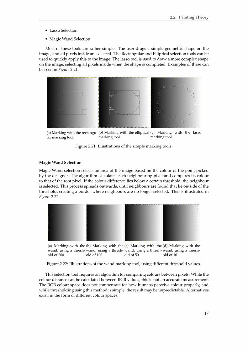
Magic Wand selection selects an area of the image based on the colour of the point pickedby the designer. The algorithm calculates each neighbouring pixel and compares its colourto that of the root pixel. If the colour difference lies below a certain threshold, the neighbouris selected. This process spreads outwards, until neighbours are found that lie outside of thethreshold, creating a border where neighbours are no longer selected. This is illustrated inFigure 2.22.
(a) Marking with thewand, using a thresh-old of 200.
(b) Marking with thewand, using a thresh-old of 100.
(c) Marking with thewand, using a thresh-old of 50.
(d) Marking with thewand, using a thresh-old of 10.
Figure 2.22: Illustrations of the wand marking tool, using different threshold values.
This selection tool requires an algorithm for comparing colours between pixels. While thecolour distance can be calculated between RGB values, this is not an accurate measurement.The RGB colour space does not compensate for how humans perceive colour properly, andwhile thresholding using this method is simple, the result may be unpredictable. Alternativesexist, in the form of different colour spaces.
17

2.2. Painting Theory
Colour spaces
There are two main colour space alternatives to RGB, one is the CIE 1931 (CieXYZ) colourspace, and the other is the CIE L*a*b* (CieLAB) colour space [9]. CieXYZ was created from aseries of experiments to determine the links between light wavelength distribution and hu-man colour perception. CieLAB was created as a uniform colour space, designed to measurethe differences in colours. It is device independent, and can therefore be used on any device.
The optimal way to compare colour distance is with the use of CieLAB, due to its unifor-mity. While there is no direct conversion from RGB to CieLAB colour coordinates, there is aconversion from CieXYZ to CieLAB. Therefore, in order to compare a colour with the thresh-old the RGB value must first be converted to CieXYZ, and then to CieLAB. The algorithm forthis can be found in Equations 2.19 and 2.20.
vrgb = [r, g, b]
mrgb2xyz =
0.412453 0.357580 0.1804230.212671 0.715160 0.0721690.019334 0.119193 0.950227
vxyz = mrgb2xyz ˆ vrgb = [x, y, z]
(2.19)
The matrix used for Equation 2.19 depends on the RGB working space being used. This matrixis taken from the sRGB colour working space [10].
vxyz = [x, y, z]
D65 = [0.950456, 1.0, 1.088754]
vxyzN =vxyz
D65= [xn, yn, zn]
vexp = [x13n , y
13n , z
13n ] = [xexp, yexp, zexp]
T = 0.008856
L =
#
116 ˚ yexp ´ 16 if: yexp ą T
903.3 ˚ yn if: yexp ď T
vxyzF =
7.787 ˚ xn +16
1167.787 ˚ yn +
16116
7.787 ˚ zn +16116
= [x f , y f , z f ]
a =
$
’
’
’
’
&
’
’
’
’
%
500 ˚ (xexp ´ yexp) if: xn ą T, yn ą T
500 ˚ (x f ´ yexp) if: xn ď T, yn ą T
500 ˚ (xexp ´ y f ) if: xn ą T, yn ď T
500 ˚ (x f ´ y f ) if: xn ď T, yn ď T
b =
$
’
’
’
’
&
’
’
’
’
%
200 ˚ (yexp ´ zexp) if: yn ą T, zn ą T
200 ˚ (y f ´ zexp) if: yn ď T, zn ą T
200 ˚ (yexp ´ z f ) if: yn ą T, zn ď T
200 ˚ (y f ´ z f ) if: yn ď T, zn ď T
vLab = [L, a, b]
(2.20)
The second conversion involves many more steps than the first. The first step is to nor-malize the XYZ values with a given whitepoint. In this case, D65 is used, which representsnormal daylight at noon. The variable T is used as a threshold, controlling whether or notthe calculation uses values from vexp, vxyzN or vxyzF. After the CieLAB values have been cal-culated for a pixel, it can be compared with the value used by the magic wand. This will be
18

2.2. Painting Theory
compared with a given threshold set by the user, and this will determine if a pixel is selectedor not. The colour distance is calculated using Equation 2.21.
f (Lp, ap, bp, Lt, at, bt) =b
(Lp ´ Lt)2 + (ap ´ at)2 + (bp ´ bt)2 (2.21)
The variables with the p attached are the values from the pixel, while the variables withthe t attached are the values from the colour picked by the magic wand.
Filters
Filters are image processing methods that can apply specific effects to an entire image. This isdone by applying a filter kernel that moves across the entire image. The effect of this dependson the composition of the kernel. Examples of filters can be found below.
Gaussian Blur
Gaussian blur is a lowpass filter that applies a Gaussian function to the filter kernel, with theaim of blurring or smoothing an image. It is a popular method to reduce image noise. Thereexists two methods of implementing the filter, either in one dimension as a line kernel, ortwo dimension as a box. The function applied in one dimension can be seen in Equation 2.22,while the function applied in two dimensions can be seen in Equation 2.23.
G(x) =1?
2πσ2e
´
x2
2σ2 (2.22)
G(x, y) =1?
2πσ2e
´
x2+y2
2σ2 (2.23)
The x and y coordinates represent the coordinates around the filter kernel midpoint. Thus,G(0, 0) would be in the middle of the filter kernel. The value of σ is the standard deviationfunction, the width of the filter kernel, with higher values resulting in greater amounts ofblur. The function is then applied to the filter kernel. A default size often used is a 7x7 filterkernel, example found in Equation 2.24.
G(´3, 3) G(´2, 3) G(´1, 3) G(0, 3) G(1, 3) G(2, 3) G(3, 3)G(´3, 2) G(´2, 2) G(´1, 2) G(0, 2) G(1, 2) G(2, 2) G(3, 2)G(´3, 1) G(´2, 1) G(´1, 1) G(0, 1) G(1, 1) G(2, 1) G(3, 1)G(´3, 0) G(´2, 0) G(´1, 0) G(0, 0) G(1, 0) G(2, 0) G(3, 0)
G(´3, ´1) G(´2, ´1) G(´1, ´1) G(0, ´1) G(1, ´1) G(2, ´1) G(3, ´1)G(´3, ´2) G(´2, ´2) G(´1, ´2) G(0, ´2) G(1, ´2) G(2, ´2) G(3, ´2)G(´3, ´3) G(´2, ´3) G(´1, ´3) G(0, ´3) G(1, ´3) G(2, ´3) G(3, ´3)
(2.24)
The usual method of applying the gaussian kernel is to use two separate passes of theone-dimensional kernel, one vertical and one horizontal. Despite having to make two passesover the image, this method still requires fewer calculations compared to the 2D kernel. Anexample of the gaussian blur operation can be seen in Figure 2.23.
Laplacian of Gaussian
A filter with the opposite effect of the Gaussian filter is the so called Laplacian of Gaussianfilter. Instead of blurring the image, this filter type sharpens the edges of an image, makingthem more distinct. The filter is divided into two different sections, that being the Laplacianand the gaussian blur. The Laplacian filter is an edge detection filter, and is very sensitiveon its own. This can result in minor edges being enhanced that the user doesn’t care about.
19

2.2. Painting Theory
(a) Image with no filter operationsperformed.
(b) Image with a gaussian blur fil-ter operation performed.
Figure 2.23: A before and after comparison of a gaussian blur operation.
Therefore, a gaussian blur is applied to the image first to smoothen all minor edges, leavingonly the significant ones.
The Laplacian of a function is defined as the divergence of its gradient ▽ [11]. Mathemat-ically, the gradient is applied twice to the function to accomplish this, ▽ ˚ ▽ = △ [12]. Thecalculation for these two functions can be found below.
▽ ˚ f (x, y) =B
Bx˚ f (x, y) +
BBy
˚ f (x, y)
▽ ˚ ▽ ˚ f (x, y) = △ ˚ f (x, y) =B2
B2x˚ f (x, y) +
B2
B2y˚ f (x, y)
(2.25)
Using the formulae in Equation 2.25, the Laplacian of the Gaussian can be calculated. Thegaussian is used from Equation 2.23. The resulting equation can then be applied to a filterkernel in a similar manner as in Equation 2.24.
△ ˚ G(x, y) =B2
B2x˚ G(x, y) +
B2
B2y˚ G(x, y) =
x2 + y2 ´ 2σ2
σ4 e´
x2+y2
2σ2 (2.26)
The result of the LoG filter will not be a sharpened image however. The edge detectionfilter produces an image highlighting all edges in an image. In order to sharpen the originalimage, the original must subtract the values of the edge detection filter from itself. All Theresulting image is sharpened. The effect of a sharpening filter can be seen in Figure 2.24.
(a) Image with no filter operationsperformed.
(b) Image with a sharpen filter op-eration performed.
Figure 2.24: A before and after comparison of a sharpen operation.
20

Chapter 3
Execution
With the background behind the application explained, the implementation process can be-gin. This chapter provides an overview of the implementation within the engine itself, dis-cussing the various parts brought up in chapter two, and how they are implemented. Theseparts include the implementation of the virtual dome surface, navigation in the virtual envi-ronment, texture mapping, painting and other sketching controls.
3.1 Unreal Engine 4
When working within the engine, there are two main ways to implement functionality. Oneway is working with code directly, using C++ to create new functionality. Since many classesand objects already exists within the engine, it is easy to inherit functionality and start froma code base. While this method is very flexible, as the developer can create whatever methodthey require, it is a slow approach that requires time to implement new features.
The other method uses the existing scripting language of the engine, called Blueprints.This method is constrained to already existing methods within the engine, but is far easierand faster to work with. This means that new prototypes of the application can be created ata much faster rate compared to raw code. An example of this system can be seen in Figure3.1.
Figure 3.1: Blueprint nodes. When the L key is pressed, the program executes according tothe nodes connected to the event.
In the end, a mix of both features will be used. It is possible to create functions using code,that can be called upon using blueprint nodes. Therefore, mixing the two provides both theflexibility and the speed required for creating a new application.
All non character objects in the scene will be implemented as Actors. Actors are inherentto Unreal Engine 4, and are used to create objects with custom functionality. This is done
21
3.2. Procedural Mesh Generation
either by creating a blueprint Actor or by creating a new class entirely inheriting from theActor superclass. Due to the need of creating new features, the second option of these ischosen.
The user will be placed in the scene as a custom Pawn character. This type of object is usedto create player or AI controlled characters that can interact with the environment. Using thiscustom Pawn character, custom controls can be implemented, allowing the player to use allof the custom functionality in the Actors present.
3.2 Procedural Mesh Generation
Procedural mesh generation is done in Unreal Engine 4 using the ProceduralMeshComponentplugin [13]. This plugin provides the functionality necessary to create a procedural mesh.The main function used to create a new mesh is the CreateMeshSection function [14]. Thisfunction requests a list of parameters, displayed previously in section 2.1.
In order to create these lists, a class to generate these must be created. This class will becalled Spheroid, and will be responsible for all mesh related mathematics. With this classcreated, it will provide the lists using the equations derived in Section 2.1, with Equations 2.1to 2.5. The main exception is the list of vertex colours, as this parameter will be unnecessarywhen a material is applied.
3.3 Dynamic Textures and Materials
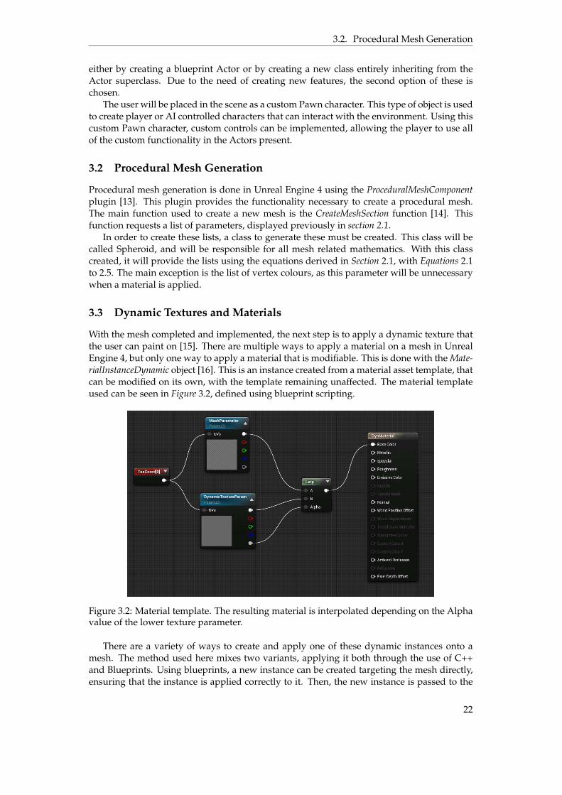
With the mesh completed and implemented, the next step is to apply a dynamic texture thatthe user can paint on [15]. There are multiple ways to apply a material on a mesh in UnrealEngine 4, but only one way to apply a material that is modifiable. This is done with the Mate-rialInstanceDynamic object [16]. This is an instance created from a material asset template, thatcan be modified on its own, with the template remaining unaffected. The material templateused can be seen in Figure 3.2, defined using blueprint scripting.
Figure 3.2: Material template. The resulting material is interpolated depending on the Alphavalue of the lower texture parameter.
There are a variety of ways to create and apply one of these dynamic instances onto amesh. The method used here mixes two variants, applying it both through the use of C++and Blueprints. Using blueprints, a new instance can be created targeting the mesh directly,ensuring that the instance is applied correctly to it. Then, the new instance is passed to the
22

3.3. Dynamic Textures and Materials
code as a pointer, making sure that the various functions necessary for painting can access itproperly.
With the instance now accessible in the code, the variables necessary for painting can becreated as well. The first of these is a structure for the texture. The texture structure, calledTexture2D, has access to an internal function used for changing the colour values of pixels.This function is called UpdateTextureRegions [17], and it will be used for the painting function.
The second structure required is a texture region structure, that determines what part ofthe texture will be accessed when it is to be updated. Due to the way the UV coordinates havebeen mapped, only one region is necessary, one covering the entire texture.
Finally, an array of texture colours is required. This array will be accessed when assigningnew colours to the texture. The painting function writes new values into this array, which isthen passed as a parameter to the UpdateTextureRegions [17] function.
Layers
While the structures tied to the mesh itself will be used for the painting, they are not tieddirectly to the layers themselves. Instead, these are kept separate in the code, as only onetexture can be tied to the mesh itself and displayed on it. Therefore, the painting functionwill make use of the layers first, and then calculate the result from them and copy it to themesh texture.
The layers have a separate set of properties. These are listed below.
• A separate dynamic material instance, using the same template as the mesh.
• A texture structure, tied to the texture parameter of the separate instance.
• A unique array of texture colours.
• A unique layer ID, to identify its location in the layer structure.
• A unique opacity value for the layer.
• A visibility modifier, to determine if it is to be displayed at all.
• A variable defining which blend mode is being used.
Half of these features exist as to mimic the material being used on the mesh, so that theycan be updated themselves. Both the material instance and the texture structure can be usedto update the displayed image on the layer menu. As for the blend mode being used for thelayer, these are used during final calculation of the resulting colour.
Paint Region
The painting functionality is divided into three parts. The first part applies new colour ontothe texture, by replacing values in the array of texture colours. This is done using Equation 2.7,comparing the current colour as the backdrop with the brush colour as the source. The areaof pixels affected depends on the current brush size, acting as the brush radius. In order tocreate a circular brush, the pixels will be selected depending on their euclidean distance fromthe pixel to the picked texture coordinate. This painting function only affects the currentlyselected layer.
The second part is used to calculate the resulting colour on the mesh depending on howmany layers are active. If only one layer is currently active, then the mesh will use the colourvalues directly from that layer. If two layers are active, then the resulting colour will use bothlayers, and calculate the result depending on the blend mode of the upper layer. If more thantwo layers are active, this process will be repeated for all visible layers, until a final set ofcolours have been calculated.
23

3.4. Saving and Exporting
The final part is the updating of the texture itself. This function uses the stored colourvalues for the mesh itself, and applies them to the texture using the UpdateTextureRegionsfunction [17]. This function accepts a number of parameters, listed below.
• Mip Index, the mip number to update.
• Number of Regions, the amount of TextureUpdateRegions supplied.
• Regions to update, a list of all TextureUpdateRegions to use.
• SrcPitch, the pitch of the source data in bytes.
• SrcBpp, the size of a single pixel in bytes.
• SrcData, an array containing all texture colours to update the texture with.
• Data Cleanup Function. A function defining how to and when to delete variables toprevent memory leaks.
The first parameter defines which mip number to update. A mipmap is a series of textureswith decreasing size and resolution to create different levels of detail as distance to an objectincreases. The mip index refers to which of these textures is to be updated. No level of detailis necessary, and thus only one image is used. Therefore, the index will always be zero. Thesecond parameter decides how many separate regions are to be updated. If more than oneis defined, the third parameter is provided as an array. The fourth parameter is calculatedusing the width of the texture times the amount of bytes necessary to store one pixel. Thissize is used in the fifth parameter as well, and for RGBA values that value is 4. The sourcedata array is the same one defined earlier, in section 3.3. The final parameter is provided asa custom class with an overloaded operator method for (), where all texture regions will bedeleted after use.
The texture regions themselves may also present a solution to a problem posed in Section2.1.2. A problem with using the single side of double side UV mapping scheme was thatthere was no way to paint with a proper transition between the sides of the sphere. Thebrush would cut off as it reached an edge of the UV map, until it crossed over to the otherside. This is not a good option for a canvas.
If the two sides of the UV map are moved to separate spots on the texture, multiple textureregions can be defined. When the brush approaches the edge, the painting function may becalled twice, one for each texture region. The coordinates would be moved so that the brushwould hit two spots, one on the region near the edge for the first region, and the other justoutside the edge for the other texture region. The two places would correspond to the samespot on the sphere, overlap with each other and provide a clean transition for the brush.
3.4 Saving and Exporting
Finally, the application needs to be able to export the resulting texture on the dome surface.This process is in and of itself rather simple. Unreal Engine 4 can take the colour values usedin the structure attached to the dome itself, and use that to create an image file of the samesize. This feature can also be expanded to export separate layers should the user wish to dothat. The resulting image file is currently being exported to the PNG format.
Secondly, another feature that is useful is the ability to save all of the work made to afile, and load it at a later time to continue working on it. This process is somewhat morecomplicated. A customised saving system can be created, that converts all of the necessaryinformation into binary machine code [18]. The information to be saved is all the data neces-sary to reconstruct the layers and their settings, as the mesh structure itself is based entirelyon these. The extension used for these binary files are picked by the developer, and as such
24

3.5. Virtual Reality
can be named anything. In this case, the saved binary file is designated with the .dsvrsf ex-tension, an acronym for Dome Sketch Virtual Reality Save File.
Not all attributes of the layers can be stored easily. Pointers and advanced structure posedifficulties when attempting to convert them to binary, which makes three of the attributescontained in the layers ineligible. These are the material instance, the texture structure andthe array of texture colours. The first two of these do not pose a problem, as they can berebuilt using the rest of the data. The final dynamic array needs to be fixed though. Thus, itscontents is copied into an internal array structure, not unlike a C++ vector.
With all of the necessary parameters properly stored, they can be converted into binarycode. This is done using an overloaded operator method «, using the internal FArchive object.These archive objects are used to work with files, both to save data and load data. Thisoverloaded operator works both ways, making sure that all data is always saved and loadedin the right order. If this was not the case, the program would crash [18].
One final hurdle exists. While an arbitrary number of layers can be stored in a binaryformat such as this, a prepared structure is necessary for loading them again. This structureneeds to contain the same amount of layers as was saved previously. However, it is not pos-sible to read from the saved binary file how many layers were stored, as the only informationone can attain is the exact size in bytes. A work-around is required.
A second much smaller file is created, its only purpose to store the amount of saved lay-ers. This file will be loaded first and converted back into data. With this information, theprogram can create a list of correct size, where the saved layers can be loaded into. The sec-ond binary file is designated with the .dsvrc extension, an acronym for Dome Sketch VirtualReality Count.
3.5 Virtual Reality
An important end goal is for the application to function in VR, and thus the project must becreated with this in mind. While the technical aspects around the project itself is less impor-tant, there are design decisions that are influenced by this. The first of which is interactionwith the environment. The HTC Vive uses a pair of controllers to interact with the virtual en-vironment. Compared to a mouse and keyboard, the precision afforded by these controllersare inferior compared to the mouse when pointing at things. Also, the amount of buttonspresent on the controllers are far fewer compared to the keyboard.
This necessitates the creation of a menu that the user can interact with. This menu pro-vides access to all advanced features that can’t be mapped onto the controllers themselves.Preferably, this menu must always be present to the user, as they can move around the envi-ronment and requires access to it regardless of where they are standing. The usual methodfor creating a menu in other applications with access to mouse control is to create a HeadsUp Display (HUD). This would be a menu attached to the screen itself, that would then beinteracted with. Since a Heads Up Display (HUD) can’t be interacted with in virtual reality,an alternative is needed. A possibility would be to attach a menu onto one of the controllers,and use the other one to interact with it. Since the controllers are always present, this wouldsolve that issue.
Navigation
An issue brought up in the second question in Section 1.5, is the matter of navigation. Sincethe dome itself can be scaled up and down according to the users desires, the user may wishto walk to different places and view the dome from different perspectives to make sure thateverything looks good from all angles. However, as room space is forever limited, an alterna-tive to physical navigation is necessary. This is a task in and of itself, tying movement to thecontrollers is usually not a good idea due to the resulting VR sickness of having the avatarmove while the user is stationary [19].
25
3.6. Sketching Controls and Implementation
There are multiple different ways to try and implement navigation in ways that limit VRsickness. The simplest way to do this is to implement teleportation. Instantaneous movementfrom one spot to another is useful when perfect immersion is not a concern, as it is easy toimplement. Alternatives such as walking in place to simulate physical movement can helpreduce VR sickness, but methods such as these require access to tracking equipment that canregister body movement or trackers tied to the limbs [19]. Motion can also be simulated usingthe movement of the controllers themselves, and this would require no extra equipment.
The method of navigation chosen for the application is teleportation. It is easily imple-mented in comparison to the other alternatives, and immersion is a secondary concern sincethe purpose of the application is not to provide an immersive experience.
3.6 Sketching Controls and Implementation
The various controls brought up in relation to the third and final question in Section 1.5 needto be implemented as well. The implementation of some of these will be simpler than others.While layers, blending modes and opacity have been covered, the others have not.
Marking Tools
There is a simple way to check whether or not a pixel is marked or not. If a structure of thesame size as the texture is created, it can be used to represent marked or unmarked pixels.If a pixel in a certain location is selected, that index of the structure is set to true. If not, it isset to false. Whenever the painting function is called, it checks the pixel in question with thestructure, and decides whether or not to paint on it.
Marking an area depends on the specific tool used. A rectangular or elliptical markingtool would simply draw the shape from the point where the user presses the trigger, to thepoint where the user releases it. The magic wand in comparison would use the algorithmspresented in Equations 2.19. to 2.21.
Filters
There is little in the way of advanced implementation here. The filter kernel simply movesalong the picture, and applies its values to create the filter effect. Texture padding can beskipped simply by putting the kernel outside the texture itself, and applying the values ofthe pixels effected.
26

Chapter 4
Results
The following is a description of the resulting application. The first section describes theworkflow of the project itself, and how a user may interact with the application. The othersections describe different portions of the application, and how they were implemented.
4.1 Workflow
The implementation was an iterative process, as contact was maintained with the designerthroughout. Communication was done at regular intervals with the designer, through meet-ings where progress was discussed. Whenever new features were added, they could bedemonstrated easily, making the constant feedback a valuable resource. With this feedbackcame the ability to easily prioritise which features should be implemented first.
For instance, the tools brought up in section 2.2 were prioritised higher or lower dependingon the wishes of the designer. The implementation of layers was assigned the highest priorityof these, as it is a baseline for a multitude of other features, and almost a prerequisite foradvanced painting.
Another instance of useful feedback gained was the decision to not use the standardsphere shown in Figure 2.1. The concerns about the resolution at the poles were broughtup as feedback, and also the idea to use a cube sphere instead.
Application Work-flow
The user starts with a blank canvas, surrounding them as a dome. The user is equippedwith two controllers, with different functionality tied to them. The left controller has sev-eral menus attached to it, providing all of the functionality required as there are not enoughbuttons provided to map everything to. The menus clearly display their purpose with de-scriptive icons and titles. The right controller is used for all interaction, both with the leftcontroller menus and with the canvas itself.
The user can paint on the canvas, change the colour and size of the brush and add multiplelayers that can be painted on separately. The opacity of both the brush and the layers canbe changed easily through the use of the menus and the right controller. When the user issatisfied with their work they can save it using the left controls menu. They can also create ablank canvas to start something new, or load an existing file to continue with previous work.
4.2 Mesh Generation
The procedural generation was implemented by creating two classes, Spheroid and Dynam-icActor. The Spheroid class handles all the necessary math calculation for the proceduralgeneration, providing all of the lists required to generate a mesh. The second class is therepresentation of the dome in the application itself, that the user can interact with.
27

4.3. Interaction
An implementation of procedurally generating an ordinary sphere, as illustrated in Sec-tion 2.1. The result of this is displayed on the left side of Figure 2.3. As stated earlier, thisresults in problems with distortion on the surface. A simple way of compensating for thiswas implemented in the painting algorithm, scaling the brush size depending on the dis-tance to the pole of the sphere. While the brush size remained consistent, it became clear thatthe resolution near the poles was poor in comparison to the rest of the sphere.
Currently, the DynamicActor uses an imported half-Cubesphere, with custom UV map-ping. It became quite clear that the method used for procedurally generating such a creationwould take too long to implement, and as such this method became its replacement. Themethod can be seen in Figure 3.1, where a blueprint node retrieves all the necessary informa-tion to generate a mesh procedurally and feeds it into the DynamicActor. The mesh used canbe seen in Figure 4.1.
(a) Half Cubesphere shown incolour.
(b) Half Cubesphere shown inwireframe mode.
Figure 4.1: The mesh used for the dome.
The drawback with this method is that, if the user requires a different level of detail on themesh itself, they would have to create a new mesh with an external program and re-import itto the engine. This lacks the flexibility provided by the procedural generation method.
4.3 Interaction
The user has access to two HTC Vive controllers. Since the amount of buttons on these con-trollers are limited, most functionality is located at a menu attached to the left controller seenin the virtual environment. See Figure 4.2 for an image of what the controllers look like in thevirtual environment.
Figure 4.2: Both controllers and their menus.
28

4.3. Interaction
The menu connected to the left controller can be interacted with, and all advanced fea-tures can be found on it, with the exception of brush size and brush opacity, mapped to thetrackpad of the right controller. The menu consists of three separate screens surrounding theleft controller. These screens can be rotated around it using the left controller trackpad but-tons, so that the user does not need to rotate the controller itself to interact with the menu.The different menu screens can be seen in Figure 4.3.
(a) Control menu.
(b) Layer menu.
(c) Colour picker menu.
(d) Status Menu.
Figure 4.3: Menu screens.
The current options on the control options offer control over the following parameters:
• A "new" button, displayed in the top left corner, This button resets the canvas and alllayers completely, allowing the user to start over.
• An "open" button, top middle. This button is used to select a previously saved canvas,using the method described in section 3.6.
• A "save" button, top right corner. This button is used to save the current canvas, usingthe method described in section 3.6.
• The brush icon, middle left, allows the user to select the brush tool. Compared to thepencil, this tool has soft edges when painting.
• The eye dropper icon, middle, allows the user to select the colour picker tool. Whenactive, the colour picker is used to select a colour from any point on the canvas.
• The middle right icon is used to select the teleport tool. When active, the user canteleport in the virtual environment.
29

4.4. Painting
• The lower left icon activates the pencil tool. Compared to the brush tool, the pencilpaints with a hard edge.
• The eraser icon, bottom middle, enables the eraser tool. This tool paints the canvas withan alpha value of 0, effectively erasing whatever was painted previously.
The second menu screen displays the layer options. The canvas on the left side is updatedas the surface is painted on. The checkbox next to it indicates that it is the active layer. The Xmarked button is used to delete the layer. The arrows are used to move the layer up or down,changing the order of layers. The opacity slider sets the opacity of the currently active layer.The plus icon in the bottom right corner adds new layers to the list, and finally the icon nextto it merges the currently active layer with whichever layer lies beneath it.
The third menu screen is the colour picker. It is used to select the colour of the brush. Theuser can use the controller to drag the various settings around, allowing for greater control ofcolour, hue, luminosity, alpha value and more.
The final menu screen is attached to the right controller and is visible at all times. Itdisplays useful information to the user, such as the currently selected colour, the brush size,brush opacity and which tool is currently active. This menu cannot be interacted with.
The right controller trigger is used for all interaction. When the controller is pointed atthe menu, it is used to select options and push buttons. When pointed at the environment, itcan be used to paint on the surface, teleport the user and more depending on which setting isactive on the menu. The line drawn from the right controller indicates where on the surfaceor the menu it will interact with.
4.4 Painting
All of the painting functionality is present in the DynamicActor class. Using the right con-troller the user can paint on the surface of the dome. As stated in the previous section, thereexists two may brush types: a brush with half hardness for soft strokes, and a pencil withfull hardness. The size of the brush can be controlled manually, by using the trackpad on theright controller. The same can be done with brush opacity, at which point Equation 2.7 will beapplied to calculate the resulting colour. The eraser tool allows the user to erase the colouron the layer, showing the canvas beneath. There also exists a colour picker tool, that the usercan use to pick any colour already present on the surface, and paint with. An example ofmultiple colours used with different opacities can be seen in Figure 4.4.
Figure 4.4: Different brush colours, some with different opacity values.
All material instances created use the material template called DynMaterial. This templateuses two textures to produce a result, an empty texture to paint on, and a canvas texture in
30
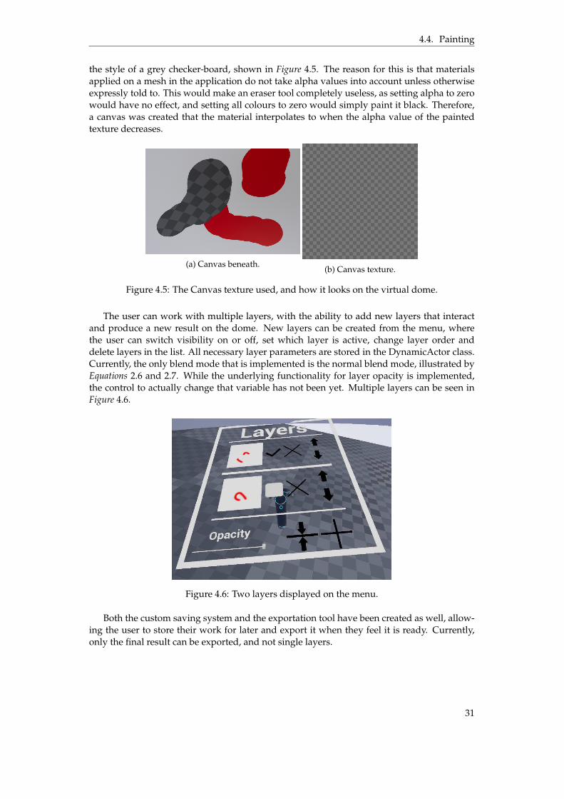
4.4. Painting
the style of a grey checker-board, shown in Figure 4.5. The reason for this is that materialsapplied on a mesh in the application do not take alpha values into account unless otherwiseexpressly told to. This would make an eraser tool completely useless, as setting alpha to zerowould have no effect, and setting all colours to zero would simply paint it black. Therefore,a canvas was created that the material interpolates to when the alpha value of the paintedtexture decreases.
(a) Canvas beneath.(b) Canvas texture.
Figure 4.5: The Canvas texture used, and how it looks on the virtual dome.
The user can work with multiple layers, with the ability to add new layers that interactand produce a new result on the dome. New layers can be created from the menu, wherethe user can switch visibility on or off, set which layer is active, change layer order anddelete layers in the list. All necessary layer parameters are stored in the DynamicActor class.Currently, the only blend mode that is implemented is the normal blend mode, illustrated byEquations 2.6 and 2.7. While the underlying functionality for layer opacity is implemented,the control to actually change that variable has not been yet. Multiple layers can be seen inFigure 4.6.
Figure 4.6: Two layers displayed on the menu.
Both the custom saving system and the exportation tool have been created as well, allow-ing the user to store their work for later and export it when they feel it is ready. Currently,only the final result can be exported, and not single layers.
31

Chapter 5
Discussion
While the application indeed allows the user to paint directly on a spherical surface, thereexists inherent flaws with painting in VR. One of these issues is the lack of precision affordedby the controllers. In a regular drawing program using mouse and keyboard, precision isnever an issue, and the user can easily work on on a picture with pixel precision. This is nota possibility in this application. In order to draw with more precision, the user would haveto walk closer to a given area and steady their arm as they paint. However, when comparedto the benefit of portability afforded by virtual reality, it is a lesser issue that can be tolerated.
Another thing that would have been useful during the thesis works final weeks wouldhave been a user testing phase, in order to gain feedback about how things have been imple-mented. With this feedback, improvements could have been made to various features in theapplication sooner. Such a testing phase was indeed planned in the beginning of the project,but due to unforeseen complications near the end it had to be postponed.
5.1 Questions
Can the fulldome be represented by an arbitrary spherical shape?
As stated in Section 2.1, the dome can be represented by a procedurally generated sphere, asthis would provide a flexible solution capable of representing any size and shape of dome.However, the problems posed by an ordinary sphere and the difficulty of generating a cube-sphere lead to the current solution. While the detail level of the sphere is fixed, the size is not.The mesh can still be scaled during runtime, allowing the user to determine the exact size oftheir choosing. This still provides the necessary flexibility that was sought at the beginningof this thesis work.
What type of navigation is optimal for the virtual fulldome environment?
While the environment can be scaled up and down at the behest of the user, navigation is stillan important tool. Two main factors were necessary in the decision-making process aboutwhich type of navigation to implement. It would need to be simple enough to implementgiven the time constraints. It also needed to be a sufficiently natural enough for of navigationas to avoid VR-sickness for the user.
With these factors in mind, teleportation was picked due to its simplicity. While instan-taneous travel can be disorienting and immersion breaking, neither of these factors was toomuch of an obstacle. Firstly, it is unlikely that the user will spend most of their time mov-ing around the environment. And lastly, the goal of the application is not immersion, but toprovide an interface that allows the user to paint on a spherical surface.
32

5.2. Future Work
What kind of controls should be available other than the sketching tool, and how should
they be implemented?
If the application is to be treated as a sketching program, there are plenty of possible tools thatcould be added to it. Only the simple examples brought up in Section 2.2 were implemented.Opacity and layers are prerequisites in order to make a basic sketching program. The othersrise in complexity. While potential ways to implement them is brought up in Chapter 3, thedecision was made during development that they were of lower priority compared to otherfeatures. These decisions were made mainly by the designer, and most of the high prioritytools and features have been implemented now, with a few exceptions.
One of these exceptions is the ability to procedurally generate the cubesphere instead ofusing the imported half-cube sphere implemented at this time. The main reason this featurewas not implemented was due to the requirements of the subdivision algorithm [6]. Thisalgorithm is easy to use given a set of requirements in the data structure defining the mesh.Requirements such as the ability to traverse the mesh using pointers. This would require alarge scale reconstruction of the Spheroid class, and the time for that was simply not available.
More advanced features like filters and marking tools were prioritised lower in compar-ison. These features are used in more advanced design programs, used for real digital art.If the purpose of the application is to be a simple sketching tool, then these features wouldlikely not be used too often. As such, development time is better allocated elsewhere.
5.2 Future Work
There are many things that can be implemented and improved in the current state of theapplication.
Brush hardness has been partially implemented, however, only in two different modes:full hardness and half hardness. These are represented by the pencil and the brush tool re-spectively. The ability to control hardness manually using a slider or similar would be useful,as the user gets greater control over their brush.
Most image editing software are able to import existing images as new layers. Anotherreason to do so here is to see what the image would look like on the virtual surface. Thisway, the designer may not even need access to the real fulldome, assuming that the two aredisplayed the same way. However, there are also certain other prerequisites that would beuseful for this feature. The simplest implementation would simply paste the image into alayer at a specified point. There would be no way to alter it at that point, other than paintover it. The implementation of layer operations is almost a necessity in order for this featureto be useful.
These operations would be Move, Rotate, Flip and Scale. Move would move the entirelayer, or a selection, to a point of the users choosing. Rotate would rotate the contents of theentire layer, or a selection. Flip would flip the position of all pixels to the other side, eithervertically or horizontally. And finally, scale would give the user the ability to shrink andenlarge the contents of an entire layer.
A way to try and deal with the controllers lack of precision would be to implement a zoomfunction. If the pixels are larger, it would be harder to miss. One way to do this would be toreplace the texture used by the canvas with a smaller selection, zooming in to that point. Thiswould partially compensate for the lack of precision, as pixels would be larger and harderto miss. Implementation could be done by pointing at a point at the texture and clicking,making that the centre of the replacement texture and reducing the size by a percentage.Alternatively, the user could "draw" i rectangle selection for zooming by picking two cornerson the surface.
Finally, increasing the amount of available blend modes for the layers would allow theuser to perform more advanced operations using layers.
33

Chapter 6
Conclusion
While the application indeed does fulfil the basic requirements put forth, there are plenty ofways that it could be improved. More features can be added, improvements made to existingones and more. Consider the requirements put forth during the introduction:
• The application must provide a virtual dome surface for painting.
• The application must be portable, allowing designers to work from other locations.
• The application must produce a result that looks identical on both the virtual dome andthe physical fulldome.
The first requirement was the simplest one to implement. The main improvement to behad in this area would be to add the procedurally generated version of the Cubesphere, al-lowing the user to control its detail level.
The second requirement is also fulfilled, due to the nature of the application being in VR.As long as the designer has access to a HTC Vive headset and accompanying controllers, theycan work remotely. This was one of the more important factors, since access to the physicalfulldome is limited.
The final requirement was the most difficult one to follow. Having to weigh betweenthe visual similarity and the physical dome, and the ability to paint on the surface itself ina consistent manner was a difficult choice. The decision was made that the ability to painttook priority, as the mapping used for the physical fulldome itself was not wholly suitablefor the task. Therefore, the exported image file will be treated as an ordinary texture, and willundergo the same treatment as ordinary images being displayed on the fulldome. Whether ornot this is the best possible method remains to be seen. In time, the application could becomequite useful for designers. In its current state, it is more of a novelty.
34
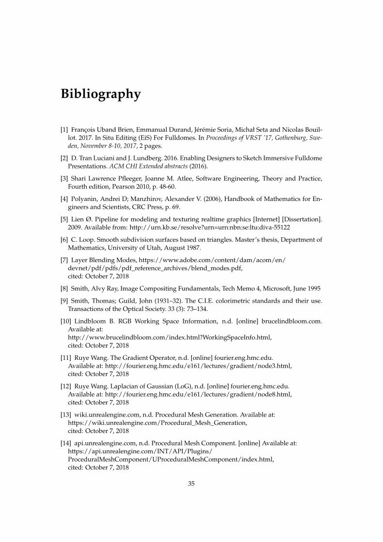
Bibliography
[1] François Uband Brien, Emmanual Durand, Jérémie Soria, Michał Seta and Nicolas Bouil-lot. 2017. In Situ Editing (EiS) For Fulldomes. In Proceedings of VRST ’17, Gothenburg, Swe-den, November 8-10, 2017, 2 pages.
[2] D. Tran Luciani and J. Lundberg. 2016. Enabling Designers to Sketch Immersive FulldomePresentations. ACM CHI Extended abstracts (2016).
[3] Shari Lawrence Pfleeger, Joanne M. Atlee, Software Engineering, Theory and Practice,Fourth edition, Pearson 2010, p. 48-60.
[4] Polyanin, Andrei D; Manzhirov, Alexander V. (2006), Handbook of Mathematics for En-gineers and Scientists, CRC Press, p. 69.
[5] Lien Ø. Pipeline for modeling and texturing realtime graphics [Internet] [Dissertation].2009. Available from: http://urn.kb.se/resolve?urn=urn:nbn:se:ltu:diva-55122
[6] C. Loop. Smooth subdivision surfaces based on triangles. Master’s thesis, Department ofMathematics, University of Utah, August 1987.
[7] Layer Blending Modes, https://www.adobe.com/content/dam/acom/en/devnet/pdf/pdfs/pdf_reference_archives/blend_modes.pdf,cited: October 7, 2018
[8] Smith, Alvy Ray, Image Compositing Fundamentals, Tech Memo 4, Microsoft, June 1995
[9] Smith, Thomas; Guild, John (1931–32). The C.I.E. colorimetric standards and their use.Transactions of the Optical Society. 33 (3): 73–134.
[10] Lindbloom B. RGB Working Space Information, n.d. [online] brucelindbloom.com.Available at:http://www.brucelindbloom.com/index.html?WorkingSpaceInfo.html,cited: October 7, 2018
[11] Ruye Wang. The Gradient Operator, n.d. [online] fourier.eng.hmc.edu.Available at: http://fourier.eng.hmc.edu/e161/lectures/gradient/node3.html,cited: October 7, 2018
[12] Ruye Wang. Laplacian of Gaussian (LoG), n.d. [online] fourier.eng.hmc.edu.Available at: http://fourier.eng.hmc.edu/e161/lectures/gradient/node8.html,cited: October 7, 2018
[13] wiki.unrealengine.com, n.d. Procedural Mesh Generation. Available at:https://wiki.unrealengine.com/Procedural_Mesh_Generation,cited: October 7, 2018
[14] api.unrealengine.com, n.d. Procedural Mesh Component. [online] Available at:https://api.unrealengine.com/INT/API/Plugins/ProceduralMeshComponent/UProceduralMeshComponent/index.html,cited: October 7, 2018
35

Bibliography
[15] api.unrealengine.com, n.d. Dynamic Textures. [online] Available at:https://wiki.unrealengine.com/Procedural_Materials,cited: October 7, 2018
[16] api.unrealengine.com, n.d. MaterialInstanceDynamic. [online] Available at:https://api.unrealengine.com/INT/API/Runtime/Engine/Materials/UMaterialInstanceDynamic/index.html,cited: October 7, 2018
[17] api.unrealengine.com, n.d. UpdateTextureRegions. [online] Available at:http://api.unrealengine.com/INT/API/Runtime/Engine/Engine/UTexture2D/UpdateTextureRegions/index.html,cited: October 7, 2018
[18] wiki.unrealengine.com, n.d. Save System, Read & Write Any Data to Compressed BinaryFiles. [online] Available at:https://wiki.unrealengine.com/Save_System,_Read_%26_Write_Any_Data_to_Compressed_Binary_Filescited: October 7, 2018
[19] Jiwan Bhandari, Sam Tregillus, and Eelke Folmer. 2017. Legomotion: Scalable Walking-based Virtual Locomotion. In Proceedings of VRST ’17, Gothenburg, Sweden, November8–10, 2017, 8 pages. https://doi.org/10.1145/3139131.3139133
36