On an alternative way of capturing RTI images with the camera dome
12
Cuneiform Digital Library Notes 2015:1 « ‹ ♦ › » On an alternative way of capturing RTI images with the camera dome Klaus Wagensonner < [email protected] > University of Oxford The camera domes (Fig. 1a) built at the Electronics and Computer Science Department (ECS) of the University of Southampton by Kirk Martinez and Philip Basford use the remote control software “RTI Acquire”, which was compiled by John Cupitt. This software connects to the LED controller (Fig. 3) and therefore allows for cycling through the 76 LEDs attached to the inside of the dome. Since the software receives a live feed from the DSLR camera on top of the dome, it serves additionally as remote software for capturing objects in the dome. But the latest generation of the camera dome (Domes 4-6) includes a feature that enables capturing via a remote cable. This was sought as a backup solution in case no computer was available or a computer is incapacitated. The disadvantage of this method is that focusing is rather time-consuming. In the original setup all captured photos remain on the memory card of the DSLR camera and need to be downloaded separately. Nevertheless, for larger projects and in order to guarantee a faster workflow it is necessary to receive a live feed from the camera for placing an object within the dome and establishing a focus. The subsequent guidelines are currently in use on the camera dome set up at the Louvre Museum, Paris (Fig. 1a and 1b). This approach has several advantages, which will become apparent in the paragraphs to follow. The main improvement is the faster capturing. While the previous software requires about 6 minutes per capture (i.e., taking 76 images per face of object), the new approach captures each face in just 2 minutes 20 seconds maintaining the same level of quality. This considerable improvement now allows for a larger amount of data that can be collected. It furthermore allows for capturing cuneiform artefacts more efficiently. General Links Archive
Transcript of On an alternative way of capturing RTI images with the camera dome
3/16/2015 CDLN 2015:1
http://cdli.ucla.edu/pubs/cdln/php/single.php?id=000054 1/12
Cuneiform Digital Library Notes2015:1 « ‹ ♦ › »
On an alternative way of capturing RTI imageswith the camera domeKlaus Wagensonner< [email protected] >University of Oxford
The camera domes (Fig. 1a) built at the Electronics and Computer Science Department (ECS) of the
University of Southampton by Kirk Martinez and Philip Basford use the remote control software “RTI
Acquire”, which was compiled by John Cupitt. This software connects to the LED controller (Fig. 3) and
therefore allows for cycling through the 76 LEDs attached to the inside of the dome. Since the software
receives a live feed from the DSLR camera on top of the dome, it serves additionally as remote software
for capturing objects in the dome. But the latest generation of the camera dome (Domes 4-6) includes a
feature that enables capturing via a remote cable. This was sought as a backup solution in case no
computer was available or a computer is incapacitated. The disadvantage of this method is that focusing
is rather time-consuming. In the original setup all captured photos remain on the memory card of the
DSLR camera and need to be downloaded separately. Nevertheless, for larger projects and in order to
guarantee a faster workflow it is necessary to receive a live feed from the camera for placing an object
within the dome and establishing a focus.
The subsequent guidelines are currently in use on the camera dome set up at the Louvre Museum, Paris
(Fig. 1a and 1b). This approach has several advantages, which will become apparent in the paragraphs
to follow. The main improvement is the faster capturing. While the previous software requires about 6
minutes per capture (i.e., taking 76 images per face of object), the new approach captures each face in
just 2 minutes 20 seconds maintaining the same level of quality. This considerable improvement now
allows for a larger amount of data that can be collected. It furthermore allows for capturing cuneiform
artefacts more efficiently.
General Links Archive

3/16/2015 CDLN 2015:1
http://cdli.ucla.edu/pubs/cdln/php/single.php?id=000054 2/12
Fig. 1a and 1b: The camera dome set up at the Louvre Museum, Paris (taken December 2014)
These guidelines are intended for non-experts who would like to use this method in the aforementioned
setup of the camera dome. Therefore, rather general notes are embedded into these instructions. The
camera remote software used and described here is just one among many commercial products for
tethered remote control of DSLR cameras (see my previous note on the imaging of cylinder seals).
1. Starting up
If the camera dome is already assembled (Fig. 1), every capture process should start by checking all
existing cable connections and camera settings in order to avoid any errors in the workflow.
1.1. Checking all cable connections
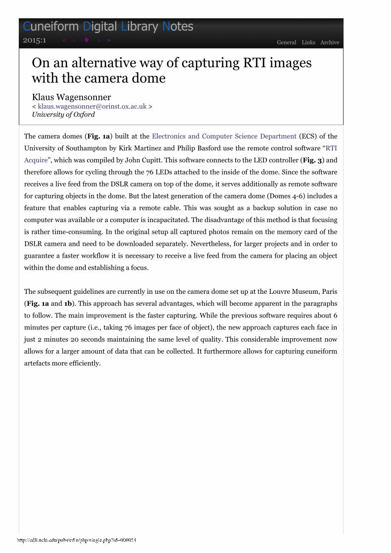
The method described in this note requires three cable connections from the body of the attached DSLR
(here a Nikon D800) (see Fig. 2). For longer capture processes it is worthwhile to establish sufficient
power for the camera via a power mains adaptor, whose cable runs into the camera’s battery
compartment (a). Although photos can be saved onto a memory card, it is more useful to transfer the
images directly to a connected computer via a USB2 or USB3 cable (b). Last but not least the camera
body is connected to the dome’s LED controller. This cable runs into the camera’s remote shutter port
(c).
3/16/2015 CDLN 2015:1
http://cdli.ucla.edu/pubs/cdln/php/single.php?id=000054 3/12
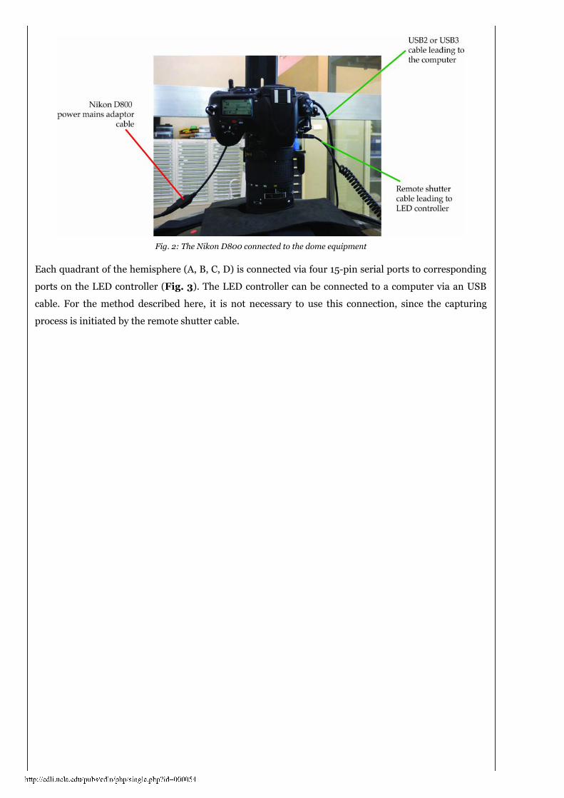
Fig. 2: The Nikon D800 connected to the dome equipment
Each quadrant of the hemisphere (A, B, C, D) is connected via four 15-pin serial ports to corresponding
ports on the LED controller (Fig. 3). The LED controller can be connected to a computer via an USB
cable. For the method described here, it is not necessary to use this connection, since the capturing
process is initiated by the remote shutter cable.

3/16/2015 CDLN 2015:1
http://cdli.ucla.edu/pubs/cdln/php/single.php?id=000054 4/12
Fig. 3: Schematics of LED controller and corresponding connections
The remote shutter cable is plugged into a corresponding port on the opposite side of the controller.
Next to it is a slightly smaller port for the connection cable that ends into a ten-pin port on the camera
body (Fig. 4).

3/16/2015 CDLN 2015:1
http://cdli.ucla.edu/pubs/cdln/php/single.php?id=000054 5/12
Fig. 4: Connecting both remote shutter cable and connector to ten-pin remote port on the camera body
1.2. Checking camera settings
Most settings (such as capture settings) can be controlled directly via the remote software on the
computer (here Smart Shooter). Therefore, any manual settings directly on the camera are not
necessary. It is, however, important to avoid any settings on the camera which might disrupt the
workflow or lead to a faulty capture. For instance, having the camera set into self-timer mode leads to a
time-lapse for each capture. Therefore the camera’s release mode dial should be set to a setting like “S”
(i.e., single frame).
The aperture of the capture should be set to a relatively high F-stop in order to increase the depth-
of-field (DoF) and therefore keep the focus in areas of the captured artefact, which are farther removed
from the camera lens then the main focus point. This is, in particular, important on reverses and
strongly curved surfaces. A very high F-stop reduces the duration of the exposure. An under-exposed
image can be avoided by decreasing the shutter speed. However, the shutter speed should not be longer
than 1.0 second, because the timer for the remote dome capturing is set; a too long exposure is not
synchronised with the change of lights in the dome. Under-exposed photos can also be corrected by
either adjusting the exposure compensation or the ISO value. For cuneiform tablets the camera is
currently set to a F-stop of 18, an ISO value of 100 and a shutter speed of 1.0 second. Minor adjustments
are necessary for, e.g., heavily fired, and therefore often dark, text artefacts.

3/16/2015 CDLN 2015:1
http://cdli.ucla.edu/pubs/cdln/php/single.php?id=000054 6/12
Fig. 5: The camera lens Nikkor 70-180 mm and the various adjustment rings
2. Setting up an object
The focus area of the artefact should be approximately on level with the horizon of the camera dome. A
simple office light helps to place the artefact or the area of interest into the centre of the capture and
focus correctly (Fig. 6). Note that the usual operating software for the camera dome “RTI Acquire” does
not work in tandem with the remote software Smart Shooter, because it also receives a live feed from the
DSLR camera.
Fig. 6: Putting AO 8331 in the camera dome’s center using a conventional office light
The height of the support needs to be adjusted according to the depth of the object. The edges of a tablet

3/16/2015 CDLN 2015:1
http://cdli.ucla.edu/pubs/cdln/php/single.php?id=000054 7/12
can be tricky sometimes. In the case of tablets of comparatively regular shape and size a support with
some foam inlays (here a conventional desk business card holder) is used to hold the tablet in place
(Fig. 7).
Fig. 7: Setting up AO 8331 for capturing the top edge
3. Preparing the capture process
After placing the object – in the case at hand AO 8331, a letter by the Babylonian king Hammurabi to
the high official Šamaš-hāzir – onto the support with adjustable height and ensuring that the main focus
point is approximately at the level of the camera dome’s horizon the remote software can help to finally
adjust both zoom and focus.

3/16/2015 CDLN 2015:1
http://cdli.ucla.edu/pubs/cdln/php/single.php?id=000054 8/12
Fig. 8: Placing AO 8331 before focusing
The settings of the camera lens – for most artefacts the Nikkor 70-180 mm macro lens is used – can be
changed via three rings (Fig. 5). (a) The zoom ring (closest to the camera body) adjusts the zoom level
from 70 to 180 mm. (b) The third ring adjusts the focus manually, if the second ring (c) is set to Manual
(M) (see Fig. 9).
Fig. 9: Putting AO 8331 into focus using a zoom box and the camera’s autofocus
Manual focusing is possible, but difficult if handling, for instance, a large cuneiform tablet with
relatively small script. It usually requires several test shots, until the perfect focus is reached. The
commercial software Smart Shooter allows for focusing automatically. However, in order to use this
function, the middle ring on the lens needs to be set to Automatic (A) by pressing the silver button and
turning the second ring counter-clockwise (Fig. 10). It is important to return this ring to Manual (M)
after focusing and before initiating the capturing process. Otherwise the camera’s shutter is not
activated and only the LEDs are circling through.

3/16/2015 CDLN 2015:1
http://cdli.ucla.edu/pubs/cdln/php/single.php?id=000054 9/12
For a better auto focus it is worthwhile to activate the software’s zoom function, which is located
directly beneath the enabling button of the live view. Upon doing that a small zoom box appears in the
main window. This box can be moved to the desired position on the object. By pressing on the button
Auto Focus the lens focuses on the selected location (Fig. 9).
Fig. 10: Switching the lens from Manual (M) to Automatic (A)
An interesting feature of the lens used for this approach is its capability to remain in focus irrespective
of the zoom level. This means the zoom level can be adjusted even after the artefact has been focused.
This feature is particularly useful for larger texts.
Fig. 11: The remote cable initiating the capture process
Once the focus is set and the object placed as requested, the only steps that remain to be done are to
disable the live view by pressing again on the check box “Enable”, switching off the light in the dome
and putting it away in order to avoid that its shadow is cast onto the object. As mentioned before, the
lens need to be set to Manual mode (M). The capture process is started by pressing the red button on
the remote cable, which is connected to the LED controller (Fig. 11 and see Fig. 3).
The LED controller now initiates the capture process and circles through all 76 LEDs in the dome.
It keeps every LED switched on for about one second.
The images should be transferred directly to the computer. In order to do that the storage location
is set to “Disk”. This has the advantage that each downloaded image is displayed in the main window

3/16/2015 CDLN 2015:1
http://cdli.ucla.edu/pubs/cdln/php/single.php?id=000054 10/12
after being downloaded. The files are usually named sequentially, which is currently incompatible to the
software in order to fit the 76 images to a Polynomial Texture Map (*.ptm). “RTI Acquire” renames the
files after being transferred according to the conventions for the PTM fitter. A solution to this different
approach is presented in the subsequent chapter.
4. Organising the image files
The fitting software requires certain prerequisites for processing the original captures taken by the
camera dome to a Polynomial Texture Map (*.ptm). One of these prerequisites is a certain directory
structure. Each face of an object being captured with the camera dome contains the subsequent
subfolders: “assembly-files”, “finished-files”, “jpeg-exports”, and “original-captures”. We want to make
sure that all captured files are stored in the subfolder “original-captures”. A second condition is the right
naming of the files. Each face needs to contain images in the sequence of “0.jpg” to “75.jpg” (or in the
respective format, if RAW captures are preferred). Bulk renaming can be done via many kinds of
software, but doing several sides per tablet might make even such comparatively simple tasks a quite
arduous endeavour. Therefore, this method uses a simple AppleScript, which not only creates the
necessary folder structure, but in the same process, also moves the original captures to the appropriate
places in the respective subfolders. The following box (Fig. 12) contains the current version of the code,
whose renaming capabilities can be found here.
Fig. 12: The current version of the AppleScript
The script checks for the number of files stored in the chosen folder and whether this amount matches

3/16/2015 CDLN 2015:1
http://cdli.ucla.edu/pubs/cdln/php/single.php?id=000054 11/12
to a valid amount of files, which is 76 or a multiple of it (for a regular tablet with six sides it is either 76,
152, 228, 304, 380, or 456). If this condition does not apply, the script displays an error message
explaining the issue. The remote software SmartShooter of course allows to take sample photos, which
are also stored in the same folder. The aforementioned error is most likely caused by these additional
files, which lead to an invalid amount of files in the folder.
If the number of files is valid, the user can enter a designator (for instance, a museum number) in
a text field. This creates the main folder, which contains at least one sub-folder for the captured side. In
the subsequent dialog box the user can choose the sides of the artefact that had been captured before. In
the case of a tablet, by default “o” (obverse) and “r” (reverse) are checked. But usually more than two
sides need to be captured. Some tablets, such as the letter AO 8331 have text written on every face.
Therefore, all sides (including the edges: “top edge” [te], “bottom edge” [be], “left edge” [le], and “right
edge” [re]) can be checked. The designations for the faces of a cuneiform tablet follow CDLI standards.
Some tablets are fragmentary with, for instance, the bottom edge broken off. In such a case, the “be” can
remain unchecked.
The script then iterates through the checked sides and organises the subfolders respectively. Since
the files are sorted by creation date, each batch of 76 files is moved to the right subfolder (Fig. 13).

3/16/2015 CDLN 2015:1
http://cdli.ucla.edu/pubs/cdln/php/single.php?id=000054 12/12
Fig. 13: Workflow of the script in order to organise the files into respective folders
The script should be run after every object in order to avoid any wrong assignments of image files.
Thanks to the faster capturing it is now more economic to capture all faces of an artefact.
Including set-up and with some experience a cuneiform tablet can be fully imaged in about 15 minutes.
Due to the manual focusing in the previous software “RTI Acquire” capturing a complete tablet took
about 45 minutes.
It should be emphasized that this approach is a work in progress. In future it should be possible
again to have the option to change the light angle already during setup.
ISSN 1546-6566 © Cuneiform Digital Library Initiative | Archival: 2015-01-15