Strength of Materials for Mechanical Engineers (Regulation
107
Vel Tech High Tech Dr.Rangarajan Dr.Sakunthala Engineering College Department of Mechanical Engineering MCQ IV SEMESTER CE8395 - Strength of Materials for Mechanical Engineers (Regulation – 2017) Prepared By: Mr.M.Jagadeesan. ME. Asst.Prof/Mech
-
Upload
khangminh22 -
Category
Documents
-
view
2 -
download
0
Transcript of Strength of Materials for Mechanical Engineers (Regulation

Vel Tech High Tech Dr.Rangarajan Dr.Sakunthala
Engineering College
Department of Mechanical Engineering
MCQ
IV SEMESTER
CE8395 - Strength of Materials for Mechanical
Engineers
(Regulation – 2017)
Prepared By: Mr.M.Jagadeesan. ME.
Asst.Prof/Mech

430
09. STRENGTH OF MATERIALS
1. Simple Stress and Strain
1. Hooke's law holds good up to:
(a) Yield point (b) Elastic limit (c) Plastic limit (d) None of these
SJVN ET 2013 Ans. (b) : Hook's law holds good up to proportional limit.
AB C D
E
F
Linear range
C'σ
∈
A → Proportional limit
B → Elastic limit
C → Yield point (upper yield point)
C' → Lower yield point
E → Ultimate strength
F → Rupture strength Note:- The answer given by the commission is option (b)
2. Strain rosettes are generally used for (a) measurement of load (b) measurement of shear strain (c) measurement of longitudinal strain (d) measurement of resilience
TNPSC AE 2017 Ans. (c) : Strain rosettes are generally used for measurement of longitudinal strain.
3. If the radius of wire stretched by a load is
doubled then its Young's modulus
(a) will be doubled (b) will be halved
(c) becomes four times (d) remains unaffected
TNPSC AE 2017 Ans. (d) : Young's modulus (E) remains the same.
Young's modulus is the property, it won't change if the
radius of wire stretched by a load.
4. Stress-strain analysis is conducted to know which of the following properties of material?
(a) Physical properties (b) Optical properties (c) Mechanical properties (d) Magnetic properties
BPSC AE 2012 Paper - VI Ans : (c) : Mechanical properties.
5. The loads acting on a 3 mm diameter bar at different points are as shown in the figure:
If E = 205 GPa, the total elongation of the bar
will be nearly. (a) 29.7 mm (b) 25.6 mm (c) 21.5 mm (d) 17.4 mm
ESE 2019 Ans. (a) :
Total elongation is equal to sum of elongation of each bar
∆ = ∆AB + ∆BC + ∆CA
= 3 31 1 2 2
1 1 2 2 3 3
pp p
A E A E A E+ +
ℓℓ ℓ
A1E1 = A2E2 = A3E3 = AE
=3 3 310 10 2000 8 10 1000 5 10 3000
AE AE AE
× × × × × ×+ +
=643 10
AE
×=
6
2 3
43 10
3 205 104
×π
× × ×= 29.68 mm
6. Rails are laid such that there will be no stress in them at 24°C. If the rails are 32 m long with an expansion allowance of 8 mm per rail, coefficient of linear expansion α =11×10
–6/°C
and E = 205 GPa, the stress in the rails at 80°c will be nearly.
(a) 68 MPa (b) 75 MPa (c) 83 MPa (d) 90 MPa
ESE 2019 Ans. (b) :
Given,
ℓ = 32 m ∆ = 8 mm
α = 11 × 10−6
/°C E = 205 GPa = 205 × 10
3 N/mm
2
∆T = 80 − 24 = 56°C
ℓ α ∆T − ∆ =E
σℓ
32 × 103 × 11 × 10
−6 × 56 − 8 =
3
3
32 10
205 10
σ× ××
11.712 = 0.156 σ σ = 75.03 N/mm
2
σ = 75.03 MPa

431
7. When a load of 20 kN is gradually applied at a particular point in a beam, it produces a maximum bending stress of 20 MPa and a deflection of 10 mm. What will be the height from which a load of 5 kN should fall onto the beam at the same point if the maximum bending stress is 40 MPa?
(a) 80 mm (b) 70 mm (c) 60 mm (d) 50 mm
ESE 2019 Ans. (c) : For 20 kN static load (P1 = 20 kN) δ1 = 10 mm (σ1)static = 20 MPa For 5 kN impact load (P2 = 5 kN) σmax = 40 MPa (σ2)static = ? δ2 = ? From equation
σ =P
A
σ ∝ P
( )( )
2 static
1 static
σ
σ= 2
1
P
P
(σ2)static = ( ) 21 static
1
P
Pσ × =
520
20× = 5 MPa
deflection (δ) ∝ P
2
1
δδ
= 2
1
P
P
δ2 =2
1
1
P
Pδ =
510
20× = 2.5 mm
As we know for impact load
σmax = static
static
2h1 1
σ + +
δ
40 =2h
5 1 12.5
+ +
h = 60 mm
8. A cylindrical specimen of steel having an
original diameter of 12.8 mm is tensile tested to
fracture and found to have engineering
fracture strength σf of 460 MPa. If its cross
sectional diameter at fracture is 10.7 mm, the
true stress at fracture will be
(a) 660 MPa (b) 645 MPa
(c) 630 MPa (d) 615 MPa
ESE 2019 Ans. (a) : Given, Initial diameter (di) = 12.8 mm Final diameter (df) = 10.7 mm Engineering fracture strength (σf) = 460 MPa True stress at fracture
(σt) =i
f
f
A
Aσ
=2
i
2
f
d460
d
=
212.8
46010.7
= 658.27 MPa
9. A copper piece originally 305 mm long is pulled in tension with a stress of 276 MPa. If the deformation is entirely elastic and the modulus of elasticity is 110 GPa, the resultant elongation will be nearly
(a) 0.43 mm (b) 0.54 mm (c) 0.65 mm (d) 0.77 mm
ESE 2019 Ans. (d) : Given, L = 305 mm
σ = 276 MPa E = 110 GPa = 110 × 10
3 MPa
Resultant elongation ∆ =PL
AE=
L
E
σ=
3
276 305
110 10
××
= 0.7652 = 0.77 mm
10. A rigid beam of negligible weight is supported in a horizontal position by two rods of steel and aluminium, 2 m and 1 m long, having values of cross sectional areas 100 mm
2 and 200 mm
2,
and young’s modulus of 200 GPa and 100 GPa, respectively. A load P is applied as shown in the figure below:
If the rigid beam is to remain horizontal then (a) the force P must be applied at the centre of
the beam (b) the force on the steel rod should be twice the
force on the aluminium rod (c) the force on the aluminium rod should be
twice the force on the steel rod (d) the forces on both the rods should be equal
ESE 2018 Ans. (c) :
Let P1 = Force in steel P2 = Force in aluminium From the given condition that the rigid beam to remain
horizontal.
δ1 = δ2
1
PL
AE
=2
PL
AE
1 1
1 1
P L
A E= 2 2
2 2
P L
A E
( )
( )1 2
22
P 2L
A2E
2
×
×
= 2 2
2 2
P L
A E
××
2P1 = P2

432
11. A 10 mm diameter bar of mild steel of elastic modulus 200×109 Pa is subjected to a tensile load of 50000N, taking it just beyond its yield point. The elastic recovery of strain that would occur upon removal of tensile load will be
(a) 1.38×10⁻³
(b) 2.68×10⁻³
(c) 3.18×10
–3 (d) 4.62×10
–3 ESE 2017
Ans. (c) : Given, d = 10 mm
E = 200 × 109 Pa = 200 × 10
3 MPa
P = 50000 N
stress (σ) =P
A=
2
P
d4
π=
2
4P
dπ
=2
4 50000
10
×π×
= 636.94 N/mm2
= 636.94 MPa
σ = E∈
∈ =3
636.94
200 10×
= 3.18 × 10⁻³
12. A bar produces a lateral strain of magnitude
60×10−5 m/m when subjected to a tensile stress
of magnitude 300 MPa along the axial direction. What is the elastic modulus of the material if the Poisson’s ratio is 0.3?
(a) 200 GPa (b) 150 GPa (c) 125 GPa (d) 100 GPa
ESE 2017 Ans. (b) : Given,
Lateral strain = 60 × 10−5
σ = 300 MPa µ = 0.3 We know that
Lateral strain = µ × longitudinal strain = µ × ∈ℓ
∈ℓ =
560 10
0.3
−×= 200 × 10
−5
σ = ∈E
E =5
300
200 10−×= 150 GPa
13. The modulus of rigidity of an elastic material is found to be 38.5% of the value of its Young’s modulus. The Poisson’s ratio µ of the material is nearly
(a) 0.28 (b) 0.30 (c) 0.33 (d) 0.35
ESE 2017 Ans. (b) : Given, G = 0.385 E
We know that E = 2G (1 + µ)
1 + µ =E
2G=
1
2 0.385×
1 + µ = 1.297
µ = 0.297
14. If for a given material, E = 2G (E is modulus of elasticity, G is the shear modulus), then the bulk modulus K will be
(a) 2
E (b)
3
E
(c) E (d) 4
E
APPSC-AE-2019 Ans. (b) : E = 2G (given)
We have E = 2G (1 + µ) 2G = 2G (1 + µ)
µ = 0 and E = 3K (1 - 2µ) E = 3K [1 - 2(0)] E = 3K
⇒ 3
EK =
15. If a material has identical properties in all the directions, it is said to be
(a) elastic (b) homogeneous (c) isotropic (d) orthotropic
APPSC-AE-2019 Ans. (c) : In isotropic material, properties of material will remain same in each direction for a point.
Isotropic material
16. Consider the state of stress at any point as σxx =
250 MPa, σzz = 250 MPa. The Young's modulus and Poisson's ratio of the material is considered as 2 GPa and 0.18 respectively.
Determine the εzz at the point. (a) -0.125 (b) 0.103 (c) -0.103 (d) 0.125
APPSC-AE-2019 Ans. (b) : σxx = 250 MPa
σyy = 0 σzz = 250 MPa E = 2 × 10
9 Pa
µ = 0.18
yy xxzz
zzE E E
σ σσε µ µ= − −
xxzz
E E
σσµ= −
(1 )xx
E
σµ= −
( )xx zzσ σ=∵
6
9
250 10(1 0.18)
2 10
×= −
×
= 0.1025 = 0.103
17. Find out the Lame constants (λ and µ) for an isotropic material having modulus of elasticity
(E) and Poisson's ratio (ν) as 200 GPa and 0.2, respectively.
(a) 80 GPa, 80 GPa

433
(b) 35.71 GPa, 166.6 GPa (c) 55.55 GPa, 83.33 GPa (d) 73.33 GPa, 66.66 GPa
APPSC-AE-2019 Ans. (c) : E = 200 GPa
Poisson's ratio ν = 0.2
Lame constant ( )(1 )(1 2 )
E νλ
ν ν=
+ −
200 0.2
55.55GPa(1 0.2)(1 2(0.2))
λ×
= =+ −
2 2 200 0.2
(1 )(1 ) (1 0.2)(1 0.2)
E νµ
ν ν× ×
= =+ − + −
=83.33 GPa
18. If a steel member is subjected to temperature rise and likely to expand freely, it will develop:
(a) No stress (b) Thermal stress (c) Tensile stress (d) Compressive stress (e) Shear stress
(CGPCS Polytechnic Lecturer 2017) Ans. (a) : If a steel member is subjected to temperature rise and likely to expand freely, it will develop zero stress. If the steel member is not free to expand completely or partially then stress will be develop.
19. The relation between modulus of elasticity (E),
modulus of rigidity (G) and Poisson's ratio (µ)
is given by:
(a) G = 2E(1 + µ) (b) G = 2E(1 – µ)
(c) E = 2G(1 + µ) (d) E = 2G(1 – µ)
(e) E = 3G(1 ± µ)
(CGPCS Polytechnic Lecturer 2017) Ans. (c) : Relation between E, G, K and µ E = 2G(1 + µ)
E = 3K(1 – 2µ)
E = 9KG
3K G+
20. The true strain t∈ and engineering strain ∈
relationship is
(a) t (1 )∈ = −∈ln (b)
t (1 )∈ = + ∈ln
(c) t (1 2 )∈ = − ∈ln (d)
t
1
(1 )∈ =
+ ∈ln
UPPSC AE 12.04.2016 Paper-I
Ans : (b) True strain:-
[ ]f fL L f
T LoLoo
Ln n
L
δ∈ = = =
∫
ℓ
ℓl l
oT
o
L Ln
L
+ ∆∈ =
l
( )T n 1∈ = + ∈l
21. The ratio between the change in volume and
original volume of the body is called
(a) tensile strain
(b) compressive strain
(c) volumetric strain
(d) shear strain APPSC AEE 2012
Ans : (c)
Volumetric strain changein volome
original volume=
v
Ve
V
∆=
22. The ratio between tensile stress and tensile strain or compressive stress and compressive strain is termed as
(a) modulus of rigidity (b) modulus of elasticity (c) bulk modulus (d) modulus of subgrade reaction APPSC AEE 2012
Ans : (b) According to Hook's law
stress ∝ strain (up to proportionality limit) eσ ∝
Ee
σ=
E = Modulus of Elasticity. where stress and strain both are tensile or compressive nature.
23. A rigid bar ACO as shown is hinged at O and is held in a horizontal position by two identical vertical steel wires AB and CD. A point load of 20 kN is hung at the position shown. The tensions in wires AB and CD are
(a) 15.2 kN and 7.1 kN (b) 11.8 kN and 7.1 kN (c) 15.2 kN and 5.0 kN (d) 11.8 kN and 5.0 kN
ESE 2017 Ans. (b) :
From similar triangle
A
C
δδ
=1
0.6
A
C
F L
AE
F L
AE
⋅
⋅
= 1
0.6
A
C
F
F=
1
0.6

434
FC = 0.6 FA .....(1) Now ∑M0 = 0
(FA × 1) + (FC × 0.6) = 20 × 0.8 FA + 0.6 FC = 16 .....(2) On solving equation (1) & (2) FA = 11.76 kN FC = 7.05 kN
24. A metal sphere of diameter D is subjected to a
uniform increase in temperature ∆T. E, ν and
α are the Young's modulus, Poisson's ratio and Coefficient of thermal expansion respectively. If the ball is free to expand, the hydrostatic stress developed within the ball due to temperature change is
(a) 0 (b) 1 2
TEαν
∆
−
(c) 1 2
TEαν
∆−
− (d)
3(1 2 )
TEαν
∆
−
APPSC-AE-2019 Ans. (a) : The hydrostatic stress developed within the ball due to temperature change is zero as the ball is free to expand.
25. A rod of length 2 m and diameter 50 mm is elongated by 5 mm when an axial force of 400 kN is applied. The modulus of elasticity of the material of the rod will be nearly
(a) 66 GPa (b) 72 GPa (c) 82 GPa (d) 96 GPa
ESE 2020
Ans. (c) :P
AE=
ℓδ
3
2
400 10 20005
π50 E
4
× ×=
×
E = 81487.3 MPa
= 81.5 GPa ≈ 82 GPa
26. The linear relationship between stress and strain for a bar in simple tension or compression is expressed with standard notations by the equation
(a) Eσ = ε (b) Eσ = ν
(c) Gσ = ν (d) Gσ = ε
ESE 2020 Ans. (a) : Eσ = ε
27. A rod of copper originally 305 mm long is pulled in tension with a stress of 276 MPa. If the modulus of elasticity is 110 GPa and the deformation is entirely elastic, the resultant elongation will be nearly
(a) 1.0 mm (b) 0.8 mm (c) 0.6 mm (d) 0.4 mm
ESE 2020 Ans. (b)
: 3
P 276 3050.765mm
AE E 110 10
σ ×δ = = = =
×
ℓ ℓℓ 0.8 mm≃
28. Which mechanical property gets affected in an alloy, when it is over-aged condition :
(a) lower hardness
(b) low strain hardening rate (c) higher yield strength (d) higher tensile strength
BHEL ET 2019 Ans. (a) :
29. After which point of the Stress-Strain Diagram does metal cutting start?
(a) Proportional point (b) Ultimate point (c) Fracture point (d) Yield point
BHEL ET 2019 Ans. (c) : After fracture point of stress-strain diagram, metal cutting start.
30. A block is dimensions of upper surface 100 mm × 100 mm. The height of the block is 10 mm. A tangential force of 10 kN is applied at the centre of the upper surface. The block is displaced by 1 mm with respect to lower face. Direct shear stress in the element is :
(a) 10 MPa (b) 1 MPa (c) 0.1 MPa (d) 100 MPa
BHEL ET 2019 Ans. (2) : Given - Dimension = 100 × 100 × 10
A = 100 × 100 mm
2
P = 10 × 103 N
Direct shear stress
3
2P 10 101N / mm
A 100 100
×τ = = =
×
= 1 MPa
31. A copper rod with initial length lo is pulled by a
force. The instantaneous length of the rod is given by l = lo ( 1 + 2e
4t), where t represents
time. True strain rate at t = 0 is :
(a) 1
3 (b)
8
3
(c) 4
3 (d)
2
3
BHEL ET 2019 Ans. (b) : Given - Initial length = lo Instantaneous length = t = lo (1 + 2e
4t)
at, t = 0 l = lo (1 + 2e
o)
l = lo (1 + 2) = 3 lo
True strain T
d∈ = ∫
l
l
T
change length
Instantaneous length∈ =
Change in length ( )4t
o
d8e
dt=
ll
at, t = 0

435
o
d8
dt= ×
ll
True strain oT
o
8
3∈ =
l
lT
8
3∈ =
32. True stress experienced by a material is ______ then the engineering stress at a given load.
(a) lower (b) higher (c) equal (d) higher or lower
BHEL ET 2019 Ans. (b) : True stress experienced by a material is higher than engineering stress at a given load.
33. A steel rod, 2 m long and 20 mm × 20 mm in cross section, is subjected to a tensile force of 40 kN. What will be elongation of the rod when the modulus of elasticity is 200 × 10
3 N/mm
2?
(a) 0.5 mm (b) 1.0 mm (c) 1.5 mm (d) 2.0 mm (e) 2.5 mm
(CGPCS Polytechnic Lecturer 2017) Ans. (b) : Data given; L = 2 m = 2 × 10
3 mm
A = 20 × 20 mm2
F = 40 kN E = 200 × 10
3 N/mm
2
δℓ = ?
We know that,
δℓ =F L
A E
××
=3 3
3
40 10 2 10
20 20 200 10
× × ×× × ×
1 mmδ =ℓ
34. Which of the following statement is correct? (a) The stress is the pressure per unit area (b) The strain is expressed in mm (c) Hook's law holds good up to the breaking
point (d) Stress is directly proportional to strain within
elastic limit UP Jal Nigam AE 2016
Ans. (d) : Stress is directly proportional to strain within elastic limit.
35. The volumetric strain is the ratio of the : (a) Original thickness to the change in thickness (b) Change in thickness to the original thickness (c) Original volume to the change in volume (d) Change in volume to the original volume
UP Jal Nigam AE 2016 Ans. (d) : Change in volume to the original volume.
36. Temperature stress are set up in a material when (a) It is free to expand or contract (b) It is first heated then cooled (c) It is first cooled and then heated (d) its expansion and contraction is restrained
Nagaland CTSE 2016 Ist Paper Ans. (d) : Whenever there is some increase or decrease in the temperature of a body, it causes the body to expand or contract, there is no stresses are induced in the body. But, if the deformation of the body is prevented, some stresses are induced in the body, such stresses are known as thermal stresses or temperature stresses.
37. A solid cube faces similar equal normal force on all faces. Ratio of volumetric strain to linear strain on any of three axes will be:
(a) 1 (b) 2
(c) 3 (d) 3 SJVN ET 2013
Ans. (c) :
∈v = ( )V 31 2
V E
δ σ= − µ
∈v = 3∈ (1 – 2µ) E
σ ∈= ∵
• It is 3 times because cube is subjected to 3 mutually perpendicular stress.
38. The ratio of linear stress to linear strain is called:
(a) Modulus of Rigidity (b) Modulus of Elasticity (c) Bulk Modulus (d) Poisson's ratio
SJVN ET 2013 Ans. (b) : The ratio of linear stress to linear strain is called modulus of elasticity.
39. Property to absorb large amount of energy before fracture is known as:
(a) Ductility (b) Toughness (c) Hardness (d) Shockproofness
SJVN ET 2013 Ans. (b) : Toughness- Property to absorb large amount of energy before fracture is known as toughness.
40. When a bar is subjected to a push of P, its (a) length, width and thickness increase (b) length, width and thickness decrease
(c) length increases, width and thickness decrease
(d) length decreases, width and thickness increase SJVN ET 2013
Ans. (d) : When a bar is subjected to a push of P, its length decreases width and thickness increases.
41. If a body is stressed within its elastic limit, the lateral strain bears a constant ratio to the linear strain. This constant known as:
(a) Poisson's Ratio (b) Volume Ratio (c) Stress Ratio (d) Strain Ratio
TRB Polytechnic Lecturer 2017 Ans. (a) : If a body is stressed within its elastic limit, the lateral strain bears a constant ratio to the linear strain. This constant known as Poisson's ratio.
42. For a given material. Young's Modulus is
200 GN/m2 and Modulus of Rigidity is
80 GN/m2. Its Poisson Ratio will be:
(a) 0.15 (b) 0.20 (c) 0.25 (d) 0.35
SJVN ET 2013 UKPSC AE 2007 Paper -I
Ans. (c) : E = 200 GN/m2
G = 80 GN/m2
E = 2G (1 + µ)
200 = 2 × 80 (1 + µ)
0.25µ =

436
43. For copper, the yield stress σy and the brittle
fracture stress σf are related as: (a) σf > σy (b) σy > σf
(c) σy = σf (d) σf << σy
TRB Polytechnic Lecturer 2017 Ans. (a) : For copper
σf > σy
44. Proof stress– (a) Is the safe stress (b) Cause a specified permanent deformation in a
material usually 0.1% or less (c) Is used in connection with acceptance tests
for materials (d) Does not exist
Nagaland CTSE 2017 Ist Paper Ans. (b) : When material such as aluminium does not have an obvious yield point and yet undergoes large strain after the proportional limit is exceeded, an arbitrary yield stress may be determined by the offset of 0.1 or 0.2% of strain.
0.2
0.2 Proof stress
45. The stress strain curve for glass rod during
tensile test would exhibit– (a) A straight line (b) A parabola (c) A sudden break (d) None of the above
Nagaland CTSE 2017 Ist Paper Ans. (c) : Stress-strain curve for a glass rod during tensile test would exhibit, a sudden break. point Occur (due to a glass becomes a Brittle material).
46. Temperature stress are set up in a material
when– (a) It is free to expand or contract
(b) It is first heated then cooled (c) It is first cooled and than heated
(d) Its expansion and contraction is restrained
Nagaland CTSE 2017 Ist Paper Ans. (d) :
th E Tσ α= ∆
( )thThermal Strain ε = ∆Tα
– For free expansion thermal stress (thσ ) = 0
– Without restriction there is no any kind of thermal
stress exist.
47. Under uniaxial strain, the ratio of maximum
shearing strain to uniaxial strain is– (a) 2.0 (b) 0.5
(c) 1.0 (d) 1.5
Nagaland CTSE 2017 Ist Paper
Ans. (b) : Under uniaxial strain, the ratio of maximum shearing strain to uniaxial strain is 0.5
48. Elongation of a bar of uniform cross-sectional area of A and length L due to self-weight is given as:
[Consider density of bar material = ρ, Modulus of elasticity = E, acceleration due to gravity = g]
(a) 2
gL
4E
ρ (b)
gL
2E
ρ
(c) 2gL
6E
ρ (d)
2gL
2E
ρ
SJVN ET 2019 UKPSC AE 2007 Paper -I
Ans. (d) : 2
gL
2E
ρ
49. The ratio of modulus of elasticity (E) to modulus of rigidity (G) in terms of Poisson's
ratio (µ) (in case of the elastic materials) is- (a) 2(1 - µ) (b) 2(1 + µ)
(c) 3(1 -2 µ) (d) 0.5(1 + µ) (d) 0.5(1 - µ)
CGPSC 26th April 1st Shift Ans. (b) : We know that relationship between modulus of elasticity (E), modulus of rigidity (G) and Poisson's
ratio (µ) is given as,
E = 2G (1 + µ)
2(1 )E
Gµ= +
50. A specimen of steel, 20 mm diameter with a gauge length of 200 mm is tested to destruction. It has an extension of 0.25 mm under a load of 80 kN and the load at elastic limit is 102 kN. The modulus of elasticity is
(a) 203718 N/mm2 (b) 259740 N/mm
2
(c) 209740 N/mm2 (d) 253718 N/mm
2
(e) 222718 N/mm2
CGPSC 26th April 1st Shift Ans. (a) : diameter (d) = 20 mm length (l) = 200 mm
extension (δ) = 0.25 mm load (P) = 80 kN = 80,000 N load at elastic limit = 102 kN We know that
Pl
AEδ =
2
4
Pl PlE
Ad
πδ δ= =
×
2
80000 200
(20) 0.254
π×
=× ×
E = 203718.32 N/mm2
51. A circular road of 25 mm diameter and 500 mm long is subjected to a tensile force of 60 kN. Determine modulus of rigidity and bulk modulus if Poisson's ratio = 0.3 and Young's modulus E = 2 × 10
5 N/mm
2

437
(a) 0.7692 × 10⁵ N/mm
2 and 1.667 × 10
5 N/mm
2
(b) 0.667 × 10⁵ N/mm
2 and 1.857 × 10
5 N/mm
2
(c) 0.1852× 10⁵ N/mm
2 and 1.6567 × 10
5 N/mm
2
(d) 0.4692× 10⁵ N/mm
2 and 1.545 × 10
5 N/mm
2
(e) 1.7562× 10⁵ N/mm
2 and 1.117 × 10
5 N/mm
2
CGPSC 26th April 1st Shift Ans. (a) : Data given as
d = 25 mm, l = 500 mm
F = 60 kN, E = 2 × 10⁵ N/mm
2
We know that
E = 2 G (l + µ)
( )
55 22 10
G 0.7692 10 N / mm2 1 0.3
×= = ×
× +
E = 3 K (1–2µ)
K = ( )
52 10
3 1 2 0.3
×× − ×
5 2K 1.667 10 N / mm= ×
52. The steel bar AB varies linearly in diameter from 25 mm to 50 mm in a length 500 mm. It is
held between two unyielding supports at room temperature. What is the stress induced in the
bar, if temperature rises by 25ºC? Take E = 2 ×
105 N/mm
2 and α = 1.667× 10
-6/ºC
(a) 110 N/mm2 (b) 140 N/mm
2
(c) 120 N/mm2 (d) 150 N/mm
2
(e) 170 N/mm2
CGPSC 26th April 1st Shift Ans. (c) : Thermal stresses in bars of tapering section
Given length of bar (l) = 500 mm dia of smaller end of bar (d1) = 25 mm dia of bigger end of bar (d2) = 50 mm
change in temperate (∆t) = 25ºC
Co-efficient of thermal expansion (α) = 12 × 10-6
/ºC Young's modulus (E) = 2 × 10
5 N/mm
2
2
1
dE t
dσ α= ∆
5 6 502 10 12 10 25
25
−= × × × × ×
= 120 N/mm2
53. A 200 × 100 × 50 mm steel block is subjected to a hydrostatic pressure of 15 MPa. The Young's
modulus and Poisson's ratio of the material are 200 GPa and 0.3 respectively. The change in
the volume of the block is (a) 100 mm
3 (b) 110 mm
3
(c) 85 mm3 (d) 90 mm
3
(e) 80 mm3
CGPSC 26th April 1st Shift
Ans. (d) : Given, Volume (V) = 200 × 100 × 50 = 10
6 mm
3
Hydrostratic pressure (σ) = 15 MPa = 15 N/mm2
Young's modulus (E) = 200 GPa = 200 × 103 N/mm
2
Poisson's ratio (µ) = 0.3
Volumetric strain (ev) 3
(1 2 )E
σµ= −
3
(1 2 )V
V E
σµ
∆= −
3
(1 2 )V
VE
σµ∆ = −
6
3
3 15 10 (1 2 0.3)
200 10
× × − ×=
×
= 90 mm3
54. A 1m long rod is fixed at one end. There is a rigid wall at a distance 1 mm from the free end of the rod as depicted in the figure. What is the thermal stress generated in the rod if its temperature is increased by 100ºC?
Take E = 200 GPa and α = 12 × 10-6
/ºC
(a) 40 MPa (b) 80 MPa (c) 120 MPa (d) 240 MPa
APPSC-AE-2019 Ans. (a) : Free expansion = l α ∆T = (1000) (12 × 10
-6) (100) = 1.2 mm
Expansion prevented = 1.2 - 1 = 0.2 mm
0.2Pl
AE=
P
Aσ =
∵
3
2 ( )(1000)
10 200 10
σ=
×
σ = 40 MPa
55. If a material is heated up, its Elastic modulus (a) decreases (b) increases (c) remains constant (d) None of the above
APPSC-AE-2019 Ans. (a) : As the material is heated up, it becomes soft. It undergoes more strain for a given stress
Eσ = ∈
∵ The modulus of elasticity
decreases.
6. Modulus of rigidity is the ratio of (a) longitudinal stress and lateral strain (b) shear stress and shear strain (c) longitudinal stress and longitudinal strain (d) shear strain and shear stress
APPSC-AE-2019 SJVN ET 2019

438
Ans. (b) : Modulus of rigidity G = Shear Stress
Shear Strain
57. Lateral strain ( )∈ can be expressed as
(a) δl
l (b)
δl
l
(c) γ ∈ (d) −γ ∈
NSPSC AE 2018
Ans. (d) : Lateral strain ( )'∈
longitudinal strain= −γ ×
= −γ × ε
where poisson ratioγ →
58. .σα ∈ This rule is known as
(a) Castinglo's theorem (b) Hooke's law (c) Young's theorem (d) Reynold law
NSPSC AE 2018
Ans. (b) : Hooke's law- A law stating that the strain in a solid is proportional to the applied stress within the proportionality limit of that material. σ ∝∈
E.σ = ∈
Eσ
=∈
where E → young's modulus
59. The elastic stress-strain behavior of rubber is (a) linear (b) non-linear (c) plastic (d) normal curve
NSPSC AE 2018
Ans. (b) : The elastic stress-strain behavior of rubber is
non-linear.
60. Allotropic metal, (a) exists in more than one type of lattice
structure depending upon temperature (b) has equal stresses in all directions (c) has only one lattice structure of all
temperature (d) gives equal strain in all direction
NSPSC AE 2018
Ans. (a) : Allotropic metal, exists in more than one type of lattice structure depending upon the temperature.
61. A bar of mild steel 200 mm long and 50 mm ×
50 mm in cross section is subjected to an axial load of 200 kN. If E is 200 GPa, the elongation
of the bar will be (a) 0.16 mm (b) 0.08 mm (c) 0.04 mm (d) 0.02 mm
JWM 2017 Ans. (b) : Length of bar, L = 200 mm Area of bar, A = 50 × 50 mm Axial load, P = 200 × 10
3 N
E = 200 × 103 N/mm
2
Elongation of bar,
3
3
PL 200 10 200
AE 50 50 200 10
× ×δ = =
× × ×
0.08mmδ =
62. ______ is the capacity of material to absorb energy when it is elastically deformed and then upon unloading, to have this energy recovered.
(a) Toughness (b) Tensile strength (c) Plasticity (d) Resilience
CIL (MT) 2017 IInd Shift Ans. (d) : Resilience- It is energy absorbed by a member in elastic region. It denotes the capacity of material to absorb energy when it is elastically deformed and then upon unloading, to release this energy. Toughness- It is energy absorbed by member just before its fracture.
63. Which of the following is correct relation among elastic constants E (modulus of
elasticity), G (modulus of rigidity), ν (Poisson's ratio) and K (bulk modulus)?
(a) ( ) ( )E 3K 1 2G 1= − ν = + ν
(b) ( ) ( )E 2G 1 3K 1= − ν = + ν
(c) ( ) ( )E 3K 1 2 2G 1= − ν = + ν
(d) ( ) ( )E 2K 1 2 3G 1= − ν = + ν
(e) ( ) ( )E 3K 1 2 2G 1= + ν = − ν
CGPSC AE 2014- I Ans. (c) : We know that
E = 3K [1 – 2ν) E = 2G [1 + ν)
64. The area of under the stress-strain diagram up to the rupture point is known as
(a) Proof resilience (b) Modulus of toughness (c) Modulus of elasticity (d) Modulus of resilience
HPPSC AE 2018 Ans. (b) :
Point A – Proporsnalty limit
Point B – Elastic limit
Point C – Upper yield Point
Point D – Lower yield Point DE – Yielding Region EF – Strain hardening region F – Ultimate point FG – Necking region G – Breaking [Rupture point] Modulus of Toughness [M.O.T.]–Modulus of Toughness is defined as energy observed by a component per unit volume just before its rupture. M.O.T.–Total area of stress vs strain curve per unit volume.

439
65. Poisson ratio is expressed as (a) Lateral stress/lateral strain (b) Longitudinal stress/longitudinal strain (c) Lateral strain/longitudinal strain
(d) Lateral stress by longitudinal stress
HPPSC AE 2018 CGPCS Polytechnic Lecturer 2017
UKPSC AE 2012 Paper-I TNPSC AE 2013
RPSC 2016 RPSC Vice Principal ITI 2018
Ans. (c) : Poisson ratio (µ)-The ratio of the transverse
contraction of a material to the longitudinal extension strain in the direction of the stretching force is the
Poisson's Ratio for a material. This Poisson's Ratio for most of the materials is in the
range of 0 to 0.5. When the Poisson's Ratio is 0 there is no reduction in
the diameter or one can even say there is no laterally contraction happening when you are elongating the
material but the density would reduce. The value 0.5 indicates the volume of the material or object will
remain the same or constant during the elongation process or when the diameter decrease of material when
the material is elastomeric.
Rubber (µ) = 0.49, Cork (µ) = 0.
66. The value of Poisson ratio for steel ranges from (a) 0.25 to 0.33 (b) 0.33 to 0.5 (c) 0.5 to 0.8 (d) o.8 to 1.2
HPPSC AE 2018 Vizag Steel (MT) 2017
Ans. (a) : The value of Poisson's ratio for steel ranges
from 0.25 to 0.33 1 1
to4 3
Rubber (µ) = 0.49
Cork (µ) = 0
Aluminium (µ) = 0.32
Concrete (µ) = 0.20
67. Area under the stress-strain curve when load is
gradually applied in tension represents the (a) Strain energy
(b) Strain energy density
(c) Strain energy per unit weight
(d) Strain energy per unit area
RPSC LECTURER 16.01.2016 Ans. (b) : Area under the stress-strain curve when load
is gradually applied in tension represents the strain
energy density.
68. Which of the relationship between bulk
modulus (K), modulus of elasticity (E) and
modulus of rigidity (G) is correct.
(a) 9KE
GK 3E
=+
(b) 9KE
GE 3K
=+
(c) 3KE
GE 9K
=+
(d) 9 3 1
E G K= +
RPSC LECTURER 16.01.2016
Ans. (d) :
9
3
KGE
K G=
+
1
3
9 9
EK G
KG KG
= +
1
1 1
3 9
E
G K
= +
1 1 1
3 9E G K= +
9 3 1
E G K= +
69. Modulus of Rigidity is related to- (a) Length (b) Shape (c) Size (d) Volume
RPSC AE 2018 Ans. (b) : Modulus of Rigidity—The modulus of rigidity is the elastic coefficient when a shear force is applied resulting in lateral deformation. It gives us a measure of how rigid a body is
xy
xy
F
AG
x
l
τ
γ
= =∆
F l
A x
×=
∆
where
• xy
F
Aτ = is shear stress.
• F is the force acting on the object.
• xy
x
lγ
∆= is the shear strain.
• ∆x is the transverse displacement.
70. The stress-strain curve of an ideal elastic material with strain hardening will be as-
(a)
(b)

440
(c)
(d)
RPSC AE 2018
Ans. (d) : 1. The stress-strain curve for an ideal elastic
material.
2. The stress-strain curve for rigid - Perfectly plastic
material
3. Stress-strain curve for elastic - Perfectly plastic material.
4. Stress-strain curve for an ideal elastic material with
strain hardening material.
5. stress-strain curve for rigid - Linear hardening
material
71. The ratio of transverse contraction strain to
longitudinal extension strain in the direction of
stretching force within elastic limits and for a
homogeneous material is ....................
(a) Modulus of Elasticity
(b) Modulus of Rigidity
(c) Bulk Modulus
(d) Poisson Ratio RPSC AE 2018
Ans. (d) : The ratio of transverse contraction strain to longitudinal extension strain in the direction of stretching force within elastic limits and for a homogeneous material is known as Poisson Ratio
denoted by 'µ'.
transverse strain
longitudinal strainµ = −
72. Detrimental property of a material for shock load application is-
(a) High density (b) Low toughness (c) High strength (d) Low hardness
RPSC AE 2018 Ans. (b) : Detrimental property of a material for shock load application is low toughness.
73. The ability of the material to absorb energy before fracture is known as:
(a) Toughness (b) Ductility (c) Cold shortness (d) Hardness
UPRVUNL AE 2016 Ans. (a) : The ability of the material to absorb energy before fracture is known as toughness.
74. For ductile materials, the largest value of
tensile stress that can be sustained by material before breaking is known as:
(a) Modulus of elasticity (b) Ultimate tensile strength (c) Yield strength (d) Toughness
UPRVUNL AE 2016 Ans. (b) : For ductile materials, the largest value of tensile stress that can be sustained by material before breaking is known as Ultimate tensile strength.
75. The equation for relationship between 1
m, C &
K is,
(a) 1 3 2
6 2
K C
m K C
−=
+ (b)
1 2 3
2 6
C K
m C K
−=
+
(c) 1 2 3
2 6
K C
m C K
−=
+ (d)
1 3 2
6 2
K C
m K C
+=
−
TNPSC AE 2013 BPSC AE 2012 Paper - VI
Ans. (a) : We know that relation between poisson ratio
1or
m
µ , modulus of rigidity (C) and bulk module (K)
is given as
( ) ( )2C 1 3K 1 2+ µ = − µ
2C 2C 3K 6K+ µ = − µ
1 3K 2C
m 6K 2C
−µ = =
+

441
76. A circular rod of length 'L' and area of cross section 'A' has a modulus of elasticity 'E' and
co-efficient of thermal expansion 'α'. One end of the rod is fixed and the other end is free. If the temperature of the rod is increased by ?T, then
(a) stress developed in the rod is E α T and strain
developed in the rod is α T (b) Both stress and strain developed in the rod are
zero (c) stress developed in the rod is zero and strain
developed in the rod is α T
(d) stress developed in the rod is E α T and strain developed in the rod is zero.
TSPSC AEE 2015 Ans. (c) : Thermal Stress will be zero in the rod because rod is free to expand during temperature rise whereas thermal strain will be αT.
77. For an isotropic, homogeneous and linearly elastic material, which obeys Hook's law, the number of independent elastic constant is
(a) 1 (b) 2 (c) 3 (d) 6
TSPSC AEE 2015 Ans. (b) : 2
78. For a circular cross section beam is subjected to a shearing force F, the maximum shear stress induced will be (where d = diameter)
(a) F/πd2 (b) 4F/πd
2
(c) 2F/πd2 (d) F/4d
2
TSPSC AEE 2015
Ans. (b) : max
shear force
shear areaτ =
=2
F
d4
π
max 2
4F
dτ =
π
79. A bar of 30 mm diameter is subjected to a pull
of 60 kN. The measured extension on gauge
length of 200 mm is 0.09 mm and change in
diameter is 0.0039 mm. Find its Poisson's ratio. (a) 0.309 (b) 0.299 (c) 0.289 (d) 0.279
TNPSC 2019 Ans. (c) : Data given-
d = 30 mm, ∆d = 0.0039 mm
l = 200 mm, ∆l = 0.09 mm
P = 60 kN
we know that
Poisson's ratio
d 0.0039
d 30
0.09
200
∆ µ = =
∆
l
l
0.2888µ =
80. Stress concentration occurs when- (a) a body is subjected to excessive stress (b) a body is subjected to unidirectional stress (c) a body is subjected to fluctuating stress (d) a body is subjected to non-uniform stress
distribution RPSC 2016
Ans : (d) Stress concentration occurs when these is
sudden change in the geometry of the body due to
cracks sharp corners, holes and decrease in the cross
section area.
81. When the temperature of a solid metal increases-
(a) strength of the metal decreases but ductility increases
(b) both strength and ductility decrease (c) both strength and ductility increase (d) strength of the metal increases but ductility
decreases RPSC 2016
Ans : (a) Strength of the metal decreases but ductility
increases. When the temperature of a solid metal
increases, then its intermolecular bonds breaks and
strength of solid metal decreases. Due to decreases its
strength, the elongation of the metal increases, when we
apply the load i.e. ductility increases.
82. The ratio of modulus of rigidity to modulus of elasticity for a poisson's ratio of 0.25 would be-
(a) 0.5 (b) 0.4 (c) 0.3 (d) 1.0
RPSC 2016
Ans : (b) E 2G(1 )= + µ
0.25µ =
G 1 1
E 2(1 ) 2(1.25)= =
+ µ
G
0.4E
=
83. A steel rod of diameter 1 cm and 1m long is
heated from 200C its α = 12×10
–6/K and E = 200
GN/m2. If the rod is free to expand, the thermal
stress developed in it is–
(a) 12×104 N/m
2 (b) 240 KN/m
2
(c) Zero (d) Infinity RPSC 2016
Ans : (c) If a material expands or contract freely due to
heating or cooling. Then no stress will develop in
material but if this expansion and contraction is
prevented than internal resisting forces are developed in
the material and because of these internal in the
material.
84. A rod is subjected to a uniaxial load with in linear elastic limit. When the change in the stress is 200 Mpa, the change in strain is 0.001. If the Poisson's ratio of the rod is 0.3, the modulus of rigidity (in Gpa) is–
(a) 75.31 (b) 76.92

442
(c) 77.23 (d) 76.11 RPSC 2016
Ans : (b)
6
11stress 200 10E 2 10 Pa
strain 0.001
×= = = ×
0.3µ = ⇒
E 2G(1 )= + µ
112 10 2G (1 0.3)× = +
10G 7.69 10 Pa= ×
G 76.62GPa=
85. A steel rod 10 mm in diameter and 1 m long is
heated from 20°C to 120°C, E = 200 GPa and
α = 12 × 10–6
per °C. If the rod is not free to expand, the thermal stress developed is :
(a) 120 MPa (tensile) (b) 240 MPa (tensile) (c) 120 MPa (compressive) (d) 240 MPa (compressive)
RPSC Vice Principal ITI 2018 Ans. (d) : Given, E = 200 GPa = 200 ×10
9 Pa
= 200 × 103 MPa
α = 12 × 10–6
Per º C ∆t = (120º – 20) = 100º C σThermal = E α ∆ t = 200 × 10
3 × 12 × 10
–6 × (120 – 20)
= 240 MPa (Compressive)
86. A steel bar of 40 mm × 40 mm square cross-section is subjected to an axial compressive load of 200 kN. If the length of the bar is 2 m and E = 200 GPa, the elongation of the bar will be :
(a) 1.25 mm (b) 2.70 mm (c) 4.05 mm (d) 5.40 mm
RPSC Vice Principal ITI 2018 Ans. (a) :
Pδ
AE=
ℓℓ
200 1000 2000
40 40 200 1000
× ×=
× × ×
= 1.25 mm
87. A uniform rigid rod of mass 'm' and length 'L' is hinged at one end as shown in the figure. A
force 'P' is applied at a distance of 2L
3 from
the hinge so that the rod swings to the right. The reaction at the hinge is :
(a) – P (b) 0 (c) P/3 (d) 2P/3
OPSC Civil Services Pre. 2011 Ans. (b) :
F B D
Considering rotational moment about support
T = I × α
22L mL
P3 3
× = × α
a
rα =
2 2
2
endpoint
mL L mLI mK ,K ,I
12 2 3
= + = =
and L
r2
= therefore, 2a
Lα =
22L mL 2aP
3 3 L× = ×
P
am
=
considering horizontal equilibrium
⇒ P – RH = m × a
⇒H
PR P m
m− + = ×
HR 0=
88. In a tensile test, when a material is stressed
beyond elastic limit, the tensile strain ___ as
compared to the stress. (a) decreases slowly (b) increases slowly (c) decreases more quickly

443
(d) increases more quickly JPSC AE - 2013 Paper-II
Ans : (d) : In a tensile test, when a material is stressed beyond elastic limit the tensile strain increases more quickly as compared to the stress.
89. The Young's modulus of a material is 125 GPa and Poisson's ratio is 0.25. The modulus of rigidity of the material is
(a) 50 GPa (b) 30 GPa (c) 5 GPa (d) 500 GPa
JPSC AE - 2013 Paper-II Ans : (a) : E = 125 GPa µ = 0.25
E = 2G (1 + µ) 125 = 2G (1+ 0.25)
125
G = =502×1.25
G = 50 GPa
90. A prismatic bar has (a) maximum ultimate strength (b) maximum yield strength (c) varying cross-section (d) uniform cross-section
BPSC AE 2012 Paper - VI Ans : (d) : A prismatic bar or beam is a straight structural piece that has the same cross section through its length.
91. The failure criterion for ductile materials is based on
(a) yield strength (b) ultimate strength (c) shear strength (d) limit of proportionality
BPSC AE 2012 Paper - VI Ans : (a) : The failure criterion for ductile materials is based on yield strength.
92. The stress-strain plot for ductile materials exhibits peak at ultimate strength
(a) because necking begins to occur whereby engineering stress becomes less than the true stress
(b) because the material starts becoming weaker at microstructural level
(c) due to strain softening of the material (d) None of the above
BPSC AE Mains 2017 Paper - VI Ans : (a) : Because necking begins to occur, where by
engineering stress becomes less than the true stress.
93. Hooke's law holds good up to : (a) Yield point
(b) Limit of proportionality
(c) Breaking point
(d) Elastic limit
OPSC AEE 2019 Paper-I Ans : (b) : Hooke’s law holds good up to limit of
proportionality.
94. In a body, thermal stress in induced because of
the existence of :
(a) Latent heat (b) Total heat
(c) Temperature gradient (d) Specific heat
OPSC AEE 2019 Paper-I
Ans : (c) : Thermal stress- If the material is restrained from expanding or contracting while the temperature change, then stress builds within the part.
95. Engineering stress-strain curve and true stress-strain curve are equal up to :
(a) Proportional limit (b) Elastic limit (c) Yield point (d) Tensile strength point
OPSC AEE 2019 Paper-I Ans : (c) : Engineering stress-strain curve and true stress stain curve equal up to yield point.
96. Two tapering bars of the material are subjected to a tensile load P. The length of both the bars are the same. The larger diameter of each of the bars is D. The diameter of the bar A at its smaller end is D/2 and that of the bar B is D/3. What is the ratio of elongation of the bar A to that of the bar B?
(a) 3 : 2 (b) 2 : 3 (c) 4 : 9 (d) 1 : 3
OPSC AEE 2019 Paper-I Ans : (b) :
Elongation of bar A
( )1 2
4A
PL
Ed dδ
π=
( )( ) 2
4 8
/ 2
PL PL
E D D EDπ π= =
Elongation of bar B
( )1 2
4B
PL
Ed dδ
π=
( )( ) 2
4 12
/3
PL PL
E D D EDπ π= =
8 2
12 3= =A
B
δδ
97. If the value of Poisson’s ratio is zero, then it means that :
(a) The material is rigid (b) The material is perfectly plastic (c) There is no longitudinal strain in the material (d) The longitudinal strain in the material is
infinite OPSC AEE 2019 Paper-I
Ans : (d) : Poisson’s ratio is defined as,
( )Lateral strain
Longitudinal axial strainµ = −
� If µ=0 then, either lateral strain is zero or longitudinal
strain is infinite.

444
98. In a homogenous, isotropic elastic material, the
modulus of elasticity E in terms of G and K is
equal to :
(a) G + 2K
9KG (b)
3G + K
9KG
(c) 9KG
G + 3K (d)
9KG
K + 3G
OPSC AEE 2019 Paper-I
RPSC AE 2018
TNPSC AE 2013
UJVNL AE 2016
APPSC AE 2012 UKPSC AE 2012, 2013 Paper-I TRB Polytechnic Lecturer 2017
Ans : (c) :
E = 3 K (1–2µ)
1 23
E
Kµ= −
2 13
E
Kµ = − –––––––––– (i)
E = 2G (1+µ)
12
= −E
Gµ
2 2E
Gµ = − ––––––––––– (ii)
From equation (i) and (ii)
1 23
E E
K G− = −
1 1
33
EG K
= +
3
33
K GE
KG
+ =
9
3
KGE
K G
= +
99. Strain is defined as the ratio of :
(a) Change in volume to original volume
(b) Change in length to original length
(c) Changes in cross-sectional area to original
cross-sectional area
(d) Any one of these
OPSC AEE 2019 Paper-I Ans : (d) : Strain is defined as the ratio of-
� Change in length to original length.
� Change in cross-sectional area to original cross
sectional area.
100. The stress-strain curve of an rigid-plastic
material will be as :
(a)
(b)
(c)
(d)
OPSC AEE 2019 Paper-I
Ans : (b)
101. Failure of a material is called fatigue when it
falls
(a) at the elastic limit
(b) below the elastic limit
(c) at the yield point
(d) below the yield point Gujarat PSC AE 2019
Ans : (d) : Fatigue- When a material is subjected to repeated stress, it fails at stress below the yield point stress. Such type of failure of a material is known as fatigue.
102. Poisson's ratio of perfectly linear elastic material is
(a) 0 (b) 1 (c) 0.3 (d) 0.5
Gujarat PSC AE 2019 Ans : (d) : Volumetric strain for liner elastic material is given by
v
v
v
∆∈ =
( ) ( )x y z1 2
E
σ + σ + σ− µ=
v 0,∆ =
1 0;− 2µ =
0.5µ =
103. A 10 mm diameter aluminium alloy test bar is
subjected to a load of 500 N. If the diameter of
the bar at this load is 8 mm, the true strain is
(a) 0.2 (b) 0.25
(c) 0.22 (d) 0.1
Gujarat PSC AE 2019 Ans : (*) : True strain is given as
0t
f
Aln
A
∈ =
o
f
d2ln
d
=

445
Since, d0 = 10 mm df = 8 mm Therefore, we get,
t
102ln
8
∈ =
= 0.446
104. True strain for a steel bar which is doubled its length by tension is :
(a) 0.307 (b) 0.5 (c) 0.693 (d) 1.0
OPSC AEE 2019 Paper-I Ans : (c) :
Initial length of bar = ℓi
Final length of bar = 2ℓi
Engineering strain 2
1−∆
∈= = =ℓ ℓ
ℓ ℓ
i i
i
L
( ) ( ) ( )ln 1 ln 1 1∈ = + ∈ = +trueTruestrain
( )ln 2∈ =true
0.693=
105. For a ductile material, toughness is a measure of
(a) Resistance to scratching (b) Ability to absorb energy upto fracture (c) Ability to absorb energy till elastic limit (d) Resistance to indentation
Gujarat PSC AE 2019 Ans : (b) : Ability to absorb energy upto fracture
106. The use of compound tubes subjected to internal pressure are made to :
(a) even out the stresses (b) increases the thickness (c) increases the diameter of the tube (d) increase the strength (HPPSC AE 2014)
Ans : (a) The use of compound tubes subjected to internal pressure are made to even out the stresses.
107. When a body is subjected to stress in all the
directions, the body is said to be under.........
strain.
(a) compressive (b) tensile
(c) shear (d) volumetric (HPPSC LECT. 2016)
Ans : (d)
When a body is subjected to stress in all the direction,
the body is said to be under volumetric strain.
108. Hooke's law is applicable:
(a) Plastic range, strain is proportional to stress
(b) Elastic range, strain is proportional to stress
(c) In both elastic and plastic range, strain is proportional to stress
(d) None of the above (HPPSC LECT. 2016)
Ans : (b) Hooke's law is applicable up to elastic range, strain is proportional to stress. Hooke's law:- The slope of this line is the ratio of stress to strain and in constant for a material. In this range, the material also remains elastic. When a material behaves elastically and also exhibits a linear relationship between stress and strain, it is called linearly elastic. The slope of stress- strain curve is called the modulus of Elasticity
109. The ratio of modulus of rigidity to bulk modulus for a Poisson's ratio of 0.25 would be:
(a) 2/3 (b) 2/5 (c) 3/5 (d) 1.0 HPPSC W.S. Poly. 2016
Ans : (c) E = 3K (1-2µ) .......…….. (i) E = 2G (1+µ) …………..(ii) 3K (1-2µ) = 2G (1+µ)
( )( )
3 1 2G
K 2 1
− µ=
+ µ
G = Modulus of rigidity K = Bulk modulus E = Modulus of Elasticity µ = Poission's ratio
( )
( )3 1 2 0.25G
K 2 1 0.25
− ×=
+
G K 3 5=
110. Two identical circular rods made of cast iron and mild steel are subjected to same magnitude of axial force. The stress developed is within proportional limit. Which of the following observation is correct ?
(a) Both roads elongate by same amount (b) MS rod elongates more (c) Cl rod elongates more (d) Both stress and strain are equal in both roads
OPSC AEE 2015 Paper-I
Ans : (c) Two identical circular rods made of cast iron and mild steel are subjected to same magnitude of axial force. The stress developed is within proportional limit. CI rod elongates more, because in broportional limit cast iron elasticity is more mild steel elasticity.
111. For a linearly elastic, isometric and
homogeneous material , the number of elastic
constants required to relate stress and strain
are : (a) Four (b) Two (c) Three (d) Six
OPSC AEE 2015 Paper-I
Ans : (b) For a linearly elastic, isometric and homogeneous material, the number of elastic constant required to relate stress and strain are two.
112. Resilience of material should be considered
when it is subjected to (a) shock load (b) electroplating (c) chemical coating (d) polishing
RPSC AE 2016

446
Ans : (a) Resilience of material should be considered when it is subjected to shock loading. Resilience:- It is the property of a materials to absorb energy and to resist shock and impact loads. It is measured by the amount of energy absorbed per unit volume within elastic limit this property is essential for spring materials.
113. The change in length due to tensile or compressive force acting on a body is given by (with usual notations)
(a) δl = AE/ Pl (b) δl = Pl/AE
(c) δl = PE/Al (d) δl= P/AlE TSPSC AEE 2015
Ans : (b)
Hook's low:- Stress ∝ strain
σ = Ee
e = p
AE
p
AE
δ=
ℓ
ℓ
δl = p
AE
ℓ
114. Which of the following is true (µ = Poisson's ratio):
(a) 0 < µ < 1/2 (b) 1 < µ < -1
(c) 1 < µ < 0 (d) ∞ < µ < -∞ UJVNL AE 2016
Ans : (a)
Total strain in x-x direction
.yx z
x
yx zx
x y z
x
eE E E
eE E E
Where
eE E E
σσ σ= − µ − µ
σ σ σ= − µ +
σ = σ = σ = σ
σ σ σ = − µ +
( )
x
x
e 2E E
e 1 2E
σ σ = − µ
σ= − µ
( )
( )
x y z v
v
e e e e
3e 1 2
E
v 31 2
v E
+ + =
σ= − µ
δ σ= − µ
This limits 2µ to maximum of 1 or the poisson's ratio lie
to 0.5. No material is known to have a higher Value for
poisson's ratio although µ for materials like rubber
approaches this value.
Poisson's ratio
0 < µ < 1/2
115. A steel rod of 100 cm long and 1 sq cm cross
sectional area has a young's modulus of
elasticity 2 × 10⁶ kgf/cm
2. It is subjected to an
axial pull of 2000 kgf. The elongation of the rod
will be.
(a) 0.05 cm (b) 0.1cm
(c) 0.15cm (d) 0.20cm
UJVNL AE 2016
Ans : (b)
l = 100 cm =1m, A = 1 × 10
-4m
2
P = 2 × 10⁴ N.
E = 2 × 10⁶kgf/cm
2 = 2×10
11N/m
2
. .
-4
1
1 10
δ =
× ×δ =
× × ×δ =
4
11
Pll
AE
2 10l
2 10
l 0 1cm
116. The elongation of a conical bar due to its self
weight is
(a) 2
6E
γℓ (b)
2
2E
γℓ
(c) 2
2E
γℓ (d)
2
E
γℓ
Where γ = unit weight of the material.
APPSC AEE 2012
Ans : (a) Elongation of conical bar due to self weight.
2
1
6E 3
γ∆ = = ×
ℓDeflection of prismatic bar
γ = Specific weight
l = length of bar
E = Modulus of Elasticity.
117. The strain due to a temperature change in a
simple bar is
(a) tα (b) / tα
(c) t / α (d) 1α +
APPSC AEE 2012

447
Ans : (a) Thermal stress and strain :-
thstress E Tσ = α∆
∆ = L α T∆
strain =L T
TL
α∆= α∆
∆ T = Temperature Change α = coefficient of thermal expansion.
σ = thermal stress
118. The ratio of total elongation of a bar of uniform cross-section produced under its own weight to the elongation produced by an external load equal to the weight of the bar is
(a) 1 (b) 2
(c) 1
2 (d)
1
4
APPSC AEE 2012
Ans : (c)
Axial elongation 1( )∆ of bar due to external load
1
PL( )
AE∆ =
Axial elongation 2( )∆ of bar due to self weight
2
PL
2AE∆ =
2
1
1
2
∆=
∆
119. Two bars A and B are of equal length but B has an area half that of A and bar A has young's modulus double that of B. When a load 'P' is applied to the two bars, the ratio of deformation between A and B is
(a) 1
2 (b) 1
(c) 2 (d) 1
4
APPSC AEE 2012 Ans : (d)
1
Bar 'A '
=ℓ ℓ
2
Bar 'B'
=ℓ ℓ
A1 = A A2 = A/2 E1 = 2E E2 = E P1 = P P2 = P
1 11
1 1
P
A Eδ =
ℓℓ
1
P
2AEδ =
ℓℓ
2
2 22
2
P
A Eδ =
ℓℓ
1
2
1
4
δ=
δℓ
ℓ 2
2P
AEδ =
ℓℓ
120. The elongation of beam of length 'l' and cross-
sectional area 'A' subjected to a load 'P' is l.δ
If the modulus of elasticity is halved, the new elongation will be
(a) 2
δℓ (b) 2( )δℓ
(c) δℓ (d) 2δℓ APPSC AEE 2012
Ans : (b) Case 1st :-
Elongation of beam
1
P
AEδ =
ℓℓ
Case 2nd
:- Modulus of elasticity is halved
2
2PS
AE=
ℓℓ
2 12δ = × δℓ ℓ
121. A 16mm diameter central hole is bored out of a steel rod of 40mm diameter and length 1.6m. The tensile strength because of this operation
(a) increases (b) remains constant (c) decreases (d) None of these APPSC AEE 2012
Ans : (c) A 16mm diameter central hole is bored out of a steel rod of 40mm diameter and length 1.6m. The tensile strength because of this operation decreases.
122. The relationship between Young's modulus
and shear modulus when 1
0,m
= is
(a) E = 2G (b) E = 3G (c) E = 2G+1 (d) C = 2E APPSC AEE 2012
Ans : (a)
1E 2G 1
m
= +
2E 3K 1
m
= −
If 1
0m
= then
E = 2G E = 3K
123. If a rigidly connected bar of steel and copper is heated, the copper bar will be subjected to
(a) compression (b) shear (c) tension (d) None of these APPSC AEE 2012
Ans : (a) If a rigidly connected bar of steel and copper is heated, the copper bar will be subjected to compression.
124. The following diagram is a stress-strain diagram of any material. Which kind of material is it?

448
(a) Plastic (b) Linear Elastic (c) Non-linear Elastic (d) Visco-elastic
APPSC-AE-2019 Ans. (d) : Purely elastic material
Loading and unloading to energy loss. Viscoelastic material
Loading and unloading the area inside the curve, hysteresis loop is energy loss.
125. A uniform taper rod of diameter 30 mm to 15 mm, length of 314 mm is subjected to 4500 N. The Young's modulus of the material is 2 × 10
5
N/mm2. Extension of the bar is
(a) 0.05 mm (b) 0.5 mm (c) 0.25 mm (d) 0.005 mm
TNPSC AE 2013 Ans. (*) : Data given- D = 30 mm d = 15 mm L = 314 mm P = 4500 N E = 2 × 10
5 N/mm
2
We know that extension of the taper bar.
P.L4
Dd.Eδ =
π
5
4 4500 314
3014 30 15 2 10
× ×δ =
× × × ×
0.02mmδ =
126. A test used to determine the behavior of
materials when subjected to high rates of
loading is known as :
(a) Hardness test (b) Impact test (c) Fatigue test (d) Torsion test HPPSC W.S. Poly. 2016
Ans : (b) A test used to determine the behavior of
materials when subjected to high rate of loading for
small time is known as impact test.
Impact loading:-
127. A cylindrical rod with length L, cross-sectional area A and Young's modulus E is rigidly fixed at its upper end and hangs vertically. The elongation of the rod due to its self weight W is
(a) 3
WL
AE (b)
2
WL
AE
(c) 2
3
WL
AE (d)
WL
AE
APPSC-AE-2019 Ans. (b) : Self weight = W = weight density × volume
W
A LAL
γ γ= × × ⇒ =
and self weight elongation 2
2sw
Ll
E
γδ =
2.
2 2
WL
WLALE AE
= =
128. Strain in direction at right angle to the direction of applied force is known as:-
(a) Lateral strain (b) Shear strain (c) Volumetric strain (d) None of the above
UKPSC AE-2013, Paper-I APPSC AEE 2012
Ans. (a) : Strain in direction at right angle to the direction of applied force is known as lateral strain.
129. A material has elastic modulus of 120 GPa and shear modulus of 50 GPa. Poisson’s ratio for the material is:-
(a) 0.1 (b) 0.2 (c) 0.3 (d) 0.33
UKPSC AE-2013, Paper-I
Ans. (b) : Given as, E = 120 GPa G = 50 GPa Then, E = 2G (1 + µ) 120 = 2 × 50 (1 + µ)
0.2µ =
130. Elongation of bar under its own weight as compared to that when the bar is subjected to a direct axial load equal to its own weight will be:-
(a) The same (b) One fourth (c) A half (d) Double
UKPSC AE-2013, Paper-I
Ans. (c) :
131. Stress and Strain are tensor of (a) zero-order (b) first order (c) second order (d) None of the above
UKPSC AE 2012 Paper-I Ans. (c) : second order
132. The unit of modulus of elasticity is same as
those of
(a) stress, strain and pressure
(b) stress, pressure and modulus of rigidity
(c) stress, force and modulus of rigidity

449
(d) stress, force and pressure UKPSC AE 2012 Paper-I
Ans. (b) : stress, pressure and modulus of rigidity
133. Which of the following has no unit ?
(a) Kinematic viscosity
(b) Strain
(c) Surface Tension
(d) Bulk Modulus
UKPSC AE 2012 Paper-I Ans. (b) : Strain
134. What does the elasticity of material enables it
to do ?
(a) Regain the original shape after the removal of
applied force. (b) Draw into wires by the application of force. (c) Resist fracture due to high impact. (d) Retain deformation produced under load
permanently. UKPSC AE 2012 Paper-I
Ans. (a) : Regain the original shape after the removal of applied force.
135. In a static tension tests of a low carbon steel sample, the gauge length affects
(a) yield stress (b) ultimate tensile stress (c) percentage elongation (d) percentage reduction in cross-sectional area
UKPSC AE 2012 Paper-I Ans. (c) : percentage elongation
136. One end of a metallic rod is fixed rigidly and its temperature is raised. It will experience
(a) zero stress (b) tensile stress (c) compressive stress (d) None of the above
UKPSC AE 2012 Paper-I Ans. (a) : zero stress
137. A metallic cube is subjected to equal pressure
(P) on its all the six faces. If ∈v is volumetric
strain produced, the ratio v
P
∈is called
(a) Elastic modulus
(b) Shear modulus
(c) Bulk modulus
(d) Strain-Energy per unit volume
UKPSC AE 2012 Paper-I Ans. (c) : Bulk modulus
138. Select the proper sequence for the following : 1. Proportional limit
2. Elastic limit
3. Yield point
4. Fracture/failure point
(a) 1-2-3-4 (b) 2-1-3-4
(c) 1-2-4-3 (d) 2-1-4-3
UKPSC AE 2012 Paper-I Ans. (a) : 1-2-3-4
139. The relation between E (modulus of elasticity)
and k (bulk modulus of elasticity) is
(a) 2
1E km
= − (b)
22 1E k
m
= −
(c) 2
3 1E km
= − (d)
24 1E k
m
= −
UPRVUNL AE 2016 UKPSC AE 2007 Paper -I
Ans. (c) : 2
3 1E km
= −
140. The elongation produced in a bar due to its self-weight is given by
(a) 29.81 l
E
ρ (b)
29.81
2
l
E
ρ
(c) 9.81 l
E
ρ (d)
29.81
2
l
E
ρ
UKPSC AE 2007 Paper -I
Ans. (b) : 29.81
2
l
E
ρ
141. Hooke's law holds good upto (a) proportional limit (b) yield point (c) elastic limit (d) plastic limit
UPRVUNL AE 2014 UKPSC AE 2007 Paper -I
Ans. (a) : Proportional limit
142. Which of the following is not the characteristic
of stress-strain curve for mild steel?
(a) The stress is proportional to the strain up to
the proportional limit
(b) Percentage reduction in area may be as high
as 60-70%.
(c) A neck is formed due to high stress level
(d) During plastic stage no strain hardening takes
place UKPSC AE 2007 Paper -I
Ans. (d) : During plastic stage no strain hardening takes place.
2. Principle Stress and Strain
143. What is the number of non-zero strain
components for a plane stress problem?
(a) 6 (b) 4
(c) 3 (d) 2
APPSC-AE-2019 Ans. (c) : In a plane stress (2D) problem the number of
non-zero strain components are x∈ ,
y∈ and φxy
Total three number.
The 2D tensor is x xy
xy y
φφ∈
∈
144. At a material point the principal stresses are σ1
= 100 MPa and σ2 = 20 MPa. If the elastic limit
is 200 MPa, what is the factor of safety based
on maximum shear stress theory?
(a) 1.5 (b) 2
(c) 2.5 (d) 3
APPSC-AE-2019

450
Ans. (b) : σ1 = 100 MPa
σ2 = 20 MPa σ3 = 0 (Minimum principal stress)
σy = 200 MPa According to Maximum Shear Stress theory
max
2
y
FOS
στ =
⇒ 1 3
2 2
y
FOS
σσ σ−=
⇒ 1 3
y
FOS
σσ σ− =
⇒ 200
100 0FOS
− =
200
2100
FOS = =
145. The state stress at a point is shown below. θ represents the principal plane corresponding to
principal stress σ1 and σ2 (σ1 > σ2). Values of
θ, σ1, and σ2 are
(a) 0º, 90º, τ and -τ
(b) 30º, 120º, τ and -τ (c) 45º, 135º, τ and -τ
(d) 45º, 135º, 2
τand
2
τ−
APPSC-AE-2019 Ans. (c) :
Due to pure shear diagonal tension (σ1 = +τ) and diagonal compression (σ2 = -τ) develops. The angle between principal planes is 90º. ∴ θ1 = 45º, θ2 = 135º, σ1 = τ, σ2 = -τ
146. According to the maximum principal stress theory, the yield locus is a/an
(a) square (b) circle (c) hexagon (d) ellipse
APPSC-AE-2019 Ans. (a) : As per Maximum principal stress theory
yielding locus is a square.
147. Which of the following represents the Mohr's circle for the state of stress shown below?
(a)
(b)
(c)
(d)
APPSC-AE-2019
Ans. (d) : Under pure shear condition, centre of Mohr's circle coincides with origin.
148. The normal stresses at a point are σx = 10 MPa,
σy = 2 MPa, and the shear stress at the at this
point is 3 MPa. The maximum principal stress
at this point would be
(a) 15 MPa (b) 13 MPa
(c) 11 MPa (d) 09 MPa
JWM 2017 Ans. (c) : Maximum principle stress,
2x y x y 2
1 xy2 2
σ + σ σ − σ σ = ± + τ
x 10 MPaσ =
y 2 MPaσ =
xy 3 MPaτ =
22
1
10 2 10 23
2 2
+ − σ = + +
6 16 9 6 5 11 MPa= + + = + =
1 11 MPaσ =
149. At a point in a bi-axially loaded member, the
principal stresses are found to be 60 MPa and
80 MPa. If the critical stress of the material is
240 MPa, what could be the factor of safety
according to the maximum shear stress theory?
(a) 2 (b) 3
(c) 2 (d) 5
JWM 2017

451
Ans. (b) : Principle stress, 1 80 MPaσ =
2 60 MPaσ =
3 0 MPaσ =
Critical stress, y 240 MPaσ =
According to maximum shear stress theory-
y2 3 3 11 2
max
or or2 2 2 2 N
σ σ − σ σ − σ σ − σ= ×
80 240
2 2 N=
×
Factor of safety N = 3
150. An element is subjected to pure shear stress
(+τxy). What will be the principle stress induced
in the element?
(a) ( )1,2 xy2σ = ± τ (b) ( )1,2 Oσ =
(c) xy
1,22
τ σ =
(d) ( )1,2 xyσ = ±τ
CIL (MT) 2017 IInd Shift Ans. (d) : In case of pure shear stress, the principle
stress is equal to the shear stress.
151. In Mohr’s circle σ1 and σ2 are the principle
stress acting at point on the component. The
maximum shear stress τmax is given by:
(a) 1 2max
*
2
σ σ τ =
(b) 1 2
max
*
4
σ σ τ =
(c) 1 2
max2
σ − σ τ =
(d) 1 2
max4
σ + σ τ =
CIL (MT) 2017 IInd Shift Ans. (c) : In case of Mohr's circle with σ1 and σ2 are the principle acting at point. The maximum shear stress
1 2
max2
σ − σ τ =
152. Radius of Mohr's circle is represented as :
[where σp1 > 0 and σp2 > 0 are the major and
minor value of principle stresses]
(a) p1 p2σ − σ (b) p1 p2
2
σ − σ
(c) p1 p2σ + σ (d) p1 p2
2
σ + σ
(e) p1 p2
2
σ × σ
CGPSC AE 2014- I Ans. (b) : Radius of Mohr's circle is represented by
p1 p2
R2
σ − σ=
153. If principle stress σp1 = 100 N/mm2 (tensile) σp2
= 40 N/mm2 (compressive), then maximum
shear stress will be: (a) 70 N/mm
2 (b) 50 N/mm
2
(c) 30 N/mm2 (d) 10 N/mm
2
(e) 5 N/mm2
CGPSC AE 2014- I Ans. (a) : Data given-
σp1 = 100 N/mm2, σp2 = – 40 N/mm
2
Then max, shear stress is given as
p1 p2
max Radius of Mohr's circle =2
σ − στ =
[ ] 2
max
100 4070N / mm
2
− −τ = =
154. The radius of a Mohr's circle represents
(a) Maximum normal stress
(b) Minimum normal stress
(c) Maximum shear stress
(d) Minimum shear stress
HPPSC AE 2018 Ans. (c) : The radius of Mohr's circle represents
maximum shear stress.
Where
σ1 = Major principal stress
σ2 = Minor principal stress
τmax = Maximum shear stress
1 2
max MCR2
σ − στ = =
155. Radius of Mohr's circle for stain is given by: [if
ε = direct strain and γ = shear strain]
(a)
2xx yy xy
2 2
ε − ε γ +
(b)
2 2xx yy xy
2 2
ε − ε γ +
(c) ( )2
2xx yyxy
2
ε − ε + γ
(d)
2 2xx yy xy
2 2
ε + ε γ +
(e) ( )2
2xx yyxy
2
ε + ε + γ
CGPSC AE 2014- I

452
Ans. (b) : Radius of Mohr's circle for strain is given as
2 2x x y y x y
R2 2
− − −ε − ε γ = +
156. The minimum number of strain gauges in a
strain rosette is (a) One (b) Two
(c) Three (d) Four
HPPSC AE 2018 Ans. (c) : The minimum number of strain gauge in a
strain rosette is Three.
Strain Gauge Rosette–A strain gauge rosette is a term
for an arrangement of two or more strain gauge that are
positioned closely to measure strains along different
directions of the component under evaluation.
157. If principal stresses in a plane stress problem
are σ1 = 100 MPa and σ2 = 40 MPa, then
magnitude of the maximum shear stress (in
MPa) will be, (a) 176.2 (b) 196
(c) 30 (d) 981.0
TNPSC AE 2014
Ans. (c) : 1 2
max2
σ − σ τ =
100 40
30 MPa2
−= =
158. In a 3-D state of stress, the independent stress
components required to define state-of-stress at
a point are -
(a) 3 (b) 6
(c) 12 (d) 9
RPSC AE 2018 Ans. (b) :
xx xy xz
yx yy yz
zx zy zz
σ τ ττ σ ττ τ σ
then,
, ,x x y y z zσ σ σ− − −
xy yxτ τ=
xz zxτ τ=
yz zyτ τ=
In a 3-D state of stress, the independent stress
components required to define state of stress at a point
is six (three normal stress and three shear stress).
159. The radius of Mohr's circle is represented by
(σxx, σyy = Direct stress and τxy = shear stress):
(a) ( )
2
xx yyσ σ−
(b) ( )
2
xx yyσ σ+
(c)
2
2
2
xx yy
xy
σ στ
+ +
(d)
2
2
2
xx yy
xy
σ στ
− +
UPRVUNL AE 2016 Ans. (d) : We know that radius of Mohr's circle is given as
1 2
max2
Rσ σ
τ−
= =
2
2
2
− = ± +
xx yy
xyRσ σ
τ
160.For an element in pure shear ( )+τxy , the
principal stresses will be given as :
(a) 1,2σ = ±τxy
(b) 1,2 / 2σ = ±τxy
(c) 1,2 2σ = ±τxy
(d) 1,2 0σ = + τxy
UPRVUNL AE 2016 Ans. (a) : We know that
For an element in pure shear (±τxy), then principal stresses.
σx = σy = 0 (Pure shear) Then principal stresses
2 2
1,2
1( ) 4
2 2
x y
x y xy
σ σσ σ σ τ
+= ± − +
1,2 xyσ τ= ±
161. The radius of Mohr's circle is equal to (a) sum of two principal stresses (b) difference of two principle stresses (c) half the sum of two principle stresses (d) half the difference of two principle stresses
TSPSC AEE 2015
Ans. (d) : 1 2max
R2
σ − σ= τ =
162. Where does principal stress occur in a component?
(a) Along the plane

453
(b) Perpendicular to the plane (c) On mutually perpendicular planes (d) Along the direction of load
TNPSC 2019 Ans. (c) : On mutually perpendicular planes principal stress does occur in a component.
163. In case of pure shear at a point, the sum of normal stresses on two orthogonal plane is equal to
(a) Maximum shear stress (b) Twice the maximum shear stress (c) Half the maximum shear stress (d) Zero
TNPSC 2019 Ans. (d) : In case of pure shear at a point, the sum of normal stresses on two orthogonal plane is equal to zero.
164. If the principle stresses in a plane stress
problem are σ1= 100 MPa, σ2= 40 MPa the magnitude of the maximum shear stress (in MPa) will be
(a) 60 (b) 50 (c) 30 (d) 20
RPSC 2016 OPSC Civil Services Pre. 2011
Ans : (c) Given,
σ1 = 100 MPa
σ2 = 40 MPa
Maximum shear stress
1 2
max
100 40
2 2
σ − σ −τ = =
max 30MPaτ =
165. The principal strains at a point in a body under biaxial state of stress are 1000 x 10
–6 and –600 x
10–6
. What is the maximum shear strain at that point?
(a) 200 x 10–6
(b) 800 x 10–6
(c) 1000 x 10
–6 (d) 1600 x 10
–6
RPSC 2016
Ans : (d) Given,
∈1=1600 × 10–6
∈2= – 600 × 10–6
Maximum Shear strain is given by
max 1 2
2 2
γ ∈ − ∈=
max 1 2∴γ =∈ − ∈
= 1000 × 10–6
– (–600×10–6
)
= 1600 × 10–6
166. A rectangular plate in plane stress is subjected
to normal stresses σx = 35 MPa, σy = 26 MPa,
and shear stress τxy = 14 MPa. The ratio of the
magnitudes of the principal stresses (σ1/σ2) is approximately :
(a) 0.8 (b) 1.5 (c) 2.1 (d) 2.9
RPSC Vice Principal ITI 2018 Ans. (d) : Given,
x 35MPaσ =
y 26MPaσ =
τxy = 14 MPa
2
x y x y 2
xy
σ σ σ σσ τ
2 2
+ − = ± +
2
x y x y 2
1 xy
σ σ σ σσ τ
2 2
+ − = + +
=
2
235 26 35 2614
2 2
+ − + +
=
2
261 9(14)
2 2
+ +
= 45.205 MPa
2
x y x y 2
2 xy
σ σ σ σσ τ
2 2
+ − = − +
2
2
2
61 9σ (14)
2 2
= − +
= 15.79 MPa
The ratio of the magnitude of principal stress,
1
2
σ 45.2052.86
σ 15.790= =
≈ 2.9
167. A wooden beam AB supporting two concentrated loads P has a rectangular cross-section of width = 100 mm and height = 150 mm. The distance from each end of the beam to the nearest load is 0.5 m. If the allowable stress in bending is 11 MPa and the beam weight is negligible, the maximum permissible load will be nearly
(a) 5.8 kN (b) 6.6 kN
(c) 7.4 kN (d) 8.2 kN ESE 2020
Ans. (d) : Mmax = P × 0.5 = P × 500 Nmm
max
max 2
6M
bdσ =
2
6 P 50011
100 150
× ×=
×
P = 8250 N = 8.25 kN

454
168. In Mohr's circle, the centre of the circle is located at
(a) x y( )
2
+σ σ from y-axis
(b) x y( )
2
−σ σfrom y-axis
(c) x y
x
( )
2
−+
σ σσ from y-axis
(d) x y
y
( )
2
−+
σ σσ from y-axis
Nagaland CTSE 2016 Ist Paper Ans. (b) : In Mohr's circle, the centre of the circle is
located at, x y( )
2
−σ σfrom y-axis.
⇒ Here BA, bisect at C, now with case centre & radius equal CB or CA to draw a circle.
φ = Angle of obliquity.
169. Shown below is an element of an elastic body
which is subjected to pure shearing stress xyτ .
The absolute value of the magnitude of the principle stresses is
(a) zero (b) xy
2
τ
(c) xy2 τ (d) xyτ
Nagaland CTSE 2016 Ist Paper Ans. (a) : Pure shear means there is no normal stress induced or applied i.e. all stresses are zero except shear.
170. In Mohr's circle the distance of the centre of
circle from y-axis is
(a) (px–py) (b) (px+py)
(c) (px+py)/2 (d) (px–py)/2 Nagaland CTSE 2016 Ist Paper
Ans. (c) : In, Mohr's circle, the distance of the centre of
circle from y-axis is (px+py)/2.
171. A body is subjected to a direct tensile stress of 300 MPa in one plane accompanied by a simple shear stress of 200 MPa. The maximum shear stress will be
(a) 150 MPa (b) 200 MPa
(c) 250 MPa (d) 300 MPa JPSC AE PRE 2019
Ans. (c) : Given,
σx = 300 MPa
σy = 0 τxy = 200 MPa
2
2
12 2
x y x y
xy
σ σ σ σσ τ
+ − = + +
2
2
22 2
x y x y
xy
σ σ σ σσ τ
+ − = − +
2
2
1
300 0 300 0(200)
2 2σ
+ − = + +
( )2 2150 150 (200)= + +
= 150 + 250 = 400 MPa
2
2
2
300 0 300 0(200)
2 2σ
+ − = − +
( )2 2150 150 (200)= − +
= 150 – 250 = –100 MPa
1 2max
2
σ στ
−=
400 ( 100)
2
− −=
= 250 MPa
172. The principle stresses σ1, σ2 and σ3 at a point
respectively are 80 MPa, 30 MPa and – 40 MPa. The maximum shear stress is:
(a) 60 MPa (b) 55 MPa (c) 35 MPa (d) 25 MPa
TRB Polytechnic Lecturer 2017 Ans. (a) : Given as,
σ1 = 80 MPa
σ2 = 30 MPa σ3 = –40 MPa We know that maximum shear stress will be, τmax. = Maximum of
2 3 3 11 2 , ,2 2 2
σ − σ σ − σσ − σ
= Max. of 80 30 30 ( 40) 40 80
, ,2 2 2
− − − − −
τmax. = 60 MPa (Compressive)
173. At a point in a stressed body there are normal stresses of 1N/mm
2 (tensile) on a vertical plane
and 0.5 N/mm2 (tensile) on a horizontal plane.
The shearing stresses on these planes are zero. What will be the normal stress on a plane making an angle 50
o with vertical plane?
[Given, (cos 50o)
2 = 0.413]
(a) 0.6015 N/mm2 (b) 0.4139 N/mm
2
(c) 0.5312 N/mm2 (d) 0.7065 N/mm
2
SJVN ET 2019

455
Ans. (d) : Given as,
1Pa, 0.5Pa, 0
50º
x y xyσ = σ = τ =
θ =
We know that
[ ] ( )50º
1 0.5 1 0.5cos 2 50º
2 2θ=
+ − σ = + ×
n
0.7065Pa=
174. A two dimensional fluid element rotates like a rigid body. At a point within the element, the pressure is 1 unit. Radius of the Mohr's circle, characterizing the state of stress at that point, is
(a) 0.5 unit (b) 1 unit (c) 2 unit (d) 0 unit (e) 0.75 unit
CGPSC 26th April 1st Shift Ans. (d) : Since the pressure in fluid is hydrodynamic type P1 = P2 = P3 = 1 Normal stress in all direction is same and shear stress on any plane is zero. Hence radius of Mohr's circle is zero.
175. A body is subjected to a pure tensile stress of
200 units. What is the maximum shear produced in the body at some oblique plane due to the above?
(a) 0 units (b) 50 units (c) 100 units (d) 150 units (e) 200 units
CGPSC 26th April 1st Shift Ans. (c) : Maximum shear stress
2
2
max2
x y
xy
σ στ τ
− = +
here σy = 0, τxy = 0, σx = 200 units
max
200100
2 2
xστ = = = units
176. Assertion (A): A plane state of stress always results in a plane state of strain.
Reason (R) : A uniaxial state of stress results in a three-dimensional state of strain.
(a) Both A and R are individually true and R is the correct explanation of A.
(b) Both A and R are individually true and R is not the correct explanation of A.
(c) A is true but R is false (d) A is false but R is true
Gujarat PSC AE 2019 Ans : (d) : � In a plane stress condition, the stress in the perpendicular direction to the plane is zero. But strain in that direction need not to be zero. Thus assertion is wrong.
177. A body is subjected to a tensile stress of 1200 MPa on one plane and another tensile stress of 600 MPa on a plane at right angles to the
former. It is also subjected to a shear stress of 400 MPa on the same planes. The maximum normal stress will be
(a) 400 MPa (b) 500 MPa
(c) 900 MPa (d) 1400 MPa
JPSC AE - 2013 Paper-II
Ans : (D) : Given, 1200MPaσ =x
600MPa 400MPaσ = τ =y xy
( ) ( )2
2
max 2 2
x y x y
n xy
σ σ σ σσ τ
+ − = + +
( ) ( )2
2
max
1200 600 1200 600400
2 2nσ
+ − = + +
( ) ( )2 2900 300 400= + +
900 500= +
1400MPa=
178. Consider a plane stress case, where σx = 3 Pa,
σy = 1 Pa and τxy = 1 Pa. One of the principal
directions w.r.t. x-axis would be
(a) 0º (b) 15º
(c) 22.5º (d) 45º
BPSC AE Mains 2017 Paper - VI Ans : (c) : Given,
σx = 3 Pa
σy = 1 Pa
τxy = 1 Pa
xy
x y
2tan2
τθ =
σ − σ =
2 1
3 1
×−
= 1
tan2θ = tan45°
θ = 22.5º
179. Which one of the following figures represents
the maximum principal stress theory?
(a)
(b)
(c)
(d)
OPSC AEE 2019 Paper-I
Ans : (a)
(i) Maximum shear stress theory

456
(ii) Maximum shear strain energy theory
(iii) Maximum strain energy theory
(iv) Maximum principal theory
180. The state of stress at a point under plane stress
condition is σxx = 40 MPa, σyy = 100 MPa and
τxy = 40 MPa. This radius the Mohr’s circle
representing the given state of stress in MPa is:
(a) 40 (b) 50
(c) 60 (d) 100 OPSC AEE 2019 Paper-I
Ans : (b) :
σxx= 40 MPa
σyy= 100 MPa
τxy = 40 MPa
Radius of the mohr’s circle
2
2
2
− = +
xx yy
xy
σ στ
( )2
240 10040
2
− = +
= 50
181. Mohr’s circle for the state of stress defined by
20 0
0 20is a circle with :
(a) Centre at (0, 0) and radius 20 MPa
(b) Centre at (0, 0) and radius 40 MPa
(c) Centre at (20, 0) and radius 20 MPa
(d) Centre at (20, 0) and radius zero radius OPSC AEE 2019 Paper-I
Ans : (d) : Data given as-
x 20MPaσ =
y 20MPaσ =
xy 0 MPaτ =
Center of Mohr's circle
x y,0
2
σ + σ =
20 20,0
2
+ = ( )20,0=
and we know that
max
20 200
2
−τ = =
182. If the centre of Mohr's stress circle coincides
with the origin on the σ - τ coordinates, then
(a) σx + σy = 0 (b) σx - σy = 0
(c) σx + σy = 1/2 (d) σx - σy = 1/2 Gujarat PSC AE 2019
BPSC Main 2017 Paper-VI
Ans : (a) :
By centre of Mohr's circle lie at x y
2
σ + σ
If is coincide with origin
i.e., x y
x y0 or 02
σ + σ= σ + σ =
x y 0σ + σ =
Principle stress are σx and –σy. Hence they are equal in magnitude but unlike in direction.
183. When a thick plate is subjected to external loads:
1. State of plane stress occurs at the surface 2. State of plane strain occurs at the surface 3. State of plane stress occurs in the interior
part of the plate 4. State of plane strain occurs at the surface Which of these statements are correct? (a) 1 and 3 (b) 2 and 4 (c) 1 and 4 (d) 2 and 3
Gujarat PSC AE 2019 Ans : (c) : For a plain strain case for a given load the strain in the thickness direction is negligible because more material is available in thickness direction which will resist any deformation in that direction (due to Poisson's effect) so strain in thickness direction in thick plate is assumed to be zero. If you thick a cracked body (part through crack) loaded in tension, the crack front in the interior will have plane strain (as the mid section is surrounded by sufficient volume of material thus making it analogous to thick section) whereas crack front at the surface will have plane stress.
184. Mohr's circle construction is valid for both stresses as well as the area moment of inertia, because
(a) both are tensors of first-order (b) both are tensors of second- order (c) both are axial vectors (d) both occur under plane stress condition
BPSC Poly. Lect. 2016
Ans : (b) Mohr's circle construction is valid for both stresses as well as the area moment of inertia because both are tensors of second order.

457
185. The co-ordinate of any point on Mohr's circle represent :
(a) State of stress at a point with reference to any arbitrary set of orthogonal axes passing through that point
(b) Principal stresses at a point (c) One of the two direct stresses and shearing
stress at a point (d) Two direct stresses at a point (HPPSC AE 2014)
Ans : (c) The coordinate of any point on Mohr's circle represent one of the two direct stresses and shearing stress at a point. Let
σ1 = 250 MPa
σ2 = –150 MPa
In ∆ABC AC = radius of Mohr's circle
r = 1 2 2002
σ − σ=
BC = 150
AB = τ = 2 2200 150−
50 7MPaτ =
186. Ellipse of stress can be drawn only when a body is acted upon by :
(a) one normal stress (b) two normal stresses (c) one shear stress (d) two normal stresses and one shear stress
(HPPSC AE 2014)
Ans : (b) Ellipse of stress is used to find resultant stress and the angle of obliquity on any plane within a stressed body. In 2-D, if is called Ellipse of stress. In 3-D it is called Ellipsoid of stress. The axis of ellipse are the two principle stresses.
187. Principal plane and plane containing
maximum shear stress are separated by:
(a) 0° (b) 30°
(c) 45° (d) 60°
(HPPSC LECT. 2016)
Ans : (c) Principal plane and plane containing
maximum shear stress are separated by 45°
188. On principal plane the shear stress is.......... (a) zero (b) unity (c) double the value of principal stress (d) half the value of principal stress
(HPPSC LECT. 2016)
BPSC AE 2012 Paper - VI APPSC AEE 2012
Ans : (a) on principal plane the shear stress is zero. Principal Stresses and Strains:- It has been observed that at any point in a strained material, there are three planes, mutually perpendicular to each other, which carry direct stresses only, and no shear stress. A little consideration will show that out of these three direct stresses; one will be maximum, the other minimum and the third an intermediate between the two. These particular planes, which have no shear stress, are known as principal planes. The magnitude of direct stress, across a principal plane, is known as principal stress.
189. For a general two dimensional stress system, what are the co-ordinates of the centre of Mohr's circl e?
(a) ,σ − σx y
02
(b) ,σ + σx y
02
(c) ,σ + σx y
02
(d) ,σ − σx y
02
UJVNL AE 2016 UKPSC AE-2013, Paper-I
APPSC AEE 2012
Ans : (c)
( )
' ,σ + σ
=
σ − σ = + τ
x y
22x y
xy
Centre of Mohr s circle 02
Radius2
190. Mohr's circle can be used to determine following stress on inclined surface
(a) Normal stress (b) Principal stress (c) Tangential stress (d) All of the above
UJVNL AE 2016
Ans : (d) Mohr's circle can be used to determine Normal stress, principal stress, and tangential stress. Mohr's Circle of Stresses:- the Mohr's circle is a graphical method of finding the normal, tangential and resultant stresses on an inclined plane. It is drawn for the following two cases:- (i) When the two mutually perpendicular principal
stresses are unequal and like. (ii) When the two mutually perpendicular principal
stresses are unequal and unlike.
191. Normal stress on a plane, the normal........
Which is inclined at an angle θ with the line of
action of applied un axial stress xσ is given by
(a) 2
x / sinσ θ (b) 2
x / cosσ θ
(c) 2
x cosσ θ (d) 2
x sinσ θ
UPPSC AE 12.04.2016 Paper-I
Ans : (c)

458
BC –A plane which is inclined at an angle (90–θ) with
the line of action of applied un-axial stress σx
x xP AB= σ × [ ]t 1 assume=
n x xP P cos AB cos= × θ = σ × × θ
The normal stress at inclined plan BC
n xn
P AB cos
ABBC
cos
σ × × θσ = =
θ
AB AB
cos , BCBC cos
θ = = θ
2
n x cosσ = σ θ
192. In which of the following two dimensional state
of stress, Mohr's stress circle takes the shape of
a point.
UPPSC AE 12.04.2016 Paper-I
Ans : (c) Draw Mohr's circle like equal normal stress
without shear stress :-
In both condition Mohr's stress circle takes the shape of
a point.
193. If a body carries two unlike principal stresses,
the maximum shear stress is given by
(a) sum of the principal stresses
(b) difference of the principal stresses
(c) half the difference of the principal stresses
(d) half the sum of the principal stresses
APPSC AEE 2012
Ans. (c & d) If a body carries two unlike principal
stresses, the maximum shear stress is given by half the
difference of the principal stresses.
Or
If a body carries two unlike principal stresses the
maximum shear stress is given by half the sum of the
principal stresses.
194. If the principal stresses at a point in a strained
body are σx and y x y( ),σ σ > σ resultant stress
on a plane carrying the maximum shear stress is equal to
(a) 2 2
x yσ + σ (b) 2 2
x yσ − σ
(c)
2 2
x y
2
σ + σ (d)
2 2
x y
2
σ − σ
APPSC AEE 2012
Ans : (c) If the principal stresses at a point in strained
body are xσ and yσ then the resultant stress on a plane.
Center of Mohr's Circle
x y,0
2
σ + σ
Resultant stress on a plane
2 2
n maxR = σ + τ
2 2
x y x yR
2 2
σ + σ σ + σ= +
2 2 2 2
x y x y y y x y2 2R
4
σ + σ + σ σ + σ + σ − σ σ=
2 2 2 2x y x y
2R
4 2
σ + σ σ + σ = =
195. Principal planes will be free of (a) normal stress (b) shear stress (c) both normal and shear stresses (d) None of these APPSC AEE 2012
Ans : (b) Principal planes will be free of shear stress.
196. Angle between the principal planes is (a) 270
0 (b) 180
0
(c) 900 (d) 45
0
APPSC AEE 2012
Ans : (c) Angle between the principal plane is 900.
197. A state of plane stress consists of a uni-axial
tensile stress of magnitude 8 kPa, exerted on
vertical surface and of unknown shearing
stresses. If the largest stress is 10 kPa, then the
magnitude of the unknown shear stress will be
(a) 6.47 kPa (b) 5.47 kPa
(c) 4.47 kPa (d) 3.47 kPa ESE 2018

459
Ans. (c) : Given,
σx = 8 kPa, σ1 = 10 kPa σy = 0 Maximum principal stress is given by
σ1 =
2
x y x y 2
xy2 2
σ + σ σ − σ + + τ
10 =
2
2
xy
8 0 8 0
2 2
+ − + + τ
10 =2 2
xy4 4+ + τ
τxy = 4.47 kPa
198. Principal stress at a point in a plane stressed
element are: σx = σy = 500 N/m2 Normal stress
on the plane inclined at 45° to x-axis will be:- (a) 0 (b) 500 N/m
2
(c) 707 N/m2 (d) 1000 N/m
2
UKPSC AE-2013, Paper-I
Ans. (b) : Given as
2
x y 500 N / mσ = σ = o45θ =
x y x y
n xycos 2 sin 22 2
σ + σ σ − σσ = + θ + τ θ
xy 0τ =
Then,
o
n
500 500 500 500cos 45
2 2
+ −σ = + 2×
n 500 Paσ =
Note : Option (a) given by UKPSC
199. Maximum shear stress in a Mohr’s circle is:- (a) Equal to the radius of Mohr’s circle (b) Greater than the radius of Mohr’s circle
(c) 2 times the radius of Mohr’s circle (d) Could be any of the above
UKPSC AE-2013, Paper-I Gujarat PSC AE 2019
Ans. (a) : Maximum shear stress in a Mohr’s circle is equal to the radius of Mohr’s circle.
200. When a wire is stretched to double its original length, the longitudinal strain produced in it is:-
(a) 0.5 (b) 1.0 (c) 1.5 (d) 2.0
UKPSC AE-2013, Paper-I
Ans. (b) : Given as; l1 = l, l2 = 2l Then, longitudinal strain
2 1
1
e−
=l l
l
2 −
=l l
l
e 1=
201. Mohr’s circle may be used to determine following stress on an inclined plane:-
(a) Normal stress (b) Principal stress (c) Tangential stress
(d) All of the above UKPSC AE-2013, Paper-I
Ans. (d) : Normal stress, principle stress and tangential stress (shear stress) are determine on an inclined plane by using Mohr's circle.
202. A solid circular shaft is subjected to a maximum shear stress of 140MPa. Magnitude of maximum normal stress developed in the shaft is:-
(a) 60 MPa (b) 90 MPa (c) 110 MPa (d) 140 MPa
UKPSC AE-2013, Paper-I
Ans. (d) : Maximum normal stress,
( )2x y 21,2 x y xy
14
2 2
σ + σσ = ± σ − σ + τ
x y xy0, 0, 140 MPaσ = σ = τ =
( )21,2
10 4 140
2σ = ± ×
1,2 140 MPaσ = ±
Then, Maximum normal stress is 140 MPa.
203. σx + σy = σx' + σy' = σ1 + σ2 The above relation is called (a) independency of normal stresses (b) constancy of normal stresses (c) first invariant of stress (d) all the above three
UKPSC AE 2012 Paper-I Ans. (c) : first invariant of stress
204. When a body is subjected to direct tensile
stresses (σx and σy) in two mutually perpendicular directions, accompanied by a
simple shear stress τxy, then in Mohr’s circle method, the circle radius is taken as
(a) x y
xy2
σ − σ+ τ
(b) x y
xy2
σ + σ+ τ
(c) ( )2 2x y xy
14
2σ − σ + τ
(d) ( )2 2x y xy
14
2σ + σ + τ
UKPSC AE 2012 Paper-I
Ans. (c) : R = ( )2 2x y xy
14
2σ − σ + τ
205. Choose the correct relationship in the given statements of Assertion (A) and Reason (R).
Assertion (A) : A plane state of stress does not necessarily result into a plane state of strain.
Reason (R) : Normal stresses acting along X and Y directions will also result into strain along the Z-direction.
Code : (a) Both (A) & (R) are correct. (R) is the correct
explanation of (A).
(b) Both (A) & (R) are correct. (R) is not the
correct explanation of (A).
(c) (A) is true, but (R) is false.

460
(d) (A) is false, but (R) is true. UKPSC AE 2012 Paper-I
Ans. (a) : Both (A) & (R) are correct. (R) is the correct explanation of (A).
206. A body is subjected to two unequal like direct stresses σ1 and σ2 in two mutually perpendicular planes along with simple shear stress q
Which among the following is then a wrong
statement ? (a) The principal stresses at a point are
221 2 1 2
1 2P ,P q2 2
σ + σ σ − σ = ± +
(b) The position of principal planes with the plane of stress σ1, are
11 2 1
1 2
1 2qtan ; 45
2
−θ = θ = θ + °σ − σ
(c) Maximum shear stress is (σt)max =
221 2 q
2
σ − σ ± +
(d) Planes of maximum shear are inclined at 45° to the principal planes.
UKPSC AE 2012 Paper-I Ans. (b) : The position of principal planes with the plane of stress σ1, are
1
1 2 11 2
1 2qtan ; 45
2
−θ = θ = θ + °σ − σ
207. A tension member with a cross-sectional area of 30 mm
2 resists a load of 60 kN. What is the
normal stress induced on the plane of maximum shear stress ?
(a) 2 kN/mm2 (b) 1 kN/mm
2
(c) 4 kN/mm2 (d) 3 kN/mm
2
UKPSC AE 2012 Paper-I Ans. (b) : 1 kN/mm
2
208. If the Mohr’s circle for a state of stress becomes a point, the state of stress is
(a) Pure shear state of stress (b) Uniaxial state of stress (c) Identical principal stresses (d) None of the above
UKPSC AE 2012 Paper-I Ans. (c) : Identical principal stresses
209. In a stressed field, the change in angle between
two initially perpendicular lines is called (a) Normal strain (b) Shear strain (c) Principal strain (d) Poisson’s ratio
UKPSC AE 2012 Paper-I Ans. (b) : Shear strain
210. The state of stress at a point in a 2-D loading is
such that the Mohr's circle is a point located at
175 MPa on the positive normal stress axis. The
maximum and minimum principle stress,
respectively, from Mohr's circle are :
(a) 0; 0 MPa
(b) + 175 MPa; + 175 MPa
(c) + 175 MPa; – 175 MPa
(d) + 175 MPa; 0 MPa BHEL ET 2019
Ans. (b) : ( )x 175 MPa Tensileσ =
( )y 175 MPa Tensileσ =
( )2
2x y x y
xy2 2
σ + σ σ − σ σ = ± + τ
175 175 175 175
02 2
+ − = ± +
σ maximum = 175 MPa σ minimum = 175 MPa
3. Shear Force and Bending
Moment Diagram
211. A propped cantilever is indeterminate
externally to
(a) The second degree (b) The third degree
(c) The fourth degree (d) The fifth degree
TNPSC AE 2017 Ans. (a) : A propped cantilever is indeterminate
externally to the second degree.
For general loading, the total reaction components (R)
are equal to (3 + 2) = 5, while the total number of
conditions (r) are equal to 3. The beam is statically
indeterminate externally to second degree.
Note- For vertical loading, the beam is statically
determinate to single degree (In figure).
212. Calculate the shear force and bending moment
at the mid point of the beam
(a) 0 kN, 0 kN-m (b) -20 kN, -20 kN-m
(c) 20 kN, -20 kN-m (d) 20 kN, 0 kN-m
APPSC-AE-2019

461
Ans. (a) :
Due to symmetry, RB (or) RC
Total load 10 8
40kN2 2
×= = =
At mid span SFE = 10 × 4 - 40 = 0 BME = 40 (2) - 10 × 4 × 2 = 0 SF and BM both will be zero at mid point.
213. Consider the following: 1. Bending moment is a moment about the
longitudinal axis of a beam. 2. A structural component cannot have axial force
and shear force together. (a) Only 1 is correct (b) Only 2 is correct (c) Both 1 and 2 are correct (d) Both 1 and 2 are incorrect
APPSC-AE-2019 Ans. (d) : • Bending moment is the moment about neutral axis, but not about longitudinal axis. • Structural components can have axial forces, shear forces together when inclined loads are acting, on a beam.
214. Out of the options given below, which one is the correct shear force diagram? B is an internal hinge
(a)
(b)
(c)
(d) None of the above
APPSC-AE-2019
Ans. (c) :
SFD
215. Find out the Static indeterminacy of the beam in the figure below
(a) 0 (b) 2 (c) 3 (d) 6
APPSC-AE-2019 Ans. (b) : If not given in a problem consider general loading on a beam. The beam is indeterminate by = 2 degree
216. At the point of contraflexure (a) bending moment changes sign (b) bending moment is maximum (c) shear force is maximum (d) None of the above
APPSC-AE-2019 Ans. (a) : The point at which bending moment changes its sign (from +ve or -ve and vice-versa) is known as point of contra flexure.
217. Consider the following: 1. In addition to equilibrium equations,
compatibility equations are also required for solving indeterminate structure.
2. A fixed beam (two ends are fixed) is a kinematically determinate structure.
(a) Both 1 and 2 are correct (b) Both 1 and 2 are wrong (c) Only 1 is correct (d) Only 2 is correct
APPSC-AE-2019 Ans. (a) : For analysing statically indeterminate structures both equilibrium and compatibility equations are required. Fixed beam has no degree of freedom.
∴ It is kinematically determinate beam.
218. For the beam shown below, the vertical reactions at A and B are respectively

462
(a) 2 kN, 3 kN (b) 3 kN, 2 kN (c) -1 kN, 1 kN (d) 1 kN, 1 kN
APPSC-AE-2019 Ans. (a) :
A
RA RB
C
B
5 kN
5 kN-m
2 m 1 m 2 m
D
0yF∑ =
RA + RB = 5 kN
0AM∑ =
RB (5) = 5 × 2 + 5 = 15/5
∴ RB = 3 kN and RA = 2 kN
219. The reaction at the support of a beam with fixed end is referred as
(a) fixed end moment (b) fixed end couple (c) floating end moment (d) floating end couple
NSPSC AE 2018
Ans. (a) : The reaction at the support of a beam with fixed end is referred as fixed end moment.
220. The difference between member of a truss and of a beam is:
(a) The members of a truss take their loads along their length whereas a beam takes loads at right angles to its length
(b) The member of the truss takes load lateral to its length whereas the beam along the length
(c) The member of the truss can be made of C.I where as the beam is of structural steel only
(d) The member of the truss can have a circular cross-section whereas the beam can have any cross-section
JWM 2017 Ans. (a) : Beams support their loads in shear and bending where as truss support loads in tension and compression. The members of a truss take their loads along their length where as a beam takes loads at right angle to its length.
221. The bean ABC is supported at A (hinge
support) and B (roller support). If a force of
100 N is applied at C as given in figure, then
the reaction at the supports will be given by :
(a) ( ) ( )A BR 50N ;R 150N= ↓ = ↑
(b) ( ) ( )A BR 50N ;R 100N= ↑ = ↓
(c) ( ) ( )A BR 150N ;R 50N= ↑ = ↓
(d) ( ) ( )A BR 150N ;R 50N= ↓ = ↑
(e) ( ) ( )A BR 50N ;R 150N= ↓ = ↓
CGPSC AE 2014- I
Ans. (a) : RA + RB = 100 100 × 1.5 = RB × 1
( )BR 150N= ↑
RA = – 50N
( )AR 50N= ↓
222. A cantilever beam of length L is subjected to a uniformly distributed load W per unit length. The maximum bending moment will be equal to
(a) WL
2 (b)
2WL
2
(c) 2
WL
4 (d)
2WL
8
HPPSC AE 2018 Ans. (b) :
Mx–x = x
Wx2
− ×
Mx–x = 2
Wx
2−
Bending moment at point B (x = 0) MB = 0 Bending moment at point A (x = L)
2
A
WLM
2= −
[ ]2
A
WLM Hogging
2= −
223. Which of the following statements is true for shear force (SF) and bending moment (BM) diagram (where, w = weight per unit length)
(a) Change in BM over a small length (dM) = Area of SF diagram under that length (Vdx)
(b) Change in BM over a small length (dM) = Rate of change of SF under that length (dV/dx)
(c) Rate of change of Change in BM over a small length (dM/dx) = Rate of change of SF under that length (dV/dx)
(d) Change in SF over a small length (dV) is greater than area of loading diagram over that length (wdx)
RPSC LECTURER 16.01.2016 Ans. (a) : We know that
dM
dx= shear force (SF)
dM = (SF) × dx So, change in BM over a small length (dM) = Area of SF diagram under that length

463
224. A beam is subjected to a force system shown in figure. This force system can be reduced to:
(a) A single force of 50 N (downward) at 2.5 m
from A (b) A single force of 50 N (downward) at 2.5 m
from D (c) A single force of 50 N (upward) at 2.5 m
from D (d) A single force of 50 N (upward) at 2.5 m
from A UPRVUNL AE 2016
Ans. (a) :
For equilibrium beam For x-distance from B moment will be zero.
For equilibrium
CW ACWM M∑ = ∑
50 + 25 = 50x x = 1.5 or From A at a distance of 2.5
Then this force system can be reduced to single force of 50 N (downward) at 2.5 m from A.
225. Bending moment at distance L/4 from one end of a simply supported beam of length (L) with uniformly distributed load of strength w per unit length is given by
(a) 27
32wL (b) 25
32wL
(c) 23
32wL (d) 21
32wL
UPRVUNL AE 2016 Ans. (c) : RA + RB = wL
taking moment at point A
2
B
LR L wL× = ×
2
B A
wLR R= =
taking moment at point C
4 4 8
c A
L L LM R w= × − × ×
23
2 4 4 8 32c
wL L L LM w wL= × − × =
226. A simply supported beam of span 4 m with hinged support at both the ends. It is carrying the point loads of 10, 20 & 30 kN at 1, 2 and 3 m from left support. The RA & RB are
(a) 27.5 kN, 32.5 kN (b) 15 kN, 45 kN (c) 25 kN, 35 kN (d) 32.5 kN, 27.5 kN
TNPSC AE 2013 Ans. (c) :
RA + RB = 60 ....(1) Taking moment about point A RB × 4 = 30 × 3 + 20 × 2 + 10 × 1 RB = 35 kN RA = 25 kN
227. Two beams of equal cross sectional area are subjected to equal bending moment. If one beam bas square cross section and the other has circular cross-section, then
(a) both beams will be equally strong (b) circular section beam will be stronger (c) square section beam will be stronger (d) the strength of the beam will depend on the
nature of loading TSPSC AEE 2015
Ans. (b) :
228. Shear force at any point of the beam is the
algebraic sum of (a) All vertical forces (b) All horizontal forces (c) Forces on either side of the point (d) Moment of forces on either side of the point
Vizag Steel (MT) 2017 Ans. (c) : � Shear force at any point of the beam is the algebraic
sum of forces on either side of the point. � Bending moment at any point of the beam is the
algebraic sum of moment of forces on either side of the point.
229. A cantilever OP is connected to another beam
PQ with a pin joint as shown in figure. A load
of 10 kN is applied at the mid-point of PQ. The
magnitude of bending moment in (kNm) at
fixed end O is–

464
(a) 2.5 (b) 5
(c) 10 (d) 25
RPSC 2016 Ans : (c) By similarity,
RP = RQ = 5kN
From FBD
Moment at point O
Mo = RP × 2 = 5 × 2 = 10 kN
230. A cantilever carries a concentrated load (W) at
its free end. Its shear force diagram will be:
(a)
(b)
(c)
(d)
CIL (MT) 2017 IInd Shift Ans. (d) : RA = w
Vx = RA = w
VA= w, VB = w
Hence, S.F.D. is as shown in figure below
231. A uniformly distributed load w (in kN/m) is acting over the entire length of a 3 m long cantilever beam. If the shear force at the midpoint of cantilever is 6 kN. What is the value of w?
(a) 2 (b) 3 (c) 4 (d) 5
OPSC AEE 2019 Paper-I Ans : (c) :
Shear force at the mid point
62
wLkN=
36
2
w×=
4w kN=
232. The moment diagram for a cantilever beam whose free end is subjected to a bending moment
(a) Triangle (b) Rectangle (c) Parabola (d) Cubic parabola
Vizag Steel (MT) 2017 Ans. (b) :
The shear force will be zero all along the span. The bending moment will be constant all along the span and equal to M.
233. If load at the free end of the cantilever beam is gradually increased, failure will occur at:-
(a) In the middle of beam (b) At the fixed end (c) Anywhere on the span (d) None of the above
UKPSC AE-2013, Paper-I Vizag Steel (MT) 2017
Ans. (b) : If load at the free end of the cantilever beam is gradually increased, failure will occur at the fixed end because of maximum bending moment will take place at the fixed end.
234. The expression 3
3
d yEl
dx at a section of a beam
represents (a) Shear force (b) Rate of loading (c) Bending moment (d) Slope
UPPSC AE 12.04.2016 Paper-I
Ans : (a) We know that 2
2
d yEI M
dx= −

465
3
3
d y dMEI
dx dx=
( )dMshear force S
dx=∵
so 3
3
d y dMEI S
dx dx= =
235. The bending moment diagram for a cantilever beam subjected to bending moment at the end of the beam would be
(a) Rectangle (b) Triangle (c) Parabola (d) None of the above
Nagaland CTSE 2016 Ist Paper Ans. (b) : The bending moment diagram for a cantilever beam subjected to bending moment at the end of the beam would be triangle & shear force diagram will be rectangle.
236. Which of the following is the correct relation of
shearing force (F) and bending moment (M) at a section?
(a) 2
2
d MF
dx= (b)
2
2
d FM
dx=
(c) dM
Fdx
= (d) dF
Mdx
=
SJVN ET 2019 Ans. (c) :
dMF
dx= ,
Where, F = Shear force M = Bending moment at a section
237. A beam is subjected to a variable loading as shown in the figure below. Reaction at point B in kN is :
(a) 6.84 (b) 7.56 (c) 5.76 (d) 8.64
BHEL ET 2019 Ans. (c) : 5.76
238. A simply supported beam of length 3.5 m
carries a triangular load as shown in the figure
below. Maximum load intensity is 7.2 N/m. The
location of zero shear stress from point A is :
(a) 3 m (b) 1.5 m
(c) 2 m (d) 2.5 m
BHEL ET 2019 Ans. (c) :
From section 'A C'-
RA + RB = 10.8 + 1.8 = 12.6
BM 0Σ =
RA × 3.5 – 10.8 × 1.5 – 1.8 ×
20.5 0
3× =
RA × 3.5 – 16.2 – 0.6 = 6
A
16.8R
3.5=
RA = 4.8 kW
RB = 12.6 – 4.85
= 7.8 kW
from section (A C) –
We know that
L W→
W
1L
→
W
x xL
→
Load at section (x - x)
1 W
W x x2 L
= × ×
2Wx
2L=
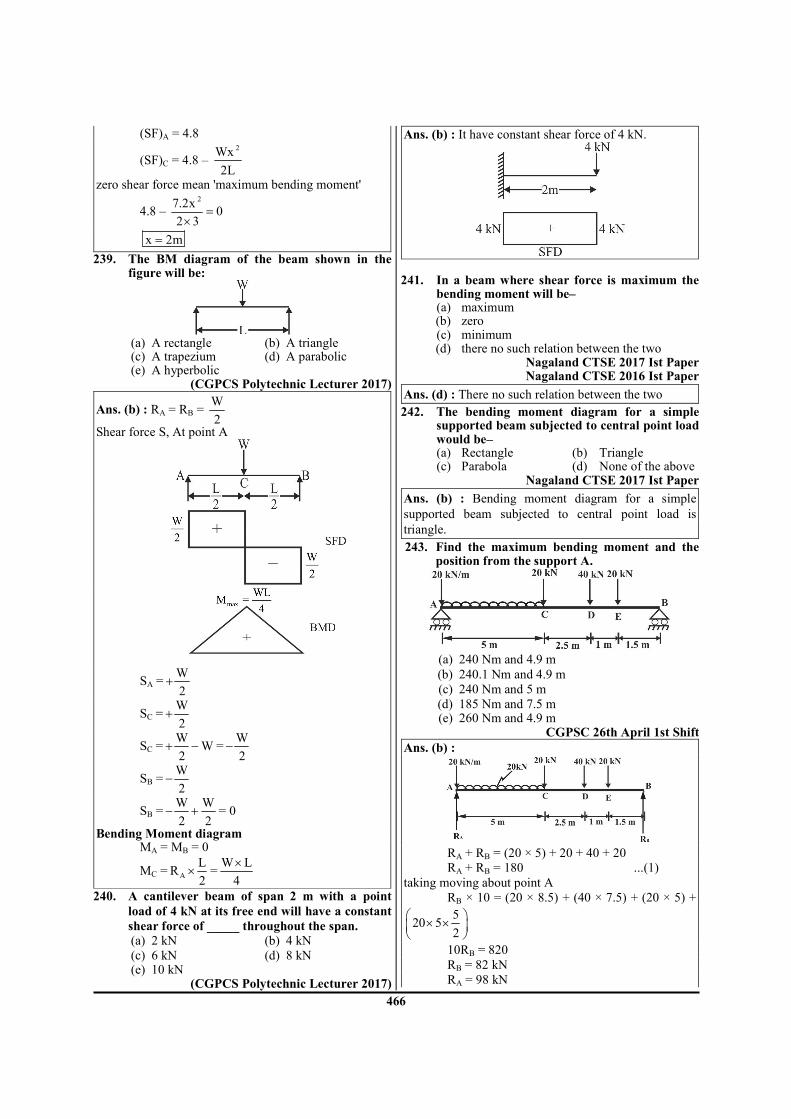
466
(SF)A = 4.8
(SF)C = 4.8 – 2Wx
2L
zero shear force mean 'maximum bending moment'
4.8 – 2
7.2x0
2 3=
×
x 2m=
239. The BM diagram of the beam shown in the figure will be:
(a) A rectangle (b) A triangle (c) A trapezium (d) A parabolic (e) A hyperbolic
(CGPCS Polytechnic Lecturer 2017)
Ans. (b) : RA = RB = W
2
Shear force S, At point A
SA =W
2+
SC =W
2+
SC =W
W2
+ − =W
2−
SB =W
2−
SB =W W
2 2− + = 0
Bending Moment diagram MA = MB = 0
MC = A
LR
2× =
W L
4
×
240. A cantilever beam of span 2 m with a point
load of 4 kN at its free end will have a constant
shear force of _____ throughout the span.
(a) 2 kN (b) 4 kN
(c) 6 kN (d) 8 kN (e) 10 kN
(CGPCS Polytechnic Lecturer 2017)
Ans. (b) : It have constant shear force of 4 kN.
241. In a beam where shear force is maximum the
bending moment will be– (a) maximum (b) zero (c) minimum (d) there no such relation between the two
Nagaland CTSE 2017 Ist Paper Nagaland CTSE 2016 Ist Paper
Ans. (d) : There no such relation between the two
242. The bending moment diagram for a simple supported beam subjected to central point load would be–
(a) Rectangle (b) Triangle (c) Parabola (d) None of the above
Nagaland CTSE 2017 Ist Paper
Ans. (b) : Bending moment diagram for a simple
supported beam subjected to central point load is
triangle.
243. Find the maximum bending moment and the position from the support A.
(a) 240 Nm and 4.9 m
(b) 240.1 Nm and 4.9 m
(c) 240 Nm and 5 m
(d) 185 Nm and 7.5 m (e) 260 Nm and 4.9 m
CGPSC 26th April 1st Shift Ans. (b) :
RA + RB = (20 × 5) + 20 + 40 + 20
RA + RB = 180 ...(1)
taking moving about point A
RB × 10 = (20 × 8.5) + (40 × 7.5) + (20 × 5) +
520 5
2
× ×
10RB = 820
RB = 82 kN
RA = 98 kN

467
Bending moment is maximum or minimum where shear force changes sign
98 2
5x x=
−
x = 4.9 m
4.9
4.998 4.9 20 4.9
2xBM = = × − × ×
= 480.2 - 240.1 = 240.1 N-m
244. Which of the following statements is/are correct?
1. In uniformly distributed load, the nature of shear force is linear and bending moment is parabolic.
2. In uniformly varying load, the nature of shear force is linear and bending moment is parabolic.
3. Under no loading condition, the nature of shear force is linear and bending moment is constant.
Select the correct answer using the code given below.
(a) 1 and 2 (b) 1 and 3 (c) 2 only (d) 1 only
ESE 2019 Ans. (d) : (i) In UDL, shear force is linear and bending moment is parabolic. Hence statement first is correct. (ii) In UVL, shear force is parabolic and bending moment is cubic. Hence statement second is incorrect. (iii) In no loading, shear force is constant and bending
moment is linear. Hence statement third is also
incorrect.
245. Which one of the following is the correct
bending moment diagram for a beam which is
hinged at the ends and is subjected to a
clockwise couple acting at the mid-span?
(a)
(b)
(c)
(d)
ESE 2018
Ans. (c) : On balancing vertical force
RA + RB = 0 .....(i) By taking moment about point A,
RB × L = M
RB =M
L .....(ii)
From equation (i) and (ii)
RA =M
L−
Bending moment MA = MB = 0
(Me)Right = B
1R
2× =
M
2(Sagging)
(Mc)Left = B
1R M
2× − =
M
2− (Hogging)
From the above computed values, bending moment diagram is drawn in the figure below.
246. The point of contraflexure occurs in (a) Cantilever beam only (b) Simply supported beam only (c) Overhanging beam only (d) Continuous only
RPSC Vice Principal ITI 2018 OPSC AEE 2019 Paper-I
APPSC AEE 2012 UPPSC AE 2016
UKPSC AE-2013, Paper-I
Ans. (c) : Point of contraflexure occurs in overhanging beam only. The point of contraflexure is the point where bending moment changes the sign.
247. The bending moment at a section tends to bend
or deflect the beam and the internal stresses
resist bending. The resistance offered by the
internal stresses to the bending is called (a) compressive stress (b) shear stress (c) bending stress (d) elastic stress
JPSC AE - 2013 Paper-II Ans : (c) : The bending moment at a section tends to
bend or deflect the beam and the internal stresses resist
bending. The resistance offered by the internal stresses
to the bending is called bending stress.
248. The flexural rigidity is the product of
(a) modulus of elasticity and mass moment of
inertia
(b) modulus of rigidity and area moment of
inertial

468
(c) modulus of rigidity and mass moment of inertia
(d) modulus of elasticity and area moment of inertia
BPSC AE 2012 Paper - VI Ans : (d) : The flexural rigidity is the product of modulus of elasticity and area moment of inertia.
249. Calculate the bending moment at the mid-point of a 6 m long simply supported beam carrying a 20 N point load at the mid-point.
(a) 20 Nm (b) 30 Nm (c) 45 Nm (d) 60 Nm
BPSC AE Mains 2017 Paper - VI Ans : (b) : By symmetry, R1 = R2 = 10 N
(BM)C = R1 × 3 = 10 × 3
(BM)C = 30 Nm
250. A 3 m long beam, simply supported at both
ends, carries two equal loads of 10 N each at a
distance of 1 m and 2 m from one end. The
shear force at the mid-point would be
(a) 0 N (b) 5 N
(c) 10 N (d) 20 N
BPSC AE Mains 2017 Paper - VI Ans : (a) :
By symmetry, R1 = R2 = 10 N
Hence shear force at midpoint is zero.
251. In a cantilever beam the bending moment with
respect to fixed end is maximum at:
(a) the center (b) the free end
(c) the fixed end (d) any point on the beam (HPPSC LECT. 2016)
Ans : (c)
In a cantilever beam the bending moment with respect
to fixed end is maximum at the fixed end.
252. In fixed beam of length (l) with a concentrated central load two points of contraflexure will occur, each from supports at a distance of :
(a) 1/3 (b) 1/ 3 (c) 1/6 (d) ¼ (HPPSC AE 2014)
Ans : (d)
fig (d) shows the B.M diagram obtained by super-
imposing and µ'diagram. At any point distance x from A
1x x x
Wx WLM
2 8= µ + µ = −
At c
L W L WL WLx , M .
2 2 2 8 8= = − =
Thus, the central B.M. is half of the B.M. for a freely supported beam. For point of Contraflexure
x
Wx WLM o
2 8= = −
This gives L
x4
=
253. Variation of bending moment in a cantilever carrying a load, the intensity of which varies uniformly from zero at the free end to w per unit run at the fixed end, is by :
(a) cubic law (b) parabolic law (c) linear law (d) none of these (HPPSC AE 2014)
Ans : (a) Variation of bending moment in a cantilever carrying a load, the intensity of which varies uniformly from zero at the free end to w per unit run at the fixed end is by cubic law. Section x–x talking from

469
Taking moment at
x–x
2
x x
1 wx xM
2 3− = ×
l
3
x x
wxM
6− =
l
Bending moment at B
x = 0, MB = 0
Bending Moment at A
x = l
A
wM
6=
2l
254. The three-moment for continuous beams was
forwarded by :
(a) Bernoulli (b) Clapeyron
(c) Castigliano (d) Maxwell
(HPPSC AE 2014)
Ans : (b) The three moment theorem for continuous
beam was forwarded by clapeyron.
255. A simply supported beam of span (l) carries a
point load (W) at the centre of the beam. The
shear force diagram will be :
(a) a rectangle
(b) a triangle
(c) two equal and opposite rectangles
(d) two equal and opposite triangles
HPPSC W.S. Poly. 2016
Ans : (c) A simply supported beam of span (l) carries a
point load (W) at the centre of the beam. The shear
force diagram will be two equal and opposite
rectangles.
256. A simply supported beam of span 10m
carrying a load of 500N at the mid span will
have a maximum bending moment of :
(a) 500 Nm (b) 1250 Nm
(c) 2500 Nm (d) 5000 Nm
(KPSC AE. 2015)
Ans : (b)
Maximum bending moment w
4=
ℓ
( )max
500 10BM
4
×=
(BM)max = 1250N.m.
257. A mass less beam has a loading pattern as
shown in Fig. The beam is of rectangular cross-
section with a width of 30 mm and height of
100 mm
the maximum bending moment occurs at
(a) Location B
(b) 2500 mm to the right of A
(c) 2675 mm to the right of A
(d) 3225 mm to the right of A
MPPSC AE 2016
Ans : (b)
RA + RC = 6000N
Taking moment about A
6000 × 3 – RC × 4 = 0
RC = 4500 N
RA = 1500 N
Taking any section from A
Shear force = 1500 – 3000 (x – 2)
and maximum bending moment occur where shear
force = 0
1500 – 3000 (x – 2) = 0
x = 2.5 m
or 2500 mm from A
258. The shear force of a cantilever beam of length
'L' with a point load 'W' at its free end is in the
shape of the following:
TSPSC AEE 2015

470
Ans : (a)
259. The maximum bending moment of a simply
supported beam of span 2m and carrying a
point load 80 kN at the centre of the beam is
(a) 160 kN-m (b) 80 kN-m
(c) 320 kN-m (d) 40 kN-m
TSPSC AEE 2015
Ans : (d)
Maximum Bending moment = wl
4
(BM)max = 80 2
4
×
(BM)max = 40 KN-m
260. A continuous beam is one which is
(a) fixed at one end and free at the other end
(b) fixed at one end and free at the other end
(c) supported on more than two supports
(d) extending beyond the supports
TSPSC AEE 2015
OPSC AE Mechanical Paper-1 15 Dec 2019
Ans : (c) A continuous beam is one which is supported
on more than two supports.
261. A beam is simply supported at its ends and is
loaded by a couple at its mid-span as shown in
figure, Shear force diagram is given by which
of the following figures?
(a)
(b)
(c)
(d)
UJVNL AE 2016
Ans : (d)
262. If the shear force diagram for a beam is
triangle with length of the beam as its base, the
beam is
(a) A cantilever with a point load at its free end.
(b) A cantilever with uniformly distributed load
over its whole span.
(c) A simply supported beam with a point load at
its mid-point.
(d) A simply supported beam with uniformly
distributed load over its whole span.
UPPSC AE 12.04.2016 Paper-I
Ans : (b) If the shear force diagram for a beam is
triangle with length of the beam as its base, the beam is
a cantilever with uniformly distributed load over its
whole span.
263. The shear force diagram of a loaded beam is
shown in the following figure. The maximum
bending moment in the beam is
(a) 16-kN-m (b) 11-kN-m
(c) 18-kN-m (d) 18-kN-m
UPPSC AE 12.04.2016 Paper-I

471
Ans : (a)
Maximum Bending Moment:-
( )max
BM 16kN m= −
We know that
( )dmshear force S
dx=
dM = Sdx C
AdM Area under=∫ Shear force diagram
(MC – MA) = 1
2 2 2 122
× + × ×
= 4 + 12 = 16 kN-m
MA = 0 [At Reaction]
So CM 16kN m= −
and also
MB – MC = ( )113 1 1 6
2
− × + × × −
= – 13 – 3 = – 16 kN-m
MB = 0 [At reaction]
CM 16 kN m= −
So maximum bending moment will be 16 kN-m at
point C.
264. In a propped cantilever beam, the number of
points of contra-flexure is
(a) 1 (b) 2
(c) 3 (d) 4
APPSC AEE 2012
Ans : (a)
In a propped cantilever beam, the number of point of
contra-flexure is one.
265. If a fixed beam is subject to a point load at mid
span, total number of points of contra-flexure
are
(a) 1 (b) 2
(c) 3 (d) zero
APPSC AEE 2012
Ans : (b) In a fixed beam is subjected to a point load at
mid span total number of points of contra-flexure are
two.
A B
WR R
2= =
( )x
PM 4x L
8= −
1
x2
<
x 0 B A
PLM M M
8= = = = −
x C
L P 1M M 4 L
2 8 2
= = = × −
PL
8=
In this bending moment diagram bending moment change it's sign at two points.
266. In a double overhanging beam carrying udl
throughout its length, the number of points of
contra flexure are
(a) 1 (b) 2
(c) zero (d) 3
APPSC AEE 2012
Ans : (b) In a double overhanging beam carrying UDL
throughout its length, the number of points of
contraflexure are two.
Points of contraflexure:– Where the bending moment
will change sign from negative to positive or vice versa.
Such a point, where the bending moment change sign, is
known as a point of contraflexure.
267. Rate of change of shear force is equal to
(a) Bending moment
(b) Intensity of loading
(c) Maximum deflection
(d) Slope APPSC AEE 2012

472
Ans : (b) (i) Rate of change of Shear force is equal to intensity of loading
( )dsw downward load
dx= −
w = load per unit length. (ii) Rate of change of bending moment along the length of beam is equal to shear force.
x
dMS
dx=
268. A cantilever is subjected to udl throughout the length. If the maximum shear force is 200kN and maximum bending moment is 400kN, the span "L" of the beam in meters is
(a) 3 (b) 2 (c) 4 (d) 8 APPSC AEE 2012
Ans : (c)
Maximum shear force = 2000kN wL = 2000kN ……..(i) Maximum Bending moment
2wL
2=4000kN ….....(ii)
for equation (i) and (ii) 2
wL
2 2wL
= L 4m=
269. A cantilever beam AB of length 1 is subjected to an anticlockwise couple of 'M' at a section C, distance 'a' from support. Then the maximum shear force is equal to
(a) M (b) M
2
(c) Zero (d) Ma APPSC AEE 2012
Ans : (c)
A cantilever beam AB of length l is subjected to an anticlockwise couple of M at a section C, distance 'a' from support, then the maximum shear force is equal to zero. Because No transfer load acting on the beam.
270. If SFD between two sections varies linearly,
BM between these sections varies
(a) linearly (b) parabolically
(c) constant (d) None of these
APPSC AEE 2012
Ans : (b) If SFD between two section varies linearly,
BM between these section varies parabolically
271. At section of a beam sudden change in BM
indicates the action of (a) point load (b) couple (c) point load or couple (d) udl APPSC AEE 2012
Ans : (b) At section of a beam sudden change in BM indicates the action of couple.
272. A cantilever of length 'l' carries a udl of w per unit m, over the whole length. If the free end be supported over a rigid prop, the reaction of the prop will be
(a) 2w
8
ℓ (b)
5w
8
ℓ
(c) 3w
8
ℓ (d)
7w
8
ℓ
APPSC AEE 2012
Ans : (c) A cantilever of length l carries a udl of w per unit m, over the whole length. If the free end be supported over a rigid prop, the reaction of the prop will
be 3w
8
ℓ.
273. For a maximum bending moment, shear force at that section should be
(a) zero (b) maximum (c) minimum (d) None of the above APPSC AEE 2012
Ans : (a) dM
shear forcedx
=
For maximum bending moment shear force will be equal to zero. 274. For uniform shear force throughout the span
of a simply supported beam, it should carry
(a) a concentrated load at the mid-span (b) a couple anywhere in the sections (c) udl over its entire span
(d) two concentrated loads equally spaced
APPSC AEE 2012

473
Ans : (b) For uniform shear force throughout the span of a simply supported beam, it should carry a couple anywhere in the section.
275. Maximum bending moment in a cantilever carrying a concentrated load at the free end occurs
(a) at the fixed end (b) at the free end (c) at the mid span (d) None of these APPSC AEE 2012
Ans : (a)
Maximum bending moment in a cantilever beam carrying a concentrated load at the free end occurs at the fixed end.
276. The given figure shows the shear force diagram for the beam ABCD. Bending moment in the portion BC of the beam
(a) is zero (b) varies linearly from B to C (c) parabolic variation between B and C (d) is a non–zero constant APPSC AEE 2012
Ans : (d)
Bending moment in the portion BC of the beam is a non-zero constant.
277. A beam carrying a uniformly distributed load rests on two supports 'b' apart with equal overhang 'a' at each end. The ratio b/a for zero bending moment at the mid span is
(a) 1/2 (b) 1 (c) 3/2 (d) 2
RPSC Vice Principal ITI 2018
Ans. (d) :
s A B
(2a b)wR R
2
+= =
B.M. at middle of AB
middle
w b b b 1BM (2a b) w a a
2 2 2 2 2
= − + × + + + ×
For zero B.M. at middle
0 =
2w b w b
(2a b) a2 2 2 2
− + × + +
= 2 2
22ab b b 2aba
2 4 2
−− + + +
= 2 2
2b bab a ab
2 4− − + + +
b
2a
=
278. A simply supported beam of length l carries a uniformly distributed load of w per unit length. It will have maximum bending moment at midpoint of beam and the value will be:
(a) 2w
2
l (b)
2w
4
l
(c) 2w
6
l (d)
2w
8
l
(e) 2w
16
l
(CGPCS Polytechnic Lecturer 2017) CGPSC 26th April 1st Shift
UKPSC AE-2013, Paper-I
Ans. (d) : We know that
RA = RB =wL
2
Taking a section x-x from a point A at a distance x. Then taking moment at x-x
Mx-x = A
xR x wx
2− ⋅
Mx-x =2wL x
x w2 2
−
For max. bending moment
x xdM
dx
− = 0
wL x
2w2 2
− = 0
wL
2= wx

474
L
x2
=
At x =L
2 [at mid] bending moment will be max. so
2
Lx
M=
=2wL L w L
2 2 4 2
×× −
×
L
2
M =2 2wL wL
4 8−
2
L / 2
wLM
8=
279. A simply supported beam of length L carrying
a concentrated load W at a section which is at a
distance of 'x' from one end. What will be the
value of bending moment at this section?
(a) W (x - x2) (b) W (x
2 - xL)
(c) 2x
W xL
−
(d) Wx
SJVN ET 2019
Ans. (c) :
A C
W
B
RA RB
x
RA + RB = W .............(i)
Taking moment about A,
RB×L = Wx
B
WxR
L=
RA = W – RB
Wx
WL
= −
Taking moment about C,
MC = RA× x
2x
W xL
= −
280. A cantilever beam of length L carry a UDL of
W per length across the whole span. What will
be the value of maximum shear stress and
maximum bending moment on the beam
respectively?
(a) 2WL, WL
2 (b) WL, WL
2
(c) 2WL WL
,2 2
(d) 2WL
WL,2
SJVN ET 2019
Ans. (d) : In question they asked max shear stress that
should be max shear force.
–Wl
–Wl
Max shear force at fixed = W × l
Max value of bending moment 1
2
= × ×
W l l
2
2=
Wl
281. A simply supported beam of span carries over its full span a load varying linearly from zero at each end to W N/m at mid span. The maximum bending moment is
(a) 2
W
12
ℓ (b)
2W
8
ℓ
(c) 2
W
4
ℓ (d)
2W
2
ℓ
JWM 2017 Ans. (a) : Consider equilibrium of beam AB total load
on beam is 1
2 W2 2
× × ×
ℓ
Total load = WL
2
As the beam symmetric, the total load equally distributed on both the support.
A B
WLR R
4= =
Bending moment (Mx)
In the region 0 < x < L
2
x
WL 1 2Wx xM .x x
4 2 L 3
= − × × ×
3WL Wx
x4 3L
= −
For maximum bending moment
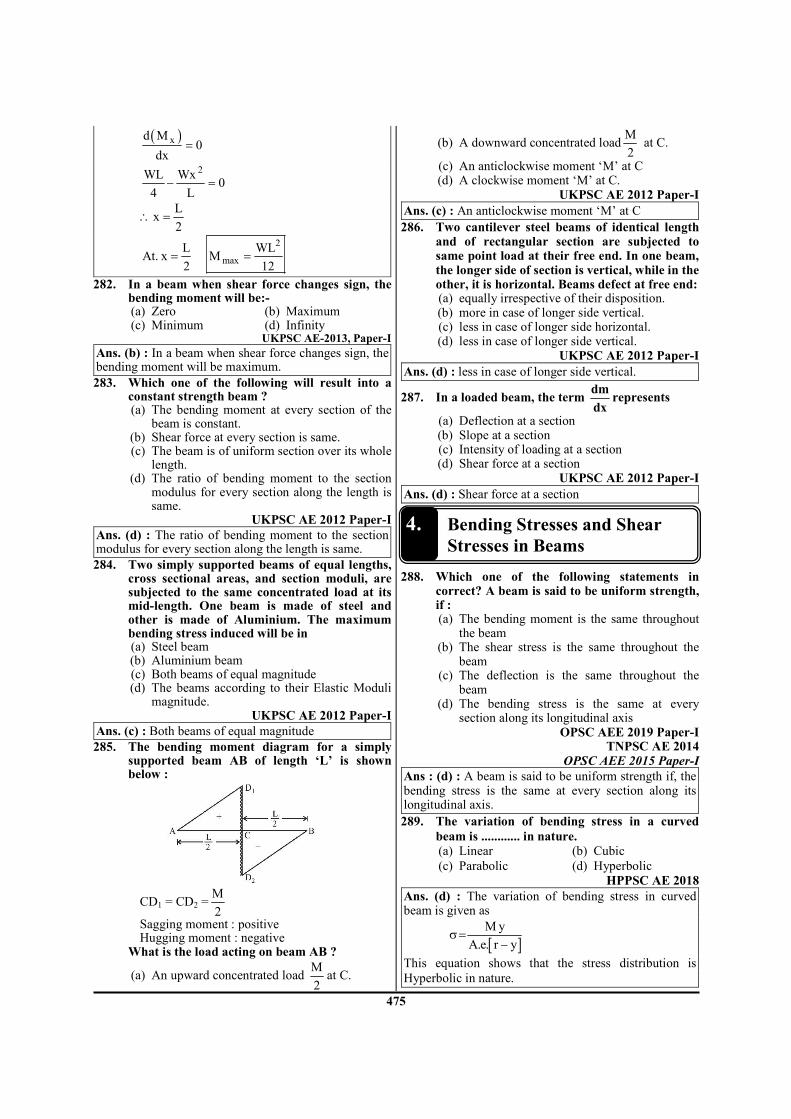
475
( )xd M
0dx
=
2WL Wx
04 L
− =
L
x2
∴ =
2
max
L WLAt. x M
2 12= =
282. In a beam when shear force changes sign, the bending moment will be:-
(a) Zero (b) Maximum (c) Minimum (d) Infinity
UKPSC AE-2013, Paper-I
Ans. (b) : In a beam when shear force changes sign, the bending moment will be maximum.
283. Which one of the following will result into a constant strength beam ?
(a) The bending moment at every section of the beam is constant.
(b) Shear force at every section is same. (c) The beam is of uniform section over its whole
length. (d) The ratio of bending moment to the section
modulus for every section along the length is same.
UKPSC AE 2012 Paper-I Ans. (d) : The ratio of bending moment to the section modulus for every section along the length is same.
284. Two simply supported beams of equal lengths, cross sectional areas, and section moduli, are subjected to the same concentrated load at its mid-length. One beam is made of steel and other is made of Aluminium. The maximum bending stress induced will be in
(a) Steel beam (b) Aluminium beam (c) Both beams of equal magnitude (d) The beams according to their Elastic Moduli
magnitude. UKPSC AE 2012 Paper-I
Ans. (c) : Both beams of equal magnitude
285. The bending moment diagram for a simply supported beam AB of length ‘L’ is shown below :
CD1 = CD2 =M
2
Sagging moment : positive Hugging moment : negative What is the load acting on beam AB ?
(a) An upward concentrated load M
2at C.
(b) A downward concentrated loadM
2 at C.
(c) An anticlockwise moment ‘M’ at C (d) A clockwise moment ‘M’ at C.
UKPSC AE 2012 Paper-I Ans. (c) : An anticlockwise moment ‘M’ at C
286. Two cantilever steel beams of identical length and of rectangular section are subjected to same point load at their free end. In one beam, the longer side of section is vertical, while in the other, it is horizontal. Beams defect at free end:
(a) equally irrespective of their disposition. (b) more in case of longer side vertical. (c) less in case of longer side horizontal. (d) less in case of longer side vertical.
UKPSC AE 2012 Paper-I Ans. (d) : less in case of longer side vertical.
287. In a loaded beam, the term dm
dxrepresents
(a) Deflection at a section (b) Slope at a section (c) Intensity of loading at a section (d) Shear force at a section
UKPSC AE 2012 Paper-I Ans. (d) : Shear force at a section
4. Bending Stresses and Shear
Stresses in Beams
288. Which one of the following statements in correct? A beam is said to be uniform strength, if :
(a) The bending moment is the same throughout the beam
(b) The shear stress is the same throughout the beam
(c) The deflection is the same throughout the beam
(d) The bending stress is the same at every section along its longitudinal axis
OPSC AEE 2019 Paper-I TNPSC AE 2014
OPSC AEE 2015 Paper-I
Ans : (d) : A beam is said to be uniform strength if, the bending stress is the same at every section along its longitudinal axis.
289. The variation of bending stress in a curved
beam is ............ in nature.
(a) Linear (b) Cubic
(c) Parabolic (d) Hyperbolic
HPPSC AE 2018 Ans. (d) : The variation of bending stress in curved beam is given as
[ ]
M y
A.e. r yσ=
−
This equation shows that the stress distribution is
Hyperbolic in nature.

476
290. When a beam is subjected to a transverse shearing force, the shear stress in the upper fibers will be–
(a) Maximum (b) Minimum (c) Zero (d) Depends on other data
Nagaland CTSE 2017 Ist Paper Ans. (c) : Shear stress in a beam is not uniformly distributed over the cross-section, but varies from zero of outer fiber to a maximum at the neutral surface.
291. A beam of uniform strength has constant : (a) Shear force (b) Bending moment (c) Cross-sectional area (d) Deflection
TRB Polytechnic Lecturer 2017 Ans. (b) : Bending moment will remain constant in uniform strength beam.
292. An inverted T-section is subjected to a shear force F. The maximum shear stress will occur at:
(a) Top of the section (b) Junction of web and flange (c) Neutral axis of the section (d) Bottom of the section
TRB Polytechnic Lecturer 2017 Ans. (c) : The maximum shear stress will occur at neutral axis of the section in inverted T-section when subjected to a shear force.
293. The nature of distribution of horizontal shear stress in a rectangular beam is :
(a) Linear (b) Parabolic (c) Hyperbolic (d) Elliptic
OPSC AEE 2019 Paper-I Ans : (b) : The nature of distribution of horizontal shear stress in a rectangular beam is parabolic.
294. The ratio of average shear stress to the maximum shear stress in a beam with a square cross-section is :
(a) 1 (b) 2/3 (c) 3/2 (d) 2
OPSC AEE 2019 Paper-I Ans : (b) : The ratio of average shear to the maximum shear stress in a beam with a square cross section is 2/3.
295. Uniformly distributed load ‘w’ act over per
unit length of a cantilever beam of 3m length. If
the shear force at the midpoint of beam is 6kN,
what is the value of ‘w’:-
(a) 2 kN/m (b) 3 kN/m
(c) 4 kN/m (d) 5 kN/m UKPSC AE-2013, Paper-I
Ans. (c) : From shear force diagram
3w 6
3 1.5=
w = 4 kN/m
296. A beam strongest in flexural is one which has (a) maximum bending stress (b) maximum area of cross section (c) maximum section modulus (d) maximum moment of inertia
APPSC AEE 2016 Ans. (c) : A beam strongest in flexural is one which has maximum section modulus.
N A
max.
IZ
y
−=
297. A beam of span 3 m and width 90 mm is loaded as shown in the figure. If the allowable bending stress is 12 MPa, the minimum depth required for the beam will be
(a) 218 mm (b) 246 mm (c) 318 mm (d) 346 mm
ESE 2020
Ans. (b) : Bending stress max
2
6 M
bd=bσ
Mmax = 14.5 × 1.5 – 12 × 0.9 = 10.95 kNm = 10.95 × 10
6 N mm
6
2
6 10.95 1012
90 d
× ×=
×
d = 246.64 mm
298. A vertical hollow aluminium tube 2.5 m high fixed at the lower end, must support a lateral load of 12 kN at its upper end. If the wall
thickness is 1
8
th of the outer diameter and the
allowable bending stress is 50 MPa, the inner diameter will be nearly
(a) 186 mm (b) 176 mm (c) 166 mm (d) 156 mm
ESE 2020 Ans. (d) :
0
1t= d
8
di = d0 – 2t
0 0 0
1 3d 2 d d
8 4= − × =
i
0
d 3
d 4=
maxb 3 4
0
32M
d (1 K )σ =
π −
3
4
3
0
32 12 10 250050
3d 1
4
× × ×=
π −
d0 = 207.54
i
3d 207.54 155.66 mm
4= × =

477
299. An I-section of a beam is shown in the figure below. If the shear stress at point P which is very close to bottom of the flange is 12 MPa, the shear stress at the point Q close to the flange is :
(a) 40 MPa (b) 12 MPa (c) Indeterminate (d) 60 MPa
BHEL ET 2019 Ans. (d) : Given - shear stress of flange
( )flange 12MPaτ =
shear stress of web (τweb) =? width of flange (bt) = 100 mm width of web (bw) = 20 mm
from - ( )( )
( )( )
flange web
web flange
b
b
τ=
τ
( )web
12 20 1
100 5= =
τ
( )web 60MPaτ =
300. The ratio of moment carrying capacity of a
square cross section beam of dimension D to
the moment carrying capacity of a circular
cross section of diameter D is :
(a) 16
3π (b)
16
π
(c) 16
5π (d)
8
3π
BHEL ET 2019 Ans. (a) :
Section modulus of square cross - section 3
s
DZ
6=
Section modulus of circular cross - section 3
c
DZ
32
π=
b
NA
M
Zσ =
For square cross section–
( ) S
b 3s
M
D
6
σ =
For circular cross section–
( ) bb 3C
M
D
32
σ =π
Note- Bending stress of both beam will be same
( ) ( )b bs cσ = σ
S C
3 3
6M 32M
D D=
π
S
C
M 16
M 3=
π
301. A steel wire of 10 mm diameter is bent into a circular shape of 5 m radius. What will be the maximum stress induced in the wire, when E = 200 GPa?
(a) 50 MPa (b) 100 MPa (c) 150 MPa (d) 200 MPa (e) 250 MPa
(CGPCS Polytechnic Lecturer 2017) Ans. (d) : Data given, d = 10 mm
R = 5 m = 5 × 103 mm
E = 200 GPa = 200 × 103 N/mm
2
σ = ? We know that pure bending equation
M
I=
Y
σ=
E
R
So σ = max.
Ey
R× ymax. =
d
2=
10
2= 5 mm
σ =3
3
200 105
5 10
××
×
σ = 200 N/mm2
200 MPaσ =
302. Section of the modulus (Z) for a rectangular section with width (b) and depth (d) is given by:
(a) 3bd
Z12
= (b) 2bd
Z12
=
(c) 3bd
Z6
= (d) 2bd
Z6
=
(e) 2bd
Z8
=
(CGPCS Polytechnic Lecturer 2017) TNPSC AE 2013
Ans. (d) : We know that
Z = N A
max.
I
Y
−
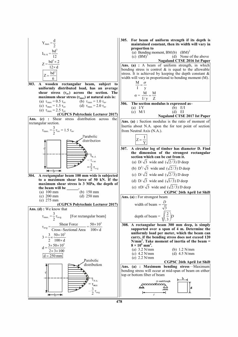
478
Ymax =d
2
IN-A =3bd
12
Z =3bd 2
12 d
××
2bd
Z6
=
303. A wooden rectangular beam, subject to uniformly distributed load, has an average
shear stress (τav) across the section. The
maximum shear stress (τmax) at natural axis is: (a) τmax = 0.5 τav (b) τmax = 1.0 τav (c) τmax = 1.5 τav (d) τmax = 2.0 τav
(e) τmax = 2.5 τav (CGPCS Polytechnic Lecturer 2017)
Ans. (c) : Shear stress distribution across the rectangular section.
τmax. =3
2τav = 1.5 τav
304. A rectgangular beam 100 mm wide is subjected
to a maximum shear force of 50 kN. If the maximum shear stress is 3 MPa, the depth of the beam will be ______.
(a) 100 mm (b) 150 mm (c) 200 mm (d) 250 mm (e) 275 mm
(CGPCS Polytechnic Lecturer 2017) Ans. (d) : We know that
τmax. =3
2τavg. [For rectangular beam]
τavg =Shear Force
Cross -Sectional Area=
350 10
100 d
××
3 =33 50 10
2 100 d
××
×
d =33 50 10
2 3 100
× ×× ×
d 250 mm=
305. For beam of uniform strength if its depth is maintained constant, then its width will vary in proportion to
(a) Bending moment, BM (b) (BM)2
(c) (BM)3 (d) None of the above
Nagaland CTSE 2016 Ist Paper Ans. (a) : A beam of uniform strength, in which bending stress is control & is equal to the allowable stress. It is achieved by keeping the depth constant & width will vary in proportional to bending moment (M).
M
I y=
σ
σ = M M
I / y Z=
306. The section modulus is expressed as– (a) I/Y (b) E/I (c) M/1 (d) EI
Nagaland CTSE 2017 Ist Paper
Ans. (a) : Section modulus is the ratio of moment of
Inertia about N.A. upon the for test point of section
from Neutral Axis (N.A.).
I
ZY
=
307. A circular log of timber has diameter D. Find the dimension of the strongest rectangular section which can be cut from it.
(a) D/ 3 wide and ( 2 / 3) D deep
(b) D2/ 3 wide and ( 2 / 3) D deep
(c) D/ 2 wide and ( 2 / 3) D deep
(d) D/ 3 wide and ( 1/ 3) D deep
(e) πD/ 3 wide and ( 2 / 3) D deep
CGPSC 26th April 1st Shift Ans. (a) : For strongest beam
width of beam 3
D=
depth of beam = 2
3D
308. A rectangular beam 300 mm deep, is simply supported over a span of 4 m. Determine the uniformly load per meter, which the beam can carry, if the bending stress does not exceed 120 N/mm
2. Take moment of inertia of the beam =
8 × 106 mm
4.
(a) 3.2 N/mm (b) 1.2 N/mm (c) 4.2 N/mm (d) 4.5 N/mm (e) 2.2 N/mm
CGPSC 26th April 1st Shift Ans. (a) : Maximum bending stress—Maximum bending stress will occur at mid-span of beam on either top or bottom fiber of beam

479
2
max8
wlM =
max
max
My
Iσ =
2
max8 2
wl d
Iσ = ×
3 2
6
(4 10 ) 300120
28 8 10
w× × = × × ×
w = 3.2 N/mm
309. Bending stress in a beam cross section at a
distance of 15 cm from neutral axis is 50 MPa.
Determine the magnitude of bending of a
distance of 10 cm from neutral axis.
(a) 50 MPa (b) 30.43 MPa
(c) 33.33 MPa (d) 75 MPa
(e) 45.53 MPa
CGPSC 26th April 1st Shift Ans. (c) :
Bending stress ( )M
yI
σ =
yσ ∝
2 2
1 1
y
y
σσ
=
2 10
50 15
σ=
σ2 = 33.33 MPa
310. The ratio of moment of inertia of a cross
section to the distance of extreme fibers from
the neutral axis is known as
(a) Elastic modulus (b) Bulk modulus
(c) Shear modulus (d) Section modulus
(e) Young's modulus
CGPSC 26th April 1st Shift
Ans. (d) : Section modulus ( )I
Zy
=
where I = Moment of inertia of a cross-section
y = distance of extreme fiber from neutral axis.
311. A flat spiral mode of strip of breadth 5 mm,
thickness 1 mm and length 1.5 m has been
subjected to a winding couple which induces a
maximum stress of 150 N/mm2. The magnitude
of winding couple is nearest to
(a) 20.8 Nmm (b) 41.6 Nmm
(c) 62.5 Nmm (d) 83.3 Nmm
TNPSC AE 2014
Ans. (c) : Data given b = 5 mm t = 1 mm L = 1.5 m σb = 150 N/mm
2
M = ? We know that
b 2
12M
btσ =
( ) 2
12 M150
5 1
×=
×
M 62.5 N mm= −
312. In a beam of I cross-section, subjected to a transverse load, the maximum shear stress is developed
(a) at the centre of the web (b) at the top edge of the top flange (c) at the bottom edge of the top flange (d) at one third distance along the web
TNPSC AE 2014 Ans. (a) : In a beam of I cross-section, subjected to a transverse load, the maximum shear stress is developed at the centre of the web.
313. Beams with four unknown reaction is (a) In-Determinate Beams (b) Determinate Beams (c) Propped Beams (d) In- Propped Beams
TNPSC AE 2013 Ans. (a) : A structure is statically indeterminate when the static equilibrium equation [Force and moment equilibrium equation condition] are insufficient for determining the internal forces and reaction on that structure. For in-determinate beam No. of equilibrium equation < No. of Reactions. For determinate beam No. of equilibrium equation = No. of reactions.
314. The cross-section of the beam is as shown in the figure.
If the permissible stress is 150 N/mm
2, the
bending moment M will be nearly
(a) 1.21 × 10⁸ N mm (b) 1.42 × 10
8 N mm
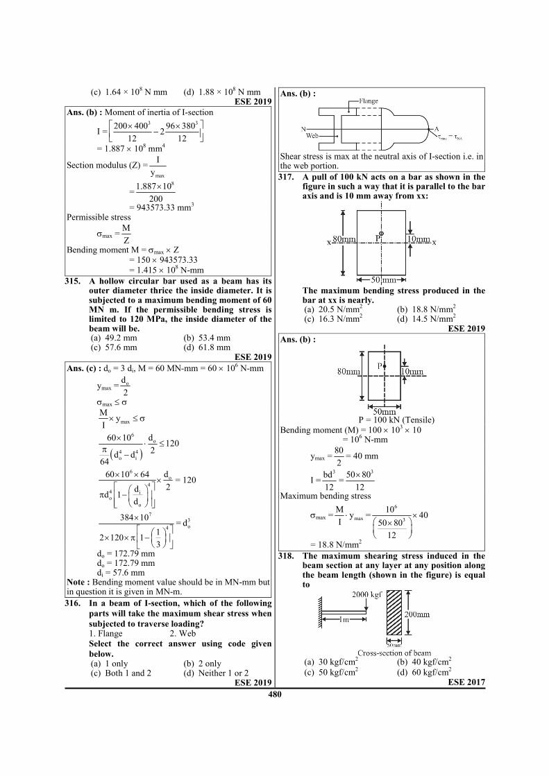
480
(c) 1.64 × 10⁸ N mm (d) 1.88 × 10
8 N mm ESE 2019
Ans. (b) : Moment of inertia of I-section
I =3 3200 400 96 380
212 12
× ×−
= 1.887 × 108 mm
4
Section modulus (Z) =max
I
y
=81.887 10
200
×
= 943573.33 mm3
Permissible stress
σmax =M
Z
Bending moment M = σmax × Z = 150 × 943573.33
= 1.415 × 10⁸ N-mm
315. A hollow circular bar used as a beam has its outer diameter thrice the inside diameter. It is subjected to a maximum bending moment of 60 MN m. If the permissible bending stress is limited to 120 MPa, the inside diameter of the beam will be.
(a) 49.2 mm (b) 53.4 mm (c) 57.6 mm (d) 61.8 mm
ESE 2019 Ans. (c) : do = 3 di, M = 60 MN-mm = 60 × 10
6 N-mm
ymax =od
2
σmax ≤ σ
max
My
I× ≤ σ
( )
6
o
4 4
o i
d60 10120
2d d
64
×⋅ ≤
π−
6
o
4
4 io
o
d60 10 64
2dd 1
d
× ××
π −
= 120
7
4
384 10
12 120 1
3
× × × π −
= 3
od
do = 172.79 mm do = 172.79 mm di = 57.6 mm Note : Bending moment value should be in MN-mm but in question it is given in MN-m.
316. In a beam of I-section, which of the following
parts will take the maximum shear stress when
subjected to traverse loading? 1. Flange 2. Web
Select the correct answer using code given
below. (a) 1 only (b) 2 only (c) Both 1 and 2 (d) Neither 1 or 2
ESE 2019
Ans. (b) :
Shear stress is max at the neutral axis of I-section i.e. in the web portion.
317. A pull of 100 kN acts on a bar as shown in the figure in such a way that it is parallel to the bar axis and is 10 mm away from xx:
The maximum bending stress produced in the
bar at xx is nearly. (a) 20.5 N/mm
2 (b) 18.8 N/mm
2
(c) 16.3 N/mm2 (d) 14.5 N/mm
2
ESE 2019 Ans. (b) :
P = 100 kN (Tensile)
Bending moment (M) = 100 × 103 × 10
= 106 N-mm
ymax =80
2= 40 mm
I =3bd
12=
350 80
12
×
Maximum bending stress
σmax = max
My
I⋅ =
6
3
1040
50 80
12
× ×
= 18.8 N/mm2
318. The maximum shearing stress induced in the beam section at any layer at any position along the beam length (shown in the figure) is equal to
(a) 30 kgf/cm2 (b) 40 kgf/cm2
(c) 50 kgf/cm2 (d) 60 kgf/cm
2
ESE 2017

481
Ans. (a) :
For rectangular cross section
τmax =3
2τavg
=23 2000
kgf / mm2 50 200
××
= 30 kgf/cm2
319. A beam of rectangular section (12 cm wide × 20 cm deep) is simply supported over a span of 12 m. It is acted upon by a concentrated load of 80kN at the mid span. The maximum bending stress induced is.
(a) 400 MPa (b) 300 MPa (c) 200 MPa (d) 100 MPa
ESE 2017 Ans. (b) : Given, b = 12 cm = 120 mm d = 20 cm = 200 mm
L = 12 m = 12000 mm
W = 80 kN = 80 × 103 N
Mmax =WL
4=
380 10 12000
4
× ×
= 240 × 106 N−mm
I =3bd
12=
3120 200
12
×
= 80 × 106 mm
4
y =d
2=
200
2= 100 mm
Maximum bending stress (σ) =MY
I
=6
6
240 10 100
80 10
× ××
= 300 MPa
320. The beam of triangular cross-section as shown in the figure below, is subjected to pure bending. If a plastic hinge develops at a section, determine the location of neutral axis (distance b from top) at that section. The beam material is elastic-perfectly plastic (i.e., yield stress is constant)
(a) 3
h (b)
2
h
(c) 2
h (d)
3
h
APPSC-AE-2019 Ans. (c) :
Ac = At
1
1 1 12
2 2 2b b h h
× × = × ×
2
1
hb
b=
from similar triangles
1
2
b b
h h
→
→
b × 2h = b1h
1
2
bb =
2
2
hb
b=
×
2
2
2
hb =
2
hb =
321. Calculate the shear force and bending moment at point B for the beam AB subjected to linearly varying load as shown in the figure. The value of the linearly varying load at the point is 6 kN/m and 4 kN/m, respectively. Point B is an internal hinge.
(a) 2.67 kN and 0 kN-m (b) 4 kN and 0 kN-m (c) 4 kN and 1.33 kN-m (d) 1.33 kN and 0 kN-m
APPSC-AE-2019 Ans. (d) :
Consider BC part
(4)(2)
1.336
B BSF R kN= = =
BMB = 0 (at hinge moment is zero)

482
322. A beam of rectangular section 200mm ×
300mm carries certain loads such that bending
moment at a section A is M and at another
section B it is (M + ∆M). The distance between
section A and B is 1 m and there are no
external loads acting between A and B. If ∆M is
20 kNm, maximum shear stress in the beam
section is
(a) 0.5 MPa (b) 1.0 MPa
(c) 1.5 MPa (d) 2.0 MPa
APPSC-AE-2019
Ans. (a) : dM
Fdx
=
20
1
kN mF
m
−=
F = 20 kN
For rectangular cross-section
max
3
2avgτ τ =
max
3
2
F
bdτ =
33 20 10
0.5 MPa2 200 300
×= = ×
323. A mild steel flat of width 100 mm and thickness
12 mm is bent into an arc of a circle of radius
10 m by applying a pure moment M. If Young's
modulus E = 200 GPa, then the magnitude of
M is
(a) 72 Nm (b) 144 Nm
(c) 216 Nm (d) 288 Nm
APPSC-AE-2019 Ans. (d) : Radius of curvature (R) = 10,000 mm
Modulus of elasticity (E) = 200 × 103 MPa
Thickness (t) = 12 mm
From bending equation
M E
I R=
3
3
200 10
10,000100 12
12
M ×=
×
M = 288000 N-mm
= 288 N-m
324. A rectangular beam section with depth 400 mm
and width 300 mm is subjected to a bending
moment of 60 kN/m. The maximum bending
stress in the section is
(a) 7.50 MPa (b) 2.50 MPa
(c) 1.56 MPa (d) 0.42 MPa
APPSC-AE-2019 Ans. (a) : Maximum bending stress in the beam
6
max 2 2
60 107.5 MPa
300 400
6 6
M Mf
Z bd
×= = = =
×
325. In case of pure bending, the beam will bend into an arc of a/an
(a) parabola (b) hyperbola (c) circle (d) ellipse
APPSC-AE-2019 Ans. (c) : If a beam is subjected to pure bending the elastic curve is a circular arc with constant radius.
326. A square section of side 'a' is oriented as shown in the figure. Determine the section modulus of the following section?
(a) 4
12 2
a (b)
3
12 2
a
(c) 4
6 2
a (d)
3
6 2
a
APPSC-AE-2019 Ans. (d) :
The section modulus is
3
3
max
.
12
6 2
2
a a
I aZ
y a
= = =
327. In theory of simple bending an assumption is made that plane sections before bending remain plane even after bending. This assumption implies that
(a) Strain is uniform across the section (b) Stress is uniform across the section (c) Stress in any layer is proportional to its
distance from the neutral axis (d) Strain in any layer is directly proportional to
its distance from the neutral axis JWM 2017
Ans. (d) : The assumption made in theory of simple bending that plane sections before bending remain plane even after bending means the strain in any layer is directly proportional to its distance from the neutral axis.
328. Moment of Inertia of the rectangle of base 80 mm and height 10 mm about its centroidal (Ixx) axis
(a) 6666.66 mm4 = Ixx (b) 5827.21 mm
4 = Ixx
(c) 7777.22 mm4 = Ixx (d) 6826.11 mm
4 = Ixx
TNPSC AE 2014

483
Ans. (a) : We know that
[ ] [ ]3
x x CG
80 10 80 1000I
12 12−
× ×= =
[ ] 4
x x CGI 6666.66 mm− =
329. The section modulus of hollow circular section is
(a) 4 4( )
16D d
D
π− (b) 4 4
( )32
D dD
π−
(c) 3 3( )
32D d
D
π− (d) 3 3
( )16
D dD
π−
TNPSC AE 2013
Ans. (b) :
4 4D dIZ
DR 64
2
−π = =
( )4 4D d
Z32D
π −=
330. The rectangular beam 'A' has length l, width b and depth d. Another beam 'B' has the same length and width but depth is double of that of 'A'. The elastic strength of beam B will be _____ as compared to beam A.
(a) same (b) double (c) four times (d) six times
TSPSC AEE 2015 Ans. (c) : We know that,
( )2depthσ ∝
so,
2A
B
d 1
2d 4
σ = = σ
Then,
B A4σ = σ
331. If the depth is kept constant for a beam of uniform strength, then its width will vary in proportional to (where M = Bending moment)
(a) M (b) M (c) M
2 (d) M
3
TSPSC AEE 2015 Ans. (a) : We know that
M
I y
σ=
3bd
I12
=
So M b∝ If depth is constant then M is directly proportional to its width [b].
For a beam of uniform strength bending stress
σ will be also constant 332. Section modulus of hollow circle with average
diameter 'd' and with thickness 't' is equal to
(a) 24
5td (b)
2 24
5t d
(c) 24
5t d (d)
25
4td
TNPSC 2019
Ans. (c) : 3
x x y y
dI I t
8− −
π= = ×
d d
Ro t2 2
= + ≃
2
x x y y
dZ Z t
4− −
π= ×
24td
5≈
333. The rectangular beam A has a length ℓ and
width b but depth d is double that of A. The elastic strength of beam B will be ____ as compared to beam A.
(a) same (b) double (c) one-fourth (d) four times
JPSC AE - 2013 Paper-II Ans : (d) : We know that section modulus for beam A,
3/12
/ 2
AA
A
I bdZ
y d= =
2
6
bd=
And section modulus for beam B
( )32 /12
2 / 2
BB
B
b dIZ
y d= =
22
3=
bd
(Depth is double that of A)
Since elastic strength of beam is directly proportional to
their respective section modulus, therefore, 2
BB A2
A
Z 2bd 6= × or Z =4Z
Z 3 bd
B AZ = 4Z

484
334. Pure bending means : (a) The bending beam shall be accompanied by
twisting (b) Shear force is zero (c) There is no twisting (d) None of these
OPSC AEE 2019 Paper-I Ans : (b) : Pure bending- Pure bending is a condition of stress where a bending moment is applied to a beam without the simultaneous application of axial shear or torsional forces. Beam that is subjected to pure bending means the shear force in the particular beam is zero and no torsional or axial loads are presented. Pure bending is also the flexure (bending) of a beam that under a constant bending moment therefore pure bending only occurs therefore pure bending only occurs when the shear force in equal to zero.
335. Which is the correct relation in a beam?
(a) M I R
y Eσ= = (b)
M y E
I Rσ= =
(c) M E
I y R
σ= = (d)
M E
y R I
σ= =
OPSC AEE 2019 Paper-I UKPSC AE 2007 Paper -I
Ans : (c) : Where M = Bending moment I = Second moment of inertia of cross section about neutral axis.
σ = Bending stress on any layer γ = Distance of any layer from neutral layer. E = Young’s Modulus R = Radius of curvature of the neutral
336. The point within the cross-sectional plane of beam through which the resultant of the external loading on the beam has to pass through to ensure pure bending without twisting of the cross-section of the beam is called :
(a) Moment centre (b) Centroid (c) Shear center (d) Elastic center
OPSC AEE 2019 Paper-I Ans : (c) : Shear center is the point within the cross sectional plane of a beam through which the resultant of the external loading on the beam has to pass through to ensure pure bending without twisting of cross section of the beam.
337. Section modulus of a beam is defined as :
(a) Iy (b) Y
I
(c) max
I
Y (d) Y
2I
OPSC AEE 2019 Paper-I APPSC AEE 2012
Ans : (c) : Section Modulus- The ratio I/y where y is the farthest or the most distant point of the section from the neutral axis is called section modulus, It is denoted by Z.
Moment of inertia about neutralaxisZ =
Distanceof farthest point fromneutralaxis
338. If E= elasticity modulus, I = moment of inertia about the neutral axis and M = bending moment in pure bending under the symmetric loading of a beam, the radius of curvature of the beam :
(i) Increases with E (ii) Increases with M (iii) Decreases with I (iv) Decreases with M Which of these are correct? (a) (i) and (ii) (b) (ii) and (iii) (c) (iii) and (iv) (d) (i) and (iv)
OPSC AEE 2019 Paper-I Ans : (d) : In pure bending
M E
y I R
σ= =
.E IR
M=
R increase with E R decrease with M Statement (i) and (iv) are correct.
339. In circular plates with edges clamped and with a uniformly distributed load, the maximum radial stress occurs at :
(HPPSC AE 2014) (a) clamp edge (b) the centre (c) the mean radius (d) none of these
Ans : (b) In circular plates with edges clamped and with a uniformly distributed load, the maximum radial stress occurs at the centre.
340. Equivalent moment of inertia of the cross-section in terms of timber of a flitched beam made up of steel and timber is (m = Es/Et) :
(a) (It + m/Is) (b) (It + Is/m) (c) (It + mIs) (d) (It + 2mIt) (HPPSC AE 2014)
Ans : (c) Equivalent moment of inertia of the cross- section in terms of timber of a flitched beam made up-of steel and timber is It + mIs m = Es/Et Es = Modulus of elasticity of steel. Et = Modulus of elasticity of timber.
341. Section modulus (Z) of a beam depends on: (a) the geometry of the cross-section (b) weight of the beam (c) only on length of the beam (d) none of the above (HPPSC LECT. 2016)
Ans : (a) section modulus (z) of a beam depends on the geometry of the cross - sections.
section modulus (Z) = max
I
Y
M E
I y R
σ= =
maxM Z= σ ×
342. Section modulus of a square section of side 'b' is equal to
(a) b3/6 (b) b
2/6

485
(c) b/6 (d) b3/3
TSPSC AEE 2015
Ans : (a) Square section moment of inertia (I) = 4b
12
Section modulus = I/y
4
sq
b 2Z
12 b
×=
×
3
sq
bZ
6=
343. The maximum bending moment of a square
beam of section modulus 3200
6mm
3 is 20 × 10
6
N-mm. The maximum shear stress induced in the beam is
(a) 30 N/mm2 (b) 7.5 N/mm
2
(c) 45 N/mm2 (d) 15 N/mm
2
TSPSC AEE 2015
Ans : (d) bending moment (M) = 20×106N-mm
section modulus (Z) = 3200
6mm
3
( )maxM Ebending equation
I y R
σ= =
max
M I
yσ=
max
M
Zσ =
6
max 3
20 10
200 / 6σ
×=
2
max 15N / mmσ =
344. In an I-section of a beam subjected to transverse shear force, the maximum shear stress is developed at
(a) The bottom edges of the top flange. (b) The top edges of the top flange. (c) The centre of the web (d) The upper edges of the bottom flange.
UPPSC AE 12.04.2016 Paper-I
Ans : (c) In an I-section of a beam subjected to transverse shear force, the maximum shear stress is developed at the centre of the web. Shear stress distribution for I-section
345. A beam of uniform strength is one, which has
same (a) bending moment throughout the section (b) shearing force throughout the section (c) deflection throughout the bean
(d) bending stress at every section APPSC AEE 2012
Ans : (d) A beam of uniform strength is one which has same bending stress at every section.
346. Neutral axis of a beam is the axis at which (a) the shear force is zero (b) the section modulus is zero (c) the bending stress is maximum (d) the bending stress is zero APPSC AEE 2012
Ans : (d) Neutral axis of a beam is the axis at which the bending stress is zero.
347. A beam cross-section is used in two different
orientations as shown in figure :
Bending moments applied in both causes are
same. The maximum bending stresses induced
in cases (A) and (B) are related as
(a) A Bσ = σ (b)
A B2σ = σ
(c) B
A2
σσ = (d) B
A4
σσ =
APPSC AEE 2012
Ans : (b)
(A) (B)
For first case:–
3 4
A
1 b bI b
12 2 96
= × =
A A4
A
M M 12 8
I y b / 4b
σ σ× ×= ⇒ =
A 3
24M
bσ = ……….. (i)

486
For second case
( )3
B
b 1I b
2 12
= × ×
4
B
bI
24=
B
B
M
I y
σ=
B4
M
bb
212 2
σ=
×
B 3
12M
bσ = ……… (ii)
For equation first and second A B2σ = σ
348. The ratio of flexural strength of a square
section with its two sides horizontal to its
diagonal horizontal is
(a) 2 (b) 2
(c) 2 2 (d) 2
5
APPSC AEE 2012
Ans : (a)
4
SH
aI
12=
a
y2
=
3
SH
aZ
6=
3
SH
aZ
6=
ISD = 4a
12
a
y2
=
ZSD = 4 3a 2 a
12 a 6 2
×=
×
we know that
M ∝ Z
3
SH SH
3
SD SD
M Z a 6 22
M Z 6 a= = × =
349. The ratio of maximum shear stress to the
average shear stress in case of a rectangular
beam is equal to
(a) 1.5 (b) 2.0 (c) 2.5 (d) 3 APPSC AEE 2012
Ans : (a) Shear stress developed is given by
2 2
2 2
3
F d F dy y
2I 4 4bd2
12
τ = − = −
×
2
max 3
6F d 3F
4 2bdbdτ = × =
max avg
3
2τ = τ
350. The nature of distribution of horizontal shear stress in a rectangular beam is
(a) linear (b) parabolic (c) hyperbolic (d) elliptic APPSC AEE 2012
Ans : (b) Shape of shear stress distribution across rectangular cross section will be parabolic .
351. Section modulus of a circular section about an
axis through its centre of gravity is
(a) 3d32
π (b) 3d
16
π
(c) 3d8
π (d) 3d
64
π
APPSC AEE 2012
Ans : (a) Section modulus (z) = I/y
I = Moment of Inertia 4d
64
π=
d
y2
=
3d
z32
π=
352. A steel plate 50mm wide and 100mm thick is to be bent into a circular arc of radius 10m. If
5 2E 2 10 N / mm= × , then the maximum
bending stress induced will be (a) 200 N/mm
2 (b) 100 N/mm
2
(c) 10,000 N/mm2 (d) 1000 N/mm
2
APPSC AEE 2012
Ans : (d) b=50mm, d= 100mm, R = 10m E= 2×10
5 N/mm
2
Bending equation :-
M E
I y R
σ= =
y = 50mm
E
y R
σ=

487
Ey
Rσ = ×
5
3
2 1050
10 10
×σ = ×
×
21000N / mmσ =
353. Radius of curvature of the beam is equal to
(a) ME
I (b)
M
EI
(c) EI
M (d)
MI
E
APPSC AEE 2012
Ans : (c) Bending equation
M E
I y R.
σ= =
M E
I R.=
Radius of curvature of the EI
(R)M
=
354. If a material expands freely due to heating, it will develop:-
(a) Thermal stresses (b) Tensile stresses (c) Compressive stresses (d) No stresses
UPRVUNL AE 2014 UKPSC AE-2013, Paper-I
Ans. (d) : If a material expands freely due to heating, it will develop no stresses.
355. A cable with uniformly distributed load per horizontal meter run will take the following shape:-
(a) Straight line (b) Parabola (c) Ellipse (d) Hyperbola
UKPSC AE-2013, Paper-I
Ans. (b) : A cable with uniformly distributed load per horizontal meter run will take parabola shape.
356. A beam of Z-section is called a (a) doubly symmetric section beam (b) singly symmetric section beam (c) a-symmetric section beam (d) none of the above
UKPSC AE 2012 Paper-I Ans. (c) : a-symmetric section beam
357. A uniform metal bar of weight ‘W’, length ‘l’, cross-sectional area ‘A’ is hung vertically with its top end rigidly fixed. Which section of the bar will experience maximum shear stress ?
(a) Top-section (b) Mid-section (c) Bottom-section (d) l/3 from top
UKPSC AE 2012 Paper-I Ans. (a) : Top-section
358. In theory of simple bending of beams, which
one of the following assumptions is incorrect ?
(a) Elastic modulus in tension and compression are same for the beam materials.
(b) Plane sections remain plane before and after
bending.
(c) Beam is initially straight.
(d) Beam material should not be brittle.
UKPSC AE 2012 Paper-I Ans. (d) : Beam material should not be brittle.
359. A beam is of rectangular section. The
distribution of shearing stress across a section
is
(a) Parabolic (b) Rectangular
(c) Triangular (d) None of the above
UKPSC AE 2012 Paper-I Ans. (a) : Parabolic
360. The well known bending formula is
(a) M E
I R= (b)
M E
R I=
(c) M y
I=
σ (d)
M y
R=
σ
UKPSC AE 2007 Paper -I
Ans. (a) : M E
I R=
361. Consider the three supports of a beam (1)
Roller, (2) Hinged and (3) Fixed. The
support(s) that permit(s) rotation is (are):
(a) 1, 2 and 3 (b) 1 and 3 only
(c) 1 and 2 only (d) 1 only UKPSC AE 2007 Paper -I
Ans. (c) : 1 and 2 only
362. Circular beams of uniform strength can be
made by varying diameter in such a way that
(a) M
Z is constant (b)
y
σ is constant
(c) E
R is constant (d)
M
R is constant
UKPSC AE 2007 Paper -I
Ans. (a) : M
Z is constant
5. Torsion of Shafts
363. Which of the following assumption in the theory of pure torsion is false
(a) All radii get twisted due to torsion (b) the twist is uniform along the length (c) the shaft is uniform circular section through
out (d) cross section plane before torsion remain
plane after torsion APPSC AEE 2016
Ans. (a) : Assumption in the theory of Torsion– 1. The material of shaft is uniform throughout the
length. 2. The twist along the shaft is uniform. 3. The shaft is of uniform circular section throughout
the length. 4. Cross-section of the shaft, which are plane before
twist remain plane after twist. 5. All radii which are straight before twist remain
straight after twist.

488
364. When a shaft is subjected to a twisting moment, every cross-section of the shaft will be under–
(a) Tensile stress (b) Compressive stress (c) Shear stress (d) Bending stress
Vizag Steel (MT) 2017 Ans. (c) : When a shaft is subjected to a twisting moment every cross section of the shaft will be under shear stress.
365. In case of a torsional problem the assumption-"Plane sections perpendicular to longitudinal axis before deformation remain plane and perpendicular to the longitudinal axis after deformation" holds true for a shaft having
(a) circular cross-section (b) elliptical cross-section (c) circular and elliptical cross-section (d) any cross-section
APPSC-AE-2019 Ans. (a) : In case of a torsional problem the assumption- "Plane sections perpendicular to longitudinal axis before deformation remain plane and perpendicular to the longitudinal axis after deformation" holds true for a shaft having circular cross-section only. It is not valid for other shape of cross-section.
366. For the two shafts connected in parallel, which of the following in each shaft is same?
(a) Torque (b) Shear stress (c) Angle of twist (d) Torsional stiffness
UKPSC AE-2013, Paper-I
Ans. (c) : When the two shafts connected in parallel then both shafts are subjected to same angle of twist.
367. A hollow shaft has external and internal diameters of 10cm and 5cm respectively. Torsional section modulus of shaft is:-
(a) 375 cm3 (b) 275 cm
3
(c) 184 cm3 (d) 84 cm
3
UKPSC AE-2013, Paper-I
Ans. (c) : We know that tosional section modulus for hollow shaft
3 4pZ D 1 K
16
π = −
where d
KD
=
putting d = 5 cm, D = 10 cm
( )4
3pZ 10 1
16 10
π 5 = × × −
3pZ 184 cm=
368. The shear stress at the centre of a circular shaft
under torsion is:-
(a) Maximum (b) Minimum
(c) Zero (d) Unpredictable UKPSC AE-2013, Paper-I
Ans. (c) : The shear stress at the centre of a circular shaft under torsion is zero rτ ∝ Note- option (d) is given by UKPSC
369. The outside diameter of a hollow shaft is twice its inside diameter. The ratio of its torque carrying capacity to that of a solid shaft of the same material and the same outside diameter is
(a) 15/16 (b) 3/4 (c) 1/2 (d) 1/16
UPRVUNL AE 2016 UKPSC AE 2012 Paper-I
Ans. (a) : The ratio of torque of hollow to solid shaft
for the same material 4H
S
T1 K
T= −
Where di
Kd0
=
Given that di 1
d0 2=
4
H
S
T 11
T 2
∴ = −
H
S
T 11
T 16= −
H
S
T 15
T 16=
370. Torsional rigidity of a solid cylindrical shaft of diameter ‘d’ is proportional to
(a) d (b) d2
(c) d4 (d)
2
1
d
UKPSC AE 2012 Paper-I Ans. (c) : d
4
371. Polar moment of inertia of an equilateral triangle of side ‘x’ is given by
(a) 4x
16 (b)
4x
16 3
(c) 4x
32 (d)
4x
64
UKPSC AE 2012 Paper-I
Ans. (b) : 4x
16 3
372. A solid shaft of uniform diameter 'D' is subjected to equal amount of bending and twisting moment 'M'. What is the maximum shear stress developed in the shaft?
(a) 3
16 2M
Dπ (b)
3
16
2
M
Dπ
(c) 3
32 2M
Dπ (d)
3
16M
Dπ
UKPSC AE 2007 Paper -I
Ans. (a) : 3
16M
Dπ
373. The diameter of kernel of a hollow circular x-
section is
(a) D d
D
+ (b)
2 2D d
D
+

489
(c) 2 2
2
D d
D
+ (d)
2 2
4
D d
D
+
UKPSC AE 2007 Paper -I
Ans. (d) : 2 2
4
D d
D
+
374. Angle of twist allowed in case of camshaft is :
(a) Dependent on its length
(b) Restricted to ½ degree irrespective of length
of the shaft
(c) Depending on the torque acting on it
(d) Dependent on the nature of the engine (i.e. 4
stroke or 2 stroke)
OPSC AEE 2015 Paper-I
Ans : (c) Angle of twist allowed in case of camshaft is
Depending on the torque acting on it.
375. A shaft turns at 200 rpm under a torque of
1800 Nm. The power transmitted is
(a) 6π kW (b) 12π kW
(c) 24π kW (d) 36π kW
APPSC-AE-2019
Ans. (b) : 2
60
NTP
π=
2 (200)(1800)
60
π=
= 12000 (π)
= (12 π) kW
376. A circular shaft is subjected to a twisting
moment T and a bending moment M. The ratio
of maximum bending stress to maximum shear
stress is given by
(a) 2M/T (b) M/T
(c) 2T/M (d) M/2T
UPPSC AE 12.04.2016 Paper-I
Ans : (a)
M E
I Y R
σ= =
Bending stress ( ) My
Iσ =
Bending stress ( )4
M d / 2
d
64
σπ×
=
Bending stress ( ) =3
32M............( i )
dσ
π
Torsion Equation
T G
J r
θ τ= =
ℓ
T .r
Jτ =
Shear stress ( ) 4
T d / 2
d
32
τπ×
=
Shear stress ( ) =3
16T...........( ii )
dτ
π
for equation (i) and (ii)
3
3
32M d
16Td
σ πτ π
= ×
2M
T
στ
=
377. A shaft of diameter d) is subjected to torque (T) and bending moment (M). The value of maximum principle stress and maximum shear stress is given respectively by:
(a) 2 2 2 2
3 3
16 16M M T ; M T
d d
+ + + π π
(b) 2 2 2 2
4 4
16 16M M T ; M T
d d
+ + + π π
(c) 2 2 2 2
3 3
16 16M T ; M M T
d d
+ + + π π
(d) 2 2 2 2
4 4
16 16M T ; M M T
d d
+ + + π π
(e) 2 2 2 2
4 4
32 32M T ; M M T
d d
+ + + π π
CGPSC AE 2014- I Nagaland CTSE 2016 Ist Paper
Ans. (a) : Maximum principle stress max .σ
2 2max 3
16M M T
d
σ = + + π
maximum shear stress
2 2max 3
16M T
d
τ = + π
378. When a circular shaft is subjected to torque, the torsional shear stress is
(a) maximum at the axis of rotation and zero at the outer surface
(b) uniform from axis of rotation to the outer surface
(c) zero at the axis of rotation and maximum at the outer surface
(d) zero at the axis of rotation and zero at the outer surface and maximum at the mean radius
RPSC Vice Principal ITI 2018 Ans. (c) :
τ T
r J=
Tr
τJ
=
At, r = 0, τ → 0 At, r = R, τ → Maximum
379. A solid bar of circular cross-section having a diameter of 40 mm and length of 1.3 m is subjected to torque of 340 Nm. If the shear modulus of elasticity is 80 GPa, the angle of twist between the ends will be
(a) 1.26° (b) 1.32°

490
(c) 1.38° (d) 1.44°
ESE 2020 Ans. (a) : Angle of twist
T
GJθ =
ℓ
3
3 4
340 10 1300
80 10 4032
× ×=
π× × ×
= 0.02198 rad
θ = 1.26º
380. A solid circular shaft of length 4 m is to transmit 3.5 MW at 200 rpm. If permissible shear
stress is 50 MPa, the radius of the shaft is: (a) 1.286 mm (b) 12.86 mm (c) 0.1286 mm (d) 128.6 mm
BHEL ET 2019 Ans. (d) : Given - Length = L = 4m Transmitted P = 3.5 MW N = 200 rpm
τ = 50 MPa, radius = r = ?
τ = 50 × 103 kPa
Power P = Tω
3.5 × 106 = T ×
2 N
60
π
= 2 200
T60
π××
3.5 × 106 = 20.943 T
T = 167.120 kN-m Torsion equation-
T T
J r=
J
rT
τ=
4d
5032r
167.120
π×
=
4d 50 d
2 5347.84
× π=
35347.84d
50 2=
× × π
d = 0.25724 2r = 0.25724 r = 0.12862 m
r 128.6 mm=
381. The maximum shear stress developed on the
surface of a solid circular shaft under pure torsion is 160 MPa. If the shaft diameter is
doubled, then the maximum shear stress developed corresponding to the same torque
will be: (a) 10 MPa (b) 30 MPa (c) 40 MPa (d) 20 MPa
BHEL ET 2019
Ans. (d) : Given
( )max 160MPaτ =
d1 = d d2 = 2d
same torque 1 2T T T= =
( )max 3 31
16T 6T160
d d
1τ = ⇒ =
π π ...(1)
when diameter is doubled.
( )( )max 3 31
16T 6T160
8 d2d
1τ = = =
ππ ...(2)
from equation (1) / equation (2)
3
3
max
160 16T 8 d
16Td
π= ×
τ π
max 20MPaτ =
382. A 50 mm diameter solid shaft is subjected to both, a bending moment and torque of 300 kN-mm & 200 kN-mm respectively. The maximum shear stress induced in the shaft is :
(a) 10.22 MPa (b) 14.69 MPa (c) 146.9 MPa (d) 102.2 MPa
BHEL ET 2019 Ans. (b) : Given diameter of shaft d = 50 mm Bending moment M = 300 kN-m Torque T = 200 kN-m
2 2
eT M T= + be the equivalent torque, which acts
alone producing the same maximum shearing stress
emax e3 3
T 16T
dd
16
τ = =ππ
( )
( ) ( )3
2 2
max 3
16 10300 200
50
×τ = +
π×
316 360.555 10
125000
× ×=
π×
5768880
392699.081=
= 14.69 MPa
383. A circular shaft of 60 mm diameter is running at 150 r.p.m. What will be the torque
transmitted by the shaft if (τ = 80 MPa)? (a) 1.1 π kN-m (b) 1.6π kN-m (c) 2.1π kN-m (d) 2.6π kN-m (e) 3.1π kN-m
(CGPCS Polytechnic Lecturer 2017) Ans. (a) : d = 60 mm N = 150 rpm τ = 80 MPa = 80 N/mm
2
We know that
T =3d
16
π× τ =
60 60 6080 N mm
16
π× × ×× −
T = 1.08π kN-m ≃ 1.1π kN-m
384. Two shaft, one solid and other hollow made to the same material will have same strength, if they are of same

491
(a) length and weight
(b) length and polar moment of inertia
(c) weight and polar moment of inertia
(d) length, weight and polar moment of inertia
Nagaland CTSE 2016 Ist Paper Ans. (b) : Two shafts, one solid and other hollow made
to the same material will have same strength, if they are
of same length and polar moment of inertia.
T G
J R= =
ℓ
τ θ
t
T GJk = =
ℓθ
max
TR
J= ×τ
385. In a rectangular shaft is subjected to torsion, the maximum shear shear stress will occur
(a) Along the diagonal (b) At the comers (c) At the centre (d) At the middle of the longer side
Nagaland CTSE 2016 Ist Paper Ans. (d) : For a rectangular shaft is subjected to torsion the maximum shear stress will occur at the midpoint of the longer side and zero at the corners.
386. An axial load P is applied on circular section of diameter D. If the same load is applied on a hollow circular shaft with inner diameter as D/2, the ratio of stress in two cases would be
(a) 4/3 (b) 9/8 (c) 1 (d) 8/3
Nagaland CTSE 2016 Ist Paper Ans. (a) : Axial load (P) on circular section & diameter (D) if the same load is applied on a hollow circular shaft with inner diameter as (D/2), then ratio of stress will be, d = D/2
1
1
Pδ =
A
12
Pδ =
πD
4
2
2
Pδ =
A
22 2
Pδ =
π(D d )
4−
2
1
2 2
2
P / (D )4
(4D D )P /
4 4
πδ
πδ=
− =
4
3
387. In case of a circular shaft subjected to torque
the value of shear stress
(a) Is uniform through out
(b) Has maximum value at axis
(c) Has maximum value at the surface
(d) Is zero at the axis and linearly increases to a
maximum value at the surface of the shaft Nagaland CTSE 2016 Ist Paper
Ans. (d) : In case of a circular shaft subjected to torsion
the value of shear stress is zero at the centre and
linearly increase to a maximum value at the surface of
the shaft.
388. In case of circular shaft subjected to torque the
value of shear stress– (a) Is uniform through out (b) Has maximum value at axis
(c) Has maximum value at the surface (d) Is zero at the axis and linearly increases to a
maximum value at the surface of the shaft
Nagaland CTSE 2017 Ist Paper Ans. (d) : In case of a circular shaft subject to torque the value of shear stress is zero at the axis & linearly
increase with ratius to a maximum value at the surface.
389. Which of the following is correct for flexible
shaft? (a) it has very low rigidity both in bending and
torsion (b) it has very high rigidity in bending and low
rigidity in torsion (c) it has low rigidity in bending and high rigidity
in torsion (d) It has very high rigidity both in bending and
torsion
SJVN ET 2019 Ans. (c) : flexible shaft has low rigidity in bending and
high rigidity in torsion.
390. Angle of twist of a solid shaft of torsional
rigidity GJ, length L and applied torque T will
be given by:
(a) T
GJL (b)
L
GJ T
(c) TL
GJ (d)
GJ
TL
SJVN ET 2019 UKPSC AE 2007 Paper -I
Ans. (c) : TL
GJ
391. Maximum value of shear stress for a hollow
shaft of outer and inner diameter D and d will
be: [where T = Applied torque]
(a)
( )3 3
16TD
D dπ − (b)
( )4 4
16TD
D dπ −
(c)
( )4 4
16T
D dπ − (d)
( )3 3
16T
D dπ −
SJVN ET 2019
Ans. (b) :
( )4 4
16TD
D dπ −
392. For a circular shaft of diameter D subjected to
torque T, the maximum value of the shear
stress is
(a) (64T/πD3) (b) (32T/πD
3)
(c) (16T/πD3) (d) (128T/πD
3)
(e) (8T/πD3)
CGPSC 26th April 1st Shift
RPSC 2016

492
Ans. (c) : From torsion equation we have
T
J r
τ=
where T = torque J = polar moment of inertia τ = shear stress r = radius The maximum value of shear stress is given by
4
232
T
dd
τπ
=
3
16T
dτ
π=
393. A solid circular shaft of 60 mm diameter and 10 m length, transmits a torque of 2000 N-m. The value of maximum angular deflection, if the modulus of rigidity is 100 GPa is
(a) 18 degree (b) 13 degree (c) 15 degree (d) 9 degree (e) 5 degree
CGPSC 26th April 1st Shift Ans. (d) : Given d = 60 mm l = 10 m = 10000 mm G = 100 GPa = 100 × 10
3 N/mm
2
T = 2000 N-m = 2000 × 103 N-mm
From torsion equation
T G
J l
θ=
3 4
3 3
. 2000 10 10
100 10 (60)32
T l
GJθ
π× ×
= =× × ×
θ = 9.43º
394. In case of shaft design, one of the following equation is known as stiffness equation:
(a) T
J R
τ= (b)
M
J R
σ=
(c) M
I R
τ= (d)
T G
J L
θ=
(e) M G
I L
θ=
CGPSC 26th April 1st Shift
Ans. (d) : Equation =
T G
J L
θis known as stiffness
equation.
395. 100 kW is to be transmitted by each of two separate shafts 'A' and 'B'. 'A' is rotating at 250 rpm and 'B' at 300 rpm. Which shaft must have greater diameter.
(a) A (b) B (c) Both will have same diameter (d) Unpredictable (e) Diameter does not affect
CGPSC 26th April 1st Shift
Ans. (a) : We know that
1N
D∝
then, A B
B A
D N 300
D N 250= =
then, DA > DB
396. A steel spindle transmits 4 kW at 800 r.p.m. The angular deflection should not exceed 0.25°/m length of the spindle. If the modulus of rigidity for the material of the spindle is 84 GPa, the diameter of the spindle will be
(a) 46 mm (b) 42 mm (c) 38 mm (d) 34 mm
ESE 2019 Ans. (d) : Given, P = 4 kW N = 800 rpm G = 84 GPa
θ = 1
0.25180 1000
π× ×
θ = 4.363 × 10⁻⁶
rad/mm
T =60P
2 Nπ
=3
60 4 10
2 800
× ×π×
= 47.77 N-m
= 47.77 × 10³ N-mm
L
θ=
T
GJ
64.363 10
1
−×=
3
3
47.77 10
84 10 J
×× ×
J = 130343.90 mm4
4
d32
π= 130343.90
d = 33.949 mm d = 34 mm
397. In a propeller shaft, sometimes apart from bending and twisting, end thrust will also develop stresses which would be
(a) Tensile in nature and uniform over the cross-section
(b) Compressive in nature and uniform over the cross-section
(c) Tensile in nature and non-uniform over the cross-section
(d) Compressive in nature and non-uniform over the cross-section
ESE 2019 Ans. (b) : Due to end thrust, stresses would be compressive in nature and uniform over cross section.
398. When two shafts, one of which is hollow, are of
the same length and transmit equal torques
with equal maximum stress, then they should
have equal (a) polar moments of inertia (b) polar moduli (c) diameters (d) angles of twist
ESE 2018

493
Ans. (b) : We know that
τ =T
rJ
×
=T
(J / r)=
p
T
Z
Zp = Polar modulus =J
r
if τ and T are same, Zp must also be same.
399. Two shafts, one solid and the other hollow,
made of the same material, will have the same
strength and stiffness, if both are of the same (a) length as well as weight (b) length as well as polar modulus (c) weight as well as polar modulus
(d) length, weight as well as polar modulus
ESE 2017 Ans. (b) : Solid shaft and hollow shaft are same material, so G is same.
T
J=
r
τ=
Gθℓ
kt =T
θ=
GJ
ℓ
τmax = max
Tr
J×
∴ For strength and stiffness to be same, both must have
same polar moment of inertia (J) and same length (ℓ).
400. The value of J in equation sST G
J y
θ= =
l for a
circular shaft of diameter d is
(a) 4d
32
π (b)
4d
64
π
(c) 4
d
16
π (d)
3d
32
π
NSPSC AE 2018
RPSC AE 2018
Ans. (a) : sST G
J y
θ= =
l
This is a general torsion equation,
T - Torque of twisting
J - Polar moment of inertia (or) polar second
moment of area about shaft axis.
SS - shear stress at outer fiber
y - radius of shaft
G - modulus of rigidity
θ - angle of twist
l - Length of the shaft For circular solid shaft
4SJ .d
32
π=
For circular Hollow shaft
4 4H o iJ D D
32
π = −
401. Torsion bars are in parallel (a) if same torque acts on each (b) if they have equal angles of twist and applied
torque apportioned between them (c) are not possible (d) if their ends are connected together
TNPSC AE 2018 Ans. (b) : Torsion bars are in parallel if they have equal angles of twist and applied torque apportioned between them.
402. When a shaft with diameter (d) is subjected to pure bending moment (Mb), the bending stress
(σb) induced in the shaft is given by:
(a) b
b 3
32M
d
σ = π
(b) b
b 3
64M
d
σ = π
(c) b
b 2
64M
d
σ = π
(d) b
b 2
32M
d
σ = π
CIL (MT) 2017 IInd Shift Ans. (a) : In case of pure bending, the bending stress
induced in the shaft b
b 3
32M
d
σ = π
.
403. Shearing stress produced on the surface of a
solid shaft of diameter (d0) is τ. The shear stress produced on the surface of hollow shaft of same material, subjected to same torque, and having the outer diameter d0 and internal diameter dx0 is given as: [Where x < 1]
(a) 41 x
τ
− (b) ( )4
1 x− τ
(c) ( )21 x− τ (d)
21 x
τ
−
(e) 41 2x
τ
−
CGPSC AE 2014- I Ans. (a) : Shear stress in solid shaft
0
s40
dT
2
d32
×τ = = τ
π×
Shear stress in hollow shaft is
( )o
4 40
T d / 2
d 1 x32
Η×
τ =π −
[ ]i od xd=
( )
( ) ( )0
440
T d / 2 1
1 xd32
Η×
τ = ×π −
H 41 x
ττ =
−
404. Three shafts (spring constant k1, k2, k3) are
connected in series such that they carries the
same torque (T), then spring constant (k) for
composite shaft will be
(a) 1 2 3= + +k k k k
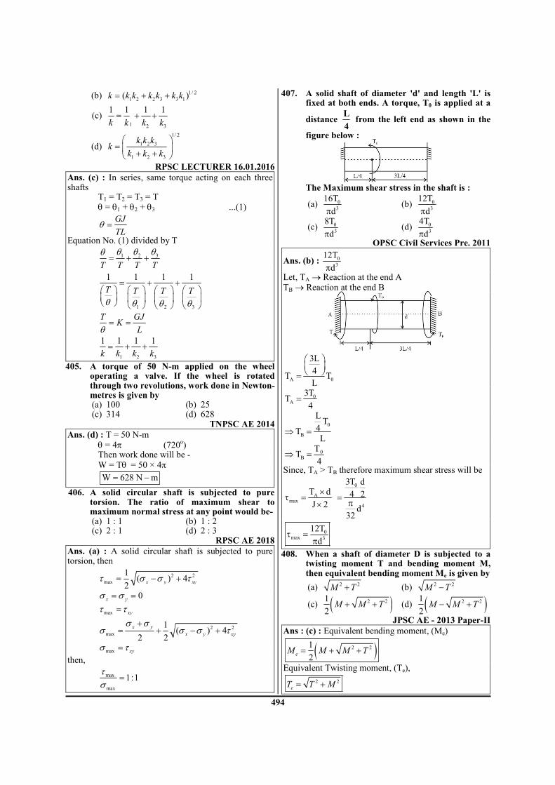
494
(b) 1/ 2
1 2 2 3 3 1( )= + +k k k k k k k
(c) 1 2 3
1 1 1 1= + +
k k k k
(d)
1/ 2
1 2 3
1 2 3
=
+ +
k k kk
k k k
RPSC LECTURER 16.01.2016 Ans. (c) : In series, same torque acting on each three shafts T1 = T2 = T3 = T
θ = θ1 + θ2 + θ3 ...(1)
GJ
TLθ =
Equation No. (1) divided by T
31 2
T T T T
θθ θθ= + +
1 2 3
1 1 1 1
T T T T
θ θ θ θ
= + +
T GJ
KLθ
= =
1 2 3
1 1 1 1
k k k k= + +
405. A torque of 50 N-m applied on the wheel operating a valve. If the wheel is rotated through two revolutions, work done in Newton-metres is given by
(a) 100 (b) 25 (c) 314 (d) 628
TNPSC AE 2014 Ans. (d) : T = 50 N-m
θ = 4π (720o)
Then work done will be -
W = Tθ = 50 × 4π W 628 N m= −
406. A solid circular shaft is subjected to pure torsion. The ratio of maximum shear to maximum normal stress at any point would be-
(a) 1 : 1 (b) 1 : 2 (c) 2 : 1 (d) 2 : 3
RPSC AE 2018 Ans. (a) : A solid circular shaft is subjected to pure torsion, then
2 2
max
1( ) 4
2x y xyτ σ σ τ= − +
0x yσ σ= =
max xyτ τ=
2 2
max
1( ) 4
2 2
x y
x y xy
σ σσ σ σ τ
+= + − +
max xyσ τ=
then,
max
max
1:1τσ
=
407. A solid shaft of diameter 'd' and length 'L' is fixed at both ends. A torque, T0 is applied at a
distance L
4 from the left end as shown in the
figure below :
The Maximum shear stress in the shaft is :
(a) 0
3
16T
dπ (b) 0
3
12T
dπ
(c) 0
3
8T
dπ (d) 0
3
4T
dπ
OPSC Civil Services Pre. 2011
Ans. (b) : 0
3
12T
dπ
Let, TA → Reaction at the end A TB → Reaction at the end B
A 0
3L
4T T
L
=
0A
3TT
4=
0
B
LT
4TL
⇒ =
0BT
4
Τ⇒ =
Since, TA > TB therefore maximum shear stress will be
Amax
T d
J 2
×τ =
×
0
4
3T d
4 2
d32
=π
0max 3
12T
dτ =
π
408. When a shaft of diameter D is subjected to a twisting moment T and bending moment M, then equivalent bending moment Me is given by
(a) 2 2M T+ (b) 2 2
M T−
(c) ( )2 21
2M M T+ + (d) ( )2 21
2M M T− +
JPSC AE - 2013 Paper-II Ans : (c) : Equivalent bending moment, (Me)
( )2 21
2eM M M T= + +
Equivalent Twisting moment, (Te),
2 2
eT T M= +

495
409. For a round shaft subjected to pure torsion, the shear stress at the centre (axis) will be
(a) maximum (b) minimum (c) zero (d) The information provided is insufficient
BPSC AE Mains 2017 Paper - VI Ans : (c) :
T G
J R
τ θ= =
ℓ
T R
J
×τ =
0
T 00
J
×τ = =
Hence, shear stress at centre will be zero for round shaft subjected to pure torsion.
410. The diameter of a shaft is increased from 30 mm to 60 mm, all other conditions remaining unchanged. How many times is its torque carrying capacity increased?
(a) 2 times (b) 4 times (c) 8 times (d) 16 times
OPSC AEE 2019 Paper-I Ans : (c) :
d1 = 30 mm, d1 = d d2 = 60 mm, d2 = 2d
3
16T
dτ =
π
3
1T' d
16
π= τ , d1 = d
3
3
dT ' 16
T"8d
16
πτ
=π
τ, d2 = 2d
T 8T '=
411. A shear stress at the centre of a circular shaft under torsion is :
(a) Zero (b) Minimum (c) Maximum (d) Infinity
OPSC AEE 2019 Paper-I Ans : (a) : Shear stress at the centre of a circular shaft under torsion is zero.
412. Angle of twist of a shaft of diameter ‘d’ is inversely proportional to :
(a) d (b) d2
(c) d3 (d) d
4
OPSC AEE 2019 Paper-I Ans : (d) : By using torsion formula,
44
1
32
T T
GJ dG d
θ θπ
= = ⇒ ∝× ×
ℓ ℓ
413. A solid shaft is used to transmit a power of 120
π kW at 120 rpm. The torque transmitted by the shaft is
(a) 30 kNm (b) 60 kNm (c) 90 kNm (d) 120 kNm
Gujarat PSC AE 2019
Ans : (a) : Given-
P = 120 πkW N = 120 rpm
P = Tω T2 N
60
π=
T2 120
12060
π×π =
T = 30 kNm
414. A hollow shaft of the same cross-section area and material as that of a solid shaft, transmits:
UJVNL AE 2016 (a) Same torque (b) Lesser torque (c) More torque (d) None
Ans : (c) A hollow shaft of the same cross- sectional area and materials transmits more torque than solid shaft. given As = Ah
2 2 2
o id d d4 4
π π = −
2 2 2
o id d d= − .............. (i)
from equation (i) we can say that do > d
3 4
o
h
3s
d 1 k
T 16
T d
16
π × τ −
= π
× τ
3 4
oh
3
s
d 1 kT
T d
− =
If we assume that [hit and trail method] di = 3 unit do = 5 unit d = 4 unit
4
h
s
3125 1
5T1.7
T 64
− = =
Th = 1.7 Ts
So we can say that Th > Ts.
415. The torque transmitted by a solid shaft of diameter d and maximum allowable shear stress τ is
(a) 3d
4
πτ (b) 3
d16
πτ
(c) 3d
32
πτ (d) 3
d64
πτ
UPPSC AE 12.04.2016 Paper-I
Ans : (b)Torsion equation
T G
J r
θ τ= =
ℓ
τ = Maximum shear stress r = Radius of the shaft T= Twisting moment J = Polar moment of Inertia G = Modulus of rigidity
ℓ = Length of the shaft

496
T
J r
τ=
44d
J mm32
π=
=r d / 2 mm
4
32T 2
dd
τπ
=
3
16T
dτ
π= .
3
d .T
16
π τ=
416. A circular shaft can transmit a torque of 5
kNm. If the torque is reduced to 4 kNm, then
the maximum value of bending moment that
can be applied to the shaft is
(a) 1 kNm (b) 2 kNm
(c) 3 kNm (d) 4 kNm
(KPSC AE 2015)
Ans : (c) Equivalent twisting moment
( ) 2 2eT M T= +
Given data
eT 5kN m= −
T 4kN m= −
2 2eT M T= +
2 25 M 4= +
M 3kN m= −
417. A solid shaft steel of 100 mm diameter and 1.0
m long is subjected to a twisting moment T.
This shaft is to be replaced by a hollow shaft
having outer and inner diameters as 100 mm
and 50 mm respectively. If the maximum shear
stress induced in both the shafts is same, the
twisting moment T transmitted by hollow shaft
must be reduced by
(a) T / 4 (b) T / 8
(c) T / 16 (d) T /12
BPSC Poly. Lect. 2016
Ans : (c) Solid Shaft hollow shaft
d = 100mm do = 100 mm
ℓ = 1.0 m di = 50 mm.
ℓ = 1.0 m.
Ts = Twisting moment for solid shaft Th = twisting
moment transmitted by hollow shaft
same material then τ = τs = τh
for solid shaft:-
3
s
dT
16
π τ=
for hollow shaft:-
( )
o
3 40
h
0
3
hh
h
s
d 1 CT
16
diC 0.5
d
d 15T
16T 16
T 15
T 16
π − τ=
= =
π= ×
=
h s
15T T
16=
Reduce twisting moment = 15
T T16
−
Reduce twisting moment = 16
T
418. The torque transmitted by a solid shaft of diameter 40 mm if the shear stress is not to exceed 400 N/cm
2, would be :
(a) 1.6 × π N-m (b) 16π N-m (c) 0.8 × π N-m (d) 0.4 × π N-m HPPSC W.S. Poly. 2016
Ans : (b) Shaft diameter = 40mm Shear stress (τmax) = 400N/cm
2
T G
J r
θ τ= =
ℓ
.J
Tr
τ=
3d
T16
π τ=
T = 16π N-m
419. A solid shaft transmits a torque of T. The allowable shear stress is τ . What is the
diameter of the shaft ?
(a) 316T
πτ (b) 3
32T
πτ
(c) 316T
πτ (d) 3
T
π
OPSC AEE 2015 Paper-I
Ans : (a) Torsion equation
T G
J r
θ τ= =
ℓ
4 3
32T 2 16T
dd d
τ= = = τ
π π
316T
d =πτ
420. The strength of a hollow shaft for the same
length, material and weight is .......... a solid
shaft:
(a) Less than (b) More than
(c) Equal to (d) None of these OPSC AEE 2015 Paper-I

497
Ans : (b) The strength of a hollow shaft for the same length, material and weight is more than a solid shaft. When the shaft is subjected to pure torsional moment (T). the torsional shear stress is given by
for solid shaft : 3
16T
dτ =
π
For hollow shaft : ( )3 4
0
16T
d 1 Cτ =
π −
421. A shaft of 20 mm diameter and length 1 m is subjected to a twisting moment, due to which shear strain on the surface of the shaft is 0.001. The angular twist in the shaft is
(a) 0.1 radian (b) 0.01 radian (c) 0.05 radian (d) 0.5 radian
UPPSC AE 12.04.2016 Paper-I
Ans : (a)
ℓ = Shaft length = 1000 mm θ = twist angle
φ = shear strain = 0.001
r = shaft radius
=ℓ
AA'.............( i )φ
=AA'
.............( ii )r
θ
for equation (i) and (ii) rφ θ=ℓ
r
φθ =
ℓ
×
=0.001 1000
20
2
θ
= 0.1 radianθ
422. Torsional rigidity of a shaft is given by
(a) T
ℓ (b)
T
J
(c) T
θ (d)
T
r
APPSC AEE 2012
Ans : (c) Torsion Equation
T G
J r
θ τ= =
ℓ
T = Torque in N-mm
l = length of the shaft in mm
R = Radius of the circular shaft in mm G = Modulus of rigidity shaft material in N/mm
2
T G
J r
θ τ= =
ℓ
TGJ =
θℓ
G J is known as torsional rigidity of the shaft. It is important to note that the relative stiffness of two shafts is measured by the inverse ratio of the angles of twist is equal length of shafts when subjected to equal torques.
423. Shear stress for a circular shaft due to torque varies
(a) from surface to centre parabolically (b) from surface to centre linearly (c) from centre to surface parabolically (d) from centre to surface linearly APPSC AEE 2012
Ans : (d) Shear stress for a circular shaft due to torque varies from centre to surface linearly.
T G
J r
θ τ= =
l
The above relation states that the intensity of shear stress at any point in the cross-section of a shaft subjected to pure torsion is proportional to its distance from the centre.
424. If two shafts of the same length, one of which is
hollow, transmit equal torques and have equal
maximum stress, then they should have equal
(a) angle of twist
(b) polar modulus of section
(c) polar moment of inertia (d) diameter APPSC AEE 2012
Ans : (b) If two shafts of the same strength, one of which is hollow, transmit equal torque and have equal maximum stress, then they should have equal Polar modulus of section.
T
J r
τ=
T Jr
τ =
JT .
r
= τ
If torque and Shear stress is maximum then Polar
modulus section 'equal.
425. A circular shaft subjected to torsion undergoes
a twist of 10 in a length of 1.2 m. If the
maximum shear stress induced is 100 MPa and
the rigidity modulus is 50.8×10 MPa, the
radius of the shaft in mm should be
(a) 270
π (b)
270
π
(c) 180
π (d)
180
π
APPSC AEE 2012

498
Ans : (a) Twists angle 0( ) 1θ =
length of shaft = 1.2 m Maximum shear stress = 100 MPa
Modulus of rigidity 5(G) 0.8 10 MPa.= ×
Torsion equation T G
J r
θ τ= =
l
6 5 6100 10 0.8 10 10
r 180 1.2
× × × π×=
×
270
r mm=π
426. Two shafts are of same length and same material. The diameter and maximum shear stress of the second shaft is twice that of the first shaft. Then the ratio of power developed between the first and second shaft is
(a) 16 (b) 16
3 3
(c) 1
16 (d)
3
16
APPSC AEE 2012
Ans : (c) Power develop (P) = Tω Case 1
st:-
3d
T16
π τ=
3
1
dP
16
π τ= × ω
Case 2nd
:-
3
2
(2d) 2P
16
π × τ= × ω
assume, both case angular speed same then
Ratio of power developed 1
2
P 1
P 16
=
1
2
P 1
P 16=
427. Two shafts A and B are made same material. The diameters of shaft B is twice that of shaft A. The ratio of power which can be transmitted by shaft A to that of shaft B is :
(a) 1/2 (b) 1/4 (c) 1/8 (d) 116
OPSC AEE 2015 Paper-I
Ans : (c) Power (P) = T × ω
and 3d .
T16
π τ=
3
dP
16
π × τ× ω=
3P d∝
3
A A
B B
P dk
P d
=
3
A
B
P dk
P 2d
=
A
B
P 1
P 8=
428. A shaft of 10 mm diameter, whose maximum shear stress is 48 N/mm
2 can produce a
maximum torque equal to (a) 2000 π N - mm (b) 4000 π N - mm (c) 1000 π N - mm (d) 3000 π N-mm
TSPSC AEE 2015
Ans : (d) Shaft dia (d) = 10 mm Max shear stress (τmax) = 48 N/mm
2
max 3
16T
dτ =
π
3
dT
16
τ× π=
348 10
T16
× π×=
T = 3000π N-mm.
429. The equivalent twisting moment to design a shaft subjected to the fluctuating loads will be given by
(a) ( ) ( )2 2
t mK M K T+
(b) ( ) ( )22
m tK M K T+
(c) ( ) ( )22
m m tK M K M K T+ +
(d) ( ) ( )22
m m t
1K M K M K T
2
+ +
TSPSC AEE 2015
Ans : (b) (i) Equivalent Bending moment
( ) ( )22
e m m t
1M K M K M K T
2
= + +
(ii) Equivalent twisting moment
( ) ( )22
e m tT K M K T= +
Km = Shock and fatigue factor for bending kt = shock and fatigue factor for twisting
430. A shaft subjected to fluctuating loads for which
the normal torque (T) and bending moment
(M) are 1000 N-m and 500 N-m respectively. If
the combined shock and fatigue factor for
bending is 1.2 and combined shock and fatigue
factor for torsion is 2 then the equivalent
twisting moment for the shaft is______
(a) 2088 N-m (b) 2050 N-m
(c) 2136 N-m (d) 2188 N-m (HPPSC AE 2014)
Ans. : (a) Equivalent twisting moment (Te)
Te = ( ) ( )2 2
m tK M K T× + ×
M = Bending moment = 500 N-m
T = Twisting moment = 1000 N-m

499
Km = fatigue factor for bending = 1.2
Kt = fatigue factor for torsion = 2
Te = ( ) ( )2 21.2 500 2 1000× + ×
Te = 2088 N-m
431. The diameter of shaft is increased from 50 mm to 100 mm all other conditions remaining unchanged. How many times the torque carrying capacity increases?
(a) 2 times (b) 4 times (c) 8 times (d) 6 times (KPSC AE. 2015)
Ans : (c) P =Tω P = power in watt T = Torque (N-m) ω = Angular velocity (Rad/sec) P T∝
3d
T16
π τ=
3T d∝
3P d∝ Torque corrying capacity increase in 8 times.
432. Power transmitted by a circular shaft is given by:
(a) πDN/60 Joules (b) 2πNT/ 60 watts (c) πDNT/ 60 watts (d) 2πNT/1000 watts (HPPSC LECT. 2016)
Ans : (b) Power transmitted by a circular shaft (p) =
2 NTwatt
60
π
2. NT
P kW60 1000
π=
×
P = T. ω kW
2 N
rad / sec60
πω =
6. Thick and Thin Cylinders and
Spheres
433. A thin cylinder with both ends closed is
subjected to internal pressure p. The
longitudinal stress at the surface has been
calculated as 0σ . Maximum shear stress at the
surface will be equal to :
(a) 02σ (b) 01.5σ
(c) 0σ (d) 00.5σ
OPSC AEE 2015 Paper-I
Ans : (d) Longitudinal stress ( )2 0
Pd
4tσ = = σ
Hoop stress ( )1 0
Pd2
2tσ = = σ
Principal stresses = 0 02 ,σ σ
Shear stress = 0 0 00
20.5
2 2
σ − σ σ= = σ
434. The initial hoop stress in a thick cylinder when it is wound with a wire under tension will be :
(a) zero (b) tensile (c) compressive (d) bending (HPPSC AE 2014)
Ans : (c) The initial hoop stress in a thick cylinder when it is wound with a wire under tension will be compressive. Analysis of Thick Cylinders/Lame's Theorem:- * Lame's assumption (i) Material of shell is homogeneous (ii) Plane section of cylinder, perpendicular to
longitudinal axis remains plane under pressure. * Subjected to internal pressure
(i)
2 2
0 i
i h 2 2
0 i
P R Rx R ,
R R
+ = σ =−
(ii) 2
i
0 h 2 2
0 i
2PRx R ,
R R= σ =
−
435. A thin cylindrical pressure vessel and a thin spherical pressure vessel have the same mean radius, same wall thickness and are subjected to same internal pressure. The hoop stresses set up in these vessels (cylinder in relation to sphere) will be in the ratio.
(a) 1 : 2 (b) 1 : 1 (c) 2 : 1 (d) 4 : 1
ESE 2017
Ans. (c) : For cylinder (σh)c =Pd
2t
For sphere (σh)s =Pd
4t
( )( )
h c
h s
σ
σ= 2
436. A spherical steel pressure vessel 400 mm in diameter with a wall thickness of 20 mm, is coated with brittle layer that cracks when strain exceeds 100 × 10
-7. What internal
pressure will cause the layer to develop cracks?
( )E 200GPa, 0.3= µ =
(a) 0.057 MPa (b) 5.7 MPa
(c) 0.57 MPa (d) 57 MPa
BHEL ET 2019 Ans. (c) : Diameter (d) = 400 mm
Thickness (t) = 20 mm Strain (∈ ) = 100 × 10
-7
∈ = 200 GPa, µ = 0.3
( )Pd1
4tE∈= − µ
[ ]7
3
P 400100 10 1 0.3
4 20 200 10
− ×× = −
× × ×
5 610 16 10 p 400 0.7
− × × = × ×
160
P ..400 0.7
=×
P 0.57 MPa=
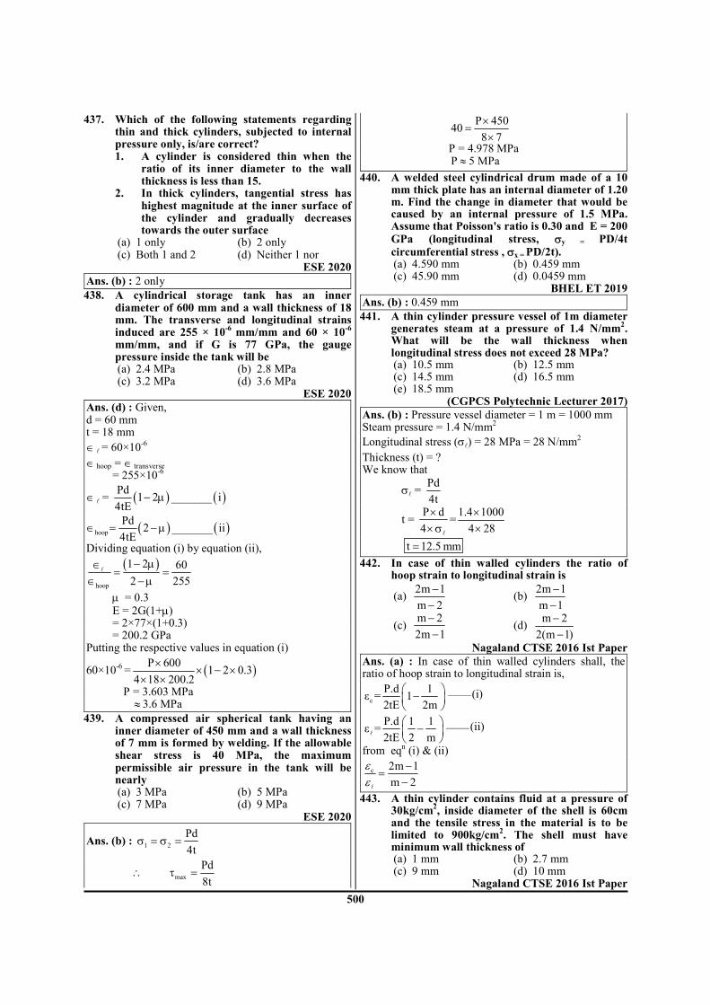
500
437. Which of the following statements regarding thin and thick cylinders, subjected to internal pressure only, is/are correct? 1. A cylinder is considered thin when the
ratio of its inner diameter to the wall thickness is less than 15.
2. In thick cylinders, tangential stress has highest magnitude at the inner surface of the cylinder and gradually decreases towards the outer surface
(a) 1 only (b) 2 only (c) Both 1 and 2 (d) Neither 1 nor
ESE 2020 Ans. (b) : 2 only
438. A cylindrical storage tank has an inner diameter of 600 mm and a wall thickness of 18 mm. The transverse and longitudinal strains induced are 255 × 10
-6 mm/mm and 60 × 10
-6
mm/mm, and if G is 77 GPa, the gauge pressure inside the tank will be
(a) 2.4 MPa (b) 2.8 MPa (c) 3.2 MPa (d) 3.6 MPa
ESE 2020 Ans. (d) : Given, d = 60 mm t = 18 mm
∈ ℓ = 60×10-6
∈ hoop = ∈ transverse
= 255×10-6
∈ ℓ = ( ) ( )Pd
1 2 _______ i4tE
− µ
( ) ( )hoop
Pd2 _______ ii
4tE∈ = − µ
Dividing equation (i) by equation (ii),
( )hoop
1 2 60
2 255
− µ∈= =
∈ − µℓ
µ = 0.3 E = 2G(1+µ) = 2×77×(1+0.3) = 200.2 GPa
Putting the respective values in equation (i)
60×10-6
= ( )P 6001 2 0.3
4 18 200.2
×× − ×
× ×
P = 3.603 MPa ≈ 3.6 MPa
439. A compressed air spherical tank having an inner diameter of 450 mm and a wall thickness of 7 mm is formed by welding. If the allowable shear stress is 40 MPa, the maximum permissible air pressure in the tank will be nearly
(a) 3 MPa (b) 5 MPa (c) 7 MPa (d) 9 MPa
ESE 2020
Ans. (b) : 1 2
Pd
4tσ = σ =
∴ max
Pd
8tτ =
P 45040
8 7
×=
×
P = 4.978 MPa P 5 MPa≈
440. A welded steel cylindrical drum made of a 10 mm thick plate has an internal diameter of 1.20 m. Find the change in diameter that would be caused by an internal pressure of 1.5 MPa. Assume that Poisson's ratio is 0.30 and E = 200 GPa (longitudinal stress, σy = PD/4t circumferential stress , σx = PD/2t).
(a) 4.590 mm (b) 0.459 mm (c) 45.90 mm (d) 0.0459 mm
BHEL ET 2019 Ans. (b) : 0.459 mm
441. A thin cylinder pressure vessel of 1m diameter generates steam at a pressure of 1.4 N/mm
2.
What will be the wall thickness when longitudinal stress does not exceed 28 MPa?
(a) 10.5 mm (b) 12.5 mm (c) 14.5 mm (d) 16.5 mm (e) 18.5 mm
(CGPCS Polytechnic Lecturer 2017) Ans. (b) : Pressure vessel diameter = 1 m = 1000 mm Steam pressure = 1.4 N/mm
2
Longitudinal stress (σℓ) = 28 MPa = 28 N/mm2
Thickness (t) = ? We know that
σℓ = Pd
4t
t = P d
4
×× σ
ℓ
=1.4 1000
4 28
××
t 12.5 mm=
442. In case of thin walled cylinders the ratio of hoop strain to longitudinal strain is
(a) 2m 1
m 2
−−
(b) 2m 1
m 1
−−
(c) m 2
2m 1
−−
(d) m 2
2(m 1)
−−
Nagaland CTSE 2016 Ist Paper Ans. (a) : In case of thin walled cylinders shall, the ratio of hoop strain to longitudinal strain is,
c
P.d 1 ____(i)ε = 12tE 2m
−
P.d 1 1 ____(ii)ε =2tE 2 m
−
ℓ
from eqn (i) & (ii)
c 2m 1
m 2
−=
−ℓ
εε
443. A thin cylinder contains fluid at a pressure of 30kg/cm
2, inside diameter of the shell is 60cm
and the tensile stress in the material is to be limited to 900kg/cm
2. The shell must have
minimum wall thickness of (a) 1 mm (b) 2.7 mm (c) 9 mm (d) 10 mm
Nagaland CTSE 2016 Ist Paper

501
Ans. (d) : P = 30kg/cm2 , d = 60 cm, δ1= 900 kg/cm
2
c
P.dδ =
2t
30 60t
2 900
×=
× =
1800
1800 = 1cm × 10 = 10mm
444. A boiler shell of 200 cm diameter and plate thickness 1.5 cm is subjected to internal pressure of 1.5 MN/m2 then hoop stress is:
(a) 30 MN/m2 (b) 50 MN/m
2
(c) 100 MN/m2 (d) 200 MN/m
2
SJVN ET 2013 Ans. (c) : Given, d = 200 cm = 200 × 10
-2 m
t = 1.5 cm = 1.5 × 10⁻²
m P = 1.5 MN/m
2
Pd
2tσ =
2
2
2
1.5 200 10100 MN / m
2 1.5 10
−
−
× ×σ = =
× ×
2100 MN / mσ =
445. The cross section area of a hollow cylinder has an internal diameter of 50 mm and a thickness of 5 mm. Moment of inertia of the cross-section about its centroidal axis is
(a) 2.848 × 105 mm
4 (b) 3.294 × 10
5 mm
4
(c) 1.424 × 105 mm
4 (d) 1.647 × 10
5 mm
4
(e) 3.294 × 105 mm
4 CGPSC 26th April 1st Shift
Ans. (e) :
Given di = 50 mm do = 60 mm
Moment of inertia (I) =
4
4
0 164
i
o
dd
d
π −
4
4 5060 1
64 60
π = −
= 329209.37 = 3.29 × 105 mm
4
446. A thin cylinder of internal diameter D = 1 m and thickness t = 12 mm is subjected to internal pressure of 4 N/mm
2. Determine hoop stresses
developed. (a) 83.33 N/mm
2 (b) 83.33 × 10
-3 N/mm
2
(c) 166.67 × 10⁻³
N/mm2 (d) 166.67 N/mm
2
(e) 166.67 N/m2
CGPSC 26th April 1st Shift
Ans. (d) : Given D = 1 m = 1000 mm t = 12 mm P = 4 N/mm
2
In a thin cylinder pressure vessel, hoop (circumferential) stress
2
Pd
tσ =
4 1000
2 12
×=
×
= 166.67 N/mm2
447. Volumetric strain of fluid filled inside the thin cylinder (diameter = (d) under the pressure (P)
is given by (where ν, t, E are Poisson ratio, thickness and modulus of elasticity respectively)
(a) Pd(1 4 )
4tE
− ν (b)
Pd(5 )
4tE
− ν
(c) Pd(5 4 )
4tE
− ν (d)
Pd(1 )
4tE
− ν
RPSC LECTURER 16.01.2016 Ans. (c) : Volumetric strain in thin cylinder (ev) is given as
2.v l he e e= + ...(1)
.4 2
l
Pd Pde
tE tEν= −
[1 2 ]4
Pd
tEν= − ...(2)
.2 4
h
Pd Pde
tE tEν= −
[2 ]4
Pd
tEν= − ...(3)
[1 2 ] 2 [2 ]4 4
v
Pd Pde
tE tEν ν= − + × −
[ ]1 2 4 2 ]4
Pd
tEν ν= − + −
[5 4 ]4
v
Pde
tEν= −
448. Volumetric strain in the pressurized thin
cylinder with hoop strain (εh) and linear strain
(εl) is given by: (a) εh + εl (b) εh + 2 εl (c) 2 εh + εl (d) εh - εl
UPRVUNL AE 2016 Ans. (c) : Volumetric strain in the pressurized thin cylinder is given as
2V l h
Ve
V
δε ε= = +
(1 2 ) 2 (2 )4 4
V
Pd Pde
tE tEµ µ= − + × −
[1 2 4 2 ]4
Pd
tEµ µ= − + −
[5 4 ]4
V
Pde
tEµ= −

502
449. A pipe of diameter 800 mm contains fluid under a pressure of 2 N/mm
2. If the tensile
strength is 100 N/mm2, the thickness of the pipe
is (a) 16 mm (b) 4 mm (c) 8 mm (d) 10 mm
TNPSC AE 2013 Ans. (c) : Data given - d = 800 mm, P = 2 N/mm
2
σH = 100 N/mm2
we know that
H
Pd
2tσ =
2 800
t2 100
×=
×
t 8 mm=
450. Lame's equation is used to find stresses in (a) Thin cylinder (b) Thick cylinder (c) Gears (d) Clutches
UPRVUNL AE 2014 TSPSC AEE 2015
Ans. (b) : Lame's equation is used to find stresses in thick cylinder.
451. Pressure vessel is said to be thin cylindrical shell, if the ratio of the wall thickness of the shell to its diameter is
(a) equal to 1/10 (b) less than 1/10 (c) more than 1/10 (d) none of these
Gujarat PSC AE 2019 Ans : (b) : A thin cylindrical shell it the ratio of the wall thickness of the shell to its diameter is less than 1/10.
452. The thickness of thin cylinder is determined on the basis of
(a) Radial stress (b) Longitudinal stress (c) Circumferential stress (d) Principal shear stress
Gujarat PSC AE 2019 Ans : (c) : The thickness of thin cylinder is determined on the basis of circumferential stress.
453. If 'P' is the pressure, 'D' is the internal diameter and 't' is the thickness of the walled longitudinal stress induced in a thin walled cylindrical vessel is
(a) PD/2t (b) PD/4t (c) PD/t (d) PD/3t
TNPSC 2019
Ans. (b) : [ ]L
PDlongitudinal stress
4tσ =
[ ]H
PDHoop stress
2tσ =
H L2σ = σ
454. The inner diameter of a cylindrical tank for liquefied gas is 250 mm. The gas pressure is limited to 15 MPa. The tank is made of plain carbon steel with ultimate tensile strength of 340 N/mm
2, Poisson’s ratio of 0.27 and the
factor of safety of 5. The thickness of the cylinder wall will be.
(a) 60 mm (b) 50 mm (c) 40 mm (d) 30 mm
ESE 2019 Ans. (d) : Maximum stress = Hoop stress is cylinder σmax = σh
u
FOS
σ=
pd
2t
340
5=
15 250
2 t
××
t = 27.57 mm ≃ 30 mm
455. A spherical shell of 1.2 m internal diameter and 6 mm thickness is filled with water under pressure until volume is increased by 400 × 10
3
mm3. If E = 204 GPa, Poisson’s ratio v = 0.3,
neglecting radial stresses, the hoop stress developed in the shell will be nearly
(a) 43 MPa (b) 38 Mpa (c) 33 Mpa (d) 28 Mpa
ESE 2019 Ans. (a) : Given, d = 1.2 m = 1200 mm r = 600 mm t = 6 mm ∆v = 400 × 10
3 mm
3
E = 204 GPa = 204 × 103 MPa
µ = 0.3
∈v =v
v
∆=
3
3
400 10
4r
3
×
π=
3
3
400 10
4(600)
3
×
π
∈v = 4.42 × 10⁻⁴
Volumetric strain (∈v) = 3 × hoop strain 4.42 × 10
−4 = 3 × ∈h
∈h = 1.47 × 10⁻⁴
∈h =n (1 )
E
σ− µ
1.47 × 10−4
= h
3(1 0.3)
204 10
σ−
×
σh = 42.94 ≃ 43 MPa
456. Consider the following statements: 1. In case of a thin spherical shell of diameter d
and thickness t, subjected to internal pressure p, the principal stresses at any point equal
pd
4t
2. In case of thin cylinders the hoop stress is
determined assuming it to be uniform across
the thickness of the cylinder
3. In thick cylinders, the hoop stress is not
uniform across the thickness but it varies
from a maximum value at the inner
circumference to a minimum value at the
outer circumference. Which of the above statements are correct? (a) 1 and 2 only (b) 1 and 3 only
(c) 2 and 3 only (d) 1, 2 and 3 ESE 2018
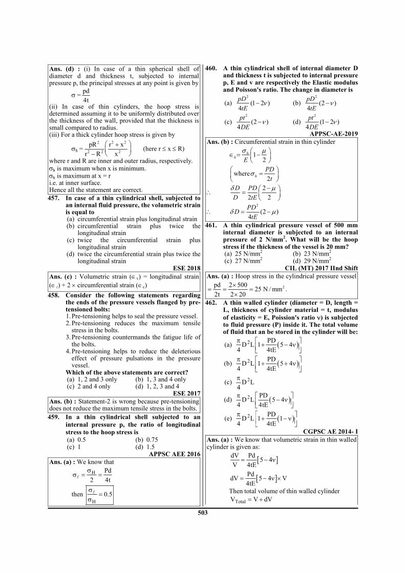
503
Ans. (d) : (i) In case of a thin spherical shell of diameter d and thickness t, subjected to internal pressure p, the principal stresses at any point is given by
σ =pd
4t
(ii) In case of thin cylinders, the hoop stress is determined assuming it to be uniformly distributed over the thickness of the wall, provided that the thickness is small compared to radius. (iii) For a thick cylinder hoop stress is given by
σh =2 2 2
2 2 2
pR r x
r R x
+
− (here r ≤ x ≤ R)
where r and R are inner and outer radius, respectively. σh is maximum when x is minimum. σh is maximum at x = r i.e. at inner surface. Hence all the statement are correct.
457. In case of a thin cylindrical shell, subjected to an internal fluid pressure, the volumetric strain is equal to
(a) circumferential strain plus longitudinal strain (b) circumferential strain plus twice the
longitudinal strain (c) twice the circumferential strain plus
longitudinal strain (d) twice the circumferential strain plus twice the
longitudinal strain ESE 2018
Ans. (c) : Volumetric strain (∈v) = longitudinal strain
(∈ℓ) + 2 × circumferential strain (∈c)
458. Consider the following statements regarding the ends of the pressure vessels flanged by pre-tensioned bolts:
1. Pre-tensioning helps to seal the pressure vessel. 2. Pre-tensioning reduces the maximum tensile
stress in the bolts. 3. Pre-tensioning countermands the fatigue life of
the bolts. 4. Pre-tensioning helps to reduce the deleterious
effect of pressure pulsations in the pressure vessel.
Which of the above statements are correct? (a) 1, 2 and 3 only (b) 1, 3 and 4 only (c) 2 and 4 only (d) 1, 2, 3 and 4
ESE 2017 Ans. (b) : Statement-2 is wrong because pre-tensioning does not reduce the maximum tensile stress in the bolts.
459. In a thin cylindrical shell subjected to an
internal pressure p, the ratio of longitudinal
stress to the hoop stress is
(a) 0.5 (b) 0.75 (c) 1 (d) 1.5
APPSC AEE 2016 Ans. (a) : We know that
H Pd
2 4t
σσ = =
ℓ
then H
0.5σ
=σ
ℓ
460. A thin cylindrical shell of internal diameter D and thickness t is subjected to internal pressure p, E and v are respectively the Elastic modulus and Poisson's ratio. The change in diameter is
(a) 2
(1 2 )4
pD
tEν− (b)
2
(2 )4
pD
tEν−
(c) 2
(2 )4
pt
DEν− (d)
2
(1 2 )4
pt
DEν−
APPSC-AE-2019 Ans. (b) : Circumferential strain in thin cylinder
12
hh
E
σ µ ∈ = −
where2
h
PD
tσ =
∴ 2
2 2
D PD
D tE
δ µ− =
∴ 2
(2 )4
PDD
tEδ µ= −
461. A thin cylindrical pressure vessel of 500 mm internal diameter is subjected to an internal pressure of 2 N/mm
2. What will be the hoop
stress if the thickness of the vessel is 20 mm? (a) 25 N/mm
2 (b) 23 N/mm
2
(c) 27 N/mm2 (d) 29 N/mm
2
CIL (MT) 2017 IInd Shift Ans. (a) : Hoop stress in the cylindrical pressure vessel
2pd 2 50025 N / mm
2t 2 20
×= = =
×.
462. A thin walled cylinder (diameter = D, length = L, thickness of cylinder material = t, modulus
of elasticity = E, Poission's ratio ν) is subjected to fluid pressure (P) inside it. The total volume of fluid that an be stored in the cylinder will be:
(a) ( )2 PDD L 1 5 4
4 4tE
π + − ν
(b) ( )2 PDD L 1 5 4
4 4tE
π + + ν
(c) 2D L4
π
(d) ( )2 PDD L 5 4
4 4tE
π − ν
(e) ( )2 PDD L 1 1
4 4tE
π + − ν
CGPSC AE 2014- I Ans. (a) : We know that volumetric strain in thin walled cylinder is given as:
[ ]dV Pd5 4
V 4tE= − ν
[ ]PddV 5 4 V
4tE= − ν ×
Then total volume of thin walled cylinder
TotalV V dV= +

504
[ ]2 2PdD L 5 4 D L
4 4tE 4
π π= × + − ν × ×
( )2Total
PdV D L 1 5 4
4 4tE
π = × + − ν
463. In thick cylinder, if hoop stress is plotted w.r.t.
2
1
r, then the curve will be
(a) Parabolic (b) Hyperbolic (c) Linear (d) Elliptical
RPSC LECTURER 16.01.2016 Ans. (c) : In thick cylinder, if hoop stress is plotted
w.r.t. 2
1
r, then the curve will be linear.
464. For thin cylinders (a) Longitudinal stress is double of the
circumferential stress (b) Longitudinal stress is half of the
circumferential stress (c) Longitudinal stress is equal to the
circumferential stress (d) Longitudinal stress is four times of the
circumferential stress
RPSC LECTURER 16.01.2016 Ans. (b) : For thin cylinders circumferential stress or
hoop stress ( )2
h
Pd
tσ =
Longitudinal stress ( )4
l
Pd
tσ =
So, we can say that
2
h
l
σσ =
So, Longitudinal stress is half of the circumferential stress.
465. A thin spherical shell of 1.5 m diameter is 8
mm thick is filled with a liquid at the pressure
of 3.2 N/mm2. The stress induced in the shell is
(a) 75 N/mm2 (b) 150 N/mm
2
(c) 200 N/mm2 (d) 180 N/mm
2
TNPSC AE 2013 Ans. (b) : Data given- d = 1.5 m = 1500 mm t = 8 mm P = 3.2 N/mm
2
l H
Pd 3.2 1500
4t 4 8
×σ = σ = =
×
2
H 150 N / mmσ =
466. A 200×100×50 mm3 steel block is subjected to a
hydrostatic pressure of 15 MPa. The Young's
modulus and poisson's ratio of the material are
200 GPa and 0.3 respectively. The change in
volume of block in mm3 is:
(a) 85 (b) 90 (c) 100 (d) 110
RPSC 2016
Ans : (b) Given,
Hydrostatic Pressure (P) = 15 MPa
Young's modulus (E) = 200 GPa
Poisson's ratio (µ) = 0.3
Volume of block (V) = 200×100×50 mm3
v
V
V
δ∈ =
v x y z x y z
1[ 2 ( )]
E∈ = σ + σ + σ − µ σ + σ + σ
z
x
V 1
{ 3P 2 ( 3P)}V E
δ= − − µ −
V 3P
{1 2 )V E
δ −= − µ
3PV
V (1 2 )E
−δ = − µ
3
3 15 200 100 50V (1 2 0.3)
200 10
− × × × ×δ = − ×
×
3V 90mmδ = −
3V 90mm (contraction)δ =
467. The Hoop stresses are acting across the (a) Circumferential section (b) Longitudinal section (c) Radial section (d) None of the above
RPSC Vice Principal ITI 2018 Ans. (a) : � The Hoop stress are acting across the
circumferential section. � The Longitudinal stress acting when two cross
sectional areas of the cylinder are subjected to equal and opposite forces the stress experienced by the cylinder.
468. For a thick-walled shell, the diameter-thickness
ratio is (a) less than 20 (b) greater than 20 (c) equal to 20 (d) equal to 20
BPSC AE 2012 Paper - VI Ans : (a) : For a thick walled shell the diameter-thickness ratio is greater than 20
469. In a thick cylinder, radial stress at inner
surface is
(a) independent of fluid pressure (b) more than fluid pressure (c) less than fluid pressure (d) equal to fluid pressure
BPSC AE 2012 Paper - VI

505
Ans : (d) : The radial stress for a thick walled cylinder is equal and opposite to the gauge pressure on the inside surface and zero on the outside.
470. Where does the maximum hoop stress in a
thick cylinder under external pressure occur?
(a) At the outer surface
(b) At the inner surface
(c) At the mid-thickness
(d) At the 2/3rd
outer radius
OPSC AEE 2019, 2015 Paper-I
Ans : (b) :
Hoop stress, 2h
AB
rσ = +
Hence hoop stress will be maximum at inner radius and minimum at outer radius.
471. A thin gas cylinder with an internal radius of 100 mm is subject to an internal pressure of 10 MPa. The maximum permissible working stress is restricted to 100 MPa. The minimum cylinder wall thickness (in mm) for safe design must be :
(a) 5 (b) 10 (c) 20 (d) 2
OPSC AEE 2019 Paper-I Ans : (b) : Given as,
r = 100 mm d = 200 mm
σ = 100 N/mm2
P = 10 N/mm2
2
Pd
tσ =
10 200
1002 t
×=
×
t = 10 mm
472. Thin cylindrical pressure vessel of 500 mm
diameter is subjected to an internal pressure of
2 N/mm2. If the thickness of the vessel is 20
mm, the hoop stress is
(a) 10 (b) 12.5 (c) 25 (d) 50
Gujarat PSC AE 2019 Ans : (c) :
Hoop stress ( )h
Pd
2tσ =
P = 2 N/mm2
d = 500 mm t = 20 mm
h
2 500
2 20
×σ =
×1000
40=
2h 25 N / mmσ =
473. A boiler shell 200 cm diameter and plate
thickness 1.5 cm is subjected to internal
pressure of "1.5 MN/m^2". Then the hoop
stress will be
(a) 50MN/m2 (b) 30MN/m
2
(c) 100MN/m2 (d) 200MN/m
2
(KPSC AE 2015)
Ans : (c) d = 200 cm. (Diameter) t = 1.5 cm (Plate thickness) p = 1.5 MN/m
2 (Internal pressure)
c
pd
2tσ =
σc = Circumferential stress or hoop stress 2
c 2
1.5 200 10
2 1.5 10
−
−
× ×σ =
× ×
2c 100MN / mσ =
474. Hoop stress in a thin cylinder of a diameter 'd' and thickness 't' subjected to pressure 'p' will be
(a) Pd
4t (b)
Pd
2t
(c) 2Pd
t (d)
Pd
t
MPPSC AE 2016 SJVN ET 2013
Ans : (b)
At at just failure condition Brusting force=Resisting force p × d× l = σc × d× 2t
σc =Pd
2t
σc is known as circumferential stress or hoop stress.
475. Thick cylinders are designed by (a) Lame's equation (b) calculating radial stress which is uniform (c) thick cylinder theory (d) thin cylinder theory
RPSC AE 2016
Ans : (a) Thick cylinder are designed by lame's equation. Lame's equation:- when the material of the cylinder is brittle, such as cast iron or cast steel, Lame's equation is used to determine the wall thickness. It is based on the maximum principal stress theory of failure, where maximum stress is equated to permissible stress for the material.

506
476. A thick cylinder, having ro and ri as outer and inner radii, is subjected to an internal pressure P. The maximum tangential stress at the inner surface of the cylinder is
(a) ( )2 2
o i
2 2
o i
P r r
r r
+
− (b)
( )2 2
o i
2 2
o i
P r r
r r
−
+
(c) ( )
2
i
2 2
o i
2Pr
r r− (d)
( )2 2
o i
2
i
P r r
r
−
UPPSC AE 12.04.2016 Paper-I
Ans : (a) For a thick cylinder, the hoop stress is maximum at the inner surface and is given by.
( )( )
2 2
o i
2 2
o i
d d.p
d d
+σ =
−
( )( )
2 2
o i
2 2
o i
r rP.
r r
+σ =
−
477. A thin cylindrical shell of diameter d and thickness t is subjected to an internal pressure P. The Poisson's ratio is v . The ratio of
longitudinal strain to volumetric strain is
(a) 1 v
2 v
−−
(b) 2 v
1 v
−−
(c) 1 2v
3 4v
−−
(d) 1 2v
5 4v
−−
UPPSC AE 12.04.2016 Paper-I
Ans : (d) For thin cylindrical shell Longitudinal strain
= −l
pde (1 2v ) ............( i )
4tE
Volumetrical strain
= −V
pde ( 5 4v ) ............( ii )
4tE
Ratio of longitudinal strain to volumetric strain.
l
V
e pd( 1 2v ) 4tE
e 4tE pd( 5 4v )
−= ×
−
l
V
e (1 2v )
e ( 5 4v )
−=
−
478. Shrinking a thick cylinder over another helps: (a) reduce the magnitude of tensile hoop stress (b) reduce the difference between the higher and
lower magnitude of tensile hoop stress (c) remove the longitudinal stress (d) reduce the cost
(HPPSC AE 2014)
Ans : (b) Shrinking a thick cylinder over another helps reduce the difference between the higher and lower magnitude of tensile hoop stress.
479. In thick cylinder, the radial stresses in the wall thickness:-
(a) is zero (b) negligible small (c) varies from the inner face to outer face (d) None of the above
UKPSC AE-2013, Paper-I
Ans. (c) : In thick cylinder, the radial stresses in the wall thickness varies from inner face [maximum] to outer face [zero].
480. The ratio of hoop stress to longitudinal stress in thin walled cylinders is
(a) 1 (b) 1/2 (c) 2 (d) 1/4
UKPSC AE 2012 Paper-I Ans. (c) : 2
481. A long column of length (l) with both ends hinged, is to be subjected to axial load. For the calculation of Euler’s buckling load, its equivalent length is
(a) l/2 (b) / 2l (c) l (d) 2l
UKPSC AE 2012 Paper-I Ans. (c) : l
482. A cylindrical shell of diameter 200 mm and wall thickness 5 mm is subjected to internal fluid pressure of 10 N/mm
2. Maximum
shearing stress induced in the shell in N/mm2, is
(a) 50 (b) 75 (c) 100 (d) 200
UKPSC AE 2012 Paper-I Ans. (d) : Data Given Diameter of shell (d) = 200 mm thickness (t) = 5 mm pressure (P) = 10 N/mm
2
then, maximum shear stress
Pd
2tτ =
10 200
2 5
×=
×
τ = 200 N/mm2
483. In a thick cylindrical shell subjected to internal fluid pressure, the state of stress at the outer surface is
(a) three-dimensional (b) two-dimensional (c) isotropic (d) none of the above
UKPSC AE 2007 Paper -I Ans. (b) : Two-dimensional
484. Compound tubes are used in internal pressure cases, for following reasons
(a) For increasing the thickness. (b) For increasing the outer diameter o the tube. (c) The strength is more. (d) It evens out stresses.
UPPSC AE 12.04.2016 Paper-I
Ans : (d) Compound tubes are used in internal pressure cases, for it evens out stresses
7. Theory of Columns
485. The ratio of a Eular critical buckling load of two columns having the same parameters with (i) both ends hinged and (ii) both ends fixed will be :
(a) 1
4 (b)
1
16

507
(c) 1
8 (d)
1
2
BHEL ET 2019 Ans. (a) : Given - Two column having same parameters Bucking load for (I) Both ends hinged (II) both ends fixed. Eular's formula (Pe)
( )2
mine 2
ElP
Le
π=
When, EI = EII = E (Imin)I = (Imin)II = Imin (Le
2)I = (Le)
III = (Le)
2
Le = αL Le = effective length of the column L = Actual length of column α = length fixity coefficient for both hinged α = 1 ` so, Le = L
for both end fixed 1
2α =
1 L
Le L2 2
= × =
( )( )
2
min
2
hingede 1
e 22
min
2
fixed
E I
LP both end hinged
P both end fixed
E I
L
4
π
= = π
2 2
min
2 2
min
E I L
L 4 E I
π= ×
π
( )( )
e 1
2
P 1
P 4
=
486. The ratio of the compressive critical load for a long column fixed at both the ends and a column with one end fixed and the other end being free is:-
(a) 2 : 1 (b) 4 : 1 (c) 8 : 1 (d) 16 : 1
UKPSC AE-2013, Paper-I
Ans. (d) : Case I- When both ends of column are fixed
[ ]2
e 1 2
4 EIP
π=
l
Case II- When one end fixed and other end is free
[ ]2
e 2 2
EIP
4
π=
l
Then
[ ][ ]
e 1
e 2
P 1616 :1
P 1= =
487. A column of length ‘l’ is fixed at both the ends. The equivalent length of the column is:-
(a) 2 l (b) 0.5 l
(c) 4 l (d) l UKPSC AE-2013, Paper-I
Ans. (b) :
488. If the diameter of a long column is reduced by 20 percent, the reduction in Euler buckling load in percentage is nearly:-
(a) 4 (b) 36 (c) 49 (d) 59
UKPSC AE-2013, Paper-I
Ans. (d) : We know tha
4eP d∝
4
e1P kd=
( )4 4e2
P k 0.8 .d=
e e2 1P 0.4096 P=
Then percentage reduction in Euler buckling load
e e1 2
e1
P P100
P
−= ×
[ ]4
4
1 0.4096kd 100
kd
−= ×
= 59%
489. Euler’s formula holds good for:- (a) Short columns only (b) Long columns only (c) Both long and short columns (d) Weak columns
UKPSC AE-2013, Paper-I
Ans. (b) : Euler’s formula holds good for long columns only.
490. The theory applicable for the analysis of thick cylinders, is
(a) Lame’s theory (b) Rankine’s theory (c) Poisson’s theory (d) Caurbon’s theory
UKPSC AE 2012 Paper-I Ans. (a) : Lame’s theory
491. Slenderness ratio has dimension of (a) cm (b) cm
–1
(c) cm2 (d) None
UKPSC AE 2012 Paper-I Ans. (d) : None
492. A cast iron sample when tested in compression fails at a compressive stress of 520 N/mm
2.
What is its shear strength? (a) 520 N/mm
2 (b) 260 N/mm
2
(c) 210 N/mm2 (d) 130 N/mm
2
UKPSC AE 2007 Paper -I Ans. (b) : 260 N/mm
2
493. The slenderness ratio of a 4 m column with fixed ends having a square cross-sectional area of side 40 mm is :
(a) 173 (b) 17.3 (c) 1.73 (d) 100
BHEL ET 2019

508
Ans. (a) : Given A = 40 mm × 40 mm, a = 40 mm
l = 4 m
slenderness ratio = Le
k
effective length of column = Le = αL where α = length fixity coefficient value 'α' far fixed end column-
1
2α =
so, Le = 1
4 2m2
× =
Slenderness ratio (s) = Le
k
minIk
A=
4
2
a
12
a
=
2a
12=
6
40 40 10
12
−× ×=
6
1600
12 10=
×
k = 0.01154 w/mK
( ) Le 2s 173.310
k 0.01154= = =
494. A column has a rectangular cross-section of 10
mm × 20 mm and a length of 1 m. The slenderness ratio of the column is close to :
(a) 200 (b) 346 (c) 625 (d) 1000
UP Jal Nigam AE 2016 Ans. (b) : Cross sectional area (A) = 10 × 20 = 200 mm
2
3
4xx
10 20I 6666.67 mm
12
×= =
3
4yy
20 10I 1666.67 mm
12
×= =
Least radius of gyration,
minmin
I 1666.67K
A 10 20= =
×
= 2.88 mm
Slenderness ratio (λ) is given by :
( )
e
min
Effective length of column ( )
Least radius of gyration K=
ℓ
1000
2.88λ = = 346.409
495. For a long slender column of uniform cross
section, the ratio of critical buckling load for
the case with both ends clamped to the case
with both ends hinged is : (a) 1 (b) 2 (c) 4 (d) 16
UP Jal Nigam AE 2016
Gujarat PSC AE 2019
TSPSC AEE 2015 Ans. (c) : Raito of critical buckling
Critical load with both ends clamed
Critical load with both ends hinged=
2
2cr e clamped column1
2cr
22e hinged column
EI
P
P EI
π
= π
ℓ
ℓ
2
2
cr clamped column1
2cr
22
hinged column
EI
P 2
P EI
π
= π
ℓ
ℓ
4
1= = 4
496. A column is known as short column if (a) The length is more than 30 times the diameter (b) Slenderness ratio is more than 120 (c) The length is less than 8 times the diameter (d) The slenderness ratio is more than 32
Nagaland CTSE 2016, 2017 Ist Paper
Ans. (d) : For short column
8, S.R. 32d
< <ℓ
Medium column
8 32, 32 S.R. 120d
≥ ≤ < <ℓ
Long column
32, S.R. 120d
> >ℓ

509
497. In case of eccentrically loaded struts (a) Hollow section is preferred (b) Solid section is preferred (c) Composite section is preferred (d) Any of the above section may be used
Nagaland CTSE 2016 Ist Paper Ans. (c) : A structural member subjected to an axial compressive stress is called strut. It case of eccentrically loaded struts, a composite section is preferred. Strut may be horizontal, vertical or inclined.
498. The equivalent length of a column supported firmly at one-end and free at other end is–
(a) 2L (b) 0.7 L (c) L (d) 0.5L
Nagaland CTSE 2017 Ist Paper
Ans. (a) : Equivalent length of a column supported
firmly at one-end so other end is free,
L=2l
499. A pin ended column of length L, modulus of elasticity E and second moment of the cross sectional area I is loaded centrically by a compressive load P. The critical buckling (Pcr) is given by
(a) (EI/π2L
2) (b) (πEI/3L
2)
(c) (πEI/L2) (d) (π2
EI/L2)
(e) (2EI/π2L
2)
CGPSC 26th April 1st Shift Ans. (d) :
End condition Effective length
2
2=cr
EIP
L
π
1. When both are hinged
Leff = L 2
2cr
EIP
L
π=
2. When both ends are fixed eff
LL =
2
2
2
4cr
EIP
L
π=
3. When one end is hinged and other is fixed
eff
LL =
2
2
2
2cr
EIP
L
π=
4. When one end is free and other end is fixed
Leff = 2L 2
24cr
EIP
L
π=
500. Rankine's formula is valid upto the slenderness ratio of
(a) 180 (b) 240 (c) 300 (d) 60 (e) 120
CGPSC 26th April 1st Shift Ans. (e) : The Rankine's formula is applicable for both long and short column. For short column slenderness ratio is less than 80 and for long column it is more than 120.
501. The factor of safety considered for Euler's formula for crippling load is
(a) 1 (b) 3 (c) 5 (d) 6
APPSC AEE 2016 Ans. (a) : The factor of safety considered for Euler's formula for crippling load is 1.
502. According to Euler's column theory, the crippling load of a column of length (l), with one end is fixed and the other end is hinged is
(a) 2 2π El/l (b) 2 2
π El/4l
(c) 2 22π El/l (d) 2 2
4π El/l APPSC AEE 2016
Ans. (c) : End Condition Euler's crippling load
Both ends hinged 2
2
EIπ
ℓ
( )e =l l
Both ends fixed 2
2
4 EIπ
ℓ
e =
ll
2
one end hinged and other end fixed
2
2
2 EIπ
ℓ
e
=
ll
2
one end fixed and other end free
2
2
EI
4
π
ℓ( )e 2=l l
503. Which of the following statements is correct? (a) Euller buckling load increases with increase
in effective length. (b) Buckling load of a column does not depend
on its cross-section (c) If free end of a cantilever column is propped
then the buckling load increases (d) Two geometrically identical columns made of
different material have same buckling load. APPSC-AE-2019
Ans. (c) : If the free end is supported by a prop, the effective length of column decreases. The load carrying capacity increase.
504. Rankine-Gordon formula is applicable for (a) Short columns (b) Long columns (c) Both (a) and (b) (d) None of the above
APPSC-AE-2019 Ans. (c) : Rankine - Gordon Formula accounts both direct load effect and buckling effect. ∴ Applicable for both short and long columns.
505. The equivalent length of a column supported firmly at both end is
(a) 2l (b) 0.7 l (c) l (d) 0.5 l
NSPSC AE 2018
Ans. (d) : The equivalent length of a column supported firmly [Fixed ends] at both end is
e 0.52
= =l
l l
506. Consider the following assumptions made in
developing Euler's column theory:
1. The column material obeys Hooke's law 2. The failure of the column occurs due to
buckling
3. The column is 'long' compared to its cross-
sectional dimensions
Which of the above statements are correct?
(a) 1 and 2 only (b) 1 and 3 only
(c) 2 and 3 only (d) 1, 2 and 3 JWM 2017

510
Ans. (d) : Euler's column theory assumption- (i) The column is perfectly straight and of uniform
cross-section. (ii) The material is homogenous end isotropic (iii) The material behaves elasticaly. (iv) The load is perfectly axial and passes through the
centroid of column section. (v) The weight of the column is neglected.
507. In Euler’s formula, the ratio of the effective length of column to least radius of gyration of the cross section is known as:
(a) Expansion ratio (b) Slenderness ratio (c) Thickness ratio (d) Compression ratio
CIL (MT) 2017 IInd Shift Ans. (b) Slenderness ratio is the ratio between the length and less radius of gyration. It is used to classify the columns.
Type of Column Slenderness Ratio Short Less than 32
Medium 32-120 Long Greater than 120
508. What is the mode of failure of a short mild steel column (having slenderness ratio less than 10) under axial compressive load?
(a) Fracture (b) Buckling (c) Yielding (d) Both (b) and (c)
RPSC AE 2018 Ans. (c) : Yielding is the made of failure of short mild steel column under axial compressive load because short (SR < 30) column always fail is crushing.
In this question, given material of short column is mild steel so fracture or bucking failure not occur because fracture failure related to brittle material and buckling failure occurs in long columns (SR > 120)
509. Which of the following is true for ideal column compressed by an axial load (P)?
(a) Column will be in stable equilibrium if P > Pcritical
(b) Column will be in stable equilibrium if P < Pcritical
(c) Column will be in unstable equilibrium if P < Pcritical
(d) Column will buckle if P < Pcritical UPRVUNL AE 2016
Ans. (b) : If axial load P = Pcritical (Neutral) If axial load P < Pcritical (Stable equilibrium) If axial load P > Pcritical (Unstable equilibrium)
510. If the diameter of a long column is reduced by
20%, the percentage of reduction in Euler
buckluing load is : (a) 4 (b) 36 (c) 49 (d) 59
TSPSC AEE 2015 HPPSC W.S. POLY. 2016
Ans. (b) : We know that
2
cr 2e
E.IP
π=
ℓ
2
4
I AK
I d
=
∝
Then 4crP d∝
20 percentage of reduction diameter of
coloumn in Euler buckling load is given as
( )44
4
d 0.8d100
d
−= × = 59
511. The columns whose slenderness ratio is less
than 80, are known as (a) Short columns (b) Long columns
(c) Weak columns (d) Medium columns
Vizag Steel (MT) 2017 Ans. (a) :
512. The slenderness ratio is the ratio of
(a) Area of column to least radius of gyration (b) Length of column to least radius of gyration
(c) Least radius of gyration to area of column
(d) Least radius of gyration to length of column
Vizag Steel (MT) 2017 Ans. (b) : Effective length of column to least radius of gyration
� Slenderness ratio (λ) ≥ 120 → Long column
80 ≤ λ < 120 → medium column
λ < 80 → short column
513. As the slenderness ration of column increase,
its compressive strength
(a) Increases
(b) Decreases
(c) Remains unchanged
(d) May increase or decrease depending on
length
Vizag Steel (MT) 2017 Ans. (b) :
Effective LengthSlenderness ratio =
Least Radius of gyration
So, the slenderness ratio of column increase its
compressive strength decrease.
514. The ratio of crippling load, for a column of
length (l) with both ends fixed to the crippling
load of the same column with both ends hinged
is equal to–
(a) 2.0 (b) 4.0
(c) 0.25 (d) 0.50
RPSC 2016
Ans : (b)
Euler Crippling Load 2
2
e
EIπ=
l
If both ends fixed 2
e
ll
=
2
e 1 2
4 EI(P )
π=
l

511
If both ends hinged e(l l)=
2
e 2 2
EI(P )
π=
l
2
2e 1
2
e 2
2
4 EI(P )
EI(P )
π
=π
l
l
e 1
e 2
(P )4
(P )=
515. A Column of rectangular section (Ixx > Iyy) is
subject to an axial load. What is the axis about
which the column will have a tending to
buckle?
(a) X–X
(b) Y–Y
(c) The diagonal of the section
(d) X–X or Y–Y axis without any preference
RPSC Vice Principal ITI 2018 Ans. (b) : Column will buckle around the axis with the
lowest moment of Inertia.
516. A column is said to be a short column, when
(a) its length is very small
(b) its cross-sectional area is small
(c) the ratio of its length to the least radius of
gyration is less than 80
(d) the ratio of its length to the least radius of
gyration is more than 80
JPSC AE - 2013 Paper-II Ans : (c) : A column is said to be short column, when
the ratio of its length to the least radius of gyration is
less than 80.
517. Euler's formula is valid for (a) short column
(b) medium column
(c) long column
(d) short and long columns both
BPSC AE 2012 Paper - VI Ans : (c) : Euler's formula is valid for long column. Rankin's formula is valid for both short and long
column.
518. A 2 m long pin ended column having Young's
modulus (E) equal to 13 GPa can sustain 250
kN Euler's critical load for buckling. The
permissible cross sectional size (I) of the
column will be
(a) 7.8 × 10–06
m4 (b) 3.9 × 10
–06 m
4
(c) 1.95 × 10–06
m4 (d) 0.975 × 10
–06 m
4
Gujarat PSC AE 2019 Ans : (a) : Using Euler's formula critical buckling load
is given by,
2
mincr 2
e
EIP
π=
ℓ
Given, ℓ = 2m
E = 13 GPa = 13 × 109 Pa
Pcr = 250 kN = 250 × 103 N
Imin = ?
( )
2 93 min
2
13 10 I250 10
2
π × × ×× =
Imin = 7.79 × 10⁻⁶
m4
= 7.8 × 10⁻⁶
m4
519. Secant formula is applicable for : (a) short columns under axial loading (b) long columns under axial loading (c) short columns under eccentric loading (d) long columns under eccentric loading
(HPPSC AE 2014)
Ans : (d) Secant formula is applicable for long column under eccentric loading.
Secant formula for maxν and
maxσ
In the Euler's buckling formula we assume that the load P acts through the centroid of the cross - section. However in reality this might not always be the case : the load P might the applied at an offset or the slender member might not be completely straight. To account for this, we assume that the load P is applied at a certain distance e away from the centroid. This them would obviously change the way we calculate our buckling load, which is what the Secant formula is for.
520. The bucking load for a column one end fixed and other end free is 10kN. If both ends of this column is fixed, then what would be the buckling load capacity of this column ?
(a) 10 kN (b) 20 kN
(c) 80 kN (d) 160 kN MPPSC AE 2016
Ans : (d) Euler's formula for a column one end fixed and other end free
( )( )
( )
( )( )
2 2
1 e2 2
2
1 e2
23
2
2
2
3
2
EI EIPe 2
42
Euler 's formula for a column both end fixed
4 EIPe
2
EI10 10 ___________ i
4 EIPe
put the valueequation i
Pe 160 10
π π= = =
π = =
π× =
π=
= ×
l l
ll
l
l
l
ℓℓ
( )2
Pe 160kN=
521. Slenderness ratio for any column is :
(a) Total length of the column/Average area of
cross-section of the column
(b) Height/weight of he column
(c) Effective length of the column/modulus of
elasticity
(d) Effective length of the column/least radius of
gyration
OPSC AEE 2015 Paper-I

512
Ans : (d) Slenderness ratio (S): Slenderness ratio of a
compression member is defined as the ratio of its
effective length to radius of gyration.
e
min
LS
K=
Le= Effective length Kmin = Least radius of gyration
minIK
A=
522. The hoop stress in a thin cylinder is (a) half of the longitudinal stress (b) equal to longitudinal stress (c) twice the longitudinal stress (d) four times the longitudinal stress
TSPSC AEE 2015
Ans : (c) Hoop stress oR circumferential stress
( )c
pd
2tσ =
longitudinal stress ( ) pd
4tσ =l
Hoop stress = 2 × longitudinal stress
523. The equivalent length of a column supported
firmly at both ends is (ℓ = length of the column)
(a) 0.5ℓ (b) 0.707ℓ
(c) ℓ (d) 2ℓ
UPPSC AE 12.04.2016 Paper-I Ans : (a)
End Condition Effective Length (ℓe)
Both end hinged L
One end fixed other free
2L
Both end fixed L/2
One end fixed and other hinged
L/ 2
524. Slenderness ratio of a column may be defined
as the ratio of its effective length to the (a) radius of column
(b) minimum radius of gyration
(c) maximum radius of gyration
(d) area of the cross-section
APPSC AEE 2012
Ans : (b) Slenderness Ratio ( )λ : - Slenderness ratio of
a compression member is defined as the ratio of its
effective length to radius of gyration
Kλ = el
e =l Effective length
K = Least radius of gyration
minIK
A=
minI = Minimum moment of Inertia about centroidal
axis.
525. The crippling load of a column with one end
fixed and other end hinged is
(a) 2 times that of a both ends hinged colum
(b) Two times that of a both ends hinged column (c) Four times that of a both ends hinged column
(d) Eight times that of a both ends hinged
column
APPSC AEE 2012
Ans : (b)
End Conditions Effective length Both end hinged L One fixed other free 2L Both end fixed L/2 One end fixed and other hinged
L / 2
(i) Crippling load of a column with one end fixed and other end hinged.
2 2
1 2 2
EI 2 EIP
(L / 2) L
π π= = …………. (i)
(ii) Crippling load of a column both end hinged
2
2 2
EIP
L
π= …………..(ii)
1 2P 2 P= ×
526. The formula given by I.S. code in calculating
allowable stress for the design of eccentrically
loaded columns is based on
(a) Johnson's parabolic formula
(b) Straight line formula
(c) Perry's formula
(d) Secant formula APPSC AEE 2012
Ans : (c) The formula given by I.S. code in calculating allowable stress for the design of eccentrically loaded columns is based on Perry's formula.
527. The Rankine constant (a) in Rankine's formula
is equal to
(a) 2
C
Eπ
σ (b) C
2E
σ
π
(c) 2
CE
π
σ (d) C
2
Eσ
π
APPSC AEE 2012
Ans : (b) Rankine's formula :-
R c e
1 1 1
P P P= +
RP = Rankine load
c cP A= σ × = crushing load
cR 2
c e2
AP
L1
KE
σ ×=
σ + π
A = Area of column
c2
aE
σ=
π= Rankin's Constant.

513
528. When both ends of the column are pinned, then
the formula for crippling load (P) is equal to
(a) 2
2
EIP
π=
ℓ (b)
2
2
4 EIP
π=
ℓ
(c) 2
2
2 EIP
π=
ℓ (d)
2
2
EIP
2l
π=
APPSC AEE 2012
Ans : (a) Crippling load of a column both end hinged
2
e 2
EIP
L
π=
E = Modulus of Elasticity
I = Moment of Inertia about centroidal axis.
l = Effective length.
529. If the flexural rigidity of the column is doubled,
then the strength of the column is increased by
(a) 16 (b) 8
(c) 2 (d) 4
APPSC AEE 2012
Ans : (c) Case st1 :-
Strength of column (P1) =2
2
EI
L
π
(Flexural rigidity of column = E ×I)
Case 2st
:-
Flexural rigidity of column is doubled.
strength of column (P2) = 2
2
2EI
L
π ×
2 1P 2 P= ×
In the flexural rigidity of the column is doubled, then
the strength of the column is increased by two times.
530. The least radius of gyration for solid circular
column is
(a) d (b) d
2
(c) d
4 (d)
d
3
APPSC AEE 2012
Ans : (c) The least radius of gyration for solid circular
column is d/4.
Radius of gyration-Radius of gyration is defined as the
square root of moment of inertia divided by the area of
itself.
yyxxx y
IIr ; r
A A= =
531. In a mild steel tube 4 m long, the flexural
rigidity of the tube is 10 21.2 10 N mm .× − The
tube is used as a strut with both ends hinged.
The crippling load kN is given by
(a) 14.80 (b) 7.40
(c) 29.60 (d) 1.85
APPSC AEE 2012
Ans : (b) tube length = 4mm
flexural rigidity (E×I) = 1.2 × 10¹⁰
N – mm2
End condition = Both ends hinged
Effective length = l
Crippling load 2
2
EIπ=
ℓ
2 10
e 2
1.2 10P
4
π × ×=
eP 7.40 kN=
532. In Rankine's formula, the material constant for
mild steel is
(a) 1
9000 (b)
1
5000
(c) 1
1600 (d)
1
7500
APPSC AEE 2012
Ans : (d)
Material Value of 'a' wrought iron 1/9000
cast iron 1/1600
Mild Steel 1/7500
Timber 1/750
533. If one end of a hinged column is made fixed
and other end free. how much is the critical
load to the original value? (a) Four times (b) One-fourth
(c) Half (d) Twice
UPRVUNL AE 2016
BPSC POLY. TEACH 2016
Ans : (b) Euler load = π2
2e
EI
l
Case– I
Initially condition [Both ends hinged]
(P1)= π2
2e
EI
l
Case - II
One end fixed and other and free
( )
= = =2 2
12 2 2
PEI EIP
4l 42l
π π
12
PP
4=
8. Strain Energy
534. The property of a material to absorb energy
within elastic limits is known as
(a) Elaticity (b) Toughness
(c) Tensile strength (d) Stiffness
(e) Resilience
CGPSC 26th April 1st Shift SJVN ET 2019
RPSC LECTURER 16.01.2016
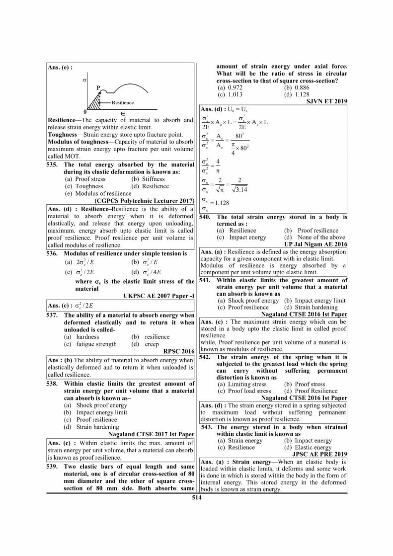
514
Ans. (e) :
Resilience—The capacity of material to absorb and release strain energy within elastic limit. Toughness—Strain energy store upto fracture point. Modulus of toughness—Capacity of material to absorb maximum strain energy upto fracture per unit volume called MOT.
535. The total energy absorbed by the material
during its elastic deformation is known as: (a) Proof stress (b) Stiffness (c) Toughness (d) Resilience (e) Modulus of resilience
(CGPCS Polytechnic Lecturer 2017) Ans. (d) : Resilience–Resilience is the ability of a material to absorb energy when it is deformed elastically, and release that energy upon unloading, maximum. energy absorb upto elastic limit is called proof resilience. Proof resilience per unit volume is
called modulus of resilience.
536. Modulus of resilience under simple tension is
(a) 22 /e Eσ (b) 2
/e Eσ
(c) 2 / 2e Eσ (d) 2 / 4e Eσ
where σe is the elastic limit stress of the
material
UKPSC AE 2007 Paper -I
Ans. (c) : 2/ 2e Eσ
537. The ability of a material to absorb energy when
deformed elastically and to return it when
unloaded is called- (a) hardness (b) resilience (c) fatigue strength (d) creep
RPSC 2016
Ans : (b) The ability of material to absorb energy when elastically deformed and to return it when unloaded is called resilience.
538. Within elastic limits the greatest amount of
strain energy per unit volume that a material
can absorb is known as– (a) Shock proof energy (b) Impact energy limit (c) Proof resilience (d) Strain hardening
Nagaland CTSE 2017 Ist Paper
Ans. (c) : Within elastic limits the max. amount of strain energy per unit volume, that a material can absorb is known as proof resilience.
539. Two elastic bars of equal length and same
material, one is of circular cross-section of 80
mm diameter and the other of square cross-
section of 80 mm side. Both absorbs same
amount of strain energy under axial force.
What will be the ratio of stress in circular
cross-section to that of square cross-section? (a) 0.972 (b) 0.886 (c) 1.013 (d) 1.128
SJVN ET 2019 Ans. (d) : Uc = Us
2 2
c sc sA L A L
2E 2E
σ σ× × = × ×
2 2
c s
22s c
A 80
A80
4
σ= =
πσ ×
2
c
2
s
4σ=
σ π
c
s
2 2
3.14
σ= =
σ π
c
s
1.128σ
=σ
540. The total strain energy stored in a body is termed as :
(a) Resilience (b) Proof resilience (c) Impact energy (d) None of the above
UP Jal Nigam AE 2016 Ans. (a) : Resilience is defined as the energy absorption capacity for a given component with in elastic limit. Modulus of resilience is energy absorbed by a component per unit volume upto elastic limit.
541. Within elastic limits the greatest amount of strain energy per unit volume that a material can absorb is known as
(a) Shock proof energy (b) Impact energy limit (c) Proof resilience (d) Strain hardening
Nagaland CTSE 2016 Ist Paper Ans. (c) : The maximum strain energy which can be stored in a body upto the elastic limit in called proof resilience. while, Proof resilience per unit volume of a material is known as modulus of resilience.
542. The strain energy of the spring when it is subjected to the greatest load which the spring can carry without suffering permanent distortion is known as
(a) Limiting stress (b) Proof stress (c) Proof load stress (d) Proof Resilience
Nagaland CTSE 2016 Ist Paper Ans. (d) : The strain energy stored in a spring subjected to maximum load without suffering permanent distortion is known as proof resilience.
543. The energy stored in a body when strained within elastic limit is known as
(a) Strain energy (b) Impact energy (c) Resilience (d) Elastic energy
JPSC AE PRE 2019 Ans. (a) : Strain energy—When an elastic body is loaded within elastic limits, it deforms and some work is done in which is stored within the body in the form of internal energy. This stored energy in the deformed body is known as strain energy.

515
Resilience—The strain energy stored in a body due to external loading within the elastic limit is known as resilience.
544. The strain energy of the spring when it is subjected to the greatest load which the spring can carry without suffering permanent distortion is known as–
(a) Limiting stress (b) Proof stress (c) Proof Resilience (d) Proof load stress
Nagaland CTSE 2017 Ist Paper Ans. (c) : The strain energy of spring subjected to max.
load, which spring can carry without suffering permanent distortion is known as proof Resilience.
545. Strain energy stored in beam with flexural rigidity EI and loaded as shown figure is
(a) (P
2L
3/3EI) (b) (2P
2L
3/3EI)
(c) (4P2L
3/3EI) (d) (6P
2L
3/3EI)
(e) (8P2L
3/3EI)
CGPSC 26th April 1st Shift Ans. (c) :
RA = RB = P
Total strain energy,
( ) ( ) ( )2 2L
0
Px dx PL 2LU 2
2EI 2EI= +∫
2 3 2 3P L P LU
3EI EI= +
2 34 P LU
3 EI=
546. Strain energy stored in a solid circular shaft is
proportional to
(a) GJ (torsional rigidity) (b) 1/(GJ)2
(c) GJ2 (d) 1/(GJ)
(e) 1/ GJ
CGPSC 26th April 1st Shift Ans. (d) : For solid shaft—Let us suppose that a solid
shaft is subjected to a torque which increase gradually
from zero to a value T. Let θ represent the resultant
angle of twist. Then, the energy stores in the shaft is
equal to work done in twisting i.e.
1
. .2
U T θ=
1 .
. .2
T lT
GJ
=
T G
J l
θ =
2
1
2
T l
GJ
=
1
UGJ
∝
547. The resilience of steel can be found by integrating stress-strain curve up to the
(a) ultimate fracture point (b) upper yield point (c) lower yield point (d) elastic point
ESE 2018 Ans. (d) : Resilience is the ability of a material to absorb energy per unit volume without permanent
deformation and is equal to the area under the stress-
strain curve upto the elastic limit.
548. Which one of the following statements is
correct?
(a) The strain produced per unit volume is called resilience.
(b) The maximum strain produced per unit
volume is called proof resilience. (c) The least strain energy stored in a unit
volume is called proof resilience. (d) The greatest strain energy stored in a unit
volume of a material without permanent deformation is called proof resilience.
ESE 2017 Ans. (d) : The greatest strain energy stored in a unit volume of a material with permanent deformation is called proof resilience.
549. Strain energy stored in a beam due to bending
is given by (Where M is bending moment, E is
modulus of elasticity, I is moment of inertia, G
is modulus of rigidity, L is the length of the
beam, and σ is the tensile strength.)
(a) 2
M dx
2EI∫ (b) 2dx
2EI
σ∫
(c) 2M dx
2GI∫ (d) 2M dx
2EL∫
HPPSC AE 2018 Ans. (a) : Strain energy stored in a beam 1. when beam is subjected to bending moment (M)
2
B.M
M .dxU
2EI= ∫
2. when beam is subjected to Twisting moment (T)
2
T.M
P
T .dxU
2GI= ∫
3. When beam is subjected to axial load P
2
A.L
P .dxU
2AE= ∫

516
550. What will be the strain energy stored in the metallic bar of cross sectional area of 2 cm
2 and
gauge length of 10 cm if it stretches 0.002 cm under the load of 12 kN?
(a) 10 N-cm (b) 12 N-cm (c) 14 N-cm (d) 16 N-cm
RPSC LECTURER 16.01.2016 Ans. (b) : Data given, A = 2 cm
2, l = 10 cm
δl = 0.002 cm P = 12 × 10
3 N
Strain energy
2
2U volume
E
σ= ×
P
Aσ =
l
el E
δ σ= =
then we get
1
2U P δ= × ×
3 31
12 10 2 102
−= × × × ×
= 12 N-cm
551. The strain energy stored in a body of volume V and subjected to a gradually applied load
which induces a stress σ is given by
(a) σE
V (b)
2σE
V
(c) 2
Vσ
E (d)
21V
2
σ
E
TNPSC AE 2014 TSPSC AEE 2015
Ans. (d) : 21
U V2 E
σ= ×
552. Strain energy stored in a prismatic bar suspended from one end due to its own weight (elastic behaviour) [x = specific weight of material, A = cross-sectional area, L = length of bar]:
(a) 3
6
x A LU
E= (b)
2 2 2
6
x A LU
E=
(c) 2 3
3
x A LU
E= (d)
2 3
6
x A LU
E=
UPRVUNL AE 2016 Ans. (d) :
Self weight at section -
.
l
W lP
L=
We know that strain energy for prismatic bar suspended
from one end due to its self weight
2
( )
2( )
Ll
ol
P dlU
AE= ∫
AE = constant
2
2
L
O
Wldl
L
AE
= ∫
2 3
2 32
L
O
W l
AE L
= ×
2 3
2
( )
32
xAL L
AEL= ×
2 3
6
x ALU
E=
553. 3PL
3El is the deflection under the load P of a
cantilever beam {Length L., modulus of
elasticity E, moment of inertia I}. The strain
energy due to bending is :
(a) 3P L
3EI
2
(b) 3P L
6EI
2
(c) 3P L
4EI
2
(d) 3P L
48EI
2
OPSC Civil Services Pre. 2011 Ans. (b) :
Mx = Px
2
xM dxU
2EI= ∫
L 2 2
0
P x dx
2EI= ∫
2 3P LU
6EI=
554. A cantilever beam of length L and flexural
modulus EI is subjected to point load P at the
free end. The elastic strain energy stored in the
beam due to bending (Neglecting transverse
shear)
(a) 2 3
6
P L
EI (b)
2 3
3
P L
EI
(c) 3
3
PL
EI (d)
3
6
PL
EI
Gujarat PSC AE 2019

517
Ans : (a) :
Bending moment at section x – x
( )x xM P.x− =
L 2xxM dx
Strain energy =2EI
∂∫
( )2LPx dx
=2EI
∂∫
2 3
P L
2EI 3
=
2 3P L
6EI=
555. Strain energy stored in a body due to a suddenly applied load compared to when applied slowly is:
(a) twice (b) four times (c) eight times (d) half (HPPSC AE 2014)
Ans : (b) Strain energy stored in a body due to suddenly applied load compared to when applied slowly is twice. Stress in a body due to gradually applied load gradually = σ stress in a body due to suddenly applied load = 2σ strain energy due to gradually applied load
2
GALU Volume2E
σ= × ...........(i)
strain energy due to suddenly applied load
( )2
SAL
2U Volume
2E
σ= ×
2
SALU 4 volume2E
σ= × ×
SAL GALU 4 U= ×
556. A square bar of side 4 cm and length 100 cm is subjected to axial load P. The same bar is then used as a cantilever beam and subjected to an end load P. The ratio of the stratin energies, stored in the bar in the second case to that stored in first case, is
(a) 16 (b) 400 (c) 1000 (d) 2500
MPPSC AE 2016
Ans : (d) Square bar Area = 16cm2
length = 100cm. moment of Inertia of square bar
3 4
4bh 421.33cm
12 12= = =
stcase1 : −
( )2
1Strain Energy U volume2E
σ= ×
2
1
P 1.6U 100
16 2E
= × ×
P
16
σ =
2
1
3.125PU
E=
case II :− −
2 3
2
P LU
6EI=
2 3
2 4
P 100 12U
E 6 4
×= ×
2
2
7812.5PU
E=
Ratioof strain energies
2
2
2
1
U 7812.5P E
E 3.125P
×=
×U
2
1
U2500
U=
557. Resilience of a bolt may be increased by (a) increasing its length (b) increasing its shank diameter (c) increasing diameter of threaded portion (d) increasing head size
RPSC AE 2016
Ans : (a) Resilience of a bolt may be increased by increasing its length.
558. The strain energy in a beam subjected to bending moment M is
(a) 2Mdx
2EI∫ (b) 2M
dx4EI∫
(c) 2M
dxEI∫ (d)
22Mdx
EI∫
UPPSC AE 12.04.2016 Paper-I
Ans : (a) Strain energy in a beam due to bending:-
2
o x
1U M .dx
2EI= ∫
ℓ
21U M .dx
2EI= ∫
559. The deflection of a cantilever beam of length L, modulus of elasticity E, moment of inertia I subjected to a point load P is PL
3/3 El. The
strain energy due to bending is: (a) 5PL
3/48EI (b) P
2L/3EI
(c) P2 L
3/6EI (d) P
2L
3/48EI
(HPPSC LECT. 2016)
Ans : (c)

518
given 3PL
3EIδ =
Then, Strain energy store in cantilever beam will be equal to [use Castigliano's theorem
[ ]dUdeflection
dP= δ
dU dP= δ
3 2 3
B
A
PL P LdU dP
3EI 6EI= =∫
( )2 3
B A
P LU U
6EI− =
9. Deflection of Beams
560. A cantilever beam of length carries a load (W = wl) uniformly distributed over its entire length. If the same total load is placed at the free end of the same cantilever, then the ratio of maximum deflection in the beam in the first case to that in the second case will be:
(a) 3
12 (b)
3
8
(c) 3
4 (d)
3
2
JWM 2017 Ans. (b) : (1) Cantilever beam with uniform distributed load over entire length- Maximum deflection,
( )4 3
A1 max
w Wy
8EI 8EI= =
ℓ ℓ
(2) Cantilever beam with concentrated load on free end-
Maximum deflection, ( )3
A2 max
WLy
3EI=
Now, 3
A1
3A2 max
y W 3EI
y 8EI W
= ×
ℓ
ℓ
3
8=
561. A cantilever beam with rectangular cross-section is subjected to uniformly distributed
load. The deflection at the tip is δ1. If the width and depth of the beam are doubled then
deflection at tip is δ2. Then 2
1
δδ
is
(a) 0.0625 (b) 16 (c) 0.5 (d) 2
APPSC-AE-2019
Ans. (a) : Deflection 1
I∝
∴
3
2 1
3
1 2
12 10.0625
16(2 )(2 )
12
bd
I
I b d
δδ
= = = =
562. In a fixed beam, at the fixed ends (a) slope is zero and deflection is maximum (b) slope is maximum and deflection is is zero (c) both slope and deflection are maximum (d) slope and deflection are zero APPSC AEE 2012
Ans : (d) In a fixed beam, at the fixed ends slope and deflection are zero.
563. The resultant deflection of a beam under unsymmetrical bending is:-
(a) Parallel to the neutral axis (b) Perpendicular to the neutral axis (c) Parallel to the axis of symmetry (d) Perpendicular to the axis of symmetry
UKPSC AE-2013, Paper-I
Ans. (b) : The resultant deflection of a beam under unsymmetrical bending is perpendicular to the neutral axis.
564. A cantilever beam of length 'L' carries a concentrated load 'P' at its midpoint. What is the deflection of the free end of the beam?
(a) 3
24
PL
EI (b)
3
48
PL
EI
(c) 3
16
PL
EI (d)
35
48
PL
EI
UKPSC AE 2007 Paper -I
Ans. (d) : 35
48
PL
EI
565. A 1.25 cm diameter steel bar is subjected to a load of 2500 kg. The stress induced in the bar will be
(a) 200 MPa (b) 210 MPa (c) 220 MPa (d) 230 MPa
ESE 2020
Ans. (a) :
( )2
P 2500 9.81200MPa
A12.5
4
×σ = = =
π
566. A cantilever beam rectangular in cross section
is subjected to a load W at its free end, causing
deflection δ1. If the load is increased to 2W,
causing deflection δ2, the value of 1
2
δ
δwould be
(a) 1 (b) 2
(c) 4 (d) 1/2 Nagaland CTSE 2016 Ist Paper
Ans. (d) : A cantilever beam rectangular in cross-
section subjected, load (W), then deflection (δ1). 3
1
WL ____( )i3EI
δ =

519
when, Load is increased to (2W), then deflection (δ2) will be,
3
2
2WL ____( )ii3EI
δ =
from (i) 2 (ii)
3
1
23
WL
3EI
2WL
3EI
δδ
= = 1
2
567. In a simply supported shaft carrying a uniformly distributed mass, the maximum deflection at the midspan is :
(a) 2
5mg
384EI∆ =
l
(b) 4
5mg
384EI∆ =
l
(c) 4mg
384EI∆ =
l
(d) 23mg
384EI∆ =
l
TRB Polytechnic Lecturer 2017 Ans. (b) :
This system treated as the simple supported shaft with
carrying UDL
Deflection at the mid-span
∆ =4
5mg
384EI
ℓ
568. We can find the deflection of beam carrying:
(a) Uniformly distributed load
(b) Central point load
(c) Gradually variable load (d) All of these loads
TRB Polytechnic Lecturer 2017 Ans. (d) : A subjected to UDL, central point load and
also gradually variable load, deflection can find out.
569. A rectangular in cross section cantilever beam
is subjected to a load W at its frees end. If the
depth of the beam is double and the load is
halved, the deflection of the free end as
compared to original deflection will be–
(a) 1/2 (b) 1/4
(c) 1/16 (d) Double
Nagaland CTSE 2017 Ist Paper Ans. (c) : We know that,
deflection of a rectangular cross section beam 3Wl
3EIδ = where
3bhI
12=
3
1 1
I hδ ∝ ⇒ δ ∝
therefor
3
1 1 2
2 2 1
W h
W h
δ= ×
δ
given. 2 1W = W /2 and
2 1h 2h=
3
1 1 1
2 1 1
W 2h16
(W / 2) h
δ= × = δ
1 216∴δ = δ
2 1 /16δ = δ
570. A simply supported beam of length L loaded by UDL of W per length all along the whole span. The value of slope at the support will be [E = modulus of elasticity, I = moment of inertia of section beam]
(a) 3
WL
24EI (b)
4WL
48EI
(c) 3WL
48EI (d)
4WL
24EI
SJVN ET 2019 Ans. (a) : Slope at any end for simple support UDL
beam3W
24EI=
ℓ
571. A simply supported beam of span L and carrying a concentrated load of W at mid span. The value of deflection at mid span will be [E = modulus of elasticity, I = moment of inertia of section of beam]
(a) 2
WL
48EI (b)
3WL
48EI
(c) 4WL
48EI (d)
3WL
30EI
SJVN ET 2019 UKPSC AE-2013, Paper-I
Ans. (b) : 3WL
48EI
572. Slope of tangent to shear force diagram gives (a) Bending moment (b) Couple moment (c) Support reactions (d) Rate of loading (e) Rate of bending moment
CGPSC 26th April 1st Shift
Ans. (d) : According to relation dF
Wdx
= − (constant)
So, slope of tangent to shear force diagram gives rate of loading.
573. What is the maximum deflection (σmax) in case of simple supported beam with uniformly distributed load?
(a) 4
8
wl
EI (b)
4
48
wl
EI
(c) 3
8
wl
EI (d)
3
48
wl
EI

520
(e) 45
384
wl
EI
CGPSC 26th April 1st Shift Ans. (e) :
Beam Max.
Deflection
Max. bending
moment
3
3
WL
EI
WL
4
8
wL
EI
2
2
wL
3
48
WL
EI
4
WL
45
384
wL
EI
2
8
wL
574. Maximum slope in case of a cantilever of length
l carrying a load P at its end is
(a) Pl2/2EI (b) Pl
2/EI
(c) Pl2/4EI (d) Pl
2/6EI
(e) Pl2/8EI
CGPSC 26th April 1st Shift Ans. (a) :
Type of load Slope at end Maximum
deflection
2
2
Pl
EIθ =
3
3
Pl
EIδ =
3
6=
wl
EIθ
4
8=
wl
EIδ
575. A uniform bar, simply supported at the ends,
carries a concentrated load P at mid-span. If
the same load be, alternatively, uniformly
distributed over the full length of the bar the
maximum deflection of the bar will decrease by.
(a) 25.5% (b) 31.5%
(c) 37.5% (d) 50.0%
ESE 2017
Ans. (c) :
δ1 =3PL
48EI δ2 =
5
384
3PL
EI
% decrease in max deflection = 1 2
1
100δ − δ
×δ
=
1 5
48 3841
48
−
= 37.5%
576. Basic equation of deflection (y) of the beam is
represented by 2
2
d yEl = M,
dx where El flexural
rigidity and M Bending moment, then 3
3
d yEl = M
dx
(a) Shear force at the section (b) Rate of loading (c) Zero always (d) Bending moment at section
UPRVUNL AE 2016 Ans. (a) :
2
2
d yEI M
dx=
We know that
dM
dx= shear force
then
3
3
d y dMEI
dx dx= = shear force at section
577. The simple supported beam 'A' of length 'l'
carries a central point load 'W'. Another beam
'E' is loaded with a uniformly distributed load
such that the total load on the beam is 'W'. The
ratio of maximum deflections between beams A
and B is (a) 5/8 (b) 8/5 (c) 5/4 (d) 4/5
TSPSC AEE 2015
Ans. (b) : 3
A
WL
48EIδ = (simply supported beam)
4
B
(simply supported with 5wL
uniform distributed load)384 EIδ =
∵ wL = W [given]
Then 3
B
5 WL
384 EIδ =
A
B
8
5
δ=
δ
578. The ratio of maximum deflections of a beam simply supported at its ends with an isolated
central load and that of with a uniformly
distributed load over its entire length is (a) 1 (b) 3/2 (c) 2/3 (d) 1/3
TSPSC AEE 2015 Ans. (c) : 2/3
579. If the depth of a rectangular beam is halved,
the deflection for a beam carrying a mid point
load shall be– (a) halved (b) doubled (c) four times (d) eight times
RPSC 2016

521
Ans : (d)
3 3WL WL
348EI bd48E
12
δ = =
13d
δ ∝
1
3
1
3d2 11d 8
2
δ= =
δ
82 1
δ = δ
580. A cantilever of length (l) carries a uniformly distributed load w per unit length over the whole length. The downward deflection at the free end will be (where W= wl = total load)
(a) 3
W
8E
l
l (b)
3W
3E
l
l
(c) 3
5W
384E
l
l (d)
3W
48E
l
l
RPSC 2016
Ans : (a)
3Wl
δ=8EI
581. In a cantilever, maximum deflection occurs where–
(a) bending moment is zero (b) bending moment is maximum (c) shear force is zero (d) slope is zero
RPSC 2016
Ans : (a)
In the cantilever beam loaded as shown, the max
bending moment is at (x = 0) but the max deflection
occur at (x = l)
Maximum deflection at x = l is given by 3
3=
Wl
EI
582. A cantilever beam having square cross section of side is subjected to an end load. If a increased by 19% the tip deflection decreases approximately
(a) 19% (b) 29%
(c) 41% (d) 50% RPSC 2016
Ans : (d)
3 3
4
Wl Wl
13EI3E a
12
δ = =
3
4
12 1
3
=
Wl
E aδ
4
1∝
aδ
2
4
1 2
4
2 1
aa a 0.19a
a
δ= + ⇒ =
δ
41.19a
a
=
21 2
1
2.0053 Decrease = 1δ
δ = δ ⇒ −δ
2 2
2
2.0053Decrease =
2.0053
δ − δδ
50.03%=
≈ 50%
583. A cantilever beam of length L is subjected to an on concentrated load P at a distance of L/3 from free end, what is the deflection at free end of the beam?
(a) 3
2PL
81EI (b)
33PL
81EI
(c) 3
14PL
81EI (d)
315PL
81EI
RPSC Vice Principal ITI 2018 Ans. (c) :
Deflection at free end A is
δA =
3 22 2
P P3 3
3EI 2EI 3
+ ×
ℓ ℓ
ℓ
= 3 3
8P 4P
81EI 54EI+
ℓ ℓ
δA = 3
14P
81EI
ℓ
584. The slope and deflection at the centre of a simple beam carrying a central point load are
(a) zero and zero (b) zero and maximum (c) maximum and zero (d) minimum and maximum
BPSC AE 2012 Paper - VI Ans : (b) : zero and maximum

522
585. Assertion (A) : In a simply supported beam subjected to a concentrated load P at mid-span, the elastic curve slope becomes zero under the load.
Reason (R) : The deflection of the beam is maximum at mid-span.
(a) Both (A) and (R) are individually true and (R) is the correct explanation of (A)
(b) Both (A) and (R) are individually true but (R) is NOT the correct explanation of (A)
(c) (A) is true but (R) is false (d) (A) is false but (R) is true
OPSC AEE 2019 Paper-I Ans : (a) : Elastic curve slope becomes zero at the point of maximum deflection in this case. Hence, of both assertion and reason are correct and reason is correct explanation of assertion.
586. In a cantilever beam, If the length is doubled
while keeping the cross-section and the concentrated load acting at the free end the same, the deflection at the free and will increase by:
(a) 2.66 times (b) 3 times (c) 6 times (d) 8 times
OPSC AEE 2019 Paper-I
OPSC AEE 2015 Paper-I
Ans : (d) :
Cantilever beam when length = l
Deflection ( )3
1
wδ =
3EI
ℓ
Cantilever beam when length = 2l
Deflection ( ) ( )3
2
w 2δ =
3EI
ℓ
21
δδ =
8
587. 3PL
3EIis the deflection under the load 'P' of a
cantilever beam (Length 'L', Modulus of elasticity 'E' and Moment of inertia 'I'). The strain energy due to bending is
(a) 2 3P L
3EI (b)
2 3P L
6EI
(c) 2 3P L
4EI (d)
2 3P L
48EI
MPPSC AE 2016
Ans : (b) When beam is cantilever and load acting
beam on free end then deflection 3
PL
3EI
( )
( )
x
2
x0
2
o
2 2
0
2 3
0
M Px
1U M dx strain energy
2EI
1U Px dx.
2EI
1U P x dx
2EI
P xU
2EI 3
=
=
=
=
=
∫
∫
∫
ℓ
ℓ
ℓ
ℓ
2 3
P LU
6 EI=
588. The maximum deflection of a cantilever beam with point load at its free end is given by
(a) 2
max
wy
2EI=
ℓ (b)
3
max
wy
3EI=
ℓ
(c) 3
max
wy
2EI=
ℓ (d)
2
max
wy
3EI=
ℓ
TSPSC AEE 2015
Ans : (b)
(i) Slope =2w
2EI
ℓ
(ii) Deflection = 3
w
3EI
ℓ
(iii) Strain energy
l
2x
d
1U M dx
2EI= ∫
( )l 2
0
1U w.x dx
2EI= ∫
3w
U6EI
=ℓ
589. The given figure shows a cantilever of span 'L'
subjected to a concentrated load 'P' and a
moment 'M' at the free end. Deflection at the
free end is given by:
(a) EI3
ML
EI2
PL22
+ (b) EI3
PL
EI2
ML32
+

523
(c) EI2
PL
EI3
ML32
+ (d) EI48
PL
EI3
ML 22
+
UJVNL AE 2016
Ans : (b)
Deflection at the free end:-
=δ
δ =
δ = δ + δ
δ = +
2
1
3
2
1 2
2 3
ML
2EI
PL
3EI
ML PL
2EI 3EI
590. Maximum deflection in a cantilever due to pure bending moment M at its end is
(a) M
2El
2l (b)
M
3El
2l
(c) M
4El
2l (d)
M
8El
2l
UPPSC AE 12.04.2016 Paper-I
Ans : (a) Maximum deflection in a cantilever due to
pure bending moment M at its end is 2M
2EI
ℓ
Slope ( θ ) =M
EI
ℓ
Deflection ( )2M
2EIδ =
ℓ
591. A beam of length, l, fixed at both ends carries a uniformly distributed load of w per unit length. If EI is the flexural rigidity, then the maximum deflection in the beam is
(a) 4
wl
192EI (b)
4wl
24EI
(c) 4
wl
384EI (d)
4wl
12EI
APPSC AEE 2012
Ans : (c) (i)
Deflection ( )4
c
W
384EIδ =
ℓ
(ii)
Deflection ( )3
c
W
192EIδ =
ℓ
592. The differential equation which gives the relation between BM, slope and deflection of a beam is
(a) 2
2
d y MEI
Idx− (b)
2
2
d yM
dx=
(c) 2
2
d yEI M
dx= (d)
dy MEI
dx F=
APPSC AEE 2012
Ans : (c) The basic differential equation can also be written as follows
2
2
d y d dy d M
dx dx dx EIdx
θ − = = =
2
2
d yEI M.
dx=
2
2
d yEI M.
dx=
This equation can be integrated in each particular can to find the angle of rotation θ or the deflection y, provided the moment M is Known.
593. A simply supported became span 3m, is subjected to a central point load of 5kN, then the slope at the mid span is equal to
(a) 25
24EI (b)
256
EI
(c) 40
48EI (d) Zero
APPSC AEE 2012
Ans : (d)
Slope 2
w
16EI=
ℓ, Deflection
3w
48EI=
ℓ
W = 5 KN (Central point load.) l = 3 m (beam span) Slope at the mid span = 0 Deflection at the mid span = Maximum.
594. A cantilever beam of length L, moment of
inertia of inertia I and Young modulus E
carries a concentrated load W at the middle of
its length. The slope of cantilever at the free
end is:

524
(a) (Wℓ^2)/2EI (b) (Wℓ^2)/4EI
(c) (Wℓ^2)/8EI (d) (Wℓ ^2)/16EI
OPSC AEE 2015 Paper-I
Ans : (c)
When load acts free end then slope 2
W
2EI=
ℓ
When load acts mid span the slope ( )2
W / 2
2EI=
ℓ
2
wSlop
8EI=
ℓ
10. Theory of Failure
595. Property of absorbing large amount of energy before fracture is known as:-
(a) Ductility (b) Toughness (c) Elasticity (d) Hardness
UKPSC AE-2013, Paper-I
Ans. (b) : Property of absorbing large amount of energy before fracture is known as Toughness.
596. According to the distortion-energy theory, the yield strength in shear is
(a) 0.277 times the yield stress (b) 0.377 times the maximum shear stress (c) 0.477 times the yield strength in tension (d) 0.577 times the yield strength in tension
ESE 2020 Ans. (d) : According to distortion energy theory,
yt
sy yt
SS 0.577S
3= =
597. Maximum principal stress theory is applicable for
(a) ductile materials (b) brittle materials (c) elastic materials (d) all of the above
UPRVUNL AE 2016 Gujarat PSC AE 2019
Ans : (b) : Maximum principle stress theory or Rankine's theory is applicable for brittle materials.
598. Consider the following 1. hard materials 2. brittle materials 3. malleable materials 4. ductile materials 5. elastic materials Of the above, Shear stress theory is applicable
for which material (a) 1 and 2 (b) 2 and 3 (c) 3 (d) 4 (e) 4 and 5
CGPSC 26th April 1st Shift Ans. (d) : Shear stress theory is applicable for ductile material.
599. Maximum principal or normal stress theory of
failure is appropriate for ____.
(a) Ductile material
(b) Brittle material
(c) Plastic material
(d) Semi plastic material
(e) Semi elastic material
(CGPCS Polytechnic Lecturer 2017)
Gujarat PSC AE 2019 Ans. (b) : Rankine Theory–Rankine's theory assumes
that failure will occur when the maximum principal
stress at any point reaches a value equal to the tensile
stress in a simple tension specimen at failure.
This theory is appropriate for Brittle material.
600. Guest's theory of failure is applicable for
following type of materials
(a) brittle (b) ductile
(c) elastic (d) plastic
(e) tough
CGPSC 26th April 1st Shift Ans. (b) : Maximum shear stress theory or Guest or
Tresca's theory is well justified for ductile material.
601. Which of the following theories of failure is not
suitable for ductile material
(a) Maximum shear stress theory
(b) Maximum principal strain theory
(c) Maximum total strain energy theory
(d) Maximum principal stress theory
RPSC LECTURER 16.01.2016 Ans. (d) : Maximum principal stress theory (Rankine's
theory) is suitable for brittle material not for ductile
material whereas Maximum shear stress theory (Gast
and Tresca theory), maximum principal strain theory
(Sent-Venant theory) and maximum total strain energy
theory (Haigh's theory) are used for ductile material.
602. Region of safety for maximum principal stress
theory under bi-axial stress is shown by:
(a) Ellipse (b) Square
(c) Pentagon (d) Hexagon
UPRVUNL AE 2016 Ans. (b) : Maximum principal stress theory—
Maximum principal stress theory or normal stress
theory says that, yielding occurs at a point in a body,
when principle stress (maximum normal stress) in a
biaxial system reaches limiting yield value of that
material under simple tension test. This theory used for
brittle material. This theory also known as Rankine
theory. Region of safety for maximum principal stress
theory under bi-axial stress is square

525
603. Failure of the component occurs when the maximum shear stress in the complex system reaches the value of maximum shear stress in simple tension at the elastic limit. This is known as:
(a) Rankine theory (b) Guest and Tresca theory (c) Haigh theory (d) St. Venant theory (e) Carnot theory
CGPSC AE 2014- I Ans. (b) : Maximum shear stress theory [Guest and Tresca theory]– Failure of the component occurs when the maximum shear stress in the complex system reaches the value of maximum shear stress in simple tension at the elastic limit. This theory is used for ductile material.
604. As per maximum shear stress theory of failure. The relation between yield strength in shear
(τy) and yield strength in tension (σt) is: (a) τt = 1.2 σt (b) τt = 0.7 σt (c) τt = 0.3 σt (d) τt = 0.5 σt
CIL MT 2017 2017 IInd shift Ans. (d) : Maximum shear stress theory (or) Guest & Tresca's Theory-According to this theory, failure of specimen subjected to any combination of load when the maximum shearing stress at any point reaches the failure value equal to that developed at the yielding in an axial tensile or compressive test of the same material.
ty
2
στ ≤
Where σt is the yield strength in tension and τy
is the yield strength in shear.
605. Design of power transmission shafting is based on
(a) Maximum shear stress theory of failure (b) St. Venant theory (c) Rankine's theory (d) Height's theory
TNPSC AE 2017 Ans. (a) : Design of power transmission shafting is based on maximum shear stress theory of failure.
606. For brittle materials the following theory s used
(a) maximum normal stress theory (b) maximum shear stress theory (c) distortion energy theory (d) all of the above
TSPSC AEE 2015 Ans. (a) : Maximum normal stress theory is used to brittle materials.
607. The theory of failure used in designing the ductile materials in a most accurate way is by
(1) maximum principal stress theory (2) distortion energy theory (3) maximum strain theory Select the correct answer using the code given below. (a) 1, 2 and 3 (b) 1 only (c) 2 only (d) 3 only
ESE 2019, 2020
Ans. (c) : Since ductile materials, under static conditions, mostly fail due to shear or distortion, distortion energy theory or Von-mises theory produces most accurate results.
608. For ductile material, the suitable failure theory is
(a) Maximum shear strain energy theory (b) Maximum shear stress theory (c) Both (a) and (b) (d) None of the above
APPSC-AE-2019 Ans. (c) : Failure Criterion Theory (1) For brittle material (i) Maximum principal stress OR Rankine's theory (ii) Maximum principal strain OR St. Venant's theory (iii) Maximum strain energy density (2) Ductile material (i) Maximum shear stress OR Guest and Tresca's theory (ii) Maximum distortion energy density OR Vonmises and Hencky's theory
609. Let σ1, σ2 and σ3 are the principal stresses at a material point. If the yield stress of the
material is σy, then according to Von Mises theory yielding will not occur if
(a) 2 2 2 2
1 2 2 3 3 1( ) ( ) ( ) 2( )yσ σ σ σ σ σ σ− + − + − <
(b) 1 2 2 3 3 1max[( ), ( ), ( )] yσ σ σ σ σ σ σ− − − <
(c) 2 2 2 2
1 2 3( ) ( ) ( ) ( )yσ σ σ σ+ + <
(d) 2 2 2 2
1 2 3 1 2 2 3 3 1( ) ( ) ( ) 2 ( ) ( )yσ σ σ ν σ σ σ σ σ σ σ+ + − + + <
APPSC-AE-2019 Ans. (a) : VonMises Yielding Failure theory
2 2 2
1 2 2 3 3 1( ) ( ) ( )
2y
σ σ σ σ σ σσ
− + − + −≥
2 2 2 2
1 2 2 3 3 1( ) ( ) ( ) 2 yσ σ σ σ σ σ σ− + − + − ≤
610. For ductile materials, the most appropriate
failure theory is
(a) maximum shear stress theory
(b) maximum principal stress theory (c) maximum principal strain theory
(d) shear strain energy theory TNPSC AE 2014
Ans. (a) : For ductile materials the most appropriate failure theory is maximum shear stress theory where as for brittle material maximum principle stress theory is used.
611. Consider the following statements :
Assertion (A) : An isotropic material is always
homogeneous.
Reason (R) : An isotropic material is one in
which all the properties are
same in all the directions at
every point.
of these statements, (a) both (A) and (R) are true and (R) is the
correct explanation of (A)

526
(b) both (A) and (R) are true but (R) is not a
correct explanation of (A)
(c) (A) is true but (R) is false
(d) (A) is false but (R) is true
TNPSC AE 2014 Ans. (a) : An isotropic material is always homogeneous
and in which all the properties are same in all the
direction at every point.
612. From a uniaxial tension test, the yield strength
of steel was found to be 200 N/mm2. A steel
shaft is subjected to a torque 'T', and a bending
moment 'M'. The theory of failure which gives
safest dimensions for the shaft and the
relationship for design is
(a) Maximum Principal Strain Theory 1 yσ = σ
(b) Maximum Principal Strain Theory
1 2 y
E E E
σσ µσ− =
(c) Maximum Shear Stress Theory 1 2
2 2
yσσ −σ=
(d) Total Strain Energy Theory
22 2
1 2
2 2 2
y
E E E
σσ σ+ =
TNPSC AE 2014 Ans. (c) : Maximum shear stress theory [Guest and
Tresca] of failure gives safest dimensions for the shaft
and the relationship for design.
613. For steel, the ultimate strength in shear as
compared in tension is nearly
(a) same (b) half
(c) one-third (d) two-third
TNPSC 2019 Ans. (b) : For steel, the ultimate strength in shear as
compared in tension is nearly half.
ut yt
1S
2τ = [According to maximum shear
stress theory]
614. For Steel, the ultimate strength in shear as
compared to in tension is nearly
(a) Same (b) Half
(c) One-third (d) Two-third
Vizag Steel (MT) 2017 Ans. (d) :
Ultimate strength in tensionultimate strength in shear = 2
3
615. For a ductile material, the limiting value of
octahedral shear stress (τo) is related to the
yield stress (Sy) as
(a) 2
3o ySτ = (b) 3 2o ySτ =
(c) 3
2o ySτ = (d) None of the above
BPSC AE Mains 2017 Paper - VI
Ans : (a) : According to Von-mises (theory of failure)
(σ1 – σ2)2 + (σ2 – σ3)
2 + (σ3 – σ1)
2 = 2σ2
yield ..........(i) The octahedral shear stress can be given by the expression,
2 2 2
ys 1 2 2 3 3 1
1( ) ( ) ( )
3τ = σ − σ + σ − σ + σ − σ ...........(ii)
from equation (i) and (ii)
2
ys yield
12
3τ = σ
ys yield
2
3τ = σ
616. The shearing yield strength (Ssy) is related to tensile yield strength (Sy) as
(a) Ssy = Sy (b) Ssy = 0.414 Sy (c) Ssy = 0.577 Sy (d) Ssy = 0.707 Sy
BPSC AE Mains 2017 Paper - VI Ans : (c) : The shearing yield strength (Ssy) is related to tensile strength (Sy) as Ssy = 0.577 Sy
617. Which of the following is applied to brittle materials?
(a) Maximum principal stress theory (b) Maximum principal strain theory (c) Maximum strain energy theory (d) Maximum shear stress theory
OPSC AEE 2019 Paper-I RPSC AE 2016
Ans : (a) : (i) Maximum principal stress theory (Rankine’s Theory)- Brittle Material (ii) Maximum Principal strain theory (St. Venant’s
theory)- Brittle material (iii) Maximum shear stress theory (Guest’s and
Tresca’s theory)- Ductile Material (iv) Maximum strain energy theory (Haigh’s theory)-
Ductile Material (v) Maximum shear strain energy theory (Mises’ and
Henkey’s theory)- Ductile Material
618. The State of stress at a point is given as σx= 100
N / mm2, σy= 40 N / mm
2 strength τxy = 40 N /
mm2. If the yield strength Sy of the material is
300 MPa, the factor of safety using maximum shear stress theory will be
(a) 3 (b) 2.5 (c) 7.5 (d) 1.25 BPSC Poly. Lect. 2016
Ans : (a)
σx = 100 N/mm
2, σy = 40 N/mm
2, τxy = 40N/mm
2

527
( )max
max
max /
σ − σ τ = + τ
τ = +
τ =
22x y
xy
2
2
900 1600
50N mm
According to maximum shear stress theory
τy= FOS × τmax
Sy= 300 MPa
then τy= 150 MPa τy= y
y
S0.5 S
2=
150 = FOS × 50
FOS 3=
619. The equivalent bending moment under combined action of bending moment M and torque T is
(a) 2 2M T+
(b) 2 21M T
2+
(c) 2 2M M T+ +
(d) ( )2 21M M T
2+ +
MPPSC AE 2016
Ans : (d) According to maximum normal stress theory
( ) ( )
( )( )
2 2
b b bmax
2 3
3 3 3
2 2
3
e
b 3max
2 2
e
1 14
2 2
1 32M 1 32M 16T4
2 2d d d
32 1M M T
2d
32M
d
1M M M T
2
σ = σ + σ + τ
= + + π π π
= + + π
∴ σ =π
= + +
Me is known as equivalent bending moment.
620. Which theory of failure is applicable for copper components under steady load?
(a) Principal stress theory (b) Strain energy theory (c) Maximum shear stress theory (d) Principal strain theory
MPPSC AE 2016
Ans : (c) Maximum shear stress theory of failure is applicable for copper components under steady load. Maximum shear stress theory or Guest and Treca's theory is well justified for ductile materials.
621. The maximum distortion energy theory of failure is suitable to predict the failure of one of the materials is :
(a) Brittle material (b) Ductile material (c) Plastics
(d) Composite materials OPSC AEE 2015 Paper-I
UJVNL AE 2016
Ans : (b) Maximum principal stress theory: Brittle material Maximum principal strain theory: Brittle material Maximum shear stress theory: Ductile material Maximum strain energy theory: Ductile material Maximum shear strain energy theory: Ductile material
622. A cold rolled steel shaft is designed on the basis
of maximum shear stress theory. The principal
stresses induced at its critical section are 60
MPa and – 60 MPa respectively. If the yield
stress for the shaft material is 360 MPa, the
factor of safety of the design is :
(a) 2 (b) 3
(c) 4 (d) 5
HPPSC W.S. Poly. 2016
OPSC AEE 2015 Paper-I
Ans : (b)
max minmax
2
σ − σ τ =
for maximum shear stress theory
utmax
FOS
ττ =
Maximum shear stress = ( )2
2x y
xy2
σ − σ + τ
2
max
60 60
2
+ τ =
max 60MPaτ =
ut 180MPaτ =
ut
max
180FOS 3
60
τ= = =
τ
FOS 3=
623. A transmission shaft subjected to bending
loads must be designed on the basis of
(a) Maximum shear stress theory (b) Fatigue strength
(c) Maximum normal stress and maximum shear
stress theories
(d) Maximum normal stress theory
MPPSC AE 2016
Ans : (d) A transmission shaft subjected to bending load must be designed on the basis of maximum normal
stress theory.

528
624. Shear stress theory is applicanle to (a) ductile materials (b) brittle materials (c) elastic materials (d) plastic materials
RPSC AE 2016
Ans : (a) Shear stress theory is applicanle to ductile material. (i) Maximum principal stress theory - Brittle material (ii) Maximum principal strain theory – Brittle material (iii) Maximum shear stress theory – Ductile material (iv) maximum total strain energy theory – Ductile material.
11. Springs
625. In a spring mass system if one spring of same stiffness is added in series, new frequency of vibration will be:-
(a) 2
nω
(b)
(c) (d) 2
nω
UKPSC AE-2013, Paper-I
Ans. (a) : Case I -
n
K
mω =
Case II - when spring is added in series.
[ ]n eqII
K KK
2.m 2ω = =
[ ] nn II 2
ωω =
626. A spring mass system shown in Figure is
actuated by a load P = 0.75 sin2t. If mass of the
block is 0.25 kg and stiffness of the spring is 4
N/m, displacement of the block will be:-
(a) 0.25 (b) 0.5
(c) 1.0 (d) 2.25 UKPSC AE-2013, Paper-I
Ans. (a) : 0.25
627. Match List – I with List – II and select the correct answer using the code given below the lists. List – I
(Characteristic)
List – II
(Member) A. Kernel of section 1. Helical spring B. Tie and Strut 2. Bending of beams C. Section modulus 3. Eccentric loading of
short column D. Stiffness 4. Roof truss
Code : A B C D (a) 1 2 3 4 (b) 3 4 2 1 (c) 4 1 2 3 (d) 2 3 1 4
UKPSC AE 2012 Paper-I Ans. (b) : A-3, B-4, C-2, D-1
628. A spring scale reads 20 N as it pulls a 5.0 kg mass across a table. what is the magnitude of the force exerted by the mass on the spring scale ?
(a) 4.0 N (b) 5.0 N (c) 20.0 N (d) 49.0 N
UKPSC AE 2012 Paper-I Ans. (c) : 20.0 N
629. In an open coiled helical spring an axial load on the spring produces which of the following stresses in the spring wire?
(a) normal (b) torsional shear (c) direct shear (d) all of the above
UKPSC AE 2007 Paper -I Ans. (d) : All of the above
630. When a helical coiled spring is compressed axially, it possesses
(a) potential energy (b) kinetic energy (c) mechanical energy (d) none of the above
UKPSC AE 2007 Paper -I Ans. (a) : Potential energy
631. The energy stored per unit volume in coil spring as compared to leaf spring is
(a) Equal amount (b) Double the amount (c) Four times higher (d) Six times higher
TNPSC AE 2017 Ans. (d) : The energy stored per unit volume in coil spring as compared to leaf spring is Six times higher. 632. A spring is made of a wire of 2 mm diameter
having a shear modulus of 80 GPa. The mean coil diameter is 20 mm and the number of active coils is 10. If the mean coil diameter is reduced to 10 mm, the stiffness of the spring is:
(a) increased by 16 times (b) decreased by 8 times (c) increased by 8 times (d) decreased by 16 times
BHEL ET 2019 Ans. (c) : D1 = 20 mm D2 = 10 mm Stiffness of spring
4
3
Gdk
8D n=
3
1k
D∝
3
1 2
2 1
k D
k D
=
3
1
2
k 20
k 10
=
k2 = 8k1

529
633. A coil is cut into two halves, the stiffness of cut coil will be:
(a) Double (b) Half (c) Same (d) None of above
SJVN ET 2013
Ans. (a) : 4
3
Gdk
64R n=
1k
nα
1 2
2 1
k n
k n=
Where, k1 and k2 are stiffness and n1 and n2 are number of coils in the spring. When a spring is cut into two equal halves.
⇒ n2 = 1n
2
⇒ 1 2 2
2 1 2
k n n
k n 2n= =
k2 = 2k1
634. For a helical spring of mean diameter D. wire diameter d. number of coils n. modules of transverse electricity C, when subjected to an axial load W the defection would be
(a) 3
n
4
W D
Cd (b)
3
4
2Wnd
CD
(c) 4 3
8Wn
CD d (d)
3
4
8WnD
Cd
Nagaland CTSE 2016-17 Ist Paper Ans. (d) : In helical spring, when it is subjected to an axial load (W) the deflection (δ) would be,
3
4
8WD nδ=
Cd
Where, D = mean diameter of spring d = wire diameter C = modules of transverse electricity W = axial load n = no, of turn or coils
635. A 2 kg pan is placed on a spring. In this condition, the length of the spring is 200 mm. When a mass of the 20 kg is placed on the pan, the length of the spring becomes 100 mm. For the spring, the un-deformed length L and the spring constant k (stiffness) are
(a) L = 220 mm, k = 1862 N/m (b) L = 210 mm, k = 1862 N/m (c) L = 210 mm, k = 1960 N/m (d) L = 200 mm, k = 1960 N/m (e) L = 200 mm, k = 2156 N/m
CGPSC 26th April 1st Shift Ans. (c) :
Spring force F = - kx F = kx (compressive force)
Case (i)—When 2 kg pan is placed on spring
Force (F) = mg = 2g N
x = (l - 200) mm
Case (ii)—When 20 kg mass is placed on the pan
Force (F) = mg = 22g N
x = (l - 100) mm
From case (i) and case (ii) spring force
F = kx
2g = k (l - 200) ...(1)
22g = k (l - 100) ...(2)
Divide equation (2) by (1)
22 100
2 200
l
l
−=
−
11l - 2200 = l - 100
10 l = 2100
l = 210 mm
From equation (1)
2g = k (l - 200)
2g = k (210 - 200)
2 2 9.81
10 10
gk
×= =
k = 1.962 N/mm
k = 1962 N/m
636. A closed coil, helical spring is subjected to a
torque about its axis. The spring wire would
experience a
(a) Direct shear stress
(b) Torsional shear stress
(c) Bending stress
(d) Direct tensile stress
(e) Bending stress and shear stress both
CGPSC 26th April 1st Shift Ans. (b) : Torsional shear stress
637. If a impression coil spring is cut in two equal
parts and the parts are then used in parallel,
the ratio of the spring rate of its initial value
will be
(a) 4 (b) 8
(c) 2 (d) 1
(e) Indeterminable due to insufficient data
CGPSC 26th April 1st Shift Ans. (a) : When a spring is cut into two equal parts then
number of coils gets halved.
∴ Stiffness of each half gets doubled when these
are connected in parallel stiffness = 2k + 2k = 4k
638. When three springs are in series having
stiffness 30 N/m, 20 N/m and 12 N/m, the
equivalent stiffness will be
(a) 14 (b) 8
(c) 12 (d) 6
(e) 10
CGPSC 26th April 1st Shift

530
Ans. (d) : Let stiffness of the composite spring be kc Given k1 = 30 N/m k2 = 20 N/m k3 = 12 N/m
Equivalent stiffness
1 2 3
1 1 1 1
ck k k k= + +
1 1 1 1
30 20 12ck= + +
1 2 3 5
60ck
+ +=
kc = 6 N/m
639. A helical spring is made from a wire of 6 mm diameter and has outside diameter of 75 mm. If
the permissible shear stress is 350 N/mm2
and modulus of rigidity is 84 kN/mm
2, the axial
load which the spring can carry without considering the effect of curvature.
(a) 422.5 N (b) 382.5 N (c) 392.5 N (d) 412.5 N (e) 402.5 N
CGPSC 26th April 1st Shift Ans. (d) : Given,
d = 6 mm, D0 = 75 mm, τ = 350 MPa, G = 84 kN/mm2
We know that D = D0–d = 75 – 6 = 69 mm
∴ spring index, D 69
C 11.5d 6
= = =
Neglecting the effect of curvature– We know that shear stress factor
s
1 1K 1 1 1.043
2C 2 11.5= + = + =
× and maximum shear
stress induced in the wire (τ)
350 = s 3 3
8WD 8W 69K 1.043
d 6
×× = ×
π π×
350W 412.7 N
0.848= =
640. Which is not a type of ends for helical compression spring
(a) Plain ends (b) square ends (c) half hook ends (d) plain and ground ends (e) square and ground ends
CGPSC 26th April 1st Shift Ans. (c) : half hook ends
641. If the stiffness of spring of centrifugal clutch is increased, it causes:
(a) increase the friction torque at maximum speed
(b) no change in engagement speed (c) increase of engagement speed (d) decrease of engagement speed
UPRVUNL AE 2016 Ans. (c) : If the stiffness of spring of centrifugal clutch is increased, it causes increase of engagement speed.
642. Two close coiled helical springs with stiffness K1 and K2 respectively are connected in series. The stiffness in equivalent spring is given by
(a) 1 2
1 2
K
K
Κ
Κ + (b) 1 2
1 2
K
K
Κ −
Κ +
(c) 1 2
1 2
K
K
Κ +
Κ (d) 1 2
1 2
K
K
Κ −
Κ
TNPSC AE 2013 APPSC-AE-2019
Ans. (a) : We assume that two close helical spring are connected in series and an axial load acting on the system. Then, total deflection in spring system due to axial load
1 2δ = δ + δ ...(1)
Equation (1) divided by W then we get
1 2
1 1 1
W W W= +
δ δ δ
We know that
W
stiffness of equivalent spring=δ
e 1 2
1 1 1
K K K= +
1 2
e 1 2
K K1
k K K
+=
1 2e
1 2
K KK
K K=
+
643. While calculating the stress induced in a closed helical spring. Wahl's factor is considered to account for

531
(a) the curvature and stress concentrated effect (b) shock loading (c) fatigue loading (d) poor service conditions
TNPSC AE 2014 Ans. (a) : While calculating the stress induced in a closed helical spring. Wahl's factor is considered to account for the curvature and stress concentrated effect.
4C 1 0.615
K4C 4 C
−= +
−
where [ ]DC Spring index
d=
644. Due to addition of extra full length leaves the deflection of a semi-elliptic spring
(a) increases (b) decreases (c) does not change (d) is doubled
TNPSC AE 2017 Ans. (b) : Due to addition of extra full length leaves the deflection of a semi-elliptic spring decreases.
645. The ratio of total load on the spring to the maximum deflection is called is
(a) Spring Tension (b) Spring life (c) Spring efficiency (d) Spring rate
TNPSC AE 2017 Ans. (d) : The ratio of total load on the spring to the maximum deflection is called is Spring rate is denoted by k.
max.
WK =
δ
646. In design of helical springs the spring index is usually taken as
(a) 3 (b) 5 (c) 8 (d) 12
TSPSC AEE 2015 Ans. (b) : In design of helical springs the spring index is usually taken as 5.
647. Which is true statement about Belleville springs?
(a) These are used for dynamic loads (b) These are composed of coned discs which
may be stacked upto obtain variety of load-deflection characteristics
(c) These are commonly used in clocks and watches
(d) These take up torsional load TNPSC 2019
Ans. (b) : These are composed of coned discs which may be stacked upto obtain variety of load-deflection characteristics is true statement about Belleville springs.
648. In spring, the Wahl's stress factor (K) is given
by C = Spring index,
(a) 4 1 0.615
4 4
−+
−C
C C (b)
4 4 0.815
4 1
−+
+C
C C
(c) 4 1 0.815
4 1
++
+C
C C (d)
4 1 0.815
4 1
++
−C
C C
Gujarat PSC AE 2019 Ans : (a) : Wahl's stress factor (K) is given by,
4C 1 0.615
4C 4 C
−= +
−
649. The spring constant of Helical Compression
Spring does not depend on
(a) Coil diameter
(b) Material strength
(c) Number of active turns
(d) Wire diameter
Gujarat PSC AE 2019
Ans : (b) : The spring constant of helical compression
spring does not depend on material strength.
650. A spring of stiffness 50 N/mm is mounted on
top of second spring of stiffness 100 N/mm,
what will be the deflection under the action of
500 N?
(a) 15 mm (b) 3.33 mm
(c) 5 mm (d) 10 mm
UPRVUNL AE 2016
Ans. (a) : Spring arrangement in series then,
1 1 1 3
100 50 100eqk= + =
100
N/mm3
eqk =
Then deflection (δ)
500
3100eq
W
kδ = = ×
δ = 15 mm
651. For a spring mass system, the frequency of
vibration is 'N' what will be the frequency
when one more similar spring is added is series
(a) N/2 (b) / 2N
(c) 2 / N (d) 2N
TNPSC AE 2017
Ans. (b) : We know that,
1
2
sN
mπ=
N s∝
When two similar spring is added in series then
sequivalent 2
s=
then,
2
1
/ 2N s
N s= (N1 = N)
2
2
NN =
652. When two springs are in series (having stiffness
k), the equivalent stiffness will be
(a) k (b) k/2
(c) 2k (d) k2
Gujarat PSC AE 2019

532
Ans : (b) :
When two spring having stiffness k and are connected in series, then the combined stiffness of the spring (keq.) is given by
eq
1 1 1
k k k= +
eq
1 1 1
k k
+=
eq
kk
2=
653. When a closely coiled helical spring of mean diameter {D} is subjected to an axial load (W), the stiffness of the spring is given by
(a) Cd4/D
3n (b) Cd
4/2D
3n
(c) Cd4/4D
3n (d) Cd
4/8D
3n
APPSC AEE 2016 Ans. (d) : We know that deflection due to axial load (W) in a closely coiled helical spring is given as,
3
4
64WR nδ=
Cd
3
4
8WD n
Cdδ =
We know that, spring stiffness of spring.
W
K =δ
4
3
CdK
8D n=
654. A composite shaft consisting of two stepped portions having spring constant k1 and k2 is held between two rigid supports at the ends. Its equivalent spring constant is
(a) (k1 + k2)/2 (b) (k1 + k2)/k1k2
(c) k1k2/(k1+k2) (d) (k1 + k2) APPSC AEE 2016
Ans. (d) :
equivalent 1 2k k k= +
655. A helical spring is subjected to an axial load W and corresponding deflection in the spring is δ. Now if the mean diameter of the spring is made half of its initial diameter keeping the material, number of turns and wire cross-section same, the deflection will be
(a) 2
δ (b)
8
δ
(c) 4
δ (d) 2δ
APPSC-AE-2019
Ans. (b) : Deflection in spring 3
3
4
8( )
WD nD
Gdδ δ α= ⇒
∴
3
2 2
1 1
D
D
δδ
=
3
2
1
2
D
D
δδ
=
⇒ 2
8
δδ =
656. The spring rate or stiffness (k) of the spring is given by:
(Where w load and δ deflection of spring) (a) k = 2wδ (b) k = δ/w (c) k = wδ (d) k = w/δ
CIL (MT) 2017 IInd Shift Ans. (d) : Spring force w = kδ
So stiffness (k) = w/δ
657. A helical compression spring has a stiffness 'K'. If the spring is cut into two equal length springs, the stiffness of each spring is
(a) K (b) 2K (c) K/2 (d) K/4
TNPSC AE 2014 Ans. (b) : Stiffness of each spring
eq
x xK
2 2K
x
2
+ =
eqK 2K=
Note : If a helical compression spring has a stiffness 'K' and cut into two parts of length m and n respectively then
m
m nK .K
m
+ =
n
m nK .K
n
+ =
658. A closed coiled helical spring is subjected to
axial load (W) and absorbs 100 Nm energy at
4cm compression. The value of axial load will
be: (a) 12.5 kN (b) 5.0 kN

533
(c) 10.0 kN (d) 2.5 kN UPRVUNL AE 2016
Ans. (b) : Energy absorbs in spring = 100 N-m
Average load on spring ( 0)
2 2
W W+= =
Deflection is spring = 4 cm = 0.04 m Then
0.04 1002
W× =
200
50000.04
W N= =
W = 5kN
659. A leaf spring is to be made with seven steel plates 65 mm wide 6.5 mm thick. Calculate the length of spring to carry a central load of 2.75 kN and the bending stress is limited to 160 MPa
(a) 644.2 mm (b) 64.42 mm (c) 74.42 mm (d) 744.2 mm
TNPSC 2019 Ans. (d) : Data given-
bσ = 160 MPa b = 65 mm
t = 6.5 mm P = 2.75 kN L = ? n = 7 We know that
b 2
3PL
2nbtσ =
2 2
b2nbt 2 7 65 6.5 160L
3PL 3 2.75 103
σ × × × ×= =
× ×
L 745.64mm 744.2mm= ≃
660. In a close-coiled helical spring (a) plane of the coil and axis of the spring are
closely attached (b) angle of helix is large (c) plane of the coil is normal to the axis of the
spring (d) deflection is small
BPSC AE 2012 Paper - VI Ans : (c) : plane of the coil is normal to the axis of the spring.
661. If a uniform pitch helical compression spring having k is cut in half, the spring constant of either of the resulting two smaller springs will be
(a) 2k (b) k (c) k/2 (d) k/4
BPSC AE Mains 2017 Paper - VI Gujarat PSC AE 2019
Ans : (a) : 4
3
Gdk
64R n=
1k
nα
1 2
2 1
k n
k n=
Where, k1 and k2 are stiffness and n1 and n2 are number
of coils in the spring.
When a spring is cut is two equal halves.
⇒ n2 = 1n
2
⇒ 1 2 2
2 1 2
k n n
k n 2n= =
k2 = 2k1
662. If both the mean coil diameter and wire diameter of a helical compression or tension spring be doubled, then the deflection of the spring close coiled under same applies load will :
(a) Be doubled (b) Be halved (c) Increase four times (d) Get reduced to one-fourth
OPSC AEE 2019 Paper-I Ans : (b) : Mean coil diameter = D
Wire diameter = d
Deflection of sprig 3
4
8=
WD n
Gd
If mean coil diameter and wire diameter doubled then,
( )( )
3 3
2 4 4
8 2 1 8
22
= =
W D n WD n
GdG dδ
( )2 1
1
2δ δ=
663. In a leaf spring, the deflection at its centre is (a) δ = Wl
3 /8 Enbt
3 (b) δ = Wl
3/4 Enbt
3
(c) δ = 3Wl3/ 8Enbt
3 (d) δ = Wl
3/2Enbt
3
TSPSC AEE 2015 (Where W = Max
. load on the pring
l - length of the spring n = No. of plates b - Width of the plates t = thickness of the plates)
Ans : (c)
M = Maximum bending moment I = Moment of Inerita.
Y = t
2= half thickness of spring.
n = Number of leaf spring.
Max bending moment = W
4n
ℓ
Maximum bending stress = 2
3 W
2 nbt
ℓ
maximum deflection = 3
3
3 w
8 nEbt
ℓ

534
664. A helical coil spring with wire diameter d and
mean coil diameter D is subjected to axial load.
A constant ratio of D and d has to be
maintained, such that the extension of the
spring is independent of D and d. What is the
ratio?
(a) D3 / d
4 (b) d
3 / D
4
(c) D4/3
/ d3 (d) d
4/3 / D
3
BPSC Poly. Lect. 2016
Ans : (a) D3 / d
4
665. Load pc and p0 respectively acting axially upon
close coiled and open coiled helical springs of
same wire dia, coil, dia, no of coils and material
to cause same deflection
(a) pc/p0 is 1, < 1 or > 1 depending upon α
(b) pc/p0 = 1
(c) pc/p0 > 1
(d) pc/p0 < 1
(HPPSC AE 2014)
Ans : (d) Load Pc and Po respectively acting axially
upon close coiled and open coiled helical spring of
same wire dia, coil dia, no of coils and material to case
same deflection
Pc/Po < 1
666. A laminated spring 1 m long carries a central
point load of 2000 N. The spring is made of
plates each 5 cm wide and 1 cm thick. The
bending stress in the plates is limited to 100
N/mm2. The number of plates required will be:
(a) 3 (b) 5
(c) 6 (d) 8
HPPSC W.S. Poly. 2016
Ans : (c)
Maximum bending stress (σmax) = 2
3 W
2 Nbt
ℓ
l = spring length = 1m
W = central point load = 2000N
b = Width = 5 cm = 5 × 10⁻²
m
t = thickness = 1cm = 1 × 10⁻²
m
σmax = maximum bending stress = 100N/mm2
σ = 2
3 W
2 Nbt
ℓ
N = 2
3 W
2 btσ
ℓ
6 2 4
3 2000 1N
2 100 10 5 10 1 10− −
×= ×
× × × × ×
N = 6
667. If a compression coil spring of stiffness 10N/m
is cut into two equal parts and the used in
parallel the equivalent spring stiffness will be:
(a) 10 N/m (b) 20N/m
(c) 40N/m (d) 80N/m
(KPSC AE. 2015)
Ans : (c) given
Stiffness = N
10m
when a compression coil spring of stiffness 10 N/m is
cut into two equal parts then.
Stiffness of spring after cut into two equal parts.
K1 = K2 = 20 N
m
and K1 & K2 use in parallel then equivalent spring
stiffness will be
Keqv. = K1 + K2 = 20 + 20
Keqv. = 40 N/m
Note : – When a spring (K) cut into parts l1 and l2 then
1K K
+= ×
1 2
1
l l
l
2K K
+= ×
1 2
2
l l
l
where K is stiffness of a spring before cutting.
668. In a laminated spring the strips are provided in
different lengths for
(a) Equal distribution of stress
(b) Equal distribution of strain energy
(c) Reduction in weight
(d) All are correct
MPPSC AE 2016

535
Ans : (a) In a laminated spring the strips are provided in
distribution of bending stress.
Different length for equal distribution of bending stress
therefore spring behave just like a uniform strength
beam.
669. Wire diameter, mean coil diameter and
number of turns of a closely-coiled steel spring
are d, D and N respectively and stiffness of the
spring is K. A second spring is made of same
steel but with wire diameter, mean coil
diameter and number of turns 2d, 2D and 2N
respectively. The stiffness of the new spring is
MPPSC AE 2016
(a) K (b) 2K
(c) 4K (d) 8K
Ans : (a)
spring stiffness (K) = 4
3
Gd
8D N
Where
G = modulus of rigidity
d = wire diameter
D = Mean coil diameter
N = Number of turns
Case 1st
4
3
GdK
8D N=
Case IIst
d = 2d
D = 2D
N = 2N
( )( )
4
1 3
1
G 2dK K
8 2D 2N
K K
×= =
× ×
∴ =
670. In the calculation of induced shear stress in the
helical springs, the wahl's correction factor is
used to take of
(a) combined effect of transverse shear stress
and bending stress in wire
(b) combined effect of bending stress and
curvature of wire of wire
(c) combined effect of transverse shear stress
and curvature of wire
(d) combined effect of torsional shear stress &
transverse shear stress of wire
MPPSC AE 2016
Ans : (a) In the calculation of induced shear stress in
the helical springs, the wahl's correction factor is used
to take of combined effect of transverse shear stress and
curvature of wire.
4C 1 0.615K
4C 4 C
−= +
−
K = Wahl's stress factor
C = Spring index = D/d
n = Number of active coils, and
G = Modulus of rigidity
671. When a helical compression spring is cut into
two equal halves, the stiffness of each of the
resulting springs will be :
(a) Unaltered
(b) One half
(c) Doubled
(d) One fourth
OPSC AEE 2015 Paper-I
Ans : (c) When a helical compression spring is cut into
two equal halves, the stiffness of each of the resulting
spring will be doubled.
Note : – When a spring (K) cut into parts l1 and l2 then
1K K
+= ×
1 2
1
l l
l
2K K
+= ×
1 2
2
l l
l
where K is stiffness of a spring before cutting.
672. An open coiled helical spring of mean diameter
d is subjected to an axial force P. The wire of
the spring is subjected to :
(a) Direct shear stress only
(b) Combined shear and bending only
(c) Combined shear, bending and twisting
(d) Combined shear and twisting only
OPSC AEE 2015 Paper-I
Ans : (d) An open coiled helical spring of mean diameter
d is subjected to an axial force P. The wire of the spring is
subjected to combined shear and twisting only.