STRENGTH ANALYSIS
34
ACCEPTANCE DATA PACKAGE NASA CONTRACT NAS8-39409 SXI STEPPER MOTOR/ENCODER AEROFLEX PIN 16187 D - STRENGTH ANALYSIS F
-
Upload
khangminh22 -
Category
Documents
-
view
0 -
download
0
Transcript of STRENGTH ANALYSIS
ACCEPTANCE DATA PACKAGE
NASA CONTRACT NAS8-39409
SXI STEPPER MOTOR/ENCODER
AEROFLEX PIN 16187
D - STRENGTH ANALYSIS
F
w
w
SECTION D
STRENGTH ANALYSIS
m
w
!
m
/ EROFLEXLABORATORIES 35South ServiceRoad. PJainview,NY 11803
TEL:516-694-6700.FAX:516-694-6771
w
LJ
STRENGTH ANALYSIS REPORT
FLIGHT READINESS REVIEW (FRR)
for
SXl STEPPER MOTOR/ENCODER
Prepared byAeroflex Laboratories
Farmingdale New York
for
NASA - MSFC
In Accordance with MSFC-HDBK-505A
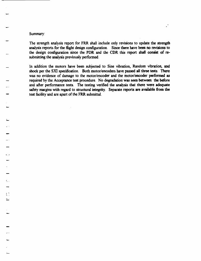
Summary_
The strength analysis report for FRR shall include only revisions to update the strength
analysis reports for the flight design configuration. Since there have been no revisions tothe design configuration since the PDR and the CDR this report shall consist of re-
submitting the analysis previously performed.
In addition the motors have been subjected to Sine vibration, Random vibration, and
shock per the SXI specification. Both motor/encoders have passed all three tests. Therewas no evidence of damage to the motor/encoder and the motor/encoder performed asrequired by the Acceptance test procedure. No degradation was seen between the beforeand after performance tests. The testing verified the analysis that there were adequate
safety margins with regard to structural integrity. Separate reports are available from the
test facility and are apart of the FRR submittal.
Z-
w
L_r
w
v
i
STEPPER MOTOR/ENCODER
SOLAR X-RAY IMAGER (SXI)
STRESS ANALYSIS
(ARX PIN 16187)
March 16, 1994
I_EROFU_X----J
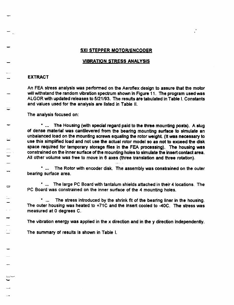
SXl STEPPER MOTOR/ENCODER
VIBRATION STRESS ANALYSIS
EXTRACT
m
L _
w
w
w
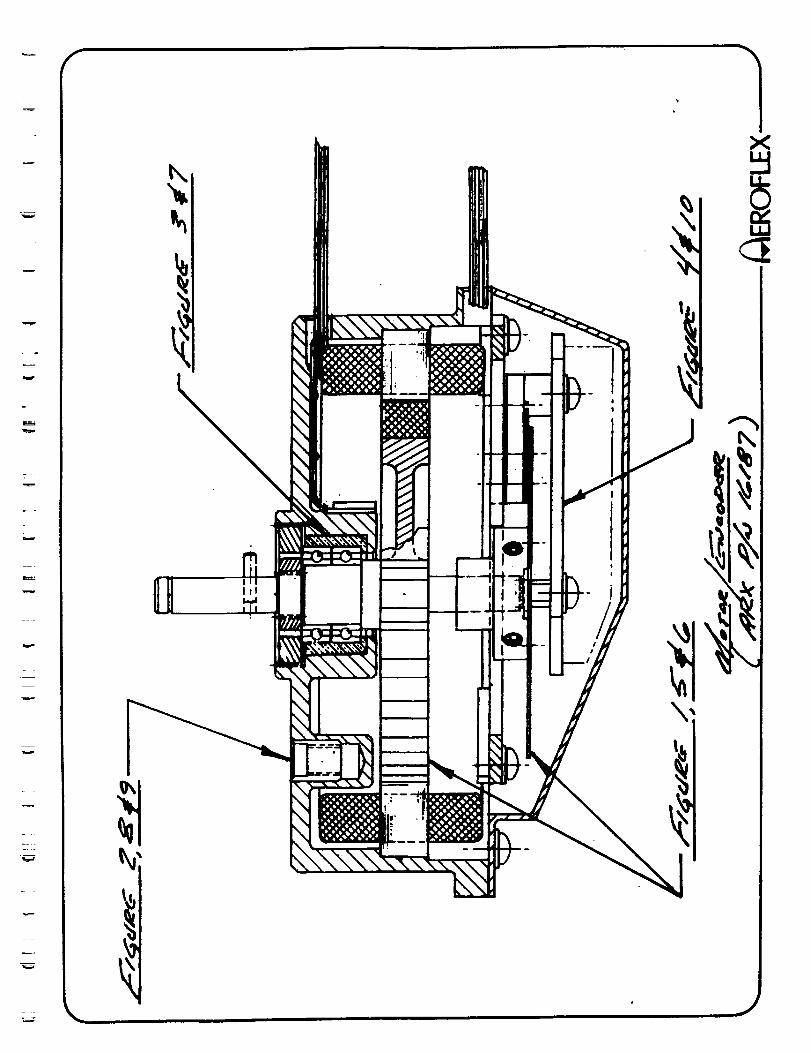
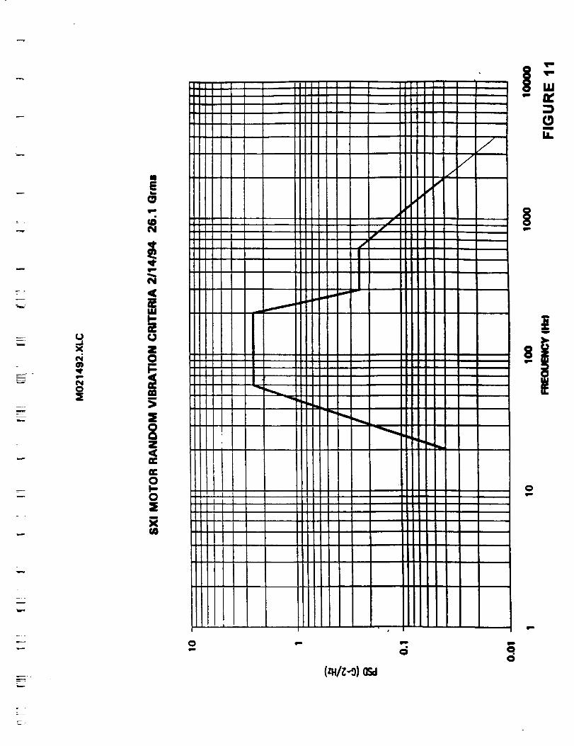
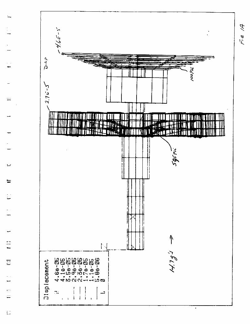
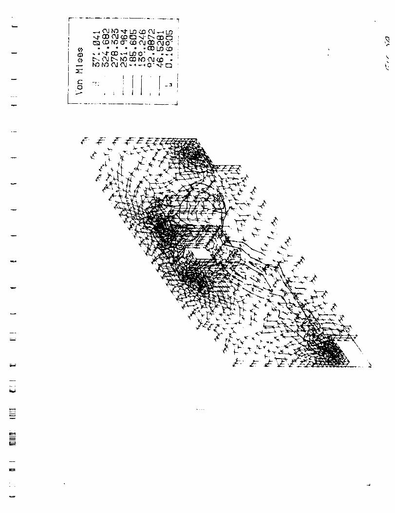
An FEA stress analysis was performed on the Aerofiex design to assure that the motor
will withstand the random vibration spectrum shown in Figure 11. The program used wasALGOR with updated releases to 5/21/93. The results are tabulated in Table I. Constants
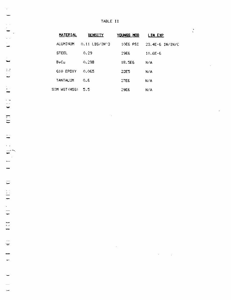
and values used for the analysis are listed in Table II.
The analysis focused on:
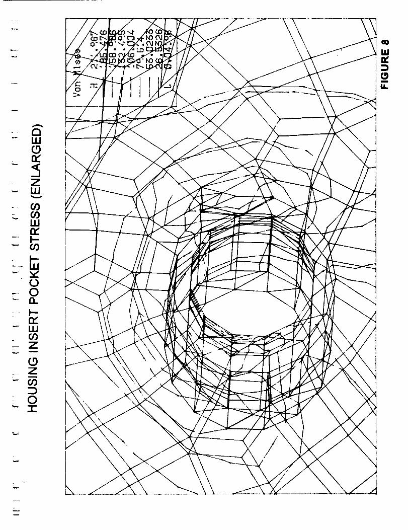
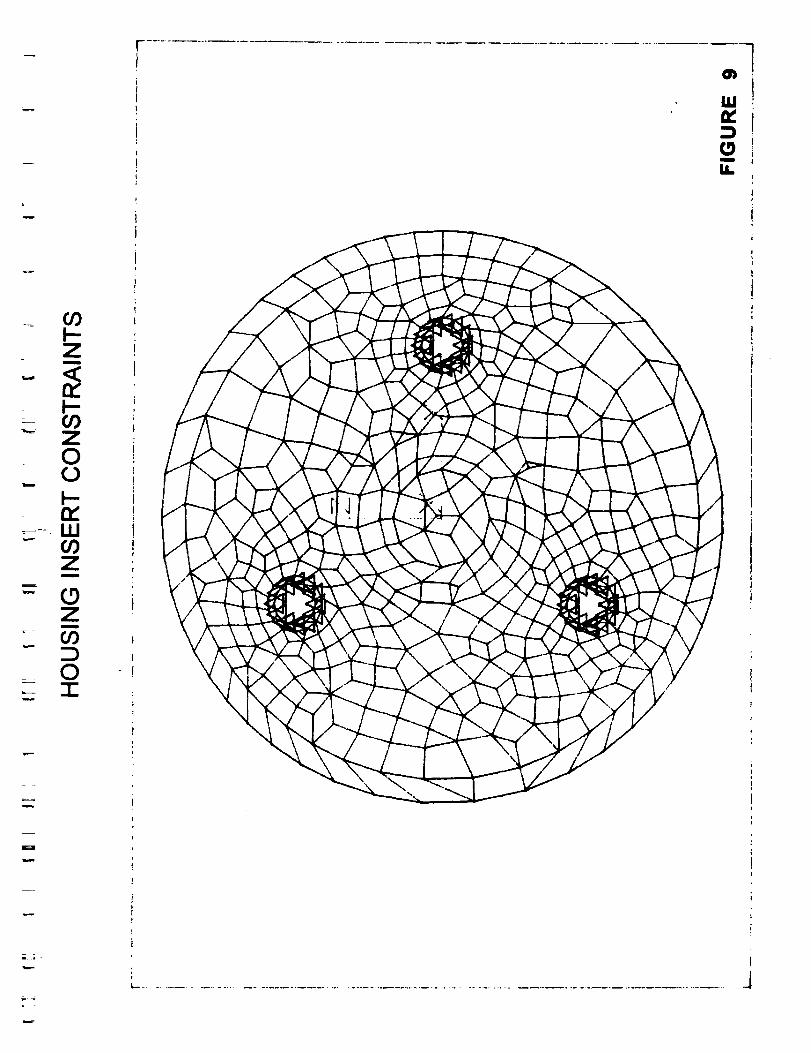
* ... The Housing (with special regard paid to the three mounting posts). A slug
of dense matedal was cantilevered from the beadng mounting surface to simulate an
unbalanced load on the mounting screws equaling the rotor weight. (It was necessary touse this simplified load and not use the actual rotor model so as not to exceed the disk
space required for temporary storage files in the FEA processing). The housing wasconstrained on the inner surface of the mounting holes to simulate the insert contact area.
All other volume was free to move in 6 axes (three translation and three rotation).
* ... The Rotor with encoder disk. The assembly was constrained on the outerbearing surface area.
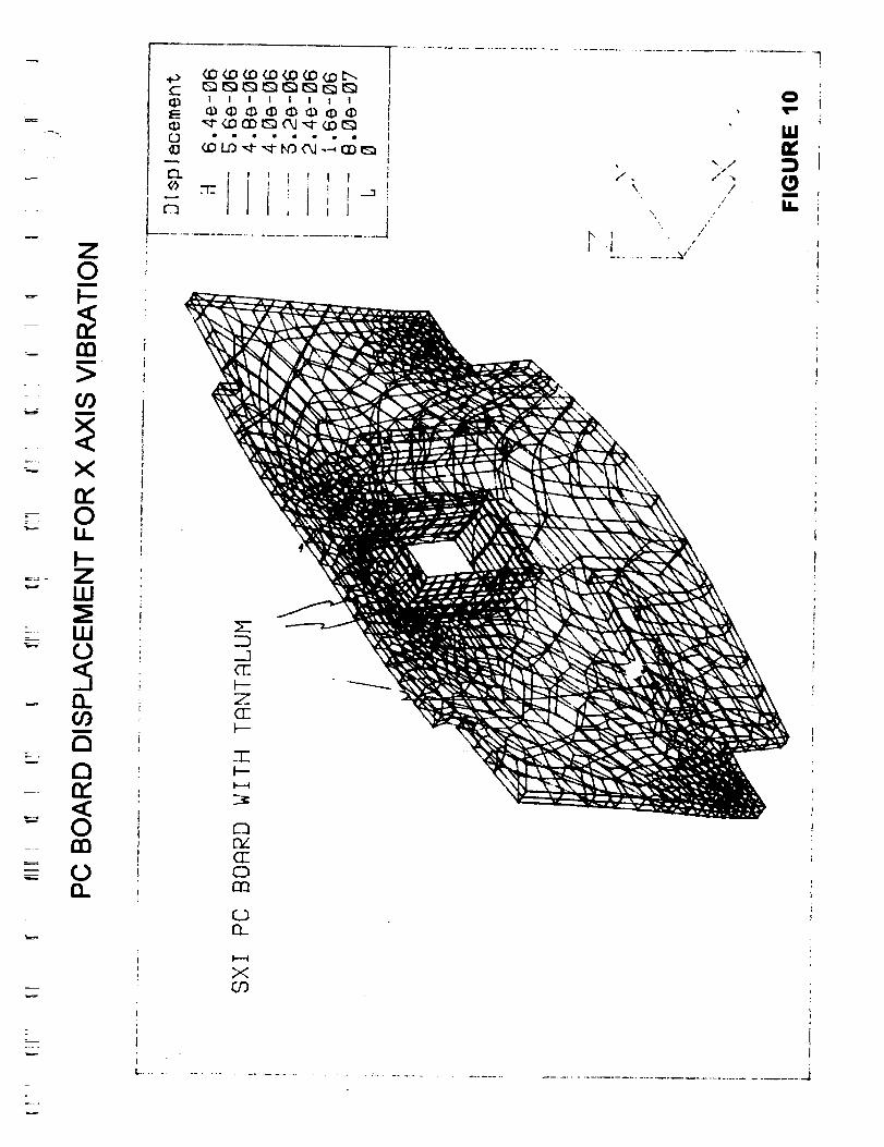
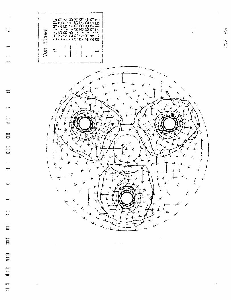
* ... The large PC Board with tantalum shields attached in their 4 locations. The
PC Board was constrained on the inner surface of the 4 mounting holes.
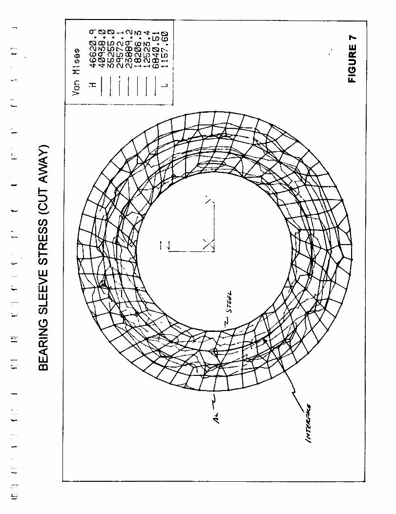
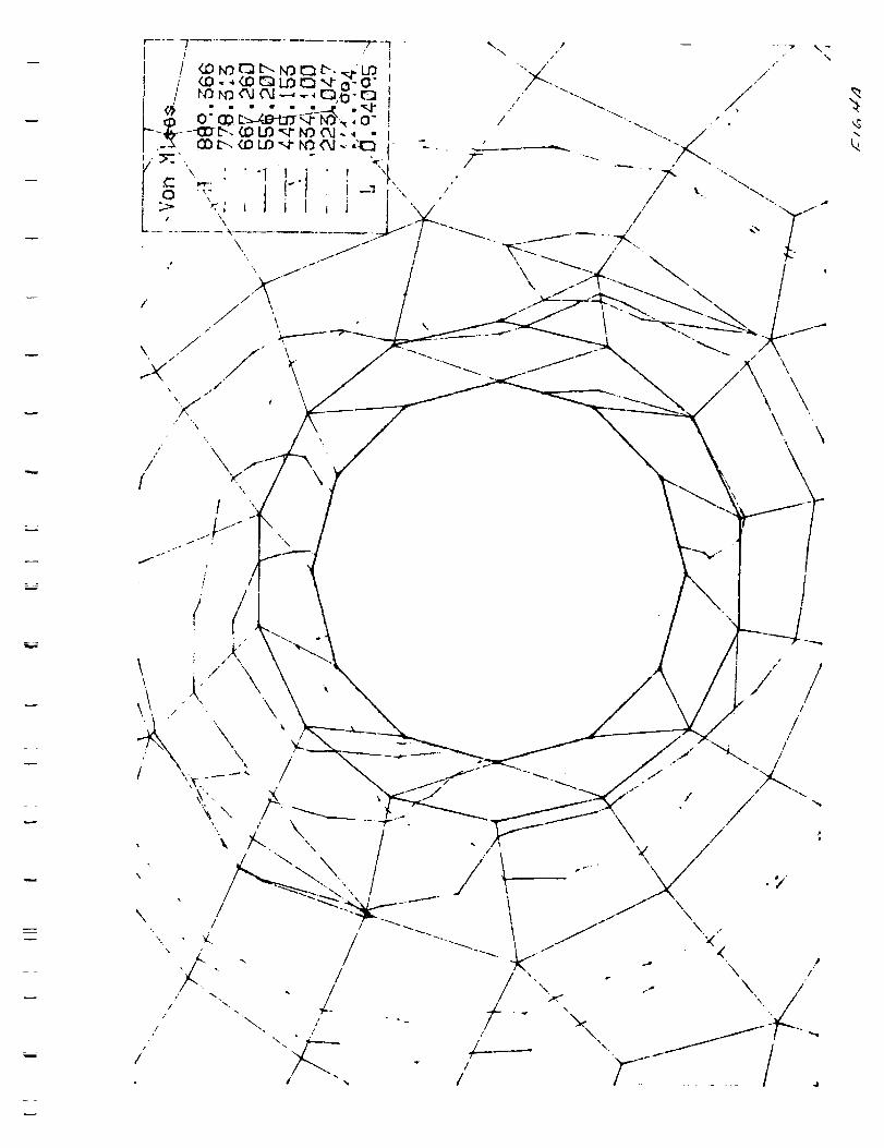
* ... The stress introduced by the shrink fit of the bearing liner in the housing.The outer housing was heated to +71C and the insert cooled to -40C. The stress was
measured at 0 degrees C.
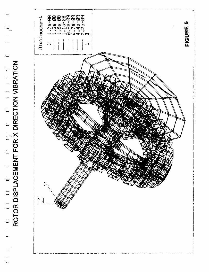
The vibration energy was applied in the x direction and in the y direction independently.
The summary of results is shown in Table I.
w
_.===
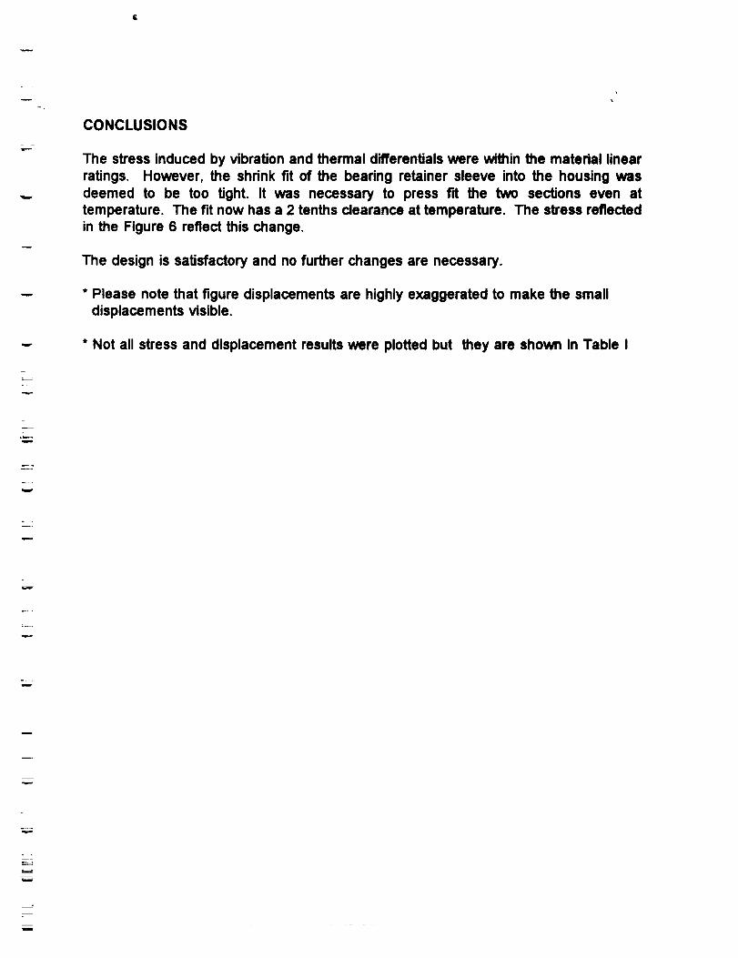
CONCLUSIONS
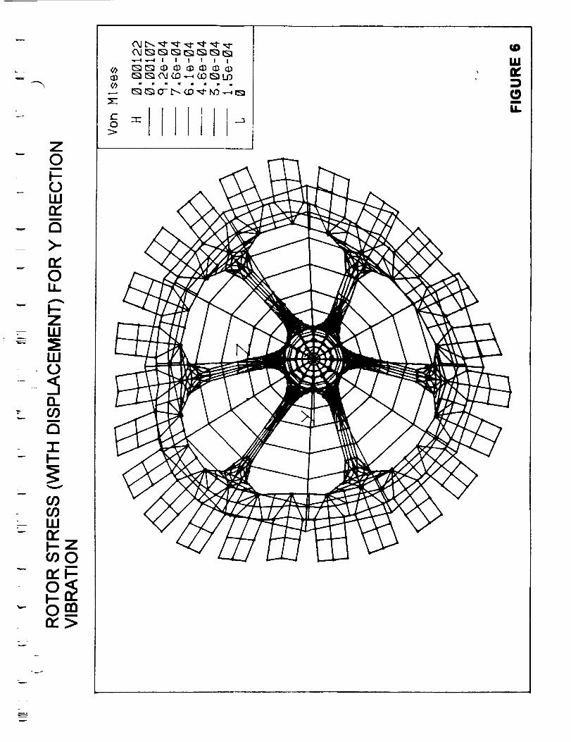
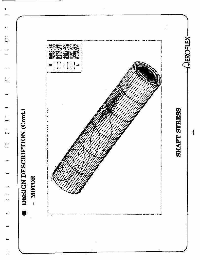
The stress induced by vibration and thermal differentials were within the material linearratings. However, the shrink fit of the bearing retainer sleeve into the housing wasdeemed to be too tight. It was necessary to press fit the two sections even attemperature. The fit now has a 2 tenths clearance at temperature. The stress reflectedin the Figure 6 reflect this change.
The design is satisfactory and no further changes are necessary.
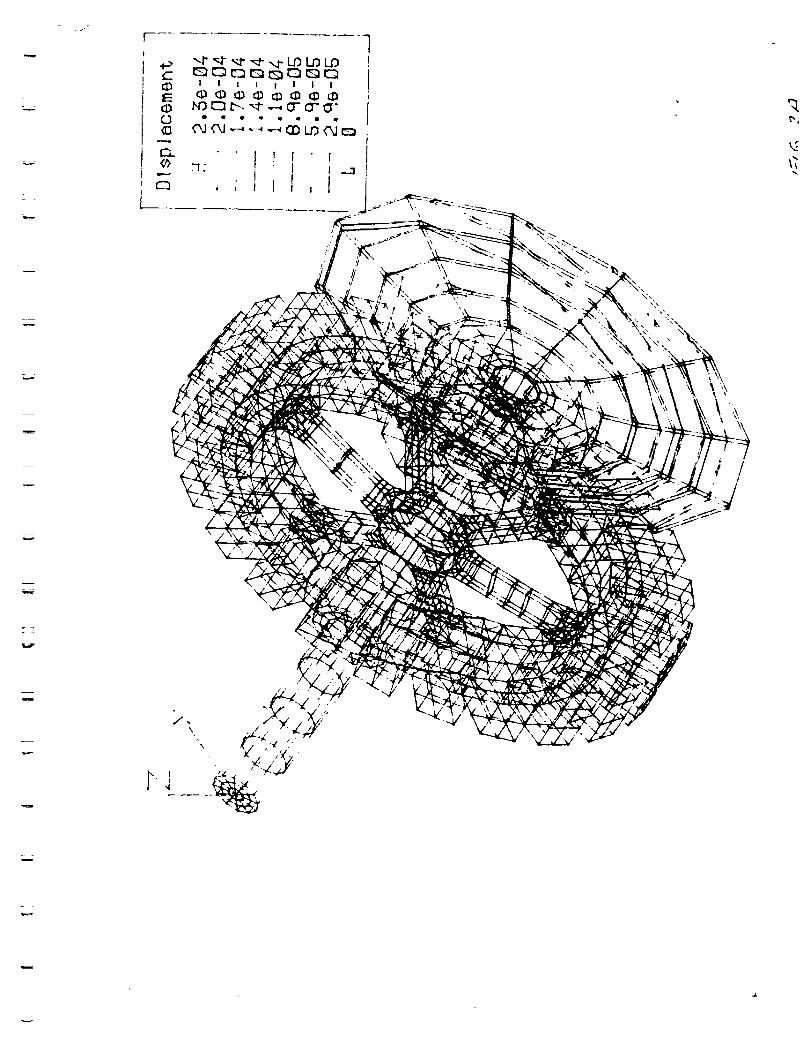
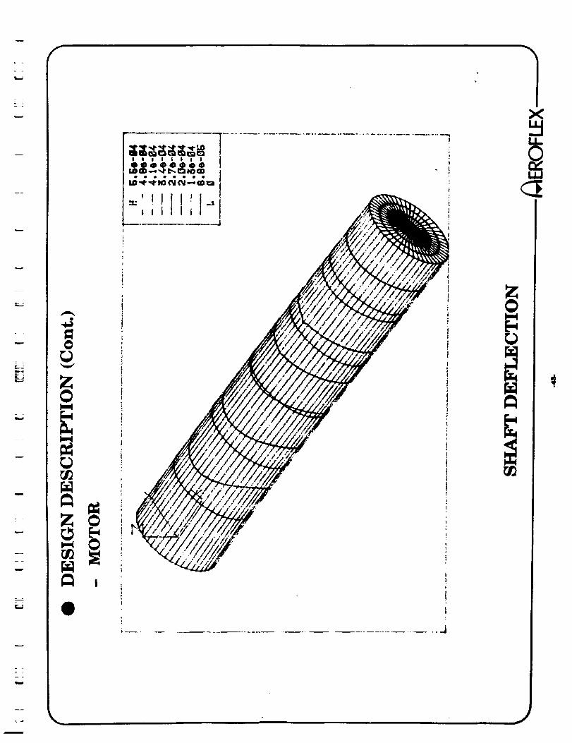
* Please note that figure displacements are highly exaggerated to make the smalldisplacements visible.
* Not all stress and displacement results were plotted but they are shown in Table I
w
o
_m
r_
w
m
m
u
?
_ ..r. _
Z
v
--=
?--
v
m
m
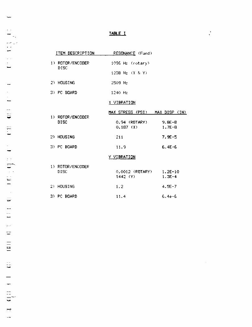
T_EI
ITEM DESCR IPT ION
1) ROTOR/ENCODER
D ISC
2) HOUSING
3) PC BOARD
I) ROTOR/ENCODER
DISC
2) HOUSING
3) PC BOARD
I) ROTOR/ENCODER
DISC
213 HOUSING
3) F'C BOARD
RESONANCE (Fund)
1096 Hz (rotary)
1238 Hz (X & Y)
25c)9 Hz
1240 Hz
X VIBRATION
MAX STRESS (PSI) MAX DISP (IN)
0.94 (ROTARY)
0.187 (X)
211
11.9
Y VIBRATION
9.8E-8
1.7E-8
7.9E-5
6.4E-6
O. 0012 (ROTARY)
1442 (Y)
1.2
11.4
1.2E-IO
1.3E-4
4.5E-7
6.4e-6
w
w
=--v
r
MATERIAL
ALUMINUM
STEEL
BeCu
G10 EPOXY
TANTALUM
SIM WGT(HSG)
TABLE II
DENS ITY
O. 11 LBS/IN"3
O. 29
O.29B
O.065
0.6
5.5
YOUN(_SMOV
IOE6 PSI
29E6
18.5E6
22E5
27E6
29E6
LIN EXP
23.4E-6 IN/IN/C
I0.6E-6
N/A
N/A
N/A
N/A
w
m
i
w
v
w
L
f 1X
|
if!
Il,|
J
_ o
00
-w
I-Ii
I
_._
n,,Ill0
"00
_Z711
_0I-
_0__
=
I
IAII%
B
IA,
1.1.1
i.,_
_-- .-I7n_
LLJ
0
--I--
:-,U-a')Z
'U
-9Z
"I:)
e_
uJn,,:00I
I,I.
.=I
-I-."-Z
<
,,a
-<0
0a.
\
a,,
m
_L
Z
Z_0
i
m
z0
: F-l.U
a
0I.I_
Z
l.l.I
i
a
0
0
\\
\
i
IJl=
=
Z0i
1--
111n,"
n,'011.
I--
i
a
7--i-
111n,,l-Z_0
l-om
_lllfli
lfliiJl
,UP
i,I,/
m
i,i,,
mo
w
L
r_
I-
w
l-
w
ww_.I
Z
oo
'I
Lf
J
I
m
_L
- D"_ LLI
@
Z-, ILl
_ O0_- LU
Or)
L)-- 0
13.
n""" UJ
¢.0Z
(.9Z
-- o3
, 0.- "r"
=
n,
I
Z
_-.CO
"_ Z0(0
t-n,
Zn
Zm
GO
_ 0
-r
!
N
_m
r
w
Z0m
!--
cO
X(Z::0L,I_
I-Zw
w0
com
a
n,"
0
tlllllll
amgamtee
N
,w !It ,/ .'_(\. ,/
q.,/
r " /'
O
mla
B
ml_
ellCVO
O
H
r.D
7
E
w
r
!
I
:E0QZ,<M.
n.0I-0
XW
0_m d q
0
|_•- n_
U..
0
[
m
E-w
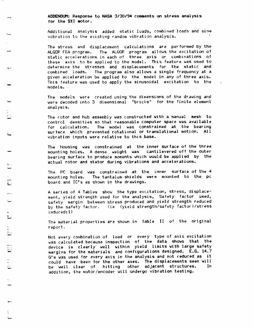
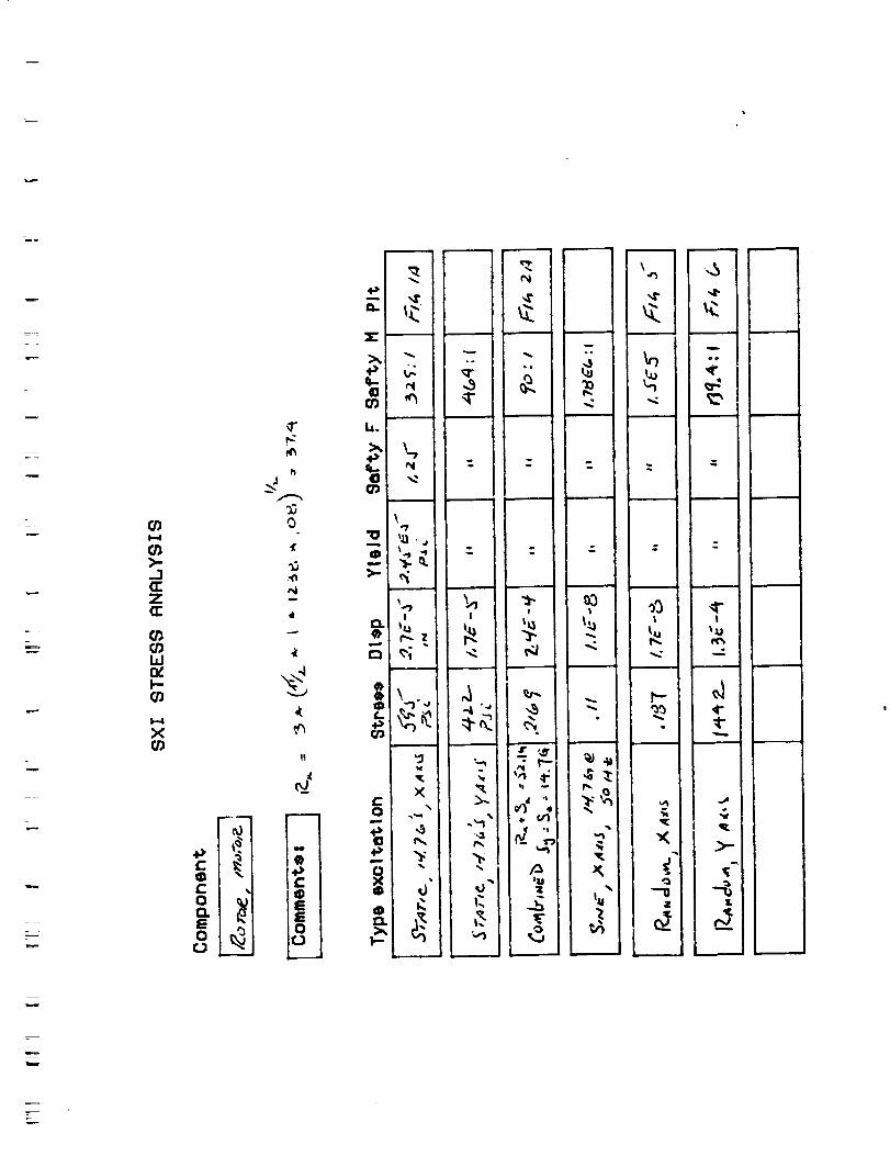
ADDENDUM: Response to NASA 3/30/94 comments on stress analysis
for the SXI motor.
Additional analysis added static loads, ,:ombined loads and sine
vibration to the existing random vibration analysis.
Tile stress and displacement calculations are performed by the
ALGOR FEA program. The ALGOR program allows the excitation of
static accelerations in each of three axis or combinations of
these axis to be applied to the model. This feature was used to
determine the stresses and displacements for the static and
combined loads. Tile program also allows a single frequency at a
given acceleration be applied to the model in any of three axis.
This feature was used to apply the sinusoidal excitation to the
models.
The models were created using the dimensions of tile drawing and
were decoded into, 3 dimensional "bricks" for the finite element
analysis.
The rotor and hub assembly was constructed with a manual mesh to
control densities so that reasonable computer space was available
for calculation. The model was constrained at tile bearing
surface which prevented rotational or translational motion. All
vibration inputs were relative to this base.
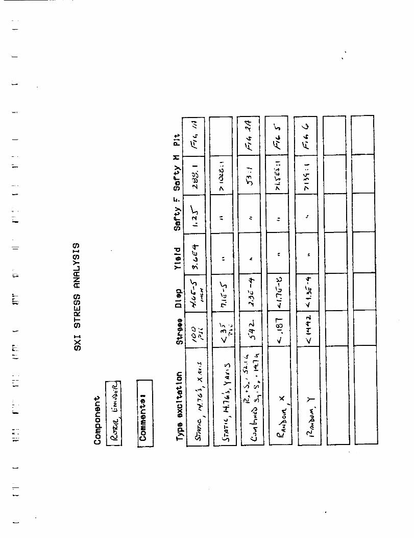
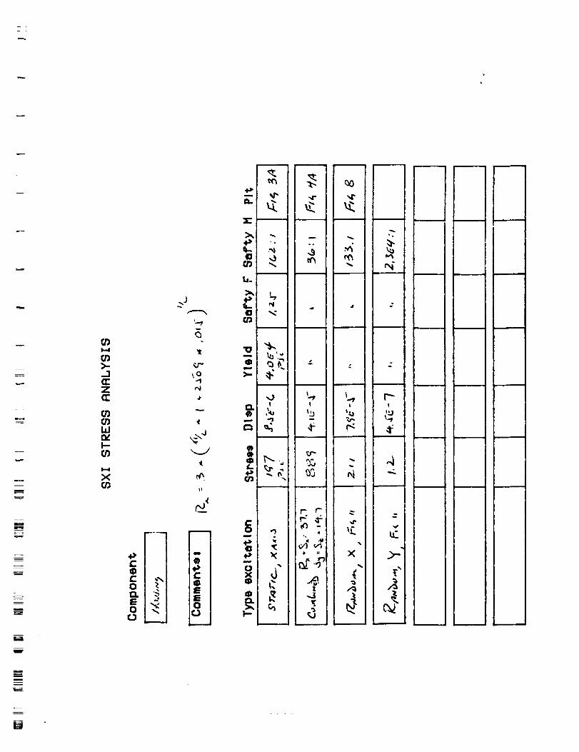
The Housing was constrained at the inner surface of the three
mounting holes. A dense weight was cantilevered off the outer
bearing surface to produce moments which would be applied by the
actual rotor and stator during vibrations and accelerations.
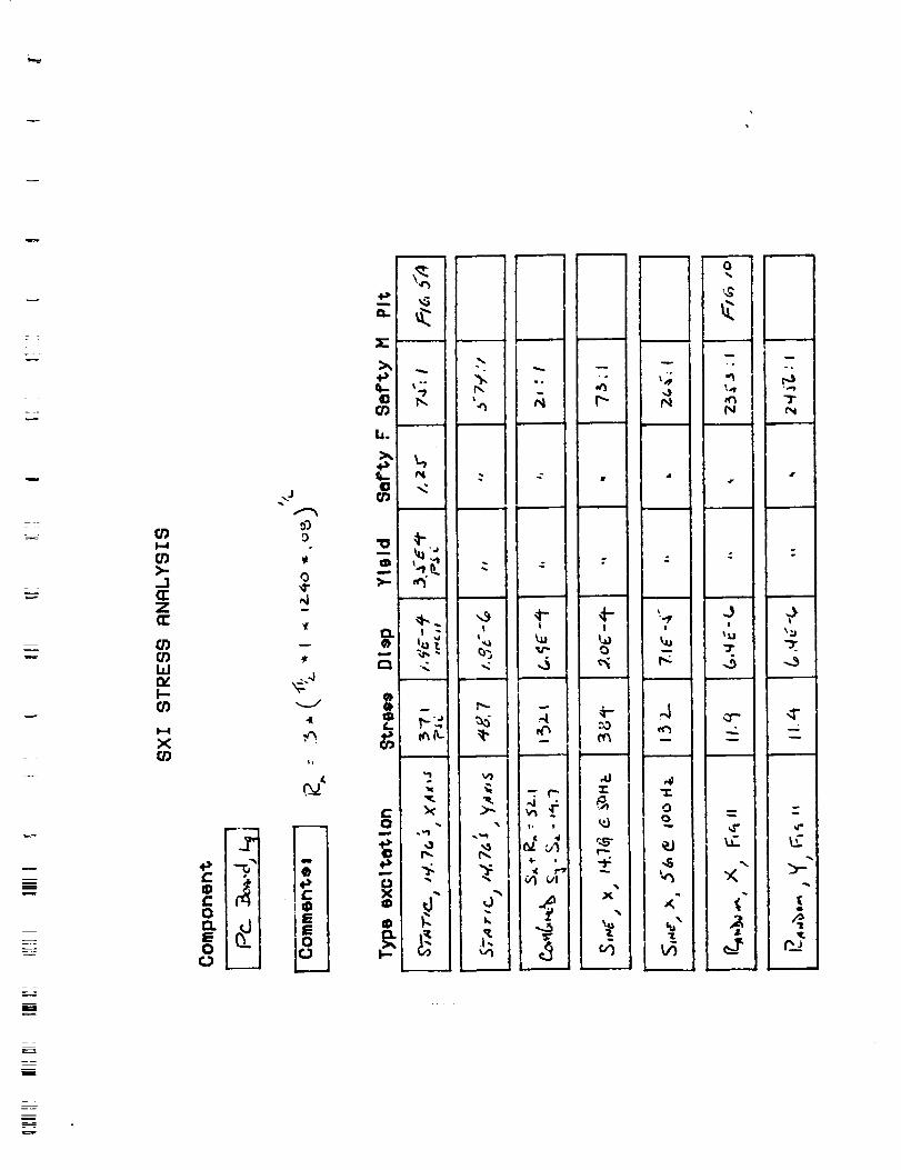
The PC board was constrained at the inner surface of the 4
mounting holes. The tantalum shields were mounted to the pc
board and IC's as shown in the drawings.
A series of 4 Tables show the type excitation, stress, displace-
ment, yield strength used for the analysis, Safety factor used,
safety margin between stress produced and yield strength reduced
by the safety factor. (ie (yield strength/safety factor)/stress
induced:l)
The material properties are shown in Table II of the original
r epc,rt.
Not every combination of load or every type of axis excitation
was calculated because inspection of the data shows that the
device is clearly well within yield limits with large safety
margins for the materials and configurations designed. E.G. 14.7
G's was used for every axis in the analysis and not reduced as it
could have been for the other axes. The displacements seen will
be well clear of hitting other adjacent structures. In
addition, the motor/encoder will undergo vibration testing.
I-4
"1(_z
O_
ILlntt'--O_
I,-.4
X
p.m
_)
,,.:,c
0 _j
E -
o
m
.0
6
,0tl _,-
0
"0
0
4
_ 0
...° .
_ J
i !
m _
• r.
J
m
J
I
J
\
m
_3I
_u
w
,,5
!
4"
4-
w
r.--;
z
I-4
>-.-1<]:ZO:
W_vI-ra
I-I
X
C: z
12. r_
o_tJiI
J
40
m
b.
.i,)tl- r_40 .,.:tD
J
•o _-
£:) -
]q
40
I_-
0 "t:Xo
O
I
I
V
t
°
i
I1
iL
B
NE
U
rj')1,4
rj)>.,
,Ia:za::
rj')t,r)i,if.v,I,.-
I,--4
Xrj_
+I,4,..11)c: _IO0. '_ I
_J
"Jr
_o../
%1
m I
Q I
• Ie iis io i
_.J ilm.=..ll
.I.3' ".
r,D --,
l.i.
,p
rj)
•o "_-
,,J
0 ,_,==..
rJ_ --
_r
=x ,."
I-
,z" ",Z"
oo "°
m
4" .it
4
,f _ l
% --
i
o ,
4 "@ LI
ff._ ×.{
d -
-0
I
1"J
,4°
J
m _
m _
m _
i
i
E
rj)
J
Z
W
X
C• _',i
Ot:i,.
0
..J
it
o¢,4
Ii
t0 -zffl
0 "_ n
'sq
.-. "Jr-
)< -,d
!
%o
",,.5
,j
4"!
o
J
J
("--,',,4 "
_.'
m
ir
w
I
4-- 'I I
I.,_ laj
,N ec
,4J ,4
£ o
r",-
%
"5 i',,_ I
. i
J i• n
I
I
d
o,
q-
t_
o
r_
M
u
!
\
t
||l_J
_ ,ll JI
!
i
T._.._
,.._.
.,,--,-
w
m
//
\\
/
L
m
-____
e-o
!
;I
tA
1 I
ju 1__,i ,I
\
\
,
o
\
i
i
\
t",%
B
z_-m
0
0 rjl7._L _ __
I ; I i j |
\
\
\
__°
w
m
m
II
w
E_
w
E =
I.-I
ZN=i
r.T.]
0
[-
I
L ....
i!
{
._. o. =j
XIi
ir _
whwl
z
-x
u
=
f
q_
_o
z
r_
0
I,UE'_Q .,-oNilkO_ll_ _'e
_LD'r41"qq'l_lq_¢3 •