Streamlined approach for environmental restoration plan for ...
104
Nevada Environmenta Restoration Project DO^NV-446- Streamlined Approach for Environmental Restoration Plan for Corrective Action Unit 430, Buried Depleted Uranium Artillery Round No. 1, Tonopah Test Range UNCONTROLLEi Controlled Copy No.: 21 Revision: 1 September 1996 Environmental Restoration Division U.S. Department of Energy Nevada Operations Office
-
Upload
khangminh22 -
Category
Documents
-
view
2 -
download
0
Transcript of Streamlined approach for environmental restoration plan for ...

NevadaEnvironmentaRestorationProject
DO^NV-446-
Streamlined Approach forEnvironmental Restoration Planfor Corrective Action Unit 430,Buried Depleted Uranium ArtilleryRound No. 1, Tonopah Test Range
UNCONTROLLEiControlled Copy No.: 21
Revision: 1
September 1996
Environmental RestorationDivision
U.S. Department of EnergyNevada Operations Office

This report has been reproduced from the best available copy.
Number of pages in this report: 100
Available to DOE and DOE contractors from:Office of Scientific and Technical Information, P.O. Box 62,Oak Ridge, TN 37831. (615)576-8401.
Available to the public from the National Technical Information Service,Department of Commerce, 5285 Port Royal Road, Springfield, VA 22161.(703) 487-4650.

DISCLAIMER
Portions of this document may be illegiblein electronic image products. Images areproduced from the best available originaldocument

DOE/NV--446
STREAMLINED APPROACH FOR ENVIRONMENTALRESTORATION PLAN FOR CORRECTIVE ACTION
UNIT 430, BURIED DEPLETED URANIUM ARTILLERYROUND NO. 1, TONOPAH TEST RANGE
DOE Nevada OperatjLas
Controlled Copy No.: 21
Revision: 1
*»» B ","• n
September 1996
DISTRIBUTION OF THIS DOCUMENT IS UNLIMITED,

STREAMLINED APPROACH FOR ENVIRONMENTAL RESTORATIONPLAN FOR CORRECTIVE ACTION UNIT 430, BURIED DEPLETED URANIUM
ARTILLERY ROUND NO. 1, TONOPAH TEST RANGE
Approved by: Date:Sabine Curtis, Subproject ManagerIndustrial Sites Subproject
Approved by: 'iWLDavid Shafer, Acting Project ManagerEnvironmental Restoration Project
Date:

TTR CAU 430Section: ContentsRevision: 1Date: 09/30/96Page i of vii
Table of Contents
List of Figures '. iii
List of Tables iii
List of Acronyms and Abbreviations iv
1.0 Introduction 1
2.0 Unit Descriptions and Closure Objectives 5
2.1 Tonopah Test Range 5
2.2 Site Locatioaand Description 8
2.3 Process Knowledge • 10
2.3.1 Hazardous Components and Information 10
2.3.2 Constituents of Concern 10
2.4 Closure Standards 10
2.5 Depleted Uranium and Plutonium Closure Standards 13
2.5.1 RESRAD Risk Assessment Calculations 13
2.5.2 RESRAD Risk Assessment Methodology 13
2.5.3 Summary and Recommendations for Depleted Uranium and Plutonium
T Closure Standards Using RESRAD 14
2.6 Clean Closure 15
3.0 Field Activities 16
3.1 Sampling 16
3.1.1 Sample Locations 22
3.1.2 Analytical Parameters 23
3.2 Field Screening and Field Surveys 23
3.3 Verification : 23
3.4 Remediation 24
3.5 Site Restoration 24
3.6 Schedule 24

TTR CAU 430Section: ContentsRevision: 1Date: 09/30/96Page ii of vii
Table of Contents (Continued)
4.0 Reports 25
5.0 Waste Management 26
6.0 Site-Specific Health and Safety Plans 28
7.0 Community Relations Plan . 29
8.0 References 30
Appendix A - Data Quality Objectives A-l
Appendix B - Guideline Concentration for Depleted Uranium and Plutonium B-l

TTR CAU 430Section-: Contents
' Revision: 1Date: 09/30/96Page iii of vii
List of Figures
Number Title Page
1-1 Closure Decision Diagram 3
2-1 Tonopah Test Range Location Map 6
2-2 Tonopah Test Range Layout, Nye County, Nevada 7
2-3 Site Location Map, Buried Depleted Uranium Artillery Round No. 1,
Tonopah Test Range, Nye County, Nevada 9
List of Tables
Number Title Page
2-1 Suspected Constituents of Concern and Closure Standards for the
Buried Depleted Uranium Artillery Round No. 1 Corrective Action Unit 430 11
2-2 Site-Specific Radionuclide Guideline Concentrations 14
3-1 Analytical Requirements for the Buried Depleted Uranium Artillery Round No. 1
Corrective Action Unit 430 17
3-2 Site Characterization and Closure Verification Analytical Chemical
Requirements 18
TTR CAU 430Section: ContentsRevision: 1Date: 09/30/96Page iv of vii
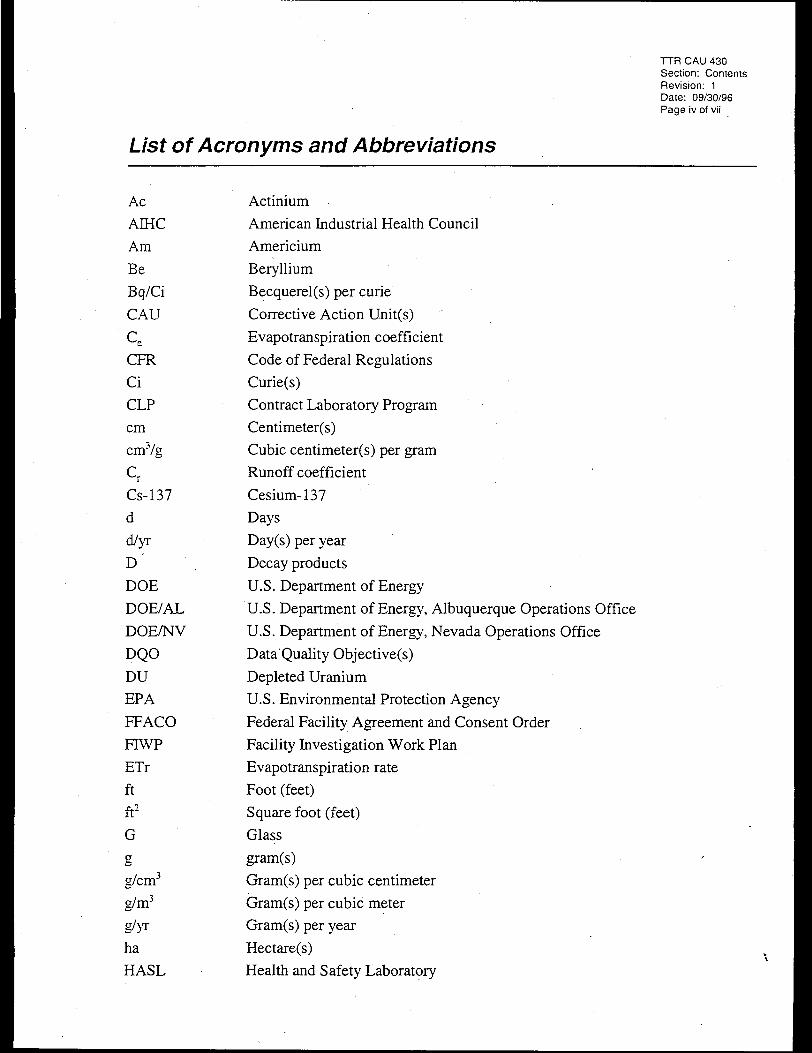
List of Acronyms and Abbreviations
AcAIHC
Am
Be
Bq/Ci
CAU
Ce
CFR
Ci
CLP
cm
cnrVg
crCs-137
d
d/yr
D
DOE
DOE/AL
DOE/NV
DQO
DUEPA
FFACO
FIWP
ETr
ft
ft2
Gaeg/cm3
g/m3
g/yrha
HASL
Actinium .American Industrial Health Council
Americium
Beryllium
Becquerel(s) per curie
Corrective Action Unit(s)
Evapotranspiration coefficient
Code of Federal Regulations
Curie(s)
Contract Laboratory Program
Centimeter(s)
Cubic centimeter(s) per gram
Runoff coefficient
Cesium-137
Days
Day(s) per year
Decay products
U.S. Department of Energy
U.S. Department of Energy, Albuquerque Operations Office
U.S. Department of Energy, Nevada Operations Office
Data Quality Objective(s)
Depleted Uranium
U.S. Environmental Protection Agency
Federal Facility Agreement and Consent Order
Facility Investigation Work Plan
Evapotranspiration rate
Foot (feet)
Square foot (feet)
Glass
gram(s)
Gram(s) per cubic centimeter
Gram(s) per cubic meter
Gram(s) per year
Hectare(s)
Health and Safety Laboratory

TTR CAU 430Section: ContentsRevision: 1Date: 09/30/96Page v of vii
List of Acronyms and Abbreviations (Continued)
HEhrs/d
hrs/y
in.
IRr
ITLV
JTA
keV
kgkg/yr
km
L
L/day
L/yrLANL
m
MB '
m/s
m/yr
m2
m2/s
m3/day
m3/yr
mg/kg
mg/L
mi
mL
mrem/pCi
mrem/yr
NA
NAS
ND
NDEP
Ni
High explosivesHour(s) per day
Hour(s) per year
Inch(es)
Irrigation rate
IT Corporation, Las Vegas
Joint Test Assembly
Kiloelectron volt
Kilogram(s)
Kilogram(s) per year
Kilometer(s)
Liter(s)
Liter(s) per day
Liter(s) per year
Los Alamos National Laboratory
Meter(s)
Mass balance
Meter(s) per second
Meter(s) per year
Square meter(s)
Square meter(s) per second
Cubic meter(s) per day
Cubic meter(s) per year
Milligram(s) per kilogram
Milligram(s) per liter
Mile(s)
Milliliter(s)
Millirem(s) per PicoCurie
Millirem(s) per year
Not applicable
National Academy of Science
Nondispersion
Nevada Division of Environmental Protection
Nickel

List of Acronyms and Abbreviations (Continued)
No.
Np
NTS POC
Pa
Pb
pCi
pCi/gpCi/L
PE
Pr
PRGPu
QA
QAPP
r
Ra
RCRA
RESRAD
Rn
RPD
s/yr
SAFER
SNL
SNM
sqft
SSHASP
svoc .TAL
Tbq
TCLP
Th
TRU
TTR
Number
NeptuniumNevada Test Site Performance Objective for Certification
Hazardous Waste
Protactinium
Lead
PicoCurie(s)
PicoCurie(s) per gram
PicoCurie(s) per liter
PolyethylenePrecipitation
Preliminary Remediation Goals.
Plutonium
Quality assurance
Quality Assurance Project Plan
Radius
Radium
Resource Conservation and Recovery Act
Residual Radioactivity (computer code)
Radon
Relative percent difference
Second(s) per year
Streamlined Approach for Environmental Restoration
Sandia National Laboratories
Special Nuclear Material .
Square foot (feet)
Site-Specific Health and Safety Plan(s)
Semivolatile organic compound(s)
Target Analyte List
Tetrabecquerel(s)
Toxicity Characteristic Leaching Procedure
Thorium
Transuranic
Tonopah Test Range
TTR CAU 430Section: ContentsRevision: 1Date: 09/30/96Page vi of vii
of Nonradioactive

TTR CAU 430Section: ContentsRevision: 1Date: 09/30/96Page vii of vii
List of Acronyms and Abbreviations (Continued)
uuxoyr(s)
£tg/L
Aim
%
%R
°C
UraniumUnexploded ordnance
Year(s)
Microgram(s) per liter
Micrometer
Percent
Percent recovery
Degree(s) Celsius

TTR CAU 430Section: 1.0Revision: 1Date: 09/30/96Page 1 of 32
1.0 Introduction
This plan addresses actions necessary for the restoration and closure of Corrective Action Unit
(CAU) No. 430, Buried Depleted Uranium (DU) Artillery Round No. 1 (Corrective Action Site
No. TA-55-003-0960), a buried and unexploded W-79 Joint Test Assembly (JTA) artillery test
projectile with high explosives (HE) (Kessel, 1996), at the U.S. Department of Energy, Nevada
Operations Office (DOE/NV) Tonopah Test Range (TTR) in south-central Nevada. It describes
activities that will occur at the site as well as the steps that will be taken to gather adequate data
to obtain a notice of completion from Nevada Division of Environmental Protection (NDEP).
This plan was prepared under the Streamlined Approach for Environmental Restoration
(SAFER) concept, and it will be implemented in accordance with the Federal Facility Agreement
and Consent Order (FFACO) (FFACO, 1996) and the Resource Conservation and Recovery Act
(RCRA) Industrial Sites Quality Assurance Project Plan (DOE/NV, 1994a).
The SAFER process is employed at CAUs where enough information exists about the nature and
extent of contamination to propose an appropriate corrective action prior to implementing a
Corrective Action Investigation. This process combines elements of the Data Quality Objective
(DQO) process and the observational approach to help plan and conduct corrective actions.
DQOs are used to identify the problem and define the type and quality of data needed to
complete the investigation phase of the process. The observational approach provides a
framework for managing uncertainty and planning decision making.- The purpose of the
investigation in the SAFER process is to document and verify the adequacy of existing
information, such as process knowledge; to affirm the decision for clean closure, closure in place,
or no further action; and to provide sufficient data to implement the corrective action.
The SAFER concept recognizes that technical decisions may be made based on incomplete, but
sufficient, information and the experience of the decision maker. Any uncertainties are
addressed by documented assumptions that are verified by sampling and analysis, data
evaluation, and on-site observations as planned activities progress, and by contingency plans as
necessary. The remediation and closure may proceed simultaneously with site characterization as
sufficient data are gathered to confirm or disprove the assumptions made in selecting the closure
method. If, at any time during the site closure, new information is developed that indicates that
the closure method or underlying assumptions should be revised, the decision-makers will
redirect the closure activities to more appropriately protect human health and the environment.

TTR CAU 430Section: 1.0Revision: 1Date: 09/30/96Page 2 of 32
NDEP will be notified, and this plan will be amended. Following the completion of SAFER
activities, a closure report will be prepared and submitted to the NDEP.
Adequate process knowledge currently exists to pr6pose clean closure as the corrective action for
the Buried DU Artillery Round No. 1 CAU. The process knowledge includes review of
historical records, geophysical surveys, and interviews with project personnel. This process
knowledge was used to determine the constituents of concern that will be present as well as the
most appropriate SAFER methods.
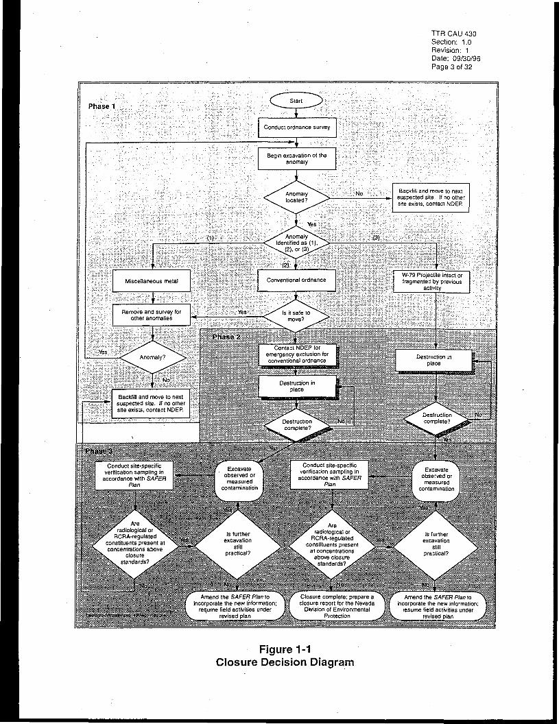
Corrective action at the Buried DU Artillery Round No. 1 CAU will be achieved in three phases.
The first phase will involve locating and assessing the projectile. The second phase involves
destruction in place and removal of the projectile or its remaining components. Finally, the third
phase will involve the remediation of radiological and chemical contamination, which includes
collecting soil samples to verify clean closure. A decision diagram which shows the iterative
process for each phase is presented in Figure 1-1.
This plan reflects the following assumptions. If, at any time during closure activities,
information is developed that invalidates any assumption, this plan shall be amended, and
amendments will be provided to NDEP for approval.
• The Buried DU Artillery Round No. 1 is located in one of three suspected locations southof Avenue 13.
• The Buried DU Artillery Round is believed to contain unexploded HE and depleteduranium.
• The Buried DU Artillery Round cannot be safely removed without first causing anexplosion of the HE, so the projectile will be detonated in place.
• Depleted uranium (U-238) will be released to the subsurface in the vicinity of theprojectile during detonation, resulting in localized contamination of the soil with depleteduranium.
• All potentially existing contamination is limited in extent to the immediate vicinity of theartillery round. Explosives residue (i.e., 2,4-Dinitrotoluene and Nitrobenzene) to bereleased during the detonation will be minor and only affect a small volume of soil nearthe detonation. All contamination that may result from detonating the round will belimited to the immediate vicinity of the round.
TTR CAU 430Section: 1.0Revision: 1Date: 09/30/96Page 3 of 32
Conduct ordnance survey
in excavation of theanomaly
Backfill and move lo nextsuspected site. If no othe!site exists, contact NDEP.
W-79 Projectile intact orfragmented by previous
activityMiscellaneous metal
Remove and survey forother anomalies
Contact NDEP foremergency exclusion forconventional ordnance
Destruction inplace
Backfill and move to nextsuspected site. If no othersite exists, contact NDEP.
Destructioncomplete?Destruction
complete?
Conduct site-specificverification sampling in
accordance with SAFERPlan
Conduct site-specificverification sampling in
accordance with SAFERPlan
Excavateobserved ormeasured
contamination
Areradiological or
RCRA-regulatedconstituents present atconcentrations above
closurestandards?
Areradiological or
RCRA-regulatedconstituents present
at concentrationsabove closure
standards?
Is furtherexcavation
stillpractical?
Amend the SAFER Plan toincorporate the new information
resume field activities underrevised plan
Amend the SAFER Plan toincorporate the new information;
resume field activities underrevised plan
Closure complete; prepare aclosure report for the Nevada
Division of EnvironmentalProtection
Figure 1-1Closure Decision Diagram

TTR CAU 430Section: 1.0Revision: 1Date: 09/30/96Page 4 of 32
A small amount of mixed waste may be generated during the detonation of the projectilebecause of the simultaneous release of U-238 and regulated organic compounds in theexplosive.
If any mixed waste is generated, it will be managed in accordance with the Mutual Consent
Agreement Between the State of Nevada and the Department of Energy for the Storage of Low-
Level Land Disposal Restricted Mixed Waste. Within nine months of the placement of mixed
waste on the transuranic (TRU) mixed waste storage pad, DOE/NV will submit a plan for
treatment and disposal of the waste to the Nevada Division of Environmental Protection.

TTR CAU 430Section: 2.0Revision: 1Date: 09/30/96Page 5 01 32
2.0 Unit Descriptions and Closure Objectives
The Buried DU Artillery Round No. 1 (CAU No. 430) is located on the Tonopah Test Range, a
U.S. Department of Energy (DOE) weapons test and research facility located in Nye County,
Nevada, on the northern portion of the Nellis Air Force Range (Figure 2-1).
2.1 Tonopah Test RangeThe TTR is approximately 255 kilometers (km) (140 miles [mi]) northwest of Las Vegas by air
and approximately 64 km (40 mi) southeast of Tonopah by road. The nearest occupied
community is Goldfield, Nevada, which is 42 km (26 mi) west of the western TTR boundary
(ERDA, 1975).
The TTR occupies about 1,616 square kilometers (624 square miles). It is bordered on the south,
east, and west by the Nellis Air Force Range and on the north by sparsely populated public land
administered by the U.S. Bureau of Land Management and the U.S. Forest Service
(DOE/NV, 1992a).
Since 1957, the TTR has been operated for the DOE Albuquerque Operations Office (DOE/AL)
by Sandia National Laboratories (SNL) and used for weapon test-support activities varying from
simple tests of hardware components or systems needing limited support to rocket launches or air
drops of test vehicles requiring full range support for the U.S. Air Force, U.S. Army, and
U.S. Navy operational and test groups as wellas some defense contractors (ERDA, 1975).
Through a Memorandum of Agreement with DOE/AL, primary responsibility for environmental
restoration activities associated with TTR CAUs has been transferred to DOE/NV
(Powers, 1996).
The TTR is divided into various areas (Figure 2-2). Areas 3 and 9 and an unnumbered Test Area
along the flight line are under SNL control; Areas 3 and 9 are the main centers of SNL activities.
Area 3 is also known as the Control Point Area and includes support facilities for maintenance
and operations. Area 9 is the center for rocket and gun firings, ordnance storage, and related test
support operations, with impact areas to the southeast. The Test Area is a series of dry lakes that
begin at Main Lake near Area 9, continue south for about 21 km (13 mi), and end with Antelope
Lake (ERDA, 1975). Area 10 and other remote parts of the range are under control of the
U.S. Air Force.

TTR CAU 430Section: 2.0Revision: 1Date: 09/30/96Page 6 of 32
\\
Arizona
\Amargoso
Valley
TonopahTest Range
LEGEND
SCALE
100 Miles
80 160 Kilometers
Source: DOE/NV, 1992a
Tonopah
Tonopah Test Range boundaryNellts Air Force Range boundaryState lineRood or highway
City
Figure 2-1Tonopah Test Range Location Map

TTR CAU 430Section: 2.0
•Revision: 1Date: 09/30/96Page 7 of 32
LEGEND
SCALE
48,000 Feet
8,000 16,000 Meters
Source: Adapted from DOE/AL, 1992
9BLM
NAFR
TTR
Tonopah Test Ronge boundary
Primary roodway
Buried DU Artillery Round No. 1
Operation Roller Coaster sites
Areo/gate
Spring
Bureau of Land Management
Nellis Air Force Range
Tonopah Test Range
Dirt road along orange barrels
Figure 2-2Tonopah Test Range Layout
Nye County, Nevada

TTR CAU 430Section: 2.0Revision: 1Date: 09/30/96Page 8 of 32
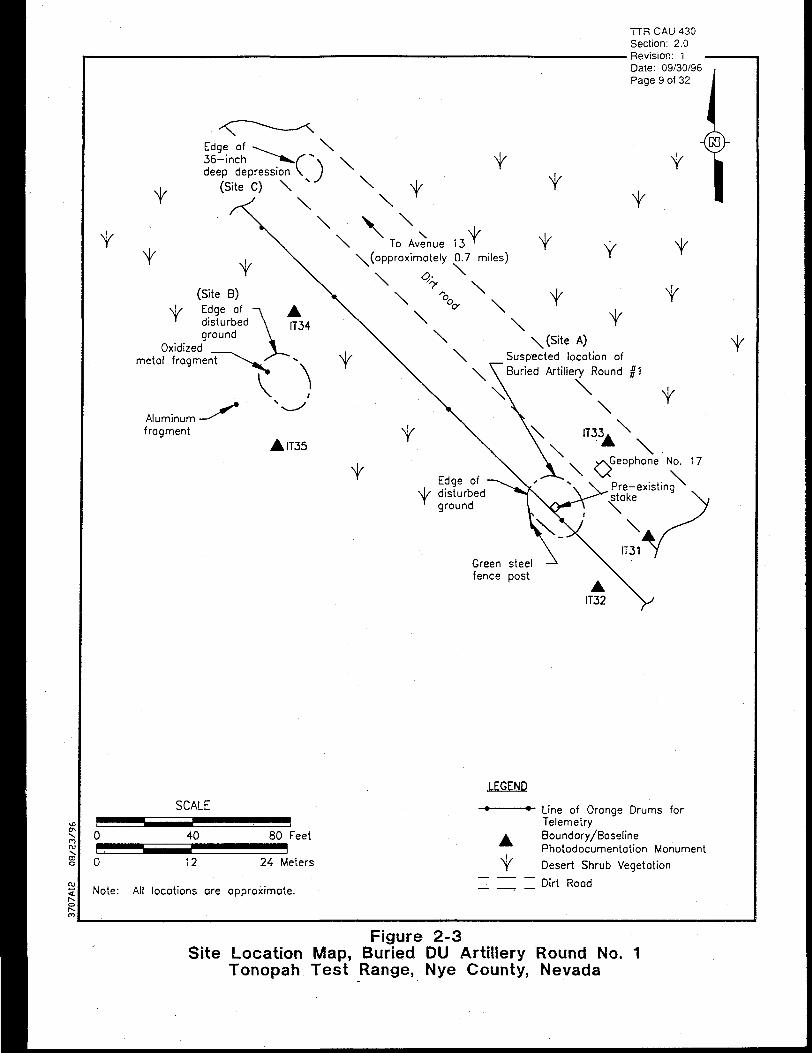
2.2 Site Location and DescriptionThe approximate location of Buried DU Artillery Round No. 1 is 1.1 km (0.7 mi) south of
Avenue 13, south of Area 9 in the Test Area (Figure 2-2). The site consists of a potentially
unexploded W-79 JTA test artillery projectile with HE. The projectile is reportedly buried in one
pit, approximately 5 to 10 feet (ft) deep (Smith, 1993a; Smith, 1996; Quas, 1996). (Because the
burial depth is not known, all exploratory excavations will be advanced past 10 feet to confirm
the absence of the projectile.) The exact location of the pit is not known. There are three
disturbed areas at the suspected site that have been identified via geophysical survey as possible
locations of the test projectile (Figure 2-3).
Buried DU Artillery Round No. 1 had DU substituted for Special Nuclear Material (SNM) to
prevent a nuclear explosion and yet retain the physical characteristics of uranium for ballistic and
other mechanical tests. Even though the artillery projectiles used at TTR did not contain SNM,
they did contain explosives and detonators; however, the detonators were not wired into the fire
system (Smith, 1996). Explosives with detonators were used in the projectile recovery system,
and these components may pose a health and safety risk.
The test procedure involved firing the projectile southward at an angle of 87 ° from an
8-inch (in.) artillery gun located in Area 9. A drogue parachute was scheduled to be deployed
during the projectile's terminal phase of travel to facilitate recovery of the undamaged test
projectile (Smith, 1993b). However, in this instance, the parachute failed to deploy, resulting in
a "hard" landing. Due to damage that the projectile received upon landing, normal recovery
operations were aborted. The projectile was retrieved and placed in a 5-foot-deep excavation for
destruction. Approximately 6 pounds of C-4 explosive (C-4) were placed in an excavation
adjacent to the projectile, and the excavation was backfilled (Smith, 1993a).
The detonation of the C-4 was planned to cause a sympathetic detonation of the HE contained
within the buried projectile which could be inferred by a resultant "burp" (or release) of radiation
(gamma radiation from U-238) at the ground surface. However, radiation from U-238 was not
detected at the surface after the detonation (Smith, 1993a), which may indicate that the C-4 failed
to cause a sympathetic detonation of the projectile. The area suspected of containing the
projectile may also contain other unexploded ordnance (UXO) (i.e., inert projectiles)
(Smith, 1996; Enlow, 1996).
TTR CAU 430Section: 2.0
• Revision: lDate: 09/30/96Page 9 of 32
t
Edge of - ^ ^ \36-inch ^ "~^ . / ' " * \ vdeep depression \ )
(Site C) \
\
\
\t t
\t t
(Site B)\V Edge of^ disturbed
groundOxidized
metal fragment
Aluminum •frogment
t
\(Site A)
Y
tSuspected locotion of
V
t
f
f
• lT35IT33. \
\t
. s^Geophone No. 17
Pre-existingstake
\
IT31Green steelfence post
SCALE
LEGEND
0Bo
40 80 Feet
12 24 Meters
Note: All locations are approximate.
Line of Orange Drums forTelemetryBoundary/BaselinePhotodocumentation MonumentDesert Shrub Vegetation
Dirt Road
Figure 2-3Site Location Map, Buried DU Artillery Round No. 1
Tonopah Test Range, Nye County, Nevada

TTR CAU 430Section: 2.0Revision: 1Date: 09/30/96Page 10 of 32
2.3 Process KnowledgeProcess knowledge is based on interviews of personnel involved with the project and a review of
historical records, geophysical surveys, and associated activities. All unclassified process
knowledge records are available for review at the IT Corporation office in Las Vegas.
Interviews and historical records used to compile process knowledge are referenced where
applicable, are listed in Section 8.0 of this plan, and are available upon request to Kevin Cabbie
of DOE/NV Environmental Restoration Division.
2.3.1 Hazardous Components and InformationThe internal specifications of a W-79 JTA projectile with HE are classified as Secret Restricted
Data. There are two different configurations of the W-79 JTA artillery test projectile with HE.
The only notable difference between the two configurations is the use of an inert vs. a live rocket
motor. The configuration of the test projectile buried at this site may be documented in the
Range Instrumentation Order, or test document. This information does not affect safety, but
might be of concern with respect to identifying post-detonation residues (SNL, date unknown).
The configuration is classified information.
The basic components of the projectile were DU and HE. The only mechanism of transport that
will result in significant contamination will be the demolition that will be performed using
C-4 explosive. The remediation will focus on remediating soil containing DU and explosive
residue. Any other contaminants potentially present will be contained within the DU and
explosive residue contaminated soil.
2.3.2 Constituents of ConcernBased on process knowledge, the constituents of concern for the Buried DU Round No. 1 are
depleted uranium from components of the projectile and chromium, mercury, lead and the
explosive compound hexahydro-l,3,5-trinitro-l,3,5-triazine, which are common components of
the explosive C-4 used in the attempt to destroy the projectile. Other projectile constituents
which may be present include beryllium, nickel, plutonium, and tritium.
2.4 Closure StandardsThe site must have soil contaminant concentrations below NDEP regulatory action levels to be
evaluated for closure. The proposed closure standards (action levels) are presented in Table 2-1.
The particular soil action levels are the following:

TTR CAU 430Section: 2.0Revision: 1Date: 09/30/96Page 11 of 32
Table 2-1Suspected Constituents of Concern and Closure Standards
for the Buried Depleted Uranium Artillery Round No. 1 Corrective Action Unit 430(Page 1 of 2)
ParameterGroup
TCLP Metalsb
TAL Total Metals
TCLPSemivolatile
Organics
Nitroaromatics &Nitroamines
Isotopic Uranium
isotopicPlutonium
NA1
Individual Constituents
ArsenicBariumCadmiumChromiumLeadMercurySeleniumSilver
BerylliumNickel
Nitrobenzene2,4-Dinitrotoluene
Octahydro-1,3,5,7-tetranitro-1,3,5,7-tetrazocineHexahydro-1,3,5-trinitro-1,3,5-triazine1,3,5-Trinitrobenzene1,3-DinitrobenzeneMethyl-2,4,6-trinitrophenyinitramine2,4,6-Trinitrotoluene4-Amino-2,6-dinitroto!uene2-Amino-4,6-dinitrotoluene2,6-Dinitrotoluene3-Nitrotoluene4-NitrotolueneNitrobenzene2,4-Dinitrotoluene
Uranium-238, -234 and -235/236
Pu-238Pu-239/240
Tritium
AnalyticalMethod3
1311/6010A,7470C
6010
1311/8270
8330
NAS-NS-3050
NAS-NS3058
EPA EERFH-01m
ClosureStandard
5 mg/L100mg/L
1mg/L5 mg/L5 mg/L
0.2 mg/L1 mg/L5 mg/L
0.14mg/kge
150 mg/kg
20.13
3000 mg/kg4.0 mg/kg3.3 mg/kg6.5 mg/kg650 mg/kg15.0 mg/kg
0.659 mg/kg0.659 mg/kg
65 mg/kg650 mg/kg650 mg/kg130 mg/kg18 mg/kg
1,044 pCi/g'u-238for DU if no
Plutonium present
Pu-238 12.8Pu-239/240 1,376
NA
Source ofStandard
Title 40 CFR 261.24Table 1
NDEP, 1992, andproposed RCRASubpart S rule forcorrective action,
55 FR 30796', 1990,and EPA Region 9PRGs, August 1996
Title 40 CFR 261.24Table 1
NDEP, 1992, andproposed RCRASubpart S rule forcorrective action,
55 FR 30796,1990,and EPA Region 9
PRGs, August 1996.
Calculated from thedose rate given jn DOE
Order 5400.51 andNTS POC
DOE Order 5400.5 andNTS POC
NTS POC

TTR CAU 430Section: 2.0Revision: 1Date: 09/30/96Page 12 of 32
Table 2-1Suspected Constituents of Concern and Closure Standards
for the Buried Depleted Uranium Artillery Round No. 1 Corrective Action Unit 430(Page 2 of 2)
ParameterGroup
Gamma emittingradionuclides
Individual Constituents
Analyze by gamma spectroscopy and reportCs-137 and any other radionuciide identified inlibrary search
AnalyticalMethoda
HASL 3004.5.2.3"
ClosureStandard
Isotope-specific
Source ofStandard
NTS POC
.From SW-846 (EPA, 1986) unless otherwise specified.Hitle 40 CFR §261.24, Table 1Q.Method for Mercurye Milligrams per literf Milligrams per kilogramAll RCRA Subpart S values from EPA, 1996. Methodology for use of Subpart S values is contained in the Contaminated Soil andGroundwater Remediation Policy (NDEP, 1992)."•Uses value for dinitrotoluene mixture per Art Gravenstein - State of Nevada (Deshler, 1996).. National Academy of Science, Nuclear Science Series, 1962.PicoCuries per gram{DOE, 1990I National Academy of Science, Nuclear Science Series, 1963Not applicable due to gaseous formU.S. Environmental Protection Agency Eastern Environmental Radiation FacilityEnvironmental Measurements Laboratory Procedure Manual, HASL-300, U.S. Department of Energy, 1992
CFR = Code of Federal RegulationsCs-137 = Cesium-137DU = Depleted UraniumHASL = Health and Safety LaboratoryNAS = National Academy of ScienceNDEP = Nevada Division of Environmental ProtectionNTS POC = Nevada Test Site Performance Objective for Certification ofNonradioactive Hazardous Waste
PRG = Preliminary Remediation GoalsRCRA = Resource Conservation and Recovery ActTAL = Target Analyte ListTCLP = Toxicity Characteristic Leaching Procedure
Toxicity Characteristics Leaching Procedure (TCLP) concentration limits for defininghazardous waste characteristics of solids under RCRA (Title 40 Code of FederalRegulation [CFR] 261.24, Table 1) for semivolatile organic compounds (SVOCs), andinorganic compounds.
Isotopic activities or total activities (e.g., total alpha, total gamma or total beta activities)above the Nevada Test Site Performance Objective for Certification of Nonradioactive(NTS POC) set forth by Bechtel Nevada (1995).
For any parameters not covered in the above action levels, action levels will be takenfrom the concentration limits in the proposed RCRA Subpart S rule for corrective action(55 FR 30796).
Soil found to contain soil concentrations above the closure standard will be excavated,
containerized, and managed appropriately as waste in accordance with Section 5.0 of this plan.
Following excavation and removal, there will be additional sampling to verify that concentrations

TTR CAU 430Section: 2.0Revision: 1Date: 09/30/96Page 13 of 32
remaining in the soil are below closure standards. This process is described in more detail in
Sections 3.1 and 3.2 of this plan.
2.5 Depleted Uranium and Plutonium Closure StandardsA site-specific radiological risk assessment was performed for CAU No. 430 to determine the
guideline concentration in soil. The guideline is defined as a depleted uranium and plutonium
concentration in soil, that given appropriate use scenarios and site parameters, will reasonably
ensure that individual dose limits of 100 millirems per year (mrem/year) will not be exceeded.
The DOE has established generic cleanup guidelines for radium and thorium in soil; cleanup
guidelines for depleted uranium and plutonium must be derived on a site-specific basis.
2.5.1 RESRAD Risk Assessment CalculationsRESRAD is a microcomputer program which utilizes the dose assessment methodology
recommended for use in deriving site-specific soil cleanup guidelines. The methodology and
resultant code were adapted from a manual developed in 1989 for implementing DOE residual
radioactive material guidelines.1 The manual and the code are used widely by DOE and its
contractors and, to some extent, by the U.S. Nuclear Regulatory Commission and licensing
states. The program is issued by the Environmental Assessment Division of Argonne National
Laboratory.
2.5.2 RESRAD Risk Assessment MethodologyAnalysis of radiation exposure pathways is used to translate radiation dose guidelines, which are
generally not directly measurable, into derived concentration guidelines, i.e., concentration of a
radionuclide in soil. The primary objective is to establish the DU and plutonium concentration in
soil that relates to a maximum effective dose equivalent of 100 mrem/year.
The pathways analysis relates DU and Pu concentration in soil to the 100 mrem/year dose
guidelines for the maximum exposed dose receptor. The analysis requires:
• Development of scenarios that describe potential exposure modes
'The DOE guidelines were incorporated into DOE Order 5400.5 in February 1990 and were included inproposed Title 10, Part 834 of the Code of Federal Regulations (March 1993).

TTR CAU 430Section: 2.0Revision: 1Date: 09/30/96Page 14 of 32
• Selection and use of mathematical models of radiation exposure and radionuclidetransport
• Reasonable numeric values for parameters used in the mathematical models
Appendix B presents the site-specific and generic data used in calculating the depleted DU and
Pu guideline concentrations, including all of the RESRAD input values and dose calculation
output. In addition, Appendix B includes the methodology used in calculating site-specific input
parameter values used as input to RESRAD. The dose contribution by individual radionuclides
for each exposure pathway and the total dose contribution by each radionuclide and from each
exposure pathway is also listed.
2.5.3 Summary and Recommendations for Depleted Uranium and PlutoniumClosure Standards Using RESRAD
Using a conservative and limiting site resident exposure, scenario, the radiological risk
assessment was performed to ensure that the soil guideline concentration complies with the
100 mrem/yr basic dose requirement established in DOE Order 5400.5. The site-specific
guideline concentrations for CAU No. 430 are listed in Table 2-2.
Table 2-2Site-Specific Radionuclide Guideline Concentrations
Radionuclide
U-238
U-235
U-234
Pu-238
Pu-239
Pu-240
Pu-241
Pu-242
Am-241
Total
Guideline Concentration(pCi/g)
6.95E-2
1.13E-3
6.50E-3
1.28E+1
1.26+3
1.19E+2
1.97E+3
2.53E-3
6.02E+1
3,422
pCi/g = PicoCuries per gramU = UraniumPu = PlutoniumAm = Americium

TTR CAU 430Section: 2.0Revision: 1Date: 09/30/96Page 15 of 32
2.6 Clean ClosureThe objective of the SAFER activities at the Buried DU Artillery Round No. 1 CAU is to remove
contaminated material with concentrations above the closure standard and to gather adequate
data to affirm the decision for clean closure. The first phase involves locating and exposing the
test projectile, assessing its condition, and determining the appropriate method to destroy the
device. The second phase includes destruction in place, removal of depleted uranium fragments,
and removal of soil potentially contaminated with DU or explosive residues. The third phase of
SAFER activities will be accomplished through sampling and analysis to verify adequacy,
correctness, and completeness of process knowledge and remedial actions.
Verification samples will be collected and analyzed to determine if additional soil excavation and
remediation are required. If each sample meets the standards described in Table 2-1, the site may
be restored and clean-closed. If the verification samples indicate that constituents of concern are
present in the soil above closure standards as presented in Section- 2.4 of this plan, additional
excavation will take place; the excavated soil will be stockpiled and managed as waste in
accordance with Section 5.0 of this plan. Additional verification samples will be collected and
analyzed; this sequence may be repeated as necessary until all areas are demonstrated to meet the
closure standards presented in Table 2-1. All verification samples will be collected and managed
in accordance with U.S. Environmental Protection Agency (EPA) quality protocols as reflected
in Section 3.0 and in the RCRA Industrial Sites Quality Assurance Project Plan (QAPP)
(DOE/NV, 1994a).
If conventional UXO (UXO containing high explosives without SNM or DU) is unearthed during
the excavation of one of the three areas suspected of containing the Buried DU Artillery Round
No. 1, and is found to be unsafe to move, it will be destroyed in place after notification and
agreement with NDEP. Verification samples will be collected from the destruction pit and
analyzed to determine if TCLP RCRA metals, or SVOCs, or explosives residue (nitroaromatics
or nitroamines) are present above the closure standards presented in Table 2-1. If these
constituents of concern are above closure standards, the impacted soil will be excavated,
segregated from other soil stockpiles, and managed as waste. Additional verification samples
will be collected and analyzed, and this sequence may be repeated as necessary until the area is
demonstrated to meet closure standards. Sampling activities will parallel those given in
Section 3.0 of this plan for the Buried DU Artillery Round No. 1 destruction pit.

TTR CAU 430Section: 3.0Revision: 1Date: 09/30/96Page 16 of 32
3.0 Field Activities
Field activities to obtain clean closure of the Buried DU Artillery Round No. 1 CAU will be
completed using the three-phase approach discussed in Section 2.9 (see Figure 1-1). This
approach includes:
• Locating and exposing the projectile or remaining components of the projectile
• Destroying the projectile or remaining components in place
• Excavating contaminated soil from the destruction pit
• Using sampling and analyses of soil to verify that all soil contaminated above closurestandards have been excavated and removed
Verification analyses for the Buried DU Artillery Round CAU will include all of the parameters
listed in Table 2-1 (TCLP and total metals, TCLP SVOCs, nitroaromatics and nitroamines,-
isotopic uranium and plutonium, tritium, and gamma spectroscopy for other radionuclides). The
sampling and analyses introduced in Table 2-1 is explained further in Tables 3-1 and 3-2.
If a conventional UXO is unearthed and requires detonation in place, or if evidence of
unexpected non-radiological contamination is discovered through analysis, further soil removal,
sampling, and analysis will be performed in accordance with Section 3.1 of this plan.
Verification analyses for any conventional UXO destruction pit or non-radiological source will
be for TCLP metals, SVOCs, and nitroaromatics and nitroamines. Radiological analyses will not
be performed for any nonradiological source discovered. With the exception of the radiological
analysis, the analytical requirements are the same as those given in Tables 3-1 and 3-2 for the
Buried DU Artillery Round No. 1.
3.1 SamplingAfter the Buried DU Artillery Round No. 1 projectile is located and destroyed in place, the soil
from the destruction pit will be removed in 1-meter (m) (3-ft) layers, segregated according to
radiological activity (based on field radiological screening results), stored on plastic sheeting, and
sampled to determine if radioactive or hazardous constituents are present in the soil above
closure standards. Surface soil around the pit that is contaminated through destruction activities
will also be removed as appropriate.

TTR CAU 430Section: 3.0Revision: 1Date: 09/30/96Page 17 of 32
Table 3-1Analytical Requirements for the Buried Depleted Uranium
Artillery Round No. 1 Corrective Action Unit 430
Parameter Group
TCLPC Metals (eight metals)
Total Metals (berylliumand nickel)
TCLP Semivolatiles (twocompounds)
Gamma EmittingRadionuclides
Isotopic Uranium
Isotopic Plutonium
Tritium
Nitroaromatics andNitroamines
(14 compounds)
Analytical Methoda
1311/601OA/7470 ,
6010A
1311/8270
HASL 300 4.5.2.3d
NAS-NS-30506
NAS-NS-3058f
EPA-EERFH-019
: 8330
Number ofVerification
SoilSamples
5
5
5
5
5
5
5
5
Number ofWaste
Profile SoilSamples
1
1
1
1
1
1
1
1
Number of FieldQuality Control
Samples'3
3
3
3
3
3
3
3
3
JTrom SW-846 (EPA, 1986) unless otherwise specifiedDuplicate, rinsate blank, and field blank samples. Duplicates and field blanks will be collected at a frequency of 1 per 20environmental samples, One rinsate blank will be collected for each separate decontamination event. •
'JTitle 40 CFR §261.24, Table 1Environmental Measurements Laboratory Procedure Manual, HASL-300, U.S. Department of Energy, 1992c
feNational Academy of Science, Nuclear Science Series, 1962National Academy of Science, Nuclear Science Series, 1963
EPA = U.S. Environmental Protection AgencyHASL = Health and Safety LaboratoryNAS = National Academy of ScienceTCLP = Toxicity Characteristic Leaching Procedure
Excavated soil will be sampled to profile the soil prior to selecting an appropriate waste disposal.
Verification sampling will be conducted within the destruction pit and surrounding surface soil to
verify that all contaminated soil has been removed.
All soil samples will be collected with a decontaminated trowel or equivalent. Discrete surface-
soil samples and waste profile samples will be collected from 0 to 15 centimeters (cm)
(0 to 6 in.) below the bottom of surface. All sampling activities and locations will be
documented. The statistical calculation of the number of required verification samples is given
in the following text. The analytical requirements for each sample are given in Table 3-1.

TTR CAU 430Section: 3.0Revision: 1Date: 09/30/96Page 18 of 32
Table 3-2Site Characterization and Closure Verification Analytical Chemical Requirements
(Page 1 of 3)
Parameter
Group
Nitroaromatics
and Nilroamines
TCLP1 Metals
TCLP
Semivolalile
Organics
Analytical
Method
8330
1311/60t0Ak
7470
1311/8270k
Sample
Medium
Water
Soil
Water
Soil
Water
Soil
Sample
Container
Q , amber
G, amber
Teflon™-
lined cap
PE m orG
G, amber,
Tellon™-
lined cap
Minimum
Amount of
Sample
Required
2 x 1 liter
4-ounce
wide-mouth
jar
1 liter
8-ounce
wide-mouth
jar
2 x 1 liter
8-ounce
wide-mouth
jar
Preservative
Cool with ice
pH<2,HNO 3n
Cool with ice
Cool wilh ice
Cool with ice
Holding
Time
7 days
180 days to
leaching;
180 days to
analysis
14 days to
leaching;
7 days to
extraction;
40 days to
analysis
Analytes to be Analyzed and Reported
Octahydro-1,3,5,7-tetranitro-1,3,5,7-tetrazocine
Hexahydro-1,3,5-trinitro-1,3,5-triazine
"1,3,5-Trinitrobenzene
1,3-Dinitrobenzene
Methyl-2,4,6-trinilrophenylnitramine
2,4,6-Trinitrotoluene
4-Amino-2,6-dinitrotoluene
2-Amino-4,6-dinitrotoluene
2,6-Dinitrotoluene
2-Nitrololuene
3-Nitrotoluene
4-Nitrotoluene
2,4-Dinitrotoluene
Nitrobenzene
As
Ba
Cd
Cr
Pb
Hg
Se
Ag
2,4-Dinitrotoluene
Nitrobenzene
Minimum
Detectable
Concentration
(mg/L)a
45^g/Le
2.5 mg/kg
0.500
0.200
0.010
0.025
0.150
0.0002
0.500
0.020
0.010
0.010
Regulatory Limit or
Closure Standard for
Soil
3300 mg/kg1 '9
4.0 mg/kg^
3.3 mg/kg9
6.5 mg/kg9
650 mg/kg9
15.0 mg/kg9
0.65 mg/kg
0.65 mg/kg
65 mg/kg'
650 mg/kg'
650 mg/kg9
650 mg/kg9
130mg/kq9
18 mg/kg9
5.0 mg/L
100.0 mg/L
1.0 mg/L
5.0 mg/L
5.0 mg/L
0.20 mg/L
1.0 mg/L
5.0 mg/L
0.13 mg/L
2.0 mg/L
Acceptable
Precision
(RPD}b
20
30
20
25
Acceptable
Accuracy
(%R)C
53 to 133
22 to 157
80 to 120
1 to 180
Refer to footnotes at end of table.

TTR CAU 430Section: 3.0Revision: 1Date: 09/30/96Page 19 of 32
Table 3-2Site Characterization and Closure Verification Analytical Chemical Requirements
(Page 2 of 3)
ParameterGbup
Gamma EmittingRadionudides
Isotopic Uranium
Total Metals
IsotopicPlutonium
AnalyticalMethod
EPA 901.1P
HASL300q
4.5.2.3
NAS-NS-3050s
6010
NAS-NS-3058
SampleMedium
Water
Soil
Water
Soil
Water
Soil
Water
Soil
SampleContainer
PEorG
PEorG
PEorG
PEorG
MinimumAmount of
SampleRequired
1 liter
500 grams
1,000 mL1
50 grams
1 liter
8-ouncewide-mouth
jar
1 liter
4 ounce
Preservative
HNO3topH<2
None
HN03topH<2
None
pH<2, HNO3
Coolto4°C
Cool to 4 °C
HN03topH<2
None
HoldingTime
6 months
6 monthsafter
collection
180 days
6 mortths
Analytes to be Analyzed and Reported
Report Cs-137 and any other radionuclideidentified in library search
Uranium-238Uranium-234
• ' Uranium-235/236
Beryllium (Be)Nickel (Ni)
Plutonium-238Plutonium-239/240
MinimumDetectable
Concentration(mg/l)a
20 pCi/Lr
0.2 pCi/g
1 pCi/t.
1 pCi/g
5,/g/L(Be)40/yg/L (Ni)
0.5 nig/kg (Be)4 mg/kg (Ni)
ipCi/L
1pCi/g
Regulatory Limit orClosure Standard for
Soil
DOE Order 5400.51 andNTS POC
500 pCi/g
0.14 mg/kg (8e)
150 mg/kg (Ni)
Soil:Pu-238 = 12.8pCi/g
Pu-239/240= 1,376 pCi/gWater:
Pu-238 = 17 pCiA.Pu-239/240= 15.5pCi/L
AcceptablePrecision
(RPO)
±20
±25
20
25
AcceptableAccuracy
(%R)C
80 to 120
70 to 120
75 to 125
75 to 125
Refer to footnotes at end of table.

Table 3-2Site Characterization and Closure Verification Analytical Chemical Requirements
(Page 3 of 3)
TTR CAU 430Section: 3.0Revision: 1Date: 09/30/96Page 20 of 32
ParameterGroup
Tritium
AnalyticalMethod
EPA 906.0
EPA EERFH-01
SampleMedium
Water
Soil
SampleContainer
PEorG
G
MinimumAmount of
SampleRequired
250 mL
100 grams
Preservative
Cool to 4°C
HoldingTime
6 months
Analytes to be Analyzed and Reported
Tritium
MinimumDetectable
Concentration(mg/L)a
500pCi/L
1 pCi/g
Regulatory Limit orClosure Standard for
Soil
Not Applicable
AcceptablePrecision(RPD)
20
AcceptableAccuracy
• (%R)°
8010 120
.Milligrams per liter, unless otherwise specifiedRelative percent differencePercent recovery
^Glass
(Micrograms per literMilligrams per kilogram^All RCRA Subpart S values from EPA, 1996. Uses value for dinitrotoluene mixture per Art Gravenstein - State of Nevada (Deshler, 1996).Value is same as that calculated for 3-nitrotoluene and 4-nitrotolueneJoxicity Characteristic Leaching Procedure from Title 40 CFR §261.24, Table 1! EPA Test Methods for Evaluating Solid Waste, 3rd Edition, Part 1 -4, SW-846,1986Method for mercury analysis
Polyethylene
QNitric acidExcept mercury: 28 days to leaching, 28 days to analysis
pStandard Methods for the Examination of Water and Wastewater, American Public Health Association, 1992Environmental Measurements Laboratory Procedure Manual, HASL-300, U.S. Department of Energy, 1992PicoCuries per literNational Academy of Sciences, Nuclear Science Series, September 1963Milliliter
°C = Degrees CelsiusCFR = Code of Federal RegulationsCs-137 = Cesium-137HASL = Health and Safely Laboratory • ,NTS POC = Nevada Test Site Performance Objective for Certification of Nonradioactive Hazardous Waste (Bechtel Nevada, 1995)RCRA = Resource Conservation and Recovery Act

TTR CAU 430Section: 3.0Revision: 1Date: 09/30/96Page 21 of 32
Data quality objectives and quality assurance (QA) objectives, including precision, accuracy,
representativeness, comparability, and completeness, have been established for the project to
ensure that the data are sufficient and of adequate quality for their intended uses. The DQOs are
included in Appendix A. The laboratory will provide Contract Laboratory Program (CLP)-like
data packages for all analyses, and ten percent of all sample results will be validated by third-
party data validators. The QA objectives are discussed in the RCRA Industrial Sites QAPP
(DOE/NV, 1994a). Quality control requirements specific to these assessment activities include
the following and are also discussed in detail in the RCRA Industrial Sites QAPP:
• One duplicate sample will be collected per 20 environmental samples collected.
• One rinsate blank will be collected per decontamination event. Dedicated trowels may beused to preclude decontamination between sample locations.
• One field blank will be collected per 20 environmental samples collected.
Statistical methods were used to determine the appropriate number of samples to collect and
verify that constituents of concern are present below closure standard levels (Table 2-1).
Equation Number 8 in Chapter 9 of SW-846 (EPA, 1986) gives the process for calculating the
number of samples required to measure the sample mean, X, of the sampled area associated with
a sample standard deviation of s, with an acceptably small probability of error, a, as:
Where:
h-a/2.a-l
s
RT
X
the corresponding student t value for the appropriate probability and number of
degrees of freedom (= n-1)
the sample standard deviation
the regulatory threshold for the constituent of concern
the mean concentration of the constituent of concern
For the Buried DU Artillery Round No. 1 at the TTR, there is no preliminary information
regarding the mean or standard deviation of the constituents of concern. In the absence of this
information, the destruction pit and any other area of concern will be divided into equal grid
spaces; and a systematic, random sampling pattern will be followed. The required number of
samples will then be calculated from the analytical results using the above equation. If additional

TTR CAU 430Section: 3.0Revision: 1Date: 09/30/96Page 22 of 32
samples are required to demonstrate that the site meets closure standards, they will be collected
at a later time. If the initial sampling effort shows that there are areas that are above the closure
standard, the contaminated areas will be excavated and resampled. The data showing the
presence of constituents of concern above the closure standard will be discarded for purposes of
calculation, and Equation 8 of Chapter 9 of SW-846 (EPA, 1986) will be applied again, using the
new data. This will confirm that an adequate number of samples was collected and analyzed to
demonstrate that the site meets closure standard requirements.
3.1.1 Sample LocationsIn the following sections, the sampling strategy for the destruction pit and the stockpiled soil are
described.
Verification Sampling of the Destruction Pit and Surroundings
Sample locations will be determined by dividing the destruction pit into four quadrants of
approximate equal size and then dividing each of these quadrants into four quadrants. The
intersection of the lines that meet in the center of each subdivided quadrant mark the
approximate sample locations. Actual sampling locations will be documented in the field.
In the event that the destruction in place is not fully contained, the sampling program will be
adjusted to verify that the impacted area around the excavation was cleaned adequately.
Radiological surveys and sampling will be carried out over that area by expanding the grid area
that will be used within the excavation.
Characterization Sampling of the Stockpiled Soil
Waste characterization soil samples will also be collected from stockpiled soil having elevated
field screening readings. There is a possibility that some uncontaminated soil may need to be
excavated (e.g., initial excavation of the soil cover to be excavated when trying to locate the
projectile); in such case, the uncontaminated soil (based on field screening) will not be
characterized. Waste characterization fwill be guided by the Waste Characterization Sampling
and Analysis Plan for Tonopah Test Range: Corrective Action Units 400, 407, 426, 430, and the
Wind Radar Antenna Pedestal, (DOE/NV, 1996b). The piles will be divided into four quadrants.
Five surface samples (0 to 6 in.) will be collected from the pile, one from the center of each
quadrant and one from the center where the four quadrants meet. The five samples will be
composited into a single sample and submitted for the same laboratory analysis as those samples
collected from the destruction pit. Results from these samples will be used to characterize the
piles of soil for disposal. Sampling locations will be documented in the field.

TTR CAU 430Section: 3.0Revision: 1Date: 09/30/96Page 23 of 32
3.1.2 Analytical ParametersAt the Buried DU Artillery Round No. 1, all samples will be analyzed for TCLP and total metals,
TCLP SVOCs, nitroaromatics and nitroamines, isotopic uranium and plutonium, tritium, and
gamma spectroscopy analyses for other radionuclides, per Tables 2-1, 3-1 and 3-2. At all other
nonradiological UXO that may be encountered, samples will be analyzed only for TCLP metals
and SVOCs, and nitroaromatics and nitroamines.
The laboratory will provide CLP-like data packages for all analyses, and ten percent of all sample
results will be validated by third-party data validators.
3.2 Field Screening and Field SurveysMagnetometer and radiological field screening methods will be used to guide excavation
activities. To ensure proper handling and shipping of potentially radioactive materials, allsoil
samples from this investigation will be screened for alpha, beta, and gamma radiation in
accordance with the NV/YMP Radiological Control Manual (DOE/NV, 1994b) before being
removed from the TTR.
The radiological surveys will be performed over a grid whose grid spacing will be selected
appropriately to cover the area effected by the demolition. The survey will be performed using a
Sodium Iodide detector to collect gamma activities and a Geiger-Mueller detector to collect alpha
and beta activities.
3.3 VerificationExcavation activities will be stopped when field magnetometer and radiological surveys
determine that sufficient soil has been removed. To verify that the excavation has been
sufficient, the soil within potentially impacted areas (e.g., destruction pit or surface areas
impacted by a release) will be sampled and analyzed in accordance with Section 3.1. If the
analytical results meet the closure standards and no other constituents of concern are found, and
if concurrence is obtained from NDEP, then no further action will be required and the site will be
considered restored and closed. If contamination is detected at concentrations above closure
standards, then additional excavation and soil sampling will be performed as described in
Section 3.1. This process will be repeated, as necessary, until analyses indicate that the closure
standards have been achieved.

TTR CAU 430Section: 3.0Revision: 1Dale: 09/30/96Page 24 of 32
3.4 RemediationThe excavation process will be performed using a backhoe or other means as directed by the
UXO team. Excavated soil will be removed in 1-m (3-ft) layers. Each layer will be screened for
radiological contamination prior to removal. Radiologically contaminated soil will be segregated
from noncontaminated soil on the basis of field measurements, and the soil will be placed on
heavy plastic sheeting and covered. All excavated soil will remain on site until sample analysis
determines its disposition. If it is determined that excavation is no longer practical or cost-
effective, work will be stopped; NDEP will be notified as soon as practical; and this plan will be
amended (or a new plan written) to encompass a subsurface investigation.
3.5 Site RestorationUpon confirmation that the site has met closure standards and upon receipt of a notice of closure
from NDEP,1 all deep excavations will be filled with clean soil from existing borrow pits, and all
shallow excavations will be graded. The landscape of the site will be recontoured to grade.
3.6 ScheduleAll appropriate permits will be obtained prior to field work. Sampling will begin after the
approval of this SAFER Plan by the NDEP. Upon approval of this plan, NDEP will be notified
of the scheduled start date of field activities at least 10 working days prior to the start of field
work. The expected schedule of completion dates (in working days) is as follows:
• Day 0: Begin location and assessment of Buried DU Artillery Round No. 1
• Day 10: Destruction in place of projectile or related components
• Day 85: Complete any required excavations and a second round of sampling ifrequired. If not required, confirm site remediations are complete throughanalytical results and waste removal.
Factors beyond DOE/NV's control, such as weather, classified TTR activities, or delays in
receipt of laboratory results, may delay field activities. If such delays occur, NDEP will be
verbally notified.
Within six months of receipt of validated laboratory results from final field activities, a closure
report will be submitted to NDEP as discussed in Section 4.0 of this plan.

TTR CAU 430Section: 4.0Revision: 1Date: 09/30/96Page 25 of 32
4.0 Reports
Reports during field activities and after completion of the SAFER process will be provided to
NDEP by DOE/NV.
Daily reports of field activities will be provided to NDEP while field activities are ongoing
through informal fax transmittal. In addition, DOE/NV will verbally inform NDEP as soon as is
practical of any substantial changes in scope or schedule. If it is determined that this plan
requires significant amendments, NDEP will be notified as soon as practical; this plan will be
amended; and NDEP's concurrence with the modified plan will be solicited.
If clean closure is achieved within six months of receipt of validated laboratory results from final
field activities, DOE/NV will provide a written closure report to the NDEP documenting that
closure was completed in accordance with this plan and will include all analytical results to
verify that clean closure did occur. Both radiological and chemical laboratory analytical results,
in addition to waste characterization and disposition information, will be included in the closure
report. The report will describe the SAFER Plan activities for each unit and request a notice of
completion from NDEP.

TTR CAU 430Section: 5.0Revision: 1Date: 09/30/96Page 26 of 32
5.0 Waste Management
All waste generated through the performance of field activities at the Buried DU Artillery Round
No. 1 CAU will be managed in accordance with existing federal and State of Nevada regulations,
DOE waste minimization and pollution prevention objectives, waste management programs, and
radiological control programs. The waste will be categorized (i.e., as sanitary, low-level, mixed,
or hazardous waste) through application of process knowledge, field screening, and confirmatory
sampling and analysis. Soil shown to be uncontaminated may be returned to the location from
which it was excavated.
The absence or removal of radiological constituents will be demonstrated through laboratory
analyses and the use of sufficiently sensitive radiological screening instruments. The instruments
will be used for detecting alpha and beta/gamma activities. In addition, swipes will be collected
on all sample containers prior to shipment off site for analysis. Off-site release limits for surface
contamination listed in the Radiological Control Manual, Table 2-2 (DOE/NV, 1994b) will
apply. Waste will be determined to be radioactive through sampling and analysis. As a waste
minimization effort, the data will be evaluated to see if they meet the definition of
nonradioactive waste as discussed in the Nevada Test Site Performance Objective for
Certification of Nonradioactive Hazardous Waste (Bechtel Nevada, 1995). With the approval by
the Bechtel Nevada Waste Management Program, waste meeting the requirements of the
NTS POC may be disposed in a sanitary landfill. Radioactive waste that does not meet the
NTS POC will be segregated and stored at the designated TTR Radioactive Material Area
pending disposal at one of the Nevada Test Site's Radioactive Waste Management Sites
according to NVO-325 requirements (DOE/NV, 1992b).
Hazardous waste is defined in Title 40 CFR Part 261. Hazardous waste will be managed in
accordance with applicable federal and state regulations. Hazardous waste will be determined to
be a mixed waste if analytical results do not meet the NTS POC for radioactivity. Mixed waste,
if generated, will be shipped to the Nevada Test Site Area 5 Transuranic Waste Storage Pad,
pending treatment and disposal. Nonradioactive hazardous waste to be disposed off of the TTR
will be packed in containers that meet all EPA and U.S. Department of Transportation criteria for
shipment and any additional criteria specified by the receiving disposal site. Hazardous wastes
will be disposed of at an off-site commercial, permitted treatment, storage, and disposal facility

TTR CAU 430Section: 5.0Revision: 1Date: 09/30/96Page 27 of 32
or recycling facility. Hazardous waste may be shipped to the Nevada Test Site for storage at the
permitted Area 5 Hazardous Waste Storage Site pending shipment to a commercial facility.
Nonrecyclable wastes that are nonhazardous and nonradioactive will be disposed of at an
appropriate sanitary landfill. Generation of transuranic, high-level, or biological waste is not
anticipated. In the event that one of these waste types is generated, work will stop; NDEP will be
notified; and this plan will be amended to assure proper waste disposition.
If any mixed waste is generated, it will be managed in accordance with the Mutual Consent
Agreement Between the State of Nevada and the Department of Energy for the Storage of Low-
Level Land Disposal Restricted Mixed Waste. Within nine months of the placement of mixed
waste on the TRU mixed waste storage pad, DOE/NV will submit a plan for treatment and
disposal of the waste to the Nevada Division of Environmental Protection.

TTR CAU 430Section: 6.0Revision: 1Date: 09/30/96Page 28 of 32
6.0 Site-Specific Health and Safety Plans
The health and safety protocols for the field activities related to the implementation of this
SAFER plan will be delineated in a Site-Specific Health and Safety Plans (SSHASPs). This
SSHASP, controlled separately from this SAFER plan, is not included as part of this plan, but
will be available upon request prior to start of field activities. The SSHASP sets forth the
specific requirements and procedures that will be followed while performing operations under
this SAFER plan. The SSHASP includes the following information:
• Engineering and administrative protective measures• Monitoring for site-specific chemical and radiological contaminants• Personal protective equipment and its use• Site control• Emergency communications• Emergency reporting protocol• Decontamination• Site characterization• Training• Excavation safety
All field activities will be performed in accordance with the applicable SSHASP, and all field
personnel involved in these activities will be familiar with requirements of the SSHASP. All
visitors to the work sites will be required to abide by these procedures.
The objective of the SSHASP is the protection of workers during SAFER plan activities. This
will be accomplished through compliance with DOE Orders, Occupational Safety and Health
Administration Regulations, and the DOE/NV NV/YMP Radiological Control Manual
(DOE/NV, 1994b), as well as the SSHASPs. Many of the operations conducted under the
DOE/NV Environmental Restoration Program are regulated under the DOE Orders and Title 29
of the Code of Federal Regulations-.
Due to unique logistics, hazards, and site conditions, individual groups of sites and/or tasks
require the production of a SSHASP. It is considered a living document, and as new information
becomes available, changes will be made as appropriate, with concurrence and approval of the
Subproject Manager.

TTR CAU 430Section: 7.0Revision: 1Date: 09/30/96Page 29 of 32
7.0 Community Relations Plan
A Public Involvement Plan is being developed for environmental restoration activities at Nevada
sites operated by DOE/NV. Under this plan, specific public-involvement activities will be
outlined for the Environmental Restoration Project, including the TTR.
Until the Public Involvement Plan is developed, public-participation activities for the
Environmental Restoration Project are referenced in the Public Participation Plan for the ERWM
Program, Nevada Operations Office (DOE/NV, 1993). Any public-participation activities
specifically relating to DOE/NV environmental restoration activities at the TTR will be publicly
announced through press releases and/or newspaper advertisements.
A fact sheet, poster board, and video covering environmental restoration activities at the TTR
also has been prepared. These and other public information materials can be obtained by writing
to the following address:
U.S. Department of EnergyNevada Operations OfficePublic Affairs and Information OfficeP.O. Box 98518Las Vegas, Nevada 89193-8518

TTR CAU 430Section: 8.0Revision: 1Date: 09/30/96Page 30 of 32
8.0 References
American Public Association. 1992. Standard Methods for the Examination of Water andWastewater.
Bechtel Nevada. 1995. Nevada Test Site Performance Objective for Certification of 'Nonradioactive Hazardous Waste (NTS POC).
Code of Federal Regulations. 1993. Protection of the Environment, Title 40, Parts 261 and 265.Washington, DC.
Code of Federal Regulations. 1996. Title 40, Part 261.24, Table 1. Washington DC.
Deshler, B. IT Corporation. 1996. Communication with Art Gravenstein, State of Nevada,3 January.
DOE, see U.S. Department of Energy.
Enlow, J. Sandia National Laboratories, Test Director. 1996. Communication with E. Seuter,IT Corporation.
EPA, see U.S. Environmental Protection Agency.
ERDA, see U.S. Energy Research and Administration.
Federal Facility Agreement and Consent Order (FFACO) of 1996. Prepared by the NevadaDivision of Environmental Protection, U.S. Department of Energy, and U.S. Department ofDefense.
Kessel, D. Sandia National Laboratories, Yucca Mountain. 1996. Communication withC. Rodriquez. IT Corporation. Las Vegas, NV.
National Academy of Sciences. 1963. Nuclear Science Series.
NDEP, see Nevada Division of Environmental Protection.
Nevada Division of Environmental Protection. 1992. Contaminated Soil and GroundwaterRemediation Policy, June 25, 1992.
Powers, K. W. DOE/NV. 1996. Memorandum to Principal Staff Regarding, "Memorandum ofAgreement Between DOE/NV and DOE/AL, Appendix C: Tonopah Test Range,"January 2, 1996. Las Vegas, NV.
Quas, J. REECo/TTR, Retired. 1996. Communication with E. Seuter, FT Corporation.

r TTB CAU 430Section: 8.0Revision: 1Dale: 09/30/96Page 31 of 32
SNL, see Sandia National Laboratories.
Sandia National Laboratories. Date unknown. TTR Range Test Plan for W-79 UD tests."W-79 UD Hydro Test Vehicle." TTR, NV.
Smith, H. D. Sandia National Laboratories. 1993a. Telecon between H. Duane Smith,Jim Truman, FT Corporation; John Quas, REECo/TTR and Randy Dubiskas,IT Corporation, about Buried DU Rounds #1 and #2. 28 July.
Smith, H. D. Sandia National Laboratory. 1993b. Telecon between H. Duane Smith,Sandia National Laboratories; Jim Truman, IT Corporation; John Quas, REECo/TTR andRandy Dubiskas, IT Corporation, 7/28/93, 1505 hrs: Buried DU Round #1 and OtherPotential Sites, 3 p.
Smith, H. D. Sandia National Laboratories. 1996. Communication with E. Seuter,IT Corporation.
U.S. Department of Energy. 1990. Radiation Protection of the Public and the Environment,DOE Order 5400.5. Washington, DC.
U.S. Department of Energy. 1992. Environmental Measurements Laboratory ProcedureManual, HASL-300.
U.S. Department of Energy, Albuquerque Operations Office. 1992. Tonopah Test RangeEnvironmental Monitoring Plan. Albuquerque, NM.
U.S. Department of Energy, Nevada Operations Office. 1992a. Tonopah Test Range Tour.April 28, 1992. Las Vegas, NV.
U.S. Department of Energy, Nevada Operations Office. 1992b. Nevada Test Site Defense WasteAcceptance Criteria, Certification, and Transfer Requirements, NV0-325, Rev. 1.Las Vegas, NV.
U.S. Department of Energy, Nevada Operations Office. 1993. Public Participation Plan forthe ERWM Program. Las Vegas, NV.
U.S. Department of Energy, Nevada Operations Office. 1994a. Resource Conservation andRecovery Act, Industrial Sites Quality Assurance Project Plan, Nevada Test Site, Nevada.Las Vegas, NV.
U.S. Department of Energy, Nevada Operations Office. 1994b. NV/YMP Radiological ControlManual. Las Vegas, NV.

TTR CAU 430Section: 8.0Revision: 1Date: 09/30/96Page 32 of 32
U.S. Department of Energy, Nevada Operations Office. 1996a. Streamlined Approach forEnvironmental Restoration Plan, CAU No. 400: Bomblet Pit and Five Points Landfill,Tonopah Test Range. Las Vegas, NV.
U.S. Department of Energy, Nevada Operations Office. 1996b. Draft Waste CharacterizationSampling and Analysis Plan for Tonopah Test Range: Corrective Action Units 400, 407, 426,430, and the Wind Radar Antenna Pedestal. Las Vegas, NV.
U.S. Energy Research and Development Administration. 1975. Environmental Assessment,Tonopah Test Range, Tonopah, Nevada. Washington, DC.
U.S. Environmental Protection Agency. 1986. Test Methods for Evaluating Solid Waste,Physical/Chemical Methods, SW-846, 3rd Edition. Washington, DC.
U.S. Environmental Protection Agency. 1989. Soil Sampling Quality Assurance User's Guide(EPA/600/8-89/046). Washington, DC.
U.S. Environmental Protection Agency. 1994. Guidance for the Data Quality ObjectivesProcess (EPA QA/G4). Washington, DC.
U.S. Environmental Protection Agency. 1996. Region 9 Preliminary Remediation Goals(PRGs) 1996. Letter from Stanford J. Smucker, Ph.D. to PRG Table Mailing List.August 1, 1996.
55 FR 30796. Corrective Action for Solid Waste Management Units (SWMUs) at HazardousWaste Management Facilities. Proposed Rule. Washington, DC.

Distribution List(Page 1 of 2)
Mr. Kevin J. Cabbie, TTR Project ManagerDOE/Nevada Operations Office
Ms. Sabine T. Curtis,Acting Industrial Sites Subproject ManagerDOE/Nevada Operations Office
Ms. Janet Appenzeller-WingIndustrial Sites Subproject ManagerDOE/Nevada Operations Office
Mr. Steven MellingtonEnvironmental Restoration Division DirectorDOE/Nevada Operations Office
Environmental Restoration Division Record CenterDOE/Nevada Operations Office
Mr. Paul J. LiebendorferBureau of Federal FacilitiesDivision of Environmental ProtectionState of Nevada333 W. Nye LaneCarson City, NV 89710
Mr. G.J. SierenDivision of Environmental ProtectionState of Nevada555 East WashingtonSuite 4300Las Vegas, NV 89101 •
Ms. Susan Barrow, Chief EMNEnvironmental Management Directorate4551 Devlin DriveNellis AFB, NV 89191-6546
Mr. Richard A. Dubiskas, Project ManagerIT CorporationLas Vegas, NV 89103
1 (Uncontrolled)
1 (3 Uncontrolled)

Distribution List(Page 2 of 2)
Mr. Ken Beach, Project ManagerIT CorporationLas Vegas, NV 89103
Ms. Cheryl RodriquezIT CorporationLas Vegas, NV 89103
Mr. Don CoxIT CorporationLas Vegas, NV 89103
Mr. Brad SchierIT CorporationLas Vegas, NV 89103
Ms. Stacey SorgIT CorporationLas Vegas, NV 89103
Ms. Jeanne WightmanIT CorporationLas Vegas, NV 89103
Mr. Dave MadsenBechtel Nevada
Ms. Karen PattonBechtel Nevada
U.S. Department of Energy"Office of Scientific and Technical Information175 Oak Ridge TurnpikeP.O. Box 62Oak Ridge, TN 378831
DOE/Nevada Operations OfficeTechnical Information Resource CenterPost Office Box 98518Las Vegas, NV 89193-8518
Copies
1

Appendix A
Data Quality Objectives

TTR CAU 430Section: Appendix ARevision: 1Date: 09/30/96Page A-i of A-ii
Table of Contents
List of Figures A-ii
A.1.0 Data Quality Objectives A-l
A.I.I Conceptual Model A-2
A.1.2 Data Quality Objectives A-6
A.l.2.1 Step 1: State the Problem A-6
A.l.2.2 Step 2: Identify the Decision A-6
A. 1.2.3 Step 3: Identify the Inputs to the Decision A-6
A. 1.2.4 Step 4: Define the Boundaries of the Study A-6
A. 1.2.5 Step 5: Develop a Decision Rule A-7
A. 1.2.6 Step 6: Specify Acceptable Limits on Decision Error A-7
A. 1.2.7 Step 7: Optimize the Design A-7

TTR CAU 430Section: Appendix ARevision: 1Date: 09/30/96Page A-ii of A-ii
List of Figures
Number Title Page
A-l Conceptual Model for the Buried Depleted Uranium Artillery Round No. 1
Corrective Action Unit A-3
A-2 Planar and Cross-Sectional Views of the Area Affected by the
Destruction of the Buried Depleted Uranium Artillery Round No. 1 A-4

TTR CAU 430Section: Appendix ARevision: 1Date: 09/30/96Page A-1 of A-8
A. 1.0 Data Quality Objectives
The sampling objectives for the Buried DU Artillery Round No. 1 SAFER Plan were determined
using the Data Quality Objective process outlined by the Environmental Protection Agency
(EPA, 1994). DQOs are qualitative and quantitative statements that specify the quality and type
of data required to support proposed potential courses of actions for the Buried DU Artillery
Round No. 1 CAU. The DQOs were developed to clearly define the purpose(s) for which
environmental data will be used and to design a data collection program that will satisfy these
goals.
The DQO process is a planning process that provides a systematic approach to defining the
criteria and objectives that data collection should satisfy. DQOs have been developed using the
step-wise planning process outlined by the EPA. The DQOs are qualitative and quantitative
statements derived from the step-wise process that clarify the study objective, define the most
appropriate type of data to collect, determine the most appropriate conditions from which to .
collect the data, and specify tolerable limits on decision errors which will be used as the basis for
establishing the quantity and quality of data needed to support the decision. The seven sequential
steps of the DQO process are:
1. State the problem
2. Identify the decision
3. Identify inputs to the decision
4. Define the study boundaries
5. Develop a decision rule
6. Specify tolerable limits on decision errors
7. Optimize the design
Ultimately, the DQO process yields a thoughtfully designed study that has well-defined
objectives, has obtainable objectives, is designed to meet objectives, and is sufficiently detailed
to be defensible -- but not overly detailed to result in wasting resources. The following seven
sections, A. 1.2.1 to A. 1.2.7, present the results of the seven step DQO planning process.
One tool used in the DQO process is the formulation of a site conceptual model.

TTR CAU 430Section: Appendix ARevision: 1Date: 09/30/96Page A-2 of A-8
A.1.1 Conceptual ModelA conceptual model has been developed to postulate potential exposure pathways from likely
contaminant sources at the Buried DU Artillery Round No. 1 CAU (Figure A-l). The conceptual
model is based on the historical information described in Section 2.0 of the main text. The
following are assumptions that were considered regarding the projectile:
• The projectile is located in one of three areas suspected of containing the projectile.
• Some components of the projectile contain depleted uranium (U-238), chromium,mercury, and lead.
• The disposition of the projectile is unknown (i.e., whether the projectile is intact or not).
• The projectile is assumed to contain unexploded high explosive and must be destroyedin-place before it is safe to remove.
The following are assumptions that were considered regarding concerns caused by the
destruction of the projectile:
• A portion of the DU will burn during the destruction of the projectile.
• Following in-place destruction of the projectile, the bulk of the contaminated soil will beconfined to the disturbed soil around the projectile. The explosives will be placed on theprojectile in such a way that the explosion is directed downward; therefore, the majorityof the contamination will increase from the original elevation of the explosives towardsthe bottom of the pit (Figure A-2).
• Distribution of the contaminants after destruction of the projectile will be heterogeneous.Fragments or particles pf DU (depending on size) will be found as radioactive hot spotsthrough radiological field screening activities.
• The concentrations of the residual hazardous or radioactive materials from the destroyedprojectile will be low.
• No other significant mechanisms (such as infiltrating fluids) exist that could drive theconstituents significantly deeper than the zone of detonation in the time interval betweendetonation and remediation.
• Destruction of the projectile could result in surface contamination in the form of DUfragments or particles caused from a breach in the detonation containment. Hot spots willbe located using radiological field screening.
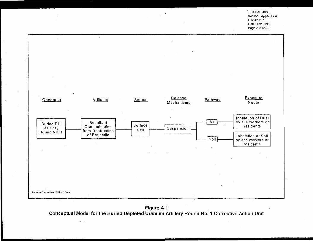
TTR CAU 430Section: Appendix ARevision: 1Date: 09/30/96Page A-3 of A-8
Generator Artifacts Source ReleaseMechanisms
Pathway
Buried DUArtillery
ResultantContamination
from Destructionof Projectile
SurfaceSoil
Suspension
Air
C3OII
Exposure
Inhalation of Dustby site workers or
residents
Inhalation of Soilby site workers or
residents
f:\wordpioc\IlAsafef\cau_430\figa-1du pie
Figure A-1Conceptual Model for the Buried Depleted Uranium Artillery Round No. 1 Corrective Action Unit

TTR CAU 430Section: Appendix ARevision: 1Date: 09/30/96Page A-4 of A-8
Top diometer isapproximately 20 ft
Bottom diameter isapproximately 8 ft
Planar View of Destruction Pit
12 ft toI15i
|
ft deep \\
^ -">•
/
A'//*-m—
/
— Surface soil (6 to 12 in.)
Cross-sectional View of Destruction Pit
NOT TO SCALE
oArea suspected to havethe greatest concentrationof contamination fromprojectile destruction
Depression
Figure A-2Planar and Cross-Sectional Views of the Area Affected by the
Destruction of the Buried Depleted Uranium Artillery Round No. 1

TTR CAU 430Section: Appendix ARevision: 1Date: 09/30/96Page A-5 of A-8
• Hot spots will be detected within the top 0 to 15 cm (0 to 6 in.) of native soil within thepit and on the surface (if a breach occurred) because the majority will be removed withthe excavation of the disturbed soil.
• A minor amount of mixed waste may be generated through a mixing during thedetonation of DU with regulated metals or semivolatiles.
These factors were considered, and from them, a conceptual model was created. Based on these
factors, it was determined that the primary contamination source of concern are fragments or
particles of DU from the destruction of the projectile. These fragments will be located as hot
spots with field radiological screening. It was also determined that the primary area impacted by
DU fragments from the destruction of the projectile will be the lower portion bf the destruction
pit. Some surface contamination could occur if a breach of containment occurs during
- destruction of the projectile. Depleted uranium fragments or particles will be located only within
the disturbed soil within the pit, or thin (6 in. deep) layer of undisturbed soil directly beneath the
pit.
The conceptual model interprets that the destruction pit and potential additional surface area has
only a shallow soil (< 30 cm [1 ft]) source after re-excavation. There would be two potential
exposure routes: inhalation and ingestion of contaminated soil. The viable contamination release
mechanism is the suspension of potentially contaminated surface soil to the air through either soil
disturbance or high winds. If the surface soil is contaminated, inhalation or ingestion (or general
consumption through the mouth) of dust or soil could be potentially harmful exposure routes.
High winds and dust devils have been documented at the TTR (DOE/NV, 1996a). Both soil
excavation activities and high winds could cause suspension of contaminated soil.
The amount of contamination will not exceed what was contained in the projectile. As such, the
amount of contamination will not be great enough to impact groundwater. Environmental
sample data will be used to determine when the site (destruction pit) or sites (destruction pit and
additional areas of surface contamination) are cleaned up. If analytical results are below closure
standards, the site(s) will be restored and clean closed. If analytical results indicate that
contamination is present above closure standards, additional soil excavation and sampling will be
performed. This will be repeated until all contamination has been removed and clean closure can
be obtained.

TTR CAU 430Section: Appendix ARevision: 1Date: 09/30/96Page A-6 of A-8
A.1.2 Data Quality ObjectivesThe DQO process (EPA, 1994) is a systematic planning tool for establishing criteria for data
quality and for developing data collection designs. It is a seven-step process which results in a
design to collect the right type, quality, and number of data needed to support an environmental
decision. The DQO process has been applied to proposed corrective action at the TTR Buried
DU Artillery Round No. 1. Each step will be discussed in the following text.
A.1.2.1 Step 1: State the ProblemIn this section, the problem is defined so that the focus of the study is unambiguous. The
problem statement is based on the site history presented in Section 2.0 and the conceptual model
presented in Section A. 1.1.
The disposition and location of the Buried DU Artillery Round No. 1 is uncertain. It is known to
contain depleted uranium and believed to contain RCRA characteristic constituents. This site
must be closed. Closure of the site will require the location, assessment, and destruction of the
projectile and remediation of the contamination caused by the destruction of the projectile and
the explosives used to cause the destruction. Sampling and analysis will be required to verify
that contaminated soil above action levels has been excavated.
A.1.2.2 Step 2: Identify the DecisionThis step defines the study question that the study will attempt to address. Field screening
instruments are needed to guide the excavation activities to ensure that excavation removes
contaminated soil, but does not remove clean soil. Verification sampling must be used to verify
that the excavation has removed all soil that exceeds action levels.
A. 1.2.3 Step 3: Identify the Inputs to the DecisionThe excavation of the contaminated soil will be guided by visual definition of impacted soil and
field screening instruments which will be used to screen for metal debris and alpha and
beta/gamma activities. The field screening is not a definitive tool for identifying soil
contamination, so verification sampling with offsite analyses will be performed to ensure that all
soil with concentrations or activities above action levels have been removed.
A. 1.2.4 Step 4: Define the Boundaries of the StudyThe temporal boundary of the study will be the time at which the SAFER plan is implemented.
No follow-up study of the CAU is planned. The spatial boundaries of the remediation and

TTR CAU 430Section: Appendix ARevision: 1Date: 09/30/96Page A-7 of A-8
verification sampling area will include the destruction pit and any surface area impacted by a
release of contamination during destruction activities.
A.I.2.5 Step 5: Develop a Decision RuleThe results of the laboratory analytical data for the verification samples from the destruction pit
and any other areas with potential contamination will determine whether the site is clean or not.
Closure standards for the constituents of concern are discussed in Section 2.0 and listed in
Table 2-1. If analytical data indicate that constituents of concern are not detected above the
closure standards, the site will be declared closed. If not, remediation will continue until
analytical data from resampling demonstrate the site to be clean.
Note that the null hypothesis (Ho) is that the site is contaminated. Only if statistically valid
results prove that the analytical data is less than the closure standards will the site be considered
"clean." Thus, the burden of proof is on the data to demonstrate that the site is clean.
A. 1.2.6 Step 6: Specify Acceptable Limits on Decision ErrorThere are two types of decision errors possible in conducting the SAFER process. These errors
are described as a Type I error (false positive," judging a clean area to be contaminated, referred
to by statisticians as the "confidence level" or 1-cc) and a Type II error ("false negative," judging
a contaminated area to be clean, referred to by statisticians as the "power," or 1-P). This SAFER
plan is designed to minimize both types of errors.
For a planned removal or remedial response operation involving potentially contaminated soil,
Type I and Type II errors are of about equal significance and are usually established at 90 to
95 percent (EPA, 1989). For the purpose of this SAFER plan, the confidence level and power
will both be assigned at 90 percent.
Because the collected data will be used to support a closure, all off-site analyses will be
documented with CLP-like data packages, and 10 percent of the data will undergo data validation
by a third party.
A. 1.2.7 Step 7: Optimize the DesignThe sampling and analysis plan has been presented in Section 3.1 of this report and considered
all seven DQO steps. Soil will be removed from the projectile destruction pit in 3-ft layers until

TTB CAU 430Section: Appendix ARevision: 1Date: 09/30/96Page A-8 of A-8
native fill beneath the projectile is reached and field screening results are negative. Each layer
will be screened for metal debris and radiological contamination prior to excavation. Metal
debris not radiologically contaminated will be removed and staged separately for disposal in a
sanitary landfill. Soil and/or metal found to be radiologically contaminated will be staged
separately pending soil sample results. Verification soil samples will be collected from native
soil at the bottom of the pit. These analytical results will verify when all contamination
(e.g., radiological or hazardous) has been removed and the site is "clean."

Appendix B
Guideline Concentrationfor Depleted Uranium and Plutonium

TTR CAU 430Section: Appendix BRevision: 1Date: 09/30/96Page B-i of B-ii
Table of Contents
B.1.0 Introduction B-1
B.2.0 Analysis B-11
B.2.1 Radiological Source Term B-11
B.2.2 Exposure Scenario and the Parameter Values B-12
B.3.0 Analytical Results B-15
B.4.0 References B-17
Attachment B-1 - Parameter Values Used as RESRAD Input for CAU No. 430
Buried DU Artillery Round B-20

TTR CAU 430Section: Appendix BRevision: 1Date: 09/30/96Page B-ii of B-ii
List of Tables
Number Title Page
B-l Dose Contributions for Individual Radionuclides and Exposure Pathways
at Corrective Action Unit No. 430 (mrem/year) B-2
B-2 Parameters Used in the RESRAD Code for Calculating Guidance
Concentrations for Corrective Action Unit No. 430, Tonopah Test Range B-3
B-3 DU and Pu Isotope Contribution to Total Radioactivity B-l3
B-4 Concentration of Source Radionuclides Resulting in a 100 mrem/yr
Residential Dose Rate for CAU No. 430 B-16

INTERNATIONALTECHNOLOGYCORPORATION
TTR CAU 430Section: Appendix BRevision: lDate: 09/30/96Page B-1 of B-44
Memorandum
To: Randy Dubiskas Date: September 5,1996
From: Steve Adams Project No. 764037.07010100
Subject: Letter Report: GUIDELINE CONCENTRATION FOR DEPLETED URANIUM ANDPLUTONIUM AT CORRECTIVE ACTION UNIT 430, BURIED DEPLETEDURANIUM ARTILLERY ROUND NO. 1
B.1.0 Introduction
Corrective Action Unit (CAU) No. 430 is located 0.7 miles south of Avenue 13, south of Area 9in the Test Area of the Tonopah Test Range (TTR). CAU No. 430 consists of a W-79 Joint TestAssembly (JTA) test artillery projectile. The projectile was reportedly buried at the site in May1987, at a depth of approximately 5 to 10 feet deep. The buried projectile had depleted uranium(DU) substituted for most of the special nuclear material. Therefore, the projectile still containsa small amount of weapons grade plutonium (Pu). In addition, the W-79 projectile containedhigh explosives and tritium gas.
Because the W-79 projectile is believed to contain unexploded high explosives (HE), it cannot besafely removed because of the risk of causing the HE to explode. Therefore, the projectile willbe detonated in place. Closure of CAU No. 430 includes destruction of the projectile in placeand removal of the projectile fragments and soil potentially contaminated with DU, Pu, andexplosives residue. The purpose of this letter report memorandum is to document an analysisperformed to define the maximum residual concentration of DU and Pu in soil that will ensurecompliance with the public dose limit established in the Department of Energy Order 5400.5(DOE, 1993).
A guideline is required for residual concentration of DU and Pu in the soil at CAU No. 430. Theguideline is defined as a DU and Pu concentration in soil that, given appropriate use scenariosand site parameters, will reasonably ensure that individual dose limits of 100 millirems per year(mrem/yr) will not be exceeded. The Department of Energy (DOE) has established genericcleanup guidelines for radium and thorium in soil; cleanup guidelines for DU and Pu must bederived on a site-specific basis.
This letter report memorandum presents the results of the guideline concentration calculations forDU and Pu in soil at CAU No. 430. In addition, it includes all of the site-specific and genericdata used in calculating this guideline concentration. The DOE residual radioactive materialguideline computer code, RESRAD, was used to calculate the guideline concentration (Yu et al,1993a). The RESRAD computer program utilizes a dose assessment methodology for deriving
44-8-85
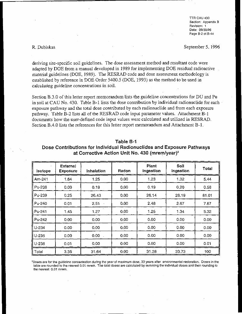
TTR CAU 430Section: Appendix BRevision: 1Date: 09/30/96Page B-2 ot B-44
R. Dubiskas September5, 1996
deriving site-specific soil guidelines. The dose assessment method and resultant code wereadapted by DOE from a manual developed in 1989 for implementing DOE residual radioactivematerial guidelines (DOE, 1989). The RESRAD code and dose assessment methodology isestablished by reference in DOE Order 5400.5 (DOE, 1993) as the method to be used incalculating guideline concentrations in soil.
Section B.3.0 of this letter report memorandum lists the guideline concentrations for DU and Puin soil at CAU No. 430. Table B-l lists the dose contribution by individual radionuclide for eachexposure pathway and the total dose contributed by each radionuclide and from each exposurepathway. Table B-2 lists all of the RESRAD code input parameter values. Attachment B-ldocuments how the user-defined code input values were calculated and utilized in RESRAD.Section B.4.0 lists the references for this letter report memorandum and Attachment B-l.
Table B-1Dose Contributions for Individual Radionuclides and Exposure Pathways
at Corrective Action Unit No. 430 (mrem/year)a
Isotope
Atn-241
Pu-238
Pu-239
Pu-240
Pu-241
Pu-242
U-234
U-235
U-238
Total
ExternalExposure
1.64
0.00
0.25
0.01
1.45
0.00
0.00
0.00
0.01
3.35
Inhalation
1.25
0.19
26.43
2.51 -
1.27
0.00
0.00
0.00
0.00
31.64
Radon
0.00
0.00
0.00
0.00
0.00
0.00
0.00
0.00
0.00
0.00
PlantIngestion
1.23
0.19
26.14
2.48
1.25
0.00
0.00
0.00
0.00
31.28
SoilIngestion
1.32
0.20
28.19
2.67
1.34
0.00
0.00
0.00
0.00
33.73
Total
5.44
0.58
81.01
7.67
5.32
0.00
0.00
0.00
0.01
100
'Doses are for the guideline concentration during the year of maximum dose, 33 years after environmental restoration. Doses in thetable are rounded to the nearest 0.01 mrem. The total doses are calculated by summing the individual doses and then rounding tothe nearest 0.01 mrem.

TTR CAU 430Section: Appendix BRevision: 1Daie: 09/30/96Page B-3 of B-44
R. Dubiskas September 5, 1996
Table B-2Parameters Used in the RESRAD Code for Calculating Guidance
Concentrations for Corrective Action Unit No. 430, Tonopah Test Range(Page 1 of 8)
Parameter
Dose Limit
Dose conversion factors for inhalation:
Ac-227+D
Am-241
Np-237+D
Pa-231
Pb-210+D
Pu-238Pu-239
Pu-240
Pu-241+D
Pu-242
Ra-226+D
Ra-228+D
Th-228+D
Th-229+D
Th-230
Th-232
U-233
U-234
U-235+D
U-236
U-238+D
Unit
mrem/yr.
mrem/pCi
ValueResident
100
6.72E+0
4.40E-1
5.40E-1
1.28E+0
2.32E-2
3.92E-1
4.29E-1
4.29E-1
8.25E-3
4.11E-1
8.60E-3
5.08E-3
3.45E-1
2.16E+0
3.26E-1
1.64E+0
1.35E-1
1.32E-1
1.23E-1
1.25E-1
1.18E-1
Reference
DOE, 1993
RESRAD default
RESRAD default
RESRAD default
RESRAD default
RESRAD defaultRESRAD default
RESRAD default
RESRAD default
RESRAD default
RESRAD default
RESRAD default
RESRAD default
RESRAD default
RESRAD default
RESRAD default
RESRAD default
RESRAD default
RESRAD default
RESRAD default
RESRAD default
RESRAD default

TTR CAU 430Section: Appendix BRevision: 1Date: 09/30/96Page B-4 of B-44
R. Dubiskas September5, 1996
Table B-2Parameters Used in the RESRAD Code for Calculating Guidance
Concentrations for Corrective Action Unit No. 430, Tonopah Test Range(Page 2 of 8)
Parameter
Dose conversion factors for ingestion:
Ac27+D
Am-241
Np-237+D
Pa-231
Pb-210+D
Pu-238
Pu-239
Pu-240
Pu-241+D
Pu-242
Ra-226+D
Ra-228+D
Th-228+D
Th-229+D
Th-230
Th-232
U-233
U-234
U-235+D
U-236
U-238+D
Unit
mrem/pCi
ValueResident
1.48E-2
3.64E-3
4.44E-31.06E-2
7.27E-3
3.20E-3
3.54E-3
3.54E-3
6.85E-5
3.36E-3
1.33E-3
1.44E-3
8.08E-4
4.03E-3
5.48E-4
2.73E-3
2.89E-4
2.83E-4
2.67E-4
2.69E-4
2.69E-4
Reference
RESRAD default
RESRAD default
RESRAD default
RESRAD default
RESRAD default
RESRAD default
RESRAD default
RESRAD default
RESRAD default
RESRAD default
RESRAD default
RESRAD default .
RESRAD default
RESRAD default
RESRAD default
RESRAD default
RESRAD default
RESRAD default
RESRAD default
RESRAD default
RESRAD default

TTR CAU 430Section: Appendix BRevision: 1Date: 09/30/96Page B-5 of B-44
R. Dubiskas Sepiember 5, 1996
Table B-2Parameters Used in the RESRAD Code for Calculating Guidance
Concentrations for Corrective Action Unit No. 430, Tonopah Test Range(Page 3 of 8)
Parameter
Plant/Soil concentration ratio:Ac-227*DAm-241Np-237+DPa-231Pb-210+DPu-238Pu-239Pu-240Pu-241+DPu-242Ra-226+DRa-228+DTh-228+DTh-229+DTh-230Th-232U-233U-234U-235+DU-236U-238+D
Area of contaminated zone
Thickness of contaminated zone
Length parallel to aquifer flow
Time since placement of material
Times for calculation10, 50, 100, 250, 500, 800, 1000, 5000,10,000
Unit
None
m2
m
m
years
years
ValueResident
2.50E-31.00E42.00E-21 .OOE-21 .OOE-21.OOE-31 .OOE-31.OOE-31.OOE-31.OOE-34.00E-24.00E-21.OOE-31.OOE-31.OOE-31.OOE-32.5E-32.5E-32.5E-32.5E-32.5E-3
1.82E+2
4.57
1.52E+1
0
NA
Reference
RESRAD defaultRESRAD defaultRESRAD defaultRESRAD defaultRESRAD defaultRESRAD defaultRESRAD defaultRESRAD defaultRESRAD defaultRESRAD defaultRESRAD defaultRESRAD defaultRESRAD defaultRESRAD defaultRESRAD defaultRESRAD defaultRESRAD defaultRESRAD defaultRESRAD defaultRESRAD defaultRESRAD default
Calculated
Calculated
Calculated
Assumption
User assumption

r TTR CAU 430Section: Appendix BRevision: 1Date: 09/30/96Page B-6 of B-44
R. Dubiskas September5, 1996
Table B-2Parameters Used in the RESRAD Code for Calculating Guidance
Concentrations for Corrective Action Unit No. 430, Tonopah Test Range(Page 4 of 8)
Parameter
Initial principal radionuclideconcentration in soil:Am-241Pu-238Pu-239Pu-240Pu-241Pu-242U-234U-235U-238
Concentration of radionuclides ingroundwater:
Cover depth
Density of contaminated zone
Contamination zone erosion rate
Contaminated zone total porosity
Contaminated zone effective porosity
Contaminated zone hydraulic conductivity
Contaminated zone "b" parameter
Evapotranspiration coefficient
Precipitation
Irrigation
Irrigation mode
Unit
pCi/g
pCi/L
m
g/cm3
m/yr
m/yr
-
-
m/yr
m/yr
-
ValueResident
6.02E+11.28E+11.26E+31.19E+21.97E+32.53E-36.50E-31.13E-36.95E-2
not used
0
1.5
1.442E-3
0.30
0.30
1000
4.05
0.68
0.127
1.53
ditch
Reference
CalculatedCalculatedCalculatedCalculatedCalculatedCalculatedCalculatedCalculatedCalculated
RESRAD calculatesfrom input data
Conservative assumption
RESRAD default
Calculated
RCRAFIWPforTTRDOE, 1994
RCRA FIWP for TTRDOE, 1994
Table 5.4, page 31Yuetal., 1993b
Table 13.1, page 77Yuetal., 1993b
Calculated
Culp and Howard, 1995
Calculated
User assumption

TTR CAU 430Section: Appendix BRevision: 1Date: 09/30/96Page B-7 of B-44
R. Dubiskas September 5, 1996
Table B-2Parameters Used in the RESRAD Code for Calculating Guidance
Concentrations for Corrective Action Unit No. 430, Tonopah Test Range(Page 5 of 8)
Parameter
Runoff coefficient
Watershed area for pond
Accuracy for water/soil computations
Density of saturated zone
Saturated zone total porosity
Saturated zone effective porosity
Saturated zone hydraulic conductivity
Saturated zone hydraulic gradient
Saturated zone "b" parameter
Water table drop rate
Well pump intake depth(below water table)
Well pumping rate
Model: nondispersion (ND) ormass balance (MB)
Number of unsaturated zones
Unsaturated zone thickness
Unsaturated zone density
Unit
-
m2
None
g/cm3
-
m/yr
-
'-
m/yr
m
m3/yr
-
m
g/cm3
ValueResident
0.2
1.82E+2
1.00E-3
1.5
0.3
0.3
1 .OE+3
1 .OOE-4
4.05
1.0E-4
10
279.6
ND
1
80
1.5
Reference
RESRAD default
not used
RESRAD default
RESRAD default
RCRAFIWPforTTRDOE, 1994
RCRAFIWPforTTRDOE, 1994
Tables 5.4 page 31Yuetal., 1993b
RCRAFIWPforTTRDOE, 1994
Table 13.1Yuetal., 1993b
RCRAFIWPforTTRDOE, 1994
RESRAD default
Calculated
ND
1
RCRAFIWPforTTRDOE, 1994
1.5

TTR CAU 430Section: Appendix BRevision: 1Date: 09/30/96Page B-8 of B-44
R. Dubiskas September5, 1996
Table B-2Parameters Used in the RESRAD Code for Calculating Guidance
Concentrations for Corrective Action Unit No. 430, Tonopah Test Range(Page 6 of 8)
Parameter
Unsaturated zone total porosity
Unsaturated zone effective porosity
Unsaturated zone "b" parameter
Unsaturated zone hydraulic conductivity
Distribution coefficient (all zones)Uranium isotopesPlutonium isotopesAmericium isotopesActinium isotopesNeptunium isotopesProtactinium isotopesLead isotopesRadium isotopesThorium isotopes
Inhalation rate
Mass loading for inhalation
Dilution length for airborne dust inhalation
Exposure duration
Shielding factor, inhalation
Shielding factor from external radiation
Fraction of time spent indoors
Fraction of time spent indoors (on site)
Shape factor flag, external gamma
Unit
-
- .
-
m/yr
cm3/gcm3/gcm3/gcm3/gcm3/gcm3/gcm3/gcm3/gcm3/g
m3/yr
g/m3
m
years
-
-
-
-
ValueResident
0.3
0.3
4.05
1 .OE+3
355501900450
55502705003200
6,372
9.86E-6
3
30
1
0.7
6.792E-1
2.797E-1
1
Parameter
RCRAFIWPforTTRDOE, 1994
RCRAFIWPforTTRDOE, 1994
Table 13.1, Yu etal., 1993b
Table 5.4, Yu et al., 1993b
Table 32.1 Yu et al., 1993B
Calculated
Calculated
RESRAD default
RESRAD default
Clayton, 1993
RESRAD default
Calculated
Calculated
RESRAD default

TTR CAU 430Section: Appendix BRevision: 1Date: 09/30/96Page B-9 of B-44
R. Dubiskas September 5, 1996
Table B-2Parameters Used in the RESRAD Code for Calculating Guidance
Concentrations for Corrective Action Unit No. 430, Tonopah Test Range(Page 7 of 8)
Parameter
Soil ingestion rate
Fruit, vegetable, and grain consumption
Leafy vegetable consumption
Milk consumption from on-site livestock
Meat consumption from on-site livestock
Fish consumption
Other seafood consumption
Drinking water intake
Contamination fraction of drinking,household, and irrigation water
Contamination fraction of plant food
Mass loading for foliar deposition
Depth of soil mixing layer
Depth of roots
Drinking, household, and irrigation, waterfraction from groundwater
Storage time forfruits, nonleafy vegetables, and grainleafy vegetablesdrinking water
Thickness of building foundation
Unit
g/yr
kg/yr
kg/yr
LVyr
kg/yr
kg/yr
kg/yr
L/yr
-
-
g/m3
m
m
-
ddd
m
ValueResident
36.5
49.49
4.13
0
0
0
0
511
1
-1
3.656E-3
0.0
0.9
1
1410
0.15
Reference
. Calculated
Calculated
Calculated
Not an exposure pathway
Not an exposure pathway
Not an exposure pathway
Not an exposure pathway
Calculated
RESRAD default
RESRAD computes fractionbased upon area of
contamination
Calculated
Conservative assumption
RESRAD default
RESRAD default
RESRAD defaultRESRAD defaultRESRAD default
RESRAD default

TTR CAU 430Section: Appendix BRevision: 1Date: 09/30/96Page B-I0of B-44
R. Dubiskas September5, 1996
Table B-2Parameters Used in the RESRAD Code for Calculating Guidance
Concentrations for Corrective Action Unit No. 430, Tonopah Test Range(Page 8 of 8)
Parameter
Bulk density of building foundation
Total porosity of building foundation
Volumetric water content of thefoundation
Diffusion coefficient for radon gasin foundation materialin contaminated zone soil
Radon vertical dimension of mixing
Average annual wind speed
Average building air exchange rate
Height of the building (room)
Building interior area factor
Building depth below ground surface
Emanating power of radon gasRn-222 gasRn-220gas
Summary of pathways selected externalgamma inhalation without radon plantingestion drinking water soil ingestionradon
Unit
g/cm3
-
m/s
m
m/s
per hour
m
-
m
• -
NA
ValueResident
2.4
0.1
3.0E-2
3.0E-72.0E-6
2
3.4
0.5
2.5
0.0
-1
0.200.15
NA
Reference
RESRAD default
RESRAD default
RESRAD default
RESRAD defaultRESRAD default
RESRAD default
Culp and Howard, 1995
RESRAD default
RESRAD default
RESRAD default
RESRAD default
RESRAD defaultRESRAD default
Scenario-dependent.Resident lives on the site
and raises as much food aspossible, but area not
sufficient to raise livestock.
AcAmcm3/gdDg/yrg/cm3
kg/yrmm/yrmma/yrMBNA
= Actinium= Americium= Cubic centimeter(s) per gram= Day(s)= Decay product(s)= Gram(s) per year= Gram(s) per cubic centimeter= Kilogram (s) per year= Meter(s)= Meter(s) per year= Meter(s)= Cubic meter(s) per year= Mass balance= Not applicable
NDNpPaPbpCi/g =pCi/gPuRaRCRA FIWP =
Rn =ThU
NondispersionNeptuniumProtactiniumLeadPicoCurie(s) per gramPicoCurie(s) per literPlutoniumRadiumResource Conservation and RecoveryAct Facility Investigation Work PlanRadonThoriumUranium

TTR CAU 430Section: Appendix BRevision: 1Date: 09/30/96PageB-11 of B-44
R. Dubiskas September 5, 1996
B.2.0 Analysis
A resident exposure scenario was chosen for CAU No. 430. This resident scenario is a plausible,but unlikely, scenario. The assumption is that, at some time within the next 10,000 years, thearea consisting of CAU No. 430 may be released for use following remediation without anyradiological restrictions, and an individual (resident) will move onto the site.
B.2. "I Radiological Source TermCalculating the dose to a member of the public from residual contamination requires definition ofa contaminated zone. This is the region within which radionuclides are present in above-background concentrations, and it is the common source term and starting point for all exposurepathway analysis. The derivation of guideline concentrations is based upon an idealizedcontaminated region of cylindrical shape within which radionuclides are assumed to be uniformlydistributed.
The tritium in the W-79 projectile was in a gaseous form which most likely escaped to theatmosphere when the projectile crashed to the ground.- In the unlikely event that the tritium gasdid not escape from the projectile when it crashed, it will escape into the atmosphere uponin-place detonation of the projectile. Tritium decays to stable helium, so there will be noradioactive decay products from the tritium to contaminate the soil upon detonation.
However, DU and Pu contamination may spread into the soil upon the in-place detonation of theW-79 projectile. For this analysis, it is conservatively assumed that the detonation may spreadthe contamination to the surface and 5 feet (ft) below the maximum expected depth of theprojectile. The lateral spread of the contamination is expected to be 5 ft; for this analysis it isconservatively assumed to be 25 ft. Thus, the total area of contamination is 1,963.5 squarefeet (ft2) (182.4 square meters [m2]). The depth of contamination is assumed to be from thesurface to 15 ft (4.57 m) below the surface. Thus, the DU and Pu contamination is assumed to beuniformly distributed in a right circular cylinder with an area of 1,963.5 ft2 and a depth of 15 ft.
DU is a mixture of uranium-238, uranium-235, and uranium-234 (U-238, U-235, U-234). Decayproducts from these three uranium isotopes have been produced during the time period since theprojectile was manufactured. Based upon the initial DU composition, the RESRAD codeautomatically calculates the concentrations of the uranium and its decay products in the soil andother environmental pathway media as well as the resultant dose contribution from each isotope.The initial assumed composition of the DU is that referenced in the Health Physics Manual ofGood Practices for Uranium Facilities (Rich et al., 1988).
The actual amount of plutonium in the W-79 JTA projectile is classified information. The Pusource term is assumed to be weapons grade plutonium that has decayed for 10 years. In order tocalculate the dose to the hypothetical resident, the amount of Pu in the W-79 projectile has to be

TTR CAU 430Section: Appendix BRevision: 1Date: 09/30/96PageB-12of B-44
R. Dubiskas September 5, 1996
defined (estimated). Even if the amount of Pu is a very small fraction of the DU mass, itscontribution to the total radioactivity will dominate the contribution from the PU. This isbecause the activity of a radionuclide is directly proportional to the inverse of its half-life, thetime it takes for half of its radioactivity to decay. The shorter the half-life, the more radioactivityper unit mass. The uranium isotopes that compose the DU have half-lives that are five orders ofmagnitude greater than the half-lives of the weapons-grade plutonium isotopes. Given the samemass of DU and Pu, the radioactivity of the uranium isotopes is five orders of magnitude lessthan the activity of the weapons-grade plutonium isotopes. For example, if the Pu mass is only0.01 percent of the DU mass, the radioactivity from the Pu will contribute 97.8 percent of thetotal radioactivity, while the DU mass will contribute only 2.2 percent of the total radioactivity(see Attachment B-l, pages B-5 through B-7 on how the radioactivity contribution from the Puand DU is calculated). As the mass fraction of the Pu varies from 0.01 percent to 10 percent, itscontribution to the total radioactivity varies from 97.8 to greater than 99.99 percent.
The dose to the hypothetical resident is directly proportional to the radioactivity to which thatperson is exposed. The inhalation and ingestion dose conversion factors for uranium areapproximately an order of magnitude less than plutonium. Given the same intake of radioactivityfor both DU and Pu to the hypothetical resident, the dose from DU will be about 10 percent ofthe dose from Pu. To ensure that the chosen radiological source term chosen provides sufficientprotection to the hypothetical resident, the amount of Pu in the W-79 projectile was chosen to be10 percent by mass. For each gram of DU, there is assumed to be 0.1 gram of weapons-gradeplutonium. Though the mass contribution of weapons-grade plutonium is only 10 percent, theradioactivity contributed by the Pu is significantly greater than the DU. The Pu will contributegreater than 99.99 percent to the total radioactivity present in the W-79 round. The methodologyused in calculating the contribution of each DU and Pu isotope to the total radioactivity is shownin Attachment B-l, on pages B-5 through B-6. The results are listed in Table B-3.
B.2.2 Exposure Scenario and the Parameter ValuesThis section examines the exposure pathways for the hypothetical resident living on theCAU No. 430 site. An exposure pathway is a route of intake to the resident from theradioactivity associated with the DU- and Pu-contaminated soil. For example, ingestion ofvegetables, fruits, and grains grown on contaminated soil would be an exposure pathway. Thedose to the hypothetical resident is calculated by summing up the doses from all exposurepathways. The calculations are performed using RESRAD.
The exposure pathways used in calculating the dose to the hypothetical resident include:
• External gamma irradiation• Inhalation of resuspended soil• Ingestion of plants grown on contaminated soil and irrigated with contaminated water

TTR CAU 430Section: Appendix BRevision: 1Date: 09/30/96PageB-13of B-44
R. Dubiskas September 5, 1996
Table B-3DU and Pu Isotope Contribution to Total Radioactivity
Isotope
U-238
U-235
U-234
Pu-238
Pu-239
Pu-240
Pu-241
Pu-242
Am-241
Abundance by Mass(ga isotope/g total mass)
9.07E-1
2.23E-3
4.54E-6
3.26E-6
8.84E-2
2.29E-3
8.38E-5
2.82E-6
7.68E-5
Abundance by Radioactivity^pCi b of isotope per pCi of total activity)
2.03E-5
3.29E-7
1.9E-6
3.73E-3
3.67E-1
3.49E-2
5.76E-1
7.4E-7
1.76E-2
^Gram(s)PicoCurie(s)
• Ingestion of contaminated drinking water• Ingestion of contaminated soil• Inhalation of radon and radon daughter products
The hypothetical resident resides on the site and is exposed to radiation emitted from the DU, thePu, and their decay products. The resident does not have to contact the contamination directly toreceive an external radiation exposure. The hypothetical resident receives external radiationexposure both while indoors and outside. This person breathes air that is contaminated withresuspended contaminated soil, radon gas, and radon decay products. The hypothetical residentraises, to the extent possible, his food in a garden located on contaminated soil. All of the waterused for drinking, cooking, and irrigation comes from a well located on site. In addition, thehypothetical resident is assumed to-ingest contaminated soil.
The hypothetical resident is assumed to live on the site 350 days per year (EPA, 1991). He isassumed to raise food in a garden irrigated with water from a well located at the downgradientedge of the decontaminated area. This location will ensure that the water from the well receivesthe maximum amount of contamination from the site. All drinking and cooking water is

TTR CAU 430Section: Appendix BRevision: 1Date: 09/30/96Page B-14 of B-44
R. Dubiskas September 5, 1996
obtained from this well. The resident drinks 1.4 liters (L) of well water per day, 490 L per year(AIHC, 1994). He raises, to the extent possible, all of his own fruits, vegetables, and grains. Theamount of food raised is limited due to the area of the contaminated soil, 0.0182 hectares (ha)(0.045 acres). The fraction of his food that is raised on the contaminated soil is calculatedinternally by RESRAD. The code assumes that it takes 2,000 square miles (m2) to raise all of anindividual's vegetables, fruits, and grains. This assumption is conservative given the climate andsoil conditions on the Tonopah Test Range. The hypothetical resident is assumed not to raise anylivestock for beef or milk or poultry for meat or eggs on the contaminated land. The area ofcontamination is not sufficiently large to raise any feed animals. The consumption rate of allfood items is based upon a 10-county lifestyle survey relevant to rural areas and towns of fewerthan 25,000 residents in the arid and semi-arid western United States (Whicker et al., 1990).
The inhalation rate for the hypothetical resident is for a reasonable worst case. This case isdefined for an individual who spends 8 hours per day sleeping and, during the remaining day,spends 25 percent of his time at a resting activity level, 60 percent at a light activity level,10 percent at a moderate activity level, and 5 percent at a heavy activity level (Yu et al., 1993b).The concentration of resuspended soil in the air is based upon the activities assumed for thehypothetical resident and site-specific measurements performed at the Tonopah Test Range andthe Nevada Test Site. The hypothetical resident is assumed to spend 24 hours per year rototillingand cultivating his garden (EG&G, 1986). During this time, the concentration of contaminateddust in the air is assumed to increase by a factor of 150 (Shinn et al., 1986). In addition, for8 hours per day, 150 days per year, the resident performs other outdoor activities associated withmaintaining his garden, orchards, and property. During these activities, the concentration ofcontaminated dust in the air is assumed to increase by a factor of two (Shinn et al., 1986).
The total time spent indoors and outside is based upon a study of nine lifestyles of individualsliving near the Nevada Test Site (Henderson and Smale, 1990). On the average, the hypotheticalresident is assumed to spend 4 hours per day outdoors on site, 350 days per year. While outside,he is exposed to an external radiation rate that is 3.33 times greater than while indoors. TheRESRAD default value of 0.7 was used to describe the amount of shielding from the externalexposure rate while the resident is indoors. The concentration of contaminated dust in the airindoors is assumed to be the same as outdoors (Clayton et al., 1993). No dust is assumed to befiltered by the heating, cooling, or ventilation system in the home or other buildings. The radoninhalation dose is calculated by assuming the residential building foundation depth is set at onemeter and the effective radon diffusion coefficient is 3 x 10'7 square meters per second (nr/s)(Yu et al., 1993b). These parameter values are RESRAD default values.
Other assumptions used in this analysis include the following:
• No cover is assumed to be placed over the decontaminated area after remedial action iscompleted.

TTR CAU 430Section: Appendix BRevision: 1Date: 09/30/96PageB-15of B-44
R. Dubiskas September 5, 1996
• The surface soil, unsaturated zone, and saturated zone soil are assumed to be sandy alluvium.This medium has an effective and total porosity of 0.3 (McWorter and Sunada, 1977) and ahydraulic conductivity of 100 meters per year (m/yr) (DOE, 1994).
• Climatography data were obtained from the 1993 Site Environmental Report for the TonopahTest Range (Culp and Howard, 1995). This document contains temperature, precipitation,and wind velocity data for TTR. The climatography data are put directly in RESRAD and arealso used in calculating other parameter values, such as the evapotranspiration coefficient.
• Data on the food consumption rate and lifestyle habits of the hypothetical resident wereadapted from articles in the November 1990 Special Issue of the Health Physics Journal,"Evaluation of Environmental Radiation Exposures from Nuclear Testing in Nevada"(Gesell and Voilleque, 1990).
• The leach rates of the DU, Pu, and their decay products from the soil by precipitation andirrigation water are calculated by RESRAD by using the distribution coefficients listed forsandy soil, Table 32.1, RESRAD Data Collection Handbook (Yu et al., 1993b).
The parameter values used in the RESRAD code for calculating the guideline concentrations arelisted in Table B-2. Attachment B-l includes the methodology on how the user-defined, site-specific data were calculated and utilized in RESRAD. The results of the analysis are discussedin the next section.
B.3.0 Analytical Results
A radiological risk assessment was performed in order to determine the relationship between theconcentration of DU and Pu in the soil at CAU No. 430 and the dose to a hypothetical resident.The analysis demonstrates that given a conservative and limiting exposure scenario for the siteresident, a concentration of 3,422 pCi/g of Pu would be required to obtain a dose of100 mrem/yr. This concentration is the sum of the Pu-238, 239, 240, 241, and americium(Am)-241. Survey instruments used to confirm cleanup concentrations are often calibrated forPu-239/240 using the 59.5 kiloelectron volt (keV) photon emission rate from Am-241 and theassumed Pu-239/240/Am-241 radioactivity ratio. The Pu-239/240 activity at this Puconcentration is 1,376 pCi/g . The concentration of the Am-241 is 60.3 pCi/g. The ratio ofPu-239/240 radioactivity to Am-241 is 22.8. All of these concentrations are equivalent and arerepresentative of the concentration that could result in a 100 mrem/yr dose to a hypotheticalresident. Listed in Table B-4 are the concentrations of the source radionuclides that will result ina 100 mrem/yr dose rate to a resident on CAU No. 430. The maximum annual dose rate of100 mrem/yr occurs in 33 years, the year 2029.

TTR CAU 430Section: Appendix BRevision: 1Date: 09/30/96Page B-16 6f B-44
R. Dubiskas September 5,1996
Table B-4Concentration of Source Radionuclides Resulting
in a 100 mrem/yr Residential Dose Rate for CAU No. 430
Radionuclide
U-238
U-235
U-234
Pu-238
Pu-239
Pu-240
Pu-241
Pu-242
Am-241
GuidelineConcentration
(pCi/g)
6.95E-2
1.13E-3
6.50E-3
1.28E+1
1.26E+3
1.19E+2
1.97E+3
2.53E-3
6.02+1
mrem/yr = Millirem(s) per yearpCi/g = PicoCurie(s) per gram
The dose contribution from each isotope for each exposure pathway and the total dose from eachisotope and each exposure pathway are listed in Table B-l. The Pu-239/240 contributes88.7 percent of the total dose to the hypothetical resident. Approximately 31 percent of the doseis received from the ingestion of Pu-239/240-contaminated soil and dust. Inhalation ofresuspended soil contaminated with Pu-239/240 contributes 29 percent of the dose, as does theingestion of Pu-239/240-contaminated food grown on site. Am-241 and Pu-241 contribute about5 percent each to the dose. No other isotope contributes greater than 0.6 percent of the dose.The uranium isotopes contribute 0.01 percent of the total dose.
A radiological risk assessment has been performed to ensure that the chosen soil guidelinecriteria would not present a risk exceeding the basic dose limit in DOE Order 5400.5(DOE, 1993). The guideline concentrations stated above and listed in Table B-2 will result in thehypothetical resident receiving less than 100 mrem/yr.

R. Dubiskas
TTR CAU 430Section: Appendix BRevision: 1Date: 09/30/96PageB-17ofB-44
September 5, 1996
B.4.0 References
AIHC. See American Industrial Health Council.
DOE. See U.S. Department of Energy.
EG&G. See EG&G Idaho.
EPA. See U.S. Environmental Protection Agency.
RCRA FIWP. See U.S. Department of Energy, 1994.
American Industrial Health Council. 1994. Exposure Factors Sourcebook. Washington, D.C.
Clayton, C.A. et al. 1993. "Particle Total Exposure Assessment Methodology (PTEAM) Study:Distribution of Aerosol and Elemental Concentration in Personal, Indoor, and Outdoor AirSamples in a Southern California Community." In J. Expos. Analysis Environ. Epidemi.,6:227-250.
Culp, T. and D. Howard. 1995. 1993 Site Environmental Report Tonopah Test Range.SAND 94-1292. Sandia National Laboratories. Albuquerque, NM.
EG&G Idaho. 1986. Development of Criteria for Release of Idaho National EngineeringLaboratory Sites Following Decontamination and Decommissioning. EGG-2400. EG&GIdaho. Idaho Falls, ID.
Gesell, T.F. and P.G. Violleque. 1990. "Evaluation of Environmental Radiation ExposuresFrom Nuclear Testing in Nevada." In Health Physics, V.59.
Henderson, R.W. and R.F. Smale. 1990. "External Exposure Estimates for Individuals Near theNevada Test Site." In Health Physics, 59:715-721.
Layton, D.W. 1993. "Metabolically Consistent Breathing Rates for Use in Dose Assessments."In Health Physics, 64:23-36.
Lindicotte, G.W. et al. 1978. "Suggested Concentration Limits for Shallow Land Burial ofRadionuclides. Waste Management and Fuel Cycles 1978." Proceedings of the Symposiumof Waste Management, March 6-8, 1978. Tucson, AZ.

TTR CAU 430Section: Appendix BRevision: 1Date: 09/30/96Page B-18 of B-44
R. Dubiskas September 5, 1996
McWorter, D.B. and D.K. Sunada. 1977. Groundwater Hydrology and Hydraulics. FortCollins, CO: Water Resources Publications.
Rich, B.L. et al. 1988. Health Physics Manual of Good Practices for Uranium Facilities.EGG-2530. EG&G Idaho. Idaho Falls, ID.
Shinn, J.H. et al. 1986. A Summary of Plutonium Aerosol Studies: Resuspension at the NevadaTest Site. Lawrence Livermore National Laboratory. Livermore, CA.
Shinn, J. 1994. Personal memorandum to R. Smiecinski on September 14, 1994, regarding the' Results of Air Monitoring from October 1993 to April 1994, Clean Slates 3 Site at Tonopah
Test Range.
Shleien, B. Ed. 1992. The Health Physics and Radiological Health Handbook. Scinta, Inc.Silver Springs, MD.
U.S. Department of Energy. 1989. A Manual for Implementing Residual Radioactive MaterialGuidelines, DOE/CH/8901. Washington, D.C.
U.S. Department of Energy. 1990. Radiation Protection of the Public and the Environment,DOE Order 5400.5. Washington, D.C.
U.S. Department of Energy. 1993. Radiation Protection of the Public and the Environment.U.S. Department of Energy Order 5400.5, Change 2. Washington, D.C.
U.S. Department of Energy. 1994. Resource Conservation Recovery Act Facility InvestigationWork Plan. U.S. Department of Energy Environmental Restoration Sites, Tonopah TestRange, Nevada (Draft). U.S. Department of Energy Nevada Operations Office.Las Vegas, NV.
U.S. Environmental Protection Agency. 1991. Risk Assessment Guidance for Superfund:Volume I-Human Health Evaluation Manual, Part B: Development of Risk-basedPreliminary Remediation Goals, OSWER Directive: 9285.603. Washington, D.C.
Wicker, F.W. et al. 1990. "The PATHWAY Food-Chain Mode." "in Health Physics,59:645-657.

TTR CAU 430Section: Appendix 5Revision: 1Date: 09/30/96Page B-19 of B-44
R. Dubiskas September 5, 1996
Yu, C. et al. 1993a. Manual for Implementing Residual Radioactive Material Guidelines UsingRESRAD, Version 5.0 ANL/EAD/LD-2. Argonne National Laboratory. Argonne, DL
Yu, C. et al. 1993b. Data Collection Handbook to Support Modeling the Impacts of RadioactiveMaterial in Soil, ANL/EAIS-8. Argonne National Laboratory. Argonne, EL.

R. Dubiskas
TTR CAU 430Section: Appendix BRevision: 1Date: 09/30/96Page B-20 of B-44
September 5, 1996
Attachment B-1
Parameter Values Used as RESRAD Inputfor CAU No. 430 Buried DU Artillery Round

TTR CAU 430Section: Appendix BRevision: 1Date: 09/30/96Page B-21 ot B-44
R. Dubiskas September5, 1996
Attachment B-1Parameter Values Used as RESRAD Input for CAU No. 430
(Page 1 of 24)
Parameter: , , '• Source: i • . . iDose Conversion Factors ! ; RESRAD default values i : i |Food Transfer Factors I I RESRAD default values i ! i IBioaccumulation factors, fresh water i not applicable, not used j | i ;Area of contamination: !Calculated
i ;i
) I I !i i I
^Assumption is that area is a 25 ft radius around the projectileiArea = pi x r"2 =;Area = :
! !
1963.494! sq.ft. j i182.4153! m"2 | ! ! |
thickness of contaminated zone ! i 15 ft =length parallel to aquifer flow ! 50ft =
4.572: m ! |15.24'
basic radiation dose limit (mrem/yr) I 1001 mrem/yr jtime since placement of material i I 9| years (May 1987)times for calculations !
ii
ij
i!
! iI0,10, 50,100, 250, 500, 800,1000, 5000, 10 000 yrs !
inote - 0 used in RESRAD input for activity is calculated for 1996; RESRAD assumes equilibriumi * i i !
Initial principal radionuclidesi :
! Ii LJ-234 = 84.2 pCi/g IiU-235 = 14.6pCi/g :
i : j 11-238=901.3 pCi/g ii ; I total = 1,000 pCi/g i
I
i !! ! !!i
! •
note - source term modified in accordance with LANL/SNL guidance, see pages B-5, B-6 of Attachment B-1i i I !
concentration in groundwatercover depth (m) !
10 pCi/L for all 3 radionuclidesI 0 | S
j
! !
soil density of contaminated zone i 1.5 g/cm"3 (RESRAD default) Icontaminated zone erosion rate (m/yr) j 1.44E-03
I
a calculated value described below! Erosion rate = average resuspension factor (1E-11 per second fShinn, et al, 1986]) x! ' I 3.154E+7 s/yr x 4.572 m contaminated zone thickness j! ii Contaminated zone erosion rate =! ! I i
0.001442 i (m/yr)
i
! i • .
|
contaminated zone total porosity = ! 0.3 (RCRA FIWP for TTR [DOE, 1994])contaminated zone effective porosity = ! 0.3 (RCRA FIWP for TTR [DOE, 1994])
II
Icontaminated zone hydraulic conductivity = 11000 (Yu, et al., 1993b, Table 5.4, page 31, sandy soil) icontaminated zone b parameter = j 4.05 (Yu, et al., 1993b, Table 13.1, page 77, sandy soil)evapotranspiration coefficient = | i 0.6791251 is calculated value
ICe = ETr/((1-Cr)Pr + IRr) where |iCe = Evapotranspiration coefficient j
IETr = evapotranspiration rate, Fig. 12-1, pg 72, Yu et al., 1993b =
! II
I1.111 m/yr
iCr = runoff coefficient, Table 10.1, pg 66, Yu et al., 1993b (default) I 0.21IPr = precipitation from (Culp and Howard, 1995) =i IRr = irrigation rate = assumming a 70% irrigation efficiency =!Ce= ! 0.679125j !
0.127J m/yr1.532857 m/yr
precipitation rate = ! ! !0.127 m/yr (Culp and Howard, 1995) |irrioation rate = I • ! 11.53 m/yr is a calculated value
!IRr= 1.2-.127/0.7 where |i 1.2 = water required per year to raise garden (m/yr) j
iI-i
1.127 = average precipitation (m/yr) at I IH (Uuip and Howard, 1995) ji.7 is the assumed irrigation efficiency, mid-range (pg 68, Yu et al., 1993b)|IRr= ! 1.532857 i jI ! I !
I!I
I
Ij
I !

TTR CAU 430Section: Appendix BRevision: 1Date: 09/30/96Page B-22 of B-44
R. Dubiskas September 5, 1996
Attachment B-1Parameter Values Used as RESRAD Input for CAU No. 430
(Page 2 of 24)
; : i • •
i r r i g a t i o n m o d e = ! ! d i t c h ' • ! ! : ;runoff coefficient = I I • '•• 2 (Table 10.1. pg 66, Yu et al., 1993b) ! • ; iwatershed area for nearby stream or pond = i 182.4153 :m"2 i j ! • i
! note - the area of contamination is the minimum area that RESRAD will accept and I ri still execute, even if ho water pathways are chosen j j
accuracy for water/soil computation = 1.001 (RESRAD default) I • |saturated zone total porosity = i '• :0.3 (RCRA FIWP for TTR [DOE, 1994]) jsaturated zone effective porosity = ^0.3 (RCRA FIWP for TTR [DOE, 1994]) jsaturated zone hyraulic conductivity = 1000 (Table 5.4, pg 31, Yu et al., 1993b) |saturated zone hydraulic gradient = ; 1E-4 (RCRA FIWP for TTR [DOE, 1994]) jsaturated zone b parameter = ! 'A.05 (Table 13.1, pg 77, Yu et al., 1993b) |water table drop rate (m/yr) ! , 1 E-4 (RCRA FIWP for TTR [DOE, 1994]) ;well pump intake depth = I 10m below the water table, RESRAD default valueModel: nondispersion or mass balance ;ND (nondispersion, RESRAD default value) iwell pumping rate (m**3/yr) = ! i 279.6165! m**3/yr : | j
icalculated = area x irrigation rate! i I Ii I I i i i i
number of unsaturated zone strata = i 1 ; (RCRA FIWP for TTR, [DOE, 1994])unsaturated zone thickness = i : 80: m (RCRA FIWP for TPR [DOE, 19941)unsaturated zone soil density = i i 1.5|g/cm"3 (RCRA FIWP for TTR JDOE, 1994])unsaturated zone total porosity = ! i 0.3: (RCRA FIWP for TTR [DOE, 1994])unsaturated zone effective porosity = i 0.3.' (RCRA FIWP for TTR [DOE, 1994])unsaturated zone b parameter = j 4.05!(Table 3.2, pg 23, Yu et al., 1993b)unsaturated zone hydraulic conductivity = j 1000;(m/yr) (Table 5.4, pg 31, Yu et al., 1993b )
I I I Idistribution coefficients: | I '
ielement [distribution coefficient (cm**3/g) from (Table 32.1, p 105, sandy soil, Yu, 1993bil l I 351 I!Th:Pa!RaIPb
3200!550!5 0 0 j ••
i
!!
270| i !
! I • I ! • i I 'Inhalation rate = i i I 6372i m**3/yr ;
'value calculated using the following methodology: i
Activity I• (
iI
i
j
j
' i
; j
i
i
ij
i1
!) 1
1
|
I1ii
OccupancyPercent ! hours/day (m**3/hr) im**3/day :days/yr im"3/yr icorrected
I I I ! ! 1 isleeping | I 33.33! : 8! 0.4095J 3.276! 350 i 1146.6| 1195.741liaht work/resting | 56.67| 13.60081 0.6111 8.310089! 350| 2908.5311 3033.182!moderate work I 6.6661 1.59984 j 1.625! 2.599741 350 i 909.909! 948.90511very heavy work 1 3.3331 0.8i 4.088] 3.2704: 350| 1144.641 1193.6961
1 i | ! I
total ! j 99.999! 24.00064; iI
! ! 16109.68; 6371.5241
! i I ! ! ! I
i where: | ! ! 1 ! I ! ;
•breathing rates from (Table 7, pg. 33, averaged by sex and age group, Layton, 1993) i i'percent of time performing different activities from reasonable worst case, (Yu et al, 1993b) i;350 days per year, (EPA, 1991) ! i ; I i
i I ! ! i i ! i i i

TTR CAU 430Section: Appendix BRevision: 1Date: 09/30/96Page B-23 of B-44
R. Dubiskas September 5, 1996
Attachment B-1Parameter Values Used as RESRAD Input for CAU No. 430
(Page 3 of 24)
exposure duration =j
! j 30
shielding factor, inhalation =mass loading for inhalation =
!yrs (RESRAD default value)
l
11 (Clayton et al., 1993).j 9.86E-06J g/m"3 I
jthis is a calculated value based upon the following: |mass loading =x ={(1 x 150 x .1 x 1.36E-5) + ( 8/24 x 150 x 2 x .1 x 1.36E-5) + (90 x .1 x 3E-5) +
i [(350-90-(8 x 150/24) -1) x 1.36E-5 ]} / 350 | whereI i j
1 = days per year that the resident is rototilling or cultivating (E-G&G, 1986)!j
150 = increase in the mass loading during rototilling/cultivation (Shinn et al., 1986)0.1 = correcting mass loading for fraction of 5.7 um particles reaching pulmonary lung (Shinn, 1986)1.36E-5 (g/m**3) = average annual mass loading at i IK (Shinn et al., 1994)8 (hrs/d) = rate resident is performing garden chores, not rototilling/cultivation (Lindicotte et al., 1978)150 (d/yr) = days per year resident is performing agricultural chores (Lindicotte et al., 1978)2 = increase in the mass loading due to agricultural chores when not rototilling/cultivation90 = days per year of maximum mass loading, but not during rototilling/cultivation3E-5= maximum natural mass loadingduring the above stated 90 days(g/m**3)350 = days resident is assumed to be on the contaminated site |x = . ! 9.86E-06I g/m**3
Idilution length for airborne dust =exposure duration =shielding factor (inhalation) =
3i 301 1
j
!
i
i
I
f
i • i im (RESRAD default value)yrs (RESRAD default value)(Clayton et al, 1993) |
shielding factor, (external gamma) = I 0.71 (RESRAD default value)traction of time spent indoors on site = 0.679224| calculated value
ifraction of time indoors on site = 17 (hrs/d) x 350 (d/yr)/ 8760 (hrs/yr)fraction of time spent outdoors = | I 0.279681 calculated value |
Ifraction of time outdoors = 7 (hrs/d) x 350 (d/yr) /8760 (hrs/yr) |
I ! Ioccupancy factor = fraction of time onsite = 0.958904
| j
I i
I
||
inote - RESRAD corrects dietary consumption, soil ingestion, inhalation inputed by theI user by multiplying the input by the occupancy factor, calculated inputs have to
be corrected by dividing by the occupancy factor, dietary intakes do not have I] to be corrected if area <1000m**2 and contamination fraction = -1
shape factor flag, external gamma = | 11 (RESRAD default value)consumption of fruits, vegetables, grains = 49.491 kg/yr is a calculated value
!II
consumption of fruits, vegetables, grains per year from table 1 (Whicker et al., 1993) Iother vegetables & fruits = .282 kg/d for males, 0.269 kg/d for femalesgrains = 0.90 kg/d for males, 0.066 for females I
ii
j total ={ [(.282 +.269)/2 ]+[(.O9 +.066)/2] }x350 days/year x 0.4 = | 49.49 j kg/yr |0.4 is the EPA guideline for maximum fraction of homegrown vegetables, fruits, grains |RESRAD corrects production by area if cont^amination ifraction = - 1 , area/2000 m**2 |
i i Iconsumption of leafy vegetables =
I I I4.131 kg/yr calculated value
I consumption of leafy vegetables, Table 1, pg 649 ̂ Whicker et al., 1990)Itotal = (.03+.029)/2 x 350 days/year x 0.4 = | 4.131 i
i
j
I'RESRAD corrects production if contamination fraction = - 1 , correction = area/2000m**2 |
milk, meat, fish, & seafood consumption = | 0soil ingestion rate = 0.1 g/d x 350 d/yr =
i correct for occupancy factor =
no cattle or cows raised on-site, no ponds I351 g/yr | |
36.51 g/yr for RESRAD inputi
I Ii occupancy factor = 365/350 i . ! i I . i !

TTR CAU 430Section: Appendix BRevision: 1Date: 09/30/96Page B-24 of B-44
R. Dubiskas September5, 1996
Attachment B-1Parameter Values Used as RESRAD Input for CAU No. 430
(Page 4 of 24)
drinking water intake = 511' L/day is a calculated valueidrinking water intake = 1.4 L/d x 350 d/yr / occupancy factor:consumption rate is from AIHC, 1994, pg. 6.36, Table 21
I •contamination fraction of all food =
!
mass loading for foliar deposition =
! i-1 : corrects for small area of site
0.003656' g/m"3 is a calculated value
I !; j
i
i imass loading =x ={(1 x 150x.1 x 1.36E-5)+ ( 8/24 x 150 x 2x .1 x 1.36E-5) + (90 x .1 x 3E-5) + | |
[(365-9D-(8 x 150/24) - 1) x 1.36E-5 0]} whereI
1 = days per year that the resident is rototilling or cultivating (EG&G, 1986)150 = increase in the mass loading during rototiliing/cultivation (Shinn et al., 1986)
I !
Ii
|
0.1 = correcting mass loading for fraction of 5.7 urn particles reaching pulmonary lung (Shinn, et al, 1986) |1.36E-5 (g/m**3) = average annual mass loading at TTR (Shinn et al., 1994) I8 (hrs/d) = rate resident is performing gardon chores, not rototiliing/cultivation ̂ Lindicotte et al., 1978)1 j150 (d/yr) = days per year resident is performing agricultural chores (Lindicbtte et al., 1978) | |2 = increase in mass loading due to agricultural chores when not rototiliing/cultivation (Shinn et al, 1986) j90 = days per year of maximum mass loading, but not during rototilling/cultivation (Shinn et al, 1986) | |3E-5= maximum natural mass loading during the above stated 90 days(g/m"3) (Shinn et al, 1994)
Ix = i 0.003656! g/m'*3
depth of soil mixing layer =depth of roots =
I!
I !
Iii
Ol m assumes no mixincjjrom clean areas I [- 0.91 m (RESRAD default value)
fraction of drinking water fraction from groundwater = 1lousehold water fraction from groundwater =J 1irriaation fraction from groundwater = 1contamination fraction for livestock fodder, water, soil
meat, milk =j
! I i "
0
assumes all water from onsite wellassumes all water from onsite wellassumes all water from onsite well
|11
I I Inot applicable to this analysis | i |resident not consuming meat or milk from I
! cattle, cows raised on-site I | |storage time of contaminated foodstuffs (days) I
I fruits, non-leafy vegetables, grains = 14 SRESRAD default valueleafy vegetables iwell watermeat, milk, fish, animal fodder =
]
jthickness of building foundation (m)xilk density of building foundation =total porosity of the building foundation =
|
11 RESRAD default value | | | .1
naRESRAD default value | •1not applicable to this analysis I j |
! resident not consuming any meat from! animals raised on-site!
0.15| RESRAD default valueII !
2.4! (g/cm**3) RESRAD default value 1 j0.1
volumetric water content of the foundation = 0.3diffusion coefficient for radon gas (m/s)
iin foundation material =j in contaminated zone soil =
radon vertical dimension of mixing (m) =average annual wind speed (m/s) =average building air exchange rate (1/hr) =height of the building (m) = i
i !
3.00E-07
RESRAD default value ! IRESRAD default value | ! i
IRESRAD default value |
2.00E-06 RESRAD default value |21 RESRAD default value
3.4i (Culp and Howard, 1995)II i
0.5I RESRAD default value !2.5I RESRAD default value | j
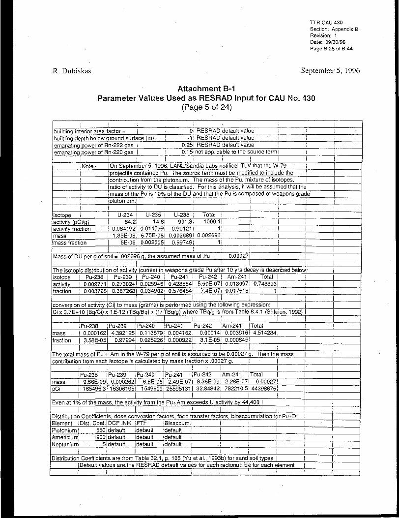
TTR CAU 430Section: Appendix BRevision: 1Date: 09/30/96Page B-25 of B-44
R. Dubiskas September 5, 1996
Attachment B-1Parameter Values Used as RESRAD Input for CAU No. 430
(Page 5 of 24)
; , i > i i • ibuilding interior area factor = I 0i RESRAD default value j i !building depth below ground surface (m) = i - 1 ! RESRAD default value j j iemanating power of Rn-222 gas i 0.25 i RESRAD default value i S Iemanating power of Rn-220 gas
I
iNote-i
! 0.15inot applicable to the source term| : |! I i ! I
On September 5,1996, LANL/Sandia Labs notified ITLV that the W-79projectile contained Pu. The source term must be modified to include the
!
! |contribution from the plutonium. The mass of the Pu, mixture of isotopes, ]|I
ratio of activity to DU is classified. For this analysis, it will be assumed that themass of the Pu is 10% of the DU and that the Pu is composed of weapons grade
\ i plutonium. I i i!
isotope iactivity (pCi/g)activity fractionmassmass fraction
! ! i ;
U-234 I U-235 j U-238 i Total i84.2| 14.6! 901.3; 1000.1!
jI
!0.0841921 0.014599! 0.90121: 1| I |1.35E-08J 6.75E-06! 0.002689i 0.002696:
5E-06! 0.0025051 0.997491 1!i l l !
i
|
Mass of DU per g of soil = .002696 g, the assumed mass of Pu = \ 0.00027J |I I I i i
l
j
!
The isoiopic distribution of activity (curies) in weapons grade Pu after 10 yrs decay is described below: jisotopeactivityfraction
Pu-2380.002771
Pu-239 ! Pu-240 i Pu-241 I Pu-242 | Am-241 Total | | |0.273024| 0.025946! 0.428554! 5.50E-07J 0.013097! 0.743393|
0.003728| 0.367268! 0.034902I 0.576484! 7.4E-07I 0.0176181 1|I I ! i
1
! ,! Iconversion of activity (Ci) to mass (grams) is performed using the following expression: |Ci x 3.7E+10 (Bq/Ci) x 1 E-12 (TBq/Bq) x (1/ TBq/g) where TBq/g is from Table 8.4.1 (Shieien, 1992)
i Pu-238mass i 0.000162
Pu-239I ' '
Pu-240 i Pu-241 i Pu-242 ! Am-241I
Total I4.3921251 0.1138791 0.004162! 0.00014! 0.003816! 4.514284! j |
fraction | 3.58E-05i 0.97294| 0.025226! 0.000922! 3.1E-05! 0.000845! | I |I I I I ! I I I .
The total mass of Pu + Am in the W-79 per g of soil is assumed to be 0.00027 g. Then the mass Icontribution from each isotope is calculated by mass fraction x .00027 g.
I 'i Pu-238
mass | 9.66E-09pCi I 165496.3
i
• I ! IPu-239 ! Pu-240 | Pu-241 i Pu-242 : Am-241
!l
!
Total |0.000262! 6.8E-06J 2.49E-07I 8.36E-09! 2.28E-07! 0.00027!163061951 1549609 j 255951311 32.84842! 782210.5
! I I i
111
443986751 i j! !
Even at 1% of the mass, the activity from the Pu+Am exceeds U activity by 44,400 !! I ! I I 1
Distribution Coefficients, dose conversion factors, food transfer factors, bioaccumulation for Pu+D:Element I Dist. Coef. DCF INH FTf jBisaccum.i iPlutonium! 550ideiauit idefault idefault I iAmericium; 1900! default I default 'default i !Neptunium' 5idefault (default idefault I i
i I
11
i 1 • 1! i i! i
! 1 !i I I I i 1
Distribution Coefficients are from Table 32.1, p. 105 (Yu et a!., 1993b) for sand soil types | !i Default values are the RESRAD default values for each radionuclide for each element! I l ! ! i I ! !

TTR CAU 430Section: Appendix BRevision: 1Date: 09/30/96Page B-26 of B-44
R. Dubiskas September5, 1996
Attachment B-1Parameter Values Used as RESRAD Input for CAU No. 430
(Page 6 of 24)
j
Calculations of RESRAD source terms: 'i
: ! I
i • ! ! : iAssume the Pu-239/240 activity = 500 pCi/g, the activity of all isotopes is calculated as follows:The activity in the Pu+Am mix = 500 g/(fraction of total due to Pu-239/240) = | 1243.256The activity for all other Pu+Am isotopes can be calculated from their fraction of the Pu+Am mix.If the Pu-239/240 activity is 200 pCi/g, the same method is used, Pu+Am activity =
i
Ii
497.3024! !Then each isotope in the Pu+Am mix can be calculated by multiplying its fraction by the total pCie.g. for Pu-238, if the total activity when Pu-239/240 = 500 pCi/g is 1243.256 pCi, the Pu-238activity is i.003728 x 1243.256= I 4.634244'; pCi/g of soil !
ii ! i
I!
!i
The U isotopic activity = (Pu+Am fraction/total Pu+Am) x total U x isotopic U activity fraction. | jIf Pu239/240 = 500 pCi/g, then Pu+Am fraction = 500 pCi/g + Pu-238.241,242, + Am = 1243.256! Ie.g., U-234 activity = (1243j3Ci/g/4.4E+7 pCi/g) x 1000 pCi/g x .084192 = i 0.002358!If Pu-239/240 activity fraction = 200 pCi/g, then the total Pu+Am activity = 497.3024:The U-234 activity = (497.3024/4.4E+7) x 1000 x .084192 = i 0.0009431
I i i I • . :
|
i
IPu-239/240 is emphasized because in-situ monitoring is based upon Am-241/Pu-239/240 activity |ratios using the 59.5 keV Am-241 photon. For the W-79 project in-situ monitoring may not beused, but if it is used it will be helpful to have the guideline in terms of Pu-239/240 or Am-241.
I i
I isotopic activity if j isotopic activity if the : >principal the Pu-239/240 I ! Pu-239/240 activity jIsotope i activity = 500 pCi/g I ;is200pCi/g I I I
I I I !U-234 | 0.0023581 iU-235 i 0.000409 I
U-238 | 0.0252381 |Pu-238Pu-239
i0.0009431 i 10.0001641 j0.0100951 i 1
4.634244! i 1.8536981 1456.6077! !
Pu-240 i 43.39231Pu-241Pu-242
!iII
II|
II
|182.6431! ! j |
! i 17.356931 i I716.71741 i 286.687!
0.00092! ! ! 0.000368|
i jAm-241 i 21.903541 1 1 8.7614141 ! 1 iTotal I 1243.2841 i | 497.31361 i
I I II
I i !
j
!
III
! ICalculate the activity and mass fraction of each isotope for Table B-1 in Appendix B: I | |isotopeU-234
mass fraction iactivity fraction [guideline concentration (pCi/g)4.55E-06I i 1.9E-06
U-235 j 0.002277I I 3.29E-07IU-238Pu-238Pu-239
6.50E-03I iIi
1.13E-03! I i |0.906811 1 2.03E-05I | 6.95E-02! !
3.26E-06! |0.003727| M.28E+01! |0.088449! | 0.367259 I 1.26E+03J |
Pu-240 | 0.002293! I 0.034901Pu-241 i 8.38E-05! I 0.5764711Pu-242 | 2.82E-06i | 7.4E-07I
II II i
1.19E+02! | I1.97E+03I i j ! j2.53E-03 • i !
Am-241 | 7.68E-05! |0.017617| | 6.02E+011 |i i i I I i Ii I ! iI I I
I II
i i I ! Ii I I
; ! i i I • i i i I |

R. Dubiskas
TTR CAU 430Section: Appendix BRevision: 1Date: 09/30/96Page B-27 of B-44
Septembers, 1996
Attachment B-1Parameter Values Used as RESRAD Input for CAU No. 430
(Page 7 of 24)
I
ICalculation of isotopic mass and activity fractions when mass fractions of Pu = 0.0001
Isotope
U-234U-235U-238Pu-238Pu-239Pu-240
Mass fractionif Pu mass
specificactivity
fraction = .0001
0.00050.25042799.739073.58E-070.0097290.000252
Pu-241 9.22E-06Pu-242Am-241
3.1E-078.45E-06
Total | 100
(TBq/g)
2.31 E-048.00E-081.24E-08
0.63412.30E-038.43 E-03
3.811.45 E-04
0.127
I i i
activity per100 g
(pCi)
3123027541522.5
334297456139937
6.05E+08574816649.49E+081218.489
29015546
1.68E+09
activity| fraction
0.001854i 0.000322! 0.019851
0.0036460.3591780.0341330.5637867.24E-070.01723
1
Pu-239/240 % of the total activity when total Pu is 0.01 % of the mass = | 39.33109Pu percent of the total activity when Pu is 0.01 % of the mass =
When DU is 99.99% of the mass its percent of the total activity =
97.79729
Ij Ij I
j
2.2027061

R. Dubiskas
TTR CAU 430Section: Appendix BRevision: 1Date: 03/30/96Page B-28 of B-44
September 5, 1996
Attachment B-1Parameter Values Used as RESRAD Input for CAU No. 430
(Page 8 of 24)
RESRAD, Version 5.61 T" Limit = 0.5 year 09/10/96 16:26 Page 1
Summary : Dose to Resident, CAU 430, 0.77 pCi/g DU, 1376 pCi/g Pu-239/240
File W79 DU 5.DAT
Table of Contents
aaaaaaaaaaaaaaaaa
Part I: Mixture Sums and Single Radionuclide Guidelines
eeeeeeeeeeeeeeSeee'eeeeee'ee'eee'eeeeeeeeeeeeeeeeeeeeeeeeee
Dose Conversion Factor (and Related) Parameter Summary 2
Site-Specific Parameter Summary .• 6
Summary of Pathway Selections 12
Contaminated Zone and Total Dose Summary 13
Total Dose Components
Time = O.OOOE+00 15
Time = 1.000E+01 16
Time = 5.000E+01 17
Time = 1.000E+02 18
Time = 2.500E+02 19
Time = 5.000E+02 : 20
Time = 8.000E+02 21
Time = 1.000E+03 22
Time = 5.000E+03 23
Time = 1.000E+04 24
Dose/Source Ratios Summed Over All Pathways 25
Single Radionuclide Soil Guidelines 26
Dose Per Nuclide Summed Over All Pathways 28
Soil Concentration Per Nuclide 30
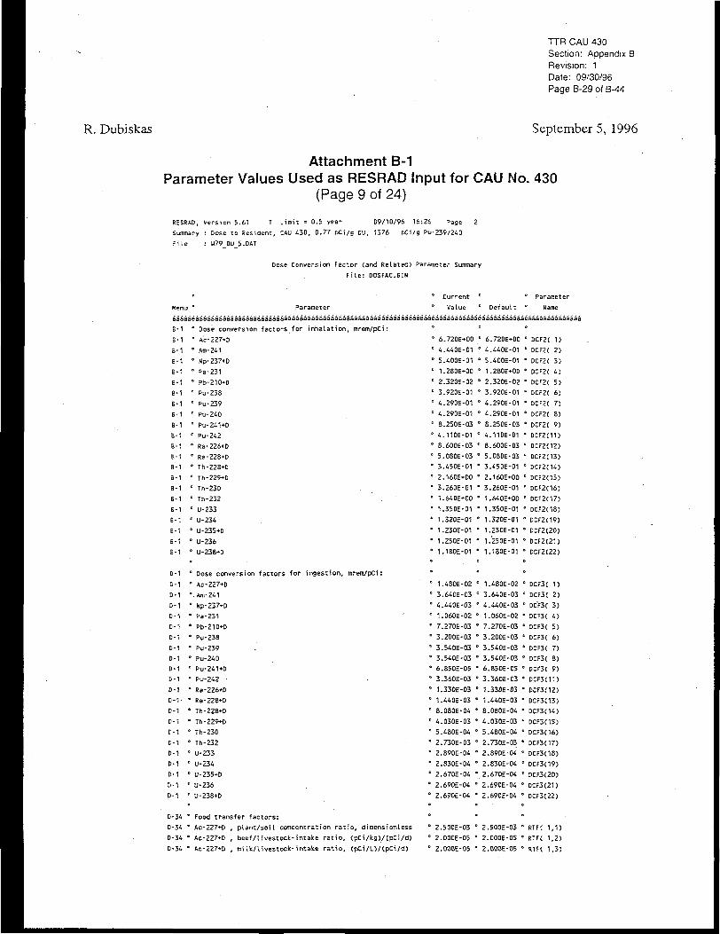
R. Dubiskas
TTR CAU 430Section: Appendix 3Revision: 1Date: 09/30/96Page B-29 of B-44
September5, 1996
Attachment B-1Parameter Values Used as RESRAD Input for CAU No. 430
(Page 9 of 24)
R£SRAD, Version 5.61 T" Limit = D.5 year 09/10/96 16:26 Page 2
Summary : Dose to Resident, CAU 430, 0.77 pCi/s DU, 1376 pCi/g Pu-239/240
File : U79_DU_5.DAT
Dose Conversion Factor (and Related) Parameter Summary
Fi le: DCSFAC.BIN
Menu ° Parameteraaaaaeaaaaaaaaaaaaaaaaaa3aaaaaaaaaaaaaaaaaaaaaaaaaaaaaaaaaaaaaaaiB-1
B-1
B-1
B-1
B-1
B-1
B-1
B-1
B-1
B-1
B-1
B-1
B-1
B-1
B-1
B-1
B-1
B-1
B-1
B-1
B-1
B-1
D-1
D-1
D-1
D-1
D-1
D-1
D-1
D-1
D-1
D-1
D-1
D-1
D-1-
D-1
D-1
C-1
D-1
D-1
D-1
D-1
D-1
D-1
° Dose conversion fac tors f o r i n h a l a t i o n , mrem/pCi:
• Ac-227+D
• Am-241
• Np-237+D
" Pa-231
° Pb-210*D
• Pu-238
' Pu-2391 Pu-240
• Pu-241+D5 Pu-242
' Ra-226+Dc Ra-228+D
• Th-22B+Dc Th-229*D
• Th-230
' Th-232
" U-233" U-234
° U-235+D
• U-2360 U-238+D
° Dose conversion factors for ingest ion, mrem/pCi:c Ac-227+D=.Am-241
" Np-237+D
• Pa-231
• Pb-210*D
• Pu-2381 Pu-239
' Pu-240* PU-24H-D
• Pu-242 •
° Ra-226+D
* Ra-228+D
* Th-228+D
• Th-229+D
• Th-230
• Th-232• U-233
* U-234
- U-235+D
• U-236
• U-238+D
Value Defaultiaaeaaaaaaaaaaaeaaaaaaaaaa
• •
• 6.720E+00 •
• 4.440E-01 *
" 5.400E-01 °
" 1.28OE+O0 °
" 2.320E-02 •
• 3.920E-01 •
• 4.290E-01 •
' 4.290E-01 *
° 8.250E-03 •
• 4.110E-01 •
" 8.6006-03 °
" 5.080E-03 •• 3.450E-01 "
• 2.160E+00 °
- 3.260E-01 "
° 1.640E+00 •
• 1.350E-01 °
" 1.320E-01 *
" 1.230E-01 °
• 1.250E-01 "• 1.180E-01 •
0 1.480E-02 '
" 3.640E-03 •
• 4.440E-03 "
° 1.060E-02 •0 7.270E-03 •
" 3.200E-03 •
* 3.540E-03 °
• 3.540E-03 "• 6.85DE-05 °
" 3.360E-03 "0 1.330E-03 •
° 1.440E-03 •
" 8.080E-04 "
• 4.030E-03 •
• 5.480E-04 •
* 2.730E-03 •" 2.890E-04 •0 2.830E-04 •
• 2.670E-04 •c 2.690E-04 °
• 2.690E-04 •
6.720E+O0
4.440E-01
5.400E-01
1.2B0E+0D
2.320E-023.920E-01
4.290E-01
4.290E-01
8.250E-034.110E-01
8.600E-03
5.080E-033.450E-01
2.160E+003.260E-01
1.640E+001.350E-01
1.320E-01
1.230E-01
1.250E-01
1.180E-01
1.480E-02
3.640E-03
4.440E-03
1.060E-02
7.270E-03
3.200E-03
3.540E-03
3.540E-036.850E-05
3.360E-03
1.330E-03
1.440E-03
8.080E-04
4.030E-03
5.480E-04
2.730E-032.890E-04
2.830E-04
2.670E-04
2.690E-04
2.690E-04
name
aeaaaaaaaaaaaaai
•
' DCF2X 1)0 DCF2( 2)
• DCF2C 3)
° DCF2C 4)
" DCF2C 5)
* DCF2C 6)
" DCF2C 7)
° DCF2C 8)
- DCF2{ 9)
• DCF2C11)
• DCF2C12)
• DCF2C13)
• DCF2O4)1 DCF2(15)
• DCF2C16)
• DCF2C17)
" DCF2(18)
• 0CF2(19)
• DCF2C20)
° DCF2C21)
• DCF2(22)
0 DCF3C 1)
• DCF3C 2)
• DCF3C 3)
• DCF3( 4)0 DCF3C 5 )
" DCF3C 6)
• DCF3< 7)
° DCF3( 8)
• DCF3C 9)
• DCF3C11)
• DCF3<12)
° DCF3(13)
• DCF3(14)
• DCF3(15)c DCF3C16)
* DCF3(17)
* DCF3C18)
• DCF3C19)
• DCF3(20)
" DCF3C21)
• DCF3C22)
D-34 e Food transfer factors:
D-34 ° Ac-227+D , plant/soi l concentration ra t io , dimensionI ess
D-34 ° Ac-227+D , beef/livestock-intake ra t io , (pCi/kg)/CpCi/d)
D-34 • Ac-227*D , mi Ik/ l ivestock-intake ra t io , CpCi/D/tpCi/d)
2.500E-03 • 2.500E-03 • RTF( 1,1)
2.0D0E-05 • 2.000E-05 • RTF( 1,2)
2.000E-05 • 2.000E-05 • RTFC 1,3)

I TTR CAU 430Section: Appendix BRevision: 1Date: 09/30/96Page B-30 of B-44
R. Dubiskas September 5, 1996
Attachment B-1Parameter Values Used as RESRAD Input for CAU No. 430
(Page 10 of 24)
RESRAD, Version 5.61 T" Limit = 0.5 year 09/10/96 16:26 Page 3
Summary : Dose to Resident, CAU 430, 0.77 pCi/s DU, 1376 oCi/s Pu-239/240
File : U79_DU_5.DAT
Dose Conversion Factor Cand Related) Parameter Summary (continued)
File: DOSFAC.BIN
Menu '
aaaaai
D-34 '
D-34 '
D-34 '
D-34 '
D-34 '
D-34 '
D-34 '
D-34 '
D-34 '
D-34 •
D-34 •
D-34 '
D-34 «
D-34 •
D-34 '
D-34 •
D-34 •
D-34 •
D-34 •
D-34 •
D-34 •
D-34 •
D-34 '
D-34 •
D-34 •
0-34 •
D-34 •
D-34 •
D-34 •
D-34 •
D-34 •
D-34 •
D-34 •
D-34 °
D-34 •
D-34 °
D-34 •
D-34 •
D-34 *
D-34 °
D-34 »
D-34 •
D-34 •
D-34 •
D-34 •
D-34 *
D-34 °
D-34 *
Parameter
•aaaaaaaaaaaaaaaaaaaaaaaaaaaaaaaaaaaaaaaaaaaaaaaaaaaaaaaaaaaaai
Am-241 , plant/soil concentration ratio, dimensionless
Am-241 , beef/tivestock-intake ratio, (pCi/kg>/CpCi/d)
Am-241 , milk/livestock-intake ratio, (pCi/l)/(pCi/d)
Np-237+D r plant/soil concentration ratio, dimensionless
Np-237+D , beef/livestock-intake ratio, (pCi/kg)/tpCi/d)
Np-237+D , mi Ik/livestock-intake ratio, (pCi/D/CpCi/d)
Pa-231 , plant/soil concentration ratio, dimensionless '
Pa-231 , beef/livestock-intake ratio, (pCi/ks)/(pCi/d)
Pa-231 , mi Ik/livestock-intake ratio, <pCi/L)/(pCi/d) • '
Pb-210+D , plant/soil concentration ratio, dimensionless '
Pb-210+D , beef/livestock-intake ratio, CpCi/k9)/(pCi/d> '
Pb-210+D , milk/livestock-intake ratio, (pCi/L)/(pCi/d> '
Pu-23B , plant/soil concentration ratio, dimensionless '
Pu-258 , beef/livestock-intake ratio, (pCi/kg)/{pCi/d) '
Pu-238 , milk/livestock-intake ratio, CpCi/D/CpCi/d) '•
Pu-239 , plant/soil concentration ratio, dimensionless '
Pu-239 , beef/livestock-intake ratio, CpCi/kg)/CpCi/d) '
Pu-239 , milk/livestock-intake ratio, (pCi/L)/(pCi/d) •
Pu-240 , plant/soil concentration ratio, dimensionless (
Pu-240 , beef/livestock-intake ratio, (pCi/kg)/(pCi/d)
Pu-240 , milk/livestock-intake ratio, CpCi/L)/CpCi/d)
Pu-241+D , plant/soil concentration ratio, dimensionless '
Pu-241+D , beef/livestock-intake ratio, (pCi/ks)/(pCi/d) •
Pu-241+D , milk/livestock-intake ratio, (pCi/U/(pCi/d) "
Pu-242 , plant/soil concentration ratio, dimensionless '
Pu-242 , beef/livestock-intake ratio, CpCi/kgj/CpCi/d) "
Pu-242 , milk/livestock-intake ratio, (pCi/L)/(pCi/d) •
Ra-226+D , plant/soil concentration ratio, dimensionless e
Ra-226+D , beef/livestock-intake ratio, CpCi/kg)/CpCi/d)
Ra-226+D , milk/livestock-intake ratio, CpCi/O/CpCi/d)
Ra-228+D , plant/soil concentration ratio, dimensionless x
Ra-22S+D , beef/livestock-intake ratio, (pCi/kg)/CpCi/d)
Ra-228+D , milk/livestock-intake ratio, CpCi/D/CpCi/d) '
Th-228+D , plant/soil concentration ratio, dimensionIess "
Th-228+D , beef/livestock-intake ratio, CpCi/kg)/(pCi/d) •
Th-228+D , milk/livestock-intake ratio, CpCi/O/CpCi/d) •
' Current ° c Parameter
' Value • Default ° Name
>aaaaaaaaaaaeaaaaaaaaaaaea3aaaaaaaaaaaa
' 1.000E-03 • 1.OD0E-03 ° RTF( 2,1)
' 5.000E-05 " 5.OOOE-O5 * RTF( 2,2)
' 2.000E-06 • 2.000E-06 ° RTF( 2,3)
' 2.000E-02 ° 2.000E-02 ' RTF( 3,1)
' 1.000E-03 ' 1.000E-03 * RTFC 3,2)
' 5.0005-06 • 5.000E-06 ° RTF( 3,3)
' 1.000E-02 • 1.000E-02 ° RTF( 4,1)
' 5.000E-03 • 5.000E-03 ° RTF( 4,2)1 5.000E-06 • 5.000E-06 ° RTFC 4,3)
1 1.00OE-02 • 1.000E-02 ° RTF( 5,1)
' 8.D00E-04 • 8.000E-04 • RTFC 5,2)
• 3.000E-04 • 3.000E-04 ° RTF( 5,3)
1 1.000E-03 • 1.000E-03 ° RTFC 6,1)1 1.000E-04 • 1.000E-04 ° RTFC 6,2)
• 1.000E-06 • 1.000E-06 " RTF{ 6,3)
1 1.OO0E-O3 • 1.000E-03 * RTFC 7,1)1 1.000E-04 • 1.000E-04 • RTF( 7,2)
1.000E-06 ° 1.000E-06 " RTFC 7,3)
1 1.000E-03 • 1.000E-03 " RTFC 8,1)1.000E-04 ' 1.000E-04 " RTFC 8,2)
1.000E-06 ° 1.000E-06 • RTFt 8,3)
1.000E-03 * LOME-03 ° RTFC 9,1)
1.000E-04 • 1.000E-04 ' RTFC 9,2)
1.000E-06 ° 1.000E-06 " RTFC 9,3)
1.000E-03 • 1.000E-03 * RTF(11,1)
1.000E-04 • L000E-04 ° RTFC11.2)
1.000E-06 ° 1.000E-06 • RTF(11,3)« O
4.000E-02 • 4.OOOE-O2 " RTF(12,1)
1.000E-03 ° L000E-03 • RTFC12.2)
1.000E-03 ° 1.000E-03 • RTFC12.3)
4.000E-02 ° 4.000E-02 • RTF(13,1)
1.000E-03 • 1.000E-03 * RTF(13,2)
1.000E-03 * 1.000E-03 ° RTF(13,3)
LOOOE-03 ° LOOOE-03 ° RTF(W,1)
1.000E-04 • L000E-04 * RTFC14.2)
5.000E-06 • 5.000E-06 • RTFC14,3)

TTR CAU 430Section: Appendix BRevision: 1Date: 09/30/96Page B-31 of B-44
R. Dubiskas September5, 1996
Attachment B-1Parameter Values Used as RESRAD Input for CAU No. 430
(Page 11 of 24)
RESRAD, Version 5.61 V Limit = 0.5 year 09/10/96 16:26 Page 4Summary : Dose to Resident, CAU 430, 0.77 pCi/g DU, 1376 pCi/g. Pu-239/240File : U79_DU_5.DAT
Dose Conversion Factor (and Related) Parameter Summary [continued)
File: DOSFAC.BIN
Menu ° Parameter °aaaaaeaaaaaaaaaaaaaaaaaaaaaaaaaaaaaaaaaaaaaaaaaaaaaaaaaaaaaaaaaaaaae;D-34 • Th-229*D , plant/soil concentration ratio, dimensionless •
beef/livestock-intake ratio, (pCi/kg)/(pCi/d) °milk/livestock-intake ratio, (pCi/L)/(pCi/d) •
CurrentValue Default
ParameterName
aaaaaaaaaaeaaaaaaaaaaaeaaaaaaaaaaaaaa
• 1.0D0E-03 • 1.000E-03 * RTF(15,1)" 1.000E-04 ' 1.000E-04 • RTF(15,2)' 5.000E-06 ° 5.000E-06 ° RTft15,3)
• 1.000E-03 • 1.000E-03 " RTF(16,1)" 1.000E-04 " 1.000E-04 • RTF(16,2)" 5.000E-06 ° 5.000E-06 • RTF(16,3)
' 1.000E-03 ° 1.000E-03 " RTF(17,1)' 1.000E-04 • 1.000S-04 * RTFC17,2)' 5.000E-06 • 5.000E-06 * RTF(17,3)
' 2.500E-03 ° 2.500F.-03 • RTF(18,1)1 3.400E-04 • 3.400E-04 • RTF{18,2)' 6.00DE-04 ° 6.000E-04 • RTF(1B,3)
' 2.50DE-03 • 2.500H-03 • RTF{19,1)• 3.400E-04 • 3.400E-04 • RTF(1y,2)• 6.000E-04. • 6.000E-04 • RTF(19,3)
' 2.500E-03 • 2.500E-03 * RTF(20,1)' 3.400E-04 ' 3.400E-04 ° RTF(20,2)1 6.000E-04 ° 6.000E-04 ° RTFC20.3)
2.500E-03 • 2.500E-03 " RTF(21,1)3.400E-04 - 3.400E-04 • RTFC21.2)6.000E-04 • 6.000E-04 • RTF(21,3)
2.500E-03 • 2.500E-03 ° RTF(22,1>3.400E-04 ° 3.400E-04 • RTFC22.2)6.000E-04 • 6.000E-04 " RTFC22.3)
1.500E+01 " 1.500E-f01 • BIOFACC 1,1)1 1.0006+03 ° 1.D0DS+03 c B!OFAC( 1,2)
o o
3.000E+01 • 3-OOOSi-OI • BIOFACt 2,1)
• 1.000E+03 • 1.000E+03 • BIOFACC 2,2)O V
3.000E+01 • 3.000E+01 • BlOFACt 3,1)4.000E+02 • 4.000E+02 • BIOFACt 3,2)
1.000E+01 ° 1.000E+01 • BIOFACt 4,1)1.100E+02 • 1.1D0E+02 ' BIOFACC 4,2)
3.OOOE+02 - 3.000E+02 • BrOFACC 5,1)1.000E+02 • 1.000E+02 ° BIOFAC( 5,2)
3.000E+01 • 3.000E*01 • BIOrAC( 6,1)1.000E+02 ' 1.000E+02 ° BIOFACt 6,2)
D-34D-34D-34D-34D-34D-34D-34D-34D-34D-34D-34D-34D-34D-34D-34D-34D-34D-34D-34D-34D-34D-34D-34D-34D-34D-34D-34D-34D-34
Th-229+DTh-229*D
0 Th-230 , plant/soil concentration ratio, dimensionless° Th-230 , beef/livestock-intake ratio, tpCi/kg)/(pCi/d)" Th-230 , milk/livestock-intake ratio, (pCi/L)/(pCi/d)
" Th-232 , plant/soil concentration ratio, dimensionless' Th-232 , beef/livestock-intake ratio, (pCi/kg)/<pCi/d)1 Th-232 , milk/livestock-intake ratio, tpCi/L)/CpCi/d)
* U-233 , plant/soil concentration ratio, dimensionless' U-233 , bee-f/livestock-intake ratio, (pCi/kgVtpCi/d)' U-233 , milk/livestock-intake ratio, (pCi/L)/(pCi/d)>1 U-234 , plant/soil concentration ratio, dimensionless' U-234 , beef/livestock-intake ratio, (pCi/kg)/(pCi/d)' U-234 , milk/livestoek-intake ratio, (pCi/L)/(pCi/d)
1 U-235+D , plant/soil concentration ratio, dimensionless1 U-235+D , beef/livestock-intake ratio, CpCi/ke)/CpCi/d)' U-235+D , milk/livestock-intake ratio, tpCi/L)/(pCi/d)
U-236 , plant/soil concentration ratio, dimensionlessU-236 , beef/livestock-intake ratio, tpCi/kg)/(pCi/d)U-236 , milk/livestock-intake ratio, (pCi/L)/(pCi/d)
U-23S+D , plant/soil concentration ratio, dimensionlessU-236+D , beef/livestock-intake ratio, (pCi/kg)/(pCi/d)
D-34 ° U-238+D , milk/livestock-intake ratio, CpCi/D/tpCi/d)
D-5D-5D-5D-5D-5D-5D-5D-5D-5D-5D-5D-5D-5D-5D-5D-5D-5D-5
° Bioaccumulation factors, fresh water, L/kg:° Ac-227+D , fish° Ac-227+D , crustaces and mollusks
° Am-241 , fishe Am-241 , crustacea and mollusksc
° Np-237*D , fishc Np-237-»-D , Crustacea and molluskse
• Pa-231 , fish° Pa-231 , crustacea and mollusks
° Pfc.-210+b , fish• Pb-210*D , Crustacea and mollusks
• Pu-238 , fishc Pu-238 , crustacea and mollusks

TTR CAU 430Section: Appendix BRevision: 1Date: 09/30/96Page B-32 of B-44
R. Dubiskas September5, 1996
Attachment B-1Parameter Values Used as RESRAD Input for CAU No. 430
{Page 12 of 24)RESRAD, Version 5.61 T" Limit = 0.5 year 09/10/96 16:26 Pace 5
Sumiary : Dose to Resident, CAU 430, 0.77 pCi/g DU, 1376 pCi/g Pu-239/240
File : W79_DU_5.DAT
Dose Conversion Factor (and Related) Parameter Summary Ccontinued)
File: DOSFAC.BIN
° ° Current ° ° Parameter
Menu " Parameter ° Value ° Default ° Name
aaaaaeaaasaaaaaaaaaaaaaaaaaaaaaaaaaaaaaaaaaaasaaaaaaaaaaaaaaaaaaaaaeaaaaaaaaaaaeaaaaaaaaaaaeaaaaaaaaaaaaaa
D-5 ' Pu-239 , fish
0-5 ° Pu-239 , Crustacea and mollusks
D-5 '
D-5 ° Pu-240 , fish
D-5 ° Pu-240 , Crustacea and mollusks
D-5 °:-5 ° Pu-241+D , fish
D-5 ° Pu-241+D , Crustacea and mollusks
D-5 °
D-5 ° Pu-242 , fish
D-5 ° Pu-242 .Crustacea and mollusks
D-5 °D-5 ° Rs-226+D , fish
D-5 ° Ra-226+D , Crustacea and mollusks
D-5 c
D-5 c Ra-228+D , fish
0-5 ° Ra-228+D , Crustacea and mollusks
D-5 "
D-5 ° Th-228+D , fish
D-5 ° Th-228+D , Crustacea and mollusks
D-5 °
D-5 ' Th-229+D , fish
D-5 ° Th-229+D , Crustacea and mollusks
D-5 °
D-5 ° Th-230 , fish
D-5 ° Th-230 , Crustacea and mollusks
D-5 "
D-5 • Th-232 , fish
D-5 ° Th-232 , Crustacea and mollusks
D-5 •
D-5 ° U-233
D-5 • U-233
D-5 •
D-5 " U-234
D-5 • U-234
, fish
, Crustacea and. mollusks
, fish
, Crustacea and mollusks
D-5 °
D-5 • U-235+D , fish
D-5 ° U-235+D , Crustacea and mollusks
D-5 °
D-5 ° U-236 , fish
D-5 ° U-236 , Crustacea and mollusks
D-5 •
D-5 ° U-238+D , fish
D-5 ° U-238+D , Crustacea and mollusks
' 3.000E+01 • 3.000E+01 • BIOFACC 7,1)0 1.000E+02 ° 1.000E+02 ° BIOFACC 7,2)
c 3.000E+01 ° 3.000E+01 ° BIOFACC 8,1)0 1.000E+02 ° 1.000E+02 ' BIOFACC 8,2)
° 3.000E+01 ° 3.000E+01 c BIOFACC 9,1)
° 1.00QE+02 ° 1.000E+02 • BIOFACC 9,2)
° 3.000E+01 ° 3.000E+01 " BIOFAC(11,1)
' 1.000E+02 ° 1.000E+02 ' BI0FACC11.2)
° 5.000E+01 ° 5.000E+01 • BI0FAC(12,1)
° 2.500E+02 ° 2.500E+02 • B1OFACC12,2)e o o
° 5.000E+01 • 5.000E+01 ° EIOFAC(13,1)0 2.500E+02 ° 2.500E+02 • BIOFACC13,2)
- 1.000E+02 ° 1.000E+02 ° BI0FACC14.1)
° 5.000E+02 ° 5.000E+02 ° BI0FAC(14,2)C D C
• 1.000E+02 ° 1.000E+02 ' BI0FACC15,1)
• 5.000E+02 •> 5.000E+02 ' BIOFACC15.2)
° 1.000E+02 • 1.000E+02 ° BI0FACC16,1)
" 5.000E+02 ° 5.000E+02 ' B1OFACC16.2)
' 1.000E+02 ° 1.000E+02 " BI0FACC17,1>
• 5.000E+02 • 5.000E+02 • B!OFACC17,2)e o e
' 1.000E+01 • 1.000E+01 ° BI0FACC18,1)
" 6.000E+01 ° 6.000E+01 ° BIOFACC18.2)o o e
" 1.000E+01 • 1.000E+01 " BI0FACC19.1)
" 6.000E+01 ° 6.000E+0T • BIOFACC19.2)
0 1.000E+01 ° 1.000E+01 ° BIOFACC20.1)
° 6.000E+01 • 6.000E+01 • BIOFACC20.2)
0 1.000E+01 ° 1.000E+01 • BI0FACC21.1)
• 6.000E+01 ° 6.000E+01 ° BIOFACC21,2)
• 1.000E+01 c 1.000E+01 ° BIOFACC22,1)
• 6.000E+01 ° 6.000E+01 ° BIOrACC22,2)
eeeeeueeeeeeeeeeeeeeeeeeeeeeeeeeeeeeeee'eeeeeeeeeeeeeeeee

TTR CAU 430Section: Appendix BRevision: 1Date: 09/30/96Page B-33 of B-44
R. Dubiskas September 5, 1996
Attachment B-1Parameter Values Used as RESRAD Input for CAU No. 430
(Page 13 of 24)RESRAD, Version 5.61 T" Limit = 0.5 year 09/10/96 16:26 Page 6
Summary : Dose tc Resident, CAU 430, 0.77 pCi/g DU, 1376 pCi/g Pu-239/240
File : U79_DU_5.DAT
Site-Specific Parameter Summary
Menu 6 Parameter
aa3aaeaaaaaaaaaaaa3333333s33a33aaaBaaaaaaaaaaa3a;
R011 • Area of contaminated zone (m**2) • 1.820E+02 ° 1.000E+04
R011 * Thickness of contaminated zone Cm) • 4.572E+00 ° 2.000E+00
R011 ' length parallel to aquifer flow Cm) • 1.524E+01 ° 1.000E+02
R011 * Basic radistion dose limit (mrem/yr) • 1.000E+02 * 3.000E+01
R011 • Time since placement of msterisl Cyr) ° 0.O00E+00 " O.OOOE+00
R011 ° Times for calculations (yr) " 1.000E+01 ° 1.000E+00
R011 " Times for calculations (yr) • 5.000E+01 " 3.000E+00
RD11 c Times for calculations (yr) ° 1.000E+02 " 1.000E+01
R011 • Times for calculations Cyr) " 2.500E+02 ° 3.000E+01
R011 ° Times for calculations (yr) • 5.O00E+02 * 1.000E+02
R011 c Times for. calculations Cyr) " 8.000E+02 ° 3.000E+02
RD11 ° Times for calculations Cyr) ° 1.000E+03 ° 1.000E+03
R011 • Times for calculations (yr) " 5.000E+03 " D.OOOE+00
RD11 ' Times for calculations (yr) ° 1.000E+04 ' O.OOOE+00
R012 • Initial principat radionuclide CpCi/g): Am-241 • 6.023E+01 ° O.OOOE+00
R012 ° Initial principsl radionuclide CpCi/g): Pu-238 • 1.276E+01 • 0.000E+00
R012 " Initial principal radionuclide <pCi/g): Pu-239 • 1.256E+03 ' O.OOOE+00
R012 • Initial principal radionuclide CpCi/g): Pu-240 ' 1.194E+02 ° 0.O00E+00 '
R012 ° Initial principal radionuclide (pCi/g): Pu-241 • 1.971E+D3 • O.OOOE+00 '
R012 ° Initial principal radionuclide (pCi/g): Pu-242 • 2.530E-03 ' O.OOOE+00 '
R012 " Initial principat radionuclide (pCi/g): U-Z31 ' 6.500E-03 • D.OOOE+00 '
R012 ° Initial principal radionuclide (pCi/g): U-235 " 1.130E-D3 ° 0.000E+00 '
R012 ° Initial principat radionuclide (pCi/g): U-238 " 6.947E-02 " O.OOOE+00 '
R012 • Concentration in grounduater (pCi/L): Am-241 ° not used • 0.000E+00 '
R012 * Concentration in groundwater (pCi/L): Pu-238 • not used " O.OOOE+00 '
R012 c Concentration in groundwater (pCi/L): Pu-239 ° not used • C.OOOE+00 '
R012 * Concentration in groundwater (pCi/L): Pu-2*0 ° not used ° O.OOOE+00 '
R012 * Concentration in groundwater CpCi/L): Pu-241 " not used • 0.000E+00 '
R012 * Concentration in groundwater CpCi/L): Pu-242 • not used • O.OOOE+00 '
R012 ° Concentration in groundwater CpCi/L): U-234 • not used * O.OOOE+00 •
R012 * Concentration in groundwater CpCi/L): U-235 " not used • 0.000E+00 "
R012 ' Concentration in groundwater CpCi/L): U-238 * not used ° 0.0D0E+00 '
User ' ° Used by RESRAD ' Parameter
* Input ° Default c (If different from user input) ° Kame
aBaaaaaaeaasaasaaaaseaaasaasaaaaeaBsaaaaaaaaaaaaaaad&siBaasaaaaaaeaaaBaaaaasaase
" AREA
° THICKO
° LCZPAO
' BRDL
° TI
" T( 2}c T{ 3)
° T( 4)
' T( 5)
' T( 6)
= TC 7)
' T( 8)
' T( 9)
' TOO)
' S1C 2)
' SIC 6)1 S1C 7)1 S1C 8)1 S1C 9)1 S1(11)
' S1O9)
' S1C20)1 S1C22)1 W1( 2)
W1C 6)1 W1C 7)
U1( 8)
W1C 9)
W1C11)
W1C19)
W1C20)
W1C22)
R013 ° Cover oepth (m) ' 0.000E+00 ° O.OOOE+OD
R013 ° Density of cover material (g/cm**3) ° not used ° 1.500E+00
R013 ° Cover depth erosion rate (m/yr) " not used ° 1.0D0E-03
R013 'Density of contaminated zone (g/cm**3) * 1.500E+00 • 1.500E+00
R013 * Contaminated zone erosion rate (m/yr> * 1.442E-03 " 1.000E-03
R013 ° Contaminated zone total porosity * 3.000E-01 * 4.000E-01
R013 ° Contaminated zone effective porosity * 3.000E-01 c 2.000E-01
R013 ° Contaminated zone hydraulic conductivity (m/yr) • 1.000E+03 ° 1.000E+01
R013 ° Contaminated zone b parameter " 4.050E+00 • 5.300E+00
RD13 • Humidity in air (g/cm**3) " not used • 8.000E+00
R013 • Evapotranspiration coefficient " 6.800E-01 ° 5.0D0E-01
R013 ° Precipitation (m/yr) ° 1.270E-01 • 1.000E+00
R013 • Irrigation (m/yr) • 1.530E+00 • 2.000E-01
R013 ° IrricEtion mode ° ditch c overhead
R013 ° Runoff coefficient • 2.000E-01 * 2.000E-01
R013 • Uatershed area for nearby stream or pond (m**2) " 1.824E+02 " 1.000E+06
' COVER01 DENSCV1 VCV: DEKSCZ
VCZ
TPCZ
EPCZ
HCCZ
BCZ
HUMID
EVAPTR
PRECIP
RI
IDITCH
RUNOFF
WAREA

TTR CAU 430Section: Appendix BRevision: 1Date: 09/30/96Page B-34 of B-44
R. Dubiskas September 5, 1996
Attachment B-1Parameter Values Used as RESRAD Input for CAU No. 430
(Page 14 of 24)
S>£SRM>, Version 5.61 T Limit = 0.5 year 09/10/96 16:26 Page 7
Sumsry : Dose to Resident, CAU 430, 0.77 pCi/g DU, 1376 pCi/g Pu-239/240
File : W79_DU_5.DAT
Site-Specific Parameter Summary (continued)
• ° User • • Used by RESRAD • Parameter
Menu ° Parameter * Input • Default ° (If different from user input) ° Name
aaaaaeaaaaaaaaaaaaaaaaaaaaaaaaa^aaaaaaaaaaaaaaaaaaaaaaaaaeaaa
R013 ° Accuracy for water/soil computations * 1.000E-03 • 1.000E-03 • --- ° EPS
ROU • Density of saturated zone (g/cm**3> ° 1.500E+00 ' 1.500E+00
ROU • Saturated zone total porosfty ° 3.0DOE-01 * 4.000E-01
ROU ° Saturated zone effective porosity ° 3.000E-01 • 2.000E-01
RDU • Saturated zone hydraulic conductivity (m/yr) • 1.000E+03 ° 1.000E+02
ROU ° Saturated zone hydraulic gradient " 1.000E-04 ° 2.000E-02
ROU ' Saturated zone b parameter ° 4.050E+00 • 5.300E+00
R014 ' Water table drop rate (m/yr) ° 1.000E-04 • 1.000E-03
ROU " Well pump intake depth (m below water table) * 1.000E+01 " 1.000E+01
ROU • Model: Nondispersion (ND) or Mass-Balance (MB) ° ND ' ND
R014 ° Well pumping rate (m**3/yr) " 2.796E+02 " 2.5D0E+02
DENSAQ
TPSZ
EPSZ
HCSZ
HGWT
BSZ
VWT
DWIBWT
MODEL
UW
R015 " Klumber of unsaturated zone strata
R015 * Unsat. zone 1, thickness (m)
R015 c Unsat. zone 1, soil density (g/cm**3)
RD15 * Unsat. zone 1, total porosity
R015 ° Unsat. zone 1, effective porosity
R015 ° Unsat. zone 1, soil-specific b parameter
R015 * Unsat. zone 1, hydraulic conductivity (m/yr)
R016 e Distribution coefficients for Am-241
RC16 * Contaminated zone Ccm"3/g)
RD16 ° Unsaturated zone 1 (cm"3/g)
R016 • Saturated zone Ccm**3/g)
R016 • Leach rate C/yr)
R016 ° Solubility constant
R016 ° Distribution coefficients for Pu-238
R016 c Contaminated zone (cm**3/g)
R016 * Unsaturated zone 1 (on**3/g)
R016 • Saturated zone Ccm**3/g>
R016 ' Leach rate (/yr)
R016 * Solubility constant
R016 ° Distribution coefficients for Pu-239
R016 * Contaminated zone (cm**3/g)
R016 • Unsaturated zone 1 (cm"3/g)
R016 ° Saturated zone (cm**3/g)
R016 • Leach rate (/yr)
R016 ' Solubility constant
R016 * Distribution coefficients for Pu-240
R016 * Contaminated zone (cm**3/g)
R016 • Unsaturated zone 1 (cm**3/g)
R016 • Saturated zone Ccm**3/g)
R016 • Leach rate (/yr)
R016 e Solubility constant
1
B.OOOE+01
1.500E+00
3.000E.-01
3.000E-01
4.050E+00
1.000E+03
1
4.000E+00
1.500E+00
4.000E-01
2.000E-01
5.300E+00
1.000E+01
1.900E+03 • 2.000E+01
1.900E+03 * 2.000E+01
1.90DE+03 • 2.000E+01
0.000E+00 ° O.OOOE+00
O.OOOE-i-00 ' 0.000E+O0
5.500E+02 " 2.000E+03
5.500E+02 ° 2.000E+03
5.500E+02 ° 2.000E+03
0.000E+O0 • 0.000E+00
0.000E+00 ° O.OOOE+00
° 5.500E+02 ° 2.000E+03
" 5.500E+02 • 2.000E+03
• 5.50OE+02 • 2.000E+03
• O.OOOE+00 • O.OOOE+00
° 0.000E+00 • 0.00OE+00
5.5D0E+02 ° 2.000E+03
5.500E+02 ° 2.000E+03
5.500E+02 " 2.000E+03
O.O00E+00 • O.OOOE+00
O.OOOE+00 ' 0.000E+00
...
...
...
...
...
...
...
4.007E-05
not used
...
...
1.384E-04
not used
...
• " " .
1.384E-04
not used
...
1.384E-04
not used
° DENSUZ(I)
° TPUZC1)c EPUZ(I)
° BUZCD0 HCUZ(I)
• DCNUCC( 2)
' DCNUCU( 2,1)
* DCNUCS( 2)c ALEACH( 2)
" SOLUBKl 2)
" DCNUCC( 6)
* DCNUCU( 6,1)c DCNUCS( 6)
° ALEACH( 6)
° SOLUBK( 6)
C
c 0CN0CC( 7)
° DCNUCU( 7,1)
• DCNUCS( 7)
" ALEACH( 7)
" SOLUBKt 7)
0 DCNUCC( 8)
* DCNUCtK 8,1)
° DCMUCSC 8)
° ALEACH( 8)
° SOLUBK( S)

TTR CAU 430Section: Appendix BRevision: 1Date: 09/30/96Page B-35 of B-44
R. Dubiskas September5, 1996
Attachment B-1Parameter Values Used as RESRAD Input for CAU No. 430
(Page 15 of 24)
RESRAO, Version 5.61 T" Limit = 0.5 year 09/10/96 16:26 t-age 8
Summary : Dose ro Resident, CAU A30, 0.77 pCi/g DU, 1376 p~i/g Du-239/2-0
rile : U79_DU_5.DAT
Site-Specific Parameter Suirmary (continued)
0 ° User ' ° Used by RESRAD ° Parameter
Menu ° Parameter ° Input c Default " (If different from user input) c Name
aaaaaeaaaaaaaaasaaaBaaaaaaaaaaaaaaaeaaaaaaaaaaaaBaaaaaaaeaaaaaaaaaaaeaaaaaaasaaaeaaaaaaaaaaaaasaaaaa
R016 ° Distribution coefficients for Pu-241 " ° • °
R016 ° Contaminated zone (cm**3/g)
RD16 " Unsaturated zone 1 (cm**3/s)
R016 ° Saturated zone (cm"3/g)
R016 ° Leach rate (/yr)
RD16 " Solubility constant
RC16 ° Distribution coefficients for Pu-242
R016 c Contaminated zone (cm**3/g)
RC16 ° Unsaturated zone 1 (cm**3/s)
R016 ° saturated zone (cm**3/g)
R016 * Leach rate C/yr)
R016 ° Solubility constant
R016 • Distribution coefficients for U-234
R016 ° Contaminated zone (cm**3/g)
R016 • Unsaturated zone 1 (cm**3/g)
R016 ' Saturated zone (cm"3/g)
R016 * Leach rate C/yr)
R016 " Solubility constant
RD16 ' Distribution coefficients for U-235
R016 ° Contaminated zone (cm**3/g)
R016 " Unsaturated zone 1 (cnV*3/g)
R016 * Saturated zone (aif"*3/g)
R016 • Leach rate (/yr)
R016 • Solubility constant
R016 " Distribution coefficients for U-238
R016 c Contaminated zone (cm**3/g)
R016 • Unsaturated zone 1 (cm**3/g)
R016 ° Saturated zone Ccm'*3/g)
R016 c Leach rate (/yr)
R016 ° Solubility constant
(
R016 c Distribution coefficients for daughter Ac-227
R016 • Contaminated zone (cm**3/g)
R016 ° Unsaturated zone 1 (cm**3/g)
R016 • Saturated zone (cm**3/g)
R016 • Leach rate (/yr)
R016 • Solubility constant
R016 ft Distribution coefficients for daughter Np-237
R016 ° Contaminated zone (cm**3/g)
R05o c - Unsaturated zone 1 (cm**3/g>
RD16 * Saturated zone (cm"3/g)
R016 • Leach rate (/yr)
R016 * Solubility constant
5.500E+02 • 2.000E+03
5.500E+02 • 2.000E*03
5.500E+02 • 2.000E+03
O.OOOE-'OO " O.OOOE+00
O.OOOE+00 ° O.OOOE+00
5.500E+02 • 2.000E+03
5.500E+02 • 2.000E+03
5.500E+02 ° 2.000E+03
0.000E+00 ° O.OOOE+00
0.000E+00 ° O.OOOE+00
3.50DE+01 • 5.000E+01
3.500E+01 • 5.000E+01
3.500E+01 " 5.000E+01
0.000E+00 " O.OOOE+00
0.000E+00 ' O.OOOE+00
3.500E+01 • 5.000E+01
3.500E+01 ° 5.000E+01
3.500S+01 ° 5.000E+01
O.OOOE+00 " 0.000E+00
0.000E+00 • 0.000E+00
3.500E+01 c 5.000E+01
3.500E+01 c 5.000E+01
3.500E+01 • 5.000E+01
0.000E+D0 • O.OOOE+00
0.000E+O0 • 0.000E+00
4.500E+02 ' 2.000E+01
4.500E+02 ° 2.000E+01
4.500E+02 • 2.000E+01
0.000E+00 • 0.O0OE+00
0.000E+00 c O.OOOr+00
5.000E+00 °-1.000E+00
5.000E+00 °-1.000E+00
5.000E+00 °-1.000E+00
0.000E+00 ' O.OOOE+00
0.000E+00 ' O.OOOE+00
1.384E-04
not used
1.384E-04
not used
2.169E-03
not used
2.169E-03
not used
2.169E-03
not used
1.691E-04
not used
1.492E-02
not used
° DCNUCC( 9)
" DCNUCUt 9, ))c DCNUCS( 9)
" ALEACH( 9)
° SOLUBKt 9)
e DCNUCCd'O
° DCNUCU(11,1)
' DCNUCS(H)
° ALEACH(H)
' SOLUBK(H)
DCKUCC(19)
DCMUCU(19,1)
DCNUCSC19)
ALEACH(19)
S0LUBKC19)
DCNUCC(20)
DCNUCU(20,1)
DCNUCS(20)
ALEACH(20)
SOLUBKC20)
DCKUCC(22)
DCKUCU(22,1)
DCNUCSC22)ALEACH(22)
SOLUBK(22)
DCNUCC( 1)
DCNUCU( 1,1)
DCNUCS( 1)
ALEACH( 1)
SOLUBK( 1)
DCNUCC( 3)
OCNUCUC 3,1)
DCNUCS( 3)
ALEACK( 3)
SOLUBK( 3)

TTR CAU 430Section: Appendix BRevision: 1Dale: 09/30/96Page B-36 of B-44
R. Dubiskas September 5, 1996
Attachment B-1Parameter Values Used as RESRAD Input for CAU No. 430
(Page 16 of 24)
R£SRAD, Version 5.61 T" Limit = 0.5 year 09/10/96 '6:26 Page 9
Sumary : Dose to Resident, CAU 430, 0.77 pti/o DU, 1376 pCi/g Pu-239/240
File : W79_DU_5.DAT
Site-Specific Parameter Summary (continued)
c ' User ' ° Used by RESRAD " Parameter
Kenu ° Parameter " Input c Default ° (If different from user input),0 Name
aaaaaeassaaaaaasasaaaaaaaaaaBaaaaaasaaaaaaaaaaassaaaaBaaeaaaaaaBaaaacasasaaaaaaaeaaasssaBaaaaaaaaaaaaaaaaaaaaaaaaeiBaaaaaasaaaaa
R016 • Distribution coefficients for daughter Pa-231 * * ° •
R016 ° Contaminated zone (cm"3/g)
RD16 ' Unsaturated zone 1 (cn;**3/g)
R016 " Saturated zone (cm**3/g)
P.016 " Leach rate C/yr)
R016 • Solubility constant
5.5D0E+02
5.500E+02
5.50DE+02
O.OOOE+00
0.000E+00
5.000E+01
5.000E+01
5.0005+01
O.OOOE+00
0.000E+00
1.384E-04
not used
' DCNUCC( 4)
" DCNUCUC 4,1)c DCNUCSC 4)
' ALEACHC 4)1 SOLUBKC 4)
^016 ° Distribution coefficients for daughter Pb-210
R016 ° Contaminated zone Ccm»*3/g)
R016 ° Unsaturated zone 1 (cm**3/g)
S016 * Saturated zone (cnr*3/g)
B016 ' Leach rate C/yr)
R016 c Solubility constant
2.7D0E+02 • 1.000E+02
2.700E+02 ° 1.000E+02
2.700E+02 ° 1.000E+02
0.000E+00 c 0.000E+00
O.OODE*OO ° O.OOOE+00
2.819E-04
not used
DCNUCCC 5)
DCNUCIK 5,1)
DCNUCS( 5)
ALEACK( 5)
SOLUBKt 5)
R016 " Distribution coefficients for daughter Ra-226
R016 c Contaminated zone (cm**3/g)
R016 * Unsaturated zone 1 Ccm"*3/s)
R016 * Saturated zone tan*"3/g)
R016 ° Leach rate C/yr)
R016 c Solubility constant
5.DD0E1-02 • 7.000E+01
5.000E+02 ° 7.000E+01
5.000E+02 " 7.000E*01
0.000E*00 c 0.000E+00
COOOE+OO • 0.000E+00
1.522E-04
not used
DCNUCCC12)
DCKUCU(12,1)
ALEACH(12)
S0LUBKCT2)
P.016 ° Distribution coefficients for daughter Ra-228
E016 ° Contaminated zone Ccm**3/g)
R016 " Unsaturated zone 1 (cm"3/g)
R016 * Saturated zone (oif"*3/g)
R016 * Leach rate (/yr)
R016 " Solubility constant
5.000E+02 - 7.000E+01
5.000E+02 • 7.000E+01
5.O00E+02 * 7.000E+01
O.OOOE+00 • 0.000E+00
O.OOOE+00 • 0.000E+00
1.522E-04
not used
DCNUCCC13)
DCNUCU(13,1)
DCNUCSC13)
ALEACHC13)
S0LUBKC13)
R016 * Distribution coefficients for daughter Th-228
R016 ° Contaminated zone (ati**3/g)
R016 * Unsaturated zone 1 [cro**3/g>
R016 • Saturated zone (cm»*3/g>
R016 • Leach rate C/yr)
R016" Solubility constant
3.200E+03 " 6.000E+04
3.200E+03 • 6.000E+04
3.200E+03 • 6.000E+04
0.000E+00 c O.OOOE+00
O.OOOE+00 ° 0.000E+00
2.379E-05
not used
DCNUCCC14)
DCNUCU(14,1>
DCNUCSC14)
ALEACH(U)
SOLUBKCK)
R016 ° Distribution coefficients for daughter Th-229
R016 B Contaminated zone (cm**3/g)
R016 ' Unsaturated zone 1 Ccm**3/g)
R016 • Saturated zone (cm**3/g)
R016 * Leach rate C/yr)
RC16 ' Solubility constant
3.200E+03 ° 6.000E+04
3.200E+03 • 6.O00E+04
3.200E+03 • 6.000E+04
0.000E+00 • 0.000E+00
0.000E+00 " O.OOOE+DO
2.379E-05
not used
DCNUCCC15)
DCNUCUC15.1)
DCNUCSC15)
ALEACHC15)
S0LUBKC15)
R016 ° Distribution coefficients for daughter Th-230
R016 6 Contaminated zone (cm**3/g)
R016 • Unsaturated zone 1 Ccm**3/g)
R016 • Saturated zone (cm'^S/g)
RD16 " Leach rate C/yr)
R016 c Solubility constant
• 3.200E+03 e 6.000E+04
° 3.200E+03 ° 6.000E+04
° 3.200E+03 " 6.000E+04
' 0.000E+00 c O.000E+00
• O.OOOE+00 " 0.000E+00
2.379E-05
not used
DCHUCCC16)
DCNUCU(16,1)
DCNUCSC16)
ALEACHC16)
S0LUBKC16)

TTR CAU 430Section: Appendix BRevision: 1Date: 09/30/96Page B-37 of B-44
R. Dubiskas September 5, 1996
Attachment B-1Parameter Values Used as RESRAD Input for CAU No. 430
(Page 17 of 24)RESRAD, Version 5.61 T" Limit = 0.5 year 09/10/96 16:26 Page 10
Sunrnary : Dose to Resident, CAU 430, 0.77 pCi/g DU, 1376 pCi/g Pu-239/240
File : W79_DU_5.DAT
Site-Specific Parameter Summary (continued)
0 • User ' ° Used by RESRAD ° Parameter
Menu ° Parameter ° Input ° Default ° (If different from user input) ° Name
aaaaaeaaaaaaaaaaaaaaaaaaaaaaaaaaaaaaaaaaaaaaaaaaaaaaaaaaeaaaaaaaaaaaeaaaaaaaaaaaeaaaa
R016 ° Distribution coefficients for daughter Th-232 • . • • •>
R016 ° Contaminated zone Ccm**3/g)
R016 " Unsaturated zone 1 (cm**3/g)
R016 * Saturated zone (cm**3/g)
R016 ° Leach rate (/yr)
R016 ' Solubility constant
RD16 e Distribution coefficients for daughter U-233
R016 ° Contaminated zone (cm**3/g)
R016 ° Unsaturated zone 1 (cm**3/g)
R016 ° Saturated zone (cm**3/g>
R016 ° Leach rate (/yr)
R016 ° Solubility constant
R016 • Distribution coefficients for daughter U-236
R016 ° Contaminated zone (cm**3/g)
R016 ' Unsaturated zone 1 (cm**3/g)
R016 • Saturated zone Ccra**3/g)
R016 ° Leach rate (/yr)
R016 c Solubility constantc
R017 • Inhalation rate (m**3/yr)
R017 ° Mass loading for inhalation (g/m**3)
R017 c Dilution length for airborne dust, inhalation
R017 c Exposure duration
R017 ° Shielding factor, inhalation
B017 ° Shielding factor, external gamma
R017 ° Fraction of time spent indoors
R017 ° Fraction of time spent outdoors (on site)
R017 ° Shape factor flag, external gamma
RO57 " Radii of shape factor array (used if FS = -1):
R017 ' Outer annular radius (m), ring 1:
R017 c Outer annular radius (m), ring 2:
R017 ° Outer annular radius (m), ring 3:
R017 • Outer annular radius (m), ring 4:
R017 c Outer annular radius (m), ring 5:
R017 ° Outer annular radius (m), ring 6:
RD17 ° Outer annular radius (m), ring 7:
R017 • Outer annular radius (m), ring 8:
R017 • Outer annular radius (m), ring 9:
R017 ° Outer annular radius (m), ring 10:
R017 ° Outer annular radius (m), ring 11:
R0'i7 • Outer annular radius (m), ring 12:
" 3.200E+D3 ° 6.000E+04 '•'
° 3.200E*03 " 6.000E*04 °
° 3.200E+03 ' 6.000E+04 °
° O.DOOE+00 • 0.000E+00 °
° 0.000E+00 ° 0.OO0E+O0 °
° 3.500E+01
° 3.500E+01
° 3.500E+01
° O.OOOE+00
" 0.000E+00e
° 3.500E+01
° 3.500E+01
•" 3.500E+01
° O.OOOE+00
° 0.OO0E+00o
° 6.372E+03
° 9.860E-06
(m)° 3.000E+00
° 3.000E+01
° 1.000E+00
.° 7.000E-01
° 6.792E-01
° 2.797E-01
° 1.000E+00o
° not used
° not used0 not used
° not used
° not used
° not used
* not used
° not used
° not used
" not used
° not used
° not used
° 5.000E+010 5
° 5
° 0
" 0
D 5
' 5
• 5
° 0
" 0.o
° 8
.000E
.000E
.0OOE
.000E
.00OE
.000E
,000E
.000E
.000E
.400E
° 2.000E
° 3.
' 3,
" i,
' 7,
' 5.
" 2.
' 1.
• 000E-
+01
+01
+00
+00
+01
+01
+01
+00
+00
+03
-04
+00
.000E+01
.OOOE-01
.OOOE-01
.000E -01
.500E-01
.O0OE-
0 5.000E-
t-00
K)1• 7.071E+01
° 0.0 0.
° 0.
" 0.0 0.
° 0.
° 0.
• o.° 0.
" 0.
,000E-i-OO
.OOOE+00
.000E-
^OOOE-
000E-
O O O E H
i-OO
i-OO
h00
i-OO
OOOS+00
0O0E+00
OOOE+00
000E+00
2.379E-05
not used
2.169E-03
not used
2.169E-03
not used
1 shows circular AREA.
° DCNUCC(17)
° DCNUCU(17,1)e DCNUCSC17)
" ALEACH(17)
° S0LUBK(17)
DCNUCCC18) .
DCNUCU(18,1)
DCNUCS(18)
ALEACH{18)
SOLUBK(18)
° DCNUCC(21)
° DCKUCU(21,1)
° DCNUCS(21)
° ALEACH(21)
° SOLUBK(21)
° INKALR
" HLINH
° LM0 ED
° SHF3
' SHF1
" FIND
° FOTD
° FS
c RAD_SHAPE( 1)
° RAD_SHAPE( 2)
" RAD_SHAPE( 3)
" RAD_SHAPE( 4)
• RAD_SHAPE( 5)
° RAD_SHAPE( 6)0 RAD_SHAPE( 7)
° RAD_SHAPE( 8)
" RAD_SHAPE( 9)0 RAD_SHAPE(10)
° RAD_SHAPE(11)
° RAD SHAPE(12)

TTR CAU 430Section: Appendix BRevision: 1Date: 09/30/96Page B-38 of B-44
R. Dubiskas September 5, 1996
Attachment B-1Parameter Values Used as RESRAD Input for CAU No. 430
(Page 18 of 24)RSSP.AD, Version 5.61 T" Limit = 0.5 year 09/10/96 16:26 ^age 11
Summary : Dose To Resident, CAU 430, 0.77 pCi/g Du, 1376 pCi/g Pu-239/2^0
File : U79_DU_5.DAT
Site-Specific Parameter Summary (continued)
Menu
aaaa;
R017
R017
R017
RO',7
R017
R017
RD17
R017
RD17
R017
RC17
RC17
R017
R018
R018
R018
R018
R018
RC18
R018
R018
R018
R018
R018
R018
R018
R018
R018
R018
R019
R019
R019
R019
RD19
RD19
R019
R019
R019
R019
R019
R019
° Parameter
ieaaaaaaaaaaaaaaaaaaaaaaaaaaaaaaaaaaa
° Fractions of annular areas within
" Ring 1
R i ng
Ring
Ring
Ring
° Ring 6
° Ring 7
" Ring 8
' Ring 9
* Ring 10c Ring 11
° Ring 12
° Fruits, vegetables and grain consumption (kg/yr)D leafy vegetable consumption Ckg/yr)0 Milk consumption (t/yr)
* Meat and poultry consumption Ckg/yr)
' Fish consumption Ckg/yr)
° Other seafood consumption (ks/yr)
° Soil ingestion rate (g/yr)= Drinking water intake (L/yr)= Contamination fraction of drinking water
' Contamination fraction of household water
' Contamination fraction of livestock waterB Contamination fraction of irrigation waters Contamination fraction of aquatic food
' Contamination fraction of plant food
' Contamination fraction of meat
' Contamination fraction of milk
' Livestock fodder intake for meat (kg/day)1 Livestock fodder intake for milk Ckg/day)
' Livestock water intake for meat (L/day)
' Livestock water intake for milk (L/day)
'Livestock soil intake (kg/day)
' Mass loading for foliar deposition (g/m**3)1 Depth of soil mixing layer Cm)! Depth of roots Cm)1 Drinking water -fraction from ground water
' Household water fraction from ground water
' Livestock water fraction from ground water
' Irrigation fraction from ground water
C U • C-12 concentration in water (9/011**3)
C U * C-12 concentration in contaminated soil Cg/g)
C U 'Fraction of vegetation carbon from soil
C U c Fraction of vegetation carbon from air
C U c C-U evasion layer thickness in soil Cm)
C U ° C-U evasion flux rate from soil Ci/sec)
User
" Input
° not usedc not used
° not used
° not used
° not used
° not used
° not used
° not used
° not used
° not usedD not used
° not used
• 4.949E+01
° 4.130E+00
° not used
° not used
" not usede not used
• 3.650E+01
• 5.11OE+O2
° 1.000E+00
" 1.000E+00c not used
• 1.OOOE+OD
* not used
°-1
• not used
° not used
" not used
° not used
° not used
° not used
" not used
° 3.656E-03
° O.OOOE+00
° 9.000E-01
' 1.000E+00
° 1.000E+00
' 1.000E+00
° not used
° not used
° not used0 not usedp not used
" not usedc not used
• Default "
' 1.000E+00 "
" 2.732E-01 °
' O.OOOE+00 "
• O.OOOE+00 °0 O.OOOE+00 '
' O.OOOE+00 °
* O.OOOE+00 °
' O.OOOE+00 °
• O.OOOE+00 •
' O.OOOE+00 °
' O.OOOE+00 °
• O.OOOE+00 °
• 1.600E+02 "0 1.400E+01 °
* 9.200E+01 °
• 6.300E+01 °
• 5.400E+00 °
" 9.000S-01 "
" 3.650E+01 °c 5.1O0S+O2 c
° 1.DO0E+OO °
° 1.000E+00 '
° 1.000E+00 °c 1.000E+00 •
" 5.000E-01 °c-1
°-1
o" 1 l' 6.800E+01 °
• 5.500E+01 °
• 5.000E+01 °
' 1.600E+02 °
" 5.000E-01 "
• 1.000E-W "0 1.500E-01 °
° 9.000E-01 "
° 1.000E+00 •
• 1.000E+00 '
' 1.000E+00 "
• 1.000E+00 °
c 2.000E-05 "
• 3.000E-02 •
• 2.000E-02 •
* 9.800E-01 •
• 3.000E-01 •c 7.000E-07 •
Used by RESRAD ° Parameter
Clf different from user input) c Name
c FRACAC 1)
• FRACAC 2)
* FRACAC 3)
" FRACAC 4)
* FRACAC 5)
° FRACAC 6)
" FRACAC 7)
" FRACAC 8)
" FRACAC 9)c FRACAC10)
° FRACAC11)
" FRACAC12)
° DIET(I)
° DIETC2)
° DIETC3)
• DIETC4)
° DIETC5)
• DIETC6)c SOIL
° DWIc FDW
° FHHW
° FLW
" FIRW
• FR9
0.910E-01 ° FPLANT
• FHEAT
* FKILK
• LFI5
° LFI6
--- ' • LWI5
• LWI6
° LSI
' HLFD
° DM
• DROOT1 FGWDW0 FGWHH
• FGWLW
' FGW1R
' C12WTR .
• C12CZ
" CSOIl
• CAIR
• DMC
... • EVSN

TTR CAU 430Section: Appendix BRevision: 1Date: 09/30/96Page B-39 of B-44
R. Dubiskas September 5, 1996
Attachment B-1Parameter Values Used as RESRAD Input for CAU No. 430
(Page 19 of 24)RESRAD, Version 5.61 T" limit = 0.5 year 09/10/96 16:26 Page 12
Sunraary : Dose to Resident, CAU 430, 0.77 pCi/g DU, 1376 pCi/g Pu-235/240
File : W79_DU_5.DAT
Site-Specific Parameter Suiroary (continued)
° ° User " ° Used by RESRAD ° Parameter
P.enu ° Parameter ° Input • Default " (If different from user input) ° Name
asasaeaaaaaaaaaaaaaaaaaaBaaaaaaaasaaaaaaBsaasaaaaaaaaaaaeaaaasaaaaaaesaaaaaaaBsaeaaiaaaaBaBasasaaaaaaaaaaaaaaaaaaeaaiaaaaBJaaBaa
C14 • C-12 evasion flux rate from soil (1/sec) • not used • 1.000E-10 • --- • REVSN
CK ° Fraction of grain in beef cattle feed ° not used • 8.000EJ01 ' •-- ' AVFG4
C*4 c Fraction of grain in milk cow feed * not used • 2.000S-01 " '• --- " AVFG5
STOR e Storage times of contaminated foodstuffs (days): e °
S70R "- Fruits, non-leafy vegetables, and grain " 1.AOOE'OI • "i.400E*01
STOR ° Leafy vegetables " 1.000E+00 ° 1.00DE+00
STOR " Milk ° not used * 1.000E+00
STOR • Meat and poultry c not used ° 2.000E+01
STOR • Fish ° not used " 7.000E+00
STOR ° Crustacea and mollusks ° not used ° 7.D00E+00
STOR c Well water ° 1.000E*00 " 1.000E+00
STOR • Surface water ' 1.000E+00 c 1.000E+00
STOR c Livestock fodder c not used ' 4.500E+01
ST0R_T(1)
ST0R_TC2)
STOR_T(3)
ST0R_T(4)
ST0R_T(5)
ST0R_T(6)
STDR_T(7)
ST0R_T(8)
STOR T(9)
R021 ° Thickness of building foundation Cm)
R021 ° Bulk density of building foundation (g/cm**3)
,R021 c Total porosity of the cover material
RC21 c Total porosity of the building foundation
R021 ° Volumetric water content of the cover material
R021 c Volumetric water content of the foundation
R021 * Diffusion coefficient for radon gas (m/sec):
R021 ° in cover material
R021 ° ' in foundation material
RG21 " in contaminated zone soil
R021 B Radon vertical dimension of mixing Cm)
R021 ° Average annual wind speed Cm/sec)
R021 ° Average building air exchange rate (1/nr)
R021 • Height of the building (room) Cm)
R021 c Building interior area factor
R021 * Building depth below ground surface Cm)
RD21 • Emanating power of Rn-222 gas
R021 " Emanating power of Rn-220 gas
1.500E-01 c 1.500E-D1
2.4O0E+00 • 2.400E+00
not used • i.000E-01
1.000E-01 ° 1.000E-01
not used * 5.000E-02
3.000E-02 • 3.000E-02
not used
3.000E-07
2.000E-06
2.000E+00
3.400E+00
5.000E-01
2.500E+00
0.000E+00
-1.000E+00
2.500E-01
1.500E-01
' 2.00DE-06
' 3.000E-07
' 2.000E-06
' 2.000E+00
' 2.000E+001 5.000E-011 2.500E+001 0.000E+00
-1.000E+001 2.500E-01
1.500E-01
code computed Ctime dependent)
code computed Ctime dependent)
: FLOOR1 DENSFL1 TPCV
TPFL
PH2OCV
PH20FL
D1FCV
DIFFL
DIFC2
HHIX
WIND
REXG
HRM
FAI
DMFL
EMANAC1)
EMANAC2)
eeeeeueeeeeeeeeeeeeeeeeeeeeeeeeeeeeeeeeee^
Summary of Pathway Selections
ass
Pathway ° User Selection
saaaaaaaaaaaaaaaaaaaaeaaaaaaaaaassaaaaaaaa
1 -- external gamma •
2 -- inhalation Cw/o radon)*
3 -- plant >ngestion e
U •- meat ingest ion . °
5 -- milk ingest ion e
6 -- aquatic foods e
7 -- drinking water •
8 -- soil ingestion •
9 -- radon *
active
active
active
suppressed
suppressed
suppressed
active
active
active

R. Dubiskas
TTR CAU 430Section: Appendix 3Revision: 1Dale: 09/30/95Page 3-40 of B-44
Septembers, 1996
Attachment B-1Parameter Values Used as RESRAD Input for CAU No. 430
(Page 20 of 24)
RESRAD, Version 5.61 T" Limit = 0.5 year 09/10/96 16:26 Page
Summary : Dose to Resident, CAU 430, 0.77 pCi/g DU, 1376 pCi/g Pu-239/240
File : W79 DU 5.DAT
Contaminated Zone Dimensions
aaaaasaaaaaaaaaaaaaaaaaaaaaa
Area: ' 182.00 square meters
Thickness: £.57 meters
Cover Depth: 0.00 meters
I n i t i a l Soil Concentrations, pCi/g
aaaaaaaaaaaaaaaaaaaaaaaaaaaaaaaaaa
Am-241
Pu-233
Pu-239
Pu-240
Pu-241
Pu-242
U-234
U-235
U-23S
6.D23E+01
1.276E+01
1.256E+03
1.194E+02
1.971E+03
2.530E-03
6.500E-D3
1.130E-03
6.947E-02
C (years ) :
TDOSE(t):
T o t a l Dose TDCSE(t), mrem/yr
Essie R a d i a t i o n Dose L i m i t = 100 mrem/yr
To ta l M i x t u r e Sum H ( t ) = F r a c t i o n of Basic Dcse L i m i t Received at Time ( t )
aasaaaassaasaaaassasaaaaaaaaasasaaaaaaaasasaaaasaasaasaassasaaaaaaasaassaa
O.OOOE+00 1.000E+01 5.000E+01 11000E+D2 2.500E+02 5.000E+02 S.00DE+G2 1.000E+D3
9.809E+D1 9.92DE+01 9.973E+01 9.S24E+01 9.352E+01 8.708E+01 8.0S3E+D1 7.727E+015.OOOE+O3
2.743E+01
1.000E+04
1.166E+01H { t ) : 9.809E-01 9.920E-01 9.973E-01 9.S24E-01 9.352E-01 8.708E-01 8.0E3E-01 7.727E-01 2.743E-01 1.166E-01
Maximum TDCSE(t): 9.993E+01 mrem/yr at t = 32 .92 p 0.03 years
To ta l Dose C o n t r i b u t i o n s TDOSE(i ,p, t> f o r I n d i v i d u a l Radionucl ides ( i ) and Pathways (p)
As mrem/yr and F r a c t i o n of To ta l Dose At t = 32.92 years
Ground
Radio- aaasssaaaaaaaaaa
Nucl ide mrem/yr f . - a c t .
aaaaaaa aaaaaaaaa aaaaaa
Am-241 1.634E+00 0.0164
Pu-238 1.049E-03 .0.0000
Pu-239 2.452E-01 0.0025
Pu-240 1.229E-02 0.0001
Pu-241 1.448E+09 0.0145
Pu-242 2.265E-07 0.0000
U-234 1.716E-06 0.0000
U-235 5.2O0E-O4 0.0000
U-238 5.599E-03 0 .0001.
eeeeeee e'eeeeeeee eee'eee
Tota l 3.348E+00 0.0335
Water Independent Pathways (Inhalation excludes radon)
Inhalationaaaaaaaaaasaaaaa
mrem/yr f r a c t .
aaaaaaaaa aaaaaa
1.249E+00 0.0125
1.893E-01 0.0019
2.641H+01 0.2643
2.505E-H3O 0.0251
1.266E+00 0.0127
5.101E-05 0.0000
3.940E-05 0.0000
6.522E-06 0.0000
3.762E-04 0.0000
eeeeeeeee eeeeee
3.162E+01 0.3164
Radon
aaaaaaaaaaaaaaaa
mrem/yr fract.
aaaaaaaaa aaaaaa
0.0OOE+O0 0.0000
7.164E-08 0.0000
0.000E+00 0.0000
1.398E-15 0.0000
O.ODOE+00 0.0000
1.915E-20 0.0000
1-242E-06 0.0000
0.OOOE+00 0.0000
4.088E-10 0.0000
eeeeeeeee eeeee'e
1.314E-06 0.0000
Plant
aaaaaaaaaaaaaaaa
mrem/yr fract.
aaaaaaaaa aaaaaa
1.227E+00 0.0123
1.852E-01 0.0019
2.612E+01 0.2614
2.478E+00 0.0248
1.247E+00 0.0125
4.999E-05 0.0000
2.266E-05 0.0000
4.174E-06 0.0000
2.302c-04 0.0000
eeeeeeeee eeeee'e
3.126E+01 0.3128
Heat
aaaaaaaaaaaaaaaa
mrem/yr fract.
aaaaaaaaa aaaaaa
0.OO0E+0O 0.0000
O.OOOE+00 0.0000
O.OOOE+00 0.0000
O.OOOE+00 D.0000
0.000E+00 0.0000
0.O00E+O0 0.0000
O.OOOE+00 0.0000
O.OOOE+00 0.0000
O.00OE+00 0.0000
eeeeeeeee eee'eee
O.OOOE+00 0.0000
Milk
aaaaaaaaaaaaaaaa
mrem/yr fract.
aaaaaaaaa'aaaaaa
D.OOOE+00 0.0000
0.O00E+00 0.0000
0.000E+00 0.0000
O.OOOE+00 0.0000
O.OOOE+00 0.0000
O.OOOE+00 0.0000
0.000E+00 0.0000
0.000E+00 0.0000
O.OOOE+00 0.0000
e'eeee'eee'e eee'eee
0.000E+00 0.0000
Soil
aaaaaaaaaaaaaaa
mrem/yr fractj
aaaaaaaaa aaaaaj
1.323E+00 0.012
1.997E-01 0.002|
2.817E+01 O.281|
2.672E+00 0.026
1.344E+00 0.012
5.39OE-O5 0.000
1.092E-05 0.000
1.868=-06 0.0001
1.108E-04 O.OOol
eee'eeeee'e eeeee|
3.370E+01 0.337

R. Dubiskas
TTR CAU 430Section: Appendix BRevision: 1Date: 09/30/96Page B-41 oi B-44
September5, 1996
Attachment B-1Parameter Values Used as RESRAD Input for CAU No. 430 -
(Page 21 of 24)
R=SRAD, Version 5.61 T" Limit = 0.5 year 09/1C/96 16:26 Page 14
Summary : Dose to Resident, CAU 430, 0.77 pCi/g DU, 1376 pCi/g Pu-239/240
Fi le : W79_DU_5.DAT
Total Dose Contr ibut ions TDOSE(i,p,t) fo r Ind iv idua l Radionuclides ( i ) and Pathways (p)
As mrem/yr and Fraction of Total Dose At t = 32.92 years
Water Dependent Pathways
Radio-
Nuclide
aaaasaa
Am-241
Pu-238
Pu-239
Pu-240
Pu-241
Pu-242
U-234
U-235
U-238
eeeeeee
Total
Water
aaaaaaaaaaaaaaaa
mrem/yr
aaaaaaaaa
O.OOOE+00
O.OOOE+00
O.OOOE+00
0.000E+00
O.OOOE+00
0.000E+00
0.000E+00
O.OOOE+00
O.OOOE+00
eeeeeeeee
0.000E+00
fract.
aaaaaa
0.0000
0.0000
0.0000
0.0000
0.0000
0.0000
0.0000
0.0000
0.0000
eeeeee
0.0000
Fish
aaaaaaaaaaaaaaaa
mrem/yr fract.
saaaaaaaa aaaaaa
O.OOOE+00 O.tfOOO
O.OOOE+00 0.0000
O.OOOE+00 0.0000
O.OOOE+00 0.0000
O.OOOE+00 0.0000
O.OOOE+00 0.0000
0.000E+OO 0.0000
0.O00E+0O 0.0000
0.000E+00 0.0000
Radon.
aaaaaaaaaaaaaaaa
mrem/yr fract.
aaaaaaaaa aaaaaa
O.OOOE+00 0.0000
0.000E+00 0.0000
O.OOOE+00 0.0000
O.OOOE+00 0.0000
O.OOOE+00 0.0000
0.000E+00 0.0000
0.00DE+00 0.0000
O.OOOE+00 0.0000
O.OOOE+00 0.0000
e'eeeeeeee eee'eee
O.OOOE+00 0.0000
Plant
aaaaaaaaaaaaaaaa
mrem/yr fract.
aaaaaaaaa aaaaaa
0.000E+00 0.0000
O.OOOE+00 0.0000
O.OOOE+00 0.0000
O.OOOE+00 0.0000
0.O00E+00 0.0000
O.OOOE+00 0.0000
0.000E+00 0.0000
0.000E+00 0.0000
0.000E+00 0.0000
eeeeeeeee eeeeee
0.000E+O0 0.0000
Meat
aaaaaaaaaaaaaaaa
mrem/yr fract.
aaaaaaaaa aaaaaa
0.000E+OO 0.0000
O.OOOE+00 0.0000
O.OOOE+00 0.0000
O.OOOE+00 0.0000
0.000E+00 0.0000
0.000E+OO 0.0000
0.000E+O0 0.0000
O.OOOE+00 0.0000
0.000E+00 0.0000
Milk
aaaaaaaaaaaaaaaa
mrem/yr fract.
aaaaaaaaa aaaaaa
O.OOOE+00 0.0000
0.000E+00 0.0000
0.000E+00 0.0000
O.OOOE+00 0.0000
O.OOOE+00 0.0000
O.OOOE+00 0.0000
0.000E+00 0.0000
0.000E+OO 0.0000
O.OOOE+00 0.0000
All Pathways*
aaaaaaaaaaasaaaa
mrem/yr fract.
aaaaaaaaa aaaaaa
5.433E+00 0.0544
5.752E-01 0.0058
8.094E+01 0.8100
7.667E+00 0.0767
5.305E+00 0.0531
1.551E-04 0.0000
7.594E-05 0.0000
5.326E-04 0.0000
6.316E-03 0.0001
eeeeeeeee eeeeee
O.OOOE+00 0.0000
eeeeeeeee eeeeee
O.OOOE+00 0.0000
eeeeeeeee eeeeee
O.OOOE+00 0.0000
eeeeeeeee eeeeee
9.993E+01 1.0000
'SUIT of all water independent and dependent pathways.
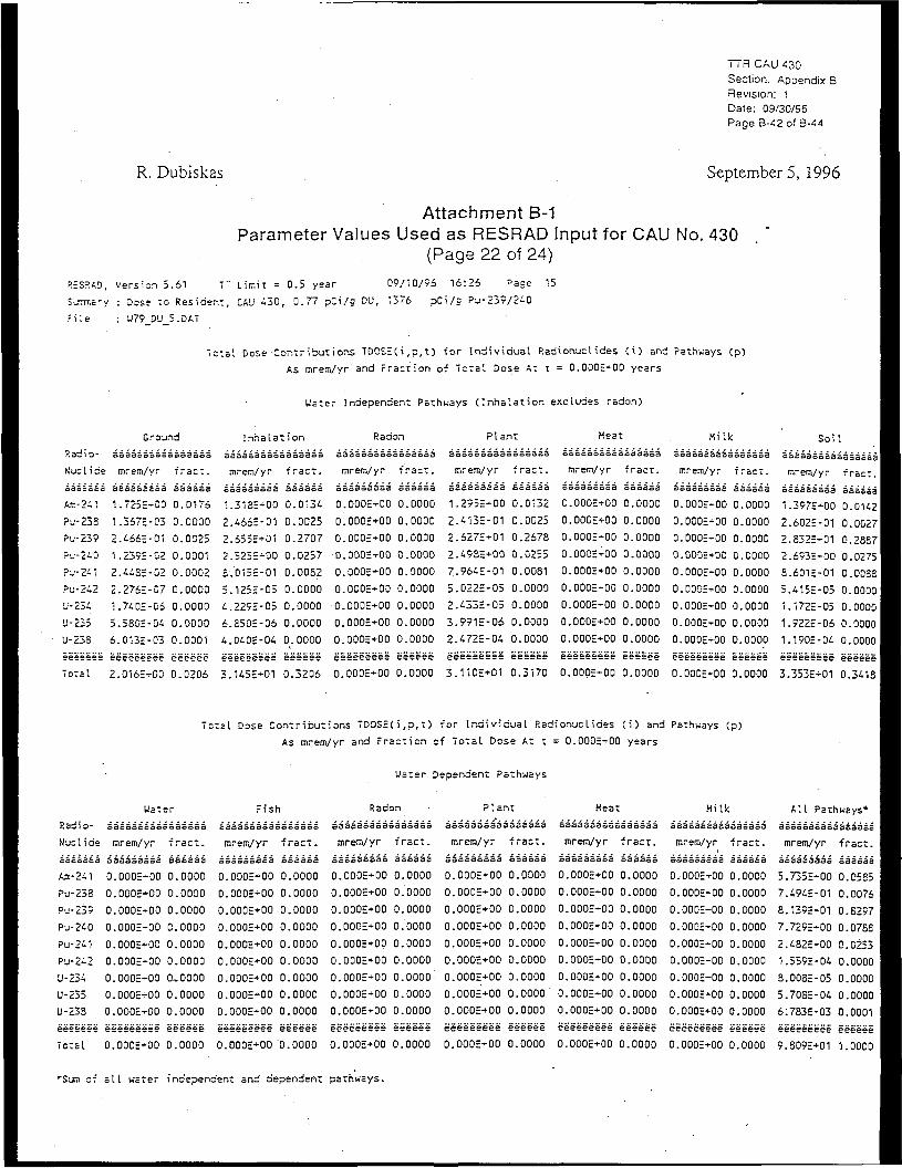
R. Dubiskas
TTR CAU 430Section. Appendix BRevision: 1Dale: 09/30/96Page B-42 of B-44
Septembers, 1996
Attachment B-1Parameter Values Used as RESRAD Input for CAU No. 430
(Page 22 of 24)RES?!AD, Version 5.61 T" Limit = 0.5 year 09/10/96 16:26 Page 15
S--.-7Tr.= ry : Dose to Resident, CAU 430, 0.77 pCi/g DU, 1376 pCi/s Pu-239/2-0
r i l e : w79_0U_5.DAT
Total Dose Contributions TDCSEC i ,p, t ) -for Individual Radionucl ides ( i ) and Pathways (p>
As mrem/yr and Fraction of Total Dose At t = O.DOOE-00 years
U'ater Independent Pathways ( Inhalat ion excludes radon)
Radio-
NucIi de
S3occod
Am-241
Pu-235
Pu-239
Pu-240
Pu-241
Pu-242
U-234
'J-235
U-23S
eeeeeee
Total
Ground
aaaaaasaaaaasaaa
mrem/yr
aaaaaaaaa
•,
1
2
1
2
21
56
.7255-00
.3675-03
.466E-01
.2395-02
.4485-02
.2765-07
.7405-06
.5805-04
.0135-03
eeeeeeeee
2.0165-00
firact.
aaaaaa
0.
0.
0.
0.
0.
0.
0.
0.
0.
.0176
.0000
.0025
.0001
,0002
.0000
0000
0000
0001
eeeeee
0.0206
Inhalati on
aaaaaaaaaaaaaaaa
mrem/yr
aaaaaaaaa
".3185+00
2.4665-01
2.655E+O1
2.5255-00
S.D13E-01
5.1255-05
4.2295-05
6.8505-06
4.0405-04
eeeeeeeee
3.1455+01
fract.
aaaaaa
0
0.
0.
0.
0.
0.
0.
0.
0.
.0134
.0025
.2707
.0257
.0052
.0000
.0000
.0000
.0000
eeeeee
0.,3206
Radon
aaaaaaaaaaaaaaaa
mrem/yr fract.
aaaaaaaaa aaaaaa
0.0005-00 0.0000
O.OODE+00 0.0000
O.DOOE-00 0.00.00
D.OOOE+00 0.0000
0.000E-00 0.0000
0.O00E-00 0.0000
O.OOOE+00 0.0000
0.000E+00 0.0000
0.00OE+O0 0.0000
eeeeeeese e'eeeee
O.ODOE+00 0.0000
Plant
mrem/yr
535533333
1.2935+00
2.4135-01
2.6275+01
2.4985+00
7.9645-01
5.0225-05
2.4335-05
3.9915-06
2.4725-04
eeeeeeeee
3.1105+01
•fract.
333333
0.0132
0.0025
0.2678
0.0255
0.00S1
0.0000
0.0000
0.0000
0.0000
eeeeee
0.3170
Meat
aoaaaasaaaaaaaea
mrem/yr fract.
3a5333553 333o53
O.OOOE+00 0.0000
O.OODE+00 0.0000
O.OOOE-00 0.0000
0.000S+00 0.0000
0.0005+00 0.0000
D.OOOE+00 0.0000
O.OOOE-00 0.0000
O.OOOE+00 0.0000
0.000E+00 0.0000
eeeeeeeee ee'eeee
O.OOOE+00 0.0000
Milk
aaaaaaaaaaaaaaaa
mrem/yr f rac t .
aaaaaaaaa aaaaaa
0.000E-00 0.0000
0.000E-00 0.0000
D.OOOE+00 0.0000
O.OOOE+00 0.0000
0.000E-00 0.0000
O.OOOE-00 0.0000
O.OOOE-00 0.0000
O.OOOE-00 0.0000
O.ODOE+00 0.0000
e'eeeeeeee eeeee'e
O.0O0E+00 0.0000
Soil
aaaaaaaaaaaaaaaaI
mrem/yr f ract .
aaaaaaaaa aaaaaaI
1.397E-00 0.0U2
2.602E-01 0.0027I
2.E32E-01 0.28E7I
2.693E-00 0.0275
E.601E-01 O.OOSS
5.415E-05 0.0000
1.172E-05 0.0000
1.522c-06 0.0000
1.190S-04 0.0000
eeeeeeeee eeeeee
3.353E+01 0.3418
Total Dose Contributions TDOS5Ci,p,t) for Individual P.adionuclides (i) and Pathways (p)
As mrem/yr and Fraction of Total Dose At t = 0.0005+00 years
Water Dependent Pathways
Radio-
Nuclide
aaoaoaa
Air.-241
Pu-238
Pu-239
P J - 2 4 0
Pu-241
Pu-242
U-234
U-235
U-238
eeeeee'e
Total
Water
aaaaaaaaaaaaaaaa
mrem/yr
aaaaaaaaa
0.0005-00
0
0
0
0
0
0
0
0
.0005-00
.0005-00
.0005-00
.0005-00
.OOOE-00
.000E-00
.000E+00
.0005-00
eeeeeeeee
0.0005+00
fract.
oocooS
0.0000
0.0000
0.0000
0.0000
0.0000
0.0000
0,0000
0.0000
0.0000
eee'eee
0.0000
Fish
aaaaaaaaaaaaaaaa
mrem/yr
aaaaaaaaa
0
0
0
0
0
0
.OOOE+DD
.000E+O0
.OOOE+00
.000E+00
.OOCE+00
.000E+00
O.OOOE+00
0
0
.0005+00
.0005+00
e'eeeeeeee
0.0005+00
fi
0,
0
0.
0,
0.
0.
0.
0.
0.
ract.
33352
.0000
.0000
.0000
.0000
.0000
.0000
.0000
.0000
.0000
eeeeee
0..0000
Radon
aaaaaaaaaaaaaaaa
mrem/yr fract.
aaaaaasaa aaaaaa
0.0005+00 0.0000
0.0O0E+00 0.0000
O.OOOE+00 0.0000
O.OOOE+00 0.0000
O.ODOE+00 0.0000
0.0005+00 0.0000
O.OOOE+00 0.0000
0.000E+00 0.0000
0.000E+00 0.0000
eeeeeeeee eeeeee
O.ODOE+00 0.0000
Plant
aaaaasasaaaaaaaa
mrem/yr fract.
saaasassa aaaaaa
O.OODE+00 0.0000
0.000E+D0 0.0000
0.000E+00 0.0000
O.000E+O0 0.0000
0.0005+00 0.0000
0.0005+00 0.0000
0.0005+00 0.0000
0.0005+00 0.0000
0.OO0E+00 0.0000
eeeeeeeee eeeeee
0.0005+00 0.0000
Meat
aaaaaaaaaaaaaaaa
rarem/yr fracr.
aaaaaaaaa aaaaaa
0.0005+00 0.0000
0.0005+00 0.0000
0.0005+00 0.0000
0.0005+00 0.0000
O.OOOE+00 0.0000
0.0005+00 0.0000
0.0005+00 0.0000
0.0005+00 0.0000
0.0005+00 0.0000
eeeeeeeee eeeeee
O.OOOE+00 0.0000
Milk
aaaaaaaaaaaaaaaa
mrem/yr fract.
aaaaaaaaa aaaaaa
O.DOOE-t-OO 0.0000
0.000E+00 0.0000
O.OOOE+00 0.0000
O.OOOE-00 0.0000
0.000E+00 0.0000
O.OOOE+00 0.0000
0.O00E+O0 0.0000
0.0005+00 0.0000
O.0O0E-00 0.0000
eeeeeeeee egggge
0.0005+00 0.0000
All Pathways*
aaaaaaaaaaaaaaaa
mrem/yr fract.
aaaaaaaaa aaaaaa
5.7355+00 O.O5S5
7.4945-01 0.0076
8.1395+01 0.8297
7.7295+00 0.0788
2.482E+00 0.0253
1.5595-04 0.0000
8.0085-05 0.0000
5.7085-04 0.0000
6.783E-03 0.0001
eee'eeeeee eeeeee
9.809E+01 1.0000
of all water independent and dependent pathways.
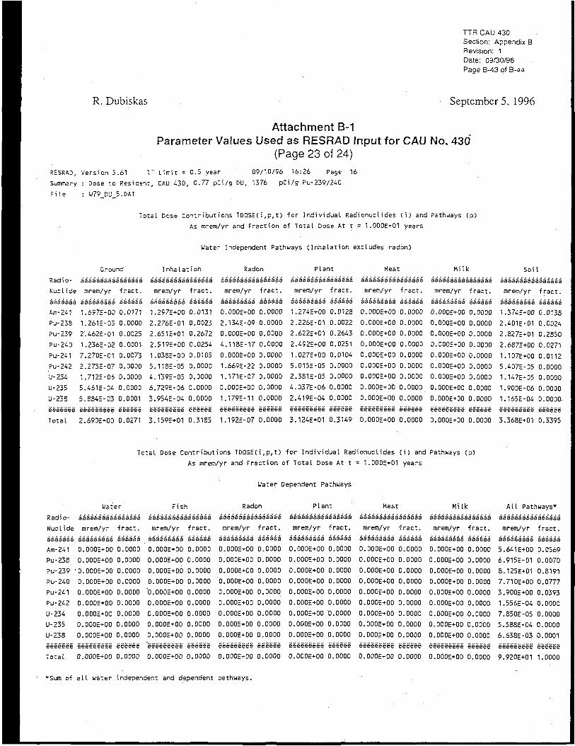
TTR CAU 430Section: Appendix BRevision: 1Date: 09/30/96Page B-43 of B-44
R. Dubiskas September 5, 1996
Attachment B-1Parameter Values Used as RESRAD Input for CAU No. 430
(Page 23 of 24)
RESRAD, Version 5.61 7" Limit = 0.5 year 09/10/96 16:26 Page 16
Sumiary : Dose to Resident, CAU 430, 0.77 pCi/g DU, 1376 pCi/g Pu-239/240
rile : U79_DLJ_5.DAT
Total Dose Contributions TDOSE(i,p,t) for Individual Radionuclides (i) and Pathways (p)
As mrem/yr and Fraction of Total Dose At t = 1.000E+01 years
Water Independent Pathways (Inhalation excludes radon)
Radio-
NucIi de
aaaaaaa
Am-241
Pu-23S
Pu-239
Pu-240
Pu-241
Pu-242
U-234
U-235
U-238
e'eeeee'e
Total
Ground
aaaaaaaaaaaaaaaa
mrem/yr fract.
aasaaa'aas eaaaaa
1.6975+00 0.0171
1.261E-03 0.0000
2'.462E-01 0.0025
1.236E-02 0.0001
7.270E-01 0.0073
2.273E-07 0.0000
1.7125-06 0.0000
5.461E-04 0.0000
5.8S45-03 0.0001
e'eeeeeee'e eee'eee
2.6905*00 0.0271
Inhalation
aaaaaaaaaaaaaaaa
mrem/yr fract.
aaaaaaaaa aaaaaa
1.297E+00 0.0131
2.276E-01 0.0023
2.651E+01 0.2672
2.519E+00 0.0254
1.03SE+00 0.0105
5.11SE-05 0.0000
4.139E-05 0.0000
6.729E-06 0.0000
3.954E-04 0.0000
eeeeeeeee eeeee'e
3.159E+01 0.3185
Radon
aaaaaaaaaaaaaaaa
mrem/yr fract.
aaaaaaaaa aaaaaa1
0.0005+00 0.0000
2.134E-09 0.0000
O.0O0E+O0 0.0000
4.11SE-17 0.0000
0.OO0H+O0 0.0000
1.669E-22 0.0000
1.171E-07 0.0000
O.OOOE+00 0.0000
1.179E-11 0.0000
eeeeeeeee e'e'eee'e
1.192E-07 0.0000
Plant
aaaaaaaaaaaaaaaa
mrem/yr fract.
aaaaaaaaa aaaaaa
1.2745+00 0.0128
2.2265-01 0.0022
2.622E+01 0.2643
2.492E+00 0.0251
1.0275+00 0.0104
5.0155-05 0.0000
2.381E-05 0.0000
4.0375-06 0.0000
2.419E-04 0.0000
eee'eeeeee eee'ee'e
3.124E+01 0.3149
Heat
aaaaaaaaaaaaaaaa
mrem/yr fract.
aaaasaaaa aaaaaa
0.0005+00 0.0000
0.0005+00 0.0000
0.0OOE+O0 0.0000
0.000E+00 0.0000
O.OOOE+00 0.0000
0.000E+00 0.0000
0.0005+00 0.0000
O.OOOE+00 0.0000
O.OOOE+00 0.0000
eeeeeeeee eeeeee
O.OOOE+00 0.0000
Milk
aaaaaaaaaaaaaaaa
mrem/yr fract.
aaaaaaaaa aaaaaa
O.OOOE+00 0.0000
O.OOOE+00 0.0000
0.000E+00 0.0000
0.0005+00 0.0000
0.0005+00 0.0000
0.0005+00 0.0000
0.0005+00 0.0000
0.0005+00 0.0000
0.0O0E+O0 0.0000
eee'eeeeee eeeee'e
O.OOOE+00 0.0000
Soil
aaaaaaaaaaaaaaaa
mrem/yr fract.
aaaaaaaaa aaaaaa
1.3745+00 0.0138
2.4015-01 0.0024
2.8275+01 0.2S50
2.6875+00 0.0271
1.107E+00 0.0112
5.407E-05 0.0000
1.1475-05 0.0000
1.900E-06 0.0000
1.165E-04 0.0000
e'eeeeeee'e e'eeeee
3.368E+01 0.3395
Total Dose Contributions TDQSECi,P,t) for Individual Radionuclides (i) and Pathways (p)
As mrem/yr and Fraction of Total Dose At t = 1.000E+01 years
Water Dependent Pathways
Radio-
Nuclide
aaaaaaa
Am-241
Pu-238
Pu-239
Pu-240
Pu-241
Pu-242
U-234
U-235
U-238
Water
aaaaaaaaaaaaaaaa
mrem/yr fract.
aaaasaaaa aaaaaa
0.0OOE+0O 0.0000
O.OOOE+00 0.0000
0.0O0E+00 0.0000
0.0005+00 0.0000
0.0005+00 0.0000
O.OOOE+00 0.0000
O.OOOE+00 0.0000
O.OOOE+00 0.0000
0.0005+00 0.0000
Fish
aaaaaaaaaaaaaaaa
mrem/yr fract.
aaaaaaaaa aaaaaa
O.OOOE+00 0.0000
0.000E+00 0.0000
0.000E+00 0.0000
0.000E+00 0.0000
"0.0005+00 0.0000
O.00OE+00 0.0000
O.OOOE+00 0.0000
O.OOOE+00 0.0000
0.0005+00 0.0000
eeeeeeeee eeeeee'
0.0005+00 0.0000
Radon
aaaaaaaaaaaaaaaa
mrem/yr fract.
aaaaaaaaa aaaaaa
0.0005+00 0.0000
0.00DE+00 0.0000
O.OOOE+00 0.0000
O.OOOE+OD 0.0000
0.0005+00 0.0000,
0.O00E+00 0.0000
0.0005+00 0.0000
O.OOOE+00 0.0000
0.000E+00 0.0000
eeeeeeee'e eeeee'e
O.OOOE+00 0.0000
Plant
aaaaasaaaaaaaaaa
mrem/yr fract.
aaaaaaaaa aaaaaa
0.0O0E+0O 0.0000
O.OOOE+00 0.0000
0.0005+00 0.0000
O.OOOE+00 0.0000
O.OOOE+00 0.0000
O.OOOE+00 0.0000
0.000E+00 0.0000
0.O00E+O0 0.0000
0.O00E+O0 0.0000
eeeeeeee'e e'eeeee
0.0005+00 0.0000
Heat
aaaaaaaaaaaaaaaa
mrem/yr fract.
aaaaaaaaa aaaaaa
0.000E+00 0.0000
0.0005+00 0.0000
O.00OE+0O 0.0000
O.OOOE+00 0.0000
O.OOOE+00 0.0000
O.OOOE+00 0.0000
0.0005+00 0.0000
O.OOOE+00 0.0000
0.000E+00 0.0000
Hi Ik
aaaaaaaaaaaaaaaa
mrem/yr fract.
aaaaaaaaa aaaaaa
0.0005+00 0.0000
0.O00E+0O 0.0000
0.O00E+00 0.0000
O.OOOE+00 0.0000
O.OOOE+00 0.0000
0.000E+00 0.0000
O.OOOE+00 0.0000
O.OOOE+00 0.0000
O.ODOE+00 0.0000
All Pathways"
aaaasaaasasaaasa
mrem/yr fract.
aaaasaaaa aaaasa
5.641E+00 0.0569
6.915E-01 0.0070
8.1255+01 0.8191
7.7105+00 0.0777
3.900E+00 0.0393
1.556E-04 0.0000
7.8505-05 0.0000
5.588E-04 0.0000
6.6385-03 0.0001
eeeeeeeTnfa!
eeeeeeeee eeeeee0.0005*00 0.0000
eeeeeeeee eeeeeeO.OOOE+00 0.0000
eeeeeeeee eeeeee'0.0005+00 0.0000
eeeeeeeee eeeeee9.920E+01 1.0000
*Sum of all water independent and dependent pathways.

I i n L-tU - J O
Sectionf-e.i:ion IDale. 09 30 95Page S--s ol E---4
R.. Dubiskas Septembers, 1996
Attachment B-1Parameter Values Used as RESRAD Input for CAU No 430
(Page 24 of 241
U-::-3ion " . . - I T L i m i - = 0 - r ~ar II? i n °~ 1±.Z6 Page 1
:: Dc.-e r.c F e : i c = r . I-LJ -3D 0 ~7 p i i c CU. 1376 p i i = ̂ J 2 2 " 2 - 0
:: u7' :_!: iJ_5..D-T
T o t a l Do:e r o n i : r ibu~ i 0-3 TDOSEi i , p , T I ' D r ,!ndi id_ial. Fadi o n u r l loss I i ] Jnd Pa-h i -5 r r I p i
A:; mrem T r and F r a c t i o n of 7 o T = I. Dc:;e A i: t = 3..DODE-01 , e a r i
Us •=- Ino-peraen: Fa thus E I: I nhal. 3t ion ercl.U3=s rairon)
C-aund
tj3n:i-
P-.zl I 35
•iIT" 2 - 1
B--22E
PL-22°;iu- 2-0
• • ' L - 2 - 1
I - J - 2 - 2
I .J-23-
l.j-2.23
!..'•• 2 2 E
7 D ~ 3 1
3
1
2
1
1—1
1C
-
3
33 :J 3 3 = = 3
mrem i-r
,5E=E-03
,1-EE 0^
,. 1-4-5= D l
,.22-E 02
..D.7E-30
,. 2iDE 07
„ n~E- o3
..IJ'iSE-On
,.3?3E-C3
.i70E-0D
':
11
0
0
D
0
0
0
0
D
D
33a==
racn.
013°
00113
,. 0023
,.D0D1
. • 1 = 2
.0000
..0 300
..on DO
..01101
,,03-,E
Inn's I. a', ion
.155=333333333333 =333333 3a35i=333 3
m"-r*i'Tr ~rac~ n~=-m t r fr3c~
35£:i3a = Ea 5353=3 i:13333a=-=3 5i333ai3
1 .2 i -E + D0 0 01 22 I), ODOE+00 0 DDOIJ
•|.±fiCE-01 0 . 0 D i 7 2 . -0DE-D7 0 O0DO
2 , D 3 3 E * - D 1 11,25-1 0.0002-1)0 0 OODD
2. . - -EE-00 II 0220 2 .°-' :1E- 15 0 DODO
•|.3?5E-<-DD IJ. 0r; Z1 D..0ODE-D0 D 0000
5..Di=E-05 I I . OODD 1, .0 l ) ' iE- I - 0 0000
j , . 7=E=-05 I3.DDD0 2 . £ : 2 1 E - D D 0 0000
C.-D7E-05 D..DODO 0.OOOE+00 0 .0000
I. .=2=E-Di. 0 .0000 1..u[]2E-09 O.DOIJO
3 , 51E+01 D , 3 I D O 3 , . 0 D 2 E D 6 11,00110
F I, a n t
mrem - r JT3cT,,
1 ICSE-TOO 0,.D12D
1 =1»E-01 0 .001c
2 iD iE-t-D'1 O..2i12
2.-iiE-30 0..02-7
1, 25-E-DO 0..0123
J-. -ETE-05 0.. 11030
2. "E3E-05 0.0000 D.ODOE-00 0..0000
- 2£l3E-0:3 0..DOOD 0,00D£+00 0..0DO0
53 li3333333a = 3 =3=1
mrem r r t r a c i . .
D..DDOE+DO 0.0I1DD
D.OOOE+OD 0,01100
O..D0OE+O0 0 .0030
O..DOOE+OO D.. 01100
O..DODE+OO 0.01100
D..DDOE+OO O..OODD
2, 2' iEE-Ou 0..DD00
3 35l::3 3:J53 3a33=53
mrem , r 4-3cr..
333=33233 353333
O.DDOE+00 0 . DI1D0
0 .OOOE-00 D ,01100
D..OODE-DO 0,01100
0.DD3E-00 O.DOOD
D. I1DOE-00 0,. ODDO
0.I1D0E+0D 0.0000
D.I1DDE-DD 0,0000
O.ODOE-OD 0.00D0
O..HDOE-DO O..DDDO
noil.
nvem ' ,-r - - a c r . .
i,..:£iE
I.7VIE
2..30£:
2,. ;=0:
1..23-:.
5 .277J
1 ,D32::
1..E:i-E
00 0 , 0 12?
01 0OD17
D1 0,. 2 = 13
D0 O..D2=7
00 0..012?
05 0,0000
DF. 0.I30DD
0 1 O.'IDOO
04 0.1)030D ooo;;:+oo D,OOOO
e-teeessei eeeeee e=eeei-£e2 E E ; = = E eee=Eti=£5 eeeees
0 OODE+00 0,0000 Q.OOQ^OQ D, 11000 5 353E+DI 0,23iC
7 D T = I . D C 3 = C o n ' r ibur . l o r ; ~U'2tz(.\ p , T )
i-3 tnrem r r a n d P r a r r i o n c
r I n d i v i d u a l Pad ionurl. ia=::
To:al. Dose J-T n = 5..O0OE+I11
and FcTht-ai 3 1 p )
Water
P 3d i 0fi u; 1. I ne
3SE33 : -a
•TT- 2 ^ 1
PL-23H
=u-23 ;
P . -2 .0
F "2 -1
Pu-2-2
U 23--.
U 22 r;
U Z3'-
g=e==ei
Tical
Z
s
0
0
11
11
11
D
0
0
0
e
0
Us:
.333 333Bt:
irreiTi' T r
533 3=3==
.OOOE+00
DOOE-rOO
.OODE-00
..ODQE+00
..OOOE-DO
..OOOE+OD
..OODE+110
,ODOE+D0
..OODE-HD
566=65=5
..000= 1-00
er
=1=):
iracz,.
5
0
0
D
0
0
0
0,
0
D
==
0
iass'a
.0000
00011
DODO
D0DI1
0000
0000
,ODOD
ooo a
DDOO
r= = = S
DODD
1
3
0
0
0
0
0
0
0
0.
0
e;
11
= 3333
n-em
5 33 33
ODDE
DDOE
DOGE'
DDDE
00I1E-
00 LIE-
0OI1E-
DDOE-
ODUE-
r = 5-TS-
ODOE-
F i s l
3OI3I
r r
53 3
+011
+011
+ 011
+011
+DD
+0D
+ DD
+00
+00
5 55
+00
1
3 =333
tract,.
330333
0.
0.
0
0.
0
0.
0
0
0
e :
0
.ODOD
.1)000
. 11000
.DODO
,DDDO
.DDOD
.0000
DOOD
.00011
;==ee
ODDll
5
3
0
0
0
0
D
0
0
D
D
e-
C
Fadon
3333 5aaS
mrem r r
3353 333a
..OODE+00
.DDOE+00
DOD:E+OO
ODDr+OD
DDOE-DD
OOOE+DD
OODE+00
ODOE+00
OODE+DO
•-£e====iE
DDOE+DO
= _:35 aaa
Tra.:T..
aa'a'aaa
0
0.
0
0.
0
0
0.
0.
D
ee
D.
. ODOO
.ODOD
.DDDO
.ODDD
,0000
.DDOO
.HOOD
.DODO
.11000
reeee
.0000
•
a
0
0
0
0
•0
D
D
0
e
0
• o c 4 3 -
m~em
a Baaa
..ODDE
J3D0E
.OOOE
..DDOE
J100E
,.ODDE
P lan t
t3j=a:
T r
s'aa
+ 00
+00
+ 0 0
+00
+ 0 0
+ 0 0
J1DDE+D0
..OOOE
JIODE
2-==ee
,O00E
+ 00
+ 0 0
= 6 6
+ 0 0
^
c
D
0
0
0
0
0
11
11
11
0
333 33
race.
aaaaa
0000
DODO
. OOOD
. 0000
. 00110
DDIJO
. 00P0
00110
. 0000
E5=ee
, DDOO
HS3T
£35Swa3 3333 533a |3
mrem, Tr "ract
23aaaa3=a 01=35= ii
II OOME+OD 0 ,00011
IJ. OODE+00 0 .0000
I1..0DDE+00 0 00011
DVOOOE-T-OO 0 OOOD
D..000E+O0 0 0000
D..DODE+DD 0 ODOD
0..000E + I10 0 0000
0,OI10E+D0 0 DDDO
COODE-rPO 0 ODDO
eeeeeeeee ======
0.0I1DE+D0 0 0000
*U
= i:i53 i3a3 53aa 1:3533 :)
mrem ,-r t r a c t
0 ODOE-OD 0 00011
0 000=+00 0 0000
0 OODE-00 0 DDOD
0 00I1E+D0 0 DOOD
0, OOIIE+OO 0 DDOO
0. DDI1E+00 0 ODOO
0,OOOE+00 0 0000
II, 000E+I10 0 ODOD
a 3 noE liiaB 55
rr t-ac:.
3,4:E-i=+00 0 0330I :;,oiitE-in o oo:;o
£ 071E+01 0 3D?3
r. 633E+DO 0 0766r.5'; iE+ll0 D D5fl
L-SuBE-llJ. 0 DDOD
7.V35E-I15 0 OO'IO
5 , 'K IE - IK D 0000
I1.00I1E+IJ0 D 0000 t ,0a iE-H3 0 00IJ1
IJ. ODJE+110 0 OOOD DDDO
" lurr c- a l l . i -a ter ind=p=n3=" i ; and depsnden i p^Th i -a r i