Steering by Gazing: An Efficient Biomimetic Control Strategy for Visually Guided Micro Aerial...
13
IEEE TRANSACTIONS ON ROBOTICS, VOL. 26, NO. 2, APRIL 2010 307 Steering by Gazing: An Efficient Biomimetic Control Strategy for Visually Guided Micro Aerial Vehicles Lubin Kerhuel, St´ ephane Viollet, and Nicolas Franceschini Abstract—OSCAR II is a twin-engine aerial demonstrator equipped with a monocular visual system, which manages to keep its gaze and its heading steadily fixed on a target (i.e., a dark edge or a bar) in spite of the severe random perturbations applied to its body via a ducted fan. The tethered robot stabilizes its gaze on the basis of two oculomotor reflexes (ORs) inspired by studies on animals: 1) a visual-fixation reflex (VFR) and 2) a vestibulo-ocular reflex (VOR). One of the key features of this robot is that the eye is decoupled mechanically from the body about the vertical (i.e., yaw) axis. To meet the conflicting requirements of high accuracy and fast ocular responses, a miniature (2.4 g) voice-coil motor (VCM) was used, which enables the eye to make a change of orientation with an unusually short rise time (19 ms). The robot, which was equipped with a high-bandwidth (7 Hz) “VOR,” which is based on an iner- tial microrate gyro, is capable of accurate visual fixation as long as there is light. The robot is also able to pursue a moving target in the presence of erratic gusts of wind. Here, we present the two in- terdependent control schemes driving the eye in the robot and the robot in space with no knowledge of the robot’s angular position. This “steering-by-gazing” control strategy, which is implemented on this lightweight (100 g) miniature aerial robot, demonstrates the effectiveness of this biomimetic visual/inertial heading control strategy. Index Terms—Autonomous robots, biorobotics, gaze stabiliza- tion, microair vehicle (MAV), oculomotor reflexes (ORs), sensori- motor control, smooth pursuit, steering strategy, vestibulo-ocular reflex (VOR), visual-fixation reflex (VFR). I. INTRODUCTION T OMORROW’S micro-air vehicles (MAVs) will be capa- ble of similar performance to those of flying insects or birds: they will be able to navigate safely in unknown environ- ments, and vision has turned out to be the most suitable sensory mode on which to base their guidance. In comparison with mi- croair vehicles (MAVs), systems such as those based on global positioning system (GPS) signals have several weaknesses, in- cluding their poor resolution, their low signal-to-noise ratio in canyons and building interiors, and their failure to cope with Manuscript received October 27, 2009; revised February 1, 2010. Current version published April 7, 2010. This paper was recommended for publication by Associate Editor M. Sitti and Editor G. Oriolo upon evaluation of the review- ers’ comments. This work was supported by the National Center for Scientific Research and the University of the Mediterranean, by the French National Re- search Agency under the ANR, RETINAE project, and by the French Armament Procurement Agency under Contract n0534022. The authors are with the Biorobotics Laboratory, Institute of Movement Sciences, National Center for Scientific Research/University of the Mediter- ranean, 13288 Marseille Cedex 09, France (e-mail: [email protected]; [email protected]; [email protected]). Color versions of one or more of the figures in this paper are available online at http://ieeexplore.ieee.org. Digital Object Identifier 10.1109/TRO.2010.2042537 unexpectedly encountered stationary or moving targets. On the other hand, active sensors, such as radio detection and rang- ing (RADAR) and forward looking infrared radar (FLIR), are so power-consuming that they are not at all suitable for use on MAVs. Most of the few visually guided MAVs, which have been developed so far, transmit images to a ground station via a ra- dio link and extensive image processing is performed off-board. The whole process may suffer from undesirable time lag and un- toward “dropouts.” Three noteworthy exceptions are the MC2 microflyer [1], a small aircraft wing [2], and a quadrotor [3], which use optic flow to react autonomously. Flying insects and birds are able to navigate swiftly in un- known environments with very few computational resources. They are not guided via radio links with any ground stations and perform all the required calculations onboard. The ability to stabilize the gaze is the key to an efficient visual guidance system, as it reduces the computational burden associated with visuomotor processing. Smooth pursuit by the eye is another requisite: the ability to fix the gaze on a given moving feature significantly reduces the neural resources required to extract rel- evant visual information from the environment. Although their brains are very small and their eyes have very few pixels, flying insects can perform some extraordinary behavioral feats, such as navigating in 3-D environments, avoiding stationary and moving obstacles, hovering [4], [5], tracking mates [6] and intruders [7], and intercepting prey [8], relying solely on visual guidance. Re- cent studies have shown that freely flying flies keep their gaze fixed in space during 100–200-ms episodes, using very fast sta- bilization reflexes [9]. The freely flying sandwasp, for instance, keeps its gaze amazingly stable despite the large thorax rolls it performs [10]. The stringent requirements involved in visual stabilization may explain why eye movements are among the fastest and most accurate of all the movements in the repertory of the animal kingdom. Gaze stabilization is a difficult task because the eye con- trol system must compensate both quickly and accurately for any sudden, untoward disturbances caused by the vagaries of the supporting head or body. In the freely flying housefly, ac- tive gaze-stabilization mechanisms prevent the incoming visual information from being affected by disturbances, such as vibra- tions or body jerks [9], [11]–[13]. This finely adapted mecha- nism is way beyond what can be achieved in the field of present- day robotics. The authors of several studies have addressed the problem of incorporating an active gaze-stabilization system into mo- bile robots. After the pioneering studies on the “Rochester head” [14], the “Oxford head” [15], and the “Harvard head” [16], a number of gaze-control systems were developed, in which 1552-3098/$26.00 © 2010 IEEE Authorized licensed use limited to: Australian National University. Downloaded on April 06,2010 at 00:11:43 EDT from IEEE Xplore. Restrictions apply.
-
Upload
independent -
Category
Documents
-
view
1 -
download
0
Transcript of Steering by Gazing: An Efficient Biomimetic Control Strategy for Visually Guided Micro Aerial...
IEEE TRANSACTIONS ON ROBOTICS, VOL. 26, NO. 2, APRIL 2010 307
Steering by Gazing: An Efficient Biomimetic ControlStrategy for Visually Guided Micro Aerial Vehicles
Lubin Kerhuel, Stephane Viollet, and Nicolas Franceschini
Abstract—OSCAR II is a twin-engine aerial demonstratorequipped with a monocular visual system, which manages to keepits gaze and its heading steadily fixed on a target (i.e., a dark edgeor a bar) in spite of the severe random perturbations applied toits body via a ducted fan. The tethered robot stabilizes its gaze onthe basis of two oculomotor reflexes (ORs) inspired by studies onanimals: 1) a visual-fixation reflex (VFR) and 2) a vestibulo-ocularreflex (VOR). One of the key features of this robot is that the eye isdecoupled mechanically from the body about the vertical (i.e., yaw)axis. To meet the conflicting requirements of high accuracy and fastocular responses, a miniature (2.4 g) voice-coil motor (VCM) wasused, which enables the eye to make a change of orientation with anunusually short rise time (19 ms). The robot, which was equippedwith a high-bandwidth (7 Hz) “VOR,” which is based on an iner-tial microrate gyro, is capable of accurate visual fixation as long asthere is light. The robot is also able to pursue a moving target inthe presence of erratic gusts of wind. Here, we present the two in-terdependent control schemes driving the eye in the robot and therobot in space with no knowledge of the robot’s angular position.This “steering-by-gazing” control strategy, which is implementedon this lightweight (100 g) miniature aerial robot, demonstratesthe effectiveness of this biomimetic visual/inertial heading controlstrategy.
Index Terms—Autonomous robots, biorobotics, gaze stabiliza-tion, microair vehicle (MAV), oculomotor reflexes (ORs), sensori-motor control, smooth pursuit, steering strategy, vestibulo-ocularreflex (VOR), visual-fixation reflex (VFR).
I. INTRODUCTION
TOMORROW’S micro-air vehicles (MAVs) will be capa-ble of similar performance to those of flying insects or
birds: they will be able to navigate safely in unknown environ-ments, and vision has turned out to be the most suitable sensorymode on which to base their guidance. In comparison with mi-croair vehicles (MAVs), systems such as those based on globalpositioning system (GPS) signals have several weaknesses, in-cluding their poor resolution, their low signal-to-noise ratio incanyons and building interiors, and their failure to cope with
Manuscript received October 27, 2009; revised February 1, 2010. Currentversion published April 7, 2010. This paper was recommended for publicationby Associate Editor M. Sitti and Editor G. Oriolo upon evaluation of the review-ers’ comments. This work was supported by the National Center for ScientificResearch and the University of the Mediterranean, by the French National Re-search Agency under the ANR, RETINAE project, and by the French ArmamentProcurement Agency under Contract n0534022.
The authors are with the Biorobotics Laboratory, Institute of MovementSciences, National Center for Scientific Research/University of the Mediter-ranean, 13288 Marseille Cedex 09, France (e-mail: [email protected];[email protected]; [email protected]).
Color versions of one or more of the figures in this paper are available onlineat http://ieeexplore.ieee.org.
Digital Object Identifier 10.1109/TRO.2010.2042537
unexpectedly encountered stationary or moving targets. On theother hand, active sensors, such as radio detection and rang-ing (RADAR) and forward looking infrared radar (FLIR), areso power-consuming that they are not at all suitable for use onMAVs. Most of the few visually guided MAVs, which have beendeveloped so far, transmit images to a ground station via a ra-dio link and extensive image processing is performed off-board.The whole process may suffer from undesirable time lag and un-toward “dropouts.” Three noteworthy exceptions are the MC2microflyer [1], a small aircraft wing [2], and a quadrotor [3],which use optic flow to react autonomously.
Flying insects and birds are able to navigate swiftly in un-known environments with very few computational resources.They are not guided via radio links with any ground stationsand perform all the required calculations onboard. The abilityto stabilize the gaze is the key to an efficient visual guidancesystem, as it reduces the computational burden associated withvisuomotor processing. Smooth pursuit by the eye is anotherrequisite: the ability to fix the gaze on a given moving featuresignificantly reduces the neural resources required to extract rel-evant visual information from the environment. Although theirbrains are very small and their eyes have very few pixels, flyinginsects can perform some extraordinary behavioral feats, such asnavigating in 3-D environments, avoiding stationary and movingobstacles, hovering [4], [5], tracking mates [6] and intruders [7],and intercepting prey [8], relying solely on visual guidance. Re-cent studies have shown that freely flying flies keep their gazefixed in space during 100–200-ms episodes, using very fast sta-bilization reflexes [9]. The freely flying sandwasp, for instance,keeps its gaze amazingly stable despite the large thorax rollsit performs [10]. The stringent requirements involved in visualstabilization may explain why eye movements are among thefastest and most accurate of all the movements in the repertoryof the animal kingdom.
Gaze stabilization is a difficult task because the eye con-trol system must compensate both quickly and accurately forany sudden, untoward disturbances caused by the vagaries ofthe supporting head or body. In the freely flying housefly, ac-tive gaze-stabilization mechanisms prevent the incoming visualinformation from being affected by disturbances, such as vibra-tions or body jerks [9], [11]–[13]. This finely adapted mecha-nism is way beyond what can be achieved in the field of present-day robotics.
The authors of several studies have addressed the problemof incorporating an active gaze-stabilization system into mo-bile robots. After the pioneering studies on the “Rochesterhead” [14], the “Oxford head” [15], and the “Harvard head” [16],a number of gaze-control systems were developed, in which
1552-3098/$26.00 © 2010 IEEE
Authorized licensed use limited to: Australian National University. Downloaded on April 06,2010 at 00:11:43 EDT from IEEE Xplore. Restrictions apply.
308 IEEE TRANSACTIONS ON ROBOTICS, VOL. 26, NO. 2, APRIL 2010
retinal position measurements were combined with inertial mea-surements [17], and the performance of these systems wereassessed qualitatively, while slow perturbations were being ap-plied by hand. Shibata and Schaal [18] designed and built agaze-control device based on an inverse model of the mam-malian oculomotor system. This device equipped with a learningnetwork was able to decrease the retinal slip 4-fold in responseto moderate frequency perturbations (of up to 0.8 Hz). Anotheradaptive image stabilizer designed to improve the performanceof a robotic agent was built and its ability to cope with moderate-frequency perturbations (of up to 0.6 Hz) was tested [19]. Anadaptive gaze-stabilization controller was recently presentedand its performance were measured in the 0.5–2-Hz frequencyrange [20]. Other gaze-stabilization systems, which are inspiredby the human vestibulo-ocular reflex (VOR), have also beendesigned for mobile robots [21]–[23], but the performance ofthese systems have yet to be assessed quantitatively. Miyauchiet al. [24] have shown the benefits of mounting a compact me-chanical image stabilizer onboard a mobile robot travelling overrough terrain. Twombly et al. [25] have performed computer-based simulations on a neurovestibular control system designedto endow a walking robot with active image-stabilization abili-ties. Wagner et al. [26] built a fast-responding oculomotor sys-tem using air bearings and bulky galvanometers [26]. Mainiet al. [27] recently succeeded in implementing fast gaze shiftsin an anthropomorphic head without using any inertial sensors.In the field of humanoid robotic research, two recent studies havedescribed the enhanced performance of a biped robot endowedwith gaze-control mechanisms [28], [29]. However, none of thetechnological solutions ever proposed are compatible with thedrastic constraints imposed on autonomous MAVs in terms oftheir mass and size.
Fast-flying insects, such as flies, possess a fine set of ocu-lomotor reflexes (ORs) that are the key to their outstandingheading stabilization performance. These reflexes are of partic-ular relevance to designing tomorrow’s miniature autonomousterrestrial, aerial, underwater, and space vehicles. As we willsee, a visually mediated heading stabilization system requiresthe following:
1) a mechanical decoupling between the eye and the body(via the eye’s orbit and the neck, as in birds, or via theneck alone, as in insects);
2) a fast and accurate actuator. Blowflies, for instance, con-trol their gaze using no less than 23 pairs of micromus-cles [30];
3) a visual-fixation reflex (VFR) that keeps the gaze lockedonto a contrasting target;
4) a VOR, which is an active inertial reflex that rotates theeye in counter phase with the head. Flies typically useinertial reflexes of this kind, which are based on the gyro-scopic haltere organs located on the thorax, especiallywhen performing yaw [11] and roll movements [12].A similar inertial reflex was developed several hundredmillion years later in mammals including humans. Rhe-sus monkeys’ VOR operates in the 0.5–5 Hz [31] andeven 5–25 Hz [32] frequency range, and is, therefore,
capable of even faster responses than the human visualsystem;
5) a proprioceptive sensor measuring the angular position ofthe eye relative to the head and that of the head relative tothe body. The question as to whether an extraretinal pro-prioceptive sensor exists in primates’ oculomotor systemis still a matter of controversy [33], [34], but a sensor ofthis kind does exist in flies, in the form of the prosternalorgan. The latter organ consists of a pair of mechanosensi-tive hair fields located in the neck region [35], [36], whichmeasure any head versus body angular deviations on thepitch [9], roll [12], and yaw axes [37];
6) an active coupling between the robot’s heading and itsgaze, via the ORs: the VFR and the VOR.
Although the present study was inspired by insects’ and ver-tebrates’ oculomotor systems, our quest was primarily for theperformance, and no attempt was made to faithfully model anyof the oculomotor control systems described in insects and ver-tebrates during the past 50 years. In the Section II, the twin-engine aerial platform is described. In the Section III, our one-axis “steering-by-gazing” control strategy is explained. In theSection IV, we describe how this strategy was implemented ona miniature aerial robot, which is called OSCAR II, which ac-quired the ability to fixate a stationary target and to pursue amoving target despite the severe aerodynamic disturbances thatwas deliberately imposed on its body. OSCAR II is the firstaerial robot capable of these performances, due to the fact thatits eye is decoupled from its body. Please note that this workis accompanied by a video, which shows the OSCAR II robotsuspended from the ceiling by a 100-µm nylon wire. The robotis free to move in the horizontal plane and to rotate around itsyaw axis.
II. OSCAR II AERIAL ROBOT
A. Robotic Platform
Like its predecessor OSCAR I [38], OSCAR II (see Fig. 1)is a twin-engine aerial platform equipped with a self-stabilizingvisual/inertial system, which operates about the vertical (yaw)axis. In addition, OSCAR II features an oculomotor mechanismthat gives its eye the ability to orient relatively to its body withina range of ±35. This additional degree of freedom mimicksthe mechanical decoupling between eye and body that is socharacteristic of animals, from box jellyfish to humans. Thesighted robot is able to adjust its heading accurately about thebody yaw axis by driving its two propellers differentially via aminiature custom-made 1-g dual sensorless speed controller (fora detailed description, see [39]). The robot’s “body” consists ofa carbon housing containing the two motors driving the robot’spropellers (see Figs. 1 and 2). These dc motors are mounted closeto the yaw rotational axis to minimize the inertial load. Eachmotor transmits its power to its respective propeller (diameter13 cm) via a 8-cm-long carbon-fiber shaft, rotating on microballbearing within the hollow beam, ending in a crown gear (with areduction ratio of 1/5). The OSCAR II robot weighs 65 g withoutthe batteries. This weight includes the two engines with their
Authorized licensed use limited to: Australian National University. Downloaded on April 06,2010 at 00:11:43 EDT from IEEE Xplore. Restrictions apply.
KERHUEL et al.: STEERING BY GAZING: AN EFFICIENT BIOMIMETIC CONTROL STRATEGY 309
Fig. 1. OSCAR II is a tethered aerial robot that controls its heading aboutthe vertical (i.e., yaw) axis by driving its two propellers differentially, based onwhat it sees. The eye of OSCAR II is mechanically decoupled from the head(which is mounted firmly on the “body”). The visual system enables the robotto fixate a target (a vertical edge placed 1 m ahead). Two oculomotor reflexes(ORs), i.e., the VOR and the VFR, stabilize the robot’s line of sight (its gaze)in response to any severe disturbances (such as gusts of wind) liable to affectits body. The heading control system in which the oculomotor reflexes (ORs)are involved (see Fig. 7) aligns the robot’s heading with the gaze and is, thus,constantly catching up with the gaze. Robot OSCAR II is mounted on a low-friction, low-inertia resolver, which monitors the heading with a high level ofaccuracy (top left photo by F. Vrignaud).
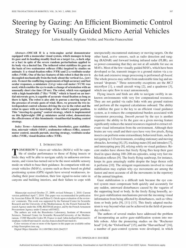
Fig. 2. (a) Detail of the OSCAR II robot. (b) Microscanning retina and thevisual processing it performs. The wave generator imposes a scanning movementon the piezo bender that shifts the two photodiodes horizontally behind the lens,perpendicularly with respect to the optical axis. The visual processing systemincludes an elementary motion detector (EMD) (see [40]).
drive mechanisms and their dedicated sensorless controller [39],the propellers, the eye with its voice coil motor (VCM)-basedposition servo system, the microrate gyro (Analog Device ADIS16100), the piezo bender, the complete electronics based onsurface-mounted device (SMD) technology and the Bluetoothcircuit for remote data monitoring. Two separate Li-Polymer(LiPo) battery packs are used to power the robot: a low-powerpack (i.e., 3.6 V–100 mAh, 3 g) for the electronics and a high-power pack (i.e., 7.2 V–620 mAh, 34 g) for the two-propellermotors. The robot’s “head” is a large (with diameter 15 mm)carbon tube, which is mounted firmly onto the motor casing.Within the head, an inner carbon “eye tube” can turn freely aboutthe yaw axis [see Fig. 2(a)]. This eye-tube is axially spring-loaded between a pivot bearing (at the bottom) and a boredmicroconical ball bearing (at the top) through which a 1-mm
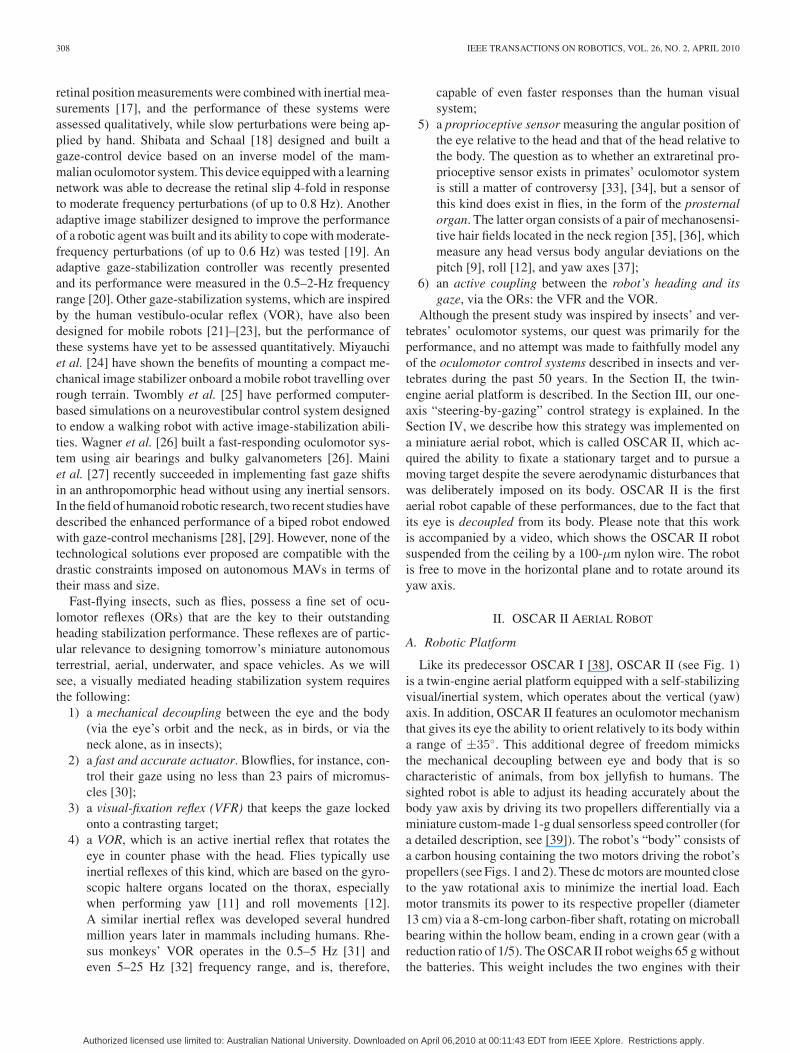
Fig. 3. (Top view) OSCAR II oculomotor mechanism. The central “eye-tube”bearing the lens and the two-pixel microscanning retina [see Fig. 2(b)] is insertedinto a larger carbon tube (i.e., “the head”) that is mounted firmly onto the robot’sbody. The eye tube is thus mechanically decoupled from the head and has onedegree of freedom about the yaw axis. The eye-in-robot angle θer between therobot’s gaze and the robot’s heading is finely controlled (via the linkage rod andthe control horn) by a micro-VCM extracted from a hard-disk microdrive.
steel axle passes freely [see Fig. 2(b)]. Due to a micromagnetglued to the tip of this axle, a tiny contactless Hall sensor (seeFig. 2) accurately gauges the eye-in-robot orientation θer (seeFig. 3). The complete visual system, including the completeOSCAR sensor (see [40]), its VCM, its driver, and the digitalcontroller, weighs only 22.5 g. The eye can rotate within the±35 range. We implemented a detection system that preventsthe VCM from saturating and thus, from being damaged byovercurrent. After a short delay, this system automatically resetsthe VCM’s angular position whenever the set point of the eye’sorientation is too large.
B. Robot’s Visual System
The robot’s eye consists of a miniature lens (with diameter5 mm and focal length 8.5 mm), behind which an elementary“retina” composed of a single pair of matched PIN photodi-odes performs a horizontal scanning operation at a frequency of10 Hz: this retina is driven by a fast piezo bender (Physik Instru-mente) via a hybrid analog–digital circuit (see Fig. 2; for detailsof the analog part, see [40]). The retinal microscanning processadopted here was inspired by our findings on the fly’s com-pound eye [41]. The two photoreceptors, therefore, scan a smallportion of the visual space in the azimuthal plane. For detailson the whys and wherefores of this microscanning process, seeour original analyses and computer simulations of the OSCARvisual-sensor principle [42]. Basically, we established that bycombining a retinal microscanning process with an elementary-motion detector (EMD), a sensitive and accurate visual position-sensing device (PSD) can be obtained, which is able to sensethe position of an edge (or a bar) within its small field of view
Authorized licensed use limited to: Australian National University. Downloaded on April 06,2010 at 00:11:43 EDT from IEEE Xplore. Restrictions apply.
310 IEEE TRANSACTIONS ON ROBOTICS, VOL. 26, NO. 2, APRIL 2010
(FOV) (here, FOV = ±1.8). This sensor’s performance in thetask consisting of locating an edge is a 40-fold improvement inresolution versus the interphotodiode angular resolution [43]. Itcan, therefore, be said to be endowed with hyperacuity [44]. Forfurther details about the performance (i.e., accuracy and calibra-tion) of this hyperacute visual position-sensing device (PSD),see [40] and [43].
III. “STEERING-BY-GAZING” CONTROL STRATEGY
The “steering-by-gazing” control strategy, which is presentedhere, amounts to maintaining the gaze automatically oriented to-ward a stationary (or moving) target and then ensuring that therobot’s heading will catch up with the gaze direction, despiteany disturbances encountered by the body. Two distinct but in-terdependent control schemes are at work in this system. Theone is in charge of the robot’s gaze, and the other is in chargeof the robot’s heading. The eye dynamics are very fast in com-parison with the robot’s body dynamics. Our control strategymakes the robot minimize its retinal error signal and its head-ing error signal without requiring any knowledge of the robot’sabsolute angular position or that of the target. The fast phase ofthe heading dynamics depends on the inertial sensor (the rategyro), while the slow phase (steady state) depends on the visualsensor. Here, we will describe the eye control system and theheading control system and explain how they interact.
A. Eye-Control Strategy
Fig. 3 shows a top view of the robot, where the various anglesare defined.
Fig. 6 summarizes the feedforward and feedback control sys-tems involved in the eye control system. The feedback controlsystem (depicted in the bottom of Fig. 6) is a regulator that keepsthe retinal error εr = θt − θgaze at zero by adjusting the robot’seye orientation θer . The gaze-control strategy ensures that θgazewill follow any changes in the target position (θtarget). Whenthe OSCAR II robot is presented with a stationary target, the eyecontrol system will compensate for any disturbances applied tothe body by holding the gaze, which is locked onto the target,due to the VOR and to the fast dynamics of the eye. If the targethappens to move, the VFR will adjust the gaze orientation θgazevia θer so that the gaze will track the target smoothly, whateverthe yaw disturbances possibly affecting the robot’s body.
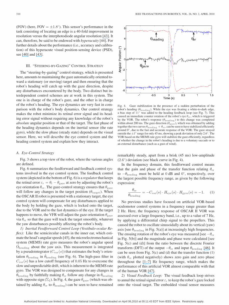
1) Inertial Feedforward Control Loop (Vestibulo-ocular Re-flex): Like the semicircular canals in the inner ear, which esti-mate the head’s angular speeds [45], the microelectromechanicalsystem (MEMS) rate gyro measures the robot’s angular speedΩheading about the yaw axis. This measurement is integratedby a pseudointegrator (Cvor(s)) that estimates the body’s orien-tation θheading in θheading (see Fig. 6). The high-pass filter inCvor(s) has a low cutoff frequency of 0.05 Hz to overcome theslow and unpredictable drift, which is inherent to the MEMS rategyro. The VOR was designed to compensate for any changes inθheading by faithfully making θer follow any change in θheadingwith opposite sign (Σ2). In Fig. 4, the gaze θgaze (which was ob-tained by adding θer to θheading ) can be seen to have remained
Fig. 4. Gaze stabilization in the presence of a sudden perturbation of therobot’s heading (θheading ). While the eye was fixating a white-to-dark edge,a bias step of 11 was added to the heading feedback loop (see Fig. 7). Thiscaused an immediate counter rotation of the robot’s eye θer , which is triggeredby the VOR. The robot’s response (θheading ) to this change was completedwithin about 200 ms. The gaze direction (θgaze ), which was obtained by addingtogether the two curves θheading + θer , can be seen to have stabilized efficientlyaround 0, due to the fast and accurate response of the VOR: The gaze strayedoutside the±1 range for only 45 ms, showing a peak deviation of only 2.6. TheVOR based on the MEMS rate gyro will stabilize the gaze efficiently, regardlessof whether the change in the robot’s heading is due to a voluntary saccade or toan external disturbance (such as a gust of wind).
remarkably steady, apart from a brisk (45 ms) low-amplitude(2.6) deviation (see black curve in Fig. 4).
In the frequency domain, this feedforward control meansthat the gain and phase of the transfer function relating θerto −θheading must be held at 0 dB and 0, respectively, overthe largest possible frequency range, as given by the followingexpression:
θer
θheading= −Cvor(s) · Heye(s) · Hgyro(s) = −1. (1)
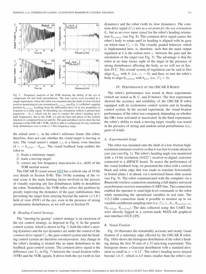
No previous studies have focused on artificial VOR-basedoculomotor control systems in a frequency range greater than2 Hz. Here, the frequency response of OSCAR II VOR wasassessed over a large frequency band, i.e., up to a value of 7 Hz,by applying a differential chirp signal to the propellers. Thiscaused the robot to oscillate sinusoidally about its vertical (yaw)axis [see θheading in Fig. 5(a)] at increasingly high frequencies.The ensuing rotation of the robot’s eye was measured [see −θerin Fig. 5(b)] and the magnitude and phase were calculated [seeFig. 5(c) and (d)] from the ratio between the discrete Fouriertransform (DFT) of the output −θer and input θheading [46]. Itcan be seen from Fig. 5(c) and (d) that the transfer function (1)(with θer plotted negatively) shows zero gain and zero phasethroughout the [1–7] Hz frequency range, which makes theperformance of this artificial VOR almost comparable with thatof the human VOR [47].
2) Visual Feedback Loop: The visual feedback loop strivesto annul the retinal signal error εr to keep the robot’s gaze lockedonto the visual target. The embedded visual sensor measures
Authorized licensed use limited to: Australian National University. Downloaded on April 06,2010 at 00:11:43 EDT from IEEE Xplore. Restrictions apply.
KERHUEL et al.: STEERING BY GAZING: AN EFFICIENT BIOMIMETIC CONTROL STRATEGY 311
Fig. 5. Frequency analysis of the VOR showing the ability of the eye tocompensate for fast body perturbations. The four curves were recorded in asingle experiment, where the robot was mounted onto the shaft of a low-frictionresolver monitoring its yaw orientation θheading (see Fig. 1). (a) Robot’s angularposition θheading resulting from the differential drive of its two propellers inresponse to a chirp signal. (b) Resulting eye orientation (which is plotted herenegatively: −θer ), which can be seen to counter the robot’s heading up tohigh frequencies, due to the VOR. (c) and (d) Gain and phase of the transferfunction (1) computed from (a) and (b). The gain and phase curves show the fastdynamics of the OSCAR’s VOR, which is able to compensate for any rotationalbody disturbances over a wide (1–7 Hz) frequency range.
the retinal error εr in the robot’s reference frame (the robot,therefore, does not care whether the visual target is moving ornot). The visual sensor’s output εro is a linear, even functionof εr = θtarget − θgaze . The visual feedback loop enables therobot to
1) fixate a stationary target;2) track a moving target;3) correct any low-frequency inaccuracies (i.e., drift) of the
VOR inertial sensor.The OSCAR II visual sensor [42] has a refresh rate of 10 Hz
(see details in Section II-B). This 10-Hz scanning of the vi-sual scene is the main limiting factor involved in the processof visually rejecting any fast disturbances liable to destabilizethe robot. Nonetheless, the VOR reflex solves this problem bygreatly improving the dynamics of the gaze stabilization, thuspreventing the target from straying beyond the narrow (±1.8)field of view (FOV) of the eye, even in the presence of strongaerodynamic disturbances, as we will see in Section IV.
B. Heading Control Strategy
The “steering-by-gazing” control strategy is an extension ofthe eye control strategy, as depicted in Fig. 6. In the genericcontrol system, which is shown in Fig. 7, both the robot’s steer-ing dynamics and the eye dynamics are under the control of thecommon drive signal Cd ; the gaze-control system and the head-ing control system are therefore interdependent. Any change inthe robot’s heading is treated like an input disturbance to thefeedback gaze-control system. The common drive signal is thedifference (see Σ2 in Fig. 7) between the visual-fixation reflex(VFR) and the VOR signals. It drives both the eye (with its fast
dynamics) and the robot (with its slow dynamics). The com-mon drive signal (Cd ) acts as a set point for the eye orientationθer but as an error input signal for the robot’s heading orienta-tion θheading (see Fig. 8). This common drive signal causes therobot’s body to rotate until its heading is aligned with its gaze(at which time Cd = 0). The visually guided behavior, whichis implemented here, is, therefore, such that the main outputregulated at 0 is the retinal error εr between the gaze and theorientation of the target (see Fig. 3). The advantage is that therobot at no time looses sight of the target in the presence ofstrong disturbances affecting the body, as we will see in Sec-tion IV-C. The overall system of regulation can be said to firstalign θgaze with θt (i.e., εr = 0), and then, to turn the robot’sbody to align θheading with θgaze (i.e., Cd = 0).
IV. PERFORMANCE OF THE OSCAR II ROBOT
The robot’s performance was tested in three experiments(which are noted as B, C, and D below). The first experimentshowed the accuracy and reliability of the OSCAR II robotequipped with its oculomotor control system and its headingcontrol system. In the second experiment, the visual-fixationperformance of the robot was compared, depending on whetherthe ORs were activated or inactivated. In the third experiment,the robot’s ability to track a moving target visually was testedin the presence of strong and random aerial perturbations (i.e.,gusts of wind).
A. Experimental Setup
The robot was mounted onto the shaft of a low-friction high-resolution miniature resolver so that it was free to rotate about itsyaw axis (see Fig. 1). The robot’s heading angle was monitoredwith a 14-bit resolution (0.022) resolver-to-digital converterconnected to a dSPACE board. To assess the performance ofthe visual feedback loop, we presented the robot with a verticalblack and white edge that was made to translate horizontallyin frontal plane 1 m ahead, via a motorized linear slide system(see Fig. 9). The robot communicated with the computer via aBluetooth wireless connection emulating a full duplex universalasynchronous receiver-transmitter (UART) bus. This connectionenabled the operator to send high-level commands to the robotwhile monitoring the operational variables in real time. The115.2-kBd connection made it possible to monitor up to sixvariables at different sampling rates (i.e., Cd , εr , θer , θheading ref ,Ωheading , θheading ). The data collected using this UART buswere directly logged in a custom-made MATLAB graphicaluser interface (GUI) [49].
B. Visual Fixation
Fig. 10 illustrates the remarkably accurate and steady visualfixation of a stationary edge effected by the OSCAR II robot.Fig. 10(b) shows the histogram distribution of the robot’s head-ing during the first 30 min of a 37-min-long experiment. Thishistogram shows a Gaussian distribution with a standard devi-ation as small as σ = 0.14. The robot’s heading never strayedbeyond ±0.4, which is 4.5 times smaller than the robot’s eye
Authorized licensed use limited to: Australian National University. Downloaded on April 06,2010 at 00:11:43 EDT from IEEE Xplore. Restrictions apply.
312 IEEE TRANSACTIONS ON ROBOTICS, VOL. 26, NO. 2, APRIL 2010
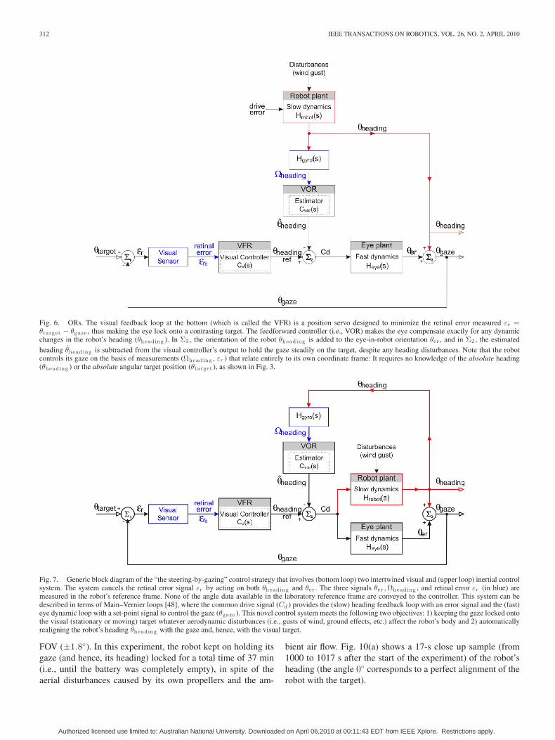
Fig. 6. ORs. The visual feedback loop at the bottom (which is called the VFR) is a position servo designed to minimize the retinal error measured εr =θtarget − θgaze , thus making the eye lock onto a contrasting target. The feedforward controller (i.e., VOR) makes the eye compensate exactly for any dynamicchanges in the robot’s heading (θheading ). In Σ3 , the orientation of the robot θheading is added to the eye-in-robot orientation θer , and in Σ2 , the estimated
heading θheading is subtracted from the visual controller’s output to hold the gaze steadily on the target, despite any heading disturbances. Note that the robotcontrols its gaze on the basis of measurements (Ωheading , εr ) that relate entirely to its own coordinate frame: It requires no knowledge of the absolute heading(θheading ) or the absolute angular target position (θtarget ), as shown in Fig. 3.
Fig. 7. Generic block diagram of the “the steering-by-gazing” control strategy that involves (bottom loop) two intertwined visual and (upper loop) inertial controlsystem. The system cancels the retinal error signal εr by acting on both θheading and θer . The three signals θer , Ωheading , and retinal error εr (in blue) aremeasured in the robot’s reference frame. None of the angle data available in the laboratory reference frame are conveyed to the controller. This system can bedescribed in terms of Main–Vernier loops [48], where the common drive signal (Cd ) provides the (slow) heading feedback loop with an error signal and the (fast)eye dynamic loop with a set-point signal to control the gaze (θgaze ). This novel control system meets the following two objectives: 1) keeping the gaze locked ontothe visual (stationary or moving) target whatever aerodynamic disturbances (i.e., gusts of wind, ground effects, etc.) affect the robot’s body and 2) automaticallyrealigning the robot’s heading θheading with the gaze and, hence, with the visual target.
FOV (±1.8). In this experiment, the robot kept on holding itsgaze (and hence, its heading) locked for a total time of 37 min(i.e., until the battery was completely empty), in spite of theaerial disturbances caused by its own propellers and the am-
bient air flow. Fig. 10(a) shows a 17-s close up sample (from1000 to 1017 s after the start of the experiment) of the robot’sheading (the angle 0 corresponds to a perfect alignment of therobot with the target).
Authorized licensed use limited to: Australian National University. Downloaded on April 06,2010 at 00:11:43 EDT from IEEE Xplore. Restrictions apply.
KERHUEL et al.: STEERING BY GAZING: AN EFFICIENT BIOMIMETIC CONTROL STRATEGY 313
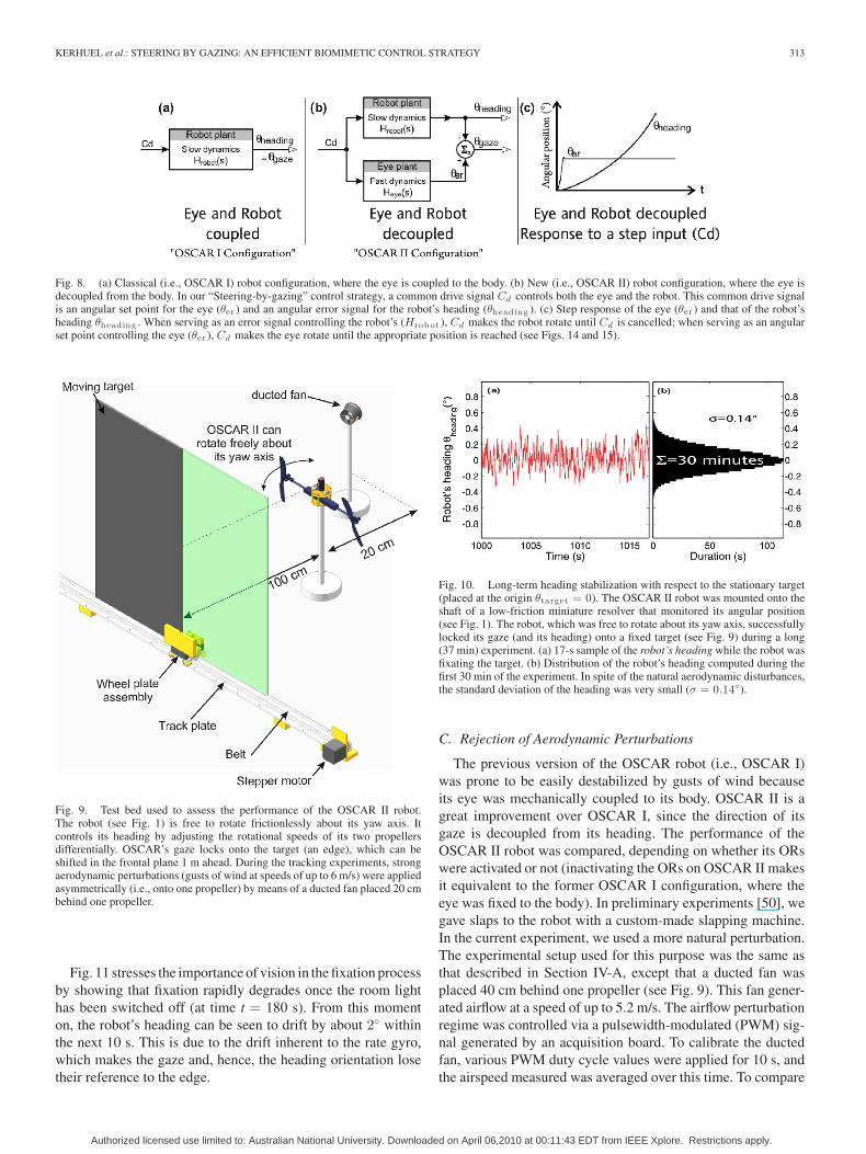
Fig. 8. (a) Classical (i.e., OSCAR I) robot configuration, where the eye is coupled to the body. (b) New (i.e., OSCAR II) robot configuration, where the eye isdecoupled from the body. In our “Steering-by-gazing” control strategy, a common drive signal Cd controls both the eye and the robot. This common drive signalis an angular set point for the eye (θer ) and an angular error signal for the robot’s heading (θheading ). (c) Step response of the eye (θer ) and that of the robot’sheading θheading . When serving as an error signal controlling the robot’s (Hrob ot ), Cd makes the robot rotate until Cd is cancelled; when serving as an angularset point controlling the eye (θer ), Cd makes the eye rotate until the appropriate position is reached (see Figs. 14 and 15).
Fig. 9. Test bed used to assess the performance of the OSCAR II robot.The robot (see Fig. 1) is free to rotate frictionlessly about its yaw axis. Itcontrols its heading by adjusting the rotational speeds of its two propellersdifferentially. OSCAR’s gaze locks onto the target (an edge), which can beshifted in the frontal plane 1 m ahead. During the tracking experiments, strongaerodynamic perturbations (gusts of wind at speeds of up to 6 m/s) were appliedasymmetrically (i.e., onto one propeller) by means of a ducted fan placed 20 cmbehind one propeller.
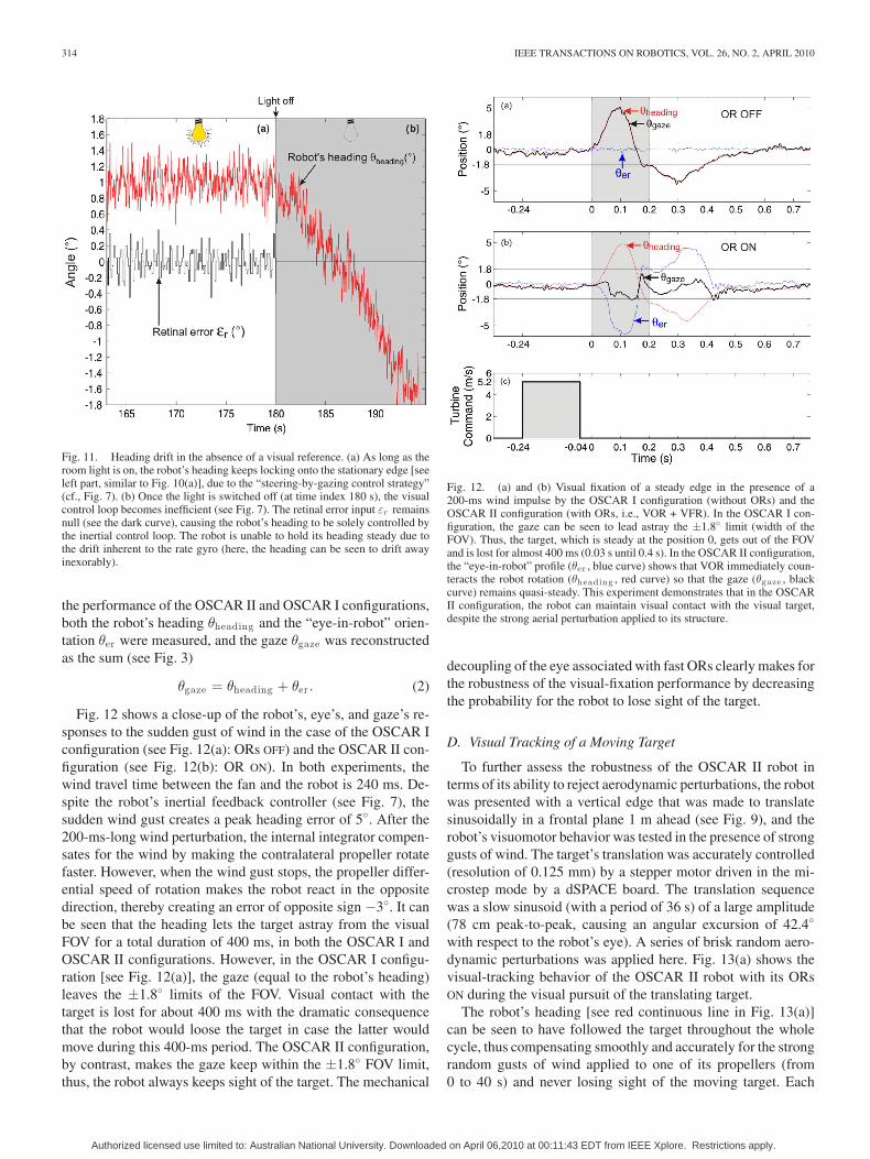
Fig. 11 stresses the importance of vision in the fixation processby showing that fixation rapidly degrades once the room lighthas been switched off (at time t = 180 s). From this momenton, the robot’s heading can be seen to drift by about 2 withinthe next 10 s. This is due to the drift inherent to the rate gyro,which makes the gaze and, hence, the heading orientation losetheir reference to the edge.
Fig. 10. Long-term heading stabilization with respect to the stationary target(placed at the origin θtarget = 0). The OSCAR II robot was mounted onto theshaft of a low-friction miniature resolver that monitored its angular position(see Fig. 1). The robot, which was free to rotate about its yaw axis, successfullylocked its gaze (and its heading) onto a fixed target (see Fig. 9) during a long(37 min) experiment. (a) 17-s sample of the robot’s heading while the robot wasfixating the target. (b) Distribution of the robot’s heading computed during thefirst 30 min of the experiment. In spite of the natural aerodynamic disturbances,the standard deviation of the heading was very small (σ = 0.14).
C. Rejection of Aerodynamic Perturbations
The previous version of the OSCAR robot (i.e., OSCAR I)was prone to be easily destabilized by gusts of wind becauseits eye was mechanically coupled to its body. OSCAR II is agreat improvement over OSCAR I, since the direction of itsgaze is decoupled from its heading. The performance of theOSCAR II robot was compared, depending on whether its ORswere activated or not (inactivating the ORs on OSCAR II makesit equivalent to the former OSCAR I configuration, where theeye was fixed to the body). In preliminary experiments [50], wegave slaps to the robot with a custom-made slapping machine.In the current experiment, we used a more natural perturbation.The experimental setup used for this purpose was the same asthat described in Section IV-A, except that a ducted fan wasplaced 40 cm behind one propeller (see Fig. 9). This fan gener-ated airflow at a speed of up to 5.2 m/s. The airflow perturbationregime was controlled via a pulsewidth-modulated (PWM) sig-nal generated by an acquisition board. To calibrate the ductedfan, various PWM duty cycle values were applied for 10 s, andthe airspeed measured was averaged over this time. To compare
Authorized licensed use limited to: Australian National University. Downloaded on April 06,2010 at 00:11:43 EDT from IEEE Xplore. Restrictions apply.
314 IEEE TRANSACTIONS ON ROBOTICS, VOL. 26, NO. 2, APRIL 2010
Fig. 11. Heading drift in the absence of a visual reference. (a) As long as theroom light is on, the robot’s heading keeps locking onto the stationary edge [seeleft part, similar to Fig. 10(a)], due to the “steering-by-gazing control strategy”(cf., Fig. 7). (b) Once the light is switched off (at time index 180 s), the visualcontrol loop becomes inefficient (see Fig. 7). The retinal error input εr remainsnull (see the dark curve), causing the robot’s heading to be solely controlled bythe inertial control loop. The robot is unable to hold its heading steady due tothe drift inherent to the rate gyro (here, the heading can be seen to drift awayinexorably).
the performance of the OSCAR II and OSCAR I configurations,both the robot’s heading θheading and the “eye-in-robot” orien-tation θer were measured, and the gaze θgaze was reconstructedas the sum (see Fig. 3)
θgaze = θheading + θer . (2)
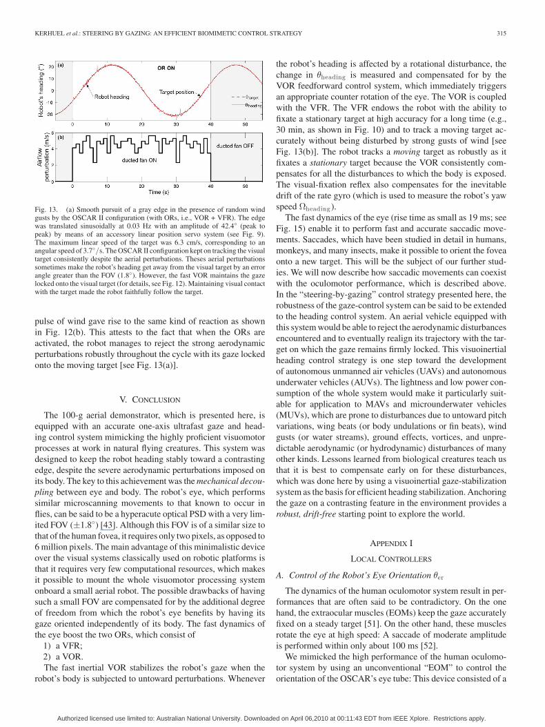
Fig. 12 shows a close-up of the robot’s, eye’s, and gaze’s re-sponses to the sudden gust of wind in the case of the OSCAR Iconfiguration (see Fig. 12(a): ORs OFF) and the OSCAR II con-figuration (see Fig. 12(b): OR ON). In both experiments, thewind travel time between the fan and the robot is 240 ms. De-spite the robot’s inertial feedback controller (see Fig. 7), thesudden wind gust creates a peak heading error of 5. After the200-ms-long wind perturbation, the internal integrator compen-sates for the wind by making the contralateral propeller rotatefaster. However, when the wind gust stops, the propeller differ-ential speed of rotation makes the robot react in the oppositedirection, thereby creating an error of opposite sign −3. It canbe seen that the heading lets the target astray from the visualFOV for a total duration of 400 ms, in both the OSCAR I andOSCAR II configurations. However, in the OSCAR I configu-ration [see Fig. 12(a)], the gaze (equal to the robot’s heading)leaves the ±1.8 limits of the FOV. Visual contact with thetarget is lost for about 400 ms with the dramatic consequencethat the robot would loose the target in case the latter wouldmove during this 400-ms period. The OSCAR II configuration,by contrast, makes the gaze keep within the ±1.8 FOV limit,thus, the robot always keeps sight of the target. The mechanical
Fig. 12. (a) and (b) Visual fixation of a steady edge in the presence of a200-ms wind impulse by the OSCAR I configuration (without ORs) and theOSCAR II configuration (with ORs, i.e., VOR + VFR). In the OSCAR I con-figuration, the gaze can be seen to lead astray the ±1.8 limit (width of theFOV). Thus, the target, which is steady at the position 0, gets out of the FOVand is lost for almost 400 ms (0.03 s until 0.4 s). In the OSCAR II configuration,the “eye-in-robot” profile (θer , blue curve) shows that VOR immediately coun-teracts the robot rotation (θheading , red curve) so that the gaze (θgaze , blackcurve) remains quasi-steady. This experiment demonstrates that in the OSCARII configuration, the robot can maintain visual contact with the visual target,despite the strong aerial perturbation applied to its structure.
decoupling of the eye associated with fast ORs clearly makes forthe robustness of the visual-fixation performance by decreasingthe probability for the robot to lose sight of the target.
D. Visual Tracking of a Moving Target
To further assess the robustness of the OSCAR II robot interms of its ability to reject aerodynamic perturbations, the robotwas presented with a vertical edge that was made to translatesinusoidally in a frontal plane 1 m ahead (see Fig. 9), and therobot’s visuomotor behavior was tested in the presence of stronggusts of wind. The target’s translation was accurately controlled(resolution of 0.125 mm) by a stepper motor driven in the mi-crostep mode by a dSPACE board. The translation sequencewas a slow sinusoid (with a period of 36 s) of a large amplitude(78 cm peak-to-peak, causing an angular excursion of 42.4
with respect to the robot’s eye). A series of brisk random aero-dynamic perturbations was applied here. Fig. 13(a) shows thevisual-tracking behavior of the OSCAR II robot with its ORsON during the visual pursuit of the translating target.
The robot’s heading [see red continuous line in Fig. 13(a)]can be seen to have followed the target throughout the wholecycle, thus compensating smoothly and accurately for the strongrandom gusts of wind applied to one of its propellers (from0 to 40 s) and never losing sight of the moving target. Each
Authorized licensed use limited to: Australian National University. Downloaded on April 06,2010 at 00:11:43 EDT from IEEE Xplore. Restrictions apply.
KERHUEL et al.: STEERING BY GAZING: AN EFFICIENT BIOMIMETIC CONTROL STRATEGY 315
Fig. 13. (a) Smooth pursuit of a gray edge in the presence of random windgusts by the OSCAR II configuration (with ORs, i.e., VOR + VFR). The edgewas translated sinusoidally at 0.03 Hz with an amplitude of 42.4 (peak topeak) by means of an accessory linear position servo system (see Fig. 9).The maximum linear speed of the target was 6.3 cm/s, corresponding to anangular speed of 3.7/s. The OSCAR II configuration kept on tracking the visualtarget consistently despite the aerial perturbations. Theses aerial perturbationssometimes make the robot’s heading get away from the visual target by an errorangle greater than the FOV (1.8). However, the fast VOR maintains the gazelocked onto the visual target (for details, see Fig. 12). Maintaining visual contactwith the target made the robot faithfully follow the target.
pulse of wind gave rise to the same kind of reaction as shownin Fig. 12(b). This attests to the fact that when the ORs areactivated, the robot manages to reject the strong aerodynamicperturbations robustly throughout the cycle with its gaze lockedonto the moving target [see Fig. 13(a)].
V. CONCLUSION
The 100-g aerial demonstrator, which is presented here, isequipped with an accurate one-axis ultrafast gaze and head-ing control system mimicking the highly proficient visuomotorprocesses at work in natural flying creatures. This system wasdesigned to keep the robot heading stably toward a contrastingedge, despite the severe aerodynamic perturbations imposed onits body. The key to this achievement was the mechanical decou-pling between eye and body. The robot’s eye, which performssimilar microscanning movements to that known to occur inflies, can be said to be a hyperacute optical PSD with a very lim-ited FOV (±1.8) [43]. Although this FOV is of a similar size tothat of the human fovea, it requires only two pixels, as opposed to6 million pixels. The main advantage of this minimalistic deviceover the visual systems classically used on robotic platforms isthat it requires very few computational resources, which makesit possible to mount the whole visuomotor processing systemonboard a small aerial robot. The possible drawbacks of havingsuch a small FOV are compensated for by the additional degreeof freedom from which the robot’s eye benefits by having itsgaze oriented independently of its body. The fast dynamics ofthe eye boost the two ORs, which consist of
1) a VFR;2) a VOR.The fast inertial VOR stabilizes the robot’s gaze when the
robot’s body is subjected to untoward perturbations. Whenever
the robot’s heading is affected by a rotational disturbance, thechange in θheading is measured and compensated for by theVOR feedforward control system, which immediately triggersan appropriate counter rotation of the eye. The VOR is coupledwith the VFR. The VFR endows the robot with the ability tofixate a stationary target at high accuracy for a long time (e.g.,30 min, as shown in Fig. 10) and to track a moving target ac-curately without being disturbed by strong gusts of wind [seeFig. 13(b)]. The robot tracks a moving target as robustly as itfixates a stationary target because the VOR consistently com-pensates for all the disturbances to which the body is exposed.The visual-fixation reflex also compensates for the inevitabledrift of the rate gyro (which is used to measure the robot’s yawspeed Ωheading ).
The fast dynamics of the eye (rise time as small as 19 ms; seeFig. 15) enable it to perform fast and accurate saccadic move-ments. Saccades, which have been studied in detail in humans,monkeys, and many insects, make it possible to orient the foveaonto a new target. This will be the subject of our further stud-ies. We will now describe how saccadic movements can coexistwith the oculomotor performance, which is described above.In the “steering-by-gazing” control strategy presented here, therobustness of the gaze-control system can be said to be extendedto the heading control system. An aerial vehicle equipped withthis system would be able to reject the aerodynamic disturbancesencountered and to eventually realign its trajectory with the tar-get on which the gaze remains firmly locked. This visuoinertialheading control strategy is one step toward the developmentof autonomous unmanned air vehicles (UAVs) and autonomousunderwater vehicles (AUVs). The lightness and low power con-sumption of the whole system would make it particularly suit-able for application to MAVs and microunderwater vehicles(MUVs), which are prone to disturbances due to untoward pitchvariations, wing beats (or body undulations or fin beats), windgusts (or water streams), ground effects, vortices, and unpre-dictable aerodynamic (or hydrodynamic) disturbances of manyother kinds. Lessons learned from biological creatures teach usthat it is best to compensate early on for these disturbances,which was done here by using a visuoinertial gaze-stabilizationsystem as the basis for efficient heading stabilization. Anchoringthe gaze on a contrasting feature in the environment provides arobust, drift-free starting point to explore the world.
APPENDIX I
LOCAL CONTROLLERS
A. Control of the Robot’s Eye Orientation θer
The dynamics of the human oculomotor system result in per-formances that are often said to be contradictory. On the onehand, the extraocular muscles (EOMs) keep the gaze accuratelyfixed on a steady target [51]. On the other hand, these musclesrotate the eye at high speed: A saccade of moderate amplitudeis performed within only about 100 ms [52].
We mimicked the high performance of the human oculomo-tor system by using an unconventional “EOM” to control theorientation of the OSCAR’s eye tube: This device consisted of a
Authorized licensed use limited to: Australian National University. Downloaded on April 06,2010 at 00:11:43 EDT from IEEE Xplore. Restrictions apply.
316 IEEE TRANSACTIONS ON ROBOTICS, VOL. 26, NO. 2, APRIL 2010
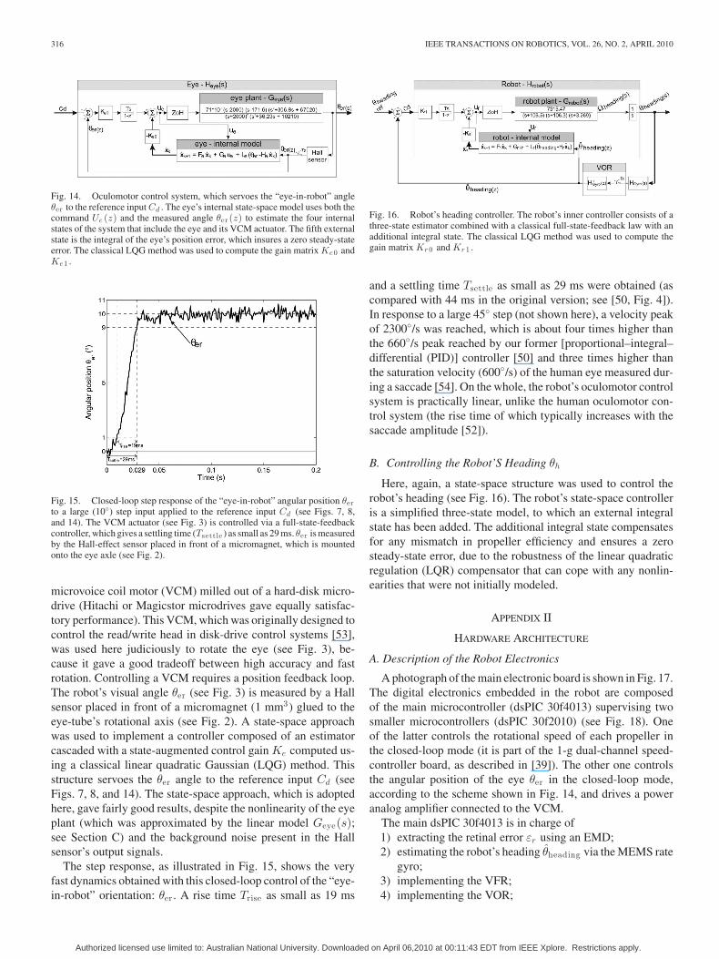
Fig. 14. Oculomotor control system, which servoes the “eye-in-robot” angleθer to the reference input Cd . The eye’s internal state-space model uses both thecommand Ue (z) and the measured angle θer (z) to estimate the four internalstates of the system that include the eye and its VCM actuator. The fifth externalstate is the integral of the eye’s position error, which insures a zero steady-stateerror. The classical LQG method was used to compute the gain matrix Ke0 andKe1 .
Fig. 15. Closed-loop step response of the “eye-in-robot” angular position θerto a large (10) step input applied to the reference input Cd (see Figs. 7, 8,and 14). The VCM actuator (see Fig. 3) is controlled via a full-state-feedbackcontroller, which gives a settling time (Tsettle ) as small as 29 ms. θer is measuredby the Hall-effect sensor placed in front of a micromagnet, which is mountedonto the eye axle (see Fig. 2).
microvoice coil motor (VCM) milled out of a hard-disk micro-drive (Hitachi or Magicstor microdrives gave equally satisfac-tory performance). This VCM, which was originally designed tocontrol the read/write head in disk-drive control systems [53],was used here judiciously to rotate the eye (see Fig. 3), be-cause it gave a good tradeoff between high accuracy and fastrotation. Controlling a VCM requires a position feedback loop.The robot’s visual angle θer (see Fig. 3) is measured by a Hallsensor placed in front of a micromagnet (1 mm3) glued to theeye-tube’s rotational axis (see Fig. 2). A state-space approachwas used to implement a controller composed of an estimatorcascaded with a state-augmented control gain Ke computed us-ing a classical linear quadratic Gaussian (LQG) method. Thisstructure servoes the θer angle to the reference input Cd (seeFigs. 7, 8, and 14). The state-space approach, which is adoptedhere, gave fairly good results, despite the nonlinearity of the eyeplant (which was approximated by the linear model Geye(s);see Section C) and the background noise present in the Hallsensor’s output signals.
The step response, as illustrated in Fig. 15, shows the veryfast dynamics obtained with this closed-loop control of the “eye-in-robot” orientation: θer . A rise time Trise as small as 19 ms
Fig. 16. Robot’s heading controller. The robot’s inner controller consists of athree-state estimator combined with a classical full-state-feedback law with anadditional integral state. The classical LQG method was used to compute thegain matrix Kr 0 and Kr 1 .
and a settling time Tsettle as small as 29 ms were obtained (ascompared with 44 ms in the original version; see [50, Fig. 4]).In response to a large 45 step (not shown here), a velocity peakof 2300/s was reached, which is about four times higher thanthe 660/s peak reached by our former [proportional–integral–differential (PID)] controller [50] and three times higher thanthe saturation velocity (600/s) of the human eye measured dur-ing a saccade [54]. On the whole, the robot’s oculomotor controlsystem is practically linear, unlike the human oculomotor con-trol system (the rise time of which typically increases with thesaccade amplitude [52]).
B. Controlling the Robot’S Heading θh
Here, again, a state-space structure was used to control therobot’s heading (see Fig. 16). The robot’s state-space controlleris a simplified three-state model, to which an external integralstate has been added. The additional integral state compensatesfor any mismatch in propeller efficiency and ensures a zerosteady-state error, due to the robustness of the linear quadraticregulation (LQR) compensator that can cope with any nonlin-earities that were not initially modeled.
APPENDIX II
HARDWARE ARCHITECTURE
A. Description of the Robot Electronics
A photograph of the main electronic board is shown in Fig. 17.The digital electronics embedded in the robot are composedof the main microcontroller (dsPIC 30f4013) supervising twosmaller microcontrollers (dsPIC 30f2010) (see Fig. 18). Oneof the latter controls the rotational speed of each propeller inthe closed-loop mode (it is part of the 1-g dual-channel speed-controller board, as described in [39]). The other one controlsthe angular position of the eye θer in the closed-loop mode,according to the scheme shown in Fig. 14, and drives a poweranalog amplifier connected to the VCM.
The main dsPIC 30f4013 is in charge of1) extracting the retinal error εr using an EMD;2) estimating the robot’s heading θheading via the MEMS rate
gyro;3) implementing the VFR;4) implementing the VOR;
Authorized licensed use limited to: Australian National University. Downloaded on April 06,2010 at 00:11:43 EDT from IEEE Xplore. Restrictions apply.
KERHUEL et al.: STEERING BY GAZING: AN EFFICIENT BIOMIMETIC CONTROL STRATEGY 317
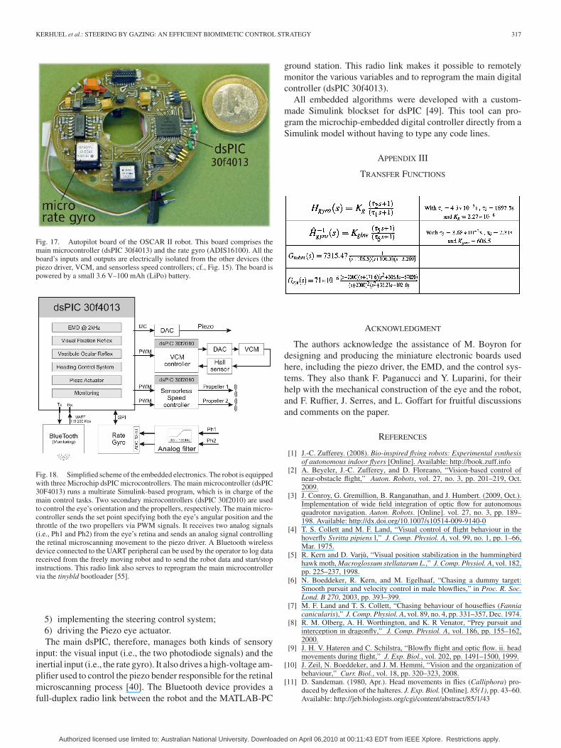
Fig. 17. Autopilot board of the OSCAR II robot. This board comprises themain microcontroller (dsPIC 30f4013) and the rate gyro (ADIS16100). All theboard’s inputs and outputs are electrically isolated from the other devices (thepiezo driver, VCM, and sensorless speed controllers; cf., Fig. 15). The board ispowered by a small 3.6 V–100 mAh (LiPo) battery.
Fig. 18. Simplified scheme of the embedded electronics. The robot is equippedwith three Microchip dsPIC microcontrollers. The main microcontroller (dsPIC30F4013) runs a multirate Simulink-based program, which is in charge of themain control tasks. Two secondary microcontrollers (dsPIC 30f2010) are usedto control the eye’s orientation and the propellers, respectively. The main micro-controller sends the set point specifying both the eye’s angular position and thethrottle of the two propellers via PWM signals. It receives two analog signals(i.e., Ph1 and Ph2) from the eye’s retina and sends an analog signal controllingthe retinal microscanning movement to the piezo driver. A Bluetooth wirelessdevice connected to the UART peripheral can be used by the operator to log datareceived from the freely moving robot and to send the robot data and start/stopinstructions. This radio link also serves to reprogram the main microcontrollervia the tinybld bootloader [55].
5) implementing the steering control system;6) driving the Piezo eye actuator.The main dsPIC, therefore, manages both kinds of sensory
input: the visual input (i.e., the two photodiode signals) and theinertial input (i.e., the rate gyro). It also drives a high-voltage am-plifier used to control the piezo bender responsible for the retinalmicroscanning process [40]. The Bluetooth device provides afull-duplex radio link between the robot and the MATLAB-PC
ground station. This radio link makes it possible to remotelymonitor the various variables and to reprogram the main digitalcontroller (dsPIC 30f4013).
All embedded algorithms were developed with a custom-made Simulink blockset for dsPIC [49]. This tool can pro-gram the microchip-embedded digital controller directly from aSimulink model without having to type any code lines.
APPENDIX III
TRANSFER FUNCTIONS
ACKNOWLEDGMENT
The authors acknowledge the assistance of M. Boyron fordesigning and producing the miniature electronic boards usedhere, including the piezo driver, the EMD, and the control sys-tems. They also thank F. Paganucci and Y. Luparini, for theirhelp with the mechanical construction of the eye and the robot,and F. Ruffier, J. Serres, and L. Goffart for fruitful discussionsand comments on the paper.
REFERENCES
[1] J.-C. Zufferey. (2008). Bio-inspired flying robots: Experimental synthesisof autonomous indoor flyers [Online]. Available: http://book.zuff.info
[2] A. Beyeler, J.-C. Zufferey, and D. Floreano, “Vision-based control ofnear-obstacle flight,” Auton. Robots, vol. 27, no. 3, pp. 201–219, Oct.2009.
[3] J. Conroy, G. Gremillion, B. Ranganathan, and J. Humbert. (2009, Oct.).Implementation of wide field integration of optic flow for autonomousquadrotor navigation. Auton. Robots. [Online]. vol. 27, no. 3, pp. 189–198. Available: http://dx.doi.org/10.1007/s10514-009-9140-0
[4] T. S. Collett and M. F. Land, “Visual control of flight behaviour in thehoverfly Syritta pipiens l,” J. Comp. Physiol. A, vol. 99, no. 1, pp. 1–66,Mar. 1975.
[5] R. Kern and D. Varju, “Visual position stabilization in the hummingbirdhawk moth, Macroglossum stellatarum L.,” J. Comp. Physiol. A, vol. 182,pp. 225–237, 1998.
[6] N. Boeddeker, R. Kern, and M. Egelhaaf, “Chasing a dummy target:Smooth pursuit and velocity control in male blowflies,” in Proc. R. Soc.Lond. B 270, 2003, pp. 393–399.
[7] M. F. Land and T. S. Collett, “Chasing behaviour of houseflies (Fanniacanicularis),” J. Comp. Physiol. A, vol. 89, no. 4, pp. 331–357, Dec. 1974.
[8] R. M. Olberg, A. H. Worthington, and K. R Venator, “Prey pursuit andinterception in dragonfly,” J. Comp. Physiol. A, vol. 186, pp. 155–162,2000.
[9] J. H. V. Hateren and C. Schilstra, “Blowfly flight and optic flow. ii. headmovements during flight,” J. Exp. Biol., vol. 202, pp. 1491–1500, 1999.
[10] J. Zeil, N. Boeddeker, and J. M. Hemmi, “Vision and the organization ofbehaviour,” Curr. Biol., vol. 18, pp. 320–323, 2008.
[11] D. Sandeman. (1980, Apr.). Head movements in flies (Calliphora) pro-duced by deflexion of the halteres. J. Exp. Biol. [Online]. 85(1), pp. 43–60.Available: http://jeb.biologists.org/cgi/content/abstract/85/1/43
Authorized licensed use limited to: Australian National University. Downloaded on April 06,2010 at 00:11:43 EDT from IEEE Xplore. Restrictions apply.
318 IEEE TRANSACTIONS ON ROBOTICS, VOL. 26, NO. 2, APRIL 2010
[12] R. Hengstenberg, “Mechanosensory control of compensatory head rollduring flight in the blowfly Calliphora erythrocephala Meig.,” J. CompPhysiol. A, vol. 163, pp. 151–165, 1988.
[13] R. Hengstenberg, “Control of head pitch in Drosophila during restand flight,” in Proc. of 20th Gottingen Neurobiol.Conf., N. Elsner andD. Richter, Eds. G. Thieme Verlag, Stuttgart, Germany, 1992, p. 305.
[14] D. H. Ballard, “Reference frames for animate vision,” in Proc. 2nd Int.Congr. Neuroethol., Berlin, Germany, Sep. 1989, pp. 1635–1641.
[15] F. Du, J. M. Brady, and D. W. Murray, “Gaze control for a two-eyed robothead,” in Proc 2nd Brit. Mach. Vision Conf., Glasgow. London, U.K.:Springer-Verlag, 1991, pp. 193–201.
[16] N. J. Ferrier and J. C. Clark, “The Harvard binocular head,” Int. J. PatternRecognit. Artif. Intell., vol. 7, no. 1, pp. 9–31, 1993.
[17] T. Yamaguchi and H. Yamasaki, “Velocity based vestibular-visual inte-gration in active sensing system,” in Proc. IEEE Int. Conf. MultisensorFusion Integr. Intell. Syst., Las Vegas, NV, 1994, pp. 639–646.
[18] T. Shibata and S. Schaal, “Biomimetic gaze stabilization based onfeedback-error learning with nonparametric regression networks,” NeuralNetw., vol. 14, pp. 201–216, 2001.
[19] F. Panerai, G. Metta, and G. Sandini, “Learning visual stabilization reflexesin robots with moving eyes,” Neurocomput., vol. 48, pp. 323–337, 2002.
[20] A. Lenz, T. Balakrishnan, A. G. Pipe, and C. Melhuish, “An adaptivegaze stabilization controller inspired by the vestibulo-ocular reflex,” IOPBioinspiration Biomimetics, vol. 3, pp. 035001-1–035001-11, 2008.
[21] A. Lewis, “Visual navigation in a robot using zig-zag behavior,” in Proc.Neural Inf. Process. Syst., 1997, pp. 822–828.
[22] P. Viola, “Neurally inspired plasticity in oculomotor processes,” in Proc.Neural Inf. Process. Syst., 1989, pp. 290–297.
[23] J.-A. Meyer, A. Guillot, B. Girard, M. Khamassi, P. Pirim, and A.Berthoz. (2005, Mar.). “The Psikharpax project: Towards building anartificial rat,” Robot. Auton. Syst. [Online]. vol. 50, no. 4, pp. 211–223. Available: http://www.sciencedirect.com/science/article/B6V16-4F3NY1T-2/2/ec53ab956f362ced1629259454a1f68a
[24] R. Miyauchi, N. Shiroma, and F. Matsuno, “Compact image stabilizationsystem using camera posture information,” J. Field Robot., vol. 25, no. 4–5, pp. 268–283, 2008.
[25] X. Twombly, R. Boyle, and S. Colombano, Active Stabilization of ImagesAcquired on a Walking Robotic Platform, G. Bebis et al., Eds., in Proc.ISVC (LNCS 4292), 2006, pp. 851–860.
[26] R. Wagner, I. W. Hunter, and H. L. Galiana, “A fast robotic eye/headsystem: Eye design and performance,” in Proc. IEEE Eng. Med. Biol.Soc., 1992, vol. 14, pp. 1584–1585.
[27] E. Maini, L. Manfredi, C. Laschi, and P. Dario. (2008, Aug.). “Bioinspiredvelocity control of fast gaze shifts on a robotic anthropomorphic head,” Au-ton. Robots [Online]. vol. 25, no. 1, pp. 37–58. Available: http://dx.doi.org/10.1007/s10514-007-9078-z
[28] S. Takizawa, S. Ushida, T. Okatani, and K. Deguchi, “2dof motion stabi-lization of biped robot by gaze control strategy,” in Proc. IEEE/RSJ Int.Conf. Intell. Robots Syst., Aug. 2–6, 2005, pp. 1102–1107.
[29] S. Ushida, K. Yoshimi, T. Okatani, and K. Deguchi, “The importance ofgaze control mechanism on vision-based motion control of a biped robot,”in Proc. IEEE/RSJ Int. Conf. Intell. Robots Syst., Oct. 2006, pp. 4447–4452.
[30] N. J. Strausfeld, H. S. Seyan, and J. J. Milde, “The neck motor systemof the fly Calliphora erythrocephala. 1. Muscles and motor neurons,” J.Comp. Physiol, vol. A 160, pp. 205–224, 1987.
[31] E. L. Keller, “Gain of the vestibulo-ocular reflex in monkey at high rota-tional frequencies,” Vis. Res., vol. 18, pp. 311–115, 1978.
[32] M. Huterer and K. E. Cullen, “Vestibulo-ocular reflex dynamics duringhigh-frequency and high acceleration rotations of the head on body inrhesus monkey,” J. Neurophysiol, vol. 88, pp. 13–28, 2002.
[33] R. W. Clifford, P. C. Know, and G. N. Dutton, “Does extraocular muscleproprioception influence oculomotor control?,” Br. J. Opthalmol., vol. 84,pp. 1071–1074, 2000.
[34] N. Dancause, M. D. Taylor, E. J. Plautz, J. D. Radel, T. Whittaker,R. J. Nudo, and A. G. Feldman, “A stretch reflex in extraocular mus-cles of species purportedly lacking muscle spindles,” Exp. Brain Res.,vol. 180, pp. 15–21, 2007.
[35] T. Preuss and R. Hengstenberg, “Structure and kinematics of the prosternalorgans and their influence on head position in the blowfly Calliphoraerythrocephala Meig.,” J. Comp. Physiol. A, vol. 171, pp. 483–493,1992.
[36] A. Paulk and C. Gilbert, “Proprioceptive encoding of head position in theblack soldier fly, Hermetia illucens (l.) (Stratiomyidae),” J. Exp. Biol.,vol. 209, pp. 3913–3924, 2006.
[37] E. Liske, “The influence of head position on the flight behaviour of thefly, Calliphora erythrocephala,” J. Insect Physiol., vol. 23, pp. 375–179,1977.
[38] S. Viollet and N. Franceschini, “Visual servo system based on abiologically-inspired scanning sensor,” in Proc. Sens. Fusion Decentral-ized Control Robot. II, vol. 3839, SPIE, Boston, MA, 1999, pp. 144–155.
[39] S. Viollet, L. Kerhuel, and N. Franceschini, “A 1-gram dual sensorlessspeed governor for micro-air vehicles,” in Proc. IEEE MED2008, Ajaccio,France, pp. 1270–1275.
[40] S. Viollet and N. Franceschini, “A high speed gaze control system basedon the vestibulo-ocular reflex,” Robot. Auton. Syst., vol. 50, pp. 147–161,2005.
[41] N. Franceschini and R. Chagneux, “Repetitive scanning in the fly com-pound eye,” in Proc. Gottingen Neurobiol. Conf., Gottingen, Germany,1997, p. 279.
[42] S. Viollet and N. Franceschini, “Biologically-inspired visual scanningsensor for stabilization and tracking,” in Proc. IEEE IROS, Kyongju,Korea, 1999, pp. 204–209.
[43] S. Viollet and N. Franceschini, “Super-accurate visual control of anaerial minirobot,” presented at the Auton. Minirobots Res. Edutainment,U. Ruckert, J. Sitte, and U. Witkowski, Eds. Padderborn, Germany, 2001.
[44] G. Westheimer, “Visual hyperacuity,” in Progress in Sensory Physiologyl, D. Ottoson, Ed. Berlin, Germany: Springer, 1981, pp. 1–30.
[45] R. H. S. Carpenter, “Vestibular eye movements,” Movements of the Eyes,London, U.K.: PION, 1988, ch. 2.
[46] G. Franklin, J. Powel, and M. Workman, Digital Control of DynamicSystems, 3rd ed. Reading, MA: Addison-Wesley, 1998.
[47] G. B. Gauthier, J. P. Piron, J. P. Roll, E. Marchetti, and B. Martin, “High-frequency vestibulo-ocular reflex activation through forced head rotationin man,” Aviat. Space Environ. Med., vol. 55, no. 1, pp. 1–7, Jan. 1984.
[48] B. Lurie and P. Enright, Classical Feedback Control With MATLA. (Con-trol Engineering), M. Dekker, Ed. New York: Marcel Dekker, 2000.
[49] L. Kerhuel. (2008, Oct.). Pic and dspic rapid prototyping blockset forsimulink [Online]. Available: http://www.kerhuel.eu
[50] L. Kerhuel, S. Viollet, and N. Franceschini, “A sighted aerial robot withfast gaze and heading stabilization,” in Proc. IEEE Conf. Intell. RobotsSyst., San Diego, CA, Oct. 2007, pp. 2634–2641.
[51] R. M. Steinman, “Voluntary control of microsaccades during maintainedmonocular fixation,” Science, vol. 155, pp. 1577–1579, 1967.
[52] W. Becker, “Saccades,” in Vision and Visual Dysfunction, vol. 8, GR.H. S. Carpenter, Ed. New York: Macmillan, 1991, ch. 5, pp. 95–137.
[53] B. M. Chen, T. H. Lee, K. Peng, and V. Venkataramanan, Hard Disk DriveServo Systems, 2nd ed. Berlin, Germany: Springer, 2006.
[54] D. Robinson, “The mechanics of human saccadic eye movement,” Phys-iol. Lond., vol. 174, pp. 245–264, 1964.
[55] C. Chiculita. (2008, Oct.). Tiny pic bootloader [Online]. Available:http://www.etc.ugal.ro/cchiculita/software/picbootloader.htm
Lubin Kerhuel was born near Paris, France. Hereceived the Engineer degree in microelectronics,the M.S. degree in signal processing and numericalcommunication from the University of Nice SophiaAntipolis, Nice, France, and the Ph.D. degree incontrol engineering and microelectronics from theMontpellier II University, Montpellier, France.
He is currently with the Biorobotics Laboratory,Institute of Movement Sciences, National Center forScientific Research/University of the Mediterranean,Marseille, France. For one year, he was with the Neu-
roscience Sensorimotor Network Laboratory, Paris, where he was engaged instudying inner ears through invasive experimentations and behavioral studies.He developed a Simulink blockset to target microcontrollers that is now usedworldwide. His current research interests include the control of minimalist aerialvehicles, helicopters, or fixed-winged vehicles, which are based on visual andinertial sensors.
Authorized licensed use limited to: Australian National University. Downloaded on April 06,2010 at 00:11:43 EDT from IEEE Xplore. Restrictions apply.
KERHUEL et al.: STEERING BY GAZING: AN EFFICIENT BIOMIMETIC CONTROL STRATEGY 319
Stephane Viollet was born in Limoges, France. Hereceived the Master’s degree in control engineeringfrom the University of Bordeaux 1, Bordeaux, France,and the Ph.D. degree from the National PolytechnicInstitute, Grenoble, France, in September 2001.
He is currently a Permanent Research Sci-entist with the Biorobotics Laboratory, Instituteof Movement Sciences, National Center for Sci-entific Research/University of the Mediterranean,Marseille, France. His current research interests in-clude biorobotics, oculomotor control, and retinal mi-
cromovements, as well as the development of novel bioinspired visual sensorsand control laws for implementation onboard autonomous flying robots.
Nicolas Franceschini was born in Macon, France.He graduated in electronics and control theory andreceived the Ph.D. degree in physics from the Na-tional Polytechnic Institute, Grenoble, France.
For nine years, he was with the Max-Planck Insti-tute for Biological Cybernetics. In 1979, he createdthe Neurocybernetics Laboratory, National Centre forScientific Research, Marseille, France, and later cre-ated the Biorobotics Laboratory. His current researchinterests include visual sensors, in particular opticflow sensors, retinal micromovements, oculomotor
control, head control, and flight control systems and their potential applicationsto air and space vehicles.
Authorized licensed use limited to: Australian National University. Downloaded on April 06,2010 at 00:11:43 EDT from IEEE Xplore. Restrictions apply.