Resource Management of Bridge Deck Rehabilitation: Jacques Cartier Bridge Case Study
Upload
khangminh22Category
view
6download
0
Steel-Composite Design of Railway Arch Bridge Improves Constructability & Efficiency
Sena Kumarasena, HNTB Corporation, Boston, MA, USA
M.V. Jatkar and V.N. Heggede, Gammon India Limited, Mumbai, India
Abstract
Anjikhad River Bridge is a 372-m (1220-ft) long railroad bridge in a remote location in Katra, India. The proposed bridge has a 265-m (870-ft) arch span over the 200-m (650-ft) deep gorge. It is designed to carry a two track rail road being built as a part of a large scale railway expansion project in this mountainous area forming the Himalayan foothills. The remote project location is inaccessible and temporary access roads that meander along the mountain slopes are being built for the transportation of construction equipment and material. The design-build team proposed a steel-composite design for the arch rib to improve the serviceability, maintainability and constructability. 1. Introduction
The US$300 million Katra-Laole section of the Udhampur-Srinagar–Baramulla rail link in the state of Jammu & Kashmir is a demanding project anywhere. However, the terrain and accessibility challenges in this lower Himalayan region makes it one of the most challenging railway projects in the world undertaken in recent history. Managed by Konkan Railway for Indian Railway, the project involves a total of 12 tunnels totaling 23 km through the most geologically active region in India. Many bridges connect these tunnels over deep gorges along the way over this highly mountainous terrain. Konkan Railway is constructing over 30 km long access roads to facilitate construction of these numerous facilities through otherwise inaccessible mountains for the first time since their formation. These access roads, currently nearing completion, meandering along the treacherous mountain slopes are the only viable means of transportation of construction equipment and material. The project also consists of two special railway bridges over Chenab River and the Anjikhad River and together these will be the largest railway bridges in India constructed with spans and heights in a similarly challenging environment. The present article is based on the design and construction aspects of the Anjikhad River Bridge.
The Anjikhad River Bridge has a total length of 372-m (1220-ft) with a 265-m (870-ft) arch span over a 200-m (650-ft) deep gorge. It is designed to carry two tracks of rail road even though only one will be installed initially. The Anjikhad Bridge is being constructed by a joint venture of Gammon India Limited and Archirodon Construction. HNTB Corporation, USA is the Design Consultant for the arch bridge on behalf of the design-build joint venture.
Following the recommendations of the technical advisory board, the requirements stipulated a steel arch bridge for this location. Based on the topologic information, the design proposed by the design-build team consisted of a steel arch design with a 200-m span over the river crossing. Three separate arch ribs of hollow box section were provided to meet the requirement for redundancy in all major elements considering the importance and the location of the structure. The initial design layout and the anticipated construction scheme are shown in Figure 1. As shown in Figure 1(b), the arch ribs were proposed to be erected first using a cable tie-back system

followed by the construction of the spandrels and the superstructure. The proposed bridge superstructure consists of four longitudinal plate girders with sleepers supporting the rails. The track alignment can be revised from the initial single track at the center to future dual tracks as shown in Figure 2.
(a) General layout with 200m arch span
(b) Anticipated construction staging Figure 1: Initial design layout

As the job progressed, various site complexities were discovered during the initial site topographic survey and geotechnical investigations. Addressing these complexities required the adaptation of the 265-m span asymmetric arch geometry shown in Figure 3. In addition to the revised span length, further design refinements were proposed and implemented that enhanced many serviceability and maintainability aspects of the bridge and its resistance to blast loads and redundancy as described later. These design refinements consisted of adding diagonal members between the spandrel columns leading to a trussed arch layout and using a steel-concrete composite design for the arch rib. These design enhancements also resulted in significant improvements to bridge constructability at this very challenging site by enabling the adaptation of cantilever construction method.
(a) Initial one track layout
(b) Future two track layout Figure 2: Deck cross section

2. Major Design Requirements
The major design requirements for the bridge consists mostly of those originally stipulated in the tender requirements and some that were enhanced or refined over the course of the design development period to date through interaction with KCRL and the proof design consultant SWK. Governing design requirements include:
1. Live Load: Two tracks of modified broad gauge loading (MBG) 25 mton axle loads for locomotive and 8.25 mton/m distributed train load on both sides of the locomotive
2. Wind: Site-specific design wind velocity of 53.5 m/s (3-second gust)
3. Seismic: Sa = 4.3g max spectral acceleration coefficient (2% damping) per IS 1893 for
seismic Zone V
4. Fatigue: Miner’s summation method for a project specific fatigue load spectrum following BS5400, Part 10
5. Deflection Criteria:
a. Vertical < L/800 per UIC 776-3R where L is conservatively taken as half the
arch span b. Lateral < L/4000 per UIC 776-2R with L taken as the distance between
expansion joints under service level wind velocity taken as (25 m/s 3-second gust)
6. Redundancy: The bridge must be able to carry self weight and one train under reduced
operating speed with damage to any one given member
7. Blast Loading: All bridge members are to be designed to a specified blast loading pressure applied on a member by member basis.
3. Design Refinements
The main design refinements proposed and implemented consisted of:
1. Arch Global Layout – A trussed arch configuration obtained by adding diagonal members to the conventional spandrel arrangement
2. Arch Rib Section – A steel composite rib design in lieu of the conventional hollow
box arrangement
3. In-Fill Concrete – Use of self-consolidating concrete for filling interior of the steel shell of the arch rib section

(a) General layout of the 265m arch span
(b) Anticipated construction staging Figure 3: Final design layout
Serviceability and maintainability advantages:
• Deflection Limits – Enhanced stiffness gained by steel-composite design help achieve the stringent deflection limits required by the project design criteria.
• Stability – The trussed arch layout results in a considerable reduction in bridge
deflections under external loads and thus eliminate secondary moments resulting from the effects of arch deformations (P x Delta effects)
• Long term maintenance – Concrete in-fill eliminates the need for interior inspection and
future painting of the rib interior. It also eliminates potential accumulation of water and other foreign matter in difficult to reach interior locations that could otherwise be a significant maintenance issue.

• Live load induced fatigue – Is considerably reduced due to the following two effects
working together:
1. Truss action reduces bending moments in the arch rib under Live Loads 2. Composite action enable shifting of the neutral axis under bending moments that
effectively reduces fatigue stresses in the steel section of the arch rib • Redundancy and blast resistance – The hollow box sections under compression (such as
in a arch rib) are vulnerable to lateral pressure resulting from blast loads. The resulting out-of-plane deflections of the plates acting together with in-plane compressive stresses can lead to total collapse of the section. Interior concrete fill provides an effective support to the plates against such deflections and improves the blast-worthiness of the rib section considerably. Further, as it would be difficult to destroy the entire rib section due to the presence of interior concrete, the system redundancy is also improved.
Bridge constructability advantages:
• The trussed arch design allows the hollow steel arch rib and the roadway to be erected in cantilever starting from each of the two sides meeting in mid span.
• The steel-concrete composite design allows a considerable reduction in the level of
complexity of arch rib fabrication as many of the interior details that stiffen the plates and stabilize cross section under final load conditions are not required.
• Weight of the conventional rib sections that can be handled with the cable-way was a
significant limitation under the tender design scenario. The reduction in the size of the rib due to composite design improved transportability and handling of field sections during erection constructability.
• The field sections can now be transported using the superstructure to the cantilever fronts
thus reducing the reliance on the cable-way and improving the feasibility of transporting larger field sections. This can be used to minimize the construction schedule due to fewer field sections and splices.
• Further, as nearly all of the compressive forces in the arch rib are carried by the concrete
core, the field splices of the steel sections are greatly simplified. The arch rib splices now have to be designed primarily as moment connections resulting in simplifications in fabrication and erection.
• The rib concrete is cast directly against the arch foundation. This enable compressive
force in the concrete core to be directly transferred to the foundations simplifying the connection of the arch rib to the foundations
Once steel erection is complete, the hollow rib sections are then to be filled with self consolidating concrete in stages to provide the composite section needed to carry the design loads in its final condition. Concrete is to be produced using a batching plant located on site and self compacting concrete was selected for this application. Self consolidating concrete was first developed in Japan in 1980s to use in heavily congested areas that cannot be effectively compacted using conventional methods. However, it is gaining popularity within the construction

industry due to its many other benefits. Use of self consolidating concrete in the present application would enable complete filling of the interior of the steel shell reliably around the interior details and help avoid the potential constructability difficulties faced with a concrete mix requiring significant active compacting effort within the restricted space.
4. Arch Global Behavior
The major factors affecting the arch global behavior are:
• The presence of three arch ribs, • Horizontal curvature of the outer ribs (plan view), and, • The truss action due to arch diagonals.
Presence of Three Ribs: The three arch ribs were provided to meet the tender requirements for redundancy of all major structural elements. Under gravity (vertical) loads the three ribs develop about the same axial compression with the center rib taking slightly more load than the outer two. The lateral loads can lead to uplift of the arch rib at the foundation if the tension induced due to lateral loads are larger than the DL compression. Under such loads (wind and seismic) however, only the outer two ribs participate in developing the tension-compression couple needed in resisting global lateral loads, and the axial compression in the middle rib remains unchanged. Preventing uplift of the outer ribs under lateral loads is made harder by the presence of the middle rib that resist and slightly more than a third of the DL yet does not participate in resisting horizontal loads. Horizontal Curvature of Outer Ribs: Starting from the 5.5m spacing at the crown, the two outer arch ribs spread out as they reach the foundations. This horizontal geometry has two major beneficial effects. First, the larger transverse spacing between the outer ribs at the foundation level reduces the tension developed in the ribs in resisting horizontal loads, thereby making it possible to eliminate uplift in arch ribs even when the DL compression in the outer ribs are reduced by the presence of the middle rib (discussed previously). Second, the horizontal curvature enhances the lateral stiffness of the global structural system that helps meet the stringent horizontal deflection requirements as well as improves global stability characteristics. Truss Action of Arch Diagonals: Under uniformly distributed loads, arch structures develop mostly axial forces and provide an excellent system for resisting such loads. However, traditional arch structures are quite sensitive to asymmetric conditions where only one half of the span is loaded. Such asymmetric loads develop significant bending components as well as significant displacements in the arch rib. For these reasons, rib depth on traditional arch layouts are controlled by the bending demand under asymmetric loads and the lowest buckling mode that has an asymmetric mode shape. This situation can be improved significantly by the addition of arch diagonals as the diagonals provide an effective resistive mechanism for asymmetric loads and asymmetric displacement conditions. Figure 4 show the buckling modes and the buckling multipliers of the trussed arch under symmetric and asymmetric live loads. The relatively high stability characteristics achieved (represented by high buckling multipliers) makes the secondary moments produced by arch deflections (geometric non-linearity) insignificant for the present structure.

(a) Buckling multipliers:
Self weight + LL over half-span = 11 (shown) Self weight + LL over full length = 13
(b) Arch LL moments from linear vs. geometrically non-linear analysis Figure 4: Arch buckling and moment magnification characteristics
-8000
-6000
-4000
-2000
0
2000
4000
6000
8000
10000
2000 2010 2020 2030 2040 2050
Vert
ical
Ben
ding
Mom
ent (
kN*m
)
Factored Linear Moment
Factored Non-linear Moment
12.5%
15.8%
5. Arch Rib Design
The arch rib is designed as a steel-concrete composite member for the final condition. As discussed previously, the construction staging involves first erecting the outer steel shell of the arch rib and then filling the interior with self consolidating concrete in stages to complete the structure. This allows steel shell of the arch rib to be designed for the governing stress conditions arising from:
1. The bending resistance requirements in the final condition 2. The temporary stress condition during bridge erection
While item 1 is a function of the structure and its loading, item 2 can be controlled by adjusting the sequence of construction not govern the design to the extent possible. The end result is a design with following fabrication and constructability advantages:
a. Typical steel arch rib sections contain complex internal fabrication details consisting of diaphragms, transverse and longitudinal stiffeners needed for distortion control and plate stability under compressive stresses. In the completed stage, the steel section is composite with the concrete core and thus provides ample resistance to distortion and plate stability issues thus greatly simplifying the fabrication issues involved in steel only rib designs.
b. The lighter steel shell is easier to handle and erect than the rib section for a steel only
design. This allows longer field sections to be used in construction leading to considerable schedule advantages
c. The arch compressive forces are carried mostly by the concrete core and does not have to
be transmitted through the field splices of the steel section, thus considerably minimizing the size of the field splices and the effort required in making them
d. The concrete core is cast integral with the foundations and thus the arch compression is
transferred directly to the foundations thus avoiding significant load transfer issues from the steel rib to the foundations encountered with traditional designs.
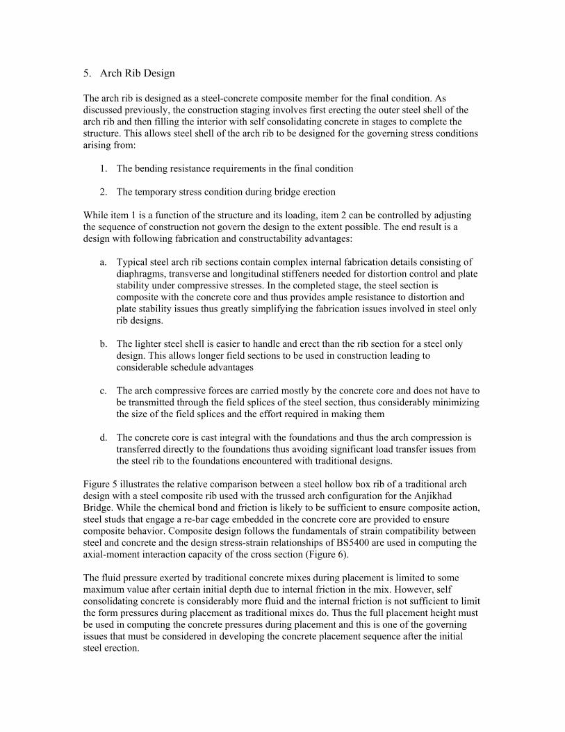
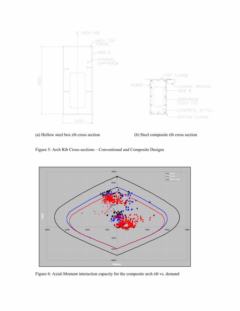
Figure 5 illustrates the relative comparison between a steel hollow box rib of a traditional arch design with a steel composite rib used with the trussed arch configuration for the Anjikhad Bridge. While the chemical bond and friction is likely to be sufficient to ensure composite action, steel studs that engage a re-bar cage embedded in the concrete core are provided to ensure composite behavior. Composite design follows the fundamentals of strain compatibility between steel and concrete and the design stress-strain relationships of BS5400 are used in computing the axial-moment interaction capacity of the cross section (Figure 6). The fluid pressure exerted by traditional concrete mixes during placement is limited to some maximum value after certain initial depth due to internal friction in the mix. However, self consolidating concrete is considerably more fluid and the internal friction is not sufficient to limit the form pressures during placement as traditional mixes do. Thus the full placement height must be used in computing the concrete pressures during placement and this is one of the governing issues that must be considered in developing the concrete placement sequence after the initial steel erection.
(a) Hollow steel box rib cross section (b) Steel composite rib cross section Figure 5: Arch Rib Cross-sections – Conventional and Composite Designs
Figure 6: Axial-Moment interaction capacity for the composite arch rib vs. demand
-45000
-30000
-15000
0
15000
30000
45000
60000
75000
-35000 -25000 -15000 -5000 5000 15000 25000 35000
M [kNm]
P [k
N]
40 MPa
30 MPa
50MPa + rebars
6. Progress of Construction
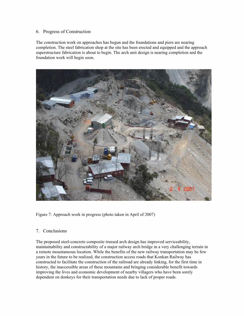
The construction work on approaches has begun and the foundations and piers are nearing completion. The steel fabrication shop at the site has been erected and equipped and the approach superstructure fabrication is about to begin. The arch unit design is nearing completion and the foundation work will begin soon.
Figure 7: Approach work in progress (photo taken in April of 2007)
7. Conclusions
The proposed steel-concrete composite trussed arch design has improved serviceability, maintainability and constructability of a major railway arch bridge in a very challenging terrain in a remote mountaneous location. While the benefits of the new railway transportation may be few years in the future to be realized, the construction access roads that Konkan Railway has constructed to facilitate the construction of the railroad are already linking, for the first time in history, the inaccessible areas of these mountains and bringing considerable benefit towards improving the lives and economic development of nearby villagers who have been sorely dependent on donkeys for their transportation needs due to lack of proper roads.

Figure 8: Access roads meandering on mountain sides (photo taken in November of 2006)
Copyright © 2022 FDOKUMEN