standards and specifications for the design and construction of ...
256
STANDARDS AND SPECIFICATIONS FOR THE DESIGN AND CONSTRUCTION OF PUBLIC IMPROVEMENTS 2010 EDITION
-
Upload
khangminh22 -
Category
Documents
-
view
1 -
download
0
Transcript of standards and specifications for the design and construction of ...

STANDARDS AND SPECIFICATIONS FOR THE DESIGN AND CONSTRUCTION
OF PUBLIC IMPROVEMENTS
2010 EDITION

STANDARDS AND SPECIFICATIONS FOR THE DESIGN AND CONSTRUCTION OF PUBLIC
IMPROVEMENTS
I N D E X O F C H A P T E R S
Chapter 1 ~ General Requirements
Chapter 2 ~ Earthwork, Erosion Control, Landscaping & Parks
Chapter 3 ~ Water System
Chapter 4 ~ Sanitary Sewer System
Chapter 5 ~ Storm Sewer System
Chapter 6 ~ Roadway Parking
Chapter 7 ~ Concrete
Chapter 8 ~ Off Street Improvements
Chapter 9 ~ Trenching, Backfilling, & Compacting
Chapter 10 ~ Acceptance Requirements
2010 EDITION
STANDARDS AND SPECIFICATIONS FOR THE DESIGN AND CONSTRUCTION OF PUBLIC
IMPROVEMENTS
Chapter 1
General Requirements
2010 EDITION

TABLE OF CONTENTS
CHAPTER 1
AUTHORITY AND PURPOSE
1.00.00 INTENT ........................................................................................................................................................... 1
1.01.00 TITLE ................................................................................................................................................................ 1 1.02.00 APPLICABILITY ............................................................................................................................................. 1 1.03.00 INTERPRETATION ......................................................................................................................................... 1 1.04.00 ENFORCEMENT RESPONSIBILITY ............................................................................................................. 2 1.05.00 VIOLATIONS ................................................................................................................................................... 2 1.06.00 VARIANCES .................................................................................................................................................... 2 1.07.00 AMENDMENTS AND REVISIONS ................................................................................................................ 2 1.08.00 SEVERABILITY .............................................................................................................................................. 2 1.09.00 DEFINITIONS .................................................................................................................................................. 2 1.10.00 ABBREVIATIONS ........................................................................................................................................... 4
1.20.00 GENERAL CONDITIONS ............................................................................................................................ 6
1.21.00 RESPONSIBILITY FOR DESIGN AND CONSTRUCTION .......................................................................... 6 1.22.0 WORK CONDITIONS ...................................................................................................................................... 6
1.22.01 Site Conditions ................................................................................................................................................ 6 1.22.02 Emergency Work ............................................................................................................................................. 6 1.22.03 Final Clean-Up ............................................................................................................................................... 6
1.23.00 CONTROL OF WORK AND MATERIALS .................................................................................................... 7 1.23.01 Authority of City ............................................................................................................................................. 7 1.23.02 Responsibilities of the Responsible Party ....................................................................................................... 7 1.23.03 Unauthorized and/or Unacceptable Work ...................................................................................................... 8 1.23.04 Samples and Tests ........................................................................................................................................... 8 1.23.05 Storage of Materials ....................................................................................................................................... 8 1.23.06 Defective Materials ......................................................................................................................................... 8
1.24.00 PROTECTION OF PUBLIC INTERESTS ....................................................................................................... 9 1.24.01 Public Convenience and Safety ...................................................................................................................... 9 1.24.02 Protection of Property and Monuments ......................................................................................................... 9 1.24.03 Installation of Survey Monuments ................................................................................................................ 10 1.24.04 Explosives ..................................................................................................................................................... 10 1.24.05 Protection of Streams, Lakes, and Reservoirs .............................................................................................. 10
1.25.00 WORK IN PUBLIC RIGHT-OF-WAY .......................................................................................................... 10 1.25.01 Relocation of Facilities ................................................................................................................................. 10 1.25.02 Permit Required – Excavation Permit .......................................................................................................... 11 1.25.03 Issuance of Permits ....................................................................................................................................... 12 1.25.04 Liability for Damage & Utility Locates ........................................................................................................ 12 1.25.05 Suspension or Revocation of Permits -- Stop Work Order ........................................................................... 12 1.25.06 Application Form .......................................................................................................................................... 12 1.25.07 Exhibition of Permit ...................................................................................................................................... 13 1.25.08 Correction Period ......................................................................................................................................... 13 1.25.09 End of Correction Period ............................................................................................................................. 13 1.25.10 Performance .................................................................................................................................................. 14
1.30.00 CONSTRUCTION DRAWING SUBMITTAL REQUIREMENTS ............................................................... 15

1
CHAPTER 1
GENERAL REQUIREMENTS
1.00.00 INTENT
The intent of these STANDARDS AND SPECIFICATIONS is to provide MINIMUM standards to safeguard life, health, property, and public welfare by regulating and controlling the design, construction, quality of materials, use, location, and maintenance of all public improvements and private improvements of common ownership including, but not limited to, sanitary sewer systems, water supply systems, storm drainage systems, streets, open space, parking lots, and appurtenances thereto.
The intent of these STANDARDS AND SPECIFICATIONS is also to insure that the City receives public facilities which are constructed with the quality and materials such that the facility meets or exceeds the normal service life requirements for similar installations and to insure that when said facilities are transferred to the City's ownership that they will be free from all defects and in suitable working order to provide the service capabilities anticipated with such a facility.
1.01.00 TITLE
These regulations, together with all future amendments, shall be known as the City of Delta STANDARDS AND SPECIFICATIONS for the Design and Construction of Public Improvements, 1999 Edition, and may be cited as such and will be referred to herein as the STANDARDS AND SPECIFICATIONS.
1.02.00 APPLICABILITY
Any reference to City STANDARDS AND SPECIFICATIONS, construction regulations, or the like in any City ordinance, contract, policy, permit, license or regulations shall be deemed to mean these STANDARDS AND SPECIFICATIONS. These STANDARDS AND SPECIFICATIONS shall apply to construction, enlargement, alteration, moving, removal, conversion, demolition, repair, and excavation of any public improvements or private improvements of common ownership specifically regulated herein. The provision of these STANDARDS AND SPECIFICATIONS applies to City contracts, utility extension agreements, and contracts made for the development of property in the City. In the case of City capital improvement contracts, the project specifications may supersede or modify these STANDARDS AND SPECIFICATIONS. Alterations, additions or repairs to existing improvements shall comply with all requirements of these STANDARDS AND SPECIFICATIONS unless specifically exempted, in writing, by the City. The City retains the right to require additional information, criteria, or requirements as conditions may warrant. Provisions of City ordinances inconsistent with these STANDARDS AND SPECIFICATIONS shall control.
1.03.00 INTERPRETATION
In the interpretation of the provisions of these STANDARDS AND SPECIFICATIONS the following shall govern:
(A) In its interpretation, the provisions of these STANDARDS AND SPECIFICATIONS shall be
regarded as the minimum requirements for the protection of the public health, safety, comfort, convenience, prosperity, and welfare of the residents of the CITY.
(B) Whenever a provision of these STANDARDS AND SPECIFICATIONS or any provision in any
2
law, ordinance, resolution, rule or regulation of any kind, contain any restrictions covering any of the same subject matter, whichever standards produce higher quality shall govern.
1.04.00 ENFORCEMENT RESPONSIBILITY
It shall be the duty of the City Manager or his representative to interpret and enforce the provisions of these STANDARDS AND SPECIFICATIONS.
1.05.00 VIOLATIONS
No person, firm, or corporation shall construct, enlarge, alter, repair, move, improve, remove, excavate, convert, or demolish any public improvements or private improvements in common ownership or permit the same to be done in violation of these STANDARDS AND SPECIFICATIONS. Whenever any work is being done contrary to the provisions of these STANDARDS AND SPECIFICATIONS, the City Manager or his designee may order the work stopped by a written notice in accordance with Section 1.26.04 of these STANDARDS AND SPECIFICATIONS.
1.06.00 VARIANCES
The provisions of these STANDARDS AND SPECIFICATIONS are not intended to prevent the use of any material or method of construction not specifically prescribed by these standards, provided any alternate has been previously approved and its use authorized in writing by the City. Whenever there are practical difficulties involved in carrying out the provisions of these procedures, the City may grant a variance for individual cases, provided that the City shall first find that a unique reason makes these standards impractical and that the modification is in conformity with the intent and purpose of these standards, and providing that such variance does not lessen any design requirements or any degree of structural or operational integrity. The City shall require that sufficient specifications, evidence, justification, and/or proof be submitted to substantiate any claims that may be made regarding the alternate material, detail, or technique. The City, in its sole discretion, will decide upon the acceptability of any proposed variance.
1.07.00 AMENDMENTS AND REVISIONS
These STANDARDS AND SPECIFICATIONS may be amended as new technology is developed and/or if experience gained in the use of these STANDARDS AND SPECIFICATIONS indicate a need for revision. The City shall have full power and authority to promulgate rules, regulations, or new standards of a technical nature, which rules, regulations, or standards shall be effective immediately upon their approval and certification by the City Manager or his designee. It is the responsibility of the Responsible Party to obtain all revisions to these STANDARDS AND SPECIFICATIONS.
1.08.00 SEVERABILITY
If any section or article of these STANDARDS OR SPECIFICATIONS is found to be unconstitutional or illegal by any court, the said section or article shall have no bearing on the effectiveness of the rest of these STANDARDS OR SPECIFICATIONS.
1.09.00 DEFINITIONS
AIR GAP shall mean the unobstructed vertical distance through the free atmosphere between the lowest opening of the potable water system feeding into a vessel and the flood level of the vessel.

3
BACKFLOW shall mean the undesirable reversal of the direction of flow of non-potable water in the potable water supply. BACKFLOW PREVENTION DEVICE shall mean a device or means designed to prevent backflow or backsiphonage. BACKPRESSURE shall mean a condition that results when the downstream pressure in a system connected to the potable water supply exceeds the upstream pressure of the potable water supply. BACKSIPHONAGE shall mean a type of backflow created by negative pressure or sub-atmospheric pressure in the potable water supply. CITY shall mean the City of Delta, in the State of Colorado, acting by and through the City Manager, Mayor, City Council, or other authorized representative. CITY CODE shall mean the official adopted Municipal City Code of Delta, Colorado. CITY REPRESENTATIVE shall mean the City Manager or his authorized representative acting on behalf of the City.
CROSS-CONNECTION shall mean a link or channel between a source of a non-potable substance and a potable water supply. DESIGNATED PRIVATE CONSTRUCTION WORK includes: private sewer systems, water and sewer service lines to buildings, grading, drainage structures, retaining walls, parking lots, private streets and walks, fire lanes, driveways, and associated construction.
DOUBLE CHECK VALVE ASSEMBLY shall mean an assembly of two independently operating check valves between two tightly closing shut-off valves with four properly located test cocks for the testing of each check valve EXPRESSIONS: Wherever the words “as directed”, “as required”, “as permitted”, or words of like meaning are used, it shall be understood that the direction, requirements, or permission of the City Representative is intended. Similarly, the words “approved”, “acceptable”, “satisfactory” shall refer to approval by the City Representative. Whenever the words “STANDARDS AND SPECIFICATIONS” are used it shall be understood that reference is made to the “City of Delta”, Standards and Specifications for the Design and Construction of Public Improvements. GRAVITY GREASE INTERCEPTOR (GGI): A plumbing appurtenance or appliance that is installed in a wastewater drainage system to separate non-petroleum fats, oils, and greases (FOG’s) and solid food particles from wastewater and is identified by outdoor (usually below grade) installation, 300-gallon minimum volume, 30-minute minimum retention time, baffles, a minimum of two compartments, and gravity separation. GREASE TRAP: A generic term used to refer to all forms of grease separation and retention, no longer officially used in codes and standards. HYDROMECHANICAL GREASE INTERCEPTOR (HGI): A plumbing appurtenance or appliance that is installed in a wastewater drainage system to separate non-petroleum fats, oils, and greases (FOG’s) from wastewater and is identified by indoor installation, separation and retention efficiency, and flow rate. The design incorporates air entrapment, hydromechanical separation, internal baffling
4
and/or barriers in combination or separately, and one of the following:
1) External flow control with air intake, directly connected 2) External flow control without air intake (vent), directly connected 3) Without external flow control, directly connected 4) Without external flow control, indirectly connected.
Certified under PDI G-101 and ASME A112.14.3 OWNER shall mean a person, company, firm, or corporation holding title to land that is being developed or modified within the City. PUBLIC IMPROVEMENTS include: all work in the public right-of-way, City property, easements dedicated to the City, private property that will become City property or an easement to the City in the future, and projects or utilities that will become the City’s responsibility to maintain. RECORD DRAWINGS: A set of drawings prepared by a registered Professional Engineer in the State of Colorado which reflect the information of record for construction of any public improvements. Commonly referred to as “As-Builts”.
REDUCED PRESSURE ZONE ASSEMBLY shall mean an assembly of two independently operating check valves with a hydraulic automatic operating differential relief valve between the two check valves and located between two tightly closing shut-off valves with four properly located test cocks. RESPONSIBLE PARTY: These “STANDARDS AND SPECIFICATIONS” are for the Design and Construction of Public Improvements. Therefore the Responsible Party shall be anyone liable for the design and/or construction of public improvements projects related to these Standards and Specifications and may include but not be limited to the Contractor, Developer, Permittee, Builder, Engineer, Consultant, and Owner. SUBCONTRACTOR: Any person, company, firm, or corporation performing work within the City limits which has a direct or indirect contract with the Responsible Party or other subcontractors and furnishes and/or performs on-site labor, and/or furnishes materials in connection with the performance of the work. SURETY shall mean the entity that is bound with and for the Responsible Party for the performance of the work as described in these specifications. (Bonded) TESTING AGENCY: Any individual, partnership, or corporation which is qualified and licensed to perform the required sampling, analysis, testing, and professional recommendation service.
VACUUM BREAKER shall mean a device designed to prevent backsiphonage.
1.10.00 ABBREVIATIONS
AASHTO American Association of State Highway and Transportation Officials
AASHTO "Green" A Policy on Geometric Design of Highways and Streets, 1990. American Association of State Highway and Transportation Officials
ACI American Concrete Institute ADA American Disabilities Act AISC American Institute of Steel Construction ANSI American National Standards Institute APWA American Public Works Association ASA American Standards Association
5
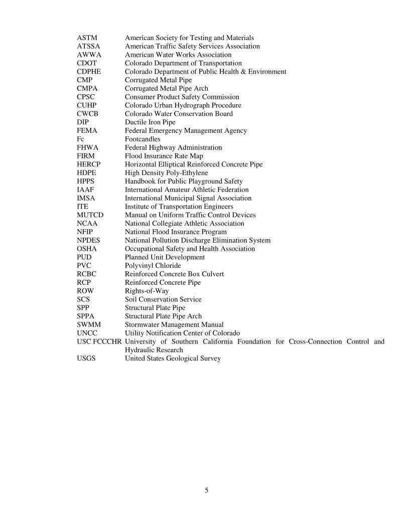
ASTM American Society for Testing and Materials ATSSA American Traffic Safety Services Association AWWA American Water Works Association CDOT Colorado Department of Transportation CDPHE Colorado Department of Public Health & Environment CMP Corrugated Metal Pipe CMPA Corrugated Metal Pipe Arch CPSC Consumer Product Safety Commission CUHP Colorado Urban Hydrograph Procedure CWCB Colorado Water Conservation Board DIP Ductile Iron Pipe FEMA Federal Emergency Management Agency Fc Footcandles FHWA Federal Highway Administration FIRM Flood Insurance Rate Map HERCP Horizontal Elliptical Reinforced Concrete Pipe HDPE High Density Poly-Ethylene HPPS Handbook for Public Playground Safety IAAF International Amateur Athletic Federation IMSA International Municipal Signal Association ITE Institute of Transportation Engineers MUTCD Manual on Uniform Traffic Control Devices NCAA National Collegiate Athletic Association NFIP National Flood Insurance Program NPDES National Pollution Discharge Elimination System OSHA Occupational Safety and Health Association PUD Planned Unit Development PVC Polyvinyl Chloride RCBC Reinforced Concrete Box Culvert RCP Reinforced Concrete Pipe ROW Rights-of-Way SCS Soil Conservation Service SPP Structural Plate Pipe SPPA Structural Plate Pipe Arch SWMM Stormwater Management Manual UNCC Utility Notification Center of Colorado
USC FCCCHR University of Southern California Foundation for Cross-Connection Control and Hydraulic Research
USGS United States Geological Survey
6
1.20.00 GENERAL CONDITIONS
1.21.00 RESPONSIBILITY FOR DESIGN AND CONSTRUCTION
The City shall have full authority to review and approve all submittals and construction for compliance with these STANDARDS AND SPECIFICATIONS. An approval or acceptance by the City does not relieve the Responsible Party from responsibility for ensuring that the calculations, plans, specifications, construction, and record drawings are in compliance with these STANDARDS AND SPECIFICATIONS. Any approval or acceptance by the City shall not result in any liability to the City or its employees for any claim, suit, loss, damage, or injury resulting from the use or implementation of the approved documents.
1.22.00 WORK CONDITIONS
1.22.01 Site Conditions
The Responsible Party shall maintain the condition of the work site such that public safety and welfare is protected. This shall include but not be limited to providing proper sanitary facilities for the duration of the construction of any public improvement project. The Responsible Party shall also take care in “tracking” debris onto any public street and will be responsible for the cleaning of such debris that is “tracked”. Responsible party shall also provide a designated pedestrian route that is ADA compliant, if appropriate, to help pedestrians safely pass through the work zone. If the City representative sees any unsafe work condition at any time, they shall cause a stop work order to be issued in conformance to Section 1.26.04.
1.22.02 Emergency Work
When, in the opinion of the City, the Responsible Party has not taken sufficient precautions for the safety of the public or the protection of the work to be constructed, or if adjacent structures or property which may be damaged by processes of construction on account of such neglect, and an emergency arises and immediate action is considered necessary in order to protect private or public interests, the City, WITH OR WITHOUT NOTICE to the Responsible Party, may provide suitable protection by causing such work to be done and material to be furnished and placed as the City may consider necessary and adequate. The cost and expense of such work and material so furnished will be borne by the Responsible Party and will be paid within 30 days of presentation of the bills. The City may also draw from the developer's surety to cover any non-payment, including accrued interest and applicable overhead costs. The performance or non-performance of such emergency work under the direction of the City will in no way relieve the Responsible Party of responsibility for damages which may occur during or after such precaution has been taken.
1.22.03 Final Clean-Up
Upon completion of the work and prior to any inspection by the City, the Responsible Party shall remove from the project area all surplus and discarded material, rubbish, and temporary structures and leave the project area in a neat and presentable condition. The Responsible Party shall restore all work that has been damaged by his operations to general conformity with the specifications for the item(s) involved. The Responsible Party shall inspect the interior of all manholes and catch basins within the construction limits for construction materials, dirt, stones, or other debris and remove same prior to any inspection by the City.

7
1.23.00 CONTROL OF WORK AND MATERIALS
1.23.01 Authority of City
The City will have the authority to stop work whenever such stoppage may be deemed necessary. The City will resolve all questions that arise as to the quality and acceptability of materials furnished, work performed, interpretation of the plans and specifications, and acceptable fulfillment of the requirements of these STANDARDS AND SPECIFICATIONS. The City representative shall resolve all questions that may arise relative to the performance of the work with respect to these STANDARDS AND SPECIFICATIONS.
City inspectors are authorized to inspect all work and all material furnished. Inspections may extend to all or any part of the work and to the preparation, fabrication, or manufacture of the materials to be used. The inspector is not authorized to revoke, alter, or waive any requirements of these STANDARDS AND SPECIFICATIONS. They are authorized to call the attention of the Responsible Party to any failure of the work or materials to conform to these STANDARDS AND SPECIFICATIONS. The Inspector will have the authority to reject materials until the City resolves any and all questions at issue.
The Inspector will, in no case, act as foreman or perform other duties for the Responsible Party nor interfere with the management of the work performed by the Responsible Party. Any "advice" or "opinion" which the inspector may give the Responsible Party will not be construed as binding upon the City representative or the City in any way or release the Responsible Party from fulfilling all of the terms of these STANDARDS AND SPECIFICATIONS. The presence or absence of the inspector will not relieve, in any degree, the responsibility or the obligation of the Responsible Party.
The City and its inspector will, at all times, have reasonable and safe access to the work whenever it is in preparation or progress and the Responsible Party will provide proper facilities for such access and inspection.
1.23.02 Responsibilities of the Responsible Party
In case of suspension of work for any cause whatsoever, the Responsible Party, before leaving
the job site, will take such precautions as may be necessary to prevent damage to the project, provide for public safety, normal drainage, and erect any necessary barricades, signs, or other facilities at his expense as directed by the City and required by these STANDARDS AND SPECIFICATIONS. The Responsible Party is responsible for ensuring that all construction and construction activities and materials are in compliance with these STANDARDS AND SPECIFICATIONS. He shall be solely responsible for all construction means, methods, techniques, sequences, and procedures. The Responsible Party shall be responsible for the acts and omissions of his employees, subcontractors, and their agents and employees. The Responsible Party shall be solely responsible for locating all existing underground installations, including service connections, in advance of excavating. City maps and databases are intended to be used for general information only, and the location of any utilities or property lines as found on the maps or databases shall be verified in the field. The Responsible Party is responsible for all testing and quality control, including providing equipment necessary to perform any necessary tests, of material and workmanship unless specified elsewhere. City may cause such testing to be completed at the expense of the responsible party if deemed necessary. If quality control testing indicates unacceptable work, Section 1.24.03 will govern.

8
1.23.03 Unauthorized and/or Unacceptable Work
Work which does not conform to the plans and these STANDARDS AND SPECIFICATIONS and which result in an inferior or unsatisfactory product will be considered unacceptable work. Unacceptable work, whether the result of poor workmanship, poor design, use of defective materials, damage through carelessness, or any other cause which is found to exist prior to the final acceptance of the work will be immediately removed and acceptably replaced or otherwise satisfactorily corrected by and at the expense of the Responsible Party. This expense includes total and complete restoration of any disturbed land or surface to original or better than the original condition that existed before the repairs or replacement.
1.23.04 Samples and Tests
To ascertain that materials and procedures comply with contract requirements, testing will be taken at the source or at the job destination at the discretion of the City and as often as the City deems it advisable or necessary. Taking of samples will be in accordance with standard practices except where methods and procedures for sampling materials are otherwise set forth in these STANDARDS AND SPECIFICATIONS.
The Responsible Party will furnish, without charge, any and all reports, summaries, field notes, etc. collected and compiled after tests are conducted. The Responsible Party may be required to furnish, when requested by the City, a written statement giving the origin, composition, and process of manufacture of a material.
Whenever any of the provisions of these STANDARDS AND SPECIFICATIONS or evidence that any material or construction does not conform to the requirements herein, the City may require that the Responsible Party have tests performed, at his expense, which will be used as proof of compliance. Test methods will be as referenced by these STANDARDS AND SPECIFICATIONS. If there are no recognized and accepted test methods for the proposed alternate, the City will determine the test procedures. All tests will be made by an agency approved by the City. The City will retain reports of such tests.
1.23.05 Storage of Materials
Materials will be stored so as to ensure the preservation of their quality and suitability for the work. Stored materials, even though approved prior to storage, will be subject to inspection prior to their use in the work and will meet all requirements of these STANDARDS AND SPECIFICATIONS at the time they are used. Stored materials will be located so as to facilitate inspection. With the prior written approval of the City, portions of the right-of-way not required for public travel may be used for storage purposes and for the placing of the Responsible Party's plants and equipment, but any additional space required will be provided by the Responsible Party at his expense. All Federal, State, and Local requirements pertaining to storage and handling of materials must be followed.
1.23.06 Defective Materials
Materials not in conformance with requirements of these STANDARDS AND SPECIFICATIONS will be considered defective and will be rejected. Rejected materials will be removed from the work site at the Responsible Party’s expense, unless otherwise permitted by the City.

9
1.24.00 PROTECTION OF PUBLIC INTERESTS
1.24.01 Public Convenience and Safety
Unless otherwise specified, the Responsible Party will give notice, in writing, to the proper authorities in charge of streets; gas and water pipes; electric service, cable television, and other conduits; railroads; poles; manholes; catch basins; and all other property that may be affected by the Responsible Party's operations at least two (2) business days after approval of permit prior to any construction. The Responsible Party will not hinder or interfere with any person in the protection of such property or with the operation of utilities at any time. The Responsible Party must obtain all necessary information in regard to existing utilities, protect such utilities from injury, and avoid unnecessary exposure so that they will not cause injury to the public.
The Responsible Party will obtain all necessary information in regard to the planned installation of new utilities and cables, conduits and transformers, make proper provision and give proper notification so that new utilities and appurtenances can be installed at the proper time and location without delay to the Responsible Party, nor cause unnecessary inconvenience to the owner or the public. New underground utilities and appurtenances will not be covered with pavement prior to the City’s inspection and approval of such facilities. When the work involves excavation adjacent to any building or wall along the work, the Responsible Party will give property owners due and sufficient notice thereof, in writing with a copy to the City.
1.24.02 Protection of Property and Monuments
The Responsible Party will use every reasonable precaution to prevent the damage or destruction of public or private property such as, but not limited to, poles, trees, shrubbery, crops, fences, monuments and all overhead structures such as, but not limited to, wires or cables which are either within or outside of the right-of-way. The Responsible Party will protect and support all water, gas, sanitary sewer, storm sewer or electrical pipes, and conduits and all railway tracks, buildings, walls, fences, or other properties that are liable to be damaged during the execution of his work. The Responsible Party will take all reasonable and proper precautions to protect persons, animals and vehicles from injury or damage and, wherever necessary, or as directed by the City, will erect and maintain a fence or railing around any excavation and place a sufficient number of amber lights about the work and keep them operational from twilight until sunrise. The Responsible Party will employ one or more watchmen as an additional security wherever they are needed or required by the City. The Responsible Party will not prevent the flow of water in the gutters of the street and will use proper means to permit the flow of surface water along the gutters while the work is progressing.
The Responsible Party will protect and carefully preserve all land boundary and City survey control monuments until the owner's authorized registered land surveyor has referenced their location for replacement. All monuments disturbed or removed by the Responsible Party through negligence or carelessness on his part or on the part of his employees or subcontractors will be replaced by a land surveyor registered in the State of Colorado, at the Responsible Party's expense. The Responsible Party will be responsible for the repair of any damage or destruction of property resulting from neglect, misconduct, or omission in his manner or method of execution or non-execution of the work or caused by defective work or the use of unsatisfactory materials. The Responsible Party will restore such property to a condition equal to or better than that existing before such damage or injury was done by repairing, rebuilding, or replacing it as may be directed by the City, or they will otherwise make good such damage or destruction in a manner acceptable to the City. The Responsible Party will be responsible for the repair of underground pipes, wires or conduits damaged by them or their subcontractors.
10
1.24.03 Installation of Survey Monuments
Permanent survey monuments, range points, and lot pins, other than those required hereby for marking the centerlines of streets, shall be set in the manner specified by the most current revision of Colorado Revised Statutes,38-51-104 and 38-51-105. Permanent survey monuments shall also be installed at all street centerline intersections and at all points of change in the direction of street centerlines (either angle or curvature), which, in the opinion of the City are significant enough to warrant monumentation for the sake of proper location of improvements. Only those survey monuments marking street centerlines must be installed in the manner specified by the drawing in the Appendix of Chapter 6 of the City of Delta’s Standards and Specifications. Such monuments shall be set to the City of Delta Geographic Information System coordinate system.
1.24.04 Explosives
When blasting is permitted and approved in writing by the City, the Responsible Party will use the utmost care to protect life and property. Signals warning persons of danger will be given before any blast. Excessive blasting or overshooting will not be permitted. The City will have authority to order any method of blasting discontinued that leads to overshooting, is dangerous to the public, or destructive to property, environment or natural features.
Before any blasting is to be performed by the Responsible Party, a certificate of insurance indicating special blasting coverage in the following minimum amounts will be filed with the City:
Property damage, each accident $1,000,000 Public liability, bodily injury $1,000,000 single limit or equivalent, each accident
The City reserves the right to require additional insurance coverage if the circumstances warrant.
The City has the right to require detailed inspections by an independent consultant or by City inspectors on any structures or properties located in the vicinity of the blasting, both before and after the blasting activity. The cost for such inspections shall be the responsibility of the Responsible Party.
1.24.05 Protection of Streams, Lakes, and Reservoirs
The Responsible Party will take all necessary precautions to prevent pollution of streams, lakes, and reservoirs by sediment, fuels, oils, bitumens, calcium chloride, fertilizers, insecticides, or other harmful materials. They will conduct and schedule their operations to avoid or minimize siltation of streams, lakes, and reservoirs. A plan for erosion protection shall be submitted to the City, approved by the City, and all required erosion control measures in place before starting work. All work must conform to all applicable local, state, and federal regulations.
1.25.00 WORK IN PUBLIC RIGHT-OF-WAY
1.25.01 Relocation of Facilities

11
The City may order the owner of facilities located in its rights of way, whether subject to a permit or not, to relocate its facilities, in order to allow the City to make any public use of streets or rights-of-way, or if required because of changing the grade, improving, repairing, constructing, or maintaining any street or rights-of-way, because of traffic conditions, public safety, installation of public improvements, or any general program for the undergrounding of such facilities, or other reasons deemed to require relocation in the City’s sole discretion. The City shall notify the owner of the facilities a reasonable time in advance, except in the case of emergency. The permittee shall thereupon, at its sole cost and expense, accomplish the necessary relocation, removal or change within a reasonable time from the date of the notification but in no event later than three working days prior to the date the City has specified, immediately in the case of emergencies. Upon the permittee’s failure to accomplish such work, the City may cause such work to be completed at the permittee’s expense and the permittee shall reimburse the City within 30 days after receipt of a written invoice. Following relocation, all affected property shall be restored to the condition which existed prior to construction by the permittee at the permittee’s expense. A new permit, or amended permit, shall be issued by the City for the relocated facility. In the event the affected utility is an existing overhead electric and communication facility, the facility or facilities may be converted to underground locations in the following manner: (A) Pursuant to the procedures of CRS 29-8-101 et seq. (B) When ordered by the City where the City is willing to pay and assume the costs of
conversion for the applicable utility.
(C) When ordered by the City in connection with incidental and episodic conversions associated with public improvements, such as street widening or sewer construction, at the cost of the public utility or cable operator.
The provisions of this section shall be applicable and supersede any inconsistent requirements in any existing permit as an exercise of the City’s police powers.
1.25.02 Permit Required – Right-of-Way and Revocable Encroachment and Utility Connect
Permit (Excavation Permit)
It shall be unlawful for any person or entity to perform work within public right-of-way of the City of Delta without first obtaining written permission from the City of Delta in the form of an excavation permit. If the work to be performed involves a City of Delta utility in a State of Colorado Highway right-of-way, both an excavation permit from the City and the appropriate permit from the Colorado Department of Transportation shall be required. A separate written application for that work done under an excavation permit shall be submitted to the City on a form provided by the City for each job. The application shall be submitted at least 48 hours prior to the planned start of work to allow for review and approval by the City. The Responsible Party may be required to increase this time up to 10 days when the work consists of more than a single spot excavation.
The City may require submission of plans and specifications. No work shall commence until the City has approved the plans and specifications and/or permit application, except in emergency conditions. A permit application shall be required for emergency conditions within 72 hours after the performance of the work and all conditions of an excavation permit shall apply. An application form (when approved) shall constitute a valid "excavation permit." Incomplete permit applications will not be reviewed or processed by the City.

12
1.25.03 Issuance of Permits
The City may grant permits to work in, construct, or excavate within the public way or to close traffic lanes or work in connection with a City utility system to any Responsible Party filing an application as herein provided, which application shall pertain to work which shall comply with the requirements of this chapter. All permits shall be issued according to the provisions of Chapter 15.30of the City of Delta Municipal Code.
1.25.04 Liability for Damage & Utility Locates
Any person or entity who shall undertake work pursuant to a permit issued under the provisions of this chapter, or to perform work under contracts with the City, or to perform work under the terms of a Utility Extension Agreement, or by virtue of permission obtained from the Council in accordance with the provisions adopted by the said Council, shall be liable for any damage or injury to persons, animals, or property as a result of any circumstances of such work. Prior to any excavation within the public right-of-way, the Responsible Party shall contact the Utility Notification Center of Colorado.
1.25.05 Suspension or Revocation of Permits -- Stop Work Order
(A) Any permit may be revoked or suspended by the City and a stop work order may be
issued after notice to the Responsible Party for: 1. Violations of any condition of the Utility Extension Agreement, or of the
approved construction drawings or specifications; or 2. Violation of any provision of these STANDARDS AND SPECIFICATIONS;
or 3. Violation of any other ordinance of the City, state law, or federal law pertaining
to the work; or
4. Existence of any condition or the occurrence of any act which may constitute or cause a condition endangering health, life, or safety, or serious damage to property.
(B) A suspension or revocation by the City and stop work orders shall take effect
immediately upon notice to the person performing the work in the field and shall remain in effect until such time as the City cancels the order in writing. A failure to abide by the terms of the suspension or revocation will be considered a violation of City ordinance.
(C) Upon receipt of a stop work order, the Responsible Party shall be responsible for taking
such precautions as may be necessary to prevent damage to the project, prevent inconvenience or hazardous conditions for the general public, provide for normal drainage, and to erect any necessary barricades, signs, or other facilities which may be necessary or directed by the City.
1.25.06 Application Form
Application for a permit to work in the public way shall be made on a form provided by the City

13
and shall recite specifically and illustrate by sketch or plan the exact location, depth, extent, nature, and purpose of the excavation desired to be made, the purpose for which the privilege is requested, and the duration of the time required for the work. Applicants shall pay a fee to the City before issuance of such permit. The amount of that fee shall be established by the City and displayed on the permit. Applicants shall also post a Performance or Contract Bond, clean irrevocable Letter of Credit, or Cash Bond in the amount as specified on the permit form. The responsible party warrants to the City that all materials and equipment incorporated in the work will be new unless otherwise specified, and that all work be of good quality, free from faults and defects and in conformance with these Standards and Specifications. All work not conforming to these standards shall be considered defective. No permit issued under the provisions hereof shall be for more than one excavation project for which a definite time limit shall be established by the City.
1.25.07 Exhibition of Permit
Such permit shall be kept at the site of the excavation while the work is in progress and shall be exhibited upon request to any police officer or other authorized representative of the City. Failure to comply with this provision shall be grounds for a revocation of the permit and the issuance of a stop work order.
1.25.08 Correction Period
All public improvements shall be subject to a correction period of at least one (1) year after the date of the acceptance from the City Representative. The Responsible Party shall be responsible for the maintenance of all public improvements during the correction period. The City Representative will notify the Responsible Party of any maintenance that may be necessary during this time. Routine maintenance normally performed by the Responsible Party includes, but shall not be limited to, the cleaning of streets, patching of potholes, and removal of blockages from water, storm and sanitary sewer facilities. The cost of any routine maintenance not performed by the Responsible Party that must be performed by the City will be billed to the Responsible Party at cost plus fifteen percent (15%).
In the event of a water main break, sanitary sewer main blockage, street or bridge failure, or other emergency that may occur during the correction period, it may become necessary for the City to undertake immediate repairs to the facilities and/or make the area safe to residents, pedestrians, or motorists. The City will attempt to contact the Responsible Party in the event of such emergency. However, if the Responsible Party or his representative cannot be contacted quickly or if the Responsible Party is unable to take immediate action to relieve the urgent situation, the City may proceed with such action as deemed necessary by the City Representative, and the Responsible Party will be billed for all costs of these actions at cost plus fifteen percent (15%).
1.25.09 End of Correction Period
At approximately nine (9) months into the correction period, the Responsible Party will schedule an inspection of the public improvements within the development to be performed by the City Representative. The Responsible Party or his representative will be invited to accompany the City's representative on all such inspections. The condition of the public improvements will be inspected for conformance with the approved plans, the Public Improvements Agreement, these STANDARDS AND SPECIFICATIONS, and any other City Codes. If due to excessive dirt or snow on streets, poor weather conditions, inaccessibility, or other reasons the inspection cannot be performed, the Responsible Party will be notified of the
14
need to postpone these activities until the cause of the delay can be rectified. Deficiencies noted during the correction inspection will be compiled in a corrections list to be mailed to the Responsible Party.
Correction list items should be corrected within 2 months of the date of the correction list, and all corrections must be completed no later than ten (10) working days prior to the scheduled end of the correction period. If all of the noted deficiencies are not corrected within this time, the public improvements may be reinspected, a revised correction list may be issued, and the end of the correction period may be adjusted at the discretion of the City Representative to allow ample time for the completion of the corrections. The end of the correction period will not be acknowledged until all noted deficiencies are corrected within the proper time frame. The appropriate City Representative shall be notified before any corrective work commences and immediately upon the completion of the repairs.
Upon completion of the correction of all deficiencies noted in the correction list, the City Representative will issue a written acknowledgment of the end of the correction period for the public improvements
1.25.10 Performance
(A) Inspection.
There shall be continuous inspections for each permit. The first shall occur upon notification by the Responsible Party that the work is ready for inspection and the second inspection as indicated in section 1.26.09 above.
(B) Barricading and Traffic Control.
1. All work within a traveled public roadway area shall be protected at all times by safety devices as prescribed by the MUTCD and in such manner as to minimize the disruption of the flow of traffic in the vicinity of the work. Normally, only one side of a street may be closed at any given time. Traffic must be provided a minimum lane width of 10 feet in the construction area. 24 hours before the start of construction, the Responsible Party shall notify emergency services and any other critically affected vehicular or pedestrian traffic or service.
2. All work within the roadway shall take place between 8:30 a.m. and 3:30 p.m.
unless otherwise stipulated on the excavation permit. 3. Unless prior approval is given by the City Representative, street excavations
must be backfilled prior to leaving the site at the end of the workday, even if the work has not been completed.
4. No person shall dig or cause to be dug any hole, drain, ditch, or any other
excavation in any street, alley, sidewalk, or other public place within the City without providing, during the nighttime, sufficient amber lights to be placed with a suitable barricade or temporary fence around such hole, drain, or other excavation in order to prevent persons, animals, and vehicles from sustaining injury. During the daytime the barricades shall be maintained but warning lights are not required. All barricades and lights shall be left in place until a permanent patch or temporary cold-mix patch can be made to the excavation.

15
(C) Removal of Safety Devices or Barricades.
No person shall damage, displace, remove, or interfere with any barricade warning light or any other safety device which is lawfully placed around or about any street, alley, sidewalk, or other excavations or construction work in the City.
1.30.00 CONSTRUCTION DRAWING SUBMITTAL REQUIREMENTS
Construction drawings shall contain the information and be in the format outlined in the separate documents titled "Checklist for Preliminary Plat Requirements" and “Drawing Standards Checklist” as provided in the Appendix of this chapter.

STANDARDS AND SPECIFICATIONS FOR THE DESIGN AND CONSTRUCTION OF PUBLIC
IMPROVEMENTS
Chapter 1 ~ Appendix
General Requirements
2010 EDITION

DRAWING STANDARDS CHECKLIST
Different people may have a variety of opinions regarding the content and
information that should be provided on a drawing with a given title. In order to
avoid confusion and to establish consistency, Drawing Standards Checklists have
been prepared by the City. These checklists establish the minimum requirements
for each drawing. The Staff may require additional drawings and/or detail, as it
deems necessary in their sole discretion.
All drawings required for submittal shall conform to the drawing standards
presented in this list. Checklists are provided in the order drawings should be
collated and presented to the City.
Index of Checklists
Page Number Checklist
2 Title Sheet 3 Notes Sheet 4 Phasing Plan 5 Site Plan 6 Grading/Drainage Plan 7 Utility Composite 8 Combined Street and Water Line Plan/Profile 10 Sanitary Sewer Plan/Profile 11 Storm Drainage Plan/Profile 12 Irrigation Plan 13 Parks/Landscaping Plan 14 Details Sheet 15 As-Built Grading/Drainage Plan 16 As-Built Combined Street and Water Plan/Profile 17 As-Built Sanitary Sewer Plan/Profile 18 As-Built Storm Drainage Plan/Profile 19 As-Built Irrigation Plan 20 As-Built Parks/Landscaping Plan

2
DRAWING STANDARDS CHECKLIST
TITLE SHEET
� Name of Project or Subdivision
� Developer/Owners Name and Contact Information
� Engineer/Designer Name and Contact Information
� Current Vicinity Map
� Index of Sheets
� Utility Notification Center of Colorado contact information
� List of Utility Contacts
� Sheet size is 24” X 36”, landscape orientation.

3
DRAWING STANDARDS CHECKLIST
NOTES SHEET
� Project Notes for General, Water, Sanitary Sewer, Storm Sewer, Grading, Roadway
� List of Abbreviations
� Legend of all line types and symbols used throughout project drawings
� Sheet size is 24” X 36”, landscape orientation.
4
DRAWING STANDARDS CHECKLIST
PHASING PLAN
� Lot and block layout
� Street names
� Lot numbers
� Phase lines and numbering
� Parks, open space, trails, detention/retention areas
� Utility phasing including end of line fire hydrants, sewer manholes, etc.
� Street phasing including temporary cul-de-sac locations
� Legend of symbols and line types used on this drawing
� Notes if applicable
� Scale
� North Arrow
� Scale must be 1”=10’, 1”=20’, 1”=30’, 1”=40’, 1”=50’, 1”=60’, or 1”=100’ and may necessitate more than one sheet depending on the size of the development or subdivision. Key map may be required if there are several match lines.
� Sheet size is 24” X 36”, landscape orientation.

5
DRAWING STANDARDS CHECKLIST
SITE PLAN
� Site boundary including lot lines and dimensions, adjacent property lines, and adjacent property owners.
� Identify all existing and proposed easements, streets, and ROWs.
� Identify all existing and proposed utilities, including appurtenances (i.e. fire
hydrants, manholes, etc)
� Identify all existing and proposed drainage and appurtenances (i.e. culverts, channels, etc.)
� Top and toe of slopes for retention/detention basins or other embankments
� Identify all paving, concrete walks, pads, ramps, and other surface treatments
� Identify all parking areas, striping, stalls, wheel chocks
� Identify parks, trails, opens space, etc.
� Identify all existing and proposed miscellaneous structures, fences, walls, septic
facilities, etc.
� Do not show existing or proposed contours
� For perimeter streets, show roadway width from curb to curb or curb to edge of asphalt, ROW width, and section lines if applicable
� Identify all access points to adjacent properties within 200’ of proposed access
points.
� Identify building footprints, if applicable.
� Legend of symbols and line types applicable to this drawing
� North Arrow
� Scale must be 1”=10’, 1”=20’, 1”=30’, 1”=40’, 1”=50’, 1”=60’, or 1”=100’ and may necessitate more than one sheet depending on the size of the development or subdivision. Key map may be required if there are several match lines.
� Sheet size is 24” X 36”, landscape orientation.

6
DRAWING STANDARDS CHECKLIST
GRADING/DRAINAGE PLAN
� Use site plan as a base drawing or otherwise provide similar information.
� Show all existing and proposed drainage facilities.
� Show all existing and proposed buried facilities that cross drainage facilities.
� Show and identify all encasement or structural pipe where applicable
� Station and label all manholes, inlets, and culverts. Provide rim and invert information if not provided elsewhere.
� Show existing and proposed surface contours with contour labels.
� Show 500 and 100-year flood and floodway boundaries, if applicable.
� Show flow direction with arrows and percent slope callouts.
� Show detention/retention facilities and cross sections with 5 year and 100 year
high water surface elevations.
� Show outlet work details, if applicable.
� Legend of symbols and line types applicable to this drawing
� North Arrow
� Scale must be 1”=10’, 1”=20’, 1”=30’, 1”=40’, 1”=50’, 1”=60’, or 1”=100’ and may necessitate more than one sheet depending on the size of the development or subdivision. Key map may be required if there are several match lines.
� Sheet size is 24” X 36”, landscape orientation.

7
DRAWING STANDARDS CHECKLIST
UTILITY COMPOSITE
� Use the site plan as a base drawing or otherwise provide similar information. � Show and differentiate all proposed and existing utilities. � Show all existing and proposed public and private utilities (i.e. sanitary, storm,
water, gas, phone, power, CATV, etc.)
� Show all utility appurtenances (i.e. manholes, fire hydrants, water valves, etc.). Identify rim and invert information if not provided elsewhere.
� Show all water and sewer tap locations.
� Legend of symbols and line types applicable to this drawing
� North Arrow
� Scale must be 1”=10’, 1”=20’, 1”=30’, 1”=40’, 1”=50’, 1”=60’, or 1”=100’ and
may necessitate more than one sheet depending on the size of the development or subdivision. Key map may be required if there are several match lines.
� Sheet size is 24” X 36”, landscape orientation.

8
DRAWING STANDARDS CHECKLIST
COMBINED STREET AND WATER LINE PLAN/PROFILE
� Use the site plan as a base drawing or otherwise provide similar information.
� Segmentize plan view as required to provide profiles below plan views.
Stationing on plan view shall align with stationing on profile.
� Show all existing and proposed profiles at CL and right and left FLs. Provide slopes with “+” or “-“.
� Cross sections may be required in addition to profiles, to review special
circumstances or to evaluate situations where a road is being widened or where flowline grades differ from the centerline grade. If required, cross sections shall include: station, existing and proposed cross sections, existing and proposed ROWs and easements, cross slopes, and existing and proposed buried utilities.
� Show existing and proposed profiles at edge of pavement if there is no gutter.
� Note adjustment of all MH rims and valves and covers for final grade.
� Elevation of FL at fillet/valley pan interface.
� Station & elevation of FL PCs (BCRs), PTs (ECRs), and handicap ramps.
� Stationing of CL PCs and PTs
� Station and elevation of pavement CL and FL VPIs, VPCs, VPTs, and high and
low points.
� Station and elevation at all grade changes and CL pavement warp at intersections.
� Provide pavement, base, and subgrade specifications.
� Barricades, turn-arounds, tapers, delineators, driveways.
� Streetlights, signing, and other traffic controls.
� Show future road extension alignment to support current design, where applicable.

9
� Show proposed permanent benchmark (for new subdivision) and all proposed horizontal control survey markers at street intersections.
� Show all existing and proposed water facilities and sizes in plan and profile.
� Show all existing and proposed buried facilities that cross water line.
� Dimension separation between water and other buried utilities (i.e. sanitary,
storm, irrigation, etc.)
� Add water services to plan view and relate to CL stationing.
� Station and label all water appurtenance locations (i.e. fire hydrants, valves, tees, crosses, plugs, bends, etc.)
� Show and identify encasement or structural pipe where applicable.
� Add existing and proposed surface profiles.
� Call out water pipe type in notes.
� Call out water minimum cover in notes. Dimension minimum cover on profile.
� Provide note regarding separation of sewer and water mains.
� Legend of symbols and line types applicable to this drawing
� North Arrow
� Scale must be 1”=10’, 1”=20’, 1”=30’, 1”=40’, 1”=50’, 1”=60’, or 1”=100’
horizontal and 1”=1’, 1”=2’, 1”=3’, 1”=4’, 1”=5’, 1”=6’ or 1”=10’ vertical, respectively and may necessitate more than one sheet depending on the size of the development or subdivision. Key map may be required if there are several match lines.
� Sheet size is 24” X 36”, landscape orientation.

10
DRAWING STANDARDS CHECKLIST
SANITARY SEWER PLAN/PROFILE � Use the site plan as a base drawing or otherwise provide similar information.
� Segmentize plan view as required to provide profiles below plan views. Stationing on
plan view shall align with stationing on profile
� Show all existing and proposed sewer facilities and sizes in profile.
� Show all existing and proposed buried facilities that cross the sewer.
� Dimension separation between sewer and other buried facilities (i.e. water, storm, irrigation, etc.)
� Show and identify encasement or structural pipe where applicable.
� Add sewer services to plan view and relate to sewer line stationing.
� Station and label all manholes, add rim and invert elevations.
� Add sewer main slopes and distances between manholes (centerline to centerline).
� Add existing and proposed surface profile.
� Call out sewer pipe types in notes.
� Call out minimum cover over sewer in notes. If sewer is less than 8’ from finished grade
to top of pipe add note: “Lots served by shallow sewer”.
� Provide note regarding separation of water and sewer mains.
� Provide note regarding service line markers and endpoint locations.
� Legend of symbols and line types applicable to this drawing
� North Arrow
� Scale must be 1”=10’, 1”=20’, 1”=30’, 1”=40’, 1”=50’, 1”=60’, or 1”=100’ horizontal and 1”=1’, 1”=2’, 1”=3’, 1”=4’, 1”=5’, 1”=6’ or 1”=10’ vertical, respectively and may necessitate more than one sheet depending on the size of the development or subdivision. Key map may be required if there are several match lines.
� Sheet size is 24” X 36”, landscape orientation.

11
DRAWING STANDARDS CHECKLIST
STORM DRAINAGE PLAN/PROFILE
� Use the site plan as a base drawing or otherwise provide similar information.
� Segmentize plan view as required to provide profiles below plan views. Stationing on plan view shall align with stationing on profile
� Show all existing and proposed drainage facilities in profile.
� Show all existing and proposed buried facilities that cross the drainage facilities.
� Dimension separation between storm drains and other buried facilities (i.e. water,
sanitary, irrigation, etc.)
� Show and identify encasement or structural pipe where applicable.
� Station and label all manholes, inlets, culverts, add rim and invert elevations.
� Add storm drain slopes and distances between manholes and/or inlets (centerline to centerline).
� Add existing and proposed surface profile.
� Call out pipe and culvert types in notes.
� Call out minimum cover over pipes and culverts in notes.
� Legend of symbols and line types applicable to this drawing
� North Arrow
� Scale must be 1”=10’, 1”=20’, 1”=30’, 1”=40’, 1”=50’, 1”=60’, or 1”=100’
horizontal and 1”=1’, 1”=2’, 1”=3’, 1”=4’, 1”=5’, 1”=6’ or 1”=10’ vertical, respectively and may necessitate more than one sheet depending on the size of the development or subdivision. Key map may be required if there are several match lines.
� Sheet size is 24” X 36”, landscape orientation.

12
DRAWING STANDARDS CHECKLIST
IRRIGATION PLAN
� Use the site plan as a base drawing or otherwise provide similar information.
� Show proposed surface contours.
� Call out minimum cover over irrigation lines.
� Identify irrigation head to head spacing and head and nozzle capabilities.
� Specify all irrigation system materials.
� Show existing and proposed ground, ditch, pipe, and/or flowline profile. Indicate all proposed covering or piping of existing ditches, as required.
� Identify existing and proposed irrigation facilities, including back flow
preventors, pumps, timer locations, electrical services, and tap locations and sizes, if applicable.
� Identify existing and proposed utilities, drainage, and road crossings.
� Station and elevation of all manholes, standpipes, gates, and other appurtenances.
� Elevation of all existing and proposed pipe and ditch flowlines.
� Lengths and slopes of ditches and pipes.
� Show hydraulic gradeline, flows, velocities, and “n” values
� Legend of symbols and line types applicable to this drawing
� North Arrow
� Scale must be 1”=10’, 1”=20’, 1”=30’, 1”=40’, 1”=50’, 1”=60’, or 1”=100’
horizontal and 1”=1’, 1”=2’, 1”=3’, 1”=4’, 1”=5’, 1”=6’, or 1”=10’ vertical, respectively and may necessitate more than one sheet depending on the size of the development or subdivision. Key map may be required if there are several match lines.
� Sheet size is 24” X 36”, landscape orientation.

13
DRAWING STANDARDS CHECKLIST
PARKS/LANDSCAPING PLAN
� Use the site plan as a base drawing or otherwise provide similar information. � Identify areas to be covered with specific landscaping materials.
� Identify boulders, mounds, swales, water courses, rock outcroppings.
� Identify living planting material in a legend including: common and botanical
names, quantities, minimum purchase sizes, mature height, ground cover/perennial material and spacing, types of soils, types of turf grasses, and other remarks.
� Specification of soil type and preparation.
� Landscaping irrigation layout, design, materials and details.
� Planting/staking and other details as required.
� Identify locations of parks equipment (i.e. benches, picnic tables, playground
equipment, etc.)
� Identify parks equipment specifications in a legend.
� Location of maintenance building and pump houses, if applicable.
� Trail cross sections shall be included, if applicable.
� Calculation used to derive required landscaping.
� Location of overhead utilities if crossing proposed landscaped areas.
� Legend of symbols and line types applicable to this drawing
� North Arrow
� Scale must be 1”=10’, 1”=20’, 1”=30’, 1”=40’, 1”=50’, 1”=60’, or 1”=100’ and may necessitate more than one sheet depending on the size of the development or subdivision. Key map may be required if there are several match lines.
� Sheet size is 24” X 36”, landscape orientation.

14
DRAWING STANDARDS CHECKLIST
DETAIL SHEET
� Separate detail sheet for water, sanitary, storm, roadway, and miscellaneous details.
� Use City provided details available in digital format.
� Roadway detail sheet to contain roadway cross-section profile as specified in soils
report.
� Other details as required to appropriately construct project.
� Scale: As required.
� Sheet size is 24” X 36”, landscape orientation

15
DRAWING STANDARDS CHECKLIST
AS-BUILT GRADING/DRAINAGE PLAN
� Use the grading and drainage plan as a base drawing. � Show only newly constructed grading contours.
� Show all newly constructed drainage facilities.
� Show all newly constructed buried facilities that cross drainage facilities.
� Show all as-built locations for manholes, inlets, and culverts. Provide as-built rim
and invert information if not provided elsewhere.
� Show as-built flow arrows and percent callouts. � Provide as-built pad elevations for all lots that are in or are adjacent to the 100-
year floodplain.
� Show detention/retention basin as-built contours and cross sections with slopes.
� Indicate volume verification of detention/retention and outlet works.
� Show drainage channel and swale as-built information, if applicable.
� Legend of symbols and line types applicable to this drawing
� North Arrow
� Scale must be 1”=10’, 1”=20’, 1”=30’, 1”=40’, 1”=50’, 1”=60’, or 1”=100’ and may necessitate more than one sheet depending on the size of the development or subdivision. Key map may be required if there are several match lines.
� Sheet size is 24” X 36”, landscape orientation

16
DRAWING STANDARDS CHECKLIST
AS-BUILT COMBINED STREET AND WATER LINE PLAN/PROFILE
� Use the combined street and water line plan/profile and as base drawing. � All vertical, horizontal, and other design information required for primary features
on the street and water line plan/profile must have corresponding as-built information provided, including pavement width, curb/gutter/sidewalk width and type, base course, and pavement thickness, geosynthetics, sub-grade stabilization, elevations, horizontal control, valves, vaults, bends, tees, crosses, fire hydrants, and other appurtenances, etc.
� As-built information for all significant changes from the approved design plans.
� Provide elevations for all PC’s, PT’s, ECR’s, angle points, grade breaks, and all
locations where elevations were shown on the design drawing.
� End of service locations must be tied to lot corners or be located by station and offset.
� Pipe type and type of pipe connections (MJ, SJ, FL, etc.)
� Legend of symbols and line types applicable to this drawing
� North Arrow
� Scale must be 1”=10’, 1”=20’, 1”=30’, 1”=40’, 1”=50’, 1”=60’, or 1”=100’
horizontal and 1”=1’, 1”=2’, 1”=3’, 1”=4’, 1”=5’, 1”=6’, or 1”=10’ vertical, respectively and may necessitate more than one sheet depending on the size of the development or subdivision. Key map may be required if there are several match lines.
� Sheet size is 24” X 36”, landscape orientation

17
DRAWING STANDARDS CHECKLIST
AS-BUILT SANITARY SEWER PLAN/PROFILE
� Use the sanitary sewer plan/profile as a base drawing. � All horizontal, vertical, and other design information required for primary features
on the sewer plan and profile must have corresponding as-built information provided, including elevations, station and offset etc. for manholes, cleanouts and other appurtenances.
� Ends of services must be tied to lot corners or be located by station and offset.
The top of the pipe or invert elevation or the depth from finished grade shall be shown.
� As-built information for all significant changes from the approved design plans.
� Pipe type shall be shown.
� Legend of symbols and line types applicable to this drawing
� North Arrow
� Scale must be 1”=10’, 1”=20’, 1”=30’, 1”=40’, 1”=50’, 1”=60’, or 1”=100’
horizontal and 1”=1’, 1”=2’, 1”=3’, 1”=4’, 1”=5’, 1”=6’, or 1”=10’ vertical, respectively and may necessitate more than one sheet depending on the size of the development or subdivision. Key map may be required if there are several match lines.
� Sheet size is 24” X 36”, landscape orientation

18
DRAWING STANDARDS CHECKLIST
AS-BUILT STORM DRAINAGE PLAN/PROFILE
� Use the storm drainage plan/profile as a base drawing.
� All horizontal, vertical, and other design information required for primary features in the storm drainage plan and profile must have corresponding as-built information provided, including elevations, station and offset, pipe and culvert slopes and distances, basin structures, etc.
� As-built information for significant changes from the approved design plans.
� Pipe and culvert type.
� Legend of symbols and line types applicable to this drawing
� North Arrow
� Scale must be 1”=10’, 1”=20’, 1”=30’, 1”=40’, 1”=50’, 1”=60’, or 1”=100’
horizontal and 1”=1’, 1”=2’, 1”=3’, 1”=4’, 1”=5’, 1”=6’, or 1”=10’ vertical, respectively and may necessitate more than one sheet depending on the size of the development or subdivision. Key map may be required if there are several match lines.
� Sheet size is 24” X 36”, landscape orientation

19
DRAWING STANDARDS CHECKLIST
AS-BUILT IRRIGATION PLAN (Only Required for City Facilities)
� Use the irrigation plan as a base drawing. � All horizontal, vertical, and other design information required for primary features
on the irrigation plan and profile must have corresponding as-built information provided.
� As-built information for all significant changes from the approved design plans.
� Pipe and culvert type.
� Legend of symbols and line types applicable to this drawing
� North Arrow
� Scale must be 1”=10’, 1”=20’, 1”=30’, 1”=40’, 1”=50’, 1”=60’, or 1”=100’
horizontal and 1”=1’, 1”=2’, 1”=3’, 1”=4’, 1”=5’, 1”=6’, or 1”=10’ vertical, respectively and may necessitate more than one sheet depending on the size of the development or subdivision. Key map may be required if there are several match lines.
� Sheet size is 24” X 36”, landscape orientation
20
DRAWING STANDARDS CHECKLIST
AS-BUILT PARKS/LANDSCAPING PLAN
� Use the Parks/Landscaping Plan as a base drawing. � All horizontal, vertical, and other design information required for primary features
on the irrigation plan and profile must have corresponding as-built information provided.
� As-built information for all significant changes from the approved design plans.
� Legend of symbols and line types applicable to this drawing
� North Arrow
� Scale must be 1”=10’, 1”=20’, 1”=30’, 1”=40’, 1”=50’, 1”=60’, or 1”=100’ and
may necessitate more than one sheet depending on the size of the development or subdivision. Key map may be required if there are several match lines.
� Sheet size is 24” X 36”, landscape orientation

STANDARDS AND SPECIFICATIONS FOR THE DESIGN AND CONSTRUCTION OF PUBLIC
IMPROVEMENTS
Chapter 2
Earthwork, Erosion Control, Landscaping & Parks
2010 EDITION

TABLE OF CONTENTS
CHAPTER 2
EARTHWORK, EROSION CONTROL, LANDSCAPING AND PARKS
Page
2.00.00 EARTHWORK AND GRADING .................................................................................................................. 1
2.10.00 EROSION CONTROL ...................................................................................................................................... 1 2.10.01 Limitations ...................................................................................................................................................... 2
2.11.00 EROSION AND SEDIMENT CONTROL PLANS .......................................................................................... 2 2.11.01 Review and Approval ...................................................................................................................................... 2 2.11.02 Grading and Erosion Control Notes ............................................................................................................... 2 2.11.03 Standard Erosion Control Details .................................................................................................................. 3
2.20.00 GENERAL LANDSCAPE SPECIFICATIONS ............................................................................................................ 3 2.21.00 DESIGN STANDARDS .......................................................................................................................................... 3
2.21.01 General Requirements .................................................................................................................................... 3 2.21.02 Submittal Requirements .................................................................................................................................. 3 2.21.03 Non Vegetative Material ................................................................................................................................. 3 2.21.04 Vegetative Material ........................................................................................................................................ 4 2.21.05 Protection of Landscaped Areas ..................................................................................................................... 5 2.21.06 Irrigation ........................................................................................................................................................ 5
2.22.00 PRESERVATION OF SIGNIFICANT LANDSCAPE FEATURES ................................................................................. 5 2.23.00 MAINTENANCE .................................................................................................................................................. 6 2.24.00 XERISCAPING ..................................................................................................................................................... 6 2.25.00 PARKING AREAS ................................................................................................................................................ 6 2.26.00 BUFFERING/SCREENING..................................................................................................................................... 7 2.50.00 GENERAL PARK SPECIFICATIONS FOR THE CITY OF DELTA .............................................................................. 7
2.50.01 Children’s Play Structures ............................................................................................................................... 8 2.50.02 Restrooms ........................................................................................................................................................ 8 2.50.03 Parking ............................................................................................................................................................ 9 2.50.04 Landscaping ..................................................................................................................................................... 9 2.50.05 Irrigation System.............................................................................................................................................. 9 2.50.06 Trails ............................................................................................................................................................... 10
2.60.00 SPORTS PACKAGE ............................................................................................................................................ 10 2.70.00 OPEN SPACE AREA ........................................................................................................................................... 10

1
CHAPTER 2
EARTHWORK, EROSION CONTROL, LANDSCAPING AND PARKS
2.00.00 EARTHWORK AND GRADING
All work performed according to this section must comply with the general requirements contained
within Chapter 1, the acceptance requirements of Chapter 10, the requirements outlined in the City of Delta Stormwater Management Manual (SWMM) and the NPDES requirements established by the Colorado Department of Public Health and Environment (CDPHE). All earthwork operations shall be executed in a manner that will minimize dust, noise, excessive accumulation of debris, danger to the public, and interference with other construction. Positive drainage and adequate erosion control shall be provided at all times during the earthwork operations.
Earthwork operations shall be executed to provide compaction to a minimum 85-percent Standard
Proctor density at + 3 percent of optimum moisture in areas to be eventually turfed or planted and compaction to minimum 95 percent Standard Proctor density at + 2 percent of optimum moisture under all walks, trails, streets, structures, public rights-of-way, and other site improvements. In areas of granular materials, use of the Modified Standard Proctor (ASTM-1557) shall be used for a compaction to minimum 90 percent density at + 2 percent of optimum moisture. Testing, if required by the City to demonstrate compliance with this specification, shall be performed per AASHTO T-180 or the above referenced ASTM standard by a qualified soils technician and stamped by a Professional Engineer registered in the State of Colorado and practicing in the field of soil mechanics in order to assure compliance with the City specifications for compaction. All costs for such testing shall be paid by the Responsible Party. Refer to the applicable section in these STANDARDS AND SPECIFICATIONS for compaction requirements within the public right-of-way.
Upon completion of earthwork operations, the Responsible Party shall leave the site and soil clean to
allow for proper installation of irrigation, plantings, and related site improvements. Completed grades shall be smoothly and uniformly sloped, properly compacted, and shall provide drainage away from site improvements. All banks or slopes constructed shall be maintained in a stable condition by approved methods to prevent slips, washouts, or erosion. No area to be seeded or sodded shall be steeper than a 4:1 maximum slope (4 horizontal: 1 vertical), nor flatter than a 2-percent minimum slope. Final grades shall conform to the final drainage study and overlot grading plans.
2.10.00 EROSION CONTROL
The primary goal of all erosion control systems is to prevent unacceptable erosion and maintain water
quality at acceptable levels. This shall be accomplished by analyzing pertinent environmental factors and applying technical procedures that result in a workable plan.
There are two major elements in developing an erosion and sedimentation control plan. The first is an
investigation and analysis of the natural characteristics of a site (such as soil type, steepness of slopes, and available vegetation) that will help the Responsible Party anticipate where erosion problems might occur. Detailed information on soils, vegetation, topography, geologic, and hydrologic conditions shall be obtained for the site. The second element is use of effective control measures. Attention shall be given to identify and evaluate problems that may cause serious erosion during and after construction. Runoff from the site, as well as runoff from the watershed above, shall be controlled and discharged safely. Measures shall be taken to prevent erosion and sediment deposition on downstream properties.
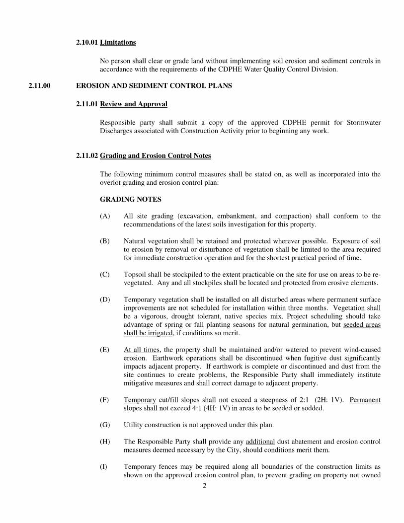
2
2.10.01 Limitations
No person shall clear or grade land without implementing soil erosion and sediment controls in accordance with the requirements of the CDPHE Water Quality Control Division.
2.11.00 EROSION AND SEDIMENT CONTROL PLANS
2.11.01 Review and Approval
Responsible party shall submit a copy of the approved CDPHE permit for Stormwater Discharges associated with Construction Activity prior to beginning any work.
2.11.02 Grading and Erosion Control Notes
The following minimum control measures shall be stated on, as well as incorporated into the
overlot grading and erosion control plan: GRADING NOTES
(A) All site grading (excavation, embankment, and compaction) shall conform to the recommendations of the latest soils investigation for this property.
(B) Natural vegetation shall be retained and protected wherever possible. Exposure of soil
to erosion by removal or disturbance of vegetation shall be limited to the area required for immediate construction operation and for the shortest practical period of time.
(C) Topsoil shall be stockpiled to the extent practicable on the site for use on areas to be re-
vegetated. Any and all stockpiles shall be located and protected from erosive elements. (D) Temporary vegetation shall be installed on all disturbed areas where permanent surface
improvements are not scheduled for installation within three months. Vegetation shall be a vigorous, drought tolerant, native species mix. Project scheduling should take advantage of spring or fall planting seasons for natural germination, but seeded areas shall be irrigated, if conditions so merit.
(E) At all times, the property shall be maintained and/or watered to prevent wind-caused
erosion. Earthwork operations shall be discontinued when fugitive dust significantly impacts adjacent property. If earthwork is complete or discontinued and dust from the site continues to create problems, the Responsible Party shall immediately institute mitigative measures and shall correct damage to adjacent property.
(F) Temporary cut/fill slopes shall not exceed a steepness of 2:1 (2H: 1V). Permanent
slopes shall not exceed 4:1 (4H: 1V) in areas to be seeded or sodded. (G) Utility construction is not approved under this plan. (H) The Responsible Party shall provide any additional dust abatement and erosion control
measures deemed necessary by the City, should conditions merit them. (I) Temporary fences may be required along all boundaries of the construction limits as
shown on the approved erosion control plan, to prevent grading on property not owned

3
by the Responsible Party. In addition, the City may require additional temporary fences if field conditions so merit them.
2.11.03 Standard Erosion Control Details
In the Appendix of these STANDARDS AND SPECIFICATIONS are the standard erosion
control details which are acceptable to the City of Delta.
2.20.00 GENERAL LANDSCAPE SPECIFICATIONS
The purpose of this Section is to enhance the aesthetic appeal of new development. Landscaping reduces heat and glare, facilitates movement of traffic within parking areas, shades vehicles and parking surfaces reducing local and ambient temperatures, buffers and screens vehicles from adjacent properties, promotes natural percolation of surface waters, improves air quality, buffers and screens potentially incompatible uses from one another, and conserves the value of property and neighborhoods within the City.
2.21.00 DESIGN STANDARDS
2.21.01 General Requirements
A. Landscaping for new developments shall occur in buffer areas, all interior parking areas, along the perimeter of the property, around new and existing structures, along street frontages, and within abutting rights of way.
B. A minimum of 1 tree and 3 shrubs shall be required for every 1000 sq. ft. of landscaped area
C. Fire hydrants must not be obscured by plant material.
D. No thorny shrubs or trees shall be allowed near sidewalks or within recreation areas.
E. Vegetation, fences, walls, and berms shall not be unsafe to motorists or pedestrians and shall comply with the sight distance specifications of section 6.17.00 of this manual.
1. No plants shall be over 24” in height within 60’ of arterial street corners.
2. No plants shall be over 24” in height within 50’ of collector street corners.
3. No plants shall be over 24” in height within 35’ of local street corners.
2.21.02 Submittal Requirements
A. Landscape plans shall be provided as specified in the drawing standards checklist of this manual
B. Landscape plans shall be stamped by a licensed Landscape Architect as required by the State of Colorado.
2.21.03 Non Vegetative Material
All landscaped areas with non plant material shall conform to the following:
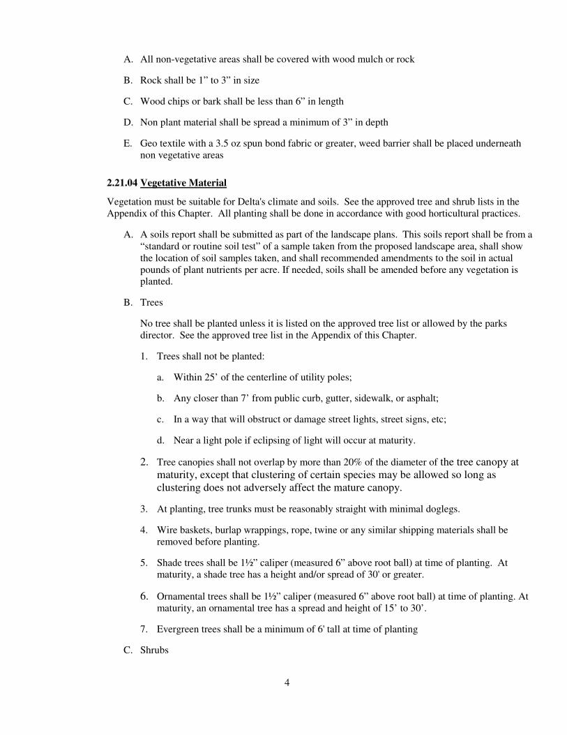
4
A. All non-vegetative areas shall be covered with wood mulch or rock
B. Rock shall be 1” to 3” in size
C. Wood chips or bark shall be less than 6” in length
D. Non plant material shall be spread a minimum of 3” in depth
E. Geo textile with a 3.5 oz spun bond fabric or greater, weed barrier shall be placed underneath non vegetative areas
2.21.04 Vegetative Material
Vegetation must be suitable for Delta's climate and soils. See the approved tree and shrub lists in the Appendix of this Chapter. All planting shall be done in accordance with good horticultural practices.
A. A soils report shall be submitted as part of the landscape plans. This soils report shall be from a “standard or routine soil test” of a sample taken from the proposed landscape area, shall show the location of soil samples taken, and shall recommended amendments to the soil in actual pounds of plant nutrients per acre. If needed, soils shall be amended before any vegetation is planted.
B. Trees
No tree shall be planted unless it is listed on the approved tree list or allowed by the parks director. See the approved tree list in the Appendix of this Chapter.
1. Trees shall not be planted:
a. Within 25’ of the centerline of utility poles;
b. Any closer than 7’ from public curb, gutter, sidewalk, or asphalt;
c. In a way that will obstruct or damage street lights, street signs, etc;
d. Near a light pole if eclipsing of light will occur at maturity.
2. Tree canopies shall not overlap by more than 20% of the diameter of the tree canopy at maturity, except that clustering of certain species may be allowed so long as clustering does not adversely affect the mature canopy.
3. At planting, tree trunks must be reasonably straight with minimal doglegs.
4. Wire baskets, burlap wrappings, rope, twine or any similar shipping materials shall be removed before planting.
5. Shade trees shall be 1½” caliper (measured 6” above root ball) at time of planting. At maturity, a shade tree has a height and/or spread of 30' or greater.
6. Ornamental trees shall be 1½” caliper (measured 6” above root ball) at time of planting. At maturity, an ornamental tree has a spread and height of 15’ to 30’.
7. Evergreen trees shall be a minimum of 6' tall at time of planting
C. Shrubs

5
No shrub shall be planted unless it is listed on the approved shrub list or allowed by the parks director. See the approved shrub list in the Appendix of this Chapter.
1. Deciduous shrub shall be a 5-gallon container size
2. Evergreen shrub shall be a 5-gallon container size
3. Minimum square footage of planting areas for a 5-gallon evergreen or deciduous shrub shall be 16 square feet.
4. Perennials and ground covers shall be a 1-gallon container size
D. Other
Other materials may not be installed unless it is listed on the applicable approved list or allowed by the City.
1. Turf mix, native grasses and wild flower mix are the only vegetation that may be planted as seed.
2. Noxious weeds are not allowed per the Colorado Noxious Weed Act Title 35 Article 5.5, enacted 1996
2.21.05 Protection of Landscaped Areas
A. All landscape areas shall be protected from vehicles through the use of permanently affixed material such as concrete curbing, large rocks, or other similar obstructions
B. Shrub beds adjacent to turf or native grass areas are to be edged with concrete, metal, brick or substantial wood material. Plastic and other light duty edgings are not allowed.
2.21.06 Irrigation
All required vegetation and landscaped areas shall be provided with an irrigation system and shall comply with the standards of section 2.50.05.
2.22.00 PRESERVATION OF SIGNIFICANT LANDSCAPE FEATURES
A. Existing landscape features such as escarpments, large or old trees or stands, heavy vegetative cover, ponds and bluffs shall be identified to the City as part of the development review process.
B. To the extent the City deems practicable, such natural features shall be preserved.
C. If a significant live feature which was to be preserved dies or is substantially damaged the developer shall replace it with an equivalent feature as determined by the City.
D. No person shall kill or damage a landscape feature required to be preserved by this Section.
E. The developer shall protect trees from compaction under the canopy drip line of the tree unless the City allows otherwise.
F. During construction, fencing or similar barriers shall isolate and protect the landscape features to be preserved.
G. All protection measures shall be clearly identified on the construction and landscape plans.

6
H. No vehicles or equipment shall be driven or parked nor shall any materials be piled within the canopy drip line of any tree to be preserved.
2.23.00 MAINTENANCE
The owners, tenants, and occupants for all new and existing uses in the City shall maintain all landscaping, fencing, and other related improvements in a healthy, neat, and well maintained condition. Maintenance includes watering, weeding, pruning, pest control, trash and litter removal, replacement of dead or diseased plant material, reseeding and other reasonable efforts.
A. Any plant that dies within 1 year of acceptance by the City shall be replaced with an equivalent live plant within ninety (90) days of notification or, if during the winter, by the next May 1st.
B. Hay mulch used during the preparation or establishment of landscaping must be certified weed-free by the Colorado Department of Agriculture.
C. The City may, without notice and without a warrant, enter the property from time to time to inspect the condition of landscaping.
D. All landscaping shall be maintained in good repair and safe condition. Violation of this provision is hereby declared to be a nuisance which may be abated by the City in any lawful manner.
2.24.00 XERISCAPING
Because of Delta's desert environment, xeriscaping and the use of xeric (low water use) plants are strongly encouraged. Xeriscape designs shall employ the following basic principles:
A. Comprehensive planning and design for low water use;
B. Creating practical turf areas;
C. Selecting low water use plants;
D. Organizing plants by water usage;
E. Adequate soil prep;
F. Using water conserving mulches;
G. Irrigating efficiently;
H. Maintaining the landscape appropriately (Source: Denver Water Board).
2.25.00 PARKING AREAS
Landscaping is required within interior areas and perimeter boundaries of parking areas to direct traffic, protect pedestrians, provide shading, reduce heat and glare, and to screen cars from adjacent properties and city streets.
All parking areas shall be landscaped as follows:
A. A landscape island is required at each end of every row of parking spaces, regardless of length or number of spaces.
B. Landscape islands must be at least 140 square feet. The narrowest/smallest dimension of

7
parking lot island shall be eight feet (8’), measured from back of curb to back of curb.
C. Concrete curbing shall surround landscape islands from parking lot surface areas to protect each landscape islands from vehicles.
D. A corner area (where it is not feasible to park a vehicle) may be considered an end island for rows that terminate at the perimeter of the parking area. Such end island shall be landscaped.
E. Parking lot interior and exterior landscaping shall include trees, shrubs, groundcover, and irrigation to the standards of this manual.
2.26.00 BUFFERING/SCREENING
Screening and buffering may include any combination of the following:
A. Fences and walls
1. Fences and walls shall conform to sections 15.04.060 and 17.04.240.B of the City Code and shall not obstruct site triangles as detailed in section 6.17.00 of this manual.
B. Berms
1. Berms shall be designed with a maximum slope of 4:1 for turf areas and 3:1 for shrub beds. Berm slopes must be stabilized with vegetation and irrigation or by other means consistent with this manual. Berms shall be undulating both vertically and horizontally with an average height of no less than 2ft.
C. Landscaped or vegetative areas
D. Increased setbacks
2.50.00 GENERAL PARK SPECIFICATIONS FOR THE CITY OF DELTA
The following are the minimum specifications required by the City of Delta for the construction of Park Areas, Sports Packages, and Open Space Areas. All new areas shall include amenities which allow people of all ages to use and enjoy the park. Overall park, sports area, and open space area layout and design shall be approved by the City. (A) A minimum of two dog waste stations shall be installed. Stations shall include a Pet Pick-up brand
bag dispenser or approved equal and a container for the disposal of waste bags. (B) Trash receptacles shall be placed at strategic locations throughout the park. Trash receptacle size,
location, design and material shall be approved by the City. The City may require multiple trash receptacles be placed close to playground, restrooms and other amenities. Thirty (30) gallon size containers may be required at remote locations. Park design may require areas for City 90 or 300 gallon receptacles.
(C) A minimum of two benches and two picnic tables per acre shall be provided. Benches and tables shall be Webcoat Visions Innovated Products, Inc or approved equal. Benches shall be a minimum of 6’ in length constructed with a minimum of 2 ¾” OD powder coated steel frames. Bench seat and back shall be Thermo-Plastic coated. Tables shall be a minimum of 8’ in length and have an accessible ADA area. Tables shall be constructed with a minimum of 2 ¾” OD powder coated steel frames. All table tops shall be constructed with #9 expanded metal and shall be Thermo-Plastic coated.
(D) Two security lights shall be installed per acre. Additional lights may be required specifically to illuminate any playground areas. Levels of illumination per park and playground space shall be a minimum of 1fc and a maximum of 3fc.

8
(E) All parks, sports package areas, and open space areas shall include restroom facilities as required in Section 2.50.02.
(F) Prior to construction of any park, all utility costs (i.e water/sewer tap fees, water/sewer system improvement fees, etc.) shall be paid. All utility connections shall be at developers expense.
2.50.01 Children’s Play Structures
(A) Children’s Modular Play Structures shall be from Miracle Recreation Equipment Company or approved equal. (No wooden structures will be allowed.)
(B) All play units shall consist of a minimum of 6 play components for ages 5 to 12. All play structures shall be required to display a manufacturer’s identification.
(C) All play equipment shall comply with current ADA law according to ASTM F1487-93 standards.
(D) All play equipment shall meet or exceed the latest CPSC Handbook for Public Playground Safety. Copies are available on the internet at www.cpsc.gov.
(E) Free standing swings shall consist of a minimum of 2 bays, 1 bay will have 2 enclosed tot seats and one bay will have 2 belt seats, with required protective area. A bay by the City’s definition will be a space for 2 swings.
(F) A parental viewing area shall be provided and include a minimum of two (2) benches per playground in addition to the benches as required in 2.50.00 (C). Benches shall be according to 2.50.00 (C).
(G) All equipment shall be installed in accordance with the Manufactures Specifications. For City owned parks and equipment, a copy of all manufactures warranty and specifications shall be provided to the City prior to acceptance by the City.
(H) Protective ground space around play structures and swings shall meet or exceed ASTM F1487-93 Standard Consumer Safety Performance Specifications for playground equipment. Protective ground space shall also meet the following standards:
1. A 6” tall and 4” wide concrete border shall be installed around the playground baseline.
2. A 5’ wide concrete sidewalk shall be installed for ADA access to the nearest Handicap transition point.
3. A drainage system shall be designed and installed under the playground area as approved by the City.
4. Materials required for critical heights fall area shall be installed according to the CPSC Handbook for Public Playground Safety Section4.5. See Table 2.a.4.
2.50.02 Restrooms
Restrooms shall be designed and constructed according to current City Building regulations. All Plans shall be approved by the City.
(A) Restroom building shall be constructed for year round operation. (B) Lighting and adequately sized ventilation shall be required. (C) Parks less than 2 acres are required to have a minimum of one unisex (appropriate for
both sexes) restroom with a partitioned toilet, urinal, and wash basin. Parks greater than 2 acres are required to have a minimum of 1 male restroom facility and 1 female restroom facility. Female section to include 2 partitioned toilets and wash basin. Male section to include 1 partitioned toilet, 1 urinal, and wash basin. Parks larger than 3 acres may be required to have additional restrooms or larger capacity restrooms as required by the City.
(D) All facilities shall be accessed from the trail or parking area by a minimum 5’ wide concrete sidewalk.
(E) Trash receptacles a minimum of 3 gallon shall be wall mounted in each restroom. Female restroom shall include an addition Rubber Main brand or approved equal feminine product disposal receptacle installed in each stall.

9
(F) Restrooms facilities shall be heated with a wall mount 220 volt electric heater. (G) Restroom construction shall comply with the most current ADA standards. (H) Restrooms must incorporate an outside drinking fountain attached to the building. (I) Restrooms shall include a wall mount 110 volt hand blow dryer and shall be located as
per building code.
2.50.03 Parking
All Parks will have a paved parking lot constructed according to City Standards and Specifications Section 6.50.00. All parking lots shall be properly marked and signed.
(A) Parks containing one acre or less will have a minimum of 7 spaces, one space being reserved for the handicapped. Parking spaces shall increase by 3 spaces per ½ acre of additional park space.
(B) Two acre parks shall have a minimum of 14 spaces with 1 being reserved for the handicapped. Larger lots will require one handicap space per every 25 spaces or as required by the ADA. Parking spaces shall increase by 3 spaces per ½ acre of additional park space.
2.50.04 Landscaping
Turf area shall be seeded or sodded with a turf type tall fescue grass or blue grass as approved by the City.
(A) A minimum of 18 trees per acre shall be installed from the City’s approved tree list included in the Appendix of this Chapter. Also refer to Landscaping section 2.21.04.
(B) A minimum of 24 shrubs per acre shall be installed from the City’s approved shrub list included in the Appendix of this Chapter. Also refer to Landscaping section 2.21.04.
(C) Turf area shall provide enough open turf clear of all obstructions, play equipment, landscaping, etc. for organized play. A minimum of ¼ acre per 1 acre park shall be provided. A minimum of ½ acre per 2 acre park shall be provided. Larger parks shall include open turf as required by the City.
(D) All plant material shall conform to the American Standards for Nursery Stock and planting shall be done in conformance with the Associated Landscape Contractors of Colorado specifications.
2.50.05 Irrigation System
Drip irrigation systems must be properly installed and filtered to the manufacturer’s specifications for open space plantings of trees and shrubs. Raw water pump system or treated water system irrigation shall be designed to provide adequate irrigation supply. The responsible party shall have the system designed and stamped by a licensed landscape architect registered in the State of Colorado utilizing the most current technical standards along with good, sound engineering judgment throughout the design process. The design process shall include coordination with the appropriate water provider. The design process includes the submittal of construction drawings for review and approval of the City.
(A) Irrigation systems using treated water must have an approved reduced pressure principal back flow device. Yearly certification shall be required.
(B) All irrigation main and lateral lines shall be a minimum of Class 200 PVC pipe and shall be buried at a minimum depth of 12”.
(C) All rotors and or impacts shall be on swing joints and shall be designed for adequate coverage. For large areas, all sprinklers shall be Rainbird 5000-8005 series rotors, depending on the area to be covered. Smaller irrigated areas shall be Rainbird Pop-ups, Maxi Paws, or Mini Paws. Poly pipe may be used as swing pipe for Pop-ups, Maxi and Mini Paws.
(D) Irrigation systems shall be fully automated with 1 valve per zone. All valves shall be Rainbird PEB or PESB or approved equal.
(E) Controller placement shall be located and approved by the City. Controllers shall be

10
Rainbird Maxicom 2 system or approved equal with the design capacity of the existing use plus the ability to have a 25% increase for added zones.
(F) Drip irrigation systems must be properly installed and filtered to the manufacturer's specifications for open space plantings of trees and shrubs.
2.50.06 Trails
Specific trail construction design shall conform to Detail P1. (A) All trails shall be designed to conform with the City’s trail comprehensive plan. (B) Trails shall wander through open space areas to allow individuals to enjoy sights,
sounds and wildlife of the park or open space area. (C) All trails shall have access to a minimum of one bench or table for a resting area a
maximum of every 400 ft. Tables and benches shall conform as per 2.50.00 (C). (D) All trail materials shall be approved by the City. (E) All trail systems shall provide an access for maintenance and the ability for emergency
equipment to access along the entire length of the system. (F) All open space multi use trails shall have a degree of access of easier to moderate with
no greater running slope of 6% for a length of 100 ft. (G) Shoulders shall be clear of all undergrowth and obstructions for a minimum of 1 ft. with
a gradual slope of a minimum of 1 ft. on each side. (H) Cross slope shall be a minimum of 2% and no greater than 3% to promote drainage for
all season use. (I) Trails are defined as a two way all season surface with a Standard width of 8 ft. (J) The developer must provide appropriate easements, right-of-ways, ditch easements,
utilities right-of-ways.
2.60.00 SPORTS PACKAGE
Sports fields may be built in combination with the above parks standards as approved by the City. If sports fields are considered, they shall comply with the following standards. Fields Specifications: All fields and or courts shall meet the requirements, specifications, and dimensions of the International Amateur Athletic Federation and the National Collegiate Athletic Association. (A) Proper backstops, goals, back boards, etc. shall be included and located as approved by the City. (B) An area adjacent to the field shall be available for seating a minimum of 30 persons per team.
Bleachers are to be constructed of aluminum frames and seats with the following dimensions. Frames are no less than 2” by 2” by 3/16” angles and channels with the seating to be 2” by 10” aluminum seat planks.
(C) All provisions of Section 2.50.00 shall apply to the design and construction of the sports fields.
2.70.00 OPEN SPACE AREA
Open space may be built in combination with the above parks standards as approved by the City. If open space is considered, it shall comply with the following standards. (A) The open space area shall include a trail system for walking and biking and shall be built
according to Section 2.50.06. (B) A minimum of 12 trees shall be planted per acre. No more than 25% of one species shall be
allowed. (C) A minimum of 16 shrubs shall be installed per acre. No more than 25% of one species shall be
allowed. (D) Open space areas shall include native grasses and sedges and shall have access to abate noxious
weeds. (E) HOA maintained open space areas less than 2 acres shall be constructed to the above standards. (F) All provisions of Section 2.50.00 shall apply to the design and construction of open space areas.
STANDARDS AND SPECIFICATIONS FOR THE DESIGN AND CONSTRUCTION OF PUBLIC
IMPROVEMENTS
Chapter 2 ~ Appendix
Earthwork, Erosion Control, Landscaping & Parks
2010 EDITION

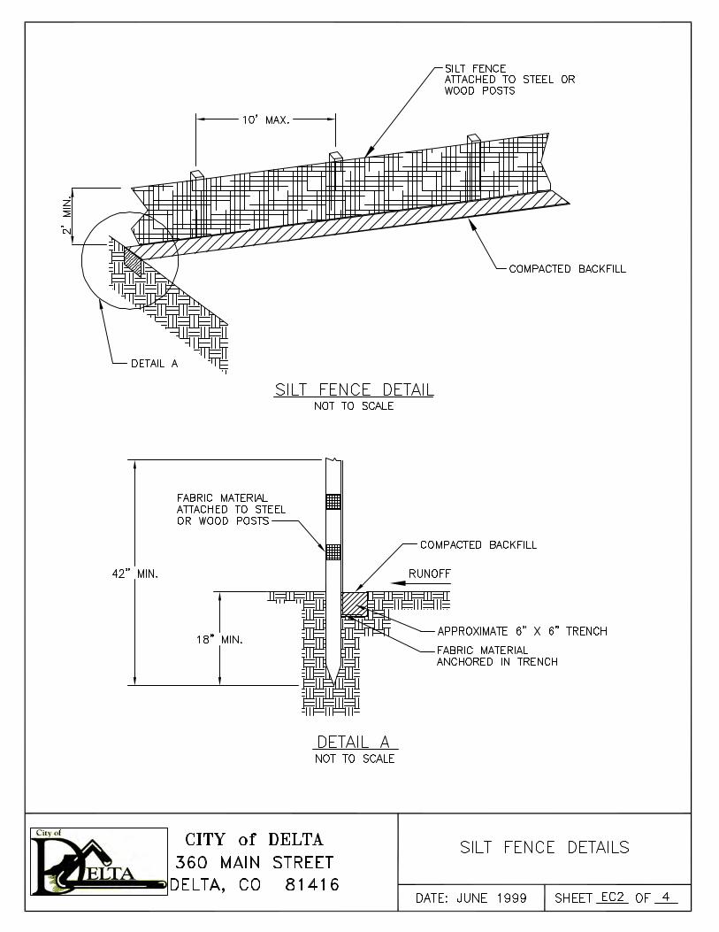


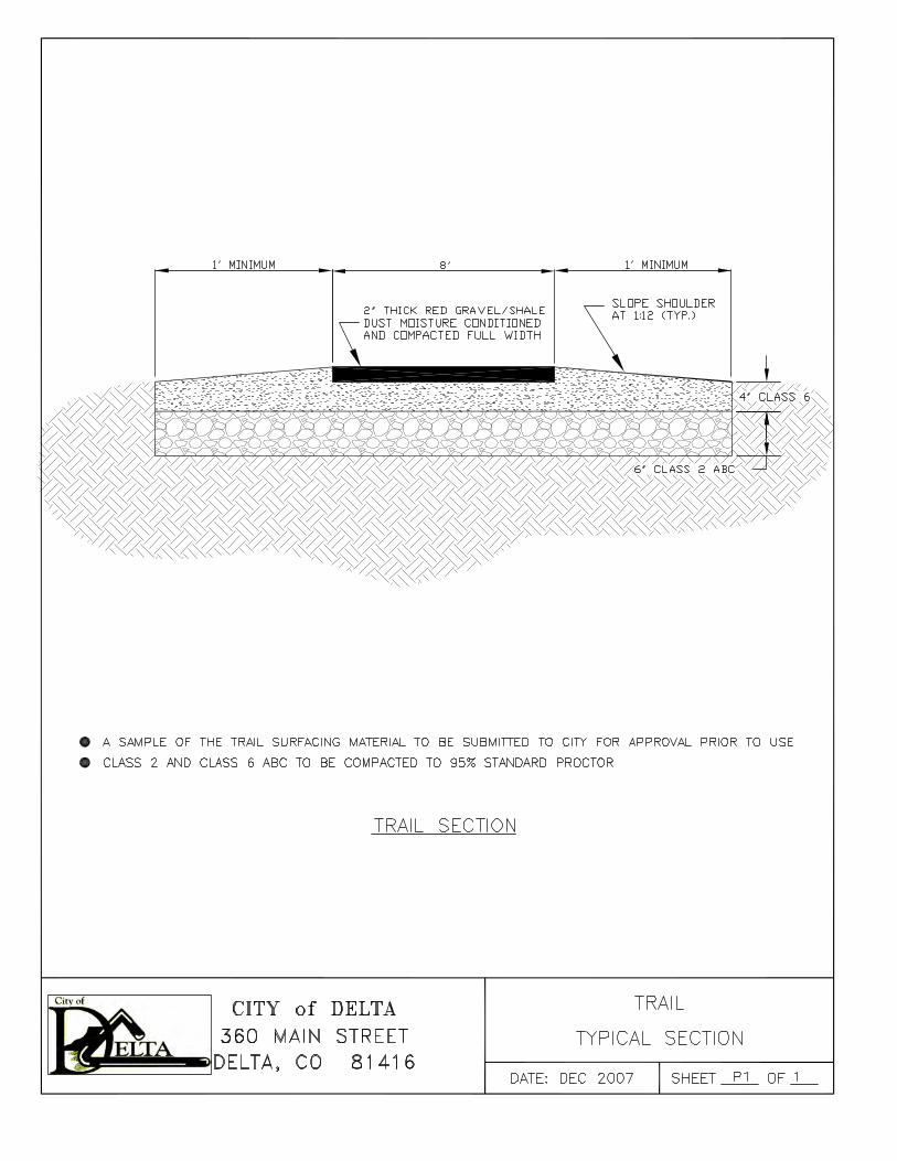

Approved Tree List
The following list is a guide to help you match the trees that are raised in our community, with proper planting and maintenance the listed trees will grow quite well. Remember to consult you local nursery or arborist about proper planting, watering, and general care of your tree. American Elm Catalpa Aristocrat Pear Ginko Bur Oak Goldenrain tree Hackberry White Ash Washington Hawthorn Green Ash Kentucky Coffee tree Austrian Pine Little leaf Linden Redbud Autumn Blaze Maple Honeylocust Crimson King Norway Maple American Linden Spring Snow Crabapple Non cotton bearing Poplar
London Plane Sycamore Lindens Norway Maple Autumn Purple Ash Quaking Aspen(very fragile) Lance leaf Cottonwood Canada Red Cherry Rocky Mtn. Maple Amber Maple Western Hackberry Red Maple Evergreen Trees
Pinyon Pine Ponderosa Pine Austrian Pine Concolor Fir Scotch Pine Colorado Blue Spruce (very salt intolerant)
Prohibited Trees: Russian Olive, Tamarisk, Lombardy Poplar, Siberian Elm, Boxelder Maple, and Cotton-bearing Cottonwood. These are but a small number of trees that will do well, however, you are encouraged to consult with your local nursery for other species that may tolerate our weather and salt conditions. Substitutions to this list must be approved in writing by the City prior to installation. Please contact the City of Delta’s Parks Department at 874-7973.
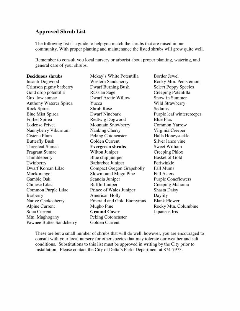
Approved Shrub List
The following list is a guide to help you match the shrubs that are raised in our community. With proper planting and maintenance the listed shrubs will grow quite well. Remember to consult you local nursery or arborist about proper planting, watering, and general care of your shrubs.
Deciduous shrubs
Insanti Dogwood Crimson pigmy barberry Gold drop potentilla Gro- low sumac Anthony Waterer Spirea Rock Spirea Blue Mist Spirea Forbel Spirea Lodense Privet Nannyberry Viburnum Cistena Plum Butterfly Bush Threeleaf Sumac Fragrant Sumac Thimbleberry Twinberry Dwarf Korean Lilac Mockorange Gamble Oak Chinese Lilac Common Purple Lilac Barberry Native Chokecherry Alpine Current Squa Current Mtn. Maghogany Pawnee Buttes Sandcherry
Mckay’s White Potentilla Western Sandcherry Dwarf Burning Bush Russian Sage Dwarf Arctic Willow Yucca Shrub Rose Dwarf Ninebark Redtwig Dogwood Mountain Snowberry Nanking Cherry Peking Cotoneaster Golden Current Evergreen shrubs Wilton Juniper Blue chip juniper Barharbor Juniper Compact Oregon Grapeholly Slowmound Mugo Pine Scandia Juniper Bufflo Juniper Prince of Wales Juniper American Holly Emerald and Gold Euonymus Mugho Pine Ground Cover Peking Cotoneaster Golden Current
Border Jewel Rocky Mtn. Pentstemon Select Poppy Species Creeping Potentilla Snow-in Summer Wild Strawberry Sedums Purple leaf wintercreeper Blue Flax Common Yarrow Virginia Creeper Halls Honeysuckle Silver lance vine Sweet William Creeping Phlox Basket of Gold Periwinkle Fall Mums Fall Asters Purple Coneflowers Creeping Mahonia Shasta Daisy Daylily Blank Flower Rocky Mtn. Columbine Japanese Iris
These are but a small number of shrubs that will do well, however, you are encouraged to consult with your local nursery for other species that may tolerate our weather and salt conditions. Substitutions to this list must be approved in writing by the City prior to installation. Please contact the City of Delta’s Parks Department at 874-7973.

STANDARDS AND SPECIFICATIONS FOR THE DESIGN AND CONSTRUCTION OF PUBLIC
IMPROVEMENTS
Chapter 3
Water System
2010 EDITION

TABLE OF CONTENTS
CHAPTER 3
WATER SYSTEM
Page
3.00.00 INTRODUCTION ........................................................................................................................................... 1
3.01.00 INTERRUPTION OF SERVICE ................................................................................................................... 1 3.02.00 WATER BREAKS ......................................................................................................................................... 1
3.10.00 DESIGN CRITERIA....................................................................................................................................... 1
3.11.00 SCOPE ........................................................................................................................................................... 1 3.12.00 GENERAL ..................................................................................................................................................... 1 3.13.00 DESIGN FLOW ............................................................................................................................................. 2 3.14.00 WATER SYSTEM DESIGN REPORT ......................................................................................................... 2 3.15.00 OPERATING PRESSURES WITHIN THE DISTRIBUTION SYSTEM ..................................................... 2 3.16.00 PRESSURE REGULATING STATIONS ..................................................................................................... 2 3.17.00 SIZING OF MAINS ....................................................................................................................................... 2
3.17.01 Distribution Mains ...................................................................................................................................... 2
3.17.02 Transmission Mains .................................................................................................................................... 2
3.18.00 SYSTEM LAYOUT ...................................................................................................................................... 3 3.18.01 General ....................................................................................................................................................... 3
3.18.02 Waterline Crossing Over or Under A Sanitary Sewer Line ........................................................................ 3
3.18.03 Waterline Crossing Over or Under A Storm Sewer Line ............................................................................ 3
3.18.04 Waterline Crossing Over A Waterline ........................................................................................................ 3
3.18.05 Limits On Vertical Separation .................................................................................................................... 3
3.19.00 EASEMENTS ................................................................................................................................................ 4 3.20.00 FUTURE CONNECTIONS ........................................................................................................................... 4 3.21.00 SERVICES .................................................................................................................................................... 4 3.22.00 TRANSMISSION MAINS ............................................................................................................................ 4 3.23.00 UNLAWFUL CONNECTIONS .................................................................................................................... 5 3.24.00 APPURTENANCES ...................................................................................................................................... 5
3.24.01 Valves .......................................................................................................................................................... 5
3.24.02 Fire Hydrants .............................................................................................................................................. 5
3.24.03 Thrust Blocks .............................................................................................................................................. 6
3.24.04 Meters ......................................................................................................................................................... 6
3.24.05 Fire Protection Service Line ....................................................................................................................... 6
3.24.06 Valve Vaults ................................................................................................................................................ 6
3.24.07 Manholes ..................................................................................................................................................... 7
3.24.08 Cross-Connection Prevention Device ......................................................................................................... 7
3.30.00 CONSTRUCTION SPECIFICATIONS ....................................................................................................... 7
3.31.00 EXCAVATION, TRENCHING AND BACKFILLING................................................................................ 7 3.32.00 BEDDING ..................................................................................................................................................... 7 3.33.00 PIPELINE INSTALLATION ........................................................................................................................ 7
3.33.01 General ....................................................................................................................................................... 7
3.33.02 Pipe ............................................................................................................................................................. 8
3.33.03 Fittings ........................................................................................................................................................ 9
3.34.00 VALVE AND VALVE BOX INSTALLATIONS ....................................................................................... 10 3.35.00 THRUST BLOCKS ..................................................................................................................................... 10 3.36.00 CONNECTION TO EXISTING MAINS .................................................................................................... 10 3.37.00 FIRE HYDRANT INSTALLATION ........................................................................................................... 10 3.38.00 TAPS ............................................................................................................................................................ 11 3.39.00 METER INSTALLATION .......................................................................................................................... 11 3.40.00 TESTS .......................................................................................................................................................... 11

3.40.01 General ..................................................................................................................................................... 11
3.40.02 Filling and Venting Lines .......................................................................................................................... 12
3.40.03 Disinfection ............................................................................................................................................... 12
3.40.04 Flushing the Main ..................................................................................................................................... 12
3.40.05 Pressure Test ............................................................................................................................................. 12
3.50.00 MATERIALS ................................................................................................................................................. 13
3.51.00 GENERAL ................................................................................................................................................... 13 3.52.00 PIPE ............................................................................................................................................................. 14
3.52.01 Polyvinyl Chloride Pipe (PVC) .......................................................................................................................... 14
3.53.00 FITTINGS .................................................................................................................................................... 14 3.54.00 VALVES ...................................................................................................................................................... 15
3.54.01 General ..................................................................................................................................................... 15
3.54.02 Gate Valves ............................................................................................................................................... 15
3.54.03 Valve Boxes ............................................................................................................................................... 15
3.55.00 FIRE HYDRANTS ...................................................................................................................................... 15 3.56.00 BLOW-OFFS ............................................................................................................................................... 15 3.57.00 MANHOLES ............................................................................................................................................... 16 3.58.00 AIR VACS ................................................................................................................................................... 16 3.59.00 ENCASEMENT........................................................................................................................................... 16
3.59.01 Concrete .................................................................................................................................................... 16
3.59.02 Polyethylene Wrap .................................................................................................................................... 16
3.60.00 METERS ...................................................................................................................................................... 16 3.61.00 PRESSURE-REDUCING VALVE ............................................................................................................. 16 3.62.00 COMBINATION AIR/VACUUM VALVES .............................................................................................. 17 3.63.00 RESTRAINING SYSTEM .......................................................................................................................... 17
3.63.01 Harness Rods ............................................................................................................................................ 17
3.63.02 Megalug .................................................................................................................................................... 17
3.64.00 CONCRETE REINFORCEMENT .............................................................................................................. 17 3.65.00 BACKFLOW PREVENTION DEVICE ...................................................................................................... 17 3.66.00 REPAIR CLAMPS ...................................................................................................................................... 18

1
CHAPTER 3
WATER SYSTEM
3.00.00 INTRODUCTION
All water distribution systems constructed within the City of Delta shall comply with the requirements of these STANDARDS AND SPECIFICATIONS and may include special criteria established by the City for overall hydraulics of the water utility system. All work performed according to this section must comply with the general requirements contained within Chapter 1 and the acceptance requirements of Chapter 10. Special criteria shall be outlined at pre-design meetings, as determined necessary by the City.
3.01.00 INTERRUPTION OF SERVICE
The City's Water Utility Department will operate all existing valves, hydrants, blow-offs and curb stops. NO VALVE OR OTHER CONTROL DEVICE ON THE EXISTING PUBLIC SYSTEM WILL BE OPERATED FOR ANY PURPOSE BY ANYONE OTHER THAN THE CITY. Forty-eight (48) hours prior to the interruption of service, the Responsible Party shall notify all users whose service will be interrupted in order for them to make provisions for necessary water storage. For water mains servicing commercial areas (i.e., restaurants) work affecting the shutdown shall only be performed between the hours of 1:00 a.m. and 5:00 a.m. No line in service will be shutdown for more than a four-hour period at one time. Prior approval by the City is required for all shutdowns. Wet taps shall be used unless unfeasible and be completed by a company specializing in this type of work.
3.02.00 WATER BREAKS
If notification prior to shutdown is impossible, the Responsible Party shall notify all users within one hour after the shutdown. Since prior notification was not possible, it will be the responsibility of the Responsible Party to supply potable water to the users affected. The Responsible Party shall also contact the City's Utilities Department and Fire Department in reference to this emergency shutdown within one hour.
3.10.00 DESIGN CRITERIA
3.11.00 SCOPE
It is the intent of this "design criteria" section to provide sufficient detailed information to enable the Engineer for the Responsible Party to correctly and efficiently design the overall water system for a particular development. If the City deems it appropriate to require the engineered design of a water system, criteria shall be made available to the Engineer to provide a design acceptable to the City. Any deviation from these STANDARDS AND SPECIFICATIONS must be approved in writing by the City.
3.12.00 GENERAL
The water system shall be designed by a professional engineer registered in the State of Colorado utilizing the most current technical standards along with good, sound engineering judgment throughout the design process. The design process includes the submittal of construction drawings for review and approval by the City.
Construction drawing submittals shall be in conformance with Section 1.40.00 of these STANDARDS AND SPECIFICATIONS.

2
At the completion of the project, the engineer shall provide the City with two (2) sets of wet stamped record drawings in conformance with Section 1.40.00 of these STANDARDS AND SPECIFICATIONS.
3.13.00 DESIGN FLOW
The flows used to design the water system for a particular development vary depending on the type of development. A list of criteria to be used in the preparation of all water system analysis will be provided if the City deems it appropriate for the design of the water system.
3.14.00 WATER SYSTEM DESIGN REPORT
A water system design report shall be submitted to the City according to the format provided by the City.
3.15.00 OPERATING PRESSURES WITHIN THE DISTRIBUTION SYSTEM
Pressure within the distribution system shall be a minimum of 40 pounds per square inch during the maximum hour demand and a maximum of 110 pounds per square inch static pressure at the main. The maximum pressure fluctuation at any location in the distribution system between maximum hour demand and minimum hour demand shall not exceed 30 pounds per square inch.
3.16.00 PRESSURE REGULATING STATIONS
Pressure-regulating valve (PRV) installations are used to control pressure between distribution zones. When main extension plans are submitted for review, the need for a pressure-regulating valve installation shall be determined by the Responsible Party's engineer and shall be based on existing zones and the existing distribution system. Plans shall be submitted as part of the utility study indicating size, type, and location of the PRV installation. All calculations shall be submitted to the City for review. A PRV may be required at the direction of the City.
3.17.00 SIZING OF MAINS
3.17.01 Distribution Mains
All mains shall be sized large enough to provide for domestic, irrigation, and fire protection flows to the area serviced according to the water system design report submitted to the City. The maximum acceptable headloss for six, eight and twelve-inch mains is two feet per thousand feet of main. The minimum diameter for water mains in residential areas, including cul-de-sacs, shall be 8 inches. All schools, shopping centers, business parks, industrial parks, and high-density residential areas shall be looped with mains at least 8 inches in diameter. All waterlines shall be looped and dead end lines will not be permitted unless approved by the City representative. Oversizing of mains may be required by the City and any cost involved in the oversizing of mains shall be the responsibility of the City.
3.17.02 Transmission Mains
All transmission mains shall be sized according to these STANDARDS AND SPECIFICATIONS.

3
3.18.00 SYSTEM LAYOUT
3.18.01 General
All mains shall be installed in dedicated rights-of-way or public easements. Water main installation in easements between single-family residential lots will only be allowed for the purpose of looping a water main at the end of a cul-de-sac. Under no circumstances should waterlines be installed parallel to and directly below any concrete such as sidewalks, curbs, or gutters. Lines shall normally be located 5 feet north or east of street centerline, or 5 feet north or east of a curbed median, unless otherwise approved by the City. The minimum depth of cover for water mains from the final approved grade of the surface to the top of the water main, shall be 4 feet. Where final grades have not been established, mains shall be installed to a depth great enough to insure 4 feet of cover below the approved future grade. The maximum depth of cover for water mains shall be 6 feet below the final approved grade of the surface unless approved otherwise, in writing, by the City.
Water mains shall be laid a minimum of ten feet horizontally from any existing or proposed utility. Upon written approval by the City, a water main may be laid closer than ten feet to a parallel sewer main if it is laid in a separate trench and if the elevation of the invert of the water main is at least 18 inches above the crown of the sewer main and, in addition, Sections 3.18.02-3.18.07 are met. Water mains shall be designed such that they extend the entire frontage of the property to be served or as approved by the City.
When the water main passes under a highway, railroad, or waterway, there shall be a minimum of five feet of cover and a steel casing shall be installed in accordance with the detail drawing in the Appendix of this chapter. The steel casing shall extend the entire width of the right-of-way or easement of the crossing structure or as directed by the City. In all cases, valves shall be located such that the water main at such crossings can be completely isolated without interruption of any services.
3.18.02 Waterline Crossing Over or Under A Sanitary Sewer Line
When there is less than 18 inches of vertical clearance between the water main and the sanitary sewer the sanitary sewer shall be encased in concrete a minimum of ten (10) feet on each side of the centerline of the crossing or polyvinyl chloride pressure pipe in accordance with AWWA C900 may be used.
3.18.03 Waterline Crossing Over or Under A Storm Sewer Line
When there is less than 18 inches of vertical clearance between the water main and the storm sewer each joint of the storm sewer within ten (10) feet of the centerline of the crossing shall be encased in concrete.
3.18.04 Waterline Crossing Over A Waterline
When there is less than 18 inches of vertical clearance, both waterlines shall be polyvinyl chloride pressure pipe in accordance with AWWA C900 or ductile iron pipe.
3.18.05 Limits On Vertical Separation
Under no circumstances shall the vertical clearance between any lines involving a waterline,

4
sanitary sewerline, or storm sewer be less than 12 inches without written approval from the City.
3.19.00 EASEMENTS
All water mains not in public right-of way shall be in an easement that has a width of at least two times the depth to the pipe invert. The minimum easement shall be 20 feet. Site-specific circumstances may dictate the need for wider easements. The centerline of the main shall be located a minimum of 10 feet from and parallel to the edge of the easement. Meters and fire hydrants not installed within the right-of-way will require an easement dedication ten feet wide and extending three feet behind the meter or fire hydrant. If the meter or fire hydrant easement is longer than ten feet, then the width of the easement shall be a minimum of 20 feet. The fire hydrant shall be centered in such easements. Neither landscaping (except grass and private irrigation systems) nor permanent structures (sheds, buildings, etc.) shall be placed in the easement.
The easement agreement, provided by the City, shall state that any temporary structures (including paving and fencing) placed in the easement shall be removed and replaced by the owner of the land, at their expense, when requested by the City so that maintenance can be performed. The owner of the land shall agree to hold the City of Delta harmless for any replacement of structures removed from the easement.
3.20.00 FUTURE CONNECTIONS
A fire hydrant, in accordance with the detail drawing in the Appendix of this chapter, is required at the end of any water main that terminates and is anticipated to be extended in the future, unless otherwise approved. When a future main extension is anticipated, the main shall be valved so that only one valve will have to be closed when the main is extended. The valve shall be placed in order that no disruption to existing water service will be experienced by any water customers. The valve shall be restrained so when the one valve is closed and the line to be extended is exposed, the valve will not blow off. Restraint shall be made by the use of a mechanical joint anchoring tee (swivel tee), cross, or by installing a minimum of two full lengths of pipe on the extension side of the valve. No service taps shall be allowed on a main that can be extended in the future between the single valve to be closed and the dead end.
3.21.00 SERVICES
Each structure shall be served by a separate service line and meter. No pressure booster facility of any kind shall be allowed on any service line between the public main and the meter. All service line pressure booster facilities shall be privately owned and maintained. Water service lines shall be located a minimum of 10 feet away from all sewer services (measured horizontally).
3.22.00 TRANSMISSION MAINS
All water mains 12 inches and larger in diameter shall be classified as "transmission mains."
All transmission mains shall have air and vacuum release valves installed at all high points on the line, and on each side of gate valves in accordance with the detail drawing in the Appendix of this chapter.
All transmission mains shall have blow-off assemblies installed at all low points on the line, constructed in accordance with the detail drawing in the Appendix of this chapter.
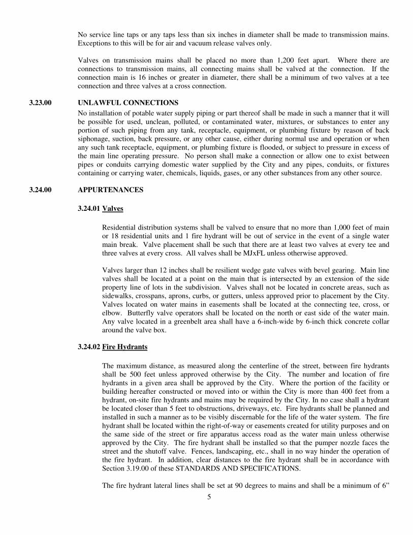
5
No service line taps or any taps less than six inches in diameter shall be made to transmission mains. Exceptions to this will be for air and vacuum release valves only. Valves on transmission mains shall be placed no more than 1,200 feet apart. Where there are connections to transmission mains, all connecting mains shall be valved at the connection. If the connection main is 16 inches or greater in diameter, there shall be a minimum of two valves at a tee connection and three valves at a cross connection.
3.23.00 UNLAWFUL CONNECTIONS
No installation of potable water supply piping or part thereof shall be made in such a manner that it will be possible for used, unclean, polluted, or contaminated water, mixtures, or substances to enter any portion of such piping from any tank, receptacle, equipment, or plumbing fixture by reason of back siphonage, suction, back pressure, or any other cause, either during normal use and operation or when any such tank receptacle, equipment, or plumbing fixture is flooded, or subject to pressure in excess of the main line operating pressure. No person shall make a connection or allow one to exist between pipes or conduits carrying domestic water supplied by the City and any pipes, conduits, or fixtures containing or carrying water, chemicals, liquids, gases, or any other substances from any other source.
3.24.00 APPURTENANCES
3.24.01 Valves
Residential distribution systems shall be valved to ensure that no more than 1,000 feet of main or 18 residential units and 1 fire hydrant will be out of service in the event of a single water main break. Valve placement shall be such that there are at least two valves at every tee and three valves at every cross. All valves shall be MJxFL unless otherwise approved.
Valves larger than 12 inches shall be resilient wedge gate valves with bevel gearing. Main line valves shall be located at a point on the main that is intersected by an extension of the side property line of lots in the subdivision. Valves shall not be located in concrete areas, such as sidewalks, crosspans, aprons, curbs, or gutters, unless approved prior to placement by the City. Valves located on water mains in easements shall be located at the connecting tee, cross, or elbow. Butterfly valve operators shall be located on the north or east side of the water main. Any valve located in a greenbelt area shall have a 6-inch-wide by 6-inch thick concrete collar around the valve box.
3.24.02 Fire Hydrants
The maximum distance, as measured along the centerline of the street, between fire hydrants shall be 500 feet unless approved otherwise by the City. The number and location of fire hydrants in a given area shall be approved by the City. Where the portion of the facility or building hereafter constructed or moved into or within the City is more than 400 feet from a hydrant, on-site fire hydrants and mains may be required by the City. In no case shall a hydrant be located closer than 5 feet to obstructions, driveways, etc. Fire hydrants shall be planned and installed in such a manner as to be visibly discernable for the life of the water system. The fire hydrant shall be located within the right-of-way or easements created for utility purposes and on the same side of the street or fire apparatus access road as the water main unless otherwise approved by the City. The fire hydrant shall be installed so that the pumper nozzle faces the street and the shutoff valve. Fences, landscaping, etc., shall in no way hinder the operation of the fire hydrant. In addition, clear distances to the fire hydrant shall be in accordance with Section 3.19.00 of these STANDARDS AND SPECIFICATIONS.
The fire hydrant lateral lines shall be set at 90 degrees to mains and shall be a minimum of 6”

6
diameter. The fire hydrant lateral line shall be no more than 70 feet in length from the main. No horizontal bends or offsets shall be used in fire hydrant lateral lines. Under no circumstances shall any tap be made on a fire hydrant lateral line.
3.24.03 Thrust Blocks
All bends, tees, plugs, dead-ends, wet taps (in certain cases), hydrants, and blow-offs shall be designed and constructed with concrete thrust blocks. If the soil-bearing strength is unknown, the soil-bearing capacity used in design shall be 1,500 pounds/square foot. Refer to the detail drawings in the Appendix of this chapter. Special care shall be taken with fire hydrant thrust blocks so as to not hinder drainage of the fire hydrant barrel via the weep holes.
3.24.04 Meters
All meter installations shall be performed by the City. Public water meter installations inside any buildings are prohibited unless otherwise approved, in writing, by the City. Meters shall be located at property line within easements. The City encourages the installation of a valve shut off on the property owners side of the meter in order to allow for the shut off of water during water break emergencies.
All water meters connected to the City of Delta's utility system shall be the property of the City. Under no circumstances shall anyone other than City personnel remove a water meter once the pit or vault has been inspected and approved. No connections shall be made in the meter pit other than those related to the meter and bypass. Irrigation system connections shall either have an irrigation tap or be made downstream from the meter and a minimum of five feet from the meter pit or vault.
For any installation where special or unusual conditions might exist, detailed drawings, accompanied by a letter of explanation, shall be submitted to the City for review and approval.
There shall be no electrical wiring allowed in any water meter pit or vault unless authorized, in writing, by the City.
Inspections of all residential pits and commercial pits or vaults shall be conducted by the City. Locations and details for commercial pits or vaults shall be reviewed and approved by the City.
All meter sizes for residential, commercial or industrial use shall be determined by a Professional Engineer registered in the State of Colorado and calculations submitted to the City for review and approval.
3.24.05 Fire Protection Service Line
Valves on newly constructed fire lines shall be located on the tee at the main line. The owner shall maintain all private fire lines beginning at but not including this valve. All fire sprinkler taps shall be installed with an approved cross-connection protection device as specified in Section 3.24.08. A property requiring a domestic service line and a fire protection service line will have separate taps for each. The City does not charge a “tapping fee” for fire sprinkler lines, but owner is responsible and shall pay all of the cost associtated with installation of required taps. Refer to the detail drawing in the Appendix of this chapter.
3.24.06 Valve Vaults
All valves larger than 12 inches shall be installed in a vault in accordance with the detail

7
drawings in the Appendix of this chapter. All valve vaults shall be capable of withstanding AASHTO H-20 highway loading. The vault shall also have lift hooks in the roof for valve removal inside the vault.
Vaults shall be made water proof after construction by use of sealants, epoxies or other approved methods. All vaults shall be designed with wall sleeves and link seal and be capable of handling thrusts caused by removing valves. All vent pipes for vaults shall be installed in conformance with the detail drawings in the Appendix of this chapter.
3.24.07 Manholes
Manholes shall be installed at all pressure regulating valve, permanent blow-off, and air release valve locations in accordance with the detail drawing in the Appendix of this chapter.
3.24.08 Cross-Connection Prevention Device
To protect the City’s potable water supply mains against cross-connection contamination (backflow and backsiphonage) an approved cross-connection control device shall be installed at any point where the possibility of contamination due to cross-connection exists. An “approved device” is one which meets the standards of the University of Southern California Foundation for Cross-Connection Control and Hydraulic Research (USC FCCCHR). Any cross-connection control device required by the City shall be installed, maintained and tested annually as required by the Colorado Department of Public Health and Environment (CDPHE) Cross-Connection Control Program, and such installation shall conform to International Plumbing Code standards. Authority to implement and maintain this cross-connection control program is contained in, but not limited to the following:
1) Colorado Primary Drinking Water Regulations, Article 12, Hazardous Cross-Connection
2) 2002 Edition of the International Plumbing Code (or more recently adopted version) 3) Colorado Cross-Connection Control Manual, CDPHE
3.30.00 CONSTRUCTION SPECIFICATIONS
3.31.00 EXCAVATION, TRENCHING AND BACKFILLING
Excavation, trenching and backfilling shall be done in accordance with Chapter 9 of these STANDARDS AND SPECIFICATIONS.
3.32.00 BEDDING
Granular bedding material used shall meet the requirements of Chapter 9 of these STANDARDS AND SPECIFICATIONS. Bedding shall be placed to six inches below the bottom of the pipe and shall be placed around the sides of the pipe and to a minimum of 12 inches above the top of the pipe and in accordance with the detail drawing in the Appendix of this chapter.
3.33.00 PIPELINE INSTALLATION
3.33.01 General
The City shall be notified at least 48 hours in advance of any pipe installation. The Responsible

8
Party shall notify and arrange for all utility locates prior to excavation. No pipes shall be backfilled until they have been inspected and approved by the City. Alignment and grade of the pipe and the location of fittings, valves, and hydrants shall be staked under the supervision of a professional surveyor registered in the State of Colorado.
Proper implements, tools, and facilities shall be provided and used by the Responsible Party for the safe and convenient execution of the work. All pipe fittings, valves, and hydrants shall be carefully lowered into the trench by means of a derrick, ropes, or other suitable tools or equipment to prevent damage to water main materials and protective coatings and linings. Chains or cables shall not be used for handling pipe with protective coatings. Under no circumstances shall water main materials be dropped or dumped into the trench.
All pipe and fittings shall be carefully examined for cracks and other defects immediately before installation. The groove in the bells of the pipe shall be full and continuous or the pipe will be rejected. Defective pipe or fittings shall be removed from the job site within 24 hours of notification by the City. All foreign matter or dirt shall be removed from the interior and ends of pipe and accessories before they are lowered into position in the trench and prior to connection. Every precaution shall be taken to prevent foreign material and trench water from entering the pipe and fittings. During construction, the Responsible Party shall provide and maintain adequate equipment to properly remove and dispose of all water entering the trench and any other part of the work.
3.33.02 Pipe
Immediately before joining two lengths of pipe, the inside of the bell and the outside of the spigot end, the gasket shall be thoroughly cleaned, and, if performing disinfection by tablet method, as described in Section 3.40.03, dry chlorinating tablets providing 65% hypochlorite shall be attached to the top end of the pipe with water-soluble permatex or an adhesive appropriate for potable water. A thin film of gasket lubricant shall be applied to the inside face of the gasket and the spigot end of the pipe. The spigot end of the pipe shall be placed in the bell with care to prevent the joint from contacting the ground. The joint shall be completed by pushing the pipe home by hand with a slow steady pressure, without jerky or jolting movements. Pipe furnished without a depth mark shall be marked before assembly to ensure insertion to the full depth of the joint. The pipe shall then be properly set and brought to correct line and grade. After installation of the polyethylene protective wrap, if required, the pipe shall be secured in place by installation of bedding material and backfill, in accordance with Chapter 9 and the detailed drawings in the Appendix of this chapter.
Deflection from a straight line or grade, as required by horizontal or vertical alignments or offsets, shall not exceed the maximum allowable limits set by the manufacturer's specifications. If the alignment requires deflection in excess of the allowable deflection per joint, special bends, or a sufficient number of shorter lengths of pipe shall be furnished to provide angular deflections within the limits set forth, as approved, in writing, by the City.
All ductile iron pipe fittings and appurtenances shall be protected with minimum 8 mil polyethylene film wrap. Miscellaneous steel or other ferrous pipe for temporary blow-offs, etc., shall be similarly protected. Methods for applying the wrap shall conform to the detail drawing in the Appendix of this chapter.
At times when installation is not in progress, the open ends of the pipe shall be closed with a watertight plug. Cutting of pipe for inserting valves, fittings, or closure pieces shall be done in

9
a neat and workmanlike manner without damage to the pipe or lining, leaving a smooth end at right angles to the axis of the pipe. Pipe ends shall be smooth and beveled with a file or other tools according to the pipe manufacturer's recommendations. Extra care should be used in handling PVC pipe during cold weather due to the reduced flexibility and impact resistance as temperatures approach and drop below freezing. PVC pipe to be stored outside and exposed to sunlight for more than 30 days shall be covered with an opaque material such as canvas. Clear plastic sheets shall not be used to cover the pipe. Air circulation shall be provided under the covering. Any over-exposed pipe, as determined by the City, will not be permitted for installation.
During the backfilling of all waterline trenches, a 2-inch-wide tape labeled "Waterline Buried Below" shall be placed in the trench backfill 1 foot above at the top of the select fill and directly over the pipe.
In addition to the tape mentioned above, all PVC waterline installations shall include the installation of a single, 14or 16-gauge, insulated copper tracing wire taped to the top of the pipe. The tracing wire shall be one piece and installed in a continuous run between valves. Tracer wire shall terminate up at the base of a fire hydrant, unless otherwise approved.
3.33.03 Fittings
Pipes shall be connected to valves and fittings by mechanical joints unless specified differently in the approved drawings. For approved slip-on joints, the joint shall be assembled with a ratchet jack or other approved method in a manner that does not cause any damage to the pipe. Both the spigot and bell must be thoroughly clean and free from tar or other coatings and rust. For mechanical joint pipe, the last 8 inches of the outside of the spigot end of the pipe and the inside of the bell of all fittings and gate valves shall be thoroughly cleaned to remove oil, grit, tar (other than standard coating), and other foreign matter from the joint and then a thin film of gasket lubricant shall be applied. The cast iron gland shall then be slipped on the spigot end of the pipe with the lip extension of the gland toward the bell of the fitting. Gasket lubricant shall be applied to the rubber gasket and placed on the spigot end of the pipe with the thick edge towards the gland.
After the spigot end of the pipe is placed into the bell and fully inserted the gasket shall be pressed into place within the bell so it is even around the entire joint. After the gland is positioned behind the gasket, the Responsible Party shall install all bolts and nuts and tighten them with a torque wrench. Nuts spaced 180 degrees apart shall be tightened alternately to produce equal pressure on all parts of the gland.
Jointing shall be done, unless specifically excepted above, in accordance with AWWA Specification C-111 for a mechanical joint for cast iron pressure pipe and fittings.

10
3.34.00 VALVE AND VALVE BOX INSTALLATIONS
In addition to the jointing requirements mentioned in Section 3.33.03 of these STANDARDS AND SPECIFICATIONS, the additional requirements of this section shall apply. Valves and valve boxes shall be installed where shown on the approved drawings and as directed by the City. Valve boxes shall be firmly supported, centered, and plumbed over the wrench nut of the valve with the box cover at or minus 1/2-inch within the surface of the finished pavement or at such other elevation as may be directed by the City. Extensions to within 4 feet of the finished grade shall be provided for valves installed with more than 4 feet of cover. Earth fill shall be carefully tamped around each valve box to a minimum distance of 4 feet on all sides of the box, or to the undisturbed trench face if less than 4 feet. Valves shall have the interiors cleaned of all foreign matter before and after installation.
Gear cases shall be tightened and the valve shall be inspected in opened and closed positions to insure that all parts are in working condition prior to installation. The cases shall be supported by bricks or other means to prevent any shock or stress being transmitted to the valve.
3.35.00 THRUST BLOCKS
The Responsible Party shall excavate as required to ensure that the thrust blocks are placed against undisturbed soil and shall form the sides of the thrust block to provide the size and shape required. When it is impossible, because of over excavation or other causes, to pour a thrust block against undisturbed earth, harness rods shall be used to anchor the fittings to the main in addition to the thrust block and as required by the City. After the concrete has been placed and has set, the Responsible Party shall remove all forming materials prior to backfilling around the thrust block. Concrete for the thrust blocks shall comply with provisions set forth in Chapter 7 of these STANDARDS AND SPECIFICATIONS
The blocking shall be placed so that the pipe and fitting joints will be accessible for repair. A bond breaker shall be placed between the fittings and the thrust block. Extra care for fire hydrant thrust blocks should be taken so as to not block proper drainage of the fire hydrant barrel from the weep holes. Backfill may be placed over the thrust blocks once the surface has set sufficiently to resist the weight of the backfill. However, no tamping or compacting shall be allowed above the thrust block for a minimum of 24 hours after placement. Concrete must set a minimum of 48 hours prior to the initial filling of the line.
3.36.00 CONNECTION TO EXISTING MAINS
At locations where connections to existing water mains are to be installed, the Responsible Party shall locate the existing mains, both vertically and horizontally, and shall verify their exact size in advance of the time scheduled for making the connections. The Responsible Party shall notify and schedule the connection with the City. Wet tap connections are preferable so as to minimize disruption of service to the system. Wet taps shall be completed by a company specializing in this type of connection. In the event a wet tap is not feasible, then every step should be taken to minimize system downtime. Prior to connecting to existing water mains, the Responsible Party shall have all men, materials, and equipment ready to connect the fitting to the existing main to keep the shut-off time to a minimum. As soon as possible after making the connections, the Responsible Party shall flush the connection to prevent any contamination of the existing facilities. The Responsible Party shall take every precaution necessary to prevent dirt or debris from entering the main.
3.37.00 FIRE HYDRANT INSTALLATION
Immediately before installation of a hydrant, the following operations shall be performed:

11
(A) The hydrant shall be thoroughly inspected for any defects or damage. (B) The hydrant interior shall be thoroughly cleaned. (C) The hydrant shall be opened and closed as many times as necessary to determine that all parts
are in proper working order, valves are seating properly and the drain valve is operating freely. Hydrants shall be set so that a minimum of 4 feet of cover is provided for the lateral line and the nozzles are a minimum of 18 inches above finished grade. Each hydrant shall be set on a concrete foundation at least 18 inches by 18-inches and 6 inches thick. Each hydrant shall be blocked against the end of the trench with a concrete thrust block. If the trench is unstable then the hydrant shall be mechanically restrained from the tee at the main to the hydrant in addition to the thrust block. Hydrants shall be orientated such that the pumper nozzle shall face the street/fire access/parking area to which it serves. Each hydrant shall have drain holes with a minimum 18-inch-thick layer of 1-1/2-inch (minimum) washed rock beneath them. A sheet of 8-mil polyethylene shall be placed over the washed rock to prevent dirt from filling the rock. All hydrants shall stand plumb and shall be connected to the street main by a minimum 6-inch lateral line. The fire hydrant base shall be adjusted to not more than 3 inches nor less than 2 inches above the approved finished grade. The maximum allowable height of extensions on hydrants is 12 inches. No hydrant lateral shall be installed any deeper than 6 feet from the top of the approved finished grade.
Hydrants shall have a traffic break-away feature in the barrel at the ground line. Depending upon hydrant location, the use of steel posts filled with concrete may be required for protection, as specified by the City. In areas where the hydrant bottom is installed below ground water, a larger area, 2 times, of 1-1/2-inch (minimum) washed rock enclosed with 8-mil polyethylene shall be installed to insure proper drainage. All other requirements shall be as shown on the detail drawing in the Appendix of this chapter.
3.38.00 TAPS
The size of tap shall be approved and/or determined by the City.
All service taps shall be made by the City and the cost associated will be determined by the City Representative. Taps will not be made on a water main until the City has performed and the main has passed the pressure tests and clear water tests. Tapping mains may require digging out bedding material and cutting or removing part of the corrosion protective wrapping. After the taps are made, the wrap shall be repaired or replaced by the Responsible Party to protect both the service line and the main.
3.39.00 METER INSTALLATION
All meter installations shall be performed by the City. No connections shall be made in the meter pit other than those related to the meter and bypass. Irrigation system connections shall either have an individual irrigation tap or be made no closer than five (5) feet from the meter pit or vault on the downstream/customer side of the meter
3.40.00 TESTS
3.40.01 General

12
The Responsible Party shall disinfect and test all mains and fire lines regardless of existing conditions. This may include repairing existing facilities that must be included in the test and are not capable of holding test pressures. All thrust blocks or other bracing facilities shall be in place at least 48 hours before the initial filling of the line. All tests shall be administered by the City.
3.40.02 Filling and Venting Lines
All existing valves shall be operated by the City. The line shall be slowly filled with water and all air expelled from the pipe. Care shall be taken so that all available hydrants (including hydrant gate valves), air valves, and other vents are open during the filling of the line. Where hydrants or other vents are not available in the line, the Responsible Party shall make whatever taps are required for venting purposes. These taps shall be abandoned after testing, the taps removed and the main repaired by the use of a stainless steel repair clamp. The rate of filling the line shall not exceed the venting capacity of the vent. Except when disinfecting the line as indicated below with the chlorination tablet method.
3.40.03 Disinfection
The Responsible Party will be required to chlorinate every new water main installed. This shall be accomplished by one of two methods. In general, the tablet method shall be used. If approved by the City Director of Utilities, the continuous feed method may be used. The tablet method shall not be used if trench water or foreign material has entered the line. Since preliminary flushing cannot be used with this method, the tablet method shall only be used when scrupulous cleanliness has been executed. Attach dry chlorinating tablets that provide 65% hypochlorite to the top end of each pipe joint with water-soluble permatex or an adhesive appropriate for potable water during installation as per Section 3.33.02 of these Standards and Specifications. The number of tablets shall be sufficient to produce a dose of 50 mg/l of chlorine. Refer to Table 2 of AWWA C651-92 for the required minimum number of tablets. This table shows the number of tablets for 25 mg/l so the number of tablets needs to be adjusted accordingly. Tablets must also be placed on all hydrants. Introduce water into the pipeline at a rate no greater than 1 ft./sec. and retain the water in the pipeline for a period of 24 hours. The minimum residual chlorine shall be 5 mg/l throughout the entire length. The continuous feed method is accomplished by introducing water into the line at a constant rate while adding chlorine to maintain a minimum concentration of 50 mg/l. The chlorine must remain in the main for a contact period of not less than 24 hours after which the treated water shall contain no less than 25 mg/l of chlorine throughout the entire length. This procedure will continue until the minimum requirements of this section are met.
3.40.04 Flushing the Main
The entire line shall be flushed after the specified contact time, and after passing the disinfection test. Such flushing shall continue until the water is clear and meets the chlorine content of the existing line. The entire line, including hydrant leads, branch lines, and dead-end mains shall be flushed. The discharge of flushed water shall be accomplished such that no erosion will occur and with no harm to fish, animals, or plants. Procedures for discharge will be subject to the review of the City.
3.40.05 Pressure Test

13
After the pipe and appurtenances have been laid, the line has been backfilled, and all field-placed concrete has cured in accordance with Section 3.35.00 of these STANDARDS AND SPECIFICATIONS, each valved section, unless otherwise directed by the CITY, shall be subjected to a hydrostatic pressure of not less than 150 PSI or 1.5 times the normal working pressure of the lines, whichever is greater. The test duration shall be not less that one (1) hour. However, in all cases the test pressure shall be 50 percent over existing main pressure in the test area. Water added to maintain the pressure shall be per AWWA C-600. Allowable leakage shall be calculated according to the following formulas:
Ductile Iron Pipe:
L = N D /P and 7400 Polyvinyl Chlorine Pipe: L = Allowable Leakage in gallons per hour N = Total number of joints D = Nominal diameter of pipe in inches P = The square root of the average test pressure in PSI
When testing against existing closed valves, an additional leakage per closed valve of 0.0078 gal/hr/in. of nominal valve size may be allowed at the discretion of the City. Each valved section of pipe shall be slowly filled with water and the specified test pressure (measured at the highest point of elevation) shall be applied by means of a pump connected to the pipe in a satisfactory manner. The pump, pipe connection, gauges, and all necessary apparatus and labor shall be furnished by the Responsible Party. Gauges and measuring devices shall be approved by the City. Before applying the specified test pressure all air shall be expelled from the pipe. Any cracked or defective pipes, fittings, valves, or hydrants discovered in the pressure test shall be removed and replaced by the Responsible Party with sound material. After all visible leaks have been repaired, the pressure test shall be conducted again. Should testing show a leakage rate in excess of the rates above, the pipeline shall not be accepted. The pipeline shall be repaired, rechlorinated to meet the criteria in Section 3.40.03 of these STANDARDS AND SPECIFICATIONS and retested as described in this section until it meets the test requirements and is accepted by the City.
3.50.00 MATERIALS
3.51.00 GENERAL
Only polyvinyl chloride (PVC) pipe is approved for water main installations. Any other material
proposed must be approved by the City, in writing, prior to construction. Specifications for other
materials may be obtained from the City prior to installation. All materials furnished shall be
new and undamaged.
Acceptance of materials or the waiving of inspection thereof shall in no way relieve the Responsible Party of the responsibility for furnishing materials meeting the requirements of these STANDARDS AND SPECIFICATIONS. The City reserves the right to direct or deny the use of certain types of materials in specific circumstances. All materials delivered to the job site shall be adequately housed and protected to ensure the preservation of their quality for the work. The presence of any defects in any materials may constitute sufficient cause for rejection of the pipe or appurtenances. Rejected materials shall be removed from the work site unless otherwise permitted by the City.

14
3.52.00 PIPE
3.52.01 Polyvinyl Chloride Pipe (PVC)
All PVC pipe 8” diameter or greater shall meet the requirements of AWWA Specification C-900, and shall be Class 150 (SDR 14 or 18). All pipe shall be suitable for use as a pressure conduit. Provisions must be made for expansion and contraction at each joint with a rubber ring. The bell shall consist of an integral wall section with a solid cross-section rubber ring that meets the requirements of AWWA Specification C-900.
Standard laying lengths shall be twenty feet (20') for all sizes. Random lengths shall not be acceptable.
Each length of pipe shall bear the date manufactured, type, grade, length, manufacturer's name, and NSF seal of approval.
Pipe joints shall be made using an integral bell with an elastomeric gasket push-on type joint or using machined couplings of a sleeve type with rubber ring gaskets and machined pipe ends to form a push-on type joint.
Solvent cement joints are strictly prohibited.
The manufacturer shall furnish a certified statement that all of the specified tests and inspections have been made and the results thereof comply with the requirements of the applicable standard(s) herein specified. A copy of the certification shall be sent to the City upon request.
3.53.00 FITTINGS
All fittings shall be manufactured in accordance with the following AWWA Standards: -- C-104, "Cement Mortar Lining for Cast-Iron and Ductile Iron Pipe and Fittings for Water" -- C-153, "Gray Iron and Ductile Iron Fittings" -- C-111, "Rubber Gasket Joints for Cast-Iron and Ductile Iron Pressure for Pipe and Fittings" The following are additional requirements or exceptions to the standards mentioned above:
All fittings shall be furnished with a cement mortar lining of standard thickness as defined in the referenced specifications and given a seal coat of bituminous material. All fittings shall be furnished with mechanical joint, or flanged ends conforming to the referenced specifications and, in addition, the tee-head mechanical joint bolts and hexagon nuts shall be fabricated from a high strength, low alloy steel known in the industry as "Cor-Ten" or approved equal. Mechanical joint anchoring fittings (swivel) as approved by the City, in writing, may also be used. All fittings shall be 150 PSI pressure rating and shall conform to the dimensions and weights shown in the tables of the referenced specifications. All fittings shall be made from gray iron or ductile iron. The manufacturer shall prepare a certified statement that the inspection and all of the specified tests have been made and the results thereof comply with the requirements of the applicable standard(s) herein specified. A copy of the certification shall be sent to the City upon request.

15
3.54.00 VALVES
3.54.01 General
All valves shall open left (counterclockwise). All valves shall have a 2-inch-square operating nut. The extension stem shall be mechanically connected to the operating nut. All valves shall have a mechanical joint end and shall be delivered complete with bolts, glands and rubber gaskets. End connections shall be furnished with all necessary joint materials and shall have full opening flow way of equal diameter to the nominal size of the connecting pipe.
3.54.02 Gate Valves
Gate valves shall be Mueller 2360 Series Resilient Wedge #509. Valves 12” and greater shall be Mueller 2361 Series Resilient Wedge with bevel gearing. Valves shall be iron body, resilient-seated, gate valves with non-rising bronze stems with design, construction, and pressure rating conforming to AWWA Specifications C-500, with modifications specified herein. Stem seals shall be double "O" ring seals designed so that the seal above the stem collar can be replaced with the valve under pressure and in full open position.
All ferrous internal and external surfaces of the valves shall be coated to a minimum thickness of four mils. The coating shall be a two-part thermosetting epoxy suitable for field overcoating and for touch-up with the same coating material without special surface preparation. The supplier shall furnish detailed performance tests of adhesion, hardness and abrasion resistance of the furnished coatings when requested by the City. The coating shall have a successful record of performance in valves, pipe or other fittings for a minimum of ten years. The double-disk gate valves shall have all bronze internal mechanisms. The resilient seat gate valves shall have external break-off capabilities for over-torquing and positive stop to prevent over compression.
All bolts and nuts used in conjunction with valves shall be stainless steel, "Cor-Ten," or approved equal. All gate valves shall be installed with a valve box meeting the material specifications of Section 3.54.03 of these STANDARDS AND SPECIFICATIONS.
3.54.03 Valve Boxes
Valve box parts shall be Tyler type or approved equal and made of gray cast-iron, buffalo-type with No. 160 large, oval base. A 5-1/4-inch slip-type shaft is required with two (2) or three (3) pieces. Valve boxes shall be considered integral units and shall have at least 6 inches adjustment above and below the specified depth of cover over the pipe. Valve box lids shall be marked with the word "WATER," and shall have a lip or flange extending into the valve box shaft. The valve box shall be of a design that will not transmit shock or stress to the valve.
3.55.00 FIRE HYDRANTS
Hydrants shall be Mueller Super Centurion 250 or Kennedy or approved equal.
3.56.00 BLOW-OFFS
Temporary blow-offs shall be fabricated from a 2” gate valve with drain hole in pipe a minimum of 3’ below ground level. The valve shall be iron-bodied bronze mounted with a 2-inch square operating nut complete with valve box. The freeze-proof riser pipe shall be provided with drain pit, and well-greased

16
plug. The standard required blow-off for 12-inch and larger mains shall be a 6-inch or larger pipe with a gate valve meeting the material requirements of Section 3.54.02 of these STANDARDS AND SPECIFICATION and a manhole meeting the material requirements of Section 4.64.00 of these STANDARDS AND SPECIFICATIONS. This blow-off shall also conform to the detail drawing in the Appendix of this chapter.
3.57.00 MANHOLES
See Section 4.64.00 of these Standards and Specifications.
3.58.00 AIR VACS
Above-ground air vacs may be required by the City. If deemed appropriate to install air vacs information shall be provided by the City or submitted to and approved by the City.
3.59.00 ENCASEMENT
3.59.01 Concrete
All concrete shall be a minimum of Class A and shall conform to City standards for Portland cement concrete work as specified in Chapter 7 of these STANDARDS AND SPECIFICATIONS. All concrete encasements shall be a minimum of 6 inches thick from outside of pipe to outside of encasement.
3.59.02 Polyethylene Wrap
Polyethylene encasement material shall be a minimum of 8 mils thick and shall be Scotchrap No. 50 (polyvinyl), or approved equal. All polyethylene encasement material shall be manufactured in accordance with AWWA Standard C-105. The raw materials used to manufacture polyethylene film shall be Type I, Class A, Grade E-1 in accordance with ASTM Standard Designations D-1250.
3.60.00 METERS
All water meters shall be provided and installed by the City. Responsible Party shall be responsible for all trench work including backfill.
3.61.00 PRESSURE-REGULATING VALVE
All pressure-regulating valves (PRV) shall be Clay or approved equal. The valve shall be designed to reduce a high upstream pressure to a constant downstream pressure by way of a pilot control system. The pilot system shall control the main valve that shall be single-seated, hydraulically-operated, diaphragm, and globe-valve type. The valve seats shall be bronze except when subjected to sustained high velocities through the valve, the manufacturer recommends stainless steel seats. An indicator rod or flow tube shall be furnished as an integral part of the valve to show the position of the valve.
The valve shall be cast-iron body. Flanges and covers shall conform to ASTM Standard Designation A-50. Bronze castings or parts of internal trim shall conform to ASTM Standard B-61. All valves shall

17
be furnished with flanged ends and drilled in accordance with ANSI B-16.1 Class 125 specifications. Flanges shall be machined to a flat surface with a serrated finish in accordance with AWWA Standard C-207. The pilot valve for controlling operation of the main valve shall be single-seated, diaphragm-operated, and spring-loaded type. The pilot valve shall be attached to the main valve with piping and isolation valves arranged for easy access in making adjustments and also for its removal from the main valve while the main valve is under pressure. The pilot control system shall be cast bronzed ASTM B-62 with 303 stainless steel trim. The needle valve shall be all bronze and included with the main valve to control the speed of piston travel.
3.62.00 COMBINATION AIR/VACUUM VALVES
At high points in water mains where air can accumulate, provisions shall be made to remove air by means of air relief valves or other means approved by the City. Air valves shall be APCO or Valmatic automatic valves. Air relief valves shall be placed in vaults which allow convenient service of the valve and provide for adequate drainage. Valves shall be cast iron body, 3/4 inch minimum or as sized by air flow requirements, 12” above ground, pointed downward, and covered by #24 mesh.
3.63.00 RESTRAINING SYSTEM
3.63.01 Harness Rods
Harness rods shall be mild steel, ASTM Standard Designation A-36. Hex nuts shall be ASTM Standard Designation A-307, Grade A or B, hexagon heavy series.
3.63.02 Megalug
Mechanical joint restraint can be accomplished by the use of a Megalug restraining system, JCM restraint, or approved equal. Glands shall be manufactured of ductile iron conforming to ASTM A 536. Dimensions of the gland shall be such that it can be used with the standardized mechanical joint bell and tee-head bolts conforming to ANSI/AWWA A21.11 and ANSI/AWWA C153/A21.53, latest revision. Twist-off nuts, sized the same as the tee-head bolts, shall be used to insure that the proper torque is applied to the bolts. In no case shall the twist-off bolts be torqued beyond 30 ft. lbs. The mechanical joint restraint device shall have a working pressure of at least 250 PSI, with a minimum safety factor of 2:1.
3.64.00 CONCRETE REINFORCEMENT
All deformed reinforcing bars shall conform to ASTM Standards A-615, Grade 40 or 60, or ASTM Standard A-671, Grade 40 or 60. All welded wire steel fabric shall conform to ASTM Standard A-185.
3.65.00 BACKFLOW PREVENTION DEVICE
All backflow prevention devices shall be USC FCCCHR-approved (or City-approved equivalent) for the intended application and shall be installed according to International Plumbing Code standards. For all devices intended for City ownership, the City retains the right to specify that the device be one of the following, depending upon the application:
A) Febco Model #765 Pressure Vacuum Breaker B) Febco Model #825Y Y-Pattern Design Reduced Pressure Zone Assembly C) Febco Model #880V Configurable Design Reduced Pressure Zone Assembly

18
3.66.00 REPAIR CLAMPS
Repair clamps shall be made of stainless steel bands with approved bolts. Gaskets shall be gridded virgin GPR compounded for water service and meeting the requirements of ASTM D 2000-90M 4AA607. Repair clamp design and make shall be submitted to the City for written approval prior to the installation.

STANDARDS AND SPECIFICATIONS FOR THE DESIGN AND CONSTRUCTION OF PUBLIC
IMPROVEMENTS
Chapter 3 ~ Appendix
Water System
2010 EDITION
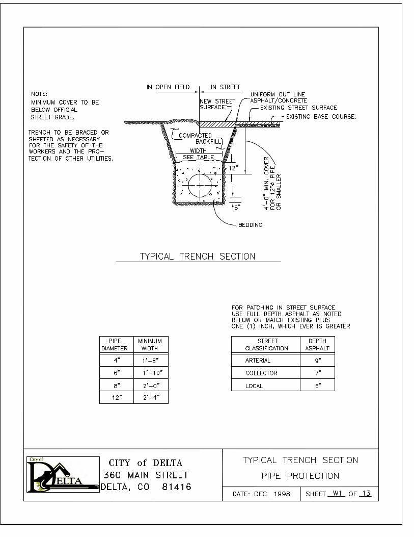
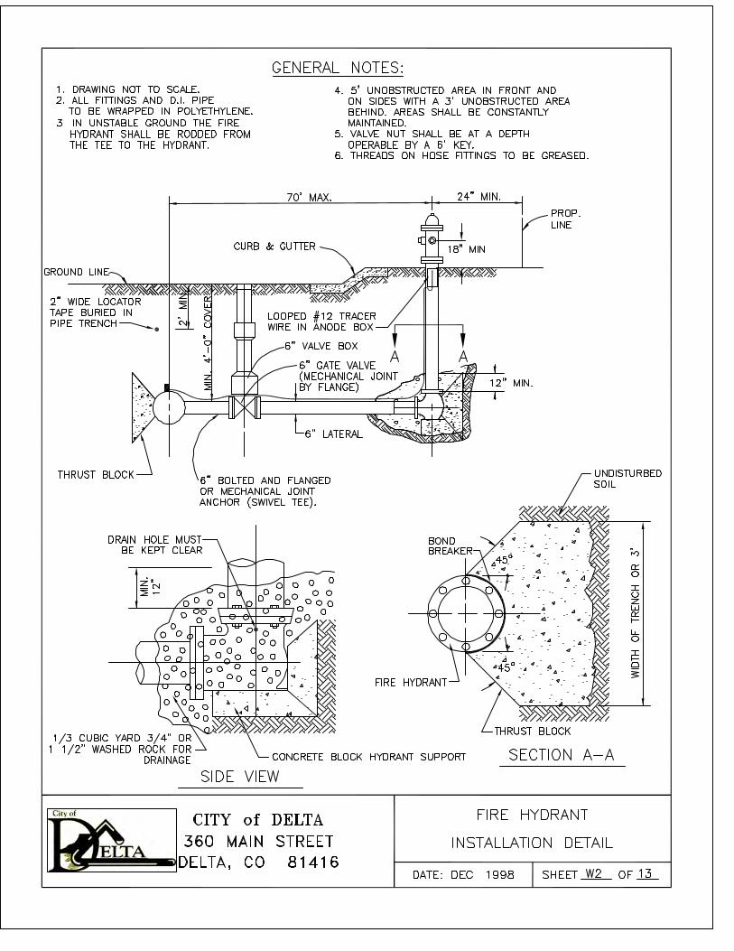
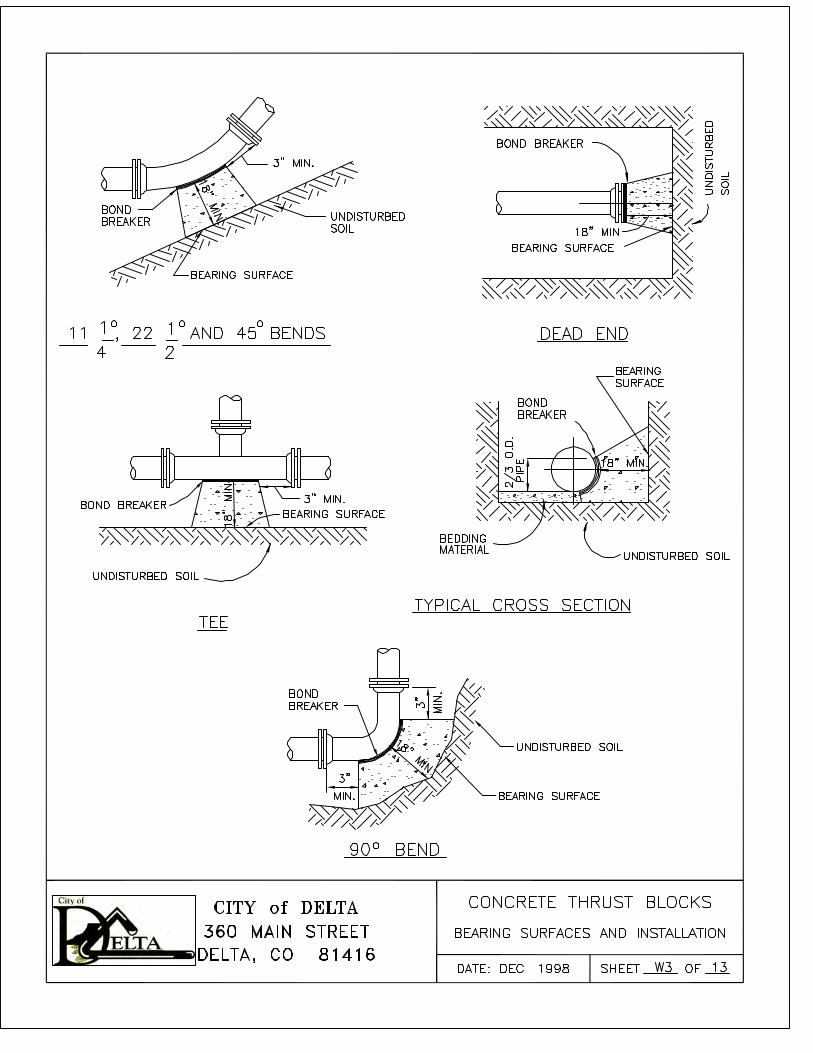

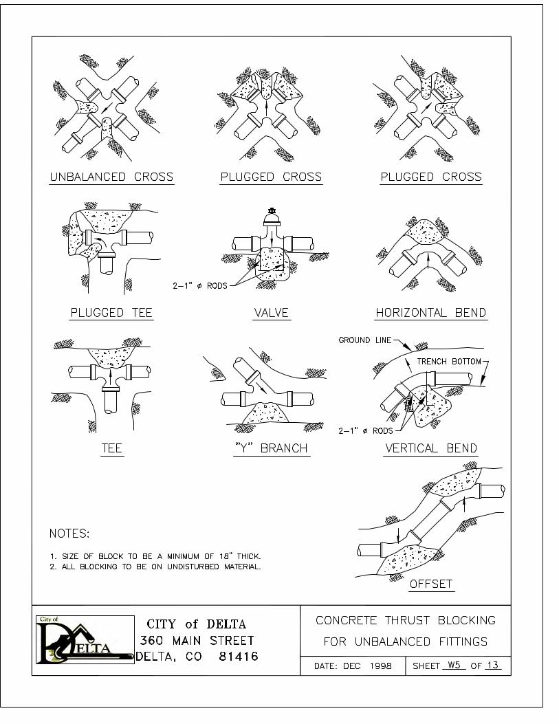


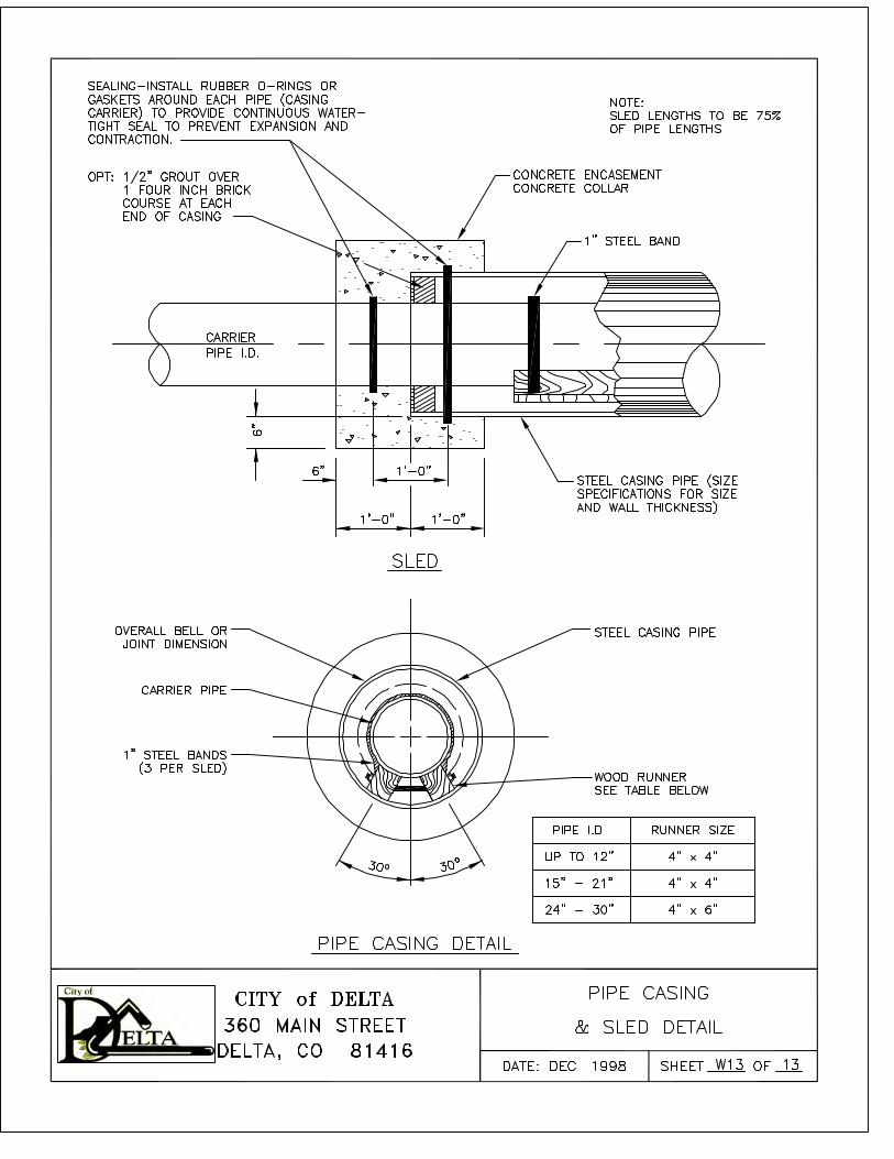

STANDARDS AND SPECIFICATIONS FOR THE DESIGN AND CONSTRUCTION OF PUBLIC
IMPROVEMENTS
Chapter 4
Sanitary Sewer System
2010 EDITION
TABLE OF CONTENTS
CHAPTER 4 SANITARY SEWER SYSTEM
Page
4.00.00 INTRODUCTION ...................................................................................................................................................................... 1
4.01.00 USE OF SANITARY SEWER ................................................................................................................................................. 1 4.20.00 DESIGN CRITERIA ................................................................................................................................................................ 1 4.21.00 SCOPE ...................................................................................................................................................................................... 1 4.22.00 GENERAL ................................................................................................................................................................................ 1 4.23.00 DESIGN FLOW ....................................................................................................................................................................... 1 4.24.00 HYDRAULIC DESIGN/SIZING OF SEWER LINES ........................................................................................................... 3
4.24.01 General .................................................................................................................................................................................. 3 4.24.02 Sanitary Sewer Mains ........................................................................................................................................................... 3 4.24.03 Sanitary Sewer Service Lines ............................................................................................................................................... 4
4.25.00 SYSTEM LAYOUT ................................................................................................................................................................. 4 4.25.01 General .................................................................................................................................................................................. 4 4.25.02 Waterline Crossing Over A Sanitary Sewer Line ................................................................................................................. 5 4.25.03 Storm Sewer Line Crossing Over Sanitary Sewer Line ....................................................................................................... 5 4.25.04 Limits On Vertical Separation .............................................................................................................................................. 5
4.26.00 EASEMENTS ........................................................................................................................................................................... 5 4.27.00 FUTURE CONNECTIONS ..................................................................................................................................................... 5 4.28.00 SERVICES ............................................................................................................................................................................... 5 4.29.00 TAPS ......................................................................................................................................................................................... 6 4.30.00 UNLAWFUL CONNECTIONS .............................................................................................................................................. 6 4.31.00 WASTEWATER PRE-TREATMENT .................................................................................................................................... 6 4.32.00 APPURTENANCES ................................................................................................................................................................ 6
4.32.01 Manholes ............................................................................................................................................................................... 6 4.32.02 Outside Drop Manholes ........................................................................................................................................................ 7 4.32.03 Underdrains .......................................................................................................................................................................... 7 4.32.04 Liftstations ............................................................................................................................................................................. 7 4.32.05 Gravity Grease and Sand/Oil Interceptors (Interceptor) ...................................................................................................... 7 4.32.06 Hydromechanical Grease Interceptors ................................................................................................................................... 7
4.39.00 CONSTRUCTION SPECIFICATIONS .................................................................................................................................. 8
4.40.00 EXCAVATION AND TRENCHING ...................................................................................................................................... 8 4.41.00 BEDDING ................................................................................................................................................................................ 8
4.41.01 General .................................................................................................................................................................................. 8 4.41.02 Class A Bedding .................................................................................................................................................................... 8 4.41.03 Class B Bedding (Granular II) ............................................................................................................................................. 8
4.42.00 PIPELINE INSTALLATION .................................................................................................................................................. 9 4.42.01 General .................................................................................................................................................................................. 9 4.42.02 Pipe ........................................................................................................................................................................................ 9
4.43.00 MANHOLE CONSTRUCTION ............................................................................................................................................ 10 4.43.01 Cast-in-Place Base ............................................................................................................................................................. 10 4.43.02 Pre-Cast Base/Inverts ......................................................................................................................................................... 11 4.43.03 Pre-Cast Barrel ................................................................................................................................................................... 11 4.43.04 Manhole Grouting Treatment ............................................................................................................................................. 11 4.43.05 Adjustment Rings ................................................................................................................................................................ 11 4.43.06 Cleanouts............................................................................................................................................................................. 12
4.44.00 CONNECTIONS TO EXISTING MANHOLES .................................................................................................................. 12 4.45.00 UNDERDRAINS ................................................................................................................................................................... 12
4.45.01 General ................................................................................................................................................................................ 12 4.45.02 System Layout ..................................................................................................................................................................... 12 4.45.03 Materials ............................................................................................................................................................................. 12 4.45.04 Mapping .............................................................................................................................................................................. 13 4.45.05 Inspections........................................................................................................................................................................... 13 4.45.06 Bedding ............................................................................................................................................................................... 13
4.45.07 Compacting Ordinary Backfill ........................................................................................................................................... 13 4.46.00 PRESSURE SEWERS ............................................................................................................................................................ 13 4.47.00 SANITARY SEWER SERVICE LINE CONSTRUCTION ................................................................................................. 13 4.48.00 TAPPING EXISTING SANITARY SEWERS ..................................................................................................................... 14
4.49.00 TESTS ........................................................................................................................................................................................ 14
4.50.00 GENERAL .............................................................................................................................................................................. 14 4.50.01 Air Tests .............................................................................................................................................................................. 15 4.50.02 Deflection Test: ................................................................................................................................................................... 15 4.50.03 Lamping Test ....................................................................................................................................................................... 15 4.50.04 Pressure Test for Pressure Sewers ..................................................................................................................................... 16 4.50.05 Manhole Leakage Test ........................................................................................................................................................ 16 4.50.06 TV Inspection ...................................................................................................................................................................... 16
4.59.00 MATERIAL SPECIFICATIONS ........................................................................................................................................... 17
4.60.00 GENERAL .............................................................................................................................................................................. 17 4.61.00 DEFECTS ............................................................................................................................................................................... 17 4.62.00 CERTIFICATION .................................................................................................................................................................. 17 4.63.00 PIPE ........................................................................................................................................................................................ 18
4.63.01 Polyvinyl Chloride Pipe (PVC) .......................................................................................................................................... 18 4.63.02 Reinforced Concrete Pipe (RCP) ....................................................................................................................................... 18
4.64.00 MANHOLES .......................................................................................................................................................................... 19 4.64.01 General ................................................................................................................................................................................ 19 4.64.02 Manhole Rings and Covers................................................................................................................................................. 19 4.64.03 Manhole Base Slabs ............................................................................................................................................................ 19 4.64.04 Joint Material ...................................................................................................................................................................... 19 4.64.05 Mortar ................................................................................................................................................................................. 19
1
CHAPTER 4 SANITARY SEWER SYSTEM
4.00.00 INTRODUCTION
All sanitary sewer systems shall comply with the requirements of these STANDARDS AND SPECIFICATIONS and may include special criteria established by the City for overall hydraulics of the sanitary sewer system. All work performed according to this section must comply with the general requirements contained within Chapter 1 and the acceptance requirements of Chapter 10. Special criteria shall be outlined at pre-design meetings, as determined necessary by the City.
4.01.00 USE OF SANITARY SEWER
The use of sanitary sewers within the City of Delta shall be in accordance with Chapter 13.04 of the Delta Municipal Code.
4.20.00 DESIGN CRITERIA
4.21.00 SCOPE
It is the intent of this "design criteria" section to provide sufficient detailed information to enable the Engineer for the Responsible Party to correctly and efficiently design the overall sanitary sewer system for a particular development. If the City deems it appropriate to require the engineered design of a sanitary sewer system, criteria shall be made available to the Engineer to provide a design acceptable to the City. Any deviation from these STANDARDS AND SPECIFICATIONS must be approved in writing by the City.
4.22.00 GENERAL
The sanitary sewer system shall be designed by a professional engineer registered in the State of Colorado utilizing the most current technical standards along with good, sound engineering judgment throughout the design process. The design process includes the submittal of construction drawings for review and approval by the City. Construction drawings shall conform to the submittal criteria in Section 1.40.00 of these Standards and Specifications. At the completion of the project, the engineer shall provide the City with two (2) sets of wet stamped record drawings in conformance with the submittal requirements of Section 1.40.00 of these Standards and Specifications.
4.23.00 DESIGN FLOW
The flows used to design the sewer system for a particular development vary depending on the type development. The following is a list of criteria to be used in the preparation of all sewer system analysis and design. (A) Design flow shall be calculated using peak domestic flow rate plus maximum infiltration. (B) Domestic wastewater flow shall be calculated using specific planning information, known or predicted, using the parameters outlined in Table 4.23.01 below. Conceptual planning information listed in the table shall be used for future flow design.

2
TABLE 4.23.01 Wastewater Design Flow Parameters Specific Development Capita per Residence 2.5 Flow per Capita (gal/day) 70 Commercial/Industiral See Table 4.23.02 Infiltration 100 gpd/in-dia/mile Conceptual Planning* Low Density Residential 953 gpd/ac Medium Density Residential 2540 gpd/ac High Density Residential 5715 gpd/ac Commercial 300 gpd/ac Industiral/Public School 1000 gpd/ac *Conceptual planning design flow parameters established utilizing low, medium, and high densities of 3, 8, and 18 units per acre respectively, 127 gal per capita per day. TABLE 4.23.02 Commercial/Industrial Specific Development Design Flow Parameters Type of Establishment Design Unit Flow (gpd/1000 sq ft) Office Buildings 200 Restaurants 500 Bars & Lounges 300 Hotels & Motels 350 Neighborhood Stores 200 Department Stores 200 Laundries & Dry Cleaning 1000 Banks & Financial Buildings 300 Medical Building & Clinics 300 Warehouses 100 Meat & Food Processing Plants 2800 Car Washes 1900 Service Stations 20 Auto Dealer. Repair & Service 150 Super Market 200 Trade Businesses 200 Places of Assembly – Churches, etc. 600 Hospitals 450 gal/bed (C) Peaking factors for residential areas shall be as per Table 4.23.03 below. For all commercial and public facility uses, the peaking factor shall be 2.0. Industrial peaking factors shall be industry specific based on metering information and must be approved by the City. TABLE 4.23.03 Residential Development Peaking Factors Service Population Peaking Factor 110 3.6 112 3.5 125 3.4 150 3.3

3
175 3.2 200 3.1 250 3.0 300 2.9 350 2.8 450 2.7 500 2.6 Greater than 500 Contact City (D) Infiltration for future sewers shall be accounted for using 100 gpd per inch diameter per mile of sewer line. Special consideration shall be given for areas of high ground water.
4.24.00 HYDRAULIC DESIGN/SIZING OF SEWER LINES
4.24.01 General
Sanitary sewer shall be designed to carry the discharge calculated in accordance with Section 4.23.00 and to transport suspended material such that deposits in the sewer are precluded. The following table gives the recommended capacity criteria for sanitary sewer mains: TABLE 4.24.01 Recommended Capacity Criteria Diameter Flow Depth Restriction (Inches) (d/D) Less than or equal to 15” 0.50 Greater than 15” 0.75
The minimum diameter for sanitary sewer mains shall be 8-inches.
Oversizing of mains may be required by the City, and the recovery of the costs of such oversizing shall the responsibility of the City.
The minimum diameter for sanitary sewer service lines shall be 4 inches.
4.24.02 Sanitary Sewer Mains
(A) The following table gives the minimum and maximum allowable slopes for sanitary sewer mains:
TABLE 4.24.02 Sanitary Sewer Main Slope Criteria Diameter Minimum Slope Maximum Slope (Inches) (Feet/Feet) (Feet/Feet) 8 0.0040 0.0180 10 0.0030 0.0120 12 0.0020 0.0100 15 0.0015 0.0080 18 0.0012 0.0090 21 or larger as approved by City

4
Sewer line design shall incorporate the largest slope possible within the requirements of Table 4.24.02 and shall maintain a uniform slope between manholes.
(B) The sewer must be designed at a slope great enough to produce a minimum flow velocity
of two feet (2') per second and a maximum flow velocity of ten feet (10’) per second at the peak design flow using the Manning equation and Manning’s n values as indicated in Table 4.24.03 below except that the slope shall never be less than the minimum slope given above:
TABLE 4.24.03 Manning’s n Vaules per Pipe Material Sewer Line Material Manning’s n Value PVC 0.009 RCP 0.013
Hydraulic design of pressure sanitary sewers shall be in accordance with chapter 3 of these standard specifications.
4.24.03 Sanitary Sewer Service Lines
The following table shows the minimum and maximum allowable slopes for sanitary sewer service lines:
TABLE 4.24.04 Sanitary Sewer Service Slope Criteria Minimum Slope Maximum Slope Diameter (Inches) (Feet/Feet) (Feet/Feet) 4 0.020 0.040 6 0.020 0.030
4.25.00 SYSTEM LAYOUT
4.25.01 General
All mains shall be installed in dedicated rights-of-way or public easements. Under no circumstances should sanitary sewer mains be installed parallel to and directly below any concrete such as sidewalks, curbs or gutters. Lines shall normally be located five feet south or west of street centerline, unless otherwise approved, in writing, by the City. Sanitary sewer mains shall be straight between manholes, both in horizontal and vertical alignment.
Sewer mains will ordinarily have a minimum of eight feet of cover to finished ground surface. Where this will provide less than nine feet of elevation difference between the finished lot grade at building line and the top of the sewer main, it will be indicated on the plans that the lot is served by a "shallow sewer" and appropriate elevation information will be given.
Sewer mains shall extend to the uppermost property line unless otherwise approved by the City. The City may participate in an extension if deemed appropriate to serve future users. Sewer mains shall terminate in a manhole. During a phased utility plan, the sewer main may be
5
temporarily allowed to dead end in a cleanout provided the main extends no more than 50 feet from the last manhole and a maximum of two (2) residential connections exist. The cleanout provided shall be in accordance with the detail drawing in the Appendix of this Chapter.
Sanitary sewer mains shall be laid a minimum of ten feet horizontally from any existing or proposed utility. Upon written approval by the City, a sanitary sewer main may be laid closer than ten feet to a parallel water main if it is laid in a separate trench and if the elevation of the invert of the water main is at least eighteen inches above the crown of the sewer main and, in addition, polyvinyl chloride pressure pipe is used for the sewer main.
When the sanitary sewer main passes under a highway, railroad or drainage or irrigation ditch, there shall be a minimum of 3-1/2 feet of cover and steel casing shall be installed in accordance with the detail drawing in the Appendix of this chapter. The steel casing shall extend the entire width of the right-of-way or easement of the crossing structure or as directed by the City.
4.25.02 Waterline Crossing Over or Under A Sanitary Sewer Line See Section 3.18.02 of these Standards and Specifications.
4.25.03 Storm Sewer Line Crossing Over or Under Sanitary Sewer Line
When there is less than 18 inches of vertical clearance between the sanitary sewer line and the storm sewer line, the sanitary sewer line shall be encased in concrete a minimum of ten feet on each side of the centerline of the crossing or polyvinyl chloride pressure pipe in accordance with American Water Works Association C900 may be used. In the case of of the sanitary sewer crossing over the storm sewer, each joint of the storm sewer within 9 feet of the centerline of the crossing shall be encased in concrete.
4.25.04 Limits On Vertical Separation
Under no circumstances shall the vertical clearance between any lines involving a waterline, sanitary sewerline, or storm sewer be less than 12 inches without prior written approval from the City.
4.26.00 EASEMENTS See Section 3.19.00 of these Standards and Specifications.
4.27.00 FUTURE CONNECTIONS
Manholes shall have a full joint of pipe stubbed out which are sized to accommodate flows from the upstream basin whenever a future extension of the sanitary sewer main is anticipated. The main line stub-out shall be capped and sealed.
4.28.00 SERVICES
Each structure shall be served by a separate service line. Sanitary sewer service lines shall be located a minimum of ten feet away from all water services (measured horizontally). Whenever possible, service lines shall be constructed perpendicular to the property line of the property they are going to serve and shall be located a minimum of 10 feet from either property line. Six inch service lines and larger shall require connection to the main with a manhole. Service connections shall not be allowed onto an

6
interceptor sewer (i.e. any sever line greater than 12” in diameter) without prior approval of the City. The point where the service line crosses under the curb, if applicable, shall be marked by chiseling a symbol “S” on the curb face.
The City shall not be held responsible for the locating of sewer service lateral stub-outs for future connections.
4.29.00 TAPS
All sanitary sewer service connections to the sanitary sewer main shall be made using "wye" fittings, unless otherwise approved by the City.
4.30.00 UNLAWFUL CONNECTIONS
It shall be unlawful to discharge roof drainage, foundation drainage, sump pumps, surface drainage or any other non-acceptable wastes to the sanitary sewer which would violate any of the provisions of Chapter 13.08.020 of the Municipal Code.
4.31.00 WASTEWATER PRE-TREATMENT
All uses shall be evaluated to determine whether the provisions of Chapter 13.08 of the City of Delta Municipal Code shall apply prior to being issued a final Certificate of Occupancy. If these provisions do apply, an approved pre-treatment device shall be installed per these Standards and Specifications and Section 4.32.05.
4.32.00 APPURTENANCES
4.32.01 Manholes
The maximum spacing between manholes shall be 400 feet for sewer pipe diameters of 15” or less. For sewer pipe diameters of greater than 15”, the maximum spacing shall be 500 feet. Manholes shall be provided at every change in grade, sewer line diameter, or intersection of sewer line equal to or larger than 15” in diameter. Manholes shall also be provided at every change in direction with the exception of sewer lines 24” in diameter or larger with a change in direction of flow less than 45 degrees. Manholes shall have a minimum diameter of 48” for all sewer pipe diameters less than 27”. For sewer pipe diameters greater than 27”, the minimum manhole diameter shall be 60”. The drop across a manhole base should match the larger of the incoming or outgoing slope but shall not be less than 0.2 foot per one foot. For manholes under the following conditions, a corrosive protective material coating shall be installed within the interior; manholes providing a change in direction equal to or greater than 45 degrees (for pipe diameters smaller than 24”), manholes in line with or at the end of sewer lines with City-preapproved slopes greater than that set forth in these criteria, manholes accepting flow from an outside drop or any form of anticipated septicity, or as required by the City. Manholes shall not be located in areas that are subject to flooding from surface runoff. Manholes shall be located in within utility easement areas that allow direct access by maintenance vehicles when it is not feasible to locate the manhole in the public street. If the possibility of surface runoff cannot be avoided, an internal watertight insert shall be installed to prevent inflow. All manholes located outside dedicated street rights-of-way shall be designed and constructed with locking-type cover and the manhole ring shall be bolted to the manhole cone.

7
4.32.02 Outside Drop Manholes
Drop manholes will only be allowed when the design engineer proves that alternates are not feasible and when approved, in writing, by the City. Outside drop manholes will be required whenever a sewer entering a manhole is at an elevation twenty-four inches or more above the manhole invert. Outside drop manholes shall be in accordance with the Detail Drawing in the Appendix of this chapter. Outside manhole drops require filleting to avoid solids deposition. The entire outside drop piping shall be encased in concrete. No inside drops are allowed.
4.32.03 Underdrains
Where underdrains are to be constructed under sewer mains, separate clean-outs shall be provided next to each manhole in accordance with the Detail Drawing in the Appendix of this chapter. Further, all underdrain service lines originating from within lots shall meet these requirements including size, marking tape and sock.
4.32.04 Liftstations Lift stations will only be allowed when the design engineer proves that this is the only option available and when approved, in writing, by the City. The City shall dictate the location and type of pumping facilities to be constructed and to require extra maintenance from the Responsible Party. The City will require the lift station to contain a separate emergency power backup in cases of power outages.
4.32.05 Gravity Grease and Sand/Oil Interceptors (Interceptor)
Any new establishment, including but not limited to Food Service Establishments (FSE) and automotive related facilities, that may contribute fats, oils, grease (FOG), sand, mud, petroleum based oils, or any other potentially damaging pollutant to the City’s wastewater treatment system shall be required to install and maintain, at the owner’s expense, a properly designed and constructed interceptor. In addition, any existing facility that contributes FOG, sand, mud, petroleum based oils, or any other potentially damaging pollutant to the City’s wastewater treatment system may be required to install and maintain, at the owner’s expense, a properly designed and constructed interceptor. Specific sizing design criteria shall be obtained from the City. Unless otherwise approved, all exterior interceptors shall meet the following minimum standards and must be approved by the City prior to installation: 1. Engineer designed and constructed for its intended purpose. 2. Precast concrete construction, reinforced to 4000 PSI minimum compressive strength at 28 day. 3. Conforming to H-20 load rating standards if installed in vehicle traffic areas. 4. At least 2 separate chambers separated by 1 baffle between any 2 chambers, the volume of the first chamber occupying approximately 2/3 of the total volume of the interceptor. 5. 2 manholes of 24” minimum diameter for each chamber, located above the inlet and oulet pipe. 6. Minimum 4” diameter inlet pipe. Outlet pipe must be equal or greater diameter than inlet. 7. Inlet pipe must have a T, the bottom of which must extend no more than ½ the depth of the liquid. 8. Outlet pipe must have a T, the bottom of which must extend no less that 12” above the tank floor. At no time may the outlet pipe T be capped. Outlet filters shall not be installed.

8
9. The inlet and outlet inverts shall differ by a minimum of 2” and a maximum of 4”. 10. A separate inspection/sampling chamber may be located in the discharge line beyond the interceptor but shall not be installed in place of the outlet pipe T. 11. Designed such that it shall not become air-bound if an airtight cover is used. 12. Interceptor shall be designed as close as possible to the establishment and shall be readily accessible for cleaning, maintenance, and inspection. 13. Interceptor shall be designed such that the retention time is at least 30 minutes. As an alternate to the above described concrete interceptor, the City will allow an interceptor constructed of fiberglass designed and manufactured by Green Turtle of Charlotte, NC. The appropriate fiberglass interceptor shall be the Proceptor® fiberglass interceptor.
4.32.06 Hydromechanical Grease Interceptors
A FSE may request an exemption to Section 4.32.05 if the establishment can show that such installation is not feasible due to physical or other limitations that would make it impractical to install an Interceptor. Such request shall be made in writing and, if approved by the City, the establishment shall be required to install and maintain, at the owner’s expense, a hydromechanical grease interceptor. Such interceptor shall be constructed and sized to conform to the Plumbing and Drainage Institute Standard G-101 (PDI G-101), shall be installed according manufacturer’s and International Plumbing Code requirements, and shall be located as close as possible to the source of the grease-producing fixture.
4.39.00 CONSTRUCTION SPECIFICATIONS
4.40.00 EXCAVATION AND TRENCHING
Excavation, trenching and backfilling shall be done in accordance with Chapter 9 of these STANDARDS AND SPECIFICATIONS.
4.41.00 BEDDING
4.41.01 General
In the event unstable trench conditions are found at pipeline grade, a minimum of one and one-half inch uniformly graded, washed rock shall be used for trench stabilization. Depth of stabilization shall be as approved by the City. Pipe bedding shall be done in accordance with Sections 4.41.00 of these STANDARDS AND SPECIFICATIONS and the Detail Drawing in the Appendix of this chapter.
4.41.02 Class A Bedding
Class A bedding is defined as that method of bedding in which the lower half of the pipe is set in a reinforced concrete cradle. The minimum thickness of concrete under the lowest part of the conduit shall be one-fourth of the outside pipe diameter but not less than four inches. The concrete shall extend around the pipe to the spring line of the pipe barrel. The width of the concrete cradle shall be at least equal to the outside pipe diameter plus eight inches.
4.41.03 Class B Bedding (Granular II)
Class B bedding is defined as that method of bedding in which the pipe is set on granular material meeting the requirements of Chapter 9 in these STANDARDS AND SPECIFICATIONS.
9
Bedding shall be placed to a depth below the bottom of the pipe equal to one-fourth of the outside pipe diameter but not less than four inches. In rock excavation this minimum depth shall be six inches. Granular material shall be placed around the sides of the pipe and to a minimum of twelve inches above the top of pipe.
4.42.00 PIPELINE INSTALLATION
4.42.01 General
The City shall be notified at least 48 hours in advance of any pipe installation. The Responsible Party shall notify and arrange for all utility locates prior to excavation. No pipes shall be backfilled until they have been inspected and approved by the City. Alignment and grade of the pipe and the location of fittings, and manholes shall be staked under the supervision of a professional surveyor registered in the State of Colorado.
Proper implements, tools and facilities shall be provided and used by the Responsible Party for the safe and convenient execution of the work. All pipe fittings, and manhole sections shall be carefully lowered into the trench by means of a derrick, ropes or other suitable tools or equipment to prevent damage to sanitary sewer line material. Under no circumstances shall sanitary sewer line materials be dropped or dumped into the trench.
All pipe fittings shall be carefully examined for cracks and other defects immediately before installation. The groove in the bells of the pipe shall be full and continuous or the pipe will be rejected. Defective pipe or fittings shall be removed from the job site within 24 hours of notification by the City. All foreign matter or dirt shall be removed from the interior and ends of the pipe before they are lowered into position in the trench and prior to connection.
Every precaution shall be taken to prevent foreign material and trench water from entering the pipe and fittings. During construction, the Responsible Party shall provide and maintain adequate equipment to properly remove and dispose of all water entering the trench and any other part of the work.
A green plastic identification strip, a minimum of three-inch wide, continuously labeled “Caution Sewer Line Below” shall be installed directly above all gravity sewer main, the full length of the sewer, and shall be buried two feet below the finished ground surface elevation. For pressure sewer main, a brown plastic identification strip, a minimum of two-inch wide, continuously labeled “Caution Buried Force Main Below” shall be installed directly above the pressure sewer, the full length of the sewer, and shall be buried two feet below the finished ground surface elevation.
4.42.02 Pipe
Pipe shall be laid from downstream to upstream with spigot ends pointing downstream. All pipe shall be placed true to line and grade and carefully centered and with a smooth invert at the joint. Pipe shall be laid with a pipe laser or similar instrument to insure proper grade is maintained. Any pipe installed at a slope less than 1% shall have a plate-tamped trench bottom to insure proper grade is maintained. The joint shall be made in a workmanlike manner and shall be watertight. Immediately before joining two lengths of pipe, the inside of the bell and the outside of the spigot end and the gasket shall be thoroughly cleaned. Caution shall be exercised to ensure that the correct type of gasket is used. A thin film of gasket lubricant shall be applied to the inside face of the gasket and the spigot end of the pipe. The spigot end of the pipe shall be placed in the bell with care to prevent the joint from contacting the ground. The joint shall be completed by pushing

10
the pipe home by hand with a slow steady pressure, without jerky or jolting movements. Pipe furnished without a depth mark shall be marked before assembly to ensure insertion to the full depth of the joint. The pipe shall then be properly set and brought to correct line and grade. The pipe shall then be secured in place by installation of bedding material and backfill, in accordance with Chapter 9 and the detailed drawings in the Appendix of this chapter.
At times when installation is not in progress, the open ends of the pipe shall be closed with a watertight plug. Cutting of pipe for inserting closure pieces shall be done in a neat and workmanlike manner without damage to the pipe or lining, leaving a smooth end at right angles to the axis of the pipe. Pipe ends shall be smooth and beveled with a file or other tools according to the pipe manufacturer's recommendations.
Extra care should be used in handling PVC pipe during cold weather due to the reduced flexibility and impact resistance as temperatures approach and drop below freezing. PVC pipe to be stored outside and exposed to sunlight for more than 30 days shall be covered with an opaque material such as canvas. Clear plastic sheets shall not be used to cover the pipe. Air circulation shall be provided under the covering. Any over-exposed pipe, as determined by the City, will not be permitted for installation.
No pipe or appurtenant structure shall be installed upon a foundation in which frost has penetrated or at any time when the City deems there is a danger of ice formation or frost penetrations at the bottom of the excavation. No pipe or appurtenant structure shall be installed unless backfilling can be completed before the formation of ice and frost.
4.43.00 MANHOLE CONSTRUCTION
4.43.01 Cast-in-Place Base
Manhole bases shall be constructed with Class A concrete, placed on undisturbed ground and in conformance with the detail drawing in the Appendix of this chapter. Changes in direction of flow through the manhole shall be made with a smooth curved channel having as large a radius as possible. The change in size of channels shall be made gradually and evenly and shall be formed directly in the concrete. The floor of the manhole outside of the channel shall be finished to a brushed surface.
Concrete bases shall extend at least eight inches below the invert of the pipe and shall be benched to at least two inches over the top of the pipe. The manhole floor between the sewer pipe and the outer portions of the bench shall be flush with the top edges at the pipe spring line and shall slope upward at least two inches per foot. Wherever grade and alignment permit, the sewer shall be laid continuously through the manhole and the manhole built later. In such cases, the foundation shall be placed as mentioned above and once the manhole is constructed, the upper half of the pipe shall be sawed out and the rough edges smoothed with cement mortar. Breaking out the top of the pipe is not permitted
Where it is not practicable to use split pipe through manholes due to breaks in alignment, grade, or elevation of intersecting sewers, the sewer invert shall be made of concrete deposited between forms. The shape of the invert shall conform to the lower half of the pipe it connects. Side branches shall be constructed with as large a radius of curvature as possible. Inverts shall be plastered with cement mortar and left smooth and clean. Where called for on the plans, a pipe bell shall be stubbed out and plugged. The bell shall be placed as close to the manhole wall as possible, unless showing otherwise on the approved plans.

11
Reinforcement will be required in the manhole base when the distance from the pipe invert to the top of the manhole cover exceeds 15 feet or when poor soil conditions exist. Reinforcement shall be approved by the City prior to installation.
4.43.02 Pre-Cast Base/Inverts
Pre-cast bases will be allowed by the City and shall be in conformance with this section.
The ground surface below the precast concrete base shall be excavated three inches below the elevation of the bottom of the base and backfilled with three quarter inch gravel meeting the requirements of Section 9.22.00. The gravel shall be carefully leveled and smoothed to give uniform support to the precast base over its entire area. The precast base shall be set at the proper location to center the manhole over the sewer main.
The precast base shall also conform to the requirements of Section 4.43.03 of these STANDARDS AND SPECIFICATIONS.
4.43.03 Pre-Cast Barrel
Precast manhole sections shall not be placed on the foundation until it has reached sufficient strength to provide support without damage. The joint between the manhole base and the barrel section shall be made with a flexible butyl resin joint sealing compound. Each succeeding precast section shall be joined in a similar manner and smoothly finished, inside and out.
4.43.04 Manhole Grouting Treatment
The horizontal joints between precast manhole sections shall be plastered and troweled smooth, inside with cement mortar in conformance with Section 4.64.05 if deemed appropriate by the City Representative. The mortar shall be not less than five-eighths inch in thickness over the joint and shall extend at least four inches on either side of the joint.
All smooth surface pipes, such as PVC or VCP shall have a manhole water-stop gasket, to be furnished by the Responsible Party, firmly attached to the pipe prior to grouting into the manhole. The opening in the manhole wall where a pipe enters or leaves shall be sealed and patched in a neat workmanlike manner, both inside and out with cement mortar. All lifting holes and other imperfections in the interior manhole wall shall be filled with cement mortar.
4.43.05 Adjustment Rings
Precast concrete adjustment rings shall be used on top of the cone to support and adjust the manhole frame to the required final grade. The maximum depth of the adjustment rings shall be twelve inches, and the maximum depth from top of cone to final grade shall be eighteen inches.
The top elevation of the manhole shall be adjusted to match final street grade. If manholes are located in open fields, they shall be left at least eighteen inches above grade and a locking ring and cover shall be installed. In cultivated areas, manholes shall be properly marked by a steel post painted red on the top six inches and located five feet from the centerline of the manhole cover.

12
4.43.06 Cleanouts
Cleanouts shall be installed next to the manhole base in conformance with the detail drawing in the Appendix of this chapter where an underdrain is installed with the sanitary sewer system. Cleanouts may also be used as discussed in Section 4.25.01.
4.44.00 CONNECTIONS TO EXISTING MANHOLES
Sewer pipe connections to existing manholes where there is no existing pipe stubbed out shall be made in such a manner that the finished work will conform as nearly as practicable to the requirements specified for new manhole construction. The Responsible Party shall carefully cut out as small an opening in the existing manhole as necessary to insert the new sewer pipe. The existing concrete foundation bench shall be ground out for a new invert with a hand grinder to the cross-section of the new pipe in order to form a smooth continuous invert similar to what would be formed in a new concrete base. Where practical, the downstream invert shall be plugged during construction to prevent storm and non-sewage flow from entering the system. The Responsible Party shall pump out and clean the manhole before removing the plug. Cement mortar shall be used to smoothly finish the new invert and to seal the new line, both inside and outside, so the junction is watertight.
4.45.00 UNDERDRAINS
4.45.01 General
Where excessive ground water is encountered, the City may require construction of a piped underdrain, to reduce infiltration. Underdrains shall be daylighted to the nearest suitable point as approved by the City.
Underdrain main construction shall be done in accordance with engineered construction plans for the work prepared under the direction of a registered professional engineer and approved by the City.
Soil samples are a prerequisite to the underdrain system. A written proposal on the underdrain system must be presented to the City of Delta before the Construction Agreement is approved.
4.45.02 System Layout
Underdrain shall be placed in its own trench approximately 1-1.5 feet below sanitary sewer main, unless otherwise approved by the City Representative. All underdrain cleanouts should be located in either a storm sewer vault or in its own valve box. Underdrain cleanouts will not be permitted in sanitary sewer manholes.
4.45.03 Materials
All underdrains shall be constructed in perforated and/or non-perforated SDR-35 PVC pipe, with a tracer wire attached for locating purposes. A minimum of 6-inch PVC pipe shall be used for all underdrain mains and services. Underdrains shall be lined in filter fabric prior to installation only if perforated.
13
4.45.04 Mapping
Record drawings shall be provided to the City prior to date of acceptance. All maps must provide adequate details of the underdrain prior to being accepted by the City.
4.45.05 Inspections
Underdrain mains will be thoroughly inspected by the City Representative prior to backfill. Underdrain cleanouts must be located outside of sanitary sewer manholes, as detailed in the Construction Agreement. Underdrain daylights shall be free from being covered by dirt. An engineering drawing of all proposed daylights shall be submitted prior to City approval.
4.45.06 Bedding
Granular bedding material shall be installed a minimum of 12 inches above the top of the pipe. Backfill must be placed in lifts not exceeding 12 inches.
4.45.07 Compacting Ordinary Backfill
All trenching, backfilling and compaction of underdrain shall be done in accordance with Chapter 9 of these STANDARDS AND SPECIFICATIONS.
4.46.00 PRESSURE SEWERS
All requirements of Chapter 3 of these STANDARDS AND SPECIFICATIONS shall apply to the installation of pressure sanitary sewer lines. All pressure sanitary sewers shall be installed using PVC C-900 per AWWA for 6” diameter or greater pipe. For pipe 4” diameter or smaller, pipe shall conform to AWWA Schedule 40 class 200 PVC. If pressure sewers are allowed by the City, design will include cleanouts and lift stations according the City.
A brown plastic identification strip, a minimum of a two-inch wide, continuously labeled "Caution Buried Force Main Below" shall be installed directly above the pressure sewer, the full length of the sewer, and shall be buried two feet below the finished ground surface elevation. Responsible party has the option of installing either a metallic identification strip or tracer wire along the pipe in conformance with Section 3.33.02 of these Standards and Specifications.
4.47.00 SANITARY SEWER SERVICE LINE CONSTRUCTION
All sanitary sewer service lines that connect to the City of Delta sanitary sewer system shall comply with these STANDARDS AND SPECIFICATIONS and the most current City adopted Uniform Plumbing Code.
The Responsible Party shall place wyes, stubs, and risers where required by the approved plans. Wyes shall be angled upwards so that the upper invert of a one-eighth bend connected to the fitting will have an elevation equal to or higher than the inside crown of the sewer main. Riser connections shall be installed

14
where the elevation of the top of the branch is more than twelve feet below the approved finished grade. Riser connections will ordinarily reach to a grade ten feet below the finished ground surface. Watertight plugs shall be installed in each branch pipe or stub. As-built measurements shall be made by the Responsible Party or his representative to reference the wye or riser connection to the nearest manhole as well as the depth from the finished grade elevation to the invert of the stub before backfill is completed. Said measurements shall be carefully and accurately made and recorded and shall be shown on the as-built plans furnished to the City prior to acceptance.
All installation work shall conform to applicable portions of ASTM C-12 and to the pipe manufacturer's installation instructions. The grooves shall be cleaned free of all foreign materials prior to assembling the joint. The pipe shall be laid with the spigot end pointing in the direction of the flow.
Trenches shall be kept free of water during laying and jointing. Lines longer than fifty feet shall be laid with batter boards, a laser, or other means approved by the City.
Clean-outs are required at a minimum interval of one hundred feet or at all bends exceeding 60 degrees or changes in grade. The area around a clean-out shall be graded so water runs away from the clean-out. No clean-outs, other than those installed as part of the sewer main underdrain system, shall be installed in publicly owned rights-of-way or easements. Service stub-ins shall be extended at least 10’ into the property and be plugged with a compression stop. Service stub-in locations shall be marked with a green post or pipe for future location and connection.
Backfilling shall be in accordance with Chapter 9 of these STANDARDS AND SPECIFICATIONS.
Service lines that need to be disconnected or abandoned shall be excavated at the main line and capped, plugged, or otherwise blocked within 2’ of the main line to prevent future connection or infiltration/inflow.
4.48.00 TAPPING EXISTING SANITARY SEWERS
Where tees have not been installed in the sewer main, the main shall be tapped by machine drilling a hole sized to fit the saddle for the service line. The drilling machine, method of drilling, and the saddle shall be approved by the City. The saddle shall be sealed when attached to the main and held in place with metal straps or other approved methods.
4.49.00 TESTS
4.49.01 General
All sanitary sewer mains, storm sewer mains, and appurtenances shall be cleaned and tested after backfill operations have been completed and compaction test results have been submitted to and approved by the City. Should the City find that the completed line or any portion thereof fails any of the specified tests, the City will not accept the new sewer line until such time as the sewer line meets the test specifications. Once the sewer line is completed the Responsible Party shall perform an air test and lamp test on the completed line. The use of alternate testing methods may be allowed or required in addition to those stated herein and determined necessary by the City. Alternate testing methods include water exfiltration test, infiltration test, deflection test, and television inspection.
The Responsible Party shall furnish all labor, materials, tools and equipment necessary to clean the pipe and appurtenances, make the tests and perform all work incidental thereto with the exception of a television inspection which the City will perform. Any damages to the pipeline

15
caused by cleaning or testing operations shall be repaired or replaced by the Responsible Party at his expense.
4.50.02 Air Tests
The Responsible Party shall perform these tests with suitable equipment specifically designed for air testing sewers. The pipe, or sections of concrete pipe to be tested, may be wetted before the air test. The line shall be plugged at each manhole with pneumatic balls. All service plugs shall be secured in place to prevent displacement during testing operations. Low pressure air shall be introduced into the plugged lines until the internal air pressure reaches 4.0 psi plus 0.4 psi per foot of water table above the pipe invert, if any. At least two minutes shall be allowed for the air temperatures to stabilize before readings are taken and the timing started.
The portion being tested shall pass if it does not lose air at a rate to cause the pressure to drop from 3.6 to 3.0 psi (plus any adjustments for water table pressure as mentioned previously) in less time than listed below:
Pipe Diameter Minimum Allowable Minutes In Inches 3.6 to 3.0 psi Pressure 4 3.0 6 3.0 8 4.0 10 5.0 12 6.0 15 7.0 18 9.0 21 10.5 24 12.0
If the installation fails this test, the testing equipment may be used to determine the location of the pipe leak.
4.49.03 Deflection Test:
The maximum vertical deflection allowed for PVC pipe is five percent. The City may require the Responsible Party to perform deflection tests of the pipe before acceptance. Optional devices for testing include calibrated television, photography, properly sized go-no-go mandrel, sewer ball, or deflectometer. The method used shall be approved by the City. To insure accurate testing, the line shall be thoroughly cleaned prior to testing. Testing shall be done no sooner than 30 days after the pipe has been backfilled.
The Responsible Party shall schedule the test with the City 48 hours prior to the test and the City shall be present during the test and shall verify the accuracy of the equipment used. The City may require the Responsible Party to perform another deflection test prior to the end of the warranty period.
4.49.04 Lamping Test
Prior to acceptance into the one-year warranty period of the pipeline installation, the City shall perform a lamp test to verify the alignment and condition of the pipe. The lamp test shall be performed only after the Responsible Party has completely cleaned the line to the satisfaction of the City. Should the lamp test indicate an alignment problem, the City shall be the sole judge of

16
the need for replacement. Unsatisfactory alignment may be the cause for rejection. The Responsible Party shall furnish the light source to be used in the lamp test and the labor necessary for the City to perform the test.
4.49.05 Pressure Test for Pressure Sewers
After the pipe has been laid, including fittings, thrust blocks, and backfill in accordance with the specifications, it shall be subjected to a hydrostatic pressure of not less than 150 P.S.I. for one hour. The allowable leakage shall not exceed the following formula:
L = ND / P
7400 L = Allowable Leakage in Gallons Per Hour N = Number of Joints in Length of Pipeline Tested D = Nominal Diameter of Pipe in Inches P = Average Test pressure during the Test, PSIG
Each valved section or the entire line if there are no valves, shall be slowly filled with water and the specified test pressure, measured at the highest point of elevation, shall be applied by means of a pump connected to the pipe in a satisfactory manner. The pump, pipe connection, gauges, and all necessary apparatus shall be furnished by the Responsible Party. Gauges and measuring devices shall be approved by the City and the necessary taps made as required by the Responsible Party. Before applying the specified test pressure, all air shall be expelled from the pipe. To accomplish this, taps shall be made at the highest elevations of the test section and plugged with brass plugs once the pipeline has passed the test.
Any cracked or defective pipes, fittings, or valves, discovered in the pressure test shall be removed and replaced by the Responsible Party with sound material. The test shall be repeated until the pipeline passes the pressure test and is accepted by the City.
4.49.06 Manhole Leakage Test
Manholes shall be tested for leakage separately from the pipe when deemed appropriate by the City Representative. The sewer pipe in the manhole shall be plugged. If the ground water table is below the invert, the manhole shall be filled with water to a depth five feet above the invert. If the ground water table is above the invert of the manhole, then the manhole shall be filled to a level at least three feet above the ground water table or to the top of the uppermost precast manhole section, whichever is less, but not less than five feet above the invert. After soaking for one hour, the manhole shall be filled to the original level. It shall then be tested for two hours. The allowable drop in the water level shall be one inch. No manhole shall be accepted that has any visible infiltration when empty. Any manhole whose test is unsatisfactory shall be repaired at the Responsible Party's expense and retested until satisfactory results are obtained.
4.49.07 TV Inspection
The City will perform TV inspections of all new sewer lines and all defects that have been repaired prior to acceptance. In order to be considered for inspection, the improvements shall have been completed, accessible

17
and cleaned sufficient to allow for detailed inspection by the City. When requested by the City, the Owner shall provide personnel and equipment to assist in the inspection process.
4.59.00 MATERIAL SPECIFICATIONS
4.60.00 GENERAL
Only those pipeline materials described in this section are approved for sanitary sewer installations. Any other material proposed as an equal shall be approved by the City prior to construction. All pipe materials to be incorporated in the construction of sanitary sewers shall conform to the requirements specified herein or as modified elsewhere in these STANDARDS AND SPECIFICATIONS. All materials furnished shall be new and undamaged. Everything necessary to complete all installations shall be furnished and installed whether shown on the approved drawings or not, and all installations shall be completed and fully operational. Acceptance of materials or the waiving of inspection thereof shall in no way relieve the Responsible Party of the responsibility for furnishing materials meeting the requirements of these STANDARDS AND SPECIFICATIONS.
All materials delivered to the job site shall be adequately housed and protected to ensure the preservation of their quality and fitness for the work.
4.61.00 DEFECTS
The presence of any of the following defects in an individual pipe, or in a shipment of pipe, may constitute sufficient cause for rejection of the pipe. Rejected materials shall be removed from the work site within 24 hours unless otherwise permitted by the City.
- Pipe length varying more than two inches from the specified length. Pipe shall not be ordered in
random lengths. - Pipe having a deviation from straight which exceeds the following: Length of Pipe in Feet = Maximum Deviation in Inches 32
- Porous areas on either the inside or the outside surface of a concrete pipe having an area of more than five square inches and a depth of more than one-half inch.
- Pipe which has been patched or repaired without written approval of the City. - Exposure of the reinforcement. - Pipe damaged during shipment or construction. - Any deficiencies noted in applicable ASTM Specifications
4.62.00 CERTIFICATION
A manufacturer's certification that material was manufactured and tested in accordance with applicable ASTM designations, together with a report of all test results, may be required by the City prior to final acceptance of the work.

18
4.63.00 PIPE
4.63.01 Polyvinyl Chloride Pipe (PVC)
Polyvinyl chloride pipe is the preferred material for all sewer line construction. All pipe materials and fittings shall meet the minimum requirements of ASTM D-3034, SDR-35, latest revision. Pipe shall be subjected to drop-impact tests in accordance with ASTM D-2444. The pipe shall have bell and spigot joints with gasketed joint. The spigot end shall be marked so the installer and the inspector can determine when the pipe is properly inserted into the bell. The maximum pipe length shall be twenty feet.
Minimum wall thickness shall be: Pipe Diameter (Inches) 4 6 8 10 12 Wall Thickness (Inches) .125 .180 .240 .300 .360
All fittings and accessories shall be as manufactured and furnished by the pipe supplier and have bell and/or spigot configurations compatible with that of the pipe. PVC pipe and all fittings shall conform to Sections 3.52.01 and 3.53.00 of these standards and specifications.
Pipe stiffness for all pipe sizes shall be tested in accordance with ASTM D-2412. Joint tightness shall be tested in accordance with ASTM D-3212.
4.63.02 Reinforced Concrete Pipe (RCP)
Reinforced concrete pipe shall only be used when the design engineer can provide sufficient proof as the positive benefit/cost ratio to the City. If RCP is to be used, it shall be T-Locked lined and a product life span or benefit/cost calculations should be provided in order for the City to determine the benefit of use. Reinforced concrete pipe in sizes twenty-one inches or larger shall conform to the requirements of the standard specifications for reinforced concrete sewer pipe, ASTM Designation C-76 for Classes II, III, IV, and V and as modified in this Section.
All RCP shall be constructed with Type II modified cement. The absorption of the pipe shall not exceed 5.5 percent of volume.
All concrete pipe fittings, wyes, tees, and bends shall be cast as an integral part of the pipe to which they are attached and shall be the same pipe classification.
The following shall be clearly marked on the exterior surface of all pipe with waterproof paint.
- ASTM Specification. - Class and Size. - Date of Manufacture. - Name or Trademark of Manufacturer.

19
4.64.00 MANHOLES
4.64.01 General
Manholes, reducing sections, ladder rungs and traffic lids shall be precast and conform to ASTM Standard Designation C-478. All traffic lids shall be designed for AASHTO H-20 traffic loading. All ladder rungs or manhole steps shall be cast into the manhole barrel when the manhole barrel is poured unless approved otherwise, in writing, by the City. Concrete reducing sections shall not be used. Concrete extension collars shall be used to bring the manhole ring and cover up to approved street or ground surface elevation.
Concrete used in the manufacturing or construction of manholes shall be a minimum of Class A concrete in accordance with Chapter of these STANDARDS AND SPECIFICATIONS.
Precast manhole risers and cones shall be manufactured in conformity with ASTM Designation C-478.
4.64.02 Manhole Rings and Covers
All cast iron manhole rings and covers and other iron castings shall be made of gray pig iron conforming to ASTM Designation A-48 and shall be free from cracks, holes, swells and cold shuts and shall have a smooth finish. Fittings shall be hot dipped in asphalt varnish meeting Federal Specification TT-V-51a or joint Army-Navy Specification JAN-P-450 in such a manner as to form a firm and tenacious coating. Cast iron manhole rings and covers shall have a combined weight of not less than 400 pounds. All metal-bearing surfaces between the ring and cover shall be machined or fabricated to ensure good seating.
4.64.03 Manhole Base Slabs
Manhole base slaps may be poured in place or precast. The slab shall be designed to uniformly support AASHTO H-20 traffic loading and any earth loading. The minimum slab thickness shall be eight inches below bottom of the pipe and 2-inches above the top of the pipe. The minimum reinforcement when required in the base slab shall conform to the detail drawings in the Appendix of this chapter.
4.64.04 Joint Material
Joint material used to set barrel sections shall be a flexible buytl resin joint sealing compound meeting Federal Specifications SS-S-00210(210-A) and AASHTO M 198-B.
4.64.05 Mortar
Mortar used in repair of precast sections shall be composed of one part Portland Cement and not more than three nor less than two parts of fine aggregate. Hydrated lime or masonry cement shall not be used. Portland cement shall meet the requirements of ASTM C-250, Type II. Fine aggregate shall consist of well-graded natural sand having clean, hard, durable, uncoated grains, free from organic matter, soft or flaky fragments or other deleterious substances. The fine aggregate shall be thoroughly washed and shall be uniformly graded from coarse to fine with a minimum of 95 percent passing a No. 4 sieve and a maximum of seven percent passing a No. 100 sieve.
STANDARDS AND SPECIFICATIONS FOR THE DESIGN AND CONSTRUCTION OF PUBLIC
IMPROVEMENTS
Chapter 4 ~ Appendix
Sanitary Sewer System
2010 EDITION


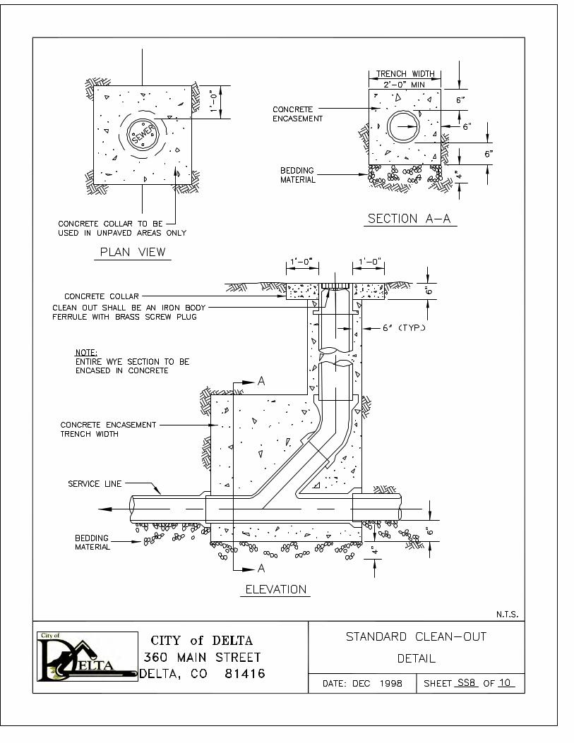

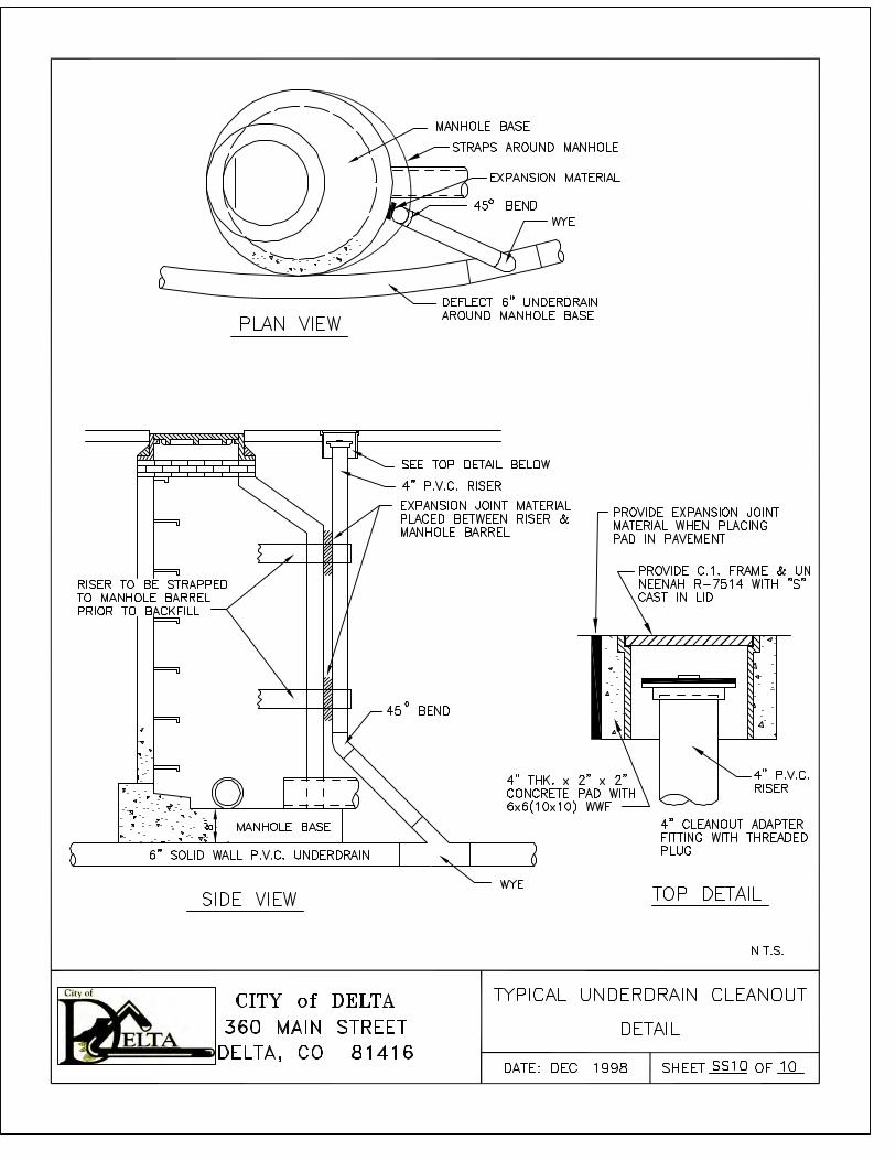

STANDARDS AND SPECIFICATIONS FOR THE DESIGN AND CONSTRUCTION OF PUBLIC
IMPROVEMENTS
Chapter 5
Storm Sewer System
2010 EDITION
TABLE OF CONTENTS
CHAPTER 5
STORM SEWER SYSTEM
Page
5.00.00 INTRODUCTION ...................................................................................................................................................................... 1
5.10.00 DESIGN CRITERIA .................................................................................................................................................................. 1
5.20.00 CONSTRUCTION SPECIFICATIONS .................................................................................................................................. 1
5.21.00 EXCAVATION AND TRENCHING ...................................................................................................................................... 1 5.22.00 BEDDING ................................................................................................................................................................................ 1
5.22.01 General .................................................................................................................................................................................. 1
5.22.02 Class A Bedding .................................................................................................................................................................... 1
5.22.03 Class B Bedding (Granular II) ............................................................................................................................................. 1
5.23.00 PIPELINE INSTALLATION .................................................................................................................................................. 1 5.23.01 General .................................................................................................................................................................................. 1
5.23.02 Pipe ........................................................................................................................................................................................ 2
5.24.00 MANHOLE CONSTRUCTION .............................................................................................................................................. 2 5.24.01 Cast-in-Place Base ............................................................................................................................................................... 2
5.24.02 Pre-Cast Base/Inverts ........................................................................................................................................................... 3
5.24.03 Pre-Cast Barrel ..................................................................................................................................................................... 3
5.24.04 Inlets ...................................................................................................................................................................................... 3
5.24.05 Manhole/Inlet Grouting Treatment ...................................................................................................................................... 3
5.24.06 Adjustment Rings .................................................................................................................................................................. 3
5.25.00 CONNECTIONS TO EXISTING MANHOLES .................................................................................................................... 3
5.30.00 TESTS .......................................................................................................................................................................................... 3
5.31.00 GENERAL ................................................................................................................................................................................ 3 5.31.01 Lamping Test ......................................................................................................................................................................... 3
5.31.02 Manhole Leakage Test .......................................................................................................................................................... 3
5.31.03 TV Inspection ........................................................................................................................................................................ 3
5.40.00 MATERIAL SPECIFICATIONS ............................................................................................................................................. 4
5.41.00 GENERAL ................................................................................................................................................................................ 4 5.42.00 DEFECTS ................................................................................................................................................................................. 4 5.43.00 CERTIFICATION .................................................................................................................................................................... 4 5.44.00 PIPE ............................................................................................................................................................................................ 4
5.44.01 Polyvinyl Chloride Pipe (PVC) ...................................................................................................................................................... 4
See Section 4.63.01 of these Standards and Specifications. ....................................................................................................................... 4
5.44.02 Reinforced Concrete Pipe (RCP) ......................................................................................................................................... 4
5.44.03 Corrugated Aluminum Pipe (CAP) ...................................................................................................................................... 4
5.44.04 Corrugated Polyethylene (PE) Pipe ..................................................................................................................................... 4
5.45.00 MANHOLES ............................................................................................................................................................................ 4 5.45.01 General .................................................................................................................................................................................. 5
5.45.02 Manhole Rings and Covers................................................................................................................................................... 5
5.45.03 Manhole Base Slabs .............................................................................................................................................................. 5
5.45.04 Joint Material ........................................................................................................................................................................ 5
5.45.05 Mortar ................................................................................................................................................................................... 5

1
CHAPTER 5
STORM SEWER SYSTEM
5.00.00 INTRODUCTION
All storm sewer systems shall comply with the requirements of these STANDARDS AND SPECIFICATIONS. All work performed according to this section must comply with the general requirements contained within Chapter 1 and the acceptance requirements of Chapter 10. Special criteria shall be outlined at pre-design meetings and in the approved construction plans, as determined necessary by the City.
5.10.00 DESIGN CRITERIA
All subdivisions, resubdivisions, planned unit development, or any other proposed construction submitted for approval under the provisions of the City of Delta Municipal Code shall include adequate storm drainage system analysis and appropriate drainage system plans, wet stamped by a licensed professional engineer, in conformance with the requirements in the Stormwater Management Manual.
5.20.00 CONSTRUCTION SPECIFICATIONS
5.21.00 EXCAVATION AND TRENCHING
Excavation, trenching and backfilling shall be done in accordance with Chapter 9 of these STANDARDS AND SPECIFICATIONS.
5.22.00 BEDDING
5.22.01 General
In the event unstable trench conditions are found at pipeline grade, a minimum of one and one-half inch uniformly graded, washed rock shall be used for trench stabilization. Depth of stabilization shall be as approved by the City. Pipe bedding shall be done in accordance with Sections 5.22.02 or 5.22.03 of these STANDARDS AND SPECIFICATIONS and the detail drawing in the Appendix of Chapter 4.
5.22.02 Class A Bedding
See Section 4.41.02 of these Standards and Specifications.
5.22.03 Class B Bedding (Granular II)
See Section 4.41.03 of these Standards and Specifications.
5.23.00 PIPELINE INSTALLATION
5.23.01 General
The City shall be notified at least 48 hours in advance of any pipe installation. The Responsible Party

2
shall notify and arrange for all utility locates prior to excavation. No pipes shall be backfilled until they have been inspected by the City. Alignment and grade of the pipe and the location of fittings, manholes and inlets shall be staked under the supervision of a professional surveyor registered in the State of Colorado.
Proper implements, tools and facilities shall be provided and used by the Responsible Party for the safe and convenient execution of the work. All pipe sections, pre-cast manholes and inlets sections, shall be carefully lowered into the trench by means of a derrick, ropes or other suitable tools or equipment to prevent damage to storm sewer line material. Under no circumstances shall storm sewer line materials be dropped or dumped into the trench.
All pipefittings shall be carefully examined for cracks and other defects immediately before installation. The groove in the bells of the pipe shall be full and continuous or the pipe will be rejected. Defective pipe or fittings shall be removed from the job site within 24 hours of notification by the City. All foreign matter or dirt shall be removed from the interior and ends of the pipe before they are lowered into position in the trench and prior to connection.
Every precaution shall be taken to prevent foreign material and trench water from entering the pipe and fittings. During construction, the Responsible Party shall provide and maintain adequate equipment to properly remove and dispose of all water entering the trench and any other part of the work.
5.23.02 Pipe
Pipe shall be laid from downstream to upstream with spigot ends pointing downstream. All pipe shall be placed true to line and grade and carefully centered and with a smooth invert at the joint. The joint shall be made in a workmanlike manner and shall be watertight. Immediately before joining two lengths of pipe, the inside of the bell and the outside of the spigot end and the gasket shall be thoroughly cleaned. Caution shall be exercised to ensure that the correct type of gasket is used. A thin film of gasket lubricant shall be applied to the inside face of the gasket and the spigot end of the pipe. The spigot end of the pipe shall be placed in the bell with care to prevent the joint from contacting the ground. The joint shall be completed by pushing the pipe home with a slow steady pressure, without jerky or jolting movements. Pipe furnished without a depth mark shall be marked before assembly to ensure insertion to the full depth of the joint. The pipe shall then be properly set and brought to correct line and grade. The pipe shall be secured in place by installation of bedding material and backfill, in accordance with Chapter 9 and the detailed drawings in the Appendix of this chapter.
Cutting of pipe for inserting closure pieces shall be done in a neat and workmanlike manner without damage to the pipe or lining, leaving a smooth end at right angles to the axis of the pipe.
No pipe or appurtenant structure shall be installed upon a foundation in which frost has penetrated or at any time when the City deems there is a danger of ice formation or frost penetrations at the bottom of the excavation. No pipe or appurtenant structure shall be installed unless backfilling can be completed before the formation of ice and frost.
5.24.00 MANHOLE CONSTRUCTION
5.24.01 Cast-in-Place Base
See Section 4.43.01 of these Standards and Specifications.

3
5.24.02 Pre-Cast Base/Inverts
See Section 4.43.02 of these Standards and Specifications.
5.24.03 Pre-Cast Barrel
See Section 4.43.03 of these Standards and Specifications.
5.24.04 Inlets
Inlets shall be constructed with Class A concrete, placed on undisturbed ground and in conformance with the detail drawings in the Appendix of Chapter 6. The top portion of inlets shall be constructed concurrently with the adjacent curb and gutter to ensure proper alignment of grades unless otherwise permitted in writing by the City Engineer.
5.24.05 Manhole/Inlet Grouting Treatment
See Section 4.43.04 of these Standards and Specifications.
5.24.06 Adjustment Rings
See Section 4.43.05 of these Standards and Specifications.
5.25.00 CONNECTIONS TO EXISTING MANHOLES
See Section 4.44.00 of these Standards and Specifications.
5.30.00 TESTS
5.31.00 GENERAL
See Section 4.49.00 of these Standards and Specifications.
5.31.01 Lamping Test
See Section 4.49.04 of these Standards and Specifications.
5.31.02 Manhole Leakage Test
See Section 4.49.06 of these Standards and Specifications.
5.31.03 TV Inspection
See Section 4.49.07 of these Standards and Specifications.

4
5.40.00 MATERIAL SPECIFICATIONS
5.41.00 GENERAL
See Section 4.60.00 of these Standards and Specifications.
5.42.00 DEFECTS
See Section 4.61.00 of these Standards and Specifications.
5.43.00 CERTIFICATION
See Section 4.62.00 of these Standards and Specifications.
5.44.00 PIPE
5.44.01 Polyvinyl Chloride Pipe (PVC)
See Section 4.63.01 of these Standards and Specifications.
5.44.02 Reinforced Concrete Pipe (RCP)
See Section 4.63.02 of these Standards and Specifications.
5.44.03 Corrugated Aluminum Pipe (CAP)
CAP and coupling bands for culverts shall conform to the requirements of AASHTO M-196 Type I or Type II. The pipe shall be fabricated with helical corrugations and a continuous lock seam. CAP shall be joined with gasketed coupling bands made of the same alloy as the pipe. Bands shall be corrugated to match the pipe ends and form a watertight seal. Gasket material shall be neoprene or other approved synthetic rubber.
5.44.04 Corrugated Polyethylene (PE) Pipe
Corrugated polyethylene pipe shall conform to AASHTO M-252 for sizes 3” through 10” and to AASHTO M-294 for sizes 12” through 36”. PE pipe for storm drains shall have a smooth interior (Type S).
5.44.05 Other Pipe Materials
All other pipe materials shall be submitted with a sample and specifications from the manufacturer during design for consideration and may only be used with written permission from the City. Pipe materials not approved prior to construction will not be considered for use.

5
5.45.00 MANHOLES
5.45.01 General
See Section 4.64.01 of these Standards and Specifications.
5.45.02 Manhole Rings and Covers
See Section 4.64.02
5.45.03 Manhole Base Slabs
See Section 4.64.03 of these Standards and Specifications.
5.45.04 Joint Material
See Section 4.64.04 of these Standards and Specifications.
5.45.05 Mortar
See Section 4.64.05 of these Standards and Specifications.

STANDARDS AND SPECIFICATIONS FOR THE DESIGN AND CONSTRUCTION OF PUBLIC
IMPROVEMENTS
Chapter 6
Roadway
2010 EDITION
TABLE OF CONTENTS
CHAPTER 6
ROADWAY
Page
6.00.00 GENERAL PROVISIONS ............................................................................................................................. 1
6.01.00 APPLICABILITY .................................................................................................................................................. 1
6.02.00 PRIVATE STREET SYSTEMS AND PARKING LOTS ............................................................................................... 1
6.03.00 CITY CAPITAL IMPROVEMENT PROJECTS .......................................................................................................... 1
6.10.00 ROADWAY DESIGN AND TECHNICAL CRITERIA ............................................................................. 1
6.11.00 LOCAL STREET .................................................................................................................................................. 1
6.11.01 Local ............................................................................................................................................................... 1
6.11.01 Estate Local .................................................................................................................................................... 2
6.12.00 COLLECTOR STREET .......................................................................................................................................... 3
6.13.00 ARTERIAL STREET ............................................................................................................................................. 4
6.13.01 Minor Arterial ................................................................................................................................................. 4
6.13.02 Principal Arterial (4-Lane)............................................................................................................................. 5
6.14.00 DRAINAGE ......................................................................................................................................................... 6
6.14.01 Crosspans ....................................................................................................................................................... 6
6.14.02 Inlets ............................................................................................................................................................... 6
6.14.03 Sidewalk Chases ............................................................................................................................................. 6
6.14.04 Temporary Erosion Control ........................................................................................................................... 7
6.15.00 HORIZONTAL ALIGNMENT ................................................................................................................................. 7
6.15.01 Horizontal Curves ........................................................................................................................................... 7
6.15.02 Curb Return Radius ........................................................................................................................................ 7
6.15.03 Design Speed .................................................................................................................................................. 7
6.15.04 Spiral Curves .................................................................................................................................................. 8
6.15.05 Small Deflection Angles .................................................................................................................................. 8
6.15.06 Compound Curves .......................................................................................................................................... 8
6.15.07 Reversing Curves ............................................................................................................................................ 8
6.15.08 Broken-Back Curves ....................................................................................................................................... 8
6.15.09 Alignment at Bridges ...................................................................................................................................... 8
6.15.10 Coordination With Vertical Alignment ........................................................................................................... 9
6.16.00 VERTICAL ALIGNMENT ...................................................................................................................................... 9
6.16.01 Permissible Roadway Grade .......................................................................................................................... 9
6.16.02 Permissible Intersection Grades (Public Rights-of-Way) .............................................................................. 9
6.16.03 Changing Grades .......................................................................................................................................... 10
6.16.04 Vertical Curves ............................................................................................................................................. 10
6.16.05 Intersections.................................................................................................................................................. 10
6.16.06 Curb Returns................................................................................................................................................. 11
6.16.07 Curb Return Profiles .................................................................................................................................... 11
6.16.08 Connection With Existing Roadways ............................................................................................................ 12
6.17.00 SIGHT DISTANCES ............................................................................................................................................ 12
6.17.01 General ......................................................................................................................................................... 12
6.17.02 Sight Distance Triangle ................................................................................................................................ 13
6.18.00 ROADWAY CROWN .......................................................................................................................................... 13
6.18.01 Cross Slope ................................................................................................................................................... 13
6.18.02 Superelevation .............................................................................................................................................. 14
6.19.00 SIDEWALKS, CURB AND GUTTERS, AND ADA RAMPS ....................................................................... 15
6.20.00 CUL-DE-SACS .................................................................................................................................................. 16
6.21.00 DECELERATION LANES .................................................................................................................................... 16
6.22.00 ACCELERATION LANES .................................................................................................................................... 17
6.23.00 OFF-SITE DESIGN............................................................................................................................................. 17
6.24.00 DEAD-END ROADS ...................................................................................................................................... 18
6.25.00 INTERSECTION SPACING........................................................................................................................... 18
6.30.00 PAVEMENT DESIGN AND TECHNICAL CRITERIA .......................................................................... 18
6.31.00 GENERAL ...................................................................................................................................................... 18
6.32.00 SUBGRADE INVESTIGATION ............................................................................................................................. 18
6.32.01 Field Investigation ........................................................................................................................................ 18
6.32.02 Classification Testing ................................................................................................................................... 18
6.32.03 Soil Grouping ............................................................................................................................................... 19
6.32.04 Subgrade Support Testing ............................................................................................................................ 19
6.4000 STREET CONSTRUCTION STANDARDS .............................................................................................. 19
6.41.00 GENERAL ...................................................................................................................................................... 19
6.42.00 COMPACTION IN UTILITY TRENCHES .............................................................................................................. 19
6.43.00 EXCAVATION AND EMBANKMENT ................................................................................................................... 20
6.43.01 General ......................................................................................................................................................... 20
6.43.02 Clearing and Grubbing ................................................................................................................................ 20
6.43.03 Removal of Existing Structures ..................................................................................................................... 21
6.43.04 Salvage.......................................................................................................................................................... 22
6.43.05 Disposal ........................................................................................................................................................ 22
6.43.06 Excavation and Embankment ....................................................................................................................... 22
6.43.07 Select Borrow Material ................................................................................................................................ 23
6.43.07 Select Borrow Material ................................................................................................................................ 23
6.44.00 SUBGRADE PREPARATION AND GRADING ....................................................................................................... 23
6.44.01 General ......................................................................................................................................................... 23
6.44.02 Subgrade Stabilization .................................................................................................................................. 23
6.44.03 Lime and Cement Treated Subgrade ............................................................................................................ 24
6.45.00 SUBBASE CONSTRUCTION ............................................................................................................................... 24
6.45.01 General ......................................................................................................................................................... 24
6.45.02 Placement and Compaction .......................................................................................................................... 24
6.46.00 BASE CONSTRUCTION ...................................................................................................................................... 24
6.46.01 General ......................................................................................................................................................... 24
6.46.02 Base Course .................................................................................................................................................. 24
6.46.03 Placement and Compaction .......................................................................................................................... 25
6.46.04 Base Surface Tolerance ................................................................................................................................ 25
6.47.00 BITUMINOUS CONSTRUCTION ......................................................................................................................... 25
6.47.01 Hot Bituminous Pavement ............................................................................................................................ 25
6.47.02 Tack Coat ...................................................................................................................................................... 25
6.47.03 Seal Coat....................................................................................................................................................... 26
6.47.04 Rejuvenating Agent ....................................................................................................................................... 26
6.47.05 Heating and Scarifying ................................................................................................................................. 26
6.47.06 Grinding........................................................................................................................................................ 26
6.48.00 APPURTENANT CONCRETE STRUCTURES ........................................................................................................ 27
6.48.01 Curb and Gutter Section ............................................................................................................................... 27
6.48.02 Sidewalks ...................................................................................................................................................... 27
6.48.03 Crosspans and Curb Return Fillets .............................................................................................................. 27
6.48.04 Curb Cuts and Driveways ............................................................................................................................. 27

6.48.05 Curb Ramps .................................................................................................................................................. 27
6.48.06 Construction Stakes ...................................................................................................................................... 28
6.48.07 Backfilling ..................................................................................................................................................... 28
6.48.08 Connections with Existing Concrete Curb, Gutter, and Drives.................................................................... 28
6.49.00 MONUMENTATION ............................................................................................................................ 28
6.60.00 BRIDGES AND MAJOR DRAINAGE STRUCTURES ........................................................................... 28
6.60.01 General ......................................................................................................................................................... 28
6.70.00 CONSTRUCTION TRAFFIC CONTROL ................................................................................................ 29
6.80.00 MATERIAL SPECIFICATIONS ................................................................................................................ 29
6.81.00 SUBBASE ....................................................................................................................................................... 29
6.82.00 BASE ............................................................................................................................................................... 29
6.83.00 BITUMINOUS MATERIALS ................................................................................................................................ 30
6.83.01 Prime Coat .................................................................................................................................................... 30
6.83.02 Hot Bituminous Pavement ............................................................................................................................ 30
6.83.03 Tack Coat ...................................................................................................................................................... 30
6.83.04 Seal Coat....................................................................................................................................................... 30
6.83.05 Rejuvenating Agent ....................................................................................................................................... 31
6.83.06 Appurtenant Structures Concrete ................................................................................................................. 31
6.84.00 STRUCTURE BACKFILL MATERIAL .................................................................................................................. 31
1
CHAPTER 6
ROADWAY 6.00.00 GENERAL PROVISIONS
6.01.00 APPLICABILITY
This chapter contains minimum criteria to be met on all streets and parking lots designed and constructed in the City, by both the Responsible Party and/or by the City. All work performed according to this section must comply with the general requirements contained within Chapter 1 and the acceptance requirements of Chapter 10.
6.02.00 PRIVATE STREET SYSTEMS AND PARKING LOTS
Private street systems and parking lots shall be subject to all minimum requirements of these STANDARDS AND SPECIFICATIONS. Traffic studies may be required by the City of Delta, refer to Chapter 8 for the requirements of such study.
6.03.00 CITY CAPITAL IMPROVEMENT PROJECTS
It is recognized that the minimum requirements contained in these STANDARDS AND SPECIFICATIONS are not necessarily sufficient for plans, specifications, and contract administration purposes for City administered street capital improvement projects. Accordingly, the City Representative is authorized to develop and/or approve such additional requirements and procedures necessary for bidding, awarding, and administering for such projects, provided said additional requirements and procedures are substantially consistent with these STANDARDS AND SPECIFICATIONS and applicable provisions of other City ordinances and resolutions.
6.10.00 ROADWAY DESIGN AND TECHNICAL CRITERIA
This section sets forth the minimum design and technical criteria and specifications to be used in the preparation of all roadway plans. Within this chapter, AASHTO "Green Book" refers to "A Policy on Geometric Design of Highways and Streets -- 2004" as published by the American Association of State Highway and Transportation Officials. Design of streets within a defined “estate subdivision” shall be in accordance with the most current City Subdivision Regulations within the City Municipal Code.
6.11.00 LOCAL STREET
6.11.01 Local
An urban local street is a general term denoting a roadway designed or operating with the following characteristics:
(A) Posted Speed Limit. Between 25 and 30 miles per hour. Posted or prima facia speeds
for the various street classifications are normally five (5) to ten (10) miles per hour less than the design speed of that street.
(B) Traffic Volumes. Less than 2,500 vehicles per day. (C) Limited Continuity.

2
(D) Safety. Designed for the safety of pedestrians and bicyclists and the ease of access to
adjacent parcels of land. (E) Traffic Control. Stop signs. Traffic requirements in other than residential areas may
require special design consideration by the applicant’s engineer and the City. (F) Function. Urban local streets provide direct access to adjacent property. Traffic
carried by local streets should have an origin or a destination with the neighborhood. Local streets are utilized in single family residential areas. Utility line easements shall be provided. Easements shall be a minimum of 20 feet on each side of the street.
(G) Right-of-Way. Fifty feet (50') minimum. (H) Number of Moving Lanes. Two. (I) Access Conditions. In accordance with Chapter 8 of these STANDARDS AND
SPECIFICATIONS. (J) Planning Characteristics. Urban local streets should not intersect major arterial
streets. (K) Type of Curb and Gutter. Six inch (6”) vertical curb and twenty-four (24”) inch
gutter. The use of the combination curb, gutter and sidewalk is strongly discouraged and may only be used on local streets with prior approval from the City. Combination curb, gutter and sidewalk shall conform to the standard detail in the appendix of this chapter.
(L) Sidewalk Width. Five foot (5’) minimum. Detached from curb or as per combination
curb, gutter and sidewalk detail in the Appendix of this chapter. (M) Cul-De-Sacs. In accordance with Section 6.20.00 of these STANDARDS AND
SPECIFICATIONS. (N) Street Widths. Thirty-four foot (34’) paved width plus two (2) two foot (2’) gutter
pans.
6.11.01 Estate Local
An estate local street is a general term denoting a roadway designed or operating with the following characteristics:
(A) Posted Speed Limit. Between 25 and 30 miles per hour. Posted or prima facia speeds
for the various street classifications are normally five (5) to ten (10) miles per hour less than the design speed of that street.
(B) Traffic Volumes. Less than 2,500 vehicles per day. (C) Limited Continuity.

3
(D) Safety. Designed for the safety of pedestrians, bicyclists and other users adjacent to the roadway and the ease of access to adjacent parcels of land.
(E) Traffic Control. Stop signs. Traffic requirements in other than residential areas may
require special design consideration by the applicant’s engineer and the City. (F) Function. Estate local streets provide direct access to adjacent property. Traffic
carried by estate local streets should have an origin or a destination with the neighborhood. Estate local streets are utilized in large lot single family residential areas with the approval of the City. 20 foot wide utility line easements shall be provided on each side of the street.
(G) Right-of-Way. Sixty feet (60') minimum. (H) Number of Moving Lanes. Two. (I) Access Conditions. In accordance with Chapter 8 of these STANDARDS AND
SPECIFICATIONS. (J) Planning Characteristics. Estate local streets should not intersect major arterial
streets. (K) Type of Curb and Gutter. Curb and gutter is generally not required for this section.
Barrow ditches conforming to the street section referenced above is acceptable. (L) Sidewalk Width. Five foot (5’) minimum. Located between the barrow ditch and
property line. (M) Cul-De-Sacs. In accordance with Section 6.20.00 of these STANDARDS AND
SPECIFICATIONS. (N) Street Widths. Thirty-six foot (36’) paved width plus two (2) two foot (2’) gravel
based shoulders.
6.12.00 COLLECTOR STREET
A collector is a general term denoting a roadway designed or operating with the following characteristics:
(A) Posted Speed Limit. Between 30 and 40 miles per hour. Posted or prima facia speeds for the various street classifications are normally five (5) to ten (10) miles per hour less than the design speed of that street.
(B) Traffic Volumes. Generally less than 7000 vehicles per day. (C) Continuous. For less than two (2) miles.

4
(D) Safety. Designed to handle traffic volumes loading from and onto local, other collector, and arterial roadways.
(E) Traffic Control. Regulation of traffic accomplished through the use of stop signs and
channelization. Traffic signals normally used only at intersections with major collectors and arterial streets.
(F) Driveways. No back-out drives permitted. (G) Function. Collector streets collect and distribute traffic between arterial and local
streets and serve as main connectors within communities, linking one neighborhood with another. Traffic carried by collector streets should have an origin or a destination within the community. 20 foot wide utility easements shall be provided on each side of the street.
(H) Right-of-Way Width. Sixty-foot (60’) minimum. (I) Number of Moving Lanes. A minimum of two (2). (J) Access Conditions. In accordance with Chapter 8 of these STANDARDS AND
SPECIFICATIONS. (K) Planning Characteristics. Collector streets should have continuity throughout a
neighborhood but need not extend beyond the neighborhood intersections with collectors, major collectors, and arterial streets should be at least one-quarter (1/4) mile apart.
(L) Type of Curb and Gutter. Six (6) inch vertical and twenty-four (24”) inch gutter. (M) Sidewalk Width. Five foot (5’) minimum. Detached from curb. (N) Street Widths. Thirty-eight foot (38’) paved width plus two (2) - two foot (2’) gutter
pans.
6.13.00 ARTERIAL STREET
6.13.01 Minor Arterial
A minor arterial street is a general term denoting a roadway designated or operating with the following characteristics:
(A) Posted Speed Limit. Between 40 and 45 miles per hour. Posted or prima facie speeds for the various street classifications are normally five (5) to ten (10) miles per hour less than the design speed of that street.
(B) Traffic Volumes. Twelve thousand (12,000) vehicles per day expected minimum
traffic volume when the land which the arterial serves is fully developed. (C) Access. In accordance with Chapter 8 of these STANDARDS AND
5
SPECIFICATIONS. (D) Continuity. Several miles, generally connecting with inter-city routes. (E) Traffic Control. Regulation of traffic accomplished by signs and channelization.
Traffic signals will normally be located only at intersections with streets of high classification. Parking should be prohibited.
(F) Function. Arterial routes permit relatively unimpeded traffic movement and are
intended for use on these routes where four (4) moving lanes and one (1) left-turn lane are required but where a major arterial cross-section would not be warranted. No parking is allowed. 20 foot wide (wider?) utility easements shall be provided on each side of the road.
(G) Right-of-Way Width. Eighty feet (80') minimum. (H) Number of Moving Lanes. Four (4). (I) Planning Characteristics. Arterials should be spaced from one-half (1/2) to one (1)
mile apart and should, where possible, be continuous. Arterials should act as boundaries between neighborhood areas. Arterial cross-section should be employed where traffic demands are high and right-of-way acquisition costs are prohibitive. Detached sidewalk required. Separate major land uses.
(J) Type of Curb and Gutter. Six inch (6”) vertical and twenty-four inch (24”) gutter. (K) Sidewalk Width. Six-foot (6') minimum, detached from curb, or as required by the
City Representative. (L) Street Widths. Two (2) twelve-foot (12') travel lanes, two (2) ten-foot (10’) travel
lanes with two (2) two-foot (2') gutter pans. Total street width shall be forty eight feet (48') flowline to flowline.
6.13.02 Principal Arterial (4-Lane)
A major arterial street is a general term denoting a roadway designated or operating with the following characteristics:
(A) Posted Speed Limit. Greater than or equal to 45 miles per hour. Posted or prima facie speeds for the various street classifications are normally five (5) to ten (10) miles per hour less than the design speed of that street.
(B) Traffic Volumes. Nineteen thousand (19,000) vehicles per day expected minimum
traffic volume when the land which the arterial serves is fully developed. (C) Access. In accordance with Chapter 8 of these STANDARDS AND
SPECIFICATIONS. (D) Continuity. Several miles, generally connecting with inter-city routes.
6
(E) Traffic Control. Movement of traffic will be controlled by signals and channelization. Parking shall be prohibited. Roadways should have a raised median strip between them.
(F) Function. Major arterial streets permit rapid and relatively unimpeded traffic
movement throughout the country, connecting major lane use element, as well as communities with one another. No parking is allowed. 20 foot wide (wider?) utility easements shall be provided on each side of the road.
(G) Right-of-Way Width. One-hundred feet (100') minimum. (H) Number of Moving Lanes. Four (4). (I) Planning Characteristics. Major arterial streets should be spaced approximately one
(1) mile apart and should traverse the entire city. Major arterial streets should not bisect neighborhoods but should act as boundaries between them.
(J) Type of Curb and Gutter. Six (6) inch vertical with twenty-four inch (24”) gutter on
outside of traveled way; six (6) inch vertical with one foot (1’) pan on medians. (K) Sidewalk Width. Six-foot (6') minimum, detached from curb, or as required by the
City Representative. (L) Street Widths. Two (2) twelve-foot (12') travel lanes and two (2) ten-foot (10’) travel
lanes with two (2) two-foot (2’) gutter pans, from one (1) sixteen foot (16’) raised median, two (2) one-foot (1') median gutter pans, plus necessary left-turn and acceleration/deceleration lanes, and minimum four-foot (4') raised median at intersections. Total street width shall be sixty-four feet (64’) flowline to flowline.
6.14.00 DRAINAGE
6.14.01 Crosspans
Crosspans shall be constructed in accordance with the detail drawing. Crosspans are not permitted across collector or arterial roadways. Double crosspans may be used parallel to collectors or arterial roadways to convey storm runoff across residential roadways. The use of double crosspans elsewhere, or the use of any crosspan on roadways where the vertical grade exceeds four-and-one-half percent (4.5%) will be considered only after all alternatives have been exhausted.
6.14.02 Inlets
Inlets shall be located to intercept the curb flow at the point curb flow capacity is exceeded by storm runoff. Inlets shall also be installed to intercept cross-pavement flows at points of transition in superelevation. Due to the presence of handicap ramps, inlets shall not be allowed in the curb return but shall be located outside the tangent points of the curb returns. Gutter transition sections abutting inlets shall not be within the curb return.
6.14.03 Sidewalk Chases
Storm water from concentrated points of discharge shall not be allowed to flow over sidewalks
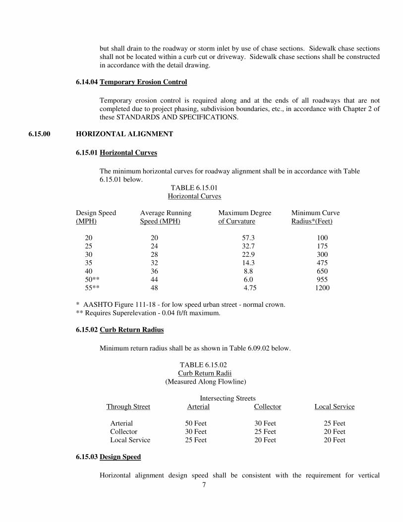
7
but shall drain to the roadway or storm inlet by use of chase sections. Sidewalk chase sections shall not be located within a curb cut or driveway. Sidewalk chase sections shall be constructed in accordance with the detail drawing.
6.14.04 Temporary Erosion Control
Temporary erosion control is required along and at the ends of all roadways that are not completed due to project phasing, subdivision boundaries, etc., in accordance with Chapter 2 of these STANDARDS AND SPECIFICATIONS.
6.15.00 HORIZONTAL ALIGNMENT
6.15.01 Horizontal Curves
The minimum horizontal curves for roadway alignment shall be in accordance with Table 6.15.01 below.
TABLE 6.15.01 Horizontal Curves
Design Speed Average Running Maximum Degree Minimum Curve (MPH) Speed (MPH) of Curvature Radius*(Feet) 20 20 57.3 100 25 24 32.7 175 30 28 22.9 300 35 32 14.3 475 40 36 8.8 650 50** 44 6.0 955 55** 48 4.75 1200
* AASHTO Figure 111-18 - for low speed urban street - normal crown. ** Requires Superelevation - 0.04 ft/ft maximum.
6.15.02 Curb Return Radius
Minimum return radius shall be as shown in Table 6.09.02 below.
TABLE 6.15.02
Curb Return Radii (Measured Along Flowline)
Intersecting Streets
Through Street Arterial Collector Local Service
Arterial 50 Feet 30 Feet 25 Feet Collector 30 Feet 25 Feet 20 Feet Local Service 25 Feet 20 Feet 20 Feet
6.15.03 Design Speed
Horizontal alignment design speed shall be consistent with the requirement for vertical

8
alignment design speed. If no superelevation is required and normal crown section exists, the horizontal curve data as shown in Table 6.15.01 shall be used.
6.15.04 Spiral Curves
Spiral curves shall be used only on arterial roadways within the City of Delta and only upon written approval of the City Representative.
6.15.05 Small Deflection Angles
For small deflection angles, curves should be sufficiently long to avoid the appearance of a kink. Curves should be at least five hundred (500) feet long for a central angle of five degrees (5o), and the minimum length should be increased one hundred feet (100') for each one-degree (1o) decrease in the central angle. Horizontal curves should not be used when the central angle is fifty-nine minutes (59') or less.
6.15.06 Compound Curves
A compound curve on arterials should be avoided, particularly where a simple curve can be obtained. Where topography makes their use necessary, the radius of the flatter curve should not be more than fifty percent (50%) greater than the radius of the sharper curve. When this is not feasible, an intermediate curve or spiral should be used to provide the necessary transitions. Spiral curves are only to be used upon written approval of the City Representative.
6.15.07 Reversing Curves
True reversing curves should not be used. In cases of reversing curves, a sufficient tangent should be maintained to avoid overlapping of the required superelevation runoff and tangent runout. The following is the minimum tangent lengths that shall be used for each roadway classification:
(A) Local -- not applicable. (B) Collector -- Fifty feet (50') minimum. (C) Arterial -- One hundred feet (100') minimum.
6.15.08 Broken-Back Curves
A broken-back curve consists of two (2) curves in the same direction joined by a short tangent, of length less than one thousand five hundred feet (1500'). Broken-back curves are undesirable. If the length of intervening tangent is less than one thousand five hundred feet (1500'), a simple curve, a compound curve, or spiral transitions should be used to provide some degree of continuous superelevation. Spiral curves are only to be used upon written approval of the City Representative.
6.15.09 Alignment at Bridges
Ending a curve on a bridge is undesirable and adds to the complication of design and

9
construction. Likewise, curves beginning or ending near a bridge should be so placed that no part of the spiral or superelevation transitions extends onto the bridge. Compound curves on a bridge are equally undesirable. If curvature is unavoidable, every effort should be made to keep the bridge within the limits of the simple curve.
6.15.10 Coordination With Vertical Alignment
To avoid the possibility of introducing serious traffic hazards, coordination is required between horizontal and vertical alignment. Particular care must be exercised to maintain proper sight distance at all times. Sharp horizontal curves introduced at or near the top of pronounced crest or bottom of sag vertical curves should be avoided. Vertical curvature superimposed upon horizontal curves, or vice versa, generally results in a more pleasing facility.
6.16.00 VERTICAL ALIGNMENT
Vertical Alignment Control Table Design Controls for vertical alignment are shown on Table 6.16.00.
TABLE 6.16.00 Vertical Alignment Controls
Design Maximum K Value Ranges Minimum VCL Description Speed* Grade** Crest Sag Crest Sag Local 35 8 40-50 50-50 50 50 Minor Collector 40 8 60-80 60-70 50 50 Minor Arterial 50 6 110-160 90-110 100 80 Principal Arterial*** 55 6 150-220 100-130 110 90 * The design speed is a minimum of 5 miles per hour over the posted speed for each classification. ** The maximum grades indicated should only be used in extreme topographic conditions. The designer should
strive to minimize the use of these grades for considerable lengths and on north-facing slopes. *** K values exceeding 125 on curbed streets should be checked for drainage. Multiple inlets may be required
within long sag on vertical curves, and where the longitudinal slope is less than 0.4 percent. 6.16.01 Permissible Roadway Grade
The minimum allowable grade for roadways is one-half percent (0.5%). The minimum allowable grade for bubbles and cul-de-sacs within the bulb is one percent (1%). The maximum allowable grade for any roadway is shown in Table 6.16.00 above. In extreme terrain, defined as having existing slopes of 10% or greater, where it is difficult to maintain the maximum grades shown, steeper grades (up to 10%) may be designed into the road profile. In these circumstances, the grade shall be decreased to 6% for 50 feet before entering a switchback and decreased to 4% for 50 feet before approaching a road intersection as measured from the intersecting street flowline.
6.16.02 Permissible Intersection Grades (Public Rights-of-Way)
10
The maximum permissible grade at intersections shall be 4% and extend a minimum of 50 feet in each direction from the flowline of the existing street. Desirable intersection grades should be in the range of one percent (1%) to four percent (4%) of all intersecting streets with the limit of two percent (2%) for arterials. The intersection grade of the major (through) street at the intersection may be dictated by design considerations for the street. However, if the major street intersection grade exceeds three percent (3%), the type of access and access control will be as directed by the City Representative. All private commercial driveways with curb return radii shall follow the standards set forth for a local street. The length of the maximum grade for the commercial driveway shall be a minimum of fifty feet (50') measured from the flowline intersection of the public roadway.
6.16.03 Changing Grades
The use of grade breaks in lieu of vertical curves is discouraged. However, if a grade break is necessary and the algebraic difference in grade does not exceed eight-tenths of a percent (0.008 ft./ft.) along the roadway, the grade break will be permitted. The maximum grade break allowed at the point of tangency at a curb return for local and collector roads shall be two percent (2%) and for arterial roadways a maximum of one percent (1%).
6.16.04 Vertical Curves
When the algebraic difference in grade (A) is at, or exceeds, eight-tenths of a percent, a vertical curve is to be used. Design criteria for vertical curves is found in Table 6.16.00 of this chapter. The minimum gradients into and out of a sag (sump) vertical curve is five-tenths of a percent (0.005 ft./ft.). Minimum length of a vertical curve is shown in Table 6.10.00 of this chapter. All vertical curves shall be labeled in the profile with length of curve (L), K=L/A values, VPC, VPT, VPI, and stationing and elevation of these components. In addition, the low point or high point of the vertical curve shall be shown.
6.16.05 Intersections
In addition, the following criteria shall apply at intersections.
(A) The grade of the "through" street shall take precedence at intersections. At the
intersections of roadways with the same classification, the more important roadway, as determined by the City Representative, shall have this precedence. The design should warp side streets to match through streets with as short a transition as possible.
(B) The key criteria for determining the elevation of the curb return on the side street and
the amount of warp needed on a side street transitioning to a through street are: 1. Permissible grade in the stop/start lane. See Section 6.16.02 of these
STANDARDS AND SPECIFICATIONS. 2. Pavement cross slope at the PCR's on the side street and permissible warp in
pavement cross slope. 3. Normal vertical curve criteria.

11
4. Vertical controls within the curb return itself.
(C) The elevation at the PCR of the curb return on the through street is always set by the
grade of the through street in conjunction with pavement cross slope. (D) Carrying the crown at a side street into the through street is permitted only when
drainage considerations warrant such a design. (E) A more detailed review shall be performed for arterial-arterial intersections to
maximize driveability. A few arterial intersections will have a uniform two percent (2%) cross-slope, the majority of them having one or more sides warped.
(F) Whenever possible, intersections shall be made at right angles or radial to a curve. No
intersecting angle of less than seventy-five degrees (75o) will be allowed.
6.16.06 Curb Returns
Minimum fall around curb returns for flow along the curb line shall be as follows:
Table 6.16.06 Curb Returns
Radius Minimum Fall 20 Feet 0.3 Feet 25 Feet 0.4 Feet 30 Feet 0.4 Feet 50 Feet 0.5 Feet All Others 1.2 Percent Around the Return 6.16.07 Curb Return Profiles
Curb return profiles are required for radii equal to or greater than twenty five (25') within the public right-of-way. A mid-point elevation along the arc length of the curb return shall be shown in plan view for radii equal to or greater than twenty-five feet (25'). Curb return design shall be set in accordance with the following design procedure. General standards for flowline control and profiles with the curb returns shall be as follows:
(A) The point of tangency at each curb return shall be determined by the projected tangent grade beginning at the point of intersection (PI) of the flowlines.
(B) The arc length and external distances of the curb return shall be computed and indicated
on the drawing. (C) Show the projected flowline (or top of curb) grade for each roadway beyond the PCR.
(D) Design the flowline of the curb return such that a maximum cross slope between the mid-point of the curve and the PICR (external distance) does not exceed five percent (5%). Grade breaks at the PCRs shall not exceed two percent (2%) for local and collector streets and one percent (1%) for arterials. The flowline design of the curb return shall be accomplished within the return without affecting street grades beyond
12
the PCR. Maximum vertical curves will equal the arc length of the curb return. The elevation and location of the high or low point within the return, if applicable, is to be called out in the profile.
(E) Scale for the curb return profile to be one inch equals one foot (1"=1’) vertically.
6.16.08 Connection With Existing Roadways
(A) Connection with existing roadways shall be smooth transitions conforming to normal
vertical curve criteria if the algebraic difference in grade between the existing and proposed grade exceeds eight-tenths (0.008 ft./ft.) of a percent. When a vertical curve is used to make this transition, it shall be fully accomplished prior to the connection with the existing improvements and shall also comply with the grade requirements at intersection approaches.
(B) Existing grade shall be shown for at least three hundred feet (300') with field verified
record drawings showing stations and elevations at twenty-five-foot (25') intervals. In the case of connection with an existing intersection, these record drawings are to be shown within a three-hundred-foot (300') radius of the intersection. This information will be included in the plan and profile that shows that proposed roadway. Limits and characteristics of the proposed improvement are the primary concern in the plan view. Such characteristics include horizontal alignment, off-site intersections, limits of the improvement, etc.
(C) Previously approved designs for the proposed improvement are not an acceptable
means of establishing existing grades. However, they are to be referenced on the construction plan where they occur.
(D) The basis of the as-built elevations shall be the design elevations (both flowline or both
top of curbs, etc.) when possible.
6.17.00 SIGHT DISTANCES
6.17.01 General
The major considerations in alignment design are safety, grade, profile, road area, design speed, sight distance, topography, drainage, and performance of heavy-duty vehicles. The road alignment should provide for safe and continuous operation at a uniform design speed. New road layout shall bear a logical relationship to existing or platted roads in adjacent properties. Design for site distances shall be in accordance with the following: Adequate intersection design necessitates the provision of safe ingress and egress from one street or driveway to the other, based in part on the ability of a driver to see oncoming vehicles or pedestrians. The following guidelines shall be used in the design of intersections, private driveways and public streets that intersect other traffic carrying facilities.

13
6.17.02 Sight Distance Triangle
At the intersection of two public streets or a private driveway and a public street, sight distance shall be evaluated across a “sight distance triangle” where obstructions are restricted according to the following criteria. Within the area of the triangle there shall be no wall, fence, sign, foliage, berming or other structure which will obscure the driver’s view of traffic approaching that intersection. The structures or berms within the sight distance triangle can extend no higher than 24 inches above the curb elevation and no lower than eight feet above the curb. Exceptions to this requirement exist for public facilities such as fire hydrants, utility poles and traffic control devices. These facilities must be located to minimize visual obstruction. The sight distance triangle shall comply with the drawings found in details contained in the appendix of this chapter. The sight distance triangle is based on the classification of the intersecting street and is based on the property lines of the adjacent parcels.
When street grades are steeper than 3.0%, adjustments must be made to compensate for the different distances required to reach the speed of highway traffic. Adjustment factors are provided in Table 6.17.01.
TABLE 6.17.01 Factors for the Effect of Grade on Sight Distance
Grade Downgrade Factor 1 Upgrade Factor 2 0 – 3% 1.0 1.0
3.1 - 5% 0.6 1.4 5.1 - 8% 0.5 1.7
1 When the highway in the section to be used for acceleration after leaving the access descends, sight distance in the direction of approaching descending highway traffic should be reduced by these factors.
2 When the highway in the section to be used for acceleration after leaving the access ascends,
then sight distance in the direction of approaching ascending should be increased by these factors.
6.18.00 ROADWAY CROWN
6.18.01 Cross Slope
Except at intersections or where superelevation is required, roadways shall be level from top of curb to top of curb (or flowline to flowline) and shall have a minimum two percent (2%) crown. Within one-hundred-fifty feet (150') of an intersection, the maximum elevation difference between flowlines shall be dictated by the allowable intersection grade and the actual distance between flowlines.
(A) Parabolic or curved crowns are not allowed. In no case shall the pavement cross slope

14
at warped intersections exceed the grade of the through street. (B) The rate of change in pavement cross slope when warping side streets at intersections
shall not exceed one percent (1%) every twenty-five feet (25') horizontally on a local roadway, one percent (1%) every thirty-seven-and-one-half feet (37.5') horizontally on a collector roadway, or one percent (1%) every fifty-six-and-one-half feet (56.5') horizontally on arterial roadway.
6.18.02 Superelevation
Superelevation is required for curves on all arterial roadways and selected collector roadways. Horizontal curve radius on superelevation shall be in accordance with the recommendations of the AASHTO "A Policy on Geometric Design of Highways and Streets”, latest edition (Green Book).
Superelevation shall not be used on local or other roadway classifications with a design speed of 40 miles per hour or less. The following procedure is an outline for the correct application of superelevation on roadways within the City of Delta.
(A) Definitions Regarding Superelevation: Superelevation Runoff. That length of roadway needed to accomplish the change in cross slope from a section with the adverse crown removed (flat) to the fully superelevated section, or vice versa.
Transition Points. Beginning or ending of tangent run-out, superelevation runoff, or full superelevation. Tangent Run-Out. That length of roadway needed to accomplish the change in cross slope from a normal (2 percent) crown section to a section with the adverse crown removed (flat), or vice versa.
(B) General: One of the most important factors to consider in highway safety is the centrifugal force generated when a vehicle traverses a curve. Centrifugal force increases as the velocity of the vehicle and/or the degree of curvature increases. In order to overcome the effects of centrifugal force, curves should be superelevated. It is impossible to balance centrifugal force by superelevation alone because for any given curve radius a certain superelevation rate is exactly correct for only one driving speed. At all other speeds there will be a side thrust either outward or inward, relative to the curve center, which must be offset by side friction.
(C) Standards for Superelevation:
AASHTO’s Green Book, Table 111-8 on superelevation give the required rates of superelevation for the various degree of curvature. Maximum superelevation rate of 0.04 foot per foot are commonly used on major streets.
(D) Urban Street Conditions:
Every effort should be made to maintain standard rates of superelevation. However, in

15
urban areas street intersections, established street grades, curbs, and drainage conditions may require a reduction in the rate of superelevation or different rates for each half of the road bed. In warping areas for drainage, adverse superelevations should be avoided.
6.19.00 SIDEWALKS, CURB AND GUTTERS, AND ADA RAMPS
(A) Roadway typical sections shall be as specified by these STANDARDS AND
SPECIFICATIONS. (B) Sidewalks or bicycle paths shall be constructed on both sides of all roadways unless approved
by the City. (C) All sidewalks used in conjunction with vertical curb and gutter shall have a minimum width of
five feet (5'). (D) Vertical curb, gutter, and detached walk shall be used on all occasions. Combination curb,
gutter, and walk may be approved for use only on local streets and in certain circumstances and must be approved in advance by the City Representative. No monolithic pours of vertical curb, gutter and sidewalk will be permitted without approval from the City Representative.
(E) Expansion joints shall be used for every 100 lineal feet of concrete poured and at every change in concrete thickness.
(F) State law requires that handicap ramps be installed at all intersections and at certain mid-block
locations for all new construction of curb and sidewalk [CRS 43-2-107(2)]. Handicap ramps shall be constructed in accordance with the most current ADA requirements and the detail drawings in these STANDARDS AND SPECIFICATIONS. If there is a conflict between these STANDARDS AND SPECIFICATIONS and the ADA requirement, the ADA requirements shall supercede the details contained herein. Handicap ramps shall be shown at all intersectionsThe detail drawing in the Appendix of this chapter indicates the preference of the location of Handicap ramps. Placement of a ramp at any location other than the most preferred location shall require prior approval by the City representative. Handicap ramps to be poured monolithic with the abutting curb and gutter.
(G) Drainage structures shall not be placed in line with handicap ramps. Location of handicap ramps
shall take precedence over location of the drainage structure.
(H) Detectable warnings as specified by the ADA will be required at all locations where pedestrians are required to cross a vehicle travel way without tactile cues. Detectable warnings shall be ‘wet set’ into a freshly finished concrete surface for each new curb ramp. Surface applied detectable warnings shall only be used for retrofitting existing curb ramps in acceptable condition. ‘Wet Set’ mats shall be cast iron detectable warning plates manufactured by East Jordan Iron Works, Neenah Foundry Company and Castings. Retrofit systems shall be a heat applied thermoplastic. All detectable warnings, except cast iron plates, shall be brick red in color. All detectable warnings shall be installed according to manufacturer’s instructions.
(I) All handicap ramps shall have a 4 foot landing at the top of the ramp with a cross slope no greater than ¼”/foot or shall be constructed using the alternative shown in the detail drawings.

16
6.20.00 CUL-DE-SACS
Cul-de-sacs shall comply with Section 16.040.070 (c) (4) of the City Code and shall be in accordance with the details in the appendix of this chapter.
Vertical alignment shall be in accordance with Section 6.16.00 of these STANDARDS AND
SPECIFICATIONS.
6.21.00 DECELERATION LANES
The design of the arterial street system depends upon the proper control of access to developments. The location and design of access points must minimize traffic hazards and interference to through traffic movements. To ensure proper control, the following standards for deceleration lanes have been established. The need for deceleration lanes is established by the approved traffic study for the preliminary plat or final development plan.
(A) Requests for exemption from the requirements for a deceleration lane shall be based upon a
traffic engineering study that presents trip-generation data for the proposed development in terms of impacts upon through traffic flows. Such requests shall be reviewed by the City Representative and may be approved, except that such an approval cannot be granted if through traffic would be impeded more than three percent (3%) of the total time, more than five percent (5%) of the time during peak traffic flow periods, or if other unique circumstances warrant special design considerations.
(B) Deceleration lanes may be required along segments of collector streets if the proposed
development constitutes a potential for creating a traffic hazard or unnecessarily impedes through traffic movements.
(C) Deceleration lanes shall have a minimum paved width of eleven feet (11') unless otherwise
approved at a lesser width by the City Representative. (D) The vehicle storage length of the deceleration lane shall be based upon the peak hour turning
volume for the development as follows:
TABLE 6.21.01 Deceleration Lanes
Peak Hour Volume Minimum Length 35-50* 40 Feet 51-60* 50 Feet 61-100 100 Feet 101-200 200 Feet 201-300 300 Feet *Minimum storage length shall be 100 feet when trucks equal or exceed 10% of turning vehicles.
Deviations from this criteria shall be in accordance with AASHTO "A Policy on Geometric Design of Highways and Streets”, latest edition (Green Book).
(E) The lead-in taper length plus additional deceleration length for the deceleration lane shall be

17
based upon the design speed of the street.
TABLE 6.21.02 Deceleration Tapers
Design Speed Deceleration Length Taper Ratio* 30 MPH & Under 235 Feet 8:1 35 MPH 280 Feet 10:1 40 MPH 320 Feet 12:1 45 MPH 385 Feet 13.5:1 50 MPH 435 Feet 15:1 55 MPH 480 Feet 18.5:1 * Taper length equals taper ratio times lane width.
(F) Deceleration lanes shall be provided for all exclusive right-turn access points (i.e., right-in/right-out driveways).
(G) The deceleration lane and the associated signage and pavement marking shall be installed as per
the requirements established by the City Representative prior to the issuance of any Certificate of Occupancy within the development.
6.22.00 ACCELERATION LANES
At intersections, it is desirable to provide acceleration lanes for vehicles turning right onto the arterial from a cross street. The design elements of these acceleration lanes shall be in accordance with Section 9.18 of the 2005 CDOT Design Guide.
6.23.00 OFF-SITE DESIGN
(A) The design grade, and existing ground at that design grade, of all roadways that dead end due to
project phasing, subdivision boundaries, etc., shall be continued in the same plan and profile as the proposed design for at least three hundred feet (300') or to its intersection with an arterial roadway.
(B) If the off-site roadway adjacent to the proposed development is not fully improved, the
Responsible Party is responsible for the design and construction of a transition for the safe conveyance of traffic from his improved section to the existing roadway. The following formula shall be applied to the taper of lane change necessary for this transition:
L = WS2/60 Where: L = Length of Transition in Feed W = Width of Offset in Feet S = Speed Limit or 85th Percentile Speed
(C) The City should be contacted to establish unusual transition criteria. This contact is the

18
responsibility of the applicant.
6.24.00 DEAD-END ROADS
Whenever a roadway terminates due to project phasing, subdivision boundaries, etc., a temporary cul-de-sac or barricades or both will be required as outlined in the City Code. Design and construction of the barricades shall comply with the requirements of the MUTCD, most recent edition. Design and construction of the temporary cul-de-sac shall comply with the standard detail at the end of this chapter. Details shall be shown on the construction drawings and installation shall be provided by the responsible party.
6.25.00 INTERSECTION SPACING
Four legged intersections shall be spaced at least 300 feet apart. Where T-intersections are used, the centerlines of streets not in alignment shall be offset a minimum of 150 feet and be 150 feet from the nearest four legged intersection. If the left turn storage requirements for adjacent intersections overlap, the minimum spacing must be increased to provide adequate left turn storage in both directions.
6.30.00 PAVEMENT DESIGN AND TECHNICAL CRITERIA
6.31.00 GENERAL
This section provides the basic criteria and design procedures for roadway pavements. Recommended design methodologies for asphalt and Portland cement concrete are addressed and essentially follow the Colorado Department of Transportation methodology. Some standardization of criteria has been made in design procedures. For all City land development approvals that involve a Public Improvements Agreement for roadway construction, the applicant shall have a subgrade investigation and pavement design report prepared by a Professional Engineer registered in the State of Colorado and practicing in the field of soils mechanics that recommends typical pavement structural section based on the known site soil conditions and the valid traffic study. This pavement design serves as a justification of the roadway improvements agreement in addition to determining roadway structural requirements.
6.32.00 SUBGRADE INVESTIGATION
6.32.01 Field Investigation
The field investigation shall consist of borings or other suitable methods of sampling subgrade soils to a depth of at least three feet (3') below proposed subgrade elevation at spacings of not more than two hundred fifty feet (250') unless otherwise accepted by the City Representative. Samples shall be taken after grading is completed and the subgrade is rough cut.
6.32.02 Classification Testing
Each subgrade sample shall be tested to determine liquid limit, plastic limit, plasticity index, Atterberg limits, and the percentage passing the U.S. Standard No. 200 sieve. Samples of sands

19
and gravels may require gradation analysis for classification determination. This data shall be determined using the following methods:
Liquid Limit AASHTO T 89 (ASTM D 4318) Plastic Limit AASHTO T 90 (ASTM D 4318) Percent Passing #200 Sieve AASHTO T 11 (ASTM C 117) Gradation AASHTO T 27 (ASTM D 422)
The results of these tests shall be used to calculate the AASHTO classification and group index using AASHTO M 145.
6.32.03 Soil Grouping
To facilitate subgrade support testing, soil samples collected in the field investigation can be combined to form soil groups. These groups shall be based upon the AASHTO classification group index and location within the area investigated. Groupings shall not consist of samples with different AASHTO classifications. (Note: There may be more than one group within a given classification.) Composite samples can be manufactured by combining small portions of each subgrade sample contained within the group and mixing to provide a uniform composite sample of the soil group. Composite samples shall be subjected to classification testing as outlined in AASHTO M145.
6.32.04 Subgrade Support Testing
Individual subgrade or composite samples shall be tested to determine the subgrade support value using Hveem stabilometer (R-value) testing. Tests shall be conducted in accordance with the procedures listed below.
(A) R-Value Tests. Hveem stabilometer tests shall be conducted in accordance with
AASHTO T 190. The design R-value shall be at 300 psi erudition pressure. The reported data shall consist of:
1. Dry density and moisture content for each sample. 2. Expansion pressure for each sample. 3. Erudition pressure -- corrected R-value curve showing the 300 psi design
R-value.
6.4000 STREET CONSTRUCTION STANDARDS
6.41.00 GENERAL
The purpose of this section is to set forth the criteria to be used in the construction of all streets and appurtenances within the City of Delta.
6.42.00 COMPACTION IN UTILITY TRENCHES
Before street construction will be permitted, the top four feet (4') of all utility trenches within the street right-of-way (including service lines) shall be compacted to ninety-five percent (95%) of maximum standard density and the balance of the trench compacted to ninety percent (90%) of maximum density,

20
as determined by ASTM D 698-78 or as specified in the approved soils report. This compaction shall extend to the street right-of-way lines as a minimum. Water settlement of trenches shall not be permitted. All water and sewer services, including water and sewer main stub-outs, shall be installed prior to street construction except that curb and gutter and sidewalk shall be installed prior to water service line installation.
6.43.00 EXCAVATION AND EMBANKMENT
6.43.01 General
The intent of this section is to specify methods and standards to be used in the construction of embankments or excavations for City streets or for other purposes, as indicated on the approved drawings or contract documents. The work will include excavation, embankment, grading; compacting; clearing and grubbing; removal of topsoil, trees, stumps, or other vegetation; removal and/or resetting of minor obstructions; subgrade preparations; and any other work incidental for the construction of excavations and embankments. All workmanship and materials shall be in accordance with the requirements of these STANDARDS AND SPECIFICATIONS and in conformity with the lines, grades, quantities, and the typical cross-section shown on the plans or as directed by the City Representative.
6.43.02 Clearing and Grubbing
Work shall consist of clearing, grubbing, removing and disposing of all vegetation and debris within the limits of the project, and such other areas as may be indicated on the approved plans or required by the work except such objects as are designated to remain or are to be removed in accordance with other sections of these STANDARDS AND SPECIFICATIONS. All surface objects and trees, stumps, roots, and other protruding obstructions not designated to remain shall be cleared and/or grubbed as required except non-perishable solid objects which shall be a minimum of two feet (2') below subgrade. Except in areas to be excavated, stump holes and other holes from which obstructions are removed shall be backfilled with suitable material and compacted in accordance with these STANDARDS AND SPECIFICATIONS. Materials and debris shall be disposed of in a manner acceptable to the City Representative. Burning shall not be permitted without prior written approval of the City Representative and the Delta county health department. The Responsible Party shall make all necessary arrangements for obtaining suitable disposal locations. If disposal will be at other than established dump sites, the City Representative may require the Responsible Party to furnish written permission from the property owner on whose property the materials and debris will be placed. Branches on trees or shrubs shall be removed as directed. Branches of trees extending over the road bed shall be trimmed to give a clear height of twenty feet (20') above the road bed surface. All trimming shall be done by skilled workmen and in accordance with good tree surgery practices. The Responsible Party shall scalp areas where excavation or embankment is to be made. Scalping shall include the removal of material such as brush, roots, sod, grass, residue of agricultural crops, sawdust, and other vegetable matter from the surface of the ground. Hedges shall be pulled or grubbed in such a manner as to assure complete and permanent removal. Sod not required to be removed will be thoroughly disked before construction of embankment.

21
6.43.03 Removal of Existing Structures
(A) The Responsible Party shall raze, remove, and dispose of all foundations, signs,
structures, fences, old pavements, abandoned pipe lines, traffic signal materials, and other obstructions which are within the project limits except for utilities and for those items which other provisions have been made for removal. Traffic signals and related materials will include all attachment hardware and other incidental materials such as, but not limited to, mast arms and span wire. Concrete adhering to sign posts shall be removed, and pedestals and bases shall be removed to one foot (1') below the surrounding ground or subgrade.
Where portions of structures are to be removed, the remaining portions shall be prepared to fit new construction. The work shall be done in accordance with plan details and in such a manner that materials to be left in place will be protected from damage. The Responsible Party at his expense shall repair all damage to portions of structures that are to remain in place. Reinforcing steel, projecting from the remaining structure, shall be cleaned and aligned to provide bond with new extension. Dowels shall be securely grouted with approved grout. Removal of sign panel shall include all work necessary to remove the panel and its attachment hardware from the existing installation. Where culverts or sewers are to be left in place and plugged, the ends shall be filled with concrete. In addition, the entire length of pipe to be left in place shall be blown full of sand. Materials used in detour structures and supplied by the Responsible Party shall be the property of the Responsible Party. After the detour is abandoned, the Responsible Party shall completely remove the detour structures and shall dispose of materials according to these STANDARDS AND SPECIFICATIONS.
(B) Bridges, culverts, and other drainage structures in use by traffic shall not be removed
until satisfactory arrangements have been made to accommodate traffic. Unless otherwise directed, the substructures of existing structures shall be removed to one foot (1') below natural stream bottom or ground surface. Where such portions of existing structures lie wholly or in part within the limits of a new structure, it shall be removed as necessary to accommodate the construction of the proposed structure. Steel, precast concrete, and wood bridges shall be carefully dismantled without unnecessary damage. Steel members to be salvaged shall be match-marked with waterproof paint.
(C) Unless otherwise provided, all pipe shall be carefully removed and cleaned. Every
precaution shall be taken to avoid breaking or damaging the pipe. Pipes to be relaid shall be removed and stored, when necessary, so that there will be no loss or damage before relaying. When removing manholes, catch basins, and inlets, any live sewer connected to these items shall be properly reconnected and satisfactory bypass service shall be maintained during such operation.
(D) Concrete or asphalt concrete that is to remain shall be cut in a straight, true line with a
vertical face. The Responsible Party shall be responsible for the cost of removal and replacement of all overbreak. Sawing shall be done carefully, and all damages to concrete or asphalt to remain in place, which are caused by the Responsible Party's operations, shall be repaired by the Responsible Party at his expense. The minimum depth of saw cuts in concrete shall be two inches (2"). If the removed portion falls

22
within five feet (5') of an existing joint or edge, the concrete shall be removed to that joint or edge.
6.43.04 Salvage
All salvageable material shown on the plans shall be removed without unnecessary damage in sections or pieces that may be readily transported and shall be stored by the Responsible Party in locations approved by the City Representative. The Responsible Party shall be required to replace any materials lost from improper storage methods or damaged by negligence.
6.43.05 Disposal
The Responsible Party shall make all necessary arrangements for obtaining suitable disposal locations, and the cost involved shall be included in the work. If disposal will be at other than established dump sites, the City Representative may require the Responsible Party to furnish written permission from the property owner on whose property the materials will be placed.
6.43.06 Excavation and Embankment
Excavation of whatever substances are encountered within the limits of the project shall be performed to the lines and grades indicated on approved plans. All excavated areas shall be graded in a manner that will permit adequate drainage. Whenever practicable, all suitable material removed from the excavations shall be used in the formation of embankments, for backfilling, and for other approved purposes. Where material encountered within the limits of the work is considered unsuitable, such material shall be excavated below the grade shown on the approved drawings or as directed by the City Representative and replaced with suitable material. All unsuitable excavated materials and any surplus or excavated material that is not required for embankments shall be disposed of by the Responsible Party.
Before any embankment is placed, clearing, tree removal, sod and topsoil removal over the entire area shall be performed in accordance with these STANDARDS AND SPECIFICATIONS. The base of fill areas shall be scarified to a depth of not less than six inches (6") prior to placement of embankment material. Each layer shall be wetted or aerated, if necessary. No embankment material shall be placed upon organic, spongy, or frozen material or other material unsuitable for the placement thereof in the opinion of the City Representative. When an embankment is to be placed on slopes, it shall be continuously benched in horizontal layers to key to the existing slopes. The construction of embankments by deposition, placing, and compacting materials of acceptable quality above the natural ground or other surface shall be in accordance with the lines, grades, and cross-sections shown on the approved plans and/or as required by the City Representative. Each lift of the embankment material shall not exceed eight inches (8") in loose depth. The Responsible Party shall thoroughly mix the different materials to secure a uniform moisture content and to insure uniform density and proper compaction. Each layer shall be thoroughly compacted by roller or vibratory equipment that is suitable for the type of embankment material to the densities specified in table found in the Colorado Department of Transportation’s Standard Specifications for Road and Bridge Construction, Section 203.07.

23
6.43.07 Select Borrow Material
In the event the material found on site is unsatisfactory for constructing subgrade, embankments, or filling excavations, the Responsible Party shall provide material from off-site. The selected borrow material shall be a well-graded mixture of sound mineral aggregate particles containing sufficient quality bonding material to secure a firm stable foundation when placed and compacted on the roadway. The R-value of the borrow shall be equal to or greater than the design R-value required for the street. The R-value of the borrow shall be provided to the City Representative prior to placing borrow. If tests reveal that material being placed is not of suitable quality and structural value, the Responsible Party shall provide other material as approved by the City Representative.
6.44.00 SUBGRADE PREPARATION AND GRADING
6.44.01 General
The work covered by this section concerns the furnishing of all labor, equipment, supplies, and materials needed to perform preparation of subgrade within the public right-of-way. The bottom of the excavation for the pavement, or top of the fill, will be known as the pavement subgrade and shall conform to the lines, grades, and cross-sections shown on the approved plans. Prior to the street being excavated, all service cuts shall be checked to see if the backfill meets density requirements. If deficient, they shall be recompacted and brought up to the density as specified in Chapter 9, Trenching , Backfilling and Compaction.
6.44.02 Subgrade Stabilization
Embankment and subgrade soils shall be compacted to ninety-five percent (95%) of maximum standard density at plus or minus two percent (+2%) optimum moisture or as recommended in the approved soils report. Maximum density shall be determined by ASTM D 698-78. Soft and yielding material and other portions of the subgrade that will not compact when rolled or tamped shall be removed as directed by the City Representative and replaced with suitable material or, if written approval by the City Representative, fabric material may be used. Material shall be approved by the City prior to purchase and installation. Subgrade surfaces below excavated areas such as cut areas and undisturbed areas shall require additional preparation. Said subgrade shall be scarified to a minimum depth of twelve inches (12"), wetted or aerated as needed, and compacted until the required density is obtained, unless otherwise approved by the City Representative. No paving, subbase, or base shall be placed on soft, spongy, or frozen unstable subgrade which is considered unsuitable by the City Representative. The Responsible Party shall, when requested by the City Representative, furnish the necessary equipment to proof roll, even though density tests may indicate compliance. Heavy construction equipment or loaded trucks acceptable to the City shall be driven over the finished subgrade and deflections noted. Soft and yielding material and portions of the subgrade which show deflection shall be scarified and re-rolled or shall be removed and replaced with subgrade course material and then placed and compacted as specified herein. Subgrade shall not be approved for base course construction or paving until it is uniformly stable and unyielding.
24
6.44.03 Lime and Cement Treated Subgrade
When recommended by the approved soils report and/or pavement design, the surface of the road bed shall be bladed to the established lines, grades, and cross-sections as shown on the approved plans. The prepared road bed shall be scarified to the depth and width required for the subgrade stabilization. The material thus obtained shall be pulverized. Application, mixing, and finishing shall be in accordance with Colorado Department of Transportation Specifications, 2005 Edition, Section 307.02 through 307.12. Hydrated lime shall conform to the requirements of ASTM C 207, Type N.
6.45.00 SUBBASE CONSTRUCTION
6.45.01 General
The subbase shall consist of a foundation course composed of granular material constructed on the prepared subgrade in accordance with these STANDARDS AND SPECIFICATIONS and in reasonable conformity to the lines and grades and typical cross-sections as shown on the approved plans.
6.45.02 Placement and Compaction
Each layer of subbase material shall be placed in layers not to exceed twelve inches (12") in compacted depth. Each layer shall be wetted or aerated, if necessary, and compacted to ninety-five percent (95%) maximum density standard proctor at plus or minus two percent (+2%) of optimum moisture as determined by ASTM D 698-78. No subbase material shall be placed upon a soft, spongy, or frozen subgrade or other subgrade, the stability of which is unsuitable for the placement thereof in accordance with the approved soils report.
6.46.00 BASE CONSTRUCTION
6.46.01 General
The intent of this section is to specify methods to be used for the construction, overlaying, sealcoating, and pavement rejuvenating of streets, parking lots, walks, drainageways, and other miscellaneous work requiring the use of aggregates. The work covered shall include general requirements that are applicable to aggregate base course, bituminous base, and pavements of the plant-mix type, bituminous prime coat, bituminous tack coat, rejuvenating applications, and asphalt concrete overly. All workmanship and material shall be in accordance with requirements of these STANDARDS AND SPECIFICATIONS and in conformity with the lines, grades, depths, quantity requirements, and the typical cross-section shown on the approved plans or as directed by the City Representative.
6.46.02 Base Course
This item shall consist of a foundation course composed of crushed gravel or crushed stone and filler, constructed on the prepared subgrade or subbase course. Construction shall be in accordance with the requirements of the Colorado Department of Transportation’s Standard Specifications for Road and Bridge Construction, Section 304 and the approved pavement design. The composite base course material shall be free from vegetation and lumps or balls of

25
clay. 6.46.03 Placement and Compaction
The base course material shall be deposited and spread in a uniform layer without segregation of size to a compacted depth not to exceed six inches (6"). The material shall be compacted to a minimum ninety percent (90%) density modified proctor as determined by ASTM D 1557-78. No base course material shall be placed upon a soft, spongy, or frozen subgrade or subbase with an unsuitable stability. Base material shall not be placed on a dry or dusty foundation where the existing condition would cause rapid dissipation of moisture from the base material and hinder or preclude its proper compaction. Such dry foundations shall have water applied and shall be reworked and recompacted. Rolling shall be continuous until the base material has been compacted thoroughly in accordance with these STANDARDS AND SPECIFICATIONS. Water shall be uniformly applied as needed during compaction to obtain optimum moisture content and to aid in consolidation. The surface of each layer shall be maintained during the compaction operations in such a manner that a uniform texture is produced and the aggregates are firmly placed.
6.46.04 Base Surface Tolerance
The prepared surface of the base shall not vary from the approved grade by more than one-half inch (1/2").
6.47.00 BITUMINOUS CONSTRUCTION
6.47.01 Hot Bituminous Pavement
All pavement shall be hot bituminous pavement of the plant mix type unless otherwise approved in writing by the City Representative and shall be a minimum of three (3”) inch on local and collector and a minimum of four (4”) inch on arterials. Construction shall be in accordance with the Colorado Department of Transportation’s Standard Specifications for Road and Bridge Construction, Section 403, and the following requirements:
(A) The asphalt cement shall be 85-100 penetration grade. (B) The gradation of the mineral aggregate shall be Grading SG (1" maximum) for new
street construction. Grading SX (1/2" maximum) may be used for overlay or in special cases as authorized in writing by the City Representative.
6.47.02 Tack Coat
When tack coat is specified on the approved plans or required by the City Representative, all construction shall be in accordance with the requirements of the Colorado Department of Transportation’s Standard Specifications for Road and Bridge Construction, Section 407. Bituminous material shall be applied at the rate of five one-hundredths (0.05) to fifteen one-hundredths (0.15) gallons per square yard.

26
6.47.03 Seal Coat
When seal coat is required, all construction shall be in accordance with the requirements of the Colorado Department of Transportation’s Standard Specifications for Road and Bridge Construction, Section 409. The type of bituminous material, cover aggregate, and rate of application shall be as shown on the approved construction plans.
6.47.04 Rejuvenating Agent
When a rejuvenating agent is specified on the approved construction plans or required by the City Representative, all materials and construction shall be in accordance with the requirements of the Colorado Department of Highways' Standard Specifications for Road and Bridge Construction, Section 407. The rejuvenating agent shall be as shown on the approved construction plans or as specified by the City Representative.
6.47.05 Heating and Scarifying
When heating and scarifying treatment is specified on the approved construction plans or required by the City Representative, all materials and construction shall be in accordance with requirements of the Colorado Department of Transportation’s Standard Specifications for Road and Bridge Construction, Section 405.
6.47.06 Grinding
Grinding shall consist of milling, grinding, or cold planing the existing pavement surface to establish a new surface profile and cross-section in preparation for a bituminous overlay. After grinding, the surface shall have a grooved or ridged finish, uniform, and resistant to raveling or traffic displacement. This textured surface shall have grooves of one-quarter inch (1/4") plus or minus one-eighth inch (+1/8). Wedge cut grinding shall consist of grinding the existing pavement surface a minimum of six feet (6') wide at the existing concrete gutter and at all existing concrete crosspans. The edge of the gutter end or crosspan end of the finished wedge cut shall be one-and-one-half inches (1-1/2") below the edge of the existing concrete gutter or lip of pan. The centerline of the street edge of the wedge cut will be cut one-eighth inch (1/8"). The depth of cut shall be determined by measuring to the top of the ridges by placing a five-foot (5') straight edge perpendicular to the grooving pattern. Full-width grinding shall consist of grinding the existing pavement surface from edge of gutter to edge of gutter to a minimum depth of two inches (2") unless otherwise directed by the City Representative. In grinding around utility castings, the Responsible Party may choose to remove the entire existing bituminous pavement around the castings where grinding is not completed and replace it with bituminous surface course placed and compacted in three-inch (3") lifts. The Responsible Party shall vertically cut the limits of the area to be patched, mechanically compact the existing base course, and prime the bottom and vertical edges before backfilling. The Responsible Party shall remove the cuttings immediately behind the grind machine by belt loader, end loader, power sweeper, and/or by hand. The removed material shall be disposed of as approved by the City Representative. The grinding machine shall be a power-operated, self-propelled machine having a cutting drum

27
with lacing patterns that will attain a grooved surface and produce grinding chips of less than one inch (1") in size. The grinding machine shall be equipped with a pressurized watering system for dust control. The equipment shall be a type that has successfully performed similar work. The cleaning equipment shall be a type that will efficiently remove all loosened material and load into trucks for hauling and spreading. Because of the nature of the streets to be ground and the traffic restrictions, a belt loader followed by a power sweeper and manual sweeper is the most desirable method. Flushing into the City's storm sewer system as a means of clean-up will not be allowed.
6.48.00 APPURTENANT CONCRETE STRUCTURES
6.48.01 Curb and Gutter Section
The section to be constructed shall be as identified on the approved plans or as shown on the detail drawings.
6.48.02 Sidewalks
Sidewalks shall be four inches (4") thick and constructed to the dimensions shown on the approved construction plans. All areas of sidewalk that will be crossed by driveways will be constructed with six-inch (6") thick concrete in residential areas and eight-inch (8") thick concrete in commercial areas. Sidewalk shall have four inches (4”) thick aggregate base course foundation uniformly placed and compacted as in Section 6.46.03.
6.48.03 Crosspans and Curb Return Fillets
Crosspans and curb return fillets shall be constructed eight inches (8") thick and reinforced as shown in the detail drawings. Where unusual conditions prevail, additional reinforcing steel and special joints may be required by the City Representative.
6.48.04 Curb Cuts and Driveways
Curb cuts shall be provided at all driveway locations and at additional locations, as shown on the approved plans. Construction of curb cuts shall be as shown on the detail drawings and in compliance with the requirements in Chapter 8. Spacing will be as shown on the approved plans or as approved by the City Representative.
6.48.05 Curb Ramps
Curb ramps for the handicapped shall be installed at locations designated by the detail drawing in the Appendix of this chapter. The detail drawing in the Appendix of this chapter indicates the preference of the location of handicap ramps. Placement of a ramp at any location other than the most preferred location shall require prior approval by the City representative and at all intersections unless approved otherwise by the City representative. Curb ramp design shall comply with the most current ADA requirements. Detectable warnings shall be used on the ramp as required by the most current ADA requirements.

28
6.48.06 Construction Stakes
The Responsible Party's surveyor shall provide all stakes required for curbs, gutters, walks, and structures and shall furnish all necessary information relating to lines and grades. The Responsible Party shall be held responsible for the reasonable preservation of all such stakes. The Responsible Party shall not remove stakes until three (3) working days after placement of concrete unless approved by the City Representative.
6.48.07 Backfilling
When side forms are removed, the space adjoining the concrete shall be backfilled, by the Responsible Party, in a timely manner with suitable material properly compacted and brought flush with the surface of the concrete and adjoining ground surface. In embankments, the backfill shall be level with the top of the concrete for at least two feet (2') and then sloped to the property line. Maximum slope shall be four horizontal to one vertical (4H:1V). Where detached walks occur, the space between the curb and walk shall be backfilled on a straight line from the top of walk to the top of curb.
6.48.08 Connections with Existing Concrete Curb, Gutter, and Drives
Where new construction abuts existing, the work shall be accomplished so that no abrupt change in grade between the old and new work results.
6.49.00 MONUMENTATION
Centerline monuments shall be set in accordance with Section 1.25.03 of these Standards and Specifications. If an existing street is to be resurfaced, monuments shall be reset, restored, or set as necessary. In paved streets, the bar and cap shall be set in concrete and shall be set under a valve box cover labeled “survey”, in accordance with the detailed drawing in the appendix of this Chapter. The cover shall be set at finished grade.
6.60.00 BRIDGES AND MAJOR DRAINAGE STRUCTURES
6.60.01 General
(A) All culvert pipe, box culverts, and bridges that will ultimately be maintained by the City
of Delta shall conform to the following: 1. AASHTO "Standard Specifications for Highway Bridges," latest edition, and
applicable interims. 2. Colorado Department of Transportation’s "Standard Specifications for Road
and Bridge Construction," latest edition. 3. Colorado Department of Transportation’s "Bridge Manual," Volumes I and II.
(B) All structures shall be designed to an HS-20 loading.
29
(C) All box culvert and bridge designs shall be certified by a Professional Engineer
registered in the State of Colorado who is competent to perform such designs. 6.70.00 CONSTRUCTION TRAFFIC CONTROL
Traffic control devices shall be maintained in a safe operating condition at all times. The Responsible Party shall provide for approval by the City, a traffic control plan, and shall comply with Chapter 8 of these STANDARDS AND SPECIFICATIONS and the MUTCD. If the City Representative finds the construction area to be inadequately barricaded, the City Representative has the authority to stop work and direct that corrective measures be taken prior to proceeding with work.
6.80.00 MATERIAL SPECIFICATIONS
6.81.00 SUBBASE
Subbase material shall be composed of granular material consisting, essentially, of sand, gravel, rock, slag, disintegrated granite, or a combination of such materials. The coarse portions of the material shall be sound fragments of the crushed or uncrushed materials enumerated above. Supplied material shall be a well-graded mixture containing sufficient soil mortar, crushed dust, or other proper quality binding material which, when placed and compacted in the roadway structure, will result in a firm, stable foundation. Material composed of uniform size particles, or which contains pockets of excessively fine or excessively coarse material, will not be acceptable for use. This material need not be crushed but shall be graded within the following limits:
TABLE 6.81.00
Standard-Size of Sieve Percent by Weight Passing Sieve 4 Inch 100 3 Inch 95 - 100 No. 200 5 - 15 Liquid Limit -- 35 Maximum Plasticity Index -- 6 Maximum
6.82.00 BASE
Base shall consist of a foundation course composed of crushed gravel or crushed stone and filler constructed on the prepared subgrade or subbase course. Materials and construction shall be in accordance with the requirements of Table 703-3 of the Colorado Department of Transportation’s "Standard Specifications for Road and Bridge Construction," Section 703. Gradation shall be Class 6 (3/4-inch maximum) in accordance with the Table 703-3.

30
6.83.00 BITUMINOUS MATERIALS
6.83.01 Prime Coat
Materials shall be in accordance with the requirements of the Colorado Department of Transportation’s "Standard Specifications for Road and Bridge Construction," Section 702. Bituminous material shall be MC-70 or cut-back AC-10 may be used if approved by the City.
6.83.02 Hot Bituminous Pavement
All pavement shall be hot bituminous pavement of the plant mix type unless otherwise approved in writing by the City Representative. Materials shall be in accordance with the Colorado Department of Transportation’s "Standard Specifications for Road and Bridge Construction," Sections 702 and 703, and the following requirements:
(A) The asphalt cement shall be 85-100 penetration grade. (B) The gradation of the mineral aggregate shall be grading SG (1-inch maximum) for new
street construction. Grading SX (1/2-inch maximum) may be used for overlay or in special cases as authorized in writing by the City Representative.
(C) When tested in accordance with the requirements of ASTMD-1559, the mixture will
conform to the following limits: Stability (minimum) 1,000 Flow (minimum) hundredths of an inch 8 Flow (maximum) hundredths of an inch 16 Percent Voids 3-5 Percent Voids Filled With Bitumen 75-85 Determination of the effect of water on the cohesion of the bituminous mixture shall be
made in accordance with AASHTO T-165. Retained strength shall be a minimum of seventy-five (75). The use of an "anti-stripping" admixture to improve the retained strength characteristics will be permitted only by written permission of the City Representative. The cost of admixtures shall be borne by the Responsible Party.
6.83.03 Tack Coat
When tack coat is specified on the approved plans or required by the City Representative, all materials shall be in accordance with the requirements of the Colorado Department of Transportation’s "Standard Specifications for Road and Bridge Construction," Section 702. Bituminous material shall be SS-1 emulsion, diluted by mixing one (1) gallon of SS-1 emulsion with one gallon of clean water.
6.83.04 Seal Coat
When seal coat is required, all materials shall be in accordance with the requirements of the

31
Colorado Department of Transportation’s "Standard Specifications for Road and Bridge Construction," Section 702. The type of bituminous material, cover aggregate, and rates of application will be as shown on the approved construction plans.
6.83.05 Rejuvenating Agent
When a rejuvenating agent is specified on the approved construction plans or required by the City Representative, all materials shall be in accordance with the requirements of the Colorado Department of Transportation’s "Standard Specifications for Road and Bridge Construction," Section 702. The rejuvenating agent shall be as shown on the approved construction plans or as specified by the City Representative.
6.83.06 Appurtenant Structures Concrete
Concrete used in the construction of curb, gutter, sidewalk, drive cuts, and other appurtenant roadway concrete structures shall be in accordance with Chapter 6 of these STANDARDS AND SPECIFICATIONS.
6.84.00 STRUCTURE BACKFILL MATERIAL
Structure backfill shall comply with Colorado Department of Transportation’s specifications for Class II material and meet the following requirements from laboratory sieves:
TABLE 6.84.00 Sieve Designation Percent by Weight Passing Lab Sieve 4 Inch 100 3 Inch 95 - 100 No. 200 3 - 15

STANDARDS AND SPECIFICATIONS FOR THE DESIGN AND CONSTRUCTION OF PUBLIC
IMPROVEMENTS
Chapter 6 ~ Appendix
Roadway
2010 EDITION


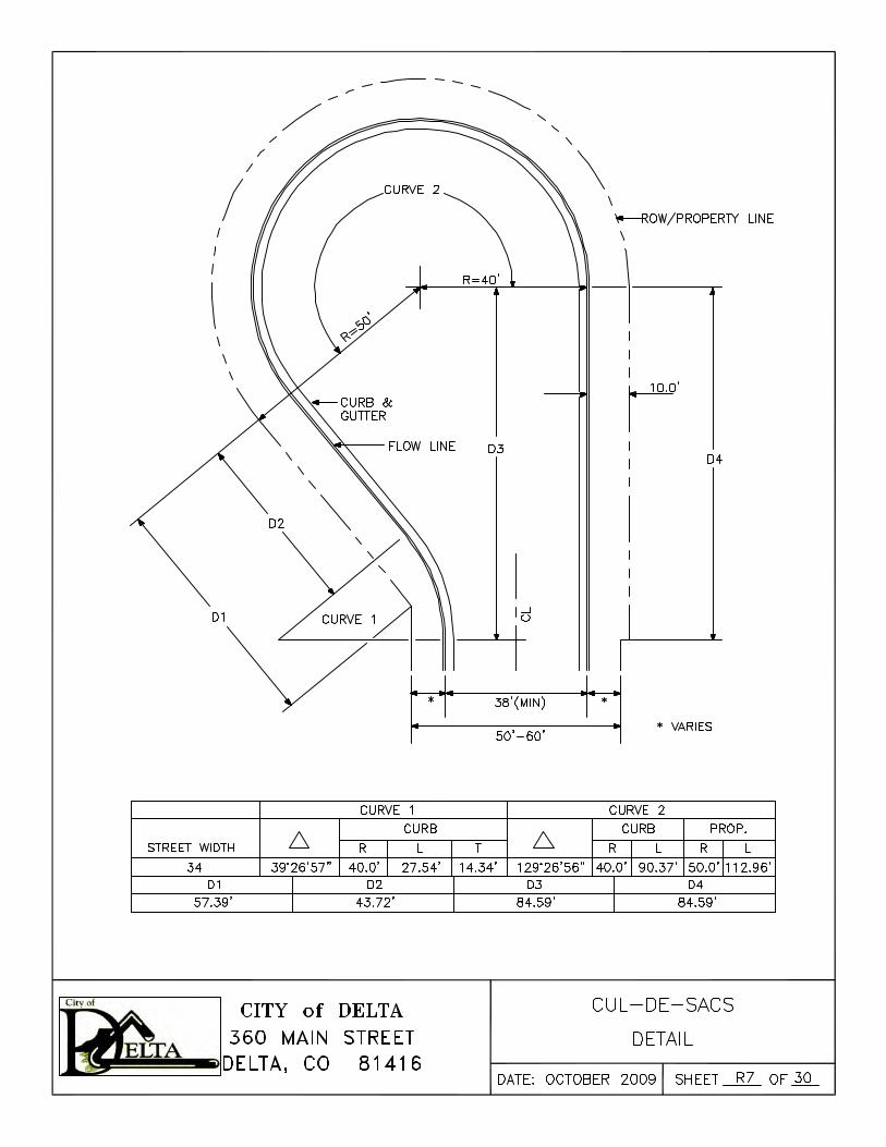
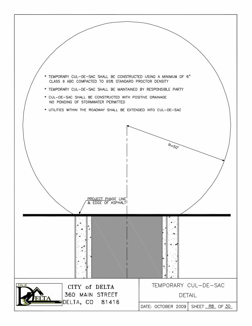


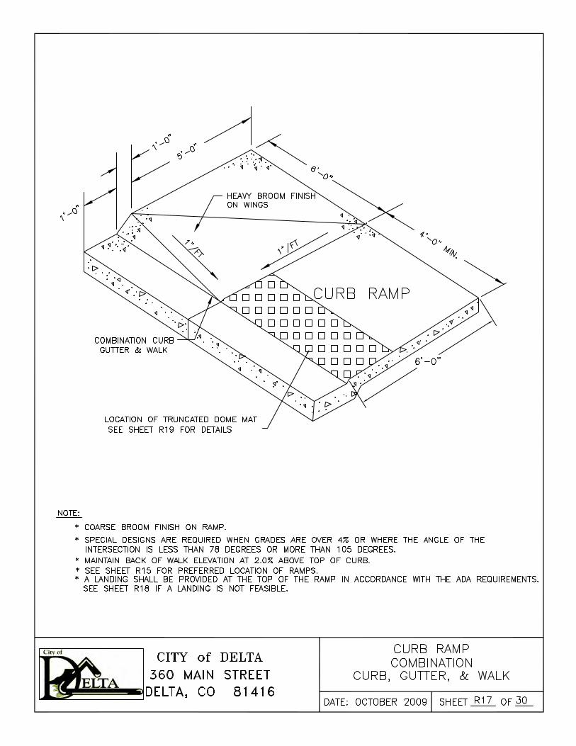

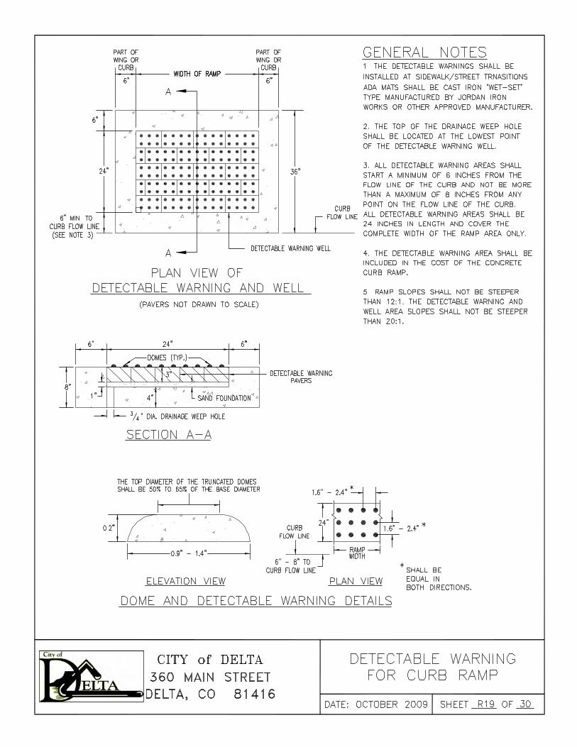

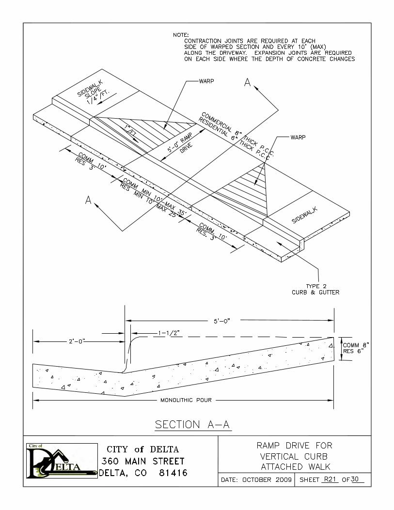


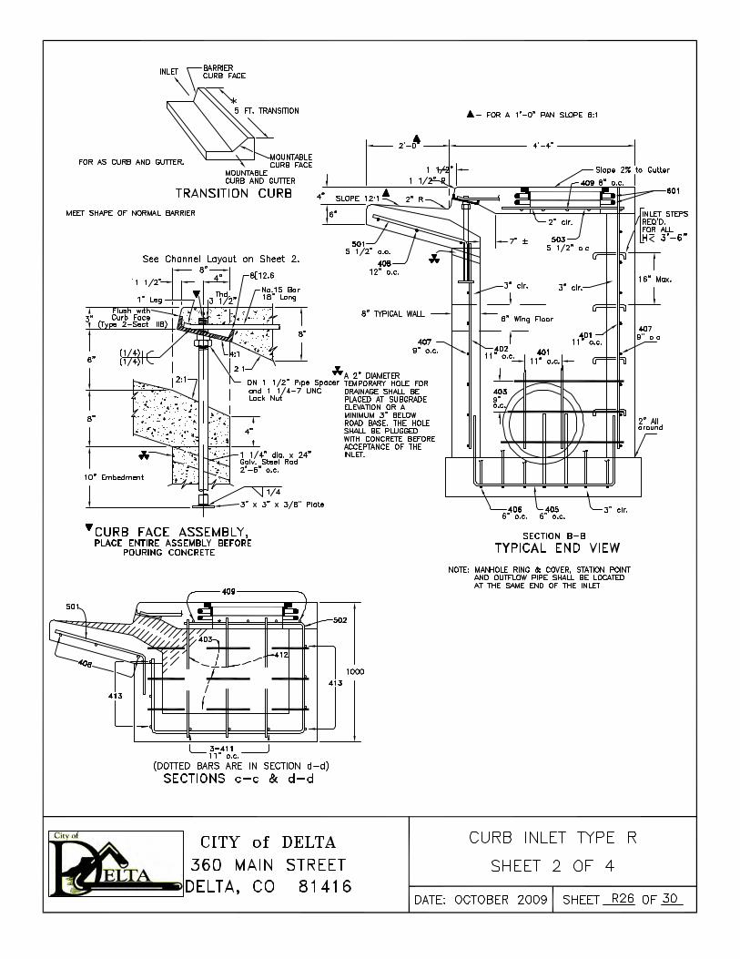
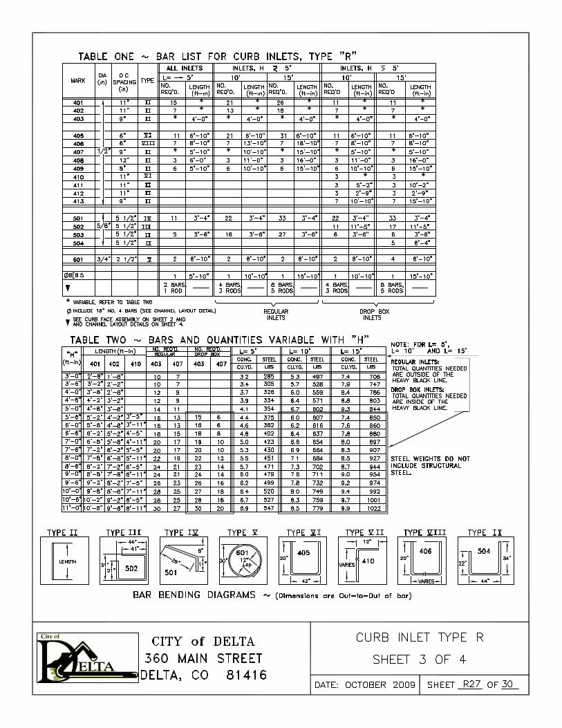


STANDARDS AND SPECIFICATIONS FOR THE DESIGN AND CONSTRUCTION OF PUBLIC
IMPROVEMENTS
Chapter 7
Concrete
2010 EDITION

TABLE OF CONTENTS
CHAPTER 7
CONCRETE
Page
7.00.00 INTRODUCTION ...................................................................................................................................................................... 1
7.01.00 GENERAL .................................................................................................................................................................................... 1
7.10.00 DESIGN STANDARDS ............................................................................................................................................................. 1
7.11.00 PLACING CONCRETE ............................................................................................................................................................ 1
7.11.01 Preparation ................................................................................................................................................................................ 1 7.11.02 Timing ........................................................................................................................................................................................ 1 7.11.03 Concrete Temperature ............................................................................................................................................................... 1 7.11.04 Handling .................................................................................................................................................................................... 2 7.11.05 Workability ................................................................................................................................................................................ 2 7.11.06 Weather Restrictions ................................................................................................................................................................. 2 7.11.07 Jointing ...................................................................................................................................................................................... 3 7.11.08 Finishing and Curing ................................................................................................................................................................ 4 7.11.09 Testing of Concrete.................................................................................................................................................................... 5 7.11.10 Repairs ....................................................................................................................................................................................... 6
7.20.00 MATERIAL SPECIFICATIONS ............................................................................................................................................. 7
7.21.00 CONCRETE MIX DESIGN ......................................................................................................................................................... 7 7.22.00 CONCRETE MATERIALS ......................................................................................................................................................... 8
7.22.01 Cement ....................................................................................................................................................................................... 8 7.22.02 Aggregate ................................................................................................................................................................................... 8 7.22.03 Water .......................................................................................................................................................................................... 9 7.22.04 Admixtures ................................................................................................................................................................................. 9
7.23.00 REINFORCING STEEL ............................................................................................................................................................... 9 7.24.00 CURING MATERIALS ............................................................................................................................................................. 10 7.25.00 FORM WORK ............................................................................................................................................................................ 10 7.26.00 JOINTING MATERIAL ............................................................................................................................................................. 10 7.27.00 BATCHING AND MIXING ...................................................................................................................................................... 11
7.27.01 General .................................................................................................................................................................................... 11 7.27.02 Proportioning the Mix ............................................................................................................................................................. 11 7.27.03 Ready-Mixed Concrete ............................................................................................................................................................ 11

1
CHAPTER 7
CONCRETE
7.00.00 INTRODUCTION
7.01.00 GENERAL
This specification enumerates the requirements for the materials, storage, transportation, measuring, mixing, placing, and curing of Portland cement concrete. This specification applies to all Portland cement concrete used in sidewalks, driveways, approaches, patches, manholes, inlets, and other structures constructed in the City of Delta. Engineering plans, licenses, permits, inspection, warranty, and acceptance shall be as detailed in these STANDARDS AND SPECIFICATIONS for the applicable type of construction involved. Permits shall be obtained before work begins. The Responsible Party shall contact the City twenty-four (24) hours in advance of concrete placement when the formwork is ready to receive the concrete. Where required, compaction test results shall verify the adequacy of all ground upon which concrete is to be placed. All work performed according to this section must comply with the general requirements contained within Chapter 1 and the acceptance requirements of Chapter 10.
7.10.00 DESIGN STANDARDS
Design criteria for the various elements using concrete are specified in other chapters of this document.
Design specifications for sidewalks, curb and gutter, driveways, inlets and sidewalks are in Chapter 6 - Roadway. Design specifications for concrete pipe, manholes, inlets, and other drainage and wastewater concrete structures are in Chapter 3 - Water System, Chapter 4 - Sanitary Sewer and Chapter 5 - Storm Sewer. Design specifications relative to traffic control items are in Chapter 8 – Off Street Improvements.
7.11.00 PLACING CONCRETE
7.11.01 Preparation
Before depositing concrete, debris shall be removed from the space to be occupied by the concrete and the forms. Concrete shall not be placed until all forms and reinforcing steel have been inspected and approved by the City Representative. The soil receiving the concrete shall be moist, but not wet, and shall not contain frost or frozen material.
7.11.02 Timing
Concrete that has developed initial set or does not have workable consistency shall not be used. Concrete shall be continuously mixed or agitated from the time the water is added until the time of use, and shall be completely discharged from the truck mixer or truck agitator within one-and-one-half (1-1/2) hours after it comes in contact with the mixing water or with the aggregates. Retempered concrete will not be allowed.
7.11.03 Concrete Temperature
At the time of concrete placement, the mix temperature shall be between fifty degrees Fahrenheit (50oF) and ninety degrees Fahrenheit (90oF). In cold weather (see Section 7.11.06), aggregates and water may be heated as part of the batching operation but they shall not be heated beyond a temperature of one-hundred-and-fifty degrees Fahrenheit (150oF). Aggregates shall not be heated directly by gas or oil flame or on sheet metal over direct flame. Materials containing frost or lumps of frozen material shall not be used in the mix, and their presence in the concrete shall be cause for rejection of that batch.
2
7.11.04 Handling
(A) Concrete shall be handled from the mixer to the place of final deposit as rapidly as
possible by methods that prevent separation or loss of ingredient. The concrete shall be deposited in the forms as nearly as practicable in its final position to avoid rehandling. Concrete shall be deposited in continuous layers, the thickness of which generally shall not exceed twelve inches (12"). Concrete shall be placed in one continuous operation, except where keyed construction joints are shown on the plans or as approved by the City Representative. Delays in excess of thirty (30) minutes may require removal and replacement of that pour, as determined by the City Representative.
(B) Concrete shall be placed in a manner that will avoid segregation and shall not be dropped
freely more than five feet (5'). If segregation occurs, the City Representative may require the concrete to be removed and replaced at the Responsible Party's expense. Necessary hand spreading shall be done with shovels and not with rakes.
(C) Concrete shall be thoroughly compacted or vibrated. All concrete shall be compacted by
internal vibration using mechanical vibrating equipment, except that concrete in floor slabs, sidewalks, or curb and gutter, not poured against form linings, shall be either tamped or vibrated. Care shall be taken in vibrating the concrete to vibrate only long enough to bring a continuous film of mortar to the surface. Vibration shall stop before any segregation of the concrete occurs. Mechanical vibrators shall be an approved type as specified in ACI Publication 309, Chapter 5. Vibrators shall not be used to move or spread the concrete. Any evidence of lack of consolidation or over consolidation will be regarded as sufficient reason to require the removal of the section involved and its replacement with new concrete at the Responsible Party's expense. The Responsible Party shall be responsible for any defects in the quality and appearance of the completed work.
7.11.05 Workability
The consistency of concrete shall be kept uniform for each class of work and shall be checked by means of a slump test or Kelly ball tests. The workability of the concrete will be varied as directed by the City Representative. At all times, concrete shall have a consistency such that it can be worked into corners and angles of the forms and around joints, dowels, and tie bars by the construction methods which are being used without excessive spading, segregation, or undue accumulation of water or laitance on the surface. If, through accident, intention, or error in mixing, any concrete that fails to conform to the proportions of the approved mix design, such concrete shall not be incorporated in the work but shall be discarded off the project site as waste material at the Responsible Party's expense. NO WATER MAY BE ADDED AT THE JOB SITE WITHOUT PERMISSION OF THE CITY REPRESENTATIVE. If approval is obtained and water is added at the job site, slump tests shall be run and test cylinders cast following the addition of the water. Any expense incurred in excess of ordinary tests will be borne by the Responsible Party.
7.11.06 Weather Restrictions
(A) Hot Weather:
Except by written authorization, concrete will not be placed if the temperature of the plastic concrete cannot be maintained at ninety degrees Fahrenheit (90oF) or lower. The placement of concrete in hot weather shall comply with ACI 305. Refer also to Section 7.11.03 of these STANDARDS AND SPECIFICATIONS.

3
(B) Cold Weather:
During extreme weather conditions, placing of concrete will be permitted only when the temperature of the concrete placed in the forms will not be less than sixty degrees Fahrenheit (60oF), nor more than ninety degrees Fahrenheit (90oF). To maintain this temperature range, the Responsible Party shall provide acceptable heating apparatus for heating the aggregates and the water. Concrete slabs shall not be placed, regardless of temperature conditions, if the supporting ground is frozen or contains frost. Use of salt or other additives to prevent concrete from freezing will not be allowed. Concrete, which has been frozen, shall be completely removed and replaced as directed by and to the satisfaction of the City Representative.
Concrete may be placed when the air temperature in the shade is at least forty degrees Fahrenheit (40oF) and rising. No concrete shall be placed, regardless of the present temperature, when the weather forecast promises freezing weather before final set of the concrete unless special means of heating and protection are used. Protection against freezing is the Responsible Party's responsibility regardless of the weather forecast or climatic conditions at the time of placing. During cold weather conditions, concrete less than seventy-two (72) hours old shall be protected, at a minimum, as follows: TABLE 7.11.06
Forecast Low Temperature (by the National Weather Service) Protection
Between 40 and 32 Degrees One layer of commercial insulation material.
Between 31 and 25 Degrees Two layers of commercial insulation material.
Below 25 Degrees Tenting and heating for a minimum of seven (7) days.
These coverings must remain in place until the concrete is at least five (5) days old.
7.11.07 Jointing
(A) Expansion Joints:
Expansion joint material shall be provided at the following locations and shall be in place prior to the placing of concrete:
1. Between new concrete and existing masonry buildings or existing concrete. 2. As shown on the drawings 3. At a minimum 100’ spacing or as directed by the City Representative 4. At any point where the thickness in concrete changes 5. At every driveway, curb return and ADA Ramp (B) Contraction Joints:
Transverse joints shall be placed at maximum intervals of ten feet (10') to control random cracking. Joints shall be formed, sawed, or tooled to a minimum depth of one-third (1/3) of the total thickness, but no less than 0.5 inches. Contraction joints shall be placed as follows:

4
1. Not more than ten feet (10') nor less than six feet (6') apart in curb and gutter and
combination curb-walk. 2. Not more than the walk width in non-monolithic concrete sidewalk.
3. At least two joints equally spaced at not greater than ten-foot (10') intervals as applicable in driveways.
4. As approved and shown on the plans for special concrete structures.
7.11.08 Finishing and Curing
In addition to the curing techniques unique to hot and cold weather placement, adequate attention shall be given to finishing and curing the fresh concrete. Exposed faces of curbs and sidewalks shall be finished to true line and grade, as shown on the plans. The surface shall be floated to a smooth, but not slippery, finish. The addition of surface water to assist in the finishing process is prohibited. Sidewalk and curb shall be broomed or combed and edged, unless otherwise indicated by the City Representative. After completion of brooming and before concrete has taken its initial set, all edges in contact with the forms shall be tooled with an edger having a three-eighths-inch (3/8") radius. No dusting or topping of the surface or sprinkling with water to facilitate finishing will be permitted.
Immediately following the removal of the forms, all fins and irregular projections shall be removed from all surfaces except from those which are not to be exposed or are not to be waterproofed. On all surfaces cavities produced by form ties, honeycomb spots, broken corners or edges, and other defects shall either be thoroughly cleaned, moistened with water, and carefully pointed and trued with a mortar consisting of cement and fine aggregate or removed and replaced at the direction of the City Representative. The surface shall be left sound, smooth, even, and uniform in color. Mortar used in pointing shall not be more than thirty (30) minutes old. All construction and expansion joints in the completed work shall be left carefully tooled and free of all mortar and concrete. The joint filler shall be left exposed for its full length with clean and true edges.
Fresh concrete shall be adequately protected from weather damage and mechanical injury during the curing periods. The selected curing process shall be started as soon as it can be done without injury to the concrete surface. The use of a membrane-curing compound is recommended. The following curing procedures may be used subject to the approval of the City Representative.
(A) Wet Burlap Curing:
After completion of the finishing operations, the surface of the concrete shall be entirely covered with burlap mats. The mats used shall be in such length or width that as laid they will extend at least twice the thickness of the concrete beyond the edges of the slab or structure. They shall be placed so that the entire structure and all edges of the concrete, when forms are removed, are completely covered. This covering shall be placed as soon as the concrete has set sufficiently to prevent marring of the surface. After being placed, the mats shall be thoroughly saturated with water by spraying with a mist spray. The burlap shall be so placed and weighted down so it remains in contact with the surface covered, and the covering shall be maintained fully wetted and in position for seven (7) days after the concrete has been placed. If it becomes necessary to remove the burlap for any reason, the concrete shall not be exposed for a period of more than one-half (1/2) hour. This method of curing shall not be used when the outside air temperature is below thirty-two degrees Fahrenheit (32oF) unless heated enclosures are provided.

5
(B) Plastic Sheet Curing:
As soon after the completion of the finishing operation as the concrete has set sufficiently to prevent marring of the surface, the top surface and sides shall be entirely covered with plastic sheet materials. The plastic sheet as prepared for use shall have such dimensions that each unit as laid will extend beyond the edges of the concrete at least twice the thickness of the concrete. The units as used shall be lapped at least twelve inches (12"), and the laps of plastic sheet shall be secure such that they do not open up or separate. The plastic shall be placed and weighted so it remains in contact with the surface covered, curing the entire curing period of seven (7) days.
(C) Waterproof Paper Curing:
The procedures used for plastic sheet curing shall be used when waterproof paper is used in curing concrete.
(D) Liquid Curing Membrane:
Immediately after the surface water has disappeared from the concrete surface, the liquid membrane curing compound (white pigmented) shall be sprayed under pressure to the concrete surface at a rate not less than one (1) gallon per one-hundred-fifty (150) square feet with a spray nozzle, or nozzles, so it covers the entire pavement with a uniform water-impermeable film. If the forms are removed within seven (7) days, the exposed sides and edges shall be sprayed in the above-described manner or the backfill completed immediately.
(E) Insulation Pad:
Insulation pads or other thermal devices may be used to protect concrete in cold weather.
(F) Wax base and resin base solutions shall not be used if linseed oil protection is to be applied to the concrete surface. If linseed oil protection is to be utilized, the method of curing shall be either linseed oil base-curing compound, wet burlap, plastic sheet, or waterproof paper curing.
7.11.09 Testing of Concrete
When testing is required, the requirements of this section shall apply to testing services for all concrete curb and gutter, sidewalk, slope paving, retaining walls, structures, and for all miscellaneous concrete testing. Testing for concrete pavement shall be in accordance with Chapter 5 of these STANDARDS AND SPECIFICATIONS.
The Responsible Party shall furnish the concrete necessary for casting test cylinders. The number of cylinders and tests shall be as follows:
Type of Test Frequency
Slump 1 per set of cylinders and as often as needed for quality control
Air Content 1 per set of cylinders and as often as needed for quality control Compressive Strength 1 set of four (4) cylinders per 100 cubic yards or major fraction
thereof on each day pavement is placed; 2 cylinders to be field cured

6
Thickness 1 per 1250 linear feet each traffic lane on freshly finished concrete and as often as needed for quality control
The degree and frequencies of all concrete testing beyond normal specified frequencies, if necessary to assure quality control, shall be determined by the City Representative at the time of concrete construction. The Responsible Party shall pay for all concrete testing necessary.
7.11.10 Repairs
After stripping of the forms, if any concrete is found to be not formed as shown on the drawings or is out of alignment or level or shows a defective surface, it shall be considered as not conforming with the intent of these STANDARDS AND SPECIFICATIONS and shall be removed and replaced by the Responsible Party at his expense unless the City Representative gives written permission to patch the defective area. In this case, patching shall be done as described in the following paragraphs. Defects that require replacement or repair are those that contain honeycomb, damage due to stripping of forms, loose pieces of concrete, bolt holes, tie-rod holes, uneven or excessive ridges at form joints, and bulges due to movement of the forms and other deficiencies noted in Section 10.40.06. Ridges and bulges shall be removed by grinding. Honeycombed and other defective concrete that does not affect the integrity of the structure shall be chipped out and the vacated areas shall be filled in a manner acceptable to the City Representative. The repaired area shall be patched with a non-shrink, non-metallic grout with a minimum compressive strength of five thousand (5000) psi in twenty-eight (28) days. All repair areas treated with an epoxy-bonding agent shall have the approval of the City Representative before the repair filling is placed. The Responsible Party is shall protect wet and workable concrete from vandalism and unintentional damage such as someone walking across the fresh concrete. In the event the finished surface is damaged due to the lack of protection by the Responsible Party, that section of concrete shall be removed and replaced at the direction and discretion of the City Representative.
Bolt holes, tie-rod holes, and minor imperfections as approved by the City Representative shall be filled with dry-patching mortar composed of one (1) part Portland cement to two (2) parts of regular concrete sand (volume measurement) and only enough water so that after the ingredients are mixed thoroughly the mortar will stick together on being molded. Mortar repairs shall be placed in layers and thoroughly compacted by suitable tools. Care shall be taken in filling rod and bolt holes so that the entire depth of the hole is completely filled with compacted mortar. The mortar mix proportions described above are approximate.
An approved mix shall be prepared by a commercial testing laboratory to insure that grout has a twenty-eight (28) day compressive strength equal to that of the area on which it is placed. The Responsible Party shall pay all costs for mix design and testing. Those areas with excessive deficiencies as determined by the City Representative shall be removed and replaced at the Responsible Party's expense. Where repairs are made in existing sidewalks, all edges of the old sidewalk allowed to remain shall be saw-cut to a minimum depth of two inches (2"). No rough edges will be permitted where new construction joins the old section. Unless directed by the City Representative, no section less than five feet (5') in length shall be placed or left in place. Where new sidewalk construction abuts existing sidewalks, the work shall be accomplished so that there is no abrupt change in grade between the old section and the new work.

7
7.20.00 MATERIAL SPECIFICATIONS
7.21.00 CONCRETE MIX DESIGN
Concrete shall be classed according to Table 7.21.00 below. Project application of the different concrete classes shall be as follows:
Concrete Sidewalk -- Class B (6 sack mix) Concrete Curb and Gutter -- Class B (6 sack mix) Concrete Structures -- Class A or B, or as designed Precast Products -- Refer to Materials Section of appropriate chapter
TABLE 7.21.00 Concrete Table
Concrete Class A AX B (k)P L DESIGN MINIMUM (a) A COMPRESSIVE STRENGTH 28 days B (45 days for Type V cement) O Pounds Per Square Inch 3750 3750 3750 3750 R A CEMENT CONTENT (Cement Factor) T Range (Pounds Per Cubic Yard): O Minimum -- 550 600 550 550 R Maximum -- 600 700 600 600 Y WATER CEMENT RATIO (Pounds of Water Per Pounds of Cement): 0.500 0.500 0.530 0.480 PERCENT ENTRAINED & ENTRAPPED AIR (Total Range): 4-7 5-8 5-8 4-7 C O CONSISTENCY AASHTO DESIGNATION A T-119 (b) -- Range in Inches: 2-4 1-3 1-4 1-3 R S AGGREGATE AASHTO DESIGNATION E M-43 -- Size Number: 467 (f) 67 467 357 F I AGGREGATE AASHTO DESIGNATION N M-6 -- Percent Total Aggregate E Range: 34-39 (f) 37-44 34-38 33-38
(a) Not a field specification requirement. The desired minimum field strength is 80 percent of the specified laboratory strength.

8
(b) The point of acceptance for consistency requirements will be at the mixer discharge for transit-mixed concrete.
7.22.00 CONCRETE MATERIALS
Concrete shall be composed of Portland cement, aggregate, and water and shall be reinforced with steel bars or steel-wire fabric where required. No admixture other than air-entraining agents shall be used without written permission of the City Representative.
7.22.01 Cement
Portland Cement shall conform to the requirements of the following specifications for the type specified or permitted:
Type Specification Portland Cement, Type I, II ASTM C 150, AASHTO M 85 Air-Entraining Portland Cement AASHTO M 134 Masonry Cement AASHTO M 150
In general, Type II cement shall be used in concrete which will be in contact with the soil unless otherwise allowed or directed by the City Representative. Unless otherwise permitted by the City Representative, the product of only one (1) mill of any one brand and type of Portland cement shall be used on the project, except for reduction of any excessive air entrainment, where air-entrainment cement is used. The Responsible Party shall provide suitable means of storing and protecting the cement against dampness. Cement which for any reason has become partially set or which contains lumps of caked cement shall be rejected. Cement salvaged from discarded or used bags shall not be used. Flyash as a substitute for cement may be added only if prior approval from the City Representative is obtained. In most cases the City will not allow the use of flyash in the mix.
7.22.02 Aggregate
Aggregate for concrete shall be proportioned in conformance with Table 7.22.00 below.
(A) Coarse Aggregate:
The coarse aggregate shall consist of broken stone or gravel composed of clean, hard, tough, and durable stone and shall be free from soft, thin, elongated, or laminated pieces, disintegrated stone, clay, loam, vegetable, or other deleterious matter. Coarse aggregate for concrete shall conform to the requirements of AASHTO M 80, except that the percentage of wear shall not exceed forty-five (45) when tested in accordance with AASHTO T 96.
(B) Fine Aggregate:
Fine aggregate shall be composed of clean, hard, durable, uncoated particles of sand, free from injurious amounts of clay, dust, soft or flaky particles, loam, shale, alkali, organic matter, or other deleterious matter. Fine aggregate shall be well-graded from course to fine and, when tested by means of laboratory sieves, shall meet the grading requirements of Table 7.22.00 below.

9
7.22.03 Water
Water used in mixing or curing shall be reasonably clean and free of oil, salt, acid, alkali, sugar, vegetable, or other substance injurious to the finished product. Water shall be tested in accordance with and shall meet the suggested requirements of AASHTO T 26. Water known to be of potable quality may be used without test. Where the source of water is relatively shallow, the intake shall be so enclosed to exclude silt, mud, grass, or other foreign materials.
7.22.04 Admixtures
The Responsible Party shall use air-entraining admixtures for all concrete that will have exposed surfaces. The Responsible Party may elect to use another admixture provided the City Representative specifically approves the admixture. Documentary evidence of acceptability will be required when new or unknown admixtures are proposed for use. Air-entraining admixtures shall conform to the requirements of ASTM C 260.
TABLE 7.22.00
Concrete Aggregate Gradation Table Percentages Passing Designated Sieves and Nominal Size Designation
Coarse Aggregates (From AASHTO M 43) Fine Aggregate * * * * ** ** AASHTO No.3 No.4 No.6 No.7 No.8 No.57 No.67 No.357 No.467 M 6 Sieve 2" 1-1/2" 3/4" 1/2" 3/8" 1" 3/4" 2" 1-1/2" #4 Size to1" to3/4" to3/8" to#4 to#8 to#4 to#4 to#4 to#4 to#100 2-1/2 100 ..... ..... ..... ..... ..... ..... ..... 100 ..... 2" 90-100 100 ..... ..... ..... ..... ..... ..... 95-100 100 1-1/2" 35-70 90-100 ..... ..... ..... 100 ..... ..... ..... 95-100 1" 0-15 20-55 100 ..... ..... 95-100 100 35-70 ..... ..... 3/4" ..... 0-15 90-100 100 ..... ..... 90-100 ..... 35-70 ..... 1/2" 0-5 ..... 20-55 90-100 100 25-60 ..... 10-30 ..... ..... 3/8" ..... 0-5 0-15 40-70 85-100 ..... 20-55 ..... 10-30 100 #4 ..... ..... 0-5 0-15 10-30 0-10 0-10 0-5 0-5 95-100 #8 ..... ..... ..... 0-5 0-10 0-5 0-5 ..... ..... ..... #16 ..... ..... ..... ..... 0-5 ..... ..... ..... ..... 45-80 #50 ..... ..... ..... ..... ..... ..... ..... ..... ..... 10-30 #100 ..... ..... ..... ..... ..... ..... ..... ..... ..... 2-10
* Additional primary gradings may be permitted when produced on the project provided the theoretical combination meets the specifications for combined aggregate sizes. ** Size No. 357 is a combination of No. 3 and No. 57. Size No. 467 is a combination of No. 4 and No.67
7.23.00 REINFORCING STEEL
Reinforcing steel shall conform to the requirements of the following specifications: (A) Deformed and plain billet-steel bars for concrete reinforcement AASHTO M 31 (B) Axle-steel deformed and plain bars for concrete reinforcement AASHTO M 53 (C) Fabricated steel bar or rod mats for concrete reinforcement AASHTO M 54

10
D) Welded steel-wire fabric for concrete reinforcement AASHTO M 55
Unless otherwise designated, bars conforming to AASHTO M 31 and M 53 shall be furnished in Grade 60 for No. 5 bars and larger and Grade 40 or 60 for bars smaller than No. 5. In AASHTO M 54, bar material conforming to AASHTO M 42 will not be permitted.
7.24.00 CURING MATERIALS
Curing materials shall conform to the following requirements:
A) Burlap cloth made from Jute or Kenaff AASHTO M 182 B) Sheet materials for curing concrete AASHTO M 171 C) Liquid membrane forming compounds for curing concrete (white pigmented) AASHTO M 148
Straw used for curing shall consist of threshed straw of oats, barley, wheat, or rye. Clean field or marsh hay may be substituted when approved by the City Representative. Old dry straw or hay, which breaks readily in the spreading process, will not be permitted.
7.25.00 FORM WORK
Whenever necessary, forms shall be used to confine the concrete and shape it to the required lines. Forms shall have sufficient strength to withstand, without deformation, the pressure resulting from placement and vibration of the concrete. Forms shall be constructed so that the finished concrete will conform to the shapes, lines, grades, and dimensions indicated on the approved plans. Any form which is not clean and has not had the surface prepared with a commercial form oil that will effectively prevent bonding and that will stain or soften concrete surfaces shall not be used. Plywood forms, plastic coated plywood forms, or steel forms shall be used for all surfaces requiring forming which are exposed to view, whether inside or outside any structure. Surfaces against backfilled earth, interior surfaces, of covered channels, or other places permanently obscured from view may be formed with forms having substandard surfaces.
Forms shall not be disturbed until the concrete has hardened sufficiently to permit their removal without damaging the concrete or until the forms are not required to protect the concrete from mechanical damage. Minimum time before removal of forms after placing concrete shall be one (1) day for footings and two (2) days for all other concrete except curbs, gutters, and sidewalks.
7.26.00 JOINTING MATERIAL
Joint materials will conform to AASHTO specifications according to type as follows:
(A) Concrete joint sealer, hot-poured elastic M 173 (B) Performed expansion joint filler (bituminous type) M 33 (C) Performed sponge rubber and cork expansion joint fillers M 153 (D) Performed expansion joint fillers (non- extruding and resilient bit) M 213

11
7.27.00 BATCHING AND MIXING
7.27.01 General
All concrete shall be thoroughly mixed in a batch mixer of an approved type and capacity for a period of not less than two (2) minutes after all the materials, including the water, have been placed in the drum. During the period of mixing, the drum shall be operated at the speed specified by the manufacturer of the equipment. The entire contents of the mixer shall be discharged before recharge, and the mixer shall be cleaned frequently. The concrete shall be mixed only in such quantities that are required for immediate use. No retempering of concrete will be permitted. Hand-mixed concrete will not be permitted except by written approval of the City Representative and then in only very small quantities or in case of an emergency.
7.27.02 Proportioning the Mix
Proportioning the dry constituents of all concrete mixtures shall be accomplished by weighing. The supplier shall provide adequate and accurate scales for this work. There shall be no variance permitted in the minimum cement factor (sacks per cubic yard) as specified for the classes of concrete. The total quantity of mixing water per sack of cement, including free water in the aggregate, shall not exceed the minimum specified herein. The supplier shall be responsible for developing the proper proportions of aggregates, cement, and water that will conform to the various requirements of these STANDARDS AND SPECIFICATIONS.
7.27.03 Ready-Mixed Concrete
The use of ready-mixed concrete in no way relieves the Responsible Party of the responsibility for proportion, mix, delivery, or placement of concrete. All concrete shall conform to all requirements of these STANDARDS AND SPECIFICATIONS and ASTM C 94 and AASHTO M 157.
The City shall have free access to the mixing plant at all times. The organization supplying the concrete shall have sufficient plant and transportation facilities to assure continuous delivery of the concrete at the required rate. The Responsible Party shall collect delivery or batch tickets from the driver for all concrete used on the project and deliver them to the City Representative. Batch tickets shall provide the following information:
(A) Weight and type of cement. (B) Weights of fine and coarse aggregates (C) Weight (in gallons) of water including surface water on aggregates (D) Quantity (cubic yards) per batch (E) Times of batching and discharging of concrete (F) Name of batch plant (G) Name of Responsible Party (H) Type (I) Name and amount of admixture (J) Date and truck number.

STANDARDS AND SPECIFICATIONS FOR THE DESIGN AND CONSTRUCTION OF PUBLIC
IMPROVEMENTS
Chapter 8
Off Street Improvements
2010 EDITION

TABLE OF CONTENTS
CHAPTER 8
OFFSTREET IMPROVEMENTS
8.00.00 INTRODUCTION 1
8.01.00 GLOSSARY OF TERMS 1
8.10.00 ACCESS 3
8.10.01 General 3
8.10.02 Design Standards 4
8.20.00 SITE DESIGN 8
8.20.01 Parking 8
8.20.02 Site Circulation 9
8.20.03 Refuse Receptacle Location & Enclosure Design 10
8.30.00 TRAFFIC CONTROL IN CONSTRUCTION AREAS 10
8.30.01 General 10
8.30.02 Time of Submittal 10
8.30.03 Scope of Construction Traffic Control Plan 11
8.30.04 Elements of Construction Traffic Control Plan 11
8.30.05 Basis for Construction Traffic Control Plan 11
8.30.06 Restriction, Regulations and Opportunities 12
8.30.07 Approval 12
8.30.08 Modifications 12
8.30.09 Applicability 12
8.31.00 TRAFFIC SIGNING AND PAVEMENT MARKINGS 12
8.31.01 General 12
8.31.02 Traffic Control Devices on Public Property 13
8.31.03 Traffic Control Devices on Private Property 13
8.31.04 Pavement Markings 13
8.32.00 SIGN SPECIFICATIONS 13
8.32.01 Sign Face Materials 13
8.32.02 Sign Post Materials 13
1
CHAPTER 8
OFFSTREET IMPROVEMENTS
8.00.00 INTRODUCTION
The standards contained in this chapter regulate all improvements to be dedicated to the public and accepted by the City, all work within the public right-of-way, and all work that is part of a site development. They are intended to provide for adequate, coordinated, modern development with required facilities to serve and protect the potential users of the various areas of the community. All work performed according to this section must comply with the general requirements contained within Chapter 1 and the acceptance requirements of Chapter 10. The standards in this chapter apply to new developments that are not constrained by already existing improvements. This chapter is not to be applied without qualification to in-fill development. In-fill development in an urban area is often constrained by existing improvements. To the extent deemed possible by the City, in-fill developments shall be required to conform to these STANDARDS AND SPECIFICATIONS. The City may allow modification of these STANDARDS AND SPECIFICATIONS when necessary to allow private and public construction that is compatible with surrounding in-place improvements.
8.01.00 GLOSSARY OF TERMS
Several terms are used herein which have a somewhat distinct meaning. For the purpose of clarity, the definition of some of these terms are listed below:
AASHTO -- American Association of State Highway and Transportation Officials Acceleration Lane -- A speed change lane, including tapered areas, for the purpose of enabling a vehicle entering a roadway to increase its speed to a rate at which it can more safely merge with through traffic. Access -- Driveway or other point of access such as a street, road, or highway that connects to the general street system. Where two public roadways intersect, the secondary roadway shall be the access. Approach -- The portion of an intersection leg that is used by traffic approaching the intersection. Commercial -- Establishments where the buying and selling of commodities, entertainment, or services is carried on, excluding service stations. Included are such uses as office buildings, restaurants, hotels, motels, banks, grocery stores, theaters, parking lots, trailer courts, and public buildings. Corner Clearance (C) -- At an intersecting street, the distance measured along the curb line from the projection of the intersection street right-of-way line to the nearest edge of the curb opening. Deceleration Lane -- A speed change lane, including tapered areas, for the purpose of enabling a vehicle that is to make an exit turn from a roadway to slow to a safe turning speed after it has left the main stream of faster-moving traffic.

2
Distance Between Double Drives (D) -- The distance measured along the curb line between the inside edges of two adjacent curb openings. Edge Clearance (E) -- The distance measured along curb line from the nearest edge of the curb opening to a point where the property line extended intersects the curb line. Flowline -- The transition point between the gutter and the face of the curb. For a cross or valley pan, it is the center of the pan. Frontage -- The distance along the street right-of-way line of a single property or development within the property lines. Corner property at an intersection would have a separate frontage along each street. Highways and Streets Manual – A Policy on Geometric Design of Highways and Streets, 2001 Industrial or Warehouse -- Any establishment that manufactures or stores an article or product. Multi-Family (MF) Residential: Three or more attached dwelling units including townhouses, condominiums, and apartments. MUTCD -- Manual on Uniform Traffic Control Devices and the Colorado Supplement. Residential -- Property used primarily for residential purposes such as single-family, two-family, and multi-family units. Service Station -- Any property where flammable liquids such as motor vehicle fuel are used, stored, and/or dispensed from fixed equipment into fuel tanks of motor vehicles. Setback (S) -- The lateral distance measured perpendicular to the street right-of-way line and extending from the right-of-way line to the closest point on a structure. Sight Distance -- The length of roadway ahead visible to the driver. The minimum sight distance available should be sufficiently long to enable a vehicle traveling at or near the design speed to stop before reaching a stationary object in its path. Single-Family (SF) Residential: Single, detached family dwelling units, double bungalows, or duplexes. Stopping Sight Distance -- The distance traveled by the vehicle from the instant the driver of a vehicle sights an object necessitating a stop to the instant the brakes are applied and the distance required to stop the vehicle from the instant brake application begins. TIS – Traffic impact study Width of Curb Opening (W) -- The width of curb opening measured at the curb line.

3
8.10.00 ACCESS CONTROL
8.10.01 General
(A) Traffic studies may be required by the City in order to adequately assess the impacts of a
development proposal on the existing and/or planned street system. The primary responsibility for assessing the traffic impacts associated with a proposed development shall rest with the Responsible Party, with the City serving in a review capacity. Traffic studies may be required by the City and, if required, the format for the study may be obtained by contacting the City.
(B) New access or changes to existing access to City streets and roadways is approved by the
City. Application shall be made to the City and be accompanied by plans of the proposed access and technical justification for the access and associated public improvements.
(C) Proposed accesses within the Growth Management Agreement, or where a property is
jointly in the City and County, shall be considered by both the City and County for review and approval.
(D) Access to state highways is governed by the State Highway Access Code. The City of
Delta has delegated its authority to administer the State Highway Access Code to the Colorado Department of Transportation who is, therefore, responsible for the review of access permits to State Highways in the City of Delta.
(E) Control values for curb openings and driveways require minimum dimensions in some
instances and maximum values for other dimensions. The design of curb openings and driveways within the range of these dimensions will provide for good service on the part of the motorist using the driveway while at the same time minimizing the interference to the traffic using the street. By controlling the location and width of openings of driveways along the street, it will be possible to avoid or eliminate long, open stretches where motorists can indiscriminately drive onto the street. The width of opening established in these STANDARDS AND SPECIFICATIONS are based on studies which indicate that the various width openings will accommodate vehicles of maximum size authorized on City streets.
(F) Utility adjustments which must be made to utility poles, street light standards, fire
hydrants, catch basins or intakes, traffic signs and signals, or other public improvements or installations which are necessary as the result of the curb openings or driveways shall be accomplished without any cost to the City of Delta. Also, any curb opening or driveway that has been abandoned shall be restored by the property owner except where such abandonment has been made at the request of or for the convenience of the City.
(G) Driveway approaches, whereby the driveway is to serve as an entrance only or as an exit
only, shall be appropriately signed by and at the expense of the property owner. The property owner will be required to provide some means of ensuring that the motorists will use the driveway either as an entrance only or an exit only, but not both.

4
8.10.02 Design Standards
(A) Curb cuts and driveways shall be constructed in accordance with the detail drawings in
these STANDARDS AND SPECIFICATIONS.
Curb cuts should not be used for commercial/industrial or high volume residential driveways. In general, when the number of parking spaces serviced by the driveway exceeds twenty (20), radius returns shall be used. Where curb cuts are allowed based on traffic considerations, concentrated storm water runoff must not be discharged across the sidewalk. These flows must be directed to a sidewalk chase section. If this is not possible due to grading restraints, radius returns, and a crosspan shall be used.
(B) Curb Opening Width for properties on various function street classifications shall be in
conformance with the detail drawing R21 & R22 of these STANDARDS AND SPECIFICATIONS.
Curb openings shall adequately handle the anticipated traffic volume and character of traffic, as well as being within the limits specified for the type of property development. The controls established for curb openings and driveways shall apply to existing streets as well as new streets that may be developed in the future.
(C) Curb Radii at the flow line of gutter shall be 20 feet for multi-family residential access and 25 feet for commercial access. Radii for industrial uses or truck delivery accesses shall be individually designed for the type of truck that will frequently use the access, with a maximum required radius of 50’.
(D) Access Spacing (1) Local Streets
Single Family Residential Driveways – Shall be placed no closer than 5 feet to the property line to allow for maneuvering to occur without trespass. In locations where the 5 foot minimum spacing cannot be met due to limited lot frontage, or other constraints, the City may allow a variance from this standard. Commercial Driveways – Minimum spacing between adjacent driveways shall be 50 feet measured from edge of apron to edge of apron. Shared driveways should be used whenever practicable. This spacing applies to double drives serving a single property and drives serving adjoining properties.
(2) Collector Streets Single Family Residential Driveways – Shall only be allowed when access to a lower order street is not available. Joint driveways shall be required for adjoining properties. On-site maneuvering area shall be included on the lot so that cars do not back out into the street in accordance with the minimum dimensions as shown on Detail OS7. Commercial Driveways – Driveways shall be spaced a minimum of 150 feet as measured

5
from centerline to centerline. Shared driveways should be used whenever practicable. Movements may be restricted to right-in/right-out.
(3) Arterial Streets Single Family Residential Driveways – Access shall not be allowed. Commercial Driveways – Shall only be allowed to access an arterial street when access to a lower order street is not available. Driveways shall be spaced a minimum of 300 feet as measured from centerline to centerline and shall serve more than one property. Movements may be restricted to right-in/right-out.
(E) Access Offsets Where properties are not large enough to allow accesses on opposite sides of the street to be aligned, the center of accesses and intersections not in alignment shall be offset a minimum of 50 feet on local commercial streets, offset 150 feet or greater on all collector streets and offset 300 feet or greater on all arterial streets. Greater distances may be required for left turn storage lanes. Shared accesses shall be encouraged wherever possible to minimize the number of access points along a street. Shared access provides for safer and more efficient operation of the flow of traffic on the street and shall meet the above requirements.
(F) Access Corner Clearance from Street Intersection:
It is important to locate driveways away from major intersections. This constraint is as much for the ability to enter and leave the property as for the benefit of intersection safety and operations. Exiting a driveway during peak-hour conditions at traffic signals is difficult where the queue of standing or slow-moving vehicles never allows a sufficient gap for entry from the driveway. Minimum corner clearances shall be established based on the classification of the road being accessed as shown below. Corner lots shall access the street with the lowest functional classification.
Street Classification
Clearance from Unsignalized Intersections
Clearance from Signalized Intersections
Single Family Residential Driveways
Local 50’ 150’ 50’
Collector 100’ 150’ 100’
Minor Arterial 100’ * 200’ * 100’ *
Major Arterial 150’ * 250’ * 150’ *
* May be restricted to right-in/right-out only access.
(G) Sight distance for curb openings to private property shall be in accordance with Chapter
6 of these STANDARDS AND SPECIFICATIONS.
To the greatest extent possible, all openings for driveways shall be located at the point of

6
optimum sight distance along the street. For openings and driveways to commercial establishments and service stations, there shall be sufficient space reasonably cleared of any obstructions such that drivers entering the property will have sufficient sight distance to enable them to make proper and safe movements. The profile of a driveway approach and the grading of the adjacent area shall be such that when a vehicle is located on the driveway outside the traveled portion of street the driver can see a sufficient distance in both directions to enable him to enter the street without creating a hazardous traffic situation.
(H) Hard surfaced driveways (concrete or asphalt) shall extend beyond the flowline (or
future flowline) of the road as follows:
Residential: 20 feet Commercial: 40 feet
(I) Number of Access Permitted:
1. Single-Family Residential. Each single-family residential property shall be limited to one (1) access point.
2. Multi-Family Residential. Access shall be determined by information provided by the
Responsible Party to the City. 3. Commercial. Commercial property having less than one hundred and fifty feet (150')
of frontage and located mid-block shall be limited to one (1) access point to the street. An exception to this rule may be where a building is constructed in the middle of a lot and parking is provided for on each side of the building. A second access point may be allowed for commercial property having more than one hundred fifty feet (150') of frontage. For commercial property located on a corner, one (1) access to each street may be permitted.
4. Service Stations. Where there is sufficient frontage to provide for minimum and
maximum requirements, two (2) access points to a street may be permitted. 5. Industrial. Access shall be determined on a case-by-case basis. The City shall
consider good traffic engineering practice and the information provided by the applicant.
(J) Curb cut opening length for access to a commercial property or service station shall not
exceed thirty-five feet (35'). Curb cut openings for residential property shall not exceed twenty-five feet (25’) This width restriction does not apply to circumstances where curb returns are required to serve a property for high traffic volume applications.
(K) Vertical alignment shall be in accordance with Section 6.16.00 of these STANDARDS
AND SPECIFICATIONS (L) Entrance Angle for all driveway approaches shall be as near ninety degrees (90o) to the
centerline of the street as possible. The minimum angle that will be permitted is sixty

7
degrees (60o).
(M) Channelizing islands may be incorporated into the access design for purposes of limiting movements into or out of accesses. Use of medians to control turning movements is preferred and will be required where physical conditions allow. When allowed, the islands shall not be smaller than 100 square feet and shall provide vertical curb and exposed aggregate or patterned concrete treatment. Patterns and color shall match those of any nearby islands or medians. Additional right-of-way or easement may be required to accommodate these designs. The ends of the islands shall typically be constructed with 2-foot flow line radii.
(N) Pedestrians and bicyclists are especially vulnerable to turning vehicles at access drives. The consolidation of access points benefits pedestrians and bicyclists by reducing the number of conflict points along the roadway. Access designs for pedestrian and bicycle facilities shall conform to Chapter 6 requirements and with the City Standard Details.
(O) Emergency vehicle accesses shall be designed to readily accommodate emergency vehicles that would ordinarily respond at the particular establishment (Refer to Fire Department Access regulations based on the Uniform Fire Code).
(P) Joint entrances shall be provided, wherever possible, to serve two adjacent properties.
Joint entrances are to be centered on the common property line.
(Q) Throat Lengths and Vehicle Stacking Adequate vehicle stacking shall be provided for both inbound and outbound vehicles. Adequate stacking facilitates the safe and efficient movement of vehicles between the street and the development. The access throat shall be of sufficient length to prevent vehicles from spilling onto the public street system. Inbound vehicle stacking areas shall be of sufficient size to ensure that vehicles will not obstruct the adjacent street, sidewalk, or circulation within the facility. The throat shall be of sufficient length to provide adequate stacking of outbound vehicles without them interfering with on-site circulation. Outbound vehicle stacking areas shall be provided to eliminate backup and delay of vehicles within the development. At signalized intersections, adequate stacking for the outbound movement must be provided to enable vehicles to exit efficiently on green.
The requirements for vehicle stacking in parking lots and at drive-up type facilities are generally based on a typical vehicle spacing of 20 feet, but may be increased where larger vehicles can be expected.
On-site stacking is measured from the flowline of the street to the first parking stall or aisle of a parking lot. Vehicle stacking equivalent to or greater than the minimum distances shall be provided at accesses serving the site per the following chart. The recommended distance for accesses with two approach lanes may be adjusted, subject to the TIS findings, roadway geometry, traffic volumes, and site layout.

8
Access Throat Stacking Requirements
On-Site Driveway
Vehicle Stacking
Lengths (feet) Parking
Spaces Per Exit Lane
STACKING LENGTH REQUIRED
Multi-Family
Residential Retail Office Industrial
0-200 25 50 25 50
201-400 25 75 100 150
401-600 50 150 200 More Lanes
601-700 100 200 More Lanes More Lanes
> 700 200 More Lanes More Lanes More Lanes
8.20.00 SITE DESIGN
8.20.01 Parking
Conventional parking layout dimensions are provided in the detail drawings OS1 – OS6 in the Appendix of this Chapter. (A) Bumpstops are required when parking stalls are immediately adjacent to a property line,
attached sidewalk, or building structure. Internal parking stalls and stalls adjacent to buffer strips that provide separation from sidewalks or property lines do not require bumpstops.
(B) Minimum grades shall be the same as the grades set forth in Section 6.18.01. Maximum grades permitted in parking lots shall not exceed eight percent (8%).
(C) Parking Structures may be allowed at the discretion of the City. Design shall comply with the current industry standard for parking structures. The City will evaluate designs for such structures on an individual case basis.
(D) Handicapped parking stalls shall be eight feet (8’) in width with a five foot (5’) unloading
area, and be located near buildings entrances and handicap ramps. The minimum required number of spaces is indicated in Table 8.12.01 below. A handicapped parking space will be required to be identified by an official "Handicapped Reserve Parking" (Manual on Uniform Traffic Control Devices, R7-8) sign with the handicapped person logo. In order for handicapped parking spaces to function as intended, they will be required to be designed according to the most recent ADA requirements and signed in a uniform manner to allow for a clear understanding of the parking zone and to make enforcement possible. Signing of one, two, or three spaces for handicapped parking spaces must be done by using one sign for each space placed at the center of each end line.
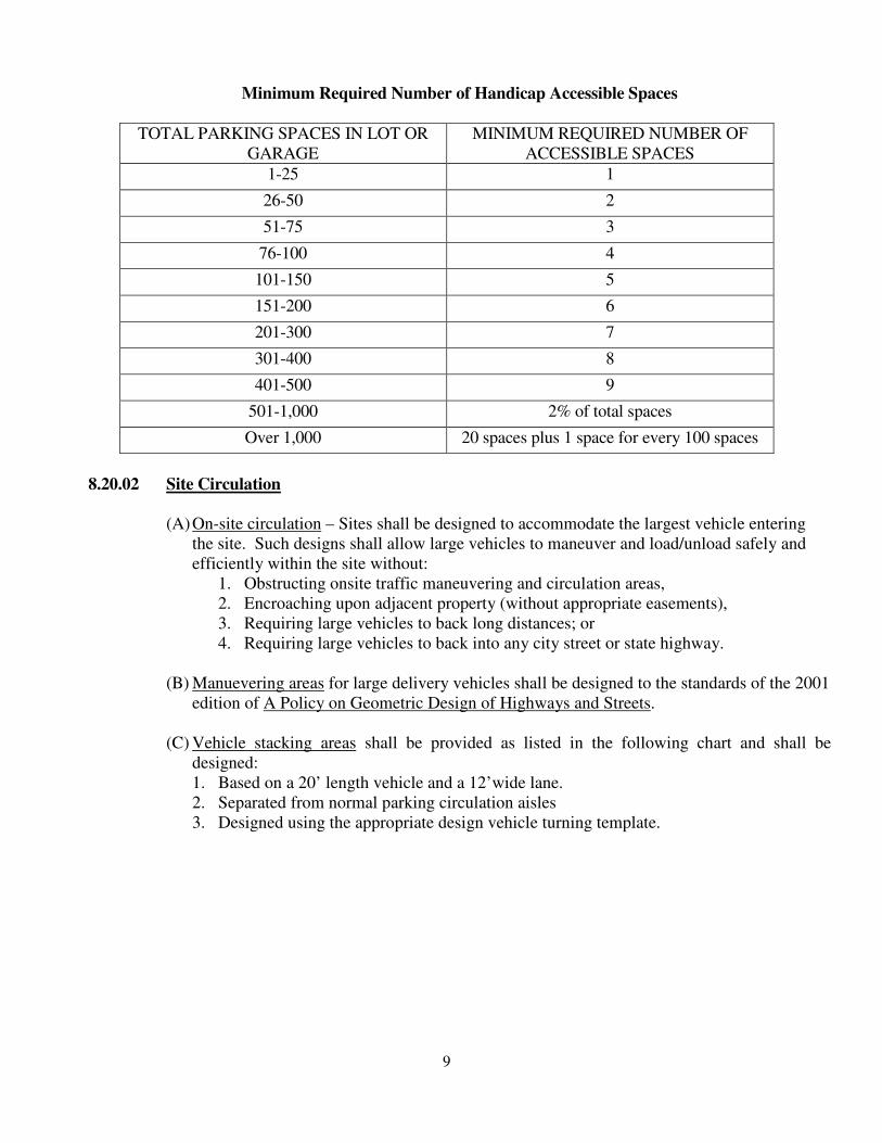
9
Minimum Required Number of Handicap Accessible Spaces
TOTAL PARKING SPACES IN LOT OR GARAGE
MINIMUM REQUIRED NUMBER OF ACCESSIBLE SPACES
1-25 1
26-50 2
51-75 3
76-100 4
101-150 5
151-200 6
201-300 7
301-400 8
401-500 9
501-1,000 2% of total spaces
Over 1,000 20 spaces plus 1 space for every 100 spaces
8.20.02 Site Circulation
(A) On-site circulation – Sites shall be designed to accommodate the largest vehicle entering
the site. Such designs shall allow large vehicles to maneuver and load/unload safely and efficiently within the site without:
1. Obstructing onsite traffic maneuvering and circulation areas, 2. Encroaching upon adjacent property (without appropriate easements), 3. Requiring large vehicles to back long distances; or 4. Requiring large vehicles to back into any city street or state highway.
(B) Manuevering areas for large delivery vehicles shall be designed to the standards of the 2001
edition of A Policy on Geometric Design of Highways and Streets. (C) Vehicle stacking areas shall be provided as listed in the following chart and shall be
designed: 1. Based on a 20’ length vehicle and a 12’wide lane. 2. Separated from normal parking circulation aisles 3. Designed using the appropriate design vehicle turning template.

10
Vehicle Stacking Requirements for Drive-Up Facilities
Type of Facility VEHICLE STACKING
Automated Tellers 4 spaces per machine
Drive-In Bank 6 spaces per window
Drive-In Restaurant 10 spaces per window*
Automatic Car Wash 5 spaces per wash line
Self-Service Car Wash 2 spaces per wash line
Drive-In Theater 15% of the total parking capacity
Service Stations 1 space per nozzle + 1 space/island/direction
Drive-In Liquor Store 3 spaces per window*
Drive-In Dry Cleaners 2 spaces per window*
*Measured from the pick-up window.
8.20.03 Refuse Receptacle Location & Enclosure Design
An area shall be provided for refuse receptacle containers acceptable to the City and to be universally accessible to all types of refuse haulers including but not limited to; side load, front load, and rear load equipment. Such area shall provide traffic circulation so as to minimize traffic hazards and provide for the safe and efficient collection of refuse. Where required, receptacles shall be screened from view according to the Detail in the Appendix of this Chapter.
8.30.00 TRAFFIC CONTROL IN CONSTRUCTION AREAS
8.30.01 General
For any construction done on, in, or to an existing or new City roadway or for the construction of any public or private improvement in an existing or new City roadway, appropriate traffic control during construction shall be provided. For any such construction, a construction traffic control plan shall be prepared by the Responsible Party and shall be approved by the City Representative prior to issuance of any permits.
Where a roadway does not currently exist, it is presumed that there is no motorist expectation of a travel route. Therefore, a construction traffic control plan for construction of a new roadway should strive to do two things: alert the motorist that this is a construction area, and alert the motorist that the road is not open to traffic. Construction traffic control plans shall also be prepared for construction occurring on existing City roadways where the motorist has an expectation of accessibility and shall be warned, advised, guided or regulated through any construction activity.
8.30.02 Time of Submittal
A construction traffic control plan shall be submitted to the City with the submittal of final construction plans or with the application for a right-of-way or public improvement construction permit(s). All final construction plans submitted to the City of Delta that entail construction on an existing City roadway or construction of a new City roadway must either:
(A) Be accompanied by a construction traffic control plan.
11
(B) Include a note stating a construction traffic control plan shall be submitted to the City for approval before any permit for construction is issued. No right-of-way or public improvement construction permit shall be issued without the approved construction traffic control plan.
8.30.03 Scope of Construction Traffic Control Plan
For construction of new roadways, traffic control during construction should strive to keep the motorist from entering the facility. The primary means to accomplish this are by use of temporary barricades located in advance of the point where new construction joins old and appropriate signing. New roadways shall not be opened to general traffic, nor the construction traffic controls removed, without the approval of the City. One precondition of such an opening is that permanent signage and striping be in place.
8.30.04 Elements of Construction Traffic Control Plan
(A) All construction traffic control plans shall contain the following information:
1. Name of contracting firm and, if different, the name of the firm responsible for traffic
control devices. 2. Name and phone number(s) of 24-hour contact person responsible for traffic control
devices. 3. Description of location of activity (roadway names, north arrow, etc).
(B) Projects identified as minor construction traffic control plans as determined by the City
Representative shall include, in addition to items listed in (A) above, either one of the following:
1. A neat sketch of the roadways and the proposed traffic control devices; or 2. A copy of a typical drawing of traffic device layout from an accepted source approved
by the City Representative.
(C) Projects identified as major construction traffic control plans as determined by the City shall include, in addition to items in (A) above, the following: The proposed traffic control devices specifically identified as to type and explicitly noted and dimensioned on as-builts, construction plan drawings or other detailed drawings.
8.30.05 Basis for Construction Traffic Control Plan
The Manual on Uniform Traffic Control Devices shall be the basis upon which the traffic control plan is designed in concert with proper, prudent and safe engineering practice. All necessary signing, striping, coning, barricading, flagging, etc. shall be shown on the plan. Other acceptable documents may be consulted or referenced, such as Traffic Control in Construction and Maintenance Work Zone (FHWA) or Flagging and Traffic Control Supervisor’s Training Manual (CDOT).
12
8.30.06 Restriction, Regulations and Opportunities
In concept, City streets shall not be closed overnight and work shall not force road or lane closures before 8:30 a.m. or after 3:30 p.m. If exceptions to this are required, this shall be noted on the construction traffic control plan and shall be approved by the City Representative. Travelway width may be restricted. Minimum travel lane width in construction areas shall be ten feet (10’), but proper controls, including flagging, shall be indicated. Prohibition of on-street parking should be considered and noted where applicable.
All traffic control devices necessary to provide for public safety at the work site shall be furnished and maintained by the Responsible Party at his own expense. If the Responsible Party does not provide the approved traffic control devices. the City may install such devices, and the entire costs of such devices shall be borne by Responsible Party. If the City is required to install the required traffic control devices due to negligence by the Responsible Party, a minimum administrative charge of three hundred dollars ($300) will be assessed to the Responsible Party.
8.30.07 Approval
The City must approve (sign and date) all construction traffic control plans. All complete road closures and all partial road closures (removing one or more travel lanes) that are proposed for overnight shall be approved by the City. One (1) copy of the approved plan shall remain with the City for verification that the traffic control plan has been adhered to in the field. One (1) copy shall be placed in the engineering project file. The Responsible Party shall have one (1) approved copy of the traffic control plan on site at all times.
8.30.08 Modifications
Actual conditions in the field may necessitate modifications to the construction traffic control plan. Provided that the general intent of the original plan is satisfied, these modifications may occur without revision to the plan. The City shall be notified of any substantial changes.
8.30.09 Applicability
The requirements of this chapter shall apply to any person, corporation, municipality, quasi-municipality agencies, mutual companies, electric, gas or communication utility (including cable TV) who for any reason cuts, disturbs or otherwise defaces any City road for the purposes of installing or repairing or for any reason pertaining to the presence of an underground utility or structure.
8.31.00 TRAFFIC SIGNING AND PAVEMENT MARKINGS
8.31.01 General
The installation of all traffic control devices shall conform to the Manual on Uniform Traffic Control Devices and the Colorado Standard Specifications for Road and Bridge Construction, latest editions.
13
8.31.02 Traffic Control Devices on Public Property
All permanently fixed traffic control devices will generally be installed by the City at the Responsible Party’s expense. However, if the Responsible Party submits a signage plan that is subsequently approved by the City Representative, the Responsible Party may install these traffic signs. Traffic signs shall be placed to conform to the drawing details.
8.31.03 Traffic Control Devices on Private Property
(A) Responsibility: All traffic control devices on private property and at all access points to
City roadways; i.e., pavement markings, regulatory sings, fire lane signs, and handicapped parking signs shall be installed and maintained by the property owner.
(B) Placement: A signage and striping plan specifying the various types and combinations of
traffic control devices shall be submitted to the City for approval.
8.31.04 Pavement Markings
The Responsible Party shall submit a plan for all pavement markings to the City for approval prior to the beginning of the work. The pavement marking plan shall meet the requirements for such work as outlined in the Manual on Uniform Traffic Control Devices. All pavement marking materials must be approved by the City.
8.32.00 SIGN SPECIFICATIONS
8.32.01 Sign Face Materials
All sign sheeting materials shall comply with the retroreflectivity requirements of the MUTCD.
8.32.02 Sign Post Materials
Sign posts used within the street right of way and on public property shall be installed by the City and billed back to the developer.

STANDARDS AND SPECIFICATIONS FOR THE DESIGN AND CONSTRUCTION OF PUBLIC
IMPROVEMENTS
Chapter 8 ~ Appendix
Off Street Improvements
2010 EDITION
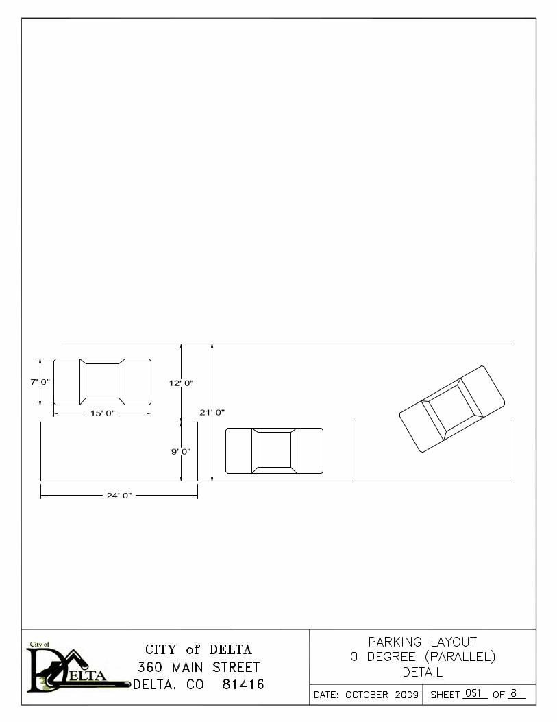
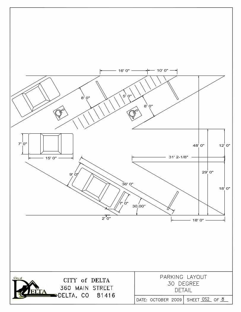


STANDARDS AND SPECIFICATIONS FOR THE DESIGN AND CONSTRUCTION OF PUBLIC
IMPROVEMENTS
Chapter 9
Trenching, Backfilling, & Compacting
2010 EDITION

TABLE OF CONTENTS
CHAPTER 9
TRENCHING, BACKFILLING, AND COMPACTING
Page
9.00.00 GENERAL ......................................................................................................................................................... 1
9.01.00 DESCRIPTION .............................................................................................................................................. 1 9.02.00 QUALITY ASSURANCE.............................................................................................................................. 1 9.02.01 Soils Report ................................................................................................................................................ 1
9.02.02 Compaction ................................................................................................................................................ 1
9.02.03 Construction Staking .................................................................................................................................. 1
9.03.00 JOB CONDITIONS........................................................................................................................................ 2 9.03.01 Drainage and Groundwater ....................................................................................................................... 2
9.03.02 Sequencing ................................................................................................................................................. 2
9.03.03 Underground Obstructions ........................................................................................................................ 2
9.04.00 MAINTENANCE AND CORRECTION ....................................................................................................... 3 9.04.01 Trench Settlement ....................................................................................................................................... 3
9.04.02 Subcontractor ............................................................................................................................................. 3
9.10.00 CONSTRUCTION SPECIFICATIONS ......................................................................................................... 3
9.11.00 PREPARATION............................................................................................................................................. 3 9.12.00 TRENCHING ................................................................................................................................................. 3 9.13.00 PIPE BEDDING ............................................................................................................................................. 5 9.14.00 BACKFILLING AND COMPACTION ........................................................................................................ 5 9.15.00 FIELD QUALITY CONTROL ...................................................................................................................... 6
9.20.00 MATERIAL SPECIFICATIONS .................................................................................................................... 7 9.21.00 STABILIZATION MATERIAL .................................................................................................................... 7 9.22.00 BEDDING MATERIALS .............................................................................................................................. 7 9.23.00 TRENCH BACKFILL MATERIAL .............................................................................................................. 8 9.24.00 STRUCTURE BACKFILL (FLOW-FILL).................................................................................................... 8 9.24.01 General ....................................................................................................................................................... 8
9.24.02 Compaction ................................................................................................................................................ 9
1
CHAPTER 9
TRENCHING, BACKFILLING AND COMPACTING
9.00.00 GENERAL
9.01.00 DESCRIPTION
(A) This section covers excavation and trenching including drainage, dewatering, preparation of
subgrades, pipe bedding, backfilling, compacting, and finish grading for underground pipe lines, service lines, and appurtenances.
(B) Reference detail drawing in the appropriate chapter of these STANDARDS AND
SPECIFICATIONS. All work performed according to this section must comply with the general requirements contained within Chapter 1 and the acceptance requirements of Chapter 10.
9.02.00 QUALITY ASSURANCE
9.02.01 Soils Report
All quality assurance criteria within the approved soils report shall be followed.
9.02.02 Compaction
Soil compaction tests shall be performed in accordance with:
(A) ASTM D 698 or ASTM D 1557, Standard or Modified Method of Test for Moisture Density Relations of Soils
(B) ASTM D 2049, Standard Method of Test for Relative Density of Cohesionless Soils
9.02.03 Construction Staking
(A) Construction staking shall be performed with qualified, competent personnel under the
direction of a professional land surveyor registered in the State of Colorado.
(B) All survey notes and construction staking notes shall be entered into bound, hard cover field books.
(C) Staking of the work shall be at fifty-foot (50') stations (maximum). (D) Offsets shall be staked so that vertical and horizontal alignment may be checked.
(E) All survey data that is developed by the Responsible Party or the Responsible Party’s surveyor in performing surveys that are required by the work shall be available to the City for examination throughout the construction period.
2
9.03.00 JOB CONDITIONS
9.03.01 Drainage and Groundwater
(A) All excavations and trenches shall be kept free from excess groundwater during
construction. (B) Any water that is encountered in the trench shall be removed to the extent necessary to
provide a firm subgrade to permit joints to be made in the dry and to prevent the entrance of water into the pipeline.
(C) Surface run-off shall be diverted as necessary to keep excavations and trenches free from
water during construction.
(D) The excavation or trench shall be kept free from water until the structure or pipe to be installed therein is completed to the extent that no damage from hydrostatic pressure, flotation, or other cause will result.
(E) Water shall be prevented from entering into previously constructed pipe.
(F) Except for storm drains, the pipe under construction shall not be used for dewatering.
9.03.02 Sequencing
(A) Pipeline installation shall be performed within two hundred (200) linear feet of trench
excavation. If construction is occurring in an open field, this distance may be increased at the City Representative's discretion.
(B) Initial trench backfill shall be performed within fifty (50) linear feet of pipeline
installation. If construction is occurring in an open field, this distance may be increased at the City Representative's discretion.
(C) Where excavation is a hazard to automotive or pedestrian traffic, the amount of open
trench and the duration of that opening is to be minimized. The Responsible Party shall coordinate the amount and duration of road closures with the City.
9.03.03 Underground Obstructions
(A) The Responsible Party shall field verify all drawings of record information obtained from
the City or other affected utility company.
(B) The Responsible Party shall notify each utility owner and request utilities to be field located by surface reference at least forty-eight (48) hours prior to trenching or excavation. This may be accomplished by calling the Utility Notification Center of Colorado.
(C) In situations where conflicts may exist, the Responsible Party shall expose and verify the
size, location, and elevation of underground utilities and other obstructions sufficiently in advance of construction to permit changes to be made to the construction drawings.
3
(D) In the case of a conflict, the Responsible Party shall notify the City and the affected utility company. The proposed work may then be modified by the Design Engineer and after the City Representative's approval.
(E) Existing improvements, adjacent property, utilities, trees, and plants that are not to be
removed shall be protected from injury or damage resulting from the Responsible Party's operations. If damage should occur, the Responsible Party shall make repair such that damaged materials are restored in original or better condition, as directed by the City Representative, utility or property owner in question.
(F) If the Responsible Party removes any underground obstructions, the following shall
apply:
1. Drainage culverts may be salvaged, stored, and reused in the original location if approval is obtained from the City Representative. All other underground obstructions shall be replaced with new materials.
2. The area in which the underground obstruction was located shall be restored to
original or better condition.
9.04.00 MAINTENANCE AND CORRECTION
9.04.01 Trench Settlement
The Responsible Party shall maintain and repair all trench settlement and make necessary repairs to pavement, sidewalks, or other structures which may be damaged as a result of backfill settlement. Responsible Party shall warrant work for a period of one (1) year after final completion and acceptance of the work.
9.04.02 Subcontractor
The Responsible Party may perform such maintenance and repairs by subcontract. If the Responsible Party chooses to subcontract the warranty work, he shall submit to the City Representative a copy of the subcontract or the work authorization as evidence of the Responsible Party's faithful intention to perform any repairs which may become necessary during the one- (1) year warranty period.
9.10.00 CONSTRUCTION SPECIFICATIONS
9.11.00 PREPARATION
(A) Topsoil shall be stripped from areas that are to be disturbed by construction and stockpiled.
(B) Topsoil shall be segregated from non-organic trench excavation material and debris.
9.12.00 TRENCHING
(A) Trenches shall be excavated by open-cut methods, except where boring or tunneling is indicated,
shown on drawings, or approved by the City Representative.
(B) Trench width shall be maintained to within three inches (3") of that specified on plans.
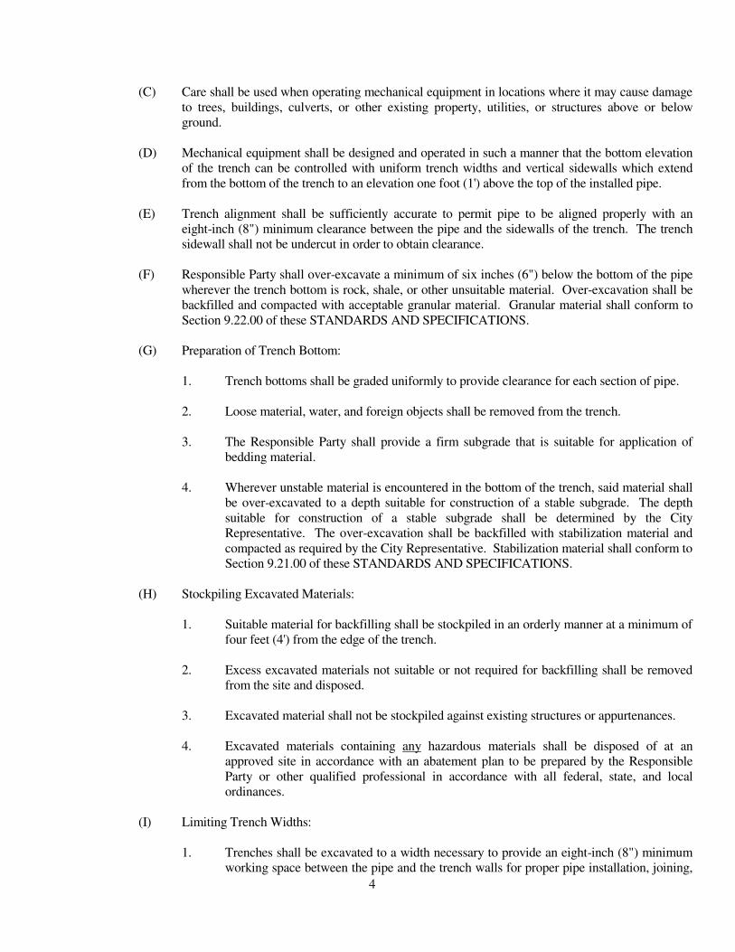
4
(C) Care shall be used when operating mechanical equipment in locations where it may cause damage
to trees, buildings, culverts, or other existing property, utilities, or structures above or below ground.
(D) Mechanical equipment shall be designed and operated in such a manner that the bottom elevation
of the trench can be controlled with uniform trench widths and vertical sidewalls which extend from the bottom of the trench to an elevation one foot (1') above the top of the installed pipe.
(E) Trench alignment shall be sufficiently accurate to permit pipe to be aligned properly with an
eight-inch (8") minimum clearance between the pipe and the sidewalls of the trench. The trench sidewall shall not be undercut in order to obtain clearance.
(F) Responsible Party shall over-excavate a minimum of six inches (6") below the bottom of the pipe
wherever the trench bottom is rock, shale, or other unsuitable material. Over-excavation shall be backfilled and compacted with acceptable granular material. Granular material shall conform to Section 9.22.00 of these STANDARDS AND SPECIFICATIONS.
(G) Preparation of Trench Bottom:
1. Trench bottoms shall be graded uniformly to provide clearance for each section of pipe.
2. Loose material, water, and foreign objects shall be removed from the trench.
3. The Responsible Party shall provide a firm subgrade that is suitable for application of
bedding material.
4. Wherever unstable material is encountered in the bottom of the trench, said material shall be over-excavated to a depth suitable for construction of a stable subgrade. The depth suitable for construction of a stable subgrade shall be determined by the City Representative. The over-excavation shall be backfilled with stabilization material and compacted as required by the City Representative. Stabilization material shall conform to Section 9.21.00 of these STANDARDS AND SPECIFICATIONS.
(H) Stockpiling Excavated Materials:
1. Suitable material for backfilling shall be stockpiled in an orderly manner at a minimum of
four feet (4') from the edge of the trench.
2. Excess excavated materials not suitable or not required for backfilling shall be removed from the site and disposed.
3. Excavated material shall not be stockpiled against existing structures or appurtenances. 4. Excavated materials containing any hazardous materials shall be disposed of at an
approved site in accordance with an abatement plan to be prepared by the Responsible Party or other qualified professional in accordance with all federal, state, and local ordinances.
(I) Limiting Trench Widths:
1. Trenches shall be excavated to a width necessary to provide an eight-inch (8") minimum
working space between the pipe and the trench walls for proper pipe installation, joining,

5
and bedding.
2. The maximum trench width at an elevation twelve inches (12") above the top of the installed pipe shall be the pipe diameter of the pipe plus 24 inches, or thirty inches (30") whichever is greater. If the width of the trench, twelve inches (12") above the top of the pipe, exceeds the maximum allowable trench width, a higher strength pipe or special pipe bedding shall be provided as required by soil-loading conditions and as approved by the City Representative.
9.13.00 PIPE BEDDING
(A) Placement and Compaction:
1. Bedding material shall be distributed and graded to provide uniform and continuous
support beneath the pipe at all points between bell holes or pipe joints. Pipe shall not be supported by the bells.
2. To prevent lateral displacement, granular bedding material shall be deposited and
compacted uniformly and simultaneously on each side of the pipe.
3. Granular bedding material shall be compacted in accordance with these STANDARDS AND SPECIFICATIONS.
(B) Ground water barriers shall be constructed in such a manner to prevent passage of water through
bedding material for the full depth of the granular bedding material and the full width of the trench.
1. Ground water barriers, if shown on the approved construction plans, shall be
approximately four feet (4') long and spaced not more than four hundred feet (400') apart.
2. Material for ground water barriers shall be as specified by the ditch company which controls the irrigation ditch to be crossed. If there is no ditch company, the City Representative shall determine the material to be used.
9.14.00 BACKFILLING AND COMPACTION
(A) Trenches shall be backfilled promptly after the pipe has been installed and inspected. Backfill
around manholes and valve boxes shall be compacted with hand-operated equipment. (B) Backfill material shall be deposited in uniform horizontal layers which may not exceed six inches
(6") (compacted depth) in all areas. Other thickness may be used with the prior written approval of the City Representative.
(C) Methods and equipment that are appropriate for the backfill of material shall be employed.
Backfill equipment or backfilling methods that transmit damaging shocks to the pipe shall not be used.
(D) Compaction shall not be performed by jetting or water settling.
(E) If compaction cannot be obtained with job excavated material, trench backfill material shall be
imported.

6
(F) Topsoil shall be replaced to the depth of stripping over all areas that are to receive vegetation. (G) Excess excavated materials and materials not suitable for backfill shall be removed from the site.
9.15.00 FIELD QUALITY CONTROL
(A) Field Compaction Control:
1. Field tests will be conducted to determine compliance of compaction methods with specified density in accordance with ASTM D 2922 (Tests for Density of Soil and Soil-Aggregate in Place by Nuclear Methods).
2. Compaction tests shall be performed at a depth of one-and-one-half feet (1-1/2') above the
top of the pipe and in one-foot (1') vertical increments up to the finish grade.
3. Compaction tests shall be performed at least once every one hundred (100) linear feet as measured along the length of the pipe.
4. If the City Representative determines that reliable and uniform results are produced by the
Responsible Party's construction techniques, the frequency of testing may be changed subject to the City Representatives discretion, but no more than three hundred (300) linear feet.
(B) Compaction shall be to the following minimum densities (reference ASTM D 698 or AASHTO T
99 unless otherwise indicated): 1. Barrier Material - 95 Percent of Maximum Standard Density. 2. Pipe Bedding: a. Compacted Granular Material - 80 Percent of Maximum Relative Density (ASTM D 2049). b. Carefully Compacted Select Soil - 90 Percent of Maximum Standard Density c. Barrier Material - 95 Percent of Maximum Standard Density 3. Trench Backfill: a. Paved roadways, sidewalks, and other areas which are to be paved: Top Four Feet (4') - 95 Percent of Maximum Standard Density Remainder of Trench - 90 Percent of Maximum Standard Density b. Gravel Roadways - 95 Percent of Maximum Standard Density c. Fields and All Other Areas - 90 Percent of Maximum Standard Density
d. Under Footings, Foundations, Structures, 100 Percent of Maximum Standard Density or in Conformance with the Approved Soils Report and Recommendations

7
(C) Moisture Content:
1. All compacted backfill shall be within two percent (2%) (plus or minus) of the optimum
moisture content of the soil as determined by ASTM D 698.
2. Water shall be added to the material or the material shall be harrowed, disced, bladed, or otherwise worked to insure a uniform moisture content, as specified.
9.20.00 MATERIAL SPECIFICATIONS
9.21.00 STABILIZATION MATERIAL
(A) If the existing soil in the trench bottom is judged to be unsuitable by the City Representative, the
top six inches (6") of the pipe subgrade shall be removed and replaced with a stabilization material.
Stabilization material shall conform to ASTM D 448 or CDOT No. 4, according to Table 9.21.00:
TABLE 9.21.00
Stabilization Material Size Percent Passing 2 Inch 100 1-1/2 Inch 90-100 1 Inch 20-55 3/4 Inch 0-15 3/8 Inch 0-5
(B) Geotextiles used for erosion control, drainage and silt fence shall conform to CDOT requirements of 712.08 in the Standard Specifications for Road and Bridge Construction.
9.22.00 BEDDING MATERIALS
(A) Granular Material. Uniformly-graded material conforming to AASHTO M6, according to Table
9.22.00:
TABLE 9.22.00 Bedding Material
Size Percent Passing 3/8 Inch 100 No. 4 95-100 No. 16 45-80 No. 50 10- 30 No. 100 2-10
(B) Select Soil. Excavated material which is free from rocks, clods, and stones greater than one-and-one-half inches (1-1/2") in any dimension and which meets other requirements of trench backfill material.
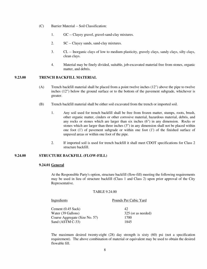
8
(C) Barrier Material -- Soil Classification: 1. GC -- Clayey gravel, gravel-sand-clay mixtures. 2. SC -- Clayey sands, sand-clay mixtures.
3. CL -- Inorganic clays of low to medium plasticity, gravely clays, sandy clays, silty clays, clean clays.
4. Material may be finely divided, suitable, job-excavated material free from stones, organic
matter, and debris.
9.23.00 TRENCH BACKFILL MATERIAL
(A) Trench backfill material shall be placed from a point twelve inches (12") above the pipe to twelve
inches (12") below the ground surface or to the bottom of the pavement subgrade, whichever is greater.
(B) Trench backfill material shall be either soil excavated from the trench or imported soil.
1. Any soil used for trench backfill shall be free from frozen matter, stumps, roots, brush, other organic matter, cinders or other corrosive material, hazardous material, debris, and any rocks or stones which are larger than six inches (6") in any dimension. Rocks or stones which are larger than three inches (3") in any dimension shall not be placed within one foot (1') of pavement subgrade or within one foot (1') of the finished surface of unpaved areas or within one foot of the pipe.
2. If imported soil is used for trench backfill it shall meet CDOT specifications for Class 2
structure backfill.
9.24.00 STRUCTURE BACKFILL (FLOW-FILL)
9.24.01 General
At the Responsible Party's option, structure backfill (flow-fill) meeting the following requirements may be used in lieu of structure backfill (Class 1 and Class 2) upon prior approval of the City Representative.
TABLE 9.24.00
Ingredients Pounds Per Cubic Yard Cement (0.45 Sack) 42 Water (39 Gallons) 325 (or as needed) Coarse Aggregate (Size No. 57) 1700 Sand (ASTM C-33) 1845
The maximum desired twenty-eight (28) day strength is sixty (60) psi (not a specification requirement). The above combination of material or equivalent may be used to obtain the desired flowable fill.

9
Structural backfill (flow-fill) will only be allowed over any water or sanitary sewer line at the discretion of the City Representative and shall be no more than two (2) feet thick.
9.24.02 Compaction
Compaction of structure backfill will not be required if material meeting the above requirements is used.

STANDARDS AND SPECIFICATIONS FOR THE DESIGN AND CONSTRUCTION OF PUBLIC
IMPROVEMENTS
Chapter 10
Acceptance Requirements
2010 EDITION
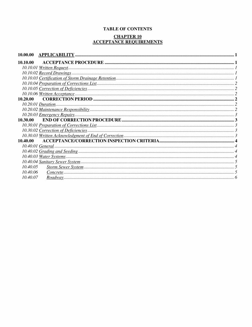
TABLE OF CONTENTS
CHAPTER 10
ACCEPTANCE REQUIREMENTS
10.00.00 APPLICABILITY ............................................................................................................................................ 1
10.10.00 ACCEPTANCE PROCEDURE .................................................................................................................. 1 10.10.01 Written Request .................................................................................................................................................. 1
10.10.02 Record Drawings ............................................................................................................................................... 1
10.10.03 Certification of Storm Drainage Retention ........................................................................................................ 1
10.10.04 Preparation of Corrections List ......................................................................................................................... 2
10.10.05 Correction of Deficiencies ................................................................................................................................. 2
10.10.06 Written Acceptance ............................................................................................................................................ 2
10.20.00 CORRECTION PERIOD ............................................................................................................................ 2 10.20.01 Duration ............................................................................................................................................................. 2
10.20.02 Maintenance Responsibility ............................................................................................................................... 2
10.20.03 Emergency Repairs ............................................................................................................................................ 3
10.30.00 END OF CORRECTION PROCEDURE ................................................................................................... 3 10.30.01 Preparation of Corrections List ......................................................................................................................... 3
10.30.02 Correction of Deficiencies ................................................................................................................................. 3
10.30.03 Written Acknowledgment of End of Correction ................................................................................................. 3
10.40.00 ACCEPTANCE/CORRECTION INSPECTION CRITERIA.................................................................. 4
10.40.01 General .............................................................................................................................................................. 4
10.40.02 Grading and Seeding ......................................................................................................................................... 4
10.40.03 Water Systems .................................................................................................................................................... 4
10.40.04 Sanitary Sewer System ....................................................................................................................................... 5
10.40.05 Storm Sewer System .................................................................................................................................... 5
10.40.06 Concrete ...................................................................................................................................................... 5
10.40.07 Roadway ...................................................................................................................................................... 6

1
CHAPTER 10 ACCEPTANCE REQUIREMENTS
10.00.00 APPLICABILITY
Before the City will assume ownership and maintenance responsibility for public improvements, the public improvements shall be formally accepted by the City Representative. The Responsible Party is responsible for the proper installation of all improvements. Failure by the City's representatives to detect improper installations or defects during the construction of improvements or during subsequent inspections does not relieve the Responsible Party of the responsibility to correct such defects at a later date.
10.10.00 ACCEPTANCE PROCEDURE
10.10.01 Written Request
At such time that the Responsible Party believes that the construction of all required public and private improvements have been completed, all improvements are accessible and visible for inspection and a written Release For Service for Public Improvements has been issued by the City Representative, a written request for acceptance shall be submitted to the City Representative.
10.10.02 Record Drawings
A complete set of blueline “as-constructed” drawings of the public improvements shall accompany the request for acceptance. Upon approval by the City, the Responsible Party will be required to submit a certified set of 3 mil double matte mylar copies with each sheet signed and sealed by the Professional Engineer registered in the State of Colorado who is responsible for the preparation of the record drawings of the “as-constructed” drawings. These drawings shall be prepared as indicated in the Drawings Standards Checklist (See Section 1.40.00 of these standards and specifications). If significant corrections to the improvements are noted during the acceptance inspection, the record drawings may be returned to the Responsible Party for revisions. In addition to the mylar copies, the Responsible Party shall submit digital copies in an AutoCAD readable format.
10.10.03 Certification of Storm Drainage Retention
A certification of the construction of all required storm drainage retention facilities shall accompany the written request for acceptance. This certification, which shall be signed and sealed by a Professional Engineer registered in the State of Colorado, shall verify that the retention facilities will function in accordance with the approved final drainage study.

2
10.10.04 Preparation of Corrections List
Upon receipt of the written request for acceptance, certification of storm drainage detention, and record drawings, the City Representative will instruct the appropriate Engineering Construction Inspector to schedule an inspection of the improvements. The Responsible Party or his representative will be invited to accompany the City's representative on all such inspections. The construction of public improvements will be inspected for conformance with the approved plans, the Public Improvements Agreement, these STANDARDS AND SPECIFICATIONS, and City Code. If, due to excessive dirt or snow on streets, poor weather conditions, inaccessibility, or other reasons the inspection cannot be performed, the Responsible Party will be notified of the need to postpone these activities until the cause of the delay can be rectified. Deficiencies noted during the inspection will be compiled in a corrections list to be mailed to the Responsible Party.
10.10.05 Correction of Deficiencies
Correction list items shall be corrected within sixty (60) days of the date of the corrections list. If all of the noted deficiencies are not corrected within this time, the public improvements may be re-inspected and any new defects may be added to the corrections list. Public improvements will not be accepted until all noted deficiencies are corrected within the proper time frame. The City Representative shall be notified before any corrective work commences and immediately upon the completion of the repairs.
10.10.06 Written Acceptance
Upon the completion of all items on the correction list and payment of all outstanding fees, including security as outlined in the Delta Municipal Code Section 16.04.080, any reimbursements, and other items owed to the City, the City Representative will record the Final Plat in the Office of the Delta County Clerk and Recorder.
10.20.00 CORRECTION PERIOD
10.20.01 Duration
All public improvements shall be subject to a correction period of at least one (1) year after the date of the recording of the Final Plat.
10.20.02 Failure/Repair Responsibility
The Responsible Party shall be responsible for failure or repair of all public improvements during the correction period. The City Representative will notify the Responsible Party of any repair or replacement that may be necessary during this time. The cost of any repair or replacement not performed by the Responsible Party that must be performed by the City will be billed to the Responsible Party at cost plus fifteen percent (15%).

3
10.20.03 Emergency Repairs
In the event of a water main break, sanitary sewer main blockage, street or bridge failure, or other emergency that may occur during the correction period, it may become necessary for the City to undertake immediate repairs to the facilities and/or make the area safe to residents, pedestrians, or motorists. The City will attempt to contact the Responsible Party in the event of such emergency. However, if the Responsible Party or his representative cannot be contacted quickly or if the Responsible Party is unable to take immediate action to relieve the urgent situation, the City may proceed with such action as deemed necessary by the City Representative, and the Responsible Party will be billed for all costs of these actions at cost plus fifteen percent (15%).
10.30.00 END OF CORRECTION PROCEDURE
10.30.01 Preparation of Corrections List
At approximately nine (9) months into the correction period, the Responsible Party will schedule an inspection of the public improvements within the development to be perfomed by the City Representative. The Responsible Party or his representative will be invited to accompany the City's representative on all such inspections. The condition of the public improvements will be inspected for conformance with the approved plans, the Official Development Plan, the Public Improvements Agreement, these STANDARDS AND SPECIFICATIONS, and any other City Codes. If due to excessive dirt or snow on streets, poor weather conditions, inaccessibility, or other reasons the inspection cannot be performed, the Responsible Party will be notified of the need to postpone these activities until the cause of the delay can be rectified. Deficiencies noted during the correction inspection will be compiled in a corrections list to be mailed to the Responsible Party.
10.30.02 Correction of Deficiencies
Correction list items should be corrected within 2 months of the date of the correction list, and all corrections must be completed no later than ten (10) working days prior to the scheduled end of the correction period. If all of the noted deficiencies are not corrected within this time, the public improvements may be re-inspected, a revised correction list may be issued, and the end of the correction period may be adjusted at the discretion of the City Representative to allow ample time for the completion of the corrections. The end of the correction period will not be acknowledged until all noted deficiencies are corrected within the proper time frame. The appropriate City Representative shall be notified before any corrective work commences and immediately upon the completion of the repairs.
10.30.03 Written Acknowledgment of End of Correction
Upon completion of the correction of all deficiencies noted in the correction list, the City Representative will issue a written acknowledgment of the end of the correction period for the public improvements.

4
10.40.00 ACCEPTANCE/CORRECTION INSPECTION CRITERIA
10.40.01 General
All public and private improvements shall be installed in conformance with the approved plans, the Public Improvements Agreement, and these STANDARDS AND SPECIFICATIONS. The City Representative shall be the final authority in the determination of defects and required corrections to public and private improvements.
10.40.02 Grading and Seeding
Finished grades shall be in conformance with the approved plans and the Public Improvements Agreement. Detention pond grading shall provide, at a minimum, the required volume as defined in the approved final drainage study. Unless otherwise approved, no slopes shall exceed a grade of four (horizontal) to one (vertical) (4:1). Seeding shall be performed and ground cover shall be established in conformance with Chapter 2 of these standards and specifications.
10.40.03 Water Systems
The required inspection and testing of water mains and appurtenances that shall be performed before systems can be released for service are outlined in Chapter 3 of these STANDARDS AND SPECIFICATIONS. At the time of acceptance and correction inspections of all public and private improvements, additional aspects of water system construction that shall be inspected include, but shall not be limited to, the following:
(A) All valves, blow-off installations, and fire hydrants shall be operable.
(B) Valve box risers shall be vertical and shall be adjusted to within one-eighth inch (1/2")
below grade in paved areas or one inch (1") above grade in landscaped areas.
(C) Valve operating nuts shall be accessible with a six-foot (6') valve key with between eighteen inches (18") and four feet (4') of clearance between the handle of the key and finished grade.
(D) Fire hydrants shall be vertical and shall be adjusted to a minimum of eighteen inches
(18") from the center of the nozzle to finished grade.
(E) A minimum of five feet (5') of clearance for operation shall be provided around all fire hydrants and water valve risers.
(F) Manhole rims and covers for water valve vaults shall be adjusted to within one-eighth
inch (1/2") below grade in paved areas or one inch (1") above grade in landscaped areas.
(G) The construction and operation of any required pumping systems shall be in conformance with the specifications issued and approved for that specific installation.
(H) All mains and manholes shall be free of construction debris, dirt, trash, and other foreign
material. (I) Manhole steps shall be properly spaced and aligned.

5
10.40.04 Sanitary Sewer System
The required inspection and testing of sanitary sewer mains and appurtenances that shall be performed before systems can be released for service as outlined in Chapter 4 of these STANDARDS AND SPECIFICATIONS. At the time of acceptance and correction inspections of all public improvements, additional aspects of sanitary sewer system construction that shall be inspected include, but shall not be limited to, the following:
(A) All mains and manholes shall be free of construction debris, dirt, trash, and other foreign
material.
(B) The City's TV inspection of all sanitary sewer mains shall be completed prior to the acceptance of public and private improvements.
(C) Manhole rims and covers shall be adjusted to within one-eighth inch (1/2") below grade
in paved areas or one inch (1") above grade in landscaped areas.
(D) Manhole steps shall be properly spaced aligned.
(E) The construction and operation of any required sewage lift systems shall be in conformance with the specifications issued and approved for that specific installation.
10.40.05 Storm Sewer System
The required inspection and testing of storm sewer mains and appurtenances that shall be performed are outlined in Chapter 5 of these STANDARDS AND SPECIFICATIONS. At the times of acceptance and correction inspections of all public improvements, additional aspects of storm sewer system construction that shall be inspected include, but shall not be limited to, the following; (A) All pipes and manholes shall be free of construction debris, dirt, trash, and other foreign
material. (B) Manhole rims and covers shall be adjusted to within one-eight inch (1/2”) below grade
in paved areas or one inch (1”) above grade in landscaped areas. (C) Manhole steps shall be properly spaced and aligned. (D) Inlets shall be properly aligned to within one-eight inch (1/2”) below grade next to
sidewalk or curb and gutter.
10.40.06 Concrete
At the time of acceptance and correction inspection of all public improvements the aspects of
concrete construction that shall be inspected include, but shall not be limited to the following:
(A) Breakage or cracking greater than 1/8” at other than construction joints. (B) Ponding of any size. (C) Settlement affecting drainage, pedestrian or traffic safety.
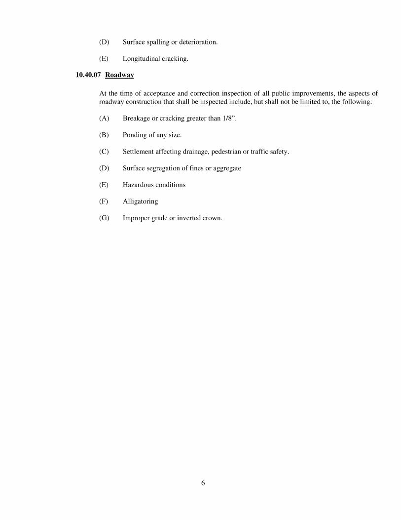
6
(D) Surface spalling or deterioration. (E) Longitudinal cracking.
10.40.07 Roadway
At the time of acceptance and correction inspection of all public improvements, the aspects of roadway construction that shall be inspected include, but shall not be limited to, the following: (A) Breakage or cracking greater than 1/8”. (B) Ponding of any size. (C) Settlement affecting drainage, pedestrian or traffic safety. (D) Surface segregation of fines or aggregate (E) Hazardous conditions (F) Alligatoring (G) Improper grade or inverted crown.