HCWA Standards and Specifications with Details_2014.pdf
154
HENRY COUNTY WATER AND SEWERAGE AUTHORITY STANDARDS AND SPECIFICATIONS JANUARY 2012
-
Upload
khangminh22 -
Category
Documents
-
view
2 -
download
0
Transcript of HCWA Standards and Specifications with Details_2014.pdf
HENRY COUNTY WATER AND SEWERAGE AUTHORITY
STANDARDS AND SPECIFICATIONS
JANUARY 2012
Henry County Water and Sewerage Authority Standards and Specifications
i
TABLE OF CONTENTS
SECTION 1 - Policies and Procedures ...................................................................................................... 1-1
1.1 General Provisions ..................................................................................................................... 1-1
1.1.1 Authority and Title ........................................................................................................... 1-1 1.1.2 Purpose and Intent ........................................................................................................... 1-1 1.1.3 Variance ........................................................................................................................... 1-1 1.1.4 Amendments and Revisions ............................................................................................. 1-1
1.2 Definitions .................................................................................................................................. 1-2
1.3 Pre-Development Requirements ................................................................................................ 1-4
1.3.1 Water/Sewer Availability Letter ...................................................................................... 1-4
1.4 Plan Review and Approval Process ........................................................................................... 1-6
1.4.1 General ............................................................................................................................. 1-6 1.4.2 Plan Preparation ............................................................................................................... 1-6 1.4.3 Plan Submittal .................................................................................................................. 1-9 1.4.4 Expiration of Plan Approval .......................................................................................... 1-10 1.4.5 Plan Modifications ......................................................................................................... 1-10
1.5 Easements and Deeded Property .............................................................................................. 1-11
1.5.1 General ........................................................................................................................... 1-11 1.5.2 Permanent Easements .................................................................................................... 1-11 1.5.3 Temporary Easements .................................................................................................... 1-12 1.5.4 Deeded Property ............................................................................................................ 1-12
1.6 Installation ................................................................................................................................ 1-13
1.6.1 General ........................................................................................................................... 1-13 1.6.2 Approved Utility Contractors ........................................................................................ 1-13 1.6.3 Inspections ..................................................................................................................... 1-13 1.6.4 Pre-Construction Meetings ............................................................................................ 1-14 1.6.5 Testing ........................................................................................................................... 1-14 1.6.6 Warranty ........................................................................................................................ 1-14
1.7 Connecting to the HCWSA System ......................................................................................... 1-15
1.8 Final Acceptance ...................................................................................................................... 1-16
1.8.1 General ........................................................................................................................... 1-16 1.8.2 Deed of Conveyance ...................................................................................................... 1-16 1.8.3 Contribution of Fixed Assets Form................................................................................ 1-16 1.8.4 Lien Waivers .................................................................................................................. 1-16 1.8.5 Corporate Owner’s Affidavit ......................................................................................... 1-16 1.8.6 Corporate Contractor’s Affidavit ................................................................................... 1-16 1.8.7 Two-Year Letter of Credit ............................................................................................. 1-17 1.8.8 Record Drawings ........................................................................................................... 1-17 1.8.9 Final Plat ........................................................................................................................ 1-17 1.8.10 Television Inspection Report and Video ........................................................................ 1-17 1.8.11 Total Coliform Analysis ................................................................................................ 1-17 1.8.12 Fees ................................................................................................................................ 1-18 1.8.13 Field Corrections ............................................................................................................ 1-18
1.9 Sanitary Sewage Lift Stations .................................................................................................. 1-19
Henry County Water and Sewerage Authority Standards and Specifications
ii
1.9.1 Ownership ...................................................................................................................... 1-19 1.9.2 Interbasin Transfer ......................................................................................................... 1-19
1.10 Fire Flow Tests .................................................................................................................... 1-20
1.10.1 General ........................................................................................................................... 1-20 1.10.2 Requesting Fire Flow Data ............................................................................................ 1-20
1.11 New Conveyor Car Wash Facilities ..................................................................................... 1-21
1.11.1 General ........................................................................................................................... 1-21 1.11.2 Failure to Comply .......................................................................................................... 1-21
SECTION 2 - Design Requirements .......................................................................................................... 2-1
2.1 Water Distribution Systems ....................................................................................................... 2-1
2.1.1 General ............................................................................................................................. 2-1 2.1.2 Design Usage Rates ......................................................................................................... 2-1 2.1.3 Design Pressures .............................................................................................................. 2-1 2.1.4 Water Line Size and Material .......................................................................................... 2-1 2.1.5 Water Line Location ........................................................................................................ 2-1 2.1.6 Water Line Bury Depth .................................................................................................... 2-2 2.1.7 Fire Hydrants ................................................................................................................... 2-2 2.1.8 Blow-Off Valves .............................................................................................................. 2-2 2.1.9 Isolation Valves ............................................................................................................... 2-2 2.1.10 Air Release Valves ........................................................................................................... 2-3 2.1.11 Thrust Restraint ................................................................................................................ 2-3 2.1.12 Water Service Connections .............................................................................................. 2-3 2.1.13 Water Meters .................................................................................................................... 2-4 2.1.14 Backflow Prevention ........................................................................................................ 2-4 2.1.15 Jack and Bore Installations .............................................................................................. 2-4 2.1.16 Creek Crossings ............................................................................................................... 2-4
2.2 Gravity Flow Sanitary Sewer Systems ....................................................................................... 2-6
2.2.1 General ............................................................................................................................. 2-6 2.2.2 Design Flow Rates ........................................................................................................... 2-6 2.2.3 Hydraulics ........................................................................................................................ 2-7 2.2.4 Sanitary Sewer Size and Material .................................................................................... 2-8 2.2.5 Sanitary Sewer Location .................................................................................................. 2-8 2.2.6 Sanitary Sewer Bury Depth ............................................................................................. 2-8 2.2.7 Sanitary Sewer Manholes ................................................................................................ 2-9 2.2.8 Corrosion Protection for Sanitary Sewer Systems ........................................................... 2-9 2.2.9 Sanitary Sewer Flow Meters .......................................................................................... 2-10 2.2.10 Jack and Bore Installations ............................................................................................ 2-10 2.2.11 Creek Crossings ............................................................................................................. 2-10 2.2.12 Aerial Crossings ............................................................................................................. 2-10
2.3 Sanitary Sewage Force Mains .................................................................................................. 2-11
2.3.1 General ........................................................................................................................... 2-11 2.3.2 Hydraulics ...................................................................................................................... 2-11 2.3.3 Force Main Size and Material ........................................................................................ 2-11 2.3.4 Force Main Location ...................................................................................................... 2-11 2.3.5 Force Main Bury Depth ................................................................................................. 2-11
Henry County Water and Sewerage Authority Standards and Specifications
iii
2.3.6 Isolation Valves ............................................................................................................. 2-12 2.3.7 Combination Air/Vacuum Valves.................................................................................. 2-12 2.3.8 Thrust Restraint .............................................................................................................. 2-12 2.3.9 Jack and Bore Installations ............................................................................................ 2-12 2.3.10 Creek Crossings ............................................................................................................. 2-12
2.4 Sanitary Sewage Lift Stations .................................................................................................. 2-13
2.4.1 General ........................................................................................................................... 2-13 2.4.2 Hydraulics ...................................................................................................................... 2-13 2.4.3 Location of Sanitary Sewage Lift Stations .................................................................... 2-14 2.4.4 Sanitary Sewage Lift Station Property and Access ........................................................ 2-14 2.4.5 Lift Station Components ................................................................................................ 2-15 2.4.6 General Electrical Requirements ................................................................................... 2-16 2.4.7 Controls .......................................................................................................................... 2-16 2.4.8 Backup Power System ................................................................................................... 2-17 2.4.9 Supervisory Control and Data Acquisition (SCADA) System ...................................... 2-17 2.4.10 Wet Well ........................................................................................................................ 2-17 2.4.11 Fence and Gate ............................................................................................................... 2-18 2.4.12 Security Light ................................................................................................................ 2-18 2.4.13 Potable Water Service Line ........................................................................................... 2-18 2.4.14 Landscape ...................................................................................................................... 2-19
SECTION 3 - Material Specifications ....................................................................................................... 3-1
3.1 General ....................................................................................................................................... 3-1
3.2 Ductile Iron Pipe and Fittings .................................................................................................... 3-1
3.3 Casing Pipe ................................................................................................................................ 3-4
3.3.1 Steel Casing Pipe for Road Crossings ............................................................................. 3-4 3.3.2 PVC Casing Pipe for Water Service Lines ...................................................................... 3-4 3.3.3 HDPE Casing Pipe for Water Service Lines .................................................................... 3-4
3.4 Casing Spacers ........................................................................................................................... 3-5
3.5 Polyethylene Encasement (Wrapping) ....................................................................................... 3-5
3.6 Copper Tubing for Water Service Lines .................................................................................... 3-5
3.7 PVC Pipe for Gravity Sanitary Sewers ...................................................................................... 3-6
3.8 C900 PVC Pipe for Sanitary Sewage Force Mains .................................................................... 3-6
3.9 Valves ........................................................................................................................................ 3-6
3.9.1 Butterfly Valves ............................................................................................................... 3-6 3.9.2 Gate Valves ...................................................................................................................... 3-7 3.9.3 Plug Valves ...................................................................................................................... 3-7 3.9.4 Check Valves for Submersible Sanitary Sewage Lift Stations ........................................ 3-8 3.9.5 Corporation Stops .......................................................................................................... 3-10 3.9.6 Curb Stops...................................................................................................................... 3-10 3.9.7 Backflow Preventers ...................................................................................................... 3-10 3.9.8 Air Release Valves ......................................................................................................... 3-11 3.9.9 Combination Air/Vacuum Valves.................................................................................. 3-12
3.10 Valve Boxes ......................................................................................................................... 3-12
3.11 Water Tapping Sleeves ........................................................................................................ 3-12
Henry County Water and Sewerage Authority Standards and Specifications
iv
3.12 Water Service Saddles ......................................................................................................... 3-13
3.13 Water Meters ........................................................................................................................ 3-13
3.13.1 Residential ..................................................................................................................... 3-13 3.13.2 Commercial and Industrial ............................................................................................. 3-13
3.14 Water Meter Boxes .............................................................................................................. 3-14
3.15 Clean-out Box ...................................................................................................................... 3-14
3.16 Meter Vaults and Valve Vaults ............................................................................................ 3-15
3.17 Fire Hydrants ....................................................................................................................... 3-15
3.18 Yard Hydrants ...................................................................................................................... 3-15
3.19 Pressure Gauges ................................................................................................................... 3-16
3.20 Diaphragm Seals .................................................................................................................. 3-16
3.21 Manholes .............................................................................................................................. 3-16
3.21.1 Precast Manholes ........................................................................................................... 3-16 3.21.2 Preformed Butyl Joint Seal ............................................................................................ 3-16 3.21.3 Pipe-to-Manhole Connectors ......................................................................................... 3-16 3.21.4 Manhole Steps ................................................................................................................ 3-17 3.21.5 Frames and Covers ......................................................................................................... 3-17
3.22 Pipe Supports/Pipe Hangers ................................................................................................. 3-17
3.23 Cast-In-Place Concrete ........................................................................................................ 3-17
3.24 Reinforcement ...................................................................................................................... 3-18
3.25 Chain Link Fence and Gates ................................................................................................ 3-18
3.26 Waterproofing ...................................................................................................................... 3-20
3.27 Coating Systems ................................................................................................................... 3-20
3.28 Manhole Repair Systems ..................................................................................................... 3-22
3.29 Manhole Liner Systems ....................................................................................................... 3-24
3.30 Stabilization Stone ............................................................................................................... 3-25
3.31 Select Earth Backfill ............................................................................................................ 3-25
3.32 Underground Utility Marking Tape ..................................................................................... 3-25
3.32.1 Tracer Wire .................................................................................................................... 3-25
3.33 Other Materials .................................................................................................................... 3-26
SECTION 4 - Construction Standards ....................................................................................................... 4-1
4.1 General ....................................................................................................................................... 4-1
4.1.1 Permits ............................................................................................................................. 4-1 4.1.2 Work Hours...................................................................................................................... 4-1 4.1.3 Utility Notification ........................................................................................................... 4-1 4.1.4 Site Safety ........................................................................................................................ 4-1
4.2 Materials .................................................................................................................................... 4-2
4.2.1 General ............................................................................................................................. 4-2 4.2.2 Delivery ........................................................................................................................... 4-2 4.2.3 Handling........................................................................................................................... 4-2 4.2.4 Storage and Protection ..................................................................................................... 4-2

Henry County Water and Sewerage Authority Standards and Specifications
v
4.3 Erosion and Sedimentation Control ........................................................................................... 4-3
4.4 Excavation .................................................................................................................................. 4-3
4.4.1 General ............................................................................................................................. 4-3 4.4.2 Clearing and Grubbing ..................................................................................................... 4-3 4.4.3 Pavement Removal .......................................................................................................... 4-3 4.4.4 Soil Excavation ................................................................................................................ 4-3 4.4.5 Rock Excavation .............................................................................................................. 4-4 4.4.6 Trench Excavation ........................................................................................................... 4-4 4.4.7 Dewatering ....................................................................................................................... 4-5
4.5 Installation .................................................................................................................................. 4-5
4.5.1 General ............................................................................................................................. 4-5 4.5.2 Ductile Iron Pipe .............................................................................................................. 4-5 4.5.3 PVC Pipe.......................................................................................................................... 4-6 4.5.4 Valves .............................................................................................................................. 4-7 4.5.5 Fire Hydrants ................................................................................................................... 4-7 4.5.6 Yard Hydrants .................................................................................................................. 4-8 4.5.7 Thrust Blocking ............................................................................................................... 4-8 4.5.8 Manholes and Wet Wells ................................................................................................. 4-8 4.5.9 Meter Boxes ..................................................................................................................... 4-9 4.5.10 Meter Vaults and Valve Vaults ........................................................................................ 4-9 4.5.11 Pavement Replacement .................................................................................................... 4-9
4.6 Coatings and Linings ................................................................................................................. 4-9
4.7 Testing...................................................................................................................................... 4-10
4.7.1 Hydrostatic Testing of Water Distribution Lines and Sanitary Sewage Force Mains ... 4-10 4.7.2 Air Pressure Testing of Gravity Sewer Lines ................................................................ 4-10 4.7.3 Television Inspection of Gravity Sewer Lines ............................................................... 4-11 4.7.4 Mandrel Testing of Gravity Sewer Lines ....................................................................... 4-12 4.7.5 Hydrostatic Testing of Water Retaining Structures ....................................................... 4-12
4.8 Disinfection .............................................................................................................................. 4-12
4.8.1 General ........................................................................................................................... 4-12 4.8.2 Disinfection Procedures ................................................................................................. 4-12
4.9 Field Testing and Starting of Systems ..................................................................................... 4-13
4.10 Site Cleanup ......................................................................................................................... 4-13
SECTION 5 - HCWSA Pre-Treatment Requirements ............................................................................... 5-1
5.1 General ....................................................................................................................................... 5-1
5.2 Grease Management Program .................................................................................................... 5-1
5.2.1 Purpose............................................................................................................................. 5-1 5.2.2 General Criteria ................................................................................................................ 5-1 5.2.3 Design Criteria ................................................................................................................. 5-2 5.2.4 Grease Interceptor Maintenance ...................................................................................... 5-4 5.2.5 Administrative Requirements .......................................................................................... 5-5 5.2.6 Enforcement ..................................................................................................................... 5-5
Henry County Water and Sewerage Authority Standards and Specifications
vi
Appendices
A Standard Water Details
B Standard Sewer Details
Henry County Water and Sewerage Authority Standards and Specifications
Section 1 Policies and Procedures
1-1
SECTION 1 - POLICIES AND PROCEDURES
1.1 General Provisions
1.1.1 Authority and Title
1.1.1.1 Authority
These Standards and Specifications are adopted by the Henry County Water and Sewerage Authority
under the authority of the Constitution of the State of Georgia.
1.1.1.2 Title
These regulations shall be known as “Henry County Water and Sewerage Authority Standards and
Specifications,” and may be referred to generally as “Standards and Specifications.”
1.1.2 Purpose and Intent
The purpose of this document is to set forth the policies, procedures, design requirements, material
requirements, and construction requirements of the Henry County Water and Sewerage Authority for the
design, installation, and construction of water distribution and sanitary sewerage systems. It is intended
that these Standards and Specifications will provide guidance for the design of water distribution and
sanitary sewerage systems and will protect and promote the health, safety, and welfare of the general
public as it relates to water distribution and sanitary sewerage systems.
1.1.3 Variance
Any variance from these Standards and Specifications shall be approved in writing by the Henry County
Water and Sewerage Authority.
1.1.4 Amendments and Revisions
The Henry County Water and Sewerage Authority shall amend and/or revise these “Standards and
Specifications” whenever it is determined to be necessary in order to improve the performance and
integrity of the water distribution and sanitary sewerage systems.
Henry County Water and Sewerage Authority Standards and Specifications
Section 1 Policies and Procedures
1-2
1.2 Definitions
ACI – American Concrete Institute
ANSI – American National Standards Institute
ASTM – American Society for Testing and Materials
AWWA – American Water Works Association
Contractor – Any individual, firm, or corporation with whom a contract is made by the developer or the
HCWSA for the purpose of constructing the water distribution and/or sanitary sewerage systems
described herein.
Developer – Any individual, firm, or corporation who contracts with a contractor to construct a water
distribution and/or sanitary sewerage system.
Developer Engineer – The engineer or land surveyor who is hired by the Developer and is in responsible
charge of the water distribution and/or sanitary sewerage system design. Developer’s engineer or land
surveyor shall be licensed by the Georgia State Board of Registration for Professional Engineers and
Land Surveyors.
DIP – Ductile Iron Pipe
DIPRA – Ductile Iron Pipe Research Association
Domestic Wastewater – Wastewater from sanitary fixtures such as toilets and urinals.
Food Service Facility – Any facility which cuts, cooks, bakes, prepares, or serves food, or which disposes
of food related wastes.
GIS – Geographic Information System
GPD – Gallons per day
GPM – Gallons per minute
Grease – A material composed primarily of fats, oil, and grease from animal or vegetable sources. The
terms fats, oil, and grease shall be deemed as Grease by definition. Grease may also include petroleum
based products.
HCWSA – Henry County Water and Sewerage Authority
HCWSA Engineer – The Henry County Water and Sewerage Authority’s engineer or authorized
representative.
PCF – Pounds per cubic foot
PSI – Pounds per square inch
PVC – Polyvinyl chloride
Sanitary Sewer Lateral – A pipe that extends from a sanitary sewer main to the public street right-of-way
or easement for the purpose of providing sewer service to a parcel.
Sanitary Sewer Main – A gravity sewer line which has one or more sanitary sewer laterals connected to it.
SCADA – Supervisory Control and Data Acquisition System

Henry County Water and Sewerage Authority Standards and Specifications
Section 1 Policies and Procedures
1-3
Water Distribution System – A network of pipes, valves, and fittings that convey potable water from a
water treatment plant to the customers.
Water Main – A pressurized pipe used to convey potable water.
Henry County Water and Sewerage Authority Standards and Specifications
Section 1 Policies and Procedures
1-4
1.3 Pre-Development Requirements
1.3.1 Water/Sewer Availability Letter
Prior to preparing and submitting construction plans for a water distribution and/or sanitary sewerage
system, the Developer/Owner shall notify the HCWSA of the proposed development. If property is being
rezoned, the Developer/Owner shall apply for and obtain a Water/Sewer Availability Letter. A proposed
development on rezoned property that would cause the existing water distribution and/or sanitary
sewerage system to exceed HCWSA or Georgia EPD limits, or would adversely affect the system, will
not be connected to the HCWSA system.
An Application for Water/Sewer Availability Letter can be obtained by visiting the Development page on
the HCWSA web site at www.hcwsa.com.
Information that shall be submitted to the HCWSA when applying for a Water/Sewer Availability Letter
includes the following.
Application for Water/Sewer Availability Letter that is signed and notarized.
A Letter of Intent that clearly states the proposed use of the development and the estimated time
period for construction.
A Preliminary Site Plan that clearly presents the following minimum information.
- Location of proposed development (identify all adjacent roads that will be used to access
proposed development).
- Overall size of proposed development.
- Land Lot(s) and District(s) that the proposed development is located in.
- Current and proposed zoning classification.
- Proposed lot layout (identify total number of proposed lots).
- Topography
- Show existing water and sanitary sewer line sizes and locations. If an extension of the
water distribution and/or sanitary sewerage system is required, a preliminary route of the
proposed extension shall be provided. Preliminary profiles of a proposed sanitary sewer
extension may be required.
- Preliminary Site Plan shall be dated and the date shall correspond with the submittal to
the County or respective City.
- A statement of whether or not the property is located within a protected watershed
district.
- If the property is located within a protected watershed, include proposed minimum lot
sizes, estimate of impervious surface area, required stream buffers, and statement of
whether or not the property is within the Water Quality Critical area.
If the proposed development is not going to be connected to a sanitary sewer system and the
proposed development is located within a protected watershed district and the proposed minimum
lot size is less than the requirements set forth in the Watershed Protection Ordinance, a letter from
the Environmental Health Department is required indicating that septic systems will be adequate
for the proposed lots and house/building sizes.
Any additional information that the HCWSA Engineer determines is necessary in order to
determine water and/or sewer availability.
The HCWSA charges an application fee for the preparation of a Water/Sewer Availability Letter. The
current fee can be obtained by visiting the Development page on the HCWSA web site at
www.hcwsa.com. A deposit and additional costs may be required for proposed larger developments,
Henry County Water and Sewerage Authority Standards and Specifications
Section 1 Policies and Procedures
1-5
industrial projects, or unusual cases that require a feasibility/basin study. Payment of the fee(s) is due at
the time of the submittal of the application for a Water/Sewer Availability Letter. This fee is non-
refundable even if it is determined that water and/or sewer service is not available.
Water/Sewer Availability Letters are valid for twelve (12) months. If no development activity
commences within twelve (12) months after issuance of the Water/Sewer Availability Letter, the letter
shall become invalid and the applicant shall be required to submit a new application. If the applicant is
unable to commence development within twelve (12) months of the issuance of the Water/Sewer
Availability Letter, a one-time extension of six (6) months may be considered by the HCWSA. The
request for extension must be in writing and must be received prior to the expiration of the original
Water/Sewer Availability Letter.
Henry County Water and Sewerage Authority Standards and Specifications
Section 1 Policies and Procedures
1-6
1.4 Plan Review and Approval Process
1.4.1 General
HCWSA only approves plans and specifications for the design and construction of the water distribution
and/or sanitary sewerage system portion of a development project. The Developer/Owner is responsible
for obtaining all other required approvals and permits from other agencies prior to beginning construction.
Plan approval by the HCWSA Engineer does not relieve the Developer/Owner of his responsibility to
comply with all applicable laws and regulations.
1.4.2 Plan Preparation
1.4.2.1 General
All water distribution and sanitary sewerage system designs and plans shall conform to these standards
and specifications.
1.4.2.2 Licensed Professionals
All water distribution and sanitary sewerage system design and plan preparation shall be performed by a
professional engineer who is knowledgeable in the design of water distribution and sanitary sewage
systems and who is licensed by the Georgia State Board of Registration for Professional Engineers and
Land Surveyors.
Likewise, all structural, electrical, etc. design and plan preparation shall be performed by a professional
engineer who is knowledgeable in the particular discipline and who is licensed by the Georgia State board
of Registration for Professional Engineers and Land Surveyors.
1.4.2.3 Reference Documents and Standards
The design of all water distribution and sanitary sewerage systems shall conform to the Henry County
Water and Sewerage Authority Standards and Specification and the following standards.
American Concrete Institute (ACI) Standards, latest editions
American National Standards Institute (ANSI) Standards, latest editions
American Society for Testing and Materials (ASTM) Standards, latest editions
American Water Works Association (AWWA) Standards, latest editions
Georgia Department of Transportation (GDOT) Standard Specifications, latest editions
Minimum Standards for Public Water Systems, latest edition, Georgia Environmental Protection
Division
Recommended Standards for Water Works, latest edition, Great Lakes-Upper Mississippi River
Board of State and Provincial Public Health and Environmental Managers
Recommended Standards for Wastewater Facilities, latest edition, Great Lakes-Upper Mississippi
River Board of State and Provincial Public Health and Environmental Managers
Utility Accommodation Policy and Standards, latest edition, Georgia Department of
Transportation
When standards conflict with one another, the HCWSA Engineer shall determine the applicable standard.
1.4.2.4 CAD Standards
HCWSA requires that Record Drawings be submitted prior to final acceptance of the water distribution
system and/or sanitary sewerage system. The Record Drawings are required to be prepared in accordance
with HCWSA “Digital As-Built CAD Standards;” therefore, it is recommended that the design drawings
Henry County Water and Sewerage Authority Standards and Specifications
Section 1 Policies and Procedures
1-7
be prepared using these CAD standards also. The “Design As-Built CAD Standards” can be obtained by
visiting the Development page on the HCWSA web site at www.hcwsa.com.
1.4.2.5 Plan Requirements
Engineering plans shall be prepared on minimum 22”x34” sheets of paper.
All drawings shall be sealed and signed by a design professional licensed by the Georgia State Board of
Registration for Professional Engineers and Land Surveyors.
Engineering plans shall contain the following drawings and information as applicable.
Cover Sheet
- Show project name
- Show location map with street names, north arrow, and scale (minimum scale shall be 1”
= 2000’)
- Show Developer/Owner’s name, address, and telephone number
- Show engineer’s name, address, and telephone number
- Show name and telephone number of a 24-hour contact person
- State land lot number(s) and district number(s) of proposed development location
Overall Site Plan Sheet(s)
- Show north arrow and scale (minimum scale shall be 1” = 500’)
- Show property lines with bearings and distances
- Show land lot lines and district lines
- Show any jurisdictional (city or county) boundary lines
- Show names of adjacent property owners
- Show all existing and proposed structures, roads, etc.
- Show all roads adjacent to and within proposed development
- Show all streams, lakes, and wetland areas
- Show all State waters located within 200 feet of the project site
- Show all undisturbed buffers
- Show a minimum of two (2) benchmarks referenced to HCWSA GIS for horizontal and
vertical control
- State the total acreage of the development
- State the total disturbed acreage
- State the acreage of contributing drainage basins to the proposed development
- State the total number of lots or units in the proposed development
- State the coordinate system that the design is referenced to
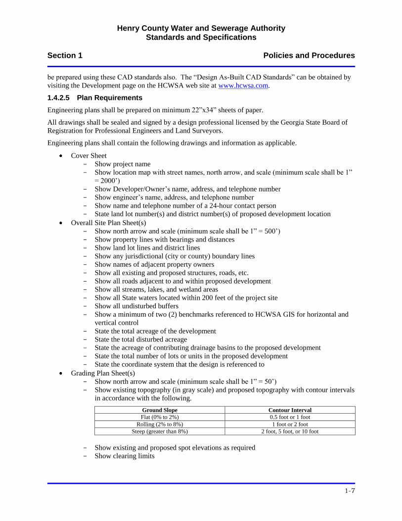
Grading Plan Sheet(s)
- Show north arrow and scale (minimum scale shall be 1” = 50’)
- Show existing topography (in gray scale) and proposed topography with contour intervals
in accordance with the following.
Ground Slope Contour Interval
Flat (0% to 2%) 0.5 foot or 1 foot
Rolling (2% to 8%) 1 foot or 2 foot
Steep (greater than 8%) 2 foot, 5 foot, or 10 foot
- Show existing and proposed spot elevations as required
- Show clearing limits
Henry County Water and Sewerage Authority Standards and Specifications
Section 1 Policies and Procedures
1-8
Water Distribution System Plan Sheet(s)
- Show north arrow and scale (minimum scale shall be 1” = 50’)
- Show proposed water line location with staking information (include water line size and
material)
- Show grading plan in gray scale
- Show all existing utilities (in gray scale) and proposed utilities
- Show all stormwater drain lines and structures in gray scale (include line size, material,
and invert data)
- Show all property lines, right-of-way lines, permanent easement lines, temporary
easement lines
- Show names of property owners and/or Parcel ID numbers
- Show all State water buffers, wetland areas, and 100-year flood plain elevation
Water Distribution System Detail Sheet(s)
- Use HCWSA standard details where applicable
Sanitary Sewer System Plan Sheet(s)
- Show north arrow and scale
- Show proposed sewer line and manhole locations with staking information (include
sewer line size and material)
- Show all existing and proposed utilities
- Show all stormwater drain lines and structures (include line size, material, and invert
data)
- Show all property lines, right-of-way lines, permanent easement lines, temporary
easement lines
Sanitary Sewer System Profile Sheet(s)
- Show horizontal and vertical scale (minimum horizontal scale shall be 1” = 50’;
minimum vertical scale shall be 1” = 20’)
- Show proposed sanitary sewer profile (include sanitary sewer size and material)
- Show slope of each section of sanitary sewer
- Show location of existing utilities that are crossing proposed sanitary sewer
- Show “invert in,” “invert out,” and “rim” elevations for each proposed and existing
manhole in profile
- Show existing and proposed ground surface profile
- Show approximate creek bottom elevation when lines are running adjacent to a creek
Sanitary Sewer System Detail Sheet(s)
- Use HCWSA standard details where applicable
Sanitary Sewage Lift Station Plan Sheet(s)
- Show north arrow and scale
- Show Top View of lift station with appropriate dimensions
- Show Bottom View of lift station with appropriate dimensions
Sanitary Sewage Lift Station Section Sheet(s)
- Show pertinent elevation sections
- Show pertinent dimensions
- Show critical elevations (top of slab, bottom of wet well, etc)
- Show pump control points (high level alarm, pump on, pump off, low level alarm, etc.)
- Show pump curve and system head curve
- Show pump design point
Henry County Water and Sewerage Authority Standards and Specifications
Section 1 Policies and Procedures
1-9
Sanitary Sewer Force Main Plan Sheet(s)
- Show north arrow and scale (minimum scale shall be 1” = 50’)
- Show proposed sanitary sewer force main location with staking information (include
force main size and material)
- Show grading plan in gray scale
- Show all existing utilities (in gray scale) and proposed utilities
- Show all stormwater drain lines and structures in gray scale (include line size, material,
and invert data)
- Show all property lines, right-of-way lines, permanent easement lines, temporary
easement lines
- Show names of property owners and/or Parcel ID numbers
- Show all State water buffers, wetland areas, and 100-year flood plain elevation
Sanitary Sewer Force Main Profile Sheet(s)
- Show horizontal and vertical scale (minimum horizontal scale shall be 1” = 50’;
minimum vertical scale shall be 1” = 20’)
- Show proposed sanitary sewer force main profile (include force main size and material)
- Show location of existing utilities that are crossing proposed sanitary sewer force main
- Show existing and proposed ground surface profile
- Show approximate creek bottom elevation when lines are running adjacent to a creek
1.4.2.6 Survey Datum
Survey data shall be geo-referenced to the State Plane Coordinate System, NAD 83, Georgia West Zone,
US Survey Feet. All surveys shall contain a minimum of two reference survey markers (pins) with x, y,
and z coordinates tied to the Henry County GPS monument system. A list of existing GIS survey
monument locations can be obtained from the Henry County GIS Department and online at the Henry
County GIS web site at www.co.henry.ga.us/GIS/.
1.4.3 Plan Submittal
1.4.3.1 Plan Review Fees
The HCWSA charges a fee for the review of water distribution and sanitary sewerage system plans and
specifications. The current Plan Review Fee Schedule can be obtained by visiting the Development page
on the HCWSA web site at www.hcwsa.com.
Payment of the Plan Review Fee is due at the time of plan re-submittal. If a re-submittal is not required,
the Plan Review Fee shall be due prior to final plan approval.
1.4.3.2 Plan Submittal Process
Construction plans and specifications for water distribution and/or sanitary sewerage systems shall be
submitted to the HCWSA. If the property that is to be developed has been rezoned, the Developer/Owner
shall have obtained a Water/Sewer Availability Letter prior to submitting construction plans and
specifications for review.
The plan submittal process is as follows.
1. Developer’s Engineer shall submit one (1) set of construction plans and specifications to
HCWSA for the initial review.
Henry County Water and Sewerage Authority Standards and Specifications
Section 1 Policies and Procedures
1-10
2. Upon receipt of the construction plans and specifications, HCWSA will review the plans and
specifications for technical adequacy and conformance with these Development Standards and
Specifications. HCWSA comments will be marked in red (Redline Comments) on the plans
and/or specifications.
3. Developer’s Engineer will be notified whether or not HCWSA has comments.
4. If there are comments, Developer’s Engineer shall pick up the construction plans and
specifications from HCWSA and address the Redline Comments. After the Redline Comments
have been addressed, Developer’s Engineer shall submit the number of revised sets of
construction plans and specifications requested in the Redline Comments along with the original
Redline Comments to HCWSA for subsequent review.
5. If and when there are no comments, Developer’s Engineer shall submit four (4) sets of plans for
final approval.
1.4.4 Expiration of Plan Approval
Plan approval is valid for twelve (12) months. Projects with approved plans that are not initiated within
twelve (12) months of plan approval or projects that are initiated and then become inactive for a twelve
(12) month period shall become invalid. If an approved plan becomes invalid, the HCWSA Engineer
shall determine if the plan can be revalidated or if a new design is required.
1.4.5 Plan Modifications
Approved plans shall not be modified or deviated from unless approved in writing by the HCWSA
Engineer.
Henry County Water and Sewerage Authority Standards and Specifications
Section 1 Policies and Procedures
1-11
1.5 Easements and Deeded Property
1.5.1 General
All water distribution and/or sanitary sewerage system appurtenances that will be owned by the HCWSA
and are not located in a public street right-of-way shall be located in a permanent easement or deeded
property that has been conveyed to the HCWSA.
All sanitary sewage lift stations shall be located on property that is platted and deeded to the HCWSA.
Any roads required to access the sanitary sewage lift station from the public street right-of-way shall be
included as part of the platted and deeded property or given as an access easement at the discretion of the
HCWSA Engineer.
HCWSA will not approve any water distribution and/or sanitary sewerage system construction until all
off-site easements and/or deeded property is conveyed to the HCWSA. A design must be submitted and
approved before easement acquisition can begin.
1.5.2 Permanent Easements
A permanent easement is a right granted by an underlying property owner that entitles its holder to a
specific use of the property in perpetuity.
1.5.2.1 “On-Site” Permanent Easements
“On-site” permanent easements are permanent easements which fall within the boundaries of the current
phase of the development and are shown on the final plat. Permanent easements are conveyed by
recording the Deed of Conveyance and final plat.
The Developer/Owner shall grant to the HCWSA, the exclusive right to construct, re-construct, operate,
maintain, repair, replace, improve, alter, remove, relocate, and inspect water distribution and/or sanitary
sewerage systems that are situated over, across, and under the land wherein the water distribution system
and/or sanitary sewerage system lies on the Developer/Owner’s property.
1.5.2.2 “Off-Site” Permanent Easements
“Off-site” permanent easements are permanent easements which fall outside the boundaries of the current
phase of the development and must be provided by the Developer/Owner on an HCWSA easement
document for each property where an easement is required in order to install the water distribution and/or
sanitary sewerage system. Plans must be submitted and approved along with an easement plat for each
property where an easement is required before the Developer/Owner obtains an easement from the
property owner.
Permanent easements through property owned by the Developer/Owner, including water and sewer lines
that will be included in later phases of the same project, shall be treated as routine “off-site” permanent
easements.
“Off-site” permanent easements shall be negotiated and acquired by the Developer/Owner.
Water distribution and/or sanitary sewerage system plans shall not receive final approval until all “off-
site” permanent easements required for system completion are approved and acquired.
1.5.2.3 Permanent Easement Requirements
Permanent easements for water distribution systems and sanitary sewage force mains shall have a
minimum width of 10 feet.
Henry County Water and Sewerage Authority Standards and Specifications
Section 1 Policies and Procedures
1-12
Permanent easements for gravity sewer systems shall have a minimum width of 20 feet.
The water line or sanitary sewage line shall be located in the center of the permanent easement.
Permanent easements shall be accessible from the public street right-of-way. If access from a public
street right-of-way is not available, permanent ingress/egress easement(s) shall be provided, as required,
to provide HCWSA access to the water and/or sewer easement. A sufficient number of permanent
ingress/egress easements shall be provided so that all portions of the water and/or sewer easement is
accessible by the HCWSA from the public right-of-way. The HCWSA Engineer will review all proposed
easements and deeded property and determine the number and location, if any, of permanent
ingress/egress easements required. In some cases, deeded property may be required for ingress/egress in
lieu of a permanent easement. The HCWSA Engineer will determine what is required.
Permanent easements for water meters and appurtenances shall extend a minimum of 10 feet beyond the
outside of the structure on each side of the structure.
The size and/or width of permanent easements may be increased or decreased at the discretion of the
HCWSA Engineer.
1.5.3 Temporary Easements
A temporary easement is a right granted for a specific period of time and once it expires, the rights
granted return to the property owner. Temporary easements are typically used for the stockpiling of dirt,
the maneuvering of equipment, or the storage of materials.
Temporary easements must be provided by the Developer/Owner on a HCWSA Temporary Construction
Easement document for each property where a temporary easement is required in order to install the water
distribution and/or sanitary sewerage system. Plans must be submitted and approved along with a
temporary easement plat for each property where a temporary easement is required before the
Developer/Owner obtains a temporary easement from the property owner.
Water distribution and/or sanitary sewerage system plans shall not receive final approval until all
temporary easements required for system completion are approved and acquired.
Temporary easements shall be of the size required to install the water distribution and/or sanitary
sewerage system.
The size and/or width of temporary easements may be increased or decreased at the discretion of the
HCWSA Engineer.
1.5.4 Deeded Property
1.5.4.1 General
Deeded property is property that is platted and deeded to the HCWSA.
Deeded property must be provided by the Developer/Owner.
1.5.4.2 Deeded Property Requirements
The minimum size of deeded property associated with a sanitary sewage lift station is 100-feet by 100-
feet square.
Sanitary sewage lift station plans shall not receive final approval until deeded property is approved and
acquired.
The required size of the deeded property may be modified at the discretion of the HCWSA Engineer.
Henry County Water and Sewerage Authority Standards and Specifications
Section 1 Policies and Procedures
1-13
1.6 Installation
1.6.1 General
Water distribution and sanitary sewerage systems shall be constructed by a HCWSA approved utility
contractor.
Water distribution and sanitary sewerage systems shall be constructed in accordance with HCWSA
approved plans and specifications. A set of HCWSA approved plans shall be present on the job site
whenever work is being performed on the water distribution and/or sanitary sewerage system and the
plans shall be made available to the HCWSA Inspector upon request.
Installation of water distribution and/or sanitary sewerage systems shall not commence until HCWSA has
granted final approval of the construction plans and specifications and the appropriate agency has issued a
Development/Land Disturbance Permit.
1.6.2 Approved Utility Contractors
Utility contractors must be approved by the HCWSA prior to performing any work on the HCWSA water
distribution and sanitary sewerage system.
Utility contractors can obtain an Approved Contractor Application form at the HCWSA or by visiting the
Development page on the HCWSA web site at www.hcwsa.com.
The Approved Contractor Application requires that the utility contractor submit copies of their State
Utility Contractor’s License, insurance information, and references.
Contractors are granted temporary approval status until they have completed at least three (3) jobs for the
HCWSA. After the contractor has completed at least three (3) jobs, the HCWSA Engineer will determine
if the contractor will be placed on the Approved Contractor List.
1.6.3 Inspections
A HCWSA Inspector, under the direction of the HCWSA Engineer, will inspect the installation of the
water distribution and/or sanitary sewerage system, on a daily basis, during all phases of construction to
ensure that the system is being constructed in accordance with the HCWSA approved plans and
specifications.
All work shall be inspected prior to backfill. It is the Developer/Owner’s and/or Contractor’s
responsibility to schedule inspections and verify that work has been inspected before it is backfilled. Any
work that is backfilled prior to inspection shall be exposed when directed by the HCWSA Inspector.
The HCWSA Inspector will inform the Developer/Owner and/or Contractor when there are deficiencies
in workmanship or when there are deviations from the approved plans and specifications.
Developer/Owner and/or Contractor shall address the deficiencies in a timely manner as determined by
the HCWSA Inspector. Failure to address deficiencies in a timely manner may result in the HCWSA
issuing a Stop Work order. Failure to address deficiencies and/or disregarding a Stop Work order may
result in additional fees and the water distribution and/or sanitary sewerage system will not be permitted
to connect to the HCWSA system.
Inspection by the HCWSA does not relieve the Developer/Owner and/or Contractor of their responsibility
for constructing the water distribution and/or sanitary sewerage system in accordance with the HCWSA
approved plans and specifications.
Henry County Water and Sewerage Authority Standards and Specifications
Section 1 Policies and Procedures
1-14
1.6.3.1 Inspection Fees
The HCWSA charges an inspection fee for the inspection of water distribution and sanitary sewerage
system construction projects. The current Inspection Fee Schedule can be obtained by visiting the
Development page on the HCWSA web site at www.hcwsa.com.
Payment of the Inspection Fee is due prior to the required preconstruction meeting with HCWSA.
1.6.4 Pre-Construction Meetings
Prior to beginning construction of any water distribution and/or sanitary sewerage system,
Developer/Owner and/or Contractor shall arrange a pre-construction meeting with the HCWSA Engineer.
The pre-construction meeting shall be held prior to beginning construction.
The HCWSA Inspector will conduct a separate pre-construction meeting with field personnel prior to
commencement of work.
1.6.5 Testing
Water distribution and sanitary sewerage systems shall be tested at the expense of the Developer/Owner.
Testing methods and practices shall be as specified in these Standards and Specifications.
1.6.6 Warranty
The Developer/Owner and/or Contractor shall warranty the water distribution and/or sanitary sewerage
system against all defects in materials and workmanship for a period of two (2) years after Final
Acceptance. This warranty shall be backed by a two (2) year Letter of Credit.
During the warranty period, the Developer/Owner and/or Contractor shall be responsible for any damage
to the water distribution and/or sanitary sewerage system.
Henry County Water and Sewerage Authority Standards and Specifications
Section 1 Policies and Procedures
1-15
1.7 Connecting to the HCWSA System
Connection to the HCWSA water distribution and/or sanitary sewerage system will only be allowed
provided that the Developer/Owner and/or Contractor has complied with HCWSA policies and
procedures and the water distribution and/or sanitary sewerage system has been installed in accordance
with the HCWSA approved plans and specifications.
The HCWSA Inspector shall be notified a minimum of 48-hours in advance of making a connection to the
HCWSA water distribution or sanitary sewerage system.
The HCWSA Inspector shall be present when the connection is made to the HCWSA water distribution or
sanitary sewerage system.
All materials, equipment, and methods used in making a connection to the HCWSA water distribution or
sanitary sewerage system shall be approved by the HCWSA Inspector.
After the connection has been made to the HCWSA water distribution and/or sanitary sewerage system,
the Developer/Owner’s system shall be immediately valved-off or plugged until Final Acceptance of the
system.
Any unauthorized connection or connection that is made without the presence of the HCWSA Inspector
shall be subject to a fine and/or refusal of service.
Any noncompliant connection or any damage to the HCWSA system shall be repaired and/or replaced at
the expense of the Developer/Owner and/or Contractor. Methods of repair and/or replacement shall
comply with these Standards and Specifications.
Henry County Water and Sewerage Authority Standards and Specifications
Section 1 Policies and Procedures
1-16
1.8 Final Acceptance
1.8.1 General
Prior to Final Acceptance of the water distribution and/or sanitary sewerage system for meter sales and
final platting, the HCWSA will make a final inspection after all pavement is installed and the
Developer/Owner shall provide the following items to the HCWSA.
1. Deed of Conveyance
2. Contribution of Fixed Assets form
3. Lien waiver(s)
4. Corporate Owner’s Affidavit
5. Corporate Contractor’s Affidavit
6. Two-year Letter of Credit
7. Two (2) hard copies of the Record Drawings and one (1) digital copy of the Record Drawings
8. Two (2) hard copies of Final Plat and one (1) digital copy of the Final Plat
9. Sanitary sewer television inspection report and video
10. Total coliform analysis
11. All required fees (water testing fees, recording fees, etc.)
12. Field corrections
Water will not be left on and meters will not be set until all required documents and information are
delivered to the HCWSA.
1.8.2 Deed of Conveyance
A Deed of Conveyance is a legal document signed and sealed and delivered to effect a transfer of
property and to show the legal right to possess it. A Deed of Conveyance shall be provided for all
easements and property to be dedicated to the HCWSA.
1.8.3 Contribution of Fixed Assets Form
The Contribution of Fixed Assets form itemizes the public assets that are being dedicated to the HCWSA.
This form shall only include “public” materials and appurtenances. “Private” materials and
appurtenances shall not be included on the form. The Contribution of Fixed Assets form can be obtained
by visiting the Development page on the HCWSA web site at www.hcwsa.com.
1.8.4 Lien Waivers
The HCWSA must ensure that all materials being dedicated as public assets have been paid for; therefore,
a lien waiver shall be secured from each supplier that materials and/or equipment is purchased.
1.8.5 Corporate Owner’s Affidavit
The HCWSA must ensure that all labor and materials required to construct a project have been paid for
and that there are no liens on the property; therefore, the Developer/Owner shall prepare a Corporate
Owner’s Affidavit and submit it to the HCWSA. A Corporate Owner’s Affidavit form can be obtained by
visiting the Development page on the HCWSA web site at www.hcwsa.com.
1.8.6 Corporate Contractor’s Affidavit
The HCWSA must ensure that the utility contractor has been paid in full and that there are no liens on the
property; therefore, the utility contractor shall prepare a Corporate Contractor’s Affidavit and submit it to
the HCWSA. A Corporate Contractor’s Affidavit form can be obtained by visiting the Development page
on the HCWSA web site at www.hcwsa.com.
Henry County Water and Sewerage Authority Standards and Specifications
Section 1 Policies and Procedures
1-17
1.8.7 Two-Year Letter of Credit
A Letter of Credit shall be provided to the HCWSA as a warranty for the materials and workmanship for
the water distribution and/or sanitary sewerage system. The term of the Letter of Credit shall be two (2)
years and the amount of the Letter of Credit shall be 10 percent of the total cost of the labor and materials
required to construct the water distribution and/or sanitary sewerage system.
Prior to the expiration of the Letter of Credit, a warranty inspection will be conducted by the HCWSA.
The Developer/Owner will be required to correct any deficiencies that are found. Upon satisfactory repair
of any deficiencies that are found, the HCWSA will release the Letter of Credit.
A sample Letter of Credit can be obtained by visiting the Development page on the HCWSA web site at
www.hcwsa.com.
1.8.8 Record Drawings
Record Drawings shall be submitted to the HCWSA prior to final acceptance of the water distribution
system and/or sanitary sewerage system.
Record Drawings shall:
1. Be sealed and signed by a design professional licensed by the Georgia State Board of Registration
for Professional Engineers and Land Surveyors;
2. Shall show all street names, right-of-way widths, easements, lot numbers and addresses, and
location, size, and material of all water distribution and/or sanitary sewerage system components;
and
3. Shall be checked and signed by the HCWSA Inspector prior to final submittal.
Submit two (2) full-size sets of Record Drawings and one (1) digital file.
1.8.8.1 Digital Data Submission Standards
Digital Record Drawings shall be prepared in accordance with HCWSA “Digital As-Built CAD
Standards” which can be obtained by visiting the Development page on the HCWSA web site at
www.hcwsa.com.
1.8.9 Final Plat
Submit two (2) hard copies and one (1) digital file of the Final Plat. Digital file shall be prepared in
accordance with HCWSA CAD standards.
1.8.10 Television Inspection Report and Video
All new sanitary sewer lines must be cleaned and television inspected to ensure that they are installed
correctly and are clean prior to being placed into service. The HCWSA inspector must be present when
the television inspection is conducted and a copy of the video inspection report must be submitted to the
HCWSA.
1.8.11 Total Coliform Analysis
Prior to system acceptance, all new water lines and existing water lines that are affected by the new
construction must be disinfected prior to being placed into service. After the Contactor has disinfected
the water line in accordance with these Standards and Specifications, the HCWSA Inspector will collect
required water sample(s) and the samples will be tested by the HCWSA laboratory at the expense of the
Developer/Owner and/or Contractor.
Henry County Water and Sewerage Authority Standards and Specifications
Section 1 Policies and Procedures
1-18
1.8.12 Fees
All fees due to the HCWSA shall be paid in full. A current fee schedule can be obtained by visiting the
Development page on the HCWSA web site at www.hcwsa.com.
1.8.13 Field Corrections
Prior to Final Acceptance, Developer/Owner and/or Contractor shall make all corrections to the water
distribution and/or sanitary sewerage system as directed by the HCWSA Inspector.
Henry County Water and Sewerage Authority Standards and Specifications
Section 1 Policies and Procedures
1-19
1.9 Sanitary Sewage Lift Stations
1.9.1 Ownership
In accordance with Article 11 of the Henry County Sewer Ordinance, no sanitary sewer lift station shall
be privately owned or maintained. All lift stations constructed or installed by a private individual or
entity shall be dedicated to, and accepted by, the HCWSA for maintenance. The following shall be
required before a lift station can be put in operation and the same accepted by the HCWSA.
1. Gravity flow sanitary sewer systems that flow into the lift station shall be designed and installed
in accordance with these Standards and Specifications.
2. The lift station and the associated sanitary sewage force main shall be designed and installed in
accordance with these Standards and Specifications.
3. The design of the gravity flow sanitary sewer line flowing into the lift station, the lift station, and
the associated sanitary sewage force main shall be submitted to the HCWSA in accordance with
these Standards and Specifications. Prior to construction and/or installation, the design of the
gravity flow sanitary sewer line flowing into the lift station, the lift station, and the associated
sanitary sewage force main shall be approved by the HCWSA.
4. Prior to installation/construction of the gravity flow sanitary sewer line flowing into the lift
station, the lift station, and the associated sanitary sewage force main system, the person or entity
seeking to construct the lift station shall pay to the HCWSA a non-refundable fee in the amount
of $50,000.00 for the operation and maintenance of the lift station.
5. Prior to acceptance of any lift station, or any gravity flow sewer line and sanitary sewer force
main system, the HCWSA shall inspect the same to ensure that all applicable rules, regulations,
and installation, design, and construction standards have been complied with.
1.9.2 Interbasin Transfer
The HCWSA has divided Henry County into certain sanitary sewer drainage basins. In accordance with
Article 11 of the Henry County Sewer Ordinance, pumping sanitary sewage from one drainage basin to
another drainage basin is allowed only under the following conditions.
1. The sewage is generated by a public entity for a facility that is being used for a public purpose.
2. The drainage area in which the wastewater treatment facility is located has capacity in excess of
the amount calculated by the HCWSA that will be needed for the proposed development of the
drainage area in which the wastewater treatment facility is located.
Henry County Water and Sewerage Authority Standards and Specifications
Section 1 Policies and Procedures
1-20
1.10 Fire Flow Tests
1.10.1 General
All fire flow tests shall be conducted or witnessed by the HCWSA.
1.10.2 Requesting Fire Flow Data
A request for available fire flow data can be made by submitting a “Request for Fire Flow Test”
application to the HCWSA. A copy of this application can be obtained by visiting the Development page
on the HCWSA web site at www.hcwsa.com. If current fire flow test information is available, this
information will be provided to the requestor at no charge.
If there is no data available at the time of the request, the requestor has the option to request that the
HCWSA either conduct a fire flow test or observe a fire flow test that will be conducted by the requestor.
A fee is applicable in both situations. Current fees are presented on the “Request for Fire Flow Test”
application.
Henry County Water and Sewerage Authority Standards and Specifications
Section 1 Policies and Procedures
1-21
1.11 New Conveyor Car Wash Facilities
1.11.1 General
In accordance with HCWSA Resolution No, 2009-12, all new conveyor car wash facilities in which the
HCWSA provides water service are required to install, utilize, and maintain a water recycling system
which recycles and reuses at least 50 percent of wash and rinse water.
1.11.2 Failure to Comply
When a facility fails to use a recycling water system that reuses at least 50 percent of the wash and rinse
water, the HCWSA will provide the violator with written notice of the violation, providing further that the
violator has thirty (30) days to cease and correct the violation and provide HCWSA with written
certification from a Georgia licensed plumber or engineer stating that the facility is presently recycling
and reusing at least 50 percent of its wash and rinse water. If the violation is not corrected within thirty
(30) days, the HCWSA will terminate water service until such time as the facility has been brought into
compliance.
Henry County Water and Sewerage Authority Standards and Specifications
Section 2 Design Requirements
2-1
SECTION 2 - DESIGN REQUIREMENTS
2.1 Water Distribution Systems
2.1.1 General
A. All water distribution systems that will be connected to the HCWSA water system shall be
designed in accordance with these standards. Any deviation from these standards shall be
approved in writing by the HCWSA Engineer.
2.1.2 Design Usage Rates
A. The following Design Usage Rates shall be used in the design of water distribution systems.
1. Residential: 300 gallons per day per connection
2. Apartment: 200 gallons per day per unit
3. Hotel/Motel: 100 gallons per day per room
4. Commercial: As required by use (provide justification to the HCWSA for the usage rate
used)
5. Fire Flow:
a. Residential: 750 gallons per minute at 20 PSI residual pressure
b. Commercial: 1,000 gallons per minute at 20 PSI residual pressure
2.1.3 Design Pressures
A. The water distribution system shall be designed to maintain a minimum pressure of 20 PSI at
ground level at all points in the distribution system and under all flow conditions.
2.1.4 Water Line Size and Material
A. Minimum Water Main Size: 8” Diameter
B. Minimum Water Main Size within Commercial, Industrial, or Manufacturing Development:
12” Diameter, unless otherwise approved by the HCWSA Engineer.
C. Acceptable Water Line Materials:
1. 4” to 12” Diameter Water Line: Pressure Class 350 Ductile Iron Pipe
2. Greater than 12” Diameter Water Line: Minimum Pressure Class 250 Ductile Iron Pipe
2.1.5 Water Line Location
A. Locate in right-of-way or in a permanent easement specifically designated for the water line.
B. Eight (8) feet behind back of curb or edge of pavement, unless otherwise approved by the
HCWSA Engineer.
C. Water lines running parallel to an existing or proposed sanitary sewer line shall be located a
minimum of 10 feet horizontally from the sanitary sewer line unless otherwise approved by the
HCWSA Engineer. Distances shall be measured outside of pipe to outside of pipe.
D. Water lines that cross an existing or proposed sanitary sewer line or storm drain line shall have
a minimum clearance of 18 inches vertically above or below the sanitary sewer line or storm
drain line where possible. At crossings, one (1) full length of water line shall be located so that
both pipe joints will be as far from the sanitary sewer line or storm drain line as possible. In
cases where the HCWSA Engineer allows a vertical clearance of less than 18 inches, the first
Henry County Water and Sewerage Authority Standards and Specifications
Section 2 Design Requirements
2-2
two joints on each side of the crossing shall be restrained and the pipe shall be protected as
required by HCWSA.
E. Use Detail W01 when applicable.
2.1.6 Water Line Bury Depth
A. Water lines shall have a minimum of 48” of cover as measured from crown of pipe to ground
surface. Where the ground surface above the water line is higher than the edge of pavement of
the existing or proposed roadway, the minimum cover shall be measured from the crown of
pipe to the edge of pavement.
B. Use Details W02 and W03 when applicable.
2.1.7 Fire Hydrants
2.1.7.1 Location
A. Locate fire hydrants within the street right-of-way or in a permanent easement.
B. Locate 2 feet inside right-of way when possible.
C. A fire hydrant shall be placed at the end of all cul-de-sacs and dead-end streets.
D. Use Details W04, W05, and W06 when applicable.
2.1.7.2 Orientation
A. Pumper nozzle shall be oriented toward the street unless otherwise approved by the HCWSA.
2.1.7.3 Spacing
A. Residential Spacing: Maximum 525 feet as measured along the edge of pavement.
B. Commercial Spacing: Maximum 400 feet as measured along the edge of pavement.
2.1.8 Blow-Off Valves
A. Blow-off valves, when required by the HCWSA Engineer, shall be located at critical high
points and low points along the water line.
B. Fire hydrants may be provided in lieu of blow-off valves.
C. Blow-off valves at high points shall be tapped into the top of the water line.
D. Blow-off valves at low points shall be tapped into the bottom of the water line.
E. Blow-offs shall be a minimum of 2-inches in diameter and must be capable of providing a
minimum flushing velocity of 2.5 feet per second in the water line.
F. Blow-offs shall not be directly connected to any sanitary sewerage line or storm drainage line
nor shall the blow-off be subject to flooding.
G. Use Detail W07 when applicable.
2.1.9 Isolation Valves
2.1.9.1 Type
A. Gate valves shall be used on water lines with nominal diameters less than or equal to 12 inches.
B. Butterfly valves shall be used on water lines with nominal diameters greater than 12 inches.
Henry County Water and Sewerage Authority Standards and Specifications
Section 2 Design Requirements
2-3
C. Use Detail W08 when applicable.
2.1.9.2 Location and Spacing
A. Typically, locate gate valves immediately on each side of all 3-way and 4-way connections.
B. Maximum spacing for isolation valves shall be 2,000 feet.
C. Use Detail W09 when applicable.
2.1.10 Air Release Valves
A. Air release valves shall be provided at all locations along the water main deemed appropriate as
determined by the design engineer.
B. Air release valve locations are subject to review by the HCWSA.
C. Air release valves shall be sized in accordance with the manufacturer’s recommendations.
D. Use Detail W10 when applicable.
2.1.11 Thrust Restraint
A. All fittings, valves, and dead-ends shall have two (2) forms of thrust restraint.
B. All pipe joints shall be restrained as required.
C. Acceptable thrust restraint includes restrained joint glands, field lock gaskets, threaded rods,
and concrete blocking.
D. Water lines shall be restrained, as required, using restrained joint type gaskets. The design
engineer shall be responsible for calculating the length of pipe from each fitting that requires
restrained joints. Calculations shall be submitted to HCWSA.
E. Use Details W11, W12, and W13 when applicable.
2.1.12 Water Service Connections
2.1.12.1 Residential Connections
A. Residential service connection shall be 1-inch diameter.
B. There shall be one (1) service connection per residence.
C. A 2” PVC or 2½” HDPE casing pipe shall be provided under the street on all long side service
connections.
D. Use Details W14, W15, and W16 when applicable.
2.1.12.2 Commercial Connections
A. Commercial service connection shall be minimum 1-inch diameter.
B. There shall be one (1) service connection per parcel.
C. A minimum 2” PVC or 2½” HDPE casing pipe shall be provided under the street on all long
side service connections.
Henry County Water and Sewerage Authority Standards and Specifications
Section 2 Design Requirements
2-4
2.1.13 Water Meters
2.1.13.1 Residential
A. Residential water meters will be provided and installed by HCWSA (meter setting fees apply).
2.1.13.2 Commercial
A. Commercial water meters 2” in size and smaller will be provided and installed by HCWSA
(meter setting fees apply).
B. Water meters greater than 2” in size shall be provided by and installed by an approved licensed
contractor.
2.1.13.3 Sub-Unit Metering
A. All multi-family buildings (apartments, town homes, condominiums, etc.) and multi-tenant
commercial buildings shall have a private sub-unit meter installed at each individual unit.
B. Sub-unit meters shall be provided by and installed by the Developer/Owner.
2.1.13.4 Fire Flow
A. All new fire flow lines shall be metered.
B. Fire flow meters shall be provided by and installed by an approved licensed contractor.
C. Existing fire flow lines that are unmetered and have more than three consecutive months of
usage shall be required to install a compact fire line meter at the Owner’s expense in
accordance with the HCWSA Fire Line Meter policy.
D. Use Details W17 and W18 when applicable.
2.1.14 Backflow Prevention
A. Backflow preventers shall be provided on all service connections.
B. Backflow preventer will be provided by HCWSA on all residential service connections.
C. Backflow preventer shall be provided by Developer/Owner on all commercial connections.
D. A double check backflow preventer shall be provided on all commercial and fire service lines.
E. Use Detail W19 when applicable.
2.1.15 Jack and Bore Installations
A. Unless otherwise approved, water mains that cross a GDOT roadway, Henry County DOT
roadway, or railroad right-of-way shall be installed with cased jack and bores.
B. Use Detail W20 when applicable.
2.1.16 Creek Crossings
A. All pipe used in creek crossings shall be ductile iron.
B. All crossings shall be perpendicular to the creek unless otherwise approved.
C. Pipe shall have casing pipe that extends to a minimum of 10 feet beyond the top of bank.
D. The minimum depth of cover above the casing pipe shall be 12 inches.
Henry County Water and Sewerage Authority Standards and Specifications
Section 2 Design Requirements
2-5
E. Use Detail W21 when applicable.
Henry County Water and Sewerage Authority Standards and Specifications
Section 2 Design Requirements
2-6
2.2 Gravity Flow Sanitary Sewer Systems
2.2.1 General
A. All gravity flow sanitary sewer systems that will be connected to the HCWSA sanitary sewage
system shall be designed in accordance with these standards. Any deviation from these
standards shall be approved in writing by the HCWSA Engineer.
2.2.2 Design Flow Rates
2.2.2.1 General
A. Sanitary sewer system shall be designed for the estimated build-out population of the drainage
basin.
B. Sanitary sewers shall be designed and installed to the uppermost property line of the
development being served.
2.2.2.2 Average Daily Flow Rates
A. The following Average Daily Flow Rates shall be used in the design of sanitary sewerage
systems.
1. Residential: 300 GPD per residential unit.
2. Apartments: 200 GPD per apartment unit.
3. Hotels/Motels: 100 GPD per hotel/motel room.
4. Commercial/Manufacturing/Industrial: As required by use (provide justification to the
HCWSA for the average daily flow rate used)
B. The projected Average Daily Flow Rate for areas outside of the proposed development shall be
calculated using the following typical flow rates.
1. Low Density Residential: 100 GPD/acre
2. Medium Density Residential: 600 GPD/acre
3. High Density Residential: 1,200 GPD/acre
4. Open/Park Areas: 100 GPD/acre
5. Commercial/Manufacturing/Industrial: 2,000 GPD/acre
2.2.2.3 Peak Hour Flow Rates
A. The Peak Hour Flow Rate for new residential developments shall be calculated using a peaking
factor of 3.0.
B. The Peak Hour Flow Rate for new commercial developments shall be calculated using a
peaking factor based upon the proposed use of the development. The minimum peaking factor
shall be 2.0.
C. The Peak Hour Flow Rate for undeveloped areas shall be calculated using the following
equation.
Where:
QPHF = Peak Hourly Flow Rate
Henry County Water and Sewerage Authority Standards and Specifications
Section 2 Design Requirements
2-7
QADF = Average Daily Flow Rate
P = Population in Thousands Based on 100 GPD/Capita
2.2.3 Hydraulics
A. Sanitary sewers shall be designed using Manning’s equation.
Where:
Q = Flow Rate, ft3/s
n = Manning’s Coefficient
A = Pipe Cross-Sectional Area, ft2
rh = Hydraulic Radius
S = Slope, ft/ft
B. The value of the Manning’s Coefficient, n, shall be 0.013 for all pipe materials.
C. Sanitary sewers shall be designed to carry the Peak Hourly Flow rate at 75 percent of the full
depth (d/dFULL = 0.75).
D. Sanitary sewers shall be designed with a minimum velocity of 2 ft/s, flowing full, based on the
Manning’s equation and using a Manning’s Coefficient of 0.013.
E. The following table presents the minimum allowable slopes for sanitary sewers; however,
slopes greater than these are desirable.
Nominal Sewer Size Minimum Slope in Feet per 100 Feet
8 inch 0.50
10 inch 0.28
12 inch 0.22
15 inch 0.15
16 inch 0.14
18 inch 0.12
20 inch 0.11
21 inch 0.10
24 inch 0.08
27 inch 0.07
30 inch 0.06
36 inch 0.05
42 inch 0.04
48 inch 0.04
F. The maximum slope of a gravity flow sanitary sewer shall be 15 percent unless approved by
HCWSA.
G. Sanitary sewers with slopes greater than 20 percent shall be anchored with concrete anchors
(dead-mans). The Developers design professional shall be responsible for calculating the size
and spacing of the concrete anchors. Calculations shall be submitted to HCWSA.
Henry County Water and Sewerage Authority Standards and Specifications
Section 2 Design Requirements
2-8
H. The angle formed between the inlet sewer line and outlet sewer line in a manhole shall be
greater-than or equal to 90° and less-than or equal to 270°.
I. Surcharging of manholes shall be prohibited.
2.2.4 Sanitary Sewer Size and Material
A. Minimum Sanitary Sewer Size
1. Sanitary Sewer Outfalls and Mains: 8” Diameter
2. Sanitary Sewer Laterals: 6” Diameter
B. Acceptable Sanitary Sewer Materials:
1. Ductile Iron Pipe (pressure class to be determined by engineer based on depth of cover)
2. Minimum SDR 35 PVC
C. Use ductile iron pipe when depth of cover is less than 5 feet or greater than 16 feet.
D. Use ductile iron pipe when slope of sewer line is greater-than or equal to 15 percent.
E. All creek crossings shall be ductile iron pipe.
F. All water line and storm water line crossings with less than 18-inches of clearance shall be
ductile iron pipe.
2.2.5 Sanitary Sewer Location
A. Sanitary sewer lines located in the right-of-way shall be located as close to the center of the
road as possible.
B. Sanitary sewer lines located in sanitary sewer easements shall be located in the center of the
easement.
C. Sanitary sewer lines running parallel to an existing or proposed water line shall be located a
minimum of 10 feet horizontally from the water line unless otherwise approved by the HCWSA
Engineer. Distances shall be measured outside of pipe to outside of pipe.
D. Sanitary sewer lines that cross an existing or proposed water line shall have a minimum
clearance of 18 inches vertically above or below the water line unless otherwise approved by
the HCWSA Engineer. At water line crossings, the sanitary sewer line shall cross in the middle
of one (1) full length of water line so that both pipe joints on the water line will be as far from
the sanitary sewer line as possible. In cases where the HCWSA Engineer allows a vertical
clearance of less than 18 inches, the first two joints on each side of the crossing shall be
restrained and the pipe shall be protected as required by HCWSA.
E. Use Detail S01 when applicable.
2.2.6 Sanitary Sewer Bury Depth
A. Sanitary sewer lines shall have a minimum of 48” of cover as measured from crown of pipe to
ground surface. Where the ground surface above the sanitary sewer line is higher than the edge
of pavement of the existing or proposed roadway, the minimum cover shall be measured from
the crown of pipe to the edge of pavement.
B. Use Details S04, S05, and S06 when applicable.
Henry County Water and Sewerage Authority Standards and Specifications
Section 2 Design Requirements
2-9
2.2.7 Sanitary Sewer Manholes
2.2.7.1 General
A. Sanitary sewer manholes shall be precast concrete structures with tongue and groove joints.
B. The minimum diameter of manholes shall be forty-eight (48) inches.
C. Manholes shall be provided with reinforced plastic manhole steps. Steps shall have a
maximum spacing of twelve (12) inches.
D. Manholes shall have a minimum 0.10 foot drop from the influent invert to the effluent invert.
E. Manholes shall have a maximum inside drop of two (2) feet. Manholes that require a drop
greater than two (2) feet shall be constructed with outside drops.
F. Manhole section joints shall be sealed watertight using a preformed butyl joint seal.
G. Pipe to manhole connections shall be sealed watertight using resilient connectors.
H. Use Details S07, S08, S09, S10, S11, and S12 when applicable.
2.2.7.2 Location and Spacing
A. Manholes shall be installed at the end of each line; at all changes in grade, size, or alignment;
and at all intersections.
B. Maximum distance between manholes shall be 400 linear feet.
2.2.7.3 Rim Elevation
A. Manholes located in the street, in a sidewalk, or in a landscaped area shall have their lids
installed flush with grade.
B. Manholes located outside of streets and sidewalks in non-landscaped areas shall have their lids
installed a minimum of 2 feet above grade, unless otherwise approved by HCWSA.
C. Use Detail S07 when applicable.
2.2.7.4 Manhole Lids
A. Manhole lids shall have a minimum clear opening of 22-inches.
B. All manholes located outside of the pavement shall have bolt down, watertight lids.
C. Use Details S13 and S14 when applicable.
2.2.8 Corrosion Protection for Sanitary Sewer Systems
A. Manholes that that have a sanitary sewage force main discharging into them and manholes that
are subject to corrosion shall be lined with a fiberglass reinforced epoxy resin lining system or
elastomeric polyurethane lining system.
B. The manhole that the sanitary sewage force main discharges into plus all manholes located
within 1,600 feet downstream of the discharge manhole shall be lined with the above described
system.
C. Existing manholes that exhibit corrosion and/or leaking shall be repaired using polyurethane
grouts to stop infiltration and repair mortars to repair the structure prior to coating with a
fiberglass reinforced epoxy resin lining system or elastomeric polyurethane lining system.
Henry County Water and Sewerage Authority Standards and Specifications
Section 2 Design Requirements
2-10
D. The sanitary sewer lines that connect these lined manholes shall be ductile iron pipe lined with
PROTECTO 401 Ceramic Epoxy or PVC pipe.
2.2.9 Sanitary Sewer Flow Meters
A. All developments, both residential and non-residential, that generate an average daily flow rate
of 100,000 GPD or more in flow shall provide a sanitary sewer flow meter in the last manhole
before the flow leaves the development. The type of flow meter that is used shall be approved
by HCWSA.
2.2.10 Jack and Bore Installations
A. Unless otherwise approved, sanitary sewer lines that cross a GDOT roadway, Henry County
DOT roadway, or railroad right-of-way shall be installed with cased jack and bores.
B. Use Detail S16 when applicable.
2.2.11 Creek Crossings
A. All pipe used in creek crossings shall be ductile iron.
B. All crossings shall be perpendicular to the creek unless otherwise approved.
C. Pipe shall be encased in concrete to a minimum of 10 feet beyond the top of bank.
D. The minimum depth of cover above the concrete encasement shall be 12 inches.
E. Use Detail S17 when applicable.
2.2.12 Aerial Crossings
A. Aerial crossings shall be avoided whenever possible. All aerial crossings shall be pre-approved
by HCWSA.
B. Any piping system that crosses a perennial or annual stream shall not cause an impedance to
navigation or cause water to pool upstream of the pipe.
C. All pipe used in aerial crossings shall be ductile iron.
D. Aerial pipe supports shall be designed by a structural engineer licensed by the Georgia State
Board of Registration for Professional Engineers and Land Surveyors.
E. Aerial pipe supports shall be situated on suitable soils. The soils on which an aerial support
will be placed shall be tested by a soils testing company for bearing capacity and suitability for
construction. A soils report shall be submitted with the construction plans and specifications.

Henry County Water and Sewerage Authority Standards and Specifications
Section 2 Design Requirements
2-11
2.3 Sanitary Sewage Force Mains
2.3.1 General
A. All sanitary sewage force mains that will be connected to the HCWSA sanitary sewage system
shall be designed in accordance with these standards. Any deviation from these standards shall
be approved in writing by the HCWSA Engineer.
2.3.2 Hydraulics
A. Sanitary sewage force mains shall be designed to have a minimum velocity of 2.5 ft/s and a
maximum velocity of 6 ft/s. The minimum velocity in the force main when all pumps are
operating shall be 3.5 ft/s.
2.3.3 Force Main Size and Material
A. Minimum Sanitary Sewer Force Main Size: 4” Diameter, unless otherwise approved by the
HCWSA Engineer.
B. Acceptable Sanitary Sewer Force Main Materials:
1. Pressure Class 350 Ductile Iron Pipe and Fittings
2. C900 PVC Pipe
2.3.4 Force Main Location
A. Sanitary sewage force mains located in the right-of-way shall be located 5 feet inside the right-
of-way and on the opposite side of the road as the water line whenever possible.
B. Sanitary sewage force mains located in sanitary sewer easements shall be located in the center
of the easement.
C. Sanitary sewage force mains shall be located a minimum of 10 feet horizontally from any
existing or proposed water main and 18 inches vertically below any existing or proposed water
main. Distances shall be measured outside of pipe to outside of pipe.
D. Sanitary sewage force mains running parallel to an existing or proposed water line shall be
located a minimum of 10 feet horizontally from the water line unless otherwise approved by the
HCWSA Engineer. Distances shall be measured outside of pipe to outside of pipe.
E. Sanitary sewage force mains that cross an existing or proposed water line shall have a
minimum clearance of 18 inches vertically above or below the water line unless otherwise
approved by the HCWSA Engineer. At water line crossings, the sanitary sewage force main
shall cross in the middle of one (1) full length of water line so that both pipe joints on the water
line will be as far from the sanitary sewage force main as possible. In cases where the HCWSA
Engineer allows a vertical clearance of less than 18 inches, the first two joints on each side of
the crossing shall be restrained and the pipe shall be protected as required by HCWSA.
F. Tracer wire shall be installed on all sanitary sewage force mains.
G. Use Detail S01 when applicable.
2.3.5 Force Main Bury Depth
A. Sanitary sewage force mains shall have a minimum of 60” of cover as measured from crown of
pipe to ground surface. Where the ground surface above the sanitary sewage force main is
Henry County Water and Sewerage Authority Standards and Specifications
Section 2 Design Requirements
2-12
higher than the edge of pavement of the existing or proposed roadway, the minimum cover
shall be measured from the crown of pipe to the edge of pavement.
B. Use Details S02, S03, and S06 when applicable.
2.3.6 Isolation Valves
A. All valves on sanitary sewage force mains shall be eccentric plug valves.
B. Use Detail S21 when applicable.
2.3.7 Combination Air/Vacuum Valves
A. Combination air/vacuum valves shall be provided at all locations along the sanitary sewage
force main deemed appropriate as determined by the design engineer.
B. Combination air/vacuum valve locations are subject to review by the HCWSA.
C. Combination air/vacuum valves shall be sized in accordance with the manufacturer’s
recommendations.
D. Use Details S22 and S23 when applicable.
2.3.8 Thrust Restraint
A. All fittings, valves, and dead-ends shall have two (2) forms of thrust restraint.
B. All pipe joints shall be restrained as required.
C. Acceptable thrust restraint includes restrained joint glands, field lock gaskets, threaded rods,
and concrete blocking.
D. Sanitary sewage force mains shall be restrained, as required, using restrained joint type gaskets.
The design engineer shall be responsible for calculating the length of pipe from each fitting that
requires restrained joints. Calculations shall be submitted to HCWSA.
E. Use Details S24, S25, and S26 when applicable.
2.3.9 Jack and Bore Installations
A. Unless otherwise approved, sanitary sewage force mains that cross a GDOT roadway, Henry
County DOT roadway, or railroad right-of-way shall be installed with cased jack and bores.
B. Use Detail S16 when applicable.
2.3.10 Creek Crossings
A. All pipe used in creek crossings shall be ductile iron.
B. All crossings shall be perpendicular to the creek unless otherwise approved.
C. When the depth of cover is less than 3 feet, the pipe shall have a casing pipe that extends to a
minimum of 10 feet beyond the top of bank.
D. The minimum depth of cover above the casing pipe shall be 12 inches.
E. Use Detail S17 when applicable.
Henry County Water and Sewerage Authority Standards and Specifications
Section 2 Design Requirements
2-13
2.4 Sanitary Sewage Lift Stations
2.4.1 General
A. This section shall be used as a guideline for the design of sanitary sewage lift stations capable
of pumping up to 700 GPM.
B. Lift stations will only be allowed when pre-approved by the HCWSA (see Section 1.9).
C. Lift stations are to be avoided whenever possible.
D. When sanitary sewage lift stations are required, the HCWSA reserves the right to design and
construct the necessary lift station(s), with appropriate charges being made to the
Developer/Owner. The HCWSA may elect to make the lift station larger than necessary to
serve the development so that other property within the drainage basin may be served.
E. Pumps, motors, and associated lift station appurtenances shall be furnished as a package from a
single manufacturer.
F. The sanitary sewage lift station shall include a standby power system and remote monitoring
system as described below.
G. In addition to complete construction plans and specifications, the following information shall
be submitted to the HCWSA Engineer as part of the sanitary sewage lift station design package.
1. Average and Peak Hour design flow rate calculations
2. Total Head calculations
3. System head curve plotted on the manufacturer’s pump curve
4. Brake Horsepower (BHP) calculations
5. Net Positive Suction Head Available (NPSHA) calculations
6. Net Positive Suction Head Required (NPSHR) data
7. 100-year flood elevation at the proposed sanitary sewage lift station site
8. Minimum wet well volume calculations/pump cycle time calculations
9. Wet well buoyancy calculations
2.4.2 Hydraulics
A. Total head shall be calculated using the following equation.
Where:
hS = Static Head, ft
hf = Head Loss due to Friction, ft
hm = Minor Head Losses, ft
hp = Pressure Head, ft
V2/2g = Velocity Head, ft
V = Velocity of the fluid in the piping system, ft/s
g = Acceleration due to Gravity, 32.2 ft/s2
Henry County Water and Sewerage Authority Standards and Specifications
Section 2 Design Requirements
2-14
B. Friction losses shall be calculated using the Hazen-Williams equation.
Where:
hf = Head Loss due to Friction, ft
Q = Flow Rate, GPM
L = Length of Pipe, ft
C = Hazen-Williams Coefficient
d = Inside Diameter of Force Main, inches
C. Minor head losses shall be calculated as a fraction of the velocity head.
Where:
hm = Minor Head Loss, ft
K = Minor Loss Coefficient. The minor loss coefficient is the sum of the head loss
coefficients for all of the minor loss elements in the piping system. Use standard published
values for “K.”
V = Velocity of the fluid in the piping system, ft/s
g = Acceleration due to Gravity, 32.2 ft/s2
2.4.3 Location of Sanitary Sewage Lift Stations
A. The location of all sanitary sewage lift stations shall be coordinated with and approved by the
HCWSA prior to beginning design.
B. Sanitary sewage lift stations shall be accessible during a 100-year storm event.
C. All mechanical components of the sanitary sewage lift station shall be located above the 100-
year flood elevation.
D. All electrical components shall be located a minimum of 3 feet above the 100-year flood
elevation.
2.4.4 Sanitary Sewage Lift Station Property and Access
A. Sanitary sewage lift stations shall be located on a minimum 100 foot by 100 foot piece of
property. This property shall be platted and deeded to the HCWSA at no cost. HCWSA may
require a larger piece of property depending on site conditions.
B. Any roads required to access the sanitary sewage lift station from the public street right-of-way
shall be included as part of the platted and deeded property. The minimum width of the access
property shall be 30 feet.
C. Reference Details S27 and S28.
Henry County Water and Sewerage Authority Standards and Specifications
Section 2 Design Requirements
2-15
2.4.5 Lift Station Components
2.4.5.1 General
A. Sanitary sewage lift stations shall be above ground Gorman-Rupp Auto-Start Lift Stations. The
above ground lift station shall be a pre-engineered unit that only requires the connection of the
inlet and outlet pipes and incoming power. Gorman-Rupp Auto-Start Lift Station shall be
manufacturer’s standard design.
B. If conditions prohibit the use of suction lift pumps, then ITT Flygt submersible pumps shall be
used.
2.4.5.2 Pumps
A. Pumps for above ground sanitary sewage lift stations shall be Gorman-Rupp T-Series, Super T-
Series, or Ultra V Series self priming centrifugal, heavy duty solids-handling pumps.
B. If conditions prohibit the use of suction lift pumps, pumps shall be ITT Flygt submersible,
heavy duty sewage pumps.
C. A minimum of two (2) pumps shall be provided.
D. The sanitary sewage lift station shall be capable of pumping the Peak Hour flow rate with the
largest pump out-of-service.
E. Pumps shall be capable of passing a 3” diameter sphere.
F. One (1) complete spare parts kit shall be provided with each pump.
G. Suction-lift pumps shall be provided with a pump drain kit consisting of 10 feet of plastic hose
with a quick-connect female cam-lock fitting on one end of the hose and two sets of fittings for
pump drains (stainless steel pipe nipple, stainless steel bushing, stainless steel ball valve, and
aluminum quick connect cam-lock fitting).
2.4.5.3 Motors
A. Motors for above ground sanitary sewage lift stations shall be horizontal, open drip-proof,
NEMA B design, induction type, with Class F insulation.
B. Motors for submersible pumps shall be NEMA B design, induction type with squirrel cage
rotor, shell type design, housed in an air filled, watertight chamber.
C. Motors shall operate on 480 Volt, 3 phase, 60 HZ power, and shall have a 1.15 service factor
unless otherwise approved by HCWSA.
D. Motor shall be non-overloading at all points along the pump curve.
2.4.5.4 Piping
A. Piping shall be appropriately sized ductile iron pipe. Minimum diameter shall be four (4)
inches.
B. A bypass connection shall be provided on the discharge header of the pump station. The size of
the discharge connection shall be equal in size to the discharge connection of the pump, but no
less than 4-inches.
2.4.5.5 Valves
A. Check Valves
Henry County Water and Sewerage Authority Standards and Specifications
Section 2 Design Requirements
2-16
1. A lever and weight type check valve or lever and spring type check valve shall be provided
on the discharge of each pump and at other locations as required.
B. Plug Valves
1. An eccentric plug valve shall be provided on the discharge of each pump.
2. An eccentric plug valve shall be installed on the force main within the lift station property.
Location to be coordinated with HCWSA.
2.4.5.6 Pressure Gauge
A. A pressure gauge shall be installed on the discharge header of the sanitary sewage lift station.
B. Above ground sanitary sewage lift stations shall have a combination pressure/vacuum gauge
installed on the suction side of the pumps.
C. Pressure gauges shall be liquid filled and shall be provided with a diaphragm seal and isolation
ball valve.
2.4.5.7 Enclosure
A. Above ground sanitary sewage lift stations shall be provided with a molded fiberglass
reinforced enclosure which houses all pumps and equipment. Enclosure shall be capable of
withstanding 150 MPH wind loads. Exterior surface shall be colored green and interior surface
shall be colored white.
B. The enclosure shall be the standard enclosure for Gorman-Rupp Auto-Start Lift Stations and
shall be provided with the following additional features.
1. 120 V, 40 W, two (2) lamp fluorescent light fixture
2. 1,600 CFM, 120 V exhaust fan with thermostat
3. Two (2) thermally actuated fresh air intake vents
4. Two (2) sets of thermally actuated exhaust vents for each engine provided
C. HCWSA reserves the right to require that another style enclosure be provided (i.e. brick, block,
stucco, etc.) depending on the location of the sanitary sewage lift station.
2.4.6 General Electrical Requirements
A. All wiring shall be in accordance with NEC standards.
B. All electrical components shall be mounted in NEMA 4X enclosure(s).
C. Power shall be 480 V, 3-phase, 60 HZ unless otherwise approved by HCWSA.
D. Use Detail S29 where applicable.
2.4.7 Controls
A. Pump Controls
1. Pump controls shall be designed and provided by the pump manufacturer.
2. Control panels located in non-hazardous locations shall be NEMA 4X, Type 304 stainless
steel. Control panels located in hazardous locations shall be NEMA 7, Type 304 stainless
steel.
3. Controls shall be provided which will allow the pumps to be operated either manually or
automatically.
Henry County Water and Sewerage Authority Standards and Specifications
Section 2 Design Requirements
2-17
B. Level Control
1. A submersible pressure transducer shall be used to measure the water level in the wet well
and turn the pumps on and off.
2. A low level float switch and high level float switch shall be provided as an emergency
backup to the submersible level transducer. A cable weight shall be provided with each
float switch.
2.4.8 Backup Power System
A. All sanitary sewage lift stations shall be provided with a backup power system.
B. Gorman-Rupp Auto-Start Ground Lift Stations
1. Backup power system shall be a diesel fuel driven Auto-Start Lift Station standby engine
which is part of the Gorman-Rupp Auto-Start Lift Station package.
2. Engine shall be equipped with all controls and components required for manual and
automatic operation.
C. Submersible Lift Stations
1. Backup power system for submersible pump stations shall be a diesel fuel driven generator.
Diesel fuel driven generators shall be provided with a fuel storage tank that provides a
minimum of 24 hours of operation.
2. Generator shall be sized to operate all pumps and appurtenances without exceeding 85
percent of the generators full capacity.
3. Generator shall have an acoustical enclosure that reduces the noise level to at least 75 dB at
3 feet.
4. Generators shall be provided with a platform that provides access to all entry points to the
enclosure.
5. Generators shall be Precision Systems, Inc. Power-Pac Above Grade, Tip-up Power
Package, or HCWSA approved equal.
6. Generator shall have the manufacturer’s standard equipment plus the following additional
equipment.
a. Insulated fiberglass enclosure
b. Exterior flashing alarm light
c. Critical exhaust silencer
d. Inside insulated exhaust
e. Sound attenuation
f. Heater
2.4.9 Supervisory Control and Data Acquisition (SCADA) System
A. Sanitary sewage lift station shall be provided with a supervisory control and data acquisition
(SCADA) system that communicates with the HCWSA. Specifications for the SCADA system
can be obtained on the HCWSA web site at www.hcwsa.com.
2.4.10 Wet Well
A. Circular wet wells shall have a minimum inside diameter of 72”.
B. Rectangular wet wells shall be minimum 72” by 72” square.
Henry County Water and Sewerage Authority Standards and Specifications
Section 2 Design Requirements
2-18
C. The volume between the “Lead Pump On” elevation and the “Pump Off” elevation shall be
calculated using the following equation.
Where:
VMIN = Minimum Wet Well Volume, gallons
Q = Flow Rate of Largest Pump, GPM
t = Pump Cycle Time, minutes
D. The minimum pump cycle time, t, shall be 10 minutes (6 starts per hour). A longer pump cycle
time, t, shall be used if required by the pump manufacturer.
E. The gravity sewer line that is connected to the sanitary sewage lift station shall not be included
in the minimum wet well volume.
F. The distance from the bottom of the wet well to the “Pump Off” level shall be per the pump
manufacturer’s recommendation.
G. The distance between the “Lead Pump On” elevation and the “Lag Pump On” elevation shall be
a minimum of six (6) inches.
H. The distance between the “Lag Pump On” elevation and the “High Level Alarm” shall be a
minimum of six (6) inches.
I. The distance between the “High Level Alarm” and the invert of the gravity sewer line entering
the wet well shall be a minimum of six (6) inches.
J. Wet well walls and piping shall be coated with a corrosion resistant coating system.
K. Wet well buoyancy calculations shall be prepared by the design engineer and submitted to
HCWSA.
L. Reference Detail S30.
2.4.11 Fence and Gate
A. A six (6) foot tall chain link fence shall be installed around the lift station.
B. Fence shall have three (3) strands of barbed wire.
C. A sixteen (16) foot double gate (two 8-foot wide gate panels) shall be provided.
D. Use Detail S31 when applicable.
2.4.12 Security Light
A. A security light and light pole shall be provided by the local electrical service provider.
2.4.13 Potable Water Service Line
A. A potable water service line shall be provided to the lift station property that terminates at a
frost proof yard hydrant.
B. A reduced pressure zone (RPZ) backflow preventer shall be provided on the potable water line.
RPZ backflow preventer shall be protected from freezing.
Henry County Water and Sewerage Authority Standards and Specifications
Section 2 Design Requirements
2-19
C. Use Detail S32 when applicable.
2.4.14 Landscape
A. Property outside of the fenced area shall be landscaped.
B. Install weed barrier fabric over all areas to receive landscaping.
C. Install evergreen shrubbery spaced no greater than five (5) feet apart around the fenced area.
Shrubbery shall have a minimum height of three (3) feet at the time of planting and shall have a
mature height of at least six (6) feet. Prepare soil and plant shrubbery in accordance with
shrubbery planting instructions.
D. Install wood mulch, free of dirt, around shrubbery and to the edge of the property. Mulch shall
have a minimum depth of three (3) inches.
Henry County Water and Sewerage Authority Standards and Specifications
Section 3 Material Specifications
3-1
SECTION 3 - MATERIAL SPECIFICATIONS
3.1 General
A. All materials and equipment used on water distribution and sanitary sewerage systems shall be
new.
3.2 Ductile Iron Pipe and Fittings
A. Ductile iron pipe shall meet the following specifications:
1. Ductile Iron Pipe:
a. Ductile iron pipe shall be designed and manufactured in accordance with
ANSI/AWWA C150/A21.50 and ANSI/AWWA C151/A21.51.
b. Ductile iron used to manufacture ductile iron pipe shall meet the following minimum
physical properties.
1) Minimum Tensile Strength – 60,000 PSI
2) Minimum Yield Strength – 42,000 PSI
3) Minimum Elongation – 10 percent
c. Ductile iron pipe thickness shall be in accordance with ANSI/AWWA C150/A21.50.
1) 4-inch through 12-inch ductile iron pipe shall be Pressure Class 350.
2) Greater than 12-inch ductile iron pipe shall be minimum Pressure Class 250.
2. Joints:
a. Buried Pipe:
1) Push-on joints in accordance with ANSI/AWWA C111/A21.11.
b. Above Grade (Non-Buried) Pipe:
1) Flanged joints in accordance with ANSI/AWWA C115/A21.15.
3. Gaskets:
a. Standard Push-on Joints:
1) Plain rubber gasket in accordance with ANSI/AWWA C111/A21.11.
b. Restrained Push-on Joints:
1) Plain rubber gasket with restraining teeth meeting the requirements of
ANSI/AWWA C111/A21.11.
2) Acceptable manufacturers of restrained joint gaskets:
a) American Ductile Iron Pipe Company Fast-Grip Gasket
b) Griffin TALON RJ Gasket
c) McWane SURE STOP 350 Gasket
d) U.S. Pipe FIELD LOK 350 Gasket
e) HCWSA Approved Equal
c. Flanged Joints:
Henry County Water and Sewerage Authority Standards and Specifications
Section 3 Material Specifications
3-2
1) Full face, 1/8” thick, red styrene-butadiene rubber (SBR) with a Durometer “Shore
A” hardness of 65, a tensile strength of 1,000 PSI in accordance with ASTM F152,
and an elongation of 400%.
2) Gaskets shall meet the dimensions of ANSI/AWWA C115/A21.15.
4. Hardware:
a. Flanged Joints:
1) Bolts shall be heavy hex type, low carbon steel, zinc plated in accordance with
ASTM A307, Grade B.
2) Nuts shall be heavy hex type, low carbon steel, zinc plated in accordance with
ASTM A563, Grade A.
3) Washers shall be SAE flat washers, low carbon steel, zinc plated in accordance
with ASTM F844.
5. Coatings:
a. Buried Pipe:
1) Interior:
a) Non-corrosive conditions: Standard thickness cement-mortar in accordance
with ANSI/AWWA C104/A21.4.
b) Corrosive conditions: PROTECTO 401 Ceramic Epoxy.
2) Exterior:
a) Asphaltic coating in accordance with ANSI/AWWA C151/A21.51.
b. Above Grade (Non-Buried) Pipe:
1) Interior:
a) Non-corrosive conditions: Standard thickness cement-mortar in accordance
with ANSI/AWWA C104/A21.4.
b) Corrosive conditions: PROTECTO 401 Ceramic Epoxy.
2) Exterior:
a) Universal primer
B. Ductile iron fittings shall meet the following specifications:
1. Ductile Iron Fittings:
a. Standard ductile iron fittings shall be designed and manufactured in accordance with
ANSI/AWWA C110/A21.10.
b. Compact ductile iron fittings shall be designed and manufactured in accordance with
ANSI/AWWA C153/A21.53.
c. Ductile iron used to manufacture ductile iron fittings shall meet the following
minimum physical properties.
1) Minimum Tensile Strength – 70,000 PSI
2) Minimum Yield Strength – 50,000 PSI
3) Minimum Elongation – 5 percent
2. Joints:
Henry County Water and Sewerage Authority Standards and Specifications
Section 3 Material Specifications
3-3
a. Buried Fittings:
1) Mechanical joints in accordance with ANSI/AWWA C111/A21.11.
2) Mechanical joints that require restraining shall be restrained with wedge type
mechanical joint retainer glands for ductile iron pipe. Retainer glands shall be
manufactured from high strength ductile iron in accordance with ASTM A536,
Grade 65-45-12. Retainer gland dimensions shall be in accordance with
ANSI/AWWA C111/A21.11 or ANSI/AWWA C153/A21.53.
3) Acceptable manufacturers of retainer glands:
a) EBBA Mega-Lug Series 1100
b) Sigma ONE-LOK Series D-SLDE
c) Romac Romagrip
d) HCWSA Approved Equal
b. Above Grade (Non-Buried) Fittings:
1) Flanged joints in accordance with ANSI/AWWA C110/A21.10.
3. Gaskets:
a. Mechanical Joints:
1) Plain rubber mechanical joint gasket in accordance with ANSI/AWWA
C111/A21.11.
b. Flanged Joints:
1) Full face, 1/8” thick, red styrene-butadiene rubber (SBR) with a Durometer “Shore
A” hardness of 65, a tensile strength of 1,000 PSI in accordance with ASTM F152,
and an elongation of 400%.
2) Gaskets shall meet the dimensions of ANSI/AWWA C115/A21.15.
4. Hardware:
a. Mechanical Joints:
1) Bolts shall be low carbon steel, zinc plated, tee-head bolts in accordance with
ANSI/AWWA C111/A21.11.
2) Nuts shall be low carbon steel, zinc plated in accordance with ANSI/AWWA
C111/A21.11.
b. Flanged Joints:
1) Bolts shall be heavy hex type, low carbon steel, zinc plated in accordance with
ASTM A307, Grade B.
2) Nuts shall be heavy hex type, low carbon steel, zinc plated in accordance with
ASTM A563, Grade A.
3) Washers shall be SAE flat washers, low carbon steel, zinc plated in accordance
with ASTM F844.
5. Coatings:
a. Buried Fittings:
1) Interior:
Henry County Water and Sewerage Authority Standards and Specifications
Section 3 Material Specifications
3-4
a) Non-corrosive conditions: Double thickness cement-mortar in accordance with
ANSI/AWWA C104/A21.4.
b) Corrosive conditions: PROTECTO 401 Ceramic Epoxy.
2) Exterior: Asphaltic coating in accordance with ANSI/AWWA C151/A21.51.
b. Above Grade (Non-Buried) Fittings:
1) Interior:
a) Non-corrosive conditions: Double thickness cement-mortar in accordance with
ANSI/AWWA C104/A21.4.
b) Corrosive conditions: PROTECTO 401 Ceramic Epoxy.
2) Exterior:
a) Universal primer
C. All ductile iron pipe and fittings used on a project shall be new and shall be the product of a
single manufacturer, unless otherwise approved by the HCWSA Engineer.
D. Acceptable manufacturers of ductile iron pipe and fittings:
1. American Cast Iron Pipe Company
2. Griffin Pipe Products Company
3. McWane, Inc./Clow Water Systems Company
4. U.S. Pipe and Foundry Company
5. HCWSA Approved Equal
3.3 Casing Pipe
3.3.1 Steel Casing Pipe for Road Crossings
A. Steel casing pipe shall be new, seamless steel pipe in accordance with ASTM A252, Grade 2.
1. Minimum Thickness: ¼”
2. Minimum Tensile Strength: 60,000 PSI
3. Minimum Yield Strength: 35,000 PSI
4. Minimum Elongation in 2 Inches: 25%
5. Casing pipe shall have no mid-welds.
B. Steel casing pipe shall be coated on the interior and exterior with bituminous asphalt.
3.3.2 PVC Casing Pipe for Water Service Lines
A. Polyvinyl chloride (PVC) casing pipe for service lines shall be new Schedule 40 PVC in
accordance with ASTM D1784.
3.3.3 HDPE Casing Pipe for Water Service Lines
B. High Density Polyethylene (HDPE) casing pipe for service lines shall be new DR 17 HDPE in
accordance with ASTM D3035 or ASTM F714. HDPE pipe materials shall be in accordance
with ASTM D3350.
Henry County Water and Sewerage Authority Standards and Specifications
Section 3 Material Specifications
3-5
3.4 Casing Spacers
A. Panel and riser shall be Type 304 stainless steel, cross-linked epoxy coated carbon steel, or
thermoplastic powder coated carbon steel.
B. Liner shall be elastomeric PVC, 0.09 inches thick, with a Durometer “Shore A” hardness of 85-
90 and a minimum 58,000 volt dielectric strength in accordance with ASTM D149.
C. Runners shall be glass reinforced polymer (nylon).
D. Acceptable Manufacturers:
1. Advance Products & Systems, Inc., Model SSI or Model SI
2. Pipeline Seal and Insulator, Inc., Model S or Model C
3. Power Seal Corporation, Model 4810
4. HCWSA Approved Equal
3.5 Polyethylene Encasement (Wrapping)
A. Polyethylene encasement material shall be minimum 8-mil, linear low density, flat tube, virgin
polyethylene film in accordance with ANSI/AWWA C105/A21.5.
B. Polyethylene encasement shall have the following properties.
1. Tensile Strength: Minimum 3,600 PSI
2. Elongation: Minimum 800%
3. Dielectric Strength: Minimum 800 V/mil
4. Impact Resistance: Minimum 600 grams
5. Propagation Tear Resistance: Minimum 2,550 grams force
C. Polyethylene encasement shall be marked with the following information.
1. Year of manufacture
2. Type of resin
3. Specification conformance
4. Applicable pipe sizes
D. Polyethylene encasement shall be the following color.
1. Water Service – Blue
2. Sanitary Sewage Service – Green
E. Securing tape shall be 2-inch wide PVC pipe tape, minimum 10-mil thickness, 245-percent
elongation, and 30 PSI tensile strength.
3.6 Copper Tubing for Water Service Lines
A. Buried services line shall be Type K, seamless soft copper tubing in accordance with ASTM
B88.
B. All above grade (non-buried) service lines shall be Type K, copper pipe in accordance with
ASTM B88.
Henry County Water and Sewerage Authority Standards and Specifications
Section 3 Material Specifications
3-6
3.7 PVC Pipe for Gravity Sanitary Sewers
A. Polyvinyl chloride (PVC) gravity sewer pipe 8” to 15” in diameter shall be minimum SDR 35
in accordance with ASTM D3034.
B. PVC gravity sewer pipe 18” in diameter and greater shall be minimum PS 46 in accordance
with ASTM F679.
C. PVC shall meet the requirements of Cell Classification 12454-B in accordance with ASTM
D1784.
D. PVC gravity sewer pipe joints shall be Bell and Spigot type in accordance with ASTM D3212.
E. Gaskets for PVC gravity sewer pipe shall be plain rubber gaskets in accordance with ASTM
F477.
F. PVC gravity sewer pipe shall be colored green.
3.8 C900 PVC Pipe for Sanitary Sewage Force Mains
A. C900 PVC pipe for sanitary sewage force mains shall be in accordance with AWWA C900.
B. Pipe pressure class shall be as required for application.
C. PVC shall meet the requirements of Cell Classification 12454 in accordance with ASTM
D1784.
D. Joint assembly for C900 PVC pipe shall be in accordance with ASTM D3139.
E. Gaskets for C900 PVC pipe shall be plain rubber gaskets in accordance with ASTM F477.
F. C900 PVC pipe shall be colored green.
3.9 Valves
3.9.1 Butterfly Valves
A. Resilient seated butterfly valve in accordance with AWWA C504.
B. Valve body shall be ASTM A126, Class B ductile iron.
C. Valve disc shall be ASTM A126, Class B ductile iron with Type 316 stainless steel edge.
D. Valve stem shall be Type 304 stainless steel in accordance with ASTM A276.
E. Minimum 200 PSI working pressure.
F. Valves shall open counter-clockwise (left).
G. End Connections:
1. Buried Valves: MJ x MJ
2. Non-Buried Valves: FLG x FLG
H. Interior and exterior surfaces shall be coated with fusion-bonded epoxy coating in accordance
with ANSI/AWWA C550.
I. Valve shall be NSF/ANSI Standard 61 compliant.
J. Acceptable Manufacturers:
Henry County Water and Sewerage Authority Standards and Specifications
Section 3 Material Specifications
3-7
1. Henry Pratt Company
2. Mueller Company
3. Dezurick
4. M & H Valve
5. HCWSA Approved Equal
3.9.2 Gate Valves
A. Resilient-seated gate valve for water supply service in accordance with AWWA C509.
B. Valve body and bonnet shall be ASTM A126, Class B ductile iron.
C. Disc shall be cast iron and shall be encapsulated in rubber.
D. Valve stem shall be cast bronze.
E. Minimum 200 PSI working pressure.
F. Operators:
1. Buried Valves: Non-Rising Stem (NRS)
2. Non-Buried Valves: Outside Stem and Yoke (OS&Y)
3. Valves shall open counter-clockwise (left).
G. End Connections:
1. Buried Valves: MJ x MJ
2. Non-Buried Valves: FLG x FLG
H. Interior and exterior surfaces shall be coated with fusion-bonded epoxy coating in accordance
with AWWA C550.
I. Valve shall be NSF/ANSI Standard 61 compliant.
J. Acceptable Manufacturers:
1. M&H Valve Company, Style 4067
2. Mueller Company, 2360 Series
3. U.S. Pipe Valve and Hydrant Division, A-USP0-20
4. East Jordon
5. HCWSA Approved Equal
3.9.3 Plug Valves
A. Eccentric plug valve.
B. Valve body shall be ASTM A126, Class B ductile iron.
C. Valve plug shall be Type 316 stainless steel with resilient coating.
D. Valve stem shall be Type 316 stainless steel.
E. Minimum 175 PSI working pressure for valves less than or equal to 12” in size. Minimum 150
PSI working pressure for valves greater than 12” in size.
F. Operators:
1. Rotary type actuator
Henry County Water and Sewerage Authority Standards and Specifications
Section 3 Material Specifications
3-8
G. End Connections:
1. Buried Valves: MJ x MJ
2. Non-Buried Valves: FLG x FLG
H. Interior and exterior surfaces shall be coated with fusion-bonded epoxy coating.
I. Acceptable Manufacturers:
1. M&H Valve Company
2. Val-Matic Valve & Manufacturing Corporation
3. HCWSA Approved Equal
3.9.4 Pressure Reducing Valves
A. Pressure reducing valve shall be hydraulically operated, single diaphragm-actuated, globe
pattern valve that maintains a constant downstream pressure regardless of changing flow rate
and/or inlet pressure.
B. Valve body and cover shall be ASTM A536 ductile iron.
C. Disc guide, seat, cover bearing, stem, nut, and spring shall be Type 303 stainless steel.
D. Disc shall be Buna-N rubber.
E. Diaphragm shall be nylon reinforced Buna-N rubber.
F. Minimum 250 PSI working pressure.
G. End connections shall be FLG x FLG.
H. Interior and exterior surfaces shall be coated with fusion-bonded epoxy coating.
I. Valve shall be NSF/ANSI Standard 61 compliant.
J. Pressure reducing valve shall have the following added options.
1. Opening speed control
2. X101 visual valve position indicator
3. Inlet and outlet pressure gauge pre-piped with pilot tubing
4. Wye-strainer on pilot tubing
5. Check valve on pilot tubing
K. Pilot Control Valve
1. Pressure reducing pilot control valve shall be direct-acting, adjustable, spring-loaded,
normally open, diaphragm valve with fixed orifice.
2. Valve body shall be ASTM B62 bronze.
3. Valve trim shall be Type 303 stainless steel.
4. Diaphragm shall be Buna-N rubber.
5. Minimum 400 PSI working pressure.
6. Spring settings shall range from 0 to 450 PSI.
L. Pilot system shall include an opening speed control and shall be connected to main valve with
copper tubing and fittings.
M. Acceptable Manufacturers:
1. Cla-Val Model 90-01
Henry County Water and Sewerage Authority Standards and Specifications
Section 3 Material Specifications
3-9
2. HCWSA Approved Equal
3.9.5 Altitude Valves
A. Altitude valve shall be hydraulically operated, single diaphragm-actuated, globe or angle
pattern, non-throttling type valve that controls the high water level in a reservoir without the
need for floats or other devices.
B. Valve body and cover shall be ASTM A536 ductile iron.
C. Disc guide, seat, cover bearing, stem, nut, and spring shall be Type 303 stainless steel.
D. Disc shall be Buna-N rubber.
E. Diaphragm shall be nylon reinforced Buna-N rubber.
F. Minimum 250 PSI working pressure.
G. End connections shall be FLG x FLG.
H. Interior and exterior surfaces shall be coated with fusion-bonded epoxy coating.
I. Valve shall be NSF/ANSI Standard 61 compliant.
J. Altitude valve shall have the following added options.
1. X101 visual valve position indicator
2. Inlet and outlet gauges
3. Wye-strainer in pilot piping
K. Pilot Control Valve
1. Pilot control valve shall be diaphragm-actuated, three-way type valve that operates on the
differential pressure between the valve and the water surface elevation in the reservoir and
an adjustable spring load.
2. Valve body shall be ASTM B62 bronze.
3. Valve trim shall be Type 303 stainless steel.
4. Diaphragm shall be Buna-N rubber.
5. Minimum 150 PSI working pressure.
6. Spring settings shall range from 5 to 200 feet.
7. Pilot valve shall have valve position indicator.
L. Pilot system shall be connected to main valve with copper tubing and fittings.
M. Acceptable Manufacturers:
1. Cla-Val Model 610-16
2. HCWSA Approved Equal
3.9.6 Check Valves for Submersible Sanitary Sewage Lift Stations
A. Air cushioned, weight and lever swing check valve in accordance with AWWA C508.
B. Interior and exterior surfaces shall be coated with fusion-bonded epoxy coating.
C. Acceptable Manufacturers:
1. APCO Series 6000
2. Golden Anderson Fig. No. 250-D
Henry County Water and Sewerage Authority Standards and Specifications
Section 3 Material Specifications
3-10
3. Mueller Valve Company
4. HCWSA Approved Equal
3.9.7 Corporation Stops
A. Brass corporation stop in accordance with AWWA C800.
B. Minimum 300 PSI working pressure.
C. Connections: AWWA Standard Thread (CC) x Copper Tube Size (CTS) Compression.
D. Acceptable Manufacturers:
1. A. Y. McDonald Company, Model 4101B-22
2. Ford Meter Box, Model B1000-4
3. HCWSA Approved Equal
3.9.8 Curb Stops
3.9.8.1 Standard Curb Stops
A. Brass curb stop in accordance with AWWA C800.
B. Minimum 300 PSI working pressure.
C. Connections: Copper Tube Size (CTS) Compression x FNPT.
D. Acceptable Manufacturers:
1. A. Y. McDonald Company, Model 6102W-22
2. Ford Meter Box, Model B43-23
3. HCWSA Approved Equal
3.9.8.2 Angled Curb Stops
A. Brass curb stop in accordance with AWWA C800.
B. Minimum 300 PSI working pressure.
C. Connections: Copper Tube Size (CTS) Compression x CTS Compression.
D. Acceptable Manufacturers:
1. A. Y. McDonald Company, Model 4640B-22
2. Ford Meter Box BA43-232W
3. HCWSA Approved Equal
3.9.9 Backflow Preventers
3.9.9.1 Dual Check Backflow Preventers
A. Dual check backflow preventer shall be in-line accessible, straight cartridge style dual check
valve.
B. Acceptable Manufacturers:
1. The Ford Meter Box Company, Inc.
a. 3/4” Dual Check Backflow Preventer – Model HHCH31-323
b. 1” Dual Check Backflow Preventer – Model HHCH31-344
c. A.Y.McDonald – Model 111-3JE-43 or 111-3JE-44
Henry County Water and Sewerage Authority Standards and Specifications
Section 3 Material Specifications
3-11
d. 1” Dual Check Backflow Preventer – Model HHCH31-344
2. HCWSA Approved Equal
3.9.9.2 Double Check Backflow Preventers
A. Double Check Backflow Preventer shall be in accordance with ASTM C510.
B. Acceptable Manufacturers:
1. ¾” to 2” Double Check Backflow Preventers:
a. Ames Fire & Waterworks, Series 2000B
b. Watts Water Technologies, Series 007
c. Wilkens/Zurn, Model 350
d. HCWSA Approved Equal
2. 2 ½” to 10” Double Check Backflow Preventers:
a. Ames Fire & Waterworks, Series 2000SS-OSY
b. Watts Water Technologies, Series 774-OSY
c. Wilkens/Zurn, Model 350-OSY
d. HCWSA Approved Equal
3.9.9.3 Reduced Pressure Zone (RPZ) Backflow Preventers
A. Reduced Pressure Zone (RPZ) Backflow Preventers shall be in accordance with ASTM C511.
B. Acceptable Manufacturers:
3. ¾” to 2” RPZ Backflow Preventers:
e. Ames Fire & Waterworks, Series 4000B
f. Watts Water Technologies, Series 009
g. Wilkens/Zurn, Model 375
h. HCWSA Approved Equal
4. 2 ½” to 10” Double Check Backflow Preventers:
i. Ames Fire & Waterworks, Series 4000SS-OSY
j. Watts Water Technologies, Series 994-OSY
k. Wilkens/Zurn, Model 375-OSY
l. HCWSA Approved Equal
3.9.10 Air Release Valves
A. Air release valve shall be suitable for potable water or sanitary sewage service.
B. Valve body shall be carbon steel.
C. Maximum Operating Pressure: 250 PSI
D. Operating Range: 0 to 250 PSI
E. Air Release Capacity: 135 CFM
F. Connection: 2” FNPT
Henry County Water and Sewerage Authority Standards and Specifications
Section 3 Material Specifications
3-12
G. Interior and exterior of valve shall be epoxy coated.
H. Connection nipples and isolation ball valve shall be Type 316 stainless steel.
I. Acceptable Manufacturers:
1. H-Tec Model 984
2. HCWSA Approved Equal
3.9.11 Combination Air/Vacuum Valves
A. Combination air/vacuum valve shall be suitable for potable water or sanitary sewage service.
B. Valve body shall be carbon steel.
C. Maximum Operating Pressure: 250 PSI
D. Operating Range: 0 to 250 PSI
E. Air Release Capacity: 135 CFM
F. Connection:
1. 2” to 3”: FNPT
2. 4” and larger: AWWA C115/ANSI B16.1
G. 2” to 3” connection nipples and isolation ball valves shall be Type 316 stainless steel.
H. Interior and exterior of 4” and larger valves shall be epoxy coated.
I. Acceptable Manufacturers:
1. H-Tec Model 986
2. HCWSA Approved Equal
3.10 Valve Boxes
A. Two-piece, adjustable, cast iron valve box.
B. The word “WATER” shall be cast into the lid on valve boxes used for water service.
C. The word “SEWER” shall be cast into the lid on valve boxes used for sanitary sewage service.
3.11 Water Tapping Sleeves
A. Tapping sleeve shall meet requirements of AWWA C223 and shall be NSF/ANSI Standard 61
certified.
B. Body shall be carbon steel in accordance with ASTM A283, Grade C and neck shall be carbon
steel in accordance with ASTM A53.
C. Flange shall be carbon steel in accordance with ASTM A36 and shall accept a tapping valve.
D. Gasket shall be NSF/ANSI Standard 61 certified, heavy duty, Buna N.
E. Bolts shall be heavy hex type, low carbon steel, zinc plated in accordance with ASTM A307,
Grade B.
F. Nuts shall be heavy hex type, low carbon steel, zinc plated in accordance with ASTM A563,
Grade A.
Henry County Water and Sewerage Authority Standards and Specifications
Section 3 Material Specifications
3-13
G. Washers shall be SAE flat washers, low carbon steel, zinc plated in accordance with ASTM
F844.
H. Tapping sleeve shall be epoxy coated in accordance with AWWA C213, except for stainless
steel.
I. Taps on asbestos-concrete (AC) pipe shall be full circle stainless steel.
J. Gaskets:
1. Full faces, cloth reinforced, plain rubber in accordance with ANSI/AWWA C110/A21.10
and ANSI/AWWA C115/A21.15.
K. Acceptable Manufacturers:
1. Ford Meter Box Style FTSC
2. Smith-Blair Style 622
3. JCM 462
4. HCWSA Approved Equal
3.12 Water Service Saddles
A. Double strap service saddle in accordance with AWWA C800.
B. Ductile iron body in accordance with ASTM A536.
C. AWWA Standard Thread (CC) outlet.
D. Carbon steel straps in accordance with ASTM A108.
E. Nuts shall be heavy hex type, low carbon steel, zinc plated in accordance with ASTM A563,
Grade A.
F. Washers shall be SAE flat washers, low carbon steel, zinc plated in accordance with ASTM
F844.
G. NSF/ANSI Standard 61 certified, heavy duty, Buna N outlet gasket.
H. Acceptable Manufacturers:
1. Ford Meter Box Style F202
2. Smith-Blair Style 313
3. JCM 402
4. Power Seal 3413
5. HCWSA Approved Equal
3.13 Water Meters
3.13.1 Residential
A. All residential water meters are provided by HCWSA (meter setting fees apply).
3.13.2 Commercial and Industrial
A. All commercial water meters less than 4-inch in size are provided by HCWSA (meter setting
fees apply).
B. Developer/Contractor shall provide compact fire line water meters 4-inch in size and greater.

Henry County Water and Sewerage Authority Standards and Specifications
Section 3 Material Specifications
3-14
C. Acceptable Manufacturers:
1. Sensus 4” Omni F2 (OMNI-614) CFLM with locking ball valve on test outlet
2. Sensus 6” Omni F2 (OMNI-616) CFLM with locking ball valve on test outlet
3. Sensus 8” Omni F2 (DS-W-OMF-08-0611-01-A) CFLM with locking ball valve on test
outlet
4. Sensus 10” Omni F2 (DS-W-OMF-10-0611-01-A) CFLM with locking ball valve on test
outlet
3.14 Water Meter Boxes
A. Water meter box shall be high density polyethylene or fiber reinforced plastic.
B. Water meter boxes for ¾” and 1” services shall be standard meter box that measures minimum
12 wide by 17 long by 12” deep.
C. Water meter boxes for 1½” to 2” services shall be jumbo meter box that measures minimum
14¾” wide by 21” long by 12” deep.
D. Water meter box color: Black
E. Water meter box lids shall be cast iron T-cover with 2” diameter hole offset for touch read
installation.
F. Water meter boxes shall have the words “WATER METER” embossed on the lid.
G. Acceptable Manufacturers:
1. Standard Meter Box
a. Carson L Series 1419-12
b. DFW Plastics, Inc. 1200 Series
c. Southeastern Distributors, Inc., Rhino MB-16L
d. HCWSA Approved Equal
2. Jumbo Meter Box
a. Carson L Series 1530-18
b. DFW Plastics, Inc. 1500 Series
c. HCWSA Approved Equal
3. Meter Box Lid
a. Sigma Corporation
b. Vestal Manufacturing Enterprises, Inc.
c. HCWSA Approved Equal
3.15 Clean-out Box
A. Clean-out box shall be high density polyethylene plastic.
B. Clean-out box shall 10” diameter round valve box.
C. Clean-out box lid shall be high density polyethylene plastic T-cover.
D. Clean-out boxes shall have the words “HCWSA SEWER” embossed on the lid.
E. Clean-out box color: Black
Henry County Water and Sewerage Authority Standards and Specifications
Section 3 Material Specifications
3-15
F. Acceptable Manufacturer’s:
1. Carson L Series 910
2. DFW Plastics, Inc. 1100 Series
3. HCWSA Approved Equal
3.16 Meter Vaults and Valve Vaults
A. Meter vaults and valve vaults shall be precast concrete in accordance with ASTM C478.
B. Concrete Compressive Strength: 4,000 PSI @ 28 days.
C. Tongue and groove joints with preformed butyl joint sealant.
D. Meter vault and valve vaults shall have a minimum 48”x48” aluminum access hatch. Access
hatch shall be hinged with tamper proof bolts, shall have automatic hold open arm, shall have
flush aluminum drop handle, and shall have a staple for pad lock. All hardware shall be Type
316 stainless steel. Access hatch shall be U.S. F. Fabrication Model APD300, or HCWSA
approved equal.
E. Steps shall be located at hatch and hatch shall be offset so that steps are accessible.
3.17 Fire Hydrants
A. Six inch, dry barrel, fire hydrant in accordance with AWWA C502.
B. Minimum Working Pressure: 250 PSI
C. 6” MJ base connection.
D. Minimum 4½” main valve.
E. Fire hydrant shall have automatic drain that closes fully when the main valve is opened.
F. Nozzles:
1. One (1) 4½” pumper nozzle
2. Two (2) 2½” hose nozzles
G. 1½” National Standard pentagon operating nut. Open counter-clockwise.
H. Color: Silver (factory painted)
I. Minimum Depth of Bury: 4 feet
J. Acceptable Manufacturers:
1. M&H Valve Company Style 129
2. Mueller Valve Company Super Centurion A-421
3.18 Yard Hydrants
A. Non-freezing, compression, post type hydrant with self-draining barrel.
B. Suitable for 150 PSI working pressure.
C. Hose Connection Size: ¾”
D. Handle shall be capable of locking with a padlock.
Henry County Water and Sewerage Authority Standards and Specifications
Section 3 Material Specifications
3-16
E. Acceptable Manufacturers:
1. Simmons 800 Series
2. HCWSA Approved Equal
3.19 Pressure Gauges
A. Pressure gauges shall be minimum 2½” diameter, liquid filled, Type 316 stainless steel gauges.
B. Range of gauge shall be approximately 2 times the normal operating pressure.
C. Acceptable Manufacturers:
1. Ametek
2. Ashcroft
3. Trerice
4. HCWSA Approved Equal
3.20 Diaphragm Seals
A. Diaphragm seals shall be Type 316 stainless steel seals with flushing connections.
B. Acceptable Manufacturers:
1. Ametek
2. Ashcroft
3. Trerice
4. HCWSA Approved Equal
3.21 Manholes
3.21.1 Precast Manholes
A. Precast concrete manholes in accordance with ASTM C478.
B. Concrete Compressive Strength: 4,000 PSI @ 28 days.
C. Tongue and groove joints with preformed butyl joint seals.
3.21.2 Preformed Butyl Joint Seal
A. Preformed butyl joint seals shall be in accordance with ASTM C990.
B. Preformed butyl joint seals shall be provided in rope form.
C. Acceptable Manufacturers:
1. Hamilton Kent, Inc. (Kent Seal No. 2)
2. Henry Company (Ram-Nek Joint Sealant)
3. Press-Seal Gasket Corporation (EZ-STIK)
4. HCWSA Approved Equal
3.21.3 Pipe-to-Manhole Connectors
A. Pipe-to-manhole connectors shall be resilient connectors with stainless steel clamps in
accordance with ASTM C923.
B. Acceptable Manufacturers:
Henry County Water and Sewerage Authority Standards and Specifications
Section 3 Material Specifications
3-17
1. A-Lok Products, Inc.
2. Trelleborg Pipe Seals Milford, Inc. (Kor-N-Seal)
3. HCWSA Approved Equal
3.21.4 Manhole Steps
A. Manhole steps shall be copolymer polypropylene type with ½” Grade 60 steel reinforcing rod
conforming to ASTM C478.
B. Acceptable Manufacturers:
1. American Step Company, Inc.
2. M. A. Industries, Inc.
3. HCWSA Approved Equal
3.21.5 Frames and Covers
A. Frames and covers shall be heavy duty ductile iron castings.
B. Acceptable Manufacturers:
1. Standard Manhole Frame and Covers for sanitary sewer manholes:
a. U.S. Foundry, Model 362-CK
b. East Jordan Iron Works, Model 1480-1
c. HCWSA Approved Equal
2. Bolt-down Manhole Frame and Covers for sanitary sewer manholes:
a. U.S. Foundry, Model 362-CK-BWT
b. East Jordan Iron Works, Model V-2480-1
c. HCWSA Approved Equal
3. Manhole Frame and Cover for air release valve and combination air/vacuum (CAV) valves:
a. Neenah Foundry, Model R-1563
b. HCWSA Approved Equal
3.22 Pipe Supports/Pipe Hangers
A. Pipe supports, saddles, hangers, etc. shall be manufactured from carbon steel and shall be prime
coated in the factory.
B. Pipe supports shall be adjustable.
C. Hardware shall be Type 316 Stainless Steel.
D. Acceptable Manufacturers:
1. Anvil International
2. Cooper B-Line
3. HCWSA Approved Equal
3.23 Cast-In-Place Concrete
A. Concrete mix design shall be in accordance with ACI 318.
1. 28-Day Strength: 4,000 PSI
Henry County Water and Sewerage Authority Standards and Specifications
Section 3 Material Specifications
3-18
2. Cement Content: Minimum 560 pounds per cubic yard
3. Air Content: 5% to 7% in accordance with ASTM C231
4. Water to Cement Ratio: Maximum 0.44
5. Slump Range: 3 to 5 inches in accordance with ASTM C143
6. Use of fly ash shall be approved by HCWSA Engineer
7. Use of admixtures shall be approved by HCWSA Engineer
B. Materials
1. Cement
a. Domestic Portland cement in accordance with ASTM C150, Type II.
2. Fine Aggregate
a. Washed, inert, natural sand in accordance with ASTM C33.
3. Coarse Aggregate
a. No. 57 stone in accordance with ASTM C33.
4. Water
a. Clean, potable water free from injurious amounts of oils, acids, alkalis, salts, organic
matter, or other deleterious substances.
3.24 Reinforcement
A. Steel reinforcing bars shall be in accordance with ASTM A615, Grade 60.
B. Welded wire reinforcement shall be in accordance with ASTM A185.
3.25 Chain Link Fence and Gates
A. Chain Link Fence Fabric
1. Chain link fence shall be galvanized fabric in accordance with ASTM A392, Type II, Class
2, 2.0 ounces per square foot.
2. Fence height shall be six (6) feet.
3. Core Wire Gauge: No. 9
4. Pattern: 2-inch diamond-mesh
B. Posts
1. Intermediate/Line Posts
a. Schedule 40 galvanized steel pipe in accordance with ASTM F1083.
b. Diameter: 2.375”
c. Weight: Minimum 3.65 pounds per foot
d. Zinc Coating: Minimum 1.8 ounces per square foot
2. End, Corner, Angle, Pull, and Gate Posts
a. Schedule 40 galvanized steel pipe in accordance with ASTM F1083.
b. Diameter: 4”
c. Weight: Minimum 9.1 pounds per foot
d. Zinc Coating: Minimum 1.8 ounces per square foot
Henry County Water and Sewerage Authority Standards and Specifications
Section 3 Material Specifications
3-19
3. Top and Brace Rails
a. Schedule 40 galvanized steel pipe in accordance with ASTM F1083.
b. Diameter: 1.66”
c. Weight: Minimum 2.27 pounds per foot
d. Zinc Coating: Minimum 1.8 ounces per square foot
4. Gate Frame Posts
a. Schedule 40 galvanized steel pipe in accordance with ASTM F1083.
b. Diameter: 1.90”
c. Weight: Minimum 2.72 pounds per foot
d. Zinc Coating: Minimum 1.8 ounces per square foot
5. Interior Bracing Posts for Gates
a. Schedule 40 galvanized steel pipe in accordance with ASTM F1083.
b. Diameter: 1.66”
c. Weight: Minimum 2.27 pounds per foot
d. Zinc Coating: Minimum 1.8 ounces per square foot
C. Fence Fittings
1. All fence fittings shall be in accordance with ASTM F626.
2. Barbed wire support arms shall have 45 degree angle and shall support three (3) strands of
barbed wire.
D. Tension Wire
1. Zinc-coated steel marcelled tension wire in accordance with ASTM A824, Type II.
2. Diameter: 0.177” (7 gauge)
3. Zinc Coating: 1.20 ounces per square foot
E. Barbed Wire
1. Zinc-coated barbed wire in accordance with ASTM A121.
2. Line Wire:
a. Two (2) strands of twisted wire
b. Diameter: 12½ gauge
c. Zinc Coating: 0.80 ounces per square foot
3. Barbs:
a. Number of Points: 4
b. Length: Minimum 3/8”
c. Diameter: 14 gauge
d. Spacing: 5”
F. Gates
1. Gates shall be designed and fabricated in accordance with ASTM F900.
G. Gate Accessories
Henry County Water and Sewerage Authority Standards and Specifications
Section 3 Material Specifications
3-20
1. Provide gate hinges that are structurally capable of supporting the gate leaf and allow the
gate to open and close without binding. Hinges shall be designed to allow the gate to open
180 degrees.
2. Single gates shall be provided with a gate latch that holds the gate in a closed position and
has provisions for a gate lock.
3. Double gates shall be provided with a drop rod or plunger bar type gate latch arranged to
engage the gate stop. Locking devices shall be constructed so that the center drop rod or
plunger cannot be raised when the gate is locked. Gate latch shall have provisions for a
gate lock.
4. Double gates shall be provided with gate stops.
5. Gates with gate leafs greater than 5 feet shall be provided with gate keepers.
3.26 Waterproofing
A. Water repellent for above grade concrete, brick, and CMU surfaces that are not scheduled to be
painted shall be a colorless, totally clean, penetrating water repellent made up of silanes and
oligomeric alkoxysiloxanes.
B. Acceptable Manufacturers:
1. PROSOCO, Inc. Sure Klean Weather Seal Siloxane WB Concentrate
2. HCWSA Approved Equal
3.27 Coating Systems
A. TNEMEC product names and numbers are specified herein. Equivalent materials produced by
HCWSA approved manufacturers shall be acceptable.
B. Coating Systems
1. Ductile Iron Pipe, Pumps, and Valves – Interior Exposed
a. System Type: Epoxy/Epoxy
b. Surface Preparation: Per manufacturer’s recommendation
c. Prime Coat: TNEMEC Series N69 Hi-Build Epoxoline, 3 to 5 mils DFT
d. Finish Coat: TNEMEC Series N69 Hi-Build Epoxoline, 4 to 6 mils DFT
e. Total DFT: 7 to 11 mils
2. Ductile Iron Pipe, Pumps, and Valves – Exterior Exposed
a. System Type: Epoxy/Epoxy/Polyurethane
b. Surface Preparation: Per manufacturer’s recommendation
c. Prime Coat: TNEMEC Series N69 Hi-Build Epoxoline, 3 to 5 mils DFT
d. Intermediate Coat: TNEMEC Series 69 Hi-Build Epoxoline, 4 to 6 mils DFT
e. Finish Coat: TNEMEC Series 73 Endura-Shield, 2 to 3 mils DFT
f. Total DFT: 9 to 14 mils
3. Ductile Iron Pipe, Pumps, and Valves – Below Grade (Buried) and Immersed
a. System Type: Epoxy/Coal Tar Epoxy
b. Surface Preparation: Per manufacturer’s recommendation
c. Prime Coat: TNEMEC Series N69 Hi-Build Epoxoline, 3 to 5 mils DFT
d. Finish Coat: TNEMEC Series 46H-413 Hi-Build Tneme-Tar, 14 to 20 mils DFT
Henry County Water and Sewerage Authority Standards and Specifications
Section 3 Material Specifications
3-21
e. Total DFT: 17 to 25 mils
4. Ductile Iron Pipe, Pumps, and Valves – Severe Atmosphere (Inside Pump Station Wet
Wells)
a. System Type: Vinyl Ester
b. Surface Preparation: Per manufacturer’s recommendation
c. Prime Coat: TNEMEC Series 120-5002 Vinester, 12 to 18 mils DFT
d. Finish Coat: TNEMEC Series 120-5001 Vinester, 12 to 18 mils DFT
e. Total DFT: 24 to 36 mils
5. Structural Steel – Interior Exposed
a. System Type: Epoxy/Epoxy
b. Surface Preparation: SSPC-SP6/NACE 3
c. Prime Coat: TNEMEC Series N69 Hi-Build Epoxoline, 3 to 5 mils DFT
d. Finish Coat: TNEMEC Series N69 Hi-Build Epoxoline, 3 to 5 mils DFT
e. Total DFT: 6 to 10 mils
6. Structural Steel – Exterior Exposed
a. System Type: Epoxy/Polyurethane
b. Surface Preparation: SSPC-SP6/NACE 3
c. Prime Coat: TNEMEC Series N69 Hi-Build Epoxoline, 3 to 5 mils DFT
d. Intermediate Coat: TNEMEC Series N69 Hi-Build Epoxoline, 2 to 3 mils DFT
e. Finish Coat: TNEMEC Series 73 Endura-Shield, 2 to 5 mils DFT
f. Total DFT: 7 to 13 mils
7. Structural Steel – Below Grade (Buried) and Immersed
a. System Type: Epoxy/Coal Tar Epoxy
b. Surface Preparation: SSPC-SP10/NACE 2
c. Prime Coat: TNEMEC Series N69 Hi-Build Epoxoline, 3 to 5 mils DFT
d. Finish Coat: TNEMEC Series 46H-413 Hi-Build Tneme-Tar, 14 to 20 mils DFT
e. Total DFT: 17 to 25 mils
8. Structural Steel – Severe Atmosphere (Inside Pump Station Wet Wells)
a. System Type: Vinyl Ester
b. Surface Preparation: SSPC-SP5/NACE 1
c. Prime Coat: TNEMEC Series 120-5002 Vinester, 12 to 18 mils DFT
d. Finish Coat: TNEMEC Series 120-5001 Vinester, 12 to 18 mils DFT
e. Total DFT: 24 to 36 mils
9. Concrete Masonry Unit (CMU) – Interior Exposed
a. System Type: Epoxy/Epoxy
b. Surface Preparation: SSPC-SP13/NACE 6, ICRI CSP1-3, CMU clean and dry
c. Prime Coat: TNEMEC Series 130 Envirofill, 60 to 80 square feet per gallon
d. Intermediate Coat: TNEMEC Series N69 Hi-Build Epoxoline, 4 to 6 mils DFT
e. Finish Coat: TNEMEC Series N69 Hi-Build Epoxoline, 4 to 6 mils DFT
f. Total DFT: 8 to 12 mils
10. Concrete Masonry Unit (CMU) – Exterior Exposed

Henry County Water and Sewerage Authority Standards and Specifications
Section 3 Material Specifications
3-22
a. System Type: Acrylate/Acrylate
b. Surface Preparation: SSPC-SP13/NACE 6, ICRI CSP1-3, CMU clean and dry
c. Prime Coat: TNEMEC Series 130 Envirofill, 60 to 80 square feet per gallon
d. Intermediate Coat: TNEMEC Series 156 Enviro-Crete, 4 to 8 mils DFT
e. Finish Coat: TNEMEC Series 156 Enviro-Crete, 4 to 8 mils DFT
f. Total DFT: 8 to 16 mils
11. Cast-In-Place and Precast Concrete – Interior Exposed
a. System Type: Epoxy/Epoxy
b. Surface Preparation: SSPC-SP13/NACE 6, ICRI CSP1-3, concrete cured a minimum of
28 days
c. Prime Coat: TNEMEC Series N69 Hi-Build Epoxoline, 4 to 6 mils DFT
d. Finish Coat: TNEMEC Series N69 Hi-Build Epoxoline, 4 to 6 mils DFT
e. Total DFT: 8 to 12 mils
12. Cast-In-Place and Precast Concrete – Exterior Exposed
a. System Type: Waterborne Acrylate/Waterborne Acrylate
b. Surface Preparation: SSPC-SP13/NACE 6, clean and dry, concrete cured a minimum of
28 days
c. Prime Coat: TNEMEC Series 156 Enviro-Crete, 4 to 8 mils DFT
d. Finish Coat: TNEMEC Series 156 Enviro-Crete, 4 to 8 mils DFT
e. Total DFT: 8 to 16 mils
13. Cast-In-Place and Precast Concrete – Severe Atmosphere (Inside Pump Station Wet Wells)
a. System Type: Vinyl Ester/Vinyl Ester
b. Surface Preparation: SSPC-SP13/NACE 6, ICRI CSP5, concrete cured a minimum of
28 days
c. Filler: TNEMEC Series 120-5003, fill voids
d. Prime Coat: TNEMEC Series 120-5002 Vinester, 12 to 18 mils DFT
e. Finish Coat: TNEMEC Series 120-5001 Vinester, 12 to 18 mils DFT
f. Total DFT: 24 to 36 mils
14. Coating systems not listed shall be approved by the HCWSA Engineer.
3.28 Manhole Repair Systems
A. Polyurethane Grouts for Stopping Leaks
1. Hydrophobic Polyurethane Grout
a. Hydrophobic polyurethane grout shall be a grout that when it makes contact with
water, is designed to fill large voids in rock fissures, gravel layers, joints, and cracks in
concrete structures and is designed for the cut-off of gushing water.
b. Acceptable Manufacturers:
1) Hydro Active CUT, De Neef Construction Chemicals, Inc.
2) Prime Flex EXP, Prime Resins, Inc.
3) HCWSA Approved Equal
2. Hydrophilic Polyurethane Gel
Henry County Water and Sewerage Authority Standards and Specifications
Section 3 Material Specifications
3-23
a. Hydrophobic polyurethane gel shall be a gel that when it makes contact with water, is
designed to foam or gel and quickly cures to a flexible, impermeable foam or gel mass
that is unaffected by mildly corrosive environments.
b. Acceptable Manufacturers:
1) Hydro Active MultiGel NF, De Neef Construction Chemicals, Inc.
2) Prime Flex Hydro Gel SX, Prime Resins, Inc.
3) HCWSA Approved Equal
3. Hydrophilic Polyurethane Resin
a. Hydrophilic polyurethane resin shall be a resin that when it makes contact with water,
is designed to expand quickly and cure to a tough, flexible, adhesive, closed-cell foam
that is essentially unaffected by mildly corrosive environments.
b. Acceptable Manufacturers:
1) Hydro Active Sealfoam NF, De Neef Construction Chemicals, Inc.
2) Prime Flex 900 XLV, Prime Resins, Inc.
3) HCWSA Approved Equal
B. Repair Mortars
1. Calcium Aluminate Repair Mortar
a. Calcium aluminate repair mortar shall be a blend of quartz silica, fibers, and calcium
aluminate cement designed for areas of moderate hydrogen sulfide concentration.
b. Calcium aluminate repair mortar shall have the following characteristics.
1) Compressive Strength: Minimum 8,000 PSI in accordance with ASTM C109
(Modified)
2) Flexural Strength: Minimum 1,200 PSI in accordance with ASTM C293
3) Shrinkage: Maximum 0.040% in accordance with ASTM C596
4) Tensile Strength: Minimum 600 PSI in accordance with ASTM C496
5) Freeze/Thaw After 100 Cycles: No effect in accordance with ASTM C666
6) Bond Strength: Minimum 1,500 PSI in accordance with ASTM C882 (Modified)
c. Acceptable Manufacturers:
1) Cem Tec Silatec CAM, A.W. Cook Cement Products
2) HCWSA Approved Equal
2. Microsilica Repair Mortar
a. Microsilica repair mortar shall be a blend of Portland cement, dry prozzolanic
materials, and a densified microsilica powder admixture.
b. Microsilica repair mortar shall have the following characteristics.
1) Compressive Strength: Minimum 8,000 PSI in accordance with ASTM C109
2) Split Tensile Strength: Minimum 570 PSI in accordance with ASTM C496
3) Flexural Strength: Minimum 1,000 PSI in accordance with ASTM C293
4) Density: Minimum 118 pounds per cubic foot
c. Acceptable Manufacturers:
1) Reliner MSP Cement, Standard Cement Material, Inc.
2) HCWSA Approved Equal
Henry County Water and Sewerage Authority Standards and Specifications
Section 3 Material Specifications
3-24
3.29 Manhole Liner Systems
A. Flexible Polyurethane Elastomer Liner
1. Flexible urethane elastomer liner shall be a 100% solids material having the following
characteristics.
a. Abrasion Resistance: 1 kg, 1,000 cycles, CS-17 Wheel – 106 mg loss in accordance
with ASTM D4060
b. Adhesion: 300 PSI, concrete failure in accordance with ASTM D4541
c. Dielectric Strength: Minimum 430 V/mil in accordance with ASTM D149, Method A
d. Direct Impact: Steel pipe, 160 inches/pound, no failures in accordance with ASTM
D2794
e. Durometer Hardness: Shore D 43 in accordance with ASTM D2240
f. Elongation: Recoverable 45% at 77 °F in accordance with ASTM D638
g. Flexibility: No effect bending 0.5 mm plate coated with 20 mils over mandrel of 8 mm
diameter in accordance with ASTM D1737
h. Permeability: 0.189 grains per hour per square foot per inch Hg in accordance with
ASTM E96
i. Thermal Conductivity: 0.133 BTU per hour per foot per °F at 77 °F in accordance with
ASTM C177
j. Tensile Strength: 1,988 PSI at 77 °F in accordance with ASTM D638
2. Coating System
a. Sherwin Williams SherFlex Elastomeric Polyurethane
1) Surface Preparation: SSPC-SP13/NACE 6, concrete cured a minimum of 28 days
2) Prime Coat: Corobond LT Epoxy Primer, 4 to 8 mils DFT
3) Finish Coat: SherFlex Elastomeric Polyurethane, 250 mils DFT
4) Total DFT: 254 to 258 mils
b. Spraywall
1) Surface Preparation: SSPC-SP13/NACE 6, concrete cured a minimum of 28 days
2) Finish Coat: Spraywall, 250 mils DFT
3) Total DFT: 250 mils
3. Acceptable Manufacturers:
a. Sherwin Williams
b. Sprayroq, Inc.
c. HCWSA Approved Equal
B. Fiberglass Reinforced Modified Epoxy Resin Liner System
1. Fiberglass reinforced liner system shall resist corrosion and shall eliminate all sources of
groundwater infiltration and voids in the manhole structure.
2. Reinforcing fabric shall be a bonded fabric of Type E glass with the following
characteristics.
a. Tensile Strength: 500,000 PSI
b. Modulus of Elasticity: 10,500,000 PSI
c. Elongation: Maximum 4.8%
Henry County Water and Sewerage Authority Standards and Specifications
Section 3 Material Specifications
3-25
3. Modified epoxy resin shall be bisphenol A epoxy resin cross linked with a modified
polyamide curing agent. Epoxy resin shall have the following characteristics.
a. Hardness: 68 to 70 Shore D in accordance with ASTM D2240
b. Tensile Strength: 12,400 PSI in accordance with ASTM D638
c. Compressive Strength: 16,800 PSI in accordance with ASTM D695
d. Flexural Strength: 13,900 PSI in accordance with ASTM D790
e. Impact Resistance: 160 inch pounds in accordance with NCS PS 55
f. Heat Distortion Temperature: 220 °F in accordance with ASTM D648
g. Ultimate Elongation: 4.5% in accordance with ASTM D638
4. Acceptable Manufacturers:
a. PerpetuWall Lining System, Protective Liner Systems, Inc.
b. HCWSA Approved Equal
3.30 Stabilization Stone
A. Stabilization stone shall be No. 57 Coarse Aggregate (maximum stone size of 1½”) in
accordance with ASTM C33.
B. Stabilization stone shall be clean, durable particles of crushed stone or gravel capable of
withstanding the effects of handling, spreading, and compacting without degradation.
3.31 Select Earth Backfill
A. Select earth backfill shall be excavated SM and ML material that is free from rocks larger than
3-inches in diameter, ashes, cinders, refuse, organic material, frozen soil, and other deleterious
material.
B. Material containing more than 10-percent gravel, stones, or shale particles is not acceptable.
C. Provide imported material if required to accomplish work.
3.32 Underground Utility Marking Tape
A. Minimum 4 mil polyethylene film formulated to resist degradation due to acid and alkaline
soils.
B. Width shall be 3-inches.
C. Colors:
1. Water Service – Blue with the words “WATER” printed continuously along the tape.
2. Sanitary Sewage Service – Green with the words “SEWER” printed continuously along the
tape.
D. Lettering shall be 1-inch high, permanent black type.
3.32.1 Tracer Wire
A. Direct burial #14 AWG solid, soft drawn, high strength copper clad steel wire.
B. 30 volt rating.
C. 30-mil high molecular weight, high density, polyethylene jacket complying with ASTM D1248.
Henry County Water and Sewerage Authority Standards and Specifications
Section 3 Material Specifications
3-26
D. Colors:
1. Water Service – Blue
2. Sanitary Sewage Service – Green
E. Tracer wires shall be connected together using moisture displacement connectors with strain
relief.
F. Acceptable Manufacturers:
1. Copperhead Industries, LLC
2. Pro-Line Safety Products Company
3. HCWSA Approved Equal
3.33 Other Materials
A. Materials not covered in these specifications shall be in accordance with the approved plans.
Henry County Water and Sewerage Authority Standards and Specifications
Section 4 Construction Standards
4-1
SECTION 4 - CONSTRUCTION STANDARDS
4.1 General
A. Water distribution and sanitary sewerage systems shall be constructed by a HCWSA approved
utility contractor.
B. Water distribution and sanitary sewerage systems shall be constructed in accordance with plans
approved by the HCWSA.
4.1.1 Permits
A. Construction activities shall not commence until HCWSA has granted final approval of the
construction plans and specifications and Henry County has issued a Development Permit.
B. Developer/Owner and/or Contractor shall be responsible for obtaining all permits and approvals
required for working in the county or state right-of-way.
4.1.2 Work Hours
A. Work shall be executed Monday through Friday during normal work hour (7:00 AM to 5:00
PM) unless otherwise approved by HCWSA.
B. Requests for work outside of normal working hours must be received in writing by the
HCWSA a minimum of 36 hours in advance of performing the work.
C. An inspection fee equal to the employee’s time and benefits will be assessed if the Contractor
elects to work outside of normal working hours or on Saturday or Sunday.
D. A fee will be assessed to any Contractor who works on Saturday or Sunday without prior
approval from the HCWSA.
4.1.3 Utility Notification
A. Contractor shall notify Utility Protection Center a minimum of three (3) days prior to beginning
any clearing, grading, or excavating activities.
4.1.4 Site Safety
A. Contractor shall be responsible for site safety. Contractor shall identify a site safety officer
who shall be responsible for conducting daily safety meetings and ensuring a safe work
environment.
B. All work shall be conducted in accordance with OSHA standards. In accordance with Safety
Resolution 2005-12, HCWSA will issue a “Stop Work” order if an unsafe condition exists.
C. All equipment and tools used in the construction of water distribution and/or sanitary sewerage
systems shall be in good working order.
D. Contractor shall provide, erect and maintain all necessary barricades, signs, lights, and danger
signals necessary for the protection of the work and the safety of the public. Contractor shall
provide a sufficient number of flagmen whenever it is deemed necessary.
E. All work shall be planned and performed by the Contractor in such a manner as to minimize
interference with vehicular and pedestrian traffic. Whenever work will cause disruption to the
normal flow of traffic or pose a potential hazard, the Contractor shall be responsible for
implementing safety measures and traffic control procedures in accordance with the “Manual
Henry County Water and Sewerage Authority Standards and Specifications
Section 4 Construction Standards
4-2
on Uniform Traffic Control Devices,” latest edition, published by the U.S. Department of
Transportation, Federal highway Administration. Contractor shall obtain approval from the
Henry County DOT and/or Georgia DOT prior to working in any public right-of-way.
4.2 Materials
4.2.1 General
A. All materials and equipment provided for the project shall be new and shall be in accordance
with these Standards and Specifications.
B. Contractor shall be responsible for the delivery, handling, storage, and protection of all
materials and equipment used on the project.
C. All materials and equipment shall be boxed, crated, or otherwise protected during
transportation, handling, and storage.
4.2.2 Delivery
A. Contractor shall coordinate the delivery of all materials and equipment.
B. Contractor shall provide all equipment and tools required for unloading and moving materials
and equipment.
4.2.3 Handling
A. Materials and equipment shall be handled in accordance with the manufacturer’s instructions.
B. Any materials or equipment that are dropped, dumped, improperly handled, or otherwise
damaged during construction shall be subject to rejection by the HCWSA without further
justification.
C. Contractor shall provide all equipment and tools required for moving materials and equipment
to, from, and around the project site.
4.2.4 Storage and Protection
A. Materials and equipment shall be stored in accordance with the manufacturer’s instructions.
B. Contractor shall be responsible for the storage and protection of all materials and equipment.
C. Pipe may be stored along the route; however, pipe shall not be strung out for more than 1,000
feet beyond the point that the pipe is being installed.
D. Contractor shall be responsible for making the necessary arrangements for obtaining all storage
locations/sites required to properly store and protect materials and equipment.
E. Materials and equipment shall be protected from exposure to the elements and shall be kept dry
at all times. The materials and equipment shall be stored above ground level and shall be
adequately supported using wood blocking, wood pallets, or other approved support material.
F. Pumps, motors, valves, electrical and instrumentation equipment, and other mechanical
equipment shall be stored in a weather-tight enclosure which is maintained at a minimum air
temperature of 60 °F.
Henry County Water and Sewerage Authority Standards and Specifications
Section 4 Construction Standards
4-3
4.3 Erosion and Sedimentation Control
A. Contractor shall be responsible for complying with all requirements of Henry County, the
Georgia EPD, and the United States Army Corps of Engineers related to erosion and sediment
control. This shall include obtaining all required permits and designing and implementing all
erosion and sediment control measures.
4.4 Excavation
4.4.1 General
A. Prior to beginning any excavation, an investigation shall be conducted to determine the location
of existing underground structures and conflicts. The Contractor shall be responsible for
repairing damage to existing structures.
B. When obstructions not indicated on the plans interfere with the progress of work, an alteration
of the plans may be required. All alterations or deviations in line and grade, or the removal,
relocation, or reconstruction of the obstruction shall be approved in writing by the HCWSA.
4.4.2 Clearing and Grubbing
A. Areas to be cleared and grubbed shall be limited to the areas shown on the HCWSA approved
plans.
B. Trees located within the area to be cleared or along the clearing limits that are not specified to
be removed shall be protected with tree protection fence.
C. All materials that are cleared and grubbed from the project site shall be properly disposed of
offsite.
D. Burning of debris onsite may be permitted; however, the Contractor must obtain a permit from
the appropriate agency prior to burning.
4.4.3 Pavement Removal
A. When approved by Georgia DOT, Henry County DOT, and/or HCWSA, pavement and road
surfaces shall be removed as required in order to install the water distribution and/or sanitary
sewerage system appurtenances.
B. Pavement shall be cut using a rotary saw in order to ensure straight lines. If the adjacent
pavement is damaged, the damaged pavement shall be cut out.
C. The width of pavement removal for pipe trenches shall be twelve (12) inches greater than the
width of the trench on each side.
D. Driveways and sidewalks shall be removed to their full width and from control joint to control
joint.
E. Curb and gutter shall be removed from control joint to control joint.
F. All materials shall be properly disposed of offsite.
4.4.4 Soil Excavation
A. Excavate soil to the lines, grades, and dimensions shown on the HCWSA approved plans and as
necessary to accomplish work. Do not over excavate without authorization from the HCWSA
Engineer.
Henry County Water and Sewerage Authority Standards and Specifications
Section 4 Construction Standards
4-4
B. Excavated soil shall be stockpiled in locations designated on the HCWSA approved plans. If a
stockpile area is not designated, soil shall be stockpiled in a manner such that it will not
obstruct the work nor endanger the workers or the public, obstruct sidewalks, driveways,
roadways, or other structures.
C. Excavated soil shall not be placed against tree trunks.
D. Excavated soil that is unsuitable or exceeds the quantity required for fill or backfill shall be
disposed of offsite.
4.4.5 Rock Excavation
A. When rock excavation is necessary, all rock shall be removed to provide a clearance below and
on each side of all pipe, valves, and fittings of at least six (6) inches for nominal pipe sizes of
24-inches or less and at least nine (9) inches for nominal pipe sizes greater than 24-inches.
Clearance for structures shall be at least twelve (12) inches.
B. Contractor shall obtain written approval from the HCWSA prior to conducting any blasting
activities.
C. Rock blasting shall be conducted in accordance with Chapter 120-3-10-0.4 of the “Rules and
Regulations for Explosives and Blasting Agents” and all other applicable local, state, and
federal regulations.
D. A Blasting Report consisting of a pre-blast report, drilling log, and a post-blast report shall be
submitted to HCWSA after rock blasting is complete.
E. Rock blasting shall be conducted by a licensed blasting contractor.
F. After rock removal, trench shall be backfilled with No. 57 stabilization stone up to the grade of
the pipe or structure to be installed.
G. Excavated rock shall be disposed of offsite unless otherwise approved by HCWSA.
4.4.6 Trench Excavation
A. Trenches shall be excavated to the required alignment, depth, and width required to install the
pipe or structure and shall conform to all federal, state, and local regulations for the protection
of workers.
B. The Contractor is responsible for trench safety. HCWSA will issue a Stop Work order if unsafe
conditions exist.
C. The width of the trench shall be of sufficient width to install the pipe, accommodate
compaction equipment, and make necessary inspections. When required, trenches shall be
made wider to permit the placing of shoring.
D. Trench bottom shall be constructed to provide a firm, stable, and uniform support for the full
length of the pipe. Blocking shall not be used to change pipe grade or to intermittently support
pipe across excavated sections.
E. If unsuitable soil exists, the trench shall be over-excavated to remove the unsuitable soil and
backfilled with No. 57, or suitable HCWSA approved, stabilization stone. The HCWSA
Inspector shall determine the depth of over excavation.
F. Open trenches shall be limited to 300 feet in length and shall be backfilled at the end of each
work day.
Henry County Water and Sewerage Authority Standards and Specifications
Section 4 Construction Standards
4-5
G. Open trenches shall be barricaded or covered until they are completely backfilled.
H. Excavated soil that is unsuitable or exceeds the quantity required for backfill shall be disposed
of offsite.
4.4.7 Dewatering
A. Where running or standing water occurs in an excavation or where the soil in the bottom of an
excavation displays a “quick” tendency, the water shall be removed by pumping.
B. The excavation shall be kept free from water during installation operations by suitable means,
such as well points, until the pipe has been installed and backfill placed and compacted to a
sufficient height to prevent pipe flotation.
C. Contractor shall provide all labor, materials, and equipment required to remove and control
water as required to accomplish work.
D. Contractor shall properly dispose of water in a manner that will not cause erosion or flooding,
or otherwise damage existing facilities, completed work, or adjacent property. Contractor shall
be responsible for any damage caused by the dewatering operation.
E. Contractor shall be responsible for obtaining any required permits, required by regulatory
agencies, for discharging water from dewatering operations.
4.5 Installation
4.5.1 General
A. Pipe shall be laid and maintained on lines and grades established by the HCWSA approved
plans and specifications.
B. Fittings, valves, hydrants, manholes, valve vaults, and other structures shall be installed at the
locations shown on the HCWSA approved plans unless otherwise approved in writing by the
HCWSA.
C. Prior to installation, the interior of pipes, fittings, valves, and other appurtenances shall be
cleaned free of dirt and debris.
D. Materials shall be installed in accordance the manufacturer’s recommendations.
E. Contractor shall provide all labor, materials, and equipment required to install water
distribution and/or sanitary sewerage system appurtenances.
4.5.2 Ductile Iron Pipe
A. Water Lines
1. Ductile iron pipe shall be bedded in accordance with ANSI/AWWA C150/A21.50 and
ANSI/AWWA C151/A21.51, Type 2 Laying Condition.
a. Ductile iron pipe shall be laid on a flat bottom trench and bedded to its centerline with
lightly consolidated select earth backfill.
b. Backfill from centerline of pipe to 12-inches below the finished grade with select earth
backfill. Backfill shall be placed in 6-inch lifts and manually compacted to a minimum
of 90 percent of the maximum dry density, as determined by ASTM D698, prior to
placing succeeding lifts.
Henry County Water and Sewerage Authority Standards and Specifications
Section 4 Construction Standards
4-6
c. Backfill final 12-inches of trench with select earth backfill. Backfill shall be placed in
6-inch lifts and mechanically compacted to 100 percent of the maximum dry density, as
determined by ASTM D698, prior to placing succeeding lifts.
2. Ductile iron pipe that is installed above grade (non-buried) shall be properly supported with
pipe supports, as approved by HCWSA.
B. Gravity Flow Sanitary Sewers
1. Ductile iron pipe shall be bedded in accordance with ANSI/AWWA C150/A21.50 and
ANSI/AWWA C151/A21.51, Type 5 Laying Condition.
a. Ductile iron pipe shall be bedded to its centerline with No. 57 stabilization stone.
There shall be a minimum of 4-inches of No. 57 stabilization stone under the pipe.
Stabilization stone shall be compacted to a minimum of 90 percent of the maximum
dry density as determined by ASTM D698.
b. Backfill from centerline of pipe to top of pipe with No. 57 stabilization stone or select
earth backfill. Backfill shall be placed in 6-inch lifts and manually compacted to a
minimum of 90 percent of the maximum dry density, as determined by ASTM D698,
prior to placing succeeding lifts.
c. Backfill from top of pipe to finished grade with select earth backfill. Backfill shall be
placed in 6-inch lifts and mechanically compacted to a minimum of 90 percent of the
maximum dry density, as determined by ASTM D698, prior to placing succeeding lifts.
C. Sanitary Sewage Force Mains
1. Ductile iron pipe shall be bedded in accordance with ANSI/AWWA C150/A21.50 and
ANSI/AWWA C151/A21.51, Type 3 Laying Condition.
a. Ductile iron pipe shall be bedded on a minimum of 4-inches of loose select earth
backfill.
b. Ductile iron pipe shall be backfilled to the crown of the pipe with lightly consolidated
select earth backfill.
c. Install tracer wire on ductile iron sanitary sewage force mains. Install tracer wire along
the entire length of the pipe.
d. Backfill from top of pipe to 12-inches below the finished grade with select earth
backfill. Backfill shall be placed in 6-inch lifts and mechanically compacted to a
minimum of 90 percent of the maximum dry density, as determined by ASTM D698,
prior to placing succeeding lifts.
e. Backfill final 12-inches of trench with select earth backfill. Backfill shall be placed in
6-inch lifts and mechanically compacted to 100 percent of the maximum dry density, as
determined by ASTM D698, prior to placing succeeding lifts.
2. Install PVC force main markers at grade along the centerline of the pipe. Install at intervals
as determined by HCWSA. Markers will be provided by HCWSA.
3. Ductile iron pipe that is installed above grade (non-buried) shall be properly supported with
pipe supports, as approved by HCWSA.
4.5.3 PVC Pipe
A. Gravity Flow Sanitary Sewers
Henry County Water and Sewerage Authority Standards and Specifications
Section 4 Construction Standards
4-7
1. SDR 35/ SDR 26 PVC pipe shall be bedded in accordance with AWWA C605, Type 5
Bedding.
a. PVC pipe shall be bedded to crown of pipe with No. 57 stabilization stone. There shall
be a minimum of 4-inches of No. 57 stabilization stone under the pipe. Stabilization
stone shall be compacted to a minimum of 90 percent of the maximum dry density as
determined by ASTM D698.
b. Backfill from top of pipe to finished grade with select earth backfill. Backfill shall be
placed in 6-inch lifts and mechanically compacted to a minimum of 90 percent of the
maximum dry density, as determined by ASTM D698, prior to placing succeeding lifts.
B. Sanitary Sewage Force Mains
1. C900 PVC pipe shall be bedded in accordance with AWWA C605, Type 3 Bedding.
a. C900 PVC pipe shall be bedded on a minimum of 4-inches of loose select earth
backfill.
b. C900 PVC pipe shall be backfilled to the crown of the pipe with lightly consolidated
select earth backfill.
c. Install tracer wire on C900 PVC pipe sanitary sewage force mains. Install tracer wire
along the entire length of the pipe.
d. Backfill from top of pipe to 12-inches below the finished grade with select earth
backfill. Backfill shall be placed in 6-inch lifts and mechanically compacted to a
minimum of 90 percent of the maximum dry density, as determined by ASTM D698,
prior to placing succeeding lifts.
e. Backfill final 12-inches of trench with select earth backfill. Backfill shall be placed in
6-inch lifts and mechanically compacted to 100 percent of the maximum dry density, as
determined by ASTM D698, prior to placing succeeding lifts.
2. Install PVC force main markers at grade along the centerline of the pipe. Install at intervals
as determined by HCWSA. Markers will be provided by HCWSA.
4.5.4 Valves
A. Valves shall be installed plumb with the operator straight up and the valve aligned with the
direction of the pipe. Valves shall not be used to bring misaligned pipe into alignment during
installation.
B. Valves shall be properly supported so that they do not place any undue stress on the pipe.
C. Valves shall be placed on top of a minimum of eight (8) inches of No. 57 stabilization stone.
No. 57 stabilization stone shall extend up to ½ of the valve diameter and shall extend out
twelve (12) inches in all directions from the valve.
D. A valve box shall be installed plumb over the valve operator and adjusted so that it is flush with
the finished grade. A concrete collar shall be cast around the top of the valve box.
E. Valves installed above grade (non-buried) shall be properly supported with pipe supports.
4.5.5 Fire Hydrants
A. Fire hydrants shall stand plumb with the hose nozzles parallel with or at right angles to the curb
and the pumper nozzle facing the curb in the locations shown on the HCWSA approved plans.
Henry County Water and Sewerage Authority Standards and Specifications
Section 4 Construction Standards
4-8
B. Fire hydrant shall be placed on top of a minimum of eighteen (18) inches of No. 57 stabilization
stone. No. 57 stabilization stone shall extend up six (6) inches above the drain hole and shall
extend out twelve (12) inches in all directions from the fire hydrant. Minimum eight (8) cubic
feet of No. 57 stabilization stone.
4.5.6 Yard Hydrants
A. Yard hydrants shall be set plumb in the locations shown on the HCWSA approved plans.
B. Yard hydrant shall be placed on top of a minimum of eighteen (18) inches of No. 57
stabilization stone. No. 57 stabilization stone shall extend up six (6) inches above the drain
hole and shall extend out six (6) inches in all directions from the yard hydrant. Minimum two
(2) cubic feet of No. 57 stabilization stone.
4.5.7 Thrust Blocking
A. Thrust blocking shall be installed at all bends, tees, dead-ends, and locations where thrust may
be developed in the pressurized pipeline.
B. Thrust blocking shall consist of cast-in-place concrete, tie rods, combinations thereof, or other
methods approved by the HCWSA Engineer.
C. Thrust blocking shall be placed against undisturbed ground.
D. A minimum 10-mil plastic sheet shall be placed between the concrete and the pipe and fittings.
Concrete shall not cover the bolts and nuts on the valves and fittings.
E. Pipe that is encased in concrete shall be poly-wrapped.
4.5.8 Manholes and Wet Wells
A. Manholes and wet wells shall be set plumb in the locations shown on the HCWSA approved
plans.
B. Manholes and wet wells shall be placed on top of a minimum of twelve (12) inches of No. 57
stabilization stone. No. 57 stabilization stone shall extend a minimum of twelve (12) inches
beyond the outside of the structure in all directions. Unsuitable ground conditions may require
additional and/or larger stabilization stone.
C. Manholes shall be positioned such that the influent and effluent pipes enter the center of their
respective openings and do not pinch the resilient seal. Pipe shall not rest on the invert of the
opening.
D. Prior to joining sections, tongue and groove joints shall be cleaned free of dirt and debris.
E. Manhole sections shall be aligned such that the interior manhole steps are vertically aligned.
F. Resilient pipe seal clamps shall be tightened in accordance with the manufacturer’s
instructions.
G. Manhole lifting holes shall be sealed using non-shrink grout throughout the entire depth of the
hole.
H. Manholes and wet wells shall be backfilled with select earth backfill. Backfill shall be placed
in 6-inch lifts and mechanically compacted to a minimum of 95 percent of the maximum dry
density, as determined by ASTM D698, prior to placing succeeding lifts.
Henry County Water and Sewerage Authority Standards and Specifications
Section 4 Construction Standards
4-9
I. An invert shall be built in each manhole to transition flow from the influent pipe to the effluent
pipe. The invert shall have a “U” shape.
J. Manholes that that have a sanitary sewage force main discharging into them plus all manholes
located within 1,600 feet downstream of the discharge manhole and all other manholes that are
subject to corrosion shall be lined with a fiberglass reinforced epoxy resin lining system or
elastomeric polyurethane lining system. Liner shall be installed after the manhole has been set
and backfilled. After liner is installed, the manhole shall be Holiday tested to verify coating
does not contain any discontinuities.
4.5.9 Meter Boxes
A. Meter boxes shall be set plumb in the locations shown on the HCWSA approved plans.
B. Meter boxes shall be placed on top of a minimum of four (4) inches of No. 57 stabilization
stone. No. 57 stone shall extend a minimum of four (4) inches beyond the outside of the box in
all directions.
C. The top of the meter box shall be set flush with grade and shall not be set in a depression.
D. Backfill around the meter box shall be manually compacted.
4.5.10 Meter Vaults and Valve Vaults
A. Meter vaults and valve vaults shall be set plumb in the locations shown on the HCWSA
approved plans.
B. Meter vaults and valve vaults shall be placed on top of a minimum of twelve (12) inches of No.
57 stabilization stone. No. 57 stone shall extend a minimum of twelve (12) inches beyond the
outside of the vault in all directions.
C. The top of the meter vault or valve vault shall be six (6) inches above grade when located “out
of pavement” and shall be set flush with grade when located “in pavement.” Meter vaults and
valve vaults shall not be set in a depression.
D. Openings for pipe shall be sealed using non-shrink grout.
E. Meter vaults and valve vaults shall be backfilled with select earth backfill. Backfill shall be
placed in 6-inch lifts and mechanically compacted to a minimum of 95 percent of the maximum
dry density, as determined by ASTM D698, prior to placing succeeding lifts.
4.5.11 Pavement Replacement
A. Pavement shall be replaced in accordance with Georgia DOT and/or Henry County DOT
standard specifications.
4.6 Coatings and Linings
A. The following items/materials shall be painted or lined with the appropriate coating system.
1. Above grade concrete, brick, and CMU that is scheduled to be painted
2. Above grade (non-buried) and submerged ductile iron pipe and fittings
3. Valves
4. Pipe supports
5. Structural steel
6. Equipment and appurtenances
Henry County Water and Sewerage Authority Standards and Specifications
Section 4 Construction Standards
4-10
7. Pump station wet wells
8. Manholes that a force main discharges into plus all manholes within 1,600 feet of the
discharge manhole.
9. Other manholes subject to corrosion as determined by the HCWSA Engineer
B. All above grade concrete, brick, and CMU surfaces that are not scheduled to be painted shall be
applied with a clear water repellent.
4.7 Testing
4.7.1 Hydrostatic Testing of Water Distribution Lines and Sanitary Sewage Force Mains
A. Water distribution system piping and sanitary sewage force mains shall be hydrostatically
tested in accordance with AWWA C600.
B. Hydrostatic test shall be witnessed by the HCWSA Inspector.
C. Pipe shall be slowly filled with potable water until all air is removed and the line is pressurized
to the test pressure. Service lines shall be included as part of the hydrostatic test.
D. Test pressure shall be 1.5 times the maximum working pressure or 150 PSI, whichever is
greater as measured at the lowest point in the system.
E. Test pressure shall not vary by more than ±5 PSI for the duration of the test.
F. Test shall last a minimum of two (2) hours.
G. Makeup water shall be added, as required, to maintain the pressure within 5 PSI of the test
pressure. The maximum amount of makeup water allowed shall be determined by the
following formula.
Where:
L = Testing Allowance (Makeup Water), GPH
S = Length of Pipe Tested, ft
D = Nominal Diameter of Pipe, in
P = Test Pressure, PSIG
H. Test shall be considered acceptable if pressure remains within the acceptable limits for the
entire test period and the makeup water volume does not exceed the maximum allowable.
I. When unsatisfactory test results are obtained, repair pipe and retest until pipe passes hydrostatic
test. Repair visible leaks regardless of quantity of leakage.
4.7.2 Air Pressure Testing of Gravity Sewer Lines
A. Gravity sewer piping shall be low pressure air tested in accordance with UNI-B-6.
B. Low pressure air test shall be witnessed by the HCWSA Inspector.
C. Gravity sewer lines shall be tested from manhole to manhole. Lines shall be free of dirt and
debris and no personnel shall be permitted in the manholes when the test is being conducted.
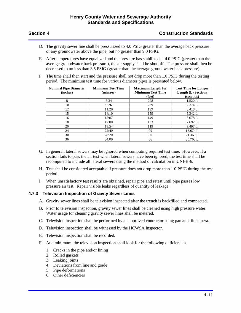
Henry County Water and Sewerage Authority Standards and Specifications
Section 4 Construction Standards
4-11
D. The gravity sewer line shall be pressurized to 4.0 PSIG greater than the average back pressure
of any groundwater above the pipe, but no greater than 9.0 PSIG.
E. After temperatures have equalized and the pressure has stabilized at 4.0 PSIG (greater than the
average groundwater back pressure), the air supply shall be shut off. The pressure shall then be
decreased to no less than 3.5 PSIG (greater than the average groundwater back pressure).
F. The time shall then start and the pressure shall not drop more than 1.0 PSIG during the testing
period. The minimum test time for various diameter pipes is presented below.
Nominal Pipe Diameter
(inches)
Minimum Test Time
(min:sec)
Maximum Length for
Minimum Test Time
(feet)
Test Time for Longer
Length (L) Sections
(seconds)
8 7:34 298 1.520 L
10 9:26 239 2.374 L
12 11:20 199 3.418 L
15 14:10 159 5.342 L
16 15:07 149 6.078 L
18 17:00 133 7.692 L
20 18:54 119 9.497 L
24 22:40 99 13.674 L
30 28:20 80 21.366 L
36 34:00 66 30.768 L
G. In general, lateral sewers may be ignored when computing required test time. However, if a
section fails to pass the air test when lateral sewers have been ignored, the test time shall be
recomputed to include all lateral sewers using the method of calculation in UNI-B-6.
H. Test shall be considered acceptable if pressure does not drop more than 1.0 PSIG during the test
period.
I. When unsatisfactory test results are obtained, repair pipe and retest until pipe passes low
pressure air test. Repair visible leaks regardless of quantity of leakage.
4.7.3 Television Inspection of Gravity Sewer Lines
A. Gravity sewer lines shall be television inspected after the trench is backfilled and compacted.
B. Prior to television inspection, gravity sewer lines shall be cleaned using high pressure water.
Water usage for cleaning gravity sewer lines shall be metered.
C. Television inspection shall be performed by an approved contractor using pan and tilt camera.
D. Television inspection shall be witnessed by the HCWSA Inspector.
E. Television inspection shall be recorded.
F. At a minimum, the television inspection shall look for the following deficiencies.
1. Cracks in the pipe and/or lining
2. Rolled gaskets
3. Leaking joints
4. Deviations from line and grade
5. Pipe deformations
6. Other deficiencies

Henry County Water and Sewerage Authority Standards and Specifications
Section 4 Construction Standards
4-12
G. A television inspection report containing the following information shall be submitted to the
HCWSA.
1. Length of pipe between manholes
2. Location of services
3. Deficiencies
H. No paving shall be done until gravity sewer lines are passed by the HCWSA.
4.7.4 Mandrel Testing of Gravity Sewer Lines
A. If the television inspection indicates that there is excessive deflection of the sewer line or that
the sewer line is egg shaped, the sewer lines shall be tested for deformation using a mandrel in
accordance with ASTM D3034.
B. The sewer line shall be capable of passing a mandrel which has a diameter that is 95 percent of
the diameter of the sewer line.
C. Any sewer line that fails the mandrel test shall be re-laid or replaced as required.
4.7.5 Hydrostatic Testing of Water Retaining Structures
A. Water retaining structures shall be hydrostatically tested in accordance with ACI 350.1 and
350.1R.
B. Hydrostatic test shall be witnessed by the HCWSA Inspector.
C. Hydrostatic testing shall not begin until concrete has cured for a minimum of 14 days.
D. Water retaining structures shall be filled with potable water to the maximum operating level
within the structure. Water level shall be maintained at this level for 72 hours prior to
beginning the actual test.
E. Test shall be considered acceptable when there is no visible sign of flowing or seeping water
and no measureable loss of water (HST-NML) which means the drop in water surface shall not
exceed 1/8 inch in three (3) days.
F. When unsatisfactory test results are obtained, repair water retaining structure and retest until
structure passes hydrostatic test. Repair visible leaks regardless of quantity of leakage.
4.8 Disinfection
4.8.1 General
A. All newly installed water distribution piping and existing water distribution piping affected
during construction shall be disinfected in accordance with AWWA C651.
B. The HCWSA Inspector shall be present during the disinfection process.
C. A HCWSA water meter is required for all flushing procedures.
D. All water samples will be collected and tested by HCWSA. Sampling and testing fees apply.
4.8.2 Disinfection Procedures
A. Prior to chlorination, the water line shall be slowly filled with water to remove air pockets and
then flushed to remove foreign debris. A minimum flushing velocity of 2.5 ft/s shall be
maintained. Line shall be flushed until water is clear of suspended solids and color.
Henry County Water and Sewerage Authority Standards and Specifications
Section 4 Construction Standards
4-13
B. All water used shall meet drinking water standards with the active distribution system being
appropriately protected from cross contamination.
C. Chlorine shall be injected into the system in sufficient quantity to obtain a concentration of 25
mg/l.
D. All valves, hydrants, services, etc. shall be operated to ensure disinfection.
E. Chlorine solution shall be retained in the system for a minimum of 24 hours. At the end of the
24 hour period, a residual of not less than 10 mg/l shall remain. If the residual is less than 10
mg/l, the disinfection procedure shall be repeated.
F. Flush all lines until the chlorine residual is equal to the existing system. After system is
flushed, all valves shall be closed.
G. After chlorination and flushing is complete, HCWSA will collect a sample from the disinfected
water distribution system and perform a total coliform analysis. If the system does not pass the
total coliform analysis, the disinfection procedure shall be repeated.
H. System shall not be placed into service until all tests are acceptable and HCWSA gives Final
Approval to place the system into operation.
4.9 Field Testing and Starting of Systems
A. Contractor is responsible for start-up of all equipment and mechanical systems.
B. Contractor shall provide all labor and materials required to perform start-up of all equipment
and mechanical systems.
C. Contractor shall obtain the services of the equipment manufacturer(s), as required, to certify the
installation.
D. Equipment manufacturer(s) shall certify in writing that their equipment has been installed
properly, the equipment functions properly, and the equipment warranty is valid. Written
certification shall be on the manufacturer’s letterhead.
E. Contractor shall obtain the services of the equipment manufacturer(s), as required, to train
HCWSA personnel on the operation and maintenance of their equipment.
F. A copy of the start-up test report and manufacturer’s certification shall be given to the
HCWSA.
4.10 Site Cleanup
A. Contractor shall remove all unused material, excess soil and rock, and all other debris from the
construction site as closely behind the work as practical. If the Contractor fails to maintain
clean-up responsibilities as directed by the HCWSA Inspector, the HCWSA may issue a “Stop
Work” order.
B. All trenches shall be backfilled and tamped before the end of each work day.
C. Prior to requesting final completion, the Contractor shall complete the following cleanup tasks.
1. Remove and properly dispose of all accumulated debris and all excess material of any kind
from the job site.
Henry County Water and Sewerage Authority Standards and Specifications
Section 4 Construction Standards
4-14
2. Repair or replace any work, trees, lawns, shrubs, fences, flower beds, drainage culverts, or
any other property damaged by the construction. All items damaged beyond repair shall be
replaced with new material of equal quality.
3. Clean all road surfaces.
Henry County Water and Sewerage Authority Standards and Specifications
Section 5 HCWSA Pre-Treatment Requirements
5-1
SECTION 5 - HCWSA PRE-TREATMENT REQUIREMENTS
5.1 General
HCWSA has implemented an Industrial Pre-Treatment Program and a Grease Management Program for
the purposes of protecting the HCWSA sanitary sewerage system. Industries that discharge wastewater to
the HCWSA sanitary sewer collection system are required to comply with the HCWSA Industrial Pre-
Treatment Program. Commercial facilities that discharge fats, oils, and grease into the HCWSA sanitary
sewer collection system are required to comply with the Grease Management Program. The Grease
Management Program rules and regulations are presented below.
5.2 Grease Management Program
5.2.1 Purpose
A. The purpose of the HCWSA Grease Management Program is to minimize the introduction of
fats, oils, and grease into the HCWSA sanitary sewerage system. The main components of the
program are the proper sizing, installation, and maintenance of grease interceptors. The
administrative and inspection requirements of food service facilities are established herein.
5.2.2 General Criteria
A. Installation Requirements for New Food Service Facilities
1. All proposed or newly remodeled food service facilities inside the HCWSA sanitary
sewerage service area shall be required to install, operate, and maintain an approved grease
interceptor.
2. All interceptor units shall be installed outside of the food service facility building unless the
user can demonstrate to the HCWSA that an interceptor located outside of the food service
facility is not feasible.
3. All grease interceptor units shall be of the type and capacity approved by Henry County
and the HCWSA.
B. Prohibited Discharges
1. Domestic wastewater shall not be discharged into the grease interceptor unless specifically
approved, in writing, by the HCWSA.
C. Requirements for Existing Food Service Facilities
1. All existing food service facilities inside the HCWSA sanitary sewerage service area are
expected to conduct their operations in such a manner that grease is captured on the user’s
premises and then properly disposed.
2. Existing food service facilities will be handled under HCWSA’s Grease Management
Program in the following manner.
a. HCWSA will periodically inspect each food service facility on an as needed basis to
assure that each facility is complying with the intent of the Grease Management
Program. The frequency of the inspection shall be determined by the HCWSA.
b. Each food service facility in the vicinity of the problem area will be inspected. The
facilities grease control practices and the adequacy of their grease control
interceptor/equipment will be assessed. Maintenance records will also be reviewed.
Henry County Water and Sewerage Authority Standards and Specifications
Section 5 HCWSA Pre-Treatment Requirements
5-2
c. Following the inspections, HCWSA will send written notice to the inspected food
service facility. The written notice will contain a summary of the policy requirements
and the results of the inspection. The inspections will typically result in one of the
following actions.
1) Facilities equipped with an appropriate and adequately sized grease interceptor who
are meeting the intent of the Grease Management Program through effective grease
control practices will be commended for their compliance.
2) After notice and an opportunity to be heard, facilities that are not in compliance
shall be required to develop and submit to HCWSA a proposed plan designed to
achieve compliance through improved housekeeping and/or increased maintenance
and pumping on the existing grease interceptor/equipment.
3) Facilities that are not successful in achieving compliance with the intent of the
Grease Management Program through improved housekeeping and increased
maintenance and pumping on the existing grease interceptor/equipment will be
required to install the necessary grease interceptor/equipment to bring the facility
into compliance.
D. Waste Minimization Plan
1. Food service facilities shall develop and implement a Waste Minimization Plan pertaining
to the disposal of grease, oils, and food particles.
2. Educational materials are available from HCWSA regarding the minimization of these
wastes.
E. Floor Drains
1. Only floor drains which discharge or have the potential to discharge grease shall be
connected to the grease interceptor.
F. Location
1. Each grease interceptor shall be installed and connected so that it is easily accessible for
inspection, cleaning, and removal of the intercepted grease at any time.
2. Grease interceptors required under this ordinance shall be installed outside of the food
service facility. The best location is in an area outside of an exterior wall, but upstream of
the domestic wastewater drain line(s).
3. A grease interceptor shall not be installed inside any part of a building unless approved, in
writing, by the HCWSA. The user bears the burden of demonstrating that an outside grease
interceptor is not feasible.
5.2.3 Design Criteria
A. Construction of Interceptors
1. Grease interceptors shall be constructed in accordance with Henry County plumbing
standards and shall have a minimum of two compartments with fittings designed for grease
retention.
2. All alternative grease removal devices or technologies shall be subject to the written
approval of the HCWSA. Such approval shall be based on demonstrated removal
efficiencies of the proposed technology.
B. Access
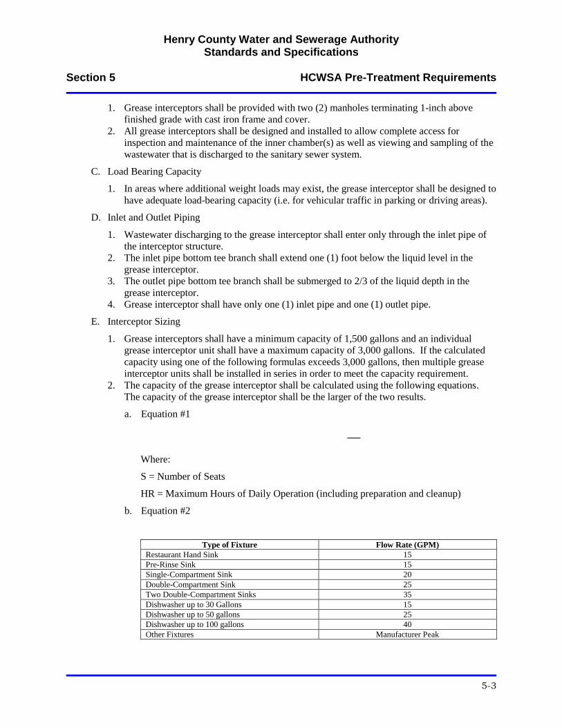
Henry County Water and Sewerage Authority Standards and Specifications
Section 5 HCWSA Pre-Treatment Requirements
5-3
1. Grease interceptors shall be provided with two (2) manholes terminating 1-inch above
finished grade with cast iron frame and cover.
2. All grease interceptors shall be designed and installed to allow complete access for
inspection and maintenance of the inner chamber(s) as well as viewing and sampling of the
wastewater that is discharged to the sanitary sewer system.
C. Load Bearing Capacity
1. In areas where additional weight loads may exist, the grease interceptor shall be designed to
have adequate load-bearing capacity (i.e. for vehicular traffic in parking or driving areas).
D. Inlet and Outlet Piping
1. Wastewater discharging to the grease interceptor shall enter only through the inlet pipe of
the interceptor structure.
2. The inlet pipe bottom tee branch shall extend one (1) foot below the liquid level in the
grease interceptor.
3. The outlet pipe bottom tee branch shall be submerged to 2/3 of the liquid depth in the
grease interceptor.
4. Grease interceptor shall have only one (1) inlet pipe and one (1) outlet pipe.
E. Interceptor Sizing
1. Grease interceptors shall have a minimum capacity of 1,500 gallons and an individual
grease interceptor unit shall have a maximum capacity of 3,000 gallons. If the calculated
capacity using one of the following formulas exceeds 3,000 gallons, then multiple grease
interceptor units shall be installed in series in order to meet the capacity requirement.
2. The capacity of the grease interceptor shall be calculated using the following equations.
The capacity of the grease interceptor shall be the larger of the two results.
a. Equation #1
Where:
S = Number of Seats
HR = Maximum Hours of Daily Operation (including preparation and cleanup)
b. Equation #2
Type of Fixture Flow Rate (GPM)
Restaurant Hand Sink 15
Pre-Rinse Sink 15
Single-Compartment Sink 20
Double-Compartment Sink 25
Two Double-Compartment Sinks 35
Dishwasher up to 30 Gallons 15
Dishwasher up to 50 gallons 25
Dishwasher up to 100 gallons 40
Other Fixtures Manufacturer Peak
Henry County Water and Sewerage Authority Standards and Specifications
Section 5 HCWSA Pre-Treatment Requirements
5-4
3. Under-sink or in-line grease interceptor requirements shall meet Plumbing and Drainage
Institute Standard PDI-G101 and shall have a minimum grease retention capacity of 100
pounds. Larger interceptors shall be provided if required by the HCWSA.
4. Grease interceptor designs represent minimum standards for normal usage. Installations
with heavier usage require more stringent measures for which the user is responsible and
shall pay the costs to provide additional measures if required by the HCWSA.
5. HCWSA reserves the right to evaluate interceptor sizing on an individual basis for facilities
with special conditions, such as highly variable flows, high levels of grease discharge, or
other unusual situations that are not adequately addressed by the formula.
5.2.4 Grease Interceptor Maintenance
A. Pumping
1. All grease interceptors shall be maintained by the user at the user’s expense.
2. Maintenance shall include the complete removal of all contents, including floating
materials, wastewater, and bottom sludge and solids.
3. Decanting or discharging of removed waste back into the interceptor for the purpose of
reducing the volume to be disposed of is strictly prohibited.
B. Pumping Frequency
1. Grease interceptors must be pumped out completely a minimum of once every three (3)
months.
2. Under-sink and in-line grease interceptors must be pumped/cleaned out completely a
minimum of once every month.
3. Grease interceptors may need to be pumped more frequently as needed to prevent carry
over grease into the sanitary sewer collection system.
4. Pumping frequency may be extended past the minimum period if the user can demonstrate
that the grease interceptor can function properly with a longer pumping frequency.
Extended pumping frequencies must be approved by the HCWSA.
C. Notice of Violation
1. Grease interceptor inspections will be performed at the food service facility.
2. If the oil and grease concentrations exceed HCWSA’s maximum discharge limits and/or
the combined depth of bottom and top solids exceeds 33 percent of the total depth of the
trap, the facility will be notified in writing of the findings and the user will be given seven
(7) days to achieve compliance.
3. If the interceptor is not cleaned or HCWSA is not notified of the interceptor being cleaned
within this time period, a Notice of Violation (NOV) letter will be issued to the user. In the
NOV, the user will be given three (3) days to comply.
4. If compliance is not achieved within the three day period, the user’s water service will be
terminated. Water service, once terminated, will not be restored until the user has achieved
compliance.
D. Disposal of Interceptor Pumped Material
1. All waste removed from each grease interceptor shall be recorded on a proper manifest
form.
2. In no way shall the pumped material be returned to any private or public portion of the
sanitary sewer collection system.
Henry County Water and Sewerage Authority Standards and Specifications
Section 5 HCWSA Pre-Treatment Requirements
5-5
E. Additives
1. No additives shall be used at any time.
F. Chemical Treatment
1. Chemical treatments such as drain cleaners, enzymes, acids, and other chemicals designed
to dissolve, purge, or remove grease shall not be allowed to enter the grease interceptor.
5.2.5 Administrative Requirements
A. Administrative Fees
1. No fee will be charged for an inspection by HCWSA; however, if the user’s grease
interceptor is not in compliance with the Grease Management Program, a re-inspection fee
will be charged for each inspection thereafter until compliance is achieved. The current re-
inspection fee can be obtained on the HCWSA web site at www.hcwsa.com.
B. Inspection and Entry
1. Authorized personnel of the HCWSA, bearing proper credentials and identification, shall
have the right to enter upon all properties subject to the Grease Management Program at
any time and without prior notification for the purpose of inspection, observation,
measurement, sampling, testing, or record review.
C. Record Retention and Reporting
1. All users must keep a record of any cleaning or maintenance performed on their grease
interceptor.
2. The following records must be kept on-site at the food service facility for a minimum of
two (2) years.
a. Manifests are required for all grease interceptors and shall contain the following
information.
1) Food service facility (generator) information including name, address, volume
pumped, date and time of pumping, and generator signature verifying the
information;
2) Transporter information including company name, address, license plate number,
permit number, driver name, and driver signature verifying transporter information;
and
3) Receiving information including facility name, address, date and time of receiving,
EPD permit number, and signature verifying receipt of waste.
4) Manifests must be mailed, faxed, or electronically submitted to HCWSA within
fourteen (14) days after the interceptor maintenance was performed.
5) A manifest may not be required for under-sink or in-line grease interceptors if the
user can present a valid reason to HCWSA as to why one is not necessary.
b. Maintenance logs are required for all grease interceptors and shall indicate the date and
time that the maintenance was performed and shall have a description of the
maintenance that was performed.
5.2.6 Enforcement
A. Enforcement of these regulations shall be in accordance with the provisions of the HCWSA
Enforcement Response Plan.
Henry County Water and Sewerage Authority Standards and Specifications
Section 5 HCWSA Pre-Treatment Requirements
5-6
B. Failure to comply with the Grease Management Program will be grounds for discontinuation of
water service.
Henry County Water and Sewerage Authority Standards and Specifications
APPENDIX A
Standard Water Details
W01 Residential Utility Placement for Road with 50’ Right-of-Way
W02 Water Line Trench Detail
W03 Pipe Depth at Edge of Pavement
W04 Typical Fire Hydrant Assembly
W05 Fire Hydrant in Cul-de-Sac
W06 Fire Hydrant at Dead-End
W07 Water Line Blow-Off
W08 Water Line Isolation Valve
W09 Water Line Intersection
W10 Water Main Combination Air/Vacuum Valve
W11 Thrust Block
W12 Concrete Deadman
W13 Thrust Restraint
W14 Residential Water Meter Detail
W15 Short Side Residential Service Detail
W16 Long Side Residential Service Detail
W17 4’, 6”, and 8” Omni F2 Fireline Meter
W18 10” Omni F2 Compact Fireline Meter
W19 Commercial Backflow Preventer (4” and Larger)
W20 Typical Jack and Bore Detail
W21 Creek Crossing
W22 Pavement Repair
Henry County Water and Sewerage Authority Standards and Specifications
Appendix B
Standard Sewer Details
S01 Residential Utility Placement for Road with 50’ Right-of-Way
S02 Ductile Iron Sanitary Sewage Force Main Trench Detail
S03 C900 PVC Sanitary Sewage Force Main Trench Detail
S04 Ductile Iron Gravity Sewer Trench Detail
S05 SDR 35/SDR 26 Gravity Sewer Trench Detail
S06 Pipe Depth at Edge of Pavement
S07 Standard Sanitary Sewer Manhole
S08 Sanitary Manhole with Outside Drop
S09 Sanitary Sewer Doghouse Manhole
S10 Shallow Sanitary Sewer Manhole
S11 Sanitary Sewer Manhole Vent
S12 Standard Manhole Invert
S13 Standard Sanitary Sewer Manhole Lid
S14 Watertight Sanitary Sewer Manhole Lid
S15 Sanitary Force Main Discharge Manhole
S16 Typical Jack and Bore Detail
S17 Creek Crossing
S18 Sewer Service Line Lateral
S19 Service Lateral for Sewer Lines 16 Feet Deep and Greater
S20 Sanitary Sewer Service Line Clean-Out Connection
S21 Sanitary Sewage Force Main Isolation Valve
S22 Sanitary Sewage Combination Air/Vacuum Valve (3” and Smaller)
S23 Sanitary Sewage Combination Air/Vacuum Valve (4” and Larger)
S24 Thrust Block
S25 Concrete Deadman
S26 Thrust Restraint
S27 Typical Sanitary Sewage Lift Station Property Layout
Henry County Water and Sewerage Authority Standards and Specifications
S28 Access Road
S29 Lift Station Electrical Connection
S30 Typical Sanitary Sewage Lift Station Wet Well
S31 Chain Link Fence
S32 Frost Proof Yard Hydrant
S33 Grease Interceptor
S34 Pavement Repair
S35 Sanitary Sewer Connection for Dumpster Pad without Canopy
S36 Sanitary Sewer Connection for Dumpster Pad with Canopy
S37 Sewer Easement Access Gate

NOTES:
1. NO TREES OR FENCES ALLOWED WITHIN THE ROAD R/W OR UTILITY EASEMENT EXCEPT WHERE
REQUIRED BY CITY, COUNTY, OR OTHER GOVERNMENT ORDINANCE.
2. ALL TREES SHALL BE CLEARED AND SHOULDERS GRADED WITHIN 6" OF FINAL GRADE (INCLUDING
UTILITY EASEMENT) PRIOR TO THE INSTALLATION OF ANY UTILITIES.
3. UTILITY PLACEMENT SHALL REMAIN CONSISTENT FROM BACK OF CURB THROUGHOUT THE PROJECT
REGARDLESS OF ANY INCONSISTENCIES IN ROAD CONSTRUCTION. EXAMPLES: STORM SEWERS,
CULVERTS, CUL-DE-SACS, ETC...(EXCEPT CATV).
4. AFTER VERIFICATION OF FINAL GRADE, UTILITIES SHOULD BE INSTALLED AS FOLLOWS: WATER,
ELECTRIC, GAS, TELEPHONE, AND CABLE TELEVISION.
5. TOTAL CLEARED AND GRADED WIDTH TO BE 60' MINIMUM.
6. PROPERTY CORNER REFERENCE SHALL BE PLACED ON CURB AND GUTTER AND ON 10' OFFSET
STAKE.
7. UTILITY EASEMENT SHALL BE SHOWN AND RECORDED WITH THE FINAL PLAT.
8. WATER METER BOXES SHALL BE LOCATED 6' BACK OF R/W. SEWER SERVICES SHALL BE STUBBED
OUT 10' BACK OF R/W.
9. WATER LATERALS SHALL BE MARKED WITH A BLUE "W" ON CURB AS SOON AS POSSIBLE AFTER CURB
HAS BEEN INSTALLED. SEWER LATERALS SHALL BE MARKED WITH A GREEN "X" ON CURB.
10. DEPTH REQUIREMENTS INDICATE MINIMUM DEPTH AT TIME OF INSTALLATION BELOW CURB LINE .
11. THIS STANDARD MAY BE COMBINED WITH JOINT USE STANDARD.
12. CATV PEDESTALS, TELEPHONE PEDESTALS, TRANSFORMERS, AND WATER METERS SHALL BE PLACED
IN 5' UTILITY EASEMENT.
13. UTILITIES SHALL BE LOCATED WITHIN PLUS/MINUS 6" OF PLAN LOCATION.
11' 11' 2'2'
5'
UTILITY
EASEMENT 6' 4' 2' 2' 4' 6'
5'
UTILITY
EASEMENT
25' 25'
50' RIGHT-OF-WAY
1' - CATV
8' - GAS
10' - TELEPHONE
12' - POWER
1' - CATV
8' - WATER
10' - TELEPHONE
12' - POWER
SIDEWALK SIDEWALK
VA
RIE
S
2" PVC RISER
PIPE EXTENDING
5' ABOVE GRADE
AT END OF
SERVICE LINE
2" PVC RISER
PIPE EXTENDING
5' ABOVE GRADE
AT END OF
SERVICE LINE
3'
2'
3'
2' 2'
4'
2'
3'
2
:
1
2
:
1
HENRY COUNTY WATER & SEWERAGE AUTHORITY
REVISED:
SCALE:
DETAIL NO.
RESIDENTIAL UTILITY PLACEMENT
FOR ROAD WITH 50' RIGHT-OF-WAY
W01
01/01/2012
N.T.S.
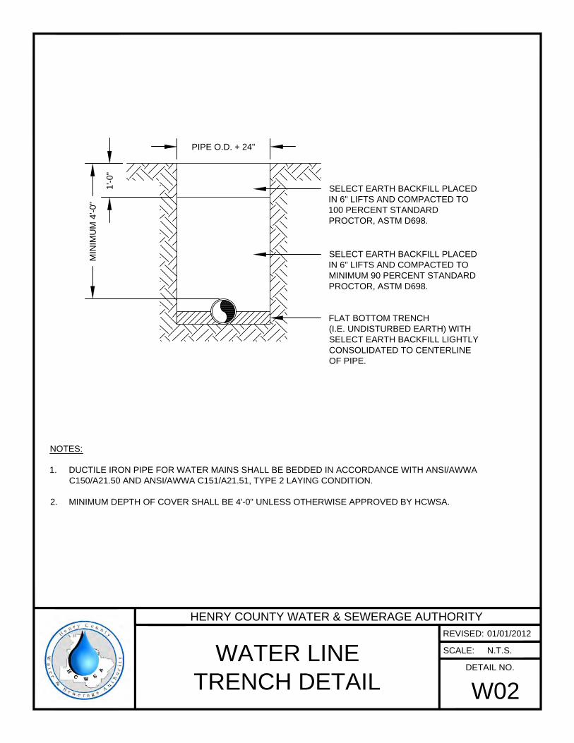
FLAT BOTTOM TRENCH
(I.E. UNDISTURBED EARTH) WITH
SELECT EARTH BACKFILL LIGHTLY
CONSOLIDATED TO CENTERLINE
OF PIPE.
SELECT EARTH BACKFILL PLACED
IN 6" LIFTS AND COMPACTED TO
MINIMUM 90 PERCENT STANDARD
PROCTOR, ASTM D698.
NOTES:
1. DUCTILE IRON PIPE FOR WATER MAINS SHALL BE BEDDED IN ACCORDANCE WITH ANSI/AWWA
C150/A21.50 AND ANSI/AWWA C151/A21.51, TYPE 2 LAYING CONDITION.
2. MINIMUM DEPTH OF COVER SHALL BE 4'-0" UNLESS OTHERWISE APPROVED BY HCWSA.
PIPE O.D. + 24"
MIN
IM
UM
4
'-0
"
SELECT EARTH BACKFILL PLACED
IN 6" LIFTS AND COMPACTED TO
100 PERCENT STANDARD
PROCTOR, ASTM D698.
1'-0
"
HENRY COUNTY WATER & SEWERAGE AUTHORITY
REVISED:
SCALE:
DETAIL NO.
WATER LINE
TRENCH DETAIL
W02
01/01/2012
N.T.S.
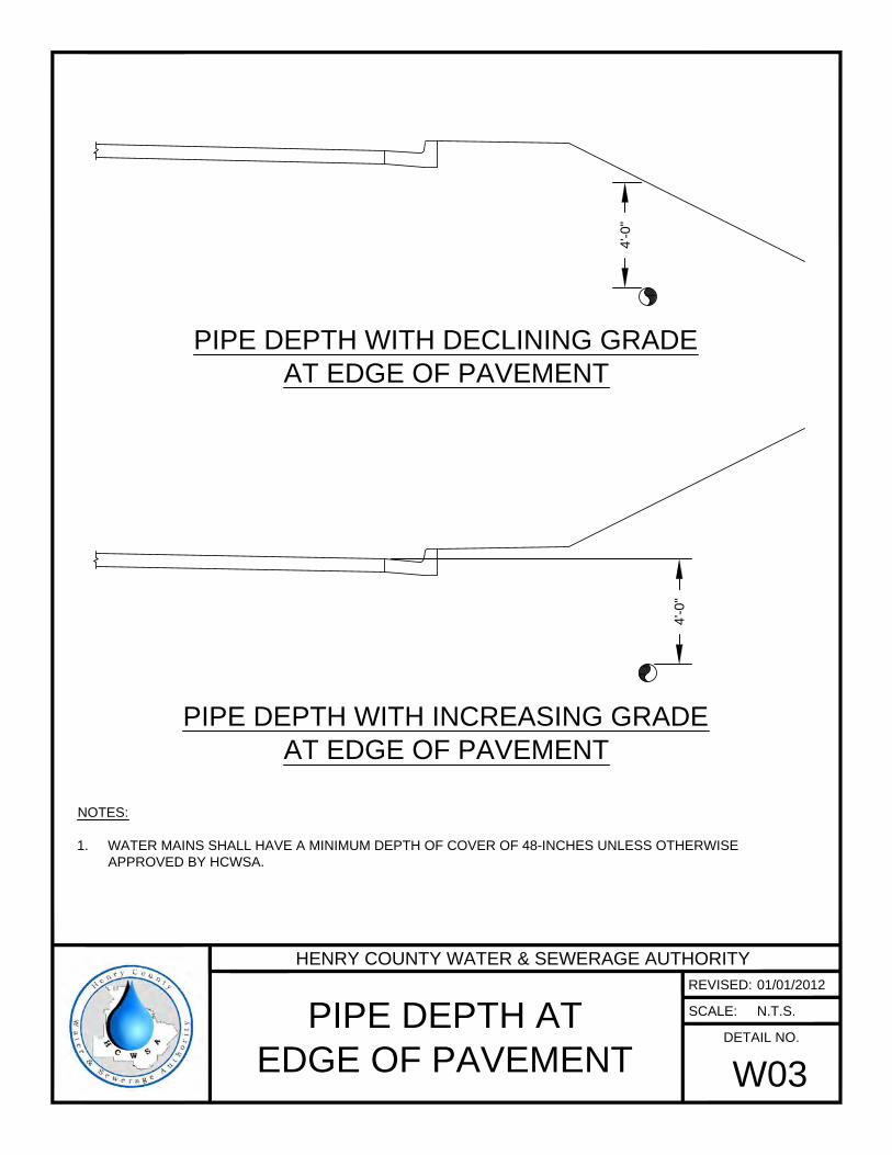
4'-0
"
4'-0
"
NOTES:
1. WATER MAINS SHALL HAVE A MINIMUM DEPTH OF COVER OF 48-INCHES UNLESS OTHERWISE
APPROVED BY HCWSA.
PIPE DEPTH WITH DECLINING GRADE
AT EDGE OF PAVEMENT
PIPE DEPTH WITH INCREASING GRADE
AT EDGE OF PAVEMENT
HENRY COUNTY WATER & SEWERAGE AUTHORITY
REVISED:
SCALE:
DETAIL NO.
PIPE DEPTH AT
EDGE OF PAVEMENT
W03
01/01/2012
N.T.S.
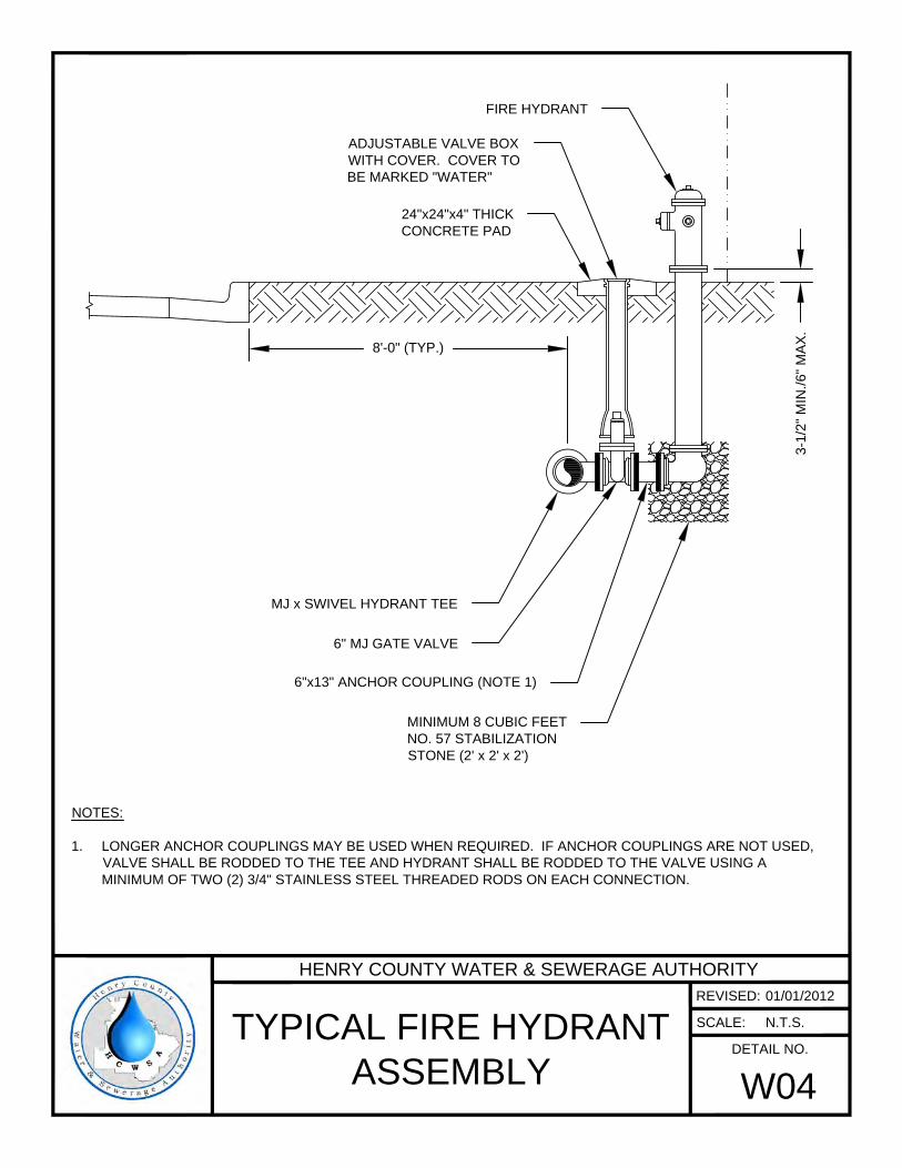
ADJUSTABLE VALVE BOX
WITH COVER. COVER TO
BE MARKED "WATER"
24"x24"x4" THICK
CONCRETE PAD
FIRE HYDRANT
8'-0" (TYP.)
MJ x SWIVEL HYDRANT TEE
6" MJ GATE VALVE
6"x13" ANCHOR COUPLING (NOTE 1)
MINIMUM 8 CUBIC FEET
NO. 57 STABILIZATION
STONE (2' x 2' x 2')
NOTES:
1. LONGER ANCHOR COUPLINGS MAY BE USED WHEN REQUIRED. IF ANCHOR COUPLINGS ARE NOT USED,
VALVE SHALL BE RODDED TO THE TEE AND HYDRANT SHALL BE RODDED TO THE VALVE USING A
MINIMUM OF TWO (2) 3/4" STAINLESS STEEL THREADED RODS ON EACH CONNECTION.
3-1
/2
" M
IN
./6
" M
AX
.
HENRY COUNTY WATER & SEWERAGE AUTHORITY
REVISED:
SCALE:
DETAIL NO.
TYPICAL FIRE HYDRANT
ASSEMBLY
W04
01/01/2012
N.T.S.
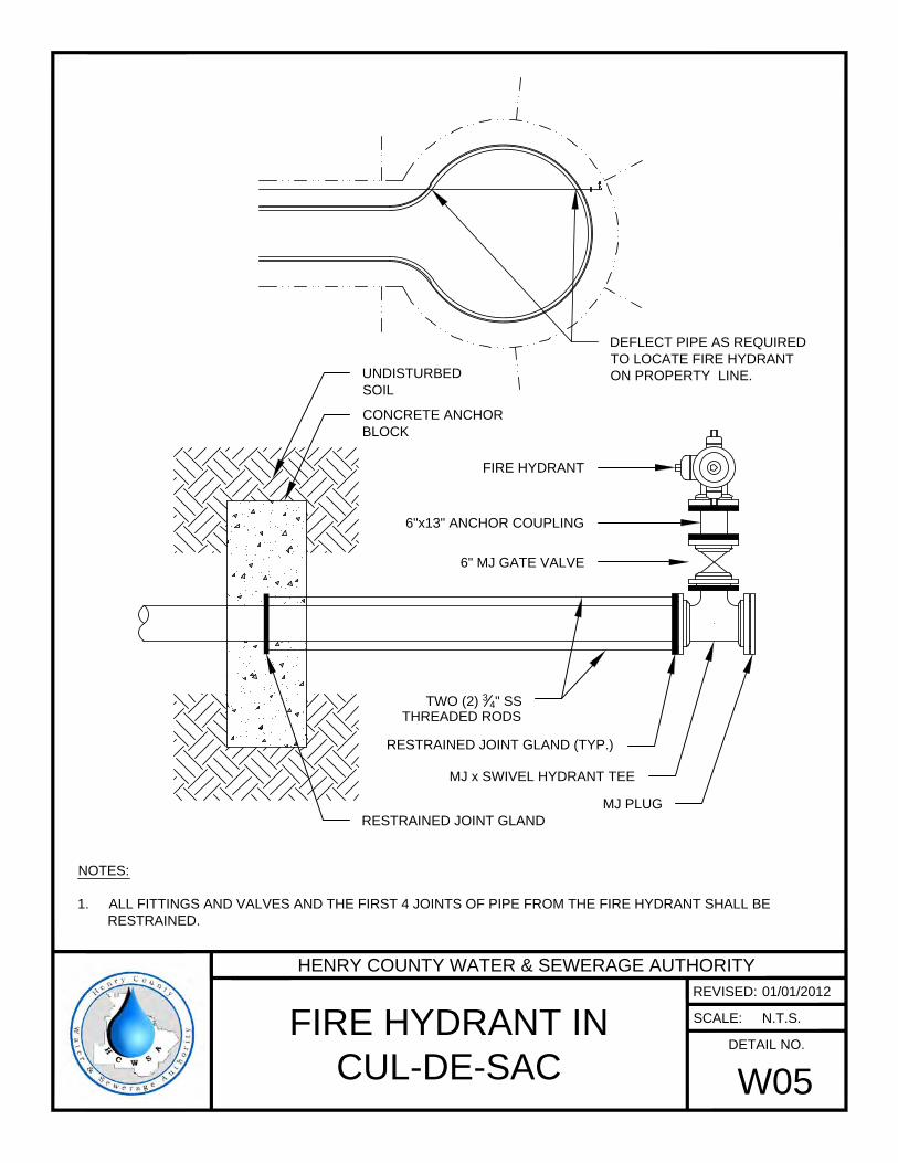
6"x13" ANCHOR COUPLING
6" MJ GATE VALVE
FIRE HYDRANT
MJ PLUG
MJ x SWIVEL HYDRANT TEE
RESTRAINED JOINT GLAND (TYP.)
UNDISTURBED
SOIL
NOTES:
1. ALL FITTINGS AND VALVES AND THE FIRST 4 JOINTS OF PIPE FROM THE FIRE HYDRANT SHALL BE
RESTRAINED.
DEFLECT PIPE AS REQUIRED
TO LOCATE FIRE HYDRANT
ON PROPERTY LINE.
TWO (2)
3
4
" SS
THREADED RODS
RESTRAINED JOINT GLAND
CONCRETE ANCHOR
BLOCK
HENRY COUNTY WATER & SEWERAGE AUTHORITY
REVISED:
SCALE:
DETAIL NO.
FIRE HYDRANT IN
CUL-DE-SAC
W05
01/01/2012
N.T.S.
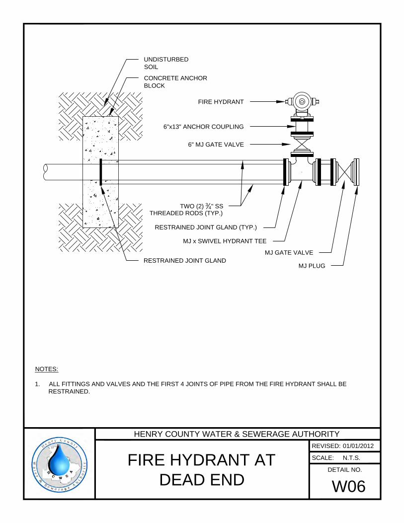
NOTES:
1. ALL FITTINGS AND VALVES AND THE FIRST 4 JOINTS OF PIPE FROM THE FIRE HYDRANT SHALL BE
RESTRAINED.
6"x13" ANCHOR COUPLING
6" MJ GATE VALVE
FIRE HYDRANT
MJ x SWIVEL HYDRANT TEE
MJ PLUG
MJ GATE VALVE
RESTRAINED JOINT GLAND (TYP.)
UNDISTURBED
SOIL
RESTRAINED JOINT GLAND
CONCRETE ANCHOR
BLOCK
TWO (2)
3
4
" SS
THREADED RODS (TYP.)
HENRY COUNTY WATER & SEWERAGE AUTHORITY
REVISED:
SCALE:
DETAIL NO.
FIRE HYDRANT AT
DEAD END
W06
01/01/2012
N.T.S.
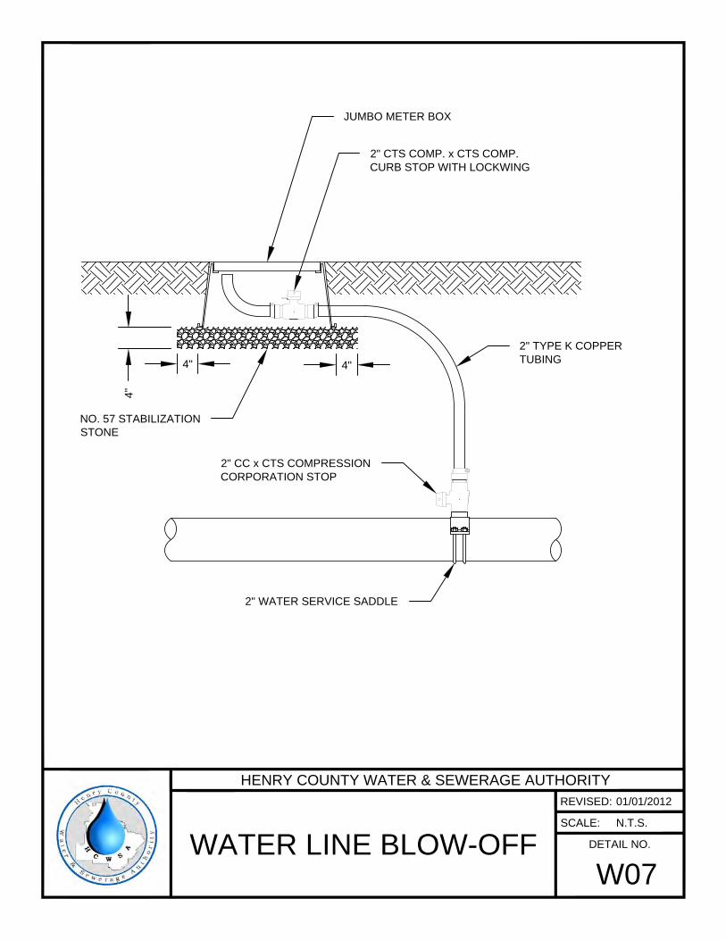
2" CC x CTS COMPRESSION
CORPORATION STOP
2" WATER SERVICE SADDLE
4"
4"
4"
2" CTS COMP. x CTS COMP.
CURB STOP WITH LOCKWING
JUMBO METER BOX
NO. 57 STABILIZATION
STONE
2" TYPE K COPPER
TUBING
HENRY COUNTY WATER & SEWERAGE AUTHORITY
REVISED:
SCALE:
DETAIL NO.
WATER LINE BLOW-OFF
W07
01/01/2012
N.T.S.
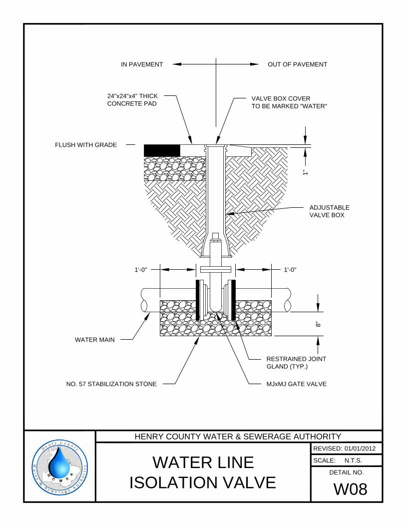
1'-0"1'-0"
VALVE BOX COVER
TO BE MARKED "WATER"
OUT OF PAVEMENTIN PAVEMENT
24"x24"x4" THICK
CONCRETE PAD
FLUSH WITH GRADE
1"
ADJUSTABLE
VALVE BOX
RESTRAINED JOINT
GLAND (TYP.)
MJxMJ GATE VALVE
WATER MAIN
8"
NO. 57 STABILIZATION STONE
HENRY COUNTY WATER & SEWERAGE AUTHORITY
REVISED:
SCALE:
DETAIL NO.
WATER LINE
ISOLATION VALVE
W08
01/01/2012
N.T.S.
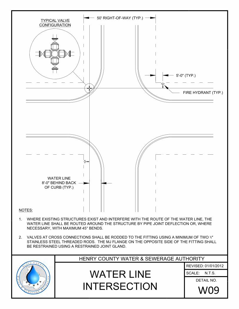
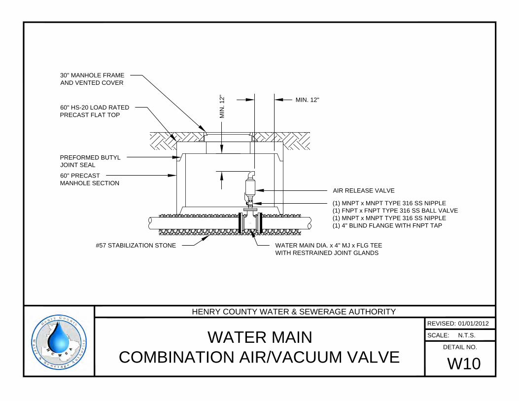
(1) MNPT x MNPT TYPE 316 SS NIPPLE
(1) FNPT x FNPT TYPE 316 SS BALL VALVE
(1) MNPT x MNPT TYPE 316 SS NIPPLE
(1) 4" BLIND FLANGE WITH FNPT TAP
AIR RELEASE VALVE
60" HS-20 LOAD RATED
PRECAST FLAT TOP
PREFORMED BUTYL
JOINT SEAL
60" PRECAST
MANHOLE SECTION
30" MANHOLE FRAME
AND VENTED COVER
MIN
. 1
2"
MIN. 12"
WATER MAIN DIA. x 4" MJ x FLG TEE
WITH RESTRAINED JOINT GLANDS
#57 STABILIZATION STONE
HENRY COUNTY WATER & SEWERAGE AUTHORITY
REVISED:
SCALE:
DETAIL NO.
WATER MAIN
COMBINATION AIR/VACUUM VALVE
W10
01/01/2012
N.T.S.


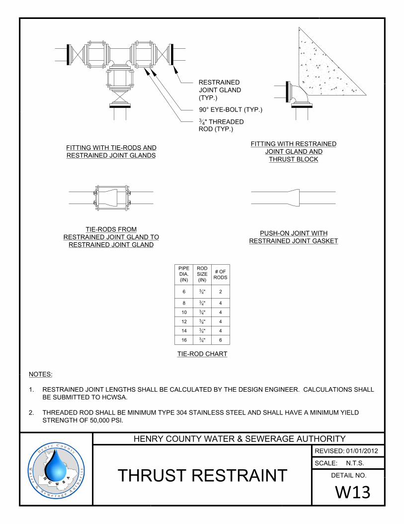
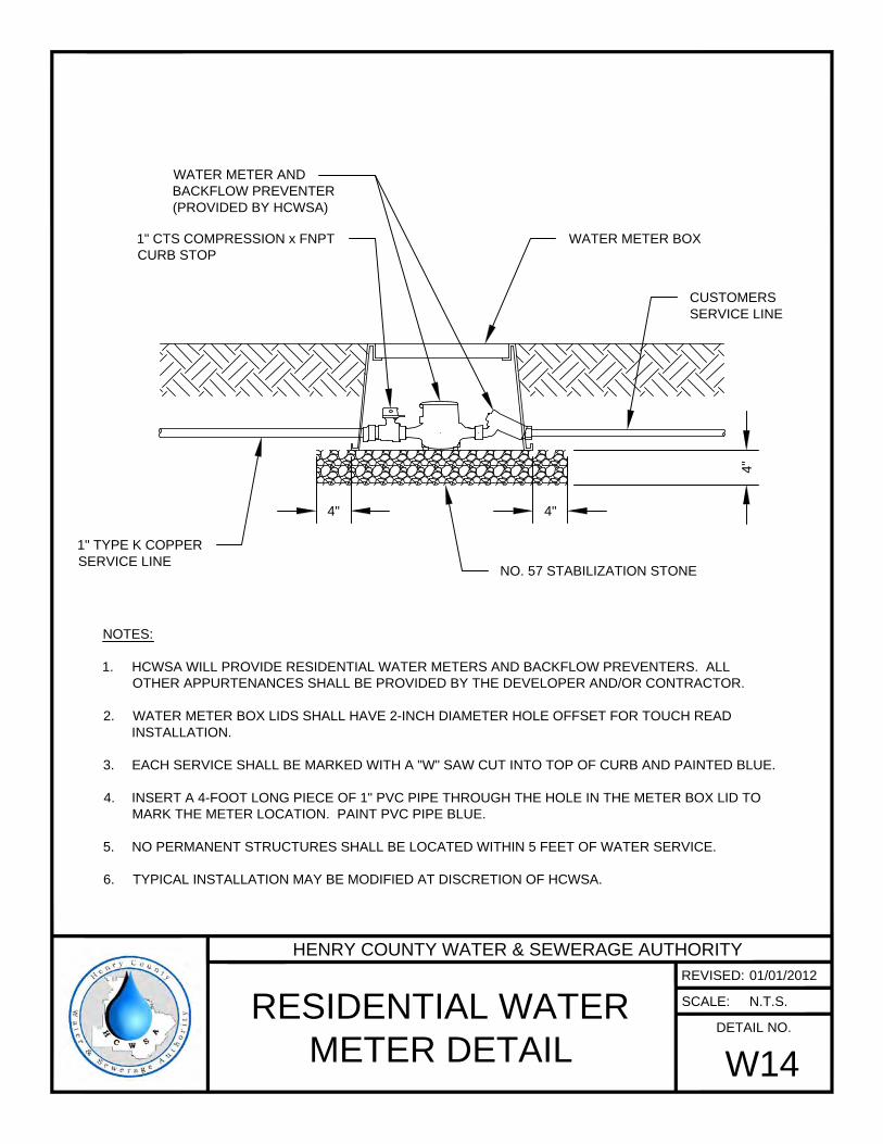
4"
4"4"
WATER METER BOX1" CTS COMPRESSION x FNPT
CURB STOP
1" TYPE K COPPER
SERVICE LINE
WATER METER AND
BACKFLOW PREVENTER
(PROVIDED BY HCWSA)
CUSTOMERS
SERVICE LINE
NO. 57 STABILIZATION STONE
NOTES:
1. HCWSA WILL PROVIDE RESIDENTIAL WATER METERS AND BACKFLOW PREVENTERS. ALL
OTHER APPURTENANCES SHALL BE PROVIDED BY THE DEVELOPER AND/OR CONTRACTOR.
2. WATER METER BOX LIDS SHALL HAVE 2-INCH DIAMETER HOLE OFFSET FOR TOUCH READ
INSTALLATION.
3. EACH SERVICE SHALL BE MARKED WITH A "W" SAW CUT INTO TOP OF CURB AND PAINTED BLUE.
4. INSERT A 4-FOOT LONG PIECE OF 1" PVC PIPE THROUGH THE HOLE IN THE METER BOX LID TO
MARK THE METER LOCATION. PAINT PVC PIPE BLUE.
5. NO PERMANENT STRUCTURES SHALL BE LOCATED WITHIN 5 FEET OF WATER SERVICE.
6. TYPICAL INSTALLATION MAY BE MODIFIED AT DISCRETION OF HCWSA.
HENRY COUNTY WATER & SEWERAGE AUTHORITY
REVISED:
SCALE:
DETAIL NO.
RESIDENTIAL WATER
METER DETAIL
W14
01/01/2012
N.T.S.

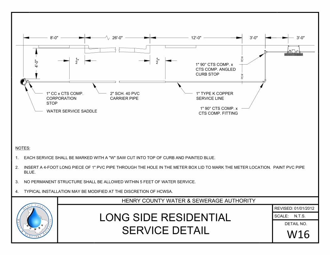
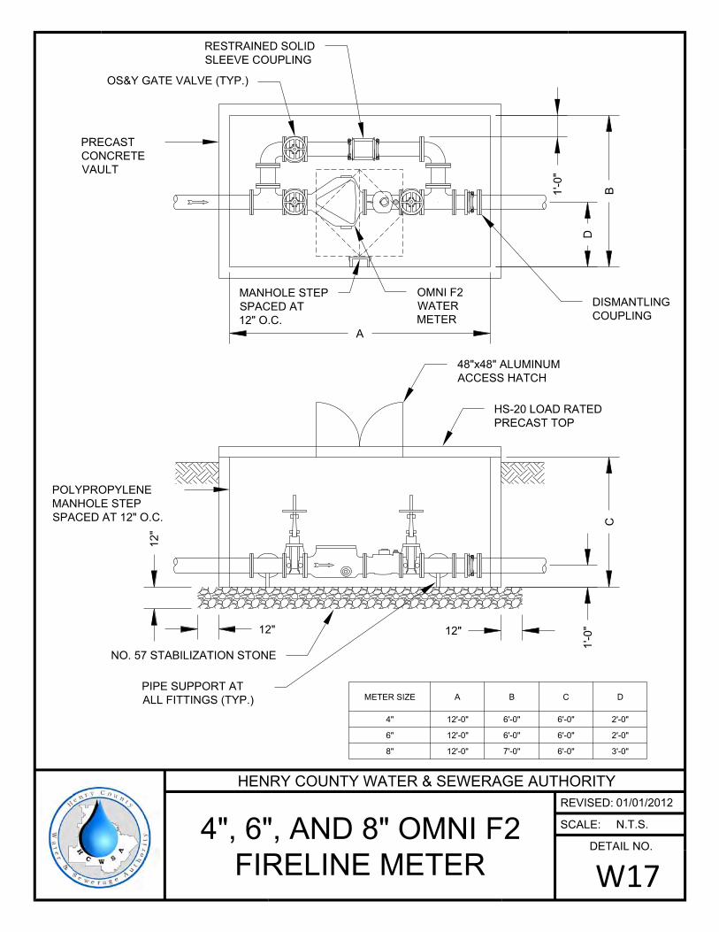
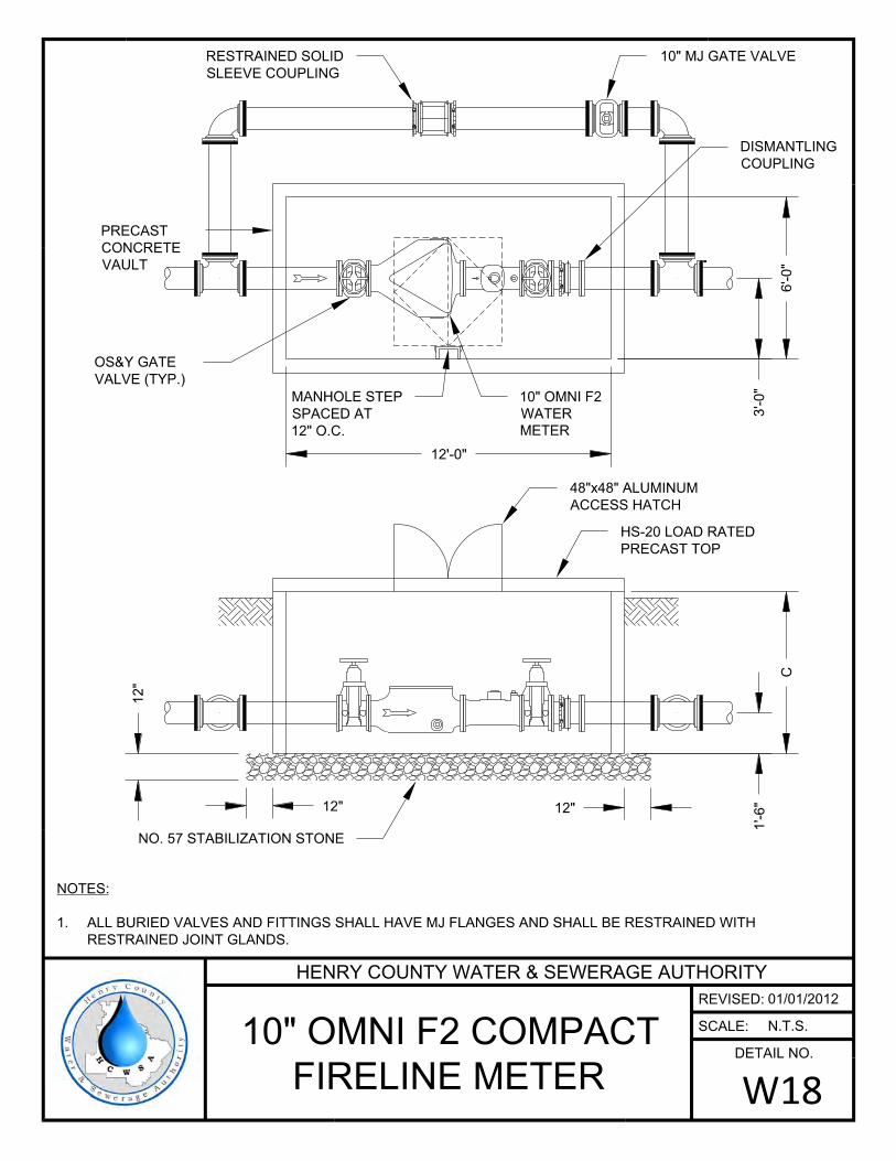
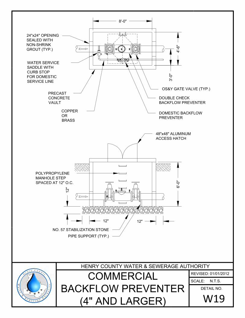
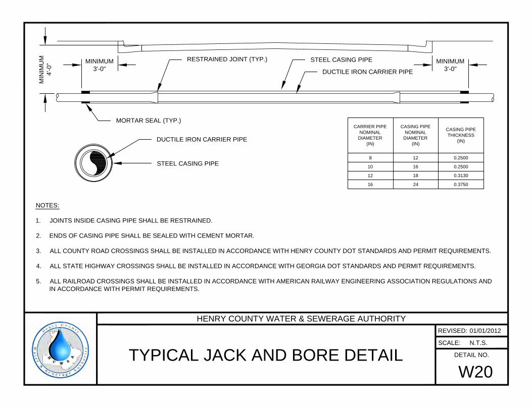
NOTES:
1. JOINTS INSIDE CASING PIPE SHALL BE RESTRAINED.
2. ENDS OF CASING PIPE SHALL BE SEALED WITH CEMENT MORTAR.
3. ALL COUNTY ROAD CROSSINGS SHALL BE INSTALLED IN ACCORDANCE WITH HENRY COUNTY DOT STANDARDS AND PERMIT REQUIREMENTS.
4. ALL STATE HIGHWAY CROSSINGS SHALL BE INSTALLED IN ACCORDANCE WITH GEORGIA DOT STANDARDS AND PERMIT REQUIREMENTS.
5. ALL RAILROAD CROSSINGS SHALL BE INSTALLED IN ACCORDANCE WITH AMERICAN RAILWAY ENGINEERING ASSOCIATION REGULATIONS AND
IN ACCORDANCE WITH PERMIT REQUIREMENTS.
MINIMUM
3'-0"
MINIMUM
3'-0"
MIN
IM
UM
4'-0
"
STEEL CASING PIPE
DUCTILE IRON CARRIER PIPE
STEEL CASING PIPE
DUCTILE IRON CARRIER PIPE
RESTRAINED JOINT (TYP.)
CARRIER PIPE
NOMINAL
DIAMETER
(IN)
CASING PIPE
NOMINAL
DIAMETER
(IN)
CASING PIPE
THICKNESS
(IN)
8 12 0.2500
10 16 0.2500
12 18 0.3130
16 24 0.3750
MORTAR SEAL (TYP.)
HENRY COUNTY WATER & SEWERAGE AUTHORITY
REVISED:
SCALE:
DETAIL NO.
TYPICAL JACK AND BORE DETAIL
W20
01/01/2012
N.T.S.
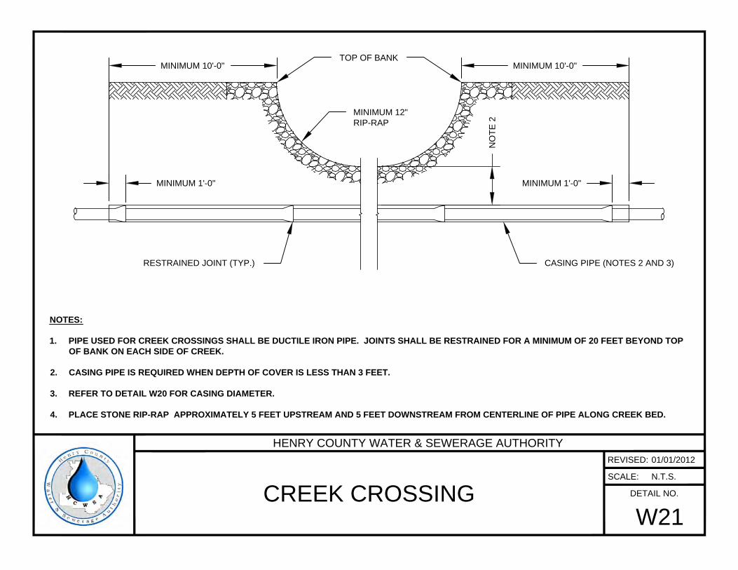
MINIMUM 10'-0" MINIMUM 10'-0"
MINIMUM 1'-0" MINIMUM 1'-0"
TOP OF BANK
MINIMUM 12"
RIP-RAP
CASING PIPE (NOTES 2 AND 3)
NOTES:
1. PIPE USED FOR CREEK CROSSINGS SHALL BE DUCTILE IRON PIPE. JOINTS SHALL BE RESTRAINED FOR A MINIMUM OF 20 FEET BEYOND TOP
OF BANK ON EACH SIDE OF CREEK.
2. CASING PIPE IS REQUIRED WHEN DEPTH OF COVER IS LESS THAN 3 FEET.
3. REFER TO DETAIL W20 FOR CASING DIAMETER.
4. PLACE STONE RIP-RAP APPROXIMATELY 5 FEET UPSTREAM AND 5 FEET DOWNSTREAM FROM CENTERLINE OF PIPE ALONG CREEK BED.
NO
TE
2
RESTRAINED JOINT (TYP.)
HENRY COUNTY WATER & SEWERAGE AUTHORITY
REVISED:
SCALE:
DETAIL NO.
CREEK CROSSING
W21
01/01/2012
N.T.S.

NOTES:
1. THIS DETAIL IS THE MINIMUM PAVEMENT REPAIR REQUIREMENT. HENRY COUNTY DOT OR GEORGIA
DOT PAVEMENT REPAIR DETAILS SHALL SUPERCEDE THIS DETAIL AND SHALL BE USED WHERE
APPLICABLE.
2. CONCRETE FOR CONCRETE CAP SHALL HAVE A MINIMUM COMPRESSIVE STRENGTH OF 2,500 PSI @ 28
DAYS.
EXISTING PAVEMENT
TRENCH BACKFILLED
PER APPROPRIATE
PIPE BEDDING DETAIL
8" CONCRETE CAP
SAW CUT EDGE
1
1
2
" ASPHALT SURFACE
TOPPING WITH TACK COAT
APPLIED TO CONCRETE
AND EDGES OF EXISTING
PAVEMENT
12" 12"
HENRY COUNTY WATER & SEWERAGE AUTHORITY
REVISED:
SCALE:
DETAIL NO.
PAVEMENT REPAIR
W22
01/01/2012
N.T.S.
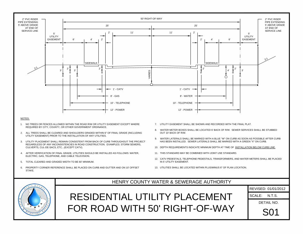
NOTES:
1. NO TREES OR FENCES ALLOWED WITHIN THE ROAD R/W OR UTILITY EASEMENT EXCEPT WHERE
REQUIRED BY CITY, COUNTY, OR OTHER GOVERNMENT ORDINANCE.
2. ALL TREES SHALL BE CLEARED AND SHOULDERS GRADED WITHIN 6" OF FINAL GRADE (INCLUDING
UTILITY EASEMENT) PRIOR TO THE INSTALLATION OF ANY UTILITIES.
3. UTILITY PLACEMENT SHALL REMAIN CONSISTENT FROM BACK OF CURB THROUGHOUT THE PROJECT
REGARDLESS OF ANY INCONSISTENCIES IN ROAD CONSTRUCTION. EXAMPLES: STORM SEWERS,
CULVERTS, CUL-DE-SACS, ETC...(EXCEPT CATV).
4. AFTER VERIFICATION OF FINAL GRADE, UTILITIES SHOULD BE INSTALLED AS FOLLOWS: WATER,
ELECTRIC, GAS, TELEPHONE, AND CABLE TELEVISION.
5. TOTAL CLEARED AND GRADED WIDTH TO BE 60' MINIMUM.
6. PROPERTY CORNER REFERENCE SHALL BE PLACED ON CURB AND GUTTER AND ON 10' OFFSET
STAKE.
7. UTILITY EASEMENT SHALL BE SHOWN AND RECORDED WITH THE FINAL PLAT.
8. WATER METER BOXES SHALL BE LOCATED 6' BACK OF R/W. SEWER SERVICES SHALL BE STUBBED
OUT 10' BACK OF R/W.
9. WATER LATERALS SHALL BE MARKED WITH A BLUE "W" ON CURB AS SOON AS POSSIBLE AFTER CURB
HAS BEEN INSTALLED. SEWER LATERALS SHALL BE MARKED WITH A GREEN "X" ON CURB.
10. DEPTH REQUIREMENTS INDICATE MINIMUM DEPTH AT TIME OF INSTALLATION BELOW CURB LINE .
11. THIS STANDARD MAY BE COMBINED WITH JOINT USE STANDARD.
12. CATV PEDESTALS, TELEPHONE PEDESTALS, TRANSFORMERS, AND WATER METERS SHALL BE PLACED
IN 5' UTILITY EASEMENT.
13. UTILITIES SHALL BE LOCATED WITHIN PLUS/MINUS 6" OF PLAN LOCATION.
11' 11' 2'2'
5'
UTILITY
EASEMENT 6' 4' 2' 2' 4' 6'
5'
UTILITY
EASEMENT
25' 25'
50' RIGHT-OF-WAY
1' - CATV
8' - GAS
10' - TELEPHONE
12' - POWER
1' - CATV
8' - WATER
10' - TELEPHONE
12' - POWER
SIDEWALK SIDEWALK
VA
RIE
S
2" PVC RISER
PIPE EXTENDING
5' ABOVE GRADE
AT END OF
SERVICE LINE
2" PVC RISER
PIPE EXTENDING
5' ABOVE GRADE
AT END OF
SERVICE LINE
3'
2'
3'
2' 2'
4'
2'
3'
2
:
1
2
:
1
HENRY COUNTY WATER & SEWERAGE AUTHORITY
REVISED:
SCALE:
DETAIL NO.
RESIDENTIAL UTILITY PLACEMENT
FOR ROAD WITH 50' RIGHT-OF-WAY
S01
01/01/2012
N.T.S.
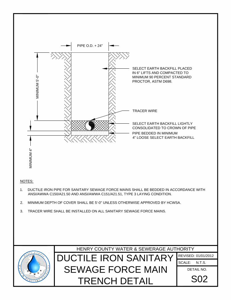
SELECT EARTH BACKFILL LIGHTLY
CONSOLIDATED TO CROWN OF PIPE
TRACER WIRE
SELECT EARTH BACKFILL PLACED
IN 6" LIFTS AND COMPACTED TO
MINIMUM 90 PERCENT STANDARD
PROCTOR, ASTM D698.
PIPE O.D. + 24"
NOTES:
1. DUCTILE IRON PIPE FOR SANITARY SEWAGE FORCE MAINS SHALL BE BEDDED IN ACCORDANCE WITH
ANSI/AWWA C150/A21.50 AND ANSI/AWWA C151/A21.51, TYPE 3 LAYING CONDITION.
2. MINIMUM DEPTH OF COVER SHALL BE 5'-0" UNLESS OTHERWISE APPROVED BY HCWSA.
3. TRACER WIRE SHALL BE INSTALLED ON ALL SANITARY SEWAGE FORCE MAINS.
MIN
IM
UM
4
"
MIN
IM
UM
5
'-0
"
PIPE BEDDED IN MINIMUM
4" LOOSE SELECT EARTH BACKFILL
HENRY COUNTY WATER & SEWERAGE AUTHORITY
REVISED:
SCALE:
DETAIL NO.
DUCTILE IRON SANITARY
SEWAGE FORCE MAIN
TRENCH DETAIL
S02
01/01/2012
N.T.S.
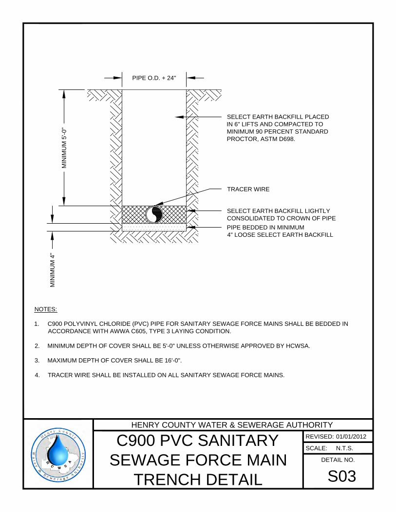
NOTES:
1. C900 POLYVINYL CHLORIDE (PVC) PIPE FOR SANITARY SEWAGE FORCE MAINS SHALL BE BEDDED IN
ACCORDANCE WITH AWWA C605, TYPE 3 LAYING CONDITION.
2. MINIMUM DEPTH OF COVER SHALL BE 5'-0" UNLESS OTHERWISE APPROVED BY HCWSA.
3. MAXIMUM DEPTH OF COVER SHALL BE 16'-0".
4. TRACER WIRE SHALL BE INSTALLED ON ALL SANITARY SEWAGE FORCE MAINS.
SELECT EARTH BACKFILL LIGHTLY
CONSOLIDATED TO CROWN OF PIPE
TRACER WIRE
SELECT EARTH BACKFILL PLACED
IN 6" LIFTS AND COMPACTED TO
MINIMUM 90 PERCENT STANDARD
PROCTOR, ASTM D698.
PIPE O.D. + 24"
MIN
IM
UM
4
"
MIN
IM
UM
5
'-0
"
PIPE BEDDED IN MINIMUM
4" LOOSE SELECT EARTH BACKFILL
HENRY COUNTY WATER & SEWERAGE AUTHORITY
REVISED:
SCALE:
DETAIL NO.
C900 PVC SANITARY
SEWAGE FORCE MAIN
TRENCH DETAIL
S03
01/01/2012
N.T.S.
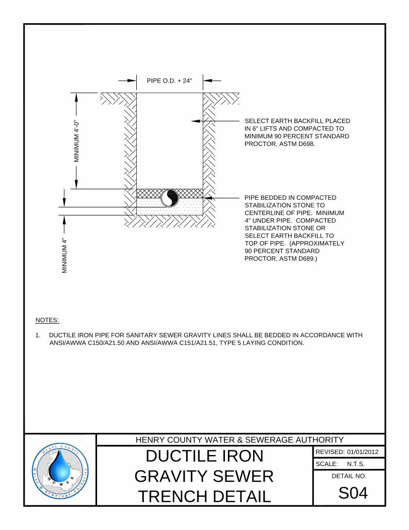
PIPE BEDDED IN COMPACTED
STABILIZATION STONE TO
CENTERLINE OF PIPE. MINIMUM
4" UNDER PIPE. COMPACTED
STABILIZATION STONE OR
SELECT EARTH BACKFILL TO
TOP OF PIPE. (APPROXIMATELY
90 PERCENT STANDARD
PROCTOR, ASTM D689.)
PIPE O.D. + 24"
NOTES:
1. DUCTILE IRON PIPE FOR SANITARY SEWER GRAVITY LINES SHALL BE BEDDED IN ACCORDANCE WITH
ANSI/AWWA C150/A21.50 AND ANSI/AWWA C151/A21.51, TYPE 5 LAYING CONDITION.
MIN
IM
UM
4
"
MIN
IM
UM
4
'-0
"
SELECT EARTH BACKFILL PLACED
IN 6" LIFTS AND COMPACTED TO
MINIMUM 90 PERCENT STANDARD
PROCTOR, ASTM D698.
HENRY COUNTY WATER & SEWERAGE AUTHORITY
REVISED:
SCALE:
DETAIL NO.
DUCTILE IRON
GRAVITY SEWER
TRENCH DETAIL
S04
01/01/2012
N.T.S.
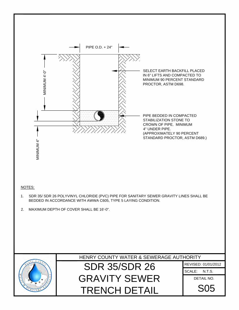
PIPE BEDDED IN COMPACTED
STABILIZATION STONE TO
CROWN OF PIPE. MINIMUM
4" UNDER PIPE.
(APPROXIMATELY 90 PERCENT
STANDARD PROCTOR, ASTM D689.)
PIPE O.D. + 24"
NOTES:
1. SDR 35/ SDR 26 POLYVINYL CHLORIDE (PVC) PIPE FOR SANITARY SEWER GRAVITY LINES SHALL BE
BEDDED IN ACCORDANCE WITH AWWA C605, TYPE 5 LAYING CONDITION.
2. MAXIMUM DEPTH OF COVER SHALL BE 16'-0".
MIN
IM
UM
4
"
MIN
IM
UM
4
'-0
"
SELECT EARTH BACKFILL PLACED
IN 6" LIFTS AND COMPACTED TO
MINIMUM 90 PERCENT STANDARD
PROCTOR, ASTM D698.
HENRY COUNTY WATER & SEWERAGE AUTHORITY
REVISED:
SCALE:
DETAIL NO.
SDR 35/SDR 26
GRAVITY SEWER
TRENCH DETAIL
S05
01/01/2012
N.T.S.
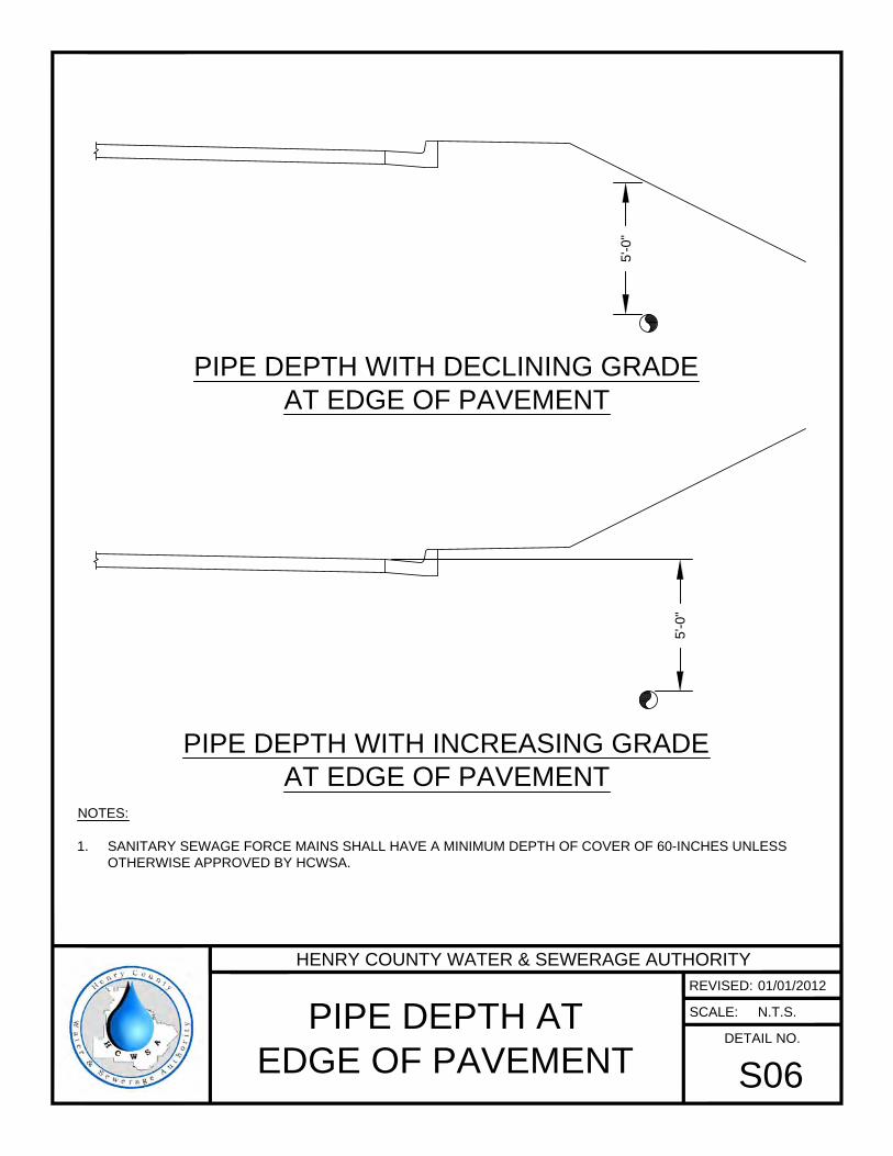
5'-0
"
5'-0
"
NOTES:
1. SANITARY SEWAGE FORCE MAINS SHALL HAVE A MINIMUM DEPTH OF COVER OF 60-INCHES UNLESS
OTHERWISE APPROVED BY HCWSA.
PIPE DEPTH WITH DECLINING GRADE
AT EDGE OF PAVEMENT
PIPE DEPTH WITH INCREASING GRADE
AT EDGE OF PAVEMENT
HENRY COUNTY WATER & SEWERAGE AUTHORITY
REVISED:
SCALE:
DETAIL NO.
PIPE DEPTH AT
EDGE OF PAVEMENT
S06
01/01/2012
N.T.S.

48" DIAMETER
BASE SECTION
48" DIAMETER
RISER SECTION
48" DIAMETER
ECCENTRIC
CONE SECTION
PREFORMED BUTYL
JOINT SEAL (TYP.)
POLYPROPYLENE
MANHOLE STEP
SPACED AT 12" O.C.
(TYP.)
CAST IRON MANHOLE
FRAME AND COVER
(COVER TO BE MARKED
"SEWER")
IN PAVEMENTOUT OF PAVEMENT
2'-0
"
GRADE RINGS OR BRICK
WHEN REQUIRED
(MAX. ADJUSTMENT = 12")
NOTES:
1. MANHOLES LOCATED OUTSIDE OF PAVEMENT SHALL HAVE BOLT-DOWN LIDS.
2. MANHOLES SHALL HAVE A MINIMUM DROP OF 0.10 FEET FROM INFLUENT INVERT TO EFFLUENT INVERT.
NO. 57 STABILIZATION STONE
12" 12"
12
"
PRECAST, SOLID
CONCRETE, OR
BRICK INVERT
HENRY COUNTY WATER & SEWERAGE AUTHORITY
REVISED:
SCALE:
DETAIL NO.
STANDARD SANITARY
SEWER MANHOLE
S07
01/01/2012
N.T.S.
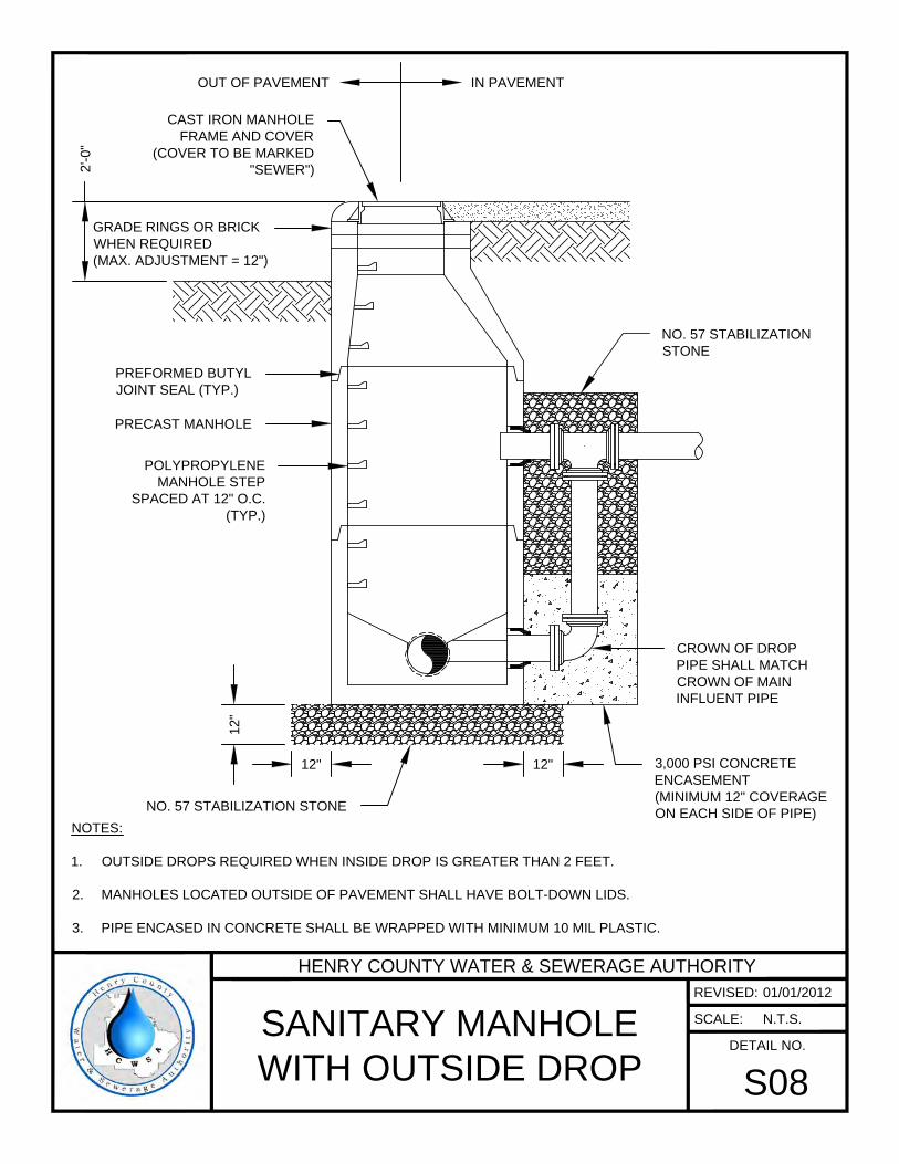
POLYPROPYLENE
MANHOLE STEP
SPACED AT 12" O.C.
(TYP.)
CAST IRON MANHOLE
FRAME AND COVER
(COVER TO BE MARKED
"SEWER")
IN PAVEMENTOUT OF PAVEMENT
2'-0
"
NOTES:
1. OUTSIDE DROPS REQUIRED WHEN INSIDE DROP IS GREATER THAN 2 FEET.
2. MANHOLES LOCATED OUTSIDE OF PAVEMENT SHALL HAVE BOLT-DOWN LIDS.
3. PIPE ENCASED IN CONCRETE SHALL BE WRAPPED WITH MINIMUM 10 MIL PLASTIC.
NO. 57 STABILIZATION STONE
12"
12
"
PREFORMED BUTYL
JOINT SEAL (TYP.)
PRECAST MANHOLE
12"
CROWN OF DROP
PIPE SHALL MATCH
CROWN OF MAIN
INFLUENT PIPE
3,000 PSI CONCRETE
ENCASEMENT
(MINIMUM 12" COVERAGE
ON EACH SIDE OF PIPE)
GRADE RINGS OR BRICK
WHEN REQUIRED
(MAX. ADJUSTMENT = 12")
NO. 57 STABILIZATION
STONE
HENRY COUNTY WATER & SEWERAGE AUTHORITY
REVISED:
SCALE:
DETAIL NO.
SANITARY MANHOLE
WITH OUTSIDE DROP
S08
01/01/2012
N.T.S.
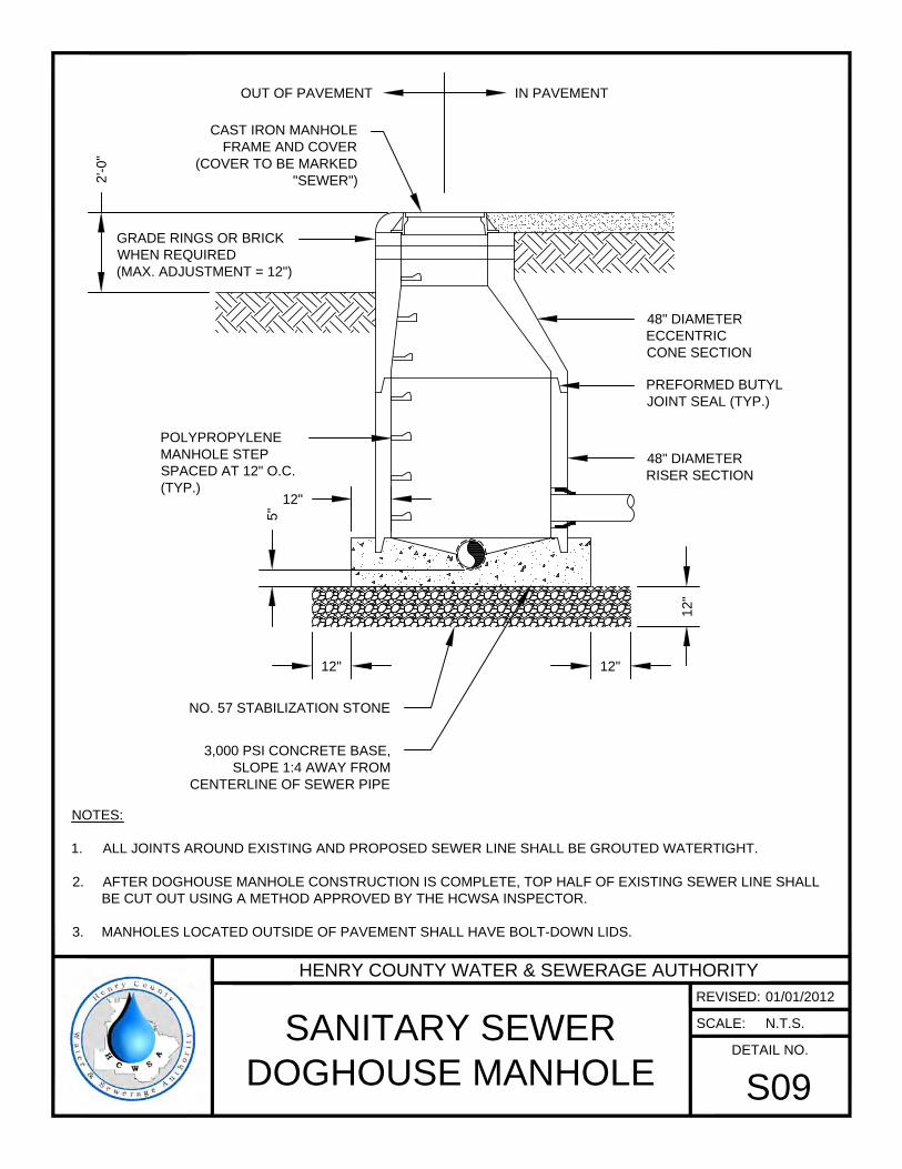
48" DIAMETER
RISER SECTION
48" DIAMETER
ECCENTRIC
CONE SECTION
PREFORMED BUTYL
JOINT SEAL (TYP.)
POLYPROPYLENE
MANHOLE STEP
SPACED AT 12" O.C.
(TYP.)
CAST IRON MANHOLE
FRAME AND COVER
(COVER TO BE MARKED
"SEWER")
IN PAVEMENTOUT OF PAVEMENT
2'-0
"
NOTES:
1. ALL JOINTS AROUND EXISTING AND PROPOSED SEWER LINE SHALL BE GROUTED WATERTIGHT.
2. AFTER DOGHOUSE MANHOLE CONSTRUCTION IS COMPLETE, TOP HALF OF EXISTING SEWER LINE SHALL
BE CUT OUT USING A METHOD APPROVED BY THE HCWSA INSPECTOR.
3. MANHOLES LOCATED OUTSIDE OF PAVEMENT SHALL HAVE BOLT-DOWN LIDS.
NO. 57 STABILIZATION STONE
12" 12"
12
"
3,000 PSI CONCRETE BASE,
SLOPE 1:4 AWAY FROM
CENTERLINE OF SEWER PIPE
5"
12"
GRADE RINGS OR BRICK
WHEN REQUIRED
(MAX. ADJUSTMENT = 12")
HENRY COUNTY WATER & SEWERAGE AUTHORITY
REVISED:
SCALE:
DETAIL NO.
SANITARY SEWER
DOGHOUSE MANHOLE
S09
01/01/2012
N.T.S.
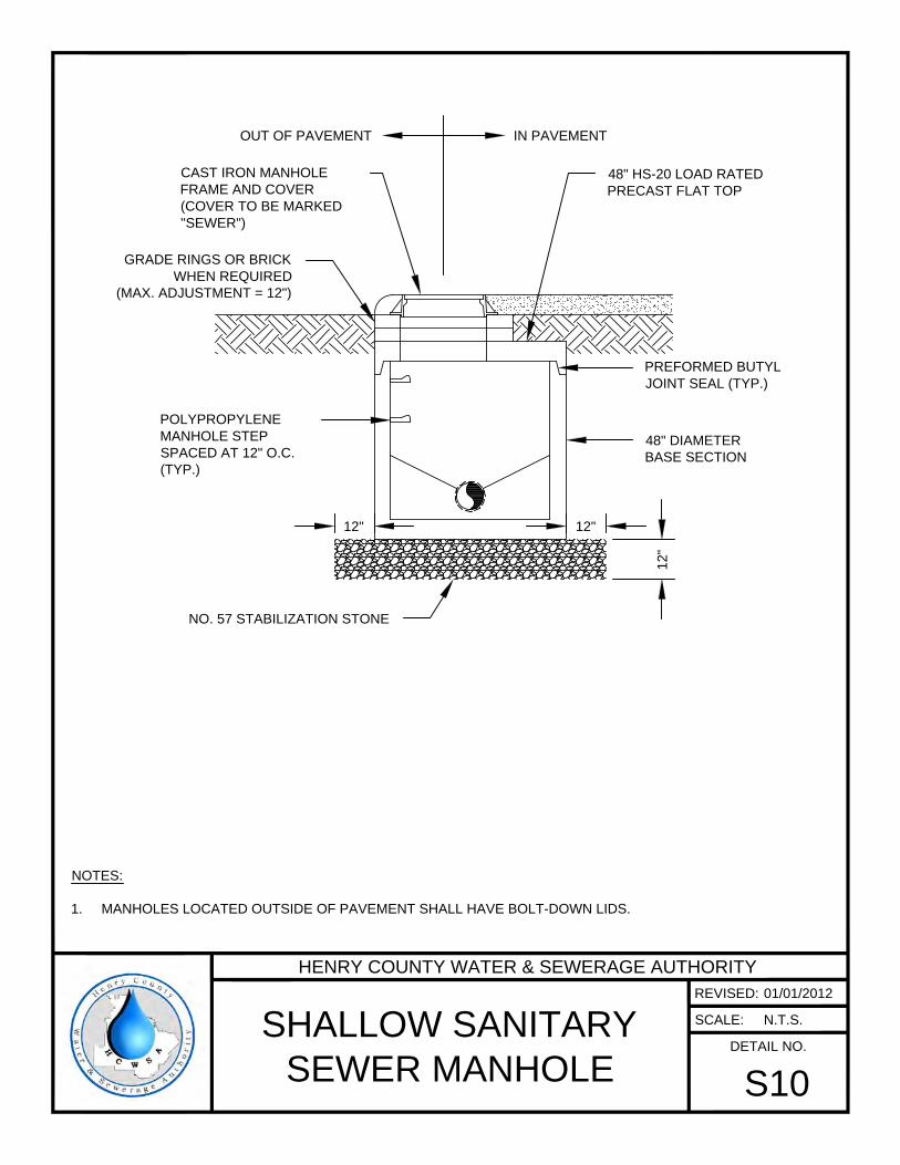
48" DIAMETER
BASE SECTION
PREFORMED BUTYL
JOINT SEAL (TYP.)
POLYPROPYLENE
MANHOLE STEP
SPACED AT 12" O.C.
(TYP.)
CAST IRON MANHOLE
FRAME AND COVER
(COVER TO BE MARKED
"SEWER")
IN PAVEMENTOUT OF PAVEMENT
NOTES:
1. MANHOLES LOCATED OUTSIDE OF PAVEMENT SHALL HAVE BOLT-DOWN LIDS.
NO. 57 STABILIZATION STONE
12" 12"
12
"
48" HS-20 LOAD RATED
PRECAST FLAT TOP
GRADE RINGS OR BRICK
WHEN REQUIRED
(MAX. ADJUSTMENT = 12")
HENRY COUNTY WATER & SEWERAGE AUTHORITY
REVISED:
SCALE:
DETAIL NO.
SHALLOW SANITARY
SEWER MANHOLE
S10
01/01/2012
N.T.S.
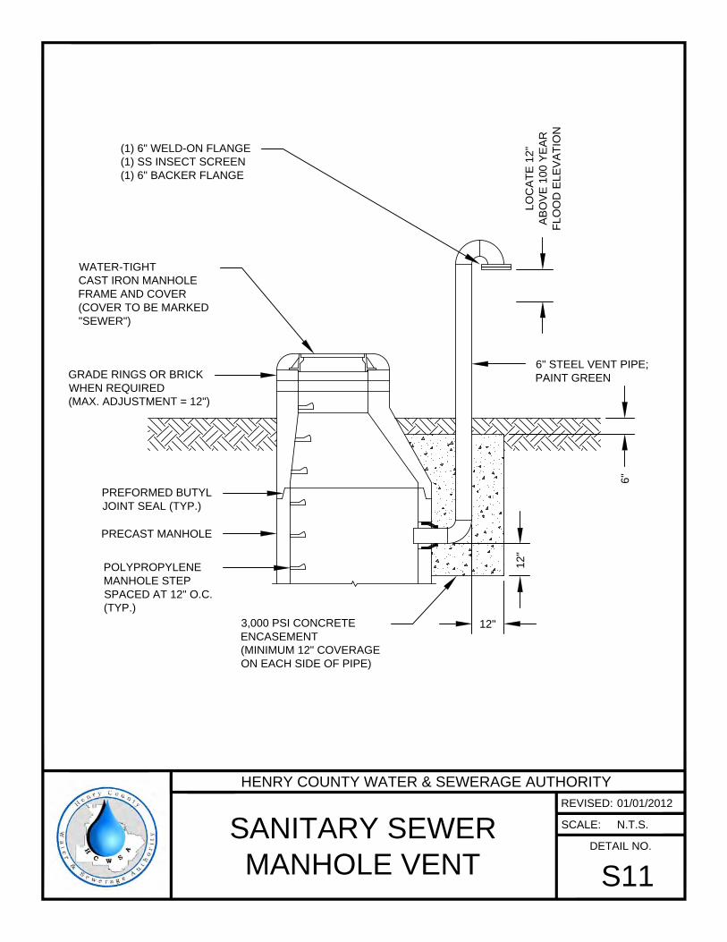
POLYPROPYLENE
MANHOLE STEP
SPACED AT 12" O.C.
(TYP.)
WATER-TIGHT
CAST IRON MANHOLE
FRAME AND COVER
(COVER TO BE MARKED
"SEWER")
PREFORMED BUTYL
JOINT SEAL (TYP.)
PRECAST MANHOLE
LO
CA
TE
1
2"
AB
OV
E 1
00
Y
EA
R
FL
OO
D E
LE
VA
TIO
N
(1) 6" WELD-ON FLANGE
(1) SS INSECT SCREEN
(1) 6" BACKER FLANGE
6" STEEL VENT PIPE;
PAINT GREEN
6"
12
"
12"
3,000 PSI CONCRETE
ENCASEMENT
(MINIMUM 12" COVERAGE
ON EACH SIDE OF PIPE)
GRADE RINGS OR BRICK
WHEN REQUIRED
(MAX. ADJUSTMENT = 12")
HENRY COUNTY WATER & SEWERAGE AUTHORITY
REVISED:
SCALE:
DETAIL NO.
SANITARY SEWER
MANHOLE VENT
S11
01/01/2012
N.T.S.
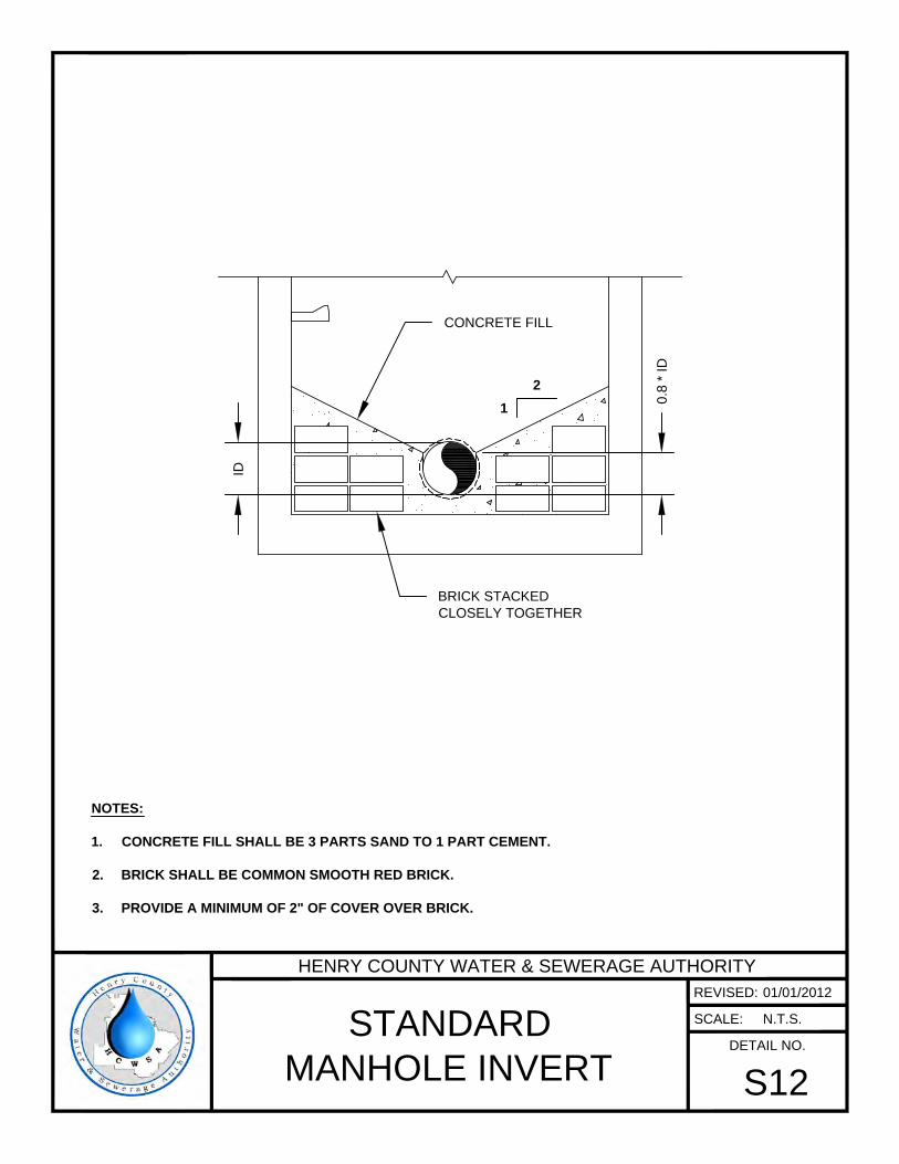
ID
0.8
* ID
2
1
BRICK STACKED
CLOSELY TOGETHER
CONCRETE FILL
NOTES:
1. CONCRETE FILL SHALL BE 3 PARTS SAND TO 1 PART CEMENT.
2. BRICK SHALL BE COMMON SMOOTH RED BRICK.
3. PROVIDE A MINIMUM OF 2" OF COVER OVER BRICK.
HENRY COUNTY WATER & SEWERAGE AUTHORITY
REVISED:
SCALE:
DETAIL NO.
STANDARD
MANHOLE INVERT
S12
01/01/2012
N.T.S.
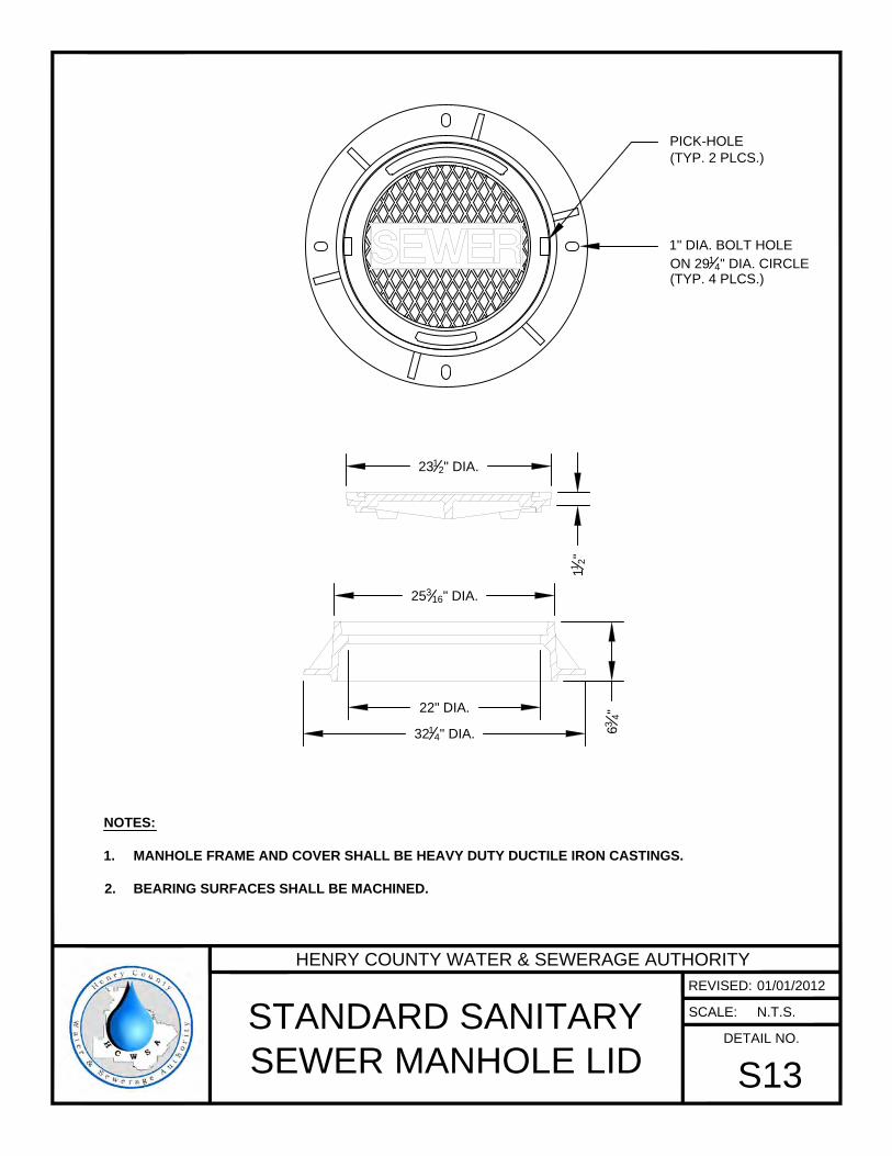
23
1
2
" DIA.
1
1
2
"
25
3
16
" DIA.
6
3
4
"
32
1
4
" DIA.
22" DIA.
PICK-HOLE
(TYP. 2 PLCS.)
1" DIA. BOLT HOLE
ON 29
1
4
" DIA. CIRCLE
(TYP. 4 PLCS.)
NOTES:
1. MANHOLE FRAME AND COVER SHALL BE HEAVY DUTY DUCTILE IRON CASTINGS.
2. BEARING SURFACES SHALL BE MACHINED.
HENRY COUNTY WATER & SEWERAGE AUTHORITY
REVISED:
SCALE:
DETAIL NO.
STANDARD SANITARY
SEWER MANHOLE LID
S13
01/01/2012
N.T.S.
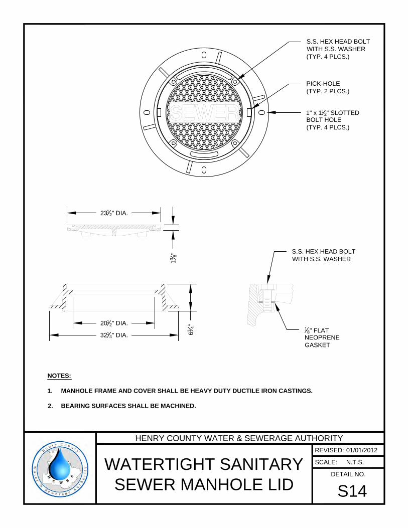
23
1
2
" DIA.
1
3
8
"
6
3
4
"
32
1
4
" DIA.
20
1
2
" DIA.
NOTES:
1. MANHOLE FRAME AND COVER SHALL BE HEAVY DUTY DUCTILE IRON CASTINGS.
2. BEARING SURFACES SHALL BE MACHINED.
S.S. HEX HEAD BOLT
WITH S.S. WASHER
1
8
" FLAT
NEOPRENE
GASKET
PICK-HOLE
(TYP. 2 PLCS.)
1" x 1
1
2
" SLOTTED
BOLT HOLE
(TYP. 4 PLCS.)
S.S. HEX HEAD BOLT
WITH S.S. WASHER
(TYP. 4 PLCS.)
HENRY COUNTY WATER & SEWERAGE AUTHORITY
REVISED:
SCALE:
DETAIL NO.
WATERTIGHT SANITARY
SEWER MANHOLE LID
S14
01/01/2012
N.T.S.
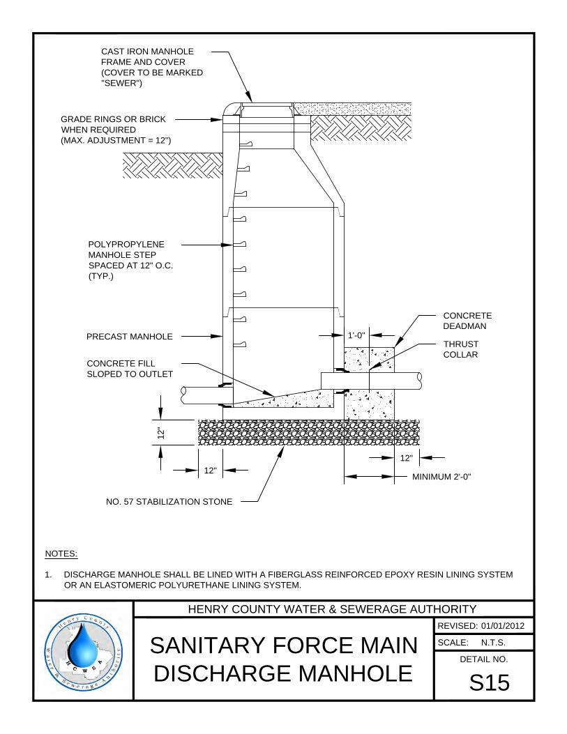
POLYPROPYLENE
MANHOLE STEP
SPACED AT 12" O.C.
(TYP.)
PRECAST MANHOLE
NOTES:
1. DISCHARGE MANHOLE SHALL BE LINED WITH A FIBERGLASS REINFORCED EPOXY RESIN LINING SYSTEM
OR AN ELASTOMERIC POLYURETHANE LINING SYSTEM.
CAST IRON MANHOLE
FRAME AND COVER
(COVER TO BE MARKED
"SEWER")
CONCRETE FILL
SLOPED TO OUTLET
MINIMUM 2'-0"
THRUST
COLLAR
1'-0"
CONCRETE
DEADMAN
12
"
12"
12"
NO. 57 STABILIZATION STONE
GRADE RINGS OR BRICK
WHEN REQUIRED
(MAX. ADJUSTMENT = 12")
HENRY COUNTY WATER & SEWERAGE AUTHORITY
REVISED:
SCALE:
DETAIL NO.
SANITARY FORCE MAIN
DISCHARGE MANHOLE
S15
01/01/2012
N.T.S.
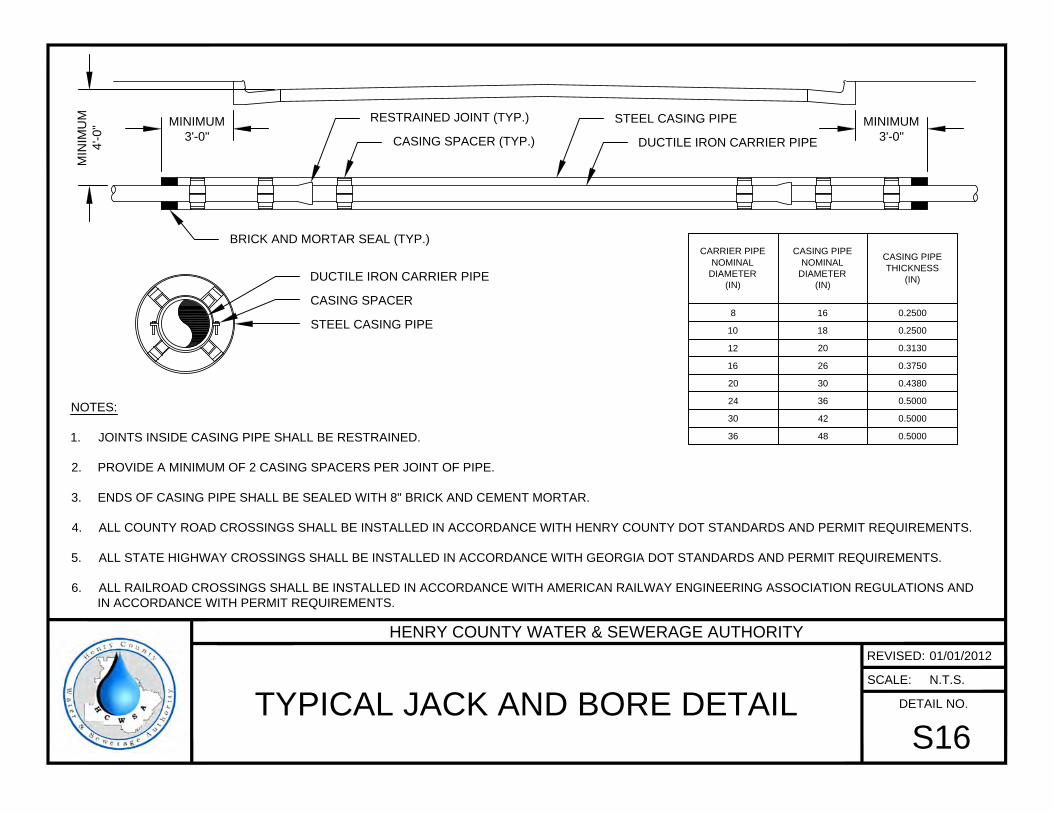
NOTES:
1. JOINTS INSIDE CASING PIPE SHALL BE RESTRAINED.
2. PROVIDE A MINIMUM OF 2 CASING SPACERS PER JOINT OF PIPE.
3. ENDS OF CASING PIPE SHALL BE SEALED WITH 8" BRICK AND CEMENT MORTAR.
4. ALL COUNTY ROAD CROSSINGS SHALL BE INSTALLED IN ACCORDANCE WITH HENRY COUNTY DOT STANDARDS AND PERMIT REQUIREMENTS.
5. ALL STATE HIGHWAY CROSSINGS SHALL BE INSTALLED IN ACCORDANCE WITH GEORGIA DOT STANDARDS AND PERMIT REQUIREMENTS.
6. ALL RAILROAD CROSSINGS SHALL BE INSTALLED IN ACCORDANCE WITH AMERICAN RAILWAY ENGINEERING ASSOCIATION REGULATIONS AND
IN ACCORDANCE WITH PERMIT REQUIREMENTS.
MINIMUM
3'-0"
MINIMUM
3'-0"
MIN
IM
UM
4'-0
"
STEEL CASING PIPE
CASING SPACER
DUCTILE IRON CARRIER PIPE
STEEL CASING PIPE
DUCTILE IRON CARRIER PIPE
RESTRAINED JOINT (TYP.)
CASING SPACER (TYP.)
CARRIER PIPE
NOMINAL
DIAMETER
(IN)
CASING PIPE
NOMINAL
DIAMETER
(IN)
CASING PIPE
THICKNESS
(IN)
8 16 0.2500
10 18 0.2500
12 20 0.3130
16 26 0.3750
20 30 0.4380
24 36 0.5000
30 42 0.5000
36 48 0.5000
BRICK AND MORTAR SEAL (TYP.)
HENRY COUNTY WATER & SEWERAGE AUTHORITY
REVISED:
SCALE:
DETAIL NO.
TYPICAL JACK AND BORE DETAIL
S16
01/01/2012
N.T.S.

MINIMUM 10'-0" MINIMUM 10'-0"
MINIMUM 1'-0" MINIMUM 1'-0"
TOP OF BANK
MINIMUM 12"
RIP-RAP
CASING PIPE (NOTES 2 AND 3)
NOTES:
1. PIPE USED FOR CREEK CROSSINGS SHALL BE DUCTILE IRON PIPE. JOINTS SHALL BE RESTRAINED FOR A MINIMUM OF 20 FEET BEYOND TOP
OF BANK ON EACH SIDE OF CREEK.
2. CASING PIPE IS REQUIRED WHEN DEPTH OF COVER IS LESS THAN 3 FEET.
3. REFER TO DETAIL S16 FOR CASING DIAMETER.
4. PLACE STONE RIP-RAP APPROXIMATELY 5 FEET UPSTREAM AND 5 FEET DOWNSTREAM FROM CENTERLINE OF PIPE ALONG CREEK BED.
NO
TE
2
RESTRAINED JOINT (TYP.)
HENRY COUNTY WATER & SEWERAGE AUTHORITY
REVISED:
SCALE:
DETAIL NO.
CREEK CROSSING
S17
01/01/2012
N.T.S.
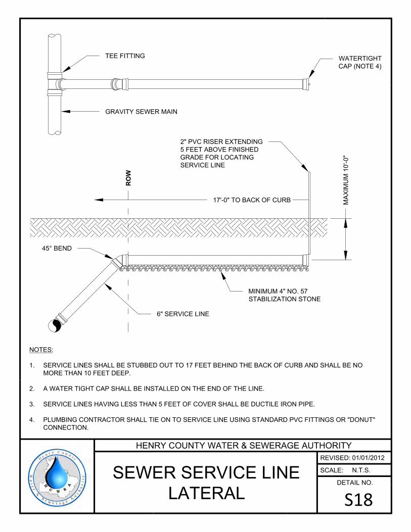
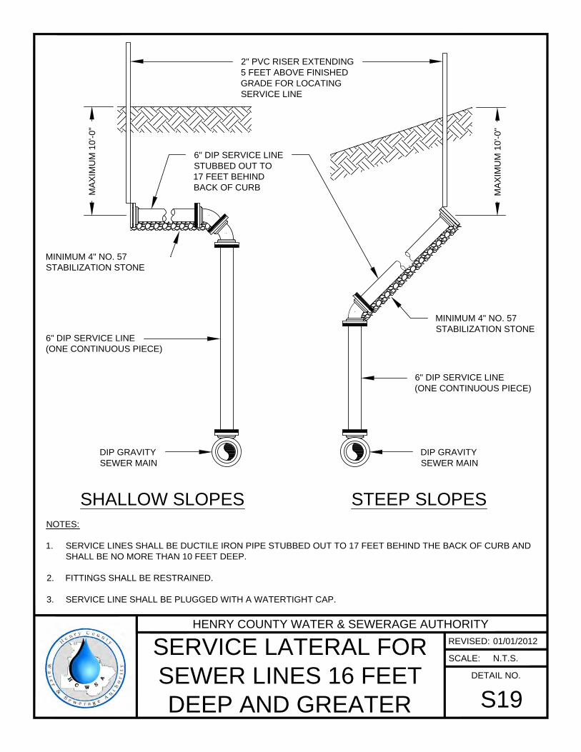
STEEP SLOPESSHALLOW SLOPES
6" DIP SERVICE LINE
(ONE CONTINUOUS PIECE)
6" DIP SERVICE LINE
(ONE CONTINUOUS PIECE)
MINIMUM 4" NO. 57
STABILIZATION STONE
6" DIP SERVICE LINE
STUBBED OUT TO
17 FEET BEHIND
BACK OF CURB
MINIMUM 4" NO. 57
STABILIZATION STONE
2" PVC RISER EXTENDING
5 FEET ABOVE FINISHED
GRADE FOR LOCATING
SERVICE LINE
NOTES:
1. SERVICE LINES SHALL BE DUCTILE IRON PIPE STUBBED OUT TO 17 FEET BEHIND THE BACK OF CURB AND
SHALL BE NO MORE THAN 10 FEET DEEP.
2. FITTINGS SHALL BE RESTRAINED.
3. SERVICE LINE SHALL BE PLUGGED WITH A WATERTIGHT CAP.
MA
XIM
UM
1
0'-0
"
MA
XIM
UM
1
0'-0
"
DIP GRAVITY
SEWER MAIN
DIP GRAVITY
SEWER MAIN
HENRY COUNTY WATER & SEWERAGE AUTHORITY
REVISED:
SCALE:
DETAIL NO.
SERVICE LATERAL FOR
SEWER LINES 16 FEET
DEEP AND GREATER
S19
01/01/2012
N.T.S.
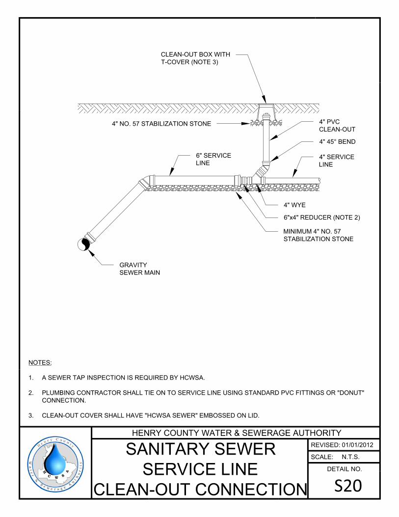
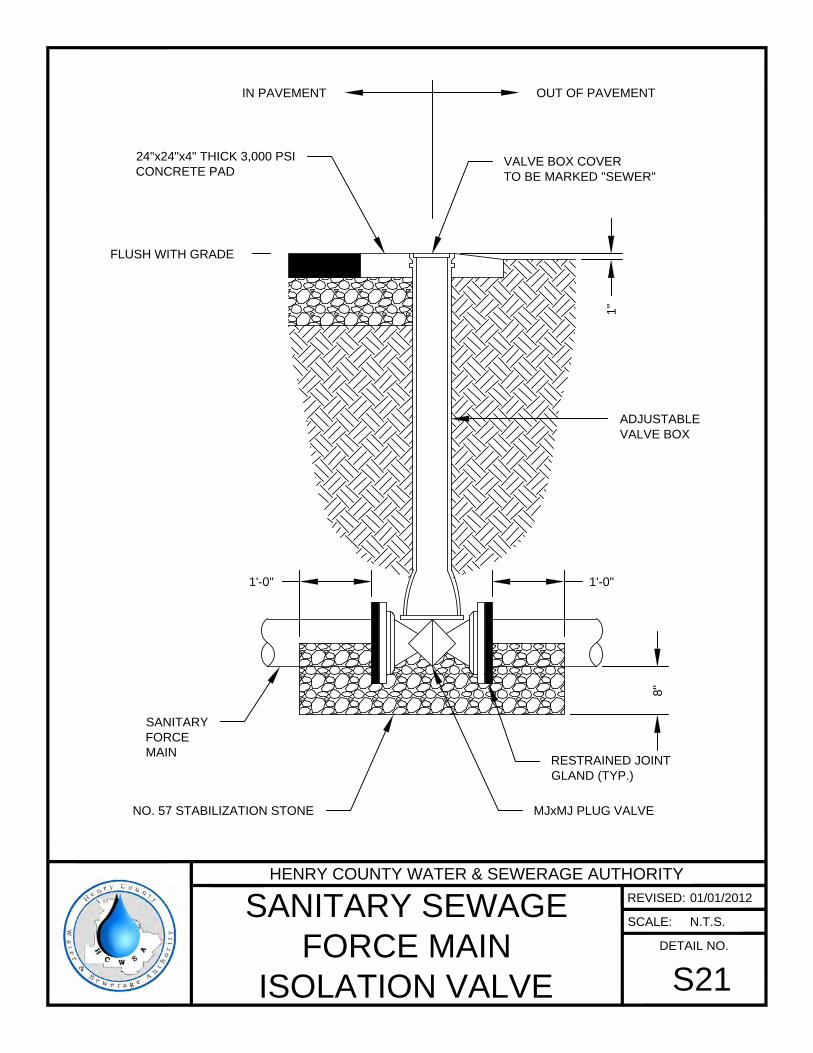
1'-0"1'-0"
VALVE BOX COVER
TO BE MARKED "SEWER"
OUT OF PAVEMENTIN PAVEMENT
24"x24"x4" THICK 3,000 PSI
CONCRETE PAD
FLUSH WITH GRADE
1"
ADJUSTABLE
VALVE BOX
RESTRAINED JOINT
GLAND (TYP.)
MJxMJ PLUG VALVE
SANITARY
FORCE
MAIN
8"
NO. 57 STABILIZATION STONE
HENRY COUNTY WATER & SEWERAGE AUTHORITY
REVISED:
SCALE:
DETAIL NO.
SANITARY SEWAGE
FORCE MAIN
ISOLATION VALVE
S21
01/01/2012
N.T.S.
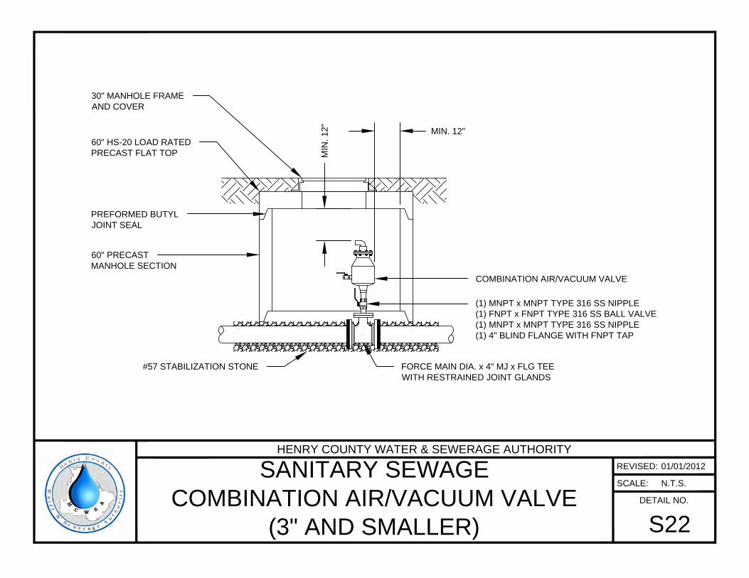
(1) MNPT x MNPT TYPE 316 SS NIPPLE
(1) FNPT x FNPT TYPE 316 SS BALL VALVE
(1) MNPT x MNPT TYPE 316 SS NIPPLE
(1) 4" BLIND FLANGE WITH FNPT TAP
COMBINATION AIR/VACUUM VALVE
60" HS-20 LOAD RATED
PRECAST FLAT TOP
PREFORMED BUTYL
JOINT SEAL
60" PRECAST
MANHOLE SECTION
30" MANHOLE FRAME
AND COVER
MIN
. 1
2"
MIN. 12"
FORCE MAIN DIA. x 4" MJ x FLG TEE
WITH RESTRAINED JOINT GLANDS
#57 STABILIZATION STONE
HENRY COUNTY WATER & SEWERAGE AUTHORITY
REVISED:
SCALE:
DETAIL NO.
SANITARY SEWAGE
COMBINATION AIR/VACUUM VALVE
(3" AND SMALLER)
S22
01/01/2012
N.T.S.
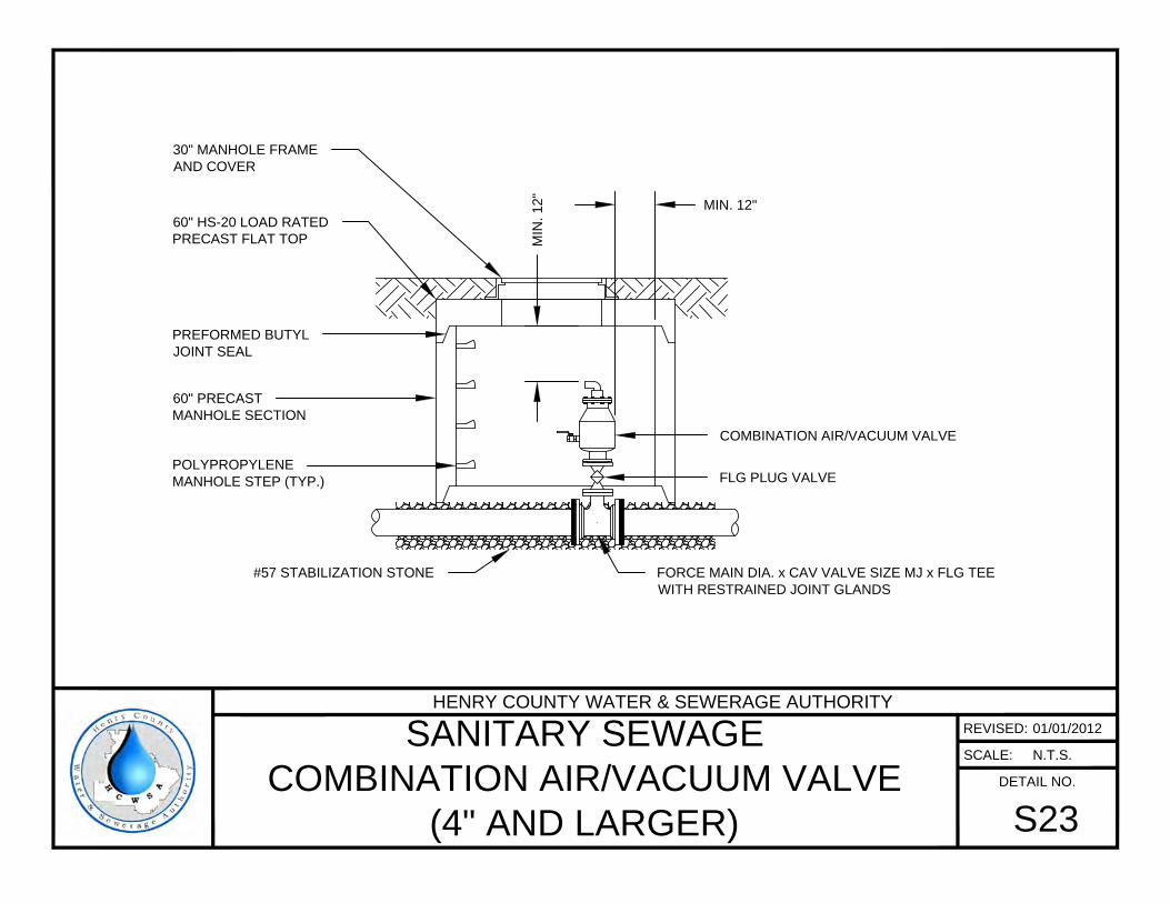
FLG PLUG VALVE
COMBINATION AIR/VACUUM VALVE
60" HS-20 LOAD RATED
PRECAST FLAT TOP
PREFORMED BUTYL
JOINT SEAL
60" PRECAST
MANHOLE SECTION
POLYPROPYLENE
MANHOLE STEP (TYP.)
30" MANHOLE FRAME
AND COVER
MIN
. 1
2"
MIN. 12"
FORCE MAIN DIA. x CAV VALVE SIZE MJ x FLG TEE
WITH RESTRAINED JOINT GLANDS
#57 STABILIZATION STONE
HENRY COUNTY WATER & SEWERAGE AUTHORITY
REVISED:
SCALE:
DETAIL NO.
SANITARY SEWAGE
COMBINATION AIR/VACUUM VALVE
(4" AND LARGER)
S23
01/01/2012
N.T.S.
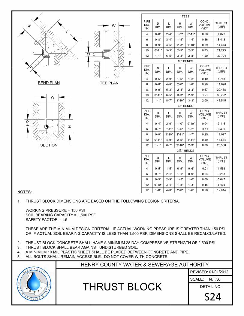
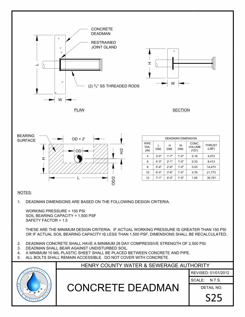
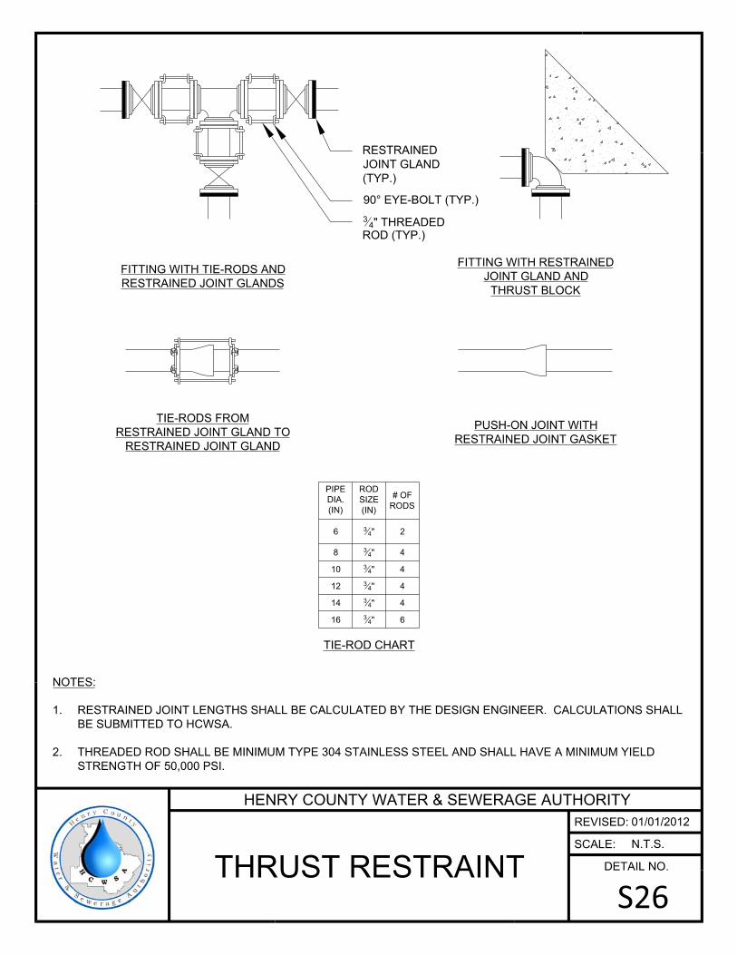

100'
20' 60' 20'
10
0'
20
'6
0'
20
'
30'
12'
15'
15
'
15
'
15'
GENERATOR
LIFT STATION
CHAIN LINK
FENCE
EVERGREEN
SHRUBBERY
16' DOUBLE GATE
SCADA TOWER
CONTROL PANEL/
SCADA PANEL
UTILITY POLE
MIN. 1" WATER SERVICE
YARD HYDRANT
HENRY COUNTY WATER & SEWERAGE AUTHORITY
REVISED:
SCALE:
DETAIL NO.
TYPICAL SANITARY
SEWAGE LIFT STATION
PROPERTY LAYOUT
S27
01/01/2012
N.T.S.
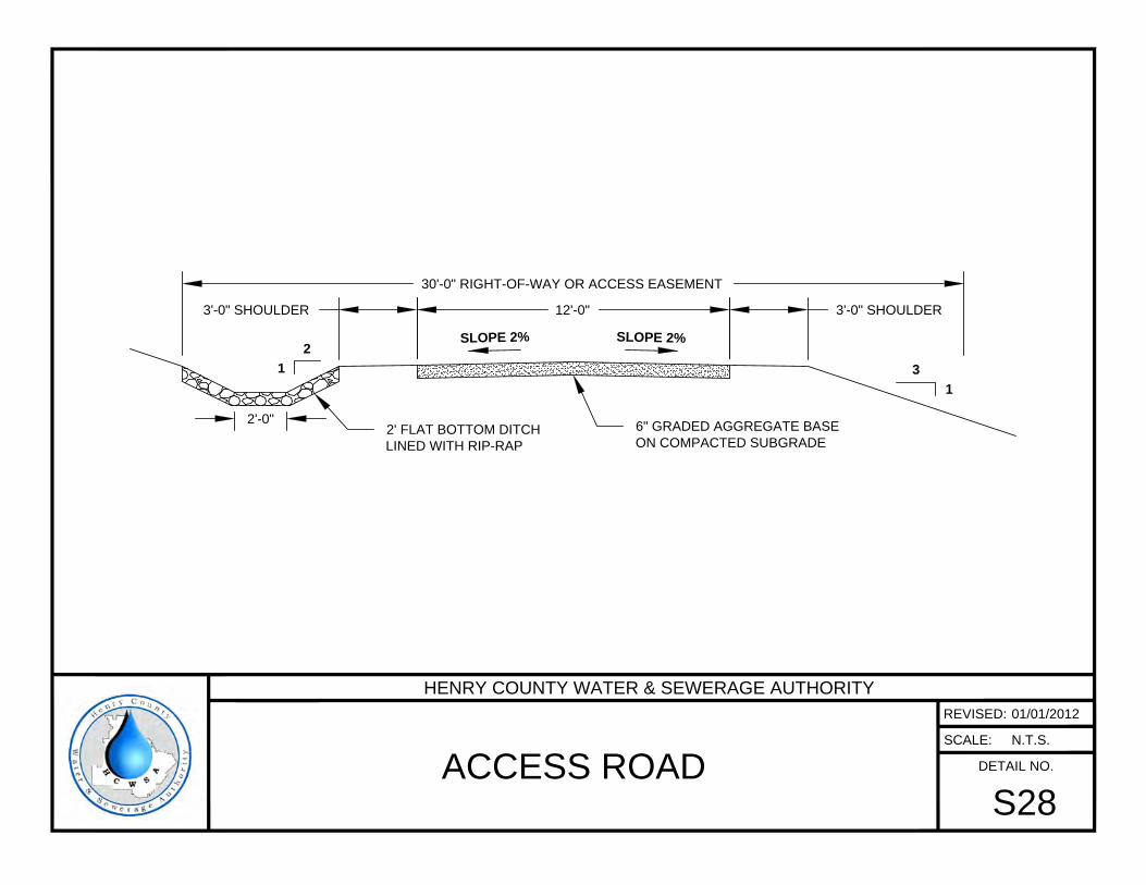
12'-0" 3'-0" SHOULDER3'-0" SHOULDER
30'-0" RIGHT-OF-WAY OR ACCESS EASEMENT
SLOPE 2% SLOPE 2%
6" GRADED AGGREGATE BASE
ON COMPACTED SUBGRADE
2
1
3
1
2'-0"
2' FLAT BOTTOM DITCH
LINED WITH RIP-RAP
HENRY COUNTY WATER & SEWERAGE AUTHORITY
REVISED:
SCALE:
DETAIL NO.
ACCESS ROAD
S28
01/01/2012
N.T.S.
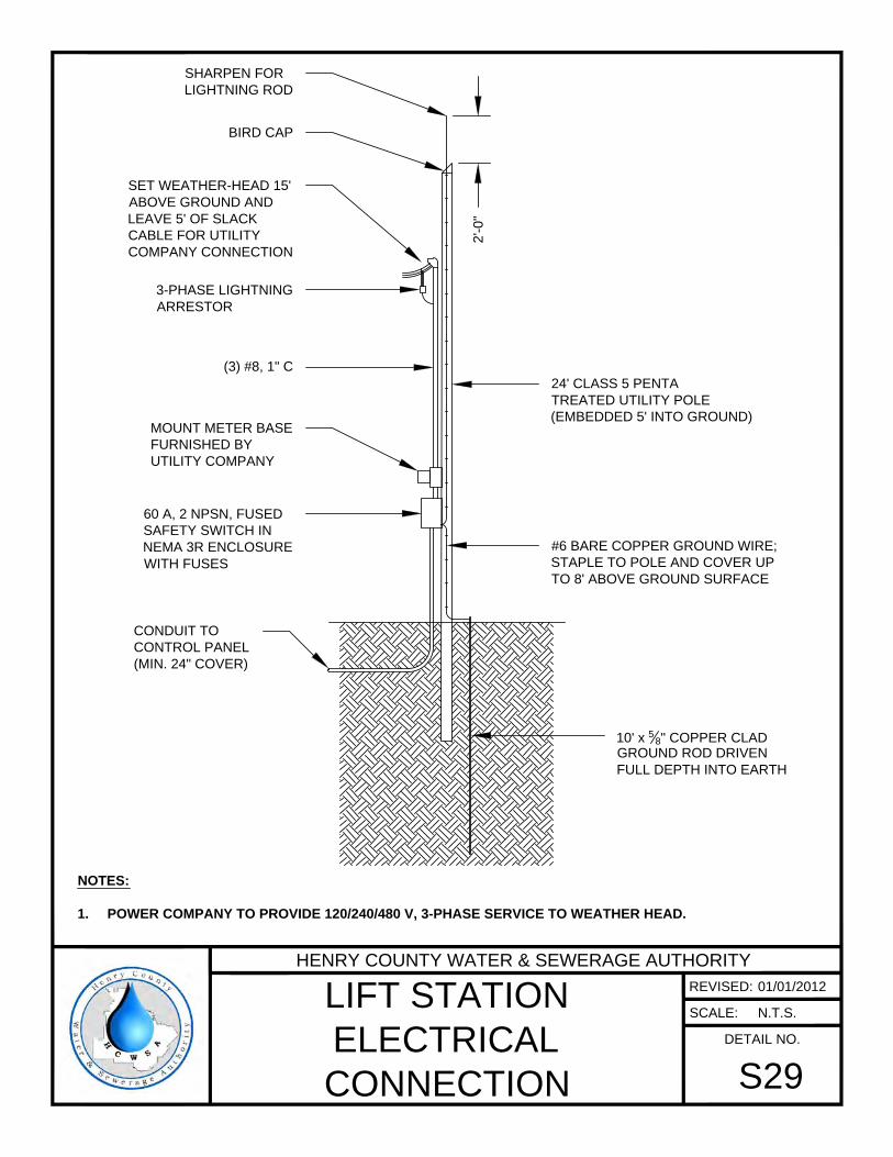
24' CLASS 5 PENTA
TREATED UTILITY POLE
(EMBEDDED 5' INTO GROUND)
10' x
5
8
" COPPER CLAD
GROUND ROD DRIVEN
FULL DEPTH INTO EARTH
NOTES:
1. POWER COMPANY TO PROVIDE 120/240/480 V, 3-PHASE SERVICE TO WEATHER HEAD.
2'-0
"
SHARPEN FOR
LIGHTNING ROD
3-PHASE LIGHTNING
ARRESTOR
SET WEATHER-HEAD 15'
ABOVE GROUND AND
LEAVE 5' OF SLACK
CABLE FOR UTILITY
COMPANY CONNECTION
(3) #8, 1" C
#6 BARE COPPER GROUND WIRE;
STAPLE TO POLE AND COVER UP
TO 8' ABOVE GROUND SURFACE
60 A, 2 NPSN, FUSED
SAFETY SWITCH IN
NEMA 3R ENCLOSURE
WITH FUSES
MOUNT METER BASE
FURNISHED BY
UTILITY COMPANY
CONDUIT TO
CONTROL PANEL
(MIN. 24" COVER)
BIRD CAP
HENRY COUNTY WATER & SEWERAGE AUTHORITY
REVISED:
SCALE:
DETAIL NO.
LIFT STATION
ELECTRICAL
CONNECTION
S29
01/01/2012
N.T.S.
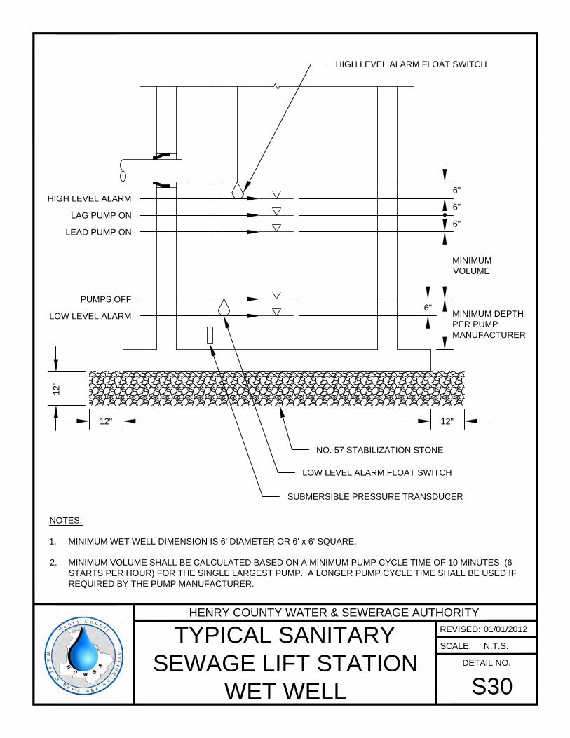
6"
6"
MINIMUM
VOLUME
MINIMUM DEPTH
PER PUMP
MANUFACTURER
HIGH LEVEL ALARM
LAG PUMP ON
LEAD PUMP ON
PUMPS OFF
6"
12"12"
12
"
LOW LEVEL ALARM
6"
LOW LEVEL ALARM FLOAT SWITCH
NO. 57 STABILIZATION STONE
SUBMERSIBLE PRESSURE TRANSDUCER
HIGH LEVEL ALARM FLOAT SWITCH
NOTES:
1. MINIMUM WET WELL DIMENSION IS 6' DIAMETER OR 6' x 6' SQUARE.
2. MINIMUM VOLUME SHALL BE CALCULATED BASED ON A MINIMUM PUMP CYCLE TIME OF 10 MINUTES (6
STARTS PER HOUR) FOR THE SINGLE LARGEST PUMP. A LONGER PUMP CYCLE TIME SHALL BE USED IF
REQUIRED BY THE PUMP MANUFACTURER.
HENRY COUNTY WATER & SEWERAGE AUTHORITY
REVISED:
SCALE:
DETAIL NO.
TYPICAL SANITARY
SEWAGE LIFT STATION
WET WELL
S30
01/01/2012
N.T.S.
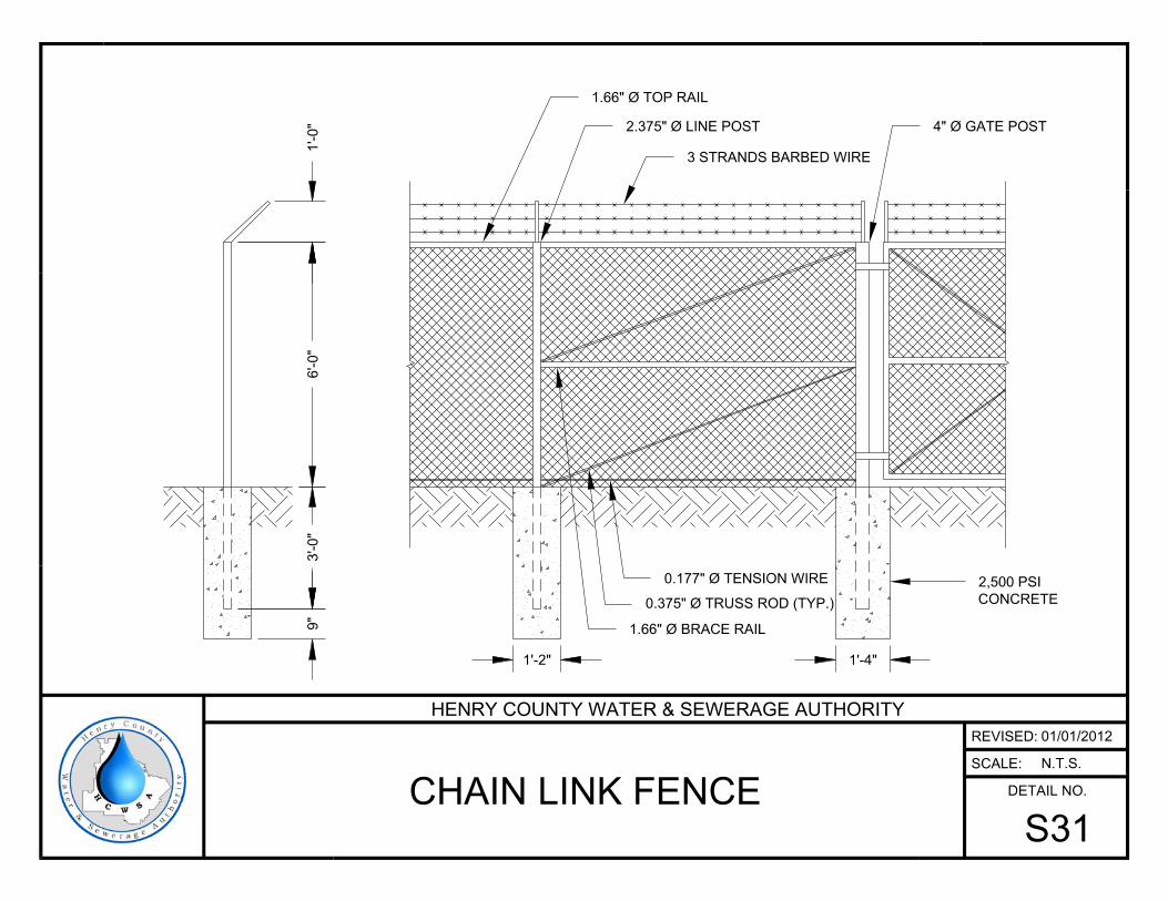
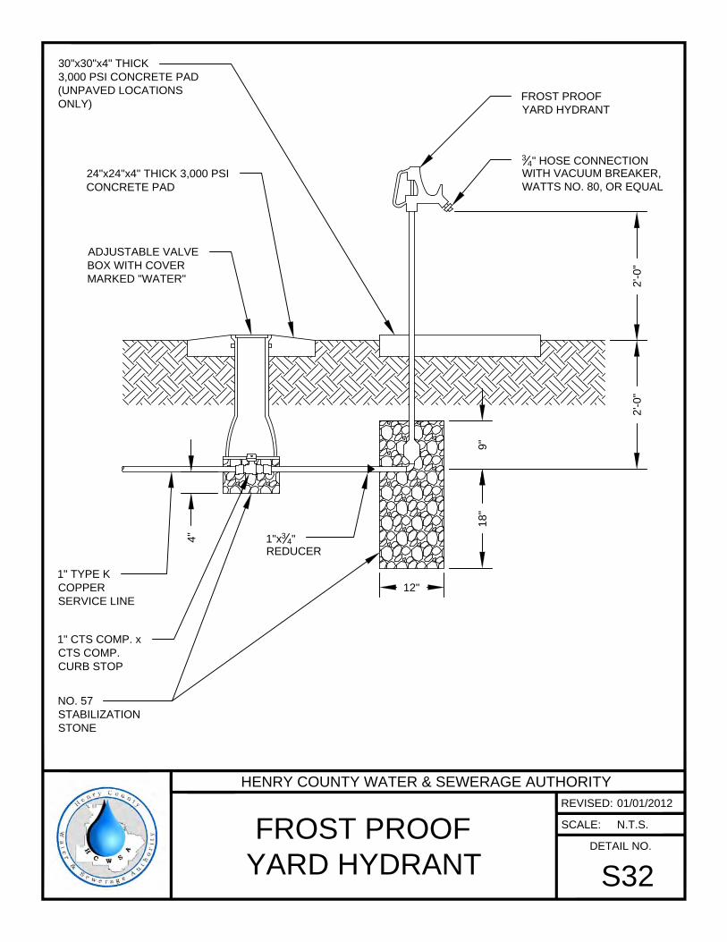
FROST PROOF
YARD HYDRANT
3
4
" HOSE CONNECTION
WITH VACUUM BREAKER,
WATTS NO. 80, OR EQUAL
30"x30"x4" THICK
3,000 PSI CONCRETE PAD
(UNPAVED LOCATIONS
ONLY)
9"
18
"
12"
4"
ADJUSTABLE VALVE
BOX WITH COVER
MARKED "WATER"
24"x24"x4" THICK 3,000 PSI
CONCRETE PAD
1" CTS COMP. x
CTS COMP.
CURB STOP
1" TYPE K
COPPER
SERVICE LINE
1"x
3
4
"
REDUCER
NO. 57
STABILIZATION
STONE
2'-0
"2
'-0
"
HENRY COUNTY WATER & SEWERAGE AUTHORITY
REVISED:
SCALE:
DETAIL NO.
FROST PROOF
YARD HYDRANT
S32
01/01/2012
N.T.S.
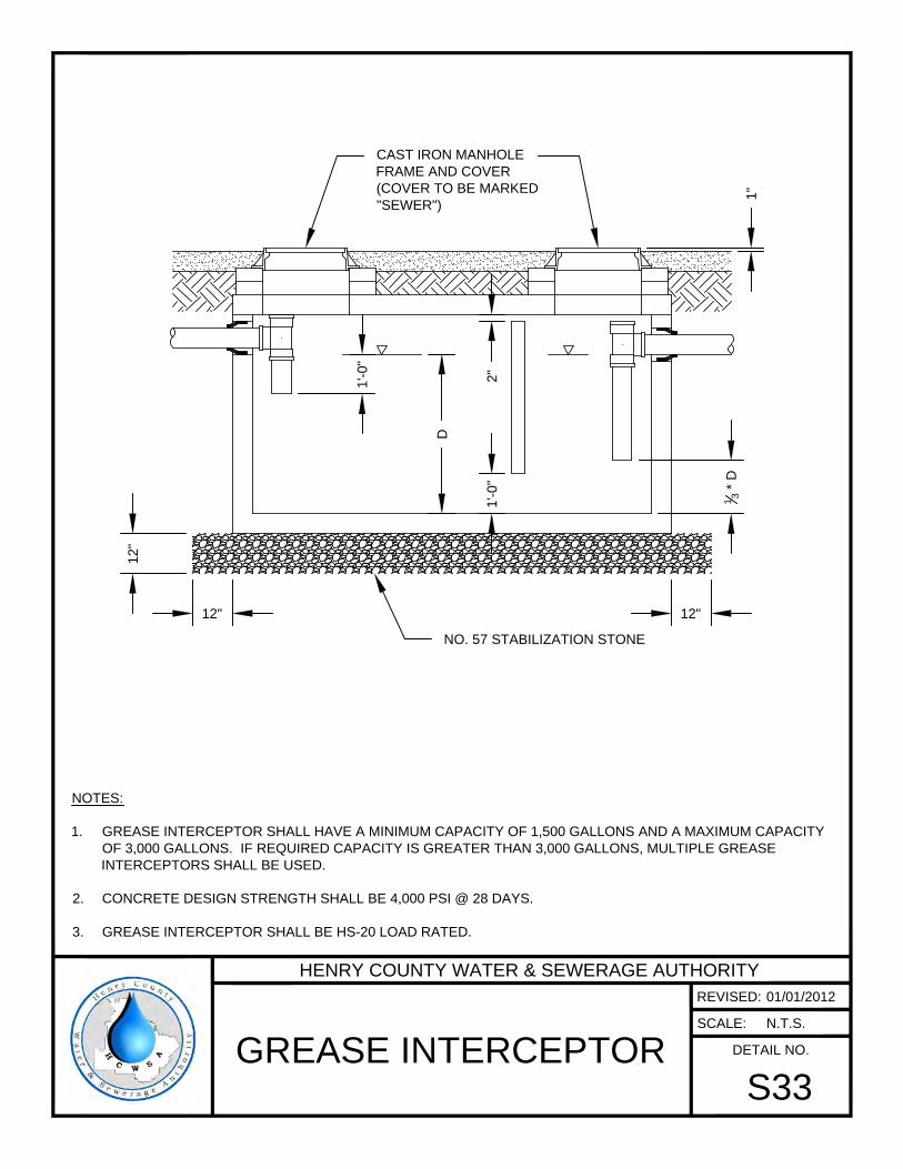
12"
12
"
12"
D
1'-0
"
1
3
* D
NO. 57 STABILIZATION STONE
CAST IRON MANHOLE
FRAME AND COVER
(COVER TO BE MARKED
"SEWER")
1"
NOTES:
1. GREASE INTERCEPTOR SHALL HAVE A MINIMUM CAPACITY OF 1,500 GALLONS AND A MAXIMUM CAPACITY
OF 3,000 GALLONS. IF REQUIRED CAPACITY IS GREATER THAN 3,000 GALLONS, MULTIPLE GREASE
INTERCEPTORS SHALL BE USED.
2. CONCRETE DESIGN STRENGTH SHALL BE 4,000 PSI @ 28 DAYS.
3. GREASE INTERCEPTOR SHALL BE HS-20 LOAD RATED.
1'-0
"2
"
HENRY COUNTY WATER & SEWERAGE AUTHORITY
REVISED:
SCALE:
DETAIL NO.
GREASE INTERCEPTOR
S33
01/01/2012
N.T.S.
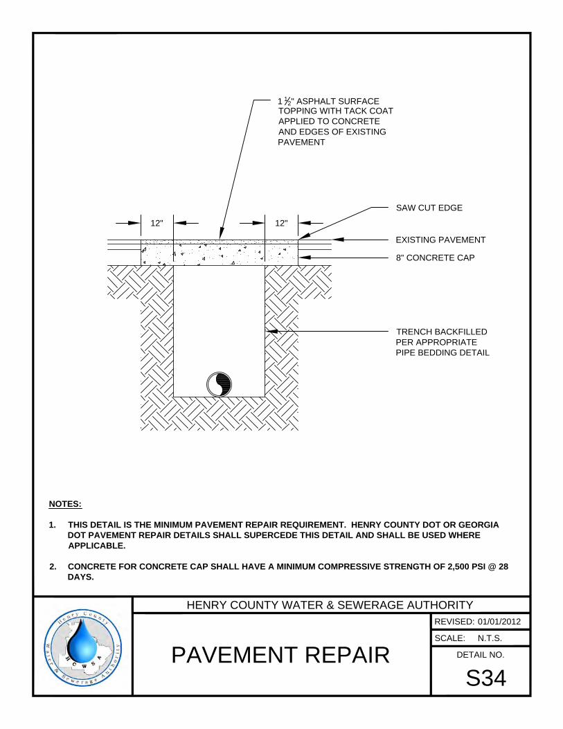
EXISTING PAVEMENT
TRENCH BACKFILLED
PER APPROPRIATE
PIPE BEDDING DETAIL
8" CONCRETE CAP
SAW CUT EDGE
1
1
2
" ASPHALT SURFACE
TOPPING WITH TACK COAT
APPLIED TO CONCRETE
AND EDGES OF EXISTING
PAVEMENT
12" 12"
NOTES:
1. THIS DETAIL IS THE MINIMUM PAVEMENT REPAIR REQUIREMENT. HENRY COUNTY DOT OR GEORGIA
DOT PAVEMENT REPAIR DETAILS SHALL SUPERCEDE THIS DETAIL AND SHALL BE USED WHERE
APPLICABLE.
2. CONCRETE FOR CONCRETE CAP SHALL HAVE A MINIMUM COMPRESSIVE STRENGTH OF 2,500 PSI @ 28
DAYS.
HENRY COUNTY WATER & SEWERAGE AUTHORITY
REVISED:
SCALE:
DETAIL NO.
PAVEMENT REPAIR
S34
01/01/2012
N.T.S.
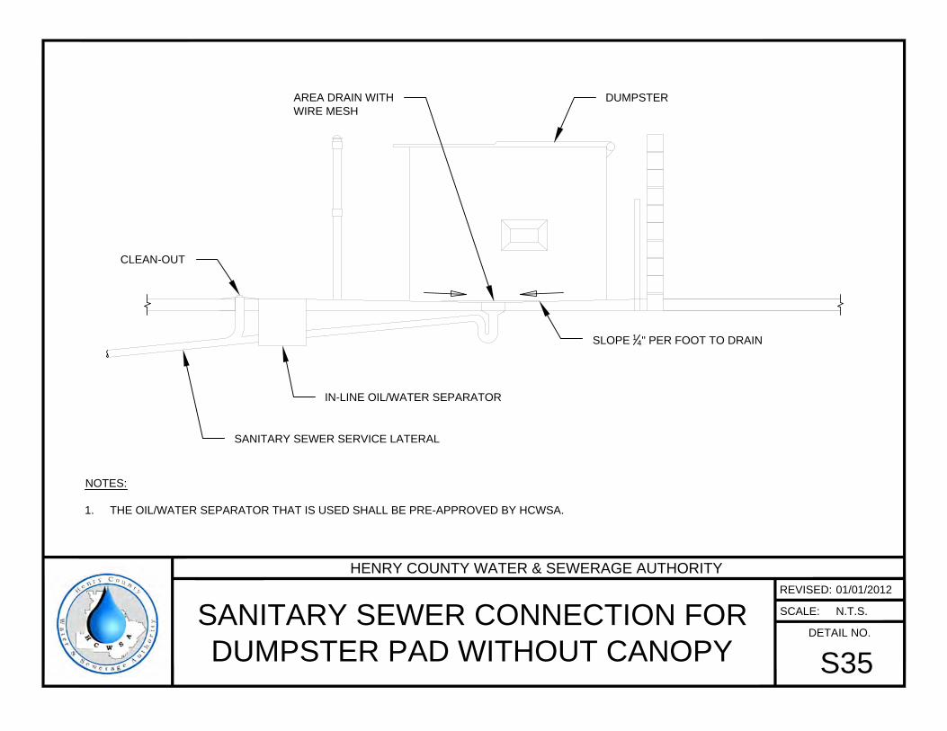
SANITARY SEWER SERVICE LATERAL
IN-LINE OIL/WATER SEPARATOR
DUMPSTER
CLEAN-OUT
SLOPE
1
4
" PER FOOT TO DRAIN
AREA DRAIN WITH
WIRE MESH
NOTES:
1. THE OIL/WATER SEPARATOR THAT IS USED SHALL BE PRE-APPROVED BY HCWSA.
HENRY COUNTY WATER & SEWERAGE AUTHORITY
REVISED:
SCALE:
DETAIL NO.
SANITARY SEWER CONNECTION FOR
DUMPSTER PAD WITHOUT CANOPY
S35
01/01/2012
N.T.S.
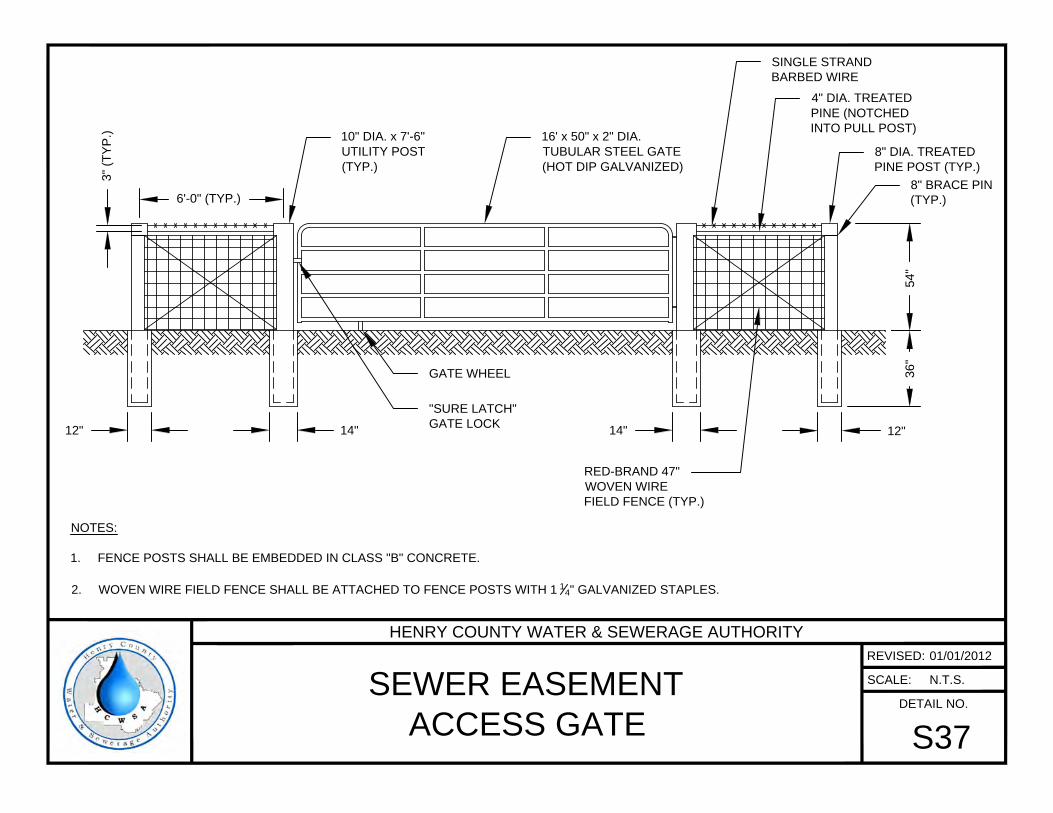
16' x 50" x 2" DIA.
TUBULAR STEEL GATE
(HOT DIP GALVANIZED)
10" DIA. x 7'-6"
UTILITY POST
(TYP.)
6'-0" (TYP.)
3" (T
YP
.)
SINGLE STRAND
BARBED WIRE
4" DIA. TREATED
PINE (NOTCHED
INTO PULL POST)
8" DIA. TREATED
PINE POST (TYP.)
"SURE LATCH"
GATE LOCK
54
"3
6"
12"14"14"12"
RED-BRAND 47"
WOVEN WIRE
FIELD FENCE (TYP.)
GATE WHEEL
NOTES:
1. FENCE POSTS SHALL BE EMBEDDED IN CLASS "B" CONCRETE.
2. WOVEN WIRE FIELD FENCE SHALL BE ATTACHED TO FENCE POSTS WITH 1
1
4
" GALVANIZED STAPLES.
8" BRACE PIN
(TYP.)
HENRY COUNTY WATER & SEWERAGE AUTHORITY
REVISED:
SCALE:
DETAIL NO.
SEWER EASEMENT
ACCESS GATE
S37
01/01/2012
N.T.S.