STANDARDS AND SPECIFICATIONS FOR THE ...
202
STANDARDS AND SPECIFICATIONS FOR THE CONSTRUCTION OF PUBLIC IMPROVEMENTS VOLUME I STREETS JULY 2017 TOWN OF HUDSON, COLORADO Adopted by Resolution No. 17-20, July 19, 2017
-
Upload
khangminh22 -
Category
Documents
-
view
3 -
download
0
Transcript of STANDARDS AND SPECIFICATIONS FOR THE ...

STANDARDS AND SPECIFICATIONS
FOR THE
CONSTRUCTION OF PUBLIC IMPROVEMENTS
VOLUME I
STREETS
JULY 2017
TOWN OF HUDSON, COLORADO
Adopted by Resolution No. 17-20, July 19, 2017


TOWN OF HUDSON, COLORADO
STANDARDS AND SPECIFICATIONS
FOR
CONSTRUCTION OF PUBLIC IMPROVEMENTS
VOLUME I
STREETS
Page No.
Street Design Criteria 3 - 44
Street Construction Specifications 45 - 119
Appendix 121


Page 1
STREET DESIGN CRITERIATABLE OF CONTENTS
Page No.SECTION 1- MINIMUM DESIGN CRITERIA
1.01 Scope 31.02 General 31.03 Right-of-Ways and Street Cross-sections 61.04 Horizontal Alignment 71.05 Street Function, Safety, Accessibility, and Planning Characteristics 81.06 Vertical Alignment 91.07 Intersections 121.08 Cul-De-Sacs 141.09 Medians 141.10 Sidewalks and Curb Types 151.11 Curb Grade and Radius 151.12 Drainage 161.13 Cross Pans 161.14 Inlets 161.15 Cross Slope 171.16 Pavement Design 171.17 Transitions 171.18 Street Projections into Future Adjoining Subdivisions 171.19 Recommended Design Standards for Bus Stops 171.20 Street Lighting Standards 181.21 Sign Standards 231.22 Landscape Standards for Streetscape and Medians 251.23 Bike Paths or Trail Crossing Under Roadways 251.24 Deceleration Lanes and Turning Lanes 251.25 Street Markings Standards 261.26 Traffic Signal Standards 261.27 Transportation Impact Study (TIS) 26
SECTION 2 - SOIL INVESTIGATIONS & PAVEMENT DESIGN
2.01 Soil Investigations 312.02 Soils Report 332.03 Subsurface Water Investigations 342.04 Unsuitable Soils Mitigation 352.05 Final Pavement and Design Report 362.06 Final Pavement Design – Soils Sampling 362.07 Final Pavement Design – Soils Testing 372.08 Pavement Thickness Design Criteria 382.09 Pavement Design Procedures 412.10 Final Pavement Design Report Certification 43

Page 2
STREET DESIGN CRITERIALIST OF TABLES
Page No.
Table 1.03.1 General Parameter 7
Table 1.04.1 Street Flowline Offsets 8
Table 1.06.1 Minimum and Maximum Allowable Street Slope & Street Grades 10
Table 1.06.2 Minimum Distance for Maximum 2% Approach Grade 10
Table 1.06.3 Minimum Length of Vertical Curves 11
Table 1.07.1 Sight Distance Triangle Setback 13
Table 1.11.1 Curb Return Radii Criteria 16
Table 1.20.1 Recommended Street Illumination Levels 22
Table 1.20.2 Street Light Requirements 22
Table 1.20.3 Street Lighting Spacing 23
Table 1.20.4 Intersection Light Location 23
Table 1.27.1 Acceptable Level of Service from Intersection Delay 30
Table 2.01.1 Tests Required for Each Boring 33
Table 2.07.1 Expansion Potential of Subgrade Soil 37
Table 2.08.1 Flexible Pavement Design Criteria 39
Table 2.08.2 Pavement Strength Coefficients 41

Page 3
SECTION 1MINIMUM DESIGN CRITERIA
1.01 SCOPE
The purpose of this section of this document is to present the Town of Hudson criteria for the design of streets. It is to be used by developers, design architects, and design engineers in the design of public and private streets for which approval by the Town of Hudson Public Works Department is required. All street design, layout, alignment, and classification shall conform to these design criteria, the Hudson Comprehensive Plan, and the Hudson Municipal Code.
1.02 GENERAL
A. MINIMUM STANDARDS
1. The provisions stipulated in this section are general in nature and shall be considered as applicable to all parts of these specifications, including any supplements and revisions. All construction within the public right-of-way shall be designed by or under the direct supervision of a Professional Engineer (P.E.) registered in the State of Colorado. All drawings and support data submitted to the Town for approval must bear their seal and signature. No permits for construction will be issued until these documents have been certified by a P.E. Any over-lot grading completed during the design phase of the project must be certified by a P.E. prior to issuance of any permits for construction.
2. The design criteria as presented is intended to aid in preparation of plans and specifications for the Town of Hudson including minimum standards where required. These design criteria are considered minimum and a complete design will usually require more than is presented in this document. As with any design criteria, occasions may arise where the minimum standards are inappropriate. In these cases, a variance shall be considered. Written request for each variance should be directed to the Town Public Works Department and shall conform to the requirements of the Public Works Director.
3. Whenever the provisions of these Standards are found to be inconsistent with any other regulations or codes, the Town Engineer shall determine the standard to apply. The provisions of these regulations are minimum requirements that do not preclude imposition of more restrictive standards by agreement or by law.
4. Projects shall comply with all laws, regulations, codes, and ordinances applicable to the design and the furnishing and performance of the work. Except where otherwise expressly required by applicable laws, regulations, codes or ordinances, the Town shall not be responsible for monitoring compliance with any law, regulation, code or ordinance.
5. The Town has subdivision regulations and development code, within the Municipal Code, that can help define the various processes required for projects.
6. Prior to the contractor beginning work, an approved set of plans and specifications must be on file with the Town of Hudson. All contracts, bonds, insurance, permits, and licenses must be fully executed by the Contractor before beginning work.
7. Town's review and approval will only be to determine if the plans, specifications, and construction conform to the Town's requirements. Town's review and approval will not relieve the Design Professional and Contractor/Owner from responsibility for any variation from the Town requirements or adequate design standards. The Town's review and approval shall not constitute any assumption of responsibility or liability for the design or construction.
8. It is the intent and purpose of the standards and specifications to obtain high quality construction throughout, with the completed work complying with these standards and specifications.
9. Reference to standard specifications, manuals, or codes of any technical society, organization, or association or to the laws or regulations of any governmental authority, whether such reference is specific or by implication, shall mean the latest standard specification, manual, code, or laws or regulations in effect at the time of Town acceptance. However, no provision of any referenced standard

Page 4
specification, manual, or code shall be effective to change the duties and responsibilities of the Town or any of their consultants, agents, or employees from those set forth in these Standards and Specifications. Work shall be done in compliance with the accepted plans and to the satisfaction of the Town.
10. Consideration shall be given, within the established framework of local streets, to provide for uniformity of street widths, proper alignment, street names, and conformity to existing street patterns. The street design shall be directly related to the traffic needs. The streets, intersections, driveways, and pedestrian facilities shall be designed to provide for the greatest safety for motorists, pedestrians, and bicyclists.
11. All alleys, when permitted by the Town Engineer, shall be paved to the full width of right-of-way, or as approved by the Town Engineer, and shall provide paved access to a paved street at both ends.
12. Residential lots adjacent to an arterial street shall be served by a local street. Direct access will not be allowed from any residential lot onto an arterial.
13. Streets of less than the entire minimum right-of-way roadway width should be avoided and permitted only by approval of the Town Engineer. Sufficient engineering data shall be provided to establish feasibility of widening without causing unacceptable drainage, sight distance, or other problems. Street improvement plans shall include the entire width.
14. Development projects and/or subdivisions adjacent to existing public roadways must, in addition to dedicating additional right-of-way for future street expansion needs, evaluate existing improvements along those rights-of-ways. These improvements include but are not limited to public and private utilities, storm water facilities, irrigation facilities, fences, etc. Developers must provide for proper engineering and construction as necessary to modify and/or protect those facilities as well as providing proper development grading along the existing roadways to accommodate the design and construction of the future roadway improvements. Engineer shall include preliminary profiles and cross-sections.
15. All proposed projects shall be referenced to the Town of Hudson’s adopted control network and shall obtain the location and elevation of the nearest appropriate reference monument from the Public Works Director prior to survey. If a suitable Town of Hudson control monument is not located within two miles of the proposed project, the Town will provide one within 20 working days of the request date. The monument name and elevation used shall be clearly marked on all construction drawings.
B. SOILS REPORT AND PAVEMENT DESIGN REPORT
A Soils Report and Pavement Design Report shall be submitted to the Town, for review and acceptance, prior to any construction related to the installation of public improvements. The reports shall comply with the requirements outlined in Section II of the Street Design Criteria part of this manual. A checklist is provided in the Appendix to assist in the preparation of the reports.
C. TRANSPORTATION IMPACT STUDIES
Transportation Impact Studies (TIS) are required in order to adequately assess the impacts of a development proposal on the existing and/or planned street system. Unless waived by the Town Engineer, a TIS report shall be required for all development proposals. The TIS shall be prepared by a Professional Engineer.
D. PRECONSTRUCTION CONFERENCE
A preconstruction conference may be required prior to the issuance of any permits for construction. Attendance should include representatives from the Public Works Department, Town Planner, Developer/Owner, Design Engineer, General Contractor, and Sub-contractors including; earthwork, utilities, curb and gutter, paving, and signing.

Page 5
E. DEFINITIONS AND ABBREVIATIONS
Wherever the following words, phrases, or abbreviations appear in these specifications they shall have the following meanings.
1. AASHTO – American Association of State Highway and Transportation Officials.
2. ADA – Americans with Disabilities Act.
3. ADT – Average Daily Traffic Count.
4. ASTM – American Society for Testing Materials.
5. TOWN – An individual employed by the Town of Hudson whom is authorized to make the applicable decisions on behalf of the Town.
6. TOWN ENGINEER – a term used in situations where a decision or action may be required by the Town Engineer or his authorized representative employed by the Town of Hudson. The Engineer shall have the authority on behalf of the Town to ascertain that all design and construction is equal to or exceeds the minimum requirements set forth in these criteria and standards.
7. CDOT – Colorado Department of Transportation.
8. CONSTRUCTION DRAWINGS – detailed and working drawings including plan, profile, and detail sheets of proposed utility drainage and street improvements approved by the Engineer.
9. CONSULTANT – the partnership, corporation, or individual who is registered as a professional engineer, according to Colorado statutes, and who is hired by the Developer/ Owner, and is empowered to act as his agent for the project.
10. DESIGN ENGINEER – the partnership, corporation, or individual who is registered as a professional engineer, according to Colorado statutes, and who is hired by the Developer/Owner, and is empowered to act as his agent for the project. The Design Engineer may also be referred to as the Professional Engineer, Civil Engineer, Geotechnical Engineer, or Traffic Engineer.
11. DESIGN SPEED – a speed determined for design and correlation of the physical features of a street that influence vehicle operation; the maximum safe speed maintainable on a specified section of street when conditions permit design features to govern. Design speed is generally higher than the posted speed limit in order to provide a factor of safety and consider other conditions or uses of the street that may affect vehicle operation.
12. DEVELOPER – the owner, corporation, association, partnership, or individual who has entered into an agreement with the Town and has entered into an agreement with the Contractor to perform the construction work.
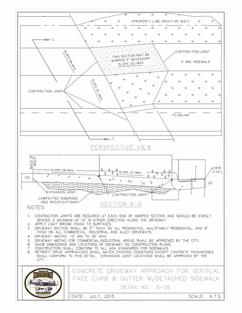
13. DRIVEWAY APPROACH – that portion of concrete extending from the street gutter lip to the property line or back of sidewalk, or the full width of the access from the public right-of-way to private property.
14. EYEBROW – a bulb or semi-circular extension of a curb on one side of a street or at an elbow intersection.
15. GEOTECHNICAL ENGINEER – the partnership, corporation, or individual who is registered as a Professional Engineer or Professional Geologist, according to Colorado Statutes, and who is hired by the Developer/Owner to prepare the Soils Report and Final Pavement Design Report for the project.
16. MAY – a permissive condition. No requirement for design or application is intended.
17. MGPEC – Metropolitan Government Pavement Engineers Council.

Page 6
18. MUTCD – Manual of Uniform Traffic Control Devices
19. OWNER – the developer, corporation, association, partnership, or individual who has entered into an agreement with the Town and has entered into an agreement with the Contractor to perform the work.
20. PLANS – detailed and working drawings including plan, profile, and detail sheets of proposed utility improvements, approved by the Town Engineer.
21. PROFESSIONAL ENGINEER – an individual whom has been licensed and has active status as determined by the Colorado Department of Regulatory Agencies, State Board of Registration for Professional Engineers.
22. ROAD OR STREET – as used in this specification shall include the pavement section, right-of-way, sidewalks, driveways, bikeways, alleys, and alley approaches.
23. SHALL – a mandatory condition. Where certain requirements in the design of application are described with the "shall" stipulation, it is mandatory that these requirements be met.
24. SHOULD – an advisory condition. Where the work "should" is used, it is considered to be advisable usage, but not mandatory. Deviations may be allowed when reasons are given which show that the intent of the standard is met.
25. STANDARD STREET SPECIFICATIONS – the current Town of Hudson Design Criteria and Construction Specifications for Streets.
26. STOPPING SIGHT DISTANCE – shall mean that distance measured from the drivers’ eye, 3.5 feet above the pavement to the top of any object six inches high on the pavement anywhere on the road.
27. STREET WIDTH – that distance measured from curb face to curb face across a street which should generally include the gutter pans on each side.
28. UTILITIES – shall mean all utilities on site prior to the time of any design; such as but not limited to water lines, sanitary sewer lines, drainage lines, electric lines, gas lines, telephone lines, and cable television lines.
1.03 RIGHT-OF-WAYS AND STREET CROSS-SECTIONS
A. GENERAL
1. Sufficient right-of-way shall be provided as required for the traffic needs and cross-section and maintenance of the street including cut or fill slopes, auxiliary lanes, landscaping, signing, utilities, and other aspects of the development.
2. Standard right-of-way and street widths shall meet or exceed the minimums set forth in the Design Criteria. Additional right-of-way and roadway width may be required to accommodate traffic or other development needs such as turn lanes, deceleration lanes, extra lanes, pedestrian or bicycle facilities, landscaping, utilities, or construction requirements such as cut or fill slopes.
B. DESIGN CRITERIA
See Table 1.03.1 – General Parameters. Standard right-of-way and street widths shall meet or exceed the following minimum criteria.
Page 7
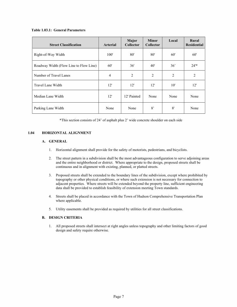
Table 1.03.1: General Parameters
Street Classification ArterialMajor
CollectorMinor
CollectorLocal Rural
Residential
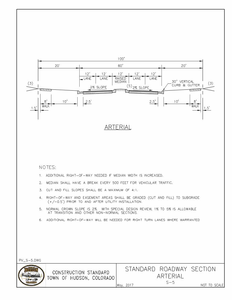
Right-of-Way Width 100' 80' 80' 60' 60'
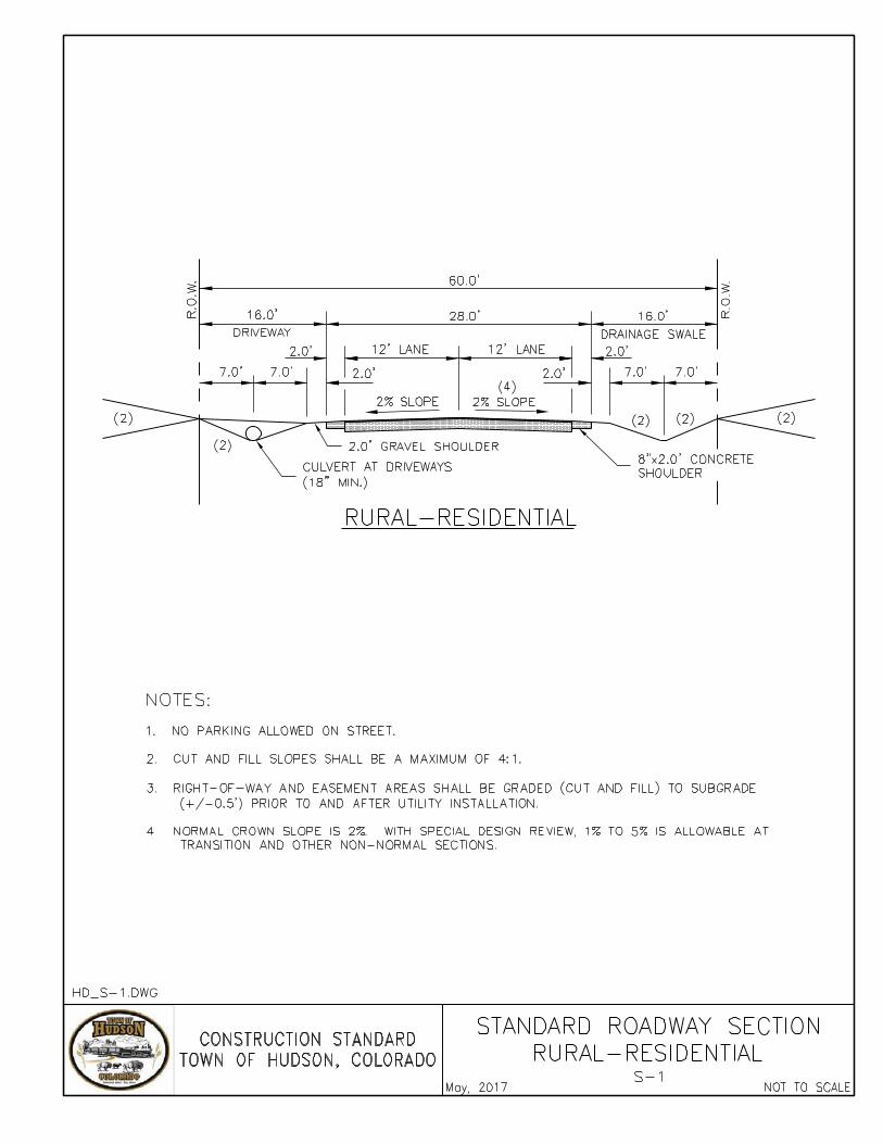
Roadway Width (Flow Line to Flow Line) 60' 36' 40' 36’ 24'*
Number of Travel Lanes 4 2 2 2 2
Travel Lane Width 12' 12' 12' 10' 12'
Median Lane Width 12' 12' Painted None None None
Parking Lane Width None None 8’ 8' None
*This section consists of 24’ of asphalt plus 2’ wide concrete shoulder on each side
1.04 HORIZONTAL ALIGNMENT
A. GENERAL
1. Horizontal alignment shall provide for the safety of motorists, pedestrians, and bicyclists.
2. The street pattern in a subdivision shall be the most advantageous configuration to serve adjoining areas and the entire neighborhood or district. Where appropriate to the design, proposed streets shall be continuous and in alignment with existing, planned, or platted streets.
3. Proposed streets shall be extended to the boundary lines of the subdivision, except where prohibited by topography or other physical conditions, or where such extension is not necessary for connection to adjacent properties. Where streets will be extended beyond the property line, sufficient engineering data shall be provided to establish feasibility of extension meeting Town standards.
4. Streets shall be placed in accordance with the Town of Hudson Comprehensive Transportation Plan where applicable.
5. Utility easements shall be provided as required by utilities for all street classifications.
B. DESIGN CRITERIA
1. All proposed streets shall intersect at right angles unless topography and other limiting factors of good design and safety require otherwise.

Page 8
2. Where streets intersecting with other streets are not in alignment, the street's centerline shall be offset in accordance with the following table:
Table 1.04.1: Street Flowline Offsets
Intersecting Roadway
MinimumOffset
Arterial 660 feetCollector 330 feet
Local 135 feetRural Residential 135 feet
3. Flowline offset distances shall be measured from nearest flowline to nearest flowline.
4. The number of intersecting streets along Arterials and Collectors shall be held to a minimum. The allowable spacing of intersections varies depending on signalization and presence of a raised center median. Refer to access management section of Technical Design Criteria Table 1.04.2.
5. Local streets should not intersect Major Collectors or Arterial streets.
1.05 STREET FUNCTION, SAFETY, ACCESSIBILITY AND PLANNING CHARACTERISTICS
A. GENERAL
All street classifications shall be designed for the safety of motorists, pedestrians and bicyclists. Accessibility shall be provided in accordance with all ADA (Americans With Disabilities Act) requirements. Alleys are not mentioned in these criteria because of the large number of variables in their design. However, any permanent alley design must be approved by the Town.
DESIGN CRITERIA
1. RURAL RESIDENTIAL
FUNCTION – Rural Residential streets serve local traffic and have low traffic volumes. Traffic carried by Rural Residential streets should have an origin or a destination within the rural estate neighborhood, and are designed to discourage through traffic. Rural Residential streets are typically designed to connect to Collector streets, although they can also be designed as cul-de-sacs or to provide connectivity to adjacent subdivisions.
CHACTERISTICS – Rural Residential streets shall be for residential developments with rural acreage lots. Local streets should not intersect Major Collectors or Arterial streets. Traffic control shall be provided using stop signs at all intersections.
2. LOCAL
FUNCTION – Local streets shall provide for local traffic and have low traffic volumes. Traffic carried by Local streets should have an origin or a destination within the neighborhood, and be designed to discourage through traffic. Local streets are typically designed to connect to Collector streets, although they can also be designed as cul-de-sacs or provide connectivity to adjacent subdivisions.
CHACTERISTICS – Local residential streets are intended for use in medium to high density residential neighborhoods. Local streets should not intersect Major Collectors or Arterial streets. Parking shall be allowed on both sides of local residential streets. Traffic control shall be provided using stop signs at all intersections.

Page 9
3. MINOR COLLECTOR
FUNCTION – Minor Collectors collect and distribute traffic between Arterials, Major Collectors, and Local streets and serve as main connectors within communities, linking one neighborhood with another.
PLANNING CHARACTERISTICS – Minor Collectors are generally intended for use within residential neighborhoods or to connect smaller neighborhoods. Intersections with other Collector and Arterial streets should be at least one-quarter (1/4) mile apart. Regulation of traffic shall be accomplished through the use of stop signs and channeling.
4. MAJOR COLLECTOR
FUNCTION – Major Collector streets shall be designed to permit relatively unimpeded traffic movement and are intended for use on those routes where a larger classified street is not warranted.
PLANNING CHARACTERISTICS – Major Collector streets should be employed where traffic demands dictate. Major Collector streets are intended for use in commercial/industrial areas or high density residential. See the Street Standards Technical Design Criteria Chart for allowable intersection spacing. Street parking is not allowed on Major Collector streets. Access from streets of lower classification will be permitted, but in all cases, will be controlled by traffic control devices. Direct access to abutting property is not permitted unless no other access is reasonably available. Regulation of traffic shall be accomplished through the use of traffic signs, signals, and channeling. Traffic signals will normally be located only at intersections with Arterial Streets.
5. ARTERIAL
FUNCTION – Arterial streets permit relatively unimpeded traffic movement and are intended for use on those routes where four moving lanes and one left-turn lane are required.
PLANNING CHARACTERISTICS – Arterials should be employed where traffic demand dictates. Arterials should be spaced approximately one (1) mile apart and should, where possible, be continuous. Arterial should act as boundaries between neighborhood areas. Intersections with Collectors streets should be at least one-quarter (1/4) mile apart. See the Street Standard Technical Design Criteria Chart for allowable intersection spacing. No street parking is allowed on Arterial streets. Regulation of traffic shall be accomplished through the use of traffic signs, signals, and channeling. Traffic signals will normally be required at intersections. Access from streets of lower classification will be permitted, but in all cases, will be controlled by traffic control devices. Direct access to abutting property is not permitted unless no other access is reasonably available. Arterial streets are intended to have continuous medians.
1.06 VERTICAL ALIGNMENT
A. GENERAL
Vertical alignment and grades shall be designed to bear a logical relationship to the existing topography, drainage needs and shall provide for the safety of motorists, pedestrians, and bicyclists.

Page 10
B. DESIGN CRITERIA
1. All proposed streets shall conform to the minimum and maximum allowable street slope and street grade standards shown in the following table:
Table 1.06.1: Minimum and Maximum Allowable Street Slope and Street Grade
Notes: a. Grading behind sidewalks and between detached sidewalk and curb shall be a maximum of 4:1. Special conditions outside of this range may be approved by the Town Engineer.
b. Normal crown slope is 2 percent. One percent to 5 percent is allowable at transition and other non-normal sections with special design review. Special conditions outside of these ranges may be approved by the Town Engineer.
2. Minimum grade on gutter shall be 0.4 percent. Particular attention shall be given to maintain a 0.4 percent minimum grade especially on a sag vertical curve. Crosspans, cul-de-sacs, eyebrow, and curb return gutters shall have a minimum grade of 0.6 percent.
3. Connections with existing streets shall be made in a way that will create a smooth transition. The higher volume street at an intersection shall govern the through grade and cross-sections. The maximum allowable approach grade at an intersection shall be two (2%) percent for a distance as designated by the following table:
Table 1.06.2: Minimum Distance for Maximum 2% Approach Grade
Approaching Street Local Collector Arterial Rural Residential
Local 30 Feet 50 Feet 75 Feet 30 Feet
Collector 75 Feet 150 Feet
Arterial 200 Feet
Rural Residential 30 Feet 50 Feet 75 Feet 30 Feet
Note: Distances shown are measured from the flowline intersections.
The intersection of any street with a Major street shall be designed to the ultimate street grade of the Major street. The grading of the property adjacent to the Major street shall meet these ultimate grades. A detail of the intersection sufficient to show drainage and grades must be provided.
Street Type Street Grades %Min. / Max. Cross Slope %
Arterial (a) 0.4/5.0 2.0 Normal crown (b) 5.0 Max – for super-elevation.
Major Collector (a) 0.4/5.0 2.0 Normal crown (b) 4.0 Max – for super-elevation.
Minor Collector (a) 0.4/5.0 2.0 Normal crown (b)
Local (a) 0.4/5.0 2.0 Normal crown (b)
Rural Residential (a) 0.4/5.0 2.0 Normal crown (b)
Alley (where permitted) 0.4/5.0 2.0 Min.
Emergency 0.4/5.0 2.0 Min.

Page 11
Connection with existing streets shall be smooth transitions and existing grades shall be shown for at least one hundred and fifty (150') feet on all sides of the connection. The grade and ground lines of all streets that dead end, except cul-de-sacs, shall be continued for five hundred (500') feet beyond the proposed construction. The grade and ground lines of all Arterial Streets shall be designed to continue one-thousand (1000') feet beyond the end of proposed construction.
4. Vertical curves shall meet or exceed the following minimum criteria:
Table 1.06.3: Minimum Length of Vertical Curves (In Feet)
Grade Change % Arterial Collector Other
0.00 - 0.99 none none none
1.00 - 1.99 200 120 60
2.00 - 2.99 300 160 90
3.00 - 3.99 450 220 120
4.00 - 4.99 600 280 150
5.00 - 5.99 700 330 180
6.00 - 6.99 --- 380 210
7.00 - 7.99 --- 430 240
8.00 - 8.99 --- --- 270
9.00 - 9.99 --- --- 300
10.00 - 10.99 --- --- 330
11.00 - 12.00 ---- ---- 360
Note: Lengths above do not allow passing on crest of vertical curves. Design may warrant a passing move on Collectors or Arterial, which would lengthen the vertical curves. The required lengths for passing will be provided on a case-by-case basis by the Engineer.
Profile may be designed with a maximum one percent (1%) change in grade at the vertical point of intersection (VPI).
5. The purpose of super elevating a roadway is to improve the riding comfort on curves where the traveling speed is great enough to exert a lateral thrust greater than that which can reasonably be resisted by friction alone.
In the Town of Hudson, super elevation may be allowed on Arterial streets and selected Collector streets in order to reduce the minimum centerline radius allowed. Super-elevation shall not be used on Local streets. When super-elevations are required, the super elevation shall be in accordance with the recommendations of AASHTO and approved by the Town Engineer.
When super elevation is used, a minimum one hundred (100') foot run-out shall be used entering and exiting the super-elevated portion. In cases where the super elevation transition changes the gutter on one side of the street from water carrying to non-water carrying, the water must enter a storm sewer system or other acceptable outlet from the street rather than crossing said street in sheet flow. The gutter shall always be inflow type.
When super-elevation is used, the rate of super-elevation shall be clearly shown on the drawings along with exaggerated (preferably 1"= 20' Horizontal, 1"= 1' Vertical) profiles of the centerline and both flowlines. The super-elevation run-out length, crown run-out length, and point at which full super-elevation is reached shall be clearly shown.

Page 12
6. The design engineer shall show either centerline profile or both flowline profiles. If centerline profiles are provided, the flowline profile information, distances and grades, shall also be provided everywhere it is not parallel to the centerline and along all horizontal curves. If flowline profiles are provided, the design engineer shall also show centerline profiles through intersections and details at any mid-block crosspans to provide smooth riding transitions. The actual distance and grades of curb returns shall be given for all intersections. Flowline profiles shall be shown around cul-de-sacs, kneecaps, bulb-outs and elbows.
For arterial and major collector streets and for widening of existing streets, the design engineer shall provide cross-sections to the construction limits at fifty (50') foot intervals on all streets showing existing and proposed construction. Cross-section profiles shall be provided to include the street, curb, gutter and walk to a point twenty (20') feet beyond walk.
1.07 INTERSECTIONS
A. GENERAL
1. Intersections shall be designed to provide for the safety of motorists, pedestrians, and bicyclists.
2. At street intersections, property lines shall be truncated as shown in Standard Detail S-9 to provide adequate right-of-way for curb ramps and utilities.
3. Intersection design shall take into consideration auxiliary turn lanes as required by the approved Transportation Impact Study, or as required for site specific conditions.
B. DESIGN CRITERIA
1. The design criteria for all street intersections shall conform to the Horizontal Alignment Design Criteria outlined in Section 1.04 above. All intersections shall be designed and constructed with pedestrian curb ramp access on all corners in accordance with all ADA requirements. See Standard Details.
2. Intersection Obstruction Free Areas – Intersection obstruction-free area shall mean that area which the Town shall be required to maintain in order to preserve the sight, distance, and safety of motorists, pedestrians, and bicyclists, by requiring an unobstructed intersection sight distance (ISD) area. ISD is the unobstructed line of sight necessary for most drivers stopped at an intersection to see an approaching vehicle to avoid a collision. When the lines of sight for both left and right directions are combined, a sight triangle is formed. There should be no visual obstructions.
The ISD depends on the street operating speed and desired maneuver of existing vehicle. These areas shall be free from shrubs, ground covers, berms, fences, signs, structures, parked vehicles, or other materials. Trees, within the sight distance triangle (whether within the public right-of-way or on private property) must not impair sight distance. Permits for planting trees are required by the Town which will provide guidelines for the type, location, and spacing of trees. These distances are typical sight distance triangles to be used under normal conditions and may be modified by the Town in order to protect the public safety and welfare in the event that exceptional sight conditions necessitate such a modification.

Page 13

Page 14
1.08 CUL-DE-SACS
A. GENERAL
Permanent no outlet streets shall be in the form of a cul-de-sac. Such cul-de-sacs are allowed on local streets only. No outlet streets without a cul-de-sac shall not be allowed unless designed to connect with a future street. If the temporary no outlet street is longer than eight hundred (800') feet, or serves as primary access to any lot, a temporary turn-around or a temporary paved connection to another street shall be provided. At least an eighty (80') foot temporary turn-around easement shall be provided when needed on temporary dead-end streets. Such turn-around easement shall not be required if no lots in the subdivision are dependent on such street for access.
B. DESIGN CRITERIA
1. Permanent no outlet streets in the form of a cul-de-sac shall have a maximum length of 500 feet (measured along the centerline, from the centerline of the intersecting street to the center point of the bulb), or a maximum of ten (10) lots on a Local low-volume street or twenty-five (25) lots on a Local Residential street. The right-of-way for a cul-de-sac shall conform to the right-of-way requirements for the specific street classification of the cul-de-sac.
2. Cul-de-sacs on a Local low-volume street shall have a minimum pavement radius of forty (40') feet if no truck traffic is anticipated. Cul-de-sacs on Local streets shall have a minimum pavement radius of fifty (50') feet if truck traffic is anticipated, or if a fire hydrant is located within the cul-de-sac. See Standard Detail S-10.
3. Surface drainage on a cul-de-sac shall be toward the intersecting street, or if that is not possible, a drainage outlet and right-of-way shall be provided from the cul-de-sac.
1.09 MEDIANS
A. GENERAL
Prior to design of any medians on public streets, the Standard Details shall be checked and Town staff consulted for specific requirements; such as median width, landscaping, decorative concrete, median cover design, etc. Generally, medians should be designed to meet the requirements of the AASHTO "Policy on Geometric Design of Highways and Streets" (latest revision).
B. DESIGN CRITERIA
1. The design of medians shall include the evaluation for needed turn lanes and accesses. This need will be determined by a Traffic Impact Study and current AASHTO requirements.
2. Landscaped medians shall be provided with drainage facilities to handle sprinkler runoff and nuisance flows. When low maintenance landscaping is used in conjunction with trickle irrigation, outfall curb and gutter should be used; otherwise, inflow curb and gutter with a properly designed storm drain system shall be installed.
3. The nose of the median on arterial streets should be a minimum of twenty (20') feet behind the flowline of the intersected street and shall not encroach on pedestrian crosswalks. Turning templates must be used to determine the shape of the median.
4. The minimum radius for nose curbs should be two (2') feet to flowline. The minimum width of a median shall be four (4') feet.
5. Medians shall be irrigated and landscaped whenever possible. The minimum width of landscaped medians shall be twelve (12') feet.

Page 15
1.10 SIDEWALKS AND CURB TYPES
A. GENERAL
1. Sidewalks shall be designed to provide for the safety of pedestrians.
2. All intersections shall be designed and constructed with pedestrian curb ramp access on all corners in accordance with all ADA requirements.
3. Meandering sidewalks shall be subject to special review and approval by the Town.
4. The minimum sidewalk width shall be five (5') feet. Wider sidewalks may be required by the Town where warranted by anticipated pedestrian traffic; such as at or near schools and/or parks.
B. DESIGN CRITERIA
1. Rural Residential – Intersections shall be designed at grade with direct access to abutting property permitted. A two (2') foot wide concrete shoulder shall be provided on each side of the street. Curb and gutter and sidewalks are normally not required on Local-Low Volume streets.
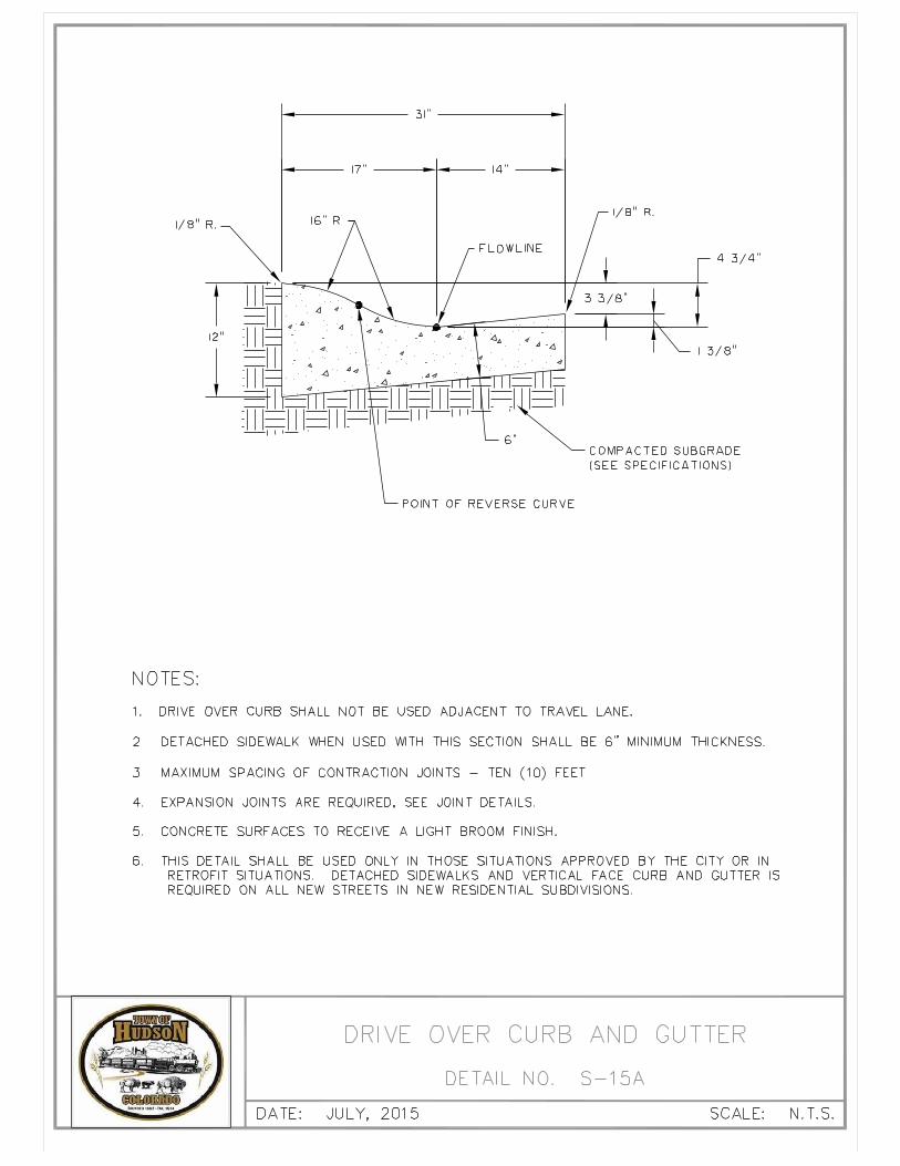
2. Local – The standard curb and gutter for Local streets is the drive over curb with sidewalk attached.
3. Minor Collector – The standard curb and gutter for Minor Collector is vertical face curb and gutter. Sidewalks shall be detached.
4. Major Collector – The standard curb and gutter for Major Collector is vertical face curb and gutter. Sidewalks shall be detached, and the minimum width of the detached area shall be at least six (6’) feet wide.
5. Arterial – The standard curb and gutter for Arterial streets is vertical face curb and gutter with detached sidewalk.
1.11 CURB GRADE AND RADIUS
A. GENERAL
1. Intersections and approved pedestrian crossings shall be designed and constructed with pedestrian curb ramp access in accordance with ADA requirements.
2. Drive approaches shall be constructed in accordance with the Standard Details. Any deviation from these details shall be considered on an individual basis.
Minimum grade on gutter shall be 0.4 percent. Particular attention shall be given to maintain a 0.4 percent minimum grade especially on a sag vertical curve.

Page 16
B. DESIGN CRITERIA
Table 1.11.1: Curb Types and Curb Return Radii Criteria
Street Class Standard Curb Type
Curb Detail
Return Radii
Intersecting Street
Arterials Vertical S-16 50-60’30-40’
ArterialsCollectors
Collectors Vertical S-1630-40’20-30’20-30’
CollectorsLocals
Driveways
Locals
Major & Commercial/IndustrialResidentialLocal Low Volume
VerticalRolloverShoulder
S-16S-16S-1
20-30’20’40’
Locals, Drivewaysand Alleys
1.12 DRAINAGE
Drainage system design shall be in accordance with current Storm Drainage Design Criteria adopted by the Town of Hudson.
1.13 CROSS PANS
A. GENERAL
Cross pans shall be designed and constructed in accordance with the Structural Design Criteria and Standard Details section of this manual.
B. DESIGN CRITERIA
1. Cross pans shall be a minimum of eight (8') feet wide, 8" thick concrete, with a maximum depth of one (1") inch. Mid-block cross pans shall be a minimum of ten (10') feet wide with one and one-quarter (1-1/4") inches maximum depth. Larger widths may be required by the Town.
2. Cross pans are discouraged on Arterial or Major Collector streets or at signalized intersections.
3. Minimum grade on cross pans at flowline of pan shall be 0.6 percent.
4. Cross pan approaches shall be designed using the appropriate design speeds.
5. Cross pan approaches on Local streets at intersections shall be in accordance with Standard Details.
1.14 INLETS
A. GENERAL
1. Inlets shall not be installed in the curb return and shall not be in line with accessibility ramps. In residential developments, inlets should be located at property lines where possible.
2. Inlets shall be designed and constructed in accordance with Storm Drainage Design Criteria adopted by the Town of Hudson.
3. Inlet structures shall not be constructed until the curb and gutter has been installed, unless approved by the Town Engineer.
Page 17
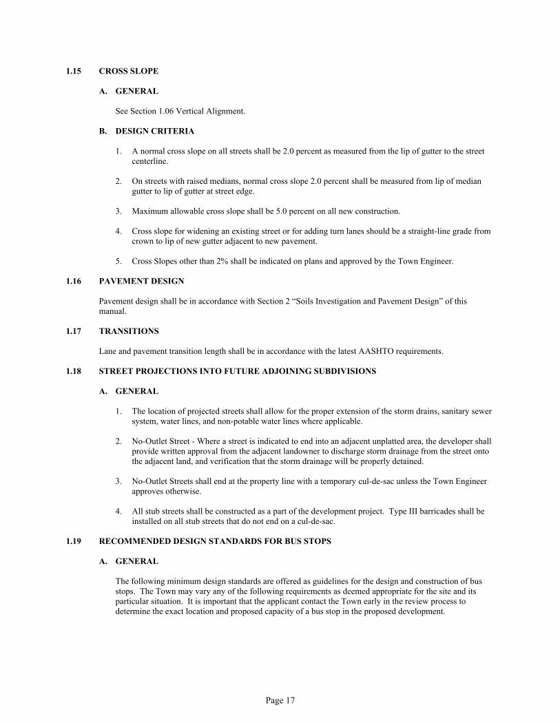
1.15 CROSS SLOPE
A. GENERAL
See Section 1.06 Vertical Alignment.
B. DESIGN CRITERIA
1. A normal cross slope on all streets shall be 2.0 percent as measured from the lip of gutter to the street centerline.
2. On streets with raised medians, normal cross slope 2.0 percent shall be measured from lip of median gutter to lip of gutter at street edge.
3. Maximum allowable cross slope shall be 5.0 percent on all new construction.
4. Cross slope for widening an existing street or for adding turn lanes should be a straight-line grade from crown to lip of new gutter adjacent to new pavement.
5. Cross Slopes other than 2% shall be indicated on plans and approved by the Town Engineer.
1.16 PAVEMENT DESIGN
Pavement design shall be in accordance with Section 2 “Soils Investigation and Pavement Design” of this manual.
1.17 TRANSITIONS
Lane and pavement transition length shall be in accordance with the latest AASHTO requirements.
1.18 STREET PROJECTIONS INTO FUTURE ADJOINING SUBDIVISIONS
A. GENERAL
1. The location of projected streets shall allow for the proper extension of the storm drains, sanitary sewer system, water lines, and non-potable water lines where applicable.
2. No-Outlet Street - Where a street is indicated to end into an adjacent unplatted area, the developer shall provide written approval from the adjacent landowner to discharge storm drainage from the street onto the adjacent land, and verification that the storm drainage will be properly detained.
3. No-Outlet Streets shall end at the property line with a temporary cul-de-sac unless the Town Engineer approves otherwise.
4. All stub streets shall be constructed as a part of the development project. Type III barricades shall be installed on all stub streets that do not end on a cul-de-sac.
1.19 RECOMMENDED DESIGN STANDARDS FOR BUS STOPS
A. GENERAL
The following minimum design standards are offered as guidelines for the design and construction of bus stops. The Town may vary any of the following requirements as deemed appropriate for the site and its particular situation. It is important that the applicant contact the Town early in the review process to determine the exact location and proposed capacity of a bus stop in the proposed development.

Page 18
B. DESIGN STANDARDS
1. Bus Lane Width – Bus lanes and stops should be asphalt or concrete and at least ten (10') feet wide.
2. Bus Stop Lengths – Near-side bus stops should be concrete and at least fifty (50') feet long for a single bus, plus a thirty (30 ') to seventy (70 ') foot distance to the radius of intersection.
Far-side bus stops should be concrete and provide a fifty (50') feet loading area plus a thirty (30 ') to seventy (70 ') feet distance to the radius of intersection.
Mid-block bus stops shall be paved and include transition requirements for near and far-side bus bays. Total impacted area for a single bus stop would be seventy feet (70') with thirty feet (30 ') bus stop and two twenty feet (20 ') transitions before and after the bus stop.
All bus stop locations should be approved by the Town Transit Manager.
3. Bus Shelters – Shelters should be used at major bus stops to protect users from the weather. Locations with high passenger demands and low bus service frequency should be given priority. The shelter should have maximum transparency and be highly visible from the surrounding area to assure users' safety. Shelters should be of vandal proof construction and materials, durable, and easily maintained. The appearance of the shelter should be visually pleasing and in natural tones. Openings should be at least 36 inches wide. Capacity should be based on maximum passenger accumulation at the stop, with approximately 5 square feet per person allowed to develop size requirements. They shall not obstruct pedestrian flow or motorists' sight distance. All bus shelters shall be approved by the Town Transit Manager.
1.20 STREET LIGHTING STANDARDS
A. PURPOSE
The purpose of streetlight installations shall be to illuminate the public traveled ways to a level that provides for the safe passage of public traffic, both vehicle and pedestrian.
B. RESIDENTIAL AREAS
All lighting in residential areas shall be installed to minimize light shining on or negatively affecting the neighboring residents. Low-light trespass luminaries should be utilized whenever possible.
C. GUIDELINES
Uniform lighting will be used on new roadway projects involving Arterial and Collector streets. The guidelines shall be the Illuminating Engineering Society (IES) Lighting Handbook, latest edition, and the Design Manual of the Colorado Division of Highways, latest edition and supplemental revisions or guidelines approved by the Town. All fixtures, poles, and designs will be reviewed and approved by the power provider. Drawings for installation will be prepared by the Developer/Owner with help from the local power provider and approved by the Town prior to installation. In new subdivisions, a street lighting plan will be required for approval of the subdivision. A street light will be required for all cul-de-sacs. All electrical work will be completed in accordance by NEC standards. Contractor shall install all materials in accordance with the manufacturer’s instructions, unless otherwise specified.
D. LAYOUT CRITERIA
1. Mounting Height – Streetlight mounting height shall not exceed 20 feet in residential areas. In areas other than residential, the mounting height shall not exceed 40 feet.
2. Signalized Intersections – Signalized intersections will be lighted using combined streetlights and mast arms. Mounting of signals will be perpendicular to the flow line.
3. Railroad Crossing Lighting – Railroad crossing lighting will conform to the Railroad-Highway Grade Crossing Handbook (FHWA).

Page 19
4. Lighting in Underpasses – All bridge underpasses, where vehicles, pedestrians, bicyclists, or equestrians may be present, shall require lighting.
5. Attached Sidewalks – Install street lighting behind sidewalks where sidewalks attached to the curb are used.
6. Detached Sidewalks – For sidewalks detached from the curb, install street lighting with a minimum of 2 feet clearance from back of curb to roadway side of support pole and 2 feet clear from all walks.
7. Drawing – Except within the Town power service territories, drawings for installations will be prepared by the Developer with assistance from the power provider and approved by the Town prior to installation. In new subdivisions, a street lighting plan will be required prior to approval of the subdivision.
8. Permission for Alternate Designs – Alternate designs for fixtures, if approved by the Town, may be used if installed in more than 20 locations on site.
9. Fire Hydrant Conflicts and Property Lines – When locating proposed lighting, avoid possible conflicts with fire hydrants. Light poles shall be a minimum of ten (10') feet from fire hydrants. Light poles should be placed at property lines in residential areas where possible.
10. Roundabout Lighting – Lighting columns should be arranged around the perimeter of the roundabout in a simple ring, with the lights equidistant from the center and from each other. Lighting should extend at least 197 feet back along each approach road. Mounting height should be uniform throughout the intersection and not less than on any approach road. Minimum horizontal illuminance at the curb lines should be as given in Table 1.20-1. The minimum illuminance required should not be less than the highest level of lighting for any of the approach roads.
E. LIGHTING SYSTEMS DESCRIPTIONS
These lighting standards apply to all new street lighting systems.
F. REFRACTOR STYLE COBRA
The refractor style cobra with a Type-3 semi-cutoff distribution pattern mounted on poles shall be the standard construction for Major Collector and Arterial streets.
G. TRADITIONAL-STYLE FIXTURE
A traditional-style fixture with a Type-3 distribution mounted on steel black painted poles shall be used on local streets.
H. LIGHT TYPES AND LOCATION OF USE
Specific light types [High Pressure Sodium (HPS), Mercury, etc.] shall be installed according to Town Standards. Refer to Table 1.20.2. Poles or luminaries, which are equivalent to those described below, shall be approved by the Town.
I. SPACING
The Designer shall design the spacing of all street lighting according to Table 1.20.3, and shall conform to Average Maintained Illuminance Value and Illuminance Uniform Ratio in Table 1.20.1.
J. POSITIONING AT INTERSECTIONS
In general, the nighttime visibility of a pedestrian or hazardous object within an intersection is enhanced by increased contrast between the object and the surrounding street area. The optimum contrast (and hence safety) is achieved when the streetlights are situated to silhouette (or backlight) objects in the intersection. Therefore, streetlights at intersections are required to be placed on the downstream side of the intersecting

Page 20
street, as viewed by a motorist approaching the intersection in the lane directly beneath the luminaries. The positioning of light standards at intersecting streets shall be as noted in Table 1.20.4.
K. PORTABLE MESSAGE SIGN PANEL
Portable message sign panel shall be furnished as a device fully self-contained on a portable trailer, capable of being licensed for normal highway travel, and shall include leveling and stabilization jacks. The panel shall display a minimum of three – eight-character lines. The panel shall be a dot-matrix type with an LED legend on a flat black background. LED sign shall have a pre-default message that activates before a power failure. The sign shall be capable of 360 degrees’ rotation and shall be able to be elevated to a height of at least five (5) feet above the ground measured at the bottom of the sign. The sign shall be visible from one-half mile under both day and night conditions. The message shall be legible from a minimum of 750 feet. The sign shall automatically adjust its light source to meet the legibility requirements during the hours of darkness. The sign enclosure shall be weather tight and provide a clear polycarbonate front cover.
Each sign shall also conform to the following:
1. In addition to the onboard solar power operation with battery back-up, each sign shall be capable of operation on a hard wire, 100-110 VAC, external power source.
2. All electrical wiring, including connectors and switch controls necessary to enable all required sign functions, shall be provided with each sign.
3. Each sign shall be furnished with an operating and parts manual, wiring diagrams, and trouble-shooting guide.
4. The portable message sign shall be capable of maintaining all required operations under Colorado mountain-winter weather conditions.
5. Each sign shall be furnished with an attached license plate and mounting bracket.6. Each sign shall be wired with a 7-prong male electric plug for the brake light wiring system.
The portable message sign panel shall be on the project site at least seven (7) days prior to the start of active roadway construction. Maintenance, storage, operation, relocation to different sites during the project, and all repairs of the portable message sign panels shall be the responsibility of the Contractor.
L. LIGHT POLE OFFSET DISTANCES
Distance behind back of walk for local streets shall be at least two (2') feet, and must be within easements or right-of-way on Local residential streets. For Collectors and Arterials, the light must be offset at least two (2') feet from the back of curb and provide a clearance space between the light pole and edge of walk that equals or exceeds the required sidewalk width. Pole with “Break-away” supports should be utilized whenever appropriate.
M. STREET LIGHTING IN MEDIANS
Street trees (full shade) shall not be placed within 40 feet of a street light. Ornamental trees shall be no closer than 15 feet to any street light.
N. UNDERGROUND SERVICE
Street lighting shall be installed with underground electric service on all newly developed dedicated public streets in the Town. The Developer is responsible for coordinating with the appropriate utility company on all aspects of design and installation. 1-inch HDPE SDR 11 or 1-inch SCH 40 PVC conduit or approved equal shall be used for all residential roadways and 2-inch SCH 80 PVC and/or 2 inch HDPE SDR 11 is to be used along all Major Collector and Arterials, and roadway crossings for the electrical interconnect system. Conduits from the Meter and Electrical panel located by the Utility Company’s approval shall be 2-inch SCH 80 PVC to the first pole location.
1. Substructure Conflict – Contractor shall locate and protect substructure(s) shown on the plans and those identified by UNCC. The contractor shall provide for minimum 18-inch clearance between edge of foundation and substructures unless otherwise directed by the Inspector/Engineer. In the event an 18-inch clearance cannot be achieved, the contractor shall make arrangements for relocation of substructures at no cost to the Town.

Page 21
2. Underground Service Alert – The contractor shall obtain an underground service alert inquiry I.D. number by call 811 or visiting www.call811.com before commencing any excavation or install ground rods. Two (2) working days shall be allowed after the I.D. number is obtained and before the excavation work is started so that utility owners can be notified. All inspections must be arranged at least two (2) days in advance.
3. Site Preparation – Construction in proximity of electric overhead lines - All new and existing streetlights shall conform to clearances with overhead electric power lines and communication lines. The contractor shall be responsible for all necessary coordination with responsible utility company and shall assume all costs incurred in complying with these requirements.
For Town of Hudson projects, each bidder, prior to submitting his bid, shall inspect the job site and include in his bid any charges by the Utility Company for de-energizing, grounding or placing effective barriers or sleeves to prevent physical contact with the lines. All costs incurred for temporary relocation of power lines shall be assumed by the Town. Contractor shall not be responsible for costs incurred by the utility for any permanent relocation of lines to accommodate required clearances from street lighting equipment after construction.
4. Underground Wire Size – Wire size to be determined by Engineer during design.
5. Concrete Bases – Cement bases must meet the utility’s standards and specifications for the installed light fixture. The bases can either be poured in place or be the prefab type.

Page 22
Table 1.20.1: Recommended Street Illumination Levels(In foot-candles)
Area ClassificationRoadway and Walkway
Classification Commercial Intermediate Residential
Vehicular Roadways
FreewayExpressway
ArterialCollector
LocalAlleys
0.61.41.71.20.90.6
0.61.21.30.90.70.4
0.61.00.90.60.40.2
Pedestrian Walkways
SidewalksPark Walkways
0.90.5
0.60.5
0.20.5
Area Classification Definitions
Commercial
A business area of a municipality where ordinarily there are many pedestrians during night hours. This definition applies to densely developed business areas outside, as well as within the central part of a municipality. The area contains land use which attracts a relatively heavy volume of night time vehicular and/or pedestrian traffic on a frequent basis.
IntermediateThose areas of a municipality often with moderately heavy night time pedestrian activity; such as, in blocks having libraries, community recreation centers, large apartment buildings, industrial buildings, or neighborhood retail stores.
Residential A residential development or a mixture of residential and small commercial establishments, with few pedestrians at night.
Note Values in table assume typical asphalt roadway surface (pavement classification R2 or R3). Consult the IES document for other pavement surfaces.
Source Illuminating Engineering Society RP-8 (8).
Table 1.20.2: Street Light Requirements
Street Classification Lighting System
Major Collector & Arterials 250-W cobra, semi-cutoff style, steel davit, 32-foot mounting height
Minor Collector & Locals 100-W Traditional-style, steel pole, 20-foot mounting height
Industrial/Commercial 250-W cobra, semi-cutoff style, steel davit, 32-foot mounting height

Page 23
Table 1.20.3: Street Lighting Spacing
Classification Luminaries LED Spacing Layout
Arterial 250-W Cobra 100-W 150–250 feet Staggered layout
Major Collector 250-W Cobra 100-W 150-250 feet Staggered layout
Minor Collector 100-W Pole Top 20-W 160–250 feet Staggered layout
Local 100-W Pole Top 20-W 160–250 feet Staggered layout
Sidewalk/Historic 70-W Pole Top 20-W 75-100 feet Entire Block
Alley 100-W Cobra 100-W 100-200 feet Entire Block
Note: Spacing to be determined by Average Maintained Illuminance Value and Illuminance Uniform Ratio in Table 1.20.1
Table 1.20.4: Intersection Light Locations
Major Collectors/Arterial 4 lights, one on each cornerArterial/Arterial 4 lights, one on each cornerCollector/Collector 2 lights, one on opposite cornersLocal/Collector 2 lights, one on opposite cornersLocal/Local 1 light on one cornerCul-de-sac 1 light at end of Cul-de-sac. If length>250’ – 1 light mid-
blockAlley 1 light at each end (length >400’ – 1 light mid-block)
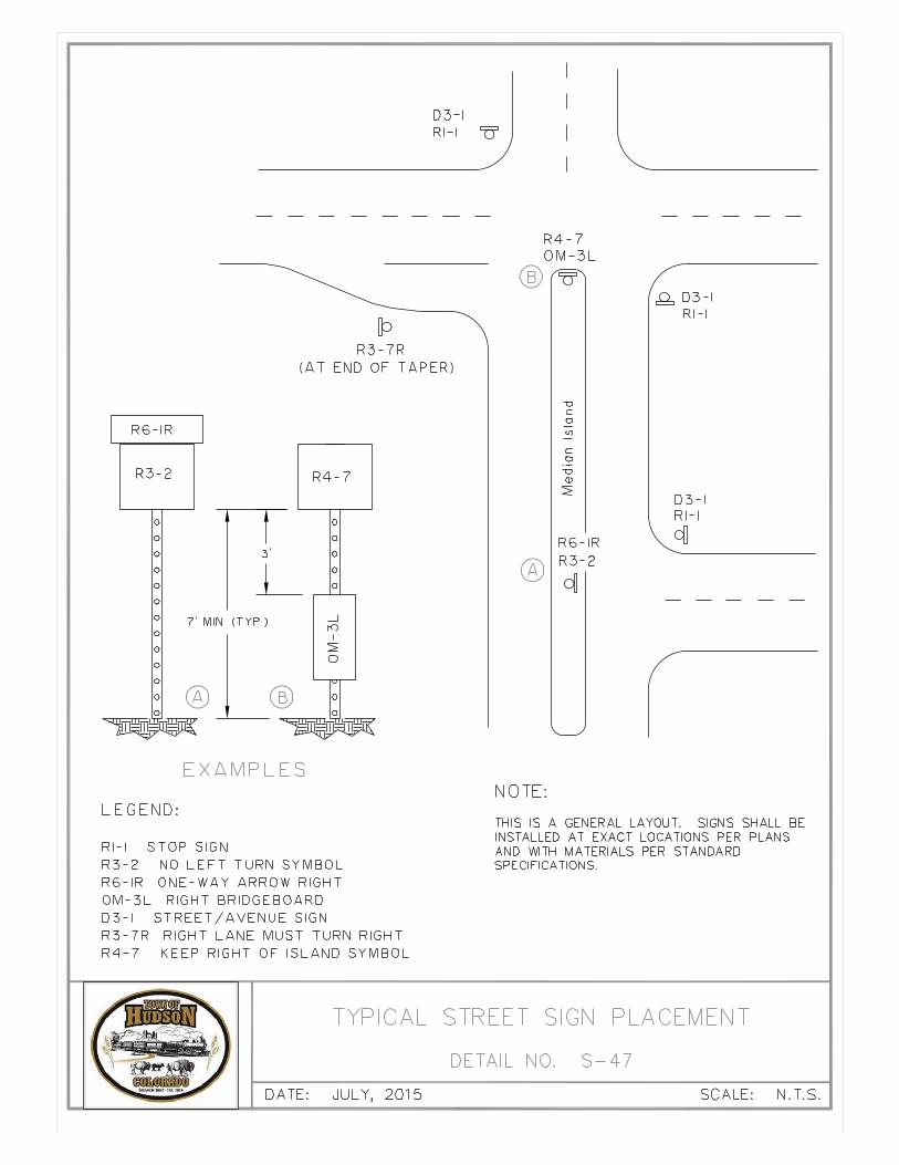
1.21 SIGN STANDARDS
A. GENERAL
All signing shall be in accordance with the following design criteria and construction specifications.
B. DESIGN CRITERIA
1. All signs shall conform to current Manual on Uniform Traffic Control Devices (MUTCD), Colorado Supplements, and the Town of Hudson Standards Drawings and Specifications.
2. All signs shall be installed on Telespar type perforated posts with anchors at proper heights as per current MUTCD Standards.
3. Sign material shall be as follows:a. 36" x 36" or less shall be .080-gauge aluminum – pre-punched holes.b. 36" x 36" or larger shall be .100-gauge aluminum – pre-punched holes.c. 36” x 8” or greater shall be .080-gauge aluminum – pre-punched holes.d. All street name signs are double sided.e. Street name blanks shall be .08 gage blanks.f. The sheeting shall be High Intensity Prismatic.g. The street sign blanks shall be a minimum 30” and a maximum of 36”. The font shall be Highway
Font D.1) 30”x30” or smaller shall be a minimum of .080-gauge aluminum2) 36”x36” or larger shall be a minimum of .100-gauge aluminum3) Extruded blades shall be a minimum of .091-gauge aluminum

Page 24
h. Street and Avenue signs for post mounting shall be extruded aluminum, 6”x30” minimum to maximum of 36” in length. Town of Hudson standards are reflective White High Intensity Prismatic background with an EC film reverse weeding for letters, numbers, block numbers and arrows. (Highway Font D, 4” uppercase n first letter, lowercase on the rest of the name, on correct baseline, and 2” for block numbers and arrows.)
i. Stop signs must be DG3 with 3M protective coating.j. All signs shall be ordered complete with address.
4. All signs shall be 3M High Intensity Prismatic or Diamond Grade Reflective sheeting ten (10) year guarantee, or approved equal. Legends and symbols shall be made with Electro Cut (EC) Film. The Town reserves the right to request material changes to signs.
5. Sign sheeting standard, use reflective white background with green EC Film on top layer with reverse weed which shows reflective white blocked uppercase letters, numbers, and arrows.
6. Street and Avenue signs for post mounting shall be aluminum, 6" x 30" (minimum) in length.
7. The principal legend on guide signs shall be in letters and numerals at least 6 inches in height for all uppercase letters, or a combination of 6 inches in height for all uppercase letters and 4.5 inches in height for lowercase letters. On low volume roads (as defined in MUTCD Section 5A.01) urban streets with speeds of 25 mph or less, the principal legend shall be in letters at least 4 inches in height for all uppercase letters, or a combination of 4 inches in height for uppercase letters and 3 inches in height for lowercase letters. Refer to Standard Details for font and height for signage examples.
8. Recommended minimum letter heights on street name signs and highway speed limit signs are as follows:a. Overhead all types, all speed limits (Uppercase) shall be 12 inches; (Lowercase) shall be 9 inches.b. Post-mounted, multi-lane, more than 40 mph (Uppercase) shall be 8 inches; (Lowercase) shall be 6
inches.c. Post-mounted, multi-lane, 40 mph or less (Uppercase) shall be 6 inches; (Lowercase) shall be 4.5
inches.d. Post-mounted, 2-Lane, all speed limits (Uppercase) shall be 6 inches; (Lowercase) shall be 4.5
inches. ** If overhead street name signs are used, the lettering should be composed of initial uppercase letters at least 12 inches in height and lowercase letters at least 9 inches in height.
9. At signalized intersections, these signs shall be sized in accordance with Specifications for Oversize Street Signs or approved equal in Highway Standards. Use Word Font D - 12" uppercase on correct baseline.
10. All signs shall be mounted with Town approved vandal type rivets and with washers.a. 3/8" drive rivetb. 3/8" corner bolt with 5/16" nutc. Street name blade use 5/16" bolt 1/2" thread length 1/2" headd. 1 1/2" metal fender washer with 3/8" hole for signs 24" x 30" or biggere. 1 1/4" metal fender washer with 3/8" hole for signs 12" x 24" up to 24" x24”f. 7/8" nylon washer with 3/8" hole for signs 12" x 18" or smaller
11. Telespar type posts shall meet or exceed the following:a. Posts – 2" x 2", 12-gauge, ASTM Specification No. A446, Grade A, drilled on 1" centers. b. Anchors – 2 1/4" x 2 1/4" x 3', 12-gauge, ASTM Specification No. A446, drilled on 1" centers. c. All posts and anchors shall be galvanized to ASTM Specification A525 coating designation G90.
12. Wood/Metal/Fiberglass/post mounting - Band-It Type #201 3/4" stainless steel band, Band-It Type #201 3/4" Ear-Lokt Buckle, Band-It Type #DO22 3/4" Bracket, 5/16" x 3/4" Bolt w/ six-sided head, 5/16" plastic washer.
13. Sign shall have a seven-foot (7') clearance (minimum) from the bottom of sign to the ground at installation, or as approved by the MUTCD Standards and the Public Works Department.

Page 25
14. All multiple mounted signs on single post, the lowest sign shall be no lower than six (6') feet on urban roadways, with a one (1'') gap between signs. The lowest sign shall be seven (7') feet if near pedestrian or parking traffic.
15. All signs placed, with the exception of STOP and YIELD signs, shall be near property lines; they are not to intrude on driveways, doorways, or any type of entrance.
16. For 36” or longer street name signs, the signs shall be riveted together at ends with a 3/16” rivet.
17. Signs shall be placed behind curb to minimum specifications according to MUTCD. (Part II Signs) Standards and Colorado Supplements. Town of Hudson prefers signs to be placed two (2') feet behind the curb or sidewalk whenever possible.
18. Signs shall be placed a minimum of five (5') feet from fire hydrants.
19. Placement of “Stop” signs shall be in accordance with Town Standards. Behind curb, ramp, or crosswalk with a minimum of 36 inches behind sidewalk at radius point or as approved by Town of Hudson.
20. Signs shall not have any company logos or decals on them.
21. Signs placed in concrete islands shall be either core drilled with a 4' hole, or a piece of 4' PVC pipe may be poured into the full depth of the concrete and flush with the top of concrete.
22. All sign placement shall call for current locates to the ‘CALL BEFORE YOU DIG” at 1-800-922-1987 before sign installation. Current locates shall be established before the final inspection of sign installations.
1.22 LANDSCAPE STANDARDS FOR STREETSCAPE AND MEDIANS
Tree and shrub plantings on new and existing streetscapes and medians must be approved in advance by the Town. A permit is required from the Town prior to any plantings in the public right-of-way.
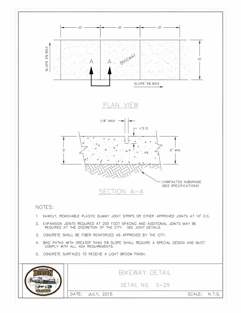
1.23 BIKE PATHS OR TRAIL CROSSING UNDER ROADWAYS
To accommodate both bicycle and pedestrian traffic on the existing and proposed bike path or trail system, the following shall be considered minimum clearances for bridges where the bike path or trail crossed under a roadway:
Horizontal: Twelve (12') feet from abutment to curb or edge of water.Vertical: Ten (10') feet from bike path or trail surface to underside of bridge.Note: The bike path of trail surface elevation should be at or above the high-water mark for
the two (2) year storm.
1.24 DECELERATION LANES AND TURNING LANES
A. GENERAL
A traffic impact study, along with the Town Engineer, shall determine the need of deceleration lanes and turning lanes.
B. DESIGN CRITERIA
1. The required deceleration lengths excluding stored vehicles are based on the design speed for the Arterial and are as follows:
Design Speed (mph) 30 40 45 50 55Decel. Length (ft.) 230 330 430 550 680

Page 26
2. These lengths include the taper length. On many Arterials, it is not possible to provide the full deceleration length due to existing conditions. In such instances, it will be necessary to coordinate the design with the Town Engineer.
3. On deceleration lanes where it is necessary to store stopped vehicles (such as at traffic signals), additional lengths shall be provided to accommodate the average number of vehicles anticipated at the peak hour, per signal cycle, if indicated from the most recent traffic impact analysis. In such cases, the “storage length” shall be added to the “deceleration length” to arrive at the total length. The recommended storage length for non-signalized intersections is as follows:
Turning Vehicles Per Hour 30 60 100 200 300Storage Length (ft.) 25 50 100 175 250
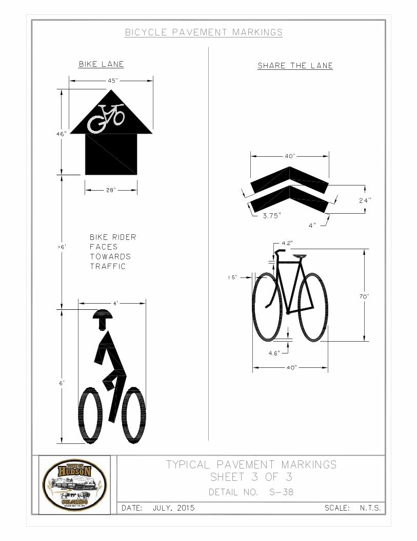
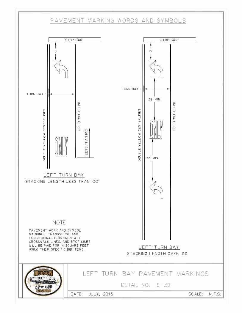
1.25 STREET MARKINGS STANDARDS
A. GENERAL
All street markings shall be in compliance with the current Manual of Uniformed Traffic Control Devices Standards and the following design criteria.
B. DESIGN CRITERIA
1. Refer to Construction Specifications Section 02618 of this manual for information on materials and construction.
2. The Design Engineer may use the current version of the CDOT M&S Standards, Standard Plan No. S-627-1 “Typical Pavement Markings” for guidance when preparing roadway plans.
1.26 TRAFFIC SIGNAL STANDARDS
A. GENERAL
All traffic signals shall be incompliance with the current Manual of Uniformed Traffic Control Devices Standards and the following design criteria.
B. DESIGN CRITERIA
1. The Town Engineer maintains current standard drawings and construction specifications for traffic signals which can be furnished to the Design Engineer upon request. Before materials are ordered, contact Town of Hudson.
2. In general, the Design Engineer can use the current version of the CDOT Standard Specifications for Road and Bridge Construction, Section 614 “Traffic Control Devices” for guidance when preparing roadway plans.
1.27 TRANSPORTATION IMPACT STUDY (TIS)
A. PURPOSE
The Traffic Impact Study (TIS) will determine and analyze the traffic impact a development imposes on the existing and 20-year transportation system affected by the development. Site and background traffic should be analyzed as to safety and efficiency in traversing the impacted street system leading up to, entering, circulating within the site, as well as the site and back through the system during the peak hour (PH) traffic period. All intersections, streets, adjacent drives and site access affected by the traffic will be analyzed with consideration given to adjacent land use, traffic generations, and improvements to the system, existing, committed and planned and as covered n comprehensive plans. Recommendations as to improvements, and phasing should be given.
At some point, the development traffic and background traffic growth may trigger the need for an additional travel lane, a signal, or an exclusive turn lane at a signalized intersection or into the

Page 27
development. This may be when the first phase is done, at build out, or within 20 years when the increased background and site traffic will require the improvements. It is the intent of the study to determine if the first phase, build out phase, or 20-year traffic will require improvements on the existing system.
B. RESPONSIBILITY FOR TRAFFIC IMPACT STUDIES
The developer provides a TIS prepared by a Professional Engineer experienced in transportation planning.
C. CONDITIONS FOR REQUIREMENT
Not all developments will generate the traffic required to do a study. The Town will determine if a study is required and the specific scope of the study. In general, a TIS is required when:
1. The site is estimated to generate 50 or more build-out peak hour trips on an arterial or collector, or 100 or more on a local street.
2. A capacity or safety issue exists or will exist before the proposed site is built out.3. The expansion of an existing development or change in use increases traffic to that stated in
number 1, or will add peak hour traffic to the existing background traffic on the adjacent main street or signalized intersections that will decrease Level of Service (LOS) to “D” or lower.
4. A new location or relocation of an access point may create a traffic problem.5. Estimated traffic will have a negative impact on local streets or intersections.6. Capacity, sight distance or safety will be compromised.
D. SCOPE MEETING
It is recommended that the developer and Town Engineer meet with the appropriate Town staff and present a conceptual map (to scale) with planned use (housing, commercial, office, industrial, etc.), surrounding land use and estimated access points. More detailed information such as the number of employees or homes, hours of operation, and daily and peak hour trip generation can be supplied later. If the project is on a State route, CDOT shall be involved. The following should be agreed upon:
1. Existing, build-out, and 20-year daily traffic volumes.2. Existing and 20-year, 24-hour traffic count source.3. Build-out and 20-year trip distribution.4. Number of travel lanes for collectors and arterials in the build-out and 20-year period.5. If a grade-separated interchange will be built.6. Any planned Town streets or improvements.
Twenty-four-hour volumes (existing, build-out, and 20 year) and peak-hour distribution should be in written form and used as reference during the TIS review. The peak-hour traffic percent of the daily traffic should be around 10%
E. STUDY AREA BOUNDARIES
The study boundary should include the network impacted by the new development which would include streets, signalized intersections, and those to be signalized in the future, and all commercial and private drives within 400' of the project property boundary.
F. STUDY AREA MAP
A scaled map should include:
1. Site location.2. All streets and street names internal and adjacent to proposed site.

Page 28
3. All drives within 400' of the proposed site boundary, including drives & streets on opposite side of roads.
4. All existing and proposed site access drives and spacing dimensioned between them.5. Footprints, with square footage, of all buildings and their use, if known.6. Project parking and drive aisles.7. Adjacent existing land uses.8. Existing lanes including turn lanes and dimensions.9. A north arrow and map scale.
G. TIS REQUIREMENTS
Summary of Major Requirements
1. Project description.2. Existing 24-hour counts, intersection turn moves and LOS.3. Use of each building, square footage, and traffic generated.4. Site build-out and background traffic (daily and peak hour), distribution, peak-hour turning
movements, LOS, signal warrants, queuing analysis, and traffic progression analysis.5. 20-year site and background traffic, distribution, peak-hour turning movements, LOS signal
warrants, queuing analysis and traffic progression analysis.6. Turn lane improvements or new turn lanes resulting from the development.7. Number all pages including the appendix.
H. TRIP GENERATION
A Trip Table of proposed land uses is required and includes both 24-hour and peak-hour generated traffic for total build-out. Peak hour traffic is the most critical determinate of signal, access point, and turn lane needs. It is not always highest during the usual 4:30 to 5:30 weekday period. Commercial area impact is typically greatest on Saturday afternoon, and homes in the weekday morning or evening. A special generator (stadium, school, library, movie theater, etc.) may have a peak-hour traffic demand different from the usual afternoon peak-hour traffic, and not on weekdays. If these uses will produce the greatest total demand, then use them, along with the other uses, in the Trip Generation Table, and state the reason. The table should include:
1. Land use category and number from the ITE Trip Generation Manual.2. The square feet of each building, or number of housing units, employees, etc.3. ITE Trip Generation Rates and Trips for the morning and afternoon peak-hours producing the
highest number of trips.4. Total daily traffic, and total morning and afternoon entering and exiting traffic.5. If development is proposed in phases, and any phase will produce need for a signal, turn lanes, or
degrade the existing LOS to a “D” or lower, then show that phase as a separate Trip Table from the total Trip Table, and the year it may happen, if not within the default five-year span.
6. Pass-by and internal trip reduction, if any.7. Document the source of trip rates, pass-by, and internal trip reduction rates.
I. EXISTING CONDITIONS
1. Describe the existing zoning, land use, surrounding road names and number of lanes. Include a scale map of the above, with driveway access points within 400'.
2. Prepare a map of the 24-hour daily traffic counts, peak-hour turning movements (AM, PM, and noon if noon is the highest, or Saturday PM counts, if highest). All counts should have existing morning traffic counts on top, and evening on bottom.
3. A map of the peak hour LDS for each turn movement impacted by the development.
Page 29
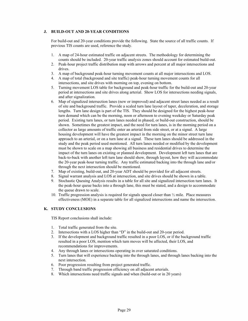
J. BUILD-OUT AND 20-YEAR CONDITIONS
For build-out and 20-year conditions provide the following. State the source of all traffic counts. If previous TIS counts are used, reference the study.
1. A map of 24-hour estimated traffic on adjacent streets. The methodology for determining the counts should be included. 20-year traffic analysis zones should account for estimated build-out.
2. Peak-hour project traffic distribution map with arrows and percent at all major intersections and drives.
3. A map of background peak-hour turning movement counts at all major intersections and LOS.4. A map of total (background and site traffic) peak-hour turning movement counts for all
intersections, and site drives with morning on top, evening on bottom.5. Turning movement LOS table for background and peak-hour traffic for the build-out and 20-year
period at intersections and site drives along arterial. Show LOS for intersections needing signals, and after signalization.
6. Map of signalized intersection lanes (new or improved) and adjacent street lanes needed as a result of site and background traffic. Provide a scaled turn lane layout of taper, deceleration, and storage lengths. Turn lane design is part of the TIS. They should be designed for the highest peak-hour turn demand which can be the morning, noon or afternoon to evening weekday or Saturday peak period. Existing turn lanes, or turn lanes needed in phased, or build-out construction, should be shown. Sometimes the greatest impact, and the need for turn lanes, is in the morning period on a collector as large amounts of traffic enter an arterial from side street, or at a signal. A large housing development will have the greatest impact in the morning on the minor street turn lane approach to an arterial, or on a turn lane at a signal. These turn lanes should be addressed in the study and the peak period used mentioned. All turn lanes needed or modified by the development must be shown to scale on a map showing all business and residential drives to determine the impact of the turn lanes on existing or planned development. Development left turn lanes that are back-to-back with another left turn lane should show, through layout, how they will accommodate the 20-year peak-hour turning traffic. Any traffic estimated backing into the through lane and/or through the next intersection should be mentioned.
7. Map of existing, build-out, and 20-year ADT should be provided for all adjacent streets.8. Signal warrant analysis and LOS at intersection, and site drives should be shown in a table.9. Stochastic Queuing Analysis results in a table for all site and signalized intersection turn lanes. It
the peak-hour queue backs into a through lane, this must be stated, and a design to accommodate the queue drawn to scale.
10. Traffic progression analysis is required for signals spaced closer than ½ mile. Place measures effectiveness (MOE) in a separate table for all signalized intersections and name the intersection.
K. STUDY CONCLUSIONS
TIS Report conclusions shall include:
1. Total traffic generated from the site.2. Intersections with a LOS higher than “D” in the build-out and 20-year period.3. If the development and background traffic resulted in a poor LOS, or if the background traffic
resulted in a poor LOS, mention which turn moves will be affected, their LOS, and recommendations for improvements.
4. Any through lanes or intersections operating in over saturated conditions.5. Turn lanes that will experience backing into the through lanes, and through lanes backing into the
next intersection.6. Poor progression resulting from project generated traffic.7. Through band traffic progression efficiency on all adjacent arterials.8. Which intersections need traffic signals and when (build-out or in 20 years)

Page 30
L. RECOMMENDED SITE AND AREA OF INFLUENCE IMPROVEMENTS
Summary of recommendations shall include:
1. Improvements needed at build-out.2. Improvements needed in 20 years.3. Needed ROW for improvements.4. Need for traffic signals and additional turn lanes resulting from the increased traffic.5. Turn lane geometry at signalized or future signalized intersections, and all site accesses.6. Pedestrian and wheel chair access.7. Cost estimates for major improvements generated by the development.
Table 1.27.1: Acceptable Level of Service from Intersection Delay
Land Use Type
Other Corridors
Intersection TypeCommercial Corridors
Mixed Used Areas
Low Density Mixed Use Residential
All Other Areas
Signalized Intersections(overall) D E D D
Any LegE E D E
Any Movement E E E E
Stop sign control (arterial/collector or local) N/A F F E
Stop sign control (local/local or collector/local – any approach leg
N/A C C C

Page 31
SECTION 2SOIL INVESTIGATIONS AND PAVEMENT DESIGN
2.01 SOILS INVESTIGATIONS
A. GENERAL REQUIREMENTS
Three categories of soils testing and reports are required for all projects requiring right-of-way grading and paving. Soils Report, final Pavement Design Report, and extra testing (e.g., imported fill). All sampling and testing of soils shall be performed under the direct supervision of a Professional Engineer. All required reports shall be prepared and signed by a Professional Engineer.
1. Soils Report – This report evaluates the characteristics of the soils and the general issues of groundwater, soil stability, and swells potential. If groundwater is found to be an issue per the Geotechnical Report measures to mitigate ground water impacts to the proposed use must be provided in the development plans. (See Section 2.03) A Soils Report is required for street and related improvements within the right-of-way, public easements. This report is required as part of the preliminary plat submittal. The Soils Report is valid for three (3) years. If construction has not begun three (3) years following the date the Soils Report is accepted by the Town, an updated Soils Report will be required.
2. Final Pavement Design Report – This report is required for all projects with roadway improvements. The soil investigation associated with this report will occur after grading for public roadways is complete to within six (6) inches of anticipated final subgrade elevation, and sanitary sewer lines have been installed. This report must be submitted and approved prior to any concrete or paving installation. The Final Pavement Design Report is valid for one (1) year. If paving construction has not begun one year following the date the report is accepted by the Town, an updated report will be required.
3. Extra Testing – If imported fill material is required for the project, this material shall also be tested to meet Town standards before placement.
B. TIMING OF SOIL BORINGS
1. Initial Borings – The information from the initial soil borings must be summarized in the Soils Report. The entire site shall be sampled for initial testing. This is required because street locations may not yet be determined or may change. A minimum of one (1) sample for every five (5) acres shall be taken to establish general site grading recommendations, preliminary foundation recommendations, and preliminary pavement section design. In areas where groundwater is suspected within five (5') feet of the original ground surface, borings shall be taken during the time of year that the groundwater table is likely to be highest in elevation. Generally, evaluation for groundwater shall be done between May 1 and October 1.
2. Structures – Soil borings for design of structures shall be taken prior to the design of the structure.
3. Imported Fill – All fill material shall be tested by the Geotechnical Engineer and approved by the Town prior to its use in the public right-of-way and easement. (See 2.01G)
C. FREQUENCY OF SOIL BORINGS
1. Basic Requirements – A minimum of two borings shall be provided for each project. The number of borings should be dependent on project size and Geotechnical Engineer’s recommendations, but shall not be less than a minimum of one (1) boring per five (5) acres.
2. Structures – Testing frequency for structures shall satisfy AASHTO Bridge Design requirements and CDOT Materials Testing requirements.

Page 32
D. LOCATION AND DEPTH OF BORINGS
1. Basic Requirements – Borings shall be taken to a minimum depth of 10 feet below the proposed grade. The original ground elevation at the top of each boring shall be clearly identified. If preliminary plans exist, borings shall be taken at the location of future roads, buildings, etc.
2. Structures – Borings for structures shall be taken to a minimum depth of 10 feet below the footing elevation.
3. Piers or Piles – Initial borings shall extend deeper than 10 feet if it is anticipated that piers or piles will be used within the development as a construction method. In such cases, the depth of borings shall extend to a depth of 10 feet below the anticipated piers or pile depth or to a depth at which sound bedrock is encountered.
E. SOIL GROUPING AND SUBGRADE SUPPORT TESTING
To simplify subgrade support testing (R-Value), soil samples may be combined to form soil groups consistent with the AASHTO classification, group index, and location for the area investigated. Groupings shall not mix samples with different AASHTO classifications. Soil groupings shall not be used to reduce swell potential of the in-situ subgrade soils. An adequate number of tests should be performed for the Geotechnical Engineer to determine whether or not the subgrade soil is capable of supporting the proposed construction and design loads, but shall never be less than a minimum of two (2) per Soils Report. If the subgrade soils are not suitable, then the Geotechnical Engineer shall provide a specific recommendation for subgrade stabilization. The Final Pavement Design Report shall contain construction details related to the specific mitigation measures recommended in the Soils Report.
F. REQUIRED TESTS
The tests listed in Table 2.01.1 are required for each boring described in the Soils Report. Soils shall be described in the Soils Report. Soils shall be described visually, then tested in a laboratory to determine the AASHTO Classification of each soil type.

Page 33
Table 2.01.1: Test Required for Each Boring
Test Testing Frequency Notes / Exceptions
Visual Each Soil Type Described in the Field
Liquid Limit Each Soil Type Passing No. 40 Sieve
Plastic Limit Each Soil Type Passing No. 40 Sieve
Moisture Each Soil Type
Percent Passing 200 Each Soil Type
Gradation Each Granular Soil A-1 through A-4 soils
AASHTO Classification Each Soil Type
R-Value See Section 2.01E
Swell/Consolidation Test Each Clay Soil Type A-6 through A-7 soils
Percentage of Soluble Sulfates Each Clay Soil Type A-6 through A-7 soils
Standard Penetration Test Each Soil Type
Groundwater
If encountered, depth to water below ground surface (DTW bgs) in feet
Bedrock Level If encountered, depth to bedrock bgs in feet
Corrosion Potential Resistivity Each Soil Type
G. IMPORTED FILL MATERIAL TESTING
All imported fill material shall be tested for swell, atterberg limits, and R-value (1 test for each soil type) and approved by the Town Engineer prior to use in the right-of-way. All imported fill shall have an R-value equal to or greater than the on-site subgrade materials. Imported fill shall not have liquid limit greater than 40 and a plasticity index greater than 20. The swell potential shall be less than 2.0% at 150 psf load.
2.02 SOILS REPORT
A. REPORT REQUIREMENTS
A Soils Report shall be submitted with the final plat. The report shall show results from all required testing. The report shall also include a description of site characteristics, e.g., location, topography, drainage features, etc. A checklist (see appendix) has been developed to assist in preparation of Soils Reports. It includes items pertinent for the Town’s review and reflects established professional engineering practice for Soils Reports. The final version of the Soils Report, which has been accepted by the Town, must be clearly identified and dated as such.

Page 34
The following acceptance block must be on the title page of the submittal:
ENGINEERING REVIEW, TOWN OF HUDSON
Review is for general compliance with Town of Hudson Standards and Requirements. TheTown of Hudson is not responsible for the correctness of design, dimensions, details, quantities, and design safety.
No Exceptions TakenMake Corrections NotedRejected - See Checklist
Review Engineer_______________________________________ Date______________________
In addition to the basic report requirements, each Soils Report shall include the following items:
1. Site location and description
2. Laboratory test reports conducted using the most current AASHTO test methods, for the tests listed in Table 2.01.1
3. Boring logs with ground elevation, of each soil type, 0.5 feet.
4. Depth to bedrock, if encountered.
5. Mitigation plans and recommendations for unsuitable or swelling soils.
6. Additional tests. These may be required for trench backfill evaluation, fill evaluation, slope stability, imported soils, etc.
7. Elevation of groundwater encountered in each boring.
2.03 SUBSURFACE WATER INVESTIGATION
A. CONDITIONS FOR REQUIREMENT
If groundwater is encountered within five (5') feet of the original ground surface, a Subsurface Water Investigation Report shall be submitted for approval by the Town Engineer, unless the Town Engineer has waived this requirement. This report is required to ensure mitigation of high groundwater effects upon public improvements within the right-of-way or easements. This information may be a separate report or may be included in the Soils Report.
Exception for Buried Utility Construction - This report is not required for temporary dewatering activity needed to facilitate construction of buried utilities. However, all applicable State requirements must be followed.
This report is not required for temporary dewatering activity needed to facilitate construction of buried utilities. However, all applicable state requirements must be followed.
B. REPORT REQUIREMENTS
The report shall include recommendations and proposed methods of dealing with groundwater. This shall include proposed methods for dewatering utility trenches and proposed methods for protecting foundations and structures.
The subsurface water investigation report shall include the following information:
1. Site location and description. Include locations of any on-site or nearby irrigation ditches and wetlands.

Page 35
2. Lowest and highest elevations of water table and likely direction of flow. Elevations for high water to be taken between May 1 and October 1.
3. Potential sources of groundwater. Include proximity to irrigation ditch systems.
4. Other relevant subsurface information, such as, water ownership (water rights), groundwater quality (contamination or other undesirable characteristics).
5. Potential future groundwater conditions and cone of influence.
6. Subsurface drainage recommendations, including its effects on all conditions, including sensitive habitat and wetlands.
7. Subsurface drains - If subsurface drains are recommended, the drains must have a gravity discharge without any possibility of backflow or blockage of the outlet. Any subsurface drain system shall be owned and maintained by the Developer or the Developers assigned successor(s). These drains may discharge into the Town’s storm drainage system, including inlets or detention ponds, upon approval of the Town Engineer. Anticipated impacts to the groundwater table on adjacent properties must be quantified. Subsurface drains may be located in the public right-of-way or easements, but shall be maintained by the Developer or the Developers assigned successor(s). Subsurface drains shall have properly designed clean-outs and be designed to prevent any possibility of backflow or blockage from occurring.
2.04 UNSUITABLE SOIL MITIGATION
Mitigation plans for unstable or swelling soils (unsuitable for construction) revealed by the soils investigation shall be submitted by the Geotechnical Engineer. The following specific factors shall be addressed:
A. MITIGATION PLANS AND APPROVAL
All special problems found in soils investigation (e.g., expansion, frost, soluble sulfates, shallow bedrock, groundwater, soil instability, etc.) shall be addressed in the mitigation plans. All mitigation procedures must be approved by the Town Engineer prior to their implementation. If soils mitigation is required, the approved soil treatment shall extend to the back of curb, or to the back of sidewalk for attached or monolithic sidewalk. If the soils beneath the curb, gutter, and attached sidewalk have passed required proof-rolling and compaction tests, then these items may be constructed. In such cases, if soils mitigation is required under the pavement, the approved soil treatment shall extend from lip of gutter to lip of gutter.
B. MITIGATION FOR SWELL
If the swell potential is 2.0 percent or greater at 150 psf (ASTM D 4546, the final Pavement Design Report must provide mitigation measures. The mitigation measures shall reduce destructive swell potential under the public improvements to less than 2.0 percent. The swell test report shall specify sample conditions, surcharge pressures, and other key testing factors. Limits of mitigation shall be clearly identified in the Final Pavement Design Report and shall be based on tested samples.
Possible measures for mitigation may include the following:
1. Over-Excavation - Over-excavation and replacement with suitable non-expansive or low-expansive material to a depth sufficient to mitigate expansion is a common mitigation method.
2. Subsurface Drains - Subsurface drains may be effective at reducing the groundwater, thereby reducing swelling.
3. Moisture Treatments - Soils may be conditioned with moisture and compacted to an appropriate level of compaction for the expansive condition, including stability requirements.
4. Other Procedures - Other procedures may be proposed for review and approval by the Town Engineer. The chosen method must work for the full life expectancy of the roadway.

Page 36
C. SPECIFIC MITIGATION REQUIREMENTS
Specific mitigation requirements and methods generally accepted by the Town of Hudson are described in Section 02225 – GRADING, COMPACTION, AND UNIMPROVED AREA PREPARATION of this manual.
2.05 FINAL PAVEMENT DESIGN REPORT
A. GENERAL
The purpose of this chapter is to present the Street Structural Design Criteria required for use on all streets in the Town of Hudson. These criteria shall be used in conjunction with Section 1, Minimum Design Criteria. Soils Investigations and Report requirements are outlined in Section 2, 2.01 through 2.04. The Final Pavement Design Report shall include follow-up testing for subgrade soil expansion, subsurface water, and R-value.
1. Existing Streets – For existing streets the Town Engineer may require deflection tests or other testing of the existing pavement and base structure to determine if an overlay is feasible, or if reconstruction is necessary. The Town Engineer shall notify the Developer if this testing is required.
2. AASHTO Design – The design criteria and procedures presented follow American Association of State Highway and Transportation Officials (AASHTO) Guide for the Design of Pavement Structures.
3. Pavement Type – Streets are to be constructed of either asphalt pavement (HBP) or concrete pavement (PCCP) on top of compacted aggregate base course material and subgrade.
4. Treated Subgrade – The use of treated subgrade, or treated base may be acceptable when designed and submitted by the Geotechnical Engineer, and approved by the Town Engineer in accordance with these standards. The subgrade must be within 6 inches of final subgrade elevation prior to any soil tests and borings.
5. Roundabouts – The pavement thickness design for the circulatory roadway shall be based on the sum of the 20-year design volumes from all legs. A separate pavement design is required. The minimum asphalt sections listed in Table 2.08.1 shall also apply to roundabouts.
6. Approval – A preliminary pavement design may be submitted with final construction plans, but will not be approved until subgrade soil samples are analyzed after preliminary grading and sanitary sewer construction. Town’s approval is required prior to subgrade treatment, placement of aggregate base course, or pavement construction.
7. Pavement Design Updates – A new, revised Pavement Design investigation and report shall be required if the following conditions occur:
a. Phases – If it has been more than one year since the original design was completed, or if the roadway design or location has been changed.
b. Imported Fill Material – If imported fill material is used, tests must be taken to prove that the properties of the imported material meet or exceed the properties (R-Value) of the on-site materials. If this condition is not met, the Pavement Design the pavement shall be updated.
2.06 FINAL PAVEMENT DESIGN – SOILS SAMPLING
A. SOIL INVESTIGATION REQUIREMENTS
1. Soil borings shall be taken in the existing or proposed street right-of-way. Subgrade samples shall be taken after the installation of the mainline sanitary sewer, or waterline in which the final insitu subgrade strength characteristics may be affected by their installation. The subgrade shall be with-in six (6) inches of final subgrade elevation. Any required fill material shall be placed to the sub-grade elevation prior to sampling. The final Pavement Design Report shall be approved by the Town, prior to installation of curb and gutter.

Page 37
2. Frequency of Testing - A minimum of two borings shall be obtained per project, or a minimum of one boring per 500 lineal feet of new roadway, whichever is greatest. The Geotechnical Engineer or the Town may require more frequent testing, especially on sites that have high groundwater, swelling, or unstable soils.
3. Depth of Borings - Borings shall be taken to a minimum depth of 4 feet below the proposed subgrade elevation. The Geotechnical Engineer or Town may require deeper borings, especially when related to high groundwater levels, utility trenches, swelling soils, or other design concerns.
2.07 FINAL PAVEMENT DESIGN – SOILS TESTING
Soils shall be classified visually and tested in a laboratory to determine the properties listed in Section 2.01 Soils Investigations. A Boring Log and tests as described above in Table 2.01.1 in Section 2.01.F are required for each sample for Final Pavement Design.
A. SUBGRADE SUPPORT TESTING
Subgrade samples shall be tested for subgrade support value (R-Value). The Final Pavement Design Report shall clearly state whether or not the subgrade soil is capable of supporting the proposed construction and design traffic loads. Recommendation for subgrade stabilization (See Section 2.04), if required, shall also be provided.
B. HVEEM STABILOMETER
The subgrade support value shall be determined using Hveem Stabilometer (R-Value). The design R-value shall be for 300 psi (2070 kPa) exudation pressure. Reported data shall be contained in the Final Pavement Design Report and shall include the following:
1. Test procedure reference.2. Dry density and moisture content for each sample.3. Expansion pressure for each sample.4. Exudation Pressure. Corrected R-value curve showing the 300 psi (2070 kPa) design R-value.
C. SWELL TESTS
Swell tests shall be conducted for all A-6 through A-7 soils. The following table provides a guideline for expansion potential. Surcharge pressure shall be 150 psf.
Table 2.07.1: Expansion Potential of Subgrade Soils
% PassingNo. 200 Sieve
Liquid Limit (%)
Standard Penetration Resistance (Blows/Ft)
Volume Change Estimate(% of Total)
Expansion Classification
>95 >60 >30 >10 Very High
60-95 40-60 20-30 4-10 High
30-60 30-40 10-20 1-3 Medium
<30 <30 <10 <1 Low

Page 38
2.08 PAVEMENT THICKNESS DESIGN CRITERIA
Pavement design procedures in this section provide for a 20-year service life of pavement when normal maintenance is provided to keep the roadway surface in an acceptable condition.
A. DESIGN FACTORS
1. Equivalent Daily Load Applications (EDLA) – Equivalent Daily Load Applications (EDLA) and Equivalent Single Axle Loads (ESAL) units are based on 18-kip (80 KN) axle loading on each design lane. All data and design procedures in this section use EDLA or ESAL units for pavement loading repetitions. Minimum EDLA and ESAL criteria for each roadway classification are given in Table 2.08.1. The values shall be increased for roadways with a traffic study showing higher traffic numbers.
2. Design Serviceability – The Serviceability Index to be used for all Town Roadways dedicated for public use is given in Table 2.08.1.
3. Minimum Pavement Section – Table 2.08.1 provides the minimum acceptable pavement sections for each roadway classification based on assumed subgrade support and traffic values. These pavement thicknesses may be used for preliminary planning purposes, cost estimates, or final pavement designs when approved by the Geotechnical Engineer and the Town. All pavement thickness designs must be based on actual subgrade support test results and traffic projections for the specific project, but shall not be less than the minimum per Table 2.08.1.
4. Flexible Pavement Strength Coefficients – Table 2.08.2 contains the standard design coefficient for various pavement materials. Nonstandard design coefficients may be used, only if approved in advance by the Town Engineer. In addition, design values must be verified by pre-design mix test data and supported by daily construction tests.
5. Portland Cement Concrete Pavement – PCCP roadways shall have a minimum thickness of six (6) inches, and shall meet the requirements of MGPEC Section II.

Page 39
Table 2.08.1: Flexible Pavement Design Criteria
20-Year DesignTraffic
InformationServiceability
Index (psi) Reliability
AggregateBase
ThicknessClass 5 or 6
AsphaltThickness,
inches
Grading S(3/4 inch
aggregate)
Grading SG(1-1/2 inchaggregate)
Layer, inches
Layer, inches
Layer, inches
Layer, inchesRoad
Classification
Min.EDLA
(2)Min.
ESALSi
InitSt
Final D psi % Min Max Min Max Min Max Min Max
MinimumStructura
lNumber
(3)
LocalResidential two-lane (4)Residential one-lane (1)Industrial/commercial
51050
3650073000365000
4.54.54.5
2.02.02.3
2.52.52.2
657075
666
6.59.010.0
3.53.55.0
5.56.07.5
222
333
3.03.03.0
4.04.56.0
2.392.493.29
CollectorMinorMajorIndustrial/commercial
2550100
182500365000730000
4.54.54.5
2.32.32.3
2.22.22.2
758585
666
7.08.011.0
5.06.06.0
7.08.09.0
222
333
3.03.03.0
5.56.57.5
2.973.483.85
ArterialTwo-laneFour-laneSix-lane
100200300
73000014600002190000
4.54.54.5
2.52.52.5
2.02.02.0
909090
666
11.515.017.0
6.06.56.5
9.510.511.0
222
333
3.03.03.0
8.09.09.5
4.084.514.77
Notes:1. Wearing surface course shall be Grading S or SX for residential roadway classification and Grading S for collectors, arterials, and all industrial/commercial roadways.2. EDLA shall be calculated based on projected traffic uses. Minimum EDLA values are as given for the design lane. The Engineer may require greater EDLA values if
warranted3. Minimum structural numbers are based on subgrade R-value=5 and MR (Resilient Modulus) =555 x R + 1000.4. Single lane refers to a paved surface less than 20 feet wide, including residential alleys.5. Min/max lift thicknesses - Grade SX - 1-1/2"/2-1/2", Grades S - 2"/3", Grade SG - 3"/5"
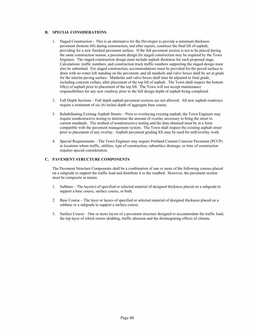
Page 40
B. SPECIAL CONSIDERATIONS
1. Staged Construction – This is an alternative for the Developer to provide a minimum thickness pavement (bottom lift) during construction, and after repairs, construct the final lift of asphalt, providing for a new finished pavement surface. If the full pavement section is not to be placed during the same construction season, a pavement design for staged construction may be required by the Town Engineer. The staged construction design must include asphalt thickness for each proposed stage. Calculations, traffic numbers, and construction truck traffic numbers supporting the staged design must also be submitted. For staged construction, accommodations must be provided for the paved surface to drain with no water left standing on the pavement, and all manhole and valve boxes shall be set at grade for the interim paving surface. Manholes and valve boxes shall later be adjusted to final grade, including concrete collars, after placement of the top lift of asphalt. The Town shall inspect the bottom lift(s) of asphalt prior to placement of the top lift. The Town will not accept maintenance responsibilities for any new roadway prior to the full design depth of asphalt being completed.
2. Full Depth Sections – Full depth asphalt pavement sections are not allowed. All new asphalt roadways require a minimum of six (6) inches depth of aggregate base course.
3. Rehabilitating Existing Asphalt Streets – Prior to overlaying existing asphalt, the Town Engineer may require nondestructive testing to determine the amount of overlay necessary to bring the street to current standards. The method of nondestructive testing and the data obtained must be in a form compatible with the pavement management system. The Town shall inspect the existing asphalt street prior to placement of any overlay. Asphalt pavement grading SX may be used for mill/overlay work.
4. Special Requirements – The Town Engineer may require Portland Cement Concrete Pavement (PCCP) in locations where traffic, utilities, type of construction, subsurface drainage, or time of construction requires special consideration.
C. PAVEMENT STRUCTURE COMPONENTS
The Pavement Structure Components shall be a combination of one or more of the following courses placed on a subgrade to support the traffic load and distribute it to the roadbed. However, the pavement section must be composite in nature.
1. Subbase – The layer(s) of specified or selected material of designed thickness placed on a subgrade to support a base course, surface course, or both.
2. Base Course – The layer or layers of specified or selected material of designed thickness placed on a subbase or a subgrade to support a surface course.
3. Surface Course – One or more layers of a pavement structure designed to accommodate the traffic load; the top layer of which resists skidding, traffic abrasion and the disintegrating effects of climate.

Page 41
Table 2.08.2: Pavement Strength Coefficients
Pavement Structure ComponentConventional Materials
Design Strength Coefficients
(Per Inch of Material) Limiting Test CriteriaPlant Mix Seal Coat 0.25 R 90+
New Bituminous Pavement 0.44 See Note 1
Existing Bituminous Pavement 0.24 R>72
New Aggregate Base Course 0.11 R>69
Existing Aggregate Base Course 0.10 R>50
Granular Subbase Course 0.07 R>78
Recycled Asphalt Pavement 0.12
Chemically Treated Subgrades2
(or Approved Substitute)
CompressiveStrength of FieldSpecimen
Cement Treated Subgrade 0.23 5 day, 160 psi
Fly Ash Treated Subgrade 0.10 5 day, 160 psi @ 70F
Lime Treated Subgrade 0.14 5 day, 160 psi, PI<6
Kiln Dust Treated Subgrade 0.10 5 day, 160 psi, PI<6
Notes:1. Greater strength coefficient may be considered if derived from deflection
data collected on the existing street.2. Strength coefficient is only acceptable if material is properly mixed and
field tests correlate with laboratory results. Strength Coefficient shall be reduced by 50 percent if field test correlations are not performed.
3. Provide the Town with test results for items tested in the above Table 2.08.2.
2.09 PAVEMENT DESIGN PROCEDURES
A. FLEXIBLE PAVEMENT DESIGN
1. General – Flexible pavements are those pavements that have sufficiently low bending resistance to maintain continuous contact with the underlying structure, yet have sufficient stability to support a given traffic loading condition. An example is asphaltic concrete pavement.
2. Procedure – Computer generated printouts and/or other design calculations must be included with the design submittal. The following procedure should be used in determining the structural number and thickness of the pavement being designed:a. Confirm the roadway classification and corresponding EDLA. The predicted volumes in the traffic
impact study must be used whenever they exceed the minimum EDLA values given in Table 2.08.2.
b. Determine the serviceability index (SI) and reliability for the roadway classification (Table 2.08.1).c. Convert the R-value using the AASHTO conversion for the subgrade to resilient modulus.d. Determine the structural numbers using AASHTO pavement design software or monographs from
AASHTO along with soil support test results and EDLA values previously determined. If used, copies of the monograph determinations must be included with the design submittal.

Page 42
e. Once the structural number (SN) has been determined, the design thickness of the pavement structure can also be determined by the software that uses the general equation:
SN = A1D1M1 + A2D2M2 + A3D3M3 +...
A1 = Hot Bituminous Pavement (HBP) Strength CoefficientsA2, A3, ... = Strength Coefficients of Additional Pavement ComponentsThe strength coefficients for various components of the pavement structure are given in Table 2.08-2
D1 = Thickness of HBP(inches)D2, D3, ... = Thickness of Additional Pavement Component
M1, M2, … = Drainage Coefficient of Additional ComponentsThese values are available in AASHTO Design Criteria or from Colorado Asphalt Pavement Association. Designers should use a value of 1.0 unless specific drainage information indicates otherwise.
f. The standard deviation for design of asphalt pavement shall be 0.44.g. The design must reference any mitigation measures required when the subgrade contains swelling
soils. Design reports recommending permeable layers in the pavement system must present the measures to be used to ensure adequate drainage of such layers and to maintain separation of the layers from the swelling soils.
B. RIGID PAVEMENT DESIGN
1. General – Rigid pavements are those that possess a high bending resistance and distribute loads over a large area of foundation soil. Examples include Portland Cement Concrete Pavement (PCCP) shall have a minimum thickness of six (6) inches and shall meet the requirements of MGPEC Item 11.
2. Procedure – Computer generated printouts and/or other design calculations must be included with the design submittal.
The design of rigid pavement is a function of structural quality of the subgrade soil (R-value), traffic (EDLA), and the strength of the concrete (working stress). In comparison to the strength of the concrete pavement, the structural contributions of underlying layers to the capacity of the pavement are relatively insignificant. However, to ensure proper drainage, PCCP shall not be placed directly on fine-grained soils.
The following procedure should be used in determining the structural number and thickness of the pavement being designed:
a. Confirm roadway classification and corresponding EDLA. The predicted volumes in the traffic impact study must be used whenever they exceed the minimum EDLA values given in Table 2.08-1.
b. Determine the serviceability index of the roadway classification from Table 2.08-1.c. The reliability factor for design of all concrete pavements shall be 90 percent.d. The working stress of the concrete is to be obtained from design tables, and verified during
construction.e. The standard deviation for design of concrete pavements shall be between 0.30 and 0.40.f. Determine the structural numbers using AASHTO pavement design software or Nomographs.
Printouts from software or copies of the Nomographs shall be included with the design submittal.g. Determine the pavement section thickness. A minimum thickness of six (6) inches of concrete slab
must be provided. If fine-grained subgrade exists, a minimum of six (6) inches of aggregate base course shall be provided.
h. Design must reference any mitigation measures required when the subgrade contains sulfates.

Page 43
C. RIGID PAVEMENT JOINT DESIGN
The rigid pavement joint designs shall conform to CDOT M & S Standards. A Joint Layout Plan shall be prepared by the Design Engineer and approved by the Town prior to construction.
2.10 PAVEMENT DESIGN REPORT
The pavement design report shall be prepared by or under the supervision of and signed and stamped by a Professional Engineer. The report shall make a recommendation for a typical pavement structural section based on known site soil conditions and the valid traffic impact study. The appendix includes a Pavement Design Report checklist.

Page 44

Page 45
STREET CONSTRUCTION SPECIFICATIONS
TABLE OF CONTENTS
Page No.
01010 Summary of Work 47
02220 Excavation, Removals and Embankment 59
02223 Structural Backfill 63
02225 Grading, Compaction, Subgrade, and Unimproved Area Preparation 67
02227 Subbase 69
02229 Aggregate Base Course 71
02575 Bituminous Paving 73
02576 Street Pavement Patching 75
02585 Portland Cement Concrete Pavement 77
02595 Utility Cut and Backfill 79
02610 Manhole and Valve Box Adjustments 81
02618 Pavement Marking Standards 83
02810 Irrigation System 97
03310 Curbs, Gutters, Sidewalks, Valley Gutters, Bikeways, Driveway and Alley Approaches 115

Page 46

Page 47
SECTION 01010SUMMARY OF WORK
PART 1 – GENERAL
1.1 SCOPE
A. All pavement and street construction within the Town of Hudson on Town right-of-ways or Town owned property shall be constructed in accordance with the requirements of this specification, Colorado Department of Transportation Standard Specifications for Road and Bridge Construction as referenced herein and as related to Town Ordinances. All standard specifications, i.e. ASA, AWWA, ASTM, ACI, CHS, ISSA etc. are made a portion of these specifications by reference and shall be the latest edition and revision thereof. The Town of Hudson standards, specifications, and special provisions shall take precedence over conflicting provisions in the CDOT Standard Specifications and other referenced standards.
Whenever the provisions of these Standards are found to be inconsistent with any other regulations or codes, the Engineer (as defined below) shall determine the standard to apply. The provisions of these regulations are minimum requirements that do not preclude imposition of more restrictive standards by agreement or by law.
B. Accepted Plans – Pavement and street construction shall be done in accordance with engineered construction plans for the work, prepared under the direction of a Professional Engineer and accepted by the Town of Hudson Department of Public Works. Plans shall conform to the Street Design Criteria section of these specifications and shall show all the information called for on the "Construction Plans Check List" shown in Appendix A. Construction shall conform to the standard detail drawings included in these specifications.
Prior to the Contractor/Owner beginning work, an accepted set of plans and specifications must be on file with the Town of Hudson Public Works Department. All contracts, bonds, insurance, permits, and licenses must be fully executed by the Contractor/Owner before beginning work. Contractor/Owner shall have a copy of the accepted plans and specifications, along with the Town’s “Design Criteria and Construction Specifications”, on the site at all times during construction.
C. Preconstruction Conference – A preconstruction conference shall be held prior to the issuance of any permits for construction. Attendance should include the Public Works Department, Developer/Owner, Design Engineer, General Contractor, Subcontractors including; earthwork, utilities, curb and gutter, paving and signing.
1.2 GENERAL CONDITIONS
A. DEFINITIONS
1. ABILITY – that which a person can do on the basis of present development and training.
2. AGENCY – shall mean the Town of Hudson.
3. BASE COURSE – the layer or layers of specified or selected material placed on a sub-base or a subgrade to support a surface course.
4. CDOT STANDARD SPECIFICATIONS – Colorado Department of Transportation, "Standard Specifications for Road and Bridge Construction" latest edition.
5. CERTIFICATE OF FINAL ACCEPTANCE – At the expiration date of the warranty period and after all deficiencies are corrected to the satisfaction of the Town Engineer a Certificate of Final Acceptance will be issued.
6. CERTIFICATE OF SUBSTANTIAL COMPLETION – shall constitute the initiation of the warranty period.
7. TOWN – The Town of Hudson.

Page 48
8. COMPETENT – a person who has the natural powers, physical or mental, to meet the demands of a situation or work; the word is widely used to describe the ability to meet all requirements, natural, legal, or other of a given task.
9. CONSTRUCTION DRAWINGS – Detailed and working drawings, including plan, profile, and detail sheets of proposed utility improvements, approved by the Engineer.
10. CONSULTANT – the partnership, corporation, or individual who is a Registered Professional Engineer in the State of Colorado hired by the Owner and is empowered to act as his agent for the project.
11. CONTRACTOR – the corporation, association, partnership, or individual who has entered into an Agreement with the Owner to perform the work, and who is licensed and bonded in the Town of Hudson in accordance with the requirements of the Town Code, for public right-of-way work.
12. DAYS – intended as calendar days, not normal working days, unless stipulated as working days.
13. DESIGN ENGINEER – the partnership, corporation, or individual who is registered as a professional engineer, according to Colorado statutes, and who is hired by the Owner, and is empowered to act as his agent for the project.
14. DIVISION – when referred to in the CDOT Standard Specifications shall mean the Town of Hudson Public Works Department.
15. ENGINEER – A term used in situations where a decision or action may be required by the Town Engineer with the Town of Hudson.
16. EMBANKMENT – Fill placed within limits of right-of-way and easements upon which improvements will be constructed.
17. MAY – a permissive condition. No requirement for design or application is intended.
18. NORMAL WORKING DAYS – Monday through Friday. Saturdays, Sundays, and legal Holidays shall not be considered normal working days.
19. OR AN APPROVED EQUAL – as approved to being acceptable by the Engineer.
20. OWNER – the developer, corporation, association, partnership, or individual who has entered into an Agreement with the Town and has entered into an agreement with the Contractor to perform the work.
21. PROJECT AS BUILT RECORD DRAWINGS – Detailed drawings which have been prepared by the Design Engineer, upon completion and at the time of the certificate of substantial completion, and show actual construction and contain field dimensions, elevations, details, changes made to the construction drawings by modification, details which were not included on the construction drawings, and horizontal and vertical locations of underground utilities which have been impacted by the utility installation.
22. PROJECT REPRESENTATIVE – shall mean an authorized representative of the Engineer assigned to complete project observation and review for contract performances, standards, and contract compliance.
23. PROVIDE – furnish and install complete in place.
24. QUALIFIED – acquired abilities: skill, knowledge, experience, that fits a person for a position, office, or profession.
25. REMOVE – remove and dispose of legally.
26. ACCEPTANCE TESTING – shall mean test that will be performed by the Town of Hudson Public Works Department or its authorized representative. Acceptance tests shall include but not be limited to the following: CONCRETE - slump, compressive strength, air content, and aggregate sieve analysis tests, SOILS -moisture density relationship and density tests, AGGREGATE BASE COURSE -moisture-density relationship and density tests, HOT BITUMINOUS PAVEMENT tests.

Page 49
27. SHALL – a mandatory condition.
28. SHOULD – an advisory condition. Where the word "should" is used, it is considered to be advisable usage, but not mandatory. Deviations may be allowed when reasons are given which show that the intent of the standard is met.
29. STANDARD STREET SPECIFICATIONS – the current Town of Hudson Design Criteria and Construction Specifications for Streets.
30. STREET – as used in this specification shall include the pavement section, right-of-way, sidewalks, driveways, bikeways, alleys and alley approaches.
31. SUBBASE – the layer or layers of specified or selected material placed on a subgrade to support a base course, surface course, or both.
32. SUBGRADE – the top surface of a roadbed upon which the pavement structure, shoulders, and curbs are constructed.
33. SURFACE COURSE – one or more layers of a pavement structure designed to accommodate the traffic load, the top layer of which resists skidding, traffic abrasion, and the disintegrating effects of climate. The top layer is sometimes called "Wearing Course."
34. UTILITIES – Shall mean all utilities on site prior to the time of any design; such as but not limited to water lines, sanitary sewer lines, drainage lines, electric lines, gas lines, telephone lines, and cable television lines.
35. WORK – the entire completed construction or the various separately identifiable parts required to be furnished for the project. Work is the result of performing services, furnishing the labor and furnishing and incorporating materials and equipment into the construction.
36. WORKING DAYS – Any day, exclusive of Saturdays, Sundays, and holidays, on which weather and other conditions not under the control of the Contractor will permit construction operations to proceed with the normal working force engaged in performing those items controlling the completion of the work.
37. WORKING HOURS – The Contractor shall restrict working hours to between 7:00 a.m. and 6:00 p.m. on normal Town of Hudson business days unless prior approval has been obtained from the Town Engineer.
B. ABBREVIATIONS
1. AASHTO – American Association of State Highway and Transportation Officials.
2. ACI – American Concrete Institute.
3. ADA – Americans with Disabilities Act
4. APWA – American Public Works Association
5. ASTM – American Society for Testing and Materials
6. AWG – American Wire Gauge
7. AWS – American Welding Society
8. AWWA – American Water Works Association
9. EPA – United States Environmental Protection Agency
10. ITE – Institute of Transportation Engineers

Page 50
11. ISSA – International Slurry Seal Association
12. MGPEC – Metropolitan Governments Pavement Engineers Council
13. OSHA – Occupational Safety and Health Administration
C. INTERPRETATION
1. These Specifications contain many command sentences which are directed at the Contractor/Owner unless otherwise stated.
2. The Contractor/Owner shall request clarification of all apparent conflicts by contacting the Engineer. The Engineer will not be responsible for any explanations, interpretations, or supplementary data provided by others.
D. VARIANCES FROM STANDARDS
These standards and construction plans are intended to supplement each other. When conflicts and/or questions arise between the accepted plans, specifications, development standards, referenced standards or other contract documents, the Engineer shall make the final decision concerning such matters. If administrative changes are made after approval of the plans, the variance from these standards must be approved in writing by the Engineer. Work shall be completed according to the design accepted by the Engineer. Written clarification shall be obtained from the Engineer for acceptance of omissions, conflicts, or revisions prior to construction.
E. OMISSIONS
1. Any work not specifically set forth in the construction plans or these standards, but which is necessary as determined by the Engineer, shall be completed.
2. The Standards and Specifications are complementary; what is called for by one is as binding as if called for by all. It is the intent of the Standards and Specifications to require a functionally complete Project (or part thereof) to be constructed in accordance with these Standards and Specifications. Any work, materials, or equipment that may reasonably be inferred as being required to produce the intended result will be provided whether or not specifically called for. When words which have a well-known technical or trade meaning are used to describe work, materials, or equipment, such words shall be interpreted in accordance with that meaning.
F. GENERAL QUALIFICATIONS
The provisions of the Standards and Specifications apply to the construction, enlargement, removal, alteration, relocation, repair, trenching, and restoration of any Public Improvement or common facilities regulated herein.
1. Exceptions – Requests for exceptions shall be submitted in writing to the Town Public Works Department. The request shall state the variance requested, the justification and supporting data for the variance, and the requested change to the standards or specifications for the specific project. The Engineer may require that exceptions be signed by a professional engineer registered to do work in the State of Colorado and bear their seal.
2. Exceptions to the Construction Specifications for Streets as outlined in this document shall be reviewed by the Public Works Director, or his designee, and shall meet the following criteria for approval:
a. Special circumstances or conditions exist which limit the ability of the design to meet the design standards outlined in the document. Financial difficulties, loss of prospective profits, and previously approved exceptions in other developments shall not be considered special circumstances; or
b. The exception represents an alternative design that will meet the intent of the standards and requirements set forth in this document.

Page 51
c. In either case, if granted, the exception will not be detrimental to the public interest or other property, nor in conflict with the Town Comprehensive Plan, and will not endanger the public safety, health or welfare.
All exceptions for construction specifications must be reviewed and acted on prior to construction. The Town shall respond promptly and in writing to such requests but reserves a minimum of five (5) working days for review and response. When additional review time is required, the Town shall notify the submitter of the need for additional time within two (2) working days of the submittal.
1.3 REGULATIONS FOR STREET CONSTRUCTION
A. PERMITS REQUIRED
1. No person, firm, or corporation may perform any work in the public right-of-way without first obtaining the appropriate permit through the Town. Once the permit is secured the permittee shall notify the Town 24 hours prior to initiating construction.
Every applicant shall agree in making application for a permit to be bound by all provisions of the Hudson Municipal Code Chapter 11. The following is required to complete a construction permit:
a. 8 ½” x 11" Site Planb. Signed and accepted construction plans c. Project Schedule d. Project Quantities
A Traffic Control Plan and cover sheet must be submitted and reviewed by Traffic Operations before permit for excavation or construction will be issued.
A permit for excavation or construction in public right-of-way/easement is required for the following. (See Appendix)
a. Street Paving – includes new street construction, reconstruction, overlays, crack sealing and seal coats.
b. Curb, Gutter and Sidewalk – includes new, reconstruction, and repair of curbs, gutters, sidewalks, and other various concrete appurtenances in the public right-of-way.
c. Utility Construction – includes new, reconstruction and repair of water, sewer, storm sewer, power, gas, telephone, and cable TV lines and other various appurtenances related to these projects in the public right-of-way/easements. This permit also covers Emergency Street Cuts.
2. Other Fees and Permits – The Contractor/Owner shall obtain all necessary permits for construction, unless otherwise directed by the Town. All permits must be in accordance with Town, County, State, and Federal requirements. Town review and approval of all permits must be accomplished prior to the start of any construction. Examples of permits that might be required and locations where initial contact is to be made are as follows:
Partial List of Permits Initial Contact
State Utility Permit CDOTState Access Permit CDOT Railroad Use of Right-of-Way Railroad CompanyRailroad Work in Right-of-Way Railroad CompanyE.P.A. N.P.D.E.S. Permit Colorado Dept. of Health Corps of Engineer's Permits Corps of EngineersAir Quality Weld County Work in Ditch Right-of-Way Individual Ditch Companies
This list is provided as an aid, and shall not be interpreted as a complete list of all permits required. It shall be the responsibility of the Contractor/Utility to determine the type of permits required by the specific development. The Town shall make all available effort to assist the Contractor/Owner in

Page 52
determining, and obtaining permits required. A copy of all permits must be available for inspection on the job site at all times.
All required fees must be paid in advance, prior to issuance of permit and commencement of any construction.
B. PROJECT OBSERVATION AND REVIEW
All construction and installations shall be subject to observation and review by the Engineer or his authorized Project Representative. Certain types of work may have continuous observation and review.
It shall be the responsibility of the person performing the work authorized by the permit to notify the Town that such work is ready for observation and review. The Town requires that every request for observation and review is to be received one working day before such service is desired. Such requests shall be made by telephone to the Public Works Department, Monday through Friday between 7:00 A.M. and 4:30 P.M.
The Contractor/Owner wishing to work outside of these hours and requiring observation and review of such work shall be assessed an observation and review fee based upon the actual costs to the Town associated with supplying a project representative for overtime hours. Additionally, there will be a two (2) hour minimum for observation and review work outside of the normal work hours. The Contractor/Owner is responsible for notifying the Construction Services of his intent to work overtime hours, weekends, or holidays. Such notice shall be given as soon as possible, but, in no case less than 24 hours prior to the overtime work. The Engineer or his representative shall have total control when determining the need for observation and review of any work.
The Engineer may make or require other observations and reviews of any work as deemed necessary to ascertain compliance with the Town's Development Standards, Design and Construction Standards, or other standard specifications and codes.
C. AUTHORITY OF PROJECT REPRESENTATIVE
The Project Representative is authorized to check all work performed in connection with street construction, including but not limited to clearing and grubbing, compaction of subgrade, placement of sub-base, base and asphalt, forms, concrete work, signage, pavement markings, and materials to be used.
The Project Representative is present on the site to advise contractors on these standards. He has authority to reject defective materials and workmanship, until any questions of issue can be resolved by the Engineer, and advise the Contractor/Owner in complying with construction plans and standards.
The Project Representative shall, in no case, act as foreman or perform other duties for the Contractor/Owner, nor interfere with the management of the work done by the Contractor/Owner. The presence or absence of the Project Representative shall not relieve in any degree, the responsibility or the obligation of the Contractor/Owner to perform the work in accordance with the plans or specifications.
The Engineer and Project Representative shall, at all times, have reasonable and safe access to the work whenever it is in preparation or progress and the Contractor/Owner will provide proper facilities for such access for observation and review. The Project Representative has the authority to select locations for tests.
Whenever any portion of these specifications are violated, the Director of Public Works, by written notice, may order that portion of construction which is in violation of these specifications or other approved plans, specifications, and materials to cease until such violation is corrected. A copy of the notice shall be filed with the Contractor's license application for future review. If deficiencies are not corrected, performance shall be required of the Contractor's Surety. A re-inspection of constructed facilities shall occur at the end of the two-year warranty period.

Page 53
D. COMPACTION IN NEW UTILITY TRENCHES, CULVERTS, ETC.
All utility trenches within the street right-of-way (including service lines) must be mechanically compacted to not less than 95% of maximum density within + two percent (2%) of optimum moisture content as determined by AASHTO T99. Alternatively, utility trenches can also be backfilled with flowable fill to within one foot of finished grade. This includes gas, electric, TV cable, telephone and other utilities lines serving the development. All water and sewer services, including water and sewer main stub-outs, shall be installed prior to street construction. Trench backfill in utility easements within 20 feet of right-of-way shall be mechanically compacted to 95% maximum density or backfilled with flowable fill to within one foot of finish grade. Trench backfill in utility easements beyond 20 feet from right-of-way shall be compacted to 90% maximum density. Water settlement and/or jetting of trenches shall not be permitted.
E. MATERIALS AND QUALITY CONTROL TESTING
1. The Contractor/Owner is responsible for the quality control testing and protection of work until a certificate of substantial completion is issued by the Town of Hudson. All quality control test results shall be made available to the Engineer immediately after testing. The Town will provide acceptance testing. Acceptance testing may include but not be limited to tests associated with placing of concrete, asphalt, and base course subgrade preparation, and trench compaction. The Contractor/Owner shall coordinate with the Project Representative as to when he or she is ready for acceptance tests. See Appendix (Schedules for Quality Control and Acceptance Sampling and Testing).
2. The Contractor/Owner shall be responsible for the costs associated with re-testing due to failed acceptance tests.
F. MATERIALS, MANUFACTURER'S CERTIFICATES AND RECOMMENDATIONS
1. All materials and equipment shall be new and of a quality acceptable to the Town Engineer.
2. If required by the Town Engineer, the Contractor/Owner shall furnish satisfactory evidence (including reports of required tests) as to the kind and quality of materials and equipment. All materials and equipment shall be applied, installed, connected, erected, used, cleaned, and conditioned in accordance with the instructions of the applicable supplier except as otherwise provided in the Contract Documents; but no provision of any such instructions will be effective to assign to Town, or any of Town's representatives, any duty or authority to supervise or direct the furnishing or performance of the work.
3. When deemed necessary by the Engineer, the Contractor/Owner shall submit a certificate to the Engineer, secured from manufacturer of all the material used as a permanent part of the project, certifying that their product as used on the project, conforms to all Town specifications. No material shall be used until the certificates are approved by the Engineer.
4. All manufacturer's recommendations, instructions, or specifications regarding installation and use of products shall be considered a part of these Standards and Specifications and of equal force. Any conflict between the manufacturer's instructions and these Standards and Specifications shall be decided and settled by the Engineer and shall not be open for arbitration. All such manufacturer's instructions and submittals shall be presented to the Engineer for approval prior to scheduling a pre-construction meeting.
G. TRAFFIC CONTROL
1. A Traffic Control Plan (TCP) shall be submitted and reviewed by the Public Works Department prior to commencing any work. If the proposed work is in the State Highway right-of-way, then a construction traffic control plan approved by CDOT must also be submitted afterwards to the Town prior to commencing any work.
2. The Contractor/Owner shall be responsible for all types of traffic, including pedestrians, in the construction area. SPECIAL ATTENTION SHALL BE GIVEN TO INDIVIDULS UNDER THE AMERICANS WITH DISABILITY ACT.

Page 54
3. Any person who makes pavement cuts, excavations, places an embankment, or does any work in public right-of-way, including but not limited to areas along a public street, alley, or sidewalk, shall place barricades, warning signals, detour signs as appropriate, and/or other safety devices at the location, sufficient to warn the public of the hazard, the cut, excavation or embankment. Safety devices must be in compliance with the Manual of Uniform Traffic Control Devices (MUTCD), CDOT’s “Colorado Supplement” to the MUTCD and Town of Hudson Standards.
4. All work areas including but not limited to open cuts, trenches, ditches, manholes, and/or other hazards shall be completely surrounded by approved fencing and other appropriate controls to protect and warn pedestrians and persons using bicycles, wheel-chairs, and other vehicles. Temporary walk ways must be provided with all-weather surfacing.
5. The Contractor/Owner shall appoint a Traffic Control Supervisor who shall be responsible for the traffic control and who shall be certified by the American Traffic Safety Services Association (ATSSA) and/or the Colorado Contractor’s Association (CCA). The Contractor must also provide a Traffic Control Supervisor (TCS) to be on the job site at all times during job set-up. The TCS must be available 24 hours per day to resolve traffic control problems during construction. All Traffic Control Supervisors shall have in their possession a current T.C.S. card. A current copy of the T.C.S. card must be on file with the Town at least one (1) week in advance of the job setup. Representatives MUST understand/read/write and speak English.
6. Type C arrow boards MUST be used on ALL Arterial and Collector roadways for lane closures.
7. Variable Message Boards (VMB) MUST be used for ALL Arterial and Collector roadway closures or as specified by Project contracts. Duration of sign usage shall be predetermined by the Contractor or Town Representative.
8. Intersections and driveways shall be closed only for a minimum amount of time. The Contractor/Owner shall coordinate driveway closures with property owners, one (1) week prior to construction by written notification with final approval by the Town Representative.
9. Removal of any and all permanent street signs shall be coordinated with the Public Works Department. It will be the responsibility of the Contractor/Owner to replace/repair said signs until job project is final with Town’s acceptance of the project after the two-year warranty.
10. Developments with private streets shall also adhere to these same guidelines; except their permanent traffic control devices shall be maintained by their Homeowner’s Association Group (HOA).
11. The Contractor shall maintain responsibility to change or adjust traffic control devices if conditions warrant.
12. All flaggers shall be properly trained according to State and Federal guidelines. The Contractor/Owner shall submit copies of flagger’s certifications card to the Town Representative and/or Traffic Operations prior to construction.
13. The Contractor/Owner shall repair and replace damaged or missing permanent or temporary traffic control devices immediately within job site.
14. The Contractor/Owner shall maintain all necessary barricades, signs, permanent signs, temporary signs, pavement markings, and other traffic control devices between phases of construction even if construction activity ceased for a year or more.
15. All temporary painted lane line shifts SHALL be permanently removed by means that do not damage existing asphalt by the end of the construction project.
16. If the traffic control is deemed insufficient, notice will be given to rectify. If after one (1) hour the deficiencies have not been corrected, the Town reserves the right to temporarily suspend operations until traffic control is in compliance.
17. After the streets are constructed, the new streets must be controlled with either construction traffic control devices or permanent traffic control signage (stop signs, street signs, etc.) and pavement

Page 55
markings. Building permits cannot be issued until permanent traffic control devices are in place due to construction or unrelated traffic into and out of the development site. Street signs are included as required signage during the building construction phase to ensure that emergency services and building inspection staff can find building addresses.
18. The Town of Hudson will not be responsible for the maintenance of traffic signs or pavement markings as part of a new subdivision until the certificate of substantial completion is issued. At that time, Public Works will complete an inspection of the development to assure all the signs and pavement markings were installed in accordance with approved plans.
19. If there are deficiencies, the Contractor/Owner or the other party shall be responsible at no cost to the Town to bring the permanent traffic control signs and pavement markings back in compliance with approved plans.
20. The Contractor/Owner shall hold harmless the Town of Hudson and Town staff against claims resulting from accidents involving construction work or construction traffic control.
21. The Contractor/Owner shall schedule and expedite the work to cause the least inconvenience to the public.
22. No work shall be performed on the local streets before 7:00 a.m. or after 6:00 p.m. each workday unless otherwise approved by the Town Project Representative.
23. No work shall be allowed on Saturdays or Sundays unless approved by the Town Project Representative 48 hours in advance of these days. Work performed on these days is considered overtime hours.
24. Construction or repair work will not be permitted at or near the vicinity of signalized intersections or on any Arterial and Collector streets that have major traffic volumes between the hours of 7:00 a.m. to 8:30 a.m. and 3:30 p.m. to 6:30 p.m. during the rush hours and school term (except in the case of an emergency or with approval of the Town Representative).
25. When the work is stopped for the day, all traffic lanes of an Arterial or Collector roadway shall be opened to traffic unless extended closure is authorized by the Town Representative. A traffic lane shall be considered satisfactory for opening to traffic only if it is paved, patched, or plated in conformance with Section 02595. No full street closures will be allowed except in special conditions. No work will be permitted on holidays except in case of an emergency. Construction may not begin until all traffic control devices are in place.
26. The Contractor/Owner shall remove all traffic control devices immediately upon completion of work or when they are no longer needed (take off job site or move to designated holding area).
H. CONSTRUCTION STAKES
1. Stakes shall be the responsibility of the Contractor/Owner unless other arrangements are made with the Engineer prior to initial construction.
2. All vertical and horizontal control shall be based on the Town's monumentation and current datum. Proposed reference monumentation shall be approved by the Engineer prior to survey.
3. A 48-hour notice shall be given by the Contractor/Owner prior to the Town providing construction staking.
I. PRESERVATION OF SURVEY MONUMENTS
It shall be the policy of the Town of Hudson to preserve and perpetuate survey monuments existing within the Public Right-of-Way. See Standard Detail S-32.

Page 56
1. Definitions
a. "Aliquot Corner" means any section corner or quarter section corner and any other corner in the Public Land Survey System created by subdividing land according to the rules of procedure set forth in Section 38-50-101, "Laws of the State of Colorado regulating the Practice of Land Surveying".
b. "Acceptable monumentation of aliquot corners" means a monument meeting the physical standards for similar monuments set by the United States Bureau of Land Management (Chapter 1V, Manual of Instructions for the Survey of Public Lands, 1973) pursuant to Colorado State Law. Where any aliquot corner falls within the traffic area of a street, road, or highway, the top of the monument shall be placed one-half foot below the surface of the roadway, and if such surface is any form or pavement, the monument shall be provided with a monument box marked "SURVEY", the top of which shall be set one-quarter (1/4") inch below an existing pavement surface and one-half (½") inch below the surface of new pavement.
c. "Professional Land Surveyor" means any individual who practices professional land surveying and is currently registered with the Board of Professional Land Surveyors to practice in the State of Colorado.
2. All existing aliquot corner monuments in Public Right-of-Way shall be preserved whenever possible. Monuments that must be disturbed during construction shall be referenced by a Professional Land Surveyor before being disturbed and be replaced with acceptable monumentation at the completion of construction.
3. All construction plans or drawings shall show the location of aliquot corner monuments known to be in existence in the area of construction. Should an undiscovered or previously unknown monument be found during construction, it shall be preserved or referenced in compliance with the “Laws of the State of Colorado regulating the Practice of Land Surveying Title 38, Articles 1-101 and Title 38, Articles 53-103” and be replaced with acceptable monumentation at the completion of construction.
4. Should an aliquot corner monument be destroyed by construction or utility repair the Town shall have authority to cause such monument to be legally replaced and monumentated at the Contractor/Owner's expense.
J. CONFORMITY OF WORK AND MATERIALS
All work performed and all materials furnished shall be within the lines, grades, cross sections, dimensions, and material requirements, including applicable tolerances, shown on the plans or indicated in these criteria and specifications.
It shall be the responsibility of each individual Contractor/Owner to keep the work area clean during the prosecution of the work.
K. LOAD RESTRICTIONS The Contractor/Owner shall comply with CDOT Section 105 of the latest edition of the Standard Specifications for Road and Bridge Construction for Truck-Load Weights.
L. UTILITY COORDINATION
1. During construction, the Contractor/Owner shall keep inlets, junction boxes, manholes, control valves, and fire hydrants clear at all times. For all street construction, which impacts utilities, the Contractor/Owner shall provide a Town-approved means of temporary service during the approved construction time and properly reconnect such utility service immediately following construction.
2. In the event that a manhole frame, valve box, or other fixture is covered up during construction, it shall be made accessible within twenty-four (24) hours and raised to the proper alignment and grade prior to the issuance of the Certificate of Substantial Completion unless otherwise approved by the Engineer.
3. Locating or moving existing utilities or coordinating the installation of new utilities is the responsibility of the Contractor(s)/Owner performing the work. Relocation of utilities which are in a public right-of-way or easements shall be the responsibility of the permittee.

Page 57
M. PROTECTION OF EXISTING UNDERGROUND UTILITIES
The Contractor/Owner shall, at all times, take proper precautions for the protection of utilities, the presence of which are known or can be determined by field location of the utility companies. The Contractor/Owner shall be responsible for all expenses relating to damage to utilities. Hand-excavation shall be used whenever necessary. It is the Contractor/Owner's responsibility to call for utility locates and abide by those requirements as outlined by State Statutes. Call UNCC at 1-800-922-1987 for locates.
N. ARCHAEOLOGICAL
If the Contractor's excavating operations encounter remains of historical or archaeological significance, the operations shall be temporarily discontinued. The Contractor/Owner shall notify the Engineer, who will contact the proper authorities, to determine the disposition of the remains and artifacts. The Contractor/Owner shall protect the site in such a manner as to preserve the artifacts encountered.
O. PRESERVATION OF PROPERTY
Existing improvements, adjacent property, utilities, trees and plants that are not to be removed shall be protected from injury or damage resulting from the Contractor/Owner's operations.
P. PROTECTION OF PUBLIC AND PRIVATE INSTALLATIONS
The Contractor/Owner shall at all times take proper precautions for the protection of driveway culverts, street intersection culverts or aprons, irrigation crossings, mail boxes, driveway approaches, temporary or permanent street markings, signage, and all other identifiable installations that may be encountered during construction. The Contractor/Owner shall be responsible for all expenses relating to damage to public and private installations.
Q. TIMELINESS OF REPAIRS
Repairs, which are not termed a hazard to pedestrians, vehicles, or structures, shall be completed within thirty (30) days after receipt of notice to repair from the Public Works Department.
R. SEQUENCE OF CONSTRUCTION
All curb, gutter, crosspans, and sidewalk shall be constructed after the sanitary sewer, water, non-potable water, and storm sewer mains and services have been installed in accordance with these standards. All street grades shall be within six (6") inches of finished pavement subgrades prior to curb, gutter and sidewalk installation. Water valve boxes, manholes, and associated appurtenances shall be adjusted to final grade after installation of the pavement. Electrical, telephone, cable TV lines, and all other conduit which are in the public right-of-way shall be installed after sewer, water, non-potable water, and storm sewer mains. Conduit for dry utilities shall be installed prior to curb, gutter, and sidewalk. Tunneling under existing sections of curb, gutter and sidewalk is not allowed. Utility easements shall be brought to final grade prior to installation of utilities. New signage and pavement markings must not be installed until after all road work and utilities have been installed.
S. COMPLETION AND WARRANTY
Upon written request of the Contractor/Owner, the Engineer and Project Representative shall, in accompaniment with the Contractor/Owner or his representative, physically examine the work and/or phase of the work. One reproducible set of project as-built record drawings shall be prepared by the Contractor/ Owners' Design Engineer and issued to the Town prior to issuing a Certificate of Substantial Completion. The Project Representative shall issue a "punch list" of deficiencies to be completed prior to the issuing of a Certificate of Substantial Completion. If no deficiencies are found, a Certificate of Completion will be issued. The Certificate of Substantial Completion shall constitute the initiation of the warranty period. The Contractor/Owner shall warranty the completed work to be free of defects in workmanship or materials for a period of two (2) years. All work that fails or deteriorates during the first or second year shall be replaced under this warranty. The Contractor/Owner shall be responsible for all costs of material, equipment, labor, and/or traffic control for warranty work. Warranty work shall be completed in accordance with these specifications within 30 days of written notification by the Town, or agreed upon by the engineer.

Page 58
The determination of the necessity during the warranty period for the repair or replacement in whole or in part of the work shall rest entirely with the Director of Public Works.
T. ACCEPTANCE
Upon written request of the Contractor/Owner, the Engineer and Project Representative shall, in accompaniment with the Contractor/Owner, physically examine the work and/or phase of the work. The Engineer or his designee shall issue written partial acceptance of the work with a "punch list" of deficiencies to be completed within 30 days and prior to final acceptance. After all deficiencies are corrected to the satisfaction of the Director of Public Works a Certificate of Final Acceptance will be issued. If no deficiencies are found, the Director of Public Works will issue a Certificate of Final Acceptance. The issuance of a Certificate of Substantial Completion and/or Certificate of Final Acceptance shall not relieve the Contractor/Owner from the responsibility or liability of conforming to the approved plans and specifications.
Such written request shall not be made more than 60 days from the end of the warranty period nor less than 30 days.
U. PAYMENTS
When the CDOT Standard Specifications refers to payment or basis of payment, it shall be disregarded unless specifically referred to in other contract documents associated with the work. The Town of Hudson has no responsibility for payments unless the work was contracted by the Town.
V. CONFLICTS/QUESTIONS
When conflicts and/or questions arise between the accepted plans, specifications, development standards, referenced standards, or other contract documents, the Engineer shall make the final decision concerning such matters.
W. LIABILITY
The Town, the Engineer, or Engineer's authorized representatives charged with the enforcement of these Standards and Specifications, acting in good faith and without malice in the discharge of their duties, will not thereby be rendered personally liable for any damage that may accrue to persons or property as a result of any act or by reason of any act or omission in the discharge of their duties.
X. NO WAIVER OF LEGAL RIGHTS
The Town will not be precluded or stopped by any measurement, estimate, or certificate (made either before or after the completion and acceptance of the work) from showing the true amount and character of the work performed and the materials furnished by the Contractor/Owner, or from showing that any such measurement, estimate or certificate is untrue or is incorrectly made.

Page 59
SECTION 02220EXCAVATION, REMOVALS AND EMBANKMENT
PART 1 – GENERAL
1.1 SCOPE
The Work covered by this section concerns the furnishing of all labor, equipment, supplies, and materials necessary to perform clearing, grubbing, and removal of objectionable materials from the right-of-way prior to grading operations and placement of embankment to conformity with lines, grades, and typical sections as shown on the plans or as staked.
PART 2 – MATERIALS
2.1 SOIL MATERIALS
A. Generally, soil materials for roadway construction shall be as recommended in the approved soils report. The following soils materials are the minimum requirements for the materials to be used in the construction of roadways.
B. Embankment and fill material shall consist of soil, granular sand, gravel, and cobble material, free from frozen material, organic material, trash, glass, broken concrete, and other corrosive or deleterious material. The Contractor shall import approved material as necessary. Approval of embankment and fill material is contingent on the material having a resistance value when tested by the Hveem Stabilometer, or equivalent resilient modulus value, of at least that specified in the approved plans or pavement design and a maximum dry density of not less than 90 pounds per cubic foot. The material must be stable and have a liquid limit less than 40 and a plastic index less than 20 when tested in accordance with AASHTO T-89 and T-91, respectively. Size restrictions are as follows:
1. No material shall have a dimension larger than six (6") inches. Where the subgrade layer is less than six (6") inches the maximum size shall not exceed two thirds (2/3) the depth of the layer.
2. These size restrictions are contingent upon the material being evenly distributed in finer material such that uniform soil consolidation is achieved. If uniform soil consolidation is not being achieved, the Engineer may reduce the size of materials allowed or change the embankment and fill material requirements.
3. Where unstable subgrade is encountered, the Contractor shall take steps necessary to stabilize the material by techniques such as over-excavation and backfill with imported material, use of geotextile reinforcement, chemical stabilization or other methods. The Contractor shall notify the Engineer of the proposed solution to stabilize the subgrade. If required by the Town, the Owner's Design Engineer will make recommendations on stabilization techniques and materials. See Geotextile Reinforcement Placing, Street Construction Specifications, Section 02225 subsection 3.2-B.
4. If tests or observations reveal that material being placed is not of suitable quality and structural value, the Contractor shall provide other material as approved by the Engineer.
PART 3 – EXECUTION
3.1 CLEARING AND GRUBBING
The natural ground surface shall be cleared of all vegetation; such as, trees, logs, upturned stumps, roots of downed trees, brush, grass, weeds, and all other objectionable materials within the limits of construction. All surface objects and all trees, roots, and other protruding obstructions not designated to remain shall be cleared and/or grubbed, including mowing, as required, except stumps and roots and nonperishable solid objects which will be removed a minimum of two (2') feet below subgrade or slope of embankments. In streets, stumps and root systems shall be removed to below the two (2') foot level.

Page 60
Except in areas to be excavated, all holes resulting from the removal of obstructions shall be backfilled with suitable material and compacted in accordance with subsection 3.5 - Embankment.Trees which are to be removed shall be removed in such a manner as not to injure standing trees, plants, and improvements which are to remain. Any object that is designated to remain and is damaged shall be repaired or replaced as directed by the Engineer at the Contractor's expense.
Before the start of any overlot grading, stockpiling of soil, or clearing or grubbing operation, the Contractor/Owner shall file and obtain approval for a State of Colorado permit for Erosion and Sediment Control. The Contractor/Owner shall also file and obtain approval for an Erosion Control Plan (ECP) which shall be approved by the Town. See the Town's Storm Drainage Design Criteria Manual for details of the ECP. After the approval of the ECP, the Engineer shall issue a grading permit for the work as shown on the ECP. The installation of those items required on the ECP shall be installed and functional prior to the start of any land disturbing activities. Additionally, the Contractor/Owner shall post with the Town a bond in an amount to be determined by and as required by the development agreement.
3.2 REMOVAL AND DISPOSAL OF MATERIALS
All materials removed shall be legally disposed of outside of the right-of-way. No accumulation of flammable material shall remain on or adjacent to the right-of-way. The roadway and related work areas shall be left with a neat and finished appearance. In no case shall the material removed from the right-of-way and stockpiled be left in such a manner as to pose an erosion, weed, or hazard to the public. Stockpiles shall be left with long sloping sides and in such a manner as to accommodate the use of mechanical mowing equipment. The Contractor shall make all arrangements to obtain written permission from property owners for disposal locations outside the limits and view of the project.
The Contractor shall legally dispose of all material that is deemed unusable by the Engineer, off of the project site.
3.3 REMOVAL OF EXISTING IMPROVEMENTS
A. BITUMINOUS PAVEMENT
Bituminous pavement shall be removed to clean, straight lines by such methods as cutting, drilling, or others that will insure the breaking of pavement in a straight line in accordance with "Utility Cut and Backfill" Section 02595 of this manual. Also, see Standard Detail S-31. All saw cutting shall not extend past the construction limits by more than the depth of the structure and such overcut shall be sealed by a method approved by the Engineer.
Pavements which are to be overlaid shall be repaired as required by Section 02595 "Utility Cut and Backfill".
Also see Section 02595 "Utility Cut and Backfill" for restrictions on cutting and patching bituminous pavement.
B. CONCRETE PAVEMENT
Crosspans, Alley Intersections, and Concrete pavement shall be removed to the nearest construction joint or saw cut to full depth. See Standard Detail S-31. Sections shall be saw cut in straight lines either parallel with the curb or perpendicular to the alignment of the sidewalk or curb. All over sawing shall not extend more than the depth of the structure past the construction limits and shall be sealed in the same manner as joints. If the removed portion falls within less than five (5') feet of a construction joint, cold joint, expansion joint, edge, crack, or existing patch, the concrete shall be removed to the joint, crack, edge, or patch.
See Section 02595 "Utility Cut and Backfill" for restrictions on cutting and patching concrete pavement.

Page 61
C. CONCRETE CURB, GUTTER, SIDEWALK, AND DRIVEWAYS
Concrete shall be removed to edges neatly sawed to full depth. Sidewalks and driveways shall be saw cut in straight lines either parallel with the curb or perpendicular to the alignment of the sidewalk or curb. No section to be replaced shall be less than three (3') feet in either width or length. If the saw cut in the sidewalk or driveway falls within less than five (5') feet of a construction joint, expansion joint, or edge, the concrete shall be removed to the joint or edge. The sawing of concrete shall be done carefully, and all damages to concrete to remain in place due to Contractor's operations shall be repaired at the expense of the Contractor. All saw cutting shall not extend past the construction limits by more than 3 inches and such overcut shall be sealed in the same manner as cracks.
See Section 02595 "Utility Cut and Backfill" for restrictions on cutting and patching concrete curb, gutter, sidewalks, driveways, etc. See Standard Detail S-25.
3.4 TREE REMOVAL
The Town Forester shall be notified and approval obtained prior to excavation, removal, and/or modification of any tree within the public right-of-way.
3.5 EXCAVATION
A. Excavation of all materials shall be performed in conformity with the lines and grades indicated on the drawings or as staked. Suitable material removed from the excavations may be used in the formation of embankments and backfilling or any other areas within the right-of-way as permitted by the Engineer. Where material encountered within the limits of the work is considered unsuitable by the Engineer, such material shall be excavated as directed by these standards, the plans, or the Engineer and replaced with suitable material.
B. Foundations and the pavement structure shall be founded on original, undisturbed soil or on structural backfill extended to the undisturbed soil. Foundations and the pavement structure shall not be founded on existing fill if encountered at the project site. If existing fill is encountered at the subgrade, the Contractor shall excavate to original undisturbed soil and bring the grade to the required elevation with approved material and methods. Existing fill material, if encountered at the site, shall be removed. Existing fill may be stockpiled for reuse in backfills and embankments if it meets the requirements of the specifications. The Contractor shall remove unsuitable soil material as directed by the Engineer. The disposal of unsuitable soil material is the responsibility of the Contractor.
C. Excavate rock that is encountered at the site to a minimum depth of 6 inches below subgrade within the limits of the roadbed.
D. The Contractor shall blend the intersection of cut slopes with the slopes of adjacent natural ground surfaces in a uniform manner. The tops of cut slopes shall be flattened and rounded in accordance with the approved plans.
E. All excavated material shall be stockpiled in a manner that does not endanger the work or workers and does not obstruct sidewalks, streets, alleys, and/or driveways. The work shall be done in a manner that will minimize interference with traffic and/or drainage of the street. The Contractor at the end of each day shall barricade all excavations and ditch lines, remove excess excavated material from travel ways, and thoroughly clean all streets, alleys, and/or sidewalks affected by the excavation.
F. Materials encountered during excavation; such as, rubbish, organic, or frozen material, and any other material which is unsatisfactory for use as backfill in the opinion of the Engineer, shall be removed from the site and legally disposed of at the Contractor's expense. Stones, concrete, or asphalt chunks larger than six (6") inches or frozen material shall be considered unsatisfactory backfill and removed by the Contractor. Frozen material, however, may be thawed out and used at a later date.

Page 62
3.6 EMBANKMENT
This work shall consist of the construction of embankments by depositing, placing, and compacting material of acceptable quality and structural value above the natural ground or other surface in conformance with the lines, grades, and cross-sections shown on the drawings or as established. Before any embankment is placed, clearing, tree removal, sod and topsoil removal over the entire area shall be performed in accordance with paragraphs 3.1 through 3.3 above.
When an embankment is to be placed on slopes, it shall be continuously benched in horizontal layers to key into the existing slope. Each layer of the embankment material shall not exceed eight (8") inches in loose depth. The Contractor shall thoroughly mix and insure uniform density and moisture for proper compaction.
Cut areas shall be thoroughly compacted for a depth of eight (8") inches below finished subgrade. Each layer in fill and cut areas shall be thoroughly compacted by static roller or vibratory equipment. See Section 02225 subsection 3.1 for details of grading, compaction, and subgrade preparation. The base of fill areas should be scarified to a depth of not less than eight (8") inches and compacted to not less than 95 percent of maximum density within + two (2%) percent of optimum moisture content as determined by AASHTO T99, prior to placement of embankment material. Each layer shall be wetted or aerated, if necessary. No embankment material shall be placed upon soft, spongy, or frozen material or other material, the stability of which is, in the opinion of the Engineer, unsuitable for the placement thereof.

Page 63
SECTION 02223STRUCTURAL BACKFILL
PART 1 – GENERAL
1.1 SCOPE
This section includes the material and construction specifications for structural backfill and filter materials.
PART 2 – MATERIALS
2.1 STRUCTURAL BACKFILL
A. Structural Backfill shall comply with CDOT Standard Specifications for Class 1 material and meet the following requirements from laboratory sieves:
Class 1
SieveDesignation
% By WeightPassing Lab Sieves
2 inch 100
No. 4 30 - 100
No. 50 10 - 60
No. 200 5 - 20
Class 1 Structural Backfill shall be used on all bridges, box culverts, or where otherwise specified. In addition, this material shall have a liquid limit not exceeding 35 and a plasticity index of not over 6 when determined in conformity with AASHTO T 89 and T 90.
B. Class 2 Structural Backfill shall be composed of suitable materials developed on the project. To be suitable for use under this classification, backfill shall be free of frozen lumps, wood, or other organic material. If the material contains rock fragments or other materials that, in the opinion of the Engineer, will be injurious to the structure, the native material shall not be used for backfilling, and the Contractor shall be required to furnish "Class 1 Structural Backfill" material.
C. Flowable backfill may be substituted for Structure Backfill (Class 1) and (Class 2) where it is used to backfill culvert pipes, storm sewer pipes and utility cuts. It shall not be used to backfill abutments.
2.2 FLOWABLE BACKFILL
Flowable backfill meeting the following requirements shall be used to backfill all open cuts in portions of public right-of-way beneath existing paving, curb, gutter, or sidewalk improvements. Alternate backfill methods for large excavations will be considered on an individual review basis with the Town Engineer.
Flowable backfill shall consist of a controlled low-strength, self-leveling concrete material composed of various combinations of cement, fly ash, aggregate, water, and chemical mixture. It shall have a design compressive strength between 50 psi and 150 psi at 28 days when tested in accordance with ASTM D 4832. The mix shall result in a product having a slump in the range of 7 to 10 inches at the time of placement. The Contractor shall submit a mix design for approval by the Town prior to placement. The mix design shall be supported by laboratory test data verifying compliance with the 28-day compressive strength requirements.
Compaction of flowable backfill will not be required.
Flowable backfill shall not be allowed to freeze.
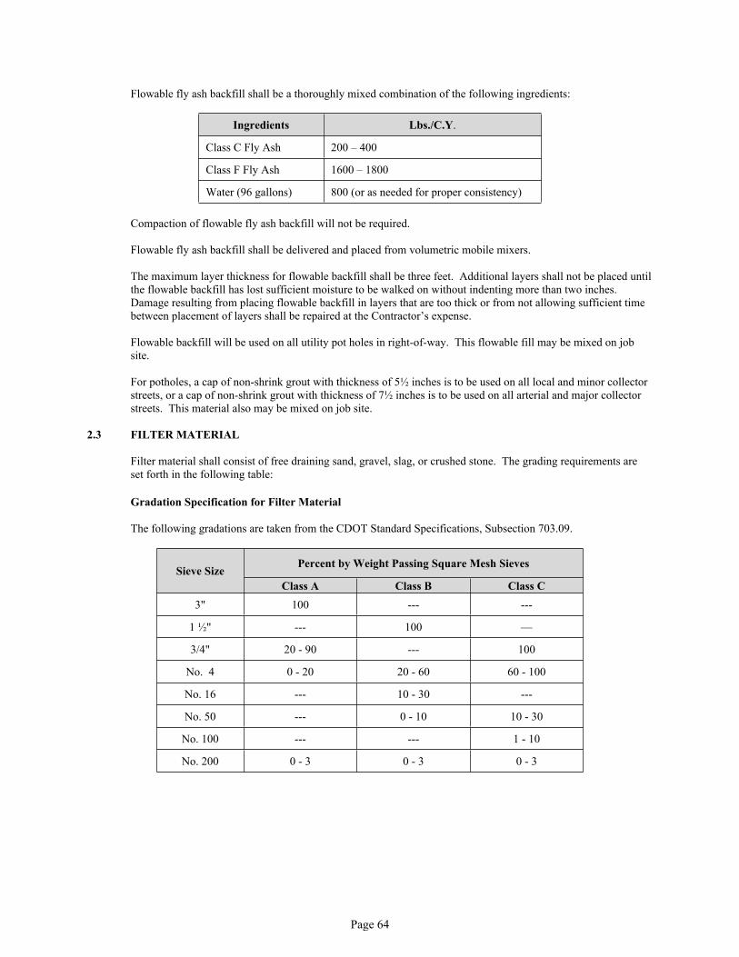
Page 64
Flowable fly ash backfill shall be a thoroughly mixed combination of the following ingredients:
Ingredients Lbs./C.Y.
Class C Fly Ash 200 – 400
Class F Fly Ash 1600 – 1800
Water (96 gallons) 800 (or as needed for proper consistency)
Compaction of flowable fly ash backfill will not be required.
Flowable fly ash backfill shall be delivered and placed from volumetric mobile mixers.
The maximum layer thickness for flowable backfill shall be three feet. Additional layers shall not be placed until the flowable backfill has lost sufficient moisture to be walked on without indenting more than two inches. Damage resulting from placing flowable backfill in layers that are too thick or from not allowing sufficient time between placement of layers shall be repaired at the Contractor’s expense.
Flowable backfill will be used on all utility pot holes in right-of-way. This flowable fill may be mixed on job site.
For potholes, a cap of non-shrink grout with thickness of 5½ inches is to be used on all local and minor collector streets, or a cap of non-shrink grout with thickness of 7½ inches is to be used on all arterial and major collector streets. This material also may be mixed on job site.
2.3 FILTER MATERIAL
Filter material shall consist of free draining sand, gravel, slag, or crushed stone. The grading requirements are set forth in the following table:
Gradation Specification for Filter Material
The following gradations are taken from the CDOT Standard Specifications, Subsection 703.09.
Percent by Weight Passing Square Mesh Sieves Sieve SizeClass A Class B Class C
3" 100 --- ---
1 ½" --- 100 —
3/4" 20 - 90 --- 100
No. 4 0 - 20 20 - 60 60 - 100
No. 16 --- 10 - 30 ---
No. 50 --- 0 - 10 10 - 30
No. 100 --- --- 1 - 10
No. 200 0 - 3 0 - 3 0 - 3

Page 65
During progress of construction, the Engineer will determine the class of filter material to be used. The following table is intended to be a guide:
Table of Recommended Filter Classes
Percentage of Soil Passing Designated SievesSieve Size or Designation *Use Class
A, B or C**Use Class
B or CUse Class
CNo. 10 less than 85, and ---- ----
No. 40 less than 24 less than 85 more than 85
* Based on the minus 3" portion of the soil adjacent to the filter material.
** To drain large quantities of water, use the most open grading recommended.
PART 3 – EXECUTION
3.1 STRUCTURAL EXCAVATION
A. Unsuitable foundation material shall be removed and wasted in a manner acceptable to the Engineer. Unsuitable foundation material which is suitable for embankments and suitable surplus excavated material shall be used in the construction of embankments. Unsuitable material removed below designed elevation shall be replaced with approved material.
B. Rock, hardpan, or other unyielding material encountered in trenches for culvert pipe or conduit shall be removed below the designed grade for a minimum depth of 12 inches. This extra depth excavation shall be backfilled and compacted with Class 1 or other approved material. The type of compaction shall be the same as that required for structure backfill (Class 1), as specified below.
3.2 STRUCTURAL BACKFILL
Backfill shall consist of approved materials uniformly distributed in layers brought up equally on all sides of the structure. Each layer of backfill shall not exceed six inches before compacting to the required density and before successive layers are placed. Structural backfill (Class 1) shall be compacted to a density of not less than 95 percent of maximum density within + two (2%) percent of optimum moisture content as determined by AASHTO T99.
Required density for structural backfill (Class 2) shall conform to Section 02225 Grading, Compaction and Subgrade Preparation Subsection 3.1.
Compaction methods that produce horizontal or vertical earth pressures, which may cause excessive displacement or overturning, or may damage structures, shall not be used.
Backfill material shall not be deposited against newly constructed masonry or concrete structures until the concrete has developed a field compressive strength of equal to the design compressive strength.
Shape the surface of the subgrade under structures such that they are not more than zero inches above or one and one quarter (1-1/4") inches below the required subgrade elevation. Unless otherwise indicated in the Contract or directed by the Engineer, all sheeting and bracing used in making structure excavation shall be removed by the Contractor prior to backfilling.
3.3 FLOWABLE BACKFILL
Compaction of flowable backfill will not be required.
The maximum lift thickness for flowable backfill shall be three feet unless proper consolidation techniques are used. Additional lifts shall not be placed until the flowable backfill has lost sufficient moisture to be walked on

Page 66
without indenting more than two inches. Any damage resulting from placing flowable backfill in lifts that are too thick or from not allowing sufficient time between lifts shall be repaired at the Contractor's expense.
3.4 FILTER MATERIAL AND PLACEMENT
Construction requirements for filter material for subsurface drains shall conform to the applicable requirements of CDOT Standard Specifications Section 605.
Filter material shall be placed behind bridge abutments, wingwalls, and retaining walls as provided in the Contract and in accordance with the following requirements:
1. Wall drain outlets shall be backed with sacked filter material conforming to the gradation requirements for course aggregate No. 3 or No. 4 set forth in CDOT Standard Specifications Table 703-1.
2. Filter material shall be placed in horizontal layers along with and by the same methods specified for structural backfill.

Page 67
SECTION 02225GRADING, COMPACTION SUBGRADE, AND UNIMPROVED AREA PREPARATION
PART 1 – GENERAL
1.1 SCOPE
The work covered by this section concerns the furnishing of all labor, equipment, supplies, and materials needed to perform preparation of subgrade within the public right-of-way.
PART 2 – MATERIALS
2.1 See Sections 02220 and 02223 Subsection Part 2 Materials.
2.2 Geotextile Reinforcement – Geotextile Reinforcement shall be as recommended by an experienced Geotechnical Engineer retained by the Owner and who is a Registered Professional Engineer in the State of Colorado.
PART 3 – EXECUTION
3.1 COMPACTION OF SUBGRADE
A. Field compaction densities for embankments and subgrade soils for improved areas shall be not less than 95% of maximum density or within ± two percent (2%) of optimum moisture content as determined by AASHTO T99.
B. Field compaction densities for embankments and soils for unimproved areas shall be not less than 90% of maximum density within ± two (2%) percent of optimum moisture content as determined by AASHTO T99.
Do not compact topsoil.
Soft and yielding material and other portions of the subgrade which will not compact when rolled or tamped shall be removed as directed by the Engineer and replaced with suitable material. The Contractor/Owner shall, when requested by the Engineer, furnish the necessary equipment to proof roll a questionable area even though density tests may indicate compliance with density requirements. If, based on proof rolling, the Engineer determines that the questionable area exhibits any visible deflection in the form of weaving or pumping and/or the soil cracks, the Contractor/Owner shall be required to correct the problem to the satisfaction of the Engineer. One such method of stabilizing the subgrade is the use of geotextile reinforcement as given in subsection 3.2 below.
Subgrade surfaces below excavated areas such as cut areas and undisturbed areas requiring additional preparation; said subgrade shall be scarified to a minimum depth of eight (8") inches, wetted or aerated as needed and compacted until the required density and stability is obtained unless otherwise approved by the Engineer. Such scarification shall be done in such a manner as to achieve a uniform mixture of the subgrade soils. Pockets of clay, sand, dry, wet, or stratified soil layers are to be thoroughly mixed, creating a soil blend of uniform consistency.
Scarification shall mean a thorough mixing of the subgrade soils to the required depth either by equipment mounted ripper teeth or turning the soil with a construction disc. If the scarified soil does not exhibit sufficient subgrade strength for roadway construction, the Owner's Geotechnical Engineer shall be consulted and alternate methods of construction may be approved by the Engineer. Application of geotextile reinforcement may be accepted if recommended by the Owner's Geotechnical Engineer.
If the required compaction is not obtained, it shall be the responsibility of the Contractor to re-compact the material. In cases where there is a failure to achieve the required compaction, the Engineer may require that the backfill be removed and replaced with Town approved backfill material.
If the Contractor's scheduling of work, methods, or inclement weather caused a naturally suitable subgrade to become unstable, the area shall be sub-excavated and stabilized as described above at the Contractor's expense.

Page 68
Acceptable compaction test results shall not relieve the Contractor from correction or repairing of any substandard work before or during the warranty period.
3.2 GEOTEXTILE
A. Geotextile reinforcement shall be used in areas of unstable subgrade if recommended by the Owner's Geotechnical Engineer and approved by the Town.
B. Geotextile Reinforcement shall be installed as per the manufacturer’s recommendations and approved by the Town.
3.3 POZZOLAN TREATED SUBGRADE (i.e. LIME, CEMENT FLY ASH, and KILN DUST)
Town of Hudson Construction Specification for Pozzolan Treated Subgrade hereby references the Metropolitan Government Pavement Engineers Council (MGPEC) Pavement Standards and Construction Specification Manual, Volume 1, latest revisions, Item 5 - Stabilized Subgrade.
3.4 SUBGRADE SURFACE TOLERANCE
The excavation and embankments for the street, intersections, and driveways shall be finished to a reasonable smooth and uniform surface. Variations from the subgrade shall not vary more than one quarter (1/4") inch above or one half (½") inch below the required subgrade elevation in soil and shall be sub-excavated to a minimum depth of six (6") inches in rock. Where bituminous or Portland cement concretes are to be placed directly on the subgrade, the subgrade plane shall not vary from design grade.

Page 69
SECTION 02227SUB-BASE
PART 1 – GENERAL
1.1 DESCRIPTION
The sub-base, when required for stabilization of the subgrade, shall consist of a foundation course composed of granular material constructed on the prepared subgrade in accordance with these specifications and in conformance with the lines and grades and typical cross sections as shown on the plans or established.
PART 2 – MATERIALS
2.1 GRADATION
This material need not be crushed, but can be of the pit run variety graded to meet the following limits: (CDOT Standard Specifications Class 1)
Standard Sizeof Sieve
% By Weight Passing Sieves
2 ½ inch 100
2 inch 5 - 100
No. 4 30 - 65
No. 200 5 - 15
Liquid limit 35 maximum
Plasticity index 6 maximum
"R" value 50 minimumLos Angeles Abrasion Test
(AASHTO M147) Loss < 50%
The material supplied shall be a well graded mixture, consisting of sound aggregate particles and sufficient filler or other proper quality binding material, which when placed and compacted will result in a firm, dense, unyielding foundation. Balls of clay within the graded mixture will not be accepted.
PART 3 – EXECUTION
3.1 PLACEMENT AND COMPACTION
Each layer of sub-base material shall be placed in layers not to exceed six (6") inches in compacted depth. Each layer shall be wetted or aerated, if necessary, and compacted to 95% maximum density at ±2% of optimum moisture as determined by AASHTO T99. No sub-base material shall be placed upon a soft, spongy, frozen subgrade, or other unstable subgrade which is unsuitable for the placement thereof.
3.2 SUB-BASE SURFACE TOLERANCE
The prepared surface of the sub-base shall not vary from the established grade by more than one-quarter (1/4") inch above or one-half (½") inch below the required subgrade elevation.

Page 70
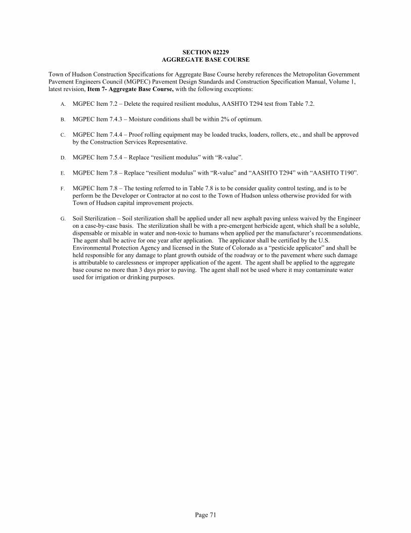
Page 71
SECTION 02229AGGREGATE BASE COURSE
Town of Hudson Construction Specifications for Aggregate Base Course hereby references the Metropolitan Government Pavement Engineers Council (MGPEC) Pavement Design Standards and Construction Specification Manual, Volume 1, latest revision, Item 7- Aggregate Base Course, with the following exceptions:
A. MGPEC Item 7.2 – Delete the required resilient modulus, AASHTO T294 test from Table 7.2.
B. MGPEC Item 7.4.3 – Moisture conditions shall be within 2% of optimum.
C. MGPEC Item 7.4.4 – Proof rolling equipment may be loaded trucks, loaders, rollers, etc., and shall be approved by the Construction Services Representative.
D. MGPEC Item 7.5.4 – Replace “resilient modulus” with “R-value”.
E. MGPEC Item 7.8 – Replace “resilient modulus” with “R-value” and “AASHTO T294” with “AASHTO T190”.
F. MGPEC Item 7.8 – The testing referred to in Table 7.8 is to be consider quality control testing, and is to be perform be the Developer or Contractor at no cost to the Town of Hudson unless otherwise provided for with Town of Hudson capital improvement projects.
G. Soil Sterilization – Soil sterilization shall be applied under all new asphalt paving unless waived by the Engineer on a case-by-case basis. The sterilization shall be with a pre-emergent herbicide agent, which shall be a soluble, dispensable or mixable in water and non-toxic to humans when applied per the manufacturer’s recommendations. The agent shall be active for one year after application. The applicator shall be certified by the U.S. Environmental Protection Agency and licensed in the State of Colorado as a “pesticide applicator” and shall be held responsible for any damage to plant growth outside of the roadway or to the pavement where such damage is attributable to carelessness or improper application of the agent. The agent shall be applied to the aggregate base course no more than 3 days prior to paving. The agent shall not be used where it may contaminate water used for irrigation or drinking purposes.

Page 72

Page 73
SECTION 02575BITUMINOUS PAVING
Town of Hudson Construction Specifications for Bituminous Paving hereby references the Metropolitan Government Pavement Engineers Council (MGPEC) Pavement Design Standards and Construction Specification Manual, Volume 1, latest revisions, Item 9 - Hot Mix Asphalt Pavement, with the following exceptions:
A. MGPEC Item 9.2.3 – Hydrated lime is acceptable, but may be substituted with an approved chemical anti-stripping additive.
B. MGPEC Item 9.13.1 – In addition to the surface tolerances stated, there shall be no allowance for standing water on the final pavement surface. After compaction, the asphalt pavement adjoining the concrete gutter pan shall be between ¼" and ½" higher than the lip of the concrete pan.
C. MGPEC Item 9.14 – The total thickness of the pavement, as called for on the Plans, shall not differ by more than ten (10%) percent for any one sample. The average total thickness of all samples taken shall not differ by more than seven and one-half (7.5%) percent. If the total thickness is proven to be less than these tolerances, the Town will require asphalt milling and/or overlay to correct the problem. If the total thickness is proven to be greater than these tolerances, the Town will not be responsible for compensating the Contractor for the excess amount of asphalt.
D. MGPEC Item 9.15 – The testing referred to in Table 9.15 is to be considered quality control testing, and is to be performed by the developer or contractor at no cost to the Town of Hudson unless otherwise provided for with Town of Hudson capital improvement projects.
E. MGPEC Item 9.15 – In Table 9.15, under Minimum Frequency for the density testing, change the 250 lineal feet to 500 lineal feet.

Page 74

Page 75
SECTION 02576STREET PAVEMENT PATCHING
Town of Hudson Construction Specification for Asphalt Patching hereby references the Metropolitan Government Pavement Engineers’ Council (MGPEC) Pavement Design Standards and Construction Specification Manual, Volume 1, latest revision, Item 17 - Asphalt Patch, with the following exceptions:
A. Item 17.3 – Subgrade preparation shall be in accordance with Town of Hudson Construction Specifications, Section 02225.
B. Item 17.3 – Final replacement thickness of patches shall be 5 ½" for local streets, 7" for industrial, collector and arterial streets, or 1" greater than the existing pavement, whichever is greater.
C. Item 17.3 – Replacement of unstable subgrade with flow fill is not required. However, unstable subgrade shall be stabilized in a manner approved by the Town Hudson Construction Services Representative prior to patching.
D. If pavement patch is made in a concrete pavement, see MGPEC Item 11 for PCCP requirements. Patches in concrete pavement shall consist of Portland Cement Class P concrete, and shall be doweled to the existing pavement in a manner specified by the Town of Hudson Construction Services Representative.
E. The contractor shall be responsible for maintaining temporary patches. In the case of an emergency the Town of Hudson may elect to repair the temporary patch and back charge the Contractor for all costs associated with the repairs.

Page 76

Page 77
SECTION 02585PORTLAND CEMENT CONCRETE PAVEMENT
Town of Hudson Construction Specifications for Portland Cement Concrete Pavement hereby references the Metropolitan Government Pavement Engineers Council (MGPEC) Pavement Design Standards and Construction Specifications Manual, Volume 1, latest revisions, Item 11 - Portland Cement Concrete Pavement, with the following exceptions:
A. Item 11.4.1 – Delete “Item 3, Embankment” and replace with Town of Hudson Construction Specifications, Section 02220.
B. Item 11.11 – The testing referred to in Table 11.11 is to be considered quality control testing, and is to be performed by the developer or contractor at no cost to the Town of Hudson unless otherwise provided for with Town of Hudson capital improvement projects.
C. Item 11.2.6 Admixtures – Calcium chloride or admixtures containing chloride shall not be allowed in reinforced concrete and is strictly prohibited in the production of high early strength concrete.

Page 78

Page 79
SECTION 02595UTILITY CUT AND BACKFILL
Town of Hudson Construction Specifications for Utility Cut and Backfill hereby references the Metropolitan Government Pavement Engineers’ Council (MGPEC) Pavement Design Standards and Construction Specifications Manual, Volume 1, latest revisions, Item 19 - Utility Cut and Backfill, with the following exceptions:
A. Excavation for Utility Location (Pot Holing) – All excavations for utility locates, unless otherwise approved by the Town of Hudson Engineering Division, will be made by the pot holing method, with a hole not exceeding 12 inches in diameter. Backfill shall be flowable fill, capped with non-shrink grout in conformance with Section 02223 - 2.2. The caps shall be 5 ½ inches thick in local streets, 7 ½ inches thick in other streets, and shall be finished between ¼ inch and ½ inch below adjacent asphalt pavements.
If the utility patch is made in a concrete pavement, see MGPEC Item 11 for PCCP requirements. Concrete patches shall be doweled to the surrounding concrete pavement. Dowel in accordance with requirements by the Town.
B. Item 18.3.2 – Delete the words “tunnel or” in the last sentence of the first paragraph.
C. Item 18.3.6 – The Contractor is responsible for maintaining temporary patches. In case of an emergency the Town of Hudson may elect to repair the temporary patch and back charge the contractor for all costs associated with the repairs.
D. Item 18.3.6 – If a temporary patch is used and construction traffic control for the project is terminated, the appropriate contractor must obtain another Street Cut Permit, including the approval of a construction Traffic Control Plan, to provide for the final patch work. This is to insure proper approval of traffic control and schedule inspections. If this final patch work is completed within 30 days of the temporary patch, no additional fee will be charged for the follow-up permit.
E. Item 18.3.6 – If approved by the Town, good quality asphalt milling material may be used as a temporary patch on low volume streets.
F. Item 18.3.7 – Gravel surface streets - When trenches are excavated in streets or alleys with a gravel surface, the contractor shall replace the surface with aggregate base course meeting the requirements of MGPEC Item 7. Replacement shall be one (1") inch greater in depth than the original gravel surface, but not less than five (5") inches.
G. Item 18.3.7 – Do not place overlays with feathered edges on collectors or arterial streets. Particular care must be taken in constructing joints to provide smooth transitions, and to avoid problems with drainage or access at the edges of gutter pans.
H. Item 18.3.7 – Completion of the utility cut including pavement replacement and cleanup shall normally be accomplished within two (2) days after the activity involving the cut is completed.
I. Item 18.3.7 – Removal and replacement of unsatisfactory or failed pavement patches shall be completed within thirty (30) days of written notification of deficiency. Failure to comply may result in the Town of Hudson taking action upon the contractor’s performance bond.
J. Item 18.3.7 – Minimum asphalt patch thickness in the Town of Hudson 5 ½” for local streets and 7" for other streets.
K. Item 18.3.7 – Damaged concrete curb and gutter shall be removed and replaced to the nearest crack control joints.
L. Backfill Material must conform to one of the following:
1. Flowable backfill, in accordance with MGPEC Item 18.
2. Use aggregate base course material, in accordance with MGPEC Item 7, mechanically compacted in 8" (maximum) lifts, moisture controlled within +/- 2% or optimum, to 95% AASHTO T-180. A density test is

Page 80
required for each 1-foot of backfill placed and a minimum of one test per 200 feet or one test per pipe run (min.). The contractor must pay for all testing costs.
3. If the contractor wants to use the onsite material, the material must be evaluated by a Geotechnical Engineer. The engineer must confirm in writing that the material meets structural fill requirements. A proctor curve for each different type of the material must accompany the letter from the engineer. The material is to be mechanically compacted in max. 8" lifts. Material to be moisture controlled within +/- 2% of optimum. A density test is required for each 1' of backfill placed and a minimum of one test per 200', or one test per pipe run (min.). The contractor must pay for all testing costs.
M. Backfill around manholes, water valves and inlets are required to be installed in 8" lifts and compaction tests on
each side of structure at each 8" lift intervals. The contractor must pay for all testing costs.

Page 81
SECTION 02610MANHOLE AND VALVE BOX ADJUSTMENT
PART 1 – GENERAL
1.1 DESCRIPTION
The Contractor shall adjust all manholes, valve boxes, survey monument boxes, and other fixtures encountered within the area to be paved to conform to the finished surface of the pavement to be built as per the street plans and details and in accordance with all requirements outlined in these specifications.
PART 2 – MATERIALS
2.1 All materials necessary for adjusting manholes or valve boxes as required for resurfacing must be on hand at the job site prior to placement of any asphalt or concrete pavement. See Standard Details S-32, S-33, and S-34.
Concrete or other approved grade rings shall be used for adjusting manhole frames and covers, valve boxes, and other similar devices to proper grade and alignment.
A good grade non-shrink grout shall be used for resetting manhole frames and grade rings.
Concrete used around manholes and valve boxes in asphalt paved streets shall be in accordance withMGPEC Item 11, Portland Cement Concrete Pavement.
Reinforcing Steel shall be specified in CDOT Standards Specifications, Section 709.
PART 3 – EXECUTION
3.1 OBSERVATION AND REVIEW
Manhole frames and covers, valve boxes, and all other similar devices shall be raised to final grade. After adjustment, the Contractor shall notify the Town who shall make an inspection to check for cleanliness, proper alignment, and elevation.
All valve boxes shall be inspected by applying a valve key to each operating nut to insure an acceptable alignment.
3.2 SAFETY
To provide proper protection to the public, manhole frames and covers, and valve boxes shall be accessible no later than twenty-four (24) hours after they have been buried by the work in progress and brought to final grade within one week.
3.3 ASPHALT PAVEMENT LOCATIONS Following installation of the final lift of asphalt pavement, final grading adjustments shall be made for all manhole frames and covers, and valve boxes. Final grading adjustments shall be made within a one-week period following placement of the final wearing surface. The following procedures are required. See Standard Details S-33 and S-34.
Remove bituminous pavement to clean straight lines and excavate as shown on Standard Details S-33 and S-34.
Complete final grading adjustments of the manhole frame or water valve box. Shim and grout into place, checking for proper alignment and slope of the grade ring. Grading requirements are shown in Standard Detail S-33 and S-34.
Following inspection and acceptance by the Project Representative or Construction Service’s Representative for proper alignment and slope of grade ring proceed with placing concrete.

Page 82
3.4 ADJUSTMENT FOR CONCRETE PAVEMENT
After placement of the concrete and jointing has begun, a transverse joint will be placed at each manhole frame and at each water valve box or other similar device. In the event that a manhole frame, water valve box, or other similar device should be covered up during construction, the Contractor will be responsible for raising the manhole frame or water valve box up through the concrete. This work will take place no later than twenty-four (24) hours after completion of the work. The concrete edges will be full-depth saw cut and be a minimum of twelve (12") inches from the manhole frame or water valve box.
After removal of the old concrete, the existing slab will be drilled eight (8") inches deep. Sixteen (16") inches long #4 reinforcing bars will be placed at twelve (12") inches on center. Concrete pavement shall be replaced to the existing depth plus one (1") inch, or a minimum of six (6") inches, whichever is greater. A minimum mix design for concrete, as shown above in Section 2, shall be used.
The concrete shall be protected from the weather and rapid loss of moisture. Concrete shall be protected from the vehicular traffic of a period not less than seven (7) days or three (3) days with high/early or quick strength concretes.

Page 83
SECTION 02618PAVEMENT MARKING STANDARDS
All pavement marking installations shall be in compliance with the current (M.U.T.C.D.) Manual of Uniformed Traffic Control Devices Standards.
At intersections in all directions, all markings shall be of a permanent type marking, to include but not limited to: Crosswalks, Stop Bars, Arrows Only, Turn bay line, Centerline, etc.
PART I – GENERAL
All pavement markings shall be placed in accordance with the following requirements. When the term “full compliance” is used, it means pavement markings shall meet the requirements of these specifications.
Pavement Marking Plan – When pavement marking location details are not provided in the Contract, the Contractor shall submit a layout of existing conditions to the Town for approval or modification. This layout is to be used as the final pavement-marking plan.
A. Roadways Closed to Traffic During Construction – Full compliance pavement markings shall be in place on all roadways prior to opening traffic.
B. Roadways Constructed Under Traffic – Full compliance final pavement markings shall be placed within two weeks after final surfacing is completed. Full compliance pavement markings shall also be placed on any roadways open to traffic when the project pavement work is discontinued for more than two weeks.
C. Temporary pavement markings and control points for the installation of those pavement markings for roadways that are being constructed under traffic are as follows:
1. When one roadway of a normally physically divided highway is closed, and a crossover is constructed, full compliance pavement marking shall be placed along the tapers and through the median crossovers to the two-way traffic section. Pavement marking through the two-way traffic section shall be as shown on the plans.
When a two-lane highway is closed, and a bypass detour is provided, full compliance pavement markings shall be placed the full length of the detour prior to operation of the detour.
In either case, the type of marking materials applied to a final surface, when removed, shall not leave a scar that conflict with permanent markings.
2. The following criteria apply to all construction and maintenance on roadways open to traffic other than (D) 1 above.
Control points, four-inch by one-foot marks at 40 foot intervals, are guide markers for the installation of temporary and / or full compliance markings.
All temporary broken line pavement markings shall be installed daily and shall be at least 18 inches long with a maximum gap of 38 feet. An 18-inch stripe with a maximum gap of 18 feet shall be used on curves for roadways with severe curvature. A severe curve is defined as a curve whose safe speed is 10 mph or more below the approach posted speed limit.
Temporary pavement markings for “no passing zones” shall be full compliance.
For short term situation (3 calendar days or less) where temporary broken center lines are installed, “no passing” restrictions may be identified by appropriate signs including R4-1 and R4-2 until final markings are installed.
For roadways with a volume of 750 ADT or less, “no passing” restrictions can be identified for up to two weeks with appropriate signs.Temporary pavement stencils (school, railroad etc.) are not required unless detailed on the plans.
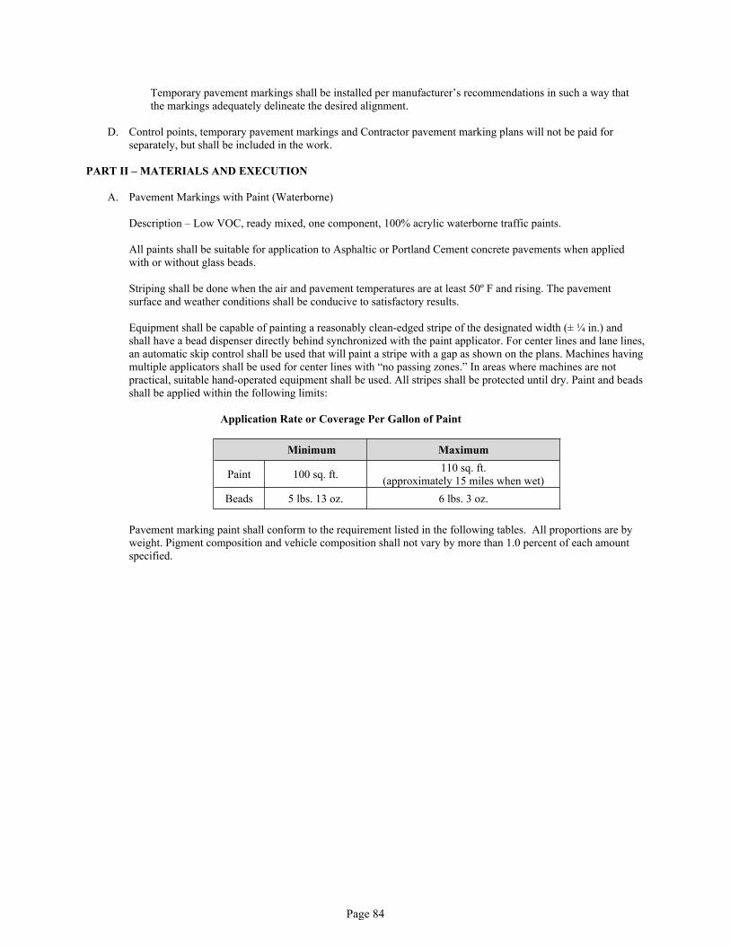
Page 84
Temporary pavement markings shall be installed per manufacturer’s recommendations in such a way that the markings adequately delineate the desired alignment.
D. Control points, temporary pavement markings and Contractor pavement marking plans will not be paid for separately, but shall be included in the work.
PART II – MATERIALS AND EXECUTION
A. Pavement Markings with Paint (Waterborne)
Description – Low VOC, ready mixed, one component, 100% acrylic waterborne traffic paints.
All paints shall be suitable for application to Asphaltic or Portland Cement concrete pavements when applied with or without glass beads.
Striping shall be done when the air and pavement temperatures are at least 50º F and rising. The pavement surface and weather conditions shall be conducive to satisfactory results.
Equipment shall be capable of painting a reasonably clean-edged stripe of the designated width (± ¼ in.) and shall have a bead dispenser directly behind synchronized with the paint applicator. For center lines and lane lines, an automatic skip control shall be used that will paint a stripe with a gap as shown on the plans. Machines having multiple applicators shall be used for center lines with “no passing zones.” In areas where machines are not practical, suitable hand-operated equipment shall be used. All stripes shall be protected until dry. Paint and beads shall be applied within the following limits:
Application Rate or Coverage Per Gallon of Paint
Minimum Maximum
Paint 100 sq. ft. 110 sq. ft. (approximately 15 miles when wet)
Beads 5 lbs. 13 oz. 6 lbs. 3 oz.
Pavement marking paint shall conform to the requirement listed in the following tables. All proportions are by weight. Pigment composition and vehicle composition shall not vary by more than 1.0 percent of each amount specified.

Page 85
Characteristics Yellow White
Viscosity at 77 degrees F, KU 80-90 80-90Dry to no pick-up time, ASTM D-711
without beads, minutes 3 max. 3 max.
No-Track time, Actual @ 77 degreesF/50% RH, seconds 90 max 90 max
Directional Reflectance % 87 min. 50
Contrast Ratio @ 15 mils wet 0.98 min 0.95 min.
Scrub test, Cycles 1000 min 1000 min
Volatile Organic Compound, grams/liter Below 150 Below 150
Total Pigment, % by Weight 62 min. 62 min.
Total Solids, % by Weight 76 min. 76 min.
Total Solids, % by Volume 58 min. 58 min.
PH 9.6 min. 9.6 min.
Reportable Components:
Yellow Vapor Pressuremm Hg @ Temp °F Weight
PercentMethyl Alcohol 97.68 68 5
Quartz Silica N/A N/A 0.32
1
OSHA PEL = 200 PPM (skin) (260 MG/M3), STEL 250 PPMACGIH TLV = 200 PPM (skin) (260 MG/M3) STEL 250 PPMNIOSH = TWA 200 PPM, 800 PPM (CEILING)
2,2,4 TRIMETHYL - 1,3 - PENTANEDIOL MONOISOBUTYRATE
NOISH REL = TWA 0.05 MG/M3, 3,000,000 FIBERS/M3OSHA PEL = TWA RESPIRABLE: 0.1 MG/M3 TOTAL DUST: 30 MG/M3ACGIH TLV = TWA RESPIRABLE: 0.1 MG/M3
White Vapor Pressuremm Hg @ Temp °F Weight
PercentMethyl Alcohol 98.68 68 5
Quartz Silica N/A N/A 1.24
1
OSHA PEL= 200 PPM (SKIN), STEL 250 PPMACGIH = 200 PPM (SKIN), STEL 250 PPMNOISH = TWA 200 PPM, 800 PPM (CEILING)
2,2,4 TRIMETHYL - 1,3 - PENTANEDIOL MONOISOBUTYRATE
NIOSH REL = TWA 0.05 MG/M3, 3,000,000 FIBERS M/3OSHA PEL = TWA RESPIRABLE: 0.1 MG/M3, TOTAL DUST: 30 MG/M3ACGIH = TWA RESPIRABLE: 0.1 MG/M3

Page 86
B. Pavement Marking with Paint (Alkyd)
Striping shall be done when the air and pavement temperatures are at least 40 degrees F for alkyd paints.
The pavement surface and weather condition shall be conducive to satisfactory results.
Equipment shall be capable of painting a reasonably clean-edged stripe of the designated width (± ¼ in.) and shall have a bead dispenser directly behind, synchronized with the paint applicator. For centerline and lane lines, an automatic skip control shall be used that will paint a stripe with a gap as shown on the plans. Machines having multiple applicators shall be used for center lines with “no passing zones.” In areas where machines are not practical, suitable hand-operated equipment shall be used. Stripes shall be protected until dry.
Paint and beads shall be applied within the following limits:
Application Rate or Coverage per Gallon of Paint
Minimum Maximum
Paint 100 sq. ft. 110 sq. ft.
Beads 5 lbs.13 oz. 6 lbs.3 oz.
Alkyd pavement marking paint shall conform to the requirements listed below. All proportions are by weight. Pigment composition and vehicle composition shall not vary by more than 1.0 percent of amount specified. Finished Paint Pigment (White and Yellow) shall be 49.0% to 52%
Pigment Composition: White Yellow
Titanium Dioxide, ASTM D 476, Type III 27.0% 8.0%
Chrome Yellow, Medium ASTM D 211 Type III 18.0%
Calcium Carbonate, ASTM D 1199 Type GC-II 18.0% 17.0%
Magnesium Silicate, ASTM D 605 54.3% 56.3%
Pigment Suspending Agent (see below)
Vehicle Composition White Yellow
Alkyd Resin Solution, AASTO M 248 Type F 70%
VM&P Naphtha, Fed. Spec. TT-N-95, Type I 30.0%
Driers, ASTM D 600 cl.B, and Anti-Skinning Agent, Methanol
Pigment Suspending – Organo-montmorillonite shall be added to achieve the desired storage and stability requirements.
Properties of Finished Paint – The paint at the time of container filling shall be free of skins, pigment agglomerates and foreign matter and shall meet the following requirements:
Fitness of grind, Hegman, minimum: 2Consistency, Krebs-Stormer, K.U. @ 77° F (25° C): 70-80Drying time, a wet film of paint 15 mils thick tested according to ASTM Method D 711, minutes maximum: 30
Reflectance – The white paint shall have a daylight 45 degree, 0-degree luminous directional reflectance of not less than 80% when compared to magnesium oxide (ASTM E 97).Color – The yellow paint color shall have visually match color chip No 33538 of Federal Standard 595a.

Page 87
Retroreflectivity – The Contractor shall meet or exceed CDOT Special Provision Exhibit ‘A,’ for Region 4, retroreflectivity minimums for white and yellow painted markings:
1. Yellow painted markings below 350 MCD will be rejected.
2. White painted markings below 400 MCD will be rejected.
3. A test with a Retroreflectometer will be performed within one (1) week after striping. The Town of Hudson will provide a Retroreflectometer for this test.
C. Epoxy Pavement Markings
The epoxy pavement marking compound shall be applied with equipment that will precisely meter the two components.
The equipment shall produce the required amount of heat at the mixing head and gun tip to provide and maintain the temperatures specified.
Before mixing, the individual components A and B shall each be heated to a temperature of 80 degrees F to 140 degrees F. After mixing, the application temperature for the combined material at the gun tip shall be 80º F to 140º F. The 140º F upper limit is the maximum temperature under any circumstances.
Both pavement and air temperatures shall be at least 50º F at the time of epoxy pavement application.
The surface areas of new Portland Cement concrete pavement and decks that are to receive markings shall be sandblasted prior to placement of the epoxy pavement marking. The amount of sandblasting shall be sufficient to remove all dirt, and curing compound residue.
The surface areas of new asphalt pavement, and existing asphalt pavement, and existing concrete pavement that are to receive markings shall be cleaned with a high-pressure air blast to remove loose material prior to placement of the epoxy pavement marking. Any pavement which has become dirty from tracked mud etc. as determined by the Project Representative or Construction Services’ Representative shall be cleaned prior to the placement of the epoxy pavement marking.
When recommended by the epoxy manufacturer, a high-pressure water blast integrated into the gun carriage shall be used to clean the pavement surface prior to epoxy pavement marking application. The water blast shall be followed by a high-pressure air blast to remove all residual water, leaving only a damp surface.
Epoxy pavement marking shall be applied to the road surface according to the epoxy manufacture’s recommended methods at 15 mils minimum thickness. Glass beads shall be applied into the epoxy pavement marking by means of a pressurized bead applicator at a rate of 0.25 pounds per square foot (25 pounds per gallon) minimum.
Glass Bead Reflective Minimums (Iowa DOT Blend)
The glass spheres shall be transparent, clear, colorless, and free from milkiness, dark particles, and excessive air inclusions. They shall be essentially clear from surface scarring or scratching. The glass spheres shall be free of hard lumps and clusters and shall dispense readily under any conditions suitable for paint striping.

Page 88
Specific Requirements
1. Gradation.The glass spheres shall meet the gradation requirements for type as given below:
Sieve Size Percent Passing20 (850 µm) 10030 (600 µm) 75-9550 (300 µm) 15-35100 (150 µm) 0-5
2. Roundness - The glass spheres shall have a minimum of 80% true spheres.
3. Refractive Index - The glass spheres shall have a minimum refractive index of 1.50.
4. Properties of Dual Coated Spheres - The glass spheres shall be coated with a dual coating. The coating shall have both a moisture resistant silicone coating and an adhesion promoting silane coating. The spheres shall pass the moisture resistance test and the adherence coating test.
5. Properties of Silicone Coated Spheres - The glass spheres shall be coated only with a silicone coating (no silane). The spheres shall pass the moisture resistance test and shall test negative for the adherence coating test.
6. Properties of Uncoated Spheres - The glass spheres shall pass the free flow test.
Epoxy pavement marking and beads shall be applied within the following limits:
Minimum Maximum15 mil marking 100 sq. ft. 110 sq. ft.
Beads 25 lbs.
Epoxy Pavement Marking Material:
1. Formulation – Epoxy pavement marking material shall be a two component, 100% solids, material formulated to provide simple volumetric mixing ratio of two volumes of component A and one volume of component B unless otherwise recommended by the material manufacturer.
2. Composition – The component A of both white and yellow pigments shall be within the following limits.
White YellowMin% by weight Titanium Dioxide, (ASTM D 476 Type II) 18%
Min% by weight Chrome Yellow, (ASTM D 211, Type III) 23%
Epoxy Resin 75-82% 70-77%
3. Epoxy Number – The epoxy number of the epoxy resin shall be 0.38 ± 0.05 as determined by ASTM D 1652 for White and Yellow Component A on pigment free basis.
4. Amine Number – The Amine Number on the curing agent (component B) shall be 410 ± 50 per ASTM D 2071.
5. Toxicity – Upon heating to application temperature, the material shall not produce fumes, which are toxic or injurious to persons or property.
6. Color and Weather Resistance – The mixed epoxy compound, both white and yellow, when applied to 3 inch by 6-inch aluminum panels at 15 ± ½ mils of thickness with no glass beads and exposed in the Q.U.V.

Page 89
Environmental Testing Chamber as described in ASTM G 53, shall conform to the following minimum requirements. (The test shall be conducted for 75 hours at 50 degrees C, 4 hours humidity, and 4 hours U.V., in alternating cycles. The prepared panels shall be cured at 77 degrees F for 72 hours prior to exposure.) The color of the White Epoxy System shall not be darker than Federal Standard No. 595A17778. The color of the Yellow Epoxy System shall conform to Federal Standard No. 595A13538. The gloss values of both samples shall not be less than 70 degrees after the test.
7. Drying Time – The epoxy pavement marking material shall have a setting time to a no-tracking condition of not more than 25 minutes at a temperature of 73 degrees F and above.
8. Curing – The epoxy material shall be capable of fully curing under the constant surface temperature condition of 25 degrees F and above.
9. Adhesion to concrete – The catalyzed epoxy pavement marking material, when tested according to ACI Method 503, shall have such a high degree of adhesion to the specified (4,000 psi minimum) concrete surface that there shall be a 100% concrete failure in the performance of this test.
10. Hardness – The epoxy pavement marking materials, when tested according to ASTM D 2240, shall have a Shore D Hardness between 75 and 100. Samples shall be allowed to cure at room temperature (75º F ± 2º F) for a minimum of 12 hours and a maximum of 48 hours prior to performing the indicated test.
11. Resistance – The abrasion resistance shall be evaluated on Taber Abrader with a 1000-gram load and CS-17 wheels. The wear index shall be calculated based on ASTM test Method C-501 and the wear index for the catalyzed material shall not be more than 70. The test shall be run on cured samples of material which have been applied at film thickness of 15 ± ½ mils to code S-16 stainless steel plates. The samples shall be allowed to cure at 75º ± 2º F for a minimum of 48 hours prior to performing the indicated tests.
12. Tensile Strength – When tested according to ASTM D 638, the epoxy pavement marking materials shall have a tensile strength of not less than 6,000 pounds per square inch. The Type IV Specimens shall be cast in a suitable dynamic testing machine. The samples shall be allowed to cure at room temperature (75 º F ± 2 º F) for a minimum of 12 hours and a maximum of 48 hours prior to performing the indicated tests.
13. Compressive Strength – When tested according to ASTM D 695, the catalyzed epoxy pavement marking materials shall have a compressive strength of not less than 12,000 pounds per square inch. The cast sample shall be conditioned at room temperature (75 º F ± 2 º F) for a minimum of 12 hours and a maximum of 48 hours prior to performing the tests. The rate of compression of these samples shall be no more than 1/4 inch per minute.
D. Extruded /Spray Thermoplastic Pavement Marking
1. Equipment – General
The material shall be applied to the pavement by an extrusion method wherein one side of the shaping die is the pavement and the other three sides are contained by, or are part of suitable equipment for heating, mixing, and controlling the flow of the material.
The equipment shall be constructed to provide continuous mixing and agitation of the material. Conveying parts of the equipment between the main material reservoir and the shaping die shall be so constructed as to prevent accumulation and clogging. All parts of the equipment which come in contact with the material shall be easily accessible and exposable for cleaning and maintenance.
All mixing and conveying parts up to and including the shaping die, shall maintain the material at the plastic temperature.
The equipment shall be so constructed as to assure continuous uniformity in the dimensions of the stripe. The applicator shall provide a means for cleanly cutting off square stripe ends and shall provide a method of applying “skip” lines. The use of pans, aprons, or similar appliances that the die overruns will not be permitted under this specification.
Beads for the surface of the completed stripe shall be applied by an automatic bead dispenser attached to the applicator in such a manner that the beads are dispensed almost instantly upon the completed line. The bead

Page 90
dispenser shall be equipped with an automatic cutoff control synchronized with the cutoff of the thermoplastic material.
Excess glass beads shall be removed immediately from pedestrian areas and roadway.
The equipment shall be so constructed as to provide for varying die widths to produce varying widths of traffic markings.
The equipment shall be so designed to permit agitation of the material to prevent scorching, discoloration or excessive high temperatures of any part of the material.
A special kettle shall be provided for melting and heating the composition. The kettle shall be equipped with an automatic thermoplastic control device so that heating can be done by controlled heat transfer liquid rather than direct flame.
The applicator and kettle shall be so equipped and arranged as to satisfy the requirements of the National Fire Underwriters.
The equipment shall be so equipped as to permit preheating of the pavement immediately prior to application of the material.
The applicator shall be mobile and maneuverable to the extent that straight lines can be followed and normal curves can be made in a true arc.
2. Types of Equipment
a. Portable applicator – The portable applicator shall be a device typically used for painting crosswalk lines, stop bars, short lane lines, and short lane center lines. The applicator shall be easily maneuverable and capable of being propelled by the operator.
b. Mobile applicator – The mobile applicator shall contain equipment to provide for automatic installation of skip lines in any combination of line and skip up to 40 feet. The mobile applicator shall be moved in conjunction with the melting and heating kettles in such a manner as to provide continuous highway operation of the kettles and the mobile applicator as an integral unit.
c. Epoxy Primer Equipment – The epoxy primer application shall be accomplished using equipment having the following features:
1) The main storage tank shall be equipped with a visible gauge which will allow the Engineer to readily ascertain the rate of application.
2) The main storage tank shall be equipped with a heating device which will maintain the epoxy at a constant efficient temperature.
3) The spray nozzle and epoxy spray shall be protected from the action of wind to insure placement where needed.
3. Cleaning Equipment
Equipment must be provided to insure removal of dust, debris, paint and other foreign matter from the road surface immediately prior to the installation of the composition, or immediately prior to the application of primer.
4. Application of Material
The stripe shall be applied to the pavement either to the right or left of the application unit, dependent upon roadway lane being used. The unit shall not occupy more than one lane of roadway while operating.
The finished lines shall have well-defined edges and be free of waviness. All of the equipment necessary to the preheating and application of the material shall be so designed that the temperature of the material can be controlled within the limits necessary to its pour ability for good application.
At the time of installation of thermoplastic materials, the pavement shall be clean, dry, and free of oil, dirt, grease, paint or other foreign contaminants. Pavement and ambient temperatures shall be at least 50º F.

Page 91
The marking material shall not be applied until the epoxy resin primer reaches the tacky stage, approximately 15 minutes under normal conditions. An infra-red heating device may be employed to shorten the curing time of the epoxy.
To ensure the best possible adhesion, the marking material as specified, shall be installed at the manufacturer’s recommended temperature.
The minimum thickness of thermoplastic lines, as viewed from a lateral cross section, shall not be less than 3/32 inch at the edges, nor less than 1/8 inch at the center. Measurement shall be taken as an average throughout any 36-inch section of the line. The material, when formed into traffic stripes, must be readily renewable by placing an overlay of new material directly over an old line of compatible material. Such new material shall bond itself to the old line in such a manner that no splitting of separation takes place.
5. Thermoplastic Marking Material
Thermoplastic marking material shall conform to AASHTO M 249 except for the following:
a. In paragraph 3.1.2. of the AASHTO specifications, delete the first two sentences and replace with the following:
The material manufacturer shall have the option of formulating the material according to its own specifications. However, the binder shall be composed of alkyd resins wherein a minimum of 70 percent (by weight) of the binder shall be maleic modified glycerol ester of rosin. The physical and chemical properties contained in this specification shall apply regardless of the type of formulation used.
b. In paragraph 4.3 of the AASHTO specifications, add the following physical characteristics:
The infra-red spectra of the extracted binder will be compared to the characteristic absorption bands of maleic modified glycerol ester of rosin.
c. In paragraph 6.1 of the AASHTO specifications, delete the second sentence and replace with the following:
The containers of thermoplastic material shall weigh approximately 50 pounds (23 kg).
E. Pavement Primers
The type and application rate of epoxy resin primer shall be as recommended by the thermoplastic or preformed plastic pavement marking manufacturer.
A primer application rate of zero will not be accepted, except for thermoplastic marking and inlaid preformed plastic pavement marking placed on new asphalt surfaces as recommended by the manufacturer and approved in writing by the Engineer. However, if the Engineer determines that a new asphalt surface has become soiled, prior to placement of the pavement markings, pavement primer will be required and shall be applied as approved.
The epoxy resin primer material may be accepted at the job site on the basis of a manufacturers’ certification, or a sample may be sent to the laboratory for testing, in which case three weeks shall be allowed between sampling and intended use.
F. Preformed Thermoplastic /Inlay Applications
1. Marking layout is performed following completion of the breakdown roller passes and wheel roller, if used.
2. The material should be positioned on top of the asphalt only after the surface temperature drops below 210° F. It may be necessary to wipe off surface moisture with a towel, if puddles exist, prior to installing material.
3. The performed thermoplastic material should remain in position for 3 to 5 minutes, undisturbed. This allows the material to absorb heat, which enables it to stay in position when the inlay roller makes its initial pass. Stepping on the performed thermoplastic material immediately after initial placement may be necessary.

Page 92
4. The material should be rolled into the asphalt at between 170 and 200° F. The finish roller should be used for inlay of preformed thermoplastic material. A vibratory roller can be used to inlay performed material down to 160° F (surface temperature). A minimum 10-ton roller is required to ensure proper inlay.
5. Glass beads shall be sprinkled onto the pavement marking material surface. This will enhance initial retroreflectivity and aid in cooling the markings. It is important to keep all traffic off the pavement marking material to prevent damage.
6. Material should now be inspected to ensure proper inlay. A good inlay is realized when the material is flush with the road surface. (It may be necessary to feather the leading edges to prevent snow plow damage.) Inspect material to ensure that the indents are closed. A propane torch shall be used to apply additional heat on markings that are not inlaid sufficiently. This situation usually occurs by the edge of the road, next to a concrete gutter. Also, if it begins to rain, the asphalt cools much quicker and the pavers do not always stop paving operations. If the roller does not inlay the pavement marking material, additional heat shall be applied to ensure the proper bond. A roller may be used again.
7. Preparation and timing are keys to a successful inlay. The following tips will help ensure success:a. You must have a dedicated roller. It can be the primary finish roller, but the driver must know when to
roll over the material and not turn on the markings. A minimum 10-ton roller is required.b. An infrared thermometer is required to monitor asphalt temperature. Wind, rain, ambient
temperatures, and asphalt thickness can affect how quickly the asphalt cools. Hot/dry days provide more time to layout the material. Cool/wet days offer less time to position the marking.1) Keep all wheeled vehicles and pedestrians off the marking until it has cooled to at least 120°F.2) Whenever inlaying centerline, turn bay, or skip line, consideration should be given to avoid
overlap. The pavers should adjust the pass width to accommodate markings. The preformed marking material should be installed on the second pass.
3) Once marking is inlaid, additional roller passes are not necessary. However, pavers usually continue to make passes to ensure proper asphalt compaction. This will not affect the inlay of markings.
4) Refer to specific manufacturer’s instruction guide book.
G. Pavement Marking Tape (Removable)
1. Retro-reflective tape shall be suitable for temporary use on Asphaltic or Portland cement concrete pavements. The tape shall be applied at the locations shown on the plans or as directed. The surface to which the tape is applied shall be clean, dry and free of dirt, oils and grease. The tape shall be pressed down immediately after application, until it adheres properly and conforms to the surface. Temporary marking tape shall be removed on sections where tape conflicts with revised traffic lanes prior to opening of new lanes to traffic.
2. Pavement marking tape (removable) shall be installed in accordance with the manufacturer’s recommendations, and maintained throughout the required construction phase at no additional cost to the Town’s Traffic Operation.
3. Pavement marking tape designated in the pay item as removable shall conform to ASTM D 4592, Type I, and shall be 4 ± 0.1 inches wide.
4. Perform Thermoplastic/ Existing Overlay or Older Top Surface Application:a. All symbols and legends shall comply with the Manual on Uniformed Traffic Control Devices
including metric requirements.b. After the marking has cooled down, a chisel test shall be performed to ensure that a proper bond has
been achieved.c. Dry asphalt of existing moisture. Do not install marking if it is raining or snowing. Wait 24 hours after
precipitation has stopped.d. Do not apply marking on top of salt or other deicers. Wait for 2 or 3 heavy rainfalls prior to installing
the marking material, or use a pressure washer to prepare surface.e. The road must be free of dirt, dust, chemicals, and significant oily substances.f. The material can be placed over existing preformed thermoplastic, if existing material has been heated
with a torch and the majority of thermoplastic has been lifted with a shovel.g. On Portland cement concrete roads, a sealant may be needed to ensure a proper bond.

Page 93
(Check manufacturer’s recommended instructions for installation.)h. Curing compounds must be sandblasted or grinded on new Portland cement concrete to ensure adequate
bonding.i. All leading edges of the pavement markings shall be “feathered” due to snowplow damage.j. Glass beads shall be sprinkled onto the pavement marking material surface. This will enhance initial
retroreflectivity and aide in cooling the markings. It is important to keep all traffic off the pavement marking material to prevent damage.
k. Crosswalks, stop bars, sidewalks and access ramps that have any loose glass beads shall be cleaned thoroughly with a leaf blower immediately after pavement marking is installed.
H. Pavement Marking Tape (Removable Material)
1. Description – The marking tape shall consist of weather and traffic resistant yellow or white colored reflective material. The material shall consist of conformable (metal foil) backing with a pressure sensitive adhesive design for adhesion to asphalt or concrete surfaces.
2. Requirements:
a. Color – The color of the visible or outer surface shall closely match the White or Yellow traffic marking paint specified for highway delineation. Glass beads shall be strongly adhered to the tape.
b. Reflectance – The White and Yellow tapes shall have the following initial minimum reflectance values at 0.2º and 0.5º observation angles and 86.0º entrance angles as measured in accordance with the testing procedures of Federal Test Method Standard 370. The photometric quantity measured is specific luminance (SL), and is expressed as millicandelas per square foot per foot-candle.
c. Adhesive – The striping tape shall be supplied in rolls ready for application and have a protected pressure sensitive adhesive which shall not have a protective liner nor require a solvent activator.
d. Adhesion – The material shall adhere to asphalt and concrete surfaces when applied at surface temperatures of 35 degrees F and above. Once applied, the tape shall adhere to the pavement at sub-freezing temperatures.
e. Conformability – The material shall be thin flexible, conformable, and show no cracking, flaking, or bead loss. Following application, the tape shall remain conformed to the texture of the pavement surface. The thickness shall not be less than 17 mils.
f. Removability – The tape shall be removable by following manufacturers’ recommendations so long as the material is substantially intact. Removal shall not require sandblast, solvents, or grinding methods.
g. Durability – The striping material applied in accordance with manufacturers’ recommended procedures shall be weather resistant and show no appreciable fading, lifting, or shrinkage during the useful life of the line.
h. Packaging and Delivery – The striping material as supplied shall be of good appearance and free of cracks. The edges shall be true, straight, and unbroken. The material shall be supplied in rolls with no more than one splice per fifty yards of length.
I. The striping material shall be packaged in accordance with accepted commercial standards to prevent damage during shipment and storage. The tape as supplied shall be suitable for use for a period of at least one year following delivery when stored at temperatures of 100 degrees F or below.
1. Raised Pavement Markers
Raised pavement markers (temporary) shall be installed on centerlines, edge lines, and lane lines where specified in the contract. Single markers shall be installed at five-foot intervals for solid lines. A group of four markers at three-feet spacing and at 40-feet intervals shall be installed for skip lines.
Raised pavement marker shall not be less than 3.5 inches nor more than 4.5 inches in the major dimension and not more than 0.75 inches in height. The marker shall contain a retro-reflective element not less than 0.38 square inch in area. The color of the marker and the retro-reflective element shall match the color of the
Color White YellowObservation AngleSpecific Luminance
0.2°1360
0.5°760
0.2°820
0.5°510

Page 94
pavement marking line. The reflective quality requirements shall be at least equal to the following minimum values:
Specific Intensity Candlepower per
Foot-CandleObservation
Angle DegreesEntrance
Angle Degrees White Yellow0.10.1
020
1.00.4
0.600.24
The marker shall be ceramic or plastic and shall be secured to old or new pavement using an adhesive approved by the manufacturer.
J. Grooved Concrete for Inlay Applications
1. All materials for use by the Town shall have manufacture’s installation specifications for installation and shall be supplied to the project managers.
2. The bottom of the groove shall have a smooth, flat finished surface. This shall be accomplished by utilizing gang-stacking cutting head having diamond tipped cutting blades. The spacers between each blade shall be such that there will be less than a 10 mil rise in the finished groove between the blades.
3. The edges of the preformed plastic pavement marking shall be straight and uniform, and uniformly adhere to pavement.
4. Grooves shall be clean, dry and free of oil, dirt, grease, paint or other foreign contaminants. Contractor shall protect the grooves from traffic and re-clean grooves as necessary prior to application of the performed plastic pavement markings.
5. Grooved width shall be the tape width ±¼”. Grooved depth shall be 100% of the tape and adhesive thickness plus 15%. For Series A380-I of A381-I tape, the grooved depth shall be 80 mils ± 10 mils.
6. Groove position shall be a minimum of 2” from the edge of the tape to the longitudinal pavement joint.
K. Pavement Marking and Striping Installation
Town of Hudson shall make the final determination in regard to the type and location pavement markings and striping within the right-of-way during the review of the project signing and striping plans.
1. Pavement Markings (Symbols and Legends)
All symbols and legends shall comply with the Manual on Uniformed Traffic Control Devices (MUTCD) including metric requirements.
The use of preformed pavement markings shall be used with the installations of all symbols and legends; such as, all arrows, “ONLYs,” school XINGs, bike lane symbols, railroad, etc. on new and overlay streets. The use of reversible arrows will not be accepted on new and overlay streets.”
2. Crosswalks
General – Crosswalks shall be used at all signalized intersections where pedestrian signal indications are located and approved pedestrian and school crossing locations.
a. Standard Crosswalk. White 8’ long x 12” wide “Continental” or standard style bars. The placement of these bars shall be on 5’-6” centers.
b. Transverse Crosswalk. Where applicable, shall be a white 12” Crosswalk bar on both sides of the designated walkway area, and shall be installed to the full asphalt or concrete width of the roadway, minus the gutter pans.

Page 95
3. Stop Bars
a. Stop bars are required at all signalized intersections and locations specified by the Town of Hudson.b. All stop bars shall be white 24” wide the full width of the appropriated travel lane including the
designated bike lane, not closer than 4’ form the closest edge of the crosswalk.
L. Striping Requirements
Striping over existing markings shall not vary ¼” along the edge of existing marking. The Contractor may be required to apply markings by means of hand-operated equipment in order to accurately match existing striping at tight radius curves.
The Contractor shall provide flaggers, signs, barricades, cones, or other devices need to ensure sufficient safety for the motoring public and pedestrian traffic.
1. Parking Lot and On-Street Painting
a. Parking stall shall have a minimum width of 8’; 9’ stall is preferred.b. All parking line striping of stalls, gores, and edge line widths shall be a 4” white line with drop on glass
beads applied.
2. Fire Lanes
a. Fire lane legends will be positioned by the Town of Hudson prior to installation.b. Fire lanes shall be a 4” wide yellow painted line no closer than 20’ from any permanent building.
3. Curb Painting
a. On new concrete where curing compound is used, all concrete shall be pressure-washed prior to painting applications.
b. Curb shall be scraped where paint is loose or chipping away prior to painting.c. The top of curb shall be fully cleaned prior to painting.d. Raised island “Bull Noses” shall be painted and, then, glass beads applied before the paint dries.e. Yellow curb painting shall indicate no parking zones.f. Red and white curb painting shall indicate passenger drop-off and loading zones. (5’ alternating each
color)g. Black and white curb painting shall indicate materials and equipment loading and unloading zones. (5’
alternating each color)h. Blue curb shall indicate handicap-parking zones.
4. Stencil Painting
All stencils used shall conform to MUTCD standards for shapes and sizes.
M. Removal
1. The roadway shall have no more than ¼” damage after removal of pavement markings.
2. Disposal of materials, as a result of removal, are the responsibility of the Contractor.
3. The Contractor, at his expense, shall legally dispose of the material.

Page 96

Page 97
SECTION 02810-IRRIGATIONIRRIGATION SPECIFICATIONS
TABLE OF CONTENTS
Page No.
I. PART 1 - GENERAL
1.01 Scope 981.02 Work Not Included 981.03 Submittals 981.04 Rules and Regulations 991.05 Quality Assurance 991.06 Testing 991.07 Construction Review 1011.08 Coordination and Scheduling 1011.09 Guarantee/Warranty and Replacement 101
II. PART - MATERIALS
2.01 Quality 1022.02 Substitutions 1022.03 Sleeving 1022.04 Pipe and Fittings 1022.05 Mainline Components 1032.06 Sprinkler Irrigation Components 1032.07 Drip Irrigation Components 1032.08 Control System Components 1042.09 Other Components 106
III. PART 3 - EXECUTION
3.01 Inspections and Reviews 1073.02 Layout of Work 1073.03 Excavation, Trenching, And Backfilling 1073.04 Sleeving and Boring 1083.05 Assembling Pipe and Fittings 1083.06 Installation of Mainline Components 1093.07 Installation of Sprinkler Irrigation Components 1093.08 Installation of Drip Irrigation Components 1103.09 Installation of Control System Components 1113.10 Installation of Other Components 1123.11 Project Record (As-Built) Drawings 1123.12 Winterization and Spring Start-Up 1123.13 Maintenance 1123.14 Cleanup 113

Page 98
PART 1 - GENERAL
1.01 SCOPE
Furnish all labor, materials, supplies, equipment, tools, and transportation, and perform all operations in connection with and reasonably incidental to the complete installation of the irrigation system, and guarantee/warranty as shown on the drawings, the installation details, and as specified herein. Items of work specifically included are:
A. Procurement of all applicable licenses, permits, and fees.
B. Coordination of Utility Locates ("Utility Notification Center").
C. Connection of electrical power supply to the irrigation control system.
D. Sleeving for irrigation pipe and wire.
E. Preparation of Record Drawings.
F. Spring start-up and winterization.
G. Maintenance period.
1.02 WORK NOT INCLUDED
Items of work specifically excluded or covered under other sections are:
A. Provision of electrical power supply to the irrigation control system.
B. Provision for water to the site (water meter).
1.03 SUBMITTALS
A. Deliver four (4) copies of all submittals to the Owner's Representative within 10 working days from the date of Notice to Proceed. Provide information in a 3-ring binder with table of contents and index sheet. Provide sections that are indexed for different components and labeled with the specification section number and the name of the component. Submittals must be made for all the components on the material list. Indicate which items are being supplied on the catalog cut sheets when multiple items are shown on one sheet. Submittal package must be complete prior to being reviewed by the Owner's Representative. Incomplete submittals will be returned without review.
Materials List - Include sleeving, pipe, fittings, mainline components, sprinkler, drip irrigation components, control system components, shop drawings and all other components shown on the drawings and installation details or described herein. Components such as pipe sealant, wire, wire connectors, ID tags, etc. must be included. Quantities of materials need not be included.
B. Manufacturers' Data - Submit manufacturers' catalog cuts, specifications, and operating instructions for equipment shown on the materials
C. Shop Drawings - Submit shop drawings called for in the installation details. Show products required for proper installation, their relative locations, and critical dimensions. Note modifications to the installation detail.
D. The following items are required to receive Rain Bird’s installation verification and warranty verification - Maxicom Central Control Systems, Rain Bird Weather Stations, Rain Bird Cluster Control Units (CCU), Rain Bird Site Satellites (SITE-SAT), and Rain Bird Satellites (SAT). Prior to finial acceptance of the project, the contractor shall be responsible for contacting and coordinating installation verification for any and all of the aforementioned products required by and installed on this project.

Page 99
1.04 RULES AND REGULATIONS
A. Work and materials shall be in accordance with the adopted edition of the National Electric Code, the Uniform Plumbing Code as published by the Western Plumbing Officials Association, and applicable laws and regulations of the governing authorities.
B. When the contract documents call for materials or construction of a better quality or larger size than required by the above-mentioned rules and regulations, provide the quality and size required by the contract documents.
C. If quantities are provided either in these specifications or on the drawings, these quantities are provided for information only, it is the Contractor's responsibility to determine the actual quantities of all material, equipment, and supplies required by the project and to complete an independent estimate of quantities and wastage.
1.05 QUALITY ASSURANCE
A. Engage an experienced Installer who has completed irrigation work similar in material, design, and extent to that indicated for this project and with a record of successful irrigation installations.
B. Installer ‘s Field Supervision: Installer shall have a Certified Landscape Technician (CLT) as the supervisor, on the project site full-time when irrigation installation is in progress.
1.06 TESTING
A. Notify the Owner's Representative three days in advance of testing.
B. Pipelines jointed with rubber gaskets or threaded connections may be subjected to a pressure test at any time after partial completion of backfill. Pipelines jointed with solvent-welded PVC joints shall be allowed to cure at least 24 hours before testing.
C. Subsections of mainline pipe may be tested independently, subject to the review of the Owner's Representative.
D. Furnish clean, clear water, pumps, labor, fittings, and equipment necessary to conduct tests or retests.
E. All costs, including travel expenses for site visits by the Project Manager, for any reinspection that may be required due to non-compliance with the Construction Documents shall be the sole responsibility of the Contractor.
F. Hydrostatic Pressure Test (Solvent Weld Mainline Pipe)
1. Subject mainline pipe to a hydrostatic pressure equal to 140 PSI for two hours. Test with mainline components installed.
2. Backfill to prevent pipe from moving under pressure. Expose couplings and fittings.
3. Expose all remote-control valves their riser pipe and service tee fittings.
4. Purge air from mainline pipe before test. Attach pressure gauge to mainline pipe in test section.
5. Observe pressure loss on pressure gauge. If pressure loss is greater than 5 PSI, identify reason for pressure loss. Replace defective pipe, fitting, joint, valve, or appurtenance. Repeat test until pressure loss is equal to or less than 5 PSI.
6. Visually inspect irrigation pipe for leakage and replace defective pipe, fittings, joint, valve, or appurtenance. Repeat test until pipe passes test.
7. Cement or caulking to seal leaks is prohibited.

Page 100
G. Volumetric Leakage Test
1. Backfill to prevent pipe from moving under pressure. Expose couplings and fittings.
2. Purge air from pipeline before test.
3. Subject mainline pipe to 140 PSI for two hours. Maintain constant pressure.
4. Provide all necessary pumps, bypass piping, storage tanks, meters, 3-inch test gauge, supply piping, and fittings in order to properly perform testing.
5. Testing pump must provide a continuous 140-PSI to the mainline. Allowable deviation in test pressure is 5-PSI during test period. Restore test pressure to 140-PSI at end of test.
6. Water added to mainline pipe must be measured volumetrically to nearest 0.10 gallons.
7. Use the following table to determine maximum allowable volume lost during test:
Leakage Allowable (Gallons per (100 Joints) / Hour)
Test Pressure (PSI)Pipe Size (Inches) 60 70 80 90 100 110 120 130 140
2 ½” 0.39 0.42 0.45 0.48 0.51 0.53 0.56 0.58 0.613” 0.48 0.51 0.55 0.58 0.62 0.65 0.68 0.70 0.734” 0.62 0.66 0.71 0.75 0.80 0.84 0.87 0.91 0.946” 0.90 0.97 1.04 1.11 1.18 1.23 1.29 1.34 1.40
H. Operational Test
1. Activate each remote-control valve in sequence from controller. The Owner's Representative will visually observe operation, water application patterns, and leakage.
2. Replace defective remote-control valve, solenoid, wiring, or appurtenance to correct operational deficiencies.
3. Replace, adjust, or move water emission devices to correct operational or coverage deficiencies.
4. Replace defective pipe, fitting, joint, valve, sprinkler, or appurtenance to correct leakage problems. Cement or caulking to seal leaks is prohibited.
5. Repeat test(s) until each lateral passes all tests. Repeat tests, replace components, and correct deficiencies at no additional cost to the Owner.
I. Control System Acceptance Test
1. Upon completion of construction, Town of Hudson Parks Department Representatives will administer a System Acceptance Test.
2. Following construction completion and a Review by the Project Manager, an evaluation period will begin. After 30 days of continuous service without major system problems, the system will be accepted and the guarantee/warranty period will begin. If at any time during the 30-day evaluation period, a major system problem occurs, the source of the problem will be determined and corrected and the 30-day evaluation period will start again. Equipment will not be accepted until such time as the System Acceptance Test is passed.
3. If successful completion of the System Acceptance Test is not attained within 90 days following commencement of the evaluation period, the Project Manager has the option to request replacement of equipment, terminate the order, or portions thereof, or continue with the System Acceptance Test. These options will remain in effect until such time as a successful completion of the System Acceptance Test.
4. Final payment will be made after successful completion of the System Acceptance Test.

Page 101
J. Control System Grounding
1. Test for proper grounding of control system per manufacturer's recommendations. Test results must meet or exceed manufacturer's guidelines for acceptance.
2. Replace defective wire, grounding rod, or appurtenances. Repeat the test until the manufacturer's guidelines are met.
1.07 CONSTRUCTION REVIEW
The purpose of on-site reviews by the Owner's Representative is to periodically observe the work in progress, the Contractor's interpretation of the construction documents, and to address questions with regard to the installation.
A. Scheduled reviews such as those for irrigation system layout or testing must be scheduled with the Project Manager as required by these specifications.
B. Impromptu reviews may occur at any time during the project.
C. A review will occur at the completion of the irrigation system installation and Project Record Drawing submittal.
1.08 COORDINATION AND SCHEDULING
The irrigation construction schedule is to be provided at the Pre-Construction meeting depicting the dates the various stages of the project will start and when they will be completed.
1.09 GUARANTEE/WARRANTY AND REPLACEMENT
The purpose of this guarantee/warranty is to ensure that the Owner receives irrigation materials of prime quality, installed and maintained in a thorough and careful manner.
A. For a period of one year from commencement of the formal maintenance period, guarantee/warranty irrigation materials, equipment, and workmanship against defects. Fill and repair depressions. Restore landscape or structural features damaged by the settlement of irrigation trenches or excavations. Repair damage to the premises caused by a defective item. Make repairs within seven days of notification from the Owner's Representative.
B. Contract documents govern replacements identically as with new work. Make replacements at no additional cost to the contract price.
C. Guarantee/warranty applies to originally installed materials and equipment and replacements made during the guarantee/warranty period.

Page 102
PART 2 - MATERIALS
2.01 QUALITY
Use materials that are new and without flaws or defects of any type, and which are the best of their class and kind.
2.02 SUBSTITUTIONS
A. Alternative equipment must be approved by the Engineer prior to bidding. The Contractor is responsible for making any changes to the design to accommodate alternative equipment.
B. Pipe sizes referenced in the construction documents are minimum sizes, and may be increased at the option of the Contractor.
2.03 SLEEVING
A. Install a separate sleeve beneath paved areas to route each run of irrigation pipe or wiring bundle.
B. Sleeving material beneath pedestrian pavements shall be PVC Class 200 pipe with solvent welded joints.
C. Sleeving beneath drives and streets shall be PVC Class 200 pipe with solvent welded joints.
D. Sleeving diameter: equal to twice that of the pipe or wiring bundle.
2.04 PIPE AND FITTINGS
A. Mainline Pipe and Fittings
1. Use rigid, un-plasticized polyvinyl chloride (PVC) 1120, 1220 National Sanitation Foundation (NSF) approved pipe, extruded from material meeting the requirements of Cell Classification 12454-A or 12454-B, ASTM Standard D1784, with an integral belled end suitable for solvent welding.
2. Use Class 200, SDR-21, rated at 200 PSI, conforming to the dimensions and tolerances established by ASTM Standard D2241. Use PVC pipe rated at higher pressures than Class 200 in the case of small nominal diameters that are not manufactured in Class 200.
3. Use solvent weld pipe for mainline pipe with a nominal diameter less than 3-inches or where a pipe connection occurs in a sleeve. Use Schedule 40, Type 1, PVC solvent weld fittings conforming to ASTM Standards D2466 and D1784. Use primer approved by the pipe manufacturer. Solvent cement to conform to ASTM Standard D2564.
B. Lateral Pipe and Fittings
1. Use rigid, un-plasticized polyvinyl chloride (PVC) 1120, 1220 National Sanitation Foundation (NSF) approved pipe, extruded from material meeting the requirements of Cell Classification 12454-A or 12454
2. ASTM Standard D1784, with an integral belled end suitable for solvent welding.
3. Use Class 160, SDR-26, rated at 160 PSI, conforming to the dimensions and tolerances established by ASTM Standard D2241.
4. Use solvent weld pipe for lateral pipe. Use Schedule 40, Type 1, PVC solvent weld fittings conforming to ASTM Standards D2466 and D1784 for PVC pipe. Use primer approved by the pipe manufacturer. Solvent cement to conform to ASTM Standard D2564, of a type approved by the pipe manufacturer.
C. Specialized Pipe and Fittings
1. Low Density Polyethylene Hose:a. Use pipe specifically intended for use as a flexible swing joint.

Page 103
1) Inside diameter: 0.490_+0.010 inch.2) Wall thickness: 0.100+0.010 inch.3) Color: Black.
b. Use spiral barbed fittings supplied by the same manufacturer as the hose.
2. Assemblies calling for flanged connections shall utilize stainless steel studs and nuts and rubber gaskets.
3. Assemblies calling for threaded pipe connections shall utilize PVC Schedule 80 and 40 threaded fittings and Spears pre-manufactured swing-joint assemblies. Use PVC Schedule 80 nipples.
4. Joint sealant - Use non-hardening, nontoxic pipe thread sealant formulated for use on threaded connections and approved by the pipe fitting and valve manufacturers. Where directed by valve manufacturers, use thread tape for threaded connections at valves instead of thread paste.
5. Copper Pipe - Use Type “K” rigid pipe conforming to ASTM Standard B88. Use wrought copper of cast bronze fittings, soldered, flared mechanical, or treaded joint per installation details or local code. Use a 95-percent tin and 5-percent antimony solder.
D. Joint Restraint Harness
1. Use a joint restraint harnesses wherever joints are not positively restrained by flanged fittings, threaded fittings, and/or thrust blocks.
2. Use a joint restraint harness with transition fittings between metal and PVC pipe, where weak trench banks do not allow the use of thrust blocks, or where extra support is required to retain a fitting or joint.
3. Use bolts, nuts, retaining clamps, all-thread, or other joint restraint harness materials that are zinc plated or galvanized.
4. Use on pipe greater than or equal to 3-inch diameter or any diameter rubber gasket pipe.
2.05 MAINLINE COMPONENTS
A. Master Valve Assembly - As presented in the installation details.
B. Flow Sensor Assembly - As presented in the installation details.
C. Isolation Gate Valve Assembly - As presented in the installation details. Acceptable manufacturers are American AVK, Clow, Kennedy, Mueller, Matco, Nibco, or Waterous.
D. Quick Coupling Valve Assembly - As presented in the installation details.
2.06 SPRINKLER IRRIGATION COMPONENTS
A. Remote Control Valve (RCV) Assembly for Sprinkler Laterals: as presented in the installation details. Use wire connectors and waterproofing sealant to join control wires to solenoid valves. Use standard Christy I.D. tags with hot-stamped black letters on a yellow background. Install a separate valve box over a 3-inch depth of 3/4-inch gravel for each assembly. Provide PRS-Dial pressure regulators at all spray and rotor sprinkler remote control valves.
B. Sprinkler Assembly - As presented in the drawings and installation details.
C. Sprinkler Pressure Test Kit - Provide Rain Bird PHG assembly, and Rain Bird Pitot Tube (part no. 41017), for use in pressure adjustment for spray and rotors sprinklers.
2.07 DRIP IRRIGATION COMPONENTS
A. Remote Control Valve (RCV) /assembly fir Drip Laterals.
1. As presented in drawing and installation details.

Page 104
B. Inline Drip Tubing
1. Tubing- Use UV resistant polyethylene drip tubing with integral pressure compensating drip emitters. Emitter spacing as noted in drawings and installation details. Use emitters that are pressure compensating from 8 to 70 PSI. Use tubing with O.D. of 0.660”, and I.D. of 0.560”. Use tubing stakes or landscape fabric staples to hold above-ground pipe in place.
2. Blank Drip Tubing - Use UV resistant polyethylene blank tubing for supply and exhaust manifolds with flows less than five (5) GPM, and start connections between manifolds and drip tubing. Use PVC compression line fittings compatible with inline drip tubing. Use blank tubing from same manufacture as inline drip tubing.
3. Flush Valve Assembly - As presented in drawings and installation details.
2.08 CONTROL SYSTEM COMPONENTS
A. Satellite Controller Assembly - All incidental parts which are not specified herein and are necessary to complete the system shall be furnished and installed as though such parts were shown on plans or specified. All systems shall be in satisfactory operation at the time of completion. Contractor is responsible to meet with designated Town of Hudson Parks Division staff as well as Denver Brass and Copper Technical Services Staff to determine appropriate communication path from the below options before package system is to be ordered. Contractor is also required to provide designated Town of Hudson Parks Division Staff with a final Denver Brass and Copper Package System final sales order for approval before ordering of system occurs.
1. Communication Patha. Link Radio
1) The Link Radio communication for the irrigation interconnect as required from the CCU to the satellite unit(s) shall be 2-watt, 450 MHz Motorola Radio/Modem unit(s) with RS-232 cable from CCU and satellite unit to radio/modem unit (9 pin only), RG-58 antenna cable, antenna (as specified).
2) Each satellite and decoder shall be grounded by means that conform to the requirements of the National Electrical Code, current edition as adopted by the Town, and the manufactures specifications. No solder connections will be allowed. Resistance to ground shall be no greater than 10 ohms. Site verifications, grounding test and inspection, flow monitor setup and programming provided by Denver Brass and Copper technical services. Contractor to provide a signed and dated document from DBC technical services providing passing grounding requirements as well as flow monitor setup prior to final acceptance.
b. Cluster Control Unit or Site Satellite Options1) Cluster control unit (CCU) may be required in a location with no viable radio link path.
CCU28 will be installed per all manufacturers’ standards within the same Package System by Denver Brass and Copper, including the Satellite Controller(s). The CCU will be assigned an available radio frequency and will be radio link path communication to the Satellite controller within the assembly, as well as all future Satellites able to communicate via radio to this CCU.
2) Contractor is required to install telephone communications line from a reliable telephone pedestal or DMARK box to the CCU, coordinate termination of wire ends and installation of DMARK box if necessary with local regulatory agency, and verify operation of telephone line in accordance with local regulatory agency over aforementioned telephone service. Contractor will be responsible to coordinate with the Town Information Technology Department and telephone regulatory agency for assigning the new phone number to the proper Town Account at time of installation. Contractor will supply and install all underground conduit (2” Minimum) with pull string, sleeves (3” Minimum), and all unmentioned items necessary to install operational phone service into controller cabinet and shall be in satisfactory working condition at time of completion.
3) After evaluation of the site by Town Staff and the Central Control Service Provider (Denver Brass and Copper) has determined the communication path, a third option is a Site Satellite controller. All items from sect ii above will be followed for phone service; the controller will be a model number ESP-SITESAT with appropriate numbers of stations for project.

Page 105
2. Automatic Controller(s), Central Control Cluster(s), and Related Equipment - As presented in the drawings and installation details.a. Acceptable manufacture; Denver Brass and Copper Package Systems. Controller shall be installed
per manufacturers specifications, and as specified herein.b. The controller shall be ESP-xxSAT-LW-PT3002. See drawings for correct number of stations.
Central Control Cluster shall be a CCU28-WM.
3. Satellite Controller Assembly(s)a. Controller enclosures shall be “Strong Box” manufactured by V.I.T. Products, Inc.b. The above described product shall be a NEMA 3R rain-proof enclosure using UL listed parts.c. The enclosure shall be of a vandal and weather resistant nature, manufactured entirely of 304
grade stainless steel. The main housing shall be louvered upper and lower body to allow for cross-ventilation. A stainless-steel backboard shall be provided for the purpose of mounting electronic and various other types of equipment. The backboard shall be mounted on four stainless steel bolts that will allow for removal of the backboard.
d. All satellite assemblies shall be linked to a CCU via Link Radio.e. The satellite assembly shall be pre-assembled by Denver Brass and Copper Technical Services in
a Strongbox stainless steel weatherproof, vandal resistant, lockable enclosure with flush mounted handle as manufactured by V.I.T. Products, Inc.
f. The satellite assembly shall consist of a stainless-steel enclosure, stainless steel removable backboard, terminal interface board with radio remote receptacle, key operated on/off switch, a ground fault circuit interrupter duplex receptacle.
g. LSP-Line Voltage Surge Protection: The assembly shall be protected on the line voltage side by a device that will control all surges coming, in, and provide noise filtering and line conditioning.
h. Each station shall have three (3) levels lightning/surge protection. The satellite control unit will integrate the RainBird compatible TRC brand remote receiver card, model number 01060. The board shall also have a master valve isolation relay. There shall also be a 15 Amp fuse-protected GFCI 24 VAC terminal for auxiliary equipment usage.
i. DLB-Data Line Lightning Protection Board-flow sensing - Satellite unit will include surge protector and transient barrier that protects up to two (2) low voltage input devices including flow sensors and 2-wire communication path.
j. Each satellite assembly shall have one (1) flow sensing assemblies, properly sized to monitor and react to excessive system flow conditions, both mainline and smallest zone flows. For Link Radio, the satellite assembly shall consist of a pulse transmitter and receiver.
k. All components shall be properly and neatly wired to the appropriate terminal interface board. Bundle wires and tie with nylon zip-ties.
l. The satellite assembly shall be covered by a five-year limited warranty. Warranty service shall be performed in the field on the site where equipment is located.
4. Lightning protection - Provide one 12" x 36" x 0.0625" ground plate, one 5/8"x10 foot copper clad UL listed grounding rod, 30 feet of #6 AWG bare copper grounding wire, and one CADWELD connector, and two 6-inch round valve boxes at each satellite controller group. Contractor responsible for adding to the grounding path until test measures 10 ohms or less.
5. Wire markers - Pre-numbered or labeled with indelible nonfading ink, made of permanent, nonfading material.
B. Power Wire
1. Electric wire from the power source to satellite control unit shall be solid or stranded copper, Type UF single conductor cable or multi-conductor with ground cable, UL approved for direct underground burial. Power wires shall be black, white, and green in color. The Contractor is responsible for verifying that the power wire sizes are compatible and adequate for the control system being used.
2. Splices - Use 3M 82-A series connectors.
3. Conduit - PVC Schedule 40.
4. Warning tape: Inert plastic film highly resistant to alkalis, acids, or other destructive chemical components likely to be encountered in soils. Three inches wide, colored yellow, and imprinted with “CAUTION: BURIED ELECTRIC LINE BELOW?”

Page 106
C. Control Wire
1. Use American Wire Gauge (AWG) No. 14 solid copper, Type UF or PE cable, UL approved for direct underground burial from the controller unit to each remote-control valve.
2. Common Wire - Use American Wire Gauge (AWG) No. 12 solid copper, Type UF or PE cable, UL approved for direct underground burial from the controller unit to each remote-control valve.
3. Color - Wire color shall be continuous over its entire length.a. Control wire: Red.b. Common wire: White.c. Spare control wire: Any color except Red or White.d. Spare common wire: Any color except those above.
4. Splices - Use 3M DBY-6 or 3M DBR-6.
5. Warning tape - Inert plastic film highly resistant to alkalis, acids, or other destructive chemical components likely to be encountered in soils. Three inches wide, colored yellow, and imprinted with "CAUTION: BURIED ELECTRIC LINE BELOW."
D. Sensor Cable
1. Use shielded and jacketed, twisted pair, multi conductor PE-89 (6 Pair), 19AWG wire designed for direct burial, as recommended by central control system manufacturer.
2. Splices - Use 3m #SLiC with 3m “Insulation Displacement Connections” (316IR or UR-2), Ranger Servicseal Connectors, or approved equal, as recommended by central control manufacturer.
3. Electrical Conduit - Use PVC Schedule 40 conduit conforming to dimensions and tolerances established by ASTM Standard D-1785. Use Schedule 40, Type 1, PVC solvent weld sweep fittings for PVC conduit conforming to ASTM Standard D2466 and D1784 for buried installations. Use rigid metallic conduit with sweep elbows for above ground installations.
4. Warning Tape - Inert plastic film highly resistant to alkalis, acids, or other destructive chemical compounds likely to be encountered in soils. Three inches wide, red in color, and imprinted with “CAUTION: BURRIED ELECTRIC LINE BELOW”.
2.09 OTHER COMPONENTS SUPPLIED BY CONTRACTOR
A. Tools and Spare Parts - Provide operating keys, servicing tools, spare parts and other items indicated in the General Notes of the drawings.
B. Other Materials - Provide other materials or equipment shown on the drawings or installation details that are part of the irrigation system, even though such items may not have been referenced in these specifications.
C. Remote Control Unit - Provide one (1) TRC Commander Transmitter model number 01035.

Page 107
PART 3 - EXECUTION
3.01 INSPECTIONS AND REVIEWS
A. Site Inspections
1. Verify construction site conditions and note irregularities affecting work of this section. Report irregularities to the Owner's Representative prior to beginning work.
2. Beginning work of this section implies acceptance of existing conditions.
B. Utility Locates ("Utility Notification Center of Colorado")
1. Arrange for and coordinate with local authorities the location of all underground utilities.
2. Repair any underground utilities damaged during construction. Make repairs at no additional cost to the contract price.
3. Irrigation System Layout Review - Irrigation system layout review will occur after the staking has been completed. Notify the Owner's Representative one week in advance of review. Modifications will be identified by the Owner's Representative at this review.
3.02 LAYOUT OF WORK
A. Stake out the irrigation system. Items staked include: back flow device, sprinklers, mainline and lateral pipe, control valves, quick coupling valves, controller, and isolation valves.
B. Install all mainline pipe and mainline components inside of project property lines.
3.03 EXCAVATION, TRENCHING, AND BACKFILLING
A. Excavate to permit the pipes to be laid at the intended elevations and to permit work space for installing connections and fittings.
B. Minimum cover (distance from top of pipe or control wire to finish grade):1. 24-inches over mainline pipe and over electrical conduit.2. 28-inches over control wire.3. 18-inches over lateral pipe to sprinklers.
C. Maintain at least 15-feet clearance from the centerline of any tree.
D. PVC lateral pipes may be pulled into the soil utilizing a vibratory plow device specifically manufactured for pipe pulling. Minimum burial depths equal minimum cover listed above.
E. Backfill only after lines have been reviewed and tested.
F. Excavated material is generally satisfactory for backfill. Backfill shall be free from rubbish, vegetable matter, and stones larger than 2-inches in maximum dimension. Remove material not suitable for backfill. Backfill placed next to pipe shall be free of sharp objects that may damage the pipe.
G. Backfill unsleeved pipe in either of the following manners:
1. Backfill and puddle the lower half of the trench. Allow to dry 24 hours. Backfill the remainder of the trench in 6-inch layers. Compact to density of surrounding soil.
2. Backfill the trench by depositing the backfill material equally on both sides of the pipe in 6-inch layers and compacting to the density of surrounding soil.

Page 108
H. Enclose pipe and wiring beneath roadways, walks, curbs, etc., in sleeves. Minimum compaction of backfill for sleeves shall be 95% Standard Proctor Density, ASTM D698-78. Use of water for compaction around sleeves, "puddling", will not be permitted.
I. Dress backfilled areas to original grade. Incorporate excess backfill into existing site grades.
J. Where utilities conflict with irrigation trenching and pipe work, contact the Owner's Representative for trench depth adjustments.
3.04 SLEEVING AND BORING
A. Install sleeving at a depth that permits the encased pipe or wiring to remain at the specified burial depth.
B. Extend sleeve ends six inches beyond the edge of the paved surface. Cover pipe ends and mark with stakes.
C. Bore for sleeves under obstructions that cannot be removed. Employ equipment and methods designed for horizontal boring.
3.05 ASSEMBLING PIPE AND FITTINGS
A. General
1. Keep pipe free from dirt and pipe scale Cut pipe ends square and debur. Clean pipe ends.
2. Keep ends of assembled pipe capped. Remove caps only when necessary to continue assembly.
3. Trenches may be curved to change direction or avoid obstructions within the limits of the curvature of the pipe. Minimum radius of curvature and offset per 20-foot length of pipe by pipe size are shown in the following table. All curvature results from the bending of the pipe lengths. No deflection will be allowed at a pipe joint.
Size Radius Offset Per 20' Length
1½'' 25' 7'-8"
2" 25' 7'-8"
2 ½" 100' 1'-11"
3" 100' 1'-11"
B. Mainline Pipe and Fittings
1. Use only strap-type friction wrenches for threaded plastic pipe.
2. PVC Rubber-Gasketed Pipea. Use pipe lubricant. Join pipe in the manner recommended by manufacturer and in accordance with
accepted industry practices.b. Ductile iron fittings shall not be struck with a metallic tool. Cushion blows with a wood block or
similar shock absorber.
3. PVC Solvent Weld Pipea. Use primer and solvent cement. Join pipe in a manner recommended by the manufacturer and in
accordance with accepted industry practices.b. Cure for 30 minutes before handling and 24 hours before allowing water in pipe.c. Snake pipe from side to side within the trench.
4. Fittings - The use of cross type fittings is not permitted. Do not strike ductile iron fittings with metallic tools. Cushion blows with wood block or similar shock absorber

Page 109
C. Lateral Pipe and Fittings
1. Use only strap-type friction wrenches for threaded plastic pipe.
2. PVC Solvent Weld Pipea. Use primer and solvent cement. Join pipe in the manner recommended by the manufacturer and in
accordance with accepted industry practices.b. Cure for 30 minutes before handling and 24 hours before allowing water in the pipe.c. Snake pipe from side to side within the trench.
3. Fittings - The use of cross type fittings is not permitted.
D. Specialized Pipe and Fittings
1. Low Density Polyethylene Hose - Install per manufacturer's recommendations.
2. Flanged connections - Install stainless steel studs and nuts and rubber gaskets per manufacturer's recommendations.
3. PVC Threaded Connections:a. Use only factory-formed threads. Field-cut threads are not permitted.b. Use only non-hardening, nontoxic thread sealant.c. When connection is plastic-to-metal, the plastic component shall have male threads and the metal
component shall have female threads.
4. Make metal-to-metal, threaded connections with non-hardening, nontoxic pipe sealant applied to the male threads only.
5. Copper Pipea. Use flux and solder. Join pipe in manner recommended by manufacturer and in accordance with
local codes and accepted industry practices.b. Solder so that continuous bead shows around the joint circumference.
3.06 INSTALLATION OF MAINLINE COMPONENTS
A. Master Valve Assembly - Install where indicated on the drawings.
B. Flow Sensor Assembly - Install where indicated on the drawings.
C. Isolation Gate Valve Assembly:
1. Install where indicated on the drawings.
2. Locate at least 12-inches from and align with adjacent walls or edges of paved areas.
D. Quick Coupling Valve Assembly - Install where indicated on the drawings
3.07 INSTALLATION OF SPRINKLER IRRIGATION COMPONENTS
A. Remote Control Valve (RCV) Assembly for Sprinkler Laterals
1. Flush mainline before installation of RCV assembly.
2. Install where indicated on the drawings. Connect control wires to remote control valve wires using 3M DBY-6 or DBR-6 waterproof connectors. Install connectors per the manufacturer's recommendations.
3. Install only one RCV to a valve box. Locate valve box at least 12-inches from and align with nearby walls or edges of paved areas. Group RCV assemblies together where practical. Arrange grouped valve boxes in rectangular patterns. Allow at least 12-inches between valve boxes.

Page 110
4. Attach ID tag with controller station number to control wiring.
5. Brand valve box lid with appropriate station number for each remote-control valve. Branding device must create letters a minimum of 3-inches in height and 0.2-inches deep in lid.
B. Sprinkler Assembly
1. Flush lateral pipe before installing sprinkler assembly.
2. Install per the installation details at locations shown on the drawings.
3. Locate rotary sprinklers 6-inches from adjacent walls, fences, or edges of paved areas.
4. Locate spray sprinklers 3-inches from adjacent walls, fences, or edges of paved areas.
5. Install sprinklers perpendicular to the finish grade.
6. Supply appropriate nozzle or adjust arc of coverage of each sprinkler for best performance.
7. Adjust the radius of throw of each sprinkler for best performance.
C. Sprinkler Pressure Test Kit
1. Use a pilot tube and pressure gauge at the worst-case rotor sprinkler assembly, from the respective remote-control valve. Adjust PRS-Dial at each rotor remote control valve, to provide the design operating pressure at the worst-case rotor sprinkler head. Typically, the worst-case sprinkler is the sprinkler furthest from the remote-control valve. Complete pressure adjustment for every rotor remote control valve.
2. Using pressure gauge and necessary fittings, place pressure gauge on worst-case spray sprinkler, from the respective remote-control valve. Adjust PRS-Dial at each spray remote control valve to provide an operating pressure of 30 PSI at the worst-case spray sprinkler head. Typically, the worst-case sprinkler is the sprinkler furthest from the remote-control valve. Complete pressure adjustment for each spray remote control valve.
3. Turn over pilot tube and pressure gauge to the Town of Hudson at completion of construction.
3.08 INSTALLATION OF DRIP IRRIGATION COMPONENTS
A. Remote-Control Valve (RCV) Assembly for Drip Laterals
1. Flush mainline pipe before installing RCV assembly.
2. Locate as show on drawings. Connect control wires to remote control valve wires using wire connectors and waterproof sealant. Provide 3M DBY-6 or DBR-6 connectors and sealant per manufacturer’s recommendations.
3. Install only one RCV per valve box. Locate at least 12-inches from and align with nearby walls or edges of paved areas. Group RCV assemblies together where practical. Align grouped valve boxes in uniform patterns. Allow at least 12-inches between valve boxes. Brand controller letter and station number on valve box lid in 2-inch high letters.
4. Arrange grouped valve boxes in rectangular patterns.
B. Inline Drip Tubing - Install inline drip tubing components in strict accordance with tubing manufacturer’s details, guidelines, and recommendations.

Page 111
C. Flush Valve Assembly - Provide at end of each dripper line grid as show and directed on drawings and installation details. Install at least 12-inches from and align with adjacent walls or edges of paved areas. Brand “FV” on valve box lid in 2-inch high letters.
3.09 INSTALLATION OF CONTROL SYSTEM COMPONENTS
A. Satellite Controller Assemblies
1. The location of the Satellite Controller Assemblies as depicted on the drawings is approximate; the Project Manager will determine the exact site location during sprinkler layout review.
2. Assemble satellite control assembly, sensors, and appurtenance in satellite enclosure per authorized manufacturer representative recommendation and shop drawings. Provide pre-fabrication and testing of controller assembly by authorized Rain Bird Maxicom distributor representative prior to installation in field. Provide installation observation and wire connections in field by manufacturer’s personnel or trained distributor personnel.
3. Provide combination switch/GFCI outlet in accordance with local codes inside satellite controller assembly enclosure.
4. Provide electrical service connection for Satellite Controller Assemblies under direction and observation of manufactures’ personnel or trained distributor personnel. Utilize existing electrical source. Provide primary surge protection arrestors on incoming power lines in accordance with control system manufacturer recommendations.
5. Lightning protection - Drive grounding rod into soil its full length. Space rod and grounding plate 20 feet apart in a straight line away from controller. Connect #6 AWG copper grounding wire to rod from plate using CADWELD connection. Install 6-inch round valve box over each CADWELD connection and grounding plate connection. Connection of grounding wire to the satellite must be per satellite manufacturer or distributor's recommendations.
6. Attach wire markers to the ends of control wires inside the controller unit housing. Label wires with the identification number (see drawings) of the remote-control valve to which the control wire is connected.
7. Connect control wires to the corresponding controller terminal.
B. Power Wire
1. Install with a minimum number of field splices. If a power wire must be spliced, make splice with recommended connector, installed per manufacturer's recommendations. Locate all splices in a separate 12-inch standard valve box. Coil 2 feet of wire in valve box.
2. All power wire shall be laid in trenches. The use of a vibratory plow is not permitted.
3. Green wire shall be used as the ground wire from power source to all satellites.
4. Carefully backfill around power wire to avoid damage to wire insulation or wire connectors.
5. Unless noted on plans, install wire parallel with mainline pipe. Install wire a minimum of 2-inches below top of PVC mainline pipe.
6. Encase wire not installed with PVC mainline pipe in electrical conduit with a continuous run of warning tape placed in the backfill, 6-inches above the wiring.
C. Control Wire
1. Bundle control wires where two or more are in the same trench. Bundle with pipe wrapping tape spaced at 10-foot intervals.
Page 112
2. Provide a 24-inch excess length of wire in an 8-inch diameter loop at each 90-degree change of direction, at both ends of sleeves, and at 100-foot intervals along continuous runs of wiring. Do not tie wiring loop. Coil 24- inch length of wire within each remote-control valve box.
3. Install common ground wire and one control wire for each remote-control valve. Multiple valves on a single control wire are not permitted.
4. If a control wire must be spliced, make splice with wire connectors and waterproof sealant, installed per the manufacturer's instructions. Locate splice in a valve box that contains an irrigation valve assembly, or in a separate 12-inch standard valve box. Use same procedure for connection to valves as for in-line splices.
5. Unless noted on plans, install wire parallel with and below PVC mainline pipe.
6. Protect wire not installed with PVC mainline pipe with a continuous run of warning tape placed in the backfill six inches above the wiring.
3.10 INSTALLATION OF OTHER COMPONENTS
A. Tools and Spare Parts - Prior to the Review at completion of construction, supply to the Town operating keys, servicing tools, spare parts, and any other items indicated in the General Notes on the drawings.
1. Other Materials - Install other materials or equipment shown on the drawings or installation details that are part of the irrigation system, even though such items may not have been referenced in these specifications.
3.11 PROJECT RECORD DRAWINGS
A. The Contractor is responsible for documenting changes to the design. Maintain on-site and separate from documents used for construction, one complete set of contract documents as Project Documents. Keep documents current. Do not permanently cover work until as-built information is recorded. Record pipe and wiring network alterations. Record work that is installed differently than shown on the construction drawings. Record accurate reference dimensions, measured from at least two permanent reference points, of each irrigation system valve, each backflow prevention device, each controller or control unit, each sleeve end, each stub-out for future pipe or wiring connections, and other irrigation components enclosed within a valve box.
B. Prior to construction completion, obtain from the Owner's Representative an AutoCAD data file for this project. Using CAD, duplicate information contained on the project drawings maintained on site. Label each sheet "Record Drawing".
C. Turn over the "Record Drawings" to the Owner's Representative. Completion of the Record Drawings will be a prerequisite for the Review at the completion of the irrigation system installation.
3.12 WINTERIZATION AND SPRING START-UP
Winterize the irrigation system in the fall after the installation, and start-up the irrigation system the following spring. Repair any damage caused in improper winterization at no additional cost to the Owner. Coordinate the winterization and start-up with the landscape maintenance personnel.
3.13 MAINTENANCE
A. Upon completion of construction and Review by the Owner's Representative, maintain irrigation system for a duration of 30 calendar days. Make periodic examinations and adjustments to irrigation system components so as to achieve the most desirable application of water.
B. Following completion of the Contractor's maintenance period, the Owner will be responsible for maintaining the system in working order during the remainder of the guarantee/warranty period, for performing necessary minor maintenance, for trimming around sprinklers, for protecting against vandalism, and for preventing damage after the landscape maintenance operation.

Page 113
3.14 CLEANUP
Upon completion of work, remove from the site all machinery, tools, excess materials, and rubbish.

Page 114
Page 115
SECTION 03310CURBS, GUTTERS, SIDEWALKS, VALLEY GUTTERS,BIKEWAYS, DRIVEWAY AND ALLEY APPROACHES
PART 1 – GENERAL
1.1 DESCRIPTION
Curbs, gutters, sidewalks, valley gutters, bikeways, driveway and alley approaches constructed within the Urban Growth Area of the Town of Hudson shall be concrete unless approved otherwise by the Engineer.
PART 2 – MATERIALS
2.1 REFERENCES
Materials and construction methods shall meet the requirements of the CDOT Standard Specifications except as noted herein.
Concrete shall meet or exceed the requirements of the latest edition of MGPEC Item 11 – PCCP.
2.2 MIX DESIGN
A. All concrete shall be ready mixed concrete. Concrete mix designs consist of selecting the aggregates appropriate for the concrete application, and performing a mix design to determine the properties of the proposed mix. The proposed mix shall be tested in accordance with ACI code requirements. The Contractor must submit one (1) mix design per each concrete type intended for use within the public rights-of-way at the start of each calendar year. No concrete shall be placed prior to the submittal of such mix designs.
B. Concrete for bikeways shall be fiber reinforced. The fibers shall be as per manufacturer’s specifications and as approved by the Engineer.
2.3 ADDITIVES
A. Admixtures shall meet the requirements of MGPEC Item 11 – PCCP. Exception: Calcium chloride or admixtures containing chloride shall not be allowed in reinforced concrete and is strictly prohibited in the production of high early strength concrete.
B. Additives for concrete, other than those specified in the mix design, shall not be used without prior written approval of the Engineer. When approved for use, chemical admixtures or additives shall comply with applicable ASTM or AASHTO standards. Application of admixtures shall be as per manufacturer's specifications.
C. Coloring for colored concrete shall be accomplished by the addition of an approved commercially pure or synthetic mineral pigment as specified in the contract documents.
PART 3 – EXECUTION
3.1 BATCHING
Batching of concrete shall conform to CDOT Standard Specifications, Section 601.06.
3.2 MIXING
A. Mixing of concrete shall conform to CDOT Standard Specifications, Section 601.07.
B. The Contractor shall submit to the Town the ready-mix delivery ticket for each load upon request by the Town indicating the following:
1. Supplier's name and date. 2. Truck number.

Page 116
3. Project number and location. 4. Concrete class designation. 5. Cubic yards batched.6. Mix design identification. 7. Type, brand, and amount of cement. 8. Brand and amount of all admixtures.9. Weights of fine and coarse aggregates.
10. Moisture content of fine and coarse aggregates. 11. Gallons of batch water. 12. Time at which water was added.13. Elapsed time between when water was added and concrete load was in place.14. Amounts of initial water and the maximum number of gallons of supplemental water allowed to be
added for each truck at the job site.15. Name of individual authorizing supplemental water.16. Numerical sequence of delivery by indicating cumulative yardage delivered on each ticket.17. Provide the following titles with blank space to record discharge time, water-cement ratio, air content,
slump, and revolutions.
3.3 LIMITATIONS OF PLACING CONCRETE
Refer to MGPEC, Item 11 – PCCP.
3.4 PREPARATION OF SUBGRADE
A. Subgrade Preparation – Subgrade preparation shall be completed in accordance with Section 02225, Subsection 3.1 of these specifications entitled "Preparation of Subgrade".
B. No pea gravel, sand, or other material with less than ten (10%) percent passing the #100 sieve will be allowed as bedding beneath any concrete within the Town right-of-way.
C. If in the opinion of the Town, the foundation soil is of such character that it will swell or shrink with changes in its moisture content to such an extent that the concrete may be damaged; the soil shall be excavated as directed by the Town refilled and compacted with material which meets the requirements of these specifications.
D. The subgrade and/or sub-base shall be brought to a firm and unyielding condition with a uniform density. All soft and yielding material and other portions of the subgrade that will not compact readily when rolled or tamped shall be removed and replaced with suitable material. Concrete shall not be placed on a soft, spongy, frozen, or otherwise unsuitable subgrade. Before placing any concrete, the subgrade shall be tested for conformity with the cross-section shown on the plans, using an approved template, or other approved method. The finished subgrade shall be kept smooth, damp, and compacted prior to placing concrete.
E. Construction Sequence – All curb, gutter, valley gutters, and sidewalk (where attached) shall be constructed after installation of sanitary sewer and storm sewer mains, laterals, and service lines have been installed and properly compacted in accordance with these specifications. Water mains and service lines which cross curb, gutter, attached walks, and driveways shall also be installed and properly compacted prior to installation of said curb, gutter, attached walks, and driveway approaches. Tunneling under curb, gutter, and walks will not be allowed. Water valve boxes and manholes should be adjusted to final grade after installation of curb and gutter and pavement. Electrical services should be installed after water services, but prior to installation of curb radii except where previous arrangements for use of conduit have been made and approved by the electric company.
F. Prior to constructing the infrastructure, the area in the right-of-way should be brought to ±6" of finished subgrade.
3.5 CONSTRUCTION OF CURBS, GUTTERS, SIDEWALKS, VALLEY GUTTERS, BIKEWAYS, DRIVEWAY AND ALLEY APPROACHES
A. Construction requirements for concrete curbs, sidewalks, and bikeways shall conform to MGPEC Item 11 - PCCP except as modified by these specifications.

Page 117
B. Where a section of concrete sidewalk, curb and gutter, valley gutter, bikeways, driveway, or alley approach has been disturbed, it shall be removed to a joint, if the joint is situated within five feet of the proposed or existing cut, otherwise a full depth straight line shall be saw cut prior to replacement.
Where new construction abuts existing, the work shall be accomplished so that the variance in grade between the old and new work does not exceed one quarter (1/4") inch.
3.6 PLACING CONCRETE
A. Alignment and Grades – The alignment and grade elevations of the forms shall be checked by the Contractor immediately ahead of concrete placement and necessary corrections will be made. Any forms that have been disturbed or subgrade that has become unsuitable shall be corrected, forms reset, and rechecked. Any variations in grade and alignment shall be subject to approval by the Town prior to placing the concrete. Forms shall be oiled prior to placement of concrete. The subgrade shall be moist but not wet prior to placing concrete. After the Town has approved the forms and subgrade, the concrete shall be deposited on the subgrade to the required depth and width in successive batches and in a continuous operation. The concrete shall be placed as uniformly as possible to minimize the amount of spreading necessary. While being placed, the concrete shall be consolidated or vibrated with suitable tools to prevent the formation of voids or honeycomb.
All curves with radii less than two-hundred (200) feet shall be constructed with flexible forms.
Curb ramps shall not have a lip between the flowline of the gutter and the ramp approach.
The flowline of all new valley gutters shall be a straight-line grade between the gutters at each end of the new valley gutter. The Contractor is required to set finishing screed points at minimum intervals of ten (10') feet along the flowline to control the finished elevation. The screed points shall be removed or driven through the plastic concrete into the subgrade after the concrete has been finished to the required elevation. The use of timber screed points is expressly prohibited.
No low spots, which cause water to pond, will be acceptable.
Sidewalk, curb and gutter, valley gutters, bikeways, driveways, and alley approaches shall be formed and placed true to line, grade, and cross section. The finished surface must be straight and true to within one-quarter (1/4") inch along any ten-foot length of the new concrete in the vertical or horizontal plane. Forms for sidewalks (attached or detached) shall be so set that the sidewalk shall have a slope toward the street of 1:50 or 2 percent. Bikeways shall have a side slope of 1:50 or 2 percent.
The maximum extended running slope of sidewalks (attached or detached) and bikeways shall not exceed 1:20 or 5 percent.
B. Construction Stakes – The Contractor/Owner shall provide all construction stakes required for curbs, gutters, walks, and structures and will furnish all necessary information relating to lines and grades. The Contractor shall be held responsible for the reasonable preservation of all such stakes. The Contractor shall not remove stakes until three working days after placement of the concrete unless approved by the Town.
C. Concrete shall be thoroughly vibrated or properly consolidated. Care shall be taken in vibrating concrete to bring only a continuous film of mortar to the surface. Vibration shall stop before any segregation of the concrete occurs.
Any evidence of lack of consolidation or over-consolidation shall be regarded as sufficient reason for requiring the removal of the section involved and its replacement with new concrete at the Contractor's expense.
3.7 TEST REQUIREMENTS
A. The Contractor shall provide quality control testing (see Table in Appendix). Copies of quality control test results shall be kept in a notebook which is kept onsite at all times by the contractor. Formal test results shall be sent to the Town on a weekly basis.

Page 118
The Town of Hudson will provide acceptance testing associated with placing of concrete, base course subgrade preparation, and trench compaction. The Contractor shall coordinate with the Town as to when he or she is ready for acceptance tests.
The Contractor/Owner shall furnish the concrete necessary for acceptance testing. The Contractor/Owner shall be responsible for the costs associated with re-testing due to failed acceptance tests.
B. Concrete acceptance testing to be completed by the Town will follow recognized ASTM, AASHTO or ACI procedures.
Concrete that does not meet the acceptance criteria shall be removed and replaced.
3.8 FINISHING CONCRETE
A. Finishing – After the concrete has been placed and consolidated in the forms, it shall be finished. A wood float shall be used to bring the surface of the concrete to its final form; excessive working of the surface will not be permitted. The Contractor is cautioned against the use of a steel trowel for floating the finished concrete. This practice can excessively seal and trap moisture beneath the surface. Premature surface spalling may occur. Repair of such spalling will be the responsibility of the Contractor/Owner.
The final texture of all exposed surfaces shall be obtained by light brooming. For sidewalks, bikeways, and driveway, broom the surface in the direction perpendicular to the main traffic flow. For all concrete surfaces that are designed to carry storm water; such as, curbs and gutters, valley gutters, and crosspans, broom the surface in the direction of flow.
After completion of brooming and before the concrete has taken its initial set, all edges in contact with the forms shall be tooled with an edger having a one-quarter (1/4") inch radius. No dusting or topping of the surface or sprinkling with water to facilitate finishing will be permitted.
B. Remove Forms – Face forms for concrete curb may be removed for finishing curb face and fillets as soon as the concrete will retain its shape. Do not remove the back forms for concrete curbs until the concrete has been in place for at least six (6) hours.
3.9 JOINTS
A. Transverse Joints – See Standard Detail S-22. Transverse joints (contraction joints) shall be located at intervals of ten (10') feet in curbs, gutters, and crosspans. When combination curb, gutter, and walk are used, the joint shall be continuous through all three elements. Joint depth shall be a minimum of one-third (1/3) the thickness of the concrete. Joint width shall be a maximum of one-quarter (1/4") inch wide except at expansion joints. For tooled joints, the edges adjacent to joint shall be rounded with an edger of one-quarter (1/4") inch radius.
Joints for Bikeways shall be removable plastic dummy joint strips or saw-cut at ten (10') feet intervals, tooled joints shall not be allowed on any bikeway except at expansion joints. See Standard Detail S-29.
Saw cutting of joints shall be performed as soon as the concrete surface is hard enough to allow the sawing operation without otherwise marring the concrete surface, prior to any development of shrinkage cracks. Saw-cutting shall proceed around the clock if necessary to meet these requirements.
B. Expansion Joints – Expansion joints shall be required as shown on Standard Detail S-22.
Expansion joints, where required, shall be filled with one-half (1/2") inch thick full depth, preformed expansion joint material as per CDOT Standard Specifications, Subsection 705.01. Expansion joint material must be set vertical and with the top edge 3/4-inch below the finished surface. The joint shall be edged with a one-quarter (1/4") inch radius edging tool.

Page 119
3.10 CURING
Curing of the concrete shall meet the requirements of MGPEC, Item 11 –PCCP.
Concrete shall be cured by protecting it against loss of moisture, rapid temperature change, freezing, rain or hail, flowing water, and mechanical injury. The edge of concrete exposed by the removal of forms shall be protected immediately to provide these surfaces with continuous curing treatment. The coating shall be protected against marring for a period of at least five (5) days after application. Any coating marred, or otherwise disturbed, shall be given an additional coating.
It shall be the Contractor's responsibility to protect the concrete being cured from the elements, traffic, and vandalism.
The Contractor shall have the equipment needed for adequate curing available before commencing concrete placement. Inadequate protection by the Contractor shall be cause for suspension of concreting operations and damaged concrete shall be removed and replaced at the Contractor/Owner's expense.
3.11 DRIVEWAY INSTALLATIONS
See Standard Details S-26 and S-27. All driveways constructed of concrete within public right-of-way shall conform to the requirements of these specifications. When constructed of concrete, the thickness shall not be less than six (6") inches. Driveways abutting a curb, gutter, and sidewalk combination or drive-over curb and gutter or driveway gutter pan or any cross gutter shall have a strip of non-extruding expansion joint material one-half (1/2") inch thick, conforming to the cross-sections of the driveway, placed between the driveway and the sidewalk or curb or cross gutter so as to provide for the expansion of the concrete driveway. See Standard Detail S-22.
3.12 ALLOWABLE CURB CUTS
See Standard Detail S-24. Curb cuts will be allowed only with authorization from the Town. The Town may permit valley gutter or any other types of curb cuts which best serve the property owner.
3.13 PROTECTION/DEFACED/DAMAGED OR DEFECTIVE CONCRETE
The Contractor shall be responsible for taking adequate steps to protect concrete placed during precipitous, hot, or cold weather. Limitations on the placing and protecting of concrete shall conform to MGPEC Item 11 - PCCP Any concrete damaged by precipitation or extreme temperatures or otherwise defective shall be removed and replaced at the Contractor/Owner's expense.
A. Cold Weather Concreting – Cold weather concreting requirements shall start when the ambient temperature is less than 40o F. Concrete shall not be placed when the ambient temperature falls below 35o F.
When the ambient temperature drops to or is below 35o F, the contractor shall maintain the concrete surface temperature above 50o F until the concrete reaches a field compressive strength of 4000 psi. It shall be the Contractor’s responsibility to determine for himself the necessity of undertaking protective measures and the type of protective measures to be used. Once the concrete reaches a field comprehensive strength of 4000 psi, the cold weather protection can be discontinued.
B. Potential Frost Damage – The following procedures shall be followed if the temperature of the surface of the concrete falls below 32o F before the concrete reaches the required compressive field strength of 4000 psi.
1. The Contractor will take cores at locations designated by the Town.
2. The Town will take immediate possession of the cores and submit the cores to a petrographer for examination in accordance with ASTM C 856.
3. All costs associated with coring, transmittal of cores, petrographic examination, and reports shall be borne by the Contractor regardless of the outcome of the petrographic examination.
4. Concrete damaged by the frost as determined by the petrographic examination shall be removed and replaced at the Contractor’s expense.

Page 120
3.14 BACKFILLING
Once the concrete has gained sufficient strength to not be damaged, the space adjoining the concrete shall be backfilled with suitable material, properly compacted, and brought flush with the surface of the concrete and adjoining ground surface. In embankments, the backfill shall be level with the top of the concrete and the maximum slope shall be 4:1. Where detached walks occur, the space between the curb and walk shall be backfilled on a straight line from the top of walk to the top of curb not to exceed 4:1 slope.
3.15 OPENING TO TRAFFIC
Walks and bikeways shall not be opened to pedestrian or bicycle traffic for at least twenty-four (24) hours after placement; driveways, curb, gutter, and valley gutters shall not be opened to vehicular traffic for at least seven (7) days after placement or until field-cured test cylinder breaks show an average compressive strength of 80% of the 28th day mix design strength psi. Exception will be made where high-early quick strength cement is used. In cases where high-early strength cements are used, the Contractor shall request a variance from the Engineer for opening to traffic sooner. The Contractor shall maintain suitable barricades to comply with the foregoing requirements. (See Traffic Control, Construction & Road Maintenance Activity Schedule for authorized work activity within project limits.)

Page 121
APPENDIXPage No.
Construction Plans Checklist .................................................................................................................................123
Soils Report Submittal Checklist...........................................................................................................................127
Final Pavement Design Report Submittal Checklist..............................................................................................129
Pre-Construction Meeting......................................................................................................................................131
Schedule for Quality Control and Testing .............................................................................................................133
Guideline for Quality Assurance Sampling and Testing .......................................................................................135
Certificate of Substantial Completion....................................................................................................................137
Certificate of Acceptance.......................................................................................................................................139
Standard Details.....................................................................................................................................................141

Page 122

Page 123
TOWN OF HUDSON
CONSTRUCTION PLANS CHECKLIST
1. General Drafting Standards Sheets maximum size shall be 24" x 36" in size. Text should be legible and relocated from areas with congestion or numerous line types. No text shall be under a L80 or 0.08" in height. Any reduced plans shall not have any text heights under the L80 height. All existing improvements, including lot lines, ROW lines, etc. shall be dashed. All existing contour lines shall be dashed with a dashX2 or hiddenX2 line. Any existing improvements, contours, lot lines, ROW lines, etc. shall continue past the boundary lines at least
100 feet. Each sheet shall have a title block and named appropriate with the name of the subdivision and sheet purpose and
sheet number. Original and revision dates on all sheets. Sheets containing plan views shall contain a north arrow, bar scale and written scales for horizontal, along with
vertical if appropriate. The boundary should always be in a heavy line type. Acceptance signature blocks shall be included on all sheets where public improvements are to be constructed. Plans shall be checked, sealed, signed and dated by a Registered Professional Engineer.
2. Cover Sheet Project Name and Legend. All General Notes for entire project. Vicinity or location map with site denoted and streets, parks schools, etc. labeled. Benchmark description including reference to datum (NAVD29). Descriptions shall be sufficient to provide for
locating monuments. Basis of bearings, section or control line information including all aliquot corners. Sheet Index. List of Contacts and Engineer’s Signature Block Owner, engineer and developer’s name, address and telephone numbers.
3. General Requirements for All Plan and Profile Sheets Horizontal Scale: 1"=50’ or larger. Vertical Scale: 1"=5’ or larger. Match lines labeled with corresponding sheet number. Existing and proposed rights-of-way, easements, and property lines, on and adjacent to the site. Label street names. Denote all lot numbers and blocks. Curb and gutter, sidewalk, and alleys. Beginning station tied and referenced to section line or control line.
4. Phasing Plan – If Applicable Denote the phases in heavy lines and large lettering. Draw and label any temporary traffic signage required for proposed phasing.
5. Grading Plan Existing site topography extending a minimum 100’ past property limits. Existing and proposed curb and gutter, sidewalk, bike-paths, alleys, and other improvements including irrigation
ditches drainage swales, and structures. Location of fixed objects and features (wetlands, trees, poles, fences, buildings, walls, etc.). Label all improvements such as structures. Cross-sections and details may be necessary to adequately describe
improvements. Show and label driveway grades and dimensions. 100-year floodplain and floodway lines and flood elevations if applicable. Label all proposed and existing finished floor elevations on and adjacent to the site. Existing contours (2.0-foot maximum interval). Proposed contours (2.0-foot maximum interval). Line types should be heavier than the existing. Index contours
should be heavier than others. Show match with existing contours. Label street slopes, grade breaks, and approximate high and low point locations. Spot elevations at all property corners. Survey control points with elevations and coordinates. Drainage designation for each lot. Show drainage flow arrows.
Page 124
Where parking lots, special entrances, trash enclosures, special structures, etc. are to be constructed spot elevations should be added at all points where curb directions change.
Do not include existing or proposed utilities.
6. Erosion Control Plan Proposed silt fence and other erosion control devices. For plan requirements and symbols see “Storm Drainage Volume II - Design Criteria and Construction
Specifications,” Section 13.
7. Master Utility Plan Existing utilities both on and adjacent to site. Draw at an appropriate (readable) scale. Proposed utilities on and adjacent to the site. Draw proposed utilities in a heavier weight than the existing.
Include all manholes, fire hydrants, valves, inlets, irrigation structures, etc. Alignment of all dry utilities including gas, electric, telephone, and cable television. Proposed points of connection for water and sewer. Proposed abandonment of any existing lines. Conduits for dry utility sleeves, labeled with conduct size and utility use.
8. Signage, Striping and Lighting Plan The signage, striping and lighting items set forth on this sheet shall be set in a heavier line weight and shall be
appropriately labeled. Pavement marking shall include lane lines, cross walks and stop bars, lettering and symbols. Dimension lane
widths. A sign table shall be included listing all signs, their MUTCD designation and number required.
9. Street Plan and Profile Existing street improvements for full width of street plus 50’ beyond construction limits. Proposed street improvements; curb and gutter, storm inlets, sidewalk, bikeways and alleys. Curb types, pan
widths, etc. should be denoted on the plan. Limits of construction shall be noted. Curve layout information including radius, length of curve, central or deflection angle, stationing of point of
curvature (P.C.) and point of tangent (P.T.) Plan view shall denote right-of-way widths, flowline to flowline widths, flowline spot elevations at intersections,
cul-de-sacs, “knee-caps” and the beginning and ending of horizontal curves with stationing at any alignment changes. If plan is too cluttered intersection details shall be provided. Proposed contours and utilities are not typically shown in the plan view.
Profile view shall contain a minimum of one profile, that being the centerline. Whenever the street cross section varies from the standard section, other profiles or cross-sections should be added to clarify including flow-line profiles for curb returns and cul-de-sacs. Cross-sections shall be provided for arterial and major collector streets as well as widening of existing streets.
Profiles shall extend a minimum 100’ beyond limits of construction. Cross-sections shall extend a minimum 25’ beyond construction limits.
If centerline profile is used a distance and slope should be denoted on the profile view for all horizontal curves at flowlines.
Existing and proposed profiles should be shown and labeled. Existing profiles shall be in a dashed line type. Vertical curve data shall include beginning and ending grades, length of curve, stationing for point of vertical curvature, point of vertical intersection, and point of vertical tangent.
10. Utility Plan and Profile Separate plan and profile sheets shall be provided for water, sanitary sewers, storm drains, storm water channels,
non-potable water, irrigation pipelines, and ditches. For storm drains, follow those requirements as set forth in the “Storm Drainage Volume II - Design Criteria and
Construction Specifications,” Section 2.5 Construction Plans. Show all existing and proposed utilities including valves, fire hydrants, manholes, inlets and associated items in
the plan view. Draw proposed subject utility with a heavy line weight. Draw and label any proposed new connections to the existing systems, as well as existing service connections, by
station in the plan view. Include any benchmarks and horizontal control points. Label and draw the pipe alignment with stationing, pipe size, type of material, pipe class and length between
fittings or manholes on the plan and profile views. Profiles should accurately depict the existing and proposed grades above pipes. The profiles should depict all proposed crossings with other existing or proposed utilities. Label all crossings
with the type of utility and size and elevation if known. Show any special thrust restraint.

Page 125
The profiles for the water lines shall denote the top of pipe elevations for all fittings. The profiles for sewer lines shall denote manhole rim elevations along with the various invert elevations. Stations that correspond to any pipe appurtenances including air relief valves, pressure reducing valves, blow-
offs, lift stations, and clean-outs.
11. Detail Sheets Typical sections shall be provided for all streets showing all improvements and dimensions. This shall include
the pavement section design. Add any applicable standard details as provided in the “Design Criteria and Construction Specifications” manual. Include special details for any item not clearly described or labeled in the Construction Plans or Design Criteria
manuals. This is particularly true for drainage channels, rip-rap areas, irrigation structures, retaining walls and all other non-standard structures.
12. General NotesThe following general notes shall be included on construction plans as applicable: All work within the public right-of-way, or easement shall conform to the Town of Hudson Construction
Specifications and Design Standards. The Contractor is responsible for obtaining all required permits prior to commencement of any work on the
project. A permit from Public Works Department (970-350-9881) is required for all construction in public right-of-way or easements. A pre-construction conference shall be held with Town representatives before a permit will be issued. Call Utility Notification Center of Colorado at 1-800-922-1987 for utility locates at least 48 hours prior to any excavation work.
The Contractor shall notify Construction Services (970-350-9358) at least 24 hour prior to required inspection. It is the Contractor's responsibility to notify the Owner/ Developer, and the Town, of any problems in
conforming to the accepted plans for any element of the proposed improvements prior to its construction. It is the responsibility of the Developer during construction activities to resolve construction problems due to
changed conditions, or design errors encountered by the Contractor during the progress of any portion of the project. If, in the opinion of the Town, the modifications proposed by the Developer, to the accepted plans, involve significant changes to the character of the work, or to the future contiguous public or private improvements, the Developer shall be responsible for re-submitting the revised plans to the Town of Hudson for acceptance prior to any further construction related to that portion of the project. Any improvements not constructed in accordance with the accepted plans, or the accepted revised plans, shall be removed and reconstructed according to the approved plan.
The Contractor shall be solely and completely responsible for the conditions at and adjacent to the job site, including safety of all persons and property, during the performance of the work. This requirement shall apply continuously and shall not be limited to normal working hours. The duty of the Town to conduct construction review of the Contractor's performance is not intended to include review of the adequacy of the Contractor's safety measures in, on, or near the construction site.
The Contractor shall provide all lights, signs, barricades, flag persons, or other devices necessary to provide for public safety in accordance with the current Manual on Uniform Traffic Control Devices, and the Hudson Supplement to the Manual on Uniform Traffic Control Devices.
The Contractor is responsible for the protection of all survey monuments. Any monument that must be destroyed for construction shall be replaced. The Contractor shall engage the services of a Professional Licensed Surveyor (PLS) prior to disturbing any monuments.
Prior to final placement of surface pavement, all underground utility mains shall be installed and service connections stubbed out beyond curb line, when allowed by the utility. Service from public utilities and from sanitary sewers shall be made available for each lot in such a manner that will not be necessary to disturb the street pavement, curb, gutter, and sidewalk when connections are made.
A Geotechnical Report has been prepared by ______ (include report date and project #) for right-of-way grading and paving. Refer to Geotechnical Report for any requirements exceeding Town Standards. A Final Pavement Design Report is also required. The soil investigation for this report shall occur after utility construction and grading for streets is completed to within 6" of anticipated subgrade. The final Pavement Design Report shall be accepted by the Town of Hudson prior to any non-structural concrete, pavement or subgrade installation.

Page 126

Page 127
TOWN OF HUDSONSOILS REPORT SUBMITTAL CHECKLIST
Development/Project Name: ________________________________________________
Location: _______________________________________________________________
Submitted By: ___________________________________________________________
Firm: __________________________________________________________________
Contact: ________________________________________________________________
Phone: _________________________________________________________________
Submitted Date: (1) __________ (2) _____________ (3) _____________(4) ______________
Date Approved: ______________________
1. Report Format Title page with project address and approval block. 8 ½” x 11” paper size report, bound together. Dated, checked, signed, and stamped by a Registered Professional Engineer (Colorado). Clearly show original submittal date, and revision dates (if applicable).
2. Soils Information Boring locations and site plan. Boring logs. Gradation tests and/or Atterberg limits. Proctor curves and compaction tests. Swell; if this exceeds 2.0% at 150 psf load, the report shall include proposed mitigation methods. Soil classification (AASHTO). Problem areas within the site. Groundwater levels. Trenching restrictions or slope stability issues.
3. Construction Methods Re-testing after rough grading. Construction phasing or sequence. Lift thickness and compaction requirements. Problem areas and recommendations.

Page 128

Page 129
TOWN OF HUDSON
PAVEMENT DESIGN REPORT SUBMITTAL CHECKLIST
Development/Project Name: ____________________________________________________
Location: ___________________________________________________________________
Submitted By: _______________________________________________________________
Firm: ______________________________________________________________________
Contact: ____________________________________________________________________
Phone: _____________________________________________________________________
Submitted Date: (1) ___________ (2) ____________ (3) ____________ (4) ______________
Date Approved: ______________________________________________________________
1. Report Format Title page with project address and approval block. 8 ½” x 11” paper size report, bound together. Dated, checked, signed, and stamped by a Registered Professional Engineer (Colorado). Clearly show original submittal date, and revision dates (if applicable).
2. Required Information Vicinity map to locate the investigated area. Scaled drawing showing the location of final borings. Final layout with street names. Scaled drawings showing the estimated extent of subgrade soil type and EDLA for each street classification. Pavement design alternatives for each street classification. Tabular listing of sample designation, depth, group number, liquid limit, plasticity index, percent passing #200
sieve, AASHTO classification, group index, and soils description. R-Value test results of each soil type used in the design. Swell/consolidation test results. Identification of any samples consolidated to create composite sample for testing purposes. Borrow source identification (on-site or imported). Pavement design nomographs or computer software printouts. Design calculations and coefficients used for all pavement design section materials. Mix design test results if chemical subgrade stabilization methods have been approved by the Town. A discussion of any potential unsuitable subgrade issues including; heave or settlement, frost, ground water,
drainage issues, cold weather construction, organics, etc. Recommendations to alleviate or mitigate the impacts of identified unsuitable subgrade soils.

Page 130

Page 131
TOWN OF HUDSON
PRE-CONSTRUCTION MEETING
Project Name: _______________________________________________
Project Location: ___________________________________________
Date: _________________________________________________________
1) Owner/Developer Information
Contact Person:Address:Phone:
2) Contractor Information
Contact Person:Address:Phone:
Subcontractors/Suppliers:
1. 2. 3.____________________
4. 5. 6. ____________________
7. 8. 9. ____________________
Design Engineer: ____________________________________________________________Surveying/Layout: ___________________________________________________________Quality Control Testing: ______________________________________________________
3) Required Permits
Town R.O.W. Permit:CDOT or Weld County:Storm Water Discharge:Railroad, Ditch Company, Other:
4) Construction Schedule
Start Date:Anticipated Duration:
5) Coordination with Utilities & Town of Hudson
Hunter Fobare 303-536-9311
6) Additional Information/Special Conditions
______________________________________________________________________________________________________________________________________________________________________________________________________________________________________________________________________________________________________________________________________________________________________________________________________________________________________________________________________________________

Page 132
TOWN OF HUDSON
PRE-CONSTRUCTION MEETING
Project Name: __________________________________________________Project Location: ________________________________________________Date: _________________________________________________________
Name Title Agency/ Company Phone # Email

Page 133
TOWN OF HUDSON
SCHEDULE FOR QUALITY CONTROL SAMPLING AND TESTING
Identification Type of Test Required Minimum Sampling/Testing Frequency
Moisture/Density Curve One Per Soils Type
Sewer/Water /Non-Potable Water Compaction % Compaction
% Moisture
Mainline: One Test Every 200 L.F. Every other 8" lift of Backfill.Water Service: One Test every other 8" lift of Backfill.Sewer Service: One Test every other 8" lift of Backfill.Water Valve/Manhole: One Test each 8" lift of Backfill. Test Opposite Sides
Moisture/Density Curve One Per Soils TypeStorm Water Compaction % Compaction
% MoistureMainline: One Test every 200 L.F. every other 8" lift of Backfill.Service: One Test every other 8" lift of backfill.
Moisture/Density Curve One Per Soils Type% Compaction% Moisture 1 per 100 C.Y. or Fraction thereof. Minimum 1 per Structure.Structure Backfill
Gradation 1 per 200 C.Y. or Fraction thereof.Moisture/Density Curve Gradation One Per Soils Type
Embankment and Subgrade Soils Compaction % Compaction
% Moisture
One Test Per 450 CU. Yds. or Fraction thereof, and/orEach Lift Placed Shall be Tested for Embankment Fill.One Test for Each 200 Lane Feet, Each Lift (Not Less Than One Test/Day) Shall be Tested for Subgrade Compaction.
Filter Material/Bed Course Material Gradation One Per Type, per Project
Aggregate Base Course(See MGPEC Item 7)
Hot Bituminous Pavement(See MGPEC Item 9)
Concrete Sampling & Testing
Compressive StrengthAir contentSlumpTemperatureThicknessUnit WeightJoint Sealant Pull TestGradation
ASTM C 39 One set* per 100 cubic yards (minimum of one /day.ASTM C 231 One test per each first three trucks, then one for every 5 trucks.**ASTM C 143 One test per each first three trucks, then one for every 5 trucks.**ASTM C 1064 One test with every air and slump testASTM C 174 One core test per 500 linear feet per lane.***ASTM C 138 One per air content test.See MGPEC Item 11 One per 1,000 LF of joints.ASTM C 136 One per Source, per Project.
* One set consists of at least 4 cylinders.** If out of specification, test until in specification.*** For street pavements only.
Moisture/Density Curve One Per Soils TypeAll other utilities and/or Excavation in the ROW or Easements within 20 feet of ROW (Irrigation, Gas, Power, Cable T.V., Telephone line, etc.) Flowable Fill may be used in lieu of compacting on site material.
% Compaction % Moisture
Mainlines: One Test Every 200 L.F./Every Other 8" Lift of Backfill.Services: One Test Every Other 8" Lift of Backfill.
Moisture/Density Curve One Per Soils TypeUtility trenches in easements beyond 20 feet of ROW. Flowable fill may be used in lieu of compacting on site material.
% Compaction%Moisture One Test Every 1,000 Feet.

Page 134

Page 135
TOWN OF HUDSON
GUIDELINE FOR QUALITY ASSURANCE SAMPLING AND TESTING
Identification Type of Test Required Minimum Sampling/Testing FrequencyMoisture/Density Curve One Per Soils Type
Sewer/Water Compaction% Compaction% Moisture
Mainline: One Test Every 1000 L.F.Water Service: One Test Per 20 Services.Sewer Service: One Test Per 20 Services.Water Valve/Manhole: At Inspectors Discretion. Test Opposite Sides
Moisture/Density Curve One Per Soils TypeStorm Water Compaction % Compaction
% MoistureMainline: One Test Every 1000 L.F.Lateral: One Test Per 4 Laterals.
Moisture/Density Curve One Per Soils Type% Compaction% Moisture
1 per 100 C.Y. Minimum 1 per StructureStructure Backfill
Gradation 1 per 1000 C.Y.Moisture/Density CurveGradation
One Per Soils TypeEmbankment and Subgrade Soils Compaction % Compaction
% MoistureOne Test Per 2500 CU. Yds. for Embankment Fill.One Test for each Soil Type for Subgrade Tests.
Filter Material/Bed Course Material
Gradation One Per Type
Moisture/Density CurveGradation
One Per Type
Aggregate Base Course % Compaction% Moisture
One Test Every 1000 L.F. Staggered and on Center Line.
Design Check Annual CheckExtraction/Gradation One Per Project. Depending on Project Size.Superpave/Rice One Sample Per ProjectHot Bituminous Pavement
Density One Core Per 500 L.F.SlumpAir ContentTemperatureCompressive Strength
One Slump; Air Content, Temp. and 4-Cyl. for each Project or at Inspectors Discretion (1 @ 7 Days. 2 @ 28 Days, 1 hold)Concrete Sampling & Testing for
Sidewalks, Bike paths
Gradation One Per SourceSlumpAir ContentTemperatureCompressive Strength
One Slump, Air Content, Temp. & 4-Cyl. for each for each structure or at the Inspectors Discretion (1 @ 7 Days. 2 @ 28 Days, 1 hold)Concrete Sampling & Testing for
Structure Concrete
Gradation One Per SourceSlumpAir ContentTemperatureCompressive Strength
One Slump, Air Content, Temp. & 4-Cyl. for each 1500 L.F. or Fraction Thereof or at the Inspectors Discretion (1 @ 7 Days. 2 @ 28 Days, 1 hold)Concrete Sampling & Testing for
Curb & Gutter
Gradation One Per SourceMoisture/Density Curve One Per Soils TypeAll other utilities and/or
Excavation in the ROW or Easements (Irrigation, Gas, Power, Cable T.V., Telephone line, etc.) Flowable Fill may be used in lieu of compacting on site material
% Compaction% Moisture
Mainlines: One Test Every 1000 L.F./Services: One test per 20 services

Page 136

Page 137
TOWN OF HUDSON
CERTIFICATE OF SUBSTANTIAL COMPLETION
Project: _________________________________________________________________________
Developer: ______________________________________________________________________
Contractor: _______________________________________________________________________
Permit Number: ___________________________________________________________________
Date Two-Year Warranty Begins: _____________________________________________________
Type of Work Completed: _____________________________________________________________________________________________
_____________________________________________________________________________________________
_____________________________________________________________________________________________
_____________________________________________________________________________________________
____________________________ Construction Services Date

Page 138

Page 139
TOWN OF HUDSON
CERTIFICATE OF ACCEPTANCE
Project: ___________________________________________________________
Developer: ________________________________________________________
Contractor: ________________________________________________________
Permit Number: ____________________________________________________
Certificate of Substantial Completion: ___________________________________
Date 2-Year Warranty Began: _________________________________________
Date 2-Year Warranty Ends: ___________________________________________
Type of Work Accepted: ________________________________________________________________________
_____________________________________________________________________________________________
_____________________________________________________________________________________________
_____________________________________________________________________________________________
_______________________________________________ _______________________________Construction Services Date

Page 140

Page 141
STANDARD DETAILS INDEX SHEETDATE: MAY 2015
DETAIL #
S-1S-2S-3S-4S-5S-5AS-6
S-7
S-8S-9S-10S-11S-12S-12-4S-13S-14S-15S-15AS-16S-17S-18S-19
S-20S-21S-22
S-23-A
S-23-D
S-24
S-25
DRAWING DESCRIPTION
STANDARD ROADWAY SECTIONS
RURAL RESIDENTIALLOCALMINOR COLLECTORMAJOR COLLECTORARTERIALRESERVEDRESERVED
CONCRETE IMPROVEMENTS
STREET INTERSECTION CROSS PAN APPROACH DETAIL
STREET INTERSECTION APPROACH DETAILINTERSECTION RIGHT-OF-WAYCUL-DE-SAC DETAILCORNER CURB RAMP DETAIL - 20’ RADIUSCORNER CURB RAMP DETAIL - 30’ RADIUSDIRECTIONAL CORNER CURB RAMP DETAILMIDBLOCK CURB RAMP DETAILCURB RAMP DETAIL FOR DETACHED SIDEWALKDRIVE OVER CURB, GUTTER AND SIDEWALKDRIVE OVER CURB, AND GUTTERVERTICAL FACE CURB AND GUTTERADA DETECTABLE WARNING DETAILMEDIAN CURBSCURB, GUTER AND SIDEWALK TEMPORARY
END SECTIONCURBHEAD DETAILDETACHED SIDEWALK DETAILCONCRETE JOINT DETAILS FOR SIDEWALKS,
CURBS, GUTTERS & CROSS PANS SIDEWALK CHASE FOR ATTACHED SIDEWALKS
(2 SHEETS)SIDEWALK CHASE FOR DETACHED SIDEWALKS
(2 SHEETS)RESIDENTIAL CURB CUT LOCATION
STANDARDSCURB, GUTTER AND SIDEWALK REPAIR DETAIL
DETAIL #
S-26
S-27
S-28S-29
S-30
S-31
S-32S-33
S-34
S-35S-36
S-37S-38S-39S-40
S-41
S-42S-43S-44S-45S-46S-47S-48S-49
DRAWING DESCRIPTION
CONCRETE DRIVEWAY APPROACH FOR VERTICAL FACE CURB & GUTTER W/DETACHED SIDEWALK
CONCRETE DRIVEWAY APPROACH FOR VERTICAL FACE CURB & GUTTER W/ATTACHED SIDEWALK
CONCRETE CROSS PAN DETAILBIKEWAY DETAIL
MISC. DETAILS
NEW DEVELOPMENT TRENCH EXCAVATION & BACKFILL DETAIL
EXISTING STREET PAVEMENT PATCH DETAIL FOR ASPHALT AND CONCRETE
SURVEY MONUMENT IN PAVEMENTWATER VALVE DETAIL FOR RAISING TO
FINISHED GRADEMANHOLE RAISING DETAIL
SIGNAGE, STRIPING & MISC. TRAFFIC
STREET NAME SIGH LAYOUT – D3 COMBINATION STREET NAME / NO OUTLET
SIGN – W14-1P/D3 SPECIALSTREET NAME SIGN – D3TYPCAL PAVEMENT MARKINGS (3 SHEETS)LEFT TURN BAY PAVEMENT MARKINGSROUNABOUT SIGNAGE AND PAVEMENT
MARKINGS (2 SHEETS)STREET LIGHT PLACEMENT AT
INTERSECTIONSSTANDARD BUS STOP LOCATIONSTYPICAL DIAMOND SIGN INSTALLATIONTYPICAL ISLAND SIGN INSTALLATIONTYPICAL NO PARKING SIGN INSTALLATIONTYPICAL STOP SIGN INSTALLATIONTYPICAL STREET SIGN PLACEMENT RIGHT IN/RIGHT OUT LAYOUT (2 SHEETS)PARKING AREA DIMENSION