Stabilized Large Mode Area in Tapered Photonic Crystal Fiber for Stable Coupling
11
Stabilized Large Mode Area in Tapered Photonic Crystal Fiber for Stable Coupling Volume 4, Number 2, April 2012 M. Uthman B. M. A. Rahman N. Kejalakshmy A. Agrawal H. Abana K. T. V. Grattan DOI: 10.1109/JPHOT.2012.2188788 1943-0655/$31.00 ©2012 IEEE
-
Upload
independent -
Category
Documents
-
view
0 -
download
0
Transcript of Stabilized Large Mode Area in Tapered Photonic Crystal Fiber for Stable Coupling

Stabilized Large Mode Area in Tapered Photonic Crystal Fiber for Stable CouplingVolume 4, Number 2, April 2012
M. UthmanB. M. A. RahmanN. KejalakshmyA. AgrawalH. AbanaK. T. V. Grattan
DOI: 10.1109/JPHOT.2012.21887881943-0655/$31.00 ©2012 IEEE

Stabilized Large Mode Area in TaperedPhotonic Crystal Fiber for Stable Coupling
M. Uthman, B. M. A. Rahman, N. Kejalakshmy, A. Agrawal,H. Abana, and K. T. V. Grattan
School of Engineering and Mathematical Sciences, City University London, EC1V 0HB London, U.K.
DOI: 10.1109/JPHOT.2012.21887881943-0655/$31.00 �2012 IEEE
Manuscript received January 11, 2012; revised February 15, 2012; accepted February 16, 2012. Dateof publication February 23, 2012; date of current version March 1, 2012. Corresponding author:M. Uthman (e-mail: [email protected]).
Abstract: A rigorous modal solution approach based on the numerically efficient finiteelement method (FEM) has been used to design a tapered photonic crystal fiber with a largemode area that could be efficiently coupled to an optical fiber. Here, for the first time, wereport that the expanded mode area can be stabilized against possible fabricationtolerances by introducing a secondary surrounding waveguide with larger air holes in theouter ring. A full-vectorial H-field approach is employed to obtain mode field areas along thetapered section, and the Least Squares Boundary Residual (LSBR) method is used toobtain the coupling coefficients to a butt-coupled fiber.
Index Terms: Photonic crystal fibers (PCFs), coupling, mode area, single mode fiber (SMF).
1. IntroductionA wide range of photonic crystal fibers (PCFs) [1], [2] can be used as potential waveguides anddevices which may exploit their characteristics of being single moded, having higher modalbirefringence, and offering adjustable spot-size and dispersion properties, which may be tailored forvarious linear and nonlinear applications. Initially, PCF was considered to be an endlessly singlemode fiber (SMF), but later, numerical studies such as using the multipole method and the finiteelement method (FEM), have revealed that the cutoff conditions are critically controlled by thediameter to pitch ratio [3]–[5]. Their mode field areas (MFAs) are controllable and thus able toachieve both large and small spot-sizes. As an example, PCFs with smaller MFAs can be envi-saged by enhancing their power density and tailoring their dispersion properties for variousnonlinear applications, such as supercontinuum generation. Such a PCF with small core can alsoallow easy access to the evanescent fields for the design of optical sensors.
However, practical difficulties related to achieving efficient coupling of a PCF with a smaller MFAto the input/output sections have often been considered as creating a serious drawback in PCFtechnology. Unlike fusion splicing in conventional SMF, joining a PCF is difficult as the integrity ofthe air holes is difficult to preserve, even though several recent efforts concerning fusion splicing ofa PCF to an SMF have been reported [6]–[8]. However, to obtain a low-loss coupling is particularlychallenging due to the large mismatch between the MFA of a PCF and that of an SMF. A shortgradient index fiber lens has also been considered [9] by incorporating this component between thetwo coupling sections with different MFAs. Use of a fused biconical taper, which is often used for apassive fiber coupler, has also been envisaged by placing a PCF and a pretapered SMF side byside and twisting and tapering them for efficient evanescent coupling [10]. A PCF can also betapered adiabatically to adjust its MFA [11], [12]. As an example, if the up-tapered part has a larger
Vol. 4, No. 2, April 2012 Page 340
IEEE Photonics Journal Stabilized Large Mode Area in Tapered PCF
width near the end, its MFA increases, and the coupling loss to an SMF can be relatively low, asreported in the literature [13], [14]. However, these terminal sections with a large core dimension arelikely to bemultimoded which could also restrict the flexibility of the PCF designs. On the other hand, ifthe dimensions of a tapered PCF are adiabatically reduced, when the core mode approaches cutoff,the MFAwould also increase. PCFs have been routinely tapered to control their dispersion propertieswith their pitch reduced from 3.0 �m to 500 nm [15], and even below 300 nm [16].
When a PCF is operating near the cutoff condition, as the pitch is reduced, this leads to theexpansion of the mode field into the air cladding region [17]. This could expand the MFA to a sizesimilar to that of an SMF which would make coupling between them easier. For this purpose, a PCFsection can be tapered to bring it close to the cutoff condition. However, as it expands very rapidly inthis region, it may be difficult to control as any small fabrication errors can make the MFA unstablewhen it expands exponentially. A similar problem exists in coupling a laser beam with a smallasymmetric shape to an SMF with a larger circular beam profile. In that context, monolithicallyintegrated spot-size converters (SSCs) have been reported [18], [19] and have been designed totransform the spot-size of the output laser beam to allow for efficient coupling. To control the MFAwith its fabrication tolerances, it is suggested here, for the first time, that a secondary guide can beconsidered. This approach is evaluated by using a rigorous full-vectorial FEM and the LeastSquares Boundary Residual (LSBR) method. It is also shown here that the MFA can be stabilized,this being to account for the changes that may occur during the manufacturing processes of atapered PCF. Coupling between waveguide sections with different spot-sizes have been aconsistent problem, such as for photonic crystals [20], plasmonic waveguides [21], [22] as well asfor efficient light extraction [23], [24], where the approach presented here, i.e., the use of taperedguided wave section, can be considered.
1.1. TheoryThe coupling losses are caused by the mismatch of the MFAs and changes in the effective
indices between the coupling sides. A typical approach to reduce the coupling loss would be totransform the MFA of one side adiabatically to achieve a better matching. If the changes areimplemented slowly compared to the diffraction angle then the terminal MFA would give a clearindication of coupling efficiency enhancement. Hence, an accurate mode solver could be used tofind the MFA of a tapered PCF rather than a beam evolutionary approach [10], [13] or a time-domainapproaches [12], which are computationally more expensive.
In the modal solution approach based on the FEM, the intricate cross section of the PCF can beaccurately represented using many triangles of different shapes and sizes [25], [26]. This flexibilitymakes the FEM preferable when compared with the finite difference method (FDM), which not onlyuses inefficient regular spaced meshing but, in addition, cannot represent slanted or curveddielectric interfaces. The optical modes in a high contrast PCF, with 2-D confinement, are alsohybrid in nature, with all six components of the E and H fields being present. It is also known thatmodal hybridness is enhanced by the presence of slanted or curved dielectric interfaces. Hence,only a vectorial formulation can accurately represent their modal solutions and also the need for anaccurate representation of the circular air holes. In the present approach, a H-field based rigorousfull-vectorial FEM has been used to analyze the operation regime of PCFs with air holes arranged ina triangular lattice in the silica cladding. The H-field formulation [25] with the augmented penaltyfunction technique is given as
!2 ¼
Rðr � ~HÞ� � "̂�1ðr � ~HÞ d�
� �þ
Rð�="oÞðr � ~HÞ � ðr � ~HÞ d�
� �R~H� � �̂~H d�
(1)
where ~H is the full-vectorial complex magnetic field; "̂ and �̂ are the permittivity and permeability,respectively, of the waveguide; "0 is the permittivity of the free space; !2 is the eigenvalue, where! is the angular frequency of the wave; and � is a dimensionless parameter used to impose thedivergence-free condition of the magnetic field in a least squares sense. In this formulation, both
IEEE Photonics Journal Stabilized Large Mode Area in Tapered PCF
Vol. 4, No. 2, April 2012 Page 341

the "̂ and �̂ parameters can be arbitrary complex tensors with possible off-diagonal coefficients,suitable to characterize electrooptic, acoustooptic, and elastooptic devices.
Finally, to analyze the coupling between a PCF and an optical fiber, the overlap integral methodcan be used to find the transmission coefficients and a simpler impedance-based approach can beused to find the reflection coefficients at the junction interfaces. However, it has been shown thatthe LSBR method [19], [27] is rigorously convergent and it also can be used to obtain both thetransmission and reflection coefficients by considering all the guided and discretized radiationmodes of the structures. This LSBR method has been used here to find the power coupling betweena butt-coupled PCF and conventional optical fibers. On the other hand, a versatile FDTD [33]approach can also be used to study scattering coefficients at a junction, but this approach isnumerically very expensive.
2. Results
2.1. Analysis of an SMFIn this paper, the MFA is studied in some detail; however it is important to note that there have
been various alternative definitions to represent this particular parameter. The MFA can berepresented by the spot-size �, the effective area Aeff, and the Area second moment of intensityASMI. The spot-size is usually defined as the area where the field intensity falls to 1=e of itsmaximum value (or where power intensity is 1=e2) [18], [19]. The effective area Aeff ¼ððRjE j2ÞdAÞ2=ð
RjE j4dAÞÞ, where E is the electric field amplitude [29]. The Area second moment
of the optical intensity ASMI ¼ 2pðð
Rx2Iðx ; yÞ=ð
RIðx ; yÞÞÞ, where Iðx ; yÞ is the second moment of
the intensity distribution profile [30]. Initially, a simple circular fiber is considered to study its MFA.The refractive indices of the silica cladding and the Ge-doped core are taken as 1.445 and 1.4502,respectively, at the operating wavelength of 1.55 �m. Since, the TE and TM modes are degenerate;only the quasi-TM mode (with the dominant Hx and Ey fields) is considered in this analysis.
The variations of the effective index and the different MFAs with the core radius for this opticalfiber are shown in Fig. 1. The effective index is defined as ne ¼ �=ko, where � is the propagationconstant and the wavenumber ko ¼ 2�=�. It is shown that as the core radius is reduced, theeffective index is monotonically reduced. Several MFA designs were studied carefully for differentcore radii. As the core radius is reduced, initially the MFAs reduce but as cutoff region approaches,the MFAs begin to increase again. However, their values and expansion regimes are slightlydifferent. The values for these MFAs were slightly different but they become identical atR ¼ 5:0 �m. An SMF often has a radius of between 4.5 and 5.0 �m. A closer investigation has
Fig. 1. Variation of mode field area and effective index of an SMF against core radius R.
IEEE Photonics Journal Stabilized Large Mode Area in Tapered PCF
Vol. 4, No. 2, April 2012 Page 342

revealed that the field profile at R ¼ 5:0 �m closely follows a Gaussian profile, which suggests thatfor a Gaussian shaped field profile, all the different MFA definitions may lead to a similar value.However, when the radius was larger than 5.0 �m, it was observed that in the field decay rate in thecladding was faster than its equivalent Gaussian profile suggests. Similarly, for a radius smallerthan 5.0 �m, the field decays slowly in the cladding region compared with its equivalent Gaussianfitting profile. Thus, an MFA defined by different approaches will likely have different values whenthe mode field is not Gaussian in shape.
2.2. Analysis of a Tapered PCFIn this section, the MFA of a PCF, the main subject of this research, is thoroughly investigated.
The PCF considered here has a number of rings N (where in this case N ¼ 7), and its silicarefractive index is taken as 1.445 at the operating wavelength of 1.55 �m. The pitch � is varied from2.0 to 0.4 �m with an air-hole diameter d ¼ 0:4�. Variations of the different MFA parameters withthe pitch length � are shown in Fig. 2. The log scale is used for the MFA to cover the lower rangemore clearly. As the radius is reduced, the MFA initially reduces but then begins to increase again. Itcan be seen that all these parameters increase as the modal cutoff is approached; however, itsspot-size � also shows saturation. It should be noted that for a low-index contrast SMF, the modalfield reduces monotonically in the cladding. However, due to the presence of air holes in a PCF, thefield profile does not decay monotonically outside the core region. In the definition of the spot-size,only the localized field values are considered, whereas the Aeff and ASMI use the integration of fieldprofile, and these are more stable. Although these values give some indication of their MFAs andare useful to identify the size for optimum coupling, to calculate the coupling efficiency, the rigorousLSBR approach will be used.
The Hx field profile for the Hx11 mode is shown in Fig. 3 for a PCF with 7 air-hole rings, when
� ¼ 1:0 �m and for all the rings d=� ¼ 0:4, and except for the last ring, where d7=� ¼ 0:8. It can beobserved that the field contours are not concentric circles but show Bcheese-like[ holes due to thepresence of the air holes. The variation of the Hx along the x -axis is also shown as an inset, clearlydemonstrating the field variations are not monotonic, and the location field minima around the airholes are shown by arrows. Hence, the simple spot-size, which depends on the local field values,can be unreliable when used to describe the MFA of a PCF. Subsequently, to gauge the fieldexpansion, the term Aeff is used in this work.
Variations of the effective areas Aeff with the pitch for a PCF with 5 air-hole rings are shown inFig. 4. Here, the effect of the field expansion for two different air-hole ratios d=� are shown,besides the effect of having a larger air hole in the last ring (which also is shown). When all the air
Fig. 2. Variation of mode field areas of a PCF against the pitch �.
IEEE Photonics Journal Stabilized Large Mode Area in Tapered PCF
Vol. 4, No. 2, April 2012 Page 343

holes are of identical diameter and either 0:4� or 0:5�, the value of Aeff increases exponentially as� is reduced. It can be observed that for a smaller d=� ¼ 0:4, the effective area Aeff becomeshigher due to the smaller size of the air holes, compared with that where d=� ¼ 0:5. It can also beobserved that as larger air holes were introduced in the outermost ring (5th ring, shown as aninset), the value of the MFA is forced to remain flatter than it would have been otherwise at lowervalues of pitch. In the case of d=� ¼ 0:4, all the air holes in the first four rings have their dimensiond ¼ 0:4� except the fifth ring which has a larger dimension, which denoted by d5 ¼ 0:8�. Thisensures that the MFA is stable at the lower pitch values without it expanding exponentially and themode expansion slows down by the last ring, which has larger air holes. This would allow stablecoupling to occur without much error or uncertainty even if there were structural variationsoccurring during the fabrication or tapering. This figure also demonstrates that a PCF with smallerair holes in most of the inner rings and larger air holes in the last ring is expected to produce alarger Aeff, which is also reasonably stable with the pitch variation. There are also some randomvariations which occur due to mode degeneration with the cladding modes [31].
Next, the variations of the effective areas Aeff with the pitch are shown in Fig. 5 for twodifferent numbers of air-hole rings, given by N ¼ 5 and 7. In both cases, d=� is taken as 0.4, and
Fig. 4. Variations of the Aeff with the pitch length for PCF having d=� ¼ 0:4 and 0:5 for N ¼ 5.
Fig. 3. Hx field profile of the Hx11 mode for N ¼ 7, � ¼ 1:0, d=� ¼ 0:4, and d7=� ¼ 0:8.
IEEE Photonics Journal Stabilized Large Mode Area in Tapered PCF
Vol. 4, No. 2, April 2012 Page 344

additional curves are also shown when the air-hole diameter in the last ring is increased to 0:8�. Itcan be noted that when all the air-hole diameters are of the same size for all the rings, the value ofAeff increases progressively as the pitch � is reduced. When the number of rings is large, the valueof Aeff is slightly larger as there is a larger cladding region available into which the mode canexpand. It is also shown in Fig. 5 that by using 7 rings ðN ¼ 7Þ and having the same diameter airholes in the last ring (seventh), a higher Aeff value can be obtained, but this would be very sensitiveto the pitch value. However, as the air-hole diameter of the last ring is increased, in both cases, thevalue of Aeff stabilizes. It can be also noted here that this Aeff value is stable when the air-holediameter in the last ring is large, where d ¼ 0:8� and with a smaller value of the pitch, Aeff shows alower variation with the pitch. This suggests that if the terminal dimension of a tapered PCF is takenas � ¼ 0:7 �m, a smaller variation of pitch due to the fabrication tolerances would not change Aeff
significantly. For N ¼ 7, when all the air holes in the first six rings have a dimension d ¼ 0:4�(except the air holes in the 7th ring with the dimension of d7 ¼ 0:8�), the stabilized value of MFA isaround 20 �m2.
As can be observed, when the number of rings in the cladding, N, is increased, this results in anincrease in the MFA as well. This shows that with a higher number of rings it is possible to achieve avery high MFA that is comparable with that of SMF or if needed to be comparable to that of anerbium-doped fiber amplifier (EDFA); this would then result in a lowering of the insertion loss whenbutt-coupled to these fibers.
2.3. Coupling Between PCF and Optical FiberFinally, the Coupling Efficiency is calculated rigorously by using the LSBR method [27]. In Fig. 5,
it was shown that a stable value of Aeff ¼ 20 �m can be obtained for N ¼ 7 with all the air-holediameters d ¼ 0:4�, except that of the last ring, where d7 ¼ 0:8�. A typical EDFA may have an Aeff
value around 25 �m2 and an SMF have its Aeff around 80 �m2. Thus a tapered PCF with N ¼ 7,d=� ¼ 0:4 and a final (seventh) hole ratio d7=� ¼ 0:8 �m, as shown above, could be efficientlycoupled to an EDFA or a lensed fiber with a similar MFA.
The variations of the Coupling Efficiency with the pitch length for a PCF with 7 rings are shown inFig. 6 when it is butt-coupled to an EDFA. In this case the core and cladding indices of the EDFAare taken to be 1.46178 and 1.445, respectively and its radius is taken as 2.5 �m. When all the airholes are equal to 0:4�, the Coupling Efficiency to this EDFA is shown by a dashed line and whenthe diameters of the air holes in the last ring are increased to 0:8�, this is shown by a solid line. Alog-scale is used for the coupling efficiency to show the lower value more clearly.
It can be observed that with the outer rings having larger air holes, as the pitch length is reducedfrom 2.0 to 0.5 �m, the coupled power is seen to be stable over the range of lower values of pitch
Fig. 5. Variations of the Aeff with the pitch length for PCF having d=� ¼ 0:4 for N ¼ 5 and N ¼ 7.
IEEE Photonics Journal Stabilized Large Mode Area in Tapered PCF
Vol. 4, No. 2, April 2012 Page 345

(for � ¼ 0:7–1:0 �m), as shown by the solid line. In this case, the value of the MFA of the PCF hasan expanded, as well as a stable value, as shown earlier in Fig. 5, yielding a very stable powerCoupling Efficiency with its maximum value of �0.95, which can be achieved at � ¼ 0:85 �m.
However, the power coupling to an EDFA, for a PCF with all the air holes identical (dashed line),not only shows a lower Coupling Efficiency but also shows a random variation in the couplingcoefficient. This is due to the degeneration of the core mode with the cladding mode which isparticularly frequent near cutoff. Previously, it had been reported that a PCF near cutoff or whenbent shows that the loss value is erratic due to mode degeneration [31], [32] of the core mode withthe surface modes in the extensive solid outer cladding. Similarly, it has been observed here thatthe presence of a larger air hole reduces the silica area near the boundary and consequentlyreduces the possibility mode degeneration, resulting in a more stable in the coupling efficiency.Hence, it is shown that by increasing the diameter of the last air-hole ring, the expanded modes aremore isolated from the high index outer cladding region and mode degeneration is also avoided.Thus a stable coupling can be achieved over a range of the pitch lengths which is stable during thepossible change of the pitch when the PCF is tapered. Such an approach would also be moretolerant against waveguides misalignment, as the spot-sizes are being expanded in this case.
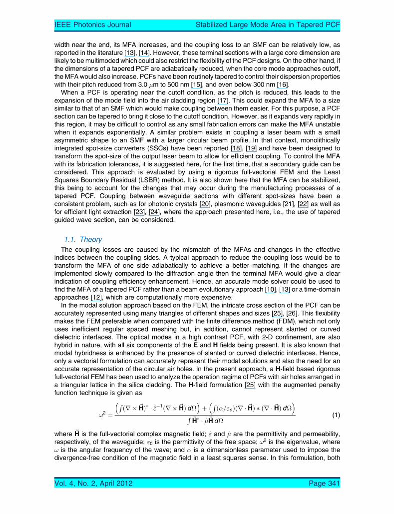
Next, the number of rings is increased to study the degree to which expansion of spot-size whichcan be achieved. The variation of the effective area Aeff with the reduction of the pitch � is shown inFig. 7 for N ¼ 7; 8; and 10. In all the cases, the air-hole diameter of the last ring has been increasedto 0:8� to stabilize the MFA near their cutoff conditions.
In each case as the pitch is reduced, the MFA increases as the PCF designs approaches theircutoff, but due to the presence of larger air holes in all the cases the MFA reaches a maximumvalue. However, it can be observed that for higher ring numbers, the maximum Aeff value washigher, which would allow efficient coupling to an optical fiber with a large MFA.
From the work done, it is clear that different numbers of rings are best suited for coupling of aPCF to an SMF, EDFA or lensed fiber. Next, the mode shape area required from the different opticalfibers, all of which guide a single moded waveguide, is studied by adjusting the radius and indexcontrast to maintain them identical. In this case, the cladding refractive index is taken as 1.445, andthe core index is adjusted for each fiber diameter to have the same normalized dimension V .
The variation of the required refractive index of the core with its radius a is shown in Fig. 8,designed to maintain the single modedness by keeping the V parameter fixed at V ¼ 2:23821417,which is that of a typical SMF. The variation of the MFA, Aeff with the radius for this fiber with aconstant value of V (where V ¼ 2:23821417) is also shown here. It can be observed that as a isreduced, the value of Aeff also reduces.
Fig. 6. Variations of the coupled power to an EDFA with the tapered pitch � of a PCF.
IEEE Photonics Journal Stabilized Large Mode Area in Tapered PCF
Vol. 4, No. 2, April 2012 Page 346
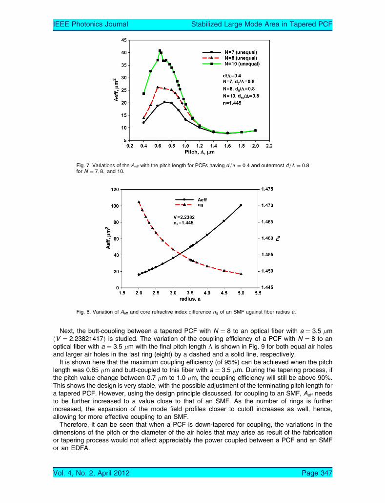
Next, the butt-coupling between a tapered PCF with N ¼ 8 to an optical fiber with a ¼ 3:5 �mðV ¼ 2:23821417Þ is studied. The variation of the coupling efficiency of a PCF with N ¼ 8 to anoptical fiber with a ¼ 3:5 �m with the final pitch length � is shown in Fig. 9 for both equal air holesand larger air holes in the last ring (eight) by a dashed and a solid line, respectively.
It is shown here that the maximum coupling efficiency (of 95%) can be achieved when the pitchlength was 0.85 �m and butt-coupled to this fiber with a ¼ 3:5 �m. During the tapering process, ifthe pitch value change between 0.7 �m to 1.0 �m, the coupling efficiency will still be above 90%.This shows the design is very stable, with the possible adjustment of the terminating pitch length fora tapered PCF. However, using the design principle discussed, for coupling to an SMF, Aeff needsto be further increased to a value close to that of an SMF. As the number of rings is furtherincreased, the expansion of the mode field profiles closer to cutoff increases as well, hence,allowing for more effective coupling to an SMF.
Therefore, it can be seen that when a PCF is down-tapered for coupling, the variations in thedimensions of the pitch or the diameter of the air holes that may arise as result of the fabricationor tapering process would not affect appreciably the power coupled between a PCF and an SMFor an EDFA.
Fig. 8. Variation of Aeff and core refractive index difference ng of an SMF against fiber radius a.
Fig. 7. Variations of the Aeff with the pitch length for PCFs having d=� ¼ 0:4 and outermost d=� ¼ 0:8for N ¼ 7; 8; and 10.
IEEE Photonics Journal Stabilized Large Mode Area in Tapered PCF
Vol. 4, No. 2, April 2012 Page 347
3. ConclusionA novel design approach for a PCF which could be considered as a candidate for efficient couplingto an optical fiber has been presented. Initially various MFA parameters and field profiles for anSMF and a PCF were studied. It has been shown here that a smaller air-hole diameter and a largernumber of rings would allow the Aeff value to reach a higher value, which can be achieved byoperating a PCF near cutoff. However, as its expansion near cutoff can be very rapid and unstable,by increasing the air-hole diameter in the last ring, this parameter can be stabilized with the variationof the fabrication tolerances. Using this approach presented above, it is possible to avoiduncertainty resulting from the variations in the dimensions of the pitch or the diameters of the airholes in the PCF as a result of fabrication or tapering, thereby ensuring that the PCF can besuccessfully coupled to an optical fiber without any significant loss in coupled power. Additionally, itis also shown here that the largest air holes in the last ring reduce the mode degeneration with thecladding modes. During the tapering process it has been assumed that the pitch � reducesgradually while keeping the d=� ratio constant. However, the air holes can also collapse, and theair-hole/pitch ratio can also change, although this may give an additional flexibility, as well as anadditional parameter to optimize the situation. Once the nature of the deviations are known a priorithen a rigorous numerical approach, such as that presented above, can be used to optimize thedesigns before their fabrication for experimental use. In this approach, as the PCF operates nearcutoff, it is normally expected that the leakage and bending losses will be increased. However, inthis approach, since larger hole diameters are used in the last air-hole ring, in fact, rather, lowerleakage and bending losses are expected. Additionally, if required additional air-hole rings withlarger hole diameters can be included and the design can be optimized [34] to reduce leakage andbending losses further.
References[1] P. J. St. Russell, BPhotonic-crystal fibers,[ J. Lightw. Technol., vol. 24, no. 12, pp. 4729–4749, Dec. 2006.[2] P. Russell, BPhotonic crystal fibers,[ Science, vol. 299, no. 5605, pp. 358–362, Jan. 2003.[3] N. A. Mortensen, BEffective area of photonic crystal fibers,[ Opt. Exp., vol. 10, no. 7, pp. 341–348, Apr. 2002.[4] B. T. Kuhlmey, R. C. McPhedran, and C. M. de Sterke, BModal cutoff in microstructured optical fibers,[Opt. Lett., vol. 27,
no. 19, pp. 1684–1686, Oct. 2002.[5] N. Kejalakshmy, B. M. A. Rahman, A. Agrawal, T. Wongcharoen, and K. T. V. Grattan, BCharacterisation of single-
polarization single mode photonic crystal fiber using full-vectorial finite element method,[ Appl. Phys. B, vol. 93, no. 1,pp. 223–230, Oct. 2008.
[6] P. J. Bennett, T. M. Monro, and D. J. Richardson, BToward practical holey fiber technology: Fabrication, splicing,modeling, and characterization,[ Opt. Lett., vol. 24, no. 17, pp. 1203–1205, Sep. 1999.
Fig. 9. Variation of Coupling Efficiency to PCF with tapered pitch � and SMF a ¼ 3:5 �m.
IEEE Photonics Journal Stabilized Large Mode Area in Tapered PCF
Vol. 4, No. 2, April 2012 Page 348

[7] J. H. Chong and M. K. Rao, BDevelopment of a system for laser splicing photonic crystal fiber,[Opt. Exp., vol. 11, no. 12,pp. 1365–1370, Jun. 2003.
[8] Y. Wang, H. Bartelt, S. Brueckner, J. Kobelke, M. Rothhardt, K. Morl, W. Ecke, and R. Willsch, BSplicing Ge-dopedphotonic crystal fibers using commercial fusion splicer with default discharge parameters,[ Opt. Exp., vol. 16, no. 10,pp. 7258–7263, May 2008.
[9] A. D. Yablon and R. T. Bise, BLow-loss high-strength microstructured fiber fusion splices using GRIN fiber lenses,[IEEE Photon. Technol. Lett., vol. 17, no. 1, pp. 118–120, Jan. 2005.
[10] J. Liu, T.-H. Cheng, Y.-K. Yeo, Y. Wang, L. Xue, Z. Xu, and D. Wang, BLight beam coupling between standard singlemode fibers and highly nonlinear photonic crystal fibers based on the fused biconical tapering technique,[ Opt. Exp.,vol. 17, no. 5, pp. 3115–3123, Mar. 2009.
[11] H. C. Nguyen, B. T. Kuhlmey, E. C. Magi, M. J. Steel, P. Domachuk, C. L. Smith, and B. J. Eggleton, BTapered photoniccrystal fibres: Properties, characterisation and applications,[ Appl. Phys. B, vol. 81, no. 2/3, pp. 377–387, Jul. 2005.
[12] H. C. Nguyen, B. T. Kuhlmey, M. J. Steel, C. L. Smith, E. C. Magi, R. C. McPhedran, and B. J. Eggleton, BLeakage ofthe fundamental mode in photonic crystal fiber tapers,[ Opt. Lett., vol. 30, no. 10, pp. 1123–1125, May 2005.
[13] J. K. Chandalia, B. J. Eggleton, R. S. Windeler, S. G. Kosinski, X. Liu, and C. Xu, BAdiabatic coupling in tapered air-silica microstructured optical fiber,[ IEEE Photon. Technol. Lett., vol. 13, no. 1, pp. 52–54, Jan. 2001.
[14] G. E. Town and J. T. Lizier, BTapered holey fibers for spot-size and numerical-aperture conversion,[ Opt. Lett., vol. 26,no. 14, pp. 1042–1044, Jul. 2001.
[15] S. G. Leon-Saval, T. A. Birks, W. J. Wadsworth, P. J. St. Russel, and M. W. Mason, BSupercontinuum generation insubmicron fiber waveguides,[ Opt. Exp., vol. 12, no. 13, pp. 2864–2869, Jun. 2004.
[16] E. C. Magi, P. Steinvurzel, and B. J. Eggleton, BTapered photonic crystal fibers,[ Opt. Exp., vol. 12, no. 5, pp. 776–784,Mar. 2004.
[17] B. M. A. Rahman, A. K. M. S. Kabir, M. Rajarajan, K. T. V. Grattan, and V. Rakocevic, BBirefringence study of photoniccrystal fibers by using the full-vectorial finite element method,[ Appl. Phys. B, vol. 84, no. 1/2, pp. 75–82, Jul. 2006.
[18] T. Wongcharoen, B. M. A. Rahman, M. Rajarajan, and K. T. V. Grattan, BSpot-size conversion using uniform waveguidesections for efficient laser-fiber coupling,[ J. Lightw. Technol., vol. 19, no. 5, pp. 708–716, May 2001.
[19] M. Rajarajan, B. M. A. Rahman, and K. T. V. Grattan, BNumerical study of spot-size expanders for an efficient OEIC toSMF coupling,[ IEEE Photon. Technol. Lett., vol. 10, no. 8, pp. 1082–1084, Aug. 1998.
[20] P. E. Barclay, K. Srinivasan, M. Borselli, and O. Painter, BEfficient input and output fiber coupling to a photonic crystalwaveguide,[ Opt. Lett., vol. 29, no. 7, pp. 697–699, Apr. 2004.
[21] H. Zhao, J. Zhang, G. Liu, and N. Tansu, BSurface plasmon dispersion engineering via double-metallic Au/Ag layers forIII-nitride based light-emitting diodes,[ Appl. Phys. Lett., vol. 98, no. 15, pp. 151115-1–151115-3, Apr. 2011.
[22] C. H. Lu, C. C. Lan, Y. L. Li, and C. P. Liu, BEnhancement of green emission from InGaN/GaN multiple quantum wellsvia coupling to surface plasmons in a two-dimensional silver array,[ Adv. Funct. Mater., vol. 21, no. 24, pp. 4719–4723,Dec. 2011.
[23] J. J. Weirer, A. David, and M. M. Megens, BIII-Nitride photonic-crystal light-emitting diodes with high extractionefficiency,[ Nat. Photon., vol. 3, no. 3, pp. 163–169, Mar. 2009.
[24] X. H. Li, R. Song, Y. K. Ee, P. Kumnorkaew, J. F. Gilchrist, and N. Tansu, BLight extraction efficiency of III-nitride light-emitting diodes with colloidal microlens array with various aspect ratios,[ IEEE Photon. J., vol. 3, no. 3, pp. 489–499,Jun. 2011.
[25] B. M. A. Rahman and J. B. Davies, BFinite-element solution of integrated optical waveguide,[ J. Lightw. Technol.,vol. LT-2, no. 5, pp. 682–688, Oct. 1984.
[26] K. Saitoh and M. Koshiba, BNumerical modelling of photonic crystal fiber,[ J. Ligthw. Technol., vol. 23, no. 11, pp. 3580–3590, Nov. 2005.
[27] B. M. A. Rahman and J. B. Davies, BAnalysis of optical waveguide discontinuities,[ J. Ligthw. Technol., vol. 6, no. 1,pp. 52–57, Jan. 1988.
[28] B. M. A. Rahman, E. O. Ladele, T. Wongcharoen, and K. T. V. Grattan, BSpot-size converters for efficient laser-fibercoupling,[ in Proc. SPIE, 2001, vol. 4532, pp. 281–291.
[29] M. Koshiba and K. Saitoh, BStructural dependence of effective area and mode field diameter for holey fibers,[ Opt. Exp.,vol. 11, no. 15, pp. 1746–1756, Jul. 2003.
[30] Encyclopaedia of Laser Physics and Technology, Beam Radius. [Online]. Available: http://www.rp-photonics.com/beam_radius.html
[31] B. M. A. Rahman, N. Kejalakshmy, M. Uthman, A. Agrawal, T. Wongcharoen, and K. T. V. Grattan, BMode degenerationin bent photonic crystal fibre study by using the finite element method,[ Applied Optics, vol. 48, no. 31, pp. G131–G138,Nov. 2009.
[32] B. Bourliaguet, C. Pare, F. Emond, A.Croteau, A. Proulx, andR. Vallee, BMicrostructured fiber splicing,[Opt. Exp., vol. 11,no. 25, pp. 3412–3417, Dec. 2003.
[33] W. Jiang, L. Shen, D. Chen, and H. Chi, BAn extended FDTD method with inclusion of material dispersion for full-vectorial analysis of photonic crystal fibers,[ J. Lightw. Technol., vol. 24, no. 11, pp. 4417–4423, Nov. 2006.
[34] B. M. A. Rahman, M. Uthman, N. Kejalakshmy, A. Agrawal, and K. T. V. Grattan, BDesign of bent photonic crystal fibersupporting a single polarization,[ Appl. Opt., vol. 50, no. 35, pp. 6505–6511, Dec. 2011.
IEEE Photonics Journal Stabilized Large Mode Area in Tapered PCF
Vol. 4, No. 2, April 2012 Page 349