
Spider 7 Instruction Manual - HubSpot
34
Spider Tracks Limited 205/150 Karangahape Road Auckland 1010 New Zealand Spider 7 Instruction Manual Applicable for both internal and external antenna variants of the Spider 7 with GPIO connection.
-
Upload
khangminh22 -
Category
Documents
-
view
5 -
download
0
Transcript of Spider 7 Instruction Manual - HubSpot

Spider Tracks Limited 205/150 Karangahape Road
Auckland 1010 New Zealand
Spider 7 Instruction Manual
Applicable for both internal and external antenna variants of the Spider 7
with GPIO connection.
1
Table of Contents
Record of Revision and Approvals 3 Appends: 3 1. Installation 4
1.1. Overview 4 1.2. Positioning the Spider 4 1.3. External antenna 5 1.4. Power 6 1.5. Keypad 6 1.6. General Purpose Input Output 6
2. Initialisation 14 2.1. Start Up 14 2.2. GPS Signal 14 2.3. Iridium Connectivity 14
3. Operation 15 3.1. System Attributes 15 3.2. Watch Button 16 3.3. Radius Button 16 3.4. Mark Button 16 3.5. SOS Function 17 3.6. Adjusting the LED Brightness 17 3.7. Spidertxt 2.0 17
4. Troubleshooting 18 4.1. Discontinuous Tracks 18 4.2. Lost GPS 18 4.3. Lost Iridium Connectivity 18
Appendix 19 (A)Spider 7 Minor Modification Summary Report 19
(A)1.Description 19 (A)2.Modification Approval Basis 19 (A)3.Configuration Control Data 19 (A)4.Post Installation Testing 19 (A)5.Operation and Limitations 19 (A)6.Weight and Balance 20 (A)7.Electrical Load 20 (A)8.Continuing Airworthiness 20
(B)Spider 7 Structure Test Procedure 21

2
(B)1.Test Definition 21 (B)2.Special Tools and Equipment 21 (B)3.Test Conditions 21 (B)4.Applied Loads 21 (B)5.Test Procedure 21 (B)6.Pass/Fail Criteria 22 (B)7.Test Record 22
(C)Spider 7 Electromagnetic Compatibility Test Procedure 23 (C)1.Test Definition 23 (C)2.Special Tools and Equipment 23 (C)3.Test Conditions 23 (C)4.Test Procedure 24 (C)5.Pass/Fail Criteria 24 (C)6.Test Record 26
(D)Wiring Diagram - Power Lead 31 (E) Datasheet for Iridium/GPS S67-1575-109 32 (F) RTCA DO-160 Test Reports 33

3
Record of Revision and Approvals
RECORD OF REVISIONS AND APPROVALS
Rev. DD/MM/YY Description Pages
Released by Approved by Affected
IR 17/11/15 Initial release All S. Ridder D. Blackwell
2.0.0 22/12/15 Antenna information
5 S. Ridder L. McCarthy changed
3.0.0 08/02/16 Antenna polarisation
5 S. Ridder D. Blackwell added
4.0.0 24/01/17 Revised and broadened
All D. Blackwell L. McCarthy scope
5.0.0 1/06/17 Addition of GPIO
All L. McCarthy S. Williams configuration information
Appends:
• Minor Modification Summary Report
• Structure Test Procedure
• Electromagnetic Compatibility Test Procedure
• RTCA DO-160 Test Reports

4
1. Installation
1.1. Overview
While Spiders in the most part are operated as portable electronic devices, there are a
number of settings where an operator may wish to obtain a field approval, engineering order,
or modification approved by your local airworthiness regulator.
This can be a confusing and complex process. Given simplicity and excellence are two of
Spidertracks’ cornerstone principals we have put a significant effort into providing all the
aeronautical data required to obtain these approvals. This includes the RTCA DO-160 test
data, modification templates (created by an FAA Delegated Engineering representative) with
simple effective test matrixes and drawings so that your local installer can seamlessly apply
for any additional certification.
The high level document is enclosed at Annex D and all of the supporting documents and
information is freely available on our support website or, if you need more help please call
our helpful support team on +64 9 222 0016.
With over 5,000 Spider units in service and almost 6,000,000 flight hours tracked, we are
confident we can help you through the often confusing and complex topic of aeronautical
certification.
1.2. Positioning the Spider
Correct positioning of the Spider’s antenna is critical in achieving effective performance from
the Spidertracks system as a whole. This is not an issue with Spider products that connect to
an external antenna as the visibility specification is met by virtue of the antenna installation,
however, when installing any Spider product that has the antenna integrated within the
device, particular attention is required. In this case the Spider should be mounted up on top
of the instrument panel in the aircraft, as far forward under the glare shield as possible to
maximise visibility with the sky, and free from any obstructions.
In order to function nominally, the Spider is required to receive GPS signal and then transmit
that information, along with other flight data, to the Iridium satellite network. The GPS
antenna is able to receive GPS information at any angle as long as it is not obstructed by
metallic material, such as the centre windshield pillar, however, the Iridium antenna must
have an unobstructed, horizon-horizon view of the sky in all directions to function nominally
(Figure1). Obstructions consist of any metallic or carbon composite object, but also
electrically heated windshield filaments that act as an RF shield whether they are turned on
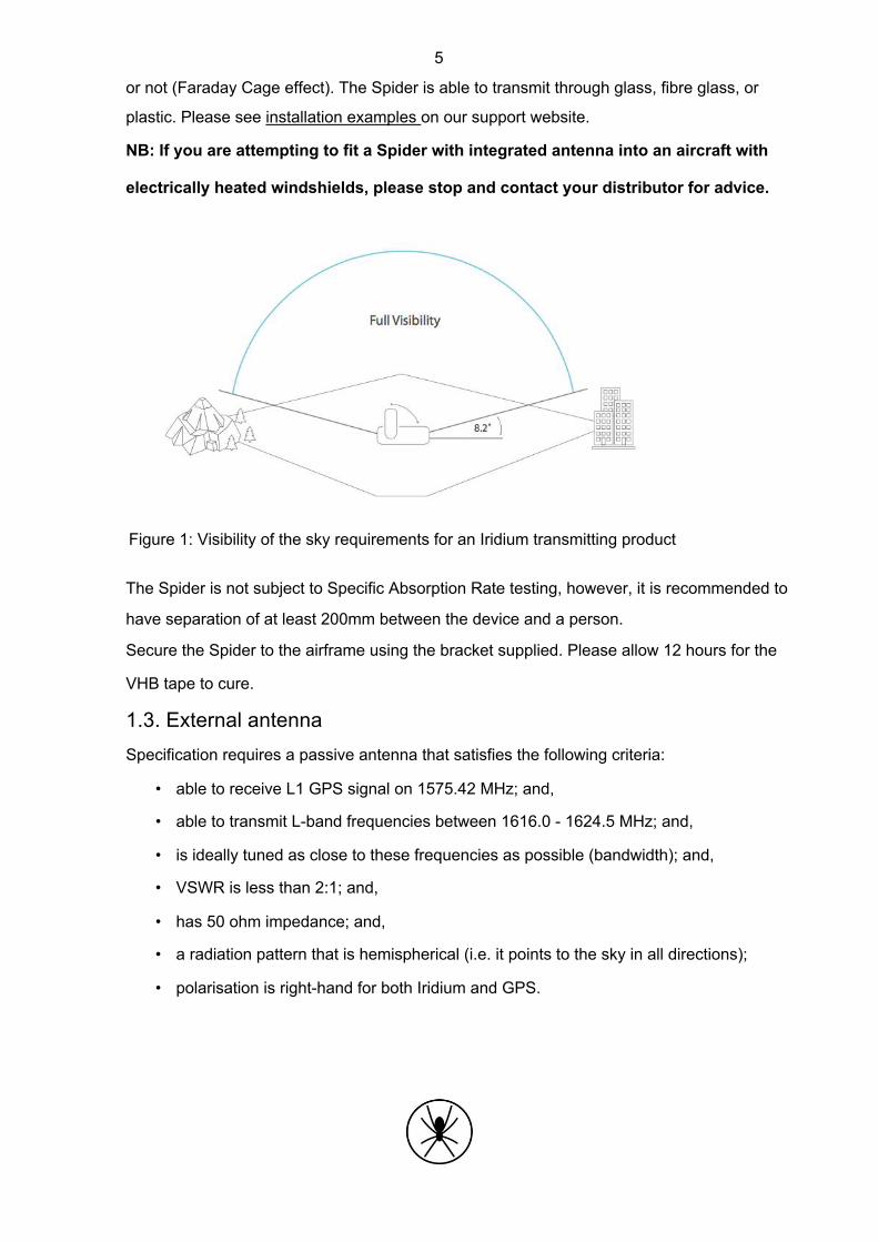
5
or not (Faraday Cage effect). The Spider is able to transmit through glass, fibre glass, or
plastic. Please see installation examples on our support website.
NB: If you are attempting to fit a Spider with integrated antenna into an aircraft with
electrically heated windshields, please stop and contact your distributor for advice.
Figure 1: Visibility of the sky requirements for an Iridium transmitting product
The Spider is not subject to Specific Absorption Rate testing, however, it is recommended to
have separation of at least 200mm between the device and a person.
Secure the Spider to the airframe using the bracket supplied. Please allow 12 hours for the
VHB tape to cure.
1.3. External antenna
Specification requires a passive antenna that satisfies the following criteria:
• able to receive L1 GPS signal on 1575.42 MHz; and,
• able to transmit L-band frequencies between 1616.0 - 1624.5 MHz; and,
• is ideally tuned as close to these frequencies as possible (bandwidth); and,
• VSWR is less than 2:1; and,
• has 50 ohm impedance; and,
• a radiation pattern that is hemispherical (i.e. it points to the sky in all directions);
• polarisation is right-hand for both Iridium and GPS.

6
There are many options for this antenna, ideally there will be one available on the aircraft
already. Spidertracks does have experience with an antenna (P/N: S67-1575-109)
manufactured by Sensor Systems (Appendix E). This carries an FAA TSO-C129.
The Spider is a low power transmitting device (mW range). Minimising losses between the
device and the antenna should be considered in the installation process. There should be not
more than 2dB of losses between the two components, including insertions. Antenna cable
should be RG-178 or similar. In the case where a cable of significant length is required, it
may be necessary to use a higher grade.
1.4. Power
Power supply must be stable in the range of 10 V - 32 V DC and capable of delivering at
least 1.5 A peak current. The Spider is supplied with a 2m auxiliary power lead and can be
connected directly to an auxiliary power outlet. The power lead is fuse protected within the
cigarette lighter adapter plug.
As auxiliary power sockets wear they can become loose and disrupt the power supply to the
Spider, which in turn can lead to unreliable performance (see 4.1). In more permanent
installations it is recommended to hard-wire the lead to the avionics bus. This is generally
considered a minor modification when conducted by a LAME or certified technician
(Appendix D).
NB: If removing the auxiliary plug to hard-wire into the aircraft’s power, the Spider must be
protected by a 3A in line fuse.
1.5. Keypad
The remote keypad provides I/O functionality and should be mounted somewhere practical in
the cockpit but within reach of the pilot(s). The keypad is on a 2m lead and connects to the
Spider’s Mini USB port.
1.6. General Purpose Input Output
The General Purpose Input Output (GPIO) allows signals from equipment on the aircraft to
be sent through the Spider to the Spidertracks website, e.g., Take off and Landing messages
from the helicopter collective switch.

7
Figure 2. Components supplied with GPIO: Bulgin connector, 10 x pins, and cable
Figure. 3. GPIO pins as looking from the front face of the Spider

8
1.6.1. Pin Description Table 1. GPIO pin descriptions
Pin GPIO Cable Name Description Colour
1 Red Non-isolated +3.3 The +3.3VDC rail is intended to power such things as input VDC voltage sensors signal It is currently limited to 100mA to protect the Spider in the event
that this output is shorted 2 Black Non-isolated General purpose ground
ground 3 Grey Non-isolated input The basic protection consists of current limiting resistors and
1 with basic TVS diodes protection There is provision for adjusting the default Low-Pass frequency of 106kHz
4 Yellow Non-isolated input
Maximum voltage is +3.3 VDC 2 or analogue
input 5 Orange Isolated output The isolated outputs share a common ground connection. This is
ground separated from the Spider Ground 6 Blue Isolated output 1 The isolated output has an open collector configuration. The
specification must be strictly followed. 7 Brown Isolated output 2 An open collector output allows the 3rd party to pull the voltage
up to a large range of voltages and the Spider will drive this voltage low to activate the output. IMPORTANT
Maximum voltage is +80 VDC • • Maximum current must be kept < 30 mA • This is done by selecting an appropriate resistor value
Failure to limit the current and/or voltage will • result in permanent damage to that particular output port
8 Purple Isolated input The isolated inputs share a common ground connection. This is ground separated from the Spider Ground
9 White Isolated input 1 Voltage input range of +3.3 VDC ~ +12VDC (Absolute Max +15
VDC) without 620 ohm resistor. 10 Green Isolated input 2 Voltage input range of +9 VDC ~ +32VDC with 620 ohm resistor.
IMPORTANT Failure to limit the current and/or voltage will •
result in permanent damage to that particular input port
The Isolated GPIO input is quite different to the Non-isolated GPIO input:

9
• To detect a situation where it is either ground or no ground, we should use a Non-isolated
GPIO input
• In a situation where we need to detect a signal, either a voltage or a ground, we should use
an Isolated GPIO input.
• We should always make use of the Isolated GPIO input common ground pin when we want
to use an Isolated GPIO input
• The voltage or ground must be recognised by the Spider GPIO interface for it to work
1.6.2. Input Signal Classification The following are suggested installations based on the above case numbers and associated input
signals. Table 2: Input signal cases
Case Input Signal Example Input GPIO Input Pin Signal Value
1 Ground/Disconnect ground/no ground Pin 3 or Pin 4
2 Pin 9 or Pin 10
3 Pin 9 or Pin 10 4 Voltage/Ground with signal 24V/ground Pin 3 or Pin 4
isolation (signal separation is 12V/ground
done by a diode) 5 Voltage/Ground 24V/ground Pin 9 or Pin 10
12V/ground
6
Pin 3 or Pin 4
7 Voltage/Voltage 24V/1V, input Pin 9 or Pin 10 source voltage is Note in this case only one isolated 24V input pin can be used since pin 9 and pin 10 share the common ground pin 8.
8 Pin 3 or Pin 4 A NO (normally open) relay is used in this case.
Case 1:

10 Case 2: Case 3: Case 4: Case 5:

11 Case 6:
Case 7:
Case 8:

12 1.6.3. Website Configuration An administrator of your account can configure the GPIO at any time from the go.spidertracks.com
website. They need to login to the organisation settings of the organisation the Spider is registered.
Go to Event Logging menu on the left hand menu bar.
Figure 4. Event Logging and GPIO setup on go.spidertracks.com Under GPIO Settings select an aircraft to configure. Note, the aircraft must have a Spider 7 with
GPIO assigned to it. If this is not already configured it can be done from the Aircraft Settings page.
Select Event Logging Enabled to yes and save to turn the GPIO on. Once saved you will be able to
select the Event Groups and whether it is rising edge or falling edge triggered. You don’t need to
configure all four pins. The following event groups are currently available: • Engine On / Off • Take Off / Landing • Pump On / Off • Tank Open / Close

13 • Bucket Open / Close In order to use Take Off and Landing event messages you must also configure and install
the Spider for Engine On and Off events. Once you save the configuration a message will be sent to the Spider to update the firmware. The
Spider must connect to the Iridium Satellite Network in order to receive this update. We
recommend 10 minutes of connection in order to process all updates. If you require a different event description to the ones listed above, please contact
1.6.4. Testing To check the information you are receiving is correct, go to the History page within your account.
Select the checkbox beside the ‘test flight’ and click on the download button in the top bar. The
event description will show within the CSV file. The event is not currently displayed on the maps
within the Flying or History pages. For further assistance please contact [email protected].

14
2. Initialisation
Figure 3 provides a visual reference for content discussed within Sections 2 and 3 of this
document.
Figure 5: Spider 7 Keypad I/O
2.1. Start Up
When the Spider is first powered the LEDs will cycle through a start-up sequence (that
indicates firmware version) and should then display a solid Power LED indicator only.
2.2. GPS Signal
In order to acquire a GPS lock, the aircraft will need to be outside and in full view of the sky
(refer to 1.1) with the power on. Once a GPS lock is attained the Signal LED indicator
(bottom right) will turn orange. A GPS lock should be acquired within 60 seconds in the
general case.
2.3. Iridium Connectivity
Once a GPS lock has been attained the Spider will immediately attempt to send the first
position report to the Iridium satellites. Once a connection has been made with the Iridium
network, the Signal LED indicator will turn from orange to green and should remain green
throughout the duration of the flight.
Under normal operating conditions the time taken from startup through GPS lock and
connection with the Iridium network should be less than 2 minutes.

15
3. Operation
Tracking, communication and other flight data transmitted via the Spider can be viewed on
the Spidertracks website and mobile application, however, this will first need to be configured
at go.spidertracks.com. For setting up your account, please refer to the User Guide for the
Spidertracks website.
Reporting parameters are configured within the website and not on the Spider itself. When
such parameters are initialised, or changed, the Spidertracks system queues a configuration
message for delivery to the Spider. This sits on the gateway until the next subsequent
‘session’ that the Spider establishes, at which point the message is delivered and the
Spider’s operating system is updated accordingly. Configuration updates can be made in real
time while the aircraft is in flight.
When powered and in full view of the sky, the Spider will begin to send position reports
consistent with how it has been configured without any interaction required by the pilot. The
purpose of the keypad is to provide visual indication on the state of the Spider as well as
additional functionality, but is not required for the Spider to report aircraft position.
3.1. System Attributes
There are many features of the Spidertracks system that are delivered through software
services and are not specific to any of the Spider product variants. The full range of these
are beyond the scope of this document, however, the following two sub-sections summarise
cornerstone attributes and provides context for Spider functions discussed in this section.
3.1.1. Tracking Modes Spidertracks provides both passive and active tracking capabilities (referred to as normal
and watch modes respectively).
Under normal tracking conditions, the Spider will report positional information and flight
events in real time, however, if the aircraft were to encounter an emergency situation in flight,
ground personnel would not be alerted to this unless there was a conscious SOS button
pressed by the crew.
In watch mode, the Spidertracks system is actively monitoring the status of the flight. If
communication with the aircraft is lost for a period of ten minutes, a tier one alert will be
pushed through to the emergency management framework.
Watch mode can be activated either manually or automatically (by speed trigger). In either
case, the watch button must be pressed to disable the watch system - there is no auto-off.

16
3.1.2. Emergency Management Framework
The Spidertracks system comes with a two tiered emergency management framework, which
are aligned with the ICAO definitions of uncertainty and alert. Recipients of these alert
notifications are fully customisable within the Organisational Settings of the website.
3.2. Watch Button
The Watch button has two purposes:
1. To manually activate/deactivate the watch system at any stage of flight when operating in
normal reporting mode; or,
2. To turn the Watch system off when operating under automated watch mode. Note that
the aircraft must be below the configured speed threshold in order to disable the watch
system when operating in automated watch mode.
The watch button will toggle on/off - do not press and hold the button. When disabling the
system the LED indicator will begin to flash once toggled. The Spider has now sent a watch-
off message. Until the message has been sent successfully, the LED will continue to flash. It
is normal operation for this to take up to 60 seconds. While this is in process the aircraft must
remain in full view of the sky. If the Spider is powered off before transmitting the watch-off
message, a tier one alert will be raised.
3.3. Radius Button
Radius is a dynamic exclusion zone of a preconfigured size within the Organisational
Settings of the website. When the Radius button is toggled on, position reporting is
suspended while the aircraft operates within the bounds of that geo-fenced area. Tracking
will resume on exiting the radius area or toggling off the Radius button. For information on
configuring Radius please refer to User guide and videos for the spidertracks website.
3.4. Mark Button
Up to four pre-programmed macro messages can be delivered by way of toggling the Mark
button the corresponding number of times, i.e. a single toggle will trigger Mark 1 message to
be sent, toggling twice will trigger Mark 2 message to be sent. Each message is geo-
stamped and includes all other parameters of a standard position report.
Configuration of macro messages, recipients and delivery mechanism are configured within
the Organisational Settings of the website.
17
3.5. SOS Function
A tier-one alert can be initiated immediately by pressing the Radius and the Mark buttons
together. When the SOS function has been toggled all LEDs across the top of the keypad will
flash simultaneously and the Spider will default to a rapid reporting state (8-10 second
intervals in the general case).
NB: The SOS state can not be disabled any other way than to power-cycle the Spider.
3.6. Adjusting the LED Brightness
You can adjust the LED brightness on the keypad by pressing and holding the Mark button.
The LED will cycle through the levels of brightness. Release the Mark button when your
desired brightness is reached.
3.7. Spidertxt 2.0
The Spider 7 is equipped with Low Energy Bluetooth (BLE) technology and is compatible
with Spidertxt 2.0. This enables two-way freeform messaging to/from the cockpit using a
mobile device connected to the Spider.
For more information on Spidertxt 2.0 please contact Spidertracks support.

18
4. Troubleshooting
4.1. Discontinuous Tracks
Intermittent power supply issues are often the cause of this and are easily recognisable by:
• Multiple short tracks which constitute what should have been a single track between
point A and B
• An excessive number of 0 minute tracks • Missing tracks (last track terminates at point C, next track originates at point D)
• Last point in track is at a high altitude and/or airspeed • In the case where a Spider is operating in watch mode, an undesirable outcome of
erratic power cycling may be a tier one alert being fired
Generic Causality:
• Spider is powered by auxiliary power outlet (cigarette lighter) which is subject to
interruption from bumps, knocks, and vibration
• Spider is powered by a battery pack which is unable to deliver enough current, and/ or
is running flat
4.2. Lost GPS
If the GPS signal is lost both the Satellite and GPS LED on the Spider will turn off. On the
keypad, the Signal LED will turn off. It is not uncommon to drop a GPS lock but occurrences
should be infrequent and not last for periods of more than a few seconds.
4.3. Lost Iridium Connectivity
If the Spider can not connect to an Iridium Satellite for a short period of time there will be a
transmission delay from real-time. If the delay exceeds 120 seconds, the Satellite LED on
the Spider 7 will turn off, but the GPS LED will stay on to indicate that the unit still has a GPS
lock. The Signal LED on the keypad will turn orange.
The Spider uses temporary memory to store a maximum of 10 points, therefore even if the
Spider is struggling to send position points, it can still add points to the queue as long as
there is a GPS lock. Once the Satellite connection is re-established, the Satellite LED on the
Spider will turn back on and the Signal LED on the keypad will turn green.

19
Appendix
(A)Spider 7 Minor Modification Summary Report
(A)1.Description
The subject modification consists of the installation of a Spider 7 real-time aircraft tracking
device.
(A)2.Modification Approval Basis
Spidertracks recommends classifying the subject modification as a minor modification. This
recommendation is based on the evaluations of the modification against: (1) Transport
Canada Civil Aviation Standard 571 Appendix A, Criteria for the Classification of
Modifications and Repairs; and (2) Federal Aviation Administration FAR Part 43 Appendix A.
Therefore, acceptable data will be employed to support the installation of the Spider 7.
Compliance is at owner’s discretion.
(A)3.Configuration Control Data
Chapter Version Date
Spider 7 Instruction Manual 3.0.0 24/01/2017
(A)4.Post Installation Testing
Complete post installation in accordance with the following guidelines:
Title Version Date
Appendix (B): Spider 7 Structure Test Procedure IR 17/11/2015
Appendix (C) : Spider 7 Electromagnetic Compatibility Test IR 17/11/2015
Procedure
(A)5.Operation and Limitations
Refer to Spider Tracks Limited, Spider 7 Instruction Manual for operational instructions.
Basic flight manual limitations remain applicable.

20
(A)6.Weight and Balance
Update aircraft weight and balance report as required:
Description Weight [kg] Arm [mm] Moment [kg-mm]
Installation, Spider 7 0.165
(A)7.Electrical Load
Installation of the Spider 7 introduces a maximum continuous draw of 1.0A at 12VDC.
Update the aircraft electrical load analysis report as required.
(A)8.Continuing Airworthiness
Maintenance of the modification is in accordance with the applicable OEM maintenance
manual. Instructions for Continued Airworthiness (ICA) are not required.

21
(B)Spider 7 Structure Test Procedure
(B)1.Test Definition
The purpose of these test procedures is to demonstrate structural integrity for the installation
of the Spider 7.
(B)2.Special Tools and Equipment
A calibrated digital or analogue fish hook type scale (e.g. Transducer Techniques HFG-110)
is required to conduct the structural testing.
(B)3.Test Conditions
The Spider 7 must be installed prior to starting the structural testing. Allow for adequate time
for the adhesive to fully bond to the installation location.
(B)4.Applied Loads
Conservative ultimate load factors for structural testing purposes are provided for FAR 23
(normal, acrobatic and utility category airplanes) and FAR 27 (normal rotorcraft) installations.
For additional information, refer to the acceptable data source, FAA AC43.13-2B, Chapter 1,
Paragraphs 103 through 105.
Load Case Ultimate
Weight of Spider 7 Minimum Applied Load
Load Factor [Load Factor x Weight]
Forward 18.0g 0.165 kg 2.970 kg
Downward 20.0g 0.165 kg 3.300 kg
Upward 5.7g 0.165 kg 0.941 kg
Side 8.0g 0.165 kg 1.320 kg
Table 3: Minimum Applied Loads.
(B)5.Test Procedure
The following procedures detail the methodology for the structural test.
1. Record the serial number of the Spider 7 being used in the test and complete the test
record information.

22
2. Apply the minimum loads listed in Chapter 3.4 to the centre of the Spider 7 in
accordance with AC 43.13-2B, Para 105. Record the actual applied loads:
Forward
Downward
Upward
Side
(B)6.Pass/Fail Criteria
When no damage or permanent deformation occurs after 7 seconds of applied static load in
all directions, the Spider 7 installation is acceptable. Should permanent deformation occur
after 3 seconds, reinforcements are required (e.g. doubler installation) to the affected
structure and repeat test.
(B)7.Test Record
Date of Test
Spider 7 S/N
Location of Test
A/C Registration
LAME conducting testing:
Print Name Signature License No.

23
(C)Spider 7 Electromagnetic Compatibility Test
Procedure
(C)1.Test Definition
The purpose of these test procedures is to demonstrate Electromagnetic Compatibility
(EMC) between the aircraft’s electrical or electronic systems, and the Spider 7 being tested.
This test procedure is an aircraft-level test, to determine if there is any electromagnetic or
radio frequency interference (EMI/RFI) to the various critical aircraft systems, radios and
installed equipment.
(C)2.Special Tools and Equipment
The following equipment may be required depending on aircraft installed equipment and
availability of navigation aids and ATC radar in the area where testing is conducted.
a. NAV/COM Ramp Tester (e.g. NAV-402AP, IFR-4000); b. Transponder/DME Ramp Tester (e.g. ATC-600A, ATC-601, IFR-6000);
c. TCAS Ramp Tester (e.g. TCAS-201, IFR-6000); d. Headsets; and
e. Other equipment as required to exercise all modes of operation for systems under
test.
(C)3.Test Conditions
All aircraft systems under test must be functional prior to starting the EMC test. Any reduced
functionality of the system(s) should be noted. All testing shall be conducted in day VFR
conditions with a clear view of the sky to ensure that a GPS fix can be obtained for starting
the Iridium transmission.
For the test, the following conditions are required:
a. All engines running with all generators online (for part of the test);
b. All electrical busses powered; and c. All avionics/electrical systems and installed equipment powered and active.

24
(C)4.Test Procedure
The following procedures detail the methodology for the EMC test.
1. Identify all aircraft systems under testing from the test matrix table and strike out
those that are not applicable to the respective aircraft used in the test.
2. Record the serial number of the Spider 7 being used in the test and complete the test
record information.
3. Power up the Spider 7. The left LED on the keypad of the Spider will glow green and
the right LED will turn amber when it has a GPS fix.
4. Achieve a Bluetooth connection with the Spider 7 and an appropriate device (e.g.
Apple iPhone).
5. Operate each aircraft system under test in all the modes of operation, while
monitoring the system for interference. If there is no interference observed, insert a
check mark in the “passed” column. If interference is observed, describe the
interference in the respective observation column and contact Spider Tracks Limited
for further assistance.
6. Multiple systems may be monitored in tandem to expedite the test whenever possible.
7. Systems should be tested on the ground unless the aircraft system/equipment can
only be tested in flight.
8. If there are avionics/electrical systems on the aircraft that are not listed, add them at
the end of the table.
9. Ensure there is no interference to aircraft systems from the use of the Spider 7. 10. When test is complete, note any comments or differences in the test procedures
“Comments” section remembering to sign and date the appropriate areas at the end
of this document.
(C)5.Pass/Fail Criteria
EMC testing is subjective in nature since an interference can be deemed acceptable or
unacceptable. If an interference is observed, the decision of acceptability should be
determined by the person who will be making a compliance finding against the applicable
airworthiness standards. In general, the systems under test shall have no unintentional
changes in operating mode, unexpected responses, intermittent behaviours, or unacceptable
noise.

25

26
(C)6.Test Record
Date of Test
Spider 7 S/N
Location of Test
A/C Registration
Aircraft System Test Instructions
Passed Observations Under Test
Open squelch. Tune to 118, 120,
VHF 1 124, 128, 132, 136MHz. Listen for
☐
noise . Verify transmit and
reception.
Open squelch. Tune to 118, 120,
VHF 2 124, 128, 132, 136MHz. Listen for
☐
noise . Verify transmit and
reception.
Open squelch. Tune to 118, 120,
VHF 3 124, 128, 132, 136MHz. Listen for
☐
n o i s e . Ve r i f y t r a n s m i t a n d
reception.
Tune to 3, 6, 9, 15, 21, 27MHz.
HF 1 Listen for noise. Verify transmit
☐
and reception in both AM and
SBB modes for each channel.
VHF/FM 1 Tune to test frequency. Verify
☐
transmit and reception.
VHF/FM 2 Tune to test frequency. Verify
☐
transmit and reception.
UHF 1 Tune to test frequency. Verify
☐
transmit and reception.
Tune in to local stations and/or
VOR 1 use ramp tester. Verify VOR
☐
bearing display and station audio
ident.
Tune in to local stations and/or
VOR 2 use ramp tester. Verify VOR
☐
bearing display and station audio
ident.
SATCOM Verify operation in all modes. ☐

27
Aircraft System Test Instructions
Passed Observations Under Test
ILS 1 Tune in to local stations and/or use ramp tester. Verify GS / LOC ☐
display and station audio ident.
ILS 2 Tune in to local stations and/or use ramp tester. Verify GS / LOC ☐
display and station audio ident.
DME 1 Tune in to local stations and/or use ramp tester. Verify correct ☐
DME and station audio ident.
DME 2 Tune in to local stations and/or use ramp tester. Verify correct ☐
DME and station audio ident.
ADF 1 Tune in to local stations and/or use ramp tester. Verify correct ☐
indication and station audio ident.
Display GPS satellite data. Verify
GPS 1 signal quality and number of
☐
satellites tracking. Verify GPS
position is reasonable.
Display GPS satellite data. Verify
GPS 2 signal quality and number of
☐
satellites tracking. Verify GPS
position is reasonable.
Display GPS satellite data. Verify
GPS 3 signal quality and number of
☐
satellites tracking. Verify GPS
position is reasonable.
RAD ALT 1 Verify RAD ALT displays zero feet
☐
on ground.
RAD ALT 2 Verify RAD ALT displays zero feet
☐
on ground.
ELT Monitor ELT for inadvertent
☐
trigger.
WX RADAR Operate weather radar in all available modes. And verify no ☐
erroneous indications.
CLOCKS Verify no erroneous indications. ☐
STBY INST Verify no erroneous indications. ☐
STBY COMPASS Monitor for erratic indications. ☐

28
Aircraft System Test Instructions
Passed Observations Under Test
HSI/DG 1 Monitor for erratic indications. ☐
HSI/DG 2 Monitor for erratic indications. ☐
AHRS 1 Monitor for erratic attitude and
☐
heading indications.
AHRS 2 Monitor for erratic attitude and
☐
heading indications.
CVR Run self-test if available. Verify no
☐
flags or lights appear.
FDR Run self-test if available. Verify no
☐
flags or lights appear.
COCKPIT LIGHTS Verify normal operation. ☐
EXTERNAL Verify normal operation.
☐
LIGHTS
HTAWS Monitor for erroneous indications.
☐
Perform self-test if available.
TCAS Monitor for erroneous indications.
☐
Perform self-test if available.
MFD Monitor for erroneous indications.
☐
Perform self-test if available.
TRANSPONDER Use ramp tester or check in flight t o e s t a b l i s h M o d e C ☐
interrogations.
CAUTION PANEL Monitor for erroneous indications. ☐
CIRCUIT Monitor for erroneous indications. ☐
BREAKERS
SPAS Perform system test and monitor
☐
for erroneous indications.
AFCS / SCAS / Perform system test and monitor ☐
CSAS for erroneous indications.
FLIGHT Engage flight director in all modes ☐
DIRECTOR 1 of operation.
FLIGHT Engage flight director in all modes ☐
DIRECTOR 2 of operation.
ADC 1 Perform a system function test. Verify correct display of airspeed, ☐
altitude, TAT, TAS.

29
Aircraft System Test Instructions
Passed Observations Under Test
ADC 2 Perform a system function test. Verify correct display of airspeed, ☐
altitude, TAT, TAS.
HEATER / ECS Operate in all modes. ☐
FUEL QUANTITY Monitor for erroneous or erratic
☐
indications.
FUEL SYSTEM Monitor for erroneous or erratic
☐
indications.
HYDRAULIC SYS Cycle hydraulic pumps. Monitor f o r e r r o n e o u s o r e r r a t i c ☐
indications.
FUEL CONTROL Cycle system to manual and back to auto. Monitor for erroneous or ☐
erratic indications.
FIRE DETECTION Monitor for erroneous or erratic ☐
SYSTEM(S) indications.
Run engines. Verify proper
ENGINE functioning. Monitor for erroneous or erratic indications. Transfer ☐
INDICATING
electrical busses to all engine
driven generator(s).
AC/DC Configure the electrical systems in different modes. Verify no
ELECTRICAL ☐
interference when switching loads
SYSTEMS
from one bus to another.
MAST MOMENT Monitor for erroneous or erratic ☐
INDICATOR indications.
FADEC / DECU Run engines in all modes. Monitor f o r e r r o n e o u s o r e r r a t i c ☐
indications.
VEMD Run engines in all modes. Monitor f o r e r r o n e o u s o r e r r a t i c ☐
indications.
PITOT STATIC Confirm correct operation.
☐
HEAT
EMERGENCY Monitor for inadvertent activation. ☐
LIGHTS
PARTICLE Monitor for erroneous indications. ☐
SEPERATOR

30
Aircraft System Test Instructions
Passed Observations Under Test
CYCLIC TRIM Verify for normal operation and
☐
monitor for inadvertent activation.
ENGINE TRIM Verify for normal operation and
☐
monitor for inadvertent activation.
CARGO HOOK Verify for normal operation and
☐
monitor for inadvertent activation.
LONG LINE Verify for normal operation and ☐
RELEASE monitor for inadvertent activation.
☐
☐
☐
Comments:
Indicate any deviations from the test procedure, or observations regarding the test results:
LAME conducting testing:
PRINT NAME SIGNATURE LICENSE NO
Pilot conducting testing:
PRINT NAME SIGNATURE LICENSE NO

31
(D)Wiring Diagram - Power Lead

32
(E) Datasheet for Iridium/GPS S67-1575-109

33
(F) RTCA DO-160 Test Reports
Links to download:
• DO-160F Sections 15 and 21: Magnetic Effect & RF Emissions
• DO-160G Sections 7 and 8: Shock and Vibration
• DO-160G Section 17: Voltage Spike
• DO-160G Section 26: Flammability