Specification for the use of Video and Audio Coding ... - dvb.org
304
Digital Video Broadcasting (DVB); Specification for the use of Video and Audio Coding in Broadcast and Broadband Applications DVB Document A001 Jul 2019
-
Upload
khangminh22 -
Category
Documents
-
view
2 -
download
0
Transcript of Specification for the use of Video and Audio Coding ... - dvb.org

Digital Video Broadcasting (DVB); Specification for the use of Video and Audio Coding
in Broadcast and Broadband Applications
DVB Document A001
Jul 2019

This page is left intentionally blank

DVB BlueBook A001 (Jul 2019)
3
Contents
Intellectual Property Rights ...................................................................................................................... 17
Foreword................................................................................................................................................... 17
Modal verbs terminology ......................................................................................................................... 18
Introduction .............................................................................................................................................. 18
1 Scope .............................................................................................................................................. 21
2 References ...................................................................................................................................... 21 2.1 Normative references ............................................................................................................................... 21 2.2 Informative references ............................................................................................................................. 23
3 Definition of terms, symbols and abbreviations ............................................................................. 25 3.1 Terms ....................................................................................................................................................... 25 3.2 Symbols ................................................................................................................................................... 34 3.3 Abbreviations ........................................................................................................................................... 34
4 Systems layer ................................................................................................................................. 37 4.0 Introduction.............................................................................................................................................. 37 4.1 Broadcast bitstreams and Baseline IRDs ................................................................................................. 37 4.1.0 General ............................................................................................................................................... 37 4.1.1 Introduction (Recommendation ITU-T H.222.0 / ISO/IEC 13818-1 Introduction) ........................... 37 4.1.2 Packetized Elementary Stream (PES) (Recommendation ITU-T H.222.0 / ISO/IEC 13818-1,
clause Intro.4) ..................................................................................................................................... 38 4.1.3 Transport stream system target decoder (Recommendation ITU-T H.222.0 / ISO/IEC 13818-1,
clause 2.4.2) ....................................................................................................................................... 38 4.1.4 Transport packet layer (Recommendation ITU-T H.222.0 / ISO/IEC 13818-1, clause 2.4.3.2) ........ 38 4.1.4.1 Null packets .................................................................................................................................. 38 4.1.4.2 Transport packet header ................................................................................................................ 38 4.1.4.2.1 Transport_error_indicator ....................................................................................................... 38 4.1.4.2.2 Transport_priority ................................................................................................................... 38 4.1.4.2.3 Transport_scrambling_control ................................................................................................ 38 4.1.4.2.4 Void ........................................................................................................................................ 38 4.1.5 Adaptation field (Recommendation ITU-T H.222.0 / ISO/IEC 13818-1, clause 2.4.3.4) .................. 39 4.1.5.1 Random_access_indicator ............................................................................................................ 39 4.1.5.2 Elementary_stream_priority_indicator ......................................................................................... 40 4.1.5.3 Program Clock Reference (PCR) .................................................................................................. 41 4.1.5.4 Other fields ................................................................................................................................... 41 4.1.6 Packetized Elementary Stream (PES) Packet (Recommendation ITU-T H.222.0 / ISO/IEC 13818-1,
clause 2.4.3.6) .................................................................................................................................... 42 4.1.6.1 stream_id and stream_type ........................................................................................................... 42 4.1.6.2 PES_scrambling_control .............................................................................................................. 43 4.1.6.3 PES_priority ................................................................................................................................. 43 4.1.6.4 Copyright and original_or_copy ................................................................................................... 43 4.1.6.5 Trick mode fields .......................................................................................................................... 43 4.1.6.6 additional_copy_info .................................................................................................................... 44 4.1.6.7 Optional fields .............................................................................................................................. 44 4.1.6.8 PES_extension_field ..................................................................................................................... 44 4.1.6.9 Multiple video pictures per PES packet ........................................................................................ 45 4.1.6.10 Presentation Time Stamp and Decoding Time Stamp occurrence ................................................ 46 4.1.6.11 STD audio buffer size ................................................................................................................... 47 4.1.7 Program Specific Information (PSI) (Recommendation ITU-T H.222.0 / ISO/IEC 13818-1,
clause 2.4.4) ....................................................................................................................................... 48 4.1.8 Use of program and elementary stream descriptors (Recommendation ITU-T H.222.0 /
ISO/IEC 13818-1, clause 2.6) ............................................................................................................ 48 4.1.8.0 Introduction .................................................................................................................................. 48 4.1.8.1 video_stream_descriptor and audio_stream_descriptor ................................................................ 48 4.1.8.2 hierarchy_descriptor ..................................................................................................................... 48 4.1.8.3 registration_descriptor .................................................................................................................. 49

DVB BlueBook A001 (Jul 2019)
4
4.1.8.4 data_stream_alignment_descriptor ............................................................................................... 49 4.1.8.5 target_background_grid_descriptor .............................................................................................. 49 4.1.8.6 video_window_descriptor ............................................................................................................ 49 4.1.8.7 Conditional Access CA_descriptor ............................................................................................... 49 4.1.8.8 ISO_639_Language_descriptor .................................................................................................... 49 4.1.8.9 system_clock_descriptor .............................................................................................................. 50 4.1.8.10 multiplex_buffer_utilization_descriptor ....................................................................................... 50 4.1.8.11 copyright_descriptor ..................................................................................................................... 50 4.1.8.12 maximum_bitrate_descriptor ........................................................................................................ 50 4.1.8.13 private_data_indicator_descriptor ................................................................................................ 50 4.1.8.14 smoothing_buffer_descriptor ........................................................................................................ 50 4.1.8.15 STD_descriptor ............................................................................................................................. 50 4.1.8.16 IBP_descriptor .............................................................................................................................. 50 4.1.8.17 MPEG-4_audio_descriptor ........................................................................................................... 50 4.1.8.18 AVC_video_descriptor ................................................................................................................. 51 4.1.8.19 SVC_extension_descriptor ........................................................................................................... 51 4.1.8.19a HEVC_video_descriptor .............................................................................................................. 51 4.1.8.20 Void .............................................................................................................................................. 52 4.1.8.21 Void .............................................................................................................................................. 52 4.1.8.22 Void .............................................................................................................................................. 52 4.1.8.23 Void .............................................................................................................................................. 52 4.1.8.24 Void .............................................................................................................................................. 52 4.1.8.24.1 Void ........................................................................................................................................ 52 4.1.8.24.2 Void ........................................................................................................................................ 52 4.1.8.24.3 Void ........................................................................................................................................ 52 4.1.8.25 Void .............................................................................................................................................. 52 4.1.8.26 Void .............................................................................................................................................. 52 4.1.8.27 MPEG-4 audio extension descriptor ............................................................................................. 52 4.1.8.28 MVC_extension_descriptor .......................................................................................................... 53 4.1.8.29 Void .............................................................................................................................................. 53 4.1.8.30 Void .............................................................................................................................................. 53 4.1.8.31 MPEG-H_3dAudio_descriptor ..................................................................................................... 53 4.1.8.32 Void .............................................................................................................................................. 53 4.1.9 Compatibility with ISO/IEC 11172-1 (Recommendation ITU-T H.222.0 / ISO/IEC 13818-1,
clause 2.8) .......................................................................................................................................... 53 4.1.10 Storage Media Interoperability ........................................................................................................... 53 4.2 Bitstreams from storage applications and IRDs with digital interfaces ................................................... 54 4.2.0 Scope .................................................................................................................................................. 54 4.2.1 Partial Transport Streams ................................................................................................................... 54 4.2.2 Decoding of Trick Play data (Recommendation ITU-T H.222.0 / ISO/IEC 13818-1, clause 2.4.3.7)
............................................................................................................................................................ 54
5 Video .............................................................................................................................................. 55 5.0 Introduction.............................................................................................................................................. 55 5.1 25 Hz MPEG-2 SDTV IRDs and Bitstreams ........................................................................................... 56 5.1.0 General ............................................................................................................................................... 56 5.1.1 Profile and level ................................................................................................................................. 56 5.1.2 Frame rate .......................................................................................................................................... 56 5.1.3 Aspect ratio ........................................................................................................................................ 56 5.1.4 Luminance resolution ......................................................................................................................... 57 5.1.5 Chromaticity Parameters .................................................................................................................... 58 5.1.6 Chrominance ...................................................................................................................................... 59 5.1.7 Video sequence header ....................................................................................................................... 59 5.2 25 Hz MPEG-2 HDTV IRDs and Bitstreams .......................................................................................... 59 5.2.0 General ............................................................................................................................................... 59 5.2.1 Profile and level ................................................................................................................................. 59 5.2.2 Frame rate .......................................................................................................................................... 59 5.2.3 Aspect ratio ........................................................................................................................................ 60 5.2.4 Luminance resolution ......................................................................................................................... 60 5.2.5 Chromaticity Parameters .................................................................................................................... 61 5.2.6 Chrominance ...................................................................................................................................... 61 5.2.7 Video sequence header ....................................................................................................................... 61

DVB BlueBook A001 (Jul 2019)
5
5.2.8 Backwards Compatibility ................................................................................................................... 61 5.3 30 Hz MPEG-2 SDTV IRDs and Bitstreams ........................................................................................... 62 5.3.0 General ............................................................................................................................................... 62 5.3.1 Profile and level ................................................................................................................................. 62 5.3.2 Frame rate .......................................................................................................................................... 62 5.3.3 Aspect ratio ........................................................................................................................................ 62 5.3.4 Luminance resolution ......................................................................................................................... 63 5.3.5 Chromaticity Parameters .................................................................................................................... 64 5.3.6 Chrominance ...................................................................................................................................... 65 5.3.7 Video sequence header ....................................................................................................................... 65 5.4 30 Hz MPEG-2 HDTV IRDs and Bitstreams .......................................................................................... 65 5.4.0 General ............................................................................................................................................... 65 5.4.1 Profile and level ................................................................................................................................. 65 5.4.2 Frame rate .......................................................................................................................................... 65 5.4.3 Aspect ratio ........................................................................................................................................ 66 5.4.4 Luminance resolution ......................................................................................................................... 66 5.4.5 Chromaticity Parameters .................................................................................................................... 67 5.4.6 Chrominance ...................................................................................................................................... 67 5.4.7 Video sequence header ....................................................................................................................... 67 5.4.8 Backwards Compatibility ................................................................................................................... 67 5.5 Specifications Common to all H.264/AVC IRDs and Bitstreams............................................................ 68 5.5.0 Scope .................................................................................................................................................. 68 5.5.1 General ............................................................................................................................................... 68 5.5.2 Sequence Parameter Set and Picture Parameter Set ........................................................................... 68 5.5.2.0 General ......................................................................................................................................... 68 5.5.2.1 pic_width_in_mbs_minus1 and pic_height_in_map_units_minus1 ............................................. 68 5.5.3 Video Usability Information .............................................................................................................. 69 5.5.3.0 General ......................................................................................................................................... 69 5.5.3.1 Aspect Ratio Information ............................................................................................................. 69 5.5.3.2 Colour Parameter Information ...................................................................................................... 69 5.5.3.3 Chrominance Information ............................................................................................................. 69 5.5.3.4 Timing Information ...................................................................................................................... 69 5.5.3.5 Picture Structure Information ....................................................................................................... 70 5.5.4 Supplemental Enhancement Information ........................................................................................... 70 5.5.4.0 General ......................................................................................................................................... 70 5.5.4.1 Picture Timing SEI Message ........................................................................................................ 70 5.5.4.2 Pan-Scan Rectangle SEI Message ................................................................................................ 71 5.5.4.3 Still pictures .................................................................................................................................. 71 5.5.5 Random Access Point......................................................................................................................... 71 5.5.5.0 General ......................................................................................................................................... 71 5.5.5.1 Time Interval Between RAPs ....................................................................................................... 72 5.6 H.264/AVC SDTV IRDs and Bitstreams ................................................................................................ 72 5.6.1 Specifications Common to all H.264/AVC SDTV IRDs and Bitstreams ........................................... 72 5.6.1.0 Scope ............................................................................................................................................ 72 5.6.1.1 Sequence Parameter Set and Picture Parameter Set ..................................................................... 72 5.6.1.2 Profile and level ............................................................................................................................ 73 5.6.1.3 Aspect ratio ................................................................................................................................... 73 5.6.2 25 Hz H.264/AVC SDTV IRD and Bitstream ................................................................................... 73 5.6.2.0 General ......................................................................................................................................... 73 5.6.2.1 Colour Parameter Information ...................................................................................................... 73 5.6.2.2 Frame rate ..................................................................................................................................... 74 5.6.2.3 Luminance resolution ................................................................................................................... 74 5.6.3 30 Hz H.264/AVC SDTV IRD and Bitstream ................................................................................... 75 5.6.3.0 General ......................................................................................................................................... 75 5.6.3.1 Colour Parameter Information ...................................................................................................... 75 5.6.3.2 Frame rate ..................................................................................................................................... 76 5.6.3.3 Luminance resolution ................................................................................................................... 76 5.7 H.264/AVC HDTV IRDs and Bitstreams ................................................................................................ 77 5.7.1 Specifications common to all H.264/AVC HDTV IRDs and Bitstreams ........................................... 77 5.7.1.0 Scope ............................................................................................................................................ 77 5.7.1.1 Sequence Parameter Set and Picture Parameter Set ..................................................................... 77 5.7.1.2 Aspect ratio ................................................................................................................................... 78

DVB BlueBook A001 (Jul 2019)
6
5.7.1.3 Colour Parameter Information ...................................................................................................... 78 5.7.1.4 Luminance resolution ................................................................................................................... 78 5.7.2 25 Hz H.264/AVC HDTV IRD and Bitstream ................................................................................... 79 5.7.2.0 General ......................................................................................................................................... 79 5.7.2.1 Profile and level ............................................................................................................................ 79 5.7.2.2 Frame rate ..................................................................................................................................... 79 5.7.2.3 Backwards Compatibility ............................................................................................................. 80 5.7.3 30 Hz H.264/AVC HDTV IRD and Bitstream ................................................................................... 80 5.7.3.0 General ......................................................................................................................................... 80 5.7.3.1 Profile and level ............................................................................................................................ 80 5.7.3.2 Frame rate ..................................................................................................................................... 80 5.7.3.3 Backwards Compatibility ............................................................................................................. 80 5.7.4 50 Hz H.264/AVC HDTV IRD and Bitstream ................................................................................... 81 5.7.4.0 General ......................................................................................................................................... 81 5.7.4.1 Profile and level ............................................................................................................................ 81 5.7.4.2 Frame rate ..................................................................................................................................... 81 5.7.4.3 Backwards Compatibility ............................................................................................................. 81 5.7.5 60 Hz H.264/AVC HDTV IRD and Bitstream ................................................................................... 81 5.7.5.0 General ......................................................................................................................................... 81 5.7.5.1 Profile and level ............................................................................................................................ 81 5.7.5.2 Frame rate ..................................................................................................................................... 82 5.7.5.3 Backwards Compatibility ............................................................................................................. 82 5.8 SVC HDTV IRDs and Bitstreams ........................................................................................................... 82 5.8.1 Specifications common to all SVC HDTV IRDs and Bitstreams ...................................................... 82 5.8.1.0 Introduction .................................................................................................................................. 82 5.8.1.1 Classes of SVC operation ............................................................................................................. 82 5.8.1.1.0 General .................................................................................................................................... 82 5.8.1.1.1 Class S Bitstream .................................................................................................................... 83 5.8.1.1.2 Class Q Bitstream ................................................................................................................... 83 5.8.1.1.3 Class M Bitstream ................................................................................................................... 83 5.8.1.2 System Considerations ................................................................................................................. 84 5.8.1.3 SVC Sequence Parameter Set and Picture Parameter Set ............................................................. 84 5.8.1.3.0 General .................................................................................................................................... 84 5.8.1.3.1 pic_width_in_mbs_minus1 and pic_height_in_map_units_minus1 ....................................... 84 5.8.1.3.2 Subset Sequence Parameter Set .............................................................................................. 85 5.8.1.4 Video Usability Information ......................................................................................................... 85 5.8.1.4.0 General .................................................................................................................................... 85 5.8.1.4.1 Aspect Ratio Information ........................................................................................................ 86 5.8.1.4.2 Colour Parameter Information ................................................................................................ 86 5.8.1.4.3 Chrominance Information ....................................................................................................... 86 5.8.1.4.4 Timing Information ................................................................................................................. 87 5.8.1.4.5 Picture Structure Information .................................................................................................. 87 5.8.1.5 Supplemental Enhancement Information...................................................................................... 87 5.8.1.5.0 General .................................................................................................................................... 87 5.8.1.5.1 Picture Timing SEI Message................................................................................................... 88 5.8.1.5.2 Pan-Scan Rectangle SEI Message ........................................................................................... 88 5.8.1.5.3 Scalable Nesting SEI Message ................................................................................................ 88 5.8.1.5.4 Still pictures ............................................................................................................................ 89 5.8.1.6 SVC Random Access Point .......................................................................................................... 89 5.8.1.6.0 General .................................................................................................................................... 89 5.8.1.6.1 Time Interval Between SVC RAPs ......................................................................................... 90 5.8.2 25 Hz SVC HDTV IRD and Bitstream .............................................................................................. 90 5.8.2.0 General ......................................................................................................................................... 90 5.8.2.1 Profile and level ............................................................................................................................ 90 5.8.2.2 25 Hz SVC base layer bitstream ................................................................................................... 91 5.8.2.3 Frame rate ..................................................................................................................................... 91 5.8.2.4 Luminance resolution ................................................................................................................... 91 5.8.2.5 Aspect Ratio Information ............................................................................................................. 92 5.8.2.6 Backwards Compatibility ............................................................................................................. 92 5.8.3 30 Hz SVC HDTV IRD and Bitstream .............................................................................................. 92 5.8.3.0 General ......................................................................................................................................... 92 5.8.3.1 Profile and level ............................................................................................................................ 92

DVB BlueBook A001 (Jul 2019)
7
5.8.3.2 30 Hz SVC base layer bitstream ................................................................................................... 93 5.8.3.3 Frame rate ..................................................................................................................................... 93 5.8.3.4 Luminance resolution ................................................................................................................... 93 5.8.3.5 Aspect Ratio Information ............................................................................................................. 94 5.8.3.6 Backwards Compatibility ............................................................................................................. 94 5.8.4 50 Hz SVC HDTV IRD and Bitstream .............................................................................................. 94 5.8.4.0 General ......................................................................................................................................... 94 5.8.4.1 Profile and level ............................................................................................................................ 94 5.8.4.2 50 Hz SVC base layer bitstream ................................................................................................... 95 5.8.4.3 Frame rate ..................................................................................................................................... 95 5.8.4.4 Luminance resolution ................................................................................................................... 95 5.8.4.5 Aspect Ratio Information ............................................................................................................. 96 5.8.4.6 Backwards Compatibility ............................................................................................................. 96 5.8.5 60 Hz SVC HDTV IRD and Bitstream .............................................................................................. 96 5.8.5.0 General ......................................................................................................................................... 96 5.8.5.1 Profile and level ............................................................................................................................ 96 5.8.5.2 60 Hz SVC base layer bitstream ................................................................................................... 97 5.8.5.3 Frame rate ..................................................................................................................................... 97 5.8.5.4 Luminance resolution ................................................................................................................... 98 5.8.5.5 Aspect Ratio Information ............................................................................................................. 98 5.8.5.6 Backwards Compatibility ............................................................................................................. 98 5.9 25 Hz VC-1 SDTV IRDs and Bitstreams ................................................................................................ 99 5.9.0 General ............................................................................................................................................... 99 5.9.1 Profile, Level and Colour Difference Format ..................................................................................... 99 5.9.2 Frame rate .......................................................................................................................................... 99 5.9.3 Aspect ratio ........................................................................................................................................ 99 5.9.4 Luminance resolution ......................................................................................................................... 99 5.9.5 Colour Parameter Information.......................................................................................................... 100 5.9.6 Random Access Point....................................................................................................................... 100 5.10 25 Hz VC-1 HDTV IRDs and Bitstreams .............................................................................................. 101 5.10.0 General ............................................................................................................................................. 101 5.10.1 Profile, Level and Colour Difference Format ................................................................................... 101 5.10.2 Frame rate ........................................................................................................................................ 101 5.10.3 Aspect ratio ...................................................................................................................................... 101 5.10.4 Luminance resolution ....................................................................................................................... 101 5.10.5 Colour Parameter Information.......................................................................................................... 102 5.10.6 Random Access Point....................................................................................................................... 102 5.10.7 Backwards Compatibility ................................................................................................................. 102 5.11 30 Hz VC-1 SDTV IRDs and Bitstreams .............................................................................................. 103 5.11.0 General ............................................................................................................................................. 103 5.11.1 Profile and level ............................................................................................................................... 103 5.11.2 Frame rate ........................................................................................................................................ 103 5.11.3 Aspect ratio ...................................................................................................................................... 103 5.11.4 Luminance resolution ....................................................................................................................... 103 5.11.5 Colour Parameter Information.......................................................................................................... 104 5.11.6 Random Access Point....................................................................................................................... 104 5.12 30 Hz VC-1 HDTV IRDs and Bitstreams .............................................................................................. 105 5.12.0 General ............................................................................................................................................. 105 5.12.1 Profile, Level and Colour Difference Format ................................................................................... 105 5.12.2 Frame rate ........................................................................................................................................ 105 5.12.3 Aspect ratio ...................................................................................................................................... 105 5.12.4 Luminance resolution ....................................................................................................................... 106 5.12.5 Colour Parameter Information.......................................................................................................... 106 5.12.6 Random Access Point....................................................................................................................... 106 5.12.7 Backwards Compatibility ................................................................................................................. 107 5.13 MVC Stereo HDTV IRDs and Bitstreams ............................................................................................. 107 5.13.1 Specifications common to all MVC Stereo HDTV IRDs and Bitstreams ........................................ 107 5.13.1.0 General ....................................................................................................................................... 107 5.13.1.1 Introduction ................................................................................................................................ 107 5.13.1.2 Composition of MVC Stereo HDTV Bitstreams ........................................................................ 107 5.13.1.3 MVC Sequence Parameter Set and Picture Parameter Set ......................................................... 108 5.13.1.4 pic_width_in_mbs_minus1 and pic_height_in_map_units_minus1 ........................................... 108

DVB BlueBook A001 (Jul 2019)
8
5.13.1.5 Subset Sequence Parameter Set .................................................................................................. 108 5.13.1.6 Video Usability Information ....................................................................................................... 109 5.13.1.6.0 General .................................................................................................................................. 109 5.13.1.6.1 MVC VUI parameters ........................................................................................................... 109 5.13.1.6.2 Aspect Ratio .......................................................................................................................... 109 5.13.1.6.3 Colour Parameter Information .............................................................................................. 110 5.13.1.6.4 Luminance Resolution .......................................................................................................... 110 5.13.1.7 HRD Conformance ..................................................................................................................... 110 5.13.1.8 Supplemental Enhancement Information.................................................................................... 111 5.13.1.8.0 General .................................................................................................................................. 111 5.13.1.8.1 Prohibited SEI messages ....................................................................................................... 111 5.13.1.8.2 Order of SEI Messages ......................................................................................................... 112 5.13.1.8.3 Multiview View Position SEI message ................................................................................. 112 5.13.1.9 Random Access Point ................................................................................................................. 112 5.13.1.9.0 General .................................................................................................................................. 112 5.13.1.9.1 Time Interval Between RAPs ............................................................................................... 113 5.13.1.10 Additional constraints ................................................................................................................. 113 5.13.1.10.1 Constraints Common to Base and Dependent Views ............................................................ 113 5.13.1.10.2 MVC Stereo Base view constraints....................................................................................... 114 5.13.1.10.3 MVC Stereo Dependent view constraints ............................................................................. 114 5.13.1.11 Access Unit Structure ................................................................................................................. 115 5.13.2 25 Hz MVC Stereo HDTV IRD and Bitstream ................................................................................ 116 5.13.2.0 General ....................................................................................................................................... 116 5.13.2.1 Profile and level .......................................................................................................................... 116 5.13.2.2 Frame rate ................................................................................................................................... 116 5.13.2.3 Backwards Compatibility ........................................................................................................... 117 5.13.3 30 Hz MVC Stereo HDTV IRD and Bitstream ................................................................................ 117 5.13.3.0 General ....................................................................................................................................... 117 5.13.3.1 Profile and level .......................................................................................................................... 117 5.13.3.2 Frame rate ................................................................................................................................... 117 5.13.3.3 Backwards Compatibility ........................................................................................................... 117 5.14 HEVC IRDs and Bitstreams .................................................................................................................. 117 5.14.1 Specifications Common to all HEVC IRDs and Bitstreams ............................................................ 117 5.14.1.0 Scope .......................................................................................................................................... 117 5.14.1.1 General ....................................................................................................................................... 119 5.14.1.2 Video Parameter Set ................................................................................................................... 119 5.14.1.3 Sequence Parameter Set .............................................................................................................. 119 5.14.1.4 Picture Parameter Set.................................................................................................................. 120 5.14.1.5 Video Usability Information ....................................................................................................... 120 5.14.1.5.0 General .................................................................................................................................. 120 5.14.1.5.1 Aspect Ratio and Overscan Information ............................................................................... 120 5.14.1.5.2 Video Range ......................................................................................................................... 121 5.14.1.5.3 Colour Parameter Information .............................................................................................. 121 5.14.1.5.4 Chrominance Information ..................................................................................................... 121 5.14.1.5.5 Picture Structure Information ................................................................................................ 122 5.14.1.5.6 Default Display Window ...................................................................................................... 122 5.14.1.5.7 Timing Information ............................................................................................................... 123 5.14.1.6 Supplemental Enhancement Information.................................................................................... 123 5.14.1.6.0 General .................................................................................................................................. 123 5.14.1.6.1 Picture Timing SEI Message................................................................................................. 123 5.14.1.6.2 Recovery Point SEI Message ................................................................................................ 124 5.14.1.7 Frame rate ................................................................................................................................... 124 5.14.1.8 Random Access Point ................................................................................................................. 125 5.14.1.8.0 General .................................................................................................................................. 125 5.14.1.8.1 Time Interval Between Random Access Points .................................................................... 126 5.14.1.9 Scalability ................................................................................................................................... 126 5.14.1.9.0 General .................................................................................................................................. 126 5.14.1.9.1 Temporal sub-layers .............................................................................................................. 127 5.14.1.9.2 Layer Sets ............................................................................................................................. 127 5.14.1.10 HEVC Seamless splicing ............................................................................................................ 127 5.14.2 HEVC HDTV IRDs and Bitstreams ................................................................................................. 127 5.14.2.0 General ....................................................................................................................................... 127

DVB BlueBook A001 (Jul 2019)
9
5.14.2.1 Profile, tier and level .................................................................................................................. 128 5.14.2.2 Luminance resolution ................................................................................................................. 129 5.14.2.3 Colour Parameter Information .................................................................................................... 129 5.14.3 HEVC UHDTV IRDs and Bitstreams .............................................................................................. 130 5.14.3.0 General ....................................................................................................................................... 130 5.14.3.1 Profile, tier and level .................................................................................................................. 130 5.14.3.2 Luminance resolution ................................................................................................................. 131 5.14.3.3 Colour Parameter Information .................................................................................................... 131 5.14.3.4 Backwards Compatibility ........................................................................................................... 132 5.14.4 HEVC HDR UHDTV IRDs and Bitstreams .................................................................................... 132 5.14.4.1 General ....................................................................................................................................... 132 5.14.4.2 Profiles, Tiers and Levels ........................................................................................................... 132 5.14.4.3 Luminance Resolutions .............................................................................................................. 132 5.14.4.4 High Dynamic Range and Colour Parameter Information.......................................................... 133 5.14.4.4.1 Signalling of colour primaries and matrix coefficients ......................................................... 133 5.14.4.4.2 HEVC HDR UHDTV IRDs and Bitstreams using HLG10 .................................................. 133 5.14.4.4.3 HEVC HDR UHDTV IRDs and Bitstreams using PQ10...................................................... 135 5.14.4.5 Frame Rates ................................................................................................................................ 140 5.14.4.6 Backwards Compatibility ........................................................................................................... 140 5.14.5 HEVC HDR HFR UHDTV IRDs and Bitstreams and HEVC HFR UHDTV Bitstreams ................ 140 5.14.5.1 General ....................................................................................................................................... 140 5.14.5.2 Profiles, Tiers and Levels ........................................................................................................... 141 5.14.5.2.1 Common................................................................................................................................ 141 5.14.5.2.2 HFR Bitstreams using dual PID and temporal scalability ..................................................... 141 5.14.5.2.3 HFR Bitstreams using single PID ......................................................................................... 142 5.14.5.3 Luminance Resolutions .............................................................................................................. 142 5.14.5.4 Colour Parameter Information .................................................................................................... 142 5.14.5.5 High Frame Rates ....................................................................................................................... 143 5.14.5.5.1 General .................................................................................................................................. 143 5.14.5.5.2 Dynamic Changes in Frame Rate .......................................................................................... 144 5.14.5.6 HEVC temporal sub-layers for HFR Bitstreams using dual PID and temporal scalability ........ 144 5.14.5.7 HEVC encoding structure for HFR Bitstreams using dual PID and temporal scalability .......... 145 5.14.5.8 Constraint on TemporalId ........................................................................................................... 146 5.14.5.9 Backwards Compatibility ........................................................................................................... 147
6 Audio ............................................................................................................................................ 147 6.0 Introduction............................................................................................................................................ 147 6.1 MPEG-1 and MPEG-2 backward compatible audio .............................................................................. 147 6.1.0 General ............................................................................................................................................. 147 6.1.1 Audio mode ...................................................................................................................................... 148 6.1.2 Layer ................................................................................................................................................ 149 6.1.3 Bitrate ............................................................................................................................................... 149 6.1.4 Sampling frequency.......................................................................................................................... 149 6.1.5 Emphasis .......................................................................................................................................... 149 6.1.6 Cyclic redundancy code ................................................................................................................... 150 6.1.7 Prediction ......................................................................................................................................... 150 6.1.8 Multilingual ...................................................................................................................................... 150 6.1.9 Extension Stream ............................................................................................................................. 150 6.1.10 Ancillary Data .................................................................................................................................. 150 6.1.11 MPEG Surround configurations, profiles and levels ........................................................................ 151 6.2 AC-3 and Enhanced AC-3 audio ........................................................................................................... 151 6.2.0 General ............................................................................................................................................. 151 6.2.1 AC-3 and Enhanced AC-3 PES constraints ...................................................................................... 151 6.2.1.1 Encoding ..................................................................................................................................... 151 6.2.1.2 Decoding .................................................................................................................................... 152 6.2.1.3 Byte-alignment ........................................................................................................................... 152 6.2.2 Enhanced AC-3 with multiple independent substreams - PES constraints ...................................... 153 6.2.2.1 Encoding ..................................................................................................................................... 153 6.2.2.2 Decoding .................................................................................................................................... 154 6.3 DTS Audio ............................................................................................................................................. 154 6.3.0 General ............................................................................................................................................. 154 6.3.1 DTS Audio and DTS-HD PES Constraints ...................................................................................... 154

DVB BlueBook A001 (Jul 2019)
10
6.3.1.1 Encoding ..................................................................................................................................... 154 6.3.1.2 Decoding .................................................................................................................................... 155 6.3.1.3 Byte-alignment ........................................................................................................................... 155 6.4 MPEG-4 AAC, MPEG-4 HE AAC and MPEG-4 HE AAC v2 audio ................................................... 155 6.4.0 Introduction ...................................................................................................................................... 155 6.4.1 LATM/LOAS formatting ................................................................................................................. 156 6.4.2 Profiles and Levels ........................................................................................................................... 157 6.4.2.1 Profiles and Levels for AAC, HE AAC and HE AAC v2 .......................................................... 157 6.4.2.2 Profiles and Levels for MPEG Surround in combination AAC, HE AAC and HE AAC v2 ...... 158 6.4.3 Dynamic Range Control ................................................................................................................... 158 6.5 Random Access Points with MPEG-4 Audio ........................................................................................ 159 6.5.0 General ............................................................................................................................................. 159 6.5.1 Definition of RAP with MPEG-4 Audio .......................................................................................... 159 6.5.1.0 Introduction ................................................................................................................................ 159 6.5.1.1 RAP with the LATM/LOAS transport header ............................................................................ 159 6.5.1.2 RAP with the AAC Profile ......................................................................................................... 159 6.5.1.3 RAP with the HE AAC Profile ................................................................................................... 159 6.5.1.4 RAP with the HE AAC v2 Profile .............................................................................................. 160 6.5.1.5 RAP with AAC-LC / HE AAC plus MPEG Surround ............................................................... 160 6.5.1.6 RAP with Dynamic Range Control and MPEG-4 Audio ancillary data ..................................... 160 6.5.2 Time interval Between RAPs ........................................................................................................... 161 6.6 AC-4 channel-based audio ..................................................................................................................... 161 6.6.0 Introduction ...................................................................................................................................... 161 6.6.1 General ............................................................................................................................................. 161 6.6.2 PES packaging for AC-4 elementary streams .................................................................................. 162 6.6.3 PES packaging for AC-4 for receiver mix audio .............................................................................. 162 6.6.4 DRC and Loudness .......................................................................................................................... 163 6.6.5 Dialogue Enhancement .................................................................................................................... 164 6.6.6 Audio/Video Synchronization .......................................................................................................... 164 6.6.7 AC-4 Sync Frame Format ................................................................................................................ 165 6.7 AC-4 for channel-based, immersive and personalized audio ................................................................. 165 6.7.1 AC-4 specific NGA concepts ........................................................................................................... 165 6.7.2 General requirements ....................................................................................................................... 165 6.7.3 PES packaging for AC-4 elementary streams .................................................................................. 167 6.7.4 Multiple audio programme components ........................................................................................... 167 6.7.4.1 General ....................................................................................................................................... 167 6.7.4.2 Single-stream delivery ................................................................................................................ 168 6.7.4.3 Multi-stream delivery ................................................................................................................. 168 6.7.5 DRC and Loudness .......................................................................................................................... 169 6.7.6 Dialogue Enhancement .................................................................................................................... 170 6.7.7 Audio/Video frame rate matching .................................................................................................... 170 6.8 MPEG-H Audio ..................................................................................................................................... 171 6.8.1 Introduction ...................................................................................................................................... 171 6.8.2 Profiles and Levels for MPEG-H Audio .......................................................................................... 171 6.8.3 MHAS elementary stream formatting .............................................................................................. 172 6.8.4 Random Access Points with MPEG-H Audio .................................................................................. 173 6.8.4.1 Definition of RAP with MPEG-H Audio ................................................................................... 173 6.8.4.2 Time interval Between RAPs ..................................................................................................... 173 6.8.4.3 Tune-In at a RAP ........................................................................................................................ 173 6.8.5 Configuration Change and Audio/Video Alignment ........................................................................ 174 6.8.6 Metadata Audio Elements and Audio Preselections ......................................................................... 174 6.8.7 MPEG-H Multi-Stream Audio ......................................................................................................... 175 6.8.7.1 Encoding and Decoding of MPEG-H Multi-Stream Audio ........................................................ 175 6.8.7.2 Example of MPEG-H Multi-Stream Audio ................................................................................ 175 6.8.8 Loudness and Dynamic Range Control ............................................................................................ 176 6.8.9 User Interactivity and Personalization.............................................................................................. 177 6.8.9.1 Audio Scene and User Interactivity Information ........................................................................ 177 6.8.9.2 User Interface Examples (informative)....................................................................................... 177 6.8.9.2.1 Introduction ........................................................................................................................... 177 6.8.9.2.2 MPEG-H Audio Decoder API for User Interface ................................................................. 177 6.8.9.2.3 User Interface on Systems Level .......................................................................................... 178 6.9 DTS-UHD Audio ................................................................................................................................... 179

DVB BlueBook A001 (Jul 2019)
11
6.9.1 Overview .......................................................................................................................................... 179 6.9.1.1 DTS-UHD Stream Structure ....................................................................................................... 179 6.9.1.2 Decoders and Renderers ............................................................................................................. 180 6.9.1.3 Sync Intervals ............................................................................................................................. 180 6.9.2 Multi-stream Playback ..................................................................................................................... 181 6.9.3 Detailed Requirements ..................................................................................................................... 182 6.9.3.1 DTS-UHD BroadcastChunk ....................................................................................................... 182 6.9.3.2 Requirements for including the DTS-UHD BroadcastChunk ..................................................... 183 6.9.4 General Requirements for DTS-UHD .............................................................................................. 184 6.9.5 DTS-UHD PES Packaging ............................................................................................................... 184 6.9.6 Loudness .......................................................................................................................................... 185 6.9.7 Dynamic Range Personalization ...................................................................................................... 185
Annex A (informative): Examples of Full screen luminance resolutions for SDTV and
25 Hz/30 Hz HDTV .............................................................................. 186
Annex B (normative): Auxiliary Data in the Video Elementary Stream .............................. 189
B.1 Overview ...................................................................................................................................... 189
B.2 Common Syntax and Semantics ................................................................................................... 189
B.3 Active Format Description (AFD) ............................................................................................... 190 B.3.0 Introduction............................................................................................................................................ 190 B.3.1 Coded Frame in MPEG-2 Video............................................................................................................ 190 B.3.2 Coded Frame in H264/AVC Video ........................................................................................................ 191 B.3.3 Coded Frame in VC-1 Video ................................................................................................................. 191 B.3.4 Common Semantics of AFD .................................................................................................................. 191 B.3.5 Relationship with Pan Vectors ............................................................................................................... 194 B.3.6 Coded Frame in HEVC Video ............................................................................................................... 194
B.4 Bar data ........................................................................................................................................ 194 B.4.0 Syntax and semantics ............................................................................................................................. 194 B.4.1 Recommended Receiver Response to Bar Data ..................................................................................... 196 B.4.2 Relationship Between Bar Data and AFD ............................................................................................. 196
B.5 Closed Captions ........................................................................................................................... 196 B.5.0 Introduction............................................................................................................................................ 196 B.5.1 Syntax and Semantics of cc_data() ........................................................................................................ 196
B.6 Auxiliary Data and MPEG-2 video .............................................................................................. 197 B.6.1 Coding ................................................................................................................................................... 197 B.6.2 Syntax and Semantics ............................................................................................................................ 198
B.7 Auxiliary Data and H264/AVC, MVC Stereo or SVC video ....................................................... 198 B.7.1 Coding ................................................................................................................................................... 198 B.7.2 Syntax and Semantics ............................................................................................................................ 198 B.7.3 Auxiliary Data in MVC Stereo HDTV Bitstreams ................................................................................ 199
B.8 Auxiliary Data and VC-1 video.................................................................................................... 199 B.8.1 Coding ................................................................................................................................................... 199 B.8.2 Syntax and Semantics ............................................................................................................................ 200
B.8a Auxiliary Data and HEVC video ................................................................................................. 200 B.8a.1 Coding ................................................................................................................................................... 200 B.8a.2 Syntax and Semantics ............................................................................................................................ 200
B.9 Relationship with Wide Screen Signalling (WSS) ....................................................................... 201
B.10 Aspect Ratio Ranges .................................................................................................................... 201
B.11 Multi Region Disparity................................................................................................................. 201 B.11.0 Introduction............................................................................................................................................ 201 B.11.1 Syntax and Semantics of Multi Region Disparity .................................................................................. 202
Annex C (normative): Implementation of Ancillary Data for MPEG Audio ....................... 206

DVB BlueBook A001 (Jul 2019)
12
C.1 Scope ............................................................................................................................................ 206
C.2 Introduction .................................................................................................................................. 206
C.3 DVB Compliance ......................................................................................................................... 206
C.4 Detailed specification for MPEG1 and MPEG2 .......................................................................... 206 C.4.1 DVD-Video Ancillary Data ................................................................................................................... 206 C.4.2 Extended ancillary data syntax .............................................................................................................. 207 C.4.2.0 Syntax............................................................................................................................................... 207 C.4.2.1 ancillary_data_sync .......................................................................................................................... 208 C.4.2.2 bs_info .............................................................................................................................................. 208 C.4.2.3 mpeg_audio_type ............................................................................................................................. 208 C.4.2.4 dolby_surround_mode ...................................................................................................................... 208 C.4.2.5 ancillary_data_bytes ......................................................................................................................... 208 C.4.2.6 ancillary_data_status ........................................................................................................................ 209 C.4.2.7 advanced_dynamic_range_control ................................................................................................... 209 C.4.2.8 dialog_normalization ........................................................................................................................ 210 C.4.2.8.0 Syntax ......................................................................................................................................... 210 C.4.2.8.1 dialog_normalization_on ............................................................................................................ 210 C.4.2.8.2 dialog_normalization_value ....................................................................................................... 210 C.4.2.9 reproduction_level ............................................................................................................................ 210 C.4.2.9.0 Syntax ......................................................................................................................................... 210 C.4.2.9.1 surround_reproduction_level ...................................................................................................... 211 C.4.2.9.2 production_roomtype.................................................................................................................. 211 C.4.2.9.3 reproduction_level_value ........................................................................................................... 211 C.4.2.10 downmixing_levels_MPEG2 ........................................................................................................... 211 C.4.2.10.0 Syntax ......................................................................................................................................... 211 C.4.2.10.1 center_mix_level_on .................................................................................................................. 211 C.4.2.10.2 surround_mix_level_on .............................................................................................................. 212 C.4.2.10.3 mix_level_value ......................................................................................................................... 212 C.4.2.11 audio_coding_mode ......................................................................................................................... 212 C.4.2.11.0 Syntax ......................................................................................................................................... 212 C.4.2.11.1 compression_on .......................................................................................................................... 212 C.4.2.12 compression_value ........................................................................................................................... 213 C.4.2.13 coarse_grain_timecode ..................................................................................................................... 213 C.4.2.14 fine_grain_timecode ......................................................................................................................... 213 C.4.2.15 scale_factor_CRC ............................................................................................................................ 213 C.4.2.16 Void .................................................................................................................................................. 214 C.4.2.17 Void .................................................................................................................................................. 214 C.4.2.18 Void .................................................................................................................................................. 214 C.4.3 Announcement Switching Data ............................................................................................................. 214 C.4.4 Scale Factor Error Check ....................................................................................................................... 215 C.4.5 RDS data via UECP protocol ................................................................................................................. 215
C.5 Detailed specification for MPEG4 AAC, HE AAC and HE AAC v2 Audio ............................... 216 C.5.1 Transmission of MPEG4 Audio ancillary data ...................................................................................... 216 C.5.2 MPEG4 Audio ancillary data syntax ..................................................................................................... 217 C.5.2.0 Syntax............................................................................................................................................... 217 C.5.2.1 ancillary_data_sync .......................................................................................................................... 217 C.5.2.2 bs_info .............................................................................................................................................. 217 C.5.2.2.0 Syntax ......................................................................................................................................... 217 C.5.2.2.1 mpeg_audio_type ....................................................................................................................... 217 C.5.2.2.2 dolby_surround_mode ................................................................................................................ 218 C.5.2.2.3 drc_presentation_mode ............................................................................................................... 218 C.5.2.3 ancillary_data_status ........................................................................................................................ 218 C.5.2.4 downmixing_levels_MPEG4 ........................................................................................................... 219 C.5.2.4.0 General ....................................................................................................................................... 219 C.5.2.4.1 center_mix_level_on .................................................................................................................. 219 C.5.2.4.2 surround_mix_level_on .............................................................................................................. 219 C.5.2.4.3 mix_level_value ......................................................................................................................... 220 C.5.2.5 audio_coding_mode ......................................................................................................................... 220 C.5.2.5.0 Syntax ......................................................................................................................................... 220

DVB BlueBook A001 (Jul 2019)
13
C.5.2.5.1 compression_on .......................................................................................................................... 221 C.5.2.5.2 compression_value ..................................................................................................................... 221 C.5.2.6 coarse_grain_timecode ..................................................................................................................... 221 C.5.2.7 fine_grain_timecode ......................................................................................................................... 221 C.5.2.8 Persistance of MPEG4 ancillary data ............................................................................................... 221 C.5.3 Announcement Switching Data ............................................................................................................. 222 C.5.4 DRC Presentation Mode ........................................................................................................................ 222
Annex D (normative): Coding of Data Fields in the Private Data Bytes of the Adaptation
Field ....................................................................................................... 225
D.1 Introduction .................................................................................................................................. 225
D.2 Private data bytes detailed specification ...................................................................................... 225 D.2.0 General ................................................................................................................................................... 225 D.2.0a DVB Compliance ................................................................................................................................... 226 D.2.1 Announcement Switching Data ............................................................................................................. 226 D.2.2 AU_information ..................................................................................................................................... 226
D.3 PVR assistance ............................................................................................................................. 231 D.3.1 Introduction (informative) ..................................................................................................................... 231 D.3.2 Encoding of PVR assist information (normative) .................................................................................. 231 D.3.3 Tier framework ...................................................................................................................................... 232 D.3.3.0 Introduction ...................................................................................................................................... 232 D.3.3.1 Background (informative) ................................................................................................................ 232 D.3.3.2 Specification for H.264/AVC (normative) ....................................................................................... 232 D.3.3.2a Specification for HEVC (normative) ............................................................................................... 233 D.3.3.3 Examples of tier number assignment for H.264/AVC and HEVC (informative) ............................. 234 D.3.4 Sub-stream framework ........................................................................................................................... 236 D.3.4.1 Background (informative) ................................................................................................................ 236 D.3.4.2 Tier Signalling (normative) .............................................................................................................. 236 D.3.4.3 Playback speed information (normative).......................................................................................... 237 D.3.4.4 Sub-stream associated with a Playback speed (normative) .............................................................. 237 D.3.4.5 Examples of sub-streams (informative)............................................................................................ 238 D.3.5 Segmentation signalling ......................................................................................................................... 238 D.3.6 PVR Assistance Signalling Syntax ........................................................................................................ 239
Annex E (normative): Supplementary Audio Services ........................................................... 244
E.1 Overview ...................................................................................................................................... 244
E.2 Syntax and semantics ................................................................................................................... 244
E.3 Coding for Audio Description SA services .................................................................................. 246
E.4 Coding for Clean Audio SA services ........................................................................................... 247
E.5 Decoder behaviour ....................................................................................................................... 248
E.6 Decoder user indicators ................................................................................................................ 249
E.7 Advanced Clean Audio Services .................................................................................................. 249 E.7.0 Introduction............................................................................................................................................ 249 E.7.1 Basic Principle ....................................................................................................................................... 249 E.7.2 Control Information ............................................................................................................................... 250 E.7.3 Coding for Dialogue Enhancement SA services .................................................................................... 252 E.7.3.0 General ............................................................................................................................................. 252 E.7.3.1 Supplementary SAOC-DE stream .................................................................................................... 253 E.7.4 Decoder and Renderer behaviour ........................................................................................................... 253 E.7.4.0 Scope ................................................................................................................................................ 253 E.7.4.1 Mono/Stereo service with Dialogue Enhancement .......................................................................... 253 E.7.4.2 Multichannel service with Dialogue Enhancement .......................................................................... 254 E.7.4.3 Loudness compensation ................................................................................................................... 256
Annex F (informative): Encoding Guidelines to Enable Trick Play Support of H.264/AVC
Streams ................................................................................................. 257

DVB BlueBook A001 (Jul 2019)
14
F.1 Introduction .................................................................................................................................. 257 F.1.1 Overview ............................................................................................................................................... 257 F.1.2 Technical Requirements ........................................................................................................................ 257
F.2 Discardable Pictures ..................................................................................................................... 258 F.2.0 Introduction............................................................................................................................................ 258 F.2.1 MPEG-2 Discardable Pictures ............................................................................................................... 258 F.2.2 H.264/AVC Discardable Pictures .......................................................................................................... 259 F.2.3 Discardable Pictures and Trick Play Speeds .......................................................................................... 259 F.2.4 Smooth Trick Play and Compression Efficiency ................................................................................... 260 F.2.5 Impact of Adaptive Encoding on Guidelines ......................................................................................... 261
Annex G (informative): Random Access Point Considerations for SVC................................. 262
G.1 Scope ............................................................................................................................................ 262
G.2 Overview ...................................................................................................................................... 262
G.3 Encoder Implementation Guidelines ............................................................................................ 262
G.4 Decoder Implementation Guidelines ............................................................................................ 263 G.4.0 General ................................................................................................................................................... 263 G.4.1 Decoding process with output picture skipping ..................................................................................... 263 G.4.2 Decoding process with seamless output................................................................................................. 265 G.4.3 Display Process at a Transition from Base to Enhancement Layer Decoding ....................................... 266
Annex H (normative): Frame Compatible Plano-Stereoscopic 3DTV .................................. 268
H.1 Scope ............................................................................................................................................ 268
H.2 Frame compatible plano-stereoscopic 3DTV definition .............................................................. 268
H.3 System layer specifications common to all plano-stereoscopic 3DTV IRDs and Bitstreams ...... 269 H.3.0 Scope ..................................................................................................................................................... 269 H.3.1 General ................................................................................................................................................... 269 H.3.2 Frame compatible plano-stereoscopic 3DTV Specific Program Elementary Stream descriptor............ 269 H.3.2.1 AVC_video_descriptor..................................................................................................................... 269
H.4 Video specifications Common to all frame compatible plano-stereoscopic 3DTV IRDs and
Bitstreams ..................................................................................................................................... 269 H.4.0 Scope ..................................................................................................................................................... 269 H.4.1 General ................................................................................................................................................... 269 H.4.2 Supplemental Enhancement Information ............................................................................................... 270 H.4.2.0 General ............................................................................................................................................. 270 H.4.2.1 Frame Packing Arrangement SEI Message ...................................................................................... 270
Annex I (normative): Considerations for Encoding and Random Access for MVC Stereo
Video ..................................................................................................... 273
I.0 Introduction .................................................................................................................................. 273
I.1 Video Sequence Structure ............................................................................................................ 273 I.1.0 General ................................................................................................................................................... 273 I.1.1 Closed Coded Video Sequence .............................................................................................................. 274 I.1.2 Open Coded Video Sequence ................................................................................................................ 275
I.2 Guidelines for TS Packet Multiplexing ........................................................................................ 276
Annex J (normative): Service Frame Compatible Plano-Stereoscopic 3DTV with HEVC
coding .................................................................................................... 277
J.1 Scope ............................................................................................................................................ 277
J.2 Service frame compatible plano-stereoscopic 3DTV definition .................................................. 277
J.3 System layer specifications common to all HEVC service frame compatible plano-stereoscopic
3DTV IRDs and Bitstreams ......................................................................................................... 278

DVB BlueBook A001 (Jul 2019)
15
J.3.1 Scope ..................................................................................................................................................... 278 J.3.2 General ................................................................................................................................................... 278 J.3.3 Service frame compatible plano-stereoscopic 3DTV Specific Program Elementary Stream descriptor 278 J.3.3.1 HEVC_video_descriptor .................................................................................................................. 278
J.4 Video specifications common to all HEVC service frame compatible plano-stereoscopic 3DTV
IRDs and Bitstreams..................................................................................................................... 279 J.4.1 Scope ..................................................................................................................................................... 279 J.4.2 General ................................................................................................................................................... 279 J.4.3 Supplemental Enhancement Information ............................................................................................... 279 J.4.3.1 General ............................................................................................................................................. 279 J.4.3.2 Frame Packing Arrangement SEI Message ...................................................................................... 279 J.4.4 VUI - Default Display Window and service compatibility of frame compatible services ..................... 281
Annex K (informative): Next-Generation Audio Overview ...................................................... 282
K.1 NGA Concepts ............................................................................................................................. 282 K.1.1 Introduction............................................................................................................................................ 282 K.1.2 Immersive audio .................................................................................................................................... 282 K.1.3 Preselections and Personalized audio .................................................................................................... 282
K.2 Examples ...................................................................................................................................... 283 K.2.1 Audio Programme Examples ................................................................................................................. 283 K.2.2 Audio Preselection Examples ................................................................................................................ 283
K.3 Carriage of NGA .......................................................................................................................... 284
Annex L (normative): Video codec profiles for DVB DASH ................................................. 285
L.1 Introduction .................................................................................................................................. 285
L.2 H.264/AVC and HEVC player conformance points .................................................................... 285 L.2.1 Summary of player conformance points ................................................................................................ 285 L.2.2 Relationship with broadcast IRDs (informative) ................................................................................... 287 L.2.3 Constraints, relaxations and extensions common to all H.264/AVC player conformance points .......... 287 L.2.4 avc_hd_50_level40 ................................................................................................................................ 288 L.2.5 avc_hd_60_level40 ................................................................................................................................ 288 L.2.6 avc_hd_50 .............................................................................................................................................. 288 L.2.7 avc_hd_60 .............................................................................................................................................. 289 L.2.8 Constraints, relaxations and extensions common to all HEVC player conformance points .................. 289 L.2.9 hevc_hd_50_8 ........................................................................................................................................ 290 L.2.10 hevc_hd_60_8 ........................................................................................................................................ 290 L.2.11 hevc_hd_50_10 ...................................................................................................................................... 290 L.2.12 hevc_hd_60_10 ...................................................................................................................................... 290 L.2.13 hevc_uhd ................................................................................................................................................ 291 L.2.14 hevc_uhd_hlg10 ..................................................................................................................................... 291 L.2.15 hevc_uhd_pq10 ...................................................................................................................................... 291 L.2.16 hevc_uhd_hfr_hlg10 .............................................................................................................................. 292 L.2.17 hevc_uhd_hfr_pq10 ............................................................................................................................... 292
L.3 Content requirements ................................................................................................................... 293 L.3.1 Content interoperability requirements ................................................................................................... 293 L.3.2 H.264/AVC bitstream requirements ...................................................................................................... 293 L.3.2.1 General ............................................................................................................................................. 293 L.3.2.2 Sequence Parameter Set ................................................................................................................... 293 L.3.2.3 Video Usability Information ............................................................................................................ 293 L.3.2.4 Aspect ratio ...................................................................................................................................... 293 L.3.2.5 Colour parameter information .......................................................................................................... 294 L.3.2.6 Chrominance information ................................................................................................................ 294 L.3.2.7 Picture timing SEI message .............................................................................................................. 294 L.3.2.8 Frame rate ........................................................................................................................................ 295 L.3.3 HEVC bitstream requirements ............................................................................................................... 295 L.3.3.1 General ............................................................................................................................................. 295 L.3.3.2 Sequence Parameter Set ................................................................................................................... 295

DVB BlueBook A001 (Jul 2019)
16
L.3.3.3 Video Usability Information ............................................................................................................ 296 L.3.3.4 Aspect ratio ...................................................................................................................................... 296 L.3.3.5 Video range ...................................................................................................................................... 296 L.3.3.6 Colour parameter information .......................................................................................................... 296 L.3.3.7 Chrominance information ................................................................................................................ 296 L.3.3.8 Supplemental Enhancement Information ......................................................................................... 297 L.3.3.9 Picture timing SEI message .............................................................................................................. 297 L.3.3.10 Optional SEI messages for HDR bitstreams using PQ10 ................................................................. 297 L.3.3.10.1 General ....................................................................................................................................... 297 L.3.3.10.2 Mastering display colour volume ............................................................................................... 297 L.3.3.10.3 Content light level information ................................................................................................... 298 L.3.3.11 Frame rate ........................................................................................................................................ 300
Annex M (informative): Bibliography ......................................................................................... 301
Annex N (informative): Change History .................................................................................... 302
History .................................................................................................................................................... 304
DVB BlueBook A001 (Jul 2019)
17
Intellectual Property Rights
Essential patents
IPRs essential or potentially essential to normative deliverables may have been declared to ETSI. The information
pertaining to these essential IPRs, if any, is publicly available for ETSI members and non-members, and can be found
in ETSI SR 000 314: "Intellectual Property Rights (IPRs); Essential, or potentially Essential, IPRs notified to ETSI in
respect of ETSI standards", which is available from the ETSI Secretariat. Latest updates are available on the ETSI Web
server (https://ipr.etsi.org/).
Pursuant to the ETSI IPR Policy, no investigation, including IPR searches, has been carried out by ETSI. No guarantee
can be given as to the existence of other IPRs not referenced in ETSI SR 000 314 (or the updates on the ETSI Web
server) which are, or may be, or may become, essential to the present document.
Trademarks
The present document may include trademarks and/or tradenames which are asserted and/or registered by their owners.
ETSI claims no ownership of these except for any which are indicated as being the property of ETSI, and conveys no
right to use or reproduce any trademark and/or tradename. Mention of those trademarks in the present document does
not constitute an endorsement by ETSI of products, services or organizations associated with those trademarks.
Foreword
This Technical Specification (TS) has been produced by Joint Technical Committee (JTC) Broadcast of the European
Broadcasting Union (EBU), Comité Européen de Normalisation ELECtrotechnique (CENELEC) and the European
Telecommunications Standards Institute (ETSI).
For a history of the revisions of the present document, please refer to annex N.
The revisions to the present document have been developed in a largely backwards compatible manner, i.e. no changes
to the mandatory functionality of a previously defined IRD have been made between one edition of the present
document and the next.
NOTE: The EBU/ETSI JTC Broadcast was established in 1990 to co-ordinate the drafting of standards in the
specific field of broadcasting and related fields. Since 1995 the JTC Broadcast became a tripartite body
by including in the Memorandum of Understanding also CENELEC, which is responsible for the
standardization of radio and television receivers. The EBU is a professional association of broadcasting
organizations whose work includes the co-ordination of its members' activities in the technical, legal,
programme-making and programme-exchange domains. The EBU has active members in about
60 countries in the European broadcasting area; its headquarters is in Geneva.
European Broadcasting Union CH-1218 GRAND SACONNEX (Geneva) Switzerland Tel: +41 22 717 21 11 Fax: +41 22 717 24 81
The Digital Video Broadcasting Project (DVB) is an industry-led consortium of broadcasters, manufacturers, network
operators, software developers, regulatory bodies, content owners and others committed to designing global standards
for the delivery of digital television and data services. DVB fosters market driven solutions that meet the needs and
economic circumstances of broadcast industry stakeholders and consumers. DVB standards cover all aspects of digital
television from transmission through interfacing, conditional access and interactivity for digital video, audio and data.
The consortium came together in 1993 to provide global standardization, interoperability and future proof
specifications.

DVB BlueBook A001 (Jul 2019)
18
Modal verbs terminology
In the present document "shall", "shall not", "should", "should not", "may", "need not", "will", "will not", "can" and
"cannot" are to be interpreted as described in clause 3.2 of the ETSI Drafting Rules (Verbal forms for the expression of
provisions).
"must" and "must not" are NOT allowed in ETSI deliverables except when used in direct citation.
Introduction
The present document presents guidelines covering coding and decoding using the MPEG-2 system layer, video coding
and audio coding.
The guidelines presented in the present document for the Integrated Receiver-Decoder (IRD) are intended to represent a
minimum functionality that all IRDs of a particular class are required to either meet or exceed. It is necessary to specify
the minimum IRD functionality for basic parameters, if broadcasters are not to be prevented from ever using certain
features. For example, if a significant population of IRDs were produced that supported only the Simple Profile,
broadcasters would never be able to transmit Main Profile bitstreams.
IRDs are classified in five dimensions as:
• "25 Hz" ("50 Hz") or "30 Hz" ("60 Hz"), depending on whether the nominal video frame rates based on 25 Hz
or 30 000/1 001 Hz (approximately 29,97 Hz) are supported. It is expected that 25 Hz IRDs and 50 Hz IRDs
will be used in those countries where the existing analogue TV transmissions use 25 Hz frame rate and 30 Hz
IRDs and 60 Hz IRDs will be used in countries where the analogue TV transmissions use 30 000/1 001 Hz
frame rate. There are also likely to be "dual-standard" IRDs which have the capabilities of both 25 Hz (50 Hz)
and 30 Hz (60 Hz) IRDs.
• "SDTV", "HDTV" or "UHDTV", depending on whether or not they are limited to decoding pictures of
conventional TV resolution. The capabilities of an SDTV IRD are a sub-set of those of an HDTV IRD. An
HDTV IRD capabilities are a sub set of those of an UHDTV IRD.
• "with digital interface" or "Baseline", depending on whether or not they are intended for use with a digital
bitstream storage device such as a digital VCR. The capabilities of a Baseline IRD are a sub-set of those of an
IRD with digital interface.
• MPEG-2 video, H.264/AVC, MVC, SVC, HEVC or VC-1 video coding formats.
• Audio coding formats according to clause 6.
To give a complete definition of an IRD, all five dimensions need to be specified, e.g.:
• 25 Hz SDTV Baseline IRD MPEG-2 video, MPEG-1 Layer II audio, for an IRD able to decode
720 × 576 interlaced 25 Hz video pictures.
• 30 Hz HDTV Baseline IRD H264/AVC video, HE AAC Level 4 audio, for an IRD able to decode up to
1 920 × 1 080 interlaced 30 Hz video pictures or 1 280 × 720 progressive 60 Hz video pictures.
• UHDTV IRD HEVC video, HE AAC Level 4 audio, for an IRD able to decode up to 3 840 × 2 160, 60 Hz
video pictures.
All the formats supported by an IRD conforming to the present document are listed in annex A.
It should be noted that in DVB systems the source picture format, encoded picture format and display picture format do
not need to be identical. For example, HDTV source material may be broadcast as an SDTV bitstream after
down-conversion to SDTV resolution and encoding within the constraints of MPEG-2 video Main Profile at Main
Level. The IRD receiving the bitstream may then up-convert the decoded picture for display at HDTV resolution.
Another notable feature of the DVB system is that a single Transport Stream may contain programme material intended
for more than one type of IRD. A typical example of this is likely to be the simulcasting of SDTV and HDTV video
material. In this case an SDTV IRD will decode and display SDTV pictures whilst an HDTV IRD will decode and
display HDTV pictures from the same Transport Stream.
DVB BlueBook A001 (Jul 2019)
19
Where a feature described in the present document is mandatory, the word "shall" is used and the text is in italic; all
other features are optional. The functionality is specified in the form of constraints on MPEG-2 systems, video and
audio formats which the IRDs are required to decode correctly.
The specification of these baseline features in no way prohibits IRD manufacturers from including additional features,
and should not be interpreted as stipulating any form of upper limit to the performance. The guidelines do not cover
features, such as the IRDs up-sampling filter, which affect the quality of the displayed picture rather than whether the
IRD is able to decode pictures at all. Such issues are left to the marketplace.
The guidelines presented for IRDs observe the following principles:
• wherever practical, IRDs should be designed to allow for future compatible extensions to the bitstream syntax;
• all "reserved" and "private" bits in MPEG-2 systems, video and audio formats should be ignored by IRDs not
designed to make use of them.
The rules of operation for the encoders are features and constraints which the encoding system should adhere to in order
to ensure that the transmissions can be correctly decoded. These constraints may be mandatory or optional.
Clauses 4 to 6 and the annexes, provide the guidelines for the Digital Video Broadcasting (DVB) systems layer, video
and audio respectively. For information, some of the key features are summarized below, but clauses 4 to 6 and the
annexes should be consulted for all definitions:
Systems:
• MPEG-2 Transport Stream (TS) is used.
• Service Information (SI) is based on MPEG-2 program-specific information.
• Scrambling is as defined in ETSI TS 100 289 [i.15].
• Conditional access uses the MPEG-2 Conditional Access CA_descriptor.
• Partial Transport Streams are used for digital VCR applications.
Video:
• MPEG-2 Main Profile at Main Level is used for MPEG-2 encoded SDTV.
• MPEG-2 Main Profile at High Level is used for MPEG-2 encoded HDTV.
• H.264/AVC Main Profile at Level 3 is used for H.264/AVC SDTV.
• H.264/AVC High Profile at Level 4 is used for 25 Hz and 30 Hz H.264/AVC HDTV.
• H.264/AVC High Profile at Level 4.2 is used for 50 Hz and 60 Hz H.264/AVC HDTV.
• H.264/AVC Scalable High Profile at Level 4 is used for 25 Hz and 30 Hz SVC HDTV.
• H.264/AVC Stereo High Profile at Level 4 is used for 25 Hz and 30 Hz MVC Stereo HDTV.
• H.264/AVC Scalable High Profile at Level 4.2 is used for 50 Hz and 60 Hz SVC HDTV.
• HEVC Main or Main 10 Profile at Level 4.1 is used for HEVC HDTV.
• HEVC Main 10 Profile at Level 5.1 is used for HEVC UHDTV and HEVC HDR UHDTV.
• HEVC Main 10 Profile at Level 5.2 is used for HEVC HFR UHDTV.
• VC-1 Advanced Profile at Level 1 is used for VC-1 SDTV.
• VC-1 Advanced Profile at Level 3 is used for VC-1 HDTV.
• The 25 Hz MPEG-2 SDTV IRD, 25 Hz H.264/AVC SDTV IRD and 25 Hz VC-1 SDTV IRD support 25 Hz
frame rate.

DVB BlueBook A001 (Jul 2019)
20
• The 25 Hz MPEG-2 HDTV IRD, 25 Hz H.264/AVC HDTV IRD, 50 Hz HEVC HDTV IRD and 25 Hz VC-1
HDTV IRD support frame rates of 25 Hz or 50 Hz.
• The 30 Hz MPEG-2 SDTV IRD, 30 Hz H.264/AVC SDTV IRD and 30 Hz VC-1 SDTV IRD support frame
rates of 24 000/1 001, 24, 30 000/1 001 and 30 Hz.
• The 30 Hz MPEG-2 HDTV IRD, 30 Hz H.264/AVC HDTV IRD, 60 Hz HEVC HDTV IRD and 30 Hz VC-1
HDTV IRD supports frame rates of 24 000/1 001, 24, 30 000/1 001, 30, 60 000/1 001 and 60 Hz.
• The HEVC UHDTV IRD and HEVC HDR UHDTV IRD support frame rates of 24 000/1 001, 24, 25,
30 000/1 001, 30, 50, 60 000/1 001 and 60 Hz.
• The HEVC HDR HFR UHDTV IRD supports frame rates of 24 000/1 001, 24, 25, 30 000/1 001, 30, 50,
60 000/1 001, 60, 100, 120 000/1 001 and 120 Hz.
• SDTV pictures may have either 4:3, 16:9 or 2.21:1 aspect ratio; IRDs support 4:3 and 16:9 and optionally
2.21:1 aspect ratio.
• MPEG-2 HDTV pictures have 16:9 or 2.21:1 aspect ratio; IRDs support 16:9 and optionally 2.21:1 aspect
ratio.
• H.264/AVC HDTV pictures have 16:9 aspect ratio; IRDs support 16:9 aspect ratio.
• HEVC HDTV and UHDTV pictures have 16:9 aspect ratio; IRDs support 16:9 aspect ratio.
• SVC HDTV pictures have 16:9 aspect ratio; IRDs support 16:9 aspect ratio.
• MVC Stereo HDTV pictures have 16:9 aspect ratio; IRDs support 16:9 aspect ratio.
• VC-1 HDTV pictures have 16:9 aspect ratio; IRDs support 16:9 aspect ratio.
• MPEG-2 IRDs support the use of pan vectors to allow a 4:3 monitor to give a full-screen display of a 16:9
coded picture of SDTV resolution.
• IRDs may also optionally support the use of the Active Format Description (refer to annex B of the present
document) as part of the logic to control the processing and positioning of the reconstructed image for display.
• IRDs may also optionally support frame compatible plano-stereoscopic 3DTV services (see annex H).
• IRDs may also optionally support service frame compatible plano-stereoscopic 3DTV services with HEVC
coding (see annex J).
Audio:
• Audio content complies with MPEG-1 Layer I, MPEG-1 Layer II, MPEG-2 Layer II backward compatible,
AC-3, Enhanced AC-3, AC-4, DTS Audio, DTS-HD, DTS-UHD, MPEG-4 AAC, MPEG-4 HE AAC,
MPEG-4 HE AAC v2 or MPEG-H LC audio. MPEG-1 Layer II, MPEG-4 AAC, MPEG-4 HE AAC and
MPEG-4 HE AAC v2 audio streams may optionally include MPEG Surround data.
• Sampling rates of 32 kHz, 44,1 kHz and 48 kHz are supported by IRDs.
• The encoded bitstream does not use emphasis.
• IRDs may also optionally support full multi-channel decoding of MPEG-2 Layer II backwards compatible
multi-channel audio.
• The use of Layer II encoding is recommended for MPEG-1 audio bitstreams.
• IRDs may also optionally support the decoding of MPEG-1/-2/-4 audio streams which include ancillary data
(see annex C).
• IRDs may also optionally support supplementary-mixed services (see annex E).
Annex L contains MPEG DASH player conformance points for H.264/AVC and HEVC video, designed to correspond
to the IRD conformance points.

DVB BlueBook A001 (Jul 2019)
21
1 Scope
The present document provides implementation guidelines and conformance points for the use of audio-visual coding
utilizing MPEG-2 Systems in satellite, cable and terrestrial broadcasting systems and in IP-based networks, and for the
use of video coding for adaptive bitrate delivery over IP-based networks. The present document covers Standard
Definition Television (SDTV), High Definition Television (HDTV), Plano Stereoscopic 3DTV and Ultra High
Definition Television (UHDTV). More specifically, the present document covers the first and second phases of the
DVB UHDTV specification, as well as the DVB Next Generation Audio specification.
2 References
2.1 Normative references
References are either specific (identified by date of publication and/or edition number or version number) or
non-specific. For specific references, only the cited version applies. For non-specific references, the latest version of the
referenced document (including any amendments) applies.
Referenced documents which are not found to be publicly available in the expected location might be found at
https://docbox.etsi.org/Reference.
NOTE: While any hyperlinks included in this clause were valid at the time of publication, ETSI cannot guarantee
their long term validity.
The following referenced documents are necessary for the application of the present document.
[1] Recommendation ITU-T H.222.0 / ISO/IEC 13818-1: "Information technology - Generic Coding
of moving pictures and associated audio information: Systems".
NOTE: Please refer whenever possible to the latest version and subsequent amendments.
[2] Recommendation ITU-T H.262 / ISO/IEC 13818-2: "Information technology - Generic coding of
moving pictures and associated audio information: Video".
[3] ISO/IEC 13818-3: "Information technology -- Generic coding of moving pictures and associated
audio information -- Part 3: Audio".
[4] ISO/IEC 13818-9: "Information technology -- Generic coding of moving pictures and associated
audio information -- Part 9: Extension for real time interface for systems decoders".
[5] Void.
[6] Void.
[7] Void.
[8] ISO/IEC 11172-1: "Information technology -- Coding of moving pictures and associated audio for
digital storage media at up to about 1,5 Mbit/s -- Part 1: Systems".
[9] ISO/IEC 11172-3: "Information technology -- Coding of moving pictures and associated audio for
digital storage media at up to about 1,5 Mbit/s -- Part 3: Audio".
[10] Recommendation ITU-T J.17: "Pre-emphasis used on sound-programme circuits".
[11] EBU Recommendation R.68: "Alignment level in digital audio production equipment and in
digital audio recorders".
[12] ETSI TS 102 366: "Digital Audio Compression (AC-3, Enhanced AC-3) Standard".
[13] Recommendation ITU-R BT.709: "Parameter values for the HDTV standards for production and
international programme exchange".
[14] ETSI EN 300 294: "Television systems; 625-line television Wide Screen Signalling (WSS)".

DVB BlueBook A001 (Jul 2019)
22
[15] ETSI TS 102 114 (V1.4.1): "DTS Coherent Acoustics; Core and Extensions with Additional
Profiles".
[16] Recommendation ITU-T H.264 / ISO/IEC 14496-10:2014: "Information technology -- Coding of
audio-visual objects -- Part 10: Advanced Video Coding".
[17] ISO/IEC 14496-3:2009: "Information technology -- Coding of audio-visual objects -- Part 3:
Audio".
[18] ETSI EN 300 401: "Radio Broadcasting Systems; Digital Audio Broadcasting (DAB) to mobile,
portable and fixed receivers".
[19] Recommendation ITU-T T.35: "Procedure for the allocation of ITU-T defined codes for non-
standard facilities".
[20] SMPTE ST 421-2013: "VC-1 Compressed Video Bitstream Format and Decoding Process".
[21] SMPTE RP 227: "VC-1 Bitstream Transport Encodings".
[22] RDS-Forum SPB 490: "RDS Universal Encoder Communication Protocol", Final Version 6.02,
September 2006.
[23] SMPTE ST 2016-1:2009: "Format for Active Format Description and Bar Data".
[24] CTA CEB16-B: "Active Format Description (AFD) & Bar Data Recommended Practice".
[25] Recommendation ITU-R BT.1700: "Characteristics of composite video signals for conventional
analogue television systems".
[26] CTA-708-E: "Digital Television (DTV) Closed Captioning".
[27] ISO 639-2: "Codes for the representation of names of languages -- Part 2: Alpha-3 code".
[28] Void.
[29] ISO/IEC 23003-1:2007: "Information technology -- MPEG audio technologies -- Part 1: MPEG
Surround".
[30] ISO/IEC 23003-1:2007/Cor 1:2008: "Information technology -- MPEG audio technologies --
Part 1: MPEG Surround", Technical corrigendum 1".
[31] IEC 61966-2-4: "Multimedia systems and equipment - Colour measurement and management -
Part 2-4: Colour management - Extended-gamut YCC colour space for video applications -
xvYCC".
[32] Void.
[33] ETSI TS 101 547-2: "Digital Video Broadcasting (DVB); Plano-stereoscopic 3DTV; Part 2: Frame
Compatible Plano-stereoscopic 3DTV".
[34] Void.
[35] Recommendation ITU-T H.265 / ISO/IEC 23008-2: "Information technology -- High efficiency
coding and media delivery in heterogeneous environments -- Part 2: High efficiency video
coding".
[36] Recommendation ITU-R BT.2020: "Parameter values for ultra-high definition television systems
for production and international programme exchange".
[37] Void.
[38] Recommendation ITU-R BT.601-7 (2011): "Studio encoding parameters of digital television for
standard 4:3 and wide screen 16:9 aspect ratios".
[39] ISO/IEC 23003-2:2010: "Information technology -- MPEG audio technologies -- Part 2: Spatial
Audio Object Coding (SAOC)".

DVB BlueBook A001 (Jul 2019)
23
[40] ISO/IEC 23003-2:2010/Amd 3:2015: "Information technology -- MPEG audio technologies --
Part 2: Spatial Audio Object Coding (SAOC)" -- Amendment 3: "Dialogue enhancement".
[41] ISO/IEC 14496-26:2010: "Information technology -- Coding of audio-visual objects - Part 26:
Audio conformance".
[42] Void.
[43] ETSI TS 103 190-1: "Digital Audio Compression (AC-4) Standard; Part 1: Channel based
coding".
[44] ETSI TS 101 547-4: "Digital Video Broadcasting (DVB); Plano-stereoscopic 3DTV; Part 4:
Service frame compatible Plano-stereoscopic 3DTV for HEVC coded services".
[45] Recommendation ITU-R BT.2100: "Image parameter values for high dynamic range television for
use in production and international programme exchange".
[46] ETSI TS 103 190-2: "Digital Audio Compression (AC-4) Standard; Part 2: Immersive and
personalized audio".
[47] ISO/IEC 23008-3:2015: "Information technology -- High efficiency coding and media delivery in
heterogeneous environments - Part 3: 3D audio", ISO/IEC 23008-3:2016/Amd 2:2016: "MPEG-H
3D Audio File Format Support", ISO/IEC 23008-3:2015/Amd 3 2017: "MPEG-H 3D Audio
Phase 2".
[48] ISO/IEC 23003-4:2015: "Information technology -- MPEG audio technologies - Part 4: Dynamic
Range Control".
[49] ETSI TS 103 491: "DTS-UHD Audio Format; Delivery of Channels, Objects and Ambisonic
Sound Fields".
[50] ETSI TS 103 572: “HDR Signalling and Carriage of Dynamic Metadata for Colour Volume
Transform; Application #1 for DVB compliant systems".
[51] ETSI TS 103 433-2: “High-Performance Single Layer High Dynamic Range (HDR) System for
use in Consumer Electronics devices; Part 2: Enhancements for Perceptual Quantization (PQ)
transfer function based High Dynamic Range (HDR) Systems (SL-HDR2)”.
[52] CTA 861-G: “A DTV Profile for Uncompressed High Speed Digital Interfaces”, November 2016.
2.2 Informative references
References are either specific (identified by date of publication and/or edition number or version number) or
non-specific. For specific references, only the cited version applies. For non-specific references, the latest version of the
referenced document (including any amendments) applies.
NOTE: While any hyperlinks included in this clause were valid at the time of publication, ETSI cannot guarantee
their long term validity.
The following referenced documents are not necessary for the application of the present document but they assist the
user with regard to a particular subject area.
[i.1] Void.
[i.2] Void.
[i.3] Void.
[i.4] Recommendation ITU-R BT.470: "Conventional Television Systems".
NOTE: The present document only references Systems B, G, and I.
[i.5] Recommendation ITU-R BT.1358 (2007): "Studio parameters of 625 and 525 line progressive
scan television systems".

DVB BlueBook A001 (Jul 2019)
24
[i.6] Void.
[i.7] Void.
[i.8] SMPTE ST 125:2013: "SDTV Component Video Signal Coding 4:4:4 and 4:2:2 for 13.5 MHz and
18 MHz Systems".
[i.9] SMPTE ST 170:2004: "Television - Composite Analog Video Signal - NTSC for Studio
Applications".
[i.10] SMPTE ST 267:1995: "Television - Bit-Parallel Digital Interface - Component Video Signal 4:2:2
16x9 Aspect Ratio".
[i.11] SMPTE ST 274:2008: "Television - 1920 x 1080 Image Sample Structure, Digital Representation
and Digital Timing Reference Sequences for Multiple Picture Rates".
[i.12] SMPTE ST 293:2003: "Television - 720 x 483 Active Line at 59.94-Hz Progressive Scan
Production - Digital Representation".
[i.13] SMPTE ST 296:2012: "Television - 1280 x 720 Progressive Image Sample Structure - Analog and
Digital Representation and Analog Interface (R2006)".
[i.14] HDMI LLC, High-Definition Multimedia Interface Specification Version 1.4a. March 4, 2010.
NOTE: Available at http://www.hdmi.org/manufacturer/specification.aspx.
[i.15] ETSI TS 100 289 (V1.2.1): "Digital Video Broadcasting (DVB); Support for use of the DVB
Scrambling Algorithm version 3 within digital broadcasting systems".
[i.16] Blu-ray Disc Association: "White Paper Blu-ray Disc™ Read-Only Format 2.B Audio Visual
Application Format Specifications for BD-ROM Version 2.5", July 2011.
NOTE: Available at http://blu-raydisc.com/assets/Downloadablefile/BD-ROM-AV-WhitePaper_110712.pdf.
[i.17] Recommendation ITU-R BS.1770: "Algorithms to measure audio programme loudness and true-
peak audio level".
[i.18] EBU Recommendation R 128:2014: "Loudness normalization and permitted maximum level of
audio signals".
[i.19] EBU Tech 3344:2014: "Guidelines for Distribution and Reproduction of Programmes in
accordance with EBU R 128".
[i.20] ANSI/SCTE 172:2011: "Constraints on AVC video coding for Digital Program Insertion".
[i.21] Free TV Australia Operational Practice OP- 59:2013: "Measurement and Management of
Loudness in Soundtracks for Television Broadcasting".
[i.22] Recommendation ITU-R BS.1771-1 (2012): "Requirements for loudness and true-peak indicating
meters".
[i.23] EBU Tech 3342:2014: "Loudness Range: A measure to supplement loudness normalization in
accordance with EBU R 128".
[i.24] EBU Tech 3343:2014: "Practical guidelines for Production and Implementation in accordance
with EBU R 128".
[i.25] SMPTE ST 292-1:2012: "1.5 Gb/s Signal/Data Serial Interface".
[i.26] SMPTE ST 2084: "High Dynamic Range Electro-Optical Transfer Function of Mastering
Reference Displays".
[i.27] ARIB STD-B67: "Essential Parameter Values for the Extended Image Dynamic Range Television
(EIDRTV) System for Programme Production".
[i.28] ETSI TS 103 448: "AC-4 Object Audio Renderer for Consumer Use".
DVB BlueBook A001 (Jul 2019)
25
[i.29] SMPTE ST 2086: "Mastering Display Color Volume Metadata Supporting High Luminance and
Wide Color Gamut Images".
[i.30] Recommendation ITU-R BT.2073-0: "Use of the high efficiency video coding (HEVC) standard
for UHDTV and HDTV broadcasting".
[i.31] EBU Technical Recommendation R92: "Active picture area and picture centring in analogue and
digital 625/50 television systems".
[i.32] ETSI EN 300 468: "Digital Video Broadcasting (DVB); Specification for Service Information (SI)
in DVB systems".
[i.33] ISO/IEC 23009-1: "Information technology - Dynamic adaptive streaming over HTTP (DASH) -
Part 1: Media presentation description and segment formats".
[i.34] ETSI TS 103 285: "Digital Video Broadcasting (DVB); MPEG-DASH Profile for Transport of
ISO BMFF Based DVB Services over IP Based Networks".
[i.35] ETSI TS 103 584: "DTS-UHD Point Source Renderer".
[i.36] ATSC: "Code point registry".
NOTE: Available at https://www.atsc.org/techdoc/code-point-registry.
[i.37] SMPTE ST 2094-1:2016: "Dynamic Metadata for Color Volume Transform - Core Components".
[i.38] SMPTE ST 2094-10:2016: "Dynamic Metadata for Color Volume Transform - Application #1".
[i.39] SMPTE, ST 2094-40:2016: “Dynamic Metadata for Color Volume Transform – Application #4”.
[i.40] ETSI TS 103 433-1: “High-Performance Single Layer High Dynamic Range (HDR) System for
use in Consumer Electronics devices; Part 1: Directly Standard Dynamic Range (SDR)
Compatible HDR System (SL-HDR1)”.
3 Definition of terms, symbols and abbreviations
3.1 Terms
For the purposes of the present document, the following terms apply:
25 Hz H.264/AVC HDTV Bitstream: bitstream which contains only H.264/AVC High Profile at Level 4 (or simpler)
video at 25 Hz or 50 Hz frame rates as specified in the present document
25 Hz H.264/AVC HDTV IRD: IRD that is capable of decoding and displaying pictures based on a nominal video
frame rate of 25 Hz or 50 Hz from H.264/AVC High Profile at Level 4 bitstreams as specified in the present document,
in addition to providing the functionality of a 25 Hz H.264/AVC SDTV IRD
25 Hz H.264/AVC SDTV Bitstream: bitstream which contains only H.264/AVC Main Profile at Level 3 video
at 25 Hz frame rate as specified in the present document
25 Hz H.264/AVC SDTV IRD: IRD which is capable of decoding and displaying pictures based on a nominal video
frame rate of 25 Hz from H.264/AVC Main Profile at Level 3 bitstreams as specified in the present document
25 Hz MPEG-2 HDTV Bitstream: bitstream which contains only MPEG-2 Main Profile, High Level (or simpler)
video at 25 Hz or 50 Hz frame rates as specified in the present document
25 Hz MPEG-2 HDTV IRD: IRD that is capable of decoding and displaying pictures based on a nominal video frame
rate of 25 Hz or 50 Hz from MPEG-2 Main Profile, High Level bitstreams as specified in the present document, in
addition to providing the functionality of a 25 Hz SDTV IRD
25 Hz MPEG-2 SDTV Bitstream: bitstream which contains only MPEG-2 Main Profile, Main Level video at 25 Hz
frame rate as specified in the present document

DVB BlueBook A001 (Jul 2019)
26
25 Hz MPEG-2 SDTV IRD: IRD which is capable of decoding and displaying pictures based on a nominal video
frame rate of 25 Hz from MPEG-2 Main Profile, Main Level bitstreams as specified in the present document
25 Hz MVC Stereo HDTV Bitstream: MVC bitstream that contains a 25 Hz MVC Stereo Base view bitstream and a
25 Hz MVC Stereo Dependent view bitstream as specified in the present document
NOTE: A 25 Hz MVC Stereo Bitstream contains only H.264/AVC Stereo High Profile at Level 4 video at 25 or
50 Hz frame rates as specified in the present document.
25 Hz MVC Stereo HDTV IRD: IRD that is capable of decoding and displaying pictures based on nominal video
frame rates of 25 or 50 Hz from H.264/AVC Stereo High Profile Level 4 bitstreams as specified in the present
document, in addition to providing the functionality of a 25 Hz H.264/AVC HDTV IRD
25 Hz SVC HDTV Bitstream: SVC bitstream that contains a 25 Hz SVC HDTV Bitstream Subset as specified in the
present document
25 Hz SVC HDTV Bitstream Subset: bitstream subset, of an SVC Bitstream, that contains coded slice NAL units with
DQId greater than 0 and contains only H.264/AVC Scalable High Profile at Level 4 (or simpler) video at 25 Hz or
50 Hz frame rates as specified in the present document
25 Hz SVC HDTV IRD: IRD that is capable of decoding and displaying pictures based on nominal video frame rate of
25 Hz or 50 Hz from H.264/AVC Scalable High Profile Level 4 bitstreams as specified in the present document, in
addition to providing the functionality of a 25 Hz H.264/AVC HDTV IRD
25 Hz VC-1 HDTV Bitstream: bitstream which contains only VC-1 Advanced Profile at Level 3 (or simpler) video at
25 Hz or 50 Hz frame rates as specified in the present document
25 Hz VC-1 HDTV IRD: IRD that is capable of decoding and displaying pictures based on a nominal video frame rate
of 25 Hz or 50 Hz from VC-1 Advanced Profile at Level 3 bitstreams as specified in the present document, in addition
to providing the functionality of a 25 Hz VC-1 SDTV IRD
25 Hz VC-1 SDTV Bitstream: bitstream which contains only VC-1 Advanced Profile at Level 1 video at 25 Hz frame
rate as specified in the present document
25 Hz VC-1 SDTV IRD: IRD which is capable of decoding and displaying pictures based on a nominal video frame
rate of 25 Hz from VC-1 Advanced Profile at Level 1 bitstreams as specified in the present document
30 Hz H.264/AVC HDTV Bitstream: bitstream which contains only H.264/AVC High Profile at Level 4 (or simpler)
video at 24 000/1 001, 24, 30 000/1 001, 30, 60 000/1 001 or 60 Hz frame rates as specified in the present document
30 Hz H.264/AVC HDTV IRD: IRD that is capable of decoding and displaying pictures based on nominal video frame
rates of 24 000/1 001, 24, 30 000/1 001, 30, 60 000/1 001 or 60 Hz from H.264/AVC High Profile at Level 4 bitstreams
as specified in the present document, in addition to providing the functionality of a 30 Hz H.264/AVC SDTV IRD
30 Hz H.264/AVC SDTV Bitstream: bitstream which contains only H.264/AVC Main Profile at Level 3 video
at 24 000/1 001, 24, 30 000/1 001 or 30 Hz frame rate as specified in the present document
30 Hz H.264/AVC SDTV IRD: IRD which is capable of decoding and displaying pictures based on a nominal video
frame rate of 24 000/1 001 (approximately 23,98), 24, 30 000/1 001 (approximately 29,97) or 30 Hz from H.264/AVC
Main Profile at Level 3 bitstreams as specified in the present document
30 Hz MPEG-2 HDTV Bitstream: bitstream which contains only MPEG‑2 Main Profile, High Level (or simpler)
video at 24 000/1 001, 24, 30 000/1 001, 30, 60 000/1 001 or 60 Hz frame rates as specified in the present document
30 Hz MPEG-2 HDTV IRD: IRD that is capable of decoding and displaying pictures based on nominal video frame
rates of 24 000/1 001, 24, 30 000/1 001, 30, 60 000/1 001 or 60 Hz from MPEG-2 Main Profile, High Level bitstreams
as specified in the present document, in addition to providing the functionality of a 30 Hz SDTV IRD
30 Hz MPEG-2 SDTV Bitstream: bitstream which contains only MPEG-2 Main Profile, Main Level video at
24 000/1 001, 24, 30 000/1 001 or 30 Hz frame rate as specified in the present document
30 Hz MPEG-2 SDTV IRD: IRD which is capable of decoding and displaying pictures based on a nominal video
frame rate of 24 000/1 001 (approximately 23,98), 24, 30 000/1 001 (approximately 29,97) or 30 Hz from MPEG-2
Main Profile at Main Level bitstreams as specified in the present document

DVB BlueBook A001 (Jul 2019)
27
30 Hz MVC Stereo HDTV Bitstream: MVC bitstream that contains a 30 Hz MVC Stereo Base view bitstream and a
30 Hz MVC Stereo Dependent view bitstream as specified in the present document
NOTE: A 30 Hz MVC Stereo HDTV Bitstream contains only H.264/AVC Stereo High Profile at Level 4 video at
24 000/1 001, 24, 30 000/1 001, 30, 60 000/1 001 or 60 Hz frame rates as specified in the present
document.
30 Hz MVC Stereo HDTV IRD: IRD that is capable of decoding and displaying pictures based on nominal video
frame rates of 24 000/1001, 24, 30 000/1 001, 30, 60 000/1 001 or 60 Hz from H.264/AVC Stereo High Profile Level 4
bitstreams as specified in the present document, in addition to providing the functionality of a 30 Hz H.264/AVC
HDTV IRD
30 Hz SVC HDTV Bitstream: SVC bitstream that contains a 30 Hz SVC HDTV Bitstream Subset as specified in the
present document
30 Hz SVC HDTV Bitstream Subset: bitstream subset, of an SVC Bitstream, that contains coded slice NAL units with
DQId greater than 0 and contains only H.264/AVC Scalable High Profile at Level 4 (or simpler) video at 24 000/1 001,
24, 30 000/1 001, 30, 60 000/1 001 or 60 Hz frame rates as specified in the present document
30 Hz SVC HDTV IRD: IRD that is capable of decoding and displaying pictures based on nominal video frame rates
of 24 000/1 001, 24, 30 000/1 001, 30, 60 000/1 001 or 60 Hz from H.264/AVC Scalable High Profile Level 4
bitstreams as specified in the present document, in addition to providing the functionality of a 30 Hz H.264/AVC
HDTV IRD
30 Hz VC-1 HDTV Bitstream: bitstream which contains only VC-1 Advanced Profile at Level 3 (or simpler) video at
24 000/1 001, 24, 30 000/1 001, 30, 60 000/1 001 or 60 Hz frame rates as specified in the present document
30 Hz VC-1 HDTV IRD: IRD that is capable of decoding and displaying pictures based on nominal video frame rates
of 24 000/1 001, 24, 30 000/1 001, 30, 60 000/1 001 or 60 Hz from VC-1 Advanced Profile at Level 3 bitstreams as
specified in the present document, in addition to providing the functionality of a 30 Hz SDTV IRD
30 Hz VC-1 SDTV Bitstream: bitstream which contains only VC-1 Advanced Profile at Level 1 video at
24 000/1 001, 24, 30 000/1 001 or 30 Hz frame rate as specified in the present document
30 Hz VC-1 SDTV IRD: IRD which is capable of decoding and displaying pictures based on a nominal video frame
rate of 24 000/1 001 (approximately 23,98), 24, 30 000/1 001 (approximately 29,97) or 30 Hz from VC-1 Advanced
Profile at Level 1 bitstreams as specified in the present document
3DTV: DVB frame compatible plano-stereoscopic three-dimensional television
50 Hz H.264/AVC HDTV Bitstream: bitstream which contains only H.264/AVC High Profile at Level 4.2 (or
simpler) video at 25 Hz or 50 Hz frame rates as specified in the present document
50 Hz H.264/AVC HDTV IRD: IRD that is capable of decoding and displaying pictures based on a nominal video
frame rate of 25 Hz or 50 Hz from H.264/AVC High Profile at Level 4.2 bitstreams as specified in the present
document, in addition to providing the functionality of a 25 Hz H.264/AVC HDTV IRD
50 Hz HEVC HDTV 8-bit IRD: IRD that is capable of decoding and displaying pictures based on a nominal video
frame rate of 25 Hz or 50 Hz from HEVC Main Profile HEVC HDTV Bitstreams as specified in the present document
50 Hz HEVC HDTV 10-bit IRD: IRD that is capable of decoding and displaying pictures based on a nominal video
frame rate of 25 Hz or 50 Hz from HEVC HDTV Bitstreams as specified in the present document
50 Hz HEVC HDTV IRD: collective term referring to either a 50 Hz HEVC HDTV 10-bit IRD or a 50Hz HEVC
HDTV 8-bit IRD
50 Hz SVC HDTV Bitstream: SVC bitstream that contains a 50 Hz SVC HDTV Bitstream Subset as specified in the
present document
50 Hz SVC HDTV Bitstream Subset: bitstream subset, of an SVC Bitstream, that contains coded slice NAL units with
DQId greater than 0 and contains only H.264/AVC Scalable High Profile at Level 4.2 (or simpler) video at 25 Hz or
50 Hz frame rates as specified in the present document
50 Hz SVC HDTV IRD: IRD that is capable of decoding and displaying pictures based on a nominal video frame rate
of 25 Hz or 50 Hz from H.264/AVC High Profile at Level 4.2 bitstreams as specified in the present document, in
addition to providing the functionality of a 50 Hz H.264/AVC HDTV IRD and a 25 Hz SVC HDTV IRD

DVB BlueBook A001 (Jul 2019)
28
60 Hz H.264/AVC HDTV Bitstream: bitstream which contains only H.264/AVC High Profile at Level 4.2 (or
simpler) video at 24 000/1 001, 24, 30 000/1 001, 30, 60 000/1 001 or 60 Hz frame rates as specified in the present
document
60 Hz H.264/AVC HDTV IRD: IRD that is capable of decoding and displaying pictures based on nominal video frame
rates of 24 000/1 001, 24, 30 000/1 001, 30, 60 000/1 001 or 60 Hz from H.264/AVC High Profile at Level 4.2
bitstreams as specified in the present document, in addition to providing the functionality of a 30 Hz H.264/AVC
HDTV IRD
60 Hz HEVC HDTV 8-bit IRD: IRD that is capable of decoding and displaying pictures based on a nominal video
frame rate of 24 000/1 001, 24, 30 000/1 001, 30, 60 000/1 001 or 60 Hz from HEVC Main Profile HEVC HDTV
Bitstreams as specified in the present document
60 Hz HEVC HDTV 10-bit IRD: IRD that is capable of decoding and displaying pictures based on a nominal video
frame rate of 24 000/1 001, 24, 30 000/1 001, 30, 60 000/1 001 or 60 Hz from HEVC HDTV Bitstreams as specified in
the present document
60 Hz HEVC HDTV IRD: collective term referring to either a 60 Hz HEVC HDTV 10-bit IRD or a 60Hz HEVC
HDTV 8-bit IRD
60 Hz SVC HDTV Bitstream: SVC bitstream that contains a 60 Hz SVC HDTV Bitstream Subset as specified in the
present document
60 Hz SVC HDTV Bitstream Subset: bitstream subset, of an SVC Bitstream, that contains coded slice NAL units with
DQId greater than 0 and contains only H.264/AVC Scalable High Profile at Level 4.2 (or simpler) video at
24 000/1 001, 24, 30 000/1 001, 30, 60 000/1 001 or 60 Hz frame rates as specified in the present document
60 Hz SVC HDTV IRD: IRD that is capable of decoding and displaying pictures based on nominal video frame rates
of 24 000/1 001, 24, 30 000/1 001, 30, 60 000/1 001 or 60 Hz from H.264/AVC Scalable High Profile Level 4.2
bitstreams as specified in the present document, in addition to providing the functionality of a 60 Hz H.264/AVC
HDTV IRD and a 30 Hz SVC HDTV IRD
audio preselection: set of Audio Programme Components representing a version of the Audio Programme that may be
selected by a user for simultaneous decoding
NOTE: An Audio Preselection is a sub-selection from all available Audio Programme Components of one Audio
Programme. An Audio Preselection can be considered the NGA equivalent of audio services in
predecessor systems, whereby each audio service comprises a complete audio mix.
audio presentation: audio preselection in the context of AC-4
audio preset: audio preselection in the context of MPEG-H Audio
audio programme: complete collection of all Audio Programme Components and a set of accompanying Audio
Preselections
NOTE: Not all Audio Programme Components of one Audio Programme are necessarily meant to be presented at
the same time. An Audio Programme may contain Audio Programme Components that are always
presented, and it may include optional Audio Programme Components.
audio programme component: smallest addressable unit of an Audio Programme
auxiliary NGA stream: NGA stream delivered using NGA multi-stream delivery, and containing additional Audio
Programme Components not contained in the main NGA stream
AVC video sub-bitstream of MVC: video sub-bitstream that contains only the base view, i.e. containing all VCL NAL
units associated with the minimum value of view order index present in each AVC video sequence of the AVC video
stream. The AVC video sub-bitstream conforms to the specification of a H.264/AVC HDTV Bitstream.
AVC video sub-bitstream of SVC: video sub-bitstream that contains the base layer as defined in annex G of
Recommendation ITU-T H.264 [16] / ISO/IEC 14496-10 [16] and that additionally contains NAL units with
nal_unit_type equal to 14 (prefix NAL units)
NOTE: The AVC video sub-bitstream contains all VCL NAL units associated with dependency_id equal to 0.
DVB BlueBook A001 (Jul 2019)
29
baseline IRD: IRD which provides the minimum functionality to decode transmitted bitstreams as recommended in the
present document
NOTE: It is not required to have the ability to decode Partial Transport Streams as may be received from a digital
interface connected to digital bitstream storage device such as a digital VCR.
component group: group of audio programme components
default audio preselection: audio preselection including all Audio Programme Components to be decoded when IRD
cannot make a selection amongst several preselections
dynamic mapping: dynamic adaptation of an HDR video signal to the characteristics of a display
dynamic mapping information: information associated with one or more frames of the video content as part of a DVB
service that can guide dynamic mapping, as produced in a reference viewing environment or otherwise
frame compatible: arrangement of the Left and Right images in a spatial multiplex which results in an image which
can be treated like a normal HDTV image by the receiver demodulator and compression decoder
H.264/AVC bitstream: collective term referring to the H.264/AVC SDTV Bitstream and the H.264/AVC HDTV
Bitstream
H.264/AVC GOP: collection of H.264/AVC Access Units (AUs) starting at, and including the AU comprising the
H.264/AVC RAP, and including all the AUs up to, but not including the next AU that is an H.264/AVC RAP
H.264/AVC HDTV bitstream: collective term referring to the 25 Hz H.264/AVC HDTV Bitstream, the 30 Hz
H.264/AVC HDTV Bitstream, the 50 Hz H.264/AVC HDTV Bitstream and the 60 Hz H.264/AVC HDTV Bitstream
H.264/AVC HDTV IRD: collective term referring to the 25 Hz H.264/AVC HDTV IRD, the 30 Hz H.264/AVC
HDTV IRD, the 50 Hz H.264/AVC HDTV IRD and the 60 Hz H.264/AVC HDTV IRD
H.264/AVC IRD: collective term referring to the H.264/AVC SDTV IRD and the H.264/AVC HDTV IRD
H.264/AVC SDTV bitstream: collective term referring to the 25 Hz H.264/AVC SDTV Bitstream and the 30 Hz
H.264/AVC SDTV Bitstream
H.264/AVC SDTV IRD: collective term referring to the 25 Hz H.264/AVC SDTV IRD and the 30 Hz H.264/AVC
SDTV IRD
H.264/AVC RAP: access unit with AU delimiter in an H.264/AVC Bitstream at which an IRD can begin decoding
video successfully
NOTE: This access unit includes exactly one Sequence Parameter Set (that is active) with VUI and the Picture
Parameter Set that is required for decoding the associated picture. The SPS also precedes any SEI NAL
units in this access unit. This access unit contains an IDR picture or an I picture.
HEVC bitstream: collective term referring to either a HEVC HDTV Bitstream, a HEVC UHDTV Bitstream, a HEVC
HDR UHDTV Bitstream, a HEVC HFR UHDTV Bitstream or a HEVC HDR HFR UHDTV Bitstream
HEVC DVB_RAP: access unit with AU delimiter in an HEVC Bitstream from which an IRD can decode and
successfully reconstruct all pictures that follow in output order the HEVC DVB_RAP access unit, including the HEVC
DVB_RAP
HEVC HDR HFR UHDTV bitstream: HEVC video stream which contains a HEVC Main 10 Profile High Dynamic
Range video (i.e. using either the HLG or the PQ transfer characteristics) up to Level 5.2 (inclusive) at 100, 120 000/1
001 or 120 Hz as specified in the present document
HEVC HDR HFR UHDTV IRD: IRD that is capable of decoding and displaying pictures from HEVC HFR UHDTV
Bitstreams or HEVC HDR HFR UHDTV Bitstreams as specified in the present document, in addition providing the
abilities of the HEVC HDR UHDTV IRD
HEVC HDR UHDTV bitstream: HEVC video stream or HEVC temporal video sub-bitstream which contains HEVC
Main 10 Profile High Dynamic Range video (i.e. using either the HLG or the PQ transfer characteristics) up to Level
5.1 (inclusive) as specified in the present document

DVB BlueBook A001 (Jul 2019)
30
HEVC HDR UHDTV IRD: IRD that is capable of decoding and displaying pictures from HEVC HDR UHDTV
Bitstreams as specified in the present document, in addition providing the abilities of the HEVC UHDTV IRD
HEVC HDTV 8-bit IRD: collective term referring to either a 50 Hz HEVC HDTV 8-bit IRD or a 60 Hz HEVC HDTV
8-bit IRD
HEVC HDTV 10-bit IRD: collective term referring to either a 50 Hz HEVC HDTV 10-bit IRD or a 60 Hz HEVC
HDTV 10-bit IRD
HEVC HDTV bitstream: HEVC video stream or HEVC temporal video sub-bitstream which contains either HEVC
Main 10 Profile or HEVC Main Profile encoded video up to Level 4.1 (inclusive) as specified in the present document
HEVC HDTV IRD: collective term referring either to a 50 Hz HEVC HDTV 10-bit IRD, a 50 Hz HEVC HDTV 8-bit
IRD, a 60 Hz HEVC HDTV 10-bit IRD, or a 60 Hz HEVC HDTV 8-bit IRD
HEVC HFR UHDTV bitstream: HEVC video stream which contains a HEVC Main 10 Profile video up to Level 5.2
(inclusive) at 100, 120 000/1 001 or 120 Hz as specified in the present document
HEVC IRD: collective term referring to either a HEVC HDTV IRD, a HEVC UHDTV IRD, a HEVC HDR UHDTV
IRD or a HEVC HDR HFR UHDTV IRD
HEVC layer set: As defined in Recommendation ITU-T H.265 / ISO/IEC 23008-2 [35], clause 3.
HEVC temporal sub-layer: As defined in Recommendation ITU-T H.265 [35] / ISO/IEC 23008-2 [35], clause 3.
HEVC temporal video sub-bitstream: As defined in Recommendation ITU-T H.222.0 / ISO/IEC 13818-1 [1],
clause 2.1.106.
HEVC temporal video subset: As defined in Recommendation ITU-T H.222.0 / ISO/IEC 13818-1 [1], clause 2.1.107.
HEVC UHDTV bitstream: HEVC video stream or HEVC temporal video sub-bitstream which contains HEVC Main
10 Profile encoded video up to Level 5.1 (inclusive) as specified in the present document
HEVC UHDTV IRD: IRD that is capable of decoding and displaying pictures from HEVC UHDTV Bitstreams as
specified in the present document, in addition providing the abilities of the HEVC HDTV IRD
HEVC video sub-bitstream: As defined in Recommendation ITU-T H.222.0 / ISO/IEC 13818-1 [1], clause 2.1.105.
HEVC video stream: As defined in Recommendation ITU-T H.222.0 / ISO/IEC 13818-1 [1], clause 2.1.95.
HFR bitstream: collective term referring to either a HEVC HFR UHDTV Bitstream or a HEVC HDR HFR UHDTV
Bitstream
HLG10: HLG HDR solution with 10-bit coding, non-constant luminance YCbCr, narrow range and colour primaries,
as defined in Recommendation ITU-R BT.2100 [45]
I picture: picture (frame or field) containing only intra macroblocks
IRD with Digital Interface: IRD which has the ability to decode Partial Transport Streams received from a digital
interface connected to digital bitstream storage device such as a digital VCR as specified in the present document, in
addition to providing the functionality of a Baseline IRD
main NGA stream: NGA stream delivered using NGA multi-stream delivery, and containing at least all the Audio
Programme Components corresponding to the Default Audio Preselection
MPEG-2 bitstream: collective term referring to the 25 Hz MPEG-2 SDTV Bitstream, 30 Hz MPEG-2 SDTV
Bitstream, 25 Hz MPEG-2 HDTV Bitstream, 30 Hz MPEG-2 HDTV Bitstream
MPEG-2 IRD: collective term referring to the 25 Hz MPEG-2 SDTV IRD, 30 Hz MPEG-2 SDTV IRD, 25 Hz
MPEG-2 HDTV IRD, 30 Hz MPEG-2 HDTV IRD
MPEG-4 AAC, MPEG-4 HE AAC and MPEG-4 HE AAC v2 RAP: access unit in an MPEG-4 audio Bitstream at
which an IRD can begin decoding and play-out audio with full fidelity
NOTE: This includes that all relevant metadata parameters are present in the AU.
MPEG DASH media presentation: As defined in ISO/IEC 23009-1 [i.33].

DVB BlueBook A001 (Jul 2019)
31
MPEG DASH player: hardware device or software component capable of playing an MPEG DASH Media
Presentation and containing one or more media decoders
multi-stream delivery: method for carrying Audio Programme Components in several NGA streams
NOTE: E.g. when Audio Programme Components offering additional languages are carried in separate
elementary streams to facilitate remultiplexing or service aggregation.
MVC stereo anchor picture: picture composed of exactly one base view component and exactly one dependent view
component
NOTE: This is the MVC Stereo equivalent to an H.264/AVC RAP.
MVC stereo access unit: set of NAL units that are consecutive in decoding order and contain exactly one primary
coded picture consisting of one base view component and one dependent view component
NOTE: In addition to the primary coded picture, an MVC Stereo access unit may also contain one or more
redundant coded pictures, one auxiliary coded picture. or other NAL units not containing slices or slice
data partitions of a coded picture. The decoding of an MVC Stereo access unit always results in one
decoded picture consisting of one or two decoded view components. Clause 5.13 gives further details
about the composition of the base view and dependent view components.
MVC stereo base view component: coded representation of the Base view in a single access unit
MVC stereo base view (or dependent view) bitstream: collection of all VCL NAL units and associated non-VCL
NAL units associated with the value of view_id corresponding to the Base view (or the Dependent view), of a video
bitstream conforming to the H.264/AVC Stereo High Profile Level 4, as defined in Recommendation ITU-T H.264 /
ISO/IEC 14496-10 [16]
NOTE: The MVC Stereo Base view bitstream is the MVC Stereo equivalent to the AVC video sub-bitstream of
MVC as per Recommendation ITU-T H.222.0 / ISO/IEC 13818-1 [1] (with the additional restrictions
specified in clause 5.13 of the present document) and under the H.264/AVC Stereo High Profile Level 4
constraints. The MVC Stereo Dependent view bitstream is equivalent to the MVC video sub-bitstream in
Recommendation ITU-T H.222.0 / ISO/IEC 13818-1 [1] under the H.264/AVC Stereo High Profile
Level 4 constraints.
MVC stereo bitstream: bitstream that conforms to the H.264/AVC Stereo High Profile Level 4 specified in annex H of
Recommendation ITU-T H.264 / ISO/IEC 14496-10 [16], and with the restrictions specified in the present document
MVC stereo corresponding (or associated) view component: opposite (Base/Dependent) view component with same
value of Presentation Time Stamp (PTS)
MVC stereo coded video sequence: collection of MVC Stereo access units (AUs) starting at, and including the AU
comprising the MVC Stereo RAP, and including all the AUs up to, but not including the next AU that is an MVC
Stereo RAP
MVC stereo dependent unit: set of NAL units that are consecutive in decoding order and contain exactly one
non-Base view component
NOTE: A dependent unit starts from a view and dependency representation delimiter NAL unit, VDRD_nal_unit
(nal_unit_type = 24).
MVC stereo dependent view component: coded representation of Dependent view in a single access unit
MVC stereo HDTV bitstream: collective term referring to the 25 Hz MVC Stereo HDTV Bitstream, and the 30 Hz
MVC Stereo HDTV Bitstream
MVC stereo HDTV IRD: collective term referring to the 25 Hz MVC Stereo HDTV IRD, and the 30 Hz MVC Stereo
HDTV IRD [16]
MVC stereo HDTV sub-bitstream: collective term referring to either the MVC Stereo Base view bitstream or the
MVC Stereo Dependent view bitstreams of 25 Hz MVC Stereo HDTV or 30 Hz MVC Stereo HDTV Bitstreams
NGA stream: audio elementary stream, containing one or more Audio Programme Components of one Audio
Programme

DVB BlueBook A001 (Jul 2019)
32
pan vector: horizontal offset in video frame centre position specified by non-zero value in the
frame_centre_horizontal_offset field in the MPEG video stream
partial transport stream: bitstream derived from an MPEG-2 Transport Stream by removing those Transport Stream
Packets that are not relevant to one particular selected programme, or a number of selected programmes
plano-stereoscopic: three-dimensional picture that uses two single pictures, Left and Right, displayed on a single plane
surface (the TV screen in the case of 3DTV)
player conformance point: set of decoding requirements that an MPEG DASH player may meet and thereby be able to
decode bitstreams from an MPEG DASH presentation that (a) fall within the mandatory requirements of a player that
supports the specific player conformance point and (b) comply with the general content requirements defined for the
codec associated with the player conformance point
PQ10: PQ HDR solution with 10-bit coding, non-constant luminance YCbCr, narrow range and colour primaries, as
defined in Recommendation ITU-R BT.2100 [45]
single-stream delivery: method for carrying all Audio Programme Components in a single NGA stream
SVC access unit: access unit as specified in annex G of Recommendation ITU-T H.264 / ISO/IEC 14496-10 [16]
NOTE: An SVC access unit results from re-assembling SVC dependency representations as specified in
Recommendation ITU-T H.222.0 / ISO/IEC 13818-1 [1].
SVC base layer bitstream: bitstream subset of an SVC Bitstream that conforms to one or more H.264/AVC profiles
specified in annex A of Recommendation ITU-T H.264 / ISO/IEC 14496-10 [16]
NOTE: The SVC base layer bitstream of an SVC bitstream is specified in clause G.8.8.2 of Recommendation
ITU-T H.264 / ISO/IEC 14496-10 [16].
SVC base layer RAP: set of all NAL units that are present in the AVC video sub-bitstream of an SVC Access unit
NOTE: The SVC Base layer RAP obeys the constraints of the corresponding H.264/AVC RAP. Additionally the
subset SPS of all enhancement layers follow the SPS of the SVC base layer RAP and are ordered with
increasing value of DQId.
SVC bitstream: bitstream that conforms to one or more of the profiles specified in annex G of Recommendation ITU-T
H.264 / ISO/IEC 14496-10 [16]
SVC dependency representation: collection of all VCL NAL units with the same value of dependency_id of an SVC
access unit and the associated non-VCL NAL units
NOTE: Re-assembling SVC dependency representations in a consecutive order of dependency_id starting from
the lowest value of dependency_id present in the access unit up to any value of dependency_id present in
the access unit, while reordering the non-VCL NAL units conforming to the order of NAL units within an
access unit as specified in annex G of Recommendation ITU-T H.264 / ISO/IEC 14496-10 [16], results in
an SVC access unit.
SVC enhancement layer RAP: set of all NAL units that are present in the SVC video sub-bitstream of an SVC Access
unit
NOTE: The subset SPS of all enhancement layers with dependency_id greater than the dependency_id of the
SVC Enhancement layer RAP follow the subset SPS of this SVC Enhancement layer RAP and are
ordered with increasing value of DQId.
SVC HDTV bitstream: collective term referring to the 25 Hz SVC HDTV Bitstream, the 30 Hz SVC HDTV
Bitstream, the 50 Hz SVC HDTV Bitstream, and the 60 Hz SVC HDTV Bitstream
SVC HDTV bitstream subset: collective term referring to the 25 Hz SVC HDTV Bitstream Subset, the 30 Hz SVC
HDTV Bitstream Subset, the 50 Hz SVC HDTV Bitstream Subset, and the 60 Hz SVC HDTV Bitstream Subset
SVC HDTV IRD: collective term referring to the 25 Hz SVC HDTV IRD, the 30 Hz SVC HDTV IRD, the 50 Hz SVC
HDTV IRD, and the 60 Hz SVC HDTV IRD
SVC I picture: picture (frame or field) containing one or more SVC dependency representations that only consist of
slices with slice_type equal to 2 or 7

DVB BlueBook A001 (Jul 2019)
33
NOTE: An SVC I picture is associated with one or more values of dependency_id. An SVC I picture for a
particular value of dependency_id specifies that the SVC dependency representation with the particular
value of dependency_id only consists of slices with slice_type equal to 2 or 7.
SVC IRD: alternative term referring to SVC HDTV IRD.
SVC IDR picture: picture (frame or field) containing one or more SVC dependency representations that have idr_flag
equal to 1
NOTE: An SVC IDR picture is associated with one or more values of dependency_id. An SVC IDR picture for a
particular value of dependency_id specifies that the SVC dependency representation with the particular
value of dependency_id has idr_flag equal to 1. Each SVC IDR picture for a particular value of
dependency_id is an SVC I picture for the particular value of dependency_id.
SVC layer picture: picture obtained from decoding a subset or the complete set of the SVC dependency
representations present in an SVC access unit
NOTE: An SVC layer picture is associated with a particular value of dependency_id. An SVC layer picture for a
particular value of dependency_id is the picture obtained by decoding all SVC dependency
representations of an SVC access unit with dependency_id less than or equal to the particular value of
dependency_id.
SVC layer representation: collection of all VCL NAL units with the same value of quality_id of an SVC dependency
representation
SVC random access dependency representation (SVC RADP): SVC dependency representation of an SVC RAP for
which dependency_id is equal to one of the values that are associated with the SVC RAP
SVC RAP: collective term for an SVC Base layer RAP or an SVC Enhancement layer RAP
NOTE: An SVC RAP for a particular value of dependency_id specifies that an IRD can begin decoding the SVC
layer pictures for the particular value of dependency_id. An SVC RAP includes all SVC Sequence
Parameter Sets including VUI and all Picture Parameter Sets that are referenced in the VCL NAL units of
the access unit. The access unit does not contain any Sequence Parameter Set (nal_unit_type equal to 7)
that is not referenced in the VCL NAL units of the access unit. Any SVC Sequence Parameter Set
precedes any SEI NAL units in this access unit. An SVC RAP contains an SVC I picture (which may be
an SVC IDR picture). An SVC RAP has temporal_id equal to 0.
SVC video sub-bitstream: video sub-bitstream that contains VCL NAL units with nal_unit_type equal to 20 with the
same NAL unit header syntax element dependency_id not equal to 0
VC-1 access point: access unit in a VC-1 Bitstream at which an IRD can begin decoding video successfully
NOTE: This access unit contains a sequence header and can have no decoding dependence on any data preceding
this point.
VC-1 bitstream: collective term referring to the VC-1 SDTV Bitstream and the VC-1 HDTV Bitstream
VC-1 HDTV bitstream: collective term referring to the 25 Hz VC-1 HDTV Bitstream and the 30 Hz VC-1 HDTV
Bitstream
VC-1 HDTV IRD: collective term referring to the 25 Hz VC-1 HDTV IRD and the 30 Hz VC-1 HDTV IRD
VC-1 IRD: collective term referring to the VC-1 SDTV IRD and the VC-1 HDTV IRD
VC-1 SDTV bitstream: collective term referring to the 25 Hz VC-1 SDTV Bitstream and the 30 Hz VC-1 SDTV
Bitstream
VC-1 SDTV IRD: collective term referring to the 25 Hz VC-1 SDTV IRD and the 30 Hz VC-1 SDTV IRD
video sub-bitstream: collection of all VCL NAL units associated with the same value of dependency_id of a video
bitstream conforming to annex G of Recommendation ITU-T H.264 / ISO/IEC 14496-10 [16] and all associated
non-VCL NAL units in decoding order as defined in Recommendation ITU-T H.264 / ISO/IEC 14496-10 [16]

DVB BlueBook A001 (Jul 2019)
34
NOTE: Re-assembling video sub-bitstreams in a consecutive order of dependency_id, starting from the
dependency_id equal to 0 up to any value of dependency_id, results in a video bitstream conforming to
annex G of Recommendation ITU-T H.264 / ISO/IEC 14496-10 [16].
3.2 Symbols
Void.
3.3 Abbreviations
For the purposes of the present document, the following abbreviations apply:
AAC Advanced Audio Coding
NOTE: According to ISO/IEC 14496-3 [17].
AAC-LC Advanced Audio Coding - Low Complexity
AC-3 Dolby AC-3 audio coding system
NOTE: According to ETSI TS 102 366 [12].
AC-4 Dolby AC-4 audio coding system
NOTE: According to ETSI TS 103 190-1 [43].
ACADE Advanced Clean Audio - Dialogue Enhancement
AD Audio Description
AFD Active Format Description
AOT Audio Object Type
AP Audio Programme
API Application Programming Interface
ASCII American Standard Code for Information Interchange
AU Access Unit
AVC Advanced Video Coding
BGO Background Object
BLA Broken Link Access
bslbf bit string, left bit first, where "left" is the order in which bit strings are written in the present
document
CA Conditional Access
CEA Consumer Electronics Association
CPB Coded Picture Buffer
CRA Clean Random Access
CRC Cyclic Redundancy Check
DAB Digital Audio Broadcasting
DAR Display Aspect Radio
DASH Dynamic Adaptive Streaming over HTTP
DE Dialogue Enhancement
DEP Decodability Entry Point
DMI Dynamic Mapping Information
DPB Decoded Picture Buffer
DRC Dynamic Range Control
NOTE: As defined in ISO/IEC 14496-3 [17].
DTH Direct-To-Home
DTS Decoding Time Stamp
DTS Audio DTS® audio coding system
DTS-HD Advanced DTS® audio coding system
NOTE: According to ETSI TS 102 114 [15].
DTS-UHD DTS® UHD audio coding system
DVB BlueBook A001 (Jul 2019)
35
NOTE: According to ETSI TS 103 491 [49].
DVB Digital Video Broadcasting
DVB-SI Digital Video Broadcasting – Service Information
DVD Digital Versatile Disc
EBU European Broadcasting Union
ES Elementary Stream
ESCR Elementary Stream Clock Reference
FGO Foreground Object
FM Frequency Modulation
GOP Group Of Pictures
GUI Graphical User Interface
H.264/AVC Advanced Video Coding for Generic Audiovisual Services
NOTE: According to H.264/AVC [16].
HD High Definition
HDMI High-Definition Multimedia Interface
HDR High Dynamic Range
HDTV High Definition Television
HE AAC High-Efficiency Advanced Audio Coding
NOTE: According to ISO/IEC 14496-3 [17].
HEVC High Efficiency Video Coding
HFR High Frame Rate
HLG Hybrid Log-Gamma
NOTE: According to Recommendation ITU-R BT.2100 [45].
HRD Hypothetical Reference Decoder
HOA Higher Order Ambisonics
IDR Instantaneous Decoding Refresh
NOTE: As defined in H.264/AVC [16].
IEC International Electrotechnical Commission
I-frame Intra-coded frame
IMDCT Inverse Modified Discrete Cosine Transform
IP Internet Protocol
IRAP Intra Random Access Point
IRD Integrated Receiver-Decoder
ISO International Organization for Standardization
ISO BMFF ISO Base Media File Format
ITU-R International Telecommunications Union - Radiocommunications standardization sector
ITU-T International Telecommunications Union - Telecommunications standardization sector
LATM Low overhead Audio Transport Multiplex
LC Low Complexity
LOAS Low Overhead Audio Stream
lsb less significant bit
LUFS Loudness Units relative to Full Scale
MAE MPEG-H Metadata Audio Element
MBAFF Macroblock-Adaptive Frame-Field coding
MHAS MPEG-H Audio Stream
MMCO Memory Management Control Operation
MPD Media Presentation Description
MPEG Moving Pictures Experts Group
MPEG-H LC MPEG-H Audio Low Complexity Profile
NOTE: As defined in ISO/IEC 23008-3 [47].
MRC Modification Range Control
msb most significant bit
MVC Multi-View Coding

DVB BlueBook A001 (Jul 2019)
36
NAL Network Abstraction Layer
NGA Next-Generation Audio
PAT Program Association Table
PCM Pulse Code Modulation
PCR Program Clock Reference
PES Packetized Elementary Stream
PID Packet Identifier
PLUGE Picture Line Up Generation Equipment
PMT Program Map Table
POC Picture Order Count
PPS Picture Parameter Set
NOTE: As defined in H.264/AVC [16].
PQ Perceptual Quantization
PS Parametric Stereo
PSI Program Specific Information
PTS Presentation Time Stamp
PVR Personal Video Recorder
RAP Random Access Point
RBSP Raw Byte Sequence Payload
RDS Radio Data System
SA Supplementary Audio
SAOC Spatial Audio Object Coding
SBR Spectral Band Replication
SCTE Society of Cable Telecommunications Engineers
SDR Standard Dynamic Range
SDTV Standard Definition Television
SEI Supplemental Enhancement Information
SI Service Information
SMPTE Society of Motion Pictures and Television Engineers
SPS Sequence Parameter Set
NOTE: As defined in H.264/AVC [16].
STD System Target Decoder
SVC Scalable Video Coding
NOTE: As specified in annex G of H.264/AVC [16].
tcimsbf two's complement integer, most significant bit first
TOC Table Of Contents
TS Transport Stream
T-STD Transport stream-System Target Decoder
TV Television
UECP Universal Encoder Communication Protocol
UHDTV Ultra High Definition Television
uimsbf Unsigned integer, most significant bit first
VC-1 advanced Video Coding
NOTE: According to SMPTE ST 421 [20].
VCL Video Coding Layer
VCR Video Cassette Recorder
VPS Video Parameter Set
VUI Video Usability Information
WSS Wide Screen Signalling

DVB BlueBook A001 (Jul 2019)
37
4 Systems layer
4.0 Introduction
This clause describes the guidelines for encoding the systems layer of MPEG-2 in DVB broadcast bitstreams, and for
decoding this layer in the IRD. The source bitstream may be transmitted via a satellite, cable or terrestrial channel, or
via a digital interface. Clause 4.1 applies to the encoding of all source bitstreams and their decoding by a Baseline IRD.
Clause 4.2 gives specific information relating to bitstreams transmitted via a digital interface intended for VCR
applications and decoding by IRDs equipped with such an interface.
4.1 Broadcast bitstreams and Baseline IRDs
4.1.0 General
The multiplexing of baseband signals and associated data conforms to Recommendation ITU-T H.222.0 /
ISO/IEC 13818-1 [1]. Some of the parameters and fields are not used in the DVB System and these restrictions are
described below.
To allow full compliance to Recommendation ITU-T H.222.0 / ISO/IEC 13818-1 [1] and upward compatibility with
future enhanced versions, a DVB IRD shall be able to skip over data structures which are currently "reserved", or
which correspond to functions not implemented by the IRD. As an example of this capability, a descriptor tag not yet
defined within the DVB System shall be interpreted as a no-action tag, its length field correctly decoded and subsequent
data skipped.
For the same reason, IRD design should be made under the assumption that any legal structure as permitted by
Recommendation ITU-T H.222.0 / ISO/IEC 13818-1 [1] may occur in the broadcast stream even if presently reserved
or unused. Therefore the following is assumed:
• private data shall only be acted upon by decoders which are so enabled;
• filling out the bitstream shall be carried out using the normal stuffing mechanism. Reserved fields shall not be
used for this purpose. Data of reserved fields shall be set to 0xFF.
The headings in this clause are based on Recommendation ITU-T H.222.0 / ISO/IEC 13818-1 [1]. The numbers in
brackets after the headings are the relevant chapter and clause headings of Recommendation ITU-T H.222.0 /
ISO/IEC 13818-1 [1].
4.1.1 Introduction (Recommendation ITU-T H.222.0 / ISO/IEC 13818-1 Introduction)
MPEG-2 systems specify two types of multiplexed data stream: the transport stream and the program stream.
Encoding: The transmitted multiplex shall use the transport stream.
Decoding: All Baseline IRDs shall be able to demultiplex the MPEG-2 transport stream. Demultiplexing of
program streams (as described in clauses Intro.2 and Intro.3 of Recommendation ITU-T H.222.0 /
ISO/IEC 13818-1 [1]) is optional.

DVB BlueBook A001 (Jul 2019)
38
4.1.2 Packetized Elementary Stream (PES) (Recommendation ITU-T H.222.0 / ISO/IEC 13818-1, clause Intro.4)
Encoding: The creation of a physical Packetized Elementary Stream (PES) by an encoder is not required.
ESCR fields and ES rate fields need not be coded.
Decoding: ESCR fields and ES rate fields need not be decoded.
4.1.3 Transport stream system target decoder (Recommendation ITU-T H.222.0 / ISO/IEC 13818-1, clause 2.4.2)
Encoding: The system clock frequency shall conform to the tolerance specified in clause 2.4.2.1 of
Recommendation ITU-T H.222.0 / ISO/IEC 13818-1 [1]. It is recommended that the tolerance is
within 5 parts per million.
Decoding: The IRD shall operate over the full tolerance range of the system clock frequency specified in
clause 2.4.2.1 of Recommendation ITU-T H.222.0 / ISO/IEC 13818-1 [1].
4.1.4 Transport packet layer (Recommendation ITU-T H.222.0 / ISO/IEC 13818-1, clause 2.4.3.2)
4.1.4.1 Null packets
Encoding: The encoding of null packets (those with PID value 0x1FFF) shall be as specified in
Recommendation ITU-T H.222.0 / ISO/IEC 13818-1 [1].
4.1.4.2 Transport packet header
4.1.4.2.1 Transport_error_indicator
Encoding: It is recommended that any error detecting devices in a transmission path should set the
transport_error_indicator bit when uncorrectable errors are detected.
Decoding: Whenever the transport_error_indicator flag is set in the transmitted stream it is recommended
that the IRD should then invoke a suitable concealment or error recovery mechanism.
4.1.4.2.2 Transport_priority
Decoding: The transport_priority bit has no meaning to the IRD, and may be ignored.
4.1.4.2.3 Transport_scrambling_control
Encoding: The transport_scrambling_control bits shall be set according to clause 5.1 of ETSI
TS 100 289 [i.15].
Table 1: Void
Decoding: These bits shall be read by the IRD, and the IRD shall respond in accordance with clause 5.1 of
ETSI TS 100 289 [i.15].
4.1.4.2.4 Void

DVB BlueBook A001 (Jul 2019)
39
4.1.5 Adaptation field (Recommendation ITU-T H.222.0 / ISO/IEC 13818-1, clause 2.4.3.4)
4.1.5.1 Random_access_indicator
For MPEG-2 Video Bitstreams, the following applies:
Encoding: It is recommended that the random_access_indicator bit is set whenever a random access point
occurs in video streams (i.e. video sequence header immediately followed by an I-frame).
For H.264/AVC Bitstreams, the following applies:
Encoding: The random_access_indicator bit shall be set whenever an H.264/AVC RAP occurs in video
streams (see H.264/AVC RAP definition in clauses 3.1 and 5.5.5).
Decoding: The random_access_indicator bit may be ignored by the IRD. It can be beneficially utilized
together with the elementary_stream_priority indicator to identify RAP.
For SVC Bitstreams, the following applies:
Encoding: The random_access_indicator bit shall be set whenever an SVC random access dependency
representation (as part of an SVC RAP) occurs in video sub-bitstreams (see SVC random access
dependency representation definition in clause 3.1 and SVC RAP definition in clauses 3.1
and 5.8.1.6).
Decoding: The random_access_indicator bit may be ignored by the IRD. It can be beneficially utilized
together with the elementary_stream_priority indicator to identify SVC random access
dependency representations and SVC RAPs.
For VC-1 Bitstreams, the following applies:
Encoding: The random_access_indicator bit shall be set whenever a VC-1 Access Point occurs in video
streams (see random_access_indicator and VC-1 Access Point definitions in SMPTE
RP 227 [21]).
Decoding: The random_access_indicator bit may be ignored by the IRD. It can be beneficially utilized
together with the elementary_stream_priority indicator to identify a VC-1 Access Point.
For MVC Bitstreams, the following applies:
Encoding: The random_access_indicator bit shall be set whenever an MVC Stereo random access view
component (as part of an MVC Stereo RAP) occurs in the MVC Bitstream (see MVC Stereo RAP
definition in clause 3.1). Both Base and Dependent view components of an MVC Stereo RAP shall
set this bit to "1".
Decoding: The random_access_indicator bit may be ignored by the IRD. It can be beneficially utilized
together with the elementary_stream_priority indicator to identify MVC Stereo random access
view components in Base and Dependent views.
For HEVC Bitstreams, the following applies:
Encoding: The random_access_indicator bit shall be set whenever an HEVC DVB_RAP occurs in video
streams (see HEVC DVB_RAP definition in clauses 3.1 and 5.14.1.8).
NOTE: The random_access_indicator bit should only be set in the transport packet containing PES packet
containing the first byte of the HEVC DVB_RAP.
Decoding: The random_access_indicator bit may be ignored by the HEVC IRD.
For MPEG-4 AAC, MPEG-4 HE AAC and MPEG-4HE AAC v2 audio Bitstreams, the following applies:
Encoding: The random_access_indicator bit shall be set whenever an MPEG-4 AAC, HE AAC or HE AAC
v2 RAP occurs in audio streams (see MPEG-4 AAC, HE AAC or HE AAC v2 RAP definition in
clause 6.5).

DVB BlueBook A001 (Jul 2019)
40
Decoding: The random_access_indicator bit may be ignored by the IRD. It can be beneficially utilized
together with the elementary_stream_priority indicator to identify RAP.
For MPEG-H Audio Bitstreams, the following applies:
Encoding: The random_access_indicator bit shall be set whenever an MPEG-H Audio RAP occurs in audio
streams (see MPEG-H Audio RAP definition in clause 6.8.4).
Decoding: The random_access_indicator bit may be ignored by the IRD. It can be beneficially utilized
together with the elementary_stream_priority indicator to identify RAP.
4.1.5.2 Elementary_stream_priority_indicator
For MPEG-2 Video Bitstreams, the following applies:
Decoding: The elementary_stream_priority_indicator bit may be ignored by the IRD.
For H.264/AVC Bitstreams, the following applies:
Encoding: The elementary_stream_priority_indicator bit shall be set only when an access unit containing an
I or IDR picture (all slices of the picture have a slice_type equal to 0x02 or 0x07) is present in
H264/AVC video streams.
The elementary_stream_priority_indicator shall be set in the adaptation header of the transport packet that contains
the first slice start code of this I or IDR picture (per Recommendation ITU-T H.222.0 / ISO/IEC 13818-1 [1]). This
adaptation header may be in the transport packet immediately after the packet containing the
random_access_indicator.
Decoding: The elementary_stream_priority_indicator bit may be ignored by the IRD. It can be beneficially
utilized to support trick modes.
For SVC Bitstreams, the following applies:
Encoding: The elementary_stream_priority_indicator bit shall be set only when an SVC dependency
representation that consists only of slices with slice_type equal to 0x02 or 0x07 is present in a
video sub-bitstream.
The elementary_stream_priority_indicator shall be set in the adaptation header of the transport packet that contains
the first slice start code of this SVC dependency representation (per Recommendation ITU-T H.222.0 /
ISO/IEC 13818-1 [1]). This adaptation header may be in the transport packet immediately after the packet containing
the random_access_indicator.
Decoding: The elementary_stream_priority_indicator bit may be ignored by the IRD. It can be beneficially
utilized to support trick modes.
For VC-1 Bitstreams, the following applies:
Encoding: The elementary_stream_priority_indicator bit shall be set only when an access unit containing an
I picture is present in VC-1 video streams (see elementary_stream_priority_indicator definition
in SMPTE RP 227 [21]).
Decoding: The elementary_stream_priority_indicator bit may be ignored by the IRD. It can be beneficially
utilized to support trick modes.
For MVC Bitstreams, the following applies:
Encoding: The elementary_stream_priority_indicator bit shall be set only when an I or an IDR picture
(slice_type 0x02 or 0x07) is present in the MVC Base view or in the MVC Dependent view of an
MVC Stereo access unit. If an I or an IDR picture is present in both base and dependent views of
the same access unit, then this bit shall be set to "1" for both view components.
The elementary_stream_priority_indicator shall be set in the adaptation header of the transport packet that contains
the first slice start code of this I or IDR picture (per Recommendation ITU-T H.222.0 / ISO/IEC 13818-1 [1]). This
adaptation header may be in the transport packet immediately after the packet containing the
random_access_indicator.

DVB BlueBook A001 (Jul 2019)
41
Decoding: The elementary_stream_priority_indicator bit may be ignored by the IRD. It can be beneficially
utilized to support trick modes.
For HEVC Bitstreams, the following applies:
Encoding: The elementary_stream_priority_indicator bit shall be set only when an access unit containing an
HEVC DVB_RAP picture is present in HEVC video streams.
The elementary_stream_priority_indicator shall be set in the adaptation header of the transport
packet that contains the first slice start code of this picture (per Recommendation ITU-T H.222.0 /
ISO/IEC 13818-1 [1]).
NOTE: In some cases, the start of the access unit (access_unit_delimiter) and the start of the first slice may be
separated by multiple transport packets. And hence the adaptation header may not be in the transport
packet immediately after the packet containing the random_access_indicator.
Decoding: The elementary_stream_priority_indicator bit may be ignored by the HEVC IRD. It can be
beneficially utilized to support trick modes.
4.1.5.3 Program Clock Reference (PCR)
Encoding: The time interval between two consecutive PCR values of the same program shall not exceed
100 ms as specified in clause 2.7.2 of Recommendation ITU-T H.222.0 / ISO/IEC 13818-1 [1].
For MVC Stereo Bitstreams, the PCR shall not be placed in the MVC Stereo Dependent bitstream, because legacy
receivers might be unable to decode the (2D HDTV) MVC Stereo Base view bitstream.
Decoding: The IRD shall operate correctly with PCRs for a program arriving at intervals not exceeding
100 ms.
4.1.5.4 Other fields
This clause covers the following fields:
• original_program_clock_reference_base;
• original_program_clock_reference_extension;
• splice_countdown;
• private_data_byte;
• adaptation_field_extension (including fields within).
Encoding: These fields are optional in a DVB bitstream. The flags that indicate the presence or absence of
each of these fields shall be set appropriately.
NOTE: The usage of private_data_byte should comply with annex D of the present document.
Decoding: IRDs shall be able to accept bitstreams which contain these fields. IRDs may ignore the data
within the fields.

DVB BlueBook A001 (Jul 2019)
42
4.1.6 Packetized Elementary Stream (PES) Packet (Recommendation ITU-T H.222.0 / ISO/IEC 13818-1, clause 2.4.3.6)
4.1.6.1 stream_id and stream_type
Encoding: Elementary streams shall be identified by stream_id and stream_type in accordance with
Recommendation ITU-T H.222.0 / ISO/IEC 13818-1 [1], tables 2-22 and 2-34.
For VC-1 Bitstreams, the following applies:
Encoding: Elementary streams shall be identified by stream_id (with the extension mechanism) and
stream_type in accordance with SMPTE RP 227 [21].
For VC-1 Bitstreams, the value of stream_type shall be set to 0xEA.
Decoding: IRDs shall be able to accept bitstreams which contain these encoded values.
For MPEG-4 AAC, MPEG-4 HE AAC and MPEG-4 HE AAC v2 audio streams, the following applies:
Encoding: The value of the stream_id field for LATM/LOAS formatted MPEG-4 AAC, MPEG-4 HE AAC and
MPEG-4 HE AAC v2 packetized elementary streams shall be 110x xxxx, where each x can be
either 0, or 1. The value of stream_type for MPEG-4 AAC, MPEG-4 HE AAC and MPEG-4 HE
AAC v2 packetized elementary streams shall be 0x11 (indicating ISO/IEC 14496-3 [17] Audio
with the LATM transport syntax).
Decoding: This field shall be read by the IRD, and the IRD shall interpret this field in accordance with
MPEG systems syntax.
For MPEG-H Audio streams, the following applies:
Encoding: The value of the stream_id field for MHAS formatted MPEG-H Audio packetized elementary
streams shall be 110x xxxx, where each x can be either 0, or 1. The value of stream_type for
MPEG-H Audio packetized elementary streams shall be 0x2D or 0x2E (indicating
ISO/IEC 23008-3 [47] Audio with MHAS transport syntax). The stream_type value 0x2D shall be
used for NGA single-stream delivery or for the main stream in case of NGA multi-stream delivery.
The stream_type value 0x2E shall be used for additional (auxiliary) stream in case of NGA multi-
stream delivery (see clause 6.8.7 regarding multi-stream MPEG-H Audio).
Decoding: This field shall be read by the IRD, and the IRD shall interpret this field in accordance with
MPEG systems syntax.
For AC-3, Enhanced AC-3, AC-4, DTS Audio, DTS-HD or DTS-UHD audio streams, the following applies:
Encoding: AC-3, Enhanced AC-3, AC-4, DTS Audio, DTS-HD and DTS-UHD packetized elementary streams
shall conform to the requirements of a user private stream type 1, as described in
Recommendation ITU-T H.222.0 / ISO/IEC 13818-1 [1]. The value of the stream_id field for an
AC-3, Enhanced AC-3, AC-4, DTS Audio, DTS-HD or DTS-UHD elementary stream shall be
0xBD (indicating private_stream_1). The recommended value of stream_type for an AC-3,
Enhanced AC-3, AC-4, DTS Audio, DTS-HD or DTS-UHD elementary stream shall be 0x06
(indicating PES packets containing private data). Multiple AC-3, Enhanced AC-3, AC-4, DTS
Audio, DTS-HD or DTS-UHD streams may share the same value of stream_id since each stream
is carried with a unique PID value. The mapping of values of PID to stream_type is indicated in
the transport stream Program Map Table (PMT).
Decoding: These fields shall be read by the IRD, and the IRD shall interpret these fields in accordance with
MPEG systems syntax.

DVB BlueBook A001 (Jul 2019)
43
For MVC bitstreams, the following applies:
Encoding: Elementary streams shall be identified by stream_id and stream_type in accordance with
Recommendation ITU-T H.222.0 / ISO/IEC 13818-1 [1], tables 2-22 and 2-34. In case of an AVC
video sub-bitstream of MVC, as defined in clauses 2.1.88 and 2.1.85 of Recommendation ITU-T
H.222.0 / ISO/IEC 13818-1 [1] and in clause 3.1 of the present document, the stream_type for this
elementary stream shall be equal to 0x1B.The MVC video sub-bitstream containing the Dependent
View shall have the stream_type value equal to 0x20.
The value of stream_id for both Base and Dependent view bitstreams shall be equal to 1110 0000
(binary) as per Recommendation ITU-T H.222.0 / ISO/IEC 13818-1 [1].
Decoding: IRDs shall be able to accept bitstreams which contain these encoded values.
For HEVC bitstreams, the value of stream_type is specified in clauses 5.14.1.9 and 5.14.5.6.
4.1.6.2 PES_scrambling_control
Encoding: The PES_scrambling_control bits shall be set according to clause 5.1 of ETSI TS 100 289 [i.15].
Table 2: Void
Decoding: The PES_scrambling_control bits shall be read by the IRD, and the IRD shall respond in
accordance with clause 5.1 of ETSI TS 100 289 [i.15].
4.1.6.3 PES_priority
Decoding: The PES_priority bit may be ignored by the IRD.
4.1.6.4 Copyright and original_or_copy
Encoding: The copyright and original_or_copy bits may be set as appropriate.
Decoding: The IRD need not interpret these bits. The setting of these bits shall not be altered in any digital
output from the IRD.
4.1.6.5 Trick mode fields
This clause covers the following fields:
• trick_mode_control;
• field_id;
• intra_slice_refresh;
• frequency_truncation;
• field_rep_cntrl.
Encoding: These trick mode fields shall not be transmitted in a broadcast bitstream. Bitstreams for other
applications (e.g. for non-broadcast interactive services, storage applications, etc.) may use these
fields.
Decoding: The IRD may skip over any data which is flagged as being in a trick mode, if it does not support
decoding of trick modes. If the IRD has a digital interface intended for digital VCR applications, it
is recommended that it supports decoding of trick modes as indicated in clause 4.2.2.

DVB BlueBook A001 (Jul 2019)
44
4.1.6.6 additional_copy_info
Encoding: This field may be used as appropriate.
Decoding: The IRD need not interpret this field. The coding of the field shall not be altered in any digital
output from the IRD.
4.1.6.7 Optional fields
This clause covers the following fields:
• ESCR;
• ESCR_extension;
• ES_rate;
• previous_PES_packet_CRC;
• PES_private_data;
• pack_header();
• program_packet_sequence_counter;
• MPEG1_MPEG2_identifier;
• original_stuff_length;
• P-STD_buffer_scale;
• P-STD_buffer_size.
Encoding: These fields are optional in a DVB bitstream. The flags that indicate the presence or absence of
each of these fields shall be set appropriately.
Decoding: The IRD shall be able to accept bitstreams which contain these fields. The IRD may ignore the
data within the fields.
4.1.6.8 PES_extension_field
For MPEG-2 Video Bitstreams and H.264/AVC Bitstreams the PES_extension_field data field is currently "reserved".
Encoding: This extension field shall not be coded unless specified in the future by MPEG.
Decoding: The IRD shall be able to accept bitstreams which contain this field. The IRD may ignore the data
within the field.
For SVC Bitstreams the PES_extension_field data field is used to provide the TREF field as defined in clauses 2.4.3.7
and 2.14.3.4 of Recommendation ITU-T H.222.0 / ISO/IEC 13818-1 [1] which identifies, if present, the corresponding
SVC dependency representation of the same access unit in a corresponding video sub-bitstream.
Encoding: This extension field shall be coded as specified in Recommendation ITU-T H.222.0 /
ISO/IEC 13818-1 [1].
Decoding: The IRD shall be able to accept bitstreams which contain this field. The IRD shall use this field
according to Recommendation ITU-T H.222.0 / ISO/IEC 13818-1 [1].
For VC-1 Bitstreams the PES_extension_field data field is used to provide the stream_id_extension field which
identifies this stream as a VC-1 bitstream.
Encoding: This extension field shall be coded as defined in SMPTE RP 227 [21].
Decoding: The IRD shall be able to accept bitstreams which contain this field.

DVB BlueBook A001 (Jul 2019)
45
4.1.6.9 Multiple video pictures per PES packet
For MPEG-2 video Bitstreams, while there is no restriction against multiple video pictures in a single PES packet, there
may be some MPEG-2 decoders that do not support this.
Encoding: The encoder should not put multiple video pictures in a single PES packet.
Decoding: The IRD may be able to accept and decode bitstreams which contain multiple video pictures in a
single PES.
For H.264/AVC Bitstreams, multiple video pictures are allowed in a single PES packet.
Encoding: A PES packet per access unit start shall be sent unless multiple access units can be placed in a
single transport packet. In this last case, the encoder may put multiple complete access units in a
single PES packet. In applications where the IRD is capable of decoding and displaying bitstreams
that contain fractions of Access Units, the PES packet may contain fractions of Access Units and
encoders are recommended to utilize this option for instance when bitrate savings can be achieved.
An access unit with H.264/AVC RAP shall be the first access unit in the PES packet (see
clause 4.1.5.1) and shall always be preceded by a PES header. Changes to picture size or frame
rate cannot occur between access units in the same PES packet. The maximum increment in PTS
values between two successive PES packets shall be less than 700 ms with the exception case
where video is coded using still pictures where the spacing shall be less than 5 seconds. A single
PES packet shall not contain multiple H.264/AVC Still pictures or multiple H.264/AVC RAPs.
NOTE 1: Usage of multiple pictures per PES packet as per the above represents a very constrained set of conditions
under which this may occur. Use of this feature potentially introduces complexity in timing extraction.
Therefore, it is recommended that this feature is only used where the consequential bitrate savings are
essential and the potential system effects are considered.
Decoding: The IRD shall support decoding and displaying bitstreams, which contain multiple complete
access units in a single PES packet. It is strongly recommended that the IRD also supports
decoding and displaying bitstreams that contain fractions of access units in PES packet.
For SVC Bitstreams, multiple video pictures are not allowed in a single PES packet.
Encoding: A single PES packet per SVC dependency representation shall be sent.
Decoding: The IRD shall support decoding and displaying bitstreams, which contain a single complete SVC
dependency representation in a single PES packet.
For VC-1 Bitstreams, multiple video pictures are allowed in a single PES packet.
Encoding: A PES packet per access unit start shall be sent unless if multiple access units can be placed in a
single transport packet. In this last case, the encoder may put multiple complete access units in a
single PES packet. In applications where the IRD is capable of decoding and displaying bitstreams
that contain fractions of access unit, the PES packet may contain fractions of access units and
encoders are recommended to utilize this option for instance when bitrate savings can be achieved.
An access unit with a VC-1 Access Point shall be the first access unit in the PES packet (see
clause 4.1.5.1) and shall always be preceded by a PES header.
NOTE 2: Usage of multiple pictures per PES packet as per the above represents a very constrained set of conditions
under which this may occur. Use of this feature potentially introduces complexity in timing extraction.
Therefore, it is recommended that this feature is only used where the consequential bitrate savings are
essential and the potential system effects are considered.
Decoding: The IRD shall support decoding and displaying bitstreams, which contain multiple complete
access units in a single PES packet. It is strongly recommended that the IRD also supports
decoding and displaying bitstreams that contain fractions of access units in PES packet.

DVB BlueBook A001 (Jul 2019)
46
For MVC Bitstreams, multiple video pictures are not allowed in a single PES packet.
Encoding: A single PES packet per MVC view component shall be sent. Additionally, the following applies:
• The first byte of a PES packet payload for the Base (Dependent) View video elementary stream
shall be the first byte of the Base (Dependent) View component.
• If the coded picture has frame structure, one PES packet containing the view component shall
contain only one frame.
• If the coded picture has field structure, one PES packet containing the view component shall
contain a field picture.
Decoding: The IRD shall support decoding and displaying of MVC Stereo bitstreams, consisting of an MVC
Stereo Base view bitstream and an MVC Stereo Dependent view bitstream, which are both sent in
separate elementary streams.
For HEVC Bitstreams, multiple video pictures are not allowed in a single PES packet.
Encoding: Each PES packet shall contain exactly one complete AU. The first payload byte after the PES
header shall be the start of the AU. The "data_alignment_indicator" in the PES header shall be set
to a value of "1".
Decoding: The HEVC IRD shall support decoding and displaying bitstreams where each PES packet contains
exactly one complete AU.
4.1.6.10 Presentation Time Stamp and Decoding Time Stamp occurrence
For H.264/AVC Bitstreams:
Encoding: Every PES header shall contain the Presentation Time Stamp and the Decoding Time Stamp (only
if it differs from the Presentation Time Stamp) of the first access unit in the PES packet. The start
of the first access unit shall occur in the same transport packet as the PES header or the packet of
same PID immediately following the packet with the PES header, if the data preceding the access
unit start code forces the access unit start code into the next transport packet. When a PES packet
contains multiple access units, for any access units following the first access unit in the same PES
packet the H.264/AVC syntax elements num_units_in_tick, time_scale, pic_struct (if present), and
the value of the H.264/AVC variables TopFieldOrderCnt and BottomFieldOrderCnt of the access
unit shall allow the derivation of Presentation Time Stamp and the Decoding Time Stamp for the
access unit.
Decoding: If Presentation Time Stamp is available and Decoding Time Stamp is not available for the first
access unit in the PES packet, the H.264/AVC IRD shall set the Decoding Time Stamp equal to the
Presentation Time Stamp (per Recommendation ITU-T H.222.0 / ISO/IEC 13818-1 [1]). The
Presentation Time Stamp and the Decoding Time Stamp of any access units following the first
access unit in the same PES packet shall be derived using the H.264/AVC syntax elements
num_units_in_tick, time_scale, pic_struct (if present), and the value of the H.264/AVC variables
TopFieldOrderCnt and BottomFieldOrderCnt of the access unit.
For SVC Bitstreams:
Encoding: Every PES header shall contain the Presentation Time Stamp and the Decoding Time Stamp (only
if it differs from the Presentation Time Stamp) of the SVC dependency representation in the PES
packet. The start of the SVC dependency representation shall occur in the same transport packet
as the PES header or the packet of same PID immediately following the packet with the PES
header, if the data preceding the SVC dependency representation start code forces the SVC
dependency representation code into the next transport packet.
Decoding: If a Presentation Time Stamp is available and a Decoding Time Stamp is not available for the SVC
dependency representation in the PES packet, the SVC IRD shall set the Decoding Time Stamp
equal to the Presentation Time Stamp (per Recommendation ITU-T H.222.0 /
ISO/IEC 13818-1 [1]).

DVB BlueBook A001 (Jul 2019)
47
For MVC Bitstreams:
Encoding: Every PES header shall contain the Presentation Time Stamp and the Decoding Time Stamp (only
if it differs from the Presentation Time Stamp) of the MVC Stereo AU in the PES packet.
The PTS shall be the same for Base and Dependent view components within the same MVC Stereo
AU, as per Recommendation ITU-T H.222.0 / ISO/IEC 13818-1 [1].
The DTS, when present, shall be the same for Base and Dependent view components within the
same MVC Stereo AU, as per Recommendation ITU-T H.222.0 / ISO/IEC 13818-1 [1].
Decoding: If a Presentation Time Stamp is available and a Decoding Time Stamp is not available for the
MVC view component(s) in the PES packet, the MVC IRD shall set the Decoding Time Stamp
equal to the Presentation Time Stamp (per Recommendation ITU-T H.222.0 /
ISO/IEC 13818-1 [1].
For HEVC Bitstreams:
Encoding: Every PES header shall contain the Presentation Time Stamp and the Decoding Time Stamp (only
if it differs from the Presentation Time Stamp).
Decoding: If Presentation Time Stamp is available and Decoding Time Stamp is not available for the access
unit in the PES packet, the HEVC IRD shall set the Decoding Time Stamp equal to the
Presentation Time Stamp (per Recommendation ITU-T H.222.0 / ISO/IEC 13818-1 [1]).
Within the accuracy of their respective clocks, the Decoding Time Stamp and Presentation Time Stamp shall indicate
the same instant in time as the nominal CPB removal time and the DPB output time in the HRD respectively when
picture timing SEI information is transmitted (per clause 2.4.3.7 of Recommendation ITU-T H.222.0 /
ISO/IEC 13818-1 [1]). This ensures consistency between the STD model of Recommendation ITU-T H.222.0 /
ISO/IEC 13818-1 [1] and the HRD model of Recommendation ITU-T H.264 / ISO/IEC 14496-10 [16]. See
clause 5.13.1.7 for more details on HRD conformance.
4.1.6.11 STD audio buffer size
For AC-3 and Enhanced AC-3:
• It is recommended that for AC-3 and Enhanced AC-3 audio in a DVB system, the main audio buffer size (BSn)
has a fixed value of 5 696 bytes.
For AC-4:
• It is recommended that for AC-4 audio in a DVB system, the main audio buffer size (BSn) has a fixed value of
131 072 bytes.
For DTS Audio:
• It is recommended that for DTS Audio in a DVB system, the main audio buffer size (BSn) has a fixed value of
9 088 bytes.
For DTS-HD and DTS-UHD:
• It is recommended that for DTS-HD and DTS-UHD audio in a DVB system, the main audio buffer size (BSn)
has a fixed value of 66 434 bytes.
For MPEG-4 AAC, MPEG-4 HE AAC and MPEG-4 HE AAC v2:
• It is recommended that for MPEG-4 AAC, MPEG-4 HE AAC and MPEG-4 HE AAC v2 audio in a DVB
system, the main audio buffer size (BSn) has a value of 3 584 bytes for level 2 decoders and 8 976 bytes for
level 4 decoders as defined in Recommendation ITU-T H.222.0 / ISO/IEC 13818-1 [1], clause 2.11.2.2.
• Refer to Recommendation ITU-T H.222.0 / ISO/IEC 13818-1 [1] for the derivation of (BSn) for audio
elementary streams.
DVB BlueBook A001 (Jul 2019)
48
For MPEG-H Audio:
• It is recommended that for MPEG-H Audio in a DVB system, the main audio buffer size (BSn) has a value as
defined in ISO/IEC 13818-1 [1], clause 2.19.3.
• Refer to Recommendation ITU-T H.222.0 / ISO/IEC 13818-1 [1] for the derivation of (BSn) for audio
elementary streams.
4.1.7 Program Specific Information (PSI) (Recommendation ITU-T H.222.0 / ISO/IEC 13818-1, clause 2.4.4)
The Program Association Table (PAT) and Program Map Table (PMT) should be repeated with a maximum time
interval of 100 ms between repetitions. In distribution applications, the maximum time interval between repetitions of
each of these tables shall be 100 ms.
4.1.8 Use of program and elementary stream descriptors (Recommendation ITU-T H.222.0 / ISO/IEC 13818-1, clause 2.6)
4.1.8.0 Introduction
This clause contains further constraints on using descriptors as defined in Recommendation ITU-T H.222.0 [1] /
ISO/IEC 13818-1 [1]. Use of descriptors not defined in Recommendation ITU-T H.222.0 / ISO/IEC 13818-1 [1] is
covered in ETSI EN 300 468 [i.32].
4.1.8.1 video_stream_descriptor and audio_stream_descriptor
For MPEG-2 Video Bitstreams:
Encoding: The video_stream_descriptor shall be used to indicate video streams containing still picture data,
otherwise these descriptors may be used when appropriate. If profile_and_level_indication is not
present, then the video bitstream shall comply with the constraints of Main Profile at Main Level.
The appropriate profile_and_level_indication field shall always be transmitted for Profiles and
Levels other than Main Profile at Main Level.
If the audio_stream_descriptor is not present, then the audio bitstream shall not use sampling frequencies of 16 kHz,
22,05 kHz or 24 kHz, and all audio frames in the stream shall have the same bitrate.
Decoding: The IRD may use these descriptors when present to determine if it is able to decode the streams.
4.1.8.2 hierarchy_descriptor
For audio Bitstreams:
Encoding: The hierarchy_descriptor shall be used if, and only if, audio is coded as more than one
hierarchical layer.
For SVC Bitstreams:
Encoding: The hierarchy_descriptor shall be used according to Recommendation ITU-T H.222.0 /
ISO/IEC 13818-1 [1].
Decoding: The IRD shall use the hierarchy_descriptor according to Recommendation ITU-T H.222.0 /
ISO/IEC 13818-1 [1].

DVB BlueBook A001 (Jul 2019)
49
4.1.8.3 registration_descriptor
For MPEG-2 Video, H.264/AVC and SVC Bitstreams:
Encoding: The registration_descriptor may be used when appropriate.
Decoding: The IRD need not make use of this descriptor.
For VC-1 Bitstreams, the following applies:
Encoding: A registration_descriptor shall be used for the signalling of VC-1 bitstreams as defined in
SMPTE RP 227 [21]. One and only one registration_descriptor shall be present.
Decoding: VC-1 IRDs shall decode and process the registration descriptor conveying a VC-1 registration
code to access information relevant to the encoded bitstream.
4.1.8.4 data_stream_alignment_descriptor
For MPEG-2 Video, H.264/AVC, SVC and MVC Stereo Bitstreams:
Encoding: The data_stream_alignment_descriptor may be used when appropriate.
Decoding: The IRD need not make use of this descriptor.
For VC-1 Bitstreams, the following applies:
Encoding: The data_stream_alignment_descriptor shall not be used. See SMPTE RP 227 [21] for a
functional equivalent of the data_stream_alignment_descriptor that is specific to VC-1 bitstreams.
4.1.8.5 target_background_grid_descriptor
Encoding: The target_background_grid_descriptor shall be used when the horizontal or vertical resolution
is other than 720 × 576 pixels for a 25 Hz bitstream or is other than 720 × 480 pixels for a 30 Hz
bitstream, otherwise its use is optional.
Decoding: If this descriptor is absent, a default grid of 720 × 576 pixels shall be assumed by a 25 Hz IRD, a
default grid of 720 × 480 pixels shall be assumed by a 30 Hz IRD. The display of correctly
windowed video on background grids other than 720 × 576 pixels is optional for a 25 Hz SDTV
IRD, the display of correctly windowed video on background grids other than 720 × 480 pixels is
optional for a 30 Hz SDTV IRD. The HDTV IRD shall read this descriptor, when present, to
override the default values.
4.1.8.6 video_window_descriptor
Encoding: The video_window_descriptor may be used when appropriate, to indicate the required position of
the video window on the screen.
Decoding: When a video_window_descriptor is present, the IRD shall use the conveyed information to
position the video window accordingly.
4.1.8.7 Conditional Access CA_descriptor
Encoding: The CA_descriptor shall be encoded as defined in ETSI TS 100 289 [i.15].
Decoding: The IRD shall interpret this descriptor as defined in ETSI TS 100 289 [i.15].
4.1.8.8 ISO_639_Language_descriptor
Encoding: The ISO_639_Language_descriptor shall be present if more than one audio (or video) stream
with different languages is present within a program. It is optional otherwise. The use of the
ISO_639_Language_descriptor is recommended for all audio, video and data streams.

DVB BlueBook A001 (Jul 2019)
50
Decoding: The IRD shall use the data from this descriptor to assist the selection of appropriate audio (or
video) stream of program, if more than one stream is available.
NOTE: Further rules for when this descriptor is used in conjunction with other DVB descriptors are given in
ETSI EN 300 468 [i.32], in particular in annexes J and M.
4.1.8.9 system_clock_descriptor
Encoding: It is recommended that the system_clock_descriptor is included in the program_info part of the
Program Map Table for each program.
Decoding: The IRD need not make use of this descriptor.
4.1.8.10 multiplex_buffer_utilization_descriptor
Encoding: The multiplex_buffer_utilization_descriptor may be used when appropriate.
Decoding: The IRD need not make use of this descriptor.
4.1.8.11 copyright_descriptor
Encoding: The copyright_descriptor may be used when appropriate.
Decoding: The IRD need not make use of this descriptor.
4.1.8.12 maximum_bitrate_descriptor
Encoding: The maximum_bitrate_descriptor may be used when appropriate.
Decoding: The IRD need not make use of this descriptor.
4.1.8.13 private_data_indicator_descriptor
Encoding: The private_data_indicator_descriptor may be used when appropriate.
Decoding: The IRD need not make use of this descriptor.
4.1.8.14 smoothing_buffer_descriptor
Encoding: It is recommended that the smoothing_buffer_descriptor is included in the program_info part of
the Program Map Table for each program.
Decoding: The IRD need not make use of this descriptor, but the information may be of assistance to digital
VCRs.
4.1.8.15 STD_descriptor
Encoding: The STD_descriptor shall be used as specified in Recommendation ITU-T H.222.0 /
ISO/IEC 13818-1 [1].
Decoding: The IRD need not make use of this descriptor.
4.1.8.16 IBP_descriptor
Encoding: The IBP_descriptor may be used when appropriate.
Decoding: The IRD need not make use of this descriptor.
4.1.8.17 MPEG-4_audio_descriptor
For MPEG-4 AAC, MPEG-4 HE AAC and MPEG-4 HE AAC v2:

DVB BlueBook A001 (Jul 2019)
51
Encoding: The MPEG-4_audio_descriptor may be used when appropriate.
Decoding: The IRD need not make use of this descriptor.
4.1.8.18 AVC_video_descriptor
For H.264/AVC:
Encoding: The AVC_video_descriptor may be used when appropriate. The AVC_video_descriptor shall be
used to signal presence of H.264/AVC still pictures within the coded video sequence (see
clause 5.5.4.3).
Decoding: The IRD need not make use of this descriptor. However, the information may assist in support for
H.264/AVC still pictures (see clause 5.5.4.3).
For SVC:
Encoding: The AVC_video_descriptor may be used when appropriate. The AVC_video_descriptor shall be
used to signal presence of H.264/AVC still pictures within the coded video sequence (see
clause 5.5.4.3).
Decoding: The IRD need not make use of this descriptor. However, the information may assist in support for
H.264/AVC still pictures (see clause 5.5.4.3) and may assist the IRD in selecting the video
sub-bitstreams to tune in.
For MVC:
Encoding: The AVC_video_descriptor may be used when appropriate. The AVC_video_descriptor shall be
used to signal presence of H.264/AVC still pictures within the MVC Stereo Base view coded video
sequence (see clause 5.5.4.3).
The AVC_video_descriptor shall not be associated with the MVC Stereo Dependent view
bitstream.
Decoding: The IRD need not make use of this descriptor. However, the information may assist in support for
H.264/AVC still pictures (see clause 5.5.4.3) and may assist the IRD in selecting the video
sub-bitstreams to tune in.
4.1.8.19 SVC_extension_descriptor
For SVC:
Encoding: The SVC_extension_descriptor may be used when appropriate.
If the SVC_extension_descriptor is present in an SVC video sub-bitstream (i.e. a video
sub-bitstream with dependency_id greater than 0), then the syntax element
no_sei_nal_unit_present shall be set equal to 1.
Decoding: The IRD need not make use of this descriptor. However, the information conveyed assists the
re-assembling process of video sub-bitstreams and may also assist the IRD in selecting the video
sub-bitstreams to tune in.
4.1.8.19a HEVC_video_descriptor
For HEVC:
Encoding: The HEVC_video_descriptor shall be present in the PMT. Per Recommendation ITU-T H.222.0 /
ISO/IEC 13818-1 [1], it is conveyed in the descriptor loop for the respective elementary stream in
the PMT. temporal_layer_subset_flag shall be set to "1", so that temporal_id_min and
temporal_id_max are present.
temporal_id_min shall be set to "0" for stream_type 0x24.
DVB BlueBook A001 (Jul 2019)
52
NOTE: When temporal sub-layers are not used (all the NAL units in the associated elementary stream have
nuh_temporal_id_plus1 equal to 1), the values of temporal_id_min and temporal_id_max are present, but
both equal to "0".
The HEVC_still_present_flag shall be equal to "0".
Decoding: It is recommended that the HEVC IRD make use of this descriptor and evaluates the level_idc,
temporal_id_min and temporal_id_max fields.
The HEVC IRD may ignore the HEVC_still_present_flag.
4.1.8.20 Void
NOTE: Moved to clause 4.1.6.11.
4.1.8.21 Void
4.1.8.22 Void
4.1.8.23 Void
4.1.8.24 Void
4.1.8.24.1 Void
4.1.8.24.2 Void
4.1.8.24.3 Void
4.1.8.25 Void
4.1.8.26 Void
4.1.8.27 MPEG-4 audio extension descriptor
Semantics: The MPEG-4 audio extension descriptor syntax provides information about presence of MPEG
Surround data in conjunction with MPEG-1 Layer II, MPEG-4 AAC, MPEG-4 HE AAC or HE
AAC v2 elementary streams within a DVB transport stream. The MPEG-4 audio
extension_descriptor is located in the PMT and is defined in Recommendation ITU-T H.222.0 /
ISO/IEC 13818-1 [1].
Encoding: If MPEG Surround data according to [29] and [31] is transmitted in conjunction with MPEG-4
AAC, MPEG-4 HE AAC or MPEG-4 HE AAC v2 elementary streams, the MPEG-4 audio
extension descriptor shall be included in a program map section at most once in relevant ES_info
descriptor loop which describes an elementary stream carrying a MPEG-4 AAC, MPEG-4 HE
AAC or MPEG-4 HE AAC v2 audio stream coded in accordance with ISO/IEC 14496-3 [17] that
is included in a DVB transport stream. One audio profile level indication shall be specified for the
AAC, HE AAC or HE AAC v2 part. Additionally, one audio profile level indication shall be
specified for the MPEG Surround part. If MPEG Surround data according to [29] and [31] is
transmitted in conjunction with MPEG-1 Layer II elementary streams, the MPEG-4 audio
extension descriptor shall be included in a program map section at most once in each relevant
ES_info descriptor loop which describes an elementary stream carrying a MPEG-1 Layer II audio
stream coded in accordance with ISO/IEC 11172-3 [9] that is included in a DVB transport stream.
One audio profile level indication for the MPEG Surround part shall be specified.
Decoding: In case the IRD is capable of decoding MPEG Surround, this descriptor shall be read and
interpreted by the IRD.

DVB BlueBook A001 (Jul 2019)
53
4.1.8.28 MVC_extension_descriptor
For MVC:
Encoding: The MVC extension descriptor carried in the PMT shall be present for the Dependent view
component.
Also, the following applies:
- The syntax element no_prefix_nal_unit_present shall be set equal to 1.
- The syntax of the view_association_not_present and base_view_is_left_eyeview shall be set
accordingly to indicate which view, left or right, has been assigned to the Base view
component by the content author.
Decoding: An IRD shall use this descriptor to determine the association of left view and right view to the
Base and Dependent view components.
The two fields, view_association_not_present and base_view_is_left_eyeview, of the MVC
extension descriptor shall be set in accordance with the Multiview view position SEI message.
NOTE: In the case of inconsistencies between MVC extension descriptor and Multiview view position SEI
message, the latter takes precedence.
4.1.8.29 Void
4.1.8.30 Void
4.1.8.31 MPEG-H_3dAudio_descriptor
Semantics: The MPEG-H_3dAudio_descriptor provides information about individual MPEG-H Audio
elementary streams within a DVB transport stream that are to be identified in the PSI PMT
sections. The MPEG-H_3dAudio_descriptor is defined in ISO/IEC 13818-1 [1], clause 2.6.106
and is located in the PMT.
Encoding: The MPEG-H_3dAudio_descriptor shall be included in a program map section at most once in
each relevant ES_info descriptor loop which describes an elementary stream carrying an
MPEG-H Audio stream, coded in accordance with ISO/IEC 23008-3 [47], that is included in a
DVB transport stream.
The profile and level value shall be signalled in the mpegh3daProfileLevelIndication field in the
MPEG-H_3dAudio_descriptor() as specified in ISO/IEC 13818-1, clause 2.6.106 [1]. The values
for LC Profile Level 1, 2 and 3 are "0x0B," "0x0C," and "0x0D", respectively, as specified in
ISO/IEC 23008-3 [47], clause 5.3.2.
Decoding: This descriptor shall be read and interpreted by the IRD.
4.1.8.32 Void
4.1.9 Compatibility with ISO/IEC 11172-1 (Recommendation ITU-T H.222.0 / ISO/IEC 13818-1, clause 2.8)
Decoding: Compatibility with ISO/IEC 11172-1 [8] (MPEG-1 Systems) is optional.
4.1.10 Storage Media Interoperability
It is recommended that the total bitrate of the set of components, associated PMT and PCR packets for an SDTV service
anticipated to be recorded by a consumer, should not exceed 9 000 000 bit/s. It is recommended that the total bitrate of
the set of components, associated PMT and PCR packets for an HDTV service anticipated to be recorded by a
consumer, should not exceed 28 000 000 bit/s.

DVB BlueBook A001 (Jul 2019)
54
It is recommended that the parameters sb_size and sb_leak_rate in the smoothing_buffer_descriptor remain constant for
the duration of an event. The value of the sb_leak_rate should be the peak attained during the event.
NOTE: The short_smoothing_buffer_descriptor may be included in DVB-SI tables to signal the bitrate for each
event. It is defined in ETSI EN 300 468 [i.32].
4.2 Bitstreams from storage applications and IRDs with digital interfaces
4.2.0 Scope
This clause covers both the treatment of Partial Transport Streams which result from external program selection and
Trick Play information received from a storage device. MPEG-2 PSI and DVB SI Tables for use specifically in storage
applications are defined in ETSI EN 300 468 [i.32].
4.2.1 Partial Transport Streams
Partial transport streams for transfer on a digital interface, e.g. for digital VCR applications, have been defined in
IEC CD - 100C/1883. A Partial Transport Stream may be created by selection of Transport Stream Packets from one or
more program(s), including PSI Packets.
Encoding: The Partial Transport Stream shall be fully MPEG compliant with reference to MPEG-2
"Extension for Real-Time-Interface for systems decoders" (ISO/IEC 13818-9 [4]).
Decoding: Devices equipped with a digital interface intended for digital VCR applications shall accept the
bursty character of a Partial Transport Stream with gaps of variable length between the Transport
Stream Packets.
4.2.2 Decoding of Trick Play data (Recommendation ITU-T H.222.0 / ISO/IEC 13818-1, clause 2.4.3.7)
Encoding: Trick mode operation shall be signalled by use of the DSM_trick_mode flag in the header of the
video Packetized Elementary Stream (PES) packets. During trick mode playback the storage
device shall construct a bitstream which is syntactically and semantically correct, except as
outlined in the note below.
Decoding: It is recommended that devices decode the DSM_trick_mode_flag and the eight bit trick mode
field. Devices which decode the trick mode data shall follow the normative requirements detailed
in Recommendation ITU-T H.222.0 / ISO/IEC 13818-1 [1], 2 for all values of the
trick_mode_control field.
NOTE: Trick Mode Semantic Constraints.
The bitstream delivered to the decoder during trick mode shall comply with the syntax defined in the MPEG-2 standard.
However, for the following video syntax elements, semantic exceptions apply in the presence of the DSM_trick_mode
field:
• bit_rate;
• vbv_delay;
• repeat_first_field;
• v_axis_positive;
• field_sequence;
• subcarrier;
• burst_amplitude;

DVB BlueBook A001 (Jul 2019)
55
• subcarrier_phase.
A decoder cannot rely on the values encoded in these fields when in trick mode.
Similarly, for the systems layer, the following semantic exceptions apply in the presence of the DSM_trick_mode field:
• maximum spacing of PSI information may exceed 400 ms;
• maximum spacing of Presentation Time Stamp or Decoding Time Stamp occurrences may exceed 700 ms;
• PES packets may be void of video data to indicate a change in trick mode byte;
• a PES packet void of video data may contain a Presentation Time Stamp to indicate effective presentation time
of new trick mode control;
• when trick_mode status is true, the elementary stream buffers in the T-STD may underflow.
5 Video
5.0 Introduction
This clause describes the guidelines for encoding MPEG-2 video, or H.264/AVC video, or HEVC video, or VC-1 video
in DVB broadcast bitstreams, and for decoding this bitstream in the IRD.
Clause 5.1 applies to 25 Hz MPEG-2 SDTV IRDs and broadcasts intended for reception by such IRDs.
Clause 5.2 applies to 25 Hz MPEG-2 HDTV IRDs and broadcasts intended for reception by such IRDs.
Clause 5.3 applies to 30 Hz MPEG-2 SDTV IRDs and broadcasts intended for reception by such IRDs.
Clause 5.4 applies to 30 Hz MPEG-2 HDTV IRDs and broadcasts intended for reception by such IRDs.
Clause 5.5 applies to all H.264/AVC IRDs and broadcasts intended for reception by such IRDs.
Clause 5.6 applies to H.264/AVC SDTV IRDs and broadcasts intended for reception by such IRDs.
Clause 5.7 applies to H.264/AVC HDTV IRDs and broadcasts intended for reception by such IRDs.
Clause 5.8 applies to SVC HDTV IRDs and broadcasts intended for reception by such IRDs.
Clause 5.9 applies to 25 Hz VC-1 SDTV IRDs and broadcasts intended for reception by such IRDs.
Clause 5.10 applies to 25 Hz VC-1 HDTV IRDs and broadcasts intended for reception by such IRDs.
Clause 5.11 applies to 30 Hz VC-1 SDTV IRDs and broadcasts intended for reception by such IRDs.
Clause 5.12 applies to 30 Hz VC-1 HDTV IRDs and broadcasts intended for reception by such IRDs.
Clause 5.13.1 applies to all MVC Stereo HDTV IRDs and broadcasts intended for reception by such IRDs.
Clause 5.13.2 applies to 25 Hz MVC Stereo HDTV IRDs and broadcasts intended for reception by such IRDs.
Clause 5.13.3 applies to 30 Hz MVC Stereo HDTV IRDs and broadcasts intended for reception by such IRDs.
Clause 5.14 applies to all HEVC IRDs and broadcast intended for reception by such IRDs.
To allow full compliance to the MPEG-2, H.264/AVC, HEVC and VC-1 standards and upward compatibility with future
enhanced versions, a DVB IRD shall be able to skip over data structures which are currently "reserved", or which
correspond to functions not implemented by the IRD.
This clause is based on Recommendation ITU-T H.262 / ISO/IEC 13818-2 [2], Recommendation ITU-T H.264 /
ISO/IEC 14496-10 [16], SMPTE ST 421 [20] and Recommendation ITU-T H.265 / ISO/IEC 23008-2 [35].

DVB BlueBook A001 (Jul 2019)
56
The following clauses do not imply that either MPEG-2 video, H.264/AVC video, HEVC video or VC-1 video are
mandatory. The codecs that a given IRD supports will define which of the following clauses the IRD shall comply with.
5.1 25 Hz MPEG-2 SDTV IRDs and Bitstreams
5.1.0 General
The video encoding shall conform to Recommendation ITU-T H.262 / ISO/IEC 13818-2 [2]. Some of the parameters
and fields are not used in the DVB System and these restrictions are described below. The IRD design shall be made
under the assumption that any legal structure as permitted by Recommendation ITU-T H.262 / ISO/IEC 13818-2 [2]
may occur in the broadcast stream even if presently reserved or unused.
5.1.1 Profile and level
Encoding: Encoded bitstreams shall comply with the Main Profile Main Level restrictions, as described in
Recommendation ITU-T H.262 / ISO/IEC 13818-2 [2], clause 8.2. The
profile_and_level_indication is "01001000" or, if appropriate, "0nnnnnnn", where
"0nnnnnnn">"01001000", indicating a "simpler" profile or level than Main Profile, Main Level.
Decoding: The 25 Hz MPEG-2 SDTV IRD shall support the decoding of Main Profile Main Level bitstreams.
Support for profiles and levels beyond Main Profile, Main Level is optional. If the IRD encounters
an extension which it cannot decode, such as one whose identification code is Reserved, Picture
Sequence Scaleable, Picture Spatial Scaleable or Picture Temporal Scaleable, it shall discard the
following data until the next start code (to allow backward compatible extensions to be added in
the future).
5.1.2 Frame rate
Encoding: The frame rate shall be 25 Hz, i.e. frame_rate_code is "0011".
Still pictures may be encoded by use of a video sequence consisting of a single intra-coded picture (see definition of
still pictures in Recommendation ITU-T H.222.0 / ISO/IEC 13818-1 [1], clause 2.1.70).
Decoding: All 25 Hz MPEG-2 SDTV IRDs shall support the decoding and display of video material with a
frame rate of 25 Hz interlaced (i.e. frame_rate_code of "0011"). Support of other frame and field
rates is optional.
25 Hz MPEG-2 SDTV IRDs shall be capable of decoding and displaying still pictures, i.e. video
sequences consisting of a single intra-coded picture (see definition of still pictures in
Recommendation ITU-T H.222.0 / ISO/IEC 13818-1 [1], clause 2.1.70).
5.1.3 Aspect ratio
Encoding: The source aspect ratio in 25 Hz MPEG-2 SDTV bitstreams shall be either 4:3, 16:9 or 2.21:1.
Note that decoding of 2.21:1 aspect ratio is optional for the 25 Hz MPEG-2 SDTV IRD.
The aspect_ratio_information in the sequence header shall have one of the following three values:
▪ 4:3 aspect ratio source: "0010";
▪ 16:9 aspect ratio source: "0011";
▪ 2.21:1 aspect ratio source: "0100".
It is recommended that pan vectors for a 4:3 window are included in the transmitted bitstream when the source aspect
ratio is 16:9 or 2.21:1. The vertical component of the transmitted pan vector shall be zero.

DVB BlueBook A001 (Jul 2019)
57
If pan vectors are transmitted then the sequence_display_extension shall be present in the bitstream and the
aspect_ratio_information shall be set to '0010' (4:3 display). The display_vertical_size shall be equal to the
vertical_size. The display_horizontal_size shall contain the resolution of the target 4:3 display. The value of the
display_horizontal_size field may be calculated by the following equation:
display_horizontal_size =
Table 3 gives some typical examples.
Table 3: Values for display_horizontal_size
horizontal_size × vertical_size
Source aspect ratio Display_horizontal_size
720 × 576 16:9 540
544 × 576 16:9 408
480 × 576 16:9 360
352 × 576 16:9 264
352 × 288 16:9 264
Decoding: The 25 Hz MPEG-2 SDTV IRD shall be able to decode bitstreams with values of
aspect_ratio_information of "0010" and "0011", corresponding to 4:3 and 16:9 aspect ratio
respectively. If the IRD has a digital interface, this should be capable of outputting bitstreams with
aspect ratios which are not directly supported by the IRD to allow their decoding and display via
an external unit.
All 25 Hz MPEG-2 SDTV IRDs shall support the use of pan vectors and up sampling to allow a
4:3 monitor to give a full-screen display of a selected portion of a 16:9 coded picture with the
correct aspect ratio. IRDs implementing the 2.21:1 aspect ratio should support the use of pan
vectors and up sampling to allow a 4:3 monitor to give a full-screen display of a selected portion
of the 2.21:1 picture with the correct aspect ratio. Support for pan vectors with non-zero vertical
components is optional. When no pan vectors are present in the transmitted bitstream, the central
portion of the wide-screen picture shall be displayed. The support of vertical resampling to obtain
the correct aspect ratio for a letterbox display of a 16:9 or 2.21:1 coded picture on a 4:3 monitor is
optional.
5.1.4 Luminance resolution
Encoding: The encoded picture shall have a full-screen luminance resolution (horizontal × vertical) of one of
the following values:
▪ 720 × 576;
▪ 544 × 576;
▪ 480 × 576;
▪ 352 × 576;
▪ 352 × 288.
In addition, non full-screen pictures may be encoded for display at less than full-size (when using
one of the standard up-conversion ratios at the IRD), for example using 704 × 576.
NOTE: An encoded resolution of 704 × 576 pixels is often used to encode just the active 702 pixel portion of the
video line, excluding the analogue blanking that may be present at the start and end of the full 720 pixel
digital video line.
Decoding: The 25 Hz MPEG-2 SDTV IRD shall be capable of decoding pictures with luminance resolutions
as shown in table 4 and applying up sampling to allow the decoded pictures to be displayed at
full-screen size. In addition, IRDs shall be capable of decoding lower picture resolutions and
displaying them at less than full-size after using one of the standard up-conversions, e.g. a
horizontal resolution of 704 pixels within the 720 pixels full-screen display.
3
4
ratioaspect source
_sizehorizontal

DVB BlueBook A001 (Jul 2019)
58
Table 4: Resolutions for Full-screen Display from 25 Hz MPEG-2 SDTV IRD
Coded Picture Displayed Picture Horizontal up sampling
Luminance resolution
(horizontal vertical)
Aspect Ratio 4:3 Monitors
16:9 Monitors
720 576 4:3 16:9
2.21:1
1
4/3 (see note 2)
5/3 (see note 3)
3/4 (see note 1)
1
5/4 (see note 4)
544 576 4:3 16:9
2.21:1
4/3
16/9 (see note 2)
20/9 (see note 3)
1 (see note 1)
4/3
5/3 (see note 4)
480 576 4:3 16:9
2.21:1
3/2
2 (see note 2)
5/2 (see note 3)
9/8 (see note 1)
3/2
15/8 (see note 4)
352 576 4:3 16:9
2.21:1
2
8/3 (see note 2)
10/3 (see note 3)
3/2 (see note 1)
2
5/2 (see note 4)
352 288 4:3 16:9
2.21:1
2
8/3 (see note 2)
10/3 (see note 3)
(and vertical up sampling 2)
3/2 (see note 1)
2
5/2 (see note 4)
(and vertical up sampling 2)
NOTE 1: Up sampling of 4:3 pictures for display on a 16:9 monitor is optional in the IRD, as 16:9 monitors can be switched to operate in 4:3 mode.
NOTE 2: The up sampling with this value is applied to the pixels of the 16:9 picture to be displayed on a 4:3 monitor.
NOTE 3: The up sampling with this value is applied to the pixels of the 2.21:1 picture to be displayed on a 4:3 monitor. Up sampling from 2.21:1 pictures for display on a 4:3 monitor is optional in the IRD.
NOTE 4: The up sampling with this value is applied to the pixels of the 2.21:1 picture to be displayed on a 16:9 monitor. Up sampling from 2.21:1 pictures for display on a 16:9 monitor is optional in the IRD.
NOTE 5: It is recommended that luminance resolution of 704 pixels represents the "middle" of the picture, and that it be decoded to a 720 pixels full-screen display by placing 8 pixels of padding at each side. It is recommended that luminance resolutions, such as 352 pixels, that are natural scalings of 704 pixels, be upscaled to 704 pixels and padded as above. It is recommended that all other resolutions be scaled as indicated by the table above. Where this does not result in the expected 720 pixels full-screen display, it is recommended that the result of the scaling be clipped or padded symmetrically as required to produce a 720 pixels full-screen display.
NOTE 6: The 16x9 picture comprises only the 702 pixels in the centre of the 720 pixel wide digital line. To avoid aspect ratio distortions and blanking or padding pixels appearing on the left and right of the screen, it is recommended that the remaining 18 pixels are not displayed (see EBU Technical Recommendation R92 [i.31]).
5.1.5 Chromaticity Parameters
Encoding: It is recommended that the chromaticity co-ordinates of the ideal display, opto-electronic transfer
characteristic of the ideal display and matrix coefficients used in deriving luminance and
chrominance signals from the red, green and blue primaries be explicitly signalled in the encoded
bitstream by setting the appropriate values for each of the following 3 parameters in the
sequence_display_extension(): colour_primaries, transfer_characteristics, and
matrix_coefficients.
Within 25 Hz MPEG-2 SDTV bitstreams, if the sequence_display_extension() is not present in the
bitstream or colour_description is zero, the chromaticity shall be implicitly defined to be that
corresponding to colour_primaries having the value 5, the transfer characteristics shall be
implicitly defined to be those corresponding to transfer_characteristics having the value 5 and the
matrix coefficients shall be implicitly defined to be those corresponding matrix_coefficients
having the value 5. This set of parameter values corresponds signals compliance with
Recommendation ITU-R BT.1700 [25], Part B.
NOTE: Previous editions of the present document referenced Recommendation ITU-R BT.470 [i.4] System B, G,
I colorimetry. Recommendation ITU-R BT.1700 [25] replaces Recommendation ITU-R BT.470 [i.4].

DVB BlueBook A001 (Jul 2019)
59
5.1.6 Chrominance
Encoding: The operation used to down sample the chrominance information from 4:2:2 to 4:2:0 shall be
indicated by the parameter chroma_420_type in the picture coding extension. A value of zero
indicates that the fields have been down sampled independently. A value of one indicates that the
two fields have been combined into a single frame before down sampling. It is desirable that the
fields are down sampled independently (i.e. chroma_420_type = 0) to allow the IRD to use less
memory for picture reconstruction.
Decoding: It is desirable that the operation used to up sample the chrominance information from 4:2:0 to
4:2:2 should be dependent on the parameter chroma_420_type in the picture coding extension.
5.1.7 Video sequence header
Encoding: It is recommended that a video sequence header, immediately followed by an I-frame, be encoded
at least once every 500 ms. If quantizer matrices other than the default are used, the appropriate
intra_quantizer_matrix and/or non_intra_quantizer_matrix are recommended to be included
in every sequence header.
NOTE 1: Increasing the frequency of video sequence headers and I-frames will reduce channel hopping time but
will reduce the efficiency of the video compression.
NOTE 2: Having a regular interval between I-frames may improve trick mode performance, but may reduce the
efficiency of the video compression.
5.2 25 Hz MPEG-2 HDTV IRDs and Bitstreams
5.2.0 General
The video encoding shall conform to Recommendation ITU-T H.262 / ISO/IEC 13818-2 [2]. Some of the parameters
and fields are not used in the DVB System and these restrictions are described below. The IRD design shall be made
under the assumption that any legal structure as permitted by Recommendation ITU-T H.262 / ISO/IEC 13818-2 [2]
may occur in the broadcast stream even if presently reserved or unused.
5.2.1 Profile and level
Encoding: Encoded 25 Hz MPEG-2 HDTV bitstreams shall comply with the Main Profile High Level
restrictions, as described in Recommendation ITU-T H.262 / ISO/IEC 13818-2 [2], clause 8.2.
The profile_and_level_indication is "01000100" or, if appropriate, "0nnnnnnn", where
"0nnnnnnn">"01000100", indicating a "simpler" profile or level than Main Profile, High Level.
Decoding: The 25 Hz MPEG-2 HDTV IRD shall support the decoding of Main Profile High Level bitstreams.
This requirement includes support for "simpler" profiles and levels, including Main Profile at
Main Level, as defined in table 8-15 of Recommendation ITU-T H.262 / ISO/IEC 13818-2 [2].
Support for profiles and levels beyond Main Profile, High Level is optional. If the IRD encounters
an extension which it cannot decode, such as one whose identification code is Reserved, Picture
Sequence Scaleable, Picture Spatial Scaleable or Picture Temporal Scaleable, it shall discard the
following data until the next start code (to allow backward compatible extensions to be added in
the future).
5.2.2 Frame rate
Encoding: The frame rate shall be 25 Hz or 50 Hz, i.e. frame_rate_code is "0011" or "0110".
The source video format for 50 Hz frame rate material shall be progressive. The source video
format for 25 Hz frame rate material may be interlaced or progressive.
Still pictures may be encoded by use of a video sequence consisting of a single intra-coded picture
(see definition of still pictures in Recommendation ITU-T H.222.0 / ISO/IEC 13818-1 [1],
clause 2.1.70).
DVB BlueBook A001 (Jul 2019)
60
Decoding: All 25 Hz MPEG-2 HDTV IRDs shall support the decoding and display of video material with a
frame rate of 25 Hz progressive, 25 Hz interlaced or 50 Hz progressive (i.e. frame_rate_code of
"0011" or "0110") within the constraints of Main Profile at High Level. Support of other frame
and field rates is optional.
25 Hz MPEG-2 HDTV IRDs shall be capable of decoding and displaying still pictures, i.e. video
sequences consisting of a single intra-coded picture (see definition of still pictures in
Recommendation ITU-T H.222.0 / ISO/IEC 13818-1 [1], clause 2.1.70).
5.2.3 Aspect ratio
Encoding: The source aspect ratio in 25 Hz MPEG-2 HDTV bitstreams shall be 16:9 or 2.21:1. Note that
decoding of 2.21:1 aspect ratio is optional for the 25 Hz MPEG-2 HDTV IRD.
The aspect_ratio_information in the sequence header shall have the value "0011" or "0100".
Decoding: The 25 Hz MPEG-2 HDTV IRD shall be able to decode bitstreams with aspect_ratio_information
of value "0011", corresponding to 16:9 aspect ratio. The support of the aspect ratio 2.21:1 is
optional. If the IRD has a digital interface, this should be capable of outputting bitstreams with
aspect ratios which are not directly supported by the IRD to allow their decoding and display via
an external unit.
5.2.4 Luminance resolution
Encoding: The encoded picture shall have a full-screen luminance resolution within the constraints set by
Main Profile at High Level, i.e. it shall not have more than:
▪ 1 088 lines per frame;
▪ 1 920 luminance samples per line;
▪ 62 668 800 luminance samples per second.
It is recommended that the source video for 25 Hz MPEG-2 HDTV Bitstreams has a luminance
resolution of:
▪ 1 080 lines per frame;
▪ 1 920 luminance samples per line;
▪ with an associated frame rate of 25 Hz, with two interlaced fields per frame.
The source video may or may not be down-sampled prior to encoding.
The use of other encoded video resolutions within the constraints of Main Profile at High Level is
also permitted. Annex A of the present document provides examples of supported full-screen
luminance resolutions. In addition, non full-screen pictures may be encoded for display at less than
full-size.
NOTE 1: The limit of 62 668 800 luminance samples per second of Main Profile at High Level excludes the use of
the maximum allowed picture resolution at 50 Hz frame rate.
NOTE 2: If the recommended source video format is encoded without down-sampling it gives 51 840 000
luminance samples per second and therefore falls within the allowed range for Main Profile at High
Level.
Decoding: The 25 Hz MPEG-2 HDTV IRD shall be capable of decoding and displaying pictures with
luminance resolutions within the constraints set by Main Profile at High Level.

DVB BlueBook A001 (Jul 2019)
61
5.2.5 Chromaticity Parameters
Encoding: The chromaticity co-ordinates of the ideal display, opto-electronic transfer characteristic of the
source picture and matrix coefficients used in deriving luminance and chrominance signals from
the red, green and blue primaries shall be explicitly signalled in the encoded HDTV bitstream by
setting the appropriate values for each of the following 3 parameters in the
sequence_display_extension(): colour_primaries, transfer_characteristics, and
matrix_coefficients.
It is recommended that 25 Hz MPEG-2 HDTV bitstreams use either Recommendation ITU-R
BT.709 [13] or IEC 61966-2-4 [31] colorimetry.
BT.709 [13] colorimetry usage is signalled by setting colour_primaries to the value 1,
transfer_characteristics to the value 1 and matrix_coefficients to the value 1.
IEC 61966-2-4 [31] colorimetry usage is signalled by setting colour_primaries to the value 1,
transfer_characteristics to the value 11 and matrix_coefficients to the value 1.
Decoding: The 25 Hz MPEG-2 HDTV IRD shall be capable of decoding bitstreams that use Recommendation
ITU-R BT.709 [13] colorimetry. It is recommended that appropriate processing be included for the
accurate representation of pictures using Recommendation ITU-R BT.709 [13] colorimetry.
The 25 Hz MPEG-2 HDTV IRD may be capable of decoding bitstreams that use
IEC 61966-2-4 [31] colorimetry.
NOTE 1: The 25Hz MPEG-2 HDTV IRD may not include appropriate processing for the accurate representation of
pictures that use IEC 61966-2-4 [31] colorimetry.
NOTE 2: For the 50 Hz 576P video format the colorimetry standard recommended is Recommendation ITU-R
BT.1358 [i.5].
5.2.6 Chrominance
Encoding: The operation used to down sample the chrominance information from 4:2:2 to 4:2:0 shall be
indicated by the parameter chroma_420_type in the picture coding extension. A value of zero
indicates that the fields have been down sampled independently. A value of one indicates that the
two fields have been combined into a single frame before down sampling. It is desirable that the
fields are down sampled independently (i.e. chroma_420_type = 0) to allow the IRD to use less
memory for picture reconstruction.
Decoding: It is desirable that the operation used to up sample the chrominance information from 4:2:0 to
4:2:2 should be dependent on the parameter chroma_420_type in the picture coding extension.
5.2.7 Video sequence header
Encoding: It is recommended that a video sequence header, immediately followed by an I-frame, be encoded
at least once every 500 ms. If quantizer matrices other than the default are used, the appropriate
intra_quantizer_matrix and/or non_intra_quantizer_matrix are recommended to be included
in every sequence header.
NOTE 1: Increasing the frequency of video sequence headers and I-frames will reduce channel hopping time but
will reduce the efficiency of the video compression.
NOTE 2: Having a regular interval between I-frames may improve trick mode performance, but may reduce the
efficiency of the video compression.
5.2.8 Backwards Compatibility
Decoding: In addition to the above, a 25 Hz MPEG-2 HDTV IRD shall be capable of decoding any bitstream
that a 25 Hz MPEG-2 SDTV IRD is required to decode, as described in clause 5.1.

DVB BlueBook A001 (Jul 2019)
62
5.3 30 Hz MPEG-2 SDTV IRDs and Bitstreams
5.3.0 General
The video encoding shall conform to Recommendation ITU-T H.262 / ISO/IEC 13818-2 [2]. Some of the parameters
and fields are not used in the DVB System and these restrictions are described below. The IRD design shall be made
under the assumption that any legal structure as permitted by Recommendation ITU-T H.262 / ISO/IEC 13818-2 [2]
may occur in the broadcast stream even if presently reserved or unused.
5.3.1 Profile and level
Encoding: Encoded bitstreams shall comply with the Main Profile Main Level restrictions, as described in
Recommendation ITU-T H.262 / ISO/IEC 13818-2 [2], clause 8.2. The
profile_and_level_indication is "01001000" or, if appropriate, "0nnnnnnn", where
"0nnnnnnn">"01001000", indicating a "simpler" profile or level than Main Profile, Main Level.
Decoding: The IRD shall support the syntax of Main Profile. Support for profiles and levels beyond Main
Profile, Main Level is optional. If the IRD encounters an extension which it cannot decode, such
as one whose identification code is Reserved, Picture Sequence Scaleable, Picture Spatial
Scaleable or Picture Temporal Scaleable, it shall discard the following data until the next start
code (to allow backward compatible extensions to be added in the future).
5.3.2 Frame rate
Encoding: The frame rate shall be either 24 000/1 001, 24, 30 000/1 001 or 30 Hz, i.e. the frame_rate_code
field shall be encoded with one of the following values: "0001", "0010", "0100" or "0101".
Still pictures may be encoded by use of a video sequence consisting of a single intra-coded picture
(see definition of still pictures in Recommendation ITU-T H.222.0 / ISO/IEC 13818-1 [1],
clause 2.1.70).
Decoding: All 30 Hz SDTV IRDs shall support the decoding and display of Main Profile @ Main Level video
with a frame rate of 24 000/1 001, 24, 30 000/1 001 or 30 Hz. Support of other frame rates is
optional.
IRDs shall be capable of decoding and displaying still pictures, i.e. video sequences consisting of
a single intra-coded picture (see definition of still pictures in Recommendation ITU-T H.222.0 /
ISO/IEC 13818-1 [1], clause 2.1.70).
5.3.3 Aspect ratio
Encoding: The source aspect ratio in 30 Hz MPEG-2 SDTV bitstreams shall be either 4:3, 16:9 or 2.21:1.
Note that decoding of 2.21:1 aspect ratio is optional for the 30 Hz SDTV IRD.
The aspect_ratio_information in the sequence header shall have one of the following three values:
▪ 4:3 aspect ratio source: "0010";
▪ 16:9 aspect ratio source: "0011";
▪ 2.21:1 aspect ratio source: "0100".
It is recommended that pan vectors for a 4:3 window are included in the transmitted bitstream
when the source aspect ratio is 16:9 or 2.21:1. The vertical component of the transmitted pan
vector shall be zero.

DVB BlueBook A001 (Jul 2019)
63
If pan vectors are transmitted then the sequence_display_extension shall be present in the
bitstream and the aspect_ratio_information shall be set to '0010' (4:3 display). The
display_vertical_size shall be equal to the vertical_size. The display_horizontal_size shall contain
the resolution of the target 4:3 display. The value of the display_horizontal_size field may be
calculated by the following equation:
display_horizontal_size =
Table 5 gives some typical examples.
Table 5: Values for display_horizontal_size
horizontal_size vertical_size
Source aspect ratio Display_horizontal_size
720 480 16:9 540
640 480 16:9 480
544 480 16:9 408
480 480 16:9 360
352 480 16:9 264
352 240 16:9 264
Decoding: The 30 Hz MPEG-2 SDTV IRD shall be able to decode bitstreams with values of
aspect_ratio_information of "0010" and "0011", corresponding to 4:3 and 16:9 aspect ratio
respectively. If the IRD has a digital interface, this should be capable of outputting bitstreams with
aspect ratios which are not directly supported by the IRD to allow their decoding and display via
an external unit.
All 30 Hz MPEG-2 SDTV IRDs shall support the use of pan vectors and up sampling to allow
a 4:3 monitor to give a full-screen display of a selected portion of a 16:9 coded picture with the
correct aspect ratio. IRDs implementing the 2.21:1 aspect ratio should support the use of pan
vectors and up sampling to allow a 4:3 monitor to give a full-screen display of a selected portion
of the 2.21:1 picture with the correct aspect ratio. Support for pan vectors with non-zero vertical
components is optional. When no pan vectors are present in the transmitted bitstream, the central
portion of the wide-screen picture shall be displayed. The support of vertical resampling to obtain
the correct aspect ratio for a letterbox display of a 16:9 or 2.21:1 coded picture on a 4:3 monitor is
optional.
5.3.4 Luminance resolution
Encoding: The encoded picture shall have a full-screen luminance resolution (horizontal × vertical) of one of
the following values:
▪ 720 × 480;
▪ 640 × 480;
▪ 544 × 480;
▪ 480 × 480;
▪ 352 × 480;
▪ 352 × 240.
In addition, non full-screen pictures may be encoded for display at less than full-size (when using
one of the standard up-conversion ratios at the IRD).
3
4
ratioaspect source
_sizehorizontal

DVB BlueBook A001 (Jul 2019)
64
Decoding: The 30 Hz MPEG-2 SDTV IRD shall be capable of decoding pictures with luminance resolutions
as shown in table 6 and applying up sampling to allow the decoded pictures to be displayed at
full-screen size. In addition, IRDs shall be capable of decoding lower picture resolutions and
displaying them at less than full-size after using one of the standard up-conversions, e.g. a
horizontal resolution of 704 pixels within the 720 pixels full-screen display.
Table 6: Resolutions for Full-screen Display from 30 Hz MPEG-2 SDTV IRD
Coded Picture Displayed Picture Horizontal up sampling
Luminance resolution
(horizontal vertical)
Aspect Ratio 4:3 Monitors
16:9 Monitors
720 480 4:3 16:9
2:21:1
1
4/3 (see note 2)
5/3 (see note 3)
3/4 (see note 1)
1
5/4 (see note 4)
640 480 4:3 9/8 27/32 (see note 1)
544 480 4:3 16:9
2:21:1
4/3
16/9 (see note 2)
20/9 (see note 3)
1 (see note 1)
4/3
5/3 (see note 4)
480 480 4:3 16:9
2:21:1
3/2
2 (see note 2)
5/2 (see note 3)
9/8 (see note 1)
3/2
15/8 (see note 4)
352 480 4:3 16:9
2:21:1
2
8/3 (see note 2)
10/3 (see note 3)
3/2 (see note 1)
2
5/2 (see note 4)
352 240 4:3 16:9
2:21:1
2
8/3 (see note 2)
10/3 (see note 3)
(and vertical up sampling 2)
3/2 (see note 1)
2
5/2 (see note 4)
(and vertical up sampling 2)
NOTE 1: Up sampling of 4:3 pictures for display on a 16:9 monitor is optional in the IRD, as 16:9 monitors can be switched to operate in 4:3 mode.
NOTE 2: The up sampling with this value is applied to the pixels of the 16:9 picture to be displayed on a 4:3 monitor.
NOTE 3: The up sampling with this value is applied to the pixels of the 2.21:1 picture to be displayed on a 4:3 monitor. Up sampling from 2.21:1 pictures for display on a 4:3 monitor is optional in the IRD.
NOTE 4: The up sampling with this value is applied to the pixels of the 2.21:1 picture to be displayed on a 16:9 monitor. Up sampling from 2.21:1 pictures for display on a 16:9 monitor is optional in the IRD.
NOTE 5: It is recommended that luminance resolution of 704 pixels represents the "middle" of the picture, and that it be decoded to a 720 pixels full-screen display by placing 8 pixels of padding at each side. It is recommended that luminance resolutions, such as 352 pixels, that are natural scalings of 704 pixels, be upscaled to 704 pixels and padded as above. It is recommended that all other resolutions be scaled as indicated by the table above. Where this does not result in the expected 720 pixels full-screen display, it is recommended that the result of the scaling be clipped or padded symmetrically as required to produce a 720 pixels full-screen display.
5.3.5 Chromaticity Parameters
Encoding: It is recommended that the chromaticity co-ordinates of the ideal display, opto-electronic transfer
characteristic of the ideal display and matrix coefficients used in deriving luminance and
chrominance signals from the red, green and blue primaries be explicitly signalled in the encoded
bitstream by setting the appropriate values for each of the following 3 parameters in the
sequence_display_extension(): colour_primaries, transfer_characteristics, and
matrix_coefficients.
Within 30 Hz SDTV bitstreams, if the sequence_display_extension() is not present in the bitstream
or colour_description is zero, the chromaticity shall be implicitly defined to be that corresponding
to colour_primaries having the value 6, the transfer characteristics shall be implicitly defined to
be those corresponding to transfer_characterstics having the value 6 and the matrix coefficients
shall be implicitly defined to be those corresponding matrix_coefficients having the value 6. This
set of parameter values signals compliance with Recommendation ITU-R BT.1700 Part A [25].
NOTE: Previous editions of the present document referenced SMPTE ST 170 colorimetry [i.9].
Recommendation ITU-R BT.1700 Part A [25] references SMPTE ST 170 [i.9].

DVB BlueBook A001 (Jul 2019)
65
5.3.6 Chrominance
Encoding: The operation used to down sample the chrominance information from 4:2:2 to 4:2:0 shall be
indicated by the parameter chroma_420_type in the picture coding extension. A value of zero
indicates that the fields have been down sampled independently. A value of one indicates that the
two fields have been combined into a single frame before down sampling. It is desirable that the
fields are down sampled independently (i.e. chroma_420_type = 0) to allow the IRD to use less
memory for picture reconstruction.
Decoding: It is desirable that the operation used to up sample the chrominance information from 4:2:0 to
4:2:2 should be dependent on the parameter chroma_420_type in the picture coding extension.
5.3.7 Video sequence header
Encoding: It is recommended that a video sequence header, immediately followed by an I-frame, be encoded
at least once every 500 ms. If quantizer matrices other than the default are used, the appropriate
intra_quantizer_matrix and/or non_intra_quantizer_matrix are recommended to be included
in every sequence header.
NOTE 1: Increasing the frequency of video sequence headers and I-frames will reduce channel hopping time but
will reduce the efficiency of the video compression.
NOTE 2: Having a regular interval between I-frames may improve trick mode performance, but may reduce the
efficiency of the video compression.
5.4 30 Hz MPEG-2 HDTV IRDs and Bitstreams
5.4.0 General
The video encoding shall conform to Recommendation ITU-T H.262 / ISO/IEC 13818-2 [2]. Some of the parameters
and fields are not used in the DVB System and these restrictions are described below. The IRD design shall be made
under the assumption that any legal structure as permitted by Recommendation ITU-T H.262 / ISO/IEC 13818-2 [2]
may occur in the broadcast stream even if presently reserved or unused.
5.4.1 Profile and level
Encoding: Encoded 30 Hz MPEG-2 HDTV bitstreams shall comply with the Main Profile High Level
restrictions, as described in Recommendation ITU-T H.262 / ISO/IEC 13818-2 [2], clause 8.2.
The profile_and_level_indication is "01000100" or, if appropriate, "0nnnnnnn", where
"0nnnnnnn">"01000100", indicating a "simpler" profile or level than Main Profile, High Level.
Decoding: The 30 Hz MPEG-2 HDTV IRD shall support the decoding of Main Profile High Level bitstreams.
This requirement includes support for "simpler" profiles and levels, including Main Profile at
Main Level, as defined in table 8-15 of Recommendation ITU-T H.262 / ISO/IEC 13818-2 [2].
Support for profiles and levels beyond Main Profile, High Level is optional. If the IRD encounters
an extension which it cannot decode, such as one whose identification code is Reserved, Picture
Sequence Scaleable, Picture Spatial Scaleable or Picture Temporal Scaleable, it shall discard the
following data until the next start code (to allow backward compatible extensions to be added in
the future).
5.4.2 Frame rate
Encoding: The frame rate shall be 24 000/1 001, 24, 30 000/1 001, 30, 60 000/1 001 or 60 Hz,
i.e. frame_rate_code is "0001", "0010", "0100", "0101", "0111" or "1000".
The source video format for 24 000/1 001, 24, 60 000/1 001 and 60 Hz frame rate material shall
be progressive. The source video format for 30 000/1 001 and 30 Hz frame rate material may be
interlaced or progressive.

DVB BlueBook A001 (Jul 2019)
66
Still pictures may be encoded by use of a video sequence consisting of a single intra-coded picture
(see definition of still pictures in Recommendation ITU-T H.222.0 / ISO/IEC 13818-1 [1],
clause 2.1.70).
Decoding: All 30 Hz MPEG-2 HDTV IRDs shall support the decoding of video material with a frame rate of
24 000/1 001, 24, 30 000/1 001, 30, 60 000/1 001 or 60 Hz (i.e. frame_rate_code of "0001",
"0010", "0100", "0101", "0111" or "1000") within the constraints of Main Profile at High Level.
Support of other frame rates is optional.
30 Hz MPEG-2 HDTV IRDs shall support the display of video whose source frame rate is
24 000/1 001, 24, 30 000/1 001, 30, 60 000/1 001 or 60 Hz progressive. 30 Hz MPEG-2 HDTV
IRDs shall support the display of video whose source frame rate is 30 000/1 001 or 30 Hz
interlaced.
30 Hz MPEG-2 HDTV IRDs shall be capable of decoding and displaying still pictures, i.e. video
sequences consisting of a single intra-coded picture (see definition of still pictures in
Recommendation ITU-T H.222.0 / ISO/IEC 13818-1 [1], clause 2.1.70).
5.4.3 Aspect ratio
Encoding: The source aspect ratio in 30 Hz MPEG-2 HDTV bitstreams shall be 16:9 or 2.21:1. Note that
decoding of 2.21:1 aspect ratio is optional for the 30 Hz MPEG-2 HDTV IRD.
The aspect_ratio_information field in the sequence header shall have the value "0011" or "0100".
Decoding: The 30 Hz MPEG-2 HDTV IRD shall be able to decode bitstreams with aspect_ratio_information
of value "0011", corresponding to 16:9 aspect ratio. If the IRD has a digital interface, this should
be capable of outputting bitstreams with aspect ratios which are not directly supported by the IRD
to allow their decoding and display via an external unit.
5.4.4 Luminance resolution
Encoding: The encoded picture shall have a full-screen luminance resolution within the constraints set by
Main Profile at High Level, i.e. it shall not have more than:
▪ 1 088 lines per frame;
▪ 1 920 luminance samples per line;
▪ 62 668 800 luminance samples per second.
It is recommended that the source video for 30 Hz MPEG-2 HDTV Bitstreams has a luminance
resolution of:
▪ 1 080 lines per frame and 1 920 luminance samples per line, with an associated frame rate of
30 000/1 001 (approximately 29,97) Hz with two interlaced fields per frame.
▪ The source video may or may not be down-sampled prior to encoding.
▪ The use of other encoded video resolutions within the constraints of Main Profile at High
Level is also permitted. Annex A of the present document provides examples of supported
full-screen luminance resolutions. In addition, non full-screen pictures may be encoded for
display at less than full-size.
▪ The limit of 62 668 800 luminance samples per second of Main Profile at High Level
excludes the use of the maximum allowed picture resolution at 60 Hz and 60 000/1 001 frame
rates.
NOTE: If the recommended source video format is encoded without down-sampling it gives
62 145 854 luminance sample per second and therefore falls within the allowed range for Main Profile at
High Level.
Decoding: The 30 Hz MPEG-2 HDTV IRD shall be capable of decoding and displaying pictures with
luminance resolutions within the constraints set by Main Profile at High Level.

DVB BlueBook A001 (Jul 2019)
67
5.4.5 Chromaticity Parameters
Encoding: The chromaticity co-ordinates of the ideal display, opto-electronic transfer characteristic of the
source picture and matrix coefficients used in deriving luminance and chrominance signals from
the red, green and blue primaries shall be explicitly signalled in the encoded HDTV bitstream by
setting the appropriate values for each of the following 3 parameters in the
sequence_display_extension(): colour_primaries, transfer_characteristics, and
matrix_coefficients.
It is recommended that 30 Hz MPEG-2 HDTV bitstreams use either Recommendation
ITU-R BT.709 [13] or IEC 61966-2-4 [31] colorimetry.
BT.709 [13] colorimetry usage is signalled by setting colour_primaries to the value 1,
transfer_characteristics to the value 1 and matrix_coefficients to the value 1.
IEC 61966-2-4 [31] colorimetry usage is signalled by setting colour_primaries to the value 1,
transfer_characteristics to the value 11 and matrix_coefficients to the value 1.
Decoding: The 30 Hz MPEG-2 HDTV IRD shall be capable of decoding bitstreams that use
Recommendation ITU-R BT.709 [13] colorimetry. It is recommended that appropriate processing
be included for the accurate representation of pictures using Recommendation ITU-R BT.709 [13]
colorimetry.
The 30 Hz MPEG-2 HDTV IRD may be capable of decoding bitstreams that use
IEC 61966-2-4 [31] colorimetry.
NOTE 1: The 30 Hz MPEG-2 HDTV IRD may not include appropriate processing for the accurate representation
of pictures that use IEC 61966-2-4 [31] colorimetry.
NOTE 2: For the 60 000/1 001 or 60 Hz 480P video format the colorimetry standard recommended is
Recommendation ITU-R BT.1358 [i.5].
5.4.6 Chrominance
Encoding: The operation used to down sample the chrominance information from 4:2:2 to 4:2:0 shall be
indicated by the parameter chroma_420_type in the picture coding extension. A value of zero
indicates that the fields have been down sampled independently. A value of one indicates that the
two fields have been combined into a single frame before down sampling. It is desirable that the
fields are down sampled independently (i.e. chroma_420_type = 0) to allow the IRD to use less
memory for picture reconstruction.
Decoding: It is desirable that the operation used to up sample the chrominance information from 4:2:0 to
4:2:2 should be dependent on the parameter chroma_420_type in the picture coding extension.
5.4.7 Video sequence header
Encoding: It is recommended that a video sequence header, immediately followed by an I-frame, be encoded
at least once every 500 ms. If quantizer matrices other than the default are used, the appropriate
intra_quantizer_matrix and/or non_intra_quantizer_matrix are recommended to be included
in every sequence header.
NOTE 1: Increasing the frequency of video sequence headers and I-frames will reduce channel hopping time but
will reduce the efficiency of the video compression.
NOTE 2: Having a regular interval between I-frames may improve trick mode performance, but may reduce the
efficiency of the video compression.
5.4.8 Backwards Compatibility
Decoding: In addition to the above, a 30 Hz MPEG-2 HDTV IRD shall be capable of decoding any bitstream
that a 30 Hz MPEG-2 SDTV IRD is required to decode, as described in clause 5.3.

DVB BlueBook A001 (Jul 2019)
68
5.5 Specifications Common to all H.264/AVC IRDs and Bitstreams
5.5.0 Scope
The specification in this clause applies to the following IRDs and Bitstreams:
• 25 Hz H.264/AVC SDTV IRD and Bitstream;
• 30 Hz H.264/AVC SDTV IRD and Bitstream;
• 25 Hz H.264/AVC HDTV IRD and Bitstream;
• 30 Hz H.264/AVC HDTV IRD and Bitstream;
• 50 Hz H.264/AVC HDTV IRD and Bitstream;
• 60 Hz H.264/AVC HDTV IRD and Bitstream;
• 25 Hz MVC Stereo HDTV IRD and Bitstream;
• 30 Hz MVC Stereo HDTV IRD and Bitstream.
5.5.1 General
The video encoding and video decoding shall conform to Recommendation ITU-T H.264 / ISO/IEC 14496-10 [16].
Some of the parameters and fields are not used in the DVB System and these restrictions are described below.
H.264/AVC Bitstreams and IRDs shall support some parts of the "Supplemental Enhancement Information (SEI)" and
the "Video usability information (VUI)" syntax elements as specified in Recommendation ITU-T H.264 /
ISO/IEC 14496-10 [16], annexes D and E. The H.264/AVC IRD design shall be made under the assumption that any
legal structure as permitted by Recommendation ITU-T H.264 / ISO/IEC 14496-10 [16] and the restrictions that are
specified for the H.264/AVC IRDs may occur in the broadcast stream even if presently reserved or unused.
NOTE: To improve trick mode it is strongly recommended to disable non-paired fields in H.264/AVC Encoder.
5.5.2 Sequence Parameter Set and Picture Parameter Set
5.5.2.0 General
Encoding: More than one picture parameter set can be present in the bitstream between two H.264/AVC
RAPs. Between two H.264/AVC RAPs, the content of a picture parameter set with a particular
pic_parameter_set_id shall not change. I.e. if more than one picture parameter set is present in
the bitstream and these picture parameter sets are different from each other, then each picture
parameter set shall have a different pic_parameter_set_id.
Note that multiple PPSs may be present in the H.264/AVC RAP access unit and the number of PPS that may be present
is constrained by clause 4.1.5.2 where the start of the access unit (access_unit_delimiter) and the start of the first slice of
the access unit occurs either in the same transport packet or in 2 successive transport packets.
5.5.2.1 pic_width_in_mbs_minus1 and pic_height_in_map_units_minus1
Encoding: The time interval between two changes in pairs of pic_width_in_mbs_minus1 and
pic_height_in_map_units_minus1 shall be greater than or equal to one second. Changing the
pair pic_width_in_mbs_minus1 and pic_height_in_map_units_minus1 requires software
processing in the decoder. Limiting the frequency of this change is to constrain the IRD software
processing required to support aspect ratio changes.
NOTE: A pair of pic_width_in_mbs_minus1 and pic_height_in_map_units_minus1 is distinct from another
pair if one or both syntax element values pic_width_in_mbs_minus1 and
pic_height_in_map_units_minus1 differ.

DVB BlueBook A001 (Jul 2019)
69
If the number of samples per row of the luminance component of the source picture is not an
integer multiple of 16 and additional samples are padded to make the number of samples per row
of the luminance component an integer multiple of 16, it is recommended that these samples are
padded at the right side of the picture.
If the number of samples per column of the luminance component of the source picture is not an
integer multiple of 16 and additional samples are padded to make the number of samples per
column of the luminance component an integer multiple of 16, it is recommended that these
samples are padded at the bottom of the picture.
5.5.3 Video Usability Information
5.5.3.0 General
The IRD shall support the use of Video Usability Information of the following syntax elements:
• Aspect Ratio Information (aspect_ratio_idc);
• Colour Parameter Information (colour_primaries, transfer_characteristics, and matrix_coefficients);
• Chrominance Information (chroma_sample_loc_type_top_field and chroma_sample_loc_type_bottom_field);
• Timing information (time_scale, num_units_in_tick, and fixed_frame_rate_flag);
• Picture Structure Information (pic_struct_present_flag).
5.5.3.1 Aspect Ratio Information
The support of aspect_ratio_idc values for H.264/AVC SDTV IRDs and Bitstreams is specified in clause 5.6.1.3 and
for H.264/AVC HDTV IRDs and Bitstreams is specified in clause 5.7.1.2 and for MVC in clause 5.13.1.6.2.
5.5.3.2 Colour Parameter Information
The support of colour_primaries, transfer_characteristics, and matrix_coefficients values for the 25 Hz H.264/AVC
SDTV IRD and Bitstream is specified in clause 5.6.2.1, for the 30 Hz H.264/AVC SDTV IRD and Bitstream is
specified in clause 5.6.3.1, and for H.264/AVC HDTV IRDs and Bitstreams is specified in clause 5.7.1.3 and for MVC
Stereo HDTV IRDs in clause 5.13.1.6.2.
5.5.3.3 Chrominance Information
Encoding: It is recommended to specify the chrominance locations using the syntax elements
chroma_sample_loc_type_top_field and chroma_sample_loc_type_bottom_field in the VUI. It
is recommended to use chroma sample type equal to 0 for both fields.
Decoding: H.264/AVC IRDs shall support decoding any allowed values of
chroma_sample_loc_type_top_field and chroma_sample_loc_type_bottom_field. It is
recommended that appropriate processing be included for the display of pictures.
5.5.3.4 Timing Information
The support of time_scale and num_units_in_tick values for the 25 Hz H.264/AVC SDTV IRD and Bitstream is
specified in clause 5.6.2.2, for the 30 Hz H.264/AVC SDTV IRD and Bitstream is specified in clause 5.6.3.2, for the
25 Hz H.264/AVC HDTV IRD and Bitstream is specified in clause 5.7.2.2, for the 30 Hz H.264/AVC HDTV IRD and
Bitstream is specified in clause 5.7.3.2, for the 50 Hz H.264/AVC HDTV IRD and Bitstream is specified in
clause 5.7.4.2, for the 60 Hz H.264/AVC HDTV IRD and Bitstream is specified in clause 5.7.5.2, for the 25 Hz MVC
Stereo HDTV IRD and Bitstream in clause 5.13.2.2 and for the 25 Hz MVC Stereo HDTV IRD and Bitstream in
clause 5.13.3.2. In the case of still picture the fixed_frame_rate_flag shall be equal to 0. In other cases, the
fixed_frame_rate_flag shall be equal to 1. The frame rate cannot be changed between two IDR access units.
DVB BlueBook A001 (Jul 2019)
70
5.5.3.5 Picture Structure Information
The support of pic_struct_present_flag in the Bitstream is specified in clause 5.5.4.1 related to use of Picture Structure
information in the Picture Timing SEI and is common to all H.264/AVC IRDs and Bitstreams. For bitstreams that carry
the picture structure information (such as film mode), it is recommended that the pic_struct_present_flag be set to "1"
in the VUI and the picture timing SEI is associated with each access unit in the coded sequence. If the sequence does
not require picture structure information, then the pic_struct_present_flag should be set to "0" in the VUI. Use of this
flag bit in the VUI allows use of picture timing SEI with only the picture structure information without the need to
include HRD information (such as CPB and DPB delay or initial values of the delay in the buffering period SEI).
5.5.4 Supplemental Enhancement Information
5.5.4.0 General
The IRD shall support the use of Supplemental Enhancement Information of the following message types:
• Picture Timing SEI Message;
• Pan-Scan Rectangle SEI Message;
• "User data registered by Recommendation ITU-T T.35 SEI message" syntactic element [19]
user_data_registered_itu_t_t35 as defined in clause B.7.
5.5.4.1 Picture Timing SEI Message
Encoding: It is recommended to transmit a picture timing SEI message for every access unit of a coded video
sequence.
If the H.264/AVC Bitstream contains picture structure information, then the
pic_struct_present_flag shall be set to "1" in the VUI and a picture timing SEI message shall be
associated with every access unit. Otherwise the pic_struct_present_flag shall be set to "0".
NOTE 1: Setting pic_struct_present_flag to "1" indicates the presence of pic_struct that assists decoders in
determining if the picture should be displayed as a frame or one or more fields. Possible values for
pic_struct are defined in table D-1 of Recommendation ITU-T H.264 / ISO/IEC 14496-10 [16].
Progressive coded video sequences (with frame_mbs_only equal to 1) should only use pic_struct values
of 0, 7, 8. Interlace coded video sequences (with frame_mbs_only_flag equal to 0) should only use
pic_struct values of 1, 2, 3, 4, 5, 6.
It is recommended that bitstreams avoid mixing interlaced and progressive pic_struct values within a coded video
sequence to allow decoders to maintain a consistent display.
Note that it is recommended to avoid using frame doubling or tripling modes when coding frames in MBAFF mode.
It is recommended that ct_type be explicitly transmitted to convey the original picture scan.
NOTE 2: Possible values for ct_type are defined in table D-2 of Recommendation ITU-T H.264 /
ISO/IEC 14496-10 [16]. Setting ct_type to 2 may be used to indicate an unknown original picture scan.
The ct_type field may change between progressive and interlaced within a sequence. Progressive ct_types
values may be present within a coded video sequence with interlaced pic_struct values but it is
recommended not to transmit interlaced ct_type values within a coded video sequence with progressive
pic_struct values.
NOTE 3: The original picture scan can be quite useful for assisting operations such as deinterlacing and trick
modes. Explicit transmission of the ct_type field is indicated when the clock_timestamp_flag[i] is set
to 1:
▪ If a timecode is to be carried, it is recommended that the full_timestamp_flag is set to "1" and
hours_value, minutes_value, seconds_value and n_frames are used to transport the timecode
values. Time_offset may be ignored and normally carry the value "0", if present.

DVB BlueBook A001 (Jul 2019)
71
NOTE 4: The default value of time_offset_length is 24 unless specified otherwise by the VUI message HRD
parameters, which in turn requires the presence of additional fields in the picture timing SEI message
(cpb_removal_delay and dpb_output_delay).
Decoding: H.264/AVC IRDs shall support all values defined in pic_struct including all modes requiring field
and frame repetition. The H.264/AVC IRDs need not make use of any other syntax elements
(except pic_struct) in the picture timing SEI message, if these elements are present.
If ct_type is not present, then the value "2" (unknown) shall be inferred.
Note that if present, the picture structure information shall convey the picture output order in the same order as the
Picture Order Count (POC) information in the H.264/AVC Bitstream (per clause D.2.2 of Recommendation
ITU-T H.264 / ISO/IEC 14496-10 [16]). This ensures consistency between the SEI message and the HRD model of
Recommendation ITU-T H.264 / ISO/IEC 14496-10 [16].
5.5.4.2 Pan-Scan Rectangle SEI Message
Encoding: The pan_scan_rect SEI may be used when appropriate.
Decoding: H.264/AVC IRDs shall support all values specified in pan_scan_rect, except
pan_scan_rect_top_offset[i] and pan_scan_rect_bottom_offset[i]. The IRD need not make use of
pan_scan_rect_top_offset[i] and pan_scan_rect_bottom_offset[i] parameters in the
pan_scan_rect SEI message.
There may be more than one pan_scan_rect SEI message transmitted with an access unit. Any
pan_scan_rect SEI messages after the first may be ignored.
The support of the use of pan_scan_rect for up sampling is specified to allow a 4:3 monitor to
give a full-screen display of a selected portion of a 16:9 coded picture with the correct aspect ratio.
The support of vertical resampling to obtain the correct aspect ratio for a letterbox display of a
16:9 coded picture on a 4:3 monitor is optional.
NOTE: Use of AFD as defined in clause B.3 and Bar Data as defined in clause B.4 may provide a more
convenient mechanism for enabling the full screen display of a selected portion of the coded picture.
5.5.4.3 Still pictures
Encoding: Still pictures shall comply with "AVC still picture" definition as per Recommendation
ITU-T H.222.0 / ISO/IEC 13818-1 [1]. For Still pictures the frame rate specification for H264
AVC IRDs shall not apply. The fixed_frame_rate_flag shall be equal to 0.
NOTE: For display that requires a fixed frame refresh according to the IRD frequency, the previously decoded
picture should be displayed till the next picture is available.
5.5.5 Random Access Point
5.5.5.0 General
The definition for H.264/AVC RAP in clause 3 shall apply.
For MVC Stereo Bitstreams and MVC Stereo RAP guidelines, please refer to clause 5.13.1.9.
Encoding: The time interval between H.264/AVC RAPs may vary between programs and also within a
program. The broadcast requirements should set the time interval between H.264/AVC RAPs as
specified in clause 5.5.5.1.
NOTE: The AU_information_descriptor described in annex D provides a means of signalling information about
Random Access Points that may be used by some applications, and it is recommended that this is present.
All pictures with PTS greater than or equal to PTS(rap) shall be fully reconstructible and
displayable, where PTS(rap) represents the Presentation Time Stamp of the picture of the
H.264/AVC RAP. This means that decoders receiving the RAP shall not need to utilize data
transmitted prior to the RAP to decode pictures displayed after the RAP.

DVB BlueBook A001 (Jul 2019)
72
To improve applications such as channel change, it is recommended that the Presentation Time
Stamp of the picture of H.264/AVC RAP be less than or equal to [DTS(rap) + 0,5 seconds] where
DTS(rap) represents the Decoding Time Stamp of the picture of H.264/AVC RAP.
Packetization of random access points shall comply with the following additional rule:
A transport packet containing the PES header of a H.264/AVC RAP shall have an adaptation field.
The payload_unit_start_indicator bit shall be set to "1" in the transport packet header and the
adaptation_field_control bits shall be set to "11"(as per Recommendation ITU-T H.222.0 /
ISO/IEC 13818-1 [1]). In addition, the random_access_indicator bit in the adaptation header
shall be set to "1". The elementary_stream_priority_indicator bit shall also be set to "1" in the
same adaptation header if this transport packet contains the slice start code of the H.264/AVC
RAP access unit (see clauses 4.1.5.1 and 4.1.5.2).
Decoding: H.264/AVC IRDs shall be able to start decoding and displaying an H.264/AVC Bitstream at an
H.264/AVC RAP.
5.5.5.1 Time Interval Between RAPs
Encoding: The encoder shall place H.264/AVC RAPs in the video elementary stream at least once every 5 s.
It is recommended that H.264/AVC RAPs occur in the video elementary stream on average at least
every 2 s. Where rapid channel change times are important or for applications such as PVR it may
be appropriate for H.264/AVC RAPs to occur more frequently, such as every 500 ms. The time
interval between successive RAPs shall be measured as the difference between their respective
DTS values.
NOTE 1: Decreasing the time interval between H.264/AVC RAPs may reduce channel hopping time and improve
trick modes, but may reduce the efficiency of the video compression.
NOTE 2: Having a regular interval between H.264/AVC RAPs may improve trick mode performance, but may
reduce the efficiency of the video compression.
5.6 H.264/AVC SDTV IRDs and Bitstreams
5.6.1 Specifications Common to all H.264/AVC SDTV IRDs and Bitstreams
5.6.1.0 Scope
The specification in this clause applies to the following IRDs and bitstreams:
• 25 Hz H.264/AVC SDTV IRD and Bitstream;
• 30 Hz H.264/AVC SDTV IRD and Bitstream.
5.6.1.1 Sequence Parameter Set and Picture Parameter Set
Encoding: In addition to the provisions set forth in Recommendation ITU-T H.264 / ISO/IEC 14496-10 [16],
the following restrictions shall apply for the fields in the sequence parameter set:
profile_idc = 77 (Main Profile)
profile_idc = 100 when bitstream complies with High Profile.
See clause 5.6.1.2 for details of when the bitstream may optionally comply with High Profile.
constraint_set0_flag = 0
constraint_set1_flag = 1 (when profile_idc = 77) or
= 0 (when profile_idc = 100)
constraint_set2_flag = 0

DVB BlueBook A001 (Jul 2019)
73
constraint_set3_flag = 0 (when profile_idc = 100)
gaps_in_frame_num_value_allowed_flag = 0 (gaps not allowed)
vui_parameters_present_flag = 1
5.6.1.2 Profile and level
Encoding: H.264/AVC SDTV Bitstreams shall comply with Main Profile Level 3 restrictions, as described in
Recommendation ITU-T H.264 / ISO/IEC 14496-10 [16]. In addition, in applications where
decoders support the High Profile, the encoded bitstream may optionally comply with the High
Profile.
The value of level_idc shall be equal to 30.
Decoding: H.264/AVC SDTV IRDs shall support decoding and displaying of Main Profile Level 3 bitstreams.
Support of the High Profile and other profiles beyond Main Profile is optional. Support of levels
beyond Level 3 is optional. If the H.264/AVC SDTV IRD encounters an extension which it cannot
decode, it shall discard the following data until the next start code prefix (to allow backward
compatible extensions to be added in the future).
5.6.1.3 Aspect ratio
Encoding: The source aspect ratio in H.264/AVC SDTV Bitstreams shall be either 4:3 or 16:9.
The frame cropping information in the Sequence Parameter Set may be used when appropriate.
Decoding: H.264/AVC SDTV IRDs shall support decoding and displaying H.264/AVC SDTV Bitstreams with
the values of aspect_ratio_idc and other constraints that are specified in clause 5.6.2 for the 25 Hz
H.264/AVC SDTV IRDs and Bitstreams and clause 5.6.3 for the 30 Hz H.264/AVC SDTV IRDs
and Bitstreams.
The source aspect ratio information shall be derived from the pic_height_in_map_units_minus1
and the pic_width_in_mbs_minus1 and the frame cropping information coded in the Sequence
Parameter Set as well as the sample aspect ratio encoded with the aspect_ratio_idc value in the
Video Usability Information (see values of aspect_ratio_idc in Recommendation ITU-T H.264 /
ISO/IEC 14496-10 [16], table E-1).
H.264/AVC SDTV IRDs shall support frame cropping.
5.6.2 25 Hz H.264/AVC SDTV IRD and Bitstream
5.6.2.0 General
This clause specifies the 25 Hz H.264/AVC SDTV IRD and Bitstream. All specifications in clauses 5.5 and 5.6.1 shall
apply. The specification in the remainder of this clause only applies to the 25 Hz H.264/AVC SDTV IRD and
Bitstream.
5.6.2.1 Colour Parameter Information
Encoding: The chromaticity co-ordinates of the ideal display, opto-electronic transfer characteristic of the
source picture and matrix coefficients used in deriving luminance and chrominance signals from
the red, green and blue primaries shall be explicitly signalled in the encoded 25 Hz H.264/AVC
SDTV Bitstream by setting the appropriate values for each of the following 3 parameters in the
VUI: colour_primaries, transfer_characteristics, and matrix_coefficients.
It is recommended that Recommendation ITU-R BT.1700 Part B [25] colorimetry is used in the
H.264/AVC Bitstream, which is signalled by setting colour_primaries to the value 5,
transfer_characteristics to the value 5 and matrix_coefficients to the value 5.

DVB BlueBook A001 (Jul 2019)
74
Decoding: 25 Hz H.264/AVC SDTV IRDs shall support decoding bitstreams with any allowed values of
colour_primaries, transfer_characteristics and matrix_coefficients. It is recommended that
appropriate processing be included for the accurate representation of pictures using BT.
Recommendation ITU-R BT.1700 Part B [25] colorimetry.
NOTE: Previous editions of the present document referenced Recommendation ITU-R BT.470 [i.4] System B, G
colorimetry. Recommendation ITU-R BT.1700 [25] replaces Recommendation ITU-R BT.470 [i.4].
5.6.2.2 Frame rate
Encoding: The frame rate shall be 25 Hz in 25 Hz H.264/AVC Bitstreams. This shall be indicated in the VUI
by setting time_scale and num_units_in_tick according to table 7. Time_scale and
num_units_in_tick define the picture rate of the video.
Table 7: time_scale and num_units_in_tick for Progressive and Interlace Frame Rates for 25 Hz H.264/AVC SDTV
Frame Rate Interlaced or Progressive
time_scale Num_units_in_tick
25 P 50 1
25 I 50 1
Decoding: 25 Hz H.264/AVC SDTV IRDs shall support decoding and displaying video with a frame rate of
25 Hz within the constraints of Main Profile at Level 3. Support of other frame rates is optional.
5.6.2.3 Luminance resolution
Encoding: 25 Hz H.264/AVC SDTV Bitstreams shall represent video with luminance resolutions as shown in
table 8. Non full-screen pictures may be encoded for display at less than full-size (when using one
of the standard up-conversion ratios at the 25 Hz H.264/AVC SDTV IRD).
Decoding: 25 Hz H.264/AVC SDTV IRDs shall be capable of decoding pictures with luminance resolutions as
shown in table 8 and applying up sampling to allow the decoded pictures to be displayed at
full-screen size. In addition, 25 Hz H.264/AVC SDTV IRDs shall be capable of decoding lower
picture resolutions and displaying them at less than full-size after using one of the standard
up-conversions, e.g. a horizontal resolution of 704 pixels within the 720 pixels full-screen display.

DVB BlueBook A001 (Jul 2019)
75
Table 8: Resolutions for Full-screen Display from 25 Hz H.264/AVC SDTV IRD and supported by 25 Hz H.264/AVC HDTV IRD, 50 Hz H.264/AVC HDTV IRD, 25 Hz SVC HDTV IRD
and 50 Hz SVC HDTV IRD
Coded Picture Displayed Picture
Horizontal up sampling
Luminance resolution (horizontal × vertical)
Source Aspect Ratio
Aspect_ratio_idc 4:3 Monitors 16:9 Monitors
720 × 576 4:3 16:9
2 4
× 1 × 4/3 (see note 2)
× 3/4 (see note 1) × 1
544 × 576 4:3 16:9
4 12
× 4/3 × 16/9 (see note 2)
× 1 (see note 1) × 4/3
480 × 576 4:3 16:9
10 6
× 3/2 × 2 (see note 2)
× 9/8 (see note 1) × 3/2
352 × 576 4:3 16:9
6 8
× 2 × 8/3 (see note 2)
× 3/2 (see note 1) × 2
352 × 288 4:3 16:9
2 4
× 2 × 8/3 (see note 2)
(and vertical up sampling × 2)
× 3/2 (see note 1) × 2
(and vertical up sampling × 2)
NOTE 1: Up sampling of 4:3 pictures for display on a 16:9 monitor is optional in the IRD, as 16:9 monitors can be switched to operate in 4:3 mode.
NOTE 2: The up sampling with this value is applied to the pixels of the 16:9 picture to be displayed on a 4:3 monitor. NOTE 3: It is recommended that luminance resolution of 704 pixels represents the "middle" of the picture, and that it be
decoded to a 720 pixels full-screen display by placing 8 pixels of padding at each side. It is recommended that luminance resolutions, such as 352 pixels, that are natural scalings of 704 pixels, be upscaled to 704 pixels and padded as above. It is recommended that all other resolutions be scaled as indicated by the table above. Where this does not result in the expected 720 pixels full-screen display, it is recommended that the result of the scaling be clipped or padded symmetrically as required to produce a 720 pixels full-screen display.
NOTE 4: The 16x9 picture comprises only the 702 pixels in the centre of the 720 pixel wide digital line. To avoid aspect ratio distortions and blanking or padding pixels appearing on the left and right of the screen, it is recommended that the remaining 18 pixels are not displayed (see EBU Technical Recommendation R92 [i.31].
5.6.3 30 Hz H.264/AVC SDTV IRD and Bitstream
5.6.3.0 General
This clause specifies the 30 Hz H.264/AVC SDTV IRD and Bitstream. All specifications in clauses 5.5 and 5.6.1 shall
apply. The specification in the remainder of this clause only applies to the 30 Hz H.264/AVC SDTV IRD and
Bitstream.
5.6.3.1 Colour Parameter Information
Encoding: The chromaticity co-ordinates of the ideal display, opto-electronic transfer characteristic of the
source picture and matrix coefficients used in deriving luminance and chrominance signals from
the red, green and blue primaries shall be explicitly signalled in the encoded H.264/AVC
Bitstream by setting the appropriate values for each of the following 3 parameters in the VUI:
colour_primaries, transfer_characteristics, and matrix_coefficients.
It is recommended that Recommendation ITU-R BT.1700 [25], Part A colorimetry is used for
video of all other vertical resolutions in the H.264/AVC Bitstream, which is signalled by setting
colour_primaries to the value 6, transfer_characteristics to the value 6 and matrix_coefficients
to the value 6.
Decoding: The 30 Hz H.264/AVC SDTV IRD shall be capable of decoding bitstreams with any allowed values
of colour_primaries, transfer_characteristics and matrix_coefficients. It is recommended that
appropriate processing be included for the accurate representation of pictures using
Recommendation ITU-R BT.1700 [25], Part A colorimetry.
NOTE: Previous editions of the present document referenced SMPTE ST 170 colorimetry [i.9].
Recommendation ITU-R BT.1700 [25], Part A references SMPTE ST 170 [i.9].

DVB BlueBook A001 (Jul 2019)
76
5.6.3.2 Frame rate
Encoding: The frame rate shall be 24 000/1 001, 24, 30 000/1 001, 30 Hz. This shall be indicated in the VUI
by setting time_scale and num_units_in_tick according to table 9. Time_scale and
num_units_in_tick define the picture rate of the video.
Table 9: Time_scal and num_units_in_tick for Progressive and Interlace Frame Rates for 30 Hz H.264/AVC SDTV
Frame Rate Interlaced or Progressive
time_scale Num_units_in_tick
24 000/ 1 001 P 48 000 1 001
24 P 48 1
30 000/ 1 001 P 60 000 1 001
30 P 60 1
30 000/ 1 001 I 60 000 1 001
30 I 60 1
Decoding: The 30 Hz H.264/AVC SDTV IRD shall support decoding and displaying video with a frame rate
of 24 000/1 001, 24, 30 000/1 001 or 30 Hz within the constraints of Main Profile at Level 3.
Support of other frame rates is optional.
5.6.3.3 Luminance resolution
Encoding: 30 Hz H.264/AVC SDTV Bitstreams shall represent video with luminance resolutions as shown in
table 10. Non full-screen pictures may be encoded for display at less than full-size (when using
one of the standard up-conversion ratios at the 30 Hz H.264/AVC SDTV IRD).
Decoding: 30 Hz H.264/AVC SDTV IRDs shall be capable of decoding pictures with luminance resolutions as
shown in table 10 and applying up sampling to allow the decoded pictures to be displayed at
full-screen size. In addition, 30 Hz H.264/AVC SDTV IRDs shall be capable of decoding lower
picture resolutions and displaying them at less than full-size after using one of the standard
up-conversions, e.g. a horizontal resolution of 704 pixels within the 720 pixels full-screen display.

DVB BlueBook A001 (Jul 2019)
77
Table 10: Resolutions for Full-screen Display from 30 Hz H.264/AVC SDTV IRD, and supported by 30 Hz H.264/AVC HDTV IRD, 60 Hz H.264/AVC HDTV IRD, 30 Hz SVC HDTV IRD
and 60 Hz SVC HDTV IRD
Coded Picture Displayed Picture
Horizontal up sampling
Luminance resolution (horizontal × vertical)
Source Aspect Ratio
aspect_ratio_idc
4:3 Monitors 16:9 Monitors
720 × 480 4:3 16:9
3 5
× 1 × 4/3 (see note 2)
× 3/4 (see note 1) × 1
640 × 480 4:3 16:9
1 14
× 9/8 × 3/2
× 27/32 (see note 1) × 9/8
544 × 480 4:3 16:9
5 13
× 4/3 × 16/9 (see note 2)
× 1 (see note 1) × 4/3
480 × 480 4:3 16:9
11 7
× 3/2 × 2 (see note 2)
× 9/8 (see note 1) × 3/2
352 × 480 4:3 16:9
7 9
× 2 × 8/3 (see note 2)
× 3/2 (see note 1) × 2
352 × 240 4:3 16:9
3 5
× 2 × 8/3 (see note 2)
(and vertical up sampling × 2)
× 3/2 (see note 1) × 2
(and vertical up sampling × 2)
NOTE 1: Up sampling of 4:3 pictures for display on a 16:9 monitor is optional in the IRD, as 16:9 monitors can be switched to operate in 4:3 mode.
NOTE 2: The up sampling with this value is applied to the pixels of the 16:9 picture to be displayed on a 4:3 monitor. NOTE 3: It is recommended that luminance resolution of 704 pixels represents the "middle" of the picture, and that it be
decoded to a 720 pixels full-screen display by placing 8 pixels of padding at each side. It is recommended that luminance resolutions, such as 352 pixels, that are natural scalings of 704 pixels, be upscaled to 704 pixels and padded as above. It is recommended that all other resolutions be scaled as indicated by the table above. Where this does not result in the expected 720 pixels full-screen display, it is recommended that the result of the scaling be clipped or padded symmetrically as required to produce a 720 pixels full-screen display.
5.7 H.264/AVC HDTV IRDs and Bitstreams
5.7.1 Specifications common to all H.264/AVC HDTV IRDs and Bitstreams
5.7.1.0 Scope
The specification in this clause applies to the following IRDs and bitstreams:
• 25 Hz H.264/AVC HDTV IRD and Bitstream;
• 30 Hz H.264/AVC HDTV IRD and Bitstream;
• 50 Hz H.264/AVC HDTV IRD and Bitstream;
• 60 Hz H.264/AVC HDTV IRD and Bitstream.
5.7.1.1 Sequence Parameter Set and Picture Parameter Set
Encoding: In addition to the provisions set forth in Recommendation ITU-T H.264 / ISO/IEC 14496-10 [16],
the following restrictions shall apply for the fields in the sequence parameter set:
profile_idc = 100 (High Profile [16])
constraint_set0_flag = 0
constraint_set1_flag = 0
constraint_set2_flag = 0

DVB BlueBook A001 (Jul 2019)
78
constraint_set3_flag = 0
gaps_in_frame_num_value_allowed_flag = 0 (gaps not allowed)
vui_parameters_present_flag = 1
5.7.1.2 Aspect ratio
Encoding: The source aspect ratio in H.264/AVC HDTV Bitstreams shall be 16:9.
The source aspect ratio information shall be derived from the aspect_ratio_idc value in the Video
Usability Information (see values of aspect_ratio_idc in Recommendation ITU-T H.264 /
ISO/IEC 14496-10 [16], table E-1).
The frame cropping information in the Sequence Parameter Set may be used when appropriate.
Decoding: H.264/AVC HDTV IRDs shall support decoding and displaying H.264/AVC HDTV Bitstreams with
the values of aspect_ratio_idc as specified in table 11.
The source aspect ratio information shall be derived from the pic_height_in_map_units_minus1
and the pic_width_in_mbs_minus1 and the frame cropping information coded in the Sequence
Parameter Set as well as the sample aspect ratio encoded with the aspect_ratio_idc value in the
Video Usability Information (see values of aspect_ratio_idc in Recommendation ITU-T H.264 /
ISO/IEC 14496-10 [16], table E-1).
H.264/AVC HDTV IRDs shall support frame cropping.
5.7.1.3 Colour Parameter Information
Encoding: The chromaticity co-ordinates of the ideal display, opto-electronic transfer characteristic of the
source picture and matrix coefficients used in deriving luminance and chrominance signals from
the red, green and blue primaries shall be explicitly signalled in the encoded H.264/AVC HDTV
Bitstream by setting the appropriate values for each of the following 3 parameters in the VUI:
colour_primaries, transfer_characteristics, and matrix_coefficients.
It is recommended that H.264/AVC HDTV bitstreams use either Recommendation ITU-R
BT.709 [13] or IEC 61966-2-4 [31] colorimetry.
BT.709 [13] colorimetry usage is signalled by setting colour_primaries to the value 1,
transfer_characteristics to the value 1 and matrix_coefficients to the value 1.
IEC 61966-2-4 [31] colorimetry usage is signalled by setting colour_primaries to the value 1,
transfer_characteristics to the value 11 and matrix_coefficients to the value 1.
Decoding: H.264/AVC HDTV IRDs shall be capable of decoding bitstreams with any allowed values of
colour_primaries, transfer_characteristics and matrix_coefficients. It is recommended that
appropriate processing be included for the accurate representation of pictures using
Recommendation ITU-R BT.709 [13] colorimetry.
H.264/AVC HDTV IRDs may be capable of decoding bitstreams that use IEC 61966-2-4 [31]
colorimetry.
NOTE: The H.264/AVC HDTV IRD might not include appropriate processing for the accurate representation of
pictures that use IEC 61966-2-4 [31] colorimetry.
5.7.1.4 Luminance resolution
Encoding: H.264/AVC HDTV Bitstreams shall represent video with luminance resolutions as shown in
table 11. Non full-screen pictures may be encoded for display at less than full-size (when using
one of the standard up-conversion ratios at the H.264/AVC HDTV IRD).
Decoding: H.264/AVC HDTV IRDs shall be capable of decoding pictures with luminance resolutions as
shown in table 11 and applying up sampling to allow the decoded pictures to be displayed at
full-screen size.

DVB BlueBook A001 (Jul 2019)
79
Table 11: Resolutions for Full-screen Display from H.264/AVC HDTV IRD and SVC HDTV IRD
Coded Picture
Luminance resolution (horizontal × vertical)
Source Aspect Ratio
aspect_ratio_idc 16:9 Monitors Horizontal up sampling
1 920 × 1 080 16:9 1 × 1
1 440 × 1 080 16:9 14 × 4/3
1 280 × 1 080 16:9 15 × 3/2
960 × 1 080 16:9 16 × 2
1 280 × 720 16:9 1 × 1
960 × 720 16:9 14 × 4/3
640 × 720 16:9 16 × 2
5.7.2 25 Hz H.264/AVC HDTV IRD and Bitstream
5.7.2.0 General
This clause specifies the 25 Hz H.264/AVC HDTV IRD and Bitstream. All specifications in clauses 5.5 and 5.7.1 shall
apply. The specification in the remainder of this clause only applies to the 25 Hz H.264/AVC HDTV IRD and
Bitstream.
5.7.2.1 Profile and level
Encoding: 25 Hz H.264/AVC HDTV Bitstreams shall comply with the High Profile Level 4 restrictions, as
specified in Recommendation ITU-T H.264 / ISO/IEC 14496-10 [16].
The value of level_idc shall be equal to 30, 31, 32, or 40.
Decoding: 25 Hz H.264/AVC HDTV IRDs shall support the decoding of High Profile Level 4 bitstreams. This
requirement includes support for High Profile and levels 3 to 4. Support for profiles and levels
other than High Profile, Level 3 to 4 is optional. If the 25 Hz H.264/AVC HDTV IRD encounters
an extension which it cannot decode, it shall discard the following data until the next start code
prefix (to allow backward compatible extensions to be added in the future).
5.7.2.2 Frame rate
Encoding: The frame rate shall be 25 Hz or 50 Hz. This shall be indicated in the VUI by setting time_scale
and num_units_in_tick according to table 12. Time_scale and num_units_in_tick define the
picture rate of the video. The source video format for 50 Hz frame rate material shall be
progressive. The source video format for 25 Hz frame rate material shall be interlaced or
progressive.
Table 12: Time_scal and num_units_in_tick for Progressive and Interlace Frame Rates for 25 Hz H.264/AVC HDTV, 50 Hz H.264/AVC HDTV, 25 Hz SVC HDTV, 50 Hz SVC HDTV
and 25 Hz MVC Stereo HDTV
Frame Rate Interlaced or Progressive time_scale num_units_in_tick
25 P 50 1
25 I 50 1
50 P 100 1
Decoding: 25 Hz H.264/AVC HDTV IRDs shall support decoding and displaying video with a frame rate of
25 Hz interlaced or progressive, or 50 Hz progressive within the constraints of High Profile at
Level 4. Support of other frame rates is optional.

DVB BlueBook A001 (Jul 2019)
80
5.7.2.3 Backwards Compatibility
Decoding: 25 Hz H.264/AVC HDTV IRDs shall be capable of decoding any bitstream that a 25 Hz
H.264/AVC SDTV IRD is required to decode and resulting in the same displayed pictures as the
25 Hz H.264/AVC SDTV IRD, as described in clause 5.6.2.
5.7.3 30 Hz H.264/AVC HDTV IRD and Bitstream
5.7.3.0 General
This clause specifies the 30 Hz H.264/AVC HDTV IRD and Bitstream. All specifications in clauses 5.5 and 5.7.1 shall
apply. The specification in the remainder of this clause only applies to the 30 Hz H.264/AVC HDTV IRD and
Bitstream.
5.7.3.1 Profile and level
Encoding: 30 Hz H.264/AVC HDTV Bitstreams shall comply with the High Profile Level 4 restrictions, as
specified in Recommendation ITU-T H.264 / ISO/IEC 14496-10 [16].
The value of level_idc shall be equal to 30, 31, 32, or 40.
Decoding: 30 Hz H.264/AVC HDTV IRDs shall support the decoding of High Profile Level 4 bitstreams. This
requirement includes support for High Profile and levels 3 to 4. Support for profiles and levels
other than High Profile, Level 3 to 4 is optional. If the 30 Hz H.264/AVC HDTV IRD encounters
an extension which it cannot decode, it shall discard the following data until the next start code
prefix (to allow backward compatible extensions to be added in the future).
5.7.3.2 Frame rate
Encoding: The frame rate shall be 24 000/1 001, 24, 30 000/1 001, 30, 60 000/1 001 or 60 Hz. This shall be
indicated in the VUI by setting time_scale and num_units_in_tick according to table 13.
Time_scale and num_units_in_tick define the picture rate of the video. The source video format
for 24 000/1 001, 24, 60 000/1 001 and 60 Hz frame rate material shall be progressive. The source
video format for 30 000/1 001 and 30 Hz frame rate material shall be interlaced or progressive.
Table 13: Time_scal and num_units_in_tick for Progressive and Interlace Frame Rates for 30 Hz H.264/AVC HDTV, 60 Hz H.264/AVC HDTV, 30 Hz SVC HDTV, 60 Hz SVC HDTV
and 30 Hz MVC Stereo HDTV
Frame Rate Interlaced or Progressive time_scale Num_units_in_tick
24 000/ 1 001 P 48 000 1 001
24 P 48 1
30 000/ 1 001 P 60 000 1 001
30 P 60 1
30 000/ 1 001 I 60 000 1 001
30 I 60 1
60 000/ 1 001 P 120 000 1 001
60 P 120 1
Decoding: 30 Hz H.264/AVC HDTV IRDs shall support decoding and displaying video with a frame rate of
30 000/1 001, 30 Hz interlaced or progressive, or 24 000/1 001, 24, 60 000/1 001 or 60 Hz
progressive within the constraints of High Profile at Level 4. Support of other frame rates is
optional.
5.7.3.3 Backwards Compatibility
Decoding: 30 Hz H.264/AVC HDTV IRDs shall be capable of decoding any bitstream that a 30 Hz
H.264/AVC SDTV IRD is required to decode and resulting in the same displayed pictures as the
30 Hz H.264/AVC SDTV IRD, as described in clause 5.7.2.

DVB BlueBook A001 (Jul 2019)
81
5.7.4 50 Hz H.264/AVC HDTV IRD and Bitstream
5.7.4.0 General
This clause specifies the 50 Hz H.264/AVC HDTV IRD and Bitstream. All specifications in clauses 5.5 and 5.7.1 shall
apply. The specification in the remainder of this clause only applies to the 50 Hz H.264/AVC HDTV IRD and
Bitstream.
5.7.4.1 Profile and level
Encoding: 50 Hz H.264/AVC HDTV Bitstreams shall comply with the High Profile Level 4.2 restrictions, as
specified in Recommendation ITU-T H.264 / ISO/IEC 14496-10 [16].
The value of level_idc shall be equal to 41 or 42.
Decoding: 50 Hz H.264/AVC HDTV IRDs shall support the decoding of High Profile Level 4.2 bitstreams.
This requirement includes support for High Profile and levels 4.1 and 4.2. Support for profiles and
levels other than High Profile, Level 4.1 and 4.2 is optional. If the 50 Hz H.264/AVC HDTV IRD
encounters an extension which it cannot decode, it shall discard the following data until the next
start code prefix (to allow backward compatible extensions to be added in the future).
5.7.4.2 Frame rate
Encoding: The frame rate shall be 25 Hz or 50 Hz. This shall be indicated in the VUI by setting time_scale
and num_units_in_tick according to table 12. Time_scale and num_units_in_tick define the
picture rate of the video. The source video format for 50 Hz frame rate material shall be
progressive. The source video format for 25 Hz frame rate material shall be interlaced or
progressive.
Decoding: 50 Hz H.264/AVC HDTV IRDs shall support decoding and displaying video with a frame rate of
25 Hz interlaced or progressive, or 50 Hz progressive within the constraints of High Profile at
Level 4.2. Support of other frame rates is optional.
5.7.4.3 Backwards Compatibility
Decoding: 50 Hz H.264/AVC HDTV IRDs shall be capable of decoding any bitstream that a 25 Hz
H.264/AVC HDTV IRD is required to decode and resulting in the same displayed pictures as the
25 Hz H.264/AVC HDTV IRD, as described in clause 5.7.2.
5.7.5 60 Hz H.264/AVC HDTV IRD and Bitstream
5.7.5.0 General
This clause specifies the 60 Hz H.264/AVC HDTV IRD and Bitstream. All specifications in clauses 5.5 and 5.7.1 shall
apply. The specification in the remainder of this clause only applies to the 60 Hz H.264/AVC HDTV IRD and
Bitstream.
5.7.5.1 Profile and level
Encoding: 60 Hz H.264/AVC HDTV Bitstreams shall comply with the High Profile Level 4.2 restrictions, as
specified in Recommendation ITU-T H.264 / ISO/IEC 14496-10 [16].
The value of level_idc shall be equal to 41 or 42.
Decoding: 60 Hz H.264/AVC HDTV IRDs shall support the decoding of High Profile Level 4.2 bitstreams.
This requirement includes support for High Profile and levels 4.1 and 4.2. Support for profiles and
levels other than High Profile, Level 4.1 and 4.2 is optional. If the 60 Hz H.264/AVC HDTV IRD
encounters an extension which it cannot decode, it shall discard the following data until the next
start code prefix (to allow backward compatible extensions to be added in the future).

DVB BlueBook A001 (Jul 2019)
82
5.7.5.2 Frame rate
Encoding: The frame rate shall be 24 000/1 001, 24, 30 000/1 001, 30, 60 000/1 001 or 60 Hz. This shall be
indicated in the VUI by setting time_scale and num_units_in_tick according to table 13.
Time_scale and num_units_in_tick define the picture rate of the video. The source video format
for 24 000/1 001, 24, 60 000/1 001 and 60 Hz frame rate material shall be progressive. The source
video format for 30 000/1 001 and 30 Hz frame rate material shall be interlaced or progressive.
Decoding: 60 Hz H.264/AVC HDTV IRDs shall support decoding and displaying video with a frame rate of
30 000/1 001, 30 Hz interlaced or progressive, or 24 000/1 001, 24, 60 000/1 001 or 60 Hz
progressive within the constraints of High Profile at Level 4.2. Support of other frame rates is
optional.
5.7.5.3 Backwards Compatibility
Decoding: 60 Hz H.264/AVC HDTV IRDs shall be capable of decoding any bitstream that a 30 Hz
H.264/AVC HDTV IRD is required to decode and resulting in the same displayed pictures as the
30 Hz H.264/AVC HDTV IRD, as described in clause 5.7.3.
5.8 SVC HDTV IRDs and Bitstreams
5.8.1 Specifications common to all SVC HDTV IRDs and Bitstreams
5.8.1.0 Introduction
The specification in this clause applies to the following IRDs and bitstreams:
• 25 Hz SVC HDTV IRD and Bitstream;
• 30 Hz SVC HDTV IRD and Bitstream;
• 50 Hz SVC HDTV IRD and Bitstream;
• 60 Hz SVC HDTV IRD and Bitstream.
The restrictions for SVC HDTV Bitstreams and the capabilities for SVC HDTV IRDs are partly specified via SVC
HDTV Bitstream Subsets. An SVC HDTV Bitstream Subset is a subset of an SVC HDTV Bitstream that can be
obtained from the SVC HDTV Bitstream by discarding one or more access units and/or one or more VCL NAL units,
starting from VCL NAL units with the largest value of DQId, and associated non-VCL NAL units in one or more access
units, similar to the process specified in clause G.8.8.1 of Recommendation ITU-T H.264 / ISO/IEC 14496-10 [16]. An
SVC HDTV Bitstream Subset may be identical to the SVC HDTV Bitstream that contains the SVC HDTV Bitstream
Subset. Some of the restriction for SVC HDTV Bitstreams and capabilities for SVC HDTV IRDs are specified by
specifying restrictions for SVC HDTV Bitstream Subsets.
5.8.1.1 Classes of SVC operation
5.8.1.1.0 General
The video encoding and video decoding shall conform to Recommendation ITU-T H.264 / ISO/IEC 14496-10 [16].
Some of the parameters and fields are not used in the DVB System and these restrictions are described below. SVC
Bitstreams and IRDs shall support some parts of the "Supplemental Enhancement Information (SEI)", the "Video
usability information (VUI)", and the "SVC Video Usability Information extension (SVC VUI extension)" syntax
elements as specified in Recommendation ITU-T H.264 / ISO/IEC 14496-10 [16], annexes D and E and clauses G.13
and G.14. The SVC IRD design shall be made under the assumption that any legal structure as permitted by
Recommendation ITU-T H.264 / ISO/IEC 14496-10 [16] and the restrictions that are specified for the SVC IRDs may
occur in the broadcast stream even if presently reserved or unused.

DVB BlueBook A001 (Jul 2019)
83
5.8.1.1.1 Class S Bitstream
Number of dependency representations:
Decoding: Class S IRDs shall be capable of ignoring VCL NAL units (of an SVC Bitstream) that have
dependency_id greater than 1.
Class S IRDs shall be capable of decoding and rendering pictures that are represented by an SVC
Bitstream Subset that does not contain VCL NAL units with dependency_id greater than 1.
Number of layer representations:
Encoding: In class S Bitstreams, VCL NAL units with dependency_id equal to 1 and quality_id equal to 0
shall have ref_layer_dq_id equal to 0.
Decoding: Class S IRDs shall be capable of ignoring VCL NAL units (of an SVC Bitstream) that have
quality_id greater than 0.
Class S IRDs shall be capable of decoding and rendering pictures that are represented by an SVC
Bitstream Subset that does not contain VCL NAL units with quality_id greater than 0.
store_ref_base_pic_flag:
Encoding: In class S bitstreams, VCL NAL units with dependency_id less than or equal to 1 shall have
store_ref_base_pic_flag equal to 0.
5.8.1.1.2 Class Q Bitstream
Number of dependency representations:
Decoding: Class Q IRDs shall be capable of ignoring VCL NAL units (of an SVC Bitstream) that have
dependency_id greater than 0.
Class Q IRDs shall be capable of decoding and rendering pictures that are represented by an SVC
Bitstream Subset that does not contain VCL NAL units with dependency_id greater than 0.
Number of layer representations:
Decoding: Class Q IRDs shall be capable of ignoring VCL NAL units (of an SVC Bitstream) that have
quality_id greater than 3.
Class Q IRDs shall be capable of decoding and rendering pictures that are represented by an SVC
Bitstream Subset that does not contain VCL NAL units with quality_id greater than 3.
store_ref_base_pic_flag:
Encoding: In class Q Bitstreams, time interval between any two SVC access units (in decoding order) that
contain VCL NAL units with dependency_id equal to 0 and store_ref_base_pic_flag equal to 1
shall be greater than or equal to 100 ms.
5.8.1.1.3 Class M Bitstream
Number of dependency representations:
Decoding: Class M IRDs shall be capable of ignoring VCL NAL units (of an SVC Bitstream) that have
dependency_id greater than 1.
Class M IRDs shall be capable of decoding and rendering pictures that are represented by an SVC
Bitstream Subset that does not contain VCL NAL units with dependency_id greater than 1.
Number of layer representations:
Encoding: In class M Bitstreams, VCL NAL units with dependency_id equal to 1 and quality_id equal to 0
shall have ref_layer_dq_id less than 3.
DVB BlueBook A001 (Jul 2019)
84
Decoding: Class M IRDs shall be capable of discarding VCL NAL units (of an SVC Bitstream) in a way that
the set of not discarded VCL NAL units does not contain more than 4 different values of DQId (the
value of DQId for VCL NAL units is given by 16 × dependency_id + quality_id), before decoding
and rendering pictures.
Class M IRDs shall be capable of decoding and rendering pictures that are represented by an SVC
Bitstream Subset that does not contain more than 4 different values of DQId (the value of DQId
for VCL NAL units is given by 16 × dependency_id + quality_id).
store_ref_base_pic_flag:
Encoding: In class M Bitstreams, time interval between any two SVC access units (in decoding order) that
contain VCL NAL units with dependency_id equal to 0 or 1 and store_ref_base_pic_flag equal to
1 shall be greater than or equal to 100 ms.
5.8.1.2 System Considerations
As provided below, certain aspects of an SVC system are signalled using "Video Usability Information" (VUI)
parameters. These include picture colorimetry and picture Chrominance locations. When using SVC video coding, these
parameters are strongly recommended to be identical within each layer of the AVC and SVC associated bitstreams. If
they are not identical, then great care should be taken in system design and operation.
5.8.1.3 SVC Sequence Parameter Set and Picture Parameter Set
5.8.1.3.0 General
Encoding: More than one picture parameter set can be present in the bitstreams between two SVC RAPs.
Between two SVC RAPs for the same value of dependency_id, the content of a picture parameter
set with a particular pic_parameter_set_id shall not change. I.e. if more than one picture
parameter set is present in the bitstream and these picture parameter sets are different from each
other, then each picture parameter set shall have a different pic_parameter_set_id.
Note that multiple PPSs may be present in an SVC RAP access unit and the number of PPS that may be present is
constrained by clause 4.1.5.2 where the start of the SVC dependency representation (which may be indicated by the
Access Unit Delimiter or the SVC dependency representation delimiter) and the start of the first slice of the SVC
dependency representation occurs either in the same transport packet or in 2 successive transport packets.
5.8.1.3.1 pic_width_in_mbs_minus1 and pic_height_in_map_units_minus1
Encoding: The time interval between any two of the following changes shall be greater than or equal to one
second:
▪ a change of DependencyIdMax (DependencyIdMax specifies the maximum value of
dependency_id present in an access unit);
▪ for any present value of dependency_id, a change of pic_width_in_mbs_minus1 or
pic_heigth_in_map_units_minus1;
▪ for any present value of dependency_id greater than 0, a change of
scaled_ref_layer_left_offset, scaled_ref_layer_right_offset, scaled_ref_layer_top_offset
or scaled_ref_layer_bottom_offset in the layer representations with quality_id equal to 0;
▪ for any present value of dependency_id greater than 0, a change of ref_layer_dq_id in the
layer representations with quality_id equal to 0 and no_inter_layer_pred_flag equal to 0.
NOTE: Any of the above mentioned changes requires software processing in the decoder. Limiting the frequency
of these changes is to constrain the IRD software processing.
If the number of samples per row of the luminance component of the source picture for any SVC
dependency representation is not an integer multiple of 16 and additional samples are padded to
make the number of samples per row of the luminance component an integer multiple of 16, it is
recommended that these samples are padded at the right side of the picture.

DVB BlueBook A001 (Jul 2019)
85
If the number of samples per column of the luminance component of the source picture for any
SVC dependency representation is not an integer multiple of 16 and additional samples are padded
to make the number of samples per column of the luminance component an integer multiple of 16,
it is recommended that these samples are padded at the bottom of the picture.
5.8.1.3.2 Subset Sequence Parameter Set
Encoding: In addition to the provisions set forth in Recommendation ITU-T H.264 / ISO/IEC 14496-10 [16],
the following restrictions shall apply for the fields in the subset sequence parameter sets
(nal_unit_type is equal to 15):
profile_idc = 86 (Scalable High Profile [16])
constraint_set1_flag = 1
constraint_set2_flag = 0
gaps_in_frame_num_value_allowed_flag = 0 (gaps not allowed)
vui_parameters_present_flag = 1
svc_vui_parameters_present_flag = 1
seq_ref_layer_chroma_phase_x_plus1_flag = chroma_phase_x_plus1_flag
seq_ref_layer_chroma_phase_y_plus1 = chroma_phase_y_plus1
The SVC Video Usability Information extension shall include information for all present
combinations of dependency_id, quality_id and temporal_id applicable for the subset sequence
parameter set.
NOTE: Restrictions for sequence parameter sets (nal_unit_type equal to 7), which are referenced in VCL NAL
units with dependency_id equal to 0 and quality_id equal to 0 are specified by the constraints for the SVC
base layer bitstream in clauses 5.8.2.2, 5.8.3.2, 5.8.4.2 and 5.8.5.2.
5.8.1.4 Video Usability Information
5.8.1.4.0 General
The IRD shall support the use of the following syntax elements in the Video Usability Information of sequence
parameter sets (nal_unit_type is equal to 7) and subset sequence parameter sets (nal_unit_type is equal to 15):
• Aspect Ratio Information (aspect_ratio_idc).
• Colour Parameter Information (colour_primaries, transfer_characteristics, and matrix_coefficients).
• Chrominance Information (chroma_sample_loc_type_top_field and chroma_sample_loc_type_bottom_field).
The IRD shall support the use of the following syntax elements in the Video Usability Information of sequence
parameter sets (nal_unit_type is equal to 7):
• Timing information (time_scale, num_units_in_tick, and fixed_frame_rate_flag).
• Picture Structure Information (pic_struct_present_flag).
The IRD shall support the use of the following syntax elements in the SVC Video Usability Information extension of
subset sequence parameter sets (nal_unit_type is equal to 15), for each value i in the range of 0 to num_layers_minus1,
inclusive, with num_layers_minus1 being the corresponding field in the SVC Video Usability Information extension:
• Timing information (time_scale[ i ], num_units_in_tick[ i ], and fixed_frame_rate_flag[ i ]).
• Picture Structure Information (pic_struct_present_flag[ i ]).

DVB BlueBook A001 (Jul 2019)
86
5.8.1.4.1 Aspect Ratio Information
The support of aspect_ratio_idc values for 25 Hz SVC HDTV IRDs and Bitstreams, 30 Hz SVC HDTV IRDs and
Bitstreams, 50 Hz SVC HDTV IRDs and Bitstreams and 60 Hz SVC HDTV IRDs and Bitstreams is specified in
clauses 5.8.2.5, 5.8.3.5, 5.8.4.5 and 5.8.5.5, respectively.
5.8.1.4.2 Colour Parameter Information
Encoding: The chromaticity co-ordinates of the ideal display, opto-electronic transfer characteristic of the
source picture and matrix coefficients used in deriving luminance and chrominance signals from
the red, green and blue primaries shall be explicitly signalled in the encoded SVC HDTV
Bitstream by setting the appropriate values for each of the following 3 parameters in the VUI of
all SVC Sequence Parameter Sets: colour_primaries, transfer_characteristics, and
matrix_coefficients.
It is strongly recommended that the VUIs of all SVC Sequence Parameter Sets that are referenced
in the VCL NAL units of any particular access unit include the same values of colour_primaries,
transfer_characteristics, and matrix_coefficients.
Decoding: SVC HDTV IRDs shall be capable of decoding bitstreams with any allowed values of
colour_primaries, transfer_characteristics and matrix_coefficients in the VUI of the SVC
Sequence Parameter Sets. It is recommended that appropriate processing be included for the
accurate representation of pictures using Recommendation ITU-R BT.709 [13] colorimetry; and it
is recommended that appropriate processing be included for the accurate representation of pictures
using Recommendation ITU-R BT.1700 [25], Part B colorimetry for 25 Hz and 50 Hz SVC IRDs
and Bitstreams and Recommendation ITU-R BT.1700 [25], Part A colorimetry for 30 Hz and
60 Hz SVC IRDs and Bitstreams.
If a SVC IRD receives a SVC bitstream with an AVC video sub-bitstream and an SVC video
sub-bitstream, and decodes only the AVC video sub-bitstream and outputs a scaled version of this
video sub-bitstream at a resolution matching the SVC video sub-bitstream, it is recommended that
the colour parameters of the AVC video sub-bitstream be converted, if they are different, to match
those of the SVC video sub-bitstream.
5.8.1.4.3 Chrominance Information
Encoding: It is recommended to specify the chrominance locations using the syntax elements
chroma_sample_loc_type_top_field and chroma_sample_loc_type_bottom_field in the VUI of
each SVC Sequence Parameter set. It is recommended to use chroma sample type equal to 0 for
both fields.
It is strongly recommended that the chrominance locations specified by the syntax elements
chroma_phase_x_plus1_flag and chroma_phase_y_plus1 of a subset sequence parameter set be
consistent with the chrominance locations specified in the VUI of the same subset sequence
parameter set, as per Recommendation ITU-T H.264 / ISO/IEC 14496-10 [16].
It is recommended that the reference layer chrominance locations specified by the syntax elements
ref_layer_chroma_phase_x_plus1_flag and ref_layer_chroma_phase_y_plus1 be consistent with
the chrominance locations specified in the VUI of the SVC sequence parameter set that is
referenced in the reference SVC layer representation (specified by ref_layer_dq_id), as per
Recommendation ITU-T H.264 / ISO/IEC 14496-10 [16].
Decoding: SVC HDTV IRDs shall support decoding any allowed values of
chroma_sample_loc_type_top_field and chroma_sample_loc_type_bottom_field. It is
recommended that appropriate processing be included for the display of pictures.
If a SVC IRD receives a SVC bitstream with an AVC video sub-bitstream and an SVC video
sub-bitstream, and decodes only the AVC video sub-bitstream and outputs a scaled version of this
video sub-bitstream at a resolution matching the SVC video sub-bitstream, it is recommended that
the chrominance parameters of the AVC video sub-bitstream be converted, if they are different, to
match those of the SVC video sub-bitstream.

DVB BlueBook A001 (Jul 2019)
87
5.8.1.4.4 Timing Information
The support of time_scale and num_units_in_tick values in the VUI of sequence parameter sets and time_scale[ i ]
and num_units_in_tick[ i ] values, for all present values of i, in the SVC VUI extension of subset sequence parameter
sets for the 25 Hz SVC HDTV IRD and Bitstream is specified in clause 5.8.2.3, for the 30 Hz SVC HDTV IRD and
Bitstream is specified in clause 5.8.3.3, for the 50 Hz SVC HDTV IRD and Bitstream is specified in clause 5.8.4.3, and
for the 25 Hz SVC HDTV IRD and Bitstream is specified in clause 5.8.5.3. In case of still picture, the value of
fixed_frame_rate_flag in the VUI of sequence parameter sets and the value of fixed_frame_rate_flag[ i ], for all
present values of i, in the SVC VUI extension of subset sequence parameter sets shall be equal to 0. In other cases, the
value of fixed_frame_rate_flag in the VUI of sequence parameter sets and the value of fixed_frame_rate_flag[ i ], for
all present values of i, in the SVC VUI extension of subset sequence parameter sets shall be equal to 1. The frame rate
for any video sub-bitstream cannot be changed between two access units that represent SVC IDR pictures for all present
values of dependency_id.
5.8.1.4.5 Picture Structure Information
The support of pic_struct_present_flag in the VUI of sequence parameter sets and pic_struct_present_flag[ i ], for
the present values of i, in the SVC VUI extension of subset sequence parameter sets is specified in clause 5.8.1.5.1
related to use of Picture Structure information in the Picture Timing SEI and is common to all SVC HDTV IRDs and
Bitstreams. For sequences that carry the picture structure information (such as film mode), it is recommended that the
pic_struct_present_flag be set to 1 in the VUIs of the sequence parameter sets, the pic_struct_present_flag[ i ] be set
equal to 1 for the present values of i in the SVC VUI extensions of the subset sequence parameter sets and
corresponding picture timing SEI messages are associated with each access unit in the coded sequence. If the sequence
does not require picture structure information, then the pic_struct_present_flag should be set to equal to 0 in the VUIs
of the sequence parameter sets and the pic_struct_present_flag[ i ] should be set equal to 0 for the present values of i
in the SVC VUI extensions of the subset sequence parameter sets. Use of the pic_struct_present_flag field in the VUI of
sequence parameter sets and the pic_struct_present_flag[ i ] fields in the SVC VUI extension of subset sequence
parameter sets allows use of corresponding picture timing SEI messages with only the picture structure information
without the need to include HRD information (such as CPB and DPB delay or initial values of the delay in the
corresponding buffering period SEI messages).
5.8.1.5 Supplemental Enhancement Information
5.8.1.5.0 General
The IRD shall support the use of Supplemental Enhancement Information of the following message types:
• Picture Timing SEI Message;
• Pan-Scan Rectangle SEI Message;
• "User data registered by Recommendation ITU-T T.35 SEI message" syntactic element [19]
user_data_registered_itu_t_t35 as defined in clause B.7;
• Scalable Nesting SEI Message with nested SEI messages being Picture Timing or Pan-Scan Rectangle SEI
messages.
Encoding: The SVC video sub-bitstream shall not contain any NAL units with nal_unit_type equal to 6 (SEI
NAL units).
NOTE 1: All SEI messages that apply to SVC enhancement layers should be included in the AVC video
sub-bitstream (i.e. the video sub-bitstream with dependency_id equal to 0). This ensures that the access
unit re-assembling process does not require any re-ordering of NAL units.
NOTE 2: Even though SVC SEI messages other than those defined above are not precluded, transmission systems
and broadcasters should take into account that the inclusion of any optional SEI messages could
significantly increase the bitrate and buffer utilization of the base layer AVC video sub-bitstream.
(Optional SEI messages include SEI messages other than the following: Picture Timing SEI message,
Pan-Scan Rectangle SEI message, User data registered by Recommendation ITU-T T.35 [19] SEI
message, Scalable Nesting SEI message with one or more of the nested SEI messages not being a Picture
Timing SEI message or a Pan-Scan Rectangle SEI message).

DVB BlueBook A001 (Jul 2019)
88
5.8.1.5.1 Picture Timing SEI Message
Encoding: If the SVC HDTV Bitstream contains picture structure information, then the
pic_struct_present_flag shall be set equal to 1 in the VUI of the sequence parameter sets, the
pic_struct_present_flag[ i ] shall be set equal to 1 for the present values of i in the SVC VUI
extension of the subset sequence parameter sets and corresponding Picture Timing SEI messages
shall be associated with every access unit. All Picture Timing SEI messages that apply to SVC
layer representations of the same SVC dependency representation shall have the same value of
pic_struct. If the SVC HDTV Bitstream does not contain picture structure information, the
pic_struct_present_flag shall be set to 0 in the VUI of the sequence parameter sets and the
pic_struct_present_flag[ i ] shall be set equal to 1 for the present values of i in the SVC VUI
extension of the subset sequence parameter sets.
Decoding: SVC HDTV IRDs shall support all values defined in pic_struct including all modes requiring field
and frame repetition. The SVC HDTV IRDs need not make use of any other syntax elements
(except pic_struct) in the Picture Timing SEI messages, if these elements are present.
NOTE: Picture Timing SEI messages are included in corresponding Scalable Nesting SEI messages when their
presence is signalled by the field pic_struct_present_flag[ i ] in the SVC VUI extension of subset
sequence parameter sets and Picture Timing SEI messages are not included in Scalable Nesting SEI
messages when their presence is signalled by the field pic_struct_present_flag in the VUI of sequence
parameter sets (per Recommendation ITU-T H.264 / ISO/IEC 14496-10 [16]).
If present, the picture structure information conveys the picture output order in the same order as the Picture Order
Count (POC) information in the SVC HDTV Bitstream (per clause D.2.2 of Recommendation ITU-T H.264 /
ISO/IEC 14496-10 [16]). This ensures consistency between the SEI message and the HRD model of Recommendation
ITU-T H.264 / ISO/IEC 14496-10 [16].
5.8.1.5.2 Pan-Scan Rectangle SEI Message
Encoding: The pan_scan_rect SEI message may be used when appropriate.
Decoding: SVC HDTV IRDs shall support all values specified in the pan_scan_rect SEI message for all video
sub-bitstreams, except pan_scan_rect_top_offset[i] and pan_scan_rect_bottom_offset[i]. The
SVC HDTV IRD need not make use of pan_scan_rect_top_offset[i] and
pan_scan_rect_bottom_offset[i] parameters in the pan_scan_rect SEI message.
The support of the use of pan_scan_rect for up sampling is specified to allow a 4:3 monitor to
give a full-screen display of a selected portion of a 16:9 coded picture with the correct aspect ratio.
The support of vertical resampling to obtain the correct aspect ratio for a letterbox display of a
16:9 coded picture on a 4:3 monitor is optional.
NOTE 1: Pan-Scan Rectangle SEI messages that apply to dependency representations with dependency_id greater
than 0 are included in Scalable Nesting SEI messages.
NOTE 2: Use of AFD as defined in clause B.3 and Bar Data as defined in clause B.4 may provide a more
convenient mechanism for enabling the full screen display of a selected portion of the coded picture.
5.8.1.5.3 Scalable Nesting SEI Message
Encoding: SEI messages that are associated with SVC dependency representations with dependency_id
greater than 0 or with SVC layer representations with dependency_id greater than 0 or quality_id
greater than 0 or with particular bitstream subsets shall be included in Scalable Nesting SEI
messages, as specified in Recommendation ITU-T H.264 / ISO/IEC 14496-10 [16].
Decoding: SVC HDTV IRDs shall support Scalable Nesting SEI messages and shall associate the nested SEI
messages (i.e. SEI messages included in a Scalable Nesting SEI message) with the SVC
dependency representations or SVC layer representations or particular bitstream subsets
indicated by the parameters of the Scalable Nesting SEI message, as specified in Recommendation
ITU-T H.264 / ISO/IEC 14496-10 [16].

DVB BlueBook A001 (Jul 2019)
89
5.8.1.5.4 Still pictures
Encoding: Still pictures shall comply with "AVC still picture" definition as per Recommendation
ITU-T H.222.0 / ISO/IEC 13818-1 [1]. For Still pictures the frame rate specification for SVC
HDTV IRDs shall not apply. The value of fixed_frame_rate_flag in the VUI of sequence
parameter sets and the values of fixed_frame_rate_flag[ i ] in the SVC VUI extension of subset
sequence parameter sets shall be equal to 0.
For display that requires a fixed frame refresh according to the IRD frequency, the previously decoded picture should be
displayed till the next picture is available.
5.8.1.6 SVC Random Access Point
5.8.1.6.0 General
The definitions of SVC RAP and SVC random access dependency representation in clause 3 shall apply.
Encoding: The time interval between SVC RAPs (for each particular value of dependency_id) may vary
between programs and also within a program. The broadcast requirements should set the time
interval between SVC RAPs as specified in clause 5.8.1.6.1.
NOTE: The AU_information_descriptor described in annex D provides a means of signalling information about
Random Access Points that may be used by some applications, and it is recommended that this is present.
For each particular value of dependency_id, all SVC layer pictures with this particular value of
dependency_id and PTS greater than or equal to PTS(rap) shall be fully reconstructible and
displayable, where PTS(rap) represents the Presentation Time Stamp of the picture of the SVC
RAP for this particular value of dependency_id. This means that decoders receiving an SVC RAP
for a particular value of dependency_id shall not need to utilize data transmitted prior to this SVC
RAP to decode SVC layer pictures with this particular value of dependency_id that are displayed
after the SVC RAP.
If an SVC access unit represents an SVC RAP for a particular value of dependency_id, it shall also
represent an SVC RAP for all values of dependency_id in the range from 0 to the particular value
of dependency_id minus 1, inclusive.
If the maximum present value of dependency_id in an SVC access unit is different from the
maximum present value of dependency_id in the previous SVC access unit in decoding order
(when present), the SVC access unit shall represent an SVC RAP for all values of dependency_id
present in the access unit.
To improve applications such as channel change, it is recommended that the Presentation Time
Stamp of the picture of an SVC RAP be less than or equal to [DTS(rap) + 0,5 seconds] where
DTS(rap) represents the Decoding Time Stamp of the picture of the SVC RAP.
Packetization of random access points shall comply with the following additional rule:
A transport packet containing the PES header of an SVC random access dependency
representation shall have an adaptation field. The payload_unit_start_indicator bit shall be set to
"1" in the transport packet header and the adaptation_field_control bits shall be set to "11" (as
per Recommendation ITU-T H.222.0 / ISO/IEC 13818-1 [1]). In addition, the
random_access_indicator bit in the adaptation header shall be set to "1". The
elementary_stream_priority_indicator bit shall also be set to "1" in the same adaptation header if
this transport packet contains the slice start code of the SVC random access dependency
representation (see clauses 4.1.5.1 and 4.1.5.2).
Decoding: SVC HDTV IRDs shall be capable of starting decoding and displaying pictures represented by an
SVC HDTV Bitstream Subset, contained in an SVC HDTV Bitstream, at any SVC RAP with
MaxDIdRAP equal to MaxDId. MaxDIdRAP represents the maximum value of dependency_id
that is associated with the SVC RAP in the SVC HDTV Bitstream Subset and MaxDId represented
the maximum value of dependency_id that is present in the SVC RAP in the SVC HDTV
Bitstream Subset.

DVB BlueBook A001 (Jul 2019)
90
5.8.1.6.1 Time Interval Between SVC RAPs
Encoding: The encoder shall place SVC RAPs for dependency_id equal to 0 in the video elementary stream at
least once every 5 s. It is recommended that SVC RAPs for dependency_id equal to 0 occur in the
video elementary stream on average at least every 2 s. Where rapid channel change times are
important or for applications such as PVR it may be appropriate for SVC RAPs for dependency_id
equal to 0 to occur more frequently, such as every 500 ms.
For each time interval in which dependency representations with any particular value of
dependency_id greater than 0 are present in an SVC HDTV Bitstream, the encoder shall place
SVC RAPs for this particular value of dependency_id in the video elementary stream at least once
every 10 s. It is recommended that, for each time interval in which dependency representations
with any particular value of dependency_id greater than 0 are present in an SVC HDTV Bitstream,
SVC RAPs for this particular value of dependency_id occur in the video elementary stream on
average at least every 5 s.
The time interval between successive RAPs for a particular value of dependency_id shall be
measured as the difference between their respective DTS values.
NOTE 1: An SVC RAP for a particular value of dependency_id may or may not represent an SVC RAP for greater
values of dependency_id.
NOTE 2: Decreasing the time interval between SVC RAPs may reduce channel hopping time and improve trick
modes, but may reduce the efficiency of the video compression.
NOTE 3: Having a regular interval between SVC RAPs may improve trick mode performance, but may reduce the
efficiency of the video compression.
5.8.2 25 Hz SVC HDTV IRD and Bitstream
5.8.2.0 General
This clause specifies the 25 Hz SVC HDTV IRD and Bitstream. All specifications in clause 5.8.1 shall apply. The
specification in the remainder of this clause only applies to the 25 Hz SVC HDTV IRD and Bitstream.
5.8.2.1 Profile and level
Encoding: 25 Hz SVC HDTV Bitstream Subsets shall comply with the Scalable High Profile Level 4
restrictions, as specified in Recommendation ITU-T H.264 / ISO/IEC 14496-10 [16].
The value of level_idc in all sequence parameter sets and subset sequence parameter sets that are
referenced in VCL NAL units of a 25 Hz SVC HDTV Bitstream Subset shall be equal to 30, 31, 32,
or 40.
25 Hz SVC HDTV Bitstreams shall conform to Recommendation ITU-T H.264 /
ISO/IEC 14496-10 [16] and shall contain one or more 25 Hz SVC HDTV Bitstream Subsets.
Optionally, 25 Hz SVC HDTV Bitstreams may contain additional VCL NAL units and associated
non-VCL NAL units that do not belong to any 25 Hz SVC HDTV Bitstream Subset.
Decoding: 25 Hz SVC HDTV IRDs shall be capable of decoding and rendering pictures using 25 Hz SVC
HDTV Bitstreams. Support for SVC Bitstreams that do not contain 25 Hz SVC HDTV Bitstream
Subsets is optional.
25 Hz SVC HDTV IRDs shall be capable of decoding and rendering pictures that are represented
by 25 Hz SVC HDTV Bitstream Subsets contained in a 25 Hz SVC HDTV Bitstream. 25 Hz SVC
HDTV IRDs shall be capable of discarding the VCL NAL units of a 25 Hz SVC HDTV Bitstream
that do not belong to a 25 Hz SVC HDTV Bitstream Subset, before decoding and rendering
pictures. Support for decoding and rendering of pictures that are represented by a SVC Bitstream
Subset with a conformance point beyond the conformance point of 25 Hz SVC HDTV Bitstream
Subsets is optional.
DVB BlueBook A001 (Jul 2019)
91
If the 25 Hz SVC HDTV IRD encounters an extension which it cannot decode, it shall discard the
following data until the next start code prefix (to allow backward compatible extensions to be
added in the future).
5.8.2.2 25 Hz SVC base layer bitstream
Encoding: The SVC base layer bitstream of a 25 Hz SVC HDTV Bitstream (and a 25 Hz SVC HDTV
Bitstream Subset) shall obey all constraints of a 25 Hz H.264/AVC SDTV Bitstream or all
constraints of a 25 Hz H.264/AVC HDTV Bitstream.
5.8.2.3 Frame rate
Encoding: The frame rate of each video sub-bitstream of a 25 Hz SVC HDTV Bitstream Subset shall be 25 Hz
or 50 Hz. This shall be indicated in the VUI of the sequence parameter sets referenced in VCL
NAL units of the video sub-bitstream by setting time_scale and num_units_in_tick according to
table 12 and the SVC VUI extension of the subset sequence parameter sets referenced in VCL NAL
units of the video sub-bitstream by setting time_scale[ i ] and num_units_in_tick[ i ] for all
present values of i according to table 12 with substituting time_scale[ i ] for time_scale and
substituting num_units_in_tick[ i ] for num_units_in_tick. The fields time_scale and
num_units_in_tick in the VUI of sequence parameter sets and the fields time_scale[ i ] and
num_units_in_tick[ i ] in the SVC VUI extension of subset sequence parameter sets define the
picture rate of the video.
The source video format for 50 Hz frame rate video sub-bitstreams of a 25 Hz SVC HDTV
Bitstream should be progressive. The source video format for 25 Hz frame rate video
sub-bitstreams of a 25 Hz SVC Bitstream may be interlaced or progressive.
The frame rate of any video sub-bitstream, of a 25 Hz SVC HDTV Bitstream, with a particular
value of dependency_id greater than 0 shall be an integer multiple of the frame rates of all video
sub-bitstreams with smaller values of dependency_id.
If a 25 Hz SVC HDTV Bitstream Subset contains a video sub-bitstream with dependency_id equal
to 1 and the source format for this video sub-bitstream is interlaced, the source video format for
the video sub-bitstream with dependency_id equal to 0 shall also be interlaced.
Decoding: 25 Hz SVC HDTV IRDs shall support decoding and displaying video, represented by a 25 Hz SVC
HDTV Bitstream Subset, with a frame rate of 25 Hz interlaced or progressive or 50 Hz
progressive. Support of other frame rates is optional.
5.8.2.4 Luminance resolution
Encoding: Each video sub-bitstream of a 25 Hz SVC HDTV Bitstream Subset shall represent video with
luminance resolutions as shown in table 8 and table 11. Non full-screen pictures may be encoded
for display at less than full-size (when using one of the standard up-conversion ratios at the 25 Hz
SVC HDTV IRD).
If a 25 Hz SVC HDTV Bitstream Subset contains a video sub-bitstream with dependency_id equal
to 1 and this video sub-bitstream has frame_mbs_only_flag equal to 0, the value of
frame_mbs_only_flag for the video sub-bitstream with dependency_id equal to 0 shall also be
equal to 0.
Decoding: 25 Hz SVC HDTV IRDs shall be capable of decoding pictures represented by a 25 Hz SVC HDTV
Bitstream Subset with luminance resolutions as shown in table 8 and table 11 and applying up
sampling to allow the decoded pictures to be displayed at full-screen size.

DVB BlueBook A001 (Jul 2019)
92
5.8.2.5 Aspect Ratio Information
For the following specification in this clause, the source aspect ratio information shall be derived from the
pic_height_in_map_units_minus1 and the pic_width_in_mbs_minus1 and the frame cropping information coded in
the sequence parameter sets and subset sequence parameter sets referenced in the VCL NAL units of a video
sub-bitstream as well as the sample aspect ratio encoded with the aspect_ratio_idc value in the Video Usability
Information of the sequence parameter sets and subset sequence parameter sets referenced in the VCL NAL units of the
video sub-bitstream (see values of aspect_ratio_idc in Recommendation ITU-T H.264 / ISO/IEC 14496-10 [16],
table E-1).
Encoding: The source aspect ratio shall be the same for all video sub-bitstreams of a 25 Hz SVC HDTV
Bitstream Subset.
The source aspect ratio for each video sub-bitstream, of a 25 Hz SVC HDTV Bitstream Subset,
that represents pictures with one of the luminance resolutions shown in table 11 shall be 16:9.
The source aspect ratio for each video sub-bitstream, of a 25 Hz SVC HDTV Bitstream Subset,
that represents pictures with one of the luminance resolutions shown in table 8 shall be either 4:3
or 16:9.
The frame cropping information in the SVC Sequence Parameter Sets may be used when
appropriate.
Decoding: 25 Hz SVC HDTV IRDs shall support decoding and displaying pictures represented by 25 Hz SVC
HDTV Bitstream Subsets in which each video sub-bitstream obeys the constraints for
aspect_ratio_idc specified in table 11 or the constraints for aspect_ratio_idc specified in table 8
depending on the represented luminance resolution.
25 Hz SVC HDTV IRDs shall support frame cropping.
5.8.2.6 Backwards Compatibility
Decoding: 25 Hz SVC HDTV IRDs shall be capable of decoding any bitstream that a 25 Hz H.264/AVC
HDTV IRD is required to decode and resulting in the same displayed pictures as the 25 Hz
H.264/AVC HDTV IRD, as described in clause 5.7.2.
5.8.3 30 Hz SVC HDTV IRD and Bitstream
5.8.3.0 General
This clause specifies the 30 Hz SVC HDTV IRD and Bitstream. All specifications in clause 5.8.1 shall apply. The
specification in the remainder of this clause only applies to the 30 Hz SVC HDTV IRD and Bitstream.
5.8.3.1 Profile and level
Encoding: 30 Hz SVC HDTV Bitstreams shall comply with the Scalable High Profile Level 4 restrictions, as
specified in Recommendation ITU-T H.264 / ISO/IEC 14496-10 [16].
The value of level_idc in all sequence parameter sets and subset sequence parameter sets that are
referenced in VCL NAL units of a 30 Hz SVC HDTV Bitstream Subset shall be equal to 30, 31, 32,
or 40.
30 Hz SVC HDTV Bitstreams shall conform to Recommendation ITU-T H.264 /
ISO/IEC 14496-10 [16] and shall contain one or more 30 Hz SVC HDTV Bitstream Subsets.
Optionally, 30 Hz SVC HDTV Bitstreams may contain additional VCL NAL units and associated
non-VCL NAL units that do not belong to any 30 Hz SVC HDTV Bitstream Subset.
Decoding: 30 Hz SVC HDTV IRDs shall be capable of decoding and rendering pictures using 30 Hz SVC
HDTV Bitstreams. Support for SVC Bitstreams that do not contain 30 Hz SVC HDTV Bitstream
Subsets is optional.

DVB BlueBook A001 (Jul 2019)
93
30 Hz SVC HDTV IRDs shall be capable of decoding and rendering pictures that are represented
by 30 Hz SVC HDTV Bitstream Subsets contained in a 30 Hz SVC HDTV Bitstream. 30 Hz SVC
HDTV IRDs shall be capable of discarding the VCL NAL units of a 30 Hz SVC HDTV Bitstream
that do not belong to a 30 Hz SVC HDTV Bitstream Subset, before decoding and rendering
pictures. Support for decoding and rendering of pictures that are represented by a SVC Bitstream
Subset with a conformance point beyond the conformance point of 30 Hz SVC HDTV Bitstream
Subsets is optional.
If the 30 Hz SVC HDTV IRD encounters an extension which it cannot decode, it shall discard the
following data until the next start code prefix (to allow backward compatible extensions to be
added in the future).
5.8.3.2 30 Hz SVC base layer bitstream
Encoding: The SVC base layer bitstream of a 30 Hz SVC HDTV Bitstream (and a 30 Hz SVC HDTV
Bitstream Subset) shall obey all constraints of a 30 Hz H.264/AVC SDTV Bitstream or all
constraints of a 30 Hz H.264/AVC HDTV Bitstream.
5.8.3.3 Frame rate
Encoding: The frame rate of each video sub-bitstream of a 30 Hz SVC HDTV Bitstream Subset shall be
24 000/1 001, 24, 30 000/1 001, 30, 60 000/1 001 or 60 Hz. This shall be indicated in the VUI of
the sequence parameter sets referenced in the VCL NAL units of the video sub-bitstream by setting
time_scale and num_units_in_tick according to table 13 and the SVC VUI extension of the subset
sequence parameter sets referenced in the VCL NAL units of the video sub-bitstream by setting
time_scale[ i ] and num_units_in_ticks[ i ] for all present values of i according to table 13 with
substituting time_scale[ i ] for time_scale and substituting num_units_in_tick[ i ] for
num_units_in_tick. The fields time_scale and num_units_in_tick in the VUI of sequence parameter
sets and the fields time_scale[ i ] and num_units_in_tick[ i ] in the SVC VUI extension of subset
sequence parameter sets define the picture rate of the video.
The source video format for 24 000/1 001, 24, 60 000/1 001 and 60 Hz frame rate video
sub-bitstreams of a 30 Hz SVC HDTV Bitstream should be progressive. The source video format
for 30 000/1 001 and 30 Hz frame rate video sub-bitstreams of a 30 Hz SVC HDTV Bitstream
may be interlaced or progressive.
The frame rate of any video sub-bitstream, of a 30 Hz SVC HDTV Bitstream, with a particular
value of dependency_id greater than 0 shall be an integer multiple of the frame rates of all video
sub-bitstreams with smaller values of dependency_id.
If a 30 Hz SVC HDTV Bitstream Subset contains a video sub-bitstream with dependency_id equal
to 1 and the source format for this video sub-bitstream is interlaced, the source video format for
the video sub-bitstream with dependency_id equal to 0 shall also be interlaced.
Decoding: 30 Hz SVC HDTV IRDs shall support decoding and displaying video, represented by a 30 Hz SVC
HDTV Bitstream Subset, with a frame rate of 30 000/1 001, 30 Hz interlaced or progressive or
24 000/1 001, 24, 60 000/1 001 or 60 Hz progressive. Support of other frame rates is optional.
5.8.3.4 Luminance resolution
Encoding: Each video sub-bitstream of a 30 Hz SVC HDTV Bitstream Subset shall represent video with
luminance resolutions as shown in table 10 and table 11. Non full-screen pictures may be encoded
for display at less than full-size (when using one of the standard up-conversion ratios at the 30 Hz
SVC HDTV IRD).
If a 30 Hz SVC HDTV Bitstream Subset contains a video sub-bitstream with dependency_id equal
to 1 and this video sub-bitstream has frame_mbs_only_flag equal to 0, the value of
frame_mbs_only_flag for the video sub-bitstream with dependency_id equal to 0 shall also be
equal to 0.

DVB BlueBook A001 (Jul 2019)
94
Decoding: 30 Hz SVC HDTV IRDs shall be capable of decoding pictures represented by a 30 Hz SVC HDTV
Bitstream Subset with luminance resolutions as shown in table 10 and table 11 and applying up
sampling to allow the decoded pictures to be displayed at full-screen size.
5.8.3.5 Aspect Ratio Information
For the following specification in this clause, the source aspect ratio information shall be derived from the
pic_height_in_map_units_minus1 and the pic_width_in_mbs_minus1 and the frame cropping information coded in
the sequence parameter sets and subset sequence parameter sets referenced in the VCL NAL units of a video
sub-bitstream as well as the sample aspect ratio encoded with the aspect_ratio_idc value in the Video Usability
Information of the sequence parameter sets and subset sequence parameter sets referenced in the VCL NAL units of the
video sub-bitstream (see values of aspect_ratio_idc in Recommendation ITU-T H.264 / ISO/IEC 14496-10 [16],
table E-1).
Encoding: The source aspect ratio shall be the same for all video sub-bitstreams of a 30 Hz SVC HDTV
Bitstream Subset.
The source aspect ratio for each video sub-bitstream, of a 30 Hz SVC HDTV Bitstream Subset,
that represents pictures with one of the luminance resolutions shown in table 11 shall be 16:9.
The source aspect ratio for each video sub-bitstream, of a 30 Hz SVC HDTV Bitstream Subset,
that represents pictures with one of the luminance resolutions shown in table 10 shall be either 4:3
or 16:9.
The frame cropping information in the SVC Sequence Parameter Sets may be used when
appropriate.
Decoding: 30 Hz SVC HDTV IRDs shall support decoding and displaying pictures represented by 30 Hz SVC
HDTV Bitstream Subsets in which each video sub-bitstream obeys the constraints for
aspect_ratio_idc specified in table 11 or the constraints for aspect_ratio_idc specified in table 10
depending on the represented luminance resolution.
30 Hz SVC HDTV IRDs shall support frame cropping.
5.8.3.6 Backwards Compatibility
Decoding: 30 Hz SVC HDTV IRDs shall be capable of decoding any bitstream that a 30 Hz H.264/AVC
HDTV IRD is required to decode and resulting in the same displayed pictures as the 30 Hz
H.264/AVC HDTV IRD, as described in clause 5.7.3.
5.8.4 50 Hz SVC HDTV IRD and Bitstream
5.8.4.0 General
This clause specifies the 50 Hz SVC HDTV IRD and Bitstream. All specifications in clause 5.8.1 shall apply. The
specification in the remainder of this clause only applies to the 50 Hz SVC HDTV IRD and Bitstream.
5.8.4.1 Profile and level
Encoding: 50 Hz SVC HDTV Bitstream Subsets shall comply with the Scalable High Profile Level 4.2
restrictions, as specified in Recommendation ITU-T H.264 / ISO/IEC 14496-10 [16].
The value of level_idc in all sequence parameter sets and subset sequence parameter sets that are
referenced in VCL NAL units, of a 50 Hz SVC HDTV Bitstream Subset, that have dependency_id
equal to 0 shall be equal to 30, 31, 32, or 40. The value of level_idc in all subset sequence
parameter sets that are referenced in VCL NAL units, of a 50 Hz SVC HDTV Bitstream Subset,
that have dependency_id equal to 1 shall be equal to 41 or 42.
50 Hz SVC HDTV Bitstreams shall conform to Recommendation ITU-T H.264 /
ISO/IEC 14496-10 [16] and shall contain one or more 50 Hz SVC HDTV Bitstream Subsets.
Optionally, 50 Hz SVC HDTV Bitstreams may contain additional VCL NAL units and associated
non-VCL NAL units that do not belong to any 50 Hz SVC HDTV Bitstream Subset.

DVB BlueBook A001 (Jul 2019)
95
Decoding: 50 Hz SVC HDTV IRDs shall be capable of decoding and rendering pictures using 50 Hz SVC
HDTV Bitstreams. Support for SVC Bitstreams that do not contain 50 Hz SVC HDTV Bitstream
Subsets is optional.
50 Hz SVC HDTV IRDs shall be capable of decoding and rendering pictures that are represented
by 50 Hz SVC HDTV Bitstream Subsets contained in a 50 Hz SVC HDTV Bitstream. 50 Hz SVC
HDTV IRDs shall be capable of discarding the VCL NAL units of a 50 Hz SVC HDTV Bitstream
that do not belong to a 50 Hz SVC HDTV Bitstream Subset, before decoding and rendering
pictures. Support for decoding and rendering of pictures that are represented by a SVC Bitstream
Subset with a conformance point beyond the conformance point of 50 Hz SVC HDTV Bitstream
Subsets is optional.
If the 50 Hz SVC HDTV IRD encounters an extension which it cannot decode, it shall discard the
following data until the next start code prefix (to allow backward compatible extensions to be
added in the future).
5.8.4.2 50 Hz SVC base layer bitstream
Encoding: The SVC base layer bitstream of a 50 Hz SVC HDTV Bitstream (and a 50 Hz SVC HDTV
Bitstream Subset) shall obey all constraints of a 25 Hz H.264/AVC SDTV Bitstream or all
constraints of a 25 Hz H.264/AVC HDTV Bitstream.
5.8.4.3 Frame rate
Encoding: The frame rate of each video sub-bitstream of a 50 Hz SVC HDTV Bitstream Subset shall be 25 Hz
or 50 Hz. This shall be indicated in the VUI of the sequence parameter sets referenced in the VCL
NAL units of the video sub-bitstream by setting time_scale and num_units_in_tick according to
table 12 and the SVC VUI extension of the subset sequence parameter sets referenced in the VCL
NAL units of the video sub-bitstream by setting time_scale[ i ] and num_units_in_tick[ i ] for all
present values of i according to table 12 with substituting time_scale[ i ] for time_scale and
substituting num_units_in_tick[ i ] for num_units_in_tick. The fields time_scale and
num_units_in_tick in the VUI of sequence parameter sets and the fields time_scale[ i ] and
num_units_in_tick[ i ] in the SVC VUI extension of subset sequence parameter sets define the
picture rate of the video.
The source video format for 50 Hz frame rate video sub-bitstreams of a 50 Hz SVC HDTV
Bitstream should be progressive. The source video format for 25 Hz frame rate video
sub-bitstreams of a 50 Hz SVC HDTV Bitstream may be interlaced or progressive.
If a 50 Hz SVC HDTV Bitstream Subset contains a video sub-bitstream with dependency_id equal
to 1, the source video format for this video sub-bitstream shall be progressive.
The frame rate of any video sub-bitstream, of a 50 Hz SVC HDTV Bitstream, with a particular
value of dependency_id greater than 0 shall be an integer multiple of the frame rates of all video
sub-bitstreams with smaller values of dependency_id.
Decoding: 50 Hz SVC HDTV IRDs shall support decoding and displaying video, represented by a 50 Hz SVC
HDTV Bitstream Subset, with a frame rate of 25 Hz interlaced or progressive, or 50 Hz
progressive. Support of other frame rates is optional.
5.8.4.4 Luminance resolution
Encoding: Each video sub-bitstream of a 50 Hz SVC HDTV Bitstream Subset shall represent video with
luminance resolutions as shown in table 11. Non full-screen pictures may be encoded for display
at less than full-size (when using one of the standard up-conversion ratios at the 50 Hz SVC
HDTV IRD).
If a 50 Hz SVC HDTV Bitstream Subset contains a video sub-bitstream with dependency_id equal
to 1, the field frame_mbs_only_flag shall be equal to 1 for this video sub-bitstream.

DVB BlueBook A001 (Jul 2019)
96
If a 50 Hz SVC HDTV Bitstream Subset contains a video sub-bitstream with dependency_id equal
to 1 and the field frame_mbs_only_flag for the video sub-bitstream with dependency_id equal to 0
is equal to 0, the fields pic_height_in_map_units_minus1, frame_crop_top_offset and
frame_crop_bottom_offset for the video sub-bitstream with dependency_id equal to 1 shall be
equal to 2 × ( picHeightInMapUnitsMinus1DId0 + 1 ) - 1, 2 × frameCropTopOffsetDId0 and
2 × frameCropBottomOffsetDId0, respectively, with picHeightInMapUnitsMinus1DId0,
frameCropTopOffsetDId0 and frameCropBottomOffsetDId0 being the values of the fields
pic_height_in_map_units_minus1, frame_crop_top_offset and frame_crop_bottom_offset,
respectively, for the video sub-bitstream with dependency_id equal to 0.
NOTE: Scalability from an interlaced base layer (with frame_mbs_only_flag equal to 0) to a progressive
enhancement layer (with frame_mbs_only_flag equal to 1) is only supported when the vertical luminance
resolution is the same in both layers.
Decoding: 50 Hz SVC HDTV IRDs shall be capable of decoding pictures represented by a 50 Hz SVC HDTV
Bitstream Subset with luminance resolutions as shown in table 11 and applying up sampling to
allow the decoded pictures to be displayed at full-screen size.
5.8.4.5 Aspect Ratio Information
For the following specification in this clause, the source aspect ratio information shall be derived from the
pic_height_in_map_units_minus1 and the pic_width_in_mbs_minus1 and the frame cropping information coded in
the sequence parameter sets and subset sequence parameter sets referenced in the VCL NAL units of a video
sub-bitstream as well as the sample aspect ratio encoded with the aspect_ratio_idc value in the Video Usability
Information of the sequence parameter sets and subset sequence parameter sets referenced in the VCL NAL units of the
video sub-bitstream (see values of aspect_ratio_idc in Recommendation ITU-T H.264 / ISO/IEC 14496-10 [16],
table E-1).
Encoding: The source aspect ratio for each video sub-bitstream of a 50 Hz SVC HDTV Bitstream Subset shall
be 16:9.
The frame cropping information in the SVC Sequence Parameter Sets may be used when
appropriate.
Decoding: 50 Hz SVC HDTV IRDs shall support decoding and displaying pictures represented by 50 Hz SVC
HDTV Bitstream Subsets in which each video sub-bitstream obeys the constraints for
aspect_ratio_idc specified in table 11.
50 Hz SVC HDTV IRDs shall support frame cropping.
5.8.4.6 Backwards Compatibility
Decoding: 50 Hz SVC HDTV IRDs shall be capable of decoding any bitstream that a 50 Hz H.264/AVC
HDTV IRD is required to decode and resulting in the same displayed pictures as the 50 Hz
H.264/AVC HDTV IRD, as described in clause 5.7.4.
5.8.5 60 Hz SVC HDTV IRD and Bitstream
5.8.5.0 General
This clause specifies the 60 Hz SVC HDTV IRD and Bitstream. All specifications in clause 5.8.1 shall apply. The
specification in the remainder of this clause only applies to the 60 Hz SVC HDTV IRD and Bitstream.
5.8.5.1 Profile and level
Encoding: 60 Hz SVC HDTV Bitstream Subsets shall comply with the Scalable High Profile Level 4.2
restrictions, as specified in Recommendation ITU-T H.264 / ISO/IEC 14496-10 [16].

DVB BlueBook A001 (Jul 2019)
97
The value of level_idc in all sequence parameter sets and subset sequence parameter sets that are
referenced in VCL NAL units, of a 60 Hz SVC HDTV Bitstream Subset, that have dependency_id
equal to 0 shall be equal to 30, 31, 32, or 40. The value of level_idc in all subset sequence
parameter sets that are referenced in VCL NAL units, of a 60 Hz SVC HDTV Bitstream Subset,
that have dependency_id equal to 1 shall be equal to 41 or 42.
60 Hz SVC HDTV Bitstreams shall conform to Recommendation ITU-T H.264 /
ISO/IEC 14496-10 [16] and shall contain one or more 60 Hz SVC HDTV Bitstream Subsets.
Optionally, 60 Hz SVC HDTV Bitstreams may contain additional VCL NAL units and associated
non-VCL NAL units that do not belong to any 60 Hz SVC HDTV Bitstream Subset.
Decoding: 60 Hz SVC HDTV IRDs shall be capable of decoding and rendering pictures using 60 Hz SVC
HDTV Bitstreams. Support for SVC Bitstreams that do not contain 60 Hz SVC HDTV Bitstream
Subsets is optional.
60 Hz SVC HDTV IRDs shall be capable of decoding and rendering pictures that are represented
by 60 Hz SVC HDTV Bitstream Subsets contained in a 60 Hz SVC HDTV Bitstream. 60 Hz SVC
HDTV IRDs shall be capable of discarding the VCL NAL units of a 60 Hz SVC HDTV Bitstream
that do not belong to a 60 Hz SVC HDTV Bitstream Subset, before decoding and rendering
pictures. Support for decoding and rendering of pictures that are represented by a SVC Bitstream
Subset with a conformance point beyond the conformance point of 60 Hz SVC HDTV Bitstream
Subsets is optional.
If the 60 Hz SVC HDTV IRD encounters an extension which it cannot decode, it shall discard the
following data until the next start code prefix (to allow backward compatible extensions to be
added in the future).
5.8.5.2 60 Hz SVC base layer bitstream
Encoding: The SVC base layer bitstream of a 60 Hz SVC HDTV Bitstream (and a 60 Hz SVC HDTV
Bitstream Subset) shall obey all constraints of a 30 Hz H.264/AVC SDTV Bitstream or all
constraints of a 30 Hz H.264/AVC HDTV Bitstream.
5.8.5.3 Frame rate
Encoding: The frame rate of each video sub-bitstream of a 60 Hz SVC HDTV Bitstream Subset shall be
24 000/1 001, 24, 30 000/1 001, 30, 60 000/1 001 or 60 Hz. This shall be indicated in the VUI of
the sequence parameter sets referenced in the VCL NAL units of the video sub-bitstream by setting
time_scale and num_units_in_tick according to table 13 and the SVC VUI extension of the subset
sequence parameter sets referenced in the VCL NAL units of the video sub-bitstream by setting
time_scale[ i ] and num_units_in_tick[ i ] according to table 13 with substituting time_scale[ i ]
for time_scale and substituting num_units_in_tick[ i ] for num_units_in_tick. The fields time_scale
and num_units_in_tick in the VUI of sequence parameter sets and the fields time_scale[ i ] and
num_units_in_tick[ i ] in the SVC VUI extension of subset sequence parameter sets define the
picture rate of the video.
The source video format for 24 000/1 001, 24, 60 000/1 001 and 60 Hz frame rate video
sub-bitstreams of a 60 Hz SVC HDTV Bitstream should be progressive. The source video format
for 30 000/1 001 and 30 Hz frame rate video sub-bitstreams of a 60 Hz SVC HDTV Bitstream
may be interlaced or progressive.
If a 60 Hz SVC HDTV Bitstream Subset contains a video sub-bitstream with dependency_id equal
to 1, the source video format for this video sub-bitstream shall be progressive.
The frame rate of any video sub-bitstream, of a 60 Hz SVC HDTV Bitstream, with a particular
value of dependency_id greater than 0 shall be an integer multiple of the frame rates of all video
sub-bitstreams with smaller values of dependency_id.
Decoding: 60 Hz SVC HDTV IRDs shall support decoding and displaying video, represented by a 60 Hz SVC
HDTV Bitstream Subset, with a frame rate of 30 000/1 001, 30 Hz interlaced or progressive or
24 000/1 001, 24, 60 000/1 001 or 60 Hz progressive. Support of other frame rates is optional.

DVB BlueBook A001 (Jul 2019)
98
5.8.5.4 Luminance resolution
Encoding: Each video sub-bitstream of a 60 Hz SVC HDTV Bitstream Subset shall represent video with
luminance resolutions as shown in table 11. Non full-screen pictures may be encoded for display
at less than full-size (when using one of the standard up-conversion ratios at the 60 Hz SVC
HDTV IRD).
If a 60 Hz SVC HDTV Bitstream Subset contains a video sub-bitstream with dependency_id equal
to 1, the field frame_mbs_only_flag shall be equal to 1 for this video sub-bitstream.
If a 60 Hz SVC HDTV Bitstream Subset contains a video sub-bitstream with dependency_id equal
to 1 and the field frame_mbs_only_flag for the video sub-bitstream with dependency_id equal to 0
is equal to 0, the fields pic_height_in_map_units_minus1, frame_crop_top_offset and
frame_crop_bottom_offset for the video sub-bitstream with dependency_id equal to 1 shall be
equal to 2 × ( picHeightInMapUnitsMinus1DId0 + 1 ) − 1, 2 × frameCropTopOffsetDId0 and
2 × frameCropBottomOffsetDId0, respectively, with picHeightInMapUnitsMinus1DId0,
frameCropTopOffsetDId0 and frameCropBottomOffsetDId0 being the values of the fields
pic_height_in_map_units_minus1, frame_crop_top_offset and frame_crop_bottom_offset,
respectively, for the video sub-bitstream with dependency_id equal to 0.
NOTE: Scalability from an interlaced base layer (with frame_mbs_only_flag equal to 0) to a progressive
enhancement layer (with frame_mbs_only_flag equal to 1) is only supported when the vertical luminance
resolution is the same in both layers.
Decoding: 60 Hz SVC HDTV IRDs shall be capable of decoding pictures represented by a 60 Hz SVC HDTV
Bitstream Subset with luminance resolutions as shown in table 11 and applying up sampling to
allow the decoded pictures to be displayed at full-screen size.
5.8.5.5 Aspect Ratio Information
For the following specification in this clause, the source aspect ratio information shall be derived from the
pic_height_in_map_units_minus1 and the pic_width_in_mbs_minus1 and the frame cropping information coded in
the sequence parameter sets and subset sequence parameter sets referenced in the VCL NAL units of a video
sub-bitstream as well as the sample aspect ratio encoded with the aspect_ratio_idc value in the Video Usability
Information of the sequence parameter sets and subset sequence parameter sets referenced in the VCL NAL units of the
video sub-bitstream (see values of aspect_ratio_idc in Recommendation ITU-T H.264 / ISO/IEC 14496-10 [16],
table E-1).
Encoding: The source aspect ratio for each video sub-bitstream of a 60 Hz SVC HDTV Bitstream Subset shall
be 16:9.
The frame cropping information in the SVC Sequence Parameter Sets may be used when
appropriate.
Decoding: 60 Hz SVC HDTV IRDs shall support decoding and displaying pictures represented by 60 Hz SVC
HDTV Bitstream Subsets in which each video sub-bitstream obeys the constraints for
aspect_ratio_idc specified in table 11.
60 Hz SVC HDTV IRDs shall support frame cropping.
5.8.5.6 Backwards Compatibility
Decoding: 60 Hz SVC HDTV IRDs shall be capable of decoding any bitstream that a 60 Hz H.264/AVC
HDTV IRD is required to decode and resulting in the same displayed pictures as the
60 Hz H.264/AVC HDTV IRD, as described in clause 5.7.5.
DVB BlueBook A001 (Jul 2019)
99
5.9 25 Hz VC-1 SDTV IRDs and Bitstreams
5.9.0 General
The video encoding and video decoding shall conform to SMPTE ST 421 [20]. Some of the parameters and fields are
not used in the DVB System and these restrictions are described below. The VC-1 IRD design shall be made under the
assumption that any legal structure as permitted by SMPTE ST 421 [20] and the restrictions that are specified for the
VC-1 IRDs may occur in the broadcast stream even if presently reserved or unused.
5.9.1 Profile, Level and Colour Difference Format
Encoding: 25 Hz VC-1 SDTV Bitstreams shall comply with the restrictions described in SMPTE ST 421 [20]
for Advanced Profile at Level 1.
The value of PROFILE shall be equal to '11' indicating Advanced Profile. The value of LEVEL
shall be equal to '001' indicating Level 1 or, if appropriate, '000' indicating Level 0.
Decoding: 25 Hz VC-1 SDTV IRDs shall support decoding and displaying of Advanced Profile bitstreams at
Level 1 using 4:2:0 colour difference format. Support of levels beyond Level 1 is optional. If the
VC-1 IRD encounters an extension which it cannot decode, it shall discard the following data until
the next start code prefix (to allow backward compatible extensions to be added in the future).
5.9.2 Frame rate
Encoding: The frame rate in 25 Hz VC-1 SDTV Bitstreams shall be 25 Hz. This shall be indicated by setting
FRAMERATENR to 2 and FRAMERATEDR to 1.
Decoding: 25 Hz VC-1 SDTV IRDs shall support decoding and displaying video with a frame rate of 25 Hz
within the constraints of Advanced Profile at Level 1. Support of other frame rates is optional.
5.9.3 Aspect ratio
Encoding: The source aspect ratio in 25 Hz VC-1 SDTV Bitstreams shall be either 4:3 or 16:9. The display
geometry information to optimally render the decoded picture shall be signalled by an appropriate
combination of DISP_HORIZ_SIZE, DISP_VERT_SIZE, ASPECT_RATIO,
ASPECT_HORIZ_SIZE and ASPECT_VERT_SIZE.
Decoding: 25 Hz VC-1 SDTV IRDs shall support decoding and displaying 25 Hz VC-1 SDTV Bitstreams with
source aspect ratios of either 4:3 or 16:9. It is recommended that the display process use the
display geometry information signalled by DISP_HORIZ_SIZE, DISP_VERT_SIZE,
ASPECT_RATIO, ASPECT_HORIZ_SIZE and ASPECT_VERT_SIZE to optimally render
the decoded picture.
5.9.4 Luminance resolution
Encoding: 25 Hz VC-1 SDTV Bitstreams shall represent coded video with luminance resolutions as shown in
table 14. Non full-screen pictures may be encoded for display at less than full-size, when using
one of the standard up-conversion ratios at the 25 Hz VC-1 SDTV IRD (e.g. a horizontal
resolution of 704 pixels within the 720 pixels full-screen display).
Decoding: 25 Hz VC-1 SDTV IRDs shall be capable of decoding pictures with luminance resolutions as
shown in table 14 and applying up sampling to allow the decoded pictures to be displayed at
full-screen size. In addition, 25 Hz VC-1 SDTV IRDs shall be capable of decoding lower picture
resolutions and displaying them at less than full-size after using one of the standard
up-conversions, e.g. a horizontal resolution of 704 pixels within the 720 pixels full-screen display.

DVB BlueBook A001 (Jul 2019)
100
Table 14: Resolutions for Full-screen Display from 25 Hz VC-1 SDTV IRD
Coded Picture Displayed Picture
Horizontal up sampling
Luminance resolution (horizontal × vertical)
Source Video Aspect Ratio
4:3 Monitors 16:9 Monitors
720 × 576 4:3 16:9
× 1 × 4/3 (see note 2)
× 3/4 (see note 1) × 1
544 × 576 4:3 16:9
× 4/3 × 16/9 (see note 2)
× 1 (see note 1) × 4/3
480 × 576 4:3 16:9
× 3/2 × 2 (see note 2)
× 9/8 (see note 1) × 3/2
352 × 576 4:3 16:9
× 2 × 8/3 (see note 2)
× 3/2 (see note 1) × 2
352 × 288 4:3 16:9
× 2 × 8/3 (see note 2)
(and vertical up sampling × 2)
× 3/2 (see note 1) × 2
(and vertical up sampling × 2)
NOTE 1: Up sampling of 4:3 pictures for display on a 16:9 monitor is optional in the IRD, as 16:9 monitors can be switched to operate in 4:3 mode.
NOTE 2: The up sampling with this value is applied to the pixels of the 16:9 picture to be displayed on a 4:3 monitor.
NOTE 3: It is recommended that luminance resolution of 704 pixels represents the "middle" of the picture, and that it be decoded to a 720 pixels full-screen display by placing 8 pixels of padding at each side. It is recommended that luminance resolutions, such as 352 pixels, that are natural scalings of 704 pixels, be upscaled to 704 pixels and padded as above. It is recommended that all other resolutions be scaled as indicated by the table above. Where this does not result in the expected 720 pixels full-screen display, it is recommended that the result of the scaling be clipped or padded symmetrically as required to produce a 720 pixels full-screen display.
5.9.5 Colour Parameter Information
Encoding: The chromaticity co-ordinates of the ideal display, opto-electronic transfer characteristic of the
source picture and matrix coefficients used in deriving luminance and chrominance signals from
the red, green and blue primaries shall be explicitly signalled in the encoded 25 Hz VC-1 SDTV
Bitstream by setting the appropriate values for each of the following 3 parameters:
COLOR_PRIM, TRANSFER_CHAR and MATRIX_COEFF.
It is recommended that Recommendation ITU-R BT.1700 Part B [25] colorimetry is used in the
25 Hz VC-1 SDTV bitstream, which is signalled by setting COLOR_PRIM to the value 5,
TRANSFER_CHAR to the value 5 and MATRIX_COEFF to the value 6.
Decoding: 25 Hz VC-1 SDTV IRDs shall support decoding bitstreams with any allowed values of
COLOR_PRIM, TRANSFER_CHAR and MATRIX_COEFF. It is recommended that
appropriate processing be included for the accurate representation of pictures using
Recommendation ITU-R BT.1700 Part B [25] colorimetry.
NOTE: Previous editions of the present document referenced Recommendation ITU-R BT.470 System B,
G colorimetry [i.4]. Recommendation ITU-R BT.1700 [25] replaces Recommendation ITU-R
BT.470 [i.4].
5.9.6 Random Access Point
Encoding: Where channel change times are important it is recommended that a Sequence Header and
Entry-Point Header are encoded at least once every 500 ms. In applications where channel change
time is an issue but coding efficiency is critical, it is recommended that a Sequence Header and
Entry-Point Header are encoded at least once every 2 s. For those applications where channel
change time is not an issue, it is recommended that a Sequence Header and Entry-Point Header are
sent at least once every 5 s.

DVB BlueBook A001 (Jul 2019)
101
NOTE 1: Increasing the frequency of Sequence Header and Entry-Point Header will reduce channel hopping time
but will reduce the efficiency of the video compression.
NOTE 2: Having a regular interval between Entry-Point Headers may improve trick mode performance, but may
reduce the efficiency of the video compression.
NOTE 3: The AU_information_descriptor described in annex D provides a means of signalling information about
Random Access Points that may be used by some applications, and it is recommended that this is present.
5.10 25 Hz VC-1 HDTV IRDs and Bitstreams
5.10.0 General
The video encoding and video decoding shall conform to SMPTE ST 421 [20]. Some of the parameters and fields are
not used in the DVB System and these restrictions are described below. The VC-1 IRD design shall be made under the
assumption that any legal structure as permitted by SMPTE ST 421 [20] and the restrictions that are specified for the
VC-1 IRDs may occur in the broadcast stream even if presently reserved or unused.
5.10.1 Profile, Level and Colour Difference Format
Encoding: 25 Hz VC-1 HDTV Bitstreams shall comply with the restrictions described in SMPTE ST 421 [20]
for Advanced Profile at Level 3.
The value of PROFILE shall be equal to '11' indicating Advanced Profile. The value of LEVEL
shall be equal to '011' indicating Level 3 or, if appropriate, '010' indicating Level 2, '001'
indicating Level 1 or'000' indicating Level 0.
Decoding: 25 Hz VC-1 HDTV IRDs shall support decoding and displaying of Advanced Profile bitstreams at
Level 3 using 4:2:0 colour difference format. Support of levels beyond Level 3 is optional. If the
VC-1 IRD encounters an extension which it cannot decode, it shall discard the following data until
the next start code prefix (to allow backward compatible extensions to be added in the future).
5.10.2 Frame rate
Encoding: The frame rate in 25 Hz VC-1 HDTV Bitstreams shall be 25 Hz or 50 Hz. This shall be indicated
by setting FRAMERATENR to 2 or 4, as appropriate, and FRAMERATEDR to 1.
Decoding: 25 Hz VC-1 HDTV IRDs shall support decoding and displaying video with a frame rate of 25 Hz
or 50 Hz within the constraints of Advanced Profile at Level 3. Support of other frame rates is
optional.
5.10.3 Aspect ratio
Encoding: The source aspect ratio in 25 Hz VC-1 HDTV Bitstreams shall be 16:9. The display geometry
information to optimally render the decoded picture shall be signalled by an appropriate
combination of DISP_HORIZ_SIZE, DISP_VERT_SIZE, ASPECT_RATIO,
ASPECT_HORIZ_SIZE and ASPECT_VERT_SIZE.
Decoding: 25 Hz VC-1 HDTV IRDs shall support decoding and displaying 25 Hz VC-1 HDTV Bitstreams
with source aspect ratios of 16:9. It is recommended that the display process use the display
geometry information signalled by DISP_HORIZ_SIZE, DISP_VERT_SIZE,
ASPECT_RATIO, ASPECT_HORIZ_SIZE and ASPECT_VERT_SIZE to optimally render
the decoded picture.
5.10.4 Luminance resolution
Encoding: 25 Hz VC-1 HDTV Bitstreams shall represent video with luminance resolutions as shown in
table 15. Non full-screen pictures may be encoded for display at less than full-size (when using
one of the standard up-conversion ratios at the 25 Hz VC-1 HDTV IRD).

DVB BlueBook A001 (Jul 2019)
102
Decoding: 25 Hz VC-1 HDTV IRDs shall be capable of decoding pictures with luminance resolutions as
shown in table 15 and applying up sampling to allow the decoded pictures to be displayed at
full-screen size.
Table 15: Resolutions for Full-screen Display from 25 Hz VC-1 HDTV IRD
Coded Picture
Luminance resolution (horizontal × vertical)
Source Aspect Ratio
16:9 Monitors Horizontal up sampling
1 920 × 1 080 16:9 × 1
1 440 × 1 080 16:9 × 4/3
1 280 × 1 080 16:9 × 3/2
960 × 1 080 16:9 × 2
1 280 × 720 16:9 × 1
960 × 720 16:9 × 4/3
640 × 720 16:9 × 2
5.10.5 Colour Parameter Information
Encoding: The chromaticity co-ordinates of the ideal display, opto-electronic transfer characteristic of the
source picture and matrix coefficients used in deriving luminance and chrominance signals from
the red, green and blue primaries shall be explicitly signalled in the encoded 25 Hz VC-1 HDTV
Bitstream by setting the appropriate values for each of the following 3 parameters:
COLOR_PRIM, TRANSFER_CHAR and MATRIX_COEFF.
It is recommended that Recommendation ITU-R BT.709 [13] colorimetry is used for all 25 Hz
VC-1 HDTV Bitstreams, which is signalled by setting COLOR_PRIM to the value 1,
TRANSFER_CHAR to the value 1 and MATRIX_COEFF to the value 1.
Decoding: 25 Hz VC-1 HDTV IRDs shall support decoding bitstreams with any allowed values of
COLOR_PRIM, TRANSFER_CHAR and MATRIX_COEFF. It is recommended that
appropriate processing be included for the accurate representation of pictures using
Recommendation ITU-R BT.709 [13] colorimetry.
5.10.6 Random Access Point
Encoding: Where channel change times are important it is recommended that a Sequence Header and
Entry-Point Header are encoded at least once every 500 ms. In applications where channel change
time is an issue but coding efficiency is critical, it is recommended that a Sequence Header and
Entry-Point Header are encoded at least once every 2 s. For those applications where channel
change time is not an issue, it is recommended that a Sequence Header and Entry-Point Header are
sent at least once every 5 s.
NOTE 1: Increasing the frequency of Sequence Header and Entry-Point Header will reduce channel hopping time
but will reduce the efficiency of the video compression.
NOTE 2: Having a regular interval between Entry-Point Headers may improve trick mode performance, but may
reduce the efficiency of the video compression.
NOTE 3: The AU_information_descriptor described in annex D provides a means of signalling information about
Random Access Points that may be used by some applications, and it is recommended that this is present.
5.10.7 Backwards Compatibility
Decoding: 25 Hz VC-1 HDTV IRDs shall be capable of decoding any bitstream that a 25 Hz VC-1 SDTV IRD
is required to decode and resulting in the same displayed pictures as the 25 Hz VC-1 SDTV IRD.

DVB BlueBook A001 (Jul 2019)
103
5.11 30 Hz VC-1 SDTV IRDs and Bitstreams
5.11.0 General
The video encoding and video decoding shall conform to SMPTE ST 421 [20]. Some of the parameters and fields are
not used in the DVB System and these restrictions are described below. The VC-1 IRD design shall be made under the
assumption that any legal structure as permitted by SMPTE ST 421 [20] and the restrictions that are specified for the
VC-1 IRDs may occur in the broadcast stream even if presently reserved or unused.
5.11.1 Profile and level
Encoding: 30 Hz VC-1 SDTV Bitstreams shall comply with the restrictions described in SMPTE ST 421 [20]
for Advanced Profile at Level 1.
The value of PROFILE shall be equal to '11' indicating Advanced Profile. The value of LEVEL
shall be equal to '001' indicating Level 1 or, if appropriate, '000 'indicating Level 0.
Decoding: 30 Hz VC-1 SDTV IRDs shall support decoding and displaying of Advanced Profile bitstreams at
Level 1 using 4:2:0 colour difference format. Support of levels beyond Level 1 is optional. If the
VC-1 IRD encounters an extension which it cannot decode, it shall discard the following data until
the next start code prefix (to allow backward compatible extensions to be added in the future).
5.11.2 Frame rate
Encoding: The frame rate in 30 Hz VC-1 SDTV Bitstreams shall be 24 000/1 001, 24, 30 000/1 0001 or
30 Hz. This shall be indicated by setting FRAMERATENR to 1 or 3 and FRAMERATEDR to 1
or 2, as appropriate.
Decoding: 30 Hz VC-1 SDTV IRDs shall support decoding and displaying video with a frame rates of
24 000/1 001, 24, 30 000/1 0001 or 30 Hz within the constraints of Advanced Profile at Level 1.
Support of other frame rates is optional.
5.11.3 Aspect ratio
Encoding: The source aspect ratio in 30 Hz VC-1 SDTV Bitstreams shall be either 4:3 or 16:9. The display
geometry information to optimally render the decoded picture shall be signalled by an appropriate
combination of DISP_HORIZ_SIZE, DISP_VERT_SIZE, ASPECT_RATIO,
ASPECT_HORIZ_SIZE and ASPECT_VERT_SIZE.
Decoding: 30 Hz VC-1 SDTV IRDs shall support decoding and displaying 30 Hz VC-1 SDTV Bitstreams with
source aspect ratios of either 4:3 or 16:9. It is recommended that the display process use the
display geometry information signalled by DISP_HORIZ_SIZE, DISP_VERT_SIZE,
ASPECT_RATIO, ASPECT_HORIZ_SIZE and ASPECT_VERT_SIZE to optimally render
the decoded picture.
5.11.4 Luminance resolution
Encoding: 30 Hz VC-1 SDTV Bitstreams shall represent coded video with luminance resolutions as shown in
table 16. Non full-screen pictures may be encoded for display at less than full-size, when using
one of the standard up-conversion ratios at the 30 Hz VC-1 SDTV IRD (e.g. a horizontal
resolution of 704 pixels within the 720 pixels full-screen display).
Decoding: 30 Hz VC-1 SDTV IRDs shall be capable of decoding pictures with luminance resolutions as
shown in table 16 and applying up sampling to allow the decoded pictures to be displayed at
full-screen size. In addition, 30 Hz VC-1 SDTV IRDs shall be capable of decoding lower picture
resolutions and displaying them at less than full-size after using one of the standard
up-conversions, e.g. a horizontal resolution of 704 pixels within the 720 pixels full-screen display.

DVB BlueBook A001 (Jul 2019)
104
Table 16: Resolutions for Full-screen Display from 30 Hz VC-1 SDTV IRD
Coded Picture Displayed Picture
Horizontal up sampling
Luminance resolution (horizontal × vertical)
Source Video Aspect Ratio
4:3 Monitors 16:9 Monitors
720 × 480 4:3 16:9
× 1 × 4/3 (see note 2)
× 3/4 (see note 1) × 1
640 × 480 4:3 16:9
× 9/8 × 3/2
× 27/32 (see note 1) × 9/8
544 × 480 4:3 16:9
× 4/3 × 16/9 (see note 2)
× 1 (see note 1) × 4/3
480 × 480 4:3 16:9
× 3/2 × 2 (see note 2)
× 9/8 (see note 1) × 3/2
352 × 480 4:3 16:9
× 2 × 8/3 (see note 2)
× 3/2 (see note 1) × 2
352 × 240 4:3 16:9
× 2 × 8/3 (see note 2)
(and vertical up sampling × 2)
× 3/2 (see note 1) × 2
(and vertical up sampling × 2)
NOTE 1: Up sampling of 4:3 pictures for display on a 16:9 monitor is optional in the IRD, as 16:9 monitors can be switched to operate in 4:3 mode.
NOTE 2: The up sampling with this value is applied to the pixels of the 16:9 picture to be displayed on a 4:3 monitor. NOTE 3: It is recommended that luminance resolution of 704 pixels represents the "middle" of the picture, and that
it be decoded to a 720 pixels full-screen display by placing 8 pixels of padding at each side. It is recommended that luminance resolutions, such as 352 pixels, that are natural scalings of 704 pixels, be upscaled to 704 pixels and padded as above. It is recommended that all other resolutions be scaled as indicated by the table above. Where this does not result in the expected 720 pixels full-screen display, it is recommended that the result of the scaling be clipped or padded symmetrically as required to produce a 720 pixels full-screen display.
5.11.5 Colour Parameter Information
Encoding: The chromaticity co-ordinates of the ideal display, opto-electronic transfer characteristic of the
source picture and matrix coefficients used in deriving luminance and chrominance signals from
the red, green and blue primaries shall be explicitly signalled in the encoded 30 Hz VC-1 SDTV
Bitstream by setting the appropriate values for each of the following 3 parameters:
COLOR_PRIM, TRANSFER_CHAR and MATRIX_COEFF.
It is recommended that Recommendation ITU-R BT.1700 Part A [25] colorimetry is used for
30 Hz VC-1 SDTV bitstreams, which is signalled by setting COLOR_PRIM to the value 6,
TRANSFER_CHAR to the value 6 and MATRIX_COEFF to the value 6.
Decoding: 30 Hz VC-1 SDTV IRDs shall support decoding bitstreams with any allowed values of
COLOR_PRIM, TRANSFER_CHAR and MATRIX_COEFF. It is recommended that
appropriate processing be included for the accurate representation of pictures using
Recommendation ITU-R BT.1700 Part A [25] colorimetry.
NOTE: Previous editions of the present document referenced SMPTE ST 170 colorimetry [i.9].
Recommendation ITU-R BT.1700 Part A [25] references SMPTE ST 170 [i.9].
5.11.6 Random Access Point
Encoding: Where channel change times are important it is recommended that a Sequence Header and
Entry-Point Header are encoded at least once every 500 ms. In applications where channel change
time is an issue but coding efficiency is critical, it is recommended that a Sequence Header and
Entry-Point Header are encoded at least once every 2 s. For those applications where channel
change time is not an issue, it is recommended that a Sequence Header and Entry-Point Header are
sent at least once every 5 s.

DVB BlueBook A001 (Jul 2019)
105
NOTE 1: Increasing the frequency of Sequence Header and Entry-Point Header will reduce channel hopping time
but will reduce the efficiency of the video compression.
NOTE 2: Having a regular interval between Entry-Point Headers may improve trick mode performance, but may
reduce the efficiency of the video compression.
NOTE 3: The AU_information_descriptor described in annex D provides a means of signalling information about
Random Access Points that may be used by some applications, and it is recommended that this is present.
5.12 30 Hz VC-1 HDTV IRDs and Bitstreams
5.12.0 General
The video encoding and video decoding shall conform to SMPTE ST 421 [20]. Some of the parameters and fields are
not used in the DVB System and these restrictions are described below. The VC-1 IRD design shall be made under the
assumption that any legal structure as permitted by SMPTE ST 421 [20] and the restrictions that are specified for the
VC-1 IRDs may occur in the broadcast stream even if presently reserved or unused.
5.12.1 Profile, Level and Colour Difference Format
Encoding: 30 Hz VC-1 HDTV Bitstreams shall comply with the restrictions described in SMPTE ST 421 [20]
for Advanced Profile at Level 3.
The value of PROFILE shall be equal to '11' indicating Advanced Profile. The value of LEVEL
shall be equal to '011' indicating Level 3 or, if appropriate, '010' indicating Level 2, '001'
indicating Level 1 or'000' indicating Level 0.
Decoding: 30 Hz VC-1 HDTV IRDs shall support decoding and displaying of Advanced Profile bitstreams at
Level 3 using 4:2:0 colour difference format. Support of levels beyond Level 3 is optional. If the
VC-1 IRD encounters an extension which it cannot decode, it shall discard the following data until
the next start code prefix (to allow backward compatible extensions to be added in the future).
5.12.2 Frame rate
Encoding: The frame rate in 30 Hz VC-1 HDTV Bitstreams shall be 24 000/1 001, 24, 30 000/1 0001, 30,
60 000/1 000 or 60 Hz. This shall be indicated by setting FRAMERATENR to 1, 3 or 5 and
FRAMERATEDR to 1 or 2, as appropriate.
Decoding: 30 Hz VC-1 HDTV IRDs shall support decoding and displaying video with a frame rate of
24 000/1 001, 24, 30 000/1 0001, 30, 60 000/1 000 or 60 Hz within the constraints of Advanced
Profile at Level 3. Support of other frame rates is optional.
5.12.3 Aspect ratio
Encoding: The source aspect ratio in 30 Hz VC-1 HDTV Bitstreams shall be 16:9. The display geometry
information to optimally render the decoded picture shall be signalled by an appropriate
combination of DISP_HORIZ_SIZE, DISP_VERT_SIZE, ASPECT_RATIO,
ASPECT_HORIZ_SIZE and ASPECT_VERT_SIZE.
Decoding: 30 Hz VC-1 HDTV IRDs shall support decoding and displaying 30 Hz VC-1 HDTV Bitstreams
with source aspect ratios of 16:9. It is recommended that the display process use the display
geometry information signalled by DISP_HORIZ_SIZE, DISP_VERT_SIZE,
ASPECT_RATIO, ASPECT_HORIZ_SIZE and ASPECT_VERT_SIZE to optimally render
the decoded picture.
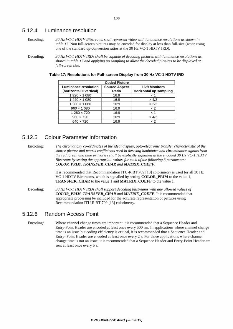
DVB BlueBook A001 (Jul 2019)
106
5.12.4 Luminance resolution
Encoding: 30 Hz VC-1 HDTV Bitstreams shall represent video with luminance resolutions as shown in
table 17. Non full-screen pictures may be encoded for display at less than full-size (when using
one of the standard up-conversion ratios at the 30 Hz VC-1 HDTV IRD).
Decoding: 30 Hz VC-1 HDTV IRDs shall be capable of decoding pictures with luminance resolutions as
shown in table 17 and applying up sampling to allow the decoded pictures to be displayed at
full-screen size.
Table 17: Resolutions for Full-screen Display from 30 Hz VC-1 HDTV IRD
Coded Picture
Luminance resolution (horizontal × vertical)
Source Aspect Ratio
16:9 Monitors Horizontal up sampling
1 920 × 1 080 16:9 × 1
1 440 × 1 080 16:9 × 4/3
1 280 × 1 080 16:9 × 3/2
960 × 1 080 16:9 × 2
1 280 × 720 16:9 × 1
960 × 720 16:9 × 4/3
640 × 720 16:9 × 2
5.12.5 Colour Parameter Information
Encoding: The chromaticity co-ordinates of the ideal display, opto-electronic transfer characteristic of the
source picture and matrix coefficients used in deriving luminance and chrominance signals from
the red, green and blue primaries shall be explicitly signalled in the encoded 30 Hz VC-1 HDTV
Bitstream by setting the appropriate values for each of the following 3 parameters:
COLOR_PRIM, TRANSFER_CHAR and MATRIX_COEFF.
It is recommended that Recommendation ITU-R BT.709 [13] colorimetry is used for all 30 Hz
VC-1 HDTV Bitstreams, which is signalled by setting COLOR_PRIM to the value 1,
TRANSFER_CHAR to the value 1 and MATRIX_COEFF to the value 1.
Decoding: 30 Hz VC-1 HDTV IRDs shall support decoding bitstreams with any allowed values of
COLOR_PRIM, TRANSFER_CHAR and MATRIX_COEFF. It is recommended that
appropriate processing be included for the accurate representation of pictures using
Recommendation ITU-R BT.709 [13] colorimetry.
5.12.6 Random Access Point
Encoding: Where channel change times are important it is recommended that a Sequence Header and
Entry-Point Header are encoded at least once every 500 ms. In applications where channel change
time is an issue but coding efficiency is critical, it is recommended that a Sequence Header and
Entry- Point Header are encoded at least once every 2 s. For those applications where channel
change time is not an issue, it is recommended that a Sequence Header and Entry-Point Header are
sent at least once every 5 s.

DVB BlueBook A001 (Jul 2019)
107
NOTE 1: Increasing the frequency of Sequence Header and Entry-Point Header will reduce channel hopping time
but will reduce the efficiency of the video compression.
NOTE 2: Having a regular interval between Entry-Point Headers may improve trick mode performance, but may
reduce the efficiency of the video compression.
NOTE 3: The AU_information_descriptor described in annex D provides a means of signalling information about
Random Access Points that may be used by some applications, and it is recommended that this is present.
5.12.7 Backwards Compatibility
Decoding: 30 Hz VC-1 HDTV IRDs shall be capable of decoding any bitstream that a 30 Hz VC-1 SDTV IRD
is required to decode and resulting in the same displayed pictures as the 30 Hz VC-1 SDTV IRD.
5.13 MVC Stereo HDTV IRDs and Bitstreams
5.13.1 Specifications common to all MVC Stereo HDTV IRDs and Bitstreams
5.13.1.0 General
The specification in this clause applies to the following IRDs and Bitstreams:
• 25 Hz MVC Stereo HDTV IRD and Bitstream;
• 30 Hz MVC Stereo HDTV IRD and Bitstream.
In addition to the constraints applicable to the H.264/AVC Stereo High Profile Level 4 of Recommendation ITU-T
H.264 / ISO/IEC 14496-10 [16], the constraints listed in the following clauses apply to the MVC Stereo HDTV IRDs
and Bitstreams defined in the present document.
NOTE: The H.264/AVC HDTV IRD and Bitstream specification applies to MVC Stereo IRDs and Bitstreams as
far as the Base view Bitstream of an MVC Stereo HDTV Bitstream is compliant with the H.264/AVC
HDTV Bitstream specification.
5.13.1.1 Introduction
The video encoding and video decoding shall conform to Recommendation ITU-T H.264 / ISO/IEC 14496-10 [16].
Some of the parameters and fields are not used in the DVB System, or they shall take certain predetermined values.
These restrictions are described below.
MVC Stereo HDTV Bitstreams and IRDs shall support some parts of the "Supplemental Enhancement Information
(SEI)", the "Video usability information (VUI)", the "MVC SEI messages", and the "MVC Video Usability Information
extension (MVC VUI extension)" syntax elements as specified in Recommendation ITU-T H.264 /
ISO/IEC 14496-10 [16], annexes D and E and clauses H.13 and H.14.
5.13.1.2 Composition of MVC Stereo HDTV Bitstreams
Encoding: MVC Stereo HDTV Bitstreams, as defined in the present document, shall contain a single MVC
Stereo Base view bitstream and a single MVC Stereo Dependent view bitstream.
The MVC Stereo Base view bitstream and the MVC Stereo Dependent view bitstream shall be sent
in separate elementary streams and on separate PIDs.
Decoding: MVC Stereo IRDs shall support the decoding of MVC Stereo HDTV Bitstreams, for which MVC
Stereo Base view bitstream and MVC Stereo Dependent view bitstream are sent in separate
elementary streams and on separate PIDs.

DVB BlueBook A001 (Jul 2019)
108
5.13.1.3 MVC Sequence Parameter Set and Picture Parameter Set
The clause applies to MVC Base view video only.
Encoding: In addition to the provisions relating to the MVC Stereo High Profile set forth in Recommendation
ITU-T H.264 / ISO/IEC 14496-10 [16], the following restrictions apply for the fields in the
sequence parameter set:
profile_idc = 100 (High Profile [16])
constraint_set0_flag = 0
constraint_set1_flag = 0
constraint_set2_flag = 0
constraint_set3_flag = 0
gaps_in_frame_num_value_allowed_flag = 0 (gaps not allowed)
vui_parameters_present_flag = 1
Both, the pic_parameter_set_id and the seq_parameter_set_id in the MVC Base view video stream
may only refer to those PPSs and SPSs present in the MVC Base view video stream. Additionally,
the values of the pic_parameter_set_id and the seq_parameter_set_id parameters shall not be
re-used in the MVC Dependent view video stream.
More than one PPS can be present between two MVC Stereo RAPs in the bitstream.
Multiple PPSs may be present in an MVC Stereo RAP access unit. Additionally, the following
constraints apply:
• there shall be at least one and at most 30 PPSs in the first dependent unit in a coded video
sequence;
• there shall be one or zero PPSs in each dependent unit, except for the first dependent unit in
a coded video sequence.
5.13.1.4 pic_width_in_mbs_minus1 and pic_height_in_map_units_minus1
Encoding: The values of pic_width_in_mbs_minus1 and pic_height_in_map_units_minus1 shall not change
in an MVC Stereo HDTV Bitstream and they shall take the same value in the Base and Dependent
view bitstreams.
If the number of samples per row of the luminance component of the source picture for any MVC
view component is not an integer multiple of 16 and additional samples are padded to make the
number of samples per row of the luminance component an integer multiple of 16, it is
recommended that these samples are padded at the right side of the picture.
If the number of samples per column of the luminance component of the source picture for any
MVC view component is not an integer multiple of 16 and additional samples are padded to make
the number of samples per column of the luminance component an integer multiple of 16, it is
recommended that these samples are padded at the bottom of the picture.
5.13.1.5 Subset Sequence Parameter Set
Encoding: In addition to the provisions set forth in Recommendation ITU-T H.264 / ISO/IEC 14496-10 [16],
the following restrictions shall apply for the fields in the subset sequence parameter sets
(nal_unit_type is equal to 15):
mvc_vui_parameters_present_flag = 1

DVB BlueBook A001 (Jul 2019)
109
In embedded sequence_parameter_set_data():
profile_idc = 128 (Stereo High Profile [16])
In embedded seq_parameter_set_mvc_extension()
num_level_values_signalled_minus1 = 0
In embedded mvc_vui_parameters_extension())
vui_mvc_num_ops_minus1 = 0
vui_mvc_low_delay_hrd_flag = 0 (if present)
vui_mvc_pic_struct_present_flag = 0/1 (same value as 'pic_struct_present_flag'
SPS of Base view)
The SPS encoded in the Subset SPS shall take the same values as the SPS of the Base view, with the exception of
seq_parameter_set_id, and profile_idc. Exactly one Subset SPS shall be provided in the first Dependent view
component of every coded video sequence (in decoding order). This Subset SPS is referenced by all PPSs in a coded
video sequence and no other Subset SPS shall appear in a coded video sequence.
5.13.1.6 Video Usability Information
5.13.1.6.0 General
In addition to the requirements specified in clause 5.5.3, the VUI parameters, vui_parameters(), which are encoded in
SPS in Subset SPS for MVC Dependent view video stream, shall have the same values as the VUI parameters in SPS of
the corresponding MVC Base view video stream, except for the following parameter, which if present, may take
different values:
• hrd_parameters()
• max_dec_frame_buffering
• num_reorder_frames
• max_bytes_per_pic_denom
5.13.1.6.1 MVC VUI parameters
The MVC VUI parameters extension (mvc_vui_parameters_extension()), shall be present in the Dependent view
bitstream and encoded in the Subset SPS, and they shall have the same values as VUI parameters in SPS for
corresponding view bitstream except for the following parameters, which, if present, may take different values:
• hrd_parameters()
5.13.1.6.2 Aspect Ratio
Encoding: The source aspect ratio in MVC Stereo HDTV Bitstreams shall be 16:9. The aspect ratio shall be
the same for Base view and Dependent view video.
The source aspect ratio information shall be derived from the aspect_ratio_idc value in the Video
Usability Information (see values of aspect_ratio_idc in Recommendation ITU-T H.264 /
ISO/IEC 14496-10 [16], table E-1).
The frame cropping information in the Sequence Parameter Set may be used when appropriate.
Decoding: MVC Stereo HDTV IRDs shall support decoding and displaying MVC Stereo HDTV Bitstreams
with the values of aspect_ratio_idc as specified in table 18.

DVB BlueBook A001 (Jul 2019)
110
The source aspect ratio information shall be derived from the pic_height_in_map_units_minus1
and the pic_width_in_mbs_minus1 and the frame cropping information coded in the Sequence
Parameter Set as well as the sample aspect ratio encoded with the aspect_ratio_idc value in the
Video Usability Information (see values of aspect_ratio_idc in Recommendation ITU-T H.264 /
ISO/IEC 14496-10 [16], table E-1).
MVC Stereo HDTV IRDs shall support frame cropping for the resolutions specified in table 18.
5.13.1.6.3 Colour Parameter Information
Encoding: The chromaticity coordinates of the ideal display, opto-electronic transfer characteristic of the
source picture and matrix coefficients used in deriving luminance and chrominance signals from
the red, green and blue primaries shall be explicitly signalled in each of the encoded MVC Stereo
Base view and Dependent view bitstreams by setting the appropriate values for each of the
following 3 parameters in the VUI: colour_primaries, transfer_characteristics, and
matrix_coefficients.
These parameters shall take the same values for Base and Dependent view components.
It is recommended that Recommendation ITU-R BT.709 [13] colorimetry is used for all MVC
Stereo HDTV bitstreams, which is signalled by setting colour_primaries to the value 1,
transfer_characteristics to the value 1 and matrix_coefficients to the value 1.
Decoding: MVC Stereo HDTV IRDs shall be capable of decoding MVC Bitstreams with any allowed values of
colour_primaries, transfer_characteristics and matrix_coefficients. It is recommended that
appropriate processing be included for the accurate representation of pictures using
Recommendation ITU-R BT.709 [13] colorimetry.
5.13.1.6.4 Luminance Resolution
Encoding: MVC Stereo HDTV Bitstreams shall represent video with luminance resolutions as shown in
table 18. Non full-screen pictures may be encoded for display at less than full-size (when using
one of the standard up-conversion ratios at the MVC Stereo HDTV IRD).
Decoding: MVC Stereo HDTV IRDs shall be capable of decoding pictures with luminance resolutions as
shown in table 18 and applying up sampling to allow the decoded pictures to be displayed at
full-screen size.
Table 18: Resolutions for Full-screen Display from MVC Stereo HDTV IRD
Coded Picture
Luminance resolution (horizontal × vertical)
Source Aspect Ratio
aspect_ratio_idc 16:9 Monitors Horizontal up sampling
1 920 × 1 080 16:9 1 × 1
1 440 × 1 080 16:9 14 × 4/3
1 280 × 1 080 16:9 15 × 3/2
960 × 1 080 16:9 16 × 2
1 280 × 720 16:9 1 × 1
960 × 720 16:9 14 × 4/3
640 × 720 16:9 16 × 2
5.13.1.7 HRD Conformance
The MVC Stereo Dependent view video bitstream shall conform to Type 2 (NAL level) HRD conformance, with output
timing conformance.
The HRD parameters (hrd_parameters()), if present in VUI parameters (vui_parameters()), in SPS encoded in Subset
SPS for MVC Stereo Dependent view video stream shall fulfill HRD conformance for the MVC Stereo Dependent view
component.

DVB BlueBook A001 (Jul 2019)
111
The HRD parameters (hrd_parameters()), if present in MVC VUI parameters encoded in Subset SPS,
(mvc_vui_parameters_extension()) shall conform to HRD conformance for both MVC Stereo Base view component and
MVC Stereo Dependent view component as MVC Stereo access unit. In other words, the timing for decoding and
presentation shall be the same for Base and Dependent view components, even though the specific values for the
hrd_parameters() might be different.
NOTE: As pointed out below, HRD parameters in vui_parameters(), when present, might be different from those
HRD parameters in mvc_vui_parameters_extensions().
Furthermore, for each of these view components independently, and within the accuracy of their respective clocks, the
Decoding Time Stamp and Presentation Time Stamp shall indicate the same instant in time as the nominal CPB
removal time and the DPB output time in the HRD respectively when picture timing SEI information is transmitted (per
clause 2.4.3.7 of Recommendation ITU-T H.222.0 / ISO/IEC 13818-1 [1]). This ensures consistency between the STD
model of Recommendation ITU-T H.222.0 / ISO/IEC 13818-1 [1] and the HRD model of Recommendation ITU-T
H.264 / ISO/IEC 14496-10 [16].
5.13.1.8 Supplemental Enhancement Information
5.13.1.8.0 General
In addition to the requirements specified in clause 5.5.4, the IRD shall support the use of the following message type,
which shall be sent in MVC Stereo Base view component:
• Multiview View Position SEI message, which is used to indicate which of base or dependent view corresponds
to the left or right eye, as well as to indicate that the MVC Base view component containing the SEI message
is part of an MVC Stereo HDTV bitstream and as such is associated to an MVC Dependent view component.
Clause 5.13.1.8.3 gives further details on the Multiview View Position SEI message.
Furthermore, the IRD shall support the use of the following message type, which shall only be sent in MVC Stereo
Dependent access units:
• Scalable Nesting SEI Message.
Additionally, the following applies:
• The IRD may support the use of the multi_region_disparity message, as specified in clause B.11, which, when
present in the MVC Stereo HDTV Bitstream, shall be included in a "User data registered by Recommendation
ITU-T T.35 [19] SEI message" contained in an MVC scalable nesting SEI message, and which shall be sent
for every MVC Stereo Dependent view component.
• When Buffering Period SEI and/or Picture Timing SEI are encoded in the MVC Stereo Base view bitstream,
same SEIs shall be encoded in the MVC scalable nesting SEI message of the MVC Stereo Dependent view
bitstream with the same values, except for seq_parameter_set_id, which shall be different.
• If decoded reference picture marking syntax is repeated using a Decoded reference picture marking repetition
SEI message in a MVC Stereo Base view component, then the same syntax shall be repeated in the
Corresponding view component of the MVC Stereo Dependent view bitstream by using a Decoded reference
picture marking repetition SEI.
• All SEI messages present for the Dependent view shall be placed inside the MVC scalable nesting SEI
message.
5.13.1.8.1 Prohibited SEI messages
The following SEI messages shall not be present in the MVC Base view bitstream:
• Non-required view component SEI message (since all (two) views are used).
• View dependency change SEI message (because there is just one dependent view).
• MVC scalable nesting SEI message (because operating points are not used in MVC Stereo High Profile).

DVB BlueBook A001 (Jul 2019)
112
• "User data registered by Recommendation ITU-T T.35 [19] SEI message" containing the message
multi_region_disparity().
The following SEI messages shall not be present in the MVC Dependent view bitstream:
• The MVC Dependent view bitstream shall not contain any SEI message outside the MVC scalable nesting SEI
message.
• Following SEI messages shall not be present in the MVC scalable nesting SEI message:
- Stereo video information SEI message.
- Pan-scan rectangle SEI message.
- Non-required view component SEI message.
- View dependency change SEI message.
- Multiview View Position SEI message (because it is already transmitted in the MVC Base view
bitstream).
5.13.1.8.2 Order of SEI Messages
SEI messages in the dependent unit shall be stored in the following order:
• MVC scalable nesting SEI message containing a Buffering period SEI message (if present).
• MVC scalable nesting SEI message containing a "User data registered by Recommendation ITU-T T.35 [19]
SEI message", which itself contains the message multi_region_disparity() as defined in clause B.11. Multi
region disparity may be sent in the Dependent view bitstream for each access unit.
• Other SEI messages in the MVC scalable nesting SEI message (if present).
5.13.1.8.3 Multiview View Position SEI message
Encoding: The Multiview View Position SEI message shall be present in every access unit of an MVC Stereo
Base view bitstream.
Its presence signals that the H.264/AVC access unit containing the SEI message is an MVC Stereo
Base view component associated to an MVC Stereo Dependent view component.
The Multiview View Position SEI message associates the base and dependent view to the left and
right eye.
The value of the syntax element num_views_minus1 shall be set to '1'.
Decoding: MVC Stereo IRDs shall support the Multiview View Position SEI message.
MVC Stereo IRDs shall ignore Multiview View Position SEI messages with a value of
num_views_minus1 not equal to '1'.
5.13.1.9 Random Access Point
5.13.1.9.0 General
The definition for MVC Stereo RAP in clause 3 shall apply.
Encoding: The time interval between MVC Stereo RAPs may vary between programs and also within a
program. The broadcast requirements should set the time interval between MVC Stereo RAPs as
specified in clause 5.13.1.9.1.
NOTE: The AU_information_descriptor described in annex D provides a means of signalling information about
Random Access Points that may be used by some applications, and it is recommended that this is present.

DVB BlueBook A001 (Jul 2019)
113
The AU_information_descriptor may be present in the Base view bitstream and it shall not be
present in the Dependent view bitstream.
All pictures with PTS greater than or equal to PTS(rap) shall be fully reconstructible and
displayable, where PTS(rap) represents the Presentation Time Stamp of the picture of the MVC
Stereo RAP. This means that decoders receiving the RAP shall not need to utilize data transmitted
prior to the RAP to decode pictures displayed after the RAP, at either Base or Dependent view.
See clause I.1 for details.
To improve applications such as channel change, it is recommended that the Presentation Time
Stamp of the picture of MVC Stereo RAP be less than or equal to [DTS(rap) + 0,5 seconds] where
DTS(rap) represents the Decoding Time Stamp of the picture of MVC Stereo RAP.
Packetization of random access points shall comply with the following additional rule:
A transport packet containing the PES header of an MVC Stereo RAP or an MVC Stereo random
access view component shall have an adaptation field. The payload_unit_start_indicator bit shall
be set to "1" in the transport packet header and the adaptation_field_control bits shall be set to
"11" (as per Recommendation ITU-T H.222.0 / ISO/IEC 13818-1 [1]). In addition, the
random_access_indicator bit in the adaptation header shall be set to "1". The
elementary_stream_priority_indicator bit shall also be set to "1" in the same adaptation header if
this transport packet contains the slice start code of the MVC Stereo Base view component (see
clauses 4.1.5.1 and 4.1.5.2).
Decoding: MVC Stereo IRDs shall be able to start decoding and displaying an MVC Stereo Bitstream at an
MVC Stereo RAP.
5.13.1.9.1 Time Interval Between RAPs
Encoding: The encoder shall place MVC Stereo RAPs in the MVC Stereo bitstream at least once every 5 s. It
is recommended that MVC Stereo RAPs occur in the MVC Stereo bitstream on average at least
every 2 s. Where rapid channel change times are important or for applications such as PVR it may
be appropriate for MVC Stereo RAPs to occur more frequently, such as every 500 ms. The time
interval between successive RAPs shall be measured as the difference between their respective
DTS values.
NOTE 1: Decreasing the time interval between MVC Stereo RAPs may reduce channel hopping time and improve
trick modes, but may reduce the efficiency of the video compression.
NOTE 2: Having a regular interval between MVC Stereo RAPs may improve trick mode performance, but may
reduce the efficiency of the video compression.
NOTE 3: 3D trick-modes should be used with care, as they might cause the rendered video to deviate from the
recommended production guidelines (e.g. fast-forwarding of 3D video).
5.13.1.10 Additional constraints
5.13.1.10.1 Constraints Common to Base and Dependent Views
In addition to Base and Dependent view adopting the same values (except if noted otherwise) for the parameters as
described in previous clauses, the following parameter values shall not change for the duration of the presentation:
• level_idc, which shall be equal to '40'.
• frame-rate, which shall be derived from time_scale / num_units_in_tick / 2.
• Coded Picture Buffer size (CPB), CpbSize[cpb_cnt_minus1], derived from cpb_size_scale and
cpb_size_value_minus1, when hrd_parameters() are present).
• Maximum input bit-rate to the CPB. The maximum input bitrate is BitRate[cpb_cnt_minus1], derived from
bit_rate_scale and bit_rate_value_minus1, when hrd_parameters() is present.
NOTE: Base and Dependent views may have different values for hrd_parameters(), see clause 5.13.1.8.

DVB BlueBook A001 (Jul 2019)
114
• frame_mbs_only_flag
• entropy_coding_mode_flag. The entropy_coding_mode_flag shall have the same value for base and dependent
view and shall not change in the bitstream
• view_id in the nal_unit_header_mvc_extension() in the Dependent view bitstream, which shall take a value
different from zero. View_id shall be set to zero, '0', for the Base view video, see clause 5.13.1.10.2.1.
5.13.1.10.2 MVC Stereo Base view constraints
5.13.1.10.2.1 Prohibited NAL units
Following NAL units shall not be present in the MVC Stereo Base view component video for reasons of backwards-
compatibility:
• Prefix NAL unit, nal_unit_type = 14: this NAL unit is specified in Recommendation ITU-T H.264 /
ISO/IEC 14496-10 [16] to convey the nal_unit_header_mvc_extension() for MVC Base view video. However,
the use of this NAL unit is disallowed for DVB services. Therefore, the following constant values shall be
assumed for the parameters in the nal_unit_header_mvc_extension():
- non_idr_flag shall be set according to nal_unit_type of corresponding Base view component. E.g. if
nal_unit_type of Base view component is set to '5' (IDR picture), non_idr_flag shall be set to '0',
otherwise non_idr_flag shall be set to '1'.
- priority_id shall be set to '0' (highest priority).
- view_id shall be set to '0' (base view).
- temporal_id in the Base and Dependent view components shall be set to the same value.
- anchor_pic_flag in the Base and Dependent view components shall be set to the same value.
- inter_view_flag shall be set to '1'.
• Coded slice extension NAL unit, nal_unit_type = 20.
• Subset Sequence Parameter set NAL unit, nal_unit_type = 15.
5.13.1.10.3 MVC Stereo Dependent view constraints
5.13.1.10.3.0 General
In the Coded slice extension NAL unit, nal_unit_type = 20, the svc_extension_flag shall be set to '0', meaning dependent
video bitstream complies with annex H of Recommendation ITU-T H.264 / ISO/IEC 14496-10 [16].
Furthermore, the following clauses apply.
5.13.1.10.3.1 Prohibited NAL units
The following NAL units shall not be present in the MVC Stereo Dependent view component video for reasons of
backwards-compatibility:
• Access unit delimiter NAL unit, nal_unit_type = 9.
• Sequence parameter set extension NAL unit, nal_unit_type = 13.
• Coded slice of the auxiliary coded picture without partitioning NAL unit, nal_unit_type = 19.

DVB BlueBook A001 (Jul 2019)
115
5.13.1.11 Access Unit Structure
For MVC Base view video, the AU structure is that of the H.264/AVC video, as per the present document.
For MVC Dependent view video, figure 1 shows an overview of the Dependent Unit structure for the first and
subsequent Units in a coded video sequence.
Figure 1: AU Structure for Dependent video
The first Dependent Unit in a coded video sequence of shall be composed of following NAL units, which shall be present
in this order:
• View and dependency representation delimiter NAL unit, VDRD_nal_unit (nal_unit_type = 24).
• Exactly one Subset SPS NAL unit.
• One or more PPS NAL units.
• One or more SEI NAL units (if present).
• One or more coded slice extension NAL unit(s) (nal_unit_type = 20) as required by number of slices in the
anchor picture.
• A Filler data NAL unit (if required).
• An End of sequence NAL unit (if applicable).
• An End of stream NAL unit (if applicable).

DVB BlueBook A001 (Jul 2019)
116
Any subsequent Dependent Units in a coded video sequence of MVC Dependent view video shall have following NAL
units, in this order:
• Exactly one View and dependency representation delimiter NAL unit (nal_unit_type = 24).
• One or zero PPS NAL units.
• One or more SEI NAL units, if present.
• Following NAL unit is repeated by number of slices:
- Coded slice extension NAL unit(s), i.e. coded slice of an anchor picture or a non-anchor picture.
• A Filler data NAL unit (if required).
• An End of sequence NAL unit (if applicable).
• An End of stream NAL unit (if applicable).
NOTE: Filler data NAL unit can be placed in any position unless it precedes the first slice NAL unit.
When an End of sequence NAL unit exists in MVC Stereo Base view component, an End of sequence NAL unit shall
exist in MVC Stereo Dependent view component in a same access unit.
When an End of stream NAL unit exists in MVC Stereo Base view component, an End of stream NAL unit shall exist in
MVC Stereo Dependent view component in a same access unit.
5.13.2 25 Hz MVC Stereo HDTV IRD and Bitstream
5.13.2.0 General
This clause specifies the 25 Hz MVC Stereo HDTV IRD and Bitstream. All specifications in clauses 5.5 and 5.13.1
shall apply.
5.13.2.1 Profile and level
Encoding: 25 Hz MVC Stereo HDTV Bitstreams shall comply with the Stereo High Profile Level 4
restrictions, as specified in Recommendation ITU-T H.264 / ISO/IEC 14496-10 [16].
The value of level_idc shall be equal to 40. Base and Dependent view bitstreams shall have the
same level_idc value.
Decoding: 25 Hz MVC Stereo HDTV IRDs shall support the decoding of Stereo High Profile Level 4
bitstreams. This requirement includes support for Stereo High Profile and levels 3 to 4. Support
for profiles and levels other than High Profile Level 3 to 4 is optional. If the 25 Hz MVC Stereo
HDTV IRD encounters an extension which it cannot decode, it shall discard the following data
until the next start code prefix (to allow backward compatible extensions to be added in the
future).
5.13.2.2 Frame rate
Encoding: The frame rate shall be 25 Hz or 50 Hz. This shall be indicated in the VUI by setting time_scale
and num_units_in_tick according to table 12. Time_scale and num_units_in_tick define the
picture rate of the video. The source video format for 50 Hz frame rate material shall be
progressive. The source video format for 25 Hz frame rate material shall be interlaced or
progressive.
Decoding: 25 Hz MVC Stereo HDTV IRDs shall support decoding and displaying video with a frame rate of
25 Hz interlaced or progressive, or 50 Hz progressive within the constraints of High Profile at
Level 4.
Support of other frame rates is optional.

DVB BlueBook A001 (Jul 2019)
117
5.13.2.3 Backwards Compatibility
Decoding: 25 Hz MVC Stereo HDTV IRDs shall be capable of decoding any bitstream that a 25 Hz
H.264/AVC SDTV IRD and a H.264/AVC HDTV IRD are required to decode and resulting in the
same displayed pictures as the 25 Hz H.264/AVC SDTV IRD and 25 Hz H.264/AVC HDTV IRD,
as described in clauses 5.6.2 and 5.7.2.
5.13.3 30 Hz MVC Stereo HDTV IRD and Bitstream
5.13.3.0 General
This clause specifies the 30 Hz MVC Stereo HDTV IRD and Bitstream. All specifications in clauses 5.5 and 5.13.1
shall apply. The specification in the remainder of this clause only applies to the 30 Hz MVC Stereo HDTV IRD and
Bitstream.
5.13.3.1 Profile and level
Encoding: 30 Hz MVC Stereo HDTV sub-bitstreams shall comply with the Stereo High Profile Level 4
restrictions, as specified in Recommendation ITU-T H.264 / ISO/IEC 14496-10 [16].
The value of level_idc shall be equal to 40.
Decoding: 30 Hz MVC Stereo HDTV IRDs shall support the decoding of Stereo High Profile Level 4
bitstreams. This requirement includes support for Stereo High Profile and levels 3 to 4. Support
for profiles and levels other than Stereo High Profile, Level 3 to 4 is optional. If the 30 Hz MVC
Stereo HDTV IRD encounters an extension which it cannot decode, it shall discard the following
data until the next start code prefix (to allow backward compatible extensions to be added in the
future).
5.13.3.2 Frame rate
Encoding: The frame rate shall be 24 000/1 001, 24, 30 000/1 001, 30, 60 000/1 001 or 60 Hz. This shall be
indicated in the VUI by setting time_scale and num_units_in_tick according to table 13.
Time_scale and num_units_in_tick define the picture rate of the video. The source video format
for 24 000/1 001, 24, 60 000/1 001 and 60 Hz frame rate material shall be progressive. The source
video format for 30 000/1 001 and 30 Hz frame rate material shall be interlaced or progressive.
Decoding: 30 Hz MVC Stereo HDTV IRDs shall support decoding and displaying video with a frame rate of
30 000/1 001, 30 Hz interlaced or progressive, or 24 000/1 001, 24, 60 000/1 001 or 60 Hz
progressive within the constraints of High Profile at Level 4.
Support of other frame rates is optional.
5.13.3.3 Backwards Compatibility
Decoding: 30 Hz MVC Stereo HDTV IRDs shall be capable of decoding any bitstream that a 30 Hz
H.264/AVC SDTV IRD and a 30 Hz H.264/AVC SDTV IRD are required to decode and resulting
in the same displayed pictures as the 30 Hz H.264/AVC SDTV IRD and 30 Hz H.264/AVC SDTV
IRD, as described in clauses 5.7.2 and 5.7.3.
5.14 HEVC IRDs and Bitstreams
5.14.1 Specifications Common to all HEVC IRDs and Bitstreams
5.14.1.0 Scope
The specification in clause 5.14 applies to the following IRDs and bitstreams:
• HEVC HDTV IRD and Bitstream;
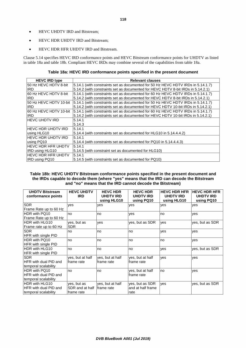
DVB BlueBook A001 (Jul 2019)
118
• HEVC UHDTV IRD and Bitstream;
• HEVC HDR UHDTV IRD and Bitstream;
• HEVC HDR HFR UHDTV IRD and Bitstream.
Clause 5.14 specifies HEVC IRD conformance points and HEVC Bitstream conformance points for UHDTV as listed
in table 18a and table 18b. Compliant HEVC IRDs may combine several of the capabilities from table 18a.
Table 18a: HEVC IRD conformance points specified in the present document
HEVC IRD type Relevant clauses
50 Hz HEVC HDTV 8-bit IRD
5.14.1 (with constraints set as documented for 50 Hz HEVC HDTV IRDs in 5.14.1.7) 5.14.2 (with constraints set as documented for HEVC HDTV 8-bit IRDs in 5.14.2.1)
60 Hz HEVC HDTV 8-bit IRD
5.14.1 (with constraints set as documented for 60 Hz HEVC HDTV IRDs in 5.14.1.7) 5.14.2 (with constraints set as documented for HEVC HDTV 8-bit IRDs in 5.14.2.1)
50 Hz HEVC HDTV 10-bit IRD
5.14.1 (with constraints set as documented for 50 Hz HEVC HDTV IRDs in 5.14.1.7) 5.14.2 (with constraints set as documented for HEVC HDTV 10-bit IRDs in 5.14.2.1)
60 Hz HEVC HDTV 10-bit IRD
5.14.1 (with constraints set as documented for 60 Hz HEVC HDTV IRDs in 5.14.1.7) 5.14.2 (with constraints set as documented for HEVC HDTV 10-bit IRDs in 5.14.2.1)
HEVC UHDTV IRD 5.14.1 5.14.3
HEVC HDR UHDTV IRD using HLG10
5.14.1 5.14.4 (with constraints set as documented for HLG10 in 5.14.4.4.2)
HEVC HDR UHDTV IRD using PQ10
5.14.1 5.14.4 (with constraints set as documented for PQ10 in 5.14.4.4.3)
HEVC HDR HFR UHDTV IRD using HLG10
5.14.1 5.14.5 (with constraint set as documented for HLG10)
HEVC HDR HFR UHDTV IRD using PQ10
5.14.1 5.14.5 (with constraints set as documented for PQ10)
Table 18b: HEVC UHDTV Bitstream conformance points specified in the present document and the IRDs capable to decode them (where "yes" means that the IRD can decode the Bitstream
and "no" means that the IRD cannot decode the Bitstream)
UHDTV Bitstream conformance points
HEVC UHDTV IRD
HEVC HDR UHDTV IRD
using HLG10
HEVC HDR UHDTV IRD using PQ10
HEVC HDR HFR UHDTV IRD
using HLG10
HEVC HDR HFR UHDTV IRD using PQ10
SDR Frame Rate up to 60 Hz
yes yes yes yes yes
HDR with PQ10 Frame Rate up to 60 Hz
no no yes no yes
HDR with HLG10 Frame rate up to 60 Hz
yes, but as SDR
yes yes, but as SDR yes yes, but as SDR
SDR HFR with single PID
no no no yes yes
HDR with PQ10 HFR with single PID
no no no no yes
HDR with HLG10 HFR with single PID
no no no yes yes, but as SDR
SDR HFR with dual PID and temporal scalability
yes, but at half frame rate
yes, but at half frame rate
yes, but at half frame rate
yes yes
HDR with PQ10 HFR with dual PID and temporal scalability
no no yes, but at half frame rate
no yes
HDR with HLG10 HFR with dual PID and temporal scalability
yes, but as SDR and at half frame rate
yes, but at half frame rate
yes, but as SDR and at half frame rate
yes yes, but as SDR

DVB BlueBook A001 (Jul 2019)
119
5.14.1.1 General
The video encoding and video decoding shall conform to Recommendation ITU-T H.265 / ISO/IEC 23008-2 [35]. Some
of the parameters and fields are not used in the DVB System and these restrictions are described below. HEVC
Bitstreams and IRDs shall support some parts of the "Supplemental Enhancement Information (SEI)" and the "Video
usability information (VUI)" syntax elements as specified in Recommendation ITU-T H.265 /
ISO/IEC 23008-2 [35], annexes D and E. The HEVC IRD design shall be made under the assumption that any structure
conforming to Recommendation ITU-T H.265 / ISO/IEC 23008-2 [35] and the restrictions that are specified for the
HEVC IRDs may occur in the broadcast stream even if presently reserved or unused.
5.14.1.2 Video Parameter Set
Decoding: HEVC IRDs conforming to the present document may ignore the content of all VPS NAL units as
defined in Recommendation ITU-T H.265 / ISO/IEC 23008-2 [35], clause 7.4.3.1. Where the
value of syntax elements in the VPS differ from those carried in or derived from the SPS, the SPS
values (including derived values) shall take precedence.
NOTE: Future versions of the present document may require use of the video parameter set, hence future IRDs
may be required to process the video parameter set.
5.14.1.3 Sequence Parameter Set
Encoding: The time interval between two successive changes in general_profile_idc, general_tier_flag or
level_idc carried in the HEVC_descriptor shall be greater than or equal to one second.
When the value of pic_height_in_luma_samples is changed between 1 080 and 540, and the
picture rate is changed between 25 and 50 or 30 000/1 001 and 60 000/1 001,
sps_max_num_reorder_pics[temporal_id_max], where temporal_id_max is signalled in the
HEVC video descriptor, expressed in seconds shall be kept constant.
The value of no_output_of_prior_pics_flag shall be provided in the bitstream and not assumed to
be inferred by the decoder.
NOTE 1: Limiting the frequency of profile, tier or level changes is to constrain the IRD complexity, while enabling
seamless switching between field and frame decoding when processing HEVC Bitstreams of interlaced
video content. In addition, the recommended signalling is provided in order to help the IRD to perform a
continuous "bumping" process (described in clause C.5.2.4 of Recommendation ITU-T H.265 /
ISO/IEC 23008-2 [35]) at a frame and field transition.
If padding is required to align the number of samples per row, it is recommended that these
samples are padded at the right side of the picture.
If padding is required to align the number of samples per column, it is recommended that these
samples are padded at the bottom of the picture.
NOTE 2: Video formats with vertical sizes of 1 080 lines can be coded as either 1 080 lines or 1 088 lines with a
conformance cropping window of 1 080 lines. If 1 088 lines is used to code 1 080 line pictures, the
conformance cropping window is defined with conf_win_top_offset equal to 0 and
conf_win_bottom_offset equal to 4. The formula to determine the number of lines to crop from the
bottom is SubHeightC × conf_win_bottom_offset and SubHeightC has a value of 2 when
chroma_format_idc equal 1.
Decoding: When the value of pic_height_in_luma_samples is changed between 1 080 and 540, and the
picture rate is changed between 25 and 50 or 30 000/1 001 and 60 000/1 001, the variable
NoOutputOfPriorPicsFlag shall not be inferred to be equal to 1 and shall be set to the value of
no_output_of_prior_pics_flag.
When conformance_window_flag is equal to 1, HEVC IRDs shall apply the conformance
cropping window signalled with conf_win_left_offset, conf_win_right_offset,
conf_win_top_offset, and conf_win_bottom_offset, as specified in Recommendation ITU-T H.265
/ ISO/IEC 23008-2 [35], clause 7.4.3.2.

DVB BlueBook A001 (Jul 2019)
120
5.14.1.4 Picture Parameter Set
Encoding: More than one picture parameter set can be present in the bitstream between two HEVC
DVB_RAPs. Between two HEVC DVB_RAPs, the content of a picture parameter set with a
particular pps_pic_parameter_set_id shall not change. I.e. if more than one picture parameter set
is present in the bitstream and these picture parameter sets are different from each other, then
each picture parameter set shall have a different pps_pic_parameter_set_id.
5.14.1.5 Video Usability Information
5.14.1.5.0 General
Encoding: HEVC Bitstreams shall set vui_parameters_present_flag to 1 in the active Sequence Parameter
Set, i.e. HEVC Bitstreams shall contain a Video Usability Information syntax structure.
In the hrd_parameters, if present, the following restrictions shall apply:
sub_pic_hrd_params_present_flag = 0
Decoding: The HEVC IRD shall support the use of Video Usability Information of the following syntax
elements:
▪ Aspect Ratio Information (aspect_ratio_idc);
▪ Overscan Information (overscan_appropriate_flag);
▪ Video Range (video_full_range_flag);
▪ Colour Parameter Information (colour_primaries, transfer_characteristics, and
matrix_coeffs);
▪ Chrominance Information (chroma_loc_info_present_flag,
chroma_sample_loc_type_top_field and chroma_sample_loc_type_bottom_field);
▪ Picture Structure Information (frame_field_info_present_flag);
▪ Default Display Window (default_display_window_flag, def_disp_win_left_offset,
def_disp_win_right_offset, def_disp_win_top_offset and def_disp_win_bottom_offset);
▪ Timing information (vui_time_scale and vui_num_units_in_tick).
5.14.1.5.1 Aspect Ratio and Overscan Information
Encoding: The display aspect ratio of the HEVC coded frame, after conformance cropping is applied, shall
be 16:9. Where source images of other aspect ratios, such as letterboxed or pillarboxed, are
formatted within 16:9 frames, signalling of AFD/Bar data documented in annex B, and Default
Display Window documented in clause 5.14.1.5.6, are recommended. However, if AFD/Bar Data
signalling documented in annex B does lead to an ambiguous determination of the active area, it is
recommended not to use it.
NOTE: When "decimated" sub-rasters as documented in clauses 5.14.2.2 and 5.14.3.2 are used, which decimate
the production image in both horizontal and vertical axes to help with bitrate efficiency, AFD/Bar data
might not work properly, and may therefore be considered ambiguous.
The sample aspect ratio information shall be signalled in the bitstream using the aspect_ratio_idc
value in the Video Usability Information (see values of aspect_ratio_idc in Recommendation
ITU-T H.265 / ISO/IEC 23008-2 [35], table E-1).
HEVC Bitstreams shall represent square pixels indicated by aspect_ratio_idc equal to 1, except
for the cases listed in table 20 and table 21.
Decoding: HEVC IRDs shall support decoding and displaying of 16:9 HEVC Bitstreams with the values of
aspect_ratio_idc set to 1 and to the additional values specified in table 20 and table 21.

DVB BlueBook A001 (Jul 2019)
121
HEVC IRDs shall support conformance cropping. Support of Default Display Window VUI is
strongly recommended. HEVC IRDs may ignore AFD/Bar Data signalling.
HEVC IRDs shall make use of pic_width_in_luma_samples, pic_height_in_luma_samples,
aspect_ratio_idc and the conformance cropping window to (where necessary) rescale the coded
video frame both horizontally and vertically to fill the 16:9 output raster.
The IRD should signal the overscan_appropriate_flag and annex B AFD/Bar Data to the display,
so that the display can optimize the presentation of the decoded video taking account of viewer
preferences and the display aspect ratio. The IRD should not apply overscan scaling itself as
overscan is a display function, and should only be applied once.
IRDs with integrated displays may combine the separate IRD and display scaling steps in to a
single process.
5.14.1.5.2 Video Range
The Recommendation ITU-R BT.2020 [36], Recommendation ITU-R BT.709 [13], Recommendation
ITU-R BT.601-7 [38] and Recommendation ITU-R BT.2100 [45] narrow range specifications provide additional
headroom above the specified reference white level and below the specified reference black level to accommodate the
small variations in signal level that occur in live TV production and to allow signal transients to pass through the
system. This is signalled to an IRD by setting the video_full_range_flag equal to "0". It is important to maintain the
additional headroom through to the output of the IRD in order to preserve detail in the highlights and lowlights of a
scene.
Encoding: The video_full_range_flag shall equal "0".
Decoding: Regardless of the value of the video_full_range_flag, it is strongly recommended that the IRD
preserves the full 8 or 10 bit signal range.
NOTE: When the video_full_range_flag is equal to "0", the HEVC IRD should not apply clipping at the
indicated black and white reference levels or tone mapping between the indicated black and white
reference levels.
5.14.1.5.3 Colour Parameter Information
Encoding: The syntax element colour_description_present_flag shall be set to "1", so that colour_primaries,
transfer_characteristics, matrix_coeffs are present in the VUI.
Decoding: HEVC IRDs shall be capable of decoding Bitstreams with colour_description_present_flag equal
to "1".
The support of colour_primaries, transfer_characteristics, and matrix_coeffs values for the HEVC HDTV IRDs and
Bitstreams is specified in clause 5.14.2.3, for the HEVC UHDTV IRDs and Bitstreams in clause 5.14.3.3, for the HEVC
HDR UHDTV IRDs and Bitstreams in clause 5.14.4.4 and for the HEVC HDR HFR UHDTV IRDs and Bitstreams in
clause 5.14.5.4.
5.14.1.5.4 Chrominance Information
Encoding: The chrominance locations shall be specified by setting chroma_loc_info_present_flag to 1 and
using the syntax elements chroma_sample_loc_type_top_field and
chroma_sample_loc_type_bottom_field in the VUI.
It is recommended to use chroma sample type equal to 0 for progressive video conforming to
Recommendation ITU-R BT.709 [13] or 2 for progressive video conforming to
Recommendation ITU-R BT.2020 [36].
Chroma samples location may be modified prior to HEVC encoding when processing interlaced
content. If chroma samples are displaced from their original location prior to HEVC encoding, the
obtained chroma samples location is signalled in the VUI by setting
chroma_sample_loc_type_top_field and chroma_sample_loc_type_bottom_field to the new
location as described in Recommendation ITU-T H.265 / ISO/IEC 23008-2 [35], figure E-1.

DVB BlueBook A001 (Jul 2019)
122
Decoding: HEVC IRDs shall support decoding any allowed values of chroma_sample_loc_type_top_field
and chroma_sample_loc_type_bottom_field. It is recommended that appropriate processing be
included for the display of pictures.
5.14.1.5.5 Picture Structure Information
The support of frame_field_info_present_flag in HEVC Bitstreams is specified in clause 5.14.1.6.1 related to use of
Picture Structure information in the Picture Timing SEI and is common to all HEVC IRDs and Bitstreams. Use of this
flag bit in the VUI allows use of picture timing SEI with only the picture structure information without the need to
include HRD information (such as CPB and DPB delay or initial values of the delay in the buffering period SEI).
Encoding: HEVC Bitstreams shall set frame_field_info_present_flag to "1" in the VUI and a picture timing
SEI message shall be associated with each access unit in the coded sequence.
Decoding: HEVC IRDs shall support decoding of the picture timing SEI message.
5.14.1.5.6 Default Display Window
The support of Default Display Window specified in the VUI is intended to help HEVC IRDs to display the video
according to the display characteristics.
Its first possible use is to signal the active area within the decoded picture. In this case, the default display window is
provided as an option to replace annex B AFD/Bar Data signalling.
Encoding: To signal the active area, HEVC Bitstreams may set default_display_window_flag to "1" in the
VUI and signal using def_disp_win_left_offset, def_disp_win_right_offset,
def_disp_win_top_offset, and def_disp_win_bottom_offset, the active area of the decoded
picture that is intended to be displayed. If the default display window is used for this purpose,
there shall not be any Frame Packing Arrangement SEI message present in the bitstream.
If both annex B AFD/Bar Data and Default Display Window are signalled in the HEVC Bitstream
for the purpose of signalling the active area, they are expected to describe the same active area.
The use of Default Display Window is recommended over the use of annex B AFD/Bar Data.
Decoding: HEVC IRDs may use Default Display Window signalling to adjust the decoded picture display in
the absence of annex B AFD/Bar Data signalling. If both Default Display Window and annex B
AFD/Bar Data are signalled in the HEVC Bitstream, HEVC IRDs may ignore annex B AFD/Bar
Data signalling as the Default Display Window signalling takes precedence.
NOTE: HEVC IRDs may blank parts of the pictures that are outside the Default Display Window.
Its second possible use is to allow the HEVC IRD to extract a 2D picture from a plano stereoscopic frame compatible
arrangement. In this case, the default display window is used together with the Frame Packing Arrangement SEI
message.
Encoding: To allow 2D compatibility of plano stereoscopic frame compatible arrangement, HEVC Bitstreams
may set default_display_window_flag to "1" in the VUI and signal using
def_disp_win_left_offset, def_disp_win_right_offset, def_disp_win_top_offset, and
def_disp_win_bottom_offset, the area of the picture containing the view intended to be displayed
as a 2D picture. If the default display window is used for this purpose, a Frame Packing
Arrangement SEI message shall be present in the bitstream for each access unit as specified in
clause J.4.3.2 of the present document.
Decoding: HEVC IRDs may use Default Display Window signalling to extract a 2D picture from a plano
stereoscopic arrangement. If both annex B AFD/Bar Data and the Default Display Window are
present in a bitstream that contains Frame Packing Arrangement SEI messages, HEVC IRDs may
use the Default Display Window to extract a 2D picture from a plano-stereoscopic arrangement
and may use AFD/Bar Data to extract the active area for display.
The above two signalling methods (signal the active area, and 2D compatibility of plano stereoscopic frame compatible
arrangement) for the Default Display Window are intended as mutually exclusive.

DVB BlueBook A001 (Jul 2019)
123
5.14.1.5.7 Timing Information
The support of vui_time_scale, vui_num_units_in_tick and elemental_duration_in_tc_minus1[temporal_id_max]
values for the HEVC IRDs and Bitstreams is specified in clause 5.14.1.7.
5.14.1.6 Supplemental Enhancement Information
5.14.1.6.0 General
Encoding: All prefix SEIs shall not occur after the first VCL NAL unit of the access unit. All suffix SEIs shall
not occur before the last VCL NAL unit of the access unit.
NOTE: HEVC allows SEI messages (both prefix and suffix SEI) to occur between the first and the last VCL NAL
units of an access unit. The constraint in the present clause forbids SEI messages from occurring between
the first and the last VCL NAL units of an access unit.
Prefix SEI NAL units within an access unit shall be placed after all NAL units of type VPS_NUT,
SPS_NUT and PPS_NUT.
Decoding: HEVC IRDs shall support the use of Supplemental Enhancement Information of the following
message types:
- Picture Timing SEI Message;
- Recovery Point SEI Message;
- "User data registered by Recommendation ITU-T T.35 SEI message" syntactic element [19]
user_data_registered_itu_t_t35 as defined in clause B.8a.
5.14.1.6.1 Picture Timing SEI Message
Encoding: HEVC Bitstreams shall contain a picture timing SEI message for every access unit of a coded
video sequence and frame_field_info_present_flag shall be set to 1 in the VUI.
The value of pic_struct shall not be equal to 1 or 2.
Before an encoding process, in order to achieve a higher frame rate than the frame rate of the
original programme, additional pictures may be created e.g. by repeating or motion interpolating
original programme pictures. It is recommended to use the duplicate_flag for this use case in a
manner different to the usage documented in Recommendation ITU-T H.265 /
ISO/IEC 23008-2 [35].
▪ If the current picture is not an original programme picture, it is recommended to set the value
of duplicate_flag to 1.
▪ In the case of motion compensated Video Standard Conversion as a pre-process before
encoding, e.g. from 50 Hz to 60 000/1 001 Hz or from 100 Hz to 120 000/1 001 Hz, there
might not be any original programme pictures preserved at all, hence it is recommended that
all pictures get duplicate_flag value 0 to avoid accidental deletion after decoding.
▪ In case of temporal layering of HFR, it is recommended that all the original programme
pictures are contained in HEVC temporal video sub-bitstream as 50 Hz (60/1 001 Hz)
capable IRD would not be able to extract the pictures from HEVC temporal video subset.
NOTE 1: Setting frame_field_info_present_flag to "1" indicates the presence of pic_struct to determine if the
picture should be displayed as a frame or one or more fields. Possible values for pic_struct are defined in
table D-2 of Recommendation ITU-T H.265 / ISO/IEC 23008-2 [35]. The pic_struct values 1 and 2 are
not allowed in bitstreams since these values do not carry field relationship information which may be
needed by the IRD to avoid field parity loss in presence of transmission errors. This implies that non-
paired fields are to be avoided in HEVC Bitstreams, and that HEVC IRD may not be able to display
correctly HEVC Bitstreams containing non-paired fields.
NOTE 2: In the context of HEVC, paired fields are two fields that are in consecutive access units in decoding order
as two coded fields of opposite parity of the same frame, regardless their display order.

DVB BlueBook A001 (Jul 2019)
124
Decoding: HEVC IRDs shall support all values defined in pic_struct including all modes requiring field and
frame repetition except pic_struct values 1 and 2. The HEVC IRDs need not make use of any
other syntax elements (except pic_struct) in the picture timing SEI message, if these elements are
present.
An IRD may utilize the values of duplicate_flag to identify and extract for display the original
lower programme frame rate out of a received and decoded higher frame rate.
5.14.1.6.2 Recovery Point SEI Message
Encoding: The recovery point SEI message shall not be present in access units that do not contain an HEVC
DVB_RAP. When present, the recovery_poc_cnt shall be set to 0, exact_match_flag shall be set to
1, and broken_link_flag shall be set to 0.
5.14.1.7 Frame rate
Encoding: The frame rate for progressive material shall be 24 000/1 001, 24, 25, 30 000/1 001, 30, 50,
60 000/1 001 or 60 Hz for all allowed luminance resolutions.
The frame rates for interlaced material shall be 25 and 30 000/1 001 Hz.
These two frame rates for interlaced material are only applicable to luminance resolutions with
1 080 lines.
The Decoding Time Stamps of access units in HEVC Bitstreams shall be inserted at a constant
rate, such as every 1/50 s for 50 Hz HEVC Bitstreams or every 1/60 s for 60 Hz HEVC Bitstreams.
NOTE 1: 24 and 24 000/1 001 Hz content is carried within a 60 and 60 000/1 001 Hz bitstream respectively, using
3:2 pull-down (pic_struct values 7 and 8) - see clause 5.14.5.5.2. In which case the HEVC temporal video
subset is not present and the DTS interval will be at multiples of 60 and 60 000/1 001 Hz.
The frame rate shall be indicated in the VUI by setting vui_time_scale, vui_num_units_in_tick
syntax elements and, if HEVC Temporal sub-layers are present, by setting
elemental_duration_in_tc_minus1[temporal_id_max] in the hrd_parameters(), where
temporal_id_max is signalled in the HEVC video descriptor (as per clause 4.1.8.19a).
Table 19 lists the frame rates that shall be supported and the recommended values for signalling
them.
Table 19: Progressive and Interlaced Frame Rates for HEVC Bitstreams and recommended values for signalling
Output Frame Rate
Interlaced or Progressive
elemental_duration_in_tc_minus1
[temporal_id_max (note 3)]
vui_time_scale vui_num_units_in_tick
Allowed pic_struct
24 000/1 001 P 0 24 000 1 001 0,7,8
24 P 0 24 1 0,7,8
25 P 0 25 1 0,7,8
25 I (encoded as frames) 0 50 1
3,4,5,6
25 I (encoded as fields) 0 50 1
9,10,11,12
30 000/1 001 P 0 30 000 1 001 0,7,8
30 000/1 001 I (encoded as frames) 0 60 000 1 001
3,4,5,6
30 000/1 001 I (encoded as fields) 0 60 000 1 001
9,10,11,12
30 P 0 30 1 0,7,8
50 P 0 50 1 0,7,8
60 000/1 001 P 0 60 000 1 001 0,7,8
60 P 0 60 1 0,7,8
NOTE 2: The interlaced frame rates are only applicable to the luminance resolutions with 1 080 lines.

DVB BlueBook A001 (Jul 2019)
125
NOTE 3: Other values of vui_time_scale, vui_num_units_in_tick and
elemental_duration_in_tc_minus1[temporal_id_max] may be used, for example where a lower frame
rate signal is carried as an HEVC temporal video sub-bitstream of a higher frame rate HEVC bitstream
(see clause 5.14.5.5). The note in clause 5.14.5.5.1 explains how to calculate the frame rate using
vui_time_scale, vui_num_units_in_tick and elemental_duration_in_tc_minus1[temporal_id_max].
Decoding: 50 Hz HEVC HDTV IRDs shall support decoding and displaying of video with an output frame
rate of 25 interlaced or progressive; 50 Hz progressive. Support of other output frame rates is
optional.
60 Hz HEVC HDTV IRDs shall support decoding and displaying of video with an output frame
rate of 30 000/1 001 interlaced or progressive; 24 000/1 001, 24, 30, 60 000/1 001 or 60 Hz
progressive. Support of other output frame rates is optional.
HEVC UHDTV IRDs shall support decoding and displaying of video with the output frame rates
supported by 50 Hz HEVC HDTV IRDs and 60 Hz HEVC HDTV IRDs.
The frame rate shall be calculated using the VUI and VUI hrd_parameters() syntax elements
vui_time_scale, vui_num_units_in_tick and
elemental_duration_in_tc_minus1[temporal_id_max]. The highest TemporalID to be decoded is
indicated by temporal_id_max, carried in the HEVC video descriptor.
The frame rates that shall be supported and the recommended values for signalling them are listed
in table 19.
NOTE 4: High Dynamic Range and/or High Frame Rates Bitstreams as defined in clauses 5.14.4 and 5.14.5 are not
intended to be used with interlaced formats. Therefore, the use of interlaced formats in HEVC UHDTV
Bitstreams will complicate any upgrade to HDR and/or HFR.
5.14.1.8 Random Access Point
5.14.1.8.0 General
Encoding: An HEVC DVB_RAP shall include exactly one Video Parameter Set (that is active), exactly one
Sequence Parameter Set (that is active) with VUI, at least one Picture Parameter Set, and
optionally a recovery point SEI message which shall be present if the nal_unit_type of the HEVC
DVB_RAP is equal to TRAIL_R. The VPS, SPS, and PPS that are required for decoding the
associated picture shall precede SEI NAL units in this access unit. The recovery point SEI
message, when present, shall precede all other SEI NAL units in an HEVC DVB_RAP.
The nal_unit_type of each VCL NAL unit of an HEVC DVB_RAP picture shall be equal to one of
BLA_W_LP, BLA_W_RADL, BLA_N_LP, IDR_W_RADL, IDR_N_LP, CRA_NUT or TRAIL_R
that contains only slices with slice_type equal to 2 (I slice) (per Recommendation ITU-T H.265 /
ISO/IEC 23008-2 [35]).
If a NAL unit contains a HEVC DVB_RAP, the value of nuh_temporal_id_plus1 shall be equal to
1.
NOTE 1: For progressive content coding, it is recommended that HEVC IRAP pictures (IDR, BLA or CRA) are
used.
The time interval between HEVC DVB_RAPs may vary between programs and also within a
program. The broadcast requirements should set the time interval between HEVC DVB_RAPs as
specified in clause 5.14.1.8.1.
All pictures with PTS greater than or equal to PTS(rap) shall be fully reconstructible and
displayable, where PTS(rap) represents the Presentation Time Stamp of the picture of the HEVC
DVB_RAP. This means that decoders receiving the HEVC DVB_RAP shall not need to utilize data
transmitted prior to the HEVC DVB_RAP to decode pictures displayed after the HEVC DVB_RAP.
To improve applications such as channel change, it is recommended that the Presentation Time
Stamp of the picture of HEVC DVB_RAP be less than or equal to [DTS(rap) + 0,67 seconds]
where DTS(rap) represents the Decoding Time Stamp of the picture of HEVC DVB_RAP.

DVB BlueBook A001 (Jul 2019)
126
Packetization of random access points shall comply with the following additional rule:
A transport packet containing the PES header of a HEVC DVB_RAP shall have an adaptation
field. The payload_unit_start_indicator bit shall be set to "1" in the transport packet header and
the adaptation_field_control bits shall be set to "11" (as per Recommendation ITU-T H.222.0 /
ISO/IEC 13818-1 [1]). In addition, the random_access_indicator bit in the adaptation header
shall be set to "1". The elementary_stream_priority_indicator bit shall also be set to "1" in the
same adaptation header if this transport packet contains the first slice start code of the HEVC
DVB_RAP access unit (see clauses 4.1.5.1 and 4.1.5.2).
Both the random_access_indicator and elementay_stream_priority_indicator bits shall be set to
"1" in the adaptation field of a transport packet containing the PES packet header of HEVC
DVB_RAP if this transport packet also contains the first slice start code of HEVC DVB_RAP
picture. Otherwise a transport packet with the elementary_stream_priority_indicator bit set to
"1" may follow the transport packet with the random_access_indicator bit set to "1".
Decoding: HEVC IRDs shall be able to start decoding and displaying an HEVC Bitstream at an HEVC
DVB_RAP.
NOTE 2: In the case where elementary_stream_priority_indicator and random_access_indicator are used to
identify the HEVC DVB_RAP, it should be noted that a VPS, SPS, PPS and any SEI may exceed one or
more transport packet in length.
5.14.1.8.1 Time Interval Between Random Access Points
Encoding: The encoder shall place HEVC DVB_RAPs in the video elementary stream at least once every 5 s.
It is recommended that HEVC DVB_RAPs occur in the video elementary stream on average at
least every 2 s. Where rapid channel change times are important or for applications such as PVR it
may be appropriate for HEVC DVB_RAPs to occur more frequently, such as every 1 second. The
time interval between successive HEVC DVB_RAPs shall be measured as the difference between
their respective DTS values.
NOTE 1: Decreasing the time interval between HEVC DVB_RAPs may reduce channel hopping time and improve
trick modes, but may reduce the efficiency of the video compression.
NOTE 2: Having a regular interval between HEVC DVB_RAPs may improve trick mode performance, but may
reduce the efficiency of the video compression.
NOTE 3: Due to the nature of video encoding, the HEVC DVB_RAP period may not be exactly aligned to whole
seconds.
5.14.1.9 Scalability
5.14.1.9.0 General
HEVC Temporal sub-layers are components of a single bitstream, analogous to the tiers described in annex D of the
present document, and signalled using the nuh_temporal_id_plus1 in the NAL unit header. That is, each HEVC
Temporal sub-layer represents a set of pictures that are only dependent upon pictures of an equivalent or lower
numbered sub-layer. HEVC Temporal sub-layers can be beneficially used to assist trick modes.
Extensions might be added in future versions of the present document. It is expected that such extensions would use
additional transport stream PIDs to allow such services to be introduced in a backwards compatible manner.
Decoding: HEVC IRDs shall skip over data structures which are currently "reserved" (as per
Recommendation ITU-T H.265 / ISO/IEC 23008-2 [35]), or which correspond to functions not
implemented by the HEVC IRD.

DVB BlueBook A001 (Jul 2019)
127
5.14.1.9.1 Temporal sub-layers
Encoding: HEVC Bitstreams and HEVC temporal video sub-bitstreams shall be carried on a single Transport
Stream PID with stream_type equal to 0x24. Only HEVC Bitstreams and HEVC temporal video
sub-bitstreams:
▪ obeying the limits associated with level 4.1 for HDTV HEVC Bitstreams shall be carried
within this PID;
▪ obeying the limits associated with level 5.1 for UHDTV HEVC Bitstreams or UHDTV HDR
HEVC Bitstreams shall be carried within this PID.
The Decoding Time Stamps of access units in HEVC Bitstreams and HEVC temporal video sub-
bitstreams carried within this PID shall be inserted at a constant rate.
All Access Units of HEVC Bitstreams and HEVC temporal video sub-bitstreams carried within this
PID shall have values of TemporalId lower than or equal to 4.
Decoding: HEVC HDTV IRDs shall decode HEVC Bitstreams with stream_type equal to 0x24, obeying the
limits associated with level 4.1.
HEVC UHDTV IRDs shall decode HEVC Bitstreams and HEVC temporal video sub-bitstreams
with stream_type equal to 0x24, obeying the limits associated with level 5.1.
HEVC IRDs shall decode HEVC Bitstreams and HEVC temporal video sub-bitstreams with
sps_max_sub_layers_minus1 greater than 0.
NOTE: HEVC IRDs are not required to use the temporal substream extraction process described in
Recommendation ITU-T H.265 / ISO/IEC 23008-2 [35], clause 10 to decode and display the HEVC
Bitstreams in the Transport Stream PID with stream_type equal to 0x24.
5.14.1.9.2 Layer Sets
Encoding: HEVC Bitstreams and HEVC video sub-bitstreams shall set the NAL unit header nuh_layer_id
equal to 0 for Transport Streams with stream_type equal to 0x24.
Decoding: HEVC IRDs may ignore all NAL units with values of nuh_layer_id not equal to 0.
NOTE 1: It is possible that future versions of the present document may allow non-zero values, but that these
streams should still be decodable by HEVC IRDs compliant with the present document.
NOTE 2: It is expected that NAL units with values of nuh_layer_id other than 0 would occur on a different PID
(or separate but associate bitstream carriage) and so would not be expected to be seen by a decoder
compliant to the present document.
NOTE 3: HEVC Layer sets may be used in future versions of the present document to support for example, high
dynamic range, wide colour gamut, 3D or higher spatial resolution extensions.
5.14.1.10 HEVC Seamless splicing
Seamless splicing of HEVC video may be accomplished by conforming to the constraints of ANSI/SCTE 172 [i.20],
"Constraints on AVC Video Coding for Digital Program Insertion".
NOTE: While ANSI/SCTE 172 is currently drafted with AVC in mind, the constraints are fully applicable to
HEVC and DVB expects that SCTE will produce an updated document which explicitly includes HEVC.
5.14.2 HEVC HDTV IRDs and Bitstreams
5.14.2.0 General
This clause specifies the HEVC HDTV IRDs and Bitstreams. All specifications in clause 5.14.1 shall apply. The
specification in the remainder of this clause only applies to the HEVC HDTV IRDs and Bitstreams.

DVB BlueBook A001 (Jul 2019)
128
Two HEVC HDTV IRDs are defined in the present document: HEVC HDTV 10-bit IRD and HEVC HDTV 8-bit IRD
with the capabilities defined in the definitions.
5.14.2.1 Profile, tier and level
Encoding: In addition to the provisions set forth in Recommendation ITU-T H.265 /
ISO/IEC 23008-2 [35], the following restrictions shall apply for the fields in the sequence
parameter set:
bit_depth_luma_minus8 = 0 or 2
bit_depth_chroma_minus8 = bit_depth_luma_minus8
vui_parameters_present_flag = 1
sps_extension_present_flag = 0
In addition to the provisions set forth in Recommendation ITU-T H.265 /
ISO/IEC 23008-2 [35], the following restrictions shall apply for the fields in the profile_tier_level
syntax structure in the sequence parameter set:
general_tier_flag = 0
general_profile_idc = 1 (Main profile) or 2 (Main 10 profile)
HEVC HDTV Bitstreams shall obey the limits in Recommendation ITU-T H.265 /
ISO/IEC 23008-2 [35], table A.1 and table A.2 associated with Level 4.1.
general_level_idc shall be less than or equal to 123 (level 4.1), unless the HEVC Bitstream is a
HEVC temporal video sub-bitstream. In this case, sps_max_sub_layers_minus1 shall be greater
than "0", sub_layer_level_present_flag[i] where 'i' is equal to temporal_id_max carried within
the HEVC Video Descriptor shall be equal to "1", and sub_layer_level_idc[i] where 'i' is equal to
temporal_id_max carried within the HEVC Video Descriptor shall be less than or equal to "123"
(level 4.1).
It is recommended that bitstreams which are compliant with the Main profile set
general_profile_compatibility_flag[ 1 ] to 1.
As specified in annex A of Recommendation ITU-T H.265 / ISO/IEC 23008-2 [35], the value of
bit_depth_luma_minus8 and bit_depth_chroma_minus8 shall be equal to 0 when
general_profile_idc is equal to 1 or general_profile_compatibility_flag[1] is equal to 1.
NOTE 1: In the Main 10 Profile and the Main Profile, chroma_format_idc is equal to '1'.
Decoding: HEVC HDTV 10-bit IRDs shall support the decoding of HEVC HDTV Bitstreams.
HEVC HDTV 8-bit IRDs shall support the decoding of HEVC HDTV Bitstreams within the
constraints of the definition.
If temporal extensions are added in future versions of the present document, general_level_idc
may be greater than 123 (level 4.1). When sps_max_sub_layers_minus1 is greater than "0", IRDs
may ignore general_level_idc and shall make use of the sub_layer_level_idc[i] syntax element,
where 'i' is equal to temporal_id_max carried within the HEVC Video Descriptor, to determine
whether a bitstream or sub-bitstream can be decoded.
The HEVC HDTV IRD may ignore sequence parameter set extensions signalled by
sps_extension_present_flag set to "1".
NOTE 2: HEVC HDTV IRDs are not required to decode and display correctly HEVC Bitstreams or HEVC
temporal video sub-bitstreams that do not obey the constraints and limits associated with the Main or
Main 10 Profile, Main Tier, Level 4.1.

DVB BlueBook A001 (Jul 2019)
129
5.14.2.2 Luminance resolution
Encoding: HEVC HDTV encoders shall, as a minimum, represent video with the luminance resolutions
shown in table 20, where luminance resolution is to be understood as the video resolution after
conformance cropping. Pictures may be down-scaled and encoded at less than full size using the
reciprocal of the scaling ratios shown in the table. Additional luminance resolutions may be
supported, but they shall be square pixel formats indicated by aspect_ratio_idc equal to "1".
Where non 16:9 sources are re-formatted and encoded within a 16:9 frame, AFD/bar data defined
in clause B.3 and default display window defined in clause 5.14.1.5.6 should be included within
the bitstream to assist the IRD in displaying the content.
Decoding: HEVC HDTV IRDs shall be capable of decoding pictures with luminance resolutions shown in
table 20, where luminance resolution is to be understood as the video resolution after
conformance cropping. HEVC IRDs shall be able to reconstruct the image size to allow the
decoded pictures to be displayed at full-screen size.
Table 20: Resolutions for Full-screen Display from HEVC HDTV IRD
Luminance resolution Scan (interlace/
progressive)
Aspect ratio Example up-sampling for 1 920 x 1 080 display
Horizontal Vertical Coded Frame
Aspect_ratio_idc
Horizontal Vertical
1 920 1 080 I and P 16:9 1 x 1 x 1
1 440 1 080 I and P 16:9 14 x 4/3 x 1
1 600 900 P 16:9 1 x 6/5 x 6/5
1 280 720 P 16:9 1 x 3/2 x 3/2
960 720 P 16:9 14 x 2 x 3/2
960 540 P 16:9 1 x 2 x 2
5.14.2.3 Colour Parameter Information
Encoding: The chromaticity co-ordinates of the ideal display, opto-electronic transfer characteristic of the
source picture and matrix coefficients used in deriving luminance and chrominance signals from
the red, green and blue primaries shall be explicitly signalled in the encoded HEVC HDTV
Bitstream by setting the appropriate values for each of the following 3 parameters in the VUI:
colour_primaries, transfer_characteristics, and matrix_coeffs.
HEVC HDTV Bitstreams shall use Recommendation ITU-R BT.709 [13] or optionally
IEC 61966-2-4 [31] colorimetry for luminance resolutions shown in table 20. For other luminance
resolutions, usage of Recommendation ITU-R BT.709 [13] should be used except for interlaced
resolutions with heights of 576 or 480 lines where Recommendation ITU-R BT.601-7 [38] is
appropriate.
NOTE: Interlaced Standard Definition resolutions are not currently defined for HEVC bitstreams and IRDs in the
present document. Nonetheless, the above clause states that Recommendation ITU-R BT.601-7 [38]
colorimetry should be used if encoders support those resolutions.
Recommendation ITU-R BT.709 [13] colorimetry usage is signalled by setting colour_primaries
to the value 1, transfer_characteristics to the value 1 and matrix_coeffs to the value 1.
IEC 61966-2-4 [31] colorimetry usage is signalled by setting colour_primaries to the value 1,
transfer_characteristics to the value 11 and matrix_coeffs to the value 1.
Decoding: HEVC HDTV IRDs shall be capable of decoding bitstreams that use Recommendation ITU-R
BT.709 [13] colorimetry. It is recommended that appropriate processing be included for the accura
te representation of pictures using Recommendation ITU-R BT.709 [13] colorimetry.
HEVC HDTV IRDs may be capable of decoding bitstreams that use IEC 61966-2-4 [31]
colorimetry.

DVB BlueBook A001 (Jul 2019)
130
5.14.3 HEVC UHDTV IRDs and Bitstreams
5.14.3.0 General
This clause specifies the HEVC UHDTV IRDs and Bitstreams. All specifications in clause 5.14.1 shall apply. The
specification in the remainder of this clause only applies to the HEVC UHDTV IRDs and Bitstreams.
5.14.3.1 Profile, tier and level
Encoding: In addition to the provisions set forth in Recommendation ITU-T H.265 /
ISO/IEC 23008-2 [35], the following restrictions shall apply for the fields in the sequence
parameter set:
bit_depth_luma_minus8 = 0 or 2
bit_depth_chroma_minus8 = bit_depth_luma_minus8
vui_parameters_present_flag = 1
sps_extension_present_flag = 0
In addition to the provisions set forth in Recommendation ITU-T H.265 /
ISO/IEC 23008-2 [35], the following restrictions shall apply for the fields in the profile_tier_level
syntax structure in the sequence parameter set:
general_tier_flag = 0
general_profile_idc = 2 (Main 10 profile)
HEVC UHDTV Bitstreams shall obey the limits in Recommendation ITU-T H.265 /
ISO/IEC 23008-2 [35], table A.1 and table A.2 associated with Level 5.1.
general_level_idc shall be less than or equal to 153 (level 5.1), unless the HEVC Bitstream is a
HEVC temporal video sub-bitstream. In this case, sps_max_sub_layers_minus1 shall be greater
than "0", sub_layer_level_present_flag[i] where 'i' is equal to temporal_id_max carried within
the HEVC Video Descriptor shall be equal to "1", and sub_layer_level_idc[i] where 'i' is equal to
temporal_id_max carried within the HEVC Video Descriptor shall be less than or equal to "153"
(level 5.1).
It is recommended that bitstreams which are compliant with the Main profile set
general_profile_compatibility_flag[ 1 ] to 1.
NOTE 1: In the Main 10 Profile, chroma_format_idc is equal to '1'.
Decoding: HEVC UHDTV IRDs shall support the decoding of Main 10 Profile and Main Profile, Main Tier,
Level 5.1 bitstreams within the constraints of the present document.
If temporal extensions are added in future versions of the present document, general_level_idc
may be greater than 153 (level 5.1). When sps_max_sub_layers_minus1 is greater than "0", IRDs
may ignore general_level_idc and shall make use of the sub_layer_level_idc[i] syntax
element, where 'i' is equal to temporal_id_max carried within the HEVC Video Descriptor, to
determine whether a bitstream or sub-bitstream can be decoded.
HEVC UHDTV IRDs may ignore sequence parameter set extensions signalled by
sps_extension_present_flag set to "1".
NOTE 2: HEVC UHDTV IRDs are not required to decode and display correctly HEVC Bitstreams or HEVC
temporal video sub-bitstreams that do not obey the constraints and limits associated with the Main or
Main 10 Profile, Main Tier, Level 5.1.
NOTE 3: High Dynamic Range and/or High Frame Rates Bitstreams as defined in clauses 5.14.4 and 5.14.5 are not
intended to be used with a coding bit depth of 8 bits. Therefore, the use of a coding bit depth of 8 bits in
HEVC UHDTV Bitstreams might complicate any upgrade to HDR and/or HFR.

DVB BlueBook A001 (Jul 2019)
131
5.14.3.2 Luminance resolution
Encoding: HEVC UHDTV encoders shall, as a minimum, represent video with the luminance resolutions
shown in table 21 and the luminance resolutions shown in table 20, where luminance resolution is
to be understood as the video resolution after conformance cropping. Pictures may be down-
scaled and encoded at less than full size using the reciprocal of the scaling ratios shown in those
two tables. Additional luminance resolutions may be supported, but they shall be square pixel
formats indicated by aspect_ratio_idc equal to "1".
Where non 16:9 sources are re-formatted and encoded within a 16:9 frame, AFD/bar data defined
in clause B.3 and default display window defined in clause 5.14.1.5.6 should be included within
the bitstream to assist the IRD in displaying the content.
Decoding: HEVC UHDTV IRDs shall be capable of decoding pictures with luminance resolutions shown in
table 21 and luminance resolutions shown in table 20, where luminance resolution is to be
understood as the video resolution after conformance cropping. HEVC IRDs shall be able to
reconstruct the image size to allow the decoded pictures to be displayed at full-screen size.
Table 21: Resolutions for Full-screen Display from HEVC UHDTV IRD
Luminance resolution Scan (interlace/
progressive)
Aspect ratio Example up-sampling for 3 840 x 2 160 display
Horizontal Vertical Coded Frame
Aspect_ratio_idc
Horizontal Vertical
3 840 2 160 P 16x9 1 1 1
2 880 2 160 P 16x9 14 x 4/3 x 1
3 200 1 800 P 16x9 1 x 6/5 x 6/5
2 560 1 440 P 16x9 1 x 3/2 x 3/2
NOTE: High Dynamic Range and/or High Frame Rates Bitstreams as defined in clauses 5.14.4 and 5.14.5 are not
intended to be used with non-square pixel formats (with aspect_ratio_idc not equal to "1"). Therefore,
the use of non-square pixel formats in HEVC UHDTV Bitstreams might complicate any upgrade to HDR
and/or HFR.
5.14.3.3 Colour Parameter Information
Encoding: The chromaticity co-ordinates of the ideal display, opto-electronic transfer characteristic of the
source picture and matrix coefficients used in deriving luminance and chrominance signals from
the red, green and blue primaries shall be explicitly signalled in the encoded HEVC Bitstream by
setting the appropriate values for each of the following 3 parameters in the VUI:
colour_primaries, transfer_characteristics, and matrix_coeffs.
HEVC UHDTV Bitstreams shall use Recommendation ITU-R BT.709 [13] or Recommendation
ITU-R BT.2020 [36] non-constant luminance colorimetry.
BT.709 [13] colorimetry usage is signalled by setting colour_primaries to the value 1,
transfer_characteristics to the value 1 and matrix_coeffs to the value 1.
BT.2020 [36] non-constant luminance colorimetry usage is signalled by setting colour_primaries
to the value 9, transfer_characteristics to the value 14 and matrix_coeffs to the value 9.
Decoding: HEVC UHDTV IRDs shall be capable of decoding bitstreams that use Recommendation
ITU-R BT.709 [13] or Recommendation ITU-R BT.2020 [36] non-constant luminance colorimetry.
It is recommended that appropriate processing be included for the accurate representation of
pictures using Recommendation ITU-R BT.709 [13] colorimetry.
NOTE 1: The HEVC UHDTV IRDs might not include appropriate processing for the accurate representation of
pictures using Recommendation ITU-R BT.2020 [36] non-constant luminance colorimetry. DVB
anticipates that BT.2020 colour primaries will be used together with future versions of the present
document. Equipment makers should consider including the capability to map BT.2020 colour primaries
for BT.709 displays.

DVB BlueBook A001 (Jul 2019)
132
NOTE 2: Where IRDs implement a transformation of the colour space of the coded bitstream to match the
capabilities of the display (e.g. from a Recommendation ITU-R BT.2020 non-constant luminance [36]
bitstream to a Recommendation ITU-R BT.709 [13] display), it is recommended that the colour space
conversion does not:
▪ impose a hard limit such that all bitstream colours outside of the gamut of the display are placed on
the outer boundary of the display gamut;
▪ linearly scale the wider gamut of the bitstream to fit within the gamut of the display.
NOTE 3: High Dynamic Range and/or High Frame Rates Bitstreams as defined in clauses 5.14.4 and 5.14.5 are not
intended to be used with BT. 709 colour primaries. Therefore, the use of BT. 709 colour primaries in
HEVC UHDTV Bitstreams might complicate any upgrade to HDR and/or HFR.
5.14.3.4 Backwards Compatibility
Decoding: HEVC UHDTV IRDs shall be capable of decoding any bitstream that a HEVC HDTV IRD is
required to decode and resulting in the same displayed pictures as the HEVC HDTV IRD, as
described in clause 5.14.2.
5.14.4 HEVC HDR UHDTV IRDs and Bitstreams
5.14.4.1 General
This clause specifies the HEVC HDR UHDTV IRDs and Bitstreams that add High Dynamic Range functionalities in
addition to those supported in HEVC UHDTV IRDs and Bitstreams.
The present clause specifies two types of HEVC HDR UHDTV Bitstreams:
• Bitstreams using HLG10: the Bitstreams are specified in such a way that HEVC UHDTV IRDs as specified in
clause 5.14.3 are expected to produce good images, although with a quality that may be lower than the one
produced by HEVC HDR UHDTV IRDs.
• Bitstreams using PQ10: for such Bitstreams, HEVC UHDTV IRDs as specified in clause 5.14.3 are not
expected to produce any picture at all.
HEVC HDR UHDTV IRDs may support one or both types of Bitstreams specified in the present clause.
All specifications in clause 5.14.1 shall apply. The specification in the remainder of this clause only applies to the
HEVC HDR UHDTV IRDs and Bitstreams.
5.14.4.2 Profiles, Tiers and Levels
All specifications in clause 5.14.3.1 shall apply with the following restriction.
Encoding: In addition to the provisions set forth in Recommendation ITU-T H.265 /
ISO/IEC 23008-2 [35] and in clause 5.14.3.1, the following restriction shall apply for the fields in
the sequence parameter set:
bit_depth_luma_minus8 = 2
5.14.4.3 Luminance Resolutions
Encoding: HEVC HDR UHDTV encoders shall, as a minimum, represent video with the luminance
resolutions shown in table 21a. Pictures may be downscaled and encoded at less than full size
using the reciprocal of the scaling ratios shown in table 21a. Additional luminance resolutions may
be supported, but they shall be square pixel formats indicated by aspect_ratio_idc equal to "1".

DVB BlueBook A001 (Jul 2019)
133
Decoding: HEVC HDR UHDTV IRDs shall be capable of decoding pictures with luminance resolutions
shown in table 21a. HEVC HDR UHDTV IRDs shall be capable to reconstruct the image size to
allow the decoded pictures to be displayed at full-screen size.
Table 21a: Resolutions for Full-screen Display from HEVC HDR UHDTV IRD
Luminance resolution Scan (interlace/prog
ressive)
Aspect ratio Example up-sampling for 3 840 x 2 160 display
Horizontal Vertical Coded Frame
Aspect_ratio_idc
Horizontal Vertical
3 840 2 160 P 16:9 1 x 1 x 1
3 200 1 800 P 16:9 1 x 6/5 x 6/5
2 560 1 440 P 16:9 1 x 3/2 x 3/2
1 920 1 080 P 16:9 1 x 2 x 2
1 600 900 P 16:9 1 x 12/5 x 12/5
1 280 720 P 16:9 1 x 3 x 3
960 540 P 16:9 1 x 4 x 4
NOTE: Table 21a contains only progressive and square pixel formats. The interlaced and non-square pixel
formats documented in tables 20 and 21 are therefore not meant to be used for HEVC HDR UHDTV
Bitstreams and these formats are not guaranteed to be supported by HEVC HDR UHDTV IRDs, except if
the bitstream fulfills all the constraints of an HEVC UHDTV Bitstream, as specified in clause 5.14.4.6 on
Backwards Compatibility.
5.14.4.4 High Dynamic Range and Colour Parameter Information
5.14.4.4.1 Signalling of colour primaries and matrix coefficients
Encoding: HEVC HDR UHDTV Bitstreams shall use Recommendation ITU-R BT.2100 [45] colour primaries
and non-constant luminance matrix coefficients, which shall be explicitly signalled to the IRD by
setting the VUI colour_primaries equal to 9 and matrix_coeffs equal to 9. Content produced with
different system colorimetry shall be mapped in to a BT.2100 colour container prior to HEVC
encoding.
NOTE: Recommendation ITU-R BT.2100 [45] colour primaries and non-constant luminance matrix coefficients
are identical to Recommendation ITU-R BT.2020 [36] colour primaries and non-constant luminance
matrix coefficients, so the same VUI parameter values are used.
Decoding: HEVC HDR UHDTV IRDs shall be capable of decoding high dynamic range bitstreams with
Recommendation ITU-R BT.2100 [45] colour primaries and non-constant luminance matrix
coefficients.
It is recommended that appropriate processing is performed for the representation of pictures using
Recommendation ITU-R BT.2100 [45] colour primaries and non-constant luminance matrix
coefficients.
5.14.4.4.2 HEVC HDR UHDTV IRDs and Bitstreams using HLG10
5.14.4.4.2.1 Signalling of transfer characteristics
HLG10 is specified for HDR bitstreams intended to be decodable by HEVC UHDTV IRDs. The HLG10 signalling
specified below may also be used for HLG services where there is no requirement for the bitstreams to be decodable by
HEVC UHDTV IRDs.
Encoding: HEVC HDR UHDTV Bitstreams using HLG10 shall set VUI transfer_characteristics to the value
"14" to signal the opto-electronic transfer function as Recommendation ITU-R BT.2020 [36]
10-bits.

DVB BlueBook A001 (Jul 2019)
134
HEVC HDR UHDTV Bitstreams using HLG10 shall also contain the
alternative_transfer_characteristics SEI message. The alternative_transfer_characteristics SEI
message shall be inserted on the HEVC DVB_RAP, and preferred_transfer_characteristics shall
be set equal to "18", indicating Recommendation ITU-R BT. 2100 [45] HLG system.
NOTE 1: Recommendation ITU-R BT.2100 [45] HLG system has an identical Opto-Electronic Transfer Function
to ARIB STD-B67 [i.27], so the same preferred_transfer_characteristics value is used.
Decoding: HEVC HDR UHDTV IRDs using HLG10 shall be capable of decoding high dynamic range
bitstreams conforming to HLG10, as specified in Recommendation ITU-R BT.2100 [45].
It is recommended that the IRD implements processing to map the large colour volume of the
HLG10 signal to the potentially smaller colour volume of the display.
NOTE 2: At the time of writing, the ITU-R has not yet published Production Guidelines for Recommendation ITU-
R BT.2100 [45] programmes. In the meantime, the reference level for graphics can be assumed to be
75 % of the narrow range signal. Similarly, when re-mapping SDR content into an HLG10 container (e.g.
for output over HDMI), SDR 90 % of the narrow range signal can be mapped to HLG10 75 % of the
narrow range signal.
5.14.4.4.2.2 Dynamic switching between SDR and HDR as a result of bitstream splicing
5.14.4.4.2.2.1 Introduction
Broadcast services are expected to be delivered in either a high dynamic range or a standard dynamic range format.
However, bitstream splicing within a network may result in dynamic changes between high and standard dynamic range
content at the IRD.
5.14.4.4.2.2.2 Transition from HDR to SDR
Encoding: HEVC HDR UHDTV Bitstreams may switch to a HEVC UHDTV Bitstream. To improve the
detectability of SDR switching for IRDs:
- If the HEVC UHDTV bitstream is using BT.709 colour primaries, the HEVC UHDTV
bitstream shall alter the VUI colour_primaries to the value 1, transfer_characteristics to the
value 1 and matrix_coeffs to the value 1.
If an alternative_transfer_characteristics SEI message is present during the HEVC UHDTV
bitstream transmission, it shall have preferred_transfer_characteristics set to 1.
- If the HEVC UHDTV bitstream is using BT.2020 colour primaries, the HEVC UHDTV
bitstream shall contain the alternative_transfer_characteristics SEI message. The
alternative_transfer_characteristics SEI message shall be inserted on the HEVC DVB_RAP
(at least on the first one followed by SDR transmission), and
preferred_transfer_characteristics shall be set equal to "14" to signal the opto-electronic
transfer function as Recommendation ITU-R BT.2020 [36] 10-bits.
Decoding: HEVC HDR UHDTV IRDs using HLG10 should be capable of handling such a change to HEVC
UHDTV bitstream seamlessly.
NOTE: The above constraint on handling such a change seamlessly applies to the bitstream, and not to the
display. The display may, for example, show a black screen temporarily when switching between
different transfer characteristics and/or colour primaries.
5.14.4.4.2.2.3 Transition from SDR to HDR
Encoding: HEVC UHDTV Bitstreams may switch to a HEVC HDR UHDTV Bitstream. The HEVC HDR
UHDTV Bitstream shall be compliant with clause 5.14.4.4.2.1.
Decoding: HEVC HDR UHDTV IRDs using HLG10 should be capable of handling such a change to HEVC
HDR UHDTV bitstream seamlessly.

DVB BlueBook A001 (Jul 2019)
135
NOTE: The above constraint on handling such a change seamlessly applies to the bitstream, and not to the
display. The display may, for example, show a black screen temporarily when switching between
different transfer characteristics and/or colour primaries.
5.14.4.4.3 HEVC HDR UHDTV IRDs and Bitstreams using PQ10
5.14.4.4.3.1 General Introduction
The following subclauses contain the specific signalling required for the transmission of PQ10 and optional
supplemental enhancement information messages. Optional Supplemental Enhancement Information messages assist
IRDs in post processing to adapt the picture to the rendering capabilities of displays with differing capabilities than the
mastering display used to create the HDR content (including, but not limited to, displays intended to render SDR
pictures). It is noted that different messages (or parts of them) may serve similar purposes.
NOTE: Optional Supplemental Enhancement Information message support is optional both in the bitstream and
in the IRD. As Phase 2 IRDs will exist which do not take account of these optional SEI messages,
broadcasters should be aware of this and take suitable measures to facilitate quality of HDR reproduction
by IRDs not utilizing these optional SEI messages.
5.14.4.4.3.2 Signalling of transfer characteristics
Encoding: HEVC HDR UHDTV Bitstreams using PQ10 shall set VUI transfer_characteristics to the value
"16" to signal the electro-optical transfer function as Recommendation ITU-R BT.2100 [45] PQ
system.
NOTE: Recommendation ITU-R BT.2100 [45] PQ system has an identical Electro-Optical Transfer Function to
SMPTE ST 2084 [i.26], so the same transfer_characteristics value is used.
Decoding: HEVC HDR UHDTV IRDs using PQ10 shall be capable of decoding high dynamic range
bitstreams that use Recommendation ITU-R BT.2100 [45] PQ system.
It is recommended that appropriate processing is performed for the representation of pictures using
Recommendation ITU-R BT.2100 [45] PQ transfer characteristics.
5.14.4.4.3.3 Optional Supplemental Enhancement Information messages
5.14.4.4.3.3.1 General
The present clause specifies restrictions applying to Supplemental Enhancement Information messages that are
specified in Recommendation ITU-T H.265 / ISO/IEC 23008-2 [35] and that may be optionally present in HEVC HDR
UHDTV Bitstreams using PQ10.
These Supplemental Enhancement Information messages provide a production or playout side controlled post
processing in the IRD and do not preclude alternative postprocessing on the IRD side.
Decoding: HEVC HDR UHDTV IRDs are not required to support the SEI messages specified in the present
clause.
5.14.4.4.3.3.2 Mastering Display Colour Volume SEI message
HEVC Mastering Display Colour Volume SEI message identifies the colour volume (primaries white point and
luminance range) of a display considered to be the mastering display for the associated video content. The usage of this
information may help improving colour reproduction of mastered content when represented in different colour volume
or shown on other displays than the mastering display. The information conveyed in this SEI message is intended to be
adequate for purposes corresponding to the use of Society of Motion Picture and Television Engineers ST 2086 [i.29]
"Mastering Display Color Volume Metadata Supporting High Luminance and Wide Color Gamut Images".
Encoding: HEVC HDR UHDTV Bitstreams using PQ10 may contain a mastering display colour volume SEI
message as specified in Recommendation ITU-T H.265 / ISO/IEC 23008-2 [35], annex D. If a
mastering display colour volume SEI message is present, it shall be transmitted with every HEVC
DVB_RAP.

DVB BlueBook A001 (Jul 2019)
136
It is recommended that HEVC HDR UHDTV Bitstreams set a valid number to
display_primaries_x[c], display_primaries_y[c], white_point_x, white_point_y,
max_display_mastering_luminance, min_display_mastering_luminance fields.
If the proper value for all these fields is unknown, it is recommended that no mastering display
colour volume SEI message is present in the HEVC HDR UHDTV Bitstream; or if the proper
value for any one of the following fields are unknown, display_primaries_x[c],
display_primaries_y[c], white_point_x, white_point_y or max_display_mastering_luminance, it is
recommended that the unknown field is set to 0.
The lowest value for min_display_mastering_luminance that is valid without ambiguity is 0,0001,
when viewing a Reference Monitor calibrated while viewing a test pattern (such as PLUGE for
example). Hence it is recommended that:
- an unknown value for min_display_mastering_luminance should be signalled with value 0;
- a known value for min_display_mastering_luminance should be signalled with a value
larger than or equal to 0,0001.
5.14.4.4.3.3.3 Content Light Level Information SEI message
HEVC Content Light Level information SEI message identifies upper bounds for the nominal target brightness light
level of the associated video content. The information conveyed in this SEI message is intended to be adequate for
purposes corresponding to the use of the Consumer Technology Association standard CTA-861.3 "HDR Static
Metadata Extension".
Encoding: HEVC HDR UHDTV Bitstreams using PQ10 may contain a content light level SEI message as
specified in Recommendation ITU-T H.265 / ISO/IEC 23008-2 [35], annex D. If a content light
level information SEI message is present, it shall be transmitted with every HEVC DVB_RAP.
NOTE: In some cases, such as live and linear broadcast, it may not be possible to calculate the values of
max_content_light_level and max_pic_average_light_level fields.
If the value for these fields is known, it is recommended that HEVC HDR UHDTV Bitstreams
include valid settings for the max_content_light_level and max_pic_average_light_level fields.
If the value for all these fields is unknown, it is recommended that no content light level
information SEI message is present in the HEVC HDR UHDTV Bitstream; or if the value for any
one of these fields is unknown, it is recommended that the unknown field is set to 0.
5.14.4.4.3.3.4 Optional Supplemental Enhancement Information messages carrying DMI
5.14.4.4.3.3.4.1 General
The present clause specifies restrictions applying to Supplemental Enhancement Information messages carrying DMI as
specified in ETSI TS 103 572 [50] or ETSI TS 103 433-2 [51] or CTA-861-G [52], and that may be optionally present
in HEVC HDR UHDTV Bitstreams using PQ10.
The Supplemental Enhancement Information messages carrying DMI defined in the present clause can guide dynamic
mapping, as produced in a reference viewing environment or otherwise. A display that is cognisant of the DMI can use
this information to adapt the rendering of the video content to its own display capabilities and/or to the viewing
environment, including the possibility to replicate as closely as possible the intended appearance of that content as
produced in the reference viewing environment.
Encoding: HEVC HDR UHDTV Bitstreams using PQ10 may contain Supplemental Enhancement
Information messages carrying DMI according to the rules defined for each DMI format in the
present clause.
HEVC HDR UHDTV Bitstreams using PQ10 may simultaneously include Supplemental
Enhancement Information messages carrying DMI from multiple DMI formats defined in the
present clause.

DVB BlueBook A001 (Jul 2019)
137
If DMI is included, it is recommended that the PQ10 Bitstream provides video quality at the level
that can be expected from an HEVC HDR UHDTV IRD using PQ10 that does not support DMI,
and that the DMI enables further enhancement of the video.
Decoding: HEVC HDR UHDTV IRDs are not required to support the SEI messages specified in the present
clause.
HEVC HDR UHDTV IRDs may support one or more DMI formats defined in the present clause.
HEVC HDR UHDTV IRDs may optionally support processing based on DMI included in the SEI
messages specified in the present clause, and alternative and/or additional processing may be
applied.
5.14.4.4.3.3.4.2 Dynamic switching between bitstreams with and without DMI
Broadcast services may switch dynamically between bitstreams supporting different DMI formats or no DMI at all.
Encoding: HEVC HDR UHDTV Bitstreams using PQ10 with DMI may switch to HEVC HDR UHDTV
Bitstreams using PQ10 with a different DMI format or without DMI. HEVC HDR UHDTV
Bitstreams using PQ10 without DMI may switch to HEVC HDR UHDTV Bitstreams using PQ10
with DMI.
Decoding: If an HEVC HDR UHDTV IRD supports one or more DMI formats it should be capable of
handling such a change seamlessly.
NOTE: The above constraint on handling such a change seamlessly applies to the bitstream, and not to the
display. The display may, for example, show a black screen temporarily when switching.
5.14.4.4.3.3.4.3 SMPTE ST 2094-10 SEI message
SMPTE ST 2094-10 [i.38] DMI provides and describes dynamic information about the video signal. The information
conveyed in the SEI message carrying SMPTE ST 2094-10 [i.38] DMI is adequate for purposes corresponding to the
use of Society of Motion Picture and Television Engineers SMPTE ST 2094-1 [i.37] "Dynamic Metadata for Color
Volume Transform - Core Components" and SMPTE ST 2094-10 [i.38] "Dynamic Metadata for Color Volume
Transform - Application #1".
Encoding: HEVC HDR UHDTV Bitstreams using PQ10 may contain SEI messages carrying SMPTE ST
2094-10 DMI.
The SMPTE ST 2094-10 DMI is carried in the video elementary stream as Supplemental
Enhancement Information in HEVC’s “User data registered by Recommendation ITU-T T.35 SEI
message” syntactic element as defined in clause B.7.2.
If the "User data registered by a Recommendation ITU-T T.35 [19] SEI message" carrying
SMPTE ST 2094-10 DMI is present in an HEVC HDR UHDTV Bitstream using PQ10, the
constraints defined below shall apply.
- It shall be a prefix SEI message (i.e. nal_unit_type shall be equal to PREFIX_SEI_NUT) sent
for every access unit of the HEVC HDR UHDTV Bitstream using PQ10.
- The HEVC HDR UHDTV Bitstream using PQ10 shall contain a Mastering Display Colour
Volume SEI message as specified in clause 5.14.4.4.3.3.2.
The following constraints shall apply to the syntactic element as defined in clause B.7.2 of the
"User data registered by a Recommendation ITU-T T.35 [19] SEI message" carrying SMPTE ST
2094-10 DMI:
- user_identifier shall be set equal to “GA94” indicating a DVB1_data() structure as defined in
clause B.2 of the present document.
- user_data_type_code referenced by the DVB1_data() structure shall be set equal to “0x09”
indicating a ST2094-10_data() structure as defined in clause 4 of ETSI TS 103 572 [50].

DVB BlueBook A001 (Jul 2019)
138
The following constraints shall apply to the ST2094-10_data() structure of the "User data
registered by a Recommendation ITU-T T.35 [19] SEI message" carrying SMPTE ST 2094-10
DMI:
- app_identifier shall be set equal to "1".
- app_version shall be set equal to "0".
- The number of extension blocks with ext_block_level set equal to "1" shall be constrained to
be equal to "1".
- The number of extension blocks with ext_block_level set equal to "2" shall be constrained to
be less than or equal to "16".
- The number of extension blocks with ext_block_level set equal to "5" shall be constrained to
be less than or equal to "1".
5.14.4.4.3.3.4.4 SL-HDR2 SEI message
Dynamic mapping according to SL-HDR2 is specified in ETSI TS 103 433-2 [51] and provides a broadcaster with an
HDR-to-HDR/SDR reference display mapping method to verify the intended result of the display mapping process. The
defined reference display mapping method does not imply that the video signal will be mapped with the reference
display mapping method nor does it enforce implementation on the IRD.
Encoding: HEVC HDR UHDTV Bitstreams using PQ10 may contain SEI messages carrying SL-HDR2 DMI.
The SL-HDR2 DMI is carried in the video elementary stream as Supplemental Enhancement
Information in HEVC’s “User data registered by Recommendation ITU-T T.35 SEI message”
syntactic element. The syntax and semantics of SL-HDR2 DMI are specified in Annex A of ETSI
TS 103 433-2 [51].
NOTE: Annex A of ETSI TS 103 433-2 [51] refers to ETSI TS 103 433-1 [i.40] in which the syntax and
semantics common to SL-HDR1 and SL-HDR2 is specified. It also provides additional constraints to SL-
HDR2 DMI.
If the "User data registered by a Recommendation ITU-T T.35 [19] SEI message" carrying SL-
HDR2 DMI is present in an HEVC HDR UHDTV Bitstream using PQ10, the following constraints
shall apply.
- It shall be a prefix SEI message (i.e. nal_unit_type shall be equal to PREFIX_SEI_NUT)
- All constraints specified in Annex A of ETSI TS 103 433-2 [51] shall apply.
- It shall be transmitted at least with every HEVC DVB_RAP of the HEVC HDR UHDTV
Bitstream using PQ10.
NOTE: The persistence of the SL-HDR2 DMI is controlled by two flags that are included in the SEI message.
The DMI may apply to the current picture only, until the next SL-HDR Information SEI message (or the
end of the bitstream), or it may be cancelled.
- If src_mdcv_info_present_flag is set equal to “1” and the HEVC HDR UHDTV Bitstream
using PQ10 contains a Mastering Display Colour Volume SEI message, the values for the
corresponding syntax elements should be identical.
Decoding: It is recommended that the IRD implements either the reference display mapping method or a
display mapping method that performs at least as well as the reference display mapping method
given the capabilities of the IRD.
5.14.4.4.3.3.4.5 SMPTE ST 2094-40 SEI message
SMPTE ST 2094-40 [i.39] DMI provides and describes dynamic information about the video signal. The information
conveyed in the SEI message carrying SMPTE ST 2094-40 [i.39] DMI is adequate for purposes corresponding to the
use of Society of Motion Picture and Television Engineers SMPTE ST 2094-1 [i.37] "Dynamic Metadata for Color

DVB BlueBook A001 (Jul 2019)
139
Volume Transform - Core Components" and SMPTE ST 2094-40 [i.39] "Dynamic Metadata for Color Volume
Transform - Application #4".
Encoding HEVC HDR UHDTV Bitstreams using PQ10 may contain SEI messages carrying SMPTE ST
2094-40 DMI.
The SMPTE ST 2094-40 DMI is carried in the video elementary stream as Supplemental
Enhancement Information in HEVC’s “User data registered by Recommendation ITU-T T.35 SEI
message” syntactic element. The syntax and semantics of the SEI message carrying the DMI based
on SMPTE ST 2094-40 are specified in CTA-861-G [52] Annex S.
If the "User data registered by a Recommendation ITU-T T.35 [19] SEI message" carrying
SMPTE ST 2094-40 DMI is present in an HEVC HDR UHDTV Bitstream using PQ10, the
following constraints shall apply.
- It shall be a prefix SEI message (i.e. nal_unit_type shall be equal to PREFIX_SEI_NUT) sent
for every access unit of the HEVC HDR UHDTV Bitstream using PQ10.
- The HEVC HDR UHDTV Bitstream using PQ10 shall contain a Mastering Display Colour
Volume SEI message as specified in clause 5.14.4.4.3.3.2.
- itu_t_t35_terminal_provider_oriented_code shall be set equal to “0x0001”.
- num_windows shall be constrained to a value of 1.
- targeted_system_display_actual_peak_luminance_flag shall be constrained to a value of 0.
- num_distribution_maxrgb_percentiles [ 0 ] shall be constrained to a value of 9.
- fraction_bright_pixels [ 0 ] shall be constrained to a value of 0.
- mastering_display_actual_peak_luminance_flag shall be constrained to a value of 0.
- num_bezier_curve_anchors [ 0 ] shall be constrained to values of 0 to 9, inclusive.
- color_saturation_mapping_flag [ 0 ] shall be constrained to a value of 0.
- distribution_maxrgb_percentages[ 0 ][ 0 ] shall be constrained to a value of 1.
- distribution_maxrgb_percentages[ 0 ][ 1 ] shall be constrained to a value of 5.
- distribution_maxrgb_percentages[ 0 ][ 2 ] shall be constrained to a value of 10.
- distribution_maxrgb_percentages[ 0 ][ 3 ] shall be constrained to a value of 25.
- distribution_maxrgb_percentages[ 0 ][ 4 ] shall be constrained to a value of 50.
- distribution_maxrgb_percentages[ 0 ][ 5 ] shall be constrained to a value of 75.
- distribution_maxrgb_percentages[ 0 ][ 6 ] shall be constrained to a value of 90.
- distribution_maxrgb_percentages[ 0 ][ 7 ] shall be constrained to a value of 95.
- distribution_maxrgb_percentages[ 0 ][ 8 ] shall be constrained to a value of 99.
5.14.4.4.3.4 Dynamic switching between SDR and HDR as a result of bitstream splicing
5.14.4.4.3.4.1 Introduction
Broadcast services are expected to be delivered in either a high dynamic range or a standard dynamic range format.
However, bitstream splicing within a network may result in dynamic changes between high and standard dynamic range
content at the IRD.

DVB BlueBook A001 (Jul 2019)
140
5.14.4.4.3.4.2 Transition from HDR to SDR
Encoding: HEVC HDR UHDTV Bitstreams may switch to a HEVC UHDTV Bitstream.
- If the HEVC UHDTV bitstream is using BT.709 colour primaries, the HEVC UHDTV
bitstream shall alter the VUI colour_primaries to the value 1, transfer_characteristics to the
value 1 and matrix_coeffs to the value 1.
- If the HEVC UHDTV bitstream is using BT.2020 colour primaries, the HEVC UHDTV
bitstream shall alter the VUI colour_primaries to the value 9, transfer_characteristics to the
value 14 and matrix_coeffs to the value 9.
Decoding: HEVC HDR UHDTV IRDs using PQ10 should be capable of handling such a change to HEVC
UHDTV Bitstream seamlessly.
NOTE: The above constraint on handling such a change seamlessly applies to the bitstream, and not to the
display. The display may, for example, show a black screen temporarily when switching between
different transfer characteristics and/or colour primaries.
5.14.4.4.3.4.3 Transition from SDR to HDR
Encoding: HEVC UHDTV Bitstreams may switch to a HEVC HDR UHDTV Bitstream. The HEVC HDR
UHDTV Bitstream shall be compliant with 5.14.4.4.3.2.
Decoding: HEVC HDR UHDTV IRDs using PQ10 should be capable of handling such a change to HEVC
HDR UHDTV Bitstream seamlessly.
NOTE: The above constraint on handling such a change seamlessly applies to the bitstream, and not to the
display. The display may, for example, show a black screen temporarily when switching between
different transfer characteristics and/or colour primaries.
5.14.4.5 Frame Rates
All specifications in clause 5.14.1.7 shall apply with the following restrictions.
Encoding: Only progressive frame rates shall be used, i.e. the value of field_seq_flag in the Video Usability
Information shall be equal to 0.
Decoding: HEVC HDR UHDTV IRDs shall support decoding and displaying of video with an output frame
rate of 24 000/1 001, 24, 25, 30 000/1 001, 30, 50, 60 000/1 001 or 60 Hz progressive.
5.14.4.6 Backwards Compatibility
Decoding: HEVC HDR UHDTV IRDs shall be capable of decoding any bitstream that a HEVC UHDTV IRD
is required to decode and resulting in the same displayed pictures as the HEVC UHDTV IRD, as
described in clause 5.14.3.
5.14.5 HEVC HDR HFR UHDTV IRDs and Bitstreams and HEVC HFR UHDTV Bitstreams
5.14.5.1 General
This clause adds High Frame Rate (HFR) functionality in addition to the functionalities supported in HEVC UHDTV
IRDs and Bitstreams or HEVC HDR UHDTV IRDs and Bitstreams.
The present clause specifies two types of Bitstreams that include the HFR functionality (where standard frame rates
HEVC IRDs refer to HEVC IRDs that are capable to decode frame rates up to 60 Hz only, such as the HEVC UHDTV
IRD or the HEVC HDR UHDTV IRD):
DVB BlueBook A001 (Jul 2019)
141
• HFR Bitstreams using dual PID and temporal scalability: the Bitstreams are specified in such a way that
standard frame rates HEVC IRDs are expected to display fair motion portrayal, although the motion portrayal
may not be as good as that reproduced by HEVC HDR HFR UHDTV IRDs.
• HFR Bitstreams using single PID: for such Bitstreams, standard frame rates HEVC IRDs are not expected to
produce any picture at all.
The HEVC HDR HFR UHDTV IRD shall support the decoding of both of the HFR Bitstream types specified in the
present sub-clause.
All specifications in clause 5.14.1 shall apply.
It is assumed that all HEVC IRDs that support HFR will also support HDR, i.e. there is no specification of an IRD
conformance point to support HFR but not HDR.
5.14.5.2 Profiles, Tiers and Levels
5.14.5.2.1 Common
Encoding: In addition to the provisions set forth in Recommendation ITU-T H.265 /
ISO/IEC 23008-2 [35], the following restrictions shall apply for the fields in the sequence
parameter set:
bit_depth_luma_minus8 = 2
bit_depth_chroma_minus8 = bit_depth_luma_minus8
vui_parameters_present_flag = 1
sps_extension_present_flag = 0
In addition to the provisions set forth in Recommendation ITU-T H.265 /
ISO/IEC 23008-2 [35], the following restrictions shall apply for the fields in the profile_tier_level
syntax structure in the sequence parameter set:
general_tier_flag = 0
general_profile_idc = 2 (Main 10 profile)
general_level_idc shall be less than or equal to 156 (level 5.2)
HEVC HDR HFR UHDTV Bitstreams and HEVC HFR UHDTV Bitstreams shall obey the limits in
Recommendation ITU-T H.265 / ISO/IEC 23008-2 [35], table A.1 and table A.2 associated with
Level 5.2.
NOTE: In the Main 10 Profile, chroma_format_idc is equal to '1'.
Decoding: HEVC HDR HFR UHDTV IRDs shall support the decoding of Main 10 Profile, Main Tier,
Level 5.2 bitstreams within the constraints of the present clause.
HEVC HDR HFR UHDTV IRDs may ignore sequence parameter set extensions signalled by
sps_extension_present_flag set to "1".
5.14.5.2.2 HFR Bitstreams using dual PID and temporal scalability
All specifications in clause 5.14.5.2.1 shall apply.
Encoding: sps_max_sub_layers_minus1 shall be greater than "0".
sub_layer_level_present_flag[i] where 'i' is equal to temporal_id_max carried within the HEVC
Video Descriptor for stream_type 0x24 shall be equal to "1", and

DVB BlueBook A001 (Jul 2019)
142
sub_layer_level_idc[i] where 'i' is equal to temporal_id_max carried within the HEVC Video
Descriptor for stream_type 0x24 shall be less than or equal to "153" (level 5.1).
NOTE: HEVC UHDTV IRDs, specified in clause 5.14.3, are able to decode frame rates only up to 60 Hz. They
are expected to be able to decode HEVC HFR UHDTV Bitstreams by receiving only the half frame rate
HEVC temporal video sub-bitstream contained therein.
HEVC HDR UHDTV IRDs, specified in clause 5.14.4, are able to decode frame rates only up to 60 Hz.
They are expected to be able to decode HEVC HDR HFR UHDTV and HEVC HFR UHDTV Bitstreams
by receiving only the half frame rate HEVC temporal video sub-bitstream contained in the respective
HFR Bitstream.
5.14.5.2.3 HFR Bitstreams using single PID
All specifications in clause 5.14.5.2.1 shall apply.
Encoding: sps_max_sub_layers_minus1 may be greater than "0".
sub_layer_level_present_flag[i] where 'i' is equal to temporal_id_max carried within the HEVC
Video Descriptor for the single PID with stream_type 0x24 may be equal to "1" or "0".
HFR Bitstreams using single PID are not required to include an HEVC UHDTV sub-bitstream.
The details of sps_max_sub_layers_minus1, sub_layer_level_present_flag[i] and
sub_layer_level_idc[i] allow for these values not to be set thereby allowing for a bitstream that
does not include a HEVC temporal video sub-bitstream.
5.14.5.3 Luminance Resolutions
All specifications in clause 5.14.4.3 shall apply, i.e. HEVC HFR UHDTV Bitstreams and HEVC HFR HDR UHDTV
Bitstreams shall represent the same luminance resolutions as HEVC HDR UHDTV Bitstreams.
5.14.5.4 Colour Parameter Information
Encoding: HEVC HFR UHDTV Bitstreams and HEVC HDR HFR UHDTV Bitstreams shall use
Recommendation ITU-R BT.2100 [45]colour primaries and non-constant luminance matrix
coefficients, which shall be explicitly signalled to the IRD by setting the VUI colour_primaries
equal to 9 and matrix_coeffs equal to 9. Content produced with different system colorimetry shall
be mapped in to a BT.2100 colour container prior to HEVC encoding.
NOTE: Recommendation ITU-R BT.2100 [45] colour primaries and non-constant luminance matrix coefficients
are identical to Recommendation ITU-R BT.2020 [36] colour primaries and non-constant luminance
matrix coefficients, so the same VUI parameter values are used.
HEVC HFR UHDTV Bitstreams shall use Recommendation ITU-R BT.2020 [36] opto-electronic
transfer characteristics, which shall be explicitly signalled to the IRD by setting the VUI
transfer_characteristics to the value 14.
HEVC HDR HFR UHDTV Bitstreams shall use specifications in clause 5.14.4.4.2 or
clause 5.14.4.4.3.
Decoding: HEVC HDR HFR UHDTV IRDs shall use specifications in clause 5.14.4.4.
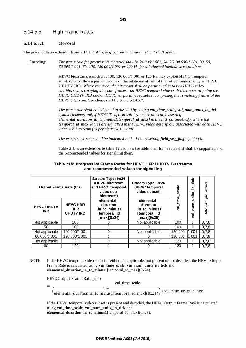
DVB BlueBook A001 (Jul 2019)
143
5.14.5.5 High Frame Rates
5.14.5.5.1 General
The present clause extends clause 5.14.1.7. All specifications in clause 5.14.1.7 shall apply.
Encoding: The frame rate for progressive material shall be 24 000/1 001, 24, 25, 30 000/1 001, 30, 50,
60 000/1 001, 60, 100, 120 000/1 001 or 120 Hz for all allowed luminance resolutions.
HEVC bitstreams encoded at 100, 120 000/1 001 or 120 Hz may exploit HEVC Temporal
sub-layers to allow a partial decode of the bitstream at half of the native frame rate by an HEVC
UHDTV IRD. Where required, the bitstream shall be partitioned in to two HEVC video
sub-bitstreams carrying alternate frames - an HEVC temporal video sub-bitstream targeting the
HEVC UHDTV IRD and an HEVC temporal video subset comprising the remaining frames of the
HEVC bitstream. See clauses 5.14.5.6 and 5.14.5.7.
The frame rate shall be indicated in the VUI by setting vui_time_scale, vui_num_units_in_tick
syntax elements and, if HEVC Temporal sub-layers are present, by setting
elemental_duration_in_tc_minus1[temporal_id_max] in the hrd_parameters(), where the
temporal_id_max values are signalled in the HEVC video descriptors associated with each HEVC
video sub bitstream (as per clause 4.1.8.19a).
The progressive scan shall be indicated in the VUI by setting field_seq_flag equal to 0.
Table 21b is an extension to table 19 and lists the additional frame rates that shall be supported and
the recommended values for signalling them.
Table 21b: Progressive Frame Rates for HEVC HFR UHDTV Bitstreams and recommended values for signalling
Output Frame Rate (fps)
Stream Type: 0x24 (HEVC bitstream
and HEVC temporal video sub-bitstream)
Stream Type: 0x25 (HEVC temporal
video subset)
vu
i_ti
me
_sc
ale
vu
i_n
um
_u
nit
s_
in_
tic
k
All
ow
ed
pic
_s
tru
ct
HEVC UHDTV IRD
HEVC HDR HFR
UHDTV IRD
elemental_ duration
_in_tc_minus1 [temporal_id _max](0x24)
elemental_ duration
_in_tc_minus1 [temporal_id _max](0x25)
Not applicable 100 0 Not applicable 100 1 0,7,8
50 100 1 0 100 1 0,7,8
Not applicable 120 000/1 001 0 Not applicable 120 000 1 001 0,7,8
60 000/1 001 120 000/1 001 1 0 120 000 1 001 0,7,8
Not applicable 120 0 Not applicable 120 1 0,7,8
60 120 1 0 120 1 0,7,8
NOTE: If the HEVC temporal video subset is either not applicable, not present or not decoded, the HEVC Output
Frame Rate is calculated using vui_time_scale, vui_num_units_in_tick and
elemental_duration_in_tc_minus1[temporal_id_max](0x24).
HEVC Output Frame Rate (fps)
= vui_time_scale
(1 +
elemental_duration_in_tc_minus1[temporal_id_max](0x24)) ∗ vui_num_units_in_tick
If the HEVC temporal video subset is present and decoded, the HEVC Output Frame Rate is calculated
using vui_time_scale, vui_num_units_in_tick and
elemental_duration_in_tc_minus1[temporal_id_max](0x25).

DVB BlueBook A001 (Jul 2019)
144
HEVC Output Frame Rate (fps)
= vui_time_scale
(1 +
elemental_duraction_in_tc_minus1[temporal_id_max](0x25)) ∗ vui_num_units_in_tick
Decoding: HEVC HDR HFR UHDTV IRDs shall support decoding and displaying of video with the output
frame rates supported by HEVC UHDTV IRDs and 100, 120 000/1 001 and 120 Hz in addition.
The frame rate shall be calculated using the VUI and VUI hrd_parameters() syntax elements
vui_time_scale, vui_num_units_in_tick and
elemental_duration_in_tc_minus1[temporal_id_max]. The highest TemporalID to be decoded is
indicated by temporal_id_max, carried in the HEVC video descriptor.
The frame rates that shall be supported and the recommended values for signalling them are listed
in tables 19 and 21b.
5.14.5.5.2 Dynamic Changes in Frame Rate
Efficient encoding of "film-style" 24, 25, 30 000/1 001 and 30 Hz material is not currently possible within a full frame
rate 100, 120 000/1 001 or 120 Hz HEVC video bitstream as the HEVC pic_struct parameter does not permit frame
quadrupling and sextupling. In addition, high frame rate programmes may include inserts (e.g. from a radio camera) at
standard frame rates. Thus, a restricted set of dynamic changes in frame rate are permitted:
Encoding: The video frame rate indicated by the vui_time_scale, vui_num_units_in_tick and
elemental_duration_in_tc_minus1[temporal_id_max] shall change only at an HEVC DVB_RAP.
Such changes shall be restricted to either a doubling or halving of frame rate between 50,
60 000/1 001 or 60 Hz and 100, 120 000/1 001 or 120 Hz.
Decoding: Changes in frame rate at the IRD output, indicated by the vui_time_scale,
vui_num_units_in_tick and elemental_duration_in_tc_minus1[temporal_id_max], should be
seamless when they occur at an HEVC DVB_RAP and represent either a doubling or halving of
frame rate between 50, 60 000/1 001 or 60 Hz and 100, 120 000/1 001 or 120 Hz.
NOTE: Where the output frame rate is halved from 100, 120 000/1 001 or 120 Hz to 50, 60 000/1 001 or 60 Hz,
the HEVC temporal video subset will no longer be present.
5.14.5.6 HEVC temporal sub-layers for HFR Bitstreams using dual PID and temporal scalability
HEVC UHDTV IRDs are specified in clause 5.14.3 and are by definition capable to decode frame rates up to 60 Hz
only. HEVC HDR UHDTV IRDs are specified in clause 5.14.4 and are by definition capable to decode frame rates up
to 60 Hz only.
HEVC Temporal sub-layers enable the partial decoding of an HEVC bitstream at a submultiple of its native frame-rate.
Encoding: Where a half frame rate component of a 100, 120 000/1 001 or 120 Hz HEVC bitstreams is
required to be decoded by an HEVC UHDTV IRD or an HEVC HDR UHDTV IRD, the HEVC
video bitstream shall be partitioned in to two sub-bitstreams carrying alternate frames:
- A half frame rate HEVC temporal video sub-bitstream comprising the lower temporal sub-
layers with a frame rate equal to 50, 60 000/1 001 or 60 Hz as defined in the
clause 5.14.1.9.1;
- An HEVC temporal video subset, comprising one temporal sub-layer and containing every
second picture in display order as defined in the present clause.

DVB BlueBook A001 (Jul 2019)
145
HEVC temporal video subsets shall be carried on a single Transport Stream PID with stream_type
equal to 0x25. Only HEVC temporal video subsets obeying the limits associated with level 5.2 for
HEVC HDR HFR UHDTV Bitstreams or HEVC HFR UHDTV Bitstreams shall be carried within
this PID.
Decoding: HEVC HDR HFR UHDTV IRDs shall decode HEVC Bitstreams and HEVC temporal video sub-
bitstreams with stream_type equal to 0x24 and HEVC temporal video subsets with stream_type
equal to 0x25, obeying the limits associated with level 5.2 for HEVC HDR HFR UHDTV
Bitstreams or HEVC HFR UHDTV Bitstreams.
5.14.5.7 HEVC encoding structure for HFR Bitstreams using dual PID and temporal scalability
HEVC UHDTV IRDs are specified in clause 5.14.3 and are by definition capable to decode frame rates up to 60 Hz
only. HEVC HDR UHDTV IRDs are specified in clause 5.14.4 and are by definition capable to decode frame rates up
to 60 Hz only.
Encoding: Where a half frame rate component of a 100, 120 000/1 001 or 120 Hz HEVC bitstreams is
required to be decoded by an HEVC UHDTV IRD or an HEVC HDR UHDTV IRD, the HEVC
video bitstream shall be partitioned in to two sub-bitstreams carrying alternate pictures in display
order:
- A half frame rate HEVC temporal video sub-bitstream comprising the lower temporal sub-
layers with a frame rate equal to 50, 60 000/1 001 or 60 Hz as defined in the
clause 5.14.1.9.1;
- An HEVC temporal video subset, comprising one temporal sub-layer and containing every
second picture in display order.
HEVC DVB_RAP pictures shall be included into the half frame rate HEVC temporal video sub-
bitstream.
The Decoding Time Stamps of access units in the half frame rate HEVC temporal video sub-
bitstream shall be in a constant rate, i.e. 60 Hz for 120 Hz HFR Bitstreams, 50 Hz for 100 Hz HFR
Bitstreams.
NOTE 1: The constraint is introduced to ensure that the DTS value of an access unit in the HEVC temporal video
sub-bitstream can be applied both to decoding of the half frame rate UHDTV video only, and decoding of
the HFR UHDTV video. For information, an example of a coding structure that fulfils this constraint is
documented in Recommendation ITU-R BT.2073-0 [i.30], annex 2.
NOTE 2: 24 and 24 000/1 001 Hz content is carried within a 60 and 60 000/1 001 Hz bitstream respectively, using
3:2 pull-down (pic_struct values 7 and 8) - see clause 5.14.5.5.2. In which case the HEVC temporal
video subset is not present and the DTS interval will be at multiples of 60 and 60 000/1 001 Hz.
All aspects other than the frame rate (such as colour primaries, matrix coefficients, transfer
characteristics, resolution, bit depth for example) shall stay the same in the half frame rate HEVC
temporal video sub-bitstream and the HEVC temporal video subset.
Decoding: HEVC HDR HFR UHDTV IRDs shall decode both the half frame rate HEVC temporal video sub-
bitstream and the HEVC temporal video subset to reconstruct the HFR UHDTV video. HEVC
UHDTV IRDs and HEVC HDR UHDTV IRDs are only required to decode the half frame rate
HEVC temporal video sub-bitstream.

DVB BlueBook A001 (Jul 2019)
146
5.14.5.8 Constraint on TemporalId
For HFR Bitstreams using dual PID and temporal scalability, the following constraints shall apply:
Encoding: The values of TemporalId shall be assigned to the set of pictures as below, with TemporalId =
nuh_temporal_id_plus1 - 1 as specified in Recommendation ITU-T H.265 /
ISO/IEC 23008-2 [35]:
TemporalId = 6 Reserved for future extensions
TemporalId = [N+1] Access Unit of the HEVC temporal video subset that only carries a
picture for 100, 120 000/1 001 or 120 Hz
TemporalId = N Access Unit of the HEVC temporal video sub-bitstream that carries a
non-reference picture for standard frame rate equal to or lower than
60 Hz. This picture may be a reference picture for the HEVC temporal
video subset when present.
TemporalId = 0…[N-1] Access Unit of the HEVC temporal video sub-bitstream that carries a
reference picture for standard frame rate equal to or lower than 60 Hz
The value of N is configured at the encoder. The value of N shall be in the range 1 to 4 (inclusive)
and shall remain static.
The value of temporal_id_max in the HEVC video descriptor for stream_type 0x24 shall be equal
to N.
The values of temporal_id_min and temporal_id_max in the HEVC video descriptor for
stream_type 0x25, carrying the pictures for 100, 120 000/1 001 or 120 Hz, shall be equal to N+1.
When splicing between dual PID high frame rate and single PID standard frame rate bitstreams the
HEVC video descriptor should remain static. Changes in the HEVC video descriptor at splice
points may lead to unpredictable IRD behaviour.
For HFR Bitstreams using single PID, the following constraints shall apply:
Encoding: If HEVC sub-layers are used, the values of TemporalId shall be assigned to the set of pictures as
below, with TemporalId = nuh_temporal_id_plus1 - 1 as specified in
Recommendation ITU-T H.265 / ISO/IEC 23008-2 [35]:
TemporalId = 6 Reserved for future extensions
TemporalId = [N+1] Access Unit of the HEVC video bitstream that only carries a non-
reference picture for 100, 120 000/1 001 or 120 Hz
TemporalId = 0…N Access Unit of the HEVC video bitstream that carries a picture for
standard frame rate equal to or lower than 60 Hz
The value of N is configured at the encoder. The value of N shall be in the range 1 to 4 (inclusive)
and shall remain static.
The value of temporal_id_max in the HEVC video descriptor for stream_type 0x24 shall be equal
to N+1.
When splicing between single PID high frame rate and single PID standard frame rate bitstreams,
the temporal_id_max for the high frame rate bitstream shall be higher than the temporal_id_max
of the standard frame rate bitstream.
NOTE 1: There might be gaps in the values of TemporalId in use. For example, for HFR bitstreams using dual PID,
the Access Units of a half frame rate HEVC temporal video sub-bitstreams may have values of
TemporalId equal to 0, 1 or 2, and the Access Units of the HEVC temporal video subset may have
TemporalId equal to 5. Therefore, there will be no Access Units with values of TemporalId equal to 3 or
4.
NOTE 2: TemporalId [N+1] will not be present when a high frame rate bitstream switches to standard frame rate.
See clause 5.14.5.5.2 Dynamic Changes in Frame Rate.

DVB BlueBook A001 (Jul 2019)
147
5.14.5.9 Backwards Compatibility
Decoding: HEVC HDR HFR UHDTV IRDs shall be capable of decoding any bitstream that a HEVC HDR
UHDTV IRD is required to decode and resulting in the same displayed pictures as the HEVC HDR
UHDTV IRD, as described in clause 5.14.4.
6 Audio
6.0 Introduction
This clause describes the guidelines for encoding MPEG-1 or MPEG-2 Layer II backward compatible audio, or AC-3
audio, or Enhanced AC-3 audio, or AC-4 audio, or DTS Audio, or DTS-HD audio, or DTS-UHD audio, or MPEG-4
AAC audio, or MPEG-4 HE AAC audio, or MPEG-4 HE AAC v2 audio, or MPEG-H audio, or combinations of MPEG
Surround audio with MPEG-1 Layer II, MPEG-4 AAC audio, or MPEG-4 HE AAC audio, or MPEG-4 HE AAC v2
audio in DVB broadcast bitstreams, and for decoding this bitstream in the IRD.
The following clauses do not imply that either MPEG-1 audio, or MPEG-2 Layer II backward compatible audio, or
AC-3 audio, or Enhanced AC-3 audio, or AC-4 audio, or DTS Audio, or DTS-HD audio, or DTS-UHD audio, or
MPEG-4 AAC audio, or MPEG-4 HE AAC audio, or MPEG-4 HE AAC v2 audio, or combinations of MPEG Surround
with MPEG-1 Layer II, MPEG-4 AAC audio, or MPEG-4 HE AAC audio, or MPEG-4 HE AAC v2 audio, or MPEG-H
audio are mandatory. The codecs that a given IRD supports will define which of the following clauses the IRD shall
comply with.
The recommended level for reference tones for transmission is 18 dB below clipping level, in accordance with
EBU Recommendation R.68 [11].
It is recommended that IRDs handle loudness normalization in accordance with EBU Recommendation R 128 [i.18] and
EBU Tech 3344 [i.19].
6.1 MPEG-1 and MPEG-2 backward compatible audio
6.1.0 General
MPEG-1 and MPEG-2 backward compatible audio encoding shall conform to either ISO/IEC 11172-3 [9] or
ISO/IEC 13818-3 [3]. Some of the parameters and fields in ISO/IEC 11172-3 [9] and ISO/IEC 13818-3 [3] are not used
in the DVB System and these restrictions are described below.
The design of an IRD compatible with MPEG-1 and/or MPEG-2 backward compatible audio should be made under the
assumption that any legal structure as permitted by ISO/IEC 11172-3 [9] or ISO/IEC 13818-3 [3] may occur in the
broadcast stream even if presently reserved or unused. To allow full compliance to ISO/IEC 11172-3 [9] and
ISO/IEC 13818-3 [3] and upward compatibility with future enhanced versions, a DVB IRD shall be able to skip over
data structures which are currently "reserved", or which correspond to functions not implemented by the IRD. For
example, an IRD which is not designed to make use of the ancillary data field shall skip over that portion of the
bitstream.
This clause is based on ISO/IEC 11172-3 [9] (MPEG-1 audio) and ISO/IEC 13818-3 [3] (MPEG-2 backward
compatible audio).
Optionally, also the combination of MPEG-1 Layer II with MPEG Surround is supported. The encoding and decoding
of MPEG Surround complies with ISO/IEC 23003-1 [29] and [31]. MPEG Surround creates a (mono or stereo)
downmix from the multi-channel audio input signal. This downmix is encoded using a core audio codec, in this case
MPEG-1 Layer II. In addition, MPEG Surround generates a spatial image parameter description of the multi-channel
audio that is added as an ancillary data stream to the core audio codec. Legacy mono or stereo decoders ignore the
ancillary data and play back a stereo respectively mono audio signal. MPEG Surround capable decoders will first
decode the mono or stereo core codec audio signal and then use the spatial image parameters extracted from the
ancillary data stream to generate a high quality multi-channel audio signal.

DVB BlueBook A001 (Jul 2019)
148
Spatial
parameters
Spatial
multi channel
reconstruction
ch1
ch2
chN
MPEG Surround Decoder
Stereo or
mono
downmix ch1
ch2
chN
stereo
or
mono
downmi
x
downmi
x
automatic
downmix
(optional)
spatial
parameters
estimation
MPEG Surround Encoder
Manual
downmix
automatic
downmix
multi channel
signal
Figure 1a: Principle of MPEG Surround, the downmix is coded using MPEG-1 Layer II
This clause is based on ISO/IEC 11172-3 [9], Recommendation ITU-T H.222.0 / ISO/IEC 13818-1 [1] and
IEC 61966-2-4 [31].
6.1.1 Audio mode
Encoding: MPEG-1 and MPEG-2 backward compatible audio shall be encoded in one of the following
modes:
▪ ISO/IEC 11172-3 [9] single channel;
▪ ISO/IEC 11172-3 [9] joint stereo;
▪ ISO/IEC 11172-3 [9] stereo;
▪ ISO/IEC 13818-3 [3] multi-channel audio, backwards compatible to ISO/IEC 11172-3 [9]
(dematrix procedure = 0, 1 or 2).
In addition, audio may be encoded in ISO/IEC 11172-3 [9] dual channel mode, in a transmission
intended both as a contribution feed and for Direct-To-Home (DTH) reception. However, this is
not recommended. Care needs to be taken to ensure that the optional dual channel decoding mode
is supported in the DTH IRD. Furthermore, there may be problems due to the left/right channel
selection being performed by different equipment from the decoding unit (e.g. decoding may be by
a set-top-box but left/right channel selection and audio balance may be performed by the TV set).
Decoding: IRDs compatible with MPEG-1 and/or MPEG-2 backward compatible audio shall be capable of
decoding the following audio modes:
▪ ISO/IEC 11172-3 [9] single channel;
▪ ISO/IEC 11172-3 [9] joint stereo;
▪ ISO/IEC 11172-3 [9] stereo.

DVB BlueBook A001 (Jul 2019)
149
IRDs compatible with MPEG-1 and/or MPEG-2 backward compatible audio shall be capable of
decoding at least the ISO/IEC 11172-3 [9] compatible basic stereo information from an
ISO/IEC 13818-3 [3] multi-channel audio bitstream. Full decoding of an ISO/IEC 13818-3 [3]
multi-channel audio bitstream is optional.
Support for decoding of ISO/IEC 11172-3 [9] dual channel is optional.
6.1.2 Layer
Encoding: An ISO/IEC 11172-3 [9] encoded bitstream shall use either Layer I or Layer II coding
(layer = "11" or "10" respectively). Use of Layer II is recommended.
An ISO/IEC 13818-3 [3] multi-channel encoded bitstream shall use Layer II coding
(layer = "10").
Decoding: IRDs shall be capable of decoding Layer I and Layer II. In case the IRD supports MPEG
Surround decoding, it shall support the combination of MPEG-1 Layer II with MPEG Surround.
The IRD shall interpret these formats in accordance with MPEG-1 and MPEG Surround audio
syntax.
6.1.3 Bitrate
Encoding: The value of bitrate_index in the encoded bitstream shall be one of the 14 values from "0001" to
"1110"(inclusive).
For Layer I, these correspond to bitrates of: 32 kbits/s, 64 kbits/s, 96 kbits/s, 128 kbits/s,
160 kbits/s, 192 kbits/s, 224 kbits/s, 256 kbits/s, 288 kbits/s, 320 kbits/s, 352 kbits/s, 384 kbits/s,
416 kbits/s or 448 kbits/s.
For Layer II, these correspond to bitrates of: 32 kbits/s, 48 kbits/s, 56 kbits/s, 64 kbits/s, 80 kbits/s,
96 kbits/s, 112 kbits/s, 128 kbits/s, 160 kbits/s, 192 kbits/s, 224 kbits/s, 256 kbits/s, 320 kbits/s and
384 kbits/s.
For ISO/IEC 13818-3 [3] encoded bitstreams with total bitrates greater than 384 kbit/s, an
extension bitstream shall be used. The bitrate of that extension may be in the range of 0 to
682 kbit/s.
Decoding: IRDs shall be capable of decoding bitstreams with a value of bitrate_index from "0001" to
"1110"(inclusive). Support for the free format bitrate (bitrate_index = "0000") is optional.
6.1.4 Sampling frequency
Encoding: The audio sampling rate of primary sound services shall be 32 kHz, 44,1 kHz or 48 kHz. Sampling
rates of 16 kHz, 22,05 kHz, 24 kHz, 32 kHz, 44,1 kHz or 48 kHz may be used for secondary sound
services.
Decoding: The IRD shall be capable of decoding audio with sampling rates of 32 kHz, 44,1 kHz and 48 kHz.
Support for sampling rates of 16 kHz, 22,05 kHz and 24 kHz is optional.
6.1.5 Emphasis
Encoding: The encoded bitstream shall have no emphasis (emphasis = "00").
Decoding: The IRD shall be capable of decoding audio with no emphasis. Support for 50/15 microseconds
de-emphasis and Recommendation ITU-T J.17 [10] de-emphasis (emphasis = "01" or "11") is
optional.

DVB BlueBook A001 (Jul 2019)
150
6.1.6 Cyclic redundancy code
Encoding: The parity check word (crc_check) shall be included in the encoded bitstream.
Decoding: It is recommended that the IRD use crc_check to detect errors and subsequently invoke suitable
concealment or muting mechanisms.
6.1.7 Prediction
Encoding: ISO/IEC 13818-3 [3] multichannel encoded bitstreams shall not use mc_prediction
(mc_prediction_on equals "0").
Decoding: The IRD shall be capable of decoding ISO/IEC 13818-3 [3] multichannel encoded bitstreams
which do not use mc_prediction.
6.1.8 Multilingual
Encoding: ISO/IEC 13818-3 [3] multichannel encoded bitstreams shall not contain multilingual channels
(no_of_multilingual_channels equals "0").
Decoding: The IRD shall be capable of decoding ISO/IEC 13818-3 [3] multichannel encoded bitstreams
which do not contain multilingual channels.
6.1.9 Extension Stream
Encoding: When an ISO/IEC 13818-3 [3] encoded bitstream uses an extension stream, it is recommended
that a continuous stream of extension frames is maintained for the duration of a programme, even
if a total bitrate of less than 384 kbits/s would be sufficient to encode individual frames. This
prevents undesired resets of the audio decoder.
6.1.10 Ancillary Data
Encoding: ISO/IEC 13818-3 [3] stereo or multichannel encoded bitstreams may contain ancillary data as
described in annex C. It is recommended to include the data in the bitstream.
- In order to support the contribution of DAB signals, the ancillary data field may embed the
DAB ancillary data field [18].
- In order to support the transmission of RDS data to DVB receivers and analogue FM
transmitters, the ancillary data field may embed RDS data via the UECP protocol.
- If data fields according to DVD-Video extended ancillary data (as described in annex C) or
ancillary data according to the DAB specification [18] are used, they have, for backward
compatibility reasons, to be the first data field at the end of the audio frame. This means that a
common usage of DVD-Video and DAB data is excluded.
Decoding: The IRD may interpret the ancillary data field in an ISO/IEC 13818-3 [3] stereo or multichannel
bitstream as described in annex C and it is recommended that the contribution IRD make use of
this data.

DVB BlueBook A001 (Jul 2019)
151
6.1.11 MPEG Surround configurations, profiles and levels
The baseline MPEG Surround profile is defined in ISO/IEC 23003-1 [29] and ISO/IEC 23003-1:2007/Cor:2008,
Technical Corrigendum 1 [30]. For the combination of MPEG Surround with MPEG-1 Layer II, the baseline MPEG
Surround profile shall be used together with the restrictions defined in clauses 6.1.1 to 6.1.10.
The MPEG Surround bitstream payload shall comply with level 3 or 4 of the Baseline MPEG Surround profile.
Encoding: In case of the combination of MPEG-1 Layer II with MPEG Surround, the MPEG Surround
bitstream shall be embedded into the ancillary data of the MPEG-1 Layer II bitstream using the
AncDataElement() bitstream element as defined in ISO/IEC 23003-1 [29]. For MPEG-1 Layer II,
the spatial frame length, indicated by the bsFrameLength parameter, shall correspond to the
MPEG-1 Layer II frame length. Hence, the bsFrameLength shall be one of the following values:
{17, 35}, resulting in effective MPEG Surround frame lengths of 1 152 and 2 304 time domain
samples respectively.
Decoding: The IRD, if compatible with MPEG-1 Layer II audio and capable of decoding MPEG Surround
and capable of providing 7.1 channels or more of output, shall be capable of providing decoder
output according to MPEG Surround Baseline profile level 4.
The IRD, if compatible with MPEG-1 Layer II audio and capable of decoding MPEG Surround
and capable of providing more than two and up to 5.1 channels of output shall be capable of
providing decoder output according to MPEG Surround Baseline profile level 3.
The IRD, if compatible with MPEG-1 Layer II audio and capable of decoding MPEG Surround
and capable of providing 2.0 channels of output shall be capable of providing decoder output
according to MPEG Surround Baseline profile level 1.
6.2 AC-3 and Enhanced AC-3 audio
6.2.0 General
The coding and decoding of AC-3 and Enhanced AC-3 elementary streams is based upon ETSI TS 102 366 [12].
IRDs compatible with AC-3 shall decode all bitrates and sample rates listed in ETSI TS 102 366 [12] (not including
annex E).
IRDs compatible with Enhanced AC-3 shall additionally decode Enhanced AC-3 streams with data rates from 32 kbps
to 3 024 kbps and support all sample rates listed in ETSI TS 102 366 [12], annex E.
Enhanced AC-3 bit streams are similar in nature to standard AC-3 bit streams, but are not backwards compatible
(i.e. they are not decodable by standard AC-3 decoders). Some constraints are placed on the PES layer for the case of
multiple audio streams intended to be reproduced in exact sample synchronism as described in clause 6.2.1.
6.2.1 AC-3 and Enhanced AC-3 PES constraints
6.2.1.1 Encoding
In some applications, the audio decoder may be capable of simultaneously decoding two elementary streams containing
different programme elements, and then combining the programme elements into a complete programme.
Most of the programme elements are found in the main audio service. Another programme element (such as a spoken
narration of the picture content intended for the visually impaired listener, a specially created dialogue based audio
service for the hearing impaired listener, or additional audio services such as a spoken director's commentary or
alternative languages) may be found in an associated audio service.

DVB BlueBook A001 (Jul 2019)
152
In order to have the audio from the two elementary streams reproduced in exact sample synchronism, it is necessary for
the original audio elementary stream encoders to have encoded the two audio programme elements frame
synchronously; i.e. if audio stream 1 has sample 0 of frame n taken at time t 0, then audio stream 2 should also have
frame n beginning with its sample 0 taken the identical time t 0. If the encoding of multiple audio services is done frame
and sample synchronous, and decoding is intended to be frame and sample synchronous, then the PES packets of these
audio services shall contain identical values of PTS, which refer to the audio access units intended for synchronous
decoding.
Audio services intended to be combined together for reproduction according to the mixing process defined in
ETSI TS 102 366 [12] (annex E) shall meet the following constraints:
• Audio services intended to be combined together for reproduction shall be encoded at an identical sample
rate.
• The main programme audio shall be encoded as either an AC-3 or an Enhanced AC-3 elementary stream. The
associated audio service shall be encoded as an Enhanced AC-3 elementary stream.
• The Enhanced AC-3 elementary stream carrying the associated audio service shall contain mixing metadata
for use by the decoder to control the mixing process.
• When mixing metadata is present in the Enhanced AC-3 elementary stream, the AD_Descriptor defined in
clause E.1 shall not be present in the PES encapsulation of the Enhanced AC-3 elementary stream.
• The main programme shall contain from 1 to 7.1 channels of audio. The Enhanced AC-3 elementary stream
that carries the associated audio services to be mixed with the main programme audio shall contain no more
than two audio channels, and shall not contain more audio channels than the main audio programme.
• Dual-mono coding mode is not supported for either the main programme or associated audio service.
• The encoding of the associated audio service and subsequent creation of the associated audio service
elementary stream shall be done with knowledge of the encoding of the main programme stream.
• The pgmscl field in the associated programme bitstream should be set to a positive value. It is recommended
this be positive 12 dB to match the default user volume adjustment setting in the decoder.
6.2.1.2 Decoding
If audio access units from two audio services which are to be simultaneously decoded have identical values of PTS
indicated in their corresponding PES headers, then the corresponding audio access units shall be presented to the
audio decoder for simultaneous synchronous decoding. Synchronous decoding means that for corresponding audio
frames (access units), corresponding audio samples are presented at the identical time.
If the PTS values do not match (indicating that the audio encoding was not frame synchronous) then the audio
frames (access units) of the main audio service may be presented to the audio decoder for decoding and presentation at
the time indicated by the PTS. An associated service, which is being simultaneously decoded, may have its audio
frames (access units), which are in closest time alignment (as indicated by the PTS) to those of the main service being
decoded, presented to the audio decoder for simultaneous decoding. In this case the associated service may be
reproduced out of sync by as much as 1/2 of a frame time. (This is typically satisfactory; a visually impaired narration
does not require highly precise timing.)
A minimum functionality mixer is described in clause E.4 of ETSI TS 102 366 [12]. IRDs that implement this mixing
method shall set the default user volume adjustment of the associated programme level to minus 12 dB.
The IRD may use the ISO 639-2 [27] language descriptor to indicate the language of the content of the associated
programme. As the associated services are carried in separate elementary streams to the main service different
languages may be indicated for each programme stream.
6.2.1.3 Byte-alignment
The AC-3 and Enhanced AC-3 elementary stream shall be byte-aligned within the MPEG-2 data stream. This means
that the initial 8 bits of an AC-3 or Enhanced AC-3 frame shall reside in a single byte, which is carried by the MPEG-2
data stream.
DVB BlueBook A001 (Jul 2019)
153
6.2.2 Enhanced AC-3 with multiple independent substreams - PES constraints
6.2.2.1 Encoding
In some applications, the audio decoder may be capable of simultaneously decoding two different programme elements,
carried as separate independent substreams within a single Enhanced AC-3 elementary stream, and then combining the
programme elements into a complete programme.
Most of the programme elements are found in the main audio service. Another programme element (such as a spoken
narration of the picture content intended for the visually impaired listener, a specially created dialogue based audio
service for the hearing impaired listener or additional audio services such as a spoken director's commentary) may be
found in one or more independent substreams carried in the same Enhanced AC-3 bitstream as the main programme.
The Enhanced AC-3 elementary stream shall contain no more than three independent substreams in addition to the
independent substream containing the main audio programme. The main audio programme shall only be delivered in
independent substream 0.
When mixing metadata is present in one of more substreams of the Enhanced AC-3 elementary stream, the
AD_Descriptor defined in clause E.1 shall not be present in the PES encapsulation of the Enhanced AC-3 elementary
stream.
In order to have the independent substreams containing audio from the main programme and the associated audio
service reproduced in exact sample synchronism, it is necessary for the Enhanced AC-3 encoder to have encoded all of
the audio programme elements frame synchronously; i.e. if the independent substream 0 has sample 0 of frame n taken
at time t 0, then independent substream 1 should also have frame n beginning with its sample 0 taken the identical
time t 0.
Independent substreams intended to be combined together for reproduction according to the mixing process defined in
ETSI TS 102 366 [12] (annex E) shall meet the following constraints:
• Independent substreams intended to be combined together for reproduction shall be encoded at an identical
sample rate.
• The independent substream carrying the associated audio service shall contain mixing metadata for use by the
decoder to control the mixing process.
• The independent substream that carries the main programme shall contain from 1 to 5.1 channels of audio.
The independent substream that carries the associated audio services to be mixed with the main programme
audio shall contain no more than two audio channels, and shall not contain more audio channels than the
main audio programme.
• Dual-mono coding mode is not supported for either the main programme or associated audio service.
• The encoding of the associated audio service and subsequent creation of the associated audio service
substream shall be done with knowledge of the encoding of the main programme substream.
• The pgmscl field in the associated programme substream should be set to a positive value. It is recommended
this be positive 12 dB to match the default user volume adjustment setting in the decoder.

DVB BlueBook A001 (Jul 2019)
154
6.2.2.2 Decoding
IRDs shall be able to accept Enhanced AC-3 elementary streams that contain more than one independent substream.
For TV-broadcasting applications, noticeably public service broadcasting, there is often a requirement for commentary
or narration audio services to provide for different languages or Visually Impaired or Hearing Impaired audiences. To
allow cost effective transmission and reproduction of these services it is strongly recommended that IRDs be able to
select additional independent substreams carried in an Enhanced AC-3 elementary stream and mix the selected
independent substream with the main audio programme. A minimum functionality mixer is described in clause E.4 of
ETSI TS 102 366 [12]. IRDs that include this mixing capability shall set the default user volume adjustment of the
associated programme level to minus 12 dB.
The IRD may use the ISO 639-2 [27] language descriptor to indicate the language of the content of the main
programme. As the associated programmes are carried in the same elementary stream as the main programme, the IRD
shall assume that the language of associated programmes carried in independent substreams is the same as that of the
main programme. To deploy associated programmes with different languages than the main programme, separate
Enhanced AC-3 elementary streams shall be used, as described in clauses 6.2.1.1 and 6.2.1.2.
IRDs that support multiple different output-interfaces, for example headphone output or baseband analogue outputs,
may optionally support separate mixes for each output created by multiple Enhanced AC-3 decoders.
6.3 DTS Audio
6.3.0 General
The coding and decoding of DTS Audio coded elementary streams is based upon ETSI TS 102 114 [15].
IRDs compatible with DTS Audio shall decode all bitrates and sample rates listed in ETSI TS 102 114 [15].
Some constraints are placed on the PES layer for the case of multiple audio streams intended to be reproduced in exact
sample synchronism as described in clause 6.3.1.
6.3.1 DTS Audio and DTS-HD PES Constraints
6.3.1.1 Encoding
In some applications, the audio decoder may be capable of simultaneously decoding two elementary streams containing
different programme elements, and then combining the programme elements into a complete programme.
Most of the programme elements are found in the main audio service. Another programme element (such as a narration
of the picture content intended for the visually impaired listener) may be found in the associated audio service.
In order to have the audio from the two elementary streams reproduced in exact sample synchronism, it is necessary for
the original audio elementary stream encoders to have encoded the two audio programme elements frame
synchronously; i.e. if audio stream 1 has sample 0 of frame n taken at time t 0, then audio stream 2 should also have
frame n beginning with its sample 0 taken the identical time t 0. If the encoding of multiple audio services is done frame
and sample synchronous, and decoding is intended to be frame and sample synchronous, then the PES packets of these
audio services shall contain identical values of PTS, which refer to the audio access units intended for synchronous
decoding.
Audio services intended to be combined together for reproduction shall be encoded at an identical sample rate.

DVB BlueBook A001 (Jul 2019)
155
6.3.1.2 Decoding
If audio access units from two audio services which are to be simultaneously decoded have identical values of PTS
indicated in their corresponding PES headers, then the corresponding audio access units shall be presented to the
audio decoder for simultaneous synchronous decoding. Synchronous decoding means that for corresponding audio
frames (access units), corresponding audio samples are presented at the identical time.
If the PTS values do not match (indicating that the audio encoding was not frame synchronous) then the audio
frames (access units) of the main audio service may be presented to the audio decoder for decoding and presentation at
the time indicated by the PTS. An associated service, which is being simultaneously decoded, may have its audio
frames (access units), which are in closest time alignment (as indicated by the PTS) to those of the main service being
decoded, presented to the audio decoder for simultaneous decoding. In this case the associated service may be
reproduced out of sync by as much as 1/2 of a frame time. (This is typically satisfactory; a visually impaired narration
does not require highly precise timing.)
6.3.1.3 Byte-alignment
The DTS Audio and DTS-HD elementary streams shall be byte-aligned within the MPEG-2 data stream. This means
that the initial 8 bits of a DTS Audio/DTS-HD frame shall reside in a single byte, which is carried by the MPEG-2 data
stream.
6.4 MPEG-4 AAC, MPEG-4 HE AAC and MPEG-4 HE AAC v2 audio
6.4.0 Introduction
The coding and decoding of MPEG-4 AAC, MPEG-4 HE AAC and MPEG-4 HE AAC v2 elementary streams is based
upon ISO/IEC 14496-3 [17].
The MPEG-4 AAC and the MPEG-4 High Efficiency AAC Profiles are subsets of the MPEG-4 High Efficiency AAC
v2 profile. HE AAC adds the AOT SBR to the MPEG-4 AAC Profile. HE AAC v2 adds the AOT PS to the MPEG-4
High Efficiency AAC profile to improve the audio quality at low bitrates. Every HE AAC decoder can decode an HE
AAC v2 bitstream, but will not be able to use the parametric stereo information and will therefore replay on a mono
signal.
Bit Rate [kbit/s] 48 64 128 96 32
Perceptual Quality Quality level,
PCM 44,1 kHz, 16 bit, stereo
HE AAC AAC
16
HE AAC v2
Figure 2: Typical bitrate range of the HE AAC v2, HE AAC and AAC for stereo
Figure 2 indicates the typical bitrate ranges for the use of MPEG-4 HE AAC v2, MPEG-4 HE AAC and MPEG-4 AAC
on the encoder side for stereo. The actual bitrates for the use of the different tools is dependent from the encoder
implementation.

DVB BlueBook A001 (Jul 2019)
156
Optionally, also the combination of MPEG-4 AAC, MPEG-4 HE AAC and MPEG-4 HE AAC v2 with MPEG
Surround is supported. The encoding and decoding of MPEG Surround complies with ISO/IEC 23003-1:2007 [29] and
ISO/IEC 23003-1:2007/Cor:2008 [30]. MPEG Surround creates a (mono or stereo) downmix from the multi-channel
audio input signal. This downmix is encoded using a core audio codec, in this case MPEG-4 AAC, HE AAC or HE
AAC v2. In addition, MPEG Surround generates a spatial image parameter description of the multi-channel audio that is
added as an ancillary data stream to the core audio codec. Legacy mono or stereo decoders ignore the ancillary data and
playback a stereo respectively mono audio signal. MPEG Surround capable decoders will first decode the mono or
stereo core codec audio signal and then use the spatial image parameters extracted from the ancillary data stream to
generate a high quality multi-channel audio signal.
Spatial
parameters
Spatial
multi channel
reconstruction
ch1
ch2
chN
MPEG Surround Decoder
Stereo or
mono
downmix ch1
ch2
chN
stereo
or
mono
downmi
x
downmi
x
automatic
downmix
(optional)
spatial
parameters
estimation
MPEG Surround Encoder
Manual
downmix
automatic
downmix
multi channel
signal
Figure 3: Principle of MPEG Surround, the downmix is coded using MPEG-4 AAC, HE AAC or HE AAC v2
6.4.1 LATM/LOAS formatting
The MPEG-4 HE AAC or HE AAC v2 elementary stream data shall be first encapsulated in the LATM multiplex format
according to ISO/IEC 14496-3 [17].
When MPEG Surround is used then the combination of MPEG Surround as specified in ISO/IEC 23003-1 [29] and [31]
with MPEG-4 AAC, MPEG-4 HE AAC or MPEG-4 HE AAC v2 as specified in ISO/IEC 14496-3 [17] is transmitted
using LOAS/LATM, being also specified in ISO/IEC 14496-3 [17]. First, the combined MPEG-4 AAC/MPEG Surround,
MPEG-4 HE AAC/MPEG Surround or MPEG-4 HE AAC v2/MPEG Surround shall be formatted using the LATM
multiplex format.
The AudioMuxElement() multiplex element format shall be used.
The LATM formatted MPEG-4 HE AAC or HE AAC v2 elementary stream data shall be encapsulated in the LOAS
transmission format according to ISO/IEC 14496-3 [17]. The AudioSyncStream() version shall be used.
AudioSyncStream() adds a sync word to the audio stream to allow for synchronization. Semantics: The semantics of the
AudioMuxElement() and AudioSyncStream() formatting are described in ISO/IEC 14496-3 [17].
Encoding: The MPEG-4 HE AAC and HE AAC v2 elementary streams shall be formatted with
AudioMuxElement() LATM multiplex format, and AudioSyncStream() LOAS transmission
format.
The MPEG-4 AAC/MPEG Surround, MPEG-4 HE AAC/MPEG Surround and MPEG-4 HE AAC
v2/MPEG Surround elementary streams shall be formatted with AudioMuxElement() LATM
multiplex format, and AudioSyncStream() LOAS transmission format.
The following limitations to the LATM multiplex shall apply:
▪ audioMuxVersion shall be "0";
▪ numLayer shall be "0", as no scalable profile is used; When MPEG Surround is used this
indicates that a single layer is present consisting of MPEG-4 AAC, MPEG-4 HE AAC or
MPEG-4 HE AAC v2 with embedded MPEG Surround data;

DVB BlueBook A001 (Jul 2019)
157
▪ numProgram shall be "0", as there is only one audio program per LATM multiplex;
▪ numSubFrames shall be "0", as there is only one PayloadMux() (access unit) per LATM
AudioMuxElement();
▪ allStreamsSameTimeFraming shall be "1", as all payloads belong to the same access unit;
▪ the fields taraBufferFullness and latmBufferFullness shall be set to their largest
respective value, indicating that buffer fullness measures are not used in DVB context;
▪ the value for frameLengthFlag contained in the GASpecificConfig shall be set to 0,
indicating that the transform length of the IMDCT for AAC is 1 024 samples for long and
128 for short blocks.
In case of the combination MPEG-4 AAC with MPEG Surround, the Audio Object Type (AOT)
element, audioObjectType, shall be set to the value 2 (indicating AAC-LC).
In case of the combination MPEG-4 HE AAC with MPEG Surround or the combination of MPEG-4
HE AAC v2 with MPEG Surround, the Audio Object Type (AOT) element, audioObjectType, shall
be set to the value 5 (indicating SBR). Furthermore, separate fill elements shall be employed to
embed the SBR(/PS) extension data elements sbr_extension_data(), described in
ISO/IEC 14496-3 [17], and MPEG Surround spatial audio data SpatialFrame(), described in
ISO/IEC 23003-1 [29] and [31].
The spatial frame length, indicated by the bsFrameLength parameter, shall correspond to the
MPEG-4 AAC frame length. Hence, the bsFrameLength shall be any of the following values:
{15, 31, 63}, resulting in effective MPEG Surround frame lengths of 1 024, 2 048 and 4 096 time
domain samples respectively.
Decoding: These formats shall be read by the IRD, and the IRD shall interpret these formats in accordance
with MPEG-4 audio syntax.
In case the IRD supports MPEG Surround decoding, these formats shall be read by the IRD, and
the IRD shall interpret these formats in accordance with MPEG-4 and MPEG Surround audio
syntax.
6.4.2 Profiles and Levels
6.4.2.1 Profiles and Levels for AAC, HE AAC and HE AAC v2
MPEG-4 AAC, HE AAC and HE AAC v2 are defined in ISO/IEC 14496-3 [17], clause 1.5.2 as AAC Profile, High
Efficiency AAC Profile and High Efficiency AAC v2 Profile respectively.
Encoding: The encoder shall use either the MPEG-4 AAC Profile, the MPEG-4 High Efficiency AAC Profile
or the MPEG-4 High Efficiency AAC v2 Profile. Use of the MPEG-4 HE AAC Profile is
recommended.
Monaural, stereo and parametric stereo MPEG-4 HE AAC v2 bitstreams shall comply with level 2
restrictions.
Monaural and stereo MPEG-4 AAC and HE AAC bitstreams shall comply with level 2 restrictions,
respectively.
Multichannel audio up to 5.1 channel bitstreams shall comply with the level 4 restrictions
respectively. Coupling Channel Elements (CCEs) according to ISO/IEC 14496-3 [17] shall not be
used.

DVB BlueBook A001 (Jul 2019)
158
Decoding: The IRD, if compatible with MPEG-4 AAC audio, shall be capable of decoding MPEG-4 AAC,
MPEG-4 High Efficiency AAC or the MPEG-4 High Efficiency AAC v2 Profile bitstreams.
A MPEG-4 HE AAC v2 monaural, stereo and parametric stereo enabled decoder shall support
decoding MPEG-4 HE AAC v2 Profile Level 2 bitstreams. This requirement does include support
for lower levels, but not other profiles. Support for other profiles and for levels beyond Level 2 is
optional.
A MPEG-4 AAC and HE AAC monaural and stereo enabled decoder shall support decoding
MPEG-4 High Efficiency AAC Profile Level 2 bitstreams. This requirement does include support
for lower levels, but not other profiles. Support for other profiles and for levels beyond Level 2 is
optional.
MPEG-4 AAC, HE AAC or HE AAC v2 multi-channel enabled decoder shall support decoding
MPEG-4 AAC Profile, MPEG-4 High Efficiency AAC Profile or High Efficiency AAC v2 Profile
Level 4 bitstreams respectively. This requirement does include support for lower levels, but not
other profiles. Support for other profiles and for levels beyond Level 4 is optional. Support for
Coupling Channel Elements (CCEs) according to ISO/IEC 14496-3 [17] is optional. If an IRD
supports higher levels than level 2 then it shall also support Matrix-Mixdown according to
ISO/IEC 14496-3 [17], clause 4.5.1.2.2. It shall further support the application of
downmixing_levels_MPEG4 in ancillary data (annex C).
6.4.2.2 Profiles and Levels for MPEG Surround in combination AAC, HE AAC and HE AAC v2
The Baseline MPEG Surround Profile is defined in ISO/IEC 23003-1 [29] and ISO/IEC 23003-1:2007/Cor:2008 [30].
For the combination of MPEG Surround with MPEG-4 AAC, MPEG-4 HE AAC or MPEG-4 HE AAC v2, the Baseline
MPEG Surround Profile will be employed together with the AAC Profile, High Efficiency AAC Profile or High
Efficiency AAC v2 Profile respectively. The AAC or HE AAC or HE AAC v2 bitstream payloads shall comply with
level 2 or level 4 of the respective profile. The MPEG Surround bitstream payload shall comply with level 3, 4 or 5 of
the Baseline MPEG Surround profile.
Encoding: In combination with MPEG Surround, MPEG-4 AAC, MPEG-4 HE AAC or MPEG-4 HE AAC v2
bitstream payloads shall comply with the restrictions of level 2 of their respective profile. If the
MPEG Surround bitstream payload complies to Level 5 of the Baseline MPEG Surround profile,
bitstream payloads shall comply to Level 4 of the AAC or HE_AAC profile.
Decoding: The IRD, if compatible with MPEG-4 HE AAC audio at Level 4 and capable of decoding MPEG
Surround and capable of providing 7.1 channels or more of output, shall be capable of providing
decoder output according to MPEG Surround Baseline profile level 5.
The IRD, if compatible with MPEG-4 HE AAC audio up to Level 3 and capable of decoding
MPEG Surround and capable of providing 7.1 channels or more of output, shall be capable of
providing decoder output according to MPEG Surround Baseline profile level 4.
The IRD, if compatible with MPEG-4 HE AAC audio and capable of decoding MPEG Surround
and capable of providing more than two and up to 5.1 channels of output shall be capable of
providing decoder output according to MPEG Surround Baseline profile level 3.
The IRD, if compatible with MPEG-4 HE AAC audio and capable of decoding MPEG Surround
and capable of providing up to 2.0 channels of output shall be capable of providing decoder
output according to MPEG Surround Baseline profile level 1.
6.4.3 Dynamic Range Control
The MPEG-4 AAC Dynamic Range Control (DRC) tool is defined in ISO/IEC 14496-3 [17], clause 4.5.2.7. For more
detailed information on the MPEG-4 AAC Dynamic Range Control tool see ISO/IEC 14496-3 [17].
Encoding: It is strongly recommended that the encoder uses the MPEG-4 AAC Dynamic Range Control
(DRC) tool.

DVB BlueBook A001 (Jul 2019)
159
Decoding: The IRD shall support the MPEG-4 AAC Dynamic Range Control (DRC).If a program reference
level is not transmitted in the bitstream, it is strongly recommended that a program reference level
of -23 dB is assumed.
It is strongly recommended that each IRD operates either at a target level of -23 dB or at a target
level of -31 dB.
Details of how Dynamic Range Control should be applied are specified in clause C.5.4.
6.5 Random Access Points with MPEG-4 Audio
6.5.0 General
The definition for MPEG-4 AAC, MPEG-4 HE AAC and MPEG-4 HE AAC v2 RAP in clause 3 shall apply.
6.5.1 Definition of RAP with MPEG-4 Audio
6.5.1.0 Introduction
In contrast to MPEG-2, MPEG-4 audio streams may not be accessible and decodable with full fidelity with each single
access unit (AU). The reason for this is to save bit-rate by not transmitting static information with each AU. The
following clause describes required constraints to start decoding of MPEG-4 audio at a given AU.
6.5.1.1 RAP with the LATM/LOAS transport header
The LATM/LOAS transport format carries the "StreamMuxConfig". This structure carries essential, but quasi-static
information such as sampling rate or channel configuration. As these parameters change rather seldom in broadcast
applications, this structure need not be transmitted with each access unit, but is expected to be present periodically to
allow for random access to the stream.
Encoding: For a RAP, within AudioMuxElement(), useSameStreamMux shall be set to "0";
i.e. StreamMuxConfig() is present.
Within the scope of the present document, useSameConfig is always set to "0". See clause 6.4.1, where both,
numProgram and numLayer shall be "0" yielding to useSameConfig to be set to "0" as well. In consequence an
AudioSpecificConfig() is always contained in a StreamMuxConfig().
6.5.1.2 RAP with the AAC Profile
AAC-LC is the only Audio Object Type used in the AAC Profile. In addition to the given constraints with the
LATM/LOAS transport header (see clause 6.5.1.1), the following constraints shall be satisfied for this AOT.
Encoding: If channel configuration 0 is used, the ProgramConfigElement() containing the actual channel
configuration shall be present in the bitstream for a RAP.
6.5.1.3 RAP with the HE AAC Profile
The HE AAC profile is based on the AAC profile and is extended by the Audio Object Type SBR; therefore all
constraints from the AOT AAC-LC (see clause 6.5.1.2) shall also be fulfilled.
In contrast to the AAC configuration that is completely described by the AudioSpecificConfig(), the Audio Object
Type SBR decoder needs additional configuration parameters. These parameters are transmitted inside the SBR header
which is not required to be contained in every access unit.
To allow the decoder to access and instantaneously fully decode a HE AAC profile bit stream, it is necessary to transmit
an sbr_header() in the first access unit after a RAP (RAP access unit).
Encoding: For a RAP in case of the Audio Object Type SBR, the bs_header_flag shall be set to "1";
i.e. sbr_header() is present.

DVB BlueBook A001 (Jul 2019)
160
NOTE 1: The use of tools that rely on preceding frames (i.e. time differential coding of parameters) is prohibited
for frames containing an SBR header by the MPEG-4 Audio Conformance (ISO/IEC 14496-26 [41],
clause 7.17.1.2.1.4). This restriction ensures that a RAP frame can be completely decoded and processed.
NOTE 2: According to ISO/IEC 14496-3 [17], clause 4.5.2.8.2.1, "as long as no SBR header part is present, the
SBR decoder performs upsampling and delay adjustment only". Therefore, audio playback may start even
if sbr_header() was not yet received, but only with reduced quality. Therefore, ISO/IEC 14496-3 [17]
recommends: "In continuous broadcast applications, SBR extension data elements with an SBR header
part are typically sent twice per second. In addition, a SBR header part can any time be inserted, if an
instantaneous, possibly program dependent, change of header parameters is required" (see
ISO/IEC 14496-3 [17], clause 4.5.2.8.2.1).
6.5.1.4 RAP with the HE AAC v2 Profile
The HE AAC v2 profile is based on the HE AAC profile and is extended by the Audio Object Type Parametric Stereo
(PS); therefore all constraints from the HE AAC profile (see clause 6.5.1.3) shall also be satisfied.
As with the Audio Object Type SBR, the configuration parameters for the Audio Object Type PS payload are
transmitted inside the PS header information, which is not required to be contained in every access unit.
To allow the decoder to access and instantaneously fully decode a HE AAC v2 profile bit stream, it is necessary to
transmit PS header information in the first access unit of a sequence (RAP AU).
Encoding: For a RAP in case of the Audio Object Type Parametric Stereo, enable_ps_header should be set
to "1", i.e. the PS decoder configuration data is transmitted.
NOTE 1: The use of tools that rely on preceding frames (i.e. time differential coding of parameters) for frames with
enable_ps_header = 1 is prohibited by the MPEG-4 Audio Conformance (ISO/IEC 14496-26 [41],
clause 7.18.1.3). This restriction ensures that an RAP frame can be completely decoded and processed.
NOTE 2: As the Audio Object Type Parametric Stereo conformance requires a PS header with every SBR header
(see ISO/IEC 14496-26 [41], clause 7.18.1.3), this requirement is also implicitly inherited from the Audio
Object Type SBR requirements.
NOTE 3: According to ISO/IEC 14496-3 [17], clause 8.6.5.1, mandates that a conformant decoder that receives PS
data output the mono signal in the two output channels until a first ps_data() element with
enable_ps_header == 1 is received and in which for all enabled parameters frequency differential coding
is employed and num_env>0, ensuring that the PS data can be decoded correctly.
Therefore audio playback may start even if ps_data() may not be decoded.
6.5.1.5 RAP with AAC-LC / HE AAC plus MPEG Surround
As MPEG Surround is based on an AAC-LC or HE AAC core coder, all restrictions for AAC-LC and HE AAC shall
also apply for MPEG Surround respectively. Further restrictions are as follows, for details see ISO/IEC 23003-1 [29].
Encoding: For a RAP in case of MPEG Surround, the SpatialSpecificConfig() data structure shall be
transmitted, i.e. in sac_extension_data(), ancType and ancStart shall be set to "1".
Additionally, the coding of RAP frames shall be independent of previous frames. Therefore the
bitstream payload element bsIndependencyFlag shall be set to "1".
6.5.1.6 RAP with Dynamic Range Control and MPEG-4 Audio ancillary data
Encoding: For a RAP, both dynamic_range_info() and MPEG4_ancillary_data() shall be present in access
unit. Further, prog_ref_level_present shall be set to 0x1, i.e. the program reference level is
present in dynamic_range_info(). In MPEG4_ancillary_data(),
downmixing_levels_MPEG4_status shall be set to "1".

DVB BlueBook A001 (Jul 2019)
161
6.5.2 Time interval Between RAPs
Encoding: The encoder shall place MPEG-4 AAC, HE AAC or HE AAC v2 RAPs in the audio elementary
stream at least every 2 seconds.
It is recommended that MPEG-4 AAC, HE AAC or HE AAC v2 RAPs occur in the audio
elementary stream on average at least every 500 ms. Further it is recommended those audio frames
in the audio elementary stream whose PTS values are closest to the PTS values of the RAPs of the
associated video elementary stream are also coded as RAPs.
NOTE: PTS of HE AAC v2 RAP usually will not be identical to that of associated video elementary stream RAP,
therefore the associated audio/video RAPs should have closest PTS values.
6.6 AC-4 channel-based audio
6.6.0 Introduction
Clause 6.6 specifies carriage of audio encoded using ETSI TS 103 190-1 [43], using bitstream_version=0. Carriage of
audio with bitstream_version>0, encoded using ETSI TS 103 190-2 [46] is specified in clause 6.7 of the present
document.
6.6.1 General
The coding and decoding of the raw AC-4 frames of an AC-4 elementary stream is based upon ETSI
TS 103 190-1 [43]. AC-4 elementary streams consist of presentations, which define a set of one or more substreams to
be presented simultaneously.
The following requirements apply for encoders and IRDs compatible with AC-4:
Encoding: An AC-4 elementary stream shall contain at least one presentation. The first presentation (by
order of appearance) shall contain main audio of up to 7.1 channels, plus an optional dialogue
enhancement substream of up to 3 channels (L,C,R).
The AC-4 elementary stream shall be encoded at an audio frame rate in the set {48 000/2 048,
24 000/1 001, 24, 25, 30 000/1 001, 30, 50, 60 000/1 001, 60} Hz. This set corresponds to all video
frame rates as per clause 5.14.1.7 of the present document and additionally includes the native
AC-4 frame rate.
An AC-4 elementary stream shall be encoded with a sampling rate of 48 kHz, 96 kHz or 192 kHz.
The raw AC-4 frames shall be encapsulated in the AC-4 Sync Frame format, as described in
clause 6.6.6 of the present document. Frames encapsulated in this way are subsequently referred to
as AC-4 frames.
The bitstream_version field according to clause 4.3.3.2.1 of ETSI TS 103 190-1 [43] shall be set
to the value 0.
The presentation_version field according to clause 4.3.3.4.1 of ETSI TS 103 190-1 [43] shall be
set to the value 0.
Decoding: The IRD shall by default decode the first presentation. It may skip additional presentations
contained in the AC-4 elementary stream.
The IRD shall be capable of decoding a substream of main audio of up to 7.1 channels and a
substream containing dialogue enhancement of up to 3 channels (L,C,R).
The IRD shall be able to decode all audio frame rates in the set {48 000/2 048, 24 000/1 001, 24,
25, 30 000/1 001, 30, 50, 60 000/1 001, 60} Hz. This set corresponds to all video frame rates as per
clause 5.14.1.7 of the present document and additionally includes the native AC-4 frame rate.
The IRD may decode the 48 kHz substream of elementary streams encoded at 96 kHz or 192 kHz.
The IRD may ignore AC-4 elementary streams with bitstream_version field not equal to 0.

DVB BlueBook A001 (Jul 2019)
162
The IRD may skip presentations if the presentation_version field is not 0.
The IRD may ignore umd_payload_substreams data as described in ETSI TS 103 190-1 [43],
clause 4.3.3.6.1.
The IRD may ignore protection_bits_primary and protection_bits_secondary as defined in
ETSI TS 103 190-1 [43], clause 4.3.15.3.1.
The IRD shall ignore protection_bits_primary and protection_bits_secondary as defined in
ETSI TS 103 190-1 [43], clauses 4.3.15.3.1 and 4.3.15.3.2 if the key_id as defined in ETSI
TS 103 190-1[43], clause 4.3.3.6.2 is equal to 0x06.
6.6.2 PES packaging for AC-4 elementary streams
With AC-4 elementary streams, frame sizes (in bytes) vary between AC-4 frames. In order to minimize overhead, AC-4
frames should be packaged into PES packets in a way to best fit them to the payload of the PES packets with minimum
or no padding required.
To achieve this multiple AC-4 frames may be packed per PES packet. The number of AC-4 frames per PES packet may
vary between PES packets, but each PES packet shall contain an integer number of AC-4 frames only. AC-4 frames
shall not be split over two or more PES packets.
The AC-4 elementary stream shall be byte-aligned within the PES packet so that the first byte of the first AC-4 frame
contained in the PES packet is located in the first byte of the PES packet payload.
Encoders shall signal random access frames by setting the random_access_indicator in the adaptation_field in the
MPEG 2 transport layer. Random access frames in AC-4 elementary streams are indicated by the b_iframe_global flag
in ETSI TS 103 190-1 [43].
Some additional constraints are placed on the PES layer for the case of multiple separate elementary streams intended to
be reproduced in sync as described in clause 6.6.2 of the present document.
6.6.3 PES packaging for AC-4 for receiver mix audio
In some applications, the IRD may be capable of simultaneously decoding several different programme elements and
subsequently combine them into a complete programme. This is referred to as "receiver-mix" audio in ETSI
EN 300 468 [i.32].
In this use case, most of the programme elements are found in the main audio service. Some programme elements (such
as a spoken narration of the picture content intended for the visually impaired listener, a specially created dialogue
based audio service for the hearing impaired listener or additional audio services such as a spoken director's
commentary) may be carried in separate AC-4 elementary streams.
In addition to the requirements for PES packaging of AC-4 elementary streams in clause 6.6.1 of the present document,
the following constraints apply for two elementary streams containing programme elements which are to be combined
in a "receiver-mix":
Encoding: The elementary stream carrying the associated audio service shall only contain a single
presentation, consisting of a single substream.
The elementary stream carrying the associated audio service shall carry either mono or stereo
content.
The PES packets of the associated audio service shall carry the AD_descriptor as described in
clause E.2 of the present document which contains the metadata for use by the decoder to control
the mixing process, described in clause E.3 of the present document.
NOTE: The signalling for receiver mix audio is defined in clause J.2 of ETSI EN 300 468 [i.32].
Decoding: Clause E.3 of the present document specifies that support for decoding supplementary audio is
optional. If implemented, the decoder should follow the mixing process as described in clauses E.3
and E.5 of the present document.

DVB BlueBook A001 (Jul 2019)
163
6.6.4 DRC and Loudness
The AC-4 bitstream format has been designed to enable intelligent control of audio loudness processing algorithms
found throughout today's media workflows and delivery chains to improve the overall quality of audio programmes for
consumers.
The loudness metadata included in the AC-4 elementary stream allows the full range of parameters to be described,
including:
• true peak and maximum true peak, as specified in Recommendation ITU-R BS.1770 [i.17];
• relative gated loudness values, as specified in Recommendation ITU-R BS.1770 [i.17];
• speech gated loudness values, as specified, e.g. in FreeTV OP-59 [i.21];
• the dialogue gating type, as specified in ETSI TS 103 190-1 [43];
• momentary and maximum momentary loudness, as specified in Recommendation ITU-R BS.1771-1 [i.22];
• short term and maximum short term loudness, as specified in Recommendation ITU-R BS.1771-1 [i.22]; and
• loudness range and its measurement practice type, as specified in EBU Tech Document 3342 [i.23].
The Dynamic Range Control (DRC) elements of AC-4 provide users and systems with a flexible range of dynamic
range control options to address a wide range of device profiles and user applications.
In order to take full advantage of these features, it is strongly recommended to follow the recommendations in
EBU R 128 [i.18], EBU Tech Doc 3343 [i.24] and EBU Tech Doc 3344 [i.19] or local loudness regulations, e.g.
FreeTV OP-59 [i.21].
In order to comply with EBU R 128 [i.18], the following constraints apply:
Encoding: The dialnorm_bits parameter shall be used to indicate the audio programme loudness measured
according to local loudness regulations (EBU Tech 3344 [i.19], FreeTV OP-59 [i.21]). The
loud_prac_type parameter shall accordingly be set to indicate the measurement practice used.
The b_loudcorr_type flag shall be set to zero, if the audio programme has been corrected with an
infinite look-ahead (file-based). If the loudness correction was based on a combination of real-
time loudness measurement and dynamic range compression, the flag shall be set to one.
The max_truepk parameter should be set to the maximum true peak sample value of the audio
programme, measured according to annex 2 of Recommendation ITU-R BS.1770 [i.17] and
without metadata applied.
The lra parameter should be set to the loudness range of the audio programme as specified in EBU
Tech Document 3342 [i.23].
The loudrelgat parameter may be used to signal the measurement of the integrated loudness of the
audio programme, as specified in Recommendation ITU-R BS.1770 [i.17], without loudness or
DRC metadata applied.
The dialgate_prac_type parameter may be set to the appropriate type if dialogue gating that was
utilized to measure the audio programme loudness (indicated in dialnorm_bits) for normalizing
the program prior to transmission.
The max_loudstrm3s parameter may be used to signal the maximum short-term loudness of the
audio programme, measured as specified in Recommendation ITU-R BS.1771-1 [i.22], without
loudness or DRC metadata applied.
The max_loudmntry parameter may be used to signal the mamimum maximum momentary
loudness of the audio programme, measured as specified in Recommendation
ITU-R BS.1771-1 [i.22], without loudness or DRC metadata applied.
All 4 default DRC modes, indicated by drc_decoder_mode_id values 0 to 3 shall be included in the
AC-4 elementary stream.

DVB BlueBook A001 (Jul 2019)
164
Table 22: drc_decoder_mode_id supported by AC-4
Value of drc_decoder_mode_id
DRC decoder mode Output level range in LUFS
0 Home Theatre -31...-27
1 Flat panel TV -26...-17
2 Portable - Speakers -16...0
3 Portable - Headphones -16...0
Decoding: The IRD shall apply DRC and loudness metadata as specified in ETSI TS 103 190-1 [43].
The IRD shall support all default DRC decoder modes as well as the EAC-3 profiles. The decoder
shall also support parametric DRC curves as defined by ETSI TS 103 190-1 [43].
Table 23: (E-)AC-3 profiles supported by AC-4
drc_eac3_profile Profile
0 None
1 Film standard
2 Film light
3 Music standard
4 Music light
5 Speech
It is strongly recommended for the IRD to operate at target level of -23 LUFS for IDTVs and set
top boxes or -31 LUFS for Home Theatre systems to maintain full dynamic range.
6.6.5 Dialogue Enhancement
The AC-4 bitstream format features flexible and scalable dialogue enhancement capabilities, which are built into the
codec. They are detailed in clause 5.7.8 of ETSI TS 103 190-1 [43]. The following constraints apply:
Encoding: An AC-4 elementary stream carrying an audio programme that contains dialogue (mixed into the
main programme, or separate next to a music and effects track) should contain dialogue
enhancement data.
Decoding: The IRD shall be capable of applying dialogue enhancement carried in the AC-4 elementary
stream as described in ETSI TS 103 190-1 [43].
6.6.6 Audio/Video Synchronization
AC-4 is designed to facilitate keeping video and audio in sync throughout the distribution chain by providing the
flexibility to encode the audio programme at the same frame rate as the video programme. This means that for every
video frame there is a corresponding audio frame when this AC-4 feature is enabled.
When enabled, this optional AC-4 feature facilitates splicing workflows as well as use cases like transcoding from or to
SMPTE ST 292-1 [i.25].
When the A/V sync feature of AC-4 is enabled, the following constraints apply:
Encoding: An AC-4 elementary stream should be encoded with a frame rate equal to the video frame rate.
Where an equal video frame rate is used, the PTS associated with the first AC-4 frame in each PES
packet should match the PTS of the corresponding video frame. That means that for each video
access unit there should be a matching audio access unit with the same (signalled or inferred)
presentation time.

DVB BlueBook A001 (Jul 2019)
165
6.6.7 AC-4 Sync Frame Format
AC-4 frames shall be encapsulated as specified in ETSI TS 103 190-2 [46], annex C. Encapsulated AC-4 frames shall
be carried in the PES_packet_data_byte section of the PES_packet structure as defined in Recommendation
ITU-T H.222.0 / ISO/IEC 13818-1 [1].
Figure 4: Void
Table 24: Void
Table 25: Void
Table 26: Void
6.7 AC-4 for channel-based, immersive and personalized audio
6.7.1 AC-4 specific NGA concepts
Clause 4.5 of ETSI TS 103 190-2 [46] gives an in-detail view of the structure of AC-4. This clause serves as a brief
introduction to AC-4 specific concepts as they relate to NGA.
AC-4 offers the possibility to carry many different components in one stream, and to combine these components into
complete experiences in IRD. Therefore, receiver mix capabilities are fundamental to every AC-4 decoder.
The AC-4 elementary streams each carry a table of contents (TOC) which lists the different experiences (called
presentations) that can be derived.
In the context of clause 6.7, Audio Preselections are implemented as AC-4 presentations, and Audio Programme
Components are implemented by substream groups.
AC-4 presentations aggregate substream groups. In a presentation, substream groups take on a specific role (such as
M&E, dialogue, etc.). Substream groups, in turn, are aggregations of substreams.
It is important to note that there is a many to many relationship between these concepts. This provides flexibility to re-
use substream groups and substreams many times over.
6.7.2 General requirements
The coding and decoding of the raw AC-4 frames of an AC-4 elementary stream is defined in ETSI TS 103 190-2 [46].
AC-4 elementary streams consist of presentations, which define a set of one or more substream groups to be presented
simultaneously.
The following requirements apply for encoders and IRDs compatible with AC-4:
Encoding: An AC-4 elementary stream shall contain at least one presentation, containing main audio. The
md_compat field as defined by clause 6.3.2.2.3 of ETSI TS 103 190-2 [46] shall be less than or
equal to three.
If the video frame rate is less than or equal to 60 Hz or the video is encoded according to clauses
5.14.5.2.2, 5.14.5.6 and 5.14.5.7 of the present document., the AC-4 elementary stream shall be
encoded at an audio frame rate in the set {48 000/2 048, 24 000/1 001, 24, 25, 30 000/1 001, 30,
50, 60 000/1 001, 60} Hz. This set corresponds to all video frame rates as per clause 5.14.1.7 of the
present document and additionally includes the native AC-4 frame rate.
If the video frame rate is in the set {100, 120 000/1 001, 120} Hz and the video is encoded
according to clause 5.14.5.2.3 of the present document, the AC-4 elementary stream shall be
encoded at an audio frame rate in the set {48 000/2 048, 24 000/1 001, 24, 25, 30 000/1 001, 30,
50, 60 000/1 001, 60, 100, 120 000/1 001, 120} Hz.

DVB BlueBook A001 (Jul 2019)
166
NOTE 1: See also clause 6.7.7 for additional requirements if audio and video are to use matching frame rates.
An AC-4 elementary stream shall be encoded with a sampling rate of 48 kHz, 96 kHz or 192 kHz.
The raw AC-4 frames shall be encapsulated in the AC-4 Sync Frame format, as described in ETSI
TS 103 190-2 [46], annex C. Frames encapsulated in this way are subsequently referred to as AC-
4 frames.
The bitstream_version field according to clause 6.2.1.1 of ETSI TS 103 190-2 [46] shall be set to
the value 2.
The presentation_version field according to clause 6.2.1.3 of ETSI TS 103 190-2 [46] shall be set
to the value 1.
The number of presentations in an elementary stream shall be 64 or less.
A reference renderer provides a broadcaster a tool to verify the rendering performance of the generated NGA delivery
signal. Defining a reference renderer does not imply that the signal will be rendered with the reference renderer nor
does it enforce implementation requirements on the IRD.
Decoding: The IRD shall, by default, and in the absence of any user preference data, decode the first
presentation that it can decode as determined by the following paragraphs. It may ignore
additional presentations contained in the AC-4 elementary stream.
The IRD shall be capable of decoding presentations where the md_compat field as defined by
clause 6.3.2.2.3 of ETSI TS 103 190-2 [46] is less than or equal to three.
The IRD shall be able to decode all audio frame rates in the set {48 000/2 048, 24 000/1 001, 24,
25, 30 000/1 001, 30, 50, 60 000/1 001, 60} Hz. This set corresponds to all video frame rates as per
clause 5.14.1.7 of the present document and additionally includes the native AC-4 frame rate.
If the IRD supports video frame rates between 100 Hz and 120 Hz, it shall additionally be able to
decode all audio frame rates in the set {100, 120 000/1 001, 120} Hz.
The IRD shall be able to decode elementary streams with a sample rate of 48 kHz, and the 48 kHz
part of elementary streams with sample rates of 96 kHz and 192 kHz. The IRD may additionally
support decoding into 96 kHz, or 192 kHz.
The IRD shall decode AC-4 elementary streams with bitstream_version equal to 0 and AC-4
elementary streams with bitstream_version equal to 2. The IRD may decode or ignore AC-4
elementary streams with other values of bitstream_version.
The IRD shall be able to decode presentations with presentation_version equal to 0 and
presentations with presentation_version equal to 1. It may decode or ignore presentations where
the presentation_version field is greater than 1.
The IRD may ignore emdf_payload_substreams data as described in ETSI TS 103 190-1 [43],
clause 4.3.15.1.
The IRD may ignore protection_bits_primary and protection_bits_secondary as defined in
ETSI TS 103 190-1 [43], clause 4.3.15.3.1.
The IRD shall ignore protection_bits_primary and protection_bits_secondary as defined in
ETSI TS 103 190-1 [43], clauses 4.3.15.3.1 and 4.3.15.3.2 if the key_id as defined in
ETSI TS 103 190-1[43], clause 4.3.3.6.2 is equal to 0x06.
It is recommended that the IRD implements either the reference renderer or a renderer that
performs at least as well as the reference renderer given the capabilities of the IRD.
NOTE 2: The reference renderer for audio coded in accordance with ETSI TS 103 190-2 [46] is defined in ETSI
TS 103 448 [i.28]. ISO/IEC 23003-4 [48] specifies the semantics of the metadata syntax contained in
clause 6.3.9 of ETSI TS 103 190-2 [46].

DVB BlueBook A001 (Jul 2019)
167
6.7.3 PES packaging for AC-4 elementary streams
AC-4 frames shall be encapsulated as specified in ETSI TS 103 190-2 [46], annex C. Encapsulated AC-4 frames shall
be carried in the PES_packet_data_byte section of the PES_packet structure as defined in Recommendation
ITU-T H.222.0 / ISO/IEC 13818-1 [1].
In AC-4 elementary streams, frame sizes (in bytes of the encoded frame) can vary between AC-4 frames. In order to
minimize overhead, AC-4 frames should be packaged into PES packets in a way to best fit them to the payload of the
PES packets with minimum or no padding required.
To achieve this, multiple AC-4 frames may be packed per PES packet. The number of AC-4 frames per PES packet
may vary between PES packets, but each PES packet shall contain an integer number of AC-4 frames only. AC-4
frames shall not be split over two or more PES packets.
The AC-4 elementary stream shall be byte-aligned within the PES packet so that the first byte of the first AC-4 frame
contained in the PES packet is located in the first byte of the PES packet payload.
Encoders shall signal random access frames by setting the random_access_indicator in the adaptation_field in the
MPEG 2 transport layer. Random access frames in AC-4 elementary streams are indicated by the b_iframe_global flag
as defined in ETSI TS 103 190-2 [46].
Some additional constraints are placed on the PES layer for the case of multiple separate elementary streams intended to
be reproduced in sync as described in clause 6.7.4.2 of the present document.
6.7.4 Multiple audio programme components
6.7.4.1 General
Multiple audio programme component use cases are a generalization of receiver-mix audio as defined in earlier versions
of the present document: several audio components are decoded and mixed in the receiver. To implement these use
cases, the IRD shall be capable of simultaneously decoding several different audio components and subsequently
combining them into a complete programme.
In these use cases, most of the programme components may be multiplexed into the main audio service. Some other
programme components (such as a spoken director's commentary) may additionally be carried as:
• separate substream groups within the same AC-4 elementary stream (see clause 6.7.4.2);
• separate AC-4 elementary streams (see clause 6.7.4.3);
• a combination of the above.
The additional programme components are referred to as supplementary audio components below.
NOTE 1: In this context, the following use-cases are covered: music+effects combined with one of multiple
languages, spoken narration of the picture content intended for the visually impaired listener, a specially
created dialogue based audio service for the hearing impaired listener or additional audio services such as
a spoken director's commentary, or additional effects tracks.
The following requirements apply to all multiple audio programme component use cases:
Encoding: At least one presentation shall be entirely contained within a single PES.
Decoding: The IRD shall support single-stream delivery as defined in clause 6.7.4.2.
The IRD should support multi-stream delivery as defined in clause 6.7.4.3.
NOTE 2: This includes support for supplementary audio.
The presentation shall be decoded and its substreams combined as described in clause 4.8.4 in
ETSI TS 103 190-2 [46].
The IRD shall ignore the contents of the AD_descriptor, and instead use pan & fade values from
the elementary stream, as specified in ETSI TS 103 190-2 [46], clause 6.2.7.4.

DVB BlueBook A001 (Jul 2019)
168
6.7.4.2 Single-stream delivery
In this use case, the supplementary audio components are carried as separate substream groups in the same AC-4
elementary stream, and all presentations are contained in a single PES.
In addition to the requirements in clause 6.7.4.1, the following constraints apply.
Encoding: The b_multi_pid field as defined in ETSI TS 103 190-2 [46], clause 6.3.2.2.7 shall be set to 0.
To provide I-Frames (see ETSI TS 103 190-2 [46], clause 4.5.2) flags b_audio_ndot, b_pres_ndot,
b_oamd_ndot of substreams combined in one elementary stream shall be aligned.
NOTE: Following this requirement ensures that muxing/splicing operations keep presentations intact that
combine several substreams.
6.7.4.3 Multi-stream delivery
In this use case (often termed "multi PID"), most of the programme components are found in the main audio service,
but at least one supplementary programme component (such as a narration of the picture content intended for the
visually impaired listener) is carried in a separate PES.
NOTE 1: It follows that in this case at least some presentations span across separate PES.
Support for this case is optional.
Encoding: Support of this case is optional for encoders. Encoders may encode all components into a single
PES.
Decoding: Support of this case is optional for IRDs. An IRD may ignore presentations that span separate
PES.
When this case is supported, the following requirements apply.
NOTE 2: The term "contributing streams" is defined to be the set of all elementary streams that contain Audio
Programme Components contributing to a presentation. A bitstream element is said to be contributing if it
is contained in a contributing stream.
Encoding: For any presentation, all contributing elementary streams shall share the same frame rate.
For any presentation, all contributing elementary streams shall be time aligned with each other,
i.e. the PTS of audio frames (whether transmitted explicitly or implied) shall be identical.
For any presentation, all contributing elementary streams shall have synchronized sequence
numbers.
For any presentation, all contributing elementary streams should use identical i-framing to
facilitate synchronous startup after a channel change.
For any presentation, the b_multi_pid field in the contributing ac4_presentation_v1_info
containers according to ETSI TS 103 190-2 [46], clause 6.3.2.2.7 shall be set to 1.
The presentation elements in the contributing TOCs shall be identical except for the actual
substream group information. Specifically, the presentation_group_index elements shall match.
Decoding: The contributing elementary streams may be remixed into a single elementary stream as per the
steps described in ETSI TS 103 190-2 [46], clause 5.1.2.

DVB BlueBook A001 (Jul 2019)
169
6.7.5 DRC and Loudness
The AC-4 bitstream format has been designed to enable intelligent control of audio loudness processing algorithms
found throughout today's media workflows and delivery chains to improve the overall quality of audio programmes for
consumers.
The loudness metadata included in the AC-4 elementary stream allows the full range of parameters to be described,
including:
• true peak and maximum true peak, as specified in Recommendation ITU-R BS.1770 [i.17];
• relative gated loudness values, as specified in Recommendation ITU-R BS.1770 [i.17];
• speech gated loudness values, as specified, e.g. in Free TV OP-59 [i.21];
• the dialogue gating type, as specified in ETSI TS 103 190-1 [43];
• momentary and maximum momentary loudness, as specified in Recommendation ITU-R BS.1771-1 [i.22];
• short term and maximum short term loudness, as specified in Recommendation ITU-R BS.1771-1 [i.22]; and
• loudness range and its measurement practice type, as specified in EBU Tech Document 3342 [i.23].
The Dynamic Range Control (DRC) elements of AC-4 provide users and systems with a flexible range of dynamic
range control options to address a wide range of device profiles and user applications.
In order to take full advantage of these features, it is strongly recommended to follow the recommendations in
EBU R 128 [i.18], EBU Tech Doc 3343 [i.24] and EBU Tech Doc 3344 [i.19] or local loudness regulations, e.g.
FreeTV OP-59 [i.21].
In order to comply with EBU R 128 [i.18], the following constraints apply:
Encoding: The dialnorm_bits parameter shall be used to indicate the audio programme loudness measured
according to local loudness regulations (EBU Tech 3344 [i.19], FreeTV OP-59 [i.21]). The
loud_prac_type parameter shall accordingly be set to indicate the measurement practice used.
The b_loudcorr_type flag shall be set to zero, if the audio programme has been corrected with an
infinite look-ahead (file-based). If the loudness correction was based on a combination of real-
time loudness measurement and dynamic range compression, the flag shall be set to one.
The max_truepk parameter should be set to the maximum true peak sample value of the audio
programme, measured according to annex 2 of Recommendation ITU-R BS.1770 [i.17] and
without metadata applied.
The lra parameter should be set to the loudness range of the audio programme as specified in EBU
Tech Document 3342 [i.23].
The loudrelgat parameter may be used to signal the measurement of the integrated loudness of the
audio programme, as specified in Recommendation ITU-R BS.1770 [i.17], without loudness or
DRC metadata applied.
The dialgate_prac_type parameter may be set to the appropriate type if dialogue gating that was
utilized to measure the audio programme loudness (indicated in dialnorm_bits) for normalizing
the program prior to transmission.
The max_loudstrm3s parameter may be used to signal the maximum short-term loudness of the
audio programme, measured as specified in Recommendation ITU-R BS.1771-1 [i.22], without
loudness or DRC metadata applied.
The max_loudmntry parameter may be used to signal the mamimum maximum momentary
loudness of the audio programme, measured as specified in Recommendation
ITU-R BS.1771-1 [i.22], without loudness or DRC metadata applied.
All 4 default DRC modes, indicated by drc_decoder_mode_id values 0 to 3 as defined in ETSI
TS 103 190-1 [43], clause 4.3.13.3.1 shall be included in the AC-4 elementary stream.

DVB BlueBook A001 (Jul 2019)
170
Decoding: The IRD shall apply DRC and loudness metadata as specified in ETSI TS 103 190-2 [46].
The IRD shall support the relevant DRC decoder modes as defined in ETSI TS 103 190-1 [43],
clause 4.3.13.3.1.
NOTE 1: Different device types typically operate at different output reference levels (e.g. in a mobile phone, DRC
decoder mode 2 might be found to be relevant, whereas for a TV, decoder mode 1 might).
NOTE 2: The E-AC-3 profiles as defined in ETSI TS 103 190-1 [43], clause 4.3.13.2.2 provide further provisions
for the case that transcoding to E-AC-3 is supported by the IRD.
The decoder shall also support parametric DRC curves as defined by ETSI TS 103 190-1 [43],
clause 4.3.13.4.
6.7.6 Dialogue Enhancement
The AC-4 bitstream format features flexible and scalable dialogue enhancement capabilities, which are built into the
codec. They are detailed in clause 5.7.8 of ETSI TS 103 190-1 [43] and clause 5.8 of ETSI TS 103 190-2 [46]. The
following constraints apply:
Encoding: An AC-4 elementary stream carrying an audio programme that contains dialogue mixed into the
main programme should contain dialogue enhancement data.
Decoding: The IRD shall be capable of applying dialogue enhancement carried in the AC-4 elementary
stream as described in ETSI TS 103 190-1 [43] and ETSI TS 103 190-2 [46].
6.7.7 Audio/Video frame rate matching
AC-4 is designed to facilitate keeping video and audio in sync throughout the distribution chain by providing the
flexibility to encode the audio programme at the same frame rate as the video programme. This means that for every
video frame there is a corresponding audio frame when this AC-4 feature is enabled.
When enabled, this optional AC-4 feature facilitates splicing workflows as well as use cases like transcoding from or to
SMPTE ST 292-1 [i.25].
When the A/V sync feature of AC-4 is enabled for a programme, the following constraints apply to all elementary
streams of that programme:
Encoding: If Audio/Video frame rate matching is used:
- If the video is encoded as specified in clauses 5.14.5.2.2, 5.14.5.6 and 5.14.5.7 of the present
document, the audio frame rate shall be chosen to match the frame rate of the half frame rate
HEVC temporal video sub-bitstream.
- Otherwise, an AC-4 elementary stream shall be encoded with a frame rate equal to the video
frame rate.
The PTS associated with the first AC-4 frame in each PES packet should match the PTS of the
corresponding video frame. That means that for each video access unit there should be a matching
audio access unit with the same (signalled or inferred) presentation time. Table 27 summarizes the
above constraints for informative purposes.
Table 27: Choosing the audio frame rate afr dependent on video frame rate vfr
Framerate vfr ≤ 60 Hz 60 Hz < vfr ≤ 120 Hz
Video encoded per
clause
Any Clauses 5.14.5.{2.2, 6, 7}
Clause 5.14.5.2.3
Rate aligned afr = vfr afr = vfr/2 afr = vfr
Rate not aligned
afr ∈ {48 000/2 048, 24 000/1 001, 24, 25, 30 000/1 001, 30, 50, 60 000/1 001, 60} Hz
afr ∈ {48 000/2 048, 24 000/1 001, 24, 25, 30 000/1 001, 30, 50, 60 000/1 001, 60, 100, 120 000/1 001, 120} Hz

DVB BlueBook A001 (Jul 2019)
171
6.8 MPEG-H Audio
6.8.1 Introduction
MPEG-H Audio offers methods for coding of channel-based content, coding of object-based content, and coding of
scene-based content (using Higher Order Ambisonics [HOA] as a sound-field representation). Figure 5 provides an
overview of the signal flow in the MPEG-H Audio decoder from bit-stream input to loudspeaker or headphone outputs.
The transmitted audio signals are decoded by the MPEG-H Audio Core Decoder. Channel-based signals are mapped to
the target reproduction loudspeaker layout using the Format Conversion module. Object-based signals are decoded and
rendered to the target reproduction loudspeaker layout by the Object Renderer module. HOA content is rendered to the
target reproduction loudspeaker layout using the associated HOA metadata by a HOA decoder including renderer.
Figure 5: Top level block diagram of the MPEG-H Audio decoder
6.8.2 Profiles and Levels for MPEG-H Audio
Encoding: Audio signals shall be encoded according to the MPEG-H Audio Low Complexity (LC) Profile as
defined in ISO/IEC 23008-3 [47], clause 4.
The encoder shall use the MPEG-H Audio LC Profile Level 1, Level 2 or Level 3.
The immersiveDownmixFlag in the downmixConfig() structure shall be set to 0.
The MPEG-H Audio LC Profile specifies a complete signal chain from bit-stream input to loudspeaker output including
the decoding, rendering, mixing and loudness/DRC processing of MPEG-H Audio LC Profile Level 1, Level 2 and
Level 3 bitstreams. The renderers for object and HOA signals specified in [47] are the reference renderers for audio
object content and HOA content encoded in accordance with MPEG-H Audio LC Profile. The interface to the reference
renderer for local setup information is defined in ISO/IEC 23008-3 [47], clauses 17.2, 17.3 and 17.5, the interface to the
renderer for user interaction is defined in ISO/IEC 23008-3 [47], clauses 17.7 and 17.8.
A reference renderer provides a broadcaster a tool to verify the rendering performance of the generated NGA delivery
signal. Defining a reference renderer does not imply that the signal will be rendered with the reference renderer nor
does it enforce implementation requirements on the IRD.

DVB BlueBook A001 (Jul 2019)
172
Decoding: The IRD shall be capable of decoding MPEG-H Audio LC Profile Level 1, Level 2 and Level 3
bitstreams with the following relaxations:
- It is recommended that the IRD implements either the reference object renderer and the
reference HOA renderer, or an object renderer and an HOA renderer that perform at least as
well as the reference renderer given the capabilities of the IRD. This performance
recommendation covers the behaviour of the IRD over the complete decoding and rendering
chain, especially for the case of configuration changes as described in clause 6.8.5, mixing of
channel, HOA and object content or DRC processing, loudness compensation and user
interactivity.
- The user interaction interface as defined for the reference renderer in ISO/IEC 23008-3 [47],
clause 17 is optional.
- The Generic Loudspeaker Rendering/Format Conversion defined in ISO/IEC 23008-3 [47],
clause 10 is optional.
- The Immersive Renderer defined in ISO/IEC 23008-3 [47], clause 11 is optional.
- Binaural rendering defined in ISO/IEC 23008-3 [47], clause 13 is optional.
6.8.3 MHAS elementary stream formatting
Encoding: The MPEG-H Audio elementary streams shall be encapsulated in the MPEG-H Audio Stream
Format (MHAS) according to ISO/IEC 23008-3 [47], clause 14, with further specification in
ISO/IEC 13818-1 [1], clause 2.19.2.
MHAS packets of all types defined in ISO/IEC 23008-3 [47], clause 14, may be present in an
MHAS elementary stream with the following exception:
MHAS packets with the types PACTYP_CRC16, PACTYP_CRC32, PACTYP_GLOBAL_CRC16
and PACTYP_ GLOBAL_CRC32 shall not be present in an MHAS elementary stream.
Other MHAS packets may be present in the MHAS stream.
If Audio Scene Information, according to ISO/IEC 23008-3 [47], clause 15, is present, it shall
always be encapsulated in an MHAS PACTYP_AUDIOSCENEINFO packet.
Audio Scene Information shall not be included in the mpegh3daConfig() structure in the MHAS
PACTYP_MPEGH3DACFG packet.
Decoding: The IRD shall read and process MHAS packets of the following types in accordance with ISO/IEC
23008-3 [47], clause 14: PACTYP_SYNC, PACTYP_MPEGH3DACFG,
PACTYP_AUDIOSCENEINFO, PACTYP_AUDIOTRUNCATION,
PACTYP_MPEGH3DAFRAME, PACTYP_USERINTERACTION and
PACTYP_LOUDNESS_DRC (see clause 6.8.9 for further specifications regarding the last two
packet types).
The IRD may read and process MHAS packets of the following types: PACTYP_SYNCGAP,
PACTYP_BUFFERINFO, PACTYP_MARKER and PACTYP_DESCRIPTOR.
It is optional for the IRD to process MHAS packets of the type PACTYP_SYSMETA and thus
packets of this type may be ignored.
Other MHAS packets may be present in an MHAS elementary stream and may be ignored.

DVB BlueBook A001 (Jul 2019)
173
6.8.4 Random Access Points with MPEG-H Audio
6.8.4.1 Definition of RAP with MPEG-H Audio
Encoding: All rules defined in ISO/IEC 13818-1 [1], clause 2.19.2 regarding Random Access Points (RAP)
shall apply. Particularly, this clause specifies that a RAP into an MPEG-H Audio Stream consists
of the following MHAS packets, in the following order:
- PACTYP_SYNC
- PACTYP_MPEGH3DACFG
- PACTYP_MPEGH3DAFRAME
Additionally, the following rules apply:
- An MHAS PACTYP_BUFFERINFO packet shall be present before the MHAS
PACTYP_MPEGH3DAFRAME packet.
- If Audio Scene Info is present, an MHAS PACTYP_AUDIOSCENEINFO packet shall
directly follow the MHAS PACTYP_MPEGH3DACFG packet as defined in
ISO/IEC 23008-3 [47], clause 14.
Furthermore, the audio data encapsulated in the MHAS packet PACTYP_MPEGH3DAFRAME
shall follow the rules for a random access point as defined in ISO/IEC 23008-3 [47], clause 5.7.
Additional MHAS packets may be present in-between the above listed MHAS packets or after the
MHAS PACTYP_MPEGH3DAFRAME packet, with one exception: when present the MHAS
PACTYP_AUDIOSCENEINFO packet directly follows the MHAS PACTYP_MPEGH3DACFG
packet.
6.8.4.2 Time interval Between RAPs
Encoding: MPEG-H Audio RAPs shall be inserted in the audio elementary stream at least once in every 2
seconds. The minimum distance between two RAPs shall be 500 ms.
It is recommended that those audio frames whose PTS values are closest to the PTS values of the RAPs of the
associated video elementary stream are also coded as RAPs.
6.8.4.3 Tune-In at a RAP
A tune-in happens, for example when the IRD switches the service. The audio decoder is able to tune-in to a new audio
stream at every random access point (RAP).
Starting with the RAP, the decoder receives MHAS packets. The configuration information (contained in the MHAS
PACTYP_MPEGH3DACFG and PACTYP_AUDIOSCENEINFO packets) that is present at the RAP is used to
initialize the audio decoder. After initialization, the audio decoder reads encoded audio frames (contained in the MHAS
PACTYP_MPEGH3DAFRAME packet) and decodes them.
Decoding: To optimize startup delay at tune-in the information from the MHAS PACTYP_BUFFERINFO
packet should be taken into account. The input buffer should be filled at least to the state indicated
in the MHAS PACTYP_BUFFERINFO packet before starting to decode audio frames.
NOTE: It may be necessary to feed several audio frames into the decoder before the first decoded PCM output
buffer is available, as described in ISO/IEC 23008-3 [47], clause 4.
It is recommended that on tune-in, the IRD performs a 100ms fade-in on the first PCM output buffer that it receives
from the audio decoder.

DVB BlueBook A001 (Jul 2019)
174
6.8.5 Configuration Change and Audio/Video Alignment
MPEG-H Audio enables seamless configuration changes in a broadcast environment. A configuration change takes
place in an audio stream when the content setup or the Audio Scene Information changes (e.g. when changes occur in
the channel layout, the number of objects, etc.) and, therefore, a new MHAS PACTYP_MPEGH3DACFG packet is
required. Additionally, if the Audio Scene Information is present, a new MHAS PACTYP_AUDIOSCENEINFO packet
is also required. Even though configuration changes usually happen at program boundaries, they are not restricted to
that case and they may occur at any time within a program.
Encoding: At each configuration change, the MHASPacketLabel shall be changed to a different value from
the MHASPacketLabel in use before the configuration change occurred. The Access Unit that
contains a configuration change shall be encoded as RAP as defined above.
The values of the MHASPacketLabel shall be set according to ISO/IEC 23008-3 [47], clause 14.
Decoding: If the decoder detects a configuration change in the bitstream, the decoder shall perform the
configuration change according to ISO/IEC 23008-3 [47], clause 5.5.6.
The configuration change can, for instance, be detected through the change of the
MHASPacketLabel of the packet PACTYP_MPEGH3DACFG compared to the value of the
MHASPacketLabel of previous MHAS packets.
If MHAS packets of type PACTYP_AUDIOTRUNCATION are present, they shall be used as
described in ISO/IEC 23008-3 [47], clause 14.
The Access Unit that contains the configuration change and the last Access Unit before the configuration change may
contain a truncation message (PACTYP_AUDIOTRUNCATION) as defined in ISO/IEC 23008-3 [47], clause 14. The
MHAS packet of type PACTYP_AUDIOTRUNCATION enables synchronization between video and audio elementary
streams at program boundaries. When used, sample-accurate splicing and reconfiguration of the audio stream are
possible.
NOTE: A change in the mpegh3daLoudnessInfoSet() and mpegh3daUniDrcConfig() structures may occur
without triggering a configuration change. Changes in mpegh3daLoudnessInfoSet() and
mpegh3daUniDrcConfig() are handled as described in ISO/IEC 23003-4 [48], clause 6.8.
6.8.6 Metadata Audio Elements and Audio Preselections
MPEG-H Audio uses a set of static metadata, the "Metadata Audio Elements" (MAE), to define an "Audio Scene". An
Audio Scene represents an Audio Programme.
Audio Programme Components are associated with metadata that contain all information necessary for personalization,
interactive reproduction, and rendering in flexible reproduction layouts.
The metadata (MAE) is structured in several hierarchy levels. The top-level element of MAE is represented by the
"mae_AudioSceneInfo()" structure. Sub-structures of the "mae_AudioSceneInfo()" structure contain "Groups," "Switch
Groups," and "Presets". The Groups and Switch Groups represent Audio Programme Components, Presets represent
Audio Preselections.
Encoding: If the Audio Programme contains Audio Preselection description, the Audio Programme shall
contain exactly one default Audio Preselection, i.e. the Audio Preselection containing the main
audio to be decoded in the absence of any user preference data or any other system automatic
selection information. This means that, if the Audio Programme contains Audio Preselection
description, exactly one group preset shall have the mae_groupPresetID field equal to 0.
The number of Audio Preselections shall be equal with 31 or less, i.e. the mae_numGroupPresets
field shall be set to a value between 0 and 31. If the Audio Programme does not contain Audio
Preselection description the mae_numGroupPresets field shall be set 0.
Decoding: The IRD shall, by default, and in the absence of any user preference data or any other system
automatic selection information, decode the default Audio Preselection, i.e. the IRD shall decode
the Audio Programme Components contained in the group preset with the mae_groupPresetID
field set to 0.

DVB BlueBook A001 (Jul 2019)
175
The IRD shall be capable of decoding all Audio Preselections, i.e. decode all group presets
signalled in the "mae_GroupPresetDefinition()" structure as defined in ISO/IEC 23008-3 [47],
clause 15.
If the IRD receives a Preselection ID value, the IRD shall decode the Audio Programme
Components contained in the group preset with the mae_groupPresetID field equal to the
received Preselection ID value.
6.8.7 MPEG-H Multi-Stream Audio
6.8.7.1 Encoding and Decoding of MPEG-H Multi-Stream Audio
The multi-stream-enabled MPEG-H Audio System is capable of handling Audio Programme Components delivered in
several different elementary streams (e.g. one MHAS stream containing one complete audio main, and one or more
auxiliary MHAS streams, containing different languages and audio description).
The main MHAS stream (containing one complete audio main or the Audio Programme Components corresponding to
the default Audio Preselection) and auxiliary MHAS streams (containing the Audio Programme Components
corresponding to several other Audio Preselections) can be carried:
• within a single MPEG-H Audio elementary stream, or
• as separate MPEG-H Audio elementary streams.
The MAE information allows the MPEG-H Audio Decoder to correctly decode several MHAS streams. The MHAS
streams can be provided directly to the MPEG-H Audio Decoder. Alternatively, the MHAS streams can be first merged
into one single MHAS stream which is provided to the MPEG-H Audio Decoder.
Encoding: For each MHAS stream, the MHASPacketLabel shall be set according to
ISO/IEC 23008-3 [47],clause 14.6.
One MHAS stream shall be the main stream, i.e. in exactly one MHAS stream the Audio Scene
Information shall have the mae_isMainStream field set to 1. In all other MHAS streams the
mae_isMainStream shall be set to 0.
In each auxiliary MHAS stream (i.e. streams with mae_isMainStream field set to 0) the
mae_bsMetaDataElementIDoffset field in the Audio Scene Information shall be set to the index of
the first metadata element in the auxiliary MHAS stream minus one.
All MHAS elementary streams that carry Audio Programme Components of one Audio Programme
shall be time aligned, i.e. the PTS of those audio frames of the main and all auxiliary streams that
correspond to the same time instance (whether transmitted explicitly or implied) shall be identical.
In each auxiliary MHAS elementary stream (i.e. streams with mae_isMainStream field set to 0),
RAPs shall be aligned to the RAPs present in the main stream (i.e. the stream with
mae_isMainStream field set to 1).
Decoding: The IRD shall be capable of simultaneously decoding of Audio Programme Components from the
main and up to 2 auxiliary MHAS streams and subsequently combining them into a single
elementary stream by utilizing the field mae_bsMetaDataElementIDoffset in the Audio Scene
Information as described in ISO/IEC 23008-3 [47], clause 14.6.
6.8.7.2 Example of MPEG-H Multi-Stream Audio
Figure 6 illustrates an example of a multi-stream delivery scenario wherein, out of several incoming streams, the main
stream (stream #0) and the third stream (stream #2) are selected and merged into a single stream, while the second
stream (stream #1) is discarded, based on information obtained from the systems level.

DVB BlueBook A001 (Jul 2019)
176
Figure 6: Example of switching and merging multiple incoming streams
6.8.8 Loudness and Dynamic Range Control
The MPEG-H Audio System includes advanced tools for loudness and dynamic range control inherited from
ISO/IEC 23003-4 [48]. ISO/IEC 23003-4 defines a comprehensive and flexible metadata format that includes
transmission of loudness metadata according to recommendations Recommendation ITU-R BS.1770 [i.17] and
Recommendation ITU-R BS.1771-1 [i.22] amongst others. Further, ISO/IEC 23003-4 is compliant to worldwide
loudness regulations including EBU Recommendation R 128 [i.18].
Encoding: Loudness metadata shall be embedded within the mpegh3daLoudnessInfoSet() structure as defined
in ISO/IEC 23008-3 [47], clause 6.3. Such loudness metadata shall include at least the loudness of
the audio content rendered to the default rendering layout as indicated by the referenceLayout
field (see ISO/IEC 23008-3 [47], clause 5.3.2). More precisely, the mpegh3daLoudnessInfoSet()
structure shall include at least one loudnessInfo() structure with loudnessInfoType set to 0, whose
drcSetId and downmixId fields are set to 0 and which includes at least one methodValue field
with methodDefinition set to 1 or 2 (see ISO/IEC 23008-3 [47], clause 6.3.1 and
ISO/IEC 23003-4 [48], clause 7.3). The indicated loudness value shall be measured according to
local loudness regulations (e.g. EBU R 128 [i.18]).
DRC metadata shall be embedded in the mpegh3daUniDrcConfig() and uniDrcGain() structures
as defined in ISO/IEC 23008-3 [47], clause 6.3.
For each included DRC set the drcSetTargetLoudnessPresent field shall be set to 1. The
bsDrcSetTargetLoudnessValueUpper and bsDrcSetTargetLoudnessValueLower fields shall be
configured to continuously cover the range of target loudness levels between -31 dB and 0 dB.
Loudness compensation information (mae_LoudnessCompensationData()) as defined in
ISO/IEC 23008-3 [47], clause 15.5 shall be present in the Audio Scene Information if the
mae_allowGainInteractivity field (according to ISO/IEC 23008-3 [47], clause 15.3) is set to 1 for
at least one Group.
Decoding: The IRD shall apply loudness and DRC metadata as specified in ISO/IEC 23008-3 [47], clause 6.
The loudness normalization feature of the MPEG-H Audio Decoder shall be enabled constantly.
NOTE: The target level for normalization is typically fixed and dependent on the specific receiving device
(e.g. audio-video receiver, TV set, Mobile device).
Groups:* channel bed* effects* main dialog LANG1mae_isMainStream = 1;
stream #0
Groups:* main dialog LANG2
mae_isMainStream = 0;mae_bsMetaDataElementIDoffset = 8;
stream #1
Groups:* audio description LANG1
mae_isMainStream = 0;mae_bsMetaDataElementIDoffset = 10;
stream #2
Systems Interaction: - select language LANG 1 - merge stream #0 and stream #2
MHAS
MHAS sub-streams:
MHAS mergerMHAS
MHAS
MHAS
MHASPacketLabel = 1:* channel bed* effects* main dialog LANG1mae_isMainStream = 1;
MHASPacketLabel = 2:* audio description LANG1mae_isMainStream = 0;mae_bsMetaDataElementIDoffset = 10;
MHAS

DVB BlueBook A001 (Jul 2019)
177
6.8.9 User Interactivity and Personalization
6.8.9.1 Audio Scene and User Interactivity Information
If the MPEG-H Audio bitstream enables user interactivity, i.e. it contains an MHAS packet with type
PACTYP_AUDIOSCENEINFO, the user may change certain aspects of the rendered audio scene during playback, e.g.
change the gain or position of an audio object.
The Audio Scene Information as defined in ISO/IEC 23008-3 [47], clause 15 contains information as to what the user is
allowed to change and by how much, e.g. which Audio Programme Components are enabled for interactivity and what
the maximum allowed changes are (e.g. in terms of gain or position). The Audio Scene Information also may contain
textual labels with descriptions of Audio Programme Components or presets that can be used in a Graphical User
Interface (GUI).
Changes that result from user interactivity in the GUI are taken into account by the MPEG-H Audio Decoder during
rendering of the audio scene.
Decoding: If MHAS_PACTYP_USERINTERACTION and MHAS_PACTYP_LOUDNESS_DRC packets are
present in the MHAS stream the IRD shall read and interpret these formats in accordance with
ISO/IEC 23008-3 [47], clause 14.
If the user interactivity results in gain changes of one or more Audio Programme Components in
the audio scene, loudness compensation as defined in ISO/IEC 23008-3 [47], clause 15 shall be
applied.
The preferred Loudness and DRC configuration shall be controlled by the
mpegh3daLoudnessDrcInterface() structure as defined in ISO/IEC 23008-3 [47], clause 14.2.2
and ISO/IEC 23003-4 [48], annex B.
The mpegh3daLoudnessDrcInterface() structure shall be restricted to parameter changes in the
loudnessNormalizationControlInterface() and dynamicRangeControlInterface() sub-structures.
The loudnessNormalizationOn field (part of loudnessNormalizationControlInterface()) and the
dynamicRangeControlOn field (part of dynamicRangeControlInterface()) shall be set to 1 (see
ISO/IEC 23003-4 [48], annex B).
6.8.9.2 User Interface Examples (informative)
6.8.9.2.1 Introduction
Two examples are described how the Audio Scene Information can be provided to the GUI and how the user
interactivity information can be provided from the GUI to the audio decoder:
• Through an interface (API) of the MPEG-H Audio Decoder, as further described in clause 6.8.9.2.2.
• Through a separate building block at systems level of the receiving device, as further described in
clause 6.8.9.2.3.
6.8.9.2.2 MPEG-H Audio Decoder API for User Interface
In the scenario described in this clause the audio decoder has two interfaces:
• the data interface for the encoded bitstream data; and
• an additional interface for User Interactivity Information. This additional interface is defined in
ISO/IEC 23008-3 [47], clause 17.7.
As shown in figure 7, the MPEG-H Audio Decoder makes the Audio Scene Information available to an application for
usage in a GUI. In return, the MPEG-H Audio Decoder receives User Interactivity Information from the application
through the mpegh3daElementInteraction() structure as defined in ISO/IEC 23008-3 [47], clause 17.7. The
ei_interactionMode field in the mpegh3daElementInteraction() structure is set to one only if preset information is
present in the bitstream.

DVB BlueBook A001 (Jul 2019)
178
Optionally, the MPEG-H Audio decoder may receive an mpegh3daLoudnessDrcInterface() structure as defined in
ISO/IEC 23008-3 [47], clause 14.2.2 for selection of a preferred DRC and loudness configuration.
Figure 7: MPEG-H Audio Decoder Interface for User Interactivity
6.8.9.2.3 User Interface on Systems Level
In the scenario described in this clause the audio decoder has only the data interface for the encoded bitstream data and
no additional interface for user interactivity. Two separate building blocks at systems level are connected to the GUI, an
"MHAS Extractor" building block and an "MHAS Embedder" building block.
As shown in figure 8, the Audio Scene Information is extracted from the MPEG-H Audio bitstream at systems level.
The "MHAS Extractor" building block parses the MHAS stream, extracts the MHAS PACTYP_AUDIOSCENEINFO
packet and makes it available to the application for usage in a GUI.
In return the "MHAS Embedder" accepts the User Interactivity Information from the application layer. The User
Interactivity Information is carried in the mpegh3daElementInteraction() structure which is further encapsulated in the
MHAS PACTYP_USERINTERACTION packet, as defined in ISO/IEC 23008-3 [47], clause 14.4.9. The
ei_interactionMode field in the mpegh3daElementInteraction() structure is set to one only if preset information is
present in the bitstream.
The "MHAS Embedder" building block embeds the MHAS packet PACTYP_USERINTERACTION into the MHAS
stream that is fed into the audio decoder. Optionally the MHAS packet PACTYP_LOUDNESS_DRC as defined in
ISO/IEC 23008-3 [47], clause 14.4.10 is also embedded into the MHAS packet stream, if the preferred DRC and
loudness configuration is intended to be changed in the GUI.
Figure 8: Interface on Systems Level for User Interactivity
GUI
Systems LevelMHAS
MPEG-H Audio Decoder
MHAS_PACTYP_AUDIOSCENEINFO
Bitstream Interface
MHAS
MHAS packet Extractor
MHAS packet Embedder
MHAS PACTYP_USERINTERACTION
(optionally: MHAS PACTYP_LOUDNESS_DRC)
Bitstream Interface
MHAS

DVB BlueBook A001 (Jul 2019)
179
6.9 DTS-UHD Audio
6.9.1 Overview
6.9.1.1 DTS-UHD Stream Structure
ETSI TS 103 491 [49] defines a DTS-UHD audio stream as a sequence of DTS-UHD audio frames. Each DTS-UHD
audio frame, in turn, is composed of sets of coded waveforms (the audio essences) and metadata such as positional or
loudness information.
In DTS-UHD, audio program components are organized into audio program component groups. Audio program
components can be part of several audio program component groups; and each audio program component group
contains one or more one audio program components. This allows the efficient construction of audio preselections.
Figure 9 shows an example of how information within a DTS-UHD frame is organized.
Figure 9: Organization Example of DTS-UHD Component Groups
Audio program component groups are completely contained within a particular DTS-UHD stream; that is, the audio
program components all reside in the same DTS-UHD stream that also contains the audio program component group.
Audio preselections according to clause K.1.3 are combined from Audio Program Components.
NOTE: In DTS-UHD, this relationship is indirect as audio preselections are combined from audio program
component groups.
When the audio preselection is made up of more than one audio program component group, each such group is
contributed from a different DTS-UHD stream, as further specified in clause 6.9.2.

DVB BlueBook A001 (Jul 2019)
180
6.9.1.2 Decoders and Renderers
A DTS-UHD decoder is configured to decode a specific audio program component group, identified by configuration
parameter ucAudPresIndex. The decoder then processes a selected DTS-UHD audio stream into sets of linear PCM
waveforms. The waveforms are passed to a renderer along with the respective object metadata, plus additional metadata
specific to the audio program component group. Figure 10 provides an illustration.
Figure 10: Component Group Selection Decoded and Rendered
The renderer applies the metadata to the essence from the given time interval and mixes all inputs together to generate
the final output to the speakers.
A reference renderer provides a broadcaster a tool to verify the rendering performance of the generated NGA delivery
signal. Defining a reference renderer does not imply that the signal will be rendered with the reference renderer nor
does it enforce implementation requirements on the IRD.
It is recommended that the IRD implements either the reference renderer or a renderer that performs at least as well as
the reference renderer given the capabilities of the IRD.
NOTE: A reference renderer for DTS-UHD can be found in ETSI TS 103 584 [i.35].
6.9.1.3 Sync Intervals
To enable break-in, the stream is partitioned into sync intervals. Sync intervals start and end at sync frames. The
duration of the sync interval is unlimited, but is nominally between 500 ms and 2 seconds.
Sync frames are special DTS-UHD audio frames that represent the random access points for random navigation to a
particular location in the bitstream as specified in ETSI TS 103 491 [49], clause 4.2.3. Decoding start with a sync frame
and the decoder commences to decode the stream as configured by the parameter ucAudPresIndex.
Sync frames also mark the points where DTS-UHD BroadcastChunk data becomes valid as further detailed in
clause 6.9.3.2.

DVB BlueBook A001 (Jul 2019)
181
6.9.2 Multi-stream Playback
The provisions of this clause apply to the case when an audio programme contains multiple elementary streams.
This case is characterized by the presence of one main stream and one or more auxiliary streams. The audio program
shall contain no more than a maximum of 8 DTS-UHD audio streams. The stream with stream ID = 0 is called the
"main stream"; all other streams are called "auxiliary streams".
In this case, Audio Preselections can be made up of more than one audio program component group, and the conceptual
model assumed in the present document is such that the separate component groups are decoded by separate DTS-UHD
decoders as defined in ETSI TS 103 491 [49].
NOTE: This does not preclude other implementations; an implementation choice may be a single decoder
processing the frames from the various streams sequentially, then rendering all waveforms from the given
time interval together to generate the final output to the speakers.
The individual audio component groups making up the preselection carry positional information for each waveform.
Each audio component group also passes available loudness and dynamic metadata to the renderer. The final rendering
metadata for scaling the output shall always be provided by the highest ordered elementary stream in the sequence that
contains such metadata.
In the example of Figure 11 three elementary streams contribute to a particular preselection. Component #2 is from the
highest ordered stream in a multi-stream preselection. The renderer will first look for metadata from Component #2 to
perform the final scaling of the mix. If some metadata is missing, then the renderer looks at the metadata delivered with
Component #1, and finally Component #0, in order, to fill in the missing metadata.
To illustrate this example, consider that the component from elementary stream #0 carries music and effects, the
component from elementary stream #1 carries dialogue, and the component from elementary stream #2 adds spoken
subtitles. Multiple dialogue objects might be able to use the same music and effects, so the mixing metadata with the
dialogue will be preferred when only these two components are selected. Since the spoken subtitle is stored in stream
#2, and was mastered with the M&E plus dialog, it was the only one mastered with the awareness of the other
components. Therefore, the metadata in Component #2 can provide the best experience. In some scenarios, new mixing
metadata may not be generated with the spoken subtitle, i.e. it was mastered in consideration of the stream #1 metadata.
In this case, stream #1 metadata will be used for the final rendering.
Figure 11: DTS-UHD Multi-stream Example

DVB BlueBook A001 (Jul 2019)
182
6.9.3 Detailed Requirements
6.9.3.1 DTS-UHD BroadcastChunk
The DTS-UHD BroadcastChunk is a map of the audio programme. It carries high-level information about the
preselections available, and a mapping of the components to specific preselections.
The structure of the BroadcastChunk is defined in Table 28. This metadata block is delivered in the main DTS-UHD
stream and is carried between audio frames. If auxiliary streams are also present, these streams do not carry a
BroadcastChunk. The components delivered in auxiliary streams are referenced by the BroadcastChunk in the main
stream.
The BroadcastChunk is organized by language. For each language indicated there are one or more SelectionSets, each
defining a preselection. Each SelectionSet is composed of two parts. The first part is a preamble that identifies certain
properties of the preselection. The second part is a list of components needed to compose the preselection. The
preamble has several pre-defined flags to indicate specific features, and an optional byte to further differentiate
programme content. Each component is identified with a StreamID and a ComponentID.
Table 28: DTS-UHD BroadcastChunk
Syntax Number of bits
Identifier
DTSUHD_BCHUNK 32 bslbf
ByteCount 8 uimsbf
Version 3 uimsbf
numLanguages 5 uimsbf
for (i=0; i ≤ numLanguages; i++) { // LanguageIndex = i
ISO639_code // Language Table 24 bslbf
}
for (i=0; i ≤ numLanguages; i++) { // Language Groups
b_UserByte 1 bslbf
reserved_bits 2 blsbl
numSelectionSets [i] // Preselections per group 5 uimsbf
for (j = 0; j ≤ numSelectionSets [i]; j++) { // ProgramIndex = j
AudioDescription // properties of Preselection 1 bslbf
SpokenSubtitle 1 bslbf
DialogueEnhancement 1 bslbf
if (b_UserByte)
UserByte 8 bslbf
numComponents 3 uimsbf
reserved_bits 2 bslbf
for (k = 0; k ≤ numComponentGroups; k++) { // each Preselection
StreamID 3 uimsbf
ComponentGroupID 5 uimsbf
} // numComponentGroups
} //numSelectionSets
} //numLanguages
CRC16 16 bslbf
Semantics:
DTSUHD_BCHUNK is a 4-byte syncword identifying the broadcast chunk. The value shall be as shown in Table 29.
ByteCount is the size, in bytes, of the DTS-UHD BroadcastChunk. This value shall reflect the number of bytes in the
BroadcastChunk excluding the syncword, but inclusive of ByteCount and CRC16.
Version shall be set to 0.
numLanguages is a 5-bit unsigned integer representing the number of language codes in the language table.
numLanguages + 1 shall equal the number of language codes in the language table and the number of language
groups defined in the BroadcastChunk.

DVB BlueBook A001 (Jul 2019)
183
ISO639_code shall be used to indicate the language of the preselections in the language group as a 3 byte language
code according to ISO 639-2 [27].
b_UserByte indicates the presence of a user byte. If b_UserByte is equal to 1, then a user defined byte shall be included
in each preselection preamble for the associated language group. If b_UserByte is equal to 0, a user defined byte shall
not be present.
numSelectionSets[i] is a 5-bit unsigned integer representing the number of preselections defined for a particular
language group. numSelectionSets[i] + 1 shall equal the number of preselections listed in language group i.
AudioDescription shall be equal to 1 if the preselection includes scene descriptive audio. Otherwise,
AudioDescription shall equal 0. Preselections including scene descriptive audio should contain an object where the
corresponding m_ucAssociatedAssetType is set to ASSET_TYPE_VISUALLY_IMPAIRED, as described in clause
7.7.6.5.2 of TS 103 491 [49].
SpokenSubtitle shall be equal to 1 if the preselection includes spoken subtitles. Otherwise, SpokenSubtitle shall equal
0. Preselections including spoken subtitle should contain an object where the corresponding
m_ucAssociatedAssetType is set to ASSET_TYPE_SPOKEN_SUBTITLE as described in clause 7.7.6.5.2 of
TS 103 491 [49].
DialogueEnhancement shall be equal to 1 if the preselection includes dialogue that has been enhanced for improved
voice clarity. Otherwise, DialogueEnhancement shall be set to 0. Preselections including dialog enhancement should
contain an object where the corresponding m_ucAssociatedAssetType is set to
ASSET_TYPE_HEARING_IMPAIRED as described in clause 7.7.6.5.2 of TS 103 491 [49].
UserByte shall exist or not according to b_UserByte.
NumComponents is a 3-bit unsigned integer representing the number of components creating the given preselection.
NumComponents + 1 shall equal the total number of components listed by StreamID and ComponentID to define the
given preselection.
reserved_bits are 2 bits reserved for future definition. They shall both be set to 0.
StreamID shall identify which elementary stream is contributing a given component. The value 0 is assigned to the
main stream, which is the first stream in the TS multiplex. The value 1 represents the first auxiliary stream, and so on,
to a maximum of 8 elementary streams.
ComponentGroupID shall identify a specific contribution within the stream indicated by StreamID with the
corresponding value of ucAudPresIndex, as defined in ETSI TS 103 491 [49].
CRC16 : A BroadcastChunk shall be terminated with a 16-bit CRC starting from (including) numLanguages, through
the last instance of ComponentID. The CRC shall be calculated by initializing to 0xFFFF and computed with the
polynomial 𝑥16 + 𝑥12 + 𝑥5 + 1.
6.9.3.2 Requirements for including the DTS-UHD BroadcastChunk
The following requirements and constraints apply to the use of the DTS-UHD BroadcastChunk:
Encoding: The BroadcastChunk shall be present when a given audio programme uses multiple DTS-UHD
elementary streams.
The BroadcastChunk should be present when a single stream audio programme contains multiple
preselections.
When the BroadcastChunk is present, it shall be transmitted in the main elementary stream and
shall be located before any audio frame.
The BroadcastChunk shall not be encrypted.
When the BroadcastChunk is required, it shall be present at least once per sync interval.
If the BroadcastChunk is present more than once per sync interval, then all instances of the
BroadcastChunk in that sync interval shall be identical.
Decoding: The BroadcastChunk shall always apply to the next sync interval.

DVB BlueBook A001 (Jul 2019)
184
6.9.4 General Requirements for DTS-UHD
The following requirements apply to encoders and IRDs:
Encoding: The elementary stream shall be constructed in compliance with ETSI TS 103 491 [49] with the
following constraints:
The main elementary stream shall contain a default preselection.
The default preselection shall be constrained to at most 16 full bandwidth waveforms and two LFE
channels.
A sync frame shall be present at every random access point.
If DTS-UHD auxiliary streams are present in the Audio Programme, the sync frames of the
auxiliary streams shall be aligned to the sync frames of the main stream.
At least one 48 kHz presentation shall be present in Audio Programme. Other audio sampling
frequencies are optional.
Note that seamless playback requires that audio chunk type, audio frame duration and maximum
audio sampling frequency in the elementary stream to remain constant.
Decoding: The IRD shall be able to decode and render at least 16 full bandwidth waveforms and two LFE
waveforms from the delivered DTS-UHD Audio Programme.
The IRD shall be capable of decoding preselections with a sampling frequency of 48 kHz.
The IRD shall invoke playback according to Table 4-1 in ETSI TS 103 491 [49] using either
API_PRES_SELECT_DEFAULT_AP, or API_PRES_SELECT_SPECIFIC_AP. The IRD shall
not invoke playback using API_PRES_SELECT_OBJECT_ID_LIST.
6.9.5 DTS-UHD PES Packaging
Multiple access units are permitted in a PES packet. Audio access units begin with a valid DTS sync word. Valid DTS
sync words are listed in Table 29.
Table 29: DTS-UHD Syncwords
Name Syncword Description
DTSUHD_SYNC 0x40411BF2 DTS-UHD Sync Frame
DTSUHD_NOSYNC 0x71C442E8 DTS-UHD Non-sync Frame
DTSUHD_BCHUNK 0x2A3E2523 DTS-UHD BroadcastChunk
If a transport packet is designated to be a random-access point, the following conditions shall be satisfied according to
ISO/IEC 13818-1 [1]:
• PES header shall be present;
• PES header shall contain PTS;
• Data_Alignment_Indicator within the PES header shall be set to 1 and the syncword (DTSUHD_SYNC) shall
immediately follow the PES header.
A decoder session can only begin on a sync frame; therefore, only sync frames can be random access points. Note that
only transport packets which are random access points require syncword alignment.
When a DTSUHD_BCHUNK is extracted from the TS, then it shall be delivered to the decoder promptly such that it
will come into effect at the next Sync Frame.

DVB BlueBook A001 (Jul 2019)
185
6.9.6 Loudness
The DTS-UHD elementary stream is capable of carrying multiple loudness parameter sets, some of which include
(nominally) the complete presentation, the speech components only, and composition of all components excluding the
speech.
The loudness metadata will be contributed from the highest ordered stream containing such metadata for the entire
preselection as indicated in clause 6.9.2.
Each loudness parameter set consists of 3 values:
• m_rLoudness is the measured loudness, stored with an associated asset type code
• m_ucAssociatedAssetType which describes the type of asset being measured
• m_ucLoudnessMsrmType which indicates the method used to calculate m_rLoudness
Details regarding loudness measurements and signaling for DTS-UHD are documented in ETSI TS 103 491 [49],
clause 7.7.6.5.
6.9.7 Dynamic Range Personalization
Multiple selectable and custom dynamic range compression curves can be associated with an Audio Programme to
facilitate adaptation to various listening environments. The presence of a selectable DRC curve is indicated by the
bitstream metadata parameter m_bCustomDRCCurveMDPresent as defined in ETSI TS 103 491 [49]. Different
curves can be assigned to high, medium and low compression to accommodate various playback environments. More
information about this can be found in ETSI TS 103 491 [49], clause 7.7.6.8.

DVB BlueBook A001 (Jul 2019)
186
Annex A (informative): Examples of Full screen luminance resolutions for SDTV and 25 Hz/30 Hz HDTV
Table A.1: Examples of MPEG-2 screen resolution
vertical_size value
horizontal_size value
aspect_ratio information
frame_rate code (see note)
Progressive or Interlace
Decodeable by MPEG-2 SDTV
IRD
1 080 1 920 16:9 25 P N
1 080 1 920 16:9 23,976; 24; 29,97; 30
P N
1 080 1 920 16:9 25 I N
1 080 1 920 16:9 29,97; 30 I N
720 1 280 16:9 25; 50 P N
720 1 280 16:9 23,976; 24; 29,97; 30; 59,94;
60
P N
576 720 16:9 50 P N
576 720 4:3, 16:9 25 P Y
576 720 4:3, 16:9 25 I Y
576 544 4:3, 16:9 25 P Y
576 544 4:3, 16:9 25 I Y
576 480 4:3, 16:9 25 P Y
576 480 4:3, 16:9 25 I Y
576 352 4:3, 16:9 25 P Y
576 352 4:3, 16:9 25 I Y
480 720 16:9 59,94; 60 P N
480 720 4:3, 16:9 23,976; 24; 29,97; 30
P Y
480 720 4:3, 16:9 29,97; 30 I Y
480 640 4:3 23,976; 24; 29,97; 30
P Y
480 640 4:3 29,97; 30 I Y
480 544 4:3, 16:9 23,976; 29,97 P Y
480 544 4:3, 16:9 29,97 I Y
480 480 4:3, 16:9 23,976; 29,97 P Y
480 480 4:3, 16:9 29,97 I Y
480 352 4:3, 16:9 23,976; 29,97 P Y
480 352 4:3, 16:9 29,97 I Y
288 352 4:3, 16:9 25 P Y
240 352 4:3, 16:9 23,976; 29,97 P Y
NOTE: Shaded "frame_rate_code" values indicate 30 Hz bitstreams, clear values 25 Hz bitstreams.

DVB BlueBook A001 (Jul 2019)
187
Table A.2: Examples of H.264/AVC Screen Resolution
Vertical size
Horizontal size Aspect ratio Frame rate (see note)
Progressive or Interlaced
Decodable by H.264/AVC SDTV IRD
1 080 1 920, 1 440, 1 280, 960
16:9 23,976; 24 P N
25 I N
P N
29,97; 30 I N
720 1 280, 960, 640 16:9 25; 50 P N
23,976; 24; 29,97; 30; 59,94; 60
P N
576 720 4:3, 16:9 25 P Y
I Y
544, 480, 352 4:3, 16:9 25 P Y
I Y
480 720, 640, 544, 480, 352
4:3, 16:9 23,976; 24; 29,97; 30
P Y
29,97; 30 I Y
288 352 4:3 25; 50 P Y
25 I Y
240 352 4:3 23,976; 24; 29,97; 30; 59,94; 60
P Y
29,97; 30 I Y
NOTE: Shaded "frame_rate_code" values indicate 30 Hz bitstreams, clear values 25 Hz bitstreams.
Table A.3: Examples of VC-1 screen resolution
Vertical size
Horizontal size Aspect ratio Frame rate (see note)
Progressive or Interlaced
Decodable by VC-1 SDTV IRD
1 080 1 920, 1 440, 1 280, 960
16:9 23,976; 24 P N
25 I N
P N
29,97; 30 I N
720 1 280, 960, 640 16:9 25; 50 P N
23,976; 24; 29,97; 30; 59,94; 60
P N
576 720 4:3, 16:9 25 P Y
I Y
544, 480, 352 4:3, 16:9 25 P Y
I Y
480 720, 640, 544, 480, 352
4:3, 16:9 23,976; 24; 29,97; 30 P Y
29,97; 30 I Y
288 352 4:3 25; 50 P Y
25 I Y
240 352 4:3 23,976; 24; 29,97; 30; 59,94; 60
P Y
29,97; 30 I Y
NOTE: Shaded "frame_rate" values indicate 30 Hz bitstreams, clear values 25 Hz bitstreams.

DVB BlueBook A001 (Jul 2019)
188
Table A.4: Examples of HEVC Bitstreams Resolutions
Vertical size Horizontal size Display aspect ratio
Frame rate (see note)
Progressive or Interlaced
Decodable by HEVC HDTV IRD
2 160 3 840, 2 880 16:9 25, 50 P N
24 000/1 001, 24, 30 000/1 001, 30, 60 000/1 001, 60
P N
1 800 3 200 16:9 25, 50 P N
24 000/1 001, 24, 30 000/1 001, 30, 60 000/1 001, 60
P N
1 440 2 560 16:9 25, 50 P N
24 000/1 001, 24, 30 000/1 001, 30, 60 000/1 001, 60
P N
1 080 1 920, 1 440 16:9 24 000/1 001, 24 P Y
25 I Y
P Y
50 P Y
30 000/1 001, 30 I Y
P Y
60 000/1 001, 60 P Y
900 1 600 16:9 25, 50 P Y
24 000/1 001, 24, 30 000/1 001, 30, 60 000/1 001, 60
P Y
720 1 280, 960 16:9 25, 50 P Y
24 000/1 001, 24, 30 000/1 001, 30, 60 000/1 001, 60
P Y
540 960 16:9 25, 50 P Y
24 000/1 001, 24, 30 000/1 001, 30, 60 000/1 001, 60
P Y
NOTE: Shaded frame rate values indicate bitstreams that might not be able to be decoded by 50 Hz HEVC HDTV IRDs.

DVB BlueBook A001 (Jul 2019)
189
Annex B (normative): Auxiliary Data in the Video Elementary Stream
B.1 Overview
Certain picture-related types of data may be carried in the video elementary stream. While the "outer wrapper" is codec
dependent, the basic data structures are shared in common between MPEG-2, H.264/AVC, HEVC, and VC-1. These
picture-related data types include Active Format Description (AFD), bar data, North American-style closed captions
and disparity for graphics placement in plano-stereoscopic 3DTV.
Transmission of these descriptions and use of these descriptions by a receiver are both optional.
B.2 Common Syntax and Semantics
The payload is identified by use of several identifier values. Each one specifies the underlying payload syntax. In the
case of the DVB1_data() structure, there is an additional sub-identifier and several sub-structures are used.
Table B.1: Values for user_identifier
user_identifier user_structure()
0x47413934 ('GA94') DVB1_data()
0x44544731 ('DTG1') afd_data()
NOTE: Values of the user_identifier are registered with SMPTE-RA.
user_identifier: A 32 bit field whose value indicates the contents of the user_structure() as indicated in table B.1.
user_structure(): This is a variable length data structure defined by the value of user_identifier and table B.1. The two
possible structures are shown in tables B.2 and B.3.
Table B.2: Afd_data() Syntax
Syntax No. of Bits Identifier
afd_data() {
'0' 1 bslbf
active_format_flag 1 bslbf
reserved (set to '00 0001') 6 bslbf
if (active_format_flag == 1) {
reserved (set to '1111' ) 4 bslbf
active_format 4 bslbf
}
}
active_format_flag: A 1 bit flag. A value of "1" indicates that an active format is described in this data structure.
active_format: A 4 bit field describing the "area of interest" in terms of its aspect ratio within the coded frame.
Table B.3: DVB1_data() Syntax
Syntax No. of Bits Identifier
DVB1_data() {
user_data_type_code 8 uimsbf
user_data_type_structure()
}
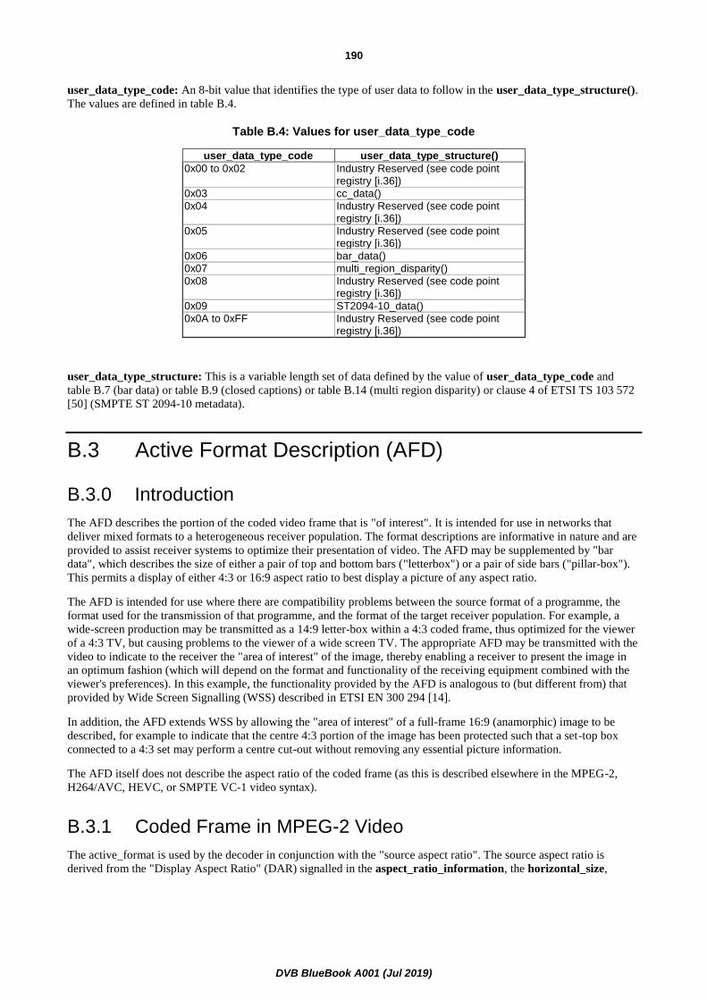
DVB BlueBook A001 (Jul 2019)
190
user_data_type_code: An 8-bit value that identifies the type of user data to follow in the user_data_type_structure().
The values are defined in table B.4.
Table B.4: Values for user_data_type_code
user_data_type_code user_data_type_structure()
0x00 to 0x02 Industry Reserved (see code point registry [i.36])
0x03 cc_data()
0x04 Industry Reserved (see code point registry [i.36])
0x05 Industry Reserved (see code point registry [i.36])
0x06 bar_data()
0x07 multi_region_disparity()
0x08 Industry Reserved (see code point registry [i.36])
0x09 ST2094-10_data()
0x0A to 0xFF Industry Reserved (see code point registry [i.36])
user_data_type_structure: This is a variable length set of data defined by the value of user_data_type_code and
table B.7 (bar data) or table B.9 (closed captions) or table B.14 (multi region disparity) or clause 4 of ETSI TS 103 572
[50] (SMPTE ST 2094-10 metadata).
B.3 Active Format Description (AFD)
B.3.0 Introduction
The AFD describes the portion of the coded video frame that is "of interest". It is intended for use in networks that
deliver mixed formats to a heterogeneous receiver population. The format descriptions are informative in nature and are
provided to assist receiver systems to optimize their presentation of video. The AFD may be supplemented by "bar
data", which describes the size of either a pair of top and bottom bars ("letterbox") or a pair of side bars ("pillar-box").
This permits a display of either 4:3 or 16:9 aspect ratio to best display a picture of any aspect ratio.
The AFD is intended for use where there are compatibility problems between the source format of a programme, the
format used for the transmission of that programme, and the format of the target receiver population. For example, a
wide-screen production may be transmitted as a 14:9 letter-box within a 4:3 coded frame, thus optimized for the viewer
of a 4:3 TV, but causing problems to the viewer of a wide screen TV. The appropriate AFD may be transmitted with the
video to indicate to the receiver the "area of interest" of the image, thereby enabling a receiver to present the image in
an optimum fashion (which will depend on the format and functionality of the receiving equipment combined with the
viewer's preferences). In this example, the functionality provided by the AFD is analogous to (but different from) that
provided by Wide Screen Signalling (WSS) described in ETSI EN 300 294 [14].
In addition, the AFD extends WSS by allowing the "area of interest" of a full-frame 16:9 (anamorphic) image to be
described, for example to indicate that the centre 4:3 portion of the image has been protected such that a set-top box
connected to a 4:3 set may perform a centre cut-out without removing any essential picture information.
The AFD itself does not describe the aspect ratio of the coded frame (as this is described elsewhere in the MPEG-2,
H264/AVC, HEVC, or SMPTE VC-1 video syntax).
B.3.1 Coded Frame in MPEG-2 Video
The active_format is used by the decoder in conjunction with the "source aspect ratio". The source aspect ratio is
derived from the "Display Aspect Ratio" (DAR) signalled in the aspect_ratio_information, the horizontal_size,
DVB BlueBook A001 (Jul 2019)
191
vertical_size, and display_horizontal_size and display_vertical_size if present (see Recommendation ITU-T H.262 /
ISO/IEC 13818-2 [2]):
• If sequence_display_extension() is not present:
source aspect ratio = DAR
• If sequence_display_extension() is present:
source aspect ratio = DAR
B.3.2 Coded Frame in H264/AVC Video
The active_format is used by the receiver in conjunction with picture size and shape information as indicated in the
"sequence parameter set RBSP" and the aspect_ratio_idc field of the "VUI parameters". In particular, the picture
width, picture height, frame cropping information, and sample aspect ratio are important for proper use of active_format
(see ISO/IEC 14496-10 [16]).
The combination of source aspect ratio and active_format allows the receiver to identify whether the "area of interest" is
the whole of the frame (e.g. source aspect ratio 16:9, active_format 16:9 center), a letterbox within the frame
(e.g. source aspect ratio 4:3, active_format 16:9 center), or a "pillar-box" within the frame (e.g. source aspect ratio 16:9,
active_format 4:3 center).
B.3.3 Coded Frame in VC-1 Video
The active_format is used by the decoder in conjunction with the sample aspect ratio signalled in a VC-1 elementary
stream by means of the ASPECT_RATIO field in the sequence header as defined in SMPTE ST 421 [20].
The combination of sample aspect ratio and active_format allows the decoder to identify whether the "area of interest"
is the whole of the frame (e.g. source aspect ratio 16:9, active_format 16:9 centre), a letterbox within the frame
(e.g. source aspect ratio 4:3, active_format 16:9 centre), or a "pillar-box" within the frame (e.g. source aspect ratio 16:9,
active_format 4:3 centre).
B.3.4 Common Semantics of AFD
The combination of source aspect ratio and active_format allows the decoder to identify whether the "area of interest" is
the whole of the frame (e.g. source aspect ratio 16:9, active_format 16:9 centre), a letterbox within the frame
(e.g. source aspect ratio 4:3, active_format 16:9 centre), or a "pillar-box" (see note) within the frame (e.g. source aspect
ratio 16:9, active_format 4:3 centre).
NOTE: "Pillar-box" describes a frame that the image fails to fill horizontally, in the same way that a "Letterbox"
describes a frame that the image fails to fill vertically.
_sizehorizontal
izevertical_s
ertical_sizdisplay_ve
izerizontal_sdisplay_ho

DVB BlueBook A001 (Jul 2019)
192
Table B.5: Active_format
Active_format Aspect ratio of the "area of interest"
0000 AFD unknown (see below)
0001 Reserved
0010 box 16:9 (top)
0011 box 14:9 (top)
0100 box > 16:9 (centre)
0101 to 0111 Reserved
1000 Active format is the same as the coded frame
1001 4:3 (centre)
1010 16:9 (centre)
1011 14:9 (centre)
1100 Reserved
1101 4:3 (with shoot and protect 14:9 centre)
1110 16:9 (with shoot and protect 14:9 centre)
1111 16:9 (with shoot and protect 4:3 centre)
AFD 0000 indicates that information is not available and is undefined. Unless bar data is available, receivers and video
equipment should interpret the active format as being the same as the coded frame. AFD "0000", when accompanied by
bar data, signals that the image's aspect ratio is narrower than 16:9, but is not either 4:3 or 14:9. The bar data should be
used to determine the extent of the image.
AFD "0100", which should be accompanied by bar data, signals that the image's aspect ratio is wider than 16:9, as is
typically the case with widescreen features. The bar data should be used to determine the height of the image.
The complete set of Active Formats described in the present document is illustrated in table B.6. Note that for each
format two example illustrations have been given, corresponding to the source aspect ratio of the coded frame being 4:3
and 16:9. The AFD may also be used with coded frames of other aspect ratios. For example a coded frame of 2.21:1
with active_format 10 would represent a 16:9 image centred (pillar-box) within a 2.21:1 frame.
The Active Formats are illustrated using the following diagrammatic representation.
Figure B.1
Table B.6: Active Formats Illustrated
Active_format Illustration of described format
Value Description In 4:3 coded frame In 16:9 coded frame
0000 to 0001 reserved
Bounding box represents
the coded frame
The smallest rectangle enclosing the white regions indicates the area of essential
picture information which should always be displayed by all receivers
Grey regions that lie outside the smallest rectangle enclosing the white regions indicate areas of the picture that may be cropped by the receiver
without significant loss to the viewer
Black regions indicate areas of the picture that do not
contain useful information and should be cropped by
the receiver where appropriate

DVB BlueBook A001 (Jul 2019)
193
Active_format Illustration of described format
Value Description In 4:3 coded frame In 16:9 coded frame
0010 box 16:9 (top)
0011 box 14:9 (top)
0100 box > 16:9 (centre)
0101 to 0111 reserved
1000 As the coded frame
1001 4:3 (centre)
(see note)
1010 16:9 (centre)
1011 14:9 (centre)
1100 reserved
1101 4:3
(with shoot and protect 14:9 centre)
1
1110
16:9
(with shoot and protect 14:9 centre)
1111 16:9
(with shoot and protect 4:3 centre)
NOTE: It is recommended to use the 4:3 coded frame mode to transmit 4:3 source material rather than using a pillar-box to transmit it in a 16:9 coded frame. This allows for higher horizontal resolution on both 4:3 and 16:9 sets.

DVB BlueBook A001 (Jul 2019)
194
B.3.5 Relationship with Pan Vectors
Encoding: Encoded bitstreams may optionally include pan vectors and AFDs.
Decoding: The decoder may use the AFD as part of the logic that decides how the IRD processes and
positions the reconstructed image for display on a monitor, where the monitor aspect ratio does not
match the source aspect ratio (e.g. whether to use pan vectors, or generate a letterbox display).
B.3.6 Coded Frame in HEVC Video
The active_format is used by the receiver in conjunction with picture size and shape information as indicated in the
"sequence parameter set RBSP" and the aspect_ratio_idc field of the "VUI parameters". In particular, the picture
width, picture height, frame cropping information, and sample aspect ratio are important for proper use of active_format
(see Recommendation ITU-R H.265 / ISO/IEC 23008-2 [35]).
The combination of the aspect ratio of the coded frame and active_format allows the receiver to identify whether the
"area of interest" is the whole of the frame (e.g. aspect ratio 16:9, active_format 16:9 center), or a "pillar box" within
the frame (e.g. aspect ratio 16:9, active_format 4:3 center).
B.4 Bar data
B.4.0 Syntax and semantics
Table B.7 describes the syntax of bar data. Bar data should be included in video user data whenever the rectangular
picture area containing useful information does not extend to the full height or width of the coded frame and AFD alone
is insufficient to describe the extent of the image. See clause B.3.4.
NOTE 1: Bar data is intended to facilitate a fixed-pixel display's picture optimization. Images are not expected to
be resized or scaled, rather to permit backlights to be turned off in the signalled bar. Please consult
SMPTE ST 2016-1 and clause B.4.2 for additional information.
NOTE 2: In the case of HEVC coded video, certain "decimated" sub-rasters are documented in clauses 5.14.2.2 and
5.14.3.2 which decimate the production image in both horizontal and vertical axes to help with bitrate
efficiency. As AFD/Bar Data might not work properly in combination with such sub-rasters, the HEVC
Default Display Window documented in clause 5.14.1.5.6 can be used as an alternative.
Bar data is constrained (below) to be signalled in pairs, either top and bottom bars or left and right bars, but not both
pairs at once. Bars may be unequal in size. One bar of a pair may be zero width or height.

DVB BlueBook A001 (Jul 2019)
195
Table B.7: Bar Data Syntax
Syntax No. of Bits Identifier
bar_data() {
top_bar_flag 1 bslbf
bottom_bar_flag 1 bslbf
left_bar_flag 1 bslbf
right_bar_flag 1 bslbf
reserved (set to "1111") 4 bslbf
if (top_bar_flag == "1") {
marker_bits (set to "11") 2 bslbf
line_number_end_of_top_bar 14 uimsbf
}
if (bottom_bar_flag == "1") {
marker_bits (set to "11") 2 bslbf
line_number_start_of_bottom_bar 14 uimsbf
}
if (left_bar_flag == "1") {
marker_bits (set to "11") 2 bslbf
pixel_number_end_of_left_bar 14 uimsbf
}
if (right_bar_flag == "1") {
marker_bits (set to "11") 2 bslbf
pixel_number_start_of_right_bar 14 uimsbf
}
}
Designation of line numbers for line_number_end_of_top_bar and line_number_start_of_bottom_bar is video
format-dependent and shall conform to the applicable standard indicated in table B.8.
NOTE 3: The range of line numbers and pixels within the coded frame for each image format is specified in table 2
of SMPTE ST 2016-1:2009 [23].
Table B.8: Line Number Designation
Video Format Applicable Standard
480 Interlaced 4:3 SMPTE ST 125 [i.8]
480 Interlaced 16:9 SMPTE ST 267 [i.10]
480 Progressive SMPTE ST 293 [i.12]
720 Progressive SMPTE ST 296 [i.13]
1 080 Interlaced SMPTE ST 274 [i.11]
1 080 Progressive SMPTE ST 274 [i.11]
top_bar_flag: This flag shall indicate, when set to "1", that the top bar data is present. If left_bar_flag is "1", this flag
shall be set to "0".
bottom_bar_flag: This flag shall indicate, when set to "1", that the bottom bar data is present. This flag shall have the
same value as top_bar_flag.
left_bar_flag: This flag shall indicate, when set to "1", that the left bar data is present. If top_bar_flag is "1", this flag
shall be set to "0".
right_bar_flag: This flag shall indicate, when set to "1", that the right bar data is present. This flag shall have the
same value as left_bar_flag.
line_number_end_of_top_bar: A 14-bit unsigned integer value representing the last line of a horizontal letterbox bar
area at the top of the reconstructed frame. Designation of line numbers shall be as defined per each applicable standard
in table B.8.
line_number_start_of_bottom_bar: A 14-bit unsigned integer value representing the first [i.12] line of a horizontal
letterbox bar area at the bottom of the reconstructed frame. Designation of line numbers shall be as defined per each
applicable standard in table B.8.
DVB BlueBook A001 (Jul 2019)
196
pixel_number_end_of_left_bar: A 14-bit unsigned integer value representing the last horizontal luminance sample of
a vertical pillar-box bar area at the left side of the reconstructed frame. Pixels shall be numbered from zero, starting
with the leftmost pixel.
pixel_number_start_of_right_bar: A 14-bit unsigned integer value representing the first horizontal luminance sample
of a vertical pillar-box bar area at the right side of the reconstructed frame. Pixels shall be numbered from zero, starting
with the leftmost pixel.
additional_bar_data: Reserved for future DVB definition.
B.4.1 Recommended Receiver Response to Bar Data
Receiving device designers are strongly encouraged to study Consumer Electronics Association (CEA) bulletin CTA
CEB16-B [24], which contains recommendations regarding the processing of bar data.
B.4.2 Relationship Between Bar Data and AFD
Certain combination of Active Format Description and bar data may be present in video user data (either, neither, or
both). Please consult clause 5 of SMPTE ST 2016-1 [23] for detailed guidance on this subject. Note that AFD data may
not always exactly match bar data because AFD primarily deals with 4:3, 14:9, and 16:9 aspect ratios while bar data can
represent nearly any aspect ratio.
NOTE: SMPTE ST 2016-1 [23] provides guidance for signaling aspect ratios other than 4:3, 14:9, and 16:9. In
part it says "AFD '0000', when accompanied by Bar Data, signals that the active image's aspect ratio is
narrower than 16:9, but is not 4:3 or 14:9. … AFD code '0100' signals that the active image aspect ratio
is wider than 16:9." Content producers are expected to correctly code AFD/bar data with their source
video images.
B.5 Closed Captions
B.5.0 Introduction
The caption data, (as well as AFD and bar data) is carried in the user data of the video elementary stream.
The underlying structure, cc_data(), is common across MPEG-2, H.264/AVC, HEVC and VC-1.
B.5.1 Syntax and Semantics of cc_data()
The syntax for cc_data() is shown in table B.9.

DVB BlueBook A001 (Jul 2019)
197
Table B.9: cc_data Syntax
Syntax No. of Bits Identifier
cc_data() {
reserved (set to "1") 1 bslbf
process_cc_data_flag 1 bslbf
zero_bit (set to "0") 1 bslbf
cc_count 5 uimsbf
reserved (set to "1111 1111") 8 bslbf
for ( i=0 ; i < cc_count ; i++ ) {
one_bit (set to "1") 1
reserved (set to "1111") 4
cc_valid 1 bslbf
cc_type 2 bslbf
cc_data_1 8 bslbf
cc_data_2 8 bslbf
}
marker_bits = "11111111" 8 bslbf
}
process_cc_data_flag: This flag is set to indicate whether it is necessary to process the cc_data. If it is set to "1", the
cc_data shall be parsed and its meaning processed. When it is set to "0", the cc_data shall be discarded.
zero_bit: This bit shall be "0" to maintain backwards compatibility with previous versions of CEA-708-E [26].
cc_count: This 5-bit integer indicates the number of closed caption constructs following this field. It can have values 0
through 31. The value of cc_count shall be set according to the frame rate and coded picture structure (field or frame)
such that a fixed bandwidth of 9 600 bits per second is maintained for the closed caption payload data. Sixteen (16) bits
of closed caption payload data are carried in each pair of the fields cc_data_1 and cc_data_2.
one_bit: This bit shall be "1" to maintain backwards compatibility with previous versions of CEA-708-E [26].
cc_valid: This flag is set to "1" to indicate that the two closed caption data bytes that follow are valid. If set to "0" the
two data bytes are invalid, as defined in CEA-708-E [26].
cc_type: Denotes the type of the two closed caption data bytes that follow, as defined in CEA-708-E [26].
cc_data_1: The first byte of a closed caption data pair as defined in CEA-708-E [26].
cc_data_2: The second byte of a closed caption data pair as defined in CEA-708-E [26].
B.6 Auxiliary Data and MPEG-2 video
B.6.1 Coding
The Auxiliary Data (AFD, bar data, and caption data) is carried in the video elementary stream at the picture level as
shown in table B.10. The repetition rate of the Auxiliary Data depends upon its payload.
When present, caption data shall be carried in the data structure cc_data(), within the picture user data syntax as
shown in table B.9, and shall be present for every picture. Receivers may ignore caption data.
When present, bar data shall be carried in the data structure bar_data(), within the picture user data syntax as shown
in table B.7. After any sequence_header() such bar data shall appear before the next picture_data() within
extension_and_user_data(2). After introduction, such bar data shall remain in effect until:
1) the next sequence_header(); or
2) extension_and_user_data(2) containing a bar_data() structure which contains new bar data; or

DVB BlueBook A001 (Jul 2019)
198
3) extension_and_user_data(2) containing AFD per clause B.3.4.
After any sequence_header(), unless AFD data is present specifying otherwise, the absence of bar data shall indicate
that the rectangular picture area containing useful information extends to the full height and width of the coded frame.
B.6.2 Syntax and Semantics
Table B.10 is provided to show the syntax that is required for picture extension and user data (specifically
extension_and_user_data(2)) as defined by MPEG-2 video (ISO/IEC 13818-2 [2]).
Table B.10: Auxiliary Data for MPEG-2 video
Syntax No. of Bits Identifier
user_data() {
user_data_start_code 32 bslbf
user_identifier 32 bslbf
user_structure()
}
In accordance with the bit stream syntax in table B.10, more than one picture user data construct may follow any given
picture header. However, no more than one picture user data construct using the same user_identifier or
user_data_type_code shall follow any given picture header.
Receiving devices are expected to silently discard any unrecognized video user data encountered in the video bit stream.
For example, if an unrecognized 32-bit identifier is seen following the user_data_start_code, or an unrecognized 8-bit
user_data_type_code is seen following the DVB_identifier, data should be discarded until another start code is seen.
user_data_start_code: This shall be set to 0x0000 01B2 per ISO/IEC 13818-2 [2].
user_identifier: This is a 32 bit code that indicates the contents of the user_structure() as indicated in table B.1.
user_structure(): This is a variable length data structure defined by the value of user_identifier and table B.1.
B.7 Auxiliary Data and H264/AVC, MVC Stereo or SVC video
B.7.1 Coding
The Auxiliary Data is carried in the data as Supplemental Enhancement Information in H.264/AVC's "User data
registered by Recommendation ITU-T T.35 [19] SEI message" syntactic element (see clauses D.8.5 and D.9.5 of
ISO/IEC 14496-10 [16]).
Encoding: Support for the encoding of Auxiliary Data is optional.
Decoding: Support for the decoding of Auxiliary Data is optional.
B.7.2 Syntax and Semantics
The Auxiliary Data (AFD, bar data, caption data and multi_region_disparity) is carried in the video elementary stream
as Supplemental Enhancement Information in H.264/AVC's "User data registered by Recommendation ITU-T T.35
SEI message" syntactic element [19]. The syntax of Auxiliary Data is illustrated in table B.11.

DVB BlueBook A001 (Jul 2019)
199
Table B.11: Active Format Description for H264/AVC video
user_data_registered_itu_t_t35(payloadSize) { Descriptor Notes
itu_t_t35_country_code b(8) 0xB5
Itu_t_t35_provider_code u(16) 0x0031
user_identifier f(32)
user_structure()
}
itu_t_t35_country_code: This 8 bit field shall have the value 0xB5.
itu_t_t35_provider_code: This 16 bit field shall have the value 0x0031.
user_identifier: This is a 32 bit code that indicates the contents of the user_structure() as indicated in table B.1.
NOTE: In MPEG-2, the only discriminator within user_data is this 32-bit value. In the context of H.264/AVC,
the value of user_identifier is used in addition to country and provider codes to definitively identify this
as Auxiliary Data.
user_structure(): This is a variable length data structure defined by the value of user_identifier and table B.1.
B.7.3 Auxiliary Data in MVC Stereo HDTV Bitstreams
When present in MVC Stereo HDTV Bitstreams, the active format descriptor, bar data and closed caption data shall be
the same for both base and dependent view bitstreams and may be transmitted in the MVC Stereo Base view bitstream.
When present in MVC Stereo HDTV Bitstreams, the multi_region_disparity() data shall be sent in the
user_data_registered_itu_t_t35() SEI message, which is contained in MVC scalable nesting SEI message of every MVC
Stereo Dependent view component. When present in MVC Stereo HDTV Bitstreams, the multi region disparity data
shall be present for every MVC Stereo Dependent view component.
B.8 Auxiliary Data and VC-1 video
B.8.1 Coding
The Auxiliary Data is carried in the user data of the video elementary stream as defined in SMPTE ST 421 [20]. After
each sequence start (and repeat sequence start) the default aspect ratio of the area of interest is that signalled by the
sequence header and sequence display extension parameters. When present, after introduction, an AFD or bar data
persists until the next sequence start or until another AFD or different bar data is introduced.
Encoding: Support for the encoding of Auxiliary Data is optional.
The Auxiliary Data may be inserted in the video elementary stream as sequence level, entry-point
level or frame level user data as specified in SMPTE ST 421 [20]. For example, it could be
inserted once per sequence, once per entry-point, or once per frame. It may be changed for each
frame. Caption data, when present, shall be inserted once per frame.
After introduction, such an AFD remains in effect until the next sequence start or until a new AFD is introduced.
Decoding: Support for the decoding of Auxiliary Data is optional.
A decoder that supports the decoding of Auxiliary Data shall be capable of decoding it from the
sequence level, entry-point level and frame level locations specified in SMPTE ST 421 [20].

DVB BlueBook A001 (Jul 2019)
200
B.8.2 Syntax and Semantics
The Auxiliary Data is carried in the user data of the video elementary stream as defined in SMPTE ST 421 [20]. The
syntax is illustrated in table B.12.
Table B.12: Auxiliary Data for VC-1 video
Syntax No. of Bits Identifier
user_data() {
VC1_user_data_start_code 32 bslbf
user_identifier 32 bslbf
user_structure()
}
VC1_user_data_start_code: This 32-bit field shall be set to 0x0000011D to indicate the beginning of a user data
structure in the VC-1 elementary stream.
user_identifier: This is a 32 bit code that indicates the contents of the user_structure() as indicated in table B.1.
user_structure(): This is a variable length data structure defined by the value of user_identifier and table B.1.
B.8a Auxiliary Data and HEVC video
B.8a.1 Coding
The Auxiliary Data is carried in the data as Supplemental Enhancement Information in HEVC's "User data registered by
Recommendation ITU-T T.35 [19] SEI message" syntactic element (see clauses D.2.6 and D.3.6 of Recommendation
ITU-T H.265 / ISO/IEC 23008-2 [35]).
Encoding: Support for the encoding of Auxiliary Data is optional.
When the "User data registered by Recommendation ITU-T T.35 [19] SEI message" is present in
an HEVC Bitstream, it shall be a prefix SEI message (i.e. nal_unit_type shall be equal to
PREFIX_SEI_NUT).
Decoding: Support for the decoding of Auxiliary Data is optional.
B.8a.2 Syntax and Semantics
The Auxiliary Data (AFD, bar data, caption data and multi_region_disparity) is carried in the video elementary stream
as Supplemental Enhancement Information in HEVC's "User data registered by Recommendation ITU-T T.35 SEI
message" syntactic element [19] which shall be the same as for H.264/AVC. See clause B.7.2 for the syntax and
semantics.

DVB BlueBook A001 (Jul 2019)
201
B.9 Relationship with Wide Screen Signalling (WSS)
The AFD and bar data provide a super-set of the aspect ratio signalling specified in ETSI EN 300 294 [14]. The
mapping of source aspect ratio and active_format to WSS Aspect Ratio is given in table B.13.
Table B.13: Support for WSS
Sequence Header
Active Format Description
WSS
Source aspect ratio
Value Code (Bits 0-3)
Description
1001 0001 full format 4:3
1011 1000 box 14:9 Centre
0011 0100 box 14:9 Top
4:3 1010 1101 box 16:9 Centre
0010 0010 box 16:9 Top
0100 1011 box > 16:9 Centre
1101 0111 full format 4:3 (shoot and protect 14:9 Centre)
16:9 1010 1110 full format 16:9 (anamorphic)
As all-digital systems are constructed, there may remain legacy (or even regulatory) requirements to provide WSS
support at some IRD outputs. It is recommended that transmission systems make use of SMPTE ST 2016-1:2009 [23]
for signalling AFD and bar data in the incoming video, and that IRDs provide support for this on digital outputs.
Encoding: Incoming aspect ratio signalling (whether originating via WSS or AFD) should be placed in the
video elementary stream per the present document. If desired, the encoder may also carry
equivalent WSS data per ETSI EN 300 294 [14] in a separate PID.
Decoding: IRDs shall pass AFD and bar data values to their digital video outputs. Such values may be
translated, per table B.13 into analogue WSS waveforms for appropriate placement on analogue
outputs.
B.10 Aspect Ratio Ranges
The labels 4:3, 14:9, 16:9 and > 16:9 used in the AFD shall correspond to the aspect ratio ranges specified in
ETSI EN 300 294 [14] (note that the corresponding active lines specified in ETSI EN 300 294 [14] do not, in general,
apply).
B.11 Multi Region Disparity
B.11.0 Introduction
This clause describes how to convey depth information in the form of disparity values so as to enable the overlay of
additional information (graphics, menus, etc.) such that a depth violation between the plano-stereoscopic video and
graphics is avoided.
For each frame, one maximum disparity value is transmitted. Regions are defined according to a set of predefined
image partitioning patterns. For each region of each frame, exactly one minimum disparity value is transmitted.
NOTE: The presence of multi region disparity information can be signalled using the video depth range
descriptor, as is specified in clause 6.4.16 of ETSI EN 300 468 [i.32].

DVB BlueBook A001 (Jul 2019)
202
B.11.1 Syntax and Semantics of Multi Region Disparity
The syntax for multi_region_disparity() is shown in table B.14.
Table B.14: Multi Region Disparity Syntax
Syntax No. of bits Identifier
multi_region_disparity() {
multi_region_disparity_length 8 uimsbf
if ( ((multi_region_disparity_length > 1) && (multi_region_disparity_length < 6)) || (multi_region_disparity_length == 10) || (multi_region_disparity_length == 17) )
{
number_of_regions = multi_region_disparity_length -1
max_disparity_in_picture 8 tcimsbf
for (i=0; i<number_of_regions, i++) {
min_disparity_in_region_i 8 tcimsbf
}
} else if (multi_region_disparity_length == 0) {
/* there is no disparity information to deliver */
} else {
for (i=0;i<N;i++) {
reserved_for_future_use 8 bslbf
}
}
}
multi_region_disparity_length: The multi_region_disparity_length is an 8-bit field specifying the number of bytes in
the multi_region_disparity() immediately following the byte defining the value of this field. Furthermore, it signals the
type of region pattern. The multi_region_disparity_length field has a limited set of values that correspond to predefined
image partitioning patterns specified below in table B.15, all other values are prohibited or reserved for future use.
Each image partitioning pattern defines several regions of the image. The boundaries between the regions shall be
located at one quarter, one half and three quarters of the coded image width and height before cropping (for example,
for images of size 1 920 × 1 080, the size 1 920 × 1 088 shall be used to determine the position of the boundaries in the
transmitted picture). The different region partitioning patterns are all based on these partition boundaries. Each region is
identified by a number increasing from left to right and from top to bottom.
Table B.15: Meaning of multi_region_disparity_length
Value Meaning of the value
0 no disparity information is to be delivered
1 Prohibited
2 one minimum_disparity_in_region is coded as representing the minimum value in overall picture (see figure B.3)
3 two vertical minimum_disparity_in_regions are coded (see figure B.4)
4 three vertical minimum_disparity_in_regions are coded (see figure B.5)
5 four minimum_disparity_in_regions are coded (see figure B.6)
6 to 9 reserved for future use
10 nine minimum_disparity_in_regions are coded (see figure B.7)
11 to 16 reserved for future use
17 sixteen minimum_disparity_in_regions are coded (see figure B.2)
18 to 255 reserved for future use
NOTE 1: Each region is made up to align to the 4 x 4 partition boundaries as shown in figure B.2. The patterns
defined in figures B.3 to B.7 are based on the pattern from figure B.2 by spatially combining some of the
regions.
NOTE 2: When multi_region_disparity_length is set to 0, the IRD is recommended to use a safer display method
while graphics are present, to avoid viewer's eye strain. One of the safer display methods is to switch
video to 2D, while graphics are overlaid onto the video with a slight disparity, which can retain a viewer's
3D experience.

DVB BlueBook A001 (Jul 2019)
203
NOTE 3: The value of multi_region_disparity_length should not be modified within an event, except to switch to
the value '0' on a frame-by-frame basis to indicate that no disparity value is signalled for a picture.
max_disparity_in_picture: this field specifies the maximum disparity value in a picture. The value signalled is a two's
complement integer in the range [-128, +127].
min_disparity_in_region_i: this field specifies the minimum disparity value in region i. The value signalled is a two's
complement integer in the range [-128, +127]. The identifier i for each region depends on the value of
multi_region_disparity_length. Figures B.2 to B.7 show the regions and their associated number for each allowed
pattern.
The disparity value is the difference between the horizontal positions of a pixel representing the same point in space in
the right and left views. The difference is given in number of pixels relative to a screen with a horizontal size of
1 920 pixels. Particularly, if right position minus left position is a positive value, it refers to a point behind the display
screen, and if it is a negative value, it refers to a point in front of the display screen. Max (maximum) disparity gives the
farthest, while min (minimum) disparity gives the closest point in depth.
Figure B.2: Size and position of regions for multi_region_disparity_length = 17
NOTE: R0 spatially encompasses all the regions defined in figure B.2.
Figure B.3: Size and position of regions for multi_region_disparity_length = 2
region 0[R0]
region 1[R1]
region 2[R2]
region 3[R3]
region 4[R4]
region 5[R5]
region 6[R6]
region 7[R7]
region 8[R8]
region 9[R9]
region 10[R10]
region 11[R11]
region 12[R12]
region 13[R13]
region 14[R14]
region 15[R15]
region 0[R0]

DVB BlueBook A001 (Jul 2019)
204
NOTE: R0 spatially encompasses the regions R0 to R7 defined in figure B.2 and R1 spatially encompasses the regions R8 to R15 defined in figure B.2.
Figure B.4: Size and position of regions for multi_region_disparity_length = 3
NOTE: R0 spatially encompasses the regions R0 to R3 defined in figure B.2, R1 spatially encompasses the regions R4 to R11 defined in figure B.2 and R2 spatially encompasses the regions R12 to R15 defined in figure B.2.
Figure B.5: Size and position of regions for multi_region_disparity_length = 4
region 0[R0]
region 1[R1]
region 0[R0]
region 1[R1]
region 2[R2]

DVB BlueBook A001 (Jul 2019)
205
NOTE: R0 spatially encompasses the regions R0, R1, R4, R5 defined in figure B.2, R1 spatially encompasses the regions R2, R3, R6, R7 defined in figure B.2, R2 spatially encompasses the regions R8, R9, R12, R13 defined in figure B.2 and R3 spatially encompasses the regions R10, R11, R14, R15 defined in figure B.2.
Figure B.6: Size and position of regions for multi_region_disparity_length = 5
NOTE: R0 is identical to the region R0 defined in figure B.2, R1 spatially encompasses the regions R1 and R2 defined in figure B.2, R2 is identical to the region R3 defined in figure B.2, R3 spatially encompasses the regions R4 and R8 defined in figure B.2, R4 spatially encompasses the regions R5, R6, R9, R10 defined in figure B.2, R5 spatially encompasses the regions R7 and R11 defined in figure B.2, R6 is identical to the region R12 defined in figure B.2, R7 spatially encompasses the regions R13 and R14 defined in figure B.2 and R8 is identical to the region R15 defined in figure B.2.
Figure B.7: Size and position of regions for multi_region_disparity_length = 10
region 0[R0]
region 1[R1]
region 2[R2]
region 3[R3]
region 0[R0]
region 1[R1]
region 2[R2]
region 3[R3]
region 4[R4]
region 5[R5]
region 6[R6]
region 7[R7]
region 8[R8]

DVB BlueBook A001 (Jul 2019)
206
Annex C (normative): Implementation of Ancillary Data for MPEG Audio
C.1 Scope
This annex contains the guidelines required to include ancillary data in the MPEG-1, MPEG-2 or MPEG-4 Audio
elementary stream.
The IRD design should be made under the assumption that any structure as permitted by this annex may occur in the
broadcast stream. The IRD is not required to make use of this data but its use is recommended.
C.2 Introduction
An MPEG-1/-2/-4 audio elementary stream provides for the inclusion of ancillary data. This data can be used to convey
specific information about the audio content to the decoder, allowing the broadcaster to control rendering of the content
to a greater extent. The data includes dynamic range control information and dialogue normalization information.
In case of MPEG-1 streams or MPEG-2 streams without an extension stream (MPEG audio format 1), ancillary data
described in this annex is placed at the end of each base frame.
In case of MPEG-2 streams with extension stream (MPEG audio format 2), the ancillary data described in this annex is
placed at the end of each base frame.
In case of MPEG-4 streams in LATM/LOAS format, the ancillary data described in this annex is placed into
data_stream_element() (see ISO/IEC 14496-3 [17], table 4.10).
C.3 DVB Compliance
The ancillary data format described in this annex does not introduce any additional elements to the DVB transport
stream. It is compliant with the present document and compatible with all MPEG-1/-2/-4 audio decoders.
Presence and type of ancillary data in audio elementary streams is signalled in DVB SI Program Map Table by the
ancillary data descriptor (see ETSI EN 300 468 [i.32], clause 6.2.2).
C.4 Detailed specification for MPEG1 and MPEG2
C.4.1 DVD-Video Ancillary Data
The transmission of "dynamic_range_control" in MPEG1 Layer I/II and MPEG2 Layer I audio is optional. If applied,
16 bits of ancillary data [b15.b0] (situated at the end of each MPEG audio base frame) shall be used.
Table C.1: DVD-Video ancillary data syntax
Syntax No. of Bits Mnemonic
dvd_ancillary_data( ) {
dynamic_range_control 8 bslbf
dynamic_range_control_on 1 bslbf
reserved (set to "000 0000b") 7 bslbf
}
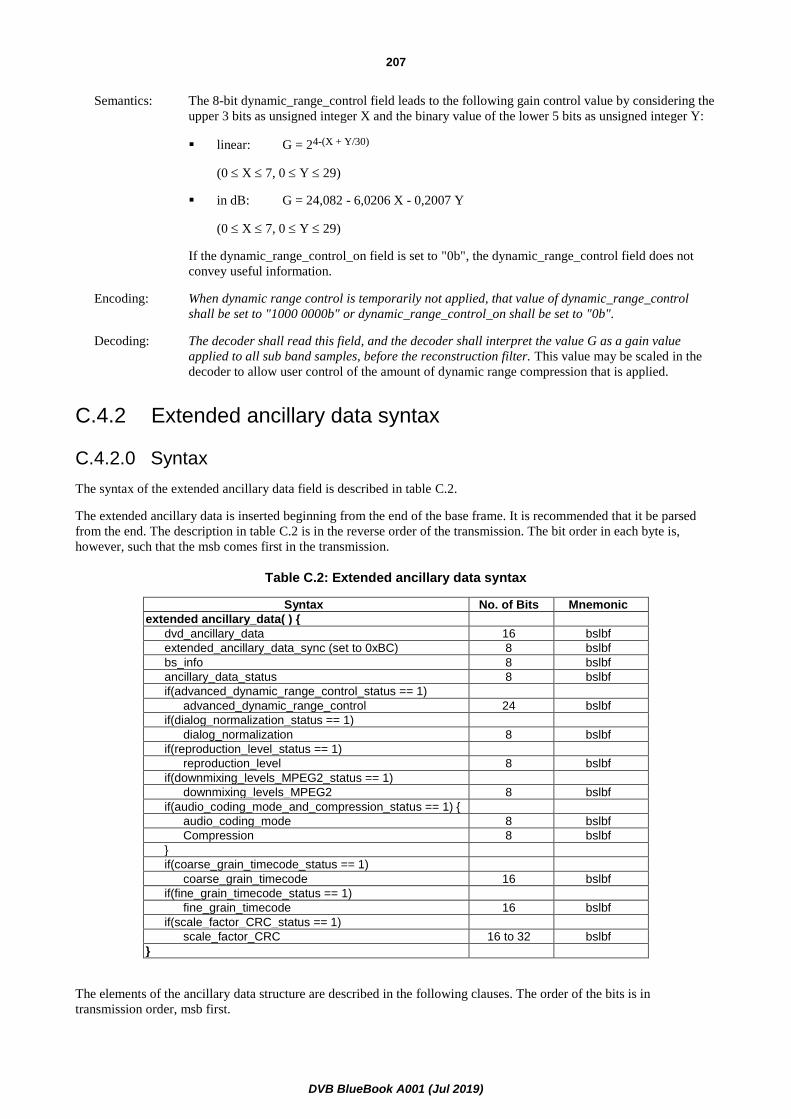
DVB BlueBook A001 (Jul 2019)
207
Semantics: The 8-bit dynamic_range_control field leads to the following gain control value by considering the
upper 3 bits as unsigned integer X and the binary value of the lower 5 bits as unsigned integer Y:
▪ linear: G = 24-(X + Y/30)
(0 X 7, 0 Y 29)
▪ in dB: G = 24,082 - 6,0206 X - 0,2007 Y
(0 X 7, 0 Y 29)
If the dynamic_range_control_on field is set to "0b", the dynamic_range_control field does not
convey useful information.
Encoding: When dynamic range control is temporarily not applied, that value of dynamic_range_control
shall be set to "1000 0000b" or dynamic_range_control_on shall be set to "0b".
Decoding: The decoder shall read this field, and the decoder shall interpret the value G as a gain value
applied to all sub band samples, before the reconstruction filter. This value may be scaled in the
decoder to allow user control of the amount of dynamic range compression that is applied.
C.4.2 Extended ancillary data syntax
C.4.2.0 Syntax
The syntax of the extended ancillary data field is described in table C.2.
The extended ancillary data is inserted beginning from the end of the base frame. It is recommended that it be parsed
from the end. The description in table C.2 is in the reverse order of the transmission. The bit order in each byte is,
however, such that the msb comes first in the transmission.
Table C.2: Extended ancillary data syntax
Syntax No. of Bits Mnemonic
extended ancillary_data( ) {
dvd_ancillary_data 16 bslbf
extended_ancillary_data_sync (set to 0xBC) 8 bslbf
bs_info 8 bslbf
ancillary_data_status 8 bslbf
if(advanced_dynamic_range_control_status == 1)
advanced_dynamic_range_control 24 bslbf
if(dialog_normalization_status == 1)
dialog_normalization 8 bslbf
if(reproduction_level_status == 1)
reproduction_level 8 bslbf
if(downmixing_levels_MPEG2_status == 1)
downmixing_levels_MPEG2 8 bslbf
if(audio_coding_mode_and_compression_status == 1) {
audio_coding_mode 8 bslbf
Compression 8 bslbf
}
if(coarse_grain_timecode_status == 1)
coarse_grain_timecode 16 bslbf
if(fine_grain_timecode_status == 1)
fine_grain_timecode 16 bslbf
if(scale_factor_CRC_status == 1)
scale_factor_CRC 16 to 32 bslbf
}
The elements of the ancillary data structure are described in the following clauses. The order of the bits is in
transmission order, msb first.

DVB BlueBook A001 (Jul 2019)
208
C.4.2.1 ancillary_data_sync
Encoding: This field shall be set to 0xBC.
Decoding: The decoder may use this field to verify the availability of the extended ancillary data. If the IRD
indicates that this information is present, this takes precedence.
C.4.2.2 bs_info
The detailed syntax is described in table C.3.
Table C.3: Bs_info syntax
Syntax No. of Bits Mnemonic
bs_info( ) {
mpeg_audio_type 2 bslbf
dolby_surround_mode 2 bslbf
ancillary_data_bytes 4 uimsbf
}
C.4.2.3 mpeg_audio_type
Table C.4: MPEG audio type Table
mpeg_audio_type Description
"00" Reserved
"01" Only MPEG1 audio data
"10" MPEG2 audio data
"11" Reserved
Decoding: The decoder may ignore this field.
C.4.2.4 dolby_surround_mode
Table C.5: Dolby surround mode Table
mpeg_audio_type Description
"00" Reserved
"01" MPEG1 part is not Dolby surround encoded
"10" MPEG1 part is Dolby surround encoded
"11" Reserved
Decoding: It is recommended that the decoder parse this field and provides this information to the
reproduction set-up.
C.4.2.5 ancillary_data_bytes
This field indicates the amount of ancillary data bytes that precede this byte in the transmission. This field may be used
by the decoder as an indication of how many bytes it needs to buffer.

DVB BlueBook A001 (Jul 2019)
209
C.4.2.6 ancillary_data_status
The detailed syntax is described on table C.6.
Table C.6: Ancillary_data_status syntax
Syntax No. of Bits Mnemonic
ancillary_data_status( ) {
advanced_dynamic_range_control_status 1 bslbf
dialog_normalization_status 1 bslbf
reproduction_level_status 1 bslbf
downmix_levels_MPEG2_status 1 bslbf
scale_factor_CRC_status 1 bslbf
audio_coding_mode_and_compression status 1 bslbf
coarse_grain_timecode_status 1 bslbf
fine_grain_timecode_status 1 bslbf
}
Semantics: The bits in this field indicate the presence of the associated fields in the ancillary data.
Encoding: A bit in this field shall be set to "1" if the associated field is present in the bitstream.
Decoding: It is recommended that the decoder parse this field to allow parsing of the following fields in the
ancillary data section.
C.4.2.7 advanced_dynamic_range_control
The detailed syntax is described on table C.7.
Table C.7: Advanced_dynamic_range_control syntax
Syntax No. of Bits Mnemonic
advanced_dynamic_range_control( ) {
advanced_drc_part_0 8 bslbf
advanced_drc_part_1 8 bslbf
advanced_drc_part_2 8 bslbf
}
Semantics: Each field consists of an unsigned integer value X in the three most significant bits and an
unsigned integer value Y in the five less significant bits. The actual value is
24,082 - 6,0206 X - 0,2007 Y dB. The 1 152 samples of an MPEG2 frame are divided in 3 parts of
384 samples. The advanced_drc values are applicable for the corresponding part of the audio
frame.
Decoding: If this field is present and the decoder supports this type of dynamic range control, these values
shall be used rather than the DVD-Video ancillary data. The decoder shall apply these values to
the sub band samples, before the reconstruction filter. These values may be scaled in the decoder
to allow user control of the amount of dynamic range compression that is applied.

DVB BlueBook A001 (Jul 2019)
210
C.4.2.8 dialog_normalization
C.4.2.8.0 Syntax
The detailed syntax is described on table C.8.
Table C.8: Dialog_normalization syntax
Syntax No. of Bits Mnemonic
dialog_normalization( ) {
dialog_normalization_on 2 bslbf
dialog_normalization_value 6 uimsbf
}
C.4.2.8.1 dialog_normalization_on
Table C.9: Dialog normalization Table
dialog_normalization_on Description
"00" dialog_normalization_value is not valid
"01" reserved
"10" dialog_normalization_value is valid
"11" Reserved
C.4.2.8.2 dialog_normalization_value
Semantics: This field represents the headroom in dB of the dialogue component in the MPEG1 compatible
part, relative to full-scale sine wave. Values 41 through 63 are reserved. When dialogue
normalization is temporarily not applied, "Dialogue_Normalization_on" shall be set to "00" and
"Dialog_Normalization_value" shall be set to "000000".
Decoding: It is recommended that the decoder parse this field. The decoder should apply these values to the
sub band samples, before the reconstruction filter, in order to allow reproduction of different
programmes with the same dialogue level.
C.4.2.9 reproduction_level
C.4.2.9.0 Syntax
The detailed syntax is described on table C.10.
Table C.10: Reproduction_level syntax
Syntax No. of Bits Mnemonic
reproduction_level ( ) {
Surround_reproduction_level 1 bslbf
production_roomtype 2 bslbf
reproduction_level_value 5 uimsbf
}

DVB BlueBook A001 (Jul 2019)
211
C.4.2.9.1 surround_reproduction_level
Table C.11: Surround reproduction level Table
surround_reproduction_level Description
"0" The surround channels have the correct level for reproduction
"1" The surround channels should be attenuated by 3 dB during reproduction
Decoding: It is recommended that the decoder parse this filed and pass the value to the reproduction unit to
allow correct adjustment of the surround levels.
C.4.2.9.2 production_roomtype
Table C.12: Production room type Table
production_roomtype Description
"00" not indicated
"01" large room
"10" small room
"11" reserved
Decoding: It is recommended that the decoder parse this field and pass the value to the reproduction unit to
allow correct adjustment of the monitoring equipment.
C.4.2.9.3 reproduction_level_value
Semantics: This field represents the absolute acoustic sound pressure level in dB SPL during the final audio
mixing session.
Decoding: The decoder may ignore this field.
C.4.2.10 downmixing_levels_MPEG2
C.4.2.10.0 Syntax
The detailed syntax is described on table C.13. The down mixing levels describe the down mix in the decoder for stereo
reproduction.
Table C.13: Downmixing_levels_MPEG2 syntax
Syntax No. of Bits Mnemonic
downmixing_levels_MPEG2 ( ) {
center_mix_level_on 1 bslbf
center_mix_level_value 3 bslbf
Surround_mix_level_on 1 bslbf
Surround_mix_level_value 3 bslbf
}
C.4.2.10.1 center_mix_level_on
Semantics: If this field is set to "1" the center_mix_value field indicates nominal down mix level of the centre
channel with respect to the left and right front channels. If this field is set to "0" the
center_mix_value field shall be set to "000".
Decoding: It is recommended that the decoder parse this field.

DVB BlueBook A001 (Jul 2019)
212
C.4.2.10.2 surround_mix_level_on
Semantics: If this field is set to "1" the surround_mix_value field indicates nominal down mix level of the
surround channels with respect to the left and right front channels. If this field is set to "0" the
surround_mix_value field shall be set to "000".
Decoding: It is recommended that the decoder parse this field.
C.4.2.10.3 mix_level_value
Table C.14: Mix level value Table
mix_level_value Multiplication factor
"000" 1,000 (0,0 dB)
"001" 0,841 (-1,5 dB)
"010" 0,707 (-3,0 dB)
"011" 0,596 (-4,5 dB)
"100" 0,500 (-6,0 dB)
"101" 0,422 (-7,5 dB)
"110" 0,355 (-9,0 dB)
"111" 0,000 (- dB)
Decoding: The multi-channel decoder may apply these values as gain factors to the individual channels when
a down mix for stereo listening has to be created. The values need to be scaled to avoid overload
after the mixing process.
C.4.2.11 audio_coding_mode
C.4.2.11.0 Syntax
The detailed syntax is described in table C.15.
Table C.15: Audio coding mode syntax
Syntax No. of bits Mnemonic
audio_coding_mode ( ) {
MPEG2_extension_stream_present 1 bslbf
MPEG2_center 2 bslbf
MPEG2_surround 2 bslbf
MPEG2_lfeon 1 bslbf
MPEG2_copyright_ident_present 1 bslbf
compression_on 1 bslbf
}
Semantics: The semantics of the fields MPEG2_extension_stream_present, MPEG2_center,
MPEG2_surround and MPEG2_lfeon is as defined in the mc_header field in ISO/IEC 13818-3 [3].
If MPEG2_copyright_ident_present is set to "0" the copyright identification in the MPEG-2
mc_header is not filled in. If MPEG2_copyright_ident_present is set to "1" the copyright
identification in the MPEG-2 mc_header is used.
Decoding: The decoder may ignore this field. It may be parsed be multiplexers and bitstream monitors to
simplify extraction of these parameters from a bitstream.
C.4.2.11.1 compression_on
Semantics: If this field is set to "1" the compression_value field indicates the heavy compression factor used
for monophonic down mix reproduction. If this field is set to "0" the compression_value field shall
be "0000 0000".

DVB BlueBook A001 (Jul 2019)
213
Decoding: It is recommended that the decoder parse this field.
C.4.2.12 compression_value
Semantics: This field consists of a value X in the four most significant bits and a value Y in the four less
significant bits. The actual value is 48,164 - 6,0206 X - 0,4014 Y dB.
Decoding: These values shall be applied to the sub band samples, before the reconstruction filter when the
decoder has to create a mix for monophonic listening where overloading of a subsequent analog
transmission is highly undesirable.
C.4.2.13 coarse_grain_timecode
The detailed syntax is described on table C.16.
Table C.16: Coarse grain time code syntax
Syntax No. of Bits Mnemonic
coarse_grain_timecode ( ) {
coarse_grain_timecode_on 2 bslbf
coarse_grain_timecode_value 14 bslbf
}
Semantics: If coarse_grain_timecode_on is set to "10" the five most significant bits of this value represents the
time in hours, the next six bits represent time in minutes, and the final three bits represent the time
in eight second increments. If coarse_grain_timecode_on is not set to "10" all the bits of
coarse_grain_timecode_value shall be set to "0".
Decoding: The decoder may ignore this field.
C.4.2.14 fine_grain_timecode
The detailed syntax is described in table C.17.
Table C.17: Fine grain time code syntax
Syntax No. of Bits Mnemonic
fine_grain_timecode ( ) {
fine_grain_timecode_on 2 bslbf
fine_grain_timecode_value 14 bslbf
}
Semantics: If fine_grain_timecode_on is set to "10" the three most significant bits of this value represents the
time in seconds, the next five bits represent time in video frames, and the final six bits represent
the time in fractions of 1/64 of a video frame. If fine_grain_timecode_on is not set to "10" all the
bits of fine_grain_timecode_value shall be set to "0".
Decoding: The decoder may ignore this field.
C.4.2.15 scale_factor_CRC
Semantics: The scale_factor CRC permits to verify the integrity of the MPEG Audio scale factors. The coding
is according to Recommendation ITU-T T.35 [19].
Encoding: It recommended that scale_factor_CRC be included for mobile applications.
Decoding: It is recommended to parse the data from the end. The length of the field depends on the bitrate
index of the MPEG-1 header of the following frame. It is recommended to always parse the full 32
possible bits.

DVB BlueBook A001 (Jul 2019)
214
C.4.2.16 Void
C.4.2.17 Void
C.4.2.18 Void
C.4.3 Announcement Switching Data
The transmission of announcement switching data in the ancillary data field of MPEG audio frames is optional. The
syntax of the announcement switching data field is described in table C.18. Note that the description in table C.18 is in
the reverse order of the transmission. The bit order in each byte is, however, such that the msb comes first in the
transmission. The data field length gives the number of bytes following this byte within this data field.
Table C.18: Announcement switching data field
Syntax No. of Bits Mnemonic
announcement_switching_data( ) {
announcement_switching_data_sync 8 bslbf
data_field_length 8 bslbf
announcement_switching_flag_field_1 16 bslbf
announcement_switching_flag_field_2 16 bslbf
}
Semantics: The announcement_switching_data_sync should be set to 0 x AD.
The announcement_switching_flag_fields are 16-bit flag fields specifying which type of announcements are actually
running. The association between the bits of the flag field and the announcement types shall be according to the
announcement_support_indicator as specified in table C.18a. A bit shalFl be set to "1" if the announcement is running
and it shall be set to "0" if the announcement is not running.
Table C.18a: Coding of the announcement support indicator
Bit flag Description
b0 (see note) Emergency alarm
b1 Road Traffic flash
b2 Public Transport flash
b3 Warning message
b4 News flash
b5 Weather flash
b6 Event announcement
b7 Personal call
b8 to b15 Reserved for future use
NOTE: This bit is transmitted last.
The announcement_switching_flag_field_1 shall be used for announcements within the audio elementary stream that is
actually decoded.
The announcement_switching_flag_field_2 shall be used for announcements within other audio elementary streams.
Corresponding links shall be provided by means of the announcement_support_descriptor as specified in table C.18a.
Encoding: The announcement_switching_data_field is allowed to be embedded at the end of a MPEG audio
packet, between the end of the audio data and another data field that is part of the ancillary data
field or between two other data fields that are part of the ancillary data field.
If data fields according to DVD-Video, extended ancillary data or ancillary data according to the
DAB specification [18] are used, then the announcement_switching_data_field is not allowed to
be inserted at the end of an audio packet.

DVB BlueBook A001 (Jul 2019)
215
Decoding: It is recommended to parse the data from the end.
C.4.4 Scale Factor Error Check
The transmission of a scale factor error check in the ancillary data field of MPEG audio frames is optional. The syntax
of the corresponding data field is described in table C.19. Note that the description in table C.19 is in the reverse order
of the transmission. The bit order in each byte is, however, such that the msb comes first in the transmission. The
data_field_length gives the number of bytes following this byte within this data field.
Table C.19: Scale factor error check data field
Syntax No. of Bits Mnemonic
scale_factor_error_check_data( ) {
scale_factor_error_check data_sync 8 bslbf
data_field_length 8 bslbf
scale factor CRC 32 bslbf
}
Semantics: The scale_factor_error_check data_sync should be set to 0 x FE.
The scale_factor CRC permits to verify the integrity of the MPEG Audio scale factors.
Encoding: The scale_factor_error_check is allowed to be embedded at the end of a MPEG audio packet,
between the end of the audio packet and another data field that is part of the ancillary data field or
between two other data fields that are part of the ancillary data field.
If data fields according to DVD-Video extended ancillary data (as described in clause C.4.1) or ancillary data according
to the DAB specification ETSI EN 300 401 [18] are used, then the scale_factor_error_check_data_field is not allowed
to be inserted at the end of an audio packet.
Decoding: It is recommended to parse the data from the end.
C.4.5 RDS data via UECP protocol
The transmission of RDS data via the UECP protocol [22] in the ancillary data field of MPEG audio frames is optional.
The syntax of the UECP data field is described in table C.20. Note that the description in table C.20 is in the reverse
order of the transmission. The bit order in each byte is, however, such that the msb comes first in the transmission. The
data field length gives the number of bytes following this byte within this data field.
Table C.20: UECP data field
Syntax No. of Bits Mnemonic
UECP_data( ) {
UECP_data_sync 8 bslbf
data_field_length 8 bslbf
for (i=0; i<N; i++){
UECP_data_byte 8 uimsbf
}
}
Semantics: The UECP_data_sync should be set to 0xFD.
The bytes in the UECP_data_byte field shall be byte aligned with the UECP data bytes. There is
no need to align the UECP_data_byte field with the UECP frames. Consequently, one or more
complete UECP frames and/or only parts of UECP frames may be contained in one
UECP_data_byte field.
The length of the UECP_data_byte field can vary between consecutive audio packets.
Encoding: The encoding complies fully to the UECP specification [22].

DVB BlueBook A001 (Jul 2019)
216
The following addresses are assigned to DVB consumer receivers which are tuned to the indicated
programme. For dual mono, the Terminal Address allows to assign different RDS information to
the different audio channels.
NOTE: Within the DVB system the dual mono mode is generally deprecated. For legacy reasons, however, this
option has been kept for RDS transmission.
Table C.21
Site Address Terminal Address DVB consumer receiver
0 0 All
1008
0 Stereo
1 Dual Channel, ch. A
2 Dual Channel, ch. B
3 Single Channel (Mono)
4 to 63 Not yet assigned
For professional decoding equipment at FM transmitters the addresses are individually assigned.
Decoding: It is recommended to parse the data from the end.
C.5 Detailed specification for MPEG4 AAC, HE AAC and HE AAC v2 Audio
C.5.1 Transmission of MPEG4 Audio ancillary data
MPEG4 ancillary data as defined in this annex shall be placed into a single data_stream_element() as defined in
ISO/IEC 14496-3 [17], table 4.10.
The data_stream_element() <DSE> shall follow any combination of related <SCE>, <CPE>, <LFE>, and
<FIL <EXT-SBR_DATA>> audio elements, to which the ancillary data applies.
The element_instance_tag of this data_stream_element() shall have the same value as the element_instance_tag of the
first audio element to which the ancillary data applies.
Examples of possible streams are:
for a 2-channel program:
<CPE><DSE><FIL><TERM><CPE><DSE><FIL><TERM>…
for a 2-channel program with SBR:
<CPE><SBR(CPE)><DSE><FIL><TERM><CPE><SBR(CPE)><DSE><FIL><TERM>…
for a 5.1-channel program:
<SCE><CPE><CPE><LFE><DSE><FIL><TERM><SCE><CPE><CPE><LFE><DSE><FIL>
<TERM>…
For further reference see clauses 4.5.2.1.2 and 4.5.2.9.2 in ISO/IEC 14496-3 [17].

DVB BlueBook A001 (Jul 2019)
217
C.5.2 MPEG4 Audio ancillary data syntax
C.5.2.0 Syntax
The syntax of the ancillary data field is described in table C.22. Data are transmitted in the order as given in table C.22.
Table C.22: MPEG4 ancillary data syntax
Syntax No. of Bits Mnemonic
MPEG4 ancillary_data( ) {
ancillary_data_sync 8 bslbf
bs_info 8 bslbf
ancillary_data_status 8 bslbf
If (downmixing_levels_MPEG4_status == 1)
downmixing_levels_MPEG4 8 bslbf
If (audio_coding_mode_and_compression_status == 1) {
audio_coding_mode 8 bslbf
Compression_value 8 bslbf
}
if(coarse_grain_timecode_status == 1)
coarse_grain_timecode 16 bslbf
if(fine_grain_timecode_status == 1)
fine_grain_timecode 16 bslbf
}
C.5.2.1 ancillary_data_sync
Encoding: This field shall be set to 0xBC.
Decoding: The decoder may use this field to verify the availability of the MPEG4 Audio ancillary data.
C.5.2.2 bs_info
C.5.2.2.0 Syntax
The detailed syntax is described in table C.23.
Table C.23: bs_info syntax
Syntax No. of Bits Mnemonic
bs_info( ) {
mpeg_audio_type 2 bslbf
dolby_surround_mode 2 bslbf
drc_presentation_mode 2 bslbf
reserved, set to "00" 2 bslbf
}
C.5.2.2.1 mpeg_audio_type
Table C.24: MPEG audio type Table
mpeg_audio_type Description
"00" Reserved
"01" Reserved
"10" Reserved
"11" MPEG4 Audio data
Encoding: This field shall be set according to table C.24.

DVB BlueBook A001 (Jul 2019)
218
Decoding: The decoder may ignore this field.
C.5.2.2.2 dolby_surround_mode
Table C.25: Dolby surround mode Table
dolby_surround_mode Description
"00" Dolby surround mode not indicated
"01" 2-ch audio part is not Dolby surround encoded
"10" 2-ch audio part is Dolby surround encoded
"11" Reserved
Semantics: In case of 2-channel audio streams it can be indicated, whether the audio signal is encoded in
Dolby surround mode.
Encoding: This field may be provided by encoders when the audio stream is in 2-channel (stereo) format. It
shall be set to "00" for other than 2-channel audio streams.
Decoding: It is strongly recommended that the decoder parses this field and provides this information to the
reproduction set-up.
C.5.2.2.3 drc_presentation_mode
Table C.26: DRC presentation mode Table
drc_presentation_mode Description
"00" DRC presentation mode not indicated
"01" DRC presentation mode 1
"10" DRC presentation mode 2
"11" Reserved
Semantics: This field indicates whether ISO/IEC 14496-3 [17] or C.5.2.5 dynamic range control takes priority
on the outputs as defined in clause C.5.3.
To avoid disturbances in the audio output, it should not be changed within an elementary stream.
Encoding: This field may be provided by encoders. It shall be set to "00" if the DRC presentation mode is not
indicated.
Decoding: It is strongly recommended that the decoder parses this field and makes use of this information.
C.5.2.3 ancillary_data_status
The detailed syntax is described on table C.27.
Table C.27: Ancillary_data_status syntax
Syntax No. of Bits Mnemonic
ancillary_data_status( ) {
Reserved, set to "0" 1 bslbf
Reserved, set to "0" 1 bslbf
Reserved, set to "0" 1 bslbf
downmixing_levels_MPEG4_status 1 bslbf
Reserved, set to "0" 1 bslbf
audio_coding_mode_and_compression status 1 bslbf
coarse_grain_timecode_status 1 bslbf
fine_grain_timecode_status 1 bslbf
}
Semantics: The bits in this field indicate the presence of the associated fields in the ancillary data.

DVB BlueBook A001 (Jul 2019)
219
Encoding: A bit in this field shall be set to "1" if the associated field is present in the bitstream.
Decoding: It is strongly recommended that the decoder parse this field to allow parsing of the following fields
in the ancillary data section.
C.5.2.4 downmixing_levels_MPEG4
C.5.2.4.0 General
When multichannel audio streams are decoded by an IRD and only 2-channel audio output is required, then matrix mix
down shall be applied.
This part of the MPEG-4 ancillary data gives the possibility to transmit matrix mix down coefficients with higher
resolution than defined in ISO/IEC 14496-3 [17]. The detailed syntax is described in table C.28.
Table C.28: Downmixing_levels_MPEG4 syntax
Syntax No. of Bits Mnemonic
downmixing_levels_MPEG4 ( ) {
center_mix_level_on 1 bslbf
center_mix_level_value 3 bslbf
surround_mix_level_on 1 bslbf
surround_mix_level_value 3 bslbf
}
Encoding: It is strongly recommended that this matrix mix down information is supplied by the encoder and
both, center_mix_level_on and surround_mix_level_on are set to "1" when multichannel audio
is transmitted.
Decoding: It is strongly recommended that the decoder parses this field and uses the information in cases
where matrix mix down is needed.
C.5.2.4.1 center_mix_level_on
Semantics: This field indicates, whether the center_mix_value field carries information for matrix mix down.
Encoding: If this field is set to "1" the center_mix_value field shall indicate the matrix mix down level of the
centre channel with respect to the left and right front channels. If this field is set to "0" the
center_mix_value field shall be set to "000".
Decoding: It is strongly recommended that the decoder parses and makes use of this field.
C.5.2.4.2 surround_mix_level_on
Semantics: This field indicates, whether the surround_mix_value field carries information for matrix mix
down.
Encoding: If this field is set to "1" the surround_mix_value shall indicate the matrix mix down level of the
surround channels with respect to the left and right front channels. If this field is set to "0" the
surround_mix_value field shall be set to "000".
Decoding: It is strongly recommended that the decoder parses and makes use of this field.

DVB BlueBook A001 (Jul 2019)
220
C.5.2.4.3 mix_level_value
Table C.29: Mix level value Table
mix_level_value Multiplication factor
"000" 1,000 (0,0 dB)
"001" 0,841 (-1,5 dB)
"010" 0,707 (-3,0 dB)
"011" 0,596 (-4,5 dB)
"100" 0,500 (-6,0 dB)
"101" 0,422 (-7,5 dB)
"110" 0,355 (-9,0 dB)
"111" 0,000 (- dB)
Encoding: When provided, the values of center_mix_level_value and surround_mix_level_value shall be set
to indicate the multiplication factors for 2-channel matrix mix down. The broadcaster shall ensure
that sufficient headroom and/or dynamic range control values are included in the transmission to
prevent any overload when downmixing. For further details refer to clause C.5.3.
Decoding: The multi-channel decoder may apply these values as gain factors to the individual channels when
a down mix for 2-channel stereo listening has to be created. The derived stereo signal can be
generated within a matrix-mixdown decoder by use of the following equations:
Lo = L center_mix_level C surround_mix_level Ls
Ro = R center_mix_level C surround_mix_level Rs
where L, R, C, Ls and Rs are the transmitted source signals and Lo and Ro are the derived
2-channel stereo signals.
When a down-mix for 1-channel monophonic listening has to be created, a matrix mixdown
decoder can make use of the following equation:
M = L R 2 center_mix_level C surround_mix_level (Ls Rs)
where L, R, C, Ls and Rs are the transmitted source signals and M is the derived mono signal.
To prevent any highly undesired overload, dynamic range control values shall be applied (see
clause C.5.3).
C.5.2.5 audio_coding_mode
C.5.2.5.0 Syntax
The detailed syntax is described in table C.30.
Table C.30: Audio coding mode syntax
Syntax No. of Bits Mnemonic
audio_coding_mode ( ) {
reserved, set to "000 0000" 7 bslbf
compression_on 1 bslbf
}
Decoding: It is recommended that the decoder parse this field.

DVB BlueBook A001 (Jul 2019)
221
C.5.2.5.1 compression_on
Semantics: This field indicates, whether the compression_value field carries information.
Encoding: If this field is set to "1" the compression_value field indicates the heavy compression factor. If
this field is set to "0" the compression_value field shall be "0000 0000".
Decoding: It is strongly recommended that the decoder parses and makes use of this field.
C.5.2.5.2 compression_value
Semantics: This field consists of a value X in the four most significant bits and a value Y in the four less
significant bits. The actual compression value is 48,164 - 6,0206 X - 0,4014 Y dB.
The compression_value field indicates a heavy compression factor which may be applied instead
of ISO/IEC 14496-3 [17] dynamic_range_info() on the decoder side when a strong dynamic range
compression is desired.
Encoding: The encoder may provide this information.
If provided, besides possible artistic reduction of dynamic range, these values shall be suitable to
prevent clipping for monophonic and stereophonic downmix and multichannel playout according
to clause C.5.4.
Decoding: If compression_on is set to "1", the IRD shall apply these values instead of the
ISO/IEC 14496-3 [17] dynamic_range_info() when creating a monophonic RF modulated output
or as required according to clause C.5.4.
C.5.2.6 coarse_grain_timecode
See clause C.4.2.13.
C.5.2.7 fine_grain_timecode
See clause C.4.2.14.
C.5.2.8 Persistance of MPEG4 ancillary data
Though it may be appropriate to send the MPEG4 ancillary data periodically, it may not be required to send it with each
audio frame.
Each value remains unchanged and in effect unless it is specifically overwritten by new transmitted data structures.
After synchronizing to a new stream, an IRD should assume the following values as default:
Table C.31: Default values after synchronization
Data field Default value
dolby_surround_mode "00"
drc_presentation_mode "00"
center_mix_level_value "010"
surround_mix_level_value "010"
compression_on "0"
compression_value "0000 0000"
coarse_grain_timecode "00 00000000000000"
fine_grain_timecode "00 00000000000000"
NOTE: It may be desireable that any encoder sends MPEG4 ancillary data at least at each Random Access Point
of the bitstream to start decoding with well-defined MPEG4 ancillary data.
(PES packets which contain the StreamMuxConfig() at the beginning of an AudioSyncFrame() are
Random Access Points of MPEG-4 Audio formatted according to clause 6.4).

DVB BlueBook A001 (Jul 2019)
222
C.5.3 Announcement Switching Data
The transmission of announcement switching data in MPEG4 ancillary data is optional. The syntax of the
announcement switching data field is described in table C.32.
Table C.32: Announcement switching data field
Syntax No. of Bits Mnemonic
announcement_switching_data( ) {
announcement_switching_data_sync 8 bslbf
data_field_length 8 bslbf
announcement_switching_flag_field_1 16 bslbf
announcement_switching_flag_field_2 16 bslbf
}
Semantics: The announcement_switching_data_sync should be set to 0xAD.
The data_field_length gives the number of bytes following this byte within this data field.
The announcement_switching_flag_fields are 16-bit flag fields specifying which type of
announcements are actually running. The association between the bits of the flag field and the
announcement types shall be according to the announcement_support_indicator as specified in
table C.18a. A bit shall be set to "1" if the announcement is running and it shall be set to "0" if the
announcement is not running.
The announcement_switching_flag_field_1 shall be used for announcements within the audio
elementary stream that is actually decoded.
The announcement_switching_flag_field_2 shall be used for announcements within other audio
elementary streams. Corresponding links are provided by means of the
announcement_support_descriptor [i.32].
Decoding: It is recommended that the decoder parse this field.
C.5.4 DRC Presentation Mode
Dynamic Range Control may either be used to limit the dynamic range of an audio signal to improve intelligibility
under noisy listening environments or may be used to prevent highly undesired overloads. The latter may occur when
audio is played back at a higher target level than its program reference level or when a reduction of the number of
output channels has to be performed (i.e. downmixing).
To avoid these overloads, special constraints while producing audio signals should be maintained or appropriate
dynamic range control values should be transmitted along with the audio as metadata. Besides the
ISO/IEC 14496-3 [17] dynamic_range_info() also the compression_value of the present document (see
clause C.5.2.5.2) can be used for this purpose.
Notes on ISO/IEC 14496-3 [17] dynamic_range_info():
These values carry the "light compression" gains. According to ISO/IEC 14496-3 [17], these values may be scaled by
factors between 0 and 1 prior to appliance to match individual circumstances. In ISO/IEC 14496-3 [17], scaling is
differentiated for negative and positive gains. While scaling of positive gains (less increase of loudness) is always
possible, scaling of negative gains (less attenuation) is prohibited under special circumstances in order to accomplish
overload prevention.
Notes on compression_value:
This value carries the "heavy compression" gain. It is used when appliance of light compression according to
ISO/IEC 14496-3 [17] dynamic_range_info() is not sufficient. No scaling is allowed for this value.
DVB BlueBook A001 (Jul 2019)
223
Encoding: The broadcaster will mix programmes for DRC presentation mode 1 or DRC presentation mode 2
receivers. The use of these modes should be signalled by the encoder via the
drc_presentation_mode field (see clause C.5.2.2.3). If the DRC presentation mode is not
indicated, the drc_presentation_mode field shall be set to "00".
DRC Presentation Mode 1:
If 'DRC presentation mode 1' is signalled in the drc_presentation_mode field, the following
applies:
Both dynamic range control data according to ISO/IEC 14496-3 [17] and to C.5.2.5 shall be
transmitted.
To avoid any highly undesired overload for levelling and/or downmixing towards a target level of
-23 dB (corresponding a value of 92), the broadcaster shall ensure that sufficient headroom
and/or dynamic range control data according to clause C.5.2.5 are included in the transmission.
To avoid any highly undesired overload for levelling and/or downmixing towards a target level of
-31 dB (corresponding a value of 124), the broadcaster shall ensure that sufficient headroom
and/or dynamic range control data according to ISO/IEC 14496-3 [17] are included in the
transmission.
DRC Presentation Mode 2:
If 'DRC presentation mode 2' is signalled in the drc_presentation_mode field, the following
applies:
To avoid any highly undesired overload when levelling and/or providing a stereophonic downmix
towards a target level of -23 dB (corresponding a value of 92), the broadcaster shall ensure that
sufficient headroom and/or dynamic range control data according to ISO/IEC 14496-3 [17] are
included in the transmission.
To avoid any highly undesired overload when levelling and providing a monophonic downmix
(e.g. RF modulated output) towards a target level of -23 dB (corresponding a value of 92), the
broadcaster should ensure that sufficient headroom and/or dynamic range control data according to
clause C.5.2.5 are included in the transmission.
Decoding: According to clause 6.4.3, it is strongly recommended that the IRD operates at one of two different
target levels.
If the IRD supports the DRC presentation mode, the following rules shall apply:
Operation at target level -31 dB:
If the IRD operates at a target level of -31 dB, dynamic range control data according to
ISO/IEC 14496-3 [17] shall be applied if present.
If a downmix of multichannel audio is performed, scaling of negative gain words (ctrl1 as of
chapter 4.5.2.7.2 of ISO/IEC 14496-3 [17]) is not permitted. Otherwise, scaling of DRC gain
words is allowed.
Operation at target level -23 dB:
If the IRD operates at a target level of -23 dB and DRC presentation mode 1 is signalled, dynamic
range control data according to clause C.5.2.5 shall be applied if present. Scaling of DRC gain
words is not allowed in this case.
If the IRD operates at a target level of -23 dB and DRC presentation mode 2 is signalled, dynamic
range control data according to ISO/IEC 14496-3 [17] shall be applied if present on stereophonic
and multi-channel outputs. Scaling of negative gain words (ctrl1 as of chapter 4.5.2.7.2 of
ISO/IEC 14496-3 [17]) is not permitted (regardless of whether a downmix of multichannel audio
is performed or not).
When presentation mode 2 is signalled, dynamic range control data according to clause C.5.2.5
shall not be applied to stereophonic and multi-channel outputs.
When downmixing for monophonic outputs, dynamic range control data according to
clause C.5.2.5 shall be applied if present, otherwise dynamic range control data according to
ISO/IEC 14496-3 [17] shall be applied if present. Scaling of DRC gain words is not allowed in
this case.

DVB BlueBook A001 (Jul 2019)
224
Table C.33 illustrates these two different DRC presentation modes.
Table C.33: Required Dynamic Range Control schemes for playback to prevent overload when DRC Presentation Modes is signalled
Playback corresponding to a target level of -31 dB
Playback corresponding to a target level of -23 dB
Channels of playback system
5.1 2.0 5.1 2.0 1.0
DR
C
pre
se
nta
tio
n
mo
de
1
2-channel Stereo Audio content
Not specified ISO DRC (scaling allowed) or Compression _value
Not specified Compression _value
Compression _value
Multichannel Audio content
ISO DRC (scaling allowed) or Compression _value
ISO DRC (scaling restricted) or Compression _value
Compression _value
Compression _value
Compression _value
DR
C
pre
se
nta
tio
n
mo
de
2
2-channel Stereo Audio content
Not specified ISO DRC (scaling allowed)
Not specified ISO DRC (scaling restricted)
Compression _value
Multichannel Audio content
ISO DRC (scaling allowed)
ISO DRC (scaling restricted)
ISO DRC (scaling restricted)
ISO DRC (scaling restricted)
Compression _value
NOTE 1: ISO DRC (scaling allowed): Dynamic range control data according to ISO/IEC 14496-3 [17] is applied. Scaling of both positive and negative gain words (ctrl1 and ctrl2 as of clause 4.5.2.7.2 of ISO/IEC 14496-3 [17]) is allowed.
NOTE 2: ISO DRC (scaling restricted): Dynamic range control data according to ISO/IEC 14496-3 [17] is applied. Scaling of negative gain words (ctrl1 as of clause 4.5.2.7.2 of ISO/IEC 14496-3 [17]) is not permitted (i.e. ctrl1 has to be equal to 1). Scaling of positive gain words is still possible.
NOTE 3: Compression_value: If dynamic range control data according to clause C.5.2.5 are present, these values are applied without any scaling. Appliance of dynamic range control data according to ISO/IEC 14496-3 [17] is only permitted if dynamic range control data according to clause C.5.2.5 are not present.

DVB BlueBook A001 (Jul 2019)
225
Annex D (normative): Coding of Data Fields in the Private Data Bytes of the Adaptation Field
D.1 Introduction
A compliant bitstream may contain data fields in the private data bytes of the adaptation field [1] for use in certain
applications. When such private data bytes are used in the manner described in clause D.2 of this annex or they are
used in combination with PVR-assisting coding as described in clause D.3 (below) the bitstream shall conform to the
provisions of this annex. This annex does not apply to SVC bitstreams. In the case of an MVC transmission, this annex
currently applies only to the base layer.
This annex contains the guidelines required to include and to decode data fields in the private data bytes of the
adaptation field [1] for PVR and other applications.
D.2 Private data bytes detailed specification
D.2.0 General
Transport stream (TS) packets coded according to Recommendation ITU-T H.222.0 / ISO/IEC 13818-1 [1] may include
an adaptation field. The presence of an adaptation field is indicated by means of the adaptation_field_control, i.e. a 2-bit
field in the header of the TS packet. The adaptation field itself may contain private_data_bytes. The presence of private
data bytes is signalled by means of the transport_private_data_flag coded at the beginning of the adaptation field. If
private data bytes exist the total number of private data bytes is specified by means of the
transport_private_data_length, an 8-bit field that is directly followed by the private data bytes. The private data bytes
may be composed of one or more data fields as shown in figure D.1. Gaps are not allowed between two data fields.
Figure D.1: Coding scheme for private data bytes within the adaptation field
Encoding: The following semantics apply to all data fields specified in this annex.
data_field_tag: The data field tag is an 8-bit field which identifies the type of each data field. The
values of data_field_tag are defined in table D.1.
data_field_length: The data field length is an 8-bit field specifying the total number of bytes of
the data portion of the data field following the byte defining the value of this field.
Table D.1: Allocation of data_field_tags
data_field_tag Description
0x00 Reserved
0x01 Announcement switching data field
0x02 AU_information data field
0x03 PVR_assist_information data field
0x04 Void
0x05 to 0x9F Reserved for future use
0xA0 to 0xFF User defined
private data bytes of the adaptation field
data field 1 data field 2 data field 3 data field n...

DVB BlueBook A001 (Jul 2019)
226
Decoding: The IRD design should be made under the assumption that any structure or combination of
structures as permitted by this annex may occur in the broadcast stream. The IRD is not required to
make use of this data.
D.2.0a DVB Compliance
The presence and encoding of data fields in the private_data_bytes in the adaptation field data according to the present
document is signalled in DVB-SI Program Map Table by the adaptation field data descriptor (see ETSI
EN 300 468 [i.32], clause 6.2.1).
D.2.1 Announcement Switching Data
The announcement switching data field is used to indicate whether spoken announcements are actually running or not.
In comparison with that, the general support of announcements is indicated by means of the
announcement_support_descriptor [i.32].
The transmission of the announcement switching data field is optional but it shall be continuously provided in those
audio streams that may carry announcements at some point in time. The announcement switching data field shall be
present at least every 100 ms. The syntax of the announcement switching data field is described in table D.2.
Table D.2: Announcement switching data field
Syntax No. of Bits Mnemonic
announcement_switching_data( ) {
data_field_tag 8 uimsbf
data_field_length 8 uimsbf
announcement_switching_flag_field 16 bslbf
}
Semantics: Announcement_switching_flag_field: This 16-bit flag field specifies which type of
announcements are actually running. The association between the bits of the flag field and the
announcement types shall be according to the announcement_support_indicator as specified in
table C.18a. A bit shall be set to "1" if the announcement is running and it shall be set to "0" if the
announcement is not running.
D.2.2 AU_information
The AU_information data field is used to signal the presence of the start of an access unit in the payload of the transport
packet containing the data field, and to convey information about that access unit that is of use to PVR applications. All
the information provided in this adaptation data field should be considered "helper" information rather than definitive
information. Thus, if there are any conflicts between the information signalled in this adaptation data field and the
actual stream, then the information in the stream shall take precedence over the information in this adaptation data
field. However, such a conflict should be considered an error condition and as such should not occur. It is recommended
that the AU_information data field is present at the start of each access unit of an H.264/AVC [16] video streams. It is
not recommended to use this structure with HEVC streams.
NOTE 1: The PVR_assist information defined in clause D.3 should normally be used in preference to the
AU_information.
Where multiple access units occur in a transport packet, then multiple AU_information data fields may be used. Each
adaptation data field shall apply to the corresponding access unit in the transport packet. I.e. the first data field shall
apply to the first access unit starting in the transport packet, the second data field shall apply to the second access unit
starting in the transport packet, etc.
The AU_information data field(s), when present, shall be the first data field(s) in the adaptation field.
There shall not be more adaptation data fields with the same data field tag value than there are access units starting in
the packet.
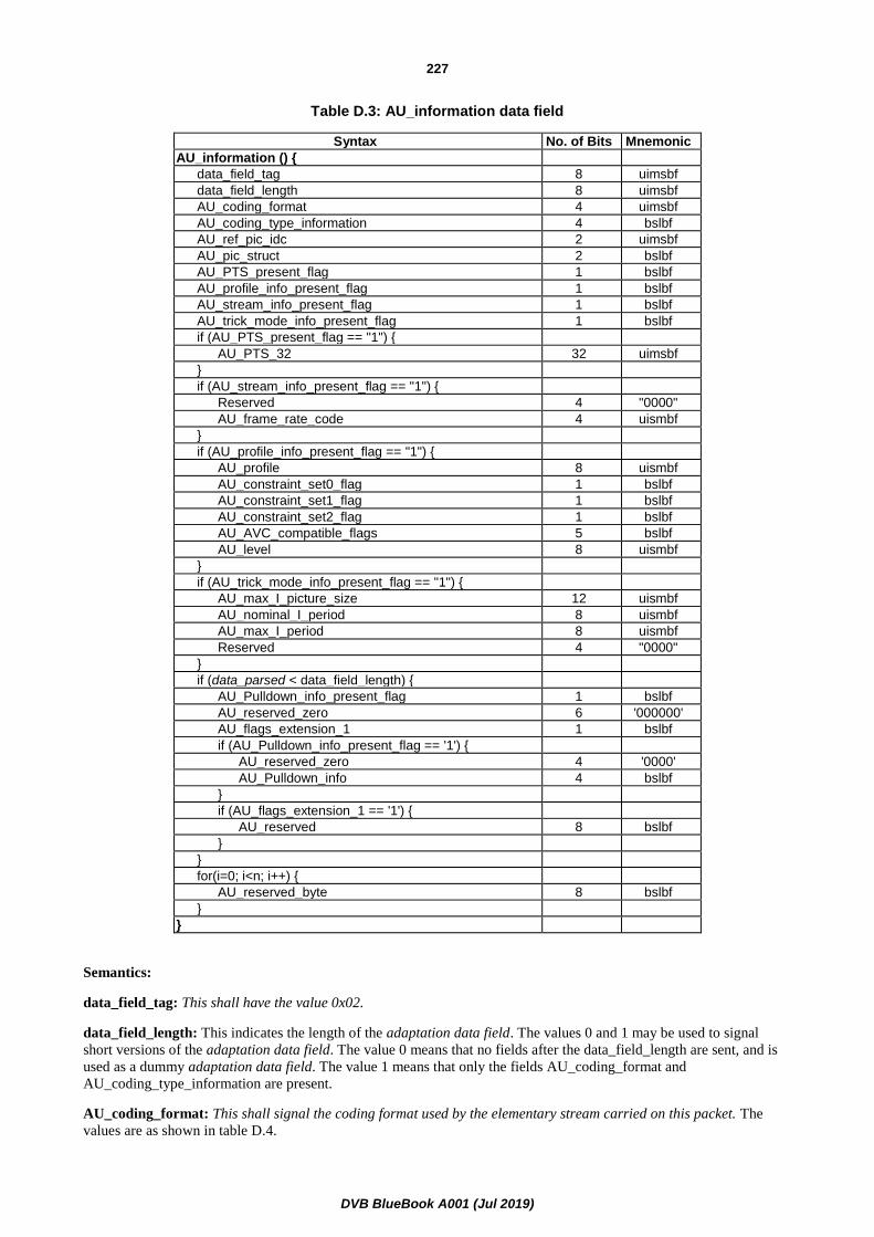
DVB BlueBook A001 (Jul 2019)
227
Table D.3: AU_information data field
Syntax No. of Bits Mnemonic
AU_information () {
data_field_tag 8 uimsbf
data_field_length 8 uimsbf
AU_coding_format 4 uimsbf
AU_coding_type_information 4 bslbf
AU_ref_pic_idc 2 uimsbf
AU_pic_struct 2 bslbf
AU_PTS_present_flag 1 bslbf
AU_profile_info_present_flag 1 bslbf
AU_stream_info_present_flag 1 bslbf
AU_trick_mode_info_present_flag 1 bslbf
if (AU_PTS_present_flag == "1") {
AU_PTS_32 32 uimsbf
}
if (AU_stream_info_present_flag == "1") {
Reserved 4 "0000"
AU_frame_rate_code 4 uismbf
}
if (AU_profile_info_present_flag == "1") {
AU_profile 8 uismbf
AU_constraint_set0_flag 1 bslbf
AU_constraint_set1_flag 1 bslbf
AU_constraint_set2_flag 1 bslbf
AU_AVC_compatible_flags 5 bslbf
AU_level 8 uismbf
}
if (AU_trick_mode_info_present_flag == "1") {
AU_max_I_picture_size 12 uismbf
AU_nominal_I_period 8 uismbf
AU_max_I_period 8 uismbf
Reserved 4 "0000"
}
if (data_parsed < data_field_length) {
AU_Pulldown_info_present_flag 1 bslbf
AU_reserved_zero 6 '000000'
AU_flags_extension_1 1 bslbf
if (AU_Pulldown_info_present_flag == '1') {
AU_reserved_zero 4 '0000'
AU_Pulldown_info 4 bslbf
}
if (AU_flags_extension_1 == '1') {
AU_reserved 8 bslbf
}
}
for(i=0; i<n; i++) {
AU_reserved_byte 8 bslbf
}
}
Semantics:
data_field_tag: This shall have the value 0x02.
data_field_length: This indicates the length of the adaptation data field. The values 0 and 1 may be used to signal
short versions of the adaptation data field. The value 0 means that no fields after the data_field_length are sent, and is
used as a dummy adaptation data field. The value 1 means that only the fields AU_coding_format and
AU_coding_type_information are present.
AU_coding_format: This shall signal the coding format used by the elementary stream carried on this packet. The
values are as shown in table D.4.

DVB BlueBook A001 (Jul 2019)
228
Table D.4: AU_coding_format values
Value Stream Type
0 Undefined
1 Recommendation ITU-T H.262 [2] / ISO/IEC 13818-2 [2] Video or ISO/IEC 11172-1 [8] constrained parameter video stream
2 H.264/AVC video stream as defined in Recommendation ITU-T H.264 / ISO/IEC 14496-10 [16] Video
3 VC-1 video stream as defined in SMPTE ST 421 [20]
4 HEVC video stream as defined in ISO/IEC 23008-2 [35] Video
5-0xF Reserved
AU_coding_type_information: Indicates the coded picture/slice types present in the immediately following access
unit. For Recommendation ITU-T H.264 / ISO/IEC 14496-10 [16] video, this field shall be interpreted as a four bit field
with the syntax shown in table D.5.
Table D.5: AU_coding_type_information for Recommendation ITU-T H.264 / ISO/IEC 14496-10 video
Syntax No. of Bits Mnemonic AU_IDR_slice_present_flag 1 bslbf
AU_I_slice_present_flag 1 bslbf
AU_P_slice_present_flag 1 bslbf
AU_B_slice_present_flag 1 bslbf
For Recommendation ITU-T H.262 / ISO/IEC 13818-2 [2] Video, this field shall be interpreted according to table D.6.
These values are identical to (but one bit longer than) the values in table 6-12 of ISO/IEC 13818-2 [2].
For VC-1 (SMPTE ST 421 [20]), this field shall be interpreted as per table D.6.
Table D.6: AU_coding_type_information for Recommendation ITU-T H.262 / ISO/IEC 13818-2 video
Value AU_coding_type_information 0 Undefined
1 I
2 P
3 B
4 to 0xF Reserved
For HEVC video, this field shall be interpreted as per table D.6a.
Table D.6a: AU_coding_type_information for HEVC video
Syntax No. of Bits Mnemonic Reserved_0 1 bslbf
AU_I_slice_present_flag 1 bslbf
AU_P_slice_present_flag 1 bslbf
AU_B_slice_present_flag 1 bslbf
NOTE 2: The slice present can be calculated from the slice_type field of the NAL units that comprise the AU.
AU_ref_pic_idc: This field indicates if any of the access unit is required in the reconstruction of other access units. The
value "00" means that it is not used by other access units. In the case of Recommendation ITU-T H.264 /
ISO/IEC 14496-10 [16], the value shall be the nal_ref_idc field in the NAL header used for any slice that makes up the
access unit.
For VC-1 (SMPTE ST 421) [20], this shall take the value "00" for all pictures (and related headers) that are not used
as reference, and shall not take the value "00" for all pictures that are used as reference.
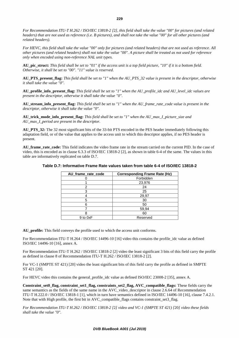
DVB BlueBook A001 (Jul 2019)
229
For Recommendation ITU-T H.262 / ISO/IEC 13818-2 [2], this field shall take the value "00" for pictures (and related
headers) that are not used as reference (i.e. B pictures), and shall not take the value "00" for all other pictures (and
related headers).
For HEVC, this field shall take the value "00" only for pictures (and related headers) that are not used as reference. All
other pictures (and related headers) shall not take the value "00". A picture shall be treated as not used for reference
only when encoded using non-reference NAL unit types.
AU_pic_struct: This field shall be set to "01" if the access unit is a top field picture, "10" if it is a bottom field.
Otherwise, it shall be set to "00". "11" value is reserved.
AU_PTS_present_flag: This field shall be set to "1" when the AU_PTS_32 value is present in the descriptor, otherwise
it shall take the value "0".
AU_profile_info_present_flag: This field shall be set to "1" when the AU_profile_idc and AU_level_idc values are
present in the descriptor, otherwise it shall take the value "0".
AU_stream_info_present_flag: This field shall be set to "1" when the AU_frame_rate_code value is present in the
descriptor, otherwise it shall take the value "0".
AU_trick_mode_info_present_flag: This field shall be set to "1" when the AU_max_I_picture_size and
AU_max_I_period are present in the descriptor.
AU_PTS_32: The 32 most significant bits of the 33-bit PTS encoded in the PES header immediately following this
adaptation field, or of the value that applies to the access unit to which this descriptor applies, if no PES header is
present.
AU_frame_rate_code: This field indicates the video frame rate in the stream carried on the current PID. In the case of
video, this is encoded as in clause 6.3.3 of ISO/IEC 13818-2 [2], as shown in table 6-4 of the same. The values in this
table are informatively replicated on table D.7.
Table D.7: Informative Frame Rate values taken from table 6-4 of ISO/IEC 13818-2
AU_frame_rate_code Corresponding Frame Rate (Hz)
0 Forbidden
1 23,976
2 24
3 25
4 29,97
5 30
6 50
7 59,94
8 60
9 to 0xF Reserved
AU_profile: This field conveys the profile used to which the access unit conforms.
For Recommendation ITU-T H.264 / ISO/IEC 14496-10 [16] video this contains the profile_idc value as defined
ISO/IEC 14496-10 [16], annex A.
For Recommendation ITU-T H.262 / ISO/IEC 13818-2 [2] video the least significant 3 bits of this field carry the profile
as defined in clause 8 of Recommendation ITU-T H.262 / ISO/IEC 13818-2 [2].
For VC-1 (SMPTE ST 421) [20] video the least significant bits of this field carry the profile as defined in SMPTE
ST 421 [20].
For HEVC video this contains the general_profile_idc value as defined ISO/IEC 23008-2 [35], annex A.
Constraint_set0_flag, constraint_set1_flag, constraints_set2_flag, AVC_compatible_flags: These fields carry the
same semantics as the fields of the same name in the AVC_video_descriptor in clause 2.6.64 of Recommendation
ITU-T H.222.0 / ISO/IEC 13818-1 [1], which in turn have semantics defined in ISO/IEC 14496-10 [16], clause 7.4.2.1.
Note that with High profile, the first bit in AVC_compatible_flags contains constraint_set3_flag.
For Recommendation ITU-T H.262 / ISO/IEC 13818-2 [2] video and VC-1 (SMPTE ST 421) [20] video these fields
shall take the value "0".

DVB BlueBook A001 (Jul 2019)
230
For HEVC video these fields shall take the value of the fields general_profile_flag[i] for the values of i from 0 to 7.
AU_level: This field conveys the level used to which the access unit conforms.
For Recommendation ITU-T H.264 / ISO/IEC 14496-10 [16] video this carries the level_idc value as defined in
ISO/IEC 14496-10 [16], annex A.
For Recommendation ITU-T H.262 / ISO/IEC 13818-2 [2] video the least significant 4 bits of this field carry the level
as defined in clause 8 of Recommendation ITU-T H.262 / ISO/IEC 13818-2 [2].
For VC-1 (SMPTE ST 421) video, the least significant bits of this field shall carry the level as defined in
SMPTE ST 421 [20].
For HEVC video this carries the level_idc value present in the HEVC_video_descriptor as defined in clause 4.1.8.19a
of the present document.
AU_max_I_picture_size: This value indicates the buffer size, in units of 16 ×1 024 bits, that is implemented by the
encoder rate control, and thus the maximum intra picture size that can be found in the current bitstream. This value,
according to profile and level, shall comply with ISO/IEC 14496-10 [16], HEVC [35] and ISO/IEC 13818-2 [2] limits.
The value 0 is forbidden.
AU_nominal_I_period: This value indicates the nominal distance between two consecutive I/IDR pictures, on a frame
picture count basis, and for HEVC the distance between two consecutive HEVC DVB_RAP pictures. The value 0 is
forbidden.
AU_max_I_period: This value indicates the maximum distance that can be found in the stream between two
consecutive I/IDR pictures, on a frame picture count basis. The value 0 is forbidden.
AU_Pulldown_info_present_flag: This field shall be set to '1' if the AU_Pulldown_info field is present.
AU_flags_extension_1: This field shall be set to '1' if the AU_reserved bytes is used for additional flags.
NOTE 3: This flag provides for future extensions. Whilst for the present document, the value of this flag should be
'0', the value of '1' should be correctly processed.
AU_Pulldown_info: This field carries the four bits carried in the H.264/AVC structure signalling the AU's display
characteristics, specifically the pic_struct field of the picture timing SEI message. The default value for this field shall
be the same as AU_pic_struct. Table D.8 shows the default values to be used for Pulldown_info if the field is not
transmitted.
Table D.8: AU_Pulldown_info default values
AU_pic_struct default AU_Pulldown_info value
00 0
01 1
10 2
For HEVC, when present this field shall carry the values of the pic_struct field of the picture timing SEI message.
NOTE 4: The combination of "AU_pic_struct" and "AU_Pulldown_info" may only be correct when
"AU_pic_struct" is set to "00" and "AU_Pulldown_info" is present and set equal to the "pic_struct" field
of the picture timing SEI message for H.264/AVC. For VC-1 (SMPTE ST 421) and MPEG-2
ISO/IEC 13818-2 / Recommendation ITU-T H.262 [2], it is recommended that these syntax elements are
set to 0.

DVB BlueBook A001 (Jul 2019)
231
D.3 PVR assistance
D.3.1 Introduction (informative)
The "PVR_assist_information" data field is used to signal information with the aim of helping PVR applications
perform trick-play operations but does not mandate any specific PVR device behaviour. The information in this clause
is specific to H.264/AVC, and HEVC and could be extended for use with other video codecs.
The "PVR_assist_information" data field may be used in addition to the "AU_information" data field, but it is
recommended that it be used independently. It is recommended that the PVR assist information is present at the start of
each video access unit.
PVR assist information is conveyed in 3 levels. The first level imposes minor encoding constraints in addition to what is
specified, for H.264/AVC, in clauses 5.5, 5.6 and 5.7 of the present document, and for HEVC in clause 5.14 of the
present document. See clause D.3.2 for these additional constraints. An application conveying just the first level of
information sets the "data_field_length" value to "0" in the PVR assist information data and this may be conveyed at
each picture or at a RAP. The second level of information includes the first level (encoding constraints) and adds
signalling of picture interdependencies using the syntax element "PVR_assist_tier_pic_num". Coding of this syntax
element is specified in clause D.3.3. An application conveying just the first and second levels of PVR assist information
sets the syntax element "data_field_length" value to "0x01", includes a correct value for "PVR_assist_tier_pic_num"
(tier number), conveys the "PVR_assist_tier_pic_num" syntax element for each picture and sets all the following syntax
elements to "0":
• pvr_assist_block_trick_mode_present_flag.
• pvr_assist_pic_struct_present_flag.
• pvr_assist_tier_next_pic_in_tier_present_flag.
• pvr_assist_substream_info_present_flag.
• pvr_assist_extension_present_flag.
Based on the "PVR_assist_tier_pic_num" syntax element, the third level provides additional information aimed at
assisting PVR applications with the ability to perform trick-play operations. The additional information includes the
following two methods as specified in clauses D.3.3 and D.3.4:
1) Information related to a Tier framework which describes signalling for extractable and decodable
sub-sequences based on pictures interdependencies. This allows the PVR application to efficiently select
pictures when performing a given trick-mode.
2) Information related to a sub-stream framework which explicitly signals the achievable trick-play speeds and
their associated subset of pictures.
Depending on the application, it is possible to use none, one or a combination of the two frameworks. When the PVR
assist information includes signalling for both the frameworks, receivers are only expected to use either one of the
signalled information.
In addition, the PVR assist information provides segmentation information and signalling to selectively block respective
trick modes.
D.3.2 Encoding of PVR assist information (normative)
This clause describes and specifies a set of encoding guidelines that shall be used when PVR assist information is
conveyed in the MPEG-2 transport stream.
In the following text RAP is used to mean "for H.264/AVC streams, RAP, and for HEVC streams, HEVC DVB_RAP".
The equivalent negative term non-RAP is also used.

DVB BlueBook A001 (Jul 2019)
232
For H.264/AVC, in addition to the constraint of one video access unit (AU) start per PES packet, each PES packet
shall contain exactly one AU. The first payload byte after the PES header shall be the start of the AU. The
"data_alignment_indicator" in the PES header shall be set to a value of "1".
NOTE: For HEVC, this constraint is already present in clause 5.
If there are any conflicts between the information signalled in this PVR assist information and the actual stream, then
the information in the stream shall take precedence over the information in this PVR assist information. However, such
a conflict should be considered an error condition and as such should not occur.
When PVR assist information is present, it shall be located in the adaptation header's private data field of MPEG-2
transport stream packets containing the PES header of video access units. These MPEG-2 transport packets shall have
their "payload_unit_start_indicator" (PUSI) flag set to a value of "1" and the adaptation control field set to a value of
"11".
The PVR assist information uses a tag, length, value structure, consistent with the usage shown in clause D.2, with a
"data_field_tag" value of "0x03". Note that when the "AU_information" with a "data_field_tag" value of "0x02" is
present in the same adaptation field, it shall precede the PVR assist information. In this instance, there should be no
conflicts between the information provided in both data fields. Any conflict shall be considered an error condition and
the PVR assist information shall take priority.
For H.264/AVC or HEVC, the maximum time interval between successive RAP pictures shall be less than or equal to
1,28 seconds. This value accommodates variations either due to non-integer frame rates or GOP lengths that are a
power of 2 up to 32 frames for interlaced video, and up to 64 frames for progressive video. While the 1,28 seconds
value is derived for a GOP of 32 frames for 25 Hz, the corresponding value is 1,068 seconds for frame rates of
30 000/1 001 Hz. It is strongly recommended that the maximum time interval be less than or equal to 1,068 seconds for
frame rates of 30 Hz, 30 000/1 001 Hz, 60 Hz and 60 000/1 001Hz.
Non-paired fields shall not be used in H.264/AVC Bitstreams or HEVC Bitstreams.
D.3.3 Tier framework
D.3.3.0 Introduction
The method is based on a tier system framework that conceptually parallels the data dependency hierarchy system
described in clause D.2.11 of Recommendation ITU-T H.264 / ISO/IEC 14496-10 [16] to achieve independently
decodable sub-sequences that can be extracted and used by PVR applications to fulfil trick modes.
The premise for the tier framework is to signal picture interdependencies to assist PVR applications in fulfilling trick
modes. The method is flexible and adapts to the potentially elaborate picture interdependencies that may be present in
an H.264/AVC stream or an HEVC stream. The tier framework extends its flexibility and adaptability without imposing
encoding constraints.
D.3.3.1 Background (informative)
A hierarchy of data dependency tiers contains at most 7 tiers. For H.264/AVC, the tiers are ordered hierarchically from
"1" to "7", and for HEVC the tiers are ordered hierarchically from "0" to the highest TemporalId value + 1, based on
their "decodability" so that any picture with a particular tier number does not depend directly or indirectly on any
picture with a higher tier number.
D.3.3.2 Specification for H.264/AVC (normative)
Each picture in the video stream may belong to one of the 7 tiers. For any value of k = 1,…5, any picture in the kth tier
shall not depend directly or indirectly on the processing or decoding of any picture in the (k+1) th tier or above.
This implies the following:
• A picture that depends on a reference picture cannot have a tier number smaller than the tier number of the
reference picture.

DVB BlueBook A001 (Jul 2019)
233
• A picture that depends on a picture issuing an MMCO that affects its picture referencing cannot have a tier
number smaller than the tier number of the picture issuing the MMCO.
Two field pictures belonging to the same frame shall have the same tier number. Starting at a RAP, the two field
pictures belonging to the same frame may be found by checking the value of "PVR_assist_pic_struct", if present, in
consecutive pictures.
Tier 1 consists of the first level of picture extractability, and each subsequent tier corresponds to the next level of
picture extractability in the video stream. All RAP pictures shall belong to Tier 1 and all Tier 1 pictures shall be RAP
pictures. Tier 5 is the largest tier number that may be assigned to reference pictures that are intended to be extracted for
trick modes. Tiers 6 and 7 correspond to the last level of picture extractability such as discardable pictures and pictures
that are not used as reference for trick-modes. Tiers 6 and 7 pictures are intended to be discardable for trick-mode
purposes and do not depend on other Tier 6 and 7 pictures. For H.264/AVC video, all pictures belonging to Tier 7 shall
have "nal_ref_idc" equal to "0". It should be noted, that some pictures with "nal_ref_idc" equal to "0" may either be
signalled as Tier 6 or Tier 7 and some discardable pictures with "nal_ref_idc" not equal to "0" may be signalled as
Tier 6.
Starting from a RAP picture and including the RAP picture, Tier 2 pictures can be decoded progressively and output
independently of pictures in Tier 3 through Tier 7. More generally, for any value of k = 1, … 7 a Tier k picture is
decodable if all immediately-preceding Tier 1 through Tier k pictures, inclusive, in the video stream have been decoded.
This requires that for tier values k= 2, 3, 4 or 5 if a picture is signalled as Tier k, then there shall be at least one Tier
(k-1) picture signalled between this RAP and the next RAP in decode order. The exception is for pictures with tiers 6
and 7 that do not depend on other tier 6 and 7 pictures.
Depending on the GOP structures, all tier numbers between 1 and 7 may not be allocated to pictures and there may be a
gap between the highest tier number used for reference pictures (1, 2, 3, 4 or 5) and tier number 6 or 7. A single gap is
permitted between the highest tier number used for reference pictures and tier number 6 or 7.
Tier number "0" is reserved for future use. "PVR_assist_tier_pic_num" field shall always be present for each picture
when either tier framework and sub-stream framework or a combination is used. This also requires "data_field_length"
to be set to a value greater than "0".
In the tier framework, if the tier number of a picture has a value of "6" or "7", then the picture shall be considered a
discardable picture and may not belong to a decodable sub-sequence.
In addition, in the tier framework other parameters such as "PVR_assist_tier_m_cumulative_frames" and
"PVR_assist_tier_m" are included to signal the minimum number for pictures intended to be extracted and decoded per
each 1 second interval for a particular trick mode speed and higher. The following describes the use and setting of these
syntax elements:
The number of pictures signalled from Tiers 1 through n where 1<n<6 should be approximately half the number of
pictures per every consecutive 1,0 second interval of the video stream, and the pictures should be evenly spread, to
provide a smooth 2x trick mode. The complementary fields "PVR_assist_tier_m_cumulative_frames" and
"PVR_assist_tier_m" may be signalled for this purpose.
The premise behind these two syntax elements is that if a sufficient number of pictures are provided to fulfil smooth 2x
playback, then there will be a sufficient number of pictures to also render smooth playback of speeds higher than 2x.
For example, if 30 of every 60 pictures per second are signalled with Tiers 1 to n with these complementary fields, then
it is possible to provide a 2x playback of 60 pictures per second from the 30 signalled pictures in every 1,0 second
interval, or equivalently 60 signalled pictures can be decoded from every 2,0 second interval. Likewise, smooth 4x
playback can be fulfilled with 15 of the signalled pictures in every 1,0 second interval.
D.3.3.2a Specification for HEVC (normative)
HEVC supports a mechanism that can be made compatible with the tier framework through the ability to signal a video
bitstream as comprising of a number of temporal sublayers, where each temporal sublayer has a TemporalId carried as
the nuh_temporal_id_plus1 field in the NAL_unit_header. The tier number may be used to signal the sublayers of
HEVC consistently in accordance with their TemporalId values. Within the context of this annex, temporal sublayers
refer only to temporal sublayers carried within a single PID. The tier number for each picture is derived from its
TemporalId value. The tier value of an HEVC DVB_RAP picture shall be 0. All pictures that are not HEVC DVB_RAP
pictures shall have tier value equal to TemporalId +1.

DVB BlueBook A001 (Jul 2019)
234
Additional constraints may be imposed on the tier framework if required, e.g. as defined in Recommendation ITU-T
H.265 / ISO/IEC 23008-2 [35], clause 10 for subbitstream extraction. Utilizing the tier framework provides easy access
to the sublayer information without requiring either access to, or parsing and decrypting of, the HEVC bitstream.
For HEVC Video, Tier 0 (i.e. TemporalId 0) consists of pictures which can all be extracted, and each subsequent tier
corresponds to another level of pictures which can be additionally extracted to assist trick play operations. For HEVC,
all HEVC DVB_RAP pictures shall belong to Tier 0 and all Tier 0 pictures shall be HEVC DVB_RAP pictures.
D.3.3.3 Examples of tier number assignment for H.264/AVC and HEVC (informative)
When a PVR application starts extracting a subsequence beginning at a RAP, its decodability entry point (DEP) is
defined to be the RAP from which all pictures of this extracted subsequence can be fully reconstructed. Note that DEP
is the RAP if it contains an IDR picture for H.264/AVC, or an IDR or CRA for HEVC; otherwise, the DEP could be the
previous RAP.
For all values of k from 1 to 6, a Tier k picture after a RAP is decodable and can be fully reconstructed if the respective
tier number is signalled for each and every picture belonging to Tiers 1 through k that are located between the Tier k
picture's DEP and the Tier k picture.
The GOP depicted in figure D.2 illustrates that every other picture may be signalled with Tiers 1 through 4. In
figure D.2, the first and second rows depict picture output order and decode order, respectively; the third row shows the
respective tier number of each picture in decode order.
A wide range of playback speeds are possible from Tier 1 pictures only (i.e. very fast) to higher tier numbers. A PVR
application may provide alternate speeds with the pictures in Tiers 1 to (k-1) and a portion of the pictures in tier k. In
some cases the display of some pictures may be repeated to avoid imposing the decoder to run beyond its capabilities;
in other cases to maintain speed accuracy. Using the signalled tier numbers, a PVR application may select the
appropriate set of pictures for a particular trick mode without causing a decoder to process pictures faster than 1x.

DVB BlueBook A001 (Jul 2019)
235
P17P9 I25I1 B3 B5 B7 B11 B13 B15 B19 B21 B23b2 b4 b6 b8 b10 b12 b14 b16 b18 b20 b22 b24
P17P9 I25I1 B3B5 B7 B11B13 B15 B19B21 B23b2 b4 b6 b8 b10 b12 b14 b16 b18 b20 b22 b24
22 11 43 4 43 4 43 47 7 7 7 7 7 7 7 7 7 7 7
00 00 21 2 21 2 21 23 3 3 3 3 3 3 3 3 3 3 3
Pictures in Decode Order
Pictures in Output Order
Tier Number for AVC (in Decode Order)
11 00 32 3 32 3 32 34 4 4 4 4 4 4 4 4 4 4 4
Tier Number for HEVC (in Decode Order)
Temporal_ID for HEVC (in Decode Order)
77 71 74 4 74 4 74 43 7 7 2 3 7 7 2 3 7 7 1
33 30 32 2 32 2 32 21 3 3 0 1 3 3 0 1 3 3 0
Tier Number for AVC (in Output Order)
44 40 43 3 43 3 43 32 4 4 1 2 4 4 1 2 4 4 0
Tier Number for HEVC (in Output Order)
Temporal_ID for HEVC (in Output Order)
(a) Output Order(a) Output Order
(b) Decode Order
Figure D.2
In figure D.3, 2x trick mode may be rendered by decoding every other picture. In some cases, a PVR may render a 2x
playback speed by decoding the pictures in tiers 1 to 3 and repeating the output of each picture once.
The tier framework can also be used to signal discardable pictures, or different categories of discardable pictures. For
instance, with an MPEG-2 like GOP with three B pictures between reference pictures, the middle B picture of every trio
can be signalled as a Tier "6" picture and the other two as Tier "7" pictures. This facilitates retention of the temporal
sampling of the video when pictures need to be discarded.

DVB BlueBook A001 (Jul 2019)
236
I1 b2 B3 b4 B5 b6 B7 b8 P9 b10 B11 b12 B13 b14 B15 b16 P17 b18 B19 b20 B21 b22 B23 b24 I25
Tier Number
1 7 4 7 3 7 4 7 2 7 4 7 3 7 4 7 2 7 4 7 3 7 4 7 1
2X speed: independent decodable sub-sequence of pictures in Tiers 1 through 4
x x x x x x x x x x x x x
4X speed: independent decodable sub-sequence of pictures in Tiers 1 through 3
x x x x x x x
8X speed: independent decodable sub-sequence of pictures in Tiers 1 through 2
x x x x
12X speed: independent decodable sub-sequence of pictures in Tiers 1
I1 I1 I25 I25 I49 I49 I73 I73 I96 I96
24X speed: independent decodable sub-sequence of pictures in Tiers 1
I1 I25 I49 I73 I96 I120
Figure D.3
D.3.4 Sub-stream framework
D.3.4.1 Background (informative)
This method is based on a sub-stream framework, which relieves the PVR device from the burden of determining the
subset of pictures needed to fulfil a trick play speed. To achieve a pre-defined trick-mode speed, the PVR device is
hypothetically supposed to decode a signalled sub-stream, select the pictures to display and choose their display
duration. Each defined sub-stream is signalled on a picture basis, and may be guaranteed to be decodable by a compliant
decoder. Note that this requires the "data_field_length" to be set to a value greater than "0" and the
"PVR_assist_tier_pic_num" field be present for each picture.
This framework may also facilitate switching between different playback speeds on a real-time basis.
Playback speed information assists in signalling one or more sub-streams corresponding to respective pre-defined
playback speeds. Up to four speeds may be signalled per picture to signal that this picture belongs to a corresponding
extractable sub-stream, and each extractable sub-stream is associated with one of 15 playback speeds.
Furthermore, picture interdependencies as described in clause D.3.3, might be used by the PVR device to achieve
intermediate playback speeds.
Note that playback speed information does not define the features, trick mode strategies or the effective trick mode
speed achieved by the PVR device.
D.3.4.2 Tier Signalling (normative)
"PVR_assist_tier_pic_num" shall be present for each picture. Note that this requires the "data_field_length" to be set to
a value greater than "0". Coding of "PVR_assist_tier_pic_num" is defined in clause D.3.3. If the stream contains
signalling for both the tier and substream frameworks, there shall be no conflict in the value signalled in syntax element
"PVR_assist_tier_m_cumulative_frames" and a speed associated with 2x. If a conflict occurs, it is recommended that
"PVR_assist_tier_m_cumulative_frames_present_flag" be set to "0" when "PVR_assist_substream_info_present_flag"
is set to "1".

DVB BlueBook A001 (Jul 2019)
237
D.3.4.3 Playback speed information (normative)
Playback speed information should be used to signal one or more sub-streams deemed best by the encoder to fulfil
respective playback speeds.
If "PVR_assist_substream_1x_decodable _flag" is set to a value of "1", sub-streams do not require any additional
resources and throughput capabilities of a 1x decoder (as defined in clause D.3.4.4) when played at their pre-defined
trick-mode speeds.
D.3.4.4 Sub-stream associated with a Playback speed (normative)
The following defines a sub-stream that is signalled with playback speed information as it is constructed by the encoder.
• A sub-stream is a fully decodable subset of pictures that can be extracted from the original stream.
• A sub-stream where the "PVR_assist_substream_1x_decodable_flag" is set to "1" obeys the following
constraints:
- Max bitrate constraint: The sum of sizes of "Number of pictures per second" consecutively decoded
pictures in the sub-stream does not exceed the "VCL max size" indicated in table D.9.
- Jitter constraint: Let "S" be the intended playback speed of the sub-stream relative to the original stream
from which the sub-stream is extracted. The maximum number of pictures in the original stream between
two consecutive signalled pictures in the sub-stream, in output order, shall not exceed the following
values:
▪ 2 if S < 2
▪ 2 × Ceil (S-1) if 2 ≤ S < 4
▪ 3 × Ceil (S) if 4 ≤ S < 19
▪ 4 × Ceil (S) if S ≥ 19
Where: "Ceil" is the upward rounding function.
Table D.9: VCL maximum size values
IRD Frame rate (Hz) Number of pictures
per second H.264/AVC
VCL max size HEVC VCL max size
25 Hz or 30 Hz H.264/AVC SDTV
24 or 24 000 / 1 001 24 10 Mbits Not applicable
25 25 10 Mbits Not applicable
30 or 30 000 / 1 001 30 10 Mbits Not applicable
25 Hz or 30 Hz HDTV
24 or 24 000 / 1 001 24 25 Mbits Not applicable
25 25 25 Mbits Not applicable
30 or 30 000 / 1 001 30 25 Mbits Not applicable
50 50 25 Mbits Not applicable
60 or 60 000 / 1 001 60 25 Mbits Not applicable
50 Hz or 60 Hz HDTV
24 or 24 000 / 1 001 24 62,5 Mbits 20 Mbits
25 25 62,5 Mbits 20 Mbits
30 or 30 000 / 1 001 30 62,5 Mbits 20 Mbits
50 50 62,5 Mbits 20 Mbits
60 or 60 000 / 1 001 60 62,5 Mbits 20 Mbits
UHDTV
24 or 24 000 / 1 001 24 Not applicable 40 Mbits
25 25 Not applicable 40 Mbits
30 or 30 000 / 1 001 30 Not applicable 40 Mbits
50 50 Not applicable 40 Mbits
60 or 60 000 / 1 001 60 Not applicable 40 Mbits

DVB BlueBook A001 (Jul 2019)
238
D.3.4.5 Examples of sub-streams (informative)
Sub-streams are constructed on the encoding side to help the PVR devices perform pre-defined trick-play speeds. The
GOP structures chosen by the encoder are constrained such that trick-mode operation is possible considering the PVR
device's capabilities. However, the present document does not impose specific GOP structures, and the encoder still has
to derive them in order to maximize the coding efficiency and to obey other constraints.
The PVR device may choose different strategies to achieve the desired trick-mode speed. The most common are as
follows:
• Display evenly distributed pictures. The sub-stream depicted in figure D.4 shows an example achieving a
2x trick-mode display speed using this strategy.
• Display RAP and the middle of the GOP pictures. The sub-stream depicted in figure D.5 illustrates an example
to achieve a 4x trick-mode display speed.
• Display only RAP pictures.
While constructing Sub-streams, the encoder infers implicitly such a trick-mode strategy, and when
"PVR_assist_substream_1x_decodable _flag" is set to "1", it ensures that even a 1x capable decoder may perform it.
I0
b1
P2
b3
P4
b5
P6
b7
P8
b9
P10
b11
P12
b13
P14
b15
P16
b17
P18
b19
I20
Pictures not part of the sub-stream
Signaled, decoded and displayed pictures
Example of 2x playback dropping evenly distributed discardable frames
(10 frames decoded out of 20)
Figure D.4
I0
b1
b2
P3
B4
b5
P6
b7
P8
b9
P10
b11
B12
b13
P14
b15
b16
P17
b18
b19
I20
Pictures not part of the sub-stream
Example of 4x playback displaying the middle-GOP frame
(5 frames decoded out of 20)
Signaled, decoded and displayed pictures
Signaled, decoded but not displayed pictures
Figure D.5
D.3.5 Segmentation signalling
Segmentation information provided in the PVR assist information enhances the implementation of PVR applications
with the following:
1) Segment (chapter) identification.
2) Program identification.

DVB BlueBook A001 (Jul 2019)
239
3) Start of a segment.
4) End of a segment.
5) Start of a program.
6) End of a program.
7) Location of scene change.
The rules for transmission of segmentation information and associated receiver behaviour are outside the scope of the
present document.
NOTE: Other standards also supply methods to signal segmentation. It is possible multiple methods may be
employed with a single service. In such case, the service operator should take care to ensure matching
information is supplied via each method used. If a conflict exists, the method documented in this annex
should be used.
D.3.6 PVR Assistance Signalling Syntax
Table D.10: PVR_assist_information data field
Syntax No. bits Mnemonic
PVR_assist_information( ) {
data_field_tag 8 uimsbf
data_field_length 8 uimsbf
if (data_field_length > 0) {
PVR_assist_tier_pic_num 3 uimsbf
PVR_assist_block_trick_mode_present_flag 1 bslbf
PVR_assist_pic_struct_present_flag 1 bslbf
PVR_assist_tier_next_pic_in_tier_present_flag 1 bslbf
PVR_assist_substream_info_present_flag 1 bslbf
PVR_assist_extension_present_flag 1 bslbf
if (PVR_assist_block_trick_mode_present_flag == "1") {
PVR_assist_pause_disable_flag 1 bslbf
PVR_assist_fwd_slow_motion_disable_flag 1 bslbf
PVR_assist_fast_fwd_disable_flag 1 bslbf
PVR_assist_rewind_disable_flag 1 bslbf
PVR_assist_reserved_0 4 "0000"
}
if (PVR_assist_pic_struct_present_flag == "1") {
PVR_assist_pic_struct 4 uimsbf
PVR_assist_reserved_0 4 "0000"
}
if (PVR_assist_tier_next_pic_in_tier_present_flag == "1") {
PVR_assist_tier_next_pic_in_tier 7 uimsbf
PVR_assist_reserved_0 1 "0"
}
if (PVR_assist_substream_info_present_flag == "1") {
for ( i = 0; i < 4; i++) {
PVR_assist_substream_flag_i 1 bslbf
}
PVR_assist_substream_speed_info_present_flag 1 bslbf
PVR_assist_substream_1x_decodable _flag 1 bslbf
PVR_assist_reserved_0 2 "00"
if (PVR_assist_substream_speed_info_present_flag == "1") {
for ( i = 0; i < 4; i++) {
PVR_assist_substream_speed_idx_i 4 uimsbf
}
}
}
if (PVR_assist_extension_present_flag == "1") {
PVR_assist_segmentation_info_present_flag 1 bslbf
PVR_assist_tier_m_cumulative_frames_present_flag 1 bslbf

DVB BlueBook A001 (Jul 2019)
240
Syntax No. bits Mnemonic
PVR_assist_tier_n_mmco_present_flag 1 bslbf
PVR_assist_temporal_id_info_present_flag 1 bslbf
PVR_assist_reserved_0 4 "0000"
if (PVR_assist_segmentation_info_present_flag == "1") {
PVR_assist_seg_id 8 uimsbf
PVR_assist_prg_id 16 uimsbf
PVR_assist_seg_start_flag 1 bslbf
PVR_assist_seg_end_flag 1 bslbf
PVR_assist_prg_start_flag 1 bslbf
PVR_assist_prg_stop_flag 1 bslbf
PVR_assist_scene_change_flag 1 bslbf
PVR_assist_reserved_0 3 "000"
}
if (PVR_assist_tier_m_cumulative_frames_present_flag == "1") {
PVR_assist_tier_m 3 uimsbf
PVR_assist_tier_m_cumulative_frames 5 uimsbf
}
if (PVR_assist_tier_n_mmco_present_flag == "1") {
PVR_assist_tier_n_mmco 3 uimsbf
PVR_assist_reserved_0 5 "00000"
}
if (PVR_assist_temporal_id_info_present_flag == "1") {
PVR_assist_max_temporal_id 3 uimsbf
PVR_assist_reserved_0 5 "00000"
}
}
for (i=0; i<n; i++) {
PVR_assist_reserved_byte 8 uimsbf
}
}
}
Semantics:
data_field_tag: This shall have the value "0x03".
data_field_length: This indicates the length of this descriptor excluding the "data_field_tag" and "data_field_length"
fields. A value of "0" for this field indicates that the encoding constraints as specified in clause D.3.2 shall be met.
PVR_assist_tier_pic_num: For H.264/AVC streams, the tier number of the picture associated with this PVR assistive
information equals this value. For H.264/AVC streams, the lowest tier number is equal to "1" and the highest tier
number is equal to "7". For H.264/AVC streams, a value of "0" is reserved for future use.
For HEVC streams, this value shall be set as described in clause D.3.3.2a above.
PVR_assist_block_trick_mode_present_flag: This flag can be set to "1" at a non-RAP picture only if its value at the
prior RAP picture was set to "1". It shall be set to "1" when the following flags are present:
1) PVR_assist_pause_disable_flag.
2) PVR_assist_fwd_slow_motion_disable_flag.
3) PVR_assist_fast_fwd_disable_flag.
4) PVR_assist_rewind_disable_flag.
PVR_assist_pic_struct_present_flag: this field shall be set to "1" only if the video stream is an AVC or HEVC stream
and the "PVR_assist_pict_struct" field is present. Otherwise it shall be set to "0".
NOTE 1: If "PVR_assist_pict_struct_present_flag" is set to "0" and the AU_information data field is included, then
"pic_struct" information may be available in the AU_information data field.
PVR_assist_tier_next_pic_in_tier_present_flag: This field shall be set to "1" when the
"PVR_assist_tier_next_pic_in_tier" is present; otherwise it shall take the value "0".

DVB BlueBook A001 (Jul 2019)
241
PVR_assist_substream_info_present_flag: this field shall be set to "1" when values are present for the four flags
corresponding to "PVR_assist_substream_flag_i" = 0 to 3, and for "PVR_assist_substream_speed_info_present_flag".
PVR_assist_extension_present_flag: this field shall be set to "1" if any of the following flags is set to "1":
1) PVR_assist_segmentation_info_present_flag.
2) PVR_assist_tier_m_cumulative_frames_present_flag.
3) PVR_assist_tier_n_mmco_present_flag.
4) PVR_assist_temporal_id_info_present_flag.
Otherwise it shall be set to "0". In some cases, these extension flags may be provided only with pictures corresponding
to RAPs.
PVR_assist_pause_disable_flag: The value of this flag shall be implied to be "0" unless provided explicitly in this
field. This flag is set to "1" to signal disabling pause until the next RAP picture. The value of this flag at a non-RAP
picture shall be equal to its value at the prior RAP picture.
PVR_assist_fwd_slow_motion_disable_flag: The value of this flag shall be implied to be "0" unless provided
explicitly in this field. This flag is set to "1" to signal disabling forward slow motion, including frame stepping, until the
next RAP picture. The value of this flag at a non-RAP picture shall be equal to its value at the prior RAP picture.
PVR_assist_fast_fwd_disable_flag: The value of this flag shall be implied to be "0" unless provided explicitly in this
field. This flag is set to "1" to signal disabling fast forward until the next RAP picture. The value of this flag at a
non-RAP picture shall be equal to its value at the prior RAP picture.
PVR_assist_rewind_disable_flag: The value of this flag shall be implied to be "0" unless provided explicitly in this
field. This flag is set to "1" to signal disabling rewind, including reverse slow motion and frame stepping, until the next
RAP picture. The value of this flag at a non-RAP picture shall be equal to its value at the prior RAP picture.
PVR_assist_pic_struct: This shall reflect the "pic_struct" value of the AU in the AVC elementary stream (ES). If the
ES carries the "Picture Timing SEI Message" with the "pic_struct" field, this shall be equal to that value. If "pic_struct"
is not carried within the ES, then for AVC this value should reflect that of Table D-1 of Recommendation
ITU-T H.264 / ISO/IEC 14496-10 [16], and for HEVC this value should reflect that of Table D-2 of HEVC [35].
PVR_assist_tier_next_pic_in_tier: The value of this field indicates the relative location in decoding order of the next
picture in the video stream with the tier number equal to "PVR_assist_tier_pic_num". A value of "0" indicates the next
picture in decoding order. A value of "127" indicates that the relative location of the next picture sharing the same tier is
not known.
NOTE 2: The "PVR_assist_tier_next_pic_in_tier" field may be associated with any picture, but it is recommended
that this field is not used in real-time applications where low encoding delay is desired.
PVR_assist_substream_flag_i: This field shall be set to "1" to signal that the associated picture is to be extracted to
construct the sub-stream whose playback speed is indicated by "PVR_assist_substream_speed_idx_i". This flag shall be
set to "0" if "PVR_assist_substream_speed_idx_i" is equal to "0000".
PVR_assist_substream_speed_info_present_flag: This field shall be set to "1" when
"PVR_assist_substream_speed_idx_i" is not equal to "0000" for 'i' in the range "0" through to "3" inclusive.
PVR_assist_substream_1x_decodable _flag: This field shall be set to "1" when all sub-streams follow the constraints
in clause D.3.4.4.
PVR_assist_substream_speed_idx_i: When set to a non-zero value, this field provides the speed for the extractable
sub-stream containing the pictures identified by "PVR_assist_substream_flag_i" = "1", while a zero value is used to
avoid defining a sub-stream. The value of "PVR_assist_substream_speed_idx" is used to look-up the corresponding
trick mode speed value in table D.11. A non-zero value of "PVR_assist_substream_speed_idx" indicates a sub-stream in
accordance to clause D.3.4.4. The value of "PVR_assist_substream_speed_idx_i" at a non-RAP picture shall be equal to
its value at the prior RAP picture.
NOTE 3: "PVR_assist_substream_speed_idx_i" may be associated with any picture but it is recommended to be
provided only with RAP pictures. If possible, it is also recommended to avoid changes to
"PVR_assist_substream_speed_idx_i".

DVB BlueBook A001 (Jul 2019)
242
Table D.11: Trick mode index to speed values
Index Trick Mode Speed
0 No defined sub-stream
1 1,25
2 1,5
3 2,0
4 2,5
5 3,0
6 4,0
7 5,0
8 6,0
9 8,0
10 10,0
11 12,0
12 16,0
13 20,0
14 24,0
15 30,0
PVR_assist_segmentation_info_present_flag: This field shall be set to "1" if the "PVR_assist_segmentation_info"
field is present. Otherwise it shall be set to "0".
NOTE 4: The "PVR_assist_segmentation_info" field may be associated with any picture but it is recommended that
"PVR_assist_segmentation_info" is only associated with the first and last pictures of each segment and
when scene changes are indicated.
PVR_assist_tier_m_cumulative_frames_present_flag: This field shall be set to "1" if the "PVR_assist_tier_m" field
and "PVR_assist_tier_m_cumulative_frames" are present. Otherwise it shall be set to "0". For HEVC, it is
recommended that this flag is set to "0".
NOTE 5: The "PVR_assist_tier_m_cumulative_frames_present_flag" may be associated with any picture but it is
recommended to be set only on RAP pictures.
PVR_assist_tier_n_mmco_present_flag: This field shall be set to "1" if the "PVR_assist_tier_n_mmco" field is
present. Otherwise it shall be set to "0".
NOTE 6: The "PVR_assist_tier_n_mmco_present_flag" may be associated with any picture but it is recommended
to be set only on RAP pictures.
For HEVC bitstreams, the "PVR_assist_tier_n_mmco_present_flag" shall be set to "0".
PVR_assist_temporal_id_info_present_flag: This field shall be set to "1" if "PVR_assist_max_temporal_id" is
present. In some cases, this flag may be provided only with pictures corresponding to RAPs. This field shall be set to
"0" for AVC streams.
PVR_assist_seg_id: This field conveys the "id" of the segment to which the picture belongs. "PVR_assist_seg_id" shall
be sent in ascending order resuming at program start and beginning at 0. A value of "255" is used to indicate an
undefined segment id.
PVR_assist_prg_id: This field conveys the "id" of the program to which the picture belongs. The information provided
in this field can be used to obtain the title or other attributes of the program from program guide information. The "id"
of a program for a particular program guide information service has to be available to the encoder to provide this field.
A value of "65535"is used to indicate an undefined program id.
PVR_assist_seg_start_flag: This field shall be set to "1" on the first picture in presentation time order of a segment.
Otherwise it shall be set to "0". This segment is identified by the "PVR_assist_seg_id" field.
PVR_assist_seg_end_flag: This field shall be set to "1" on the last picture in presentation time order of a segment.
Otherwise it shall be set to "0". This segment is identified by the "PVR_assist_seg_id" field.
PVR_assist_prg_start_flag: This field shall be set to "1" on the first picture in presentation time order of a program.
Otherwise it shall be set to "0". This program is identified by the "PVR_assist_prg_id" field.

DVB BlueBook A001 (Jul 2019)
243
PVR_assist_prg_stop_flag: This field shall be set to "1" on the last picture in presentation time order of a program.
Otherwise it shall be set to "0". This program is identified by the "PVR_assist_prg_id" field.
PVR_assist_scene_change_flag: This field shall be set to "1" at the first display-order picture of a new scene that
carries this flag. Note that the present document does not define "scene change".
PVR_assist_tier_m: This field is the tier number associated with "PVR_assist_tier_m_cumulative_frames". The value
of this field should be chosen to signal a sufficient number of frames via "PVR_assist_tier_m_cumulative_frames"
which would provide for smooth playback speeds of 2x and above. The value of this field should be chosen to provide
less than or equal to half of the number of frames per second of the original frame rate.
NOTE 7: For HEVC this field is recommended not to be present.
PVR_assist_tier_m_cumulative_frames: This field conveys the value of the intended minimum number of extractable
frames per second from tier 1 through "PVR_assist_tier_m".
NOTE 8: For HEVC this field is recommended not to be present.
PVR_assist_tier_n_mmco: This field represents the smallest tier number below which MMCOs can be ignored by
decoders during trick-play modes. If this field is set to "7", then this signals that MMCOs could be present on any tier
signalling reference pictures. If this field is set to "1", then this signals that the video stream does not contain MMCOs.
NOTE 9: For HEVC, this field is not present.
PVR_assist_max_temporal_id: The value of this field represents the maximum TemporalId of associated HEVC
video stream. This value shall be set to the same value as the field sps_max_sub_layers_minus1 of the sequence
parameter set corresponding to the frame to which this field applies. The value of "PVR_assist_max_temporal_id" shall
be in the range of 0 to 6, inclusive. The value of this field may be used to provide the information about trick mode
speeds those are supported from the stream and corresponding ranges of TemporalId values.
NOTE 10: For AVC, this field is not present.
PVR_assist_reserved_byte: This field allows for future PVR assist information to be conveyed in the stream.

DVB BlueBook A001 (Jul 2019)
244
Annex E (normative): Supplementary Audio Services
E.1 Overview
Supplementary audio (SA) services provide an additional audio soundtrack that provides an additional feature or
function over and above that provided by the main audio stream. The SA stream may be provided using one of two
schemes:
• "Broadcast mix": pre-mixed by the broadcaster and offered as an alternative audio stream.
• "Receiver mixed": mixed in the receiver under the control of signalling provided by the broadcaster plus some
limited control of the user.
This annex only deals with receiver-mixed SA services. Further information on the DVB-SI signalling for receiver-
mixed SA services can be found in clause J.2 of ETSI EN 300 468 [i.32].
Examples of SA services include audio description for the visually impaired, audio for the hearing impaired ("Clean
Audio") and a director's commentary. The language used in this annex is mainly in terms of an audio description service
although it is equally applicable to all SA applications.
Audio description (AD) delivers a description of the scene. It is intended to aid understanding and enjoyment
particularly, but not exclusively, for viewers who have visual impairments.
Clean Audio refers to audio providing improved intelligibility. It is targeted for viewers with hearing impairments, but
can as well serve as improvement for listening in noisy environments like airplanes.
Loud sound effects or music could make the added supplementary audio hard to discern so an important requirement is
to adjust, on a passage-by-passage basis, the relative level of programme sound in the mix which the SA user hears. The
programme maker is best able to determine the level under controlled conditions when authoring the SA information to
modulate the level of programme sound in the SA-capable receiver so suitable SA information is thus transmitted
within the SA stream.
Individual SA users will have different aural acuity, describers (of AD) will have different styles of delivery (voice
pitch and timbre), several voices may be used to describe one programme and there are, in practice, differences in audio
signal level for different home receivers. An essential requirement is for the user to be able to adjust the volume of the
SA signal to suit his/her condition.
The ability to optionally mix one or more supplementary additional audio channels with the main programme sound can
have other applications, including multi-language commentaries, use for interactivity, and educational purposes.
E.2 Syntax and semantics
SA control information is coded in PES_private_data within the PES encapsulation of the coded SA component in
accordance with Recommendation ITU-T H.222.0 / ISO/IEC 13818-1 [1].

DVB BlueBook A001 (Jul 2019)
245
Table E.1: AD_descriptor
Syntax value No. of Bits Identifier
AD_descriptor {
Reserved 1111 4 bslbf
AD_descriptor_length 4 bslbf
AD_text_tag 0x4454474144 40 bslbf
version_text_tag 8 bslbf
AD_fade_byte 0xXX 8 bslbf
AD_pan_byte 0xYY 8 bslbf
if (version_text_tag == 0x31) {
Reserved 0xFFFFFF 24 bslbf
}
if (version_text_tag == 0x32) {
AD_gain_byte center 0xUU 8 bslbf
AD_gain_byte front 0xVV 8 bslbf
AD_gain_byte surround 0xWW 8 bslbf
}
Reserved 0xFFFFFFFF 32 bslbf
}
AD_descriptor_length: The number of significant bytes following the length field (i.e. 8 or 11).
AD_text_tag: A string of 5 bytes forming a simple and unambiguous means of distinguishing this from any other
PES_private_data. A receiver which fails to recognize this tag should not interpret this audio stream as audio
description.
version_text_tag: The AD_text_tag is extended by a single ASCII character version designator (here "1" indicates
revision 1). Descriptors with the same AD_text_tag but a higher version number shall be backwards compatible with
the present document - the syntax and semantics of the fade and pan fields will be identical but some of the reserved
bytes may be used for additional signalling.
AD_fade_byte: Takes values between 0x00 (representing no fade of the main programme sound) and 0xFF
(representing a full fade). Over the range 0x00 to 0xFE one lsb represents a step in attenuation of the programme sound
of 0,3 dB giving a range of 76,2 dB. The fade value of 0xFF represents no programme sound at all (i.e. mute). The rate
of signalling and the expected behaviour of a decoder to changes in fade byte are described below.
AD_pan_byte: Takes values between 0x00 representing a central forward presentation of the audio description and
0xFF, each increment representing a 360/256 degree step clockwise looking down on the listener (i.e. just over
1,4 degrees, see figure E.2). The rate of signalling and the expected behaviour of a decoder are described below.
AD_gain_byte_center: Represents a signed value in dB. Takes values between 0x7F (representing +76,2 dB boost of
the main programme centre) and 0x80 (representing a full fade). Over the range 0x00 to 0x7F one lsb represents a step
in boost of the programme centre of 0,6 dB giving a maximum boost of +76,2 dB. Over the range 0x81 to 0x00 one lsb
represents a step in attenuation of the programme centre of 0,6 dB giving a maximum attenuation of -76,2 dB. The gain
value of 0x80 represents no main centre level at all (i.e. mute). The rate of signalling and the expected behaviour of a
decoder to changes in gain byte are described below.
AD_gain_byte_front: As AD_gain_byte_center, applied to left and right front channel.
AD_gain_byte_surround: As AD_gain_byte_center, applied to all surround channels.
The maximum rate of signalling of fade, pan and gain values is determined by the number of audio PES packets per
second for that SA stream. For efficiency several access units (AUs) of audio are typically encapsulated within one PES
packet and the fade and pan values in each AD_descriptor are deemed to apply to each AU encapsulated within, and
which commences in, that PES packet. In typical efficient encapsulation fade and pan values are transmitted every
120 ms to 200 ms. This allows the control over the attack and decay of a fade where a particular gap in the narrative
permits.
An AD decoder maintains the relative timing between the decoded AD signal and the decoded programme sound signal
and between the appropriate fade, pan and gain values and the decoded description signal.

DVB BlueBook A001 (Jul 2019)
246
During programmes for which there is no description there is little reason to transmit an SA stream of continual silence;
in these cases the bitrate accorded to SA may be reassigned for other purposes. Decoders should therefore be able to
respond promptly to the restoration of the SA component at the start of a described programme.
In the case of AD, the streams for programme sound and for AD are distinguished in the PSI by the use of the
ISO_639_language descriptor. The audio_type field within the descriptor associated with programme sound is typically
assigned the value 0x00 ("undefined") whilst the equivalent descriptor associated with AD has its audio_type field
assigned the value 0x03 ("visual impaired commentary"). If a service has AD in several languages the PMT reference to
each stream will have the appropriate ISO_639_language_code and the AD-capable decoder should discriminate
between them on the basis of the preferred language chosen in the user settings.
In the case of Clean Audio, the streams for programme sound and for Clean Audio are distinguished in the PSI by the
use of the ISO_639_language descriptor. The audio_type field within the ISO_639_language descriptor associated with
main programme sound is typically assigned the value 0x00 ("undefined") whilst the equivalent descriptor associated
with Clean Audio has its audio_type field assigned the value 0x02 ("hearing impaired").
E.3 Coding for Audio Description SA services
AD content is voice-only and is conveyed as a mono signal coded in accordance with ISO/IEC 11172-3 [9] or
ISO/IEC 14496-3 [17] or ETSI TS 102 366 [12] or ETSI TS 103 190-1 [43]. The coding scheme used for the main
audio service determines the coding scheme used for the description service (i.e. they shall use the same coding
standard) and the sampling rate shall be the same for both services.
The principles of processing in a SA decoder in the case of AD when main audio is stereo are shown diagrammatically
in figure E.1.
user control of
overall volume
user control of
description volume
programme provider control of
programme volume
during description passages
decoded audio
description
mono
decoded main
programme
stereo
R
L
Figure E.1: Functionality of AD decoder processing
The level by which the main programme sound should be attenuated during a description passage is signalled in
PES_private_data within the PES encapsulation of the coded SA component (as specified in Recommendation
ITU-T H.222.0 / ISO/IEC 13818-1 [1].
Encoding: Support for the encoding of AD is optional.
Decoding: Support for the decoding of AD is optional.
The signalled fade value is an unsigned byte value, 0x00 representing 0 dB, each increment representing a nominal
0,3 dB, 0xFE representing approximately -76,2 dB whilst the fade value 0xFF represents completely mute programme
sound.
The signalled gain values for centre, front (L/R) and surround of the main programme represent a signed byte value,
with 0x00 representing 0 dB, 0x7F representing +76,2 dB boost, 0x81 representing -76,2 dB and 0x80 complete mute.
This allows a gain of -76,2 to +76,2 in steps of nominal 0,6 dB.

DVB BlueBook A001 (Jul 2019)
247
To obtain the attenuation/boost for left and right channel, the front gain value and the fade value are converted to factors
and multiplied. This factor is then applied to left and right main channel. The attenuation/boost for a centre channel, if
present, is obtained from centre gain value and fade value. The surround gain value is applied similarly to all present
surround channels.
A pan control value is also included within the transmitted data structure, enabling the decoded SA signal (when
delivered as a separate mono stream) to be panned around the sound stage of the main programme sound and thus
allowing the programme maker to place the "describer" at any preferred position within the sound field. As with fade,
transmitted pan is a byte value, 0x00 representing centre front where each increment represents about 1.4° clockwise
looking down on the listener (see figure E.2). For stereo the pan value will be restricted to ±30° of the centre front
(i.e. to the range 0xEB..0xFF and 0x00..0x15) but the syntax of the signalling allows for any future use in which an AD
component might be provided with a surround-sound main programme audio.
The values of fade, pan and gain are signalled in a PES packet apply to each access unit of AD sound contained within
that same PES packet. This allows fade, pan and gain to be relatively gradual or to be abrupt as the programme material
allows.
pan = 0x00
0xC0
0x80
(front) LEFT (front) RIGHT
30°
110°
(rear) LEFT (rear) RIGHT
CENTRE
0x40
0x15 0xEB
0x4E 0xB2
limits for stereo
NOTE: Seen from above the listener; includes mapping onto multi-channel sound presentation.
Figure E.2: Interpretation of audio description pan value
E.4 Coding for Clean Audio SA services
In case an AD_descriptor is present in conjunction with a service signalled as audio_type 0x00 ("undefined"), the AD
descriptor is utilized to provide a clean audio service. The level by which the main audio service should be attenuated
for Clean Audio output is signalled in PES_private_data within the PES encapsulation of the main programme audio
component (as specified in Recommendation ITU-T H.222.0 / ISO/IEC 13818-1 [1]. In this case, only
AD_gain_byte_center, AD_gain_byte_front and AD_gain_byte_surround are evaluated. This allows for a dynamic
level modification of channel groups in a surround sound setup.
Encoding: Support for the encoding of Clean Audio is optional.

DVB BlueBook A001 (Jul 2019)
248
Decoding: Support for the decoding of Clean Audio is optional.
The principles of processing in a SA decoder in the case of Clean Audio are shown diagrammatically in figure E.3.
Figure E.3: Functionality of Clean Audio decoder processing
The audio processor should accentuate the level of the centre channel (containing the dialogue) and attenuate the other
channels, according to the values signalled in the AD_descriptor. The level of the centre channel added should
additionally be under user control to allow individual tailoring of the sound for audibility.
E.5 Decoder behaviour
If there is a valid AD descriptor in the encoded description signal for the selected service, the SA decoder should
present the appropriate mix of programme sound and associate signal to the user, attenuating the programme sound by
0,3 dB per fade value increment and 0,6 dB per gain value step. If the SA decoder cannot support such small steps then
the implemented attenuation should match the intended attenuation as closely as possible. For example if only -1 dB
steps are possible then fade values of 0x00 and 0x01 should map to 0 dB, 0x02, 0x03 and 0x04 should map to -1 dB,
0x05, 0x06, 0x07 and 0x08 to -2 dB, etc.
When fade and gain values are 0x00 (or in the absence of an SA stream for AD) the programme sound level should be
unattenuated. Care should be taken to ensure that the default levels of programme sound and supplementary signal are
consistent when fed with streams coding standard level signals. It is also important that the mono supplementary audio
is matrixed to the stereo output so as to achieve a constant perceived volume as the supplementary audio is panned from
stereo left through stereo centre to stereo right.
NOTE 1: E.g. using a model based on constant power as the description is panned across the stereo sound stage.
NOTE 2: The perceived loudness level of the main programme audio may well vary between different broadcast
services. If the main programme audio is derived from a system using gain control metadata, for example
AC-3, then the perceived loudness of the programme dialogue should be constant but it is likely to be
different to that of a service for which the programme sound is delivered as MPEG-1 Layer II. For
any receiver which can decode main audio sources other than MPEG-1 Layer II, the manufacturer may
need to consider implementing different default gain levels for the audio description signal to provide a
reasonable match of loudness to that of the programme dialogue. The ability of the user to adjust the
relative level of description should nevertheless be retained.
In a stereo environment the SA decoder should interpret any pan values outside the ranges 0xEB..0xFF and 0x00..0x15
in the following manner. Pan values from 0x16 to 0x7F inclusive should be mapped to the value 0x15 (i.e. stereo hard
right). Pan values from 0x80 to 0xEA should be mapped to the value 0xEB (i.e. stereo hard left).
MCA
Encoder
Multichannel Audio (MCA) bitstream
MCA
Decoder
L
Clean Audio Output
C
R
LFE Ls Rs
L
R
LFE
Ls
Rs
C (
Optional user control of mix of speech and background sound
Programme provider control of speech/background sound mix via metadata
+ signalling/metadata

DVB BlueBook A001 (Jul 2019)
249
When the user selects a new service or if the SA decoder detects an error in, or absence of, the AD descriptor in the
encoded SA signal, the SA decoder should have a strategy which leads to muting the decoded description signal,
restoring the programme sound to its default unfaded amplitude and setting the effective fade, pan and gain values to
0x00. This restoration should not be abrupt - it is recommended that under such conditions the value of fade and of pan
are ramped to the default values (0x00) over a period of at least 1 second. Equally, if the SA stream component is
suddenly regained the implemented value of fade, pan and gain should be ramped to the signalled values from the
default values (0x00) over a similar period.
E.6 Decoder user indicators
Description, in the case of AD, is typically confined to gaps in the programme narrative; these opportunities are
therefore dependent on the programme. Some programmes are more suited to description than others; one may be
effectively self-describing whilst another (e.g. news or a studio interview) might offer no opportunity for descriptive
interpolation. Receiver implementations of SA should therefore allow the user to confirm that, in what may be extended
gaps between description passages, description silence does not necessarily imply failure in delivery of the service or in
the receiving equipment.
Many potential users of AD will be visually impaired. The user interface should not, therefore, rely solely on visual
clues (lights or on-screen display logos) to indicate status (e.g. presence or absence of description). Audible indications
are desirable and designers should consider how to distinguish different states using, for example, contrasting tones.
Conversely, many potential users of Clean Audio will be hearing impaired. The user interface, in this case, should rely
more on visual feedback than audible indications.
E.7 Advanced Clean Audio Services
E.7.0 Introduction
The Clean Audio service as described in clause E.4 is only applicable to a multichannel audio service with the
additional restriction that the dialogue is exclusively mixed into the center channel.
The Advanced Clean Audio supplemental audio service specified in this clause enables Dialogue Enhancement for
stereo and multichannel audio services. In general, it is applicable to all channel layouts. For multichannel audio it can
be used for dialogue that is mixed into all front channels or for center-only dialogue. It allows enhancing only the
dialogue signal part of a channel's signal instead of the complete channel signal.
Dialogue Enhancement is based on MPEG SAOC (ISO/IEC 23003-2 [39]). MPEG SAOC is a very powerful
technology that allows manipulation of audio objects during rendering for any number of audio objects. It does not only
allow gain changes, but also re-panning of objects in the audio scene. The main principle is that all audio objects are
mixed to one audio signal for transmission. Additional parametric side information enables the manipulation of the
mixed audio signal in the decoder, based on user interaction.
A subset of the MPEG SAOC functionality is used for Dialogue Enhancement. This subset is specified in the MPEG
SAOC Dialogue Enhancement Profile (SAOC-DE) in ISO/IEC 23003-2 Amendment 3 [40].
E.7.1 Basic Principle
The SAOC-DE encoder receives the sources, analyses those sources in relation to the mixed audio signal and produces
a stream of side information data from the signal analysis. The dialogue and background input signals can be mixed
internally or (as shown in the figure E.4) an external mix is used together with a clean dialogue or background signal.
The mixed signal is encoded with an audio codec such as MPEG-4 AAC or HE AAC. The stream of SAOC-DE side
information is embedded into the encoded audio bit stream.

DVB BlueBook A001 (Jul 2019)
250
Figure E.4: Example Signal Flow Diagram
On the receiving side, after the audio bit stream is decoded, the SAOC-DE decoder takes the decoded mix signal and
uses the descriptive data from the SAOC-DE side information stream to enable access to the audio sources. The user is
then able to adjust the volume of the dialogue relative to the background, e.g. to improve the intelligibility of the
dialogue.
There are two modes of operation for the SAOC-DE encoder: the "basic mode" with a parametric description of the
audio sources as described above and the "enhanced mode" with additional residual information. The residual
information can be used in the decoder and renderer to further increase the range where the volume of dialogue can be
changed. The residual information is also part of the side information stream. Preset control data that easily configures
one or more target sound scenes can also be transmitted in the side information.
The technology is fully compatible with existing transmission and playback equipment. Legacy devices that are not
capable of decoding the parametric side information will play back the default mix signal and ignore the side
information. The audio quality of the mix signal is not compromised.
All channel configurations defined in clause 6 are supported, including mono, stereo and multichannel 5.1. The number
of rendered output channels for the user controlled mix is always equal to the number of channels of the default mix at
the audio decoder output.
E.7.2 Control Information
Advanced Clean Audio "Dialogue Enhancement" (DE) control information, when present, shall be coded as
DE_control_data according to table E.2. This information shall be carried as PES_private_data within the PES packet
header of the audio component that carries the coded SAOC-DE parametric data. The usage of the PES_private_data
field is in accordance with Recommendation ITU-T H.222.0 / ISO/IEC 13818-1 [1].
Note that the PES_private_data field has a fixed length of 16 Bytes, so that the DE_control_data structure needs to be
padded at the end with fill_byte up to this length.

DVB BlueBook A001 (Jul 2019)
251
Table E.2: DE_control_data
Syntax Value No. of Bits Identifier
DE_control_data {
Reserved 1111 4 bslbf
DE_control_data_length 4 uimsbf
DE_text_tag 0x4143414445 40 bslbf
DE_version_text_tag 8 bslbf
if (DE_version_text_tag == 0x31) {
DE_SAOC-DE_in_band 1 bslbf
DE_mode 4 uimsbf
DE_loudness_compensation_info 1 bslbf
Reserved 11 2 bslbf
DE_max_attenuation_dialogue 8 uimsbf
DE_max_attenuation_background 8 uimsbf
if (DE_loudness_compensation_info == 1) {
DE_loudness_diff_dialogue 8 uimsbf
DE_loudness_diff_background 8 uimsbf
}
}
for (i=0; i<N; i++) {
fill_byte 0xFF 8 bslbf
}
}
DE_control_data_length: The number of significant bytes (excluding any fill bytes) following the length field
(i.e. 9 or 11).
DE_text_tag: A string of 5 bytes forming a simple and unambiguous means of distinguishing this from any other
PES_private_data. A receiver, which fails to recognize this tag ("ACADE") should not interpret this audio elementary
stream as carrying dialogue enhancement data (SAOC-DE).
NOTE: The DE_text_tag value corresponds to the string "ACADE" = "Advanced Clean Audio - Dialogue
Enhancement".
DE_version_text_tag: The DE_text_tag is extended by a single ASCII character version designator (here the ASCII
character "1", i.e. DE_version_text_tag == 0x31, indicates revision 1). A DE_control_data component with the same
DE_text_tag but a higher version number shall be backwards compatible with the present document.
DE_SAOC-DE_in_band: This flag is set to DE_SAOC-DE_in_band == 1 if the SAOC-DE side information is
embedded into the main audio bitstream. It is set to DE_SAOC-DE_in_band == 0 if the SAOC-DE side information is
delivered as a separate bitstream.
DE_mode: Information which channels of the main audio service carry dialogue signal. In case of multichannel audio
the channels which do not carry dialogue signals will not be processed by the SAOC-DE decoder but by-passed as
described below.
Table E.3: DE_mode
Syntax Value
Stereo service with dialogue on left and right channel 0
Multichannel service with dialogue on center channel 1
Multichannel service with dialogue on the left, center and right channels
2
Mono service 3
Reserved 4-15
DE_loudness_compensation_info: This field signals if loudness compensation information is present.

DVB BlueBook A001 (Jul 2019)
252
Table E.4: DE_loudness_compensation_info
Syntax Value
No loudness compensation info present. 0
Loudness compensation info is present. Reference for loudness compensation info are the dialogue-only and background-only signals.
1
DE_max_attenuation_dialogue: Represents the maximum dialogue attenuation using an unsigned value in steps of
0,25 dB as max_dialogue_att = DE_max_attenuation_dialogue × 0,25 dB. The maximum attenuation that can be
signalled is 63,75 dB. A value of DE_max_attenuation_dialogue == 0 signals that no user-defined attenuation of the
dialogue is allowed. If DE_control_data is not present, the maximum attenuation shall have the default value of
max_dialogue_att = 63,75. The MRC values (Modification Range Control, see [40]) carried inside the SAOC-DE
bitstream shall be set accordingly.
DE_max_attenuation_background: Represents the maximum background attenuation using an unsigned value in
steps of 0,25 dB as max_background_att = DE_max_attenuation_background × 0,25 dB. The maximum attenuation
that can be signalled is 63,75 dB. A value of DE_max_attenuation_background == 0 signals that no user-defined
attenuation of the background is allowed. If DE_control_data is not present, the maximum attenuation shall have the
default value of max_background_att = 63,75.The MRC values (Modification Range Control, see [40]) carried inside
the SAOC-DE bitstream shall be set accordingly.
DE_loudness_diff_dialogue: Represents the loudness difference of the dialogue-only signal compared to the default
audio mix signal using an unsigned value in steps of 0,1 dB as KFGO
= -(DE_loudness_diff_dialogue × 0,1) dB. The
largest difference value that can be signalled is -25,5 dB.
DE_loudness_diff_background: Represents the loudness difference of the background-only signal compared to the
default audio mix signal using an unsigned value in steps of 0,1 dB as KBGO
= -(DE_loudness_diff_background ×
0,1) dB. The largest difference value that can signalled is -25,5 dB.
The maximum rate of signalling DE_control_data is determined by the number of audio PES packets per second for
the audio stream that carries the DE data. For efficiency several access units (AUs) of audio are typically encapsulated
within one PES packet and the DE_max_attenuation_dialogue/background and
DE_loudness_diff_dialogue/background values in each DE_control_data applies to each AU that starts in that PES
packet.
E.7.3 Coding for Dialogue Enhancement SA services
E.7.3.0 General
If the SAOC-DE side information is embedded in the main audio stream (as described in clause E.7.1), the
DE_control_data may be present in the PES_private_data of the main audio stream. In case the SAOC-DE side
information is delivered in a separate supplementary audio stream, the DE_control_data is embedded in
PES_private_data of this supplementary audio stream.
Encoding: Support for the encoding of SAOC-DE Dialogue Enhancement is optional. If present, the
SAOC-DE side information shall comply with the SAOC Dialogue Enhancement Profile, Level 1
or 2 [40].
Decoding: Support for the decoding of SAOC-DE Dialogue Enhancement is optional. If the IRD supports
SAOC-DE, the IRD shall be capable of decoding SAOC Dialogue Enhancement Profile Level 2
bitstreams [40].
The audio processor should accentuate the level of the dialogue signal in those channels that are signalled to contain
dialogue (e.g. the left, centre and right channels) and attenuate the background signal parts in those channels. It should
further attenuate accordingly the complete other channels containing no dialogue signal. The dialogue signal shall be
equally accentuated or attenuated in all channels that are signalled to contain dialogue. The background signal shall
be equally accentuated or attenuated in all channels. The decoding and rendering process shall be performed as further
described in clause E.7.4.

DVB BlueBook A001 (Jul 2019)
253
The level change shall be under user control to allow individual tailoring of the sound for audibility. The values
DE_max_attenuation_dialogue and DE_max_attenuation_background signalled in the DE_control_data represent
the maximum boundaries the device may offer for attenuation of dialogue or background.
E.7.3.1 Supplementary SAOC-DE stream
As an alternative to embedding the SAOC-DE side information into the main audio stream, it may be delivered as a
separate supplementary audio stream.
The SAOC data stream shall be encapsulated as an LATM/LOAS stream as described in ISO/IEC 14496-3 [17]. The
SAOC data is embedded in Access Units, the Audio Specific Configuration signals only the SAOC-DE AOT
(AOT=45) and consists only of the SaocDeSpecificConfiguration.
Note that in this case no encoded AAC audio data is presented in the LATM/LOAS stream.
Further note that the SAOC-DE supplementary audio stream is not a self-dependent audio stream. It is used by the
SAOC decoder together with the PCM samples of the main audio as it is described for the case that the SAOC-DE data
is embedded into the main audio stream. This is different to the case of e.g. receiver-mix AD as described in clause E.3
that can be decoded to PCM data and mixed with the main audio on PCM level.
To avoid confusion with MPEG-4 AAC data encapsulated in LATM/LOAS, the stream_type 0x11 (as defined in
table 2-34 of Recommendation ITU-T H.222.0 / ISO/IEC 13818-1 [1] for ISO/IEC 14496-3 [17] Audio with the LATM
transport syntax) should not be used for the supplementary audio SAOC-DE stream. Instead, the stream_type 0x06
(PES packets with private data) should be used.
E.7.4 Decoder and Renderer behaviour
E.7.4.0 Scope
This clause describes the decoding and rendering process if the SAOC-DE data is utilized.
E.7.4.1 Mono/Stereo service with Dialogue Enhancement
In case of a mono or stereo service the audio decoder first decodes the encoded audio data. The decoded audio data of
the channels is then forwarded to the SAOC-DE decoder. Additionally, the SAOC-DE side information data that is
either embedded in the main audio stream or in a separate supplemental audio stream is also forwarded to the
SAOC-DE decoder as illustrated in figure E.5.
Based on user interactivity the gain level of the dialogue or the background may be changed in the SAOC-DE decoder.
The user input dialogue gain gINPUT
(in decibels) is limited to the maximum modification boundaries defined by
max_dialogue_att and max_background_att. The limitation is done with:
gINPUT
LIM =max g
INPUT,-max_dialogue_att( ) , if g
INPUT£ 0
min gINPUT
,max_background_att( ) , otherwise
ì
íï
îï
Note that when the SAOC preset parameter (predefined rendering information) is present and when it is selected by the
user, the dialogue gain gINPUT
is set to the preset value.

DVB BlueBook A001 (Jul 2019)
254
AUDIO
DECODER
SAOC-DE
DECODER
SAOC-DE SIDE INFORMATION
TRANSPORT
STREAM
AND
PES
DECODERAUDIO
BITSTREAM
TRANSPORT
BITSTREAM
USER INPUT:
DIALOGUE GAIN
gINPUT
OUTPUT
SIGNALS
AUDIO
CHANNELS
USER INPUT
LIMITER
max_dialogue_att, max_background_att
input
Gm
Figure E.5: Stereo service with Dialogue Enhancement
The Dialogue Gain input input
Gm to the SAOC-DE decoder is an unsigned float value in linear gain domain, and can be
determined from the limited user input gain gINPUT
LIM as:
0.0510
LIMINPUTginput
Gm = .
A value of 1input
Gm == is equivalent to no gain change to dialogue or background. If 1input
Gm , the background is
attenuated to enhance the dialogue part of the signal, and if 1input
Gm , the dialogue part is attenuated.
Table E.5: Examples for mapping of dB values
to input values for input
Gm to SAOC-DE Decoder
input
Gm
0,25 0,5 1 2 4
Background attenuation in dB - - 0 6 dB 12 dB
Dialogue attenuation in dB 12 dB 6 dB 0 - -
NOTE: dB values are rounded to integer values for those examples.
Note that the SAOC-DE decoder only attenuates either the background or the dialogue part of the signal. Thus, there
may be a loss in perceived loudness of the modified mix signal that is the output signal of the SAOC-DE decoder
compared to the default downmix without any SAOC-DE processing.
The renderer shall compensate the loss in loudness by a moderate enhancement of this modified mix if
DE_loudness_compensation_info is set to "1" in DE_control_data. This process utilizes the values
DE_loudness_diff_dialogue and DE_loudness_diff_background from DE_control_data and is described in
clause E.7.4.3.
E.7.4.2 Multichannel service with Dialogue Enhancement
In case of a multichannel service the audio decoder first decodes the encoded audio data. In contrast to a mono/stereo
service the SAOC-DE decoder does not process all decoded audio channels, but only those that carry dialogue signals.
The number of processed channels depends on the value of DE_mode in DE_control_data:
• If DE_mode == 1, only the center channel is processed by the SAOC-DE decoder. The left, right, surround
channels, and the LFE channel are by-passed.
• If DE_mode == 2, the left, center and right channels are processed by the SAOC-DE decoder. The surround
channels and the LFE channel are by-passed.
The by-passed channels that do not carry dialogue need to be time-aligned to the SAOC-DE output channels, and the
background modification gain mBGO
from the SAOC-DE processed channels has to be applied on them. To compensate

DVB BlueBook A001 (Jul 2019)
255
for the delay of the SAOC-DE decoder processing, the by-passed channels are delayed by d samples. The delay d
depends on the operation mode of the SAOC-DE decoder and may also be implementation dependent. Finally, all
channels (the processed and the by-passed) are combined again to a complete multichannel output signal.
Figure E.6 illustrates the process taking place in the following steps:
• "Delay" block: The by-pass channels YBYPASS
are delayed by d samples to temporally align them with the
SAOC-DE decoder output. In case of no additional implementation dependent delay, the delay value is
d = 1281 samples in the case of High Quality mode, and d = 1601 samples in the case of Low Power mode,
see clause 5.4.2.1 of ISO/IEC 23003-2 [39].
• "Gain mapping" block: Receive the limited gain value mG
from the SAOC-DE decoder (as defined in
clause 12.8 "Modification range control for SAOC-DE" [40]), and determine the applied FGO/BGO gains:
1
, and 1 , if 1
1, and , if 1
FGO G BGO G
FGO BGO G G
m m m m
m m m m−
= =
= =
• "Gain adjust" block: The gain mBGO
applied on the background inside the SAOC-DE decoder is applied on the
delay-adjusted "By-pass channels".
• "Channel combiner" block: Combine the "SAOC-DE output channels" from the SAOC-DE decoder and the
"By-pass channels" into one output signal YFULL
of the correct dimensionality and channel order. The
channels of this signal shall be in the same order as the audio decoder output signal "Audio channels"
provided for the "Channel splitter" implementing the selection of the channels to be processed with the SAOC-
DE decoder and the by-pass channels.
The renderer shall compensate the loss in loudness by a moderate enhancement of the output signal YFULL
if
DE_loudness_compensation_info is set to "1" in DE_control_data. This process utilizes the values
DE_loudness_diff_dialogue and DE_loudness_diff_background from DE_control_data and is described in
clause E.7.4.3.
AUDIO
DECODER
SAOC-DE
DECODER
SAOC-DE SIDE INFORMATION
SAOC-DE
DOWNMIX
BY-PASS
CHANNELS
YBYPASS
DELAYGAIN
ADJUST
mBGO
CHANNEL
COMBINER
TRANSPORT
STREAM
AND
PES
DECODER
AUDIO
BITSTREAM
TRANSPORT
BITSTREAM
OUTPUT
SIGNALS YFULL
BY-PASS CHANNEL SIGNALING
SAOC-DE OUTPUT CHANNELS
CHANNEL
SPLITTER
AUDIO
CHANNELS
GA
IN
MA
PP
ING
mG
d
USER INPUT:
DIALOGUE GAIN
gINPUT
USER INPUT
LIMITER
max_dialogue_att, max_background_att
input
Gm
Figure E.6: Multichannel service with Dialogue Enhancement
In case of DE_control_data is not present, the information about the processed and by-passed channels may be
implicitly derived from the SAOCDESpecificConfig during decoding the SAOC-DE data (see [40]). If one processed
channel is signalled in SAOCDESpecificConfig, the processed channel shall be assumed to be the center channel and
the left, right, surround channels and the LFE channel are by-passed. If three processed channels are signalled in
SAOCDESpecificConfig, the processed channels shall be assumed to be the left, center, and right channels, and the
surround channels and the LFE channel are by-passed.

DVB BlueBook A001 (Jul 2019)
256
E.7.4.3 Loudness compensation
This clause describes how the renderer compensates for the possible loss in loudness due to the signal modification with
SAOC-DE using the values KFGO
and KBGO
decoded from DE_loudness_diff_dialogue and
DE_loudness_diff_background in DE_control_data. The loudness compensation is achieved by applying a gain
value g on the SAOC-DE output channels and the by-passed channels (in the case of a multichannel signal).
This is done as follows:
• The (limited) dialogue modification gain value mG
obtained from the SAOC-DE decoder is used to determine
the effective gains for the foreground object (FGO, e.g. dialogue) and for the background object (BGO, e.g.
ambiance). This is done by the "Gain mapping" block which produces the gain values mFGO
and mBGO
.
• The "Output loudness estimator" block uses the loudness information KFGO
and KBGO
, and the effective gain
values mFGO
and mBGO
to estimate this possible change in the loudness compared to the default downmix case.
The change is then mapped into the "Loudness compensation factor" which is applied on the output for
producing the final "Output signals".
The loudness compensation processing takes place in the following steps:
• Obtain the meta-object loudness information KFGO
and KBGO
.
• Calculate the change in the output loudness compared to the default downmix with:
DL =10log10
mFGO
2 10KFGO
10 +mBGO
2 10KBGO
10
10KFGO
10 +10KBGO
10
• Calculate the loudness compensation gain gD
=10-0.05DL.
• Apply the scaling value gD
on the audio channels YFULL
.
Figure E.7 illustrates the complete process in case of a multichannel service from audio decoding to SAOC-DE
decoding, delay compensation, gain adjustment and loudness compensation. Similar steps without the by-pass channel
processing can be implemented for a mono/stereo service.
AUDIO
DECODER
SAOC-DE
DECODERSAOC-DE
DOWNMIX
BY-PASS
CHANNELS
YBYPASS
DELAYGAIN
ADJUST
mBGO
CHANNEL
COMBINER
TRANSPORT
STREAM
AND
PES
DECODER
AUDIO
BITSTREAMTRANSPORT
BITSTREAM
OUTPUT
LOUDNESS
ESTIMATOR
GAIN
ADJUST
YFULL
LOUDNESS
COMPENSATION
FACTOR
OUTPUT
SIGNALS
BY-PASS CHANNEL SIGNALING
SAOC-DE OUTPUT CHANNELS
CHANNEL
SPLITTER
AUDIO
CHANNELS
GA
IN
MA
PP
ING
mFGO
mG
d
USER INPUT:
DIALOGUE GAIN
gINPUT
USER INPUT
LIMITER
input
Gm
SAOC-DE SIDE INFORMATION
max_dialogue_att, max_background_att
OBJECT LOUDNESS
INFORMATION: KFGO, KBGO
ΔL
Δg
Figure E.7: Loudness compensation in the case of multichannel service with Dialogue Enhancement

DVB BlueBook A001 (Jul 2019)
257
Annex F (informative): Encoding Guidelines to Enable Trick Play Support of H.264/AVC Streams
F.1 Introduction
F.1.1 Overview
This annex discusses informative guidelines on the encoding of H.264/AVC Bitstreams to enable support of trick play
modes. MPEG-2 personal video recording devices and services are increasingly being used in the marketplace and it is
reasonable to expect this trend to continue. As industry migrates to the H.264/AVC standard, it is therefore also
reasonable to believe that consumers will expect the functionality of their H.264/AVC PVR services to be at least as
good as (and most likely better than) their MPEG-2 counterparts. It is important to recognize that the unofficial
widely-adopted methods of MPEG-2 encoding directly enabled many of the techniques currently used to achieve trick
mode functionality. The same is true of VC-1 encodings. Note that MPEG-2 video can be encoded in a manner that
makes PVR very difficult but since most encoders encoded bitstreams in a "PVR-friendly" manner, this was not an
issue with MPEG-2 Bitstreams. Again, the same is true of VC-1 encodings. Currently, the lack of syntax and semantics
constraints on H.264/AVC Bitstreams combined with the rich set of video coding tools in H.264/AVC allows for a wide
variety of potential bitstreams with some being very problematic for any type of sophisticated bitstream manipulation
such as the trick modes in H.264/AVC PVR implementations. For these reasons, the guidelines in this appendix were
constructed to assist encoders to create H.264/AVC Bitstreams that are "PVR-friendly" while not imposing significant
constraints that would impact coding efficiency. Note that this annex is informative since it is understood that enabling
trick play support is an optional feature that may or may not be appropriate depending on its intended use. In the case of
an MVC transmission, this annex currently applies only to the base layer.
F.1.2 Technical Requirements
One class of trick play modes consists of the desire to play back the video at a speed that is a multiple of real-time
playback. Let a Nx trick play mode (where N is a positive number greater than 1) represent video playback at a speed of
N times real-time playback. For example, a 3x trick play mode may be desired which would allow a user to fast forward
through a program three times as fast as normal playback, i.e. in one-third the time. It is often desired for these trick
modes to be relatively "smooth", i.e. an Nx trick mode (where N is a positive integer) requires (at least approximately)
every Nth picture in the bitstream to be displayed. For example, repeating every thirtieth picture ten times would not
constitute a "smooth" 3x trick mode using this definition. This "smooth" requirement may not be required for very fast
trick modes like 15x or 30x fast forward since the human visual system cannot process such rapid motion. However,
this requirement is desirable for trick modes such as 2x and 3x fast forward to obtain the satisfactory visual appearance
of moving objects during the trick play.
In general, without any encoding constraints, the minimum requirement to implement trick modes is for the decoding to
be done at the same speed as the desired trick mode to ensure that every prediction region is available for use in the
motion compensation process, e.g. a decoder that runs at three times the normal speed of decoding is needed to
guarantee 3x fast forward functionality. Note that this is a significant increase from the minimum requirement needed
for normal playback. This approach has been done before for trick play with MPEG-2 standard definition content but is
not practical or cost effective for many current and future applications. For example, decoding HD H.264/AVC video at
three times the normal decoding speed is currently not possible in a cost-efficient fashion and even if this increased
capability were made available in the future, it may not be desirable because of the increased cost relative to the
minimum requirement for normal playback. This leads to a key technical assumption for the cost-effective
implementation of trick play modes:
• Encoding intended for trick-play will be done in such a way that it does not burden decoders to decode
pictures at a rate faster than normal playback to implement a trick play mode.

DVB BlueBook A001 (Jul 2019)
258
F.2 Discardable Pictures
F.2.0 Introduction
Many PVR implementations drop pictures in the bitstream (i.e. skip over and do not present these pictures to the
decoder) to circumvent the need to decode bitstreams at speeds that are a multiple of real-time decoding. The visual
effect of decoding at a multiple of real-time decoding can then be achieved using a normal decoder. This is only
possible if a dropped picture is not needed for display and also not needed as a reference frame for another picture that
is needed for display. These pictures are termed "discardable" pictures. The following clauses will discuss how the
"discardable" pictures concept was exploited in MPEG-2 trick play implementations and then how this same concept
can be used to implement H.264/AVC trick play.
F.2.1 MPEG-2 Discardable Pictures
In the MPEG-2 video standard, B-pictures are not allowed to be used as reference pictures for motion compensation.
This has a significant benefit for trick play modes since any B-pictures in a MPEG-2 Bitstream can be dropped without
affecting the decodability of other pictures. The "discardability" property of B-pictures is commonly used by many
MPEG-2 trick mode implementations.
Figure F.1 illustrates the unofficial but widely-adopted MPEG-2 GOP structure, the IBBP GOP structure, which has
two B-pictures placed between every pair of anchor I- and/or P-pictures. By dropping the B-pictures in this type of
stream and passing the remaining pictures to the decoder, the visual effect of 3x fast forward trick play can be
implemented with a decoder running at normal playback speed.
I0 B1 B2 P3 B4 B5 P6 B7 B8 P9 B10 B11 P12 B13 B14 ...
Non-discardable pictures Discardable pictures (B-Pictures in MPEG-2)
Normal playback of these 15 frames in a 30 fps sequence would span 1/2 second
10 of the 15 Pictures are discardable
I0
Dropping discardable pictures leaves 5 pictures
Normal playback of these 5 frames would create the visual effect of 3x trick play (1/2 second of content displayed over 1/6 second)
P3 P6 P9 P12
Figure F.1: Example of achieving a 3x trickplay mode from a common MPEG-2 GOP structure (IBBP)
Figure F.2 illustrates a MPEG-2 GOP structure, the IPPP GOP structure, where no B pictures are placed between every
pair of anchor I- and/or P- pictures. Note that this structure is compliant to MPEG-2 but the technique of dropping
B-pictures described above will not create a 3x trick play mode with this MPEG-2 coding structure since there are not
enough B-pictures to drop (there is only one discardable picture at the end of the MPEG-2 GOP). In this case, a decoder
that can run at N times normal decoding speed is necessary to support N times fast forward trick play since every
picture is dependent on the previous picture in the MPEG-2 GOP.
Note that the problematic effect on PVR of a bitstream with a coding structure as shown in figure F.1 has often been
overlooked and not usually an issue because this type of MPEG-2 GOP structure is rarely used in broadcast
applications.
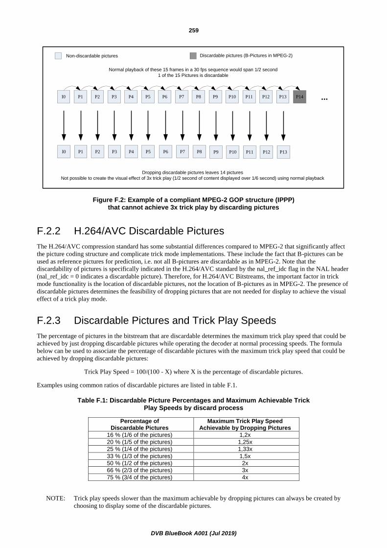
DVB BlueBook A001 (Jul 2019)
259
I0 P1 P2 P3 P4 P5 P6 P7 P8 P9 P10 P11 P12 P13 P14 ...
Non-discardable pictures Discardable pictures (B-Pictures in MPEG-2)
Normal playback of these 15 frames in a 30 fps sequence would span 1/2 second
1 of the 15 Pictures is discardable
I0 P3 P6 P9 P12P1 P4 P7 P10 P13P2 P5 P8 P11
Dropping discardable pictures leaves 14 pictures
Not possible to create the visual effect of 3x trick play (1/2 second of content displayed over 1/6 second) using normal playback
Figure F.2: Example of a compliant MPEG-2 GOP structure (IPPP) that cannot achieve 3x trick play by discarding pictures
F.2.2 H.264/AVC Discardable Pictures
The H.264/AVC compression standard has some substantial differences compared to MPEG-2 that significantly affect
the picture coding structure and complicate trick mode implementations. These include the fact that B-pictures can be
used as reference pictures for prediction, i.e. not all B-pictures are discardable as in MPEG-2. Note that the
discardability of pictures is specifically indicated in the H.264/AVC standard by the nal_ref_idc flag in the NAL header
(nal_ref_idc = 0 indicates a discardable picture). Therefore, for H.264/AVC Bitstreams, the important factor in trick
mode functionality is the location of discardable pictures, not the location of B-pictures as in MPEG-2. The presence of
discardable pictures determines the feasibility of dropping pictures that are not needed for display to achieve the visual
effect of a trick play mode.
F.2.3 Discardable Pictures and Trick Play Speeds
The percentage of pictures in the bitstream that are discardable determines the maximum trick play speed that could be
achieved by just dropping discardable pictures while operating the decoder at normal processing speeds. The formula
below can be used to associate the percentage of discardable pictures with the maximum trick play speed that could be
achieved by dropping discardable pictures:
Trick Play Speed = 100/(100 - X) where X is the percentage of discardable pictures.
Examples using common ratios of discardable pictures are listed in table F.1.
Table F.1: Discardable Picture Percentages and Maximum Achievable Trick Play Speeds by discard process
Percentage of Discardable Pictures
Maximum Trick Play Speed Achievable by Dropping Pictures
16 % (1/6 of the pictures) 1,2x
20 % (1/5 of the pictures) 1,25x
25 % (1/4 of the pictures) 1,33x
33 % (1/3 of the pictures) 1,5x
50 % (1/2 of the pictures) 2x
66 % (2/3 of the pictures) 3x
75 % (3/4 of the pictures) 4x
NOTE: Trick play speeds slower than the maximum achievable by dropping pictures can always be created by
choosing to display some of the discardable pictures.

DVB BlueBook A001 (Jul 2019)
260
F.2.4 Smooth Trick Play and Compression Efficiency
Constraining a certain percentage of pictures in the bitstream to be discardable is necessary to enable the technique of
dropping discardable pictures to achieve a trick play mode. However, it is important to recognize that determining the
interval period between pictures where this percentage is constrained has a tradeoff between whether a smooth trick
play is achieved and the coding structure which can impact coding efficiency. For example, figures F.3 and F.4 both
illustrate coding structures with 66 % of its pictures as discardable pictures (in both cases 10 of the 15 total pictures are
discarded).
Figure F.3 has a more regular discardable picture structure and represents the further requirement of 2 out of every 3
pictures to be discardable. Dropping the discardable pictures in figure F.3 will result in smooth 3x playback since every
third picture in the original stream remains. However, note that the tradeoff for the ability to create a smooth 3x trick
play is that the discardable picture structure places a tight constraint on the encoding which could reduce compression
efficiency.
Ten out of the 15 total pictures in figure F.4 are discardable as in figure F.3, but its discardable picture structure is not
as regular. Dropping the discardable pictures in figure F.4 will not result in a smooth trick play experience as in
figure F.3. However, note that dropping discardable pictures can still be used to achieve the visual effect of playing
through the content at three times the speed (since 5 frames remain) but without the serious constraint on the encoding.
NOTE: Although structure may not always guarantee smooth playback, there are methods that could create an
appearance of smoother playback by means outside of this appendix.
To enable trick play support and still facilitate maximum compression efficiency, the percentage of discardable pictures
will be calculated over the length of a H.264/AVC GOP (which, at the maximum 5 second time interval between the
DTS of successive RAPs, may be up to 300 pictures). Encoding for the smoothest trick-play will distribute discardable
pictures evenly in time throughout the H.264/AVC GOP.
I0 P1 P2 P3 P4 P5 P6 P7 P8 P9 P10 P11 P12 P13 P14 ...
Non-discardable pictures Discardable pictures
I0 P6P3 P9 P12 ...
Normal playback of these 15 frames in a 30 fps sequence would span 1/2 second
10 of the 15 Pictures are discardable
Dropping discardable pictures leaves 5 pictures
Normal playback of these 5 frames would create the visual effect of 3x trick play (1/2 second of content displayed over 1/6 second)
Figure F.3: Coding Structure with 2 Out of Every 3 Pictures as Discardable Pictures (the Discardable Pictures are inserted consistently)

DVB BlueBook A001 (Jul 2019)
261
I0 P1 P2 P3 P4 P5 P6 P7 P8 P9 P10 P11 P12 P13 P14 ...
Non-discardable pictures Discardable pictures
I0 P6 P8 P10 P13 ...
Dropping discardable pictures leaves 5 pictures
Normal playback of these 5 frames would create the visual effect of 3x trick play (1/2 second of content displayed over 1/6 second)
Normal playback of these 15 frames in a 30 fps sequence would span 1/2 second
10 of the 15 pictures are discardable
Figure F.4: Coding Structure with 10 out of Every 15 Pictures as Discardable Pictures (The Discardable Pictures are not inserted consistently)
F.2.5 Impact of Adaptive Encoding on Guidelines
It is well known that greater compression efficiency can be achieved by encoders that are able to dynamically adapt to
content. This adaptation may occur in the middle of encoding a H.264/AVC GOP, especially with real-time encoders.
For this reason, it is often difficult for an encoder to forecast a resulting property of the H.264/AVC GOP such as the
number of discardable pictures in a H.264/AVC GOP before it actually encodes the H.264/AVC GOP since it may
decide to change its methodology while encoding the H.264/AVC GOP. On the other hand, there is typically a general
encoding methodology that will be used if the content being encoded is not drastically different from what the encoder
is expecting.

DVB BlueBook A001 (Jul 2019)
262
Annex G (informative): Random Access Point Considerations for SVC
G.1 Scope
This annex contains encoder and decoder implementation guidelines to cover the cases where SVC Base layer RAPs are
transmitted more frequently than SVC Enhancement layer RAPs. Note that decoder implementations that follow the
guidelines in this annex may require additional complexity beyond typical SVC decoding.
G.2 Overview
The specification for SVC RAPs in clause 5.8.1.6 enables SVC Base layer RAPs to be transmitted more frequently than
SVC Enhancement layer RAPs. Increasing the time interval between SVC Enhancement layer RAPs can significantly
improve coding efficiency for enhancement layers, since more SVC Enhancement layer representations (SVC
dependency representation with dependency_id greater than 0) can be inter-predicted using previously decoded pictures
as references. However, increasing the time interval between SVC Enhancement layer RAPs also increases the average
time before IRDs can start decoding the SVC Enhancement layer representations.
This annex specifies optional encoder and decoder implementation guidelines that enable SVC IRDs to reduce the time
for an IRD to output decoded pictures of the complete SVC Bitstream by initially decoding the SVC Bitstream at the
first SVC RAP that is received, irrespective of whether this SVC RAP represents an SVC Base layer RAP or an SVC
Enhancement layer RAP. If the initial SVC RAP represents an SVC Base layer RAP only, the SVC IRD starts decoding
and displaying the base layer and switches to enhancement layer decoding when the first SVC Enhancement layer RAP
is received.
This method can be beneficially used in a number of transmission scenarios, which include all types of broadcast
transmission systems, e.g. satellite, terrestrial, cable or IP channels. The benefits may include increased error resilience
as well as reduced bitrate and channel change time.
Clause G.3 provides the encoder implementation guidelines while clause G.4 provides those for the decoder.
G.3 Encoder Implementation Guidelines
The following encoder implementation guidelines should be followed by an SVC encoder in order to enable SVC IRDs
to implement the techniques in clause G.4 to efficiently start decoding at any received RAP:
1) Access units with PTS less than the PTS(rap) do not follow any access unit (in decoding order) with PTS
greater than the PTS(rap), where PTS(rap) is the Presentation Time Stamp of an access unit that represents an
SVC Enhancement layer RAP.
2) The dependency representations with a particular value of dependency_id greater than 0 in access units with
PTS greater than PTS(rap) do not reference any picture with PTS less than PTS(rap) through inter-prediction,
where PTS(rap) is the Presentation Time Stamp of an access unit that represents an SVC Enhancement layer
RAP for that particular value of dependency_id.
3) The difference between the Presentation Time Stamp of an SVC Enhancement layer RAP with PTS(rap) and
the Presentation Time Stamp of any access unit that follows the SVC Enhancement layer RAP in decoding
order but precedes it in output order should not be greater than 150 milliseconds.
4) The number of required frame stores in the decoded picture buffer (specified by max_dec_frame_buffering, if
present) for decoding a particular layer associated with a particular value of dependency_id does not exceed
the value of MaxDpbFrames for any layer with dependency_id greater than the particular value of
dependency_id.
DVB BlueBook A001 (Jul 2019)
263
Each of these constraints is designed to simplify the decoder implementation as specified in clause G.4. An SVC
encoder may choose to omit any of these guidelines but should carefully consider the potential effect on decoder
implementations that may depend on these constraints for robust implementation.
G.4 Decoder Implementation Guidelines
G.4.0 General
The following decoder implementation guidelines could be followed by an SVC IRD in order to start decoding at any
received RAP.
It is suggested that an SVC IRD starts decoding an SVC Bitstream at the first SVC RAP that it receives, independent of
whether this SVC RAP represents an SVC Base layer RAP or an SVC Enhancement layer RAP. If the initial SVC RAP
represents an SVC Enhancement layer RAP, decoding can continue as normal.
If the initial SVC RAP represents an SVC Base layer RAP only, the SVC IRD can start decoding and displaying the
base layer and switch to enhancement layer decoding when the first SVC Enhancement layer RAP is received. The
switching from base layer decoding to enhancement layer decoding at a non IDR picture is not directly specified in
annex G of Recommendation ITU-T H.264 / ISO/IEC 14496-10 [16] and could vary between different SVC IRD
implementations resulting in different visual results for this transition.
For example, an SVC IRD capable of performing dual decoding (simultaneous parallel decoding of the base and
enhancement layers) could decode the base layer starting with the SVC Base layer RAP and additionally decode the
enhancement layer starting at the next SVC Enhancement layer RAP. For all access units that precede the SVC
Enhancement layer RAP in output order, the SVC IRD can output the decoded SVC Base layer representations (SVC
dependency representation with dependency_id equal to 0). For the SVC Enhancement layer RAP and all access units
that follow the SVC Enhancement layer RAP in output order, the SVC IRD can output the decoded SVC Enhancement
layer representations. This dual decoding system may not require the encoder implementation guidelines specified in
clause G.3 to be followed but the use of dual decoding for a single stream may be computationally and/or cost
prohibitive. The encoder implementation guidelines specified in clause G.3 are intended to simplify the switching
between base and enhancement layer decoding and permit implementations with a single decoding process.
In clauses G.4.1 and G.4.2, two example decoding processes enabling the switching from base to enhancement layer
decoding after random access are given. The guidelines in these clauses outline the main steps required for
implementing the switching between base and enhancement layer decoding. Note that the clauses do not cover all the
details required in an implementation and there may be different decoding processes to achieve similar results.
Clause G.4.1 outlines a decoding approach where pictures around the transition point may be skipped.
Clause G.4.2 outlines a decoding approach where there is a seamless transition between SVC Base layer pictures (SVC
layer picture with dependency_id equal to 0) and SVC Enhancement layer pictures (SVC layer picture with
dependency_id greater than 0) around the transition point.
Clause G.4.3 outlines approaches for reducing the visibility of the transition between displaying SVC Base layer
pictures and SVC Enhancement layer pictures after accessing a bitstream at an SVC Base layer RAP.
For the following guidelines in this annex, MaxDIdRAP represents the maximum value of dependency_id that is
associated with an SVC RAP in the SVC Bitstream and MaxDId represents the maximum value of dependency_id
present in an SVC RAP in the SVC Bitstream. For a particular SVC RAP referred to as rapX, MaxDIdRAP and
MaxDId may be specified by the functional relationships MaxDIdRAP(rapX) and MaxDId(rapX), respectively.
G.4.1 Decoding process with output picture skipping
If an SVC IRD starts decoding an SVC Bitstream at an SVC RAP with MaxDIdRAP less than MaxDId, which is
referred to as rapA in the following text, the SVC IRD may use a decoding process similar to the following steps:
1) The SVC IRD decodes the SVC layer picture with dependency_id equal to MaxDIdRAP(rapA) for the SVC
RAP rapA.

DVB BlueBook A001 (Jul 2019)
264
2) Where rapB represents the next SVC RAP in the SVC Bitstream that follows rapA in decoding order and has
MaxDIdRAP(rapB) greater than MaxDIdRAP(rapA), the SVC IRD continues decoding all SVC layer pictures
with dependency_id equal to MaxDId(rapA) of the access units that precede rapB in decoding order.
3) If rapB represents an IDR picture for dependency_id equal to MaxDIdRAP(rapB), the SVC layer picture with
dependency_id equal to MaxDIdRAP(rapB) for rapB is decoded.
4) If rapB does not represent an IDR picture for dependency_id equal to MaxDIdRAP(rapB), SVC layer pictures
with dependency_id equal to MaxDIdRAP(rapB) are decoded for rapB and all access units that follow rapB in
decoding order but precede it in output order.
5) For each access unit with a Presentation Time Stamp greater than or equal to the Presentation Time Stamp of
rapA and less than the Presentation Time Stamp of rapB, the SVC IRD outputs the decoded SVC layer
pictures for dependency_id equal to MaxDIdRAP(rapA). If rapB does not represent an IDR picture for
dependency_id equal to MaxDIdRAP(rapB), no pictures are output for the access units that follow the rapB in
decoding order but precede it in output order.
6) For all access units for which SVC layer pictures with dependency_id less than MaxDId(rapA) are output, the
decoded SVC layer pictures should be re-sampled, before displaying, in order to match the resolution of the
dependency representation with dependency_id equal to MaxDId(rapA). The re-sampling operation is
specified for a smooth transition at SVC RAPs by which the dependency_id of the decoded SVC layer pictures
is increased. Note that the enhancement layer resolution is determined prior to the output of the first picture in
the base layer for the SVC IRD to perform proper re-sampling.
7) If MaxDIdRAP(rapB) is less than MaxDId(rapB), the SVC IRD continues decoding with step 2, where the
SVC RAP rapA is replaced with the SVC RAP rapB and the SVC RAP rapB is determined as specified in
step 2. Note that this step is only applicable to systems with more than two dependency representations.
8) If MaxDIdRAP(rapB) is equal to MaxDId(rapB), the SVC IRD continues decoding as specified in
Recommendation ITU-T H.264 / ISO/IEC 14496-10 [16].
In figure G.1, the decoding process is illustrated as an example for accessing an SVC Bitstream at an SVC Base layer
RAP. The decoding process starts with decoding the SVC Base layer representation for the SVC Base layer RAP and all
access units that follow the SVC Base layer RAP and precede the SVC Enhancement layer RAP in decoding order:
• For the SVC Enhancement layer RAP and all access units that follow the SVC Enhancement layer RAP in
decoding order, the SVC enhancement layer representations are decoded.
• For the SVC Base layer RAP and all access units that follow the SVC Base layer RAP in output order and
precede the SVC Enhancement layer RAP in decoding order, the SVC Base layer representations are output.
• For the SVC Enhancement layer RAP and all access units that follow the SVC Enhancement layer RAP in
output order, the SVC Enhancement layer representations are output.
• No picture is output for the access units that follow the SVC Enhancement layer RAP in decoding order but
precede it in output order.
NOTE: The access units are displayed in decoding order (from left to right). The subscript numbers indicate the output order. The representations that are decoded are marked with blue frames; the representations that are output are marked grey.
Figure G.1: Illustration of the decoding process with output picture skipping when accessing a two-layer SVC Bitstream at an SVC Base layer RAP
I0 B-2 B-3 B2 B3 B6 B5 B7 P12B-1 P4 B1 I8 B10 B9 B11 P16
I0 B-2 B-3 B2 B3 B6 B5 B7 P12B-1 P4 B1 I8 B10 B9 B11 P16
I0 B2 B3P4 B1 I8
I8
Base and Enhancement
layer RAP (non-IDR)Base layer RAP (non-IDR)
Enhancement
Layer
Base
Layer

DVB BlueBook A001 (Jul 2019)
265
G.4.2 Decoding process with seamless output
If an SVC IRD starts decoding an SVC Bitstream at an SVC RAP with MaxDIdRAP less than MaxDId, which is
referred to as rapA in the following, the SVC IRD may use a decoding process similar to the following steps:
1) The SVC IRD decodes the SVC layer picture with dependency_id equal to MaxDIdRAP(rapA) for the SVC
RAP rapA.
2) Where rapB represents the next SVC RAP in the SVC Bitstream that follows rapA in decoding order and has
MaxDIdRAP(rapB) greater than MaxDIdRAP(rapA), the SVC IRD continues decoding all SVC layer pictures
with dependency_id equal to MaxDId(rapA) of the access units that precede rapB in decoding order.
3) If rapB represents an IDR picture for dependency_id equal to MaxDIdRAP(rapB), the SVC layer picture with
dependency_id equal to MaxDIdRAP(rapB) for rapB is decoded.
4) If rapB does not represent an IDR picture for dependency_id equal to MaxDIdRAP(rapB), the following steps
apply:
a) For rapB, both the SVC layer picture with dependency_id equal to MaxDIdRAP(rapA) and the SVC
layer picture with dependency_id equal to MaxDIdRAP(rapB) are decoded. The SVC layer picture with
dependency_id equal to MaxDIdRAP(rapA) is inserted in the decoded picture buffer, while the SVC
layer picture with dependency_id equal to MaxDIdRAP(rapB) is temporarily stored separately from the
decoded picture buffer as decoding SVC layer pictures with dependency_id equal to MaxDIdRAP(rapA)
continues.
b) The SVC IRD continues decoding all SVC layer pictures with dependency_id equal
to MaxDIdRAP(rapA) of the SVC access units that follow rapB in decoding order and have a
Presentation Time Stamp less than the Presentation Time Stamp of rapB.
c) All pictures in the decoded picture buffer are marked as "unused for reference" and the temporarily
stored layer picture with dependency_id equal to MaxDIdRAP(rapB) for rapB is inserted in the decoded
picture buffer in preparation for decoding SVC layer pictures with dependency_id equal
to MaxDIdRAP(rapB).
5) For each access unit with a Presentation Time Stamp greater than or equal to the Presentation Time Stamp of
rapA and less than the Presentation Time Stamp of rapB, the SVC IRD outputs the decoded SVC layer
pictures for dependency_id equal to MaxDIdRAP(rapA).
6) For all access units for which SVC layer pictures with dependency_id less than MaxDId(rapA) are output, the
decoded SVC layer pictures should be re-sampled, before displaying, in order to match the resolution of the
dependency representation with dependency_id equal to MaxDId(rapA). The re-sampling operation is
specified for a smooth transition at SVC RAPs by which the dependency_id of the decoded SVC layer pictures
is increased. Note that the enhancement layer resolution is determined prior to the output of the first picture in
the base layer for the SVC IRD to perform proper re-sampling.
7) If MaxDIdRAP(rapB) is less than MaxDId(rapB), the SVC IRD continues decoding with step 2, where the
SVC RAP rapA is replaced with the SVC RAP rapB and the SVC RAP rapB is determined as specified in
step 2. Note that this step is only applicable to systems with more than two dependency representations.
8) If MaxDIdRAP(rapB) is equal to MaxDId(rapB), the SVC IRD continues decoding as specified in
Recommendation ITU-T H.264 / ISO/IEC 14496-10 [16].
In figure G.2 the decoding process is illustrated for an example of accessing an SVC Bitstream at an SVC Base layer
RAP. The decoding process starts with decoding the SVC Base layer representation for the SVC Base layer RAP and all
access units that follow the SVC Base layer RAP and precede the SVC Enhancement layer RAP in decoding order:
• For the SVC Enhancement layer RAP, both the SVC Base layer representation and SVC Enhancement layer
representation are decoded. The decoded SVC Base layer representation is normally inserted in the decoded
picture buffer while the decoded SVC Enhancement layer representation is stored in a temporary frame store.

DVB BlueBook A001 (Jul 2019)
266
• For the access units that follow the SVC Enhancement layer RAP in decoding order but precede it in output
order, the IRD continues decoding the SVC Base layer representations. Before the first access unit that follows
the SVC Enhancement layer RAP in both decoding and output order is decoded, all SVC Base layer
representations in the decoded picture buffer are marked as "unused for reference" and the temporary stored
SVC Enhancement layer representation (for the SVC Enhancement layer RAP) is inserted in the decoded
picture buffer. The decoding process then continues with decoding the SVC Enhancement layer
representations for all following access units.
• For the SVC Base layer RAP and all access units that follow the SVC Base layer RAP and precede the SVC
Enhancement layer RAP in output order, the SVC Base layer representations are output. For the SVC
Enhancement layer RAP and all access units that follow the SVC Enhancement layer RAP in output order, the
SVC Enhancement layer representations are output.
NOTE: The access units are displayed in decoding order (from left to right). The subscript numbers indicate the output order. The representations that are decoded are marked with blue frames; the representations that are output are marked grey.
Figure G.2: Illustration of the decoding process with seamless output when accessing a two-layer SVC Bitstream at an SVC Base layer RAP
G.4.3 Display Process at a Transition from Base to Enhancement Layer Decoding
This clause provides guidelines for reducing the visibility of the transition between displaying SVC Base layer pictures
and SVC Enhancement layer pictures when accessing SVC Bitstream at an SVC Base layer RAP. An SVC IRD is not
required to follows these guidelines.
For all pictures for which the SVC Base layer representations are output by the decoding process (see clauses G.4.1 and
G.4.2), the decoded SVC Base layer representations should be re-sampled to the enhancement layer frame size before
displaying.
If SVC Base layer pictures and SVC Enhancement layer pictures represent the same area of the source pictures, the
transition between displaying re-sampled SVC Base layer pictures and SVC Enhancement pictures might be visible as a
quality change in the displayed video signal. If the SVC Base layer pictures represent a subset of the source picture area
that is represented by the SVC Enhancement layer pictures, the transition between displaying re-sampled SVC Base
layer pictures and SVC Enhancement pictures might be more pronounced and appear to be a cut between different
scenes. In the following text, two approaches are outlined which can be applied for reducing the visibility of a transition
between displaying re-sampled SVC Base layer pictures and SVC Enhancement layer pictures:
• When SVC Base layer pictures and SVC Enhancement layer pictures represent the same area of the source
pictures, the visibility of the transition between base and enhancement layer decoding can be reduced by
applying a time-varying low-pass filter (before display) to the initial pictures that are displayed from the SVC
Enhancement layer representation. For the first picture for which the SVC Enhancement layer representation is
output, the cut-off frequency can be selected according to the ratio between the SVC Base layer picture and
SVC Enhancement layer picture sizes. The cut-off frequency of the low-pass filter can then be continuously
increased in output order until the SVC Enhancement layer pictures are displayed without the additional
low-pass filtering. For example, this transition interval could be about 1 second.
I0 B-2 B-3 B2 B3 B6 B5 B7 P12B-1 P4 B1 I8 B10 B9 B11 P16
I0 B-2 B-3 B2 B3 B6 B5 B7 P12B-1 P4 B1 I8 B10 B9 B11 P16
I0 B2 B3P4 B1 I8
I8
Base and Enhancement
layer RAP (non-IDR)Base layer RAP (non-IDR)
Enhancement
Layer
Base
Layer

DVB BlueBook A001 (Jul 2019)
267
• When the SVC Base layer picture represent a subset of the source picture area that is represented by the SVC
Enhancement layer pictures, the visibility of the transition between base and enhancement layer decoding can
be reduced by continuously increasing the cropping window for the initial pictures that are displayed from the
SVC Enhancement layer representation. For the first SVC Enhancement layer representation that is output,
only the portion of the picture that corresponds to the base layer cropping window can be displayed (after
re-sampling it to the enhancement layer frame size). For the following SVC Enhancement layer
representations, this cropping window can be continuously increased until it matches the enhancement layer
cropping window specified in the bitstream. For example, this transition interval could be about 1 second. This
approach of continuously increasing the cropping window could also be combined with the approach of
applying a time-varying low-pass filter described above.

DVB BlueBook A001 (Jul 2019)
268
Annex H (normative): Frame Compatible Plano-Stereoscopic 3DTV
H.1 Scope
This annex contains encoder and decoder implementation guidelines for frame compatible plano-stereoscopic 3DTV
systems. Such systems are built upon the existing H.264/AVC High Definition system and include the additional
requirement and guidelines to deliver frame compatible plano-stereoscopic 3DTV services. Depending on the output
resolution, interlace or progressive frame format, frame rate and 3DTV formatting arrangement, a frame compatible
plano-stereoscopic 3DTV system supports the combinations described in the table H.1. All the other combinations that
are not defined in the table H.1 remain optional and are left to the responsibility of the broadcaster or the service
provider to ensure that systems for the proper delivery of services based on them are available. The term HDTV is used
to refer to non-frame compatible plano-stereoscopic 3DTV services (i.e.: 2D services). For frame compatible
plano-stereoscopic 3DTV implementation guidelines refer to ETSI TS 101 547-2 [33].
Table H.1: Frame compatible mandated 3DTV formats/structures
IRD Class Output resolution/Format
Frame rate Frame compatible arrangement type
25 Hz 720p 50 Hz Top-and-Bottom, Side-by-Side
25 Hz 1 080i 25 Hz Side-by-Side
30 Hz 720p 59,94/60 Hz Top-and-Bottom, Side-by-Side
30 Hz 1 080i 29,97/30 Hz Side-by-Side
30 Hz 1 080p 23,98/24 Hz Top-and-Bottom, Side-by-Side
H.2 Frame compatible plano-stereoscopic 3DTV definition
25 Hz frame compatible plano-stereoscopic 3DTV IRD: IRD that is capable of decoding and displaying pictures
based on a nominal video frame rate of 25 Hz or 50 Hz from H.264/AVC High Profile at Level 4 bitstreams as specified
in the present document, in addition to providing the functionality of interpreting the specific plano-stereoscopic 3DTV
signalling as specified in this annex.
25 Hz frame compatible plano-stereoscopic 3DTV Bitstream: bitstream which contains only H.264/AVC High
Profile at Level 4 video at 25 Hz or 50 Hz frame rates as specified in the present document with the specific
plano-stereoscopic 3DTV signalling as specified in this annex.
30 Hz frame compatible plano-stereoscopic 3DTV IRD: IRD that is capable of decoding and displaying pictures
based on nominal video frame rates of 24 000/1 001 (approximately 23,98), 24, 30 000/1 001 (approximately 29,97),
30, 60 000/1 001 (approximately 59,94) or 60 Hz from H.264/AVC High Profile at Level 4 bitstreams as specified in
the present document, in addition to providing the functionality of interpreting the specific plano-stereoscopic 3DTV
signalling as specified in this annex.
30 Hz frame compatible plano-stereoscopic 3DTV Bitstream: bitstream which contains only H.264/AVC High
Profile at Level 4 video at 24 000/1 001, 24, 30 000/1 001, 30, 60 000/1 001 or 60 Hz frame rates as specified in the
present document with the specific plano-stereoscopic 3DTV signalling as specified in this annex.

DVB BlueBook A001 (Jul 2019)
269
H.3 System layer specifications common to all plano-stereoscopic 3DTV IRDs and Bitstreams
H.3.0 Scope
The specification in this clause applies to the following IRDs and Bitstreams:
• 25 Hz frame compatible plano-stereoscopic 3DTV IRD and Bitstream;
• 30 Hz frame compatible plano-stereoscopic 3DTV IRD and Bitstream.
H.3.1 General
Frame compatible plano-stereoscopic 3DTV IRDs and Bitstreams shall comply with the system layer specifications
related to all H.264/AVC HDTV IRDs and bitstreams as defined in clause 4 with the extensions as specified in this
annex.
H.3.2 Frame compatible plano-stereoscopic 3DTV Specific Program Elementary Stream descriptor
H.3.2.1 AVC_video_descriptor
For frame compatible plano-stereoscopic 3DTV:
Encoding: The AVC_video_descriptor, as specified in Recommendation ITU-T H.222.0 /
ISO/IEC 13818-1 [1], shall be used when appropriate. The syntax element
Frame_Packing_SEI_not_present_flag shall be set to 0 in the AVC_video_descriptor to signal
presence of frame packing arrangement SEI message within the coded video sequence (see
clause H.4.2).
Decoding: The frame compatible plano-stereoscopic 3DTV IRD shall use this descriptor in order to identify
the presence of the frame packing arrangement SEI message in the bitstream.
H.4 Video specifications Common to all frame compatible plano-stereoscopic 3DTV IRDs and Bitstreams
H.4.0 Scope
The specification in this clause applies to the following IRDs and Bitstreams:
• 25 Hz frame compatible plano-stereoscopic 3DTV IRD and Bitstream;
• 30 Hz frame compatible plano-stereoscopic 3DTV IRD and Bitstream.
H.4.1 General
Frame compatible plano-stereoscopic 3DTV IRDs and Bitstreams shall comply with the common specifications to all
H.264/AVC IRDs and bitstreams as defined in clause 5.5 with extensions as specified in this annex.
25 Hz frame compatible plano-stereoscopic 3DTV IRD and bitstreams shall comply with the specifications of 25 Hz
H.264/AVC HDTV as defined in clause 5.7 with extensions as specified in this annex.

DVB BlueBook A001 (Jul 2019)
270
30 Hz frame compatible plano-stereoscopic 3DTV IRD and bitstreams shall comply with the specifications of 30 Hz
H.264/AVC HDTV as defined in clause 5.7 with extensions as specified in this annex.
H.4.2 Supplemental Enhancement Information
H.4.2.0 General
Frame compatible plano-stereoscopic 3DTV IRDs shall support the use of frame packing arrangement SEI message in
the conditions depicted in this clause.
Frame compatible plano-stereoscopic 3DTV bitstreams shall not use the Stereo Video information SEI message.
Frame compatible plano-stereoscopic 3DTV IRDs shall ignore any Stereo Video information SEI message.
H.4.2.1 Frame Packing Arrangement SEI Message
Encoding: The constraints defined below apply to frame compatible plano-stereoscopic 3DTV bitstreams and
are made in order to support the formats listed in table H.1:
When the AVC_video_descriptor has its frame_packing_SEI_not_present_flag syntax element
equal to 0, the frame packing arrangement SEI shall be transmitted with each access unit. The
syntax element frame_packing_arrangement_repetition_period shall be set to'0' (1b in
Exp-Golomb code).
The syntax element frame_packing_arrangement_id shall be set to '0' (1b in Exp-Golomb code).
The syntax element frame_packing_arrangement_type defines the arrangement of the left and
right views inside an HDTV frame. In order to fulfil the frame compatible plano-stereoscopic
3DTV formats/structures listed in the table H.1, when present,
frame_packing_arrangement_type should have one of the defined values: '3' for Side-by-Side,
'4' for Top-and-Bottom, depending on the following conditions:
• for a 25 Hz frame compatible plano-stereoscopic 3DTV bitstream:
- if the frame rate is 25 Hz interlaced and if the decoded video resolution is 1 080i, then
the frame_packing_arrangement_type should be '3';
- if the frame rate is 50 Hz progressive and if the decoded video resolution is 720p, then
the frame_packing_arrangement_type should be either '3' or '4'.
• for a 30 Hz frame compatible plano-stereoscopic 3DTV bitstream:
- if the frame rate is 23,98 Hz or 24 Hz progressive and if the decoded video resolution is
1 080p, then the frame_packing_arrangement_type should be either '3' or '4';
- if the frame rate is 59,94 Hz or 60 Hz interlaced and if the decoded video resolution is
1 080i, then the frame_packing_arrangement_type should be '3';
- if the frame rate is 60 Hz progressive and if the decoded video resolution is 720p, then
the frame_packing_arrangement_type should be either '3' or '4'.
NOTE 1: The use of any other combination of frame format and frame packing arrangement type, not specified
above is not required to be supported by frame compatible plano-stereoscopic 3DTV IRDs.
Changes to frame packing arrangement SEI, including the frame_packing_arrangement_type
shall only occur at a RAP with an IDR picture.
NOTE 2: An IDR picture cancels all prior SEI messages. An IDR without a frame packing arrangement SEI
indicates a switch in the video sequence from a frame compatible plano-stereoscopic 3DTV to an HDTV
event.

DVB BlueBook A001 (Jul 2019)
271
NOTE 3: In the case of a switch from a frame compatible plano-stereoscopic 3DTV event to an HDTV event,
transmission of a frame packing arrangement SEI with frame_packing_arrangement_cancel_flag = 1
starting at the first RAP with an IDR picture of the HDTV format content, may provide explicit
confirmation at the video layer that such a format change has occurred. In the case of a switch from an
HDTV event to a frame compatible plano-stereoscopic 3DTV event, transmission of a frame packing
arrangement SEI with frame_packing_arrangement_cancel_flag = 1 starting at a RAP with an IDR
picture of the HDTV format content, may provide an early indication of such a format change at the event
boundary. Clause 6.5 of ETSI TS 101 547-2 [33] makes provisions concerning such format transitions.
▪ In order to be consistent with the minimum capabilities in HDMI 1.4a [i.14] for plano-stereoscopic
3DTV:
- The syntax element quincunx_sampling_flag shall be set to '0'.
- The syntax element content_interpretation_type shall be set to '1'.
- The syntax elements spatial_flipping_flag and frame0_flipped_flag shall be set to '0'.
NOTE 4: The HDMI 1.4a specification does not provide all the information on the sub-sampling method, filters
and how the views are ordered inside an HDTV frame. Therefore care should be taken on the use of any
other value than the ones specified above.
The syntax elements frame0_grid_position_x, frame0_grid_position_y, frame1_grid_position_x
and frame1_grid_position_y should be set to '0000'.
When frame_packing_arrangement_type is equal to '3' or '4', the following syntax elements shall
be equal to '0':
- field_views_flag;
- current_frame_is_frame0_flag;
- frame_packing_arrangement_extension_flag.
NOTE 5: As specified in Recommendation ITU-T H.264 / ISO/IEC 14496-10 [16], any other value of the above
listed syntax elements combined with a frame_packing_arrangement_type equal to '3' or '4' is reserved
for future use.
The syntax elements frame0_self_contained_flag and frame1_self_contained_flag should be set
to '0'.
Decoding: Frame compatible plano-stereoscopic 3DTV IRDs shall support the frame_packing_arrangement
SEI message.
Frame compatible plano-stereoscopic 3DTV IRDs shall ignore frame packing arrangement SEI
messages with a value of frame_packing_arrangement_id not equal to '0'.
25Hz frame compatible plano-stereoscopic 3DTV IRDs shall support the following values of
frame_packing_arrangement_type:
- frame_packing_arrangement_type value '3' (Side-by-Side) shall be supported for 25 Hz,
1 080 lines vertical resolution interlaced video.
- frame_packing_arrangement_type values '3' (Side-by-Side) and '4' (Top-and-Bottom) shall
be supported for 50 Hz, 720 lines vertical resolution progressive video.
- 30 Hz frame compatible plano-stereoscopic 3DTV IRDs shall support the following values of
frame_packing_arrangement_type:
- frame_packing_arrangement_type value '3' (Side-by-Side) and '4' (Top-and-Bottom) shall
be supported for 23,98 Hz or 24 Hz, 1 080 lines vertical resolution progressive video.
- frame_packing_arrangement_type value '3' (Side-by-Side) shall be supported for 59,94 Hz
or 60 Hz, 1 080 lines vertical resolution interlace video.

DVB BlueBook A001 (Jul 2019)
272
- frame_packing_arrangement_type value '3' (Side-by-Side) and '4' (Top-and-Bottom) shall
be supported for 60 Hz, 720 lines vertical resolution progressive video.
Frame compatible plano-stereoscopic 3DTV IRDs shall ignore the following syntax elements
field_views_flag, current_frame_is_frame0_flag, frame0_self_contained_flag,
frame1_self_contained_flag, frame_packing_arrangement_extension_flag.

DVB BlueBook A001 (Jul 2019)
273
Annex I (normative): Considerations for Encoding and Random Access for MVC Stereo Video
I.0 Introduction
The following clauses give guidelines for allowing easy random access within MVC Stereo bitstreams. These
guidelines are based on the Blu-ray Disc White Paper [i.16].
I.1 Video Sequence Structure
I.1.0 General
Figure I.1 shows the typical coded video sequence structure and frame and view dependencies of MVC Stereo video, as
stored on a Blu-ray Disc. Broadcast video may, or may not, have a similar structure, though it is recommended. This is
shown here for illustrative purposes.
Figure I.1: Typical coded video sequence structure of MVC Stereo video
In order to enable quick random access, the following constraints apply:
• The first access unit in a coded video sequence in decoding order is an MVC Stereo RAP.
• In case the Dependent view component is a B picture component, then the corresponding view component of
Base view video shall also be B picture component.

DVB BlueBook A001 (Jul 2019)
274
• In case the Dependent view component is a non-reference B picture component, the corresponding view
component of Base view video shall also be a non-reference B picture component.
• The coded video sequence structure for Base view video stream and Dependent view video stream shall be the
same, including:
- whether it is open or closed coded video sequence structure;
- the number of view components;
- the values of nal_ref_idc of a NAL unit with slice data for Base view component and nal_ref_idc of a
NAL unit with slice data for the corresponding Dependent view component shall be the same;
- the display order of the pictures, i.e. Picture Order Count, POC;
- the decoding delay, defined as the PTS of the first displayed picture in a coded video sequence minus its
DTS.
I.1.1 Closed Coded Video Sequence
In the case of a closed coded video sequence (see figure I.2) the first Dependent view component in decoding order
shall be an MVC Stereo anchor view component associated with a Base view component containing an IDR picture. An
anchor view component associated with an IDR base view component prohibits view component referencing over
coded video sequence boundary, hence, it shall be possible to decode correctly all view components in a closed coded
video sequence, even when random access to this coded video sequence is executed.
Figure I.2: Example of Closed coded video sequence for MVC Dependent view bitstream

DVB BlueBook A001 (Jul 2019)
275
I.1.2 Open Coded Video Sequence
In case of an open coded video sequence structure, (see figure I.3), the first Dependent view component in decoding
order shall be an MVC Stereo anchor view component associated with a Base view component containing an (non-IDR)
I picture. Since an anchor view component associated with a I picture does not prohibit view component referencing
over coded video sequence boundary, it may be the case that view components prior to the I picture in display order
cannot be correctly decoded when random access to this coded video sequence is executed.
If it is desireable to encode MVC sub-bitstream to correctly decode view components subsequent to the first Dependent
anchor view component associated with a Base view component containing an I picture in display order, the following
conditions shall be satisfied:
• Pictures prior to the first Dependent anchor view component associated with a Base view component
containing an I picture in display order may use reference to past, future and Corresponding view components.
It is assumed that these view components are not displayed in case of random access to an open coded video
sequence.
• Pictures subsequent to the first Dependent anchor view component associated with a Base view component
containing an I picture in display order may use references to past, future, and Corresponding view
components, but these view components shall not use past reference to view components prior to the first
anchor view components in display order.
Figure I.3: Example of Open coded video sequence for MVC Dependent view bitstream

DVB BlueBook A001 (Jul 2019)
276
I.2 Guidelines for TS Packet Multiplexing
Re-multiplexing during transmission might alter the relative reception order of Base and Dependent transport stream
packets (TS packets), when compared to the original transmission order. In the present document, this is called
'inter-PID reordering'. Figure I.4 represents a sample setup of a live broadcast system where re-multiplexing of
TS packets might cause inter-PID reordering.
Figure I.4: Example of Live Broadcast where re-multiplexing might occur
Since the TS packet order affects random access, a transmission system should try to limit inter-PID re-ordering as
much as possible. One possibility would be to satisfy the following conditions:
• The first transport packet of the PES packet header belonging to the MVC Stereo Base view component of the
first Access Unit in a coded video sequence should precede the first transport packet of the PES packet header
from the corresponding MVC Stereo Dependent view component.
• The last transport packet for the last Dependent Unit in the coded video sequence should precede the first
transport packet of the PES packet header belonging to the MVC Stereo Base view component of the first
Access Unit of the following coded video sequence.

DVB BlueBook A001 (Jul 2019)
277
Annex J (normative): Service Frame Compatible Plano-Stereoscopic 3DTV with HEVC coding
J.1 Scope
This annex contains encoder and decoder implementation guidelines for HEVC service frame compatible
plano-stereoscopic 3DTV systems. Such systems are built upon the existing HEVC High Definition system and include
the additional requirement and guidelines to deliver frame compatible plano-stereoscopic 3DTV services. Depending on
the frame rate and 3DTV formatting arrangement, a service frame compatible plano-stereoscopic 3DTV system
supports the combinations described in the table J.1. All the other combinations that are not defined in the table J.1
remain optional and are left to the responsibility of the broadcaster or the service provider to ensure that systems for the
proper delivery of services based on them are available. The term HDTV is used to refer to non-frame compatible
plano-stereoscopic 3DTV services (i.e. 2D services). For service frame compatible plano-stereoscopic 3DTV
implementation guidelines refer to ETSI TS 101 547-4 [44].
Table J.1: Service frame compatible mandated 3DTV formats/structures
IRD Class Output resolution/Format
Frame rate Frame compatible arrangement type
50 Hz 1 080p 50 Hz Top-and-Bottom
60 Hz 1 080p 59,94/60 Hz Top-and-Bottom
J.2 Service frame compatible plano-stereoscopic 3DTV definition
50 Hz HEVC service frame compatible plano-stereoscopic 3DTV IRD: IRD that is capable of decoding and
displaying pictures based on a nominal video frame rate of 50 Hz from up to HEVC Main 10 Profile at
Level 4.1 bitstreams as specified in clause 5.14.2 of the present document, in addition to providing the functionality of
interpreting the specific plano-stereoscopic 3DTV signalling as specified in the present annex.
50 Hz HEVC service frame compatible plano-stereoscopic 3DTV Bitstream: HEVC video stream which contains
HEVC Main or Main 10 Profile encoded video at Level 4.1 at 50 Hz frame rates as specified in clause 5.14.2 of the
present document with the specific plano-stereoscopic 3DTV signalling as specified in the present annex.
60 Hz HEVC service frame compatible plano-stereoscopic 3DTV IRD: IRD that is capable of decoding and
displaying pictures based on nominal video frame rates of 60 000/1 001 (approximately 59,94) Hz or 60 Hz from up to
HEVC Main 10 Profile at Level 4.1 bitstreams as specified in clause 5.14.2 of the present document, in addition to
providing the functionality of interpreting the specific plano-stereoscopic 3DTV signalling as specified in the present
annex.
60 Hz HEVC service frame compatible plano-stereoscopic 3DTV Bitstream: HEVC video stream which contains
HEVC Main or Main 10 Profile encoded video at Level 4.1 at 60 000/1 001 or 60 Hz frame rates as specified in
clause 5.14.2 of the present document with the specific plano-stereoscopic 3DTV signalling as specified in the present
annex.
HEVC service frame compatible plano-stereoscopic 3DTV IRD: collective term referring to either a 50 Hz HEVC
service frame compatible plano-stereoscopic 3DTV IRD or a 60 Hz HEVC service frame compatible plano-stereoscopic
3DTV IRD.
HEVC service frame compatible plano-stereoscopic 3DTV Bitstream: collective term referring to either a 50 Hz
HEVC service frame compatible plano-stereoscopic 3DTV Bitstream or a 60 Hz HEVC service frame compatible
plano-stereoscopic 3DTV Bitstream.

DVB BlueBook A001 (Jul 2019)
278
J.3 System layer specifications common to all HEVC service frame compatible plano-stereoscopic 3DTV IRDs and Bitstreams
J.3.1 Scope
The specification in this clause applies to the following IRDs and Bitstreams:
• 50 Hz HEVC service frame compatible plano-stereoscopic 3DTV IRD and Bitstream;
• 60 Hz HEVC service frame compatible plano-stereoscopic 3DTV IRD and Bitstream.
J.3.2 General
HEVC service frame compatible plano-stereoscopic 3DTV IRDs and Bitstreams shall comply with the system layer
specifications related to all HEVC HDTV IRDs and bitstreams as defined in clause 4 with the extensions as specified in
the present annex.
J.3.3 Service frame compatible plano-stereoscopic 3DTV Specific Program Elementary Stream descriptor
J.3.3.1 HEVC_video_descriptor
For service frame compatible plano-stereoscopic 3DTV:
Encoding: The HEVC_video_descriptor, as specified in Recommendation ITU-T H.222.0 /
ISO/IEC 13818-1 [1], shall be present in the PMT. The syntax element
non_packed_constraint_flag shall be set to 0 in the HEVC_video_descriptor to signal the
presence of the frame packing arrangement SEI message within the coded video sequence (see
clause J.4.2).
Decoding: The HEVC service frame compatible plano-stereoscopic 3DTV IRD shall use this descriptor in
order to identify the presence of the frame packing arrangement SEI message in the bitstream.

DVB BlueBook A001 (Jul 2019)
279
J.4 Video specifications common to all HEVC service frame compatible plano-stereoscopic 3DTV IRDs and Bitstreams
J.4.1 Scope
The specification in this clause applies to the following IRDs and Bitstreams:
• 50 Hz HEVC service frame compatible plano-stereoscopic 3DTV IRD and Bitstream;
• 60 Hz HEVC service frame compatible plano-stereoscopic 3DTV IRD and Bitstream.
J.4.2 General
HEVC service frame compatible plano-stereoscopic 3DTV IRDs and Bitstreams shall comply with the common
specifications to all HEVC IRDs and Bitstreams as defined in clause 5.14 of the present document with extensions as
specified in the present annex.
50 Hz HEVC service frame compatible plano-stereoscopic 3DTV IRDs shall comply with the specifications of 50 Hz
HEVC HDTV10-bit IRDs as defined in clause 5.14.2 of the present document with extensions as specified in the present
annex.
60 Hz HEVC service frame compatible plano-stereoscopic 3DTV IRDs shall comply with the specifications of 60 Hz
HEVC HDTV10-bit IRDs as defined in clause 5.14.2 of the present document with extensions as specified in the present
annex.
HEVC service frame compatible plano-stereoscopic 3DTV Bitstreams shall comply with the specifications of HEVC
HDTV Bitstreams as defined in clause 5.14.2 of the present document with extensions as specified in the present annex.
J.4.3 Supplemental Enhancement Information
J.4.3.1 General
HEVC service frame compatible plano-stereoscopic 3DTV IRDs shall support the use of frame packing arrangement
SEI message in the conditions depicted in this clause.
NOTE: Other frame packing arrangement types might be added in future versions of the present document.
J.4.3.2 Frame Packing Arrangement SEI Message
Encoding: The constraints defined below apply to service frame compatible plano-stereoscopic 3DTV
bitstreams and are made in order to support the formats listed in table J.1:
When the HEVC_video_descriptor has its non-packed-constraint_flag syntax element equal to 0,
the frame packing arrangement SEI shall be transmitted with each access unit.
The syntax element frame_packing_arrangement_id shall be set to '0' (1b in Exp-Golomb code).
The syntax element frame_packing_arrangement_type defines the arrangement of the left and
right views inside an HDTV frame. In order to fulfil the service frame compatible
plano-stereoscopic 3DTV formats/structures listed in the table J.1, when present,
frame_packing_arrangement_type shall have the value '4' (Top-and-Bottom).
NOTE 1: The use of any otherframe packing arrangement type, not specified above, is not required to be supported
by service frame compatible plano-stereoscopic 3DTV IRDs.

DVB BlueBook A001 (Jul 2019)
280
Changes to frame packing arrangement SEI, including the frame_packing_arrangement_type
shall only occur at a HEVC DVB_RAP.
NOTE 2: An IDR picture cancels all prior SEI messages. An IDR without a frame packing arrangement SEI
indicates a switch in the video sequence from a frame compatible plano-stereoscopic 3DTV to an HDTV
event.
NOTE 3: In the case of a switch from a frame compatible plano-stereoscopic 3DTV event to an HDTV event,
transmission of a frame packing arrangement SEI with frame_packing_arrangement_cancel_flag = 1
starting at the first RAP with an IDR picture of the HDTV format content, may provide explicit
confirmation at the video layer that such a format change has occurred. In the case of a switch from an
HDTV event to a frame compatible plano-stereoscopic 3DTV event, transmission of a frame packing
arrangement SEI with frame_packing_arrangement_cancel_flag = 1 starting at a HEVC DVB_RAP of
the HDTV format content, may provide an early indication of such a format change at the event
boundary. Clause 6.5 of ETSI TS 101 547-4 [44] makes provisions concerning such format transitions.
In order to be consistent with the minimum capabilities in HDMI [i.14] for plano-stereoscopic
3DTV:
- the syntax element quincunx_sampling_flag shall be set to '0';
- the syntax element content_interpretation_type shall be set to '1';
- the syntax elements spatial_flipping_flag and frame0_flipped_flag shall be set to '0'.
NOTE 4: The HDMI specification does not provide all the information on the sub-sampling method, filters and
how the views are ordered inside an HDTV frame. Therefore care should be taken on the use of any other
value than the ones specified above.
The syntax elements frame0_grid_position_x, frame0_grid_position_y,
frame1_grid_position_x and frame1_grid_position_y should be set to '0000'.
When frame_packing_arrangement_type is equal to '4', the following syntax elements shall be
equal to '0':
- field_views_flag;
- current_frame_is_frame0_flag.
NOTE 5: As specified in Recommendation ITU-T H.265 / ISO/IEC 23008-2 [35], any other value of the above
listed syntax elements combined with a frame_packing_arrangement_type equal to '4' is reserved for
future use.
The syntax elements frame0_self_contained_flag and frame1_self_contained_flag should be set
to '0'.
Decoding: HEVC service frame compatible plano-stereoscopic 3DTV IRDs shall support the
frame_packing_arrangement SEI message.
HEVC service frame compatible plano-stereoscopic 3DTV IRDs shall ignore frame packing
arrangement SEI messages with a value of frame_packing_arrangement_id not equal to '0'.
50 Hz HEVC service frame compatible plano-stereoscopic 3DTV IRDs shall support the following
value of frame_packing_arrangement_type:
- frame_packing_arrangement_type value '4' (Top-and-Bottom).
60 Hz HEVC service frame compatible plano-stereoscopic 3DTV IRDs shall support the following
value of frame_packing_arrangement_type:
- frame_packing_arrangement_type value '4' (Top-and-Bottom).
Frame compatible plano-stereoscopic 3DTV IRDs shall ignore the following syntax elements
field_views_flag, current_frame_is_frame0_flag, frame0_self_contained_flag,
frame1_self_contained_flag.

DVB BlueBook A001 (Jul 2019)
281
J.4.4 VUI - Default Display Window and service compatibility of frame compatible services
The Default Display Window may be used to allow HEVC IRDs to extract one of the views for 2D display from a
frame compatible format signalled by the Frame Packing Arrangement SEI message.
As an example, the values indicated in table J.2 might be used.
Table J.2: Default Display Window parameter values for service (2D) compatibility of Frame Compatible Formats
Frame compatible
plano-stereoscopic 3DTV video
format
Default display window top offset (luma
samples)
Default display window right offset (luma
samples)
Default display window bottom
offset (luma samples)
Default display window left offset (luma
samples)
1 920 x 1 080p Top-and-Bottom
0 0 540 0
When the default display window is used to signal the 2D view to be extracted from the decoded picture (like in the
example above), IRDs incognizant of frame compatible plano-stereoscopic 3DTV formats may apply the default display
window as carried in the coded bitstream to crop the decoded picture. The cropped picture may be upscaled to the size
of the conformance window. IRDs cognizant of the stereoscopic formats shall output the content of the conformance
cropping window if present in the coded bitstream (conformance_window_flag in the SPS is equal to 1). If the
conformance cropping window is not present (conformance_window_flag in the SPS is equal to 0), the decoder shall
output the whole decoded picture.

DVB BlueBook A001 (Jul 2019)
282
Annex K (informative): Next-Generation Audio Overview
K.1 NGA Concepts
K.1.1 Introduction
Next Generation Audio (NGA) Systems provide Broadcasters, Operators and Content Providers with more flexibility to
create and deliver their content. These NGA Systems introduce a number of new concepts and techniques, including:
• The capability to provide Immersive Audio with the addition of height elements.
• The capability to provide personalization options to broadcasters and consumers.
• The introduction of Audio Objects to facilitate immersive and personalized audio.
K.1.2 Immersive audio
Immersive Audio can be experienced with additional speakers adding the height elements (adding either direct speakers
or simulating real speakers through various techniques such as sound frames or "up-firing" speakers). Using appropriate
virtualization techniques, immersive audio can also be experienced through headphones.
The height elements may be carried either by additional audio channels, sound field representation, audio objects or a
combination of these.
Audio objects can be conceptualized as either mono or stereo audio tracks with metadata that describes their properties
e.g. type of content, positional and/or time metadata. These are delivered separately and are combined in the receiver,
and are then matched to the final speaker layout of the user's reproduction equipment. Audio objects can be used to
carry all of the Audio Programme Components of the Audio Programme, or their use can be restricted to a subset e.g. to
speech elements.
K.1.3 Preselections and Personalized audio
As Audio Programme Components are combined at the receiver it is now possible to allow user interaction with the
final mixing process. This can then allow the user to vary elements of the mix e.g. some constrained control over the
relative level of dialogue with respect to the ambient music and effects.
In the hybrid configuration where Audio Programme Components can also be delivered in conjunction with the ambient
sound, the receiver then combines the ambient sound and objects. This leads to a very efficient system where say the
ambience is carried in an audio format that is optimized for ambient audio sources and the dialogue and speech related
elements are transmitted as objects.
Audio Preselections are where alternative audio mixes are made available to the user for 'User Personalization'. These
mixes could include existing service types such as alternative language versions or Audio Description services, but
could also include new services such as a biased crowd and commentary mix at a sports event or a team channel. As
some of the elements of the production may be shared between different Preselections, as these are combined at the
receiver, this can also lead to a very efficient method of delivering these additional alternative services.
The signalling of preselections uses the audio preselection descriptor in DVB-SI, which is defined in clause 6.4.1 of
ETSI EN 300 468 [i.32]. Further rules for its use are given in annex M of ETSI EN 300 468 [i.32].

DVB BlueBook A001 (Jul 2019)
283
K.2 Examples
K.2.1 Audio Programme Examples
A number of Audio Programme Components in the Audio Programme can be selected in different ways to create
various audio experiences. Table K.1 provides two examples of such audio experiences (Audio Preselections) that could
be specified by different broadcasters. The Audio Preselection information is essentially additional metadata which
requires signaling at systems level and links to the Audio Programme Components to be played out together to form a
predefined audio experience.
Table K.1: Example Broadcast Audio Preselections in an Audio Programme
Audio Programme
Input Elements Audio
Preselections
Components Referenced by Preselection
AP 1 5.1 M&E + D1 (EN) + D2 (DE) + AD (EN) + TeamRadio
English M&E + D1
English + AD M&E + D1 + AD
German M&E + D2
M&E + Team Radio M&E + TeamRadio
M&E Only M&E
AP 2 7.1.4 M&E + D1 (EN) + D2 (DE) + AD (EN)
English M&E + D1
English + AD M&E + D1 + AD
German M&E + D2
M&E Only M&E
AP 3 O(15).1 M&E + D1 (EN) + D2 (DE) + AD (EN)
English M&E + D1
English + AD M&E + D1 + AD
German M&E + D2
M&E Only M&E
AP 4 HOA(6) M&E + D1 (EN) + D2 (DE) + AD (EN)
English M&E + D1
English + AD M&E + D1 + AD
German M&E + D2
M&E Only M&E
NOTE: Audio Programme examples 2, 3 and 4 are used only to illustrate the different immersive formats supported by NGA systems.
K.2.2 Audio Preselection Examples
Figure K.1 illustrates the example of clause K.2.1 in more detail, assuming all Audio Programme Components and the
Audio Preselection information are contained in the same stream (single-stream delivery case). Compared with legacy
systems, this approach offers a bitrate efficient delivery, for example, of a multi-language program by using the same
components in different Preselections (e.g. the M&E component) instead of several complete audio mixes ("complete
mains").

DVB BlueBook A001 (Jul 2019)
284
Figure K.1: Example Broadcast Audio Preselections in an Audio Programme (AP 1)
For automatic selection the Preselection information contains language, accessibility and role attributes. Similarly "text
labels" can be used for displaying the Preselections availability on the TV screen and allow manual selection.
K.3 Carriage of NGA
The simplest method for carrying the Audio Programme Components is to carry all components in a single elementary
stream (linked to a single PID, i.e. single-stream delivery case). In this case all components are carried in the transport
stream together with the signaling information of the available Audio Preselections. This example emphasizes one of
the main differences of the NGA systems compared to the legacy systems, one PID can contain much more than one
complete audio main. In legacy systems the multi-language functionality can be achieved using supplementary streams
("broadcast-mix" or "receiver-mix"). For NGA systems this is achieved in a much more bitrate efficient way using only
one stream (linked to one PID) containing the independent components instead of complete mains.
In some applications the broadcaster might decide to embed some of the Audio Programme Components in individual
elementary streams (separate elementary streams with separate PIDs, i.e. multi-stream delivery case). This method is
used with non NGA codecs in the case of Audio Description, and a secondary language. In these use cases, the
additional language or the Audio Description are placed on separate PIDs and all streams are multiplexed into the same
transport stream for distribution.

DVB BlueBook A001 (Jul 2019)
285
Annex L (normative): Video codec profiles for DVB DASH
L.1 Introduction
This annex specifies DVB bitstream and decoder requirements for video content delivered using MPEG DASH.
DASH content is offered in the form of a DASH media presentation description (MPD) that can target a range of device
capabilities, with MPEG DASH players able to select those parts of the presentation that they can present and ignoring
those that they cannot.
This model for interoperability calls for a different structure to the specification of content conformance points and
player capabilities than is used for broadcast.
Clause L.2 defines the decoder requirements in terms of "player conformance points" that other specifications may
reference. The player conformance points are specified by referencing the broadcast IRDs but with constraints,
relaxations and extensions to account for the differing requirements of MPEG DASH delivery compared to use in a
broadcast MPEG-2 Transport Stream.
Clause L.3 defines the content requirements, describing how content can be offered that is interoperable with one or
more player conformance points and covering constraints on the use of each supported video codec.
This annex focusses on H.264/AVC and HEVC bitstream requirements that are the foundation of interoperability
between encoders and decoders. It does not cover how bitstreams should be used within an MPEG DASH media
presentation, nor does it cover requirements relating to bitstream switching, ISO BMFF system layer constraints or
playback of MPEG DASH media presentations themselves. Those aspects, as they relate to DVB DASH, are covered in
the DVB DASH specification ETSI TS 103 285 [i.34]. For these reasons, the decoder requirements specified in this
annex are necessary but not sufficient for a decoder to be suitable for playback of DVB DASH content according to
ETSI TS 103 285 [i.34] and reference shall also be made to that specification.
L.2 H.264/AVC and HEVC player conformance points
L.2.1 Summary of player conformance points
Table L.1 specifies the principal requirements of codec profile, colorimetry, resolution and frame rates that MPEG
DASH players shall support for each of the defined player conformance points.

DVB BlueBook A001 (Jul 2019)
286
Table L.1: Player conformance points
Name Codec Frame formats
Colorimetry Resolutions (notes 1 and 2)
Frame rates (notes 1 and 3)
avc_hd_50_level40
H.264/AVC Main and High Profile up to level 4.0
Interlaced and progressive
Recommendation ITU-R BT.709 [13]
Up to 1 920 x 1 080
50 Hz family
avc_hd_60_level40
H.264/AVC Main and High Profile up to level 4.0
Interlaced and progressive
Recommendation ITU-R BT.709 [13]
Up to 1 920 x 1 080
60 Hz family
avc_hd_50
H.264/AVC Main and High Profile up to level 4.2
Interlaced and progressive
Recommendation ITU-R BT.709 [13]
Up to 1 920 x 1 080
50 Hz family
avc_hd_60
H.264/AVC Main and High Profile up to level 4.2
Interlaced and progressive
Recommendation ITU-R BT.709 [13]
Up to 1 920 x 1 080
60 Hz family
hevc_hd_50_8
HEVC Main Profile up to level 4.1
Progressive Recommendation ITU-R BT.709 [13]
Up to 1 920 x 1 080
50 Hz family
hevc_hd_60_8
HEVC Main Profile up to level 4.1
Progressive Recommendation ITU-R BT.709 [13]
Up to 1 920x1 080
60 Hz family
hevc_hd_50_10
HEVC Main and Main 10 Profile up to level 4.1
Progressive Recommendation ITU-R BT.709 [13]
Up to 1 920 x 1 080
50 Hz family
hevc_hd_60_10
HEVC Main and Main 10 Profile up to level 4.1
Progressive Recommendation ITU-R BT.709 [13]
Up to 1 920 x1 080
60 Hz family
hevc_uhd
HEVC Main and Main 10 Profile up to level 5.1
Progressive Recommendations ITU-R BT.709 [13] and BT.2020 [36]
Up to 3 840 x 2 160
50 Hz and 60 Hz families
hevc_uhd_hlg10
HEVC Main 10 Profile up to level 5.1
Progressive Recommendation ITU-R BT.2100 [45] HLG (note 4)
Up to 3 840 x 2 160
50 Hz and 60 Hz families
hevc_uhd_pq10
HEVC Main 10 Profile up to level 5.1
Progressive Recommendation ITU-R BT.2100 [45] PQ (note 4)
Up to 3 840 x 2 160
50 Hz and 60 Hz families
hevc_uhd_hfr_hlg10
HEVC Main 10 Profile up to level 5.2
Progressive Recommendation ITU-R BT.2100 [45] HLG (note 5)
Up to 3 840 x 2 160
50 Hz and 60 Hz families, and 100 Hz, 120/1 001 Hz, 120 Hz
hevc_uhd_hfr_pq10
HEVC Main 10 Profile up to level 5.2
Progressive Recommendation ITU-R BT.2100 [45] PQ (note 5)
Up to 3 840 x 2 160
50 Hz and 60 Hz families, and 100 Hz, 120/1 001 Hz, 120 Hz
NOTE 1: Only resolution and frame rate combinations which fall within the capabilities of the specified level are required. The highest frame rates may not be possible in combination with the highest resolutions.
NOTE 2: Specific resolutions for interoperability testing are defined in ETSI TS 103 285 [i.34], clause 10.3. NOTE 3: "50 Hz family" refers to 6,25 Hz, 12,5 Hz, 25 Hz and 50 Hz; "60 Hz family" refers to 6 000/1 001 Hz, 6 Hz,
7 500/1 001 Hz, 7,5 Hz, 12 000/1 001 Hz, 12 Hz, 15 000/1 001 Hz, 15 Hz, 24 000/1 001 Hz, 24 Hz, 30 000/1 001 Hz, 30 Hz, 60 000/1 001 Hz and 60 Hz.
NOTE 4: These HDR player conformance points also support BT.709 and BT.2020 SDR transfer characteristics at the same resolutions and frame rates as for HDR.
NOTE 5: These HDR player conformance points also support BT.2020 SDR transfer characteristics at the same resolutions and frame rates as for HDR.
Requirements for the player conformance points and the relationships with relevant broadcast IRDs in clause 5 are
specified in clauses L.2.2 to L2.17.
Some player conformance points require support for others. Table L.2 summarizes these dependencies.

DVB BlueBook A001 (Jul 2019)
287
Table L.2: Conformance point dependencies
Player conformance point Additional player conformance points required
avc_hd_50_level40
avc_hd_60_level40
avc_hd_50 avc_hd_50_level40 (note 1)
avc_hd_60 avc_hd_60_level40 (note 1)
hevc_hd_50_8
hevc_hd_60_8
hevc_hd_50_10 hevc_hd_50_8 (note 1)
hevc_hd_60_10 hevc_hd_60_8 (note 1)
hevc_uhd hevc_hd_50_8, hevc_hd_60_8, hevc_hd_50_10 and hevc_hd_60_10 (note 1)
hevc_uhd_hlg10 hevc_uhd (note 2)
hevc_uhd_pq10 hevc_uhd (note 2)
hevc_uhd_hfr_hlg10 hevc_uhd_hlg10 (note 1)
hevc_uhd_hfr_pq10 hevc_uhd_pq10 (note 1)
NOTE 1: In this case, the additional player conformance point is a strict subset and is inherently included in the capabilities defined for the broader conformance point.
NOTE 2: In this case, the additional player conformance point requires BT.709 and 8-bit support which means it is not a strict subset of the player conformance point in the left column.
L.2.2 Relationship with broadcast IRDs (informative)
Each DASH player conformance point defined in the present annex is related to a broadcast IRD defined in clause 5.
The requirements are not identical and a decoder conforming to one of the broadcast IRDs will not necessarily meet the
requirements for the related DASH player conformance point.
Table L.3 lists the related broadcast IRD for each DASH player conformance point. This information may be helpful in
selecting appropriate DASH player conformance points for a device that supports one or more broadcast IRDs, and vice
versa.
Table L.3: Related IRDs for DASH player conformance points
DASH player conformance point Related broadcast IRD
avc_hd_50_level40 25 Hz H.264/AVC HDTV IRD
avc_hd_60_level40 30 Hz H.264/AVC HDTV IRD
avc_hd_50 50 Hz H.264/AVC HDTV IRD
avc_hd_60 60 Hz H.264/AVC HDTV IRD
hevc_hd_50_8 50 Hz HEVC HDTV 8-bit IRD
hevc_hd_60_8 60 Hz HEVC HDTV 8-bit IRD
hevc_hd_50_10 50 Hz HEVC HDTV 10-bit IRD
hevc_hd_60_10 60 Hz HEVC HDTV 10-bit IRD
hevc_uhd HEVC UHDTV IRD
hevc_uhd_hlg10 HEVC HDR UHDTV IRD using HLG10
hevc_uhd_pq10 HEVC HDR UHDTV IRD using PQ10
hevc_uhd_hfr_hlg10 HEVC HDR HFR UHDTV IRD using HLG10
hevc_uhd_hfr_pq10 HEVC HDR HFR UHDTV IRD using PQ10
L.2.3 Constraints, relaxations and extensions common to all H.264/AVC player conformance points
Common decoder requirements for all H.264/AVC DASH player conformance points are those specified in the
'Decoding' paragraphs within clauses 5.5 and 5.7.1 subject to the following constraints, relaxations and extensions:
• Clause 5.5.5 does not apply to MPEG DASH players.
• In clause 5.7.1.2, the values of aspect_ratio_idc that are mandatory to support shall be replaced with the
following: aspect_ratio_idc equal to 1 shall be supported, along with the resolution-specific aspect_ratio_idc
values listed in table L.4.

DVB BlueBook A001 (Jul 2019)
288
Table L.4: Resolution specific aspect_ratio_idc values
Coded picture luminance resolution aspect_ratio_idc
720 x 576, 704 x 576, 352 x 288 2, 4
544 x 576 4, 12
• Picture aspect ratios of 4:3 and 16:9 shall be supported (measured after conformance cropping is applied).
• In clause 5.7.1.3, content that does not contain colour parameter information should be considered as having
BT.709 colorimetry.
NOTE: This is to give the widest interoperability with the existing content referred to in clause L.3.2.5.
• In clause 5.7.1.4, the reference to table 11 does not apply to MPEG DASH players. Resolutions for use with
DVB DASH can be found in clause 10.3 of ETSI TS 103 285 [i.34].
L.2.4 avc_hd_50_level40
The decoder requirements for this DASH player conformance point correspond to the requirements for the 25 Hz
H.264/AVC HDTV IRD specified in the 'Decoding' paragraphs included in and referenced from clause 5.7.2 with the
following constraints, relaxations and extensions together with those in clause L.2.3:
• In clause 5.7.2.1, decoding of Main Profile shall also be supported. The final sentence "If the … IRD
encounters an extension…" does not apply to MPEG DASH players. If the decoder encounters an extension
that it cannot parse, it shall discard the following data until the end of the NAL unit.
• In clause 5.7.2.2, frame rates of one half and one quarter of the specified values shall additionally be
supported.
L.2.5 avc_hd_60_level40
The decoder requirements for this DASH player conformance point correspond to the requirements for the 30 Hz
H.264/AVC HDTV IRD specified in the 'Decoding' paragraphs included in and referenced from clause 5.7.3 with the
following constraints, relaxations and extensions together with those in clause L.2.3:
• In clause 5.7.3.1, decoding of Main Profile shall also be supported. The final sentence "If the … IRD
encounters an extension…" does not apply to MPEG DASH players. If the decoder encounters an extension
that it cannot parse, it shall discard the following data until the end of the NAL unit.
• In clause 5.7.3.2, frame rates of one half and one quarter of the specified values shall additionally be
supported.
L.2.6 avc_hd_50
The decoder requirements for this DASH player conformance point correspond to the requirements for the 50 Hz
H.264/AVC HDTV IRD specified in the 'Decoding' paragraphs included in and referenced from clause 5.7.4 with the
following constraints, relaxations and extensions together with those in clause L.2.3:
• In clause 5.7.4.1, decoding of Main Profile shall also be supported. The final sentence "If the … IRD
encounters an extension…" does not apply to MPEG DASH players. If the decoder encounters an extension
that it cannot parse, it shall discard the following data until the end of the NAL unit.
• In clause 5.7.4.2, frame rates of one half and one quarter of the specified values shall additionally be
supported.
• The backwards compatibility requirements of clause 5.7.4.3 do not apply. Decoders supporting this player
conformance point implicitly support the avc_hd_50_level40 conformance point as it is a strict subset.

DVB BlueBook A001 (Jul 2019)
289
L.2.7 avc_hd_60
The decoder requirements for this DASH player conformance point correspond to the requirements for the 60 Hz
H.264/AVC HDTV IRD specified in the 'Decoding' paragraphs included in and referenced from clause 5.7.5 with the
following constraints, relaxations and extensions together with those in clause L.2.3:
• In clause 5.7.5.1, decoding of Main Profile shall also be supported. The final sentence "If the … IRD
encounters an extension…" does not apply to MPEG DASH players. If the decoder encounters an extension
that it cannot parse, it shall discard the following data until the end of the NAL unit.
• In clause 5.7.5.2, frame rates of one half and one quarter of the specified values shall additionally be
supported.
• The backwards compatibility requirements of clause 5.7.5.3 do not apply. Decoders supporting this player
conformance point implicitly support the avc_hd_60_level40 conformance point as it is a strict subset.
L.2.8 Constraints, relaxations and extensions common to all HEVC player conformance points
Common decoder requirements for all HEVC DASH player conformance points are those specified in the 'Decoding'
paragraphs within clause 5.14.1 subject to the following constraints, relaxations and extensions:
• In clause 5.14.1.3, the paragraph "When the value of pic_height_in_luma_samples is changed…" does not
apply to MPEG DASH players.
• In clause 5.14.1.5.1, content with aspect_ratio_idc equal to 1 shall be supported. Other values may be
supported.
• Picture aspect ratios of 4:3 and 16:9 shall be supported (measured after conformance cropping is applied).
• In clause 5.14.1.5.3, content that does not contain colour parameter information should be considered as
having BT.709 colorimetry.
NOTE: This is to give the widest interoperability with the existing content referred to in clause L.3.3.6.
• In clause 5.14.1.6.0, support for the Recovery Point SEI Message is not required.
• In clause 5.14.1.6.1, support for pic_struct values other than 0 is not required.
• In clause 5.14.1.7, frame rates of one half and one quarter of the specified values shall additionally be
supported. Support for interlaced content is not required. The sentence beginning "The highest TemporalID…"
does not apply to MPEG DASH players; carriage of this variable for MPEG DASH is outside the scope of the
present document.
• Clause 5.14.1.9.1 does not apply to MPEG DASH players.
• In clause 5.14.1.9.2, note 2 does not apply to MPEG DASH players.
• MPEG DASH players shall decode HEVC bitstreams with sps_max_sub_layers_minus1 greater than 0.
• When sps_max_sub_layers_minus1 is greater than "0", and where a value of HighestTid has been provided
by an out of band mechanism (e.g. a DASH MPD), MPEG DASH players may ignore general_level_idc and
shall make use of the sub_layer_level_idc[i] syntax element, where 'i' is equal to the value of HighestTid to
determine whether a bitstream can be decoded.
• Clause 5.14.1.10 does not apply to MPEG DASH players.
• Sequence parameter set extensions signalled by sps_extension_present_flag set to "1" may be ignored.
• MPEG DASH players shall support HEVC bitstreams that meet the constraints and limits associated with the
Main Tier.

DVB BlueBook A001 (Jul 2019)
290
L.2.9 hevc_hd_50_8
The decoder requirements for this DASH player conformance point consist of the common requirements specified in
the 'Decoding' paragraphs within clause 5.14.1 with the constraints, relaxations and extensions listed in clause L.2.8,
along with the requirements for the HEVC HDTV IRD specified in the 'Decoding' paragraphs within clause 5.14.2 with
the following constraints, relaxations and extensions:
• Clause 5.14.2.1 does not apply to MPEG DASH players. Players supporting the hevc_hd_50_8 player
conformance point shall support bitstreams that conform to the requirements of clause L.3.3 within the
constraints defined for hevc_hd_50_8 in table L.1.
• In clause 5.14.2.2, the reference to table 20 does not apply to MPEG DASH players. Resolutions for use with
DVB DASH can be found in clause 10.3 of ETSI TS 103 285 [i.34].
L.2.10 hevc_hd_60_8
The decoder requirements for this DASH player conformance point consist of the common requirements specified in
the 'Decoding' paragraphs within clause 5.14.1 with the constraints, relaxations and extensions listed in clause L.2.8,
along with the requirements for the HEVC HDTV IRD specified in the 'Decoding' paragraphs within clause 5.14.2 with
the following constraints, relaxations and extensions:
• Clause 5.14.2.1 does not apply to MPEG DASH players. Players supporting the hevc_hd_60_8 player
conformance point shall support bitstreams that conform to the requirements of clause L.3.3 within the
constraints defined for hevc_hd_60_8 in table L.1.
• In clause 5.14.2.2, the reference to table 20 does not apply to MPEG DASH players. Resolutions for use with
DVB DASH can be found in clause 10.3 of ETSI TS 103 285 [i.34].
L.2.11 hevc_hd_50_10
The decoder requirements for this DASH player conformance point consist of the common requirements specified in
the 'Decoding' paragraphs within clause 5.14.1 with the constraints, relaxations and extensions listed in clause L.2.8,
along with the requirements for the HEVC HDTV IRD specified in the 'Decoding' paragraphs within clause 5.14.2 with
the following constraints, relaxations and extensions:
• Clause 5.14.2.1 does not apply to MPEG DASH players. Players supporting the hevc_hd_50_10 player
conformance point shall support bitstreams that conform to the requirements of clause L.3.3 within the
constraints defined for hevc_hd_50_10 in table L.1.
• In clause 5.14.2.2, the reference to table 20 does not apply to MPEG DASH players. Resolutions for use with
DVB DASH can be found in clause 10.3 of ETSI TS 103 285 [i.34].
• Decoders supporting the hevc_hd_50_10 player conformance point implicitly support the hevc_hd_50_8
conformance point as it is a strict subset.
L.2.12 hevc_hd_60_10
The decoder requirements for this DASH player conformance point consist of the common requirements specified in
the 'Decoding' paragraphs within clause 5.14.1 with the constraints, relaxations and extensions listed in clause L.2.8,
along with the requirements for the HEVC HDTV IRD specified in the 'Decoding' paragraphs within clause 5.14.2 with
the following constraints, relaxations and extensions:
• Clause 5.14.2.1 does not apply to MPEG DASH players. Players supporting the hevc_hd_60_10 player
conformance point shall support bitstreams that conform to the requirements of clause L.3.3 within the
constraints defined for hevc_hd_60_10 in table L.1.
• In clause 5.14.2.2, the reference to table 20 does not apply to MPEG DASH players. Resolutions for use with
DVB DASH can be found in clause 10.3 of ETSI TS 103 285 [i.34].

DVB BlueBook A001 (Jul 2019)
291
• Decoders supporting hevc_hd_60_10 player conformance point implicitly support the hevc_hd_60_8
conformance point as it is a strict subset.
L.2.13 hevc_uhd
The decoder requirements for this DASH player conformance point consist of the common requirements specified in
the 'Decoding' paragraphs within clause 5.14.1 with the constraints, relaxations and extensions listed in clause L.2.8,
along with the requirements for the HEVC UHDTV IRD specified in the 'Decoding' paragraphs within clause 5.14.3
with the following constraints, relaxations and extensions:
• Clause 5.14.3.1 does not apply to MPEG DASH players. Players supporting the hevc_uhd player conformance
point shall support bitstreams that conform to the requirements of clause L.3.3 within the constraints defined
for hevc_uhd in table L.1.
• In clause 5.14.3.2, the reference to table 21 does not apply to MPEG DASH players. Resolutions for use with
DVB DASH can be found in clause 10.3 of ETSI TS 103 285 [i.34].
• Decoders supporting the hevc_uhd player conformance point implicitly support the hevc_hd_50_8,
hevc_hd_60_8, hevc_hd_50_10 and hevc_hd_60_10 conformance points as they are strict subsets.
L.2.14 hevc_uhd_hlg10
The decoder requirements for this DASH player conformance point consist of the common requirements specified in
the 'Decoding' paragraphs within clause 5.14.1 with the constraints, relaxations and extensions listed in clause L.2.8,
along with the requirements for the HEVC HDR UHDTV IRD using HLG10 specified in the 'Decoding' paragraphs
within clause 5.14.4 with the following constraints, relaxations and extensions:
• Clause 5.14.4.2 does not apply to MPEG DASH players. Players supporting the hevc_uhd_hlg10 player
conformance point shall support bitstreams that conform to the requirements of clause L.3.3 within the
constraints defined for hevc_uhd_hlg10 in table L.1.
• In clause 5.14.4.3, the reference to table 21a does not apply to MPEG DASH players Resolutions for use with
DVB DASH can be found in clause 10.3 of ETSI TS 103 285 [i.34].
• Clause 5.14.4.4.2.2 does not apply to MPEG DASH players.
NOTE: Transitions between SDR and HDR transfer characteristics may occur only at a Period boundary in DVB
DASH content and so there are no SDR/HDR splicing considerations to consider at the bitstream level.
• In clause 5.14.4.5, frame rates of one half and one quarter of the specified values shall additionally be
supported.
• The backwards compatibility requirements of clause 5.14.4.6 do not apply. MPEG DASH players supporting
the hevc_uhd_hlg10 player conformance point shall additionally support all of the requirements for the
hevc_uhd player conformance point specified in clause L.2.13.
L.2.15 hevc_uhd_pq10
The decoder requirements for this DASH player conformance point consist of the common requirements specified in
the 'Decoding' paragraphs within clause 5.14.1 with the constraints, relaxations and extensions listed in clause L.2.8,
along with the requirements for the HEVC HDR UHDTV IRD using PQ10 specified in the 'Decoding' paragraphs
within clause 5.14.4 with the following constraints, relaxations and extensions:
• Clause 5.14.4.2 does not apply to MPEG DASH players. Players supporting the hevc_uhd_pq10 player
conformance point shall support bitstreams that conform to the requirements of clause L.3.3 within the
constraints defined for hevc_uhd_pq10 in table L.1.
• In clause 5.14.4.3, the reference to table 21a does not apply to MPEG DASH players. Resolutions for use with
DVB DASH can be found in clause 10.3 of ETSI TS 103 285 [i.34].
• Clause 5.14.4.4.3.4 does not apply to MPEG DASH players.

DVB BlueBook A001 (Jul 2019)
292
NOTE: Transitions between SDR and HDR transfer characteristics may occur only at a Period boundary in DVB
DASH content and so there are no SDR/HDR splicing considerations to consider at the bitstream level.
• In clause 5.14.4.5, frame rates of one half and one quarter of the specified values shall additionally be
supported.
• The backwards compatibility requirements of clause 5.14.4.6 do not apply. MPEG DASH players supporting
the hevc_uhd_pq10 player conformance point shall additionally support all of the requirements for the
hevc_uhd player conformance point specified in clause L.2.13.
L.2.16 hevc_uhd_hfr_hlg10
The decoder requirements for this DASH player conformance point consist of the common requirements specified in
the 'Decoding' paragraphs within clause 5.14.1 with the constraints, relaxations and extensions listed in clause L.2.8,
along with the requirements for the HEVC HDR HFR UHDTV IRD using HLG10 specified in the 'Decoding'
paragraphs within clause 5.14.5 with the following constraints, relaxations and extensions:
• Requirements relating to "HFR bitstreams using dual PID and temporal scalability" do not apply to MPEG
DASH players and clauses 5.14.5.6, 5.14.5.7 and 5.14.5.8 do not apply.
NOTE: The use of temporal sub-layers within HFR bitstreams for MPEG DASH is described in ETSI
TS 103 285 [i.34].
• Clause 5.14.5.2 does not apply to MPEG DASH players. Players supporting the hevc_uhd_hfr_hlg10 player
conformance point shall support bitstreams that conform to the requirements of clause L.3.3 within the
constraints defined for hevc_uhd_hfr_hlg10 in table L.1.
• In clause 5.14.4.3, referenced from 5.14.5.3, the reference to table 21a does not apply to MPEG DASH
players. Resolutions for use with DVB DASH can be found in clause 10.3 of ETSI TS 103 285 [i.34].
• Clause 5.14.4.4.2.2, referenced from 5.14.5.4, does not apply to MPEG DASH players.
• In clause 5.14.5.5.1, frame rates of one half and one quarter of the specified values shall additionally be
supported.
• Clause 5.14.5.5.2 does not apply to MPEG DASH players.
• The backwards compatibility requirements of clause 5.14.5.9 do not apply. MPEG DASH players supporting
the hevc_uhd_hfr_hlg10 player conformance point shall additionally support all of the requirements for the
hevc_uhd_hlg10 player conformance point specified in clause L.2.14.
L.2.17 hevc_uhd_hfr_pq10
The decoder requirements for this DASH player conformance point consist of the common requirements specified in
the 'Decoding' paragraphs within clause 5.14.1 with the constraints, relaxations and extensions listed in clause L.2.8,
along with the requirements for the HEVC HDR HFR UHDTV IRD using PQ10 specified in the 'Decoding' paragraphs
within clause 5.14.5 with the following constraints, relaxations and extensions:
• Requirements relating to "HFR bitstreams using dual PID and temporal scalability" do not apply to MPEG
DASH players and clauses 5.14.5.6, 5.14.5.7 and 5.14.5.8 do not apply.
NOTE: The use of temporal sub-layers within HFR bitstreams for MPEG DASH is described in ETSI
TS 103 285 [i.34].
• Clause 5.14.5.2 does not apply to MPEG DASH players. Players supporting the hevc_uhd_hfr_pq10 player
conformance point shall support bitstreams that conform to the requirements of clause L.3.3 within the
constraints defined for hevc_uhd_hfr_pq10 in table L.1.
• In clause 5.14.4.3, referenced from 5.14.5.3, the reference to table 21a does not apply to MPEG DASH
players. Resolutions for use with DVB DASH can be found in clause 10.3 of ETSI TS 103 285 [i.34].
• Clause 5.14.4.4.3.4, referenced from 5.14.5.4, does not apply to MPEG DASH players.

DVB BlueBook A001 (Jul 2019)
293
• In clause 5.14.5.5.1, frame rates of one half and one quarter of the specified values shall additionally be
supported.
• Clause 5.14.5.5.2 does not apply to MPEG DASH players.
• The backwards compatibility requirements of clause 5.14.5.9 do not apply. MPEG DASH players supporting
the hevc_uhd_hfr_pq10 player conformance point shall additionally support all of the requirements for the
hevc_uhd_pq10 player conformance point specified in clause L.2.15.
L.3 Content requirements
L.3.1 Content interoperability requirements
MPEG DASH presentations include a number of Representations along with explicit signalling of codec used, profile
and level information, frame rate and resolution, plus colorimetry information where necessary.
Content can be created that is interoperable at the codec level with any of the defined player conformance points
defined in clause L.2. This is achieved by including within the DASH presentation one or more Representations that
satisfy the general codec bitstream constraints in clause L.3.2 or L.3.3 and fall within the mandatory requirements of a
player that supports the specific player conformance point from clause L.2 and summarized in table L.1.
Content providers may choose which player conformance points they wish to target.
L.3.2 H.264/AVC bitstream requirements
L.3.2.1 General
The video encoding shall conform to Recommendation ITU-T H.264 / ISO/IEC 14496-10 [16]. Some of the parameters
and fields are not used in the DVB System and these restrictions are described below.
L.3.2.2 Sequence Parameter Set
In addition to the provisions set forth in Recommendation ITU-T H.264 / ISO/IEC 14496-10 [16], the following
restrictions shall apply for the fields in the sequence parameter set:
gaps_in_frame_num_value_allowed_flag = 0 (gaps not allowed)
If the number of samples per row of the luminance component of the source picture is not an integer multiple of 16 and
additional samples are padded to make the number of samples per row of the luminance component an integer multiple
of 16, it is recommended that these samples are padded at the right side of the picture.
If the number of samples per column of the luminance component of the source picture is not an integer multiple of 16
and additional samples are padded to make the number of samples per column of the luminance component an integer
multiple of 16, it is recommended that these samples are padded at the bottom of the picture.
L.3.2.3 Video Usability Information
H.264/AVC Bitstreams shall set vui_parameters_present_flag to 1 in the active Sequence Parameter Set,
i.e. H.264/AVC Bitstreams shall contain a Video Usability Information syntax structure.
L.3.2.4 Aspect ratio
The present document does not restrict the picture aspect ratios that may be used by content. Content intended to be
compatible with TV devices should use a 4:3 or 16:9 picture aspect ratio. Requirements for targeting other types of
devices may differ.

DVB BlueBook A001 (Jul 2019)
294
NOTE 1: In order to be compatible with the mandatory requirements in the player conformance points defined in
clause L.2, content needs to use either 4:3 or 16:9 aspect ratio.
The sample aspect ratio information shall be signalled in the bitstream using the aspect_ratio_idc value in the Video
Usability Information.
NOTE 2: In order to be compatible with the mandatory requirements in the player conformance points defined in
clause L.2, content needs to use one of the aspect_ratio_idc values described in clause L.2.3.
L.3.2.5 Colour parameter information
Except as stated in the following paragraph, the chromaticity co-ordinates of the ideal display, opto-electronic transfer
characteristic of the source picture and matrix coefficients used in deriving luminance and chrominance signals from the
red, green and blue primaries shall be explicitly signalled in the encoded bitstream by setting the appropriate values for
each of the following 3 parameters in the VUI: colour_primaries, transfer_characteristics, and matrix_coefficients.
It is recognized that a significant amount of Video on Demand content existed prior to the publication of this
specification that was produced and encoded with BT.709 colorimetry without colour parameter information being
included. Such content shall be considered to comply with this specification but risks being presented with incorrect
colorimetry by some MPEG DASH players. It is recommended that steps be taken to add colorimetry information to
such content where it is commercially reasonable to do so.
It is recommended that Recommendation ITU-R BT.709 [13] colorimetry is used. Recommendation ITU-R BT.709 [13]
colorimetry usage is signalled by setting colour_primaries to the value 1, transfer_characteristics to the value 1 and
matrix_coefficients to the value 1.
L.3.2.6 Chrominance information
It is recommended to use chroma sample location type equal to 0 for both fields.
Where the chroma sample location type is not 0, the chrominance locations should be specified by setting
chroma_loc_info_present_flag to 1 and using the syntax elements chroma_sample_loc_type_top_field and
chroma_sample_loc_type_bottom_field in the VUI.
L.3.2.7 Picture timing SEI message
If the H.264/AVC Bitstream contains picture structure information, then the pic_struct_present_flag shall be set to "1"
in the VUI and a picture timing SEI message shall be associated with every access unit. Otherwise the
pic_struct_present_flag shall be set to "0".
NOTE 1: Setting pic_struct_present_flag to "1" indicates the presence of pic_struct that assists decoders in
determining if the picture should be displayed as a frame or one or more fields. Possible values for
pic_struct are defined in table D 1 of Recommendation ITU-T H.264 / ISO/IEC 14496-10 [16].
Progressive coded video sequences (with frame_mbs_only equal to 1) should only use pic_struct value
of 0. Interlace coded video sequences (with frame_mbs_only_flag equal to 0) should only use pic_struct
values of 1, 2, 3, 4, 5, 6.
It is recommended that ct_type be explicitly transmitted to convey the original picture scan.
NOTE 2: Possible values for ct_type are defined in table D 2 of Recommendation ITU-T H.264 /
ISO/IEC 14496-10 [16]. Setting ct_type to 2 may be used to indicate an unknown original picture scan.
The ct_type field may change between progressive and interlaced within a sequence. Progressive
ct_types values may be present within a coded video sequence with interlaced pic_struct values but it is
recommended not to transmit interlaced ct_type values within a coded video sequence with progressive
pic_struct values.
NOTE 3: The original picture scan can be quite useful for assisting operations such as deinterlacing and trick
modes. Explicit transmission of the ct_type field is indicated when the clock_timestamp_flag[i] is set to
1.

DVB BlueBook A001 (Jul 2019)
295
If a timecode is to be carried, it is recommended that the full_timestamp_flag is set to "1" and
hours_value, minutes_value, seconds_value and n_frames are used to transport the timecode values.
Time_offset may be ignored and normally carry the value "0", if present.
NOTE 4: The default value of time_offset_length is 24 unless specified otherwise by the VUI message HRD
parameters, which in turn requires the presence of additional fields in the picture timing SEI message
(cpb_removal_delay and dpb_output_delay).
Note that if present, the picture structure information shall convey the picture output order in the same order as the
Picture Order Count (POC) information in the H.264/AVC Bitstream (per clause D.2.2 of Recommendation
ITU-T H.264 / ISO/IEC 14496-10 [16]). This ensures consistency between the SEI message and the HRD model of
Recommendation ITU-T H.264 / ISO/IEC 14496-10 [16].
L.3.2.8 Frame rate
Frame rate may be indicated in the VUI by setting time_scale and num_units_in_tick so as to correctly define the
picture rate of the video.
The source video format shall be interlaced or progressive when the frame rate is 25 Hz, 30 Hz or 30 000 / 1 001 Hz.
For all other frame rates, the source video format shall be progressive.
L.3.3 HEVC bitstream requirements
L.3.3.1 General
The video encoding shall conform to Recommendation ITU-T H.265 / ISO/IEC 23008-2 [35]. Some of the parameters
and fields are not used in the DVB System and these restrictions are described below.
L.3.3.2 Sequence Parameter Set
Video shall be encoded as progressive frames. The general_progressive_source_flag shall be set to 1. The
general_interlaced_source_flag shall be set to 0. The general_frame_only_constraint_flag shall be set to 1.
As specified in annex A of Recommendation ITU-T H.265 / ISO/IEC 23008-2 [35], when general_profile_idc is equal
to 1 or general_profile_compatibility_flag [1] is equal to 1, i.e. when the bitstream indicates conformance with the
Main Profile, the value of bit_depth_luma_minus8 and bit_depth_chroma_minus8 shall be equal to 0. HDR shall
not be used with Main Profile.
When general_profile_idc is equal to 2 or general_profile_compatibility_flag[2] is equal to 1, i.e. when the bitstream
indicates conformance with the Main 10 Profile, the value of bit_depth_luma_minus8 shall be set to 0 or 2 and
bit_depth_chroma_minus8 shall be equal to the value of bit_depth_luma_minus8. HDR content using Main 10
Profile shall have bit_depth_luma_minus8 and bit_depth_chroma_minus8 set to 2.
If padding is required to align the number of samples per row, it is recommended that these samples are padded at the
right side of the picture.
If padding is required to align the number of samples per column, it is recommended that these samples are padded at
the bottom of the picture.
When video is encoded using temporal layers and a bitstream does not contain all of the temporal layers (for example if
it contains only those layers that carry the standard frame rate part of high frame rate source material) then:
• The variable HighestTid, as defined in Recommendation ITU-T H.265 / ISO/IEC 23008-2 [35], shall be
provided by an out of band mechanism, e.g. the DASH MPD in the case of MPEG DASH delivery. Carriage
of this variable is outside the scope of the present document.
• If the level to which the bitstream conforms is different to that carried by general_level_idc then
sub_layer_level_idc[i] shall be present and shall be set correctly for i=HighestTid.

DVB BlueBook A001 (Jul 2019)
296
L.3.3.3 Video Usability Information
HEVC Bitstreams shall set vui_parameters_present_flag to 1 in the active Sequence Parameter Set, i.e. HEVC
Bitstreams shall contain a Video Usability Information syntax structure.
field_seq_flag shall be set to 0.
L.3.3.4 Aspect ratio
The present document does not restrict the picture aspect ratios that may be used by content. Content intended to be
compatible with TV devices should use a 4:3 or 16:9 picture aspect ratio. Requirements for targeting other types of
devices may differ.
NOTE 1: In order to be compatible with the mandatory requirements in the player conformance points defined in
clause L.2, content needs to use either 4:3 or 16:9 aspect ratio.
The sample aspect ratio information shall be signalled in the bitstream using the aspect_ratio_idc value in the Video
Usability Information.
NOTE 2: In order to be compatible with the mandatory requirements in the player conformance points defined in
clause L.2, content needs to use an aspect_ratio_idc value of 1.
L.3.3.5 Video range
The video_full_range_flag shall equal "0".
L.3.3.6 Colour parameter information
Except as stated in the following paragraph, the syntax element colour_description_present_flag shall be set to "1", so
that colour_primaries, transfer_characteristics, matrix_coeffs are present in the VUI.
It is recognized that a significant amount of Video on Demand content existed prior to the publication of this
specification that was produced and encoded with BT.709 colorimetry without colour parameter information being
included. Such content shall be considered to comply with this specification but risks being presented with incorrect
colorimetry by some MPEG DASH players. It is recommended that steps be taken to add colorimetry information to
such content where it is commercially reasonable to do so.
Recommendation ITU-R BT.709 [13] colorimetry usage is signalled by setting colour_primaries to the value 1,
transfer_characteristics to the value 1 and matrix_coeffs to the value 1.
Recommendation ITU-R BT.2020 [36] non-constant luminance colorimetry usage is signalled by setting
colour_primaries to the value 9, transfer_characteristics to the value 14 and matrix_coeffs to the value 9.
Recommendation ITU-R BT.2100 [45] high dynamic range content with non-constant luminance is signalled by setting
colour_primaries to the value 9 and matrix_coeffs to the value 9.
HEVC HDR bitstreams using HLG10 shall set VUI transfer_characteristics to the value 14 to signal the opto-
electronic transfer function as Recommendation ITU-R BT.2020 [36] 10-bits. Such streams shall also contain the
alternative_transfer_characteristics SEI message. The preferred_transfer_characteristics shall be set equal to 18,
indicating Recommendation ITU-R BT. 2100 [45] HLG system.
HEVC HDR bitstreams using PQ10 shall set VUI transfer_characteristics to the value 16 to signal the electro-optical
transfer function as Recommendation ITU-R BT.2100 [45] PQ system.
L.3.3.7 Chrominance information
It is recommended to use chroma sample location type equal to 0 for progressive video conforming to Recommendation
ITU-R BT.709 [13] or 2 for progressive video conforming to Recommendation ITU-R BT.2020 [36].
Where the chroma sample location type is not 0, the chrominance locations shall be specified by setting
chroma_loc_info_present_flag to 1 and using the syntax elements chroma_sample_loc_type_top_field and
chroma_sample_loc_type_bottom_field in the VUI.

DVB BlueBook A001 (Jul 2019)
297
L.3.3.8 Supplemental Enhancement Information
All prefix SEI NAL units within an access unit shall be placed after all NAL units of type VPS_NUT, SPS_NUT and
PPS_NUT and prior to the first VCL NAL unit of the access unit. All suffix SEIs shall not occur before the last VCL
NAL unit of the access unit.
NOTE: HEVC allows SEI messages (both prefix and suffix SEI) to occur between the first and the last VCL NAL
units of an access unit. The constraint in the present clause forbids SEI messages from occurring between
the first and the last VCL NAL units of an access unit.
L.3.3.9 Picture timing SEI message
HEVC Bitstreams may contain a picture timing SEI message for every access unit of a coded video sequence and
frame_field_info_present_flag may be set to 1 in the VUI.
The value of pic_struct shall be equal to 0.
Before an encoding process, in order to achieve a higher frame rate than the frame rate of the original programme,
additional pictures may be created e.g. by repeating or motion interpolating original programme pictures. It is
recommended to use the duplicate_flag for this use case in a manner different to the usage documented in
Recommendation ITU-T H.265 / ISO/IEC 23008-2 [35].
• If the current picture is not an original programme picture, it is recommended to set the value of
duplicate_flag to 1.
• In the case of motion compensated Video Standard Conversion as a pre-process before encoding, e.g. from
50 Hz to 60 000/1 001 Hz or from 100 Hz to 120 000/1 001 Hz, there might not be any original programme
pictures preserved at all, hence it is recommended that all pictures get duplicate_flag value 0 to avoid
accidental deletion after decoding.
L.3.3.10 Optional SEI messages for HEVC HDR bitstreams using PQ10
L.3.3.10.1 General
The present clause specifies restrictions applying to Supplemental Enhancement Information messages that are
specified in Recommendation ITU-T H.265 / ISO/IEC 23008-2 [35] or Supplemental Enhancement Information
messages carrying DMI as specified in ETSI TS 103 572 [50] or ETSI TS 103 433-2 [51] or CTA-861-G [52], and that
may be optionally present in HEVC HDR bitstreams using PQ10.
These Supplemental Enhancement Information messages provide production or playout side controlled post processing
in the MPEG DASH player and do not preclude alternative postprocessing on the player side.
L.3.3.10.2 Mastering display colour volume
HEVC HDR bitstreams using PQ10 may contain a mastering display colour volume SEI message as specified in
Recommendation ITU-T H.265 / ISO/IEC 23008-2 [35], annex D.
It is recommended that HEVC HDR bitstreams set a valid number to display_primaries_x[c], display_primaries_y[c],
white_point_x, white_point_y, max_display_mastering_luminance, min_display_mastering_luminance fields.
If the proper value for all these fields is unknown, it is recommended that no mastering display colour volume SEI
message is present in the HEVC HDR bitstream; or if the proper value for any one of the following fields are unknown,
display_primaries_x[c], display_primaries_y[c], white_point_x, white_point_y or
max_display_mastering_luminance, it is recommended that the unknown field is set to 0.
The lowest value for min_display_mastering_luminance that is valid without ambiguity is 0,0001, when viewing a
Reference Monitor calibrated while viewing a test pattern (such as PLUGE for example). Hence it is recommended that:
• an unknown value for min_display_mastering_luminance should be signalled with value 0;
• a known value for min_display_mastering_luminance should be signalled with a value larger than or equal
to 0,0001.
DVB BlueBook A001 (Jul 2019)
298
L.3.3.10.3 Content light level information
HEVC HDR bitstreams using PQ10 may contain a content light level SEI message as specified in Recommendation
ITU-T H.265 / ISO/IEC 23008-2 [35], annex D.
NOTE: In some cases, such as live and linear broadcast, it may not be possible to calculate the values of
max_content_light_level and max_pic_average_light_level fields.
If the value for these fields is known, it is recommended that HEVC HDR bitstreams include valid settings for the
max_content_light_level and max_pic_average_light_level fields.
If the value for all these fields is unknown, it is recommended that no content light level information SEI message is
present in the HEVC HDR bitstream; or if the value for any one of these fields is unknown, it is recommended that the
unknown field is set to 0.
L.3.3.10.4 DMI
L.3.3.10.4.1 General
The Supplemental Enhancement Information messages carrying DMI defined in the present clause can guide dynamic
mapping, as produced in a reference viewing environment or otherwise. A display that is cognisant of the DMI can use
this information to adapt the rendering of the video content to its own display capabilities and/or to the viewing
environment, including the possibility to replicate as closely as possible the intended appearance of that content as
produced in the reference viewing environment.
HEVC HDR Bitstreams using PQ10 may contain Supplemental Enhancement Information messages carrying DMI
according to the rules defined for each DMI format in the present clause.
HEVC HDR Bitstreams using PQ10 may simultaneously include Supplemental Enhancement Information messages
carrying DMI from multiple DMI formats defined in the present clause.
If DMI is included, it is recommended that the HEVC HDR Bitstream using PQ10 provides video quality at the level
that can be expected from an MPEG DASH player using PQ10 that does not support DMI, and that the DMI enables
further enhancement of the video.
L.3.3.10.4.2 SMPTE ST 2094-10 SEI message
SMPTE ST 2094-10 [i.38] DMI provides and describes dynamic information about the video signal. The information
conveyed in the SEI message carrying SMPTE ST 2094-10 [i.38] DMI is adequate for purposes corresponding to the
use of Society of Motion Picture and Television Engineers SMPTE ST 2094-1 [i.37] "Dynamic Metadata for Color
Volume Transform - Core Components" and SMPTE ST 2094-10 [i.38] "Dynamic Metadata for Color Volume
Transform - Application #1". HEVC HDR Bitstreams using PQ10 may contain SEI messages carrying SMPTE ST
2094-10 DMI.
The SMPTE ST 2094-10 DMI is carried in the video elementary stream as Supplemental Enhancement Information in
HEVC’s “User data registered by Recommendation ITU-T T.35 SEI message” syntactic element as defined in clause
B.7.2.
If the "User data registered by a Recommendation ITU-T T.35 [19] SEI message" carrying SMPTE ST 2094-10 DMI is
present in an HEVC HDR Bitstream using PQ10, the constraints defined below shall apply.
• It shall be a prefix SEI message (i.e. nal_unit_type shall be equal to PREFIX_SEI_NUT) sent for every access
unit of the HEVC HDR Bitstream using PQ10.
• The HEVC HDR Bitstream using PQ10 shall contain a Mastering Display Colour Volume SEI message as
specified in clause L.3.3.10.2.
The following constraints shall apply to the syntactic element as defined in clause B.7.2 of the "User data registered by
a Recommendation ITU-T T.35 [19] SEI message" carrying SMPTE ST 2094-10 DMI:
• user_identifier shall be set equal to “GA94” indicating a DVB1_data() structure as defined in clause B.2 of
the present document.

DVB BlueBook A001 (Jul 2019)
299
• user_data_type_code referenced by the DVB1_data() structure shall be set equal to “0x09” indicating a
ST2094-10_data() structure as defined in clause 4 of ETSI TS 103 572 [50].
The following constraints shall apply to the ST2094-10_data() structure of the "User data registered by a
Recommendation ITU-T T.35 [19] SEI message" carrying SMPTE ST 2094-10 DMI:
• app_identifier shall be set equal to "1".
• app_version shall be set equal to "0".
• The number of extension blocks with ext_block_level set equal to "1" shall be constrained to be equal to "1".
• The number of extension blocks with ext_block_level set equal to "2" shall be constrained to be less than or
equal to "16".
• The number of extension blocks with ext_block_level set equal to "5" shall be constrained to be less than or
equal to "1".
L.3.3.10.4.3 SL-HDR2 SEI message
Dynamic mapping according to SL-HDR2 is specified in ETSI TS 103 433-2 [51] and provides a broadcaster with an
HDR-to-HDR/SDR reference display mapping method to verify the intended result of the display mapping process. The
defined reference display mapping method does not imply that the video signal will be mapped with the reference
display mapping method nor does it enforce implementation on the IRD.
HEVC HDR Bitstreams using PQ10 may contain SEI messages carrying SL-HDR2 DMI.
The SL-HDR2 DMI is carried in the video elementary stream as Supplemental Enhancement Information in HEVC’s
“User data registered by Recommendation ITU-T T.35 SEI message” syntactic element. The syntax and semantics of
SL-HDR2 DMI are specified in Annex A of ETSI TS 103 433-2 [51].
NOTE: Annex A of ETSI TS 103 433-2 [51] refers to ETSI TS 103 433-1 [i.40] in which the syntax and
semantics common to SL-HDR1 and SL-HDR2 is specified. It also provides additional constraints to SL-
HDR2 DMI.
If the "User data registered by a Recommendation ITU-T T.35 [19] SEI message" carrying SL-HDR2 DMI is present in
an HEVC HDR Bitstream using PQ10, the following constraints shall apply.
• It shall be a prefix SEI message (i.e. nal_unit_type shall be equal to PREFIX_SEI_NUT)
• All constraints specified in Annex A of ETSI TS 103 433-2 [51] shall apply.
• It shall be transmitted at least with every HEVC IRAP as defined in Recommendation ITU-T H.265 / ISO/IEC
23008-2 [35] of the HEVC HDR Bitstream using PQ10.
NOTE: The persistence of the SL-HDR2 DMI is controlled by two flags that are included in the SEI message.
The DMI may apply to the current picture only, until the next SL-HDR Information SEI message (or the
end of the bitstream), or it may be cancelled.
• If src_mdcv_info_present_flag is set equal to “1” and the HEVC HDR Bitstream using PQ10 contains a
Mastering Display Colour Volume SEI message, the values for the corresponding syntax elements should be
identical.
L.3.3.10.4.4 SMPTE ST 2094-40 SEI message
SMPTE ST 2094-40 [i.39] DMI provides and describes dynamic information about the video signal. The information
conveyed in the SEI message carrying SMPTE ST 2094-40 [i.39] DMI is adequate for purposes corresponding to the
use of Society of Motion Picture and Television Engineers SMPTE ST 2094-1 [i.37] "Dynamic Metadata for Color
Volume Transform - Core Components" and SMPTE ST 2094-40 [i.39] "Dynamic Metadata for Color Volume
Transform - Application #4".
HEVC HDR Bitstreams using PQ10 may contain SEI messages carrying SMPTE ST 2094-40 DMI.

DVB BlueBook A001 (Jul 2019)
300
The SMPTE ST 2094-40 DMI is carried in the video elementary stream as Supplemental Enhancement Information in
HEVC’s “User data registered by Recommendation ITU-T T.35 SEI message” syntactic element. The syntax and
semantics of the SEI message carrying the DMI based on SMPTE ST 2094-40 are specified in CTA-861-G [52] Annex
S.
If the "User data registered by a Recommendation ITU-T T.35 [19] SEI message" carrying SMPTE ST 2094-40 DMI is
present in an HEVC HDR Bitstream using PQ10, the following constraints shall apply.
• It shall be a prefix SEI message (i.e. nal_unit_type shall be equal to PREFIX_SEI_NUT) sent for every access
unit of the HEVC HDR Bitstream using PQ10.
• The HEVC HDR Bitstream using PQ10 shall contain a Mastering Display Colour Volume SEI message as
specified in clause L.3.3.10.2.
• itu_t_t35_terminal_provider_oriented_code shall be set equal to “0x0001”.
• num_windows shall be constrained to a value of 1.
• targeted_system_display_actual_peak_luminance_flag shall be constrained to a value of 0.
• num_distribution_maxrgb_percentiles [ 0 ] shall be constrained to a value of 9.
• fraction_bright_pixels [ 0 ] shall be constrained to a value of 0.
• mastering_display_actual_peak_luminance_flag shall be constrained to a value of 0.
• num_bezier_curve_anchors [ 0 ] shall be constrained to values of 0 to 9, inclusive.
• color_saturation_mapping_flag [ 0 ] shall be constrained to a value of 0.
• distribution_maxrgb_percentages[ 0 ][ 0 ] shall be constrained to a value of 1.
• distribution_maxrgb_percentages[ 0 ][ 1 ] shall be constrained to a value of 5.
• distribution_maxrgb_percentages[ 0 ][ 2 ] shall be constrained to a value of 10.
• distribution_maxrgb_percentages[ 0 ][ 3 ] shall be constrained to a value of 25.
• distribution_maxrgb_percentages[ 0 ][ 4 ] shall be constrained to a value of 50.
• distribution_maxrgb_percentages[ 0 ][ 5 ] shall be constrained to a value of 75.
• distribution_maxrgb_percentages[ 0 ][ 6 ] shall be constrained to a value of 90.
• distribution_maxrgb_percentages[ 0 ][ 7 ] shall be constrained to a value of 95.
• distribution_maxrgb_percentages[ 0 ][ 8 ] shall be constrained to a value of 99.
L.3.3.11 Frame rate
The frame rate may be indicated in the VUI by setting vui_time_scale, vui_num_units_in_tick syntax elements and, if
HEVC Temporal sub-layers are present, by setting elemental_duration_in_tc_minus1[temporal_id_max] in the
hrd_parameters().

DVB BlueBook A001 (Jul 2019)
301
Annex M (informative): Bibliography
• ETSI TR 101 162: "Digital broadcasting systems for television, sound and data services; Allocation of Service
Information (SI) codes for Digital Video Broadcasting (DVB) systems".
• CEI/IEC 61883-1: "Consumer audio/video equipment - Digital interface - Part 1: General".
• CEI/IEC 61883-2: "Consumer audio/video equipment - Digital interface - Part 2: SD-SVCR data
transmission".
• CEI/IEC 61883-3: "Consumer audio/video equipment - Digital interface - Part 3: HD-DVCR data
transmission".
• CEI/IEC 61883-4: "Consumer audio/video equipment - Digital interface - Part 4: MPEG2-TS data
transmission".
• IEC 62106:1999: "Radio Data System".
• ETSI TS 101 547-1: "Digital Video Broadcasting (DVB); Plano-stereoscopic 3DTV; Part 1: Overview of the
multipart".
• ETSI TS 101 547-3: "Digital Video Broadcasting (DVB); Plano-stereoscopic 3DTV; Part 3: HDTV Service
Compatible Plano-stereoscopic 3DTV".
• SMPTE ST 2036-1:2013: "Ultra High Definition Television - Image Parameter Values For Program
Production".
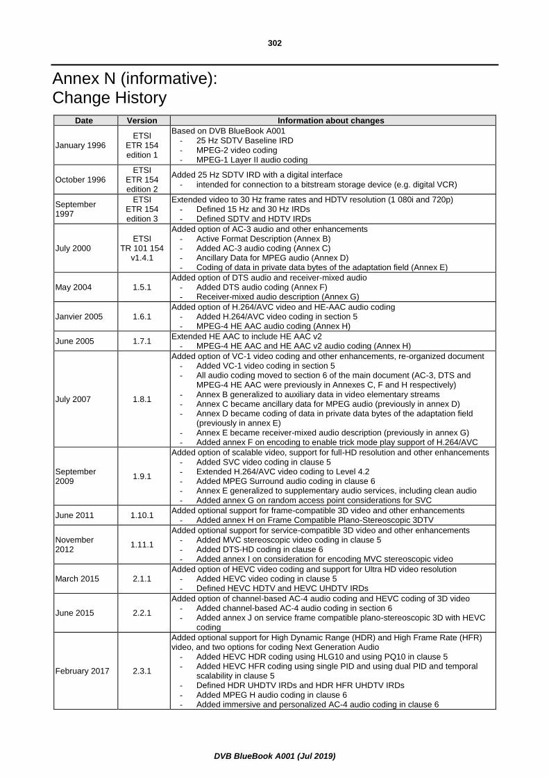
DVB BlueBook A001 (Jul 2019)
302
Annex N (informative): Change History
Date Version Information about changes
January 1996 ETSI
ETR 154 edition 1
Based on DVB BlueBook A001 - 25 Hz SDTV Baseline IRD - MPEG-2 video coding - MPEG-1 Layer II audio coding
October 1996 ETSI
ETR 154 edition 2
Added 25 Hz SDTV IRD with a digital interface
- intended for connection to a bitstream storage device (e.g. digital VCR)
September 1997
ETSI ETR 154 edition 3
Extended video to 30 Hz frame rates and HDTV resolution (1 080i and 720p) - Defined 15 Hz and 30 Hz IRDs - Defined SDTV and HDTV IRDs
July 2000 ETSI
TR 101 154 v1.4.1
Added option of AC-3 audio and other enhancements - Active Format Description (Annex B) - Added AC-3 audio coding (Annex C) - Ancillary Data for MPEG audio (Annex D) - Coding of data in private data bytes of the adaptation field (Annex E)
May 2004 1.5.1 Added option of DTS audio and receiver-mixed audio
- Added DTS audio coding (Annex F) - Receiver-mixed audio description (Annex G)
Janvier 2005 1.6.1 Added option of H.264/AVC video and HE-AAC audio coding
- Added H.264/AVC video coding in section 5 - MPEG-4 HE AAC audio coding (Annex H)
June 2005 1.7.1 Extended HE AAC to include HE AAC v2
- MPEG-4 HE AAC and HE AAC v2 audio coding (Annex H)
July 2007 1.8.1
Added option of VC-1 video coding and other enhancements, re-organized document - Added VC-1 video coding in section 5 - All audio coding moved to section 6 of the main document (AC-3, DTS and
MPEG-4 HE AAC were previously in Annexes C, F and H respectively) - Annex B generalized to auxiliary data in video elementary streams - Annex C became ancillary data for MPEG audio (previously in annex D) - Annex D became coding of data in private data bytes of the adaptation field
(previously in annex E) - Annex E became receiver-mixed audio description (previously in annex G) - Added annex F on encoding to enable trick mode play support of H.264/AVC
September 2009
1.9.1
Added option of scalable video, support for full-HD resolution and other enhancements - Added SVC video coding in clause 5 - Extended H.264/AVC video coding to Level 4.2 - Added MPEG Surround audio coding in clause 6 - Annex E generalized to supplementary audio services, including clean audio - Added annex G on random access point considerations for SVC
June 2011 1.10.1 Added optional support for frame-compatible 3D video and other enhancements
- Added annex H on Frame Compatible Plano-Stereoscopic 3DTV
November 2012
1.11.1
Added optional support for service-compatible 3D video and other enhancements - Added MVC stereoscopic video coding in clause 5 - Added DTS-HD coding in clause 6 - Added annex I on consideration for encoding MVC stereoscopic video
March 2015 2.1.1 Added option of HEVC video coding and support for Ultra HD video resolution
- Added HEVC video coding in clause 5 - Defined HEVC HDTV and HEVC UHDTV IRDs
June 2015 2.2.1
Added option of channel-based AC-4 audio coding and HEVC coding of 3D video - Added channel-based AC-4 audio coding in section 6 - Added annex J on service frame compatible plano-stereoscopic 3D with HEVC
coding
February 2017 2.3.1
Added optional support for High Dynamic Range (HDR) and High Frame Rate (HFR) video, and two options for coding Next Generation Audio
- Added HEVC HDR coding using HLG10 and using PQ10 in clause 5 - Added HEVC HFR coding using single PID and using dual PID and temporal
scalability in clause 5 - Defined HDR UHDTV IRDs and HDR HFR UHDTV IRDs - Added MPEG H audio coding in clause 6 - Added immersive and personalized AC-4 audio coding in clause 6

DVB BlueBook A001 (Jul 2019)
303
Date Version Information about changes
February 2018 2.4.1
Added H.264/AVC and HEVC video conformance points for DVB-DASH: - Annex L contains H.264/AVC and HEVC video conformance points to be
referenced by ETSI TS 103 285 (DVB-DASH) - Editorial modifications to remove the circular normative references between the
present document and ETSI EN 300 468
January 2019 2.5.1 Added DTS-UHD as additional audio coding standard for Next Generation Audio in clause 6.9, added some clarifications for the HEVC related text, and added clarification that the code points in Annex B are owned by ATSC.
xxxx 20xx 2.6.1
Added the following modifications: - HDR Dynamic Mapping support for broadcast and DVB-DASH (Annex L) - Harmonization of terms for HEVC HDR bitstreams in Annex L - Constraint on position of HEVC SEI NAL units - Clarifications for DTS-UHD

DVB BlueBook A001 (Jul 2019)
304
History
Document history
Edition 1 January 1996 Publication as ETSI ETR 154
Edition 2 October 1996 Publication as ETSI ETR 154
Edition 3 September 1997 Publication as ETSI ETR 154
V1.4.1 July 2000 Publication as ETSI TR 101 154
V1.5.1 May 2004 Publication
V1.6.1 January 2005 Publication
V1.7.1 June 2005 Publication
V1.8.1 July 2007 Publication
V1.9.1 September 2009 Publication
V1.10.1 June 2011 Publication
V1.11.1 November 2012 Publication
V2.1.1 March 2015 Publication
V2.2.1 June 2015 Publication
V2.3.1 February 2017 Publication
V2.4.1 February 2018 Publication
V2.5.1 January 2019 Publication