SPECIFICATION FOR ELECTRONICS TRAINERS - Dvet ...
36
Government of Maharashtra Directorate of Vocational Education and Training, Maharashtra State SPECIFICATION FOR ELECTRONICS TRAINERS Version 4 2019 - 20 SPECIFICATION FOR ELECTRONICS TRAINERS
-
Upload
khangminh22 -
Category
Documents
-
view
0 -
download
0
Transcript of SPECIFICATION FOR ELECTRONICS TRAINERS - Dvet ...

Government of Maharashtra Directorate of Vocational Education and Training, Maharashtra State
SPECIFICATION FOR ELECTRONICS TRAINERS
Version 4 2019 - 20
SPECIFICATION FOR ELECTRONICS TRAINERS

Government of Maharashtra Directorate of Vocational Education and Training, Maharashtra State
SPECIFICATION FOR ELECTRONICS TRAINERS
Version 4 2019 - 20
© Property of DVET Confidential Page 2 of 36
TABLE OF CONTENTS 1 Network and Internet Security Trainer......................................................................................... 3 2 ADC to DAC Cards Trainer .............................................................................................................. 5 3 Basic Electronics Trainer ................................................................................................................ 7 4 Discrete Components Trainer ........................................................................................................ 9 5 Digital and Analog Bread Board Trainer ..................................................................................... 11 6 Digital IC Trainer ........................................................................................................................... 13 7 Electronics Sensor Trainer - 10 Sensors ..................................................................................... 14 8 Fiber Optic Communication Trainer ........................................................................................... 16 9 Frequency Modulator and Demodulator Trainer ..................................................................... 18 10 Linear IC Trainer ........................................................................................................................... 19 11 Machine Shop Sensor Trainer ..................................................................................................... 20 12 Op Amp Trainer ............................................................................................................................ 22 13 PAM, PPM, PWM Trainer ............................................................................................................ 23 14 Power Electronics Trainer - 06 Application Boards ................................................................... 24 15 Seven Segment DPM Trainer....................................................................................................... 26 16 Data Acquisition System ............................................................................................................. 27 17 Analog Component Trainer ......................................................................................................... 28 18 Micro Processor Trainer ............................................................................................................... 30 19 Microcontroller Trainer (8051) with Programming Software and 6 Applications .................. 31 20 Hardware and Network Trainer.................................................................................................. 33 21 Electronics Circuit Simulation Software - 6 User License ......................................................... 34 22 LAN Protocol Simulation and Analyser Software ...................................................................... 36

Government of Maharashtra Directorate of Vocational Education and Training, Maharashtra State
SPECIFICATION FOR ELECTRONICS TRAINERS
Version 4 2019 - 20
© Property of DVET Confidential Page 3 of 36
1 Network and Internet Security Trainer
Basic Indicative Diagram
Network Security Module: 1.2.1 This training system should help to understanding of Local Area Network
(LAN) including fundamentals of networking. 1.2.2 It should assist for knowledge of all network layers, cable designing and
building of a complete network of computers. 1.2.3 Students can study of various topologies using different standards given
by IEEE with actual connections made in different topologies and data can be transferred.
1.2.4 It should have provision to understand protocols, topologies used in networking, measurement of error rate, throughput and effect of errors on protocols.
1.2.5 It should have PC to PC using RJ-45 Connector, Star topology using RJ45 Connector, Ring topology using DB9 Connector.
1.2.6 Trainer should be RoHS complained. It should be compact, lightweight and housing should be made of ABS material. It should come with technical chart pasted on its cover to learn and understand more about applications and technical details.
1.2.7 This training system should have software by which student can study Star & Ring selection, Protocols: CSMA /CD, CSMA /CA, Stop N Wait, Go back to N, Selective repeat, Sliding Window, Token Bus, Token Ring, Packet size: 128, 256, 512, 1024, 2048, 4096, 8192, 16384Inter Packet delay: 1000 – 5000 ms, Error generation: Acknowledgment lost, bad packet, auto error generation, Complete analysis of Network & Protocols, Real time Graphic representation of data on s/w screen with packet details, Network details like, Indication of computer name, IP address, MAC address, Port number, status of network, Network & protocol analysis like Indication of packet serial number, file name, file size, file number, receiver name, receiver IP address, total packets, packet length, time out, protocol, topology, receiver, MAC address, port number, file send start time, file sent completion time, transmission time data rate(Mbps),percentage error.

Government of Maharashtra Directorate of Vocational Education and Training, Maharashtra State
SPECIFICATION FOR ELECTRONICS TRAINERS
Version 4 2019 - 20
© Property of DVET Confidential Page 4 of 36
Internet Security Module: 1.3.1 Networking: Policy Based Routing, Automatic Gateway Failover 1.3.2 Administration: Multiple Administrator Support, Administrator Profile
Management 1.3.3 Centralized Management System: Dashboard, Appliance Monitoring and
Alerts 1.3.4 Bandwidth management: User Bandwidth control, Traffic shaping,
Bandwidth Limit for each profile/user 1.3.5 URL Filtering: Category Based, Custom Web Lists, HTTP & HTTPS Blocking 1.3.6 High Availability: Active/Stand By with Automatic and Force
Synchronization, Email and SMS notification 1.3.7 Mail Protection: Mail Antivirus and Anti-spam, Attachment Control,
(SMTP, POP3 and IMAP), Attachment Control, Keyword Blocking in Email 1.3.8 Firewall & Security Features: Intrusion Prevention System, Gateway
Antivirus 1.3.9 User Authentication: Internal Database, Active Directory Integration, IP /
MAC Binding, Multiple Authentication Servers 1.3.10 Technical Details
1.3.10.1 Interfaces: 1.3.10.1.1 Copper Port: 02 Nos. 1.3.10.1.2 Console Port: 01 No. 1.3.10.1.3 USB Port: 04 Nos.
1.3.10.2 Firewall TCP Throughput: 2200 Mbps 1.3.10.3 Antivirus Throughput: 170 Mbps 1.3.10.4 Users/ Nodes: Unrestricted 1.3.10.5 Three year licensed software

Government of Maharashtra Directorate of Vocational Education and Training, Maharashtra State
SPECIFICATION FOR ELECTRONICS TRAINERS
Version 4 2019 - 20
© Property of DVET Confidential Page 5 of 36
2 ADC to DAC Cards Trainer
Basic Indicative Diagram
ADC Trainer Card: 2.2.1 4 bit discrete & 8 bit Monolithic converters 2.2.2 Unipolar & Bipolar DC voltages 2.2.3 O/P status displayed by LED 2.2.4 Functional block indicated on board mimic. 2.2.5 Built in DC power supply 2.2.6 Trainer should be RoHS compliant 2.2.7 Trainer should be compact, lightweight and housing should be made of
ABS material. 2.2.8 Technical chart should be pasted on the trainer to learn and understand
more about applications and technical details. 2.2.9 A/D Conversion:
2.2.9.1 4 Bit discrete (ramp) 2.2.9.2 8 Bit Monolithic converter
2.2.10 Signal source: Unipolar & Bipolar DC voltages 2.2.11 O/P Indication: By LEDs separate for each type 2.2.12 Inter connections: 2mm banana socket 2.2.13 Power Supply: 230V, 50Hz.
DAC Trainer Card 2.3.1 4 bit weighted resistor-4 R-2R network 2.3.2 10 bit monolithic D/A converters. 2.3.3 On board Sine Generator 2.3.4 Functional block indicated on board mimics 2.3.5 Built in DC power supply 2.3.6 Trainer should be RoHS compliant 2.3.7 Trainer should be compact, lightweight and housing should be made of
ABS material. 2.3.8 Technical chart should be pasted on the trainer to learn and understand
more about applications and technical details. 2.3.9 D/A Conversion:
2.3.9.1 4 Bit weighed resistor 2.3.9.2 4 Bit R-2R ladder network 2.3.9.3 8 Bit Monolithic D/A Converter

Government of Maharashtra Directorate of Vocational Education and Training, Maharashtra State
SPECIFICATION FOR ELECTRONICS TRAINERS
Version 4 2019 - 20
© Property of DVET Confidential Page 6 of 36
Signal: DC supply with toggle switches O/P indication: On DMM or Oscilloscope Inter Connections: 2mm. banana sockets Power Supply: 230V, 50Hz

Government of Maharashtra Directorate of Vocational Education and Training, Maharashtra State
SPECIFICATION FOR ELECTRONICS TRAINERS
Version 4 2019 - 20
© Property of DVET Confidential Page 7 of 36
3 Basic Electronics Trainer
Basic Indicative Diagram
On Platform Breadboard to design circuits On board DC Power Supply: +5V/1A (fixed); ±15V/1A (fixed); ±15V/200mA (Variable) On Board AC Supply: 5V-0V-5V; 10V-0V-10V (Provision to use as 5V, 10V, 15V, 20V AC
& also as center tap) Sine/ Square/ TTL Generator: 10Hz to 1MHz in 4 Steps (Variable in between the steps) Amplitude: Sine (0 to 15Vpp); Square Wave (0 to 10Vpp); TTL-5V (fixed) Volt/Current/Frequency Measurement for Voltage Range +12V to -12V DC, Current
Range 0 to 500mA DC and Frequency Range DC to 100KHz (All with respect to Ground) Display: LCD Computer Interface: Acquisition from two Analog input channels (Max. input 1
Volt,), Frequency 300Hz to 3.4kHz) Continuity Tester: For testing the continuity. Provided with Beeper Sound. Fixed TTL (Clock): 0.1Hz Data Switches: 8 in Nos (Toggle switches for High/Low TTL levels) with LED indication LED Display: 8 in Nos (for High/Low TTL levels indication) Logic Probe: Logic level identifier H/L for TTL level (7 segment display) Potentiometer: 6mos (100Ω to 47KΩ) Speaker: 8Ω/2W for audio use Power Supply: 110-220V, 50Hz Trainer should be RoHS compliant Trainer should be compact, lightweight and housing should be made of ABS material. Ready to use experiment board should be fitted in place of bread board to perform
following experiments on Rectifier Circuits board: 3.20.1 To study Half wave Rectifier 3.20.2 To study Center tap Full wave Rectifier 3.20.3 To study Bridge Rectifier

Government of Maharashtra Directorate of Vocational Education and Training, Maharashtra State
SPECIFICATION FOR ELECTRONICS TRAINERS
Version 4 2019 - 20
© Property of DVET Confidential Page 8 of 36
The trainer should include online single user Classroom / laboratory teaching, learning and simulation software module on Analog & Digital Electronic with following key features: 3.21.1 The content should designed by using platforms like Visual Basic, Dot Net,
Flash etc. and should be useful to understand the basic concepts of various technologies in electronics including advance technologies, the software should comprises simulations, animations, videos, graphs, charts, along with mandatory rich content and theory to understand fundamental concepts, interactive learning objects, FAQ, MCQ etc. of Analog and Digital Electronic with following topics:
3.21.2 Software module on Analog and Digital Electronic to understand fundamental concept of Atom, Charge, Introduction to Electricity, DC and AC Sources of Electricity, Electronic Components, Series and Parallel Circuits, Voltage Divider and Current Divider Circuit, Circuit Analysis: Ohm`s Law, Kirchhoff’s Law, Loop and Mesh Analysis, Star and Delta Network, Network Theorems: Thevenin’s, Norton`s, Superposition, Maximum Power Transfer, Millman’s, Reciprocity, Magnetism, Electromagnetism, Alternating Current Circuits, Transformer, Rectifier, Filter, Semiconductor Devices: Diode, BJT, FET, Operational Amplifier, Power Amplifier, Thyristor Family, Measuring Instruments: Oscilloscope, Multimeter, Digital Electronics, Number Systems, Codes, Complements, Boolean Algebra, Logic Gates, Arithmetic Circuits: Adder, Subtractor, Combinational Circuits: Multiplexer, Demultiplexer, Encoder, Decoder, Sequential Circuits (Flip-Flops): S-R Flip-Flop, D Flip-Flop, J-K Flip-Flop, T Flip-Flop, Registers and Counters etc.

Government of Maharashtra Directorate of Vocational Education and Training, Maharashtra State
SPECIFICATION FOR ELECTRONICS TRAINERS
Version 4 2019 - 20
© Property of DVET Confidential Page 9 of 36
4 Discrete Components Trainer
Basic Indicative Diagram
Flexibility of making circuit connections Online learning material for step by step procedure to perform the experiment
and other details related to theory and experiments. Trainer should be RoHS compliant Trainer should be compact, lightweight and housing should be made of ABS
material. DC Power Supplies: + 5V, 1 A (Fixed), + 12V, 500 mA (Fixed), -12V, 500 mA (Fixed),
+ 12V, 500 mA (Variable), -12V, 500 mA (Variable) AC Supply: 9V-0V-9V, 500mA Breadboard: Breadboard for making various circuits and testing them. External
components/IC can be fitted conveniently. Function Generator: Operating modes Sine, Square and Triangular. Frequency
range 1 Hz to 100 KHz. Volt/ Current/ Frequency Measurement: Voltage Range +12V to -12V DC, Current
Range 0 to 500mA DC, Frequency Range DC to 100KHz (All with respect to Ground) Display: LCD Computer Interface: Acquisition from two Analog input channels (Max. input 1
Volt, Frequency 300Hz to 3.4kHz) Continuity Tester: For testing the continuity. Provided with beeper sound. Power Supply: 110-220 V, 50Hz. Ready to use experiment board should be fitted in place of bread board to perform
following experiments on Diode Characteristics (Si, Zener, LED) 4.15.1 Study of V-I characteristics of Silicon Diode 4.15.2 Study of V-I characteristics of Zener Diode 4.15.3 Study of V-I characteristics of Light Emitting Diode (LED)
The trainer should include online single user Classroom / laboratory teaching, learning and simulation software module on Analog Electronic with following key features: 4.16.1 The content should designed by using platforms like Visual Basic, Dot Net,
Flash etc. and should be useful to understand the basic concepts of various technologies in electronics including advance technologies, the software should comprises simulations, animations, videos, graphs, charts, along with mandatory rich content and theory to understand fundamental concepts, interactive learning objects, FAQ, MCQ etc. of Analog Electronic with following topics:

Government of Maharashtra Directorate of Vocational Education and Training, Maharashtra State
SPECIFICATION FOR ELECTRONICS TRAINERS
Version 4 2019 - 20
© Property of DVET Confidential Page 10 of 36
4.16.2 Understand the fundamental concept of Electronic Components, Series and Parallel Circuits, Voltage Divider and Current Divider Circuit, Circuit Analysis: Ohm`s Law, Kirchhoff’s Law, Loop and Mesh Analysis, Star and Delta Network, Network Theorems: Thevenin’s, Norton`s, Superposition, Maximum Power Transfer, Millman’s, Reciprocity, Magnetism, Electromagnetism, Alternating Current Circuits, Transformer, Rectifier, Filter, Semiconductor Devices: Diode, BJT, FET, Operational Amplifier, Power Amplifier, Thyristor Family, Measuring Instruments: Oscilloscope, Multimeter.
Government of Maharashtra Directorate of Vocational Education and Training, Maharashtra State
SPECIFICATION FOR ELECTRONICS TRAINERS
Version 4 2019 - 20
© Property of DVET Confidential Page 11 of 36
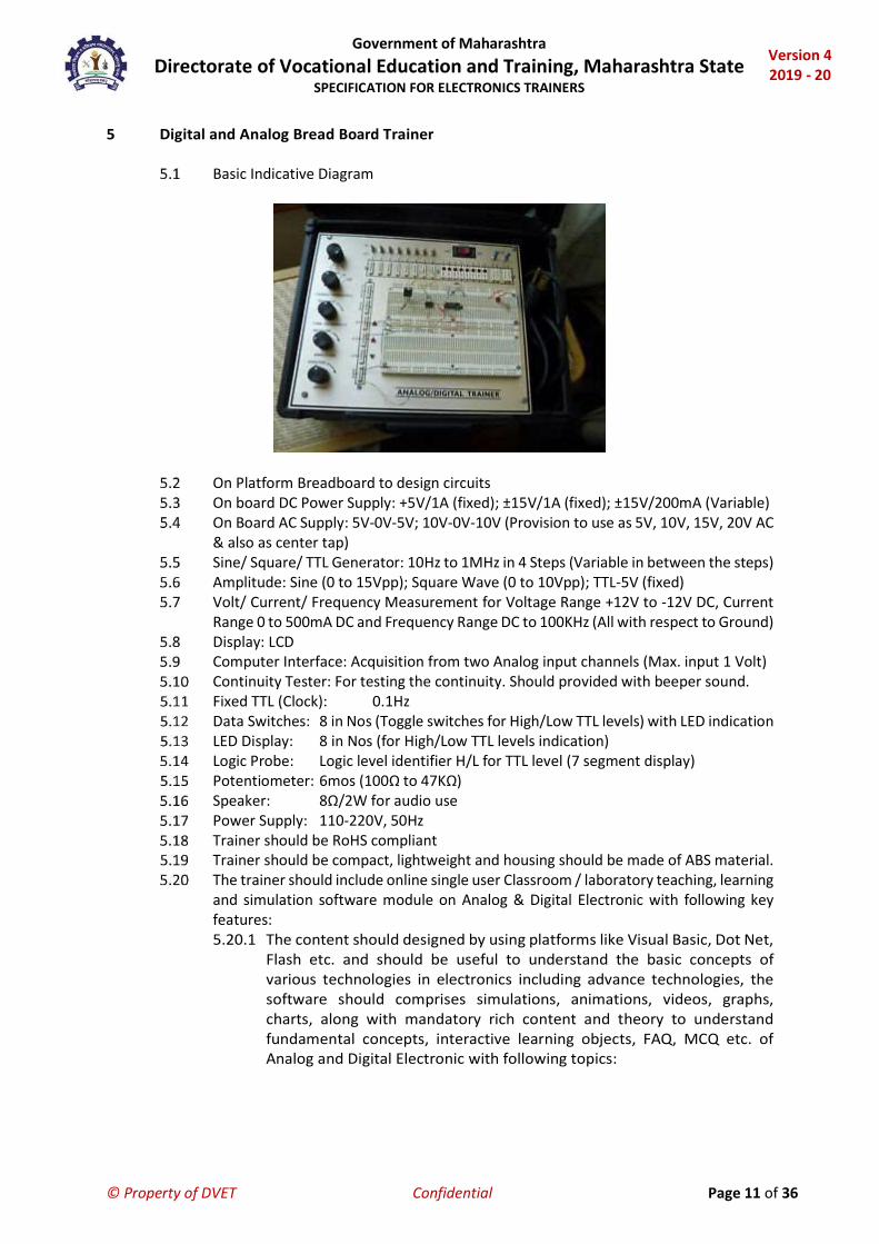
5 Digital and Analog Bread Board Trainer
Basic Indicative Diagram
On Platform Breadboard to design circuits On board DC Power Supply: +5V/1A (fixed); ±15V/1A (fixed); ±15V/200mA (Variable) On Board AC Supply: 5V-0V-5V; 10V-0V-10V (Provision to use as 5V, 10V, 15V, 20V AC
& also as center tap) Sine/ Square/ TTL Generator: 10Hz to 1MHz in 4 Steps (Variable in between the steps) Amplitude: Sine (0 to 15Vpp); Square Wave (0 to 10Vpp); TTL-5V (fixed) Volt/ Current/ Frequency Measurement for Voltage Range +12V to -12V DC, Current
Range 0 to 500mA DC and Frequency Range DC to 100KHz (All with respect to Ground) Display: LCD Computer Interface: Acquisition from two Analog input channels (Max. input 1 Volt) Continuity Tester: For testing the continuity. Should provided with beeper sound. Fixed TTL (Clock): 0.1Hz Data Switches: 8 in Nos (Toggle switches for High/Low TTL levels) with LED indication LED Display: 8 in Nos (for High/Low TTL levels indication) Logic Probe: Logic level identifier H/L for TTL level (7 segment display) Potentiometer: 6mos (100Ω to 47KΩ) Speaker: 8Ω/2W for audio use Power Supply: 110-220V, 50Hz Trainer should be RoHS compliant Trainer should be compact, lightweight and housing should be made of ABS material. The trainer should include online single user Classroom / laboratory teaching, learning
and simulation software module on Analog & Digital Electronic with following key features: 5.20.1 The content should designed by using platforms like Visual Basic, Dot Net,
Flash etc. and should be useful to understand the basic concepts of various technologies in electronics including advance technologies, the software should comprises simulations, animations, videos, graphs, charts, along with mandatory rich content and theory to understand fundamental concepts, interactive learning objects, FAQ, MCQ etc. of Analog and Digital Electronic with following topics:

Government of Maharashtra Directorate of Vocational Education and Training, Maharashtra State
SPECIFICATION FOR ELECTRONICS TRAINERS
Version 4 2019 - 20
© Property of DVET Confidential Page 12 of 36
5.20.2 Software module on Analog and Digital Electronic to understand fundamental concept of Atom, Charge, Introduction to Electricity, DC and AC Sources of Electricity, Electronic Components, Series & Parallel Circuits, Voltage Divider and Current Divider Circuit, Circuit Analysis: Ohm`s Law, Kirchhoff’s Law, Loop and Mesh Analysis, Star and Delta Network, Network Theorems: Thevenin’s, Norton`s, Superposition, Maximum Power Transfer, Millman’s, Reciprocity, Magnetism, Electromagnetism, Alternating Current Circuits, Transformer, Rectifier, Filter, Semiconductor Devices: Diode, BJT, FET, Operational Amplifier, Power Amplifier, Thyristor Family, Measuring Instruments: Oscilloscope, Multimeter, Digital Electronics, Number Systems, Codes, Complements, Boolean Algebra, Logic Gates, Arithmetic Circuits: Adder, Subtractor, Combinational Circuits: Multiplexer, Demultiplexer, Encoder, Decoder, Sequential Circuits (Flip-Flops): S-R Flip-Flop, D Flip-Flop, J-K Flip-Flop, T Flip-Flop, Registers and Counters etc.

Government of Maharashtra Directorate of Vocational Education and Training, Maharashtra State
SPECIFICATION FOR ELECTRONICS TRAINERS
Version 4 2019 - 20
© Property of DVET Confidential Page 13 of 36
6 Digital IC Trainer
Basic Indicative Diagram
Trainer should be RoHS compliant Trainer should be compact, lightweight and housing should be made of ABS
material. Size of Breadboard: 172.5 mm x 68mm DC Supply: +5 V, 500 mA Clock Frequency: 1 Hz, 100 Hz, 1 KHz, 100 KHz Amplitude: 3.3V (TTL) Duty Cycle: 50 %, TTL output Pulsar Switches: 2 Nos. Graphical LCD: 128 X 64 dots(To display pin diagram of various digital ICs
so that students can make by their own digital circuits) Data switches: 8 Nos. (Toggle switches for both TTL modes) Digital Circuits: Virtual, should be interfaced with real time Inputs/outputs LED display: 8 Nos. (TTL) Seven Segment Display: 3 Nos. ZIF Socket: ZIF socket consists of 40 pins with 2mm output socket for
each pin 8, 14,16,20,40 pin ICs can be inserted without force. Supply Inputs can be connected to the ZIF socket through 2mm patch Chord.
Main Supply: 100V - 240V AC, 50Hz The trainer should include online single user Classroom / laboratory teaching, learning
and simulation software module on Digital Electronic with following key features: 6.17.1 The content should designed by using platforms like Visual Basic, Dot Net,
Flash etc. and should be useful to understand the basic concepts of Digital Electronics, the software should comprises simulations, animations, videos, graphs, charts, along with mandatory rich content and theory to understand fundamental concepts, interactive learning objects, FAQ, MCQ etc. of Digital Electronic with following topics:
6.17.2 Number Systems, Codes, Complements, Boolean Algebra, Logic Gates, Arithmetic Circuits: Adder, Subtractor, Combinational Circuits: Multiplexer, De multiplexer, Encoder, Decoder, Sequential Circuits (Flip-Flops): S-R Flip-Flop, D Flip-Flop, J-K Flip-Flop, T Flip-Flop, Registers and Counters
Government of Maharashtra Directorate of Vocational Education and Training, Maharashtra State
SPECIFICATION FOR ELECTRONICS TRAINERS
Version 4 2019 - 20
© Property of DVET Confidential Page 14 of 36
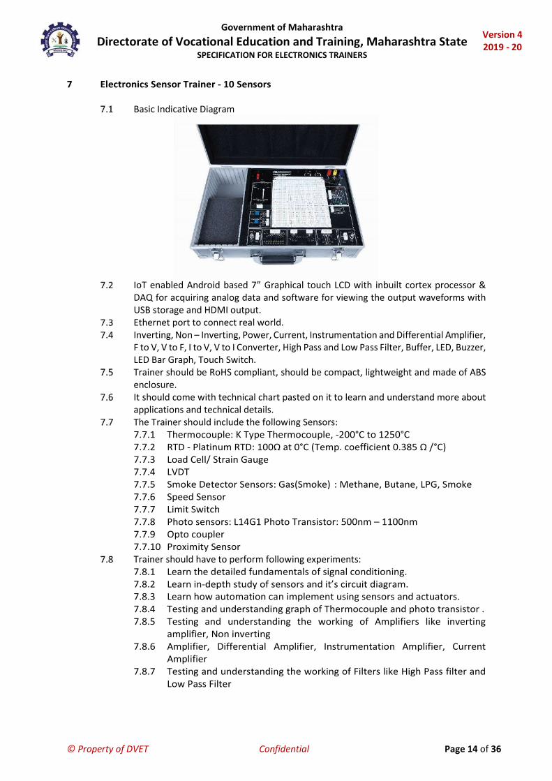
7 Electronics Sensor Trainer - 10 Sensors
Basic Indicative Diagram
IoT enabled Android based 7” Graphical touch LCD with inbuilt cortex processor &
DAQ for acquiring analog data and software for viewing the output waveforms with USB storage and HDMI output.
Ethernet port to connect real world. Inverting, Non – Inverting, Power, Current, Instrumentation and Differential Amplifier,
F to V, V to F, I to V, V to I Converter, High Pass and Low Pass Filter, Buffer, LED, Buzzer, LED Bar Graph, Touch Switch.
Trainer should be RoHS compliant, should be compact, lightweight and made of ABS enclosure.
It should come with technical chart pasted on it to learn and understand more about applications and technical details.
The Trainer should include the following Sensors: 7.7.1 Thermocouple: K Type Thermocouple, -200°C to 1250°C 7.7.2 RTD - Platinum RTD: 100Ω at 0°C (Temp. coefficient 0.385 Ω /°C) 7.7.3 Load Cell/ Strain Gauge 7.7.4 LVDT 7.7.5 Smoke Detector Sensors: Gas(Smoke) : Methane, Butane, LPG, Smoke 7.7.6 Speed Sensor 7.7.7 Limit Switch 7.7.8 Photo sensors: L14G1 Photo Transistor: 500nm – 1100nm 7.7.9 Opto coupler 7.7.10 Proximity Sensor
Trainer should have to perform following experiments: 7.8.1 Learn the detailed fundamentals of signal conditioning. 7.8.2 Learn in-depth study of sensors and it’s circuit diagram. 7.8.3 Learn how automation can implement using sensors and actuators. 7.8.4 Testing and understanding graph of Thermocouple and photo transistor . 7.8.5 Testing and understanding the working of Amplifiers like inverting
amplifier, Non inverting 7.8.6 Amplifier, Differential Amplifier, Instrumentation Amplifier, Current
Amplifier 7.8.7 Testing and understanding the working of Filters like High Pass filter and
Low Pass Filter

Government of Maharashtra Directorate of Vocational Education and Training, Maharashtra State
SPECIFICATION FOR ELECTRONICS TRAINERS
Version 4 2019 - 20
© Property of DVET Confidential Page 15 of 36
7.8.8 Testing and understanding the working of Types of and Converters like Frequency to Voltage and Voltage to Frequency convertor, Current to Voltage and Voltage to current convertor.
7.8.9 Study of output blocks like LED, Buzzer and LED bar graph. 7.8.10 Testing and understanding graph of Gas (Smoke), Limit switch, proximity
sensor, Opto coupler sensors. 7.8.11 Fault finding to Types of signal conditioning and Sensors. 7.8.12 See the sensor real timer graph using computer based software 7.8.13 Sensors data logging using computer based software 7.8.14 HDMI and Ethernet connectivity.
The trainer should include online single user Classroom / laboratory teaching, learning and simulation software module with following key features: The content should designed by using platforms like Visual Basic, Dot Net, Flash etc. and should be useful to understand the basic concepts of various sensors and its signal conditioning, interfacing, applications etc. the software should comprises simulations, animations, videos, graphs, charts, along with mandatory rich content and theory to understand fundamental concepts, interactive learning objects, FAQ, MCQ etc. following topics: 7.9.1 Sensor, Transducer and actuator 7.9.2 Difference between sensor and transducer 7.9.3 Signal Conditioning: Inverting amplifier, Non inverting amplifier,
Differential Amplifier, Instrumentation Amplifier, F to V Convertor, V to F convertor, I to V Convertor, V to I convertor, Current Amplifier, High and Low Pass Filter
7.9.4 Characteristic of different types of Sensors. Working of Sensors like RTD, Thermocouple, Photo Diode, Gas (Smoke), Limit switch, speed sensor, load cell, LVDT, Opto coupler and Proximity Sensor

Government of Maharashtra Directorate of Vocational Education and Training, Maharashtra State
SPECIFICATION FOR ELECTRONICS TRAINERS
Version 4 2019 - 20
© Property of DVET Confidential Page 16 of 36
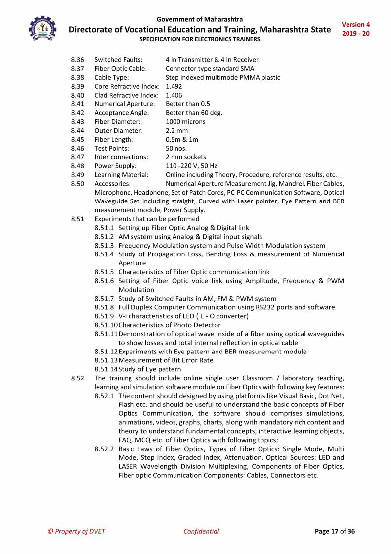
8 Fiber Optic Communication Trainer
Basic Indicative Diagram
Full Duplex Analog & Digital Trans-receiver 660 nm & 950 nm Fiber Optic LED channel with Transmitter & Receiver AM-FM-PWM modulation / demodulation PC-PC communication with RS232 ports & software On board Function Generator Functional blocks indicated on-board Input-output & test points provided On board voice link Built in DC Power Supply Numerical Aperture measurement jig and mandrel for bending loss measurement Data Generator with selectable clock (64/ 128/ 256 KHz) Noise Generator with variable gain Eye pattern observation and Bit Error Rate measurement Four digits (Seven segment display)Bit Error Counter Switched faults on Transmitter & Receiver Trainer should be RoHS compliant Trainer should be compact, lightweight and housing should be made of ABS material. Trainer should come with technical chart pasted on it to learn and understand more
about applications and technical details. Transmitter: 2 Nos., Fiber Optic LED having peak wavelength of emission
660 nm & 950 nm Receiver: 2 Nos., Fiber Optic Photo detector Modulation Techniques: AM, FM, PWM. Drivers: 1 No. with Analog & Digital modes AC Amplifier: 2 Nos. Clock: Crystal controlled Clock 4.096 MHz PLL detector: 1 No. Comparator: 2 Nos. Filters: 2 Nos. 4th order Butterworth, 3.4 KHz cut-off frequency Analog Band Width: 350 KHz Digital Band Width: 2.5 MHz Function Generator: 1 KHz Sine wave (Amplitude adjustable) 1 KHz Square Wave
(TTL) Voice Link: Fiber Optic voice link using microphone & speaker (built in) PC-PC Communication: Using 2 channel RS232 Port: RS232 (9 Pin) Baud Rate: 19200
Government of Maharashtra Directorate of Vocational Education and Training, Maharashtra State
SPECIFICATION FOR ELECTRONICS TRAINERS
Version 4 2019 - 20
© Property of DVET Confidential Page 17 of 36
Switched Faults: 4 in Transmitter & 4 in Receiver Fiber Optic Cable: Connector type standard SMA Cable Type: Step indexed multimode PMMA plastic Core Refractive Index: 1.492 Clad Refractive Index: 1.406 Numerical Aperture: Better than 0.5 Acceptance Angle: Better than 60 deg. Fiber Diameter: 1000 microns Outer Diameter: 2.2 mm Fiber Length: 0.5m & 1m Test Points: 50 nos. Inter connections: 2 mm sockets Power Supply: 110 -220 V, 50 Hz Learning Material: Online including Theory, Procedure, reference results, etc. Accessories: Numerical Aperture Measurement Jig, Mandrel, Fiber Cables,
Microphone, Headphone, Set of Patch Cords, PC-PC Communication Software, Optical Waveguide Set including straight, Curved with Laser pointer, Eye Pattern and BER measurement module, Power Supply.
Experiments that can be performed 8.51.1 Setting up Fiber Optic Analog & Digital link 8.51.2 AM system using Analog & Digital input signals 8.51.3 Frequency Modulation system and Pulse Width Modulation system 8.51.4 Study of Propagation Loss, Bending Loss & measurement of Numerical
Aperture 8.51.5 Characteristics of Fiber Optic communication link 8.51.6 Setting of Fiber Optic voice link using Amplitude, Frequency & PWM
Modulation 8.51.7 Study of Switched Faults in AM, FM & PWM system 8.51.8 Full Duplex Computer Communication using RS232 ports and software 8.51.9 V-I characteristics of LED ( E - O converter) 8.51.10 Characteristics of Photo Detector 8.51.11 Demonstration of optical wave inside of a fiber using optical waveguides
to show losses and total internal reflection in optical cable 8.51.12 Experiments with Eye pattern and BER measurement module 8.51.13 Measurement of Bit Error Rate 8.51.14 Study of Eye pattern
The training should include online single user Classroom / laboratory teaching, learning and simulation software module on Fiber Optics with following key features: 8.52.1 The content should designed by using platforms like Visual Basic, Dot Net,
Flash etc. and should be useful to understand the basic concepts of Fiber Optics Communication, the software should comprises simulations, animations, videos, graphs, charts, along with mandatory rich content and theory to understand fundamental concepts, interactive learning objects, FAQ, MCQ etc. of Fiber Optics with following topics:
8.52.2 Basic Laws of Fiber Optics, Types of Fiber Optics: Single Mode, Multi Mode, Step Index, Graded Index, Attenuation. Optical Sources: LED and LASER Wavelength Division Multiplexing, Components of Fiber Optics, Fiber optic Communication Components: Cables, Connectors etc.
Government of Maharashtra Directorate of Vocational Education and Training, Maharashtra State
SPECIFICATION FOR ELECTRONICS TRAINERS
Version 4 2019 - 20
© Property of DVET Confidential Page 18 of 36
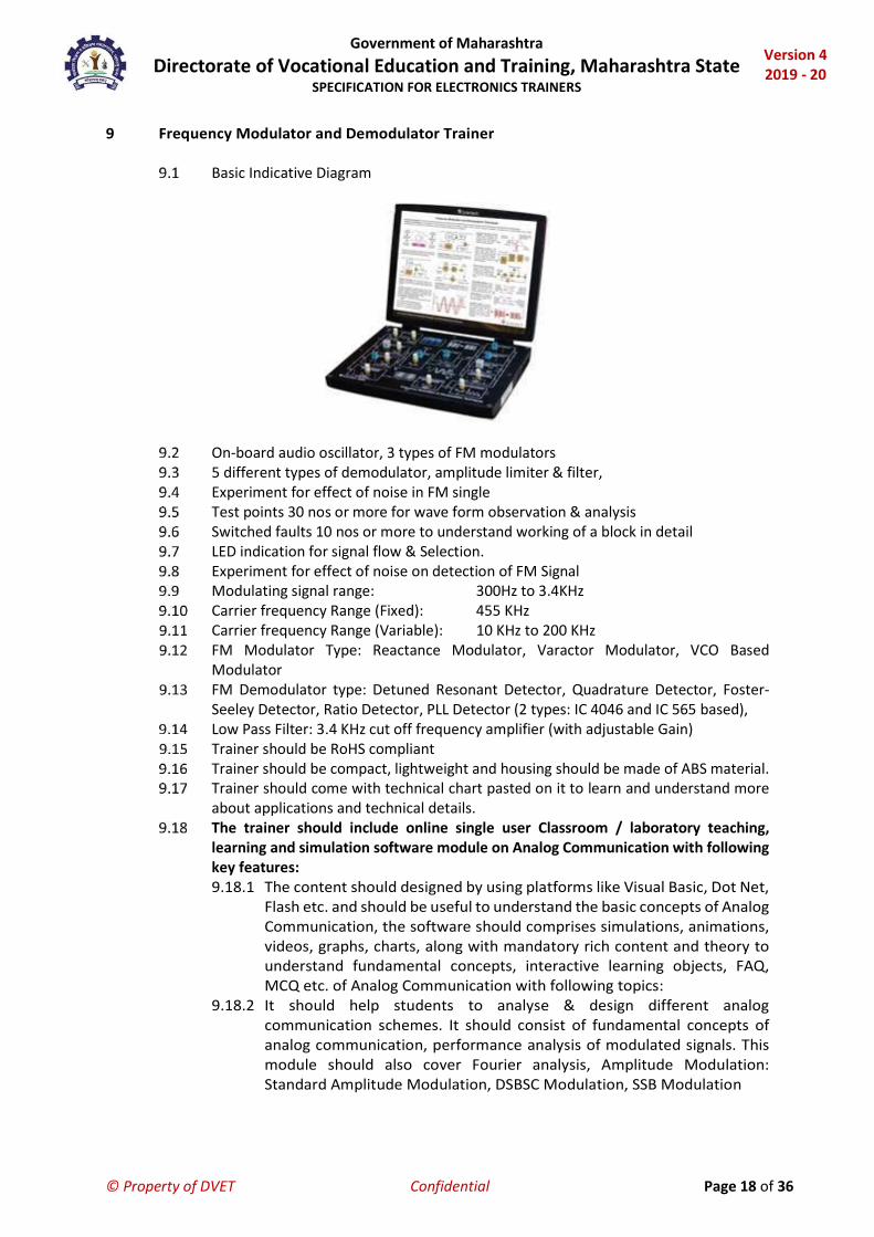
9 Frequency Modulator and Demodulator Trainer
Basic Indicative Diagram
On-board audio oscillator, 3 types of FM modulators 5 different types of demodulator, amplitude limiter & filter, Experiment for effect of noise in FM single Test points 30 nos or more for wave form observation & analysis Switched faults 10 nos or more to understand working of a block in detail LED indication for signal flow & Selection. Experiment for effect of noise on detection of FM Signal Modulating signal range: 300Hz to 3.4KHz Carrier frequency Range (Fixed): 455 KHz Carrier frequency Range (Variable): 10 KHz to 200 KHz FM Modulator Type: Reactance Modulator, Varactor Modulator, VCO Based
Modulator FM Demodulator type: Detuned Resonant Detector, Quadrature Detector, Foster-
Seeley Detector, Ratio Detector, PLL Detector (2 types: IC 4046 and IC 565 based), Low Pass Filter: 3.4 KHz cut off frequency amplifier (with adjustable Gain) Trainer should be RoHS compliant Trainer should be compact, lightweight and housing should be made of ABS material. Trainer should come with technical chart pasted on it to learn and understand more
about applications and technical details. The trainer should include online single user Classroom / laboratory teaching,
learning and simulation software module on Analog Communication with following key features: 9.18.1 The content should designed by using platforms like Visual Basic, Dot Net,
Flash etc. and should be useful to understand the basic concepts of Analog Communication, the software should comprises simulations, animations, videos, graphs, charts, along with mandatory rich content and theory to understand fundamental concepts, interactive learning objects, FAQ, MCQ etc. of Analog Communication with following topics:
9.18.2 It should help students to analyse & design different analog communication schemes. It should consist of fundamental concepts of analog communication, performance analysis of modulated signals. This module should also cover Fourier analysis, Amplitude Modulation: Standard Amplitude Modulation, DSBSC Modulation, SSB Modulation

Government of Maharashtra Directorate of Vocational Education and Training, Maharashtra State
SPECIFICATION FOR ELECTRONICS TRAINERS
Version 4 2019 - 20
© Property of DVET Confidential Page 19 of 36
10 Linear IC Trainer
Basic Indicative Diagram
It should have built-in Function Generator, Continuity Tester, Toggle Switch, Potentiometer, Frequency Measurement, Computer Interface
Functional Blocks indicated on board mimic On board DC and AC Power Supply, Function Generator, Continuity Tester On board Toggle Switches and Potentiometers Solder less Breadboard On Board Voltage/ Current/Frequency Measurement Trainer should be RoHS compliant Trainer should be compact, lightweight and housing should be made of ABS material. Regulated DC power supplies: +5V-1A (Fixed), ±12V-500mA (Fixed), ± 12V-500mA
(Variable) AC supply: 9V-0V-9V/500mA Function Generator
10.12.1 Operating modes: Sine, Square, Triangular 10.12.2 Frequency range: 1 Hz to 100 KHz
Volt/Current/Frequency Measurement: Voltage Range +12V to -12V DC Current Range 0 to 500mA DC
Display: LCD Computer Interface: Acquisition from two Analog input channels (Max. input 1
Volt, Frequency 300Hz to 3.4kHz) Continuity Tester: For testing the continuity. Provided with Beeper Sound. The training should include online single user Classroom / laboratory teaching,
learning and simulation software module on Analog Electronic with following key features: 10.17.1 The content should designed by using platforms like Visual Basic, Dot Net,
Flash etc. and should be useful to understand the basic concepts of Analog Electronics, the software should comprises simulations, animations, videos, graphs, charts, along with mandatory rich content and theory to understand fundamental concepts, interactive learning objects, FAQ, MCQ etc. of Analog Electronic with following topics:
10.17.2 Understand the fundamental concept of Electronic Components, Series and Parallel Circuits, Voltage Divider and Current Divider Circuit, Circuit Analysis: Ohm`s Law, Kirchhoff`s Law, Loop and Mesh Analysis, Star and Delta Network, Network Theorems: Thevenin’s, Norton`s, Superposition, Maximum Power Transfer, Millman’s, Reciprocity, Magnetism, Electromagnetism, Alternating Current Circuits, Transformer, Rectifier, Filter, Semiconductor Devices: Diode, BJT, FET, Operational Amplifier, Power Amplifier, Thyristor Family, Measuring Instruments: Oscilloscope, Multimeter.

Government of Maharashtra Directorate of Vocational Education and Training, Maharashtra State
SPECIFICATION FOR ELECTRONICS TRAINERS
Version 4 2019 - 20
© Property of DVET Confidential Page 20 of 36
11 Machine Shop Sensor Trainer
Basic Indicative Diagram
Inductive Sensor, Capacitive Sensor, Magnetic Sensor, Ultrasonic Sensor should be mounted on panel along with DAQ and Counter Box.
Precise Signal conditioning Real-time DAQ interface with ADC, DAC & digital input/output Supplied with Dashboard Software for supervisory control of the process with data
acquisition Computer Based Data Logging Interface with Ethernet based DAQ Sensitive, linear, stable and accurate Industrial look & feel User friendly, self explanatory system Experiments configurable through patch board Enhanced electrical safety considerations Practice Troubleshooting skills Compact tabletop ergonomic design Ready Experimental details Robust design and construction Online Product Tutorial Data Acquisition System (DAQ): 1 No.
11.18.1 Analog Inputs: 8 Nos. 11.18.2 Digital Inputs: 8 Nos. 11.18.3 Digital Outputs: 8 Nos. 11.18.4 ADC Resolution: 24 Bit 11.18.5 RS485 Interface: Yes 11.18.6 USB Interface: Yes 11.18.7 Ethernet Interface: Yes 11.18.8 Data Logging: Yes
Inductive Sensor: 1 No. 11.19.1 Operating input voltage: 10-30 V DC 11.19.2 Sensor type: PNP 11.19.3 Output voltage: 10-30V DC 11.19.4 Sensing Range: 0-5 mm 11.19.5 Switch Type: No 11.19.6 Body: Cubical/Cylindrical
Capacitive Sensor: 1 No. 11.20.1 Operating input voltage: 10-30 V DC 11.20.2 Sensor Type: PNP

Government of Maharashtra Directorate of Vocational Education and Training, Maharashtra State
SPECIFICATION FOR ELECTRONICS TRAINERS
Version 4 2019 - 20
© Property of DVET Confidential Page 21 of 36
11.20.3 Output Toltage: 10-30V DC 11.20.4 Sensing Range: 2-8 mm 11.20.5 Switch Type: No 11.20.6 Body: Cubical/Cylindrical
Magnetic Sensor: 1 No. 11.21.1 Operating input voltage: 10-30 V DC 11.21.2 Sensor Type: PNP 11.21.3 Output Voltage: 10-30V DC 11.21.4 Sensing Range: 60 mm (approximately) 11.21.5 Switch Type: No 11.21.6 Body: Cubical/Cylindrical
Ultrasonic Sensor: 1 No. 11.22.1 Operating Input Voltage: 10-30 V DC 11.22.2 Sensor Type: PNP 11.22.3 Output Voltage: 10-30V DC 11.22.4 Sensing Range: 80 - 300 mm (approximately) 11.22.5 Switch Type: No
Connecting Wires: 15 Nos. (Patch cord) Motor: 1 No.
11.24.1 Operating Voltage: 24V DC 11.24.2 Current Rating: 1A (Approx)
Motor Driver: 1 No. Power Distribution Box: 1 No.
11.26.1 Operating Voltage: 24V DC 11.26.2 Current Rating: 4A (approx)
Counter Box: 1 No. 11.27.1 Supply Voltage: 90-230V AC 11.27.2 Display Configuration: 6 Digits Counts, 5 Digits RPM Indicator 11.27.3 Counting Direction: Up, Down, Bi directional 11.27.4 Sensor Type: PNP 11.27.5 Sensor Output Voltage: 10-30 VDC 11.27.6 Current Rating: 0.05A
Indication Box: 1 No. 11.28.1 Supply: 24V DC 11.28.2 Colour: Green 11.28.3 Panel: Vertical Mounting Plate of at least W 600 X H 390 X D 300
The trainer should support to perform following lab experiments: 11.29.1 DAQ Digital Input 11.29.2 DAQ Digital Outputs 11.29.3 DAQ Analog Inputs 11.29.4 Inductive Sensor 11.29.5 Capacitive Sensor 11.29.6 Magnetic Sensor 11.29.7 Ultrasonic Sensor 11.29.8 Counter Box 11.29.9 RPM Counting of DC Motor using Counter box and Sensors 11.29.10 Motor Speed Control using DAQ
Government of Maharashtra Directorate of Vocational Education and Training, Maharashtra State
SPECIFICATION FOR ELECTRONICS TRAINERS
Version 4 2019 - 20
© Property of DVET Confidential Page 22 of 36
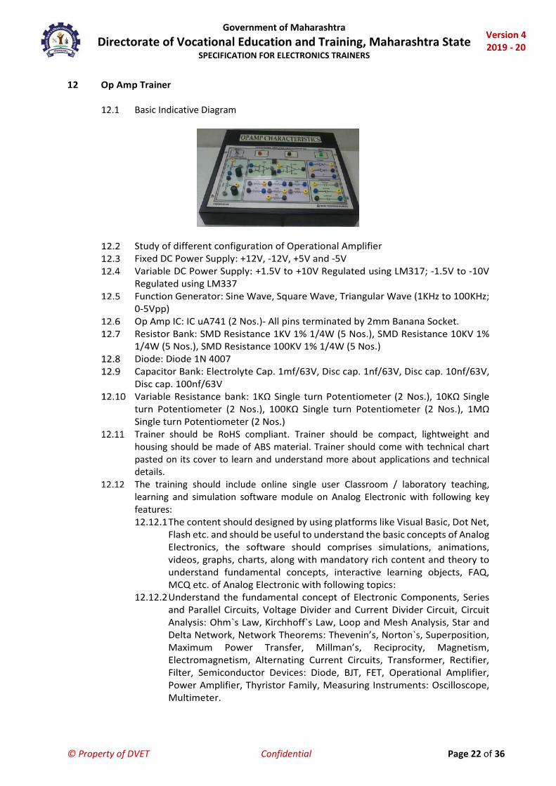
12 Op Amp Trainer
Basic Indicative Diagram
Study of different configuration of Operational Amplifier Fixed DC Power Supply: +12V, -12V, +5V and -5V Variable DC Power Supply: +1.5V to +10V Regulated using LM317; -1.5V to -10V
Regulated using LM337 Function Generator: Sine Wave, Square Wave, Triangular Wave (1KHz to 100KHz;
0-5Vpp) Op Amp IC: IC uA741 (2 Nos.)- All pins terminated by 2mm Banana Socket. Resistor Bank: SMD Resistance 1KV 1% 1/4W (5 Nos.), SMD Resistance 10KV 1%
1/4W (5 Nos.), SMD Resistance 100KV 1% 1/4W (5 Nos.) Diode: Diode 1N 4007 Capacitor Bank: Electrolyte Cap. 1mf/63V, Disc cap. 1nf/63V, Disc cap. 10nf/63V,
Disc cap. 100nf/63V Variable Resistance bank: 1KΩ Single turn Potentiometer (2 Nos.), 10KΩ Single
turn Potentiometer (2 Nos.), 100KΩ Single turn Potentiometer (2 Nos.), 1MΩ Single turn Potentiometer (2 Nos.)
Trainer should be RoHS compliant. Trainer should be compact, lightweight and housing should be made of ABS material. Trainer should come with technical chart pasted on its cover to learn and understand more about applications and technical details.
The training should include online single user Classroom / laboratory teaching, learning and simulation software module on Analog Electronic with following key features: 12.12.1 The content should designed by using platforms like Visual Basic, Dot Net,
Flash etc. and should be useful to understand the basic concepts of Analog Electronics, the software should comprises simulations, animations, videos, graphs, charts, along with mandatory rich content and theory to understand fundamental concepts, interactive learning objects, FAQ, MCQ etc. of Analog Electronic with following topics:
12.12.2 Understand the fundamental concept of Electronic Components, Series and Parallel Circuits, Voltage Divider and Current Divider Circuit, Circuit Analysis: Ohm`s Law, Kirchhoff`s Law, Loop and Mesh Analysis, Star and Delta Network, Network Theorems: Thevenin’s, Norton`s, Superposition, Maximum Power Transfer, Millman’s, Reciprocity, Magnetism, Electromagnetism, Alternating Current Circuits, Transformer, Rectifier, Filter, Semiconductor Devices: Diode, BJT, FET, Operational Amplifier, Power Amplifier, Thyristor Family, Measuring Instruments: Oscilloscope, Multimeter.

Government of Maharashtra Directorate of Vocational Education and Training, Maharashtra State
SPECIFICATION FOR ELECTRONICS TRAINERS
Version 4 2019 - 20
© Property of DVET Confidential Page 23 of 36
13 PAM, PPM, PWM Trainer
Basic Indicative Diagram
PAM-PPM-PWM modulation & demodulation techniques, Natural & flat-top sampling, On-board filter and ac amplifier, Selectable 4 different sampling pulse frequencies on board, Voice communication using dynamic microphone & speaker, Sample, Sample & hold & Flat-Top O/P in PAM On Board Sampling Frequencies (Pulse): 8KHz, 16KHz, 32KHz, 64KHz Low Pass Filter: 4th order BW filter AC amplifier: With adjustable Gain Control DC O/P: 0-4 V (Variable) Test Point: 25nos or more Trainer should be RoHS compliant Trainer should be compact, lightweight and housing should be made of ABS material. Trainer should come with technical chart pasted on its cover to learn and understand
more about applications and technical details. The training should include online single user Classroom / laboratory teaching,
learning and simulation software module on Analog Communication with following key features: 13.16.1 The content should designed by using platforms like Visual Basic, Dot Net,
Flash etc. and should be useful to understand the basic concepts of Analog Communication, the software should comprises simulations, animations, videos, graphs, charts, along with mandatory rich content and theory to understand fundamental concepts, interactive learning objects, FAQ, MCQ etc. of Analog Communication with following topics:
13.16.2 It should help students to analyse & design different analog communication schemes. It should consist of fundamental concepts of analog communication, performance analysis of modulated signals. This module should also cover Fourier analysis, Amplitude Modulation: Standard Amplitude Modulation, DSBSC Modulation, SSB Modulation.
Government of Maharashtra Directorate of Vocational Education and Training, Maharashtra State
SPECIFICATION FOR ELECTRONICS TRAINERS
Version 4 2019 - 20
© Property of DVET Confidential Page 24 of 36
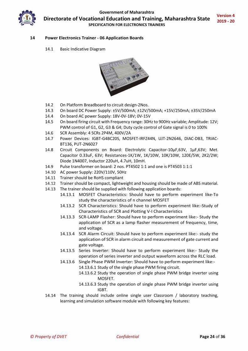
14 Power Electronics Trainer - 06 Application Boards
Basic Indicative Diagram
On Platform Breadboard to circuit design-2Nos. On board DC Power Supply: ±5V/500mA; ±12V/500mA; +15V/250mA; ±35V/250mA On board AC power Supply: 18V-0V-18V; 0V-15V On board firing circuit with Frequency range: 30Hz to 900Hz variable; Amplitude: 12V;
PWM control of G1, G2, G3 & G4; Duty cycle control of Gate signal is 0 to 100% SCR Assembly: 4 SCRs 2P4M, 400V/2A Power Devices: IGBT-G4BC20S, MOSFET-IRFZ44N, UJT-2N2646, DIAC-DB3, TRIAC-
BT136, PUT-2N6027 Circuit Components on Board: Electrolytic Capacitor-10µF,63V, 1µF,63V; Met.
Capacitor 0.33uF, 63V; Resistances-1K/1W, 1K/10W, 10K/10W, 120E/5W, 2K2/2W; Diode 1N4007, Inductor 220uH, 4.7uH, 10mH.
Pulse transformer on board: 2 nos. PT4502 1:1 and one is PT4503 1:1:1 AC power Supply: 220V/110V, 50Hz Trainer should be RoHS compliant Trainer should be compact, lightweight and housing should be made of ABS material. The trainer should be supplied with following application boards:
14.13.1 MOSFET Characteristics: Should have to perform experiment like-To study the characteristics of n channel MOSFET
14.13.2 SCR Characteristics: Should have to perform experiment like:-Study of Characteristics of SCR and Plotting V-I Characteristics
14.13.3 SCR-LAMP Flasher: Should have to perform experiment like:- Study the application of SCR as a lamp flasher measurement of frequency, time, and voltage.
14.13.4 SCR Alarm Circuit: Should have to perform experiment like:- study the application of SCR in alarm circuit and measurement of gate current and gate voltage.
14.13.5 Series Inverter: Should have to perform experiment like:- Study the operation of series inverter and output waveform across the RLC load.
14.13.6 Single Phase PWM Inverter: Should have to perform experiment like:- 14.13.6.1 Study of the single phase PWM firing circuit. 14.13.6.2 Study the operation of single phase PWM bridge inverter using
MOSFET. 14.13.6.3 Study the operation of single phase PWM bridge inverter using
IGBT. The training should include online single user Classroom / laboratory teaching,
learning and simulation software module with following key features:

Government of Maharashtra Directorate of Vocational Education and Training, Maharashtra State
SPECIFICATION FOR ELECTRONICS TRAINERS
Version 4 2019 - 20
© Property of DVET Confidential Page 25 of 36
14.14.1 The content should designed by using platforms like Visual Basic, Dot Net, Flash etc. and should be useful to understand the basic concepts of various technologies in electronics including advance technologies, the software should comprises simulations, animations, videos, graphs, charts, along with mandatory rich content and theory to understand fundamental concepts, interactive learning objects, FAQ, MCQ etc. with following topics:
14.14.2 Introduction, Definition, Insulators, Semiconductors and Conductors, Types of Semiconductors, PN Junction Diode, Transistor PNP and NPN, Power Electronics Devices. Triggering and Commutation: Turn-ON Method of a Thyristor, Gate Triggering Methods, Turn-OFF Method. Gate Firing Circuits: General Firing Circuit, Resistance Firing Circuit, Resistance-Capacitance Firing Circuit for Half and Full Wave, UJT Oscillator, Synchronized UJT Triggering (Ramp Triggering), Ramp and Pedestal Triggering. Phase Controlled Rectifier: Introduction, Classification, Uncontrolled Rectifiers (Half Wave, Full Wave and Bridge).

Government of Maharashtra Directorate of Vocational Education and Training, Maharashtra State
SPECIFICATION FOR ELECTRONICS TRAINERS
Version 4 2019 - 20
© Property of DVET Confidential Page 26 of 36
15 Seven Segment DPM Trainer
Basic Indicative Diagram
Trainer should be RoHS compliant Trainer should be compact, lightweight and housing should be made of ABS material. Technical Details:
15.4.1 Voltage 15.4.1.1 DC Voltage: 0 - 350V 15.4.1.2 AC RMS Voltage: 0 - 350V
15.4.2 Current 15.4.2.1 DC Current: 0 - 2A 15.4.2.2 AC Current: 0 - 2A
15.4.3 Resistance: 0 - 2MV 15.4.4 On Board Fuse: 200mA, 2A 15.4.5 Mains supply: 230V, 50Hz
The trainer should be able to perform following experiments: 15.5.1 Study of DC and AC Voltage Measurement 15.5.2 Study of DC and AC Current Measurement 15.5.3 Study of Resistance Measurement Study of Continuity Tester
Government of Maharashtra Directorate of Vocational Education and Training, Maharashtra State
SPECIFICATION FOR ELECTRONICS TRAINERS
Version 4 2019 - 20
© Property of DVET Confidential Page 27 of 36
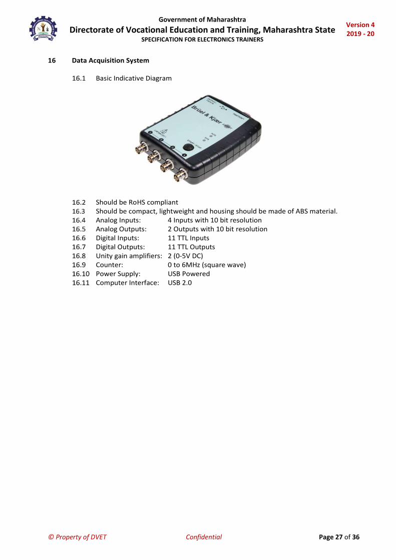
16 Data Acquisition System
Basic Indicative Diagram
Should be RoHS compliant Should be compact, lightweight and housing should be made of ABS material. Analog Inputs: 4 Inputs with 10 bit resolution Analog Outputs: 2 Outputs with 10 bit resolution Digital Inputs: 11 TTL Inputs Digital Outputs: 11 TTL Outputs Unity gain amplifiers: 2 (0-5V DC) Counter: 0 to 6MHz (square wave) Power Supply: USB Powered Computer Interface: USB 2.0

Government of Maharashtra Directorate of Vocational Education and Training, Maharashtra State
SPECIFICATION FOR ELECTRONICS TRAINERS
Version 4 2019 - 20
© Property of DVET Confidential Page 28 of 36
17 Analog Component Trainer
Basic Indicative Diagram
Flexibility of making circuit connections. Online learning material for step by step procedure to perform the experiment and
other details related to theory and experiments. Trainer should be RoHS compliant Trainer should be compact, lightweight and housing should be made of ABS material. DC Power Supplies: + 5V, 1 A (Fixed), + 12V, 500 mA (Fixed), -12V, 500 mA (Fixed), +
12V, 500 mA (Variable), -12V, 500 mA (Variable) AC Supply: 9V-0V-9V, 500mA Breadboard: Breadboard for making various circuits and testing them. External
components/IC can be fitted conveniently. Function generator: Operating modes Sine, Square and Triangular. Frequency range 1
Hz to 100 KHz. Volt/Current/Frequency Measurement: Voltage Range +12V to -12V DC, Current
Range 0 to 500Ma DC, Frequency Range DC to 100KHz (All with respect to Ground) Display: LCD Computer Interface: Acquisition from two Analog input channels (Max. input 1 Volt,
Frequency 300Hz to 3.4kHz) Continuity Tester: For testing the continuity. Should provide with beeper sound. Power Supply: 110-220 V, 50Hz. Ready to use experiment board should be fitted in place of bread board to perform
following experiments on Zener Voltage Regulator board: 17.15.1 Study of Zener diode as a voltage regulator, when input voltage Vin is fixed
while Load resistance RL is variable 17.15.2 Study of Zener diode as a voltage regulator, when input voltage Vin is
variable while Load resistance RL is fixed. The trainer should include online single user Classroom / laboratory teaching, learning
and simulation software module on Analog Electronic with following key features: 17.16.1 The content should designed by using platforms like Visual Basic, Dot Net,
Flash etc. and should be useful to understand the basic concepts of Analog Electronics, the software should comprises simulations, animations, videos, graphs, charts, along with mandatory rich content and theory to understand fundamental concepts, interactive learning objects, FAQ, MCQ etc. of Analog Electronic with following topics:

Government of Maharashtra Directorate of Vocational Education and Training, Maharashtra State
SPECIFICATION FOR ELECTRONICS TRAINERS
Version 4 2019 - 20
© Property of DVET Confidential Page 29 of 36
17.16.2 Understand the fundamental concept of Electronic Components, Series and Parallel Circuits, Voltage Divider and Current Divider Circuit, Circuit Analysis: Ohm`s Law, Kirchhoff’s Law, Loop and Mesh Analysis, Star and Delta Network, Network Theorems: Thevenin’s, Norton`s, Superposition, Maximum Power Transfer, Millman’s, Reciprocity, Magnetism, Electromagnetism, Alternating Current Circuits, Transformer, Rectifier, Filter, Semiconductor Devices: Diode, BJT, FET, Operational Amplifier, Power Amplifier, Thyristor Family, Measuring Instruments: Oscilloscope, Multimeter.

Government of Maharashtra Directorate of Vocational Education and Training, Maharashtra State
SPECIFICATION FOR ELECTRONICS TRAINERS
Version 4 2019 - 20
© Property of DVET Confidential Page 30 of 36
18 Micro Processor Trainer
Basic Indicative Diagram
72 I/O lines through 8255 Three channel Timer/Counter using 8253 8 channel ADC with On board DAC It should support have two modes of operation-Keyboard mode and Serial Mode/ It should have the Facility of downloading and uploading the files from Computer All Address and Control lines are provided on 50 pin connector Operating Frequency: 5 MHz RAM: 16 K ROM: 16 K Display: 20 X 2 LCD Input: ASCII Keyboard Mains supply: 90 - 230V AC, 50 Hz The training should include online single user Classroom / laboratory teaching,
learning and simulation software module with following key features: 18.14.1 The content should designed by using platforms like Visual Basic, Dot Net,
Flash etc. and should be useful to understand the basic concepts of various technologies in electronics including advance technologies, the software should comprises simulations, animations, videos, graphs, charts, along with mandatory rich content and theory to understand fundamental concepts, interactive learning objects, FAQ, MCQ etc. with following topics:
18.14.2 Embedded System: Module on Embedded system should cover following topics: Basics: Definition, Characteristics, Architecture, Applications, Categories: Stand Alone Embedded System, Real-Time Embedded System, Network Information Appliances, Mobile Devices; Digital Primer and Components: Numbering and Coding System, Digital Gates, Basic Components-Transistor, Diode, Resistance, Capacitance, Seven Segment Display, Power Supply. 8051 Microcontroller: Microcontroller, Architecture, Features, 8051 Pinout and Details, Registers and SFR, Memory Map, Instruction Set, Addressing Mode, Timer and Counters, Interrupts, Serial Communication. 8051 Peripheral Interfacing: Switch Interface, Seven Segment Display Interface, LED interface, LCD Interface.

Government of Maharashtra Directorate of Vocational Education and Training, Maharashtra State
SPECIFICATION FOR ELECTRONICS TRAINERS
Version 4 2019 - 20
© Property of DVET Confidential Page 31 of 36
19 Microcontroller Trainer (8051) with Programming Software and 6 Applications
Basic Indicative Diagram
Trainer should be RoHS compliant Trainer should be compact, lightweight and housing should be made of ABS material. Trainer should come with technical chart pasted on it to learn and understand more
about applications and technical details. Communication: USB Programming mode: PC mode, Hex keypad mode MCU: 8051 core Crystal Frequency: 11.0592 MHz DC Power Supplies: +12V, -12V, +5V & - 5V Programmer: Ready to run programmer will program 8051 devices Interconnection for modules: 2 mm patch cords and FRC cables Online Product Manual: Should include Theory, procedure, reference, results etc. Power Supply: 110V - 260VAC, 50Hz Accessories: USB cable, Mains cord, Patch cords, 20 Pin FRC Cable and & Power Supply Input Interface Module
19.15.1 Keyboard: ASCII keyboard 19.15.2 LED'S: 12 Nos. 19.15.3 Switches: 4 Nos. 19.15.4 Keypad: 4 X 4 matrix hex keypad 19.15.5 Power Supply: From Microcontroller development platform 19.15.6 Study Material: Online - Include theory, procedure, reference results, etc. 19.15.7 Interface: 20 pin FRC cable 19.15.8 Test points: 2 Nos.
Display Module 19.16.1 Display: 16 x 2 character LCD 19.16.2 Contrast control: 0 - 5 V (Variable) 19.16.3 Backlight control: 0 - 5 V (Variable) 19.16.4 Seven segment display: 4 Nos. 19.16.5 LED bar graph: 1 No. 19.16.6 Interface: 20 pin FRC cable 19.16.7 Test points: 25 Nos. or more 19.16.8 Power Supply: From Microcontroller development platform 19.16.9 Learning Material: Online-include theory, procedure, reference
results, etc.

Government of Maharashtra Directorate of Vocational Education and Training, Maharashtra State
SPECIFICATION FOR ELECTRONICS TRAINERS
Version 4 2019 - 20
© Property of DVET Confidential Page 32 of 36
ADC/DAC Module 19.17.1 ADC: ADC0808 19.17.2 DAC: DAC0808 19.17.3 Power Supply: From Microcontroller development Platform 19.17.4 Interface: 20 pin FRC cable 19.17.5 Test Points: 25 Nos. or more
Computer Interface Module 19.18.1 Serial Communication: RS232 Port 19.18.2 USB Communication: USB port 19.18.3 Baud Rate: Configurable (Default 9600) 19.18.4 Power Supply: From Microcontroller development platform 19.18.5 Interface: 20 pin FRC cable 19.18.6 Test points: 6 Nos 19.18.7 Banana socket: 15 Nos or more
Motor Drive Module 19.19.1 Stepper Motor: +5 V 19.19.2 DC Motor: +12 V 19.19.3 Servo Motor: +5 V 19.19.4 Interface: 20 pin FRC cable 19.19.5 Test points: 13 19.19.6 Power Supply: From Microcontroller development platform
Data Acquisition System 19.20.1 Analog Inputs: 4 Inputs with 10 bit resolution 19.20.2 Analog Outputs: 2 Outputs with 10 bit resolution 19.20.3 Digital Inputs: 11 TTL Inputs 19.20.4 Digital Outputs: 11 TTL Outputs 19.20.5 Unity gain amplifiers: 2 (0-5V DC) 19.20.6 Counter: 0 to 6MHz (square wave) 19.20.7 Power Supply: USB Powered 19.20.8 Computer Interface: USB 2.0
The training should include online single user Classroom / laboratory teaching, learning and simulation software module with following key features: 19.21.1 The content should designed by using platforms like Visual Basic, Dot Net,
Flash etc. and should be useful to understand the basic concepts of Microcontroller, Embedded and its Applications, the software should comprises simulations, animations, videos, graphs, charts, along with mandatory rich content and theory to understand fundamental concepts, interactive learning objects, FAQ, MCQ etc. with following topics:
19.21.2 Embedded System: Module on Embedded system should cover following topics: Basics: Definition, Characteristics, Architecture, Applications, Categories: Stand Alone Embedded System, Real-Time Embedded System, Network Information Appliances, Mobile Devices; Digital Primer and Components: Numbering and Coding System, Digital Gates, Basic Components-Transistor, Diode, Resistance, Capacitance, Seven Segment Display, Power Supply. 8051 Microcontroller: Microcontroller, Architecture, Features, 8051Pinout and Details, Registers and SFR, Memory Map, Instruction Set, Addressing Mode, Timer and Counters, Interrupts, Serial Communication. 8051 Peripheral Interfacing: Switch Interface, Seven Segment Display Interface, LED interface, LCD Interface.

Government of Maharashtra Directorate of Vocational Education and Training, Maharashtra State
SPECIFICATION FOR ELECTRONICS TRAINERS
Version 4 2019 - 20
© Property of DVET Confidential Page 33 of 36
20 Hardware and Network Trainer
Basic Indicative Diagram
This training system should help to understanding of Local Area Network (LAN) including fundamentals of networking.
It should assist for knowledge of all network layers, cable designing and building of a complete network of computers.
Students can study of various topologies using different standards given by IEEE with actual connections made in different topologies and data can be transferred.
It should have provision to understand protocols, topologies used in networking, measurement of error rate, throughput and effect of errors on protocols.
It should have PC to PC using RJ-45 Connector, Star topology using RJ45 Connector, Ring topology using DB9 Connector.
This training system should have software by which student can study Star & Ring selection, Protocols: CSMA /CD, CSMA /CA, Stop N Wait, Go back to N, Selective repeat, Sliding Window, Token Bus, Token Ring, Packet size: 128, 256, 512, 1024, 2048, 4096, 8192, 16384Inter Packet delay: 1000 – 5000 ms, Error generation: Acknowledgment lost, bad packet, auto error generation, Complete analysis of Network & Protocols, Real time Graphic representation of data on s/w screen with packet details, Network details like, Indication of computer name, IP address, MAC address, Port number, status of network, Network & protocol analysis like Indication of packet serial number, file name, file size, file number, receiver name, receiver IP address, total packets, packet length, time out, protocol, topology, receiver, MAC address, port number, file send start time, file sent completion time, transmission time data rate(Mbps),percentage error.
Trainer should be RoHS complained. It should be compact, lightweight and housing should be made of ABS material.
It should come with technical chart pasted on it to learn and understand more about applications and technical details.

Government of Maharashtra Directorate of Vocational Education and Training, Maharashtra State
SPECIFICATION FOR ELECTRONICS TRAINERS
Version 4 2019 - 20
© Property of DVET Confidential Page 34 of 36
21 Electronics Circuit Simulation Software - 6 User License
Basic Indicative Diagram
The software should have facility of circuit simulation and PCB design of analog, digital and mixed electronic circuits with their PCB layouts.
It should have a library of at least 20 thousand components. It should support Spice, VHDL, Verilog, Verilog AMS and System C, Create Digital filters
in System C and run in software, add MCUs in System C to the software. It should also have facility to analyse SMPS, RF, Communication, Power Electronics
and Optoelectronic circuits. The software must be able to simulate PIC, AVR, 8051, ARM and Arduino MCUs, in
digital or mixed circuit environment. It should have features to generate and debug MCU code using the integrated flow
chart tool and test microcontroller applications in a mixed circuit environment. The software should have facility of fault creation in the components, automatic
calculation of the component value for the optimization of designed circuit. It should support digital circuit simplification of digital logics and the implementation
of logic gates using Quine-Mccluskey method and Karnaugh-Map. The software should support. symbolic analysis: automatic creation of closed form
expressions and for DC, AC and Transient analysis of linear circuits. The software should support ADCs, DACs with SPI, I2C, SPI bus simulation, PM bus,
SM bus simulation. It should also provide facility to study two-port parameters of networks (S, Z, Y and
H), DC Transfer Characteristic with Nested sweep option and Parameter Sweeping function to study the response of components. Functions to plot the frequency response, Phasor Diagram, Nyquist Diagram and Noise Analysis. Linux simulation on ARM MCU should be possible.
Pre-recorded (.wav) files can be used as input in circuits and transient analysis results can be converted to .wav files or played using the sound system of computers.
All six user perpetual license of the software should support either the digital online access, and simulation or the license protection should be supported through USB hardware dongle and have facility to upgrade in future.
Should create Multilayer PCB layouts of circuits, with automatically placed and routed components. All components in software should be “PCB-ready” and have associated footprints which user can review and change on a component spreadsheet.
Government of Maharashtra Directorate of Vocational Education and Training, Maharashtra State
SPECIFICATION FOR ELECTRONICS TRAINERS
Version 4 2019 - 20
© Property of DVET Confidential Page 35 of 36
It should also have 3D capability to preview the physical parts already on the schematic diagram with run time animation in 2D and 3D view, visualizations of PCB design with Enclosures in 3D, 3D printer support, Importing Footprints in 2D and 3D in industry standard formats. PCB design software should support both G code and Gerber generation of the data.

Government of Maharashtra Directorate of Vocational Education and Training, Maharashtra State
SPECIFICATION FOR ELECTRONICS TRAINERS
Version 4 2019 - 20
© Property of DVET Confidential Page 36 of 36
22 LAN Protocol Simulation and Analyser Software
Basic Indicative Diagram
The module should create a virtual environment to implement various LAN configurations and should give results of simulation.
User should able to simulate LAN to best possible combination before actual implementation.
5 User License The software module should cover following topics in detail:
22.5.1 Networking: History, Components (NIC, Repeater, HUB, Bridge, Switch, Router, MSAU), Topologies (Bus, Rig, Star, Mesh, Tree), Network Types(LAN, MAN, WAN), VLAN, Internet
22.5.2 Networking Models: OSI Model, TCP/IP Model, IEEE Standards, Protocols 22.5.3 Switching: Circuit Switching, Packet Switching, Message Switching, PSTN,
ISDN, DSL 22.5.4 Ethernet: Introduction, Fast Ethernet, Gigabit 22.5.5 Network Security: Introduction, VPN, Firewall 22.5.6 Algorithms: Dijkstra’s Algorithm, Bellman Ford Algorithm 22.5.7 Network Design Lab: Bus, Hub, Switch