
Street Name Street Type Direction Municipality - Forsyth County
Upload
khangminh22Category
view
0download
0
StIFIECTRICn1 tri 1
BRISBANE CITY COUNCIL
Sewerage Pump Station SP007
Ferrol St
Coorparoo
Contract : BW 70103-013
Job Number : WT400035
Volume 1
ELECTRICAL INSTALLATION
OPERATIONS and MAINTENANCE MANUAL
INSTALLATION BY:
SJ Electric (Qld) Pty Ltd 19 Elliot Street
Albion Qld 4010
Telephone: 07 3256 1522 Fax: 07 3256 1533
SP007 Ferol Street Coorparoo SPS Electrical Installation Volume 1 OM Manual
Q-Pulse Id TMS871 Active 10/12/2014 Page 1 of 560

INDEX
SECTION Sewerage Pump Station - SP007 Ferrol St - Coorparoo
Volume 1
1.
GENERAL
1..1 General Workplace Health & Safety 1..2 Project Overview 1..3 Plant Maintenance 1..4 Electrical Control System 1..5 Control & Monitoring System
Volume 1
2.
MANUFACTURER'S TECHNICAL DATA
2.1 Terasaki XS 400 Circuit Breakers. 2.2 Sprecher and Schuh CA-7Contactors. 2.3 Critec TDS -180-4S-277 Surge Diverter 2.4 Critec TDF-10A-240V Surge Filter. 2.5 Critec DAR-275V Alarm Relay 2.6 Crompton Phase Failure Relay. 2.7 Multitrode MTR Level Relay 2.8 Trio DR900-06A02-DO Radio. 2.9 Polyphaser IS-50NX Impulse Suppressor. 2.10 Powerbox Radio/DC converter. 2.11 Powerbox Modem/Power Supply. 2.12 Multitrode Level Probe 2.13 Emotron Soft Starter MSF 2.0 2.14 Vega Delivery Pressure Transmitter 2.15 Endress & Hauser Wet Well Level Transmitter
Volume 2
3.
DRAWINGS
Volume 2
4.
INSPECTION & TEST RESULTS
Volume 2
5.
COMPLIANCE CERTIFCATES
SP007 Ferol Street Coorparoo SPS Electrical Installation Volume 1 OM Manual
Q-Pulse Id TMS871 Active 10/12/2014 Page 2 of 560

SP007 Ferol Street Coorparoo SPS Electrical Installation Volume 1 OM Manual
Q-Pulse Id TMS871 Active 10/12/2014 Page 3 of 560

1
1
I I
1
SP007 Ferol Street Coorparoo SPS Electrical Installation Volume 1 OM Manual
Q-Pulse Id TMS871 Active 10/12/2014 Page 4 of 560

Page 1
1.1 General Workplace Health and Safety
The Workplace Health and Safety Act (1995) sets out the laws about
Workplace Health and Safety for all workplaces, workplace activities and
specified high risk plant. The Electrical Safety Act (2002) sets out the laws
covering electrical safety. Nothing in this document is designed, in any way, to
undermine the authority of the Acts.
All reasonable care must always be taken to ensure the plant is without risk
to the health and safety of personnel operating and maintaining plant and
equipment.
Employers have an obligation to ensure the workplace health and safety of all
personnel at work.
It is employer responsibility to ensure that all persons entering or working on
the premises use appropriate personal protective equipment.
Personal protective equipment includes gloves, safety glasses, hard hats, ear
protection, safe foot ware and, where necessary, specialist protective clothing
for hazardous areas.
Any item of equipment should always be isolated before maintenance or
repairs commence to ensure that inadvertent operation of the item does not
result in risk to the health and safety of any person.
Where the item is isolated, any total or partial shutdown should not allow a
hazardous situation to be created.
Where the item cannot be isolated, another person should be stationed at the
controls of the item and an effective means of direct communication should
exist between the persons carrying out the maintenance and the person at the
controls.
23/06/09
SP007 Ferol Street Coorparoo SPS Electrical Installation Volume 1 OM Manual
Q-Pulse Id TMS871 Active 10/12/2014 Page 5 of 560

Page 2
General Operating Principles
All persons working the premises must be qualified Electrical Engineers or
electrical trades persons capable of performing the required tasks
competently. All personnel must also be familiar with plant and equipment.
Adequate information, instruction, training and supervision must be provided
to enable personnel to perform work without risk to health and safety.
Work in an orderly way.
Plan work in advance to avoid hazardous situations.
Warn others of any hazards.
Make inquiries before starting work, particularly on any unfamiliar
installation or equipment.
Before any work begins ensure that any instructions received or given are
fully understood.
Concentrate on the task on hand.
Do not distract others or allow yourself to be distracted by foolish actions.
Work from a safe and convenient position that provides a maximum working
space that you do not have to over reach, you cannot slip, trip or stumble and
so endanger yourself and others.
Keep the working area tidy and free of unwanted materials and equipment.
Use insulated tools where possible.
Inspect tools and equipment regularly and ensure that any necessary
maintenance is carried out.
Keep yourself in good health.
Do not work if ill or over tired, to the extent that your concentration,
movement or alertness is affected. Illness or fatigue can endanger yourself
and others.
23/06/09
SP007 Ferol Street Coorparoo SPS Electrical Installation Volume 1 OM Manual
Q-Pulse Id TMS871 Active 10/12/2014 Page 6 of 560

Page 3
1.2 Project Overview
Contract BW70103-013 was for the manufacture and testing of ten (1) new pump
station switchboards for various locations throughout Brisbane.
Equipment provided by SJ Electric ensures safe and efficient operation of the
pump stations. Equipment supplied and installed by SJ Electric includes: -
Switchboards
Instrumentation
Civil Works
The switchboard incorporates the latest technology in motor control, power
monitoring, and instrumentation. It is important engineers, technicians and
operators are familiar with the equipment installed before attempting any
adjustments, modifications or maintenance.
The following Sections of this manual contain a comprehensive description of all
equipment supplied, by SJ Electric. It is recommended that this manual be
referred to before carrying out any work on any equipment.
23/06/09
SP007 Ferol Street Coorparoo SPS Electrical Installation Volume 1 OM Manual
Q-Pulse Id TMS871 Active 10/12/2014 Page 7 of 560

Page 4
1.3 Plant Maintenance
To ensure proper operation of the plant the following should be observed: -
The plant should be kept clean and tidy at all times. Not only is this of
aesthetic value, it extends equipment life.
Check that all plant and equipment is operating correctly. Correctly operating
equipment promotes overall plant efficiency.
All items and areas of equipment should be hosed down and cleaned
regularly.
WARNING
Avoid directly hosing any drive motor or electrical item.
All maintenance, service, modifications and significant deviations from
Normal operating conditions should be recorded in the Plant Service Log
After a month of operation, check the tension of all bolts associated with the
plant and thereafter periodically. Bolted connections on painted surfaces can
loosen due to thinning of the paint underneath the bolt head-bearing surface.
Motor mounting bolts and other bolted connections subjected to vibration
should be periodically checked for loosening.
WARNING
Before starting work on any item ensure that the power supply is
isolated, tagged off, and the item cannot be started.
The importance of preventative maintenance cannot be over-emphasized.
Regular maintenance and suitable care of the equipment will ensure a long
and reliable service life of the equipment.
Many stoppages can be avoided by following the recommended maintenance
procedures. Do not wait until you hear the grinding of equipment that has
broken down. If you see any item wearing down, replace it, before it causes
damage to other associated items.
23/06/09
SP007 Ferol Street Coorparoo SPS Electrical Installation Volume 1 OM Manual
Q-Pulse Id TMS871 Active 10/12/2014 Page 8 of 560

Page 5
Preventive Maintenance
Maintenance procedures recommended to extend switchboard life are
outlined as follows: -
Switchboard exterior should be regularly wiped down with a solvent
base cleaner such as "Spray & Wipe". This will ensure longevity of the
powder-coated surface.
Accessible areas like distribution boards and motor starter panels
should be cleaned with a vacuum cleaner to remove dust and foreign
matter.
PLC panels should be maintained as dust free as possible. Dusting with
a dry rag is recommended - taking care not allows dust inside the I/O
modules or processor.
When removing or installing PLC modules care should be taken to
ensure that power is turned off to the rack before modules are
removed or installed.
Connections and efficient operation of circuit breakers, contactors and
isolators should be checked every 12 months - especially where
connected to busbars.
Busbar connections should be checked every 12 months.
Globes for indicator lights should be checked on a weekly basis with
any faulty lamps replaced.
Cubicle Fans Filter should be inspected and cleaned frequently.
23/06/09
SP007 Ferol Street Coorparoo SPS Electrical Installation Volume 1 OM Manual
Q-Pulse Id TMS871 Active 10/12/2014 Page 9 of 560

Page 6
1.4 Electrical Control System
General Description
The switchboards are manufactured from 3mm aluminium and are
suitable for location outdoors; the switchboards have been designed by
Brisbane Water and contain several separate sections including:
Incoming Section.
Metering.
Motor Starter Section.
Distribution Section.
RTU Section.
1.5 Control and Monitoring System.
The control and monitoring of the system is performed by the Brisbane
Water telemetry system and was not included in this contract.
23/06/09
SP007 Ferol Street Coorparoo SPS Electrical Installation Volume 1 OM Manual
Q-Pulse Id TMS871 Active 10/12/2014 Page 10 of 560

I
II
I
i
SP007 Ferol Street Coorparoo SPS Electrical Installation Volume 1 OM Manual
Q-Pulse Id TMS871 Active 10/12/2014 Page 11 of 560

1
SP007 Ferol Street Coorparoo SPS Electrical Installation Volume 1 OM Manual
Q-Pulse Id TMS871 Active 10/12/2014 Page 12 of 560

I
8
9
o
SP007 Ferol Street Coorparoo SPS Electrical Installation Volume 1 OM Manual
Q-Pulse Id TMS871 Active 10/12/2014 Page 13 of 560

e
8
II
I ,
*
SP007 Ferol Street Coorparoo SPS Electrical Installation Volume 1 OM Manual
Q-Pulse Id TMS871 Active 10/12/2014 Page 14 of 560

TECHNICAL DATA SHEET
For
SEWERAGE PUMP STATION SP007 Ferrol St Coorparoo
Equipment Type:
Location:
Model Numbers:
Manufacturer:
Supplier:
Circuit Breaker
Main Incomer Pump Circuit Breakers
XS 400
Terasaki
NHP Pty Ltd 25 Turbo Drive Coorparoo QLD 4151
Ph: 07 3891 6008 Fx: 07 3891 6139
SP007 Ferol Street Coorparoo SPS Electrical Installation Volume 1 OM Manual
Q-Pulse Id TMS871 Active 10/12/2014 Page 15 of 560

abemorwan IA Nowa. Terhmology TERASAKI
TemiBreak MCCBs
XS400 series thermal magnetic type
Adjustment range 63 - 100 % of nominal current rating.
Standards AS 2184/AS/NZS 3947-2.
Adjustable thermal and magnetic trip.
XS400CJ (35 kA) 3 pole Ampere rating
250
400
Min
160
250
Max
250
400
Cat. No.
XS400CJ 250 3
XS400CJ 400 3
400 Non-Auto (5 kA for 0.3 sec) ') Refer page 5 - 48
XS400CJ (35 kA) 4 pole
250 160 250 XS400CJ 250 4
400 250 400 XS400CJ 400 4
XS400NJ (50 kA) 3 pole
Short circuit capacity Model I/C
--..1111111=1911M-
Voltage
XS400CJ
XS400NJ
250 160 250
400 250 450
XS400NJ 250 3
XS400NJ 400 3
XS400NJ (50 kA) 4 pole
250 160 250
400 250 400
XS400NJ 250 4
XS400NJ 400 4
Dimensions (mm) Description
XS400CJ/NJ 3 pole
4 pole
Height
260
260
Width
140
185
Depth
103
103
kg
4.7
6.1
w
-07570- 1
. 0,-
Fl ° P ° P
Notes: ') Load-break isolating switch only - no protection. 2) MCCBs only. ') Poles in series. Refer applications Section 13.
35 kA (AS 2184)
50 kA
415 V 50 Hz
415 V 50 Hz
DC use 3)
XS400CJ
XS400NJ
I/C
40 kA
40 kA
Voltage
250 V DC
250 V DC
Refer to ratings chart at the front of this section.
For ratings to AS/NZS 3947-2 and AS 2184, and Ics /Icu.
Cross reference table Section
Accessories 6
Selectivity & cascade 13
Application data
Characteristic curves
13
7
Motor starting 13
Connection & mounting details 7 and 8
Detailed dimen. - MCCB only 7
- motor operators 7
Product extensions Section
Chassis (TemWay, MHC, UHC) 6
TemCurve 13
Residual current relays 11
Base standards
I EC 60947-2
BS EN 60947 Part 2
VDE 0660 Part 1
AS/NZS 3947-2/Aust./NZ
AS 2184-1990/Australia 2)
JIS C 8372/JAPAN
JEC 160/JAPAN
Approvals
ASIA /UK, Aust. standards
Marine
NK/JAPAN
Lloyds R/UK
ABS/USA
GL/GERMANY
BV/FRANCE
DNV NORWAY
5 -29
SP007 Ferol Street Coorparoo SPS Electrical Installation Volume 1 OM Manual
Q-Pulse Id TMS871 Active 10/12/2014 Page 16 of 560

I
SP007 Ferol Street Coorparoo SPS Electrical Installation Volume 1 OM Manual
Q-Pulse Id TMS871 Active 10/12/2014 Page 17 of 560

ODInnaraton is Protection Technoloxy TERASAKI
Standard TemBreak circuit breaker Selection guide
Type XM3OPB XS125CS XS125CJ XS125NS XS125NJ 'Ampere frame 30A 125A 125A
Number of poles 3P 1P ') 2P ') U 3P 4P U 1P ') 2P ') 3P 4F'
Outside view
Notes:
,) 1 Pole breaker only XS125CS and XS125NS respectively.
) 2 pole breaker is a 3 pole breaker with the centre pole omitted.
Supplied as standard. 0 Optional standard.
(p., Yes or available. - Not available
1=1 Indent only
't .
IwiErk
1 C
7'
-,..),,i-r..- rj
15, ;',.; w
....'
s.
tpf:art--
L.
.1°14 Thar i'"
Rated current (A),In NRC - Nominal rated current ASR - Adjustable setting range
NRC NRC NRC ASR NRC NRC ASR
0.7 8.0 16 50
min
20 12.5
max
20 16 50
min
20 12.5
max
20 Rated current at 40'C
1.4 10 20 63 32 20 32 20 63 32 20 32
2.0 12 25 80 50 32 50 25 80 50 32 50
2.6 32 100 63 40 63 32 100 63 40 63
4.0 40 125 100 63 100 40 125 100 63 100
5.0 125 80 125 125 80 125
AC RATED INSULATION VOLTAGE (Ui) 690 690 690
AC RATED BREAKING CAPACITY sym RMS RA]
IEC 60947-2 (Ica] IEC 60947-2 (ICs]
AS/NZS 3947-2 flail AS/NZS 3947-21Ics)
Note: Rated Impulse withstand voltage
Uimp (kV) is 8kV on all XS, XE and XH MCCB's
1100V - - 1000V - -
690V - - 5/2.5
660V 5/2.5
500V - 7.5/3.8 12/6
440V 85 10/5 10/5 22/11 22/11
415V 85 14/7 14/7 25/13 25/13
400V 85 18/9 18/9 25/13 25/13
380V 85 18/9 18/9 30/15 30/15
240V 125 14/7 25/13 25/13 25/13
AS 2184 440V 85 14 25
415V 85 18 30
NEMA AB-1 600V 85 - - 12
480V 85 - 10 - 22
without InsL 240-690V - DC RATED BREAKING 250V - 10 - 15
CAPACITY (kA) 125V 10 15 15 20
RATED SHORT TIME CURRENT RMS Lk/Li LIcvd - DIMENSIONS (mm)
a 78 30 90 120 30 90 120
I-a- r i b 148 155 155 --, c 98 86 86
d 116 104 104
Weigh
CONNECTION
(kg) marked standard type 1.3 0.51 1.3 1.58 0.51 1.3 1.58
AND MOUNTINGS
front
connect (FC)
rear
connect (RC)
plug-in (PM)
draw-out (DO)
terminal screw
attached flat bar - 0 - o solderless terminal (PWC) 0 o 0 bolt stud o o - o flat bar stud - for switchboard o - o - 0 for distribution board - o o
- STANDARD FEATURES
contact indicator
trip button - PROTECTIVE FUNCTIONS
Electronic type
Adjustable LTD. STD & INST - - - Adjustable GFT or Adjustable PTA (option) -
- - - - Trip indicators (option) (contacts)
Thermal-magnetic type
fixed magnetic trips
trips
magnetic trips
CODE
fixed
- -
-
thermal and
thermarand adjustable magnetic
adjustable thermal and fixed
adjustable thermal and magnetic trips
ACCESSORIES (option)
Internally
mounted
auxiliary switch AUX - - alarm switch ALT - - shunt trip SHT e undervollage trip IJVT
MOT - - - Externally
mounted
motor operator
external panel mounted type XFE - operating breaker mounted type TFJ - - handle variable depth type XFH - IP 65 handle variable deptlype TLK - - extension handle - - mechanical interlock front type - - mechanical interlock rear type - mechanical interlock cable type - - key interlock - 0 handle holder 5
handle lock
captive padlock attachment
terminal cover front connect type - terminal cover rear/plug-M type - - interpole barriers - - accessories lead terminals - o - OCR sealing kit -
5 - 2
SP007 Ferol Street Coorparoo SPS Electrical Installation Volume 1 OM Manual
Q-Pulse Id TMS871 Active 10/12/2014 Page 18 of 560

aInnovoron In Protectlen Technoingy TERASAKI
Standard TemiBreak circuit breaker Selection guide
XH125NJ XE225NC XS25ONJ XH25ONJ XS400CJ XS400NJ 125A 225A 250A 250A 400A 400A
3P 4P 3P 313 4P 313 413 3P 413 0 313 4P LL
- - 44 7_ - ps..LD
15*
o .
4
- . ,. l'(./1.
11L. 5
Eilar f
i r Iu..i4'.. c,..
I 6 rt. .,
9 , .
NRC ASR NRC NRC ASR NRC ASR NRC ASR NRC ASR
min max min max min max min max min max
20 12.5 20 125 200 160 100 160 160 100 160 250 160 250 250 160 250
32 20 32 150 250 250 160 250 250 160 250 400 250 400 400 250 400
50 32 50 175
63 40 63
100 63 100
125 80 125
690 690 690 690 690 690
ICU /ICS ICU/ICS
- - - - - - - - - - - 8/4 - 8/4 15/7.5 16/8 18/9
8/4 - 8/4 15/7.5 16/8 18/9
25/13 10/5 22/11 25/13 22/11 30/15
42/21 15/7.5 25/13 42/21 30/15 42/12 _ 50/25 15/7.5 25/13 50/25 30/15 50/25
50/25 18/9 25/13 50/25 35/18 50/25
50/25 18/9 35/18 50/25 35/18 50/25
85/43 25/13 50/25 85/43 50/25 85/43
50 15 30 50 36 50
50 18 35 50 36 50
25 - 22 25 22 30
42 15 25 42 30 42
- - - - - 40 10 40 40 40 40
40 15 40 40 40 40
- - - - -
90 120 105 105 140 105 140 140 185 140 185
155 165 165 165 260 260
86 67 86 103 103 103
104 82 107 124 131 131
1.3 1.58 1.4 1.85 2.4 2.1 2.6 4.7 6.1 4.7 6.1
0 0 (Bar) 0 (Bar) 0 (Bar) 0 (Bar) 0 (Bar)
0 0 0 0 0 0 0 0 0 0 - -
- - - 0 0 0 0 0 0 0 0
- - - - - - - - - 0 0
- - - - - - - - - _ -
- _
- - _
-
- - - -
- - - - - - - -
- - - -
5 - 3
SP007 Ferol Street Coorparoo SPS Electrical Installation Volume 1 OM Manual
Q-Pulse Id TMS871 Active 10/12/2014 Page 19 of 560

TERASAKI Sect ri o Innovatory Proterriox Trchnology
MCCB operational characteristics & dimensions 17
Page
Thermal - magnetic MCCB characteristics 7 - 2 to 7 - 4 Time / current characteristics thermal - magnetic MCCBs 7 - 5 to 7 - 10 Electronic MCCB characteristics - settings 7 -11 to 7 - 14 PTA - Pre-trip alarm option 7- 15 to 7 - 19 GF - Ground fault / 4th CT option 7- 16 to 7 - 19 LED trip indication options 7- 18 to 7 - 19 Time / current characteristics electronic MCCBs 7- 20 to 7 - 22 OCR checker for electronic MCCBs 7 -23 TemCurve selectivity software 7 -24 MCCB dimensions with and without motors fitted 7- 25 to 7 - 50 AC Watts loss - 3 pole MCCBs 7 -51
7 - 1
SP007 Ferol Street Coorparoo SPS Electrical Installation Volume 1 OM Manual
Q-Pulse Id TMS871 Active 10/12/2014 Page 20 of 560

TERASAKI Innowors In Prowl!. Technology
MCCB Technical data Thermal Magnetic MCCBs
Thermal-Magnetic MCCBs are available from 125 AF to 800 AF. Depending on the type of MCCB thermal
and/or magnetic trip setting may be adjustable.
Fixed Adjustable Fixed Adjustable MCCB type thermal thermal magnetic magnetic
XS125CS, XS125NS
XS125CJ, XS125NJ _
XH125NJ, XH125PJ, TL100NJ
XH160PJ
XE225NC
XS25ONJ, XH25ONJ
XH250PJ
XS400CJ, XS400NJ, XH400PJ, TL25ONJ
XS630CJ, XS630N1, XH630PJ
XS800NJ
XH800PJ
Note: Yes
- No
.A.;:cess to setting (hats
From 125 AF to 250 AF the thermal adjustment is visible from the front of the MCCB. At 400 AF and above a protective cover must be
removed to gain access to the settings. To achieve access to the settings, the cover screw under the 'sealed' label must be removed.
To adjust the individual trip settings, turn the setting dial with a flat bladed screwdriver.
Once set, secure the cover and apply a new sealing label.
V
a
a
XH25ONJ XS400NJ XS400NJ (cover removed)
7 - 2
SP007 Ferol Street Coorparoo SPS Electrical Installation Volume 1 OM Manual
Q-Pulse Id TMS871 Active 10/12/2014 Page 21 of 560

aMao...ears in Prong-doh Technology TERASAKI
IVICCB Technical data
Therma I Adjustment TemBreak MCCBs have a wide thermal adjustment range, one of
the largest on the market. The rated current 'Ir' is continuously
adjustable from 63 % to 100 % of its nominal current 'In. There
are three main points of calibration marked at 63 %, 80 % and
100 %, as shown in the diagram below.
0.63 0.8 1.0
Thermal adjustment range
Examples
Magnetic Adjustment The magnetic adjustment is available on MCCBs of 400 AF and
above. The magnetic setting 'Im is continuously adjustable from
500 % to 1000 % of its rated current 'In. There are five main
points of calibration marked as multiples of In; 5, 6, 7.1, 8.5
and 10. These are shown in the diagram below.
Magnetic ad.ustment range
Current x In
1. XS125NJ/125A MCCB set at V= 0.8, the rated current is calculated as 125 x 0.8 = 100 A
2. XS400NJ/400A MCCB set at Im = 6, the magnetic setting is calculated as 400 x 6 = 2400 A
3. XS63ONJ/630A MCCB set at Ir = 0.8 and Im = 5.0
The rated current is calculated as 630 x 0.8 = 504 A
The magnetic setting is calculated as 630 x 5 = 3150 A
Note that the magnetic setting is a multiple of the nominal current In and not the rated current Ir.
All thermal and magnetic trip settings are expressed as AC RMS values.
All MCCBs are calibrated at 45 'C unless otherwise specified.
Breakers with adjustable magnetic trip
Rated Magnetic trip current (A)
Breaker current (A) Scale 10 8.5 7.1 6 5
XS400CJ 250 2500 2125 1775 1500 1250
XS400NJ 400 4000 3400 2840 2400 2000
XH400PJ 400 4000 3400 2840 2400 2000
XS630CJ 400 4000 3400 2840 2400 2000
XS63ONJ 630 6300 5355 4473 3780 3150
XH630PJ 630 6300 5355 4473 3780 3150
XS800NJ 800 8000 6800 5680 4800 4000
XH800PJ 800 8000 6800 5680 4800 4000
Note: Settings; 3-poles can be adjusted simultaneously with one adjustment dial.
7 - 3
SP007 Ferol Street Coorparoo SPS Electrical Installation Volume 1 OM Manual
Q-Pulse Id TMS871 Active 10/12/2014 Page 22 of 560

SP007 Ferol Street Coorparoo SPS Electrical Installation Volume 1 OM Manual
Q-Pulse Id TMS871 Active 10/12/2014 Page 23 of 560

TERASAKI I msenwors In Prawrien recliner lou
MCCB Technical data
Time/current characteristic curves 4 3
2
so 40 30
20
It
6 5 4
3
2
11- 1
so 40 30
20
10 8
6
5 4
3
2
1
0.8 06 0.5 0.4 0.3
0.2
0.1
0.08 0.06 0.05 0.04 0.03
0.02
0.01 0.008
Ma
Min
2 2 8 F F, §.!EF,I Milli III Percent Rated Current
Example 1
The XS25ONJ set at its maximum thermal setting of
250A experiences an overload of 1000A. What would
be the tripping time?
Solution
As the axis are 'percent' rated current the overload as
a percentage to rated current is
100 A = 400 %
250
The maximum and minimum on the curve are the
tolerance bands. Therefore at 400 % overload the
tripping time would be as follows:
Maximum trip time - 30 seconds
Minimum trip time 10 seconds
Average trip time A 20 seconds
Due to strict quality control of the manufacturing and
calibration processes, the characteristic curve of most
MCCBs will follow the 'average' curve within the
tolerance band.
Ambient compensating curves Example 2
130
c:/) C
120
C 5)
110
C
a, 100
93%
90 Calibrated at 40 °C - 0
45 °C - 5
160-250A max.) Calibrated temperature
4
160-250A(min.)
10 20 30 40 50 15 25 35 45 55
Ambient temperature (°C)
60 65
The XS25ONJ is calibrated at 250 A for 45 "C ambient.
If the temperature rose to 55 *C what effect would
this have?
Solution
At 55 "C the ambient compensating factor is 93 %,
i.e. 250 x 0.93 = 232.5 A
In other words the XS25ONJ would act as an MCCB set
at 232.5 A, in 55 'C.
SP007 Ferol Street Coorparoo SPS Electrical Installation Volume 1 OM Manual
Q-Pulse Id TMS871 Active 10/12/2014 Page 24 of 560

eInnovaram in Protralon TiChR010., TERASAKI
MCCB Technical data
XS125CS, XS125NS
Time/current characteristic curves
I
-0-
4 3
2
Ste
40
30
20
to 6
4
1
t 60 40
30
20
10 s
6
5
4
3
2
1
0.8 0.6 0.5 0.4 0.3
0.2
0 1
0.08 006 0.05 0.04
0.03
0.02
0.01 .008 008 005
2
Magnetic trip current
Rated current Magnetic Vol curert (A) (A)
16 208.42
20 26042 25 32545 32 420.84 40 520.104
50 650.130 820.164 63
80 1040:208
100 1300.260
125 1550.310
sx
BIZ
min /
I
I
.
I
I
125
1
1
:
20.1005
1
1
4
I
I
I
AA,
I
g ? ..f-1 § 3 F. 3 3 3 3 33i1 3 ,3. ,3, 1 1 1 ill Percent Ra ad Current
Ambient compensating curves
140
130
5 120
.(q.)
110
0 100
90
80
Calibrated at 40 °C - 0 45 °C - 5
16, 40. 63. BOA
k m 20.100A = mous ESSMS -r sw.. 254
Calibrated temperature
10 20 30 40 50
15 25 35 45 55
60 65
XS125CJ, XS125NJ, XH125NJ, XH125NJ Time/current characteristic curves
T 5 2
2
40
30
20
10
4
3
2
so 40
30
20
10
4
3
2
0.8 06 0.5 0.4
0.3
0.2
0.1
0.08 0 06 0.05 0.04 0.03
0.02
0.01 0.008 0.006
_V_ 13.6436
288 F, 5 3 3 F. 31 1 111 11111
Magnetic trip current
Rated twat (A)
20
32
50
63
100
125
566guanctrip cured (Al
260.52 420.84
650.130 820.164 1300.260 1550.310
Min
125A
' 2°' 32, 50, 63, 100A
6
Percent Rated Current
Ambient compensating curves
150
140
130
cn
5 120 12
5 110
'a, 100 a-
90
80
50A 20A (max)
Calibrated temperature
Ambient temperature (°C) Calibrated at 40 °C - 10 20 30 40 50 60
45 °C - 5 15 25 35 45 55 65
Ambient temperature (°C)
7 - 5
SP007 Ferol Street Coorparoo SPS Electrical Installation Volume 1 OM Manual
Q-Pulse Id TMS871 Active 10/12/2014 Page 25 of 560

ODInn000lors in Prelfea. Technology TERASAKI
MCCB Technical data
XE225NC T me/current characteristic curves
T 2
50 40
30
20
2
1
50 40
30
20
10
5
4
3
2
1
0.8 00 0.5 0.4 0.3
0.2
0.1
0.08 0.06 0.05 0.04
0.03
0.02
901 0.008 0.005 0.005
8 F 3 §HE§§ 11 1 1111
Magnetic trip current
Rated cunent Magnetic trip cunent
(A)
125 12504250
150 17504350
175 17504350
200 20004450
225 22504450
7 Max
MIn
Percent Rated Current
Ambient compensating curves
130
125. 200, 2 50 Calibrated temperature
90 Calibrated at 40 °C - 0 10 20 30 40 50
Ambient tempera ure (°C) 0
XH160PJ, XS25ONJ, XH25ONJ Time/current characteristic curves
E
a a.
T :1111 Magnetic trip current
1 Rated current IA) Magr,edc0ipaamt 5,11111
100 17604 76
"41 20
1
E
io
0.8 OA 0.5 0.4
0.3
0.2
0.1
0,06=mmim.....m....====.1...[ 0.05 0.04
0.03
0.02
0.01 0.008 0.008
_7_ 0.005
2
1111 250 27504275
16111111 1111 1111111111111111 NEMEVM
INIMMIIMIMMIIIIIIIIII 1____MMEN11111=_IMIIIII_MME =11111101111111MIIMININ
1111 111 1 fig II
NM
11111 MEMMINUMMIMMIMMEMENIMIIIIMEMMOMMON onnommommommismommommoms limu ii
a ? r:1 F1 F. 1.1, 5 1 E ,s: Li 1 1 1 I 1 8 111 Percent Rated Current
Ambient compensating curves
130
'5 110 0 C a)
100 0
90
160, 250A (max)
Calibrated temperature
160. 250A (min)
Calibrated at 40 °C - 0 10 20 30 40 50 60
45 °C - 5 15 25 35 45 55 65
Ambient temperature (°C)
7 - 6
SP007 Ferol Street Coorparoo SPS Electrical Installation Volume 1 OM Manual
Q-Pulse Id TMS871 Active 10/12/2014 Page 26 of 560

aInnomors In ProlerrIox Technology TERASAKI
MCCB Technical data
XH250PJ, XS400CJ, XS400NJ, XH400PJ Time/current characteristic curves
T 2
4o
ao
20
10 0
4
3
2
50 40
30
20
1:
5 4
3
2
0.8 0.6 0.5 0.4
0.3
0.2
0.1
0.08 0 06 0.05 0.04
0.03
0.02
0.01 0.008 0.006 0.005
Magnetic trip current
Rated current (A)
NRC
250
400
04 current
(A)
25001250
40303400
z M ax
Mln
Adjustable setting range or
magnetic trip. Five stages
within this range.
05 X10
ag? s F. E F, §3131I1 Pe cent Rated Current
Ambient compensating curves
140
130 250A min.
4048 min Calibrated temperature
0
100
90
Calibrated at 40 °C - 0 10 20 30 40 50
Ambient temperature (°C)
60
XS630CJ, XS63ONJ, XH630PJ
Time/current characteristic curves
1
a
T
5. 40
30
20
10 a
4
3
2
50 40
30
20
10
5
4
3
2
1
0.8 0.6
0.5 0.4 0.3
0.2
0.1
0.08 0.06 0.05 0.04
0.03
0.02
0.01 0.008 0 005 0.005
Magnetic trip current
Rated current (A) NRC
400
630
Maredc trip current
(A)
40301400
63C0±630
Max
In
Adjustable setting range or
magnetic trip. Five stages
within this range
05 X10
13.1?FF §
Percent Rated Current
Ambient compensating curves
130
120
77;
'8110
8 a 100 a_
(mini (mini
1 I
Calibrated temperature
Calibrated at 40 °C 900 45 °C - 5
10 20 30 40 50 60 15 25 35 45 55 65
Ambient temperature (°C)
SP007 Ferol Street Coorparoo SPS Electrical Installation Volume 1 OM Manual
Q-Pulse Id TMS871 Active 10/12/2014 Page 27 of 560

aInnowara in Prounion Terionalev TERASAKI
MCCB Technical data
XS800NJ, XH800PJ Time/current characteristic curves
a
2 2
1
50 40
30
20
1:
6 5 4
3
50 40 30
20
10
6
3
2
1
0.6 0.6 0.5 0.4 0.3
0.2
0.1 0.08 006 0.05 0.04 0.03
0.02
Magnetic trip current
Rated Currant (A)
NRC
800
Magnetic trip =ant (A)
80002800
Max
In
Adjustable setting range or
magnetic tnp. Five stages
within this range.
X5 010
0.01 0.008 0.006 0 005
333 3_ F r & &
s na§1 g Lui Percent Rated Current
Ambient compensating curves
130
cn
120
C a)
5 110
C a)
100
90
8000 0,104
Calibrated temperature
Calibrated at 40 °C 0 10 20 30 40 50 60
45 °C - 5 15 25 35 45 55 65
Ambient temperature (°C)
XM3OPB Time/current characteristic curves
-f
-V_
3
2
t SO
40 10
20
1
1
so 40
10
20
10 5
a 5
4
3
2
0 /
.5 O8 0.5 0.4 0.3
0.2
0.1
0.03 0.06 0.05 0.04 0.03
0.02
0.01 0.003
0 008 0.005
2
Motor output (kW) and Rated current (A)
(A)
(W) (A)
(W8 200V 400V 20OV 400V
0.7 - 0.2 a 1.5 3.7
1.4 0.2 0.4 10 2.2 - 2 - 0.75 12 - 5.5
2.6 0.4
4 0.75 1.5
5 - 2.2 r
l 1181111111
MIMMMIllrAll=1 =II IIIM
Mtn.
g? .1 .? ci i $ 3 38 33.4 g i A 1 11111
Percent Rated Current
Ambient compensating curves
C a) to c a) 'a
CI_ a
250 200 150 125 100 90
Calibrated at 40 °C - 0 10 20 30 40 50
45 °C - 5 15 25 35 45 55 Ambient temperature (°C)
7 - 8
SP007 Ferol Street Coorparoo SPS Electrical Installation Volume 1 OM Manual
Q-Pulse Id TMS871 Active 10/12/2014 Page 28 of 560

aInnowtorl In Proeernon Technology TERASAKI
MCCIB Technical data
TL3OF
Time/current characteristic curves
T 2
L2
20
30
10
4
3
2
50 40
30
20
10
4
3
2
1
0.8 06 0.5 0.4 0.3
0.2
0.1
0.08 0.08 0.05 0.04 0.03
0.02
0.01 0.008 0 OM 0 005
F F 3 3, a3331,3 3 X1111
Magnetic trip current
Rated current (A)
Poteretic trip Oared (A)
195:39_
20 260:52
30 390:712
Mtn (15, 20, 30
Percent Rated Current
Ambient compensating curves
140
130
120
C
110
C
100
90
80
I5A
Calibrated temperature
30A
TL1OONJ
Time/current characteristic curves
54 40
30
10
2
-16- 1
50 40
30
20
10
6
5 4
2
1
0.8 06 0.5 0.4
0.3
0.2
0.1
0.06 0 06
0.05 0.04
0.03
0.02
0.01 0.056 0 006 0.005
C3F F. 3 3 S 3
Magnetic trip current
Rated current (A)
Magnetictrip anent (A)
20
32
50
63
260.52 420:84
650:130 820-1164
13ooaso
3 3 3,
Percent Rated Current
Ambient compensating curves
160
150
140
130
120
63A n n)
Calibrated temperature
Calibrated at 40 °C - 0 10 20 30 40 50 60 a_
45 °C - 5 15 25 35 45 55 65
Ambient temperature (°C) 90
80
1000
Calibrated at 40 °C - 0 10 20 30 40 50 60
45 °C - 15 25 35 45 55 65
Ambient temperature (°C)
7 - 9
SP007 Ferol Street Coorparoo SPS Electrical Installation Volume 1 OM Manual
Q-Pulse Id TMS871 Active 10/12/2014 Page 29 of 560

IDInnororon a Proreclion Technology TERASAKI
MCCB Techntical data
TL25ONJ Time/current characteristic curves
.6
C
T 1
5,1
20
6
405°
0.7
0.2
0.1 0.08 0.08 0.05 0.04
0.03
0.02
0.01 0.008
0.006 --0.003
3 F FL: F. $ 3 333E! 3 11,3.1
Magnetic trip current
1111111111:1541
IMP1110111111
111111111 Ad'ustable setting range
this range. ratringP:ive
stages
Percent Rated Current
Ambient compensating curves
150
140
I130
120
a)
41 1 1 0
100
90
80
Calibrated temperature
250A (max)
Calibrated at 40 °C - 0 10 20 30 40 50 60
45 °C - 5 15 25 35 45 55 65
Ambient temperature (°C)
7 -10
SP007 Ferol Street Coorparoo SPS Electrical Installation Volume 1 OM Manual
Q-Pulse Id TMS871 Active 10/12/2014 Page 30 of 560

0 Innewory in Profection Technolop TERASAKI
MCCB Technical data Microprocessor based characteristics and adjustments
Characteristics
The standard microprocessor based MCCB from Terasaki has the most flexible characteristics on the European market. In addition to the
standard overload and short circuit protection, there are a number of options available to meet specific applications.
I2T Pick-up Test MCCB type LTD STD INST Ramp LED port
XS400, XH400 ')
XS630, XH630 ')
PTA GFT
X5800, XH800 ')
XS1250SE 3)
XS1600SE 2)
XS2000NE
XS2500NE
Standard on all TemBreak Microprocessor MCCBs
Note: Standard
Optional
- Not available ') Includes TL400NE & XV400NE
') Includes TL630NE to TL1250NE
3) Includes XV630, 800 & 1250
internal external LEDs LEDs
Legend
LTD - -
STD
INST
12t RAMP
Pick-up LED
Test Port
PTA
GFT
LEDs
HI-INST
Long Time Delay
Short Time Delay
Instantaneous
Pre-Trip Alarm
Ground Fault Trip
Light Emitting Diodes
High Instantaneous
Application
Overload protection, True RMS
Short circuit protection and selectivity
Short circuit protection, fast acting
Provides easier grading with downstream fuses
Lights on LTD overload, flashes on PTA pick-up
Facility for TNS-1 OCR checker for calibration checking
Useful for loadshedding application
Protection against ground faults
Indication of fault for faster diagnosis
High inrush applications, increased selectivity
Standard for all
TemBreak
Microprocessor
MCCBs
Access to setting dials To adjust the settings on the microprocessor
TemBreak, the sealed label must be broken and
the cover fixing screws removed. To adjust the
individual trip settings, turn the setting dial with a flat bladed screwdriver. Align the setting required between the black dots marked on
the dial.
XH400SE
Integral leads
Shunt trip
Undervoltage trip
Integral leads
Aux switch
Alarm switch XH400SE (cover removed)
7 -11
SP007 Ferol Street Coorparoo SPS Electrical Installation Volume 1 OM Manual
Q-Pulse Id TMS871 Active 10/12/2014 Page 31 of 560

S
aInnotwors In Prot, don Primo logy TERASAKI
MCCB Techncai data Microprocessor based characteristics - adjustments, operation, settings
Standard time current curves
Standard microprocessor adjustments
T
CT RATED CURRENT
In 1250 A
TEST IN
0 0 0 0
BASE CUR.
ic 1250
0.63 0.8 1.0
A
LONG TIME
0.9
CURR. o.83) 0.95
SETTING
0.8 \ 1.0
RATED3CUR. (A)
15
TIME SETTING
0 SEC at 6x11
PICK UP
SHORT TIME INSTANTANEOUS
0.2 0.15 0.25
it SEC
3 n-12 h x
SHORT TIME 121
I I
OFF ON
112 SEC atiOx lo
Setting Dial
Base current setting
LTD pick-up
LTD setting
STD pick-up
STD setting
INST pick-up
Available adjustments
lo 0.63 - 0.8 - 1.0 x In
11 0.8 - 0.85 - 0.9 - 0.95 - 1.0 x lo
Ti 5 - 10 - 15 - 20 - 25 - 30 (at 11 x 600 %)
12 2 - 4 - 6 - 8 -10 x lo
T2 0.1 - 0.15 - 0.2 - 0.25 - 0.3
13 3 - 12 - x lo (continuously adjustable)
Each part of the characteristic curve can be
independently adjusted. This unique adjustability of
LTD, STD and INST enables the standard
microprocessor MCCB to achieve more than 200,000
permutations of its time/current characteristic.
This makes the TemBreak microprocessor range one of
the most flexible on the market.
To complement this range, NHP have developed
TemCurve selectivity analysis software, which contains
the full range of TemBreak MCCBs on database. This
software package highlights the full benefit of having
highly adjustable microprocessor MCCBs when
involved with difficult selectivity problems.
The 12t ramp switch, which is provided as standard,
assists in discrimination with downstream fuses.
With the switch off, the STD operates with a definite time characteristic: L with the switch on, the
characteristic alters to a ramp: L , cutting off the
corner which poses a potential selectivity problem.
Amps
Amps
Secs
Amps
Secs
Amps
Note: A special generator Ti setting adjustment of 1-5 sec (at Ii x 600 %), is also available. Please contact NHP for details.
SP007 Ferol Street Coorparoo SPS Electrical Installation Volume 1 OM Manual
Q-Pulse Id TMS871 Active 10/12/2014 Page 32 of 560

aInnomors In PrOlerliOn Technology TERASAKI
MCCIB Technical data Adjustment of TemBreak (electronic type) tripping characteristics
Electronic models of TemBreak come standard with an 8-bit microprocessor overcurrent relay (OCR). It is the OCR which
provides the functions necessary for protection, while maintaining a high level of reliability.
Note: The ground fault trip and pre-trip alarm cannot be used
simultaneously in a single breaker.
Front view
Sealed label
Spare labels (sealing label)
Cover
The wide OCR adjustment range allows the circuit breaker to be
set-up in order to trip under certain conditions. Adjustments can
be made to the tripping current as well as the tripping time of
the breaker.
Figure 1. Electronic OCR adjustment possible (with label removed).
T b
Ty
Te b
1
LONG TIME
02 raw.
CURB. a.
SETTING V .. 1.0
I' RATED CURIA)
20
TSrTING a a ), 1, SEC
016211
PICK UP
SHORT TIME
e
2 \ /10
b h
INSTANTANEOUS
b
GROUND FAULT
0.2 02
00. Is XL
oa ../(a o..
al \firte r. SEC
PRE TRIP ALARM
0.11 0.0
0.1 1A
b
02 0.15 ... 025
SHORT
0.1\ 03
Tr SEC OFF I
TIME
I
ON
I Tx SEC
PI CT RATED CURRENT BASE CUR.
In 1 1 A k I 1250 IA
TEST IN
0000 OM 11.0 . at 10x le
Adjustment method
Remove the sealing label, loosen and remove the cover fixing
screws and remove the cover. To adjust the individual trip
settings, turn the setting dial with a flat bladed screwdriver.
Note: Align the groove (end marked with dots) between the bands for the required setting. For example, the diagram right shows lo = 1.0.
The I NST and GFT pick-up currents are continuously adjustable.
LONG TIME
0.9
CUR. oy SETTING
0.8
11
Example XS1250NE
0.95
xlo
1.0 DOTS
Secure the cover and apply the sealing label.
SP007 Ferol Street Coorparoo SPS Electrical Installation Volume 1 OM Manual
Q-Pulse Id TMS871 Active 10/12/2014 Page 33 of 560

TERASAKI Innowron in Protection Trehnology
MCCB Technical data Microprocessor based characteristics - adjustments, operation and examples
Overload adjustment The rated current of the microprocessor based TemBreak is
adjusted using two current multipliers. This process achieves
high accuracy adjustment from 50 % to 100 %. These are the
LTD pick-up dial (11) and the Base Current (lo) selector switch.
The rated current (LTD pick-up) is achieved as follows:
IRATED = In X 10 X 11
In the example shown on the right the rating would be:
IRATED = 1250 x 1.0 x 1.0 = 1250 A
In total there are 15 possible increments of adjustment between
50 and 100 % as shown below.
Base current
Current dial
Breaker
rated current
0.63 0.8 1.0
72% in this example
T
CT RATED CURRENT
In I 1250 I A
TEST IN
0 0 0 0
BASE CUR.
I 1250 1
0.03 0.9 1.0
xb
A
LONG TIME
CURB. o.n5/".. 0.95
SETTING
0.8 \ 1.0
RATED CUR (A)
15
TIME SETTING
A T, SEC
O at6xh
PICK UP
SHORT TIME INSTANTANEOUS
U.2 SHORT TIME Pt
To SEC OFF ON
IT2SEC at 10x In
63 80 100
80 85 90 95 100 80 85 100 80 85 90 95 100 90 95
50 54 57 60 63 64 68 80 80 85 90 95 100 72 76
FxzIrnp12 Setting; In the example shown on the right, what are all the settings in Amps?
Solution
'RATING LTD pick-up = In x 10 x 11
1250 x 0.8 x 0.9 = 900 A
STD pick-up = In x 10 X 12
1250 x 0.8 x 4 = 4000 A
INST pick-up = In X 10 X 13
1250 x 0.8 x 12 = 12,000 A
GFT pick-up = In X IG
1250 x 0.1 = 125 A
(Note that GFT is a function of In and not lo)
Example - Time/Current curves
T2 = 100 msec
LTD
STD
INST
Tr b
I
LONG TIME
0.9
SCEuTTR%G.AeR,!\\?..,
o.),,.....11),,,. oh
I. RATED CUR. (A)
15
TIME SETTING %
5
r. SEC ° 016 0 II
PICK UP
SHORT TIME
8
2.,,,,,, 4 'b
INSTANTANEOUS
12
b b
GROUND FAULT
0.1 0 O.
N X I,
0.3
o.2","-..\Iy.,1
a, \ i<e/0, T. sec
. 0.2 SHORT TIME PI
o.i:/..". CT RATED CURRENT BASE CUR.
In 1 1250 I A
,
I 1250 I A oA io.a
T2 SEC OFF
1
FTI
ON
ITzSEC
TEST IN
0 0 0 0 0,93 04 1.0
0 a110x 10
Id.
= 900 A 12 = 4000 A 13 = 12000 A I
E p
TG = 100 msec
GFT
1G = 125 A I
7 -14
SP007 Ferol Street Coorparoo SPS Electrical Installation Volume 1 OM Manual
Q-Pulse Id TMS871 Active 10/12/2014 Page 34 of 560

innovoion In Protection Technology TERASAKI
MCCB Technical data Options (electronic type) TemBreak
Pre-trip alarm (PTA)
The PTA continuously monitors the true RMS value of the load current. When
the load current exceeds the pre-set current (Ip) an LED gives local alarm
that the MCCB is approaching an overload situation. Should the current I p be exceeded for 40 secs a (N /0) contact will close to provide remote indication and/or load shedding.
PTA specifications
Operating time (s) [Ip]
Output contact
PTA indication
Adjustable steps of 70, 80, 90, 100 % of the
selected rated current [Il].
Setting tolerance ±10 %
Note: The long time-delay trip does not operate 'first' when the pick-up current is adjusted to 100 %
of the rated current [Ii].
PTA characteristics
PTA characteristics
ti ndPeP(: )
40
MIN MO 11111 MMININIMINE MEM. 111IMMMIMM= 11111.=====
MIMESLTD characteristic curve
1111111 IMPIIMEM=IMIMIMI= inim 1 81111
i° am PTA pick-up current setting range
110111PIIUM 1114=11101 1111111INM
1111 rdi illEIMM==111111111 11111r=aMTATI=U== ir===asemommi III OM
70 100 150 % X [I,
40 secs (fixed definite time-delay) setting tolerance is ±10 %
Normally open contact, (la) Integral lead is standard length (450 mm)
Resistive load Inductive load
Rating of 250 V AC 125 VA (2 A max) 20 VA (2 A max)
contact 220 V DC 60 W (2 A max) 10 W (2 A max)
Pick-up LED flickers
TemBreak
MCCB
Output contact (N/O)
C of the pre-trip alarm
O
)
Computer Essential Load Non-essential Load Non-essential Load
SP007 Ferol Street Coorparoo SPS Electrical Installation Volume 1 OM Manual
Q-Pulse Id TMS871 Active 10/12/2014 Page 35 of 560

1
TERAsm
MCCB Technical data Adjustment of TemBreak electronic type OCR
with ground fault
Ground fault trip The GFT pick-up current is continuously adjustable from 10 % to 40 % of the rated CT current.
Notes: The ground fault trip and pre-trip alarm cannot be used simultaneously in a single breaker. XS400SE, XH400SE are not available with ground fault function. When a three pole breaker is used in a 3 phase, 4 wire system, a separate CT is required for the neutral line. (refer NHP).
GFT specifications
Pick-up current (A): [IG] 0.2 0.3
0.1 0.4
lc X lc-r
Time-delay (S): [TG]
0.3
o.21 \o.4
ol
To SEC
Continuously adjustable from 10 to 40 % of the rated CT
current (la) setting tolerance is ± 15 %
The GFT has a definite time-delay characteristic and is
adjustable in steps of 0.1, 0.2, 0.3, 0.4, 0.8 s. Total clearing
time is +50 ms and resettable time is 20 ms for the preset
time delay.
Tripping time (s)
0.8
GFT characteristics 0.1
4th CT for GFT
Rating (A) Type
2500 UX0Y0007A
2000 UX0Y0006A
1600 UX0Y0005A
1250 UX0Y0004A
1000 UX0Y0003A
800 UX0Y0002A
630 UX0Y0001A
N
m
L__ - A - Dimensions (mm)
Rating (A) A _
C- -
F
H
B C D E F H CH M
"st
OFT pick-up current setting range
C/
10 40 %x (IcT)
2500-1000 140 110 50 10 80 85 145 75 85 35
800-630 105 100 40 8 50 75 110 57 50 20
7 -16
SP007 Ferol Street Coorparoo SPS Electrical Installation Volume 1 OM Manual
Q-Pulse Id TMS871 Active 10/12/2014 Page 36 of 560

TERASAKI Innovator, in Protection Technology
MCCB Technical data Tem Break electronic type with ground fault
External neutral sensor (4th CT)
External neutral sensors are required whenever optional earth fault is used on 3 phase 4 wire systems
The position and direction of 4th CT
LINE LOAD
3 PHASE SUPPLY
THE POSITION OF 4TH CT.
z W z _2J
The direction of 4th CT
DIRECTION LINE SIDE
NEUTRAL BAR
EARTH BAR
EXTERNAL NEUTRAL SENSOR
WIRES 1 mm° MIN. TWISTED TOGETHER
7 -17
SP007 Ferol Street Coorparoo SPS Electrical Installation Volume 1 OM Manual
Q-Pulse Id TMS871 Active 10/12/2014 Page 37 of 560

TERASAKI Innovator, In Proleerion Technology
MCCB Technical data Trip indicators
The LEDs when lit, indicate which trip function tripped the breaker
eg, long-time-delay (LTD), short-time delay/ instantaneous (STD/INST) or ground fault (GFT) (control power required).
Trip indicator display (1250 AF and above)
reset button pushed to turn OFF the LED
LED for LTD tripped indication
Note: If a pre-trip alarm (PTA) is fitted, the LED control power can be
used (common).
LED for STD/INST tripped indication
TRIP INDICATORS
LED for GFT hipped indication
. T
to
lg To
LONG TIME
0.9
~r0.95 CURR. oily' SETTING
0.8 \ L0
xh RATED CUR. (A)
15
TIME tot"""e \ 2.0
SETTING 5\ i .r, SEC
at6xli
PICK UP
SHORT TIME
6
8
2J \e t0
lo x to
INSTANTANEOUS
6 7-1--i8
3 1-12
b x b
,
GROUND FAULT
02 0.3
0.1 OA
Is x 6
0.3 Wmal1
0.2/In
0.1\ /0.8
To SEC
a b I
0.2
0.15 "~ 025
SHORT TIME 121
CT RATED CURRENT BASE CUR.
0.1\ 0.3 I 1250 A k 1250 A
TEST IN
0.63 0.8 1._ 0
I I
To SEC OFF ON
I I T2 SEC 0000 A
- at 10 x lo
x6
PICK UP LED turns on when LTD function picks up. In case PTA is fitted, this LED flickers when PTA function picks up. (seperate control power required).
Trip indic5tor display (400 Al' to 800 AF) and OCR controller example: XS, XH400
An optional feature available with TemBreak electronic type are
fault indication contacts - these are voltage free and provide a
signal of the cause of a trip (long time, STD/INST).
F
9 - 260 -2 28 -2 4 -
71
L
OCR CONTROLLER
Example XS1250SE
An external trip indicator box is required with 400AF models.
ON
iMP 141419S
OFF
CONNECTION TERMINALS FOR FAULT (CONTACTS OUTPUT)
80
LED INDICATORS
OPTIONAL 44 -.- 45
Notes: For dimensions of XS/XH800SE and PE refer to pages 7 - 40 and 7 - 41, add dimensions of OCR controller and trip indication box (above).
7 -18
SP007 Ferol Street Coorparoo SPS Electrical Installation Volume 1 OM Manual
Q-Pulse Id TMS871 Active 10/12/2014 Page 38 of 560

aInnowor, iu Protection Technology TERASAKI
MCCB Technical data OCR controller (PTA and trip indication)
OCR controller mounting position Dimension table (mm)
OCR controller Terminal screw M3.5
Ampere frame
Type of MCCB
A
With UVT
controller Without UVT
controller
B
400 XS400 34 97 48
XH400/TL400NE 34 97 48
630 XS630/XV 64 151 60
XH630 64 151 60
800 XS800/XV 64 151 60
XH800 64 151 60
1250 XS1250SE/XV 51 114 72
1600 XS1600SE/TL-NE 51 114 92
2000 XS2000NE 54 180 115
2500 XS2500NE 54 180 115
OCR controller (PTA and trip indication) The OCR controller is installed in the left hand side of the breaker
(standard). This can also be installed externally to the breaker (please
specify when ordering).
OCR controller specifications Control power source
Rated voltage 100-120 V AC or 200-240 V AC
Consumption 2 VA
Note: The permissible range of control power is 85-110 % of the rated voltage.
OCR controller connection diagram ') ')
OCR controller mounted on the left OCR controller installed external to hand side of the breaker
1 1 I
j lop,
1°P
ON
I=1 ION
OS OFF
os - PALc PTA
PALa I output contact. (1a)
Lead wire (450 mm tong)
the breaker
r>211-. Ca I ZAP, t contact. la
Lead wire (450 one long)
NOTE: Terminal OSi and OS. are already connected.
Notes: 2) Standard torque for the terminal screws M3.5 - 0.88-1.18 Nm (9-12 Kgf.cm). 2) Connected cable size - Max 2.0 mm2.
OCR controller dimensions (Installed external to the breaker)
SP007 Ferol Street Coorparoo SPS Electrical Installation Volume 1 OM Manual
Q-Pulse Id TMS871 Active 10/12/2014 Page 39 of 560

SP007 Ferol Street Coorparoo SPS Electrical Installation Volume 1 OM Manual
Q-Pulse Id TMS871 Active 10/12/2014 Page 40 of 560

0
TERASAKI Anomie," In Protection Technology
MCCB Technical data
Time/Current curves XS400, XH400, TL400NE, XV400 Time/current characteristic curves
1:
2
1- 1
SO
40 30
20
1:
3
1
0.111
01 0.5 0.1 0.3
0.2
01 0.00 001 0.03 0.04 0.03
0.02
0.01 0.005 0 004
_I_ 0005
Curves baud on standard setting
ssFF F. F F IFF.111 LFA, Percent Rated Current
Overcurrent tripping characteristics
CT rated current (A) (10 250, 400
Base current setting (A) (1o) (1.) x (0.63-0.8-1,Q)
Long time-delay pick-up current (A): (I,) (lx) x (0.8-0.85-0.9-0.95-IQ) Non-tripping at
(1,) setting x 105 % and below. Tripping at
125 % and above.
Long time-delay time settings (5) (T,) (5-10-15-2Q-30) at (II) x 600 % current.
Setting tolerance ± 20 %
Short time-delay pick-up current (A): (12) (to) x (2-4-6-8-2 Setting tolerance ± 15 %
Short time-delay time settings (5) (1.2) Opening time (Q,1, 0.15, 0.2, 0.25, 0.3) in the
definite time-delay. Total clearing time is +50
ms and resettable time - 20 ms for the time-
delay setting
Instantaneous trip pick-up current (A) (13) Continuously adjustable from (lo) x (3 to 12)
Setting tolerance ± 20 %
Pre-trip alarm pick-up current (A) (10 (I,) x (0.7, 0.8, Q,9, 1.0) Setting tolerance =10 %
Pre-trip alarm time setting (S) (Tr) 40 fixed definite time-delay. Setting tolerance
± 10 %
Note: Optional. Underlined values will be applied as standard ratings unless otherwise specified when ordering.
XS630, XH630, XS800, XH800, XV630, XV800 Time/current characteristic curves
T
00
3o
20
Sc
a I:
1°0
10
0::
0.5 0.4 0.3
0.2
0.1 0.08 0.08 0.05 0.04 0.03
0.02
0.01 0.008 0.005 - 0.005
11111111Mi
sum 111111111IMMI
11111 II" 11111111111111110 ME= 111111=1 iliEn MO I I CU= MI
Inn 111111111111=1 IIMMI= 1111111111111111
IIMMII=1
11111111
T
Curves based on standard efUngs
2S 777F 2 F FR F 1 $F311 I lig Percent rated current of
CT rated current (In) Percent rated current of be CM 01 (0)
Overcurrent tripping characteristics
CT rated current (A) (I.)
Base current setting (A) (I.)
Long time-delay pick-up current (A): (b)
Long time-delay time settings (S) (TO
Short time-delay pick-up current (A): (b)
Short time-delay time settings (S) (To)
Instantaneous trip pick-up current (A) (b)
Pre-trip alarm pick-up current (A) (In)
Pre-trip alarm time setting (S) Cr.)
Ground fault trip pick-up current (A) (I.)
Ground fault trip time setting (S) (Tx)
630, 800
(I.) x (0.63-0.8-1.0)
(I.) x (0.8-0.85-0.9-0.95-1 Non-tripping at (b)
setting x 105 % and below. Tripping at 125 %
and above.
(5-10-15-2Q-30) at x 600 % current.
Setting tolerance ± 20 %
(I.) x (2-4-6-8-10) Setting tolerance ± 15%
Opening time (Q,J., 0.15, 0.2, 0.25, 0.3) in the
definite time-delay. Total clearing time is +50 ms
and resettable time - 20 ms for the time-delay
setting
Continuously adjustable from (I.) x (3 to 12)
Setting tolerance a 20 %
(I,) x (0.7, 0.8, 43, 1.0) Setting tolerance ± 10 %
40 fixed definite time -delay. Setting tolerance a 10 %
Continuously adjustable from (I.) x al to 0.4)
Setting tolerance :15 %
Opening time (0.1 -0.2- 0.1- 0.4 -0.8) in the definite
time-delay. Total clearing time is +50 ms and
resettable time is - 20 ms for the time-delay
settings
Note: Optional. Underlined values will be applied as standard ratings unless otherwise specified when ordering.
7 -20
SP007 Ferol Street Coorparoo SPS Electrical Installation Volume 1 OM Manual
Q-Pulse Id TMS871 Active 10/12/2014 Page 41 of 560

TERASAKI bellOYMOIS In Protection Technology
MCCB Technical data Microprocessor based characteristics and adjustments
XS1250SE, XS1600SE, XS.2000NE, XS2500NE, TL630NE, TL800NE, TL1250NE & XV1250 Time/current characteristic curves
T 3
40 30
20
0
3
1
60 44)
30
20
0.4 0.3
0.2
0.1 0.0$ 0.06 0.04 0.04 0 03
0.02
001 0.003) 0 006 0.006
T
'Ea
Curves be ci on standard setting
MIN NI rallrantra .._.ti MEMrara ran 2222
Percent rated urtent of CT ratan current (In)
1 1 F F F 1 3 Fail Percent elect cement of base current 1101
Overcurrent tripping characteristics
CT rated current (A) (I.) 1000, 1250, 1600, 2000, 2500
Base current setting (A) (lo) (I) x (0.63-0.8-10)
Long time-delay pick-up current (A): (1,) (la) x (0.8-0.85-0.9-0.95-1.0) Non-tripping at (I,)
setting x 105 % and below. Tripping at 125 %
and above.
Long time-delay time settings (S) (T,) (5-10-15-2Q-30) at (1) x 600 % current.
Setting tolerance ± 20 %
Short time-delay pick-up current (A): (12) (10) x (2-4-6-8-10) Setting tolerance ± 15 %
Short time-delay time settings (S) (Ts) Opening time (0.1, 0.15, 0.2.0.25, 0.3) in the
definite time-delay. Total clearing time is +50 ms
and resettable time - 20 ms for the time-delay
setting
Instantaneous trip pick-up current (A) (18) Continuously adjustable from (1o) x (3 to 12)
Setting tolerance ± 20 %
Pre-trip alarm pick-up current (A) (Ir) (1.) 0 (0.7, 0.8,1.9. 1.0) Setting tolerance ±10 %
Pre-trip alarm time setting (S) (T.) 40 fixed definite time-delay. Setting tolerance ±10%
Ground fault trip pick-up current (A) (la) Continuously adjustable from (1.) x (l to 0.4)
Setting tolerance ± 15 %
Ground fault trip time setting (S) (To) Opening time (0.1-0.2-0.3-0.4-0.8) in the
definite time-delay. Total clearing time is +50 ms
and resettable time is - 20 ms for the time-delay
settings
Note: Optional. Underlined values will be applied as standard ratings unless otherwise specified when ordering.
7 -21
SP007 Ferol Street Coorparoo SPS Electrical Installation Volume 1 OM Manual
Q-Pulse Id TMS871 Active 10/12/2014 Page 42 of 560

eInnawars In Prolecaon Technology TERASAKI
MCCB Technical data Time/Current curves - Mathematical analysis
MCCB curves A microprocessor MCCB has three major regions on its overcurrent tripping characteristic, namely Long Time Delay (LTD) for overload protection,
Short Time Delay (STD) and Instantaneous (INST), both for short-circuit protection.
The following is an insight into how these curves interact and could act as
a guide for hand-drawing the curves. Tem Curve Selectivity Analysis
Software is available for computerised generation of curves (refer to page
7 - 24).
Firstly consider the following basic characteristic curve shown in figure 1.
The LTD takes the form of a curve and has the following characteristic
equation:
(12-1). t = k
where 'k' is a constant. To determine k, the calibration point of the LTD
should be used, i.e. t = T1 at 11 = 6 (600 %).
IEC - 60947 - 2 states that a breaker must not trip below 105 % of its
rated current, and always trip at 130 % of its rated current.
Terasaki microprocesssor MCCBs however are calibrated to trip between
105 % and 125 %, giving them a higher degree of accuracy. If the middle
point is taken then the pick-up of the MCCB is 115 % of its rated current.
The STD and INST parts of the curve can be drawn more easily as they are
simply a series of horizontal and vertical lines determined by the 12 and T2
settings for the STD, and 13 setting for the INST.
Example
If we assume that we have:
XS1250SE with 1250A CTs and
10 = 1, II = 0.8, T1 = 30 secs,
12 = 8, T2 = 0.2 sec and
13 = 12 (dial setting on OCR)
then the characteristic curve can be constructed as follows.
To draw the LTD we firstly need to determine the constant k, as follows:
k = (12 - 1) t = (62 - 1) 30 = 1050
giving the characteristic equation:
(12 - 1) t = 1050
By simple arithmetic the tripping times for each level of overload can now
be determined.
For 400 % overload (for the example this is equivalent to 1250 x 1.0 x 0.8
x 4 = 400 A).
1050 = 1050 = 70 secs
(12 - 1) (42 - 1)
The STD and INST can be constructed as follows with
12 = In x lo x 12
13 = In x 10 x I,
Please note that 20 ms is taken as an average time for the INST trip of the
MCCB as it is the maximum time it will take the MCCB to trip. In practice
the breaker will open much faster, particularly at high faults where the
current limiting qualities of the MCCB become more effective.
Fig. 1
709
T,=30s
T
72=0.2
20 ms
LTD
LTD
115% 400% 600% =1150A =4000A X000 A
STD I;
STD/INST
INST
6. 1x In 13 . Lox 13
=1250,0.8 6 =1250,10.8x12 =8000A =12000A
7 -22
SP007 Ferol Street Coorparoo SPS Electrical Installation Volume 1 OM Manual
Q-Pulse Id TMS871 Active 10/12/2014 Page 43 of 560

. t, °; .
SP007 Ferol Street Coorparoo SPS Electrical Installation Volume 1 OM Manual
Q-Pulse Id TMS871 Active 10/12/2014 Page 44 of 560

aInnomolon Ix Reardon Technology TERASAKI
MCCB Technical data OCR checker, inspection and maintenance
TemBreak -OCR CHECKPFt
T
1.4
.Rup Cii_lfr 411LT-
lit; WAIT
PFF rhiv> ermx,
:ELEMENT ;SELECT CURRENT`
\--:OUNcTi6N TEAASAKII ELECTRIC-ta,Lril, SERIAL'Wo! 0±7101
The Tem Break (Electronic) OCR
checker, Type TNS-1, is a
portable easy-to-use
instrument for field testing the trip functions.
It checks the pick-up current
and tripping time value of the
LTD, STD, INST and GFT
functions.
Ratings and specifications
Power source
Power consumption
Application
Measurement of set
current values
Measurement of tripping
time values
Outline dimensions (mm)
Weight
100-110 V, 220-240 V AC single phase 50/60 Hz
30 VA
LTD function check (set current and trip time values)
STD function check (set current and trip time values)
INST function check (set current value)
GFT function check (set current and trip time values)
Display 3-digit digital display
Range 0-900 mA
Range 0.00-99.9 seconds
200 W x 84 H x 130 D
2.7 kg
7 -23
SP007 Ferol Street Coorparoo SPS Electrical Installation Volume 1 OM Manual
Q-Pulse Id TMS871 Active 10/12/2014 Page 45 of 560

-
I
SP007 Ferol Street Coorparoo SPS Electrical Installation Volume 1 OM Manual
Q-Pulse Id TMS871 Active 10/12/2014 Page 46 of 560

TemCurve Selectivity Analysis Software
Our objective is to provide you with the tools
necessary to ensure your time is managed as
effectively and efficiently as possible.
Tem Curve has been developed wholly by NHP for
the Australian market, but will also be used
within the Terasaki organisation throughout the
world. -
7 -24
I 0 .
Circuit breaker selection and set-up can be a
laborious and,time-consuming task. NHP has
ensured that Tenturve 4.0, for "Windows' 98,
2000, NT, and XP is now even simpler to operate.
Hence, accurate results can-_be tgainedzin-atif.--,-.:i
matter of minutes.
The database within Tem Cuive holds the
characteristic curves for all Terasaki devices
presently available from NHP. In addition to
this, the extensive database of non-Terasaki r.
devices allows you to produce accurate grading
from the-transformer prim-arrsideanneVointrif
final distribution.
High quality prints can be output, including the
characteristic curves for each chosen device
as well as a complete list of device settings.
I . 0 . 0 '
SP007 Ferol Street Coorparoo SPS Electrical Installation Volume 1 OM Manual
Q-Pulse Id TMS871 Active 10/12/2014 Page 47 of 560

MCCB Technical data Tem Break XM3OPB
Outline dimensions (mm)
Front connected (standard)
ASL
Moun ing hole
Mounting hole
Rear connected (optional)
Line side terminal M5 X0.8 screw
22
L 57 6
ASL
Insulated stud block
M5X11.8/ I screw
68
5 Ill
Preparation of conductor
12 max)
aInnovator, la Prowl/en Trchnoloo TERASAKI
ASL: Arrangement standard line
It Handle frame centre line
Drilling plan
sii Alai& IV VW MY
Drilling plan
ASL
Plug-in (optional)
ASL
M6 screw In
Mounting plate
UM .9
FPI T.
OEM 5
78
-.. M4 X0.7 Tapped hole
Panel cut-out
Panel cut-out # 15 for accessory wiring when necessary dimensions shown give
an allowance of 1.0 mm
around the handle escutcheon.
. .
#5.8 Mounting hole
ASL
Preparation of conductor
eVls ra 5.5
Drilling plan
SP007 Ferol Street Coorparoo SPS Electrical Installation Volume 1 OM Manual
Q-Pulse Id TMS871 Active 10/12/2014 Page 48 of 560

aInners toff In Proirenon technology TERASAKI
MCCB Technical data TemBreak XS125CS, CJ, NS, NJ, XH125NJ, PJ and TL3OF MCCBs
Outline dimensions (mm)
Front connected (standard)
interpore banier
IP (removable)
3P 4P Mounting hole
N M4 x 07 6 Mounting screw
I _60.1
120
Rcoi connected (optional)
ASL
Mounting plate
II/ Insulated stud block
II nil !!
fI
I
Plug-in (optional)
M8 screw
4P
co 1
U1
Detais for A5L connection
M6
Mounting
Conductor width M5x0.8 Mounting screw
Drilling plan
3P 4P Iii
ASL: Arrangement standard line
y: Handle frame centre line
Note: XS125NS 1 pole only
Drilling plan
3P
rf ASL
6.!
/ 5 15 P15 lor accessory wiring when necessary
Mounting block
M4 x 0 .7' Tapped hole Panel cut-out dimensions
shown give an allowance of 1.0 mm around the handle escutcheon.
1
4P
Panel cut-out 4P
3P
3P
Drilling plan
P
7 -26
SP007 Ferol Street Coorparoo SPS Electrical Installation Volume 1 OM Manual
Q-Pulse Id TMS871 Active 10/12/2014 Page 49 of 560

MCCB Technical data Tem Break TL100F/TL100EM - TL1OONJ
Outline dimensions (mm)
Front connected (standard)
TL100F
AS L
3P Mtg. hole GP
Pan head screw
CO*
Front connected
TL1001\11
3P
34-- 5 35 35
52.5 87.5
140
4P Mounting hole
Rear connected
Bold stud type
"ON" side: 33.5 "OFF" side: 62
M8 screw
ASL
Pan head screw
15 for accesso wirin when necessa
Note: Interpole barriers standard on TL1OONJ.
125
143
E la
09 16(max.)
aInmewors IN Prometion Terhaelou TERASAKI
ASL: Arrangement standard line
Handle frame centre line
1,14507 Mtg. screw +- 10
Preparation of conductor
ph
15
Drilling plan
15
M4X0.7 Mounting screw
4P
Drilling plan
4 P
0, Na
Drilling plan
3P lii
41.
Tapped 15 15
n I
Panel cut-out
Panel cut-out dimensions shown give an allowance of 1.0 mm around the handle escutcheon.
SP007 Ferol Street Coorparoo SPS Electrical Installation Volume 1 OM Manual
Q-Pulse Id TMS871 Active 10/12/2014 Page 50 of 560

ablow...tors In Protection Technology TERASAKI
MCCB Technical data Motor operators (XMB type) for XS125, XH125, TL100NJ, TL3OF ') 2)
Outline dimensions (mm)
Front connected (standard) Preparation of conductor
ASL: Arrangement standard line t Handle frame centre line
Drilling plan
3P
lt
Rear connected (optional)
Mounting pate
Plug-in (optional)
Details br ASL
connecbon
Mounting plate
Mounting block
3P
0
0
ASL
4P 90
30 -
Drilling plan
3P
4P
LtoM4 x 0.7 Tapped hole
4P
Ni
tso, m4 xo.7 I go Tapped hole
5 15
01510r accessory Wiring when necessary
Preparation of conductor
0E5
6 0
mr4T41
89
223 MS Tapped screw
119
Notes: ') For dimensions of 7MB-3BA2 used for TL100F refer to NHP.
2) Dimensions for TL100NJ not showing length of MCCB. Refer page 7 - 27.
Above outline dimensions are for AC motors. Contact NHP for details for DC motors.
Drilling plan
3P 4P 06
7 -28
SP007 Ferol Street Coorparoo SPS Electrical Installation Volume 1 OM Manual
Q-Pulse Id TMS871 Active 10/12/2014 Page 51 of 560

MCCB Technical data TemBreak XE225NC
Outline dimensions (mm)
Front connected (standard)
Interpole barrier". (removable) It
ASL
Mounting ft hole
It I
(DOci:ol)
105
Breakers with terminal bars available on request
Panel cut-out
AS1.
M8 screw tg.
Panel cut-out dimensions shown give an
allowance of 1.5 mm around the handle
escutcheon.
Rear connected (optional)
Insulated stud block 020
Stud can be turned 90'
Mounting plate
(max.13.2)
0 Innontrors in Promo/on Technology TERASAKI
ASL: Arrangement standard line
le: Handle frame centre line
Preparation of conductor Drilling plan
23(max)
with terminal bars (optional)
M4x0.7 Mounting screw
as
Conductor overlap ma
4415 57 i it
ASL
5 M4X0.7 Tapped hole
Drilling plan
l
125
0 401
4SL
0
201
0 CO
I mai 1 '
.,
; M4x0.7 ?2! !
Tapped hole
_LI
Conductor overlap max.
024
015 for accessory wiring when necessary
Note: In the standard shipment mode, terminals on both the line side and the load side are in a horizontal orientation.
SP007 Ferol Street Coorparoo SPS Electrical Installation Volume 1 OM Manual
Q-Pulse Id TMS871 Active 10/12/2014 Page 52 of 560

a',mowers in Protection Technology TERASAKI
MCCB Technical data Motor operators for XE225NC
Outline dimensions (mm)
Front connected (standard)
Interpole barriers
(removable)
ASL
ON-OFF Incficator
Earth terminal
(M4 x0.7 Screw)
Fara Limmirtiom SW" M3.5 Terminal
70
105
screw
21 NI
Preparation of With terminal bars conductor (optional)
M8 Screw 16.5
Operating handle
164.1
WI- 149
23 (max.)
It
ASL ASL Control circuit terminal
9.6 M4 x0 7
Mounting screw
26 30 8.5
Breakers with terminal bars available on request.
Rear connected (optional)
11;51.1L710,3 She 1010 02I'd
/
lloiennytmg plam. ,
!I'm, can bo !Whitt 9(1.
,,, etninKtx rt.enlo.rntx.
71--,
XI .1
\ 719
.42.41
Note: In the standard selection mode, terminals on both the line side
and load side are in a horizontal orientation.
ASL
ASL: Arrangement standard line
lO: Handle frame centre line
Drilling plan
011
M4X0.7 Tapped hole
Drilling plan
eta I is
, 44,011 Pz 1
(1 [ Tapp rzt IKI ull
PI,%, rrinling ran7,10 ; . if
Il 1.I
7V ....
L.L.1 i r2LSIT f)..___WV1501) ill ir.9 'MICA heCJISSaty
ker'41u4er nvettut Trate,
7 -30
SP007 Ferol Street Coorparoo SPS Electrical Installation Volume 1 OM Manual
Q-Pulse Id TMS871 Active 10/12/2014 Page 53 of 560

6 henontors ix PIINIMOW Technology TERASAKI
MCCB Technical data Tem Break XS25ONJ
Outline dimensions (mm)
Front connected (standard)
3P GP
Preparation of conductor
ASL: Arrangement standard line
le: Handle frame centre line
(optional)
With terminal bars
28, 4P
Drilling plan
A
Breakers with terminal bars available on request.
Rear connected (optional) Mounting plate
_ .
Drilling plan
3P H
AS
024
'4;
4P
4; 4; 44;
4: al JIM ,11/ ,11
m4X0.7 tapped hole
mmonim 4:1(44 :Dr
35 35
20 35 35 20 35135 35 20
015 for accessory wiring when necessary
Note: In the standard shipment mode, terminals on both the line side and the load side are in a horizontal orientation.
Plug-in (optional) Mounting block
3P
ti GP
1t1
140
Drilling plan
3P 4P
30 28 30 06
Panel cut-out
GP
3P
IN
Panel cut out dimensions shown give an allowance of 1.0 mm around the handle escutcheon.
. _
13
7 -31
SP007 Ferol Street Coorparoo SPS Electrical Installation Volume 1 OM Manual
Q-Pulse Id TMS871 Active 10/12/2014 Page 54 of 560

TERASAKI ININeron In Proterrion Technology
MCCB Technical data Motor operators (XMB type) for XS25ONJ
Outline dimensions (mm)
Front connected (standard)
Irterpolebaniers 3p (removable)
ASL
4P Conn( ciao bemired
105 52.5 815
140
-4 tD
MO Screw
r°
24
Preparation of conductor
21 ASI. (max.)
188
operating bandit)
Breakers with terminal bars available on request.
Rear connected (optional)
Mounting plate (max) 51
With terminal bars (optional)
97
ASL: Arrangement standard line
Handle frame centre line
Drilling plan
28 4P
3P
Drilling plan
024 4P
U Stud can be \ turned 90*
Note: In the standard selection mode, terminals on both the line side and the load side are in a horizontal orientation.
Plug-in (optional) Mounting block
3P 4P ItI
Note: For dimensions and selection of motors for TL225F refer to NHP.
11312°51oraccassorY min9 when necessary
I 35_115 20 20 35 35 35
Drilling plan
7 -32
SP007 Ferol Street Coorparoo SPS Electrical Installation Volume 1 OM Manual
Q-Pulse Id TMS871 Active 10/12/2014 Page 55 of 560

aInneretaa in Prelettion Trehwelog, TERASAKI
MCCB Technical data TemBreak XH160PJ and XH25ONJ
Outline dimensions (mm)
Front-connected (standard)
Interco le barrier
(removable)
AS
3P 4F.
!I IL
140
MB screw
M4 X 0 .7
Mounting screw
24
Note: Breakers with terminal bars available on request.
Rear-connected (optional) Mounting ale t=5 max.
A
Stud can be 4P
Preparation of conductor
3
(max.)
max.61
09 ASL
u 11
(optional) With terminal bars
23 23
A
a
A51.
Drilling plan
Conductor 3P 024 overlap max.
\re9
70 35.1
23
ASL: Arrangement standard line
t: Handle frame centre line
28
4I. Conductor cnertap max. 28
Drilling plan
4P
3P
4- _I M4X(:). 7
Tapped hole
35
Panel cut-out
Mi I
20135135 i29, 20_1.351351_35 120_
015 for accessory wiring when necessary
Note: In the standard shipment mode, terminals on both the line side and the load side
are in a horizontal orientation.
Plug-in (optional) Details of connections Mounting block
3P
35 35
105 140
ASL
Panel cut-out dimensions shown give an allowance of 1.0 mm around the handle
escutcheon.
Drilling plan
3P GP
30 28 30 06
3
7 -33
SP007 Ferol Street Coorparoo SPS Electrical Installation Volume 1 OM Manual
Q-Pulse Id TMS871 Active 10/12/2014 Page 56 of 560

coInnomfors In Protection Technology TERASAKI
MCCB Technical data Motor operators for XH160PJ and XH25ONJ
Outline dimensions (mm)
Front connected (standard)
Inlerpole barriers 3p (removable)
a
;
ASL
4 P Control circuit termhal
:r
.. .4.. .. CS
SIP 21
0 1
1111 II 105
3535 35
52.5 87.5
140
Rear connected (optional)
M8 Screw 24
Operating handle
Mounting plate (max )51
Preparation of conductor
23 \ Erg --r
ASL (max.) ASL
With terminal bars (optional)
97 23 23
ASL: Arrangement standard line
It: Handle frame centre line
Drilling plan
11
Drilling plan
Note: In the standard selection mode, terminals on both the line side and the load side are in a horizontal orientation.
Plug-in (optional)
3P
Mounting block
4P
Details for connection
Drilling plan
3P 4P 30 28 30 06
7 -34
SP007 Ferol Street Coorparoo SPS Electrical Installation Volume 1 OM Manual
Q-Pulse Id TMS871 Active 10/12/2014 Page 57 of 560

eInn...tars St Prorecrivw Treknolov TERASAKI
MCCEB Technic& data Tem Break TL225F, TL25ONJ
Outline dimensions (mm) Front connected (standard)
TL225F
Utg riese
14ersafpnag toc3m1 haul lam
Front connected
TL2501\11
3P
Interpole barrier hl
(removable)
4P
Preparation of * Of4 :17 3s_ conductor Or, h. 71
'1410 x'
Ai L
Mti P110 WW1
IC5 A."1(1.7 133
163
Hexagonal socket head screw
Rear connected Flat bar stud
M10
Preparation of conductor
1531
ASL: Arrangement standard line
le: Handle frame centre line
With terminal bars (optional)
,30
=Me ,..-1
411 1 caltuOrg Er DM 4% 41
cee:110.. Irm+- 4 9 r4_ff:51,Th
Drilling plan
I- 9
f 4 j to6 141bs=frzt
With Terminal Bars
(optional) t=8 3 P
M6 mounting screw
'133.5
7
MValues for conductors or optional terminal bars
3P
hl
Drilling plan
4P
4P
Conduc or overlap.max.
Note: In the standard selection mode, terminals on both the line side and the load side are in a horizontal orientation.
ASL
Drilling plan
4P
3P
hl
Panel cut-out
Panel cut-out dimensions shown give an allowance of 1.0 mm around the handle escutcheon.
7 -35
SP007 Ferol Street Coorparoo SPS Electrical Installation Volume 1 OM Manual
Q-Pulse Id TMS871 Active 10/12/2014 Page 58 of 560

TERASAKI Antiwar, In Protection Technology
MCCB Technical data TemBreak XS400, XH400, XH250PJ, XV400
Outline dimensions (mm)
Front connected (standard)
Interpol° 0
barrier (removable)'
AS
3P 4P IL
0 I i I Mtg. hole I
M 10 ON side:31 screw OFF side 30
40,45
Rear connected (optional)
ASL
Mtg plate
5513
AIM P Th
o E
4P
3P
013
stud can be to ned 90'
45 45
conductor overlap. max.
ASL: Arrangement standard line t Handle frame centre line
Optional extension busbars
Iinthst
14.5
,ecr,pmt:1:laille.r.3?..
hl
, 120
8
f..
IN 6
m19. 014 2 1,2,s, 4
(max.)
MEM 7.t.E.7- K 11.
screw
Drilling plan
3P 4P l)
MI IF IF
ASL
45
AL AL.A1 viirmirwr A 33 90 33
se I
IF IF
38 OFF side'
M6 tapped hole 45
thamliKr1110=3
MOM 33
0 36
5 tor accessory wiring when necessary
Note: In the standard selection mode, terminals on both the line side and the load side are in a horizontal orientation.
Plug-in (optional)
AEI 35 max. conductor width
3P
Drilling plan
4P
F. 3P 1
I try
I .T.I1
Asti:
1
L 1\7-__H\
1.4 6 tapped hole
Panel cut-out
4P
3P
Itl
Panel cut-out dimensions shown give an allowance of 1.0 mm around the handle escutcheon.
4P
i
ick1.4 8 Mtg. screw
1 I
accessory connection block
A54
N410 screw
47 135.i 9-P-
4_ Ica_
- -
Mtg. angle
L. 60
SP007 Ferol Street Coorparoo SPS Electrical Installation Volume 1 OM Manual
Q-Pulse Id TMS871 Active 10/12/2014 Page 59 of 560

S
eInman:or, in Protection Technology TERASAKI
MCCB Technical data Tem Break TL400NE
Outline dimensions (mm)
Front connected
3P
Interpol° barrier hl (removable)
mountin. hole
4P
Hexagonal socket head screw
Preparation of conductor
ASL: Arrangement standard line t Handle frame centre line
With Terminal Bars Drilling plan
(optional) t=8 3P
Rear connected
Flat bar stud
4P
iralues for conductors or optional terminal bars
Conductor oveap.max.
3P
Id
ISM 13
45
0
3P
Drilling plan
4P
hl
4P
Note: In the standard selection mode, terminals on both the line side and the load side are in a horizontal orientation.
415 for accessory wiring en necessary
ASL
4P
3P
Panel cut-out
Panel cut-out dimensions shown
give an allowance of 1.0 mm around the handle escutcheon.
7 -37
SP007 Ferol Street Coorparoo SPS Electrical Installation Volume 1 OM Manual
Q-Pulse Id TMS871 Active 10/12/2014 Page 60 of 560

TERASAKI innowtora In Protection Trent.° lov
MCCB Technical data Motor operators (XMC type) for XS400, XH400, XV400, TL25ONJ, TL400NE ')
Outline dimensions (mm)
Front connected (standard)
ASL: Arrangement standard line
le: Handle frame centre line
Rear connected (opticnal)
frb.
I 54.47 crn
Or
91%,c4
Drilling plan
3P
It
4P
Drilling plan
Panel cut-out
Note: In the standard selection mode, terminals on both the line side
and the load side are in a horizontal orientation.
Plug-in (optional)
15 for accessory wiring when necessary
Mounting block
3P Id
Panel cut out dimensions shown give an allowance
' of 1.0 mm around the , handle escutcheon.
Drilling plan
Note: ') TL25ONJ and TL400NE length dimension not shown.
Refer pages 7 - 35 and 7 - 37.
7 - 38
SP007 Ferol Street Coorparoo SPS Electrical Installation Volume 1 OM Manual
Q-Pulse Id TMS871 Active 10/12/2014 Page 61 of 560

Imnornlors In Proreolon Technology TERASAKI
MCCB Technical data TemBreak 630 AF XS630, XH630
Outline dimensions (mm)
Front connected (standard) 3P 4P
013 8 32
at] 105 175
Rear connected (optional)
Plug-in (optional) 3P 4P
3P
ASL: Arrangement standard line t Handle frame centre line
4P
0 48
4P
M8
3P 4P
4P L 40x40x4 0 14 L 40x40x4 0 14
T.-7,11
SP007 Ferol Street Coorparoo SPS Electrical Installation Volume 1 OM Manual
Q-Pulse Id TMS871 Active 10/12/2014 Page 62 of 560

TERASAKI Innonitorn in Protection Technology
MCCB Technical data Tem Break 800 AF XS800, XH800
Outline dimensions (mm)
Front connected (standard)
4P
extension handle (removable)
6
10 32
ASL
I 411
;I ;I
Rear connected (optional)
stud can be turned 90'
4P
0
111417-."'
.1
Mtg plate
Plug-in (optional)
Details for connection
13
70 70 7 13
conductor overlap, max.
conductor overlap, max
ASL
36
3P
Drilling plan
ASL: Arrangement standard line
It Handle frame centre line
Drilling plan
M8 Mtg. screw
4P
41-0-1114-6- :
4P 3P
T ASL
alk.11.10 IlLn1.11
43 Miff= 43 43
M8 tapped hole
diW 41111
NIP.!-111111m m
70 70 70 43
048 0 15 for accessory wiring when necessary
Mounting block
3P
Ell 40-
ASL ASL
40 max. conductor width 140
210_
4P Mtg. angle
101011111101
11:11111:210M
L7 70a
0 70
280
ASL
(11
rj
MB tapped hole
Panel cut-out
Panel cut-out dimensions shown give an allowance of 1.0 mm around the handle escutcheon.
Drilling plan
4P 3P
-LS ASL
90 011
SP007 Ferol Street Coorparoo SPS Electrical Installation Volume 1 OM Manual
Q-Pulse Id TMS871 Active 10/12/2014 Page 63 of 560

0 Imp:ow:tors in Prated.). Technology TERASAKI
MCCB Technical data Motor operators (XMC type) for XS630, XH630, XS800, XH800
Outline dimensions (mm)
Front connected (standard)
3p al 13
IS
9.17%34 tr
A, 17
-tr
ASL: Arrangement standard line t Handle frame centre line
B (mm)
Types A (mm) 3 pole N pole
X11, XV, XS800NE 10 36 36
XH, XV, X$630NE 8 36 36
Cared cb:c.0_ 1,141 lolcu-49 soIra
L
Rear connected (optional)
carer:act An _AN
E4 ftii Imo' 31131
20.5
3415
ASL
Drilling plan
3P 4P
It
Drilling plan 4P
3P
hl
------4.-
1
ASL i
Ma Tapped hole
Panel cut-out
#15 for accessory wirin when necessary
Note: In the standard selection mode, terminals on both the line side and the load side are in a horizontal orientation.
Plug-in (optional)
ASL
Mounting block
3P hl
NIMPINIPIN ;MIMI
4P
MNEM
ilrf I
Panel cut-out dimensions shown give an allowance of 1.0 mm around the motor operator frame.
Drilling plan
aP
3P
1_. mminaw.6-411 ASL
r 4- anwmnoraw!r12
90
Mounting angle
SP007 Ferol Street Coorparoo SPS Electrical Installation Volume 1 OM Manual
Q-Pulse Id TMS871 Active 10/12/2014 Page 64 of 560

TERASAKI Innonerory In Proleelion Technology
MCCB Technical data TemBreak XS1250, XV1250
Outline dimensions (mm)
Front connected (standard) 3 P Mtg. hole
Rear connected (optional)
M8 Mtg. screw
Insulator.
.1.
4P
p
extension handle \ (removable
31
ASL: Arrangement standard line
le: Handle frame centre line
M$ Mtg. screw
(7
ao I 171
Drilling plan 3P
09 Itl
4P
hi
Drilling plan
Panel cut-out
226
Mtg plate \Soft plastic tubing, 050, to be
provided on center pole and neutral pole of Vertical terminal type for Insulation.
79-1
230 300 015 for accessory wiring when necessary
Note: In the standard shipment mode, terminals on both the line side and the load side are in a horizontal orientation.
Plug-in (optional)
ASL
. 138
3P
accessory connection -4
block :=T
Mtg. angle
S.410
Mtg. sere
62 85 70 70
conductor overlap
n
Mounting block
3P
Panel cut-out dimensions shown give an allowance of 1.5 mm around the handle escutcheon.
Drilling plan
III
ngle
7 -42
SP007 Ferol Street Coorparoo SPS Electrical Installation Volume 1 OM Manual
Q-Pulse Id TMS871 Active 10/12/2014 Page 65 of 560

0) Innen...tors in Protection Technology TERASAKI
MCCIB Technical data Motor operators (XMD type) for XS1250, XV1250
Outline dimensions (mm)
Front connected (standard)
ASL
Control circuit terminal
3P
13
4P
Rear connected (optional)
ASL
Mounting plate M8 Mounting screw
Insulator
242.5 21
Solt plastc tubing so or lo be provided on center pole and neutral pole of vertical terminal type for insulation
Conductor width max.
Conductor width,max.
4P
3P
Drilling plan
4P
ASL: Arrangement standard line
Handle frame centre line
M8 Mounting screw
Note: In the standard selection mode, terminals on both the line side
and the load side are in a horizontal orientation.
Plug-in (optional)
Auxiliary circuit terminal
sled can be turned 96
Mounting block
3P
Drilling plan
4P
3P
ASL
a
70 49
Panel cut-out
Panel cut-out dimensions shown give
an allowance of 1.0 mm
around the motor operator frame.
Drilling plan
SP007 Ferol Street Coorparoo SPS Electrical Installation Volume 1 OM Manual
Q-Pulse Id TMS871 Active 10/12/2014 Page 66 of 560

TERASAKI Innowors In Prweesion Tech., logy
MCCB Technical data TemBreak XS1600SE, TL630, TL800, TL1250NE
Outline dimensions (mm)
Front connected (standard) 3P
Mtg. hole
4 P 0
11
Insulator
ASL: Arrangement standard line t Handle frame centre line
Drilling plan
4P extension handle (removable)
Mtg angle
MS Mtg. screw
\ M8 Mtg screw
conductor 'overlap, max.
Rear connected with motor operator Panel cut-out
Draw-out (optional) Breaker fixing screw
e Connection accessory
e 33
block
ASL
/ Mtg hole
4P
Conductor evade
draw-out handle (removable)
3q5 (draw -out))
325 (disconnected) 295 (test)
265 Isonnectedl
extension hand
(removable) 1111
MI 15. It
Panel cut-out dimensions shown give an allowance of 1.5 mm around the handle escutcheon.
Drilling plan
4P 413112541625.
Ka A r----" 9112 M g. hole MelME=W jr31
ASL ASL I
II
396 526 Kira
(connected) conductor overlap, max. conductor
overlap, max
17111WIE111 Imiimwmas 200
413030 170
I I S
L
Mtg. angle I 215 j
SP007 Ferol Street Coorparoo SPS Electrical Installation Volume 1 OM Manual
Q-Pulse Id TMS871 Active 10/12/2014 Page 67 of 560

TERASAKI
MCCIB Technical data Motor operators (XMD type) for XS1600SE TL630NE, TL800NE, TL1250NE
Outline dimensions (mm) 3P Front connected
(standard)
4P at
8
Rear connected (optional)
ASL
Mounting angle
M8 Mounting screw
280
Draw out (optional)
Accessory connection block
ASL
4 4
28 300(max.) 28
28
Lock plate
ASL:
types,
Arrangement standard line t Handle frame centre line
Inudator
AS
Conductor width.max
III 1111
1 11 11
4P
Draw-out handle (removable)
Breaker fixing screw
max .9 4.5
20
262.5
357
46
Mounting angle
M8 Mounting screw
Drilling plan
Disconnected
SP007 Ferol Street Coorparoo SPS Electrical Installation Volume 1 OM Manual
Q-Pulse Id TMS871 Active 10/12/2014 Page 68 of 560

aIsmannera lw Protectiox Tethnolog TERASAKI
MCCB Technical data Motor operators for XS1600 TL630NE, TL800NE, TL1250NE
Outline dimensions (mm)
Front connected (standard)
Drilling plan
Draw out
Mounting hole 12
ASL: Arrangement standard line t Handle frame centre line
Panel cut-out
Panel cut-out dimensions shown give an allowance
of 1.0 mm around the motor operator frame.
Drilling plan
112.5(4P 182.5 (4P)
12
1111/
ctol iralir15 IHMM Conductor Condu width,max width.max.
ASL ASL
200 (3P)
100(4P) 170(4P) Mounting angle
7 -46
SP007 Ferol Street Coorparoo SPS Electrical Installation Volume 1 OM Manual
Q-Pulse Id TMS871 Active 10/12/2014 Page 69 of 560

eInnomrors in Protection Technology TERASAKI
MCCIB Technical data TemBreak XS2000NE
Outline dimensions (mm)
Front-connected (optional) 3P 6
M19 hole t 011
I I
Rear-connected (standard)
extension handle (removable)
4P
28.8
extension handle (removable)
conductor overlap, max.
M 10 Mtg - screw
Draw-out (optional)
I I 20 conductor 105 105 110 overtop. max.
Drilling plan
ASL: Arrangement standard line
le: Handle frame centre line
M 10 Mtg. screw
Drilling plan
Panel cut-out
Note: ') Use non-magnetic angle (SUS 304 etc).
draw-out handle (removable) 561 (draw-out)
extension handle \ I- 371 (discon__,../ nected) 4P (removable) \ 1
I
34 I (test) 3P 4 P \ Is\ i 31 I (connected) Mtg. note:mg
1
/111 \ . IV -1
...As. N I \ '
0 1 I
514(max) 308 +25 1._ .4.66
1.106i105 )10J
conductor overlap, max.
3
Panel cut-out dimensions shown give an
' allowance of 2 mm around the handle escutcheon.
Drilling plan
SP007 Ferol Street Coorparoo SPS Electrical Installation Volume 1 OM Manual
Q-Pulse Id TMS871 Active 10/12/2014 Page 70 of 560

e TERASAKI Innovator, in Protection Technology
MCCB Technical data TemBreak XS2500NE
Outline dimensions (mm)
Rear-connected (RC standard, no FC version)
3P Mtg. hole
ASL
0
320
4P extension handle (removable)
ASL: Arrangement standard line It Handle frame centre line
M W Mtg. screw
Mtg. angle
11
2
14 05 1a5 110
conductor overlap. max 20 40
160
Panel cut-out
4P
3P
Panel cut-out dimensions shown
give an allowance of 2 mm around
the handle escutcheon.
Note: RC - Rear connected, FC - Front connected.
Drilling plan
Note: 1) Use non-magnetic
angle (SUS 304 etc)
Note: 1) Use non-magnetic angle (SUS 304 etc)
7 -48
SP007 Ferol Street Coorparoo SPS Electrical Installation Volume 1 OM Manual
Q-Pulse Id TMS871 Active 10/12/2014 Page 71 of 560

ODMoo...tors in Protection Trcknolov TERASAKI
MCCB Technical data Motor operators (XMB type) for XS2000NE & XS2500NE
Outline dimensions (mm)
Front connected (optional)
65 3P erg trie
II
rim ll 105
Rear connected (standard)
Draw-out (optional)
011 4P itt
ASL
Draw-cut hank rernoiable
28.8
MCCB accessories
ASL: Arrangement standard line y: Handle frame centre line
Drilling plan
429
Mb O Mounting screw
4 P
3P
276
'if
105 tO5 ,110
18
Note: ) Use non-magnetic angle
(SUS 304 etc)
Drilling plan
SP007 Ferol Street Coorparoo SPS Electrical Installation Volume 1 OM Manual
Q-Pulse Id TMS871 Active 10/12/2014 Page 72 of 560

aInners Ion In Protection Technology TERASAKI
MCCB Technical data Motor operators XMB types for XS2000NE & XS2500NE
Outline dimensions (mm)
Front connected (standard)
ASL
3P 4P Mounting hole
ltl
Manual operating handle
(removable) M10 Mounting saew
/ewe
320 ,..105 105 110
160 269 .1
429
Drilling plan
014
MCCB accessories
ASL: Arrangement standard line t Handle frame centre line
4P
3P
276
Iti
20 Conductor :20
311 150 overlap, max 1.105 14105 1110
H- -r-
Note: ') Use non-magnetic angle
(SUS 304 etc)
SP007 Ferol Street Coorparoo SPS Electrical Installation Volume 1 OM Manual
Q-Pulse Id TMS871 Active 10/12/2014 Page 73 of 560

a,.,,,, h Prolerdon Trehnology TERASAKI
MCCB Technical data
AC power watts loss - 3 Pole MCCBs
G A
AC P WI? I CSS
W.115 n
si
d4: FO KR LOSS
'NAPS ro .1
tx4
I IMP
I #1,41 7-r3
Pill <<t41 .11
*Aim I
t.. 125
9N711:41.1, I E: I 3S ]ia
, n411Q'1. PIL ',",- 411)
zsio6tifsE. 15J .16 47,n
II" 553 4)
, . ---1 C75 1:17.5 UNI
Stx
4,* htC i liD3
62NtwiL I :4"4 sap Imo
1147:0?-trj -60 11:15
Notes: Standard terminal arrangements. 125 - 1600 front connection. 2000 and above rear connection. ') Watts loss figures are for 3 poles.
e.g. An XH125NJ operating at 125 A, will have a total watts loss of 41 watts. 2) Watts loss values are approximate and will vary according to ambient conditions and switchboard construction.
SP007 Ferol Street Coorparoo SPS Electrical Installation Volume 1 OM Manual
Q-Pulse Id TMS871 Active 10/12/2014 Page 74 of 560

i
I
1
SP007 Ferol Street Coorparoo SPS Electrical Installation Volume 1 OM Manual
Q-Pulse Id TMS871 Active 10/12/2014 Page 75 of 560

>140WI,
I re-
CAD
AMU:Land Po erCad milking together
PowerCad has established itself as the standard for electrical engineering design software for electrical engineering building services PowerCad contains a suite of electrical design software which provides solutions rangingt, from basic cable sizing up to complete electrical design and modelling There are 5
software packages which have a stepped level of features These are ,(:)uickCable-LTT, ,QuickCableTM, PowerCalcTM', PowerCalc -,HTM, while the finalend Most powerful version is called PowerCad5TM
'
04,
lin t1
Jelit-"k*
PowerCad 5 features Maximum,demand Cable sizing Conduit sizing Fault-loop impedance
, Cable voltage drop calculations '0 Cable thermal stress
circuit calculations i tthr,oLigh energy la
Harmonic analysis H_ arfrionic mitigation ,tr
fa-Efor correction resonance
Distribution Network Modelling 3:Y ediagrarn
? Single e diagram4export to AutoCad Autoead interface?f,or loads input Auto 8c,submains,cable Lelectio Automatic final`sitbcircuit cable sizing Circuit b eakeriselection
ation'time-current'kurVes .E-o-ordination curve on screen CB
adjustment. Substatidn sizing 51316171:ibraries and light fitting Lumin'are Libraries Extensive reporting with print -
- Telpr eview Auirect online support
Standards AS/NZS';'.!IrellaS and eP5 e- 1 Generator sizjrg.- Harmonic adthie filtering Reactor passive filtering
milirriapster switches
PowerCad.5TM design software
now includeS Terasaki circuit
breakers
The,above rs a typical screen representation providing a circuit schematic, along with an open window showing a protective device picture, its various device OCR settings, Cat ,No, and other device details
PowerCad 5 - application Starting with a network single line diagram, the designer is able to assign the loads in the system from whidh the software,calculates:maximum demands, determines the appropriate cable sizes, and selects
protective, devices and can finally undertake:a powerful hartr,nonic modelling function of'the entire system In order for'the software to accurately model the proteetike devices in the system, PowerCad includes various device characteristic data as a library, within its softwate, inelbding Terasaki circuit breakeis,
. II
II
tf fit ff
eliR1246ENGINEERINGARRatitteill A B N 84 004 304 812
SP007 Ferol Street Coorparoo SPS Electrical Installation Volume 1 OM Manual
Q-Pulse Id TMS871 Active 10/12/2014 Page 76 of 560

1
8
SP007 Ferol Street Coorparoo SPS Electrical Installation Volume 1 OM Manual
Q-Pulse Id TMS871 Active 10/12/2014 Page 77 of 560

SP007 Ferol Street Coorparoo SPS Electrical Installation Volume 1 OM Manual
Q-Pulse Id TMS871 Active 10/12/2014 Page 78 of 560

TECHNICAL DATA SHEET
For
SEWERAGE PUMP STATION SP007 Ferrol St Coorparoo
Equipment Type: Motor Contactors
Location: Motor Starter Section
Model Numbers: CA7-9
Manufacturer: Sprecher & Schuh
Supplier: NHP Pty Ltd 25 Turbo Drive Coorparoo QLD 4151
Ph: 07 3891 6008 Fx: 07 3891 6139
SP007 Ferol Street Coorparoo SPS Electrical Installation Volume 1 OM Manual
Q-Pulse Id TMS871 Active 10/12/2014 Page 79 of 560

SP007 Ferol Street Coorparoo SPS Electrical Installation Volume 1 OM Manual
Q-Pulse Id TMS871 Active 10/12/2014 Page 80 of 560

Sales CA1 Conlactors Controls Motors
to 60HP ( @460/575V)
Coil terminals are field-reversible! Mount a motor circuit controller on top or
an overload relay on bottom
Auxiliary contacts may be mounted on front and/or sides of contactor
All CA7 contactors are designed, tested and can be selected for Type 1 and
Type 2 Coordination
Auxiliary contacts are "mechanically linked" with CA7's main contacts -
a requirement in safety circuits
Compact dimensions mean less panel space and lower cost
Universal accessories fit all CA7
contactors - leaving you with less
inventory and more flexibility!
As Little as 45mm Wide
Reduces Panel Space
rTi- itTe-ovcrc;04:2=t4,_.-
JI
5 (-I0 KJ
Compact dimensions with maximum performance! Our CA7 contactors control motors up to 60HP, in frame sizes ranging
from 45mm (1-3/4") to a maximum of 72mm (2-3/4") wide.
Because of its modular design, CA7 is flexible and easy to use. All CA7 contactors use the same accessories, reducing the need
to stock additional inventory. They are also mechanically and
electrically compatible with Sprecher + Schuh's CEP7 electronic
As little as 45mm (1-3/4") wide
Mechanically Linked Auxiliaries
Dual-terminal technology maximizes wiring options and termination reliability
9-85A range covers more than 90%
of all industrial applications
Protects against manual operation and accidental contact with live parts
Dimensionally compatible with KT7 motor circuit controller and
CEP7 electronic overload relay
Label your contactor for easy identification
!EC design provides a more precise fit to your application - save money by
buying only what you need
overload relay and KT7 motor circuit controller. This provides easy, clean installation for a variety of motor starter applications.
Whether part of a system or for individual use, the CA7 is the
right contactor for the job.
sprecher+ schuh
SP007 Ferol Street Coorparoo SPS Electrical Installation Volume 1 OM Manual
Q-Pulse Id TMS871 Active 10/12/2014 Page 81 of 560

Save space, save money The CA7 contactor series includes ten contactors within four frame
sizes. The two smallest sizes house capacities up to 25HP (@460V)
and 30HP (@575V). They measure only 45mm (I-3/4") in width!
Even the largest of the contactors - the CA7-85, controlling motors
to 60HP - measures only 72mm (2-3/4") wide. The space you save
with CA7 translates to smaller panels and lower cost.
Maximum flexibility The CA7 contactor is designed for
ultimate flexibility. Coil terminals can
be supplied on the top or bottom, and
are field-reversible to suit individual wiring needs. Auxiliary contacts can
be mounted on the top and sides, for
the most efficient use of panel space.
In reversing applications where space
may be tight, the mechanical interlock has a built-in auxiliary to save room.
Field-reversible coil terminals provide additional flexibility
Dual terminal technology pro- vides additional wiring options, as well as increased reliability and a faster wiring process.
Dual wiring terminals speed installation
State-of-the-art technology CA7 contactors utilize the latest design technology. Combined with Sprecher + Schuh's CEP7 solid state electronic overload relay, the CA7 becomes the most accurate and reliable motor starter available. Mechanically linked contacts provide safety for all applications. In addition, snap-on electronic timers and a PLC interface are also available.
Modular design The CA7 contactor series in-
0" 0
cludes universal accessories to fit
every frame size. This provides incredible flexibility, and elimi- nates the need to purchase size-specific components.
Because of their modular design, CA7 contactors are easily joined
to form complete starter combinations. The CA7 is specially designed for electrical and mechanical compatibility with our overload and motor circuit controllers.
CA7 Selected Technical Data
Catalog
Number
CA7-9
AC-1
Amp Rating
40°C
32
Maximum Horsepower Max.
Single Phase Three Phase Aux
115V
1/3
230V
1
200V
2
,230V
2
460V 575V
7-1/2
Contacts
9 5
CA7-12 32 1/2 2 3 3 7-1/2 10 9
CA7-16 32 1 3 5 5 10 15 9
CA7-23 32 2 3 5 7-1/2 15 15 9
CA7-30 50 2 5 7-1/2 10
10
20
25
25
30
9
9 CA7-37 50 3 5 10
CA7-43 85 3 7-1/2 10 15 30
40
50
30
50
60
8
8-1 8
CA7-60 100 5 10 15 20
CA7-72 100 5 15 20 25
30 CA7-85 100 7-1/2 15 25 60 60
Sprecher + Schuh US Division Headquarters 15910 International Plaza Dr., Houston, TX 77032 Tel: (281) 442-9000; Fax: (800) 739-7370 www.ssusa.cc
'Publication No: F-CA7-R1 10/02
Sprecher + Schuh Canadian Division 3610 Nashua Or., Unit 10, Mississauga, Ontario L4V 1L2
Tel: (905) 677-7514; Fax: (905) 677-7663 www.sscdn.cc
See Sprecher + Schuh's general catalog for complete information and pricing on CA7 contactors.
sprecher+ schuh
SP007 Ferol Street Coorparoo SPS Electrical Installation Volume 1 OM Manual
Q-Pulse Id TMS871 Active 10/12/2014 Page 82 of 560

: D prevent electrical shObk, disconnect from power before installing or servicing. Install in suitable enclosUre. Keep free from contaminants.
Achtung: Vor Installations- oder SerVicearbeiten StromverSorgung unterbrechen, urn Unfalle zu vermeiden. Die Gerate mussen in
einem passenden Gehause eingebaut and gegen Verschmutzung geschutzt werden.
Attenzione: Per prevenire infortuni, togliere tensione prima dell'installazione o manutenzione. Installare in custodia idonea. Tenere lontano da contaminant. Attention: Avant le montage et la mise en service, couper l'alimentation secteur afin d'eviter tout accident. Prevoir une mise en coffret ou armoire appropriee. Proteger le produit contre les environnements agressifs.
Atencion: Desconectar la alimentacion electrica antes de realizar el montaje y la puesta en servicio, con el objeto de evitar accidentes. Instaladoen una caja o armario apropiado. Proteger el producto de los ambientes agresivos.,
0 4,5
45
[mm]
98
103
40
ld c [mm] 34 ' 53 . 56
11 mm 1 x 2,5...10 mm2 x 2,5...10 mm2
14...4 AWG
Cu wire only
x 2,5...16 mm2 mm2
14...4 AWG
CA131
: IED
2,5...3,5.Nm 22...31 lb-in 2
No.
Use 75°C
. 1 No 3
Pozidriv No 2 (. 0... 2x2,5...16
. No.
Al 9 i1 1 x 1..2,5 mm2 x 1..2,5 mm2
AWG
Cu wire only
x 1...4 mm2. mm2
AWG
Oka
DM
1...1,5 Nm 8,9...13 lb-in
No
2
.
Use 75°C
1
A2 '' 2x1...4 3
Pozidriv No 2 . No.16...12
...-C30 /...-30 .-C37 /...-37
CE IEC 60947-1/-4-1 EN 60947-1/-4-1
UL 508; CSA 22.2 No. 14;
,Min. distance lateral to grounded parts or walls = 6mm
-Min. seitlicher Abstand zu geerdeten Teile oder Wende = 6mm
-Distance lateral min. enver pieces mises terre ou parois = 6mm
-Distania laterale min. verso pezzi a
massa o pareti = 6mm -Distancia lateral min. a chasis o
paredes = 6mm
IEC 60947-4-1 EN 60947-4-1 Ue 690 V
,,,,. _[ '''
Type 1
_ ---
Type 2
max.
Type 2
30 125 A 80 A
4/DTalach 37 125 A 80 A
NOTICE (IEC/EN 60947 1) This product has been designed for environment A. Use of this product in
environment B may cause unwanted electromagnetic disturbances in which case the user may be required to take adequate mitigation measures. BEMERKUNG (IEC/EN 60947-1) Diesel Product ist IOr Umgebungsklasse A bestimmt. Der Gebriuch dieses Produkteain Umgebungsklasse B kann unerwOnschte elektromagnetische StOrungen verursachen, in diesem Fall muss der Benutzer die n0figen Massnahmen zur Verringerung ergreiten. REMAROUE (IEC/EN 60947-1) Ce product on l'utillse dans renvironnement A. L'utIlisanon de ce prodult dans l'environnemeht B peal crier des perturbations electromagnotiques. En ce cas, l'utilisateur dolt prendre des mesures pour diminuer les perturbation Olectromagndtiques. AVVERTENZA (IEC/EN 60947-1) Ouesto prodotto b state progettatto per an ambiente di tipo A. L'utilizzo di questo prodotto in an ambiente B protrebbe causare disturbi elettromagnetici indesiderati, in questo case potrebbe essere richiesto all'utilizzatore di prendere appropriate misure di mitigazione. OBSERVACION (IEC/EN 60947 -1) Este producto se puede usar en el ambiente A. El use en el
ambiente B puede causer perturbaciones electromagneticas. En ese case de use, at usuario debe tomer medides be diminuir as perturbaciones electromagneticas.
0 a)
.
r0 o O 0
a .) c
-E-> .2 (a - at c 2.). 0 0 0.
E E
3 2 To 1:1 .1f) cn Z
C.)
a.c)
g g D
E
E
2 0 > e 0 z 0 0:3
O Ln
N 0 M
Technische Anderungen vorbehalten 22.221.950-01 / 05.2007 Ausgabe 10.
SP007 Ferol Street Coorparoo SPS Electrical Installation Volume 1 OM Manual
Q-Pulse Id TMS871 Active 10/12/2014 Page 83 of 560

sprecher+ schuh
Contact Block Performance & Selection
r
SP007 Ferol Street Coorparoo SPS Electrical Installation Volume 1 OM Manual
Q-Pulse Id TMS871 Active 10/12/2014 Page 84 of 560

Table of Contents
Contact Block Contact Material 3
Considerations Contact Construction 3
Contact Size/Volume - Stationary vs. Movable 4
Contact Reliability 5
Contact Resistance 5
Switch Design Single Break vs. Double Break 6
Considerations Contact Motion 6
Spring Force 7
Overtravel 7
Contact Underlap vs. Contact Overlap 7
Direct Drive 8
Contact Action 8
Mechanically Linked Contacts 9
Time Delay 9
Stacking .9
Wiring Termination 10
Finger-Safe 12
Special Environmental Considerations 13
Considerations Environmentally Sealed Devices 14
Standards and Approvals 15
Switch Life 15
Shock and Vibration 16
Dielectric Strength 16
Contact Block Ratings 17
SP007 Ferol Street Coorparoo SPS Electrical Installation Volume 1 OM Manual
Q-Pulse Id TMS871 Active 10/12/2014 Page 85 of 560

Contact Block Considerations
Contact Material
Contact Construction
A combination of many factors affect the dependability, life expectancy, and suitability of a contact block in any given application. Understanding the most important of those factors can help you select the best switch for your needs. In the pages that follow you'll gain a
basic understanding of switch materials and properties, and how they affect switch performance.
The contact material forms the surfaces that come in contact with each other to establish an electrical circuit. Typical contact materials include fine silver, nickel-silver, and silver alloys. Fine silver' provides low electrical resistance between the movable and stationary contact interface. Silver alloys form harder surfaces to reduce wear and help prevent contact welding.
In low voltage applications (below 48V DC and 0.1 A; or below 24V AC and 0.4 A) where excess oil or dust is present, the use of more noble alloys (such as palladium, gold, and their alloys) in the contact material is recommended. These alloys are highly reliable in this type of environment.
Silver alloys are susceptible to chemical attack which can affect reliability at low voltages. Noble metals resist chemical attack, but are susceptible to frictional polymer formation, which can affect reliability. Combining gold and palladium will resist frictional polymer formation.
The perimeter of the contact is often shaped like a circle or rectangle and may have little effect on contact performance. The shape of the faces where the fixed and movable contacts meet is more important. This interface should not have two flat surfaces meeting. If one of the contacts has a flat surface, the other contact should be a rounded surface' to provide a more defined and controlled touch point.
Figure I. Bifurcated Spanner Example
The bifurcated style of construction provides a higher degree of reliability than the butt spanner because it divides each movable contact into two sections at the tip of the spanner. This minimizes the chance of foreign materials accumulating on contact surfaces and preventing the completion of the circuit. Even if foreign material accumulates on one of the contact tips, the second tip will most likely touch a clean spot establishing the circuit. Typically, the bifurcated spanner is designed for use in full voltage applications, where the arc between the spanner and stationary contacts will burn off small amounts of contamination in most cases. To aid contact cleaning the contact spanner is designed to flex, which wipes the stationary surface and allows each finger to act independently.
3
SP007 Ferol Street Coorparoo SPS Electrical Installation Volume 1 OM Manual
Q-Pulse Id TMS871 Active 10/12/2014 Page 86 of 560

Contact Block Considerations
Contact Size /.
Volume - Stationary vs.
Movable
Figure 2. Pentafurcated and Quadfurcated Spanner Examples
In low voltage applications (below 48V DC and 0.1 A or below 24V AC and 0.4 A) pentafurcated/quadfurcated styles of construction provide the highest degree of reliability because they divide each movable spanner contact side into separate flexible fingers. Every part in the system is corrosion-resistant and the flexible spanner is designed to wipe the stationary contacts clean every time the circuit is opened or closed. This is important since the absence of an arc in low voltage environments means that contaminants will not be burned off, but will be eliminated by the wiping action. Therefore, the pentafurcated or quadfurcated are the most reliable styles of spanners available.
Some manufacturers use protrusions such as bars or nibs raised on the face of either the movable or stationary contact to help establish the circuit under low power conditions. These raised surfaces will tend to penetrate non-conducting films that may he present on contact surfaces. They may also lessen the chance of foreign matter preventing completion of the circuit. Such protrusions may, however, quickly burn away under arcing or higher current conditions.
Base materials to which the contact material is attached include copper alloys and steel. Copper alloy is preferable because of its thermal conductivity, electrical conductivity, and corrosion properties.
Contact size refers to the size of the face of the contact or the areas that meet to form the interface between the movable and stationary contacts. Volume is the total amount of contact material.
It is desirable to make one of the contacts smaller than the other so it stays within the perimeter of the other contact when switch action takes place. This arrangement provides greater assurance that alignment of contacts is maintained under repeated operation and resulting wear. Misalignment can cause severe contact wear and shorten switch life.
In the contact set, the movable contact is most often the smaller contact in both size and volume, so that its mass and resulting inertia can be minimized. Partly because of its low volume, the movable contact operates at a higher temperature than the stationary contact. Consequently, the stationary contact will also contribute to a greater rate of wear on the movable contact. The stationary contact is generally attached to a more massive base structure that provides abetter heat sink than the movable contact structure.
In alternating current applications, the higher temperature of the movable contact can cause material to be expelled from the surface of the contact. The higher temperature can cause transfer of material to the cooler surface of the stationary contact as well. In direct current applications, the relative polarity of the contacts has a major effect on how the contact material is transferred from one surface to the other.
SP007 Ferol Street Coorparoo SPS Electrical Installation Volume 1 OM Manual
Q-Pulse Id TMS871 Active 10/12/2014 Page 87 of 560

SP007 Ferol Street Coorparoo SPS Electrical Installation Volume 1 OM Manual
Q-Pulse Id TMS871 Active 10/12/2014 Page 88 of 560

Contact Block Considerations
Contact Reliability
Contact Resistance
Contact reliability pertains to the ability of contacts to establish a circuit across the interface between the stationary and movable contact set(s) each time the switch is operated.. This reliability can be most often adversely affected by two conditions:
Mechanical debris within the switch
Non-conducting films that form on the contact surfaces
Mechanical debris or dirt can be introduced into the switch during assembly. Dirt and debris can also be interjected during installation or can be a product of switch.action. The wear produced by internal switch components sliding past one another during operation can generate dirt. Care must be taken in the design of moving mechanisms to keep this wear to a minimum.
Non-conducting film and oxides can he formed from gaseous contaminants that enter the switch from an external environment as well as being formed from internally generated reactants. Sealing methods have been developed to isolate the switch interior from the external environment. An understanding of the relationship of all the material used in the construction of a switch is required to eliminate the internally generated reactants. This requires knowledge of the post curing outgassing of any plastics, elastomers, paint, and other components used in the construction of the system. Some gases will react in the presence of an electric arc to form non-conducting films that will cause reliability problems if deposited on the contact face. The tendency of many thermoset plastics to continue to outgas for a period of time after curing has led to the use of thermoplastic materials in
switch interiors.
Contact resistance pertains to resistance across the interface between a pair of movable and stationary contacts. The higher the value of this resistance, the more difficult it is to
establish a circuit when the contacts close. This is especially true in low power circuits. Higher resistance also contributes to contact heating.
The initial contact resistance of both fine silver contacts and noble contact materials. (gold, palladium, and their alloys) is 10...15 milliohms. However, the resistance of noble contact materials will remain relatively constant during their lifetime compared to silver contacts, which typically increase over time These resistance values could vary with the ambient conditions in the vicinity of the contacts themselves
Sealed switches have slightly higher initial contact resistances compared to silver contacts (80...150 milliohnns, depending on type), but they remain stable over the life of the device.
5
SP007 Ferol Street Coorparoo SPS Electrical Installation Volume 1 OM Manual
Q-Pulse Id TMS871 Active 10/12/2014 Page 89 of 560

Switch Design Considerations
Single Break vs.
Double Break
Contact Motion
In addition to the physical characteristics of the materials used in manufacturing, design considerations also affect the performance of a switching mechanism. In this section you'll gain an overview of those switch design fundamentals and how they affect switch performance.
Figure 3. Single Break Design
Figure 4. Double Break Design
O 0
Single break and double break refer to the number of contact pairs that are used to make or break the electrical circuit. Single.break means the electrical circuit is controlled by one set of contacts. Double break means the electrical circuit is controlled by two sets of contacts in series.
In a single break design, the contact pair tends to repeatedly make and break the circuit on the same spot on the contact faces. This helps to keep the contact touch point clean, enhancing the contact reliability.
The double break design provides twice the length of air gap in the electrical circuit using the same stroke of the actuating member as with the single break design. The result is the electrical arc that is created by the opening of the circuit will be extinguished sooner and with less actuator movement as compared to a single break design.
Also, since the energy in the arc created upon contact opening is distributed across two air gaps, there is less tendency for the contacts to weld in the double break design.
On the other hand, because of the nature of the double break design, the contact points of the spanner may vary slightly with each actuation. This variation may, over time, affect switch reliability.
Contact motion refers to the relative motion of the contact faces as they begin to touch one another. Various design techniques are utilized to increase the reliability of the contacts establishing the circuit as they meet.
A wiping or sliding action will help clear surfaces of dirt and oxides and break any nonconducting film that may have formed on contact surfaces. This type of action must be carefully controlled, especially with precious metal contacts, to avoid excessive mechanical wear of the contacts.
Contact tips on the end of the spanner must be capable of flexing and twisting to establish 'a
seat on the surfaces of bifurcated/quadfurcated/pentafurcated stationary contacts. A sliding action of one contact against the other could cause continuity interruptions if the moving contact slides up over a piece of debris.
SP007 Ferol Street Coorparoo SPS Electrical Installation Volume 1 OM Manual
Q-Pulse Id TMS871 Active 10/12/2014 Page 90 of 560

SP007 Ferol Street Coorparoo SPS Electrical Installation Volume 1 OM Manual
Q-Pulse Id TMS871 Active 10/12/2014 Page 91 of 560

Switch Design Considerations
Spring Force
Overtravel
The spring force discussed in the following paragraphs is the force provided within the contact block that returns the contact structure to its normal or unoperated state when the external force applied to the device operator is removed. This force holds the contact structure in its normal state until an external force is again applied to the device operator.
The amount of spring force is determined by the force required to insure contact reliability under the conditions in a variety of applications. Sufficient force is required to break through contaminants that may be present on the contact faces on the normally closed (N.C.) contacts. The force should insure that contacts stay stable under possible shock and vibration. Light welds created by contact arcing on the normally open (N.O.) contacts should be able to be broken by spring force. The spring force required to maintain circuit reliability is dependant on the contact material hardness. Greater force is required for harder materials.
Spring force directly affects the external force required to operate and to some extent contribute to internal switch friction. Consideration must be given to these factors when determining the spring force used.
Overtravel in a switch pertains to the amount of travel, occurring in a switch beyond what is required to operate. Overtravel allows for wear within the switch mechanism. It helps to
insure the switch will continue to function as the contacts wear or erode. Overtravel also provides contact stabilization under conditions of shock and vibration.
Contact Underlap Contact underlap and overlap refer to the relative action of the N.O. and N.C. contacts
vs. Contact Overlap when the switch is actuated.
Underlap is the more common type of switch action. As the device operator is moved from its rest positiOn to initiate switch action, the folloWing events take place in order:
1. The N.C. contact opens.
2. There is a duration where no electrical continuity is present.
I The N.O. contact closes.
In overlap type switch action, the N.O. contact makes its circuit before the N.C. contact breaks its circuit:There is never a period of time when electrical continuity is absent:
1. The N.O. contact closes.
2. There is a duration where both circuits are active.
3. The N.C. contact opens.
The type of switch action selected is dependant on the requirements of the specific user circuit application.
SP007 Ferol Street Coorparoo SPS Electrical Installation Volume 1 OM Manual
Q-Pulse Id TMS871 Active 10/12/2014 Page 92 of 560

Switch Design Considerations
Direct Drive
Contact Action
NFPA 79 and EN 418 both require that emergency stops must be a direct drive design. A direct drive design switch will have continuous mechanical linkage from the external operating member to the contact carrier. It will not employ the use of any resilient members or springs in the mechanical actuating path to open the N.C. contacts.
A special case of direct drive design is a switch that complies with IEC 60947-5-1. It is
designed so that contact separation will take place even though the contacts may have been welded or "sticking" during fault circuit conditions. A direct drive switch is designed to allow contact separation even if the contacts have been lightly welded during fault circuit conditions. The manufacturer provides the fusing level requirements needed to protect these contacts from welding. The actuator movement and actuator force required affecting contact separation are specified by the switch manufacturer.
This type of switch construction is used to help ensure that contact action takes place when the external operating member is actuated. By avoiding the use of any springs in the actuating path, a solid connection is provided directly from the external mushroom operator to the contacts.
Contact opening should always take place at the same point in the actuating stroke and with the same operating force. By their nature, these types of switches fall into the slow break/slow make category of devices although some special designs have been developed that provide positive opening in snap action devices. With increased awareness of safety concerns and the movement toward designing devices that are used globally, greater emphasis has been placed on the direct drive feature.
Contact action refers to how contacts make and/or break the electrical circuit they intend to control. There are two basic types of contact action: slow make/slow break and snap action.
In slow make/slow break action, the contact carrier and contacts move at the same rate of travel as the actuating mechanism. This action is most often obtained with direct drive switch designs. Since the rate of movement of the contacts is solely dependant on the speed of the external actuator, it can result in slow separation of contacts and create a condition called "teasing".
In the teasing condition, the air gap created to break the electrical circuit opens so slowly that arcing occurs between the faces of the stationary and moveable contacts. This arcing is detrimental to the contacts because of accelerated contact wear and material transfer and can cause the contacts to weld rather than separate. The arcing can also cause circuit problems by introducing noise.
Snap action design incorporates a resilient member or springs between the actuator and contact carrier. The springs cause the contacts to move independently of the actuating mechanism. The mechanism is designed so that when actuator movement takes place, not only does the contact carrier movement take, place, but energy is also built up in the spring system. Prior to the point in the travel of the actuator where contact separation takes place, the contact carrier and spring system are designed to go into an overcenter mode.
SP007 Ferol Street Coorparoo SPS Electrical Installation Volume 1 OM Manual
Q-Pulse Id TMS871 Active 10/12/2014 Page 93 of 560

Switch Design Considerations
Mechanically Linked Contacts
Time Delay
Stacking
At the overcenter point, sufficient energy is available in the spring system allowing the carrier to move independently of any further actuator motion and the contacts snap open. This rapid opening prevents teasing and minimizes contact welding. Some snap action devices also incorporate direct opening action. The direct opening action occurs slightly later in the travel than the normal snapover point if the contacts were slightly welded:
This construction has also been known as "positively guided contacts". It combines a N.C. and N.O. contact combination to prevent N.C. and N.O. contacts from closing at the same time. This nomenclature is generally applied to control relays, but is also applicable to pushbuttons, pressure and temperature switches, and other control circuit devices. It is
generally used for checking control circuit functions.
Time delay of a switching device is the interval between the time when the external operator of the switching device is actuated and the time when the contact action actually occurs.
In a switching device where time delay is provided, contact action takes place at a
predetermined time interval after physical action has taken place to displace the external operator in a sufficient manner to operate the device. This time delay is fixed in some devices and adjustable in others to meet circuit requirements. Pneumatic timers are commonly used to perform this function.
A switching device that has been designed for stacking has provisions for attaching multiple contact elements to the operator.
Stacking provides a means for multiple circuits to be actuated from a single external operator. A switching device with this capability can perform multiple functions or combinations of functions depending on the type of external operator. A selector switch type operator with several positions in combination with multiple contact elements is one example of this type of device.
SP007 Ferol Street Coorparoo SPS Electrical Installation Volume 1 OM Manual
Q-Pulse Id TMS871 Active 10/12/2014 Page 94 of 560

Switch Design Considerations
Wiring Termination The following are examples of some of the more common methods of termination used.
Binding Head Screw This screw has a larger than normal head. The underside of the screw head has a groove where the wire seats and is secured when the screw is tightened. It is most effective when used with solid wire. A cup washer can be added to accommodate stranded wire, but care must be exercised to ensure that all strands are secured
Saddle Clamp This is a U-shaped clamp with a screw in the center. The screw threads into a flat conductor on the switching device and the legs of the U slide over the edges of the flat conductor in order to trap the wire.
Figure 5.
Wire is inserted here
or hero
----- Screw
Saddle Clamp
Flat Conductor
The saddle clamp should be designed so it tilts to securely clamp a single wire on one side or a different wire size on each side of the clamp.
Barrel Type - This is similar to the saddle clamp design, but instead of a U-shaped clamp, the clamp is rectangular.
Figure 6.
Wire is inserted here I
Screw
Barrel
Flat Conductor
The screw is not threaded into the flat conductor but rather bears against its top surface. This causes the barrel to be drawn upward clamping the wire between the undersurface of the flat conductor and the lower portion of the barrel. A major advantage is the wire is easy to insert into the clamping area.
Pressure Plate A pressure plate is essentially a flat piece of material with a screw in the center. As with the saddle clamp, the screw threads into the flat conductor on the switching device. Even though the pressure plate is flat, it is designed to force the individual strands of wire to the center of the face plate that comes in contact with the conductor on the switching device where they are restrained. In addition, features are often designed into the body of the switching device that prevent any wire strands from escaping the pressure plate clamping action.
10
SP007 Ferol Street Coorparoo SPS Electrical Installation Volume 1 OM Manual
Q-Pulse Id TMS871 Active 10/12/2014 Page 95 of 560

Switch Design Considerations
Stab Type This type of termination is often termed quick-connect, piish-on, fast-on, etc. The connection between the switching device and.the wire is made with special complementary connection parts. The male part is normally built into the switching device and, the female Part is mechanically. attached to the wire end. Termination is accomplished. by mating the connector parts.-This method provides a quick way to attach wires to the 'switching device and it is'easy to remove the wires for service.
PC Pin These are switching devices that can besoldered directly to a printed circuit board or plugged with pin connectors into receptacles mounted on the board.
Lugs and Ferrules These devices are 'mechanically secured to the wire end. They make it easier to attach the wire to the switch terminal. They are normally used with stranded wire.
Lugs provide a flat projection that is usually shaped like a fork or ring. The projection
can be inserted under the head of the screw,' inserted into saddle clamps, or slipped
under pressure plates.
Ferrules provide a pin type projection well suited for use with saddle clamps,
pressure plates, and barrel type terminals.
Solder' Solder can be applied to the end of stranded wire to prevent the individual strands of wire from separating. The end of the wire becomes solid when soldered and can be used with saddle clamps, pressure plates, and barrel type terminals. It should be noted that the solder end will be quite hard and will resist the crushing effect of clamping means. Because of the irregular shape obtained through soldering, only partial contact between the wire and the terminal could result.
Spring-Clamp This termination style is designed to minimize wiring time. The optimized spring-clamp is designed to reduce stress relaxation while maintaining contact force. An opening force is applied by a lever. The wire is then inserted and the opening force is removed. Upon force removal, the spring-clamp closes on the wire. This design is good for vibration environments.
Because of the large variety of termination options and the importance of establishing and maintaining a reliable connection between the switching device and the circuit, standards have been developed to address this area. The Underwriters Laboratories Pullout and Secureness test is used to insure that termination methods have sufficient strength to retain the wire under conditions of use This test also determines if the wire strands have been damaged during the wiring process or are susceptible to breakage under conditions of use.
SP007 Ferol Street Coorparoo SPS Electrical Installation Volume 1 OM Manual
Q-Pulse Id TMS871 Active 10/12/2014 Page 96 of 560

Switch Design Considerations
Finger-Safe A finger-safe device provides a degree of protection from accidental, casual contact of live electrical parts by personnel. Only those components meeting or exceeding the requirements of IEC standard IP2X (listed under IEC 529) can be considered finger-safe.
Those standards describe a model test finger, along with guidelines for the manner in which the test finger is to be manipulated in the vicinity of the wiring terminals to determine if the switching device provides the required degree of protection.
Some switching devices achieve the finger-safe condition by basic device design while others require an external attachment.
The finger-safe feature is becoming more prevalent as safety issues take on added importance. Higher voltage levels pose a greater risk of injury and liability. A concern of finger-safe design is it may provide a false sense of security to personnel who have access to the area where electrical terminations are made.
12
SP007 Ferol Street Coorparoo SPS Electrical Installation Volume 1 OM Manual
Q-Pulse Id TMS871 Active 10/12/2014 Page 97 of 560

Special Considerations
Environmental Considerations
Every switch serves as just one element in a complete system. Where and how that system operates plays a significant role in which switch will deliver the most cost-effective performance over time. In the section that follows, you'll gain a better understanding of some of the extraordinary issues involved in switch specification.
Careful consideration of the environment to which the switching device is subjected will help ensure proper operation and acceptable service life. Consideration of external environmental conditions of the operators includes temperature and humidity, shock and vibration, and exposure to washdown, cutting fluids, etc., encountered during operation.
In installations where an unfriendly external environment exists, the switching device should be housed in an enclosure designed to isolate it from the environment. Various enclosure ratings have been developed for use in specific environments and these ratings are regulated by industry standards. The external environment of the switching device can have a profound effect on the operation of the device and on its service life.
Conditions generated within enclosures can also have a negative effect on switch operation and life. Condensation, internally generated chemicals, or trapped dirt are some of the more common problems. In addition, since each switching device is made of a variety of materials, each produces its own internal environment. Caution must be taken during the design of the switching device to ensure the materials selected are proper for this kind of device and are compatible with one another.
The following information points out some key internal and external conditions affecting switching devices, as well as their effects.
Temperature All electrical devices have a maximum operating temperature rating and this rating is
generally understood by the user. The maximum storage temperature and the effects of low temperature are not as well-understood.
Exceeding the high temperature limits can cause degradation of materials within the switch. This degradation can weaken switch parts or release gases from plastics and elastomers. A change in physical dimensions may occur, affecting operational travel and force. A very low, temperature environment can cause sticking of the actuator and compromise the return action provided by the internal springs within the switching devices. Great care should be taken to exclude freezing liquids from the vicinity of the external operator or the switch may be inoperative under available levels of operating force.
Large fluctuations in temperature can lead to condensation of water or other liquids, and result in the problems relating to humidity, chemicals, and gases listed below (in those cases it is generally helpful to ventilate the enclosure).
Humidity Moisture can cause the formation of rust and corrosion on metallic parts as well as contribute to electrical problems such as arc tracking.
Chemicals and Gases This class of contaminants can cause degradation of material used in the product in a
13
SP007 Ferol Street Coorparoo SPS Electrical Installation Volume 1 OM Manual
Q-Pulse Id TMS871 Active 10/12/2014 Page 98 of 560

Environmentally Sealed Devices
Switch Design Considerations
variety of ways. Corrosion of metallic parts and the degradation of physical properties of plastics and elastomers are among the most common effects. The formation of conductive films on the surface of the insulation can cause arc tracking.
Dirt and Debris Whether originating internally from wear or damage, or externally, this material can cause friction between, moving parts, increase wear, and reduce switch life. Dirt on contacts increases resistance and contributes to contact reliability problems.
Shock and Vibration Consideration must be given to the shock and vibration to which the switching device is
subjected. Severe shocks can cause unintended momentary contact operation that could result in circuit malfunction. Long term exposure to vibration can cause premature wear of the switch elements' and generation of internal dirt. Even a poorly designed panel door, can repeatedly subject a switching device to damaging shock and vibration.
It's also important to handle a switch with care during installation to avoid damaging shock.
Physical Abuse Improper handling of the switching device during shipping or installation can cause damage to device components that could affect operation.
An environmentally sealed device isolates the contact area from the environment.
The most common type of construction has the contacts hermetically sealed within a glass envelope. Prior to sealing, the interior of the glass envelope is filled with an inert gas that keeps the environment around the contacts stable. This construction keeps out explosive gases or contaminants that could affect contact reliability. Since the contacts are not accessible for actuation by mechanical means, they are operated by means of magnetic flux.
A special version of the sealed switch known as a logic reed is used in logic circuits. The logic reed is characterized by very short contact bounce, typically less than 0.5 milliseConds.
Contact isolation can also be accomplished by mechanical means such as a flexible diaphragm. These methods do not, however, provide a true hermetic seal, and are more susceptible to wear and degradation.
14
SP007 Ferol Street Coorparoo SPS Electrical Installation Volume 1 OM Manual
Q-Pulse Id TMS871 Active 10/12/2014 Page 99 of 560

Switch Design. Considerations
Standards and Approvals
Switch Life
Standards have been developed by industry groups and governmental units to help ensure that switching devices meet certain requirements with regard to installation criteria, safe operation, load carrying ability, minimum mechanical and electrical life, etc.
Once a particular design has met the requirements of a specific standard, a marking may be affixed to devices constructed according to that design indicating that the standards of that particular agency have been met.
Users need to be aware of which standards pertain to the products used in their locations and which approvals are required. Requirements vary depending on the application and the governmental unit having jurisdiction. Some of the standards that apply to switching devices are listed below:
UL 508
NEMA ICS 5 part 1
IEC 60947-5-1
CSA 22.2 No. 14
Switch life can be defined in a variety of ways. It can be defined as the time when the switch physically fails and can no longer provide contact action. It can also be defined as the point when the operating characteristics change to such a degree that switch action is no longer reliable or the parameters fall outside those required for that application. Examples of the latter would be an increase in operating force or. excessive travel to obtain contact action.
A switching device may wear out due to mechanical considerations. Repeated operations cause physical wear of parts due to friction, shock, and stress, and can lead to eventual component failure. Dirt and debris generated by the moving mechanism can cause binding and can be a source of contact contamination.
The electrical life of a switch is not necessarily related to its mechanical life. The electrical life of a switch is primarily load dependant, because the electrical load is the main source of heating in - and damage to - current carrying components. High current loads can also contribute to arcing at the contacts during contact action. This arcing action results in contact erosion and deformation and can lead to welding of the contacts. As a result, it
is good practice to evaluate both mechanical and electrical life ratings before selecting a
switching device.
The switch environment can cause corrosion. This may lead to friction, physical failure of components, and dirt or corrosion in the contact areas.
Low level, switching and infrequent use may allow buildup of film on contact faces, affecting contact reliability. Logic reed switches or switches with precious metal contacts are ideal in these applications.
15
SP007 Ferol Street Coorparoo SPS Electrical Installation Volume 1 OM Manual
Q-Pulse Id TMS871 Active 10/12/2014 Page 100 of 560

Special Considerations
Shock and Vibration
Dielectric Strength
Shock and vibration refer to the physical conditions that are present in the environment where the switch operates. These conditions often introduce undesirable motion into the device mechanism..
Sources of shock can be the normal motion of the equipment where the device is mounted or the expected movement of the entire control systeni. Stich motion may be repetitive.in nature or may occur only periodically under specific situations such as startup, etc. The user may try to anticipate random, abnormal conditions which could result in a high shock situation. One-time mishandling during shipping and installation can cause damage that will affect operation.
Another source of high shock is the slamining of control panel doors where the switching devices are mounted. In order to minimize the effect of known vibration, the axis of actuation of the switching device should not lie on the same plane as that of the direction of normal equipment vibration.
Contact reliability can be affected by shock and vibration. Continual vibration causes mechanical wear and under load conditions, arcing can lead to welding of contacts. A severe shock can cause unintended, momentary contact operation that could result in circuit malfunction.
The mechanical wear caused by long term exposure to vibration can result in the generation of dirt and debris which affects contact reliability and causes added friction in
the sliding portions of the mechanism.
Dielectric strength is a measure of the ability of the insulation used in the switching device to withstand the application of a voltage across its surface or through its mass. This will determine the maximum electrical rating of the deviOe.
Degradation of the dielectric strength of insulation can lead to failure of the device. Unintended electrical continuity may be established between circuit elements and ground. In either case, the, result is a failure of the switch to perform its intended function.
The most common type of failure is due to arc tracking across the surface of the insulation. The coMbination of a particular insulation and environmental conditions such as moisture and/or certain gases in the presence of an electrical arc can result in the buildup of a
conducting path.
16
SP007 Ferol Street Coorparoo SPS Electrical Installation Volume 1 OM Manual
Q-Pulse Id TMS871 Active 10/12/2014 Page 101 of 560

Special Considerations
Contact Block Ratings
The contact block rating of a switching device is the electrical load that the device is
capable of switching. This rating is expressed in voltage and current and typically refers to the maximum values that can be switched in a specified number of operations. Although contact blocks are usually rated for maximum conditions, there is a practical low load limit that the contacts will switch in a reliable manner.
Exceeding the high loads can cause burning and pitting of the contacts leading to welding and contributing to arc tracking. If the load to be switched is of a very low energy level, any contaminants or non-conducting films on the contacts may prevent a circuit from being established when the contacts are operated. If loads below 48V DC and 0.1 A, or below 24V AC and 0.4 A, are to be switched, the user must be cautious when selecting the contact materials. If the switching is within a typical Type 4/4X/13 environment, the quadfurcated/ pentafurcated blocks should be used for ultimate reliability. If the switching is within Class 1 and 2 Division 2 environment, without a sealing well or a conduit seal off, logic reed, sealed switch, or stackable sealed switch contact blocks should be used. If this type of switch is used at the high end of the rating, then caution should be exercised if these contacts are, used for switching low energy loads. The feature built in for establishment of low energy loads may have been burned away during high load switching operations.
Due to the growing popularity of solid-state devices being used in control circuits, the trend in industry is toward lower energy loads.
17
SP007 Ferol Street Coorparoo SPS Electrical Installation Volume 1 OM Manual
Q-Pulse Id TMS871 Active 10/12/2014 Page 102 of 560

sprecher+ schuh
Divisional Headquarters
Sprecher+Schuh US Division Headquarters
15910 International Plaza Dr., Houston, TX 77032
Tel: (281) 442-9000 Fax: (800) 739-7370
Sprecher+Schuh Canadian Division :
3610 Nashua Dr., Unit 10, Mississauga, Ontario LV4 1L2" Tel: (905) 677-7514 Fax: (905) 677-7663
www.sprecherschuh.com
Publication No: TECH -CONTACT_PERFORMANCe_207' 07/2007'
SP007 Ferol Street Coorparoo SPS Electrical Installation Volume 1 OM Manual
Q-Pulse Id TMS871 Active 10/12/2014 Page 103 of 560

I
s I
0
SP007 Ferol Street Coorparoo SPS Electrical Installation Volume 1 OM Manual
Q-Pulse Id TMS871 Active 10/12/2014 Page 104 of 560

SP007 Ferol Street Coorparoo SPS Electrical Installation Volume 1 OM Manual
Q-Pulse Id TMS871 Active 10/12/2014 Page 105 of 560

TECHNICAL DATA SHEET
For
SEWERAGE PUMP STATION SP007 Ferrol St Coorparoo
Equipment Type: Surge Diverter
Location: Main Incomer
Model Numbers: TDS-180-4S-277
Manufacturer: Critec
Supplier: Energy Correction Options PO Box 431 Kelvin Grove, QLD. 4059
Ph: 07 3356 0577 Fx: 07 3356 1432 Web: www.ecoptions.com.au
SP007 Ferol Street Coorparoo SPS Electrical Installation Volume 1 OM Manual
Q-Pulse Id TMS871 Active 10/12/2014 Page 106 of 560

y-
43- (et44.,,
410
OOP-
-41k0
TDS CRITEC® Transient Discriminating
Surge Diverters
1CD®
SP007 Ferol Street Coorparoo SPS Electrical Installation Volume 1 OM Manual
Q-Pulse Id TMS871 Active 10/12/2014 Page 107 of 560

The stress, which an SPD will experience under surge conditions, is a function of many complex and interrelated parameters. These include:
Location of the SPD(s) within the structure - are they located at the main distribution board or within the facility at secondary board, or even in front of the end-user equipment?
Method of coupling the lightning strike to the facility - for example, is this via a direct strike to the structures LPS, or via induction onto building wiring due to a
nearby strike?
Distribution of lightning currents within the structure - for example, what portion of the lightning current enters
the earthing system and what remaining portion seeks
a path to remote grounds via the power distribution system and equipotential bonding SPDs?
ype of power distribution system - the distribution of lightning current on a power distribution system is
strongly influenced by the grounding practice for the neutral conductor. For example, in the TN-C system with its multiple earthed neutral, a more direct and lower impedance path to ground is provided for lightning currents than in a TT system.
Additional conductive services connected to the facility - these will carry a portion of the direct lightning current and therefore reduce the portion which flows through the power distribution system via the lightning equipotential bonding SPD.
Type of waveshape - it is not possible to simply consider
the peak current which the SPD will have to conduct, one also has to consider the waveshape of this surge. It
is also not possible to simply equate the areas under the current-time curves (also referred to as the action integral)
for SPDs under different waveshapes.
KA.gy attempts have been made to quantify the electrical ironment and "threat level" which an SPD will
experience at different locations within a facility. The
new IEC'm standard on lightning protection, IEC 62305-4 "Protection against lightning - Part 4: Electrical and
electronic systems within structures" has sought to address
this issue by considering the highest surge magnitude which may be presented to an SPD based on the lightning protection level (LPL) being considered. For example, this
standard postulates that under a LPL I the magnitude of a
direct strike to the structure's LPS may be as high as 200kA 10/350. While this level is possible, its statistical probability of occurrence is approximately 1%. In other words, 99% of discharges will be less than this postulated 200 kA peak current level.
An assumption is made that 50% of this current is
conducted via the building's earthing system, and 50% returns via the equipotential bonding SPDs connected to
a three wire plus neutral power distribution system. It is also
assumed that no additional conductive service exists. This implies
that the portion of the initial 200 kA discharge experienced by
each SPD is 25 kA.
Simplified assumptions of current dispersion are useful in
considering the possible threat level, which the SPD(s) may
experience, but it is important to keep in context the assumptions
being made. In the example above, a lightning discharge of 2001A has been considered. It follows that the threat level to the equipotential bonding SPDs will be less than 25kA for 99% of the time. In addition, it has been assumed that the waveshape
of this current component through the SPD(s) will be of the
same waveshape as the initial discharge, namely 10/350, while in reality the waveshape have been altered by the impedance of building wiring, etc.
Many standards have sought to base their considerations on
field experience collected overtime. For example, the IEEE° guide to the environment C62.41.1 and the recommended practice C62.41.2 present two scenarios of lightning discharge and
different exposure levels under each of these depending on the
location where the SPD is installed. In this standard, Scenario II
depicts a direct strike to the structure, while Scenario I depicts
a nearby strike and the subsequent conducted current into a
structure via power and data lines. The highest surge exposure
considered feasible to an SPD installed at the service entrance to a
facility under Scenario I is 10kA 8/20, while under Scenario II it is
considered to be 101(A 10/350 (exposure Level 3).
From the above, it is apparent that the selection of the appropriate surge rating for an SPD depends on many complex
and interconnected parameters. When addressing such
complexities, one needs to keep in mind that one of the more important parameters in selecting an SPD is its limiting voltage performance during the expected surge event, and not the energy withstand which it can handle.
Lightning terminal collection volume
2
Protection zones defined by specific product application.
SP007 Ferol Street Coorparoo SPS Electrical Installation Volume 1 OM Manual
Q-Pulse Id TMS871 Active 10/12/2014 Page 108 of 560

o
Transient Discriminating Technology To meet the fundamental requirements of performance, longer service life and greater safety under real world conditions, ERICO
has developed Transient Discriminating (TD) Technology.
This quantum leap in technology adds a level of "intelligence" to the Surge Protection Device enabling it to discriminate between sustained abnormal over-voltage conditions and true transient or surge events. Not only does this help ensure safe
operation under practical application, but it also prolongs the life of the protector since permanent disconnects are not required as a means of achieving internal over-voltage protection.
Traditional Technologies Conventional SPD technologies utilize metal oxide varistors and/ or silicon avalanche diodes to clamp or limit transient events.
However, these devices are susceptible to sustained 50/60Hz mains over-voltage conditions which often occur during faults to the utility system. Such occurrences present a significant safety hazard when the suppression device attempts to clamp the peak of each half cycle on the mains over-voltage. This con- dition can cause the device to rapidly accumulate heat and in turn fail with the possibility of inducing a fire hazard.
The Core of TD Technology The secret to ERICO's Transient Discriminating Technology is its
active frequency discrimination circuit. This patented device can
discriminate between a temporary over-voltage (TOV) condition
Traditional Technology Active TD Technology
and a very fast transient, which is associated with lightning or
switching-induced surges. When the transient frequencies are
detected, the patented Quick-Switch within TD activates to allow the robust protection to limit the incoming transient. The
frequency discriminating circuit that controls the Quick-Switch helps ensure that the SPD device is immune to the effects of a
sustained 50 or 60Hz TOV. This allows the device to keep operat- ing, in order to help provide safe and reliable transient protection, even after an abnormal over-voltage condition has occurred.
Meeting & Exceeding UL® Standards The CRITEC° range of surge protection devices from ERICO°
employing TD Technology has been specifically designed to meet and exceed the new safety requirements of UL 1449 Edition 3. To meet the abnormal over-voltage testing of UL
1449 Edition 3, many manufacturers of SPD devices have incor-
porated fuse or thermal disconnect devices which permanently disconnect all protection from the circuit during an over-voltage event. Transient Discriminating Technology on the other hand will allow the SPD device to experience an abnormal over- voltage up to twice its nominal operating voltage and still
remain operational even after this event! This allows the device to help provide safe, reliable and continuous protection to your sensitive electronic equipment. TD Technology is
especially recommended for any site where sustained over-voltages are known to occur, and where failure of traditional SPD technologies cannot be tolerated.
The UL 1449 testing standard addresses the safety of an SPD
device under temporary and abnormal overvoltage conditions, but does not specifically mandate a design that will give a reliable, long length of service in the real world. Specifically, UL 1449 tests that the SPD remains operational at 10% above nominal supply voltage, allowing SPD manufacturers to design products that permanently disconnect just above that. Most reputable manufacturer's designs allow for up to a 25% overvoltage, while ERICO's TD Technology gives even greater overhead.
TD TECHNOLOGY PROVIDES CONTINUED PROTECTION -
EVEN AFTER OVER-VOLTAGES
Typical Supply Problems
1. Transient 2. Substantial 1. Transient Imp luse Over-voltage Impluse
AArfivv\i\
Traditional Technology Response
1141$ f Camping threshold
.....
TD Technology Solution
aPIO -a- 4
3
SP007 Ferol Street Coorparoo SPS Electrical Installation Volume 1 OM Manual
Q-Pulse Id TMS871 Active 10/12/2014 Page 109 of 560

.
-( . I. 0
.
e
-
-
. .
. . -
.
-
-0. . -00
TDS 130 CRITEC® TDS Surge Diverter - TDS1 30 Series
Surges and voltage transients are a major cause of expensive electronic equipment failure and business disruption. Damage may result in the loss of capital outlays, such as computers and communications equipment, as well as consequential loss of revenue and profits due to unscheduled system down-time.
The TDS130 series of surge suppressors provide economical and reliable protection from voltage transients on power distribution systems. The TDS130 is specifically designed for the protection of single phase power supplies within instrumentation and control applications. They are conveniently packaged for easy installation on 35 mm DIN rail within control panels.
CRITECTD technology helps ensure reliable and continued operation during sustained and abnormal over-voltage events. Internal thermal disconnect devices help ensure safe behavior at end-of life. A visual indicator flag provides user-feedback in the event of such operation. The TDS130 provides a set of optional voltage- free contacts for remote signaling that maintenance is required.
- - The convenient plug-in module . - and separate base design facilitates
- - replacement of a failed surge module . without needing to undo installation
- wiring.
0 -
-
"
-
-
90 mm
\ I
-'5 (3.54")
I Al
18 mm (0.71")
68 mm (2.68")
e 1 1
702421 ITD51301TR 40 702422 Item Number or Europe
Nominal Voltage, U 120-150 VAC 220-240 VAC Max Cant Operating Voltage, U, 170VAC 275VAC Stand-off Voltage 230VAC 440VAC Frequency 0-100Hz Nominal Discharge Current, 1 8kA 8/20ps per mode Max Discharge Current, I.. 151cA 81200 L-N
15kA 8/20ps L-PE
Protection Modes L-G, L-N, N-G
Technology TD Technology with thermal disconnect Short Circuit Current Rating, 1, 200kAIC Back-up Overcurrent Protection 63AgL, if supply > 63A Voltage Protection Level, Up 500V00 3kA (L+N-G)
800V 0 3kA (L-N) 800V 0 3kA (L+N-G) 1500V 0 3kA (L-N)
Status N/O, N/C Change-over contact, 250V-/0.5A, max 1.5 mm2 (#14AWG) terminals Mechanical flag I remote contacts (R model only)
Module Width 1 M Dimensions HxDx W: mm (in) 90 x 68 x 18 (3.54 x 2.68 x 0.71) Weight kg (Ibs) 0.12 (0.26) Enclosure DIN 43 880, UL94V-0 thermoplastic, IP 20 (NEMA-1) Connection 1 mm2 to 6 mm2 (#18AWG to #10AWG)
Line and Neutral Terminals 525 mm2 (#4AWG) stranded 535 mm2 (#2AWG) solid PE Terminal
Mounting 35 mm top hat DIN rail Temperature -40°C to 80°C (-40°F to 176°F) Humidity 0% to 90% Approvals CE, IEC° 61643-1, UL° 1449 Ed 3 Recognized Component Type 2
Surge Rated to Meet ANSNIEEE° C62.41.2 Cat A, Cat B
IEC 61643-1 Class II
Ul 1449 Ed3 In 3kA mode Replacement Module TD5130M150 TD5130M240 Replacement Module (Europe) 702432 702424
4
SP007 Ferol Street Coorparoo SPS Electrical Installation Volume 1 OM Manual
Q-Pulse Id TMS871 Active 10/12/2014 Page 110 of 560

S
o
-
TDS 1 50 CRITEC® TDS Surge Diverter - TDS1 50 Series
Surges and voltage transients are a major cause of expensive electronic equipment failure and business disruption. Damage may result in the loss of capital outlays, such as computers and communications equipment, as well as consequential loss of revenue and profits due to unscheduled system down-time.
. - The TDS150 series of surge suppressors provide
D economical and reliable protection from voltage o . transients on power distribution systems. They are
. conveniently packaged for easy installation on 35 mm DIN rail within main distribution panelboards.
CRITE TD technology helps ensure reliable and continued operation during sustained and abnormal
t A 0 over-voltage events. Internal thermal disconnect devices help ensure safe behavior at end-of-life. A visual indicator flag provides user- feedback in the event of such operation. As standard, the TDS150 provides a set of voltage-free contacts for remote signaling that maintenance is required.
The convenient plug-in module and separate base design facilitates replacement of a
failed surge module without needing to undo installation wiring.
- .
. .
. .0- , . I- -
-
- -
0
: 0
-
.
-
. .
D O' . .
. - .
O 0- . 0 .0"
-
14
-
18 mm mm (0.69")
Model TDS150192150-ITDS1501SR2401TDS1501SR277 702404 702406
1TDS1501SR560 702407 702408 Item Number or Europe
Nominal Voltage, Un 120-150 VAC 220-240 VAC 240-277 VAC 480-560 VAC Max Cont. Operating Voltage, 1.1c 170VAC 275VAC 320VAC 610VAC Stand-off Voltage 240VAC 440VAC 480VAC 700VAC Frequency 0-100Hz Short Circuit Current Rating, 6 200kAIC Back-up Overcurrent Protection 125AgL, if supply > 100A Technology TD with thermal disconnect Max Discharge Current, Ins. 50kA 8/20ps Nominal Discharge Current, I,, 25kA 8/20ps 1201(A 8/20 Protection Modes Single mode (L-G L-N or N-G) Voltage Protection Level Up 400V CI 3kA
1.0kV @ In 700V @ 3kA 1.2kV @ In
I800V @ 3kA 1.6kV @ In
1.8kV @ 3kA 2.4kV @ In
Status WO, N/C Change-over contact, 250V-40.5A, max 1.5 mm2 (#14AWG) terminals Mechanical flag / remote contacts (R model only)
Dimensions HxDx W: mm (in) 90 x 68 x 18 (3.54 x 2.68 x 0.69) Module Width 1 M Weight: kg (Ibs) 0.12 (0.26) Enclosure DIN 43 880, UL94V-0 thermoplastic, IP 20 (NEMA-1) Connection s25 mm2 (#4AWG) stranded
s35 mm2 (#2AWG) solid Mounting 35 mm top hat DIN rail Temperature -40°C to 80°C (-40°F to 176°F) Humidity 0% to 90% Approvals CE, !EC 61643-1, 1.11. 1449 Ed 3 Recognized Component Type 2
Surge Rated to Meet ANS IEEE C62.41.2 Cat A, Cat B, Cat C
ANSP IEEE C62.41.2 Scenario II, Exposure 2, 501(A 8/20ps IEC 61643-1 Class II
UL 1449 Ed3 In 201(A mode Replacement Module TDS150M150 ITDS150M240 ITD5150M277 ITDS150M560
5
SP007 Ferol Street Coorparoo SPS Electrical Installation Volume 1 OM Manual
Q-Pulse Id TMS871 Active 10/12/2014 Page 111 of 560

.
-
ID
.
. .
p
-
D : : I
. .
. . -
. e
-
II : I
0 -
-
S. 0 .
.
.
.
.
.
-
- 0 .0
"
-
TDS 1 100 CRITEC® TDS Surge Diverter - TDS1 100 Series
Surges and voltage transients are a major cause of expensive electronic equipment failure and business disruption. Damage may result in the loss of capital outlays, such as computers and communications equipment, as well as consequential loss of revenue and profits due to unscheduled system down-time.
The TDS1100 series of surge suppressors provide economical and reliable protection from voltage transients on power distribution systems. They are conveniently packaged for easy installation on 35 mm DIN rail within main distribution panelboards.
CRITEC® TD technology helps ensure reliable and continued operation during sustained and abnormal over-voltage events. Internal thermal disconnect devices help ensure safe behavior at end-of-life. A visual indicator flag provides user-feedback in the event of such operation. As standard, the TDS1100 provides a set of voltage-free contacts for remote signaling that maintenance is due.
The convenient plug-in module and separate base design facilitates replacement of a
failed surge module without needing to undo installation wiring.
90 mm (3.54")
35 mm (1.38")
Mai lel TDS110025R150 702409
TD511002SR240- 702411
TDS110025112771TDS11002SR5607 702412 702413 Item Number for Europe
Nominal Voltage, Up 120-150 VAC 220-240 VAC 240-277 VAC 480-560 VAC Max Cont. Operating Voltage, U, 170VAC 275VAC 320VAC 610VAC Stand-off Voltage 240VAC 440VAC 480VAC 700VAC Frequency 0-100Hz Short Circuit Current Rating, I,, 200kAIC Back-up Overcurrent Protection 125AqL, if supply > 100A Technology TD with thermal disconnect Max Discharge Current, I.., 100kA 8/20ps Impulse Current. 1p. 12.5kA 10/350us Nominal Discharge Current, In 50kA 8/20ps 140kA 8/20us Protection Modes Single mode (L-G, L-N or N-G)
Voltage Protection Level, Up 400V 0 3kA 1700V
1.0kV 0 20kA 0 3kA
11.2kV 0 20kA 800V 0 3kA 1.6kV 0 20kA
1.8kV 0 3kA 2.4kV 0 20kA
Status NM, N/C Change-over contact, 250V-/0.5A, max 1.5 mm2 (#14AWG) terminals Mechanical flag / remote contacts (R model only)
Dimensions HxDx W: mm (in) 90 x 68 x 35 (3.54 x 2.68 x 1.38) Module Width 2 M Weight kg (Ibs) 0.24 (0.53) Enclosure DIN 43 880, UL94V-0 thermoplastic, IP 20 (NEMA-1) Connection 525 mm2 (#4AWG) stranded
535 mm2 (#2AWG) solid Mounting 35 mm top hat DIN rail Temperature -40°C to 80°C (-40°F to 176°F) Humidity 0% to 90% Approvals CE, IEC 61643-1, UL 1449 Ed 3 Recognized Component Type 2
Surge Rated to Meet ANSIG/IEEE° C62.41.2 Cat A, Cat B, Cat C
ANSI°/IEEE° C62.41.2 Scenario II, Exposure 3, 100kA 820ps, 10kA 10/350ps IEC 61643-1 Class I and Class II
UL° 1449 Ed3 In 20kA mode Replacement MOV Module TDS150M150 ITDS150M240 1TDS150M277 1TDS150M560
6
SP007 Ferol Street Coorparoo SPS Electrical Installation Volume 1 OM Manual
Q-Pulse Id TMS871 Active 10/12/2014 Page 112 of 560

.
. -
11
. . . o
I
-
II I
0
. . ."
. S.
"0. - 0
. 0. - 0" . -
"0 . "0 0"
$ 1 : i - 0 I'
- .0 0
- . e 0
00" . .
. .
O 1" .0^
90
Ai
-
TDS350 CRITEC® TDS Surge Diverter - TDS350 Series
Surges and voltage transients are a major cause of expensive electronic equipment failure and business disruption. Damage may result in the loss of capital outlays, such as computers and communications equipment, as well as consequential loss of revenue and profits due to unscheduled system down-time.
CRITEC.TD technology helps ensure reliable and continued operation during sustained and abnormal over-voltage events. Internal thermal disconnect devices help ensure safe behavior at end-of-life. A visual indicator flag provides user-feedback in the event of such operation. As standard, the TDS provides a
set of voltage-free contacts for remote signaling that maintenance is due.
The convenient plug-in module and separate base design facilitates replacement of a failed surge module without needing to undo installation wiring.
TDS50120/240
TD5350TT
p I I
TDS350TNC
90 mm (3.54")
70 mm (2.76")
1 1
90 mm (3.54")
1 1
53 mm (2.07")
Miidil TDS3S0TNC150_111)550120240 702414 702419
LIDS350TNC277 1
702417 TDS3507150 _ITDS350T1-277 702416 702418
__;
Item Number or Europe Nominal Voltage, Lin 120-150 VAC 240-277 VAC 120-150 VAC 240-277 VAC Max Cont Operating Voltage, U, 170295VAC 240/480VAC 320/536VAC 170/295VAC 320/536VAC Stand-off Voltage 240/415VAC 240/480VAC 480/813VAC 240/415VAC 480/813VAC Frequency 0-100Hz Short Circuit Current Rating, I. 200kAIC Back-up Overcurrent Protection 125AgL, if supply > 100A Technology TD with thermal disconnect Max Discharge Current, 1.. 501(A 820ps 12.5kA 10/350ps N-PE
50kA 8/20ps Nominal Discharge Current, I. 25kA 8/20ps 20kA 8/20 25kA 8/20ps ]20kA 8/20 Protection Modes L-N 1L-N, N-PE L-N L-N, N-PE
Voltage Protection Level, Up 400V 0 3kA 1.0kV 0 In
800V 0 3kA 1.6kV 0 In
400V 0 3kA I800V 0 3kA 1.0kV I0 In 11.6kV CO In
Status N/0, WC Change-over contact, 250V-/0.5A, max 1.5 mm2 ( #14AWG) terminals Mechanical flag / remote contacts
Dimensions HxDx W: mm (in) 90 x 68 x 53 (3.54 x 2.68 x 2.07) 90 x 68 x 70 (3.54 x 2.68 x 2.76) Module Width 3 M 4 M Weight kg (Ibs) 0.36 (0.79) 0.5 (1.10) Enclosure DIN 43 880, UL94V-0 thermoplastic, IP 20 (NEMA-1) Connection s25 mm' (#4AWG) stranded
s35 mm= ( #2AWG) solid Mounting 35 mm top hat DIN rail Temperature -40°C to 80°C (-40°F to 176°F) Humidity 0% to 90% Approvals CE, IEC 61643-1, UL 1449 Ed 3 Recognized Component Type 2
Surge Rated to Meet ANSIMEEE C62.41.2 Cat A, Cat 8, Cat C
ANS1 /IEEE C62.41.2 Scenario II, Exposure 2, 50kA 820ps IEC 61643-1 Class II
UL 1449 Ed3 In 20kA mode Replacement MOV Module TDS150M150 1TDS150M277 TDS150M150 1TD5150M277 Replacement GDT Module SGD112M Replacement GOT Module (Europe) - 702403
7
SP007 Ferol Street Coorparoo SPS Electrical Installation Volume 1 OM Manual
Q-Pulse Id TMS871 Active 10/12/2014 Page 113 of 560

AUSTRALIA Phone +61-2-9751.8500 Fax +61-2-9475-5334
BELGIUM Phone +0800-757-48
Fax 03800-757-60
BRAZIL Phone +55-11-3673-4333 Fax +55-11-3621-4066
CANADA Phone +1-800-677-9089 Fax +1-800-677-8131
CHILE Phone +56-2-370-2908 Fax +56-2-370-2914
ERIE12°
CHINA Phone +8641-3430-4878
Fax +86-21-5831-8177
DENMARK Phone +808-89-373 Fax +808-89-372
FRANCE Phone +33-4-77-365-656 Fax +33-4-77-553-789
GERMANY Phone +0-800-189-0272 Fax +0-800189-0274
HONG KONG Phone +852-2764-8808 Fax +852-2764-4486
www.erico.com
HUNGARY Phone +068-03465-38
Fax +31-13-583-5499
INDONESIA Phone +62-21-575-0941
Fax +62-21-575-0942
ITALY Phone +39-02-8474-2250
Fax +39-02-8474-2251
MEXICO Phone +52-55-5260-5991
Fax +52-55-52603310
NETHERLANDS Phone +31-13-583-5400 Fax +31-13-583-5499
NORWAY Phone +80018073 Fax +800100-66
POLAND Phone +443-71-374-4022
Fax *48-71-374-4043
SINGAPORE Phone +65-6-268-3433 Fax +65-6-268-1389
likr;,' AMISH'
4.M13=1:ZINI SPAIN Phone +34-93-467-7726
Fax +34-93-467-7725
SWEDEN Phone +0207-909-08 Fax +0207-989-64
SWITZERLAND Phone +0800-558-697 Fax +0800-559-615
THAILAND Phone +66-2-267-5776
Fax +66-2-636-6488
UNITED ARAB EMIRATES Phone +971-4-881-7250 Fax +971-4-881-7270
UNITED KINGDOM Phone +0808-2344670 Fax +0808-2344-676
UNITED STATES Phone +1-440-248-0100 Fax +1-4402460723
ANSI is a registered trademark of the American National Standards Institute. IEC Is a registered trademark of the International Electrotechnical Commission. IEEE is a registered trademark of the Institute of Electrical and Electronic Engineers, Incorporated. NEMA is a registered trademark of the National Electrical Manufacturers Association. UL is a registered trademark of Underwriters Laboratories, Inc.
WARNING (RICO products shall be installed and used only as Indicated in ERICO's product instruction sheets and training materials. Instruction sheets are available at www.erico.com and from your ERICO customer service representative. Improper installation, misuse, misapplication or other failure to completely follow ERICO's instructions and warnings may cause product
inction, property damage, serious bodily injury and death.
Copyright 02008 ERICO International Corporation. All rights reserved. CADDY, CADWELD, CRITEC, ERICO, ERIFLEX, ERITECH, and LENTON are registered trademarks of ERICO International Corporation. 671211-WHEN 17981307WWEN 01110.6M8
SP007 Ferol Street Coorparoo SPS Electrical Installation Volume 1 OM Manual
Q-Pulse Id TMS871 Active 10/12/2014 Page 114 of 560

I Q
SP007 Ferol Street Coorparoo SPS Electrical Installation Volume 1 OM Manual
Q-Pulse Id TMS871 Active 10/12/2014 Page 115 of 560

0
8
S
SP007 Ferol Street Coorparoo SPS Electrical Installation Volume 1 OM Manual
Q-Pulse Id TMS871 Active 10/12/2014 Page 116 of 560

TECHNICAL DATA SHEET
For
SEWERAGE PUMP STATION SP007 Ferrol St Coorparoo
Equipment Type: Surge Filter
Location: Main Incomer
Model Numbers: TDF-10A-240V
Manufacturer: Critec
Supplier: Energy Correction Options PO Box 431 Kelvin Grove, QLD. 4059
Ph: 07 3356 0577 Fx: 07 3356 1432 Web: www.ecoptions.com.au
SP007 Ferol Street Coorparoo SPS Electrical Installation Volume 1 OM Manual
Q-Pulse Id TMS871 Active 10/12/2014 Page 117 of 560

=R/ TECH Features
CRITEC Transient Discriminating (TD) Technology provides increased service life
In-line series protection
High efficiency low pass sine wave filtering - ideal for the protection of switched mode power supplies
Three modes of protection: L-N, L-PE & N-PE
35 mm DIN rail mount - simple installation
LED status indication and opto-isolated output - for remote status monitoring
CE, UL 1449 Ed. 3 Listed
TDF CRITEC® Transient Discriminating Filter
The TDF series has been specifically designed for process control applications to protect the switched mode power supply units on devices such as PLC controllers, SCADA systems and motor controllers. Units are UL. Recognized and available for 3A, 10A and 20A loads and suitable for 110-120V ac/dc and 220-240Vac circuits.
The TDF is a series connected, single phase surge filter providing an aggregate surge capacity of 50kA (8/20ps) across L-N, L-PE,
and N-PE. The low pass filter provides up to 65dB of attenuation to voltage transients. Not only does this reduce the residual let-through voltage, but it also helps further reduce the steep voltage rate-of-rise providing superior protection for sensitive electronic equipment.
aili=instr
Zr,
STATUS SENSE
6
5
odel m Num r or Europe
TDF3A120V ITDF3A240V ITDF10A120V 700001 700002 700003
TDF10A240V 700004
ITDF20A120V 700005
ITDF20A240V 700006
Nominal Voltage, U. 110-120 V 220-240 V 110-120 V 220-240 V 110-120 V 220-240 V
Distribution System TN-C-S, TN-S
Max Cont. Operating Voltage, Uc
170VAC 340VAC 170VAC 340VAC 170VAC 340VAC
Stand-off Voltage 240V 400V 240V 400V 240V 400V Frequency 0-60Hz 50/60Hz 0-60Hz 50/60Hz
Max Line Current, k 3 A 10 A 20 A Operating Current 0 U. 135 mA 1250 mA 240 mA 1480 mA 240 mA 480 mA Max Discharge Current, 1.1.11
10kA 8/20ps N-PE
20kA 8/20ps L-N
20kA 8/20ps L-PE
Protection Modes All modes protected Technology In-line series low pass sine wave filter
TD Technology
Voltage Protection Level, 500V 0 500A 1700V 0 500A 250V 0 3kA 1600V 0 3kA
500V 0 500A 250V @ 3kA
700V 0 500A 600V 0 3kA
500V 0 500A 250V ft 3kA
700V 0 500A 600V it 3kA
Filtering -62d8 0 100kHz -65d8 0 100kHz -53d8 0 100kHz
Status Green LED. On =Ok. Isolated opto-coupler output Dimensions H x D x W:
mm (in) 90 x 68 x 72
(3.54 x 2.68 x 2.83) 90x 68 x144 (3.54 x 2.68 x 5.67)
Module Width 4 M 8 M
We ht: kg (Ibs) 0.7 (1.54) 1.48 (3.25) 11.57 (3.46)
Enclosure DIN 43 880, UL94V-0 thermoplastic, IP 20 (NEMA -1)
Connection 1 mm2 to 6 mm2 (#18AWG to #10)
Mounting 35 mm top hat DIN rail
Back-up Overcurrent Protection
3A 110A 20A
Temperature -35°C to 55°C (-31°F to 131°F
Humidity 0% to 90% Approvals C-Tick, CE (NOM 3A, 120V), CSA 22.2, UL 1283,
UL 1449 Ed 3 Recognized Component Type 2
Surge Rated to Meet ANSIEEE* 062.41.2 Cat A, Cat 8, Cat C
(1) Opto-coupler output can be connected to DINLINE Alarm Relay (DAR275V) to provide Form C dry contacts.
ANSI is a registered trademark of the American National Standards Institute. IEEE is a registered trademark of the Institute of Electrical and Electronics Engineers, Incorporated. NEMA is a registered trademark of the National Electrical Manufacturers Association. UL is a registered trademark of Underwriters Laboratories, Inc.
WARNING ERICO products shall be installed and used only as indicated in ERICO's product instruction sheets and training materials. Instruction sheets are available at www.erico.com and from your ERICO customer service representative. Improper installation, misuse, misapplication or other failure to completely follow ERICO's instructions and warnings may cause product malfunction, property damage, serious bodily injury and death.
Copyright 02008 ERICO International Corporation. All rights reserved. CADDY, CADWELD, CRITEC, ERICO, ERIFLEX, ERITECH, and LENTON are registered trademarks of ERICO International Corporation.
www.erico.com ERGO'
SP007 Ferol Street Coorparoo SPS Electrical Installation Volume 1 OM Manual
Q-Pulse Id TMS871 Active 10/12/2014 Page 118 of 560

SRI TECH Features
In-line series protection EMI/RFI noise filtering - protects against industrial electrical noise
Compact design - fits into motor control and equipment panels
Three modes of protection: L-N,
L-PE & N-PE
35 mm DIN rail mount - simple installation
LED power indicator
DSF CRITEC® Dinline Surge Filter
The two port" DSF series has been specifically designed for process control applications to protect the switched mode power supply units on devices such as PLC controllers, SCADA systems and motor controllers. The 30V unit is suitable for 12V and 24Vaddc signaling and control systems.
The 6A DSF series incorporates a space efficient, low pass, series filter which provides attenuation to high frequency interference. The larger 20A model provides status indication and a higher surge rating, making this ideal for the protection of higher risk equipment.
72 mm
DSF20A
E N
DSF20A275V only
a
odel r Europe
DSF6A30V
702090 IDSF6A150V 1DSF6A275V IDSF20A275V 701000 701030 701020
Nominal Voltage, U. 24 110-120 V 220-240 V
Distribution System 1Ph 2W+G
System Compatibility TN-5, TN-C-S
Max Cont. Operating Volt-
age, 1k
30VAC, 38VDC 150VAC 275VAC
Frequency 0-60Hz 50160Hz
Max Line Current, li 6 A 20 A
Operating Current 0 U, 7 mA
Max Discharge Current, I".. 4kA 8/20us 16kA 8/20us 15kA 8/20ps L-N
15kA 8/20us L-PE
25kA 8/20ps N-PE
Protection Modes All modes protected
Technology In-line series filter MOV
Voltage Protection Level, U, 110V 0 3kA 1400V 0 3kA 1750V 0 3kA 710V 0 3kA
Filtering -3dB CI 300kHz -3d8 @ 62kHz
Status LED power indicator Status indicator
Dimensions HxDx W:
mm (in) 90 x 68 x 36
(3.54 x 2.68 x 1.42)
90 x 68 x72 (3.54 x 2.68 x 2.83)
Module Width 2 M 4 M
Obi 0.2 (0.441) 0.7 (1.543) ebl DIN 43 880, UL94V-0 thermoplastic, IP 20 (NEMA-1)
Connection 1 mrn2 to 6 mm2 (4118AWG to #10AWG)
Mounting 35 mm top hat DIN rail
Back-up Overcurrent Protection
6A 20A 1
Temrrature -35°C to 55°C (-31°F to 131°F)
Humidity 0% to 90%
Approvals C-Tick, CE, NOM, UL 1449 Ed 3
Recognized Component Type 2
C-Tick, CE
Surge Rated to Meet ANSEEE 062.41.2 Cat A, Cat B
ANSI is a registered trademark of the American National Standards Institute. IEEE is a registered trademark the Institute of Electrical and Electronics Engineers, Incorporated. NEMA is a registered trademark the National Electrical Manufacturers Association. UL is a registered trademark Underwriters Laboratories, Inc.
WARNING ERICO products shall be installed and used only as indicated in ERICO's product instruction sheets and training materials. Instruction sheets are available at www.erico.com and from your ERICO customer service representative. Improper installation, misuse, misapplication or other failure to completely follow ERICO's instructions and warnings may cause product malfunction, property damage, serious bodily injury and death.
Copyright 02008 ERICO International Corporation. All rights reserved. CADDY, CADWELD, CRITEC, ERICO, ERIFLEX, ERITECH, and LENTON are registered trademarks of ERICO International Corporation.
www.erico.com ERICO' E175-WWEN E80013'07WWEN 008136M8
SP007 Ferol Street Coorparoo SPS Electrical Installation Volume 1 OM Manual
Q-Pulse Id TMS871 Active 10/12/2014 Page 119 of 560

SP007 Ferol Street Coorparoo SPS Electrical Installation Volume 1 OM Manual
Q-Pulse Id TMS871 Active 10/12/2014 Page 120 of 560

ERICCID TRANSIENT DISCRIMINATING FILTER
INSTALLATION INSTRUCTIONS
1. PREPARATION DANGER: Electrical shock or burn hazard. A\ Installation of this Transient Voltage Surge Suppressor should only be made by qualified
personnel. Failure to lockout electrical power during installation or maintenance can result in fatal electrocution or severe burns. Before making any connections to this electrical panel be sure that power has been removed from all associated wiring, electrical panels, and other electrical equipment.
CAUTION NOTES: 1. The installation of this Surge Protector should
follow all applicable electrical codes, such as the National Electrical Code, or the Canadian Electrical Code.
2. Check to make sure line voltage does not exceed Surge Protector voltage requirement.
3. Prior to installation ensure that the TDF is of the correct voltage, current, and frequency rating for your application.
4. The earth terminal must be connected to a low impedance earth (< 10 ohms) for correct operation.
5. Do not perform a "Flash Test" or use a Mega-Ohm Meter (Megger) to test circuits that are protected with TDF modules. Damage may occur to the TDF modules.
6. Follow all instructions to ensure correct and safe operation.
7. Do not attempt to open or tamper with the TDF units in any way as this may compromise performance and will void warranty.
2. INTRODUCTION
Transient Discriminating Filters (TDF) are packaged in "DIN 43 880" profile enclosures for simple installation onto 35mm DIN
MODEL NUMBER TDF-3A-120V TDF-10A-120V TDF-20A-120V TDF-3A-240V
TDF-10A-240V TDF-20A-240V
rails. They can be selected for use on distribution systems with nominal RMS voltages of 120Vac or 240Vac at frequencies of 50/60Hz. The 120Vac unit also operates on nominal 125Vdc supplies.
3. QUICK INSTALLATION OVERVIEW Install in the following manner:
1. Ensure that power is removed from the area and the circuits that will be connected.
2. Snap lock the TDF module to the DIN rail.
3. Install the appropriate upstream overcurrent protection.
4. Connect wiring to the indicated i/p and o/p terminals.
5. Apply power and observe correct operation of the Status Indication, and alarm facilities if provided - see Section 11
4. PROTECTION CONCEPTS
To optimize effectiveness of the TDF protection, the unprotected and protected wiring should be separated. Wiring from the exposed transient source to the TDF should be considered unprotected and kept approximately 12" (300mm) from all other wiring wherever possible. Wiring on the equipment side of the TDF should be considered protected.
The separation of protected and unprotected wiring is
recommended to minimize the risk that transients conducted on unprotected wiring may cross couple onto protected circuits, and diminish the level of protection available from the TDF module.
The terminals on the TDF module are labeled "INPUT/LINE" (unprotected side) and "OUTPUT/LOAD" (protected side) assuming that the source of the transients is on the input side of the TDF module.
For applications where the transient source is on the load side of the TDF module, the TDF should be reverse connected with the INPUT/LINE terminals connected to the load side, toward the source of the transients.
www.erico.com Page 1 of 2
SP007 Ferol Street Coorparoo SPS Electrical Installation Volume 1 OM Manual
Q-Pulse Id TMS871 Active 10/12/2014 Page 121 of 560

i
SP007 Ferol Street Coorparoo SPS Electrical Installation Volume 1 OM Manual
Q-Pulse Id TMS871 Active 10/12/2014 Page 122 of 560

ERICCI° TRANSIENT DISCRIMINATING FILTER
5. MOUNTING
TDFs are designed to clip to 35mm DIN rails (standard EN50022). Unless otherwise mechanically restrained, use horizontal DIN rails with the TDF module spring clips to the bottom and the label text the correct way up.
NOTE: TDFs must be installed in an enclosure or panel that:
prevents the TDF unit temperature from exceeding
122°F (50°C)
provides adequate electrical and safety protection
prevents the ingress of moisture and water
allows TDF status indicators to be inspected
6. GROUND FAULT CIRCUIT INTERRUPTION (GFCI)
Where GFCI protectors (RCDs/ELCBs) are used, it is
preferable that the TDF modules be installed prior to these devices (i.e. upstream). If this is not done, nuisance tripping of the GFCIs may occur during transient activity.
7. CONDUCTOR TERMINATION
Each TDF terminal is designed to accept wire sizes from 10 to 18 AWG (1.5mm2 to 6mm2) solid or stranded conductor. The wire insulation should be stripped back 5/16" (8mm).
NOTE: Do not use greater than 9inlbs (1Nm) of torque when tightening the terminals. For UL compliance, where two wires may need to be terminated into one terminal, the permissible wire size is 18AWG each.
8. FUSING AND ISOLATION
Overcurrent protection must be installed in the upstream circuit of every TDF to provide protection to the unit itself, the load and the wiring in case of fault situations. The current rating of the breaker or fuse used should be determined according to below. However, the current rating should be less than the rating of the wiring. For example, if a 20A TDF were installed in
a circuit with wiring that can carry 15A, then a 15A overcurrent device must be installed upstream to protect both the TDF and wiring from overload.
MAX FUSE SIZES: TDF RATING 3A 10A 20A
FUSE RATING 4A 10A 20A
9. STATUS INDICATION
TDF modules have a single Status Indicator on the front panel. When power is applied and full surge capacity is available, the Status Indicator will be illuminated. Should power be applied and the indicator fail to illuminate, the TDF should be replaced, as optimum protection is no longer provided.
10. MAINTENANCE & TESTING
Before removing a TDF module from service, ensure that the power has been removed from the module. Replacement of a
TDF module should only be undertaken by qualified personnel.
NOTE: TDF units should be inspected periodically, and also following any periods of lightning or transient voltage activity. Check the Status Indicator and replace the module if it is not illuminated as detailed in Section 9 STATUS INDICATION.
11. DINLINE ALARM RELAY (DAR)
The TDF status monitoring circuit which provides the visual Status Indicator, also provides a low voltage opto-coupler alarm output circuit. Should voltage free alarm contacts be required, the ERICO Inc, DINLINE ALARM RELAY (DAR) should be used.
The DAR module provides a fully isolated dry contact alarm output. One DAR can be used per TDF, or up to 16 TDFs can be connected in series to one DAR to provide a common dry contact alarm output.
Ensure that the voltage rating of the alarm wiring is rated in
accordance with the other voltages present in the equipment. This would normally be the same voltage rating as that used for the TDF module input wiring.
It is recommended that the DAR unit be powered from the output/load side of the TDF being monitored, however the DAR can be powered from other circuits. This allows for example, one DAR unit to be connected to separate TDFs which are protecting a three phase circuit.
NOTE: Depending upon the usage of the DAR output contacts, failure of power to the DAR may be interpreted as a
failure of one or more TDFs. Visual inspection of the DAR and TDF Status Indicator is required to clarify this situation.
12. USE OF OTHER INTERFACES
ERICO, Inc. DAR units are recommended for the interfacing of equipment to the TDF opto-coupler alarm output circuit. The direct connection of other equipment to the TDF opto-coupler alarm output circuit may not provide sufficient isolation or exceed the opto-coupler specifications. This may damage the TDF and/or the connected equipment. Warranty may be voided under such circumstances. However, the specifications for TDF alarm output has been provided for those who desire to use the TDF opto-coupler output directly.
The TDF alarm opto-coupler output is available on terminals 3
and 5. Terminal 3 is the positive and 5 is the negative side. This output is an open collector transistor output of the opto- coupler. When the opto-coupler is driven on, it should be arranged to have 2mA flowing through it. For use with 24Vdc circuits, a 12142 current limiting burden resistor is required. For use with 12Vdc circuits, a 5.61(Q current limit resistor is required. For use with 5Vdc circuits, a 2.21d) current limit resistor is required.
NOTE: In connecting to the TDF opto-coupler alarm output, do not reverse the +1- connections or exceed the maximum permissible ratings (30Vdc) as damage may occur.
www.erico.com Page 2 of 2 Doc: HBCR1351.DOC, Rev: 4
SP007 Ferol Street Coorparoo SPS Electrical Installation Volume 1 OM Manual
Q-Pulse Id TMS871 Active 10/12/2014 Page 123 of 560

SP007 Ferol Street Coorparoo SPS Electrical Installation Volume 1 OM Manual
Q-Pulse Id TMS871 Active 10/12/2014 Page 124 of 560

SP007 Ferol Street Coorparoo SPS Electrical Installation Volume 1 OM Manual
Q-Pulse Id TMS871 Active 10/12/2014 Page 125 of 560

TECHNICAL DATA SHEET
For
SEWERAGE PUMP STATION SPOO7 Ferrol St Coorparoo
Equipment Type: Surge Filter Alarm Relay
Location: Main Incomer
Model Numbers: DAR-275V
Manufacturer: Critec
Supplier: Energy Correction Options PO Box 431 Kelvin Grove, QLD. 4059
Ph: 07 3356 0577 Fx: 07 3356 1432 Web: www.ecoptions.com.au
SP007 Ferol Street Coorparoo SPS Electrical Installation Volume 1 OM Manual
Q-Pulse Id TMS871 Active 10/12/2014 Page 126 of 560

SP007 Ferol Street Coorparoo SPS Electrical Installation Volume 1 OM Manual
Q-Pulse Id TMS871 Active 10/12/2014 Page 127 of 560

DINLINE ALARM RELAY (DAR)
INSTALLATION INSTRUCTIONS
1. PREPARATION
DANGER: Electrical shock or burn hazard. !\ Installation of this device should only be made by qualified personnel. Failure to lockout
electrical power during installation or maintenance can result in fatal electrocution or severe burns. Before making any connections be sure that power has been removed from all associated wiring, electrical panels, and other electrical equipment.
/7 CAUTION NOTES:
1. The installation of this device should follow all applicable electrical codes, such as the National Electrical Code.
2. Check to make sure line voltage does not exceed DAR275V voltage ratings.
3. Follow all instructions to ensure correct and safe operation.
4. Do not attempt to open or tamper with the DAR in
any way as this may compromise performance and will void warranty. No user serviceable parts are contained.
2. INTRODUCTION
Selected DSD, TDS & TDF DINLINE Surge Protection Devices include status monitoring circuits which provide visual status display of device capacity. They may also provide a low voltage opto-coupler alarm output circuit that can be connect to
the DAR to provide potential free (Form C) change-over contacts. The DAR alarm contacts may be used to provide output to external alarm systems or remote monitoring circuits.
One DAR can be used per DSD/TDS/TDF opto-coupler alarm or up to 16 DSD opto-coupler alarms can be connected in
series to the one DAR to provide a common output. It is
recommended that the DAR be powered from the same power circuit that feeds the device(s) being monitored, however the DAR can be powered from other circuits. This allows for example, one DAR unit to be connected to separate SPDs that are protecting a three phase circuit.
MODEL NUMBER DAR 275V
Note. Depending upon the usage of the DAR output contacts, failure of power to the DAR may be interpreted as a failure of one or more of the SPDs being monitored. Visual inspection of the DAR and SPDs status displays would determine this.
3. MOUNTING
The DAR is designed to clip to 35mm (top hat) DIN rails (standard EN50022). Unless otherwise mechanically restrained, use horizontal DIN rails with the DAR module spring clips to the bottom and the label text the correct way up.
NOTE: The DAR must be installed in an enclosure or panel that:
prevents the DAR temperature from exceeding
131°F (55°C)
provides adequate electrical and safety protection
prevents the ingress of moisture and water
allows DAR status indicators to be inspected
4. ELECTRICAL CONNECTION
The interconnecting wiring should:
be of size #10 b #14 AWG (2.5mm2 to 6mm2) solid or stranded conductor.
The wire insulation should be stripped back 5/16" (8mm).
NOTE: Do not use greater than 9inlbs (1Nnn) of torque when tightening the terminals.
CONNECTION TO TELECOMMUNICATIONS NETWORKS
The DAR is approved for use in Australia where the alarm contacts may be connected to private lines or building cabling associated with the telecommunications network. NO direct connection to the public switched network should be made.
www.erico.com Page 1 of 2
SP007 Ferol Street Coorparoo SPS Electrical Installation Volume 1 OM Manual
Q-Pulse Id TMS871 Active 10/12/2014 Page 128 of 560

DINLINE ALARM RELAY
INSTALLATION INSTRUCTIONS
5. INTERCONNECTION
When connecting the DAR to a single opto-coupler output the + terminal of the SPD should connect to the + terminal on the DAR. The - terminal should connect to the - terminal.
DSD 2S/2T
Opto-coupler output
DAR
I I
555(1) PhN+
3. To transient >1 protected
equipment
Voltage free contacts
To remote alarm circuit
+/- terminal connections are polarity sensitive. Do not reverse.
When connecting the DAR to multiple opto-couplers the opto- couplers should be connected in series with + terminal of one connected to the - terminal of the next. The DAR + terminal should connect to + SPD terminal at one end of the series connection and the - DAR terminal connect to the - SPD terminal at the other end of the series connection.
o-aci Ph N E
+- +- QM mm
Os PhN E
mm
Lipto 16 connectans per DAR module
5555 phrr + -
DAR
trill Voltage free contacts
+/- terminal connections are polarity sensitive. Do not reverse.
5. STATUS INDICATION
Protection Operational
Normal
CO * Fault
0 0 ei'-j
li x STATUS Protection Alarm Fault Mode
DISPLAY
Normal
O0-7 Fault . 0 -0o
Normal
0®, Fault 0 00
EXP LANATION
Normal operation
Normal (green) indcator ON Red indicator OFF Relay is energised Power is supplied
DSO in alarm node or power to DSD has been removed
Normal (green) in cicatcw OFF Red eidicator ON Relay is de-energised Power is supplied
Power to DAR removed Protection status unknown
Normal (green) indicatrOFF Red indicator OFF Relay is de-energised Power is OFF
www.erico.com
6. FUSING AND ISOLATION
Overcurrent protection must be installed in the upstream circuit of the power supply to the DAR to provide protection to the unit itself and the wiring in case of fault conditions.
The fuse rating should be based on the wiring size used to connect to the DAR Ph & N terminals. Australian regulations AS3000-1991, Table B2 specifies the following upstream protection for single phase circuits, unenclosed in air.
Cable Size
1.5mm2
2.5mm2
HRC Fuse or
16A
20A
CB Rewirable Fuse
12A
16A
4mm2 25A 20A
6mm2 32A 25A
Where overcurrent protection of the appropriate rating or smaller is already fitted in the upstream circuit, overcurrent protection at the DAR will not be required
6. MAINTENANCE Sr TESTING
Before removing a DAR unit from service, ensure that the power has been removed. Maintenance, testing and replacement should only be undertaken by qualified personnel.
Testing of a DAR unit which is connected to a fully functional DSD unit can be accomplished by removing power to the DSD only. The DAR Status indication and output contacts should alter from the Normal to Fault condition.
Testing of the DAR unit alone may be accomplished by disconnecting the + / -connections to the unit. When power is
applied the DAR "Fault" Status Indicator should be illuminated. By connecting the + / - terminals together, the "Normal" Status Indicator should be illuminated. The output contacts should alter to the appropriate state.
7. USE OF OTHER INTERFACES
Only DAR units are recommended for the interfacing of equipment to the DSD, TDS & TDF opto-coupler alarm output circuit(s). The direct connection of other equipment to these opto-coupler alarm outputs may not provide sufficient isolation or exceed the opto-coupler specifications. This may damage the SPD and/or the connected equipment. Warranty may be voided under such circumstances.
NOTE: In connecting to the SPD opto-coupler alarm output(s), do not reverse the +/- connections as damage may occutil
Page 2 of 2 Doc: HBCR1681, Rev: 1
SP007 Ferol Street Coorparoo SPS Electrical Installation Volume 1 OM Manual
Q-Pulse Id TMS871 Active 10/12/2014 Page 129 of 560

II
s e
SP007 Ferol Street Coorparoo SPS Electrical Installation Volume 1 OM Manual
Q-Pulse Id TMS871 Active 10/12/2014 Page 130 of 560

I S
.
SP007 Ferol Street Coorparoo SPS Electrical Installation Volume 1 OM Manual
Q-Pulse Id TMS871 Active 10/12/2014 Page 131 of 560

TECHNICAL DATA SHEET
For
SEWERAGE PUMP STATION SP007 Ferrol St Coorparoo
Equipment Type: Phase Failure Relay
Location: Common Control
Model Numbers: 252-PS GW
Manufacturer: Crompton
Supplier: Crompton Instruments. PO Box 5108 Minto Business Center Minto NSW, 2566
Ph: 02 9603 2066 Fx: 02 9603 9335
SP007 Ferol Street Coorparoo SPS Electrical Installation Volume 1 OM Manual
Q-Pulse Id TMS871 Active 10/12/2014 Page 132 of 560

0
Page .1' of 2
Ref: IW250PMSH - Rev 6 - March 02
- 0
Models Covered 252-PMM 252 -PMT 252-F'SF 252-PSG 253-PH3 .252-PMM 252 -PMT.
Introducticin Thermistor Trip. Relay (262-PMMA 252-PMT). The trip inputs are monitored within settable limits. In the event of the:input moving otitsideeste_ limits, the unit will initiate a tripsignal yia a doubts pole 'changeover relay. An illuminated green LED indicates when the thennistor- ternperature:is within normal Working limits. The unit is designed such that the alarm relay is energised when. normal temperatures are reached. Model 252-PMM has the facility for manual resetting, so that the trip condition remains after normal operating temperature is reached; until manual intervention occurs.
Phase Balance Relay (252-PSF & 262-PSG) Trip inputs are monitored within settable limits. In the event Of the input moving outside theselimits, the unit wilt initiate a trip signal via a double pole changeover relay. An illuminated: red LED indicates that the supply is within limits.
Speed Sensing Relay (261-PH3) Trip inputs are monitored within settable limits. In the event of the input moving outside these limits, the unit will initiate a trip signal. The illuminated red LED's indicates that the single pole output relays are in an energised state and at normal running speed all three .relays should be energised. Units Arefactory_adjus_ActIcr;r1a4a1 running speed =-3.75MA\ output. The meter adriirpo- t on the product front isZirdior this requirement, which also ensures the trip levels.ere set to the calibrated values. Terminal 8 is connected to terminal 5. .
internally. Terminals 15 and 16 give a 0/1mA signal proportional to speed.
No.1 Relay energises on rising speed No.2 Relay energises on rising speed No.3 Relay de-energises on rising speed
This product is designed for use only with magnetic coil inductive sensors.
Warning . During normal operation, wiltaget hazardous to life may
be present at some of the terminals of this unit. . Installation and servicing should be performed only by qualified, .properly trained personnel'. abiding by local --
regulations, Ensure all supplies'are de-energised before attempting connection or other procedures.... . I
It is recommended adjustments be made wittily... -
supOlies de-energised, but if this is, not possible, then extreme be einifolsed.'7' -_ . - Terminals s-TiOuld not be user aCcessible after installation and external installation provisions must be sufficient to prevent helards under fault conditions: .
This unit is not intended to function-as part of a.system prOviding the sole means of fault protection - good .
engineering practice.dictates that any critical function be protected by at least two independent and diverse means.
Never open circuit the secondary winding of an energised current transformer:
I
Protector Trip Relays.' DIN Rail & Wall Mounted 250 Series Thermistor Trip, Speed Sensing .& Phase Antde Installation The Protector should be installed in a dry.position, not in direct sunlight and, where the ambient temperature is reasonably stable and will not be outside the range 0 to 60 degrees Celsius. Mounting will normally be on a vertical surface but other positions wilt notaffect the operation. Vibration should be kept to-iniinimum:-The Protectors are designed for mounting on -a-Enim rail to DIN 46277. Alternatively they may be screw fixed,. a special adaptor is supplied to mourn 252 types. .
To mount a protector on a DIN rail, the top edge of the cutout on the back is hooked over one edge. of the ra3 and the bottom edge carrying the release dip clicked into place. 'Check that the unit is firmlyfixed. Removal or repositioning may be a*tieved by levering down the release dip and lifting: the unit up and off the rail.
Commotion oSagrarns should be carefully followed to ensure correct poterity and phase rotation where applicable: External voltage transformers maybe used on 252-PSF and 252-PSG to extend the range.
252-PMM, 252 PMT & 253-PH3 .
Pick up, input and output leaOs should be kept separate from any other vitring.
Setting Controls (252-PSF, .25243SG)
.-.4hel?J)1.c4c1Pct§;havglw.94611ibr,a_ pon faciiitieuLial,can.be_set. to suitoperatin§ requirements and they are factonicalibrated .
as follows:- 1. .°/o unbalance set points
Voltages of and below 380 volts 1-1 are calibrated to 1.0% class indei of rated voltage. Voltages above 360 volts L-L are calibrated to 1.5% dass index of rated voltage.
2. Time Delay For all voltage ranges 10% maximum delay.
3. Voltage Withstand . .
Continuous overload = 1:35x rated-voltage . - -
Setting Up (all other models) The calibration marks around the controls are provided as a guide if the installer does not have access.to accurate equipment. The maximum ernoi of the calibration"marks is :
typically 10% of the span of the control-concerned...
Maintenance .
The unit should be inspected to normal standards for this class of equipment. For example remove accumulations of .
chist and checkall connections :tor tightngssAnd corrosion.. In the.unlikely event of a reparebeirign-etessery it is
-recommended that the unit be returned to the'factory or to the -rreareSt Crompton Instruments SerVice Centre
Electromagnetic Compatibility. This unit has been designed to provide protection igainSt EM (electro-magnetic) interference in line with requirements of . EU and other regulations. Precautions necessary to provide proper operation of this.and adjacent equipment will be installation dependent and so the' following. can only be ..
general guidance:- ;'
Avoid routing wiring to this unit alongside cables and products that are, or could be, a source of interference.
SP007 Ferol Street Coorparoo SPS Electrical Installation Volume 1 OM Manual
Q-Pulse Id TMS871 Active 10/12/2014 Page 133 of 560

SP007 Ferol Street Coorparoo SPS Electrical Installation Volume 1 OM Manual
Q-Pulse Id TMS871 Active 10/12/2014 Page 134 of 560

Page 2 of2
Ref: 1W250PMS1-1 7 Reti 6 - March 02
The auxiliary supply to the unit should' ot be subject to excessive interference. In some cases, esupply line filterMay be required: To protect the product against incorrect operation or permanent dainage, surge transients must be controlled. It is good EMC practice to suppress differential surges to 2kV or less at the source. The unit has been designed to automaticallysecoyer,frontitgil transients, however
'.in-extreme cirr:ulnstanoes it may tie necessary to temporarilydiscopmict the auxiliary supply fora-period: of greater than 5 seconds to restore correct operation.
252PMT
52-PSG 2-PSG
Output Roby
741eaS1.fttll Ccret 2
14 11 12 . 22 21 24 ocunroussos
L au. N
114.1t5e013
13
7 a q 111 14 122 121 24
q Albilsvca 4/41)
t Elia Cara woo ,
34 31 32 15 16 2 S
Ruby
. Ciontud eel f Coned! eel 2 .
14 11 12 22 21 24 alaCMICTOR
I' .24 119..22
r= Lt
15 Ut
);i5ecegib 0, 10 011AM
252-PMM
263-PH3
Model 252
I INSTALLATION INSTRUCTIONS
Protector Trip Relays DIN Rail 84 Wall Mounted 250 Series Thermistor Trip, Speed Sensing & Phase Angle
Screened communication and small signal leads are recommended and may berequired. These and other connecting leads may require the fitting of RF suppression compOnents, such as ferrite absorbers, line filters etc., if RF fields cause problems.
is good practice to install sensitive electronic instruments that are performing critical funotthriceirrEMCenclosures that project against electrical interference causing a' disturbance
_tin function.
2 T
1 T
.21 24
add
lox coon
L w. N Fn ro o 1. I a
ConflectiOn Details 1.3. 1.:4: 1.24
3,61.2 is
2527PMM can operate in either an automatic or a manual reset mode. For automatic the reset link R.1 R2 is to be disconnected: For manual the reset link R1-R2 must be inserted.
112
r13;;E...43
CC CC
C 1:10000 1211
ttotext 'A' .2 Rdestee alp Tb outs le4
.Hotee To eutt MS
The Int onnation contained In these instanation instructions is for use only bYinitallers trained to. make electrical power Installations and is intended to describe the correct method of Installation for this product. However, Tyco Electronics has no control over the. Meld conditions, which Influence product Installation. -
It Is the user's responsibility to determine the suitability or the installation method In the users field conditions. Tyco Electronics' only obligations are those in TyCo Electronics' standard Conditions of Sale for this product and in no.case will.Tyco Electronics be liable for any Other incidental, indirect or consequential daMages
rising from the use or misuse of the products Crompton is atrade Mark.. ." . -" Tycio, Ekictrantett UK Urnited CrOmpton Instrurnents Freebournes Road, Witham, Esseit, CM8 3M-1; UK Phone' +44 1376 509 509 Fax: +44 1376 509 511. httlt://enorgy.tyccietoctnmics.cans:
SP007 Ferol Street Coorparoo SPS Electrical Installation Volume 1 OM Manual
Q-Pulse Id TMS871 Active 10/12/2014 Page 135 of 560

II
8
8
9
SP007 Ferol Street Coorparoo SPS Electrical Installation Volume 1 OM Manual
Q-Pulse Id TMS871 Active 10/12/2014 Page 136 of 560

e
1
II
I I
SP007 Ferol Street Coorparoo SPS Electrical Installation Volume 1 OM Manual
Q-Pulse Id TMS871 Active 10/12/2014 Page 137 of 560

TECHNICAL DATA SHEET
For
SEWERAGE PUMP STATION SP007 Ferrol St Coorparoo
Equipment Type: Level Relay
Location: Common Control
Model Numbers: MTR 240VAC
Manufacturer: Multitrode
0 Supplier: Multitrode Pty Ltd
130 Kinston Road Underwood. QLD 4119 Tel: 07 3340 7000 Fax: 07 3340 7077
SP007 Ferol Street Coorparoo SPS Electrical Installation Volume 1 OM Manual
Q-Pulse Id TMS871 Active 10/12/2014 Page 138 of 560

MTR/MTRA InstalletiOn & Troubleshooting 1
Introduction The MulbTrode level control relay is a Solid-State electronic module in a hi-impact plastic case with a DIN rail attachment on the back, making. a shap,on7snap-off installation. Any number of relays can be easily added to the_DIN metal, rail then wired together to form a complex pumping system that other wise may havelo be controlled and operated by a programmed:PLC.
The relay is normally matched with the Muff)" TrOde probe which works in conjunction with the relay and uses the conductivity of the liquid to complete an electrical circuit.
2 Electrical Overview am. Therearel0 screw: terminals on the unit=-Fadng'therelaras
shown, we look at the bottom terminals (left to right);
Lb- (Charge Mode). This is the point:when the probels,dry the relay will turn on:
Lo r (Discharge mode). This is the point when the probe in the tank is dry the relay will turn off.
Hi - (Chargemode). This is the point when the probe in the .
tank is.wet a relay will turn off.
HI - (Discharge mode). This is the point when the probe in the tank is wet a relay will turn on.
C - is common earth. All earth bonding must be terminated herefor correct operation.
" L " is "live" (240V AC)
If the tank is plastic, of if you are conducting tests in a plastic bucket or the vessel has no earth point inside; yciu must install an earth,rOd within.the tank, vestel or bucket and make eure that it is bonded back to C. On the relay Unit; "
3 DIP Switches
3.1 DIP Switches (See Wiring Diagram for full program functions.)
11.1 DIP 1.& 2
DIP 1 and 2-control the Sensitivity, in other words the cleaner the liquid the higher the sensitivity setting must be. Concentrated acids, minerals are by their own chemical composition highly conductive, so a low level of sensitivity is required, purified water is almostan insulator against electrical current flow so a higher sensitivity inside the relay is required.
3.1.2 DIP3,4&5 DIP switches-3;:4 and 5; control delay on activation:,: -For example, in discharge mode with DIP switChes 34 and 5 set to 10 seconds, when the Hi point becomes wet it will activate the motor and it will take 10 seconds of continual coverage of the probe sensor:to make the relay dose and start the pump. This is invaluable when the probe is in a turbulent part of a well where fluid is splashing around touching the sensors momentarily, and false activation cannot be tolerated.
3.1.3 DIP 6
DIP switch .6 controls the charge/discharge function. Set "ON" for charge, and "OFF' for discharge
MTR <lnstallatlon AlltUS v1-0-0.doc 13-May4005 Page 1-of 41-1'
SP007 Ferol Street Coorparoo SPS Electrical Installation Volume 1 OM Manual
Q-Pulse Id TMS871 Active 10/12/2014 Page 139 of 560

MULTITRODE 'Leaden In 1;m"psseiiim menagem4i teusi3aoly
3.2 Relay Contacts & their ApplicatiOns
,34.1 COntaCtS,15, 18 & 18
Contacts 15, 16, and-18 are.Used-for electronic or visual notification of a change in-state atthe puinp itself. Contacts 15, 16, and 18 are used for more advanced applications because they are a changeover relay, their state may be the same as contacts 25, 28 or the opposite. Both sets of contactors are triggered simultaneously. An example is when in discharge mode, (see. FigUre 1).
You have a gravity flow coming in so the fluid reaches the lower sensor. PB1, contacts 15 and 18 are open (15 being common to both contact 16 and 18) contacts 25 and 28 are also normally open but contacts 15 16 in this current situation are closedkwhether PB1 is wet or dry is of no concern all will stay
-''thirieW The level-now -rideStiti PB2 and both regiserigeState, contacts 25 and 28 dose toturn-on---1 the pump, contacts 15 and 16 are open, with 15 and 18 dosed.
In advanced applications this.state change may be fed into a logic device to indicate the pump is running or the pump has stopped and perhaps light an LED or incandescent light source for visual confirmation that a change has Occurred in the relay.
3.2.2 Contacts 25 & 28
Contacts 25 and 28 are used to control pump states. Contacts 25 and 28 are mostly used for turning on motors via a starting relay or solenoid, so, these sets of contacts react to the rising or falling levels of the fluid inside the tank, they will operate to tum on a pump in discharge mode when the top sensor is wet and in charge mode turn on the pump when the bottom sensor is dry.
4 Practical OveMew
4.1 Discharge Mode - DIP switch 6 set to "OFF"
r - - Ground Level t.,....- ........ .........- Airr - -
Gravity _r, .,.J.=....
Inflow ,
PB2-
r.
Figure 1- Discharge Mode .
---g> Pump
Outflow: rim r2s I 3 Is 1
J 1,--;/",1 mauttroot
Upir wet UAW Ran war aria
- No VAC
LO I KI C I L 1 N INI011 ONEINE MI= Iq /IL)
le ill .
411Intra 411' 414
Pio op iv .
probes, Figure 1Shows two probes, (PB1 connected to Lo and PB2 connected to Hi). The pit is mostly ,
underground and there is a gravity-fed inlet at, the top left=hend side.. The pit is empty with PB1 completely dry. Dipswitch 6 is set to "OFF."
Pump Contactor
Power
The relay operation depends on the electrical conductivity of liquid in the pit, i.e. no liquid = no current flow. The level starts to rise and covers.PB1:
This is a discharge operation so we do not want the relay to dose and start a pump until the well is full so as the water rises it reaches PB2, the relay doses and the pump starts. The level now drops below PB2 but the pump still continues to run, the leVel continues to drop below PB1 the relay opens the pump stops.
MTI4 inatellatiori y104).doc 13-May=2005 . Page2-ef4
SP007 Ferol Street Coorparoo SPS Electrical Installation Volume 1 OM Manual
Q-Pulse Id TMS871 Active 10/12/2014 Page 140 of 560

MULTITRODE iesftrt Si Pimp Potion Manownein Restnedogy
4.2 Charge Mode - DIP switch 6 set to "On
Pump Contactor
Ground Level
Figure 2 -:Charge Mode
Note: °C" Is connected to common bonded earth: The unit will not operate correctly if not earthed.
Let's look at the. same relay but in a tank that is charging (DIP .6 is now on). See Figure 3; where liquid ispeing pumped into a tank, and discharging-throtigh-a vravity2feedAheitankiwom, steel stands "x" metres above the ground.
kirVID, pt. coy
SEX& A
With the tank full, PB1 and PB2 will be wet, the relay is off, and the pump. has stopped. Water is slowly fed out from the bottom, and now as PB2 (HI) becomes dry nothing happens; the water now drops to below PB1 (Lo), and the purnpsfestarts.to fill the tank
The pump will continue to fill the tank until PB2 (HI), becomes:wet again. : ,
4.3 MTRA Relay with klarin (Discharge AppliCatiOnt Only)
Figeita:3,= MTRA Operation
MTP;InstallatiOh AU+US v1-0-0.doc 13-May 2005 Page 3'of
SP007 Ferol Street Coorparoo SPS Electrical Installation Volume 1 OM Manual
Q-Pulse Id TMS871 Active 10/12/2014 Page 141 of 560

MULTITRODE leaders In Pump Station Management Tecnnology
The MTRA.relay works in the same way as the MTR relay except the MTRA has a separate alarm output, .
and does not have a charge mode. The planned application is to close'a contact to illuminate a warning alarm light... Various other applications-have included introducing a third probe, to latch another relay.
In Figure 2 we see three probes in a pit that is plastic, note the steel rod in the tank. (In a plastic vessel a steel rod must be used to create an earth return in the liquid so probes can function.) PB1, PB2, and PB3 are dry, and the relay power LED is on. When water enters the pit and wets PB1, nothing happens, water now reaches PB2 causing contacts 13 and 14 to dose, the pump LED to light, and the water to drop.
If, for example, the pUmp has its inlet partially blocked; the level.continues to rise and wets PB3. This closes a .separate relay that can activate a red flashing light, an audible fog horn or send a 5 volt pulse into another device with the common cause to warn human beings that a spill is due to occur. If the pumps become unclogged and PB3 becomes dry the alarm opens again and breakS the circuit that stops- the light from flashing or the foghorn.from sounding:
5 Most Common Installation Problems The relay requires a path between the probes to earth through the liquid. If you are testing in a. plastic bucket, have installed the probe in a plastic tank or have no good earthing in the vessel you will need to install a separate earth and make sure all earth bonding comes back to the C terminal. Most problems like these are traced back to a lack of or poor earthing, or open circuits in the probe wiring.
Now is the time to check the relay by using "the bridge testing line technique" remember you must simulate a fluid flow to correctly ascertain a good relay or a bad one. (All DIPswitch settings from 1 to 6 should be off.)
Cut two pieces of insulated flexible copper wire one black one red 250 mm long, strip both ends back 10 mm on both cables, and join one black end and one red end. Insert the joined ends into C on the relay box, observing all safe electrical practises. You should have one black wire and one red wire free.
Set your relay for discharge mode (DIP switch 6 is off) with no sensors connected to the unit, connect the red wire to Lo - nothing should happen (if It doeireturn the relay for replacement or repair). Now connect the black wire to the Hi terminal the relay activated LED should light instantly (if it does not, the relay should be returned for repair*).
6 Troubleshooting I have checked all the DIPswitches and settings but In discharge mode as soon as the bottom This is the most common problem encountered with relay set up
sensor gets wet the pump turns on then turns off and commissioning, the probe in the bottom of the tank is wired
almost straightaway. into the Hi, terminal instead of the Lo terminal.
The installation went fine but now and again the Check the sensitivity level set on the relay, some times the level is
pump will not turn on, even though I am sure the set for foul water but due to changes in the flow the water
probe is wet. becomes grey or clear, try changing the setting from 20K0 to 80K0 and monitor the results carefully.
If you have completed the test schedule for the relay and it passed.
All wiring is complete and all DIPswitches have then check the wiring to the sensors - for this is now where the
been checked but the pump will not turn on at all. problem-lies or in the earthing arrangements. If possible check the resistance between the sensor cable and the steel sensor on the probe to prove a solid connection.
* Please contact your distributor or agent before returning any product for repair or warranty claim.
MultiTrode Pty Ltd-Australla Ph: +61 7 3340 7000 Fx: +61 7 3340 7077
E-mail: salesOmultitrode.com.au
M ULTITRODE Leaders in Pump Stollen Management liettnoMgY
Sydney-Australia MultiTrode inc-USA Ph: +61 2 9533 7735 Ph: +1 561 994 8090 Fx: +61 2 9533 7790 Fx: +1 561 994 6282
Visit www.multitrode.com.au for the latest Information E-mail: sales(amultitrode.net
MTR Installation: AU+US v1-0-0.dOc 13-May-2005 Page 4 of 4
SP007 Ferol Street Coorparoo SPS Electrical Installation Volume 1 OM Manual
Q-Pulse Id TMS871 Active 10/12/2014 Page 142 of 560

8
8
9
SP007 Ferol Street Coorparoo SPS Electrical Installation Volume 1 OM Manual
Q-Pulse Id TMS871 Active 10/12/2014 Page 143 of 560

8
I
SP007 Ferol Street Coorparoo SPS Electrical Installation Volume 1 OM Manual
Q-Pulse Id TMS871 Active 10/12/2014 Page 144 of 560

TECHNICAL DATA SHEET
For
SEWERAGE PUMP STATION SP007 Ferrol St Coorparoo
Equipment Type: Radio
Location: RTU Section
Model Numbers: DR900-06A02-DO
Manufacturer: Trio
Supplier: Brisbane Water
SP007 Ferol Street Coorparoo SPS Electrical Installation Volume 1 OM Manual
Q-Pulse Id TMS871 Active 10/12/2014 Page 145 of 560

SP007 Ferol Street Coorparoo SPS Electrical Installation Volume 1 OM Manual
Q-Pulse Id TMS871 Active 10/12/2014 Page 146 of 560

TC 900DR USER GUIDE C) 7- Ft IC CI NI
41 Aster Avenue Carrum Downs 3201 Australia Tel: 61 3 9775 0505 Fax: 61 3 9775 0606
GENERAL The Trio Data Com TC-900DR is a full duplex 900 MHz Radio featuring a fully integrated 4800/9600 bps data radio modem and antenna diplexer. Configuration of the unit is fully programmable, with parameters held in non volatile memory (NVRAM). All configuration parameters are accessible using the TC-DRPROG installation package, consisting of a programming lead, manual and software which will run on a PC under Windows 95/98/NT. It is
essential that each unit is programmed to suit individual requirements prior to operation. For detailed information refer to the TC-900DR Handbook.
DATA CONNECTION The data connection is via a DB9 connector labeled 'Port N' (shown below), which is wired as a DCE.
Jser Serial "Port A" Pin Assignment.
EXTERNAL VIEW OF 'PORT A
NOTE: Pin 6 and pin 9 provide a dual function which depends on the mode that the TC-900DR is operating in.
RI /B ER
CTS
RTS
DSR/PGM Q§.)
O
L'9
O
O
COM
DTR
TXD
RXD
DCD
PIN NO. & FUNCTION DATA CARRIER DETECT (DCD)
2. RECEIVE DATA OUTPUT (RXD) 3. TRANSMIT DATA IN (TXD) 4. DATA TERMINAL READY (DTR) 5. COMMON (COM) 6. PROGRAM PIN (PGM) 7. REQUEST TO SEND (RTS) 8. CLEAR TO SEND (CTS) 9. BIT ERROR RATE PIN (BER)
User Serial "Port B" Pin Assignment.
Port B can be used as a secondary data steam (independent of Port A) once configured by the programmer. Port B also has one connection that may be of use for installation. This connection (Pin 9) is Receive Signal Strength Indicator (RSSI) output. 0-5V where 1.5V typically indicates -110dBm and, every 0.5V increase indicates an improvement of » 10dBm.
EXTERNAL VIEW OF 'PORT B'
O ©
0
PIN NO. & FUNCTION 1. DATA CARRIER DETECT (DCD) 2. RECEIVE DATA 0/P (RxD) 3. TRANSMIT DATA 0/P (TxD) 4. UNUSED 5. COMMON 6. DATA SET RECEIVE (DSR) 7. UNUSED 8. UNUSED 9. RECEIVE SIGNAL STRENGTH
OTE: Port B Pin 9 output has a high impedance of round 50K OHMS and loading will decrease accuracy of
the RSSI measurement.
POWER CONNECTIONS
The power required is 13.8VDC nominal, at 600mA (Tx) nominal. If the POWER LED indicator is not illuminated once power is applied, check the internal 1Amp fuse fitted within the unit.
POWER CONNECTOR PIN ASSIGNMENT .
Efx t. view o socket
TOP PIN +VE SUPPLY (13.8vac, mi Top
BOTTOM PIN GROUND
AUXILIARY CONNECTOR The auxiliary connector is primarily for use with the optional audio handset. The connections to this auxiliary 6 pin RJ11 connector are as follows:
PIN NUMBER FUNCTION 1 8 VOLTS 2 AUDIO OUT 3 GROUND 4 MIC INPUT/SENSE 5 GROUND 6 MANUAL PTT
The optional audio handset is recommended as an aid in checking installations for radio path viability. This audio handset will only function when fitted prior to applying power to the unit.
The modem upon power,up will check the presence of the handset and will inhibit data being transmitted so that voice communications can be established.
Once the path tests have been conducted the audio handsets MUST be REMOVED and the unit powered up with the.handset removed before data communication can commence.
External view of socket
Top
6 1
USER INDICATIONS The TC-900DR provides 4 LED's that show status information to the user - POWER, RXSIG, SYNC, and TXMIT indications.
The POWER is indicated by a green LED and simply signifies that power has been applied to the unit:
The RXSIG LED (yellow) indicates the level of RSSI signal from the radio IF strip, compared to a threshold level set in the configuration data programmed by the user. If the signal is above the threshold, then the LED indicator is turned on.
In all operation modes except "Programmer mode", the SYNC LED (yellow) indicates when the modem has detected a valid data stream. The SYNC LED is activated, when the modem detects a valid HDLC flag sequence, and remains active until an invalid. sequence of seven or more consecutive "1" bits is detected.
The SYNC LED will not be turned on if the RSSI signal strength (as indicated by the RXSIG LED) is below the minimum threshold. This prevents false SYNC detection from noise.
The TXMIT LED (red) indicator is connected directly to the modem's PTT output transistor. Whenever the radio is transmitting, this TXMIT LED indicator will be on.
L.:1DocsViBlOvserguicleVno datacom 900drug.lwp
SP007 Ferol Street Coorparoo SPS Electrical Installation Volume 1 OM Manual
Q-Pulse Id TMS871 Active 10/12/2014 Page 147 of 560

SPECIAL MODES OF OPERATION Part of the power-up/reset initialisation phase of the TC-900DR are tests to determine if the modem should ..anter one of 3 "special operation" modes. In these modes the TC -900DR won't operate in its standard run mode.
Programmer mode. Bit error rate test mode. Handset mode.
These modes are only entered if the required setup conditions are present at power up. An error mode of operation can also be entered into, if during normal operation, an error condition occurs. PROGRAMMER MODE CABLE - Pins 2, 3, 4, 5 straight through with Pin 6 on the DB9 connector of Port A, connected to pin 5. When the modem is powered up with this fitted, the controller senses this and attempts to enter "Programmer mode" and the "SYNC" LED will flash approx. once per second. (Note, the TC-DRPROG programming software and lead has the required connections). Failure to supply the correct password in time, will cause the modem to abandon the "Programmer mode" attempt, and go on with it's normal mwer-up procedure. BIT ERROR RATE TEST MODE Pin 9 of the DB9 connector of Port A, is normally the Ring Indicate output line. However, if this pin is driven positive (connecting it to pin 6 [DSR] and pin 7 [RTS]), then the modem's data transmitter and receiver will enter the BER test mode. This will activate the RF transmitter, and generate a scrambled bit pattern which should be decoded at a receiver as a constant logic "1" level in the unscrambled data. Any errors in the decoded bitstream, will be "0", and the receiver portion of the modem in this mode, will activate the SYNC LED every time it sees a "0" bit.
Note: As the TC-900DR is full duplex this test can operate in both directions simultaneously.
Every error bit detected, will activate the SYNC LED. For error rates of 1 in 103 and above, the SYNC LED will be ON most of the time. A 1 in 104 error rate will show the SYNC LED active for approximately 10% of the time. This function provides a crude indication of Bit Error Rate for nstallation purposes. Note: Error count messages (ET:XXXX) for every 10,000 bits are presented to Port A for the user. If pin 9 ceases to be driven positive, then the BER Test mode is terminated, and the modem restarts it's initialisation phase. HANDSET MODE The DFM4-9 modem tests for the presence of a handset plugged into the handset auxiliary port at power up. If a
handset is plugged in, the modem will not generate a data stream. However, it will continue to indicate received RF .signal strength. The handset has .a PTT button, and this signal is connected across the modern's PTT output. Thus the handset PTT switch will activate the TXMIT LED. It is essential to remove the handset from the unit and reapply power to the unit in order to return to normal operation. ERROR INDICATION MODES There are 3 error conditions that cause the RXSIG & SYNC LEDs to be used for error indications and not their normal purpose. Two are fatal conditions, that cause the modem to restart after the duration.of the error indication )hase.
L.:Docs1H8KlusprguideVrio datacom 900thvgly/p
TRANSMIT POWER LOW While the modem activates the radiO transmitter, it periodically checks the transmit power. If the power measurement is less than a threshold set in the non-volatile memory, then the RXSIG and SYNC LEDs are made to alternate, approximately 4 times per second. The TXMIT LED will also be on during this process. This indication condition will persist for the duration of the transmission. As soon as the transmission is discontinued, the error indication will cease, and the two LEDs revert to their normal function. Factory set to 100 milliWatts.
NVRAM READ ERROR The DFM4-9DR modem accesses the non-volatile memory as part of it's initialisation phase, to read programming configuration data. If the communication protocol with the device is violated, or the non-volatile memory CRC checksum is found to be incorrect, then the modem indicates this by flashing the RXSIG and SYNC LEDs twice alternately. That is, one LED operates ON and OFF twice, then the other. A total of five cycles of this occurs, then the modem restarts initialisation.
SYNTHESISER LOCK DETECT ERROR If at any time during normal operation, BER mode, or handset mode, the TBB206 frequency synthesiser indicates an out of lock condition, the modem enters an error indication mode for a short time before restarting.
One LED is turned ON (0), the LEDs are swapped, then both turned OFF (e). Then the latter LED ON again, swap LEDS, and then OFF. This will give the appearance of a sweeping motion between the LEDs. The following table shows all error condition displays.
Tx PWR Err NVRAM Err SYNTH Err
RXSIG SYNC RXSIG SYNC RXSIG SYNC
o o 0 0 0
o 0 0 e 0
o 0 0 0
0 0 0 repeat
0 continue repeat
MOUNTING AND ANTENNA CONNECTION The TC-900DR should be mounted in a cool, dry, vibration free environment, whilst providing easy access to screws and connections. There are 4 mounting holes on the unit. The antenna should be an external yagi antenna but can be a ground independent dipole mounted via a feeder to the antenna connector (SMA type) for short range applications. However the whole radio modem should be clear of the associated data equipment to prevent mutual interference.
ASSEMBLY OF POWER LEAD A small plastic bag containing a molex connector (M5557-2R) and two pins (M5556-TL) is provided in the packing box.
The pins are designed to take 18-24 (AWG) wire size with insulation range 1.3 - 3.10mm.
Please take care when crimping the pins. 04/01
SP007 Ferol Street Coorparoo SPS Electrical Installation Volume 1 OM Manual
Q-Pulse Id TMS871 Active 10/12/2014 Page 148 of 560

D R 1 CD r./1
TC-900DR
900 MHz
Full Duplex Data Transceiver
User Manual
Issue 13 : February 2001
SP007 Ferol Street Coorparoo SPS Electrical Installation Volume 1 OM Manual
Q-Pulse Id TMS871 Active 10/12/2014 Page 149 of 560

TABLE OF CONTENTS
1 INTRODUCTION 1
1.1 GENERAL 1
1.2 FACTORY QUALITY ASSURANCE 2
1.3 FEATURES 3
1.4 SPECIFICATIONS 4
1.4.1 RADIO SECTION 4
1.4.2 MODEM SECTION 5
1.4.3 RADIO AND MODEM SECTIONS COMBINED 5
1.4.4 CONNECTORS 6
1.5 OPTIONAL ACCESSORIES 6
2 HARDWARE TECHNICAL DESCRIPTION 7
2.1 GENERAL 7
2.2 RADIO SECTION 8
2.2.1 RECEIVER 9
2.2.2 TRANSMITTER 12
2.2.3 FREQUENCY CONTROL 16
2.2.4 INTERFACES 19
2.3 ANTENNA DIPLEXER SECTION 21
2.3.1 GENERAL 21
2.3.2 INTERFACES 22
2.4 AUDIO HANDSET SECTION 23
2.4.1 GENERAL 23
2.4.2 INTERFACES 24
2.5 MODEM SECTION 25
2.5.1 MODEM CONTROL 26
2.5.2 HOST INTERFACE 28
2.5.3 RADIO INTERFACE 29
2.5.4 TRANSMIT SIGNAL CONDITIONING 31
2.5.5 RECEIVE SIGNAL CONDITIONING 31
2.5.6 USER INDICATIONS 33
2.5.7 POWER SUPPLY 34
SP007 Ferol Street Coorparoo SPS Electrical Installation Volume 1 OM Manual
Q-Pulse Id TMS871 Active 10/12/2014 Page 150 of 560

2.5.8 INTERFACES 35
3 OPERATIONAL DESCRIPTION 37
3.1 GENERAL 37
3.2 TC-900DR MODEM FIRMWARE REVISION VA2.3.0 39
3.2.1 FUNCTIONAL CHANGES AND ADDITIONS 39
3.2.2 OTHER ENHANCEMENTS 40
3.3 FACILITIES AND CONFIGURATION INFORMATION 41 FIRMWARE VERSION 2.2
3.3.1 GENERAL 41
3.3.2 INTERNAL DATA STREAM ROUTING 42
3.3.3 DIAGNOSTICS REPEAT FUNCTION 42
3.3.4 DIAGNOSTICS FRAME STRUCTURE 42
3.3.5 DIAGNOSTICS COMMAND SET 43
3.3.6 PARAMETER SET 49
3.3.7 ADVANCED STREAM ROUTING FUNCTIONS 51
3.4 FACILITIES AND CONFIGURATION INFORMATION 52 VERSION 2
3.4.1 GENERAL 52
3.4.2 BRIEF OVERVIEW OF MODEM INTERNAL OPERATION. 52
3.4.3 SELECTING FRAME SIZE 53
3.4.4 CONFIGURING PAD PARAMETERS 54
3.4.5 SUPERVISORY SIGNALLING CHANNEL: APPLICATIONS 55 & CONFIGURATION.
3.4.6 SLIP/KISS PROTOCOL DRIVERS 57
3.4.7 RF TRANSMITTER CONTROL AND CHANNEL ACCESS 60 STRATEGIES
3.4.8 SELECTING FLOW CONTROL REGIMES 61
3.4.9 SETTING MINIMUM RSSI LEVEL 64
3.4.10 SETTING PTT TIMER 64
3.4.11 DATA STREAM SWITCHING, SELECTING AND 65 ENABLING SID CODES
3.4.12 SETTING TRANSMITTER LEAD_IN_DELAY 66
3.5 FACTORS AFFECTING MODEM SYNCHRONISATION TIME 67
3.5.1 (UN)SCRAMBLER AND HDLC STATE MACHINE 67
3.5.2 PHASE LOCKED LOOP 67
3.5.3 ERROR CONTROL 67
3.5.4 TRANSMISSION FORMAT AND TIMING 68
3.5.5 COLLISION AVOIDANCE SCHEME 69
SP007 Ferol Street Coorparoo SPS Electrical Installation Volume 1 OM Manual
Q-Pulse Id TMS871 Active 10/12/2014 Page 151 of 560

3.6 TEMPERATURE COMPENSATION 70
3.7 USER INDICATIONS 70
3.8 SPECIAL MODES OF OPERATION 71
3.8.1 GENERAL 71
3.8.2 PROGRAMMER MODE 71
3.8.3 BIT ERROR RATE TEST MODE 72
3.8.4 HANDSET MODE 72
3.8.5 ERROR INDICATION MODES 73
3.9 SYNCHRONOUS OPERATION MODE FIRMWARE 75 REVISION: V2.1
3.9.1 GENERAL 75
3.9.2 DATA RECEIVER 75
3.9.3 SETTING MINIMUM RSSI LEVEL 75
3.9.4 DATA RECEIVER CLOCK OUTPUT 76
3.9.5 OTHER RS232 RECEIVER CONTROL LINES 76
3.9.6 DATA TRANSMITTER 76
3.9.7 DATA TRANSMITTER CLOCKS 76
3.9.8 TRANSMITTER RTS/CTS LINES 77
3.9.9 PHASE SYNCHRONISM WITH GLOBAL CLOCKS 77
3.9.10 TRANSMIT TIMER 77
3.9.11 LED INDICATORS 77
3.9.12 SPECIAL MODES OF OPERATION 78
3.9.13 WIRING ADAPTOR HARNESS FOR TC-900DR 81 SYNCHRONOUS MODEL
4 ALIGNMENT PROCEDURE 82
4.1 GENERAL 82
4.2 TEST EQUIPMENT REQUIRED 82
4.3 TEST POINT LOCATIONS 83
4.3.1 MODEM SECTION PCB 83
4.3.2 RADIO SECTION PCB 84
4.4 ADJUSTMENT POINTS 85
4.5 LINK OPTIONS 85
4.6 HOUSING 86
4.6.1 DISASSEMBLY PROCEDURE 86
4.6.2 MODEM AND POWER SUPPLY PCB 86
4.6.3 ANTENNA DIPLEXER 86
SP007 Ferol Street Coorparoo SPS Electrical Installation Volume 1 OM Manual
Q-Pulse Id TMS871 Active 10/12/2014 Page 152 of 560

4.6.4 RADIO SECTION PCB 87
4.7 ALIGNMENT DESCRIPTION 88
4.7.1 REFERENCE OSCILLATOR AND SYNTHESIZER 88
4.7.2 121 MHZ MODULATOR 89
4.7.3 TX FINAL 90
4.7.4 RECEIVER 91
5 INSTALLATION OVERVIEW 92
5.1 GENERAL 92
5.2 INSTALLATION 93
5.2.1 DATA CONNECTION 93
5.2.2 MOUNTING 93
5.2.3 POWER CONNECTIONS 93
5.2.4 COAX CABLE CONNECTION 93
5.3 ANTENNA INSTALLATION 95
5.3.1 YAGI ANTENNAS 95
5.3.2 OMNI DIRECTIONAL ANTENNAS 95
5.3.3 ANTENNA PLACEMENT 96
5.3.4 REFLECTIONS AND OUTPUT POWER 96
5.4 COMMISSIONING - RSSI LEVEL 97
5.4.1 CHECKING DATA COMMUNICATIONS 97
5.4.2 BIT ERROR RATE (BER) TESTING 97
5.4.3 OUTPUT POWER - VSWR 98
5.4.4 DATA CONNECTION 98
5.5 GENERAL CHECKLIST 100
6 FAULT FINDING 101
6.1 MODEM/GENERAL 101
6.2 RECEIVER 103
6.2.1 RECEIVE SENSITIVITY LOW 103
6.2.2 RECEIVER LEVEL CHART 104
6.3 TRANSMITTER 105
7 APPENDIX A DRAWINGS 108
8 APPENDIX B GLOSSARY 109
SP007 Ferol Street Coorparoo SPS Electrical Installation Volume 1 OM Manual
Q-Pulse Id TMS871 Active 10/12/2014 Page 153 of 560

IMPORTANT NOTICE
© COPYRIGHT - ALL RIGHTS RESERVED
This handbook is for the installation, operation and maintenance of the TC-900DR. The specifications described are typical only, and are subject to normal manufacturing and service tolerances.
Trio Data Com Pty Ltd reserves the right to modify the equipment, its specifications or this manual without prior notice, in the interest of improving performance, reliability or servicing. At the time of publication all data is correct for the operation of the equipment at the voltage and/or temperature referred to. Performance data indicates typical values related to the particular product.
This manual is copyright © by Trio Data Com Pty Ltd. All rights reserved. No part of the documentation or the information supplied may be divulged to any third party without the express written permission of Trio Data Com Pty Ltd.
Same are proprietary to Trio Data Com Pty Ltd and are supplied for the purposes referred to in the accompanying documentation and must not be used for any other purpose. All such information remains the property of Trio Data Com Pty Ltd and may not be reproduced, copied, stored on or transferred to any other media or used or distributed in any way save for the express purposes for which it is supplied.
Products offered may contain software which is proprietary to Trio Data Com Pty Ltd. However, the offer of supply of these products and services does not include or infer any transfer of ownership of such proprietary information and as such reproduction or re-use without the express permission in writing from Trio Data Com Pty Ltd is forbidden.
Permission may be applied for by contacting Trio Data Com Pty Ltd in writing.
SP007 Ferol Street Coorparoo SPS Electrical Installation Volume 1 OM Manual
Q-Pulse Id TMS871 Active 10/12/2014 Page 154 of 560

Modifications
Issue 1 February 1993 (Preliminary)
Issue 2 May 1993 Major Changes to Section 3
Issue 3 September 1993
Minor Changes to sections, 3.1, 3.2.1, 3.2.2.1, 3.2.7, 3.4.3, 3.4.4, 4.4, 4.5, 4.7, 4.7.2, 4.7.3
Major Changes; Inserted new section 3.2.6 KISS/SLIP Deleted section 4 Programming Deleted section 5.7.5, 5.7.6, 5.7.7 AFC Alignment
Removed Filter Alignment Setup Diagram
Inserted RSSI Level cf Received Signal (typical)
Issue 4 February 1994
Minor Changes to all sections
Additions to Section 3 for Firmware V2.2 and Synchronous Operation
Issue 5 March 1994
Addition of section 5.2.6.1 and 5.2.6.4
Revised figure on page 75
Issue 6 September 1994
Addition to Section 3.2.5, 4.7.1, 4.7.2, 4.7.3, 4.7.4
Addition of Sections 3.3.11.1, 3.3.11.2, 4.5.1,
Issue 7 April 1995
Addition to Sections 3.8.11.2 and 3.8.12.5 Rev D Sync LED
Issue 8 September 1995
Insertion of new Section 3.2
Issue 9 June 1998
Section 3.3.6 replaced
Issue 10 February 1999
SP007 Ferol Street Coorparoo SPS Electrical Installation Volume 1 OM Manual
Q-Pulse Id TMS871 Active 10/12/2014 Page 155 of 560

Modifications (cant.)
Issue 11 February 1999
Minor changes to Sections 1.5, 3.3.1,
Deleted Section 1.6, 4.5.1
Replaced Section 5
Issue 12 July 2000
Minor Change to Section 7
Issue 13 February 2001
Change of Company Name
SP007 Ferol Street Coorparoo SPS Electrical Installation Volume 1 OM Manual
Q-Pulse Id TMS871 Active 10/12/2014 Page 156 of 560

SP007 Ferol Street Coorparoo SPS Electrical Installation Volume 1 OM Manual
Q-Pulse Id TMS871 Active 10/12/2014 Page 157 of 560

TC-900DR User Manual Issue 13 : February 2001
SECTION 1
INTRODUCTION
1 INTRODUCTION
1.1 GENERAL
The TC-900DR is a Full Duplex 900 MHz Radio, featuring a fully integrated 4800 or 9600 bps data modem.
The entire unit is housed in a robust metal enclosure that provides a compact and transportable means for the transmission of data over radio.
The product has been fully designed and developed in Australia, by an Australian owned and managed company.
The TC-900DR meets the ACA SP4/89 specification which covers radio data transmissions over point-to-point and point-to-multipoint systems.
It is ideally suited for applications such as :
Transaction Processing.
Public Utility Telemetry Systems.
Alarm Monitoring.
Supervisory Control and Data Acquisition.
Energy Distribution.
Inventory Control
Common Carrier Data Services.
Temporary Installations
72
22
IP
22
17
The modem provides byte oriented packet data communications over narrow band FM systems, using digital filtered binary FSK modulation.
The TC-900DR can be supplied for use with 12.5kHz, 15kHz, 25kHz or 30kHz channel spacings. Its operational parameters can be programmed with the TC-D Series installation programmer. This is a separate software package that runs on an IBM compatible PC under Windows 95/98/NT.
© Copyright Trio Data Corn Pty Ltd Page 1
SP007 Ferol Street Coorparoo SPS Electrical Installation Volume 1 OM Manual
Q-Pulse Id TMS871 Active 10/12/2014 Page 158 of 560

TC-900DR User Manual Issue 13 : February 2001
1.2 FACTORY QUALITY ASSURANCE
The TC-900DR has been designed and manufactured with particular emphasis placed on the following points :
{ State of the art design techniques.
( Simple assembly/disassembly.
{ Minimal alignment requirements.
{ Manufactured using quality components.
All units have been manufactured using automated assembly procedures. This assures attention to detail and a high level of quality control.
All components used are of high quality, and conform to Trio DataCom's required specifications. The component suppliers provide batch, date and manufacturing criteria that are required to meet quality control standards.
Each unit is individually tested with an inbuilt self diagnostic program. It is then passed through a set of automatic test procedures with minimal human intervention. This ensures a consistently manufactured and performing product. Many of the alignments are factory set and should not require re-alignment in the field.
Trio DataCom's quality control does not finish here. Once each unit has passed its individual tests, it is placed in a cyclic heat/cooling chamber. This chamber is
automatically cycled from -10°C to +65°C, twice, over a twenty hour period. During this time, the modem controller - using external precision calibrated test equipment - monitors and stores frequency stability versus temperature data. The TC-900DR uses this information to achieve its temperature compensated, frequency stability level of 1ppm.
Power output is measured during the temperature cycling. This is achieved by having the unit connected to a PC and various test equipment via a GPIB. Units that fail any of these tests are reported by the test program and corrective action taken before going through the complete cycle once again. Each unit shipped from the factory comes with a
factory alignment printout which details:
Configuration.
, Transmit frequency.
Receive frequency.
Receiver sensitivity.
Transmitter power output.
Transmitter modulation.
In most cases, the radio transmitter as shipped from the factory will require no re-alignment.
It is this care and quality control that ensures that the purchaser of a TC-900DR radio modem, obtains a consistently manufactured and performance specified product, which has been "burned in" to minimise any operational failures.
© Copyright Trio DataCom Pty Ltd Page 2
SP007 Ferol Street Coorparoo SPS Electrical Installation Volume 1 OM Manual
Q-Pulse Id TMS871 Active 10/12/2014 Page 159 of 560

TC-9000F? User Manual Issue 13 : February 2001
1.3 FEATURES
Advanced microwave and digital techniques were employed during the design phase of the TC-900DR, ensuring an innovative and state of the art product.
Features include :
Fully integrated full duplex radio and modem
Built in antenna diplexer
Power output +30dBm (1 Watt nom) at antenna connector
Radio meets ACA SP4/89 requirements 2/90
In-built transparent remote diagnotics capability.
Custom single chip modem - digital signal processing
4800 & 9600 bps transfer rates, full duplex
Selectable 110..19k2 asynchronous RS-232 host interface
Unique collision avoidance facilities
Integrated supervisory signalling channel
Software selectable configuration parameters
Configurable bit error rate testing
Excessive temperature power fold-back
Auxiliary port for use with an optional supervisory audio handset
© Copyright Trio DataCom Pty Ltd Page 3
SP007 Ferol Street Coorparoo SPS Electrical Installation Volume 1 OM Manual
Q-Pulse Id TMS871 Active 10/12/2014 Page 160 of 560

TC-900DR User Manual
1.4 SPECIFICATIONS
1.4.1 RADIO SECTION
Rx frequency range
Tx frequency range
Channel spacing
Frequency stability
Power output at Antenna connector
Duty cycle
Output impedance
Timeout timer
Tx key up time
Rx sensitivity
Rx intermodulation
Rx spurious responses
Tx spurious emissions
Full duplex with single antenna.
Issue 13 : February 2001
923MHz to 933MHz (see note 1)
847MHz to 857MHz (see note 2)
Fully synthesized 12.5kHz / 25kHz, [opt 15/30] with programmable 1/2 channel raster offset
1 ppm (-10°C to 65°C amb), [opt -30°C to 70°C], aging <= 1ppm/Annum
+30 dBm ±1dBm (1W nom) switchable under software control 200mW/1W
Continuous
50 Ohms
Programmable from 1 sec. to 28 minutes (max)
<= to 1mS (output 1dB of power).
0.5uV at antenna input for 12 dB SINAD at "delayed Rx signal" test point.
>= 70 dB spurious free dynamic range.
<= -65 dB.
<=-65 dBc (ref unmodulated carrier).
Note 1. The reciprocal frequency option for point-to-point operation or point to multi-point base repeaters is available as follows :
- Rx frequency range 847MHz to 857 MHz. - Tx frequency range 923MHz to 933 MHz.
Note 2. The transmitter is normally supplied, with its frequency offset from the receiver by 76 MHz.
© Copyright Trio DataCom Pty Ltd Page 4
SP007 Ferol Street Coorparoo SPS Electrical Installation Volume 1 OM Manual
Q-Pulse Id TMS871 Active 10/12/2014 Page 161 of 560

TC-900DR User Manual Issue 13 : February 2001
1.4.2 MODEM SECTION
User Ports
Data Rate
BER
Data Format
DB-9 connector, EIA RS232, DCE, serial asynchronous, 300..19k2 baud, 7/8 bit, no/odd/even parity.
4800/9600 bps Full Duplex.
Less than 10E-6 @ -105dbm measured at antenna port
Narrow band digital filtered binary FSK Modulation, using Trio DataCom's DFM4-9 digital modem chipset, including Trio's unique supervisory signalling channel C/DSMA collision avoidance scheme.
Synchronisation Delay : 20 milliseconds.
1.4.3 RADIO AND MODEM SECTIONS COMBINED
Occupied bandwidth : Meets ACA SP4/89 guidelines for point-to-point and point-to-multipoint assignments.
Mean deviation ±1.5 kHz (4800bps), ±2.75 kHz (9600bps)
Power requirements : 14 Volts AC 10VA or 13.8Volts DC (11 to 16V Max).
Transmit current <= to 600 mA.
Receive current 175 mA.
Size 241mm x 161mm x 65mm.
Weight 1.3Kg.
© Copyright Trio Data Corn Pty Ltd Page 5
SP007 Ferol Street Coorparoo SPS Electrical Installation Volume 1 OM Manual
Q-Pulse Id TMS871 Active 10/12/2014 Page 162 of 560

TC-900DR User Manual Issue 13 : February 2001
1.4.4 CONNECTORS
User RS-232 Connection
Mating connectors
Antenna Connection
Mating connector
AC/DC Power Connector
Mating connector
Supervisory Audio Handset Connector
Mating connector
1.5 OPTIONAL ACCESSORIES
DB9 female wired as DCE (modem). (AMP Part # 747844-5)
DB9 male solder type. (AMP Part # 747983-3) Backshell to suit. (AMP Part # 205729-1). Optional supplied to order.
Gold plated SMA female bulkhead. (E.F.JOHNSON Part # 142-0701-501)
SMA male to RG223 crimp type. (E.F.JOHNSON Part # 142-0407-006) Optional supplied to order
2 pin locking (9A rating). (PCB SOCKET MOLEX Part # M5569-2A2)
(RECEPTACLE MOLEX Part# M5557-2R) (RECEPT PINS MOLEX Part # M5556-TL). Supplied with standard unit.
6 pin modular jack. (AMP Part # 520250-3)
6 pin modular jack plug. (AMP Part # 5-641337-3). Supplied with optional audio handset.
Trio stock a large range of ancillary devices including coax cables, RF connectors, antennas, lightning protection, power supplies, etc.
Please contact Sales for futher information.
© Copyright Trio DataCom Pty Ltd Page 6
SP007 Ferol Street Coorparoo SPS Electrical Installation Volume 1 OM Manual
Q-Pulse Id TMS871 Active 10/12/2014 Page 163 of 560

TC-900DR User Manual Issue 13 : February 2001
SECTION 2
HARDWARE TECHNICAL DESCRIPTION
2 HARDWARE TECHNICAL DESCRIPTION
2.1 GENERAL
The TC-900DR is a 900 MHz full duplex radio complete with radio modem and antenna diplexer. In this and subsequent descriptions to follow, references have been made to block diagrams, circuit diagrams and component loading diagrams.
These can be found in appendix A, at the rear of this manual.
The unit can be divided into five major sub-blocks :
Radio section.
Antenna diplexer section.
Audio handset.
Modem section.
Unit housing assembly.
© Copyright Trio Data Corn Pty Ltd Page 7
SP007 Ferol Street Coorparoo SPS Electrical Installation Volume 1 OM Manual
Q-Pulse Id TMS871 Active 10/12/2014 Page 164 of 560

TC-900DR User Manual Issue 13 : February 2001
2.2 RADIO SECTION
The radio section is built on a single PCB with approximate dimensions of 193mm x 152mm x 1.6mm.
This section consists of the following main blocks :
Receiver. Transmitter. Frequency control. Interfaces.
Each of these blocks can be further broken down as follows :
Receiver. Pre-amplifier. Mixer. 45 MHz I.F. filter. FM I.F. & Demodulator Audio processing.
- Data. - Voice.
RSSI processing.
Transmitter. Audio processing.
- Data. - Voice.
Modulator. Multiplier. Mixer. Power amplifier. Control.
- PTT. - Power.
Frequency control Synthesiser. Local oscillator. AFC
Interfaces Modem section. Antenna diplexer. Audio handset.
© Copyright Trio Data Corn Pty Ltd Page 8
SP007 Ferol Street Coorparoo SPS Electrical Installation Volume 1 OM Manual
Q-Pulse Id TMS871 Active 10/12/2014 Page 165 of 560

SP007 Ferol Street Coorparoo SPS Electrical Installation Volume 1 OM Manual
Q-Pulse Id TMS871 Active 10/12/2014 Page 166 of 560

TC-900DR User Manual Issue 13 : February 2001
2.2.1 RECEIVER
The general form of the receiver circuitry is shown in diagrams "DR9 Macro Block Diagram" (drawing number TC01-05-19 sheet 3/3), and "900 MHz Radio - Block Diagram" (drawing number TC01-05-19 sheet 2/3).
2.2.1.1 PRE-AMPLIFIER
The receiver pre-amplifier obtains signal direct from the antenna diplexer port -
connector X2. It consists of two stages. The first stage is optimised to give a low noise figure, while the second is optimised to produce gain.
The central devices used are MRF5711 high frequency transistors. They provide the basis for a wide band amplifier that can receive from the lowest band frequency range of 852 to 854 MHz to the higher band frequency range of 928 to 930 MHz.
The RF selectivity is provided by the diplexer filter.
Strip line impedance matching networks are employed to ensure optimum performance of the amplifier.
The overall gain of the pre-amplifier is set to 20dB.
2.2.1.2 MIXER
The receiver mixer consists of a 180 "rat race hybrid ring" followed by a passive Schottky mixer diode.
The mixer injection frequency is set 45MHz from the required receive frequency, (high side injection for 930 MHz receive and low side for 850 MHz receive). This results in an I.F. frequency output of 45 MHz.
The level of the injection is set to 6 dBm by the amplifier stage Q3.
2.2.1.3 FIRST I.F. STRIP FILTER
The required receiver mixer product is filtered by the first I.F. filter. The filter is a
bandpass crystal controlled device, centred on 45 MHz, and provides image rejection for the second IF Mixer.
The filter is aligned for optimum response by adjustment of inductors L4,L3 and L5.
© Copyright Trio Data Com Pty Ltd Page 9
SP007 Ferol Street Coorparoo SPS Electrical Installation Volume 1 OM Manual
Q-Pulse Id TMS871 Active 10/12/2014 Page 167 of 560

SP007 Ferol Street Coorparoo SPS Electrical Installation Volume 1 OM Manual
Q-Pulse Id TMS871 Active 10/12/2014 Page 168 of 560

TC-900DR User Manual Issue 13 : February 2001
2.2.1.4 FM IF and DEMODULATOR
The heart of the demodulator section is an NE615D high performance low power mixer FM IF system IC.
This device incorporates a mixer/oscillator, two limiting intermediate frequency amplifiers, a quadrature detector, muting circuitry, logarithmic RSSI, and a voltage regulator.
The input to the device is from the output of the 45 MHz first IF strip filter. This is applied at RFin and RFbypass pins (U2-p1,p2).
This signal is applied internally to a Gilbert cell mixer, which is set to convert the signal down to 455kHz.
The mixer injection is supplied by an internal oscillator, which is driven by an external oscillating signal applied at the XTAL OSC pins (U2-p3,p4).
The basic injection frequency is governed by the 44.545 MHz crystal XTAL1. This produces a mixer output product of 455 kHz.
The output of the mixer is available at MIXER OUT (U1-p20). This is applied to a 455kHz centred bandpass filter. This acts as the "front end" filter, CF1.
The bandwidth and rolloff characteristics of this filter are set, depending on the required baud rate of the data being used on the modem, and the required channel spacing. Refer to Circuit Diagram for filter types.
The filtered output is then applied to the input of the internal IF amplifier, IF AMPIN (U1-p18). The bandwidth of the amplifier is about 40 MHz, with a gain of about 39 dB(uv). C10 and C11 provide IF amplifier decoupling.
The output is available at IF AMP OUT (U1-p16). This is applied to a 455kHz centered bandpass filter. This acts as the "rear end" filter, CF2.
Again the filter selection depends on the required bandwidth. Refer to Circuit Diagram for filter types.
The filtered output is then applied to the input of the internal IF limiter, LIMITER IN (Ul-p14). The bandwidth of the limiter is about 28 MHz, with a gain of about 62 dB(uv). C13 and C14 provide IF limiter decoupling.
The signal from the second limiting amplifier is passed to an internal Gilbert cell quadrature detector, as well as to LIMITER OUT (U1-p11).
One of the Gilbert cell ports is driven directly by the IF, the other by a tuned quadrature network, which is driven by the IF signal from LIMITER OUT. The tuned network is based around a ceramic resonator CF3. The Q of the network is varied depending on the required baud rate used by the modem. For 9600 baud the link LK3 is inserted, giving a higher damping factor than that required for 4800 baud, where the link is removed.
This gives the two input signals applied to the Gilbert cell a 90 degree phase relationship, the output of which is the demodulated audio/data signal.
The output signal is available at UNMUTED AUDIO OUT (U1-p9). A gated output is also available at MUTED AUDIO OUT (U1-p8).
© Copyright Trio Data Com Pty Ltd Page 10
SP007 Ferol Street Coorparoo SPS Electrical Installation Volume 1 OM Manual
Q-Pulse Id TMS871 Active 10/12/2014 Page 169 of 560

SP007 Ferol Street Coorparoo SPS Electrical Installation Volume 1 OM Manual
Q-Pulse Id TMS871 Active 10/12/2014 Page 170 of 560

TC-900DR User Manual Issue 13 : February 2001
2.2.1.5 AUDIO PROCESSING
2.2.1.5.1 DATA
The demodulated data signal output has been assigned to the UNMUTED AUDIO OUT pin (U1-p9). This ensures no interruption to the flow of data.
The signal is filtered by the C22, R20, R29 and C23 filter network. This is to remove any high frequency components produced at the output of the quadrature detector.
It is then amplified and DC level shifted by op-amp U1:C. The amount of DC bias applied to the signal can be varied by the potentiometer VR2. For correct processing by the modem, this level is set to 2V. The AC level of the signal is set to about 1 Vp-p
2.2.1.5.2 AUDIO
The demodulated audio signal output has been assigned to the MUTED AUDIO OUT pin (U1-p8). This allows switching control of the audio passed to the handset earpiece.
The signal is filtered by R23 and C17. This is to remove any high frequency components produced at the output of the quadrature detector.
It is then buffered, amplified and level shifted by op-amp U1:D, and presented to the handset via coupling capacitor C20 and connector X3-p2.
The mute control signal is applied to the NE615 (FM IF system IC) MUTE IN pin (U2-p5). When active, the audio output signal from the IC is attenuated by greater than 60dB.
2.2.1.6 RSSI
The RSSI output is presented by the NE615 at RSSI OUT (U2-p7). This signal is logarithmic with an output range greater than 90 dB. It is used for audio mute processing, and by the modem section as a data qualifier signal.
The signal is first passed through a unity gain buffer, op-amp U1:B, before it is split.
The RSSI level is compared with the setting of "audio mute adj" potentiometer VR1, by op-amp U1:A. The result is passed to the MUTE IN pin of the NE615.
This allows a suitable mute cutoff point to be set for the received audio sent to the handset earpiece.
The RSSI signal is also passed to the modem section for processing via R19 and connector X1-p21.
© Copyright Trio Data Corn Pty Ltd Page 11
SP007 Ferol Street Coorparoo SPS Electrical Installation Volume 1 OM Manual
Q-Pulse Id TMS871 Active 10/12/2014 Page 171 of 560

TC-900DR User Manual Issue 13 : February 2001
2.2.2 TRANSMITTER
The general form of the transmit circuitry is shown in diagrams "DR9 Macro Block Diagram" (drawing number TC01-05-19 sheet 3/3), and "900 MHz Radio - Block Diagram" (drawing number TC01-05-19 sheet 2/3).
2.2.2.1 AUDIO PROCESSING
2.2.2.1.1 DATA
The transmit data signal enters the radio section via connector J*3-p13, from the modem section. It is biased via R68 and R75 to a DC level of about 0.86V. The signal is then passed through a level setting potentiometer VR2, used to set the level of transmit deviation.
It is then presented to the input of the modulator circuit.
2.2.2.1.2 VOICE
The transmit voice signal enters the radio section via connector X3-p4, from the microphone in the handset. The pre-amp in the microphone circuit is given some bias via R76.
The signal is first passed through a clipping circuit. This consists of back to back clamping diode pair D2, AC-coupled via C154. This ensures that a maximum transmit deviation level is imposed.
The modulator circuitry is based around a low power FM transmitter system IC,MC2833. Included in this device is a microphone amplifier and clipper. The audio is passed to the amplifier via R76 at the MIC AMP INPUT pin (U7-p5).
Feedback for gain is supplied by R76, and band limiting by C50. The amplifier output is presented at MIC AMP OUTPUT (U7-p4).
Further low pass filtering is provided by the network of R71, C49, R59.. and C42... C43 provides a rising response below 100Hz. This filtering is needed to shape the base band signal, so as the transmit frequency spectrum stays within channel boundaries.
The audio is coupled into the modulator circuit at the MODULATOR INPUT pin of the MC2833 (U7-p3).
© Copyright Trio Data Com Pty Ltd Page 12
SP007 Ferol Street Coorparoo SPS Electrical Installation Volume 1 OM Manual
Q-Pulse Id TMS871 Active 10/12/2014 Page 172 of 560

SP007 Ferol Street Coorparoo SPS Electrical Installation Volume 1 OM Manual
Q-Pulse Id TMS871 Active 10/12/2014 Page 173 of 560

TC-900DR User Manual Issue 13 : February 2001
2.2.2.2 MODULATOR
The heart of the modulator section is an MC2833 low power FM transmitter system IC. This device is a one chip FM transmitter subsystem designed for FM communication equipment. It includes a microphone amplifier, a variable reactance modulator, a voltage controlled oscillator, and two auxiliary transistors.
Data is fed directly to the input of the reactance modulator at the MODULATOR INPUT pin (U7-p3). The audio channel is fed via an inbuilt clipper amplifier in the MC2833. The output of this variable reactance circuit is used to modulate the FM carrier.
The carrier frequency of the modulator is provided by an internal oscillator, which is driven by an external oscillating signal applied at the RF OSC pins (U7-p15,p16).
This oscillating signal is governed by the 20.166 MHz crystal XTAL3. The actual applied frequency is set by the modulating signal, which slightly varies ("pulls") the crystal frequency. This is achieved by connection of the crystals circuit to the output of the variable reactance circuit VARIABLE REACTANCE OUTPUT (U7-p1). This output is coupled to the crystal via a frequency trimming coil L6.
The output FM signal is presented at the RF OUTPUT pin (U7-p14).
2.2.2.3 MULTIPLIER
The output of the modulator is passed to a frequency tripler stage employing auxiliary transistor TR2. This places the carrier frequency at 60.5 MHz.
It then passes to a frequency doubler stage employing auxiliary transistor TR1, where the carrier is moved up to 121 MHz.
The signal is amplified through these stages to a level of about -4 dBm at 121 MHz.
2.2.2.4 MIXER
The transmit FM signal at 121 MHz when mixed with the VCO frequency by U8 produces a transmitter signal 76 MHz from the receiver frequency.
The mixer employed is an MCL SBL-1X monolithic doubly balanced mixer (U8).
The transmit VCO signal is amplified to a level of about +6 dBm by Q2, and applied to the "L" input of the mixer. The 121 MHz signal is applied to the "I" input of the mixer.
To select the correct mixing product for the transmitter, a tunable filter using C78 and a coupled stripline circuit is used.
The output signal is then buffered by two MRF5711 transistors Q4 and Q5, to provide about +4 dBm of signal level, which is applied to the final amplifier section.
© Copyright Trio Data Corn Pty Ltd Page 13
SP007 Ferol Street Coorparoo SPS Electrical Installation Volume 1 OM Manual
Q-Pulse Id TMS871 Active 10/12/2014 Page 174 of 560

TC-900DR User Manual Issue 13 : February 2001
2.2.2.5 POWER AMPLIFIER
The power amplifier provides an overall gain of about 30dB. This is achieved by three stages of amplification.
The first stage uses an MRF5711 transistor (Q8). This device is primarily designed for high gain, low-noise, small signal amplifiers, and is ideal for a transmitter pre amplifier. This stage provides about 13 dB of gain. The power control circuit acts on this stage to provide constant power at the PA. output connector.
The second stage uses an MRF8372 transistor (Q9). This device is primarily designed for wideband, large signal predriver stages, in the 800MHz range. This provides a further 10 dB of gain.
The final stage uses two MRF8372 transistors (Q10, Q11) in a parallel configuration to provide the final output power. Each of these stages provides about 10 dB of gain. The output impedance is matched to 50 ohms via the use of balanced impedance strip lines.
The transmitted signal is presented at connector X4, at a level of about +32 dBm, where it is passed to the diplexer section.
2.2.2.6 CONTROL
2.2.2.6.1 PTT
PTT must be activated for the TC-900DR to transmit an RF signal. There are two sources of PTT, the audio handset, and the modem section.
PTT from the audio handset is referred to as "manual PTT". It enters the radio section via connector X3-p6. It is passed to the PTT control switch transistor Q12. PTT is active LOW, and turns on Q12 when applied.
PTT from the modem section enters the radio section via connector X1-p12, "/PTT". It is
connected to the PTT control switch transistor Q12.
When PTT is not activated the transmitter is totally disabled. All stages of the transmit chain are turned off. This is to ensure that power consumption is kept to a minimum.
The PTT signal connects to the start of the transmit chain at the multiplier stage.
The internal transistors of the MC2833 IC, TR1 and TR2 have their bases effective grounded, turning off the devices. Similarly the mixer output buffer and amplifier transistors Q4 and Q5 are turned off as are the final amplifier stages employing Q8, Q9, Q11 and Q10.
When the PTT is activated, bias is applied to all these stages and transmission is possible.
Note : Tx enable must also be active to allow transmission.
© Copyright Trio DataCom Pty Ltd Page 14
SP007 Ferol Street Coorparoo SPS Electrical Installation Volume 1 OM Manual
Q-Pulse Id TMS871 Active 10/12/2014 Page 175 of 560

TC-900DR User Manual Issue 13 : February 2001
2.2.2.6.2 TRANSMIT ENABLE
Transmit enable is a further control placed on the transmitter circuits. No transmission is
possible unless the transmit enable signal is active. The signal enters the radio section via connector X1-p11, "/TX EN", from the modem section.
This signal basically enables the PTT switching transistor Q12, thus providing VCC for the 20.166 MHz oscillator section of the MC2833 modulator IC, and bias to the handset microphone.
2.2.2.6.3 POWER
The RF power output of the TC-900DR can be set to two levels. Low power level is
200mW, and high power is 1W.
This level is controlled by two dc levels. One signal is a control level from the modem section, the other from an RF detector located at the output of the transmitter itself. These two signals are used in conjunction to hold the output power constant.
The signal from the modem section enters the radio section via connector X1-p10, "TXPWR". The signal is fed to an op-amp comparison circuit U9:A, via level setting potentiometer VR4.
The level is compared to that actually detected at the output of the transmitter, by the circuit based around diode D3. The comparator output is then used to bias the first stage of the P.A. section (Q8) of the transmitter, hence varying the transistor gain performance and ultimately the output RF power. This basic feedback network is required to keep the power at a constant level, regardless of any external conditions.
The detected output power level is also fed back to the modem section for monitoring and analysis via connector X1-p9, "TXPWR SENSE".
2.2.2.6.4 TEMPERATURE SENSE
A temperature sensing device is included in the radio section. The device used is an LM335 precision temperature sensor, U6. It is operated as a two terminal zener diode, with a breakdown voltage directly proportional to absolute temperature, with an output of +10 mV per degree kelvin.
The temperature data output is passed to the modem section for analysis and processing via connector X1-p14, "TEMP SENSE".
During the "Burn In" cycle, that the TC-900DR is passed through during production, the unit calibrates the output of the sensor to the test temperature. In particular it stores the hottest temperature reached by the test cycle (about 65C).
If the unit reaches this maximum temperature setting while operating in the field, the modem section of the TC-900DR will automatically signal the power control circuit to place the transmitter into low power mode (200mW).
This low level of output power is retained until the temperature sensor signals the modem section, that the temperature has fallen back below the maximum temperature. When this occurs the transmitter is placed back to its previous power setting. A hysteresis is built into the microprocessor control circuitry to stop power jitter.
This scheme is referred to as "High Temperature Fold Back". It is used to protect the transmitter final power transistors from any damage that may be encountered under extreme temperature conditions.
© Copyright Trio DataCom Pty Ltd Page 15
SP007 Ferol Street Coorparoo SPS Electrical Installation Volume 1 OM Manual
Q-Pulse Id TMS871 Active 10/12/2014 Page 176 of 560

SP007 Ferol Street Coorparoo SPS Electrical Installation Volume 1 OM Manual
Q-Pulse Id TMS871 Active 10/12/2014 Page 177 of 560

TC-900DR User Manual Issue 13 : February 2001
2.2.3 FREQUENCY CONTROL
2.2.3.1 SYNTHESISER
The synthesiser section provides a local oscillator for use by the receiver and transmitter sections.
The synthesiser circuitry is based around a TBB206 PLL frequency synthesiser IC.
This device is a complex PLL circuit in CMOS technology for processor controlled frequency synthesis. The processor resides in the modem section, and three basic control lines are used to interface to the device. The enable "EN", data "DA" and clock "CL" control signals are passed to the TBB206 via connector X1-p16,p17,p18 respectively.
The reference frequency for the synthesiser is applied to the "RI" pin of the TBB206 (U3-p2). This reference is provided by a 12.000 MHz voltage adjustable temperature compensated crystal oscillator (VTCXO), XTAL2. This input has a sensitive preamplifier for a 16-bit (R)eference divider. C33 provides AC coupling for the input.
The VCO frequency is applied to the "Fl" input pin of the TBB206 (U3-p8). This input has a highly sensitive preamplifier for a 12-bit N divider and a 7-bit A divider. C29 provides AC coupling for the input.
The actual signal applied to the "Fl" input is from the output of a TBB202 dual modulus divider IC (U4-p4). This is to transform the actual VCO frequency of between 786 MHz and 996 MHz, down to a frequency acceptable for use by the "Fl" input.
The divider ratio selected by the TBB202 is determined by the state of the "MOD" input pin (U4-p6). If the signal is HIGH, then a ratio of 1:128 is used. If the signal is LOW, a
ratio of 1:129 is used. The state of this signal is controlled by the TBB206 synthesiser "MOD" output pin (U3-p7). The TBB206 drives this output LOW at the beginning of a
cycle. When the A divider has reached its set value, the "MOD" output is set to HIGH. When the N divider reaches its set value, the output is set LOW again and the cycle is repeated.
The input to the TBB202 divider is from the VCO output via a strip line impedance matching network. The signal is applied to the "I1" pin (U44-p1).
The TBB202 can be placed into standby mode, when not in use. This is achieved by connection of the "STB" pin (U4-p7), to the multi function output port of the TBB206 synthesiser (U3-p6). This port is driven by the DFM4-9 modem IC located in the modem section.
The phase detector signal is provided on the "PD" pin of the TBB206 (U3-p12). This signal has especially short anti backlash pulses to avoid any "dead zones", and to neutralise any small phase deviations. This signal is passed to the loop filter of the VCO circuit.
A lock detect indication is given by the TBB206 synthesiser at the "LD" output pin (U3-p14). This signal is filtered and shaped by the network using R47 and C36, and presented to the modem section for monitoring and processing, via connector X1-p19.
© Copyright Trio DataCom Pty Ltd Page 16
SP007 Ferol Street Coorparoo SPS Electrical Installation Volume 1 OM Manual
Q-Pulse Id TMS871 Active 10/12/2014 Page 178 of 560

SP007 Ferol Street Coorparoo SPS Electrical Installation Volume 1 OM Manual
Q-Pulse Id TMS871 Active 10/12/2014 Page 179 of 560

TC-900DR User Manual Issue 13 : February 2001
2.2.3.2 VCO
The VCO used is an MQC309 series VCO. The exact device used depends on the required frequencies that the unit has to work with.
Two types are used :
A. MQC309 798 - Frequency range of 784 MHz to 816 MHz
Gives unit frequency ranges of :
- Transmit : 905 MHz to 937 MHz - Receive : 829 MHz to 861 MHz
B. MQC309 978 - Frequency range of 962 MHz to 994 MHz
Gives unit frequency ranges of :
- Transmit : 841 MHz to 873 MHz - Receive : 917 MHz to 949 MHz
The 798 type employs low side injection to the mixers, whereas the 978 type employs high side injection.
The loop filter consists of R44, C40, C41 and R43.
The output of the VCO is passed to the receiver mixer via RXMIX, and to the transmitter mixer via TXMIX signal lines. Each of these is impedance matched by strip line circuits for optimum performance.
The layout and selection of all these components has been done in such a way so as to minimise VCO noise being impressed onto either the transmitted or received RF signals.
2.2.3.3 VCO TEMPERATURE COMPENSATION
Frequency temperature compensation is provided for by an input to the reference oscillator circuit.
During the "Burn In" cycle, that the TC-900DR is passed through during production, the unit calibrates the output of the temperature sensor to the test temperature and to any frequency variations that occur, and stores the results.
When the unit is operating in the field, the temperature of the unit is constantly being analysed. Should a frequency offset be required based on the calibration measurements, the modem section signals to the 12.000 MHz reference oscillator to vary its frequency slightly. This signal is passed to the radio section via connector X1-p15, "TEMP COMP". The voltage on this line "pulls" the reference oscillator XTAL2 onto a new frequency, which corresponds to the correct offset required.
Note : Because the temperature compensation for the installed VTCXO is held in the NVRAM of the modem it is imperative that modems and radio boards are maintained as matched pairs. Should either the VCO or NVRAM require replacement it is highly recommended that the unit be returned to the manufacturer for re-calibration.
© Copyright Trio DataCom Pty Ltd Page 17
SP007 Ferol Street Coorparoo SPS Electrical Installation Volume 1 OM Manual
Q-Pulse Id TMS871 Active 10/12/2014 Page 180 of 560

SP007 Ferol Street Coorparoo SPS Electrical Installation Volume 1 OM Manual
Q-Pulse Id TMS871 Active 10/12/2014 Page 181 of 560

TC-900DR User Manual Issue 13 : February 2001
2.2.3.4 RECEIVER AFC
Automatic frequency control is provided for the received signal. The control signal is applied to the radio section from the modem section via connector X1-p22, "AFC CTL".
The basic injection frequency to the front end mixer of the NE615 FM demodulator IC (U2), is governed by the 44.545 MHz crystal XTAL1. The actual applied frequency can be set by the level of the AFC signal, which slightly varies ("pulls") the XTAL1 crystal frequency via the varactor diode DV1.
The modem section monitors the average DC level of the received signal (DATA signal X1-p13), which gives an indication of received frequency drift.
From this the modem section calculates the required compensation necessary and applies it to the "AFC CTL" signal line.
A reference signal is passed back to the modem section from the radio section via connector X1-p23, "AFC REF". This is processed by the modem section, and used to help determine the level of AFC signal level.
© Copyright Trio Data Com Pty Ltd Page 18
SP007 Ferol Street Coorparoo SPS Electrical Installation Volume 1 OM Manual
Q-Pulse Id TMS871 Active 10/12/2014 Page 182 of 560

TC-900DR User Manual Issue 13 : February 2001
2.2.4 INTERFACES
2.2.4.1 MODEM SECTION
The radio section interfaces to the modem section via connector X1. Attached permanently to this connector is a 90mm length of 26 way ribbon cable, fitted with a female 26 way connector at the other end. This attaches to connector JX3 on the modem section PCB.
Refer to interface diagram "RADIO MODEM INTERFACE", drawing number TC01-05-18 sheet 1/3.
CONNECTOR X1/JX3 PIN NUMBERS
SIGNAL DESCRIPTION
RAIL RAIL RAIL
1
2
3
4 5
6 7
8
13V8 POWER SUPPLY 13V8 POWER SUPPLY 13V8 POWER SUPPLY GROUND GROUND GROUND 8V POWER SUPPLY 8V POWER SUPPLY
9 TXPWR SENSE (o/p- TRANSMIT POWER SENSE) 10 TXPWR (i/p - TRANSMIT POWER LEVEL) 11 /TX EN (i/p - TRANSMIT ENABLE) 12 /PTT (i/p - PRESS TO TALK) 13 DATA (i/p - TRANSMIT DATA) 14 TEMP SENSE (o/p - TEMPERATURE SENSOR) 15 TEMPCOMP (i/p-TEMPERATURE COMPENSATION) 16 EN (i/p - ENABLE FOR SYNTH) 17 DA (i/p - DATA FOR SYNTH) 18 CK (i/p - CLOCK FOR SYNTH) 19 LD (o/p - LOCK DETECT FROM SYNTH) 20 DATA OUT (o/p - RECEIVED DATA) 21 RSSI (o/p - RSSI SIGNAL) 22 AFC CTL (i/p - AFC CONTROL) 23 (UNUSED) 24 SUPPLY/MIC (UNUSED) 25 TEST1 (UNUSED) 26 TEST2 (UNUSED)
2.2.4.2 ANTENNA DIPLEXER
The interface between the radio section and the antenna diplexer section is via coaxial connectors X4 and X2, and low loss coaxial cables.
CONNECTOR SIGNAL DESCRIPTION
X4 TRANSMITTER OUTPUT
X2 RECEIVER INPUT
© Copyright Trio DataCom Pty Ltd Page 19
SP007 Ferol Street Coorparoo SPS Electrical Installation Volume 1 OM Manual
Q-Pulse Id TMS871 Active 10/12/2014 Page 183 of 560

SP007 Ferol Street Coorparoo SPS Electrical Installation Volume 1 OM Manual
Q-Pulse Id TMS871 Active 10/12/2014 Page 184 of 560

TC-900DR User Manual Issue 13 : February 2001
2.2.4.3 AUDIO HANDSET
The interface between the radio section and the audio handset is via the modular-6 pin connector X3.
CONNECTOR X3 SIGNAL DESCRIPTION PIN NUMBERS
1 8V POWER SUPPLY
2 AUDIO OUT (o/p - AUDIO TO EARPIECE)
3 GROUND
4 MIC (i/p - MICROPHONE AUDIO)
5 GROUND
6 MANUAL PTT (i/p - HANDSET PTT)
© Copyright Trio Data Corn Pty Ltd Page 20
SP007 Ferol Street Coorparoo SPS Electrical Installation Volume 1 OM Manual
Q-Pulse Id TMS871 Active 10/12/2014 Page 185 of 560

TC-900DR User Manual Issue 13 : February 2001
2.3 ANTENNA DIPLEXER SECTION
2.3.1 GENERAL
The antenna diplexer section of the TC-900DR is a separate plug in module, that "piggy backs" the radio section PCB.
The diplexer performs two major tasks. Firstly it couples both the transmit and receive RF paths to the antenna while providing high isolation between them, and secondly it provides image and spurious rejection for each of these paths, with high Q bandpass filters.
The isolation between the transmit side and the receive side is greater than 50 dB.
The diplexer consists of two teflon PCB's bonded together using a critical temperature and pressure process. The top and bottom outer layers are connected via brass eyelets, that are pressed through the PCB. This eliminates the need for through hole plating of Teflon, which requires the use of dangerous chemicals.
The design is essentially two continuous ground planes, filled in between, with laminate dielectric, and stripline filter tracks which are centrally located between these ground planes.
The etching of the filter tracks is closely monitored and controlled to ensure an accuracy of better than 0.001" in track width and spacing.
The diplexer has been factory tested to ensure bandpass and performance characteristics are met. The diplexer has approximately 3 dB of loss at 930 MHz and 2
dB of loss at 850 MHz.
This diplexer requires no alignment in the field.
© Copyright Trio Data Com Pty Ltd Page 21
SP007 Ferol Street Coorparoo SPS Electrical Installation Volume 1 OM Manual
Q-Pulse Id TMS871 Active 10/12/2014 Page 186 of 560

SP007 Ferol Street Coorparoo SPS Electrical Installation Volume 1 OM Manual
Q-Pulse Id TMS871 Active 10/12/2014 Page 187 of 560

TC-900DR User Manual Issue 13 : February 2001
2.3.2 INTERFACES
The antenna diplexer connects to the radio section via low loss coaxial cables and connectors, and to the units antenna via a SMA connector.
Two versions of the diplexer are available, depending on the transmit and receive frequencies used. The difference between the two is the loading of the SMA connector.
TYPE-A CONNECTIONS (Transmit frequency = 930 MHz range)
DIPLEXER CONNECTOR SIGNAL DESCRIPTION AND DESTINATION
850 MHz port RF RECEIVE - RADIO SECTION X2
930 MHz port RF TRANSMIT - RADIO SECTION X4
ANT port ANTENNA
TYPE-B CONNECTIONS (Transmit frequency = 850 MHz range)
DIPLEXER CONNECTOR SIGNAL DESCRIPTION AND DESTINATION
850 MHz port RF TRANSMIT - RADIO SECTION X4
930 MHz port RF RECEIVE - RADIO SECTION X2
ANT port ANTENNA
© Copyright Trio DataCom Pty Ltd Page 22
SP007 Ferol Street Coorparoo SPS Electrical Installation Volume 1 OM Manual
Q-Pulse Id TMS871 Active 10/12/2014 Page 188 of 560

TC-900DR User Manual Issue 13 : February 2001
2.4 AUDIO HANDSET SECTION
2.4.1 GENERAL
Refer to diagram "MTCU HANDSET MAIN PCB & MIC PCB CIRCUIT DIAGRAM", drawing number 5015-A200-50.
The handset provides an audio link between units, to assist in link setup and commissioning. It is not intended for general use and the equipment is not licensed for voice operation only.
Caution : When the handset is inserted into the TC-900DR, reliable data transmission or reception is not possible. Unintentional voice traffic on a point to multi point system may cause data corruption to other units.
The data transmission section of the modem is totally disabled, if the handset is plugged in when the TC-900DR is turned on.
The handset contains two PCB's, a receive board and a microphone board, which are connected by a 10 way ribbon cable. Acoustic padding is also included in the handset for improved performance.
The microphone board contains an ECM30 electret microphone, along with a common emitter preamplifier stage (Q1), to provide transmit voice audio.
There are four indication LED's that are not used by the TC-900DR.
The receiver board contains a 78L05 5V voltage regulator (REG1). This is used to supply power to the LF353 receive amplifier (U2-p7), which drives a DH32-30 ohm earpiece.
The sidetone circuit provided by U2-p1 is disabled and not used by the TC-900DR. Similarly, the LED drivers are disabled.
The PTT switch places a ground connection onto its output signal line, for processing by the radio section.
© Copyright Trio Data Corn Pty Ltd Page 23
SP007 Ferol Street Coorparoo SPS Electrical Installation Volume 1 OM Manual
Q-Pulse Id TMS871 Active 10/12/2014 Page 189 of 560

TC-900DR User Manual Issue 13 : February 2001
2.4.2 INTERFACES
The audio handset connects directly to the radio section via the RJ11 connector, X3. Attached to the handset is an 8 way flexible curly cord.
PIN NUMBER HANDSET X3 PIN RADIO SECTION CONNECTOR NUMBER CONNECTOR X3
1 LED CLK UNUSED
2 LED DATA - UNUSED
3 13V2 1 8V POWER SUPPLY
4 DGND 3 GROUND
5 PTT 6 MANUAL PTT
6 MIC 4 MIC
7 MIC RET 5 GROUND
8 EAR PHONE 2 AUDIO OUT
© Copyright Trio DataCom Pty Ltd Page 24
SP007 Ferol Street Coorparoo SPS Electrical Installation Volume 1 OM Manual
Q-Pulse Id TMS871 Active 10/12/2014 Page 190 of 560

TC-900DR User Manual Issue 13 : February 2001
2.5 MODEM SECTION
The modem section is built on a single PCB with approximate overall dimensions of 165mm x 152mm x 18mm.
It consists of the following main blocks :
Modem control
- DFM4-9 modem.
- Reset and watchdog.
- Memory.
- External NVRAM.
- External RAM.
Host interface.
Radio interface.
Transmit signal conditioning.
Receive signal conditioning.
- Data recovery.
- Clock recovery.
User indications.
Power supply
Interfaces.
- Radio section.
- Port A.
- Port B.
- Power.
© Copyright Trio Data Com Pty Ltd Page 25
SP007 Ferol Street Coorparoo SPS Electrical Installation Volume 1 OM Manual
Q-Pulse Id TMS871 Active 10/12/2014 Page 191 of 560

TC-900DR User Manual Issue 13 : February 2001
2.5.1 MODEM CONTROL
2.5.1.1 DFM4-9 MODEM
The modem section is controlled by a DFM4-9 Trio Data Com modem IC, (U5).
This device is specifically designed to provide data communications from a host computer over a radio channel.
The DFM4-9 is capable of full duplex operation, at data rates of 4800 baud or 9600 baud over the radio channel. The transmitter and receiver data rates may be set independently. The host computer interface provides two RS232 asynchronous serial ports, configurable for a variety of baud rates, and data formats.
In the standard delivery format of the modem, only one asynchronous serial port is operational. (Port A).
Advanced data recovery techniques are employed to ensure excellent performance in
both good and noisy signal environments.
The data transmission method used, employs advanced optimal waveform shaping techniques. This maximises the recovered signal at the destination receiver, while remaining within the allocated RF channel bandwidths. The method uses computer generated Finite Impulse Response (FIR) techniques, to derive the transmitted waveform data.
The modem features a unique supervisory signalling channel, which embeds low speed data in the primary bit-stream, and is transparent to the user of the primary channel.
To drive the DFM4-9 modem clocking circuits, an external resonator is required. A 19.6608 MHz crystal (XTAL1) is applied to the OSC pins (U5-p9,10) of the device to achieve this.
A 4 way DIP switch is supplied to set up some configuration parameters of the modem. These are only read by the DFM4-9 at device power up. They connect to the "ESx" pins of the device (U5-p3,p5,p6,p7). Switches 1 and 2 are presently unused, switches 3 and 4 are defined in section 4.5.1.
© Copyright Trio DataCom Pty Ltd Page 26
SP007 Ferol Street Coorparoo SPS Electrical Installation Volume 1 OM Manual
Q-Pulse Id TMS871 Active 10/12/2014 Page 192 of 560

TC-900DR User Manual Issue 13 : February 2001
2.5.1.2 RESET AND WATCHDOG
A MAX690 reset and watchdog IC (U3), is used to perform a variety of ancillary functions. This device provides a fixed length reset pulse for the proper initialisation of the modem chip on power up and reinitialisation. The MAX690 monitors the level of the VCC power supply line. If the voltage moves out of specification, the reset output is activated. This ensures that the modem chip recovers correctly in the event of a power failure. The reset signal is applied to the "RESET" pin of the modem (U5-p8).
The MAX690 provides a power monitoring function, which gives advance warning of imminent power supply failure. The DFM4-9 modem checks this signal, applied to its "PF" pin (U5-p2), before performing any transactions with the non-volatile memory, thus preventing accidental corruption of the contents of this memory. This "advance warning", is the length of time that the power supply capacitors hold their charge, after loss of power, before the Vcc supply rail drops below its cutoff level, and a reset pulse is
generated.
The MAX690 also includes a "watchdog" timer. This timer must be strobed at a minimum rate, to prevent a reset pulse being generated. The DFM4-9 provides this signal at its "WDO" pin (U5-p22). Should the DFM4-9 modem operation go astray for some reason, it
is probable that it will no longer perform this strobing function correctly. This condition is treated as irrecoverable and the MAX690 will timeout on its watchdog function and re-initialise the modem.
2.5.1.3 MEMORY
2.5.1.3.1 EXTERNAL NVRAM
The DFM4-9 modem, has a wide variety of configurable operating parameters, all of which are stored in an ST24C04 NVRAM IC, (U4). These parameters are read at power up, and determine the operating characteristics of the modem.
The NVRAM has 4096 bits of memory. It is accessed using the standard I2C, two wire, bus interface . A feature of this particular device, is a write protect function for one area of the memory.
This write protect feature prevents configuration data being inadvertently corrupted should some anomaly in modem operation occur. A hardware signal line is used to override this write protection feature, so that the configuration data may be changed by manual means. This signal can be accessed via the front panel connector, and is used when the TC-DFM9I P modem programmer is connected.
2.5.1.3.2 EXTERNAL RAM External RAM is used to store data frames.
The RAM used may be either a 6264-8K or 62256-32K byte IC (U9). The standard TC-900DR is supplied with an 8K package. The DFM4-9 modem, tests the size of the attached RAM on power up.
All of the externally connected RAM is used to store packet data, and is allocated evenly between transmit and receive data. This memory is connected to the modem chip, by an 8 bit bus, and 3 control lines.
© Copyright Trio Data Corn Pty Ltd Page 27
SP007 Ferol Street Coorparoo SPS Electrical Installation Volume 1 OM Manual
Q-Pulse Id TMS871 Active 10/12/2014 Page 193 of 560

TC-900DR User Manual Issue 13 : February 2001
Two 8 bit 74HC573 latches (U8 and U10), are used to latch the memory address off the bus, before the data read or write cycle. The read/write control line to the RAM, is passed as the top address line in the MSB address latch.
The RAM read cycle operates as follows :
- The modem sets the two latch control lines, LADR_EN and HADR_EN, high. - The high-address/R_select is then placed on the 8 bit bus. - The HADR_EN line is set low to latch the data into U8. - The lower eight address bits are placed on the bus. - The LADR_EN line is set to low to latch the data into U10. - The modem bus port is set to input mode. - The RAM CE line is set low. - The modem reads the data off the bus.
The RAM write cycle operates as follows :
- The modem sets the two latch control lines LADR_EN and HADR_EN, high. - The high-address/W_select is then placed on the 8 bit bus. - The HADR_EN line is set low to latch the data into U8. - The lower eight address bits are placed on the bus. - The LADR_EN line is set to low to latch the data into U10. - The modem bus port is set to output mode. - The modem writes the data to the bus. - The RAM CE line is set low to write the data into the RAM.
Note: WARNING A modem containing a 32K RAM package will not be compatible with a modem containing an 8K RAM package if end to end flow control is being used over the data link.
2.5.2 HOST INTERFACE
The host interface is provided by two RS232 ports, configured as DCE. These ports are presented to the user as 9 way female DMIN connectors, designated as PORT A and PORT B.
With the standard TC-900DR, only PORT A is operational.
The RS232 level translation is performed by two LT1081/MAX232 line transceivers (U1 and U2). These require a single five volt supply, and include internal charge pumps to generator the required +10V and -10V rails.
The four input and four output lines implement one full duplex serial port with RTS/CTS/DTR and DCD. This is PORT A. A second full duplex port with no handshake lines is provided on PORT B.
© Copyright Trio DataCom Pty Ltd Page 28
SP007 Ferol Street Coorparoo SPS Electrical Installation Volume 1 OM Manual
Q-Pulse Id TMS871 Active 10/12/2014 Page 194 of 560

TC-900DR User Manual Issue 13 : February 2001
2.5.3 RADIO INTERFACE
The interface to the radio is via a 26 pin PCB header connector, X4.
The modem section has full control over the connected radio transceiver. It provides :
- Four lines for synthesiser control (used for RF channel selection). - RSSI detection. - Temperature sense input. - Transmit power sense input. - Temperature compensation for the synthesiser reference frequency. - Receiver AFC. - PTT control. - Analogue lines for receive and transmit data signals. - Regulated +13.8V and +8V power supplies.
Input to the receiver signal port, RXSIG, is offset by 2.0V DC, with a signal level of 1Vp-p AC.
The transmit signal output, TXSIG, has a signal level of 1Vp-p for 4800BPS, and 2Vp-p for 9600BPS, with a nominal DC offset of 2.0V. This offset may vary by ±1v according to the modulator temperature compensation requirements.
An ADC0834 four channel ADC (U6), is used to monitor various analogue quantities within the radio. The DFM4-9 modem communicates with the ADC by controlling 3 lines. An active high chip select, "ADCS" line (U5-p33), a data clock, "DCLK" line (U5-p35), and a serial data, "SD" line (U5-p36).
The state of the data line from the ADC is clocked into internal registers of the DFM4-9 on the rising edge of the clock line. The data stream consists of a four bit preamble, which includes the channel address. From the 5th clock pulse onward, the ADC drives the data line with the data of the conversion, MSB first. The transaction is terminated with the CS line being set to inactive low.
The first channel is used to monitor temperature, by measuring the voltage from an LM335 monolithic temperature sensor U6. The LM335 is situated in the radio section, adjacent to the 20.1666MHz XTAL and VCXO synthesiser reference oscillator, and is fed into the modem section via connector X4-p14, ADCO.
The second channel is used to monitor RSSI, by measuring the RSSI output of the NE615 IF circuit. This signal is fed to the modem section from the radio section via connector X4-p21, ADC1.
The third channel is used to monitor the power level output by the RF transmitter, by measuring a voltage derived in the power control section of the radio. This is used to determine the "health" of the radio transmitter. This signal is fed to the modem section from the radio section via connector X4-p9, ADC2.
The fourth channel of the ADC, is used to measure the voltage of the +13.8 volt supply rail and to sense the presence of the audio handset at power up. The handset derives microphone bias from the modulator stage, and the voltage at this point is measured and compared with a fixed nominal value, to determine if the handset is connected at the time of TC-900DR power up. This signal is fed to the modem section from the radio section via connector X4-p24, ADC3. This 4th ADC channel is also multiplexed to measure the AFC control voltage so that an indication of received signal frequency can be made. U14:D is used to perform this switching function.
© Copyright Trio Data Com Pty Ltd Page 29
SP007 Ferol Street Coorparoo SPS Electrical Installation Volume 1 OM Manual
Q-Pulse Id TMS871 Active 10/12/2014 Page 195 of 560

TC-900DR User Manual Issue 13 : February 2001
An auxiliary latch (U11) is provided to supply some of the output control to the radio section.
The latch receives data from the same data buss as the RAM. The lower six bits are fed to an R/2R ladder network DAC (RN2), which is used to present an analogue voltage to the radio's local oscillator synthesiser frequency reference. This correction voltage provides for excellent temperature stability of the radio. This signal is fed to the radio section via connector X4-p15, TEMP COMP.
The two top bits of the latch, drive auxiliary functions within the radio section.
Bit 6 is used to control the power of the RF transmitter in the radio section. This can be set to a HIGH level of 1W, or to a LOW level of 200mW. This signal is fed to the radio section via connector X4-p10, TXPWR.
Bit 7 provides the RF transmitter enable signal to the radio section. No RF signal can be transmitted unless this signal is set to active. This signal is fed to the radio section via connector X4-p11, TX EN.
© Copyright Trio Data Com Pty Ltd Page 30
SP007 Ferol Street Coorparoo SPS Electrical Installation Volume 1 OM Manual
Q-Pulse Id TMS871 Active 10/12/2014 Page 196 of 560

TC-900DR User Manual Issue 13 : February 2001
2.5.4 TRANSMIT SIGNAL CONDITIONING
The transmit section of the DFM4-9 modem, outputs a byte of data, four times per bit period, on the "TDx" pins (TD1..TD7, U5-p56..49).
The parallel data is presented to an eight bit R/2R ladder network (RN1). This is a simple DAC which produces the transmit waveform at its output.
This signal is fed into opamp (U13:C) for amplification and filtering. This stage is a single pole low pass filter, used to attenuate clocking noise in the waveform. Two more filter stages follow, U13:B and U13:D.
By using 4 samples per bit, and an 8 bit resolution, precise control of the waveform shape is possible.
The gain and pole frequency of amplifier stage U13:C is switched by the DFM4-9 modem, via a 74HC4066 CMOS FET switches (U14:A). This is to produce the required waveform for the two data rates currently available. The bit rate output signal, "BRO" is provided at U5-p44.
For 4800 baud, components C43 and R45, are "included" in the feedback loop of the amplifier stage. When 9600 baud is selected, switch U14:A is turned OFF, and the components are "excluded" from the circuit.
2.5.5 RECEIVE SIGNAL CONDITIONING
The data receiver, consists of several functional blocks. Some of these are implemented by internal functions of the modem IC, and the remainder by external circuitry.
The incoming analogue signal, is routed to two separate sections of circuitry. One to process the received clock, the other to process the received data.
© Copyright Trio DataCorn Pty Ltd Page 31
SP007 Ferol Street Coorparoo SPS Electrical Installation Volume 1 OM Manual
Q-Pulse Id TMS871 Active 10/12/2014 Page 197 of 560

TC-900DR User Manual Issue 13 : February 2001
2.5.5.1 DATA RECOVERY
The data recovery is based around an "Integrating Data Slicer" circuit.
This circuit consists of a non-inverting, resetable integrator (U16:A, U12:C and U15:D), a
dual peak detector (U12:A,B) and a reference divider.
The received signal is passed into the modem section from the radio section via connector X4-p20, "RXSIG".
The signal is integrated by the non-inverting integrator formed by U16:A, and U12:C, and then forwarded on to a comparator (U7:B), where it is "squared up", ready to be read by the DFM4-9 modem.
An output signal is provided by the modem IC, to indicate the sampling point. In fact this signal, called "RxCLKOUT", is pulsed high immediately after the sampling operation has taken place.
The integrator is reset at the end of each bit period, by the 74HC4066 FET switch, U15:D, after the value of the bit has been read. The DFM4-9 provides this reset signal at the reset integrator "RxCLKOUT" pin (U5-p19).
The integrated receive signal, is then fed to the dual peak detector, where the positive and negative peaks of the integrated signal are detected, and stored on the capacitors C28 and C27.
The peak detector's attack time is determined by the output resistance of the opamps (U12:A,B) and the bulk resistance of the diodes (D7, D4). The decay time however is determined by the values of the hold capacitors (C28, C27) and the summing resistors (R24, R25).
Four diodes (D5, D6, D8, D9) are used to clamp the reference rail. If the incoming signal has a large DC shift, this clamping arrangement ensures that the data slicer reference level is quick to settle somewhere near its final operating point. This clamp however does impose a maximum allowable input signal level. Exceeding this level will cause the integrated signal to directly modulate the reference rail. The derived reference voltage level, is amplified and output back to the radio section, where it is used for AFC in the receiver.
© Copyright Trio Data Com Pty Ltd Page 32
SP007 Ferol Street Coorparoo SPS Electrical Installation Volume 1 OM Manual
Q-Pulse Id TMS871 Active 10/12/2014 Page 198 of 560

SP007 Ferol Street Coorparoo SPS Electrical Installation Volume 1 OM Manual
Q-Pulse Id TMS871 Active 10/12/2014 Page 199 of 560

TC-900DR User Manual Issue 13 : February 2001
2.5.5.2 CLOCK RECOVERY
The received clock signal is presented to the DFM4-9 modem at its "RXCLK" input (U5-p4).
Within the DFM4-9, a phase-locked-loop is used for data clock recovery, which relies on level transitions in the data signal.
This mechanism maintains the data sampling point in the center of the bit cells by comparing the signal's level transitions with an internal clock.
An error in the relative phase of the RXCLK signal and the internal clock, causes the internal clock to increase or decrease in speed, to bring the phase error to zero.
The phase-locked-loop clock recovery mechanism within the DFM4-9 modem, maintains the sampling point in the center of the bit cells, but the use of the integrator demands that this take place at the end of the bit cell. This means that the signal fed to the DFM4-9 modem RXCLK input must be delayed by half a bit period.
To obtain this, the received signal is passed through a half bit delay, low-pass filter (U16:D, U12:D, U7:A). The delay characteristics of this filter, are switchable between the available data rates of 4800 and 9600 baud operation, by five 74HC4066 FET switches. These switches are controlled by the "BRO" output of the DFM4-9.
2.5.6 USER INDICATIONS
There are four indication LED's supplied for user information. POWER, TXMIT, SYNC and RXSIG. The POWER LED is green, TXMIT LED is red and the other two are yellow.
The POWER LED (LED4), is driven from the 13V8 power supply line. When supply is present the LED is activated.
The TXMIT LED (LED3), is activated when PTT is present. It is driven when the switching transistor Q3 is turned ON by the DFM4-9 modem "PTT" output going active (UX3-p38).
The SYNC LED (LED2), is activated when a valid data stream has been detected. It is
driven when the switching transistor Q2 is turned ON by the DFM4-9 modem "SYNC" output going active (U5-p43).
The RXSIG LED (LED1), is activated when the received signal level is at a usable level. It is driven when the switching transistor Q1 is turned ON by the DFM4-9 modem "RXSIG" output going active (U5-p43).
© Copyright Trio Data Corn Pty Ltd Page 33
SP007 Ferol Street Coorparoo SPS Electrical Installation Volume 1 OM Manual
Q-Pulse Id TMS871 Active 10/12/2014 Page 200 of 560

TC-900DR User Manual Issue 13 : February 2001
2.5.7 POWER SUPPLY
The power supply is based around the use of three voltage regulators that supply +13V8, +8V and +5V.
The incoming power is applied to a bridge rectifier (BR1),. Normally two legs of this bridge are linked out, so it provides only reverse polarity protection shunt diodes. A special manufacturing option allows for AC input, where the links are removed. A 2200uF electrolytic capacitor (C2), provides filtering for AC inputs.
This is then applied to an LT1086 low dropout regulator (REG1). The output of this is set to 13V8 and feeds the RF final amplifier, and the following two regulators.
The 8V regulator (REG2) takes it's input directly from the 13V8 rail, its output is routed to the radio section, and provides supply for one of the amplifier devices.
The 5V regulator (REG3) provides the supply rail for the modem section logic circuits. It
takes it's input from the 13V8 rail via diode D1. Extra filtering capacitance is provided by C7.
© Copyright Trio Data Corn Pty Ltd Page 34
SP007 Ferol Street Coorparoo SPS Electrical Installation Volume 1 OM Manual
Q-Pulse Id TMS871 Active 10/12/2014 Page 201 of 560

TC-900DR User Manual Issue 13 : February 2001
2.5.8 INTERFACES
2.5.8.1 RADIO SECTION
The modem section interfaces to the radio section via connector JX3. The physical link between the two sections is achieved via a 90mm length of 26 way ribbon cable.
Refer to interface diagram "RADIO MODEM INTERFACE", drawing number TC01-05-18 sheet 1/3.
CONNECTOR JX3 PIN NUMBER
SIGNAL DESCRIPTION
13V8 POWER SUPPLY RAIL 13V8 POWER SUPPLY RAIL 13V8 POWER SUPPLY RAIL GROUND GROUND GROUND 8V POWER SUPPLY 8V POWER SUPPLY
1
2
3
4 5
6 7
8
9 ADC2 (i/p - TRANSMIT POWER SENSE) 10 TXPWR (o/p - TRANSMIT POWER LEVEL) 11 /TX EN (o/p - TRANSMIT ENABLE) 12 /PTT OUT (o/p - PRESS TO TALK) 13 TXSIG (o/p - TRANSMIT DATA) 14 ADCO (i/p - TEMPERATURE SENSOR) 15 TEMPCOMP (o/p- TEMPERATURE COMPENSATION) 16 EN (o/p - ENABLE FOR SYNTH) 17 DA (o/p - DATA FOR SYNTH) 18 CK (o/p - CLOCK FOR SYNTH) 19 LD (i/p - LOCK DETECT FROM SYNTH) 20 RXSIG (i/p - RECEIVED DATA) 21 ADC1 (i/p - RSSI SIGNAL) 22 AFC CTL (o/p - AFC CONTROL) 23 SPARE (UNUSED) 24 ADC3 (FOR SUPPLY/HANDSET) 25 TESTI (UNUSED) 26 TEST2 (UNUSED)
© Copyright Trio DataCom Pty Ltd Page 35
SP007 Ferol Street Coorparoo SPS Electrical Installation Volume 1 OM Manual
Q-Pulse Id TMS871 Active 10/12/2014 Page 202 of 560

TC-900DR User Manual Issue 13 : February 2001
2.5.8.2 PORT A
The modem section interfaces to the host user via the 9 way female DMIN type connector JX1.
CONNECTOR JX1 PIN NUMBER
SIGNAL DESCRIPTION
1 DATA CARRIER DETECT (DCD) 2 RECEIVE DATA OUTPUT (RXD) 3 TRANSMIT DATA IN (TXD) 4 DATA TERMINAL READY (DTR) 5 COMMON (COM) 6 DATA SET READY/prog mode (DSR) 7 REQUEST TO SEND (RTS) 8 CLEAR TO SEND (CTS) 9 RING INDICATE/BER Test Mode (RI)
Note: Pin 6 and pin 9 provide a dual function which depends on the mode that the TC-900DR is operating in.
2.5.8.3 PORT B
For the standard delivery version of the TC-900DR, port B is normally not enabled. This port provides no handshake lines except DCD (parallel connected with DCD on Port A) and DSR which is wired active.
CONNECTOR JX1 SIGNAL DESCRIPTION PIN NUMBER
1 DATA CARRIER DETECT (DCD) 2 RECEIVE DATA OUTPUT (RXD) 3 TRANSMIT DATA IN (TXD) 4 5 COMMON (COM) 6 DATA SET READY/prog mode (DSR) 7
8
9 RECEIVE SIGNAL STRENGTH INDICATOR (RSSI)
Pin 9 is used to output the RSSI signal for external measurement.
The RSSI output ranges from 0 to 5 Volts, where 5 volts indicates the strongest signal. It
is important to note that this port output has a high impedance of around 50K ohms and loading will decrease accuracy of the recorded measurement.
2.5.8.4 POWER
Power is supplied to the modem section via connector X1. Typically +13.8V DC is
applied to the top pin, with the common connected to the bottom pin.
© Copyright Trio Data Corn Pty Ltd Page 36
SP007 Ferol Street Coorparoo SPS Electrical Installation Volume 1 OM Manual
Q-Pulse Id TMS871 Active 10/12/2014 Page 203 of 560

SP007 Ferol Street Coorparoo SPS Electrical Installation Volume 1 OM Manual
Q-Pulse Id TMS871 Active 10/12/2014 Page 204 of 560

TC-900DR User Manual Issue 13 : February 2001
SECTION 3
OPERATIONAL DESCRIPTION
3 OPERATIONAL DESCRIPTION
3.1 GENERAL
The Trio Data Com TC-900DR radio modem, is a full duplex 4800/9600 bits per second device, which converts digital data into an analogue form suitable for transmission over a
radio channel. It uses specially filtered direct binary frequency modulation techniques to achieve this. It conversely, converts the analogue signal derived from a radio channel into a digital data signal.
The heart of the unit is the DFM4-9 modem IC. This performs all waveform shaping, randomising and de-randomising, NRZ/NRZI conversion, clock recovery, and HDLC framing and CRC error generation and checking. These functions are performed simultaneously, allowing full duplex operation at up to 9600bps.
The modem is fully HDLC compatible. The user is provided with two RS232 compatible ports, which may each be configured with a standard PAD interface or SLIP/KISS protocol driver. The unit may also be configured for repeater operation.
It may be configured to use RS232 handshake lines, or XON/XOFF flow control on Port A.
The modem features a unique supervisory signalling channel, which embeds low speed data in the primary bit-stream, and is transparent to the user of the primary channel.
The supervisory signalling channel can be disabled if not required. It could be used to pass low speed data such as E and M status or C/DSMA control schemes.
The data rate of the supervisory signalling channel can be set independently for transmit and receive. It can range from about 40 to 533 bps with the primary channel rate at 4800 baud, and 80 to 1067 bps at a primary channel rate of 9600 baud.
NOTE: with the supervisory signalling channel active, the bit-stream is not compatible with standard HDLC interface devices (such as 8530).
The host user port may be configured for baud rates of 300 to 19K2, with 7 or 8 bit character size, 1 or 2 stop bits, and parity off/odd/even.
The DFM4-9 modem includes several data tables which are used to generate waveforms with different characteristics. This is primarily for optimum performance at differing baud rates. A custom data table can be placed into the NVRAM of the modem, for specialised applications.
© Copyright Trio Data Com Pty Ltd Page 37
SP007 Ferol Street Coorparoo SPS Electrical Installation Volume 1 OM Manual
Q-Pulse Id TMS871 Active 10/12/2014 Page 205 of 560

SP007 Ferol Street Coorparoo SPS Electrical Installation Volume 1 OM Manual
Q-Pulse Id TMS871 Active 10/12/2014 Page 206 of 560

TC-900DR User Manual Issue 13 : February 2001
Configuration of the modem is fully programmable, with parameters held in non-volatile memory. All configuration parameters are accessible with the TC-DFM9IP Installation Program.
Configuration parameters include but are not limited to:
Supervisory Signalling Channel rate. XON/XOFF or RTS/CTS/DTR/DCD handshake mode. Default transmitter lead in delay. Constant specifying minimum RE RSSI for valid receive. Constant specifying minimum Tx power level. Asynchronous serial port parameters. User interface operating mode :
- User port interface protocol - PAD Parameters
© Copyright Trio Data Corn Pty Ltd Page 38
SP007 Ferol Street Coorparoo SPS Electrical Installation Volume 1 OM Manual
Q-Pulse Id TMS871 Active 10/12/2014 Page 207 of 560

TC-900DR User Manual Issue 13 : February 2001
3.2 TC-900DR MODEM FIRMWARE REVISION VA2.3.0
3.2.1 FUNCTIONAL CHANGES AND ADDITIONS
The Diagnostics "M" command (serial port Mode) completed. The implementation of this command was not finished in time for VA2.2 release. This command is used to configure either of the two user ports, for character length, number of stop bits, parity odd/even/off.
1 Bit 7 is used to address which port is being referenced (set to "0" for Port B, or set to "1" for Port A).
2 Bit 6 determines the character size. Set to "0" for 8 bit, or "1" for 7 bit character size.
3 Bit 5 is set to "1" to enable parity, "0" to disable parity.
4 Bit 4 determines Odd (set bit to "1"), or Even (set bit to "0") parity if Bit 5 is set.
5 Bit 3 determines the number of stop bits. Set to "0" for 1 stop bit, or set to "1" for 2 stop bits.
6 Bits 2, 1, and 0 are used to select the baud rate. The following table shows the available rates. The 19.2K baud selection should only be made for Port A if Port B is disabled. The last selection of 110 baud may be deleted from future firmware revisions.
Bit Bit 1 Bit 0 Baud Rate
0 0 0 300
0 0 1 600
0 1 0 1,200
0 1 1 2,400
1 0 0 4,800
1 0 1 9,600
1 1 0 19,200
1 1 1 110
Channel Access Strategy 3 is now defined. This is selected by setting bits 1 and 0 (TxCtrI1 and TxCtrlO) in "Config1", both to "1". This mode forces a randomly generated delay before transmission begins, even if the channel is perceived to be clear. This delay mechanism is similar to that used in Channel Access Strategy 2 when the channel is perceived to be busy. This operating mode is useful in systems that include remote terminals that generate reports at regular fixed intervals. In such a system, slight differences in this interval between two remotes, would cause them to become synchronised for some time, and thus transmissions from them would consistently
© Copyright Trio DataCom Ply Ltd Page 39
SP007 Ferol Street Coorparoo SPS Electrical Installation Volume 1 OM Manual
Q-Pulse Id TMS871 Active 10/12/2014 Page 208 of 560

TC-900DR User Manual Issue 13 : February 2001
collide. Inserting a randomly generated delay before all transmissions will reduce the incidence of this effect.
The RS232 DCD handshake line now becomes active only during output of received data. Formerly, the DCD line indicated real time SYNC status of the modem data receiver. To facilitate the use of RS232 to RS422/RS485 converters, the DCD line is
driven active a short time (approximately 0.5mS) before the received data is output to the user port, and lingers for approximately 2 to 3 character times (i.e. is proportional to baud rate of user port). The modem generates only one DCD function, which is available on pin 1 of both Port A and Port B. Thus the DCD pin of both user ports will be activated when either port is outputting received data.
3.2.2 OTHER ENHANCEMENTS
Improvements in handling of the RS232 RTS line (Port A), makes the modem more tolerant in the timing of rapid OFF transitions of this handshake line, immediately after the end of the last character of a message. It has been observed that communications drivers in many PLCs turn their RTS output line OFF very shortly after the end of a
message, resulting in the loss of the last character of the message with previous modem firmware revisions. This revision does not suffer this problem.
The random number generator used for the Channel Access Timer, has been improved to make it more random.
© Copyright Trio Data Corn Pty Ltd Page 40
SP007 Ferol Street Coorparoo SPS Electrical Installation Volume 1 OM Manual
Q-Pulse Id TMS871 Active 10/12/2014 Page 209 of 560

TC-900DR User Manual Issue 13 : February 2001
3.3 FACILITIES AND CONFIGURATION INFORMATION FIRMWARE VERSION 2.2
3.3.1 GENERAL
The TC-900DR provides fully transparent remote diagnostics facilities, and expanded data stream switching, which supports advanced stream trunking applications.
The diagnostics core, supports the reporting of current analogue conditions, including temperature, RSSI (Received Signal Strength Indication), RF transmitter power, AFC (i.e. received signal frequency offset), and supply voltage. Also, an extensive range of operating parameters may be changed remotely, including remote (RF) channel change.
Configuration options, allow various system topology's, so that the location of the system's diagnostics controller is flexible.
The data stream switching mechanism has been upgraded to allow either MUX/DeMUXing or multi-stream routing functions, independently for each port.
A few other minor upgrades to previous revisions of firmware are:
Two different "ticker clocks" implemented, one running at 1 mS, and used for a) PAD Character Input Timers, and b) Channel Access Timer when running in
Collision Avoidance mode. The other "ticker clock" runs at 10mS, and is used for the PTT timer, and a host of other internal functions, not accessible by configuration programming.
When XON/XOFF flow control is enabled on PortA, the CTS output line continues to operate correctly, indicating the flow control state. XON/XOFF characters are generated in addition to, and reflect state changes on this line. As before, the DTR input line is ignored while XON/XOFF flow control is set, and the RTS line is not required to be true to validate transmit data.
The modem stores data for transmission in buffer memory, which is limited. It also keeps track of frame boundaries of the stored data, and the number of frames it can manage is also limited by the amount of memory used to record the position of the frame boundaries. Thus it is possible that the modem can approach overflow before exhausting data buffer space, if frames are small. This flow control state is activated when the "frame boundary memory" approaches half full, for similar reasons used in data buffer management.
If the Supervisory Signalling Channel is enabled in both transmit and receive directions, and PortA is configured in Repeater Mode, then the received Supervisory Signalling Channel data is also repeated, by being copied from the Supervisory Signalling Channel receiver to the Supervisory Signalling Channel transmitter.
RSSI measurements are full eight bit conversion, so the "min_RSSI" configuration parameter lies in the range 0 - 255 (decimal). This is only important when setting this parameter without the aid of the DRPROG programmer.
© Copyright Trio Data Com Pty Ltd Page 41
SP007 Ferol Street Coorparoo SPS Electrical Installation Volume 1 OM Manual
Q-Pulse Id TMS871 Active 10/12/2014 Page 210 of 560

TC-900DR User Manual Issue 13 : February 2001
3.3.2 INTERNAL DATA STREAM ROUTING
Essentially, all data streams travelling in both directions (transmit and receive), are examined and tested for a match with the diagnostics receive SID header code. If this match test is successful, then the data frame is copied into a buffer for the diagnostics core to process. The data frame also continues in the original direction as well. Thus diagnostics frames received from the radio channel (receive data), and from the stream switcher (transmit data, from one of the physical ports), are copied as they pass between the HDLC "device" and the data stream "switcher". Messages generated by the diagnostics core in response to received commands, are always sent back to the source of the command. That is, if a status request is received from the radio channel side of the modem, then the response is directed back out of the radio channel.
This dual access structure, allows the diagnostics controller to be located on either side of the modem, and thus supports any system topology.
3.3.3 DIAGNOSTICS REPEAT FUNCTION
Some applications will require that the "base" unit in a point to multi-point system repeats diagnostics frames. This will be the case where the system diagnostics controller is attached to a remote terminal in the system, and polls the system population from this point. The "base" unit must re-transmit diagnostics frames which are not addressed to itself. A "diagnostics repeat" configuration bit enables this function.
3.3.4 DIAGNOSTICS FRAME STRUCTURE
Diagnostics data frames, are structured according to a defined protocol. A frame consists 1st of the SID header code, which would normally (but not necessarily) be 00. Following this is a three byte address of the destination unit, followed by a three byte source address. An addressed unit responding to a diagnostics command, will swap these two address fields around, in the response frame. The destination address in a diagnostics frame to a TC-900DR unit, is in fact the unique (factory) serial number of the unit. By convention, the diagnostics controller (a DOS based PC), will use a unique address for itself, outside the range of permissible TC-900DR addresses (e.g. 000000). Following the two address fields, is a single character command/response code, which is in turn followed by any operands that may or may not be required for the command/response. Total frame size is limited to 17 bytes. After the SID header, address fields, and command/response mnemonic, this allows up to nine bytes of data to be transferred per diagnostics frame.
© Copyright Trio DataCorn Ply Ltd Page 42
SP007 Ferol Street Coorparoo SPS Electrical Installation Volume 1 OM Manual
Q-Pulse Id TMS871 Active 10/12/2014 Page 211 of 560

TC-900DR User Manual Issue 13 : February 2001
3.3.5 DIAGNOSTICS COMMAND SET
The following is a list of the command set recognised by the diagnostics core in the TC-900DR Firmware. Also is tabulated the response to each command. The following examples use address 123456 for the TC-900DR unit address, and 000000 for the address of the system diagnostics controller. For the purposes of clarity only, each byte in the example messages is separated by a comma. Mnemonics are represented in
quoted form to indicate an ASCII character (e.g. "C" is actually binary byte h'43).
B Warm Boot Command.
This command forces the addressed unit to perform a "warm boot". Previous to this, the unit will have been halted (see "H" command), and one or more parameters changed with "P" and "W' commands.
Syntax: -
Command:- 12,34,56,00,00,00,"B"
Response:- 00,00,00,12,34,56,"b"
C Calibration Constant Poll.
This command requests the addressed unit to reply with it's internal Analogue To Digital Converter (ADC) calibration constants. These are necessary to accurately interpret the data sent in Status Poll ( "S") replies. This command has no operands, and the response mnemonic is "c". The form of the command and reply is:
Syntax: -
Command:- 12,34,56,00,00,00,"C"
Response:- 00,00,00,12,34,56,"c",tt,rr,pp,ff,ss
Where:-
tt = Temperature calibration code
rr = RSSI calibration code
pp = Transmit Power calibration code
ff = Received Frequency Offset calibration code
ss = Power Supply calibration code
© Copyright Trio Data Com Pty Ltd Page 43
SP007 Ferol Street Coorparoo SPS Electrical Installation Volume 1 OM Manual
Q-Pulse Id TMS871 Active 10/12/2014 Page 212 of 560

TC-900DR User Manual Issue 13 : February 2001
D Powered Up Response
This command is sent from the modem to the controller in response to a status poll ("S") immediately after the modem has been powered up. The modem will continue to send this command in response to a status poll until the controller acknowledges the command with a "d". The modem will then respond normally to a status poll.
This mechanism is used by the controller to determine whether it requires calibration data from the modem.
Syntax: -
Command:- 00,00,00,12,34,56"D"
Response:- 12,34,56,00,00,00"d"
F Set New RF Synthesiser Frequency.
This command forces the unit to set the RF synthesiser to a new frequency, thus selecting another radio channel. This command has one operand, which defines the source of the synthesiser data. A value of zero, indicates that the frequency data has already been set with a parameter set command. Values from one to four select one of the channels stored in the NVRAM of the modem configuration. The addressed unit responds with an "f" reply, before executing the channel change command (i.e. on the old channel).
Syntax: -
Command:- 12,34,56,00,00,00,"F",nn
Response:- 00,00,00,12,34,56,1"
Where: -
nn = 00 to 04 to select data source.
H Halt Command.
This command forces the addressed unit to halt all internal operations, except diagnostics processing. This is necessary, when changing some parameters, before a warm boot command is issued to the re-configured unit.
Syntax: -
Command:- 12,34,56,00,00,00,"H"
Response:- 00,00,00,12,34,56,"h"
© Copyright Trio Data Corn Pty Ltd Page 44
SP007 Ferol Street Coorparoo SPS Electrical Installation Volume 1 OM Manual
Q-Pulse Id TMS871 Active 10/12/2014 Page 213 of 560

TC-900DR User Manual Issue 13 : February 2001
M Set Serial Port Mode.
This command forces the addressed unit to change the operating mode of one or both serial ports. Parameters such as character size, number of stop bits, parity etc. are changed with this command. It should be noted, that data may be lost while the operating mode of the serial ports is changed.
Syntax: -
Command:- 12,34,56,00,00,00,"M",xx
Response:- 00,00,00,12,34,56,"m"
Where:-
xx = Serial port address bit and mode data
P Parameter Set command.
This command stores the contents of the operand string to a storage buffer. No other action is taken. This command should be immediately followed by a "W' command. See "W' command below. The parameter may be either a bit quantity, a byte quantity, a word quantity, or a string quantity. The diagnostics core in the modem firmware determines this from the parameter indentifier, which indexes an internal lookup table. String quantities are of indefinite length, and determined by the length of the operand string in the received "P" command. The "P" command response ("p"), echoes the complete received string. This is unique to the "P" and "W' commands.
Syntax: -
Command:- 12,34,56,00,00,00,"P",nn,aa,bb,cc,...
Response:- 00,00,00,12,34,56,"p",nn,aa,bb,cc,...
Where: -
nn = parameter identifier
aa, bb, cc,... are data value(s) for selected parameter
© Copyright Trio Data Corn Pty Ltd Page 45
SP007 Ferol Street Coorparoo SPS Electrical Installation Volume 1 OM Manual
Q-Pulse Id TMS871 Active 10/12/2014 Page 214 of 560

SP007 Ferol Street Coorparoo SPS Electrical Installation Volume 1 OM Manual
Q-Pulse Id TMS871 Active 10/12/2014 Page 215 of 560

TC-900DR User Manual Issue 13 : February 2001
R Parameter Readback command.
This command forces the addressed unit to read the state of the addressed parameter, and send this data back the the command originator (diagnostics controller) in a reply message. Again the size of the parameter (bit, byte, word, or string) is determined by the parameter identifier. String parameters are returned as a string of eight consecutive bytes.
Syntax: -
Command:- 12,34,56,00,00,00,"R",nn
Response:- 00,00,00,12,34,56,"r",nn,aa,bb,...hh
S Status Poll.
This command requests the addressed unit to reply with the current value of analogue quantities, present temperature, last/present received RSSI, transmit power of last transmission, received frequency offset of last/present received signal, and present supply voltage.
Syntax: -
Command:- 12,34,56,00,00,00,"S"
Response:- 00,00,00,12,34,56,"s",tt,rr,pp,ff,ss
Where:-
tt = Temperature conversion code
rr = RSSI conversion code
pp = Transmit Power conversion code
ff = Received Frequency Offset conversion code
ss = Power Supply conversion code
© Copyright Trio Data Corn Pty Ltd Page 46
SP007 Ferol Street Coorparoo SPS Electrical Installation Volume 1 OM Manual
Q-Pulse Id TMS871 Active 10/12/2014 Page 216 of 560

TC-900DR User Manual Issue 13 : February 2001
T Diagnostics Watchdog Timer command.
This command forces the addressed unit to (re)set a special watchdog timer. The operand value is a word (16_bit) quantity. A zero value will disable the timer. A non-zero value will initialise the timer. This timer, while non-zero, will be decremented periodically. If the timer is decremented to zero, then the TC-900DR will perform a cold boot, thus restoring operating parameters from the NVRAM configuration memory. This command should be used in conjunction with parameter set and write commands. If a parameter change renders the unit in-operable, then either it will not continue to receive further "T" commands to reset the timer, or the system diagnostics controller may cease to send the timer reset commands, thus will eventually cause the unit to cold boot.
Syntax: -
Command:- 12,34,56,00,00,00,"T",nnnn
Response:- 00,00,00,12,34,56,"t"
Where:-
nnnn = timer reset value (16 bit value)
V Request Firmware Version String command.
This command requests the addressed unit to reply with a string indicating it's firmware version number. Future firmware versions may provide further facilities that may then be used, by sending appropriate commands.
Syntax: -
Command:- 12,34,56,00,00,00,"V"
Response:- 00,00,00,12,34,56,"v","A2.2.0"
© Copyright Trio Data Com Pty Ltd Page 47
SP007 Ferol Street Coorparoo SPS Electrical Installation Volume 1 OM Manual
Q-Pulse Id TMS871 Active 10/12/2014 Page 217 of 560

S
TC-900DR User Manual Issue 13 : February 2001
W Write Parameter command.
This command is used in conjunction with the "P" parameter set command. This parameter write command must be identical to the previous parameter set command. Providing they are identical (excepting the command mnemonic), then the operand is written to the selected modem operating parameter. Changing some parameters while normal operation continues could produce improper operation, possibly resulting in
corrupted parameters, so the unit should be halted with a HALT command before such parameters are changed.
Syntax: -
Command:- 12,34, 56,00,00,00, "W',nn,aa,bb,cc,...
Response:- 00,00,00,12,34,56,"w",nn,aa,bb,cc,...
Where: -
nn = parameter identifier
aa, bb, cc,... are data value(s) for selected parameter
© Copyright Trio Data Corn Pty Ltd Page 48
SP007 Ferol Street Coorparoo SPS Electrical Installation Volume 1 OM Manual
Q-Pulse Id TMS871 Active 10/12/2014 Page 218 of 560

TC-900DR User Manual
3.3.6 PARAMETER SET
Issue 13 : February 2001
The following is a list of parameters which may be remotely set. Parameters marked with a "*", should only be changed while the unit is in a halted state, followed by a warm boot command. Parameters marked with a "#", may only be referenced in an "R" readback command. Attempts to change these with "P" and "W' commands may produce unpredictable results.
Parameter Identifier
Parameter Type(Size)
Parameter Name
00 (A@) undefined not defined, reserved to facilitate future expansion
01 (AA) undefined not defined, Trio Data Com test use only
02 (AB) byte Drift_Offset
03 (AC) word PTT _ Time
04 (AD) string Synthesiser Data for channel change
05 (AE) byte min_RSSI
06 (AF) byte Tx_LID
07 (AG) byte Slot_Num
08 (AH) byte Slot_Time
09 (Al) word SIDA1 and SIDA2
OA (AJ) word SIDB1 and SIDB2
OB ( "K) word SIDD1 and SIDD2
OC (AL) byte KISS_adrA
OD (AM) byte KISS_adrB
OE (AN) byte EOMA_code
OF (AO) byte EOMB_code
10 ( "P) byte input_timeA
11 (AQ) byte input_timeB
12 ( "R) byte frame_sizeA
13 (AS) byte frame_sizeB
14 (AT) bit * SLIP/KISS_mode portA
15 (AU) bit * SLIP/KISS_mode portB
16 (AV) bit EOM_enable portA
17 ( "W) bit EOM_enable portB
18 (AX) bit * KISS_mode portA
19 (AY) bit * KISS_mode portB
1A ( "Z) bit RTS/CTS_interlock portA
1B (A() bit * PORTB _ enable
1C (A\) bit * Repeat_Enable portA
1D ( "]) bit * Repeat_Enable portB
© Copyright Trio DataCom Pty Ltd Page 49
SP007 Ferol Street Coorparoo SPS Electrical Installation Volume 1 OM Manual
Q-Pulse Id TMS871 Active 10/12/2014 Page 219 of 560

TC-900DR User Manual Issue 13 : February 2001
1 E (AA) bit * (Not defined, reserved for Error Recovery Enable)
1F (A_) bit * (Not defined, reserved for Error Recovery Enable)
20 ( ) bit Live Frame portA
21 (!) bit Live Frame portB
22 (") bit XonXoffMode portA
23 (#) bit XonXoffMode portB
24 ($) byte PORTA_Config
25 (%) byte PORTB_Config
26 (&) bit diags_repeat
27 (') bit TxPWR HI/LOW
28 (0 bit SID Enable
29 0) bit RTS2PTT
2A (*) bit SYNC2PTT
2B (+) bit SCDO _ Default
2C (,) bit SupChnFunc
2D (-) bit TxCtrll
2E (.) bit TxCtrlO
2F (/) byte Configl
30 (0) byte # SMR1 (portA serial port mode)
31 (1) byte # SMRO (portB serial port mode)
32 (2) byte # BRR1 (portA serial port baud rate)
33 (3) byte # BRRO (portB serial port baud rate)
Additions for version A2.3.0
34 (4) byte errlimit (Frame Error output for Base Station)
35 (5) byte err_flags
36 (6) word good_cnt
37 (7) word bad _ cnt
38 (8) word lost_sync_cnt
39 (9) word lost RSSI cnt
Additions for version A2.3.1
3A (:) byte DCD_timeA
3B (;) byte DCD_timeB
3C (<) byte Diags_Delay
© Copyright Trio DataCorn Pty Ltd Page 50
SP007 Ferol Street Coorparoo SPS Electrical Installation Volume 1 OM Manual
Q-Pulse Id TMS871 Active 10/12/2014 Page 220 of 560

SP007 Ferol Street Coorparoo SPS Electrical Installation Volume 1 OM Manual
Q-Pulse Id TMS871 Active 10/12/2014 Page 221 of 560

TC-900DR User Manual Issue 13 : February 2001
3.3.7 ADVANCED STREAM ROUTING FUNCTIONS
The TC-900DR provides advanced stream routing functions. For each port, there is
allocated two SID (Stream IDentifier) codes, and a configuration flag that determines how these two codes are used.
With the flag off, SIDx1 (where x is A or B for portA and portB respectively) defines the SID code of received frames that are de-multiplexed to the port, and SIDx2 defines the SID code that is inserted by the modem at the front of every frame it transmits. Thus only one data stream passes through the port, and the modem manages the insertion and extraction of SID header codes.
With the configuration flag on, SIDx1 and SIDx2 define a range of streams that will be passed from the received data to the port. SIDx1 defines the lowest stream, while SIDx2 defines the highest stream. The SID header codes remain on the received frames, and are passed to the port. For transmit data, the modem assumes that the SID header codes are already in place, being inserted by some external device, and no processing is performed on the transmit data. For this application, it is highly desirable that a SLIP (or KISS) driver be employed so that frame boundaries are defined.
These functions are independent for each port, so it is possible to construct (say), a
multi-drop, multi-hop repeated data system, where one stream can be "peeled off' at each repeater site. There are many other possibilities, the TC-900DR product simply requiring suitable configuration to construct a vast range of network topologies.
© Copyright Trio Data Com Pty Ltd Page 51
SP007 Ferol Street Coorparoo SPS Electrical Installation Volume 1 OM Manual
Q-Pulse Id TMS871 Active 10/12/2014 Page 222 of 560

SP007 Ferol Street Coorparoo SPS Electrical Installation Volume 1 OM Manual
Q-Pulse Id TMS871 Active 10/12/2014 Page 223 of 560

TC-900DR User Manual Issue 13 : February 2001
3.4 FACILITIES AND CONFIGURATION INFORMATION VERSION 2
3.4.1 GENERAL
The TC-900DR, provides two independent user data streams, which are multiplexed onto the radio channel data stream. The stream switching protocol also provides for an embedded remote diagnostics facility.
The two (asynchronous) user ports can be configured for a variety of baud rates, character sizes, parity, and stop bits.
Flow control on user Port_A may be set to use RTS/CTS/DTR/DCD handshake lines, or XON/XOFF characters. Flow control for Port_B may be set to use XON/XOFF characters, or no flow control. Port_B is not supported by RTS/CTS/DTR handshake lines.
Data is transported in (HDLC) frames, protected by a 16 bit CRC error checking sequence, conforming to the CCITT standard. Received frames found to contain errors are discarded. The TC-900DR does not release received data frames to the user port, until completely received, and error checked.
Maximum frame size is configurable for each port independently, and may be set to any value between 4 and 255. Frame size limiting is disabled by setting this parameter to zero (0).
Each user port, is supported with PAD functions conforming to X3, or SLIP *' or KISS* protocol interface.
For Point To Multipoint applications, a unique collision avoidance mechanism is
available, with configurable channel access parameters.
All configuration parameters are held in a non-volatile memory. Normally, this memory can only be written when the radio modem is connected to a programmer.
3.4.2 BRIEF OVERVIEW OF MODEM INTERNAL OPERATION.
3.4.2.1 DATA TRANSMITTER
Each physical user port, is supported by a "driver", in this case a PAD (Packet Assembler/Dis-assembler) or SLIP/KISS. This function transfers the data from the port, to a buffer memory. This buffer not only stores the raw user data, but also keeps track of frame boundaries. Another functional block, retrieves that stored data, and feeds it to a
third mechanism, which generates the data waveform which is applied to the radio transmitter modulator.
1 * SLIP ®Tm KISS ®Tm
© Copyright Trio Data Corn Pty Ltd Page 52
SP007 Ferol Street Coorparoo SPS Electrical Installation Volume 1 OM Manual
Q-Pulse Id TMS871 Active 10/12/2014 Page 224 of 560

TC-900DR User Manual Issue 13 : February 2001
3.4.2.2 DATA RECEIVER.
The receiver extracts data frames from the received signal, and stores the contents of the frames into buffer memory. It may also perform a steering function, if more than one port is enabled. A second function is to retrieve the stored data, and send it to the user port(s), consistent with some flow control regime.
3.4.3 SELECTING FRAME SIZE
The selection of maximum frame size is a compromise between channel through-put and data propagation time over the link.
The receiving modem collects and stores the incoming data frame, and on detecting the end of the frame, checks if an error has occurred. If not, then the stored data is released for transfer to the user data port. If an error has occurred, then the stored data is
"flushed" from the data store. Thus a delay is introduced between the time the frame data begins to enter the destination radio modem, and the time this data begins to emanate from the user port. This delay is effectively the length of the data frame, which consists of the user's data, plus the framing overhead. This overhead will include at least 24 bits for the HDLC Flag and FCS (error checking data), plus another 8 bits if SID (Stream IDentifier) codes are enabled (refer to detailed description elsewhere in this document), plus the duration of the transmitter Lead-In-Delay, if the radio transmitter had to be started up to send the data. Thus larger frames reduce the proportional overhead, but increase the end to end propagation delay.
On the assumption that the radio transmitter was already on, and that the frames include the SID header, then every frame includes 32 bits of overhead.
Assuming that the user port is configured for 8 bit character size (8 bit data no parity, or 7 bit data and parity), and 1 stop bit, then each character is carried as a 10 bit sequence on the asynchronous user channel. On the radio channel data stream, user data is stripped of the start and stop bits used on the asynchronous user port, and transmitted as eight bit "octets", and so the character rate is 1/8th of the bit rate, while on the asynchronous user port, the character rate is 1/10th of the bit rate. For every 16 user characters 32 bits are stripped off, so if the maximum frame size parameter is set to 16, and the nominal baud rates are the same, then the effective character rates on the asynchronous user channel and the synchronous radio data channel will be the same. This also assumes that the supervisory signalling channel is not enabled, and does not allow for the overhead introduced by the HDLC "dummy zero" stuffing mechanism.
© Copyright Trio Data Com Pty Ltd Page 53
SP007 Ferol Street Coorparoo SPS Electrical Installation Volume 1 OM Manual
Q-Pulse Id TMS871 Active 10/12/2014 Page 225 of 560

TC-900DR User Manual Issue 13 : February 2001
3.4.4 CONFIGURING PAD PARAMETERS
The Packet Assembler/Dis-assembler (PAD) can be configured with a variety of parameters. Each user port is supported by an identical but independent PAD.
The configuration parameters of the PAD, control how the user data (to be transmitted) is
framed. There are three distinct mechanisms that can cause the frame that will carry the user data to be closed.
The first of these is the Maximum Frame Size parameter, already discussed above. As each character is input to the modem, a counter is incremented, and when this counter reaches the set maximum frame size, the data storage mechanism that operates within the modem, will close the frame. This function may be disabled, by setting the parameter to zero.
The second mechanism, is the use of a specified End Of Message (EOM) character. This function is enabled/disabled by a flag in a configuration byte for the port driver. The EOM character may be any 8 bit character. When the EOM function is enabled, all incoming user data is compared to the selected EOM character code, and in the event of a match, the current frame is closed. Note that this match only triggers the frame closure mechanism. The matching character is not deleted from the user data stream, and in fact becomes the last user character in the frame.
The third mechanism, is the implementation of a timer. If the timer is enabled, each character received from the user port re-starts the timer. If the time duration between successive user characters allows the timer to expire, then the frame closure mechanism is invoked. The timer counts in units of "ticker clocks", which_ is a time interval generated by the modem internally, and is approximately 2.5mS. The reload value for the timer can be set from 1 to 255 ticker clocks. The timer mechanism is disabled by setting the PAD timer parameter to zero.
There is a single bit configuration flag, that allows the radio modem to begin transmitting user data, even before the frame is deemed to be complete. In this case, as soon as there is any data in the storage buffer, the modem begins the transmission procedure. Providing that the input character rate is greater than or equal to the character rate on the synchronous radio channel, then there is no danger of an under-run condition, where the modem transmitter runs out of data before the PAD deems a frame end. However, should this occur, the modem data transmitter function simply closes the frame itself. Further data is carried in the next frame. This may or may not cause problems elsewhere in a system context. If higher protocol layers are employed (e.g. X.25, AX.25 etc.), where address and control fields normally occupy fixed positions in data frames, then the above scenario should not be allowed to occur.
The major advantage of allowing the radio modem to begin the transmission procedure before the frame is deemed to be complete, is that it avoids a (store and forward) delay in the modem transmitter, similar to that required in the receiver. For applications where a transparent point to point link is all that is required, this mode provides the most time efficient transport mechanism.
In fact with the immediate transmission function enabled, there is little necessity to enable the EOM or timer functions of the PAD.
© Copyright Trio Data Com Pty Ltd Page 54
SP007 Ferol Street Coorparoo SPS Electrical Installation Volume 1 OM Manual
Q-Pulse Id TMS871 Active 10/12/2014 Page 226 of 560

TC-900DR User Manual Issue 13 : February 2001
3.4.5 SUPERVISORY SIGNALLING CHANNEL: APPLICATIONS & CONFIGURATION.
The reader is referred to drawing number TC01-05-18, which provides a diagramatic view of this section.
The Supervisory Signalling Channel (SSC) is implemented by the insertion of extra data bits in the primary bit-stream on the synchronous radio channel. These extra bits are inserted between primary data octets, at a rate which can be set to range from once every octet, to once every 15 octets. The SSC operates independently for transmit and receive directions, and can be disabled by setting the rate variable to zero.
The SSC, when enabled, can be configured either to provide end-to-end flow control for Port_A data, or implement the collision avoidance mechanism.
3.4.5.1 PORT_A END TO END FLOW CONTROL APPLICATION.
In this configuration, the SSC is used to carry flow control information for data on Port_A at each end of the link.
SSC data inserted into the transmitted bit-stream, relates to the flow of the primary data stream received. When handshake lines are employed, the DTR line locally controls the flow of receive data to the user port. The state of this line is also logically combined with the "fill" state of the receive buffer, and the result is then sent as SSC data in the transmit data stream. Thus the state of the transmitted SSC data bit is one ("1") if the DTR line is in a "false" state, OR the receive buffer is more than half (approximately) full. In the case where XON/XOFF flow control is used, the DTR line input is instead replaced with the state of the last received XON or XOFF control character.
SSC data extracted from the received bit-stream, is logically combined with the "fill" state of the transmit buffer, and the result is output to the CTS line of the modem. The CTS output line is set to "false" if the transmit buffer is more than half (approximately) full, OR the received SSC data bit is a one ("1"). Thus the CTS line is set to "false" if the local transmit buffer is more than half (approximately) full, OR the remote receive buffer is more than half full, OR the remote DTR input line is "false" (or equivalent XOFF received).
Data flow control is exercised only at the user port. No flow control is used on the radio channel, so once data is entered into the transmit buffer, it will be transmitted. This is the reason why the buffers are only allowed to become half full before the flow control mechanism engages. If the flow of receive data is stopped by deactivating the DTR line, the remaining data in the transmit buffer will not overflow the receive buffer. It should be noted that some hysteresis is used in the buffer occupancy tests, to prevent the CTS line from changing state too often, as some hosts (e.g. DOS machines) appear to get confused when this happens.
If the SSC is not configured for end to end flow control, or is disabled, then the flow control mechanisms still operate at a local level. That is, the CTS line (or equivalent XON/XOFF control regime) reflects the fill state of the local transmit buffer.
© Copyright Trio Data Com Pty Ltd Page 55
SP007 Ferol Street Coorparoo SPS Electrical Installation Volume 1 OM Manual
Q-Pulse Id TMS871 Active 10/12/2014 Page 227 of 560

TC-900DR User Manual Issue 13 : February 2001
3.4.5.2 COLLISION AVOIDANCE APPLICATION.
When the SSC is allocated to transporting collision avoidance data, the transmitted SSC data reflects the state of the radio receiver. Other processes in the modem, measure the RSSI signal from the radio receiver, and compare this measurement to a preset threshold level. This threshold value is also held in the non-volatile configuration memory. The result of the comparison is copied to the modem pin that drives the RXSIG LED. The transition of the RXSIG signal from off to on, (re)starts an internal timer. This time is a fixed value of 35 ±5mS. The SSC data transmitted, is simply a copy of the RXSIG pin state, until the timer terminates, and there-after, the modem data receiver must be "SYNC'd" to maintain the "1" state of the SSC transmit data. Thus the SSC data transmitted by the modem will indicate that the radio channel receiver is busy, using only RSSI for the first 35 ±5mS, but after this time, data receiver SYNC is used to qualify this state. This prevents low level RF interference from effectively blocking the channel.
At the receiving end, the recovered SSC data is used by the radio modem to determine when the receiver of the destination station is free. This data can then be used to control it's channel access strategy. Channel access strategies are dealt with in more detail elsewhere in this document.
In such a data transport system, there is a single unit which performs the function of Master, and two or more stations which operate as Slaves. The SSC need only operate in one direction, that from Master to Slaves. In the reverse direction, the SSC can be disabled. That is the SSC in the Slaves is enabled in the data receiver only, while in the Master, it is enabled only in the data transmitter.
3.4.5.3 RECEIVED SSC DATA DEFAULT STATE
The received SSC data bit is stored in an internal latch. This latch is updated each time a SSC data bit is extracted from the incoming bit-stream. However, if the radio receiver looses signal, then a default state is forced into the latch. This default state is configurable.
For applications which use the SSC for collision avoidance, this configuration bit would normally be set to "1", so that the remote station would not attempt channel access while the signal from the base is lost.
For applications which use the SSC for end to end flow control, setting the default state of the SSC receive data latch to "0", would cause the CTS output line to indicate local flow control status only, until the destination unit enables it's transmitter, where-upon the received SSC data would reflect the state of the destination receive buffer and DTR input line. Alternatively, setting the default state to "1", would ensure that the CTS output line would be in a "FALSE" state, until the destination unit enables it's transmitter, where-upon the received SSC data would reflect the state of the destination receive buffer and DTR input line.
An associated configuration bit, is one that allows the automatic activation of the radio transmitter, whenever the data receiver attains SYNC. When this configuration bit is set to "1", the modem will automatically activate the radio transmitter's PTT control line when the data receiver is SYNC'd. This could be used at the base end of a small point to multipoint network, using the SSC for flow control, and would not require the host connected to base, to specifically activate the radio transmitter to establish the end to end link.
© Copyright Trio DataCom Pry Ltd Page 56
SP007 Ferol Street Coorparoo SPS Electrical Installation Volume 1 OM Manual
Q-Pulse Id TMS871 Active 10/12/2014 Page 228 of 560

TC-900DR User Manual Issue 13 : February 2001
3.4.6 SLIP/KISS PROTOCOL DRIVERS
In addition to a generic PAD, two other host interface protocols are supported, "Serial Line Interface Protocol", SLIP, which hails from the world of UNIX(tm), and an extension of SLIP, KISS "Keep It Simple Stupid", (a rather unfortunate phrase in the present context, but a protocol standard proposed by Phil Kahn, USA, specifically for the control of radio connected data terminals) which includes a facility to send commands which are addressed to the DCE device itself. These commands set operating parameters of the radio-modem DCE, such as transmitter lead-in delay, or radio channel (RF frequency).
Neither of these protocol standards, specify anything about the construction of data packets on the radio channel. Allocation of address, control, and information fields is the user's responsibility.
As standard, the modem is equipped with an 8K (8192 bytes, 32K optional) data storage memory to hold transmit and receive data. This memory is divided equally between transmit and receive buffer space, and equally between the two user ports, so the largest frame size is 4095 bytes, if only PortA is enabled, (or 2047 bytes each if both user ports are enabled), before the frame check sequence (FCS)is appended.
Additionally, the modem can store up to sixty four separate frames for each direction, again split between the two user ports if both are enabled, though the total byte count is
still limited to 8192 total.
3.4.6.1 SLIP Protocol Description/Definition
The SLIP protocol, is a data transport protocol, originated and used extensively in
UNIX(tm) based systems, and thus also closely associated with TCP/IP networked systems. Although not truly a "standard" it is so widely used that it has become the defacto standard for serial interface in UNIX and many other networked systems. SLIP is a method of framing messages containing binary data, on asynchronous channels. The asynchronous serial channel is configured for eight bit character size, no parity, and one stop.
A specific binary code called FEND (Frame End, hexadecimal value=C0) is reserved to define a frame boundary. Should this same code occur in the data message to be transferred across the channel controlled under SLIP, then an escape sequence is used so that the message byte will not be confused for a FEND. This escape sequence, involves replacing the message hexadecimal CO code with a two byte sequence FESC, TFEND. FESC (Frame Escape) is the binary code hexadecimal DB, and TFEND (Transposed FEND) is binary code hexadecimal DC. Likewise, if the FESC character ever appears in the user data, it is replaced with the two character sequence FESC, TFESC (Transposed FESC). The TFESC is the binary code hexadecimal DD. The following table clarifies this.
© Copyright Trio Data Com Pty Ltd Page 57
SP007 Ferol Street Coorparoo SPS Electrical Installation Volume 1 OM Manual
Q-Pulse Id TMS871 Active 10/12/2014 Page 229 of 560

TC-900DR User Manual Issue 13 : February 2001
ABBREVIATION DESCRIPTION HEX.VALUE
FEND Frame end CO (192)
FESC Frame escape DB (219)
TFEND Transposed frame end DC (220)
TFESC Transposed frame escape DD (221)
As characters arrive at the SLIP receiver, they are appended to a buffer containing the current frame. Receiving a FEND marks the end of the frame, and consequently, succeeding bytes are considered part of the next frame.
Receipt of a FESC code puts the SLIP receiver into "escaped mode", causing it to translate a following TFESC or TFEND back to a FESC or FEND code, appending it to the buffer, and resuming it's normal state. Receipt of any byte other than TFESC or TFEND while in escaped mode, is an error. No translation occurs, and the SLIP receiver leaves escaped mode. A TFESC or TFEND received while not in escaped mode is
treated as an ordinary character and stored accordingly. Reception of consecutive FEND characters, causes no action to be taken (i.e. is not interpreted as zero length frames).
An example of a typical SLIP frame is shown below. The message consists of the string DA,C4,CO3C5,DB,20,BD,DC,DD. The SLIP frame will be:-
<FEND>,DA,C4,<FESC>,<TFEND>,C5,<FESC>,<TFESC>,20,BD,DC,DD,<FEND>
CO,DA,C4,DB,DC,C5,DB,DD,20,BD,DC,DD,C0
3.4.6.2 KISS Protocol Description/Definition
The KISS protocol is an extension of SLIP. It uses the same method of framing packets, using FEND, FESC, TFEND, and TFESC codes. However, the first byte in each frame is reserved as a control code, that defines the function/content of the frame, and also contains an address.
This addressing scheme allows up to sixteen "Terminal node controllers" (TNC's), to share a multidrop buss. The top nibble of the control code carries the TNC address, and the lower nibble carries the command code. Normally the address is set at zero for installations containing only one TNC. Note that some extensions have been proposed for the KISS protocol, that properly support addressed multidrop line operation of multiple TNCs, that the present TC-900DR modem firmware does not implement. The following table shows the commands defined by KISS, and the comment column indicates how the TC-900DR modem interprets them.
© Copyright Trio Data Com Pty Ltd Page 58
SP007 Ferol Street Coorparoo SPS Electrical Installation Volume 1 OM Manual
Q-Pulse Id TMS871 Active 10/12/2014 Page 230 of 560

TC-900DR User Manual Issue 13 : February 2001
COMMAND FUNCTION COMMENTS
0 Data Frame The rest of the frame is data to be transmitted.
1 Tx Delay The next byte is the RF transmitter key-up delay in
octets.
2 Slotnum The next byte is the Slotnum parameter.
3 Slot-Time The next byte is the "Slot" interval in "ticker clocks".
4 TxTail The next byte is the time to hold up the RF transmitter after the closing FLAG has been sent. This command is obsolete, and not implemented in
the TC-900DR.
5 Full Duplex The next byte is zero for half duplex, non-zero for full duplex. This command is not implemented in the TC-900DR, as it always operates in full duplex mode.
6 Set Hardware Specific for each TNC. This parameter has values between 00 and 03, and commands the TC-900DR to set RF channels 0 to 3. Values above 3 are ignored by the present modem firmware, but may be used in future versions.
F ExitKISS Exit KISS and return control to higher level TNC control program. This command is not implemented in the TC-900DR.
© Copyright Trio Data Com Pty Ltd Page 59
SP007 Ferol Street Coorparoo SPS Electrical Installation Volume 1 OM Manual
Q-Pulse Id TMS871 Active 10/12/2014 Page 231 of 560

TC-900DR User Manual Issue 13 : February 2001
3.4.7 RF TRANSMITTER CONTROL AND CHANNEL ACCESS STRATEGIES
There are three conditions which cause the modem to activate the radio transmitter. These are: a) receiver SYNC if enabled, as described above; b) RTS if enabled, as described below; and c) the existence of a data frame ready for transmission. The first two mechanisms are absolute, and if enabled, cause an immediate activation of the radio transmitter. There are two configuration bits that control how the availability of a data frame, will activate the radio transmitter, and thus gain access to the channel. For the purposes of this description, these are referred to as Modes A, B, and C.
In Mode A, channel access is immediate. The radio transmitter is activated, and the modem then proceeds to send a preamble sequence, followed by the data. The preamble sequence is necessary for receiver synchronisation, and the length is a
configuration parameter. Further discussion of these aspects of the modem configuration are dealt with elsewhere in this document.
In Mode B, the modem will attempt channel access only if the radio receiver is NOT receiving a signal (i.e. the measured RSSI level is below the minimum RSSI threshold as described elsewhere in this document). This method could be used for small point to multipoint systems, where the base station would enable it's radio transmitter on receiving a transmission. Typically this would be done at the base unit by enabling the SYNC-PTT function, as described above. This implements a basic collision avoidance system, without the use of the Supervisory Signalling Channel, which then remains available for flow control applications.
In Mode C, the modem will attempt channel access only if the data receiver is SYNC'd, and the SSC data is "0" (i.e. base receiver free). This is the full Collision Avoidance system as described in detail above.
In the latter two cases, if another data frame is ready for transmission at the time the present one is ending, then it is automatically appended as another frame, and the transmission continues. Obviously since the radio transmitter is already enabled, no preamble is required or sent. The modem itself does not limit the number of consecutive frames it will transmit. If data continues to be input to the modem, once channel access is gained, it continues to be transmitted. It is the responsibility of the user to manage any maximum channel access time in overall system design. However, if the PTT timer is enabled (dealt with in detail elsewhere in this document), and the set time is reached, then the modem will disable the radio transmitter PTT line. User data will now be lost.
For the two latter strategies, if channel access fails (i.e. signal at radio receiver in the former case, or SSC=1 in latter case), then the modem uses a timed delay mechanism before testing for channel availability again.
© Copyright Trio Data Com Pty Ltd Page 60
SP007 Ferol Street Coorparoo SPS Electrical Installation Volume 1 OM Manual
Q-Pulse Id TMS871 Active 10/12/2014 Page 232 of 560

TC-900DR User Manual Issue 13 : February 2001
3.4.7.1 SELECTING "SLOTIME" AND "SLOTNUM" VALUES
This delay time is necessary to prevent multiple remotes from attempting to gain access to the channel as soon as it is signalled to be clear after another transmission has finished, as this would result in the transmissions from all these remotes colliding. Instead, when a modem fails to gain channel access, it generates a randomly selected delay time, and when this time has expired, it again tests for channel availability.
There are two parameters which are used to generate the delay time. The "Slotime" parameter defines the size of the time increment used in selecting the delay. This value defines a time counted in "ticker clocks" (approximately 2.5mS), and has an allowable range of 0 to 255. The "Slot Num" parameter defines the upper limit of the random number generator. The random number generator selects an integer between one and the value of "Slot Num", and then multiplies this by the value of "Slotime" to derive the delay time. The "Slot Num" parameter has a maximum allowable range of 1 to 16.
These two parameters together provide a very flexible method of tuning the channel access characteristics of a system, and should be regarded as system tuning parameters. In the absence of any knowledge of a system configuration, Trio DataCom's set default values for these to parameters to 4 and 16 for "Slotime" and "Slot Num" respectively.
3.4.7.2 PTT CONTROL BY RTS LINE
Applications relying on establishing a point to point link before data is transferred, would normally require some "manual" method of activating the radio transmitter. A configuration bit enables the RTS input line to be used as a PTT control. The modem is always generating a data signal. During the time when no user data is available, the modem continually generates an "idle" bit-stream of HDLC FLAGs. This sequence produces no data output at the receiving radio modem.
3.4.8 SELECTING FLOW CONTROL REGIMES
The type of flow control to be used on the radio modem port(s), depends on the user's application and capabilities of the equipment which the user interfaces to the TC-900DR.
Port_A, which is always active, can be configured to use the standard RS232 handshake lines RTS/CTS/DTR, or use XON/XOFF protocol.
© Copyright Trio Data Com Pty Ltd Page 61
SP007 Ferol Street Coorparoo SPS Electrical Installation Volume 1 OM Manual
Q-Pulse Id TMS871 Active 10/12/2014 Page 233 of 560

TC-900DR User Manual Issue 13 : February 2001
3.4.8.1 PORT A, HARDWARE HANDSHAKE FLOW CONTROL
If hardware handshake lines are configured, then RTS must be active to validate characters input to the modem for transmission. As each character is received (i.e. at the end of each character bit sequence) the state of the RTS input line is tested to validate the character. If the RTS line is tested "true", then the character is stored ready for transmission. If "false", then the character is discarded. The modem provides flow control of transmit data with the CTS line. The CTS line is set "false" to indicate that no more transmit data should be input. Normally, most terminals or hosts will still send one or two more characters after the CTS line is set "false", and this is normal and allowed for in the CTS control logic. In fact the modem will continue to accept and store transmit data (providing the RTS line is still active) even though it has set the CTS line to "false", however the user then risks the occurrence of an overflow condition. If the transmit buffer becomes full, then further data is discarded.
A configuration bit, further controls the state of the CTS output line in relation to the RTS input line. If the bit is clear, then the CTS output will always indicate the flow control state, regardless of the state of the RTS input. If the bit is set, the CTS line is conditional on the state of the RTS input. If the RTS input is "false", then the CTS output is also "false". If the RTS input is "true", then the CTS output indicates the flow control state. This latter configuration is typical of a "wired" modem.
The modem's internal data store holds both the raw user data, and records the position of frame boundaries (as defined by PAD operation) in the data. A limited amount of memory is allocated to storing the frame boundary data. When this memory space is full, the modem sets the CTS output to false, even though the character storage space may not be full. The frame boundary storage space is sufficient to hold data for 64 frames. If the modem has both ports (Port_A and Port_B) enabled, then this space is evenly divided between the two, or if Port_B is disabled, then up to 64 frames can be stored for Port_A. If data continues to be input when the CTS line has been set to "false" because no more frame boundaries can be recorded, then the frame closure mechanism may abort. This has the effect that a frame will not be closed when defined by PAD configuration. An example of this, is where the PAD is configured to close the frame on receiving a <CR> (carriage return) EOM. If the frame boundary space is full, when a
<CR> is input, then the subsequent characters will be appended to the same frame. Another attempt to create a new frame will not occur until the same or another frame close condition (as defined by PAD configuration) occurs, in this case another <CR>. This logic avoids the unnecessary loss of data.
Situations where the data storage space or frame boundary storage space become full, would be rare, and would only be likely to occur if the transmitter could not gain access to the channel, or the input data rate exceeds the channel transmission rate for some time.
Normally the TC-900DR is manufactured with an 8 kilobyte memory for data storage. This memory space is divided equally between transmit and receive data storage. If both user ports are enabled, then each half is equally divided between the ports (i.e. 2K/2K/2K/2K for Port_A transmit, Port_A receive, Port_B transmit, Port_B receive). If Port_B is disabled, then 4K is available for each of the transmit and receive data storage functions for Port_A.
The DTR line controls the flow of receive data to the user port. While the DTR input line is "true", available received data is output from the port. If the DTR input is "false", then receive data output ceases.
© Copyright Trio DataCorn Pty Ltd Page 62
SP007 Ferol Street Coorparoo SPS Electrical Installation Volume 1 OM Manual
Q-Pulse Id TMS871 Active 10/12/2014 Page 234 of 560

TC-900DR User Manual Issue 13 : February 2001
3.4.8.2 PORT_A XON/XOFF FLOW CONTROL PROTOCOL
When XON/XOFF flow control is configured for Port_A, the CTS line is set "true", the RTS input line is not required to validate input data, and receive data is not dependent on the state of the DTR line. Instead of controlling the CTS line, the modem sends XON/XOFF characters (embedded in the receive data stream), to the port. The flow of receive data is controlled by the receipt of XON/XOFF characters in the transmit data stream. These control characters are trapped out of the transmit data stream, and are not transmitted.
The underlying flow control logic is the same as RTS/CTS/DTR control. An XON is sent instead of a "false" to "true" transition of the CTS line, and an XOFF is sent instead of a "true" to "false" transition on the CTS line. A received XON is recorded by an internal flag that emulates a "true" state on the DTR line, and a received XOFF is recorded by the flag to emulate a "false" state on the DTR line.
This method of flow control would be considered to be less reliable, since a lost XON or XOFF control character could cause either an overflow condition, or data flow to stop altogether.
3.4.8.3 PORT_B FLOW CONTROL
User Port_B can be configured for no flow control, or XON/XOFF flow control. When XON/XOFF flow control is configured, it operates identically to Port_A, except that this port has no CTS line to set "true". Flow control on Port_B operates at a local level only, since end to end flow control via the SSC is available only for Port_A.
If XON/XOFF flow control is disabled, then no flow control is used on Port_B, as there are no RTS/CTS/DTR lines implemented on Port_B. Users should be careful to avoid overflow conditions, to avoid loss of data.
It will now be obvious that the RTS input line on Port_A can be used by more than one function in the modem. RTS can have no function, or be used in Port_A flow control, and/or provide a manual PTT facility.
© Copyright Trio Data Com Pty Ltd Page 63
SP007 Ferol Street Coorparoo SPS Electrical Installation Volume 1 OM Manual
Q-Pulse Id TMS871 Active 10/12/2014 Page 235 of 560

SP007 Ferol Street Coorparoo SPS Electrical Installation Volume 1 OM Manual
Q-Pulse Id TMS871 Active 10/12/2014 Page 236 of 560

TC-900DR User Manual Issue 13 : February 2001
3.4.9 SETTING MINIMUM RSSI LEVEL
The data receiver of the modem is continually running. It will be in one of two states. It is not SYNC'd, and thus looking for HDLC FLAGs in the radio receiver signal, or it is SYNC'd, and recovering frame data to be checked and stored. If the radio receiver is not receiving a signal, then the recovered signal applied to the data receiver of the modem, will consist only of noise. To prevent the modem from erroneously locking onto noise, a
minimum RSSI level must be present to validate the recovered signal applied to the modem data decoder. This threshold level, is stored in the non-volatile configuration memory. It should be set by applying a signal to the radio receiver, which produces a
desired SiNaD result, a desired bit error rate, or more crudely, a predetermined absolute signal level into the antenna connector of the TC-900DR. The modem (operating in
Test/Program mode) is then commanded to measure the RSSI level, which produces a
response of a message indicating the measured level, in hexadecimal. This process should be repeated several times, then an average taken. The analogue to digital conversion performed in this way, is an eight bit conversion. In normal operation, the modem performs a six bit conversion when measuring the RSSI level, so the average of the levels measured in the test mode should now be divided by four. The result should now be stored in the configuration memory, at the address reserved for it.
3.4.10 SETTING PTT TIMER
The modem implements a PTT timer. This timer can be disabled entirely by setting the PTT Timer configuration value to zero. The timer value is a 16 bit number, that counts in "ticker clocks". If the timer is enabled, whenever the modem activates the PTT control to the radio transmitter, it initialises the timer with the configured value. The timer is decremented while the PTT control remains active, and if it terminates, the PTT control is deactivated. No other action is taken, and all other functions within the modem are oblivious to this condition, so data frames continue to be output, and thus lost. The PTT timer is to be considered an emergency override mechanism only, in case an error occurs in the operation of the user's host equipment and/or software. To reset this time-out state, conditions must be met that would cause the modem to normally deactivate the PTT control. The PTT timer will then be re-initialised the next time the PTT control is activated. The time-out period may be set in "ticker clock" (2.5mS) increments to over 160 seconds.
© Copyright Trio Data Com Pty Ltd Page 64
SP007 Ferol Street Coorparoo SPS Electrical Installation Volume 1 OM Manual
Q-Pulse Id TMS871 Active 10/12/2014 Page 237 of 560

SP007 Ferol Street Coorparoo SPS Electrical Installation Volume 1 OM Manual
Q-Pulse Id TMS871 Active 10/12/2014 Page 238 of 560

TC-900DR User Manual Issue 13 : February 2001
3.4.11 DATA STREAM SWITCHING, SELECTING AND ENABLING SID CODES
The TC-900DR radio modem includes a feature that provides data stream switching. This is achieved by placing a Stream Identifier code (SID) at the beginning of every frame. This code functions as a simple addressing function. If both user ports of the TC-900DR are enabled, then SID codes should also be enabled, so that data frames carry a code which identifies the originating port (A or B), thus the port to which the frame data should be directed when the frame is received at the destination station.
However this stream switching mechanism is not only confined to this simple application. The SID codes for each user port, are contained in the configuration memory, and are thus "soft". It would be possible to engineer a small (up to 256 stations) network using an individual SID code for each remote station. Since the modem receiver will discard frames which are headed by an SID code which is not recognised, only frames specifically addressed would be stored and passed on to the attached host. The SID code is allocated to the port, so the modem uses the same SID code both for transmission and receipt of frames. Therefore in such a system, the master would be configured with SID codes disabled. The host attached to the master would preface each message with the eight bit address of the destination remote. The message from the remote emanating from the port will have the SID code removed. A message received from a remote, will have the SID code of the sending station at the beginning as the first byte. The remote modem itself places this code at the head of the frame.
Another application of the stream switching feature, is a remote diagnostics facility. This is a facility which is planned for release in the next firmware version. A reserved SID code will be used to address a diagnostics function within the modem. A command/addressing protocol is being developed that employs the units own unique serial number for addressing. "Stay tuned for further updates!".
The SID code is placed in the first octet of each frame. This provides up to 256 unique codes. However, to avoid possible future compatibility problems where higher level protocols are in use on the same channel (e.g. AX.25, etc.), it is suggested that the SID codes used have bit0 set to "1". Such higher level protocols normally use extended addressing where more than one octet is used to carry the destination/source address. A frame using an SID code with bit() set, will fail an address test and be discarded by such systems. Conversely, if this modem receives a frame containing a higher level protocol, bit 0 of the first octet will normally be set to "0", so will not match any SID code stored in
the configuration memory, and be discarded.
By default, Trio Data Com sets the SID codes to 03 and 05 for ports A and B respectively. We have also reserved SID code 00 for the diagnostics facilities.
3.4.11.1 Separate Tx And Rx SID Codes. (Firmware Revision V2.1 onwards)
Firmware revision V2.1.0 onwards allows the Transmit and Receive SID codes to be different. Normally the RxSID and TxSID parameters (separate for each port) would be programmed the same. By programming them to be different, means that a TC-900DR unit will receive frames carrying a SID code that matches the configured RxSID code, but transmit frames which carry a SID code that is specified by the TxSID code configuration parameter. Applications for this feature are in small point to multipoint systems, using a
central "community" repeater.
© Copyright Trio Data Corn Pty Ltd Page 65
SP007 Ferol Street Coorparoo SPS Electrical Installation Volume 1 OM Manual
Q-Pulse Id TMS871 Active 10/12/2014 Page 239 of 560

TC-900DR User Manual Issue 13 : February 2001
3.4.11.2 Repeater Operation Mode. (Firmware Revision V2.1 onwards)
The TC-900DR radio modem may also be configured in a repeater mode. The repeater function is enabled as a protocol driver on a port. Thus each user port driver can individually be configured for repeater operation. Essentially, what this does is automatically routes the received data frames back to the transmitter. If SID codes are enabled, then the original SID codes are stored as part of the data frame, and thus the retransmitted frame is identical to that received. Note that only frames received error free will be repeated.
When a port driver is configured for repeater operation, the RxSID and TxSID codes stored in configuration data in the NVRAM are used to define a range of streams to be repeated. The RxSID code configuration parameter defines the lowest SID stream to be repeated, and the TxSID code configuration parameter defines the highest SID stream that will be repeated. Thus it is possible to configure a unit to perform a repeater function for two separate ranges of streams, by configuring both user ports with a repeater driver, or to configure one end of a data link to also be a repeater for a range of other streams.
3.4.12 SETTING TRANSMITTER LEAD_IN_DELAY
Whenever the radio transmitter is activated a timer is started. No data frames are transmitted until this timer terminates, so that the destination unit receiver has time to synchronise it's data receiver before frame data is begun. The radio transmitter is very fast, reaching final output power and frequency stability in a matter of a few hundred microseconds (other sections of this document deal with the receiver synchronising aspects). This timer counts in octets, not "ticker clocks" as most other timed functions do, so the actual time elapsed is a function of the radio channel bit rate. However, the synchronisation time is primarily a function of the number of bits to the receiver. Trio Data Com would suggest a value of 25 to 50 (decimal) for this parameter, but it's final value will depend on signal strength and quality at the receiving point, and should best be determined by test.
© Copyright Trio Data Com Pty Ltd Page 66
SP007 Ferol Street Coorparoo SPS Electrical Installation Volume 1 OM Manual
Q-Pulse Id TMS871 Active 10/12/2014 Page 240 of 560

SP007 Ferol Street Coorparoo SPS Electrical Installation Volume 1 OM Manual
Q-Pulse Id TMS871 Active 10/12/2014 Page 241 of 560

TC-900DR User Manual Issue 13 : February 2001
3.5 FACTORS AFFECTING MODEM SYNCHRONISATION TIME
3.5.1 (UN)SCRAMBLER AND HDLC STATE MACHINE
It can be shown, that the un-scrambler in the receiving unit will synchronise to the scrambler in the sending unit in 17 bits maximum.
The receiving unit must then detect an HDLC FLAG, which will take another 15 bits maximum. Thus the HDLC state machine and unscrambler should be synchronised in 32 bits maximum.
3.5.2 PHASE LOCKED LOOP
Before valid data can be read for the unscrambler, the phase locked loop (PLL) must lock. The time required for this to occur is affected by signal quality and content. The PLL relies on level transitions of the binary signal, on which to lock. It essentially compares the phase of an internal counter, with the phase of the incoming data bits. A detected phase error, will cause the internal counter to speed up or slow down, to reduce the phase error. The greater the error, then the greater the speed adjustment to the internal counter.
If the incoming data stream has few transitions, then the internal counter will "catch up" to it quicker, since it's speed is adjusted less often. The PLL will synchronise to within 90% of the correct phase (from 0%), in 16 to 36 bits time, depending on the number of transitions.
In practice, even though the PLL has not reached 90% lock, meaningful data will still be obtained as long as a good strength, clean signal is available.
3.5.3 ERROR CONTROL
Having recovered the raw data, the modem then applies the bit-stream to a
de-ramdomiser, which is based on a recursive tapped shift register, described by the polynomial:
X'7 + X12 + 1
The output of the de-randomiser is then fed through another conversion function, to convert the NRZI data to NRZ.
The data is now an HDLC data stream, conforming to IS03309. It is then applied to a
function which detects HDLC FLAGs, and extracts "dummy zeros", which were inserted by the transmitter. Frame boundaries are detected at this point.
The modem calculates and appends a 16 bit Cyclic Redundancy Checksum (CRC) word to the end of each frame. This calculation uses the polynomial:
X16 + X'2 + X5 + 1
This is sometimes referred to as CRC-CCITT since it is a CCITT standard.
© Copyright Trio DataCom Pty Ltd Page 67
SP007 Ferol Street Coorparoo SPS Electrical Installation Volume 1 OM Manual
Q-Pulse Id TMS871 Active 10/12/2014 Page 242 of 560

SP007 Ferol Street Coorparoo SPS Electrical Installation Volume 1 OM Manual
Q-Pulse Id TMS871 Active 10/12/2014 Page 243 of 560

TC-900DR User Manual Issue 13 : February 2001
The 1's complement is taken of the calculation result and this FCS is appended to the end of the data frame and sent MSB first. (Refer to ISO 3309 for more information)
At the receiver, this calculation is repeated on the received data, and the result checked. A detected error, will cause the receiver to discard the entire frame. A higher protocol level (determined by the user) will detect the lost packet, and initiate a re-send of the packet.
In terms of the reliability of this FCS, it can be claimed that the following will be detected :
2
All single bit errors.
All double bit errors.
Any odd number of errors.
Any burst error less than 16 bits long.
Most large burst errors.
From here emanates the original frame data, provided the FCS was correct. If not then the frame data is discarded. The data is stored in externally addressed memory, connected to the modem IC. Maximum data packet size is determined by the amount of available memory. Normally the modem is fitted with an 8K CMOS RAM, of which half (4096 bytes) is allocated to the receiver. The modem can be fitted with an external memory up to 32K with no other modifications. The receiver section of the modem can store up to 32 separate data packets.
How this data is handled from this point on, depends on the user protocol implemented by the modem on the user interface.
3.5.4 TRANSMISSION FORMAT AND TIMING
The data to be transmitted is input to the modem, via the user interface protocol implemented on the user interface. The modem stores the data packet(s) in externally addressed memory, connected to the DFM4-9 modem IC. Maximum data packet size is determined by the amount of available memory. Normally the modem is fitted with an 8K CMOS RAM, of which half (4096 bytes) is allocated to the transmitter. The modem can be fitted with an external memory up to 32K with no other modifications. The transmitter section of the modem can store up to 32 separate data packets.
Most of the transmitter functions are performed internally in the modem IC, with only a
DAC (Digital to Analogue Converter) and final low pass filter implemented by external circuitry.
The data is placed into an HDLC frame (consistent with IS03309), complete with dummy zeroes where required. During transmission, a CRC calculation (CRC-CCITT) is performed, and when the end of the data packet is reached, this FCS (Frame Check Sequence) is appended to the end of the frame, before the closing HDLC FLAG.
Where two or more consecutive frames are sent, only one FLAG octet is used to delimit the frames. All frames are composed of an integral number of octets.
2 "Data and Computer Communications" William Stallings
© Copyright Trio Data Com Pty Ltd Page 68
SP007 Ferol Street Coorparoo SPS Electrical Installation Volume 1 OM Manual
Q-Pulse Id TMS871 Active 10/12/2014 Page 244 of 560

SP007 Ferol Street Coorparoo SPS Electrical Installation Volume 1 OM Manual
Q-Pulse Id TMS871 Active 10/12/2014 Page 245 of 560

TC-900DR User Manual Issue 13 : February 2001
Data from the HDLC formatting stage is fed through a function, to convert the NRZ data to NRZI format.
The NRZI encoded data stream is now fed to a data randomiser, to ensure that there is no DC component to the data stream. This is based on a recursive seventeen bit shift register with two taps.
3.5.5 COLLISION AVOIDANCE SCHEME
The unique supervisory signalling channel facility available in this product is ideally suited to the implementation of a highly effective collision avoidance mechanism. This is a highly desirable feature in a multipoint data network, in that it allows vastly increased usage of the available channel capacity.
For instance, take a point-to-multipoint network, with a central base station, and a large number of remote data terminals scattered around the central station.
This is a split frequency duplex channel, where the central station is able to transmit on frequency F1, and simultaneously receive on frequency F2. Remote stations transmit on frequency F2, and receive on frequency Fl.
If a transmission by one remote station is "crashed" by a transmission by another remote station, then the base station may not get the message correctly, and thus not acknowledge it. If there is no control over when the remote stations transmit, then because the remote stations cannot "hear" each other, their transmissions will begin to collide more often as the data traffic increases. This type of system will suffer a total blockage as the total traffic requirement approaches about 50% of the channel capacity.
Now, if the base station could quickly inform all other remote terminals, when the base receiver is busy because one of the remote terminals is transmitting, then this message can be delivered to the base receiver without being "jumped on" by another terminal blindly "crashing in". The next terminal can then deliver it's message when the receiver is signaled to be free. Of course collisions are still possible, but the occurrence of these can be dramatically reduced by this type of scheme.
Now to implementation specifics. The supervisory signalling channel in the modem, can be set independently for transmit and receive directions. For the purposes of this collision avoidance scheme, the supervisory signalling channel is only required in the base transmit direction. In the reverse direction, the supervisory signalling channel is
disabled. The base transmitter is active full time, sending only FLAGs when it has no real data to send. The base controller, then indicates to the whole population of remote terminals, the current status of the base receiver, in the value of the supervisory signalling channel data bits.
The remote data terminals are programmed so that they will not begin a transmission if the received supervisory signalling channel data indicates that the base receiver is currently busy. This would result in remote terminals queuing for access to the base receiver. To prevent all these remote terminals all beginning a transmission as soon as the base indicates a free receiver, a "windowed" timing mechanism would be implemented, with a random factor added in the terminal's selection of a "window".
There are many factors that would determine the quantification of system variables, but this short description serves to illustrate a basic approach.
© Copyright Trio DataCom Pty Ltd Page 69
SP007 Ferol Street Coorparoo SPS Electrical Installation Volume 1 OM Manual
Q-Pulse Id TMS871 Active 10/12/2014 Page 246 of 560

SP007 Ferol Street Coorparoo SPS Electrical Installation Volume 1 OM Manual
Q-Pulse Id TMS871 Active 10/12/2014 Page 247 of 560

TC-900DR User Manual Issue 13 : February 2001
3.6 TEMPERATURE COMPENSATION
Periodically, the modem controller reads the voltage on the temperature transducer mounted on the radio section. This value is then used in a table look-up procedure, to derive correction data to be applied to the modulator circuitry via a transmit waveform offset voltage. This is provided by the output of the six bit DAC (UX8/RN2), which is fed to the correction voltage input of the 12MHz reference oscillator.
The offset table is constructed in the temperature calibration cycle performed during the factory testing procedure. The radio-modem is temperature cycled twice from -10C to +65C. During this time, the necessary data is determined to correct the temperature induced frequency errors. At the end of the cycle, the final database is constructed and written to the non-volatile memory.
3.7 USER INDICATIONS
The TC-900DR provides three LED's that show status information to the user - RXSIG, SYNC, and TXMIT indications.
In all operation modes of the modem except "Programmer mode" (see the section below on special modes of operation), the RXSIG LED indicates the level of the RSSI signal from the radio IF strip, compared to a threshold set in the configuration data read from the non-volatile memory. If the signal is above the threshold, then the LED indicator is turned on. There is no hysteresis applied in this process.
In normal operation, the SYNC LED indicates when the modem has detected a valid data stream. The SYNC LED is activated, when the modem detects a valid HDLC flag sequence, and remains active until an invalid sequence of seven or more consecutive "1" bits is detected. The SYNC LED will not be turned on if the RSSI signal strength (as indicated by the RXSIG LED) is below the minimum threshold. This prevents false SYNC detection from noise. While the modem is SYNC'd, it does not continue to measure RSSI levels.
The TXMIT LED indicator is connected directly to the modem's PTT output transistor. It is
active whenever the PTT line to the radio section is active low.
© Copyright Trio Data Com Pty Ltd Page 70
SP007 Ferol Street Coorparoo SPS Electrical Installation Volume 1 OM Manual
Q-Pulse Id TMS871 Active 10/12/2014 Page 248 of 560

TC-900DR User Manual Issue 13 : February 2001
3.8 SPECIAL MODES OF OPERATION
3.8.1 GENERAL
Part of the power-up/reset initialisation phase of the TC-900DR modem, is a set of tests to determine whether the modem should enter a special operation mode.
There are three of these "special" modes. Whilst in these modes the TC-900DR will not operate in its standard run mode.
- Programmer mode. - Bit error rate test mode. - Handset mode.
These modes are only entered if the required setup conditions are present at power up of the TC-900DR. An error mode of operation can also be entered into, if during normal operation of the TC-900DR modem, an error condition occurs.
3.8.2 PROGRAMMER MODE
Pin 6 on the DB9 connector of Port A, is normally the DSR line. This pin is pulled high by a resistor to +13.8v, so that to a connected DTE the DSR signal implies that this DCE is ready.
However, if this pin is connected to pin 5 when the modem is powered up, the controller senses this, and attempts to enter "Programmer mode". The modem sends out of the serial port, an ASCII "?" (question mark) character, and waits for the programmer to reply with a password. The SYNC LED toggles on and off with every output of the "?" prompt until the correct password is entered. This mode is sustained for approximately 30 seconds. Failure to supply the correct password in time, will cause the modem to abandon the "Programmer mode" attempt, and go on with it's normal power-up procedure. This password protection scheme provides some defense against unauthorised tampering with the TC-900DR modems configuration data.
CTS
RTS
PC Serial Port DB9 (DB25)
Program
Radio Serial Port A
DB9
Mode Selector
...----- O COM (7) 'LuE'F'?"`Test`F--j--
--------1
DTR (20)
RI/8ER 0 ®
(5) CTS I
1
TXD (2) 0 (4) RTS 0 I
RXD (3) ® (7) DCD (8)
DSR/PGM 1 0
1
COM
DTR
TXD
RXD
DCD
© Copyright Trio Data Com Pty Ltd Page 71
SP007 Ferol Street Coorparoo SPS Electrical Installation Volume 1 OM Manual
Q-Pulse Id TMS871 Active 10/12/2014 Page 249 of 560

SP007 Ferol Street Coorparoo SPS Electrical Installation Volume 1 OM Manual
Q-Pulse Id TMS871 Active 10/12/2014 Page 250 of 560

TC-900DR User Manual Issue 13 : February 2001
3.8.3 BIT ERROR RATE TEST MODE
Pin 9 of the DB9 connector of Port A, is normally the Ring Indicate output line. The modem includes a resistive pulldown to ground to show a negative condition on this line. However, if this pin is driven positive (typically by connecting it to pin 6), then the modem's data transmitter and receiver will enter the BER test mode.
It will activate the RF transmitter and generate a scrambled bit pattern which should be decoded at a receiver as a constant logic "1" level in the unscrambled data.
A test point on the modem section PCB, is available to monitor this point with a frequency counter. (In fact this test point is always active, and may be used to monitor the received data decoded by the DFM4-9 modem IC at any time). Any errors in the decoded bitstream, will be "0", and the receiver portion of the modem in this mode, will activate the SYNC LED every time it sees a "0" bit.
An internal timer is used to generate a time equivalent to 1000 bits. Every error bit detected, will activate the SYNC LED, and restart the timer. If and when the timer expires, the SYNC LED is deactivated. Thus, for error rates of 1 in 103 and above, the SYNC LED will be ON most of the time. A 1 in 104 error rate will show the SYNC LED active for approximately 10% of the time. This function provides a crude indication of Bit Error Rate for installation purposes.
Other functions performed in this state include RXSIG indication, and temperature compensation. The state of pin 9 is constantly monitored in this mode. If the pin ceases to be driven positive, then the BER Test mode is terminated, and the modem restarts it's initialisation phase.
3.8.4 HANDSET MODE
The DFM4-9 modem tests for the presence of a handset plugged into the handset audio port at power up.
This is done by measuring the voltage on channel 4 of the analogue to digital converter (UX10-p6). This signal is passed into the modem section from the radio section via connector X4-p24, "ADC3".
If a handset is plugged in, then the measured voltage will be about 2V, but if it isn't installed, then the voltage will be about 4V. The measured voltage is compared to 3V to determine whether the handset is plugged in. If this test succeeds, then the modem will not generate a data stream. However, it will continue to indicate received RF signal strength, and perform temperature compensation. The handset has a PTT button, and this signal is connected across the modem's PTT output. Thus the handset PTT switch will activate the TXMIT LED.
© Copyright Trio Data Com Pty Ltd Page 72
SP007 Ferol Street Coorparoo SPS Electrical Installation Volume 1 OM Manual
Q-Pulse Id TMS871 Active 10/12/2014 Page 251 of 560

SP007 Ferol Street Coorparoo SPS Electrical Installation Volume 1 OM Manual
Q-Pulse Id TMS871 Active 10/12/2014 Page 252 of 560

TC-900DR User Manual Issue 13 : February 2001
3.8.5 ERROR INDICATION MODES
3.8.5.1 GENERAL
There are three error conditions that will cause the RXSIG and SYNC LEDs to be used for error indications and not their normal purpose. Two of these are fatal conditions, that cause the modem to restart after the duration of the error indication phase.
3.8.5.2 TRANSMIT POWER LOW
While the modem activates the radio transmitter, it periodically checks the transmit power. If the power measurement is less than a threshold set in the non-volatile memory, then the RXSIG and SYNC LEDs are made to alternate, approximately four times per second. The TXMIT LED will also be on during this process. This indication condition will persist for the duration of the transmission. As soon as the transmission is discontinued, the error indication will cease, and the two LEDs revert to their normal function.
3.8.5.3 NVRAM READ ERROR
The DFM4-9DR modem accesses the non-volatile memory as part of it's initialisation phase, to get configuration data. If the communication protocol with the device is
violated, or the non-volatile memory CRC checksum is found to be incorrect, then the modem indicates this by flashing the RXSIG and SYNC LEDs twice alternately. That is, one LED operates ON and OFF twice, then the other. A total of five cycles of this occurs, then the modem restarts it's initialisation from scratch.
© Copyright Trio Data Com Pty Ltd Page 73
SP007 Ferol Street Coorparoo SPS Electrical Installation Volume 1 OM Manual
Q-Pulse Id TMS871 Active 10/12/2014 Page 253 of 560

TC-900DR User Manual Issue 13 : February 2001
3.8.5.4 SYNTHESISER LOCK DETECT ERROR
If at any time during normal operation, BER mode, or handset mode, the TBB206 frequency synthesiser indicates an out of lock condition, the modem enters an error indication mode for a short time before restarting. One LED is turned ON (0), the LEDs are swapped, then both turned OFF (). Then the latter LED ON again, swap LEDS, and then OFF. This will give the appearance of a sweeping motion between the LEDs.
The following table shows all error condition displays for comparison.
Tx PWR Error NVRAM Error TBB206 Error Synthesiser
RXSIG SYNC RXSIG SYNC RXSIG SYNC
0 0 0 0 0
0 0
0 0 0 0 0
0 0 0 repeat
continue
0 repeat
© Copyright Trio Data Corn Pty Ltd Page 74
SP007 Ferol Street Coorparoo SPS Electrical Installation Volume 1 OM Manual
Q-Pulse Id TMS871 Active 10/12/2014 Page 254 of 560

TC-900DR User Manual Issue 13 : February 2001
3.9 SYNCHRONOUS OPERATION MODE FIRMWARE REVISION: V2.1
3.9.1 GENERAL
The TC-900DR when operating in Synchronous mode, implements a V.24 like interface. The unit uses a special wiring harness that converts the two 9 pin "D" connectors on the end panel of the TC-900DR to a standard 25 pin "0" connector for user interface.
Synchronous Mode implements a bit level interface. Data is carried on a bit by bit basis. No framing or error detection is performed. Modem operation is full duplex.
Current implementations of SYNC mode, do not provide a DCD signal in the 25 pin RS232 interface.
3.9.2 DATA RECEIVER
While sufficient RF signal is present into the radio receiver, the data decoder is continually extracting data bits from the received signal, and outputting these to the user interface connector. If the received RF signal into the radio receiver falls below the minimum threshold, then the data decoder stops.
3.9.3 SETTING MINIMUM RSSI LEVEL
The data decoder of the modem is continually running while sufficient RF signal is present into the radio receiver. If the radio receiver is not receiving a signal, then the recovered signal applied to the data decoder of the modem, will consist only of noise. To prevent the modem from erroneously locking onto noise and producing "garbage" at the RxD pin, a minimum RSSI level must be present to validate the recovered signal applied to the modem data decoder. This threshold level, is stored in the non-volatile configuration memory. It should be set by applying a signal to the radio receiver, which produces a desired bit error rate, a desired SiNaD result, or more crudely, a
predetermined absolute signal level * into the antenna connector of the TC-900DR. The modem (operating in Test/Program mode) is then commanded to measure the RSSI level, which produces a response of a message indicating the measured level, in
hexadecimal. This process should be repeated several times, then an average taken. The analogue to digital conversion performed in this way, is an eight bit conversion. In normal operation, the modem performs a six bit conversion when measuring the RSSI level, so the average of the levels measured in the test mode should now be divided by four. The result should now be stored in the configuration memory, at the address reserved for it. The DR9_PRGM programmer available from Trio Data Com Pty Ltd facilitates this process.
*Use a signal generator modulated with a sine wave frequency of half the nominal bit rate of the unit (e.g. for a 4800BPS unit, use 2400Hz modulation).
© Copyright Trio DataCorn Pty Ltd Page 75
SP007 Ferol Street Coorparoo SPS Electrical Installation Volume 1 OM Manual
Q-Pulse Id TMS871 Active 10/12/2014 Page 255 of 560

SP007 Ferol Street Coorparoo SPS Electrical Installation Volume 1 OM Manual
Q-Pulse Id TMS871 Active 10/12/2014 Page 256 of 560

TC-900DR User Manual Issue 13 : February 2001
3.9.4 DATA RECEIVER CLOCK OUTPUT
The receive section of the modem, includes a clock line driven by the modem. This signal is used to synchronise the transfer of receive data to the user system. The RCO (Rx_Clock_Output, pin17 in the DB25 connector) line changes from ON (TRUE) to OFF (FALSE) as the RxD (Receive_Data, pin3 in the DB25 connector) line outputs the next bit, and from OFF (FALSE) to ON (TRUE) in the nominal centre of the bit cell. This conforms to the V.24 specification.
3.9.5 OTHER RS232 RECEIVER CONTROL LINES
The DSR (Data_Set_Ready) line is driven true by the modem. This line is in fact merely tied to the internal +13.8volt rail via a 4K7 resistor. The DTR (Data_Terminal_Ready) input is unused in Synchronous mode.
3.9.6 DATA TRANSMITTER
The transmit data input is continually sampled and coded for transmission. This process consists of sampling the data input, randomising the bit pattern so that the DC component of the transmitted stream is zero, and generating a waveform suitable for application to the modulator of the FM radio transmitter.
3.9.7 DATA TRANSMITTER CLOCKS
The modem transmit data interface, includes two clock lines. One clock line, TCO (Transmit_Clock_Out, pin15 in DB25 connector) is driven by the modem, the other, ICI (Transmit_Clock_In, pin24 in the DB25 connector) can be enabled to allow the external user to supply a transmit data clock. This is implemented by synchronising the internal clock generator to the user's clock (within a small frequency range). This function is
essentially a Phase Locked Loop, and effectively adjusts the phase of the internal clock to match that of the input clock. If the user clock source stops, then the modem will continue to generate the internal clock at it's nominal rate. In accordance with specification V.24, the state of the transmit data line (TxD, pin2 in the DB25 connector) is sampled on the ON to OFF transition of the clock, the bit cell boundary occurs with the OFF to ON transition of the clock.
© Copyright Trio Data Corn Pty Ltd Page 76
SP007 Ferol Street Coorparoo SPS Electrical Installation Volume 1 OM Manual
Q-Pulse Id TMS871 Active 10/12/2014 Page 257 of 560

TC-900DR User Manual Issue 13 : February 2001
3.9.8 TRANSMITTER RTS/CTS LINES
Two other control lines are included in the transmitter interface. The RTS (Ready_To_Send) input line, is used to control the radio RF transmitter. The CTS (Clear_To_Send) output line is driven by the modem, to indicate that the modem transmitter is ready to accept transmit data. The RTS to CTS time is determined by an internal timer. A configuration parameter is used to load the internal timer when the RTS line is activated, which must expire before the modem activates the CTS line. This time is necessary to allow the remote receiver to settle and synchronise to the data stream, before the user at the transmitting end begins sending data. However it should be noted, that the CTS signal does not perform any flow control function within the modem.
3.9.9 PHASE SYNCHRONISM WITH GLOBAL CLOCKS
When data is transferred over more than short distances, and synchronism must be maintained to some external global master clock (e.g. Telecom DDN network), then the propagation delay, and thus phase shift of the data becomes significant. A facility is provided, to introduce a phase delay in the transmitted data stream, of up to 3/4 of a bit, in 1/4 bit steps. This delay is adjusted so that minimum phase offset results at the receiver of the destination station.
3.9.10 TRANSMIT TIMER
The modem implements a transmit (PTT) timer. This timer can be disabled entirely by setting the PTT Timer configuration value to zero. The timer value is a 16 bit number, that counts in increments of 2.5 milliseconds. If the timer is enabled, whenever the modem activates the PTT control to the radio transmitter, it initialises the timer with the configured value. The timer is decremented while the RTS line remains active, and if it
terminates, the PTT control is deactivated. No other action is taken, and all other functions within the modem are oblivious to this condition, including the CTS line, so data continues to be "carried", and thus lost. The PTT timer is to be considered an emergency override mechanism only, in case an error occurs in the operation of the user's host equipment and/or software. To reset this timeout state, the RTS line must be taken from ON to OFF. The PTT timer will then be re-initialised the next time the RTS line is activated. The timeout period may be set in 2.5mS increments to over 160 seconds.
3.9.11 LED INDICATORS
3.9.11.1 Received Signal Strength Indication. RXSIG LED
In all operation modes of the modem except "Programmer Mode" (see section below on special modes of operation), the RXSIG LED indicates the level of the RSSI signal from the radio IF strip, compared to a threshold set in the configuration data read from the non-volatile memory. If the signal is above the threshold, then the LED indicator is turned on. There is no hysteresis applied in this process.
© Copyright Trio Data Corn Pty Ltd Page 77
SP007 Ferol Street Coorparoo SPS Electrical Installation Volume 1 OM Manual
Q-Pulse Id TMS871 Active 10/12/2014 Page 258 of 560

SP007 Ferol Street Coorparoo SPS Electrical Installation Volume 1 OM Manual
Q-Pulse Id TMS871 Active 10/12/2014 Page 259 of 560

TC-900DR User Manual Issue 13 : February 2001
3.9.11.2 Data Carrier Detect Indication. SYNC LED
In "Synchronous" operation mode (V2.1.x), prior to modem hardware revision "D", and firmware revision "V2.1.4", the SYNC LED is superfluous and not driven.
Note that firmware revision V2.1.5 onwards should only be used in SYNC mode.
From modem hardware Revision D onwards, the SYNC LED drive is used to generate a DCD function in the user interface connector, and requires firmware revision V2.1.4 onwards (i.e. firmware revision V2.1.4 onwards drives the SYNC LED ON 20mS after the "leading edge" of the RxSig LED).
This means that the SYNC LED drive should always show this function and not be allowed to show low Tx Power (see Error indication modes section 3.8.5.2). To facilitate this the Min Tx Pwr parameter in the TC-900DR modem should be set to zero, when the modem is built for synchronous operation.
3.9.11.3 Radio Transmitter Active Indication. TXMIT LED
This LED indicator is connected directly to the modem's PTT output drive. It is illuminated whenever the PTT line to the radio board is active.
3.9.12 SPECIAL MODES OF OPERATION
3.9.12.1 Programmer Mode
Part of the power-up/reset initialisation phase of the modem, are tests to determine whether the modem should enter a special operation mode. The first, is a test for "Programmer Mode". Pin6 on the DB9 connector of Port A, is normally the DSR line. To this end, this pin is pulled high by a resistor to +13.8v, so that to a connected DTE this signal says that this DCE is ready. However, if this pin is connected to pin5 (Corn) when the modem is powered up, the modern senses this, and attempts to enter "Programmer Mode". The modem sends out of PORTA, an ASCII "?" (question mark) character, and waits for the programmer to reply with a password. Failure to supply the correct password in time, will cause the modem to abandon the "Programmer Mode" attempt, and go on with it's normal power-up procedure. This password protection scheme provides some defence against unauthorised tampering with the radio/modem's configuration data.
3.9.12.2 Bit Error Rate Test Mode
The next test, is one for "Bit Error Rate Test Mode". Pin9 of the DB9 connector of Port A, is normally the Ring Indicate output line. The modem includes a resistive pulldown to Gnd to show a negative condition on this line. However, if this pin is driven positive (typically by connecting it to pin6), then the modem's data transmitter and receiver will enter the BER test mode. It will activate the RF transmitter and generate a scrambled bit pattern which should be decoded at a receiver as a constant logic "1" level in the unscrambled data. A test point on the modem PCB, is available to monitor this point with
© Copyright Trio DataCom Pty Ltd Page 78
SP007 Ferol Street Coorparoo SPS Electrical Installation Volume 1 OM Manual
Q-Pulse Id TMS871 Active 10/12/2014 Page 260 of 560

TC-900DR User Manual Issue 13 : February 2001
a frequency/event counter. (In fact this test point is always active, and may be used to monitor the received data decoded by the modem IC). Each error bit in the decoded bitstream, will be "0", and the receiver portion of the modem in this mode, will activate the SYNC LED every time it sees a "0" bit. An internal timer is used to generate a time equivalent to 1000 bits. Every error bit detected, will activate the SYNC LED, and restart the timer. If and when the timer expires, the SYNC LED is deactivated. Thus, for error rates of 1 in 103 and above, the SYNC LED will be ON most of the time. A 1 in 104 error rate will show the SYNC LED active for approximately 10% of the time. This function provides a crude indication of Bit Error Rate for installation purposes. Other functions performed in this state include RXSIG indication, and temperature compensation. The state of pin9 is constantly monitored in this mode. If the pin ceases to be driven positive, then the BER Test mode is terminated, and the modem restarts it's initialisation phase.
3.9.12.3 Order_Wire/Handset Mode
Failure of the BERT Mode test, brings the modem to test for the presence of a handset plugged into the handset audio port. This is done by measuring the voltage on channel 4 of the analogue to digital converter. If a handset is plugged in, then the measured voltage will be about 2 volt, but if it isn't installed, then the voltage will be about 4 volt. The measured voltage is compared to 3 volt to determine whether the handset is plugged in. If this test succeeds, then the modem will not generate a data waveform to the radio transmitter. However, it will continue to indicate received RF signal strength, and perform temperature compensation. The handset has a PTT button, and this signal is connected across the modem's PTT output. Thus the handset PTT switch will activate the TXMIT LED.
3.9.12.4 Error Indication Modes
There are three error conditions that will cause the RXSIG and SYNC LEDs to be used for error indications and not their normal purpose. Two of these are "fatal" conditions, that cause the modem to restart after the duration of the error indication phase.
3.9.12.5 Transmit Power Low
While the modem activates the radio transmitter, it periodically checks the level of the radio transmitter output power. If the power measurement is less than a threshold set in
the non-volatile memory, then the RXSIG and SYNC LEDs are made to alternate, approximately four times per second. Of course, the TXMIT LED will also be on in this case. This indication condition will persist for the duration of the transmission. As soon as the transmission is discontinued, the error indication will cease, and the two LEDs revert to their normal function. The user should be aware that from Revision D of the modem PCB, this state will cause incorrect operation of the DCD output line. As stated above, the Min Tx Pwr parameter should be set to zero.
© Copyright Trio DataCom Pty Ltd Page 79
SP007 Ferol Street Coorparoo SPS Electrical Installation Volume 1 OM Manual
Q-Pulse Id TMS871 Active 10/12/2014 Page 261 of 560

TC-900DR User Manual Issue 13 : February 2001
3.9.12.6 NVRAM Read Error
The modem accesses the non-volatile memory as part of it's initialisation phase, to get configuration data. If the communication protocol with the memory device is violated, or the non-volatile memory CRC checksum is found to be incorrect, then the modem indicates this by flashing the RXSIG and SYNC LEDs twice alternately. That is, one LED winks on and off twice, then the other. A total of five cycles of this occurs, then the modem restarts it's initialisation from scratch.
3.9.12.7 Radio Frequency Synthesiser, Lock Detect Error
If at any time during normal operation, BERT mode, or handset mode, the frequency synthesiser indicates an out of lock condition, the modem enters an error indication mode for a short time before restarting. One LED is turned ON, the LEDs are swapped, then both off. Then the latter LED ON again, swap LEDS, and OFF. This will give the appearance of a sweeping motion between the LEDs. The following table shows all three modes for comparison.
Tx PWR Error NVRAM Error TBB206 Error Synthesiser
RXSIG SYNC RXSIG SYNC RXSIG SYNC
0 0 0 0 0
0 0
0 0 0 0 0
0 0 0 repeat
continue
0
repeat
© Copyright Trio DataCorn Pty Ltd Page 80
SP007 Ferol Street Coorparoo SPS Electrical Installation Volume 1 OM Manual
Q-Pulse Id TMS871 Active 10/12/2014 Page 262 of 560

TC-900DR User Manual Issue 13 : February 2001
3.9.13 WIRING ADAPTOR HARNESS FOR TC-900DR SYNCHRONOUS MODEL
PORT A 1 (DCD) (RCO) 17 DB25F
2 (RxD) (RxD) 3
3 (TxD) (TxD) 2
4 (DTR) (DTR) 20
5 (Corn) (Corn) 7
6 (DSR) (DSR) 6
7 (RTS) (RTS) 4
8 (CTS) (CTS) 5
9 (RI)
PORT B 1 (DCD) (DCD) 8
2 (RxD) (TCO) 15
3 (TxD) (TCI) 24
4
5 (Corn)
6 (DSR)
7
8
9 (RSSI)
© Copyright Trio Data Corn Pty Ltd Page 81
SP007 Ferol Street Coorparoo SPS Electrical Installation Volume 1 OM Manual
Q-Pulse Id TMS871 Active 10/12/2014 Page 263 of 560

TC-900DR User Manual Issue 13 : February 2001
SECTION 4
ALIGNMENT PROCEDURE
4 ALIGNMENT PROCEDURE
4.1 GENERAL
This section details operational performance and alignment procedures that may be required for the TC-900DR. During servicing it may also be necessary to measure specific performance parameters as a means of verifying the presence of a fault condition.
4.2 TEST EQUIPMENT REQUIRED
The following list of test equipment is required to carry out all of the procedures detailed below.
Frequency counter accurate to better than 100 Hz at 1 GHz
FM Signal generator. 455 kHz to 1 GHz. -120 dBm to +10dbm. Synthesised in 100 Hz steps.
Spectrum analyser 10 MHz to 1GHz. Dispersion down to 2kHz/cm. 80+ dB dynamic range. IF b/w down to 1 kHz.
RF Power meter to 1GHz. -20 to +30 dbm. Accuracy ± 0.25 dB.
Digital volt meter.
HP3406 RF Millivoltmeter or similar.
RF Test leads, MCX male and SMA male.
Audio noise and distortion test set.
Audio oscillator.
Surface mount repair tools.
© Copyright Trio Data Corn Pty Ltd Page 82
SP007 Ferol Street Coorparoo SPS Electrical Installation Volume 1 OM Manual
Q-Pulse Id TMS871 Active 10/12/2014 Page 264 of 560

TC-900DR User Manual Issue 13 : February 2001
4.3 TEST POINT LOCATIONS
Both the radio section PCB and the modem section PCB contain numerous test points. They are easily located on the PCB's, and are detailed below.
4.3.1 MODEM SECTION PCB
TEST POINT SIGNAL
TP1 TP2 TP3 TP4 TP5 TP6 TP7 TP8
TxCLK BER TST SYNC RxCLKOUT RxCLK RxDATA DATA OUT INTEGRATOR
DESCRIPTION
Transmit clock BER test output Synchronised output Integrator reset Receive clock Receive data Transmit data Rx integrator reset
© Copyright Trio Data Com Pty Ltd Page 83
SP007 Ferol Street Coorparoo SPS Electrical Installation Volume 1 OM Manual
Q-Pulse Id TMS871 Active 10/12/2014 Page 265 of 560

TC-900DR User Manual Issue 13 : February 2001
4.3.2 RADIO SECTION PCB
TEST POINT SIGNAL DESCRIPTION
FINAL PA SECTION TP31 TXPWR-2 Bias to Q8 TP25 TXPWR-3 Bias to 08 TP27 TXPWR-4 Bias to Q9 TP14 +8v Power Supply TP15 TXEN Transmit enable TP20 RxMIXOUT Rx mixer bias TP28 TXPA-1 Bias to Q10 TP29 TXPA-2 Bias to Q11 TP26 +13V8 Power supply TP33 PWR CONT Power control supply TP30 PTT+8V Press to talk
121 MHz SECTION TP13 DATA Tx data input TP17 60.5 MHz Modulated 60.5MHz TP16 121 MHz Output of doubler TP18 121 MHz Modulated 121 MHz TP32 MIC Tx Mic audio input
NE615 IF SECTION TP6 415kHz UP 455 filter input/second mixer output TP9 QUAD Quad detector TP8 DATA Rx data out TP10 AUDIO Rx audio out TP7 RSSI RSSI output TP4 MUTE Mute control output TP1 2nd L.O Second Xtal oscillator TP2 2nd L.O Second Xtal oscillator TP3 IF Input 45 MHz IF filter input TP5 IF Output 45 MHz IF filter output TP19 VCO VCO oscillator injection
SYNTHESISERNCO SECTION TP12 LOCK DET Synthesiser lock detect TP11 +5V Synthesiser +5v supply
AUXILIARY HANDSET INTERFACE SECTION TP21 MIC Tx mic audio input TP22 PTT Manual press to talk TP23 +8V Handset +8V supply TP24 AUDIO OUT Rx audio output
© Copyright Trio Data Corn Pty Ltd Page 84
SP007 Ferol Street Coorparoo SPS Electrical Installation Volume 1 OM Manual
Q-Pulse Id TMS871 Active 10/12/2014 Page 266 of 560

SP007 Ferol Street Coorparoo SPS Electrical Installation Volume 1 OM Manual
Q-Pulse Id TMS871 Active 10/12/2014 Page 267 of 560

TC-900DR User Manual Issue 13 : February 2001
4.4 ADJUSTMENT POINTS
All adjustment points are located on the radio section PCB. The following is a list of these adjustable components.
COMPONENT ADJUSTMENT
XTAL2 VCO reference frequency
VR3 Deviation level set
L10 Trip ler filter
L9 Doubler filter
L7 121 MHz filter
L8 121 MHz final filter
L6 Tx frequency set (121MHz Osc)
VR4 Tx power control adjust
C78 Tx mixer tunable filter
VR1 Rx audio mute adjust
VR2 Rx data DC BIAS offset adjust
L3 45 MHz filter alignment
L1 44.545 oscillator adjust
L4 45 MHz filter alignment
L5 45 MHz filter alignment
4.5 LINK OPTIONS
Several options are set in the TC-900DR modem by the setting of links on the radio section PCB. Listed below is an option table for the various combinations.
LINK NUMBER SETTING DESCRIPTION
LK2 IN AFC option disabled OUT AFC option enabled (factory standard)
LK4 IN OUT
PWR control disable PWR control enabled
© Copyright Trio DataCom Pty Ltd Page 85
SP007 Ferol Street Coorparoo SPS Electrical Installation Volume 1 OM Manual
Q-Pulse Id TMS871 Active 10/12/2014 Page 268 of 560

TC-900DR User Manual Issue 13 : February 2001
4.6 HOUSING
The TC-900DR has been designed with the serviceability of the unit in mind. Construction of the unit is robust yet easily dismantled. The unit is primarily assembled in an aluminium extrusion with a central chassis that is fixed to the front panel.
4.6.1 DISASSEMBLY PROCEDURE
To disassemble the unit, simply remove the two silver screws on the underside of the unit and the six black screws located on the front panel (the front panel of the unit has the two DB9 connectors protruding from it). Ensure you do not loose the attached nylon washers, as these prevent the Lexan front panel label being damaged upon replacing and tightening the six screws. Simply slide the unit out of the extrusion clasping front panel and the complete unit is exposed to you.
Caution : When re-assembling be careful not to foul the ribbon cable against the case when sliding the unit into its case as this may inadvertently damage the cable.
4.6.2 MODEM AND POWER SUPPLY PCB
All components and connections to the modem section PCB are accessible without removing the PCB from the chassis. If access to the rear of the PCB is required, firstly remove two nuts that clamp the C TO-220 power supply regulator to the front panel. Once this is removed, simply remove the four screws securing the PCB to the chassis.
The PCB is now free to work on, and can be folded out so as to service the unit in an open accessible condition whilst still connected to the radio section PCB. If required, the modem section PCB can be separated from the radio section PCB by simply unplugging the ribbon cable.
NOTE: Regulators will need to have heat-sinks fitted if unit is to be operated in this condition for excessive time periods.
4.6.3 ANTENNA DIPLEXER
The antenna diplexer is mounted on top of the radio section PCB. It is easily removed by firstly disconnecting the two miniature RF connectors (MCX type) from the PCB.
Care should be taken when unplugging these connectors so as not to damage them, it is important to remove and insert connectors in a vertical direction.
Secondly, remove the nut securing the antenna output connector from the central mounting chassis. The last two remaining screws must be removed which secure the diplexer to two metal PCB standoffs on the radio section PCB. The diplexer can now be removed.
Testing of the radio section PCB can be continued without the antenna diplexer, by connecting to the receiver and transmitter ports separately.
Miniature MCX RF Connectors are available from Trio DataCom if required.
© Copyright Trio DataCom Pty Ltd Page 86
SP007 Ferol Street Coorparoo SPS Electrical Installation Volume 1 OM Manual
Q-Pulse Id TMS871 Active 10/12/2014 Page 269 of 560

TC-900DR User Manual Issue 13 : February 2001
4.6.4 RADIO SECTION PCB
The radio section consists of a two sided PCB which has surface mount components on one side and conventional components on the other. Several critical test points are accessible on the component side of the PCB which minimises removal of the PCB from the chassis.
To remove the PCB from the chassis, fifteen screws must be removed. Upon removal of these screws, the PCB can be manoeuvred from the chassis and once again can fold out so as to be serviceable as a complete unit.
NOTE : It is essential that all RF Deck mounting bolts are fitted and secure upon reassembly as many of these bolts provide inter-stage isolation and secure grounding ensuring the product meets all specifications.
Once service of the unit is complete, reassembly is simply the reversal of the above procedures.
Care should be taken when sliding the complete chassis assembly back into the extrusion. Ensure that the ribbon cable connecting the modem and radio section PCB's is carefully "tucked" away within its designated slot so as not to damage the cable.
© Copyright Trio Data Com Pty Ltd Page 87
SP007 Ferol Street Coorparoo SPS Electrical Installation Volume 1 OM Manual
Q-Pulse Id TMS871 Active 10/12/2014 Page 270 of 560

TC-900DR User Manual Issue 13 : February 2001
4.7 ALIGNMENT DESCRIPTION
CAUTION - As the TC-900DR is capable of full duplex operation, care should be taken to avoid damage to sensitive test equipment such as signal generators or spectrum analysers. It is recommended that a 30db 2 Watt pad be connected between the unit and any test equipment prior to testing.
This section is for alignment/adjustment of the RF Deck and should be read in
conjunction with Section 2 (Hardware Technical Description) and Section 7 (Fault Finding) if faults or difficulties are experienced.
For initial alignment, proceed in the following order :
Reference oscillator & synthesiser.
121 MHz Tx modulated injection oscillator.
Tx final stage/Power control.
Receiver and audio mute
4.7.1 REFERENCE OSCILLATOR AND SYNTHESIZER
1 Check VOX() (XTAL2) for reference frequency o/p at a level of 550 mV rms with an RF Millivoltmeter, and the VCO o/p for an RF level of around 150 mV rms.
2 Check that the TBB202 dual modulus prescaler (U4) is producing an output of approximately 7 MHz and a level of 550 mV rms at the "IF" i/p to the TBB206 synthesiser I.C.(U3-p8)
3 Ensure that the synthesiser has been programmed to a frequency within the range of the VCO, and check that the VCO is locked by observing a high (5V) level on Lock detect output of the synthesiser I.C.(U3-p14). Note that very short duration pulses to ground is normal.
4 Program the synthesiser with the following VCO frequencies according to VCO type and ensure lock occurs at both ends of the frequency range. These frequencies are 2 MHz beyond the published specification. VCO TYPE: MQC-798 Maximum 786MHz VCO = 907MHz Tx or 831MHz Rx Minimum 814MHz VCO = 935MHz Tx or 859MHz Rx VCO TYPE: MQC-978 Maximum 996MHz VCO = 875MHz Tx or 951MHz Rx Minimum 960MHz VCO = 839MHz Tx or 915MHz Rx
5 Program the VCO to a given frequency within the range as specified above and measuring the VCO o/p frequency, adjust the 12 MHz (VCXO) reference trimmer to bring the frequency within 250 Hz of the VCO frequency. Note: Unit is temperature compensated at factory and no field adjustment of Ref. Oscillator is possible. If VCO frequency is not correct (±1500Hz), consult factory for service advice. Note ensure that the VCXO control input is within its active range (1-4 Volts).
© Copyright Trio DataCom Pty Ltd Page 88
SP007 Ferol Street Coorparoo SPS Electrical Installation Volume 1 OM Manual
Q-Pulse Id TMS871 Active 10/12/2014 Page 271 of 560

TC-900DR User Manual Issue 13 : February 2001
6 Check the VCO power o/p by monitoring the Rx mixer bias at TP20, where approximately 200 mVDC should be measured.
7 With a spectrum analyser set to the VCO frequency and a dispersion of about 5 or 10 kHz per cm, check that the reference sidebands are less than -60dBc in the adjacent channel.
8 Check VTCXO Reference frequency is F(tx) +121 MHz for 853 remote units or F(tx) -121 MHz for master units. If Reference is out by more than ±1.5kHz, drift offset should be applied via the programmer or unit should be returned for factory service. attempting to alter Reference trimmer will void temperature compensation process and should only be done in an emergency and as a temporary measure.
4.7.2 121 MHZ MODULATOR
Note - make sure the transmitter is loaded with a suitable attenuator on the antenna or Tx o/p socket before energising
1. For Initial alignment set all coil cores to their nominal positions as per the table below :
Miller coils L9 5 turns from top of coil can L10 2 turns L7 4 turns L8 5 turns L6 0 turns
To prevent the final transmitter stages from producing excessive power whilst low level stages are being aligned, it is suggested that the Tx post mixer tunable filter be de-tuned. Energise the transmitter via manual PTT from the auxiliary handset.
2. Tune L7 through L10 for peak o/p. For initial alignment this can be done by monitoring the 121 MHz level at TP18 initially and then at the input to the SBL-1X transmit mixer (U8), where a level of about 75mV should be measured by an RF millivoitmeter (e.g HP11960).
Typical RF millivoltmeter readings for each stage are :
TP17 125 mV RF = 0.25 VDC on HP11960 probe. TP16 40 mV RF = 0.06 VDC on HP11960 probe. TP18 550 mV RF = 1.0 VDC on HP11960 probe. 121 MHz i/p to mixer 75 mV RF = 0.13 VDC on HP11960 probe.
Note: The signal at TP17 is present as long as "Tx En" is active. The subsequent test points require PTT to also be active.
If the complete transmit chain is known to be operative then the 121 MHz o/p can be peaked by first de-tuning C78 on the tunable Tx filter until the Tx power o/p is
less than 100 mW and then tuning Inductors L7 to L10 for maximum output at the Tx frequency.
© Copyright Trio DataCom Pty Ltd Page 89
SP007 Ferol Street Coorparoo SPS Electrical Installation Volume 1 OM Manual
Q-Pulse Id TMS871 Active 10/12/2014 Page 272 of 560

TC-900DR User Manual Issue 13 : February 2001
3. With the radio section links set for the desired data rate (see link table above),set the peak deviation as per the chart below with VR3, and center frequency to 121.000 MHz with L6. NOTE : THESE ADJUSTMENTS ARE INTERACTIVE. ENSURE ALL COILS ARE SECURE BAUD RATE DEVIATION LEVEL 4800 bps ± 1.5 kHz peak 9600 bps ± 2.75 kHz peak
4. Note that temperature compensation is applied to the 121MHz oscillator so attempting to adjust either VR3 or L6 will upset compensation and should only be done as a temporary measure. Return unit to factory for repair if errors >±500Hz are detected.
4.7.3 TX FINAL
NOTE: It is essential that all RF Deck mounting bolts are fitted and secure upon reassembly as many of these bolts provide inter-stage isolation and secure grounding ensuring the product meets all specifications.
1 Ensure the 121 MHz Tx injection is operating correctly.
2 Check Q2,4,5,8, are all biased correctly as per the voltage chart. Temporarily disable the Tx power control circuitry by shorting LK4 located on the top side of the board near the ribbon cable. Energise the transmitter via the manual PTT on the auxiliary handset.
3 Tune the Tx filter tuning capacitor C78 for a peak output power measured at Antenna port or X4.
4 With full drive, Q9 driver collector current as seen across TP26//TP27 should be approximately 45 mA (100mVDC), and NOT MORE THAN 55mA (120mVDC).
5 With full drive at Q9 each final transistor should be drawing around 175 mA(385mVDC) as seen across TP26/TP29 or TP28. The output power measured directly at the final connector should be between +32 and +34 dbm without power control.
6 Re-enable the power control circuitry and with the 'Txpwr' control line set at +5VDC, set VR4 for +32 dbm+/- 0.25 dB at the tx o/p socket X4. Check that the current in EACH final collector does NOT EXCEED 225 mA.
7 Check with the spectrum analyser that the Tx o/p is free from spurious signals.
Note 1 . Prior to the diplexer the VCO level is nominally about -20 dbc.
Note 2 . Close in mixing products (less than +1- 30 MHz) must be greater than 65db below the carrier, as they are not attenuated by the diplexer filters.
© Copyright Trio Data Corn Pty Ltd Page 90
SP007 Ferol Street Coorparoo SPS Electrical Installation Volume 1 OM Manual
Q-Pulse Id TMS871 Active 10/12/2014 Page 273 of 560

TC-900DR User Manual Issue 13 : February 2001
D.C. Voltages of Radio Section
RF Output Power set to +32 dbm at X4 (diplexer input) with 13.8 VDC supply
Transistor Base Emitter Collector
Q2 1.66 VDC 0.92 VDC 6.96 VDC
Q4 1.79 VDC 1.06 VDC 6.46 VDC
Q5 1.80 VDC 1.08 VDC 7.51 VDC
Q8 1.05 VDC 0.31 VDC 4.02 VDC
Q9 0.47 VDC 0 VDC 13.35 VDC
Q10 0.28 VDC 0 VDC 13.05 VDC
Q11 0.29 VDC 0 VDC 13.16 VDC
Q12 7.17 VDC 7.97 VDC 7.88 VDC
Q1 7.29 VDC 7.97 VDC 7.91 VDC
Q13 4.56 VDC 3.84 VDC 7.97 VDC
Q7 1.14 VDC 0.41 VDC 6.68 VDC
Q6 1.13 VDC 0.40 VDC 7.52 VDC
Q3 1.06 VDC 0.33 VDC 7.59 VDC
4.7.4 RECEIVER
The receiver section requires little or no alignment once factory aligned.
4.7.4.1 No AFC Models (Xtal 1 = 45.455MHz)
1 Adjust L1 for 45.455 MHz measured with pickup loop near L1.
2 In emergency adjust coils L3, L4 and L5 for best SINAD at TP8.
3 Adjust audio mute VR1 to mute handset audio at 10dB SINAD
4 Adjust VR2 for 2.0 VDC at TP8 whilst receiving data off-air.
4.7.4.2 AFC Models
Monitor 44.545 MHz with pickup at. L1. Test for 44.545 ±1.5KHz
Consult factory for alignment or service information.
© Copyright Trio DataCom Pty Ltd Page 91
SP007 Ferol Street Coorparoo SPS Electrical Installation Volume 1 OM Manual
Q-Pulse Id TMS871 Active 10/12/2014 Page 274 of 560

SP007 Ferol Street Coorparoo SPS Electrical Installation Volume 1 OM Manual
Q-Pulse Id TMS871 Active 10/12/2014 Page 275 of 560

TC-900DR User Manual Issue 13 : February 2001
SECTION 5
INSTALLATION AND COMMISSIONING
5 INSTALLATION OVERVIEW
All Data Radio Modem devices needs to be properly installed and commissioned in order to function reliably. It is important that installers are familiar with RF products / installations and are geared up with appropriate tools necessary to confirm the ongoing reliability of a communications system.
This chapter is intended as a short form checklist to ensure such radio devices are installed correctly and that important tests are made and recorded at each site for future reference should a problem eventuate.
Installers should check that each data radio has been programmed to suit their specific requirements before installation.
5.1 GENERAL
Installations play a critical role in network performance. Although this is a known fact, installations are often performed poorly or given little regard. It is essential that the installation is performed in a professional manner with careful attention and consideration to the following items :
1. Adequate primary power cable - relative to the length of cable to minimise voltage drop.
2. Shielded data cable between the unit and any external data equipment. 3. Low loss coax used for antenna feed line. 4. Careful termination of RF connectors. 5. A suitable antenna for the requirement. 6. Suitable placement of the antenna. 7. Adequate signal strength from the base station / other radio communications
device.
0 Copyright Trio Data Corn Pty Ltd Page 92
SP007 Ferol Street Coorparoo SPS Electrical Installation Volume 1 OM Manual
Q-Pulse Id TMS871 Active 10/12/2014 Page 276 of 560

TC-900DR User Manual Issue 13 : February 2001
5.2 INSTALLATION
The following information should assist when installing and commissioning data radio systems.
5.2.1 DATA CONNECTION
In industrial environments connection to any external device should be by shielded data cable with the shield connected to the connector shell to minimise data corruption, and/or radio interference.
5.2.2 MOUNTING
The radio modem should be mounted in a cool, dry, and vibration free environment. Mounting of the unit should be in a location providing easy access to screws and all connections.
5.2.3 POWER CONNECTIONS
The power required for 5 Watt (Tx) at 13.8VDC, is typically 2.0 Amps. As the Tx key up current is significant, the gauge of primary power wiring should be considered. It is suggested that a minimum of 18 gauge stranded copper wire be used for distances of up to two metres and a minimum of 14 gauge for longer distances up to 5 metres.
Ensure correct polarity to avoid costly repairs.
5.2.4 COAX CABLE CONNECTION
It is important to select the correct cable and connectors for each application as a poor selection can seriously degrade the performance of the unit.
As an example, for each 3dB of cable and connector loss, half the transmitter power is lost and twice the receiver signal power is required to produce the same bit error rate.
In some installations where strong signals are present, a compromise of cable and connector cost may be acceptable. It is essential that all connector terminations are performed as per the manufacturers specifications (especially at 900MHz and above) and if connectors are to be used outside, it is essential that a sealant such as amalgamating tape be used to seal connectors. DO NOT use acetic cure silicon to seal the connectors.
It is also important that coax cables are not stressed by tight bends, kinking or excessive flexing. Ensure that coax cables have sufficient strain relief and are secure. If large diameter rigid or semi rigid cable is used, it is recommended to use a short length of high quality RG58 or RG223 cable between the unit and main cable feed.
© Copyright Trio Data Com Pty Ltd Page 93
SP007 Ferol Street Coorparoo SPS Electrical Installation Volume 1 OM Manual
Q-Pulse Id TMS871 Active 10/12/2014 Page 277 of 560

TC-900DR User Manual Issue 13 : February 2001
The following chart is a guide to losses in various types of coaxes at 400MHz and 900MHz over distance, please consider this when installing the unit.
CABLE TYPE LOSS RELATIVE TO DISTANCE
1 dB 3 dB 6 dB 9 dB 450MHz 900MHz 450MHz 900MHz 450MHz 900MHz 450MHz 900MHz
RG58C/U 2.3m 1.6m 7m 5m 14m 10m 20m 15m
RG223/U 3.1m 2.3m 9m 7m 18m 14m 28m 21m
RG213/U 6.1m 4m 18m 12m 37m 24m 55m 37m
HELIAX LDF4-50A
19m 14m 57m 43m 114m 87m 171m 130m
HELIAX LDF5-50A
38m 25m 114m 75m 229m 150m 343m 225m
© Copyright Trio Data Corn Pty Ltd Page 94
SP007 Ferol Street Coorparoo SPS Electrical Installation Volume 1 OM Manual
Q-Pulse Id TMS871 Active 10/12/2014 Page 278 of 560

TC-900DR User Manual Issue 13 : February 2001
5.3 ANTENNA INSTALLATION
The selection of antennas and their placement is one of the most important factors when installing a radio based network. People often use a simile, it is like putting square wheels on a Mercedes Benz very true comparison.
Antennas are generally mounted to a vertical pole with either vertical or horizontal polarisation as per the licence requirement.
Antennas should be mounted as high as practical and away from metal surfaces which can cause reflections.
Determining the type of antenna is very important and as a typical generic example, Point to Multipoint (PTMP) systems generally employ high gain (3, 6, or 9dB gain) omni directional antennas at the base station sites and either omni directional whips (unity gain) or preferably high gain directional yagi antennas (9 or 14dB gain) at the remote sites.
5.3.1 YAGI ANTENNAS
Yagi antennas not only provide signal gain and directivity, but also provides protection from interfering signals which are outside the beam width of the antenna. Yagi antennas are essential when communicating over very long distances.
Yagi antennas are polarised and must be mounted either vertically (elements pointing from the ground to the sky) or horizontally (elements in parallel with the horizon).
As a general rule, Point to Multipoint remote units are vertically polarised, while Point to Point links are horizontally polarised.
When mounting yagi antennas with vertical polarisation, it should be noted that the dipole (loop section of antenna) has a drain hole. The small drain hole on one end of the dipole must be pointed towards the ground so that water will drain out of the antenna.
5.3.2 OMNI DIRECTIONAL ANTENNAS
Omni directional antennas provide a radiation pattern of equal strength through 360° in
the horizontal plane. This makes them ideal for base antennas in point to multipoint systems because they can reach the remote antennas.
Omni directional antennas are also used at remote sites (although yagi antennas are preferred) and are typically ground independent "whip" type antennas. The main reason for using whips at remote sites is for aesthetics as they are far less obtrusive than a yagi.
Regardless of the type, antennas need to be mounted properly and in a suitable location as covered below.
© Copyright Trio Data Corn Pty Ltd Page 95
SP007 Ferol Street Coorparoo SPS Electrical Installation Volume 1 OM Manual
Q-Pulse Id TMS871 Active 10/12/2014 Page 279 of 560

TC-900DR User Manual Issue 13 : February 2001
5.3.3 ANTENNA PLACEMENT
Antenna placement is of paramount importance and plays a big part of the antennas and in turn systems performance.
When choosing antenna locations the aim is to find the largest path of unobstructed space and locate the antennas within that space. It is important to locate antennas as high as possible and definitely clear of any moving obstructions.
Where possible it is important to avoid mounting antennas:
1. Against or adjacent to steel structures.
2. In an area which will have constant intermittent obstructions - people walking past, vehicles driving past etc. That is, mount antennas well above such moving obstructions.
3. Near any electrical equipment.
4. Near metal beams, structures etc.
5. Inside any metal enclosures, tin sheds / warehouses etc. - note meshed wire fences act like a "brick wall" to RF transmissions.
6. Away from guard rails or support beams.
Note: Sometimes installations in such environments are unavoidable and where this is the case, certain care can be taken to still ensure a reliable installation. Please consult Trio for assistance on a case by case basis.
If tests indicate poor signal strength then the antennas at one or both ends of the link should be raised, and/or moved clear of obstructing objects, or if directional antennas are employed they should be checked for correct directional orientation and polarisation (horizontal or vertical signal orientation).
5.3.4 REFLECTIONS AND OUTPUT POWER
Ideally, the propagation path should be clear Line of Site (LOS).
The biggest problem with UHF radio when used within "steel" buildings or obstructed paths is the large presence of signals randomly reflected from the surrounding obstructions or "steel" walls. These signals cannot be eliminated, but by maintaining a 10
to 20dB margin between the wanted and unwanted signals, problems should not be experienced. The simplest way to do this is to use directional gain antennas.
These antennas will provide attenuation to all signals arriving from a direction other than the direct path. Where steel walls or structure exist immediately behind the antenna location, the high front to back ratio of such antennas will negate such high level reflections. Power output should be set at the minimum level required to achieve a 25dB fade margin, in order to minimise the amount of RF being reflected, and to avoid saturating the receiver front end and therefore reducing the margin between wanted and unwanted signals.
© Copyright Trio Data Corn Pty Ltd Page 96
SP007 Ferol Street Coorparoo SPS Electrical Installation Volume 1 OM Manual
Q-Pulse Id TMS871 Active 10/12/2014 Page 280 of 560

TC-900DR User Manual Issue 13 : February 2001
5.4 COMMISSIONING - RSSI LEVEL
When commissioning a data radio network, it is important to ensure that the incoming received signal strength (RSSI) is adequate to provide reliable communications.
Note: A good signal path should allow for approximately 30dB fade margin.
Received signal strength (RSSI) of the incoming signal is available as an analogue output on Trio data radio modems. This RSSI output ranges from 0 to approx 4 Volts, where 4 Volts indicates the strongest signal. The actual values of received signal strength can be determined by comparing the output voltage against the calibrated graph supplied in the handbook.
By referring to the RSSI chart alignment of aerials can be optimised to achieve the greatest signal strength (highest output voltage).
Note: Be sure to stand clear of aerials when measuring this output voltage, touching or standing in close proximity to aerials will give inaccurate readings.
5.4.1 CHECKING DATA COMMUNICATIONS
If the host computer and remote equipment are capable of performing data integrity tests then connect the host and terminal data equipment to the radio modems.
Remove and re-apply power to each radio modem to ensure they are both in data comms mode, and run data tests on the link.
5.4.2 BIT ERROR RATE (BER) TESTING
If the connected data equipment is NOT capable of running data integrity tests then the TC-450DS modems can be put into a BER test mode, whereby the data channel can be tested in each direction to a reasonable level without external test equipment. To run a
link test with the radio modems themselves, they must BOTH be put into BER test mode.
To place the unit in BER mode connect pin 6 and pin 9 of port A together and apply power..
The transmitter can be activated by driving the RTS pin (7) of port A positive. The unit will then send a predefined pseudo random sequence which is tested for accuracy by the receiving unit and any errors displayed on the front panel 'SYNC' lamp.
Each error bit will illuminate the lamp for approximately 1000 bits duration, therefore error rates above 1 in 1000 will show an almost constant error indication.
To return the unit to normal data transmission mode simply power it up without pin 9
connected to pin 6.
For further information on radio path problems please contact Trio Data Com for detailed advice.
Note : BER testing is not viable in an operational point to multi-point environment as the BER test will interfere with other operative units.
© Copyright Trio Data Com Pty Ltd Page 97
SP007 Ferol Street Coorparoo SPS Electrical Installation Volume 1 OM Manual
Q-Pulse Id TMS871 Active 10/12/2014 Page 281 of 560

TC-900DR User Manual Issue 13 : February 2001
5.4.3 OUTPUT POWER - VSWR
Upon installation of equipment an output power measurement should be done using a suitable power meter. Forward and reflected power should be measured at the antenna port and recorded for future reference. The reflected power measurement should be as a
minimum 3 : 1 of the forward power. If this is not the case, investigate possible causes such as poor terminations, faulty antenna etc.
5.4.4 DATA CONNECTION
The data connection is via a DB9 connector labelled 'Port A', which is wired as a DCE as shown below. The port labelled 'Port B' is not used for the standard configuration but can be enabled by the programmer for use as a totally independent second data channel. In
industrial environments connection to the modem should be by shielded data cable with the shield connected to the connector shell to minimise data corruption, and radio interference.
- User Serial "Port A" Pin Assignment
PIN NO. & FUNCTION EXTERNAL VIEW OF 'PORT A'
1. DATA CARRIER DETECT (DCD)
2. RECEIVE DATA OUTPUT (RXD)
3. TRANSMIT DATA IN (TXD)
4. DATA TERMINAL READY (DTR)
5. COMMON (COM)
6. PROGRAM PIN (PGM)
7. REQUEST TO SEND (RTS)
8. CLEAR TO SEND (CTS)
9. BIT ERROR RATE PIN (BER)
R1 /&ER
CTS
R7S
OSR/Pcr
COM LJ ®
V7R
7X0
® RXD
NOTE: Pin 6 and pin 9 provide a dual function which depends on the mode that the TC-450DR is operating in.
- User Serial "Port B" Pin Assignment.
Port B of the TC450DR is essentially unused in its standard configuration but can be enabled by the Programmer for use as a totally independent second data channel. This port is essentially used for specific applications and only has one connection that may be of use for installation purposes. This connection (Pin 9) is Receive Signal Strength Indicator (RSSI) output.
This RSSI output ranges from 0 to 5 Volts, where 5 Volts indicates the strongest signal. It
is important to note that this Port output has a high impedance of around 10K ohms and loading will decrease accuracy of the recorded measurement.
© Copyright Trio Data Com Pty Ltd Page 98
SP007 Ferol Street Coorparoo SPS Electrical Installation Volume 1 OM Manual
Q-Pulse Id TMS871 Active 10/12/2014 Page 282 of 560

TC-900DR User Manual Issue 13 : February 2001
PIN NO. & FUNCTION EXTERNAL VIEW OF 'PORT B'
1. DATA CARRIER DETECT
2. RECEIVE DATA 0/P (RxD)
3. TRANSMIT DATA 0/P (TxD)
4. DATA TERMINAL READY (DTR)
5. COMMON
6. DATA SET READY (DSR)
7. REQUEST TO SEND (RTS)
8. CLEAR TO SEND (CTS)
9. RECEIVE SIGNAL STRENGTH
© Copyright Trio Data Corn Pty Ltd Page 99
SP007 Ferol Street Coorparoo SPS Electrical Installation Volume 1 OM Manual
Q-Pulse Id TMS871 Active 10/12/2014 Page 283 of 560

TC-900DR User Manual
5.5 GENERAL CHECKLIST
Issue 13 : February 2001
The following is a simple commissioning checklist which should be used at every site not only to ensure correct installation, but also as a reference list for problems which may eventuate.
TRIO SITE COMMISSIONING CHECK LIST / RECORD
Company: Operator:
Date:
Serial #:
Config File Name:
Site Location:
Link to:
Radio Type:
Antenna Type / Gain Path Distance
Tx Power at Radio Measured RSSI Volts
Reflected Power Fade Margin
VSWR Line of Site to Base
Tx Power at Antenna DC volts at Radio (Tx)
Site QA Inspection:
Notes:
Signed Date
© Copyright Trio Data Com Pty Ltd Page 100
SP007 Ferol Street Coorparoo SPS Electrical Installation Volume 1 OM Manual
Q-Pulse Id TMS871 Active 10/12/2014 Page 284 of 560

TC-900DR User Manual Issue 13 : February 2001
SECTION 6
FAULT FINDING
6 FAULT FINDING
This section is to assist with difficulties that may be experienced when installing or working on the TC-900DR.
6.1 MODEM/GENERAL
The following is a list of possible problem areas, and suggested checks that can be made to isolate any general problem that may have occurred.
1. POWER SUPPLY
a) Check for +13.8 Volts at supply input. b) Check fuse on Modem P\S PCB (1 Amp SLO-BLOW). c) Check supply volts:
Modem P\S i) 13.8 Volts ii) 8 Volts iii) 5 Volts
RF Deck i) 13.8 Volts ii) 8 Volts iii) 5 Volts
2. ANTENNA
a) Check antenna, cable and connectors for damage or water b) Check forward and reflected power at antenna connector of unit.
VSWR should be <= 1.5:1
3. PROGRAMMING
Check programming information. e.g. i)Transmit and receive frequencies are within the operating band of the unit ii) User interface configuration.
© Copyright Trio Data Com Pty Ltd Page 101
SP007 Ferol Street Coorparoo SPS Electrical Installation Volume 1 OM Manual
Q-Pulse Id TMS871 Active 10/12/2014 Page 285 of 560

TC-900DR User Manual Issue 13 : February 2001
4. INTERFACE
a) Check connections to Port A (DB9 Connector). b) Check cable to host communications. c) Interface commands to unit are incorrect or communications are not
established correctly.
5. POOR TRANSMITTER PERFORMANCE
a) Check correct transmit frequency programmed. b) Check transmitter carrier frequency. c) Check transmitter deviation. d) Check RF output power level.
6. POOR RECEIVER PERFORMANCE
a) Check correct receive frequency programmed. b) Check receive sensitivity. c) Check audio output level and DC bias to modem. d) Check mute threshold.
© Copyright Trio DataCom Pty Ltd Page 102
SP007 Ferol Street Coorparoo SPS Electrical Installation Volume 1 OM Manual
Q-Pulse Id TMS871 Active 10/12/2014 Page 286 of 560

TC-900DR User Manual Issue 13 : February 2001
6.2 RECEIVER
The following is a list of problem areas, and suggested checks that can be made to isolate any receiver specific problems that may have occurred.
6.2.1 RECEIVE SENSITIVITY LOW
1 Check mixer drive level by measuring DC bias developed across R27.
2 Check for correct DC bias conditions and supply volts on RF Amp, Local Osc buffer, and IF Strip, compared to voltage charts.
3 Ensure 44.545 MHz oscillator (part of NE615 IF IC) is within ± 250 Hz. This is best carried out by using a communications test set such as an IFR1200 or similar in receiver mode with frequency error displayed.
4 Ensure that the local oscillator is netted to frequency by monitoring the Tx mixer injection with a pick up loop connected to a sensitive frequency counter of high stability. Adjust the VCXO frequency reference until correct L.O. frequency is observed. Note that the VCO and synthesiser use the VCXO as the frequency standard. Measure the Synthesiser LOCK signal to ensure the VCO is in phase lock.
5 With a 50 ohm signal generator tuned to 455 kHz, apply signal via a 1nF capacitor to the inputs of the 1st and second IF Amp sections of the 615 IF IC and compare the level required to produce the correct RSSI level.
6 With a 50 OHM signal generator tuned to 45.000 MHz, apply signal to the points defined on the IF test chart and compare RF level required to produce the reference RSSI level as specified at TP4.
7 Apply signal frequency to the RF input connector at X2 and compare the level required to produce RSSI reference level at TP4 with that shown in the IF Level Chart.
8 Reconnect the Antenna Diplexer and apply the signal generator to the Antenna terminal of the diplexer. Adjust the generator level to provide the same Rx mixer bias from applied RF signal as was noted in 7) above. The level required should be no more than 3 dB (Rx diplexer path loss) greater.
Note that the RSSI signal provided by the IF IC is a fairly accurate logarithmic scale between 0.5 and 4VDC, providing about 0.5 VDC for each 10 dB of signal applied to the input of the IF Strip, and can be used as a reasonable measure of signal providing it is unmodulated and on center frequency at 455 kHz.
© Copyright Trio Data Com Pty Ltd Page 103
SP007 Ferol Street Coorparoo SPS Electrical Installation Volume 1 OM Manual
Q-Pulse Id TMS871 Active 10/12/2014 Page 287 of 560

TC-900DR User Manual Issue 13 : February 2001
6.2.2 RECEIVER LEVEL CHART
The following chart lists the level (terminated) of a 50 OHM signal generator to produce 2.0VDC of RSSI at TP4 when applied as specified to the point shown and at the frequency indicated.
FREQUENCY CONNECTION POINT AND APPLICATION NOM LEVEL
455 kHz 455 kHz
455 kHz 455 kHz
45 MHz 45 MHz 45 MHz 45 MHz
Pin 20 of IC U2 NE615 via 1nF Pin 18 of IC U2 NE615 via 1nF Pin 1(i/p) of IF Filter CF2 via 1nF Pin 14 of IC U2 NE615 via 1nF
Rx i/p at X2 via coax direct Mixer i/p following R.F. Amp Mixer diode (D1) o/p across C100 Junction of 1st & 2nd 45 MHz crystal filter
-72 dBm -74 dBm -58 dBm -43 dBm
-49 dBm -62 dBm -61 dBm -77 dBm
© Copyright Trio Data Com Pty Ltd Page 104
SP007 Ferol Street Coorparoo SPS Electrical Installation Volume 1 OM Manual
Q-Pulse Id TMS871 Active 10/12/2014 Page 288 of 560

TC-900DR User Manual Issue 13 : February 2001
6.3 TRANSMITTER
The following is a list of problem areas, and suggested checks that can be made to isolate any transmitter specific problems that may have occurred.
1. NO TRANSMIT
1. Check PTT circuit. 2. Check unit is programmed within its operational range. 3. Check if manual PTT (Rear Aux connector) keys transmitter. 4. Check if any transmitter output is present. Tuning required?
2. TRANSMITTER SPURIOUS EXCESSIVE
The probable cause is dependent upon the nature of the spurious as follows:
Carrier ± 910kHz. - IF detector signal (2x455) modulating or mixing with carrier. -
Check 1n bypass on reference i/p to power control op-amp. Check bypasses on collectors and supply lines of low level transmitter stages, and L.O. buffer.
Carrier ± 20.166 and/or 40.333. - Excessive harmonics of 20.166 crystal oscillator in
121 MHz FM driver IC (U7). Check all pins of IC (U7) for correct DC conditions. Check all tuning inductors for 'normal Q', as 'soft' tuning will almost surely indicate an incorrect or faulty capacitor, or inductor.
Carrier ± VCXO reference frequency (approximately 7 MHz). - Reference signal modulating VCO, or mixing with carrier in L.O.buffers. - Check Synthesiser supply bypasses, check for defective joints or components in and around the resistive divider at output of VCO.
Note that it is imperative that low frequency divider products be attenuated before they can reach the base/emitter junctions of the L.O. buffer transistors where they can mix with the VCO frequency.
Note also that poor SMD solder joints will provide nonlinear conductance and give rise to frequency mixing in this area. Check for faulty components or poor joints around the Synthesiser to VCO frequency control area, or VCO supply line bypassing.
Excessive Transmitter power radiated or conducted to the area of the VCO can also cause spurious effects and may enhance the levels of otherwise acceptable levels of spurious. If this is suspected, check that ALL chassis securing bolts are fitted and tight on the RF deck, and that ALL bypass capacitors and chokes are fitted and correct in
and around the final Tx stages.
© Copyright Trio DataCom Pty Ltd Page 105
SP007 Ferol Street Coorparoo SPS Electrical Installation Volume 1 OM Manual
Q-Pulse Id TMS871 Active 10/12/2014 Page 289 of 560

TC-900DR User Manual Issue 13 : February 2001
3. TRANSMITTER POWER LOW OR UNSTABLE :
1 Firstly - Ensure that ALL RF Deck mounting bolts are fitted and secure.
2 Check that the feed resistors used for current indication on all stages of the final are of correct value and firmly in circuit.
3 Check that the Tx L.O. buffer and post mixer buffers are correctly biased as per the voltage charts.
4 If necessary disconnect the final stages from the Tx post mixer buffers by removing the solder bridge between Q5 and Q8, and with an appropriate instrument measure the RF power available from the Tx buffers to the final pre-driver. Note that the o/p impedance of the buffer is 50 OHM and must be measured by a
50 OHM instrument. It is highly recommended that a measuring spectrum analyser be used here as this instrument will also display the relationship between the wanted signal and other spurious or unwanted mixing products. The nominal display seen at this point by a spectrum analyser is shown on the spectrum charts attached.
5 To test the final stages separate from the buffers - inject a signal from a 50 OHM generator at Tx frequency into pre-driver (Q8) via C122. The level required to drive the final to full output is shown on the Tx level chart.
6 Check that the current drawn by the driver transistor as measured across the feed resistor (TP28 to TP27) is within spec, and if not check and or replace the driver transistor or associated components as necessary.
7 Check that the current drawn by each final transistor as indicated by the voltage across the 2.2 OHM (2x4.7 ohm in parallel) collector feed resistors (TP26 to TP28 and TP29) is within the range stated in the voltage charts, and that both are within 10% of each other. If in error check components around final pair and replace final transistors as necessary.
NOTE it is possible for power transistors to be partly defective due to current or thermal abuse, and the fact that the devices are actually drawing current does not always indicate that they are producing full power at the collector.
© Copyright Trio Data Corn Pty Ltd Page 106
SP007 Ferol Street Coorparoo SPS Electrical Installation Volume 1 OM Manual
Q-Pulse Id TMS871 Active 10/12/2014 Page 290 of 560

TC-900DR User Manual
TX LEVEL CHART :
Frequency Connection Point & Application
Base band Data from modem section TP13 (4800 baud)
Base band Applied data signal to modulator U7 pin
3 (4800 baud level from modem)
Base band Audio signal to modulator TP32
Base band
121 MHz
Final Tx frequency
Audio signal to modulator U7- pin 4
Signal level at TP18:A
Output to diplexer connector X1
Issue 13 : February 2001
Level Remarks
2 VD.0
1 Vp-p
0.84 VD.0 60 mVp_p for VR3 set for maximum value 400 mVp.p for VR3 set for minimum value
1.3 VD.0 0.5 Vp-p
-5 dBm
3W at maximum power setting
© Copyright Trio DataCom Pty Ltd Page 107
SP007 Ferol Street Coorparoo SPS Electrical Installation Volume 1 OM Manual
Q-Pulse Id TMS871 Active 10/12/2014 Page 291 of 560

TC-900DR User Manual - Issue 12 Appendix A Drawings
SECTION 7
APPENDIX A
DRAWINGS
7 APPENDIX A DRAWINGS
TC01-08-12 Data Radio Mounting Details
TC01-08-11 Data Radio Assembly Details
TC01-04-05 Data Radio Basic Modem 9K6/4K8 Component Loading Details
TC01-00-05 450DR / 900DR Packet Modem (2 sheets)
TC01-08-10 PWB Manufacturing Details 900DR Data Radio - Radio Board (2 sheets)
TC01-00-10 Data Radio Project Sheet
TC01-00-10 Data Radio Final PA (AFC Fitted)
TC01-00-10 Data Radio 121 MHz OSC (AFC Fitted)
TC01-00-10 Data Radio - Synthesiser - VCO (AFC Fitted)
TC01-00-10 Data Radio - NE6154K8/9K6 (AFC Fitted)
TC01-04-15 850-930 MHz Antenna Diplexer Component Side Assembly
TC01-05-10 Radio Board Top Side (C/S) Test Point & Adjustment Location Details
TC01-05-10 Radio Board Bottom Side (S/S) Test Point & Adjustment Location Details
TC01-05-16 Duplex Radio BER/S+N/N vs Sig
TC01-05-17 AFC Alignment Setup - Block Diagram
TC01-05-12 4800/9600 BPS Modem Functional Diagram
TC01-05-23 Asynchronous Modem Functional Diagram
TC01-05-19 Macro Block Diagram
TC01-05-18 Radio Section - Modem Section Interface
DR9-BLOK 900MHz Radio Block Diagram
RSSI Level cf Received Signal (typical)
© Copyright Trio Data Corn Pty Ltd 108
SP007 Ferol Street Coorparoo SPS Electrical Installation Volume 1 OM Manual
Q-Pulse Id TMS871 Active 10/12/2014 Page 292 of 560

TC-900Dr User Manual - Issue 12 Appendix B Glossary
SECTION 8
APPENDIX B
GLOSSARY of TERMS and ABBREVIATIONS
8 APPENDIX B GLOSSARY
ADC: Analogue to digital converter.
AFC: Automatic frequency control.
BER: Bit error rate.
bps: Bits per second.
C/DSMA: Carrier or data sense, multiple access scheme.
COM: Common.
CRC: Cyclic redundancy checksum.
CTS: Clear to send.
DAC: Digital to analogue converter.
DCD: Data carrier detect.
DCE: Data communications equipment.
DFM4-9: Trio DataCom digital modem chipset.
DIP: Dual in line package.
DOTAC: Department of Transport and Communications.
DSR: Data set ready.
DTR: Data terminal ready.
FCS: Frame check sequence.
FEND: Frame end.
FESC: Frame escape.
FIFO: First in first out.
FIR: Finite impulse response.
© Copyright Trio DataCom Pty Ltd 109
SP007 Ferol Street Coorparoo SPS Electrical Installation Volume 1 OM Manual
Q-Pulse Id TMS871 Active 10/12/2014 Page 293 of 560

TC-900Dr User Manual - Issue 12 Appendix B Glossary
FM : Frequency modulation.
FSK: Frequency shift keying.
GPIB: General purpose interface bus.
HADR_EN: High address enable signal.
IC : Integrated circuit.
I.F.: Intermediate frequency.
i/p: Input.
KISS: Keep it simple stupid.
LADR_EN: Low address enable signal.
MSB: Most significant bit.
NVRAM: Non volatile RAM.
NRZ: Non return to zero.
NRZI: Non return to zero - inverted.
o/p: Output.
PCB: Printed circuit board.
PLL: Phase locked loop.
PMP: Point-to-multipoint.
ppm: Parts per million.
PTP: Point-to-point.
PTT: Press to talk.
RF : Radio frequency.
RI : Ring indicate.
R_select: RAM read select signal.
SIO: Serial input/output.
RSSI: Receive signal strength indication.
RTS: Request to send.
Rx : Receive.
RXD: Receive data output.
SCADA: Supervisory control and data acquisition.
SLIP: Serial line interface protocol.
© Copyright Trio DataCom Pty Ltd 110
SP007 Ferol Street Coorparoo SPS Electrical Installation Volume 1 OM Manual
Q-Pulse Id TMS871 Active 10/12/2014 Page 294 of 560

TC-900Dr User Manual - Issue 12 Appendix B Glossary
TC-900DR: Trio DataCom 900MHz full duplex data transceiver.
TC-DFM9IP: Trio DataCom TC-900DR parameter programming software suite.
TFEND: Transposed Frame End.
TFESC: Transposed Frame Escape.
TNC: Terminal node controller.
Tx : Transmit.
TXD: Transmit data in.
VCO: Voltage controlled oscillator.
W_select: RAM write select signal
© Copyright Trio DataCom Pty Ltd 111
SP007 Ferol Street Coorparoo SPS Electrical Installation Volume 1 OM Manual
Q-Pulse Id TMS871 Active 10/12/2014 Page 295 of 560

:
SP007 Ferol Street Coorparoo SPS Electrical Installation Volume 1 OM Manual
Q-Pulse Id TMS871 Active 10/12/2014 Page 296 of 560

SP007 Ferol Street Coorparoo SPS Electrical Installation Volume 1 OM Manual
Q-Pulse Id TMS871 Active 10/12/2014 Page 297 of 560

SP007 Ferol Street Coorparoo SPS Electrical Installation Volume 1 OM Manual
Q-Pulse Id TMS871 Active 10/12/2014 Page 298 of 560

TECHNICAL DATA SHEET
For
SEWERAGE PUMP STATION SP007 Ferrol St Coorparoo
Equipment Type: Impulse Suppressor
Location: RTU Section
Model Numbers: IS-50NX-C2
Manufacturer: Polyphaser
Supplier: Brisbane Water
SP007 Ferol Street Coorparoo SPS Electrical Installation Volume 1 OM Manual
Q-Pulse Id TMS871 Active 10/12/2014 Page 299 of 560

SP007 Ferol Street Coorparoo SPS Electrical Installation Volume 1 OM Manual
Q-Pulse Id TMS871 Active 10/12/2014 Page 300 of 560

ALL DESIGN. OPERATIVE AND PROCESS DATA PERTAINING TO THE ARTICLE SHOWN ON THIS SHEET IS THE PROPERTY OF POLYPHASER CORPORATION. THE INFORMATION IS NOT TO BE COPIED. REPRODUCED. REVEALED TO OR APPROPRIATED BY OTHERS WITHOUT THE EXPRESS WRITTEN CONSENT OF POLYPHASER CORPORATION.
0.20 [05.2]
MAXIMUM CHARACTERISTICS
Ol
ci}
ANTENNA IS-50NX-C2 125 to 220MHz @ 375W 220 to 700MHz @ 125W 700 to 1000MHz @ 50W
golyPhaser
$ EQUIPMENT
1.75 [44.5]
REVISIONS REV LTR DATE ENG MKTG Q.A.
A 01 /30/9 6 p jp T. K. R. M.
B 06/30/99 jcc K.C.B. T.G.F. R. M.
C 01 /1 6/01 sH KCB PH RM
D 11 /18/02 sH LC SD LJ
SURGE: 50kA IEC 1000-4-5 8/20iis WAVEFORM 500 JOULES
TURN ON: 600Vdc ±20% TURN ON TIME: 2.5ns FOR 2kV/ns FREQUENCY RANGE: 125MHz TO 1GHz
VSWR: 51.1:1 OVER FREQUENCY RANGE
INSERTION LOSS: 0.1dB OVER FREQUENCY RANGE
TEMPERATURE: -45°C TO +85 °C STORAGE/OPERATING +50°C
CUSTOMER APPROVAL-
ALL DIMENSIONS SHOWN
DATE-
ABOVE ARE FOR REFERENCE ONLY.
DRAFTER
J. CALLISTER DATE
09/21/93 CORP OR AlION
P.O. BOX 9000, MINDEN. NV 89423-9000 (775) 782-2511 FAX (775) 782-4478 MECH ENGINEER DATE
DWG NO/PART NO/DESCRIPTION
IS-50NX-C2 CUSTOMER PRINT
ELEC ENGINEER
J. JONES DATE
04/12/95 MARKETING DATE
QUAUTY DEPT DATE CAGE CODE FILE NAME SCALE SHEET
R. MATHEUS 04/12/95 61114 -C1 1/1 1 OF 1
SP007 Ferol Street Coorparoo SPS Electrical Installation Volume 1 OM Manual
Q-Pulse Id TMS871 Active 10/12/2014 Page 301 of 560

s 9
SP007 Ferol Street Coorparoo SPS Electrical Installation Volume 1 OM Manual
Q-Pulse Id TMS871 Active 10/12/2014 Page 302 of 560

8
1
8
9
SP007 Ferol Street Coorparoo SPS Electrical Installation Volume 1 OM Manual
Q-Pulse Id TMS871 Active 10/12/2014 Page 303 of 560

TECHNICAL DATA SHEET
For
SEWERAGE PUMP STATION SP007 Ferrol St Coorparoo
Equipment Type: Radio/DC Converter
Location: RTU Section
Model Numbers: PB1H-2412G-CC
Manufacturer: Powerbox
Supplier: Brisbane Water
SP007 Ferol Street Coorparoo SPS Electrical Installation Volume 1 OM Manual
Q-Pulse Id TMS871 Active 10/12/2014 Page 304 of 560

PBIH Series 15-150 WATTS DC/DC SINGLE OUTPUT
Features Wide selection of models 4 input voltage ranges High efficiency Low output ripple Proven reliability Good thermal margins
: Nm..ml f aftomm..B. ,....
'
OMENNIM ..- IMamemm. 11mmmlib Mpl..mim. 401:som ffa.m. 4119a.
. 41iNmunum Iiii, I
1
iMnimmom. Mbli..INV73ft 1 CIIMEnnam. -C.:galiMilft } iNIS/Wf/amm agaMO
OUIMIE.aw MIIIMIElleb ftWINICI alZMI=1==. elill OZZIMEMINO
_ UMNIMEMISIO
Specifications OPERATING INPUT Efficiency 70%-89% Input voltage 12VDC (9.2-16)
Safety isolation (1 minute) Type - 12, 24, 48V input 24VDC (19-32) 48VDC (38-63) Input - Output: 1500VAC
110VDC (85-140) Input- Case: 1500VAC
Output- Case: 500VAC Inrush current 20A max. for 110V only Type- 110V input
OUTPUT Input- Output: 2000VAC
Input- Case: 2000VAC Output voltage See table Output- Case: 500VAC
Voltage adjustment ±10%, ±5% for PBIH-F Insulation resistance 50M (500VDC) Input - Case
Output current See table Parallel operation Consult sales office for details
Ripple & noise Output Volts x 1% + 50mV to -100mV pk-pk Remote control PBIH-R Series:
Line regulation 0.8% over input range Open link: output normal
Short link: output off Load regulation 0.9%, 0%-100% load
ENVIRONMENTAL Temperature coefficient 0°C to 50°C, 0.03% per °C
Operating temperature 0°C to 50°C full load Overvoltage protection O.V. clamp, PBIH-F
Cooling Convection cooled Output shutdown, PBIH-G,1, M, R - input must
be switched off for at least 30S to reactivate Storage temperature -20°C to +85°C
Overcurrent protection Fold back - PBIH-F
Current limiting, PBIH-G, 1, M, R (PBIH-R series is Humidity 85%
adjustable); PBIH110xxR models are not
adjustable Shock 30G, PBIH-F, G and 1
Vibration (5Hz-10Hz, 10mm),
(10Hz-50Hz) 2G, PBIH-F, G and 1 Drift Output V x 0.5% + 15(mV) per 8 hrs after 1 hr
warm-up STANDARDS AND APPROVALS
Rise Time 200mS max. - PBIH-F, M, R
100mS max. -PBIH-G,1 (at 25°C) Safety Designed to UL1950
Holdup time 10mS (only 110V input) C-tick AS/NZS CISPR11 Group 1, Class A
Remote sense PBIH-R Series only MECHANICAL
Weight PBIH-F : 250g
PBIH-G : 380g
PBIH-1 : 410g
PBIH-M : 800g
PBIH-R : 1.4kg
power ex,
SP007 Ferol Street Coorparoo SPS Electrical Installation Volume 1 OM Manual
Q-Pulse Id TMS871 Active 10/12/2014 Page 305 of 560

PBIH Series 15-150 WATTS DC/DC SINGLE OUTPUT
Selection Table
MODEL NUMBER
INPUT OUTPUT OUTPUT POWER
MODEL NUMBER
INPUT OUTPUT OUTPUT POWER
MODEL NUMBER
INPUT OUTPUT OUTPUT POWER
PBIH-1205F 9.2 -16V 5V 3A 15W PBIH- 11012G 85-140V 12V 2.1A 25W HIFI-2424M 19-32V 24V 5A 100W
PBIH -1212F 9.2-16V 12V 1.2A 15W M14110150 85-140V 15V 1.74 25W PBIH -2448M 19-32V 48V 2A 100W
PBIH-1215F 9.2-16V 15V 1A 15W PBIH- 11024G 85-140V 24V 1.1A 25W PBIH-4805M 38-63V 5V 20A 100W
PBIH -1224F 9.2-16V 24V 0.62A 15W PBIH- 11048G 85-140V 48V 0.5A 25W PBIH-4812M 38-63V 12V 9A 100W
PBIH-2405F 19-32V 5V 3A 15W PBIH-12051 9.2-16V 5V 8A SOW PBIH-4815M 38-63V 15V 7A 100W
PBIH-2412F 19-32V 12V 1.2A 15W PBIH-12121 9.2-16V 12V 3.3A 50W PBIH-4824M 38-63V 24V 5A 100W
PBIH-2415F 19-32V 1W 1A 15W PBIH-12151 9.2-16V 15V 2.7A 50W PBIH-4848M 38-63V 48V 2A 100W
PBIH -2424F 19-32V 24V 0.62A 15W PBIH-12241 9.2-16V 24V 1.7A SOW PBIH- 11005M 85-140V 5V 20A 100W
111H-4805F 38-63V 5V 3A 15W PBIH-12481 9.2-16V 48V 0.8A SOW PBIH- 11012M 85-140V 12V 9A 100W
PBIH -4812F 38-63V 12V 1.2A 15W PBIH-24051 19-32V 5V 10A SOW PBIH- 11015M 85-140V 15V 7A 100W
PBIH-4815F 38-63V 15V 1A 15W PBIH-24121 19-32V 12V 4.3A 50W PBIH- 11024M 85-140V 24V 5A 100W
PBIH -4824F 38-63V 24V 0.624 1SW P81H-24151 19-32V 1SV 3.4A SOW PBIH- 11048M 85-140V 48V 2A 100W
PBIH-11005F 85-140V 5V 3A 15W MN-24241 19-32V 24V 2.5A SOW PBIH -1205R 9.2-16V 5V 27A 150W
PBIH-11012F 85-140V 12V 1.2A 15W PENH-24481 19-32V 48V 1A SOW PBIH -1212R 9.2-16V 12V 13A 150W
PBIH-11015F 85-140V 15V IA 15W PBIH-48051 38-63V SV 10A SOW PBIH -1215R 9.2-16V 15V 10A 150W
PBIH- 11024F 85-140V 24V 0.62A 15W PBIH-48121 38-63V 12V 4.3A SOW PBIH -1224R 9.2 -16V 24V 6.5A 150W
PBIH -1205G 9.2-16V 5V 5A 25W P8111-48151 38-63V 15V 3.4A SOW PBIH -1248R 9.2-16V 48V 3.3A 150W
PBIH -1212G 9.2-16V 12V 2.1A 25W PBIH -48241 38-63V 24V 2.5A SOW PBIH -2405R 19-32V 5V 30A 150W
PBIH -1215G 9.2-16V 15V 1.7A 25W PBIH-48481 38-63V 48V IA SOW PBIH -2412R 19-32V 12V 14A 150W
P811412246 9.2-16V 24V 1.1A 25W PBIH-110051 85-140V 5V 10A 50W P81H-241511 19-32V 15V 11A 150W
PBIH-12486 9.2-16V 48V 0.5A 25W MN-110121 85-140V 12V 4.3A SOW PBIH -2424R 19-32V 24V 7A 150W
PBIH -24056 19-32V 5V 5A 25W P8IH-110151 85-140V 15V 3.4A SOW PBIH -2448R 19-32V 48V 3.5A 150W
P8111-24126 19-32V 12V 2.1A 25W PBIH-110241 85-140V 24V 2.5A SOW P811448058 38-63V 5V 30A 150W
PBIH-2415G 19-32V 15V 1.7A 25W MN-110481 85-140V 48V IA SOW 1'81H-4812R 38-63V 12V 14A 150W
PBIH -2424G 19-32V 24V 1.1A 25W PBIH -1205M 9.2-16V 5V 184 100W PBIH -4815R 38-63V 15V 11A 150W
1,8111-24486 19-32V 48V 0.5A 25W PBIH-1212M 9.2-16V 12V 9A 100W PBIH -4824R 38-63V 24V 7A 150W
PBIH -4805G 38-63V 5V 5A 25W PBIH-1215M 9.2-16V 15V 7A 100W PBIH -4848R 38-63V 48V 3.5A 150W
PBIH -4812G 38-63V 12V 2.1A 25W PBIH-1224M 9.2-16V 24V 4.5A 100W PBIH-110058 85-140V 5V 30A 150W
PBIH -4815G 38-63V 15V 1.7A 25W PBIH-1248M 9.2-16V 48V 2A 100W P8IH-11012R 85-140V 12V 14A 150W
P81H-48246 38-63V 24V 1.1A 25W PBIH-2405M 19-32V 5V 204 100W MN-11015R 85-140V 15V 114 150W
P8111-48486 38-63V 48V 0.5A 25W PBIH-2412M 19-32V 12V 9A 100W PBIH- 11024R 85-140V 24V 7A 150W
M11-110056 85-140V 5V 5A 25W PBIH -2415M 19-32V 15V 7A 100W PBIH- 11048R 85-140V 48V 3.5A 150W
PBIH-F
4-M3
2 74
depth within 3mm
30.5
Dimensions in mm
terminal No.
1 0 V (DC in)
2 +V (DC in)
3 FG
4 NO Connection
5 -V out
6 +v out
Your dependable power partner - www.powerbox.com.au
SP007 Ferol Street Coorparoo SPS Electrical Installation Volume 1 OM Manual
Q-Pulse Id TMS871 Active 10/12/2014 Page 306 of 560

PBIH Series 15-150 WATTS SINGLE OUTPUT
PBIH-G
PBIH-J
PBIH -M
PBIH-R
Dimension in mm
0
S
O
terminal No.
4-M3 depot within 3rrwn
EB tri lannil "NMI 111111111 1111
IIIIIIIIIIIIII 32 5 ±1.)
70
95,,.'
111 11111111111111111=1111
10 113111111111111101
Dimension in mm
-33 ±11
terminal No.
135"3
4-U3 depth within 3mm
4-M9 depth within 5mm
Dimension in mm
01
8 9 10
Terminal No.
H-48'
1
3 4 5 6 7
og
9 4-M3 depth within 3mm
Iii II
3111
II
(
c.
( )
c `"="c= (
)
) ( I 0 1
) (
(
(
( ) < (
16 190,'
4 - M3 depth withh 8mm
13
O
O
4 - M4
40,0
depth mein 10mrn BOTTOM
al 11111111 il Nil RHIN I l
LI LI 11 LIU LI U U LI 11 Ll LI LI tlif d " 2
Ji
IIr
111
111
r
ei 200
owerbox.
Terminal Connection
0
2
3
4
5
6
7
FG
DC +V in
OV in
LFG
NO
NO
-v out +V out
Terminal Connection
2
3
4
5
6
7
FG
DC +V in
OV in
LFG
-V out +V out
NC
Terminal Connection
2
3
4
5
6
7
+V out +V out -V out -V out
FG
-V in
+V in
Terminal Connection
1, 2 +V out 3 +S
4 -S
5, 6 -V out 7 Remote
Control 8 DC +V in
9 DC OV in
10 FG
SP007 Ferol Street Coorparoo SPS Electrical Installation Volume 1 OM Manual
Q-Pulse Id TMS871 Active 10/12/2014 Page 307 of 560

SP007 Ferol Street Coorparoo SPS Electrical Installation Volume 1 OM Manual
Q-Pulse Id TMS871 Active 10/12/2014 Page 308 of 560

TECHNICAL DATA SHEET
For
SEWERAGE PUMP STATION SP007 Ferrol St Coorparoo
Equipment Type: Modem/Power Supply
Location: RTU Section
Model Numbers: PB251-24CM-CC-TT
Manufacturer: Powerbox
Supplier: Brisbane Water
SP007 Ferol Street Coorparoo SPS Electrical Installation Volume 1 OM Manual
Q-Pulse Id TMS871 Active 10/12/2014 Page 309 of 560

PB251 Series ' 220-330 WATTS DC UPS
Features , Ultra-low noise output
Independent battery charging output DC output OK & battery OK alarms & LEDs Battery-LVD and alarm Over-temperature protection Battery fuse fail LED
ak- Specifications STANDARDS & APPROVALS 1p INPUT Safety Complies with AS/NZS 60950, class 1,
NSW Office of Fair Trading Approval N20602 Voltage: 190 to 264 vac, or 190 to 400VDC
Line regulation: 0.2 %typical EMC Emissions comply with AS/NZS CISPR11,
Group 1, Class B. Complies with ACA EMC Current: 1.4A maximum Scheme, Safety & EMC Regulatory Compliance
Inrush current: 10A maximum Marked
Frequency: 45 to 65 Hz Isolation i/p-o/p 4242VDC for 1 minute
OUTPUT i/p-ground o/p-ground
2121VDC for 1 minute 707VDC for 1 minute
Voltage See table ALARMS & BATTERY FUNCTIONS
Current See table Converter ON/OK alarm Indicated by voltage-free changeover relay
Load regulation 0.5%typical contacts &
Current limit type - load cct Constant current green LED ON=PSU OK
Current limit type - batt. cct Constant current Battery low (& fuse) alarm 10.2 to 12.6V for 12V battery, adjustable 20.4 to 25.2V for 24V battery, adjustable Indicated
by voltage-free changeover relay contacts & Short circuit protection Indefi nite, auto-resetting
Over-voltage protection 17.5 to 20V latching (13.8Vdc output) green LED: ON=BATT OK
31.5 to 39V latching (27.6Vdc output) Low voltage disconnect 9.6 to 12V for 12V battery, adjustable
Ripple & noise 28mVp-p (13.8Vdc output) 19.2 to 24V2 for 4V battery, adjustable 100 MHz bandwidth 55mVp-p (27.6Vdc output)
Charger over-load protection Auto-resetting electronic circuit breaker ENVIRONMENTAL
Reverse polarity protection Internal battery fuse Operating 0 to 70°C ambient with derating, 5.90% temperature
Battery to load voltage drop 0.2 to. 0.25V typical relative humidity
(non-condensing) MECHANICAL Over-temperature protection Automatic & auto-resetting Case size 264 L x 172 W x 67 H mm
Cooling requirement Natural convection Case size with heatsink 264 Lx186Wx 67 Hmm
Efficiency 80% minimum Rack size 232 Dx19"Wx 2RUH
Weight 1.9 kg
Weight with heatsink 2.1 kg
Weight (rack mounted version) 5.5 kg
fl
Selection Table
MODEL NUMBER
OUTPUT OUTPUT Note: Non standard battery
VDC (LOAD IBATT POWER charging current available on
PB251-12CM 13.8V 16A 2A 220W request. ie PB251-12CM-H-10 for 10A.
PB251-12CM-H 13.8V 20A 2A 275W
P8251-24CM 27.6V 11A 2A 300W
PB251-24CM-H 27.6V 12A 2A 330W
P8251-12RML 13.8V 20A 4A 275W
PB251-12B 13.8V 20A 4A 275W
PB251-24RML 27.6V 12A 2A 330W
322 power ©M.
SP007 Ferol Street Coorparoo SPS Electrical Installation Volume 1 OM Manual
Q-Pulse Id TMS871 Active 10/12/2014 Page 310 of 560

P!,
SP007 Ferol Street Coorparoo SPS Electrical Installation Volume 1 OM Manual
Q-Pulse Id TMS871 Active 10/12/2014 Page 311 of 560

PB251 Series 275 -330 WATTS DC UPS
Technical Illustrations 254
11 1-
1 P8251°34(4-)MECHANKALOUTUNE HEALS WIC P11251.,CM-11 only
NOTES: 1. MourtisgConoos: Schalk for 164 Hanioaro
rdad 165s BOrnm Aterraw. 254x tiOrron
2. M3 thoodsol bola onbctunsolbase ardayd 130x BOrnrnosorss
Aterros: 221x BOrnnl /altos 3. AC Hain: I OAC hs s I IEC603 Mx." Inlo 4. Oapd and Battey. 4W PLiggaslo ScrowTerrinslBbd*
St/ode/or upto4 so nuns*. 5. Ahono 6W Pluggals SawwToMralBbd
Strada fa upto 15 sq mrnwth
OUTPUT/BATTER Y ALARM TERSANATICNS TERPANATONS
0,0 0 0 b.+, corpeo°o°oc'oDo -(pC), 0 00 o
:4,00000 0 , 0 0 0 0 0 0 0 0 0 , 0 , 0 0 0 0 0 0 0 30°0 0 0 0 0 0 0 0 0 , 0 , 0 , 0 0 .0 0 0 0 0 0 0 06
0 0, 0 0,0 0 0 0 0 0 0 0 0 C_)
0 0 0 0 C 0 0 0°0°0°0° °O°0°0°0°0°0°0°0°0°0°0 000000000000 0A0,0,0,0n0,0n0,0n0,0,Cn 9',,,,T0-0--0-000,'0,'.0gOgOgCrAi +'106'06060'50-00806060-00506 -08co°o°o°o°o°o°c°0°o°o(:occ,o °o°0°0°0°090°0°0.°000000 o 0 0 C) 0 O 4,0,0,000,0 4` -boo
o000000000 0 0o 0°o00o00o o°-0
o
o°°o°° o o o o o ,o0o0, 02020°0 000.020 O 0 0 0 0000000
° 00000 o o 0
80 Lm
80
221
Sou-dad mairtho
11 11111111111111111111111111111I
88
I 54
1,41UrN
428.00
TO? VIEW
172 186 (PB251 ii'CM+1 Orly)
PB251-"RML & -12B MECHANICAL OUTLINE
0 0
2
-
o MYER su m
0 OD OK 0 0 OATTERY OR "°
0
C\ 0
0 Q VOLTAGE LOAD CURRENT BATTERY CURRENT 0 I 465.50 I I
483 00
FRONT VIEW
O
0
0
0
I 14.01.4.1.1.1 °
I
.
.
''' 110:00000
REAR VIEW (PB251-"RML)
0
0
06--) .. 0
0
il .
. .
.
____ ...
REAR VIEW (PB251-12B)
NOTES:
L 2RU x IV rack enclosure per IEC 297
2. Mounting slots are suitable for M6 hardware. 3. Input connector Is a 10A Class I IEC60320 4. 2 meter IEC mains cord with Australian plug is supplied with unit.
5. PB251 -12B alarm terminal b DB25 femak. 6. P8251-1213 output and battery connector Is Hbose pn. H5 28R-4A.
Madng connector is Hirose pn. HS 28P-4A (not supplied). 7. P 8 251-"R ML alarm and output terminals are M3.5 screws
suitable for ring or fork lugs up to 8 mm wide.
0
Pant...Rai ALARM AND OUTPUT TERMINALS
le (1)
NO NC C INC
BATT OK
NO
DC OK
le 0 I 0 !I 1111...e
LOAD BATTERY
PB251 -12B OUTPUT & BATTERY CONNECTOR
PINT: +OUTPUT
PINT: OUTPUT
PINS: a BATTERY
PIN4: BATTERY
P8251-128 ALARM CONNECTOR
Your dependable power partner - www.powerbox.com.au
PIN 1: COMMON
0 PIN 6: DC OK (NC)
PINTS: BATTERY OK (NO)
323
SP007 Ferol Street Coorparoo SPS Electrical Installation Volume 1 OM Manual
Q-Pulse Id TMS871 Active 10/12/2014 Page 312 of 560

-
SP007 Ferol Street Coorparoo SPS Electrical Installation Volume 1 OM Manual
Q-Pulse Id TMS871 Active 10/12/2014 Page 313 of 560

12
SP007 Ferol Street Coorparoo SPS Electrical Installation Volume 1 OM Manual
Q-Pulse Id TMS871Active 10/12/2014Page 314 of 560

8
8
SP007 Ferol Street Coorparoo SPS Electrical Installation Volume 1 OM Manual
Q-Pulse Id TMS871 Active 10/12/2014 Page 315 of 560

TECHNICAL DATA SHEET
For
SEWERAGE PUMP STATION SP007 Ferrol St Coorparoo
Equipment Type: Level Probe
Location: Common Control
Model Numbers: 020130FSP
Manufacturer: Multitrode
Supplier: Multitrode Pty Ltd 130 Kinston Road Underwood. QLD 4119 Tel: 07 3340 7000 Fax: 07 3340 7077
SP007 Ferol Street Coorparoo SPS Electrical Installation Volume 1 OM Manual
Q-Pulse Id TMS871 Active 10/12/2014 Page 316 of 560

The MultiTrode Probe MultiTrode probes are unsurpassed for rugged reliability, cost effectiveness and simplicity. Designed for the tough, turbulent conditions found in water, sewage and industrial tanks and sumps, the probes can be found in the simplest and the most complex water and wastewater management systems around the world.
Low maintenance
Simple installation Excellent in turbulence Short & long term cost savings
Environmentally friendly Safe, low sensing voltage Unaffected by fat, grease, debris and foam
Positive pump cut-out Safe - MTISB Barrier
Reliable in all conditions Operation is unaffected by build up of fat, grease debris and foam, which causes other systems such as floats, bubblers, pressure and ultrasonic transducers to fail. Turbulence does not affect the probe operation. The rugged, streamlined design eliminates tangling and is ideal for confined spaces.
Positive pump cut-out Operational consistency is important to longevity, low maintenance and cost control. The positive pump cut-out ensures pumps are turned off at the same level every time. This avoids damage due to pump over run and the cost of additional control equipment.
Safe for people and environment The extra low sensing voltage ensures operators and maintenance staff are protected. All MultiTrode products are environmentally safe, containing no mercury or other harmful contaminants.
Cost savings The low cost of equipment, installation and maintenance makes MultiTrode one of the most efficient level control systems available. Plus robust construction and longevity ensures continued cost savings when compared to other systems on the market.
M U LTITRODE
Standard and custom probes MultiTrode manufactures a wide range of standard probes, from a single sensor (200mm) to a ten-sensor probe (1000mm increasing to a maximum of nine metres). Custom probes can be manufactured to suit your requirements.
Installation Installation is straightforward. Probes are easy to install without entering the wet area. The probe is simply lowered in from the top and suspended by its own cable, using the mounting kit supplied.
MTAK-1 Mounting Kit (Supplied)
The mounting bracket is a standard accessory supplied with all
multi-sensor probes (not standard with 0.2/1-xx single sensor probe).
The MTAK-1 mounting bracket has
an integral cleaning device. All metal components are stainless steel.
MTAK-2 Mounting Kit (Optional extra)
This extended bracket provides up to 300mm extra wall clearance. This bracket is not included as standard with probes.
Ordering Examples and Information
Model Code
Probe Length (m/in)
Sensor Separation
(mm/in)
Cable Length* (m/ft)
Number of Sensors
0.2/1-10 0.2/8 N/A 10/33 1
0.5/3-10 0.5/16 150/6 10/33 3
1.0/10-10 1/40 100/4 10/33 10
1.5/10-30 1.5/60 150/6 30/100 10
2.0/10-30 2/80 200/8 30/100 10
2.5/10-30 2.5/96 250/10 30/100 10
3.0/10-30 3/115 300/12 30/100 10
6.0/10-30 6/224 600/24 30/100 10
9.0/10-30 9/368 900/40 30/100 10
*Cable Length 10m/33ft or 30m/100ft
Probe Length (meters)
2.5
Sensor Cable Length Points (meters)
10 10
www.multitrode.com
MultiTrode Pty Ltd Australia Brisbane Technology Park 18 Brandt Street
PO Box 4633 Eight Mile Plains Qld 4113
Tel: +61 7 3340 7000 Fax: +61 7 3340 7077
MultiTrode Inc USA 6560 East Rogers Circle
Boca Raton Florida 33487
Tel: +1 561 994 8090 Fax: +1 561 994 6282
SP007 Ferol Street Coorparoo SPS Electrical Installation Volume 1 OM Manual
Q-Pulse Id TMS871 Active 10/12/2014 Page 317 of 560

MultiTrode Probe Immersion Table
mulbErode WATER WASTEWATER PUMP STATION TECHNOLOGY
PVC and AVESTA 254-SMO stainless steel comprise the major, exposed surfaces of the MultiTrode probe, and have been operated and tested in the following chemicals.
ACETIC ACID 50% Aqueous
ADIPIC ACID Saturated Aqueous
ALUMINIUM SULPHATE 27%
AMMONIUM CARBONATE 50% Aqueous
AMMONIUM HYDROXIDE All Concentrations
AMMONIUM PHOSPHATE All Concentrations
AMMONIUM SULPHATE All Concentrations
AMMONIUM SULPHIDE All Concentrations
AMYL ALCOHOL
ANILINE HYDROCHLORIDE All Concentrations
BARIUM HYDROXIDE All Concentrations
BEER
BORAX All Aqueous
BORIC ACID All Aqueous
CALCIUM NITRATE 50% Aqueous
CHLORIC ACID 10%
CHROMIC ACID 5% I FORMIC ACID Up to 50% Aqueous 4110 _t
GELATINE All Concentrations
GLUCOSE All Concentrations
GLYCERINE All Concentrations
HYDROBROMIC ACID 50% Aqueous
HYDROCYANIC ACID 100%
HYDROFLUORIC ACID 1%
HYDROGEN PEROXIDE 30% Aqueous
HYDROGEN SULPHIDE Moist Gas or Saturated Aqueous solution
LACTIC ACID 18% Aqueous
LEAD ACETATE All Concentrations
MERCURY 100%
MILK Sour
NITRIC ACID Up to 40% Aqueous
OXALIC ACID 5%
PHOSPHORIC ACID Up to 30% Aqueous
POTASSIUM BICHROMATE 25%
POTASSIUM CHLORATE 36%
POTASSIUM CHROMATE All Concentrations
POTASSIUM CYANIDE All Concentrations
POTASSIUM PERMANGANATE 5-10%
POTASSIUM PERSULPHATE Saturated
POTASSIUM SULPHATE All Concentrations
SODIUM ACETATE All Concentrations
SODIUM BICARBONATE All Concentrations
SODIUM BISULPHATE 5%
SODIUM BISULPHITE 10%
SODIUM CHLORATE 30%
SODIUM FLUORIDE 5-10%
SODIUM NITRATE All Concentrations
SODIUM PHOSPHATE All Concentrations
SODIUM SILICATE All Aqueous
SODIUM SULPHATE All Concentrations
SODIUM SULPHIDE 5%
SODIUM SULPHITE 50%
SODIUM THIOSULPHATE 16-25%
SULPHUR DIOXIDE Technically Pure Anhydrous
SULPHURIC ACID 98%
SULPHUROUS ACID Saturated Aqueous
TANNIC ACID All Aqueous
TARTARIC ACID All Aqueous
TURPENTINE OIL Technically Pure
VINEGAR 4-5%
YEAST All Aqueous
Unless stated otherwise, all aqueous solutions are 100%.
Note: MultiTrode probes can be used in many other aggressive applications and the list above is by no means complete.
Leaders in Pump Station Management Technology www.multitrode.com
SP007 Ferol Street Coorparoo SPS Electrical Installation Volume 1 OM Manual
Q-Pulse Id TMS871 Active 10/12/2014 Page 318 of 560

MULTITRODE
Materials:
Sensors:
Casing:
Cable:
Resin:
Dimensions:
Mounting:
MultiTrode Probe Specifications
Avesta 254 SMO high grade stainless steel alloy
uPVC premium quality extruded tube
PVC/PVC multi-core, purpose-manufactured
Fast cure, low viscosity, and solvent free
Compressive Strength (TM-45) 7 days at 25°C (77°F)
Elastic Modulus in Compression (TM-45) 7 days at 25°C
Flexural Strength (TM-46) 7 days at 25°C (77°F)
TG (TM-22) 7 days at 25°C (77°F)
32 mm (1 Y4 in) diameter x specified length
4%4417 tN* = 60 N/mm2
= 60 N/mm2
= Specimen did not break under test
= 30°C (86°F)
via the supplied suspension/cleaning bracket inside the wet well
* Mounting bracket not supplied with single-sensor probes
Environmental Range:
Cable:
Conductor Size
Strands/Conductor
Ohms/km
Ohms/mile
0°C to +65°C (32°F to +149°F)
10-core 3-core
0.75mm2 0.75mm2
24 24
25
40 40
* Other multi-core cables are available for non-standard probes
Oversheath:
Nominal diameter
Core Colours:
Oversheath:
10-core
11.2 mm
White *
Blue
3-core
6.8 mm
White *
* All multi-core cables are printed: "1-ONE-1", "2-TWO-2" = etc. every 200mm (7 in)
Single -core
1.00mm2
30
20
32
Single-core
6.8 mm
White
Custom Probes:
MultiTrode can manufacture custom probes to suit a particular application. Custom probes are manufactured exacilihiiotir requirements, within the following limits
No. of Sensors
Sensor spacing
Section length*
Cable length
25 sensors max.
76.2 mm (3 in) min.
3m (115 in) max.
400m (1500 ft) max.
* Note: Probes over 3m (10 feet) in length are made in sections.
Leaders in Pump Station Management Technology www.multitrode.com
SP007 Ferol Street Coorparoo SPS Electrical Installation Volume 1 OM Manual
Q-Pulse Id TMS871 Active 10/12/2014 Page 319 of 560

13
SP007 Ferol Street Coorparoo SPS Electrical Installation Volume 1 OM Manual
Q-Pulse Id TMS871 Active 10/12/2014 Page 320 of 560

I 9
SP007 Ferol Street Coorparoo SPS Electrical Installation Volume 1 OM Manual
Q-Pulse Id TMS871 Active 10/12/2014 Page 321 of 560

TECHNICAL DATA SHEET
For
SEWERAGE PUMP STATION SP007 Ferrol St Coorparoo
Equipment Type: Soft Starter
Location: Drive section
Model Numbers: MSF-017
Manufacturer: Emotron
Supplier: Siemens Ltd. 885 Mountain Highway Bayswater Vic 3153
Tel: 137 222 Fax: 1300 360 222
SP007 Ferol Street Coorparoo SPS Electrical Installation Volume 1 OM Manual
Q-Pulse Id TMS871 Active 10/12/2014 Page 322 of 560

_
I
SP007 Ferol Street Coorparoo SPS Electrical Installation Volume 1 OM Manual
Q-Pulse Id TMS871 Active 10/12/2014 Page 323 of 560

Emotron MSF 2.0 Softstarter
Instruction manual
English
emot ron® DEDICATED DRIVE
SP007 Ferol Street Coorparoo SPS Electrical Installation Volume 1 OM Manual
Q-Pulse Id TMS871 Active 10/12/2014 Page 324 of 560

Valid for the following softstarter models: MSF 2.0
MSF 2.0
SOFTSTARTER
Instruction manual
Document number: 01-4135-01 Edition: rl Date of release: 25-07-2007 © Copyright Emotron AB 2000-2007 Emotron retains the right to change specifications and illustrations in
the text, without prior notification. The contents of this document may not be copied without the explicit permission of Emotron AB.
SP007 Ferol Street Coorparoo SPS Electrical Installation Volume 1 OM Manual
Q-Pulse Id TMS871 Active 10/12/2014 Page 325 of 560

1
SP007 Ferol Street Coorparoo SPS Electrical Installation Volume 1 OM Manual
Q-Pulse Id TMS871 Active 10/12/2014 Page 326 of 560

Safety instructions
Safety The softstarter should be installed in a cabinet or in an electrical control room.
The device must be installed by trained personnel.
Disconnect all power sources before servicing.
Always use standard commercial fuses, slow blow e.g. gl,
gG types, to protect the wiring and prevent short circuiting. To protect the thyristors against short-circuit currents, superfast semiconductor fuses can be used if preferred. The normal guarantee is valid even if superfast semiconductor fuses are not used.
Operating and maintenance personnel 1. Read the whole Instruction Manual before install-
ing and putting the equipment into operation.
2. During all work (operation, maintenance, repairs, etc.) observe the switch-off procedures given in this instruction as well as any other operating instruction for the driven machine or system. See Emergency below.
3. The operator must avoid any working methods which reduce the safety of the device.
4. The operator must do what he can to ensure that no unauthorised person is working on the device.
5. The operator must immediately report any changes to the device which reduce its safety to the user.
6. The user must undertake all necessary measures to operate the device in perfect condition only.
Installation of spare parts We expressly point out that any spare parts and acces- sories not supplied by us have also not been tested or approved by us.
Installing and/or using such products can have a nega- tive effect on the characteristics designed for your device. The manufacturer is not liable for damage aris- ing as a result of using non-original parts and accesso- ries.
Emergency You can switch the device off at any time with the mains switch connected before the softstarter (both motor and control supply voltage must be switched off).
Dismantling and scrapping The enclosure of the softstarter is made of recyclable material such as aluminium, iron and plastic. Legal requirements for disposal and recycling of these materi- als must be complied with.
The softstarter contains a number of components demanding special treatment, such as thyristors for example. The circuit boards contain small amounts of tin and lead. Legal requirements for the disposal and recycling of these materials must be complied with.
General warnings
WARNING! Make sure that all safety measures have been taken before starting the motor in order to avoid personal injury.
WARNING! Never operate the softstarter with the front cover removed.
WARNING! Make sure that all safety measures have been taken before switching on the power supply.
Emotron AB 01-4135-01r1 1
SP007 Ferol Street Coorparoo SPS Electrical Installation Volume 1 OM Manual
Q-Pulse Id TMS871 Active 10/12/2014 Page 327 of 560

2 Emotron AB 01-4135-01d
1
i
SP007 Ferol Street Coorparoo SPS Electrical Installation Volume 1 OM Manual
Q-Pulse Id TMS871 Active 10/12/2014 Page 328 of 560

Contents
1. General information 5 8. Functional description 43
1.1 How to use the Instruction Manual 5 8.1 General settings 44 1.2 Integrated safety systems 5 8.2 Motor data 45
1.3 Safety measures 5 8.3 Motor protection 46 1.4 Notes to the Instruction Manual 5 8.4 Parameter set handling 51 1.5 Type number 5 8.5 Autoreset 52
1.6 Standards 6 8.6 Serial communication 54
1.7 Tests in accordance with norm EN 60204 8.7 Operation settings 55 standard 6 8.8 Process protection 69
1.8 Transport and packing 6 8.9 I/O settings 77 1.9 Unpacking MSF-310 and larger types 6 8.10 View operation 91 1.10 Glossary 7 8.11 Alarm list 94
2. Description 9 8.12 Softstarter data 95
2.1 Background theory 9 9. Protection and alarm 97 2.2 Reduced voltage starting 10 9.1 Alarm codes 97 2.3 Other starting methods 12 9.2 Alarm actions 97 2.4 Use of softstarters with torque control 13 9.3 Reset 97
3. Mounting 15 9.4 Alarm overview 98
3.1 Installation of the softstarter in a cabinet 15 10. Troubleshooting 101
4. Connections 19 10.1 Fault, cause and solution 101
4.1 Connecting mains and motor cables 20 11. Maintenance 105 4.2 Control Connection 24 11.1 Regular maintenance 105 4.3 Minimum wiring 25
4.4 Wiring examples 25 12. Options 107
5. How to get started 27 12.1 Serial communication 107
12.2 Field bus systems 107 5.1 Checklist 27 12.3 External control panel 107 5.2 Applications 27 12.4 Terminal clamp 108 5.3 Motor data 28
5.4 Start and stop 28 13. Technical data 109
5.5 Setting the start command 29 13.1 Electrical specifications 109 5.6 Viewing the motor current 29 13.2 General electrical specifications 114 5.7 Starting 29 13.3 Fuses and power losses 115
6. Applications and functions selection 31 13.4 Mechanical specifications including mechanical
drawings 116
6.1 Softstarter rating according to AC53a 31 13.5 Derating at higher temperature 117
6.2 Softstarter rating according to AC53b 31 13.6 Environmental conditions 117
6.3 The Applications Rating List 32 13.7 Standards 117
6.4 The Application Functions List 34 13.8 Power- and signal connectors. 118
6.5 Special conditions 36 13.9 Semi-conductor fuses 119
7. Operation of the softstarter 39 14. Set-up menu list 121
7.1 General description of user interface 39
7.2 Control panel 39
7.3 LED indication 40
7.4 The menu structure 40
7.5 The keys 40
7.6 Control panel lock 41
7.7 Overview of softstarter operation and parameter set- up 42
Emotron AB 01-4135-011'1 3
SP007 Ferol Street Coorparoo SPS Electrical Installation Volume 1 OM Manual
Q-Pulse Id TMS871 Active 10/12/2014 Page 329 of 560

4 Emotron AB 01-4135-01r1
SP007 Ferol Street Coorparoo SPS Electrical Installation Volume 1 OM Manual
Q-Pulse Id TMS871 Active 10/12/2014 Page 330 of 560

1. General information
This manual describes the Emotron Softstarter MSF 2.0.
1.1 How to use the Instruction Manual
This instruction manual tells you how to install and operate the softstarter MSF 2.0. Read the whole Instruction Manual before installing and putting the unit into operation.
Once you are familiar with the softstarter, you can operate it
from the control panel by referring to chapter 5. page 27. This chapter describes all the functions and possible settings.
1.2 Integrated safety systems The device is equipped with a protection system which reacts to:
Over temperature
Voltage unbalance
Over- and under voltage
Phase reversal
Phase loss
Motor overload protection thermal and PTC.
Motor load monitor, protecting machine or process maximum or minimum alarm
Starts per hour limitation
The softstarter is equipped with a connection for protective earth -±- (PE).
All MSF 2.0 softstarters are IP 20 enclosed types, except MSF-1000 and MSF-1400 which are delivered as open chassis IPOO.
1.3 Safety measures These instructions are a constituent part of the device and must be:
Available to competent personnel at all times.
Read prior to installation of the device.
Observed with regard to safety, warnings and informa- tion given.
The tasks in these instructions are described so that they can
be understood by people trained in electrical engineering. Such personnel must have appropriate tools and testing instruments available. Such personnel must have been trained in safe working methods.
The safety measures laid down in DIN standard VDE 0100 must be guaranteed.
The user must obtain any general and local operating per- mits and meet any requirements regarding:
Personnel safety
Product disposal
Environmental protection
NOTE! The safety measures must remain in force at all times. Should questions or uncertainties arise, please contact your local sales outlet.
1.4 Notes to the Instruction Manual
NOTE: Additional information as an aid to avoiding problems.
CAUTION: Failure to follow these instructions can result in malfunction or damage to the softstarter.
WARNING: Failure to follow these instructions can result in serious injury to the user in addition to serious damage to the softstarter.
Important For all enquiries and spare parts orders, please quote the cor- rect name of the device and serial number to ensure that your inquiry or order is dealt with correctly and swiftly.
1.5 Type number Fig. 1, page 5 gives an example of the type code number used for an Emotron MSF Softstarter. With this code number the exact type of the softstarter can be determined. This identification will be required for type specific informa- don when mounting and installing. The code number is
located on the product label, on the front of the unit.
MSF
1
-017 525 2 C V
2 3 4 5 6 7
Fig. 1 Type number.
Emotron AB 01-4135-01r1 General information 5
SP007 Ferol Street Coorparoo SPS Electrical Installation Volume 1 OM Manual
Q-Pulse Id TMS871 Active 10/12/2014 Page 331 of 560

Table 1
Position Configuration
parameter Description
1 Softstarter type MSF 2.0 type, Fixed
2 Motor current 017-1400 A
3 Mains supply voltage
525 V
690 V
4 Control supply voltage
2=100-240 V
5=380-500 V
5 Control panel option
C=Standard, no external control panel H=External control panel
6 Coated boards option
-=No coated boards V=Coated boards
7 Communication option
N=No COM included S=RS232/485 included D=DeviceNet included P=Profibus included
1.6 Standards The device is manufactured in accordance with these regula-
tions:
IEC 60947-4-2
EN 60204-1, Safety of Machinery, Electrical equipment of machines, part 1, General requirements and VDE 0113.
EN 61000-6-4, EMC, Emission standard for industrial environments
EN 61000-6-3, EMC, Emission standard for residential, commercial and light-industrial environments
EN 61000-6-2, EMC, Immunity for industrial environ- ments
GOST
UL 508
1.7 Tests in accordance with norm EN 60204 standard
Before leaving the factory, the device was subjected to the following tests:
Through connection of earthing system:
a) visual inspection. b) check that earthing wire is firmly connected.
Insulation
Voltage
Function
1.8 Transport and packing The device is packed in a carton or plywood box for delivery.
The outer packaging can be recycled. The devices are care-
fully checked and packed before dispatch, but transport damage cannot be ruled out.
Check on receipt Check that the goods are complete as listed on the delivery note, see type no. etc. on the rating plate.
Is the packaging damaged? Check the goods for damage (visual check).
If you have cause for complaint If the goods have been damaged during transport:
Contact the transport company or the supplier immedi- ately.
Keep the packaging (for inspection by the transport company or for returning the device).
Packaging for returning the device Pack the device so that it will resist shock and impact.
Intermediate storage After delivery or after it has been dismounted, the device can
be stored before further use in a dry room.
1.9 Unpacking MSF-310 and larger types
The MSF 2.0 softstarter is attached to the plywood box/ loading stool by screws, and the softstarter must be
unpacked as follows:
1. Open only the securing plates at the bottom of the box (bend downwards). Then lift up the box from the load- ing stool, both top and sides in one piece.
2. Loosen the three (3) screws on the front cover of the softstarter unit, down by the lower logo.
3. Push up the front cover about 20 mm so that the front cover can be removed.
4. Remove the two (2) mounting screws at the bottom of the softstarter.
5. Lift up the softstarter unit at the bottom about 10 mm and then push backwards about 20 mm so that the soft- starter can be removed from the mounting hooks* at the top. The hooks are placed under the bottom plate and cannot be removed until the softstarter is pulled out.
6. Loosen the two screws (2) for the mounting hooks and remove the hooks.
7. The hooks are used as an upper support for mounting the softstarter.
6 General information Emotron AB 01-4135-01r1
SP007 Ferol Street Coorparoo SPS Electrical Installation Volume 1 OM Manual
Q-Pulse Id TMS871 Active 10/12/2014 Page 332 of 560

Fig 2 Unpacking MSF-310 and larger models.
1.10 Glossary
1.10.1 Abbreviations In this manual the following abbreviations are used:
Table 2 Abbreviations
Abbreviation Description
FLC Full load current
DOL Direct on-line
1.10.2 Definitions In this manual the following definitions for current, voltage,
power, torque and speed are used:
Table 3 Definitions
Name Description Unit
Insoft Nominal softstarter current A
Pnsoft Nominal softstarter power kW, HP
Nnsoft Nominal softstarter speed rpm
Tr, Nominal motor torque Nm, lbft
lln Nominal motor voltage V
In Nominal motor current A
Pn Nominal motor power kw, HP
Pnormal Normal load % of I),
Emotron AB 01-4135-01r1 General information 7
SP007 Ferol Street Coorparoo SPS Electrical Installation Volume 1 OM Manual
Q-Pulse Id TMS871 Active 10/12/2014 Page 333 of 560

8 General information Emotron AB 01-4135-01r1
SP007 Ferol Street Coorparoo SPS Electrical Installation Volume 1 OM Manual
Q-Pulse Id TMS871 Active 10/12/2014 Page 334 of 560

2. Description
In this chapter different starting methods for induction motors are explained and compared. The functionality of softstarters with torque control and their advantages and limitations compared to other starting methods are explained.
First a brief account of the background theory of starting induction motors will be given in section 2.1. Thereafter the different starting methods based on the usage of reduced voltage will be described and compared. This chapter will
also cover softstarters with torque control. In section 2.3 some common starting methods based on other physical principles are explained. With this information some limita- tions of the reduced voltage starters will become clear. In
section 2.4 there is a brief analysis of which applications may
benefit from using a softstarter.
2.1 Background theory The following two sections deal with motors with squirrel- cage rotors. In contrast to a wound rotor, the squirrel-cage rotor consists of straight conductors, which are short- circuited together at both ends.
When such a motor is connected directly to the line voltage it will typically draw a starting current of about 5 to 8 times its nominal current while the resulting starting torque will
be about 0.5 to 1.5 times its nominal torque. In the follow-
ing picture a typical starting characteristic is shown. The x-
axis represents the speed relative to the nominal speed while
the y-axis shows the torque and the current respectively, even
those normalized to their nominal values. The dashed line
indicates the nominal values.
T/T, 2.5 -
2-
1.5 -
1-
0.5 -
0
0
Torque
0.5 n/nn
1
Fig. 3 Typical torque characteristics for the DOL start
Fig. 4 Typical current characteristics for the DOL start
For many industrial applications direct on-line starting is
not convenient, as the supply in this case has to be dimen- sioned to deliver the unnecessarily high starting current. Moreover, most applications do not gain anything from the high starting torque. Instead there is a risk of mechanical wear or even damage because of the resulting jerk at spee-
dup.
The acceleration torque is determined by the difference between motor and load torque. The figure below shows some typical torque characteristics for constant speed appli- cations. For comparative purposes, the inducion motors' torque characteristic is added to the diagram.
Fig. 5 Typical load torque characteristics
Typical applications with constant load are elevators, cranes and conveyors. Linear load characteristics are found for cal-
endar rollers and smoothing machines; quadratic correlation between speed and torque is typical for pumps and fans.
Emotron AB 01-4135-01r1 Description 9
SP007 Ferol Street Coorparoo SPS Electrical Installation Volume 1 OM Manual
Q-Pulse Id TMS871 Active 10/12/2014 Page 335 of 560

Some applications like conveyors or screws may need an ini-
tial torque boost. However, for many applications it can be
seen that the torque needed is much lower than the torque delivered by the induction motor in a DOL start.
A common method to reduce both starting torque and cur- rent is to decrease the motor voltage during starting. The following figure shows how the motor's torque and current characteristics are changed when the supply voltage is
reduced.
Fig. 6 Reduced voltage start
A general rule of thumb is that the torque at each operating point is roughly proportional to the square of the current. This means when the motor current is decreased by a factor of two by means of reducing the supply voltage, the torque delivered by the motor will be decreased by a factor of four (approximately).
T 1 2
ILV = 1/2 IDot. TLV 1/4 TOOL
ILV = 1/3 IDOL TLV 1/9 TDOL
LV=low voltage DOL=Direct on line
This relationship is the base for any starting method using reduced voltage. It can be seen that the possibility of reduc- ing the starting current depends on the correlation between the motor's and the load's torque characteristic. For the com- bination of an application with very low starting load and a
motor with very high starting torque, the starting current may be reduced significantly by means of decreasing the voltage during start. However, for applications with high starting load it may - depending on the actual motor - not be possible to reduce the starting current at all.
2.2 Reduced voltage starting This section describes different starting methods which are
based on the reduced-voltage principle explained above. A
pump and its quadratic torque characteristic are used as an
example.
The star-delta starter is the simplest example of a reduced voltage starter. The motor phases are first star connected; at
about 75% of nominal speed the phase connection is then changed to delta. To enable star-delta start, both ends of all
three motor windings have to be available for connection. Moreover, the motor has to be dimensioned for the (higher) voltage in the delta connection. The following figure shows the resulting torque and current characteristics.
Fig. 7 Star-delta start
10 Description Emotron AB 01-4135-01r1
SP007 Ferol Street Coorparoo SPS Electrical Installation Volume 1 OM Manual
Q-Pulse Id TMS871 Active 10/12/2014 Page 336 of 560

The disadvantage of the star-delta start is that it cannot be
adapted to a special application. Both the voltage in star and in delta connection are defined by the supply, the resulting starting performance depends on the motor's DOL charac- teristic. For some applications the star-delta starter cannot be used as the resulting torque in star connection is too low
to start rotating the load. On the other hand for low load applications further savings of starting current are impossi- ble even though a big torque reserve is available. Moreover, the resulting abrupt rise of torque first at start and later when changing from star to delta connection may contrib- ute to mechanical wear. The high transient currents during start-delta transition create unnecessary excess heat in the motor.
Better performance is achieved with a voltage ramp start, which a simple electronic softstarter can provide. The volt- age is increased linearly from an initial value to the full sup- ply voltage by means of phase angle control. The resulting torque and current characteristics are shown in the following figure.
Fig. 8 Soft starting- voltage ramp
Obviously a much smoother start is realized compared to the star-delta start and the starting current is decreased.
A softstarter i often used to keep the starting current below a
desired level. For the example above, setting a current limit of three times the nominal current may be desirable. The following figure shows the resulting torque and current char- acteristics.
Fig. 9 Soft starting - voltage ramp with current limit
Once again the figure illustrates that the resulting perform- ance depends on the combination of motor and load charac- teristics. In the example above the motor torque is close to the load torque at about half speed. This means for some other applications with different load characteristics (for
example a linear torque-speed correlation) this particular motor would need more than three times the nominal cur- rent to start.
The most sophisticated electronic softstarters use torque control, which results in an almost constant acceleration during the start. A low starting current is also achieved. However, even this start method uses reduced motor voltage and the quadratic correlation between current and torque described in the first section of this chapter is still valid. This means, the lowest possible starting current is determined by the combination of motor and load characteristics.
Emotron AB 01-4135-01r1 Description 11
SP007 Ferol Street Coorparoo SPS Electrical Installation Volume 1 OM Manual
Q-Pulse Id TMS871 Active 10/12/2014 Page 337 of 560

Fig. 10 Soft starting - torque control
For optimal starting performance, correct setting of the soft- starter's parameters such as initial torque and end torque at
start and start time is important. The choice of parameters is
explained in detail in section 8.7, page 55.
2.3 Other starting methods In contrast to the preceding sections of this chapter, which focused on squirrel-cage motors, slip-ring motors are dealt with later on. A slip-ring motor is equipped with a wound rotor; one end of each rotor winding is available for external connection via slip-rings. These motors are often optimized for rotor resistance starting, e.g. with short-circuited rotor windings they develop a very low torque at an extremely high current. For starting external resistances are connected to the rotor windings. During the start, the resistance value
is decreased in several steps until the rotor windings are
short-circuited at nominal speed. The following figure
shows typical torque and current characteristics for a slip-
ring motor during the start with an external rotor-resistance starter.
Fig. 11 Rotor-resistance starting
Because of the low starting torque it is often not possible to short-circuit the rotor windings and replace the rotor-resist- ance starter with a softstarter. However, it is always possible to use a frequency inverter instead. The following illustra- tion shows how the torque and current characteristics are
affected when the stator frequency is changed.
12 Description Emotron AB 01-4135-01r1
SP007 Ferol Street Coorparoo SPS Electrical Installation Volume 1 OM Manual
Q-Pulse Id TMS871 Active 10/12/2014 Page 338 of 560

Fig. 12 Voltage /frequency regulation
Thus, such a motor can be started with a quite simple fre-
quency inverter with voltage-frequency regulation. This solution is even valid for all other applications, which for
some reason (high load torque compared to motor torque etc.) cannot be started by a softstarter.
2.4 Use of softstarters with torque control
To determine if a specific application benefits from using a
softstarter at all, the correlation between the motor's torque characteristic during the start and the load's requirements has to be evaluated. As it can be seen from the examples above, the application will only benefit from using a soft- starter if the load torque during the start is clearly below the motor's starting capacity. However, even loads with a high initial release torque may profit from a softstarter. In this case an initial torque boost can be used, thereafter the start ramp is continued reducing the starting current considera- bly.
The profit can be maximized when using a softstarter with torque control. To be able to configure the torque control parameters for optimal performance, the load characteristics (linear, square or constant load, need of initial release
torque) must be known. In this case a proper torque control method (linear or square) can be chosen and torque boost can be enabled if needed. A description of the load charac- teristics of several common applications and guidelines for
proper settings are found in chapter 6. page 31, Applications and Functions Selection. Optimization of the torque control parameter is explained in detail in section 8.7, page 55.
Emotron AB 01-4135-01r1 Description 13
SP007 Ferol Street Coorparoo SPS Electrical Installation Volume 1 OM Manual
Q-Pulse Id TMS871 Active 10/12/2014 Page 339 of 560

14 Description Emotron AB 01-4135-01r1
SP007 Ferol Street Coorparoo SPS Electrical Installation Volume 1 OM Manual
Q-Pulse Id TMS871 Active 10/12/2014 Page 340 of 560

3. Mounting
This chapter describes how to mount the MSF 2.0 soft- starter. Before mounting it is recommended that the installa- tion be planned out first:
Be sure that the softstarter suits the mounting location.
The mounting site must support the weight of the soft- starter.
Will the softstarter continuously withstand vibrations and/or shocks?
Consider using a vibration damper.
Check ambient conditions, ratings, required cooling air flow, compatibility of the motor, etc.
Do you know how the softstarter will be lifted and trans- ported?
Make sure that the installation is performed in accordance with the local safety regulations of the electricity supply company. And in accordance with DIN VDE 0100 for set-
ting up heavy current plants.
Care must be taken to ensure that personnel do not come into contact with live circuit components.
WARNING! Never operate the softstarter with the front cover removed.
3.1 Installation of the softstarter in a cabinet
When installing the softstarter:
Ensure that the cabinet will be sufficiently ventilated after the installation.
Keep the minimum free space, see the tables on page 15.
Ensure that air can flow freely from the bottom to the
top.
NOTE: When Installing the softstarter, make sure it does not come into contact with live components. The heat generated must be dispersed via the cooling fins to prevent damage to the thyristors (free circulation of air).
MSF-017 to MSF-835 are all delivered as enclosed versions with front opening. The units have bottom entry for cables
etc. see Fig. 20 on page 21 and Fig. 22 on page 23. MSF- 1000 and MSF-1400 are delivered as open chassis.
3.1.1 Cooling
MSF-017 to MSF-250
Table 4 MSF-017 to MSF-250
MSF model
Minimum
above 1)
free space
below
(mm):
at side
-017, -030, -045 100 100 0
-060, -075, -085 100 100 0
-110, -145 100 100 0
-170, -210, -250 100 100 0
1) Above: wall-softstarter or softstarter-softstarter
MSF-310 to MSF-1400
Table 5 MSF-310 to MSF-1400.
MSF model
Minimum free space (mm):
above 1) below at side
-310, -370, -450
-570, -710, -835
-1000, -1400
100
100
100
100
100
100
0
0
100
1) Above: Wall-softstarter or softstarter-softstarter
Emotron AB 01-4135-01r1 Mounting 15
SP007 Ferol Street Coorparoo SPS Electrical Installation Volume 1 OM Manual
Q-Pulse Id TMS871 Active 10/12/2014 Page 341 of 560

3.1.2 Mounting schemes
MSF-017 to MSF-250
Fig. 13 Hole pattern for MSF-017 to MSF-250 (backside view).
Table 6
Fig. 14 Hole pattern for screw attachment, MSF-310 to MSF-835. Hole distance (mm).
MSF Model
Hole distance w1 [mm]
Hole distance H1 [mm]
Hole distance
E
Hole distance
F
Clam./ screw
Tightening torque for bolt [mm]
Cable PE cable Supply and PE
-017, -030, -045 78.5 265 5.5/M5 8 8 0.6
-060, -075, -085 78.5 265 5.5/M5 12 8 0.6
-110, -145 128.5 345 5.5/M5 20 12 0.6
-170, -210, -250 208.5 445 5.5/M5 20 12 0.6
-310, -370, -450 460 450 44 39 8.5/M8 50 12 0.6
-570, -710, -835 550 600 45.5 39 8.5/M8 50 12 0.6
-1000, -1400 8.5/M8 50 12 0.6
Observe that the two mounting hooks supplied (see mounting the softstarter as upper support (only MSF-310 to section 1.9, page 6 and Fig. 2 on page 7) must be used for MSF-835).
16 Mounting Emotron AB 01-4135-01r1
SP007 Ferol Street Coorparoo SPS Electrical Installation Volume 1 OM Manual
Q-Pulse Id TMS871 Active 10/12/2014 Page 342 of 560

Fig. 15 Hole pattern for MSF-170 to MSF-250 with upper mounting bracket instead of DIN rail.
A
e
0 0 V
W3
L.4
W2 W1
6 hl
fZi
Fig 16 Busbar distances MSF-310 to MSF-835.
Table 7 Busbar distances
MSF model Dist. hi
(mm) Dist. Wi
(mm) Dist.W2
(mm) Dist.W3
(mm)
-310 to -450
-570 to -835
-1000 -1400
104
129
33
35
55
206
239.5
322.5
379
444
590.5
Emotron AB 01-4135-01r1 Mounting 17
SP007 Ferol Street Coorparoo SPS Electrical Installation Volume 1 OM Manual
Q-Pulse Id TMS871 Active 10/12/2014 Page 343 of 560

0
Fig. 17 MSF-1000 to MSF-1400
Fig. 18 Hole pattern busbar MSF-1000 to MSF-1400.
18 Mounting Emotron AB 01-4135-01r1
SP007 Ferol Street Coorparoo SPS Electrical Installation Volume 1 OM Manual
Q-Pulse Id TMS871 Active 10/12/2014 Page 344 of 560

4. Connections
The description of installation in this chapter follows the EMC standards and the Machinery Directive.
If the softstarter is temporarily stored before being con- nected, please check the technical data for environmental conditions. If the softstarter is moved from a cold storage room to the room where it is to be installed, condensation can form on it. Allow the softstarter to become fully accli-
matised and wait until any visible condensation has evapo- rated before connecting the mains voltage.
NOTE: The softstarter must be wired with shielded control cable to fulfil EMC regulations according to section 1.6, page 6.
NOTE: For UL-approval use 75°C Copper wire only.
Emotron AB 01-4135-01r1 Connections 19
SP007 Ferol Street Coorparoo SPS Electrical Installation Volume 1 OM Manual
Q-Pulse Id TMS871 Active 10/12/2014 Page 345 of 560

4.1 Connecting mains and motor cables
Fig. 19 Connection of MSF-017 to MSF-085.
Connection of MSF-017 to MSF-085
Device connections I. Protective earth, L (PE), mains supply, motor (on the
right and left inside of the cabinet)
2. Protective earth, 4-- (PE), control supply voltage
3. Control supply voltage connection 01, 02
4. Mains supply Ll, L2, L3
5. Motor power supply Tl, T2, T3
6. Current transformers (can be mounted outside for
bypass see section 8.7.5, page 67)
7. Mounting of EMC gland for control cables
20 Connections Emotron AB 01-4135-01r1
SP007 Ferol Street Coorparoo SPS Electrical Installation Volume 1 OM Manual
Q-Pulse Id TMS871 Active 10/12/2014 Page 346 of 560

2"fty!..11;I:t1"',IJ
Fig. 20 Connection of MSF-110 to MSF-145.
Connection of MSF-110 to MSF-145
Device connections 1. Protective earth, -l_ (PE), mains supply, motor (on the
left inside of the cabinet)
2. Protective earth 1 (PE), control supply voltage
3. Control supply voltage connection 01, 02
4. Mains supply LI, L2, L3
5. Motor power supply T1, T2, T3
6. Current transformers (can be mounted outside for bypass see section 8.7.5, page 67)
7. Mounting of EMC gland for control cables
Emotron AB 01-4135-01r1 Connections 21
SP007 Ferol Street Coorparoo SPS Electrical Installation Volume 1 OM Manual
Q-Pulse Id TMS871 Active 10/12/2014 Page 347 of 560

3 2
ULJULJULA 000111001:011:1111111110111
.60:WDULA:LEUDEDDL4
03-F104
Fig. 21 Connection of MSF-170 to MSF-250.
Connection of MSF-170 to MSF-250
Device connections 1. Protective earth, (PE), mains supply, motor (on the
left inside of the cabinet)
2. Protective earth L (PE), control supply voltage
3. Control supply voltage connection 01, 02
4. Mains supply Li, L2, L3
5. Motor power supply T1, T2, T3
6. Current transformers (can be mounted outside for
bypass see section 8.7.5, page 67)
7. Mounting of EMC gland for control cables
22 Connections Emotron AB 01-4135-01r1
SP007 Ferol Street Coorparoo SPS Electrical Installation Volume 1 OM Manual
Q-Pulse Id TMS871 Active 10/12/2014 Page 348 of 560

Fig. 22 Connection of MSF-310 to MSF -1400.
Connection of MSF-310 to MSF-1400
Device connections
1. Protective earth, (PE), mains supply and motor
2. Protective earth, (PE), control supply voltage
3. Control supply voltage connection 01, 02
4. Mains supply Li, L2, L3
5. Motor power supply TI, T2, T3
6. Current transformers (possible to mount outside for
bypass see section 8.7.5, page 67)
7. Mounting of EMC gland for control cables
Emotron AB 01-4135-01r1 Connections 23
SP007 Ferol Street Coorparoo SPS Electrical Installation Volume 1 OM Manual
Q-Pulse Id TMS871 Active 10/12/2014 Page 349 of 560

4.2 Control Connection
11 t9 tzi'm 0""Ettn On or
Fig. 23 PCB (control board) connections.
Table 8 PCB Terminals
Terminal Function Electrical characteristics 01
Control supply voltage 100-240 VAC ±10% alternative 380-500 VAC ±10% see rating plate 02
PE Protective Earth 1
11 Digital input 1 0-3 V -> 0; 8-27 V-> 1.
Max. 37 V for 10 sec. Impedance to 0 VDC: 2.2 kS2. 1 '1 -LL Digital input 2
13 Control signal supply voltage to PCB terminal 11 and 12, 10 kS) potentiometer, etc.
+12 VDC ±5%. Max. current from +12 VDC: 50 mA.
Short circuit-proof but not overload-roof.
14 Analogue input, 0-10 V, 2-10 V, 0-20 mA and 4-20 mA/digital input.
Impedance to terminal 15 (0 VDC) voltage signal: 125 K2, current signal: 1005).
15 GND (common) 0 VDC
16 Digital input 3 0-3 V -> 0; 8-27 V-> 1.
Max. 37 V for 10 sec. Impedance to 0 VDC: 2.2 kQ. 17 Digital input 4
18 Control signal supply voltage to PCB terminal 16 and 17,
10 k0 potentiometer, etc.
+12 VDC ±5%. Max. current from +12 VDC = 50 mA.
Short circuit-proof but not overload-proof.
19 Analogue output Analogue output contact: 0-10 V, 2-10 V; min load impedance 70052 0-20 mA and 4-20 mA; max load impedance 75052
21 Programmable relay K1. Factory setting is "Operation" with indication by closing terminal 21 to 22.
1-pole closing contact, 250 VAC 8 A or 24 VDC 8 A resis- tive, 250 VAC, 3 A inductive. 22
23 Programmable relay K2. Factory setting is "Full voltage" with indication by closing terminals 23 to 24.
1-pole closing contact, 250 VAC 8 A or 24 VDC 8 A resis- tive, 250 VAC, 3 A inductive. 24
31 Programmable relay K3. Factory setting is All alarms". Indication by closing terminals 31 to 33 and opening ter- urinals 32 to 33.
1-pole change-over contact, 250 VAC 8A or 24 VDC 8A resistive, 250 VAC, 3A inductive.
32 33
69-70 I PTC Thermistor input I Alarm level 2.4 kn. Switch back level 2.2 kn.
71-72* Clickson thermistor Controlling softstarter cooling fan temperature MSF-310 - MSF-1400
73-74* NTC thermistor Temperature measuring of softstarter cooling fin 75 Current transformer input, cable S1 (blue) Connection of L1 or T1 phase current transformer
76 Current transformer input, cable 51 (blue) Connection of L3, T3 phase (MSF 017 to MSF 250) or L2, T2 phase (MSF 310 to MSF 1400)
77 Current transformer input, cable S2 (brown) Common connection for terminals 75 and 76
78* Fan connection 24 VDC
79* Fan connection 0 VDC
*Internal connection, no customer use.
24 Connections Emotron AB 01-4135-01r1
SP007 Ferol Street Coorparoo SPS Electrical Installation Volume 1 OM Manual
Q-Pulse Id TMS871 Active 10/12/2014 Page 350 of 560

4.3 Minimum wiring The figure below shows the "minimum wiring". See
section 3.1.2, page 16, for tightening torque for bolts etc.
1. Connect Protective Earth (PE) to earth screw
marked (PE).
2. Connect the softstarter between the 3-phase mains sup- ply and the motor. On the softstarter the mains side is
marked Ll, L2 and L3 and the motor side T1, T2 and T3.
3. Connect the control supply voltage (100-240 VAC) for
the control card at terminals 01 and 02.
4. Connect PCB terminals 12 and 13 (PCB terminals 11
and 12 must be linked) e.g. to a 2-position switch (on/ oFF) or a PLC, etc., to obtain control of soft start/stop (for factory configuration of the digital inputs).
5. Ensure the installation complies with the appropriate local regulations.
NOTE! The softstarter should be wired with a shielded control cable to fulfil the EMC regulations outlined in section 1.6, page 6.
NOTE! If local regulations say that a mains contactor should be used, relay K1 can control it. Always use standard commercial, slow blow fuses, e.g. gi or gG
types, to protect the wiring and prevent short circuiting. To protect the thyrlstors against short-circuit currents, superfast semiconductor fuses can be used if preferred. The normal guarantee is valid even if superfast semiconductor fuses are not used. All signal Inputs and outputs are galvanically insulated from the mains supply.
4.4 Wiring examples Fig. 55 on page 79 gives an wiring example with the follow- ing functions:
Analogue start/stop, see description on page 79.
External control of parameter set, see section 8.9.6, page 90
Analogue output, see "Analogue output" on page 82
PTC input, see description of Thermal motor protection in section 8.3.1, page 46.
Ll L2 L3 PE
00
0
100-240V- ±10%
0
PE
0 Ll L2 L3 PE 01 02 PE 21 22
T1 T2 T3 P E 11 12 13
U V w PE
231_ K2 24 33 3 32
16 17 18 19 75 76 77
03-F25-2
Fig. 24 Wiring circuit, "minimum wiring".
Emotron AB 01-4135-01r1 Connections 25
SP007 Ferol Street Coorparoo SPS Electrical Installation Volume 1 OM Manual
Q-Pulse Id TMS871 Active 10/12/2014 Page 351 of 560

26 Connections Emotron AB 01-4135-01r1
SP007 Ferol Street Coorparoo SPS Electrical Installation Volume 1 OM Manual
Q-Pulse Id TMS871 Active 10/12/2014 Page 352 of 560

5. How to get started
This chapter briefly describes the set-up for basic soft start and soft stop using the default "Torque control" function.
/\WARNING! Mounting, wiring and setting the
4 device Into operation must be carried out by properly trained personnel.
5.1 Checklist Mount the softstarter as set out in chapter 3. page 15.
Consider the power loss at rated current when dimen- sioning a cabinet, max. ambient temperature is 40°C.
Check that the motor and supply voltage corresponds to
the values on the softstarter's rating plate.
Connect the protective earth.
Connect the motor circuit according to Fig. 25.
Connect the control supply to terminals 01 and 02. The control supply voltage range is 100-240 VAC or 380- 500 VAC, see rating plate.
Connect relay K1 (terminals 21 and 22 on the soft- starter) to the contactor - the softstarter then controls the contactor (for factory configuration of Kl).
Connect terminals 12 and 13 to, e.g., a 2-way switch (closing non-return) or a PLC and a jumper between 11
and 12, etc., to obtain control of soft start/soft stop. (For factory configuration of digital inputs 1 and 2.)
Ensure the installation complies with the appropriate local regulations.
5.2 Applications
WARNING! Make sure that all safety measures have been taken before switching on the power supply.
Switch on the control supply voltage (normally 1 x 230 V);
all segments in the display and the two LEDs will be illumi- nated for a few seconds. Then the display will show menu [100]. An illuminated display indicates there is control sup- ply voltage to the softstarter unit. Check that you have
mains supply voltage to the mains contactor or to the thyris- tors. The settings are carried out according as follows:
0 0 0
\--\--\
0 0 0 0 0 LS L2 L3 PE 01 02 PE 21 Ki. 22 23CLK2 24 33
..---- K3 31 32 0
Ti T2 73 PE 11 12 13 16 17 18
Fig 25 Standard wiring.
Emotron AB 01-4135-01r1 How to get started 27
SP007 Ferol Street Coorparoo SPS Electrical Installation Volume 1 OM Manual
Q-Pulse Id TMS871 Active 10/12/2014 Page 353 of 560

5.3 Motor data Set the data, according to the motor type plate, to obtain optimal settings for start, stop and motor protection.
NOTE! The default settings are for a standard 4-pole motor according to the nominal power of the softstarter. The softstarter will run even if no specific motor data is selected, but the performance will not be optimal.
211 ° Setting
0
4 0 0 Nominal motor voltage
Default: 400 V
Range: 200-700 V
200-700 Nominal motor voltage.
211 1 0 Setting
0
Nominal
1 7 motor current
Default: Insoft in A
Range: 25-200% of Insoft in A
25-200 Nominal motor current.
Setting 2120°
7. 5 Nominal motor power
Default: Pnsoft in kW
Range: 25-400% of Pnft in kW or HR
25-400 Nominal motor power.
213 °0
Setting
Nominal
1 4 5 motor speed
Default: Nnsoft in rpm
Range: 500-3600 rpm
500-3600 Nominal motor speed.
1 Setting I
214°0
0.8 6 Nominal power factor
Default: 0.86
Range: 0.50-1.00
0.50-1.00 Nominal motor power factor.
215 °0
Setting
5 Nominal frequency
Default: 50 Hz
Range: 50 Hz, 60 Hz
50, 60 Nominal frequency.
5.4 Start and stop
315 Setting g
10 Start time
Default: 10 s
Range: 1-60 s
1-60 Start time.
3 210 0 Setting
0
4 Stop method
Default: 4 (Coast)
Range: 1, 2, 3, 4, 5
1 Linear torque control
2 Square torque control
3 Voltage control
4 Coast
5 Brake
Default "Stop method" is Coast (freewheeling).
28 How to get started Emotron AB 01-4135-01r1
SP007 Ferol Street Coorparoo SPS Electrical Installation Volume 1 OM Manual
Q-Pulse Id TMS871 Active 10/12/2014 Page 354 of 560

5.5 Setting the start command As default the softstarter is set up for remote operation via
terminals 11, 12 and 13. For easy commissioning it is possi-
ble to give start and stop signals via the control panel.
210 0 ° Stting e
0
2 Control source
Default: 2 (Remote control)
Range: 1, 2, 3
1 Control panel.
2 Remote control.
3 Serial communication control.
Menu [200] must be set to 1 to be able to operate from con-
trol panel.
NOTE! Factory default setting Is remote control (2).
To start and stop from the control panel, the "START/ STOP" key is used.
To reset from the control panel, the "ENTER .4__) /RESET" key is used. A reset can be done both when the motor is run- ning and when the motor is stopped. A reset by the control panel will not start or stop the motor.
5.6 Viewing the motor current Set the display to menu [1001. Now the motor current can
be viewed on the display.
0 0 0 0
0. 0
L Read-out
Current
Range: 0.0-9999 A
5.7 Starting Start the motor by pressing the "START/STOP" key on the control panel or through the remote control, PCB terminals 11, 12 and 13. When the start command is given, the mains contactor will be activated by relay K1 (softstarter terminals 21 and 22), and the motor then starts softly.
Current (A)
FLC
03-F113-2
Time
Fig. 26 Example of start current when the default torque con- trol is used.
Emotron AB 01-4135-01r1 How to get started 29
SP007 Ferol Street Coorparoo SPS Electrical Installation Volume 1 OM Manual
Q-Pulse Id TMS871 Active 10/12/2014 Page 355 of 560

30 How to get started Emotron AB 01-4135-01r1
SP007 Ferol Street Coorparoo SPS Electrical Installation Volume 1 OM Manual
Q-Pulse Id TMS871 Active 10/12/2014 Page 356 of 560

6. Applications and functions selection
This chapter is a guide to selecting the correct softstarter rat-
ing and softstarter functionality for different applications.
To make the right choice the following tools are used:
The norms AC53a and AC53b These norms help select the softstarter rating with regard to
duty cycle, starts per hour and maximum starting current.
The Applications Rating List With this list the softstarter rating can be selected depending on the kind of application used. The list uses two levels, see
Table 9, page 33.
The Applications Function List This table gives an overview of the most common applica- tions and their challenges. For each application MSF 2.0 solutions are proposed and a reference to the MSF 2.0 menus, which can be used, is given. See Table 10, page 34.
6.1 Softstarter rating according to AC53a
The IEC 60947-4-2 standard for electronic softstarters defines AC53a as a norm for dimensioning of softstarters for
continuous running without bypass.
The MSF 2.0 softstarter is designed to run continuously.
210A : AC-53a 5 0 - 30 : 50 - 10
101F58)
Starts per hour
On-load factor (on-load duty cycle as percent- age of operation cycle)
Start time (seconds)
Start current (multiple of FLC)
Rated FLC (Full Load Cur- rent) of starter under prescribed conditions
Fig. 27 AC53a rating example.
I- z LLI CC
Starts per hour
Start Duration - Run Time
Off Time
- - - -
TIME
Duty Cycle = (Start Duration + Run Time)
(Start Duration + Run Time + Off Time) (03-F601
Fig. 28 Duty cycle, non-bypass.
The above example indicates a current rating of 210 Amps with a start current ratio of 5.0 x FLC (1050 A) for 30 sec-
onds with a 50% duty cycle and 10 starts per hour.
NOTE! If more than 10 starts/hour or other duty cycles are needed, please contact your supplier.
In the Applications Rating List two commonly used levels of AC53a are specified. These are also given in the technical data tables (see chapter 13. on page 109).
6.2 Softstarter rating according to AC53b
This norm is made for bypass operation. The MSF 2.0 soft- starter is designed to run continuously. In the event of. high ambient temperature or for other reasons, an external bypass contactor can be used to minimize the power loss at nominal speed. In the Application Rating List, one level of AC53b is
specified, normal with bypass.
210A : AC-53b 5 0 - 30 : 1440
(03-,59)
Off time (seconds between starts)
Start time (seconds)
Start current (multiple of FCL) Rated FLC (Full Load Cur- rent) of starter under pre- scribed conditions
Fig. 29 AC53b rating example.
Emotron AB 01-4135-Old Applications and functions selection 31
SP007 Ferol Street Coorparoo SPS Electrical Installation Volume 1 OM Manual
Q-Pulse Id TMS871 Active 10/12/2014 Page 357 of 560

1-
Li.J CC
(-)
Start Duration
Off Time
TIME (03-F61)
Fig. 30 Duty cycle, bypassed
The above example indicates a current rating of 210 Amps with a start current ratio of 5.0 x FLC (1050 A) for 30 sec-
onds with a 24-minute interval between starts.
6.3 The Applications Rating List
According to the norms AC53a and AC53b a softstarter can have many current ratings.
With help of the Applications Rating List the correct rating can be chosen for most applications.
The Applications Rating List uses two levels for the AC53a norm and one level for the AC53b norm:
AC53a 5.0-30:50-10 (heavy) This level will be able to start almost all applications and fol-
lows directly the type number of the softstarter.
Example: MSF-370 is designed for 370 A full load current (FLC) and 5 times this current for a starting time of 30 sec-
onds.
AC 53a 3.0-30:50-10 (normal) This level is for lighter applications and here the MSF 2.0 can manage a higher FLC.
Example: MSF-370 can be used for an application with 450 A FLC if the starting current is not more than 3 times this current for a starting time of 30 seconds.
AC53b 3.0-30:330 (normal with bypass) This level is for lighter applications when a bypass contactor is used. The MSF 2.0 can in this case be used for applica- tions with an even higher nominal current.
Example An MSF-370 can be used for an application with a full load current of 555 A if the starting current is no more than three times this value and a bypass contactor is used.
NOTE! To compare softstarters It Is Important to ensure that not only FLC (Full Load Current) Is compared but also the starting performance.
The Applications Rating List The first column in the Applications Rating List, see Table 9, page 33 gives various applications. If the machine or application is not in this list, try to identify a similar machine or application. If in doubt please contact your sup- plier. The second and third columns gives typical ratings for
the machine or application. The ratings are divided in Nor- mal/Normal with by-pass and Heavy duty.
Example The application is a Roller Mill. From the Applications Rat- ing List a Roller Mill is rated as a Heavy duty application due to high starting current. The proper size of MSF 2.0 has to be selected from the Heavy rating column, see Technical data.
32 Applications and functions selection Emotron AB 01-4135-01r1
SP007 Ferol Street Coorparoo SPS Electrical Installation Volume 1 OM Manual
Q-Pulse Id TMS871 Active 10/12/2014 Page 358 of 560

Table 9 Applications Rating List
Applications
Normal AC53a 3.0-30:50-10
and Normal with bypass AC53b 3.0-30:300
Heavy AC 53a 5.0-30:50-10
General & Water
Centrifugal Pump
Submersible Pump
Conveyor
Compressor, Screw
Compressor, Reciprocating
Fan
Blower
Mixer
Agitator
x
x
x
x
x
x
x
x
x
Metals & Mining
Belt Conveyor
Dust Collector
Grinder
Hammer Mill
Rock Crusher
Roller Conveyor
Roller Mill
Tumbler
Wire Draw Machine
x
x
x
x
x
x
x
x
x
Food Processing
Bottle Washer
Centrifuge
Dryer
Mill
Palletiser
Separator
Slicer
x
x
x
x
x
x
x
Pulp and Paper
Repulper
Shredder
Trolley
x
x
x
Petrochemical
Ball Mill
Centrifuge
Extruder
Screw Conveyor
x
x
x
x
Transport & Machine Tool
Ball Mill
Grinder
Material Conveyor
Palletiser
Press
Roller Mill
Rotary Table
Trolley
Escalator
x
x
x
x
x
x
x
x
x
Emotron AB 01-4135-01r1 Applications and functions selection 33
SP007 Ferol Street Coorparoo SPS Electrical Installation Volume 1 OM Manual
Q-Pulse Id TMS871 Active 10/12/2014 Page 359 of 560

Table 9 Applications Rating List
Applications
Normal AC53a 3.0-30:50-10
and Normal with bypass AC53b 3.0-30:300
Heavy
AC 53a 5.0-30:50-10
Lumber & Wood Products
Bandsaw
Chipper
Circular Saw
Debarker
Planer
Sander
x
x
x
x
x
x
6.4 The Application Functions List
This list gives an overview of many different applications with their challenges and a possible solution with one of the many MSF 2.0 functions.
Description and use of the table:
Application This column gives the various applications. If the machine or application is not on this list, try to identify a similar machine or application. If in doubt please contact your sup- plier.
Table 10 Application Functions List
Challenge This column describes possible challenges that are familiar for this kind of application.
MSF 2.0 Solution Gives the possible solution for the challenge using one of the MSF 2.0 functions.
Menus Gives the menu numbers and selection for the MSF 2.0 function. "200;= I u, means: program selection 1 in menu [200].
"323;=1 / 320, 324", means: program selection 1 in menu [323], menus [320] and [324] are related to this function.
Application Challenge MSF Solution Menus
PUMP
Too fast starts and stops Pre-setting for pump application 300
Non-linear ramps Square torque control for square loads. 310;=2, 320;=2
Water hammer Square torque control 320;=2 High current and peaks during starts Square torque control 310;=2 Pump is going in wrong direction Phase reversal alarm 440 Dry running Shaft power underload 401 High load due to dirt in pump Shaft power overload 400
COMPRESSOR
Mechanical shock for compressor, motor and transmissions
Linear Torque control 310;=1
Small fuses and low current available. Linear torque control and current limit at start. 310;=1, 314 Screw compressor going in wrong direction Phase sequence alarm 440 Damaged compressor if liquid ammonia enters the compressor screw.
Shaft power overload 400
Energy consumption due to compressor run- ning unloaded
Shaft power underload 401
BLOWER
Mechanical shock for blower, motor and
transmissions. High start current requires large cables and fuses.
Torque control ensures smooth starts that minimize mechanical stress. Start current is minimized by torque-controlled start.
310;=1
34 Applications and functions selection Emotron AB 01-4135-01r1
SP007 Ferol Street Coorparoo SPS Electrical Installation Volume 1 OM Manual
Q-Pulse Id TMS871 Active 10/12/2014 Page 360 of 560

Table 10 Application Functions List
Application Challenge MSF Solution Menus
CONVEYOR
Mechanical shocks for transmissions and transported goods.
Linear torque control 310;=1
Loading or unloading conveyors Slow speed and accurate position control. 330-333, 500,501
Conveyor jammed Shaft power overload 400 Conveyor belt or chain is off but the motor is
still running Shaft power underload 401
Starting after screw conveyor has stopped due to overload.
Jogging in reverse direction and then starting in for- ward.
335, 500
Conveyor blocked when starting Locked rotor function 228, 229
FAN
High starting current in end of ramps Square torque control for square load characteristics 310;=2
Slivering belts.
Fan is going in wrong direction when starting. Catching the motor and going easy to zero speed and then starting in right direction.
310;=2
Belt or coupling broken Shaft power underload 401
Blocked filter or closed damper.
PLANER
High inertia load with high demands on
torque and current control. Linear torque control gives linear acceleration and low
starting current. 310;=1
Need to stop quickly both for emergency and
production efficiency reasons.
Dynamic vector brake without contactor for medium loads.
320;=5 323;=1,324
Reverse current brake with external contactor for heavy loads.
320;=5 323;=2,324
High speed lines Conveyor speed set from planer shaft power analogue output.
520-523
Worn out tool Shaft power overload 400 Broken coupling Shaft power underload 401
ROCK CRUSHER
High inertia Linear torque control gives linear acceleration and low starting current.
310;=1
Heavy load when starting with material Torque boost 316,317
Low power if a diesel powered generator is
used. Current limit at start 314
Wrong material in crusher Shaft power overload 400
Vibrations during stop Dynamic vector brake without contactor 320;=5 323;=1,324
E3AN DSAW
High inertia load with high demands on
torque and current control. Linear torque ramp gives linear acceleration and low starting current.
310;=1
Need to stop quickly.
Dynamic vector brake without contactor for medium loads.
320;=5 323;=1,324
Reverse current brake with external contactor for heavy loads.
320;=5 323;=2,324
High speed lines Conveyor speed set from bandsaw shaft power ana- logue output.
520-523
Worn out saw blade Shaft power overload 400 Broken coupling, saw blade or belt Shaft power underload 401
CENTRIFUGE
High inertia load Linear torque control gives linear acceleration and low starting current.
310;=1
Too high load or unbalanced centrifuge Shaft power overload 400
Controlled stop
Dynamic vector brake without contactor for medium loads.
320;=5 323;=1,324
Reverse current brake with external contactor for heavy loads.
320;=5 323;=2,324
Need to open centrifuge in a certain position. Braking down to slow speed and then positioning con- trol.
330-333, 500,501
Emotron AB 01-4135-01r1 Applications and functions selection 35
SP007 Ferol Street Coorparoo SPS Electrical Installation Volume 1 OM Manual
Q-Pulse Id TMS871 Active 10/12/2014 Page 361 of 560

Table 10 Application Functions List
Application Challenge MSF Solution Menus
MIXER
Different materials Linear torque control gives linear acceleration and low
starting current. 310;=1
Need to control material viscosity Shaft power analogue output 520-523
Broken or damaged blades Shaft power overload 400
Shaft power underload 401
HAMMER MILL
Heavy load with high breakaway torque
Linear torque control gives linear acceleration and low
starting current. 310;=1
Torque boost in beginning of ramp. 316,317
Jamming Shaft power overload 400
Fast stop Reverse current brake with reversing contactor for heavy loads.
320;=5 323;=2,324
Motor blocked Locked rotor function 228
Example Hammer Mill:
Linear Torque control (menu 310=1) will give the best
results.
Torque boost to overcome high breakaway torque (menus [316] and [317])
Overload alarm function for jamming protection (menu [400])
Stop function reverse current brake (menu [323], selec-
tion 2) can be used. Menus 324 and [325] to set the
brake time and strength.
6.5 Special conditions
6.5.1 Small motor or low load The minimum load current for the MSF 2.0 softstarter is
10% of the rated current of the softstarter, except for the
MSF-017 where the min. current is 2 A. Example: MSF-
210, rated current = 210 A. Min. Current 21 A. Please note
that this is "minimum load current" and not minimum rated
motor current.
6.5.2 Ambient temperature below 0°C
For ambient temperoires below 0°C an electric heater or
similar must be installed in the cabinet. The softstarter can
also be mounted somewhere else since the distance between the motor and the softstarter is not critical.
6.5.3 Phase compensation capacitor If a phase compensation capacitor is to be used, it must be
connected at the inlet of the softstarter, not between the
motor and the softstarter.
6.5.4 Shielded motor cable It is not necessary to use shielded wires together with soft-
starters. This is due to the very low radiated emissions.
NOTE! The softstarter should be wired with a shielded control cable to fulfil the EMC regulations outlined section 1.6, page 6.
6.5.5 Pump control with softstarter and frequency inverter together
It is possible, e.g. in a pump station with two or more pumps, to use one frequency inverter on one pump and soft- starters on each of the other pumps. The flow of the pumps can then be controlled by one common control unit.
6.5.6 Starting with counter- clockwise rotating loads
It is possible to start a motor clockwise, even if the load and motor are rotating counterclockwise e.g. fans. Depending on the speed and the load "in the wrong direction" the current can be very high.
6.5.7 Running motors connected in parallel
When starting and running motors connected in parallel, the total amount of the motor current must be equal or lower than the rating of the connected softstarter. Please
note that it is not possible to have individual settings for
each motor or to use the internal thermal motor protection. The start ramp can only be set for an average starting ramp for all the connected motors. This means that the start time may differ from motor to motor.
For motors connected in parallel, torque control is not rec- ommended because of the risk of oscillation between the motors. Voltage control with or without current limit is pre- ferred instead. The use of the braking functionality is not recommended for motors connected in parallel.
36 Applications and functions selection Emotron AB 01-4135-01r1
SP007 Ferol Street Coorparoo SPS Electrical Installation Volume 1 OM Manual
Q-Pulse Id TMS871 Active 10/12/2014 Page 362 of 560

6.5.8 Running motors linked together
When starting and running motors mechanically linked together but with one softstarter connected to each motor, there are two kinds of operation available. The first is to start the motors at the same time using voltage control with or without current limit. The second is to start one motor first
with torque or voltage control and after the motor has reached full speed, the voltage to the other motors is ramped up using voltage control.
6.5.9 Step-up transformer for high voltage motor
A step-up transformer can be used between the MSF and the
motor for controlling a motor rated at high voltage (e.g.
higher than 690 V). Torque control can be used for starting and stopping. To compensate for the step-up transformer magnetization current at start, the initial torque should be
set a little higher than normal. The motor data must be
recalculated for the lower voltage side of the transformer.
6.5.10 How to calculate heat dissipation in cabinets
See chapter 13. on page 109 "Technical Data", "Power loss
at rated motor load", "Power consumption control card" and "Power consumption fan". For further calculations please
contact your local supplier of cabinets, e.g. Rittal.
6.5.11 Insulation test on motor When testing the motor with high voltage e.g. insulation test, the softstarter must be disconnected from the motor. This is due to the fact that the softstarter will be seriously damaged by the high peak voltage.
6.5.12 Operation above 1000 m All ratings are stated at 1000 m over sea level.
If an MSF 2.0 is placed at 3000 m for example, it must be
derated.
To get information about motors and drives at higher alti-
tudes please contact your supplier to get technical informa- tion no 151.
Emotron AB 01-4135-01r1 Applications and functions selection 37
SP007 Ferol Street Coorparoo SPS Electrical Installation Volume 1 OM Manual
Q-Pulse Id TMS871 Active 10/12/2014 Page 363 of 560

38 Applications and functions selection Emotron AB 01-4135-01r1
SP007 Ferol Street Coorparoo SPS Electrical Installation Volume 1 OM Manual
Q-Pulse Id TMS871 Active 10/12/2014 Page 364 of 560

7. Operation of the softstarter
Fig. 31 MSF sofistarter models MSF-017 to MSF-1400.
7.1 General description of user interface
4
AWARNING! Never operate the softstarter with the front cover removed.
To obtain the required operation, a number of parameters must be set in the softstarter.
Configuration is carried out either from the control panel or
by a computer/control system through the serial communi- cation interface (option). Controlling the motor i.e. start/ stop, selection of parameter set, is done either from the con- trol panel, through the remote control inputs or through the serial communication interface (option).
Setting
WARNING! Make sure that all safety measures
4 have been taken before switching on the power supply.
Switch on the control supply (normally 1*230 V); all seg-
ments in the display will be illuminated for a few seconds. Then the display will show menu [100]. An illuminated dis- play indicates that there is control supply voltage to the soft- starter.
Check that you have voltage on the mains contactor or on the thyristors. Set the motor data, menus [210] to [215], to
achieve correct functionality and optimized performance of the build-in functions such as torque control, motor protec- tion, shaft power monitor etc.
7.2 Control panel
03-F28-2
Ommilm 0 START/STOP
B. B. B. B. VALUE
AMP aini ,STOP STOPS PREV NEXT
RESET
Fig. 32 Control panel.
Emotron AB 01-4135-01r1 Operation of the softstarter 39
SP007 Ferol Street Coorparoo SPS Electrical Installation Volume 1 OM Manual
Q-Pulse Id TMS871 Active 10/12/2014 Page 365 of 560

The control panel is used for selection, programming and presentation. It consists of:
2 light emitting diodes (LEDs).
1 display with three 7-segment digits showing the actual menu number.
1 display with four 7-segment digits showing the actual value.
Keyboard with eight keys.
7.3 LED indication The two light emitting diodes indicate start/stop and run- ning motor/machine.
When a start command is given either from the control panel, through the serial communication interface (option) or through the remote control inputs, the start/stop LED will be illuminated. At a stop command the start/stop LED will switch off. The start/stop LED flashes when the soft-
starter is in standby operation waiting for a start caused by
autoreset or analogue start/stop.
When the motor is running, the running LED flashes dur- ing ramp up and down and is illuminated continuously at
full motor voltage.
Voltage
Running LED Running LED
f ashing on
Start/stop LED
on
Running LED flashing
Start/stop LED off
Running LED off
03-F137-2
Fig. 33 LED indication at different operation situations.
7.4 The menu structure The menus in MSF 2.0 are organized in a 1-level structure and they are divided into the groups set out in table 8.
For easier commissioning the menus are divided into three groups, Read-out, Setting and Multi Setting. Read-out menus are only for reading; Setting menus are for setting one parameter and Multi Setting menus are for setting sev-
eral parameters which cannot be undone. The menus are
selected by navigating backwards and forwards through the menu system. Sub-menus simplify setting but are not availa-
ble when the corresponding main function is not activated.
Table 11 Menu structure of MSF 2.0.
Function Menu number
General settings 100-101, 200-202
Motor data 210-215
Motor protection 220-231
Parameter set handling 240-243
Auto reset 250-263
Serial communication 270-273
Operation settings 300-342
Process protection 400-440
I/O settings 500-534
View operation 700-732
Alarm list 800-814
Softstarter data 900-902
7.5 The keys The function of the control panel is based on a few simple rules.
1. At power up menu [100] is shown automatically.
2. Use the "NEXT -0 " and "PREV 4- " keys to move between menus. To scroll through menu numbers, press and hold either the "NEXT -I. " or the "PREV 4- "
key.
3. The "+" and " -" keys are used to increase respectively decrease the value of setting. The value is flashing during setting.
4. The "ENTER 4.J " key confirms the setting just made, and the value will go from flashing to stable.
5. The "START/STOP" key is only used to start and stop the motor/machine.
6. The 101 and [Al keys are only used for JOG from the control panel. The Jog function must be enabled in
menu [334] or [335].
40 Operation of the softstarter Emotron AB 01-4135-01r1
SP007 Ferol Street Coorparoo SPS Electrical Installation Volume 1 OM Manual
Q-Pulse Id TMS871 Active 10/12/2014 Page 366 of 560

Table 12 The keys
Start/stop motor operation. START
STOP
Display previous menu. 4:61 PREY
Display next menu. ....p NEXT
...,v
Decrease value of setting.
Increase value of setting.
Confirm setting just made. Alarm reset.
ENTER
RESET
JOG Reverse J00
JOG Forward
7.6 Control panel lock The control panel can be locked to prevent parameter being
set by unauthorised personnel.
Lock control panel by simultaneously pressing both "NEXT " and "ENTER a.i " for at least 2 sec. The message '- Loc' will be displayed for 2 seconds when locked.
To unlock control panel, simultaneously press the same
2 keys "NEXT --. " and "ENTER .4_1 " for at least 2
sec. The message 'unto' will be displayed for 2 seconds when unlocked.
In locked mode it is possible to operate the softstarter from
the control panel and to view all parameters and read-outs, but it is not possible to change any parameters.
Emotron AB 01:4135-01r1
SP007 Ferol Street Coorparoo SPS Electrical Installation Volume 1 OM Manual
Q-Pulse Id TMS871 Active 10/12/2014 Page 367 of 560

7.7 Overview of softstarter operation and parameter set-up
Table showing how parameters can be set and operation car- ried out.
Table 13 Control sources
Control source
Control panel lock
Operation
Setting of parameters Start/Stop Alarm reset
Control panel Menu [200] =1
Unlocked control panel
Control panel Control panel Control panel
Locked control panel
Control panel Control panel
Remote Menu [200] =2
Unlocked control panel
Remote Remote and control panel
Control panel
Locked control panel
Remote Remote and control panel
Serial comm. Menu [200] =3
Unlocked control panel
Serial comm. Serial comm. and control panel
Serial comm.
Locked control panel
Serial comm. Serial comm. and control panel
Serial comm.
NOTE: If external control of parameter set Is chosen In menu [240] no parameters except for parameter set [249] and control source [200] can be changed.
42 Operation of the softstarter Emotron AB 01-4135-01r1
SP007 Ferol Street Coorparoo SPS Electrical Installation Volume 1 OM Manual
Q-Pulse Id TMS871 Active 10/12/2014 Page 368 of 560

8. Functional description
This functional description for Softstarter MSF 2.0 describes the menus and parameters in the softstarter unit. You will find a short description of each function, their aims and settings.
Table 14 Menu overview
The MSF 2.0provides extensive setting possibilities via
menus on the control panel, remote control or serial com- munication. The menus are numbered according to the menu overview in Table 10.
Function Menu number Description See section
General settings 100-101 200-202
General basic settings. 8.1
Motor data 210-215 For insertion of technical data for the actual motor. 8.2
Motor protection 220-231 Protection associated with the motor in the application. 8.3
Parameter set handling
240-243 Selection and programming of parameter sets. 8.4
Auto reset 250-263 Automatic reset of active alarm and restart of MSF 2.0. 8.5
Serial communication
270-273 Serial communication settings for the data transfer. 8.6
Operation settings 300-342 Settings associated with the operation, for example the start- and stop procedures.
8.7
Process protection 400-440 Protection associated with the process. 8.8
I/O settings 500-534 In- and output settings for control and monitoring. 8.9
View operation 700-732 For read-out of measured values. 8.10
Alarm list 800-814 Latest error. Available alarms. 8.11
Softstarter data 900-902 Displays softstarter type, software variant and version. 8.12
Emotron AB 01-4135-01r1 Functional description 43
SP007 Ferol Street Coorparoo SPS Electrical Installation Volume 1 OM Manual
Q-Pulse Id TMS871 Active 10/12/2014 Page 369 of 560

8.1 General settings General settings for MSF 2.0 contains the following menus:
[100] Current
[101] Automatic return menu
[200] Control source
[201] Control panel locked for settings
[202] Enable US units
8.1.1 Current [100] This read-out menu shows the actual current to the motor.
110 0 0 0
0. 0
Read-out
Current
Range: 0.0-9999A
NOTE! This is the same read-out as menu [700].
8.1.2 Automatic return menu [101] When the MSF 2.0 is powered up, menu [100] (Current read-out) is shown as default. When another menu has been
selected by the user (moving through the menu list with the
"NEXT" or "PREV" keys) this menu will remain active.
Alternatively a specific menu can be chosen as automatic return menu. The chosen menu will be shown automatically after 60 seconds without any control panel activity.
10 I 0 Setting
0
Automatic
o F F
return menu
Default: oFF
Range: oFF, 1-999
oFF Automatic return menu is disabled.
1-999 Automatic return menu.
8.1.3 Control source [200] The softstarter can be controlled either via the control panel,
remote control or the serial communication interface.
Remote control via terminals 11,12 and 13 is the default set-
ting.
NOTE: Depending on the setting In this menu, the softstarter may be configured via control panel or via serial communication. See Table 13, page 42 for more Information.
NOTE: If control panel (1) or remote control (2) is configured, the setting can only be changed via control panel to serial communication control (3). However, if serial communication control (3) is configured, the setting can be changed either via serial communication or via control panel.
2 0 0 0 Setting
0
Control
2 source
Default: 2 (remote control)
Range: 1, 2, 3
1 Control panel.
2 Remote control.
3 Serial communication control.
8.1.4 Control panel lock [201] The MSF 2.0 Control panel can be locked to prevent parameter being set by unauthorised personnel.
Lock control panel by simultaneously pressing both keys
"NEXT -I. " and "ENTER " for at least 2 seconds.
The message "- Loc" will be displayed for 2 seconds.
To unlock control panel, simultaneously press the same
two keys "NEXT -I. " and "ENTER 4-1 " for at least 2
seconds. The message "unto" will be displayed for 2 sec-
onds.
In locked mode, all parameters and read-outs (menus) can
be displayed, but it is forbidden to change any parameters via the control panel.
The message ' -Loc' will be displayed if someone tries to set a
parameter in locked mode.
The key lock status can be read out in menu [201].
NOTE: If menu [200] Is configured for serial communication control, the softstarter may still be configured via serial communication, regardless of the control panel lock status.
2 01 0 Read-out 0
n o Control panel locked for settings
Default: no
Range: no, YES
no Control panel is not locked
YES Control panel is locked
44 Functional description Emotron AB 01-4135-01r1
SP007 Ferol Street Coorparoo SPS Electrical Installation Volume 1 OM Manual
Q-Pulse Id TMS871 Active 10/12/2014 Page 370 of 560

8.1.5 Enable US units [202] By default all read-out and configuration values are given in
SI units. If preferred, US customary units can be chosen instead. in this case the following units are used:
Powers are set and shown in HP, menus [212] and [703]
Power consumption is shown in MHph, menu [731]
Shaft torque is shown in Ibft, menu [705]
Temperature is shown in degrees Fahrenheit, menu [707]
NOTE: When the setting for US units is changed, the motor data in menus [210-215] is reset to the default values for the chosen units (SI or US customary units) in
all parameter sets.
[210] Nominal motor voltage - new default value (460 V,
for US units enabled)
[211] Nominal motor current - new default value depend- ing on softstarter size.
[212] Nominal motor power - new default value depending on softstarter size
[213] Nominal motor speed - new default value depending on softstarter size
[215] Nominal frequency - new default value (60 Hz, for
US units enabled)
If the setting is changed and confirmed with "ENTER", "SEt" is displayed for 2 seconds to indicate successful selec-
tion.
2 02 0 Setting 0
0 F F
Enable US units
Default: oFF
Range: oFF, on
oFF Values are presented in kW, Nm etc.
on Values are presented in HP, lbft etc.
8.2 Motor data For optimal performance the MSF 2.0 softstarter should be
configured according to the motor's rating plate:
[210] to [215] Nominal motor data
NOTE: The default factory settings are for a standard 4- pole motor according to the nominal current and power of the softstarter. The softstarter will run even if no specific motor data Is selected, but the performance will not be optimal.
Nominal motor voltage.
210 00
Setting
4 0 Nominal motor voltage
Default: 400 V
Range: 200-700 V
200-700 Nominal motor voltage.
NOTE: Make sure the softstarter's maximum voltage rating Is suitable for selected motor voltage.
Nominal motor current. The current range is related to the size of the softstarter.
Setting 2110°
1 7 Nominal motor current
Default: Insoft in A
Range: 25-200% of I in A nsoft -
25-200 Nominal motor current
Nominal motor power in kW or HP. The power range is
related to the size of the softstarter.
212 ° Setting
0
7. 5 Nominal motor power
Default: Pnsoft in kW
Range: 25-400% of Pnsoft in kW or HR
25-400 Nominal motor power.
Emotron AB 01-4135-01r1 Functional description 45
SP007 Ferol Street Coorparoo SPS Electrical Installation Volume 1 OM Manual
Q-Pulse Id TMS871 Active 10/12/2014 Page 371 of 560

Nominal motor speed. Off
2 s"
0 Setting
0
1 4 5 0 Nominal motor speed
Default: Nnsoft in rpm
Range: 500-3600 rpm
500-3600 Nominal motor speed.
Nominal motor power factor.
2 Setting
1_44°0
Nominal factor
0.8 6 power
Default: 0.86
Range: 0.50-1.00
0.50-1.00 Nominal motor power factor.
Nominal motor frequency
2 15 Setting g
Nominal frequency
5 Default: 50 Hz
Range: 50 Hz, 60 Hz
50, 60 Nominal frequency.
8.3 Motor protection The MSF 2.0 softstarter is equipped with different motor protection functions. The following menus are available to
configure these protection methods:
[220]-[223] Thermal motor protection
[224]-[227] Start limitation
[228]-[229] Locked rotor
[230] Single phase input failure
[231] Current limit start time expired
For these protection methods the following options are
available (all options may not be available for all protection methods - check the description of the relevant menu for
details):
The protection method is disabled.
Warning The appropriate alarm message is shown in the display and relay K3 is activated (for default configuration of the relays).
However, the motor is not stopped and operation continues. The alarm message will disappear and the relay will be reser
wen the fault disappears. The alarm may also be reset manu- ally.
Coast The appropriate alarm message is shown in the display and relay K3 is activated (for default configuration of the relays).
The motor voltage is automatically switched off. The motor freewheels until it stops.
Stop The appropriate alarm message is shown in the display and relay K3 is activated (for default configuration of the relays).
The motor is stopped according to the stop settings in
menus [320] to [325].
Brake The appropriate alarm message is shown in the display and relay K3 is activated (for default configuration of the relays).
The brake function is activated according to the braking method chosen in menu [323] and the motor is stopped according to the alarm brake settings in menus [326] to
[327] (braking strength and braking time).
8.3.1 Thermal motor protection With MSF 2.0 an internal thermal model of the motor or an
external signal from a PTC can be used for thermal motor protection. It is also possible to combine both protection methods. Slight overload for a long time and several over- loads of short duration will be detected with both methods.
Thermal motor protection [220] Thermal motor protection is activated by choosing an alarm action in menu [220]. After that menus [221] to [223] will
be available so that the type of the protection (internal and/ or PTC) can be chosen. If the operation has been inter- rupted due to a thermal motor protection alarm, a manual reset and a new start signal is needed to restart the motor. The reset and the start signal can be given via control panel, remote or via serial communication depending on the con- trol source chosen in menu [200]. Regardless of the chosen control source, it is always possible to initiate a reset via the control panel.
NOTE: A reset via the control panel will never start the motor.
46 Functional description Emotron AB 01-4135-01r1
SP007 Ferol Street Coorparoo SPS Electrical Installation Volume 1 OM Manual
Q-Pulse Id TMS871 Active 10/12/2014 Page 372 of 560

212 0 0 Setting e i
0
2 Thermal motor protection (Alarm code F2)
Default: 2 (Coast)
Range: oFF, 1, 2, 3, 4
oFF Thermal motor protection is disabled.
1 Warning
2 Coast
3 Stop
4 Brake
PTC input [221] This menu is available if thermal motor protection is ena- bled in menu [220]. To use the PTC functionality, connect the PTC to terminals 69 and 70. See fig. 53. If the motor gets too warm (PTC resistance above 2.4 kOhm), an F2
alarm will occur. The alarm will remain active until the motor has cooled down (PTC resistance below 2.2 kOhm).
2 2 1 Setting
0°
F
PTC input
Default: oFF
Range: oFF, on
oFF Motor PTC input is disabled.
on Motor PTC input is enabled.
NOTE: Open terminals will give an F2 alarm immediately. Make sure the PTC is always connected or the terminals are shorted.
Internal protection class [222] This menu is available if thermal motor protection is ena- bled in menu [220]. In this menu an internal protection class can be chosen, which enables internal thermal motor protection. With this setting a thermal curve as set out in
Fig. 34 is configured. The motor's thermal capacity is calcu-
lated continuously based on the chosen curve. If the thermal capacity exceeds 100% an F2 alarm occurs and the action chosen in menu [220] is performed. The alarm remains active until the motor model cools down to 95% of its ther- mal capacity. The used thermal capacity is shown in menu [223].
2 2 2 0 Setting 0
1 0 internal protection class
Default: 10 s
Range: oFF, 2-40 s
oFF Internal protection class is disabled.
2-40 Selection of the thermal curve as set out in
Fig. 34.
NOTE: Check that the motor current is configured properly In menu [211].
NOTE! If an external bypass contactor is used, check that the current transformers are placed and connected correctly.
CAUTION! Used thermal capacity Is set to 0 if the control board loses its supply (terminal 01 and 02). This means that the internal thermal model starts with a "cold" motor, which
perhaps in reality is not the case. This means that the motor can be overheated.
Used thermal capacity [223] This menu is available if thermal motor protection is acti- vated in menu [220] and an internal protection class is cho- sen in menu [222]. The menu shows the thermal capacity of the motor according to the thermal curve chosen in menu [222].
2 2 3 0 0
0
Read-out
Used thermal capacity
Range: 0-150%
Emotron AB 01-4135-01r1 Functional description 47
SP007 Ferol Street Coorparoo SPS Electrical Installation Volume 1 OM Manual
Q-Pulse Id TMS871 Active 10/12/2014 Page 373 of 560

Overload time (s)
100000
10000
Normal load Internal protection class: 10 s
Current: 3 x Inom
Overload time: 65 s
Heavy load Internal protection class: 10 s
Current: 5 x 'nom
Overload time: 25 s
1000
100 65
25
10
40s
30s
20s
lOs
1
1
3 5 10
5s
2s
Cu Rent (x Inom)
03-F50-2
Fig. 34 The thermal curve
8.3.2 Start limitation Start limitation is used to protect the motor by limiting the
numbers of starts per hour or securing a minimum time delay between starts. Both protection methods can be used
separately or in combination.
Start limitation [224] Start limitation is enabled in this menu by choosing a proper alarm action. The available options are:
Off The protection method is disabled.
Warning Alarm message F11 is shown in the display and relay K3 is
activated (for default configuration of the relays). However,
the start will be allowed.
Coast Alarm message F11 is shown in the display and relay K3 is
activated (for default configuration of the relays). The start will not be allowed.
A Start limitation alarm is automatically reset when a new
start signal is given. The start signal can be given via control panel, remote or via serial communication depending on the
control source chosen in menu [200]. Regardless of the cho-
sen control source, it is always possible to initiate a reset via the control panel.
NOTE: A reset via the control panel will never start the motor.
2240 Setting 1
o
o F F
Start limitation (Alarm code
Fil)
Default: oFF
Range: oFF, 1, 2
oFF Start limitation is disabled.
1 Warning
2 Coast
48 Functional description Emotron AB 01-4135-01r1
SP007 Ferol Street Coorparoo SPS Electrical Installation Volume 1 OM Manual
Q-Pulse Id TMS871 Active 10/12/2014 Page 374 of 560

Number of starts per hour [225] This menu is available if start limitation is enabled in menu [224]. In this menu the allowed number of starts per hour is
configured. If this number is exceeded, an F I I alarm occurs and the action chosen in menu [224] is performed. The alarm is active until the hour has expired and a new start can be allowed.
2 2 5 ° Setting 0
o F F
Number of starts per hour
Default: oFF
Range: oFF, 1-99
oFF Starts per hour protection is disabled
1-99 Number of starts per hour.
Min. time between starts [226] This menu is available if start limitation is enabled in menu [224]. In this menu a minimum time between consecutive starts can be configured. If a new start attempt is made before the configured minimum time is expired an Fll alarm will occur and the action chosen in menu [224] is per-
formed. The alarm remains active until the chosen mini- mum time has expired and a new start can be allowed.
2 2 6 Setting
0
Mln.
o F F
time between starts
Default: oFF
Range: oFF, 1-60 min
oFF Min. time between starts protection is disa- bled.
1-60 Min. time between starts.
Time to next allowed start [227] This menu is available if start limitation is enabled in menu [224] and at least one of the protection methods described above is configured (number of starts per hour or minimum time between starts). In this menu the remaining time to the
next allowed start is shown. If both protection methods mentioned above are activated, the shown time is the total time delay to the next start, which is allowed by both meth- ods.
2 7 0 0
0
Read-out
Time to next allowed start
Range: 0- 60 min
8.3.3 Locked rotor This alarm is used to avoid high motor current due to a
mechanically locked rotor. If the operation has been inter- rupted due to a locked rotor alarm, a manual reset and a new
start signal is needed to restart the motor. The reset and the start signal can be given via control panel, remote or via
serial communication depending on the control source cho- sen in menu [200]. Regardless of the chosen control source, it is always possible to initiate a reset via the control panel.
NOTE: A reset via the control panel will never start the motor.
Locked rotor [228] Locked rotor alarm is activated in this menu by choosing a
proper alarm action.
2 2 8 c)c)
Setting 1
o F
.
F
Locked rotor alarm (Alarm code F5)
Default: oFF
Range: oFF, 1, 2
oFF Locked rotor alarm is disabled.
1 Warning
2 Coast
Locked rotor time [229] This menu is available if Locked rotor alarm is enabled in
menu [228]. In this menu the time delay for detection of a
locked rotor is configured. If a high motor current (4.8 times the nominal motor current) is floating for a time exceeding the chosen value, an F5 alarm will occur and the action chosen in menu [228] will be performed.
2 2 9 °o Setting
5 0 Locked rotor time
Default: 5.0 s
Range: 1.0-10.0 s
1.0-10.0 Locked rotor time.
Emotron AB 01-4135-01r1 Functional description 49
SP007 Ferol Street Coorparoo SPS Electrical Installation Volume 1 OM Manual
Q-Pulse Id TMS871 Active 10/12/2014 Page 375 of 560

NOTE: Check that the motor current is configured properly In menu [211].
8.3.4 Phase input failure All phase input failures shorter than 100 ins are ignored.
Multiple phase input failure If the failure duration time is above 100 ms, operation is
temporary stopped and a new soft start is made if the failure disappears within 2 s. If the failure duration time is longer than 2 s an Fl alarm occurs and the voltage to the motor remains off. During deceleration, regardless of the failure duration time, the motor voltage is automatically switched off and the motor freewheels until it stops.
Single phase input failure During acceleration and deceleration the behaviour is the same as described above for multiple phase input failure. When running with full voltage, the softstarter can be con- figured for different actions in the event of a single phase input failure (menu [230]).
A phase input failure alarm is automatically reset when a
new start signal is given. The start signal can be given via
control panel, remote or via serial communication depend- ing on the control source chosen in menu 200. Regardless of the chosen control source, it is always possible to initiate a
reset via the control panel.
NOTE: A reset via the control panel will never start the motor.
Single phase input failure [230] The softstarter's action on a single phase input failure occur- ring during full voltage running can be configured in this menu. In the event of a single phase input failure, alarm Fl is activated after 2 s (see description above) and the chosen action is performed. The alarm remains active until the fail-
ure disappears.
[213101° Setting
1-1-1- ;0
2 Single phase input failure (alarm code Fl)
Default: 2
Range: 1, 2
1 Warning
2 Coast
8.3.5 Current limit start time expired If current limit at start is activated in menu [314], an F4
alarm can be activated if the operation is still at current limit when the configured start time has expired. A current limit start time expired alarm is automatically reset when a new start signal is given. The start signal can be given via control panel, remote or via serial communication depending on the control source chosen in menu [200]. Regardless of the cho- sen control source, it is always possible to initiate a reset via
control panel.
NOTE: A reset via the control panel will never start the motor.
Current limit start time expired [231] In this menu the alarm for current limit start time expired can be enabled and a proper action can be selected.
2 311 ° e Stting 0
2 Current limit start time expired (alarm code F4)
Default: 2
Range: oFF, 1, 2, 3, 4
oFF Current limit start time expired protection is
disabled.
1 Warning
2 Coast
3 Stop
4 Brake
NOTE: If the action for current limit start time expired is configured as Warning or the protection is not activated at all, the softstarter will ramp up to full voltage with a ramp time of 6 s If the start time has expired in current limit mode. The current Is then no longer controlled.
50 Functional description Emotron AB 01-4135-01r1
SP007 Ferol Street Coorparoo SPS Electrical Installation Volume 1 OM Manual
Q-Pulse Id TMS871 Active 10/12/2014 Page 376 of 560

8.4 Parameter set handling The use of different parameter sets can be helpful when using one softstarter to start different motors or when work- ing under various load conditions. There are four parameter sets available in MSF 2.0. Parameter set handling is control- led by the following menus:
[240] Select parameter set
[241] Actual parameter set
[242] Copy parameter set
[243] Reset to factory setting
8.4.1 Select parameter set [240]
Parameter Set 4
IParameter Set 3
Parameter Set 2
Parameter Set 1
200, 210, 211, 212, 213, 214, 220, 221, 222, 224, 225, 226, 228, 229, 230, 231, 250, 251, 252, 253, 254, 255, 256, 257, 258, 259, 260, 261, 262, 263, 310, 311, 312, 313, 314, 315, 316, 317, 320, 321, 322, 324, 325, 326, 327, 330, 331, 332, 333, 334, 335, 340, 341, 342, 400, 401, 402, 403, 404, 405, 406, 407, 408, 409, 410, 412, 420, 430, 431, 432, 433, 434, 435, 436, 437, 438, 500, 501, 502, 503, 504, 520, 521, 522, 523
03-F48-2
Common for all parameter sets
101, 201, 202, 215, 240, 242, 243, 270, 271, 272, 273, 300, 323, 411, 440, 510, 511, 512, 513, 530, 531, 532, 533, 534, 732
Fig. 35 Parameter overview
Select parameter set [240] In this menu one of the parameter sets 1-4 can be selected directly or external control of parameter sets via digital inputs can be chosen. If external control of parameter sets is
chosen, the digital inputs have to be configured properly (see
description of menus [510] to [513]). By default digital inputs 3 and 4 (terminals 16 and 17) are configured for external control of parameter sets.
2 4 () 0 Setting 0
1 Select parameter set
Default: 1
Range: 0, 1, 2, 3, 4
0 External control of parameter sets.
1, 2, 3, 4 Selection of parameter sets 1-4.
Actual parameter set [241] This menu is available when external control of parameter sets is chosen in menu [240). This menu shows which parameter set is actually selected via the digital inputs.
2 411 0 0
1
Read-out
Actual parameter set
Range: 1, 2, 3, 4
8.4.2 Copy parameter set [242] When programming a new parameter set, this function will
simplify the procedure. It is possible to copy an already pro- grammed parameter set into another set as follows:
Select a copy alternative in this menu, for example P1-2. Press Enter. "CoPY" is displayed for 2 seconds to indi- cate successful copy process. After that, "no" is displayed.
Go to menu [240] and select parameter set 2.
Make the required new settings in corresponding menus for parameter set 2.
2 4 2 c))
Multi Setting
n o Copy parameter set
Default: no
Range: no, P1-2, P1-3, P1-4, P2-1, P2-3, P2-4,
P3-1, P3-2, P3-4, P4-1, P4-2, P4-3
no No action
P1-2 etc. Copy parameter set 1 to parameter set 2
etc.
NOTE: Copying parameter sets is only allowed when the softstarter is not running.
Emotron AB 01-4135-01r1 Functional description 51
SP007 Ferol Street Coorparoo SPS Electrical Installation Volume 1 OM Manual
Q-Pulse Id TMS871 Active 10/12/2014 Page 377 of 560

8.4.3 Reset to factory setting [243] This menu enables all parameters to be reset to the default values. This includes all four parameter sets and the com- mon parameters except for parameter [202] (enable US
units). As Enable US units is not reset to default, the values
loaded for the normal motor data in menus [210] to [215] correspond to the chosen units (SI or US customary), see
description of menu [202] on page 45 for more information. The alarm list, the power consumption and the operation time will not be affected by resetting the parameters. When the reset of all parameters to the factory default values has
been executed successfully, menu [100] is shown on the dis-
play.
2 4 3 o Multi Setting
0
Reset factory
n o to settings
Default: no
Range: no, YES
no No action
YES Reset all parameters to the factory default values.
NOTE! Reset to factory settings is not allowed when the softstarter is running.
8.5 Autoreset For several non-critical application-related failure condi-
tions, it is possible to automatically generate a reset and ini- tiate a restart to overcome the fault condition. Autoreset
functionality is configured using the following menus:
[250] Autoreset attempts.
[251] to [263] Autoreset items.
In menu [250] the maximum number of automatically gen-
erated restarts allowed can be set. When this number is
exceeded and a new fault occurs, the softstarter will stay in
fault condition because external assistance is required. In menus [251] to [263], autoreset is enabled for the different protection types by choosing a delay time. If a fault occurs
for which autoreset is enabled, the motor is stopped accord-
ing to the action chosen for the relevant protection method (see menus [220] to [231] and [400] to [440] for description
of protection methods and configuration of actions on fail- ures). When the fault has disappeared, and the configured delay time has elapsed, the motor is restarted.
Example:
The motor is protected by internal thermal protection.
When a thermal protection alarm occurs, the softstarter
should wait until the motor is cooled down enough before
resuming normal operation. When this problem occurs sev-
eral times in a short period of time, external assistance is
required.
The following settings should be applied:
Activate thermal motor protection, e.g. set menu [220] to 2 (Coast).
Activate internal thermal motor protection, e.g. set
menu [222] to 10 (thermal curve for 10 s).
Insert maximum number of restarts: e.g. set menu [250] to 3.
Activate thermal motor protection to be automatically reset: e.g. set menu [251] to 100.
Configure one of the relays to give an alarm when exter-
nal assistance is required: e.g. set menu [532] to 19 (all
alarms which need manual reset).
The autoreset functionality is not available if control panel is
chosen as control source in menu [220].
WARNING: A flashing start/stop LED
indicates standby mode e.g. waiting for autoreset. The motor may be started automatically at a moment's notice.
NOTE: The autoreset cycle will be interrupted when a
stop signal is given (remote or via serial communication) or if the control source is changed to control panel in menu [200].
8.5.1 Autoreset attempts [250] In this menu the maximum allowed number of automati- cally generated restart attempts is set. If any number of autoreset attempts is selected in this menu the Autoreset functionality is activated and menus [251] to [263], will become available. If an alarm occurs for which autoreset is
enabled (in menus [251] to [263]), the motor will automati- cally be restarted when the fault has disappeared and the
delay time has expired. For each automatically generated
restart, the internal autoreset counter (not visible) will go up
one place. If no alarm occurs for more than 10 minutes, the
autoreset counter will be decreased by one. When the maxi- mum number of autoreset attempts is reached, no further restart will be allowed and the softstarter will remain in fault condition. In this case a manual reset (either via control panel, remote or serial communication, see description on
page 39) is needed.
Example:
Autoreset attempts (menu [250] =5)
Within 10 minutes 6 alarms occur.
At the 6th trip there is no autoreset, because the autore- set counter contains already 5 autoreset attempts.
To reset, apply a normal reset. This will also reset the autoreset counter.
52 Functional description Emotron AB 01-4135-01r1
SP007 Ferol Street Coorparoo SPS Electrical Installation Volume 1 OM Manual
Q-Pulse Id TMS871 Active 10/12/2014 Page 378 of 560

NOTE: The Internal autoreset counter Is reset to zero if a
stop signal Is given. After each new start signal (via remote or serial communication) the maximum number of restart attempts will be allowed as configured in menu [250].
5 0 ° Setting
0
o F
Autoreset attempts
Default: oFF
Range: oFF, 1-10
oFF Autoreset disabled.
1-10 Number of Autoreset attempts.
8.5.2 Autoreset items [251E2631 Menus [251] to [263] are available if autoreset is enabled in
menu [250]. With these menus the delay time for autoreset is configured. The delay time starts counting when the fault
is gone. When the delay time has elapsed, the alarm will be
reset and a restart attempt will automatically be made.
NOTE: Enabling autoreset for an alarm has no effect if the alarm action for the respective alarm is set to oFF or Warning (1).
Thermal motor protection autoreset [251] This menu is available if autoreset is activated in menu [250]. In this menu the delay time for thermal motor pro- tection autoreset is configured. The delay rime starts count- ing when the fault is gone. This means the internal thermal motor model has to cool down to a thermal capacity of 95% (if internal thermal motor protection is enabled) and the PTC resistance has to go down to 2.2 kOhm (if PTC is ena-
bled), which indicates that the motor has cooled down. When the delay time has elapsed, the alarm will be reset and a restart attempt will automatically be made.
2 51 0 Setting
0
Thermal
o F F
motor protection autoreset
Default oFF
Range: oFF, 1-3600 s
oFF Thermal motor protection autoreset is disa- bled
1-3600 Delay time for thermal motor protection a utoreset
Start limitation autoreset [252] This menu is available if autoreset is activated in menu [250]. In this menu the delay time for an autoreset after a
start limitation alarm (alarm code F11) is configured. The delay time starts counting when the fault is gone. This means the minimum time between starts has to be expired (if Minimum time between starts protection is enabled) and a start has to be allowed for the actual hour (if starts per hour protection is enabled). When the delay time has elapsed, the alarm will be reset and a restart attempt will
automatically be made.
Locked rotor alarm autoreset [253] This menu is available if autoreset is activated in menu [250]. In this menu the delay time for an autoreset after a
locked rotor alarm (alarm code F5) is configured. As a
locked rotor cannot be detected in stopped state, the delay time starts counting immediately after the alarm action has
been executed. When the delay time has elapsed, the alarm will be reset and a restart attempt will automatically be
made.
Current limit start time expired autoreset [254] This menu is available if autoreset is activated in menu [250]. In this menu the delay time for an autoreset after a
current limit start time expired alarm (alarm code F4) is
configured. As a current limit start time expired fault condi- tion cannot be detected in stopped state, the delay time starts counting immediately after the alarm action has been
executed. When the delay rime has elapsed, the alarm will be
reset and a restart attempt will automatically be made.
Max power alarm autoreset [255] This menu is available if autoreset is activated in menu [250]. In this menu the delay time for an autoreset after a
max power alarm (alarm code F6) is configured. As a max power fault condition cannot be detected in stopped state, the delay time starts counting immediately after the alarm action has been executed. When the delay time has elapsed,
the alarm will be reset and a restart attempt will automati- cally be made.
Min power alarm autoreset [256] This menu is available if autoreset is activated in menu [250]. In this menu the delay time for an autoreset after a
min power alarm (alarm code F7) is configured. As a min power fault condition cannot be detected in stopped state, the delay time starts counting immediately after the alarm action has been executed. When the delay time has elapsed, the alarm will be reset and a restart attempt will automati- cally be made.
Emotron AB 01-4135-01r1 Functional description 53
SP007 Ferol Street Coorparoo SPS Electrical Installation Volume 1 OM Manual
Q-Pulse Id TMS871 Active 10/12/2014 Page 379 of 560

External alarm autoreset [257] This menu is available if autoreset is activated in menu [250]. In this menu the delay time for an autoreset after a
external alarm (alarm code F17) is configured. The delay time starts counting when the fault is gone. This means the external alarm signal input has to be closed. When the delay time has elapsed, the alarm will be reset and a restart attempt will automatically be made.
Phase input failure autoreset [258] This menu is available if autoreset is activated in menu [250]. In this menu the delay time for an autoreset after a
phase input failure (alarm code F1) is configured. As a phase input failure cannot be detected in stopped state, the delay time starts counting immediately after the alarm action has
been executed. When the delay time has elapsed, the alarm will be reset and a restart attempt will automatically be
made.
Voltage unbalance alarm autoreset [259] This menu is available if autoreset is activated in menu [250]. In this menu the delay time for an autoreset after a
voltage unbalance alarm (alarm code F8) is configured. The delay time starts counting when the fault is gone. Usually,
the mains voltage will not be available to the softstarter in
stopped state as the mains contactor is deactivated. In this case a voltage unbalance failure cannot be detected in
stopped state and the delay time starts counting immediately after the alarm action has been executed. When the delay time has elapsed, the alarm will be reset and a restart attempt will automatically be made.
Over voltage alarm autoreset [260] This menu is available if autoreset is activated in menu [250]. In this menu the delay time for an autoreset after an
over voltage alarm (alarm code F9) is configured. The delay time starts counting when the fault is gone. Usually, the mains voltage will not be available to the softstarter in
stopped state as the mains contactor is deactivated. In this case an over voltage failure cannot be detected in stopped state and the delay time starts counting immediately after the alarm action has been executed. When the delay time has elapsed, the alarm will be reset and a restart attempt will
automatically be made.
Under voltage alarm autoreset [261] This menu is available if autoreset is activated in menu [250]. In this menu the delay time for an autoreset after an
under voltage alarm (alarm code F10) is configured. The delay time starts counting when the fault is gone. Usually, the mains voltage will not be available to the softstarter in
stopped state as the mains contactor is deactivated. In this case an under voltage failure cannot be detected in stopped state and the delay time starts counting immediately after the alarm action has been executed. When the delay time
has elapsed, the alarm will be reset and a restart attempt will
automatically be made.
Serial communication autoreset [262] This menu is available if autoreset is activated in menu [250]. In this menu the delay time for autoreset after a serial communication broken alarm (alarm code F15) is config- ured. The delay time starts counting when the fault is gone. This means serial communication has to be re-established. When the delay time has elapsed, the alarm will be reset and a restart attempt will automatically be made.
Softstarter overheated autoreset [263] This menu is available if autoreset is activated in menu [250]. In this menu the delay time for autoreset after a soft- starter overheated alarm (alarm code F3) is configured. The delay time starts counting when the fault is gone. This means the softstarter has to be cooled down. When the delay time has elapsed, the alarm will be reset and a restart attempt will automatically be made.
8.6 Serial communication There are several serial communication options available for MSF 2.0 (see page 107 for more information). The soft- starter can be configured and controlled via serial communi- cation if this is configured in menu [200] (see page 44). The following parameters are available to configure serial com- munication:
[270] Serial comm. unit address
[271] Serial comm. baudrate
[272] Serial comm. parity
[273] Serial comm. contact broken
NOTE: The communication parameters [270] to [272] must be set up via the control panel. To enable configuration via the control panel, menu [200] must be set to 1 (control panel) or 2 (remote control).
Serial comm. unit address [270] Serial communication unit address.
7 0 Setting 0
I Serial comm. unit address
Default: 1
Range: 1-247
1-247 Unit address.
54 Functional description Emotron AB 01-4135-01d
SP007 Ferol Street Coorparoo SPS Electrical Installation Volume 1 OM Manual
Q-Pulse Id TMS871 Active 10/12/2014 Page 380 of 560

Serial comm. baudrate [271] Serial communication baudrate.
2 7 1 o Setting 0
9 6 Serial comm. baudrate
Default: 9.6 kBaud
Range: 2.4 - 38.4 kBaud
2.4-38.4 Baudrate.
Serial comm. parity [272] Serial communication parity.
217 2 e Setting
g
-'
0 Serial comm. parity
Default: 0
Range: 0, 1
0 No parity
1 Even parity.
Serial comm. contact broken [273] If the softstarter is configured for control via serial commu- nications (menu [200] = 3) and the serial communication contact is broken during operation, an F15 alarm can be configured to occur. In this menu the alarm can be enabled and an action to be performed can be chosen. The following options are available:
Off Serial communication contact broken alarm is disabled.
Warning Alarm message F15 is shown in the display and relay K3 is
activated (for default configuration of the relays). However, the motor is not stopped and operation continues. The alarm message will disappear and the relay will be reset when the fault disappears. The alarm may also be reset manually from the control panel.
Coast Alarm message F15 is shown in the display and relay K3 is
activated (for default configuration of the relays). The motor voltage is automatically switched off. The motor freewheels until it stops.
Stop Alarm message F15 is shown in the display and relay K3 is
activated (for default configuration of the relays). The motor is stopped according to the stop settings in menus [320] to
[325].
Brake Alarm message F15 is shown in the display and relay K3 is
activated (for default configuration of the relays). The brake function is activated according to the braking method cho- sen in menu [323] and the motor is stopped according to the alarm brake settings in menus [326] to [327] (braking strength and braking time).
A serial communication broken alarm is automatically reset when a new start signal is given. The start signal can be given via control panel, remotely or via serial communica- tion depending on the control source chosen in menu 200. Regardless of the chosen control source, it is always possible to initiate a reset via control panel.
NOTE: A reset via control panel will never start the motor.
2 713 0 e Stting
0
Serial
o F F
comm. contact broken (alarm code F15)
Default: 2
Range: oFF, 1, 2, 3, 4
oFF Serial comm. contact broken disabled
1 Warning
2 Coast
3 Stop
4 Brake
8.7 Operation settings Operation settings include parameters for configuration of starting and stopping, some of these can be pre-configured for pump applications. Furthermore, some special settings for stop behaviour at alarm, parameters for slow speed and jog and additional settings such as bypass operation, power factor control and control of the internal fan are included in
this section.
[300] Preset pump control parameters
[310] -[317] Start
[320] -[327] Stop including stop at alarm
[330]-[335] Slow speed/JOG
[340] -[342] Additional settings
The MSF Softstarter controls all three phases supplied to the motor. In contrast to a simple softstarter controlling only one or two phases, the three-phase control enables different starting methods, voltage, current and torque control. A cur- rent limit can even be used in combination with either volt- age or torque control.
Emotron AB 01-4135-01r1 Functional description 55
SP007 Ferol Street Coorparoo SPS Electrical Installation Volume 1 OM Manual
Q-Pulse Id TMS871 Active 10/12/2014 Page 381 of 560

With voltage control the output voltage to the motor is line- arly increased to full line voltage during the set start time. The softstarter gives a smooth start but does not get any feedback on current or torque. The typical settings to opti- mize a voltage controlled start are the initial voltage and the start time.
With current control the output voltage to the motor is reg-
ulated so the set current limit is not exceeded during the start. Even with this starting method the starter does nor get any feedback on the motor torque. However, current control can be combined with both voltage and torque control. The typical settings to optimize a current controlled start are the current limit and the maximum starting time.
Torque control is the most sophisticated way of starting motors. The softstarter continually monitors the motor torque and controls the output voltage to the motor so the torque follows the set ramp. Both linear- and square torque ramps can be chosen according to the application requir- ments. In this way constant acceleration can be accom- plished during start which is very important in many applications. Torque control can also be used for stopping with constant deceleration. For pumps constant deceleration is important for avoiding water hammer.
8.7.1 Preset pump control [300] With this multi-setting parameter the MSF 2.0 softstarter can easily be configured for pump applications. The follow- ing parameters are set if preset pump control parameters are
chosen.
[310] Start method is set to square torque control (2)
[312] Initial torque at start is set to 10%
[313] End torque at start is set to 125%
[315] Start time is set to 10 seconds
[314] and [316] Current limit at start and torque boost are
deactivated.
[320] Stop method is set to square torque control (2)
[321] End torque at stop is set to 10%
[325] Stop time is set to 15 seconds.
These settings will lead to a smooth start with linear acceler- ation and a linear stop without water hammer for most pump applications. However, if the pre-set parameters need to be adapted for a specific application, the values in the rel-
evant menus can be adapted.
The following figure shows typical current characteristics at start and speed curve at stop.
Fig. 36 Pump control. Current at start and speed at stop.
When the pre-setting of the parameters for pump control has been executed successfully, "SEt" is shown in the display for two seconds. After that "no" will be shown again.
Note: Pre-setting of parameters for pump control Is not allowed when the softstarter is running.
0 0 o Multi Setting 0
n o Preset pump control parameters
Default: no
Range: no, YES
no No action
YES Preset parameters for pump control
56 Functional description Emotron AB 01-4135-01r1
SP007 Ferol Street Coorparoo SPS Electrical Installation Volume 1 OM Manual
Q-Pulse Id TMS871 Active 10/12/2014 Page 382 of 560

8.7.2 Start With MSF 2.0, torque control, voltage control and direct on-line are available as start methods. Torque control is
available both for loads with a linear torque characteristic like conveyors and planers and with square torque character- istics for pumps and fans. In general torque control is
recommended as a starting method; voltage control may be
used when for some special reasons a linear voltage ramp is
desired. With Direct on-line (DOL) as a start method, nei-
ther the current nor the voltage will be controlled; full volt- age is applied to the motor immediately. DOL can be used
to start the motor if the softstarter has been damaged and
the thyristors are short-circuited.
All start methods can be combined with a current limit. However, only a properly configured torque-controlled start
will lead to constant acceleration. For this reason it is not recommended to set a current limit for pump applications.
With a proper set-up of the torque control parameters, the
starting current will be very low. For applications with varia-
ble load characteristics from start to start, the current limit functionality may be useful to avoid overloading the mains
fuses. However, as the motor torque is proportional to the
square of the current, setting a low current limit will limit the motor torque considerably. If the current limit is set too
low in relation to the application's requirements, the motor will not be able to accelerate the load.
Start method [310] In this menu the start method is chosen. The menus neces-
sary for configuration of the start will be available depending on the chosen start method.
311 0 ° Setting
0
1 Start method
Default: 1
Range: 1,2,3,4 1 Linear torque control
2 Square torque control
3 Voltage control
4 Direct on-line, DOL
Torque control The default settings for initial torque at start is 10% and for end torque at start it is 150%. In Fig. 37 the resulting torque curve is shown versus time for linear and square torque char-
acteristics.
To que
2.51-n
2.0 Tn
15 Tn
0.5 Tn
End torque
Nominal torque
Initial torque
1 Linear 2 Square
03-F37-2 Start time Time
Fig. 37 Torque control at start
A Properly configured torque-controlled start will lead to a
linear speed increase and low starting current without cur- rent peaks.
Current (A)
FLC
Speed
Time
03-F114-2 Time
Fig. 38 Current and speed in torque control
Emotron AB 01-4135-01r1 Functional description 57
SP007 Ferol Street Coorparoo SPS Electrical Installation Volume 1 OM Manual
Q-Pulse Id TMS871 Active 10/12/2014 Page 383 of 560

To optimize the start, use the setting for initial torque at
start, menu [311] and end torque at start, menu (312].
When the start command is given, the motor should imme- diately start to rotate to avoid unnecessary heat development in the motor. If required, increase the initial torque at start.
The end torque at start should be adjusted so that the time for the motor to come up to nominal speed approximately matches the start time set in menu [315]. If the actual start time is much shorter than the set start time in menu [315], the End torque at stop can be decreased. If the motor does not reach full speed before the start time set in menu [315] has expired, the end torque at stop has to be increased to
avoid current peaks and jerking at the end of the ramp. This may be needed for high inertia loads such as planers, saws
and centrifuges.
The read-out of shaft torque in percentage of Tn in menu (706] may be useful for fine-tuning the start ramp.
Initial torque at start [311] This menu is available if torque control is selected in menu [310]. In this menu the initial torque at start is set.
_1.10 Setting 13111110
Initial torque
10 at start
Default: 10%
Range: 0-250% In
0-250 Initial torque at start.
End torque at start [312] This menu is available if torque control is selected in menu [310]. In this menu the end torque at start is set.
1 0 Setting
0
End
150 torque at start
Default: 150%
Range: 25-250% Tn
25-250 End torque at start.
Voltage control Voltage control can be used when a linear voltage ramp is
desired. The voltage to the motor will be ramped up linearly,
from initial voltage up to full mains voltage.
Voltage
un
MEM
MEN
Start
03-F123-2 Time
Fig. 39 Menu numbers for initial voltage and start time.
Initial voltage at start [313] This menu is available if voltage control is chosen as start method in menu [310]. In this menu the initial voltage at start is set.
3 13 ° Setting
o
3 0 Initial voltage at start
Default: 30%
Range: 25-90% U
25-90 Sets initial voltage at start.
Direct on-line, DOL If this alternative is selected in menu [310], the motor can be accelerated as if it was connected directly to the mains.
For this type of operation:
Check whether the motor can accelerate the required load (DOL start). This function can be used even with shorted thyristors.
Fig 40 DOL-start.
58 Functional description Emotron AB 01-4135-01r1
SP007 Ferol Street Coorparoo SPS Electrical Installation Volume 1 OM Manual
Q-Pulse Id TMS871 Active 10/12/2014 Page 384 of 560

Current limit Current limit at start can be used together with all start methods to limit the current to a defined max level when starting (150-500% of In). However, only a properly config- ured torque-controlled start will lead to linear acceleration. For this reason it is not recommended to set a current limit for pump applications. Moreover, as the motor torque is
proportional to the square of the current, setting a low cur- rent limit will limit the motor torque considerably. If the current limit is set too low in relation to the application's requirements, the motor will not be able to accelerate the load.
The combination DOL start and current limit at start gives
a start ramp with constant current. The softstarter will con-
trol the current up to the set current limit immediately at
start, and keep it there until the start is completed or the set
start-up time expires.
Cur ent
Current limit
FLC
03-F110-2 Starting time Time
Fig. 41 Direct on-line start in combination with current limit at start.
Current limit at start [314] In this menu the current limit at start is set.
3 1 °0 Setting
o F F
Current limit at start
Default: oFF
Range: oFF, 150-500% of In
oFF Current limit disabled.
150-500 Current limit at start.
NOTE: Even though the current limit can be set as low as
150% of the nominal motor current value, this minimum value cannot be used generally. If the current limit is set too low in relation to the application's requirements, the motor will not be able to accelerate the load.
NOTE: Check that the nominal motor current is
configured properly In menu [211] if the current limit functionality is used.
If the starting time is exceeded and the softstarter is still
operating at current limit, an alarm will be activated accord- ing to "Current limit start time expired" settings for motor protection, menu [231]. Operation may be stopped or con- tinued with a pre-defined voltage ramp. Note that the cur- rent will rise unchecked if the operation continues.
Start time [315] In this menu the desired start time is set. This menu is not available if DOL is chosen as a start method and no current limit is configured.
3 1 5 Setting
g
Start
10 time
Default: 10 s
Range: 1-60 s
1-60 Start time.
Torque boost In specific applications torque boost is required for the start. The torque boost parameter enables a high torque to be
obtained by providing a high current for 0.1-2 seconds at
start. This enables a soft start of the motor even if the break away torque is high at start. For example in crushing mills
applications etc.
When the torque boost function has finished, starting con- tinues according to the selected start method.
03-F40-2 Torque boost active time
Fig. 42 The principle of the torque boost when starting the motor.
Emotron AB 01-4135-01r1 Functional description 59
SP007 Ferol Street Coorparoo SPS Electrical Installation Volume 1 OM Manual
Q-Pulse Id TMS871 Active 10/12/2014 Page 385 of 560
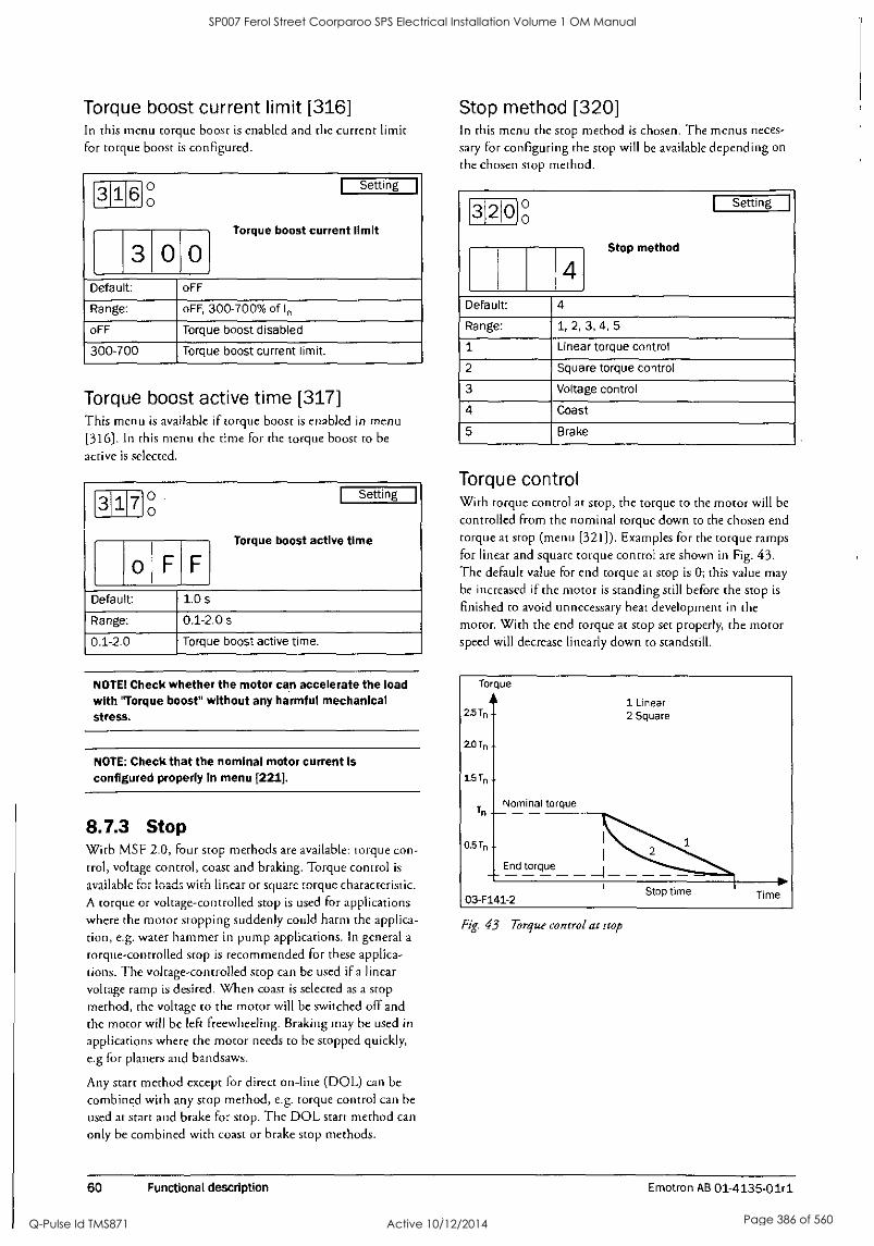
Torque boost current limit [316] In this menu torque boost is enabled and the current limit for torque boost is configured.
316 ° Setting 0
Torque boost
3 0 current limit
Default: oFF
Range: oFF, 300-700% of I,
oFF Torque boost disabled
300-700 Torque boost current limit.
Torque boost active time [317] This menu is available if torque boost is enabled in menu (316]. In this menu the time for the torque boost to be
active is selected.
3 17 00
Setting
Torque boost time
o F F
active
Default: 1.0 s
Range: 0.1-2.0 s
0.1-2.0 Torque boost active time.
NOTE! Check whether the motor can accelerate the load with 'Torque boost" without any harmful mechanical stress.
NOTE: Check that the nominal motor current is configured properly in menu [221].
8.7.3 Stop With MSF 2.0, four stop methods are available: torque con- trol, voltage control, coast and braking. Torque control is
available for loads with linear or square torque characteristic. A torque or voltage-controlled stop is used for applications where the motor stopping suddenly could harm the applica- tion, e.g. water hammer in pump applications. In general a
torque-controlled stop is recommended for these applica- tions. The voltage-controlled stop can be used if a linear voltage ramp is desired. When coast is selected as a stop method, the voltage to the motor will be switched off and the motor will be left freewheeling. Braking may be used in
applications where the motor needs to be stopped quickly, e.g for planers and bandsaws.
Any start method except for direct on-line (DOL) can be
combined with any stop method, e.g. torque control can be
used at start and brake for stop. The DOL start method can
only be combined with coast or brake stop methods.
Stop method [320] In this menu the stop method is chosen. The menus neces-
sary for configuring the stop will be available depending on
the chosen stop method.
3 2 0 °0 1 Setting I
4 Stop method
Default:
Range: 1, 2, 3, 4, 5
1 Linear torque control
2 Square torque control
3 Voltage control
4 Coast
5 Brake
Torque control With torque control at stop, the torque to the motor will be
controlled from the nominal torque down to the chosen end torque at stop (menu [321]). Examples for the torque ramps for linear and square torque control are shown in Fig. 43. The default value for end torque at stop is 0; this value may be increased if the motor is standing still before the stop is
finished to avoid unnecessary heat development in the motor. With the end torque at stop set properly, the motor speed will decrease linearly down to standstill.
To que
2.5Tn
2.0Tn
15Tn
Nominal torque
1 Linear 2 Square
0.5Tn
End torque
03-F141-2 Stop time Time
Fig. 43 Torque control at stop
60 Functional description Emotron AB 01-4135-01r1
SP007 Ferol Street Coorparoo SPS Electrical Installation Volume 1 OM Manual
Q-Pulse Id TMS871 Active 10/12/2014 Page 386 of 560

End torque at stop [321] This menu will be available if torque control is chosen as
stop method in menu [320] (alternative 1 or 2). In this menu the end torque at stop is configured.
321 °,0
Setting
0 End torque at stop
Default: 0%
Range: 0-100% of Tr,
0-100 End torque at stop.
Voltage control With voltage control at stop, the voltage to the motor will be
decreased to the chosen step down voltage at stop immedi- ately after a stop signal. Then the voltage to the motor will
follow a linear ramp down to the minimum voltage of 25% of the nominal voltage. An example of this voltage ramp is
shown in Fig. 44.
Fig. 44 Menu numbers for step down voltage at stop and stop time.
Step down voltage.at stop [322] This menu is available if voltage control is chosen as stop method in menu [320] (alternative 3). In this menu the step
down voltage at stop is chosen in percentage of the nominal motor voltage.
3 2 2 Setting
0
1 0 0 Step down voltage at stop
Default: 100%
Range: 100-40% of U
100-40 Step down voltage at stop.
Braking Braking can be used in applications where there is a need for
a quick stop.
There are two built-in braking methods: dynamic vector brake for normal loads and reverse current brake for heavy loads with high inertia. In both braking methods the MSF 2.0 continuously detects the motor speed. At low speed the DC brake mode is activated until the motor is standing still.
The MSF 2.0 will automatically turn off the output voltage when the motor has stopped or when the stop time has expired. Optionally an external rotation senaor can be con- nected via digital input, see description for menu [500] on page 77 for more information.
Dynamic vector brake With dynamic vector brake, the braking torque applied to
the motor will increase with decreasing speed. Dynamic vec-
tor brake can be used for all loads which are not rotating too
close to synchronous speed when the motor voltage is
switched off. This is valid for most applications as the load speed usually decreases because of frictional losses in gears or belt drives as soon as the motor voltage is switched off.
However, loads with very high inertia may remain at high speed even though the motor is not supplying any torque. For these applications the reverse current brake can be used
instead.
When the dynamic vector brake is used, no additional con- nections or contactors are needed.
Reverse current brake With reverse current brake, a very high braking torque can
be applied to the motor even close to synchronous speed. All
kind of loads can be stopped quickly using reverse current brake, including loads with very high inertia. If high braking torques are needed, it should be checked carefully whether the motor, the gear or belt drive and the load can withstand the high mechanical forces. To avoid harmful vibrations, it is
generally recommended to select as low a braking torque as
possible which also fulfils the demands for a short braking time.
For reverse current brake, two mains contactors are needed. The connection is shown in Fig. 45. The contactors have to
be controlled by the MSF's relay outputs. During start and full voltage operation contactor K1 will be closed, for brak- ing K1 will be opened and after a time delay K2 will be
closed to change the phase sequence.
NOTE: For several start/stops It Is recommend that the motor temperature be monitored using the PTC Input.
Emotron AB 01-4135-01r1 Functional description 61
SP007 Ferol Street Coorparoo SPS Electrical Installation Volume 1 OM Manual
Q-Pulse Id TMS871 Active 10/12/2014 Page 387 of 560

WARNING: When reverse current brake is selected, the relays and K2 are automatically programmed for reverse current brake functionality. The relay setting
remains even If reverse current brake Is deactivated. Therefore It may be necessary to adapt the relay functions manually.
1-1.
L2
L3
N
PE
0 0 D
Ll L2 L3 PE 01 02 PE 21 Ki. 22 23 K2 24 33 K3 32
Ti T2 T3 PE 11 12 13 16 17 18 o
U v ol
W PE Start/Stop
-.sr...0-
.....
Fig. 45 Reverse current brake wiring example.
Braking method [323] This menu is available if brake is selected as stop method in
menu [320] (alternative 5) or if alarm brake is activated in
menu [326] (see description of menus [326] to [327] for
more information). In this menu the brake method is
selected.
3230 Setting
0
Braking
1 method
Default: 1
Range: 1, 2
1 Dynamic vector brake
2 Reverse current brake
Braking strength [324] This menu is available if brake is selected as stop method in menu [320] (alternative 5). In this menu the braking strength is selected. To avoid unnecessary heat development in the motor and high mechanical stress it is generally rec- ommended to select as low a braking strength as possible which still fulfils the demands for a short braking time.
3 2 4 0 Setting
0
1 5 0 Braking strength
Default: 150%
Range: 150-500%
150-500 Braking strength.
62 Functional description Emotron AB 01-4135-01r1
SP007 Ferol Street Coorparoo SPS Electrical Installation Volume 1 OM Manual
Q-Pulse Id TMS871 Active 10/12/2014 Page 388 of 560

Stop time [325] This menu is available if any stop method except coast is
selected in menu [320] (alternative 1, 2, 3 or 5). In this method the desired stop rime is selected.
3 2 5 Setting
g
10 Stop time
Default: 10 s
Range: 1-120 s
1-120 Stop time.
Alarm braking For most alarms it is possible to configure them so that when they are triggered either operation continues or the motor stops (see chapter 9. page 95 for more information). Brake is
one of the actions available. If this option is chosen, the braking functionality is activated according to the brake method selected in menu [323] (see description of the brak- ing functionality above for more information). While the braking strength and stop time chosen in menus [324] and [325] are used for braking on a stop signal, different braking strengths and times can be configured in menus [326] and [327] if braking is activated by an alarm. This function may
mainly be used in combination with an external alarm (see
description on page 73), where an external signal is used to
initiate a quick stop with a higher braking strength and a
shorter braking time compared to normal operation.
If alarm braking is disabled in menu [326] and brake is cho- sen as an alarm action, the voltage to the motor will be
switched off and the motor will freewheel if the specific alarm occurrs.
Alarm braking strength [326] In this menu braking as an alarm action is enabled and the alarm braking strength is selected. If alarm braking is not activated, the motor will be left freewheeling if an alarm occurs for which brake is configured as alarm action.
3 2 6 ° e Stting
0
o F F
Alarm braking strength
Default: oFF
Range: oFF, 150-500%
oFF Coast - motor voltage is switched off.
150-500 Alarm braking strength.
NOTE: If alarm brake is enabled, the braking method chosen In menu [323] Is used.
Alarm braking time [327] This menu is available if alarm brake is enabled in menu 327. In this menu the braking time to be used in the event of braking as an alarm action is configured.
2 7 ° Setting
0
Alarm braking
10 time
Default: 10 s
Range: 1-120 s
1-120 Alarm braking time.
8.7.4 Slow speed and JOG functions MSF 2.0 is able to run the motor at a fixed slow speed for a
limited period of time. The slow speed will be about 14% of the full speed in the forward direction and 9% in the reverse
direction.
NOTE: As the motor torque during slow speed Is limited to about 30% of the nominal torque, slow speed can not be used in applications which need a high brake-away torque to start rotating.
The following functions are possible:
Slow speed during a selected time period Slow speed will be active for a selected time period before a
start is initiated or after a stop is performed.
Slow speed controlled by an external signal The time period during which slow speed is active before a
start is initiated or after a stop is performed is controlled by an external signal via the analogue/digital input. Slow speed will be active until a selected number of pulses has been detected on the input.
Slow speed using the JOG commands Slow speed can be activated independently from a start or stop via the control panel using the jog keys, via remote con- trol using the analogue/digital input or via serial communi- cation depending on the control source chosen in menu [200].
Emotron AB 01-4135-01r1 Functional description 63
SP007 Ferol Street Coorparoo SPS Electrical Installation Volume 1 OM Manual
Q-Pulse Id TMS871 Active 10/12/2014 Page 389 of 560

Speed - nN
0.14 x nN
External signal
Slow speed at start
Start command
Closed
Elf Open
Start time Full voltage running
Stop time
Time when signal is ignored
Slow speed at stop
Stopped
Time
03-F44-2
Fig. 46 Slow speed controlled by an external signal.
Slow speed for a selected time Slow speed in forward direction can be activated before a
start and/or after a stop. The resulting speed curve is shown
in Fig. 47 overleaf. Slow speed will be active for the time
period selected in menus [331] and [332]. Slow speed can be
combined with any start and stop method. However, when
slow speed at stop is used, it should be ensecured that the
motor speed is decreased to a low value when slow speed is
activated. If necessary, brake can be activated as stop method in menu [320].
The slow speed strength can be adapted to the application's requirements in menu [330]. Maximum available slow speed strength corresponds to about 30% of nominal motor torque.
If so desired, the DC brake can be activated after slow speed
at stop. If activated, the DC brake will be active for the time
period chosen in menu [333].
Slow speed during a selected time is configured using the
following menus:
[330] Slow speed strength
[331] Slow speed time at start
[332] Slow speed time at stop
[333] DC-brake at slow speed
[324] Braking strength
Slow speed controlled by an external signal Slow speed controlled by an external signal is basically the same functionality as slow speed during a selected time described above. An external signal connected to the ana- logue/digital input is also used to deactivate slow speed before the set time period has expired.
When slow speed at start is configured and the analogue/ digital input (menu [500]) is configured for slow speed, the motor will start rotating at slow speed in a forward direction after a start signal. When the number of edges set in menu [501] is detected on the analogue/digital input, slow speed is
deactivated and a start is performed according to the start settings (menu [310] Off).
When slow speed at stop is configured and the analogue/dig- ital input (menu [500]) is configured for slow speed, the motor will start rotating with slow speed in forward direc- tion after a stop has performed. When the number of pulses set in menu [501] is detected on the analogue/digital input, slow speed is deactivated and the DC brake is activated if configured in menu [333].
64 Functional description Emotron AB 01-4135-01r1
SP007 Ferol Street Coorparoo SPS Electrical Installation Volume 1 OM Manual
Q-Pulse Id TMS871 Active 10/12/2014 Page 390 of 560

Slow speed controlled by an external signal is configured using the following menus:
[500] Digital/analogue input
[501] Digital input pulses
[330] Slow speed strength
[331] Slow speed time at start
[332] Slow speed time at stop
[333] DC-brake at slow speed
[324] Braking strength
Slow speed strength [330] In this menu the slow speed strength is selected. The chosen
setting applies for both slow speed during a selected time period, slow speed controlled by an external signal and slow
speed using the JOG commands. The maximum setting (100) for the slow speed strength corresponds to about 30%
of the nominal motor torque.
3 3 0 ° Setting
o
10 Slow speed strength
Default: 10
Range: 10-100
10-100 Slow speed strength.
Slow speed time at start [331] In this menu slow speed at start is activated and the time is
set for which slow speed is active before a start. If slow speed
at start is controlled by an external signal via the analogue/
digital input, the set time becomes the maximum time for which slow speed is activated before a start is performed - if the number of edges set in menu [501] is not detected dur- ing the slow speed period.
3 1 Setting
g
o F
Slow speed time at start
Default: oFF
Range: oFF, 1-60 s
oFF Slow speed at start is disabled
1-60 Slow speed time at start.
Speed
nN
0.14 x nN
Nominal speed
Slow speed
Slow speed at start
Start command
Start time Full voltage running
Stop time
Stop command
Slow speed at stop
Stopped
Time
03-F41-2
Fig. 47 Slow speed at start/stop during a selected time period.
Emotron AB 01-4135-01r1 Functional description 65
SP007 Ferol Street Coorparoo SPS Electrical Installation Volume 1 OM Manual
Q-Pulse Id TMS871 Active 10/12/2014 Page 391 of 560

Slow speed time at stop [332] In this menu slow speed at stop is activated and the time is
set for which slow speed is active after a stop. If slow speed at
stop is controlled by an external signal via the analogue/dig- ital input, the set time becomes the maximum time for which slow speed is activated after a stop - if the number of edges is set in menu [501] is not detected during the slow speed period.
3 3 2 ° Setting
0
o F F
Slow speed time at stop
Default: oFF
Range: oFF, 1-60 s
oFF Slow speed at stop is disabled
1-60 Slow speed time at stop.
DC brake at slow speed [333] In this menu the DC brake can be activated after slow speed
at stop. This may be useful for loads with high interia or if an exact stop position is desired. The DC brake will be
active during the time set in this menu.
NOTE: The brake strength used for DC brake after slow speed corresponds to the brake strength used for braking as stop method. The braking strength can be adjusted In menu [324].
3 3 3 ° Setting
0
F
DC Brake at slow speed
Default: oFF
Range: oFF, 1-60 s
oFF DC brake at slow speed disabled.
1-60 DC brake duration time at slow speed.
Slow speed using the JOG commands Slow speed in forward or reverse direction can be activated
using the JOG commands. To use the JOG commands these
have to be independently enabled for slow speed in forward or reverse direction in menus [334] and [335]. Depending on the control source chosen in menu [200], the JOG com- mands are accepted via control panel, remotely via analogue/
digital input or via serial communications.
If the control panel is chosen as control source (menu
[200] =1) and the JOG commands are enabled in menus
[334] and [335], the JOG keys on the control panel can be
used. Slow speed in forward or reverse direction will be
active as long as the relevant button is pushed.
./ JOG ///t JOG
03-F108-2
Fig. 48 Jog keys
If remote control is chosen (menu [200] =2) and the JOG commands are enabled in menus [334] and [335], the JOG commands can be given via analogue/digital input. The ana-
logue/digital input can be configured either for jog forward or jog reverse (see description of menu [500] on page 77 for more information). Slow speed will be active as long as the
signal on the analogue/digital input is active.
If serial communication control is chosen (menu [200]=3) and the JOG commands are enabled in menus [334] and
[335], the JOG commands can be given via serial communi- cation. (See separate instruction manual for serial communi- cations options.)
JOG forward enable [334] In this menu the command for JOG in forward direction is
enabled. Depending on the control source chosen in menu
[200], the JOG forward command may be accepted from the control panel, via remote control or serial communica- tion.
NOTE! The enable functions are for all control sources.
3 3 4 0 Setting 0
o F F
JOG forward enable
Default: oFF
Range: oFF, on
oFF JOG forward disabled
on JOG forward enabled
66 Functional description Emotron AB 01-4135-01r1
SP007 Ferol Street Coorparoo SPS Electrical Installation Volume 1 OM Manual
Q-Pulse Id TMS871 Active 10/12/2014 Page 392 of 560

JOG reverse enable [335] In this menu the command for JOG in reverse direction is
enabled. Depending on the control source chosen in menu [200,], the JOG reverse command may be accepted from the control panel, via remote control or serial communication.
3 3 5 0 Setting 0
- F
JOG reverse enable
Default: oFF
Range: oFF, on
oFF JOG reverse disabled
on JOG reverse enabled
8.7.5 Additional settings [340] -[342] In this section the bypass functionality, power factor control and the control of the internal fan are described.
Bypass [340] As the MSF 2.0 is designed for continuous running, a by-
pass contactor is not normally needed. However, where there is high ambient temperature or other special conditions, the
use of a bypass contactor can be advantageous. In this case
the by-pass contactor can be controlled by one of the relays.
By default, relay K2 is configured to control a bypass contac- tor (for full voltage functionality, see description of menus [530]-[532] on page 85 for more information).
The use of a bypass contactor can be combined with any start and stop method without any connection changes being necessary. However, to use the motor protection func- tions, the load monitor and the viewing functions in
bypassed state, the current transformers have to be moved outside the softstarter. For this purpose an optional exten- sion cable is available, see chapter 12. page 107 (Options) for more information. Figures 49 - 51 below show a connec- tion example.
If a bypass contactor is used, bypass operation must be ena-
bled in menu [340] for the softstarter to work properly.
3 4 0 ° Setting 0
o F F
Bypass
Default: oFF
Range: oFF, on
oFF Bypass disabled
on Bypass enabled.
CAUTION: If the current transformers are not moved outside the softstarter, several alarm functions will not work properly.
Emotron AB 01-4135-01r1 Functional description 67
SP007 Ferol Street Coorparoo SPS Electrical Installation Volume 1 OM Manual
Q-Pulse Id TMS871 Active 10/12/2014 Page 393 of 560

L2
L3
N
PE
0o
0 C 0 000 0 0 0 0 0 0 Ll L2 L3 PE 01 02 PE 21CLKI 22 23 K2 24 33 31 32
T1 T2 T3 PE C 0 0 0
Current transformer position and connec- tion.
For MSF-017 to MSF- 250, see Fig 50.
For MSF-310 to MSF- 1400, see Fig 51.
11 12 13 16 17 18 19 0 0 0 0 0 0
1.0
Start/Stop
75 76 77 0 0 0
V w PE
03-F19-2
Fig. 49 Bypass wiring example MSF 310-1400.
Blue to terminal 75
U
Brown to terminal 77
T2 T3
-1 Blue to terminal 76
j Brown to terminal 77
w
03-F56-2
Fig. 50 Current transformer position for Bypass on MSF-017 to MSF-250.
Fig. 51 Current transformer position for Bypass on MSF-310 to MSF-1400.
68 Functional description Emotron AB 01-4135-01r1
SP007 Ferol Street Coorparoo SPS Electrical Installation Volume 1 OM Manual
Q-Pulse Id TMS871 Active 10/12/2014 Page 394 of 560
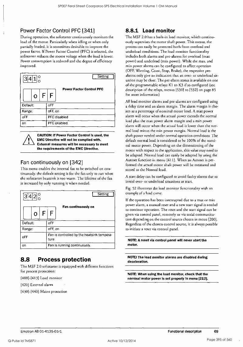
Power Factor Control PFC [341] During operation, the softstarter continuously monitors the
load of the motor. Particularly when idling or when only partially loaded, it is sometimes desirable to improve the power factor. If Power Factor Control (PFC) is selected, the
softstarter reduces the motor voltage when the load is lower.
Power consumption is reduced and the degree of efficiency improved.
3 4 1 Setting
0°
o F F
Power Factor Control PFC
Default: oFF
Range: oFF, on
oFF PFC disabled
on PFC enabled.
CAUTION: If Power Factor Control is used, the EMC Directive will not be complied with. External measures will be necessary to meet the requirements of the EMC Directive.
Fan continuously on [342] This menu enables the internal fan to be switched on con-
tinuously. the default setting is for the fan only to run when
the softstarter heatsink is too warm. The lifetime of the fan
is increased by only running it when needed.
3f42° ° Setting
o F F
Fan continuously on
Default: oFF
Range: oFF, on
oFF Fan is controlled by the heatsink tempera- ture
on Fan is running continuously.
8.8 Process protection The MSF 2.0 softstarter is equipped with different functions for process protection:
[400] -[4131 Load monitor
[420] External alarm
[430] -[440] Mains protection
8.8.1 Load monitor The MSF 2.0 has a built-in load monitor, which continu- ously supervises the motor shaft power. This means, the
process can easily be protected both from overload and
underload conditions. The load monitor functionality includes both alarms and pre-alarms for overload (max power) and underload (min power). While the max. and
min power alarms can be configured to affect operation (OFF, Warning, Coast, Stop, Brake), the respective pre-
alarms only give an indication that an over- or underload sit- uation may be close. The pre-alarm status is available on one
of the programmable relays K1 to K3 if so configured (see
description of the relays, menus [530] to [532] on page 85
for more information)
All load monitor alarms and pre-alarms are configured using
a delay time and an alarm margin. The alarm margin is cho-
sen as a percentage of nominal motor load. A max power
alarm will occur when the actual power exceeds the normal load plus the max power alarm margin and a min power
alarm will occur when the actual load is lower than the nor-
mal load minus the min power margin. Normal load is the
shaft power needed under normal operation conditions. The default normal load is considered to be 100% of the nomi- nal motor power. Depending on the dimensioning of the
motor with respect to the application, this value may need to
be adapted. Normal load can easily be adapted by using the
Autoset function in menu [411]. When an Autoset is per-
formed the actual motor shaft power will be measured and
stored to the Normal load.
A start delay can be configured to avoid faulty alarms due to
initial over- or underload situations at start.
Fig. 52 illustrates the load monitor functionality with an
example of a load curve.
If the operation has been interrupted due to a max or min power alarm, a manual reset and a new start signal is needed
to continue operation. The reset and the start signal can be
given via control panel, remotely or via serial communica- tion depending on the control source chosen in menu [200]. Regardless of the chosen control source, it is always possible
to initiate a reset via control panel.
NOTE: A reset via control panel will never start the motor.
NOTE! The load monitor alarms are disabled during deceleration.
NOTE: When using the load monitor, check that the nominal motor power is set properly in menu [212].
Emotron AB 01-4135-01r1 Functional description 69
SP007 Ferol Street Coorparoo SPS Electrical Installation Volume 1 OM Manual
Q-Pulse Id TMS871 Active 10/12/2014 Page 395 of 560

Pload
=== Start c==== Overload situation ==== Underload situation
t Max alarm margin [403]
16%
- Operation area
Max pre-alarm margin [405]
Normal load (Autoset)
Min pre-alarm margin [407]
Is Min alarm margin [409]
8%
16%
Start delay[402] Max power pre-alarm [406] 4
Max power alarm [404] Min power pre-alarm [408]
Min power alarm [410] Response time
to-
Time
03-F142-2
Fig. 52 Load monitor alarm fitnctions
For max and min power alarms the following alarm actions
are available:
Off The protection method is deactivated.
Warning The appropriate alarm message is shown in the display and relay K3 is activated (for default configuration of the relays).
However, the motor is not stopped and operation continues. The alarm message will disappear and the relay will be reset
when the fault disappears. The alarm may also be reset man-
ually.
Coast The appropriate alarm message is shown in the display and relay K3 is activated (for default configuration of the relays).
The motor voltage is automatically switched off. The motor freewheels until it stops.
Stop The appropriate alarm message is shown in the display and relay K3 is activated (for default configuration of the relays).
The motor is stopped according to the stop settings in
menus [320] to [325].
Brake The appropriate alarm message is shown in the display and relay K3 is activated (for default configuration of the relays).
The brake function is activated according to the braking method chosen in menu [323] and the motor is stopped according to the alarm brake settings in menus [326] to [327] (braking strength and braking time).
If the operation has been interrupted due to a max or min power alarm, a reset signal and a new start signal are needed to restart the motor. The reset and the start signal can be given via control panel, remotely or via serial communica- tion depending on the control source chosen in menu [200]. Regardless of the chosen control source, it is always possible to initiate a reset via control panel.
NOTE: A reset via control panel will never start the motor.
70 Functional description Emotron AB 01-4135-01r1
SP007 Ferol Street Coorparoo SPS Electrical Installation Volume 1 OM Manual
Q-Pulse Id TMS871 Active 10/12/2014 Page 396 of 560

Max power alarm [400] In this menu max power alarm is enabled and a proper alarm
action is selected. The pre-alarm functionality for max
power is automatically enabled together with the max power
alarm.
4 0 0 ° Setting 0
o F F
Max power alarm (alarm code F6)
Default: oFF
Range: oFF, 1, 2, 3, 4
oFF Max power alarm is disabled.
1 Warning
2 Coast
3 Stop
4 Brake
Min power alarm [401] In this menu min power alarm is enabled and a proper alarm
action is selected. The pre-alarm functionality for min power is automatically enabled together with the min power
alarm.
4 0 ° Setting
0
o F F
Min power alarm (alarm code F7)
Default: oFF
Range: oFF, 1, 2, 3, 4
oFF Min power alarm is disabled.
1 Warning
2 Coast
3 Stop
4 Brake
Start delay power alarms [402] This menu is available if max or min power alarm is enabled
in menu [400] or [401]. In this menu the start delay for the
power alarms and pre-alarms is selected. A start delay is use-
ful for avoiding faulty alarms due to initial over- or under- load situations. The start delay begins when a start of the
motor is initiated.
4 0 2 0 Setting
0
10 Start delay power alarms
Default: 10 s
Range: 1-999 s
1-999 Start delay for power alarms and pre- alarms.
Max power alarm margin [403] This menu is available if Max power alarm is enabled in menu (400]. In this menu the max power alarm margin is
configured. The margin is selected as percentage of nominal motor power. A max power alarm will occur if the actual
motor shaft power exceeds the normal load (menu [412]) plus the chosen max power alarm margin for a longer time
period than the max power alarm response delay set in menu
[404].
0 3 ° Setting
0
1 Max power alarm margin
Default: 16%
Range: 0-100% of Pn
0-100 Max power alarm margin
Max power alarm response delay [404] This menu is available if max power alarm is enabled in
menu [400]. In this menu the response delay for the max
power alarm is configured. A max power alarm will occur if the actual motor shaft power exceeds the normal load (menu
[412]) plus the max power alarm margin set in menu [403] for a longer time period than the chosen max power alarm
response delay.
4 014 ° Setting
0
Max
0 5 power alarm response
delay
Default: 0.5 s
Range: 0.1-90.0 s
0.1-90.0 Response delay for max power alarm.
Emotron AB 01-4135-01r1 Functional description 71
SP007 Ferol Street Coorparoo SPS Electrical Installation Volume 1 OM Manual
Q-Pulse Id TMS871 Active 10/12/2014 Page 397 of 560

Max power pre-alarm margin [405] This menu is available if max power alarm is enabled in
menu [400]. In this menu the max power pre-alarm margin is configured. The margin is selected in percent of nominal motor power. A max power pre-alarm will occur if the actual motor shaft power exceeds the normal load (menu [412]) plus the chosen max power pre-alarm margin for a longer time period than the max power pre-alarm response delay set
in menu [406]. The max power pre-alarm status is available on one of the programmable relays K1 -K3 if so configured (see description of the relays, menus [530] to [532] for more information).
4050 .
Setting
8 Max power pre-alarm margin
Default: 8%
Range: 0-100% of Pn
0-100 Max power pre-alarm margin.
Max power pre-alarm response delay [406] This menu is available if max power alarm is enabled in
menu [400]. In this menu the response delay for max power
pre-alarm is configured. A max power pre-alarm will occur if the actual motor shaft power exceeds the normal load (menu [412]) plus the max power pre-alarm margin set in menu [405] for a longer time period than the chosen max power
pre-alarm response delay.
410 6 ° Setting
0
Max
0. 5 power pre-alarm response
delay
Default: 0.5 s
Range: 0.1-90.0 s
0.1-90.0 Response delay for Max power pre-alarm.
Min power pre-alarm margin [407] This menu is available if min power alarm is enabled in
menu [401]. In this menu the min power pre-alarm margin is configured. The margin is selected as a percentage of nom- inal motor power. A min power pre-alarm will occur if the actual motor load is below the nominal load (menu [412]) minus the chosen min power pre-alarm margin for a longer time period than the min power pre-alarm response delay set
in menu [408]. The min power pre-alarm status is available
on one of the programmable relays K2-K3 if so configured (see description of the relays, menus [530] to [532] for more information.
4 0 7 o I Setting I
0
8 Min power pre-alarm margin
Default: 8%
Range: 0-100% of Pn
0-100 Min power pre-alarm margin.
Min power pre-alarm response delay [408] This menu is available if min power alarm is enabled in
menu [401]. In this menu the response delay for min power pre-alarm is configured. A min power pre-alarm will occur if the actual motor shaft power is below the normal load (menu [412]) minus the min power pre-alarm margin set in
menu [407] for a longer time period than the chosen min power pre-alarm response delay.
4 018 0 Setting 0
0 5 Min power pre-alarm response delay
Default: 0.5 s
Range: 0.1-90.0 s
0.1-90.0 Response delay for Min power pre-alarm.
Min power alarm margin [409] This menu is available if min power alarm is enabled in
menu [401]. In this menu the min power alarm margin is
configured. The margin is selected as a percentage of nomi- nal motor power. A min power alarm will occur if the actual motor shaft power is below the normal load (menu [412]) minus the chosen min power alarm margin for a longer time period than the min power alarm response delay set in menu [410].
4 0 9 ° Setting
o
1 6 Min power alarm margin
Default: 16%
Range: 0-100% of Pn
0-100 Min power alarm margin.
72 Functional description Emotron AB 01-4135-01r1
SP007 Ferol Street Coorparoo SPS Electrical Installation Volume 1 OM Manual
Q-Pulse Id TMS871 Active 10/12/2014 Page 398 of 560

Min power alarm response delay [410] This menu is available if min power alarm is enabled in
menu [401]. In this menu the response delay for min power alarm is configured. A min power alarm will occur if the actual motor shaft power is below the normal load (menu [412]) minus the min power alarm margin set in menu [409] for a longer time period than the chosen min power alarm response delay.
LI 1 0 ° Setting
0
0.5 Min power alarm response delay
Default: 0.5 s
Range: 0.1-90.0 s
0.1-90.0 Response delay for Min power alarm.
Autoset [411] This menu is available if max or min power alarm is enabled in menu [400] or [401]. The Autoset command performs a
measurement of the actual motor load and automatically sets
the normal load-in menu [412].
To perform an Autoset, select YES, and press Enter during normal operation. If Autoset has been executed successfully,
"SEC is shown in the display for two seconds. After that "no" is shown again. An Autoset can also be initiated via the
analogue/digital input, see description of menu [500] for
more information.
NOTE: Autoset Is only allowed during full voltage running.
411 ' 10 ° Multi Setting
n o Autoset
Default: no
Range: no, YES
no No action
YES Autoset
Normal load [412] This menu is available if Max or Min power alarm is enabled in menu [400] or [401]. Normal load is the shaft power needed under normal operation conditions. By default, Nor- mal load is considered to be 100% of the nominal motor power. Depending on the dimensioning of the motor with respect to the application, this value may need to be adapted. Normal load can easily be adapted by using the Autoset function in menu [411]. Normal load is set as aper-
centage of nominal motor power.
NOTE: When using the load monitor, check that the nominal motor power Is set properly in menu [212].
Al 2 ° Setting
0
1 0 Normal load
Default: 100%
Range: 0-200% of P,
0-200 Normal load
Output shaft power [413] This menu is available if max or min power alarm is enabled in menu [400] or [401]. The menu provides a read-out of the actual shaft power. It can be used as input information when the normal load is set manually.
4 0 0
0
Read-out
Output shaft power
Range: 0-200% of P,
8.8.2 External alarm [420] The MSF 2.0 can generate an alarm according to the status of an external signal. For a detailed description of the exter- nal alarm functionality see section 8.9.5, page 89.
The following alternatives are available for external alarm:
Off External alarm is deactivated.
Warning Alarm message F17 is shown in the display and relay K3 is
activated (for default configuration of the relays) if the exter- nal alarm input is opened. However, the motor is not stopped and operation continues. The alarm message will disappear and the relay will be reset when the external alarm input is closed again. The alarm may also be reset manually.
Coast Alarm message F17 is shown in the display and relay K3 is
activated (for default configuration of the relays) if the exter- nal alarm input is opened. The motor voltage is automati- cally switched off. The motor freewheels until it stops.
Stop Alarm message F17 is shown in the display and relay K3 is
activated (for default configuration of the relays) if the exter- nal alarm input is opened. The motor is stopped according to the stop settings in menus [320] to [325].
Emotron AB 01-4135-01r1 Functional description 73
SP007 Ferol Street Coorparoo SPS Electrical Installation Volume 1 OM Manual
Q-Pulse Id TMS871 Active 10/12/2014 Page 399 of 560

Brake Alarm message F17 is shown in the display and relay K3 is
activated (for default configuration of the relays) if the exter- nal alarm input is opened. The brake function is activated according to the braking method chosen in menu [323] and the motor is stopped according to the alarm brake settings in
menus [326] to [327] (braking strength and braking time).
Spinbrake The functionality for the spinbrake alternative is the same as
described above for the brake alternative. However, if spin- brake is chosen, braking can even be initiated from an inac-
tive state by opening the external alarm input. This means the softstarter can catch a freewheeling motor and brake it down to standstill. The spinbrake alternative is only availa-
ble for external alarm.
If the operation has been interrupted due to an external alarm, a reset signal and a new start signal are needed to
restart the motor. The reset and the start signal can be given
via control panel, remotely or via serial communication depending on the control source chosen in menu [200].
Regardless of the chosen control source, it is always possible to initiate a reset via control panel..
NOTE: A reset via control panel will never start the motor.
412 0 Setting
0°
External F17)
o F F
alarm (alarm code
Default: oFF
Range: oFF, 1, 2, 3, 4, 5
oFF External alarm is disabled.
1 Warning
2 Coast
3 Stop
4 Brake
5 Spinbrake
8.8.3 Mains protection The MSF 2.0 continuously monitors the mains voltage. This means the motor can easily be protected from over- and undervoltages as well as from voltage unbalance conditions. A phase reversal alarm is also available.
For mains protection the following alternatives are available:
Off The protection method is deactivated.
Warning The appropriate alarm message is shown in the display and relay K3 is activated (for default configuration of the relays).
However, the motor is not stopped and operation continues.
The alarm message will disappear and the relay will be reset
when the fault disappears. The alarm may also be reset man- ually.
Coast The appropriate alarm message is shown in the display and relay K3 is activated (for default configuration of the relays). The motor voltage is automatically switched off. The motor freewheels until it stops.
Stop The appropriate alarm message is shown in the display and relay K3 is activated (for default configuration of the relays).
The motor is stopped according to the stop settings in
menus [320] to [325].
Brake The appropriate alarm message is shown in the display and relay K3 is activated (for default configuration of the relays). The brake function is activated according to the braking method chosen in menu [323] and the motor is stopped according to the alarm brake settings in menus [326] to
[327] (braking strength and braking time).
An overvoltage, undervoltage or voltage unbalance alarm is
automatically reset when a new start signal is given. If the operation has been interrupted due to a phase reversal alarm, a reset signal and a new start signal are needed to restart the motor. The reset and the start signal can be given via control panel, remotely or via serial communication depending on the control source chosen in menu [200]. Regardless of the chosen control source, it is always possible to initiate a reset
via control panel.
NOTE: A reset via control panel will never start the motor.
Voltage unbalance alarm [430] In this menu voltage unbalance alarm is enabled and a
proper action is selected.
4 310 0 Setting 0
o F F
Voltage unbalance alarm (alarm code F8)
Default: oFF
Range: oFF, 1, 2, 3, 4
oFF Voltage unbalance alarm is disabled.
1 Warning
2 Coast
3 Stop
4 Brake
74 Functional description Emotron AB 01-4135-01r1
SP007 Ferol Street Coorparoo SPS Electrical Installation Volume 1 OM Manual
Q-Pulse Id TMS871 Active 10/12/2014 Page 400 of 560

Unbalance voltage level [431] This menu is available if voltage unbalance alarm is enabled in menu [430]. In this menu the maximum allowed voltage
unbalance level is selected. If the difference between any two
line voltages exceeds the chosen level for the response delay time set in menu [432], a voltage unbalance alarm will occur and the action selected in menu [430] will be executed.
413 1 0 Setting
0
1 0 Voltage unbalance level
Default: 10%
Range: 2-25% of Un
2-25 Voltage unbalance level.
Response delay voltage level unbalance alarm [432] This menu is available if voltage unbalance alarm is enabled in menu [430]. In this menu the response delay for voltage
unbalance alarm is selected. If the difference between any
two line voltages exceeds the level set in menu [431] for the chosen response delay time, a voltage unbalance alarm will
occur and the action selected in menu [430] will be exe-
cuted.
4 3 2 0 Setting 0
Response
1 delay voltage
unbalance alarm
Default: 1 s
Range: 1-90 s
1-90 Response delay for voltage unbalance alarm.
Overvoltage alarm [433] In this menu overvoltage alarm is enabled and a proper action is selected.
4 3 ° Setting
0
Overvoltage
o F F
alarm (alarm code F9)
Default: oFF
Range: oFF, 1, 2, 3, 4
oFF Overvoltage alarm is disabled.
1 Warning
2 Coast
3 Stop
4 Brake
Overvoltage level [434] This menu is available if overvoltage alarm is enabled in
menu [433]. In this menu the voltage level for an overvolt- age alarm is selected. If any line voltage exceeds the chosen level for the response delay time set in menu [435], an over-
voltage alarm will occur and the action selected in menu [433] will be executed.
4 3 4 0 Setting
0
1 1 5 Overvoltage level
Default: 115%
Range: 100-150% of Un
100-150 Overvoltage level
Response delay overvoltage alarm [435] This menu is available if overvoltage alarm is enabled in
menu [433]. In this menu the response delay for overvoltage alarm is selected. If any line voltage exceeds the level set in
menu [434] for the chosen response delay time, an overvolt- age alarm will occur and the action selected in menu [433] will be executed.
4 3 5 0 Setting 0
delay Response overvoltage alarm
Default: 1 s
Range: 1-90 s
1-90 Response delay for overvoltage alarm.
Undervoltage alarm [436] In this menu undervoltage alarm is enabled and a proper action is selected.
zi. 3 6 0 Setting 0
1
o F F
Undervoltage alarm (alarm code F10)
Default: oFF
Range: oFF, 1, 2, 3, 4
oFF Undervoltage alarm is disabled.
1 Warning
2 Coast
3 Stop
4 Brake
Emotron AB 01-4135-01r1 Functional description 75
SP007 Ferol Street Coorparoo SPS Electrical Installation Volume 1 OM Manual
Q-Pulse Id TMS871 Active 10/12/2014 Page 401 of 560

Undervoltage level [437] This menu is available if undervoltage alarm is enabled in menu [436]. In this menu the voltage level for an undervolt- age alarm is selected. If any line voltage is below the chosen
level for the response delay time set in menu [438], an und- ervoltage alarm will occur and the action selected in menu
[436] will be executed.
4 3 7 ° Setting
8 5 Undervoltage level
Default: 85%
Range: 75-100% of Un
75-100 Undervoltage level
Response delay undervoltage alarm [438] This menu is available if undervoltage alarm is enabled in menu [436]. In this menu the response delay for undervolt- age alarm is selected. If any line voltage is below the level set
in menu [437] for the chosen response delay time, an under- voltage alarm will occur and the action selected in menu
[436] will be executed.
4 3 8 0 Setting
0
Response delay ,
1 undervoltage
alarm
Default: 1 s
Range: 1-90 s
1-90 Response delay for undervoltage alarm
Phase sequence [439] In this menu the actual phase sequence is shown.
NOTE! The actual phase sequence can only be shown with a motor connected.
4 3 9 ° Read-out
0
Phase sequence
L- - Range: L123, L321
L123 Phase sequence L1, L2, L3
L321 Phase sequence L3, L2, L1
L- - - Phase sequence can not be detected
Phase reversal alarm [440] In this menu phase reversal alarm is enabled and a proper action can be chosen. The softstarter will detect the phase
sequence prior to each start attempt. If the actual phase
sequence does not match the phase sequence stored during activation of phase reversal alarm, the action chosen in this menu will be executed. If alternative 2 (Coast) is chosen, no
start will be performed if the wrong phase sequence is
detected.
To activate phase reversal alarm, a motor has to be con- nected and the mains voltage has to be switched on. This means activation of phase reversal alarm can either be done
in stopped state with the mains contactor switched on man- ually or during full voltage running.
4 4 0 0 Setting 0
o F F
Phase reversal alarm (alarm code F16)
Default: oFF
Range: oFF, 1, 2
oFF Phase reversal alarm is disabled.
1 Warning
2 Coast
NOTE! The actual phase sequence can be viewed in menu [439].
76 Functional description Emotron AB 01-4135-01r1
SP007 Ferol Street Coorparoo SPS Electrical Installation Volume 1 OM Manual
Q-Pulse Id TMS871 Active 10/12/2014 Page 402 of 560

8.9 I/O settings In this section the programmable inputs and outputs are
described.
[500]-[513] Input signals
[520]-[534] Output signals
A connection example using most of the available in- and
outputs is shown in Fig. 53.
This section includes also detailed descriptions of the follow- ing functions:
Start/stop/reset command functionality
Start right/left functionality
External alarm functionality
External control of parameter set
8.9.1 Input signals The MSF 2.0 has one programmable analogue/digital input and four programmable digital inputs for remote control.
Analogue/digital input [500] The analogue/digital input can either be programmed for
analog or digital functionality. The following alternatives are
available when using the input for digital signals:
Rotation sensor An external rotation sensor can be used for the braking func-
tions. If the analogue/digital input is configured for rotation sensor functionality in menu [500], braking will be deacti-
vated if the number of edges chosen in menu [501] is
detected on the input.
Slow speed This alternative is used for slow speed controlled by an exter-
nal signal (see the description of slow speed and jog func- tions in section 8.7.4, page 63 for more information). If the
number of edges set in menu [501] is detected on the input, slow speed at start or stop will be finished.
Jog Forward With this alternative, slow speed in forward direction can be
activated via the analogue/digital input. Slow speed will be
active as long as the input signal is high. See the description of slow speed and jog functions in section 8.7.4, page 63 for
more information. Note that "JOG" forward has to be ena-
bled in menu [334] to use this function.
Jog reverse With this alternative, slow speed in reverse direction can be
activated via the analogue/digital input. Slow speed will be
active as long as the input signal is high. See the description
of slow speed and jog functions in section 8.7.4, page 63 for
more information. Note that "JOG" reverse has to be ena-
bled in menu [335] to use this function.
Autoset When the analogue/digital input is configured for Autoset, a
rising edge on the input will initiate an Autoset. Note that an Autoset only can be performed during full voltage run- ning. See description of load monitor functionality in sec-
tion 8.8.1, page 69 for more information
The following alternatives are available when using the input for analogue signals:
Analogue start/stop: 0-10 V/O-20 mA or 2-10 V/4-20 mA: The analogue/digital input is used for the reference signal which controls analogue start stop. Two signal ranges
(0-10 V/0 -20 mA or 2-10 V/4-20 mA) can be chosen. Ana- logue start/stop is activated if alternative 6 or 7 is chosen in
menu [500]. See the description of Analogue start/stop on
page 79 for more information.
0 0 ° Setting
0
o F F
Analogue /digital input
Default: oFF
Range: oFF, 1-7
oFF Analogue/digital input disabled
1 Digital, Rotation sensor
2 Digital, Slow speed
3 Digital, Jog forward
4 Digital, Jog reverse
5 Digital, Autoset
6 Analogue start/stop: 0-10 V/0 -20 mA
7 Analogue start/stop: 2-10 V/4-20 mA
Emotron AB 01-4135-01r1 Functional description 77
SP007 Ferol Street Coorparoo SPS Electrical Installation Volume 1 OM Manual
Q-Pulse Id TMS871 Active 10/12/2014 Page 403 of 560

N
PE
0 0 0
0 0 0 C 0 0 0
Relay outputs
AO.
0 0 Ll L2 L3 PE 01 02 PE 21 K122 23 K2 24 33
3 31 32
PTC Input
0 0 69 70
T1 T2 T3 PE 11 12 13 14 15 16 17 18 19 75 76 77 0 0 3 0
U V w PE
Start/stop Analogue reference
I .
Parameter set
Digital Inputs Aga ogue/ Analogue digital out
n
DIgg Inputs
Measuring
03-F18-2
Fig. 53 Connection example when using the digital and analogue inputs and outputs
Digital input The analogue/digital input is used as a digital input if one of alternatives 1-5 in menu [500) is selected. Jumper J1 has to
be set for voltage control, which is the default setting.
The input signal is interpreted as 1 (high) when the input voltage exceeds 5 V. When the input voltage is below 5 V the
input signal is interpreted as 0 (low). The input signal can be
generated using the internal control supply voltage by con- necting a switch between terminal 14 (analogue/digital input) and 18 (supply voltage to terminals 14, 16 and 17).
Fig. 54 Wiring for digital input signal.
Digital input pulses [501] This menu is available if the analogue/digital input is pro- grammed for digital input signals for rotation sensor (alter- native 1) or for slow speed (alternative 2) in menu [500]. In this menu the number of edges is chosen to deactivate the braking function or the slow speed function respectively..
NOTE: All edges, both positive and negative transitions, will be counted.
5 01 °0 Setting
Digital
1 Input pulses
Default: 1
Range: 1-100
1-100 Number of edges
78 Functional description Emotron AB 01-4135-01r1
SP007 Ferol Street Coorparoo SPS Electrical Installation Volume 1 OM Manual
Q-Pulse Id TMS871 Active 10/12/2014 Page 404 of 560

Analogue input The analogue/digital input is used as an analogue input if one of alternatives 6-7 in menu [500] is selected. In this case, the input can be configured for voltage or current sig-
nal using jumper J1 (see Fig. 55). By default jumper J I is set
to voltage signal. According to the chosen alternative in
menu [500], the signal will be interpreted as 0-10 V/ 0-20 mA or 2-10 V/4-20 mA (see Fig. 56).
Fig. 55 Wiring for analogue/digital input and setting ofJI for analogue current or voltage control.
Fig. 56 Analogue input
Analogue start/stop Starts and stops can be performed according to a process sig-
nal on the analogue/digital input. This means that e.g. the
operation of a pump may be controlled according to a flow signal.
Analogue start/stop is available if remote control or serial
communication control is chosen in menu [200] (alterna-
tives 2 or 3).
NOTE: Analogue start/stop is not available if control panel Is chosen as control source In menu [200] (alternative 1).
If a start signal is given via remote or serial communication (according to the setting in menu [200]), the softstarter will check the reference signal on the analogue/digital signal. A
start will be performed if the level of the reference signal is
below the analogue start/stop on-value chosen in menu
[502] for a longer time than the analogue start/stop delay
time set in menu [504]. A stop will be performed if the ref-
erence signal exceeds the analogue start/stop off-value cho-
sen in menu [503] for a longer time than the analogue start/ stop delay time set in menu [504].
NOTE: If the selected analogue start/stop on-value is bigger than or equal to the off-value, a level above the on-value at the analogue input will cause a start. A value below the off-value will in this case cause a stop.
The start/stop LED on the front of the MSF will be flashing if the softstarter is in standby mode waiting for an analogue
start.
Warning: A flashing start/stop LED is indicating standby mode - e.g. waiting for an analogue start. The motor may be started automatically at a moment's notice
Analogue start/stop on-value [502] This menu is available if analogue start/stop is activated in
menu [500] (alternative 6 or 7). If the reference signal on
the analogue/digital input is below the chosen on-level for a
longer time than the analogue start/stop delay time chosen
in menu [504], a start will be performed..
NOTE: If the selected analogue start/stop on-value is bigger than or equal to the off-value, a level above the on-value at the analogue/digital input will cause a start.
NOTE: An analogue start will only be performed if the softstarter has been set to standby mode by a valid start signal via remote control or serial communication.
The analogue start/stop on-value is chosen as a percentage of the input signal range. This means, if the analogue/digital input is configured for 0-10 VDC/0 -20 mA (alternative 6 in
menu [500]), 25% corresponds to 2.5 V or 5 mA. If the
analogue/digital input is configured for 2-10 VDC/4-20 mA (alternative 7 in menu [500]), 25% corresponds to 4 V or 8 mA.
5 0 2 0 Setting
0
2 5 Analogue start/stop on-value
Default: 25%
Range: 0-100% of input signal range
0-100 Analogue start/stop on-value.
Emotron AB 01-4135-01r1 Functional description 79
SP007 Ferol Street Coorparoo SPS Electrical Installation Volume 1 OM Manual
Q-Pulse Id TMS871 Active 10/12/2014 Page 405 of 560

Analogue start/stop off-value [503] This menu is available if analogue start/stop is activated in
menu [500] (alternatives 6 or 7). If the reference signal on the analogue/digital input exceeds the chosen off -level for a
longer time than the analogue start/stop delay time chosen in menu [504], a stop will be performed.
NOTE: If the selected analogue start/stop off-value Is
less than or equal to the on-value, a level below the off- value at the analogue/digital Input will cause a stop.
NOTE: A stop will also be performed If the softstarter receives a stop signal via remote control or serial communication.
The analogue start/stop off -value is chosen as a percentage of the input signal range. This means if the analogue/digital input is configured for 0-10 V / 0-20 mA (alternative 6 in
menu [500]), 25% corresponds to 2.5 V or 5 mA. If the analogue/digital input is configured for 2-10 V / 4-20 mA
(alternative 7 in menu [500]), 25% corresponds to 4 V or
8 mA.
[5 Setting
0131?;
Analogue
7 5 start/stop off-value
Default: 75%
Range: 0-100% of input signal range
0-100 Analogue start/stop off-value.
Analogue start/stop delay time [504] This menu is available if analogue start/stop is activated in
menu [500] (alternatives 6 or 7). In this menu the delay
time for starts and stops caused by the analogue reference
signal is set.
5 0 4 0 Setting
0
,
1s ,
I
Analogue start/stop delay time
Default: 1 s
Range: 1-999 s
1-999 Delay time for analogue start/stop
Digital inputs The MSF 2.0 has four programmable digital inputs. The four inputs and their corresponding control supply termi- nals are shown overleaf in Fig. 57.
Fig. 57 Wiring for digital inputs 1-4.
The four digital inputs are electrically identical.The digital inputs can be used for remote control of start, stop and reset,
for choice of parameter set and for external alarm.
Stop signal If remote control is chosen in menu [200] (alternative 2),
one digital input has to be programmed as stop signal.
NOTE: No starts will be allowed if the Input set for stop signal is open or if no input is configured for stop signal.
If the motor is running a stop will he performed according to the stop settings in menus [320] to [325] as soon as the input configured for stop signal is opened. If more than one input is configured for stop signal, opening one of these will
lead to a stop. Accordingly no starts will be allowed if any of these inputs is open.
Start and reset signal The digital inputs can be configured for several different start signals (start, start R or start L signal). Closing any input, which is configured for start, will start the motor. Moreover, a rising edge on any input configured for start is
interpreted as a reset signal.
NOTE: If more than one digital input is configured for any of the start signals (start, start R or start L), closing more than one of these inputs at the same time will lead to a stop. However, if several digital Inputs are configured for the same start functionality, e.g. start R,
closing any of these Inputs will lead to a start.
Naturally the softstarter has no way of controlling the motor's running direction internally. However, if two mains contactors - one for each phase sequence - are used, these can be controlled by the softstarter using the programmable relays. The settings for the programmable relays in menus [530] to [532] correspond to the different start signals, which can be chosen for the digital inputs. In this way dif- ferent running directions for the motor can be chosen.
80 Functional description Emotron AB 01-4135-01r1
SP007 Ferol Street Coorparoo SPS Electrical Installation Volume 1 OM Manual
Q-Pulse Id TMS871 Active 10/12/2014 Page 406 of 560

Example 1. If only one running direction is used, digital input 1 can
be configured for start signal and digital input 2 for stop signal (default setting). In this case relay K1 may be con- figured for operation (default setting) and can control the mains relay. When digital inputs 1 and 2 are closed, the mains contactor will be activated and the motor will
start. When digital input 2 is opened the motor will
stop. The mains contactor will be deactivated after the stop has been finished.
2. If two running directions are desired, digital input 1 can
be configured for start R, digital input 2 for stop and digital input 3 for start L. Relay K1 controls the mains contactor for running in right direction and may be con- figured for Operation R. Relay K2 controls the mains contactor with the opposite phase sequence for running in left direction and may be configured for Operation L.
In this case closing digital inputs 1 and 2 (start right command) will lead to activation of the mains contactor for running in right direction and the motor will start in
right direction. Opening digital input 2 will lead to a
stop; the mains contactor for running right will be deac-
tivated after the stop has been finished. Closing digital inputs 2 and 3 (while digital input 1 is open) will lead to
activation of the mains contactor for running in left direction and the motor will start in left direction.
For more information see the description of the start right/ left functionality in section 8.9.4, page 87.
External alarm The digital inputs can be configured as external alarm inputs. If an input configured for external alarm is opened, the action chosen in menu [420] for external alarm is per-
formed. See description of the external alarm functionality in section 8.9.5, page 89 for more information.
NOTE: If more than one digital input is configured for external alarm, opening any of these will lead to an external alarm.
Parameter set This configuration enables choice of parameter set by an
external signal. See description of external control of param- eter set in section 8.9.6, page 90 for more information.
Digital input 1 function [510] In this menu the function for digital input 1 (terminal 11) is
selected.
5 110 Setting
0C)
1 Digital input 1 function
Default: 1
Range: oFF, 1, 2, 3, 4, 5, 6, 7
oFF Digital input 1 is disabled
1 Start signal
2 Stop signal
3 Parameter set, input 1
4 Parameter set, input 2
5 External alarm signal
6 Start R signal
7 Start L signal
Digital input 2 function [511] In this menu the function for digital input 2 (terminal 12) is
selected.
1 1 Setting
g
Digital input function
2 2
Default: 2
Range: Off, 1, 2, 3, 4, 5, 6, 7
oFF Digital input 2 is disabled.
1 Start signal
2 Stop signal
3 Parameter set, input 1
4 Parameter set, input 2
5 External alarm signal
6 Start R signal
7 Start L signal
Emotron AB 01-4135-01r1 Functional description 81
SP007 Ferol Street Coorparoo SPS Electrical Installation Volume 1 OM Manual
Q-Pulse Id TMS871 Active 10/12/2014 Page 407 of 560

Digital input 3 function [512] In this menu the function for digital input 3 (terminal 16) is
selected.
51 2 °0 setting
3 Digital input 3 function
Default: 3
Range: oFF, 1, 2, 3, 4, 5, 6, 7
oFF Digital input 3 is disabled.
1 Start signal
2 Stop signal
3 Parameter set, input 1
4 Parameter set, input 2
5 External alarm signal
6 Start R signal
7 Start L signal
Digital input 4 function [513] In this menu the function for digital input 4 (terminal 17) is
selected.
1 3 °0
Setting
4 Digital input 4 function
Default: 4
Range: oFF, 1, 2, 3, 4, 5, 6, 7
oFF Digital input 4 is disabled.
1 Start signal
2 Stop signal
3 Parameter set, input 1
4 Parameter set, input 2
5 External alarm signal
6 qtnrt R signal
7 Start L signal
8.9.2 Output signals The MSF 2.0 has one programmable analogue output and three programmable relays.
Analogue output The analogue output can present current, voltage, shaft power and torque for connection to a recording instrument, PLC etc. The external device is connected to terminals 19
(+) and 15 (-) according to Fig. 58 below. The analogue out- put can be configured for voltage or current signal. The
selection is made by jumper J2 on the control board. The default setting for J2 is voltage signal according to Fig. 58.
Fig. 58 Wiring for analogue output and setting of J2 for ana- logue current or voltage signal.
Analogue output [520] In this menu the analogue output can be set to provide either one of the signal ranges shown in Fig. 59.
100% , \, 20-4mA
s 10-2V 75%
,
I ,Z31
20-0mA \ 10-0V
50%
0-20mA 0-10y
25% 4-20mA 2-10y
0
03-F138-2
4mA 2V
20mA 10y
Output signal
Fig. 59 Analogue output
5 2 Setting
,s3)
o F F
Analogue output
Default: oFF
Range: oFF, 1, 2, 3, 4
oFF Analogue output is disabled.
1 Analogue signal 0-10 V/0 -20 mA
2 Analogue signal 2-10 V/4-20 mA
3 Analogue signal 10-0 V/20-0 mA
4 Analogue signal 10-2 V/20-4 mA
82 Functional description Emotron AB 01-4135-01r1
SP007 Ferol Street Coorparoo SPS Electrical Installation Volume 1 OM Manual
Q-Pulse Id TMS871 Active 10/12/2014 Page 408 of 560

Analogue output function [521] This menu is available if the analogue output is enabled in
menu [520] (alternatives 1-4). In this menu the desired out- put function is chosen.
5 2 1 00
Setting
I- Analogue output function
Default: 1
Range: 1,2,3,4 1 RMS current
2 Line voltage
3 Shaft power
4 Torque
The scaling of the analogue output is reset to the default val-
ues (0-100%) if a new output value is chosen in menu
[521].
Analogue output scaling By default the scaling of the analogue output corresponds to
Fig. 60. In this case the signal range of the analogue output chosen in menu [520] corresponds to 0 to 100% of the nominal motor current In, the nominal motor voltage Un,
the nominal motor power Pn or the nominal motor torque Tn respectively.
Example If 0-10 V / 0-20 mA is chosen in menu [520] (alternative 1)
and RMS current is chosen as output value in menu [521]
(alternative 1), a current of 100% of the nominal motor cur- rent gives 10 V.or 20 mA at the analogue output. A current of 25% of the nominal motor current gives 2.5 V or 5 mA at
the analogue output.
The scaling of the analogue output may be adapted for higher resolution or if values above the nominal values are to
be monitored. The scaling is done by choosing a minimum scaling value in menu [522] and a maximum value in menu [523]. An example for a different scaling is shown in Fig. 60.
500%
100%
50%
[522] =50 [5231=500
ik
[522J =0 [5231=100
0/4mA 20mA 0/2V by
03-F139-2
Output signal
Fig. 60 Scaling of analogue output
With the scaling for wide range (menu [522] =50 and menu [523] =500) according to the example in Fig. 60 the follow- ing will apply.
If 0-10 V/0 -20 mA is chosen in menu [520] (alternative 1)
and RMS current is chosen as output value in menu [521] (alternative 1), a current of 100% of the nominal motor cur- rent gives approximately 1.1 V or 2.2 mA at the analogue output.
Scaling analogue output, min [522] This menu is available if the analogue output is enabled in
menu [520]. In this menu the minimum value to be shown at the analogue output is chosen. The value is chosen in per- cent of In, U, Pn or Tn according to the output value cho- sen in menu [521].
5 2 2 Setting
00
0 Scaling analogue output, min
Default: 0%
Range: 0-500%
0-500 Minimum output value
NOTE: The minimum value for scaling the analogue output Is reset to the default value 0% If a new output value is chosen in menu [521].
Emotron AB 01-4135-01r1 Functional description 83
SP007 Ferol Street Coorparoo SPS Electrical Installation Volume 1 OM Manual
Q-Pulse Id TMS871 Active 10/12/2014 Page 409 of 560

Scaling analogue output, max [523] This menu is available if the analogue output is enabled in
menu [520]. In this menu the maximum value to be shown at the analogue output is chosen. The value is chosen as a
percentage of I,,, P,, or Tr, according to the output value chosen in menu [521].
5 2 3 Setting
°0
1 0 0 Scaling analogue output, max
Default: 100%
Range: 0-500%
0-500 Maximum output value.
NOTE: The maximum value for scaling the analogue output Is reset to the default value 100% If a new output value Is chosen In menu [521].
Programmable relay outputs The softstarter has three built-in relays, K1, K2 and K3. All
three relays are programmable.
For relay K1 (terminals 21 and 22) and K2 (terminals 23 and 24) the contact function can be programmed in menus [533] and [534] respectively to be normally open (NO) or normally closed (NC). Relay K3 is a change-over relay with three terminals (31-33), the NO functionality is available
between terminals 31 and 32, NC functionality between ter-
minals 32 and 33.
The relays can be used to control mains contactors or a
bypass contactor or to indicate alarm conditions. As illus- trated in Fig. 61 overleaf, the Operation setting (alternative 1) should be chosen to activate the mains contactor both during start, full voltage operation and stop. If a by-pass
contactor is used, this can be controlled by a relay with the setting Full voltage (2). The settings Run (5) and Brake (4)
are used when reverse current brake is chosen as stop method. In this case one relay has to be configured for Run and will control the mains contactor during the start and during full voltage operation. Another relay has to be config- ured for Brake and will control the contactor with reversed phase sequence during braking. For security reasons the relay
configured for Brake will not be activated until after a time delay of 500 ms after deactivation of the relay configured for
Run.
The settings Run R, Run L, Operation R and Operation L
are used for the start right/left functionality. Consult section 8.9.4, page 87 for more information.
Different alarms can also be indicated on the relay outputs. With the setting Power pre-alarms (alternative 3), both a
Max power pre-alarm or a Min power pre-alarm occurring will activate the relay. When Power alarms (10) is chosen as a
setting, both a Max power alarm or a Min power alarm will
activate the relay. If so desired, the relays can instead be pro-
grammed to react only to one specific power alarm or pre- alarm (11 - 14).
With setting All alarms (15) the relay will be activated for any alarm. As the power pre-alarms are not considered to be real alarms, the relay will not react to those. With alternative 16 chosen, even the power alarms are excluded. When External alarm (17) is chosen, only an External alarm will activate the relay. With setting 18, Autoreset expired, the relay will be activated when an additional fault occurs after the maximum allowed number of autoreset attempts have been executed. This may indicate that external help is
needed to rectify a re-occurring fault (see description of Autoreset in section 8.5, page 52 for detailed information). With alternative 19 the relay will indicate all alarms which need a manual reset. This includes all alarms which are not solved with an automatic Autoreset, e.g. all alarms for which Autoreset is not enabled and each alarm occurring after the maximum allowed number of autoreset attempts has been executed.
Motor voltage
operation
Full voltage
Run
Brake
Time
Time
Time
Time
Start Full Stop
delaytime voltage time
0,1s
03-F140-2
Fig. 61 The relay functions for operation, run and full voltage.
84 Functional description Emotron AB 01-4135-01r1
SP007 Ferol Street Coorparoo SPS Electrical Installation Volume 1 OM Manual
Q-Pulse Id TMS871 Active 10/12/2014 Page 410 of 560

Relay K1 [530] In this menu the function for relay K1 (terminals 21 and 22)
is chosen.
513 0 Setting
o
1 Relay K1
Default: 1
Range: oFF, 1- 19
oFF Relay inactive
1 Operation
2 Full voltage
3 Power pre-alarms
4 Brake
5 Run
6 Run R
7 Run L
8 Operation R
9 Operation L
10 Power alarms
11 Max power alarm
12 Max power pre-alarm
13 Min power alarm
14 Min power pre-alarm
15 All alarms (except power pre-alarms)
16 All alarms (except power alarms and pre-
alarms)
17 External alarm
18 Autoreset expired
19 All alarms which need manual reset
NOTE: If relay K1 Is chosen to be Inactive (oFF), the relay state Is determined by the contact function in menu [533].
WARNING: When reverse current brake Is activated by changing the settings In menu [320] (stop method), [323] (braking method) or [326] (alarm brake strength), relay K1 Is
automatically set for Run (5). If a different setting Is
desired for the specific application, the relay setting has to be changed afterwards.
Relay K2 [531] In this menu the function for relay K2 (terminals 23 and 24)
is chosen.
5 31 ° Setting 0
2 Relay K2
Default: 2
Range: oFF, 1-19
oFF Relay inactive
1-19 See menu "Relay K1 [530]" for setting alternatives.
NOTE: If relay K2 is chosen to be Inactive (oFF), the relay state Is determined by the contact function in menu [534].
/\WARNING: When reverse current brake is i activated by changing the settings in menu [320] (stop method), [323] (braking method) or [326] (alarm brake strength), relay K2 Is
automatically set for Brake (4). If a different setting is desired for the specific application, the relay setting has to be changed afterwards.
Relay K3 [532] In this menu the function for relay K3 (terminals 31-33) is
chosen.
3 2 Setting
0°
1 Relay K3
Default: 15
Range: oFF, 1-19
oFF Relay inactive
1-19 See menu "Relay K1 [530]" for setting alternatives.
Emotron AB 01-4135-01r1 Functional description 85
SP007 Ferol Street Coorparoo SPS Electrical Installation Volume 1 OM Manual
Q-Pulse Id TMS871 Active 10/12/2014 Page 411 of 560

K1 contact function [533] In this menu the contact function for relay K1 can be cho- sen. The available alternatives are Normally open (1=Clos- ing on relay activation) and Normally closed (2=Opening on
relay activation).
5 3 3 Setting
00
function
1 K1 contact
Default: 1
Range: 1, 2
1 Normally open (N.0.)
2 Normally closed (N.C.)
K2 contact function [534] In this menu the contact function for relay K2 can be cho-
sen. The available alternatives are Normally open (1=Clos- ing on relay activation) and Normally closed (2=Opening on
relay activation).
00 Setting
K2 function
1 contact
Default: 1
Range: 1, 2
1 Normally open (N.0.)
2 Normally closed (N.C.)
8.9.3 Start/stop/reset command functionality
Starting/stopping of the motor and alarm reset is done either from the control panel, through the remote control inputs or through the serial communication interface depending on the control source chosen in menu [200].
Control panel To start and stop from the control panel, the "START! STOP" key is used.
To reset from the control panel, the "ENTER 40 /RESET" key is used.
Regardless of the chosen control source, it is always possible to initiate a reset via the control panel.
NOTE! A reset via the control panel will never start the motor.
Serial communication For description of the start, stop and reset commands via
serial communication see the operation instruction supplied with this option.
Remote control When remote control is chosen in menu [200], the digital inputs are used to start and stop the motor and to reset upcoming alarms. In the following sections different possi- bilities for connecting the digital inputs are described. For the following explanations the following settings are assumed:
Menu Description Setting
510 Digital input 1 (terminal 11) Start signal (1)
511 Digital input 2 (terminal 12) Stop signal (2)
2-wire start/stop with automatic reset at start
Fig. 62 2-wire connection of terminals for start /stop /automatic reset at start
An external switch is connected between terminals 12 and 13 and a juniper is connected between terminals 11 and 12.
Start Closing terminal 12 to terminal 13 will give a start com- mand. If terminal 12 is closed to terminal 13 at power up, a
start command is given immediately (automatic start at
power up).
Sto p Opening terminal 12 will give a stop command.
Reset When a start command is given there will automatically be a
reset.
86 Functional description Emotron AB 01-4135-01r1
SP007 Ferol Street Coorparoo SPS Electrical Installation Volume 1 OM Manual
Q-Pulse Id TMS871 Active 10/12/2014 Page 412 of 560

2-wire start/stop with separate reset
Fig. 63 2-wire connection of terminals for start/stop/separate reset
One external switch is connected between terminals 11 and
13 and a second switch is connected between terminals 12
and 13.
Start Closing terminals 11 and 12 to terminal 13 will give a start
command. If terminals 11 and 12 are closed at power up, a
start command-is given immediately (automatic start at
power up).
Stop Opening terminal 12 will give a stop command.
Reset When terminal 11 is opened and closed again a reset is
given. A reset can be given both when the motor is running and when it is stopped.
3-wire start/stop with automatic reset at start
Fig. 64 Connection of terminals for start/stop/reset
An external switch is connected between terminals 11 and
13 and a second switch is connected between terminals 12
and 13.
The connection between terminal 11 and 13 is normally open and the connection between terminal 12 and 13 is nor- mally closed.
Start Closing terminal 11 momentarily to terminal 13, will give a
start command. There will not be an automatic start at
power up as long as terminal 11 is open.
Stop To stop, terminal 12 is momentarily opened.
Reset When a start command is given there will automatically be a
reset.
8.9.4 Start right/left functionality The digital inputs can be configured to enable starting a
motor in two different directions in combination with the
programmable relays K1 and K2. A connection example is
shown in Fig. 65. For the following description of the start
right/left functionality, the following settings for the digital inputs are assumed.
Menu Description Setting
510 Digital input 1 (terminal 11) Start R signal (6)
511 Digital input 2 (terminal 12) Stop signal (2)
512 Digital input 3 (terminal 16) Start L signal (7)
Emotron AB 01-4135-01r1 Functional description 87
SP007 Ferol Street Coorparoo SPS Electrical Installation Volume 1 OM Manual
Q-Pulse Id TMS871 Active 10/12/2014 Page 413 of 560

L2
L3
N
PE
000 0
HA
Ll L2 L3 PE 01 02 PE 21
T1 T2 13 PE 11 12
K122 23
13
K2 24
16 17 18
Start Reset
-4,...o-
Right/
Stop
Start Left/ Reset
03-F106-2
Fig. 65 Connection for start right/left
The configuration of the relays depends on the application's requirements. For applications which do not use the reverse
current brake functionality, the following settings may be used.
Menu Description Setting
530 Relay K1 (terminals 21 and 22) Operation R (8)
531 Relay K2 (terminals 23 and 24) Operation L (9)
With these settings the functionality is as follows:
If terminals 1 land 12 are closed to terminal 13 while termi- nal 16 is open, the mains contactor for running in right direction will be activated by relay K1 and the motor will start in right direction. If terminal 12 is opened, a stop according to the stop settings in menus [320] to [325] will be performed. When the stop is finished, the mains contac- tor for running right will be deactivated by relay Kl.
If terminal 12 is closed to terminal 13 and terminal 16 is
closed to terminal 18 while terminal 11 is open, the mains contactor for running in left direction will be activated by relay K2 and the motor will start in left direction. If terminal 12 is opened, a stop according to the stop settings in menus [320] to [325] will be performed. When the stop is finished, the mains contactor for running left will be deactivated by
relay K2.
If both start terminals (11 and 16) are closed to their respec- tive supply voltage at the same time, a stop is performed in the same way as described above. In this case no start will be allowed.
A motor can be reversed from right to left direction as fol- lows: When the motor is running in right direction, termi- nal 11 is opened. Terminal 16 is then closed to terminal 18. In this case the voltage to the motor is switched off and the mains contactor for running right is deactivated by relay KI .
After a time delay of 500 ms the mains contactor for run- ning left will be activated by relay K2 and a start in left direction will be performed. The motor can be reversed from running left to running right in the same way by open- ing terminal 16 while running left and then closing terminal 11.
CAUTION: Very high currents can arise when the motor is reversed from running at full speed In one direction to running at full speed in the opposite direction.
88 Functional description Emotron AB 01-4135-01d
SP007 Ferol Street Coorparoo SPS Electrical Installation Volume 1 OM Manual
Q-Pulse Id TMS871 Active 10/12/2014 Page 414 of 560

WARNING: if configured according to the description above, relays K1 and K2 will never be activated at the same time. There is a time delay of 500 ms for the change-over
between the relays. However, If the relays are not configured properly, they may be activated at the same time.
For applications which use the reverse current brake func- tionality, the following settings for the relays may be used.
Menu Description Setting
530 Relay K1 (terminals 21 and 22) Run R (6)
531 Relay K2 (terminals 23 and 24) Run L (7)
With these settings the functionality is as follows:
If terminals 1 land 12 are closed to terminal 13 while termi- nal 16 is open, the mains contactor for running in right direction will be activated by relay Kl and the motor will
start in right direction. If terminal 12 is opened the voltage
to the motor is switched off and the mains contactor for
running right is deactivated by relay K1. After a time delay of 500 ms the mains contactor for running left will be acti- vated by relay K2 and the reverse current brake will brake the motor to standstill. When the stop is finished, the mains contactor for running left will be deactivated by relay K2.
If terminal 12 is closed to terminal 13 and terminal 16 is
closed to terminal 18 while terminal 11 is open, the mains contactor for running in left direction will be activated by
relay K2 and the motor will start in left direction. If terminal 12 is opened the voltage to the motor is switched off and the
mains contactor for running left is deactivated by relay K2.
After a time delay of 500 ms the mains contactor for run- ning right will be activated by relay K1 and the reverse cur- rent brake will brake the motor to standstill. When the stop is finished, the mains contactor for running right will be
deactivated by relay K1.
If both start terminals (11 and 16) are closed to their respec-
tive supply voltage at the same time, a stop is performed in
the same way as described above. In this case no start will be
allowed.
A motor can be reversed in the same way as described above
for applications which do not use the reverse current brake
functionality.
WARNING: If configured according to the description above, relays K1 and K2 will never be activated at the same time. There is
a time delay of 500 ms for the change-over between the relays. However, If the relays are not configured properly, they may be activated at the same time.
NOTE: When reverse current brake is activated by changing the settings in menu [320] (stop method), [323] (braking method) or [326] (alarm brake strength), relay K1 is automatically set for Run (5) and relay K2 is automatically set for Brake (4). To use the start right/ left functionality in combination with reverse brake, the relay settings have to be adapted as described above once reverse current brake has been enabled.
8.9.5 External alarm functionality The external alarm functionality is used to generate an alarm depending on the state of an external alarm signal. Each of the digital inputs can be configured for external alarm signal. Fig. 66 shows a connection example with digital input 3
(terminal 16) configured for external alarm signal.
ITADIMLITIOLTig L elj
Fig. 66 Connection of terminals for external alarm
If any digital input is configured for external alarm signal, opening this input will cause an external alarm to occur if external alarm is enabled in menu [420].
NOTE: if more than one digital input is configured for external alarm signal, opening any of these inputs will generate an external alarm if external alarm is enabled in menu [420].
The following alarm actions are available for external alarm:
Off External alarm is disabled.
Warning An F17 alarm message is shown in the display and relay K3
is activated (for default configuration of the relays) if the external alarm input is opened. However, the motor is not stopped and operation continues. The alarm message will disappear and the relay will be reset when the external alarm input is closed again. The alarm may also be reset manually.
Coast An F17 alarm message is shown in the display and relay K3
is activated (for default configuration of the relays) if the external alarm input is opened. The motor voltage is auto- matically switched off. The motor freewheels until it stops.
Emotron AB 01-4135-01r1 Functional description 89
SP007 Ferol Street Coorparoo SPS Electrical Installation Volume 1 OM Manual
Q-Pulse Id TMS871 Active 10/12/2014 Page 415 of 560

Stop The appropriate alarm message is shown in the display and relay K3 is activated (for default configuration of the relays)
if the external alarm input is opened. The motor is stopped according to the stop settings in menus [320] to [325].
Brake The appropriate alarm message is shown in the display and relay K3 is activated (for default configuration of the relays)
if the external alarm input is opened. The brake function is
activated according to the braking method chosen in menu [323] and the motor is stopped according to the alarm brake settings in menu [326] - [327] (Braking strength and brak- ing time).
Spinbrake The functionality for the spinbrake alternative is the same as
described above for the brake alternative. However, if spin- brake is chosen, braking can even be initiated from an inac- tive state by opening the external alarm input. This means the softstarter can catch a freewheeling motor and brake it
down to standstill. The Spinbrake alternative is only availa-
ble for external alarm.
External alarm can be used together with any setting for the control source chosen in menu [200].
If the operation has been interrupted due to an external alarm, a reset signal and a new start signal are needed to
restart the motor. The reset and the start signal can be given
via control panel, remote or via serial communication depending on the control source chosen in menu [200]. Regardless of the chosen control source, it is always possible to initiate a reset via control panel.
NOTE: A reset via control panel will never start the motor.
8.9.6 External control of parameter set
The parameter set can be chosen via the digital inputs if external control of parameter set is chosen in menu [240] (alternative 0). For this purpose any of the digital inputs can be configured for parameter set input 1 (PS1, alternative 3
in menus [510] to [513]) or parameter set input 2 (PS2, alternative 4 in menus [510] to [513]). Fig. 67 shows a con- nection example for external control of parameter set, in this example digital inputs 3 and 4 are configured for PSI and PS2.
Fig. 67 Connection of external control inputs.
Table 15 How parameter set inputs are evaluated
Parameter Set PS1 (16-18) PS2 (17.18)
1 Open Open
2 Closed Open
3 Open Closed 4 Closed Closed
It is possible to use just one digital input to change between two parameter sets. According to the example above, digital input 3 is configured for PSI. If no digital input is config- ured for PS2, PS2 is considered to be open. In this case dig- ital input 3 can be used to change between parameter set 1
and 2.
Changing the parameter set via external signal is only exe- cuted in stopped mode and at full voltage operation. If the input signals for PS1 and PS2 are changed during accelera- tion or deceleration, only the new parameters for the control source (menu [200]), the analogue/digital input (menu [500]), the digital input pulses (menu [501]), the analogue start/stop on- and off-value (menus [502] and [503]) and the analogue start/stop delay (menu [504]) are loaded immediately. All other parameters will not change until the softstarter is in stopped mode or at full voltage running. In
this way a change of the control source will take effect immediately, which can be useful for changing from remote to manual operation for maintenance.
NOTE: No parameters, except for the control source In
menu [200] and the parameter set In menu [240], may be changed if external control of parameter set Is
activated in menu [240] (alternative 0).
90 Functional description Emotron AB 01-4135-01r1
SP007 Ferol Street Coorparoo SPS Electrical Installation Volume 1 OM Manual
Q-Pulse Id TMS871 Active 10/12/2014 Page 416 of 560

8.10 View operation MSF 2.0 includes numerous viewing functions which elimi- nate the need for additional transducers and meters for monitoring the operation.
[700] to [716] Operation (current, voltage, power etc.)
[720] to [725] Status (softstart status, input/output status)
[730] to [732] Stored values (operation time etc.)
8.10.10peration
RMS current
7 0 0 0 0
0. 0 Current
Read-out
Range: 0.0-9999 A
NOTE! This Is the same read-out as menu [100].
Line main voltage
710 1 0 0
0 Line main voltage
Read-out
Range: 0-720 V
Power factor
7 0 2 0 0
0. 0 0 Power factor
Read-out
Range: 0.00-1.00
Output shaftpower The output shaft power is shown in kW or in HP depending on the setting for Enable US units in menu [202].
013 0 0
0. 0 Output shaftpower
Read-out
Range: -999 9999 kW or HP
Output shaftpower in percentage unit
7 014 0 0
Read-out
Output shaftpower In
percentage units
Range: 0-200% of Pn
NOTE: This Is the same read-out as menu [413].
Shaft torque The shaft torque is shown in Nm or in lbft depending on the setting for Enable US units in menu [202].
7 0 5 0 0
0. Shaft torque
Read-out
Range: -999 9999 Nm or Ibft
Shaft torque in percentage unit
0 6 0 0
0
Read-out
Shaft torque in percentage units
Range: 1 0-250% of Tn
Emotron AB 01-4135-01r1 Functional description 91
SP007 Ferol Street Coorparoo SPS Electrical Installation Volume 1 OM Manual
Q-Pulse Id TMS871 Active 10/12/2014 Page 417 of 560

Softstarter temperature The softstart temperature is shown in degrees Celsius or in
degrees Fahrenheit depending on the setting for Enable US
units in menu [202].
7 0 7 0 0
L 0
Read-out
Softstarter temperature
Range: Low, 30-96°C or low, 85-204°F
Current phase 11
710 8 0 0
0. Current phase 1.1
Read-out
Range: 0.0-9999 A
Current phase L2
7 0 9 0 0
0 Current phase L2
Read-out
Range: 0.0-9999 A
Current phase L3
7 1 0 0 0
0. Current phase L3
Read-out
Range: 0.0-9999 A
Line main voltage L1-L2
7 1 1 0 0
0
Read-out
Line main voltage L1-12
Range: 0-720 V
Line main voltage L1-L3
112 0 0
0
Read-out I
Line main voltage L1 -L3
Range: 0-720 V
Line main voltage L2-L3
7 1 3 0 0
Read-out
Line main voltage L2-L3
Range: 0-720 V
Phase sequence
1 4 0 0
L
Phase sequence
Read-out
Range: L- -, L123, L321
Used thermal capacity
7 1 5 0 0
Read-out
Used thermal capacity
Range: 0-150%
Time to next allowed start
1 6 0 0
0
Read-out
Time to next allowed start
Range: 0-60 min
92 Functional description Emotron AB 01-4135-01r1
SP007 Ferol Street Coorparoo SPS Electrical Installation Volume 1 OM Manual
Q-Pulse Id TMS871 Active 10/12/2014 Page 418 of 560

8.10.2 Status
Softstarter status
7 2 0 ° L Read-out
o
0 Softstarter status
Range: 1-12
1 Stopped, no alarm
2 Stopped, alarm
3 Run with alarm
4 Acceleration
5 Full voltage
6 Deceleration
7 Bypassed
8 PFC
9 Braking
10 Slow speed forward
11 Slow speed reverse
12 Standby (waiting for Analogue start/stop or Autoreset)
Digital Input Status Status of the digital inputs I- 4 from left to right. L or H are
displayed for input status low (open) or high (closed).
7 2 1 0 0
L L L L
r- Read-out
Digital Input status
Range: LLLL-HHHH
Analogue/digital Input status Status of the analogue/digital input when it is used as digital
input. L and H are displayed for input status low (open) and
high (closed).
2 2 0 0
L
Read-out
Analogue/digital Input status
Range: L, H
Analogue/digital input value Value on the analogue/digital input as a percentage of the input range. This read-out depends on the configuration of the analogue/digital input in menu [500], e.g. if the ana- logue/digital input is configured for analogue start/stop 0-10 V/0 -20 mA (alternative 6), an input signal of 4 V or 8 mA will be shown as 40%. However, if the analogue/dig- ital input is configured for analogue start/stop 2.10 V/4-20 mA (alternative 7), an input signal of 4 V or 8 mA will be shown as 25%.
7 213 0 O
0
Read-out
Analogue/digital input value
Range: 0-100%
Relay status Status of the relays K1 to K3 from the left to the right. L or H are displayed for relay status low (opened) or high (closed). The status described for relay K3 corresponds to
the status of terminal 3.
7 2 4 0 0
L L L
Relay status
Read-out
Range: LLL-HHH
Analogue Output value Value on the analogue output as a percentage of the output range. This read-out depends on the configuration of the analogue output in menu [520], e.g. if the analogue/digital input is configured for 0-10 V/0 -20 mA (alternative 1) or for 10-0 V/20-0 mA (alternative 3), an output signal of 4 V or 8 mA will be shown as 40%. However, if the analogue output is configured for 2-10 V/4-20 mA (alternative 2) or 10-2 V/20-4 mA (alternative 4), an output signal of 4 V or 8 mA will be shown as 25%.
7 2 5 0 0
0
Read-out
Analogue Output value
Range: 0-100%
Emotron AB 01-4135-01r1 Functional description 93
SP007 Ferol Street Coorparoo SPS Electrical Installation Volume 1 OM Manual
Q-Pulse Id TMS871 Active 10/12/2014 Page 419 of 560

8.10.3 Stored values Operation time. The operation time is the time during which the motor connected to the softstarter is running, not the time during which the supply power is on.
lithe actual value for the operation time exceeds 9999 hours the display will alternate between the four lower digits and the higher digits.
Example If the actual operation time is 12467, 1 will be shown for 1 s, then 2467 will be shown for 5 s and so on.
713 0 0
0 Operation time
Read-out
Range: 0-9 999 999 h
Energy consumption
17 lol0 V HI
l -L1io
0. 0 0 0
Read-out
Energy consumption
Range: 0.000-2000 MWh
Reset energy consumption In this menu the stored power consumption (menu [713])
can be reset to 0.
7 3 2 ° Multi Setting
no Reset energy consumption
Default: no
Range: no, YES
no No action
YES Reset power consumption
8.11 Alarm list The alarm list is generated automatically. It shows the latest 15 alarms (F1-F17). The alarm list can be useful for tracking failures in the softstarter or its control circuit. In the alarm list both the alarm message and the operation time is saved for each alarms that occurs. In menu [800] the latest alarm message and the corresponding operation time are shown alternately, in the same way, older alarms are shown in
menus [801] to [814].
Example If the latest alarm was a phase input failure (F1), which occurred at operation time 524. Fl is shown for 4 s then 524 is shown for 2 s and so on.
If the latest alarm was a thermal motor protection alarm (F2), which occurred at operation time 17852. F2 is
shown for 3 s, after that 1 is shown for 1 s, then 7852 is
shown for 2 s and so on.
Alarm list, latest error
8 oho 0 0
F
Read-out
Alarm list, latest error
Range: F1-F17
Alarm list, error
8 0 1 0 0
F 1 Alarm list, error 14
Read-out
Range: F1-F17
Menu Function
802 Alarm list, error 13
803 Alarm list, error 12
804 Alarm list, error 11
805 Alarm list, error 10
806 Alarm list, error 9
807 Alarm list, error 8
808 Alarm list, error 7
809 Alarm list, error 6
810 Alarm list, error 5
811 Alarm list, error 4
812 Alarm list, error 3
813 Alarm list, error 2
814 Alarm list, error 1
94 Functional description Emotron AB 01-4135-01r1
SP007 Ferol Street Coorparoo SPS Electrical Installation Volume 1 OM Manual
Q-Pulse Id TMS871 Active 10/12/2014 Page 420 of 560

8.12 Softstarter data In menus [900] to [902] the softstarter type is shown and the softstarrer's software version is specified.
Softstarter type
9 0 0 0 0
1 7 Softstarter type
Read-out
Range: 17-1400 A
Software variant
910 0 0
V 2 2 0
Read-out
Software variant text
Range: Same as label
Software version
9 0 2 0 0
R 5
Read-out
Software version text
Range: Same as label
Emotron AB 01-4135-01r1 Functional description 95
SP007 Ferol Street Coorparoo SPS Electrical Installation Volume 1 OM Manual
Q-Pulse Id TMS871 Active 10/12/2014 Page 421 of 560

96 Functional description Emotron AB 01-4135-01d
SP007 Ferol Street Coorparoo SPS Electrical Installation Volume 1 OM Manual
Q-Pulse Id TMS871 Active 10/12/2014 Page 422 of 560

9. Protection and alarm
MSF 2.0 is equipped with functions for motor protection, process protection and protection of the softstarter itself.
9.1 Alarm codes Different alarm codes are used for the different errors, see
Table 16 for a description of the alarm codes used. When an
alarm occurs, this is indicated with the appropriate alarm message flashing in the display. If more than one alarm is
active at the same time, the alarm code for the last alarm is
presented on the display. The alarm code for each occurring alarm is also saved in the alarm list in menus [800] to [814].
9.2 Alarm actions For most protection methods a proper action can be chosen to be performed if the relevant alarm occurs. The following alternatives are available as alarm actions (all alternatives may not be available for all protection methods - check Table 16):
Off The alarm is deactivated.
Warning The appropriate alarm code is flashing in the display and relay K3 is activated (for default configuration of the relays)
if an the alarm occurs. However, the motor is not stopped ans operation continues. The alarm message in the display will disappear and the relay will be reset when the alarm has
disappeared. The alarm may also be reset manually. This set-
ting alternative may be useful if it is desired to control oper- ation in alarm state by an external control unit.
Coast The appropriate alarm code is flashing in the display and relay K3 is activated (for default configuration of the relays)
if an the alarm occurs. The motor voltage is automatically switched off. The motor is freewheels until it stops.
This setting alternative is useful if continuous running or active stopping could harm the process or the motor. This may be appplicable for applications with very high inertia that use braking as the normal stop method. In this case it
may be a good idea to choose Coast as alarm action on ther-
mal motor protection alarm, because continuous running or
braking could harm the motor seriously when this alarm has
occurred.
Stop The appropriate alarm code is flashing in the display and relay K3 is activated (for default configuration of the relays)
if an alarm occurs. The motor is stopped according to the
stop settings in menus [320] to [325].
This setting is useful for applications where a correct stop is
important. This may apply to most pump applications, as
Coast as an alarm action could cause water hammer.
Brake The appropriate alarm code is flashing in the display and relay K3 is activated (for default configuration of the relays)
if an alarm occurs. The brake function is activated according to the braking method chosen in menu [323] and the motor is stopped according to the alarm brake settings in menus [326] to [327] (braking strength and braking time). If alarm braking is deactivated in menu [326] and Brake is chosen as
an alarm action, the action will be the same as described above for Coast.
Brake as an alarm action may mainly be used in combina- tion with External alarm, where an external signal is used to
initiate a quick stop with a higher braking strength and a
shorter braking time compared to normal operation.
Spinbrake The functionality for the Spinbrake alternative is the same as
described above for the Brake alternative. However, if Spin- brake is chosen, braking can even be initiated from an inac- tive state. This means the softstarter can catch a freewheeling motor and brake it down to standstill.
The Spinbrake alternative is only available for External alarm. It may be useful e.g. for test running of planers and bandsaws after tool exchange. It may be desirable to acceler-
ate the tool up to a specific speed and then leave it coasting to check if there is any unbalance. In this case it is possible to
activate braking immediately by opening the external input.
In Table 16 below the alarm actions available for each alarm type are specified in detail.
9.3 Reset For the following explanations it is important to distinguish between Reset and Restart. Reset means that the alarm mes- sage on the display disappears and the alarm relay K3 (for
default configuration of the relays) is deactivated. If the operation has been interrupted due to an alarm the soft- starter is prepared for a Restart. However, giving a Reset sig-
nal without giving a new start signal will never lead to a
start.
The Reset signal can be given via control panel, remotely or via serial communication depending on the control source chosen in menu [200]. Regardless of the chosen control method, it is always possible to give a Reset signal via control panel.
If an alarm occurs whose alarm action is configured for Warning (see description of alarm actions above), the alarm will automatically be reset as soon as the failure disappears. The alarm may also be reset manually by giving a Reset sig-
nal as described above.
If operation has been interrupted due to an alarm, a Reset signal and a new start signal may be needed to Restart the motor. However, some alarms are automatically reset when a
new start signal is given. Table 16 covers all alarm types and
Emotron AB 01-4135-01r1 Protection and alarm 97
SP007 Ferol Street Coorparoo SPS Electrical Installation Volume 1 OM Manual
Q-Pulse Id TMS871 Active 10/12/2014 Page 423 of 560

whether they need a Reset signal (manual reset) or if they are
reset automatically when a new start signal is given.
An alarm can always be reset by giving a Reset signal, even if the failure that caused the alarm has not disappeared yet.
Giving a Reset will cause the alarm message on the display to
disappear and the alarm relay K3 to be deactivated (for default configuration of the relays). However, if operation has been interrupted due to an alarm, a Restart will not be
9.4 Alarm overview Table 16 Alarm overview
possible until the failure has disappeared. If a new start sig-
nal is given while the failure still is active, the alarm message
will appear flashing in the display and the alarm relay K3 will be activated again (for default configuration of the relays).
MSF 2.0 is also provided with an Autoreset function. This functionality is described in detail in section 8.5; page 52.
Alarm code
Alarm description Alarm action Protection system Reset
Fl Phase input failure. Warning Coast
Motor protection (menu [230])
Automatic Reset when new start signal is
given.
F2 Thermal motor protec- tion
Off Warning Coast Stop Brake
Motor protection (menu [220])
Separate Reset signal needed.
F3 Soft start overheated Coast Separate Reset signal needed.
F4 Current limit start time expired.
Off Warning Coast Stop Brake
Motor protection (menu [231])
rt Automatic Reset when new start signal is
given.
F5 Locked rotor alarm. Off Warning Coast
Motor protection (menu [228])
Separate Reset signal needed.
F6 Max power alarm.
Off Warning Coast Stop Brake
Process protection (menu [400])
Separate Reset signal needed.
F7 Min power alarm.
Off Warning Coast Stop Brake
Process protection (menu [401])
Separate Reset signal needed.
F8 Voltage unbalance alarm.
Off Warning Coast Stop Brake
Process protection (menu [430])
Automatic Reset when new start signal is given.
F9 Overvoltage alarm.
Off Warning Coast Stop Brake
Process protection (menu [433])
Automatic Reset when new start signal is given.
F10 Undervoltage alarm.
Off Warning Coast Stop Brake
Process protection (menu [436])
Automatic Reset when new start signal is given.
98 Protection and alarm Emotron AB 01-4135-01r1
SP007 Ferol Street Coorparoo SPS Electrical Installation Volume 1 OM Manual
Q-Pulse Id TMS871 Active 10/12/2014 Page 424 of 560

Table 16 Alarm overview
Alarm code
Alarm description Alarm action Protection system Reset
F11 Start limitation. Off Warning Coast
Motor protection (menu [224])
Automatic Reset when new start signal is
given.
F12 Shorted thyristor. Coast Separate Reset signal needed.
F13 Open thyristor. Coast Separate Reset signal needed.
F14 Motor terminal open. Coast Separate Reset signal needed.
F15 Serial communication contact broken.
Off Warning Coast Stop Brake
Control source pro- tection (menu [273])
Automatic Reset when new start signal is
given.
F16 Phase reversal alarm. Off Warning Coast
Process protection (menu [440])
Separate Reset signal needed.
F17 External alarm.
Off Warning Coast Stop Brake Spinbrake
Process protection (menu [420])
Separate Reset signal needed.
Emotron AB 01-4135-01r1 Protection and alarm 99
SP007 Ferol Street Coorparoo SPS Electrical Installation Volume 1 OM Manual
Q-Pulse Id TMS871 Active 10/12/2014 Page 425 of 560

100 Protection and alarm Emotron AB 01-4135-01r1
SP007 Ferol Street Coorparoo SPS Electrical Installation Volume 1 OM Manual
Q-Pulse Id TMS871 Active 10/12/2014 Page 426 of 560

10. Troubleshooting
10.1 Fault, cause and solution
Observation Fault indication Cause Solution
The display is not illuminated.
None No control supply voltage. Switch on the control supply voltage.
The motor does not run.
Fl (Phase input failure)
Fuse defective. Renew the fuse.
No mains supply. Switch on the mains supply.
F2
(Thermal motor protection)
PTC connection could be open. Incorrect nominal motor current could be entered in menu [211].
Check the PTC input if PTC protection is used. If internal thermal motor protection is used, perhaps an other internal thermal protection class could be
used (menu [222]). Cool down the motor and restart.
F3
(Softstarter overheated)
Ambient temperature too high.
Softstarter duty cycle exceeded. Could be fan failure.
Check ventilation of cabinet. Check the size of the cabinet. Clean the cooling fins. If the fan(s) is (are) not working cor- rectly, contact your local MSF sales outlet.
F4
(Current limit start time expired)
Current limit parameters are per- haps not matched to the load and motor.
Increase the start time (menu [315]) and/or the current limit at start (menu [314]).
F5
(Locked rotor) Something stuck in the machine or perhaps motor bearing failure.
Check the machine and motor bear- ings. Perhaps the Locked rotor time can be set longer (menu [229]).
F6
(Max power alarm) Overload
Check the machine. Perhaps the Max power alarm response delay can be set longer menu [404].
F7
(Mn power alarm) Underload
Check the machine. Perhaps the Min power alarm response delay can be set longer menu [410].
F8 (Voltage unbalance)
Mains supply voltage unbalance. Check mains supply.
F9
(Overvoltage) Mains supply overvoltage. Check mains supply.
F10 (Undervoltage)
Mains supply undervoltage. Check mains supply.
F11 (Start limitation)
Number of starts per hour exceeded, min time between starts not kept.
Wait and start again. Perhaps the number of starts per hour could be increased in menu [225] or the min time between starts could be decreased (menu [226]).
F13 (Open thyristor)
Perhaps a damaged thyristor. Initiate a reset and a restart. If the same alarm appears immediately, contact your local MSF sales outlet.
F14 (Motor terminal open)
Open motor contact, cable or
motor winding.
If the fault is not found, reset the alarm and inspect the alarm list. If alarm F12 is found, a thyristor is
probably shorted. Initiate a restart. If alarm F14 appears immediately, contact your local MSF sales outlet.
Emotron AB 01-4135-01r1 Troubleshooting 101
SP007 Ferol Street Coorparoo SPS Electrical Installation Volume 1 OM Manual
Q-Pulse Id TMS871 Active 10/12/2014 Page 427 of 560

Observation Fault Indication Cause Solution
The motor does not run.
F15 (Serial communication contact broken)
Serial communication contact bro- ken.
Initiate a reset and try to establish contact. Check contacts, cables and option board. Verify - Serial communication unit address [270]. - Baudrate menu [271]. - Parity menu [272]. If the fault is not found, run the motor from the control panel if urgent set menu [200] to 1. See also manual for serial communication.
F16 (Phase reversal)
Incorrect phase sequence on
main supply. Switch L2 and L3 input phases.
F17 (External alarm) External alarm signal input open
Check the digital input configured for External alarm. Check the configure- tion of the digital inputs (menus [510] to [513]).
Start command comes perhaps from incorrect control source. (I.e.
start from control panel when remote control is selected).
Give start command from correct control source menu [200].
The motor is running but an alarm is
given.
Fl (Phase input failure)
Failure in one phase. Perhaps fuse is defective.
Check fuses and mains supply. Select a different alarm action for Single phase input failure in menu [230] if stop is desired at single phase loss.
F4
(Current limit start time expired)
Current limit parameters are per- haps not matched to the load and motor.
Increase the start time (menu [315]) and/or the current limit at start (menu [314]). Select a different action for Current limit start time expired alarm in menu [231], if stop is desired at current limit time-out.
F12 (Shorted thyristor)
Perhaps a damaged thyristor.
When stop command is given, a free- wheel stop is made. Initiate a reset and a restart. If alarm F14 appears immediately, contact your local MSF sales outlet. If the motor must be started urgently, the softstarter can start the motor direct on-line (DOL). Set the start method to DOL in this case (menu [310] =4).
Bypass contactor is used but menu [340] 'Bypass' is not set to "on".
Set menu [340] Bypass to on.
F15 (Serial communication contact broken)
Serial communication contact bro- ken.
Initiate a reset and try to establish contact. Check contacts, cables and option board. Verify - Serial communication unit address [270]. - Baudrate menu [271]. - Parity menu [272]. If the fault is not found, run the motor from the control panel if urgent, see also manual for serial communication.
102 Troubleshooting Emotron AB 01-4135-01r1
SP007 Ferol Street Coorparoo SPS Electrical Installation Volume 1 OM Manual
Q-Pulse Id TMS871 Active 10/12/2014 Page 428 of 560

Observation Fault indication Cause Solution
The motor jerks etc.
When starting, motor reaches full speed but it jerks or vibrates.
If "Torque control" or "Pump con- trol" is selected, it is necessary to input motor data into the system.
Input nominal motor data in menus [210]-[215]. Select the proper torque control alternative in menu [310] (lin- ear or square) according to the load characteristic. S Select a correct initial- and end torque at start in menus [311] and [312]. If 'Bypass' is selected, check that the current transformers are correctly connected.
Start time too short. Increase start time [315).
If voltage control is used as start method, the initial voltage at start may be too low. Starting voltage incorrectly set.
Adjust initial voltage at start [311).
Motor too small in relation to rated current of softstarter.
Use a smaller model of the soft- starter.
Motor too large in relation to load
of softstarter. Use larger model of softstarter.
Starting voltage not set correctly.
Readjust the start ramp.
Select the current limit function.
Starting or stopping time too long.
Ramp times not set correctly. Readjust the start and/or stop ramp time.
Motor too large or too small in
relation to load. Change to another motor size.
The monitor function does not work.
No alarm or pre-alarm
It is necessary to input nominal function. motor data for this function
Incorrect alarm margins or normal load.
Input nominal motor data in menus
[210) -[215]. Adjust alarm margins and normal load in menus [402] [412]. Use Autoset [411] if needed. If a Bypass contactor is used, check that the current transformers are correctly connected.
Unexplainable alarm.
F5, F6, F7, F8, F9, F10 Alarm delay time is too short. Adjust the response delay times for the alarms in menus [229], [404], [410], [432], [435] and [438].
The system seems locked in an alarm.
F2
(Thermal motor protection)
PTC input terminal could be open. Motor could still be too warm. If internal motor protection is
used, the cooling in the internal model may take some time.
PTC input terminal should be short circuit if not used. Wait until motor PTC gives an OK (not overheated) sig- nal. Wait until the internal cooling is
done. Try to restart after a while.
F3
(Softstarter overheated) Ambient temperature to high. Perhaps fan failure.
Check that cables from power part are connected in terminals 71 to 74.
MSF-017 to MSF-250 should have a
jumper between terminals 71 and 72. Check also that the fan(s) is(are) rotating.
Emotron AB 01-4135-01r1 Troubleshooting 103
SP007 Ferol Street Coorparoo SPS Electrical Installation Volume 1 OM Manual
Q-Pulse Id TMS871 Active 10/12/2014 Page 429 of 560

Observation Fault Indication Cause Solution
Parameter will not be accepted.
If menu 240, "Parameter set" is
set to "0", the system is config- ured for external control of param- eter set. Most parameters are not allowed to be changed in this mode.
Set the menu 240, "Parameter set" to a value between "1" - "4" and then any parameter can be changed.
During start, stop and slow speed changing parameters is not per-
miffed.
Set parameters during standstill or full voltage running.
If control source is serial comm., it is impossible to change parame- ters from keyboard and vice versa.
Change parameters from the actual control source.
Some menus include only read- out values and not parameters.
Read-out values cannot be altered. In Table 14, read-out menus have '- ' in the factory setting column.
Control panel is locked for set tings.
Unlock control panel by pressing the keys keys "NEXT" and "ENTER'"for at least 3 sec.
104 Troubleshooting Emotron AB 01-4135-01r1
SP007 Ferol Street Coorparoo SPS Electrical Installation Volume 1 OM Manual
Q-Pulse Id TMS871 Active 10/12/2014 Page 430 of 560

11. Maintenance
In general the softstarter is maintenance-free. There are
however some things which should be checked regularly. In
particular, if the surroundings are dusty the unit should be
cleaned regularly.
WARNING! Do not touch parts Inside the enclosure of the unit when the control supply voltage or the mains supply voltage Is
switched on.
11.1 Regular maintenance Check that nothing in the softstarter has been damaged by vibration (loose screws or connections).
Check external wiring, connections and control signals.
Tighten terminal screws and busbar bolts if necessary.
Check that printed circuit boards, thyristors and cooling fins are free from dust. Clean with compressed air if nec-
essary. Make sure the printed circuit boards and the thyr- istors are undamaged.
Check for signs of overheating (changes in colour on printed circuit boards, oxidation of solder points etc.). Check that the temperature is within permissible limits.
Check that the cooling fan(s) permit free air flow. Clean
any external air filters if necessary.
Emotron AB 01-4135-01r1 Maintenance 105
SP007 Ferol Street Coorparoo SPS Electrical Installation Volume 1 OM Manual
Q-Pulse Id TMS871 Active 10/12/2014 Page 431 of 560

106 Maintenance Emotron AB 014135-01r1
SP007 Ferol Street Coorparoo SPS Electrical Installation Volume 1 OM Manual
Q-Pulse Id TMS871 Active 10/12/2014 Page 432 of 560

12. Options
The following options are available. Please contact your sup- plier for more detailed information.
12.1 Serial communication For serial communication the MODBUS RTU (RS232/ RS485) option board is available, order part number: 01-
1733 -00.
Fig. 68 Option RS232/485
12.2 Fieldbus systems Various option boards are available for the following bus sys-
tems:
PROFIBUS DP order part number: 01-1734-01
Device NET, order part number: 01-1736-01
Each system has its own board. The option is delivered with an instruction manual containing all the details for the installation and set-up of the board and the protocol for pro-
gramming.
Fig 69 Profibus Option
12.3 External control panel The external control panel option is used to move the con- trol panel from the softstarter to the front of a panel door or control cabinet.
The maximum distance between the softstarter and the external control panel is 3 in.
The part number to order for the external control panel is
01-2138-00. A separate data sheet for this option is availa-
ble.
Fig. 70 Use of the external control panel.
Emotron AB 01-4135-01r1 Options 107
SP007 Ferol Street Coorparoo SPS Electrical Installation Volume 1 OM Manual
Q-Pulse Id TMS871 Active 10/12/2014 Page 433 of 560

12.3.1 Cable kit for external current transformers
This kit is used for the bypass function, to connect the cur- rent transformers externally. order part number: 01 -2020- 00.
Fig. 71 Cable kit
12.4 Terminal clamp Data: Single cables, Cu or Al
Cables 95-300 mm2
MSF type Cu Cable 310
Bolt for connection to busbar M10
Dimensions in mm 33x84x47 mm
Part no. single 9350
Data: Parallel cables, Cu or Al
Cables 2x95-300 mm2
MSF type and Cu Cable 310 to 835
Bolt for connection to busbar M10
Dimensions in mm 35x87x65
Part no. parallel 9351
-17
Lc)
rri 03
4
41±0.5
47
70-300 mm
I
41±0.2 65
2x95-300 mm
col u, . to oo
33±0.5
30±0.5
35±0.5
30±0.5
Fig. 72 The terminal clamp.
108 Options Emotron AB 01-4135-01r1
SP007 Ferol Street Coorparoo SPS Electrical Installation Volume 1 OM Manual
Q-Pulse Id TMS871 Active 10/12/2014 Page 434 of 560

13. Technical data
13.1 Electrical specifications
Table 17 Typical motor power at mains voltage 400 V
MSF model
Heavy AC-53a 5.0-30:50-10
Power ®400V [kW]
Rated current [A]
Normal AC-53a 3.0-30:50-10
Power ®400V [kW]
Rated current [A]
Normal w AC-53b 3.0-30:300
Power ®400V [kW]
th bypass
Rated current [A]
MSF-017 7.5 17 11 22 11 25
-030 15 30 18.5 37 22 45
-045 22 45 30 60 37 67
-060 30 60 37 72 45 85
-075 37 75 45 85 55 103
-085 45 85 45 96 55 120
-110 55 110 75 134 90 165
-145 75 145 75 156 110 210
-170 90 170 110 210 132 255
-210 110 210 132 250 160 300
-250 132 250 132 262 200 360
-310 160 310 200 370 250 450
-370 200 370 250 450 315 555
-450 250 450 315 549 355 675
-570 315 570 400 710 450 820
-710 400 710 450 835 500 945
-835 450 835 500 960 630 1125
-1000 560 1 000 630 1125 800 1400
-1400 800 1 400 900 1650 1000 1800
Emotron AB 01-4135-01r1 Technical data 109
SP007 Ferol Street Coorparoo SPS Electrical Installation Volume 1 OM Manual
Q-Pulse Id TMS871 Active 10/12/2014 Page 435 of 560

Table 18 Typical motor power at mains voltage 460 V
MSF model
Heavy AC-53a 5.0-30:50-10
Power @460V [hp]
Rated current [A]
Normal AC-53a 3.0-30:50-10
Power @460V [hp]
Rated current [A]
Normal with AC-53b 3.0-30:300
Power @460V [hp]
bypass
Rated current [A]
MSF-017 10 17 15 22 20 25
-030 20 30 25 37 30 45
-045 30 45 40 60 50 68
-060 40 60 50 72 60 85
-075 60 75 60 85 75 103
-085 60 85 75 96 100 120
-110 75 110 100 134 125 165
-145 100 145 125 156 150 210
-170 125 170 150 210 200 255
-210 150 210 200 250 250 300
-250 200 250 200 262 300 360
-310 250 310 300 370 350 450
-370 300 370 350 450 450 555
-450 350 450 450 549 500 675
-570 500 570 600 710 650 820
-710 600 710 700 835 800 945
-835 700 835 800 960 900 1125
-1000 800 1 000 900 1125 1000 1400
-1400 1000 1 400 1250 1650 1500 1800
110 Technical data Emotron AB 01-4135-01r1
SP007 Ferol Street Coorparoo SPS Electrical Installation Volume 1 OM Manual
Q-Pulse Id TMS871 Active 10/12/2014 Page 436 of 560

Table 19 Typical motor power at mains voltage 525 V
MSF model
Heavy AC-53a 5.0-30:50-10
Power @525V [kW]
Rated current [A]
Normal AC-53a 3.0-30:50-10
Power @525V [kW]
Rated current [A]
Normal w AC-53b 3.0-30:300
Power @525V [kW]
th bypass
Rated current [A]
MSF-017 11 17 15 22 15 25
-030 18,5 30 22 37 30 45
-045 30 45 37 60 45 68
-060 37 60 45 72 55 85
-075 45 75 55 85 75 103
-085 55 85 55 96 75 120
-110 75 110 90 134 110 165
-145 90 145 110 156 132 210
-170 110 170 132 210 160 255
-210 132 210 160 250 200 300
-250 160 250 160 262 250 360
-310 200 310 250 370 315 450
-370 250 370 315 450 355 555
-450 315 450 400 549 450 675
-570 400 570 500 710 560 820
-710 500 710 560 835 630 945
-835 560 835 710 960 800 1125
-1000 710 1 000 800 1125 1000 1400
-1400 1000 1 400 1250 1650 1400 1800
Emotron AB 01-4135-01r1 Technical data 111
SP007 Ferol Street Coorparoo SPS Electrical Installation Volume 1 OM Manual
Q-Pulse Id TMS871 Active 10/12/2014 Page 437 of 560

Table 20 Typical motor power at mains voltage 575 V
MSF model
Heavy AC-53a 5.0-30:50-10
Power @575V [hp]
Rated current [A]
Normal AC-53a 3.0-30:50-10
Power @575V [hp]
Rated current [A]
Normal w AC-53b 3
Power @575V [hp]
th bypass 0-30:300
Rated current [A]
MSF-017 15 17 20 22 25 25
-030 25 30 30 37 40 45
-045 40 45 50 60 60 68
-060 50 60 60 72 75 85
-075 75 75 75 85 100 103
-085 75 85 75 90 125 120
-110 100 110 125 134 150 165
-145 150 145 150 156 200 210
-170 150 170 200 210 250 255
-210 200 210 250 250 300 300
-250 250 250 250 262 350 360
-310 300 310 400 370 450 450
-370 400 370 500 450 600 555
-450 500 450 600 549 700 675
-570 600 570 700 640 800 820
-710 700 710 800 835 1000 945
-835 800 835 900 880 1250 1125
-1000 1000 1 000 1250 1125 1500 1400
-1400 1500 1 400 1500 1524 2000 1800
112 Technical data Emotron AB 01-4135-01r1
SP007 Ferol Street Coorparoo SPS Electrical Installation Volume 1 OM Manual
Q-Pulse Id TMS871 Active 10/12/2014 Page 438 of 560

Table 21 Typical motor power at mains voltage 690 V
MSF model Heavy
AC-53a 5.0-30:50-10
Power @690V [kW]
Rated current [A]
Normal AC-53a 3.0-30:50-10
Power @690V [kW]
Rated current [A]
Normal w AC-53b 3
Power @690V [kW]
th bypass 0-30:300
Rated current [A]
MSF-017 15 17 18,5 22 22 25
-030 22 30 30 37 37 45
-045 37 45 55 60 55 68
-060 55 60 55 72 75 85
-075 55 75 75 85 90 103
-085 75 85 90 90 110 120
-110 90 110 110 134 160 165
-145 132 145 132 156 200 210
-170 160 170 200 210 250 255
-210 200 210 250 250 250 300
-250 250 250 250 262 355 360
-310 315 310 355 370 400 450
-370 355 370 400 450 500 555
-450 400 450 560 549 630 675
-570 560 570 630 640 800 820
-710 710 710 800 835 900 945
-835 800 835 900 880 1120 1125
-1000 1000 1 000 1120 1125 1400 1400
-1400 1400 1 400 1600 1524 1800 1800
Emotron AB 01-4135-01r1 Technical data 113
SP007 Ferol Street Coorparoo SPS Electrical Installation Volume 1 OM Manual
Q-Pulse Id TMS871 Active 10/12/2014 Page 439 of 560

13.2 General electrical specifications
Table 22 General electrical specifications
Parameter Description
General
Mains supply voltage 200-525 V ±10% 200-690 V +5%, -10%
Control supply voltage 100-240 V ±10% 380-500 V ±10%
Mains and Control supply frequency 50/60 Hz ±10%
Number of fully controlled phases 3
Recommended fuse for control supply Max 10 A
Control signal inputs
Digital input voltage 0-3 V->0, 8-27 V->1. Max 37 V for 10 sec.
Digital input impedance to GND (0 VDC) 2.2 k0
Analoueg input voltage/current 0-10 V, 2-10 V, 0-20 mA, 4-20 mA
Analoueg input impedance to GND (0 VDC) Voltage signal 125 k0, current signal 100 0
Control signal outputs
Output relays contact 8 A, 250 VAC or 24 VDC resistive load; 3 A, 250 VAC inductive load (PF 0.4)
Analogue output voltage/current 0-10 V, 2-10 V, 0-20 mA, 4-20 mA
Analogue output load impedance Voltage signal min load 7000, current signal max load 7500
Control signal supply
+12 VDC +12 VDC ±5%. Max current 50 mA. Short circuit proof.
114 Technical data Emotron AB 01-4135-01d
SP007 Ferol Street Coorparoo SPS Electrical Installation Volume 1 OM Manual
Q-Pulse Id TMS871 Active 10/12/2014 Page 440 of 560

13.3 Fuses and power losses
Table 23 Fuses, power losses
Model Recommended wiring fuses [A]
First column Ramp start/second column Direct-on-line start
Power loss at rated motor load [W] No losses with bypass
Power consumption control card [VA]
Heavy Normal Heavy Normal
MSF-017 25/50 32 50 70 20
-030 35/80 50 90 120 20
-045 50/125 80 140 180 25
-060 63/160 100 180 215 25
-075 80/200 100 230 260 25
-085 100/250 125 260 290 25
-110 125/315 180 330 400 25
-145 160/400 200 440 470 25
-170 200/400 200 510 630 35
-210 250/400 315 630 750 35
-250 250/500 315 750 750 35
-310 315/630 400 930 1100 35
-370 400/800 500 1100 1535 35
-450 500/1000 630 1400 1730 35
-570 630/1000 800 1700 2100 35
-710 800/1000 1000 2100 2500 35
-835 1000/1200 1000 2500 2875 35
-1000 1000/1400 1200 3000 3375 35
-1400 1400/1800 1800 4200 4950 35
Emotron AB 01-4135-01r1 Technical data 115
SP007 Ferol Street Coorparoo SPS Electrical Installation Volume 1 OM Manual
Q-Pulse Id TMS871 Active 10/12/2014 Page 441 of 560

13.4 Mechanical specifications including mechanical drawings
MSF Model
Dimensions H*W*D [mm]
Mounting position [Vertical/ Horizontal]
Weight [kg]
Connection busbars [mm]
PE
screw Cooling system
Protection class
-017, -030 320*126*260 Vertical 6.7 15*4, Cu (M6) M6 Convection IP20
-045,-060,-075, -085
320*126*260 Vert. or Horiz. 6.9 15*4, Cu (M6) M6 Fan IP20
-110, -145 400*176*260 Vert. or Horiz. 12 20*4, Cu (M10) M8 Fan IP20
-170, -210, -250 500*260*260 Vert. or Horiz. 20 30*4, Cu (M10) M8 Fan IP20
-310, -370, -450 532*547*278 Vert. or Horiz 46 40*8, Al (M12) M8 Fan IP20
-570, -710, -835 687*640*302 Vert. or Horiz 80 40*10, Al (M12) M8 Fan IP20
-1000, -1400 900*875*336 Vert. or Horiz 175 75*10, Al (M12) Fan IPOO
Fig. 73 MSF -310 to MSF -835.
116 Technical data Emotron AB 01-4135-01r1
SP007 Ferol Street Coorparoo SPS Electrical Installation Volume 1 OM Manual
Q-Pulse Id TMS871 Active 10/12/2014 Page 442 of 560

13.5 Derating at higher temperature
By derating the current to 80% of nominal current, the
MSF can be operated at an ambient temperature of up to
50 °C. E.g. a MSF-045 can operate a heavy load of 36 A (45
A*0.8).
13.6 Environmental conditions
Normal operation
Temperature 0 - 40°C
Relative humidity 95%, non-condensing
Max altitude without derating 1000 m
Storage
Temperature -25 - +70°C
Relative humidity 95%, non-condensing
13.7 Standards
Market Standard Description
All
IEC 60947-1 Low-voltage switch gear and control gear. General part.
IEC 60947-4-2 AC semiconductors motor controller and starters
EN 60204-1 Safety of machinery - Electrical equipment of machines
European
Machinery Directive 89/392/ECC, Amendment 98/37/ECC
EMC Directive 89/336/ECC, Amendment 91/263/ECC, 93/68/ECC
Low Voltage Directive 73/23/ECC, Amendment 93/68/ECC
Russian GOST R Russia certificate of conformity
American UL 508 Outline of investigation for power conversion equipment. Only models MSF-017 to MSF-250 up to 600 VAC
Emotron AB 01-4135-01r1 Technical data 117
SP007 Ferol Street Coorparoo SPS Electrical Installation Volume 1 OM Manual
Q-Pulse Id TMS871 Active 10/12/2014 Page 443 of 560

13.8 Power- and signal connectors.
Table 24 PCB Terminals
Terminal Function Electrical characteristics 01
Control supply voltage 100-240 VAC ±10% alternative 380-500 VAC ±10% see rating plate 02
PE Protective Earth _L
11 Digital input 1 0-3 V -> 0; 8-27 V-> 1.
Max. 37 V for 10 sec. Impedance to 0 VDC: 2.2 ka 12 Digital input 2
13 Control signal supply voltage to PCB terminal 11 and 12,
10 ks) potentiometer, etc. +12 VDC ±5%. Max. current from +12 VDC: 50 mA.
Short circuit-proof but not overload-roof.
14 Analogue input, 0-10 V, 2-10 V, 0-20 mA and 4-20 mA/digital input.
Impedance to terminal 15 (0 VDC) voltage signal: 125 kS1, current signal: 100 a
15 GND (common) 0 VDC
16 Digital input 3 0-3 V -> 0; 8-27 V-> 1.
Max. 37 V for 10 sec. Impedance to 0 VDC: 2.2 MI. 17 Digital input 4
18 Control signal supply voltage to PCB terminal 16 and 17,
10 kl) potentiometer, etc. +12 VDC ±5%. Max. current from +12 VDC = 50 mA.
Short circuit-proof but not overload-proof.
19 Analogue output Analogue output contact: 0-10 V, 2-10 V; min load impedance 70052
0-20 mA and 4-20 mA; max load impedance 75052
21 Programmable relay K1. Factory setting is "Operation" with indication by closing terminal 21 to 22.
1-pole closing contact, 250 VAC 8 A or 24 VDC 8 A resis- tive, 250 VAC, 3 A inductive. 22
23 Programmable relay K2. Factory setting is "Full voltage" with indication by closing terminals 23 to 24.
1-pole closing contact, 250 VAC 8 A or 24 VDC 8 A resis- tive, 250 VAC, 3 A inductive. 24
31 Programmable relay K3. Factory setting is "All alarms". Indication by closing terminals 31 to 33 and opening ter- minals 32 to 33.
1-pole change-over contact, 250 VAC 8A or 24 VDC 8A resistive, 250 VAC, 3A inductive.
32
33
69-70 I PTC Thermistor input Alarm level 2.4 kS2. Switch back level 2.2 k).
71-72* Clickson thermistor Controlling softstarter cooling fan temperature MSF-310 - MSF-1400
73-74* NTC thermistor Temperature measuring of softstarter cooling fin
75 Current transformer input, cable S1 (blue) Connection of L1 or T1 phase current transformer
76 Current transformer input, cable S1 (blue) Connection of L3, T3 phase (MSF 017 to MSF 250) or L2, T2 phase (MSF 310 to MSF 1400)
77 Current transformer input, cable S2 (brown) Common connection for terminals 75 and 76
78* Fan connection 24 VDC
79* Fan connection 0 VDC
*Internal connection, no customer use.
118 Technical data Emotron AB 01-4135-01r1
SP007 Ferol Street Coorparoo SPS Electrical Installation Volume 1 OM Manual
Q-Pulse Id TMS871 Active 10/12/2014 Page 444 of 560

13.9 Semi-conductor fuses Always use standard commercial fuses to protect the wiring and prevent short circuiting. To protect the thyristors against short-circuit currents, superfast semiconductor fuses
can be used if preferred (e.g. Bussmann type FWP or similar, see table below).
The normal guarantee is valid even if superfast semiconduc- tor fuses are not used.
Type FWP Bussmann fuse
A 12 t (fuse) x 1000
MSF-017 80 2.4
MSF-030 125 7.3
MSF-045 150 11.7
MSF-060 200 22
MSF-075 250 42.5
MSF-085 300 71.2
MSF-110 350 95.6
MSF-145 450 137
MSF-170 700 300
MSF-210 700 300
MSF-250 800 450
NOTE: Short circuit withstand MSF017-MSF060 5000 rms A when used with K5 or RK5 fuses.
NOTE: Short circuit withstand MSF075-MSF145 10000 rms A when used with K5 or RK5 fuses.
NOTE! Short circuit withstand MSF170-250 18000 rms A when used with K5 or RK5 fuses.
Emotron AB 01-4135-01r1 Technical data 119
SP007 Ferol Street Coorparoo SPS Electrical Installation Volume 1 OM Manual
Q-Pulse Id TMS871 Active 10/12/2014 Page 445 of 560

120 Technical data Emotron AB 01-4135-01r1
SP007 Ferol Street Coorparoo SPS Electrical Installation Volume 1 OM Manual
Q-Pulse Id TMS871 Active 10/12/2014 Page 446 of 560

14. Set-up menu list
Menu Function/Parameter Range Parameter alt. Alarm codes
Param. set
Factory setting
Value Page
General settings
100 Current 0.0-9999 A - - page 44
101 Automatic return menu oFF, 1-999 - oFF page 44
200 Control source 1, 2, 3 1. Control panel 2. Remote control 3. Serial comm.
1-4 2 page 44
201 Control panel locked for settings no, YES - - page 44
202 Enable US units oFF, on - oFF page 45
Motor data
210 Nominal motor voltage 200-700 V 1-4 400 page 45
211 Nominal motor current 25-200% of Insoft in A 1-4 ',soft page 45
212 Nominal motor power 25-400% of P in nft kW resp. hp 1-4 Pnsoft page 45
213 Nominal speed 500-3600 rpm 1-4 Nnsnft page 45
214 Nominal power factor 0.50-1.00 1-4 0.86 page 45
215 Nominal frequency 50, 60 Hz - 50 page 45
Motor protection
THERMAL MOTOR PROTECTION
220 Thermal motor protection oFF, 1, 2, 3, 4
oFF
1. Warning 2. Coast 3. Stop 4. Brake
1-4 2 page 46
221 PTC input oFF, on 1-4 oFF page 47
222 Internal protection class oFF, 2-40 s 1-4 10 page 47
223 Used thermal capacity 0-150% - - page 47
START LIMITATION
224 Start limitation oFF, 1, 2
oFF
1. Warning 2. Coast
1-4 oFF page 48
225 Number of starts per hour oFF, 1-99 1-4 oFF page 49
226 Min time between starts oFF, 1-60 min 1-4 oFF page 49
227 Time to next allowed start 0-60 min - - page 49
LOCKED ROTOR
228 Locked rotor alarm oFF, 1, 2
oFF
1. Warning 2. Coast
1-4 oFF page 49
229 Locked rotor time 1,0-10,0 s 1-4 5,0 s page 49
SINGLE PHASE INPUT FAILURE
230 Single phase input failure 1, 2 1. Warning 2. Coast
1-4 2 page 50
CURRENT LIMIT START TIME EXPIRED
Emotron AB 01-4135-01r1 Set-up menu list 121
SP007 Ferol Street Coorparoo SPS Electrical Installation Volume 1 OM Manual
Q-Pulse Id TMS871 Active 10/12/2014 Page 447 of 560

Menu Function/Parameter Range Parameter alt. Alarm codes
Param. set
Factory setting
Value Page
231 Current limit start time expired oFF, 1, 2, 3, 4
oFF
1. Warning 2. Coast 3. Stop 4. Brake
1-4 2 page 50
Parameter set handling
0 - External control of 240 Select parameter set 0, 1, 2, 3, 4 parameter set - 1 page 51
1-4 - Parameter set 1-4
241 Actual parameter set 1, 2, 3, 4 - - page 51
no, P1-2, P1-3, P1-4, no - no action P2-1, P2-3, P2-4, P3- P1-2 - Copy parameter
242 Copy parameter set 1, P3-2, P3-4, P4-1, set 1 to parameter set 2
- no page 51
P4-2, P4-3 etc.
243 Reset to factory settings no, YES - no page 52
Autoreset
250 Autoreset attempts oFF, 0-10 1-4 oFF page 52
251 Thermal motor protection autoreset oFF, 0-3600 s 1-4 oFF page 53
252 Start limitation autoreset oFF, 0-3600 s 1-4 oFF page 53
253 Locked rotor alarm autoreset oFF, 0-3600 s 1-4 oFF page 53
254 Current limit start time expired autoreset
oFF, 0-3600 s 1-4 oFF page 53
255 Max power alarm autoreset oFF, 0-3600 s 1-4 oFF page 53
256 Min power alarm autoreset oFF, 0-3600 s 1-4 oFF page 53
257 External alarm autoreset oFF, 0-3600 s 1-4 oFF page 53
258 Phase input failure autoreset oFF, 0-3600 s 1-4 oFF page 53
259 Voltage unbalance alarm autoreset oFF, 0-3600 s 1-4 oFF page 53
260 Overvoltage alarm autoreset oFF, 0-3600 s 1-4 oFF page 53
261 Undervoltage alarm autoreset oFF, 0-3600 s 1-4 oFF page 53
262 Serial communication autoreset oFF, 0-3600 s 1-4 oFF page 53
263 Softstarter overheated autoreset oFF, 0-3600 s 1-4 oFF page 53
Serial communication
270 Serial comm. unit address 1-247 - 1 page 54
271 Serial comm. baudrate 2.4-38.4 kBaud - 9.6 page 55
272 Serial comm. parity 0, 1 O. No parity 1. Even parity
- 0 page 55
273 Serial comm. contact broken oFF, 1, 2, 3, 4
oFF
1. Warning 2. Coast 3. Stop 4. Brake
- 3 page 55
Operation settings
PRE-SETTING
300 Preset pump control parameters no, yes no page 55
START
122 Set-up menu list Emotron AB 01-4135-01r1
SP007 Ferol Street Coorparoo SPS Electrical Installation Volume 1 OM Manual
Q-Pulse Id TMS871 Active 10/12/2014 Page 448 of 560

Menu Function/Parameter Range Parameter alt. Alarm codes
Param. set
Factory setting
Value Page
310 Start method 1, 2, 3, 4
1. Linear torque control 2. Square torque control 3. Voltage control 4. DOL
1-4 1 page 57
311 Initial torque at start 0-250% of Tn 1-4 10 page 58
312 End torque at start 25-250% of Tn 1-4 150 page 58
313 Initial voltage at start 25-80% of U 1-4 30 page 58
314 Current limit at start off, 150-500% of In 1-4 oFF page 59
315 Start time 1-60 s 1-4 10 page 59
316 Torque boost current limit off, 300-700% of In 1-4 oFF page 60
317 Torque boost active time 0.1-2.0 s 1-4 1.0 page 60
STOP
320 Stop method 1, 2, 3, 4, 5
1. Linear torque control 2. Square torque control 3. Voltage control 4. Coast 5. Brake
1-4 4 page 60
321 End torque at stop 0-100% of In 1-4 0 page 61
322 Step down voltage at stop 100-40% of U 1-4 100 page 61
323 Braking method 1, 2 1. Dynamic vector brake 2. Reverse current brake
- 1 page 62
324 Braking strength 150-500% 1-4 150 page 62
325 Stop time 1-120 s 1-4 10 page 63
326 Alarm braking strength oFF, 150-500% 1-4 oFF page 63
327 Alarm braking time 1-120 s 1-4 10 page 63
SLOW SPEED / JOG
330 Slow speed strength 10-100 1-4 10 page 65
331 Slow speed time at start oFF, 1-60 s 1-4 oFF page 65
332 Slow speed time at stop oFF, 1-60 s 1-4 oFF page 66
333 DC brake at slow speed oFF, 1-60 s 1-4 oFF page 66
334 Jog forward enable oFF, on 1-4 oFF page 66
335 Jog reverse enable oFF, on 1-4 oFF page 66
ADDITIONAL SETTINGS
340 Bypass oFF, on 1-4 oFF page 67
341 Power Factor Control (PFC) oFF, on 1-4 oFF page 69
342 Fan continuously on oFF, on 1-4 oFF page 69
Process protection
LOAD MONITOR
400 Max power alarm oFF, 1, 2, 3, 4
oFF
1. Warning 2. Coast 3. Stop 4. Brake
1-4 oFF page 71
401 Min power alarm oFF, 1, 2, 3, 4
oFF 1. Warning 2. Coast 3. Stop 4. Brake
1-4 oFF page 71
402 Start delay power alarms 1-999 s 1-4 10 page 71
Emotron AB 01-4135-01r1 Set-up menu list 123
SP007 Ferol Street Coorparoo SPS Electrical Installation Volume 1 OM Manual
Q-Pulse Id TMS871 Active 10/12/2014 Page 449 of 560

Menu Function /Parameter Range Parameter alt. Alarm codes
Param. set
Factory setting
Value Page
403 Max power alarm margin 0-100% of Pn 1-4 16 page 71
404 Max power alarm response delay 0.1-90.0 s 1-4 0.5 page 71
405 Max power pre-alarm margin 0-100% of Pn 1-4 8 page 72
406 Max power pre-alarm response delay
0.1-90.0 s 1-4 0.5 page 72
407 Min power pre-alarm margin 0-100% of Pn 1-4 8 page 72
408 Min power pre-alarm response delay 0.1-90.0 s 1-4 0.5 page 72
409 Min power alarm margin 0-100% of Pn 1-4 16 page 72
410 Min power alarm response delay 0.1-90.0 s 1-4 0.5 page 73
411 Autoset power limits no, YES - no page 73
412 Normal load 0-200% of P, 1- 4 100 page 73
413 Output shaft power 0.0-200.0% of P, - - page 73
EXTERNAL ALARM
420 External alarm oFF, 1, 2, 3, 4, 5
oFF
1. Warning 2. Coast 3. Stop 4. Brake 5. Spinbrake
1-4 oFF page 73
MAINS PROTECTION
430 Voltage unbalance alarm oFF, 1, 2, 3, 4
oFF
1. Warning 2. Coast 3. Stop 4. Brake
1-4 oFF page 74
431 Voltage unbalance level 2-25% of Un 1-4 10 page 75
432 Response delay voltage unbalance alarm
1-90 s 1-4 1 page 75
433 Overvoltage alarm oFF, 1, 2, 3, 4
oFF
1. Warning 2. Coast 3. Stop 4. Brake
1-4 oFF page 75
434 Overvoltage level 100-150% of Un 1-4 115 page 75
435 Response delay overvoltage alarm 1-90 s 1-4 1 page 75
436 Undervoltage alarm oFF, 1, 2, 3, 4
oFF
1. Warning 2. Coast 3. Stop 4. Brake
1-4 oFF page 75
437 Undervoltage level 75-100% of Un 1-4 85 page 76
438 Response delay undervoltage alarm 1-90 s 1-4 1 page 76
439 Phase sequence L123, L321 - - page 76
440 Phase reversal alarm oFF, 1, 2
oFF
1. Warning 2. Coast
- oFF page 76
I/O settings
INPUT SIGNALS
124 Set-up menu list Emotron AB 01-4135-01r1
SP007 Ferol Street Coorparoo SPS Electrical Installation Volume 1 OM Manual
Q-Pulse Id TMS871 Active 10/12/2014 Page 450 of 560

Menu Function/Parameter Range Parameter alt. Alarm codes
Param. set
Factory setting
Value Page
500 Digital/analogue input oFF, 1, 2, 3, 4, 5, 6, 7
oFF
1. Digital, Rotation sen- sor 2. Digital, Slow speed 3. Digital, Jog fwd 4. Digital, Jog rev 5. Digital, Autoset 6. Analogue start-stop, 0-10V/0-20mA 7. Analogue start-stop, 2-10V/4-20 mA
1-4 oFF page 77
501 Digital input pulses 1-100 1-4 1 page 78
502 Analogue start-stop on-value 0-100% of signal range
1-4 25 page 79
503 Analogue start-stop off-value 0-100% of signal range
1-4 75 page 80
504 Analogue start-stop delay time 1-999 s 1-4 1 page 80
510 Digital input 1 function oFF, 1, 2, 3, 4, 5, 6, 7
oFF
1. Start signal 2. Stop signal 3. Parameter set input 1
4. Parameter set input 2
5. External alarm signal 6. Start R signal 7. Start L signal
- 1 page 81
511 Digital input 2 function oFF, 1, 2, 3, 4, 5, 6, 7 See 510 - 2 page 81
512 Digital input 3 function oFF, 1, 2, 3, 4, 5, 6, 7 See 510 - 3 page 82
513 Digital input 4 function oFF, 1, 2, 3, 4, 5, 6, 7 See 510 - 4 page 82
OUTPUT SIGNALS
520 Analogue output oFF, 1, 2, 3, 4
oFF
1. 0-10V/0-20mA 2. 2-10V/4-20mA 3. 10-0V/20-0mA 4. 10-2V/20-4mA
1-4 oFF page 82
521 Analogue output function 1, 2, 3, 4 1. RMS current 2. Line voltage 3. Shaft power 4. Torque
1-4 1 page 82
522 Scaling analogue output, min 0-500% of value range
1-4 0 page 83
523 Scaling analogue output, max 0-500% of value range
1-4 100 page 84
Emotron AB 01-4135-01r1 Set-up menu list 125
SP007 Ferol Street Coorparoo SPS Electrical Installation Volume 1 OM Manual
Q-Pulse Id TMS871 Active 10/12/2014 Page 451 of 560

Menu Function/Parameter Range Parameter alt. Alarm codes
Param. set
Factory setting
Value Page
530 Relay K1 off, 1-19
oFF
1. Operation 2. Full voltage 3. Power pre-alarms 4. Brake 5. Run
6. Run R
7. Run L
8. Operation R
9. Operation L
10. Power alarms 11. Max power alarm 12. Max power pre-alarm 13. Min power alarm 14. Min power pre-alarm 15. All alarms (except power pre-alarms) 16. All alarms (except power alarm and pre- alarms) 17. External alarm 18. Auto reset expired 19. All alarms which need manual reset
- 1 page 85
531 Relay K2 off, 1-19 Same as 530 - 2 page 85
532 Relay K3 off, 1-19 Same as 530 - 15 page 85
533 K1 contact function 1, 2 1. N. . O
2. N.C. - 1 page 85
534 K2 contact function 1, 2 1. N. . O
2. N.C. - 1 page 86
View operation
OPERATION
700 Current 0.0-9999 A - - page 91
701 Line main voltage 0-720 V - - page 91
702 Power factor 0.00-1.00 - - page 91
703 Output shaft power -999-9999 kW - - page 91
704 Output shaft power in percentage units
0-200% of Pn - - page 91
705 Shaft torque -999-9999 Nm - - page 91
706 Shaft torque in percentage units 0-250% of Tn - - page 91
707 Softstarter temperature low, 30-96°C low, 85-204°F - - page 92
708 Current phase Ll 0.0-9999 A - - page 92
709 Current phase L2 0.0-9999 A - - page 92
710 Current phase L3 0.0-9999 A - - page 92
711 Line main voltage L1-L2 0-720 V - - page 92
712 Line main voltage L1-L3 0-720 V - - page 92
713 Line main voltage L2-L3 0-720 V - - page 92
714 Phase sequence L-, L123, L321 - - page 92
715 Used thermal capacity 0-150% - - page 92
716 Time to next allowed start 0-60 min - - page 92
126 Set-up menu list Emotron AB 01-4135-01r1
SP007 Ferol Street Coorparoo SPS Electrical Installation Volume 1 OM Manual
Q-Pulse Id TMS871 Active 10/12/2014 Page 452 of 560

Menu Function/Parameter Range Parameter alt. Alarm codes
Param. set
Factory setting
Value Page
STATUS
720 Softstarter status 1-12
1. Stopped, no alarm 2. Stopped, alarm 3. Run with alarm 4. Acceleration 5. Full voltage 6. Deceleration 7. Bypassed 8. PFC
9. Braking 10. Slow speed forward 11. Slow speed reverse 12. Standby (waiting for analogue start/stop or
autoreset)
- - page 93
721 Digital input status LLLL-HHHH - - page 93
722 Analogue/digital input status L, H - - page 93
723 Analogue/digital input value 0-100% of signal
range - - page 93
724 Relay status LLL-HHH - - page 93
725 Analogue output value 0-100% of signal range
- - page 93
STORED VALUES
730 Operation time 0-9 999 999 h - - page 94
731 Energy consumption 0.000-2000 MWh - - page 94
732 Reset energy consumption no, YES - no page 94
Alarm list
800 Alarm list, latest error F1-F17, h - - page 94
801 Alarm list, error 14 F1-F17, h - - page 94
802 Alarm list, error 13 F1-F17, h - - page 94
803 Alarm list, error 12 F1-F17, h - - page 94
804 Alarm list, error 11 F1-F17, h - - page 94
805 Alarm list, error 10 F1-F17, h - - page 94
806 Alarm list, error 9 F1-F17, h - - page 94
807 Alarm list, error 8 F1-F17, h - - page 94
808 Alarm list, error 7 F1-F17, h - - page 94
809 -Alarm list, error 6 F1-F17, h - - page 94
810 Alarm list, error 5 F1-F17, h - - page 94
811 Alarm list, error 4 F1-F17, h - - page 94
812 Alarm list, error 3 F1-F17, h - - page 94
813 Alarm list, error 2 F1 -F17, h - page 94
814 Alarm list, error 1 Fl-F17, h - - page 94
Softstarter data
900 Softstarter type 17-1400 A - 17 page 95
901 Software variant text Same as label - V220 page 95
902 Software version text Same as label - R15 page 95
Emotron AB 01-4135-01r1 Set-up menu list 127
SP007 Ferol Street Coorparoo SPS Electrical Installation Volume 1 OM Manual
Q-Pulse Id TMS871 Active 10/12/2014 Page 453 of 560

Explanation of units:
U Input line voltage
Un Nominal motor voltage.
In Nominal motor current.
Pn Nominal motor power.
N,, Nominal motor speed.
Tn Nominal shaft torque.
nsoft Nominal current softstarter.
Pnsoft Nominal power softstarter.
N nsoft Nominal speed softstarter.
Calculation shaft torque
T - (-1\1/1x2it)
60
128 Set-up menu list Emotron AB 01-4135-01d
SP007 Ferol Street Coorparoo SPS Electrical Installation Volume 1 OM Manual
Q-Pulse Id TMS871 Active 10/12/2014 Page 454 of 560

Index
Numerics 2-wire start/stop with automatic reset at start 86 2-wire start/stop with separate reset 87 3-wire start/stop with automatic reset at start 87
A
Abbreviations 7
Actual parameter set 51
Alarm braking 63 Alarm braking strength 63 Alarm braking time 63 Alarm codes 97 Alarm list 94 Alarm overview 98 All alarms (except power alarms and pre- alarms) 85 All alarms (except power pre-alarms) 85 All alarms which need manual reset 85
Ambient temperature below OxC 36 Analogue input 79 Analogue output 82 Analogue Output value 93 Analogue start/stop 79
0-10 V/ 0-20 mA Or 2-10 V/ 4-20 mA 77
Analogue/digital input 77 Analogue/digital Input status 93 Analogue/digital input value 93 Applications and functions selection 31
Automatic return menu 44 Autoreset 52 Autoreset expired 85
AUTOSET 77 Autoset 73
B
Background theory 9
Bandsaw 35 Blower 34 Brake 85, 97 Braking 61
Braking method 62 Braking strength 62 Busbar distances 17
Bypass 67
C
Cable kit for external current transform- ers 108
CAUTION 5
Centrifuge 35 Checklist 27 Coast 97 Compressor 34
Emotron AB 01-4135-01r1
Connections 19
Control Connection 24 Control panel 39, 42 Control panel lock 41, 44 Control source 44 Control sources 42 Conveyor 35 Cooling 15
Copy parameter set 51
Current 44 Current limit 59 Current limit at start 59 Current limit start time expired 50 Current transformer 68
D
DC brake at slow speed 66 Definitions 7
Derating at higher temperature 117
Description 9
Digital input 78 Digital input pulses 78 Digital Input Status 93 Digital inputs 80 Direct on-line, DOL 58 Dynamic vector brake 61
E
Electrical specifications 109
Enable US units 45 End torque at start 58 End torque at stop 61
Energy consumption 94 Environmental conditions 117 External alarm 73, 85 External alarm functionality 89
External alarm signal 81, 82 External control of parameter set 90 External control panel 107
F
Fan 35 Fan continuously on 69 Fieldbus systems 107 Full voltage 85 Functional description 43 Fuses and power losses 115
G
General electrical specifications 114
Glossary 7
H
Hammer mill 36 Hole pattern 17
How to get started 27
How to use the Instruction Manual ... 5
I/O settings 77 Initial torque at start 58 Initial voltage at start 58
Input signals 77 Installation of the softstarter in a cabinet
15
Insulation test on motor 37 Integrated safety systems 5
Internal protection class 47
J
Jog Forward 77 JOG forward enable 66 Jog reverse 77 JOG reverse enable 67
K
Keys 40
L
LED indication 40 Line main voltage 91
Load monitor 69 Locked rotor 49
M
Mains protection 74
Max power alarm 71, 85
Max power pre-alarm 85 Mechanical specifications including me- chanical drawings 116 Menu structure 40 Min power alarm 71, 85
Min power pre-alarm 85 Min. time between starts 49 Minimum wiring 25
Mixer 36 Motor data 45 Motor protection 46 Mounting 15
Mounting schemes 16
N
Normal load 73 NOTE 5
5
Number of starts per hour 49 Notes to the Instruction Manual
0 Operation 85 Operation above 1000 m 37 Operation L 85 Operation R 85
129
SP007 Ferol Street Coorparoo SPS Electrical Installation Volume 1 OM Manual
Q-Pulse Id TMS871 Active 10/12/2014 Page 455 of 560

Options 107 nal 63, 64 Voltage control 58, 61
Output shaftpower 91 Slow speed for a selected time 64 Voltage unbalance alarm 74
Output signals 82 Slow speed strength 65 Overvoltage alarm 75 Slow speed rime at start 65
Slow speed time at stop 66 WARNING 5 P Slow speed using the JOG commands .. Warning 97 Parameter set handling 51 63, 66 Wiring examples 25 Parameter set, input 1 81, 82 Small motor or low load 36
Parameter set, input 2 81, 82 Softstarter data 95
PCB Terminals 24, 118 Softstarter rating 31
Phase compensation capacitor 36 Softstarter status 93
Phase input failure 50 Softstarter temperature 92
Phase reversal alarm 76 Special conditions 36
Phase sequence 92 Spinbrake 97
Planer 35 Standards 117
Power alarms 85 Start 57
Power- and signal connectors 118 Start delay power alarms 71
Power factor 91 Start L signal 81, 82
Power Factor Control PFC 69 Start limitation 48
Power pre-alarms 85 Start method 57
Preset pump control 56 Start R signal 81, 82
Process protection 69 Start right/left functionality 87
Programmable relay outputs 84 Start signal 81, 82
Protection and alarm 97 Start time 59
PTC input 47 Start/stop/reset command functionality
Pump 34 86
R
Starting with counter -clockwise rotating loads 36
Reduced voltage starting 10 Step down voltage at stop 61
Relay status 93
Remote 42
Step-up transformer for high voltage motor 37
Reset 97 Stop 60, 97
Reset energy consumption 94 Stop method 60
Reset to factory setting 52 Stop signal 81, 82
Reverse current brake 61 Stop time 63
RMS current 91 Stored values 94
Rock crusher 35
Rotation sensor 77 Run 85 Technical data 109
Run L 85 Terminal clamp 108
Run R 85 The Application Functions List 34
Running motors connected in parallel . Thermal motor protection 46
36 Tightening torque for bolt 16
Running motors linked together 37 Time to next allowed start 49 Torque boost 59
S Torque boost active time 60
Safety 1 Torque boost current limit 60
Safety instructions 1 Torque control 57, 60
Safety measures 5 Torque control at start 57
Scaling of analogue output 83 Torque control at stop 60
Select parameter set 51 Troubleshooting 101
Semi-conductor fuses 119 Type number 5
Serial communication 42, 54, 107
Set-up menu list 121 U
Shaft torque 91 Undervoltage alarm 75
Shielded control cable 19 Upper mounting bracket 17
Shielded motor cable 36 Used thermal capacity 47, 92
Single phase input failure 50 Slow speed 77 V
Slow speed controlled by an external sig- View operation 91
130 Emotron AB 01-4135-01r1
SP007 Ferol Street Coorparoo SPS Electrical Installation Volume 1 OM Manual
Q-Pulse Id TMS871 Active 10/12/2014 Page 456 of 560

emotron DEDICATED DRIVE
Emotron AB, M6rsaregatan 12, SE-250 24 HelsIngborg, Sweden Tel: +46 42 16 99 00, Fax: +46 42 16 99 49
E-mail: [email protected] Internet: www.emotron.com
0 E
SP007 Ferol Street Coorparoo SPS Electrical Installation Volume 1 OM Manual
Q-Pulse Id TMS871 Active 10/12/2014 Page 457 of 560

SP007 Ferol Street Coorparoo SPS Electrical Installation Volume 1 OM Manual
Q-Pulse Id TMS871 Active 10/12/2014 Page 458 of 560

1
0
SP007 Ferol Street Coorparoo SPS Electrical Installation Volume 1 OM Manual
Q-Pulse Id TMS871 Active 10/12/2014 Page 459 of 560

TECHNICAL DATA SHEET
For
SEWERAGE PUMP STATION SP007 Ferrol St Coorparoo
Equipment Type: Delivery Pressure Transmitter
Location: Common Control
Model Numbers: BR74XXGG1FHA2X (SP119 50m Range & SP175 100m Range)
Manufacturer: Vega
Supplier: Vega 398 The Boulevard Kirrawee NSW 2232
SP007 Ferol Street Coorparoo SPS Electrical Installation Volume 1 OM Manual
Q-Pulse Id TMS871 Active 10/12/2014 Page 460 of 560

SP007 Ferol Street Coorparoo SPS Electrical Installation Volume 1 OM Manual
Q-Pulse Id TMS871 Active 10/12/2014 Page 461 of 560

Operating Instructions VEGABAR 74 4 ... 20 mA/HART
Process pressure/ Hydrostatic
SP007 Ferol Street Coorparoo SPS Electrical Installation Volume 1 OM Manual
Q-Pulse Id TMS871 Active 10/12/2014 Page 462 of 560

SP007 Ferol Street Coorparoo SPS Electrical Installation Volume 1 OM Manual
Q-Pulse Id TMS871 Active 10/12/2014 Page 463 of 560

Contents
Contents
1 About this document 1.1 Function 5 1.2 Target group 5 1.3 Symbolism used 5
2 For your safety 2.1 Authorised personnel 6 2.2 Appropriate use 6 2.3 Warning about misuse 6 2.4 General safety instructions 6 2.5 Safety approval markings and safety tips 7 2.6 CE conformity 7 2.7 Fulfilling NAMUR recommendations 7 2.8 Safety instructions for Ex areas 8 2.9 Environmental instructions 8
3 Product description 3.1 Configuration 9 3.2 Principle of operation 10 3.3 Operation 10 3.4 Packaging, transport and storage 11
4 Mounting
4.1 General instructions 12 4.2 Mounting steps 13
5 Connecting to power supply 5.1 Preparing the connection 14 5.2 Connection procedure 16 5.3 Wiring plan 17
6 Set up
6.1 Setup steps without VEGADIS 12 19 6.2 Setup steps with VEGADIS 12 19
7 Setup with PACTwareTM
7.1 Connect the PC with VEGACONNECT 3 . . . .. 22 7.2 Connect the PC with VEGACONNECT 4 . . . .. 23 7.3 Parameter adjustment with PACTwareTM 24 7.4 Parameter adjustment with AMSTM and PDM .. 24 7.5 Saving the parameter adjustment data 24
2 VEGABAR 74 - 4 ... 20 mA/HART
SP007 Ferol Street Coorparoo SPS Electrical Installation Volume 1 OM Manual
Q-Pulse Id TMS871 Active 10/12/2014 Page 464 of 560

SP007 Ferol Street Coorparoo SPS Electrical Installation Volume 1 OM Manual
Q-Pulse Id TMS871 Active 10/12/2014 Page 465 of 560

Contents
8 Maintenance and fault rectification 8.1 Maintenance 25 8.2 Fault clearance 25 8.3 Instrument repair 26
9 Dismounting
9.1 Dismounting steps 27 9.2 Disposal 27
10 Supplement
10.1 Technical data 28 10.2 Dimensions 35 10.3 Industrial property rights 41 10.4 Trademark 41
Supplementary documentation
Information: 1 Depending on the ordered version, supplementary documen-
tation belongs to the scope of delivery. You find this documentation in chapter "Product description".
Instructions manuals for accessories and replacement parts
Tip: 1 To ensure reliable setup and operation of your VEGABAR 74,
we offer accessories and replacement parts. The associated documents are:
Supplementary instructions manual 32036 "Welded socket and seals" Operating instructions manual 32798 "Breather housing VEGABOX 02" Operating instructions manual 20591 "External indicating and adjustment unit VEGADIS 12"
VEGABAR 74 - 4 ... 20 mA/HART 3
SP007 Ferol Street Coorparoo SPS Electrical Installation Volume 1 OM Manual
Q-Pulse Id TMS871 Active 10/12/2014 Page 466 of 560

SP007 Ferol Street Coorparoo SPS Electrical Installation Volume 1 OM Manual
Q-Pulse Id TMS871 Active 10/12/2014 Page 467 of 560

About this document
1 About this document
1.1 Function
This operating instructions manual provides all the information you need for mounting, connection and setup as well as important instructions for maintenance and fault rectification. Please read this information before putting the instrument into operation and keep this manual accessible in the immediate vicinity of the device.
1.2 Target group
This operating instructions manual is directed to trained personnel. The contents of this manual should be made available to these personnel and put into practice by them.
1.3 Symbolism used
Information, tip, note 1 This symbol indicates helpful additional information.
ACaution: If this warning is ignored, faults or malfunc- tions can result. Warning: If this warning is ignored, injury to persons and/or serious damage to the instrument can result. Danger: If this warning is ignored, serious injury to persons and/or destruction of the instrument can result.
GEx applications This symbol indicates special instructions for Ex applications.
List The dot set in front indicates a list with no implied sequence.
4 Action This arrow indicates a single action.
1 Sequence Numbers set in front indicate successive steps in a procedure.
4 VEGABAR 74 - 4 ... 20 mA/HART
SP007 Ferol Street Coorparoo SPS Electrical Installation Volume 1 OM Manual
Q-Pulse Id TMS871 Active 10/12/2014 Page 468 of 560

SP007 Ferol Street Coorparoo SPS Electrical Installation Volume 1 OM Manual
Q-Pulse Id TMS871 Active 10/12/2014 Page 469 of 560

For your safety
2 For your safety
2.1 Authorised personnel
All operations described in this operating instructions manual must be carried out only by trained specialist personnel authorised by the operator.
During work on and with the device the required personal protection equipment must always be worn.
2.2 Appropriate use
VEGABAR 74 is a pressure transmitter for measurement of gauge pressure, absolute pressure and vacuum.
You can find detailed information on the application range in
chapter "Product description".
Operational reliability is ensured only if the instrument is
properly used according to the specifications in the operating instructions manual as well as possible supplementary instructions.
Due to safety and warranty reasons, any invasive work on the device beyond that described in the operating instructions manual may be carried out only by personnel authorised by the manufacturer. Arbitrary conversions or modifications are explicitly forbidden.
2.3 Warning about misuse
Inappropriate or incorrect use of the instrument can give rise to application-specific hazards, e.g. vessel overfill or damage to system components through incorrect mounting or adjustment.
2.4 General safety instructions
This is a high-tech instrument requiring the strict observance of standard regulations and guidelines. The user must take note of the safety instructions in this operating instructions manual, the country-specific installation standards as well as all prevailing safety regulations and accident prevention rules.
The instrument must only be operated in a technically flawless co and reliable condition. The operator is responsible for trouble-
d free operation of the instrument.
co .d- co cv
VEGABAR 74 - 4 ... 20 mA/HART 5
SP007 Ferol Street Coorparoo SPS Electrical Installation Volume 1 OM Manual
Q-Pulse Id TMS871 Active 10/12/2014 Page 470 of 560

SP007 Ferol Street Coorparoo SPS Electrical Installation Volume 1 OM Manual
Q-Pulse Id TMS871 Active 10/12/2014 Page 471 of 560

For your safety VE During the entire duration of use, the user is obliged to determine the compliance of the required occupational safety measures with the current valid rules and regulations and also take note of new regulations.
2.5 Safety approval markings and safety tips
The safety approval markings and safety tips on the device must be observed.
2.6 CE conformity
VEGABAR 74 is in CE conformity with EMC (89/336/EWG), fulfils NAMUR recommendation NE 21 and is in CE conformity with LVD (73/23/EWG).
Conformity has been judged according to the following standards:
EMC: - Emission EN 61326: 2004 (class B)
- Susceptibility EN 61326: 2004 including supplement A
LVD: EN 61010-1: 2001
VEGABAR 74 is not subject to the pressure device guideline))
2.7 Fulfilling NAMUR recommendations
VEGABAR 74 fulfills the following NAMUR recommendations:
NE 21 (interference resistane and emitted interference) NE 43 (signal level for failure information) NE 53 (compatibility sensor and indicating/adjustment components)
VEGA instruments are generally upward and downward compatible:
Sensor software to DTM VEGABAR 74 HART DTM VEGABAR 74 for adjustment software PACTwareTM
The parameter adjustment of the basic sensor functions is independent of the software version. The range of available functions depends on the respective software version of the individual components.
The software version of VEGABAR 74 HART can be read out via PACTwareTm.
1) Due to the flush diaphragm, no own pressure compartment is formed.
6 VEGABAR 74 - 4 ... 20 mA/HART
SP007 Ferol Street Coorparoo SPS Electrical Installation Volume 1 OM Manual
Q-Pulse Id TMS871 Active 10/12/2014 Page 472 of 560

SP007 Ferol Street Coorparoo SPS Electrical Installation Volume 1 OM Manual
Q-Pulse Id TMS871 Active 10/12/2014 Page 473 of 560

For your safety
You can view all software histories on our website www.vega. corn. Make use of this advantage and get registered for update information via e-mail.
2.8 Safety instructions for Ex areas
Please note the Ex-specific safety information for installation and operation in Ex areas. These safety instructions are part of the operating instructions manual and come with the Ex- approved instruments.
2.9 Environmental instructions
Protection of the environment is one of our most important duties. That is why we have introduced an environment management system with the goal of continuously improving company environmental protection. The environment man- agement system is certified according to DIN EN ISO 14001.
Please help us fulfil this obligation by observing the environ- mental instructions in this manual:
Chapter "Packaging, transport and storage" Chapter "Disposal'
VEGABAR 74 - 4 ... 20 mA/HART 7
SP007 Ferol Street Coorparoo SPS Electrical Installation Volume 1 OM Manual
Q-Pulse Id TMS871 Active 10/12/2014 Page 474 of 560

SP007 Ferol Street Coorparoo SPS Electrical Installation Volume 1 OM Manual
Q-Pulse Id TMS871 Active 10/12/2014 Page 475 of 560

Product description
Scope of delivery
3 Product description
3.1 Configuration
The scope of delivery encompasses:
VEGABAR 74 pressure transmitter Documentation - this operating instructions manual - Test certificate for pressure transmitters - Ex-specific "Safety instructions" (with Ex-versions) - if necessary, further certificates
Components VEGABAR 74 consists of the following components:
Process fitting with measuring cell Housing with electronics Connection cable (direct cable outlet)
The components are available in different versions.
Fig. 1: Example of a VEGABAR 74 with process fitting G11/2 A 1 Connection cable 2 Housing with electronics 3 Process fitting with measuring cell
8 VEGABAR 74 - 4 ... 20 mA/HART
SP007 Ferol Street Coorparoo SPS Electrical Installation Volume 1 OM Manual
Q-Pulse Id TMS871 Active 10/12/2014 Page 476 of 560

Product description
Area of application
Functional principle
3.2 Principle of operation
VEGABAR 74 is a pressure transmitter for use in the paper, food processing and pharmaceutical industry. Thanks to the high protection class IP 68/IP 69K it is particularly suitable for use in humid environment. Depending on the version, it is used for level, gauge pressure, absolute pressure or vacuum measurements. Measured products are gases, vapours and liquids, also with abrasive contents.
The sensor element is the CERTEC® measuring cell with flush, abrasion resistant ceramic diaphragm. The hydrostatic pressure of the medium or the process pressure causes a capacitance change in the measuring cell via the diaphragm. This change is converted into an appropriate output signal and outputted as measured value.
The CERTEC® measuring cell is also equipped with a temperature sensor. The temperature value can be processed via the signal output.
Supply Two-wire electronics 4 ... 20 mA/HART for power supply and measured value transmission over the same cable.
The supply voltage range can differ depending on the instrument version.
The data for power supply are stated in chapter "Technical data" in the "Supplement'.
3.3 Operation
VEGABAR 74 4 ... 20 mA/HART can be adjusted with different adjustment media:
e with external adjustment/indication VEGADIS 12 an adjustment software according to FDT/DTM standard, e.g. PACTwareTM and PC with a HART handheld
The kind of adjustment and the adjustment options depend on the selected adjustment component. The entered parameters are generally saved in the respecitive sensor, when adjusting with PACTwareTM and PC optionally also in the PC.
VEGABAR 74 - 4 ... 20 mA/HART 9
SP007 Ferol Street Coorparoo SPS Electrical Installation Volume 1 OM Manual
Q-Pulse Id TMS871 Active 10/12/2014 Page 477 of 560

SP007 Ferol Street Coorparoo SPS Electrical Installation Volume 1 OM Manual
Q-Pulse Id TMS871 Active 10/12/2014 Page 478 of 560

Product description
Packaging
Transport
Transport inspection
Storage
3.4 Packaging, transport and storage
Your instrument was protected by packaging during transport. Its capacity to handle normal loads during transport is assured by a test according to DIN EN 24180.
The packaging of standard instruments consists of environ- ment-friendly, recyclable cardboard. For special versions, PE foam or PE foil is also used. Dispose of the packaging material via specialised recycling companies.
Transport must be carried out under consideration of the notes on the transport packaging. Nonobservance of these instruc- tions can cause damage to the device.
The delivery must be checked for completeness and possible transit damage immediately at receipt. Ascertained transit damage or concealed defects must be appropriately dealt with.
Up to the time of installation, the packages must be left closed and stored according to the orientation and storage markings on the outside.
Unless otherwise indicated, the packages must be stored only under the following conditions:
Not in the open Dry and dust free Not exposed to corrosive media Protected against solar radiation Avoiding mechanical shock and vibration
Storage and transport tern- Storage and transport temperature see "Supplement -
perature Technical data - Ambient conditions" Relative humidity 20 ... 85 `)/0
10 VEGABAR 74 - 4 ... 20 mA/HART
SP007 Ferol Street Coorparoo SPS Electrical Installation Volume 1 OM Manual
Q-Pulse Id TMS871 Active 10/12/2014 Page 479 of 560

SP007 Ferol Street Coorparoo SPS Electrical Installation Volume 1 OM Manual
Q-Pulse Id TMS871 Active 10/12/2014 Page 480 of 560

Mounting
Materials, wetted parts
Temperature limits
Connection
4 Mounting
4.1 General instructions
Make sure that the wetted parts of VEGABAR 74, especially the seal and process fitting, are suitable for the existing process conditions such as pressure, temperature etc. as well as the chemical properties of the medium.
You can find the specifications in chapter "Technical data" in
the "Supplement".
Higher process temperatures often mean also higher ambient temperatures. Make sure that the upper temperature limits stated in chapter "Technical data" for the environment of the electronics housing and connection cable are not exceeded.
Fig. 2: Temperature ranges 1 Process temperature 2 Ambient temperature
The connection cable has a capillary for atmospheric pressure compensation
4 Lead the cable end into a dry space or into a suitable terminal housing.
Information: 1 VEGA recommends the breather housing VEGABOX 02 or the
indication/adjustment VEGADIS 12. Both contain terminals and a ventilation filter for pressure compensation. For mounting outdoors, a suitable protective cover is available.
VEGABAR 74 - 4 ... 20 mA/HART 11
SP007 Ferol Street Coorparoo SPS Electrical Installation Volume 1 OM Manual
Q-Pulse Id TMS871 Active 10/12/2014 Page 481 of 560

SP007 Ferol Street Coorparoo SPS Electrical Installation Volume 1 OM Manual
Q-Pulse Id TMS871 Active 10/12/2014 Page 482 of 560

Mounting
4.2 Mounting steps
Sealing/Screwing in threaded Seal the thread with teflon, hemp or a similar resistant seal versions material on the process fitting thread 11/2 NPT.
4 Screw VEGABAR 74 into the welded socket. Tighten the hexagon on the process fitting with a suitable wrench. Wrench size, see chapter "Dimensions".
Sealing/Screwing in flange Seal the flange connections according to DIN/ANSI with a versions suitable, resistant seal and mount VEGABAR 74 with suitable
screws.
Sealing/Screwing in hygienic fittings
Use the seal suitable for the respective process fitting. You can find the components in the line of VEGA accessories in the supplementary instructions manual "Welded socket and seals".
12 VEGABAR 74 - 4 ... 20 mA/HART
SP007 Ferol Street Coorparoo SPS Electrical Installation Volume 1 OM Manual
Q-Pulse Id TMS871 Active 10/12/2014 Page 483 of 560

SP007 Ferol Street Coorparoo SPS Electrical Installation Volume 1 OM Manual
Q-Pulse Id TMS871 Active 10/12/2014 Page 484 of 560

Connecting to power supply
Note safety instructions
Take note of safety instructions for Ex applications
Select power supply
5 Connecting to power supply
5.1 Preparing the connection
Always keep in mind the following safety instructions:
Connect only in the complete absence of line voltage If overvoltage surges are expected, versions with inte- grated overvoltage arresters should be used or external overvoltage arresters should be installed
Tip: 1 We recommend the version of VEGABAR 74 with integrated
overvoltage arrester or VEGA type USB62-36G.X as external overvoltage arreaster.
Selecting connection cable
In hazardous areas you should take note of the appropriate regulations, conformity and type approval certificates of the sensors and power supply units.
Power supply and current signal are carried on the same two- wire cable. The voltage supply range can differ depending on the instrument version.
The data for power supply are stated in chapter "Technical data" in the "Supplement'.
Provide a reliable separation of the supply circuit from the mains circuits according to DIN VDE 0106 part 101.
VEGA power supply units VEGATRENN 149AEx, VEGASTAB 690, VEGADIS 371 as well as all VEGAMETs meet this requirement. When using one of these instruments, protection class III is ensured for VEGABAR 74.
Bear in mind the following factors regarding supply voltage:
Output voltage of the power supply unit can be lower under nominal load (with a sensor current of 20.5 mA or 22 mA in
case of fault message) Influence of additional instruments in the circuit (see load values in chapter "Technical data")
VEGABAR 74 is connected with standard two-wire cable without screen. An outer cable diameter of 5 ... 9 mm ensures the seal effect of the cable gland when connecting via VEGABOX 02 or VEGADIS 12. If electromagnetic interference is expected which is above the test values of EN 61326 for
VEGABAR 74 - 4 ... 20 mA/HART 13
SP007 Ferol Street Coorparoo SPS Electrical Installation Volume 1 OM Manual
Q-Pulse Id TMS871 Active 10/12/2014 Page 485 of 560

SP007 Ferol Street Coorparoo SPS Electrical Installation Volume 1 OM Manual
Q-Pulse Id TMS871 Active 10/12/2014 Page 486 of 560

Connecting to power supply E industrial areas, screened cable should be used. For HART multidrop operation we recommend as standard practice the use of screened cable.
Fig. 3: Connection of VEGABAR 74 1 Direct connection 2 Connection via VEGABOX 02 or VEGADIS 12
Cable screening and ground- If screened cable is necessary, connect the cable screen on ing both ends to ground potential. In the VEGABOX 02 or
VEGADIS 12, the screen must be connected directly to the internal ground terminal. The ground terminal on the outside of the housing must be connected to the potential equalisation (low impedance).
If potential equalisation currents are expected, the connection on the processing side must be made via a ceramic capacitor (e.g. 1 nF, 1500 V). The low frequency potential equalisation currents are thus suppressed, but the protective effect against high frequency interference signals remains.
Select connection cable for Ex applica- tions
Take note of the corresponding installation regulations for Ex applications. In particular, make sure that no potential equal- isation currents flow over the cable screen. In case of grounding on both sides this can be achieved by the use of a capacitor or a separate potential equalisation.
14 VEGABAR 74 - 4 ... 20 mA/HART
SP007 Ferol Street Coorparoo SPS Electrical Installation Volume 1 OM Manual
Q-Pulse Id TMS871 Active 10/12/2014 Page 487 of 560

SP007 Ferol Street Coorparoo SPS Electrical Installation Volume 1 OM Manual
Q-Pulse Id TMS871 Active 10/12/2014 Page 488 of 560

Connecting to power supply
Direct connection
5.2 Connection procedure
Proceed as follows:
1 Wire the connection cable up to the connection compart- ment. The bending radius must be at least 25 mm.2)
2 Connect the wire ends to the screw terminals according to the wiring plan
Via VEGABOX 01 or VEGADIS Proceed as follows: 12
1 Snap connection housing onto the carrier rail or screw it to the mounting plate
2 Loosen the cover screws and remove the cover
3 Insert the cable through the cable entry into the connection housing housing
4 Loosen the screws with a screwdriver
5 Insert the wire ends into the open terminals according to the wiring plan
6 Tighten the screws with a screwdriver
7 Check the hold of the wires in the terminals by lightly pulling on them
8 Tighten the compression nut of the cable entry. The seal ring must completely encircle the cable
9 Connect the supply cable according to steps 3 to 8
10 Screw the housing cover back on
The electrical connection is finished.
2) The connection cable is already preconfectioned. After shortening the ca- ble, fasten the type plate with support again to the cable.
VEGABAR 74 - 4 ... 20 mA/HART 15
SP007 Ferol Street Coorparoo SPS Electrical Installation Volume 1 OM Manual
Q-Pulse Id TMS871 Active 10/12/2014 Page 489 of 560

Connecting to power supply
Direct connection
Connection via VEGABOX 02
5.3 Wiring plan
Fig. 4: Wire assignment, connection cable 1 brown (+): to power supply or to the processing system 2 blue (-): to power supply or to the processing system 3 yellow: is only required with VEGADIS 12, otherwise connect to minus or
with VEGABOX 01 to terminal 33)
4 Screen 5 Breather capillaries with filter element
Fig. 5: Terminal assignment VEGABAR 74 1 To power supply or the processing system 2 Screen4)
Wire number Wire colour/Polarity VEGABAR 74 terminal
1 brown (+) 1
2 blue (-) 2
3 Yellow 2
Screen Ground
3) For customer-specific versions already connected with blue (-) when being shipped.
4) Connect screen to ground terminal. Connect ground terminal on the outside of the housing as prescribed. The two terminals are galvanically connected.
16 VEGABAR 74 - 4 ... 20 mA/HART
SP007 Ferol Street Coorparoo SPS Electrical Installation Volume 1 OM Manual
Q-Pulse Id TMS871 Active 10/12/2014 Page 490 of 560

SP007 Ferol Street Coorparoo SPS Electrical Installation Volume 1 OM Manual
Q-Pulse Id TMS871 Active 10/12/2014 Page 491 of 560

Connecting to power supply
Connection via VEGADIS 12
Fig. 6: Terminal assignment, VEGADIS 12
1 To power supply or the processing system 2 Control instrument (4 ... 20 mA measurement) 3 Screens) 4 Breather capillaries 5 Suspension cable
Wire number Wire colour/Polarity Terminal VEGADIS 12
1 brown (+) 1
2 blue (-) 2
3 Yellow 3
5) Connect screen to ground terminal. Connect ground terminal on the outside of the housing as prescribed. The two terminals are galvanically connected.
VEGABAR 74 - 4 ... 20 mA/HART 17
SP007 Ferol Street Coorparoo SPS Electrical Installation Volume 1 OM Manual
Q-Pulse Id TMS871 Active 10/12/2014 Page 492 of 560

SP007 Ferol Street Coorparoo SPS Electrical Installation Volume 1 OM Manual
Q-Pulse Id TMS871 Active 10/12/2014 Page 493 of 560

Set up
Adjustment volume
Adjustment system
6 Set up
6.1 Setup steps without VEGADIS 12
After mounting and electrical connection, VEGABAR 74 is ready for operation.
Switch on voltage
The electronics now carries out a self-check for approx. 2 seconds. Then VEGABAR 74 delivers a current of 4 ... 20 mA according to the actual level.
6.2 Setup steps with VEGADIS 12
zero - measuring range begin span - measuring range end ti - Integration time
TRANSMITTER
OPERATE Ifi , 0 ZERO( _
SPAN
VEGA ...
gee® 0000 0000 11FAIR11 EILIWA ; LIME
'TRANSMITTER I I not used I I' 4-'2*"A (.,.1 .._ -
VEGADIS 12
Fig. 7: Adjustment elements of VEGADIS 12
1 Rotary switch: choose the requested function 2 (+1 key, change value (rising) 3 (-1 key, change value (falling)
With the rotary switch the requested function is selected With the 1 +] and [ ] keys, the signal current or the integration time are adjusted Finally the rotary switch is set to position "OPERATE'
The set values are transmitted to the EEPROM memory and remain there even in case of voltage loss.
Adjustment steps, adjustment Proceed as follows for adjustment with VEGADIS 12:
1 Open housing cover
2 Connect hand multimeter to terminals 10 and 12
3 Meas. range begin: Set rotary switch to "zero"
18 VEGABAR 74 - 4 ... 20 mA/HART
SP007 Ferol Street Coorparoo SPS Electrical Installation Volume 1 OM Manual
Q-Pulse Id TMS871 Active 10/12/2014 Page 494 of 560

Set up
4 Empty the vessel or reduce process pressure
5 Set a current of 4 mA with the (+1 and N keys
6 Meas. range end: Set rotary switch to "span"
7 Fill the vessel or increase process pressure
8 Set a current of 20 mA with the f+J and [-] keys
9 Operation: Set rotary switch to "OPERATE'
10 Close housing cover
The adjustment data are effective, the output current 4 ... 20 mA corresponds to the actual level.
Adjustment steps, integration Proceed as follows for the adjustment of the integration time time with VEGADIS 12:
Adjustment steps, scaling
1 Open housing cover
2 Set rotary switch to "ti"
3 By pushing the [-] key 10-times, make sure that the integration time is set to 0 sec.
4 For every 1 sec. requested integration time, push the /41 key once.
5 The integration time is the time required by the output current signal to reach 90 % of the actual height after a sudden level change.
6 Set rotary switch to "OPERATE'
7 Close housing cover
The display outputs the current 4 ... 20 mA as bar graph and digital value.
With 4 mA no segment of the bar graph appears, with 20 mA all segments appear. This assignment is fix.
You can scale the digital value to any value between -9999 ... +9999 via the adjustment module.
Proceed as follows for scaling the indication of VEGADIS 12:
1 Open housing cover
2 Initial value: Set rotary switch to "zero"
3 Set the requested value, e.g. 0 with the (+1 and ( -J keys
4 Final value: Set the rotary switch to "span"
5 Set the requested value, e.g. 1000 with the ( +J and [-] keys
6 Decimal point: Set the rotary switch to "point'
7 With the j+J and [-I keys you can adjust the requested value, e.g. 8888 (no decimal point)
VEGABAR 74 - 4 ... 20 mA/HART 19
SP007 Ferol Street Coorparoo SPS Electrical Installation Volume 1 OM Manual
Q-Pulse Id TMS871 Active 10/12/2014 Page 495 of 560

SP007 Ferol Street Coorparoo SPS Electrical Installation Volume 1 OM Manual
Q-Pulse Id TMS871 Active 10/12/2014 Page 496 of 560

Set up
8 Set rotary switch to "OPERATE'
9 Close housing cover
The adjustment data are effective, the output current 4 ... 20 mA corresponds to the actual level.
20 VEGABAR 74 - 4 ... 20 mA/HART
SP007 Ferol Street Coorparoo SPS Electrical Installation Volume 1 OM Manual
Q-Pulse Id TMS871 Active 10/12/2014 Page 497 of 560

SP007 Ferol Street Coorparoo SPS Electrical Installation Volume 1 OM Manual
Q-Pulse Id TMS871 Active 10/12/2014 Page 498 of 560

Setup with PACTwareTM
Connecting the PC to the signal cable
7 Setup with PACTwareTM
7.1 Connect the PC with VEGACONNECT 3
Fig. 8: Connecting the PC to the signal cable 1 RS232 connection (with VEGACONNECT 3) or USB connection (with
VEGACONNECT 4) 2 VEGABAR 74 3 HART adapter cable 4 HART resistance 250 Ohm (optional depending on the processing)
Necessary components:
VEGABAR 74 PC with PACTwareTM and suitable VEGA DTM VEGACONNECT 3 or 4 with HART adapter cable (art. no. 2.25397) HART resistance approx. 250 Ohm Power supply unit
Note: 1 With power supply units with integrated HART resistance
(internal resistance approx. 250 Ohm), an additional external resistance is not necessary (e.g. VEGATRENN 149A, VEGA- DIS 371, VEGAMET 381/624/625, VEGASCAN 693). In such cases, VEGACONNECT 3 can be connected parallel to the
co 4 ... 20 mA cable. AT
co
VEGABAR 74 - 4 20 mA/HART 21
SP007 Ferol Street Coorparoo SPS Electrical Installation Volume 1 OM Manual
Q-Pulse Id TMS871 Active 10/12/2014 Page 499 of 560

Setup with PACTwareTM
Connection via HART
7.2 Connect the PC with VEGACONNECT 4
o
o
Fig. 9: Connecting the PC via HART to the signal cable 1 VEGABAR 74 2 HART resistance 250 Ohm (optional depending on the processing) 3 Connection cable with 2 mm pins and terminals 4 Processing system/PLC/Voltage supply
Necessary components:
VEGABAR 74 PC with PACTwareTM and suitable VEGA DTM VEGACONNECT 4 HART resistance 250 Ohm (optional depending on the processing) Power supply unit or processing system
* Note: 1 With power supply units with integrated HART resistance
(internal resistance approx. 250 Ohm), an additional external resistance is not necessary. This applies, e.g. to the VEGA instruments VEGATRENN 149A, VEGADIS 371, VEGAMET 381). Also usual Ex separators are most of the time equipped with a sufficient current limitation resistor. In such cases, VEGACONNECT 4 can be connected parallel to the 4 ... 20 mA cable.
22 VEGABAR 74 - 4 ... 20 mA/HART
SP007 Ferol Street Coorparoo SPS Electrical Installation Volume 1 OM Manual
Q-Pulse Id TMS871 Active 10/12/2014 Page 500 of 560

SP007 Ferol Street Coorparoo SPS Electrical Installation Volume 1 OM Manual
Q-Pulse Id TMS871 Active 10/12/2014 Page 501 of 560

Setup with PACTwareTM
i
7.3 Parameter adjustment with PACTwareTM
Further setup steps are described in the operating instructions manual "DTM Collection/PACTwarerm" attached to each CD and which can also be downloaded from our homepage. A detailed description is available in the online help of PACTwareTM and the VEGA DTMs.
Note: Keep in mind that for setup of VEGABAR 74, DTM-Collection in the actual version must be used.
All currently available VEGA DTMs are provided in the DTM Collection on CD and can be obtained from the responsible VEGA agency for a token fee. This CD includes also the up-to- date PACTwareTM version. The basic version of this DTM Collection incl. PACTwareTM is also available as a free-of- charge download from the Internet.
Go via www.vega.com and "Downloads" to the item "Soft- ware".
7.4 Parameter adjustment with AMSTM and PDM
For VEGA sensors, instrument descriptions for the adjustment programs AMSTM and PDM are available as DD or EDD. The instrument descriptions are already implemented in the current versions of AMSTM and PDM. For older versions of AMSTM and PDM, a free-of-charge download is available via Internet.
Go via www.vega.com and "Downloads" to the item "Soft- ware".
7.5 Saving the parameter adjustment data
It is recommended to document or save the parameter adjustment data. They are hence available for multiple use or service purposes.
The VEGA DTM Collection and PACTwareTM in the licensed, professional version provide suitable tools for systematic project documentation and storage.
VEGABAR 74 - 4 ... 20 mA/HART 23
SP007 Ferol Street Coorparoo SPS Electrical Installation Volume 1 OM Manual
Q-Pulse Id TMS871 Active 10/12/2014 Page 502 of 560

SP007 Ferol Street Coorparoo SPS Electrical Installation Volume 1 OM Manual
Q-Pulse Id TMS871 Active 10/12/2014 Page 503 of 560

Maintenance and fault rectification 'E 8 Maintenance and fault rectification
8.1 Maintenance
When used as directed in normal operation, VEGABAR 74 is completely maintenance free.
8.2 Fault clearance
Reaction in case of failures The operator of the system is responsible for taken suitable measures to remove interferences.
Causes of malfunction
Fault rectification
24 hour service hotline
VEGABAR 74 offers maximum reliability. Nevertheless faults can occur during operation. These may be caused by the following, e.g.:
Sensor Process Supply Signal processing
The first measures to be taken are to check the output signals as well as to evaluate the error messages via the indicating and adjustment module. The procedure is described below. Further comprehensive diagnostics can be carried out on a PC with the software PACTwareTM and the suitable DTM. In many cases, the causes can be determined in this way and faults can be rectified.
However, if these measures are not successful, call the VEGA service hotline in urgent cases under the phone no. +49 1805 858550.
The hotline is available to you 7 days a week round-the-clock. Since we offer this service world-wide, the support is only available in the English language. The service is free of charge, only the standard telephone costs will be charged.
Checking the 4 20 mA sig- Connect a handheld multimeter in the suitable measuring nal range according to the wiring plan.
? 4 ... 20 mA signal not stable
Level fluctuations
4 Adjust integration time via PACTwareTM
no atmospheric pressure compensation
4 Check the capillaries and cut them clean
24 VEGABAR 74 - 4 ... 20 mA/HART
SP007 Ferol Street Coorparoo SPS Electrical Installation Volume 1 OM Manual
Q-Pulse Id TMS871 Active 10/12/2014 Page 504 of 560

Maintenance and fault rectification
Reaction after fault rectifica- tion
4 Check the pressure compensation in the housing and clean the filter element, if necessary
? 4 ... 20 mA signal missing
Wrong connection to power supply
4 Check connection according to chapter "Connection steps" and if necessary, correct according to chapter "Wiring plan"
No voltage supply
4 Check cables for breaks; repair if necessary
supply voltage too low or load resistance too high
4 Check, adapt if necessary
? Current signal 3.6 mA; 22 mA
electronics module or measuring cell defective
4 Exchange instrument or return instrument for repair
In Ex applications, the regulations for the wiring of intrinsically safe circuits must be observed.
Depending on the failure reason and measures taken, the steps described in chapter "Set up" must be carried out again, if necessary.
8.3 Instrument repair
If a repair is necessary, please proceed as follows:
You can download a return form (23 KB) from the Internet on our homepage www.vega.com under: "Downloads - Forms and certificates - Repair form".
By doing this you help us carry out the repair quickly and without having to call back for needed information.
Print and fill out one form per instrument Clean the instrument and pack it damage-proof Attach the completed form and, if need be, also a safety data sheet outside on the packaging Please ask the agency serving you for the address of your return shipment. You can find the respective agency on our website www.vega.com under: "Company - VEGA world- wide"
VEGABAR 74 - 4 ... 20 mA/HART 25
SP007 Ferol Street Coorparoo SPS Electrical Installation Volume 1 OM Manual
Q-Pulse Id TMS871 Active 10/12/2014 Page 505 of 560

Dismounting
/N
9 Dismounting
9.1 Dismounting steps
Warning: Before dismounting, be aware of dangerous process con- ditions such as e.g. pressure in the vessel, high temperatures, corrosive or toxic products etc.
Take note of chapters "Mounting" and "Connecting to power supply' and carry out the listed steps in reverse order.
9.2 Disposal
The instrument consists of materials which can be recycled by specialised recycling companies. We use recyclable materials and have designed the electronics to be easily separable.
WEEE directive 2002/96/EG This instrument is not subject to the WEEE directive 2002/96/ EG and the respective national laws (in Germany, e.g. ElektroG). Pass the instrument directly on to a specialised recycling company and do not use the municipal collecting points. These may be used only for privately used products according to the WEEE directive.
Correct disposal avoids negative effects to persons and environment and ensures recycling of useful raw materials.
Materials: see chapter "Technical data"
If you cannot dispose of the instrument properly, please contact us about disposal methods or return.
26 VEGABAR 74 - 4 ... 20 mA/HART
SP007 Ferol Street Coorparoo SPS Electrical Installation Volume 1 OM Manual
Q-Pulse Id TMS871 Active 10/12/2014 Page 506 of 560

Supplement
10 Supplement
10.1 Technical data
General data
Manufacturer VEGA Grieshaber KG, D-77761 Schiltach
Type name VEGABAR 74
Parameter, pressure Gauge pressure, absolute pressure, vacuum
Measuring principle Ceramic-capacitive, dry measuring cell
Communication interface None
Materials and weights
Vlaterial 316L corresponds to 1.4404 or 1.4435
Materials, wetted parts - Process fitting 316L
- Diaphragm sapphire ceramic® (99.9 % oxide ceramic)
- Seal FKM (e.g. Viton), Kalrez 6375, EPDM, Chem- raz 535
- Seal process fitting thread G1/2 A, Klingersil C-4400 G11/2 A
Materials, non-wetted parts - Housing 316L
- Ground terminal 316Ti/316L
- Connection cable PUR, FEP, PE
- type label support on cable PE-HART
Weight 0.8 ... 8 kg (1.8 ... 17.6 Ibs), depending on process fitting
Output variable
Output signal
Failure signal
Max. output current
Damping (63 % of the input variable)
Step response or adjustment time
Fulfilled NAMUR recommendations
4 ... 20 mA/HART
22 mA (3.6 mA), adjustable
22.5 mA
0 ... 10 s, adjustable
70 ms (ti: 0 s, 0 ... 63 %)
NE 43
Additional output parameter - temperature
'rocessing is made via HART-Multidrop
VEGABAR 74 - 4 ... 20 mA/HART 27
SP007 Ferol Street Coorparoo SPS Electrical Installation Volume 1 OM Manual
Q-Pulse Id TMS871 Active 10/12/2014 Page 507 of 560

Supplement
Range
Resolution
Accuracy - in the range of 0 ... +100°C
(+32 ... +212 °F)
in the range of -50 ... 0 °C (-58 ... +32 °F) and +100 ... +150 °C (+212 ... +302 °F)
-50 ... +150 °C (-58 ... +302 °F)
1 °C (1.8 °F)
±3K
typ. ±4 K
Input variable
Adjustment
Zero adjustable
Span adjustable
-20 ... +95 % of the nominal measuring range
3.3 ... +120 % of the nominal measuring range
Recommended max. turn down 10:1
Nominal measuring ranges and overload resistance
Nominal range Overload, max. pressures) Overload, min. pressure
Gauge pressure
0 ... 0.1 bar/0 ... 10 kPa 15 bar/1500 kPa -0.2 bar/-20 kPa
0 ... 0.2 bar/0 ... 20 kPa 20 bar/2000 kPa -0.4 bar/-40 kPa
0 ... 0.4 bar/0 ... 40 kPa 30 bar/3000 kPa -0.8 bar/-80 kPa
0 ... 1 bar/0 ... 100 kPa 35 bar/3500 kPa -1 bar/-100 kPa
0 ... 2.5 bar/0 ... 250 kPa 50 bar/5000 kPa -1 bar/-100 kPa
0 ... 5 bar/0 ... 500 kPa 65 bar/6500 kPa -1 bar/-100 kPa
0 ... 10 bar/0 ... 1000 kPa 90 bar/9000 kPa -1 bar/-100 kPa
0 ... 25 bar/0 ... 2500 kPa 130 bar/13000 kPa -1 bar/-100 kPa
0 ... 60 bar/0 ... 6000 kPa 200 bar/20000 kPa -1 bar/-100 kPa
-1 ... 0 bar/-100 ... 0 kPa 35 bar/3500 kPa -1 bar/-100 kPa
-1 ... 1.5 bar/-100 ... 150 kPa 50 bar/5000 kPa -1 bar/-100 kPa
-1 ... 5 bar/-100 ... 500 kPa 65 bar/6500 kPa -1 bar/-100 kPa
-1 ... 10 bar/-100 ... 1000 kPa 90 bar/9000 kPa -1 bar/-100 kPa
-1 ... 25 bar/-100 ... 2500 kPa 130 bar/13000 kPa -1 bar/-100 kPa
-1 ... 60 bar/-100 ... 6000 kPa 300 bar/30000 kPa -1 bar/-100 kPa
-0.05 ... 0.05 bar/-5 ... 5 kPa 15 bar/1500 kPa -0.2 bar/-20 kPa
-0.1 ... 0.1 bar/-10 ... 10 kPa 20 bar/2000 kPa -0.4 bar/-40 kPa
6) Limited to 200 bar according to the pressure device directive.
28 VEGABAR 74 - 4 ... 20 mA/HART
SP007 Ferol Street Coorparoo SPS Electrical Installation Volume 1 OM Manual
Q-Pulse Id TMS871 Active 10/12/2014 Page 508 of 560

SP007 Ferol Street Coorparoo SPS Electrical Installation Volume 1 OM Manual
Q-Pulse Id TMS871 Active 10/12/2014 Page 509 of 560

Supplement
Nominal range Overload, max. pres- sure6)
Overload, min. pressure
-0.2 ... 0.2 bar/-20 ... 20 kPa 30 bar/3000 kPa -0.8 bar/-80 kPa
-0.5 ... 0.5 bar/-50 ... 50 kPa 35 bar/3500 kPa -1 bar/-100 kPa
Absolute pressure
0 ... 0.1 bar/0 ... 10 kPa 15 bar/1500 kPa
0 ... 1 bar/0 ... 100 kPa 35 bar/3500 kPa
0 ... 2.5 bar/0 ... 250 kPa 50 bar/5000 kPa
0 ... 5 bar/0 ... 500 kPa 65 bar/6500 kPa
0 ... 10 bar/0 ... 1000 kPa 90 bar/9000 kPa
0 ... 25 bar/0 ... 2500 kPa 130 bar/13000 kPa
I
0 ... 60 bar/0 ... 6000 kPa 200 bar/20000 kPa
Reference conditions and influencing variables (similar to DIN EN 60770-1)
Reference conditions according to DIN EN 61298-1
- Temperature +15 ... +25 °C (+59 ... +77 °F)
Relative humidity 45 ... 75 c/0
- Air pressure
Determination of characteristics
Characteristics
Reference installation position
Onfluence of the installation position
860 ... 1060 mbar/86 ... 106 kPa (12.5 ... 15.4 psi)
Limit point adjustment according to IEC 61298-2
linear
upright, diaphragm points downward
<0.2 mbar/20 Pa (0.003 psi)
Deviation determined according to the limit point method according to IEC 60770n
Applies to digital HART interface as well as to analogue current output 4 ... 20 mA. Specifications refer to the set span. Turn down (TD) = nominal measuring range/set span.
Deviation - Turn down 1:1 up to 5:1 <0.075 %
- Turn down up to 10:1 <0.015 % x TD
Deviation with absolutely flush process fittings EV, FT
Turn down 1:1 up to 5:1 <0.05 %
- Turn down up to 10:1 <0.01 % x TD
7) Incl. non-linearity, hysteresis and non-repeatability.
VEGABAR 74 - 4 ... 20 mA/HART 29
SP007 Ferol Street Coorparoo SPS Electrical Installation Volume 1 OM Manual
Q-Pulse Id TMS871 Active 10/12/2014 Page 510 of 560

SP007 Ferol Street Coorparoo SPS Electrical Installation Volume 1 OM Manual
Q-Pulse Id TMS871 Active 10/12/2014 Page 511 of 560

Supplement
Deviation with absolute pressure measuring range 0.1 bar - Turn down 1:1 up to 5:1 <0.25 % x TD
- Turn down up to 10:1 <0.05 % x TD
Influence of the product or ambient temperature
Applies to digital HART interface as well as to analogue current output 4 ... 20 mA. Specifications refer to the set span. Turn down (TD) = nominal measuring range/set span.
Average temperature coefficient of the zero signal
In the compensated temperature range of 0 ... +100 °C (+212 °F), reference temperature 20 °C (68 °F):
Average temperature coefficient of the zero signal
- Turn down 1:1 <0.05 %/10 K
- Turn down 1:1 up to 5:1 <0.1 %/10 K
- Turn down up to 10:1 <0.15 %/10 K
Outside the compensated temperature range:
Average temperature coefficient of the zero signal - Turn down 1:1 typ. <0.05 %/10 K
Thermal change of the current output
Applies also to the analogue 4 ... 20 mA current output and refers to the set span.
Thermal change, current output <0.15 % at -40 ... +80 °C (-40 ... +176 °F)
Long-term stability (similar to DIN 16086, DINV 19259-1 and IEC 60770-1)
Applies to digital HART interface as well as to analogue current output 4 ... 20 mA. Specifications refer to the set span. Turn down (TD) = nominal measuring range/set span.
Long-term drift of the zero signal <(0.1 % x TD)/1 year
Total deviation (similar to DIN 16086)
The total deviation (max. practical deviation) is the sum of basic accuracy and long-term stability:
Ftotal= Fpert + Fstab
Fpert = 1/((FT)2 + (FKI)2)
With
- Ftotai: Total deviation
- Fpert: Basic accuracy
- F stab- : Long-term drift
30 VEGABAR 74 - 4 ... 20 mA/HART
SP007 Ferol Street Coorparoo SPS Electrical Installation Volume 1 OM Manual
Q-Pulse Id TMS871 Active 10/12/2014 Page 512 of 560

VESupplement
- FT: Temperature coefficient (influ- ence of medium or ambient tem- perature)
- FKI: Deviation
Ambient conditions Ambient, storage and transport temperature - Connection cable PE
- Connection cable PUR, FEP
-40 ...
-40 ...
+60 °C (-40 ...
+85 °C (-40 ...
+140 °F)
+185 °F)
Process conditions
The specifications of the pressure stage are used as an overview. The specifications on the type plate are applicable.
Pressure stage, process fitting - Thread 316L PN 60
- Thread Alu PN 25
- Hygienic fittings 316L PN 10, PN 16, PN 25, PN 40
- Flange 316L, flange with extension PN 40 or 150 lbs, 300 lbs 316L
Product temperature depending on the measuring cell seal FKM (e.g. Viton)
- EPDM
- Kalrez 6375 (FFKM)
- Chemraz 535
Vibration resistance
Shock resistance
-20 ... +100 °C (-4 ... +212 °F)
-40 ... +100 °C (-40 ... +212 °F), 1 h: 140 °C/ 284 °F cleaning temperature
-10 ... +100 °C (+14 ... +212 °F)
-30 ... +100 °C (-22 ... +212 °F)
mechanical vibrations with 4 g and 5 ... 100 Hz8)
Acceleration 100 g/6 ms9)
Electromechanical data
Connection cable - Configuration
- Wire cross-section
- wire resistance
- Standard length
max. length with VEGADIS 12
four wires, one suspension cable, one breather capillary, screen braiding, metal foil, mantle
0.5 mm2 (AWG no. 20)
<0.036 Ohm/m (0.011 Ohm/ft)
6 m (19.685 ft)
200 m (656.168 ft)
8) Tested according to the regulations of German Lloyd, GL directive 2. 9) Tested according to EN 60068-2-27.
VEGABAR 74 - 4 ... 20 mA/HART 31
SP007 Ferol Street Coorparoo SPS Electrical Installation Volume 1 OM Manual
Q-Pulse Id TMS871 Active 10/12/2014 Page 513 of 560

SP007 Ferol Street Coorparoo SPS Electrical Installation Volume 1 OM Manual
Q-Pulse Id TMS871 Active 10/12/2014 Page 514 of 560

Supplement
- Min. bending radius at 25 °C/77 °F 25 mm (0.985 in)
- Diameter approx. 8 mm (0.315 in)
- Colour - standard PE Black
- Colour - standard PUR Blue
- Colour - Ex-version Blue
Voltage supply Supply voltage - Non-Ex instrument
- EEx is instrument
Permissible residual ripple - <100 Hz
- 100 Hz ... 10 kHz
Load
12 ... 36 V DC
12 ... 29 V DC
Uss <1 V
Uss <10 mV
see diagram
Fig. 10: Voltage diagram VEGABAR 74 1 HART load 2 Voltage limit Ex instrument 3 Voltage limit non-Ex instrument 4 Voltage supply
Load in conjunction with VEGADIS 12 see diagram
32 VEGABAR 74 - 4 ... 20 mA/HART
SP007 Ferol Street Coorparoo SPS Electrical Installation Volume 1 OM Manual
Q-Pulse Id TMS871 Active 10/12/2014 Page 515 of 560

Supplement
712,5
450
250
18 24 29 33 36 V
Fig. 11: Voltage diagram VEGABAR 74 with VEGADIS 12 1 HART load 2 Voltage limit Ex instrument 3 Voltage limit non-Ex instrument 4 Voltage supply
Integrated overvoltage protection Nominal leakage current (8/20 ps)
Min. response time
10 kA
<25 ns
Electrical protective measures
Protection IP 68 (25 bar)/IP 69K
Overvoltage category Ill
Protection class III
Approvals10)
ATEX ia
Ship approvals
Others
ATEX II 1G EEx ia IIC T6; ATEX II 2G EEx ia IIC T6
GL, LRS, ABS, CCS, RINA, DNV
WHG
10) Deviating data in Ex applications: see separate safety instructions.
VEGABAR 74 - 4 ... 20 mA/HART 33
SP007 Ferol Street Coorparoo SPS Electrical Installation Volume 1 OM Manual
Q-Pulse Id TMS871 Active 10/12/2014 Page 516 of 560

Supplement
10.2 Dimensions
VEGABAR 74 - threaded fitting
GV
SW 46 mm
(1 13/16")
C.,
(NJ
E E 0 N.
'',. G1 1/2A
055mm (2 I, /54 )
GM
GI
GR
(2 11/64
GG/GN
64,5 mm
(2 35/64
1
If
GG
Fig. 12: VEGABAR 74 threaded fitting: GV = G1/2 A manometer connection EN 837, GI = G1/2 A inner G1A A, GG = G11/2 A, GN = 11/2 NPT, GM = G11/2 A 70 mm, GR = 1/2 NPT inner IA NPT
34 VEGABAR 74 - 4 ... 20 mA/HART
SP007 Ferol Street Coorparoo SPS Electrical Installation Volume 1 OM Manual
Q-Pulse Id TMS871 Active 10/12/2014 Page 517 of 560

SP007 Ferol Street Coorparoo SPS Electrical Installation Volume 1 OM Manual
Q-Pulse Id TMS871 Active 10/12/2014 Page 518 of 560

E Supplement
VEGABAR 74 - hygienic fitting 1
co
E E N-
FE
CSI
E E LO
41,6 mm
051 mm
(2 1/84")
CC
(1 41/64'1
(3 5/16")
TA
C.)
co
E E
64 mm
(2 33/84")
CA
03
E E
03
I
r_111/1111G__v
SW 46 mm
13/16")
(3 5/64")
LA
(2 19/32" )
TB
o 78 mm / o 92 mm
(3 5/64" / 3 5/8")
RAIRB
Fig. 13: VEGABAR 74 hygienic fitting: CC = Tri-Clamp 11/2", CA = Tri-Clamp 2", LA = hygienic fitting with compression nut F40, TA = Tuchenhagen Varivent DN 32, TB = Tuchenhagen Varivent DN 25, RA/RB = bolting DN 40/DN 50 according to DIN 11851
VEGABAR 74 - 4 ... 20 mA/HART 35
SP007 Ferol Street Coorparoo SPS Electrical Installation Volume 1 OM Manual
Q-Pulse Id TMS871 Active 10/12/2014 Page 519 of 560

Supplement
VEGABAR 74 - hygienic fitting 2
Fig. 14: VEGABAR 74 KA/KH = cone DN 40, AA = DRD, SD/SE = Anderson 3" long/short fitting
36 VEGABAR 74 - 4 ... 20 mA/HART
SP007 Ferol Street Coorparoo SPS Electrical Installation Volume 1 OM Manual
Q-Pulse Id TMS871 Active 10/12/2014 Page 520 of 560

SP007 Ferol Street Coorparoo SPS Electrical Installation Volume 1 OM Manual
Q-Pulse Id TMS871 Active 10/12/2014 Page 521 of 560

Supplement
VEGABAR 74 - flange connection
cs,
E E
N
d2
041.6 mm
(1 41/64")
d4
k
D
EA, FB, FE, FQ, FH, Fl d5
TV, TS
0 DN PN D b k d2 d4 f Pi_ d5
EA 40 40 5 29/32,. 45/64" 4 21/84" 4x0 45/84" 3 l5/32" 1/8" - -
FB 50 40 6 1/2" 25/32" 4 59/64" 4xe 45/84" 4 1/84" 1/8" - -
FE 80 40 7 7/8" 15/18" 6 19/64" 8xe 45/84" 5 7/1e 1/8" - -
(i) " lbs D b k d2 d4 f R i_ d5
FQ 1 1/2" 150 5" 11/16" 3 14/16" 4x05/8" 2 7/8" 1/8" - -
FH 2" 150 6" 3/4" 4 3/4" 4xe 5/8" 3 5/8" 143" - -
F1 3" 150 7 1/2" 34" 6 4xe 5/8" 6 1/s" - -
© DN PN D b k d2 d4 f RI_ d5
TV 50 40 6 1/2" 25/32" 4 59/64" 4x0 45/84" 4 1/64" 1/8" 0 1 1/2"
TS 80 40 77/8" 15/18" 619/54" 8x045/54" C 7/ - 16" , 1/ 8" 1 1/2"
Fig. 15: VEGABAR 74 - flange connection 1 Flange connection according to DIN 2501 2 Flange fitting according to ANSI B16.5 3 Flange with extension 4 Order-specific
VEGABAR 74 - 4 ... 20 mA/HART 37
SP007 Ferol Street Coorparoo SPS Electrical Installation Volume 1 OM Manual
Q-Pulse Id TMS871 Active 10/12/2014 Page 522 of 560

Supplement
VEGABAR 74 - threaded fitting for paper industry
Fig. 16: VEGABAR 74 - connection for paper industry: BA/BB = M44x1.25
38 VEGABAR 74 - 4 ... 20 mA/HART
SP007 Ferol Street Coorparoo SPS Electrical Installation Volume 1 OM Manual
Q-Pulse Id TMS871 Active 10/12/2014 Page 523 of 560

.%E Supplement
VEGABAR 74 - extension fitting for paper industry
E E
E E
085 mm
041,6 mm
(1 41/64
(3 11/32 ")
14 mm
(35/64")
048 mm
(1 57/64")
0115mm (4 17/32")
FT/EV
E E
41,6 mm
E E 3 co
E E
413 (1 41/64")
0 115 mm
(4 17/32.)
o38mm
EG
(1 1/2")
64,5 mm
(2 35/64")
Fig. 17: VEGABAR 74 - extension fitting for paper industry: EV/FT = absolutely flush for pulper (EV 2-times flattened), EG = extension for ball valve fitting (L = order-specific)
VEGABAR 74 - 4 ... 20 mA/HART 39
SP007 Ferol Street Coorparoo SPS Electrical Installation Volume 1 OM Manual
Q-Pulse Id TMS871 Active 10/12/2014 Page 524 of 560

Supplement
10.3 Industrial property rights
10.4 Trademark
VEGA product lines are global protected by industrial property rights. Further information see http://www.vega.com Only in U.S.A.: Further information see patent label at the sensor housing.
VEGA Produktfamilien sind weltweit geschutzt durch gewerbliche Schutzrechte. Nehere Informationen unter http://www.vega.com.
Les lignes de produits VEGA sont globalement protegees par des droits de propriete intellectuelle. Pour plus d'informations, on pourra se referer au site http://www.vega.com
VEGA lineas de productos estan protegidas por los derechos en el campo de la propiedad industrial. Para mayor informed& revise la pagina web http://www.vega.com.
flwHinm npogykiAmm cpmpmbi BETA 3auitiapo-rcsi no new mmpy npaeamm Ha
14HTefIlleKTyarlbHy10 CO6CTBeHHOCTb.
ganbHeMwylo milcOopmaivio cmo-rpmTe Ha care http://www.vega.com.
vEGAA51179=4±BMVSililli'ctR1514fic. At-Ifftil-011iTitA<http://www.vega.com>.
All brands used as well as trade and company names are property of their lawful proprietor/originator.
40 VEGABAR 74 - 4 ... 20 mA/HART
SP007 Ferol Street Coorparoo SPS Electrical Installation Volume 1 OM Manual
Q-Pulse Id TMS871 Active 10/12/2014 Page 525 of 560

Supplement
VEGABAR 74 - 4 ... 20 mA/HART 41
SP007 Ferol Street Coorparoo SPS Electrical Installation Volume 1 OM Manual
Q-Pulse Id TMS871 Active 10/12/2014 Page 526 of 560

SP007 Ferol Street Coorparoo SPS Electrical Installation Volume 1 OM Manual
Q-Pulse Id TMS871 Active 10/12/2014 Page 527 of 560

Supplement
42 VEGABAR 74 - 4 ... 20 mA/HART
SP007 Ferol Street Coorparoo SPS Electrical Installation Volume 1 OM Manual
Q-Pulse Id TMS871 Active 10/12/2014 Page 528 of 560

Supplement
VEGABAR 74 - 4 ... 20 mA/HART 43
SP007 Ferol Street Coorparoo SPS Electrical Installation Volume 1 OM Manual
Q-Pulse Id TMS871 Active 10/12/2014 Page 529 of 560

E VEGA Grieshaber KG Am Hohenstein 113 77761 Schiltach Germany Phone +49 7836 50-0 Fax +49 7836 50-201 E-mail: [email protected] www.vega.com
ISO 9001
CE All statements concerning scope of delivery, application, practical use and operating conditions of the sensors and processing systems correspond to the information avail-
able at the time of printing.
© VEGA Grieshaber KG, Schiltach/Germany 2007
Subject to change without prior notice 28432-EN-070718
SP007 Ferol Street Coorparoo SPS Electrical Installation Volume 1 OM Manual
Q-Pulse Id TMS871 Active 10/12/2014 Page 530 of 560

II
8
8
e 15
SP007 Ferol Street Coorparoo SPS Electrical Installation Volume 1 OM Manual
Q-Pulse Id TMS871 Active 10/12/2014 Page 531 of 560

SP007 Ferol Street Coorparoo SPS Electrical Installation Volume 1 OM Manual
Q-Pulse Id TMS871 Active 10/12/2014 Page 532 of 560

TECHNICAL DATA SHEET
For
SEWERAGE PUMP STATION SP007 Ferrol St Coorparoo
Equipment Type: Wet Well Level Transmitter
Location: Common Control
Model Numbers: FM167-A2BMD1A3
Manufacturer: Endress & Hauser
Supplier: Unit 8/277 Lane Cove Rd North Ryde NSW 2113 Tel: 02 8877 7000 Fax: 02 8877 7099
SP007 Ferol Street Coorparoo SPS Electrical Installation Volume 1 OM Manual
Q-Pulse Id TMS871 Active 10/12/2014 Page 533 of 560

. Level .Pressure Flow
0
' 0
Teintaer ture Liquid Analyst
F\r-a Registration Systems Services
Corfilionenta. Solutions
Technical Information
Watemilot FMX167 Hydrostatic Level Measurement Reliable and rugged level probe with ceramic Measuring cell Compact device for level measurement in fresh water; wastewater and saltwater
1135 I P/00/en/02.08
Applications
The Waterpilot FMX167.is 'a pressure sensor for. hydrostatic level measurement. Three versions of
FMX167 are available at Endress+Hauser:
FMX167 with an outer diameter = 22 mm . (0.87 inch): Version very suitable for.drinkingwater applications and foruSe in probe tubes with small
diameters ".
FMX167 with an outer diameter = 42 rrim (1.66 inch): Heavy version and yery.easy to clean
thanks to the flush- mounted diaphragm. Very suitable
for wastewater and sewage treatment plants
FMX167 with an outer diameter = 29 mm (1.15 inch): Resistant version for use in saltwater.and very suitable for applications on ships (e.g. ballast .
water tanks)
Your benefits
High mechanical resistance to overload and aggressive
media .
High-precision andlong-term stability ceramic measuring cell Resistant to climatic changes thanks to potted electronics and 2-filter pressure compensation. system
4.:.20 mA output signal with integrated. overvoltage. protection. .
Simultaneous level and temperature measurement by
optional integrated temperature sensor Pt 100.
Drinking water approval: .KTW; NSF, ACS
Certified to ATEX, FM and CSA
Marine approval: GL, ABS ",
Complete measuring point solutions throUgh. .
comprehensive accessories
Endress +H.auser People for Process Automation
SP007 Ferol Street Coorparoo SPS Electrical Installation Volume 1 OM Manual
Q-Pulse Id TMS871 Active 10/12/2014 Page 534 of 560

Waterpilot FMX167
Table of contents
Function and system design DeVice selection 3
Measuring Principle .. ......... . ....... Measuringsystern 5
Input. 7
Measured variable 7
Measuring range. 7
Input signal
Output Output signal 7
Load 7
wer supply --ctrical connection
.Supply voltage Cable specifications
8
9
9
Power consumption 9
Current consumption 9
Residual ripple 9
Performanee characteristics 10 Reference operating conditions 10
Maximum measured error 10
Long-term stability 10
Influence of medium temperature on the hydrostatic level measurement of ,FIV1X167 10
Warm-up period 10
Rise time 10
Settling time 10
Installation 11
:allation instructions 11
Environment 12 Ambient temperature range 12
Storage temperature 12
Degree of protection 12
Electromagnetic compatibility (EMC) 12
Overvoltage protection 12
Process Medium temperature range Medium temperature limits
12
12
13
:Mechanical construction 13 Dimensions of level probe 13
Dimensions of suspension :clamp 14
Dimensions of extension cable mounting screws 14
Dimensions of itheterMinal boX IP 66/IP 67With filter ..: : 15
Dithensions of temperature transmitter TMT181 15
Weight 15
Eerial " 16
_.:?.nsion cable 16
Terminals 16
Certificates' and approvals 17 CE approval 17
Ex approval, type of protection .17 Drinking water approval (for FMX167 with do = 22 'mm (0.87 inch)) 17
Marine approval 17
External standards and guidelines 17
Registered trademarks: 17
Ordering informatiOn 18 FMX167 18
FMX167 (continued) 19
Accessories 19 Suspension clamp
Terminal box 19
Additional weight (for FMX167 with do = 22 mil (0.87 inch) and do = 29 mm (1:15 inch)) 19
Temperature transmitter 19
Extension cable mounting screw 19. Terminals 19
Test adapter (for FMX167 with do = 22 mm (0.87 inch) and do = 29 mm (1.15 inch)) 20
Documentation 20 Field of Activities 20 Technical Information 20 Operating Instructions 20 Safety Instructions 20 Installation/Control Drawings 20 Drinking water approval 20
Endress+Hauser
SP007 Ferol Street Coorparoo SPS Electrical Installation Volume 1 OM Manual
Q-Pulse Id TMS871 Active 10/12/2014 Page 535 of 560

Waterpilot FMX167
Function and system design
Device selection . .
Waterpilot FMXI 67
POI-RAX167.-1(.31....001 . POI
.
AMX1671.16....-xx.003
.
POI-FMX107.-16-...x -st-OCK
Field of application Hydrostatic level measurement in deep wells e.g. drinking water
Hydrosttic level easureent in measurement a rn
wastewater ' . ' ' -
Hydrostatic level measurement in
'saltwater . ', ' - :
. . .
Process connection - Suspension clamp - Extension cable mounting screw with Cl 1/2 A or 1 1/2 NPT thread
Outer diameter do 22 mm (0.87 inch) . 42 mm (1.66 inch) Max. 29 mm (1.15 inch)
Seals - FKM Vitdn -.
- EPDM11
- FKM Viton- .- FKM Viton
- EPDM
Measuring ranges . . .
- Nine fixed.preSsure measuring ranges in bar; mH2O, psi and ftH20,
. from 0...0.1 bar to 9..20 bar (9...I mH2O to 9...200 mH2O/ .
0...1.5 psi to 0...300 psi/0...3 ftH20 to 0...600 ftH20) - Customer-specific measuring ranges; factory-calibrated .
- Seven fixedpressure measuring ranges Mbar, mH2O, psi and.ftH20,. .from 0...0.1 bar to 0...4 bar
. (0...1 mH2O. to 0...40 mH2O/ 0...1.5 psi to 0....60 psi/ .
0...3 ftl-ly0 to 0...150 ftH2O)
- Customer-specific measuring . ranges; factory -calibrated '
Overload - Up to 40 bar (580 psi) Up to 25 bar (362 psi) '
Process temperature -I0...-70°C (-14...+158°F) 0...+50°C (+32...+122°F). . .
Ambient temperature range -10...-+70°C (-141:.+158°F) 0...+50°C (+32...+122°F).
Maximum measured error ±0.2 % of upper range value-(URV) .
Supply voltage 10...30 V DC
Output 4...20'mA ,-
Options - Drinking water approval - Integrated Pt 100 temperature :
sensor - .
- 'Integrated Pt 100 temperature .-
sensor and temperature. transmitter TMTI81 (4...20 mA) 7 '
- Marine approval
- Integrated Pt 100 ternperature sensor . .
- Integrated Pt 100 temperature. ..
sensor and temperature transmitter TMT181 (4...20 mA) '
- Marine approval
- integrated Pt 100 temperature sensor . .
-- Integrated Pt 100 temperature: sensor and temperature transmitter TMT181 (4...20 mA)
- Marine apProval '
Specialties - Integrated overvoltage prote6tion -
- - Large selection of approvals, including ATEX II 2 Gi FM and CSA .. - High-precision, long-te-rin stable and rugged ceramic measuring cell
Recommended for drinking water applications, not suitable for Use in hazardous areas
Enclress+Hatiser
SP007 Ferol Street Coorparoo SPS Electrical Installation Volume 1 OM Manual
Q-Pulse Id TMS871 Active 10/12/2014 Page 536 of 560

Waterpilot FMX167
. .Measuring principle The ceramic measuring cell is dry, i.e. pressure acts directly on the rugged ceramic diaphragm of Watertiilot . FMX167-and causes it to move by max: 0.005 mm.. The effects 6f air pressure on the liquid surface are transferred via a pressure compensation tube through the. extension cable to the rear of the ceramic diaphragni and compensated. PresStire-dependeht changes in capacitance caused by diaphragm movementare measured at the-electrodes of-the ceramic carrier. The eleCtronics convert the movement into a pressure-proportional signal which is linear to the meditim level.
FMXI67 measuring, principle
. Ceramic, measuring cell :Pressure compensation tube Level height Total pressure.= hydrostatic pressure + atmospheric pressure
h
p p
g Phydr.
Patin
Medium density Gravitational acceleration .
Hydrostatic pressure . Atmospheric pressur
POI-FMX1671,-15-u-n-u-072 .
Temperature measurement with optional Pt -100
.Endress+Hauser offers an optidnal 4-wire.Pt 100 resistance thermometer. for Waterpilot FMX167 to measure level and temperature simultaneously. The Pt 100 belongs to Accuracy -Class B to DIN EN 60751:
Temperature measurement with optional. Pt 100 and temperature transmitter TMT181
To convert the Pt 100 signal to a 4...20 mA signal, Endress+Hauser also offers the TMT181- temperature transmitter.
Enclress+Hauser
SP007 Ferol Street Coorparoo SPS Electrical Installation Volume 1 OM Manual
Q-Pulse Id TMS871 Active 10/12/2014 Page 537 of 560

SP007 Ferol Street Coorparoo SPS Electrical Installation Volume 1 OM Manual
Q-Pulse Id TMS871 Active 10/12/2014 Page 538 of 560

Waterpilot FMX167
Measuring system The complete standard measuring system consists of Waterpilot FMX167 and a transmitter power supply unit with supply voltage of 10...30 V DC.
Example for other measuring point solutions with transmitter and possible evaluation units from Endress+Hauser:
ca
2
0 4...20 mA
0
0
0
OP
OP
RN221N RTA421
mm
OP
RMA421
OP
OP
RMA422
RIA452
OP
Ecograph Memograph
Alphalog
OP
OP
Power supply
Power supply
Power supply
Power supply
POI-FMX107u-I 4-n-n-xx-Oa4
Application examples with FMX167
OP Overvoltage protection e.g. HAW from Endress+Hauser
1. Simple cost-effective measuring point solution: Power supply of Waterpilot in hazardous and non- hazardous areas using RN221N active barrier. Power supply and additional control of two consumers, e.g. pumps, via limit switch RTA421 with onsite display.
2. Power supply, onsite display, two switch outputs and a signal adaptation (turn down) are integrated in
evaluation devices RMA42I (for mounting on hat rails) and RIA250 (for panel mounting). The evaluation unit RMA421 also has a trend recognition function, e.g. optimizing pump control in stormwater overflow basins. This function detects and evaluates changes in a measurable value within a specific time period.
3. If several pumps are used, pump life can be prolonged by alternate switching. With alternating pump control, the pump which was out of service for the longest period of time is switched on. The evaluation units RIA452 (for panel mounting) and RMA422 (for mounting on hat rails) offer this function as well as
several others.
4. State-of-the-art recording technology with monitor recorders from Endress+Hauser, e.g. Ecograph, Memograph or hardcopy recorders such as Alphalog for documenting, monitoring, visualizing and archiving.
Endress+Hauser 5
SP007 Ferol Street Coorparoo SPS Electrical Installation Volume 1 OM Manual
Q-Pulse Id TMS871 Active 10/12/2014 Page 539 of 560

Watelpilot FM){167
RMA421 RIA250
Power supply
Power supply
0
2
r aal
rlii
Pt 100
8
OP
mA
ft Temperature
OP
4...20 mA
Level
RMA422
OP Power supply
FOI-FMX16111-14-x.x-n x-005
AppliCation examples with FMX107 with Pt 100
OP Overvoltage protection e.g. HAW from Endress+Hauser
5. If you want to measure, display and evaluate temperature as well as level, e.g. to monitor temperature in
fresh water to detect temperature limits for germ formation, you have the following options:
The optional temperature transmitter can convert the Pt 100 Signal irito.a 4...20 mA signal and transfer it to any customary evaluation unit. Evaluation devices RNIA421, RIA250sand R1A452 also offer a direct input for the Pt.I00 signal.
. .
. If you want to detect and evaluate level and temperature with one device, choose the evaluation unit RMA422.with two inpUts. It even includes the mathematical operation for linking the input signals. .
Endress+Hauser
SP007 Ferol Street Coorparoo SPS Electrical Installation Volume 1 OM Manual
Q-Pulse Id TMS871 Active 10/12/2014 Page 540 of 560

SP007 Ferol Street Coorparoo SPS Electrical Installation Volume 1 OM Manual
Q-Pulse Id TMS871 Active 10/12/2014 Page 541 of 560

Waterpilot FMX1 67
Input
Meaiured variable FMX I 67 + Pt.100 (optional).
Hydrostatic pressbre of a liquid Pt 100: Temperature of a.liquid
Temperature.transmitter (optional)
Temperature
Measuring range Nine fixed pressure measuring ranges in bar, mH2O psi and ftH20; Page 18, "Ordering infOrmation" Section: .
CustoMer-sPecific measuringranges; factory -calibrated .
Temperature measurement from -10...+70°C (+14...+158°F) (optional with Pt 100)
Input signal FMX167 + Pt 100 (optional)
Change in capacitance Pt 100: Change in resistance
Output
Temperature transmitter (optional)
Pt 100 resistance signal, 4-wire
Output signal FMX167 + Pt 100 (optional)
FMX167: 4...20 mA for hydrostatic pressure measured value, two-wire Pt 100: Temperature-dependent resistance of.
Pt 100
Temperature transmitter (optional)
4...20 mA for temperature measured value; two- wire
Load FMX167 + Pt 100 (optional)
tc't 0 .0225 A 2
Q 0.uu 1- rcadd,
UbH 10 V.
5 .
Temperature transmitter (optional)
Ub -8V. R <
tr't 0.025 A Radd
Rror t. Max. load resistance All R.,do = Additional resistances such as resistance of evaluating device and/or display instrument,
line resistance (f-ij
Ub = -Supply voltage
. Simple length of extension cablelml (cable resistance per wire 0.09 /CI'm)-
888
666
444
222
10 15 20 25 30 U B
Load chart FMX l 67 for estimating load resistance. Subtract the additional resistances, e.g. resistance of extension cable, from the calculated value as shown in the equation.
In] 1080
880
680
480
280
80
POI-F/M167ax-16-as....-001
8 10 15 20 25. 30 35 Ue
101-FMX1671z44.1.1-03..3
'Load chart temperature transmitter for estimating load resistance. Subtract the additional resistances froin the calculated value as Shown in the equation.:
Endress+Hauser
SP007 Ferol Street Coorparoo SPS Electrical Installation Volume 1 OM Manual
Q-Pulse Id TMS871 Active 10/12/2014 Page 542 of 560

SP007 Ferol Street Coorparoo SPS Electrical Installation Volume 1 OM Manual
Q-Pulse Id TMS871 Active 10/12/2014 Page 543 of 560

Waterpilot FMX167
Power supply
Electrical connection
% .. Note!:'. .
. . .
. . . .. . . . . .
When using the measuring device in hazardous areas, national standards and regulations as well as the Safety Instructions (XAs) or Installation or Control Drawings (ZDs) have to.be observed. -7> See also Page. 20, "Safety Instructions" and "InStallation/Control Drawings" Sections. Reverse, polarity protection is integrated in the Waterpilot FMX167 and in thetemperature transmitter TMT181. Changing the polarities has no impact on operation. . - . . ,
The cable must end in a dry room or in a proper terminal box. For installatiOtroutside, use'the terminal box (IP 66 /IP 67) with a GORE-TEX® filter from Etidress+Hauser. The terminal box can be ordered using the .order code ofFMX167(-> see Page '18, "Ordering.information" Section) or an accessory (order number: 52006252):'
Waterpilot FMX167, standard
10...30 V DC
4...20 mA T RP
-r
RD BK
FMX167
POI 4MX167:1-0,1-1.r-171-1:011
FMX167 electrical connection, versions "7" or "3" for Feature-70 "Additional options" in the order code see. Page 18).
Waterpilot FMX167 with Pt 100
10. ,30 V DC. --11-
4...20 mA T T
RD BK . YE BU
WH R
Pt 100
FMX167
POI I67PP.04-.P1P-111,006 . .
FMX167 electrical connection with Pt 100, versions "I" or "4" for Feature 70 "Additionalvptions." in
the order code (-> ,-see Page 8).:
Waterpilot FMX167 with Pt 100 and TMT181 temperature transmitter (4...20 mA)
FMX167 with Pt 100 and TMT181 temperature transmitter (4...20 mA),
version "5" for Feature 70 in the order code (-4 see Page 18).
I Not for FMX167 with outer diameter = 29 mm (1.1S inch)
Wire colois: RD = red, BK = black, WH = white, YE = yellow, BU = blue; BR = brown
Endress+Hauser
SP007 Ferol Street Coorparoo SPS Electrical Installation Volume 1 OM Manual
Q-Pulse Id TMS871 Active 10/12/2014 Page 544 of 560

Waterpilot Fly1X167*
Supply voltage
Note! . . .
When using the measuring device in hazardous areas; national standards and regulations as well as the safety instructions (XA.$) or Installation or Control Drawings (ZDs) have to be observed. ---iSee also Page 20, "Safety InstrUctions" and "Installation/Control Drawings" Sections.
FMX167 Pt .100 '(optional)
FMX167: 10...30 V DC
Pt 100:.10...30 V DC
Temperature transmitter (optional)
8...35 V DC
Cable specificationt FMX167 + Pt 100 (Optional)
Commercially available instrument cable Terminals, terminal housing FMX167: -
0.08..:2.5.mm2. If the Pt'100. signal is directly connected to a display and /or evaluation unit, we recommend the use of a shielded cable. .
Temperature transmitter (optional)
Commercially available instrument cable
Terminals, terminal housing FMX167:
0.08...2.5 mm2 Connection, transmitter: Max. 1.75 mm2
Power consumption. FMX167 + Pt 100 (optional)
5 0.675 W at 30 V DC
Temperature transmitter (optional)
5 0.875 W at 35 V DC
Current consumption FMX167 + Pt 100 (optional)
Max. current consumption: 5 22.5 mA
Min: current coniumptiOn:-3.5 mA
Pt 100: 5. 0.6 mA
Temperature transmitter (optional) . .
Max. current consumption: 5 25 mA WI: current consumption: 3:5 mA . Pt 100 via teniperature transmitter: 5 0.6 mA.
Residual ripple FMX167 + Pt 100 (optional)
No effect for 4...20 mA signal up to ±5 %
residual ripple Within.permissible range
Temperature transmitter (optional)
U 5 V at Ug _ 13 V, fmax = I 1c1-1
SP007 Ferol Street Coorparoo SPS Electrical Installation Volume 1 OM Manual
Q-Pulse Id TMS871 Active 10/12/2014 Page 545 of 560

SP007 Ferol Street Coorparoo SPS Electrical Installation Volume 1 OM Manual
Q-Pulse Id TMS871 Active 10/12/2014 Page 546 of 560
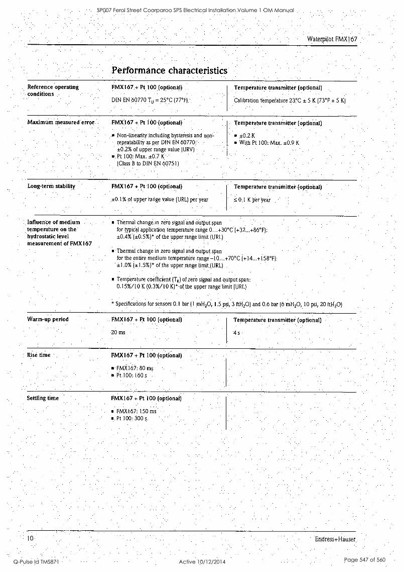
Waterpilot FMX167
Performance characteristics
Reference operating FMX167 .+ Pt 100 (optional) conditions
DIN EN 66770 Tu = :25°C (77°F);
Temperature transmitter (optional)
Calibration tempetature 23°C ± 5 K (73°F ± 5 K)
. .
Maximtim Measured error FMX167 + Pt 100 (optional)
Non-linearity including hysteresis and non- repeatability as per DIN EN 60770:.- ±0.2% of upper range value (URV)
U. Pt 100: Max. ±0.7 K
(Class B to DIN EN 60751)
Temperature transmitter (optional)
±0:2 K .
With Pt 100: Max. ±0.9 K
Long-term stability FMX167 + Pt 100 (optional)
±0.1% of upper range value (URL) per year
Temperature transmitter (optional)
0.1 K per year
Influence of medium, temperature on the hydrostatic level Measurement of FMX167
- . Thermal Change in zero signal and output span for typical application temperature range 0...+30°C (+32...+86°F): ±0.4%'(±0.5%)* of the upper range limit (URL)
E . Thermal change in zero signal and output span. for the entire medium temperature range -10...70°C ( +14..: +158 °F):
11.0% (±1.5 %)* of the upper range limit.(URL)
Temperature coefficient (TK) of zero signal and output span: 0.15%/10 K (0.3%/10 K)* of the upper range limit (URL)
* specificadons for sensors 0.1 bar (1 mH20,.1.5psi, 3 ft1-120) and 0.6 bar (6 mH2O, 10 psi, 20 ft1-120)
Warm-up period FMX167 +: Pt 100 (optional)
20 ms
Temperature transmitter (optional)
4s
Rise time FMX167 + Pt 100.(optional)
m FMX167: 80 ms o Pt 100: 160 s
FMX167 + Pt 100 (optional)
FMX167: 150 iris
Pt 100:300 s
SP007 Ferol Street Coorparoo SPS Electrical Installation Volume 1 OM Manual
Q-Pulse Id TMS871 Active 10/12/2014 Page 547 of 560

Waterpilot FMX167
Installation
Installation instructions
Installation examples; here shOwn with FMXI67 with an outer diameter = 22 inm (0.-87 inch)
. i Extension cable mounting screw can be ordered via order code. or as an accessory, a. see Page 14 and 10
2 Terminal housing can be ordered via order code or as-an-accessory, a see Page IS and 19 3 Extension cable' bending radius > 120 mm (4.72 inch) 4 Suspension clamp can be ordered via order code or as aaaccessory, a see Page 14 and 19
5 .Eitehsion cable-Upto 300 m (380), for max. lengthy see Page 76, "Extension cable! Section - 0- Guidatube for FMX167 with outer diameter = 22 MM. (0.87 inch) internal diameter > 23-mm (0.91 inch) 7 Additional weight can tie ordered as an accessory for F44X167 with outer diameter.= 22 mm.(0,87 inch)
mm IS inch), a see Page 19 .
Protection. cap,
-Note! . A sideways movement of the level piobe can lead to ineasuringeirors.Therefore install the probe at a point
.. free from flow and turbulence, or use a guide tube. The internal diameter of the guide tube should be at least 1 mm (0.04 inch) bigger than the outer diameter of the selected FMX167. -
The cable must end in a dry room or in a proper terminal box: TheterMinal bok.froM Endress+HauSer provides optimum humidity.and climatic protection and is suitable for outdoor installation. . ProtectiVe cap: to avoid mechanical damage to the measuring tell, the device is provided with a protective, cap, which should not be removed during transport and installation. . After shortening of the cable, the filter must be re-fitted on the pressure compensation hose..-
Endress+Hauser
SP007 Ferol Street Coorparoo SPS Electrical Installation Volume 1 OM Manual
Q-Pulse Id TMS871 Active 10/12/2014 Page 548 of 560

Waterpilot FNIX167
Environment
Ambient temperature :.range
FMX167 + Pt 100 (optional)
FMX167 with outer diameter .
= 22 mm (0.87 inch) and 42 mm (1.66 inch): -10...+70°C (+14...+158°F) (= medium temperature) FMX167 with outer diameter = 29 mm (1.15 inch): 0:.: +50 °C (-F32...+122°F) (= medium temperature)
Temperature transmitter (optional)
-40...+85°C (-40...+185°F)
Storage temperature FMX167 + Pt 100 (optional)
-40...+80°C (7-40...+185°F)
Temperature. transmitter (optional)
-40...+100°C (-40...+212°F)
gree of protection FMX167 + Pt 100 (optional)
IP 68,.permanently herinetically sealed Optional terminal box: IP 66/IP67
Temperature transmitter (optional)
IP 00, moisture condensatiOn permissible . When mounted in the optional terminal boxes:
IP 66/IP67
Electromagnetic compatibility (EMC)
FMX167 + Pt 100 (optional)
Interference emission to EN 61326.Class B
equipment, interference immunity to EN 61326 Appendix A (Industrial) Maximum deviation: < 0.5% of span
Temperatute transmitter (optional)
Interference emission-to EN 61326 Class B
equipment, interference immunity to EN 61326 Appendix A (Industrial)
Oyeivoltage protection FMX167 + Pt 100 (optional)
Integrated overvoltage protection to EN 61000-4-5 1.2kV
Install overvoltage protection 1.2 kV, external If.
necessary
Process
.. TeMperaturetransmitter (optional)
Install overvoltage protection, external if necessary.
Medium temperature range FMX167 + Pt 100 (optional)
FMX167 with outer diameter = 22 mm (0.87 inch) and 42 mm (1.66 inch):
10...+70°C (+14...+158°F) FMX167 with outer diameter = 29 mm (1.15 inch): 0,..+50°C (+32...+122°F)
Temperature transmitter (optional)
-40...-+85°C (740...+185°C) (= ambient temperature), install temperature transmitter outside Medium.
: 12 Endress+Hauser
SP007 Ferol Street Coorparoo SPS Electrical Installation Volume 1 OM Manual
Q-Pulse Id TMS871 Active 10/12/2014 Page 549 of 560

SP007 Ferol Street Coorparoo SPS Electrical Installation Volume 1 OM Manual
Q-Pulse Id TMS871 Active 10/12/2014 Page 550 of 560

Waterpilot FMX167
Medinm temperature lithits .PMX167 + Pt 100 (optional)
FMX167 with outer diameter .
= 22 mm (0.87 inch) and 42 mm (1.66 inch): -20...+70°C (-4...+I58°F) FMX167 with outer diameter =29 mm (1.15 inch): 0...+50°C (+32...+122°F)
(You may operate the FMX167 in this temperature .range.. The specification can.then be-exceeded, e.g.-
measuring.accuracy).
Mechanical construction.
Dimensions of level probe
. Versions of FMX167
1 FMX167, version "A" or "D" for Feature 30 ."Probe-tube" in the order code ( + see Page 18) 2.. FMX167;' version "8" for Feature 30' "Probe tube" in'thebrder code (-> see Page 18)
3 FA4X1.67, version "C" for Feature 30 "Probe tube" in the order code see Page 18) -
- 4 Pressure compensation tube 5 kxtension cable 6 Protection cap
POI-FMX107u.06-al-u-u-036
. . .
Endress +Hauser 1.3
SP007 Ferol Street Coorparoo SPS Electrical Installation Volume 1 OM Manual
Q-Pulse Id TMS871 Active 10/12/2014 Page 551 of 560

Waterpilot FX4X167
Dimensions of suspension clamp
Suspension clamp, version 2 for. Feature 20 "Conriactibn." in the.order'code (-> see Page 18)
.1.01-FM7I167n-05-u-n-u-010
Dimensions of extension cable mounting screws
POI -FMX107v-06-1.-xl-u..000
Extension cable mounting screws
1 &tension cable mbuntirig screw C 1 1/2 A, version i'3" for Feature 20 " Connection" in the order Code (-> see Page /8J Extension cable mounting screw] 1/2 NPT, version "4" for Feature 20 ".Connection" in the order code (-> see. Page 18)
SP007 Ferol Street Coorparoo SPS Electrical Installation Volume 1 OM Manual
Q-Pulse Id TMS871 Active 10/12/2014 Page 552 of 560

Waterpilot FMX167
Dimensions of the terminal box IP 66/IP 67 with filter
Terminal box
Version "3", "4" or "5" for Feature 70 "Additional options" in the order code (-> see Page 18)
1 Dummy plug M 204..5 2 GORE-TEX® filter
Terminals for 0.08..2.5 mm2
Dimensions of temperature transmitter TMT181
Temperature transmitter TMT181 (4...20 mA)
Version "5" for Feature 70 "Additional options" in the order code (-> see Page 18). The temperature transmitter can be used in non-hazardous areas and for EEx nA.
. Weight Levelprobe, outer diameter = 22 mm (0:87 inch): 290 g
Level probe, outer diameter = 42 mm (1.66 inch): 1150 g
Level probe, outer diameter = 29 mm (1.15 inch): 340 g-
m Extension cable PE: 52 g/m Extension cable FEP:108 g/rn.
.Suspenion.clamp: 170 g Extension cable mounting screw G 1 1/2 A: 770 g
Extension cable mounting screw 1 1/2 NPT: 724 g
Terminal box: 235 g .
Temperature transmitter: 40.g.
O Additional weight: 300 g
Endress.tHauerl
SP007 Ferol Street Coorparoo SPS Electrical Installation Volume 1 OM Manual
Q-Pulse Id TMS871 Active 10/12/2014 Page 553 of 560

Waterpilot FMX1:67
Material Level probe .
Level probe, outer diaMeter = 22 mni. (0.87 inch):-1.4435.(AISI 316L) Level probe; outer diameter = 42 mm (1.66 inch):1.4435 (AISI 3.16L)
LeVel probe,, outer diameter = 29. rrim. (1.15 inch):. - Level probe: 1.4435. (AISI 316L) - Sensor sleeve: PPS tpolyphenylene sulfide) 7' Heat-shrink. sleeve/cover: Polyolefin
Metal does not come into contact with the medium. ProcesS ceramic: A120311uminitim oxide ceramic Seal (internal): EPDM or Viton
I Protective cap: .
. .
- PE-HD (high-density polYethylerie) for FMX167 with outer diameter = 22 mm and 29 mm(0.87 inch and .1.15 inch). .
. .
PFA,(porfluoralicoxy) for FMX167. with outer diameter = 42. mm (1.66 inch). Extension cable insulation: Either PE-LD (low density polyethylene) or FEP (flUorinatedethylene.propylene).-
. For more information, see the next Section - "Extension cable" .
Suspension. clamp: 1.4404 (AISI 316L) and glass fiber-reinforced PA (polyamide) .Extension cable mounting screw G1 1/2 A: .1.4301 (AISI304) Extension* cable mounting screw 1'1/2 NPT: 1.4301 (AISI 304) Terminal box:PC (polycarbonate) Temperature. transmitter: Housing PC ( polycarbonate)
Extension cable PE extension cable Slip-resistant extension cable with strain-relief members made of Dynemo; shielded using aluminium-coated film; insulated. with polyethylene (PE), black; copper wires, twisted Pressure compensatiOn tube with Teflon filter
FEP eXtensiOn. cable . Slip -resistant extension cable; Shielded. using galvanized steel wire netting; insulated with fluorinated
ethylene propylene (FEP), black; copper wires, twisted Pressure compensation tube with Teflon filter .
Cross-sectiOn.of PE and FEP extension cable Total outer diameter:. 8.0 mm ± 0.25 min (0.315.inch ± 0.0098 inch) FMX167: 3 x 0.227 mm2 + pressure compensation tube with Teflon filter FMX167 with Pt 100 (optional): 7 x 0.227 mm2 + pressure compensation tube with Teflon filter
.Pressure compenSaticiti tube with Teflon filtef:
Outer diameter = 2.5 mm (0.098 inch), internal diameter = mm (0.059 inch)
Cable resistance of PE and FEP extension cable Cable resistance per wire: _c 0.09 Wm
Cable. length of PE .andFEP extension cable Please also refer to Page 7, "Load" Section. - .
and .
When using the measuring device in hazardous areas, national standards d regulations aswell as the safety instructions (XAs) or 1nstallatidri or Control Drawings (ZDs) haVe to be observed, See alsO Page 20, "Safety
Instructions" and "Installation/Control Drawings" Sections.
Further technical data of PE and FEP extension cable 'Minimum bending radius: 120 mm (4/2 inch).
Tensile strength: max. 950 N
Cable eXtraction.force: 450 N .
(The extension cable could be extracted from the level probe at a-tensile force 450 N.)
'Resistance to UV light -
PE: approved for use with drinking water
Tern:Una Is o 3 standard terminals In terminal box 4-terMinal strip can be ordered as accessory, Order No. 52008938 Wire cross-section 6.08...2.5 mm2
16 Endress+Hauser
SP007 Ferol Street Coorparoo SPS Electrical Installation Volume 1 OM Manual
Q-Pulse Id TMS871 Active 10/12/2014 Page 554 of 560

Waterpilot FMX167
Certificates and approvals
CE approval By attaching the CE symbol, Endress+Hauser confirms that the instrument fulfills all the.requirements of the relevant EC directives.
Ex approval, type of protection
ATEX II 2 G EEx ia IIC T61
ATEX II 3 G EEx nA II T6 FM: IS, Class I, Division 1, Groups A-D1
CSA: IS, Class I, Division 1, Groups A -D'
I Only for Waterpilot FMX167 without Pt 100
Waterpilot FMX167 with outer diameter =22 mm (0.87 inch) is only suitable for. use in
hazardouS areas with the FKM Viton seal.
All explosion, protection data'are contained in separate explosion protection documentation which you can also
request. Explosion protection documents are supplied as standard for all devices approved foruse in explosion hazardoUs areas: -> See also Page 20, "Safety Instructions" and "Installation/Control Drawings" Sections.
Drinking water. approval KTW certificate (for FMX167 NSF 61 approval With do = 22 mm (0.87 inch)) ACS apProVal
Marine approval GL approval ABS approval
External standards and guidelines
DIN EN 60770 (IEC 60770): Transmitters for use in industrial-control systems Part 1: Methods for performance evaluation
DIN 16086: Electrical pressure measuring instruments, pressure sensors, pressure transmitters,. pressure measuring instruments, concepts, specifications on data sheets
EN 61326 ((EC 61326-1): Electrical equipment for measurement, control and laboratory use - EMC requirements
Registered trademarks
GORE-TEX® Registered trademark, of W.L. Gore & Assotiates, Inc., USA
Ent: Iresst Hauser 17
SP007 Ferol Street Coorparoo SPS Electrical Installation Volume 1 OM Manual
Q-Pulse Id TMS871 Active 10/12/2014 Page 555 of 560

Waterpilot FMX167
Ordering information
FMX1 67 10. Approval A
B
C
S
E
F
Version kir non-hazardous area
ATEX 112 G EEx la IIC T6
ATEX II 3 G EEx nA If T6
FM IS, Class I, Division I, Groups A- D -
CSA IS, Class I, DiVision I, Groups,A- D
CSA General Purpose -.
20 Connection -
.
" . .
1-
2
3
4
. . . .
Probe cable
Suspension clamp, AISI 316L . ,
Cable. mounting screw C 11/2, AISI 304 -.
Cable mounting screw NPT 11/2, AISI 304
30 Pr be tube: -
A
B
C
D
Outer diametei cl.= 22 mm (0.87 inch); AISI 316E
Outer diameter d = 42 nun (1.66 inch), flush mount, AlS1316L
Outer diameter d 7 29 mm (1.15 inch), AISI 3 161.;With heat-shrink sleeve PPS/polyoiefin for saltwater applications . .
Outer diameter d.= 22 mm (0.87 inch), AISI 316L + drinking water approval KTW/NSF/ACS (can only be selected In conjunction with EPDM seal and PE probe cable)
40 . :
. . Measuring range: . . " . . .
Measuring
BA
BB
BC
BD
BE
BF
BG
BH'
BK
PA
PB
PC
PD
-PE
PF
PG
PH
PK
VV
range
D...0.1 bar.
0...0.2 bar
0...0.4 bar
0...0.6 bar '
0...1.0 bar
0...2.0 liar
0...4.0 bar..
0.1.10.0 bar
0...20.0 bar
0...1.5 psi
0...3 psi
O...6 psi '
0.'..10 psi
0...15 psi.
0...30 psi
0...60'psi
0...150 psi .
0...300 psi '
Adjusted to customer specifications .upper range value: 0.1
Measuring
MA
MB
MC
MD
ME
MF
MG
MH
MK
FA
FB
FC
FD
FE
FF
FG
FH
FK : '
bar (1 mH2O,
range
0...1 mH2O
0...2 mH2O
0...4 mH2O
a..6 mH2O
0...10 mH2O
0...20 mH2O
0.:.40 mH2O
0.:.100 mH2O
0...200 mF2O
0...3 ftH2O
0...6 ftH2O
0...15 ftH2O
0..:20 ftH2O '
0...30 ftH2O
0...60 ItH2O '
0...150 ftH2O
0..:300 ftH2O .
0...600 ftH2O : from 0 to (upper
1:5 psi; 3 ftH20)
Max. overload
5 bar
5 bar,
7 bar
10 bar
10 bar
18 bar.
25 bar
40 bar
40 bar
73 psi
73 psi
101 psi
145 psi '
1'45 psi
261 psi
362 psi
580 psi
580 psi -
range value) in (unit), o 20 bat (200 m2H0; 300
Vacuum resistance
0 barbs
0 bar,bs
0 barbs
0 barb,
Obarbs
0 barb,
0 barbs
0 barb,
0 barbs
0 barb,
0 bafb,
0 barbs
0.bar,b,
0 barb,
0 barb,
0 bar,bs
0 barbs
0 barb;
psi, 600 ft2H0)
50 . . . . Sensor . seal. . .
I
2
.
FKM Viton
EPDM
60 Probe cable:. : .
A
B
C
E
F
G
K
L
M
N
P
.:. in, shortable, PE:
10 m, shortable, PE - '
20 m, shortable, PE
30 ft, shortable, PE
60 ft, shortable, pE.* .
... It; shortable, PE
... m, sh ortable; FR' 10 m, shortable, FEP: :
20 m, shortable, FEP
30 ft, shortable, FEP . '
60 ft, shortable, FEP
...It, shortable, FEP
FMX167 Complete order code
Ordering information for FMX167 continued on next page:
18 Endress+Hausei.
SP007 Ferol Street Coorparoo SPS Electrical Installation Volume 1 OM Manual
Q-Pulse Id TMS871 Active 10/12/2014 Page 556 of 560

VVaterpilot FMX167
FMX167 (continued) 70 Additional option:, 7
S
I
3
4
5
Basic version'
GUABS marine certificate .
Pt 100, 4-wire
Terminal box IP66/67
Terminal box 1P66/67 + Pt 100, 4-wire.
Pt 100 + temperature transmitter TMT181, 2-wire, 4...20 mA = -20...+80°C (-4176°F) ' .
FMX167 Complete order code
Accessories
Suspension clamp Endress+Hauser offers a suspension clamp for simple FMXI67 mounting. -+ See also Page 14.
Material: 1.4404 (AISI 316L) and glass fiber reinforced PA (polyamide) Order number: 52006151
Terminal box Terminal box IP 66/IP 67 with GORE-TEX® filter incl. 3 mounted terminals. The terminal box is also suitable for installing a temperature transmitter (Order No. 52008794) or for four additional terminals (Order No. 52008938). See also Page 15.
Order number: 52006152
Additional weight (for FMX167 with do = 22 mm (0.87 inch) and do = 29 mm (1.15 inch))
. POI -FMX167x1-06-12-1,-u-01
To prevent sideways movement leading to
measuring errors or to ensure that the device lowers into a guide tube, Endress+Hauser provides additional weights. You can screw several weights together. The weights are then attached directly to the FMX167. For
FMX167 with outer diameter = 29 mm (1.15 inch), a maximum, of .5 weights may be screwed on to
FMX167. Material: 1.4435 (AISI 316L) Weight: 300 g
Order number: 52006153
Temperature transmitter Temperature transmitter, 2 -wire, preset for measuring range from - 20:.. +80 °C (-4...+176°F). This setting offers an easily displayable temperature range of 100 K. Note that the Pt 100 resistance thermometer is designed for a temperature range of -10.-..+70°C (+14:..+158°F). -> See also Page 15.
Order number: 52008794
Extension cable mounting screw
Endress+Hauser offers extension cable mounting screws to simplify the installation of the FMX167 and to close the measuring open. See also Page 14. . .
Material: 1:4301 (AISI 304) Order number for extension cable mounting screw with G 1 1/2 A thread: 52008264
-0 Order number for extension' cable mounting screw with .1 1/2 NPT thread: 52009311
Four terminals in strip for FMXI67 terminal box, suitable for wire cross-section of 0.08...2.5 mm2
o Order number: 52008938
Endress+Hauser 19
SP007 Ferol Street Coorparoo SPS Electrical Installation Volume 1 OM Manual
Q-Pulse Id TMS871 Active 10/12/2014 Page 557 of 560

1
SP007 Ferol Street Coorparoo SPS Electrical Installation Volume 1 OM Manual
Q-Pulse Id TMS871 Active 10/12/2014 Page 558 of 560

Test adapter (for FMX167 with do = 22 mm (0.87 inch) and do = 29 mm (1.15 inch))
POI-FMX167u1-05-ax-1,-11-007
Test adapter
A Connection suitable for level probe FMX1 67-
B Connection compi.essed air hose, internal diameter, quick hose gland 4 mm (0.157 inch)
Documentation
EndreSt+I-lauser offers a test adapter to simplify the function test of level probes. Note the.maximum pressure for the compressed air
hose and the maximum level probe overload. -> See
also Page 18.
The maximum pressure for the-supplied quick hose gland is 10 bar (145 psi).
Adapter material:. 1.4301 (AISI 304) Quick hose gland material: Anbdized aluminium Adapter weight: 39 g
Order number: 52011868
Field of Activities Pressure Measurement: FA004P/00/en Recording Technology: FA014R/09/de System Components: FA016K/09/en
Technical Information Temperature Head Transmitter iTEMP PCP TMT181: T1070R/09/en
Operating Instructions Waterpilot FMX167: BA231P/00/en
Safety Instructions ATEX II 2 G EEx is IIC T6:-XA131P/00/a3 ATEX II 3 G EEx nA II T6: XA132P/00/a3
Installation/ Control Drawings
FM IS Class I, Div. 1, Groups A - D: ZD063P/00/en CSA IS Class I, Div. 1, Groups A - D: ZD064P/00/en
Drinking water approVal
qnstrumenti International
Endress+Hauser Instruments International AG Kaegenstrasse 2 4153 Reinach Switzerland
Tel.+41 61 715 81 00 Fax+41 61.715 25 00 www.endress.com [email protected]
SD126P/00/a3
11351P/00/en/02.08 CCS/FM+SGML 6.0
Endre5s+HaUser People for Process. Automation
SP007 Ferol Street Coorparoo SPS Electrical Installation Volume 1 OM Manual
Q-Pulse Id TMS871 Active 10/12/2014 Page 559 of 560

j
SP007 Ferol Street Coorparoo SPS Electrical Installation Volume 1 OM Manual
Q-Pulse Id TMS871 Active 10/12/2014 Page 560 of 560
Copyright © 2022 FDOKUMEN