Church Rd Bellbowrie SPS SP303 Operations and ...
421
a V Church Rd Bellbowrie SPS SP303 Operations and Maintenance Manual Q-Pulse Id TMS730 Active 29/01/2014 Page 1 of 421
-
Upload
khangminh22 -
Category
Documents
-
view
2 -
download
0
Transcript of Church Rd Bellbowrie SPS SP303 Operations and ...

a
V
Church Rd Bellbowrie SPS SP303 Operations and Maintenance Manual
Q-Pulse Id TMS730 Active 29/01/2014 Page 1 of 421

H
A
B
C
EMERGENCY OVERFLOW TO GULLY. REFER ERG. 93C007-61
SWITCHBOARD
375 OVERFLOW
VENT POLE LOCATION TO SUIT SITE LAYOUT REFER ERG. No. IWE-BWM-10 10000
2600
1470 1820 3310
SURFACE TREATMENT TO BE MAINTENANCE FREE STAMPED CONCRETE
020 WATER STOPCOCK WITH VACUUM BREAKER.
STANDARD 1830 DIA. GRIT COLLECTOR MAINTENANCE HOLE. REFER DRG. Nos. IWE-BN1M-07 & IWE-BWM-09
SUCTION CLEANING PIPES TO FACE ACCESS ROAD
SURVEY MARK ON TOP OF SLAB
GALVANISED STEEL -2000 HIGH WITH 300 WIDE MOWING STRIP UNDER
SUCTION CLEANING PIPES TO FACE ACCESS ROAD
L.O.C.
300
r44---1--ili--1 PI ilf I
I I
-0- 4,
-T.
i y 'V'
1 I / tt /
-14- 1 L-44-«----4-.4--1
Ili V- -- ?
I
L.O.C.
ELECTRICITY PILLAR BOX. CONTRACTOR TO CONFIRM LOCATION
METRES
0 025 0.5 1 15 2 25 3 35
START OF L.O.C. RISING MAIN
AI- if*---0150 DILL RISING MAIN
SITE LAYOUT SCALE 1 i 50
GATE
NON-MOUNTABLE KERB (VERTICAL DISTANCE TOP OF HARDSTAND TO TOP OF KERB 300m)
130mn THICK CONCRETE WITH RF82 MESH
025 COPPER WATER SERVICE
AUTHORISED REDUCED PRESSURE ZONE (R.P.Z.) BACKFLOW PREVENTION DEVIC
NOTES LO.C. DENOTES LIMIT OF CONTRACT
MACI Eig Registered
rofessional EntLaar
/ I.L. (12) STANDARD OVERFLOW FLAP /
VALVE CHAMBER TYPE 1
--I
460 x 230 PRECAST I L CULVERT
0600 ACCESS HOLE
' FALL
ice- -. ----------------------i_...li
I 11 1T
I I
J I -
EMERGENCY STORAGE REFER RETICULATION DRAWINGS 01350 RCP x 28 METRES LONG
04,
1350
FALL
R.P.6.677 ACCESS HOLE 01500 iI
460 x 230 PRECAST CULVERT
3-2-03 HT DRAIN DELETED SG
H 15-4-04
6 16-6-03
PS
HT
AS BUILT - LAYOUT AMENDED.
LAYOUT REVISED
111
SG
F 2-4-03 HT DIMENSIONS ADDED SG
18-2-03 HT ISSUED FOR CONSTRUCTION SG NO. DATE BY REVISION
1 2
APP'D
3
I.WE Industrial & Water Engineers DRAFTER
H.T.
ONOCED
RPEQ 5219
OATS
31 -7 -02
(AD. ALE
IWE-BWM-01G
ONCKED DATE
15 -2 -03 PROL ENG.
S .GRAY
APPROVED
PROJECT
5
BELLBOWRIE WEST
CHURCH ROAD
PUMP STATION
III 7
RILE
SEWAGE PUMP STATION SITE LAYOUT
SHEET
SIZE
A2
DRAWING No.
IWE-BWM-01
REVISION
A
8 9 10
SCALE 1:50
11 12
Church Rd Bellbowrie SPS SP303 Operations and Maintenance Manual
Q-Pulse Id TMS730 Active 29/01/2014 Page 2 of 421

3 6 S I 6 7 I 8 9 10 11 I 12
600 x 200 OPENING FOR LEVEL PROBES REFER DETAIL DRAWING NO. IWE-BWM-12
SWITCHBOARD LOCATION (ALL ELECTRICAL CONDUITS AND DUCTS UNDER SWITCHBOARD SHALL BE SEALED WITH DOW CORNING FLOWABLE SILICONE OR EQUAL.)
150 WIDE x 50 DEEP RECESS FOR CABLE DUCT. REFER DETAIL DRAWING NO. IWE-BWM-12
II II
11
11
II
II II
II
1-DN32 ELECTRICAL SUPP_Y CONDUIT 500mm BELOW F.S.L. CONDUITS MAY ENTER CABLE PIT FROM EITHER SIDE CONTRACTOR TO CONFIRM.
\
/I ,/ I
= - -
,Y\ / ,
t
DN100 EARTH STAKE CONDUIT THROUGH FINISHED SURFACE LEVEL
DN25 ELECTRICAL CONDUIT (EARTH) UNDER SLAB
450x450x500 DEEP GRC ELECTRICAL CABLE PIT SET IN SLAB
1-DN100 ELECTRICAL SUPPLY CONDUIT 500mm BELOW F.S.L. CONDUITS MAY ENTER CABLE PIT FROM EITHER SIDE CONTRACTOR TO CONFIRM.
DN25 ELECTRICAL CONDUIT FOR CATHODIC PROTECTION (CAST CENTRALLY IN TOP SLAB)
18-2-03 HT ISSUED FOR CONSTRUCTION SG
30 -1-03 HT LAYOUT REVISED SG
26 -10 -02 HT NOTE 1 ADDED SG
20-9-02 HT LAYOUT REVISED SG
16-6-03 HT LAYOUT REVISED SG DATE BY REVISION APP'
1 2 3
Ld
11
T
DN32 ELECTRICAL CONDUIT TO VALVE PIT 500mm BELOW F.S.L.
LI" i
I M m 1- _Ili - -- m 7-- ni._---Ogilltit,":11 11
-1
I
M EH I -411jii:-.-r - 7 - - -1- W W
i I
I
I
I
I
I I I
I I M
-III' _._,M - III_ _i_
----Nli111111e,,111 .L.
_l_____III---- Ill ___.J11.".111 __I I w HI W HT I I
1_ _I
PLAN
120mm SQUARE UPVC ELECTRICAL CONNECTION BOX CAST IN SLAB
m
_ ' N- W - \
\\%0
\. -
W w 4
j_31.
flTid
IT!
z 7a"
Li 0
AS BUILT
-D4q
...r
NOTES 1. REFER TO SITE LAYOUT DRG No. IWE-BWM-01 FOR SIZE AND ANGULAR LOCATION OF PIPE & SERVICE CONNECTIONS TO WELL.
I.W.E. Industrial & Water Engineers DRAFTER
H.T. DATE
31-7-02
CAD. FLE
IWE-BWM-02D
CHEOCED
RPEQ 5219
CHECKED DATE
15-2-03
4
PRO& ERG.
S. GRAY
S
APPROVED
PROJECT
BELLBOWRIE WEST CHURCH ROAD
PUFIP STATION
TITLE
SEWAGE PUMP STATION ELECTRICAL REQUIREMENTS PLAN
SHEET
SIZE
A2
DRAWING No.
IWE-BWM-02
REVISION
SCALE 1:25
6 7 8 9 10 11 12
Church Rd Bellbowrie SPS SP303 Operations and Maintenance Manual
Q-Pulse Id TMS730 Active 29/01/2014 Page 3 of 421

H
4 5 6 a V 10
D.I.C.L. K12 FLANGE AND SOCKET CONNECTOR
300 LONG D.I.C.L. K12 SOCKET AND PLAIN TAILPIPE
'McBERNS' AUTO WELL WASHER (PROTECTED BY R.P.Z. VALVE) AND ON TIME CLOCK OPERATION WITH SOLENOID VALVE)
SUCTION CLEANING PIPE & AIR LINE TO FACE ROAD ACCESS REFER DRG. No. IWE-B WM-05
4175
D.I.C.L. K12 FLANGED BEND CUT TO SUIT. BEND TO BE ANGLED AT 22.5' VERTICALLY DOWNWARDS AND 22.5' HORIZONTALLY ANTICLOCKVISE
1600
- K12 D.I.C.L. SOCKETED INLET PIPE FROM GRIT COLLECTOR MAINTENANCE HOLE. DN225 MIN. REFER SITE LAYOUT FOR SIZE AND ANGULAR POSITION.
150 MIN. PRESSURE TAPPING (BINDER TWINLOK HOT PLUG 1/4' BSP STAINLESS STEEL)
DN32 BSP FEMALE SOCKET (ROTATED 45') WITH ISOLATING VALVE & UNION FOR VEGA PRESSURE TRANSMITTER
GRADE 316 STAINLESS STEEL BOLTS TO BE USED. FLANGES TO BE PROTECTED WITH POLYETHYLENE ADHESIVE WRAPPING CDENSO' ROCK WRAP 3000)
ANCHOR BLOCK TO SUIT THRUST & SOIL CONDITIONS.
FABRICATED M.S. HEADER TYPE 4. DN150 REFER DRAWING NO. IWE-BWM-15 FOR HEADER DETAILS. VENT POLE REFER
DETAIL DRAWING NO. IWE-BWM-10
4- -.I g r?,
DN150 U,P.V.C. CLASS 12 VENT PIPE
450 x 450 x 500 DEEP GRC ELECT. PIT CAST IN SLAB
START OF RISING MAIN
SCOUR VALVE
50 WIDE x 10 DEEP REBATE FOR 6nr) ALUMINIUM COVERS. REFER DETAIL DRG. NO. IWE-BWM 12
DOUBLE FLANGED D.I.C.L. PIPE TYPICAL
375 WIDE GRADE 316 STAINLESS STEEL LADDER. REFER WATER AND SEWERAGE RETICULATION STANDARDS DRAWING NO. 486/5/25-SF009 FOR LADDER DETAILS.
NOTES 1. REFER TO SITE LAYOUT DRG No. IWE-BWM-01 FOR SIZE AND ANGULAR LOCATION OF PIPE & SERVICE CONNECTIONS TO WELL.
D 3-2-03 HT DRAIN DELETED SG I.W.E. C 30-1-03 HT LAYOUT REVISED SG
B 26-10-02 HT NOTE 1 ADDED SG DRAFTER
H.T. F 16-6-03 HT LAYOUT REVISED SG
18-2-03 HT ISSUED FOR CONSTRUCTION SG CHECKED
RPED 5219 NO. DATE BY REVISION APP'13
2 3
ELECTRICAL CONNECTION BOX REFER DETAIL DRAWING NO. IWE-BWM-14
PLAN (NOTE COVERS OMITTED)
DN100 RISING MAIN SCOUR. LOCATION MAY VARY
FLANGED DN150 SLUICE VALVE TYPICAL (ANTICLOCKWISE ROTATION TO CLOSE) IN ACCORDANCE WITH AS 2638.1
PRESSURE TAPPING (BINDER TWINLOK HOT PLUG 1/4' BSP STAINLESS STEEL)
FLANGE ADAPTOR TABLE 'D' ('UNIFLANGE' TYPE) TYPICAL
FLANGED DN150 REFLUX VALVE
DOUBLE FLANGED DN150 D.I.C.L. PIPE WITH WEEP FLANGE TYPICAL
DN100 D.I.C.L. FLANGED WALL PIPE WITH WEEP FLANGE
AS UILT szict
RISING MAIN PIG WIDTH. 1.5 DIA. OF RISING MAIN. LENGTH' 2 X DIA. OF RISING MAIN.
TO BE MADE OF URETHANE FOAM TO BE INSTALLED PRIOR TO CONSTRUCTION OF RISING MAIN.
EMERGENCY PUMP : CONNECTION POINT. 10Ornm 'KAMLOK' FLANGED ADAPTOR TO BE
PROVIDED IN PIT..
DN100 FLANGED SLUICE VALVE (ANTI- CLOCKWISE ROTATION TO CLOSE) IN ACCORDANCE WITH AS 2638.1
Industrial & Water Engineers DATE
31-7-02
(AD. ALE
IWE-BWH-03F
00(000 DATE
15-2-03
I.
PRO). DIG.
S. GRAY
5
PROJECT
BELLBOWRIE WEST
CHURCH ROAD
PU'ilP STATION
TIRE
SEWAGE PUMP STATION CIVIL REQUIREMENTS
PLAN
SHEET
SIZE
A2
DRAWING No.
IWE-BWM-03
REVISION
APPROVED
SCALE t25
7 1
8 9 10 11 12
Church Rd Bellbowrie SPS SP303 Operations and Maintenance Manual
Q-Pulse Id TMS730 Active 29/01/2014 Page 4 of 421

2 3 4 5 6 7 8 9 10 11 12
TABULATION OF GRIT COLLECTOR 8,
PUMPING STATION LEVELS REF. DESCRIPTION LEVEL
LEVEL 1 FUNISHED SURFACE LEVEL 18.2
LEVEL 2 INVERT OF INLET AND OUTLET OF GRIT COLLECTOR MAINTENANCE HOLE 13.170
LEVEL 3 TOP OF BASE OF REFLUX VALVE PIT 16.721
LEVEL 4 INVERT OF INLET SEWER AT PUMP WELL 11.940
LEVEL 5 TOP WATER LEVEL OF PUMP WELL 13.25 LEVEL 6 BOTTOM WATER LEVEL OF PUMP WELL 12.283 LEVEL 7 TOP OF BASE SLAB OF PUMP WELL 10.900
LEVEL 8 BOTTOM OF BASE SLAB OF PUMP WELL NOTE 2
LEVEL 9 TOP OF ROOF SLAB OF PUMP WELL 18.531
LEVEL 10 INVERT LEVEL OF RISING MAIN THROUGH PIT WALL 17.394 LEVEL 11 TOP OF BASE OF GRIT COLLECTOR MAINTENANCE HOLE 12.225 LEVEL 12 INVERT LEVEL OF OVERFLOW (ON TERMINAL MANHOLE) 17.532
NOTE' FOR R.L.(2) AND R.L.C11) REFER TO GRIT COLLECTOR MAINTENANCE HOLE. FOR R.L.(12) REFER TO OVERFLOW DETAIL.
r -
I
INLET :411
SEWER & EMERGENCY STORAGE DRAIN
3.
+.
.L.t. I
DIA. 1830
!STANDARD 1830 DIA, GRIT COLLECTOR
MAINTENANCE HOLE I REFER DRG, NOS,
IWE-BWM-07 TO IWE-BWM-09
1
ILO /eL,(5)
D.I.C.L. K 12 INLET SEWER DN250
I
-L
PROVIDE 100 MINIMUM CLEARANCE FOR MOTOR CABLE/PLUG
PROVIDE GAS PROOF SEALANT AT CABLE OPENINGS ('3M FIRE BARRIER 2001 SILICONE RTU FOAM KIT')
SWITCHBOARD 755 200 345 610
AIR BLEED
SIZE OF OPENING TO BE CONFIRMED AFTER PUMP SELECTION
915
450x450x500 DEEP GRC ELECTRICAL PIT SET IN SLAB
ALUMINIUM PART COVERS CHALLC' TYPE) WITH MAX, HALF LIFT OF 16 Kg, PER PART. COVERS TO BE PROVIDED WITH PADLOCK LOCKING MECHANISM AND LOCKED DOWN WITH B.C.0 177 KEYING SYSTEM, COVERS ARE TO BE GAS TIGHT. COVERS ARE TO BE FLUSH MOUNTED. COVERS ARE TO BE REMOVABLE (FIXED HINGES ARE NOT ALLOWED). PROVIDE LIFTING LUGS ON UNDERSIDE,
PRESSURE TAPPING (BINDER TWINLOK HOT PLUG 1/4' BSP STAINLESS STEEL)
- DN32 BSP FEMALE SOCKET (ROTATED 45°) WITH ISOLATING VALVE & UNION FOR. VEGA PRESSURE TRANSMITTER
-WEEP FLANGE
NOTE 5 4 MAX --=:z3 1 ODE HOOK REFER DETAIL
DRG, NO, IWE-BWM-13 1:SL.(1)
'McBERNS' AUTO WELL WASHER (PROTECTED BY R.P.Z. VALVEJ AND ON TIME CLOCK OPERATION WITH SOLENOID VALVE)
THICKEN WALL OF PUMP WELL TO PROVIDE WATER TIGHT SEAL AT FLANGES
.......
.... ..
DN150 RISER
1
I IN 1 0 i .1tv 3 DN150 TO DN100 ECCENTRIC REDUCER
SEPARATION OF & B.W.L. TO BE DESIGNED TO SUIT 5 STARTS/HOUR FOR A SINGLE PUMP. MIN, TO BE 600.
RL.(71
NOTE 2 /PLO
PROVIDE WATER TIGHT SEAL AT JUNCTION OF FLOOR AND WALL
MASS CONCRETE BENCHING
250
MIN.
SECTION
2440
DIA.
A
250
NO 90° BENDS OR TEES ALLOWED IN HEADER
450 X 450 X 300 DEEP SUMP WITH GALVANISED GRATE COVER
WEEP FLANGE
POLYETHYLENE LINING (WHERE SPECIFIED)
DN100 'DUCKFOOT BEND' CONTRACTOR TO INSTALL TO PUMP MANUFACTURERS MINIMUM CLEARANCE FROM WELL FLOOR. RISER PIPE TO SUIT.
NOTES 1. L.O.C. DENOTES LIMIT OF CONTRACT,
2. FOR CONCRETE THICKNESS & tINFRCING DETAILS REFER TO STRUCTURAL .RAWINGS,
MIN. 3. ALL BURIED DICL PIPES SHALL BE 'GREENSLEEVE' WRAPPED.
4. AL DICL PIPES IN PUMP WELL 84 VALVE PIT SHALL BE EXTERNALLY COATED WITH 1000UM APPROVED ULTRA HIGH BUILD EPDXY.
02 & 0
(GRIT COLLECTOR MAINTENANCE HOLE ADDED TO SECTION) 4. PUMP GUIDE BARS SHALL BE STAINLESS STEEL GRADE 316.
5. STAMPED CONCRETE TO START 200 BELOW TOP OF STRUCTURES.
3-2-03 HT DRAIN DELETED. NOTE S ADDED .SG 30-1-03 HT PUMP RISER REVISED SG
54-04 PS AS BUILT LEVELS ADDED
F IA- 6- 03 HT
E 18- HT
REVISED POSITION OF AIR VALVE SG
ISSUED FOR CONSTRUCTION SD
I.W.E. Industrial & Water Engineers
CHASM
REVISION Mam
AMT
DA KZ
H., 31-7-02 WE-BIM-0AF
-03
IMSIL
S. GRAY
PROJECT
BELLBOWRIE WEST
CHURCH ROAD
P11 1.- '7TATION
mu
SEWAGE PUMP STATION
SECTION A 9.1115
Al
()RAVING No.
IWE-BWM-04
REVISION
SEW 630
Church Rd Bellbowrie SPS SP303 Operations and Maintenance Manual
Q-Pulse Id TMS730 Active 29/01/2014 Page 5 of 421

I 4 I 5 I 6 7 I 8 9 10 11 12
1' DIA. 'SURELOCK' 316 STAINLESS STEEL
CLAW COUPLING
DN63 ELECTRICAL CONDUIT LOCATION MAY VARY
PUMP GUIDE RAILS SHALL BE STAINLESS STEEL GRADE 316
DN32 PE100 PN16 P.E. AIR LINE FIXED TO SUCTION
CLEARING PIPE WITH. S.S. TIES OR POLY WELDED
DN160 PE8OB PN12.5 P.E. VACTOR PIPE
FIXED TO WALL WITH H.D.P.E. BRACKETS
AT 1500 CRS. WITH STAINLESS STEEL ANCHORS
2 X 45° SWEEP BENDS
K12 DICL FLANGED SCOUR PIPE.
HOOK SHAPED DN32 PIPE 316 STAINLESS STEEL
CONNECTED TO AIR LINE WITH 2 STAINLESS STEEL CLIPS
SECTION B
Q)2 & 03
DN150 VACTOR COUPLING AS SUPPLIED BY 'FLEXIBLE PIPE CLEANING TOOLS'. HOT DIP GALV.
M.S. FLANGE TO TABLE 'D' OF A.S.2129 WELDED TO VACTOR COUPLING. TO BE HOT DIP GALVANISED AFTER FABRICATION.
DN160 PE80 STUB FLANGE
DN160 HOT DIP GALV. METAL BACKING FLANGC TO TABLE 'D' OF A.S.2129
DN160 PE8OB PN12.5 VACTOR PIPE
VACTOR PIPE COUPLING DETAIL
NOTES
1. STAMPED CONCRETE TO START 200 BELOW TOP OF STRUCTURES.
AS BUILT /Ova "I'r
D 16-6-03 HT LAYOUT REVISED
C 13 -2 -03 HT ISSUED FOR CONSTRUCTION
B 3 -2 -03 KT NOTE 1 ADDED
A 20-9-02 KT LAYOUT REVISED
0 31-7-02 NT mntmissuE
NO. DATE W REVISION
SG
SG
SG
SG
SG
APP*
MOM
Industrial & Water Engineers BELLBOWRIE WEST ORAF1131 COM CAI no CHURCH ROAD
H.T. 31-7-02 HIE -OWN-0W
PUMP STATION 01.1, INTO 52/9
PRI11
15-2-03 W4C
S. GRAY
7
SEWAGE PUMP STATION
SECTION B SHEET
SIZE
Al DRAWING No
IWE-BWM-05
REVISION
520
11
Church Rd Bellbowrie SPS SP303 Operations and Maintenance Manual
Q-Pulse Id TMS730 Active 29/01/2014 Page 6 of 421

5 6 7 8 10 11 12
CLASS D MAINTENANCE HOLE COVER AND FRAME. REFER WATER AND SEWERAGE RETICULATION STANDARDS DRAWING NOS. 486/5/25-SF004 /1 TO 486/5/25-SF004 /
S ECTIO\ C3
375 WIDE GRADE 316L STAINLESS STEEL LADDER. REFER WATER AND SEWERAGE RETICULATION STANDARDS DRAWING NO. 486/5/25-SF009 FOR LADDER DETAILS.
150 X 150 X 150 TOE HOLES AT 300 CRS.
4
VALVE CHAMBER DETAILS AS PER WATER AND SEWERAGE RETICULATI ON STANDARDS DRAWING NO. 486/5/25-S8008.
F.S.L.
S
PE PIT (450 SQUARE) WITH LID OR SIMILAR.
100 'KAMLOK' FLANGED ADAPTOR
-100 FLANGED RISER PIPE (LENGTH TO SUIT)
ECTIO\ C3
100 x 90° FLANGED BEND
100 FLANGED SLUICE VALVE (ANTICLOCKWISE ROTATION TO CLOSE) IN ACCORDANCE WITH AS 2638.1
AS BUILT
I.W.E. Industrial
RAMP
& Water Engineers wit
31-7-02 CAD.. fit
DiE-BW21-06A
PIIIECT
BELLBOWRIE WEST
CHURCH ROAD
PUMP STATION
A 18-2-03 MT ISSUED FOR CONSTRUCTION SG O 1-7-02 HT ORIGINAL ISSUE SG
NO DATE .r VISION ATY,
otmu RPEO 5219
Mal ENG
15-2-03 USA
S. GRAY
SEWAGE PUMP STATION
SECTION C SHEET
SIZE
Al DRAWING NO.
IWE-BWM-06
REVISION
t 0
6 III 7 1 10 11 12
Church Rd Bellbowrie SPS SP303 Operations and Maintenance Manual
Q-Pulse Id TMS730 Active 29/01/2014 Page 7 of 421

U TU
1' DIA. 'SURELOCK' 316 STAINLESS STEEL CLAW COUPLING
c."
NOTE 2
FALL
POLYETHYLENE LINING (WHERE SPECIFIED)
SCREEN SUPPORT BRACKET REFER DETAIL DRG, IWE-BWM-22.
G.M.S. BAR SCREEN REFER DETAIL DRG. NO. IWE-BWM-21 .
LOCATING PINS REFER DRG. IWE-BWM-22.
MASS CONCRETE BENCHING
1 2
DN32 PE100 PN16 P.E. AIR LINE FIXED TO SUCTION CLEARING PIPE WITH S.S. TIES OR POLY WELDED
DN160 PE8OB PN12,5 P.E. VACTR PIPE FIXED TO WALL WITH H.D.RE, BRACKETS AT 1500 CRS. WITH STAINLESS STEEL ANCHORS
HOOK SHAPED DN32 PIPE 316 STAINLESS STEEL CONNECTED TO AIR LINE WITH 2 STAINLESS STEEL CLIPS
45° SWEEP BEND CUT TO SUIT
375 WIDE GRADE 316 STAINLESS STEEL LADDER. REFER WATER AND SEWERAGE RETICULATION STANDARDS DRAWING NO, 486/5/25-SF009 FOR LADDER DETAILS.
TYPE 316L STAINLESS STEEL WALL PIPE WITH WEEP FLANGE. REFER DETAIL DRG. NO. IWE-BWM-17
'SUPERSLEEVE' OR SIMILAR CONNECTOR TO SUIT APPROVED PIPEWORK FOR GRAVITY SEWER
G.M.S. BAR SCREEN REFER DETAIL DRG. NO. IWE-BWM-21
DN225 MINIMUM D.I.C.L. K12 SEWER TO PUMPING STATION
INLET SEWER
300 LONG PIPE
SUCTION CLEANING PIPES TO FACE ACCESS ROAD
PLAN SECTION C
08
300 LONG K12 D.I.C.L. SOCKET AND PLAIN TAILPIPE
WEEP FLANGE
MASS CONCRETE BENCHING
NOTE 1. FOR SIZES AMD ORIENTATION OF CONNECTIONS REFER TO SITE LAYOUT DRG. IWE -BWM -01.
AS BUILT a STAMPED CONCRETE TO START 200 ruY
BELOW TOP OF STRUCTURES.
18-2-03 HT
C 3-2-03 HT
B 12-11-01 HT
A 20 -9 -01 HT
O 31-7-01 HT
ISSUED FOR CONSTRUCTION SG NOTE 2 ADDED
SG NOTE ADDED
SG LAYOUT REVISED
SG ORIGINAL ISSUE 56
Industrial & Water Engineers
H.T. 9.7 on al
31-7-02 UWE-OWN-07D
NO. DATE BY REVISION APP13
0ECKED
RPEO 5119
POOL
15 -2 -03 S. GRAY
BELLBOWRIE WEST
CHURCH ROAD
PUMP STATION
ME
SEWAGE PUMP STATION
GRIT COLLECTOR MAINTENANCE HOLE
DETAILS Al DRAWING No. ..
IWE-BWM-07 SCM1
50 3 5 6 7 8 9
1 10 12
Church Rd Bellbowrie SPS SP303 Operations and Maintenance Manual
Q-Pulse Id TMS730 Active 29/01/2014 Page 8 of 421

7 10
SLOPE GROUND AWAY FROM TOP SLAB
STAINLESS STEEL KNIFE GATE VALVE WITH RISING SPINDLE REFER DETAIL DRAWING NOS,
IWE-B \011-18 TO IWE-BWM-20
MASS CONCRETE BENCHING
L..C.
INLET SEWER
CLASS D MAINTENANCE HOLE COVER AND FRAME.
REFER WATER AND SEWERAGE RETICULATION STANDARDS
DRAWING NOS. 486/5/25-SF004/1 TO 486/5/25-SF4/4 FOR COVER
AND FRAME DETAILS.
NOTE 2 PA, ,
111° TO PUMP
(2)
G.M.S, BAR SCREEN REFER DRG. NO. IWE-BWM721
150 MAX,
AdimpNATION tommaffil 1-'41011411Zat
375 WIDE GRADE 316 STAINLESS STEEL LADDER.
REFER WATER AND SEWERAGE RETICULATION STANDARDS
DRAWING NO. 486/5/25-SF009 FOR LADDER DETAILS.
SCREEN SUPPORT BRACKET REFER DETAIL DRAWING
NO. IWE-BWM-22
O
SCREEN LOCATING PIN REFER DETAIL DRAWING
NO. IWE-BWM-22 150 X 150 X 150
TOE HOLE
I
230
MIN.
1826
DIA.
230
MIN,
SECTION (A ) 07
WET WELL TWL RL(52
S B (1/4 ARACLEA,,,
gistered ' 4, 0.( wft""°3"lineer AS1
TABULATION OF GRIT COLLECTOR LEVELS REF. DESCRIPTION LEVEL
LEVEL 1 FINISHED SURFACE LEVEL 18.2
LEVEL 2 INVERT OF INLET AND OUTLET OF GRIT COLLECTOR MAINTENANCE HOLE 13.17
LEVEL 8 BOTTOM OF BASE SLAB OF PUMP WELL REFER STRUCTURAL DRGS.
LEVEL 9 TOP OF ROOF SLAB OF PUMP WELL 18.531
LEVEL 10 INVERT LEVEL OF RISING MAIN THROUGH PIT WALL 17.394
LEVEL 11 TOP OF BASE OF GRIT COLLECTOR MAINTENANCE HOLE 12.225
ty, 4'
0 .
/ / /
/ /
1
; I
1
\
./ .
/ / /
1 /
1
I
k 1
1
,-- .
i I
I
\ \s
; .4. .
-1-1-4- S -
1_
I I . ,
I
1
\ 1
I
/
i i
.\
1
1 1 1
I
1
1
, ,
1 1
1/1 r-
i
i
i
I
1145 1
1145
2290
PLAN OF TOP SLAB
NOTES 1, L..C. DENOTES LIMIT OF CONTRACT.
CLASS D MAINTENANCE HOLE COVER AND FRAME. (COVER TO BE FLUSH WITH TOP SLAB LEVEL)
CAST IRON VALVE BOX AND COVER CAST INTO TOP SLAB REFER WATER AND SEWERAGE RETICULATION STANDARDS DRAWING NO, 486/5/25-SFO10. LOCATION TO BE CONFIRMED ON SITE (REF. DRAWING NO. IWE-BWM-01)
CLASS D MAINTENANCE HOLE COVER AND FRAME. (COVER TO BE FLUSH WITH TOP SLAB LEVEL)
2. STAMPED CONCRETE TO START 200 BELOW TOP OF STRUCTURES.
15-4-01. PS AS BUILT LEVELS ADDED
14-6-03 HT NOTE ADDED SG 18-2-03 HT ISSUED FOR CONSTRUCTION SG 3-2-03 HT NOTE 2 ADDED SG
A 2-t1-02 HT NOTE ADDED SG 31-7-02 HT ORIGINAL ISSUE SG
I.W.E. Industrial & Water Engineers
lit/l1111
H.T.
mrz
314-02 Ca RI
WE-DWI-08D
H0. DATE BY REVISION
3 4
OFOIO rr r RPEO 5219
ROI DC.
16-6-03 mm
S. GRAY
BELLBOWRIE WEST
CHURCH ROAD
PUMP STATION
SEWAGE PUMP STATION
GRIT COLLECTOR MAINTENANCE HOLE
DETAILS
SHEET
SIZE
Al
DRAWING Na.
IWE-BWM-08
7 8 11 12
Church Rd Bellbowrie SPS SP303 Operations and Maintenance Manual
Q-Pulse Id TMS730 Active 29/01/2014 Page 9 of 421

5 6 7 I 8 I
9 I 10 I 11 I 12
375 WIDE GRADE 316L STAINLESS STEEL LADDER
SCREEN LOCATING PINS REFER DETAIL DRAWING NO. IWE-BWM-22
DN225 MINIMUM D.I.C.L. CLASS 12 SEWER TO PUMPING STATION
INLET SEWER
MASS CONCRETE BENCHING
SUCTION CLEANING PIPES TO FACE ACCESS ROAD
I.W.E. C 18-2-03 HT ISSUED FOR CONSTRUCTION SG
B 21-11-02 HT NOTE ADDED SG CRAFTER
H.T. A 20 -9 -02 HT LAYOUT REVISED SG
0 1-8-02 HT ORIGINAL ISSUE SG CHECKED
RPEQ 5219 NO. DATE BY REVISION APP'D
1 2
PLAN SECTION
(BAR SCREENS OMITTED FOR CLARITY)
NOTE 1. REFER TO SITE LAYOUT FOR ORIENTATION OF FITTINGS.
AS BUILT 111426
Industrial & Water Engineers DATE
1 -8 -02
CAD. FRE
IWE-BWH-09C
CHECKED DATE
16-6-03
3
PRO). ENG.
S. GRAY
5
AFF'ROYED
PROJECT
BELLBOWRIE WEST
CHURCH ROAD
PUMP STATION
TITLE
SEWAGE PUMP STATION GRIT COLLECTOR MAINT. HOLE
DETAIL
SHEET
SIZE
A2
DRAWING No.
IWE-BWM-09
REVISION
SCALE t20
6 7 9 10 11 I 12
Church Rd Bellbowrie SPS SP303 Operations and Maintenance Manual
Q-Pulse Id TMS730 Active 29/01/2014 Page 10 of 421

6 III
V79 VENT COWL
100 DIA. U.F.V.C. (SWV) VENT PIPE
7 I 8 I 9 10 I 11 I 12
V74 WEATI -ERING APRON TO SUIT).
SEAL BETWEEN U.P.V.C. PIPE AND POLE WITH APPROVED SEALANT.
'POLO' POLE (1B15) HEIGHT CUT TO SUIT
INSPECTION OPENING AND COVER
150 DIA. U.P.V.C. (SWV) VENT PIPE
FINISHED SURFACE LEVEL
150 DIA. U.P.V.C. (CLASS 12) VENT PIPE FROM PUMPING STATION
4 x N28 GALVANIZED BARS THREADED M24 150 AT TOP. BAR LENGTH = 2.070ri MIN.
ELEVATION
1-W4 HELIX AT 125
GRADE N25 COICRETE
P.C.D.
VENT POLE DETAIL AS BUILT
AfQ/d 311
NOTE 1. REFER TO STRUCTURAL DRAWINGS FOR CONFIRMATION OF FOOTING DETAILS. STRUCTURAL DRAWINGS TAKE PRECEDENCE OVER THIS DRAWING.
B 18 -2 -03 HT ISSUED FOR CONSTRUCTION SG
A 12 -11 -02 HT NOTE ADDED SG
0 1-8-02 HT ORIGINAL ISSUE SG
NO. DATE BY REVISION APP'D
1
I.W.E. Industrial & Water Engineers DRAFTER
H.T. OATH
1-8-02
CAD. FILE
IWE-BWM-10B
3
CHECKED
RPEQ 5219
CHECKED DATE
15-6-03 PROF. DCL
S. GRAY
APPROVAL FOR MAE
ENGRCERRIG
MANAGER
PROJECT
BEIBOWRIE WEST
CHJRCH ROAD
PUMP STATION 5
TITLE
SEWAGE PUMP STATION VENT POLE
DETAIL
SHEET
SIZE
A2
DRAWING No.
IWE-BWM-10
REVISION
SCALE. 1:20
Ne
10 1 11 12
Church Rd Bellbowrie SPS SP303 Operations and Maintenance Manual
Q-Pulse Id TMS730 Active 29/01/2014 Page 11 of 421

5 6 7 8 9 10
POST (CCA TREATED IF TIMBER)
DN20 HOSE COCK WITH ANTI-VANDAL KEY TYPE (STOCK CODE 275)
HOSE VACUUM BREAKER
?'//////,'//,/~~//~/
AUTHORISED REDUCED PRESSURE ZONE (R.P.Z.) BACKFLOW PREVENTION DEVICE
-.14 r ,711 047
BRANCH TO WELL WASHING SPRAY
WATER SERVICE DETAILS NOT TO SCALE
STANDARD PE METER BOX WITH WIRE ATTACHED LID
AS BUILT AO" 526
DN25 COPPER WATER SERVICE CONTRACTOR TO CONFIRM LOCATION
I.W.E. DRAFTER
H.T. 18-2-03 HT ISSUED FOR CONSTRUCTION SG
1-8-02 HT ORIGINAL ISSUE SG malmo
RPEQ 5219 DATE BY REVISION APP'D
Industrial & Water Engineers DATE
1-8 0 2
TAD. FILE
IWE-BWM-11A
EMCEED DATE
15 -2 -03 mum
S. GRAY
APPROVED
PROJECT
BELLBOWRIE WEST
CHURCH ROAD
PUMP STATION
TIRE
SEWAGE PUMP STATION POTABLE WATER DETAILS
SHEET
SIZE
A2
DRAWING No.
IWE-BWM--11
REVISION
RALE 1:10
1 I 2 I 3 I 6 l 5
F 10 11 I 12
Church Rd Bellbowrie SPS SP303 Operations and Maintenance Manual
Q-Pulse Id TMS730 Active 29/01/2014 Page 12 of 421

A
5 8 9 10
OPENING FOR LEVEL PROBES
150x50 OPENING TO BE FILLED WITH SEALANT UPON COMPLETION OF W1gING
C.)
tee'
En
TO SWITCHBOARD
50 200
RECESS
50
RECESS
TAPPED THREAD IN ANGLE
316 STAINLESS STEEL LEVEL PROBE BRACKET FIXED TO SLAB WITH 4-M10 STAINLESS STEEL CHEMICAL ANCHORS <HILT' HIT-HY 150 HAS OR EQUAL).
ANCHORS TO BE FIXED IN ACCORDANCE WITH MANUFACTURER'S SPECIFICATION.
o TO Fri PUMP
OPENING
En
v,
100 DEEP CABLE DUCT
DETAIL PLAN
CABLE DUCT RAMPS DOWN TO PUMP OPENING
TOP SLAB
50
50 450
COUNTERSUNK HOLE FOR SCREW
6m', THICK ALUMINIUM CHEQUER PLATE COVER
4mm NEOPRENE GASKET FIXED TO UNDERSIDE OF COVER
ALUMINIUM ANGLE WITH BRACKETS (300 MAXIMUM CENTRES) CAST INTO SLAB
150 50
316 STAINLESS STEEL LEVEL PROBE BRACKET REFER DETAIL DRAWINC NO. IWE-BWM-13
OPENING AND
PROBES CABLE DUCT
IN .TOP SLAB FOR LEVEL CHASE IN TOP SLAB FOR
(NOTE: COVERS OMITTED)
Industrial & Water Engineers C 16-6-03 HT DIMENSIONS REVISED SG
B 18-2-03 HT ISSUED FOR CONSTRUCTION SG DRAFTER DATE (AD. FOE APPROVED
A 12 -11 -02 HT H001< DETAIL ADDED SG H.T. 1-8-02 IWE-BWM-12C
0 1 -8 -02 HT ORIGINAL ISSUE SG CHECKED CHECKED DATE PROLENTF NO. DATE BY REVISION APPTI RPEQ 5219 15-2-03 S. GRAY
1 2 3 S
150
30 90
15 TYP.
30
Fs',\,, HOLE TYPICAL
40 BAR 316 STAINLESS STEEL TYPICAL
FRONT _ELEVATION
4s
L316 STAINLESS STEEL 75x6 PLATE
AS BUILT
1111 sLici
WELD AND GRIND FLAT
70
12 HOLE TYPICAL
FILLET WELD ALL AROUND
'10 BAR 316 STAINLESS STEEL TYPICAL
316 STAINLESS STEEL 75x6 PLATE
SIDE ELEVATIN
PROJECT
BELLBOWRIE WEST
CHURCH ROAD
PUMP STATION
TITLE
SEWAGE PUMP STATION LEVEL PROBE BRACKET DETAILS
6 7 B I 9
SHEET
SIZE
A2
DRAWING No.
IWE-BWM-12
REVISION
10
SCALE 1:10 1:2
11 12
Church Rd Bellbowrie SPS SP303 Operations and Maintenance Manual
Q-Pulse Id TMS730 Active 29/01/2014 Page 13 of 421

5 I 4 6 III 7 9 I 10 I 11 I 1Z
BAR ENDS MAY BE CONFIGURED TO SUIT REINFORCEMENT
OF PUMP WELL
145
20 DIA. GRADE 316
STAINLESS STEEL
ANODE HOOK DETAIL
AS BUOLT ighcs2,ct
B 16-6-03 HT DIMESION REVISED
A 18-2-03 HT ISSUED FOR CONSTRUCTION
0 3-8-02 HT ORIGINAL ISSUE
NO. DATE BY REVISION
1 2
I.W.E. Industrial & Water Engineers SG DRAFTER
H.T. DATE
3-8-02
CAD. FRE
IWE-BWM-13B APPROVED
SG
56 (NECKED
RPEC1 5219
CHECKED DATE
15-2-03 PRO/. ENG.
S. GRAY APP'D
S 6
PROJECT
BELLBOWRIE WEST
CHURCH ROAD
PUPM STATION 7
TITLE
SEWAGE PUMP STATION ANODE HOOK
DETAIL
SHEET
SIZE
A2 SCALE
1:5
9 10
DRAWING No.
1WE-BWM-13
REVISION
11 12
Church Rd Bellbowrie SPS SP303 Operations and Maintenance Manual
Q-Pulse Id TMS730 Active 29/01/2014 Page 14 of 421

120rin SQUARE UPVC ELECTRICAL CONNECTION BOX CAST IN SLAB
M20 THREADED BAR GRADE 316L STAINLESS STEEL WELDED TO WELL WALL REINFORCEMENT AND BENT UP TO 20nrn BELOW TOP OF SLAB R.L. (9)
14V
- -V"- -
AS BUILT 4h sill
18 -2 -03 HT ISSUED FOR CONSTRUCTION S
3-8-02 HT ORIGINAL ISSUE S
DATE BY REVISION APP 111
1 3
I.W.E. Industrial & Water Engineers PROJEC1
BELLBOWRIE WEST
CHURCH ROAD
PUMP STATION
CRAFTER
H.T. oArt
3-8-02
cram IWE-BWM-14A
APPROVED
CHECKED
RPEQ 5219
CHECKED DATE
15-2-03 PRO/ ENG.
S. GRAY
S 6 7
TITLE
8
SEWAGE PUMP STATION .ELECTRICAL CONNECTION
DETAIL
1 9
SHEET SIZE .
A2
DRAWING No.
IWE-BWM-14
REVISION
SCALE 1:
10 11 12
Church Rd Bellbowrie SPS SP303 Operations and Maintenance Manual
Q-Pulse Id TMS730 Active 29/01/2014 Page 15 of 421

1 I 2 3 4 5 I 6 7 8 9 10
HEADER SIZE
PIPE O.D.
MIN. WALL THICKNESS
FLANGE O.D.
FLANGE THICKNESS
NO. OF BOLTS
DIA. OF HOLES
P.C.D.
OF HOLES
150 165 6.5 280 15 8* 18 235
* OFF CENTRE DRILLING
HEADER FLANGE DETAILS (AS 4087)
FOR FLANGE DETAILS REFER TABLE ABOVE
G>
FABRICATED MILD FOR 2440 DIA.
FINISH
OUTSIDEt MEDIUM DENSITY FUSION INSIDEI CEMENT LINED
FOR FLANGE DETAILS REFER TABLE ABOVE TYPICAL
1016
TYPE 4
STEEL HEADER PUMP WELLS
BONDED POLYETHYLENE COATED
AS BUILT Atlit t
I.W.E. Industrial & Water Engineers DRAFTER
18 -2 -03 HT ISSUED FOR -CONSTRUCTION
3 -8 -02 HT ORIGINAL ISSUE
DATE BY RE VISION
1
SG H.T. DATE
3 -8 -02
CAM FILE
IWE -BWM- 15A
SG
APP'D
Gan° RPEQ 5219
3
NECKED DATE
15-2-03
4
PRO). (Ma
S. GRAY
5
APPROVED
PROJECT
BELLBOWRIE WEST
CHURCH ROAD
PUMP STATION
TITLE
SEWAGE PUMP STATION FABRICATED MILD STEEL HEADER DETAIL
SHEET
SIZE
A2
DRAWING No.
IWE-BWM-15
REVISION
SEMI 1:10
7 8 9 1
10 11 12
Church Rd Bellbowrie SPS SP303 Operations and Maintenance Manual
Q-Pulse Id TMS730 Active 29/01/2014 Page 16 of 421

3 I 4 I 5 I 6 7 I 8 I 9 I 10 11 12
75
TOP OF PUMP STATION WELL
cs' ro
NOTE.- HANGING PUMP ARRANGEMENT IS LIMITED TO MAXIMUM 6 METRES DEEP WET WELL AND MAXIMUM 30kW PUMPS. PUMP STATIONS OUTSIDE THESE PARAMETERS TO HAVE A GUIDE RAIL SYSTEM.
1
P
. - AD
vv -
LNs
,t: .
c'e ,D
150NB DISCHARGE PIPE BEND ASSEMBLY
PUMP CHAIN TO HAVE OBLONG LINKS FITTED TO ALLOW MULTIPLE LIFTS TO BE PERFORMED WHEN LIFTING/ LOWERING PUMP
LINK ASSEMBLY
ITEM DESCRIPTION QTY
1 DNI50 FLANGED D.I.C.L. BEND 1
2 PUMP GUIDE RAILS - DETAILS TO BE CONFIRMED BY CONTRACTOR 1
3 25 NB BALL VALVE ('JOHNS' OR EQUIV.) 1
4 25 NB GALV. HEX. NIPPLE 1
5 DIA. 13 (NOM. SIZE) STAINLESS STEEL LARGE DEE SHACKLE GRADE IV (WLL 0.75t) C/W SCREWED PIN
NOTE.- ALL BOLTS, NUTS & WASHERS TO BE GRADE 316 STAINLESS STEEL.
AS BUILT h ski
16 -6-03 HT AIR VALVE RELOCATED
18 -2-03 ITT ISSUED FOR CONSTRUCTION SG 3-2-03 HT AIR BLEED REPOSITIONED SG
B 30 -1-03 HT AIR BLEED NOTE ADDED S
I.W.E. Industrial & Water Engineers
A 2 n-o? HT VENT VALVE REPOSITIONED SG 0 3-8-02 HT ORIGINAL ISSUE SG H.T.
NO. DATE BY REVISION or,r 7;19
TIROL
0Ati 3-8-02
0.11. RE
IWE-BW11-16E
15-2-03 unit
S. GRAY
7
BELLBOWRIE WEST
CHURCH ROAD
PUMP STATION
SEWAGE PUMP STATION
150NB HOSE CONNECTION BEND
ASSEMBLY
SKIT SIZE
Al DRAWING No
IWE-BWM-16 %AS ¶5
10 11 12
Church Rd Bellbowrie SPS SP303 Operations and Maintenance Manual
Q-Pulse Id TMS730 Active 29/01/2014 Page 17 of 421

1 I 2 3 1. 5 6 7 I 8 9 I 10
650
305 365
C
P21
G PIPE PLATE THICKNESS (GRADE 316L STAINLESS STEEL)
A( OUTSIDE DIAMETER OF WALL PIPE TO BE EQUAL TO OUTSIDE DIAMETER OF INLET SEWER TO GRIT COLLECTOR MAINTENANCE HOLE
NOMINAL DIAMETER OF PIPE
A w B C JO E F 6
VC PIPE
DICL PIPE
PVC PIPE
150 195 177 160 281 12 235 8 18 5
225 277 259 250 371 16 324 8 18 5
300 356 345 315 455 16 406 12 22 5
WALL PIPE DETAIL
r- NUMBER OF BOLT HOLES DRILLED OFF CENTRE
F DIAMETER OF BOLT HIRES
BUOLT
Ad S.ZA Cf
I.W.E. Industrial & Water Engineers
18-2-03 HT ISSUED FOR CONSTRUCTION
3 -8 -02 HT ORIGINAL ISSUE
DATE BY REVISION
2
SG
DRAFTER
H.T. DATE
3 -8 -02
(AD. FU IWE -BWM -17A
SG
APPTI
CHECKED
RPEQ 5219
CHECKED DATE
15-2-03
PROD. ENO.
S. GRAY
APPROVED
PROJECT
BELLBOWRIE WEST
CHJRCH ROAD
PUMP STATION
TITLE
SEWAGE PUMP STATION GRIT. COLLECTOR MAINT. HOLE
WALL PIPE DETAILS
SHEET
SIZE
A2
DRAWING No.
IWE-BWM--17
REVISION
SCALE 1:10
3 4 5 6 7 8 I
9 10 11 12
Church Rd Bellbowrie SPS SP303 Operations and Maintenance Manual
Q-Pulse Id TMS730 Active 29/01/2014 Page 18 of 421

1 I 2 3 4 6 7 8 9 I 10
VALVE SPINDLE CAP TO B.C.C. STANDARD AND S.K.F. "V' RINGSEAL
127
RISING STEM COVER TUBE (S/S. GRADE 316 TUBE) AND FLANGE FROM 3 THK. PL. LENGTH OF TUBE TO CLEAR MAX. SPINDLE HEIGHT BY 5Ornri.
FMANUAL GEARBOX RATIO 2:1
("HERCUS SV4" OR SIMILAR). N.B. TO BE EPDXY COATED TO SUIT A CORROSIVE AREA.
GROUT 60
GROUT-)
.7.
INSTALL SHIM WASHER REFER DETAIL.
GEARBOX SUPPORT BRACKET, REFER DETAIL.
PLUMMER BLOCK BEARING WITH NYLON BUSHING, REFER DETAIL DRAWING NO. IWE-BWM-20
BEARING BRACKET. REFER DETAIL DRAWING NO, IWE-BWM-20
SPINDLE SHAFT REFER DETAIL DRAWING NO. IWE-BWM-19
INLET VALVE
250
...
o.
GENERAL ARRANGEMENT
4/M20 S/S. RAMSET BOLTS C/W S/S. NUTS 8. WASHERS 100mri PROTRUSION 8. THREADED LENGTH. PACK 8. GROUT AFTER INSTALLATION.
END ELEVATION
260x210x8 THICK G/BOX PLATE
GROUT
PLAN
175
FOR DIA. 35 HOLE
RISING SPINDLE
4/DIA. 17 HOLES FOR M16 HEX. HEAD M/C. SCREWS ON 165 PCD.
75x75x6 EA (U.N..)
ELEVATION
/DIA.
BORE
GEARBOX SHIM WASHER
SCALE 115
1 NO. OFF REQUIRED. INSERT BETWEEN GEARBOX A.< SUPPORT BRACKET/STOOL.
STAINLESS STEEL GRADE 316
END ELEVATION
GEARBOX SUPPORT BRACKET
1 NO. OFF REQUIRED
STAINLESS STEEL GRADE 316
AS RUBIS )00 "11
DIA. VALVE
DIMN.
'A' 150 219
225 225
300 228
I.W.E. Industrial & Water Engineers
18-2-03 HT
3-8-02 HT
DATE BY
ISSUED FOR CONSTRUCTION G
DRAFTER
H.T. DATE
3-8-02
CAD. IFOLE
IWE-BWM-18A
ORIGINAL ISSUE SG CHECKED
REVISION
2 1
APP'C, RPEQ 5219
CHKICEDDME
15-2-03 PCMIENITA
S. GRAY
APPROVED
PROLE°.
BEIBOWRIE WEST
CHURCH ROAD
PUMP STATION
TITLE
SEWAGE PUMP STATION MAINTENANCE HOLE INLET VALVE GENERAL ARRANGEMENT
SHEET
SIZE
A2
DRAWING No.
IWE-BWM-18
REVISION
3 4 I 5 6 7 8 9 1 10
SCALE 1:10 1:25
11 12
Church Rd Bellbowrie SPS SP303 Operations and Maintenance Manual
Q-Pulse Id TMS730 Active 29/01/2014 Page 19 of 421

1,1
O
O
1,1
1,1
O
ti
O
72
r- a
VI
VI
1 O
1,1
X .
CO
3
rn
7 Q.
C
A
rito rn
7 um.
5 ro
CO
A
U,
>
r:C
r" ti
GE
AR
BO
X
CO
NN
EC
TIO
N
RIS
ING
S
PIN
DLE
C
UT
F
RO
M
TO
P
OF
V
ALV
E.
MA
CH
INE
B
OT
TO
M
AN
D
WE
LD
INT
O
MA
KE
U
P
PIE
CE
.
38
O.D
. x
50
LON
G
S.S
. M
AK
E-U
P
PIE
CE
. W
ELD
IN
TO
S
HA
FT
A
ND
D
RIL
L T
O
SU
IT
RIS
ING
S
PIN
DLE
DN
40
(8
0S
5.5,
) P
IPE
48
O
.D.
x 5.
1rirn
T
HIC
K
RIS
ING
S
HA
FT
38
O.D
. S
.S.
BA
R
SP
LIC
E
INS
ER
T
MA
CH
INE
T
O
FIT
2 N
'. 1/
2'
DIA
. S
.S.
RO
LL
PIN
S
x 60
LO
NG
-
RE
MO
VE
AB
LE
FO
R
DIS
AS
SE
MB
LY
2 N
'. 1/
2'
DIA
. S
,S.
SO
LID
B
AR
S
x 60
LO
NG
DN
40
(8
0S
S.S
.)
PIP
E
48
O.D
. x
5.1t
iri
TH
ICK
R
ISIN
G
SH
AF
T
SP
LIC
E
DE
TA
IL
(As
Req
uire
d) D
N
40
(80S
S
S.)
P
IPE
48
0.
0.
x 5.
1mrn
T
HIC
K
RIS
ING
S
HA
FT
EX
IST
ING
V
ALV
E
TO
P
FIT
TE
D
WIT
H
GU
IDE
B
US
H.
DR
ILL
TO
F
IT
IF
RE
QU
IRE
D.
NE
W
CLE
VIS
T
O
MA
TC
H
EX
IST
ING
KN
IFE
G
AT
E
VA
LVE
VA
LVE
C
ON
NE
CT
ION
SP
IND
LE
SH
AF
T
DE
TA
ILS
[I)
Church Rd Bellbowrie SPS SP303 Operations and Maintenance Manual
Q-Pulse Id TMS730 Active 29/01/2014 Page 20 of 421

6 7 8 10 11 12
GROUT 25
12
C)
4/M16 S.S. RAMSET BOLTS C/W S.S. NUTS & WASHERS, WITH 60mm PROTRUSION AND THREADED LENGTH. PACK AND GROUT AFTER INSTALLATION.
ELEVATION
DRILL ALL HOLES 17mm DIA.
50 x 12 THICK S.S. GUSSET
100 x 12 THICK S.S. FLAT
170
ili
:
,
4 4 il- 4- 220
275
END ELEVATION
BEARING BRACKET NO. OFF REQUIRED - DEPENDS ON MH DEPTH
STAINLESS STEEL GRADE 316
DIA. VALVE
DIMN.
'A' 150 192
225 198
300 201
DRIL_ 18rw DIA. HOLES DRILL 14mm
DIA. HOLES IN TOP BLOCK
DRILL & TAP BOTTOM BLOCK FOR M12 S.S. BOLTS
r 1+
PLAN
50 x 50 THICK S.S. BLOCKS 50 x 12 THICK S.S. FLAT
DRILL 18ru DIA. HOLES FOR M16 S/S BOLTS
PLUMMER BLOCK BEARING
60J
SIDE ELEVATION ELEVATION
END
TO SUIT 5Orn SHAFT
PLUMMER BLOCK BUSH
N.B.7 NYLON BUSHING MATERIAL TO BE USED.
AS UILT
I.W.E. Industrial & Water Engineers
A
0
NO.
18-2-03
3-8-02 DATE
HT
HT
BY
ISSUED FOR CONSTRUCTION
ORIGINAL ISSUE
REVISION
1
=AFTER
SG H.T.
S6 CHECKED
APPT, RPEQ 5219
3
DATE
3-8-02 CHECKED DATE
15-2-03
4
CAD. FILE
IWE DWI-20A
PROD. END.
S. GRAY
APPROVED
6
PROJECT
BELLBOWRIE WEST
CHURCH ROAD
PUMP STATION 7 8
TITLE
SEWAGE PUMP STATION MAINTENANCE HOLE INLET VALVE BEARING SUPPORT DETAIL
I 9 r- 10
SHEET
SIZE
A2
DRAWING No.
IWE -BWM -20 REVISION
SCALE ,
11 12
Church Rd Bellbowrie SPS SP303 Operations and Maintenance Manual
Q-Pulse Id TMS730 Active 29/01/2014 Page 21 of 421

4 6 8 9 I 10
DIA. 13 STAINLESS STEEL PINS (WELDED)
MILD STEEL PLATE 1144x50x8 <2 OFF)
MILD STEEL PLATE 936x50x8 <3 OFF)
MILD STEEL BASE PLATE 350x50x8
MILD STEEL PLAT= REFER PLAN FOR DIMENSIONS
ELEVATION
NOTE:
ALL MILD STEEL WORK TO BE HOT DIPPED GALVANISED AFTER FABRICATION.
MILD STEEL PLATE 334x50x8
SCREEN DETAIL 3 NO. OFF REQJIRED
PLAN
AS BUILT Aterd ac
I.W.E. Industrial & Water Engineers PROJECT
BELLBOWRIE WEST
CHJRCH ROAD
PUMP STATION
TITLE C 16 6- 3 HT QUANTITY REVISED SG
B 18 -2 -03 HT ISSUED FOR CONSTRUCTION SG DRAFTER
H.T.
DATE
3 -8 -02
CAD. FILE
IWE-BWM- 21C
APPROVED A 12 11- 2 HT SCREEN BARS REVISED SG 0 3-8-02 HT ORIGINAL ISSUE SG CHECKED
APP'd RPEQ 5219
CHECKED DATE
15-2-03 PRO) (MT.
S. GRAY NO. DATE BY REVISION
2 I 3 I 5 6 7 8
SEWAGE PUMP STATION GRIT COLLECTOR MAINT. HOLE BAR SCREEN DETAIL
SHEET
SIZE
A2
DRAWING No.
IWE-BWM--21
REVISION
SCALE
9 10 11 12
Church Rd Bellbowrie SPS SP303 Operations and Maintenance Manual
Q-Pulse Id TMS730 Active 29/01/2014 Page 22 of 421

2 3 4 5 6 7 8 9 I 10
NOTE:
ALL MILD STEEL WORK TO BE HOT DIPPED GALVANISED AFTER FABRICATION.
INLET PIPE TO I PUMP WELL
1
178 222 118 222 178
r i
1109
DRILL 019 HOLES
-M.S PLATE 300x65x10
PLAN
tq INLET PIPE TO I PUMP WELL
76x38x 7 CHANNEL
DRILL 019 HOLES
ELEVATION
SCREE\ SLPPLRT BRAG KET
1 NO, OFF REQUIRED
IWE DRAFTER
H.T. 18-2-0 HT ISSUED FOR CONSTRUCTION SG
3-8-02 HT ORIGINAL ISSUE SG OECICED
RPEQ 5219 DATE BY REVISION APPT,
2 3
ETAIL
DIA. 6 POINT
DIA. 25 GRADE 316 STAINLESS STEEL
SCREEN LOCATING PI\ 2 NO. OFF REQUIRED
AS BUILT 5-2.17
Industrial & Water Engineers DATE
3-8-02 CHECKED DATE
15-2-03
6
CAD. FILE
IWE-BWM-22A
mum. S. GRAY
5
APPROVED
PROJECT
BELLBOWRIE WEST
CHURCH ROAD
PU'IP STATION
TITLE
6 7
SEWAGE PUMP STATION GRIT COLLECTOR MAINT. HOLE SCREEN DETAILS
9
SHEET
SIZE
A2
DRAWING No.
IW.E-BWM-22
REVISION
10
SCALE 1:2.5 1:5
11 12
Church Rd Bellbowrie SPS SP303 Operations and Maintenance Manual
Q-Pulse Id TMS730 Active 29/01/2014 Page 23 of 421

1 I
2 I 3 4 I 5 I 6 III 7 I 8 I 9 10 I 11 I 12
MAINTENANCE HOLE ARRANGEMENT SEE NOTE 3
AYMRO OR APPROVED EQUIVALENT STEP IRONS (238r'w WIDE) TO AUSTRALIAN STANDARD 1657
COMPRIBAND JOINT SEAL, OR APPROVED EQUIVALENT
DN 375 OUTLET TO LICENSED DI SCHARGE POINT
R.L. 18.531
O
N 230
F.S.L. 19.057 F.S.I. 19.061
IN. 1 IN4,100 GRAD
\
50mm SITE CONCRETE
LL, 17.35
230 r--
SEE NOTE 6
50 1000
x 0 In 14; I r I.L. 17.532 OVERFLOW
j 651
COMPRIBAND JOINT SEAL, OR APPROVED EQUIVALENT
I.L. 16.682
O \/\/,\/,(,\ /,\ /,/
460 x 230 PRECAST CONCRETE CULVERT CAST INS I TU CULVERT ( SEE NOTE 5)
01350 RCP
STANDARD OVERFLOW FLAP VALVE CHAMBER TYPE 1
REFER DRG. 486/6/25-SE001 A
r.
INLET SEWER
VET kra TVZ:i --
gt NOTE 1
.:1:1Z y.
;
DIA. 1830
STANDARD 1830 DIA. I GRIT COLLECTOR
MAINTENANCE HOLE I REFER DRG. NOS,
IWE-BWM-07 TO IWE-BWM-09
140 'eta)
1
L.O.C.
I.L. OD
1
1
GRIT COLLECTOR
2
E.(9)18.0
F.S.L. 18.035 ACCESS HOLE
It. 15.67 ..
01350 RCP
40< LITRE EMERGENCY STDRAC3 E: FOR DETAILS REFER TO SEWAGE RETICULATION DRAWINGS
1
1
1
1
17.40 R,(8)
ALARM LEVEL 13.55
TVL /ez.a 13.25
IPS B Utz., mAcLEAN
NOTE 2 /01.0 N Regiftred 0 MAW R.P.E.Q.677
ri
BlviL kl(6) 12283
ig
:
4.
INLET SEWER
I.L. 1147
NOTE 1
4 MAX -c:=11
TERMINAL ACCESS El L E: FOR DETAILS REFER TO
SEWAGE RETICULATION DRAWINGS.
30 FALL
1820
. 1 L. .C.
300
kLal
PUMP STATION
NOTES
1. STAMPED CONCRETE TO START 200 BELOW TOP OF STRUCTURES.
TO GRIT COLLECTOR
I.L. 13.36
TABULATION OF GRIT COLLECTOR 8,
PUMPING STATION LEVELS REF. DESCRIPTION LEVEL
LEVEL 1 FUNISHED SURFACE LEVEL 18.2
LEVEL 2 INVERT OF INLET AND OUTLET OF GRIT COLLECTOR MAINTENANCE HOLE 13.170
LEVEL 3 TOP OF BASE OF REFLUX VALVE PIT 16.721
LEVEL 4 INVERT OF INLET SEVER AT PUMP WELL 11.940
LEVEL 5 TOP WATER LEVEL OF PUMP WELL 13.25
LEVEL 6 BOTTOM WATER LEVEL OF PUMP WELL 12.283
LEVEL 7 TOP OF BASE SLAB OF PUMP WELL 10.900
LEVEL 8 BOTTOM OF BASE SLAB OF PUMP WELL NOTE 2
LEVEL 9 TOP OF ROOF SLAB OF PUMP WELL 18.531
LEVEL 10 INVERT LEVEL OF RISING MAIN THROUGH PIT WALL 17.394
LEVEL 11 TOP OF BASE OF GRIT COLLECTOR MAINTENANCE HOLE 12.225
LEVEL 12 INVERT LEVEL OF OVERFLOW FVCI 17.532
0 IS -0-04 PS AS Bar LEVELS ADDED
C 16 6 03 131 AIR VALVE RELOCATED. DRAIN REMOVED SG
B 1B -2 -03 HT ISSUED FOR CONSTRUCTION SG
I.W.E. Industrial & Water Engineers
A 3-2-03 HT MRIAIIMED SG
0 2-11-02 HT ORIGINAL ISSUE SG
mmn H.T.
IIAT!
2-11-02
FALL nu TWE-BWM-23B
NO. DATE BY REVISION
3 4
APP mm
RPEO 0219
C14
5-2-03 &Mk
S. GRAY
BELLBOWRIE WEST
CHURCH ROAD
PUMP STATION
SEWAGE PUMP STATION
EMERGENCY STORAGE
SECTIONAL DIAGRAM
9
SHEET
SIZE
Al
DRAWING No.
IWE-BWM-23 X t 0
I. 12
Church Rd Bellbowrie SPS SP303 Operations and Maintenance Manual
Q-Pulse Id TMS730 Active 29/01/2014 Page 24 of 421

2 3 4 5 6 7 8 10 11 12
2
CHURCH ROAD - SP303 ELECTRICAL DRAWINGS SEWAGE PUMP STATION
3
ELECTRICAL DRAWING LIST A
DWG N°. TITLE IWE-BWE-00 DRAWING INDEX
IWE-BWE-01 SCHEMATIC DIAGRAM
IWE-BWE-02 PUMP 01 SCHEMATIC DIAGRAM
IWE-BWE-03 PUMP 02 SCHEMATIC DIAGRAM
IWE-BWE-04 COMMON CONTROL & ALARMS SCHEMATIC DIAGRAM
IWE- BWE -05 PLC/RTU SCHEMATIC DIAGRAM
IWE-BWE-06 PLC/RTU TERMINATION DIAGRAM
IWE-BWE-07 EQUIPMENT LIST
IWE-BWE-08 CABLE SCHEDULE
IWE-BWE-09 SWITCHBOARD LABEL SCHEDULE
IWE-BWE-10 SWITCHBOARD GENERAL ARRANGEMENT
IWE-BWE-11 SWITCHBOARD CONSTRUCTION NOTES
IWE-BWE-12 SWITCHBOARD GENERAL ARRANGEMENT SECTIONS
IWE-BWE-13 SWITCHBOARD CONSTRUCTION DETAILS
IWE-BWE-14 CATHODIC PROTECTION WIRING DIAGRAM
IWE-BWE-15 CATHODIC PROTECTION EQUIPMENT LAYOUT
IWE-BWE-16 CATHODIC PROTECTION LABEL SCHEDULE
.. IWE-8WE-1 7 RAG REDUCTION TUBE FOR THE VEGA LEVEL PROBE
p MACLEA, kOgiarefoo
Professional Engineer
R.P.E.Q.677
29-08-03 HR AS BUt
I.W.E. Industrial & Water Engineers
A 18-2-03 HT ISSUED FOR EONS TRUE Ira 0 A -8 -02 HI ORIGNAL ISSUE 50
CIUFRO
H.T. Mn
I. -8 -02
CAS nu 'WE -BICE -00A
DATE Br REIMAN APP13 RCM Pp.
BELLBOWRIE WEST DEVELOPEMENT
CHURCH ROAD
PUMP STATION
SEWAGE PUMP STATION
ELECTRICAL DRAWING LIST
AS CONSTRUCTED-
SHEI T
SIZE
Al ORAwSIG
IWE-BWE-00 REVISM" B
5 6 8 9 10 11 12
Church Rd Bellbowrie SPS SP303 Operations and Maintenance Manual
Q-Pulse Id TMS730 Active 29/01/2014 Page 25 of 421

1 2 I 3 4 5 6 7 I B I 9 I 10 I 11 I 12
2
3
4
5
6
7
8
9
10
12
13
14
15
16
17
18
19
20
21
22
23
24
25
26
27
28
29
30
31
32
33
34
35
36
37
38
39
ENERGEX SUPPLY 3 PHASE, 415V SUPPLY
35kA FOR 1 Sec.
N LI L2 L3
ENERGEX
METERING
TARRIFF 22
MAIN CIRCUIT
BREAKER (NOTE 5)
I i=t 1=1
_--1 I
V91) 80kA 63A
250A
400/5A CT's REQUIRED
(SUPPLIED BY ENERGEX).
(NOTE 1)
0000 REMOTE GEN SET TERMINALS
GEN SET CIRCUIT BREAKER
0.0
(NOTE 1&2)
(NOTE 1&2)0
92A SUB-DISTRIBUTION
BOARD ISOLATOR
C) 6A 670 X
X I 671
672
20A
XIK O
xyo
x LOA
673
674
675
1=1
1=1
1=1
10A
PHASE ROTATION RELAY
SUBMERSIBLE PUMP No.1 I Refer to Sheet 02 30kW for Pump Schematic Details )
SUBMERSIBLE PUMP No.2 I Refer to Sheet 03 30kW for Pump Schematic Details )
POWER
FAILURE (NI) RELAY
C 3 PHASE
C 20 AMP
C OUTLET
SURCHARGE IMMINENT ELECTRODE RELAY (Refer to Sheet 04 Line 4)
679 LI CATHODIC PROTECTION UNIT a
(NO 687
CRITEC SURGE FILTER
N7
N7
X
N7
X
N5
80 kW & CURRENT TRANSDUCERS AUX. SUPPLY
PUMP 1 (Refer to Sheet 02 Line 101
681 kW & CURRENT TRANSDUCERS AUX. SUPPLY
PUMP 2 (Refer to Sheet 03 Line 10)
82 RTU POWER SUPPLY (Refer to Sheet OS Lim 6)
41
I I H
z
10A
683 240VAC/ 24VDC
POWER SUPPLY
+ 692 6A e 695 + 693 69.3 - 24VDC I/O SUPPLY
C> 676
N2 -C GPO TN21
677 0 RTU LAPTOP GPO (10A)
6A 678000R SWITCHES 0
(Refer to Sheet 02 Line 8 8 LINE 231
FLOURESCENT IN RTU CUBICLE
FLOURESCENT IN SOFT STARTER CUBICLE x 6A 684
X
X 685
686
687
SPARE
NOTES 1. INCOMING. GENSET.PUMP b DIST. BOARD CIRCUIT BREAKERS
ARE LINE SIDE SHROUDED.
2. CIRCUIT BREAKERS RATINGS TO SUIT FAULT LEVEL
LOAD ENSURE TYPE 2 COORDINATION WITH
CONTACTORS & OVERLOADS TO EC 947-4-1.
3.11REUIT BREAKER SETTINGS 100%
4.All WIRES & CABLE (ORES ARE FERRULED WITH
GRAFOPLAST 5I2000 COMPATIBLE LABELLING. THE
FOLLOWING PREFIXES ARE USED.
MAIN PUMP No. 1 = 1
MAIN PLIMP No. 2 2
COMMON WIRING = 6 li.e. FLOW. LEVEL. PRESSURE/
S. FOR CLARITY CONNECTIONS TO NEUTRAL MOT ALWAYS
SHOWN. REFER TO DETAILED CIRCUIT DIAGRAMS.
6. CONTRACTOR TO CONFIRM THE SUITABILITY OF AND/OR
REPLACE ITEM 21 FOR POSSIBLE FUTURE SUPPORT OF 3
PHASE 20A WELDING EQUIPMENT.
LEGEND:
ROENLATAYCOTORR
FIELD DEVICE
R.T.U. FUSE TERMINAL
O R.T.U. LINK TERMINAL
SWITCHBOARD TERMINAL
a CATHODIC PROTECTION
TERMINAL
RTU DIGITAL INPUT
RTU DIGITAL OUTPUT
lz RTU ANALOG INPUT
EQUIPMENT ITEM No.
MACLEAm .,,sC-% Roofs-bred 0, Pro:Toss:ow Engl,eer
R.P.E.13.677
CI 29/1/03 ( 94.03 B 8-2-03 A 26-10-12
o 11-1-02
NR AS BURT
HT MOTOR SIZE REVISED
HT ISSUED FOR CONSTRUCTION
so so
HT FARING REVISED so ITT 01/IGINAL ISSUE SG
I.W.E. Industrial & Water Engineers
01M119. 0611 H.T. 141-12 IWE-BWE-01C
2
NO. RATE 13T REVISION 0.11110
APP11
ISMER
BELLBOWRIE WEST DEVELOPMENT
CHURCH ROAD PUMP STATION
POWER DISTRIBUTION
SCHEMATIC DIAGRAM
AS CONSTRUC7ED
SHEET
SIZE
Al
CRAWWG No.
IWE-BWE-01 REVISION
6 7 t
8 9 10 11 12
Church Rd Bellbowrie SPS SP303 Operations and Maintenance Manual
Q-Pulse Id TMS730 Active 29/01/2014 Page 26 of 421

A
B
2 I 3 4 I 5 6 7 9 I 10 I 11 I 12
415V SUPPLY (From Dwg 0431 -E -001)
1 E N L1 L2 L3
2
3
4
5
6
7
8
9
10
12
C 13
14
15
16
17
18
19
20
21
22
E 23
F
24
25
26
27
28
29
(NOTE 1&2)
1K3
IK4
TL1
-C=D L1
-...---
F... _ ...
SOFT -I STARTER
LI 101 TI 0
L 2 T2
L3 T30
PE PEO
77 76 75
I 1
SUBMERSIBLE PUMP No.1
30kW
695
lAmp 11
100N
10.1 E 55 K1.1
to. 0,03 I START .,\ &STOP
6A Cle' W 47
102
IKS-1 05 106
108
114
_ - -..- 0 23
M2-1 0
111
1" 11 FULL910-LITA GE
102 0t1
III 111
M3-1 FAULT 117
111-2 113 12
°START/STOP
'
0 13
SOFT
I" RESET° STARTER " 101
115 w 116 RESET
30
( To Sheet 03 Line 1 )
31
32
33
34
35
36
37
38
H
39
1 I 2 1
OPE R5605
69
70
TH1
C>
TH2
RS4135-A
05485-8
PUMP I - START/STOP RELAY
16. 26,
PEW 1 - CONTROL (ROUT POWER ON RE-AY
PUMP 1 - HOURS RUN METER
PUMP I - LINE CONTACTOR ci) 20, 13,
SOFT STARTER BY-PASS CONTACTOR
3,
Mc I - SOFT STARTER FAULT AUXILIAFY RELAY
IL II. 5.
THERMISTOR3 j (x31
TO SOFT STARTER No.2
(SHEET 3 LINE 29)
24V DC
I From Sheet 01 Line 33
11(2-2
12
-0
Il
-0 20
-0 22
0
-0 26
RESET
11/03
II 06
693 -
RTU INPUTS
Ip;---( a-7-N 0L4.
10
1K5-2
25
11. C20.22221.0___(
(3/1:1_,(13 29
11/09 SOFT STARTER
FAULT (TRIPPED/
PUMP No.1
POWER ON
SPARE
SPARE
LOOIOUT STOP OPERATED
SPARE
SPARE
LOCAL RESET
PUMP RUNNING
SPARE
( To Sheet 04 Line 22 1
695 24V DC
( From Sheet 01 Line 33 lAmp
n RTU OUTPUTS
693 -
PUMP No.1
PUMP STATUS
PUMP START /STEP RELAY
To Sheet 03 Line 22 1
NOTES
1. ISNHCRMIONDGEot PUMP CIRCUIT BREAKERS ARE LINE SPX
SHROUDED.
2. CIRCUIT BREAKERS RATINGS TO SUIT FAULT LEVEL 8,
LOAD ENSURE TYPE 2 COORDINATION WITH CONTACTOR
TO EC 947-4-1.
3. TERMINAL NUMBER SHOWN EITHER IMMEDIATELY BELOW,
RIGHT OR LEFT OF TERMINAL.
4. FUSE TERMINALS ARE TO BE FITTED WITH 100mA
FUSE-MS UNLESS OTHERWISE SHOWN.
5. CIRCUIT BREAKER SETTINGS 100%
6. ALL WIRES t CABLE CORES ARE FERRULED WITH
GRAFOPLAST 512000 COMPATIBLE LABELLING. THE FOLLOWING PREFIXES ARE USED
MAIN PUMP No. I A 1
MAIN PUMP No. 2 A 2
COMMON WIRING A 6 0.e. FLOW. LEVEL. PRESSURE!
T. PART 50 NOT USED.
8. PART IK2-1 DELETED.
9. PART 11C7.1 DELETED.
LEGEND:
CROELNATAYCOTORR
FIELD DEVICE
R.T.U. FUSE TERMINAL
O R.T.U. LINK TERMINAL
1:1 SWITCHBOARD TERMINAL
A CATHODIC PROTECTION
TERMINAL
RTU DIGITAL INPUT
RTU DIGITAL OUTPUT
RTU ANALOG INPUT
EQUIPMENT ITEM No.
CI 29/8/03 9 -A -03
111-2-03
Fa:
HT
HT
AS BUILT
MOTOR SUE REVISED
ISSUED FOR CONSTRUCTION
WS
SG
SG
I . W. E. Industrial & Water Engineers
A 26-10-02 HT WIRING REVISED 5G
11-8-02 HT OPIGRUL ISSUE H.T.
Daft
11-0-02
Da all -BWE-02t
NO. OA TE BY REVISION to
APP .66A om. AM.
Mary
BELLBOWRIE WEST DEVELOPMENT
CHURCH ROAD PUMP STATION
mu
PUMP No. 1
CONTROL
SCHEMATIC DIAGRAM
AS CONSIBUCTED
SHEET DRAWING
Me-
Al IWE-BWE-02 D
REVISION
Salt
5 6 111
7 8 1
9 10 I 11 12
Church Rd Bellbowrie SPS SP303 Operations and Maintenance Manual
Q-Pulse Id TMS730 Active 29/01/2014 Page 27 of 421

(/ )
1 I 2 3 4 5 6 7 8 9 10
1
2
3
4
5
6
7
8
9
10
12
13
14
15
16
17
18
19
20
21
22
23
24
25
26
'_27
28
29
30
31
32
33
34
35
36
37
38
39
415V SUPPLY (From Dwg 0431-E-0021
E N LI L2 L3
2K3
TL2
a= L2
(i) 2K4
E. SOFT STARTER
OL1 201 TIO
L2 120
013 13
OPE PEO
77 76 75
SUBMERSIBLE PUMP No.2 30kW
LL
695
lAmp
20014
LOCKOUT g
Zc\
E/ST
22> OP
200 37 201 202 1 .203 START
6A g .6207
202 2K2
208 HRM2
214 21(1-2
214
- - . - - - - 2020 23 21(3
201 1
2
202: 21
FULL VOLTAGE 2
20014
OPERAImN Z2 2 211 X4
201 eji 210-I FAULT 33 212 E 259 0
213,12 "'START/STOP
210-2
SOFT
STARTER 201
15 RESET
2
0 PE
ROARS
0
TO SOFT STARTER No.1 RS485-A
(SHEET 2 LINE 29) RS4135-B
69
70
TH1
PUMP 2 - START/STOP RELAY
to. 26.
PUMP 2 - CONTROL (KUM POWER ON RELAY
10,
PUMP 2 - NOURS RUN METER
PUMP 2 - LINE CONTACTOR 07
AO. 13. S.
SOFT STARTER BY-PASS CONTACTOR
3,
PUMP 2 - SOFT STARTER FAULT AUXILIARY RELAY
IL 11,
TO RTU
(SHEET 5 LINE 8)
THERMISTORS
(53)
24V DC
( From Sheet 01 Line 33 )
2K2-2
693 -
RTU INPUTS PUMP No.2 12 )- POWER ON
45 ice
46
12/01 SPARE
,
-q, SPARE
12/03 LOCKOUT STOP OPERATED
SPARE 02/.01.
Si
-0 SPARE
SS
12/ LOCAL RESET
57 51
RESET 2K4-2 12/07 PUMP RIMING -o
59 0
12/08 -0 SPARE 62 61
21(5-2 SOFT STARTER
FAULT (TRPPEO1 o
63 is
64
( To Sheet 04 Line 10 )
695 24V DC
1 From Sheet 02 Line 28 I
RTU OUTPUTS
01/04 SRI
693 -
10 91
PUMP No.2
PIMP STATUS
PUMP 2 START /STOP RELAY
"-
FAULT RESET RELAY
20.
NOTES
1. INCOMING b PUMP CIRCUIT BREAKERS ARE LINE SIDE
SHROUDED.
2. CIRCUIT BREAKERS RATINGS TO SUIT FAULT LEVEL
LOAD ENSURE TYPE 2 COORDINATION WITH
CONTACTORS b OVERLOADS TO IEC 947-4-1.
-3. TERMINAL NUMBER SHOWN EITHER IMMEDIATELY
BELOW, RIGHT OR LEFT OF TERMINAL.
4. FUSE TERMINALS ARE TO BE FITTED WITH 100mA
FUSE -LINKS UNLESS OTHERWISE SHOWN.
5. CIRCUIT BREAKER SETTINGS 100%
6. ALL WIRES b CABLE CORES ARE FERRULED WITH
GRAFOPLAST 512000 COMPATIBLE LABELLING.
THE FOLLOWING PREFIXES ARE USED
MAIN PUMP No. 1 = I
MAIN PUMP No. 2 = 2
COMMON WIRING = 6 De. FLOW, LEVEL, PRESSUREI
7. PART 50 NOT USED.
8. PART 21(2-1 DELETED.
9. PART 2K7-I DELETED.
0 0 A
LEGEND:
RELAY OR
CONTACTOR COIL
FIELD DEVICE
R.T.U. FUSE TERMINAL
R.T.U. LINK TERMINAL
SWITCHBOARD TERMINAL
CATHODIC PROTECTION
TERMINAL
RTU DIGITAL INPUT
RTU DIGITAL OUTPUT
RTU ANALOG INPUT
EQUIPMENT ITEM No.
0
MACLEAA, Registered "` dfo
R.P.E.Q.677
cc%
0
B
/9/8/03 9-3-04 49-2-03
TER AS BUILT WS
HT MOTOR SIZE REVISED so HT ISSUED FOR CCRISTRUCTION so
I.W.E. Industrial & Water Engineers
A 26-t0-02 HT WIRING REVISED so 0 11 -8 -02 HT ORIGINAL ISSUE so
LAAFTER
ILT- MIT
11-8-02
um. lit 16IF-BWE-03C
DATE BY REVISION WPM ROA 06
3 4 5 A
BELLBOWRIE WEST DEVELOPMENT
CHURCH ROAD PUMP STATION
PUMP No. 2
CONTROL
SCHEMATIC DIAGRAM
Al3 CONSTRUCTED
SHEET
SIZE
Al
DRAWING Na
IWE-BWE-03 5.11
9 IT 11 12
Church Rd Bellbowrie SPS SP303 Operations and Maintenance Manual
Q-Pulse Id TMS730 Active 29/01/2014 Page 28 of 421

A B D E H
1
ELV CONTROL
24V DC
(From sheet 02 line 21)
12
7
8
9
10
12
13
14
15
16
17
18
19
20
21
22
23
24
25
26
27
28
29
30
31
32 28.
33
34
35
36
37
182 24V DC
(From sheet 03 line 21)
12
J2
RTU OUTPUTS -
COMMON CONTROL
SITE ATTENTION ALARM
RESET PUSHBUTTON
LOCAL/REMOTE STATION
SURCHARGE IMMINENT ALARM
SITE POWER ON
RTU POWER OK
SURGE DIVERTER ALARM
ENERGEX POWER ON
MAIN INCOMER CB CLOSED
BATTERY SYSTEM OK
ATTENTION INDICATOR
(SWITCHBOARD)
BATTERY CHECK RELAY ( Sheet 05 Line 5 1
SPARE
SPARE
24V DC
(Sheet OS Line 02)
WELL LEVEL TRANSMITTER
ADJUSTMENT UNIT
(VEGA)
24V DC CONTROL
LCR61
J4
WELL LEVEL TRANSMITTER
(VEGA)
DELIVERY LINE
PRESSURE TRANSMITTER ADJUSTMENT UNIT
(VEGA)
DELIVERY LINE
PRESSURE TRANSMITTER
(VEGA)
Li C HI L012
.4- I
J2
SURCHARGE IMMINENT ALARM
JUT SURCHARGE IMMINENT
IF. ELECTRODE
RTU ANALOG INPUTS
FOR INSTRUMENTS
ANALOG LEVEL METER
RTU (Sheet 05 Line 2) 24VDC
)5 12
RTU (Sheet 05 Line 2) 24VDC
RTU ANALOG INPUTS (NOTE 28c3)
ow0
A111/1/211 Al-U
SPARE
li AAvil SPARE 1103 A1/2.
NT A1/3 SPARE
t±Y±.:____Ir 4____I M/4.
At-I4 M SPARE
l'IM°--/1- SPARE RS AT/5. ALAS
SI-
SPARE
8$ EICHER RRECL NO
DATE
AS W MANAGER IMINEEFSNG
DATE 11-3-03
Ha, DATE ALUNDUENT IRONS FRODUCTION DELEGAIE
DATE 11.07.03
OWED
JOB
CAD RE STR3604 RevA.OWG
SURVEY No
SURVEYED
REED BOON
AIL DATUM
SDI
NI
(Sheet 91 Line 32) 681
(Sheet 04 Line 14)
niteds-r 0 aem.dvs WaterAlig MOW
A B E
SD.
WELL LEVEL
DELIVERY PRESSURE
SURGE DIVERTERS
(Sheet 01 Line 9)
SD2 SD3
5012
12/29
ST123
W.1 ,
--JSDAR
NOTES
J
1. All WIRES P. CABLE CORES ARE FERRULED WITH GRAFOPLAST
512000 COMPATIBLE LABELLING. THE FOLLOWING PREFIXES ARE USED MAIN PUMP No. I t.
MAIN PUMP No. 2
COMMON WIRING r 6 fi.e. FLOW. LEVEL. PRESSURE/
2. TERMINAL NUMBER SHOWN EITHER IMMEDIATELY BELOW. RIGHT
OR LEFT OF TERMINAL.
3. FUSE TERMINALS ARE TO BE FITTED WITH 100mA FUSE
TERMINALS UNLESS OTHERWISE SHOWN.
4. DOOR SWITCHES TO BE INSTALLED ON ALL DOORS.
SURGE
FILTER
503F
SD ALARM RELAY
C
17,11oJEcT
BELLBOWRIE WEST DEVELOPMENT CHURCH PUMP STATION /.
SD-
"CLOSE" F HEALTHY
O
A
I/ Al 01
LEGEND:
RELAY OR
CONTACTOR COIL
FIELD DEVICE
R.T.U. FUSE TERMINAL
R.T.U. LINK TERMINAL
SWITCHBOARD TERMINAL
CATHODIC PROTECTION
TERMINAL
RTU DIGITAL INPUT
RTU DIGITAL OUTPUT
RTU ANALOG INPUT
EQUIPMENT ITEM No.
TITLE
COMMON CONTROLS AND ROAD ALARMS
SCHEMATIC DIAGRAM
H
mA C L EA Registered ssional
cck
R.P. .Q.677
SCALE NTS
AS CONSTRUCTED
OF IS SILLTIS
DRAWING f'
IWE-BWE--04 AMEND
Church Rd Bellbowrie SPS SP303 Operations and Maintenance Manual
Q-Pulse Id TMS730 Active 29/01/2014 Page 29 of 421

3
4 ZTOVAC FROM
SUB-DISTRIBUTION BOARD
5 ISheel 01 Um 321
_ 6
8
9
10
11
12
13
14
15
16
652-1
17
18
19
20
21
22
23
24
25
26
27
28
29
31
32
33
34
35
36
37
ITU POWER FAIL RELAY ISheel 04 Line DI
HOY AC
240 OC
BATT.
749 DC SUPPLIES
. SURCHARGE
IMMHENT
14 12
LEVEL TRANSMITTER
PRESSURE
TRANSMITTER
5 12 /6 12
3 40 f780179 5A/9 5 ANP
1B2 01830 9
SAW .SAW
SPARE
BATT OK
n el A
POWER
ON
1 \711)
doom 07546
TO
SAW 02 1
J3
-IF - 2 X 6.5 Ah
BATTERIES
PRINCIPAL
DOWER
1 A717
LE3..
249 IX
0.1905
TV 5 AMP MET
IP 111
13
(Sheet 03 Lino 29)
TO SOFT J2 STARTERS
12
POWER
SUPPLY CONNECTOR
IL
BANKSIA HY HOOCH
56K
ca" Fr3 ;FT]
072 T,
RS 485 PORTS
DIGITAL INPUTS MODULE iTo.1
RS 232 PORTS
TELSTRA
JACK
REFER TO SHEET 6
0 & 5 6 7 El.
MOTHER BOARD
ml El C0791 IS 14 3 2 11 10 9 6 5 4 3 2 1 0
41.
REFER TO SHEET 6
REFER TO SHEET 6
ed 16 I 18 19 20 I 22 23 4 5 6 7 8 9 30 31 COMM Ell
ANALOG 190115
DIGITAL OUTPUTS MODULI Ho. 1
mI E2 7 5
REFER TO Vint
2 COMM
RYE°. 103 DATE
B/1/73 AS Iii mac DATE C.A.
REFER TO SHEET 6
DATE
11-3-03
NO. DATE ASTENDLIETIT IIIMALS PRP:IT/COON hETTAIRK DELEGATE
/ DATE
CRAM 07.17.03
CHECKED
REFER TO SIXET 6
NOTES
1. TERMINAL NUMBER SHOWN EITHER IMMEDIATELY BELOW, RIGHT OR
LEFT OF TERMINAL.
0
A
A1-1:12
LEGEND:
RELAY OR
CONTACTOR COIL
FIELD DEVICE
R.T.U. FUSE TERMINAL
R.T.U. LINK TERMINAL
SWITCHBOARD TERMINAL
CATHODIC PROTECTION
TERMINAL
RTU DIGITAL INPUT
RTU DIGITAL OUTPUT
RTU ANALOG INPUT
EQUIPMENT ITEM No.
JOB FILE
ACAD FLE 5IFD005 Re.A.DWG
SUMEY No. Ann Bow Brisbane Dry SURVEYED DATTAI
---../ .././FROJECT
Brisbane fted*-'1" BELLBOWRIE WEST ..0../EighwaftS CHURCH ROAD Waterjail a SEWAGE PUMP STATION
TITLE .
PLC/RTU SCHEMATIC DIAGRAM
B C E
0 ."3
MA C L Eik Regisbsracl
R.P.E. .677
6,
AS CONSIRSCTED
SCALE NTS r 6 OF 15 SHEETS
°RAVING or .
IWE-BWE-05 AMER°.
1
Church Rd Bellbowrie SPS SP303 Operations and Maintenance Manual
Q-Pulse Id TMS730 Active 29/01/2014 Page 30 of 421

2
3 SUPPLY FROM BATTERY {
SURCHARGE DINVIENT KUL TITRIME
5 SPARE { SPARE {
6 SPARE {
7 RTU SUPPLY
RADIO SUPPLY { 8
24V RE SUPPLY { 9
POWER CM RELAY III L 10 SPARE - T1
12
EIIERGENCYSEOP
13
RTU
TERMINAL STRIP
2
3 -1a1-
5
17
12
18
12
7
B
9
13
14
18
181
IS
IVOR
181
-o- 19
OR
21
22
SPARE
13 SOFT STARTER FAULT RELAY 155 L _ wos
LOCAL RESET I 11/06
14 131
PIMP RUNNING RELAY 0(3 L w01
15
16
17
SPARE
SPARE
SPARE
25
26
21
28
29
181
18 SITE ATTENTION ALARM RESET P/B L_, 11/12
-1 )1, s Terme [VEAL/REMOTE I..L. R 11/13
19 181
SURCHARGE IMMITENT ALARM RELAY LC61 L 11/14
----* 181 20 SITE POWER ON RELAY PF11-2 L was
.....--° )2
21 21.V DC SUPPLY { 111
. 182
POWER ON RELAY 281 L 12/16
SPARE 22
23
24
_I. 25
26
31
32
33
34
35
36
37
3e
39
40
42
43
41.
46
40
49
SO
51
SO
7/0'
-1E1-
53
54
55
56
EMERGENCY STOP 1,.._r_o_l_2/19
SPARE
/82 SOFT STARTER FAULT RELAY IRS L wit
59
60
61
62
LOCAL RESET
. 182 PLR? RUNNING RELAY 21(3 L 12/23
27 66
SPARE 67
lo-
65
28
29
SPARE
SPARE
SPARE
RTU POWER OK
31 SURGE INVERTER ALARM
ENERGEX POWER (111 RELAY PER-1 32
33
34
35
36
37
SPARE
102
12/78
182
102
0/10
-ThePRINCFAL ENGINEER
68
69
70
71
72
73
75
76
77
73
79
80
81
82
I
I I
I
1 BAIII..-RIORTU J POWER SUPPLY
2410 0/74110 J PCNIR SUPPLE
74/116YDC POWER
J SLF911
1 LIST IX POWER
J RIPPLY
C
DIGITAL
INPUT
MODULE
1
24V DC
COMM
DIGITAL
INPUT
MODULE
2
24V DC
R.P.E0. ND. air
NY OE
1381,0(
MUTE 041E
24V DC SUPPLY
SPARE
SPARE
SPARE
SPARE
SPARE
SPARE
SPARE
SPARE
SPARE
SPARE
SPARE
MAIN RTCOHER CB CLOSED
BATTERY SYSTEM OK
SPARE
SPARE
a 79/1/11 AS MI avocut mutual%
DATE C./
A
NO, DATE AUENINTENT 911114LS
PRODUCTION / NETWORK DELICATE
DATE
DRANN OPM 17.17.03
CHECKED
B C
JOB TAE
RTU
TERMINAL STRIP
12
183
AU 1301.
183
BLA 13/45
Ell III=1 umg 1111111==
Mii= 11:11
13111M311
caimm pii 'ammo° 1110 Mirl E:11111
.11 EB1151.1 11:11 Icamt° tammalm camsimi
EIMEM EMOI 101111111 IIDICI=11 11:1 111
MP=11 101 NO=N ram
11:1 MOO
OV DC
13/33
13/34
13/35
13/36
13/37
13/39
N/39
1300
13/41
13/42
13/43
13/44
13/45
13/46
MAO FILE 571:0006-ReyA111i6
SURVEY /h. FED BOOK I
Cay 51.021EYED AR DARN
24V DC SUPPLY { PLIMP 1 STATUS
TERMINAL
12
RTU
STRIP
184
0 0
LEGEND:
RELAY OR
CONTACTOR COIL
FIELD DEVICE
R.T.U. FUSE TERMINAL
R.T.U. LINK TERMINAL
SWITCHBOARD TERMINAL
CATHODIC PROTECTION
TERMINAL
RTU DIGITAL INPUT
RTU DIGITAL OUTPUT
RTU ANALOG INPUT
EQUIPMENT ITEM No.
1I7 COMM
77.
NO
DIGITAL
NO OUTPUT
MODULE HO
1
No 24V DC
NO
NO
COMM
DIGITAL
INPUT
MODULE
3
24V DC
15 118
119 0000 \201/00
120 01/01 0 t01
PUMP I START / STOP n/
RELAY 186 122 01/02 0 "1/202
PULP I FAULT RESET 123
RELAY DO I
124 01/03
SPARE
01/01. PUMP 2 STATUS
025
126 01/04
127 (/ ® 32 ICEATION -A 01/05
1,) 01/05
PUMP 2 START / STOP 0 RELAY 21(6 32
130 0006 01/06
PUMP 2 FAULT RESET 131
RELAY Zt(7 I0 32 132
01/01 SPARE
24,/ DC SUPPLY { SPARE { SPARE { SPARE { SPARE
133 --1'
134
185 135 01111
HO
NO
NO
DIGITAL NO
OUTPUT
110 MODULE
2 Ito 24V DC
NO
NO
136
{ 02/12
137 02/08
138 02/09 09
140 02/0
141
142 02/11
143
_D- 02/1?
1144
ATTENTION INDICATOR ® 145 -0 02/13
(SWITCHBOARD/ 021/1
BATTERY CHECK RELAY 07 6K2 ID 12 148 --./
02/14 SPARE
SPARE
SPARE
SPARE i
SPARE
SPARE
SPARE {
SPARE
{ {
149
150 0205.
151
152
A100. 153
154
{
as
ANALOGUE
INPUT
MODULE
155 A1VO.
156
A11/1. 157 'SHIELD
158
159 A11/1..
160
AIV2. 161 SHIELD
(62 -1E1- 163
AIV2-
164
AI1/3. 165 SHIELD
166
167 MI/
168
AIV4. 169
170
SHIELD
171 All/4
172
A11/5. 023 SHIELD
174
175 A11/5-
176
24V DC.
177
178
SHIELD
WELL LEVEL { 12 179
12
TRANSMITTER A11/6.
181
182
SHIELD 16
24V DC. DELIVERY LINE IT 193 12
PRESSURE TRANSMITTER A117. 184
ATV).
MAIN INSTRUMENT EARTH
05 SHIELD E/I
186 El
187 E2 E/2
188 E3 El)
ISO E4 E/4
O ES E/S
/92 E6 E/6
192 El E/1
193 El E/8
E9
195 (II
PROJECT
Brisbane BELLBOWRIE WEST ,Embierhrl CHURCH ROAD Water SEWAGE PUMP STATION
TINE
PLC/RTU TERMINATION DIAGRAM
SCALE NTS
AS COPOSTRUCIED
11' 7 OF 15 SHEETS
DRAWING If
IWE-BWE-06 AMEND.
Church Rd Bellbowrie SPS SP303 Operations and Maintenance Manual
Q-Pulse Id TMS730 Active 29/01/2014 Page 31 of 421

1 2 3 4 S 6 7 8 9 I 10 I 11 12
INN No 011 OESERVENN MANUFACEURER CATALOGUE No - 501410 OAR
5ENE TO NOD NAM won
CORRECTLY INSTALLED NI. OAR
OD I SURGE WENN (MEC 1115--03-15-777
001 1 .SURGE WRIER ALAN RELAY (RUE( 040-7791
01 I MAN CANT BREAKER SNOW TERASAKI 5545810/250 1.01B001913 Mona MINTS CAIN ERIN 0AI0611
LI 1 000 511 ORM BREAM slew El:luso xs4S6N/750 1.021001911 MOM 0I11235 IVARIIVIN NINO
_
02 I INIP CRON BREAKER SHROUD MASAN Minium NUN DIARDEPTH FUJIDLEI
03 2 PUN SON StARTER DONOR NSF-045
UNW loruc runt 14 t 5441-051080101 BOARD EIS 518010E04 SUB CNEIRACCOR (0
KONEN OS I SLONNENBUTION BOARD 011555 INAS= 113250A00 '
66 4 CURRENT TRANSFORMERS
MILK (ABLE Kir 01-107-41 DORN 10 Alt 119445 01111 131
17 2 NW CONTACEINS SPRECHER 1 50110 I SEE NNE 2. SHE 2 1
48 3 PUPP SOFT STARTER
BY-PASS CONTACTOR WOO 1 501311 01-15
19 2 PUP STATUS WIXOM WRENN 1 501.11 D5P-NC1.0
1 I PHASE ROTATOR MAY MINER E1041501-2
11 101 USED
V
12 2 NW NEUTRAL CART. ',a tom 11 05281 WHITE 1
02* 2 MAW NEUTRAL 1.118( ALSTON NIPPER INK
13 2 REP IISTRIINNT CT MINN INSERINENTS 700-9431 inn 14 1 it/STRUM:NT FUSES ALStOti 15108
%I 6 FUSE (*HERONS ALSTON 0017
5 4 ET 1E5111115 KUPPON SAKT2/35 1055921.
5.1 2 END PLATE NIPPON AP 037119
5.2 6 541E LID( 2 WAY . KUPPON 0957 11317311 .
5.3 1 SLEEVE (199110 11111 03311001
5.4 0 SCREW NIPPON 13110314101
16 2 POP MINTER CRONIN NST0UEINT5 71341266 0400/617
II 2 ROWAN TRANSDUCER MINI( 11110-WA2 .
II 2 MINE IRANSOUCER NULTITEK 11000.661
19 1 PHASE FAIN RELA1 CROMPTON NSTAINENTS 750-PS011
ZO I PHASE FAURE 021111 BREMIR MASAN 09X6-306
11 1 3 PHASE NUT (INUIT BREAKER !IWASAKI 01116-320
22 1 i NOSE OUTLET COON BREAKER 11115110 07144104/1. 1/11
23 1 MD 9195.94 4E163/2/30 r
24 I (NU LAP40 CPO (IONE BREAKET TONSAKi 01116-014/1.1118T
25 1 SW/BD FIORD OMIT BREAKER 4ER09310 006.176
76 i (ATM PROTTEINII ERNE BAR IERASAKI 0016-106
T) 1 2091E MD SUPPLY CREW en '0A580 0016-176
PI 2 NUNINCERS (RELIT BREAKER TERASAKI 0914406
29 i ON (ANN BREAKER TEILASAKI 01416410
30 101 USED
II 4 SPARE ORME BREWERS INASAXI 916406
32 2 NM DOOR NERO MORNS CA16E0 91217
33 3 SWAN IN KO MI FIERO 115115 TINNI 2130191
34 1 'FELL LEVEL MATER CRONIN 11510.141115 2444916 1-7016
35 t MUM TWANSNTTER VEGA 010
354 1 FRESSURE 11375114011 UNIT VEGA VEGA 0517
36 t WELL LEVEL IRANNITER VEGA 016
364 1 WELL LEVEE AONSTNENT WE VEGA VEGA 0511
36.2 1 RAG REDLKTOI 1 10101E
37 2 RAP MOROI (ARIN BREAKER MASAN 01116-06
38 7 AMP 1933125 RIN NEER NATIONAL 112639
)1 NOT USED
41' 2 RIN START/STOP MAY INN 181231-U-21011(
41 7 ENTREE LIMN NI RELAY 17110 0111-U440vAC
42 2 INV FAULT MAY ION 00121-11-7109AL
43 MT USED
41 IN USED
45 I ROD COAX SINN PROTIUM POLIPHASER CORPERATOL 15-5004.2
46 7 P09 VANS SPEEDIER 1 5001 FP443110
17 2 PUT START FM BUTTON WRENN 1 SCEIN 914331X11
11 3 POW EleG. STEP 0.91 13101091 MIER 1 50134 09-116341161/11
49 I RN RESET 91121 BUTTON SPRECHER 1 5004 03,46010
54 2 POP 518P 5491 BUTTON SPRINKEL 1 SOW Drip -9)9X9
51 2 9114 FAINT RESET RELAY !API 50213-U-741DE
57 3 Kw START/SUP RELAY 12411 latro-o-nror
ITEM No 011 LE5(PP11311 MANNAUUPIR CATALONK No OM MR
SENT 10 SWBD BUILDER
OAR (DIRECTLY 115)3IIED
mn. 0A1E
53 1 SURCHARGE ALAIN RELAY MAMMON MER-7
S4 tiOt USED -
55 2 fitor CONTROL SELECTOR SW. ONUS I NAIHER CAD11-27004101356/001
SE 1 SITE AMNON! RESET SPRENIER 1 500 NPF631X0
57 NOT USED
sa NOT USED
59 I ATE ANENT= AN,RN SNEERER 1 500.11 05P-9SE3.0
60 . NOT USED
61 1 3 PHASE OUTLET OSSA 56067011
62 1 1 PHASE 0UT1E1 ' CIPSAL 15129113
63 1 NEUTRAL 1191 NONE orosoo
64 I EARTH EN( 0,511. PION!
65 mown 117041A65 RUM
65.1 16 ANALOGUE DISIENINT NOM 1111-5
65.3 16 'END PLATE NNW 10 5311 125
651 76 FUSE TERINAL PHOENIX 111 -S 1451
45.4 16 ND PLATE PROM TO 5111 UK -5 451 .
65.5 N FUSE CARERNE PHOENa RISE 045.e 654 01 LISCOINET 9911043. P1NN0 GI( -5
65.7 5 ERB PLATE N0 117 TO SLIT UKS
401 9 UM STEP PHOENIX TO 9111UK-S
66 1 MAIN MURAL MK CLIPSAL 1904E1
67 1 MAN EARTH Uro CIPSAL :fruit M I 16TR0NENIATION EARTH LH( (IPSAL (19165(18
69 (0 711500
10 NM 15ED
71 .1101 05E0
72 NOT USED
1) I 34V11 3A NEAR POWER ONLY PRYER BOX E 24/03 GP
14 1 24114 ERNIE BREAKER . ITRASAKI 09116406
75 1 MU SURGE REENTON FILTER CRON SRFRODC-SE
76 1 (AMON PROICEIVII UNE
77 i BATTERY ENELOSURE NETWORK DWG 110143 MEAL 1
78 1 BANTRY INT Fen 111311564
19 1 NU LAPTOP GPO. GPSAL 5 / 419 / 441A
80 7 DEMENTIA MARECHAL DS/ MA013 HulaiN
11 2 ANNE ADAPTOR MAME 056 B(6AS) mot*
12 7 PLUG TIL MANION
I) i (TURNER FAA. RELAY INN 9121341-241169
IL 2 KU 8A0E01 135003109 SOLE GNI psi213-U-1790(
IS I RN POWER APPLY 13.820( POWERBOX NB 14451
06 1 11111 EIV/I4VDE CONVERTER MINN VTA 265U2
17 2 (611131 ARNO I08121/70
II I RAND TRID 10-9000/6
19 l EXPANSION BASE SYKAX 11005EBUI
90 I IELINTRY MT MITER WAIER1EP1 905514
91 2 MEAL 1PU1 1931101.1 smix Inman%
R 1 OLNEY MENU 5010 810501111
9) 2 010111 OUTPUT NOUN. 5 SYMAX 11105041141
14 1 ANALOGUE KV WW1 11111E0 IMIER4E01 995001
95 7 CP. RUG/500I17 4011 CLIPSAL 560 %RES 569310 5650411
16 NOT 115ED
17 1 NEMO 01.101500E5 tB806-12
11.1 I AMNON MST SW53 WIDER
97.2 I COAX CABLE CONEROU O. INOUSERES R6519
11.3 1 (0611 (ABLE came R.F. NOUSTRIS N2t)
17.4 1 COAX PLUG RI 11015INES SL1A
97.5 I COAX PLUG RI. II05TR45 NU DUNI
07.6 2 COAX PLUG RI. METRES Hill P1ALEI
97.7 1 U (LANS RF Nousitals 1301
NOTES.
1. PART 87: BATTERIES ALTERNATE BATTERIES MUST BE
SEALED LEAD-ACID, RECOMBINA TE TYPE NOM. 12V. 7Ah.
2. ITEM 50 TO BECOME NOT USED.
B
A
0
29-111-03
9-3-04 N-2-03
2640-02 104-02
NO DATE
NO
HT
HT
141
BY
AS 11.11
11E16 k Lt. 2. 3, 8. 10, IN 1 12 EAT. Nos RE
ISSUED FOR CONSTRUETTON
EOUPNENT REVLSED
MORAL ISSUE
REVOON
I.W.E. & Water Engineers
..oat
BELLBOWRIE WEST
CHURCH ROAD
SEWAGE PUMP STATION
EQUIPMENT LIST
AS COPISIRUCTED SG Industrial SO
SHEET
SUE
Al
GRAWDTG No.
IWE-BWE-07 SO CRAM,
III. 11442 L. NE
(WE-clidE-070 55
APP Nam Molly A.M.
1 2 6 9 -1 10 11 12
Church Rd Bellbowrie SPS SP303 Operations and Maintenance Manual
Q-Pulse Id TMS730 Active 29/01/2014 Page 32 of 421

as a
11
7 B I 9 10
CABLE No. SIZE mm2 CORES TYPE LENGTH FROM - TO - VIA ROUTE CABLE FUNCTION
CORRECTLY DISTALLED
NOTE:
ELECTRICAL CONTRACTOR TO COMPLETE AND SUBMIT TO PRINCIPAL FOR APPROVAL PRIOR TO ORDERING AND INSTALLATION.
DONAL DATE
PO1 240 (MINI Circular ENERGEX Supply to switchboard Incoming Mains
P02 ID Building wire Switchboard to earth stake Main Earth
P03 35 (MINI '3iearth Flexible Pump 1 to Switchboard Pump 1 Motor
PO4 35 (MINI 3.earth Flexible Pump 2 to Switchboard Pump 2 Motor
X01 Lo loss Coax Switchboard radio to aerial Radio Communications
(01 Special Wet well level Transmitter to switchboard Wet Well Level Signal
(01 Special To switchboard Delivery Pressure Transmitter Delivery Pressure Signal
1 I 2
B 19 03-0I NR AS BIM A 18 -7 -03 HT ISSUED FOR CONSTRUCTION so
0 n-o-o7 HT OR15INAL ISSUE so
NO OAIIE BY REVISION ANT
S
0
I.W.E. Industrial 8 Water Engineers
Ill PUT
TI-8-02
out HE
ME-1331E-03A
awl
MOM
BELLBOWRIE WEST DEVELOPMENT AS CONSTRUCTED
SHEET DRAWING No.
CHURCH ROAD PUMP STATION CABLE SCHEDULE SIZE
Al IWE-BWE-08
6 7 8 9 10 11 12
Church Rd Bellbowrie SPS SP303 Operations and Maintenance Manual
Q-Pulse Id TMS730 Active 29/01/2014 Page 33 of 421

2 4 5 6 7 8 9 I 10 I 11 I 12
ITEM No OESO1'11011 LAIR I (ABEL Z N IICESSARYI 1151 MGM MATERIAL / (O MR (WACKY MSTALLED HO lb DEMPP110N LABEL 1 LAIR 2 W NECESSARY! IEXT 106111 MATERIAL / COM UMW! WOMB 10 SUM INERTIA 1.0101118 ARRESTORS km FUME
WAIN k TOP STOP PUSH BUTTON PUP
KIM STOP
5.2(21 RESO
POP LOCKOUT S OP
MERGENCE STOP ULM RESET
km km Am lm
EMIL W/B/If TOROTH
W/O/W
II NAM MOH BREAKER MAN SWITC14
ODA Co Um
ERA/FOTO 13/W/8
0 PS, MEI PUSH SUTTON
02 . PUMP (!RUT BREAKER MARIO IT MA
6mm is 50 POW kW PUSH BUTTON SNP MCP km , T.1 ME
W/D/W 03 PO. SOFT STARTER
POP SUN Sall
las ias
Wilialli Si OUP FALL? RESET PS
OL
WAVY OE 511321151RIBUE1311 BOARD ES .; -I' . Y .
92/1 lm liaill.1
52 TOW START/SEOP RELAY km
11/BM 04.1
57 SUROIARGE ALARM . EOM
SOKKARGE MOT km Emb
IRAFFOLYTE
W/BAT 041
54
05 SS POO MEWL SELECTOR SW.
PUMP LEN PLOP CONTROL Um
km WON ERAFFOME V/B/V
as OIRRENE TRIMMER CURRENT TRANSFORHER CUTMNETIMISKINIER TRAEFOXIE
8/W/0 54 5111 OEM" RESET
ALARM SET
06.1 57
PLOP CONTA(TOR N4
MUM 210
(MEM RAFFOLYTE
V/B /V 51
17.1 II SM /MUM ALARM A IDIOM ALARM km TRAFFOLYIE
If At 1171
61
17.3 61 !MASI OUTLET
OTTE .1 ROE 080110E0)
km TRAFFOLYIE
WM 08 IT-PASS KRUM
-PASS CONTACTOR
34 If-PASS ONTACTOR ces 62
63
1 PRASE OUTLET
fauna UM
OE
KO PROIRTEDI
NOME
km
ibm W/B/W VIRAFFNOLY1E
09
R a EARTH UM EARM ERAFfOLITE
W/B/W 11
65
It POI MOW lb 1
11/E10( PUP lb 2
NAIR W fOl
WAN 65.1
iza 652
0 PIMP MERMEN (1 PUP No 1
NO A
PUP lb 2
100/5A
kr lm
TRAFFIXIVE
V/B/V 65.1
N INSTRUMENT FUSES IF1
2/20A 12
2/204 1.es km
TRAFFOLLIE
W/B/1/ 65.4
ICI 65.0
(T MST LW RI rt.i Aes tRAFAXYTE W/B/W 65.6
52 65.7
52 65.11
IS) 66 MAN NEUTRAL LIII IRAN 10 1 km
km
0. W/D/W TRATFOLYTE
V/B/V
ILE 67 116111 EARTH tIM MAN FIRIII
PUMP METER POW Ib I PUMP 6. 2 km TRAFFOYEE
W/8/11 61
69
VISTRUMENTATIRE EARN UNK 16TRUNEHAIKIN
EARN .
lm km
ERMFOLYTE
WOW IV HIARSOUCERS 'WO .
KILOWATT TRAMEUCER
WIZ KLOWATT 'RAMMER
Emm
lami
OMIT 1RANSOM/11 OMEN TRANSDUC01
L
(LRAM 1111115011alt
Emm
48s 71
PHASE FAURE RELAY PRA AY
lor km
1%11m 7I
21 PHASE MUM (WORT BREAKER AO FAURE SIAM km !Rik=
72
ti 3 PRASE OUTLET CROW BREAKER 7 PHASE OUTLET
5 TOR
lab km
ERAFRIETTE
li Al '
73 AVM k MAR POWER SUPPLY AVM POWER SIMI Ems FOLYIE
V N I PHASE OWLET MOAT NEARER
1 PHASE CAR 1 Ms I 1 FOY 1
W/8/W 71 AWL (11(1.11 MAKER
I/O SONNY
WM km TRAFFOLYIE
W/13/W 23 no RO) DEISM .110115 t SPARES lea TRAFRLYTE
a A 75
14 AEU LAP TOP CPO CROW BIM LAP l Ur 76
IS 11/BU FROM (MIT BREATH S10 :71T,, tens lab m OLT
W/ON 71 BATTERY ENCLOSURE OWE li
26 CAMEL PROTIUM ORM MR CA NILIC PRO11001 bem ',I' . n Pri
TE MCC POWER SMILE OR1.81 DV MOE POWER APPLY
Um T ' 79 1112 UMW GAIL
TU UMW W.
km {®
ERAFFOLITE
W/BAT 20 TRANSDUCERS (14111 BREAKER
AIRY km kb
Wi II OFCCNTACTOR
110 kr W/1/
29 REU CMT MAKER A L Y Lm
HEIM II
31 12
II 17 AEU POWER FAL RELAY 5 Am AFFOLYEE
W/B/W 32
114 11111 BOORT 0150.0EM RELAY Efl Ema ' I' 01.
W/B/W 33 n SUPPLY ITU POWER SY an .
POWER SPUN km km
TRA FFOLITE
W/0/11 31. NEIL OYU MATTI WELL MYR lm ERAFFOLYR
W/8/W '
R 11/2LVDE WAM 12/240( (131513801
/m Las
mantra WON
IS PRESSEN ERANSIMIER RELAY TRA11918111
6m TRAFTOITI
W/8/1/ 36 WO LEVI !AMMETER WEIL LEVEL
ERA/1911TER km
Emm
km
TRAK011TE
WERTMITE W/8/W
37 PIRO MIRO MOM BKR PIR9 lb 1
EUNTRO. ' PLOP lb 2
ONEROL
33 TEMP MUM RIM METER NOM RUN
TOP lb I
MIIRS RUN
PLOP Re 2
km 5. TRAFFOLYIE
W/8/11 39
41
El CONTROL IRON OM RELAY (1 UT- ON
Wm km
OLYTE
W/B/W 42 POW FAULT MAY IS MS lam MAR-OTTE
W/B/W El PUMP HIPPED ILI FAULT FIAT lm ERAFFILYIE
W/8/1/ 44 PUMP ANAL RELAY
AY ABLE AIRLINE hifil= 46 PlPFP 51011E 0020102 TIE
1 i MN 47 PUP START PUSH WHOM FOP
" SIAM POP STAR
len le TRAMLYIE
W/B/W
4
1101E
LABELS TOTED ADJAIDIE Assooato (ammo. LABELS OBSERELTED BY SWITCEBOARO 911316 APf RELOCATED TO ABOUNE DUCT Ill O(1 LB SECURED BY SW/ CANE II Al ONE (OVER
I.W.E. & Water Engineers
'kW
BELLBOWRIE WEST DEVELOPMENT
CHURCH ROAD PUMP STATION LABEL SCHEDULE
Industrict B 29 -08 -03 NR AS BUTT
A M-2-03 HT ISSUED FOlt CONSTRUCTION SG RUM" 11411
11-8-02
OA It! IWE-BWE-09A 0 I1 -0 -02 HT ORIGINAL ISSUE SG
NO. DATE BY REVISION APP 01021, 14020 .11.
5 6 8 9 le
ALS CONSTRUCTED
MEE SIZE
Al
ORAWING No-
IWE-BWE-09 REVISION
STAN
11 I 12
Church Rd Bellbowrie SPS SP303 Operations and Maintenance Manual
Q-Pulse Id TMS730 Active 29/01/2014 Page 34 of 421

7 8 9 10 11 12
G r+ SLOPING AN ROOF REMOVABLE
REFER DEEM. I
OCIOR S SEIB PADLOCK
[
[
rn ENERGEDUAL X
0
TEETERS
CON IMAM NAT KM A
ODOR STAYED 05*
DOW 6 MY FERIA
[
[
METERING cis
PM MANX NM KM
0
DOOR STAYED 175'
DOOR 7 ITT RUNAB
[
[
OUTLETS
MI =NN WNI KM
A A
i
DOOR STAYED RS'
G L+
LEFT HAND VIEW
TEST 8E00(
EMERGE%
6511 ItTER
122
ration= IdC
H
-
i p_ ,,, wI m r-7 I ragagm
c-,
co 1 ®1
LEFT HAND ELEVATION
DOORS & SHIELDS REMOVED
25 1620
D r+ F r+
RID PARMA ASPIRE
SIN
PETER
SNEED
SHERI
WAIL RUSH WITH
PROOF
531311101
Si
DUO
VDI
ODA 1 MT RC416ABC
TRIAL d
N Not Kan mow*
MIR MP ENIAZIONE1
Ma 19/ARAF NM MI5 A
DOOR STAYED NV
0008 I Ku RUSIA
0
MEAL 0
ROI OP NNLA POP 114
0008 STAVED 1115*
__J
HOLD DOWN TAG
REFER DETAIL 13
Mlle tinted type X salerial meter Reel
WEATHERPROOFED MINI MORO VENT
REMOTE GENSET TER/RALS
SEAL INS 2(11311
REST BY WICING
400
D L+ E
FRONT VIEW
400
F L+
IL
EYE BOLTS MIMED & SUN ROOF REMOVED FOR 911 (EMERY (6) TRUER CUM CI
REHR CETNI
PV3(ET
-- el - PG!
5100 PVC 91(1 CT
RTU
OM PVC MET
0
- R x 3
g
- R
X
a
g
0 ;_____-0-
150 100
2P2
MINIM
El
WM
MIME
IMMO
IAA PVC DUCT
A
HUMOR LAME DMA R
(ROOT MAUR GELS.% IITAt gITEI1S 75 71
MOUNTED ON SIX WALL
FRONT ELEVATION
DOORS & SHIELDS REMOVED
TRIAL
DEM I 01611 Tr GAL 11/F ELBOW
040 GAL RANGE (/v TEOPRENE GASKET t FIX MTH 116 5/51111 SOLES NITS 1 WAFERS
LA/ TOP SUPPORT SNIF REER DEIM 11
ON GAL (AP
044 GALVANSED WATER PIPE
VENN PROOF VENT
1
DOOR 3 KEY IRMA DOA 4
--t-
MT RC496A
/ SEM SNEID '=. .-
DIFIR DETAA e e n 4
DOOR STAYED DS
,
ii SIN
MIR OETAL
VENN
i STATED
SHIELD
5
PROOF
030/031
175*
=1 t .\.........._,
V01
II
UM DERR
MD PLUSH
SHIELD
DEfAX
nix
1
PROD
81
OCOR
Ill [I:I
REAR VIEW
L
la
WM PVT OUT =.
la ID
tarsi MAI PVC NET
Q3:1 ti).
UM PVC DAT
'---------"-----' CP01 ............... -----................._
a 1 ® 1
®
8 100 150
REAR ELEVATION
DOORS & SHIELDS REMOVED
760
700
915117
REFER °ETA( 8
(METAL SUPPORT NOT 910M0
((TAX P
WIATIERTROOFED 1 VERNII PROOFED VENT
350
RIGHT HAND VIEW
21-08-03 NR
R-2-03 HT
A 26 10-02 HT
AS BUILT
ISSUED FOR CONSTRUCTION
LAYOUT REVISED
SG
I.W.E. Industrial & Water Engineers
SG
0 16-11-02 HT ORR:ANAL ISSUE SO
WA Re KT.
OAR
11-8-02
VA Hu 1141-8W1 -108
NO. DATE REVISION APPT Mel UM APR.
BELLBOWRIE WEST DEVELOPMENT
CHURCH ROAD PUMP STATION
SWITCHBOARD
GENERAL ARRANGEMENT
48 CONSTRUCTED
SHEET SIZE
Al Sat
DRAWING Na
5 6 9 11
IWE-BWE-10
1
12
Church Rd Bellbowrie SPS SP303 Operations and Maintenance Manual
Q-Pulse Id TMS730 Active 29/01/2014 Page 35 of 421

1 2 I 3 4 5 I 6 7 8 I 9 10 I 11 12
UNSTRIXTOI
(Mile cretrarien lsm Marne rade Al.:a. GM. Piero conercetim NMI darnel Nil II Grade Alteram. Fd4.t ?Ms 115 0 "NG welded 0155 oR MOM team cod joists Idly velar& tree fres spieler and revel smooth Ore needed. (renal dons aid coven Filled 00 UM 011-01 sell mg seal. 1/' Nudes filled slam eaten! on The drmings.
116 Curb clods Fared h Ne Wear of all doors end hard muddle= and m adjure dere Wrier solaces. Boer stiffeners. doe days, cable shops, lad demote bottlers ell !Ned Mere then ea the droving. Lill-ell cows ant sanding pares fixed re5 10 sleds / chime orern Ws. Oand Flees serrefothred Ira her Baterde. Gland plate maims reinforced silt BMus not doena. bar. Gland pale teals attached lo tobide eel gland plate. Gond Oat. Them are 1431 are Wan ISO en opal beer Ord Fl
*yes Selerri, 11.8450.
She rashers filled =kr all bine Mews. ustiSma-,1 6-7
Setectrie PSCU1 Male Serbia 1107-5103 kit lecicood 71 Baal 5.0 Into 909.83 roller reel
Rey Cedes 08490, RC416AB, MOAN ten le eat der he dirge/rim.
Lad D1 S
Seectris 1137-PS(01 Inch Stele. 1177-11121 le can Edo 100-03 roller rod
SEIB Woad No2348 brass pin hotter padlock. Kneed emblems fired wlh TAU VA I.. 1110-0142
OPERANT* PARAKTERS .
%Mad AS NMI Weed 0 Frementy AC SOM '
Rated Opereisral Voltage In LIS VAC
Rated Maligns Village IA 664 V
Rated Aosinry Venage 31 YE / 2411 VAC
Rated Come OEM Bead 400 MOS Wet Carat Nand Iry 30 kA
Dram of kr t sec Dmree of Protection v 53 le AS 190 Ilemsre a Prerlice by borer' s
are admires Susie Conkers Outdoors /lass Not excerkg 200069 Form of Segregation Farm 1
Ecalling Syron T11-5
Algeria Seam Preprelier. Nish swab an esposed relth, than. demde. and decease el cedae .
pretr.tood in mordant WI% AS ISIO I AS 1715 min None LF add eel shares. 110,01001 TI conversion caring 0 dem voler nun Andy IXALN WHAT'RE! NO mere tool Is nneslachrees recomardalim. USW t EXTERNAL CoMPONENTS NM Wen 1136612 WI Fisk RITMO( 11136 Isamtig pmts. errolthems. et1.1 OULU% BriOd Vlore 1121641
Krim Dry Fin theress all relates mirrs,
All Ming Is be OW 011 M 0,6/1:0 Geode sin lined MOW.. (sere and intnventatin Ming Ins TIMM agar asetelore orel is oho coded as de oled below, earbend each end. eel leransled a the re of
Mrschre re-isolated Map logs.
Pam 0619 la be Mims Mem Mended reaper mentlors. lase Man Wed es Waled Wm. Loy Ire insInneetalisn Mph t 4-2110 Moe, vied n Melded yab sin arm sin 05tra. Forted el cce end only.
Earth oder Minn ?Sam Amble. Doors and lined etc:Mama breed WO Lars firth each shop. Wire emberin Al be ere le Crendest TRASP system. Wire 'wirers are reeds* le To hOt, lop la beim es sham.
DOOR
MIN EWE
Please veiny Al NT Red. We. She 2.5sam Rif Perini Ntlerirg 120/415 FAO Red. Wt. Noe. Blast Uwe (wed Plehriej ISeanderyl Rot Mae, BM, Grey 3300is NI VAC Cord Arne Red ' 15091en
NO 96( here Block 1.5sgrin
IL V ELV Poetic, Grey 1.5mse It Y ELY Marlin Gny 13sme 24 V 4112 Prilire Goy 1.Ssgm 34 V RR1 Negative Grey 11.5smos
kdrinsindly sale vein flhee L5ms. Drib Greenfrelm 1.5s1ns berd Door I Emethean Earth Ibeals Grem/Yrenr t gm LOOS Meese lobels 6/B/W emend tralletyle h lotell ttheale. Von* labels R/W/R rimmed Intfhlyte'.
Moin svdch labels Meet! 8/5619
MAIN SWITCH E." 401A Ma
Ecaparhent
Venting lob&
Otter keels
RTU 113m
I DANGER tow -1-h° I ISOLATE ELSE VIM 1-- U.
NAP SIATIS
OR ROOMS
SLOW 11591 - FAULT
1651 FLASH - 516.01 10011ED--
Las
Intend W/8/11
Material ft/V/R
Platered 1141/51
Mend labels termed by M throw phial veld Meads.
lents Mery eel by nariard Mil on relented le addren1 der Cd.
The dcrl rile served by a sigh cable be at me mar. (where labels served 05 RI 316 Orden Me old )bnds.
DETAIL K
1000R SUN SHIELD DETAIL)
LAM TEXT TEXT
ICON PANT FILL
LETTERS& OPIDISIMS MEMO
A SUPPLI 6J009 IT ICIER PATEL Men Eyck 100.11 I
B SPINolell Mho Block 15005 1
( 111115 Me Black 351000 1
INS STIE IS 110/1101E0 BY TENNI CONTROL
PLEASE NORM 1156 OPERATOR
BEFORE 1501.40* NAPS OR STATION
0 PLEASE MCI 5869 THE
PUMPS ARE N REMO
MODE BEFORE LENNIE SITE
Ns Nark 2T100 I
S DANCER LEV lin Red 02105 I
F MOIR= SOFT STARTERS Met I Mel Ohs Mack KANE 1
(stereo Find nth
labels Ina OA. NI grade seamless OM. M3 316 stmers sleet see Meads.
DETAIL 0 (EXTERNAL STAINLESS STEEL LABEL DETAIL)
Surge Arrestors
POWER WIRING DETAIL
DETAIL No5
1240VAC GPO)
DETAIL L
ICES HANDLE MOUNTING DETAIL)
DETAIL No6
(3 PHASE OUTLET)
DETAIL M
SUB-DISTRIBUTION BOARD ARRANGEMENT
0 III
4-
2
MP ,_.u.,_ T- 11 4-
A...A_ Off ''' OPT
...
....
RI
St 56 55
0 80 60 60
e
16
LS II LI EA L7
(6 21E0_
80
1)5° (13'
80
IL
105
11.0
O
OS
47
59.5
119 07
I
ION DERRNTION OR CUT
11 Mrs Owl Breaker 00 12 Pimp Cenil Breaker 040 SI SiNcilatrindica 8..d US 015
Neter Dead U
OS 50-6strtedna Board Oasis 16401 16 Pug Ureter Ma 34 Meagre Level Her 12113
31 Pam Hers km Meer 45.225
46 Pura %las bawler 022.5 47 Noy Slarl Pash-bathen 0313 411 Lacteal Slap Eargency Slop P66-latha 0123 L9 Non Lad Reset Oast -W11 0223 SO Need 0215 SI Nem Feet Reset 0333 55 lreal/Resee Selectee Setrb . 0333 56 Ste Allerdien AIWA 120041 PaJt-bit,, 0105 51 *helix bird.. 0173 II 3 Phase Oallet Refer Oche I 63 NINA VO Rehr Iletai 5
DETAIL R
(ESCUTCHEON CUTOUT DETAIL)
NOTES:
1. LOCATION OF ITEM 50 TO RETAINED BUT NOT INSTALLED.
0 2
MAC LEA Registered
I.W.E. & Water Engineers BELLBOWRIE WEST DEVELOPMENT
CHURCH ROAD PUMP STATION
SWITCHBOARD
CONSTRUCTION DETAILS
29-08-03 AS BUILT Industria. *-2-03 HI ISSUED FOR C0NS(RIXTP311 SG SNEET
SIZE
Al A 26 TO OP HT LAYOUT REVISED SG aea6rte
It f. Dart
11-8-07
OA RI 11-8-02 Nl ORIONAL ISSUE SG
DATE BY REVISOR APP-S set= 1.11131 esn uric
5 6 8 9 I-
10
AS CONSTRUCTED
GRAYING Re.
IWE-BWE-11
11 I 12
Church Rd Bellbowrie SPS SP303 Operations and Maintenance Manual
Q-Pulse Id TMS730 Active 29/01/2014 Page 36 of 421

2 I 3 I 4 I 5 6 7 I 8 9 10 I 11 I 12
TO S61
m
51
I.toso Mao I/11
AT tOte titAl
SN
rl ,
AA
Ts I- as -17 IN-
.
fn
an
Mit= MO Ill11 A
Ste
658
WOW= Wee 0114 A
SECTION A-A
ise Sn
NT sn "' -I" AO
MU= Wet 414A
Ste
SI
UP TOD SUPPORTA/0E KM OEM \\N
MILL= MI WA A
SECTION B-B
ADO
an
/ m--:-1
OJT OUT
500.350
ID CAW NAV
eltie Oteg A
3N
m
]III " "1-1
U a CO 011010 &
HT WPM RATE
MUMS NM WA A HAISMIIMINTO A
Ill . Ste
n an ill
SECTION C-C
55
OS
lY
ns
pn
ISOns
CANE
TRAT
OETAl
CITA
WI
0e2
SECTION D-D
an
OPEI
0.1S 1315 OPEN
le
61131 NAM WELDED N
10P WIT RANO COMER
Fart OCOR SWIM
ITEM A B C Qty Chassis til 200 113 I
&cal Ms NS 200 335 I
Hot Sections (Supplied Loose)
Ll Holz TAPED PIC
DETAII. No 1 - 2 off Required DETAIL No 2 - 2 off Regard
((Opal 56C Series Outlets) Oforerhal 3201A0 2 g g pole DoionhtTort
SECTION E-E
NOTE:-
All mounting panels 3mm aluminium with 20mm returns
Ill Al
Want SI WO
I WAT
AM
0.
OS Hs
d
AA
OREL
DETAI.
TO
0
D-
I
-I
as
m
05T25s0 00W
ETTSal Mat
Cru-
9.' 115:2S SRO
WELDED IIS1N
T- _
Oa P -..1., r"
NOTE:- SECTION F-F All mounting panels 3mm aluminium with 20mm returns
Mal PROP TOM BM SW BIM
0100 CIBCIE SEEM MUT KIDD TO P0(3081 WISS GASSES 10 0110 %TIM
-I SECTION G-G
IINI1N PANEL NAL wont OUP FOR
MOM Left
0,10 PLATE INIDEO
CP RINE mum MAO COM 0(00 MORN
010 SRO SUPPER!
NIT WIN NIS TO MAR II 108 RAI IITAt
O
zo 08 03 ILA AS BUILT
I.W.E. Industrial & Water Engineers
A V 2 03 HT KANO FOR CONS TRUE RON
0 T1 0 02 ORINNAL ISSUE
SD
SD
MOTO!
KT. DAR
R -0 -02
(At Re WE -OWE -124
NO. DAZE BY REVISION *POT MO. PG.
MOAT
BELLBOWRIE WEST DEVELOPMENT
CHURCH ROAD PUMP STATION
Tau
SWITCHBOARD
SECTIONS & DETAILS
AS CONSTRUCTED
RUT
Al
DRAWING No.
IWE-BWE-12 REVISION
4 6 7 9 10 11 .12
Church Rd Bellbowrie SPS SP303 Operations and Maintenance Manual
Q-Pulse Id TMS730 Active 29/01/2014 Page 37 of 421

1 I 2 3 4 5 6 7 8 9 10 I 11 I 12
Door Seal Eska 1011.217 EMI Sell Gip Seal
Melbas thermal bedalin DSc. 1101
Ira TNT Aloweiew cam feltd to bold isolation it plate.
Hi Acorn ref A Nal washer 8 @If ca full boom! bore
MA Alabrian Sled welded To fear of bar
DETAIL A
(THERMAL INSULATION & DOOR SEAL)
WZ3Z7Zi Saitchboard (2ET.
Ne(0elf GoRoI
VMS ride S Ian IN. all rowel
Mb% 16046004 Alanorato Dowd Part lb NU TN
Sh StledM all e40. razed rel ID rfinlit
WIN
WO DOWN BRACKET
Cover area ea elf 115 sel sows
1 adbeeke EOM goskel
110
Aro
B
c B Zr
FRONT VIEW
0
SECTION B-8
Ahrobba San Shield
San shield corners rotors 115 COME
Aka** b "4 -IN I ZS 316 S/sled boll
central Meat Kt
,V00,011 50041 add TINT 144 Peithan
DETAIL B
ISDN SHIELD MOUNTING TO SIDES. REAR AND DOORS)
KNOT
Ofh/II BRACKET
IS
JO
DETAIL E
MOLTING DOWN FACILITIES DETAIL)
18
125 IS
-Jill SECTION A-A
T-
I --1111- ?..-
51.
7545.1
Mt
I ZIP
[t.utlI"
LEFT HAM VIEW
DETAIL J
(BATTERY ENCLOSURE DETAIL)
(boo Trearreal Pond eat CFI 11 oicreval
141
IIS
REAR VIEW
HOLES 01
WIN PLATE CUT OUTS
RENEWED ICH 2Seiee FIAT FIXING HOLES NOT IM RE MAN taw APART
CASKET AMMO TO MOW NOT 0.AND PLATE e
=11101111111111
DETAIL F
(GLAND PLATE FIXING DETAIL)
PCO OLD
011 HOLES ISS
DETAIL G
(BATTERY VENT FIXING DETAIL)
Iwo Akeitinin San Roof %Nen; fro. front lo rear
025 Nankin boss central edema! Mead 111
HO I ZS 314 5 /sled Batton Head Scab, Scam 1/0 116 5 /stool swag t flat vosNer secong roof In a mem of pentens.
Weld bens id. posiliat
DETAIL C
(SUN ROOF FIXING DETAILI
TO
5
S
011Tab GALVANISED WATER PIPE
1Na NATIEUTE SPACER
ROME fa AUNIIHRI (MR
NN 5/STEEL SADDLE
FRED WITH Hi NT SISTER DUTTON TOD SOCKET SCREWS.
HUTS I WASHERS
1dP.1.101P4.111.1":1:1 °ft'
RA 011 clearance Tel in abide t arile
Alwobito tole central moral Dena 1116
015 1 3 Abram plate added to boas to peered bytes el rater
SOrShies Alanirion Angle welded bee paean
DETAIL (EYE BOLT FIXING DETAIL)
DETAIL H
IRTU LAPTOP SUPPORT SHELF)
DETAIL N
(AERIAL SUPPORT BRACKET DETAIL)
MALT MUM TO OBOE
-Aar SMITE SPACER
Olbe GAMED WATER PPE
0 DETAIL P
(FIT 3mm NEOPRENE GASKET BETWEEN PLINTH 8 FLANGE)
(FIXINGS 316 S/STEEL BOLTS, NUTS, FLAT E SPRING WASHERS)
(AERIAL FLANGE MOUNTING DETAIL)
MA C-L EA A,
Registered "` 4 Preessional Erslneer
R.P.E:Cfi77
LIA
29-1113-13 AR AS BULT
I.W.E. Industrial & Water Engineers
A 18-2-03 /IT 159/10 FOR CONSTRUCTION so
O 11-8-02 HT ORIGITAL ISSUE 56
VAPID 0111
U-8-02 Cal Kt
IWE- BWE -13A
DATE BY REVISION APPT .31 DIG
BELLBOWRIE WEST DEVELOPMENT
CHURCH ROAD PUMP STATION
SWITCHBOARD
CONSTRUCTION DETAILS
AS CONSTRUCTED
SHEET
Al DRAWING Nix
IWE-BWE-13 REVISION
5 6 8 9 1
10 11 I 12
Church Rd Bellbowrie SPS SP303 Operations and Maintenance Manual
Q-Pulse Id TMS730 Active 29/01/2014 Page 38 of 421

, 1 I 2 I 3 1 4 I 5 I 6 I 7 I B I 9 I 10 I 11 I 12
C
- 1
I 21.0 VAC FROM SHEET 01 LINE 28 I SWITCHBOARD
_ 2 AN E AN RECTIFIER UNIT
FIELD
3
- 4
5
6
7
8
9
10
11
_ 12
- 13
1 4
15
16
- 17
_ 18
_ 19
20
21
_ 22
-23
24
Mr I 1 I
.VE
4c 2.5mm2 PVC
1---
1..-
TO ANODE -- a 4t 2.51=2 NEOPRENE m TO PUMP No.1
VARISTOR
-VE CATHODE PUMP P1 - Et illIMINIF
11 RECTIFIER
UNIT MAIN SWITCH
SI - S3 CATHODE PUMP P1
10111111.1.111 IC
1 -VE
SS CATHODE REF RETURN PUMP PI - A 19.11...
GI \\\\
ZINC REF PUMP PI Cc 2.5mm2 NEOPRENE - c2 .2111111111 TO PUMP No.2 0 CATHODE PUMP P2 MIMI. al
VARISTOR 0 n CATHODE PUMP P2 - 53 P2 MIMI. ft
CATHODE REF RETURN PUMP EMI. G
G
K3.1
0;
v o >
(--,
BI
r-, /-1
G BI
r1
- RA ZINC REF PUMP P2
ZSZ
.VE OUTPUT SEE NOTE
0 AMMETER
qi
_ R-BAR CONNECTION
NEON 0 x2
G
I--
BANANA PLUG SOCKETS ON
FRONT PANEL
SWITCHBOARD CP. DE-CONTACTOR
0 K1 0 0
" I REMOTE INTERRUPT
K21
z a'
a 7 ,..., o. 2'," a. 0.
E Z o. Z E 0_ EX Ce 7 7 , I- I- I. ll. I
a. cc o., CC ,o
4.... ,.... .: z .: z CC CC EC CC 1.0 Sal 41
LL la/ .1
4.I LI- lal Y..
o ... 0 ... o DE o m = = , ,..1 .- ll Q . < . l-I /77 l.I F.-,
i',.'b-- ./
CA,
0 MANUAL MINATERRUPT SWITCH
z ,.. . < .
%-, zi ,..
35 f
NOTES
L TRANSFORMER OUTPUT CURRENT L VOLTAGE
TO SUIT APPLICATION PROVIDING SUITABLE
RESOLUTION L CONTROL
2. AMMETER & VOLTMETER TO PROVIDE
SUITABLE RESOLUTION FOR SYSTEM
3. POSITIVE WIRING TO BE RED
- NEGATIVE WIRING TO BE BLACK
L.V. AC WIRING TO BE 4mm2 BLUE/WHITE
DC WIRING TO BE 4mm2
240V AC WIRING TO BE 1.5mm2-BROWN/BLACK
REFERENCE WIRING 10 BE 1.5mm2-GREY
LEGEND
.
C>1. X I- "-
SZ
VARIAC 0,500mA RI 11--7,- 0.5Amps
0,SValls TRANSFORMER
G 1 G.
00 I = 3,
'W>^ 's
0 GAYRAD (SEE NOTE 11
o
33 "3.,
MANN
FTX/DMV-/(1 50mA
0 I- 0 L
IHentsink under bridge/
DIODE FUSE " BRIDGE . 31
2SA 0 TT
VOLTMETER
K2
la K3 /7-0\
1;\L'-/ 14
E
91
4 'S. 4 - - a 4 a g
.
F-\
G
r \ r \ r K1.1
0 m:017am
I
0
I ) 1 11 1 I l 1 1 1,1 I
25 TERMINALS WITH imm TEST PLUG SOCKETS
- 26
27
28
_ 29
Z3-0--- 070,,,O, _ 30 Ea_ E L..
31
32
33
34
35
it
. 3- .1 Z cc CC u_ ce a z ce " I-- 1- 7 o t-,
`ci z z oo_oo_ z z 7 E _ a- =,
Ix '. ;23 tc. L-', z 0, ce , cr ce v....0 ...
ErcEE -- c < c i'v , I<
TO RTU (
is o .... rg
''' 0 z e) v a ac ... E C4 g < ca
SHEET
la
.0
Q CC
Y . 04 I
a In a o La z
La - o 13.
,...
e,
... z
..... ac L0
al Cc
Cl - 240V RELAY
K2.1(3 - 24V DC RELAYS
121 - SHUNT RESISTOR (SIZED TO PRODUCE A 1V
DROP AT FULL LOAD)
VE AND -VE DC FUSES 70 BE SIZED APPROX.
SAMPS ABOVE NORMAL OUTPUT CURRENT
Z cc
' <
.
36
37
_ 38
MA C L EA
Pm"tessiorml Engineer <4
" <0
R.P.E.C677
_ 39 1. W. E.
& Water Engineers
MET
BELLBOWRIE WEST DEVELOPMENT
CHURCH ROAD PUP STATION
CATHODIC PROTECTION
SCHEMATIC DIAGRAM
AS CONSTRUCTED
Industrial 8 NR AS BOLT SHEET
SIZE
Al 5043
ORAIONG No.
IWE-BWE-14 REW51101
B A
19-08-03
81-2-03 HT ISSUED FOR TONSTRINTION SG eucuut H.T.
Oart
11-8-62
013 NI NE -13S6-33A 0 11-6 02 HT ORIGINAL ISSUE SG
NO. DATE BY REVISION APPY OCC03 MICA. ......
at 4 5 6 I
8 1
9 1
11 12 1
10
Church Rd Bellbowrie SPS SP303 Operations and Maintenance Manual
Q-Pulse Id TMS730 Active 29/01/2014 Page 39 of 421

1 2 3 6 5
560
110
120
SEE NOTE 1
4 OFF DOOR CATCHES
80 110
50
11
1
2
115
115
145 90 I 335
ENCLOSURE DOOR LAYOUT 77
6 7 8 9
I
L9
1 26 L10
13 12
.L11 1
14 L12
16
&
31 3
34 35 ___.
15
- L221 1L23
L16 L13 L14 11.171
32 25 25;
28
17
&
29
17
&
30
17
&
30
illir 24 II 0 22
L15 l 23
18
L18 L19 L20 122
20 21 19
ENCLOSURE INTERIOR LAYOUT
NOTES
I0 11 12
1. L1 TO L20 REFER TO LABEL SCHEDULE'
2. TEST PLUG BOLTS, 14 OFF FOR TERMINALS
50,51,52,53,54,56,57,SP,RB,58,55 & 53,C1 & ANODE
3. EACH LIGHT NEEDS 2 PVC STRIP CONNECTORS.
REFERENCE DRAWINGS
1. FOR LABEL SCHEDULE SEE SHEET 15
2. FOR WIRING DIAGRAM SEE SHEET 14
ITEM DESCRIPTION MAKE AND MODEL No. ITEM DESCRIPTION MAKE AND MODEL No.
1 VOLTMETER CROMPTON 19 7 TERMINALS KLIPPON TYPE SAK 10
2 . AMMETER CROMPTON 20 14 TERMINALS KLIPPON TYPE SAK 4
3 SWITCH CUTLER HAMMER E22XBFIA 21 11 TERMINALS KLIPPON TYPE SAK 10
4 SWITCH CUTLER HAMMER E22XBFIA 22 "6" RAIL, END PLATES & CLAMPS WEIDMULLER TYPE
5 PUSH BUTTON CUTLER HAMMER E22PB2B 23 2 TERMINALS KLIPPON TYPE SAK 10
6 PILOT LAMP RED RS 576-608 (SEE NOTE 3) 24 EARTH STUD
7 PILOT LAMP WHITE RS 576-620 (SEE NOTE 3) 25 FUSE HOLDER/FUSE FEDERAL FC20, 20A, 440V/16A HRC
8 PILOT LAMP AMBER RS 576-563 (SEE NOTE 3) 26 TRANSFORMER GEC ALSTHOM 240/32V, TYPE 040 9 METER PLUG BLACK RS 444-618 27 VARISTOR DC SUPPLY RS 239-264 10 METER PLUG GREEN RS 444-630 28 VARISTOR AC SUPPLY RS 649-251 11 PVC ENCLOSURE FISKARS FISSC563818G, IN GREY 29 RELAY IZUMI RY4S 240V AC
12 PVC ENCLOSURE MOUNTING PLATE 30 RELAY IZUMI RY4S 24V DC
13 VARIAC 0-260VOLTS AC 31 DIODE FUSE 25A, RS 414-752 14 HEAT SINK RS 402-945 32 RESISTOR R1 REFER WIRING DIAGRAM 15 BRIDGE RECTIFIER RS 264-917 33 TEST PLUG BOLT WEIDMULLER No.16990 SEE NOTE 2
16 FUSE HOLDER GEC Safec lip 34 flANSDUCER MANN FTX/DCV-/4-1VDC 17 RELAY BASE IZUMI RY4S 35 flANSDUCER MANN FTX/DMV-/0-50mA 18 PVC SLOTTED DUCT SO x 30
B 29 OB 03 NR AS BUILT
I.W.E. Industrial & Water Engineers
A tB-2-03 HT ISSUED FOR CONSTRUCTION so 0 HT %ZONAL ISSUE SG
-AMP Ili
RR 11 -8 -02
(8. RI WE-UWE-ISA
NO. DATE Br REVISION APPT
MOM
BELLBOWRIE WEST DEVELOPMENT
CHURCH ROAD PUMP STATION
CATHODIC PROTECTION
PANEL LAYOUT
4S COUSTRUCTED
SHEET SIZE
Al DRAWING
IWE-BWE-15
REVISION
bAftu nts
5 6 8 9 10 11 12
Church Rd Bellbowrie SPS SP303 Operations and Maintenance Manual
Q-Pulse Id TMS730 Active 29/01/2014 Page 40 of 421

1 I 2 I 3 I 4
I 5 I 6 7 8 I 9 10
H30H 3° I 3° ---I
1-- CURRENT
20 OUTPUT
REFERENCE
VOLTAGE
L21 TEXT 3mm HIGH
100
L22 TEXT 3mm HIGH
SWITCHBOARD RATING /PRIMARY 240V AC
SECONDARY 32V DC/10
TEXT 5mm HIGH
20
I-
50
L1
RECTIFIER
L11
70
REMOTE
INTERRUPT
L5
T 3° -I 3° -I H H H VARIAC OUTPUT POWER 20 20 20 ALARM 20
0-260 AC CONTROL L ON
L 3 \ - TEXT 4mm HIGH L7 HIGH TEXT 4mm HIGH
5 -I 30
T I
25 STRUCTURE 1
TEXT 3.5mm HIGH
POSITIVE
111. OUTPUT
TEXT 5.5mm HIGH L13
L9
30
ZINC REF.1 14 -
NEGATIVE
OUT UT
L8
TEXT 4mm HGN L10
TEXT 4mm HIGH
30 I---
ZINC
REF.2 J STRUCTURE 2
TEXT 3mm HIGH
TEXT 3.5mm HIGH L14 TEXT 3.5mm HIGH L2
TEXT 4mm HIGH
DIODE
FUSE
20A
20
1
50
10
51
1---
52
L18
53
\ 54
\ TEXT
56
.4mm
57
HIGH
70 71 72 73 74 75
L19
80 81 82
\ 83
\ TEXT
84 85
3.5mm
SPSP
HIGH
513 R.B 58 \ 56
TEXT
C2 C2
4mm HIGH
55
L2
53
0
C1 Cl
A N
0
P\
---1
90
20 K1 - K2 K3
L15
I--- 25 -I R 20
INTERRUPT SWITCH
MANUAL 20 R1, 2 R3
L4
50
TEXT 5mm HIGH L16 TEXT 3.5mm HIGH
L12 TEXT 4.5mm HIGH
TEXT 3mm HIGH
22mm DIA.
TEXT 3.5mm HIGH.
L6
TEXT 3mm HIGH
REFERENCE DRAWINGS
1. FOR EQUIPMENT LAYOUT REFER TO SHEET 15
2 FOR WIRING DIAGRAM REFER TO SHEET 14
NOTES
1. LABELS MADE OF -TRAFFOLYTE" 2mm THICK, WHITE ON BLACK BACKGROUND
2 LABELS FIXED WITH DOUBLE SIDED TAPE
3 L19 LABEL FIXED TO INSIDE OF DOOR NEXT TO APPROPRIATE WIRING
I.W.E. B 29-08-03 NR AS BUILT DRAFTER
H.T. A 18-2-03 HT ISSUED FOR CONSTRUCTION SG
0 11-8-02 HT ORIGINAL ISSUE SG CHECKED
NO. DATE BY REVISION APPTI
1
Industrial & Water Engineers DATE CAD. FILE
11-8-02 IWE:BWE-16A
CHECKED DATE PROD. ENG.
APPROVED
PROJECT
BELLBOWRIE WEST CHURCH ROAD PUMP STATION
TITLE
SEWAGE PUMP STATION CATHODIC PROTECTIN
LABEL SCHEDULE
SHEET
SIZE
A2
DRAWING No. As count/MED
IWE-BWE-16
REVISION
4 6 9 10
SCALE NTS
11 12
Church Rd Bellbowrie SPS SP303 Operations and Maintenance Manual
Q-Pulse Id TMS730 Active 29/01/2014 Page 41 of 421

VEGA CABLE CLAMP / SUSPENSION EYLET
OTY MATERIALS LIST
I 1 LENGTH OF HEAVY DUTY 40 mm
ORANGE PVC CONDUIT
2 1 40 mm CONDUIT END CAP
3 1 20mm METAL ALCO CABLE GLAND
TYPE UFP1B (AUSLEC)
20mm GLAND
END CAP
INSTALL AS FOLLOWS
1. Remove the neoprene seal and washers, then drill out the nut and body of the gland to lOmm dia. and re-assemble
2. Insert the 20mm gland into the conduit end cap.
3. Thread the probe's cable through the gland. 4. Cut conduit length as long as practical ( max. 4 metres
allowing for removal of the probe 5. Drill 4 x 6mm holes, 150mm from each end and every 300mm
of the cut length, prior to installation. 6. Install so that 50mm of the probe protrudes out of the
end of the conduit. Glue the conduit to the end cap.
7. Tighten the securing gland.
8. Suspend the probe at the calculated level, off the .
"Site Level Survey". .
See Note 8 DRILLED 6mm HOLES
AT 300mm INTERVALS ALONG THE LENGTH
OF THE CONDUIT
<4 metres
VEGA PROBE
B 21-06-03
A 1 11-2-03
I.W.E. Industricl & Water Engineers
ISSUED FOR CONSTRUCTION II-1-02
Liana INE-EINE-11A
BELLBOWRIE WEST DEVELOPMENT
CHURCH ROAD PUMP STATION
VEGA LEVEL PROBE
CABLE CLAMP MODIFICATION
DETAIL
SHEET
9ZE
Al IWE-BWE-17
Church Rd Bellbowrie SPS SP303 Operations and Maintenance Manual
Q-Pulse Id TMS730 Active 29/01/2014 Page 42 of 421

90
80
70
60
D3
CD
50
40
30
20
Bel
lbow
rie W
est -
Chu
rch
St
Pum
p S
tatio
n
DIC
L K
12,1
50 r
isin
g m
ain
-fou
led
max
sta
tic h
ead
- -
.228
Im
pelle
r (C
urre
ntly
fitte
d)
-- -Tes
t P
oint
(fie
ld m
easu
red
by B
W)
Min
Sta
tic H
ead
217
impe
ller
(Pro
pose
d)
200
Impe
ller
. ----
.---
..---
..---
....-
-- -
--
-
p--7
, ---
--'--
----
N
ara,
.
......
.--'-
.-- -
----
---
---
--.
-.
. .-
.
----
----
-.
....
----
----
----
-
--
War
,. .
- --
--
. ..
_ .
. _.
----
- .
. ..
.
----
----
- --
----
- .
...
.
----
----
-- ...-
.--
- ft
--...
.....-
----
-, --
----
-..-
----
----
-- -
----
----
---
. --
----
-,-.
0.1.
... n"
. --
----
--
".. 4
rms
.
.... .
.." .
..-
11.1
. so
ma
- - w
ar.
as.
- --
----
--
-
- -
----
,
----
.---
--_-
____
----
----
----
--__
_ _.
____
__--
----
----
--
._--
----
--_-
----
-- --
-___
__--
._.-
---
. ----
----
----
-_-_
-_--
- a
a a
.-- -
--_-
____
__-_
- ---
a
- a
0 10
Flow
(L
/s)
20
30
Church Rd Bellbowrie SPS SP303 Operations and Maintenance Manual
Q-Pulse Id TMS730 Active 29/01/2014 Page 43 of 421

Order No: 1091074 1
Operating Instructions VEGABAR 64 -4 ... 20 mA/HART®
Church Rd Bellbowrie SPS SP303 Operations and Maintenance Manual
Q-Pulse Id TMS730 Active 29/01/2014 Page 44 of 421

Contents
Contents
1 About this document
1.1 Function 4
1.2 Target group 4
1.3 Symbolism used 4
2 For your safety
2.1 Authorised personnel 6
2.2 Appropriate use 6
2.3 Warning about misuse 6
2.4 General safety instructions 6
2.5 CE conformity 7
2.6 Safety instructions for Ex areas 7
2.7 Environmentally responsible behaviour 7
3 Product description
3.1 Configuration 8
3.2 Principle of operation 9
3.3 Adjustment 9
3.4 Storage and transport 10
4 Mounting
4.1 Mounting procedure 11
2 VEGABAR 64 -4 20 mA/HART®
Church Rd Bellbowrie SPS SP303 Operations and Maintenance Manual
Q-Pulse Id TMS730 Active 29/01/2014 Page 45 of 421

5 Connecting to power supply
5.1 Preparing the connection 14
5.2 Connection procedure 16
5.3 Wiring plans 17
6 Set-up with the indicating and adjustment module PLICSCOM
6.1 Short description 23
6.2 Adjustment system 23
6.3 Menu schematic 24
6.4 Set-up procedure 26
7 Set-up with PACT waren.' and PC
7.1 Connecting the PC 33
8 Maintenance and fault rectification
8.1 Maintenance 35
8.2 Fault rectification 35
8.3 Instrument modification 36
8.4 Repairing the instrument 37
9 Dismounting
9.1 Dismounting procedure 38
9.2 Disposal 38
Supplement
Technical data 39
Dimensions 44
VEGABAR 64 -4 ... 20 mA/HART® 3
Church Rd Bellbowrie SPS SP303 Operations and Maintenance Manual
Q-Pulse Id TMS730 Active 29/01/2014 Page 46 of 421

About this document
1
A
1 About this document
1.1 Function
This operating instructions manual has all the infor- mation you need for quick set-up and safe operation of VEGABAR 64. Please read this manual before you start set-up.
1.2 Target group
All instructions described in this manual must be carried out only by trained and authorized personnel. The contents of this manual should be made avail- able to this personnel and put into practice by them.
1.3 Symbolism used
Information, tip, note This symbol indicates helpful additional information.
Caution This symbol informs you of a possible and danger- ous situation. Ignoring this cautionary note can impair the person and/or the instrument.
Ex applications This symbol indicates special instructions for Ex ap- plications.
4 VEGABAR 64 -4 ... 20 mA/HART®
Church Rd Bellbowrie SPS SP303 Operations and Maintenance Manual
Q-Pulse Id TMS730 Active 29/01/2014 Page 47 of 421

About this document
N3
m
0 O ts.)
List The dot set in front indicates a list with no implied sequence.
-> Action This arrow indicates a single action.
1 Sequence Numbers set in front indicate successive steps in a procedure.
VEGABAR 64 -4 ... 20 mA/HART® 5
Church Rd Bellbowrie SPS SP303 Operations and Maintenance Manual
Q-Pulse Id TMS730 Active 29/01/2014 Page 48 of 421

For your safety
2 For your safety
2.1 Authorised personnel
All operations described in this operating instructions manual must be carried out only by trained and au- thorised personnel. For safety and warranty reasons, any internal work on the instruments must be carried out only by qualified VEGA personnel.
2.2 Appropriate use
VEGABAR 64 is a pressure transmitter for level and pressure measurements.
2.3 Warning about misuse
Inappropriate or incorrect use of the instrument can give rise to application-specific hazards, e.g. vessel overfill or damage to system components through incorrect mounting or setting.
2.4 General safety instructions
VEGABAR 64 is a high-tech instrument requiring the strict observance of standard regulations and guide- lines. The user must take note of the safety instruc- tions in this operating instructions manual, the coun- try-specific installation standards (e.g. the VDE regulations in Germany) as well as all prevailing safety regulations and accident prevention rules.
6 VEGABAR 64 -4 ... 20 mA/HART®
Church Rd Bellbowrie SPS SP303 Operations and Maintenance Manual
Q-Pulse Id TMS730 Active 29/01/2014 Page 49 of 421

ii
C/1 1'43
m
0 O C.71
For your safety
2.5 CE conformity
VEGABAR 64 process pressure transmitter is in CE conformity with EMC (89/336/EWG) and NSR (73/23/EWG) and fulfils the Namur recommendations NE 21. Conformity has been judged acc. to the following standards: EMC Emission EN 61326: 1997
Susceptibility EN 61326: 1997 + A1: 1998 NSR EN 61010: 2001
VEGABAR 64 is not subject to the pressure device guideline 1).
2.6 Safety instructions for Ex areas.
Take note of the Ex specific safety instructions for Ex applications. These are part of the operating instruc- tions manual and come with Ex approved instru- ments:
2.7 Environmentally responsible behaviour
Protection of the environment is one of our most im- portant duties. That is why we have introduced an environment management system with the goal of continuously improving company environmental pro- tection. The environment management system is certified acc. to DIN EN 14001.
Please help us fulfil this obligation by observing the environmental instructions in this manual.
1) Due to the flush diaphragm, no additional pressure com- partment is formed.
VEGABAR 64 -4 ... 20 mA/HART® 7
Church Rd Bellbowrie SPS SP303 Operations and Maintenance Manual
Q-Pulse Id TMS730 Active 29/01/2014 Page 50 of 421

Product description
Scope of delivery
3 Product description
3.1 Configuration
The scope of delivery encompasses: VEGABAR 64 process pressure transmitter documentation - this operating instructions manual - Ex-specific safety instructions (with Ex ver-
sions) and, if necessary, further certificates.
Components VEGABAR 64 consists of the following components: process connection with measuring cell housing with electronics housing cover with indicating/adjustment module (option)
The components are available in different versions.
Housing cover with integrated indicating and adjustment module PLICSCOM (option)
Process connection with measuring cell
Housing with electronics
Fig. 1:
Example of a VEGABAR 64 with process connection G1A and plastic housing
8 VEGABAR 64 -4 ... 20 mAii -TART®
Church Rd Bellbowrie SPS SP303 Operations and Maintenance Manual
Q-Pulse Id TMS730 Active 29/01/2014 Page 51 of 421

Product description
CJI
m z 0 \ O \ CFI
Area of application
Physical principle
Power supply
3.2 Principle of operation
VEGABAR 64 is a pressure transmitter for use in the paper, food processing and pharmaceutical industry as well as in water/waste water applications. Depend- ent on the version, it is used for measurement of the level, the gauge pressure, the absolute pressure or the vacuum. Measured products are gases, vapours and liquids also with abrasive constituents.
The actual sensor element is the CERTEC® measur- ing cell with a flush, abrasion resistant ceramic dia- phragm. The hydrostatic pressure of the product or the process pressure effects via the ceramic dia- phragm a capacitance change in the measuring cell. This capacitance change is converted into a 4 ... 20 mA/HART® signal.
VEGABAR 64 has a two-wire 4 ... 20 mA/HART® elec- tronics requiring supply voltage: - 12 ... 36 V DC (non Ex instrument) - 12 ... 30 V DC (EEx is instrument) - 18 ... 36 V DC (Ex d instrument).
3.3 Adjustment
VEGABAR 64 can be adjusted with three different media:
with the indicating and adjustment module PLICSCOM with the adjustment software PACTwareTM and PC with a HART® handheld.
The entered parameters are generally saved in VEGABAR 64, when adjusting with PACTwaren" and PC, also optionally in the PC.
VEGABAR 64 -4 ... 20 mA/HART© 9
Church Rd Bellbowrie SPS SP303 Operations and Maintenance Manual
Q-Pulse Id TMS730 Active 29/01/2014 Page 52 of 421

Product description
Packing
3.4 Storage and transport
Your instrument was protected by packaging during transport. Its capacity to handle normal loads during transport is assured by a test acc. to DIN 55439.
The packaging consists of easily separatable monomaterials that are environment-friendly and recy- clable. Dispose of the packing material via special- ised recycling companies.
Material, packaging and padding: carton
Storage and transport tern- Storage and transport temperature:-50 1)
perature Rel. humidity: 20 ... 85 %
') See Supplement, Technical data, Ambient conditions
10 VEGABAR 64 -4 ... 20 mA/HART®
Church Rd Bellbowrie SPS SP303 Operations and Maintenance Manual
Q-Pulse Id TMS730 Active 29/01/2014 Page 53 of 421

Mounting
Select installation position
Weld the socket
4 Mounting
4.1 Mounting procedure
VEGABAR 64 functions in any installation position'). Select an installation position that lets you reach the instrument easily during mounting and connection as well as later retrofitting of-an adjustment module. When carrying out these operations, the housing can be rotated by 330°,without the use of any tools.
To mount VEGABAR, a welded socket is necessary (dependent on the process fitting). Use components from the line of VEGA accessories:
welded socket G11/2A, article no. 2.21993 welded socket Tri-Clamp 2", article no. 2.10974 welded socket, hygienic fitting with groove nut F40, article no. 2.23898 welded socket DN 40 DIN 11851, article no. 2.10955 welded socket DN 50 DIN 11851, article no. 2.4177 welded socket DN 50 DIN 11864, article no. 2.xxx welded socket DRD, article no. 2.10500 welded socket M44x1.25, article no. 2.15986
Take note of the applicable welding standards (seg- mental welding procedure).
0 In case of position correction, see 6.4 Set-up procedure".
VEGABAR 64 -4 ... 20 mA/HART® 11
Church Rd Bellbowrie SPS SP303 Operations and Maintenance Manual
Q-Pulse Id TMS730 Active 29/01/2014 Page 54 of 421

Mounting
Sealing/Screwing in Use the seal attached to the appropriate process fitting:
thread G11/2A:
Klingersil 48 x 55 x 2, article no. 2.4191 seal behind the thread Tri-Clamp 2" PN 10:
EPDM, art. no. 2.10975 hygienic connection with groove nut: EPDM 40x5, article no. 2.17682 bolting DIN 11851 DN 40: NBR, article no. 2.10956 bolting DIN 11851 DN 50: NBR, article no. 2.4178 bolting DIN 11864 DN 50: article no. xxx DRD PN 40: PTFE, article no. 2.10360 thread M44 x 1.25: Viton, article no. 2.10491
Seal with a suitable, resistant seal: flange connections acc. to DIN/ANSI
Seal the thread with Teflon, hemp or similar resistant seal materials:
thread 11/2 NP
-> Screw VEGABAR into the welded socket or insert it into the flange .
-> Tighten the hexagon screw or the process screw with a suitable wrench.
12 VEGABAR 64 -4 ... 20 mA/HART®
Church Rd Bellbowrie SPS SP303 Operations and Maintenance Manual
Q-Pulse Id TMS730 Active 29/01/2014 Page 55 of 421

CT1 cy,
m z
O 01
Mounting
Protection against mois- ture
Protect your VEGABAR against moisture penetration. with horizontally installed instruments:
-> turn the housing so that the cable entry points downwards with vertically installed instruments:
-> lead the connection cable downward in front of the cable entry.
Fig. 2: Measures against moisture penetration
Rain and condensation water can thus drain off. This applies mainly to mounting outdoors, in areas where moisture is expected (e.g. by cleaning processes) or on cooled or heated vessels.
VEGABAR 64 -4 ... 20 mA/HART® 13
Church Rd Bellbowrie SPS SP303 Operations and Maintenance Manual
Q-Pulse Id TMS730 Active 29/01/2014 Page 56 of 421

Connecting to power supply
Note safety instructions
Take note of safety instruc- tions for 6E-applications
5 Connecting to power supply
5.1 Preparing the connection
Always observe the following safety instructions: Connect only in the complete absence of line volt- age If overvoltages are expected, overvoltage arrest- ers should be installed.
We recommend VEGA overvoltage arresters US- F -LB -I and USB 62-36G.X.
In hazardous areas you should take note of the ap- propriate regulations, conformity and type approval certificates of the sensors and power supply units. The sensors must only be operated on intrinsically safe circuits. The permissible electrical values are stated in the certificate.
Select voltage supply Provide a reliable separation between the supply circuit and the mains circuits acc. to DIN VDE 0106 part 101. The VEGA power supply units VEGATRENN 149AEx, VEGASTAB 690, VEGADIS 371 as well as all .
VEGAMETs meet this requirement. When using one of these instruments, protection class III is ensured for VEGABAR 64.
Bear in mind the following factors regarding supply voltage:
the reduction of output voltage of the power sup- ply unit under nominal load the influence of additional instruments in the cir- cuit (see load values in Technical data).
14 VEGABAR 64 -4 ... 20 mA/HART®
Church Rd Bellbowrie SPS SP303 Operations and Maintenance Manual
Q-Pulse Id TMS730 Active 29/01/2014 Page 57 of 421

Select connection cable
Select connection cable for Ex appli- cations
. Connecting to power supply
. VEGABAR 64 is connected with standard two-wire cable. An outer diameter of 5 ... 9 mm ensures the seal effect of the cable entry.
If strong electromagnetic interference is expected, shielded cable is recommended. The screen should be grounded on both ends.
Take note of the corresponding installation regula- tions for Ex applications.
VEGABAR 64 -4 ... 20 mA/HART® 15
Church Rd Bellbowrie SPS SP303 Operations and Maintenance Manual
Q-Pulse Id TMS730 Active 29/01/2014 Page 58 of 421

Connecting to power supply a
5.2 Connection procedure
Proceed as follows: 1 Unscrew the housing cover 2 Loosen compression nut of the cable entry 3 Remove approx. 10 cm of the cable mantle, strip
approx.. 1 cm insulation from the ends of the indi- vidual wires
4 Insert the cable into the sensor through the cable entry
5 Lift the opening lug of the terminals with a screw- driver
6 Insert the wire ends into the open terminals ac- cording to the wiring plan
Fig. 3: Connection steps 5 and 6
7 Press down the opening lug of the terminals, you will hear the terminal spring closing
8 Check the hold of the wires in the terminals by lightly pulling on them
9 Tighten the compression nut of the cable entry, the seal ring must completely encircle the cable
10 Screw the housing cover back on
The electrical connection is finished.
16 VEGABAR 64 -4 ... 20 mA/HART®
Church Rd Bellbowrie SPS SP303 Operations and Maintenance Manual
Q-Pulse Id TMS730 Active 29/01/2014 Page 59 of 421

Connecting to power supply
Overview
Top view, electronics and connection compartment
5.3 Wiring plans
Single chamber housing
Fig. 4: Overview of the materials for the single chamber housing
Contact springs for PLICSCOM
Plug connector for VEGACON- NECT 3 with adapter cable
Spring-loaded terminals for the 4...20 mA con nection
Ground terminal 1)
Spring-loaded terminals for con- nection of VEGADIS 61
Fig. 5: Top view of the electronics and connection compartment
1) Connect cable screen here, connect ground terminal on the housing exterior to ground as prescribed. The two terminals are galvanically connected.
VEGABAR 64 -4 ... 20 mAMART® 17
Church Rd Bellbowrie SPS SP303 Operations and Maintenance Manual
Q-Pulse Id TMS730 Active 29/01/2014 Page 60 of 421

Connecting to power supply
Wiring plan
Overview
Power supply - 12...36 V DC/ 4...20 mA
PC with PACT ware"'
Display Plug con- nection
_
VEGADIS 61
Fig. 6: Wiring plan, single chamber housing
Double chamber housing
Connection compartment
Cable entry (pressure- tight with Exd)
Electronics com- partment
Fig. 7:
Double chamber housing with non-Ex instrument or Exd instru- ment
18 VEGABAR 64 -4 ... 20 mA/HART®
Church Rd Bellbowrie SPS SP303 Operations and Maintenance Manual
Q-Pulse Id TMS730 Active 29/01/2014 Page 61 of 421

Top view electronics com- partment
Top view, connection com- partment
1) Connect cable screen here, connect ground terminal on the housing exterior to ground as prescribed. The two terminals are galvani- cally connected.
2) Not with Exd
Connecting to power supply
Contact springs for PLICSCOM
Plug connec- tor for VEGACON- NECT 3 with adapter cable
N Internal connection cable to the connec- tion compartment
Fig. 8: Top view of the electronics compartment with double chamber housing
Contact springs for PLICSCOM
Plug connector2) for VEGACON- NECT 3
Spring-loaded termi- nals for the 4...20 mA connection
Ground terminal 1)
Fig. 9: Connection compartment, double chamber housing
VEGABAR 64 -4 ... 20 mA/HART® 19
Church Rd Bellbowrie SPS SP303 Operations and Maintenance Manual
Q-Pulse Id TMS730 Active 29/01/2014 Page 62 of 421

Connecting to power supply
Wiring plan
Top view, connection com- partment Exd 1)
A
Power supply 12...36 V DC/ 4...20 mA
Plug con- nection
VEGA- ', CON- \ NECT 3
PC with PACTwareTM
Fig. 10:
Wiring plan, double chamber housing
Spring-loaded terminals for the 4...20 mA con tion
Fig. 11:
Connection compartment, double chamber housing Exd
1) The indicating and adjustment module PLICSCOM can be used with Exd only in the electronics compartment.
20 VEGABAR 64 -4 ... 20 mA/HART®
Church Rd Bellbowrie SPS SP303 Operations and Maintenance Manual
Q-Pulse Id TMS730 Active 29/01/2014 Page 63 of 421

CJl N m z 0 O 0)
Connecting to power supply.
Wiring plan, Exd
Overview
Power supply 12...36 V DC/ 4...20 mA
Fig. 12:
Wiring plan, double chamber housing Exd
IP 68 housing
1111M1
ITMA A is
Fig. 13:
VEGABAR 64 with IP 68 housing and direct cable outlet, sepa- rate electronics
1) Connect screen to +-terminal or ground terminal. Ground the ground terminal on the outside of the housing acc. to regulations. The terminals are galvanically connected.
VEGABAR 64 -4 ... 20 mA/HART® 21
Church Rd Bellbowrie SPS SP303 Operations and Maintenance Manual
Q-Pulse Id TMS730 Active 29/01/2014 Page 64 of 421

Connecting to power supply
Wiring plan, plug connector for separate electronics
1) Connect cable screen here, connect ground terminal on housing exterior to ground as prescribed. The two terminals are galvanically connected._
a
Contact springs for PLICSCOM Plug connector
for VEGACON- NECT 3 with adapter cable
Spring- loaded termi- nals for the 4...20 mA connection
Ground terminal
Plug con- nector to VEGABAR
Fig. 14:
View of the combined electronics and connection compartment of the separate electronics
Screen
Breather facility Suspension cable
2
3E 0 C;)
1 0
Fig. 15:
Wiring plan, plug connector for separate electronics
Fig. 16: Wiring plan, separate electronics
22 VEGABAR 64 -4 ... 20 mA/HART®
Cs1 0 F\
z w CD C1
C1
Church Rd Bellbowrie SPS SP303 Operations and Maintenance Manual
Q-Pulse Id TMS730 Active 29/01/2014 Page 65 of 421

Set-up with the indicating and adjustment module PLICSCOM
Function/Configuration
6 Set-up with the indicating and adjustment module PLICSCOM
6.1 Short description
The indicating and adjustment module PLICSCOM is used for measured value display, adjustment and diagnostics with VEGABAR 64. It is mounted into:
the single chamber housing or the double chamber housing (optionally in elec-
. tronics or connection compartment) or the separate electronics or the VEGADIS 61.
6.2 Adjustment system
Indicating and adjustment elements
LC display for in cation of: - measured value - menu item - parameter
[ESC]: - interrupt input - move to the next higher
menu [ +]: - modify value - menu
of the param- - menu item
eter - select parameter from the list
Indication of the menu item number
[OK]: - jump to menu
range - confirm parameter - edit parameter - save value`
Adjustment system You adjust the sensor via the four keys and display of the indicating and adjustment module PLICSCOM. The functions are shown in the above illustration. 15 minutes after the last key is pressed, an automatic reset to measured value display is triggered.
VEGABAR 64 -4 ... 20 mA/HART® 23
Church Rd Bellbowrie SPS SP303 Operations and Maintenance Manual
Q-Pulse Id TMS730 Active 29/01/2014 Page 66 of 421

Set-up with the indicating and adjustment module PLICSCOM
6.3 Menu schematic
2.653 bar
2.653 bar
Sensor
2.653 bar Sensor
Sensor Sensor 18.5°C
> Basic adjustment 1 Basic adjustment 2 Basic adjustment 3 Basic adjustment 4 Basic adjustment 5
Display > Display Display Display Display Diagnostics Diagnostics > Diagnostics Diagnostics Diagnostics Service Service Service Service Service Info Info Info Info > Info
Units of 1.1
measurement bar
Displayed value 21
1. Pressure 2. Temperature
Sensor mounting 12 correction - Offset =
+ 0000.0 mbar j, 53,0 mbar P
Peak values 3.1
T-min.: -12.5°C T-max.: +85.5°C p-min.: -0.58 bar p-max.: 16.765 bar
Units 22
Pressure Level
ZERO 000.0%
000.0 mbar 000.0 mbar
1.3
4P
Current output 4.1
Output mode 4..20mA Failure mode 20,5mA min.current 4mA
Sensor status 3.2
OK
Scaling 23
0% =0 m, 100%= 1000m,
SPAN 1(30.03%
1000.0 mbar 000.0 mbar
1.4
4P
Sensor type 5.1
VEGABAR 64
Serial number 12345678
Simulation 4.2
Simulation Start?
Damping 1.5
1s
24 VEGABAR 64 -4 ... 20 mA/HART®
Church Rd Bellbowrie SPS SP303 Operations and Maintenance Manual
Q-Pulse Id TMS730 Active 29/01/2014 Page 67 of 421

Set-up with the indicating and adjustment module PLICSCOM
Date of 52 manufacture
17. Dezember 2001 Software version.
4.10.00
Date of last 5.3
change 14. Januar 2002
17:48 Uhr
Sensor details 5.4
Electronics version
Reset
Reset select?
4.3 Language
Deutsch
4.4 Sensor address 4.5
001
[ESC]
[OK]
With these keys you move in the menu field
Linearization curve
linear
1.6 Sensor tag
Sensor
1.7
VEGABAR 64 -4 ... 20 rnA/HART® 25
Church Rd Bellbowrie SPS SP303 Operations and Maintenance Manual
Q-Pulse Id TMS730 Active 29/01/2014 Page 68 of 421

Set-up with the indicating and adjustment module PLICSCOM
Boot phase
6.4 Set -up procedure
a
After VEGABAR 64 is connected to power supply, the instrument carries out a self-test:
internal test of the electronics indication of the instrument type output current jumps to the set fault value (3.6 mA or 22 mA).
The actual measured value is then displayed and the corresponding current value between 4 ... 20 mA is outputted.
VEGABAR 64
2.653 bar
Set-up procedure for VEGABAR 64: .1 Select unit of measurement 2 Carry out position correction 3 Carry out min. adjustment (zero) 4 Carry out max. adjustment (span).
In the menu item "units of measurement" you select the physical unit in which the adjustment should be carried out, e.g. m (h), %, bar...
The position correction compensates the influence of the installation position or a static pressure on the measurement. A position correction after the adjust- ment will shift the values of zero and span. The size of the adjustment span, however, remains un- changed.
1) The values correspond to the actual level as well as the settings already carried out, e.g. default.
26 VEGABAR 64 -4 20 mA/HART®
Church Rd Bellbowrie SPS SP303 Operations and Maintenance Manual
Q-Pulse Id TMS730 Active 29/01/2014 Page 69 of 421

).
m z 0 O (11
1
Set-up with the indicating and adjustment module PLICSCOM
In the menu items "zero" and "span" you determine the measuring span of the sensor.
Max.
Mm
Span 100,0%
2.653 bar
12
Zero 000,00%
0,053 bar
1 . 1
20 mA
= 4 m A
These steps are not necessary for instruments which are already adjusted acc. to the customer's request!
These data are stated on the type label of the instru- ment and in the menu items of the zero/span adjust- ment.
PLICSCOM enables the adjustment without filling or pressure. You can carry out the settings in the work- shop without the instrument having to be installed.
In the menu items "zero" and "span", the actual measured value is also displayed.
VEGABAR 64 -4 ... 20 mA/FiART® 27
Church Rd Bellbowrie SPS SP303 Operations and Maintenance Manual
Q-Pulse Id TMS730 Active 29/01/2014 Page 70 of 421

Set-up with the indicating and adjustment module PLICSCOM
Select the adjustment unit By default, VEGABAR is set to the following adjust- ment units:
mbar" for measuring ranges 0.1 bar; 0.2 bar and 0.4 bar. bar" for measuring ranges,1.0 bar and higher.
Proceed as follows when switching over to another adjustment unit') (in the example from bar to mbar):
1 Push [OK] in the measured value display, the menu overview will be displayed:
> Basic adjustment 1
Display Diagnostics Service Info
2 Confirm the menu Basic adjustment" with [OK], the menu item "Units of measurement" will be displayed:
Units of 1.1
measurement bar
3 Activate the selection with [OK] and select the requested unit (in the example mbar) with [->1.
4 Confirm with [OK] and move to position correction with [->].
The adjustment unit is now changed from bar to mbar.
') Options: mbar, bar, psi, Pa, kPa, MPa, in Hg, mm Hg, in H20, mm H20, m, mm, cm, ft.
28 VEGABAR 64 -4 ... 20 mA/HART®
O N 9 z w
U)
(.6
N
Church Rd Bellbowrie SPS SP303 Operations and Maintenance Manual
Q-Pulse Id TMS730 Active 29/01/2014 Page 71 of 421

Set-up with the indicating and adjustment module PLICSCOM
When changing to a height unit (in the example from bar to m), it is also necessary to enter the density. Proceed as follows:
1 Push [OK] in the measured value display, the menu overview will be displayed
2 Confirm the menu Basic adjustment" with [OK], the menu item "Units of measurement" will be displayed
3 Activate the selection with [OK] and select the requested unit (in the example m) with [->]
4 Confirm with [OK], the submenu Density unit" is
displayed
Units of measurement Density units > kg/dm3
loci
1.1
5 Select the requested unit, e.g. kg/dm3 with [->] and confirm with [OK], the submenu Density" is
displayed
Units of measurement Density 0001.000 > kg/dm3
1.1
6 Enter the requested density value with [->] and [+], confirm with [OK] and move to position cor- rection with [->1.
The adjustment unit is now changed from bar to m.
VEGABAR 64 -4 ... 20 mA/HART® 29
Church Rd Bellbowrie SPS SP303 Operations and Maintenance Manual
Q-Pulse Id TMS730 Active 29/01/2014 Page 72 of 421

Set-up with the indicating and adjustment module PLICSCOM
Carry out position correc- Proceed as follows: tion
1 Edit the offset value in the menu item Position correction" with [OK]:
Cursor .
position
Sensor mounting 1.2 correction
Offset = 3,8111 mbar - .0 mb;
5 ,0 mbar
Actual measured value
2 Set the requested offset value with [->] and [OK], e.g. the actual measured value with reciprocal sign
3 Confirm with [OK] and move to the min. adjust- ment (zero) with [->1.
The actual measured value is now 0.0 mbar, the posi- tion correction is finished.
Carry out min. adjustment Proceed as follows: (zero)
1 Edit the mbar value in the menu item zero" with [OK]:
Cursor position zero
000.0 %,
12
0 mbar 000.0 mbar
Percentage value of the filling or the pressure (0.0 % = 4 mA)
Actual measured value
Corresponding pressure for 0.0 %
2 Set the requested mbar value with [+] and [->]
Adjustment range: Value for pressure between -20 % ... +95.0 % of the nominal range.
30 VEGABAR 64 -4 ... 20 mA/HARP
Church Rd Bellbowrie SPS SP303 Operations and Maintenance Manual
Q-Pulse Id TMS730 Active 29/01/2014 Page 73 of 421

I)
Set-up with the indicating and adjustment module PLICSCOM
1
3 Confirm with [OK] and move to the max. adjust- ment (span) with [->]. .
If you do not know the pressure for 0.0 %, but in- stead a pressure corresponding to a value greater than 0.0 %, set the mbar value accordingly, e.g. for 10 %. VEGABAR calculates then automatically the current value for 0.0 %.
The min. adjustment (zero) is finished.
Carry out max. adjustment Proceed as follows: (span)
1 Edit the mbar value in the menu item span" with [OK]:
Cursor position span 1.3
100.0%
000 mbar 053.0 mbar -,..,
Actual measured value
Percent value of the filling or the pressure (100.0 % = 20 mA)
Appropriate pres- sure for 100.0 %
The displayed pressure for 100 % corresponds to the nominal measuring range of the sensor (in the above example 1.0 bar = 1000 mbar).
2 Set the requested mbar value with [->] and [OK]
Adjustment range: Value for pressure between -120.0 % ... +120.0 % of the nominal range.
3 Confirm with [OK] and move with [ESC] to the menu overview.
VEGABAR 64 -4 ... 20 mA/HART® 31
Church Rd Bellbowrie SPS SP303 Operations and Maintenance Manual
Q-Pulse Id TMS730 Active 29/01/2014 Page 74 of 421

Set-up with the indicating and adjustment module PLICSCOM
If you do not know the pressure for 100.0 %, but in- stead a pressure corresponding to a value less than 100.0 %, set the mbar value accordingly, e.g. for 90 %. VEGABAR calculates then automatically the current value for 100 %.
The max. adjustment (span) is finished.
The set-up of VEGABAR is finished. The other menu items are described in the separate operating in- structions manual of PLICSCOM.
32 VEGABAR 64 -4 ... 20 mA/HARP
Church Rd Bellbowrie SPS SP303 Operations and Maintenance Manual
Q-Pulse Id TMS730 Active 29/01/2014 Page 75 of 421

(J1 (43
m
N_
O
A Set-up with PACTwareTM and PC
Connecting the PC directly to the sensor
7 Set-up with PACT wareTm and PC
7.1 Connecting the PC
I2C bus plug
Adapter cable
Power supply . unit
VEGABAR 64 VEGACON- NECT 3
RS232 connection PC with PACT warem
Fig. 17:
PC connected directly to the sensor
Necessary components VEGABAR 64 PC with PACT waren" VEGACONNECT 3 with I2C bus plug and adapter cable, article no. 2.27323 power supply unit
VEGABAR 64 -4 ... 20 mA/HART® 33
Church Rd Bellbowrie SPS SP303 Operations and Maintenance Manual
Q-Pulse Id TMS730 Active 29/01/2014 Page 76 of 421

Set-up with PACTwareTM and PC
Connecting to the PC to the signal cable Communication
resistance > 250 Ohm
VEGABAR 64 VEGACON- NECT 3
Power supply unit
m RS232 connection PC with PACTwareT
Fig. 18:
PC connected to the signal cable
Necessary components: VEGABAR 64 PC with PACT wareTm
VEGACONNECT 3 with adapter for HART® communication resistance >250 Ohm power supply unit
The individual set-up steps are described in the help texts of PACT wareTm
34 VEGABAR 64 -4 20 mA/HART®
Church Rd Bellbowrie SPS SP303 Operations and Maintenance Manual
Q-Pulse Id TMS730 Active 29/01/2014 Page 77 of 421

Maintenance and fault rectification
Check the 4 ... 20 mA signal
8 Maintenance and fault rectification
8.1 Maintenance
In normal operation, the VEGABAR 64 process pres- sure transmitter is completely maintenance-free.
8.2 Fault rectification
Connect a hand-multimeter with a suitable measuring range acc. to the wiring plan.
Fault Possible reason Rectifying measure
4 ... 20 mA signal not stable
level fluctuations set integration time via PLICSCOM or PACT waren"
no atmospheric pressure compensation
check capillaries, if necessary cut clean
Check pressure compensation in the housing, if necessa- ry clean filter element
4 ... 20 mA signal missing
incorrect connection ,
to power supply check connection acc. to chapter 5.3 and correct if necessary acc. to chapter 5.2
.
no power supply check cables for line break, repair if necessary
power supply too low or load resistance too high
check and adapt if necessary
Current signal 22 mA or less than 3.6 mA
electronics module or meas. cell defective
exchange instru- ment or return for repair
VEGABAR 64 -4 ... 20 mA/HART® 35
Church Rd Bellbowrie SPS SP303 Operations and Maintenance Manual
Q-Pulse Id TMS730 Active 29/01/2014 Page 78 of 421

Maintenance and fault rectification
Fault messages via PLICSCOM
in Ex applications, the regulations fgr the wiring of intrinsically safe circuits must be observed.
Error code Meaning
E013 Measuring cell defective
E017 Adjustment span too small
E036 No operable sensor' software
E041 Hardware error, electronics defective
8.3 Instrument modification
Insert/remove PLICSCOM. PLICSCOM can be inserted or removed at any time. An interruption of the power supply is not necessary.
1 To install proceed as follows: 1 Unscrew housing cover 2 Place PLICSCOM in the desired position on the
electronics.
You can choose any one of four different positions (each displaced by 90°).
36 VEGABAR 64 -4 20 mA/HART®
Church Rd Bellbowrie SPS SP303 Operations and Maintenance Manual
Q-Pulse Id TMS730 Active 29/01/2014 Page 79 of 421

Maintenance and fault rectification
Fig. 19:
Installation of PLICSCOM
3 Press PLICSCOM lightly on the electronics and turn it to the right until it snaps in.
4 Screw housing lid with inspection window tightly back on
Removal is carried out in reverse order.
PLICSCOM is powered by the sensor, an additional connection is not necessary.
8.4 Repairing the instrument
If it is necessary to repair VEGABAR 64, please send the instrument to the following address:
VEGA Grieshaber KG Repair department Am Hohenstein 113 77761 Schiltach Germany
VEGABAR 64 -4 20 mA/HART® 37
Church Rd Bellbowrie SPS SP303 Operations and Maintenance Manual
Q-Pulse Id TMS730 Active 29/01/2014 Page 80 of 421

Dismounting
9 Dismounting
9.1 Dismounting procedure
Take note of chapters "4 Mounting" and '5 Connect- ing to power supply" and carry out the listed steps in
reverse order.
9.2 Disposal
VEGABAR 64 consists of materials which can be recycled by specialised recycling companies. We have purposely designed the electronic modules to be easily separable. Mark the instrument as scrap and dispose of it according to government regula- tions (electronic scrap ordinance, etc.).
Materials: see technical data
If you cannot dispose of the instrument properly, please contact us about disposal methods or return.
38 VEGABAR 64 -4 20 mAMART
Church Rd Bellbowrie SPS SP303 Operations and Maintenance Manual
Q-Pulse Id TMS730 Active 29/01/2014 Page 81 of 421

Supplement
Supplement
Technical data
General data
Instrument name pressure transmitter VEGABAR 64
Materials, wetted parts - process connection - diaphragm
- seal measuring cell
stainless steel 1.4435 sapphire ceramic® (99.9 % Oxideceramic) Viton, Kalrez Spectrum, EPDM
Materials, non-wetted parts - housing
- inspection window PLICSCOM - ground terminal
plastic PBT (Polyester), Alu-die casting, powder-coated, stainless steel 1.4435 Lexan stainless steel 1.4571/1.4435
Weight
Output variable
0.8 ... 8 kg (dependent on process fitting)
Output signal Resolution Fault signal Current limitation Integration time 1)
Rise time Met Namur recommendation
4 ... 20 mA/HART® 6 pA 22 mA (3.6 mA), adjustable 22 mA 0 ... 999 s, adjustable 150 ms (ti : 0 s, 0 ... 100 %) NE 43
The time required by the output signal to reach 63 % of the actual height after a jump of the input variable. After the triple integration time has passed, the output signal has reached 95 % of the jump height.
VEGABAR 64 -4 ... 20 mA/HART® 39
Church Rd Bellbowrie SPS SP303 Operations and Maintenance Manual
Q-Pulse Id TMS730 Active 29/01/2014 Page 82 of 421

Supplement
Input variable
Zero adjustable Span adjustable
-20 ... +95 % of nominal range -120 ... +120 % of nominal range
Nominal meas. range Gauge pr. resistance Low pr. resistance Gauge pressure 0...0.1 bar / 0...10 kPa 15 bar / 1 500 kPa .-0.2 bar / -20 kPa 0...0.2 bar / 0...20 kPa 20 bar / 2 000 kPa -0.4 bar / -40 kPa 0...0.4 bar / 0...40 kPa 30 bar / 3 000 kPa -0.8 bar / -80 kPa 0...1.0 bar / 0...100 kPa 35 bar / 3 500 kPa -1.0 bar / -100 kPa 0...2.5 bar / 0...250 kPa 50 bar / 5 000 kPa -1.0 bar / -100 kPa -0.05...+0.05 bar / -5...+5 kPa 15 bar / 1 500 kPa -0.2 bar / -20 kPa -0.1...+0.1 bar / -10...+10 kPa 20 bar / 2 000 kPa -0.4 bar / -40 kPa -0.2...+0.2 bar / -20...+20 kPa 30 bar / 3 000 kPa -0.8 bar / -80 kPa -0.5...+0.5 bar / -50...+50 kPa 35 bar / 3 500 kPa -1.0 bar / -100 kPa -1.0...0.0 bar / -100...0 kPa 35 bar / 3 500 kPa -1.0 bar / -100 kPa -1.0...+1.5 bar / -100...+150 kPa 50 bar /5 000 kPa -1.0 bar / -100 kPa -1.0...+5.0 bar / -100...+500 kPa 65 bar / 6 500 kPa -1.0 bar / -100 kPa -1.0...+10.0 bar / -100...+1 000 kPa 90 bar / 9 000 kPa -1.0 bar / -100 kPa -1.0...+25.0 bar / -100...+2 500 kPa 130 bar / 13 000 kPa -1.0 bar / -100 kPa -1.0 ...+40.0 bar / -100...+4 000 kPa 200 bar / 20 000 kPa -1.0 bar / -100 kPa -1.0...+60.0 bar / -100...+6 000 kPa 200 bar / 20 000 kPa -1.0 bar / -100 kPa Absolute pressure 0...1.0 bar / 0...100 kPa 35 bar / 3 500 kPa 0...2.5 bar / 0...250 kPa 50 bar / 5 000 kPa 0...5.0 bar / 0 ...500 kPa 65 bar / 6 500 kPa 0...25.0 bar / 0...2 500 kPa 130 bar / 13 000 kPa 0...40.0 bar / 0...4 000 kPa 200 bar / 20 000 kPa 0...60.0 bar / 0...6 000 kPa 200 bar / 20 000 kPa
Accuracy 2)
Reference conditions acc. to IEC 60770-1 - temperature 18 ... 30°C - relative humidity 45 ... 75 % - pressure 860 ... 1060 mbar (86 ... 106 kPa)
Determination of characteristics limit point adjustment acc. to DIN 16086 Characteristics linear
2) Similar to DIN 16086, DINV 19259-1 and IEC 60770-1.
40 VEGABAR 64 -4 ... 20 mA/HARP
Church Rd Bellbowrie SPS SP303 Operations and Maintenance Manual
Q-Pulse Id TMS730 Active 29/01/2014 Page 83 of 421

z
O Na
Supplement
Deviation in characteristics 3)
Accuracy class 0.1 Turn down Deviation in
characteristics 1 : 1 < 0.1 %
up to 1 : 5 < 0.1 %
up to 1 : 10 < 0.15 %
Influence of the ambient temperature
Accuracy class 0.1 Turn down
1 : 1
up to 1 : 5
up to 1 : 10
Average temperature coefficient of the zero signal4) 0.05 %/10 K
0.1 %/10 K 0.15 %/10 K
Long-term stability
Long-term drift of the zero signal 2) 5) < 0.1 % per 2 years
Ambient conditions
Ambient, storage and transport temperature - without PLICSCOM - ' with PLICSCOM
-50 ... +85°C -50 ... +70°C
Process conditions
Product temperature, dependent on the measuring cell seal - Viton - EPDM
- Kalrez Spectrum
Calibration position Influence of the installation position Vibration resistance
-20 ... +120°C -40 ... +120 °C (1 h: +140°C cleaning temperature) -10 ... +120°C
upright, diaphragm points downwards > 0.2 mbar/20 Pa mechanical vibrations with 4 g and 5 ... 100 Hz 6)
3)
4)
5)
Relating to the nominal range, incl. hysteresis and repeatability. In the compensated temperature range between 0°C ... 80°C, reference temperature 20°C. Acc. to IEC 60770-1, relating to the nominal range. Tested acc. to the regulations of German Lloyd, GL-directive 2.
VEGABAR 64 -4 ... 20 mA/HART® 41
Church Rd Bellbowrie SPS SP303 Operations and Maintenance Manual
Q-Pulse Id TMS730 Active 29/01/2014 Page 84 of 421

SuppleMent
Electromechanical data
Cable entry/Plug - single chamber housing - 1 x M20 x 1.5 (cable-e 5 ... 9 mm),
1 x blind stopper - 1 x 1/2 NPT, 1 x blind stopper - 1 x plug M12 x 1. 1 x blind stopper
- double chamber housing - 2 x M20 x 1.5 (cable-fa 5 ... 9 mm), 1 x blind stopper
- 1 x plug M12 x 1, 1 x blind stopper - spring-loaded terminals for wire-cross section up to 2.5 mm2 Connection cable between IP 68 instrument and separate electronics: - max. length 180 m - max. bending radius 2.5 cm
Indicating and adjustment module PLICSCOM
Power supply and data transmission through VEGABAR via sliding contacts (12C bus)
Display Adjustment elements
LC display in full Dot matrix 4 keys
Protection
Materials - housing ABS - inspection window Polyester foil
IP 20 (mounted into VEGABAR IP 40)
Power supply
Power supply - non-Ex instrument 12 ... 36 V DC - EEx is instrument 12 ... 30 V DC - Exd instrument 18 ... 36 V DC Residual ripple - < 100 Hz U. 5 1 V
- 100 Hz ... 10 kHz U. 5 10 mV Load see diagram
900
675
450
250
0
HART® load
Voltage limit Non-Ex instrument/Exd instru- r
Voltage limit ment
EEx is instrument
'12 15 18 21 24 27 33 36 V Power supply
42 VEGABAR 64 -4 ... 20 mA/HART®
Church Rd Bellbowrie SPS SP303 Operations and Maintenance Manual
Q-Pulse Id TMS730 Active 29/01/2014 Page 85 of 421

Supplement
Indicating and adjustment circuit
For connection to Data transmission Connection cable Max. cable length
VEGADIS 61 with PLICSCOM digital (12C bus) 4-wire (standard cable) 25 m
Electrical protective measures
Protection - housing - separate electronics Overvoltage category Protection class
IP 66/IP 67 or IP 68 IP 65 III
11
Approvals 7)
ATEX II 1G, 1/2G, 2G EEx ia IIC T6, ATEX II 1/2G, 2G EEx d ia IIC T6, WHG, ship approvals
7) Deviating data with Ex applications: see separate safety instructions.
VEGABAR 64 -4 ... 20 mA/HART® 43
Church Rd Bellbowrie SPS SP303 Operations and Maintenance Manual
Q-Pulse Id TMS730 Active 29/01/2014 Page 86 of 421

Supplement
Dimensions Plastic hous- Stainless Aluminium dou- Aluminium hous- ing steel housing ble chamber
housing ing
IP 68 hous- ing
AMIN 1/2 APT
* with display
External indicating unit
44 VEGABAR 64 -4 ... 20 mA/HART®
Church Rd Bellbowrie SPS SP303 Operations and Maintenance Manual
Q-Pulse Id TMS730 Active 29/01/2014 Page 87 of 421

cn
9) m 0 O CJI
Supplement
Instruments with screwed connection
GG
064
CA
RD SS
GN
TA
RT
78(082
RAIRB
ohm" 1:111
mor-
ammo or I
.65
AA
VEGABAR 64 -4 ... 20 mA/HART® 45
Church Rd Bellbowrie SPS SP303 Operations and Maintenance Manual
Q-Pulse Id TMS730 Active 29/01/2014 Page 88 of 421

Supplement
Instruments with flange connection
EA, FE, FE
EB, ED, EE
D = outer flange diameter b = flange thickness k = diameter of hole circle d2 = diameter of holes d4 = seal ledge diameter d5 = extension tube diameter f = seal ledge height
= extension tube length
Flange connection acc. to DIN 2501, seal ledge acc. to DIN 2526 form D
Order code
Flange Size D b
Holes k No. d2
Seal ledge d, f
Extensions RL') cl,
Length L without display
with display
EA DN 40/PN 40 150 18 110 4 18 88 3 -- -- 156 165 FB DN 50/PN 40 165 20 125 4 18 102 3 -- -- 158 167 FE DN 80/PN 40 200 24 160 8 18 138 3 - -- 162 171 EB DN 40/PN 40 150 18 110 4 18 88 3 38 140 149 ED DN 50/PN 40 165 20 125 8 18 138 3 38 142 151 EE DN 80/PN 40 200 24 160 8 18 138 3 38 146 155
Flange connection acc. to ANSI B 16.5, seal ledge RF
Order Flange Holes Seal ledge Extension Length L code Size D b k No. d2 d, f RL d5 without
display with display
FH 2" 150 lbs 152.4 19.1 120.7 4 19.1 91.9 1.6 157.1 166.1 Fl 3" 150 lbs 190.5 23.9 152.4 4 19.1 127.0 1.6 161.9 170.9
I) Order-specific.
46 VEGABAR 64 -4 ... 20 mA/HART®
Church Rd Bellbowrie SPS SP303 Operations and Maintenance Manual
Q-Pulse Id TMS730 Active 29/01/2014 Page 89 of 421

a
m z 0 O
Supplement
Instruments with connection for processes in the paper industry
BA/BB
* with display
e 48
e 115
FT
e38 0115
FG
VEGABAR 64 -4 ... 20 mA/FIARTe 47
Church Rd Bellbowrie SPS SP303 Operations and Maintenance Manual
Q-Pulse Id TMS730 Active 29/01/2014 Page 90 of 421

VE VEGA Grieshaber KG Am Hohenstein 113 77761 Schiltach Germany Phone (07836) 50-0 Fax (07836) 50-201 E-Mail [email protected] www.vega.com
ISO 9001
CE All statements concerning scope of delivery, application, practical use and operating conditions of the sensors and processing systems correspond to the information avail-
able at the time of printing.
Technical data subject to alterations 27526-EN-021025
Church Rd Bellbowrie SPS SP303 Operations and Maintenance Manual
Q-Pulse Id TMS730 Active 29/01/2014 Page 91 of 421

Order No: 1091074_2
Operating Instructions VEGAWELL 72 -4 ... 20 mA/HART®
Vi
Church Rd Bellbowrie SPS SP303 Operations and Maintenance Manual
Q-Pulse Id TMS730 Active 29/01/2014 Page 92 of 421

Contents
Contents
1
2
About this document
1.1 Function
1.2 Target group
1.3 Symbolism used
For your safety
4
4
4
4
6
2.1 Authorised personnel 6
2.2 Appropriate use 6
2.3 Warning about misuse 6
2.4 General safety instructions 6
2.5 CE conformity 7
2.6 Safety instructions for Ex areas 7
2.7 Environmentally responsible behaviour 7
3 Product description 8
3.1 Configuration 8
3.2 Principle of operation 9
3.3 Adjustment 10
3.4 Storage and transport 10
4 Mounting 11
4.1 Select installation position 11
4.2 Mounting procedure with straining clamp 12
4.3 Mounting procedure with screwed connection 13
2 VEGAWELL 72 -4 ... 20 mA/HART
Church Rd Bellbowrie SPS SP303 Operations and Maintenance Manual
Q-Pulse Id TMS730 Active 29/01/2014 Page 93 of 421

Contents
5 Connection to power supply 15
5.1 Prepare connection 15
5.2 Connection procedure 17
5.3 Wiring plans 18
6 Set-up 19
6.1 With VEGADIS 12 19
6.2 With PC and VVO 21
7 Maintenance and fault rectification 22
7.1 Maintenance 22
7.2 Fault rectification 22
7.3 Repairing the instrument 23
8 Dismounting 24
8.1 Dismounting procedure 24
8.2 Disposal 24
Supplement 25
Technical data 25
Dimensions 29
CE conformity declaration 31
VEGAWELL 72 -4 ... 20 mA/HART. 3
Church Rd Bellbowrie SPS SP303 Operations and Maintenance Manual
Q-Pulse Id TMS730 Active 29/01/2014 Page 94 of 421

About this document
1
A
1 About this document
1.1 Function
This operating instructions manual gives you all the information you need for quick set-up and safe opera- tion of VEGAWELL 72. Please read this manual be- fore you start set-up.
1.2 Target group
This operating instructions manual is addressed to trained specialist staff. The contents of this manual should be made available to this personnel and put into practice by them.
1.3 Symbolism used
Information, tip, note This symbol indicates helpful additional information.
Caution This symbol informs you of a possible and danger- ous situation. Ignoring this cautionary note can impair the person and/or the instrument.
Ex applications This symbol indicates special instructions for Ex ap- plications.
4 VEGAWELL 72 -4 ... 20 mA/HARP
Church Rd Bellbowrie SPS SP303 Operations and Maintenance Manual
Q-Pulse Id TMS730 Active 29/01/2014 Page 95 of 421

I.
O
O
a
About this document
List The dot put in front indicates a list with no implied sequence.
-> Action This arrow indicates a single action.
1 Sequence Numbers set in front indicate successive steps in a procedure.
VEGAWELL 72 -4 ... 20 mA/HART® 5
Church Rd Bellbowrie SPS SP303 Operations and Maintenance Manual
Q-Pulse Id TMS730 Active 29/01/2014 Page 96 of 421

For your safety
2 For your safety
2.1 Authorised personnel
All operations described in this operating instructions manual must only be carried out by trained and au- thorised personnel. For safety and warranty reasons, any internal work on the instruments must only be carried out by qualified VEGA personnel.
2.2 Appropriate use
VEGAWELL 72 is a suspension pressure transmitter for level and gauge measurement.
2.3 Warning about misuse
Inappropriate or incorrect use of the instrument can give rise to application-specific hazards, e.g. vessel overfill or damage to system parts by wrong mount- ing or setting.
2.4 General safety instructions
VEGAWELL 72 is a high-tech instrument requiring the strict observance of standard regulations and guide- lines. The user must take note of the safety instruc- tions in this operating instructions manual, the coun- try-specific installation standards (e.g. the VDE regulations in Germany) as well as all prevailing safety regulations and accident prevention rules.
6 VEGAWELL 72 -4 ... 20 mA/HART®
Church Rd Bellbowrie SPS SP303 Operations and Maintenance Manual
Q-Pulse Id TMS730 Active 29/01/2014 Page 97 of 421

2.5 CE conformity
For your safety
The VEGAWELL 72 pressure transmitter is CE con- form to EMC (89/336/EWG) and NSR (73/23/EWG) and fulfils the Namur recommendation NE 21. Conformity has been judged acc. to the following standards:
EMC - Emission EN 61326: 1997/ A1: 1998 (class B) - Susceptibility EN 61326: 1997/A1: 1998 NSR EN 61010-1: 1993.
2.6 Safety instructions for Ex areas
Take note of the Ex specific safety instructions for Ex applications. These are part of the operating instruc- tions manual and come with Ex approved instru- ments.
2.7 Environmentally responsible behaviour
Protection of the environment is one of our most im- portant duties. That is why we have introduced an environmental management system that focuses on continuous improvement of company environmental protection. The environmental management system is certified acc. to DIN EN 14001.
Please help us fulfil this obligation by observing the environmental instructions in this manual.
VEGAWELL 72- 4 ... 20 mA/HART® 7
Church Rd Bellbowrie SPS SP303 Operations and Maintenance Manual
Q-Pulse Id TMS730 Active 29/01/2014 Page 98 of 421

Product description
Scope of delivery
Components
3 Product description
3.1 Configuration
The scope of delivery encompasses: the VEGAWELL 72 pressure transmitter with sus- pension cable optional straining clamp or screwed connection documentation - this operating instructions manual - test protocol - Ex-specific safety instructions (with Ex ver-
sions) and if necessary further certificates.
VEGAWELL 72 consists of the following components: transmitter suspension cable
The components are available in different versions. By combining them in various ways in the order code, manifold instrument versions can be created (see technical data in the supplement).
Fig. 1:
Example of a VEGAWELL 72 with screwed connection
8 VEGAWELL 72 -4 ... 20 mA/HART®
Church Rd Bellbowrie SPS SP303 Operations and Maintenance Manual
Q-Pulse Id TMS730 Active 29/01/2014 Page 99 of 421

Product description
Application area
Principle of operation
Power supply
3.2 Principle of operation
VEGAWELL 72 is used for level and gauge measure- ment in wells, basins and atmospherically open ves- sels') especially in drinking water and waste water treatment.
The sensor element is a CERTEC® measuring cell with a flush ceramic diaphragm. The hydrostatic pressure induces a capacitance change in the meas- uring cell via the ceramic diaphragm. This capaci- tance change is converted by the integrated digital electronics into a 4 ... 20 mA output signal.
Fig. 2: The CERTEC61) measuring cell is flush mounted into the pres- sure transmitter
The VEGAWELL 72 has a two-wire electronics 4 ... 20 mA/HART® for power supply with:
12 ... 36 V DC (non-Ex instrument) 12 ... 29 V DC (EEx is instrument).
') For use in atmospherically closed vessels under vacuum, VEGAWELL 72 is available with absolute pressure ranges.
VEGAWELL 72 -4 ... 20 mA/HART® 9
Church Rd Bellbowrie SPS SP303 Operations and Maintenance Manual
Q-Pulse Id TMS730 Active 29/01/2014 Page 100 of 421

Product description
Packing
3.3 Adjustment
VEGAWELL 72 with 4 ... 20 mA / HART® offers three adjustment options:
External connection housing VEGADIS 12
PC with adjustment software VVO HART® handheld.
The entered parameters are generally saved in
VEGAWELL 72, if you adjust with VVO they can also be saved in the PC.
3.4 Storage and transport
Your instrument was protected by packaging during transport. Its capacity to handle normal loads during transport is assured by a test acc. to DIN 55439.
The packaging consists of carton. It is environmen- tal-friendly and recyclable. Dispose of the packing material via specialised recycling companies.
Climatic conditions t Storage and transport temperature -50°C up to') Relative humidity 20 ... 85 %.
11 See technical data, product temperature under process conditions.
10 VEGAWELL 72 -4 ... 20 mA/HART®
Church Rd Bellbowrie SPS SP303 Operations and Maintenance Manual
Q-Pulse Id TMS730 Active 29/01/2014 Page 101 of 421

Mounting
1
4 Mounting
4.1 Select installation position
Keep the following points in mind when selecting the installation position:
Lateral movements of the transmitter can cause measurement errors.
-> Mount VEGAWELL in a calm area or in a suitable protective tube. The suspension cable contains a capillary for at- mospheric pressure compensation.
-> Lead the cable end to a dry environment or into a suitable terminal housing.
VEGA recommends VEGADIS 12 for this purpose. It
contains connection terminals and a filter element for pressure compensation. For outdoor mounting , a suitable protective cover is available.
The measuring cell cover prevents mechanical damage to the measuring cell. It may only be removed when the instrument is used in extremely dirty water.
I To the processing unit and power sup-
' Ply
Fig. 3: Mounting example deep well measurement
VEGAWELL 72 -4 20 mA/HART 11
Church Rd Bellbowrie SPS SP303 Operations and Maintenance Manual
Q-Pulse Id TMS730 Active 29/01/2014 Page 102 of 421

Mounting
4.2 Mounting procedure with straining clamp
Suspension cable
Suspension opening
Clamping brackets
Fig. 4: Straining clamp
Mount VEGAWELL 72 with straining clamp as follows: 1 Hang the straining clamp on a suitable wall hook 2 Lower VEGAWELL to the requested measuring
height 3 Move the clamping brackets upward and push the
suspension cable between the clamping brackets 4 Hold the suspension cable, shift the clamping
brackets downward and fix with a light blow
Dismounting is carried out in reverse order.
12 VEGAWELL 72 -4 20 mA/HART®
Church Rd Bellbowrie SPS SP303 Operations and Maintenance Manual
Q-Pulse Id TMS730 Active 29/01/2014 Page 103 of 421

1
Mounting
1
4.3 Mounting procedure with screwed connection
Fig.5: Screwed connection
Mount VEGAWELL 72 with screwed connection as follows: 1 Weld mounting boss G11/2A 0111/2 NPT into the
vessel top
We recommend the following VEGA mounting acces- sory:
Mounting boss G11/2A of stainless steel 1.4571, article no. 2.21 993.
2 Lower VEGAWELL through the mounting boss to the requested height
3 Slide the seal ring') for the screwed connection over the suspension cable
4 Lead the suspension cable from below through the opened screwed connection
5 Slide the seal cone and cone bushing over the suspension cable, fasten manually with the seal screw
6 Turn the screwed connection into the socket, fas- ten with SW 30, then fasten seal screw with SW 19
') only with G 1 '12 A
VEGAWELL 72 -4 20 mA/HART 13
Church Rd Bellbowrie SPS SP303 Operations and Maintenance Manual
Q-Pulse Id TMS730 Active 29/01/2014 Page 104 of 421

Mounting
Height correction: 1 Loosen seal screw with SW 19 2 Slide seal cone and cone bushing over the re-
quested position on the cable 3 Fasten seal screw
Dismounting is carried out in reverse order.
14 VEGAWELL 72- 4 20 mA/HART
Church Rd Bellbowrie SPS SP303 Operations and Maintenance Manual
Q-Pulse Id TMS730 Active 29/01/2014 Page 105 of 421

Connection to power supply
Note safety instructions
1 Take note of safety instruc- tions for Ex applications
Select voltage supply
5 Connection to power supply
5.1 Prepare connection
Always observe the following safety instructions: Connect only in the complete absence of line volt- age If overvoltages are expected, overvoltage arrest- ers for the power supply side') should be in- stalled.
We recommend VEGA overvoltage arresters USB 62-36G.X.
In hazardous areas you should take note of the ap- propriate regulations and type approval certificates of the sensors and power supply units. The sensors must only be operated on intrinsically safe circuits. The permissible electrical values are stated in the certificate.
Provide a reliable separation between the supply circuit and the mains circuits acc. to DIN VDE 0106 part 101. The VEGA power supply units VEGATRENN 149AEx, VEGASTAB 690, VEGADIS 371 as well as all VEGAMETs meet this requirement. When using one of these instruments, protection class III is ensured for VEGAWELL 72.
Bear in mind the following factors regarding supply voltage:
Reduction of the output voltage of the power sup- ply unit under nominal load Influence of additional instruments in the circuit (see load values in Technical data).
1) VEGAWELL 72 has an integrated overvoltage protection.
VEGAWELL 72 -4 ... 20 mA/HART® 15
Church Rd Bellbowrie SPS SP303 Operations and Maintenance Manual
Q-Pulse Id TMS730 Active 29/01/2014 Page 106 of 421

Connection to power supply
Select connection cable
Select connection cable for Ex appli- cations
VEGAWELL 72 is connected with standard two-wire cable. When connecting to VEGADIS 12, the cable must have an outer diameter of 5 ... 9 mm to ensure the seal effect of the cable entry.
VEGAWELL 72
VEGADIS 12
Power supply
Connection cable
Power supply
Fig. 6: top: direct connection of VEGAWELL 72 to power supply bottom: connection of VEGAWELL 72 via VEGADIS 12 to power supply
If strong electromagnetic interference is expected, shielded cable is recommended. The screen should be grounded on both ends ".
Take note of the corresponding installation regula- tions for Ex applications.
I) Connect screen to .- terminal. Earth the ground screen correctly outside on the housing. The two terminals are galvanically connected.
16 VEGAWELL 72 -4 ... 20 mAMART®
Church Rd Bellbowrie SPS SP303 Operations and Maintenance Manual
Q-Pulse Id TMS730 Active 29/01/2014 Page 107 of 421

0
9 z w 0 CD
Direct connection to power supply
Connection to power sup- ply via VEGADIS 12
Connection to power supply
5.2 Connection procedure
Proceed as follows: 1 Lay the suspension cable') up to the terminal
compartment. The bending radius must have at least 25 mm
2 Connect the individual wires to the terminals acc. to the wiring plan
Proceed as follows: 1 Snap VEGADIS 12 into carrier rail or screw onto
mounting plate 2 Loosen cover screws and detach cover 3 Lead suspension cable through the cable entry
into VEGADIS 12 4 Loosen terminal screws with a screwdriver 5 Insert wire ends into the open terminals acc. to
the wiring plan 6 Tighten terminal screws with a screwdriver 7 Check the hold of the wire ends in the terminals
by slightly pulling on them 8 Tighten the compression nut of the cable entry,
the seal ring must cover the cable completely 9 Connect supply cable acc. to steps 3 to 8
10 Screw the housing cover back on
The electrical connection is finished.
1) The suspension cable is prepared and ready for use ex works. If the cable is shortened, fasten the type identifica- tion tag with holder back onto the cable.
VEGAWELL 72 -4 ... 20 mA/HART® 17
Church Rd Bellbowrie SPS SP303 Operations and Maintenance Manual
Q-Pulse Id TMS730 Active 29/01/2014 Page 108 of 421

Connection to power supply
Direct connection
Connection via VEGADIS 12
5.3 Wiring plans
Screen
Breather capillaries
Suspension cable
12 ... 36 V DC for power supply or to the
ae processing system (4 ... 20 mA)
is used in conjunction with VEGADIS 12, otherwise con- nect to minus
Fig. 7:
Wiring suspension cable
Breather capil- laries
Suspen- sion cable
Warommihmml liffaiwar
Screen
For power supply or to the process- ing system (4 ... 20 mA,
- 12 ... 36 V DC)
Control instru- ment (4 ... 20 mA measurement)
Fig. 8: Terminal assignment VEGADIS 12
') Connect screen to -terminal. Earth ground cable correctly outside on the housing. Both terminals are galvanically connected.
18 VEGAWELL 72 -4 ... 20 mA/HART®
Church Rd Bellbowrie SPS SP303 Operations and Maintenance Manual
Q-Pulse Id TMS730 Active 29/01/2014 Page 109 of 421

Set-up
Scope of adjustment
Adjustment elements
6 Set-up
After mounting and electrical connection, VEGAWELL 72 is ready for operation.
-> Switch on power supply
The electronics carries out a self-test for approx. 2 s.
Then VEGAWELL 72 delivers a current of 4 ... 20 mA according to the actual level.
6.1 With VEGADIS 12
zero - begin of the meas. range span - end of the meas. range ti - integration time
Rotary switch: Key *+" -
select the re- change value quested function (rising)
Key '-" -
change value (falling)
Fig. 9: Adjustment elements of VEGADIS 12
VEGAWELL 72 -4 ... 20 mA/HART® 19
Church Rd Bellbowrie SPS SP303 Operations and Maintenance Manual
Q-Pulse Id TMS730 Active 29/01/2014 Page 110 of 421

Set-up
Adjustment system
Set-up procedure
WE A
Select the requested function with the rotary switch. With the [+] and [-] key you set the signal current or the integration time. Finally, the rotary switch is set to position "OPER- ATE".
The set values are transferred to the EEPROM memory and remain there even in case of voltage failure.
For adjustment with VEGADIS 12 you proceed as follows: 1 Open housing cover 2 Connect hand-held multimeter to terminals 10 and
12
3 Begin of the meas. range: Set rotary switch to "zero"
4 Empty the vessel/basin or pull out VEGAWELL completely
5 Set a current of 4 mA with the [+] and [-] keys 6 End of the meas. range: Set rotary switch to
"span" 7 Fill the vessel/basin or lower VEGAWELL com-
pletely 8 Set a current of 20 mA with the [+] and [-] keys 9 Operation: Set the rotary switch to "OPERATE" 10 Close the housing cover
The adjustment data are effective, the output current 4 ... 20 mA corresponds to the actual level.
20 VEGAWELL 72 -4 ... 20 mANHART®
1
A
Church Rd Bellbowrie SPS SP303 Operations and Maintenance Manual
Q-Pulse Id TMS730 Active 29/01/2014 Page 111 of 421

Set-up
Connect the PC
6.2 With PC and VVO
Communication resist:. ance 250 Ohm"
Fig. 10: Connection of the PC to VEGADIS 12 or to the communication resistance
Required components: VEGAWELL 72 PC with VVO VEGACONNECT 3
Communication resistance 250 Ohm Power supply, e.g. power supply unit
Take note of the appropriate installation regulations for Ex applications.
11 The input resistance of the power supply is generally low- resistance. This damps the HART® signal. The communica- tion resistance of 250 Ohm increases the resistance of the signal circuit and prevents damping.
VEGAWELL 72 -4 ... 20 mA/HART® 21
Church Rd Bellbowrie SPS SP303 Operations and Maintenance Manual
Q-Pulse Id TMS730 Active 29/01/2014 Page 112 of 421

Maintenance and fault rectification
7 Maintenance and fault rectification
7.1 Maintenance
In standard operation, the VEGAWELL 72 process pressure transmitter is maintenance-free. '
When the instrument is being cleaned externally, care should be taken to avoid mechanical damage, espe- cially to the diaphragm. Cleaning detergents should neither corrode the seal nor other components of VEGAWELL 72.
7.2 Fault rectification
Fault Possible reason Rectifying measure 4 ... 20 mA signal not stable
level fluctuations set integration time via VEGADIS 12 or VVO
no atmospheric pressure compensation
check capillaries, if necessary cut them clean
check pressure compensation of VEGADIS 12; if necessary clean filter element
4 ... 20 mA signal missinc
incorrect connection to power supply
check connection acc. to chapter 5.3 and correct if necessary acc. to chapter 5.2
no power supply check cables for .
line break and re pair if necessary
power supply too low or load resistance too high
check and adapt if necessary
22 VEGAWELL 72 -4 ... 20 mA/HART0
Church Rd Bellbowrie SPS SP303 Operations and Maintenance Manual
Q-Pulse Id TMS730 Active 29/01/2014 Page 113 of 421

Maintenance and. fault rectification
Fault Possible reason Rectifying measure
Current signal 22 mA
electronics module or meas. cell defective
exchange instru- ment or return for repair
For Ex applications, the regulations for wiring of in- trinsically safe circuits must be observed.
7.3 Repairing the instrument
If it is necessary to repair VEGABAR 72, pease send the instrument to the following address:
VEGA Grieshaber KG Repair department Am Hohenstein 113 77761 Schiltach Germany
VEGAWELL 72 -4 ... 20 mA/HART® 23
Church Rd Bellbowrie SPS SP303 Operations and Maintenance Manual
Q-Pulse Id TMS730 Active 29/01/2014 Page 114 of 421

Dismounting
8 Dismounting
8.1 Dismounting procedure
Take note of chapters "4 Mounting" and "5 Connect power supply" and carry out the listed steps in re- verse order.
8.2 Disposal
VEGAWELL 72 consists of materials which can be recycled by specialised recycling companies. We have purposely designed the electronic modules to be easily separable. Mark the instrument as scrap and dispose of it according to government regula- tions.
Materials: see technical data
If you cannot dispose of the instrument correctly, please contact us concerning disposal methods or return.
24 VEGAWELL 72 -4 ... 20 mA/HART®
Church Rd Bellbowrie SPS SP303 Operations and Maintenance Manual
Q-Pulse Id TMS730 Active 29/01/2014 Page 115 of 421

Supplement
Supplement
Technical data
General data
Instrument name suspension pressure transmitter VEGAWELL 72
Materials, wetted parts - transmitter - diaphragm
- suspension cable - meas. cell seal - protective cover
stainless steel 1.4435 sapphire-ceramic® (99.9 % oxide ceramic) PE, FEP, PUR Viton, Kalrez, EPDM PA
Materials, non-wetted parts - straining clamp - closing screw - external connection
housing VEGADIS 12
stainless steel 1.4301 stainless steel 1.4435
plastic PBT (Polyester)
Weights - basic weight - suspension cable - straining clamp - screwed connection
approx. 0.7 kg approx. 0.1 kg/m approx. 0.2 kg approx. 0.4 kg
nput variable
ominal measuring ranee au e/absolu Gauge pressure resistad Low pressure resistance 0...0.1 bar / 0...10 kPa 15 bar / 1 500 kPa -0.2 bar / -20 kPa
0...0.2 bar / 0...20 kPa 20 bar / 2 000 kPa -0.4 bar / -40 kPa
0...0.4 bar / 0...40 kPa 30 bar / 3 000 kPa -0.8 bar / -80 kPa
0...1.0 bar /0...100 kPa 35 bar / 3 500 kPa -1.0 bar / -100 kPa
0...2.5 bar / 0...250 kPa 50 bar / 5 000 kPa -1.0 bar / -100 kPa
0...5.0 bar / 0...500 kPa 65 bar / 6 500 kPa -1.0 bar / -100 kPa
0...10.0 bar / 0...1 000 kPa 90 bar / 9 000 kPa -1.0 bar / -100 kPa
0...25.0 bar / 0...2 500 kPa 130 bar / 13 000 kPa -1.0 bar / -100 kPa
Zero
Span
adjustable between -20 ... +95 % of nominal range adjustable between 3.3 ... +120 % of nominal range
VEGAWELL 72 -4 ... 20 mA/HART® 25
Church Rd Bellbowrie SPS SP303 Operations and Maintenance Manual
Q-Pulse Id TMS730 Active 29/01/2014 Page 116 of 421

Supplement
Output variable
A
Output signal Resolution Fault signal Current limitation without fault Integration time') Rise time Fulfilled Namur recommendation
4 ... 20 mA/HART® 6 pA 22 mA, 3.6 mA adjustable 20.5 mA 0 ... 10 s, adjustable 70 ms (ti : 0 s, 0 ... 63 %) NE 43
Accuracy 2)
Reference conditions acc. to IEC 61298-1 - temperature - relative moisture - air pressure
Determination of characteristics Characteristics
18 ... 30°C 45 ... 75 % 860 ... 1060 mbar (86 ... 106 kPa)
lit:nit point adjustment acc. to DIN 16086 linear
Deviation in characteristics 3)
Accuracy class 0.25
Turn down 1 : 1
Deviation in character. < 0.25 %
up to 1 : 5 < 0.3 % up to 1 : 10 < 0.4 %
0.1 1 : 1 < 0.1 % up to 1 : 5 < 0.1 % up to 1 : 10 < 0.2 %
Influence of the ambient temperature
Accuracy class
0.25
Turn down
1 : 1
Average temperature coefficient of the zero signal4) <0.15 %/10 K
up to 1 : 5 <0.225% /10 K up to 1 : 10 <0.3 %/10 K
0.1 1 : 1 <0.05 %/10 K up to 1 : 5 0.075 %/10 K
up to 1 : 10 0.1 %/10 K
1)
2)
3)
4)
The time required by the output signal to reach 63 % of the actual height after a jump. After the triple integration time, the output signal has reached 95 % of the height. Similar to DIN 16086, DIN V 19259-1 and IEC 60770-1. '
Incl. hysteresis and repeatability relating to the nominal measuring range. In the compensated temperature range of 0 ... 80°C, reference temperature 20°C. Acc. to IEC 60770-1, relating to the nominal measuring range.
26 VEGAWELL 72 -4 ... 20 mA/HARTe
Church Rd Bellbowrie SPS SP303 Operations and Maintenance Manual
Q-Pulse Id TMS730 Active 29/01/2014 Page 117 of 421

VE Supplement
Long-term stability
Long-term drift of the zero signal 5) < 0.1 % per 2 years
Ambient conditions
Ambient temperature -40 ... +85°C (PE +60°C) Storage and transport temperature -40 ... +100°C
Process conditions
Product temperature depending on material Suspension cable/Meas. cell seal - PE/Viton -20 ... +60°C - PURNiton -20 ... +80°C - FEP/Kalrez -10 ... +80°C
Calibration position Influence of the installation position Vibration resistance
upright, diaphragm points downward < 0.2 mbar/20 Pa mechanical vibrations with 4 g and 5 ... 100 Hz 6)
Electromechanical data
Suspension cable - configuration
wire cross-section wire resistance
- tensile load - max. length
min. bending radius - diameter - colour
- PE non-Ex/Ex - PUR non-Ex/Ex - FEP non-Ex/Ex
four wires, one suspension cable, one breather capillary, screen braiding, foil, cover 0.5 mm2
0.036 Ohm/m 1.200 N
1000 m (with VEGADIS 12: 200 m) 25 mm (at 25°C) approx. 8 mm
black/blue blue/blue blue/blue
Cable entry VEGADIS 12 2 x M20 x 1.5 (cable-e 5 ... 9 mm)
6) Tested acc. to the regulation of the German Lloyd, GL directive 2.
VEGAWELL 72 -4 ... 20 mA/HART® 27
Church Rd Bellbowrie SPS SP303 Operations and Maintenance Manual
Q-Pulse Id TMS730 Active 29/01/2014 Page 118 of 421

Supplement
External energy
Power supply 12 ... 36 V DC Permissible residual ripple - < 100 Hz Us, 5.. 1 V - 100 Hz ... 10 kHz Uss 5. 10 mV Load see diagram
900
650
450
250
Voltage limit ,non-Ex sensor
Voltage limit HARTS load Ex sensor
- Power supply 12 15 18 21 24 27 29 33 36 V
Integrated overvoltage protection
Nominal leakage current (8/20 pS) 10 kA Min. response time < 25 ns
Electrical protective measures
Protection - transmitter IP 68 (25 bar) - VEGADIS 12 IP 65 Protection class III
Overvoltage category III
Approvals')
ATEX II 2G EEx is IIC T6, ship approval
7) Deviating data for Ex applications see separate safety instructions.
28 VEGAWELL 72 - 4 ... 20 mAMART®
Church Rd Bellbowrie SPS SP303 Operations and Maintenance Manual
Q-Pulse Id TMS730 Active 29/01/2014 Page 119 of 421

A Supplement
Dimensions
Fig. 11:
Dimensions VEGAWELL 72, standard version
Fig. 12:
Dimensions straining clamp and screwed connection
VEGAWELL 72 -4 ... 20 mA/HART5 29
Church Rd Bellbowrie SPS SP303 Operations and Maintenance Manual
Q-Pulse Id TMS730 Active 29/01/2014 Page 120 of 421

Supplement
Fig. 13: Dimensions VEGAWELL 72, left: version deep wells, right: version PE coating
30 VEGAWELL 72 -4 ... 20 mA/HARP
Church Rd Bellbowrie SPS SP303 Operations and Maintenance Manual
Q-Pulse Id TMS730 Active 29/01/2014 Page 121 of 421

Supplement
CE conformity declaration
CE Konformitatserklarung
Declaration of conformity Declaration de conformite
VEGA Grieshaber KG Am Hohenstein 113
77761 Schiltach
erklart in alleiniger Verantwortung, dab das Produkt I declare under our sole responsibility that our product / declare sous sa seule
responsabilite que le produit
VEGAWELL 72
auf das sich diese Erklarting bezieht, mit den folgenden Normen Obereinstimmt / to which this declaration relates is in conformity with the following standards I auquel se Were cette declaration
est conforme aux normes
EN 61326: 1997 / Al : 1998 (Klasse B) EN 61326: 1997 /A1 : 1998
EN 61010 - 1 : 1993
gemaB den Bestimmungen der Richtlinien / following the provision of Directives conformement aux dispositions des Directives
73/23 EWG 89/336 EWG
Schiltach, 16.09.2002 Ppc 7. 77.2/.i..rf.44,
Josef Fehrenbach Entwicklungsleitung
VEGAWELL 72 -4 ... 20 rnA/HARr 31
Church Rd Bellbowrie SPS SP303 Operations and Maintenance Manual
Q-Pulse Id TMS730 Active 29/01/2014 Page 122 of 421

VEGA Grieshaber KG Am Hohenstein 113 77761 Schiltach Germany Phone 07836 50-0 Fax 07836 50-201 E-Mail [email protected] www.vega.com
it
ISO 9001 4 CE All statements concerning scope of delivery, application, practical use and operating conditions of the sensors and processing systems correspond to the latest information at
the time of printing.
Technical data subject to alterations 27630-EN-030320
Church Rd Bellbowrie SPS SP303 Operations and Maintenance Manual
Q-Pulse Id TMS730 Active 29/01/2014 Page 123 of 421

Level and Pressure
Order No: 1091074_3
Operating Instructions VEGADIS 12
Church Rd Bellbowrie SPS SP303 Operations and Maintenance Manual
Q-Pulse Id TMS730 Active 29/01/2014 Page 124 of 421

VESA Safety information, Note Ex area
Safety information Please read this manual carefully, and also take note of country-specific installation standards (e.g. the VDE regulations in Germany) as well as all prevailing safety regulations and acci- dent prevention rules.
For safety and warranty reasons, any internal work on the instruments, apart from that in- volved in normal installation and electrical con- nection, must be carried out by qualified VEGA personnel.
Note Ex area Please note the approval documents (yellow binder), and especially the included safety data sheet.
2 VEGADIS 12
Church Rd Bellbowrie SPS SP303 Operations and Maintenance Manual
Q-Pulse Id TMS730 Active 29/01/2014 Page 125 of 421

Contents
Contents
Safety information 2
Note Ex area
1 Product description
1.1 Function and configuration 4
1.2 Types and versions 4
1.3 Technical data 5
1.4 Approvals 7
1.5 Dimensions 8
2 Mounting 8
3 Electrical connection
3.1 Connection instructions 9
3.2 Wiring plan 10
4 Setup
4.1 Adjustment elements 12
4.2 Adjustment and indicating elements (version with display) 12
4.3 Adjustment of the transmitter 13
4.4 Scaling of the indication 13
5 Diagnostics
5.1 Maintenance 14
5.2 Failure rectification 14
VESA
VEGADIS 12 3
Church Rd Bellbowrie SPS SP303 Operations and Maintenance Manual
Q-Pulse Id TMS730 Active 29/01/2014 Page 126 of 421

Product description
1 Product description
1.1 Function and configuration
VEGADIS 12 is an external connection hous- ing with integrated adjustment elements. It is
connected via the VEGA special cable with breather capillaries or a three-wire standard cable to the hydrostatic pressure transmitter D80 ... D87 or D76, D77. VEGADIS 12 is connected to the supply and signal circuit of the pressure transmitter and does not re- quire a separate external energy source.
VEGADIS 12 has the following functions: - adjustment of zero, span and ti
- atmospheric pressure compensation for the pressure transmitter
- measured value display (optional).
As a standard feature, VEGADIS 12 is equipped with an adjustment module for the pressure transmitter. The optional display is
located in the housing cover and is equipped with a bar graph and a digital display indica- tion. In this version, additional adjustment elements for indication scaling are integrated.
1.2 Types and versions
VEGADIS 12 without display
VEGADIS 12 with display
/2) VE CAA
105
4 VEGADIS 12
Church Rd Bellbowrie SPS SP303 Operations and Maintenance Manual
Q-Pulse Id TMS730 Active 29/01/2014 Page 127 of 421

Product description
1.3 Technical data
Standard data
Materials and weight Housing Ground terminal Display window Breather facility Weight
Adjustment and indicating elements Adjustment elements
Adjustment elements with display Display (option)
Connection
high-resistance plastic PBT (Polyester) stainless steel 1.4305 Lexan PTFE filter element approx. 0.5 kg
2 keys, 1 rotary switch
2 x 2 keys, 2 x 1 rotary switch LC multifunctional display with - bar graph (20 segments) - digital value (4 digits) - tendency indicator for rising or falling values
Cable entry Screw terminals
Adjustment circuit
M20 x 1.5 (for cable (a 5 ... 9 mm) for wire cross-section up to 2.5 mm2
Connection to connection cable
Cable length
;) air permeable and humidity blocking
pressure transmitter D80 ... D87, D76, D77 VEGA special cable with breather capillaries or 3-wire standard cable max. 200 m
VEGADIS 12 5
Church Rd Bellbowrie SPS SP303 Operations and Maintenance Manual
Q-Pulse Id TMS730 Active 29/01/2014 Page 128 of 421

Product description
Supply and signal circuit (analogue transmission, 4 ... 20 mA)
Supply voltage via pressure transmitter in conjunction with VEGADIS 12
- without display - with display Max. input current Range of the current signal Max. permissible load
Load diagram without display
Load diagram with display
Protective measures
12 ... 36 V DC 17 ... 36 V DC 150 mA 3.5 ... 22 mA depending on the supply voltage (see load diagrams)
O 900 07 30
S3
2
600
12
700 E
0 500
0 -1 300
100
18 24 30 36
Voltage of the external energy UH in Volt
18 24 30 36
Voltage of the external energy UH in Volt
Housing Protection class Overvoltage category
Ambient conditions
IP 65 1)
III
III
Ambient temperature - VEGADIS 12 -40°C ... +85°C - VEGADIS 12 with display -20°C ... +70 °C Storage and transport temperature -40°C ... +85°C
It Maintaining the housing protection IP 65 or IP 67 requires the use of a seal in the cable entry fitting to the cable. If the supplied seal does not fit, the customer has to provide a suitable one.
6 VEGADIS 12
Church Rd Bellbowrie SPS SP303 Operations and Maintenance Manual
Q-Pulse Id TMS730 Active 29/01/2014 Page 129 of 421

Product description
1.4 Approvals
If a pressure transmitter or the external housing is used in hazardous areas, approved ver- sions should be used.
The respective official documents (test reports, test certificates and conformity certificates) must be noted for these applications. These are supplied with the respective instrument.
General approvals VEGADIS 12 . CENELEC EEx is IIC
CE conformity C C
The external housings VEGADIS 12 or VEGADIS 12 Ex meet the protective regulations of EMC (89/336/EWG) and NSR (73/23/EWG). The conformity has been judged acc. to the following standards: EMC Emission EN 50 081
Susceptibility EN 50 082 NSR EN 61 010
NAMUR regulations Full compliance with NAMUR regulations NE21, May 1993.
VEGADIS 12 7
Church Rd Bellbowrie SPS SP303 Operations and Maintenance Manual
Q-Pulse Id TMS730 Active 29/01/2014 Page 130 of 421

Product description, mounting
1.5. Dimensions
without display 38
with display
2 Mounting
A 7- EB 5
VEGADIS 12 can be mounted in the following ways: - on carrier rail 35 x 7.5 acc. to EN 50 022
on mounting sheet or to the wall.
In case of vertical wall mounting, the cable entry must point downwards to avoid moisture ingress.
If VEGADIS 12 is additionally used for atmospheric pressure compensation for the pressure transmitter, the following must be noted: - there must be the same atmospheric pressure on the breather facility as on the vessel - the breather facility must not be clogged or dirty.
8 VEGADIS 12
Church Rd Bellbowrie SPS SP303 Operations and Maintenance Manual
Q-Pulse Id TMS730 Active 29/01/2014 Page 131 of 421

Electrical connection ' NEM 3 Electrical connection
3.1 Connection instructions
VEGADIS 12 is connected to the supply and signal circuit of the pressure transmitter and does not require a separate external energy source.
Block diagram
Pressure transmitter
VEGADIS 12
Option: Display
External energy source
The elecitronics in the pressure transmitter is designed in two-wire technology and re- quireg a supply voltage of 12 ... 36 V DC, with. display 17 ... 36 V DC. Supply voltage and current signal are led via the same two- wire:connection cable to the connection termi- nals.:Thethird cable between pressure tran'iMitter. and VEGADIS 12 is used for transmission of the adjustment data.
The external energy is provided via a sepa- rate power supply unit: - power supply unit, e.g. VEGASTAB 690 - processing unit with integrated DC current
source (e.g. active DCS input)
Make sure that the external energy source is
reliably separated from the mains circuits acc. to DIN VDE 0106, part 101. The above mentioned VEGA instruments meet this re- quirement and protection class III is therefore ensured.
The external energy source must deliver a
terminal voltage of at least 12 V or 17 V to the transmitter. The actual terminal voltage on the transmitter depends on the following factors: - output voltage UH of the external energy
source under nominal load. load resistances of the instruments in the current circuit.
For electrical connection in general, the fol- lowing points should be given attention: - The connection must be made according to
the national installation standards (e.g. in
Germany acc. to the VDE regulations). -. To avoid damage of the electronics, the
terminal voltage must not exceed 36 V.
- The connection elements have built-in pro- tection against polarity reversal.
- The wiring between pressure transmitter and VEGADIS 12 or between VEGADIS 12 and the power supply can be made with .
standard three or two-wire cable. - If strong electromagnetic interferences are
expected, screened cable is recom- mended. The screening must be made on both ends. For use in Ex areas, the installa- tion regulations must be noted.
- If overvoltages are expected, we recom- mend the installation of VEGA overvoltage arresters.
- A seal fitting the cable must be used in the cable entry.
VEGADIS 12 9
Church Rd Bellbowrie SPS SP303 Operations and Maintenance Manual
Q-Pulse Id TMS730 Active 29/01/2014 Page 132 of 421

NEMElectrical connection
3.2 Wiring plan
VEGADIS 12 without display
Pressure transmitter with direct cable outlet
Suspension cable Capillaries
br
Screen
Adjustrtk ite
' I
VEGADIS 12
ge
Pressure transmitter with terminal insert in housing
Adjustment
External energy source 12 ... 36 VDC 4 ... 20 mA
Control instru- ment 4 ... 20 mA measurement
10 VEGADIS 12
1
Church Rd Bellbowrie SPS SP303 Operations and Maintenance Manual
Q-Pulse Id TMS730 Active 29/01/2014 Page 133 of 421

Electrical connection V"SA VEGADIS 12 with display
Pressure transmitter with direct cable outlet
Suspension cable
Capillaries
br
Screen
bi
Adjustpent
1;
Pressure transmitter with terminal Insert in housing
VEGADIS 12
JO vat TRANSMITTER DISPLAY
OPERATE OPERATE IQ b
ZERO
EROL END I
SPAN POINT
(.1 Z
o< D19 2
Adjustment
Display
External energy source '
17... 36VDC 4 ... 20 mA
Control instru- ment 4 ... 20 mA measurement
VEGADIS 12 11
Church Rd Bellbowrie SPS SP303 Operations and Maintenance Manual
Q-Pulse Id TMS730 Active 29/01/2014 Page 134 of 421

NEM 4 Setup
4.1 Adjustment elements
Rotary switch: Select the requested function
Adjustment for pressure transmitter
Setup
Key Change value (rising)
Key' -': Change value (falling)
Adjustment system (trans- mitter)
Choose the requested func- tion with the rotary switch. With the '+' and '--* keys you modify the signal current to the requested values or set the suitable integration time. Set the rotary switch to posi- tion 'OPERATE'. The set val- ues are transferred to the EEPROM memory and remain there even in case of voltage loss.
4.2 Adjustment and indicating elements (version with display)
Key Change value (rising)
Rotary switch. Select requested function
Adjustment for pressure transmitter Adjustment for
display
Key' -': Change value (falling)
Tendency indication
Bar graph
16.85
Key Change value (raising)
Rotary switch: Select requested function
Key Change value (falling)
Adjustment system (trans- mitter) (see section 4.1)
Adjustment system (dis- play)
With the rotary switch you choose the requested func- tion. With the u-1-" and keys you change the display indication to the requested values or set the suitable decimal point. Then set the rotary switch to position 'OPERATE. The set values are transferred to the EEPROM memory and remain there even in case of voltage loss.
Digital value: - 4 digits as well as sign and decimal point - individual scale from -9999 ... +9999
12 VEGADIS 12
Church Rd Bellbowrie SPS SP303 Operations and Maintenance Manual
Q-Pulse Id TMS730 Active 29/01/2014 Page 135 of 421

Setup
4.3 Adjustment of the transmitter
Adjustment
To adjust the beginning of the measuring range and end value of the measuring range, connect an ammeter to terminals 10 and 12.
The measured value is identical to the output current.
1 Adjust zero (vessel empty) Set the rotary switch to zero. Set a current of 4 mA by pushing the '+' and '-' key.
2 Adjust span (max. vessel level) Set the rotary switch to span. Set a current of 20 mA by pushing the '+' and key.
Adjustment range of the measuring range final value: 3.3 % ... 120 % of nominal range
Adjustment Instructions: - A modification of the beginning of the
measuring range does not influence the adjusted span.
- It is also possible to adjust currents for partial fillings, e.g. 8 mA for 25 % and 16 mA for 75 %. The electronics then calcu- lates automatically the current values for 0 % and 100 % (only possible with a delta
3 %). - The current value first changes in steps of
6 pA steps, then after approx. 10 sec. of pressing, in steps of about 300 pA. If the current values react to the key press- ing with a time delay, this can have two reasons: - the last adjustment was carried out with
a level considerably deviating from the actual level.
Integration time
An integration time A of 0 ... 10 sec can be set for damping level fluctuations.
Procedure: Set rotary switch to A.
By pushing the key 10 times, make sure that the integration time is set to 0 sec. For every 1 sec requested integration time, push the '+' key once.
The integration time is the time required by the current output signal to reach 90 % of the actual level after a sudden level change.
4.4 Scaling of the indication
The display provides the current values 4 ... 20 mA as bar graph and as digital value.
Bar graph At 4 mA no segment of the bar graph ap- pears, at 20 mA all segments appear. This assignment is fixed.
Digital value The digital value can be scaled individually between -9999 ... +9999 via the adjustment module.
1 Adjust zero Set the rotary switch to zero. Set the requested value, e.g. 0 by pushing the '+' and key.
2 Adjust end Set the rotary switch to end. Set the requested value, e.g. 1000 by pushing the '+' and '-' key.
3 Adjust the decimal point (point) Set the rotary switch to point. Set the requested values, e.g. 8888 (no decimal point) by pushing the '+' and '-" key.
VEGADIS 12 13
Church Rd Bellbowrie SPS SP303 Operations and Maintenance Manual
Q-Pulse Id TMS730 Active 29/01/2014 Page 136 of 421

Diagnostics
5 Diagnostics
5.1 Maintenance
VEGADIS 12 is maintenance-free.
5.2 Failure rectification
In case of an instrument failure, please check the following: - the atmospheric pressure compensation - the electrical connections and components.
Check atmospheric pressure compen- sation First of all open the housing cover. The indi- cated measured value must not change. However, if the indicated value. changes nevertheless, the compensation of the atmos- pheric pressure is not ensured. Please there- fore check: - the breather facility on the housing - the capillaries in the special cable.
Note: There must be always the same atmospheric pressure on the breather facility as on the open vessel.
Check electrical components
Terminals VEGADIS 12
raInnurra Voltage Current
External energy source
Current .
Instruction for Ex applications Deviating from the previous assignment, the terminals 10 and 12 are here used for brief connection to a certified, active, floating (max. value: 470 mW) or to an individual passive, floating measuring instrument. For connec- tion, the regulations for wiring of intrinsically safe circuits (measuring instrument, supply and signal circuit) must be noted.
Voltage - Check the terminal voltage on VEGADIS 12
(must be at least 12 V DC or 17 V DC with display).
Current
Current value Condition
3.8 ... 20.5 mA standard range for output current
0 mA signal cable interrupted
< 3.6 mA electronicS or pressure sensor element defective
22 mA electronics or pressure sensor element defective
14 VEGADIS 12
Church Rd Bellbowrie SPS SP303 Operations and Maintenance Manual
Q-Pulse Id TMS730 Active 29/01/2014 Page 137 of 421

Notes NEM
VEGADIS 12 15
Church Rd Bellbowrie SPS SP303 Operations and Maintenance Manual
Q-Pulse Id TMS730 Active 29/01/2014 Page 138 of 421

VESA VEGA Grieshaber KG Am Hohenstein 113 D-77761 Schiltach Phone (0 78 36) 50 - 0 Fax (0 78 36) 50 - 201 E-mail [email protected] www.vega.com
ISO 9001
CE All statements concerning scope of delivery, application, practical use and operating conditions of the sensors and processing sys- tems correspond to the latest information at the time of printing.
Technical data subject to alterations
2.20592 / Febr. 2000
Church Rd Bellbowrie SPS SP303 Operations and Maintenance Manual
Q-Pulse Id TMS730 Active 29/01/2014 Page 139 of 421

ISO 9001
WEQ
Prillzertifikat far Druckmessumformer
Test certificate for pressure transmitters
VEGA
VEGA bestatigt, dass die zur Qualitatspriifung des Erzeugnisses eingesetzten Messmittel gultig kalibriert and auf nationale Normale der Physikalischen Technischen Bundesanstalt (PTB) riickftihrbar sind. VEGA confirms that all instruments used to assure the quality of our products are calibrated and traceable to national standards of PTB (Physikalischen Technischen Bundesanstalt)
VEGA Grieshaber KG, Am Hohenstein 113, 77761 Schiltach, Tel. 0 78 36/50-0, Fax. 0 78 36/50 201
Druckmessumformer / Pressure transmitter: BAR64
Messbereich / Meassuring range: -1 bis/to 5 bar rel.
-100 bis/to 500 kPa rel.
Seriennummer / Series no.:
Ausgang / Output:
Zulassungen / Approvals:
12494080
4 ... 20mA, HART
OHNE
Kennwerte / Characteristics: -0,970 bis/to 5,000 bar rel.
Kennliniencharakteristik / Output characteristics: max. zul. Abweichung bezogen auf Messbereich: / Dev. in linearity rel. to measuring range
0,49 bis/to 100,00 %
< 0,10 %
Kundennummer Customer ID
Auftragsnummer Order number
Auftragsposition Order position
44741
1091074
1
1
- -
1 Ref.-Druck / Ref. pressure [bar]: -0,970 0,498 1,998 3,498 5,000
Soll-Ausgang / Ideal output [°/.]: 0,49 24,96 49,96 74,96 100,00
I Ist-Ausgang / Real output [%]: L._
0,49 24,97 49,98 74,98 100,00
i 1 Abweichung / Accuracy [%]: 0,00 0,01 0,02 0,02 0,00
0,5
-0.970 0.498
-0,5
Temperatureinfluss / Temperature influence:
Temperaturfehler bei 0 bar rel. / Temperature accuracy at 0 bar rel.
Bezogen auf den Messbereich / Related to the measuring range
Bezugstemperatur 20 °C / Ref. temperature 20 °C
1.998
Temperatur [°C] Temperature
Ist-Ausgang [%] Real output
Abweichung [%] Accuracy
Datum / Date: 18.06.2003 Unterschrift / Signatur
3.498 5.000 P / bar
0 20 60 100
16,73 16,73 16,72 16,71
0,00 0,00 -0,01 -0,02
Church Rd Bellbowrie SPS SP303 Operations and Maintenance Manual
Q-Pulse Id TMS730 Active 29/01/2014 Page 140 of 421

FTX Series Isolated
4-Wire Transmitters
CaHbraUon and casPliiicUon -
Manual (Version 2.02)
FTX series
-
A NN
MANN INDUSTRIES
Church Rd Bellbowrie SPS SP303 Operations and Maintenance Manual
Q-Pulse Id TMS730 Active 29/01/2014 Page 141 of 421

Important Note:
As of December 1998, all Mann Industries' instrument in aluminium housing are manufactured in a new format where one side of the DIN rail mounting and G-rail mounting are incorporated in the body of the instrument for added stability and strength. Any of the DIN rail profiles with a 35mm overall width and 27mm channel width can now be used with this product in addition to the standard G-rail profile.
CONFIDENTIAL DOCUMENT
The information in this manual is confidential and must not be passed on to any third party without prior
written permission from MANN INDUSTRIES PTY LTD.
Church Rd Bellbowrie SPS SP303 Operations and Maintenance Manual
Q-Pulse Id TMS730 Active 29/01/2014 Page 142 of 421

CONTENTS
Section Page #
introduction
1.1 Scope 1 - 1
1.2 Revision history 1 - 1
1.3 Manual organisation 1 - 1
1.4 General description 1 - 2
Installation
2.1 General description 2 - 1
2.2 Location 2 - 1
2.3 Wiring information 2 - 1
2.4 Electrical connections 2 - 2
2.4 (i) FTX Output signal connections 2 - 3 2.4 (ii) DC current inputs (FTX/DMA) 2 - 4
2.4 (iii) DC voltage inputs (FTX/DMV and FTX/DCV) 2 - 5
2.4 (iv) Thermocouple inputs (FTX/TCX and FTX/TCL) 2 - 6
2.4 (v) RTD transmitter (FTX/RTD, FTX/RTL) 2 - 7
2.4 (vi) Resistance inputs (FTX/RES) 2 - 8
2.4 (vii) differential resistance inputs (FTX/DRT) 2 - 8 2.4 (viii) Potentiometer/slidewire wiper position inputs (FTX/POT) 2 - g
2.4 (ix) AC voltage inputs (FTX/AVX) 2 - 9 2.4 (x) Differential milliamp inputs (FTX/MAS) 2 - 10 2.4 (xi) High/low selector (FTX/HLS) 2 - 11
2.5 Cable preparation 2 - 11
2.6 Mechanical dimensions 2 - 12
(i)
Church Rd Bellbowrie SPS SP303 Operations and Maintenance Manual
Q-Pulse Id TMS730 Active 29/01/2014 Page 143 of 421

CONTENTS
Section Page #
Calibration
3.1 General 3 - 1
3.2 Equipment requirements 3 - 2
3.3 Power supply connections 3 - 2
3.4 Output signal monitoring 3 - 2
3.5 ZERO adjustment 3 - 3
3.6 SPAN adjustment 3 - 3
3.7 DC current and voltage inputs (FTX/DMA, /DCV and /DMV) 3 - 4
3.8 Thermocouple inputs (FTX/TCX and FTX/TCL) 3 - 5
3.9 Resistive temperature detector inputs (FTX/RTD and FTX/RTL) 3 - 6
3.10 Resistance inputs (FTX/RES) 3 - 7
3.11 Differential resistance inputs (FTX/DRT) 3 - 8
3.12 Potentiornetedslidewire position inputs (FTX/POT) 3 - 9
3.13 AC voltage inputs (FTX/AVX) 3 - 10
3.14 Differential milliamp inputs (FTX/MAS) 3 - 11
3.15 High/Low Selector (FTX/HLS) 3 -11
Church Rd Bellbowrie SPS SP303 Operations and Maintenance Manual
Q-Pulse Id TMS730 Active 29/01/2014 Page 144 of 421

CONTENTS
Section Page #
Modifications
4.1 General 4 - 1
4.2 Fixing screw locations 4 -1
4.3 Disassembling the housing 4 - 2
4.3 (i) Removing/replacing the Left Hand side plate 4 - 2
4.3 (ii) Removing/replacing the main board and terminal board 4 - 3 4.4 Output signal format modification 4 - 4
4.5 Input signal range modification 4 - 5
4.5 (i) General 4 - 5
4.5 (ii) Programmable thermocouple inputs (FT(/TCX/P) 4 - 5
4.6 AC power supply modifications 4 - 8
4.7 Internal adjustments 4 - 9
4.7 () General
4.7 (ii) SET ZERO control
4.7 (iii) Thermocouple inputs
4.7 (iv) FTX/RTD & FTX/RTL lead length compensation adjustment . . .
4.7 (v) FTX/DRT input balancing adjustment
4.7 (vi) FTX/MAS input balancing adjustment
4.7 (vii) High/Low selector (FTX/HLS)
4.8 Attaching a gearplate mounting bracket
4 - 9
4 -10 4 -11
4 -13 4 -14 4 -15 4 -16 4 -17
Procedure for returning equipment covered by Mann Industries' two year product warranty
Church Rd Bellbowrie SPS SP303 Operations and Maintenance Manual
Q-Pulse Id TMS730 Active 29/01/2014 Page 145 of 421

AMANN INDUSTRIES
A 1404 FTX series Introduction
Introduction 1.1 Scope
This manual contains all the information necessary to configure, calibrate and install the following instruments from Mann Industries' FTX range of 4-wire transmitters:
FTX/DMA DC milliamp transmitter;
FTX/DCV DC Voltage transmitter;
FIX/DMV DC millivolt transmitter; FTX/TCX Thermocouple transmitter, FTX/TCL Linearised thermocouple transmitter; FTX/RTD RTD transmitter,
FTX/RTL Linearised RTD transmitter; FTX/POT Potentiometer/slidewire transmitter; FTX/RES Resistance transmitter;
FIX/DRT Differential resistance transmitter, FTX/AVX AC voltage transmitter; FTX/MAS Differential milliamp transmitter; FTX/HLS High/Low Selector.
Service manuals containing circuit descriptions, board layouts, parts lists, and circuit diagrams (for those situations where equipment will be serviced by the user) are available for all instruments - please contact your local representative for details.
1.2 Revision history
V2.02 Includes HLS, AVX/.../RMS, and TCX/P July 1992
1.3 Manual organisation
The manual is divided into three sections:
Installation, which provides the necessary connection informa- tion;
Calibration, which provides the information needed for routine calibration; and
Modifications, which covers operations like changing the mounting bracket, major input range changes, input type con- version, etc..
To obtain quick and efficient service of any equipment covered by our standard 2 year warranty please follow the procedures given on the inside back cover of this manual.
1 - 1
Church Rd Bellbowrie SPS SP303 Operations and Maintenance Manual
Q-Pulse Id TMS730 Active 29/01/2014 Page 146 of 421

MANN INDUSTRIES
A NN FIX series Introduction
1.4 General description
The transmitters in the FTX range accept inputs from a number of plant based signal sources. The input measurement is converted into proportional current/voltage signal for connection to PLC/Comput- ers/DCS and other receiving devices. The instruments covered by this manual have a number of common physical features:
Input types selected by plug in personality card; Mains powered;
Non-interacting zero and span controls; Front panel mounted test points for output signal monitoring; Three port isolation to 1.5kV (ac and dc); Compact metal enclosure; Switch selectable, analogue output formats; Zero based and offset zero outputs; Temperature stable operation; 35mm Top Hat and G-rail mount (with optional gear-plate bracket);
Connections via removable, screw type, terminal blocks. The major qualification for inclusion in this manual is that the input
type is governed by the addition of a personality card. Members of the FIX series that do not feature input selection by personality card are covered by separate manuals.
Outputs are high level analogue signals. The output format is se- lected from a number of standard formats using DIP switches on the main board. In some cases units may have been ordered with custom- ised outputs (NSO option) in which case the output switch selections will be invalidated.
The units are all powered devices, which can accept DC or AC supplies depending on the power supply board used in the unit. In all cases the input and output circuits of the units are isolated from each other and from the power supply (3 port isolation).
Standard units clip directly onto 35mm Top Hat rail and G-rail. A gearplate mounting bracket is available as an option.
1 - 2
Church Rd Bellbowrie SPS SP303 Operations and Maintenance Manual
Q-Pulse Id TMS730 Active 29/01/2014 Page 147 of 421

MkA MANN INDUSTRIES
A NM FTX series Installation
Installation 2.1 General description
This chapter gives you some guidelines for installing the 4-wire transmitters covered by this manual (see section 1.1 for details).
2.2 Location
The model number label is on the left hand side panel of the instrument and includes calibration information, input type, output signal format and power supply requirements. You should check your requirements against the model number before installation. Note: all new instruments are fully calibrated before leaving the factory and should not need adjustment until the next scheduled calibration.
Test points are provided to monitor the output signal when the transmitter is in operation. The test points output a voltage for both current and voltage outputs. They allow current loop outputs to be monitored without breaking the output loop.
A mounting clip that fits both 35mm Top Hat rail and G-rail is normally fitted to all transmitters.You can also order them with a gearplate mounting bracket as an option. Section 4.8 gives instructions on changing the clip to a gearplate bracket.
Locate the instrument in an area that is free from dust, moisture and corrosive gases.
2.3 Wiring information
In general, you should choose your cables to avoid large voltage drops for any signal (input or output). Thermocouple transmitters require suitable thermocouple extension/compensating wire to con- nect the thermocouple to the instrument. Twisted pair cable is recom- mended for all other input types.
Thermocouple extension/compensating cable runs should avoid high temperature gradients and all cable runs should avoid electrically noisy environments.
If you use shielded cable, you should only connect the shield/drain at the source of the signal carried by the cable.
2 - 1
Church Rd Bellbowrie SPS SP303 Operations and Maintenance Manual
Q-Pulse Id TMS730 Active 29/01/2014 Page 148 of 421

MMANN INDUSTRIES
A NH FTX series Installation
2.4 Electrical connections
The diagram below gives external connection information for the FTX series. Input connections can be found in the following pages. Note: earth connections must be attached to the stud on the underside of. the housing for AC power supplies; this connection must be at- tached before mains power is applied to the alarm (for compliance with AS 3000 - clause 5.4.4). For DC powered devices, terminal 9 can be used for the earth connection (complies with AS3000 clause 7.16).
tii .1A-41 out Ji*:(6
FTX/DMA U.,
FOUR WIRE ISOLATED
DC MILLIAMP TRANSMITTER
10
Input signals (see following sections)
Analogue output Output -ye Output +ve
Power supply, L(+) N(-)
Fig 2.1: General connection diagram for FTX
2 - 2
Church Rd Bellbowrie SPS SP303 Operations and Maintenance Manual
Q-Pulse Id TMS730 Active 29/01/2014 Page 149 of 421

hA MANN INDUSTRIES
N N FTX series Installation
FTX series 4-wire
Transmitter
Additional device
(voltage inputs)
/ \
Receiving device
(voltage inputs)
Twisted pair cable \ /
FTX series 4-wire
Transmitter
13 14
Additional device
(Current inputs)
1 -1+
Twisted pair cable
Receiving device
(Current inputs)
1-1+
\.
Fig 2.2: Connection diagram for FTX series analogue outputs.
2.4 (i) FTX Output signal connections Fig 2.2 (above) gives connection information for the FTX series
analogue outputs. For voltage based outputs, you must use shielded cable to reduce the effects of induced noise (unless the cable run is particularly short). Connect the cable sheild/drain to ground at the transmitter end only.
Section 4 explains how you can change the output signal format.
2 - 3
Church Rd Bellbowrie SPS SP303 Operations and Maintenance Manual
Q-Pulse Id TMS730 Active 29/01/2014 Page 150 of 421

-0- MANN INDUSTRIES
NN FTX series Installation
FTX/DMA DC mA source
Twisted pair cable'
FTX/DMA
14151
Zero-based signal
DC mA source
-1+
Twisted pair cable'
Offset zero signal
'Ground cable shield at signal source only
Fig 2.3: Input connection diagrams for mA current inputs.
2.4 (ii) DC current inputs (FTX/DMA)
Fig 2.3 (above) gives connection information for zero based and offset zero, DC current signals. For details of the input impedance consult the current issue of the FTX/DMA specification sheet in the catalogue.
2 - 4
Church Rd Bellbowrie SPS SP303 Operations and Maintenance Manual
Q-Pulse Id TMS730 Active 29/01/2014 Page 151 of 421

kA MANN INDUSTRIES
A FTX series Installation
FTX/DMV
FTX/DCV
F '
Zero-based signals
) Twisted pair cable'
DC voltage source
1 -1 +1
FTYJDMV or
FTX/DCV
1415
Offset zero signals
DC voltage source
Twisted pair cable* () 'Ground cable shield at signal source only
Fig 2.4: Input connection diagrams for voltage and millivolt inputs.
2.4 (iii) DC voltage inputs (FTX/DMV and FTX/DCV) Fig 2.4 (above) gives connection information for zero based and
offset zero, DC voltage transmitters. For both voltage and millivolt signals, you must use shielded cable to rcducc the effect of induced noise.
For details of the input impedance consult the currant issue of the =levant specification sheet in the catalogue.
Note: some offset ranges will also connect between terminals 4 & 5; check the label on the top of the instrument for the correct connections.
2 - 5
Church Rd Bellbowrie SPS SP303 Operations and Maintenance Manual
Q-Pulse Id TMS730 Active 29/01/2014 Page 152 of 421

Itui MANN INDUSTRIES
NN I4R FTX series Installation
FTX/TCL Or
FTX/TCX
Transmitter set uo for internal CJC,
+ 4 5 or 6
T/C extension wire
Instrument type Thermocouple +ve Thermocouple -ye
ITXITCX/.../X* 4 5
ITX/TCU..JX* 4 5
ITX/1-CX/..JEP* External CJC board (see below)
ITX/TCU..JEF" External CJC board (see below)
B-type TIC inputs 4 1
6
'Except type B thermocouples
i
..:'
; sac .0av
lir a T/C extension wire .4 '1
.
,._-:- a
Fig 2.5: Input connection diagrams for thermocouple inputs
2.4 (iv) Thermocouple inputs (FTX/TCX and FTX/TCL)
There are a number of different options for connecting the input to the FTX series thermocouple transmitters. They are summarised in the table in fig 2.5. The /EP option is an external CJC board that can be used for improved results with extremely small input spans. The ITX/TCX/P (which has switch selectable input ranges) can be set-up for use with the external CJC board using an internal link. All other types must be ordered with the ../EP option for small ranges. See section 4 for instructions on setting the ITX/TCX/P input range switches and internal/ external CJC link.
Note: You must always use suitable thermocouple extension wire for the automatic cold junction compensation to be effective. You should also choose cable tuns to avoid large temperature gradients and electrically noisy environments. If you use a saftey barrier, calibrate the transmitter with the bather connected to the input for best results.
2 - 6
Church Rd Bellbowrie SPS SP303 Operations and Maintenance Manual
Q-Pulse Id TMS730 Active 29/01/2014 Page 153 of 421

MANN INDUSTRIES
FTX series Installation
FTX/RTD Or
FTX/RTL
4 5 6
/ N
R T
bsense
b
I
Ground cable shield at RTD end only
Fig 2.6: Input connection diagram for RTD inputs.
2.4 (v) RTD transmitter ( FTX/RTD, FTX/RTL)
Fig 2.6 below shows connections for both linearised and non-linear- ised transmitters. For 2-wire RTDs connect terminals 5 & 6 on the connector. For 4-wire RTDs leave one sense wire disconnected.
The lead length compensation method uses constant current excita- tion to compensate for the lead resistance. This method suits applica- tions that include safety barriers, i.e., monitoring temperatures in hazardous areas. The barrier should be installed between the RTD, which is placed in the hazardous area, and the transmitter, which is installed in a safe area. Follow the manuafacturcrs instructions when - installing the barrier.
2 - 7
Church Rd Bellbowrie SPS SP303 Operations and Maintenance Manual
Q-Pulse Id TMS730 Active 29/01/2014 Page 154 of 421

MLA MANN INDUSTRIES
A FTX series Installation
FTX/RES
Ground cable shield at signal source only
Fig 2.7: Input connection diagram for resistance inputs.
2.4 (vi) Resistance inputs (FTX/RES)
Fig 2.7 (above) gives connection information for resistance inputs. Note: you should fine tune the transmitter calibration after instalation for best results.
2.4 (vii) differential resistance inputs (FTX/DRT)
Fig 2.8 (below) gives connection information for differential resis- tance inputs. Note: RI must be greater than R2.
Note: you can use the FTX/DRT to monitor temperature differences if you use two, 2-wire, RTDs. The only restriction is that Ti must always be greater than 12.
FTX/DRT
2
6 5 4 T
Ground cable shield at signal source only
Fig 2.8: Input connection diagram for differential resistance inputs.
2 - 8
Church Rd Bellbowrie SPS SP303 Operations and Maintenance Manual
Q-Pulse Id TMS730 Active 29/01/2014 Page 155 of 421

kA MANN INDUSTRIES
NH FTX series Installation
Fig 2.9: Input connection diagram for position inputs.
2.4 (viii) Potentiometer/slidewire wiper position inputs (FT)UPOT)
Fig 2.9 (above) gives input connections for the position measure- ment transmitter FTX/POT.
2.4 (ix) AC voltage inputs (FTX/AVX) Fig 2.10 (below) gives connection information for AC voltage
transmitters (FTX/AVX). Standard units require a true sine wave input signal with frequency in the range 47-63 Hz. However, you can order the FTX/AVX with the /RMS option, which calculates the true nns voltage for non-sinusoidal waveforms.
FTX/AVX AC voltage source
Fig 2.10: Input connection diagram for AC voltage inputs.
2 - 9
Church Rd Bellbowrie SPS SP303 Operations and Maintenance Manual
Q-Pulse Id TMS730 Active 29/01/2014 Page 156 of 421

MANN INDUSTRIES
A NN FTX series Installation
FTX/MAS
4 5 6
4-20 mA signal
source B
4-20 mA signal
source A
Fig 2.11: Input connection diagram for differential milliamp inputs.
2.4 (x) Differential milliamp inputs (FTX/MAS) The FTX/MAS monitors the difference between two milliamp sig-
nals (normally both in 4-20mA format). At least one of the signals must be isolated and both signals must be in the same format. Fig 2.11 gives the input connections for auxiliary powered signal sources. The output of the FTX/MAS is proportional to signal A minus signal B.
Fig 2.12 explains the connections if you have two 2-wire transmitters as the input signal sources.
FTX/MAS
141516
Loop power supply
2-wire Transmitter
B
2-wire Transmitter
A
+ I 1
Fig 2.12: Input connection diagram for 2-wire transmitter inputs.
2 -10
Church Rd Bellbowrie SPS SP303 Operations and Maintenance Manual
Q-Pulse Id TMS730 Active 29/01/2014 Page 157 of 421

MANN INDUSTRIES
FTX series Installation
FTX/HLS
4 5 6
4-20 mA signal
source B
4.20 mA signal
source A
Fig 2.13: Input connection diagram for high/low selector inputs.
2.4 (xi) High/low selector (FTX/HLS) You can set the FTX/HLS to select either the higher, or the lower,
of two input signals. Section four explains how to position the jumpers on the personality card for each action.Both input signals will nor- mally be 4-20mA signals and must always be in the same format. Figure 2.13 gives connection information.
2.5 Cable preparation
When you are preparing the input and output wires for connection to the removable terminal blocks you should strip the wires to around 7 turn (0.27 inch) from the ends.-Do not tin multi-core cables-as the . solder can bend and crack when you tighten the screws. The result is- a poor connection; which may get worse. if there is any flux left behind', to corrode the contacts. It is better to use a crimp lug for multi-stranded connectors.
2 -11
Church Rd Bellbowrie SPS SP303 Operations and Maintenance Manual
Q-Pulse Id TMS730 Active 29/01/2014 Page 158 of 421

MANN INDUSTRIES
A m FTX series Installation
2.6 Mechanical dimensions
Figure 2.14 give the mechanical dimensions of the housing. Values for the depth of the housing vary according to the mounting method. Depths given refer to the distance to the mounting plate surface.
RIGHT HAND SIDE VIEW FRONT VIEW,
In
TOP VIEW
Effective depth: 35mm "Top hat" rail 123 mm G-rail (DIN 50035) 128 mm Gear-plate mount 107 mm
to surface (including rail/mounting plate)
Fig 114: F7X series transmitters' mechanical dimensions.
44 MM
2 -12
Church Rd Bellbowrie SPS SP303 Operations and Maintenance Manual
Q-Pulse Id TMS730 Active 29/01/2014 Page 159 of 421

MMANN INDUSTRIES
A FTX series Calibration
Calibration 3.1 General
This section covers routine calibration of the FIX range of 4-wire transmitters. New units are calibrated and checked before being; dispatched and should not require recalibration before being in- stalled (provided that they were ordered with the correct range).
The external calibration adjustments are:
ZERO - to give the output required, e.g., 4mA, with the input signal at the bottom of the range; and
SPAN - to give the required full scale output, e.g., 20mA, with the signal at the top of the range.
The ZERO and SPAN controls are provided with wide adjustment capability - for minor changes of output and input range these adjust- ments should be sufficient. If the output type or input type is to be altered, or if major range changes are required, section 4 (modifica- tion) should be consulted.
General calibration procedures are given first, followed by separate connection diagrams, equipment lists and calibration point set-up instructions for each input type. Since all transmitters will have the same provisions for power supply and output signal monitoring, connection details are only given once.
In addition to the external adjustments described below, there are internal factory adjustments to compensate for component. tolerances, .. -
etc. Procedures for adjustment of the internal controls are.given in-- section four for completeness.
Note: turn the controls 0 clockwise to increase the adjustment
,s_611))i(D},iiix(Dab_xvirlui
- - -
0E100130110
FTX/DIVIC
FOLIC DID. isOLTEN
DC tAtttlact TRANSICIrr ER
EIMBEICSIBLOOM
ZERO adjustment
SPAN adjustment
Output signal test points
3 - 1
Church Rd Bellbowrie SPS SP303 Operations and Maintenance Manual
Q-Pulse Id TMS730 Active 29/01/2014 Page 160 of 421

i MANN INDUSTRIES
A NH FTX series Calibration
3.2 Equipment requirements
Equipment required to calibrate specific input types is listed with the relevant calibration set-up diagram. In addition the following equip- ment will be required for all models:
1 x 4+1/2 digit, digital voltmeter (for output signal monitoring). To calibrate current outputs you will need an accurate standard resistor (say 10D ±0.05%). A suitable power supply. Flat bladed screwdriver with blade width less than 2.54mm (0.1 inch).
3.3 Power supply connections ,
See section 2.4(i).
3.4 Output signal monitoring
Connect the 4+1/2 digit DVM across the output of the transmitter as shown below. As an alternative, you can use the front panel test points (with a short across pins 13 and 14 for current outputs). For current outputs the test point signal is a millivolt signal with 10mV change for lmA change in output current, i.e., a 4 - 20mA output gives 40
across the test points.
FTX
113114
DVM (Millivolt range)
nn
113 14,
Current outputs
10 fl resistor
DVM (Voltage range)
1.1-1
Voltage outputs
Fig 3.1: Connection diagram for FIX series analogue output monitoring.
3 - 2
Church Rd Bellbowrie SPS SP303 Operations and Maintenance Manual
Q-Pulse Id TMS730 Active 29/01/2014 Page 161 of 421

NN
MANN INDUSTRIES
FTX series Calibration
3.5 ZERO adjustment
The ZERO control provides ±25% (of output span) adjustment in the minimum output signal level. Section 4 gives information neces- sary to make major changes to the output range and type. The ZERO potentiometer can be found on the front panel of the transmitter.
1. Connect up the instrument according. to figs 2.1, 3.1 and the appropriate input connection diagram. .
2. Set the input signal source to the lowest value in the input range required, e.g., 1 V for an FTX/DCV with a 1-5 V input range.
3. Turn the ZERO adjustment until the output is at the lowest value in the required output range, e.g., 4mA for a 4-20mA output range. -
This completes the ZERO adjustment.
3.6 SPAN adjustment
The SPAN control provides ±25% adjustment in output span. Its operation is independent of the ZERO control provided that the internal SET ZERO control has been correctly adjusted (see section 4). The SPAN potentiometer can be found on the front panel of the transmitter.
1. Set the ZERO adjustment according to section 3.5 above.
2. Set the input to the highest value in the input range required, e.g., 5 V for a FTX/DCV with a 1-5 V input range.
3. Turn the SPAN adjustment until the output is at the highest value, in the required output range. E.g. 20mA for a 4-20rnA output range.
4. Re-check ZERO adjustment.
This completes the SPAN control adjustment procedure.
3 - 3
Church Rd Bellbowrie SPS SP303 Operations and Maintenance Manual
Q-Pulse Id TMS730 Active 29/01/2014 Page 162 of 421

MANN INDUSTRIES
FIX series Calibration
DC mA current source
DVM (Millivolt range)
F-1
FTX/DMA
10 fl resistor
DC Volt/millivolt source
DVM (Millivolt range)
FTX/DMV or
FTX/DCV
Fig 3.2: Calibration set-up for DC current and voltage inputs.
3.7 DC current and voltage inputs (FTX/DMA, /DCV and /DMV)
Connection information is given above for DC current and voltage transmitters - the choice of terminals 4 or 5 depends on the input range (check the top label for details). Addition equipment requirements (above those given in section 3.2) are as follows:
1 x 4+1/2 digit, digital voltmeter An accurate standard resistor (say 10f1 1-0.05%)for current in- puts.
A signal source (e.g. Mann Industries P1000 or P275) with the appropriate voltage or current outputs.
For the ZERO adjustment the input should be set to the lowest value in the range required. E.g. 6mA for a 6-20mA input FTX/DMA, OV for a 0-3V input range FTX/DMV or 10mV foi a 10-30mV input range FTX/DMV.
For the SPAN adjustment the input sould be set to the highest value in the range required. E.g. 20mA fora 6-20mA input range FTX/DMA, 3V for a 0-3V input range FTX/DMV or 3OmV for a 10-30mV input range FTX/DMV.
3 - 4
Church Rd Bellbowrie SPS SP303 Operations and Maintenance Manual
Q-Pulse Id TMS730 Active 29/01/2014 Page 163 of 421

Jha MANN INDUSTRIES
li NH FTX series Calibration
Thermocouple simulator
Transmitter set-up for internal CJC
FTX/TCX Or
FTX/TCL
4 5/6
Extension/compensatinq cable to suit T/C type
Thermocouple simulator
Transmitter set-up for external CJC
FTX/TCX Or
FTX/TCL
Ext CJC card
1+
Extension/compensatina cable to suit T/C type
Fig 3.3: Calibration set-up for thermocouple inputs. Note: use terminal 6 for 8-type -re.othenvise use terminal 5
3.8 Thermocouple inputs (FTX/TCX and FTX/TCL)
Connection information is given above for thermocouple transmitter calibration. Note: for type B thermocouple transmitters connect the simulator between terminals 4 and 6, otherwise connect between terminals 4 and 5. Additional equipment requirements (above those given in section 3.2) are as follows:
1 x Thermocouple simulator Linearised thermocouple transmitters are linearised to a particular
range, if a change of range is required the user should consult the factory for details of new resistor values, etc.
For the ZERO adjustment the thermocouple simulator should be set to the lowest value in the input range required, e.g., 0°C for a 0-400°C input range.
For the SPAN adjustment set the thermocouple simulator to the highest value in the input range required, e.g., 400°C for a 0-400°C input range.
The linearity curve of the linearised FTX/TCL is optimised for a particular range at the factory. Included in the optimisation is the LINEARITY control adjustment described in section 4.7 (ii).
3 - 5
Church Rd Bellbowrie SPS SP303 Operations and Maintenance Manual
Q-Pulse Id TMS730 Active 29/01/2014 Page 164 of 421

MMANN INDUSTRIES
NH FTX series Calibration
RTD simulator
FTX/RTD Or
FTX/RTL
1415k
b
bsense
Fig 3.4: Calibration set-up for RTD inputs.
3.9 Resistive temperature detector inputs (FTXJRTD and FTXJRTL)
Connection information is given above for RTD transmitter calibra- tion. Additional equipment requirements (above those given in section 3.2) are as follows:
1 x RTD simulator. 1 x loon +/-0.3% resistor (for lead length compensation ad-
justment) A factory adjustment to balance the lead length compensation cur-
rents is described in section 4.7(iii). There are no linearisation adjust- ments required for the FTX/RTL.
For the ZERO control adjustment set the RTD simulator to the lowest value in the input range required, e.g., -50°C for a -50°C thru +50°C input range. -
_ For the SPAN control adjustment procedure set the RTD simulator to the highest value in the input range required, e.g., +50°C for a -50°C thru +50°C input range.
3 - 6
Church Rd Bellbowrie SPS SP303 Operations and Maintenance Manual
Q-Pulse Id TMS730 Active 29/01/2014 Page 165 of 421

MANN INDUSTRIES
FTX series Calibration
Resistance box
T1
FTX/R ES
-61
Fig 3.5: Calibration set-up for resistance inputs.
3.10 Resistance inputs (FTX/RES)
Connection information is given above for resistance transmitter calibration. Additional equipment requirements (above those given in section 3.2) arc as follows:
1 x accurate decade resistance box.
For improved performance the transmitter can be fine tuned after installation to compensate for any cable resistance.
During the ZERO control adjustment set the decade box to the lowest resistance in the input range required, e.g., 100. for a 10-2000 input _
range.
During the SPAN control adjustment set the decade box to the lowest resistance in the input range required, e.g., 2000 for a 10-2000 input range.
3 - 7
Church Rd Bellbowrie SPS SP303 Operations and Maintenance Manual
Q-Pulse Id TMS730 Active 29/01/2014 Page 166 of 421

MMANN INDUSTRIES
A 104 FTX series Calibration
Fig 3.6: Calibration set-up for differential resistance inputs.
3.11 Differential resistance inputs (FTX/DRT)
Connection information is given above for differential resistance transmitter calibration. Additional equipment requirements (above those given in section 3.2) are as follows :
2 x accurate resistance box Note : one resistance box can be replaced by an accurate resistor
equal to the minimum value of R2. '
While the ZERO control is being adjusted, set decade box 2 to the minimum resistance of R2 and set decade box 1 so that the difference in the input resistances. is equal to the minimum difference to be measured. E.g. To set the ZERO on an FTX/DRT with R2 minimum- value 2000 and input range 10-400 , set box 2 at 2000 and box 1 at. 2100.
While the SPAN control is being adjusted, decade box 2 remains set at the minimum value of R2 and decade box 1 is set to give the maximum difference to be measured. E.g. To set the SPAN control on an FTX/DRT with R2 minimum value 2000 and input range 10-400 ,
set decade box 2 at 2000 and box 1 at 2400 .
The input measurement is taken by feeding equal currents to both resistors and measuring the resulting difference in potential across the resistors. This method has the advantage of automatically compensat- ing for cabling resistances. An internal adjustment is provided to allow for component tolerances which would otherwise result in unequal currents to the resistors. The adjustment procedure is de- scribed in section 4.7(iv).
3 - 8
Church Rd Bellbowrie SPS SP303 Operations and Maintenance Manual
Q-Pulse Id TMS730 Active 29/01/2014 Page 167 of 421

MANN INDUSTRIES
NN FTX series Calibration
FTX/POT
4 5 161
4+1/2 digit DVM
(mV scale) mV source
Fig 3.7: Calibration set-up for positional inputs
3.12 Potentiometer/slidewire position inputs (FTX/POT)
Connection information is given above for potentiometer/slidewire position transmitter calibration. Additional equipment requirements (above those given in section 3.2) are as follows:
1 x resistor (RI in fig 3.7) with value equal to the measured end to end resistance of the potentiometer or slidewire;
1 x 4+1/2 digit Multimeter (DVM):
1 x accurate, stable, millivolt source; e.g., Mann Industries' Portacal 275.
Measure the voltage across resistor Rt. This voltage represents. 100% open and OV represents closed. If your range is not from 0-100% you must calculate the values that you require for zero and full scale output. Set the millivolt source to those values when you adjust the zero and span controls.
3 - 9
Church Rd Bellbowrie SPS SP303 Operations and Maintenance Manual
Q-Pulse Id TMS730 Active 29/01/2014 Page 168 of 421

-0- k A MANN INDUSTRIES
A FTX series Calibration
FTX/AVX
F F
DVM (Vac scale)
AC voltage source
Fig 3.8: Calibration set-up for AC voltage inputs.
3.13 AC voltage inputs (FTX/AVX)
To calibrate a FTX/AVX you will require : A suitable stable AC voltage source 1 z 4+1/2 digit, digital voltmeter for input signal monitoring Equipment as listed in section 3.2
While the ZERO control is being adjusted the input signal source should be set to the lowest value in the input range required. E.g. for a 0-500Vac FTX/AVX set the input to OVac during the zero adjust- ment.
While the SPAN control is being adjusted set the input voltage to the highest voltage in the input range required. E.g. for a 0-500Vac FTX/AVX set the input to 500Vac during the span adjustment.
3 -10
Church Rd Bellbowrie SPS SP303 Operations and Maintenance Manual
Q-Pulse Id TMS730 Active 29/01/2014 Page 169 of 421

IM
O-
64 MANN INDUSTRIES
W NN FTX series Calibration
FTX/MAS
1-41T7
DVM (mV scale)
n
DC mA source
A
10 fl Resistor
DVM (mV scale)
n
DC mA source
B
1 1
10 fl Resistor
Fig 3.9: Calibration set-up for differential milliamp inputs.
3.14 Differential milliamp inputs (FTX/MAS)
To calibrate the FTX/MAS you will require :
2 x accurate, stable, milliamp source, e.g., Mann Industries' Portacal 1000;
2 x 4+1/2 digit, digital multimeter (not required if the signal sources have displays);
2 x precision 10f2 resistor (not required if the signal sources have displays)
Equipment as listed in section 3.2 For the FTX/MAS both current inputs have the same range, if the
range is zero based then the second current source will not be required (leave input B open circuit during calibration).
While the ZERO control is being adjusted both milliamp sources should be set to the lowest value in the input range required, e.g., 4mA for a 4-20mA input range FTX/MAS,
While the SPAN control is being adjusted set milliamp source A to highest value in the input range and set milliamp source B to the lowest value in the range, c.g., for a 4-20mA input range FTX/MAS set milliamp source A to 20mA and source B to 4mA.
3.15 High/Low Selector (FTX/HLS)
The set-up for FTX/HLS calibration is the same as for the FTX/MAS (see above). To adjust the ZERO control set both signals sources to the lowest value in the input range required (normally 4 mA). To calibrate the SPAN control set both signal sources to the highest value in the input range (normally 20 mA).
3 - 1 1
Church Rd Bellbowrie SPS SP303 Operations and Maintenance Manual
Q-Pulse Id TMS730 Active 29/01/2014 Page 170 of 421

-0- MANN INDUSTRIES
A NH FTX series Modifications
Modifications 4.1 General
This section covers major modifications to the models covered-by the manual including changes of input/output type, power supply requirements and mounting bracket. It also includes procedures for adjustment of all internal, factory calibration controls (for complete- ness).
All transmitters covered by this manual (see section 1.1) use the same main board with different personality. cards..Personality cards. for particular input types can be obtained from the factory.
All the transmitters in this manual have switch selectable out- puts.The instrument will be fitted with either an AC or a DC power supply board depending on the model ordered. The AC power supply voltage can be selected by soldering across pads provided on the AC power supply board.
4.2 Fixing screw locations
The drawing below shows the locations of the side plate fixing screws.
G & H
TERFEFI 69:11 HL i LEITEmi
rCi)
1 'I
i.
111
5
Fig 4.1: Side plate Ping screw locations. 17w left hand side plate (shown) normally carries the model/ serial number label.
4 - 1
Church Rd Bellbowrie SPS SP303 Operations and Maintenance Manual
Q-Pulse Id TMS730 Active 29/01/2014 Page 171 of 421

64 MANN INDUSTRIES
Vb. FTX series Modifications NN
4.3 Disassembling the housing
4.3 (i) Removing/replacing the Left Hand side plate Two M3 countersunk bolts attach the power supply board to the left
hand side plate; they are marked G and H in fig 4.1 above.
To remove the left hand side plate:
1. Remove the six self tapping screws marked A, B, C, D, E and F and the two M3 countersunk bolts marked G & H (see fig 4.1).
2. Remove the left hand side plate and note the position of the plastic insulator covering the power supply board.
When operating AC powered instruments without the housing, take care to avoid touching the pads on the power supply board as there are high voltages present.
To replace the left hand side plate:
1. Remove the power supply board from the instrument and fix it to the side plate using bolts G & H. Make sure that you place the plastic cut-out correctly between board and side plate.
2. Plug the power supply board and side plate assembly into the terminal board. The edges of the side plate should line up with the case.
3. Replace the remaining six screws.
4 - 2
Church Rd Bellbowrie SPS SP303 Operations and Maintenance Manual
Q-Pulse Id TMS730 Active 29/01/2014 Page 172 of 421

-0- kA MANN INDUSTRIES
A NH FTX series Modifications
4.3 (ii) Removing/replacing the main board and terminal board
Removing the main board
1. Remove the power supply board as described above (section 4.3
(i));
2. Remove the six self tapping screws from the right hand side plate so that you can remove the right hand side of the case with main board still attached (i.e., equivalents of A, B, C, D, E and F on the left plate).
3. Remove the top cover.
4. Slide the base extrusion off the terminal board.
5. Remove the side plate and insulator from the main board by removing the remaining two M3 countersunk screws.
Replacing the main board
1. Position the insulating cut-out between the main board and side plate and tighten the bolts.
2. Slide the base extrusion onto the terminal board (the side plate should line up with the edges of the base extrusion) and replace the four side plate fixing screws.
3. Attach the power supply board/ left side plate assembly to the connector in the terminal board. The edges of the plate should line. up with the sides of the extrusion. Replace the four side plate fixing screws.
4. Insert the top extrusion into the front cavity and fix in place using the remaining four screws.
4 - 3
Church Rd Bellbowrie SPS SP303 Operations and Maintenance Manual
Q-Pulse Id TMS730 Active 29/01/2014 Page 173 of 421

-0--kA MANN INDUSTRIES
NN FTX series Modifications
4.4 Output signal format modification
On standard units you can select the output type (from six common output ranges) using switches on the main board. There is also a push fit jumper that you may need to move (so that the test points output the correct voltage for the output type that you have selected).The table below gives the switch settings and jumper positions. Fig 4.2 shows the location of the switch bank.
Output Switch bit CN
Link Note: Fccifossweditclhosnettaings
O--.Open / Off
1 2 3 4 5 6 7 8
0-20mA 0 CO C 0 Current
4-20mA 0 0 0 G 0 sC 0 Current
0-5V 0 T.e 0 0 Voltage For current/voltage link the board is marked C for current position & V for voltage position
1-5V 0 0 . 0 0 Voltage
0-10y . 0 re. 0 .6: 0 0 Voltage
2 -WV o o o o 0 Voltage
To modify the output type/range the power supply board must be removed and the switches/jumpers changed to the appropriate posi- tions. The instrument will then need a complete calibration - including the SET ZERO adjustment (section 4.7).
Fig 4.2: F7X main board showing switch bank and current/voltage Pamper loca- tion, for current outputs jumper is to the left.
4 - 4
Church Rd Bellbowrie SPS SP303 Operations and Maintenance Manual
Q-Pulse Id TMS730 Active 29/01/2014 Page 174 of 421

ha MANN INDUSTRIES
M l NN FTX series Modifications
4.5 Input signal range modification
4.5 (i) General
The FTX/TCX/P has switch selectable input ranges and thermocou- ple types. Most other instruments have a fixed input range with wide zero and span adjustment using the front panel ZERO and SPAN potentiometers. For major changes of input range and changes of input type, you can buy a new personality card. The only other changes that you might need to make are: attaching a CJC transistor to the terminal board (for thermocouple inputs) and the addition of a resistor on the terminal board (for high voltage inputs).
A new front cover and procedures for modifying the inputs will accompany each kit.
4.5 (ii) Programmable thermocouple inputs (FTX/TCX/P)
To change the FTX/TCX/P input range, select the appropriate switch settings for the range you want using the table below and fig 4.6. You must adjust the CJC tracking control (see section 4.7), and the zero and span controls (see section 3). To select internal or external CJC use the jumper illustrated in fig 4.6.
Type B thermocouple
Input range # Offset range Span range Switch settings
1 2 3 4 5 6 7 8 910
A 60 °C to 492 °C 805 °C to 1050 °C 0 0 0 0 0 =
0 0 0 0
B 60 °C to 695 °C 1050 °C to 1400 °C oted C 60 °C to 844 °C 1400 °C to 1820 °C ZOZO
For the switch settings 0 = Off / Open and C = On / Closed
Type E thermocouple
Input range # Offset range Span range Switch settings
1 2 3 4 5 6 7 8 910
A -19 °C to 20 °C 55 °C to 85 °C C000000000 B -42 °C to 39 °C 85 °C to 140 °C OCCC C -63 °C to 57 °C 140 °C to 235 °C = -6oao D -127 °C to 101 °C 235 °C to 400 °C
P.
TE
... _
d t 0 .0
E -190 °C to 166 °C 400 °C to 620 °C Ca: E o
F -190 °C to 221 °C 620 °C to 940 °C E. ZZ.C---'6-
For the switch settings 0 = Off / Open and C = On / Closed
4 - 5
Church Rd Bellbowrie SPS SP303 Operations and Maintenance Manual
Q-Pulse Id TMS730 Active 29/01/2014 Page 175 of 421

'O- ki MANN INDUSTRIES
A NH FTX series Modifications
Type J thermocouple Input range # Offset range Span range Switch settings
1 2 3 4 5 6 7 8 9110
A -24 °C to 23 °C 65°Cto 100 °C 0
-4_,
0000OOOO B -49 °C to 46 °C 100 °C to 175 °C OCCC C -73 °C to 67 °C 175 °C to 295 °C Z 0 6- 0 D -147 °C to 120 °C 295 °C to 530 °C 1E1E O
E -190 °C to 204 °C 530 °C to 800 °C -CCdo F -190 °C to 276 °C 800 °C to 860 °C 5 CD--
For the switch settings 0 = Off / Open and C = On / Closed
Type K thermocouple Input range # Offset range Span range
1
Switch settings
3 4 5 7 8 9 10
A
B
C
E
F
-30 °C to 29 °C
-60 °C to 59 °C
-95 °C to 85 °C
-245 °C to 156 °C
-270 °C to 270 °C
-270 °C to 366 °C
80 °C to 130 °C
130 °C to 230 °C
230 °C to 390 °C
390 °C to 700 °C
700 °C to 1100 °C
1100 °C to 1372 °C
0 0 0 0 0 0 o CCC
LOCO CC C CC
O
0 0
0 C 0
For the switch settings 0 = Off / Open and C = On / Closed
Type N thermocouple Input range # Offset range Span range
1 2
Switch settings
3 4 5 6 7 8 910 A
B
C
E
F
-47 °C to 44 °C
-99 °C to 87 °C
-160 °C to 124 °C
-270 °C to 214 °C
-270 °C to 346 °C
-270 °C to 454 °C
115 °C to 190 °C
190 °C to 290 °C
290 °C to 480 °C
480 °C to 800 °C
800 °C to 1250 °C
1250 °C to 1300 °C
0 0 0 C 0 0 0000 OCCC :COCO
0:6 CC CO '67 Ei
For the switch settings 0 = Off / Open and C = On / Closed
4 - 6
Church Rd Bellbowrie SPS SP303 Operations and Maintenance Manual
Q-Pulse Id TMS730 Active 29/01/2014 Page 176 of 421

-C'kA MANN INDUSTRIES
M A 1.04 FTX series Modifications
Type R thermocouple
Input range # Offset range Span range Switch settings
1 2 3 4 5 6 7 8 910
A -50 °C to 168 °C 390 °C to 590 °C 0 0 0 0 C ,--
=
=
0 0 0 0 0 0 CC B -50 °C to 299 °C 590 °C to 900 °C
C 0 C 0 C -50 °C to 408 °C 900 °C to 1400 °C
C C O E D -50 °C to 670 °C 1400 °C to 1760 °C
For the switch settings 0 = Off / Open and C = On / Closed
Type S thermocouple
Input range # Offset range Span range Switch settings
1 2 3 4 5 6 7 8 910
A -50 °C to 171 °C 490 °C to 605 °C 0 0 0 0 F 0 ..--- - -,.=---
6-.1
o o o -- 0 C ---
C B -50 °C to 308 °C 605 °C to 950 °C - -COD()
--. C -50 °C to 424 °C 950 °C to 1550 °C
-:-. C C 0 D -50 °C to 711 °C 1550 °C to 1768 °C
For the switch settings 0 = Off / Open and C = On / Closed
Type T thermocouple
Input range # Offset range Span range Switch settings
1 2 3 4 5 6 7 8 910
A -32 °C to 30 °C 80 °C to 120 °C 0 0 6. 0
.--ff --
.5.i.,
0 0 0 0 0 0 B -67 °C to 58 °C 120 °C to 200 °C o Z 6=
B060 C -104 °C to 83 °C 200 °C to 320 °C
t'dod D -190 °C to 143 °C 320 °C to 400 °C
For the switch settings 0 = Off / Open and C = On / Closed
Millivolt Inputs
Input range # Offset range Span range Switch settin.s
1 2 3 4 5 6 7 8 9 0
A -1.20 mV to 1.20 mV 3.2 mV to 5.6 mV 0 0 0 0 = C 0 a- ...-..
B.
--"ri
z
0 0 0 0 offg . El 0 El 0
B -2.4 mV to 2.4 mV 5.2 mV to 9.4 mV
C -3.5 mV to 3.5 mV 8.8 mV to 16.2 mV
D -6.4 mV to 6.4 mV 15.9 mV to 2.9.5 mV gitg 0 E
MEg 0 E -11.0 mV to 11.0 mV 28.0 mV to 48.0 mV
D t a E F -15.0 mV to 15.0 mV 42.0 mV to 72.0 mV
For the switch settings 0 = Off / Open and C = On / Closed
4 - 7
Church Rd Bellbowrie SPS SP303 Operations and Maintenance Manual
Q-Pulse Id TMS730 Active 29/01/2014 Page 177 of 421

NNI
MANN INDUSTRIES
FTX series Modifications
4.6 AC power supply modifications
The AC power supply board can be modified to operate at 110Vac or 240Vac by soldering and dc- soldering pads on the back of the power supply board.
The procedure for changing the power supply voltage is as follows:
a) Remove the power supply board as described in section 4.3(i).
b) Detach the board from the side plate by removing the 2 x M3 bolts from the side plates. Take note of the position of the insulating cutout between the plate and the board.
c) When altering the supply from 240Vac to 110Vac cut the track between the central pair of pads (marked 240V, see below). Place a solder bridge between each of the outer pairs of pads (marked 110V, see below).
d) Remove all traces of flux from the boards.
c) Re-assemble side plate, insulator and power supply board assem- bly.
f) Re-assemble the Transmitter (see section 4.3 (i)).
Bridge this pair of pads for 240Vac
operation.
Bridge these two pairs of pads for
110Vac operation.
Fig 4.3: View of AC power supply board solder side showing the locations of the AC voltage selection pads for 240 Vac and 110Vac operation.
4 - 8
Church Rd Bellbowrie SPS SP303 Operations and Maintenance Manual
Q-Pulse Id TMS730 Active 29/01/2014 Page 178 of 421

'LAD- MANN INDUSTRIES
11 A NH FTX series Modifications
4.7 Internal adjustments
4.7 (i) General The external control on the instruments have wide adjustment capa-
bility and for minor changes of output and input these adjustments will be sufficient. Several instruments in the FTX series also have internal controls to compensate for component tolerances during manufacture. There is no need to adjust any internal controls unless you have replaced components during a repair. The only exception is the FTX/TCX/P (with switch selectable inputs), where you must follow the cold junction compensation adjustment procedure if you change the input range. All instruments despatched from the factory are fully calibrated.
The list below gives a brief explanation of the internal adjustments for each instrument:
Set zero adjustment - all instruments have a set zero adjust- ment potentiometer. The SET ZERO control removes the inter- play between the ZERO and SPAN potentiometers. You should only adjust it if you have changed the output range.
FTX/TCX and FTX/TCL - Both types of thermocouple trans- mitter have CJC tracking adjustment controls. The FTX/TCL also has a LINEARITY control. FTX/TCX/P - the FTX/TCX/P has switch selectable input ranges jumper selection for internallextemal CJC. The person- ality card is different to the FTX/TCL and FTX/TCX so a dif- ferent procedure is given for the CJC tracking adjustment. If you have an FTX/TCX/P (switch selectable input range) then you will need to adjust the CJC tracking after a change of input thermocouple type and check the adjustment after each range change.
FTX/RTD and FTX/RTL - Both types of RTD transmitter have a control to balance the input circuit for effective lead length compensation. This is a factory control and you should not need to adjust it.
FTX/DRT - the differential resistance transmitter inputs have a balance control. This is a factory control and you should not need to adjust it.
FTX/MAS - the differential current transmitter inputs have a balance control. This is a factory control and you should not need to adjust it.
FTX/HLS - the High/Law selector has an internal balance ad- justment. This is a factory control and you should not need to adjust it.
Procedures for adjusting the factory controls are given in the follow- ing sections. You will always have to remove the left band side plate of the housing before calibration. The power supply board is shaped to allow easy access to the controls on the personality card and main circuit board.
Note: Take care to avoid touching the pads on the power supply board when operating the transmitter without a side plate as lethal voltages are present
4 - 9
Church Rd Bellbowrie SPS SP303 Operations and Maintenance Manual
Q-Pulse Id TMS730 Active 29/01/2014 Page 179 of 421

MANN INDUSTRIES
Ai FTX series Modifications
4.7 (ii) SET ZERO control Note: this control is factory set: It should not need adjustment unless
you have changed the input type or found a significant amount of interplay between the external ZERO and SPAN adjustments.
a) Remove the left hand side plate (see section 4.3 (i)).
b) Connect the instrument according to figs 2.1, 3.1 and the appro- priate calibration diagram (see section 3)
c) Set the input signal to the minimum value in the range required. E.g. 6rnA for 6-600mA input range FDUDMA.
d) Connect the DVM used to monitor the output across TPI on the main board (see below)
e) Turn the ZERO adjustment until the voltage across TP1 is 0.00ra V.
f) Reconnect the output DVM.
g) Adjust the SET ZERO adjustment until the output is at the lowest value in the required output range, e.g., 4 mA for a 4-20 mA output range. Note: there is a small interplay between the ZERO and SET ZERO adjustments so steps d) thin g) may have to be repeated.
h) Readjust the ZERO and SPAN adjustments if ner-csary.
i) Replace the left hand side plate.
This completes the SET ZERO adjustment.
Fig 4.4: Top edge of main board (actual size) showing location ofTP1 and SET ZERO adjustment (shaded ).
4 -10
Church Rd Bellbowrie SPS SP303 Operations and Maintenance Manual
Q-Pulse Id TMS730 Active 29/01/2014 Page 180 of 421

101
M MANN INDUSTRIES
NN FTX series Modifications
4.7 (iii) Thermocouple inputs For the FIXITCL personality card, the linearity curve is optimised
for the specified range at the factory by selecting particular compo- nents. The LINEARITY adjustment compensates for component vari- ations and is unlikely to require adjustment. A similar adjustment (TRACKING) , on both Fnura. and FTX/TCX, compensates for component variations in the first stage input and CJC tracking circuits. Although they are unlikely to be required, procedures for altering these adjustments are given for completeness (in sections 4.5 (i) and 4.5 (ii) below).
CJC TRACKING adjustment (for FTX/TCX and F7XITCL) Note this procedure only applies to the FTX/TCL and FTX/TCX not
the FTX/TCX/P, which has a different personality card. The procedure is as follows:
a) Remove the left hand side plate (see section 4.3). Remove the side plate from the power supply board and plug the power supply board back into the unit.
b) Connect the terminals according to figs 3.1 and 3.3,
c) Set the thermocouple simulator to the temperature at which a 4 mA (or 10 mA) output is required,
d) Adjust VRl on the personality card (see fig 4.3 below) until the voltage between pins 8 and 9 of the personality card is 0.00mV.
This completes the TRACKING adjustment.
VR1
Fig 4.3: F7X general purpose personality card showing the location olfactory adjustments VRI &VR2 and the test points on the connector (pins 8 & 9).
4 -11
Church Rd Bellbowrie SPS SP303 Operations and Maintenance Manual
Q-Pulse Id TMS730 Active 29/01/2014 Page 181 of 421

MANN INDUSTRIES
NN FTX series Modifications
CJC select jumper
7
Fig 4.6: F7X/TCX/P personality card showing CJC tracking control location.
CJC Tracking adjustment for the FTX/TCX/P The FTX/TCX/P has switch selectable input ranges, jumper selec-
tion of intemal/extemal CJC and a CC tracking adjustment. To adjust the CC tracking, follow the procedure given for the FTX/TCX and FTX/TCL, but set the voltage across 1P1 to 0.00mV using VR1. Fig 4.6 (above) shows the FTX/TCX/P personality card and the locations of JP1 and VR1.
FTX/TCL linearity adjustments Before following the linearisation adjustment procedure check that
the error at 50% or 75% input is greater than about 0.2% of span. For example, for a type K, linearised for a 200°C to 1200°C range with 4-20mA outputs. At 700°C (50%) the output should be outside the range 11.968mA to 12.032mA before the lincarisation requires adjust- ment, at 950°C (75%) the range is 15.968mA to 16.032mA.
a) Remove the left hand side plate (see section 4.3 (i)).
b) Reconnect the unit (according to figs 2.1, 3.1 and 3.3) with a suitable earth connected to the earth stud. Take care with mains powered instruments as mains voltages are present on both the power supply and terminal boards.
c) Set the input to minimum, e.g., 200°C for a 200-1200°C range.
d) Adjust the ZERO adjustment to obtain a zero output, e.g., 4mA for a 4-20mA output range.
e) Set the input to 50% and adjust the SPAN adjustment to obtain a 50% output, e.g., with input at 700°C .(for 200-1200°C input range) adjust output to 12.00tnA (for a 4-20mA output range).
1) Set the input to 100% and turn the LINEARITY adjustment (VR2 on personality card) to obtain a full scale output, e.g., With input at 1200 °C (for 200-1200°C input range) adjust the output to 20.00tnA (for a 4-20mA output range).
g) Repeat steps e) thin 6) until no further improvement can be made.
This completes the FTX/TCL LINEARITY adjustment procedure.
4 -12
Church Rd Bellbowrie SPS SP303 Operations and Maintenance Manual
Q-Pulse Id TMS730 Active 29/01/2014 Page 182 of 421

-0- LA MANN INDUSTRIES
NH FTX series Modifications
4.7 (iv) FIX/RTD & FTX/RTL lead length compensation adjustment Lead length compensation for 3-wire RTDs is achieved by injecting
equal currents into both sides of the RTD the third (sense) wire is used as a return. This allows the effect of lead resistances to be cancelled, if the resistances in each lead are approximately equal (as is generally the case). A potentiometer (VRI) is provided to allow for minor differences in component values that would otherwise deliver unequal currents to the RTD.
a) Remove the left hand side plate as described in section 4.3 (i).
b) Reconnect the power supply board.
c) Reconnect the unit (according to figures 2.1, 3.1 and 3.4) with a suitable earth connected to the earth stud. Take care with mains powered instruments as mains voltages are present on both the power supply and terminal boards.
d) Connect the 1000 resistor in series with pin 6.
e) Set the RTD simulator to 0°C.
f) Adjust VRI on the personality card until the voltage across the 1000 resistor is twice the voltage across terminals 4 and 5 of the transmitter.
g) Readjust the ZERO, SET ZERO and SPAN adjustments.
h) Reassemble the unit.
This completes the lead length compensation adjustment.
4 -13
Church Rd Bellbowrie SPS SP303 Operations and Maintenance Manual
Q-Pulse Id TMS730 Active 29/01/2014 Page 183 of 421

MANN INDUSTRIES
FTX series Modifications
4.7 (v) FTX/DRT input balancing adjustment The input measurement is taken by feeding equal currents to both
resistors and measuring the resulting difference in potential across the resistors. This method also has the advantage of providing compensa- tion for cabling resistances. A potentiometer adjustment (VR I) com- pensates for minor differences in component values that would otherwise deliver unequal currents to the resistors.
a) Remove the left band side plate as described in section 4.3 (i).
b) Reconnect the power supply board.
c) Reconnect the unit (according to figures 2.1, 3.1 and 3.6) with a suitable earth connected to pin 9. Care must be taken with mains powered instruments as mains voltages are available on both the power supply and terminal boards.
d) Set both decade boxes to the minimum value of R2.
e) Adjust VR1 until the voltages across the decade boxes are equal.
0 If necessary readjust the ZERO, SET ZERO and SPAN controls (see section 3).
g) Reassemble the instrument.
This completes the FTX/DRT input balancing procedure.
4 -14
Church Rd Bellbowrie SPS SP303 Operations and Maintenance Manual
Q-Pulse Id TMS730 Active 29/01/2014 Page 184 of 421

a MANN INDUSTRIES rl A FTX series Modifications
4.7 (vi) FTX/MAS input balancing adjustment Control VR1 on the FTX/MAS personality card compensates for
minor differences in component values that would otherwise produce unequal gains in the input amplifiers. Balancing the input gains ensures that equal changes in both input signals do not affect the
outputs; so the output is the same with both signals at 20 mA as with both signals at 4 mA. Since most FTX/MAS transmitters have 4-20mA inputs, examples are given using these inputs.
The balancing procedure ensures that the output is the same with 4
mA in both inputs as with 20 mA in both inputs.
a) Remove the left hand side plate as described in section 4.3(i).
b) Connect up the inputs, outputs and power supply as shown in figs 3.8, 3.1 and 2.1 respectively.
c) Connect a DVM to TT' 1 on the main board (see fig 4.5).
d) Set both input milliamp sources to 4mA.
e) Adjust the ZERO control until the voltage across TP1 is 0.0mV.
f) Set both input milliamp sources to 20mA.
g) Adjust VR1 on the personality card (fig 4.4) until the voltage across TP1 is 0.OmV.
h) Repeat steps d) thru g) until no further improvement can be made.
i) Set both inputs to 4mA
j) Adjust the SET ZERO control to give the required zero output, e.g., IV for a 1-5V output signal format.
k) Set milliamp source A to 20mA
1) Adjust the SPAN control to give the required full scale output, e.g., 5V for a I-5V output signal format.
4 -15
Church Rd Bellbowrie SPS SP303 Operations and Maintenance Manual
Q-Pulse Id TMS730 Active 29/01/2014 Page 185 of 421

LA MANN INDUSTRIES
A NH FTX series Modifications
4.7 (vii) High/Low selector (FTX/HLS)
Input balancing The FTX/HLS has an input balancing adjustment that balances the
two inputs. The adjustment is an internal factory adjustment that compensates for component variations during manufacture and it does not need routine adjustment.
While following this procedure you should refer to the personality card diagram (fig 4.5 below) and the set zero adjustment diagram (fig 4.2) for the location of R21. The procedure assumes a 4-20 mA input format.
The procedure for balancing the FTX/HLS inputs is as follows:
a) Remove the electronics from the housing;
b) Connect up the instrument according to fig 3.9 (diagram is for the FTX/MAS but also applies to the FTX/HLS);
c) Switch sources A and B to 20 mA;
d) Adjust VR1 (see fig 4.7) for 0.00 mV across terminals 4 and 5 of the transmitter;
e) Reassemble the unit and recalibrate according to section 3.
This completes the FTX/HLS input balancing procedure
Choosing High or Low select for FTX/HLS
a) To choose high or low select for the FTX/HLS place the jumper on the personality card according to fig 4.7 (below).
Link these pins for high selector!
Link these pins for low selector
/ANN 1
j3Rn- cal
.11 Marl:
w 0 (r7 LJ
U2 ( Os
MU 2 ..cAlati T.nsT:ki..- 0 ° 'Oin- \' -r=0-
( )t 4 C:2
LA
0
Fig 4.7: FTX/HLS personality card showing balance control location.
4 -16
Church Rd Bellbowrie SPS SP303 Operations and Maintenance Manual
Q-Pulse Id TMS730 Active 29/01/2014 Page 186 of 421

ICI MANN INDUSTRIES
M NH FTX series Modifications
4.8 Attaching a gearplate mounting bracket
Units ordered with gearplate mounted brackets will have the mount- ing factory fitted. This section is aimed at users who intend to retrofit the bracket to a unit fined with DIN rail mounting clip. When fitting a gearplate bracket the transmitter will have to be disassembled completely to allow holes to be drilled in the back of the unit.
Before attempting to modify the mounting ensure that the mounting screws (2 x 3/8 countersunk self tappers), gearplate mounting bracket, mounting hole template, and a suitable sized drill (2.5mm) are avail- able. The procedure for attaching the bracket is as follows:
a) Remove the base extrusion from the FTX main board as described in section 4.3(11).
b) Slide the plastic Top hat/ G-rail mounting clip off the base extrusion.
c) Drill two 2.5mm mounting holes in the base extrusion according to the template provided with the gearplate mounting bracket (see also below).
d) Attach the gearplate mounting bracket to the base extrusion using the 2 self tapping screws provided.
e) re-assemble the transmitter (see section 4.3 (ii)).
4 -17
Church Rd Bellbowrie SPS SP303 Operations and Maintenance Manual
Q-Pulse Id TMS730 Active 29/01/2014 Page 187 of 421

Procedure for returning equipment covered by Mann Industries' two year product warranty
i) Advise your local Mann Industries sales representative . by phone that you intend to return the unit for service. You will need the serial number and model number. In
addition you will need the name and telephone number of a person to contact should more information be required.
ii) Pack the equipment to be returned carefully so that no damage occurs during transport to the factory
iii) Enclose a return address, telephone number and some proof of purchase.
Manufactured by:
Mann Industries Pty Ltd 4/26 Leighton Place, Hornsby 2077 NSW, Australia Tel: 61 2 9477-5822 Fax: 61 2 9477-5819 Web site: www.mannind.com.au Email: [email protected]
Distributed by:
Church Rd Bellbowrie SPS SP303 Operations and Maintenance Manual
Q-Pulse Id TMS730 Active 29/01/2014 Page 188 of 421

emotron'
SERIAL COMMUNICATION OPTION
INSTRUCTION MANUAL - ENGLISH
Church Rd Bellbowrie SPS SP303 Operations and Maintenance Manual
Q-Pulse Id TMS730 Active 29/01/2014 Page 189 of 421

Valid for the following models: EMOTRON Modbus RTU
Document number: 01-1989-01 Edition: rl Date of release: 1999-10-07
Copyright Emotron AB 1999 Emotron retain the right to change specifications and illustrations in the text, without prior notification. The contents of this document may not be copied without the explicit permission of Emotron AB.
Church Rd Bellbowrie SPS SP303 Operations and Maintenance Manual
Q-Pulse Id TMS730 Active 29/01/2014 Page 190 of 421

SAFETY INSTRUCTIONS
Instruction manual It is important to be familiar with the main product (softstarter/ inverter) to fully understand this instruction manual.
Technically qualified personnel Installation, commissioning, demounting, making measure- ments, etc. of or on the Emotron products may only be carried out by personnel technically qualified for the task.
Installation The installation must be made by authorised personnel and must be made according to the local standards.
Opening the frequency inverter or softstarter
DANGER! ALWAYS SWITCH OFF THE MAINS VOLTAGE
BEFORE OPENING THE UNIT AND WAIT AT LEAST 5 MINUTES TO ALLOW THE BUFFER CAPACITORS TO
DISCHARGE.
Always take adequate precautions before opening the frequency inverter or softstarter. Although the connections for the control signals and the jumpers are isolated from the main voltage. Always take adequate precautions before opening the inverter or softstarter.
EMC Regulations EMC regulations must be followed to fulfill the EMC standards.
2
Church Rd Bellbowrie SPS SP303 Operations and Maintenance Manual
Q-Pulse Id TMS730 Active 29/01/2014 Page 191 of 421

CONTENT
1. GENERAL INFORMATION 7
1.1 Introduction 7
1.2 Description. 7
1.3 Users 8 1.4 Safety 8 1.5 Delivery and unpacking. 9
2. MODBUS RTU 10 2.1 General 10 2.2 Framing 13 2.2.1 Address field 14 2.2.2 Function field 14 2.2.3 Data field 15 2.2.4 CRC Error checking field 15 2.3 Functions 16 2.3.1 Read Coil Status 16 2.3.2 Read Input Status 17 2.3.3 Read Holding Registers 18 2.3.4 Read Input Registers 20 2.3.5 Force Single Coil 21 2.3.6 Force Single Register 22 2.3.7 Force Multiple Coil 23 2.3.8 Force Multiple Register 24 2.3.9 Force/Read Multiple Register 26 2.4 Errors, exception codes 27 2.4.1 Transmission errors 27 2.4.2 Operation errors 28
3. SOFTSTARTER MSF DATA 29
3.1 Installation bookshelf types 29 3.2 Installation of MSF-170 to MSF-1400 31 3.3 RS485 Multipoint network 31 3.3.1 RS485 connection 31 3.3.2 RS485 termination. 32 3.4 RS232 point to point network 33
3
Church Rd Bellbowrie SPS SP303 Operations and Maintenance Manual
Q-Pulse Id TMS730 Active 29/01/2014 Page 192 of 421

3.4.1 RS232 connection 33
3.4.2 RS232 wiring 33
3.5 Set-up Communication Parameters for Softstarter MSF 34
3.6 Softstarter MSF in serial comm. control mode 37
3.6.1 Selection of control mode [006] 38 3.7 Parameter List 39
3.8 Coil status list 40 3.9 Input status list 41 3.10 Input register list 42
3.11 Holding register list 45
3.12 Parameter description MSF 48 3.12.1 Softstarter type (30028). 48 3.12.2 Serial comm. contact broken (30034). 48 3.12.3 Operation mode (30041). 49 3.12.4 Operation status (30042). 49 3.12.5 Alarm (30103). 50 3.12.6 Relay indication K1 (40023). 50 3.12.7 Relay indication K2 (40024). 51 3.12.8 Analogue output value (40037). 51
3.12.9 Reset to factory setings (42032) 51
3.13 Performance 52
3.13.1 MSF response delay 52
4. INVERTER VFB/VFX DATA 53
4.1 Installation bookshelf types 53 4.1.1 Mounting option card 54
4.2 Installation of VFX types 55
4.3 RS485 Multipoint network 55
4.3.1 RS485 connection 55
4.3.2 RS485 termination. 56 4.4 RS232 point to point network 57 4.4.1 RS232 connection 57
4.4.2 RS232 wiring 57
4.5 Set-up Communication Parameters for frequency inverter VFB/VFX 58
4.6 Frequency inverter VFB/VFX in serial comm Control Mode 59
4.7 Parameter List 60 4.8 Coil status list 61
4
Church Rd Bellbowrie SPS SP303 Operations and Maintenance Manual
Q-Pulse Id TMS730 Active 29/01/2014 Page 193 of 421

4.9 Input register list 62 4.10 Holding register list 65 4.11 Parameter description VFB/VFX 73 4.11.1 Inverter software version (30017). 73 4.11.2 Inverter type (30028). 74 4.11.3 Warning, Tripmessage 1-10 (30040, 30103,
30106, 30109, 30112, 30115, 30118, 30121, 30124, 30127,30130). 75
4.11.4 Relay, Digout and CRIO relay (40023,40024,41014, 41015,41020, 41021). 75
4.11.5 5.x.x Auto restart mask (41006) 76 4.11.6 Digln (41008,41009). 76 4.11.7 Representation of speed. 76 4.12 Performance 77 4.12.1 VFB/VFX response delay 77
5. CRC GENERATION 78
List of tables Table 1 Character frame with no parity. 11 Table 2 Character frame with parity. 11 Table 3 Exception codes. 28 Table 4 RS485 pinning 31 Table 5 RS232 pinning 33 Table 6 Parameter types 39 Table 7 Coil status list 40 Table 8 Input status list 41 Table 9 Input register list 42 Table 10 Holding register list 45 Table 11 Softstarter type 48 Table 12 Serial comm. contact broken 48 Table 13 Response delay table for setting (forcing) registers 52 Table 14 RS485 pinning 55 Table 15 RS232 pinning 57 Table 16 Parameter type 60 Table 17 Coil status list 61 Table 18 Input register list 62 Table 19 Holding register list 65 Table 20 Parameter set A 70 Table 21 Parameter set B, C and D 72
5
Church Rd Bellbowrie SPS SP303 Operations and Maintenance Manual
Q-Pulse Id TMS730 Active 29/01/2014 Page 194 of 421

List of figures Fig. 1 Network configuration. 10 Fig. 2 Shows the MODBUS RTU data exchange. 11 Fig. 3 Timing diagram for a transaction (query and response
messages) (bottom in figure), a message frame (middle in figure) and a character frame (top in figure) 12
Fig. 4 MODBUS RTU option card. 29 Fig. 5 Installation of the option card. 30 Fig. 6 Mounting of the option card seen from the top. 30 Fig. 7 RS 485 mulitpoint network 31 Fig. 8 RS485 wiring 32 Fig. 9 Termination is OFF. 32 Fig. 10 Termination is ON. 32 Fig. 11 RS232 point to point network 33 Fig. 12 RS232 wiring. 34 Fig. 13 MODBUS RTU option card. 53 Fig. 14 Installation of the option card in VFB. 54 Fig. 15 Mounting of option card from above in VFB. 54 Fig. 16 RS 485 multipoint network 55 Fig. 17 RS485 wiring 56 Fig. 18 Termination is OFF 56 Fig. 19 Termination is ON 56 Fig. 20 RS232 point to point network 57 Fig. 21 RS232 wiring 57 Fig. 22 CRC example. 80
6
Church Rd Bellbowrie SPS SP303 Operations and Maintenance Manual
Q-Pulse Id TMS730 Active 29/01/2014 Page 195 of 421

1. GENERAL INFORMATION
1.1 Introduction The MODBUS RTU optional card is an asynchronous serial interface for the frequency inverters of the VFB/VFX series and the softstarters of the MSF series to exchange data asynchro- nously with external equipment.
The protocol used for data exchange is based on the Modbus RTU protocol, originally developed by Modicon.
Physical connection can be either RS232 or RS485. It acts as a slave with address 1 - 247 in a master-slave configura- tion. The communication is half duplex. It has a standard non return to zero (NRZ) format. Baudrates are possible from 2400 up to 38400 bits per sec. The character frame format (always 11 bits) has:
one start bit eight data bits one or two stop bits even or no parity bit
(The frequency inverters VFB/VFX have no parity). A Cyclic Redundancy Check is included.
1.2 Description. This instruction manual describes the installation and operation of the MODBUS RTU option card, which can be built into the following products.: - VFB/VFX Frequency inverters:
VFB40-004 to VFB40-046 VFB40-018 to VFX40-1k2 VFX50-018 to VFX50-1k2
specific information about the frequency inverters is in chapter 4. page 53. -MSF softstarters:
MSF-017 - MSF-1400 specific information about the sofstarters is in chapter 3. page 29.
GENERAL INFORMATION 7
Church Rd Bellbowrie SPS SP303 Operations and Maintenance Manual
Q-Pulse Id TMS730 Active 29/01/2014 Page 196 of 421

1.3 Users This instruction manual is intended for: - installation engineers - designers - maintenance engineers - service engineers
1.4 Safety Because this option is a supplementary part of the frequency inverter or sofstarter, the user must be aquainted with the origi- nal instruction manual of the VFB/VFX frequency inverter and the MSF sofstarter. All safety instructions, warnings etc. as men- tioned in these instruction manuals are to be known to the user. The following indications can appear in this manual. Always read these first and be aware of their content before continuing.
NOTE! Additional information as an aid to avoiding problems.
CAUTION Failure to follow these instructions can result in malfunction or damage to the softstarter or the frequency inverter.
WARNING Failure to follow these instructions can result in serious injury to the user in addition to serious damage to the soft- starter or the frequency inverter.
8 GENERAL INFORMATION
Church Rd Bellbowrie SPS SP303 Operations and Maintenance Manual
Q-Pulse Id TMS730 Active 29/01/2014 Page 197 of 421

1.5 Delivery and unpacking. Check for any visible signs of damage. Inform your supplier immediately of any damage found. Do not install the option card if damage is found.
If the option card is moved from a cold storage room to the room where it is to be installed, condensation can form on it. Allow the option card to become fully acclimatised and wait until any visible condensation has evaporated before installing it in the inverter or softstarter.
GENERAL INFORMATION 9
Church Rd Bellbowrie SPS SP303 Operations and Maintenance Manual
Q-Pulse Id TMS730 Active 29/01/2014 Page 198 of 421

2. MODBUS RTU
2.1 General Devices communicate using a master-slave technique, in which only one device (the master) can initiate transactions (called 'queries'). The other devices (the slaves) respond by supplying the requested data to the master, or by taking the action requested in the query. Typical master devices include host processors and programming panels. Typical slaves include pro- grammable controllers, motor controllers, load monitors etc, see Fig. 1.
Modbus RTU
Master
F01
Modbus RTU
Slave node #1
tiTri Modbus RTU
Slave node #2 Modbus RTU
Slave node #n
Fig. 1 Network configuration.
The master can address individual slaves. Slaves return a mes- sage (called a 'response') to queries that are addressed to them individually.
The Modbus protocol establishes the format for the master's query by placing into it the device address, a function code defining the requested action, any data to be sent, and an error checking field. The slave's response message is also constructed using Modbus protocol. It contains fields confirming the action taken, any data to be returned and an error-checking field. If an error occurred in receiving the message, or if the slave is unable to perform the requested action, the slave will construct an error message and send this as its response, see Fig. 2.
10 MODBUS RTU
Church Rd Bellbowrie SPS SP303 Operations and Maintenance Manual
Q-Pulse Id TMS730 Active 29/01/2014 Page 199 of 421

Modbus RTU
Master
Query Frame
Trailer Output Data Header
Response Frame
IModbus RTU Slave
Immediate response
Header Input Data Trailer
F02
Fig. 2 Shows the MODBUS RTU data exchange.
Modbus RTU uses a binary transmission protocol. If even parity is used, each character (8 bit data) is sent as:
Table 22 Character frame with no parity.
1 Start bit.
8 Data bits, hexadecimal 0-9,A-F, least signifi- cant bit sent first.
1 Even parity bit.
1 Stop bit.
If no parity is used each character (8 bit data) is sent as:
Table 23 Character frame with parity.
1 Start bit.
8 Data bits, hexadecimal 0-9,A-F, least signifi- cant bit sent first.
2 Stop bit.
MODBUS RTU 11
Church Rd Bellbowrie SPS SP303 Operations and Maintenance Manual
Q-Pulse Id TMS730 Active 29/01/2014 Page 200 of 421

o Ion Ion Ion o 1 I o l I on I no I on I on
[10. 1111.
1)atLbit 7SwP/P Dat bit 6
-111. Data bit 5
.1 Da a bit 4 -I. D to bit 3 .------- Data bit 2
......
-11. ......-- - Data bit I
^- 1)a a bit 0 -11. Start bit
time
1.0 High -III. CRC Los
Data character n
-10, Data character 2
Data character I
Functio 1 code lime between characters must aot_exere8'3 5 character times.
Slave adress
time The master recognises end of message.
At least 3.5 character silence time. Slave has finished transmission of response
Transmission time. Slave start sending the response message.
Al. Response del y time. Slave processes the query and prepare a response.
-0, The addressed slave recognise end of message.
At least 3.5 character silence time. -P. Master has finished transmission of query.
Teas smission time. -I. Master start sending a query message.
4 At least 3.5 haracter silence time.
C
H
A
A
C
T
A
M
E
M E
S
S
A
G E
F
A
M
E
F03
A
N
S
A
C
T
0 N
Fig. 3
12
Timing diagram for a transaction (query and response messages) (bot- tom in figure), a message frame (middle in figure) and a character frame (top in figure).
MODBUS RTU
Church Rd Bellbowrie SPS SP303 Operations and Maintenance Manual
Q-Pulse Id TMS730 Active 29/01/2014 Page 201 of 421

2.2 Framing Messages start with a silent interval of at least 3.5 character times. This is easily implemented as a multiple of character times at the baud rate used on the network (shown as T1- T2 -T3 -T4 in the table below). The first field then transmitted is the device address.
The allowed characters transmitted for all fields are hexadec- imal 0-9,A-E Network devices monitor the network bus con- tinuously, including during the 'silent' intervals. When the first field (the address field) is received, each device decodes it to find out if it is the addressed device.
Following the last transmitted character, a similar interval of at least 3.5 character times marks the end of the message. A new message can begin after this interval.
The entire message frame must be transmitted as a continu- ous stream. If a silent interval of more than 3.5 character times occurs before completion of the frame, the receiving device flushes the incomplete message and assumes that the next byte will be the address field of a new message.
Similarly, if a new message begins earlier than 3.5 character times following a previous message, the receiving device will consider it a continuation of the previous message. This will set an error, as the value in the final CRC field will not be valid for the combined messages. A typical message frame is shown below.
Header
START T1-T2-T3-T4
ADDRESS 8 bits
FUNCTION 8 bits
Data DATA n x 8 bits
Trailer CRC CHECK 16 bits
END T1-T2-T3-T4
MODBUS RTU 13
Church Rd Bellbowrie SPS SP303 Operations and Maintenance Manual
Q-Pulse Id TMS730 Active 29/01/2014 Page 202 of 421

2.2.1 Address field The address field of a message frame contains eight bits. The individual slave devices are assigned addresses in the range of 1 - 247. A master addresses a slave by placing the slave address in the address field of the message.
When the slave sends its response, it places its own address in this address field of the response to let the master know which slave is responding.
2.2.2 Function field The function code field of a message frame contains eight bits. Valid codes are in the range of 1 - 6, 15, 16 and 23. See 2.2, page 13.
When a message is sent from a master to a slave device, the function code field tells the slave what kind of action to per- form.
Examples are: - to read the ON/OFF states of a group of inputs; - to read the data contents of a group of para-
meters; - to read the diagnostic status of the slave; -to write to designated coils or registers within the slave.
When the slave responds to the master, it uses the function code field to indicate either a normal (error-free) response or that some kind of error occurred (called an exception response). For a normal response, the slave simply echoes the original function code. For an exception response, the slave returns a code that is
equivalent to the original function code with its most significant bit set to a logic 1.
In addition to its modification of the function code for an exception response, the slave places an unique code into the data field of the response message. This tells the master what kind of error occurred, or the reason for the exception, see 2.4.2, page 28.
The master device's application program has the responsibil- ity of handling exception responses. Typical processes are to post subsequent retries of the message, to try diagnostic messages to the slave and to notify operators.
14 MODBUS RTU
Church Rd Bellbowrie SPS SP303 Operations and Maintenance Manual
Q-Pulse Id TMS730 Active 29/01/2014 Page 203 of 421

Additional information about function codes and exceptions comes later in this chapter.
2.2.3 Data field The data field is constructed using sets of two hexadecimal dig- its (8 bits), in the range of 00 to FF hexadecimal.
The data field of messages sent from a master to slave devices contains additional information which the slave must use to take the action defined by the function code. This can include items like discrete and register addresses, the quantity of items to be handled and the count of actual data bytes in the field.
For example, if the master requests a slave to read a group of holding registers (function code 03), the data field specifies the starting register and how many registers are to be read. If the master writes to a group of registers in the slave (function code 10 hexadecimal), the data field specifies the starting register, how many registers to write, the count of data bytes to follow in the data field, and the data to be written into the registers.
If no error occurs, the data field of a response from a slave to a master contains the data requested. If an error occurs, the field contains an exception code that the master application can use to determine the next action to be taken.
2.2.4 CRC Error checking field The error checking field contains a 16 bit value implemented as 2 bytes. The error check value is the result of a Cyclical Redun- dancy Check (CRC) calculation performed on the message contents.
The CRC field is appended to the message as the last field in the message. When this is done, the low-order byte of the field is appended first, followed by the high-order byte. The CRC high-order byte is the last byte to be sent in the message.
Additional information about CRC calculation, see chapter 5. page 78.
MODBUS RTU 15
Church Rd Bellbowrie SPS SP303 Operations and Maintenance Manual
Q-Pulse Id TMS730 Active 29/01/2014 Page 204 of 421

2.3 Functions Emotron supports the following MODBUS function codes.
Function name Function code
Read Coil Status 1 (01h)
Read Input Status 2 (02h)
Read Holding Registers 3 (03h)
Read Input Registers 4 (04h)
Force Single Coil 5 (05h)
Force Single Register 6 (06h)
Force Multiple Coils 15 (0Fh)
Force Multiple Registers 16 (10h)
Force/Read Multiple Holding Registers
23 (17h)
2.3.1 Read Coil Status Read the status of digital changeable parameters.
EXAMPLE Requesting the motor PTC input ON/OFF-state. It is ON.
PTC input: Modbus no = 29 (1Dh) On: Yes = 1 coil = 0001 1 byte of data: Byte count=01
16 MODBUS RTU
Church Rd Bellbowrie SPS SP303 Operations and Maintenance Manual
Q-Pulse Id TMS730 Active 29/01/2014 Page 205 of 421

Request message.
Field name Hex value
Slave address 01
Function 01
Start address HI 00 Start address LO 1D
Number of Coils HI 00
Number of Coils LO 01
CRC LO 6D
CRC HI CC
Response message.
Field name Hex value
Slave address 01
Function 01
Byte count 01 Coil no.29 (1Dh) status 01
CRC LO 90
CRC HI 48
See 3.8, page 40 and 4.8, page 61 for all parameters readable with this function code.
2.3.2 Read Input Status Read the status of digital read-only information.
EXAMPLE Request the Pre-alarm status. It is no Pre-alarm. Pre-alarm sta- tus: Modbus no 2.
MODBUS RTU 17
Church Rd Bellbowrie SPS SP303 Operations and Maintenance Manual
Q-Pulse Id TMS730 Active 29/01/2014 Page 206 of 421

Request message.
Field name Hex value
Slave address 01
Function 02
Start address HI 00
Start address LO 02
Number of Inputs HI 00
Number of Inputs LO 01
CRC LO 18
CRC HI OA
Response message.
Field name Hex value
Slave address 01
Function 02
Byte count 01
Input no.2 (02h)status 00
CRC LO Al CRC HI 88
See 3.9, page 41 for all digital status readable with this function code.
2.3.3 Read Holding Registers Read the value of analogue changeable information. Example, requesting the Nominal Motor Voltage, Nominal Motor Frequency and the Nominal Motor Current. Their val- ues are 400.0 V, 60 Hz and 15.5 A.
400.0V, unit 0.1V - 4000 (OFAOh) 60Hz unit 1Hz - 60 (003Ch) 15.5A, unit 0.1A - 155 (009Bh)
18 MODBUS RTU
Church Rd Bellbowrie SPS SP303 Operations and Maintenance Manual
Q-Pulse Id TMS730 Active 29/01/2014 Page 207 of 421

Request message.
Field name Hex value
Slave address 01
Function 03
Start address HI 00 Start address LO 00
Number of Registers HI 00
Number of Registers LO 03
CRC LO 05
CRC HI CB
Response message.
Field name Hex value
Slave address 01
Function 03
Byte count 06
Reg no. 0, (Oh) data HI OF
Reg no. 0, (Oh) data LO AO
Reg no. 1, (1h) data HI 00
Reg no. 1, (1h) data LO 3C
Reg no. 2, (2h) data HI 00
Reg no. 2, (2h) data LO 9B
CRC LO 20
CRC HI 34
See 3.11, page 45 and 4.10, page 65 for all analogue changeable parameters readable with this function code.
MODBUS RTU 19
Church Rd Bellbowrie SPS SP303 Operations and Maintenance Manual
Q-Pulse Id TMS730 Active 29/01/2014 Page 208 of 421

2.3.4 Read Input Registers Read the contents of analogue read-only information.
EXAMPLE Request the Shaft Torque. It is 452.0 Nm. It has a long repre- sentation, 2 registers are used.
452.0 Nm, unit 0.1 Nm - 4520 (000011A8h).
Request message.
Field name Hex value
Slave address 01
Function 04
Start address HI 00
Start address LO OA
Number of Registers HI 00
Number of Registers LO 02
CRC LO 51
CRC HI C9
Response message.
Field name Hex value
Slave address 01
Function 04
Byte count 04
Reg no. 10 (0Ah) data HI 00
Reg no. 10 (0Ah) data LO 00
Reg no. 11 (06h) data HI 11
Reg no. 11 (0Bh) data LO A8
CRC LO F6
CRC HI 6A
See 3.10, page 42 and 4.9, page 62 for all analogue read-only information readable with this function code.
20 MODBUS RTU
Church Rd Bellbowrie SPS SP303 Operations and Maintenance Manual
Q-Pulse Id TMS730 Active 29/01/2014 Page 209 of 421

2.3.5 Force Single Coil Set the status of one changeable digital parameter.
EXAMPLE Set the Start Command to ON. This will cause the motor to start.
Modbus no = 1 - adress LO 1 (01h) Run = 1 - 0 Data HI 255 (OFFh), Data LO 00 (00h)
Request message.
Field name Hex value
Slave address 01
Function 05
Start address HI 00
Start address LO 01
Data HI FF
Data LO 00
CRC LO DD
CRC HI FA
Response message.
Field name Hex value
Slave address 01
Function 05
Start address HI 00
Start address LO 01
Data HI FF
Data LO 00
CRC LO DD
CRC HI FA
See 3.8, page 40 and 4.8, page 61 for all parameters changeable with this function code.
MODBUS RTU 21
Church Rd Bellbowrie SPS SP303 Operations and Maintenance Manual
Q-Pulse Id TMS730 Active 29/01/2014 Page 210 of 421

2.3.6 Force Single Register Set the value of one analogue changeable parameter.
EXAMPLE Set the Response Delay Max Alarm to 12.5 sec.
Modbus no 13 -> address LO (0D11)
12.5s, unit 0.1s - 125 (7Dh)
Request message.
Field name Hex value
Slave address 01
Function 06
Start address HI 00
Start address LO OD
Data HI 00
Data LO 7D
CRC LO D8
CRC HI 28
Response message.
Field name Hex value
Slave address 01
Function 06
Start address HI 00
Start address LO OD
Data HI 00
Data LO 7D
CRC LO D8
CRC HI 28
See 3.11, page 45 and 4.10, page 65 for all parameters changea- ble with this function code.
22 MODBUS RTU
Church Rd Bellbowrie SPS SP303 Operations and Maintenance Manual
Q-Pulse Id TMS730 Active 29/01/2014 Page 211 of 421

2.3.7 Force Multiple Coil Set the status of multiple digital changeable parameters.
EXAMPLE Set the Alarm Reset ON and Start Command to ON. This will cause an alarm reset before the motor starts.
Coil no. = 0-1 Reset -> 1
Run = 1
->- 00000011 (03h)
Request message.
Field name Hex value
Slave address 01
Function OF
Start address HI 00
Start address LO 00
Number of Coils HI 00 Number of Coils LO 02 Byte count 01
Coil no. 0-1 status (0000 0011B) 03
CRC LO 9E
CRC HI 96
MODBUS RTU 23
Church Rd Bellbowrie SPS SP303 Operations and Maintenance Manual
Q-Pulse Id TMS730 Active 29/01/2014 Page 212 of 421

Response message.
Field name Hex value
Slave address 01
Function OF
Start address HI 00
Start address LO 00
Number of Coils HI 00
Number of Coils LO 02
CRC LO D4
CRC HI OA
See 3.8, page 40 and 4.8, page 61 for all parameters changeable with this function code.
2.3.8 Force Multiple Register Set the contents of multiple changeable analogue parameters.
EXAMPLE Set the Response Delay Min Alarm to 25.0 sec and the Min Alarm Level to 55%.
25.0 sec, unit 0.1 sec -> - 250 (00FAh) 55%, unit 1% -> 55 (0037h)
24 MODBUS RTU
Church Rd Bellbowrie SPS SP303 Operations and Maintenance Manual
Q-Pulse Id TMS730 Active 29/01/2014 Page 213 of 421

Request message.
Field name Hex value
Slave address 01
Function 10
Start address HI 00
Start address LO 11
Number of Registers HI 00
Number of Registers LO 02
Byte count 04
Data HI reg 17 (11h) 00
Data LO reg 17 (11h) FA
Data HI reg 18 (12h) 00
Data LO reg 18 (12h) 37
CRC LO 52
CRC HI 88
Response message.
Field name Hex value
Slave address 01
Function 10
Start address HI 00
Start address LO 11
Number of Registers HI 00
Number of Registers LO 02
CRC LO 11
CRC HI CD
See 3.11, page 45 and 4.10, page 65 for all parameters changea- ble with this function code.
MODBUS RTU 25
Church Rd Bellbowrie SPS SP303 Operations and Maintenance Manual
Q-Pulse Id TMS730 Active 29/01/2014 Page 214 of 421

2.3.9 Force/Read Multiple Register Set and read the contents of multiple analogue changeable parameters in the same message.
EXAMPLE Set the Parameter Set parameter to 2 and Relay 1 function to 1
and read the Nominal Motor Speed and the Nominal Motor Power. They are 1450 rpm and 17000 W.
1450 rpm, unit 1 rpm -> 1450 (05AAh) 17000 W, unit 1 W -> 17000 (4268h)
Request message.
Field name Hex value
Slave address 01
Function 17
Start read address HI 00
Start read address LO 03
Number of read Regs HI 00
Number of read Regs LO 02
Start write address HI 00
Start write address LO 15
Number of write Regs HI 00
Number of write Regs LO 02
Byte count 04
Data HI Reg 21 (15h) 00
Data LO Reg 21 (15h) 02
Data HI Reg 22 (16h) 00
Data LO Reg 22 (16h) 01
CRC LO 62
CRC HI 77
26 MODBUS RTU
Church Rd Bellbowrie SPS SP303 Operations and Maintenance Manual
Q-Pulse Id TMS730 Active 29/01/2014 Page 215 of 421

Response message.
Field name Hex value
Slave address 01
Function 17
Byte count 04
Reg no. 3, (3h) data HI 05
Reg no. 3, (3h) data LO AA
Reg no. 4, (4h) data HI 42
Reg no. 4, (4h) data LO 68
CRC LO E8
CRC HI 85
See 3.11, page 45 and 4.10, page 65 for all parameters change- able with this function code.
2.4 Errors, exception codes Two kinds of errors are possible: - Transmission errors. - Operation errors.
2.4.1 Transmission errors Transmission errors are: - Frame error (stop bit error). - Parity error (if parity is used). - CRC error. - No message at all.
These errors are caused by i.e. electrical interference from machinery or damage to the communication channel (cables, contact, I/O ports etc.). This unit will not act on or answer the master when a transmission error occurs. (Same result as if a non-existing slave is addressed). The master will eventually cause a time-out condition.
MODBUS RTU 27
Church Rd Bellbowrie SPS SP303 Operations and Maintenance Manual
Q-Pulse Id TMS730 Active 29/01/2014 Page 216 of 421

2.4.2 Operation errors If no transmission error is detected in the master query, the mes- sage is examined. If an illegal function code, data address or data value is detected, the message is not acted upon but an answer with an exception code is sent back to the master. This unit can also send back an exception code when a set (force) function message is received during some busy operation states.
Bit 8 (most significant bit) in the function code byte is set to a
'1' in the exception response message. Example with an illegal data address when reading an input register.
Exception response message.
Field name Hex value
Slave address 01
Function 84
Exception code 02
CRC LO C2
CRC HI C1
Table 24 Exception codes.
Exc. code Name Description
01 Illegal function
This unit doesn't support the function code.
02 Illegal data address
The data address is not within its boundaries.
03 Illegal data value
The data value is not within it's boundaries.
06 Busy The unit is unable to perform the request at this time. Retry later.
28 MODBUS RTU
Church Rd Bellbowrie SPS SP303 Operations and Maintenance Manual
Q-Pulse Id TMS730 Active 29/01/2014 Page 217 of 421

3. SOFTSTARTER MSF DATA
3.1 Installation bookshelf types Fig. 4 shows the parts of the MODBUS RTU option.
Flat cable to the control board.
MODBUS RTU option module.
RS485 4-pole connector and counter piece.
RS232sub d 9-pole connector.
Termination switch
4 ,1101BUS R71 option (41,4
WARNING! Opening the softstarter. Always switch off the mains voltage before opening the softstarter and wait at least 5 minutes to allow the buffer capacitors to discharge.
Remove first the lid on the top side of the softstarter. Mount the option card according to the sequence in Fig. 4.
SOFTSTARTER MSF DATA 29
Church Rd Bellbowrie SPS SP303 Operations and Maintenance Manual
Q-Pulse Id TMS730 Active 29/01/2014 Page 218 of 421

1) 4) Remove the origi- Use tiewrap for nal lid before strain relief. installing the option card.
3) Mount the flat cable between the option card and the control board. Either of the two connec- tors on the option card can be used
2) Mount the 3 screws in their position.
Fig. 5 Installation of the option card.
Fig. 6 .1Iounting of the option card seenfroin the top.
30 SOFTSTARTER MSF DATA
Church Rd Bellbowrie SPS SP303 Operations and Maintenance Manual
Q-Pulse Id TMS730 Active 29/01/2014 Page 219 of 421

3.2 Installation of MSF-170 to MSF-1400
NOTE! Under construction, to be defined.
3.3 RS485 Multipoint network The RS485 port (see Fig. 4) is used for multi point communica- tion. A host computer (PC/PLC) can address (master) maxi- mum 247 slave stations (nodes). See Fig. 7.
BUS MASTER
RS485
VFB
Id 1
MSF
Id 2 VFX
Id 3
F10
Fig. 7 RS 485 mulitpoint network
3.3.1 RS485 connection
Table 25 RS485 pinning
RS485 pin Function
1 Ground
2 A-line
3 B-line
4 PE
The connector is a 4-pole male connector. The wiring should be done according to Fig. 8.
SOFTSTARTER MSF DATA 31
Church Rd Bellbowrie SPS SP303 Operations and Maintenance Manual
Q-Pulse Id TMS730 Active 29/01/2014 Page 220 of 421

Master Slave 1 Slave 2
1
i GND I w I GND I II R598 111.11 Rs. 11 IIMINIIIIINIIIMMIll III MOM II IP T III v v
Shield Shield
Connection to Modbus RTU Host PC/PLC
Male connectors on Modbus RTU option cards
Fig. 8 RS485 wiring
3.3.2 RS485 termination. The RS485 network must always be terminated, to avoid trans- mission problem. The termination must take place at the end of the network. In Fig. 8 this means that the termination must take place at the slave 2 unit.
Switch S1 (see Fig. 4) sets the termination ON or OFF as
indicated in the Fig. 9 and Fig. 10.
OFF
ON
F14
OFF
ON
F15
Fig. 9 Termination is OFF.
Fig. 10 Termination is ON.
NOTE! Physical connection can be either RS232 or RS485, not both on the same time.
32 SOFTSTARTER MSF DATA
Church Rd Bellbowrie SPS SP303 Operations and Maintenance Manual
Q-Pulse Id TMS730 Active 29/01/2014 Page 221 of 421

3.4 RS232 point to point network The RS232 port is used for point to point communication as a master slave. See fig Fig. 11.
PC RS232 Emotron product
F13
Fig. 11 RS232 point to point network
3.4.1 RS232 connection
Table 26 RS232 pinning
RS232 pin Function
2 TX from module
3 RX to module
5 Ground
3.4.2 RS232 wiring The RS232 port consists of a sub-D 9 pole female connector. The wiring should be done according to Fig. 11.
NOTE! Use an 1:1 cable WITHOUT a pin 2-3 crossing.
SOFTSTARTER MSF DATA 33
Church Rd Bellbowrie SPS SP303 Operations and Maintenance Manual
Q-Pulse Id TMS730 Active 29/01/2014 Page 222 of 421

Master
GND
RS232-RX
RS232-TX
Shield
PE
Connector to Female connector on
Slave
Modbus RTU Subd Modbus RTU Sub-d option card
Fig. 12 RS232 wiring.
NOTE! Physical connection can be either RS232 or RS485, not both on the same time.
3.5 Set-up Communication Parameters for Softstarter MSF
The following parameters have to be set-up: - Unit address. - Baud rate.
Parity - Behaviour when contact broken.
Setting up the communication parameter must be made in local 'Keyboard control' mode. See 3.6.1, page 38.
34 SOFTSTARTER MSF DATA
Church Rd Bellbowrie SPS SP303 Operations and Maintenance Manual
Q-Pulse Id TMS730 Active 29/01/2014 Page 223 of 421

Serial comm. unit address[111]
11111°° o
1 Serial comm unit address
Default: 1
Range: 1-247
This parameter will select the unit address.
Serial comm. baudrate[112]
112 0°
9. 6 Serial comm baudrate
Default: 9.6
Range: 2.4, 4.8, 9.6, 19.2, 38.4 kBaud
This parameter will select the baudrate.
Serial comm. parity[113]
1130
0 Serial comm parity
Default: 0
Range: 0.1
This parameter will select the parity. 0 No parity. 1 Even parity.
SOFTSTARTER MSF DATA 35
Church Rd Bellbowrie SPS SP303 Operations and Maintenance Manual
Q-Pulse Id TMS730 Active 29/01/2014 Page 224 of 421

Serial comm. broken alarm[114] If control mode is 'Serial comm. control' and no contact is
established or contact is broken the Soft starter consider the contact to be broken after 15 sec, the softstarter can act in three different ways:
1 Continue without any action at all. 2 Stop and alarm after 15 sec. 3 Continue and alarm after 15 sec.
If an alarm occurs, it is automatically reset if the communication is re-established. It is also possible to reset the alarm from the soft starter keyboard.
114 °°
I Serial comm. contact
interrupted
Default: 1
Range: oFF, 1, 2
This parameter will control the behaviour in the soft starter when the serial comm. is interrupted. oFF No alarm and continue operation. 1 Alarm and stop operation. 2 Alarm and continue operation.
36 SOFTSTARTER MSF DATA
Church Rd Bellbowrie SPS SP303 Operations and Maintenance Manual
Q-Pulse Id TMS730 Active 29/01/2014 Page 225 of 421

3.6 Softstarter MSF in serial comm. control mode
The source from where operation and parameter settings are made is selected in the Control Mode para-meter menu 006. When serial communication control mode (3) is selected, it is possible to:
Operate the soft starter only via serial comm. Set up parameters only via serial comm. Exceptions for the serial comm. parameters described above. Readout all view information and all parameters. Set up the control mode parameter from local MSF keyboard, but not via serial comm. Inspect all parameters and open the menu expansions from local MSF keyboard.
SOFTSTARTER MSF DATA 37
Church Rd Bellbowrie SPS SP303 Operations and Maintenance Manual
Q-Pulse Id TMS730 Active 29/01/2014 Page 226 of 421

3.6.1 Selection of control mode [006] Setting up the control mode has to be done from the local MSF keyboard.
006 ° 0
2 Selection of control mode
Default: 2
Range: 1, 2, 3
This parameter will select the control mode (source). 11 Keyboard control. 2 Remote input control. 3 Serial communication control.
In all control modes it is possible to read out all the information in the soft starter via serial communication, both parameters and view information.
NOTEI When Reset to factory settings is made via serial comm., the control mode will remain in serial comm. control.
See also 6.1.7 'Overview of soft starter operation and parameter set-up' in MSF instruction manual.
38 SOFTSTARTER MSF DATA
Church Rd Bellbowrie SPS SP303 Operations and Maintenance Manual
Q-Pulse Id TMS730 Active 29/01/2014 Page 227 of 421

3.7 Parameter List Logical number is often used to give a parameter a unique number. But it is not the logical number inside the actual MODBUS message.
The following table explains the relations between logical numbers and actual numbers inside MODBUS messages.
Table 27 Parameter types
Parameter type Modbus logical numbers Modbus actual numbers
Coil Status 1 - 10000 0 - 9999 (Logical-1)
Input Status 10001 - 20000 0 - 9999 (Logical-10001) Input Registers 30001 - 40000 0 - 9999 (Logical-30001)
Holding Registers 40001 - 50000 0 - 9999 (Logical-40001)
The product MSF menu column show the menu number on the PPU (Parameter Presentation Unit) for the parameter.
For more information on any parameter/function, see Instruction Manual Master Start MSF Softstarter.
SOFTSTARTER MSF DATA 39
Church Rd Bellbowrie SPS SP303 Operations and Maintenance Manual
Q-Pulse Id TMS730 Active 29/01/2014 Page 228 of 421

3.8 Coil status list Table 28 Coil status list
Modbus logical
no
Modbus no Function/Name Range/Unit
Product MSF menu
1 0 Alarm reset 0->1 = Reset
2 1 Run I-Stop Stop=0, Run=1
5 4 Auto-set monitor 0->1 = Auto-set 089
6 5 Reset power con- sumption 0->1 = Reset 206
26 25 Pump control Off, on; off=0, on=1 022
27 26 Full voltage start D.O.L. Off, on; off=0, on=1 024
28 27 By pass Off, on; off=0, on=1 032
29 28 Power factor control PFC Off, on; off=0, on=1 033
30 29 Motor PTC input No, yes; no=0, yes=1 071
31 30 Run at single phase input failure No, yes; no=0, yes=1 101
32 31 Run at current limit time-out No, yes; no=0, yes=1 102
33 32 Jog forward from keyb. enable No, yes; no=0, yes=1 103
34 33 Jog reverse from keyb. enable No, yes; no=0, yes=1 104
35 34 Phase reversal alarm Off, on; off=0, on=1 088
40 SOFTSTARTER MSF DATA
Church Rd Bellbowrie SPS SP303 Operations and Maintenance Manual
Q-Pulse Id TMS730 Active 29/01/2014 Page 229 of 421

3.9 Input status list
Table 29 Input status list
Modbus logical
no
Modbus no Function/Name Range/Unit
Product MSF menu
10001 0 Locked keyboard info 0=Unlocked, 1=Locked 221
10002 1 Extended start ramp time No, yes; no=0, yes=1 S05
10003 2 Pre-Alarm status 0=No Pre -Alarm,
10004 3 Max Pre-Alarm status
0=No Pre-Alarm, 1=Pre-Alarm
10005 4 Min Pre-Alarm status
0=No Pre-Alarm, 1=Pre-alarm
SOFTSTARTER MSF DATA 41
Church Rd Bellbowrie SPS SP303 Operations and Maintenance Manual
Q-Pulse Id TMS730 Active 29/01/2014 Page 230 of 421

3.10 Input register list Table 30 1 gnu register list
Modbus logial
no
Modbus no
Function/Name Range/Unit Product
MSF menu
30001 0 Power consumption high word 0-2E9 Wh,1Wh<->1 205
30002 1 Power consumption low word 205
30003 2 Electrical power high word 0-+-2E9 W,1 W<->1 S51
30004 3 Electrical power low word S51
30005 4 Output shaft power high word 0-+-2E9 W,1 W<->1 203
30006 5 Output shaft power low word 203
30007 6 Operation time high word 0.1 days <->1 208
30008 7 Operation time low word 0.1 days <->1 208
30011 10 Shaft torque high word 0- +-2E8 Nm, 0.1Nm <-> 1
207
30012 11 Shaft torque low word ii 207
30017 16 Software version r23 -> r = release, Bit 15-14 = 0,0 LB =23
30018 17 Software variant v001 -> HB =O, LB=01
30019 18 Current 0-6553.5A, 0.1A<->1 005
30020 19 Phase 1 current 211
30021 20 Phase 2 current ii 212
30022 21 Phase 3 current II 213
30024 23 Line main voltage II 202
30025 24 Line main voltage 1 ., 214
30026 25 Line main voltage 2 i, 215
30027 26 Line main voltage 3 ii 216
30028 27 .> Product type number 1-19 See description in 3.12.1.
30029 28 Control start by / Control mode
1= Keyboard 2= Remote 3= Serial comm.
006
30031 30 Serial comm. unit address 1-247 . 111
42 SOFTSTARTER MSF DATA
Church Rd Bellbowrie SPS SP303 Operations and Maintenance Manual
Q-Pulse Id TMS730 Active 29/01/2014 Page 231 of 421

Table 30 1 ;put register list (continuing)
Modbus logu
. al no
Mono bus Function/Name Range/Unit Product
MSF menu
30032 31 Serial comm. baudrate 2400-38400 Baud, 100 Baud <-> 1 112
30033 32 Serial comm. parity parity 0=No p 1=Even parity 113
30034 33 Serial comm. contact broken tion in 0-2 See description 3.12.2. 114
30035 34 Actual parameter set 1-4
30036 35 Shaft power % - - 2 00% +200% 1/0 < ->1 090
30037 36 Cooler temperature 30.0 100.0° 0.1°
-
C <-> 1 100.0°C
30041 40 Operation mode 1-7 See description in 3.12.3.
30042 41 Operation status 1-11 See description in 3.12.4.
30047 46 Used thermal capacity 0-150 %, 1%<->1 073 30048 47 Power factor 0.00-1.00,0.01<->1 204 30049 48 Current ratio 80 -150%, 1%<->1 30050 49 Voltage ratio 50 -150%, 1%<->1 F12
30051 50 Phase sequence
0-2 0 = None, 1 = RST, 2 = RTS
087
30052 51 Emotron product 1=VFB/VFX, 2=MSF
30103 102 Trip message 1 0- 16 See descrip- tion in 3.12.5. 901
30106 105 Trip message 2 See trip message 1. 902
30109 108 Trip message 3 See trip message 1. 903
30112 111 Trip message 4 See trip message 1. 904
SOFTSTARTER MSF DATA 43
Church Rd Bellbowrie SPS SP303 Operations and Maintenance Manual
Q-Pulse Id TMS730 Active 29/01/2014 Page 232 of 421

Table 30 Input register list (continuing)
Modbus lope!
no
Modbus no Function/Name Range/Unit
Product MSF menu
30115 114 Trip message 5 See trip message 1. 905
30118 117 Trip message 6 See trip message 1. 906
30121 120 Trip message 7 See trip message 1. 907
30124 123 Trip message 8 See trip message 1. 908
30127 126 Trip message 9 See trip message 1. 909
30130 129 Trip message 10 See trip message 1. 910
44 SOFTSTARTER MSF DATA
Church Rd Bellbowrie SPS SP303 Operations and Maintenance Manual
Q-Pulse Id TMS730 Active 29/01/2014 Page 233 of 421

3.11 Holding register list Table 31 Holding register list
Modbus logical cal
no
M dbus no Function/Name Range/Unit
Product MSF menu
40001 0 Nominal motor voltage 200.0-700.0V 0.1V<->1 041
40002 1 Nominal motor frequency 50-60Hz 1Hz<->1 046
40003 2 Nominal motor current 25 %- 150% Insoft in 042
40004 3 Nominal motor speed - 500 3600 Rpm Bit15=0->1rpm<->1 044
40005 4 Nominal motor power -
25% -150% Pnsoft in W; Bit15=0->1W<->1 Bit15=1->100W<->1
043
40006 5 Nominal motor cos phi phi = Cos 50-100, p 1.00 < > 100 045
40013 12 Start delay monitor 1-250sec,1sec<->1 091 40014 13 Max alarm response delay 0.1-25.0sec 0.1s->1 093 40015 14 Max alarm limit 5-200% Pn 1%<->1 092 40017 16 Max pre-alarm 5-200% Pn 1%<->1 094 40018 17 Min alarm response delay 0.1-25.0sec 0.1s<->1 099 40019 18 Min alarm limit 5-200% Pn 1%<->1 098
40020 19 Min pre-alarm response delay 0.1-25.0sec 0.1s<->1 097
40021 20 Min pre-alarm 5-200% Pn 1%<->1 096
40022 21 Parameter set 0 = External input
selection 1-4 = Par. set 1-4.
061
40023 22 Relay 1 1-3 See description in 3.12.6. 051
40024 23 Relay 2 1-4 See description in 3.12.7. 052
40028 27 Arlin 1, setup
0= OFF, No remote analogue control. 1= 0-10V/0-20mA 2= 2-10V/4-20mA
023
SOFTSTARTER MSF DATA 45
Church Rd Bellbowrie SPS SP303 Operations and Maintenance Manual
Q-Pulse Id TMS730 Active 29/01/2014 Page 234 of 421

Table 31 Holding register list (continuing)
Modbus logical
no
Modbus no
Function/Name Range/Unit Product
MSF menu
40037 36 An Out 1, function 1- 3 See description in 3.12.8.
40038 37 AnOut 1, setup
0= OFF, No analogue output. outp 1= 0-10V/0-20mA 2= 2-10V/4-20mA
054
40040 39 AnOut 1, scaling 5 - 150% 1% <-> 1 056
42001 2000 Initial voltage at start 25-90% U, 1% Un<->1 001
42002 2001 Start time ramp 1 1-60sec, 1 sec<->1 002
42003 2002 Step down voltage at stop 100-40% U,1% Un<->1 003 42004 2003 Stop time ramp 1 Off,1-120sec, 1s<->1 004 42005 2004 Initial voltage start ramp 2 30-90% U, 1% Un<->1 011
42006 2005 Start time ramp 2 Off,1-60sec, lsec < ->1 012
42007 2006 Step down voltage stop ramp 2
100-40% U, 1% Un<->1 013
42008 2007 Stop time ramp 2 Off,1-120sec, 1s<->1 014
42009 2008 Initial torque at start 0-200% Tn,1% Tn<->1 016
42010 2009 End torque at start 50-200% Tn, 1% Tn<->1 017
42011 2010 Torque control
Off = Torque control OFF 1 = Linear
characteristic. 2 = Square
characteristic.
025
42012 2011 Voltage ramp with current limit
Off, 150-500% In 1% In<->1 020
42013 2012 Current limit at start Of 150-500% In f, 1% In<->1 021
42014 2013 DC-Brake current limit 100-300% In 1% In<->1 035
42015 2014 DC-Brake active time Off, 1-120sec, 1s<->1 034
42016 2015 Torque boost current limit 1% In<-300-500%
In >1 031
42017 2016 Torque boost active time 1-2 Off, 0. .0sec 0.1sec<->1 030
46 SOFTSTARTER MSF DATA
Church Rd Bellbowrie SPS SP303 Operations and Maintenance Manual
Q-Pulse Id TMS730 Active 29/01/2014 Page 235 of 421

Table 31 Holding reg'ster list (confirming)
Modbus logical
no
Modb us no Function/Name Range/Unit
Product MSF menu
42018 2017 Slow speed digital input Off, 1-100 edges, 1 edge 036
42019 2018 Slow speed torque 10-100, 10 <->10 037 42020 2019 Slow speed time at start Off, 1-60sec, 1s<->1 038 42021 2020 Slow speed time at stop Off, 1-60sec, 1s<->1 039 42022 2021 Slow speed DC-Brake time Off, 1-60sec, 1s<->1 040
42023 2022 Motor thermal protection class Off, 2-40sec, 1s<->1 072
42024 2023 Starts per hour limitation Off, 1-90/hour, 1<->1 074
42025 2024 Locked rotor alarm Off, 0sec 0. 1-10. 0.1 sec<->1 075
42026 2025 Voltage unbalance alarm 5-25% Un, 1% Un<->1 081
42027 2026 Response delay voltage unbal. Off,1-60sec, lsec < ->1 082
42028 2027 Over voltage alarm 100-150 1% Un<->%
Un 1 083
42029 2028 Response delay over voltage Off, 1-60sec, 1s<->1 084
42030 2029 Under voltage alarm 75 -100% Un 1% Un<->1 085
42031 2030 Response delay under volt- age
Off, 1-60sec, lsec < ->1 086
42032 2031 Reset to factory settings No, yes; no=0, yes=1 199
SOFTSTARTER MSF DATA 47
Church Rd Bellbowrie SPS SP303 Operations and Maintenance Manual
Q-Pulse Id TMS730 Active 29/01/2014 Page 236 of 421

3.12 Parameter description MSF The MODBUS logical number inside brackets.
For more information on any parameter/function, see Instruction Manual Master Start MSF Softstarter.
3.12.1 Softstarter type (30028).
Table 32 Softstarter type
1 MSF-017 2 MSF-030 3 MSF-045 4 MSF-060 5 MSF-075 6 MSF-085
7 MSF-110 8 MSF-145 9 MSF-170 10 MSF-210 11 MSF-250 12 MSF-310
13 MSF-370 14 MSF-450 15 MSF-570 16 MSF-710 17 MSF-835 18 MSF-1000
19 MSF-1400
3.12.2 Serial comm. contact broken (30034).
Table 33 Serial comm. contact broken
0 No action when communication is lost.
1 Stop and alarm after 15 sec. when communication is lost.
2 Continue and alarm after 15 sec. when communication is lost.
Communication is considered lost if no request is made to this unit within 15 sec.
48 SOFTSTARTER MSF DATA
Church Rd Bellbowrie SPS SP303 Operations and Maintenance Manual
Q-Pulse Id TMS730 Active 29/01/2014 Page 237 of 421

3.12.3 Operation mode (30041).
1 Voltage control.
2 Torque control.
3 Current limit control.
4 Ramp with current limit control.
5 Pump application.
6 Analogue input voltage control.
7 Direct On Line start.
3.12.4 Operation status (30042).
1 Stopped.
2 Stopped with alarm condition.
3 Run with alarm condition.
4 Run acceleration.
5 Run full voltage.
6 Run deceleration.
7 Run by passed.
8 Run power factor control.
9 Run DC brake.
10 Run at slow speed forward.
11 Run at slow speed reverse.
SOFTSTARTER MSF DATA 49
Church Rd Bellbowrie SPS SP303 Operations and Maintenance Manual
Q-Pulse Id TMS730 Active 29/01/2014 Page 238 of 421

3.12.5 Alarm (30103).
1 Phase input failure Fl
2 Motor protection, overload F2
3 Soft start overheated F3
4 Current limit timeout F4
5 Locked rotor F5
6 Above max power limit F6
7 Below min power limit F7
8 Voltage unbalance F8
9 Over voltage F9
10 Under voltage F10
11 Starts/hour exceeded F11
12 Shorted thyristor F12
13 Open thyristor F13
14 Motor terminal open F14
15 Serial comm. broken F15
16 Phase reversal alarm F16
3.12.6 Relay indication K1 (40023).
1 Indicates 'Operation'.
2 Indicates 'Full voltage'.
3 Indicates 'Pre alarm'.
50 SOFTSTARTER MSF DATA
Church Rd Bellbowrie SPS SP303 Operations and Maintenance Manual
Q-Pulse Id TMS730 Active 29/01/2014 Page 239 of 421

3.12.7 Relay indication K2 (40024).
1 Indicates 'Operation'.
2 Indicates 'Full voltage'.
3 Indicates 'Pre alarm'.
4 Indicates 'DC-brake function is chosen'.
3.12.8 Analogue output value (40037). 1 RMS current (range 0 - 5(1n).
2 Main input RMS voltage (range 0 - 532V).
3 Output shaft power (range 0 - 2(Pn).
3.12.9 Reset to factory setings (42032) Reset to factory settings from serial communication will have the same effect as if it was done from the PPU keyboard, except for one parameter. The control mode (menu 006) will remain in 3 (serial comm. control) instead of being set to the default value 2 (remote control).
SOFTSTARTER MSF DATA 51
Church Rd Bellbowrie SPS SP303 Operations and Maintenance Manual
Q-Pulse Id TMS730 Active 29/01/2014 Page 240 of 421

3.13 Performance It is important to configure the communication master accord- ing to the slave performance/restrictions. The total message size must not exceed 64 bytes. Max number of registers at a time is limited to 25 (both for read and write).
Max 2 requests per sec. to reduce system disturbance. Min 1 request per 15 sec. to avoid serial comm. contact bro-
ken alarm.
3.13.1 MSF response delay The read function codes (1 - 4), will have a maximum delay of 250 ms.
Table 34 Response delay table for setting (fming) registers
Modbus logical nr Parameter
Response delay/ recommended time
out
40001-40006 Nominal motor data 500 ms/data
42032 Reset to factory set- tings 3.5 sec
Other registers 250 ms
52 SOFTSTARTER MSF DATA
Church Rd Bellbowrie SPS SP303 Operations and Maintenance Manual
Q-Pulse Id TMS730 Active 29/01/2014 Page 241 of 421

4. INVERTER VFB/VFX DATA
4.1 Installation bookshelf types Fig. 13 shows the parts of the MODBUS RTU option.
Flat cable to the control board.
MODBUS RTU option module.
RS485 4-pole connector and counter piece.
RS232sub d 9-pole connector.
Termination switch Sl.
Fig. 13 MODBUS RTU option card.
WARNING! Opening the inverter. Always switch off the mains voltage before opening the inverter and wait at least 5 minutes to allow the buffer capacitors to discharge.
Remove first the lid on the top side of the inverter. Mount the option card according to the sequence in Fig. 14.
INVERTER VFB/VFX DATA 53
Church Rd Bellbowrie SPS SP303 Operations and Maintenance Manual
Q-Pulse Id TMS730 Active 29/01/2014 Page 242 of 421

4.1.1 Mounting option card
1) Remove the original lid before install- ing the option card.
4) Use tiewrap for strain relief.
2) Mount the 3 screws in their position.
3) Mount the flat cable between the option card and the control board. Either of the two connectors on the option card can be used.
Fig. 14 Installation of the option card in VFB.
Fig. 15 Mounting of option card from above in VFB.
54 INVERTER VFB/VFX DATA
Church Rd Bellbowrie SPS SP303 Operations and Maintenance Manual
Q-Pulse Id TMS730 Active 29/01/2014 Page 243 of 421

4.2 Installation of VFX types
NOTEI Pictures are under construction, to be defined.
4.3 RS485 Multipoint network The RS485 port (see Fig. 13) is used for multi point communi- cation. A host computer (PC/PLC) can address (master) maxi- mum 247 slave stations (nodes). See Fig. 16.
BUS MASTER
RS485
VFB
Id 1
MSF
Id 2
VFX
Id 3
F10
Fig. 16 RS 485 multipoint network
4.3.1 RS485 connection
Table 35 RS485 pinning
RS485 pin Function
1 Ground
2 A-line
3 B-line
4 PE
The connector is a 4-pole male connector. The wiring should be done according to Fig. 17.
INVERTER VFB/VFX DATA 55
Church Rd Bellbowrie SPS SP303 Operations and Maintenance Manual
Q-Pulse Id TMS730 Active 29/01/2014 Page 244 of 421

Master Slave 1 Slave 2
1
A GND A w A GND i II Rs485-A Milli nsassA II IMIIMIIIIOIIMIIAOMII
IIII 1 IIIII1 11 II v Inv v
Shield Shield
Connection to Modbus RTU Host PC/PLC
Male connectors on Modbus RTU option cards
Fig. 17 RS485 wiring
4.3.2 RS485 termination. The RS485 network must always be terminated, to avoid trans- mission problem. The termination must take place at the end of the network. In finure 5 this means that the termination must take place at the slave 2 unit.
Switch S1 (see Fig. 4) sets the termination ON or OFF as indicated in the Fig. 18 and Fig. 19.
'OFF
ON
F14
OFF
ON
F15
Fig. 18 Termination is OFF
Fig. 19 Termination is ON
NOTE! Physical connection can be either RS232 or RS485, not both on the same time.
56 INVERTER VFB/VFX DATA
Church Rd Bellbowrie SPS SP303 Operations and Maintenance Manual
Q-Pulse Id TMS730 Active 29/01/2014 Page 245 of 421

4.4 RS232 point to point network The RS232 port is used for point to point communication as a
master slave. See fig Fig. 20.
PC RS232 Emotron product
F13
Fig. 20 RS232 point to point network
4.4.1 RS232 connection
Table 36 RS232 pinning
RS232 pin Function
2 TX from module
3 RX to module
5 Ground
4.4.2 RS232 wiring The RS232 port consists of a sub-D 9 pole female connector. The wiring should be done acc. to Fig. 20.
NOTE! Use an 1:1 cable WITHOUT a pin 2-3 crossing.
Master
@)=-1
00
Slave
GND n rg, v
00 RS232-11X
RS232-TX
Shield
PE
Connecto to Female connector on Modbus RTU Subd Modbus RTU Subd option card
Fig. 21 RS232 wiring
INVERTER VFB/VFX DATA 57
Church Rd Bellbowrie SPS SP303 Operations and Maintenance Manual
Q-Pulse Id TMS730 Active 29/01/2014 Page 246 of 421

NOTEI Physical connection can be either RS232 or RS485, not both on the same time.
4.5 Set-up Communication Parameters for frequency inverter VFB/VFX
The following parameters have to be set-up: - Unit address. - Baud rate.
Serial comm. unit address[262]
262 Address Stp 1
Default: 1
Range 1-247
This parameter will select the unit address.
Serial comm. baud rate[261]
261 Baudrate Stp 9600
Default: 9600
Range 2400, 4800, 9600, 19200, 38400
This parameter will select the baudrate.
58 INVERTER VFB/VFX DATA
Church Rd Bellbowrie SPS SP303 Operations and Maintenance Manual
Q-Pulse Id TMS730 Active 29/01/2014 Page 247 of 421

4.6 Frequency inverter VFB/VFX in serial comm Control Mode
The serial comm link will have access to all parameters in the VFB/VFX inverter. If a valid setting for a parameter is received over the serial link that parameter will be accepted and changed. This means that the control panel and serial comm can be used in parallel. There are some limitations of writing data when the inverter is started, see manual for further information. The only parameters that can't be used in parallell is start/stop and refer- ence values, see 4.5.
Ref control To be able to use the serial comm as a source for the speed or torque reference menu 212 has to be set to Comm or Comm/ DigIn1. See Instruction Manual VFB/VFX for further descrip- tion.
212 Ref Control Stp Comm
Default: Remote
Range Remote, keyboard, Comm, Rem/ Diglnl,or Comm/DigInl
This parameter will select reference source
Run/Stp ctrl To be able to use the serial comm as a source for starting and stopping the inverter menu 213 has to be set to Comm or Comm /DigInl. See Instruction Manual VFB/VFX for further description.
213 Run/Stp Ctrl Stp Comm
Default: Remote
Range Remote, keyboard, Comm, Rem/ Diglnl, or Comm/DigInl
This parameter will select run/stop source
INVERTER VFB/VFX DATA 59
Church Rd Bellbowrie SPS SP303 Operations and Maintenance Manual
Q-Pulse Id TMS730 Active 29/01/2014 Page 248 of 421

4.7 Parameter List Logical number is often used to give a parameter a unique number. But it is not the logical number inside the actual MODBUS message.
The following table explains the relations between logical numbers and actual numbers inside MODBUS messages.
Table 37 Parameter type
Parameter type Modbus logical
numbers Modbus actual numbers
Coil Status 1 - 10000 0 - 9999 (Logical-1)
Input Registers 30001 -
40000 0 - 9999 (Logical-30001)
Holding Registers 40001 -
50000 0 - 9999 (Logical-40001)
The product VFB/VFX menu column show the menu number on the control panel for the parameters.
For more information on any parameter/function, see Instruction Manual VFB/VFX.
60 INVERTER VFB/VFX DATA
Church Rd Bellbowrie SPS SP303 Operations and Maintenance Manual
Q-Pulse Id TMS730 Active 29/01/2014 Page 249 of 421

4.8 Coil status list
Table 38 Coil status list
Modbus logical no
Modbus no Range/Unit
Product VFB/VFX
menu
1 0 Alarm reset 0->1 = Reset
2 1 Run I-Stop Stop =O, Run=1
3 2 Run Right 1=Run R
4 3 Run Left 1=Run L
5 4 Auto-set monitor 0->1 = Auto-set 815
6 5 Reset power con- sumption 0->1 = Reset 6F1
7 Reset Run-Time 0->1 = Reset 6D1
8 7 Reset Trip Log 0->1 = Reset 7B0
10 9 Auto-restart, Over- temp trip
Off, on; off=0' on=1 242
11 10 Auto-restart, 12t oOnff,ion; off=0, 243
12 11 Auto-restart, Overvolt D
Off, on; off=0 ' on=1 244
13 12 Auto-restart, Overvolt G
Off, on; off=0' on=1 245
14 13 Auto-restart, Overvolt L
Off, on; off=0, on=1 246
15 14 Auto-restart, PTC Off " on; off=0' on=1 247
16 15 Auto-restart, External trip
Off, on; off=0, on=1 248
17 16 Auto-restart, Phase loss motor
Off, on; off=0, on=1 249
18 17 Auto-restart, Alarm
Off, on; off=0, on=1 24A
19 18 Auto-restart, Locked rotor
Off, on; off=0, on=1 24B
20 19 Auto-restart, Power fault
Off, on; off=0, on=1 24C
30 29 Motor PTC input no, yes; no=0, yes=1 271
INVERTER VFB/VFX DATA 61
Church Rd Bellbowrie SPS SP303 Operations and Maintenance Manual
Q-Pulse Id TMS730 Active 29/01/2014 Page 250 of 421

4.9 Input register list Table 39 Input register list
Modbus logical
no
Modbus no Function/Name Range/Unit
Product VFB/VFX
menu
30001 0 Power consumption high word 0-2E9 Wh, 1 Wh<->1 6F0
30002 1 Power consumption low word 6F0
30003 2 Electrical power high word 0 -+ -2E9 W, 1 W<->1 640 30004 3 Electrical power low word 640
30005 4 Output shaft power high word
0 - + - 2E9 W, 1 W<->1 630
30006 5 Output shaft power low word 630
30007 6 Operation time high word 0 - 65535 h, 1 h<->1 6D0 30008 7 Operation time low word 0 - 59 Min, 1 min<->1 6D0
30009 8 Mains time hour 0 - 65535 h, 1 h<->1 6E0
30010 9 Mains time min 0 - 59 Min, 1 min<->1 6E0
30011 10 Shaft torque high word 0- +-2E8 Nm, 0.1Nm <->1 620
30012 11 Shaft torque low word 620
30013 12 Process speed high word 1 - + - 2E8 Rpm, 1 rpm<->1000 6G0
30014 13 Process speed low word 6G0
30015 14 Shaft speed high word 0-2E8 rpm,1 rpm<->1 610 30016 15 Shaft speed low word 610
30017 16 Software version
V1.23 -> Release Bit 15-14= 0,0 Bit 13-8=1, LB =23 See 4.11.
920
30018 17 Option/variant version OPT V2.34 -> HB = 2, LB =34
920
30019 18 Current 0-6553.5 A, 0.1A <-> 1 650
30023 22 Output voltage 0-6553.5 V, 0.1V<->1 660
30028 27 Product type number See description in 4.11. 910
62 INVERTER VFB/VFX DATA
Church Rd Bellbowrie SPS SP303 Operations and Maintenance Manual
Q-Pulse Id TMS730 Active 29/01/2014 Page 251 of 421

7ithle 39 Input register list (continuing)
Modbus logical
no
Modbus no Function/Name Range/Unit
Product VFB/VFX
menu
30029 28 Control start by / Control mode
0 1=Remote, =Keyboard, 2=Serial comm
30030 29 Control ref by 0=Remote 1=Keyboard 2=Serial comm
30031 30 Serial comm. unit address 1-247 262
30032 31 Serial comm. baudrate 1=2400, 4=19200, 2=4800 5=38400 3=9600,
261
30035 34 Actual parameter set 0-3; 0= A, 2=C, 1=B 3=D
3XX
30036 35 Shaft torque % -400%-+400% 1%<->1 620
30037 36 Cooler temperature -40.0-+100. 0°C, 0.1°C<->1 690
30038 37 Frequency 0-2000.0Hz, 0.1Hz<->1 670
30039 38 DC-link voltage 0-1000V, 0.1V<->1 680
30040 39 Warning 0-31 See description in 4.11.3. 6H0
30043 42 Digital input status See description in 4.11.6. 6130
30044 43 Analog input status 1 -100 -+100%, 1%<->1 6C0 30045 44 Analog input status 2 -100 -+100%, 1%<->1 6C0 30046 45 Param_version For internal use
30052 51 Emotron product 1=VFB/VFX, 2=MSF
30101 100 Trip time 1 h 0-65535 h, 1h<->1 710 30102 101 Trip time 1 min 0-59 Min, 1 min<->1 710
30103 102 Trip message 1 0-31 See description in 4.11.3. 710
30104 103 Trip time 2 h 0-65535 h, 1h<->1 720 30105 104 Trip time 2 min 0-59 Min, 1 min<->1 720
INVERTER VFB/VFX DATA 63
Church Rd Bellbowrie SPS SP303 Operations and Maintenance Manual
Q-Pulse Id TMS730 Active 29/01/2014 Page 252 of 421

Table 39 Input register list (continuing)
Modbus logical
no
Modbus no Function/Name Range/Unit
Product VFB/VFX
menu
30106 105 Trip message 2 See trip message 1. 720 30107 106 Trip time 3 h 0-65535 h, 1h<->1 730 30108 107 Trip time 3 min 0-59 Min, 1 min<->1 730 30109 108 Trip message 3 See trip message 1. 730 30110 109 Trip time 4 h 0-65535 h, 1h<->1 740 30111 110 Trip time 4 min 0-59 Min, 1 min<->1 740 30112 111 Trip message 4 See trip message 1. 740 30113 112 Trip time 5 h 0-65535 h, 1h<->1 750 30114 113 Trip time 5 min 0-59 Min, 1 min<->1 750 30115 114 Trip message 5 See trip message 1. 750 30116 115 Trip time 6 h 0-65535 h, 1h<->1 760 30117 116 Trip time 6 min 0-59 Min, 1 min<->1 760 30118 117 Trip message 6 See trip message 1. 760 30119 118 Trip time 7 h 0-65535 h, 1h<->1 770 30120 119 Trip time 7 min 0-59 Min, 1 min<->1 770 30121 120 Trip message 7 See trip message 1. 770 30122 121 Trip time 8 h 0-65535 h, 1h<->1 780 30123 122 Trip time 8 min 0-59 Min, 1 min<->1 780 30124 123 Trip message 8 See trip message 1. 780 30125 124 Trip time 9 h 0-65535 h, 1h<->1 790 30126 125 Trip time 9 min 0-59 Min, 1 min<->1 790 30127 126 Trip message 9 See trip message 1. 790 30128 127 Trip time 10 h 0-65535 h, 1h<->1 7A0 30129 128 Trip time 10 min 0-59 Min, 1 min<->1 7A0 30130 129 Trip message 10 See trip message 1. 7A0
64 INVERTER VFB/VFX DATA
Church Rd Bellbowrie SPS SP303 Operations and Maintenance Manual
Q-Pulse Id TMS730 Active 29/01/2014 Page 253 of 421

4.10 Holding register list Titbit' 40 Hold* rutster list
Modbus logical
no
Modbus no Function/Name Range/Unit
Product VFB/VFX
menu
40001 0 Nominal motor voltage 100.0-700.0V 222 40002 1 Nominal motor frequency 50-300Hz 223 40003 2 Nominal motor current 25% l_nom-3200.0A 224
40004 3 Nominal motor speed 100-18000 rpm Bit15=0->1rpm<->1 Bit15=1->10Orpm<->1
225
40005 4 Nominal motor power 1-3276700W Bit15=0->1W<->1 Bit15=1->100W<->1
221
40006 5 Nominal motor cos phi 50-100, cos phi =1.00<->100 226
40007 6 Motor ventilation 0=Off, 1=Se lf, 2=Forced
227
40008 7 Remote input level edge 0=Level, 1=Edge 215
40009 8 Encoder pulses 5-32767 pulses/rev 252
40010 9 Encoder enable 0=Off 1=On 251
40011 10 Aarm select
0=Off, 1=Max, 2=Min, 3=Min+max
811
40012 11 Ramp enable 0=Off, , 1=0n 812
40013 12 Start delay monitor 0-3600sec 813
40014 13 Max alarm response delay 0.1- 90.0sec 814
40015 14 Max alarm limit 0-400% Tn 816 40017 16 Max pre-alarm 0-400% Tn 817 40018 17 Min alarm response delay 40014 is used for all delays
40019 18 Min alarm limit 0-400% Tn 818
40020 19 Min pre-alarm response delay 40014 is used for all delays
40021 20 Min pre-alarm 0-400% Tn 819
INVERTER VFB/VFX DATA 65
Church Rd Bellbowrie SPS SP303 Operations and Maintenance Manual
Q-Pulse Id TMS730 Active 29/01/2014 Page 254 of 421

Table 40 Holding register list (continuing)
Modbus logical
no
Modbus no Function/Name Range/Unit
Product VFB/VFX
menu
40022 21 Parameter set
0=A, 4 =Dl3, 1=13, 5=DI3+4, 2=C, 6=Comm 3=D,
234
40023 22 Relay 1 0-21 See description in 4.11.4. 451
40024 23 Relay 2 0-21 See description in 4.11.4. 452
40025 24 Relay 3 Not defined yet.
40026 25 Relay 4 Not defined yet.
40027 26 An In 1, function 0=Off, 1=Speed, 2=Torque
411
40028 27 An In 1, setup 0=0-10V/0-20mA 1=2-10V/4-20mA 2=User defined
412
40029 28 An In 1, offset -100% - +100% 1% <-> 1 413 40030 29 An In 1, gain -4.00 - +4.00, 0.01 <-> 1 414
40031 30 An In 1, bipolar 0=Off, 1=On 415
40032 31 An In 2, function 0=Off, 1=Speed, 2=Torque
416
40033 32 An In 2, setup 0=0-10V/0-20mA, 1=2-10V/4-20mA, 2=User defined
417
40034 33 An In 2, offset -100% - +100% 1% <-> 1 418
40036 35 An In 2, bipolar 0=Off, 1=On 41A
40037 36 An Out 1, function
0=Torque, 1=Sp 4=Current 1= Speed, 4= Current, 2=Shaft power, 5=El.power, 3=Frequency, 6=Outp.voltage
431
40038 37 An Out 1, setup 0=0-10V/0-20mA 1=2-10V/4-20mA 2=User defined
432
40039 38 An Out 1, offset -100% - +100% 1% <-> 1 433 40040 39 An Out 1, gain -4.00 - +4.00 0.01 <-> 1 434
66 INVERTER VFB/VFX DATA
Church Rd Bellbowrie SPS SP303 Operations and Maintenance Manual
Q-Pulse Id TMS730 Active 29/01/2014 Page 255 of 421

Table 40 Holding register list (continuing)
Modbus logical
no
Modbus no Function/Name Range/Unit
Product VFB/VFX
menu
40041 40 An Out 1, bipolar 0=Off, 1=On 435
40042 41 An Out 2, function
0=Torque, 4=Current, 1=Speed, 5=El.power,
power, 6=Outp. 3=Frequency, voltage
436
40043 42 An Out 2, setup 0=0-10V/0-20mA, 1=2-10V/4-20mA, 2=User defined
437
40044 43 An Out 2, offset -100% - +100% 1% <-> 1 438 40045 44 An Out 2, gain -4.00 - +4.00, 0.01 <-> 1 439
40046 45 An Out 2, bipolar 0=Off, 1=On 43A
40047 46 An Out 3, function
0=Torque, 4=Current, 1=Speed, 5=El.power, 2=Shaft power, 6=Outp 3=Frequency, voltage
40048 47 An Out 3, setup 0=0-10V/0-20mA, 1=2-10V/4-20mA, 2=User defined
40049 48 An Out 3,offset -100% - +100% 1% <-> 1
40050 49 An Out 3, gain -4.00 - +4.00, 0.01 <-> 1
40051 50 An Out 3, bipolar 0=Off, 1=On
40052 51 An Out 4, function
0=Torque, 4=Current, 1=Speed, 5=El.power, 2=Shaft power, 6=Outp 3=Frequency, voltage
40053 52 An Out 4, setup 0=0-10V/0-20mA, 1=2-10V/4-20mA, 2=User defined
40054 53 An Out 4, offset -100% - +100% 1% <-> 1
40055 54 An Out 4, gain -4.00 - +4.00, 0.01 <-> 1
40057 56 An Out 5, function
0=Torque, 4=Current, 1=Speed, 5=El.power, 2=Shaft power, 6=Outp 3=Frequency, voltage
40058 57 An Out 5, setup 0=0-10V/0-20mA, 1=2-10V/4-20mA, 2=User defined
INVERTER VFB/VFX DATA 67
Church Rd Bellbowrie SPS SP303 Operations and Maintenance Manual
Q-Pulse Id TMS730 Active 29/01/2014 Page 256 of 421

Table 40 Holding register list (continuing)
Modbus logical
no
Modb us no Function/Name Range/Unit
Product VFB/VFX
menu
40059 58 An Out 5, offset -100% - +100% 1% <-> 1
40060 59 An Out 5, gain -4.00 - +4.00, 0.01 <-> 1
40061 60 An Out 5, bipolar 0=Off, 1=On
41001 1000 Comm, ref 100% <-> 0x2000
41002 1001 Operation.drive mode 0=Speed, 1=Torque, 2=V/Hz
211
41003 1002 Operation.ref ctrl 0=Remote, 1=Keyboard, 2=Comm
212
41004 1003 Operation.run stop ctrl
0= Remote, 3= Rem /diginl, 1=Keyboard, 4=Comm/ diginl 2=Comm,
213
41005 1004 Operation.rotation 0=R+L, 1=R, 2=L 214 41006 1005 Utility.auto restart mask 16-bit mask
41007 1006 Utility.auto restart 0-10 241
41008 1007 Digln 1 0-11 See description in 4.11.6. 421
41009 1008 Digln 2 0-11 See description in 4.11.6. 422
41010 1009 Digln 3 0-11 See description in 4.11.6. 423
41011 1010 Digln 4 0-11 See description in 4.11.6. 424
41014 1013 Dig Out 1 0-21 See description in 4.11.4. 441
41015 1014 Dig Out 2 0-21 See description in 4.11.4. 442
41018 1017 Crio enable 0=Off, 1=On 281
41019 1018 Crio control 0=4-Speed, 1=3-pos, 2=Analogue
282
68 INVERTER VFB/VFX DATA
Church Rd Bellbowrie SPS SP303 Operations and Maintenance Manual
Q-Pulse Id TMS730 Active 29/01/2014 Page 257 of 421

Table 40 Holding reg'ster list (continuing)
Modbus. logical
no
Modbus no Function/Name Range/Unit
Product VFB/VFX
menu
41020 1019 Crio relay 1 021 See description in 4.11.4. 283
41021 1020 Crio relay 2 0-21 See description in 4.11.4. 284
41022 1021 Process unit 0=None, 3=m/s, 1=rpm, 4=/min, 2=%, 5 = /hr
6G1
41023 1022 Process scale 0-10.000, 0.0001 <=> 1 6G2
41024 1023 Multiple display 1
0=Speed, 6=Frequency, 1=Torque, 7=DC voltage, 2=Shaft power,8=Temp, 3 =El power, 9=Drive 4=Current, status, 5=Voltage, 10=Process
speed
110
41025 1024 Multiple display 2 See 41024 120
41026 1025 Utility language 0=English, 3=Dutch, 1=German, 4=French 2=Swedish,
231
41027 1026 Utility keyboard locked 0=Unlocked, 1=Locked 232 41028 1027 Serial com. address 1-247 262
41029 1028 Serial corn. Baud-rate 1=2400, 4=19200, 2=4800 5=38400 3=9600,
261
41030 1029 Serial corn. parity 0=None
41032 1031 MVB card on/off 0=Off, 1=On 291
INVERTER VFB/VFX DATA 69
Church Rd Bellbowrie SPS SP303 Operations and Maintenance Manual
Q-Pulse Id TMS730 Active 29/01/2014 Page 258 of 421

Table 41 Parameter set A
*** *** VFB/VFX Parameter set A
*** ***
41101 1100 Acceleration time 0.00-3600.00 See description in 4.11.7 311 41102 1101 Deceleration time 0.00-3600.00 See description in 4.11.7 313 41103 1102 Q-stop time 0.00-3600.00 See description in 4.11.7 31B
41104 1103 Acceleration shape 0Linear 1==S-curv, e
312
41105 1104 Deceleration shape 0=1=S-curLinearv,
e 314
41106 1105 Q-stop shape 0=Linear
41111 1110 Wait before brake time 0.00-3.00, 0.01s<->1 319
41112 1111 Vector brake 0=Off, 1=On 31A
41113 1112 Spinstart 0=Off, 1=On 31C
41114 1113 Motor pot function 0=Volatile, 325
41115 1114 Minspeed mode 0=Scale, 1=Limit, 2 =Stop
323
41116 1115 Minimum speed - 0 Maximum speed, see description in 4.11.7 321
41117 1116 Maximum speed Minimum speed-2*motor sync speed, see description in 4.11.7 322
41118 1117 Preset speed 1 02 *Motor sync speed, see description in 4.11.7 326
41119 1118 Preset speed 2 02 *Motor sync speed, see description in 4.11.7 327
41120 1119 Preset speed 3 02 *Motor sync speed, see description in 4.11.7 328
41121 1120 Preset speed 4 0-2*Motor sy speed, sync sp ,
see description in 4.11.7 329
41122 1121 Preset speed 5 0-2*Motor sy sync speed, see description in 4.11.7 32A
41123 1122 Preset speed 6 0-2*Motor sy speed, sync sp ,
see description in 4.11.7 32B
41124 1123 Preset speed 7 0-2*Motor sy speed, sync sp ,
see description in 4.11.7 32C
70 INVERTER VFB/VFX DATA
Church Rd Bellbowrie SPS SP303 Operations and Maintenance Manual
Q-Pulse Id TMS730 Active 29/01/2014 Page 259 of 421

Table 41 Parameter set A (continuing)
*** *** VFB/VFX Parameter set A
*** ***
41125 1124 Skip speed 1 Low sync speed, 0-2*Motor sy see description in 4.11.7 32D
41126 1125 Skip speed 1 High 0-2*Motor sy speed, sync sp ,
see description in 4.11.7 32E
41127 1126 Skip speed 2 Low 0-2*Motor sy speed, sync sp ,
see description in 4.11.7 32F
41128 1127 Skip speed 2 High 0-2*Motor sync speed, see description in 4.11.7 32G
41129 1128 Jog speed 0±2*Motor sync speed, see description in 4.11.7 32F
41130 1129 Maximum torque 0-400%, 1%<-> 1 or I_max /motor In 331 41131 1130 Speed P gain 0.1-30.0, 0.1<->1 342 41132 1131 Speed I time 0.01-10.00s, 0.01s<->1 343
41133 1132 Flux optimization 0=Off, 1=On 344
41134 1133 PID-controller 0=Off, 1=0n, 2=Invert
345
41135 1134 PID-controller P gain 0.1-30.0, 0.1<->1 346 41136 1135 PID-controller I time 0.01-300.00s, 0.01s<->1 347
41137 1136 PID-controller D
time 0.01-30.00s, 0.01s<->1 348
41138 1137 Low voltage overr- ride 0=Off, 1=On 351
41139 1138 Rotor locked 0=Off, 1=On 352
41140 1139 Motor lost 0=Off, 1=Resume, 2=Trip
353
41141 1140 Motor 12t type 0=Off, 1=Trip, 2=Limit
354
41142 1141 Motor 12t current 0-150% inverter i_nom, 0.1A<->1 355
41143 1142 Speed direction 0=R, 1=L, 2=R+L
324
41144 1143 Start speed 0 - + -2*Motor sync speed, see description i 4.11.7, page 76. 321
INVERTER VFB/VFX DATA 71
Church Rd Bellbowrie SPS SP303 Operations and Maintenance Manual
Q-Pulse Id TMS730 Active 29/01/2014 Page 260 of 421

Table 42 Parameter set B, C and D
*** *** VFB/VFX Parameter set B *** *** 41201- 41299 1200-1298 /* Parameter set B */
*** *** VFB/VFX Parameter set C *** *** 41301- 41399 1300-1398 /* Parameter set C */
*** *** VFB/VFX Parameter set D *** *** 41401- 41499 1400-1498 /* Parameter set D */
72 INVERTER VFB/VFX DATA
Church Rd Bellbowrie SPS SP303 Operations and Maintenance Manual
Q-Pulse Id TMS730 Active 29/01/2014 Page 261 of 421

4.11 Parameter description VFB/VFX The MODBUS logical number inside brackets.
For more information on any parameter/function, see Instruction Manual Vectorflux VFB/VFX.
4.11.1 Inverter software version (30017).
MSBFEDCBA9876543210LSB
Bit F,E Release Type: 00 Release (V)
01 Pre release (P)
10 Beta (B)
11 Alpha (A)
Bit D-8 Major version 000000 0
000001 1
111110 62
111111 63
Bit 7-0 Minor version 00000000 0
00000001 1
11111110 254
11111111 255
3508h ->
( 5.08
INVERTER VFB/VFX DATA 73
Church Rd Bellbowrie SPS SP303 Operations and Maintenance Manual
Q-Pulse Id TMS730 Active 29/01/2014 Page 262 of 421

4.11.2 Inverter type (30028).
MSB F E D C B A 8 6 5 4 3 2 1 0 LSB
Bit F,E,D,C,B Reserved for future use
Bit A Option: 0 w/o Brake chopper
1 with Brake chopper
Bit 9,8 Type: 10 FDB
11 FDX
Bit 7,6,5 Size: 000 Reserved
001 Size 1
010 Size 2
011 Size 3
100 Size 4 and 8
101 Size 5 and 10
110 Reserved
111 Size 15 and 20
Bit 4,3,2 Power: 000 Reserved
001 1st Power in size
010 2nd Power in size
011 3rd Power in size
100 4th Power in size
101 5th Power in size
110 6th Power in size
111 7th Power in size
Bit 1,0 Voltage class: 00 230V
01 400V
10 500V
11 690V
74 INVERTER VFB/VFX DATA
Church Rd Bellbowrie SPS SP303 Operations and Maintenance Manual
Q-Pulse Id TMS730 Active 29/01/2014 Page 263 of 421

4.11.3 Warning, Tripmessage 1-10 (30040, 30103, 30106, 30109, 30112, 30115, 30118, 30121, 30124, 30127,30130).
O =No warning 1=Overtemp 2=Overcurrent 3=Overvolt D
4=Overvolt G 5=Overvolt L 6=Motor Temp 7=Ext Trip
8=Spare 9=Max Alarm 10=Locked Rotor 11=Power Fault
12 =lnt Error 13=Spare 14=Spare 15=Spare 16=Overvoltage 17=Low Voltage 18=Overtemp 19=Motor lost
20=Max Pre-Alrm 21=Min Pre-Alrm 22=Overcurrent 23=Spare
24=Spare 25=Spare 26=Spare 27=Overvolt L
28=Min Alarm 29=Spare 30=Spare 31=Spare
4.11.4 Relay, Digout and CRIO relay (40023,40024,41014,41015,41020, 41021).
O =Run 1=Stop 2=Acc/Dec 3=At speed 4=At max speed 5=No Trip 6=Trip 7=Autorst Trip
8=Limit 9=Warning 10=Ready 11=T=Tlim
12=1>Inom 13=Brake 14=SgnI<Offset 15=Alarm 16=Pre Alarm 17=Max Alarm 18=Max Pre-Alrm 19=Min Alrm
20=Min Pre-Alrm 21=Deviation
INVERTER VFB/VFX DATA 75
Church Rd Bellbowrie SPS SP303 Operations and Maintenance Manual
Q-Pulse Id TMS730 Active 29/01/2014 Page 264 of 421

4.11.5 5.x.x Auto restart mask (41006)
MSBFEDCBA9876 5 4 3 210LSB
Bit 12-15 Spare
Bit 11 INT_ERROR 0x0800 Bit 10 POWER FAULT 0x0400 Bit 9 LOCKED ROTOR Ox0200 Bit 8 MON_ALARM Ox0100
Bit 7 MOTOR LOST Ox0080
Bit 6 EXT_TRIP Ox0040 Bit 5 MOTOR_TEMP Ox0020 Bit 4 OVER_VOLT_L Ox0010 Bit 3 OVER_VOLT_G Ox0008 Bit 2 OVER_VOLT_D Ox0004 Bit 1 IIT Ox0002
Bit 0 OVER_TEMP Ox0001
The corresponding bits should be set to activite the autoreset function. To enable auto reset for Int error (bit 11) and locked rotor (Bit 9) the value Ox0A00 should be written to the register.
If the value 0x0123 was read, it indicates that MON_ALARM, MOTOR_TEMP, IIT and OVER_TEMP are in auto reset mode and all other functions are swithced off.
4.11.6 Digln (41008,41009).
O =Off 1=Lim Switch+ 2=Lim Switch - 3=Ext. Trip
4 =Anln Select 5=Preset Ref 1 6=Preset Ref 2 7=Preset Ref 4
8=Quick Stop 9=Jog 10=MotPot Up 11=MotPot Down
12=PS selected!
4.11.7 Representation of speed. Bit15=0<->1rpm<->1 Bit15--=1<->10Orpm<->1
76 INVERTER VFB/VFX DATA
Church Rd Bellbowrie SPS SP303 Operations and Maintenance Manual
Q-Pulse Id TMS730 Active 29/01/2014 Page 265 of 421

4.12 Performance It is important to configure the communication master accord- ing to the slave performance/restrictions.
The total message size must not exceed 64 bytes. Max number of registers at a time is limited to 25 (both for read and write).
4.12.1 VFB/VFX response delay The response delay for the VFB/VFX will be maximum 8 ms.
INVERTER VFB/VFX DATA 77
Church Rd Bellbowrie SPS SP303 Operations and Maintenance Manual
Q-Pulse Id TMS730 Active 29/01/2014 Page 266 of 421

5. CRC GENERATION
The CRC is started by first pre-loading a 16-bit register to all l's. Then a process begins of applying successive eight-bit bytes of the message to the current contents of the register. Only the eight bits of data in each character are used for generating the CRC. Start and stop bits, and the parity bit, do not apply to the CRC.
During generation of the CRC, each eight-bit character is
exclusive ORed with the register contents. The result is shifted in the direction of the least significant bit (LSB), with a zero filled into the most significant bit (MSB) position. The LSB is extracted and examined. If the LSB was a 1, the register is then exclusive OR-ed with a preset, fixed value. If the LSB was a 0, no exclusive OR takes place.
This process is repeated until eight shifts have been per- formed. After the last (eighth) shift, the next eight-bit character is exclusive OR-ed with the register's current value, and the process repeats for eight more shifts as described above. The final contents of the register, after all the characters of the mes- sage have been applied, is the CRC value.
Generation in steps: Step 1 Load a 16-bit register with OxFFFF (all l's). Call this the CRC register. Step 2 Exclusive OR the first eight-bit byte of the message with the low order byte of the 16-bit CRC register, putting the result in the CRC register. Step 3 Shift the CRC register one bit to the right (toward the LSB), zero-filling the MSB. Extract and examine the LSB. Step 4 If the LSB is 0, repeat Step 3 (another shift). If the LSB is 1, Exclusive OR the CRC register with the polyno- mial value OxA001 (1010 0000 0000 0001) .
Step 5 Repeat Steps 3 and 4 until eight shifts have been per- formed. When this is done, a complete eight-bit byte will have been processed.
78 CRC GENERATION
Church Rd Bellbowrie SPS SP303 Operations and Maintenance Manual
Q-Pulse Id TMS730 Active 29/01/2014 Page 267 of 421

Step 6 Repeat Steps 2 ... 5 for the next eight-bit byte of the message. Continue doing this until all bytes have been proc- essed. Result The final contents of the CRC register is the CRC value. Step 7 When the CRC is placed into the message, its upper and lower bytes must be swapped as described below. Placing the CRC into the Message When the 16-bit CRC (two eight-bit bytes) is transmitted in the message, the low order byte will be transmitted first, fol- lowed by the high order byte - e.g., if the CRC value is
0x1241.
Message
CRC LO 41
CRC HI 12
Example of CRC Generation Function An example of a C language function performing CRC genera- tion is shown on this page. The function takes two arguments:
Unsigned char *puchMsg; A pointer to the message buffer containing binary data to be used for generating the CRC. Unsigned int usDataLen; The quantity of bytes in the mes- sage buffer.
The function returns the CRC as a type unsigned int.
Unsigned int CRC16 (unsigned int usDataLen, unsigned char *puchMsg)
CRC GENERATION 79
Church Rd Bellbowrie SPS SP303 Operations and Maintenance Manual
Q-Pulse Id TMS730 Active 29/01/2014 Page 268 of 421

#define CRC_POLYNOMIAL OxA001 unsigned int crc_reg; unsigned char i,k; crc_reg = OxFFFF; for (i=0 ; i<usDataLen ; i++) {
crc_reg ^= *puchMsg++; for (k=0 ; k<8 ; k++) {
if (crc_reg & Ox0001) {
crc_reg >>= 1;
crc_reg ^= CRC_POLYNOMIAL;
else crc_reg >>= 1;
}
return crc_reg;
Fig. 22 CRC example.
80 CRC GENERATION
Church Rd Bellbowrie SPS SP303 Operations and Maintenance Manual
Q-Pulse Id TMS730 Active 29/01/2014 Page 269 of 421

CRC GENERATION 81
Church Rd Bellbowrie SPS SP303 Operations and Maintenance Manual
Q-Pulse Id TMS730 Active 29/01/2014 Page 270 of 421

MAXIMIZING UPTIME
N
.7,-/ 4 u
Emotron AB Morsaregatan 12 Box 222 25 SE-250 24 Helsingborg Sweden Tel.: +46 42 169900 Fax: +46 42 169949 E -mail: [email protected] Internet: www.emotron.se
Church Rd Bellbowrie SPS SP303 Operations and Maintenance Manual
Q-Pulse Id TMS730 Active 29/01/2014 Page 271 of 421

1 Service
C-4,114444
2S .
e;09
(
The MSF gives a possibility to read out much more information than the ordinary customer can see. It is also
possible to program functions not reachable in customer menu.
A special service menu is used and it can be entered by pressing buttons "NEXT", "PREV" and "ENTER" for at
least 3 sec. To exit service menu and enter customer menu go to menu S99, select "Yes" and press, "ENTER".
An automatic return to customer menu will be made after 1 minute if no button has been pressed.
1.1 Service function overview
In short terms the following can be done in the service menu:
Softstarter type change Clear alarm list and reset/set operation time
Extend start ramp 1 up to 250 sec. (normally 60 sec.)
Enable US units, power in hp and torque in lb.ft (foot pounds of torque)
Disable current detection in F1k1C4 alarms, useful if problems with the current transformers or
testing the softstarter on a small motor Choose mechanical size for MSF 170 A, 210A and 250A, ( bookstyle = yes or no). The difference is the
positioning of current transformers: (bookstyle T1 - T3) and (old design Ti - T2)
Set parameters for fine adjusting the braking performance
Input power read out Heatsink temperature read but Current inputs 0- offsets read out
Software variant and software release read out Heater control on/off, phase angel increased to 130 degrees for resistive loads
Fan control on /off
T0005-1-11.DOC
Church Rd Bellbowrie SPS SP303 Operations and Maintenance Manual
Q-Pulse Id TMS730 Active 29/01/2014 Page 272 of 421

1.2 Service function description
Menu number
Function/ Parameter Range Default setting
Implemented in SW version
SO1 Softstarter type 17 -1400 Amp 17
SO2 Reset alarm list No, yes no
S03 Reset operation time No, yes no
SO4 Set Operation time 0.0 - 99999 hours 0
S05 Extended start ramp time No, yes no
S06 Current detection in Fl&F4 alarms
Off, on on
S07 Enable US units Off,on \. Off
SO8 Heater control Off,on Off R06
S09 Fan on/off Off,on Off R06
S13 MSF3 bookstyle design
(170 A- 250 A), No, yes yes
$14 Reverse brake nbmber of trig pulses between rpm measurement
1 - 100 12
S15 DC brake rpm value f - 100 40
S16 DC brake magnitude 1 - 250 135
New default value, sw r06= 135,
S51 Input power -9999 - 9999 kW 0
S52 Cooler temperature 0 - 100 deg. C
S53 Current 0 -offset in U phase - 3.0 - +3.0 %
S54 Current 0 -offset in W phase - 3.0 - +3.0 %
S55 Software variant text Same as label
S56 Software version text Same as label
S99 Exit service menu J No, yes no
TU005-1-11.DOC 2
Church Rd Bellbowrie SPS SP303 Operations and Maintenance Manual
Q-Pulse Id TMS730 Active 29/01/2014 Page 273 of 421

IL
S01, Softstarter type
I I lo o Softstarter type
Default 17
Range: 17 -1400 Amp
The type is selected by selecting the softstarter nominal
current.
Changing softstarter type will result in:
- All parameters in all 4 parameter sets will have
factory settings.
- Nominal motor current is set to nominal
softstarter current.
- Nominal motor power is set to nominal softstarter
power.
- Alarm list will be cleared.
- Power consumption is reset. %,.
- Current and voltage scale factors are set according
to the selected type.
Compare with menu 199 in customer menu 'Reset to factory settings'. The first 3 points are also made when resetting to factory settings.
Note also that the operation time is not reset here. See
below how to change the operation time.
S02, Reset alarm list
I I 0 o .-
Reset alarm list
Default No
Range: no, yes
Erasing the alarm list before delivery from factory or
control board changing at customer.
EDLONLI.DOC
S03, Reset operation time
100 Reset operation time
Default: No
Range: no, yes
Will set operation time to 0.
SO4 Operation time
I 10° \
Operation time
I
Default 0.0
Range: 0.0 - 99999 hours
Should indicate the operation time for the power part.
When changing a control board on a customer
softstarter, it is suggested that the operation time is set
to the same time as on the old control board (if it is
possible to read it out).
S05 Extended start ramp time
I I l0 Extended start ramp
time . .
efault: no
ange: no, yes
elect "yes" to get an extended start ramp time of 250
ec. If "no "is selected, the start ramp time is 60 sec.
ecommended with care.
Church Rd Bellbowrie SPS SP303 Operations and Maintenance Manual
Q-Pulse Id TMS730 Active 29/01/2014 Page 274 of 421

/ Ar
S06, Enable current detection in F1 &F4 alarms
I I Jo Enable current detection in F1 &F4 alarms
Default On
Range: off, on
Select "off" to disable the current dependent part in
alarms Fl and F4.
Recommended 'off' only if there is a problem with the
current transformers, and it is urgent to start. Should be
selected "on" as soon as the problem is solved.
Ilf you get Fl alarm during the start ramp while'
running the softstarter on a small motor, set this menu
to "off"
S07, Enable US units
1 to lo
Enable US units
Default Off
Range: off, on
Select "on" :
- Power presented in hp
- Torque in lb.ft.
- Nominal motor power in hp (menu 43)
- New default values on nominal motor voltage, ) frequency and speed
1.111.068_1.00C
S08, Heater control
I I o o
Heater control
Default Off
Range: off, on
Select "on" - Phase angel for alpha is increased up to 130
degrees.
- Should only be used on heater control, resistive
loads.
- If use on a motor there is a risk for mistriggering
of thyrstors
S09, Fan control
I Ho o Fan control
Default Off
Range: off, on
Select "on" - The fans start, regardless of temperature of
heatsink.
Church Rd Bellbowrie SPS SP303 Operations and Maintenance Manual
Q-Pulse Id TMS730 Active 29/01/2014 Page 275 of 421

S13, MSF 170 - 250 bookstyle
I Ho I I lo
MSF 170 - 250 bookstyle design
Default: Yes
Range: Yes,no
Select "yes" if the softstarter MSF 170, 210 or 250 are
designed in bookstyle format where the current
transformers are placed on phase 1 and 3.
Select "No" if the current transformers are placed on phases 1 and 2 as it is in the "old" design.
S14, Reverse brake, trigg pulses
i 100 . Reverse brake number of trigg pulses
Default 12
Range: 1 - 100
Numbers of cycles the reverse brake are enabled before
the rpm value are measured.
A low value is used on loads that are stopping quickly
and the value can be increased on heavy loads that
have longer stop time, to decrease the stop time.
ESL/Kali:IOC
S15, DC brake rpm value
I I to o DC brake rpm value
Default 40
Range: 1 - 100
The selected value in percent of nominal rpm when
the switch over from reverse or dynamic brake to "half
`wave rectified DC-brake" brace reverse bke mode you should not use a low value
on light loads because then the softstarter can miss the
standstill and start to rotate in the wrong direction.
S16, DC brake rpm value
I I 100
DC brake magnitude
I
Default: 120/ new default value =135 SW rev r06
Range: 1 - 250
The selected value is the magnitude of the "half wave
rectified DC-brake"in the end of reverse brake or
dynamic brake in percentage of menu 35 in customer
menu.
Church Rd Bellbowrie SPS SP303 Operations and Maintenance Manual
Q-Pulse Id TMS730 Active 29/01/2014 Page 276 of 421

/
S51, Input power
00
Input power
Default 0 Range: -9999 - 9999 kW Read out of input power (include softstarter and motor
losses).
S52, Heatsink temperature
100
Heatsink temperature
Default
Range: 0 -100 deg. C
Read out of cooler temperature.
S53, Current 0-offset in U phase
I 0 o
Current 0-offset in U
phase )
Default
Range: - 3.0 -- +3.0 %
Read out of current 0 -offset in U phase in percent of full scale. If this value is near its upper or lower limit,
the current read out could be inaccurate.
EB1.0611_1130C
S54, Current 0-offset in W phase
10 o Current 0-offset in W
phase
Default
Range: -3.0-- +3.0 %
Read out of current 0 -offset in W phase in percent of full scale. If this value is near its upper or lower limit,
the current read could be inaccurate.
S55, Software variant text
1 110 Software variant text
1
Default
Range: !v001' - ̀3,999'
Read out of software variant text.
The variants are grouped in 10 groups. The group
name is the 'v' and the most left digit (v0, vl etc.).
Every group could contain up to 99 variants.
If a software replacement is made within a
group the customer configuration is preserved (i.e. `1,101' is replaced by `v102'). This replacement could be done by the customer itself with help of an instruction.
If a software replacement is made outside a
group the customer configuration is destroyed (i.e. `v101' is replaced by `v201') and the softstarter type is set to MSF-17. This replacement should only be made by authorized service personal.
Church Rd Bellbowrie SPS SP303 Operations and Maintenance Manual
Q-Pulse Id TMS730 Active 29/01/2014 Page 277 of 421

S56, Software version text
Software version text
Default
Range:
Read out ofsoftware version text.
S99, Exit service menu
I
I go o
Exit service menu
Default no
Range: no, yes
Select "yes" to exit service menu and enter customer
menu. The menu returns to the menu that was on the
display when entering the service menu.
EBLOLLIDOC
Church Rd Bellbowrie SPS SP303 Operations and Maintenance Manual
Q-Pulse Id TMS730 Active 29/01/2014 Page 278 of 421

emotron6
MSF SOFTSTARTERS
INSTRUCTION MANUAL
Church Rd Bellbowrie SPS SP303 Operations and Maintenance Manual
Q-Pulse Id TMS730 Active 29/01/2014 Page 279 of 421

QUICK INSTALLATION CARD - MSF
Fig. 1 Standard wiring.
J1 e
I u diD u twararm"..r,
efi ism en nag mmwirnr_mrnmeil cocciocc3c30 linfilkwarialma
01
03F107
e
Fig. 2 Connections on the PCB, control card.
Table 1 PCB Terminals
Terminal Function Electrical characteristics
01 Supply voltage 100-240 VAC ±10%/380-500 VAC
± 10% 02
PE Grid _L
11 0-3 V -> 0; 8-27 V-> 1. Max. 37 V Digital inputs for start/stop and for 10 sec.
12 reset. Impedance to 0 VDC: 2.2 kit Supply/control voltage to PCB +12 VDC ±5%. Max. current from
13 terminal 11 and 12, 10 kil poten- +12 VDC: 50mA. Short circuit tiometer, etc. proof.
14 Remote analogue input control, 0-10 V, 2-10 V, 0-20 mA and 4-20
Impedance to terminal 15 (0 VDC) voltage signal: 125 kO, current sig-
mA/digital input. nal: 100 f1
15 GND (common) 0 VDC
16 Digital inputs for selection of 0-3 V->0; 8-27 V->1. Max. 37V for 17 parameter set. 10s. Impedance to 0 VDC: 2.2 Ica
Supply/control voltage to PCB +12 VDC ±5%. Max. current from 18 terminal 16 and 17, 10 kit poten- +12 VDC = 50mA. Short circuit
tiometer, etc. proof.
Analogue Output contact:
19 Remote analogue output control 0-10V, 2-10V; min load impedance 0-20mA and 4-20mA;max
load impedance 7500
21 Programmable relay lit Factory 1-pole closing contact, 250 VAC setting is "Operation" indication 8A or 24 VDC 8A resistive, 250
22 by closing terminal 21 - 22. VAC, 3A inductive.
23 Programmable relay K2. Factory 1-pole closing contact, 250 VAC setting is "Full voltage" indication 8A or 24 VDC 8A resistive, 250
24 by closing terminal 23-24. VAC, 3A inductive. .
Alarm relay K3, closed to 33 at 31 alarm. -
1-pole change over contact, 250 VAC 8A or 24 VDC 8A resistive, 32 Alarm relay K3, opened at alarm. 250 VAC, 3A inductive.
33 Alarm relay K3, common terminal.
Alarm level 2.4 kit Switch back 69-70 PTC Thermistor input level 2.2 Ica
71-72* Clickson thermistor Controlling soft starter cooling fine temperature MSF-170-MSF-835
Temperature measuring of soft 73-74* NTC thermistor starter cooling fine
Current transformer input, cable Connection of L1 or Ti phase cur- 75 S1 (blue) rent transformer
Connection of L3, T3 phase (MSF 76 Current transformer input, cable - u17 - MSF 250) or L2, T2 phase Si (blue) (MSF 310- MSF 1400)
Current transformer input, cable Common connection for terminal 77 S2 (brown) 75 and 76
78* Fan connection 24 VDC
79* Fan connection 0 VDC
*Internal connection, no customer use.
Key lock status 1 221
RMS currents and voltages in each phase 1 211-2161
Viewed soft starter data 1 201 -2081
Reset to factory settings 199
Serial communication 111-114
Automatic return menu 1
105 1
"JOG" enable
Run at F1 &F4 alarm
103-104
1 101 -1021
Machine protection I ossosal
Main supply protection 1
081-0881
901-915 Alarm List
oolf Initial voltage I 0021 Start ramp time
6031 Step down voltage at stop 1 004I Stop ramp time
I 005 1 RMS current 006 Control mode
Menu expander 008 Menu expander
Motor protection
061
1 011-0141 Dual ramp start/stop 1016-0181 Initial and end torque at start
Main functions 020-025
I o3004o1 Additional functions
1 (Nu-0461 Nominal motor parameters
1 051 -0521 Relay K1 &K2 functions
os4-o56I Analogue output
057-058 Digital input
Parameter set
Fig. 3 Menu structure.
1
Church Rd Bellbowrie SPS SP303 Operations and Maintenance Manual
Q-Pulse Id TMS730 Active 29/01/2014 Page 280 of 421

Menu nr. Function/Parameter Range Par.
set Factory setting
Page '`' 001 Initial voltage at start 25 - 90% of U 1. 4 30 page 36
002 Start time ramp 1 1- 60 s 1- 4 10 page 36
003 Step down voltage at stop 100 - 40% U 1- 4 100 page 36
004 Stop time ramp 1 oFF, 2 - 120 s 1- 4 oFF page 36
005 Current 0.0 - 9999 Amp page 36
006 Control mode 1, 2, 3 1- 4 2 page 37
007 Extended g
functions & meter- in oFF, on oFF page 38
008 Extended functions oFF, on oFF page 38
011 Initial voltage start ramp 2 30 - 90% U 1- 4 90 page 38
012 Start time ramp 2 oFF, 1 - 60 s 1- 4 oFF page 38
013 Step down voltage stop ramp 2
100 - 40% U 1- 4 40 page 38
014 Stop time ramp 2 oFF, 2 - 120 s 1- 4 oFF page 38
016 Initial torque at start 0 - 250% Tn 1- 4 10 page 39
017 End torque at start 50 - 250% Tn 1- 4 150 page 39
018 End torque at stop 0-100% Tn 1- 4 0 page 39
020 Voltage ramp with current limit at start
oFF, 150 -
500% In 1- 4 oFF page 39
021 Current limit at start oFF, 150 -
500% In 1- 4 oFF page 40
022 Pump control oFF, on 1- 4 oFF page 40
023 Remote analogue control oFF, 1, 2 1- 4 oFF page 41
024 Full voltage start D.O.L oFF, on 1- 4 oFF page 41
025 Torque control oFF, 1, 2 1- 4 oFF page 42
030 Torque boost active time oFF, 0.1- 2.0 s 1- 4 oFF page 43
031 Torque boost current limit 300 - 700% In 1- 4 300 page 43
032 Bypass oFF, on 1- 4 oFF page 43
033 Power Factor Control PFC oFF, on 1- 4 oFF page 46
034 Braking time oFF, 1 - 120 s 1- 4 oFF page 47
035 Braking strength 100 - 500% 1- 4 100 page 47
036 Braking methods 1, 2 1- 4 1 page 47
037 Slow speed torque 10 - 100 1- 4 10 page 49
038 Slow speed time at start oFF, 1- 60 S 1- 4 oFF page 49
039 Slow speed time at stop oFF, 1- 60 s 1- 4 oFF page 49
040 DC-Brake at slow speed oFF, 1-60 s 1- 4 oFF page 49
041 Nominal motor voltage 200 - 700 V 1- 4 400 page 50
042 Nominal motor current 25-1 at m n Amp ip 1- 4 I ^soft in
Am50% page 50
043 Nominal motor power 25 - 300% of Pnsoft in kW 1- Pnsoft in
kW page 50
044 Nominal speed 500 - 3600 rpm 1- 4 .
Nnwft in rpm page 50
045 Nominal power factor 0.50 - 1.00 1- 4 0.86 page 50
046 Nominal frequency 50, 60 Hz 50 page 50
051 Programmable relay K1 1, 2, 3, (4), 5 1 page 51
052 Programmable relay K2 1, 2, 3, 4, 5 2 page 51
054 Analogue output oFF, 1, 2 1- 4 oFF page 52
055 Analogue output value 1, 2, 3 1- 4 1 page 52
056 Scaling analogue output 5 - 150% 1 - 4 100 page 52
057 Digital input selection oFF, 1, 2, 3, 4 1 - 4 oFF page 53
058 Digital input pulses 1-100 1 - 4 1 page 53
061 Parameter set 0, 1, 2, 3, 4 1 page 54
071 Motor PTC input no, YES no page 55
072 Internal motor thermal pro- tection class oFF, 2 - 40 sec 10 page 55
073 Used thermal capacity 0 - 150% page 55
074 Starts per hour limitation oFF, 1-99/hour 1 - 4 oFF page 55
2
Menu nr. Function/Parameter Range Par.
set Factory setting Page
075 Locked rotor alarm oFF, 1.0-10.0 s 1- 4 oFF page 55
081 Voltage unbalance alarm 2 - 25% Un 1- 4 10 page 56
082 Response delay voltage unbalance alarm oFF, 1 - 60 sec 1- 4 oFF page 56
083 Over voltage alarm 100 - 150% Un 1- 4 115 page 56
084 Response delay over voltage alarm oFF, 1- 60 sec 1- 4 oFF page 56
085 Under voltage alarm 75 - 100% Un 1- 4 85 page 57
086 Response delay under voltage alarm oFF, 1- 60 sec 1- 4 oFF page 57
087 Phase sequence L123, L321 page 57
088 Phase reversal alarm oFF, on oFF page 57
089 Auto set power limits no, YES no page 57
090 Output shaft power 0.0 - 200.0% Pn page 57
091 Start delay power limits 1 - 250 sec 1- 4 10 page 58
092 Max power alarm limit 5 - 200% Pn 1- 4 115 page 58
093 Max alarm response delay oFF, 0.1-25.0 s 1 - 4 oFF page 58
094 Max power pre-alarm limit 5 - 200% Pn 1 - 4 110 page 58
095 Max pre-alarm response delay oFF, 0.1-25.0 s 1 - 4 oFF page 58
096 Min pre-alarm power limit 5 - 200% Pn 1- 4 90 page 58
097 Min pre-alarm response delay oFF, 0.1-25.0 s 1- 4 oFF page 59
098 Min power alarm limit 5 - 200%Pn 1- 4 85 page 59
099 Min alarm response delay oFF, 0.1-25.0 s 1- 4 oFF page 59
101 Run at single phase input failure no, YES 1- 4 no page 61
102 Run at current limit time-out no, YES 1- 4 no page 61
103 Jog forward enable oFF, on 1- 4 oFF page 61
104 Jog reverse enable oFF, on 1- 4 oFF page 61
105 Automatic return menu oFF, 1-999 oFF page 62
111 Serial comm. unit address 1- 247 1 page 62
112 Serial comm. baudrate 2. 4 4 - 38. kBaud 9.6 page 62
113 Serial comm. parity 0, 1 0 page 62
114 Serial comm. contact broken oFF, 1, 2 1 page 62
199 Reset to factory settings no, YES no page 63
201 Current 0.0 - 9999 Amp page 63
202 Line main voltage 0 - 720 V page 63
203 Output shaft power -9999-9999 kW page 63
204 Power factor 0.00 - 1.00 page 63
205 Power consumption 000-2000 0.MWh page 63
206 Reset power consumption no, YES no page 64
207 Shaft torque -9999-9999Nm page 64
208 Operation time Hours page 64
211 Current phase Li 0.0 - 9999 Amp page 64
212 Current phase L2 0.0 - 9999 Amp page 64
213 Current phase L3 0.0 - 9999 Amp page 64
214 Line main voltage L1- L2 0 - 720 V page 64
215 Line main voltage L1- L3 0 - 720 V page 64
216 Line main voltage L2 - L3 0. 720 V page 64
221 Locked keyboard info no, YES no page 65
901 Alarm list, Latest error Fl - F16 page 65
902 -
915 Alarm list, Older error in chronological order Fl - F16 page 65
Church Rd Bellbowrie SPS SP303 Operations and Maintenance Manual
Q-Pulse Id TMS730 Active 29/01/2014 Page 281 of 421

PARAMETER SET LIST-MSF
Factory setting Parameter Sets
1 2 3 4
001 Initial voltage at start 30
002 Start time ramp 1 10
003 Step down voltage at stop 100
004 Stop time ramp 1 oFF
005 Current
006 Control mode 2
007 Extended functions & metering oFF Common for al parameter sets
008 Extended functions oFF Common for al parameter sets
011 Initial voltage start ramp 2 90
012 Start time ramp 2 oFF
013 Step down voltage stop ramp 2 40
014 Stop time ramp 2 oFF
016 Initial torque at start 10
017 End torque at start 150
018 End torque at stop 0
020 Voltage ramp with current limit at start oFF
021 Current limit at start oFF
022 Pump control oFF
023 Remote analogue control oFF
024 Full voltage start D.O.L oFF
025 Torque control oFF
030 Torque boost active time oFF
031 Torque boost current limit 300 .
032 Bypass oFF
033 Power Factor Control PFC oFF
034 Braking time oFF
035 Braking strength 100
036 Braking methods 1
037 Slow speed torque 10
038 Slow speed time at start oFF
039 Slow speed time at stop oFF
040 DC-Brake at slow speed oFF
041 Nominal motor voltage 400
042 Nominal motor current in in Amp
043 Nominal motor power Posoft in kW
044 Nominal speed NInsoft in rpm
045 Nominal power factor 0.86
046 Nominal frequency 50 Common for al parameter sets
051 Programmable relay K1 1 Common for all parameter sets
052 Programmable relay K2 2 Common for al parameter sets
054 Analogue output oFF
055 Analogue output value 1
056 Scaling analogue output 100
057 Digital input selection oFF
058 Analogue input pulses 1
061 Parameter set 1
1
Church Rd Bellbowrie SPS SP303 Operations and Maintenance Manual
Q-Pulse Id TMS730 Active 29/01/2014 Page 282 of 421

Factory setting Parameter Sets
1 2 3 4
071 Motor P7C input no Common for al parameter sets
072 Internal motor thermal protection class 10
073 Used thermal capacity
074 Starts per hour limitation oFF
075 Locked rotor alarm oFF
081 Voltage unbalance alarm 10
082 Response delay voltage unbalance alarm oFF
083 Over voltage alarm 115
084 Response delay over voltage alarm oFF
085 Under voltage alarm 85
086 Response delay under voltage alarm oFF
087 Phase sequence
088 Phase reversal alarm oFF Common for al parameter sets
089 Auto set power limits no Common for al parameter sets
090 Output shaft power
091 Start delay power limits 10
092 Max power alarm limit 115
093 Max alarm response delay oFF
094 Max power pre-alarm limit 110
095 Max pre-alarm response delay oFF
096 Min pre-alarm power limit 90
097 Min pre-alarm response delay oFF
098 Min power alarm limit 85
099 Min alarm response delay oFF
101 Run at single phase input failure no
102 Run at current limit time-out no
103 Jog forward enable oFF
104 Jog reverse enable oFF
105 Automatic return menu oFF _
Common for al parameter sets
111 Serial comm. unit address 1 Common for, all parameter sets
112 Serial comm. baudrate 9.6 Common for all parameter sets
113 Serial comm. parity 0 Common for all parameter sets
114 Serial comm. contact broken 1 Common for all parameter sets
199 Reset to factory settings no Common for al parameter sets
201 Current
202 Line main voltage
203 Output shaft power
204 Power factor
205 Power consumption
206 Reset power consumption no Common for al parameter sets
207 Shaft torque
208 Operation time
211 Current phase Li 212 Current phase L2
213 Current phase L3
214 Line main voltage Ll - L2
215 Line main voltage L1 - L3
216 Line main voltage L2 - L3
221 Locked keyboard info no
2
Church Rd Bellbowrie SPS SP303 Operations and Maintenance Manual
Q-Pulse Id TMS730 Active 29/01/2014 Page 283 of 421

Valid for the following Soft starter Models: MSF-017 to MSF-1400
SOFT STARTER MSF 045
C-E C 0 US
LISTED INDCONT.E0.77AA
Motor Current: 45 A AC-53a 5.0.30: 50-10 Motor Current: 60 A AC-53a 3.0-30 : 50-10 Motor Voltage: 3x200-525V 50/60 Hz
Supply Voltage: lx100-240V 50/60 Hz
Max fuse & Power rating: See Instruction manual
Enclosure: 1P20
11110111111111111111111111111111111111 F111111111111 1111 1111
PN:01-1303-01 SN: 056133
MSF SOFT STARTER
INSTRUCTION MANUAL
Document number: 01-1363-01 Edition: r3 Date of release: 2003-02-03
Copyright Emotron AB 2000 Emotron retain the right to change specifications and illustrations in the text, without prior notification. The contents of this document may not be copied without the explicit permission of Emotron AB.
Church Rd Bellbowrie SPS SP303 Operations and Maintenance Manual
Q-Pulse Id TMS730 Active 29/01/2014 Page 284 of 421

SAFETY INSTRUCTIONS
Safety The soft starter should be installed in a cabinet or in an electrical control room.
The device must be installed by trained personnel. Disconnect all power sources before servicing. Always use standard commercial fuses, slow blow e.g. type gl, gG, to protect the wiring and prevent short circuiting. To protect the thyristors against short-circuit currents, superfast semiconductor fuses can be used if preferred. The normal guarantee is
valid even if superfast semiconductor fuses are not used.
Operating and maintenance personnel 1. Read the whole Instruction Manual before install-
ing and putting the equipment into operation. 2. During all work (operation, maintenance, repairs,
etc.) observe the switch-off procedures given in this instruction as well as any other operating instruction for the driven machine or system. See Emergency below.
3. The operator must avoid any working methods which reduce the safety of the device.
4. The operator must do what he can to ensure that no unauthorised person is working on the device.
5. The operator must immediately report any changes to the device which reduce its safety to the user.
6. The user must undertake all necessary measures to operate the device in perfect condition only.
Installation of spare parts We expressly point out that any spare parts and accesso- ries not supplied by us have also not been tested or approved by us.
Installing and/or using such products can have a
negative effect on the characteristics designed for your device. The manufacturer is not liable for damage aris- ing as a result of using non-original parts and accesso- ries.
Emergency You can switch the device off at any time with the mains switch connected in front of the soft starter (both motor and control voltage must be switched oft).
Dismantling and scrapping The enclosure of the soft starter is made of recyclable material as aluminium, iron and plastic. Legal require- ments for disposal and recycling of these materials must be complied with.
The soft starter contains a number of components demanding special treatment, as for example thyristors. The circuit board contain small amounts of tin and lead. Legal requirements for disposal and recycling of these materials must be complied with.
2
Church Rd Bellbowrie SPS SP303 Operations and Maintenance Manual
Q-Pulse Id TMS730 Active 29/01/2014 Page 285 of 421

CONTENTS
1. GENERAL INFORMATION 6 5.6 Keyboard lock 23
1.1 Integrated safety systems 6 5.7 Overview of soft starter opera-tion and parameter set-up. 23
1.2 Safety measures 6
1.3 Notes to the Instruction Manual 6 6. INSTALLATION AND 1.4 How to use the Instruction Manual 6 CONNECTION 24 1.5 Standards 6 6.1 Installation of the soft starter in a cabinet 24 1.6 Tests in accordance with norm EN60204 6 6.2 Connections 28 1.7 Inspection at delivery 7 6.3 Connection and setting on the 1.7.1 Transport and packing 7 PCB control card 32
1.8 Unpacking of MSF-310 and larger types 7 6.4 Minimum wiring 33 6.5 Wiring examples 34
2. DESCRIPTION 8
2.1 General 8 7. FUNCTIONAL DESCRIPTION
2.2 MSF control methods 9 SET-UP MENU 35
2.2.1 General features 9 7.1 Ramp up/down parameters 36 7.1.1 RMS current [005] 36
3. HOW TO GET STARTED 10 7.2 Start/stop/reset command 37 3.1 Checklist 10 7.2.1 2-wire start/stop with automatic reset 3.2 Main functions/Applications 10 at start 37
3.3 Motor Data 10 7.2.2 2-wire start/stop with separate reset 37
3.4 Setting of the start and stop ramps 11 7.2.3 3-wire start/stop with automatic reset at start. 37
3.5 Setting the start command 12 7.3 Menu expansion setting. 38
3.6 Viewing the motor current 12 7.4 Voltage control dual ramp 38
3.7 Starting 12 7.5 Torque control parameters 39
4. APPLICATIONS AND FUNCTIONS 7.6 Current limit (Main Function) 39
SELECTION 13 7.6.1 Voltage ramp with current limit 39
4.1 Soft starter rating according to AC53a 13 7.6.2 Current limit 40
4.2 Soft starter rating according to AC53b 13 7.7 Pump control (Main Function) 40
4.3 MSF Soft starter ratings 14 7.8 Analogue Input Control (Main Function) 41
4.4 The Application Ratings List 14 7.9 Full voltage start, D.O.L. (Main Function) 41
4.5 The Application Functions List 16 7.10 Torque control (Main function) 42
4.6 Function and combination matrix 19 7.11 Torque boost 43
4.7 Special condition 20 7.12 Bypass 43
4.7.1 Small motor or low load 20 7.13 Power Factor Control 46
4.7.2 Ambient temperature below OxC 20 7.14 Brake functions 46
4.7.3 Phase compensation capacitor 20 7.15 Slow speed and Jog functions 48
4.7.4 Pole-changing contactor and two speed motor 20 7.15.1 Slow speed controlled by an external signal. ..48
4.7.5 Shielded motor cable 20 7.15.2 Slow speed during a selected time 49
4.7.6 Slip ring motors 20 7.15.3 Jog Functions 49
4.7.7 Pump control with soft starter and frequency 7.15.4 DC-brake after slow speed at stop [040] 49 inverter together 20 7.16 Motor data setting 50
4.7.8 Starting with counter clockwise rotating loads20 7.17 Programmable relay K1 and K2 51 4.7.9 Running motors in parallel 20 7.18 Analogue output 52 4.7.10 How to calculate heat dissipation in cabinets .20 7.19 Digital input selection 53 4.7.11 Insulation test on motor 20 7.20 Parameter Set 54 4.7.12 Operation above 1000 m 20 7.21 Motor protection, overload (F2 alarm) 55 4.7.13 Reversing 20 7.22 Mains protection 56
5. OPERATION OF THE SOFT 7.23 Application protection (load monitor) 57
7.23.1 Load monitor max and min/protection STARTER 21 (F6 and F7 alarms) 57
5.1 General description of user interface 21 7.23.2 Pre-alarm 58
5.2 PPU unit 21 7.24 Resume alarms 61
5.3 LED display 22 7.24.1 Phase input failure Fl 61 5.4 The Menu Structure 22 7.24.2 Run at current limit time-out F4 61 5.5 The keys 23 7.25 Slow speed with JOG 61
3
Church Rd Bellbowrie SPS SP303 Operations and Maintenance Manual
Q-Pulse Id TMS730 Active 29/01/2014 Page 286 of 421

7.26 Automatic return menu 62 List of tables 7.27 Communication option, related Parameters ....62 Table 1 Applications Rating List 15 7.28 Reset to factory setting [199] 63 Table 2 Application Function List 17 7.29 View operation 63 Table 3 Combination matrix 19 7.30 Keyboard lock 65 Table 4 Start/stop combination. 19 7.31 Alarm list 65 Table 5 The keys 23
8. PROTECTION AND ALARM .... 66 Table 6 Control modes 23
Table 7 MSF-017 to MSF-250. 25 8.1 Alarm description 66 Table 8 MSF-017 to MSF-250 25 8.1.1 Alarm with stop and requiring a separate reset66 Table 9 MSF-310 to MSF-1400 25 8.1.2 Alarm with stop and requiring only a new
start command 66 Table 10 MSF-310 to MSF-1400. 25
8.1.3 Alarm with continue run 66 Table 11 Busbar distances 26
8.2 Alarm overview 67 Table 12 PCB Terminals 32
Table 13 Set-up Menu overview 35
9. TROUBLE SHOOTING 68
9.1 Fault, cause and solution 68
10. MAINTENANCE 71
11. OPTIONS 72
11.1 Serial communication 72
11.2 Field bus systems 72
11.3 External PPU. 72
11.3.1 Cable kit for external current transformers 72
11.4 Terminal clamp 73
12. TECHNICAL DATA 74
13. SET-UP MENU LIST 79
14. INDEX 82
REPRESENTATION 85
4
Church Rd Bellbowrie SPS SP303 Operations and Maintenance Manual
Q-Pulse Id TMS730 Active 29/01/2014 Page 287 of 421

List of figures Fig. 54 Wiring for slow speed external input. 53
Fig. 1 Scope of delivery. 7 Fig. 55 Parameter overview 54
Fig. 2 Unpacking of MSF-310 and larger models. 7 Fig. 56 Connection of external control inputs. 54
Fig. 3 Voltage control 8 Fig. 57 The thermal curve 55
Fig. 4 Current control 8 Fig. 58 Load monitor alarm functions. 60
Fig. 5 Torque control 8 Fig. 59 The 2 Jog keys. 61
Fig. 6 Standard wiring. 10 Fig. 60 Option RS232/485 72
Fig. 7 Example of start ramp with main Fig. 61 Option Profibus 72
function voltage ramp. 12 Fig. 62 Shows an example of the External PPU
Fig. 8 Rating example AC53a. 13 after it has been built in. 72
Fig. 9 Duty cycle, non bypass. 13 Fig. 63 Cable kit 72
Fig. 10 Rating example AC53b. 13 Fig. 64 The terminal clamp. 73
Fig. 11 Duty cycle, bypassed 13 Fig. 12 MSF soft starter models. 21 Fig. 13 PPU unit. 21 Fig. 14 LED indication at different operation situation. .22 Fig. 15 Menu structure. 22 Fig. 16 MSF-017 to MSF-250 dimensions. 24 Fig. 17 Hole pattern for MSF-017 to MSF-250 24 Fig. 18 Hole pattern for MSF-170 to MSF-250
with upper mounting bracket instead of DIN-rail. 24
Fig. 19 MSF -310 to MSF -835. 26 Fig. 20 Hole pattern for screw attachment,
MSF-310 to MSF-835. Hole distance (mm). 26 Fig. 21 Busbar distances MSF -310 to MSF -835. 26 Fig. 22 MSF -1000 to -1400 27 Fig. 23 Hole pattern busbar MSF -1000 to -1400. 27 Fig. 24 Connection of MSF-017 to MSF -085. 28 Fig. 25 Connection of MSF-110 to MSF-145. 29 Fig. 26 Connection of MSF-170 to MSF-250 30 Fig. 27 Connection of MSF-170 to MSF-1400. 31 Fig. 28 Connections on the PCB, control card. 32 Fig. 29 Wiring circuit, "Minimum wiring" 33 Fig. 30 Analogue input control, parameter set,
analogue output and PTC input. 34 Fig. 31 Forward/reverse wiring circuit. 34 Fig. 32 Menu numbers for start/stop ramps,
initial voltage at start and step down voltage at stop. 36
Fig. 33 Menu numbers for dual voltage ramp at start/stop, initial voltage at start and step down-voltage at stop. 38
Fig. 34 Current limit 39 Fig. 35 Current limit 40 Fig. 36 Pump control 40 Fig. 37 Wiring for analogue input. 41 Fig. 38 Setting voltage or current for analogue input. 41 Fig. 39 Full voltage start. 41 Fig. 40 Torque control at start/stop. 42 Fig. 41 Current and speed in torque control. 42 Fig. 42 The principle of the Torque Booster when
starting the motor in voltage ramp mode. 43 Fig. 43 Bypass wiring example MSF 310-1400. 44 Fig. 44 Current transformer position when Bypass
MSF-017 to MSF-250. 45 Fig. 45 Current transformer position when Bypass
MSF-310 to MSF-1400. 45 Fig. 46 Braking time 46 Fig. 47 Soft brake wiring example. 47 Fig. 48 Slow speed controlled by an external signal. 48 Fig. 49 Slow speed at start/stop during a
selected time 49 Fig. 50 Start/stop sequence and relay function
"Operation" and "Full voltage" 51 Fig. 51 Wiring for analogue output. 52 Fig. 52 Setting of current or voltage output 52 Fig. 53 Setting of J1 for current or voltage control. 53
5
Church Rd Bellbowrie SPS SP303 Operations and Maintenance Manual
Q-Pulse Id TMS730 Active 29/01/2014 Page 288 of 421

1 GENERAL INFORMATION
1.1 Integrated safety systems The device is fitted with a protection system which reacts to:
Over temperature. Voltage unbalance. Over- and under voltage. Phase reversal Phase loss Motor overload protection thermal and PTC. Motor load monitor, protecting machine or process max or min alarm Starts per hour limitation
The soft starter is fitted with a connection for pro- tective earth a_ (PE).
MSF soft starters are all enclosed IP 20, except MSF-1000 and MSF-1400 which are delivered as open chassi IPOO.
1.2 Safety measures These instructions are a constituent part of the device and must be:
Available to competent personnel at all times. Read prior to installation of the device. Observed with regard to safety, warnings and infor- mation given.
The tasks in these instructions are described so that they can be understood by people trained in electrical engineering. Such personnel must have appropriate tools and testing instruments available. Such personnel must have been trained in safe working methods.
The safety measures laid down in DIN norm VDE 0100 must be guaranteed.
The user must obtain any general and local operating permits and meet any requirements regarding:
Safety of personnel. Product disposal. Environmental protection.
NOTE! The safety measures must remain in force at all times. Should questions or uncertainties arise, please contact your local sales outlet.
6 GENERAL INFORMATION
1.3 Notes to the Instruction Manual
WARNING! Warnings are marked with a warning triangle.
Serial number The information given in these instructions only applies to the device with the serial number given on the label on the front page. A plate with the serial number is fixed to the device.
Important For all enquiries and spare parts orders, please quote the correct name of the device and serial number to ensure that your inquiry or order is dealt with correctly and swiftly.
NOTE! These instructions only apply to the soft starters having the serial number given on the front page, and not for all models.
1.4 How to use the Instruction Manual
This instruction manual tells you how to install and operate the MSF soft starter. Read the whole Instruc- tion Manual before installing and putting the unit into operation. For simple start-up, read chapter 2. page 8 to chapter 3. page 10.
Once you are familiar with the soft starter, you can operate it from the keyboard by referring to the chap- ter 13. page 79. This chapter describes all the functions and possible setting.
1.5 Standards The device is manufactured in accordance with these regulations.
IEC 947-4-2 EN 60204-1 Electrical equipment of machines, part 1, General requirements and VDE 0113. EN 50081-2, EMC Emission EN 50081-1, EMC Emission with bypass EN 50082-2, EMC Immunity GOST UL508
1.6 Tests in accordance with norm EN60204
Before leaving the factory, the device was subjected to the following tests:
Through connection of earthing system; a) visual inspection. b) check that earthing wire is firmly connected. Insulation Voltage Function
Church Rd Bellbowrie SPS SP303 Operations and Maintenance Manual
Q-Pulse Id TMS730 Active 29/01/2014 Page 289 of 421

1.7 Inspection at delivery
Fig. 1 Scope of delivery.
1.7.1 Transport and packing The device is packed in a carton or plywood box for delivery. The outer packaging can be returned. The devices are carefully checked and packed before dis- patch, but transport damage cannot be ruled out.
Check on receipt: Check that the goods are complete as listed on the delivery note, see type no. etc. on the rating plate.
Is the packaging damaged? Check the goods for damage (visual check).
If you have cause for complaint If the goods have been damaged in transport:
Contact the transport company or the supplier immediately. Keep the packaging (for inspection by the transport company or for returning the device).
Packaging for returning the device Pack the device so that it is shock-resistant.
Intermediate storage After delivery or after it has been dismounted, the device can be stored before further use in a dry room.
1.8 Unpacking of MSF-310 and larger types
The soft starter is attached to the plywood box/loading stool by screws, and the soft starter must be unpacked as follows:
1. Open only the securing plates at the bottom of the box (bend downwards). Then lift up the box from the loading stool, both top and sides in one piece.
2. Loosen the three (3 pcs) screws on the front cover of the soft starter, down by the lower logo.
3. Push up the front cover about 20 mm so that the front cover can be removed.
4. Remove the two (2 pcs) mounting screws at the bottom of the soft starter.
5. Lift up the soft starter at the bottom about 10 mm and then push backwards about 20 mm so that the soft starter can be removed from the mounting hooks* at the top. The hooks are placed under the bottom plate and cannot be removed until the soft starter is pulled out.
6. Loosen the screws (2 pcs) for the mounting hooks and remove the hooks.
7. The hooks are used as an upper support for mount- ing the soft starter.
Fig. 2 Unpacking of MSF-310 and larger models.
GENERAL INFORMATION 7
Church Rd Bellbowrie SPS SP303 Operations and Maintenance Manual
Q-Pulse Id TMS730 Active 29/01/2014 Page 290 of 421

2. DESCRIPTION
2.1 General The MSF is installed directly between the mains and the supply cable to the motor. If a mains contactor is used it can be activated by the integrated K1 relay.
03-F03
MSF
The MSF is developed for soft starting, stopping and braking three-phase motors.
There are 3 different kinds of soft starting control methods:
Control method 1-Phase The single phase controlled soft starters provide only a reduction in starting torque no control of current or torque. These starters need a main and bypass contactor as well as external motor protec- tions. This is a open loop voltage controller. These starters are mainly in the power up to 7.5 kW. Control method 2-Phase The two phase starters can start a motor without a mains contactor, but in that case voltage still is present at the motor when it's stopped. These start- ers are mainly in the power up to 22 kW. Control method 3-Phase In the three phase Soft Starters there are different technologies:
Voltage control Current control Torque control
Voltage control This method is the most used control method. The starter gives a smooth start but doesn't get any feedback on current or torque. The typical settings to optimize a voltage ramp are: Initial voltage, ramp time, dual ramp time.
Current (A)
-r
FLC -
03-F116
Time
Fig. 3 Voltage control
8 DESCRIPTION
Current control The voltage ramp can be used with a current limit which stops the voltage ramp when the set maximum current level is reached. The maximum current level is the main setting and must be set by the user depending the maximum current allowed for the application.
Current (A)
Current Limit
FLC
Time
03-F111
Fig. 4 Current control
Torque control Is the most sufficient way of starting motors. Unlike voltage and current based systems the soft starter moni- tors the torque need and allows to start with the lowest possible current. Using a closed loop torque controller also linear ramps are possible. The voltage ramp can not hold back the motor starting torque this results in a current peak and unlinear ramps. In the current ramp there will be no peak current, but a higher current for a longer period of time during the start compared to torque control. Current starting doesn't give linear ramps. The linear ramps are very important in many applications. For an example, to stop a pump with an unlinear ramp will give water hammer. Soft starters which doesn't monitor the torque, will start and stop to fast if the load is lighter than the setting of current or ramp time.
Fig. 5 Torque control
Church Rd Bellbowrie SPS SP303 Operations and Maintenance Manual
Q-Pulse Id TMS730 Active 29/01/2014 Page 291 of 421

2.2 MSF control methods MSF Soft Starters control all three phases supplied to the motor. It manages all the 3 possible starting meth- ods where the closed loop Torque control is the most efficient way of starting and stopping motors.
2.2.1 General features As mentioned above soft starters offer you several fea- tures and the following functions are available:
Torque controlled start and stop Current limit control at start Application "Pump" External analogue input control Torque booster at start Full voltage start (D.O.L) Dual voltage ramp at start and stop Bypass Dynamic DC-brake or Softbrake Slow speed at start and stop Jogging forward and reverse Four parameter sets Analogue output indicating current, power or voltage Viewing of current, voltage, power, torque, power consumption, elapsed time etc. Integrated safety system acc. to § 1.1, page 6, with an alarm list.
DESCRIPTION 9
Church Rd Bellbowrie SPS SP303 Operations and Maintenance Manual
Q-Pulse Id TMS730 Active 29/01/2014 Page 292 of 421

3 HOW TO GET STARTED
LL
L2
L3
N
PE
LI L2 L3 PE 01 02 PE 21 Ki 22 23L324 33L...1,324
T1 T2 T3 PE 11 12 13 14 15 16 17 18 19
start/stop
2 69 70
75 76 77
03-F17
Fig. 6 Standard wiring.
This chapter describes briefly the set-up for basic soft start and soft stop by using the default "Voltage Ramp" function.
WARNING! Mounting, wiring and setting the device Into operation must be carried out by properly trained personnel. Before set-up, make sure that the installation Is according to chapter 6. page 24 and the Checklist below.
3.1 Checklist Mount the soft starter in accordance with chapter 6. page 24. Consider the power loss at rated current when dimensioning a cabinet, max. ambient temperature is 40°C (see chapter 12. page 74). Connect the motor circuit according to Fig. 6. Connect the protective earth. Connect the control voltage to terminals 01 and 02 (100 - 240 VAC or 380-500 VAC). Connect relay K1 (PCB terminals 21 and 22) to the contactor - the soft starter then controls the contac- tor. Connect PCB terminals 12 and 13 to, e.g., a 2-way switch (closing non-return) or a PLC, etc., to obtain control of soft start/soft stop.!) Check that the motor and supply voltage corre- sponds to values on the soft starter's rating plate. Ensure the installation complies with the appropri- ate local regulations.
1) The menu 006 must be put to 01 for start/stop command from keyboard.
10 HOW TO GET STARTED
3.2 Main functions/Applications
WARNING! Make sure that all safety measures have been taken before switching on the supply.
Switch on the control voltage (normally 1 x 230 V), all segments in the display and the two LED's will be illu- minated for a few seconds. Then the display will show menu 001. An illuminated display indicates there is
supply voltage on the PCB. Check that you have mains voltage on the mains contactor or on the thyristors. The settings are carried out according to following:
The first step in the settings is to set menu 007 and 008 to "ON" to reach the main functions 020-025 and motor data 041-046.
NOTE! The main function is chosen according to the application. The tables in the applications and functions selection (table 1, page 15), gives the information to choose the proper main function.
3.3 Motor Data Set the data, according to the motor type plate to obtain optimal settings for starting, stopping and motor protection.
NOTE! The default settings are for a standard 4-pole motor acc. to the nominal power of the soft-starter. The soft starter will run even if no specific motor data is selected, but the performance will not be optimal.
Church Rd Bellbowrie SPS SP303 Operations and Maintenance Manual
Q-Pulse Id TMS730 Active 29/01/2014 Page 293 of 421

0 4 1 0 0
4 0 0 Nominal motor voltage
Default: 400 V
Range: 200-700 V
0 4 2 0 0
4 5 Nominal motor current
Default: Nominal current soft starter
Range: 25% - 150% of lnsoft in Amp
0 4 3 0 0
2 2 Nominal motor power
Default: Nominal power soft starter Range: 25% - 300% of Pnsoft in kW
0 4 4 0 0
4 5 0 Nominal motor speed
Default: Nominal speed soft starter
Range: 500-3600 rpm
4 5 0 0
8 6 Nominal motor cos phi
Default: 0.86
Range: 0.50-1.00
0 4 6 0 0
5 0 Nominal frequency
Default: 50 Hz
Range: 50/60 Hz
NOTE! Now go back to menu 007 and set It to "oFF" and then to menu 001.
3.4 Setting of the start and stop ramps
The menu's 002 and 003 can now be set to adjust the start ramp up time and the stop ramp down time.
0 0 2 0 0
1 0 Start time ramp 1
Default: 10 sec
Range: 1-60 sec
Estimate the starting-time for the motor/machine. Set "ramp up time" at start (1-60 sec). Key "ENTER 4-1 " to confirm new value. Key "NEXT ", "PREV " to change menu.
0 0 0
0 F F
Stop time ramp 1
Default: oFF
Range: oFF, 2-120 sec
Set "ramp down time" at stop (2-120 s).
"oFF" if only soft start requires.
HOW TO GET STARTED 11
Church Rd Bellbowrie SPS SP303 Operations and Maintenance Manual
Q-Pulse Id TMS730 Active 29/01/2014 Page 294 of 421

3.5 Setting the start command As default the start command is set for remote opera- tion via terminal 11, 12 and 13. For easy commission- ing it is possible to set the start command on the start key on the keyboards. This is set with menu 006.
0 0 6
2 Selection of control mode
Default: 2
Range: 1,2,3
Menu 006 must be set to 1 to be able to operate from keyboard.
NOTE! Factory default setting is remote control (2).
To start and stop from the keyboard, the "START/ STOP" key is used.
To reset from the keyboard, the "ENTER 4-J / RESET" key is used. A reset can be given both when the motor is running and when the motor is stopped. A reset by the keyboard will not start or stop the motor.
3.6 Viewing the motor current Set the display to menu 005. Now the Motor current can be viewed on the display.
0 0 5 0 0
0. 0 RMS current read-out
Default:
Range: 0.0-9999 Amp.
NOTE! The menu 005 can be selected at any time when the motor is running.
12 HOW TO GET STARTED
3.7 Starting
WARNING! Make sure that all safety measures have been taken before starting the motor in order to avoid personal Injury.
Start the motor by pressing the "START/STOP" key on the keyboard or through the remote control, PCB terminal 11, 12 and 13. When the start command is given, the mains contactor will be activated by relay K1 (PCB terminal 21 and 22), and the motor then starts softly.
Current (A)
FLC -
03-F116
Time
Fig. 7 Example of start ramp with main function voltage ramp.
Church Rd Bellbowrie SPS SP303 Operations and Maintenance Manual
Q-Pulse Id TMS730 Active 29/01/2014 Page 295 of 421

4. APPLICATIONS AND FUNCTIONS SELECTION
This chapter is a guide to select the correct soft starter rating and the selection of the Main function and addi- tional functions for each different application.
To make the right choice the following tools are used:
The norm AC53a. This norm helps selecting the soft starter rating with regard to duty cycle, starts per hour and maximum starting current. The Application Rating List. With this list the soft starter rating can be selected depending on the kind of application used. The list use 2 levels of the AC53a norm. See table 1, page 15. The Application Function List. This table gives an complete overview of most common applications and duties. For each applica- tions the menu's that can be used are given. See table 2, page 17. Function and Combination matrix. With these tables it is easy to see which combina- tions of Main and additional functions are possible, see table 3, page 19 and table 4, page 19.
4.1 Soft starter rating according to AC53a
The IEC947-4-2 standard for electronic starters defines AC53a as a norm for dimensioning of a soft starter.
The MSF soft starter is designed for continuous running. In the Applications table (table 1, page 15) two levels of AC53a are given. This is also given in the technical data tables (see chapter 12. page 74).
210A : AC-53a 5.0 - 30 : 50 - 10
0:13-F58)
Starts per hour
On-load factor (on-load duty cycle as percent- age of operation cycle)
Start time (seconds)
Start current (multiple of FLC)
Rated FLC (Full Load Current) of starter under prescribed condi- tions
Fig. 8 Rating example AC53a.
The above example indicates a current rating of 210 Amps with a start current ratio of 5.0 x FLC (1050A) for 30 seconds with a 50% duty cycle and 10 starts per hour.
NOTE! If more than 10 starts/hour or other duty cycles are needed, please contact your supplier.
z CC CC
C.)
Starts per hour
Start Duration
Run Time Off Time
- - - -
TIME
Duty Cycle = (Start Duration + Run Time)
(Start Duration + Run Time + Off Time) (03-F60)
Fig. 9 Duty cycle, non bypass.
4.2 Soft starter rating according to AC53b
This norm is made for Bypass operation. Because the MSF soft starter is designed for continuous operation this norm is not used in the selection tables in this chapter.
210A : AC-53b 5.0 - 30 : 1440
(03-F59)
Off time (seconds between starts)
Start time (seconds)
Start current (multiple of FCL) Rated FLC (Full Load Cur- rent) of starter under prescribed conditions
Fig. 10 Rating example AC53b.
1- z L.L.1
cc
U
Start Duration - - - -
Off Time
TIME (03-F61)
Fig. 11 Duty cycle, bypassed
The above example indicates a current rating of 210 Amps with a start current ratio of 5.0 x FLC (1050A) for 30 seconds with a 24-minute period between starts.
APPLICATIONS AND FUNCTIONS SELECTION 13
Church Rd Bellbowrie SPS SP303 Operations and Maintenance Manual
Q-Pulse Id TMS730 Active 29/01/2014 Page 296 of 421

4.3 MSF Soft starter ratings According to the norms AC53a and AC53b a soft starter can have many current ratings.
NOTE! Because the MSF soft starter is designed for continuous operation the norm AC53b Is not used in the application rating list.
With help of the Application Rating List with typical starting currents and categories in the AC53a level (see table 1, page 15 and table 2, page 17) it is easy to select the proper soft starter rating with the application.
The Application Rating List uses two levels for the AC53a norm:
AC53a 5.0-30:50-10 (heavy duty) This level will be able to start all applications and follows directly the type number of the soft starter. Example: MSF 370 is 370 Amps FLC and then 5
time this current in starting. AC 53a 3.0-30:50-10 (normal/light duty) This level is for a bit lighter applications and here the MSF can manage a higher FLC. Example: MSF 370 in this norm manage 450 Amps FLC and the 3 times this current in starting
NOTE! To compare Soft Starters it's important to ensure that not only FLC (Full Load Current) is compared but also that the operating parameters are identical.
4.4 The Application Ratings List Table 1 gives the Application Ratings List. With this list the rating for the soft starter and Main Function menu can be selected.
Description and use of the table: Applications. This column gives the various applications. If the machine or application is not in this list, try to iden- tify a similar machine or application. If in doubt pleas contact your supplier. AC53a ratings. The rating according to AC53a norm is here classi- fied in 2 ratings. The first for normal/light duty (3.0-30:50-10) and the second for heavy duty (5.0-30:50-10) Typical Starting current. Gives the typical starting current for each applica- tion Main Function menu. The Main Function menu is advised here. "25;=1", means: program selection 1 in menu 25. Stop function. Gives a possible Stop function if applicable. "36;=1 / 38-40", means: program selection 1 in menu 36, also menus 38 to 40 can be selected.
14 APPLICATIONS AND FUNCTIONS SELECTION
EXAMPLE: Roller Mill:
This is an application for heavy duty, Typical starting current of 450%. Main function Torque ramp start (menu 25) will give the best results. Stop function Dynamic Brake (menu 36, selection 1) can be used. As well as the Slow Speed at start and stop (menu 38-40) can be used for better start and stop per- formance.
Church Rd Bellbowrie SPS SP303 Operations and Maintenance Manual
Q-Pulse Id TMS730 Active 29/01/2014 Page 297 of 421

Table 1 Applications Rating List
Applications AC53a 3.0-30:50-10 (normal/light)
AC 53a 5.0-30:50-10
(heavy)
Typical starting
current %
Main function Menu nr.
Stop function Menu nr.
General & Water
Centrifugal Pump
Submersible Pump
Conveyor
Compressor: Screw
Compressor, Reciprocating
Fan
Mixer
Agitator
x 300 22 22
x 300 22 22
x 300-400 25;=1 36;=1 / 38-40
x 300 25 -
x 400 25;=1 -
x 300 25;=2 -
x 400-450 25;=1 -
x 400 25;=1 -
Metals & Mining
Belt Conveyor
Dust Collector
Grinder
Hammer Mill
Rock Crusher
Roller Conveyor
Roller Mill
Tumbler
Wire Draw Machine
x 400 25;=1 36;=1 / 38-40
x 350 25;=1 -
x 300 25;=1 36;=1
x 450 25;=1 36;=2
x 400 25;=1 -
x x 350 25;=1 36;=1 / 38-40
x 450 25;=1 36;=1 or 2
x 400 25;=1 -
x 450 25;=1 36;=1 or 2
Food Processing
Bottle Washer
Centrifuge
Dryer
Mill
Palletiser
Separator
Slicer
x 300 25;=2
x 400 25;=1 36;=1 or 2
x 400 25;=2
x 450 25;=1 36;=1 or 2
x 450 25;=1
x 450 25;=1 36;=1 or 2
x 300 25;=1
Pulp and Paper
Re-Pulper
Shredder
Trolley
x 450 25;=1
x 450 25;=1
x 450 25;=1
Petrochemical
Ball Mill
Centrifuge
Extruder
Screw Conveyor
x 450 25;=1
x 400 25;=1 36;=1 or 2
x 500 25;=1
x 400 25;=1
Transport & Machine Tool
Ball Mill
Grinder
Material Conveyor
Palletiser
Press
Roller Mill
Rotary Table
Trolley
Escalator
x 450 25;=1
x 350 25;=1 36;=1
x 400 25;=1 36;=1 / 38-40
x 450 25;=1
x 350 25;=1
x 450 25;=1
x 400 25;=1 36;=1 / 38-40
x 450 25;=1
x 300-400 25;=1
Lumber & Wood Products
Bandsaw
Chipper
Circular Saw
Debarker
Planer
Sander
x 450 25;=1 36;=1 or 2
x 450 25;=1 36;=1 or 2
x 350 25;=1 36;=1 or 2
x 350 25;=1 36;=1 or 2
x 350 25;=1 36;=1 or 2
x 400 25;=1 36;=1 or 2
APPLICATIONS AND FUNCTIONS SELECTION 15
Church Rd Bellbowrie SPS SP303 Operations and Maintenance Manual
Q-Pulse Id TMS730 Active 29/01/2014 Page 298 of 421

4.5 The Application Functions List This list gives an overview of many different applica- tions/duties and a possible solution with one of the many MSF functions.
Description and use of the table: Application /Duty. This column gives the various applications and level of duty. If the machine or application is not in this list, try to identify a similar machine or application. If in doubt pleas contact your supplier. Problem. This column describes possible problems that are familiar for this kind of application. Solution MSF. Gives the possible solution for the problem using one the MSF function. Menus. Gives the menu numbers and selection for the MSF function. "25;=1", means: program selection 1 in menu 25. "36;=1 / 34,35", means: program selection 1 in menu 36, menus 34 and 35 are related to this func- tion.
16 APPLICATIONS AND FUNCTIONS SELECTION
Church Rd Bellbowrie SPS SP303 Operations and Maintenance Manual
Q-Pulse Id TMS730 Active 29/01/2014 Page 299 of 421

Table 2 Application Function List
Application/ Duty Problem Solution MSF Menus
PUMP Normal
Too fast start and stops MSF Pump application with following start/stop features: 22
Non linear ramps Linear ramps without tacho. Water hammer Torque ramps for quadratic load
High current and peaks during starts. Pump is going in wrong direction Phase reversal alarm 88 Dry running Shaft power underload 96-99 High load due to dirt in pump Shaft power overload 92-95 -
COMPRESSOR Normal
Mechanical shock for compressor, motor and transmissions Linear Torque ramp or current limit start. 25;=1 or
20,21
Small fuses and low current available.
Screw compressor going in wrong direction Phase sequence alarm 88 Damaged compressor if liquid ammonia enters the compressor screw. Shaft power overload 92-95
Energy consumption due to compressor is run- ning unloaded Shaft power underload 96-99
CONVEYOR Normal/Heavy
Mechanical shocks for transmissions and trans- ported goods. Linear Torque ramp 25;=1
Filling or unloading conveyors Slow speed and accurate position control. 37-40,57,58 Conveyor jammed Shaft power overload 92-95 Conveyor belt or chain is off but the motor is still running Shaft power underload 96-99
Starting after screw conveyor have stopped due to overload. Jogging in reverse direction and then starting in forward.
Conveyor blocked when starting Locked rotor function 75
FAN Normal High starting current in end of ramps Torque ramp for quadratic need 25;=2
Slivering belts.
Fan is going in wrong direction when starting. Catches the motor and going easy to zero speed and then starting in right direction.
Belt or coupling broken Shaft power underload 96-99 Blocked filter or closed damper.
PLANER Heavy
High inertia load with high demands on torque and current control.
Linear Torque ramp gives linear acceleration and lowest possible starting current.
Need to stop quick both by emergency and pro- duction efficiency reasons.
Dynamic DC brake without Contactor for medium loads and controlled sensor less soft brake with reversing con- tactor for heavy loads.
36;=1,34,35 36;=2,34,35
High speed lines Conveyor speed set from planer shaft power analog out- put.
54_56
Worn out tool Shaft power overload 92-95 Broken coupling Shaft power underload 96-99
ROCK CRUSHER Heavy
High enertia Linear Torque ramp gives linear acceleration and lowest possible starting current.
Heavy load when starting with material Torque boost 30,31 Low power if a diesel powered generator is used.
Wrong material in crusher Shaft power overload 92-95
Vibrations during stop Dynamic DC brake without Contactor 36;=1,34,35
BANDSAW Heavy
High inertia load with high demands on torque and current control.
Linear Torque ramp gives linear acceleration and lowest possible starting current.
Need to stop quick both by emergency and pro- duction efficiency reasons.
Dynamic DC brake without Contactor for medium loads and controlled sensor less soft brake with reversing con- tactor for heavy loads.
36-1 34 35 36;=2,34,35
High speed lines Conveyor speed set from band saw shaft power analog output.
54_56
Worn out saw blade Shaft power overload
Broken coupling, saw blade or belt Shaft power underload
CENTRIFUGE Heavy High inertia load Linear Torque ramp gives linear acceleration and lowest
possible starting current.
To high load or unbalanced centrifuge Shaft power overload
Controlled stop Dynamic DC brake without Contactor for medium loads and controlled sensor less soft brake with reversing con- tactor for heavy loads.
36;=1,34,35
Need to open centrifuge in a certain position. Braking down to slow speed and then positioning control. 37-40,57,58
APPLICATIONS AND FUNCTIONS SELECTION 17
Church Rd Bellbowrie SPS SP303 Operations and Maintenance Manual
Q-Pulse Id TMS730 Active 29/01/2014 Page 300 of 421

Table 2 Application Function List
Application/ Duty Problem Solution MSF Menus
MIXER Heavy Different materials Linear Torque ramp gives linear acceleration and lowest
possible starting current.
Need to control material viscosity Shaft power analog output 54-56 Broken or damaged blades Shaft power overload 92-95
Shaft power underload 96-99
HAMMER MILL Heavy Heavy load with high breakaway torque Linear Torque ramp gives linear acceleration and lowest
possible starting current.
Torque boost in beginning of ramp. 30,31 Jamming Shaft power overload 92-95
Fast stop Controlled sensor less soft brake with reversing contactor for heavy loads.
Motor blocked Locked rotor function 75
EXAMPLE: Hammer Mill:
This is an application for heavy duty, Main function Torque ramp start (menu 25) will give the best results. Torque boost to overcome high breakaway torque (menu 30 and 31) Overload alarm function for jamming protection (menu 92 and 95) Stop function Soft Brake (menu 36, selection 2) can be used. Menu 34 and 35 to set the brake time and strength.
18 APPLICATIONS AND FUNCTIONS SELECTION
Church Rd Bellbowrie SPS SP303 Operations and Maintenance Manual
Q-Pulse Id TMS730 Active 29/01/2014 Page 301 of 421

4.6 Function and combination matrix
Table 3 gives an overview of all possible functions and combination of functions.
1. Select function in the horizontal "Main Function" column. Only one function can be selected in this column, at a time.
2. In the vertical column "Additional Functions" you will find all possible function that can be used together with your selected main function.
Table 3 Combination matrix
ta c 0 7. 0
a To
O :;: -to
Main Functions .1
4, ki
v; a E t2
To
2
8- . 0.
2 To
2
- p, 0 g i co a o'
i-ti co 0 - To ... CO 8
:_o,
0 ,f2 -
a) 3 g_
...., 0 co 0 I; o .0 a) ' 2-
12
c7s c E Zf) .., -0 '- 2 .0 1 -.F
3 to c Tio
-9
-a a)) (9.
3 0 ro , 0 - 7-2 C o o 8 E
i =
-a a)
2. o)
0 (7)
v 0 72 -. 5 `-' - cu C t) ....,
L 'u<
c 0 ..;..; (., a) t 8. a) 4' 4) E. - E 3
;--1 (D (:)
co t (n
if) 4,
E as _ E
;:-T (.6 co 0 a) s 03
ca 6 -
....k
-- *
0 E 0 c 0
- C4
co ° a) Y co
`- 4- b?)
Voltage ramp start/stop (default) X X X X X X X X X X X
Torque control start/stop (menu 025) X X X X X X X X X
Voltage ramp with current limit (menu 020) X X X X X X X X X X X
Current limit start (menu 021) X X X X X X X X X X X
Pump control (menu 022) X X X
Analog input (menu 023) X X
Direct on line start (menu 024) X X X
By using one parameter set, the following start/stop table is given.
Table 4 Start/stop combination.
NOTE! Voltage and torque ramp for starting only with softbrake.
O rz 0 Z 2 a. 0
START FUNCTION 1- to
2 cn °- E
E a) tudn
.;:, 70 >
0.
(4%
-0 ):- E 0 . 3 a- t,-
1-
Z .t.-,
0 ' c..)
0. E = a
..,
2- ._
Te 70 c a
o. o +., 0 ° .E - = O
ii.))
._s= o
0 Y
CO
.- 03
o 15 0 > 0 E 2 >,
en
a)
_...2
0 cn
Voltage ramp start X X X X
Torque control start X X X X
Current limit start X X X X
Voltage ramp with current limit X X X X
Pump control X X
Analog input X X
Direct on line start X
By using different parameter sets for start and stop, it is
possible to combine all start and stop functions.
APPLICATIONS AND FUNCTIONS SELECTION 19
Church Rd Bellbowrie SPS SP303 Operations and Maintenance Manual
Q-Pulse Id TMS730 Active 29/01/2014 Page 302 of 421

4.7 Special condition
4.7.1 Small motor or low load The minimum load current for the soft starter is 10% of the rated current of the soft starter. Except for the MSE-017 there the min. current is 2 A. Example MSE-210, rated current = 210 A. Min. Current 21 A. Please note that this is "min. load current" and not min. rated motor current.
4.7.2 Ambient temperature below 0°C For ambient temperatures below 0°C e.g. an electrical heater must be installed in the cabinet. The soft starter can also be mounted in some other place, due to that the distance between the motor and the soft starter is
not critical.
4.7.3 Phase compensation capacitor If a phase compensation capacitor is to be used, it must be connected at the inlet of the soft starter, not between the motor and the soft starter.
4.7.4 Pole-changing contactor and two speed motor
The switching device must be connected between the output of the soft starter and the motor.
4.7.5 Shielded motor cable It is not necessary to use shielded wires together with soft starters. This is due to the very low radiated emis- sions.
NOTE! The soft starter should be wired with shielded con- trol cable to fulfill EMC regulations acc. to § 1.5, page 6.
4.7.6 Slip ring motors Slip ring motors can not be used together with the soft starter. Unless the motor is rewinded (as a squirrel cage motor). Or keep the resistors in, please contact your supplier.
4.7.7 Pump control with soft starter and frequency inverter together
It is possible e.g. in a pump station with two or more pumps to use one frequency inverter on one pump and soft starters on each of the other pumps. The flow of the pumps can then be controlled by one common control unit.
4.7.8 Starting with counter clockwise rotating loads
It is possible to start a motor clockwise, even if the load and motor is rotating counter clockwise e.g. fans. Depending on the speed and the load "in the wrong direction" the current can be very high.
20 APPLICATIONS AND FUNCTIONS SELECTION
4.7.9 Running motors in parallel When starting and running motors in parallel the total amount of the motor current must be equal or lower than the connected soft starter. Please note that it is not possible to make individual settings for each motor. The start ramp can only be set for an average starting ramp for all the connected motors. This applies that the start time may differ from motor to motor. This is also even if the motors are mechanically linked, depending on the load etc.
4.7.10 How to calculate heat dissipation in cabinets
See chapter 12. page 74 "Technical Data", "Power loss at rated motor load (IN)", "Power consumption control card" and "Power consumption fan". For further cal- culations please contact your local supplier of cabinets, e.g. Rittal.
4.7.11 Insulation test on motor When testing the motor with high voltage e.g. insula- tion test the soft starter must be disconnected from the motor. This is due to the fact that the thyristors will be seriously damage by the high peak voltage.
4.7.12 Operation above 1000 m All ratings are stated at 1000 m over sea level. If a MSF is placed for example at 3000 m it must be derated unless that the ambient temperature is lower than 40 C and compensate for this higher pressure.
To get information about motors and drives at higher altitudes please contact your supplier to get technical information nr 151.
4.7.13 Reversing Motor reversing is always possible. See Fig. 31 on page 34 for the advised connection of the reverse contactors.
At the moment that the mains voltage is switched on, the phase sequence is monitored by the control board. This information is used for the Phase Reverse Alarm (menu 88, see § 7.22, page 56).
However if this alarm is not used (factory default), it is also possible to have the phase reversal contactors in the input of the soft starter.
Church Rd Bellbowrie SPS SP303 Operations and Maintenance Manual
Q-Pulse Id TMS730 Active 29/01/2014 Page 303 of 421

5 OPERATION OF THE SOFT STARTER
MSF-017 to MSF-1400
Fig. 12 MSF soft starter models.
5.1 General description of user interface
WARNING! Never operate the soft starter with removed front cover.
To obtain the required operation, a number of parame- ters must be set in the soft starter.
Setting/configuration is done either from the built- in keyboard or by a computer/control system through the serial interface or bus (option). Controlling the motor i.e. start/stop, selection of parameter set, is done either from the keyboard, through the remote control inputs or through the serial interface (option).
Setting
WARNING! Make sure that all safety measures have
been taken before switching on the supply.
Switch on the supply (normally 1 x 230 V), all seg- ments in the display will light up for a few seconds. Then the display will show menu 001. An illuminated display indicates there is supply voltage on the PCB.
Check that you have voltage on the mains contactor or on the thyristors. To be able to use all extended functions and optimize of the performance, program the motor data.
5.2 PPU unit
03-F28
B. B. B. MENU
0 RUNNING
0 START/STOP
Et B. B. B. VALUE OS InItlelv °nage' to tort( %) 02 Steil, ernp1( sec.) 03 Mewl own, okay*** tog %) 04 Stour (mot( see.) 06 Carron esdout 06 Contreen ode 07 Extended functions
ei.17GOG
,START,
STOP
4- PREV NEXT
ENTER
Fig. 13 PPU unit.
The programming and presentation unit (PPU) is a
build-in operator panel with two light emitting diodes, three + four seven-segment LED-displays and a key- board.
OPERATION OF THE SOFT STARTER 21
Church Rd Bellbowrie SPS SP303 Operations and Maintenance Manual
Q-Pulse Id TMS730 Active 29/01/2014 Page 304 of 421

5.3 LED display The two light emitting diodes indicates start/stop and running motor/machine. When a start command is given either from the PPU, through the serial interface (option) or through the remote control inputs, the start/stop-LED will be illuminated.
At a stop command the start/stop-LED will switch off. When the motor is running, the running-LED is flashing during ramp up and down and is illuminated continuously at full motor voltage.
Vol age
UN
r Time
Running-LED, flashing
Start/stop- LED,on
Running- LED,on
Running-LED, flashing
Start/stop- LED,off
Running- LED,off
Fig. 14 LED indication at different operation situation.
5.4 The Menu Structure The menus are organised in a simple one level structure with the possibility to limit the number of menus that are reachable by setting the value in menu 007 to "oFF" (factory setting). With this setting only the basic menus 001, 002, 003, 004, 005, 006 and 007 can be reached.
This to simplify the setting when only voltage start/ stop ramps are used.
If menu 007 is in "on" and menu 008 "oFF" it is possible to reach all viewing menus and alarm lists as well.
901 -915 Key lock status' 221
RMS currents and voltages in each phase 211-216
Viewed soft starter data' 201-208
Reset to factory settings! 199 1
111-114 Serial communication
Automatic return menu 105
"JOG" enable 1103-104
Run at F1&F4 alarm 101-102
Machine protection I 089-099
Main supply protection 081-0881
Motor protection N 071-075
Alarm List
001j Initial voltage I 0021 Start ramp time
1 6031Step down voltage at stop
0041 Stop ramp time 005 I RMS current
006 Control mode
Menu expander
Menu expander 007 008
011-014
1 016-018
1 020-025
I 030-040
041-046
I 051-052
) 054056 ) 057-058
Parameter set 061
Dual ramp start/stop
Initial and end torque at start
Main functions
Additional functions
Nominal motor parameters
Relay K1 &K2 functions
Analogue output
Digital input
03-F30
Fig. 15 Menu structure.
22 OPERATION OF THE SOFT STARTER
Church Rd Bellbowrie SPS SP303 Operations and Maintenance Manual
Q-Pulse Id TMS730 Active 29/01/2014 Page 305 of 421

5.5 The keys The function of the keyboard are based on a few simple rules. At power up menu 001 is shown automatically. Use the "NEXT " and "PREV 4- "keys to move between menus. To scroll through menu numbers, press and hold either the "NEXT " or the "PREV 4-- " key. The "+" and "-" keys are used to increase
respectively decrease the value of setting. The value is
flashing during setting. The "ENTER 4-J " key con- firms the setting just made, and the value will go from flashing to stable. The "START/STOP" key is only used to start and stop the motor/machine. The C-) and keys are only used for JOG from the keyboard. Please note one has to select enable in menu 103 or 104, see § 7.25, page 61.
Table 5 The keys
Start/stop motor operation. START
STOP
Display previous menu. PREV
Display next menu. .0, NEXT
Decrease value of setting.
Increase value of setting. 4 Confirm setting just made. Alarm reset.
ENTER 1I RESET
JOG Reverse co)
JOG Forward INI Table 6 Control modes
5.6 Keyboard lock The keyboard can be locked to prohibit operation and parameter setting by an unauthorised. Lock keyboard by pressing both keys "NEXT " and "ENTER
4.J " for at least 2 sec. The message '- Loc' will display when locked. To unlock keyboard press the same 2 keys "NEXT " and "ENTER 4_1" for at least 2
sec. The message 'unlo' will display when unlocked. In locked mode it is possible to view all parameters
and read-out, but it is forbidden to set parameters and to operate the soft starter from the keyboard.
The message '-Loc' will display if trying to set a
parameter or operate the soft starter in locked mode. The key lock status can be read out in menu 221.
2 2 °°
no Locked keyboard info
Default: no
Range: no, YES
no Keyboard is not locked
YES Keyboard is locked
5.7 Overview of soft starter opera- tion and parameter set-up.
Table with the possibilities to operate and set para- meters in soft starter.
Control mode is selected in menu 006 and Parame- ter set is selected in menu 061. For the keyboard lock function, see § 7.30, page 65.
Operation/ Set-up
Control mode
Start/Stop JOG fwd/rev Alarm reset
Setting of parameters
Parameter set with external selection
Menu 061=0
Parameter set with Internal selection
Menu 061=1-4
Keyboard Menu 006=1
Unlocked keyboard
Keyboard Keyboard Keyboard Keyboard
Locked keyboard
Remote Menu 006=2
Unlocked keyboard
Remote Remote Remote and keyboard
Remote Keyboard
Locked keyboard
Remote Remote Remote Remote
Serial comm. Menu 006=3
Unlocked keyboard
Serial comm Serial comm . Serial comm
and keyboard Serial comm
Locked keyboard
Serial comm Serial comm Serial comm Serial comm
OPERATION OF THE SOFT STARTER 23
Church Rd Bellbowrie SPS SP303 Operations and Maintenance Manual
Q-Pulse Id TMS730 Active 29/01/2014 Page 306 of 421

6. INSTALLATION AND CONNECTION
Mounting, wiring and setting the device into operation must be carried out by, trained personnel (electricians specialised in heavy current technology):
In accordance with the local safety regulations of the electricity supply company. In accordance with DIN VDE 0100 for setting up heavy current plants.
Care must be taken to ensure that personnel do not come into contact with live circuit components.
WARNING! Never operate the soft starter with removed front cover.
6.1 Installation of the soft starter in a cabinet
When installing the soft starter: - Ensure that the cabinet will be sufficiently
ventilated, after the installation. - Keep the minimum free space, see the tables
on page 25. - Ensure that air can flow freely from the
bottom to the top.
NOTE! When installing the soft starter, make sure It does not come into contact with live components. The heat generated must be dispersed via the cooling fins to prevent damage to the thyristors (free circulation of air).
MSF-017 to MSF-835 soft starters are all delivered as enclosed versions with front opening. The units have bottom entry for cables etc. see Fig. 25 on page 29 and Fig. 27 on page 31. MSF-1000 and MSF-1400 are delivered as open chassis.
NOTE! The soft starter should be wired with shielded con- trol cable to fulfill EMC regulations acc. to § 1.5, page 6.
NOTE! For UL-approval use 75°C Copper wire only.
MSF-017 to MSF-250
w
000 00E1 00
H
O
30.20 03-F98_1.
Fig. 16 MSF-017 to MSF-250 dimensions.
24 INSTALLATION AND CONNECTION
Fig. 17 Hole pattern for MSF-017 to MSF-250 (backside view).
Fig. 18 Hole pattern for MSF-170 to MSF-250 with upper mounting bracket instead of DIN-rail.
Church Rd Bellbowrie SPS SP303 Operations and Maintenance Manual
Q-Pulse Id TMS730 Active 29/01/2014 Page 307 of 421

MSF-017 to MSF-250
Table 7 MSF-017 to MSF-250.
MSF model Class Connection
Cony./ Fan
Dimension HxWxD (mm)
Hole dist. w1 (mm)
Hole dist. h1 (mm)
Diam./ screw
Weight (kg)
-017, -030 -045, -060, -075, -085
-110, -145
-170, -210, -250
IP 20
IP 20
IP 20
IP 20
Busbars
Busbars
Busbars
Busbars
Convection
Fan
Fan
Fan
320x126x260
320x126x260
400x176x260
500x260x260
78.5
78.5
128.5
208.5
265
265
345
445
5.5/M5
5.5/M5
5.5/M5 5.5/M5
6.7
6.9
12.0
20
Table 8 MSF-017 to MSF-250
MSF model
Minimum
above 1)
free space
below
(mm):
at side
Dimension Connection busbars Cu
Tightening torque for bolt (Nm)
Cable PE-cable Supply and PE
-017, -030, -045 100 100 0 15x4 (M6), PE (M6) 8 8 0.6 -060, -075, -085 100 100 0 15x4 (M8), PE (M6) 12 8 0.6
-110,-145 100 100 0 20x4 (M10), PE (M8) 20 12 0.6
-170, -210, -250 100 100 0 30x4 (M10), PE (M8) 20 12 0.6
1) Above: wall-soft starter or soft starter-soft starter
MSF-310 to MSF-1400
Table 9 MSF-310 to MSF-1400 see Fig. 20 on page 26.
MSF model
Class Connection Cony./
Fan Dimension
HxWxD (mm) Hole dist. w1 (mm)
Hole dist. h1 (mm)
Diam./ screw
Weight (kg)
-310 IP 20 Busbars Fan 532x547x278 460 450 8.5/M8 42
-370, -450 IP 20 Busbars Fan 532x547x278 460 450 8.5/M8 46
-570 IP 20 Busbars Fan 687x640x302 550 600 8.5/M8 64
-710 IP 20 Busbars Fan 687x640x302 550 600 8.5/M8 78
-835 IP 20 Busbars Fan 687x640x302 550 600 8.5/M8 80
-1000, -1400 IPOO Busbar Fan 900x875x336 Fig 23 8.5/M8 175
Table 10 MSF-310 to MSF-1400.
MSF model
Minimum free space (mm): Dimension Connection, busbars Ai
Tightening torque for bolt (Nm)
above 1) below at side Cable PE-cable Supply and PE
-310, -370, -450 -570; -710, -835 -1000, -1400
100 100 100
100 100 100
0
0
100
40x8 (M12) 40x10 (M12) 75x10 (M12)
50 50 50
12
12
12
0.6 0.6 0.6
1) Above: Wall-soft starter or soft starter-soft starter
INSTALLATION AND CONNECTION 25
Church Rd Bellbowrie SPS SP303 Operations and Maintenance Manual
Q-Pulse Id TMS730 Active 29/01/2014 Page 308 of 421

Fig. 19 MSF -310 to MSF -835.
Fig. 20 Hole pattern for screw attachment, MSF-310 to MSF-835. Hole distance (mm).
26 INSTALLATION AND CONNECTION
MSF e f
-310 to -450 44 39 -570 to -835 45.5 39
Observe that the two supplied mounting hooks (see § 1.8, page 7 and Fig. 2 on page 7 must be used for mounting the soft starter as upper support (only MSF- 310 to MSF-835).
e
0 0
3
W3 W2 W1
hl
115
Fig. 21 Busbar distances MSF -310 to MSF -835.
Table 11 Busbar distances
MSF model Dist. hi (mm)
Dist. wl (mm)
Dist. w2 (mm)
Dist. w3 (mm)
-310 to -450
-570 to -835
-1000 -1400
104
129
33
35
55
206
239.5
322.5
379
444
590.5
Church Rd Bellbowrie SPS SP303 Operations and Maintenance Manual
Q-Pulse Id TMS730 Active 29/01/2014 Page 309 of 421

O
Fig. 22 MSF -1000 to -1400
Fig. 23 Hole pattern busbar MSF -1000 to -1400.
INSTALLATION AND CONNECTION 27
Church Rd Bellbowrie SPS SP303 Operations and Maintenance Manual
Q-Pulse Id TMS730 Active 29/01/2014 Page 310 of 421

6.2 Connections
1"\-.01,14111K
3 2
0 0
0 0 =M= EIDEMEIDEI
03-F54_1
C
0 0
LJLJ DO
J2 ® J1
nrinrinirtri RIFgFRFZIMIEFEE1 120121121120
W-11111\11r
a
Fig. 24 Connection of MSF-017 to MSF -085.
Connection of MSF-017 to MSF-085
Device connections 1. Protective earth, 1 (PE), Mains supply, Motor
(on the right and left inside of the cabinet) 2. Protective earth, L (PE), Control voltage 3. Control voltage connection 01, 02 4. Mains supply Ll, L2, L3 5. Motor power supply Ti, T2, T3 6. Current transformers (possible to mount outside
for bypass see § 7.12, page 43) 7. Mounting of EMC gland for control cables
28 INSTALLATION AND CONNECTION
Church Rd Bellbowrie SPS SP303 Operations and Maintenance Manual
Q-Pulse Id TMS730 Active 29/01/2014 Page 311 of 421

Fig. 25 Connection of MSF-110 to MSF-145.
Connection of MSF-110 to MSF-145
Device connections 1. Protective earth, J___ (PE), Mains supply, Motor
(on the left inside of the cabinet) 2. Protective earth I (PE), Control voltage 3. Control voltage connection 01, 02 4. Mains supply Li, L2, L3 5. Motor power supply Ti, T2, T3 6. Current transformers (possible to mount outside
for bypass see § 7.12, page 43) 7. Mounting of EMC gland for control cables
INSTALLATION AND CONNECTION 29
Church Rd Bellbowrie SPS SP303 Operations and Maintenance Manual
Q-Pulse Id TMS730 Active 29/01/2014 Page 312 of 421

-
C
Waglijr -414114
3 2
5000LJULAULLIULILD 0000 0000 000111110120011111100000 1102011111100000111000EI tlrinrinrinrAinrinrinrig
03-F104
_Tuuuuuuuuuuuuuuu:),
I
LW ruin 7.- MM. wit.nrai =Mk -
0
0
0
ED
e .11
J2 Igli riFinrihrTr-i
6,FrIFIEMIF11171171 OOODODO
L
L3
1=1:1.1- .ro
012)
MEEMEEEdEibi r
Fig. 26 Connection of MSF-170 to MSF-250
Connection of MSF-170 to MSF-250
Device connections 1. Protective earth, L (PE), Mains supply, Motor
(on the left inside of the cabinet) 2. Protective earth L (PE), Control voltage 3. Control voltage connection 01, 02 4. Mains supply Ll, L2, L3 5. Motor power supply Tl, T2, T3 6. Current transformers (possible to mount outside
for bypass see § 7.12, page 43) 7. Mounting of EMC gland for control cables
30 INSTALLATION AND CONNECTION
Church Rd Bellbowrie SPS SP303 Operations and Maintenance Manual
Q-Pulse Id TMS730 Active 29/01/2014 Page 313 of 421

Fig. 27 Connection of MSF-170 to MSF-1400.
Connection of MSF-310 to MSF-1400
Device connections 1. Protective earth, -.L- (PE), Mains supply and
Motor 2. Protective earth, ± (PE), Control voltage 3. Control voltage connection 01, 02
4. Mains supply Ll, L2, 1.3
5. Motor power supply Tl, T2, T3
6. Current transformers (possible to mount outside
for bypass see § 7.12, page 43)
7. Mounting of EMC gland for control cables
INSTALLATION AND CONNECTION 31
Church Rd Bellbowrie SPS SP303 Operations and Maintenance Manual
Q-Pulse Id TMS730 Active 29/01/2014 Page 314 of 421

6.3 Connection and setting on the PCB control card
Fig. 28 Connections on the PCB, control card.
Table 12 PCB Terminals
Terminal Function Electrical characteristics 01
Supply voltage 100-240 VAC ±10%/380-500 VAC ± 10% 02
PE Gnd _L
11 Digital inputs for start/stop and reset. 0-3 V -> 0; 8-27 V-> 1. Max. 37 V for 10 sec.
Impedance to 0 VDC: 2.2 kn. 12
13 Supply/control voltage to PCB terminal 11 and 12, 10 lin potentiometer, etc.
+12 VDC ±5%. Max. current from +12 VDC: 50mA. Short circuit proof.
14 Remote analogue input control, 0-10 V, 2-10 V, 0-20 mA and 4-20 mA/digital input.
Impedance to terminal 15 (0 VDC) voltage signal: 125 la current signal: 100 f2.
15 GND (common) 0 VDC
16 Digital inputs for selection of parameter set.
0-3 V -> 0; 8-27 V-> 1. Max. 37 V for 10 sec. Imped- ance to 0 VDC: 2.2 ka 17
18 Supply/control voltage to PCB terminal 16 and 17, 10 kn. potentiometer, etc.
+12 VDC ±5%. Max. current from +12 VDC = 50mA. Short circuit proof.
19 Remote analogue output control Analogue Output contact: 0-10V, 2-10V; min load impedance won 0-20mA and 4-20mA;max load impedance 75051
21 Programmable relay K1. Factory setting is "Opera- tion" indication by closing terminal 21 - 22.
1-pole closing contact, 250 VAC 8A or 24 VDC 8A resistive, 250 VAC, 3A inductive. 22
23 Programmable relay K2. Factory setting is "Full volt- age" indication by closing terminal 23-24.
1-pole closing contact, 250 VAC 8A or 24 VDC 8A resistive, 250 VAC, 3A inductive. 24
31 Alarm relay K3, closed to 33 at alarm. 1-pole change over contact, 250 VAC 8A or 24 VDC 8A resistive, 250 VAC, 3A inductive.
32 Alarm relay K3, opened at alarm.
33 Alarm relay K3, common terminal. 69-70 PTC Thermistor input Alarm level 2.4 Id2 Switch back level 2.2 kg..
7172* Clickson thermistor Controlling soft starter cooling fine temperature MSF -310 - MSF -1400
73-74* NTC thermistor Temperature measuring of soft starter cooling fine 75 Current transformer input, cable 51 (blue) Connection of Ll or T1 phase current transformer
76 Current transformer input, cable Si (blue) Connection of L3, T3 phase (MSF 017 - MSF 250) or L2, T2 phase (MSF 310 - MSF 1400)
77 Current transformer input, cable S2 (brown) Common connection for terminal 75 and 76 78* Fan connection 24 VDC
79* Fan connection 0 VDC
*Internal connection, no customer use.
32 INSTALLATION AND CONNECTION
Church Rd Bellbowrie SPS SP303 Operations and Maintenance Manual
Q-Pulse Id TMS730 Active 29/01/2014 Page 315 of 421

6.4 Minimum wiring
L1 L2 L3 PE
00
L1 L2 L3 PE
T1 T2 73 PE
w
O PE
100-240- +10%
PE
01 02 PE 2 K122 23LK2 24 33 K3 3L 32 69 70
11 12 13 14 15 16 17 18 19 75 76 77
oI start /stop
03-F25
Fig. 29 Wiring circuit, "Minimum wiring".
The figure above shows the "minimum wiring". See § 6.1, page 24, for tightening torque for bolts etc. 1 Connect Protective Earth (PE) to earth screw
marked -I- (PE). 2. Connect the soft starter between the 3-phase mains
supply and the motor. On the soft starter the mains side is marked Ll, L2 and L3 and the motor side with T1, T2 and T3.
3. Connect the control voltage (100-240 VAC) for the control card at terminal 01 and 02.
4. Connect relay K1 (terminals 21 and 22) to the con- trol circuit.
5. Connect PCB terminal 12 and 13 (PCB terminal 11-12 must be linked) to, e.g. a 2-position switch (on/oFF) or a PLC, etc., to obtain control of soft start/stop. (For start/stop command from keyboard menu 006 must be set to 01).
6. Ensure the installation complies with the appropri- ate local regulations.
NOTE! The soft starter should be wired with shielded control cable to fulfill EMC regulations acc. to g 1.5, page 6.
NOTE! If local regulations say that a mains contactor should be used, the 111 then controls It. Always use standard commercial, slow blow fuses, e.g. type gl, gG to protect the wiring and prevent short circuiting. To protect the thyristors against short- circuit currents, superfast semiconductor fuses can be used If preferred. The normal guarantee Is valid even if superfast semiconductor fuses are not used. All signal inputs and outputs are galvanically insulated from the mains supply.
INSTALLATION AND CONNECTION 33
Church Rd Bellbowrie SPS SP303 Operations and Maintenance Manual
Q-Pulse Id TMS730 Active 29/01/2014 Page 316 of 421

6.5 Wiring examples Fig. 30 gives an wiring example with the following functions.
Analogue input control, see § 7.7, page 40 Parameter set selection, see § 7.20, page 54 Analogue output, see § 7.18, page 52 PTC input, see § 7.21, page 55
For more information see § 6.3, page 32.
L2
L3
N
PE
Ll L2 L3 PE 01 02 PE 21 23 24 33k3L 32 69 70
T1 72 73 PE 11 12 13 14 15 16 17 18 19 75 76 77
PTC
a t,!;" start/stop
L PS2
PSi
Analogueln Malogueout
2-109 0-20mA
4-20mA
Parameterset PS1 PS2
1 open open
2 closed open
3 open closed
4 closed closed
03-F18
Fig. 30 Analogue input control, parameter set, analogue output and PTC input.
Fig. 31 Forward/reverse wiring circuit.
34 INSTALLATION AND CONNECTION
Church Rd Bellbowrie SPS SP303 Operations and Maintenance Manual
Q-Pulse Id TMS730 Active 29/01/2014 Page 317 of 421

7. FUNCTIONAL DESCRIPTION SET-UP MENU
This chapter describes all the parameters and functions in numerical order as they appear in the MSF. Table 13 gives an overview of the menus, see also Chapter 13. page 79 (set-up menu list).
Table 13 Set-up Menu overview
Menu number Parameter group Menu numbers See §
Basic functions 001-008 Basic
Ramp up/down parameters 001-005 7.1
Start/Stop/Reset command 006 7.2
Menu Expansion 007-008 7.3
Extended functions 011-199
Voltage control dual ramp 011-014 7.4
Torque control parameters 016-018 7.5
Main functions 020-025 7.6 - 7.10
Additional functions 030-036 7.11 - 7.14
Slow speed and Jog functions 037-040, 57-58, 7.15, 7.19, 7.25
Motor Data Setting 041-046 7.16
Outputs Relays 051-052 7.17
Analogue output 054-056 7.18
Input Digital input 057-058 7.19
Parameter set selection 061 7.20
Motor protection 071-075 7.21
Main protection 081-088 7.22
Application protection 089-099 7.23
Resume alarms 101, 102 7.24
Auto return menu 105 7.26
Factory defaults 199 7.28
View functions 201-915
Main view 201-208 7.29
RMS current per phase 211-213 7.29
RMS voltage per phase 214-216 7.29
Keyboard lock status 221 7.30
Alarm list 901-915 7.31
FUNCTIONAL DESCRIPTION SET-UP MENU 35
Church Rd Bellbowrie SPS SP303 Operations and Maintenance Manual
Q-Pulse Id TMS730 Active 29/01/2014 Page 318 of 421

7.1 Ramp up/down parameters
Fig. 32 Menu numbers for start/stop ramps, initial voltage at start and step down voltage at stop.
Determine the starting time for the motor/machine. When setting the ramp times for starting and stopping, initial voltage at start and step down voltage at stop, proceed as follow:
0010
3 0 Setting the initial voltage at start ramp 1
Default: 30%
Range: 25 - 90% Un
Set the initial voltage. Normally the factory setting, 30% of Un, is a suitable choice.
002°°
10 Setting of start ramp 1
Default: 10 sec
Range: 1-60 sec
Set "Ramp up time" at start.
003°°
1 0 0 Setting of step down voltage stop ramp 1
Default: 100%
Range: 100-40% of Un
Step down voltage at stop can be used to stop smoothly.
36 FUNCTIONAL DESCRIPTION SET-UP MENU
004°°
o F
Setting of stop ramp 1
Default: oFF
Range: oFF, 2-120 sec
oFF Stop ramp disabled
2-120 Set "Ramp down time" at stop
7.1.1 RMS current [005]
005°°
0. 0 RMS current
Default:
Range: 0.0-9999Amp
Read-out of the RMS motor current.
NOTE! This Is the same read-out as function 201, see § 7.28, page 63.
Church Rd Bellbowrie SPS SP303 Operations and Maintenance Manual
Q-Pulse Id TMS730 Active 29/01/2014 Page 319 of 421

7.2 Start/stop/reset command Start/stop of the motor and reset of alarm is done either from the keyboard, through the remote control inputs or through the serial interface (option). The remote control inputs start/stop/reset (PCB terminals 11, 12 and 13) can be connected for 2-wire or 3-wire control.
0060
2 Selection of control mode
Default: 2
Range: 1,2,3
1
START/STOP/RESET command via the keyboard. - Press the "START/STOP" key on
the keyboard to start and stop the soft starter.
- Press "ENTER/RESET" key to reset a trip condition.
2
Via Remote control. START/STOP/ RESET commands. The following control methods are possible: - 2-wire start/stop with automatic
reset, see § 7.2.1, page 37. - 2-wire start/stop with separate
reset, see § 7.2.2, page 37. - 3-wire start/stop with automatic
reset at start, see § 7.2.3, page 37.
WARNING! The motor will start If terminals 11, 12, 13 Is In start position.
3
START/STOP/RESET commands via serial interface option. Read the operating instruction supplied with this option.
NOTE! A reset via the keyboard will not start or stop the motor.
NOTE! Factory default setting is 2, remote control.
To start and stop from the keyboard, the "START/ STOP" key is used.
To reset from the keyboard, the "ENTER 4-J / RESET" key is used. A reset can be given both when the motor is running and when the motor is stopped. A reset from the keyboard will not start or stop the motor.
7.2.1 2-wire start/stop with automatic reset at start
Closing PCB terminals 12 and 13, and a jumper between terminal 11 and 12, will give a start com- mand. Opening the terminals will give a stop. If PCB terminals 12 and 13 is closed at power up a start com- mand is given (automatic start at power up). When a start command is given there will automatically be a
reset.
7.2.2 2-wire start/stop with separate reset
0711i967=1176716"On't rfinifflenfilitlpiy
13:11303
Closing PCB terminals 11, 12 and 13 will give a start and opening the terminals 12 and 13 will give a stop. If PCB terminals 12 and 13 are closed at power up a start command is given (automatic start at power up). When PCB terminals 11 and 13 are opened and closed again a
reset is given. A reset can be given both when the motor is running and stopped and doesn't affect the start/stop.
7.2.3 3-wire start/stop with automatic reset at start.
PCB terminal 12 and 13 are normally closed and PCB terminal 11 and 13 are normally open. A start com- mand is given by momentarily closing PCB terminal 11 and 13. To stop, PCB terminal 12 and 13 are momentarily opened.
When a start command is given there will automat- ically be a reset. There will not be an automatic start at power up.
FUNCTIONAL DESCRIPTION SET-UP MENU 37
Church Rd Bellbowrie SPS SP303 Operations and Maintenance Manual
Q-Pulse Id TMS730 Active 29/01/2014 Page 320 of 421

7.3 Menu expansion setting. In order to use the viewing menus and/or the extended functions menu 007 must be set to "On", then one reach read out of the viewing menus 201- 915. To be able to set any extended functions in the menus 011-199 menu 008 must be set to "on" as well.
0 0 7 ° o
o F F
Selecting of extended functions and viewing functions
Default: oFF
Range: oFF, on
oFF Only function 1-7 are visible
on - View functions 201-915 are visible - Extended functions (menu 008) selectable
0 8 ° o
0 F F
Selecting of extended functions
Default: oFF
Range: oFF, on
oFF Only view function 201-915 are visi- ble.
on All the function menus are visible
NOTE! Menu 007 must be "on".
7.4 Voltage control dual ramp To achieve even smoother ramps at start and or stop, a
dual ramp can be used.
Fig. 33 Menu numbers for dual voltage ramp at start/stop, initial voltage at start and step down-voltage at stop.
The settings are carried out by beginning with the set- tings in menus 001-004 and 007-008 and proceed with the following steps:
38 FUNCTIONAL DESCRIPTION SET-UP MENU
0110
9 O Setting the initial voltage at start ramp 2
Default: 90%
Range: 30-90% Un
Set the start voltage for start ramp 2. The initial voltage for start ramp 2 is limited to the initial volt- age at start (menu 001), see § 7.1, page 36.
0 1 2 °o
0 F F
Setting of start ramp 2
Default: oFF
Range: oFF, 1-60 sec
oFF Start ramp 2 disabled
1-60 Set the start ramp 2 time. A dual voltage ramp is active.
0 1 3 °0
4 ,
0 Setting of step down voltage in stop ramp 2
Default: 40%
Range: 100-40% Un
Set the step down voltage for stop ramp 2. The step down voltage for stop ramp 2 is limited to the step down voltage at stop (menu 003).
014 °0
o F F
Setting of stop ramp time 2
Default: oFF
Range: oFF, 2-120 sec
oFF Stop ramp 2 disabled
1-60 Set the stop ramp 2 time. A dual voltage stop ramp is active.
Church Rd Bellbowrie SPS SP303 Operations and Maintenance Manual
Q-Pulse Id TMS730 Active 29/01/2014 Page 321 of 421

7.5 Torque control parameters 7.6 Current limit (Main Function) See also § 7.10, page 42 and chapter 4. page 13 for more information on the Torque control setting.
0 1 6 °0
10 Initial torque at start
Default: 10
Range: 0 - 250% of Tn
Insert initial torque at start in percent of nominal shaft torque (Tn), see chapter 13. page 79.
0 1 7 ° 0 .
1 5 End torque at start
Default: 150
Range: 50 - 250% of Tn
Insert end torque at start in percent of nominal shaft torque.
0180
0 End torque at stop
Default: 0
Range: 0 - 100% of Tn
Insert end torque at stop in percent of the nominal motor torque.
The Current Limit function is used to limit the current drawn when starting (150 - 500% of In). This means that current limit is only achieved during set start-up time.
Two kinds of current limit starts are available. Voltage ramp with a limited current. If current is below set current limit, this start will act exactly as a voltage ramp start. Current limit start. The soft starter will control the current up to set current limit immediately at start, and keep it there until the start is completed or the set start-up time expires.
See Fig. 34 Current limit.
NOTE! Make sure that nominal motor current In menu 042 Is correctly inserted.
7.6.1 Voltage ramp with current limit The settings are carried out in three steps: 1. Estimate starting-time for the motor/machine and
select that time in menu 002 (see § 7.1, page 36). 2. Estimate the initial voltage and select this voltage in
menu 001 (see § 7.1, page 36). 3. Set the current limit to a suitable value e.g. 300% of
In in menu 020.
0200 Voltage ramp with current
o F
limit at start
Default: oFF
Range: oFF, 150 - 500% In
oFF Voltage Ramp mode with current limit disabled. Voltage Ramp ena- bled.
150-500 Current limit level in Voltage ramp mode.
NOTE! Only possible when Voltage Ramp mode is enabled. Menus 021-025 must be "oFF".
Current
Current limit at start
Voltage ramp
Time
03-F109
Fig. 34 Current limit
FUNCTIONAL DESCRIPTION SET-UP MENU 39
Church Rd Bellbowrie SPS SP303 Operations and Maintenance Manual
Q-Pulse Id TMS730 Active 29/01/2014 Page 322 of 421

7.6.2 Current limit The settings are carried out in two steps: 1. Estimate starting time for the motor/machine and
select that time in menu 002 (see § 7.1, page 36). 2. Set the current limit to a suitable value e.g. 300% of
In in menu 021.
0 2 1 °0
o F F
Current limit at start
Default: oFF
Range: oFF, 150 - 500% In
oFF Current limit mode disabled. Voltage Ramp enabled.
150-500 Current limit level in current limit mode.
NOTE! Only possible when Voltage Ramp mode is enabled. Menus 020, 022-025 must be "oFF".
NOTE! Even though the current limit can be set as low as 150% of the nominal motor current value, this minimum value cannot be used generally. Considerations must be given to the starting torque and the motor before setting the appropriate current limit. "Real start time" can be longer or shorter than the set values depending on the load conditions. This applies to both current limit methods.
Current
Current Limit
FLC
Starting time Time 03-F110
Fig. 35 Current limit
If the starting time is exceeded and the soft starter is still operating at current level, an alarm will be acti- vated. It is possible to let the soft starter to either stop operation or to continue. Note that the current will rise uncontrolled if the operation continues (see § 7.24.2, page 61).
40 FUNCTIONAL DESCRIPTION SET-UP MENU
7.7 Pump control (Main Function) By choosing pump control you will automatically get a
stop ramp set to 15 sec. The optimising parameters for this main function are start and stop time; initial torque at start and end torque at start and stop. End torque at stop is used to let go of the pump when it's no longer producing pressure/flow, which can vary on different pumps. See Fig. 36.
Fig. 36 Pump control
Pump application The pump application is using Torque ramps for quad- ratic load. This gives lowest possible current and linear start and stop ramps. Related menus are 2, 4 (see § 7.1, page 36), 16, 17 and 18 (see § 7.5, page 39).
0 2 ° 0
o F F
Setting of pump control
Default: oFF
Range: oFF, on
oFF Pump control disabled. Voltage Ramp enabled.
on Pump control application is enabled.
NOTE! Only possible when Voltage Ramp mode Is enabled. Menu 020-021, 023-025 must be "oFF".
Church Rd Bellbowrie SPS SP303 Operations and Maintenance Manual
Q-Pulse Id TMS730 Active 29/01/2014 Page 323 of 421

7.8 Analogue Input Control (Main Function)
Soft starting and soft stopping can also be controlled via the Analogue Input Control (0-10 V, 2-10 V, 0-20 mA and 4-20 mA). This control makes it possible to con- nect optional ramp generators or regulators.
After the start command, the motor voltage is con- trolled through the remote analogue input.
WARNING! The remote analogue control may not be used for continuous speed regulation of stand- ard motors. With this type of operation the In-
crease In the temperature of the motor must be taken into consideration.
To install the analogue input control, proceed by: 1. Connect the ramp generator or regulator to termi-
nal 14 (+) and 15 (-).
nrInnr-Inr7 rnmerienmemen
flFIIRSSITEI°131111:11:11:1C11
Fig. 37 Wiring for analogue input.
2. Set Jumper J1 on the PCB control card to voltage (U) or current control (I) signal position, see Fig. 38 and Fig. 24 on page 28. Factory setting is voltage (U).
11-1-1MIMILIIMmrnfri C:101:117-Mcin
fbFig. 38 Setting voltage or current for analogue input.
023°0
Analogue
o F F
Selection of input control
Default: oFF
Range: oFF, 1, 2
oFF Analogue input disabled. Voltage Ramp enabled.
1 Analogue input is set for 0-10V/ 0-20mA control signal
2 Analogue input is set for 2-10y/ 4-20mA control signal.
NOTE! Only possible when Voltage Ramp mode is enabled. Menu 020-022, 024, 025 must be "oFF"
7.9 Full voltage start, D.O.L. (Main Function)
The motor can be accelerated as if it was connected directly to the mains. For this type of operation:
Check whether the motor can accelerate the required load (D.O.L.-start, Direct On Line start). This function can be used even with shorted thyristors.
024g
o F F
Setting of D.O.L start
Default: oFF
Range: oFF, on
oFF D.O.L. start disabled. Voltage Ramp enabled.
on D.O.L. start enabled
NOTE! Only possible when Voltage Ramp mode Is enabled. Menu 020-023, 025 must be "oFF".
Fig. 39 Full voltage start.
FUNCTIONAL DESCRIPTION SET-UP MENU 41
Church Rd Bellbowrie SPS SP303 Operations and Maintenance Manual
Q-Pulse Id TMS730 Active 29/01/2014 Page 324 of 421

7.10 Torque control (Main function) This main function can be used to make a start accord- ing to a pre-defined torque reference curve. Two dif- ferent load characteristics, linear and square, are possible to select.
At start/stop the torque controller will follow the selected characteristic.
A torque start/stop behaviour can be seen in Fig. 40.
A perfect start and stop with torque ramps have a good linearity of current. To optimise this, use the set- ting of initial torque (menu 16) and end torque (menu 18). See also § 7.5, page 39.
Example: Default for initial torque is 10% so if starting a more heavy load this will result in a small current peak in beginning of ramp. By increasing this value to 30/ 70% the current peak will not appear.
The end torque is increased mainly if the applica- tion has a high inertial load, like planers, saws and centrifuges. A current peak will appear in the end of ramp because the load is pushing the speed more or less by itself. By increasing this level to 150-250% the current will be linear and low.
02 5 °°
o F F
Torque control at start/stop
Default: oFF
Range: oFF, 1, 2
oFF Torque control is disabled Voltage Ramp enabled.
1 Torque control with linear torque characteristic
2 Torque control with square torque characteristic
NOTE! Torque control mode is only possible when Voltage Ramp mode Is enabled (menu 020-024 are "oFF").
2.5 T,
2 T,
1.5 T
T,
0.5 T,
Torque
End torque
Nominal Torque
Initial torque End torque at stop
Time
03-F37
1 Linear
2 Square
Start time Stop time
Fig. 40 Torque control at start/stop.
Fig. 41 Current and speed in torque control.
42 FUNCTIONAL DESCRIPTION SET-UP MENU
Church Rd Bellbowrie SPS SP303 Operations and Maintenance Manual
Q-Pulse Id TMS730 Active 29/01/2014 Page 325 of 421

7.11 Torque boost The Torque Booster enables a high torque to be obtained by providing a high current during 0.1 -2 sec at start. This enables a soft start of the motor even if the break away torque is high at start. For example in crushing mills applications etc.
When the torque booster function has finished, starting continues according to the selected start mode.
Torque boost Current limit -
Full speed Load current -
03-F40 Time
Fig. 42 The principle of the Torque Booster when starting the motor in voltage ramp mode.
See § 4.6, page 19, which main function that can be used with the torque boost.
030°°
o F F
Torque boost active time
Default: oFF
Range: oFF, 0.1 - 2 sec
oFF Torque boost disabled
0.1-2.0 Set the Torque boost time.
031 °°
limit
3 0 0 Torque boost current
Default: 300
Range: 300 - 700% of In
The Torque boost current controller use selected value as the motor current reference.
NOTE! Check whether the motor can accelerate the load with "Torque booster", without any harmful mechanical stress.
7.12 Bypass In cases of high ambient temperatures or other reason it may sometimes be necessary to use a by-pass contactor to minimize the power loss at nominal speed (see Tech- nical Data). By using the built-in Full Voltage Relay function an external contactor can be used to Bypass the soft starter when operating at nominal speed.
Bypass contactor can also be used if soft stop is
required. Normally a Bypass contactor is not necessary as the device is designed for continues running condi- tions, see Fig. 29 on page 33 for wiring example.
NOTE! If one like to use the alarm functions, the extended functions or the viewing functions the 2-pcs current transformers must be mounted outside the soft start as shown in Fig. 44 and Flg. 45 on page 45. For this purpose an optional extension cable for the current transformers is available. Code No 01-2020-00.
032 °°
o F F
Setting of Bypass
Default: oFF
Range: oFF, on
oFF Bypass disabled
on
Bypass enabled. Program either relay K1 or K2 to function 2 to control the bypass con- tactor, see menu 51/52.
CAUTION! If the current transformers are not mounted as in Flg. 43 on page 44 and § 6.2, page 28, the alarm and viewing functions will not work. Do not forget to set menu 032 to ON, otherwise there will be an F12 alarm and at the stop command will be a freewheeling stop.
For further information see chapter 6.2 page 28.
FUNCTIONAL DESCRIPTION SET-UP MENU 43
Church Rd Bellbowrie SPS SP303 Operations and Maintenance Manual
Q-Pulse Id TMS730 Active 29/01/2014 Page 326 of 421

L1
L2
L3
N
PE
Li L2 L3 PE 01 02 PE 2 K1 22 1 T1 T2 13 PE 11 12 13 14 15
start /stop
Ti T2 T3 PE
Current transformer position and connection
For MSF-017 to MSF-250, see Fig. 44.
For MSF-310 to MSF-1400, see Fig. 45.
23 K2 24 33 K3 3 32
16 17 18 19
69 70
75 76 77
OO
PE
03-F19
Fig. 43 Bypass wiring example MSF 310-1400.
FUNCTIONAL DESCRIPTION SET-UP MENU
Church Rd Bellbowrie SPS SP303 Operations and Maintenance Manual
Q-Pulse Id TMS730 Active 29/01/2014 Page 327 of 421

T1
SOFTSTARTER
Blue to terminal 75
U
Brown to terminal 77
T2
V
MOTOR
T3
Blue to terminal 76
Brown to terminal 77
03-F56_1
Fig. 44 Current transformer position when Bypass MSF-017 to MSF-250.
T1
SOFTSTARTER
Blue to terminal 75
T2 Blue to terminal 76
U
Brown to terminal 77
V
MOTOR
Brown to terminal 77
T3
w
03-F57_1
Fig. 45 Current transformer position when Bypass MSF-310 to MSF-1400.
FUNCTIONAL DESCRIPTION SET-UP MENU 45
Church Rd Bellbowrie SPS SP303 Operations and Maintenance Manual
Q-Pulse Id TMS730 Active 29/01/2014 Page 328 of 421

7.13 Power Factor Control During operation, the soft starter continuously moni- tors the load on the motor. Particularly when idling or when only partially loaded, it is sometimes desirable to improve the power factor. If Power factor control (PFC) is selected, the soft starter reduces the motor voltage when the load is lower. Power consumption is reduced and the degree of efficiency improved.
0330
o F F
Setting of PFC
Default: oFF
Range: oFF, on
oFF PFC disabled
on PFC enabled. The Full voltage relay function does not work.
NOTE! If the PFC is used the EMC-directive is not fulfilled.
7.14 Brake functions There are two built in braking methods for applications were the normal stop ramp is not enough.
Dynamic DC-brake Increases the braking torque by decreasing speed. Soft brake Gives a high torque at the start of the braking and then also increasing torque by decreasing speed.
In both methods the MSF detects when the motor is standing still, so rotating in wrong direction is avoided.
Dynamic Vector Brake Possible to stop motors with high inertia loads from close to synchronous speed. At 70% of the nominal speed a DC-brake is acti- vated until the motor is standing still or the selected Braking Time has expired (see menu 34, next page). No contactor needed. For extra safety, the soft starter has a digital input signal for monitoring standstill so that at real motor standstill will stop the output voltage immediately (see § 7.19, page 53).
For extra safety, the soft starter has a digital input signal for monitoring standstill. So that the output voltage is stopped immediately (see menu 57-58, § 7.19, page 53).
See Fig. 47 on page 47 for the following set-up sequence:
Soft brake is activated if menu 36=2 and menu 34 has a time selected (see next page). Menu 51 and 52 are automatically set to 5 and 4 to get the correct relay functions on K1 and K2 (see § 7.17, page 51). Relay K1 should be used to connect a contactor for supply Ll, L2, L3 to MSF or motor. Relay K2 is used to connect phase shifting contac- tor to change Ll, L2 and L3 to MSF or motor. At start K1 is activated and connects Ll, L2, L3 then the motor starts. At stop K1 opens and discon- nects Ll, L2, and L3 and after is K2 connects with the other phase sequence and the braking of the motor is active.
NOTE! Soft brake uses both programmable relays. For other functions, see also the function table In chapter 7. page 35.
NOTE! For several start/stops it Is recommend to use the PTC input.
Soft brake Even very high inertia loads can be stopped The Soft brake is a controlled reversing of the motor as the MSF measures the speed during brak- ing. Two contactors are needed which can be placed on the in- or output of the soft starter. On the input the first contactor is connected to relay K1 which is also used as a mains contactor. At 30% of the nominal speed a DC-brake is acti- vated until the motor is standing still or the selected Braking Time has expired (menu 34, next page).
46 FUNCTIONAL DESCRIPTION SET-UP MENU
WARNING! If the Soft Brake function has been selected once and after that the Bypass function is selected, then the relay functions on K1 and K2 remain in the Soft Brake functionality. Therefore It
is necessary to change the relay functions in menu 51-52 manually to the Bypass functions (see § 7.17, page 51) or reset to default in menu 199 (see § 7.28, page 63) and select the Bypass function again.
034°0
o F F
Braking time
Default: oFF
Range: oFF, 1- 120 sec
oFF Brake function disabled
1-120 Brake time
Fig. 46 Braking time
Church Rd Bellbowrie SPS SP303 Operations and Maintenance Manual
Q-Pulse Id TMS730 Active 29/01/2014 Page 329 of 421

0 3 5 0 0
1 0 Braking Strength
Default: 100
Range: 100 - 500%
0 3 6 °0
Brake method
Default: 1
Range: 1, 2
1 Dynamic vector brake, active
2 Soft brake active
Li L2
L3
N
PE
0 0 0
-4 4
Q1 (fwd)
Q2
Li L2 L3 PE 01 02 PE 2 KJ. 22 23 K2 24 33 32 69 70
T1 12 13 PE 11 12 13 14 15 16 17 18 19 75 76 77
V w PE
1 ;; 0 start /stop
03-F106
Fig. 47 Soft brake wiring example.
FUNCTIONAL DESCRIPTION SET-UP MENU 47
Church Rd Bellbowrie SPS SP303 Operations and Maintenance Manual
Q-Pulse Id TMS730 Active 29/01/2014 Page 330 of 421

7.15 Slow speed and Jog functions The soft starter is able to run the motor at a fixed slow speed for a limited period of time.
The slow speed will be about 14% of the full speed in the forward direction and 9% in the reverse direc- tion.
The following functions are possible: Slow speed controlled by an external signal. The digital input is used to run at slow speed at a start or stop command for a selected number of pulses (edges) generated by an external sensor (photo cell, micro switch, etc.). See § 7.19, page 53 for more instructions. Slow Speed during a selected time period. The slow speed will be active after a stop command for a selected time period. See § 7.19, page 53 for more instructions. Slow Speed using the "JOG"-commands. The slow Speed can be activated via the JOG keys on the keyboard or externally via the analogue input. See § 7.25, page 61 for more instructions.
7.15.1 Slow speed controlled by an external signal.
With these setting it is possible to have an external pulse or edge signal controlling the time that the Slow Speed is active either after a Start command or a Stop command or at both commands. The following menu's are involved:
Menu Function See page
57 Digital input selection page 53
58 Pulse selection page 53
37 Slow speed torque page 49
38 Slow speed time at start page 49
39 Slow speed time at stop page 49
40 DC-Brake at slow speed page 49
Installation is as follows: 1. Set the analogue input selection for Slow Speed
operation. Menu 57=2. See § 7.19, page 53. See Fig. 37 on page 41 for a wiring example.
2. Select in menu 38 (see § 7.15.2, page 49) the Slow Speed at Start time. This time will now be the abso- lute maximum time for Slow Speed to be active after a start command, in case the external signal will not appear.
3. Select in menu 39 (see § 7.15.2, page 49) the Slow Speed at Stop time. This time will now be the abso- lute maximum time for Slow Speed to be active after a stop command, in case the external signal will not appear.
4. Select in menu 57 (see § 7.19, page 53) the number of edges to be ignored by the Slow Speed input, before a start or stop is executed at slow speed. The edges are generated by an external sensor (photo cell, micro switch, etc.).
48 FUNCTIONAL DESCRIPTION SET-UP MENU
The Slow Speed torque (menu 37) and DC-Brake after Slow Speed (menu 40) can be selected if needed. (see § 7.15.4, page 49).
When the number of edges exceeds or the time expire, a start according to selected main function is made.
At stop, the motor will ramp down (if selected) and DC brake (if selected) before a slow speed forward at stop will begin. Slow speed will last as long as the number of edges on the external input is below param- eter value in menu 036 and the max duration time doesn't expires. When the number of edges exceeds or the time expire, a stop is made.
In Fig. 48 on page 48 the selected number of edges are 4. It is recommended to select DC-brake (se § 7.14, page 46) before a slow speed at stop if it is a high inertia load. See Fig. 29 on page 33 for wiring diagram. In case one use DC-brake, see § 7.15.4, page 49.
Speed
nN
nN
0.14 Slow Ramp time 'Full voltage Wed j at start running at start 1
Start command
External Open signal
Closed I
'Ramp time Slow at stop speed including at stop DC-brake time
Time when signal is Ignored
Time
Stopped
03-F44
Fig. 48 Slow speed controlled by an external signal.
This additional function can be used together with most of the main functions (see § 4.6, page 19).
037 0°
10 Slow speed torque
Default: 10
Range: 10-100
Select the magnitude of the slow speed torque.
Church Rd Bellbowrie SPS SP303 Operations and Maintenance Manual
Q-Pulse Id TMS730 Active 29/01/2014 Page 331 of 421

7.15.2 Slow speed during a selected time It is possible to have a slow speed in forward direction before a start and after a stop. The duration of the slow speed is selectable in menus 038 and 039.
It is recommended to select DC brake (see § 7.14, page 46) before a slow speed at stop if it is a high inertia load. This slow speed function is possible in all control modes, keyboard, remote and serial communication.
0138 0°
o F F
Slow speed time at start
Default: oFF
Range: oFF, 1- 60 sec
oFF Slow speed at start is disabled
1-60 Set slow speed time at start.
039 °0
o F F
Slow speed time at stop
Default: oFF
Range: oFF, 1- 60 sec
oFF Slow speed at stop is disabled
1-60 Set slow speed time at stop.
nN
0.14 *nN
Speed
Nominal speed
Slow speed
Slow speed Ramp time at 'Full voltage Ramp time Slow speed tat start start running stop in- at stop
luding DC- ake time
03-F41 Start command Stop command Stopped
Time
Fig. 49 Slow speed at start/stop during a selected time.
The Slow speed torque (menu 37) and the DC-Brake after Slow speed (menu 40, § 7.15.4, page 49) can be selected if needed.
7.15.3 Jog Functions The Jog commands can be used to let the motor run at a Slow speed (forward or reverse) as long as the Jog command is active.
The Jog commands can be activated in 2 different ways:
Jog keys The Jog-Forward and Jog-reverse keys on the con- trol panel. The keys can be programmed separate for each function. See § 7.25, page 61 for more instructions External Jog command The external command is given via terminal 14 at the digital input. Only 1 function (forward or reverse) can be programmed to the digital input at the time. See § 7.19, page 53 for more instructions.
7.15.4 DC-brake after slow speed at stop [040] A DC-brake after a slow speed at stop is possible to have, i.e. for a high inertia load or for a precise stop.
The current is controlled and the reference value for the normal DC-brake function is used (see § 7.15.4, page 49). The duration for the DC-brake is possible to select.
This DC-brake function is not applied when the "JOG 61 " and "JOG re-"N" keys are used.
0400
o F F
DC-Brake at slow speed
Default: oFF
Range: oFF, 1-60
oFF DC-brake after slow speed at stop disabled.
1-60 DC-brake duration time after slow speed at stop.
FUNCTIONAL DESCRIPTION SET-UP MENU - 49
Church Rd Bellbowrie SPS SP303 Operations and Maintenance Manual
Q-Pulse Id TMS730 Active 29/01/2014 Page 332 of 421

7.16 Motor data setting The first step in the settings is to set menu 007 and 008 to "on" to be able to reach the menus 041-046 and enter the motor data.
NOTE! The default factory settings are for a standard 4-pole motor acc. to the nominal current and power of the soft starter. The soft starter will run even if no specific motor data is selected, but the performance will not be optimal.
0 41 °°
4 0 0 Nominal motor voltage
Default: 400 V
Range: 200-700 V
Make sure the soft starters maximum voltage rat- ing is suitable for chosen motor voltage.
0 2 0 0
7 Nominal motor current
Default: Nominal soft starter current
Range: 25% - 150% of Insoft in Amp.
0 4 3 0 0
5 Nominal motor power
Default: Nominal soft starter power
Range: 25% - 300% of Pnsoft in kW
4 4 0 0
1 4 5 Nominal motor speed
Default: Nnsoft in rpm
Range: 500-3600 rpm
50 FUNCTIONAL DESCRIPTION SET-UP MENU
0 4 5 0 0
0. 8 6 Nominal motor cos phi
Default: 0.86
Range: 0.50-1.00
0 4 6 0 0
5 0 Nominal frequency
Default: 50 Hz
Range: 50/60 Hz
NOTE! Now go back to menu 007, 008 and set it to "oFF" and then to menu 001.
Church Rd Bellbowrie SPS SP303 Operations and Maintenance Manual
Q-Pulse Id TMS730 Active 29/01/2014 Page 333 of 421

Time
7.17 Programmable relay K1 and K2 The soft starter has three built-in auxiliary relays, K3 (change over contacts), is always used as an alarm relay. The other two relays, K1 and K2 (closing contacts), are programmable.
K1 and K2 can be set to either "Operation", "Full Voltage" or "Pre-alarm" indication. If DC-brake is chosen the relay K2 will be dedicated to this function.
Motor voltageU N
Function Operation
Run
Function Fullvolt age
Time
Starting Full time voltage
Stopping time
Start delay 0,1sec.
Fig. 50 Start/stop sequence and relay function "Operation" and "Full voltage".
0510
1 Setting of K1 indication
Default: 1
Range: 1, 2, 3, 4, 5
1 K1 is set for "Operation"
2 K1 is set for "Full Voltage"
3 K1 is set for "Power pre-alarm"
4 No function
5 K1 is set for "Run"
0520
2 Setting of K2 indication
Default: 2
Range: 1, 2, 3, 4, 5
1 K2 is set for "Operation"
2 K2 is set for "Full Voltage"
3 K2 is set for "Power pre-alarm"
4 K2 is set for "Softbrake"
5 K2 is set for "Run"
WARNING! If the Soft Brake function has been selected once and after that the Bypass function is selected, then the relay functions on K1 and K2 remain in the Soft Brake functionality. Therefore it is necessary to change the relay functions in menu 51-52 manually to the Bypass functions (see § 7.12, page 43) or reset to default in menu 199 (see § 7.28, page 63) and select the Bypass function again.
FUNCTIONAL DESCRIPTION SET-UP MENU
Church Rd Bellbowrie SPS SP303 Operations and Maintenance Manual
Q-Pulse Id TMS730 Active 29/01/2014 Page 334 of 421

7.18 Analogue output The soft starter can present current, voltage and power on an analogue output terminal, for connection to a
recording instrument or a PLC. The output can be configured in 4 different ways, 0-10V, 2-10y, 0-20mA or 4-20 mA. To install the instrument proceed as follows:
1. Connect the instrument to terminal 19 (+) and 15 (-).
Fig. 51 Wiring for analogue output.
2. Set Jumper J2 on the PCB board to voltage (U) or current (I) signal position. Factory setting is voltage (U). See Fig. 52 on page 52 and Fig. 24 on page 28.
Fig. 52 Setting of current or voltage output.
3. Set the parameter in menu 054.
054 C)0
o F F
Analogue output
Default: oFF
Range: oFF, 1, 2
oFF Analogue ouput is disabled
1 Analogue output is set to 0-10V/0-20mA
2 Analogue output is set to 0-10V/4-20mA
52 FUNCTIONAL DESCRIPTION SET-UP MENU
4. Choose a read-out value in menu 055
0550
1 Analogue output value
Default: 1
Range: 1, 2, 3
1 RMS current, default range 0-5xIn
2 Line input RMS voltage, default range 0-720V
3 Output shaft power, default range 0-2xPn
5. Set analogue output gain to adjust the range of cho- sen analogue output value in menu 056.
0 5 0 0
0 0 Analogue output gain
Default: 100%
Range: 5-150%
Example on settings:
Set value !scale Uscaie Pscaie
100% 0-5xIn 0-720V 0-2x Pn
50% 0-2.5xIn 0-360V O-Pn
Church Rd Bellbowrie SPS SP303 Operations and Maintenance Manual
Q-Pulse Id TMS730 Active 29/01/2014 Page 335 of 421

7.19 Digital input selection The analogue input can be used as a digital input. This is programmed in Menu 57. There are 4 different func- tions:
Rotation sensor input for braking functions. See § 7.14, page 46. Slow speed external controlled. See § 7.15.1, page 48. Jog functions forward or reverse enabled. See §
7.25, page 61.
Fig. 53 shows how to set the input for voltage or cur- rent control, with jumper J1 the control board. The default setting for J1 is voltage control.
Fig. 53 Setting offl for current or voltage control.
Fig. 54 shows a wiring example for the analogue input as it is used for digital input.
.,C
'110C96"1 =:11716" 6716116 3 06'
Fig. 54 Wiring for slow speed external input.
NOTE! If the Main Function Analogue control is program- med (see § 7.8, page 41) the analogue input can not be used for digital signal Input. The menu 57 is then automatically set to OFF.
0570
o F F
Digital Input selection
Default: oFF
Range: oFF, 1-4
oFF No digital input control
1 Rotation sensor for brake functions
2 Slow speed function
3 Jog forward command
4 - Jog reverse command
NOTE! Jog forward, reverse has to be enabled, see § 7.25, page 61.
Depending on the selection made in menu 57, menu 58 is used to program the number of the edges. The edges can be generated by an external sensor (photo cell, micro switch etc.).
0 5 8 ° o
Digital Input pulses
Default: 1
Range: 1-100
If Menu 57=1 A positive or negative edge at analogue input from a rotation sensor will give a signal to stop the braking voltage. If Menu 57=2 The number of edges to be ignored by the slow speed input, before a start or stop is executed at slow speed.
FUNCTIONAL DESCRIPTION SET-UP MENU 53
Church Rd Bellbowrie SPS SP303 Operations and Maintenance Manual
Q-Pulse Id TMS730 Active 29/01/2014 Page 336 of 421

7.20 Parameter Set Parameter Set, an important function which can be handy when using one soft starter to switch in and start different motors, or working under variable load con- ditions. For example; starting and stopping conveyor belts with different weight on the goods from time to time.
For sets of parameters can be controlled either from the keyboard, the external control inputs or the serial interface (option). Up to 51 different parameters can be set for each Parameter Set.
Parameter Set 4
Parameter Set 3
Parameter Set 2
001, 002, 003, 004, 006, 011, 012, 013, 014, 016, 017, 020, 021, 022, 023, 024, 025, 030, 031, 032, 033, 034, 035, 036, 037, 038, 039, 040, 041, 042, 043, 044, 045, 055, 056, 057, 058, 074, 075, 081, 082, 083, 084, 085, 086, 091, 092, 093, 094, 095, 096, 097, 098, 099, 101, 102, 103, 104
03-F48
Common for all parameter set
007, 008, 046, 051, 052, 061, 071, 072, 088, 089, 105, 111, 112, 113, 114, 199, 206
Fig. 55 Parameter overview
When 'Parameter set' in menu 061 is set to 0 (external selection), only parameters in menu 006 (Control mode) and 061 (Parameter set) can be changed. All other parameters are not allowed to change.
It is possible to change parameter set at stop and at full voltage running.
54 FUNCTIONAL DESCRIPTION SET-UP MENU
0 6 1 °0
1 Parameter set
Default: 1
Range: 0, 1, 2, 3, 4
0 Parameter set are selected by the external input 16 and 17 (see below).
1, 2, 3, 4 Selection of parameter set 1-4.
16 17 18
PS1
PS2
03-F49
Fig. 56 Connection of external control inputs.
Parameter Set PS1 (16-18) PS2 (17-18)
1 Open Open 2 Closed Open 3 Open Closed 4 Closed Closed
Church Rd Bellbowrie SPS SP303 Operations and Maintenance Manual
Q-Pulse Id TMS730 Active 29/01/2014 Page 337 of 421

7.21 Motor protection, overload (F2 alarm)
In many cases it is convenient to have a complete starter. The soft starter have a possibility to use either an input PTC signal from the motor, an internal ther- mal model of the motor for thermal protection or both together at the same time. Slight overload for long time and several overloads of short duration will be detected with both methods.
071 °0
no Motor PTC Input
Default: no
Range: no, YES
no Motor PTC input is disabled
YES
Motor PTC input is activated: - Connect the PTC to terminals 69
and 70, see table 12, page 32 and § Fig. 30, page 34.
- A to hot motor will give an F2 alarm. The alarm can only be reset- ted after cooling down of the motor.
NOTE! Open terminals will give an F2 alarm Immediately. Make sure the PTC is always connected or the terminals are shorted.
NOTE! The Internal motor thermal protection will still generate an alarm If it is not selected oFF.
0720
1 Internal motor thermal protection
Default: 10
Range: oFF, 2-40 sec
oFF Internal motor protection is disabled.
240
Selection of the thermal curve according to Fig. 57 - Check that menu 042 is set to the
proper motor current (see § 7.16, page 50).
- If the current exceeds the 100% level an F2 alarm is activated.
- The motor model thermal capacity must cool down to 95% before reset can be accepted.
- Used thermal capacity in menu 073 in § 7.21, page 55.
NOTE! If 'Bypass' is used check that the current trans- formers are placed and connected correctly (see Fig. 43 on page 44).
CAUTION! Used thermal capacity is set to 0 If the control board loses its supply (terminal 01 and 02). This means that the internal thermal model starts with a 'cold' motor, which perhaps In reality is not the case. This means that the motor can be overheated.
Fig. 57 The thermal curve
FUNCTIONAL DESCRIPTION SET-UP MENU 55
Church Rd Bellbowrie SPS SP303 Operations and Maintenance Manual
Q-Pulse Id TMS730 Active 29/01/2014 Page 338 of 421

0730
0 Used thermal capacity
Default: -
Range: 0-150%
Read-out of the used thermal capacity. If menu 072 'Internal motor thermal protection' is selected oFF, the capacity is shown as if the default class 10 was selected.
0740
o F F
Starts per hour limitation
Default: oFF
Range: oFF, 1-99/hour
oFF Starts per hour limitation is disabled.
1-99 Sets the start per hour limitation alarm. If the selected number is exceeded, alarm F11 occurs.
0750
o F F
Locked rotor alarm
Default: oFF
Range: oFF, 1.0-10.0 sec
oFF Locked rotor alarm is disabled
1.0-10.0 An F5 alarm is given when the rotor locks. The alarm is active during starting and running.
56 FUNCTIONAL DESCRIPTION SET-UP MENU
7.22 Mains protection
0810 Voltage unbalance alarm
Default: 10
Range: 2 -25% U n
Insert limit in % of nominal motor voltage. Max unbalance in voltage between the 3 input phases is compared with the selected value. This is a cate- gory 2 alarm.
0820 ,
o F F
Response delay voltage unbalance alarm
Default: oFF
Range: oFF, 1-60 sec
oFF Unbalance voltage alarm is disabled
1-60 Set the response delay time for unbalanced voltage alarm F8.
0830
1 1 5 Over voltage alarm
Default: 115
Range: 100 -150% U n
Insert limit in % of nominal motor voltage. Max volt- age of the 3 input phases is compared with the selected value. This is a category 2 alarm.
0840
o F F
Response delay over voltage alarm
Default: oFF
Range: oFF, 1-60 sec
oFF Overvoltage alarm is disabled
1-60 Set the response delay time for over voltage alarm F9.
Church Rd Bellbowrie SPS SP303 Operations and Maintenance Manual
Q-Pulse Id TMS730 Active 29/01/2014 Page 339 of 421

0 8 5 ° 0
o F
Under voltage alarm
Default: 85
Range: 75-100 Un
Insert limit in % of nominal motor voltage. Min volt- age of the 3 input phases is compared with the selected value. This is a category 2 alarm.
0860
o F F
Response delay under voltage alarm
Default: oFF
Range: oFF, 1-60 sec
oFF Under voltage alarm is disabled
1-60 Set the response delay time for under voltage alarm F10
0 8 7 ° 0
Phase sequence
Default: -
Range: L123, L321
L123 is the direct phase sequence. L321 is the reverse phase sequence.
8 8 ° 0
oFF Phase reversal alarm
Default: oFF
Range: oFF, on
oFF Phase reversal alarm is disabled
on
Sets the phase reversal Alarm. - Switch on the power supply first.
The phase sequence is stored as the correct sequence.
- Sets the menu 088 to "on". - Any reversal of phase sequence will
cause alarm F16.
NOTE! The actual phase sequence can be viewed In menu 87.
7.23 Application protection (load monitor)
7.23.1 Load monitor max and min/protection (F6 and F7 alarms)
MSF has a built in load monitor based on the output shaftpower. This is a unique and important function which enables protection of machines and processes driven by the motor connected to the soft starter. Both a Min and Max limit is possible to select.
In combination with the pre-alarm function, see § 7.23.2, page 58, this create a powerful protection. An auto set function is also included for an automatic set- ting of the alarm limits. A start-up delay time can be selected to avoid undesired alarms at start-up, see Fig. 58 on page 60.
NOTE! The load monitor alarms are all disabled during a stop ramp.
089 o
n o Auto set power limits
Default: no
Range: no, YES
no Auto set is disabled
YES Auto set is activated if ENTER is pressed.
0 9 0 ° 0
0 Output shaftpower in %
Default:
Range: 0-200%
Measured output shaftpower in % of nominal motor power.
NOTE! System must be in full voltage running before an
auto set Is permitted.
The actual power is regarded as 1.00xP The set levels are:
Power max alarm limit[092]: Power max pre-alarm limit[094]: Power min pre-alarm limit[096]: Power min alarm limit[098]:
act.
1.15xP actual 1.10xP actual 0.90xP actual 0.85xP actual
A successful auto set shows a message 'Set' for 3 s and if something goes wrong a message 'no' will be showed.
FUNCTIONAL DESCRIPTION SET-UP MENU 57
Church Rd Bellbowrie SPS SP303 Operations and Maintenance Manual
Q-Pulse Id TMS730 Active 29/01/2014 Page 340 of 421

0 91 °°
10 Start delay power limits
Default: 10 sec
Range: 1-250 sec
From start command during selected delay time, all power load monitor alarms and pre-alarms are disa- bled.
092 ° 0
1 1 5 Max power alarm limit
Default: 115
Range: 5-200% Pn
Insert limit in % of nominal motor power. The actual power in % of nominal motor power, could be read out in menu 090. If output shaft power exceeds selected limit, an F6-alarm occurs after the response delay time. The 'Auto set' function in menu 089, affect this limit even if the alarm is set "oFF" in menu 093. This is a category 1 alarm.
0930
oFF Response delay max alarm
Default: oFF
Range: oFF, 0.1-25.0 sec
oFF Max Alarm is disabled.
0.1-25.0 Sets the response delay of the Max Alarm level.
58 FUNCTIONAL DESCRIPTION SET-UP MENU
7.23.2 Pre-alarm It could be useful to know if the load is changing towards a load alarm limit. It is possible to insert both a Max and MM pre-alarm limit based on the motor out- put shaft power. If the load exceeds one of these limits, a pre-alarm condition occurs.
It should be noted that it is not normal alarms. They will not be inserted in the alarm list, not activat- ing the alarm relay output, not displayed on the display and they will not stop operation. But it is possible to activate relay K1 or IC2 if a pre-alarm condition occurs. To have pre-alarm status on any of these relays, select value 3 in menu 051 or 052 (see § 7.17, page 51).
A start-up delay time can be selected in menu 091 to avoid undesired pre-alarms at start-up. Note that this time is also shared with power Max and Min alarms.
NOTE! The pre-alarm status Is always available on the serial communication.
0 9 4 ° 0
1 1 Max power pre-alarm limit
Default: 110
Range: 5 -200% Pn
Insert limit in % of nominal motor power. The actual power in % of nominal motor power, could be read out in menu 090. If output shaft power exceeds selected limit, a pre-alarm occurs after the respon- se delay time. The 'Auto set' function in menu 089, affect selected limit even if the pre-alarm is set "oFF" in menu 095.
0950
o F F
Max pre-alarm response delay
Default: oFF
Range: oFF, 0.1 - 25.0 sec
oFF Max Pre-Alarm is disabled.
0.1-25.0 Sets the response delay of the Max Pre-Alarm level.
Church Rd Bellbowrie SPS SP303 Operations and Maintenance Manual
Q-Pulse Id TMS730 Active 29/01/2014 Page 341 of 421

0 9 6 ° 0
9 0 Min power pre-alarm limit
Default: 90%
Range: 5 -200% Pn
Insert limit in % of nominal motor power. The actual power in % of nominal motor power, could be read out in menu 090. If output shaft power goes below selected limit, a pre-alarm occurs after the response delay time. The 'Auto set' function in menu 089, affect selected limit even if the pre- alarm is set "oFF" in menu 097.
0970
o F F
Min pre-alarm response delay
Default: oFF
Range: oFF, 0.1 - 25.0 sec
oFF Min Pre-Alarm is disabled.
0.1-25.0 Sets the response delay of the Min Pre-Alarm level. The Min Pre-alarm is disabled during a stop ramp down.
098 0 0
8 Min power alarm limit
Default: 85
Range: 5-200% Pn
Insert limit in % of nominal motor power. The actual power in % of nominal motor power, could be read out in menu 090. If output shaft power goes below selected limit, an F7-alarm occurs after the response delay time. The 'Auto set' function in menu 089, affect this limit even if the alarm is set 'oFF' in menu 099. This is a category 1 alarm.
0990 delay
o F F
Min alarm response
Default: oFF
Range: oFF, 0.1-25.0 sec
oFF Min Alarm is disabled
0.1-25.0 Sets the response delay of the Min Alarm level. The Min alarm is disa- bled during a stop ramp down.
FUNCTIONAL DESCRIPTION SET-UP MENU 59
Church Rd Bellbowrie SPS SP303 Operations and Maintenance Manual
Q-Pulse Id TMS730 Active 29/01/2014 Page 342 of 421

0 '1
1 0
cF1*
Ln
oo
92 M
ax A
larm
( 11
5%)
Sta
rt r
amp
94 M
ax P
re-a
larm
(11
0%)
100%
D
efau
lt:P
NO
M o
r A
utos
et:P
MO
ME
NT
AR
Y
96 M
in P
re-a
larm
(90
%)
98 M
in A
larm
(85
%)
Max
Ala
rm
Max
Pre
-ala
rm
Min
Pre
-ala
rm
Min
Ala
rm
4 O
M
93 R
espo
nse
Del
ay (
1s)
4 11
1111
1=
Und
erlo
ad s
ituat
ion
Ove
rload
situ
atio
n
195
Res
pons
e D
elay
(1s
)
1
93 R
espo
nse
Del
ay (
/s)
--14
--il
197
Res
pons
e D
elay
(1s
)
____
-.4.
÷.1
19
9 R
espo
nse
Del
ay (
1s)
91 S
tart
Del
ay(1
0s)
(95
Res
pons
e D
elay
(1s
)
03-F
96
Church Rd Bellbowrie SPS SP303 Operations and Maintenance Manual
Q-Pulse Id TMS730 Active 29/01/2014 Page 343 of 421

7.24 Resume alarms
7.24.1 Phase input failure Fl Multiple phase failure. Shorter failure than 100ms is ignored. If failure duration time is between 100 ms and 2 s, operation is temporary stopped and a soft start is made if the failure disappears before 2 s. If failure duration time is longer than 2 s, an Fl alarm is given in cat. 2. Single phase failure. During start up (acceleration) the behaviour is like multiple phase failure below. When full voltage running there is a possibility to select the behaviour.
1010 loss
no Run at single phase
Default: no
Range: no, YES
no Soft starter trips if a single phase loss is detected. Alarm Fl (category 2) will appear after 2 sec.
YES
Soft starter continues to run after a
single phase loss. - Alarm F1 appears after 2 sec. - If the loose phase is reconnect the
alarm is reset automatically. - If running on 2 phases, a stop com-
mand will give a Direct on line stop (freewheel)
7.24.2 Run at current limit time-out F4 In modes 'Current limit at start' and 'Voltage ramp with current limit at start' an alarm is activated if still operating at current limit level when selected ramp time exceeds. If an alarm occurs there is a possibility to select the behaviour.
1020
n o Run at current limit time-out
Default: no
Range: no, YES
no Soft starter trips if the current limit time-out is exceeded. Alarm F4 (cate- gory 2) appears.
YES
Soft starter continues to run after the current limit time-out has exceeded: - Alarm F4 appears - The current is no longer controlled
and the soft starters ramps up to full voltage with a 6s ramp time.
- Reset the alarm with either ENTER/ RESET key or by giving a stop com- mand.
7.25 Slow speed with JOG Slow speed with "JOG" is possible from the "JOG" keys, but also from terminals, see menu 57 page 53 and serial comm. The "JOG" is ignored if the soft starter is
running. The slow speed "JOG" function has to be enabled for both forward and reverse directions in menus 103 and 104, see below.
NOTE! The enable functions Is for all control modes.
1030
o F F
JOG forward enable
Default: oFF
Range: oFF, on
oFF JOG forward disabled
on JOG forward enabled
1040
of JOG reverse enable
Default: oFF
Range: oFF, on
oFF JOG reverse disabled
on JOG reverse enabled
03-F108
Fig. 59 The 2 Jog keys.
FUNCTIONAL DESCRIPTION SET-UP MENU 61
Church Rd Bellbowrie SPS SP303 Operations and Maintenance Manual
Q-Pulse Id TMS730 Active 29/01/2014 Page 344 of 421

7.26 Automatic return menu Often it is desirable to have a specific menu on the dis- play during operation, i.e. RMS current or power con- sumption. The Automatic return menu function gives the possibility to select any menu in the menu system.
The menu selected will come up on the display after 60 sec. if no keyboard activity. The alarm messages (F1-F16) have a priority over menu 105 (as they have for all menus).
1050
o F F
Automatic return menu
Default: oFF
Range: oFF, 1-999
1-999 Pressing "+"/"-" will lead through the menu system.
7.27 Communication option, related Parameters
The following parameters have to be set-up: - Unit address. - Baud rate.
Parity - Behaviour when contact broken.
Setting up the communication parameter must be made in local 'Keyboard control' mode. See § 7.2, page 37.
111 °°
I Serial comm unit address
Default: 1
Range: 1-247
This parameter will select the unit address.
112°°
9. 6 Serial comm baudrate
Default: 9.6
Range: 2.4, 4.8, 9.6, 19.2, 38.4 kBaud
This parameter will select the baudrate.
62 FUNCTIONAL DESCRIPTION SET-UP MENU
113 Cl 0
0 Serial comm parity
Default: 0
Range: 0.1
This parameter will select the parity. 0 No parity. 1 Even parity.
Serial comm. broken alarm If control mode is 'Serial comm. control' and no con- tact is established or contact is broken the Soft starter consider the contact to be broken after 15 sec, the soft starter can act in three different ways:
1 Continue without any action at all. 2 Stop and alarm after 15 sec. 3 Continue and alarm after 15 sec.
If an alarm occurs, it is automatically reset if the com- munication is re-established. It is also possible to reset the alarm from the soft starter keyboard.
114°° o
I Serial comm. contact Interrupted
Default: 1
Range: oFF, 1, 2
This parameter will control the behaviour in the soft starter when the serial comm. is interrupted. oFF No alarm and continue operation. 1 Alarm and stop operation. 2 Alarm and continue operation.
Church Rd Bellbowrie SPS SP303 Operations and Maintenance Manual
Q-Pulse Id TMS730 Active 29/01/2014 Page 345 of 421

7.28 Reset to factory setting [199] When selecting reset to factory settings:
All parameters in all parameter sets will have default factory settings. Menu 001 will appear on the display. Note that the alarm list, the power consumption and the operation time will not have default set- tings.
1 9 ° o
factory
n o Reset to settings
Default: no
Range: no, YES
no No reset
YES Reset all functions to the factory defaults incl. all 4 Parameter Sets.
110 NOTE! Reset to factory settings is not allowed at run.
7.29 View operation
General The soft start includes as standard a numerous metering functions which eliminates the need of additional transducers and meters.
Measured values - Current RMS 3-phase current and per phase - Voltage RMS 3-phase voltage and per phase - Output shaft power /torque kW/Nm - Power factor - Power consumption in kWh - Operation time in hours
Viewing of the measured values After setting motor data and extended functions one can set menu 008 in oFF and will then automatically move to menu 201, the first menu viewing the meas- ured values and thus eliminate to scroll through menu 011 to menu 199.
2010
0. 0 RMS current
Default: -
Range: 0.0 - 9999Amp
Read-out of the RMS motor current.
NOTE! This is the same read-out as menu 005 see § 7.1.1, page 36.
202°°
0.0 RMS main voltage
Default: -
Range: 0-720V
The RMS input main voltage.
2 0 ° o
0. 0 Output motor shaftpower
Default: -
Range: -9999 -+9999kW
Viewing will show negative value if generator mode.
2 0 4 ° o
0. 0 Power factor
Default: -
Range: 0.00-1
View the actual power factor.
NOTE! The power factor viewing will not work at bypass even if the current transformers are mounted outside the soft start.
2050
0.000 Total power consumption
Default: -
Range: 0.000 -2000MWh
View the tota power consumption.
FUNCTIONAL DESCRIPTION SET-UP MENU 63
Church Rd Bellbowrie SPS SP303 Operations and Maintenance Manual
Q-Pulse Id TMS730 Active 29/01/2014 Page 346 of 421

206 °°
no Reset of power consumption
Default: no
Range: no, YES
no No reset of power consumtion.
YES Reset power consumption in menu 205 to 0.000.
207°° 0
0. Motor shaft torque
Default: -
Range: -9999 - + 9999Nm
Viewing will show negative value if generator mode.
208°° 0
0.0 Operation time
Default: -
Range: Hours
Operation time is calculated when the soft starter is in RUN mode. After 9999 hours the display will show two values. Example: 12467 hours shows 1 1 sec
2467 5sec
2110
0. RMS current in phase LI
Default: -
Range: 0.0 - 9999Amp
View the current in phase L1.
64 FUNCTIONAL DESCRIPTION srr-up MENU
212 °0
0.0 RMS current in phase L2
Default: -
Range: 0.0 - 9999Amp
View the current in phase L2.
213°°
0. 0 RMS current in phase L3
Default: -
Range: 0.0 - 9999Amp
View the current in phase L3.
214 ' Do
0 Main voltage LI-1.2
Default: -
Range: 0-720V
View main voltage L1-L2.
215°°
0 Main voltage L1 -L3
Default:
Range: 0 - 720V
View main voltage L1-L3.
216 °0
0 Main voltage L2-L3
Default: -
Range: 0 - 720V
View main voltage L2-L3.
Church Rd Bellbowrie SPS SP303 Operations and Maintenance Manual
Q-Pulse Id TMS730 Active 29/01/2014 Page 347 of 421

7.30 Keyboard lock The keyboard can be locked to prohibit operation and parameter setting by an unauthorised. Lock keyboard by pressing both keys "NEXT --. " and "ENTER
" for at least 2 sec. The message '- Loc' will display when locked. To unlock keyboard press the same 2 keys "NEXT --. " and "ENTER 4_1" for at least 2 sec. The message 'unlo' will display when unlocked.
In locked mode it is possible to view all parameters and read-out, but it is forbidden to set parameters and to operate the soft starter from the keyboard.
The message '-Loc' will display if trying to set a
parameter or operate the soft starter in locked mode. The key lock status can be read out in menu 221.
2 21 °°
keyboard Info
no Locked
Default: no
Range: no, YES
no Keyboard is not locked
YES Keyboard is locked
7.31 Alarm list The alarm list is generated automatically. It shows the latest 15 alarms (F1 - F16). The alarm list can be useful when tracing a failure in the soft starter or its control circuit. Press key "NEXT -* " or "PREV " to reach the alarm list in menus 901-915 (menu 007 has to be ON).
01 °°
F 1 Alarm
Default: -
Range: F1-F16
View actual alarm
FUNCTIONAL DESCRIPTION SET-UP MENU 65
Church Rd Bellbowrie SPS SP303 Operations and Maintenance Manual
Q-Pulse Id TMS730 Active 29/01/2014 Page 348 of 421

8. PROTECTION AND ALARM
The soft starter is equipped with a protection system for the motor, the machine and for the soft starter itself. Three categories of alarm are available:
Category 1 Alarm that stops the motor and need a separate reset before a new start can be accepted. Category 2 Alarm that stops the motor and accepts a new start command without any separate reset. Category 3 Alarm that continues to run the motor.
All alarm, except pre-alarm, will activate the alarm relay output K3, flash a red fault number on the display and it will also be placed in the alarm list. As long as
the alarm is active, the display is locked in the alarm indication.
The relay output K3 can be used in the control cir- cuit for actions needed when alarm occurs.
If more than one alarm is active, it is the last alarm that is presented on the display.
8.1 Alarm description
8.1.1 Alarm with stop and requiring a separate reset
Operation will stop for a category 1 alarm. A separate reset is needed before a new start command is accepted. It is possible to reset from keyboard (pushing "ENTER/RESET") regardless of selected control mode. It is also possible to reset the alarm from the actual control mode (i.e. if control mode is serial com- munication, a reset is possible to do from serial corn- munication).
A reset is accepted first when the alarm source goes back to normal.
When a reset is made, the alarm relay output K3 is deactivated, the alarm indication on the display disap- pear and the original menu shows.
After a reset is made the system is ready for a new start command.
8.1.2 Alarm with stop and requiring only a new start command
Operation will stop for a category 2 alarm. A restart can be done and at the same time the alarm relay out- put K3 is deactivated, the alarm indication on the dis- play disappear and the original menu shows.
It is still possible to reset the alarm in the same way as for category 1 alarms (see 8.1.1), if a start is not required at the time.
66 PROTECTION AND ALARM
8.1.3 Alarm with continue run Operation will continue run for a category 3 alarm. Some different reset behaviour is possible (see remarks for the specific alarms in § 8.2, page 67).
Automatic reset when the alarm source goes back to normal. Automatic reset when a stop command is given. Manual reset during run.
When the reset occurs, the alarm relay output K3 is
deactivated, the alarm indication on the display disap- pear and the original menu shows.
Church Rd Bellbowrie SPS SP303 Operations and Maintenance Manual
Q-Pulse Id TMS730 Active 29/01/2014 Page 349 of 421

8.2 Alarm overview
Display indication Protective function Alarm category Remark
Fl Phase input failure.
Cat 3. Run with auto reset.
Single phase failure when full voltage running if menu 101 'Run at phase loss' = YES. If the fault phase comes back, an automatic reset is made.
Cat 2. Stop with reset in start. Multiple phase failure or single phase failure when not full voltage running or if menu 101 ' Run at phase loss' = no.
F2 Motor protection, overload. Cat 1. Stop with manual reset.
If menu 071 'Motor PTC input' = YES, cool down the motor. If menu 071 'Motor PTC input' = no, the internal model has to 'cool' down.
F3 Soft start overheated Cat 1. Stop with manual reset. If not cooled down, a reset will not be accepted.
F4 Full speed not reached at set current limit and start time.
If menu 102 'Run at current limit time-out' = no. Cat 2. Stop with reset in start.
The current limit start is not com- pleted.
If menu 102 'Run at current limit time-out' = YES. Cat 3. Run with manual reset.
When start time expired, a 6 sec ramp is used to reach full voltage, without control of the current. Reset the alarm with either a manual reset or a stop command.
F5 Locked rotor. Cat 1. Stop with manual reset. Motor and/or machine protection.
F6 Above max power limit. Cat 1. Stop with manual reset. Machine protection.
F7 Below min power limit. Cat 1. Stop with manual reset. Machine protection.
F8 Voltage unbalance. Cat 2. Stop with reset in start. Motor protection.
F9 Over voltage. Cat 2. Stop with reset in start. Motor protection.
F10 Under voltage. Cat 2. Stop with reset in start. Motor protection.
F11 Starts / hour exceeded. Cat 2. Stop with reset in start. Motor and/or machine protection.
F12 Shorted thyristor. Cat 3. Run with manual reset.
When stop command comes, the stop will be a 'Direct On Line' stop,'and the soft starter will be resetted. After this fault it is possible to start only in 'Direct On Line' mode. One or more thyristors probably damaged.
F13 Open thyristor. Cat 1. Stop with manual reset. One or more thyristors probably dam- aged.
F14 Motor terminal open. Cat 1. Stop with manual reset. Motor not correctly connected.
F15 Serial communication broken.
If menu 114 Serial comm. con- tact broken = 1. Cat 2. Stop with reset in start.
Serial communication broken will stop operation. Run from keyboard if nec- essary.
If menu 114 Serial comm. con- tact broken = 2. Cat 3. Run with auto reset.
Serial communication broken will not stop operation. Stop from keyboard if necessary.
F16 Phase reversal alarm. Cat 1. Stop with manual reset. Incorrect phase order on main voltage input.
PROTECTION AND ALARM 67
Church Rd Bellbowrie SPS SP303 Operations and Maintenance Manual
Q-Pulse Id TMS730 Active 29/01/2014 Page 350 of 421

9. TROUBLE SHOOTING
9.1 Fault, cause and solution
Observation Fault indication Cause Solution
The display is not illuminated. None No control voltage. Switch on the control voltage.
The motor does not run.
.
Fl (Phase input failure)
Fuse defective. Renew the fuse.
No mains supply. Switch the main supply on.
F2 (Motor protection, overload)
Perhaps PTC connection. Perhaps incorrect nominal motor current inserted (menu 042).
Check the PTC input if PTC protec- tion is used. If internal protection is used, per- haps an other class could be used (menu 072). Cool down the motor and make a reset.
F3 (Soft start overheated)
Ambient temperature to high. soft starter duty cycle exceeded. Perhaps fan failure.
Check ventilation of cabinet. Check the size of the cabinet. Clean the cooling fins. If the fan(s) is not working cor- rect, contact your local MSF sales outlet.
F4 (Full speed not reached at set current limit and start time)
Current limit parameters are perhaps not matched to the load and motor.
Increase the starting time and/or the current limit level.
(Locked rotor)
Something stuck in the machine or perhaps motor bearing fail ore.
Check the machine and motor bearings. bearings. Perhaps the alarm delay time can be set longer (menu 075).
F6 (Above max power limit) Overload
Over load. Check the machine. Perhaps the alarm delay time can be set longer (menu 093).
F7 (Below min power limit) Underload
Under load. Check the machine. Perhaps the alarm delay time can be set longer (menu 099).
F8 (Voltage unbalance) Main supply voltage unbalance. Check mains supply.
F9 (Over voltage) Main supply over voltage. Check mains supply.
F10 (Under voltage) Main supply under voltage. Check mains supply.
F11 (Starts / hour exceeded)
Number of starts exceeded according to menu 074.
Wait and make a new start. Perhaps the number of starts / hour could be increased in menu 074.
F13 (Open thyristor) Perhaps a damaged thyristor.
Make a reset and a restart. If the same alarm appears immediately, contact your local MSF sales out- let.
F14 (Motor terminal open)
Open motor contact, cable or motor winding.
If the fault is not found, reset the alarm and inspect the alarm list. If alarm F12 is found, a thyristor is probably shorted. Make a restart. If alarm F14 appears immediately, contact your local MSF sales outlet.
68 TROUBLE SHOOTING
Church Rd Bellbowrie SPS SP303 Operations and Maintenance Manual
Q-Pulse Id TMS730 Active 29/01/2014 Page 351 of 421

Observation Fault indication Cause Solution
The motor does not run.
F15 (Serial communication bro- ken)
Serial communication broken.
Make a reset and try to establish contact. Check contacts, cables and option board. Verify - System address (menu 111). - Baudrate (menu 112). - Parity (menu 113). If the fault is not found, run the motor with keyboard control if urgent (set menu 006 to "1"). See also manual for serial communica- tion.
F16 (Phase reversal)
Incorrect phase sequence on main supply. Switch L2 and L3 input phases.
- - - -
Start command comes perhaps from incorrect control source. (I.e. start from keyboard when remote control is selected).
Give start command from correct source (menu 006).
-Loc System in keyboard lock. Unlock keyboard by pressing the keys 'NEXT' and 'ENTER' for at least 3 sec.
The motor is run- ning but an alarm is given.
Fl (Phase input failure)
Failure in one phase. Perhaps fuse defective.
Check fuses and mains supply. Deselect 'Run at single phase input failure' in menu 101, if stop is desired at single phase loss.
F4 (Full speed not reached at set current limit and start time)
Current limit parameters are perhaps not matched to the load and motor.
Increase the starting time and/or the current limit level. Deselect 'Run at current limit time-out' in menu 102, if stop is desired at current limit time-out.
F12 (Shorted thyristor)
Perhaps a damaged thyristor.
When stop command is given, a free wheel stop is made. Make a reset and a restart. If alarm F14 appears immediately, contact your local MSF sales outlet. If it is urgent to start the motor, set soft starter in 'Direct On Line' (menu 024). It is possible to start in this mode.
By pass contactor is used but menu 032 'Bypass' is not set to "on".
Set menu 032 'Bypass' to "on".
F15 (Serial communication bro- ken)
Serial communication broken.
Make a reset and try to establish contact. Check contacts, cables and option board. Verify - System address (menu 111). - Baudrate (menu 112). - Parity (menu 113). If the fault is not found, run the motor with keyboard control if urgent, see also manual for serial communication.
TROUBLE SHOOTING 69
Church Rd Bellbowrie SPS SP303 Operations and Maintenance Manual
Q-Pulse Id TMS730 Active 29/01/2014 Page 352 of 421

Observation Fault indication Cause Solution
The motor jerks etc.
When starting, motor reaches full speed but it jerks or vibrates.
If 'Torque control' or 'Pump con- trol' is selected, it is necessary to input motor data into the sys- tem.
Input nominal motor data in menus 041-046. Select the proper load characteristic in menu 025. Select a correct initial- and end torque at start in menus 016 and 017. If 'Bypass' is selected, check that the current transformers are correct connected.
Starting time too short. Increase starting time.
Starting voltage incorrectly set. Adjust starting voltage.
Motor too small in relation to rated current of soft starter.
Use a smaller model of the soft starter.
Motor too large in relation to load of soft starter. Use larger model of soft starter.
Starting voltage not set correctly
Readjust the start ramp.
Select the current limit function.
Starting or stopping time too long, soft does not work.
Ramp times not set correctly. Readjust the start and/or stop ramp time.
Motor too large or too small in relation to load. Change to another motor size.
The monitor func- tion does not work. No alarm or pre-alarm
It is necessary to input nominal motor data for this function. Incorrect alarm levels.
Input nominal motor data in menus 041-046. Adjust alarm levels in menus 091 - 099. If 'Bypass' is selected, check that the current transformers are correct con- nected.
Unexplainable alarm. F5, F6, F7, F8, F9, F10 Alarm delay time is to short.
Adjust the response delay times for the alarms in menus 075, 082, 084, 086, 093 and 099.
The system seems locked in an alarm.
F2 (Motor protection, overload)
PTC input terminal could be open. Motor could still be to warm. If internal motor protection is used, the cooling in the internal model take some time.
PTC input terminal should be short circuit if not used. Wait until motor PTC gives an OK (not over- heated) signal. Wait until the internal cooling is done. Try to reset the alarm after a while.
F3 (Soft start overheated)
Ambient temperature to high. Perhaps fan failure.
Check that cables from power part are connected in terminals 073, 074, 071 and 072. MSF-017 to MSF-145 should hand short circuit between 071 and 072. Check also that the fan(s) is rotat- ing.
Parameter will not be accepted.
_ _ _ _ If the menu number is one of 020 - 025, only one can bee selected. In other words only one main mode is possible at a time.
Deselect the other main mode before selecting the new one.
If menu 061, 'Parameter set' is set to "0", the system is in a remote parameter selection mode. It is now impossible to change most of the parameters.
Set the menu 061, 'Parameter set' to a value between "1" - "4" and then it is possible to change any parameter.
During acceleration, decelera- tion, slow speed, DC brake and Power factor control mode, it is impossible to change parame- ters.
Set parameters during stop or full voltage running.
If control source is serial comm., it is impossible to change parameters from key- board and vice versa.
Change parameters from the actual control source.
Some menus include only read out values and not parameters.
Read-out values can not be alte- red. In table 13, page 35, read-out menus has '-' in the factory set- ting column.
-Loc Keyboard is locked. Unlock keyboard by pressing the keys 'NEXT' and 'ENTER' for at least 3 sec.
70 TROUBLE SHOOTING
Church Rd Bellbowrie SPS SP303 Operations and Maintenance Manual
Q-Pulse Id TMS730 Active 29/01/2014 Page 353 of 421

11. OPTIONS
The following option are available. Please contact your supplier for more detailed information.
11.1 Serial communication For serial communication the MODBUS RTU (RS232/RS485) option card is available order number: 01-1733-00.
7-rf '112,Z 444?
Fig. 60 Option RS232/485
11.2 Field bus systems Various option cards are available for the following bus systems:
PROFIBUS DP order number: 01-1734-01 Device NET, order number: 01-1736-01 LONWORKS: 01-1737-01 HP 10: 01-1738-01 INTERBUS-S: 01-1735-01
Each system has his own card. The option is delivered with an instruction manual containing the all details for the set-up of the card and the protocol for program- ming.
Fig. 61 Option Profibus
72 OPTIONS
11.3 External PPU. The external PPU option is used to move the PPU (keyboard) from the soft starter to the front of a panel door or control cabinet.
The maximum distance between the soft starter and the external PPU is 3 m. The option can be factory mounted (01-2138-01) or it can be built in later (01-2138-00). For both versions instruction /data sheet are available.
Fig. 62 Shows an example of the External PPU after it has been built in.
11.3.1 Cable kit for external current transformers
This kit is used for the bypass function, to connect the external current transformers more easy. order number: 01-2020-00.
Fig. 63 Cable kit
Church Rd Bellbowrie SPS SP303 Operations and Maintenance Manual
Q-Pulse Id TMS730 Active 29/01/2014 Page 354 of 421

10. MAINTENANCE
In general the soft starter is maintenance free. There are however some things which should be checked regu- larly. Especially if the surroundings are dusty the unit should be cleaned regularly.
WARNING! Do not touch parts inside the enclosure of the unit when the control and motor voltage is
switched on.
Regular maintenance Check that nothing in the soft starter has been dam- aged by vibration (loose screws or connections). Check external wiring, connections and control signals. Tighten terminal screws and busbar bolts if necessary. Check that PCB boards, thyristors and cooling fin are free from dust. Clean with compressed air if necessary. Make sure the PCB boards and thyristors are undamaged. Check for signs of overheating (changes in colour on PCB boards, oxidation of solder points etc.). Check that the temperature is within permissible limits. Check that the cooling fan/s permit free air flow. Clean any external air filters if necessary.
In the event of fault or if a fault cannot be cured by using the fault-tracing table in chapter 9. page 68.
MAINTENANCE 71
Church Rd Bellbowrie SPS SP303 Operations and Maintenance Manual
Q-Pulse Id TMS730 Active 29/01/2014 Page 355 of 421

11.4 Terminal clamp Data: Single cables, Cu or Al Cables 95-300 mm2 MSF type Cu Cable 310 Bolt for connection to busbar M10 Dimensions in mm 33x84x47 mm Order No. single 9350 Data: Parallel cables, Cu or Al Cables 2x95-300 mm2 MSF type and Cu Cable 310 to -835 Bolt for connection to busbar M10 Dimensions in mm 35x87x65 Order No. parallel 9351
-13
4
41±0.5 47
70-300 mm
41
2x95-300 mm
LO'
10
co
33±0.5
30±0.5
35±0.5
30±0.5
Fig. 64 The terminal clamp.
?--)c ill4n2P7to,v
ez--r11110 2-40/ C,"7-
93o z_
erti ceri-ec,
0/-qE 6 -0/.
OPTIONS 73
Church Rd Bellbowrie SPS SP303 Operations and Maintenance Manual
Q-Pulse Id TMS730 Active 29/01/2014 Page 356 of 421

12. TECHNICAL DATA
3x200-525 V 50/60 Hz Model MSF-017 MSF-030 MSF045 MSF-060
Soft starter rating according to AC35a, see chapter 4. page 13
5.0-30:50-10 heavy
3.0-30:50-10 normal/light
5.0-30:50-10 heavy
3.0-30:50-10 normal/light
5.0-30:50-10 heavy
3.0-30:50-10 normal/light
5.0-30:50-10 heavy
3.0-30:50-10 normal/light
Rated current of soft starter (A) 17 22 30 37 45 60 60 72
Recommended motor size (kW) for 400 V 7.5 11 15 18.5 22 30 30 37
Recommended motor size (kW) for 525 V 11. 15 18.5 22 30 37 37 45
Order number: supply voltage (100-240V) 01. 1301 -01 01-1302-01 01-1303-01 01-1304-01
Order number: supply voltage (380-500V) 01-1301-02 01-1302-02 01-1303-02 01-130402
3x200-690V 50/60Hz Model MSF-017 MSF-030 MSF-045 MSF060
Rated current of soft starter (A) 17 22 30 37 45 60 60 72
Motor power for 690V 15 18.5 22 30 37 55 55 75* Order number: supply voltage (100-240V) 01-1321-01 01-1322-01 01-1323-01 01-1324-01
Order number: supply voltage (380-500V) 01-1321-02 01-1322-02 01-1323-02 01-1324-02
Electrical Data
Recommended wiring fuse (A) 1) 25/50 32 35/80 50 50/125 I 80 63/160 100 Semi-conductor fuses, if required 80 A 125 A 160 A 200 A
Power loss at rated motor load (W) 50 70 90 I 120 140 I
180 180 I
215
Power consumption control card 20 VA 20 VA 25 VA 25 VA
Mechanical Data
Dimensions in mm HxWxD 320x126x260 320x126x260 320x126x260 320x126x260 Mounting position (Vertical/Horizontal) Vertical Vertical Vert. or Horiz. Vert. or Horiz.
Weight (kg) 6.7 6.7 6.9 6.9 Connection busbars Cu, (bolt) 15x4 (M6) 15x4 (M6) 15x4 (M6) 15x4 (M8)
Cooling system Convection Convection Fan Fan
General Electrical Data
Number of fully controlled phases 3
Voltage tolerance control Control +/- 10%
Voltage tolerance motor Motor 200-525 +/- 10%/200-690 + 5%, -10%
Recommended fuse for control card (A) Max 10 A
Frequency 50/60 Hz
Frequency tolerance +/- 10%
Relay contacts 3 x 8A, 250 V resistive load, 3A 250VAC inductive (PF=0.4)
Type of protection/insulation
Type of casing protection I
IP 20
Other General Data
Ambient temperatures
In operation 0 - 40 °C
Max. e.g. at 80% IN 50 °C
In storage (-25) - (+70) °C
Relative air humidity 95%, non-condensing
Max. altitude without derating (See separate: Technical information 151) 1000 m
Norms/Standards, Conform to: IEC 947-42, EN 292, EN 60204-1, UL508
EMC, Emission EN 50081-2, (EN 50081-1 with bypass contactor)
EMC, Immunity EN 50082-2
1) Recommended wiring fuses for: Heavy (first column): ramp/direct start Normal/Light (second column): ramp start
NOTEI Short circuit withstand MSF017-060 5000 rms A when used with K5 or RK5 fuses.
* 2-pole motor
74 TECHNICAL DATA
Church Rd Bellbowrie SPS SP303 Operations and Maintenance Manual
Q-Pulse Id TMS730 Active 29/01/2014 Page 357 of 421

3x200-525 V 50/60 Hz Model MSF-075 MSF-085 MSF-110 MSF-145
Soft starter rating according to AC35a, see chapter 4. page 13
5.0-30:50-10' heavy
3.0-30:50-10 normal/light
5.0-30:50-10 heavy
3.0-30:50-10 normal/light
5.0-30:50-10 heavy
3.0-30:50-10 normal/light
5.0-30:50-10 heavy
3.0-30:50-10 normal/light
Rated current of soft starter (A) 75 85 85 96 110 134 145 156
Recommended motor size (kW) for 400 V 37 45 45 55* 55 75 75
Recommended motor size (kW) for 525 V 45 55 55 75* 75 90 90 110
Order number for supply voltage (100-240 V) 01-1305-01 01-1306-01 01-1307-01 01-1308-01
Order number for supply voltage (380-550 V) 01-1305-02 01-1306-02 01-1307-02 01-1308-02
3x200-690 V 50/60 Hz Model MSF-075 MSF085 MSF-110 MSF-145
Rated current of soft starter (A) 75 85 85 90 110 134 145 156
Motor power for 690V 55 75 75 90 90 110 132 160*
Order number for supply voltage (100-240 V) 01-1325-01 01-1326-01 01-1327-01 01-1328-01
Order number for supply voltage (380-550 V) 01-1325-02 01-1326-02 01-1327-02 01-1328-02
Electrical Data
Recommended wiring fuse (A) 80/200 I 100 100/250 125 125/315 180 160/400 200
Semi-conductor fuses, if required 250 A 315 A 350 A 450 A
Power loss at rated motor load (W) 230 260 260 290 330 400 440 I
470
Power consumption control card 25 VA 25 VA 25 VA 25 VA
Mechanical Data
Dimensions in mm HxWxD 320x126x260 320x126x260 400x176x260 400x 176x 260
Mounting position (Vertical/Horizontal) Vert. or Horiz. Vert. or Horiz. Vert. or Horiz. Vert. or Horiz.
Weight (kg) 6.9 6.9 12 12
Connection, busbars Cu, (bolt) 15x4 (M8) 15x4 (M8) 20x4 (M10) 20x4 (M10)
Cooling system Fan Fan Fan Fan
General Electrical Data
Number of fully controlled phases 3
Voltage tolerance control Control +/- 10%
Voltage tolerance motor Motor 200-525 +/- 10%/200-690 + 5%, -10%
Recommended fuse for control card (A) Max 10 A
Frequency 50/60 Hz
Frequency tolerance +/- 10%
Relay contacts 8A, 250 V resistive load, 3A, 250 V inductive load (PF=0.4)
Type of protection/Insulation
Type of casing protection IP 20
Other General Data
Ambient temperatures In operation 0 - 40 °C
Max. e.g. at 80% IN 50 °C
In storage (-25) - (+70) °C
Relative air humidity 95%, non-condensing
Max. altitude without derating (See separate: Technical information 151) 1000 m
Norms/Standards, Conform to: IEC 947-4-2, EN 292, EN 60204-1, UL508
EMC, Emission EN 50081-2, (EN 50081-1 with bypass contactor)
EMC, Immunity EN 50082-2
1) Recommended wiring fuses for: Heavy (first column): ramp/direct start Normal/Light (second column): ramp start
NOTE! Short circuit withstand MSF075-145 10000 mu; A when used with KS or RK5 fuses.
* 2-pole motor
TECHNICAL DATA 75
Church Rd Bellbowrie SPS SP303 Operations and Maintenance Manual
Q-Pulse Id TMS730 Active 29/01/2014 Page 358 of 421

3x200-525 V 50/60 Hz Model MSF-170 MSF-210 MSF-250 MSF-310 MSF-370
Soft starter rating according to AC35a, see chapter 4. page 13
0.0-30: 50-10 heavy
3.0-30: 50-10
normal/light
5.0-30: 50-10 heavy
3.0-30: 50.10
normal/light
5.0-30: 50-10 heavy
3.0-30: 50-10
normal/light
5.0-30: 50-10 heavy
3.0-30: 50-10
normal/light
5.0-30: 50-10 heavy
3.0-30: 50-10
normal/light Rated current of soft starter (A) 170 210 210 250 250 262 310 370 370 450 Recommended motor size (kW) for 400 V 90 110 110 132 132 160* 160 200 200 250
Recommended motor size (kW) for 525 V 110 132 132 160 160 200* 200 250 ' 250 315
Order no. for supply voltage (100-240V) 01-1309-11 01- 1310.11 01-1311-11 01-1312-01 01-1313-01
Order no. for supply voltage (380-550V) ' 01-1309-12 01-1310-12 01-1311-12 01-1312-02 01-1313-02
3x200-690 V 50/60 Hz Model MSF-170 MSF-210 MSF-250 MSF-310 MSF-370
Rated current of soft starter (A) 170 210 210 250 250 262 310 370 370 450 Motor power for 690 V 160 200 200 250 250 250 315 355 355 400
Order no. for supply voltage (100-240V) 01-1329-01 01-1330-01 01-1331-01 01-1332-01 01-1333-01
Order no. for supply voltage (380-550V) 01-1329-02 01-1330-02 01-1331-02 01-1332-02 01-1333-02
Electrical Data
Recommended wiring fuse (A) 1) 200/400 200 250/4001 315 250/5001 315 315/6301 400 400/800 500 Semi-conductor fuses, if required 700 A 700 A 700 A 800 A 1000 A
Power loss at rated motor load (W) 510 630 630 1 750 750 W 930 1100 1100 1535
Power consumption control card 35 VA 35 VA 35 VA 35 VA 35 VA
Mechanical Data
Dimensions mm HxWxD incl. brackets 500x260x260 500x260x260 500x260x260 532x547x278 532x547x278 Mounting position (Vertical/Horizontal) Vert. or Horiz. Vert. or Horiz. Vert. or Horiz. Vert. or Horiz. Vert. or Horiz.
Weight (kg) 20 20 20 42 46
Connection, Busbars Al/Cu (bolt) 30x4 (M10) 30x4 (M10) 30x4 (M10) 40x8 (M12) 40x8 (M12) Cooling system Fan Fan Fan Fan Fan
General Electrical Data
Number of fully controlled phases 3
Voltage tolerance control Control +/- 10%
Voltage tolerance motor Motor 200-525 +/- 1096/200-690 + 5%, -10%
Recommended fuse for control card (A) Max 10 A
Frequency 50/60 Hz
Frequency tolerance +/- 10%
Relay contacts 8A, 250 V resistive load, 3A, 250 V inductive load (PF=0.4)
Type of protection/Insulation
Type of casing protection ' IP 20
Other General Data
Ambient temperatures In operation 0 - 40 °C
Max. e.g. at 80% IN 50 °C
In storage (-25) - (+70) °C
Relative air humidity 95%, non-condensing
Max. altitude without derating (See separate: Technical information 151) 1000 m
Norms/Standards, Conform to: IEC 947-4-2, EN 292, EN 60204-1, (11L508, only MSF-170 to MSF-250)
EMC, Emission EN 50081-2, (EN 50081-1 with bypass contactor)
EMC, Immunity EN 50082-2
1) Recommended wiring fuses for: Heavy (first column): ramp/direct start Normal/Light (second column): ramp start
NOTE! Short circuit withstand MSF170-250 18000 rms A when used with K5 or RK5 fuses.
* 2-pole motor
76 TECHNICAL DATA
Church Rd Bellbowrie SPS SP303 Operations and Maintenance Manual
Q-Pulse Id TMS730 Active 29/01/2014 Page 359 of 421

3x200-525V 50/60Hz Model MSF450 MSF-570 MSF-710 MSF-835 MSF-1000 MSF-1400
Soft starter rating according to AC35a, see chapter 4. page 13
5.0-30: 50-10 heavy
3.0-30: 50-10
normal/ 5.0-30: 50-10 heavy
3.0-30: 50.10
normal/ light
5.0-30: 50-10 heavy
3.0.30: 50-10
normal/
- 5.0-30: 50-10 heavy
3.0-30: 50-10
normal/ light
5.0-30: 50-10 heavy neavy
3.0-30: 50-10
light
5.0-30: 50-10 heavy
3.0-30: 50.10
normal/ light
Rated current of soft starter (A) 450 549 570 710 710 835 835 960 1000 1125 1400 1650
Recommended motor size (kW) for 400 V 250 315 315 400 400 450 450 560 560 630 800 930
Recommended motor size (kW) for 525 V 315 400 400 500 500 560 600 630 660 710 1000 1250
Order no. for supply voltage (100-240V) 01-1341-01 01-1315-01 01- 1316.01 01-1317-01 01-1318-01 01-1319-01
Order no. for supply voltage (380-550V) 01-1314-02 01. 1315-02 01-1316-02 01-1317-02 01-1318-02 01-1319-02
3x200-690V 50/60Hz Model MSF450 MSF -570 MSF-710 MSF-835 MSF-1000 MSF-1400
Rated current of soft starter (A) 450 549 570 640 710 835 835 880 1000 1125 1400 1524
Motor poWer for 690 V 400 560 560 630 710 800 800 1000 1120 1400 1600
Order no. for supply voltage (100-240V) 01-1334-01 01-1335-01 01-1336-01 01-1337-01 01-1338-01 01-1339-01
Order no. for supply voltage (380-550V) 01-1334-02 01-1335-02 01-1336-02 01-1337-02 01-1338-02 01-1339-02
Electrical Data
Recommended wiring fuse (A 1) 500/1 k I 630 630/1 k I 800 800/1 k I 1 k 1 k/1.2 kl 1 k 1k/1.4 k I 1.2 k 1.4 k/1.8 kl 1.8 k
Semi-conductor fuses, if required 1250 A 1250 A 1800 A 2500 A 3200 A 4000 A
Power loss at rated motor load (W) 1400 I 1730 1700 I 2100 2100 I 2500 2500 I 2875 3000 I 3375 4200 1 4950
Power consumption control card 35 VA 35 VA 35 VA 35 VA 35 VA 35 VA
Mechanical Data
Dimensions mm HxWxD incl. brackets 532x547x278 687x640x302 687x640x302 687x640x302 900x875x336 900x875x336
Mounting position (Vertical/Horizontal) Vert. or Horiz. Vert. or Horiz. Vert. or Horiz. Vert. or Horiz. Vert. or Horiz. Vert. or Horiz.
Weight (kg) 46 64 78 80 175 175
Connection, Busbars Al (bolt) 40x8 (M12) 40x10 (M12) 40x10 (M12) 40x10 (M12) 75x10 (M12) 75x10 (M12)
Cooling system Fan Fan Fan Fan Fan Fan
General Electrical Data
Number of fully controlled phases 3
Voltage tolerance control Control +/- 10%
Voltage tolerance motor Motor 200-525 +/- 1096/200-690 + 5%, -10%
Recommended fuse for control card (A) Max 10 A
Frequency 50/60 Hz
Frequency tolerance +/- 10%
Relay contacts 8A, 250 V resistive load, 3A, 250 V inductive load (PF=0.4)
Type of protection/Insulation
Type of casing protection I
!P00 I
IP 20
Other General Data
Ambient temperatures In operation 0 - 40 °C
Max. e.g. at 80% IN 50 °C
In storage (-25) - (+70) °C
Relative air humidity 95%, non-condensing
Max. altitude without derating (See separate: Technical information 151) 1000 m
Norms/Standards, Conform to: IEC 947-4-2, EN 292, EN 60204-1
EMC, Emission EN 50081-2, (EN 50081-1 with bypass contactor)
EMC, Immunity EN 50082-2
1) Recommended wiring fuses for: Heavy (first column): ramp/direct start Normal/Light (second column): ramp start
TECHNICAL DATA 77
Church Rd Bellbowrie SPS SP303 Operations and Maintenance Manual
Q-Pulse Id TMS730 Active 29/01/2014 Page 360 of 421

Semi-conductor fuses Always use standard commercial fuses to protect the wiring and prevent short circuiting. To protect the thy- ristors against short-circuit currents, superfast semicon- ductor fuses can be used if preferred (e.g. Bussmann type FWP or similar, see table below).
The normal guarantee is valid even if superfast semiconductor fuses are not used.
Type FWP Bussmann fuse
A 12t (fuse) x 1000
M SF-017 80 2.4
M SF-030 125 7.3
M SF-045 150 11.7
M SF-060 200 22
M SF-075 250 42.5
M SF-085 300 71.2
M SF-110 350 95.6 M SF-145 450 137
M SF-170B 700 300
M SF-210B 700 300 M SF-250B 800 450
M SF-310 800 450 M SF-370 1000 600
M SF-450 1200 2100
M SF-570 1400 2700
M SF-710 1800 5300 MSF-835 2000
M SF-1000 2500
M SF-1400 3500
78 TECHNICAL DATA
Church Rd Bellbowrie SPS SP303 Operations and Maintenance Manual
Q-Pulse Id TMS730 Active 29/01/2014 Page 361 of 421

13. SET-UP MENU LIST
nMumenu ber Function/Parameter Range Par.set setting
Factory se tt Value Page
001 Initial voltage at start 25 - 90% of U 1- 4 30 page 36
002 Start time ramp 1 1- 60 sec 1- 4 10 page 36
003 Step down voltage at stop 100 - 40% U 1- 4 100 page 36
004 Stop time ramp 1 oFF, 2 - 120 sec 1- 4 oFF page 36
005 Current 0.0 - 9999 Amp page 36
006 Control mode 1, 2, 3 1- 4 2 page 37
007 Extended functions & metering oFF, on oFF page 38
008 Extended functions oFF, on oFF page 38
011 Initial voltage start ramp 2 30 - 90% U 1- 4 90 page 38
012 Start time ramp 2 oFF, 1- 60 sec 1- 4 oFF page 38
013 Step down voltage stop ramp 2 100 - 40% U 1- 4 40 page 38
014 Stop time ramp 2 oFF, 2 - 120 sec 1- 4 oFF page 38
016 Initial torque at start 0 - 250% Tn 1- 4 10 page 39
017 End torque at start 50 - 250% Tn 1- 4 150 page 39
018 End torque at stop 0-100% Tn 1- 4 0 page 39
020 Voltage ramp with current limit at start oFF, 150 - 500% In 1- 4 oFF page 39
021 Current limit at start oFF, 150 - 500% In 1- 4 oFF page 40
022 Pump control oFF, on 1- 4 oFF page 40
023 Remote analogue control oFF, 1, 2 1- 4 oFF page 41
024 Full voltage start D.O.L oFF, on 1- 4 oFF page 41
025 Torque control oFF, 1, 2 1- 4 oFF page 42
030 Torque boost active time oFF, 0.1 - 2.0 sec 1- 4 oFF page 43
031 Torque boost current limit 300 - 700% In 1- 4 300 page 43
032 Bypass oFF, on 1- 4 oFF page 43
033 Power Factor Control PFC oFF, on 1- 4 oFF page 46
034 Brake active time oFF, 1- 120 sec 1- 4 oFF page 47
035 Braking strength 100 - 500% 1- 4 100 page 47
036 Braking methods 1, 2 1- 4 1 page 47
037 Slow speed torque 10 - 100 1- 4 10 page 49
038 Slow speed time at start oFF, 1- 60 sec 1- 4 oFF page 49
039 Slow speed time at stop oFF, 1- 60 sec 1- 4 oFF page 49
040 DC-Brake at slow speed oFF, 1-60 sec 1- 4 oFF page 49
041 Nominal motor voltage 200 - 700 V 1- 4 400 page 50
042 Nominal motor current 25-150% Insoft in Amp 1- 4 Insnft in Amp page 50
043 Nominal motor power 25 - 300% kW
of P nsnft in 1- 4 Pnwft in kW page 50
044 Nominal speed 500 - 3600 rpm 1- 4 Nnsoft in rpm page 50
045 Nominal power factor 0.50 - 1.00 1- 4 0.86 page 50
046 Nominal frequency 50, 60 Hz 50 page 50
SET-UP MENU LIST 79
Church Rd Bellbowrie SPS SP303 Operations and Maintenance Manual
Q-Pulse Id TMS730 Active 29/01/2014 Page 362 of 421

enu nuMmber
Function/Parameter Range Par.set Factory setting Value Page
051 Programmable relay K1 1, 2, 3, (4), 5 1 page 51 052 Programmable relay K2 1, 2, 3, 4, 5 2 page 51
054 Analogue output oFF, 1, 2 1- 4 oFF page 52
055 Analogue output value 1, 2, 3 1- 4 1 page 52
056 Scaling analogue output 5 - 150% 1- 4 100. page 52
057 Digital input selection oFF, 1, 2, 3, 4 1- 4 oFF page 53
058 Digital input pulses 1-100 1- 4 1 page 53
061 Parameter set 0, 1, 2, 3, 4 1 page 54
071 Motor PTC input no, YES no page 55
072 Internal motor thermal protection class oFF, 2 - 40 sec 10 page 55
073 Used thermal capacity 0 - 150% page 55
074 Starts per hour limitation oFF, 1- 99/hour 1- 4 oFF page 55
075 Locked rotor alarm oFF, 1.0 - 10.0 sec 1- 4 oFF page 55
081 Voltage unbalance alarm 2 - 25% Un 1- 4 10 page 56
082 Response delay voltage unbalance alarm oFF, 1- 60 sec 1- 4 oFF page 56
083 Over voltage alarm 100 - 150% Un 1- 4 115 page 56
084 Response delay over voltage alarm oFF, 1- 60 sec 1- 4 oFF page 56
085 Under voltage alarm 75 - 100% Un 1- 4 85 page 57
086 Response delay under voltage alarm oFF, 1- 60 sec 1- 4 oFF page 57
087 Phase sequence L123, L321 page 57
088 Phase reversal alarm oFF, on oFF page 57
089 Auto set power limits no, YES no page 57
090 Output shaft power 0.0 - 200.0% Pn page 57
091 Start delay power limits 1- 250 sec 1- 4 10 page 58 092 Max power alarm limit 5 - 200% Pn 1- 4 115 page 58 093 Max alarm response delay oFF, 0.1 - 25.0 sec 1- 4 oFF page 58 094 Max power pre-alarm limit 5 - 200% Pn 1- 4 110 page 58 095 Max pre-alarm response delay oFF, 0.1 - 25.0 sec 1- 4 oFF page 58 096 Min pre-alarm power limit 5 - 200% Pn 1- 4 90 page 58
097 Min pre-alarm response delay oFF, 0.1 - 25.0 sec 1- 4 oFF page 59
098 Min power alarm limit 5 - 200%Pn 1- 4 85 page 59
099 Min alarm response delay oFF, 0.1= 25.0 sec 1- 4 oFF page 59
101 Run at single phase input failure no, YES 1- 4 no page 61 102 Run at current limit time-out no, YES 1- 4 no page 61
103 Jog forward enable oFF, on 1- 4 oFF page 61 104 Jog reverse enable oFF, on 1- 4 oFF page 61
105 Automatic return menu oFF, 1-999 oFF page 62
111 Serial comm. unit address 1- 247 1 page 62
112 Serial comm. baudrate 2.4 - 38.4 kBaud 9.6 page 62
80 SET-UP MENU LIST
Church Rd Bellbowrie SPS SP303 Operations and Maintenance Manual
Q-Pulse Id TMS730 Active 29/01/2014 Page 363 of 421

enu nMumber
Function/Parameter Range Par.set Factory setting Value Page
113 Serial comm. parity 0, 1 0 page 62
114 Serial comm. contact broken oFF, 1, 2 1 page 62
199 Reset to factory settings no, YES no page 63
201 Current 0.0 - 9999 Amp page 63
202 Line main voltage 0 - 720 V page 63
203 Output shaft power -9999 - 9999 kW page 63
204 Power factor 0.00 - 1.00 page 63
205 Power consumption 0.000 - 2000 MWh page 63
206 Reset power consumption no, YES no page 64
207 Shaft torque -9999 - 9999 Nm page 64
208 Operation time Hours page 64
211 Current phase L1 0.0 - 9999 Amp page 64
212 Current phase L2 0.0 - 9999 Amp page 64
213 Current phase L3 0.0 - 9999 Amp page 64
214 Line main voltage L1- L2 0 - 720 V page 64
215 Line main voltage L1- L3 0 - 720 V page 64
216 Line main voltage L2 - L3 0 - 720 V page 64
221 Locked keyboard info no, YES no page 65
901 Alarm list, Latest error Fl - F16 page 65
902 -915 Alarm list, Older error in chronological order Fl - F16 page 65
Explanation of units: U Input line voltage Un Nominal motor voltage. In Nominal motor current. Pn Nominal motor power. Nn Nominal motor speed. Tn Nominal shaft torque. Insoft Nominal current soft starter. Pnsoft Nominal power soft starter. Nnsoft Nominal speed soft starter.
Calculation shaft torque
T 12 = 1
(60 !/1x27c)
NOTE! The six main functions for motor control, menus 020-025, can only be selected one at a time.
SET-UP MENU LIST 81
Church Rd Bellbowrie SPS SP303 Operations and Maintenance Manual
Q-Pulse Id TMS730 Active 29/01/2014 Page 364 of 421

14. INDEX
Numerics Device connections 28, 31 Keyboard lock 23, 65 2-wire start/stop 37 different operation situation 22 keys 23
3-wire start/stop 37 Digital inputs 32 Dimension 25, 74 L
A DIN VDE 0100 24 LED display 22 Above max power limit 67 Direct On Line start 41 Live circuit components 24 Alarm category 67 Dismantling 2 Load monitor 57
Alarm list 65 Display next window 23 Locked rotor 67
Alarm reset 23 Display previous window 23 Low load 20 Ambient temperatures . 10, 77
20, 74, 75, Dual voltage ramp 38
M
analogue control 32 E Main functions 81 Analogue input 32, 41 Electrical characteristic 32 Mains contactor 10 Analogue output 32, 52 Electrical Data 74, 75, 76, 77 Mains supply 28, 31 Analogue output gain 52 EMC 74, 75, 76, 77 Mains voltage 10 Analogue output value 52 Emergency 2 MAINTENANCE 71 Auto set power limits 57 End torque 39 Matrix 19 automatic reset 37 Max power alarm limit 58 Automatic return menu 62 F Max power pre-alarm limit 58
Factory settings 63 Max pre-alarm response delay 58 B Features 9 Mechanical Data 74, 75, 76, 77 Basic parameter setting 10 Forward/reverse 34 Menu Below min power limit 67 Free circulation of air 24 001 36 Brake method 47 frequency 50 002 11, 36 Braking Strenght 47 Frequency inverter 20 003 36 Braking time 46 Front cover 21 004 11, 36 Busbars 25, 26 Full speed not reached 67 005 12, 36 Bypass 43 Full voltage 51 006 12, 37 Bypass contactor 44 Full voltage start 41 007 38
Function 79 008 38 C 011 38
Cabinet 24 G 012 38
Checklist 10 General Data 74 013 38
Clickson thermistor 32 General description 21 014 38
Combination matrix 19 016 39
Complaint 7 H 017 39
Confirm setting 23 Heat dissipation 20 020 39
Connections 28, 32 High ambient temperatures 43 021 40
Control mode 23, 37 022 40
Control voltage 32 023 41
control voltage 33 Increase value 23 024 41
Control voltage connection 28, 31 Increase value of setting 23 025 42
Cooling fins 24 Initial torque 39 030 43
cos phi 50 Initial voltage at start ramp 1 36 031 43
Current 63 Initial voltage at start ramp 2 38 032 43
Current in phase Ll 64 INSPECTION AT DELIVERY 7 033 46
Current in phase L2 64 Installation 24 034 46
Current in phase L3 64 Insulation test 20 035 47
Current limit 39 036 47
Current limit time-out 61 J 037 48
Current transformer 45 JOG Forward 23, 61 038 039
49 49
D
D.O.L start DC-brake DC-Brake at slow speed
41
46 49
JOG fwd/rev JOG Reverse 23, Jumper J1 Jumper J2
23 61
41
52
040 041 042 043
49 11, 50
50 11, 50
Decrease value Decrease value of setting
23 23
K
Keyboard 23
044 045 046
11, 50 11, 50 11, 50
82 INDEX
Church Rd Bellbowrie SPS SP303 Operations and Maintenance Manual
Q-Pulse Id TMS730 Active 29/01/2014 Page 365 of 421

051 052 054 055 056 057 058 061 071 072 073 074 075 081 082 083 084 085 086 087 088 089 090 091 092 093 094 095 096 097 098 099 101
102 103 104 105 199 201 202 203 204 205 206 207 208 211 212 213 214 215 216 221
901
RMS current read-out Menu expansion Menu Structure Min alarm response delay Min power alarm limit Min power pre-alarm limit Min pre-alarm response delay Minimum free space Motor
51
51
52 52 52 53 53 54 55 55 56 56 56 56 56 56 56 57 57 57 57
57 57 58 58 58 58 58 59 59 59 59 61
61
61
61
62 63 63 63 63 63 63 64 64 64 64 64 64 64 64 64
23, 65 65 12
38 22 59 59 59 59
24, 25 31
Motor current 50
Motor data 50 Motor power 50
Motor power supply 28, 31
Motor protection, overload 55, 67
Motor shaft torque 64
Motor speed 50
Motor terminal open 67
Motor voltage 50
MOUNTING 24 MOUNTING/WIRING 24
N
Next 23 Nominal frequency 11
Nominal motor cos phi 11
Nominal motor current 11
Nominal motor power 11
Nominal motor speed 11
Norms/Standards 74, 75, 76, 77
NTC thermistor 32
0
Open thyristor 67
Operation 51
Operation time 63, 64
Operation/Set-up 23
Operator panel 21
Output motor shaftpower 63
Output shaftpower 57, 63
Over voltage 56, 67
Parallel 20 Parallel cables 73
Parameter 79 Parameter Set 32, 54
PFC 46
Phase compensation capacitor 20 Phase input failure 67
Phase loss 61
Phase reversal alarm 67
Phase sequence 57
Pole-changing contactor 20 Potentiometer 32 Power consumption 63
Power factor 63
Power Factor Control 46
Power loss 10
PPU unit 21
Pre-alarm 51, 58
Prevent damage to the thyristors ....24 Previous 23
Programmable relay 51
Programming and presentation unit
(PPU) 21
protection/insulation ... 74, 75, 76, 77 Protective earth 28, 31
PTC 55
PTC Thermistor input 32 Pump control 40
Q
Quick Set-up 10
R
Rating plate 10
Recyclable material 2
Regular maintenance 71
Relay K1 32, 51
Relay K2 32
Relay K3 32 Remote 23
Reset 23 reset 66 Response delay max alarm 58 RMS current 36, 63 RMS main voltage 63
Rotating loads 20 Running motors 20 Running-LED 22
S
Safety 2, 6
Safety measures 10
Scrapping 2
Selection of control mode 12
Semiconductor fuses 33, 78 Serial comm. 23 Serial communication broken 67
Shaftpower 57, 63 Shielded motor cable 20 Shorted thyristor 67
Simple soft start and soft stop 10
Slip ring motors 20 Slow blow fuses 33 Slow speed time at start 49 Slow speed time at stop 49 Slow speed torque 48
Small motor 20 Softbrake 51
Softstart overheated 67
Spare parts 2
standard commercial fuses 78
Standard wiring 10, 33
Standards 6
Start command 22
Start delay power limits 58
Start ramp 1 36
Start ramp 2 38
Start the motor 12
Start time ramp 1 11
Start/Stop 12, 23
Start/stop combination 19
Start/stop/reset from keyboard 12
Start/stop-LED 22
Starting 12
STARTING/OPERATING 79 Starts per hour 67
Starts per hour limitation 56
Step down voltage in stop ramp 2 38
Step down voltage stop ramp 1 36
Stop command 22
Stop ramp 1 36
INDEX 83
Church Rd Bellbowrie SPS SP303 Operations and Maintenance Manual
Q-Pulse Id TMS730 Active 29/01/2014 Page 366 of 421

Stop ramp time 2 38 Stop time ramp 1 11
storage 7 Supply voltage switch
32, 74 2
Switch the device off 2
Switch-off procedures 2
T
TECHNICAL DATA 74 Terminal 32 Terminal clamp 78 Terminals 32 Thermal capacity 56 Thermal protection 55 Tightening torque 25 Torque boost active time 43 Torque boost current limit 43 Torque booster 43 Torque control 42 Trained personnel 2, 10 Transport 7
TROUBLESHOOTING 68 Two speed motor 20
U
Under voltage 57, 67 Unpacking 7
V
VIEW OPERATION 63 Voltage 63 Voltage unbalance 56, 67
Weight 74 Wiring circuit 33 Wiring example 34
84 INDEX
Church Rd Bellbowrie SPS SP303 Operations and Maintenance Manual
Q-Pulse Id TMS730 Active 29/01/2014 Page 367 of 421
REPRESENTATION
ADL Co. P.O. Box 47 12 50 40 MOSCOW Russia Tel. 00007- 095268 7423 Fax 00007- 095268 0348 [email protected]
Airtronik drives Alte Landstrasse 384 CH-8708 Mannendorf/ZH Schweiz Tel. +41 1 9207 406 Fax. +41 1 9203 689 [email protected]
AUTOMATECH Sp.zo.o ul. Ry'zowa 84 PL-02482 OPACZ-KOLONIA Poland Tel. 0048- 22-723 06 62 Fax 0048- 22-723 06 06 [email protected]
Cyclect Holdings Pte Ltd 33 Tuas View Crescent Singapore 637654 Singapore Phone: +65 265 6833 Fax: +65 264 0897 [email protected]
Elpro Drive , S. R. 0. ul. Miru 3 CZ 73961 TRINEC Tjeckien Republic Tel. 00420W 659434661 Fax 00420W 659325864 [email protected]
Emotron AB Box 222 25 SE-250 24 HELSINGBORG Sweden Tel. +46 42 169900 Fax +46 42 169949 [email protected]
Emotron Antriebssysteme GmbH Goethestrasse 6 38855 WERNIGERODE Germany Tel. 0049- 3943 92050 Fax 0049- 3943 92055 [email protected]
Emotron B.V. P.O. Box 132 5531 NX BLADEL Holland Tel. 0031- 497 389222 Fax 0031- 497 386275 [email protected]
Emotron El -FI SA Aribau 229 ES-08021 BARCELONA Spain Tel. 0034- 93 209 14 99 Fax 0034- 93 209 12 45 [email protected]
Emotron Inc 3440 Granite Circle TOLEDO, OH 43617 USA Tel. 001- (419) 841-7774 Fax 001- (419) 843-5816 paul.hackett @usa-emotron.com
Emsby 27 Rodwell Street QUE - 4108 ARCHERFIELD Australia Tel. 0061- 7 3274 2566 Fax 0061- 7 3274 2387 [email protected]
Energopro GM 523 21 Chicherin St 220029 Minsk Belarus Tel:+375 172394079, +375 172394218, +375 172345293 Fax: +375 172394949 [email protected]
Esquire Engineering sdn bhd 13, JIn Jurutera U1/23, Seksyen U1 Hicom-Glenmarie Industrial Park 40000 Shah Alam SELANGOR Malaysia Tel. 0060- 3 519 1958 Fax 0060- 3 519 1960 [email protected]
HEDTEC OY
P.O.B 110 SF-00201 HELSINGFORS Finland Tel. 00358- 9 682881 Fax 00358- 9 674918 [email protected]
Ingenior Ivar Pettersen AS Postboks 166 N-3001 DRAMMEN Norway Tel. 0047- 32 21 21 21 Fax 0047- 32 21 21 99 [email protected]
Jolly Electrical Pvt Ltd S-09, "ARIES" Complex, 87, Sampatrao Colony, B.P.0 Road, Vadodara-390 007 India Tel: +91-265 233 4634/231 0990 Fax: +91-265 233 5492 [email protected]
K.K. El-F1
2-18-4 Hagoromocho 1900021 Tachakawa J- TOKYO Japan Tel. 0081- 42 528 8820 Fax 0081- 42 528 8821 [email protected]
MAS for Eng. & Trad From Tahreer St 12, a-Abee Ema-ma St. DOKKI GIZA Egypt Tel. 0020- 2 3357947 Fax 0020- 2 3357948
Mohamad Eid Kari Marjeh -square,Euphorat st. Dagestani Bld. 1st. Fl. POB 31203 DAMASKUS Syria Tel. 00963- 11 222 3867 Fax 00963- 11 224 5425
Pardis International Golbarg W. Kerman S. Rahmati E. No:202 TEHERAN Iran Tel. 0098- 21 7838571 Fax 0098- 21 7838571 [email protected]
SAEG Controls S.A.C. Av. 6 de Agosto 1137 Jesus Maria - LIMA Peru Tel: +51 1 332 00 49 Fax: +51 1 332 06 06 [email protected]
Saftronics (PTY) LTD 27 Heronmere Road P 0 Box 38045
'2016 BOOYSENS South Africa Tel. 0027- 11 434 1345 Fax 0027- 11 434 1359 [email protected]
TENSON Engineering Ltd Room 908, Nan Fung Commercial Center 19 LAM LOK St KOWLOON BAY Hong Kong Tel. +852 2758 0878 Fax +852 2759 5335 [email protected]
Variadores S.A. Avenida 37 (Ciudad de Quito) # 82-05 Bogota, D.C. Colombia Tel: +57 1 635 7288 Fax: +57 1 611 3872 [email protected]
WELLFORD CHILE S.A. ENCALA 103645 Madrid No 1602 - Santiago SANTIAGO Chile Tel. 0056- 2 556 26 55 Fax 0056- 2 556 35 28 encala@hot mail .com
Voltampere s.a. 2nd klm Lagada-Redina GR-57200 THESSALONIKI Greece Tel. 0030- 394 26188 Fax 0030- 394 26189 [email protected]
www.emotron.com
85
Church Rd Bellbowrie SPS SP303 Operations and Maintenance Manual
Q-Pulse Id TMS730 Active 29/01/2014 Page 368 of 421

0
Emotron AB Morsaregatan 12 Box 222 25 SE-250 24 Helsingborg, Sweden Tel: +46 42 16 99 00 Fax: +46 42 16 99 49 E-mail: [email protected] Internet: www.emotron.com
e.
Church Rd Bellbowrie SPS SP303 Operations and Maintenance Manual
Q-Pulse Id TMS730 Active 29/01/2014 Page 369 of 421

Inst
alla
tion,
car
e an
d m
aint
enan
ce
3126
/314
0/31
52/3
170/
3201
/330
0
--'1
.1.:b
k.-
411'
8926
16/0
7
Fly
gt
t? I
TT
Indu
strie
s
Saf
ety
2 C
able
cha
rt
10
Dat
a pl
ate
inte
rpre
tatio
n 4
Tra
nspo
rtat
ion
and
stor
age
14
Pro
duct
des
crip
tion
Ope
ratio
n 14
Gen
eral
des
ign
of a
n IT
T F
lygt
pum
p 6
Car
e an
d m
aint
enan
ce
15
____
__
Inst
alla
tion
7 O
il ch
ange
17
Ele
ctric
al c
onne
ctio
ns
8 S
ervi
ce l
og
18
SA
FE
TY
Thi
s m
anua
l co
ntai
ns b
asic
inf
orm
atio
n on
the
ins
talla
- tio
n, o
pera
ting
and
mai
nten
ance
and
sho
uld
be f
ol-
low
ed c
aref
ully
. It
is es
sent
ial
that
thes
e in
stru
ctio
ns
are
care
fully
rea
d be
fore
ins
talla
tion
or c
omm
issi
onin
g by
bot
h th
e in
stal
latio
n cr
ew a
s w
ell
as t
hose
res
pon-
si
ble
for
oper
atio
n or
mai
nten
ance
. T
he o
pera
ting
inst
ruct
ions
sho
uld
alw
ays
be r
eadi
ly a
vaila
ble
at t
he
loca
tion
of th
e un
it.
Iden
tific
atio
n of
saf
ety
and
war
ning
sym
bols
Gen
eral
Dan
ger:
Non
-obs
erva
nce
give
n to
saf
ety
inst
ruct
ions
in
this
man
ual,
whi
ch
coul
d ca
use
dang
er t
o lif
e ha
ve
been
spe
cific
ally
hig
hlig
hted
with
th
is g
ener
al d
ange
r sy
mbo
l.
Hig
h V
olta
ge:
The
pre
senc
e of
a d
ange
rous
vol
t-
age
is id
entif
ied
with
thi
s sa
fety
sy
mbo
l.
WA
RN
ING
! N
on-o
bser
vanc
e to
thi
s w
arni
ng
coul
d da
mag
e th
e un
it or
affe
ct i
ts
func
tion
Qua
lific
atio
ns o
f pe
rson
nel
An
auth
oriz
ed (
cert
ified
) ele
ctric
ian
and
mec
hani
c sh
all
carr
y ou
t al
l wor
k.
Saf
ety
regu
latio
ns fo
r the
ow
ner/
oper
ator
A
ll go
vern
men
t reg
ulat
ions
, lo
cal
heal
th a
nd s
afet
y co
des
shal
l be
com
plie
d w
ith.
All
dang
ers
due
to e
lect
ricity
mus
t be
avo
ided
(fo
r de
tails
con
sult
the
regu
latio
ns o
f you
r lo
cal e
lect
ricity
su
pply
com
pany
).
Uni
late
ral m
odifi
catio
n an
d sp
are
part
s m
anu-
fa
ctur
ing
Mod
ifica
tions
or
chan
ges
to t
he u
nit/i
nsta
llatio
n sh
ould
on
ly b
e ca
rrie
d ou
t af
ter
cons
ultin
g w
ith I
TT
Fly
gt.
Orig
inal
spa
re p
arts
and
acc
esso
ries
auth
oriz
ed b
y th
e m
anuf
actu
rer
are
esse
ntia
l for
com
plia
nce.
The
use
of
othe
r par
ts c
an i
nval
idat
e an
y cl
aim
s fo
r w
arra
nty
or
com
pens
atio
n.
Dis
man
tling
and
re-
asse
mbl
y
If th
e pu
mp
has
been
use
d to
pum
p ha
zard
ous
med
ia,
care
mus
t be
tak
en t
hat,
whe
n dr
aini
ng
the
leak
age,
pe
rson
nel
and
envi
ronm
ent
are
not
enda
nger
ed.
All
was
te a
nd e
mis
sion
s su
ch a
s us
ed c
oola
nt m
ust
be a
ppro
pria
tely
dis
pose
d of
. C
oola
nt s
pills
mus
t be
cl
eane
d up
and
em
issi
ons
to t
he e
nviro
nmen
t m
ust
be
repo
rted
.
The
pum
ping
sta
tion
mus
t be
kep
t tid
y an
d in
goo
d or
der
at a
ll tim
es.
All
gove
rnm
ent
regu
latio
ns s
hall
be o
bser
ved.
The
pic
ture
s in
thi
s m
anua
l m
ay d
iffer
som
ewha
t fr
om t
he d
eliv
ered
pum
p de
pend
ing
on t
he h
ydra
ulic
end
con
figur
atio
n.
2
Church Rd Bellbowrie SPS SP303 Operations and Maintenance Manual
Q-Pulse Id TMS730 Active 29/01/2014 Page 370 of 421

NO
TE
S F
OR
EX
-PR
OD
UC
TS
- Onl
y E
x-ap
prov
ed p
umps
may
be
used
in
an e
xplo
sive
or
flam
mab
le e
nviro
nmen
t.
- Do
not
open
the
pum
p w
hen
an e
xplo
- si
ve g
as a
tmos
pher
e m
ay b
e pr
esen
t.
- Bef
ore
star
ting
wor
k on
the
pum
p, m
ake
sure
that
the
pum
p an
d th
e co
ntro
l pan
el
are
isol
ated
from
the
pow
er s
uppl
y an
d ca
n no
t be
ene
rgiz
ed. T
his
appl
ies
to t
he
cont
rol c
ircui
t as
wel
l.
- All
mec
hani
cal w
ork
on th
e ex
plos
ion-
pr
oof m
otor
sec
tion
mus
t be
perf
orm
ed
by p
erso
nnel
aut
horiz
ed b
y IT
T F
lygt
.
- Ele
ctric
al c
onne
ctio
n on
the
exp
losi
on-
proo
f m
otor
mus
t be
mad
e by
aut
horiz
ed
pers
onne
l.
- The
rmal
con
tact
s m
ust b
e co
nnec
ted
to
prot
ectio
n ci
rcui
t int
ende
d fo
r th
at p
ur-
pose
acc
ordi
ng t
o th
e ap
prov
al o
f the
pr
oduc
t.
- The
pum
p m
ay b
e us
ed o
nly
in a
ccor
- da
nce
with
the
app
rove
d m
otor
dat
a st
ated
on
the
data
pla
tes.
- Int
rinsi
cally
saf
e ci
rcui
ts a
re n
orm
ally
re
quire
d (E
x i)
for
the
auto
mat
ic l
evel
co
ntro
l sys
tem
by
leve
l reg
ulat
or if
m
ount
ed in
zon
e 0.
3
- Thi
s eq
uipm
ent
mus
t be
inst
alle
d in
con
- fo
rmity
to p
resc
riptio
ns in
int
erna
tiona
l or
natio
nal r
ules
( IE
C/E
N 6
0079
.14
).
- The
mai
nten
ance
ope
ratio
n m
ust b
e m
ade
in c
onfo
rmity
to th
e in
tern
atio
nal
or n
a-
tiona
l sta
ndar
ds (I
EC
/EN
600
79-1
7).
- The
yie
ld s
tres
s of
fast
ener
ele
men
ts in
th
e pr
oduc
t mus
t be
in c
onfo
rmity
with
th
e va
lue
spec
ified
in
the
tabl
e fo
r "M
ate-
ria
l of f
aste
ner
on th
e ap
prov
al d
raw
ing
or th
e pa
rts
spec
ified
in t
he p
art
list f
or
the
prod
uct.
- A
ccor
ding
to th
e A
TE
X d
irect
ive
the
Ex-
pu
mp
mus
t ne
ver r
un d
ry o
r sn
ore.
Per
- m
itted
min
imum
wat
er le
vel,
see
dim
en-
sion
al d
raw
ing
for t
he p
ump.
- The
use
r m
ust
know
abo
ut t
he ri
sks
due
the
elec
tric
cur
rent
and
the
che
mic
al a
nd
phys
ical
cha
ract
eris
tics
of th
e ga
s an
d/or
va
pour
s pr
esen
t in
haza
rdou
s ar
eas.
- IT
T F
lygt
dis
clai
ms
all r
espo
nsib
ility
for
wor
k do
ne b
y un
trai
ned,
una
utho
rized
pe
rson
nel.
A
B
- - -
i----
--1
1
c.,..
,-1.
.,!:
...T
., _
_ =
....
......
, ,..
.. .
DA
TA
PLA
TE
IN
TE
RP
RE
TA
TIO
N
Gen
eral
dat
a pl
ate
A
B
C
A
B c
F
K
M
N 0 P a T
U
V x
Ser
ial
num
ber
Pro
duct
cod
e +
Num
ber
Cur
ve c
ode
(Pro
pelle
r cod
e C
ount
ry o
f ong
in
Pro
duct
nu
mbe
r A
dditi
onal
info
rmat
ion
Pha
se; T
ype
of c
urre
nt F
requ
ency
R
ated
vol
tage
T
herm
al p
rote
ctio
n T
herm
al c
lass
R
ated
sha
ft po
wer
In
tern
atio
nal s
tand
ard
Deg
ree
of p
rote
ctio
n R
ated
cur
rent
R
ated
spe
ed
Max
. su
bmer
genc
e D
irect
ion
of ro
tatio
n: L
=le
ft. R
=rig
ht
Dut
y cl
ass
Dut
y fa
ctor
P
rodu
ct w
eigh
t Lo
cked
rot
or c
ode
lette
r P
ower
fact
or
Max
. am
bien
t te
mpe
ratu
re
App
rova
l pla
tes
The
se a
ppro
val
plat
es a
pply
to a
n ex
plos
ion-
proo
f sub
mer
sibl
e IT
T F
lygt
pum
p.
The
pla
tes
are
used
tog
ethe
r w
ith t
he g
ener
al d
ata
plat
e on
the
pum
p.
EN
: E
urop
ean
Nor
m
AT
EX
Dire
ctiv
e E
N 5
0014
, E
N 5
0018
, E
N 1
127-
1
G 1
1 2
G
EE
x dl
i T4
,
F
G
H
I
_ ...
f.,
,.1,..
.. ,..
.
C
i ; '73
1;
-- 0
-N
M
L
-K
A
B
C
F G
K
M
N 0
App
rova
l A
ppro
val a
utho
rity
+ A
ppro
val N
umbe
r A
ppro
val f
or C
lass
I A
ppro
ved
driv
e un
it S
tall
time
Sta
rtin
g cu
rren
t / R
ated
cur
rent
D
uty
clas
s D
uty
fact
or
Inpu
t pow
er
Rat
ed s
peed
C
ontr
olle
r A
dditi
onal
info
rmat
ion
Max
. am
bien
t tem
pera
ture
S
eria
l num
ber
AT
EX
mar
king
FM
: F
acto
ry M
utua
l C
lass
I D
iv.
I G
rp C
and
D
Cla
ss II
an
d Ill
Div
. I
Grp
E,
F a
nd G
Tem
pao
Mox
O
pera
ting
Tem
p.
771.
1 E
xplo
sion
pr
oof
for
use.
09
CIQ
SS
1,
D
iv
9,
giT
, it
and
0
Dus
t ig
nitio
n cr
uet
is,,
use
in
AP
PR
OV
ED
(-`,
._
..,
Cas
s II.
D
iv
1, F
p E
. F
an
d 6
(Dr
Sun
eb!e
or
su
e ir)
CIII
SS
Ill.
D
iv
1,
9901
,11r
dOU
S
LOC
alia
ll ,
;Am
bien
: lim
il:,
/ D
ri N
i N
Oi
OP
EN
W
HIL
E
EN
ER
GI7
ED
, C
ON
NE
CT
T
HE
RM
AL
CO
NT
AC
TS
N3x
, am
bien
t te
rnpe
raw
re
4
Church Rd Bellbowrie SPS SP303 Operations and Maintenance Manual
Q-Pulse Id TMS730 Active 29/01/2014 Page 371 of 421

DE
SC
RIP
TIO
N
Intr
oduc
tion
Tha
nk y
ou f
or b
uyin
g a
subm
ersi
ble
ITT
Fly
gt p
ump.
In
this
Ins
talla
tion,
Car
e an
d M
aint
enan
ce m
anua
l you
will
fin
d ge
nera
l inf
orm
atio
n on
how
to
inst
all a
nd s
ervi
ce
the
3126
, 31
40,
3152
, 31
70,
3201
or 3
300
pum
p to
giv
e it
a lo
ng a
nd r
elia
ble
life,
In
the
Par
ts L
ist
you
will
fin
d al
l th
e sp
ecifi
c te
chni
cal d
ata
for y
our
pum
p.
App
licat
ion
Thi
s In
stal
latio
n, C
are
and
Mai
nten
ance
man
ual
appl
ies
to a
sub
mer
sibl
e IT
T F
lygt
pum
p. I
f yo
u ha
ve
boug
ht a
n E
x-ap
prov
ed p
ump
(ple
ase
see
appr
oval
pl
ate
on yo
ur p
ump
or P
arts
Lis
t) s
peci
al h
andl
ing
inst
ruct
ions
app
ly a
s de
scrib
ed
in t
his
docu
men
t.
Dep
endi
ng o
n th
e hy
drau
lic e
nd,
the
pum
p is
inte
nded
to
be
used
for
:
- pum
ping
of w
aste
wat
er
- pum
ping
of
light
liq
uid
man
ure
and
urin
e
- pum
ping
of
slud
ge
- pum
ping
of
grou
nd w
ater
- pum
ping
of
sew
age
if th
e so
lids
need
to
be c
ut i
nto
smal
l pi
eces
.
The
pum
ps m
ust n
ot b
e us
ed i
n hi
ghly
cor
rosi
ve l
iqui
ds.
See
pH
lim
its b
elow
.
The
pum
p is
ava
ilabl
e fo
r per
man
ent
inst
alla
tion
in a
su
mp
or p
orta
ble
inst
alla
tion
with
hos
e co
nnec
tion
and
stan
d.
In s
ome
appl
icat
ions
, th
e pu
mp
Is a
lso
avai
labl
e fo
r a
dry
stat
iona
ry in
stal
latio
n on
a b
ase
stan
d di
rect
ly
conn
ecte
d to
the
inl
et a
nd o
utle
t lin
es.
For
furt
her
info
rmat
ion
on a
pplic
atio
ns,
cont
act
your
ne
ares
t IT
T F
lygt
rep
rese
ntat
ive.
Spe
cific
tech
nica
l dat
a F
or s
peci
fic te
chni
cal
data
rega
rdin
g yo
ur p
ump,
pl
ease
see
Par
ts L
ist.
5
Gen
eral
tec
hnic
al d
ata
Liqu
id te
mpe
ratu
re: m
ax.
40°C
(10
4°F
). I
f the
pum
p is
no
t equ
ippe
d w
ith c
oolin
g ja
cket
, th
e pu
mp
can
be
oper
ated
at
full
load
onl
y if
at le
ast
half
the
stat
or
hous
ing
is s
ubm
erge
d.
The
pum
p ca
n be
equ
ippe
d fo
r ope
ratio
n at
tem
pera
- tu
res
up t
o 90
°C (
195°
F).
At
incr
ease
d te
mpe
ratu
res,
th
e pu
mp
mus
t be
com
plet
ely
subm
erge
d w
hen
oper
ated
at
full
load
.
Hig
her
tem
pera
ture
s th
an 4
0°C
(10
4°F
) ar
e no
t pe
r-
mill
ed fo
r E
x-ap
prov
ed
pum
ps.
Liqu
id d
ensi
ty:
max
. 11
00 k
g /m
' (9.
2 lb
per
US
gal
.)
The
pH
of
the
pum
ped
liqui
d: 5
.5-1
4 (f
or c
ast
iron
pum
ps).
The
pH
of
the
pum
ped
liqui
d: 3
-14
(for
sta
inle
ss
stee
l pu
mps
).
Dep
th o
f im
mer
sion
: m
ax.
20 m
(65
ft)
.
- In
som
e in
stal
latio
ns a
nd a
t ce
rtai
n op
erat
ing
poin
ts o
n th
e pe
rfor
man
ce c
urve
, th
e no
ise
leve
l of
70
dB o
r th
e no
ise
leve
l sp
ecifi
ed f
or th
e ac
tual
pum
p m
ay b
e ex
ceed
ed.
NO
TE
for
Ex
vers
ion
page
3.
War
rant
y cl
aim
IT
T F
lygt
pum
ps a
re h
igh
qual
ity p
rodu
cts
with
ex-
pe
cted
rel
iabl
e op
erat
ion
and
long
life
. H
owev
er,
shou
ld
the
need
aris
e fo
r a w
arra
nty
clai
m,
plea
se c
onta
ct y
our
ITT
Fly
gt r
epre
sent
ativ
e.
GE
NE
RA
L D
ES
IGN
OF
A F
LYG
T P
UM
P
Des
ign
The
pum
p is
a s
ubm
ersi
ble,
ele
ctric
mot
or-d
riven
T
he m
otor
can
be
star
ted
by d
irect
on-
line
or s
tar-
pr
oduc
t. de
lta s
tart
ing.
The
mot
or c
an b
e ru
n co
ntin
uous
ly o
r int
erm
itten
tly
with
a m
axim
um o
f 15
eve
nly
spac
ed s
tart
s pe
r ho
ur.
ITT
Fly
gt m
otor
s ar
e te
sted
in
acco
rdan
ce w
ith I
EC
34
-1.
The
sta
tor
is in
sula
ted
in a
ccor
danc
e w
ith c
lass
H
(180
°C, 3
60°F
). T
he m
otor
is
desi
gned
to d
eliv
er it
s ra
ted
outp
ut a
t ±
5%
var
iatio
n fr
om t
he r
ated
vol
tage
. W
ithou
t ov
erhe
atin
g th
e m
otor
, ±
10%
var
iatio
n fr
om
the
rate
d vo
ltage
can
be
acce
pted
pro
vide
d th
at t
he
mot
or d
oes
not
run
cont
inuo
usly
at
full
load
. T
he
mot
or is
des
igne
d to
ope
rate
at
a vo
ltage
imba
lanc
e of
up
to 2
% b
etw
een
the
phas
es.
Mon
itorin
g eq
uipm
ent
The
sta
tor i
ncor
pora
tes
ther
mal
con
tact
s co
nnec
ted
in
serie
s.
The
pum
p ca
n be
equ
ippe
d w
ith s
enso
rs f
or s
ensi
ng
wat
er i
n th
e oi
l* a
nd/o
r st
ator
hou
sing
.
1. I
mpe
ller
The
pum
p is
ava
ilabl
e w
ith a
w
ide
rang
e of
im
pelle
rs
for
diffe
rent
app
licat
ions
and
cap
aciti
es.
2. S
haft
seal
s
The
pum
p ha
s tw
o m
echa
nica
l fa
ce s
eals
- on
e in
ner
and
one
oute
r, w
ith a
n in
term
edia
te o
il ho
usin
g.
3. S
haft
The
sha
ft is
del
iver
ed w
ith th
e ro
tor a
s an
int
egra
l pa
rt.
Sha
ft m
ater
ial:
stai
nles
s st
eel
or c
arbo
n st
eel.
4. B
earin
gs
The
sup
port
bea
ring
of th
e ro
tor
cons
ists
of
a si
ngle
- ro
w r
olle
r be
arin
g.
The
mai
n be
arin
g of
the
roto
r co
nsis
ts o
f a
two-
row
an
gula
r con
tact
bal
l bea
ring.
5. O
il ho
usin
g T
he o
il lu
bric
ates
and
coo
ls t
he s
eals
and
act
s as
a
buffe
r bet
wee
n th
e pu
mp
hous
ing
and
the
elec
tric
m
otor
.
6.
Coo
ling
The
sta
tor i
s co
oled
by
eith
er th
e su
rrou
ndin
g m
edia
or
by
forc
ed c
ircul
atio
n in
a c
oolin
g ja
cket
.
7.
Mot
or
Squ
irrel
-cag
e 1-
phas
e or
3-p
hase
ind
uctio
n m
otor
for
50 H
z or
60
Hz.
°Not
app
licab
le t
o E
x-ap
prov
ed p
umps
.
6
Church Rd Bellbowrie SPS SP303 Operations and Maintenance Manual
Q-Pulse Id TMS730 Active 29/01/2014 Page 372 of 421

Han
dlin
g eq
uipm
ent
Lifti
ng e
quip
men
t is
req
uire
d fo
r ha
ndlin
g th
e pu
mp.
- Sta
y cl
ear o
f su
spen
ded
load
s.
- Alw
ays
lift t
he p
ump
by it
s lif
ting
hand
le -
nev
er b
y th
e m
otor
cab
le
or t
he h
ose.
The
min
imum
hei
ght
betw
een
the
liftin
g ho
ok a
nd t
he
floor
sha
ll be
suf
ficie
nt t
o lif
t th
e pu
mp
out
of t
he s
ump.
The
lift
ing
equi
pmen
t sh
all b
e ab
le to
hoi
st t
he p
ump
stra
ight
up
and
dow
n in
the
sum
p, p
refe
rabl
y w
ithou
t th
e ne
ed f
or r
eset
ting
the
liftin
g ho
ok.
Ove
rsiz
e lif
ting
equi
pmen
t co
uld
caus
e da
mag
e if
the
pum
p sh
ould
stic
k w
hen
bein
g lif
ted.
Mak
e su
re t
hat
the
liftin
g eq
uipm
ent
is s
ecur
ely
anch
ored
.
Gen
eral
rec
omm
enda
tions
T
o en
sure
pro
per
inst
alla
tion,
ple
ase
see
the
dim
en-
sion
s on
the
dim
ensi
onal
dra
win
g in
the
Par
ts L
ist.
NO
TE
! The
end
of t
he c
able
mus
t no
t be
sub
mer
ged.
It
mus
t be
ab
ove
flood
lev
el,
as w
ater
may
pen
etra
te
thro
ugh
the
cabl
e in
to t
he j
unct
ion
box
or t
he m
otor
.
Che
ck t
hat
the
liftin
g ha
ndle
and
cha
in a
re i
n go
od
cond
ition
.
For
aut
omat
ic o
pera
tion
of t
he p
ump
(leve
l co
ntro
l),
it is
rec
omm
ende
d th
at th
e le
vel
regu
lato
rs b
e us
ed
at l
ow v
olta
ge.
The
dat
a sh
eet d
eliv
ered
with
the
reg
u-
lato
rs g
ives
the
per
mis
sibl
e vo
ltage
. Lo
cal
rule
s m
ay
spec
ify o
ther
wis
e.
Cle
an o
ut a
ll de
bris
fro
m th
e su
mp
befo
re t
he p
ump
is
low
ered
dow
n an
d th
e st
atio
n is
sta
rted
.
NO
TE
for
Ex
vers
ion
page
3.
- Min
imum
sto
p le
vel s
houl
d be
ac
cord
ing
to t
he d
imen
sion
al
draw
ing.
- The
pum
p m
ust
neve
r ru
n dr
y.
7
Saf
ety
prec
autio
ns
In o
rder
to m
inim
ize
the
risk
of a
ccid
ents
in
conn
ectio
n w
ith t
he s
ervi
ce a
nd i
nsta
llatio
n w
ork,
the
fol
low
ing
rule
s sh
ould
be
follo
wed
:
1.
Nev
er w
ork
alon
e. U
se a
lifti
ng h
arne
ss,
safe
ty
line
and
a re
spira
tor
as r
equi
red.
Do
not
igno
re
the
risk
of d
row
ning
.
2.
Mak
e su
re th
ere
are
no p
oiso
nous
gas
es w
ithin
th
e w
ork
area
.
3.
Che
ck th
e ex
plos
ion
risk
befo
re w
eldi
ng o
r us
ing
elec
tric
han
d to
ols.
4.
Do
not
igno
re h
ealth
haz
ards
. O
bser
ve s
tric
t cl
eanl
ines
s.
5.
Bea
r in
min
d th
e ris
k of
ele
ctric
al a
ccid
ents
.
6.
Mak
e su
re t
hat
the
liftin
g eq
uipm
ent
is i
n go
od
cond
ition
.
7.
Pro
vide
a s
uita
ble
barr
ier
arou
nd th
e w
ork
area
, e.
g a
guar
d ra
il.
8.
Mak
e su
re y
ou h
ave
a cl
ear
path
of
retr
eat.
9.
Use
saf
ety
helm
et,
safe
ty g
oggl
es a
nd p
rote
ctiv
e sh
oes.
10.
All
pers
onne
l who
wor
k w
ith s
ewag
e sy
stem
s m
ust
be v
acci
nate
d ag
ains
t di
seas
es to
whi
ch
they
may
be
expo
sed.
11.
A f
irst-
aid
kit
mus
t be
clo
se a
t ha
nd.
12.
Not
e th
at s
peci
al r
ules
app
ly t
o in
stal
latio
n in
expl
osiv
e at
hmos
pher
e.
Fol
low
all
othe
r he
alth
and
saf
ety
rule
s an
d lo
cal
code
s an
d or
dina
nces
.
ELE
CT
RIC
AL,
- B
efor
e st
artin
g w
ork
on t
he
pum
p, m
ake
sure
tha
t th
e pu
mp
and
the
cont
rol
pane
l ar
e is
olat
ed
from
the
pow
er s
uppl
y an
d ca
n-
not
be e
nerg
ized
.
- If th
e pu
mp
is e
quip
ped
with
au
tom
atic
lev
el c
ontr
ol,
ther
e is
a
risk
of s
udde
n re
star
t.
- All
elec
tric
al e
quip
men
t mus
t be
ea
rthe
d. T
his
appl
ies
to b
oth
pum
p eq
uipm
ent
and
any
mon
itorin
g eq
uipm
ent.
Fai
lure
to h
eed
this
war
ning
may
ca
use
a le
thal
acc
iden
t. M
ake
sure
th
at t
he e
arth
lead
is
corr
ectly
co
nnec
ted
by te
stin
g it.
NO
TE
for
Ex
vers
ion
page
3.
All
elec
tric
al w
ork
shal
l be
carr
ied
out
unde
r th
e su
per-
vi
sion
of
an a
utho
rized
ele
ctric
ian.
Loca
l cod
es a
nd r
egul
atio
ns s
hall
be c
ompl
ied
with
.
Che
ck o
n th
e da
ta p
late
whi
ch v
olta
ge s
uppl
y is
val
id
for
your
pum
p.
Che
ck th
at t
he m
ain
volta
ge a
nd f
requ
ency
agr
ee w
ith
the
spec
ifica
tions
on
the
pum
p da
ta p
late
.
If th
e pu
mp
can
be c
onne
cted
to
diffe
rent
vol
tage
s,
the
conn
ecte
d vo
ltage
is s
peci
fied
by a
yel
low
stic
ker.
8
ON
NE
CT
IO
Con
nect
the
mot
or c
able
to
the
star
ter e
quip
men
t as
ill
ustr
ated
in
the
wiri
ng d
iagr
ams.
Con
duct
ors
that
are
not
in u
se m
ust
be is
olat
ed.
The
cab
le s
houl
d be
rep
lace
d if
the
oute
r sh
eath
is
dam
aged
. C
onta
ct a
n IT
T F
lygt
ser
vice
sho
p.
Mak
e su
re th
at t
he c
able
doe
s no
t ha
ve a
ny s
harp
be
nds
and
is n
ot p
inch
ed.
Und
er n
o ci
rcum
stan
ces
may
the
sta
rter
equ
ipm
ent
be
inst
alle
d in
the
sum
p.
NO
TE
! F
or s
afet
y re
ason
s, t
he e
arth
con
duct
or
shou
ld b
e ap
prox
. 50
mm
(2.
0")
long
er t
han
the
phas
e co
nduc
tors
. If
the
mot
or c
able
is
jerk
ed l
oose
by
mis
take
, th
e ea
rth
cond
ucto
r sh
ould
be
the
last
cond
ucto
r to
com
e lo
ose
from
its
ter
min
al.
Thi
s ap
plie
s to
bot
h en
ds o
f th
e ca
ble.
The
rmal
con
tact
s ar
e in
corp
orat
ed
in th
e st
ator
, T
he
ther
mal
con
tact
s ca
n be
con
nect
ed to
max
250
V,
brea
king
cur
rent
max
4 A
. IT
T F
lygt
rec
omm
ends
tha
t th
ey b
e co
nnec
ted
to 2
4 V
ove
r sep
arat
e fu
ses
to p
ro-
tect
the
othe
r aut
omat
ic e
quip
men
t.
NO
TE
! If
the
pum
p op
tiona
lly i
s eq
uipp
ed w
ith
ther
mis
tors
in th
e st
ator
win
ding
, m
ake
sure
tha
t th
e th
erm
isto
rs a
re n
ever
exp
osed
to
volta
ges
high
er th
an
2.5
V.
If th
e vo
ltage
exc
eeds
thi
s va
lue,
e.g
. w
hen
the
cont
rol c
ircui
t is
bei
ng c
heck
ed,
the
ther
mis
tors
will
be
dest
roye
d.
Mak
e su
re th
at th
e pu
mp
is c
orre
ctly
ear
thed
(gr
ound
ed).
Whe
n us
ing
a va
riabl
e-fr
eque
ncy-
driv
e (V
FD
) th
e sh
ield
ed c
able
(ty
pe N
SS
HO
U...
/3E
+S
t) s
houl
d be
us
ed in
ord
er to
fulfi
l E
urop
ean
CE
req
uire
men
ts. C
on-
tact
you
r IT
T F
lygt
rep
rese
ntat
ive
and
ask
your
VF
D-
supp
lier f
or e
lect
rical
lim
itatio
ns.
Church Rd Bellbowrie SPS SP303 Operations and Maintenance Manual
Q-Pulse Id TMS730 Active 29/01/2014 Page 373 of 421

Rem
embe
r th
at th
e st
artin
g cu
rren
t in
dire
ct o
n-lin
e st
artin
g ca
n be
up
to s
ix t
imes
hig
her
than
the
rat
ed
curr
ent.
Mak
e su
re t
hat
the
fuse
s or
circ
uit
brea
kers
ar
e of
the
pro
per
ratin
g.
The
Par
ts L
ist
give
s ra
ted
curr
ent.
Fus
e ra
ting
and
cabl
e sh
all b
e se
lect
ed i
n ac
cord
ance
with
loca
l ru
les
and
regu
latio
ns.
Not
e th
at w
ith l
ong
cabl
es,
the
volta
ge d
rop
in t
he c
able
mus
t be
tak
en i
nto
cons
ider
- at
ion,
sin
ce th
e m
otor
's r
ated
vol
tage
is
the
volta
ge
that
is
mea
sure
d at
the
ter
min
al b
oard
in th
e pu
mp.
The
ove
rload
pro
tect
ion
(mot
or p
rote
ctio
n br
eake
r) f
or
dire
ct o
n -li
ne s
tart
ing
shal
l be
set
to
the
mot
or r
ated
cu
rren
t as
giv
en o
n th
e da
ta p
late
.
Che
ck t
he p
hase
seq
uenc
e in
the
mai
ns w
ith t
he
phas
e se
quen
ce i
ndic
ator
.
If in
term
itten
t op
erat
ion
is p
resc
ribed
(se
e D
ata
Pla
te),
th
e pu
mp
shal
l be
pro
vide
d w
ith c
ontr
ol e
quip
men
t th
at p
rovi
des
such
ope
ratio
n.
9
Mon
itorin
g eq
uipm
ent
A p
late
in
the
junc
tion
box
show
s if
the
pum
p is
eq
uipp
ed w
ith s
enso
rs.
CLS
-30
is a
lea
kage
sen
sor
for
sens
ing
wat
er in
the
oi
l ho
usin
g an
d in
itiat
es a
n al
arm
whe
n th
e oi
l co
ntai
ns 3
0% w
ater
. Oil
chan
ge i
s re
com
men
ded
afte
r th
e al
arm
. If
the
sens
or i
nitia
tes
an a
larm
sho
rtly
afte
r th
e oi
l is
chan
ged,
con
tact
you
r ne
ares
t IT
T F
lygt
rep
- re
sent
ativ
e. T
he C
LS s
enso
r is
inst
alle
d in
the
bear
ing
hous
ing
and
goes
dow
n in
to th
e oi
l ho
usin
g. T
he s
en-
sor
is n
ot a
pplic
able
to E
x-ap
prov
ed p
umps
.
CLS
sen
sor
body
mad
e of
gla
ss.
Han
dle
with
car
e.
The
FLS
sen
sor
cons
ists
of
a sm
all
float
sw
itch
for
sens
ing
wat
er in
the
sta
tor
hous
ing.
Its
des
ign
mak
es
it su
itabl
e fo
r pu
mps
in v
ertic
al i
nsta
llatio
ns.
The
FLS
se
nsor
is in
stal
led
in th
e bo
ttom
of t
he s
tato
r ho
usin
g.
The
tw
o se
nsor
s, C
LS a
nd F
LS,
can
be
used
in
the
sam
e pu
mp.
The
y ar
e co
nnec
ted
in p
aral
lel.
Fol
low
th
e in
stru
ctio
ns fo
r m
onito
ring
equi
pmen
t.
The
Min
iCas
II
is a
mon
itorin
g re
lay
to w
hich
CLS
an
d/or
FLS
are
con
nect
ed.
Che
ck:
- sig
nals
and
trip
ping
fu
nctio
n.
- that
rel
ays,
lam
ps,
fuse
s an
d co
nnec
tions
are
in
tact
.
Rep
lace
def
ectiv
e eq
uipm
ent.
GC
I4
405
1400
.204
) X
AW
O4
xs.w
ar
1- ...
GC
1
W2
r- f
U2
1
it
li U
i I
W2
V5
W51
W1
Us
V2
ve tu
t- w
et
uti7
Sin
gle-
phas
e
SU
BC
AB
/SU
BC
AB
AW
G**
*
Con
nect
ion
Con
duct
ors
star
ter
1 br
own
(red
***)
2
blac
k (b
lack
"')
3 bl
ue
(whi
ten
Ear
th
yello
w/g
reen
G
C**
ye
llow
T
1*
blac
k T
1/or
ange
" T
2*
blac
k T
2/bl
ue**
*
Sta
tor
lead
s
U1
=
red
U5
=
red
Vi
=
brow
n V
5 =
br
own
W1
=
yello
w
W5
=
yello
w
U2
=
gree
n U
6 =
gr
een
V2
=
blue
V
6 =
bl
ue
W2
=
blac
k W
6 =
bl
ack
10
GC
3-
IGC
13
11:1
1E1
405
(402
4441
.4)
OA
WW
4 X
AW
O/7
GC
1 2
S
SU
BC
AB
I
111l
T2I
T1
T2
(2s1
.5) rj
U1
V
U
vyt
V
OR
VIN
D
0 ®
0
88$
3-ph
ase,
dire
ct-o
n-lin
e st
artin
g
SU
BC
AB
/SU
BC
AB
AW
G**
*
Con
nect
ion
Con
duct
ors
star
ter
1 br
own
(red
***)
2
blue
(w
hite
***)
3
blac
k (b
lack
***)
E
arth
ye
llow
/gre
en
GC
**
yello
w
Ti'
blac
k T
1 /o
rang
e "'
T2'
bl
ack
T2/
blue
***
Sta
tor
lead
s
U1
W1
U2
V2
W2
=
red
=
brow
n =
ye
llow
=
gr
een
=
blue
=
bl
ack
Ter
min
al fa
r co
nnec
tion
of t
herm
al c
onta
cts
in th
e m
olar
and
mon
itorin
g eq
uipm
ent.
" G
C =
Gro
und
Che
ck
" SU
BC
AB
/AW
G
SU
BC
AB
Is a
reg
iste
red
trad
emar
k of
IT
T
Fly
gt A
B fo
r ele
ctric
al c
able
s.
Church Rd Bellbowrie SPS SP303 Operations and Maintenance Manual
Q-Pulse Id TMS730 Active 29/01/2014 Page 374 of 421

1111
1311
121
70X
(7
034.
241.
2)
14
25
1T1 iT2i
3 6
T1
T2
......
....
SU
BC
AB
11
4 .2
36
6
W2
U1
VI
U2
V2
IN1
3-ph
ase,
dire
ct-o
n-lin
e st
artin
g A
SU
BC
AB
C
onne
ctio
n C
ondu
ctor
s st
arte
r
1 bl
ack
1
2 bl
ack
2
3 bl
ack
3
4 bl
ack
4
5 bl
ack
5
6 bl
ack
6
Ear
th
yello
w /g
reen
T
1 bl
ack
T1
T2'
bl
ack
T2
Sta
tor l
eads
U1
=
red
VI
=
brow
n W
1 =
ye
llow
U
2 =
gr
een
V2
=
blue
W
2 =
bl
ack
SU
BC
AB
is
o re
gist
ered
tra
dem
ark
of I
TT
Fly
gt A
B f
or e
lect
rical
cab
les.
11
Y/D
BE
M
3
PD
X
v524
2414
)
aft,
4
02
61 U1
t 2
3-ph
ase,
sta
r-de
lta s
tart
ing
SU
BC
AB
Con
nect
ion
Con
duct
ors
star
ter
1 bl
ack
1
2 bl
ack
2
3 bl
ack
3
4 bl
ack
4
5 bl
ack
5
6 bl
ack
6
Ear
th
yello
w/g
reen
T
1'
blac
k T
1
T2*
bl
ack
T2
Sta
tor
lead
s
U1
=
red
V1
=
brow
n W
1 =
ye
llow
U
2 =
gr
een
V2
=
blue
W
2 =
bl
ack
12
Y/D
3-ph
ase,
sta
r-de
lta s
tart
ing
SU
BC
AB
1+
2
Con
nect
ion
Con
duct
ors
star
ter
1/4
brow
n
2/5
blue
3/
6 bl
ack
Ear
th
yello
w/g
reen
T
i *
blac
k T
1
T2*
bl
ack
T2
Sta
tor
lead
s
U1
=
red
VI
=
brow
n W
1 =
ye
llow
U
2 =
gr
een
V2
=
blue
W
2 =
bl
ack
SU
BC
AB
Is
a re
gist
ered
trad
emar
k of
IT
T F
lygt
AB
for
elec
tric
al c
able
s.
Church Rd Bellbowrie SPS SP303 Operations and Maintenance Manual
Q-Pulse Id TMS730 Active 29/01/2014 Page 375 of 421

'CH
AR
T'
230V
Y//
GC
L1
12
W2
VU
V
2 W
S
U1
V1
j U
2 W
1 U
S
Mai
ns
Lead
P
umpt
erm
inal
bo
ard
Mai
ns
Lead
P
umpt
erm
inal
bo
ard
L1
Bro
wrV
(Red
.)
U1
12
Blu
e (W
hite
.)
W1
L.3
Bla
ck (
Bla
ck.)
V
1
Ear
th (
grou
nd)
Yel
low
/Gre
en
.L
Gro
undc
heck
Y
ello
w.)
(G
C)
L1
Bro
wn/
(Red
.)
U1
I.2
Blu
e (W
hite
.)
W1
13
Bla
ck (
Bla
ck.)
V
1
Ear
th (g
roun
d)
Yel
low
/Gre
en
_l_
Gro
undc
heck
Y
ello
w.)
(G
C)
Sta
tor
lead
s 46
0V-Y
SE
R c
onne
ctio
n:
Sta
tor l
ead
Pum
p te
rmin
al
boar
d
Sta
tor
lead
s 23
0V- Y
/ /co
nnec
tion:
S
tato
r le
ad
Pum
p te
rmin
al
boar
d
Ul,
red
1.11
W2,
bla
ck
V2
V1,
bro
wn
V1
U2,
gre
en
W2
W1,
yel
low
W
1
V2,
blu
e U
2
V5,
bro
wn
U2
W5,
yel
low
V
2
U5,
red
W
2
Ul,
red
Ul
U5,
red
U
l
V1,
bro
wn
V1
V5,
bro
wn
V1
W1,
yel
low
W
1
W5,
yel
low
W
1
U2,
gre
en
U2
V2,
blu
e V
2
W2,
bla
ck
W2
Con
trol
C
able
lead
C
ontr
ol
Cab
le le
ad
T1
T1/
oran
ge.
T2
T2/
blue
.
T1
T1
/ora
nge`
T2
T2/
blue
`
SU
BC
AB
AW
G
13
TR
AN
SP
OR
TA
TIO
N. A
ND
ST
OR
AG
E
The
pum
p ca
n be
tra
nspo
rted
and
sto
red
in a
ver
tical
or
hor
izon
tal p
ositi
on.
- Alw
ays
lift
the
pum
p by
its
lifti
ng
hand
le -
neve
r by
the
mot
or c
able
or
the
hose
.
- Mak
e su
re t
hat
the
pum
p ca
nnot
ro
ll or
fall
over
and
inj
ure
peop
le
or d
amag
e pr
oper
ty.
The
pum
p is
fros
tpro
of a
s lo
ng a
s it
is o
pera
ting
or is
imm
erse
d in
the
liq
uid.
If th
e pu
mp
is r
aise
d w
hen
the
tem
pera
ture
is b
elow
fre
ezin
g, t
he i
mpe
ller
may
fr
eeze
.
The
pum
p sh
all
be r
un f
or a
sh
ort p
erio
d af
ter
bein
g ra
ised
in
orde
r to
dis
char
ge a
ll re
mai
ning
wat
er.
Bef
ore
star
ting
A f
roze
n im
pelle
r ca
n be
tha
wed
by
allo
win
g th
e pu
mp
to s
tand
im
mer
sed
in t
he l
iqui
d fo
r a
shor
t pe
riod
befo
re i
t is
sta
rted
. Nev
er u
se a
nak
ed f
lam
e to
thaw
th
e pu
mp.
For
lon
ger
perio
ds o
f st
orag
e, t
he p
ump
mus
t be
prot
ecte
d ag
ains
t m
oist
ure
and
heat
. T
he im
pelle
r sh
ould
be
rota
ted
occa
sion
ally
(fo
r ex
ampl
e ev
ery
othe
r m
onth
) to
pre
vent
the
sea
ls f
rom
stic
king
to
geth
er.
Afte
r a
long
per
iod
of s
tora
ge,
the
pum
p sh
ould
be
insp
ecte
d be
fore
it
is t
aken
int
o op
erat
ion.
P
ay s
peci
al
atte
ntio
n to
the
sea
ls a
nd t
he c
able
ent
ry.
Fol
low
the
ins
truc
tions
und
er t
he h
eadi
ng "
Bef
ore
star
ting"
.
OP
ER
AT
ION
- Bef
ore
star
ting
wor
k on
the
pu
mp,
mak
e su
re t
hat
the
pum
p is
is
olat
ed f
rom
the
pow
er s
uppl
y an
d ca
nnot
be
ener
gize
d.
- Mak
e su
re t
hat
the
pum
p ca
nnot
ro
ll or
fal
l ov
er a
nd i
njur
e pe
ople
or
dam
age
prop
erty
.
Che
ck t
hat t
he v
isib
le p
arts
on
the
pum
p an
d in
stal
latio
n ar
e un
dam
aged
and
in
good
con
ditio
n.
Che
ck t
he o
il le
vel
in t
he o
il ho
usin
g.
Rem
ove
the
fuse
s or
ope
n th
e ci
rcui
t br
eake
r an
d ch
eck
that
the
im
pelle
r ca
n be
rot
ated
fre
ely.
C
heck
tha
t th
e m
onito
ring
equi
pmen
t (if
any
) w
orks
.
Che
ck t
he d
irect
ion
of r
otat
ion.
The
im
pelle
r sh
all
rota
te c
lock
wis
e, a
s vi
ewed
from
abo
ve.
Whe
n st
arte
d, t
he p
ump
will
jer
k in
the
opp
osite
dire
ctio
n to
th
e di
rect
ion
in w
hich
the
im
pelle
r ro
tate
s. S
ee t
he
figur
e.
In t
he c
ase
of d
ry i
nsta
llatio
n, c
heck
the
dire
ctio
n of
ro
tatio
n th
roug
h th
e in
let
elbo
w a
cces
s co
ver.
Tra
nspo
se tw
o ph
ase
lead
s if
the
impe
ller.
rota
tes
in
the
wro
ng d
irect
ion
(3 -
).
In s
ome
inst
alla
tions
the
pum
p su
rfac
e an
d th
e su
rrou
ndin
g liq
uid
may
be
hot.
Bea
r in
min
d th
e ris
k of
bu
rn i
njur
ies.
14
Sta
rtin
g je
rk
Wat
ch o
ut f
or t
he s
tart
ing
jerk
, w
hich
can
be
pow
erfu
l.
Church Rd Bellbowrie SPS SP303 Operations and Maintenance Manual
Q-Pulse Id TMS730 Active 29/01/2014 Page 376 of 421

NO
TE
for
Ex
vers
ion
page
3.
Mak
e su
re th
at th
e pu
mp
cann
ot
roll
or f
all
over
and
inj
ure
peop
le
or d
amag
e pr
oper
ty.
The
fol
low
ing
poin
ts a
re im
port
ant
in c
onne
ctio
n w
ith
wor
k on
the
pum
p:
- Mak
e su
re t
hat t
he p
ump
has
been
tho
roug
hly
clea
ned.
- Bew
are
of t
he r
isk
of i
nfec
tion.
- Fol
low
loc
al s
afet
y re
gula
tions
.
The
pum
p is
des
igne
d fo
r us
e in
liq
uids
whi
ch c
an b
e ha
zard
ous
to h
ealth
. In
ord
er to
pre
vent
inj
ury
to t
he
eyes
and
ski
n, o
bser
ve th
e fo
llow
ing
poin
ts w
hen
wor
king
on
the
pum
p:
- Alw
ays
wea
r go
ggle
s an
d ru
bber
glo
ves.
- Rin
se t
he p
ump
thor
ough
ly w
ith c
lean
wat
er b
efor
e st
artin
g w
ork.
- R
inse
the
com
pone
nts
in w
ater
afte
r di
sman
tling
.
- The
oil
hous
ing
may
be
unde
r pr
essu
re.
Hol
d a
rag
over
the
oil
scre
w to
pre
vent
spl
atte
r.
Pro
ceed
as
follo
ws
if ha
zard
ous
chem
ical
s ha
ve
spla
shed
int
o yo
ur e
yes:
- Rin
se y
our
eyes
im
med
iate
ly i
n ru
nnin
g w
ater
fo
r 15
min
utes
. H
old
your
eye
lids
apar
t w
ith y
our
finge
rs.
- Con
tact
an
eye
spec
ialis
t.
On
your
ski
n:
- Rem
ove
cont
amin
ated
clo
thes
.
- Was
h yo
ur s
kin
with
soa
p an
d w
ater
.
- See
k m
edic
al a
ttent
ion,
if
requ
ired.
15 In
spec
tion
Reg
ular
ins
pect
ion
and
prev
entiv
e m
aint
enan
ce
ensu
re m
ore
relia
ble
oper
atio
n,
The
pum
p sh
ould
be
insp
ecte
d at
lea
st o
nce
a ye
ar,
but
mor
e fr
eque
ntly
und
er s
ever
e op
erat
ing
cond
ition
s.
Und
er n
orm
al o
pera
ting
cond
ition
s, t
he p
ump
shou
ld
have
a m
ajor
ove
rhau
l in
a s
ervi
ce s
hop
at le
ast
ever
y th
ird y
ear
for
perm
anen
t ins
talla
tion
and
ever
y ye
ar f
or
port
able
pum
ps.
Thi
s re
quire
s sp
ecia
l to
ols
and
shou
ld
be d
one
by a
n au
thor
ized
ser
vice
sho
p.
If th
e se
als
have
bee
n re
plac
ed a
n in
spec
tion
of t
he o
il is
rec
omm
ende
d af
ter
one
wee
k of
ope
ratio
n.
NO
TE
! R
egul
ar c
heck
of
the
cond
ition
of
the
liftin
g ha
ndle
and
cha
in i
s im
port
ant.
Insp
ectio
n of
hot
wat
er a
pplic
atio
ns
Pum
ps i
n ho
t w
ater
app
licat
ions
sha
ll un
derg
o in
spec
tion
or o
verh
aul
at a
ser
vice
sho
p as
fol
low
s,
depe
ndin
g on
the
tim
e th
ey h
ave
been
sub
mer
ged
in
the
hot
wat
er:
Tem
p.
Mod
e of
In
spec
tion
Sho
p op
erat
ion
over
haul
570°
C
Con
tinuo
us
1000
hou
rs
4000
hou
rs
(160
°F)
s70°
C
Inte
rmitt
ent
twic
e a
year
on
ce a
ye
ar
(160
°F)
s90°
C
Con
t./In
t. 6
times
a y
ear
twic
e a
year
(1
95°F
)
INT
EN
AN
CE
N-t
ype
impe
ller
- re
plac
ing
and
setti
ng c
lear
ance
War
ning
! The
impe
llers
may
hav
e ve
ry s
harp
edg
es.
Use
pro
tect
ive
glov
es.
N31
40/3
152
(0)0
,3 m
rn (0
,012
").V
9 6 2
09
(.4
0.5
,,,,,
0,Q
?372
9862
10
0 . l 2
.0,..
(0.0
60')2
98 8
2 0
axa3
4x
0,5
.-
1,00
: 02
trun
la.
N31
70/3
201 -\
-.
(2x)
2.0
ram
(0.0
8r) 6
06 5
8 00
''M
047,
0 ow
, (0,
0407
608
6.10
7 01
10,5
1r.(
0,M
0606
580
. I
R40
.3 n
rn A
00,6
0558
03
=
P. 2
.04
2, 0.
0+
2. 0,
6 Z
x 63
.76
mm
lb.
N33
00
,
MO
1,1
:Iro
n (0
,0.0
(XV
/40
2 1,
..) 0
,6 I
nto
/0,0
3716
W 1
4 01
.
(0)a
sm. m
ow" f
09 1
4 00
..-
4,0,
0 .
7..0
.5.
A-
4x 0
3,0,
7 m
m
lc.
r -
r---
2.
N31
40/3
152:
396
70
00
N31
70/3
201/
3300
: 60
9 15
00
../
-__-
1
0,
3.
"---
--,,
1(
.
4,
N31
40/3
152/
3170
/320
1
P. a i .,?
.4...
.-__
_
N33
00
c, -
_ -7
:77:
=
('
, ,
5a.
II %
.
5b.
16
Church Rd Bellbowrie SPS SP303 Operations and Maintenance Manual
Q-Pulse Id TMS730 Active 29/01/2014 Page 377 of 421

A c
heck
of
the
cond
ition
of
the
oll
can
show
whe
ther
th
ere
has
been
lea
kage
. N
ote!
Air/
oil
mix
ture
can
be
conf
used
with
wat
er/o
il m
ixtu
re.
Inse
rt a
tu
be (
or h
ose)
into
the
oil
hole
. C
over
the
top
end
of th
e tu
be a
nd t
ake
up a
lit
tle o
il fr
om t
he b
otto
m.
Cha
nge
the
oil
if it
cont
ains
too
muc
h w
ater
, i.e
. if
it is
heav
ily e
mul
sifie
d (c
ream
-like
), o
r if
the
oil
hous
ing
cont
ains
fre
e w
ater
. Che
ck a
gain
one
wee
k af
ter
chan
ging
the
oil.
The
oil
hous
ing
may
be
unde
r pr
essu
re.
Hol
d a
rag
over
the
oil
scre
w t
o pr
even
t sp
latte
r.
3126
/31
40/3
152
1.
Sus
pend
the
pum
p ho
rizon
tally
fro
m a
n ov
erhe
ad
cran
e.
2.
Uns
crew
the
oil
hous
ing
scre
w m
arke
d "o
il ou
t".
Em
ptyi
ng t
he o
il m
ust
be do
ne t
hrou
gh t
he "
oil
out"
ho
le.
Tur
n th
e pu
mp
so t
hat
the
oil
hole
fac
es
dow
nwar
ds.
It is
eas
ier
to d
rain
the
oil
if th
e oi
l ho
le
scre
w "
oil
in"
is a
lso
rem
oved
.
17 31
70/3
201
/330
0
1.
Uns
crew
the
oil
hous
ing
scre
w m
arke
d "o
il ou
t".
Em
ptyi
ng th
e oi
l mus
t be
don
e th
roug
h th
e "o
il ou
t"
hole
.
2.
Pum
p ou
t th
e oi
l. U
sing
the
oil
drai
nage
pum
p 83
95
42 o
r an
equi
vale
nt p
ump.
Mak
e su
re th
at
the
suct
ion
tube
goe
s al
l th
e w
ay d
own
to t
he o
il ho
usin
g bo
ttom
.
3126
/314
0 /
3152
/317
0 /3
201
/330
0
3.
Inst
all
the
"oil
out"
scr
ew a
nd f
ill w
ith o
il th
roug
h th
e ot
her
hole
. It
is i
mpo
rtan
t tha
t th
e oi
l be
add
ed
thro
ugh
the
hole
mar
ked
"oil
in"
sinc
e th
e oi
l ho
us-
ing
mus
t co
ntai
n so
me
air f
or p
ress
ure
equa
liza-
tio
n. A
par
affin
oil
with
vis
cosi
ty c
lose
to I
SO
VG
15
(e.g
. M
obile
Whi
tere
x 30
9) i
s re
com
men
ded.
The
pu
mp
is d
eliv
ered
from
the
fact
ory
with
this
typ
e of
oi
l. In
app
licat
ions
whe
re p
oiso
nous
pro
pert
ies
are
of l
ess
conc
ern,
a m
iner
al o
il w
ith v
isco
sity
up
to
ISO
VG
32 c
an b
e us
ed.
Ple
ase
see
Par
ts L
ist
for
the
corr
ect
volu
me
and
tight
enin
g to
rque
.
4.
Alw
ays
repl
ace
the
0-rin
gs u
nder
the
oil
hous
ing
scre
ws
with
new
one
s.
Mos
t re
cent
se
rvic
e da
te
Pum
p N
o.
Hou
rs o
f op
erat
ion
Rem
arks
S
ign.
18
Church Rd Bellbowrie SPS SP303 Operations and Maintenance Manual
Q-Pulse Id TMS730 Active 29/01/2014 Page 378 of 421

919Z62 "91..5 ,9 9.191M IN LDNU LL 6 £039 '913 LO DOEMOZE/OL tE/1519/19919/921E
a ir4
Church Rd Bellbowrie SPS SP303 Operations and Maintenance Manual
Q-Pulse Id TMS730 Active 29/01/2014 Page 379 of 421

O N CO
Church Rd Bellbowrie SPS SP303 Operations and Maintenance Manual
Q-Pulse Id TMS730 Active 29/01/2014 Page 380 of 421

FLY
GT
C
onte
nt
Inne
hall
Inha
lt
Tab
le d
es m
atie
res
Con
teni
dos
Indi
ce
3201
3201
.091
:
3201
.180
: 32
01.2
80:
3201
.290
:
3201
.980
:
EE
x d
IIB T
4, F
M: C
lass
I D
iv.1
, G
rp.
C a
nd D
Cla
ss II
Div
. 1,
Grp
. E,
F a
nd G
. Sui
tabl
e fo
r use
S
tand
ard
Sta
inle
ss S
teel
. S
tand
ard
vers
ion
Sta
inle
ss S
teel
. E
Ex
d IIB
T4,
FM
: C
lass
I D
iv.1
, C
lass
II
Div
. 1,
Grp
. E
, F
and
G. S
uita
ble
for u
se
Indu
stria
l ver
sion
in C
lass
III
Div
.1
Grp
. C
and
D
in C
lass
III
Div
.1
Dat
a pl
ates
D
atas
kylta
r D
aten
schi
lder
Mot
orpa
rts
Mot
orde
talje
r M
otor
telle
Pum
p pa
rts
Pum
pde
tal j
ar
Pum
pent
eile
Sum
p co
mpo
nent
s P
umpg
rops
deta
ljer
Sch
acht
einb
aute
ile
Exp
lode
d vi
ews
with
item
Nos
. S
priin
gtec
knin
ger
med
pos
. nr.
E
xplo
slon
szel
chnu
ngen
mit
Pos
. - N
rm.
Mot
or p
arts
Hyd
rual
ic
Par
ts
Sum
p C
ompo
nent
s
Rec
omm
ende
d S
pare
Par
ts
Par
ts fo
r S
ervi
ce
Ope
n or
der
quan
tity
FA
3
Pag
e si
de
Sei
ze
pagi
na
Pla
ques
sig
nale
tique
s P
lace
s de
car
acte
ristic
as
Tar
ghet
te s
egna
letic
he
8
Pie
ces
du m
oteu
r P
ieza
s de
l m
otor
P
arti
mot
ore
25-5
6
Pie
ces
de l
a po
mpe
P
ieza
s pa
rs b
omba
s P
arti
pam
pa
56-6
7
Equ
ipem
ent
du p
rised
E
quip
o pa
rs p
ozo
negr
o C
ompo
nent
i del
poz
zetto
68
-78
Vue
s ec
iate
es d
e is
pom
pe a
vec
N8s
de
repe
rage
D
espl
eces
num
eros
de
pos.
D
iseg
no e
splo
so c
on N
o di
pos
izio
ne.
11-1
5
16-2
1
22-2
4
79-8
0
81-8
4
FLI
FG
Z"
Sal
es c
odes
S
aljk
oder
V
erka
ufsc
ode
Cod
es d
e ve
nte
Cod
igo
de y
enta
s C
odic
i di
ven
dita
32
01
HY
DR
AU
LIC
P
AR
T
HY
DR
AU
LDE
L H
YD
RA
ULI
KT
EIL
E
PA
RT
E H
YD
RA
ULI
QU
E
PA
RT
E
HID
RA
ULI
CA
S
HY
DR
AU
LIC
P
AR
T
HY
DR
AU
LDE
L H
YD
RA
UU
KT
ElL
E
IQ 3
201.
180
(MT
1137
10
Shr
oude
d si
ngle
or
mul
ti-va
ne im
pelle
r w
ith l
arge
th
roug
hlet
s in
vol
ute.
for
liq
uids
in
susp
ensi
on a
nd f
ibre
s.
Tac
kt e
n- e
ller
flerk
anal
hjul
med
sto
rt g
enom
lopp
i pu
mp-
hu
s. F
or v
atsk
or i
nneh
alla
nde
susp
ende
rade
fas
ts p
artik
lar
och
fibre
r.
Ges
chlo
ssen
es E
in-
oder
Meh
rkan
alra
d im
S
pira
lgeh
ause
fO
r F
lOss
igke
iten
mit
lase
r- a
nd f
ests
toffh
attig
e A
ntei
le.
L Shr
oude
d si
ngle
or
mul
ti -v
ane
impe
ller
in a
diff
usor
w
ith g
uide
van
es f
or f
ibre
-fre
e liq
uids
.
Tac
kt e
n- e
ller
flerk
anal
hjul
i en
diff
usor
med
int
egre
rade
le
dske
nor
for
vats
kor
utan
fib
rer.
Ges
chlo
ssen
es E
in-
oder
Meh
rkan
alra
d im
D
iffus
or m
it
Leitw
ande
fur
FlO
ssig
keite
n oh
ne f
ests
toffh
attig
e A
ntei
le.
N
With
vol
ute
(NP
, N
S,
NT
, N
Z)
Sem
i-ope
n se
lf-cl
eani
ng m
ulti-
vane
im
pelle
r an
d vo
lute
with
cl
eani
ng g
roov
e fo
r pu
mpi
ng o
f ra
w s
ewag
e, s
ludg
e an
d liq
uid
man
ure.
Med
pum
phus
(NP
, N
S,
NT
, N
Z)
Hal
vopp
et s
jalv
rens
ande
fle
rkan
alhj
ul o
ch p
umph
us
med
re
nssp
ar f
or p
umpn
ing
av o
rena
t av
lopp
svat
ten,
avl
opps
- sl
am
och
flytg
edse
l.
INS
TA
LLA
TIO
N
INS
TA
LLA
TIO
N
AU
FS
TE
LLU
NG
SA
RT
IN
ST
ALL
AT
ION
IN
ST
ALA
CIO
N
INS
TA
LLA
ZIO
N E
PA
RT
E H
YD
RA
ULI
QU
E
PA
RT
E H
IDR
AU
LIC
AS
P
AR
TI
IDR
AU
LIC
HE
HE
AD
T
RY
CK
D
RU
CK
P
RE
SS
ION
P
RE
SIO
N
RE
VA
LEN
ZA
Rou
e fe
rmee
a c
anal
ou
a m
ulti-
cana
ux a
vec
gran
d se
ctio
n de
pas
sage
en
volu
te p
our d
es l
iqui
ds c
onte
nant
de
s m
atie
res
a fib
res
long
ues
ou d
es c
orps
sol
ides
en
su
spen
sion
.
Impu
lsor
cer
rado
. de
uno
o va
rios
cana
les,
con
gra
n pa
so d
e &
Mos
par
s fiq
uido
s qu
e co
nten
gan
selid
os e
n su
spen
sion
(a
gues
res
idua
ies
&D
arra
s).
Gira
nte
chiu
sa m
ono
o m
ultic
anal
e in
vo
lute
per
fan
ghi
ed
aque
di s
caric
o co
nten
enti
mat
eria
ii fib
rosi
e s
olid
i.
Rou
e fe
rmee
a c
anal
ou
a m
ulti-
cana
xu a
vec
un g
rand
se
ctio
n de
pas
sage
dan
s un
di
ffuse
ur a
au
bes
dire
ctric
es
pour
des
liq
uide
s sa
ns f
ibre
s.
Impu
lsor
cer
rado
, de
uno
o v
ario
s ca
nale
s en
difu
sor
abie
rto
con
alab
es
pars
bom
beo
de a
gue
brut
e.
Gira
nte
a ch
iusa
a
mon
o o
mul
tican
ale
con
diffu
sore
, pe
r ac
que
pulit
e o
legg
erm
ente
car
iche
, se
nza
cone
nuti
fibro
si.
Ave
c vo
lute
(NP
, N
S,
NT
, N
Z)
Rou
e a
mul
ti-ca
naux
sem
i-ow
erte
et
auto
-net
toya
nte
com
plet
ee p
ar u
ne v
olut
e in
clua
nt u
ne r
ainu
re d
e-
char
gean
te b
reve
tee.
Rec
omm
end)
po
ur l
e po
mpa
ge
de t
ous
type
s de
liq
uide
s al
lant
de
l'eau
pro
pre
a ce
ux
cont
enan
t un
e ha
ute
conc
entr
atio
n de
sol
ides
, te
ls
qu'e
aux
d'eg
outs
, bo
ues,
liq
uide
s fib
reux
et
lisie
r.
4
Church Rd Bellbowrie SPS SP303 Operations and Maintenance Manual
Q-Pulse Id TMS730 Active 29/01/2014 Page 381 of 421

FLY
GT
S
ales
cod
es
Sal
jkod
er
Ver
kauf
scod
e
Cod
es d
e ve
nte
Cod
igo
de y
enta
s C
odic
i di
ven
dita
32
01
N
MIt
Pum
peng
ehdu
se (N
P,
NS
, N
T,
NZ
)
Offo
nes,
sel
bstr
eini
gend
es
Meh
rkan
alra
d im
P
umpe
n-
gand
use
mit
Ent
last
ungs
nut
fur
kom
mun
ales
und
ind
ustr
ielle
s A
bwas
ser
mit
hohe
m F
aser
- und
Fes
tsto
ffant
eil.
Con
vol
ute
(NP
, N
S,
NT
, N
Z)
Impu
lsor
sem
i-abi
erto
aut
o lim
pian
te d
e do
s ca
nale
s y
difu
sor
con
ranu
ra l
impi
ante
par
a bo
mbe
d de
agu
a re
sidu
al b
rute
, lo
dos
y pu
rines
liq
uido
s.
GIR
AN
TE
-N (
NP
, N
S,
NT
, N
Z)
Gira
nte
aper
ta b
ican
ale
auto
pule
nte,
per
fang
hi e
dl
acqu
e di
sca
rico
cont
enen
ti m
ater
iali
fibro
si e
so
lidi.
HE
AD
T
RY
CK
D
RU
CK
LT=
Lo
w-h
ead
vers
ion
Lagt
ryck
sutfO
rand
e N
iede
rdru
ckau
sfU
hrun
g
PR
ES
SIO
N
PR
ES
ION
P
RE
VA
LEN
ZA
Mod
ele
bass
o pr
essi
on
Mod
elo
de b
aja
aura
de
elev
acie
n V
ersi
one
per
gran
de p
orta
ta
Cur
ve N
os;
(50
Hz:
624
, 62
5, 6
26,
627,
628
, 62
9, 8
21,
822,
823
, 82
4, 8
25)
(60
Hz:
624
, 62
5, 8
21,
822,
823
, 82
4, 8
25)
MT
.r.
Med
ium
-hea
d ve
rsio
n M
edel
tryc
ksut
fora
nde
Mitt
eldr
ucka
usfit
hrun
g
HT
=
Cur
ve N
os;
(50H
z: 4
44,
445,
44
6, 4
47,
630,
63
2, 6
34,
(635
(6
0 H
z: 4
44,
632,
634
, 63
6, 6
37,
638,
640
, 64
1
Hig
h-he
ad v
ersi
on
Heg
ftycl
tsut
fera
nde
Hoc
hdru
ckau
sfO
hrun
g
Cur
ve
Nos
; (5
0Hz:
450
,452
,455
,456
,457
,458
,460
,462
.)
(60
Hz:
452
.454
,457
,458
,462
,)
SH
=
Sup
er h
igh-
head
ver
sion
S
uper
hagt
ryck
sutfO
rand
e S
uper
- H
ochd
ruck
ausf
uhru
ng
Cur
ve
Nos
; (5
0Hz:
263
, 26
4, 2
65)
Mod
ele
moy
enne
pre
ssio
n M
odel
o de
al
lure
med
ia d
e el
evac
ien
Ver
sion
e pe
r m
edia
pre
vale
nza
only
US
-mar
ket)
636
, 637
, 63
8, 6
40,
641,
642
, 64
4)
642,
643
, 64
4)(6
35,
639
only
US
-mar
ket)
Mod
ele
haut
e pr
essi
on
Mod
elo
de g
ran
altu
ra d
e el
evac
ion
Ver
sion
e pe
r al
ta
prev
alen
za
Ver
sion
sup
er h
aute
pre
ssio
n M
odel
o de
ex
trem
adam
ente
alta
altu
ra d
e el
evac
iOn
Ver
sion
e pe
r af
tissi
ma
prev
alen
za
rilsr
alr
Sal
es c
odes
S
aljk
oder
V
erka
ufsc
ode
Cod
es d
e ve
nte
Cod
igo
de y
enta
s C
odic
i di
ven
dita
32
01
INS
TA
LLA
TIO
N
INS
TA
LLA
TIO
N
AU
FS
TE
LLU
NG
SA
FIT
P
= S
emi
perm
anen
t w
et w
ell
arra
ngem
ent
with
pum
p in
stal
led
on t
win
gui
de b
ars
with
aut
omat
ic
conn
ectio
n to
dis
char
ge.
Hal
vsta
tiona
r va
t in
stal
latio
n m
ed p
umpe
n fa
st
vid
tva
gejd
rer
och
med
au
tom
atis
k an
slut
ning
til
l ut
lopp
sror
et.
Sta
tiond
r, n
ass
mit
schr
aube
nlos
em
Kup
plun
gssy
stem
an
Dop
pelf0
hrun
gsro
hr.
S
= T
rans
port
able
ver
sion
with
hos
e co
uplin
g or
fla
nge
for
conn
ectio
n to
dis
char
ge p
ipel
ine.
Fly
ttbar
ver
sion
med
sla
ngko
pplin
g el
ler
flans
fa
r an
slut
ning
till
ut
lopp
srer
ledn
ing.
Tra
nspo
rtab
el,
nass
mit
Fla
nsch
ansc
hlus
s fu
r R
ohrle
itung
ode
r m
it D
ruck
stut
zen
far
Sch
lauc
h-
ansc
hlus
s.
T=
P
erm
anen
t dry
wel
l or
in-li
ne a
rran
gem
ent
with
fla
nge
conn
ectio
n to
su
ctio
n an
d di
scha
rge
pipe
wor
k; v
ertic
al m
ount
ing.
Sta
tiond
r to
n;
inst
alla
tion
med
fla
nsan
slut
ning
ar
till
sug-
och
try
ckle
dnin
gam
a; v
ertik
al u
ppst
dlln
ing.
Sta
tione
r, t
rock
en
mit
Sau
groh
rein
heit,
sau
g- u
nd
druc
ksei
tig f
est
vers
chra
ubt,
vert
ikal
e A
ufst
ellu
ng.
Z =
Per
man
ent
dry
wel
l or
in-
line
arra
ngem
ent
with
fla
nge
conn
ectio
n to
suc
tion
and
disc
harg
e pi
pe-
wor
k; h
oriz
onta
l m
ount
ing.
Sat
iona
r to
rr i
nsta
llatio
n m
ed f
idns
ansl
utni
ngar
til
l su
g- o
ch t
ryck
ledn
inga
rna;
hor
ison
tell
upp-
st
alln
ing.
Sta
tione
r, t
rock
en m
it S
augr
ohre
inhe
it, s
aug-
un
d dr
ucks
eitig
fes
t ve
rsch
raub
t, ho
rizon
tale
A
ufst
ellu
ng.
INS
TA
LLA
TIO
N
INS
TA
LAC
ION
IN
ST
ALL
AZ
ION
E
Per
man
ente
, in
stal
latio
n im
mer
gee.
Deu
x ba
rres
de
guid
age
perm
ette
nt l
a co
nnex
ion
auto
mat
ique
sur
un
pied
d'
assi
se.
Inst
alac
ien
fija
extr
aibl
e, s
umer
gida
y c
on
tubo
s gu
ia.
Aco
plai
men
to p
or s
u pr
opio
pes
o a
la co
nexi
6n d
edes
carg
a.
Inst
alla
zion
e se
mifi
ssa
in im
mer
sion
e,
con
pied
e di
ac
copp
iam
ento
aut
omat
ico
e tu
bi
guid
a.
Ver
sion
tra
spor
tabl
e av
ec r
acco
rd d
e tu
yau
soup
le o
u br
ide
pour
can
alis
atio
n rig
ide.
Inst
alac
iOn
tran
spor
tabl
e, c
on s
alid
a pa
ra
man
guer
a y
cola
dor.
Inst
alla
zion
e tr
ansp
orta
bile
, in
im
mer
sion
e,
con
cava
lletto
di s
oste
gno
e at
tacc
o pe
r tu
bo d
i m
anda
ta fl
essi
bile
o r
igid
°.
Per
man
ente
, in
stal
latio
n ho
rs d
'eau
ave
c ra
ccor
dem
ent
a br
ide
a In
spira
tion
et a
u re
foul
emen
t. V
ersi
on v
ertic
ale.
Inst
alac
iOn
fija,
en
cam
era
seca
. so
bre
punt
o de
apo
yo.
Asp
irand
o de
poz
o ht
imed
o co
n co
do d
e as
pira
cien
. M
onta
je v
ertic
al.
Inst
alla
zion
e fis
sa i
n ca
mer
a as
ciut
ta s
u ba
sam
ento
e co
llega
men
to d
iretto
con
le
tuba
zion
i di
as
pira
zion
e a
man
date
; m
onta
ggio
ver
tical
e.
Per
man
ente
, in
stal
latio
n ho
rs d
'eau
ave
c ra
ccor
dem
ent
it br
ide
it fla
sira
tion
et a
u
refo
ulem
ent.
Ver
sion
hor
izon
tale
.
Inst
alac
ien
fija
en c
amer
a se
ca s
obre
ba
stid
or d
e pe
rfile
s. M
onta
je h
oriz
onta
l.
Inst
alla
zion
e fis
sa i
n ca
mer
a as
ciut
ta s
u ba
sam
ento
e c
olle
gam
ento
dire
tto c
on le
tu
bazi
oni
di as
pira
zion
e e
man
data
; m
onta
ggio
orr
izzo
ntal
e.
Church Rd Bellbowrie SPS SP303 Operations and Maintenance Manual
Q-Pulse Id TMS730 Active 29/01/2014 Page 382 of 421

31E
IL
IMT
S
ales
cod
es
Sal
jkod
er
Ver
kauf
sc o
de
Cod
es d
e ve
nte
Cod
igo
de y
enta
s C
odic
i di
ven
dita
32
01
L. S
emi p
erm
anen
t in
stal
latio
n of
pum
p w
ithin
a
vert
ical
ste
el o
r ce
ncre
te c
olum
n.
Hal
vsta
tiona
r in
stal
latio
n as
pu
mp
i ve
rtik
al
brun
n av
Mel
el
ler
beto
ng.
Sta
tiona
r, n
ess
in B
eton
- od
er S
tahl
scha
cht
ars
Dur
chle
itung
m
it sc
hrau
benl
oser
Ver
bind
ung.
Per
man
ente
, in
stal
latio
n im
mer
ged
dans
un
tube
de
refo
ulem
ent.
Inst
alac
ion
fija
sum
ergi
da,
apoy
ada
en e
l fo
ndo
de l
a tu
beria
en
horm
ig&
o e
n ac
ero.
Inst
alla
zion
e se
mifi
ssa
in i
mm
ersi
ons,
en
serit
a in
tu
bo c
onte
nito
re p
re-f
abbr
icat
o in
cal
cest
ruzz
o o
in a
ccia
io.
Rub
ber M
ater
ial
Sen
sore
s N
BR
N
itrile
ru
bber
F
LS 1
0 F
lygt
ins
pect
ion
sens
or
FP
M
Flo
ur r
ubbe
r (H
ot w
ater
up
to 7
0°C
, 15
8°F
)
Sea
lring
Mat
eria
l
WC
CR
R
aIC
A
1203
CS
b
Cor
rosi
on
Res
ista
nt T
ungs
ten
Car
bide
S
ilico
n C
arbi
de
Alu
min
ium
O
xide
C
arbo
n
7
FL G
How
to r
ead
the
data
pla
te
Com
men
t lir
e la
pla
que
sign
alet
ique
H
ur m
an la
ser
data
skyl
ten
Inte
rpre
taci
on d
e la
pla
ca d
e ca
ract
eris
ticas
E
rlaut
erun
gen
zum
Dat
ensc
hild
C
ome
legg
ere
la ta
rghe
tta s
egna
letic
a A
N
Dat
a pl
ate
Inte
rpre
tatio
n
- - -
1. ..
- -t
- /
T
Erla
uter
unge
n zu
m D
aten
schi
ld
I
N
'11
s
Dat
asky
lt In
skrip
tion
A
Ser
ial
num
ber
A
Ser
ienu
mm
er
A
Ser
ien-
Nr
Pro
duct
cod
e +
Num
ber
B
Pro
dukt
kod
+ N
umm
er
B
Pro
dukt
kode
4 K
ennu
mm
er
C
Cur
ve c
ode
/ P
rope
ller
code
C
K
urv-
/ P
rope
llerk
od
C
Kun
ren-
Nr
/ P
rope
llerk
ode
D
Cou
ntry
of
orig
in
Till
verk
ning
slan
d D
H
erst
ellu
ngsl
and
E
Pro
duct
num
ber
Pro
dukt
num
mer
E
P
rodu
kt-N
r F
A
dditi
onal
in
form
atio
n F
K
ompl
ette
rand
e up
pgift
er
F
Kom
plet
tiere
nde
Ang
aben
G
P
hase
; Typ
e of
cur
rent
; F
requ
ency
F
esta
l; S
trom
art;
Fre
kven
s G
P
hase
nzah
l; S
trom
art;
Fre
quen
z H
R
ated
vol
tage
M
arks
pann
ing
H
Nen
nspa
nnun
g I
The
rmal
pro
tect
ion
1 T
erm
osky
dd
I T
herm
isch
er S
chut
z J
The
rmal
cla
ss
J Is
olat
ions
klas
s J
Isol
atio
nskl
asse
K
R
ated
sha
ft po
wer
K
M
Ark
effe
kt
K
Nen
nwel
lenl
eist
ung
L In
tern
atio
nal
stan
dard
L
Inte
rnat
ione
ll st
anda
rd
L In
tern
atio
nale
Nor
m
M
Deg
ree
of
prot
ectio
n M
S
kydd
skla
ss
M
Sch
utza
rt
N
Rat
ed c
urre
nt
N
Mar
kstr
din
N
Nen
nstr
om
O
Rat
ed s
peed
0
Var
vtal
O
N
ennd
rehz
ahl
P
Max
. su
bmer
genc
e P
M
ax.
neds
akni
ngsd
jup
P
Max
. E
inta
ucht
iefe
Q
D
irect
ion
of r
otat
ion:
L=
left,
R
.rig
ht
Q
Rot
atio
nsrik
tnin
g: L
=va
nste
r,
R.h
Oge
r O
R
Dre
hric
htun
g: L
.link
s, R
.rec
hts
Bet
riebs
klas
se
R
Dut
y cl
ass
R
DrI
ftkla
ss
S
Rel
ativ
e E
insc
haltd
auer
S
D
uty
fact
or
S
Drif
tfakt
or
T
Pro
dukt
gew
icht
T
P
rodu
ct w
eigh
t T
P
rodu
ktvi
kt
U
Kod
ebuc
hsta
be f
Or
bloc
kier
ten
U
Lock
ed r
otor
cod
e le
tter
U
Kod
boks
tav
fur
last
rot
or
Lauf
er
V
Pow
er f
acto
r V
E
ffekt
fakt
or
V
Leis
tung
sfak
tor
X
Max
. am
bien
t te
mpe
ratu
re
Max
. om
givn
ings
tem
pera
tur
X
Max
. U
mge
bung
stem
pera
tur
Lege
nds
de la
pla
que
stgn
alet
lque
A
Insc
riptio
n de
M p
lace
D
escr
izio
ne t
argh
etta
seg
nale
tica
N°
de s
erie
A
N
9 fa
bric
acie
n A
N
o. d
i m
atric
ola
B
Cod
e de
pro
duit
+
N°
B
C6d
igo
de p
rodu
cto
+
No
B
Cod
ice
prod
otto
+ N
umer
o C
N
° de
cou
rbe
/ C
ode
d'he
lice
C
N°
curv
e /
Cdd
igo
de h
elic
e C
N
o. c
um /
Cod
ice
eric
a D
P
ays
de f
abric
atio
n P
afs
de o
rigen
P
aese
di
prod
uzio
ne
E
N°
de p
rodu
it N
2 pr
oduc
to
E
No.
di
prod
otto
F
In
form
atio
ns c
ornp
lem
enta
ires
F
Info
rmed
& a
dici
onal
F
U
lterio
ri in
form
azio
ni
G
Pha
ses;
Typ
e de
cou
rant
; N
2 fa
ces;
Cla
se d
e co
rrie
nte;
N
o. d
i fa
se;
Tip
o di
cor
rent
e;
Fre
quen
ce
Fre
cuen
cia
Fre
quen
za
H
Ten
sion
no
min
ale
H
Ten
sion
nom
inal
H
T
ensi
ons
nom
inat
e di
I
Pro
tect
ion
ther
miq
ue
Pro
tecc
ien
term
ica
alim
enta
zion
e J
Cla
sse
d'is
olat
ion
Cla
se d
e ai
slam
ient
o P
rote
zion
e fo
rmic
a K
P
uiss
ance
nom
inal
e su
r l'a
rbre
K
P
oten
cia
de e
je n
omin
al
J C
lass
e di
iso
lam
ento
L
Nor
me
inte
rnat
iona
le
L N
orm
a in
tern
acio
nal
K
Pot
enza
re
sa n
omin
ate
M
Cla
sse
de p
rote
ctio
n M
C
lase
de
prot
ecci
dn
L
Sta
ndar
d in
tem
azio
nale
N
In
tens
ite n
omin
ate
N
Inte
nsid
ad d
e co
rrie
nte
nom
inal
M
C
lass
e di
pro
tezi
one
O
Vite
sse
de r
otat
ion
O
Vel
ocid
ad r
otat
ion
nom
inal
N
A
ssor
bim
ento
nom
inal
e P
P
rofo
ndeu
r d'
imm
ersi
on m
axi
P
Pro
fund
idad
in
mer
sien
max
. O
V
eloc
ity d
i ro
tazi
one
nom
inat
e Q
S
ens
de r
otat
ion:
L=
gau
che,
a
Sen
tido
de r
otat
ion:
L=
izq,
R=
dcha
P
M
ax p
rofo
ndita
d'im
mer
sion
e R
.dro
ite
R
Cla
sse
de f
onct
ionn
emen
t R
S
Cla
se d
e fu
ncio
nam
ient
o F
acto
r de
fun
cion
amie
nto
Q
Sen
so d
i ro
tazi
one:
L.s
inis
tra,
R
=de
stra
S
F
acte
ur d
e m
arch
e T
Pes
o de
l pr
oduc
to
R
Cla
sse
di s
eryi
zio
T
Poi
ds d
e pr
odui
t U
Le
tra
de c
odig
o de
rot
or
S
Fat
tore
di
utili
zzaz
ione
U
C
ode
alph
abdt
ique
rot
or
bloq
uead
o T
P
eso
del
prod
otto
ve
rrou
ille
V
Fac
tor
de p
oten
cia
U
Lette
ra c
odic
e pe
r ro
tore
chi
uso
V
Fac
teur
de
puis
sanc
e T
empe
ratu
re a
mbi
ente
max
. V
F
atto
re d
i pot
enza
X
T
empe
ratu
re a
mbi
ante
max
i M
ax t
empe
ratu
re a
mbi
ente
8
Church Rd Bellbowrie SPS SP303 Operations and Maintenance Manual
Q-Pulse Id TMS730 Active 29/01/2014 Page 383 of 421

LIF
OT
A
ppro
val
plat
e G
odka
nnan
desk
ylt
Pril
fsch
ild
110
Pla
que
d'ag
rem
ent
Pla
ca d
e ap
roba
cion
T
argh
etta
di a
ppro
vazi
one
3201
EN
: E
urop
ean
Nor
m
AT
EX
Dire
ctiv
e E
urop
ean
stan
dard
s E
N
5001
4,
EN
500
18 a
nd
EN
11
27-1
EE
x d
II B
T4
for
ambi
ent
tem
pera
ture
s 54
0°C
E
Ex
d I
for
ambi
ent
tem
pera
ture
s 54
0°C
App
rova
l pla
te
God
kann
ande
skyl
t Z
ulas
sung
ssch
ild
A
App
rova
l A
G
odka
nnan
de
A
Zul
assu
ng
B
App
rova
l au
thor
ity +
B
P
rovn
ings
myn
d. +
B
Z
ulas
sung
sste
lle +
A
ppro
val
Num
ber
God
kann
ande
num
mer
Z
ulas
sung
s-N
r C
A
ppro
val
for
Cla
ss I
C
God
kann
ande
ter
Kla
ss I
C
Zul
assu
ng f
ar K
lass
e I
D
App
rove
d dr
ive
unit
D
God
kand
driv
enhe
t D
Z
ugel
asse
ner
Ant
rieb
E
Sta
ll tim
e E
F
astb
rom
snin
gstid
E
A
brei
ssze
it F
S
tart
ing
curr
ent
/ R
ated
cur
rent
F
S
tart
stro
m /
Mar
kstr
om
F
Ant
aufs
trom
/ N
enns
trom
G
D
uty
clas
s D
riftk
lass
G
B
etrie
bskl
asse
H
D
uty
fact
or
H
Drif
tfakt
or
H
Rel
ativ
e E
insc
haltd
auer
I
Inpu
t po
wer
I
Inm
atad
effe
kt
I A
ufge
nom
men
e Le
istu
ng
J R
ated
spe
ed
J V
arvt
al
J N
ennd
rehz
ahl
K
Con
trol
ler
K
Kon
trol
lant
K
K
ontr
olls
telle
L
Add
ition
al
info
rmat
ion
L K
ompl
ette
rand
e up
pgift
er
L K
ompl
ettie
rend
e A
ngab
en
M
Max
. am
bien
t te
mpe
ratu
re
M
Max
. om
givn
ings
tem
pera
tur
M
Max
. U
mge
bung
stem
pera
tur
N
Ser
ial
num
ber
N
Ser
ienu
mm
er
N
Ser
ienn
umm
er
0 A
TE
X m
arki
ng
O
AT
EX
mar
knin
g 0
AT
EX
Mar
kier
ung
Pla
cque
d'a
grem
ent
Pla
ca d
e ap
roba
clen
T
argh
etta
app
rova
zion
e A
A
grem
ent
A
Apr
obac
i6n
A
App
rova
zion
e B
O
rgan
ism
e ay
ant
deliv
re
B
Aut
orid
ad
hom
olog
ador
a +
B
A
utor
ita d
i ap
prov
azio
ne +
l'a
grem
ent
+
N°
d'ag
rem
ent
Ng
apro
baci
en
No.
di
appr
ovaz
ione
C
A
grem
ent
pour
cla
sse
I C
A
prob
acie
n pa
rs c
lase
I C
C
lass
e di
ap
prov
azio
ne
I
D
Agr
emen
t m
oteu
r D
U
nida
d de
acc
iona
mie
nto
D
Mot
ore
appr
ovat
o E
T
emps
de
reac
tion
des
apro
bada
E
T
empo
di ar
rest
o th
erm
oson
des
E
Tie
mpo
de
para
de
F
Cor
rent
e di
spu
nto
/ F
In
tens
ite a
u de
mar
rage
/ F
In
tens
idad
de
corr
ient
e ar
ranq
ue/
Ass
orbi
men
to n
omin
ate
Inte
nsite
nom
inal
e In
tens
idad
de
corr
ient
e no
min
al
G
Cla
sse
di se
rviz
io
G
Cla
sse
de f
onct
ionn
emen
t G
C
lase
de
func
iona
mie
nto
H
Fat
tore
di
utili
zzaz
ione
H
F
acto
ry d
e m
arch
e H
F
acto
r de
fun
cion
amie
nto
I P
oten
za a
ssor
bita
I
Pui
ssan
ce a
bsor
bee
I P
oten
cia
cons
umid
a J
Vel
ocity
di
rota
zion
e no
min
ale
J V
itess
e de
rot
atio
n J
Vel
ocid
ad
rota
cidn
no
min
al
K
Con
trol
lo
K
Con
tra
lour
K
C
ontr
olad
or
L U
lterio
ri in
form
azio
ni
L In
form
atio
ns c
ompl
emen
taire
s L
Info
rmac
ion
adic
iona
l M
M
ax t
empe
ratu
re a
mbi
ente
M
T
empe
ratu
re a
mbi
ante
max
i M
T
empe
ratu
re a
mbi
ente
max
. N
N
o. d
i m
atric
ola
N
N°
de s
erie
N
N
g fa
bric
acie
n 0
Mar
catu
ra A
TE
X
0 M
arqu
e d'
AT
EX
0
Mer
cado
A
TE
X
FM
: F
acto
ry M
utua
l
Cla
ss I
Div
. I G
rp C
and
D
Cla
ss I
I an
d III
D
iv. I
G
rp E
, F
and
G
Tor
poro
tun
c.R
.s
1
D
l'E4'
,:;:s
ion'
p,'o
joitP
V1,
1
Sui
lnb:
e Ir
use
01
,12$
1111
, D
iv
1,
Hcz
ardo
us l
otol
im$
2
/ 11
6- io
r CR
tN-W
HIL
E E
NE
R11
1ZE
D
/ r;
Am
bio:
lim
ii:.
Cltn
s I.
ON
1.
gf
P C
M
a O
Ow
Ign
Rio
n nr
ool
for
ise
in A
P"o
vr,
C:n
ss
1.
Div
1.
T
R E
. F
and
0
Q ,
/ C
ON
NE
CT
T
HE
RM
AL
CO
NT
AC
TS
Mar
. cr
ibie
nt
:,Irp
erni
ure
9
FLYGT
Ord
erin
g sp
are
part
s C
omm
ande
des
pie
ces
de r
echa
nge
Res
ervd
elsb
esta
llnin
g P
edid
os d
e pi
ezas
de
reca
mbi
o E
rsat
ztei
lbes
tellu
ng
Ord
inaz
ione
par
ti di
ric
ambi
o 32
01
Ord
erin
g sp
are
part
s S
tate
ser
ial
num
ber
of t
he p
ump.
spa
re p
art
num
ber
and
quan
tity
whe
n or
derin
g.
Gen
uine
IT
T F
lygt
par
ts m
ust a
lway
s be
use
d fo
r re
pairs
if
the
pum
p is
to
fulfi
ll re
quire
men
ts a
nd o
btai
n of
ficia
l ap
prov
al.
Onl
y IT
T F
lygt
or
ITT
Fly
gt-a
utho
rized
ser
vice
pe
rson
nel m
ay u
nder
take
rep
air w
ork
on s
peci
ally
ap
prov
ed p
umps
.
Res
eryd
elsb
esst
alln
ing
Ang
e pu
mpe
ns s
erie
num
mer
, re
serv
dels
num
mer
och
ant
al
vid
best
alln
ing.
O
m p
umpe
n sk
all
uppf
ylla
kra
ven
och
upen
d of
ficie
llt
godk
anna
nde,
mas
te a
lltid
IT
T F
lygt
- orig
inal
re
serv
dela
r an
vand
as v
id s
ervi
ce.
End
ast
ITT
Fly
gt e
ller
ITT
Fly
gt-
aukt
oris
erad
ser
vice
per
sona
l far
utfO
ra s
ervi
ce a
rbet
e sp
ecie
llt g
odka
nda
pum
per.
Ers
atzt
ellb
este
llung
B
ei B
este
llung
bi
tte d
ie
Fab
rikat
ions
-Nr,
E
rsat
ztei
l-Nr
und
Anz
ahl
der
Pum
pen
ange
ben.
Wen
n di
e P
umpe
den
Erf
orde
mis
sen
ents
prec
hen
und
offiz
ielle
Zul
assu
ng e
rhal
ten
soli,
m
Oss
en i
mm
er O
rgin
al-
ITT
Fly
gt-T
eile
fur
Rep
arat
uren
ver
wen
det
wer
den.
N
ur I
TT
F
lint
oder
IT
T R
ygt-
auto
risie
rtes
War
tung
sper
sona
l da
rt
War
tung
an
spez
iell
zuge
lass
enen
Pum
pen
ausf
ahre
n.
Com
man
der
piec
es d
etac
hees
P
rOci
ser
a la
com
man
de le
num
ero
de s
erie
de
la p
ompe
, le
s re
fere
nces
des
pie
ces
deta
chee
s et
les
qua
ntite
s.
Pou
r qu
e le
pro
duit
dem
eure
con
form
e a
la r
egim
enta
tion
et a
ux
diffe
rent
s ag
rem
ents
, it
est
indi
spen
sabl
e d'
utili
ser
uniq
uem
ent d
es
piec
es d
etac
hees
IT
T F
lygt
. La
rep
arat
ion
de p
rodu
its p
osse
dant
un
agre
men
t spe
cial
ne
doit
etre
effe
ctue
e qu
e pa
r un
tec
hnic
ian
ITT
F
lygt
ou
un a
telie
r ag
ree
par
ITT
Fly
gt.
Ord
en d
e R
epue
stos
E
stab
lece
r el
nin
nero
de
serie
de
la bo
mbs
, nu
mer
os d
e ca
da p
arte
de
rep
uest
o y
conf
ided
ord
enad
a.
En
caso
de
repa
raci
ones
, de
ben
ser
usad
as p
arte
s ge
nuin
as I
TT
F
lygt
par
s co
nser
ver
la g
aran
tia.
Sol
o pe
rson
al a
utor
izad
o de
IT
T
Fly
gt d
ebe
efec
tuar
rep
arac
ione
s pa
rs m
ante
ner
la g
aran
tia d
el
equi
po.
Ord
ine
part
' di r
icam
bio
Qua
ndo
ordi
nate
In
part
di
dcam
bio,
cita
te s
empr
e la
mat
ricol
a de
lla p
ompa
, tl
codi
ce a
Is
qua
ntity
del
la p
arte
di
ric
ambi
o.
Util
izza
te s
olo
part
i di
ric
ambi
o or
igin
ali
ITT
Fly
gt s
e vo
lete
the
to
pom
pa m
ante
nga
i ro
quis
iti r
ichi
esti
per
l'om
olog
azio
ne
uffic
iale
. Q
uals
iasi
rip
araz
ione
su
pom
pe a
ntid
efla
gran
ti do
vra
esse
re
effe
ttuat
o da
tec
nici
aut
oriz
zati
della
IT
T R
ygt;
in c
aso
cont
rario
IT
T
Fly
gt d
eclin
e og
ni r
espo
nsab
ilita
.
Gua
rant
ee
Gar
anti
Gar
antie
G
aran
tie
Gar
anzi
a G
aran
tia
War
rant
y C
laim
IT
T
Fly
gt p
umps
are
hig
h qu
ality
pro
duct
s w
ith e
xpec
ted
relia
ble
oper
atio
n an
d lo
ng l
ife.
How
ever
, sh
ould
th
e ne
ed a
rise
for
a w
arra
nty
clai
m,
plea
se c
onta
ct y
our
ITT
Fly
gt r
epre
sent
ativ
e
Gar
antia
nspr
alt
ITT
F
lygt
tiliv
erka
r pu
mpa
r av
hog
kval
itet
som
fun
gera
r pa
litlig
t oc
h ha
r la
ng
livsl
angd
. S
kulle
em
elle
rtid
ett
gara
ntia
nspr
ak b
li ak
tuel
lt,
kont
akta
ndr
mas
te I
TT
Fly
gt-
repr
esen
tant
fo
r in
form
atio
n.
Gew
thrle
istu
ng
ITT
F
lygt
-Pum
pen
sind
hoc
hwer
tige
Pro
dukt
e, d
ie f
ur
zuve
rlass
igen
B
etrie
b un
d le
nge
Lebe
nsda
ur
geba
ut
sind
. F
alls
wid
er E
rwar
ten
denn
och
Gew
ahrle
istu
ngs-
an
spru
ch a
uftr
eten
sol
ite, w
ende
n S
ie s
ich
bitte
an
Ihre
IT
T F
lygt
-Ver
tret
ung.
10
Gar
antle
Le
s po
mpe
s IT
T F
lygt
son
t de
s pr
odui
ts d
e ha
ute
qual
ite,
cong
us p
our f
onct
ionn
er e
n to
ute
fiabi
lite
pend
ant
de
long
ues
anne
es.
Tou
tefo
is, e
n ca
s de
rec
lam
atio
n ev
entu
elle
sou
s to
ck
ouve
rt d
e Is
ga
rant
ie,
veui
llez
cont
acte
r l'a
genc
e IT
T F
lygt
Con
dlzi
oni d
i ga
ranz
ia
Le el
ettr
opom
pe IT
T F
lygt
son
o pr
odot
ti di
qua
lity
per
i
quai
l e
prev
ista
una
dur
ata
di e
serc
izio
lun
ge a
elid
e-
bile
. Q
ualo
ra f
osse
nec
essa
rio p
rese
ntar
e re
clam
o .
dura
nte
it pe
riodo
di
gara
nzia
, co
ntat
tare
it ra
ppre
,sen
- ta
nte
ITT
Flin
t piu
vic
ino.
Rec
lam
acio
nes
por
gara
ntta
La
s bo
mbe
s IT
T F
lygt
son
pro
duct
os d
e al
ta c
alid
ad c
on
un
func
iona
mie
nto
fiabt
e y
larg
e vi
de d
e se
rvic
io. S
in
emba
rgo,
si
hubi
era
mot
ivos
de
recl
amci
on p
or
gara
ntfa
, po
ners
e en
con
tact
o co
n el
rep
rese
ntan
te
de
ITT
Ryg
t mss
cer
cano
.
Church Rd Bellbowrie SPS SP303 Operations and Maintenance Manual
Q-Pulse Id TMS730 Active 29/01/2014 Page 384 of 421

%ad ICIO {Ai
El
cv
sued .10101,11
a 04
Rd AIUO la, 0 CV CNN C\ICV MN 1
-r CO c ' CO
.-- -I-7 -I-I- I Itt, '',-. '',, \ \ . \ I . . - ,- ,- CO
1,-- ,-----......"..........-, cop cy) c 0 N. I. :, ,II P-4"` / / /
\ \ \ \ '1
. 1-- \ \ \ \ E''V ,.` \ ,
h
CCI Ca CO CO to
\iI
+- Ca Ca
h L_CV CV
I 0 Ca
/. " Ca CV 0 CO CV 0 CV " `,2
Ca /
.4-COO>COOCNICa V.111(00) Nal CV CV NI- Oa CO st V- Ca -a-CV 1 1 11 \\\
I / / -
0 CO
o 0)
211
o 1... `... r-
...
i l---1 III i
At .., III.
/ / i ,:-/ I .5" I
i 1 '1. \ \ ; 1 /I\ 1k1, / CO CO CO
/ / I / / \ \
0 - CCC 0 CV 0) Ca CV CV,/ / / Ca Ca Ca a>
0) CO tr> CO a> C> T". 0 cv
Ca la CO Ca CDC-- OD CV 0> 0 0 LC) Nr In 0 Ca Ca 0 CV Ca CO 0 al a> 0> al
%/BMOC
Church Rd Bellbowrie SPS SP303 Operations and Maintenance Manual
Q-Pulse Id TMS730 Active 29/01/2014 Page 385 of 421

NN CO OCOO'NM L4J)- ,C 01 - 01 Cs.I CM .4-'4 .4' CO
SIII34 101 IN
O
C \I ce) ,----...-..*-.----, 0 CO 0> Og. N CM ,- 'I- 00 au 0
0.1 CO c6 oi \ \ COCO CO N N /
k I \ \ \ 1
II
0 0.1 0 0.1 Ol
N 7c\i -1- A \ c,)
5.1,-(!
CV .1- 0 0 4-^
a . . .
ocov-c000 es,-4-c;r;tr,vt mo.lcgcnor NN \\\Ii//5F,./
ScIn
CV ON U) CO tO C\I ct
CON LO .4 CO CO CO 0r NM 0.1O1O.ICOONIOJCV.4.44-00
/}1// 74./3/4/
U) CO
M
00
OD 0) .- NI- CI 0.1
O CO
O
111
, .
7,----9,711:-
C) -4- co co r- cs,
3 At. gi SO'
I I o CO 0.1 OD a) co vi IN
\ i / '1 I I // / I
MtA COMA r CO 'Cr ..rt cf) CAM Ol
OD CM 0> O
/ y
/ tO
CI M CO C, '- CO CD OF> CO CO
Church Rd Bellbowrie SPS SP303 Operations and Maintenance Manual
Q-Pulse Id TMS730 Active 29/01/2014 Page 386 of 421

31F
LIV
OT
E
xplo
ded
view
32
01
3201.980
92
93
96
90 , 23
,.7
35 -
----
32
33
53
_ 56
43
44
51
58
37
38
52
79.
24
28k,
29.2
-CE
::]
>29
28<
(CffY
/' ---2
6
N,4
0
,84
,..45
-48
/.2
81
69,,
89 .
, --
- 81
/70
57
/
112
110
I 10
, 8 -,
121
122
1
105.
-
/ 13
2 13
5-1
101
136
--
103
130-
- 12
9 -
131-
--
62
-63
73.2
73
-- -7
3.1
--14
0
108
109
10
--1-
-107
8
,- 12
0
--12
0
-114
--
-- 13
4
eel 0
2
-133
137
_ -14
1 800
P5-
417q
15
wiL
atur
'r E
xplo
ded
view
P
ump
part
s C
P;
LT/M
T
3201
Cur
ve
No
Kur
va n
r.
Kur
ve N
r.
Cou
rbe
Ng
Cur
vas
Ng
No
curv
a
50H
z:
624
625
626
627
628
629
824
825
60H
z:
624
625
821
822
823
824
825
Cur
ve
No
No
curv
e
CP
320
1 M
T
50H
z:
630
632
634
636
637
638
60 H
z: 6
32
634
636
637
638
(635
, 63
9 on
ly
US
-mar
ket)
16
Church Rd Bellbowrie SPS SP303 Operations and Maintenance Manual
Q-Pulse Id TMS730 Active 29/01/2014 Page 387 of 421

r 0 N CO
i .,,
a. 0
1 i
\ s,....
,k,_
-{
con. wow NNN N X . o
0,1=±rn zt,,,,, .0.eed. ===0=0 OYYUOZ
,
2
t
,
7
Ili '
,
0
q
1 i
,----"-' ,
'
,
1:., , ---1
- - /
-
0 pi,
--, ,
1
2
z o t cr. Q a 0.
5'
==.000
m
1
....,.. ............ ernlet.d.WOW N M
0 ..ezo,,,? .= OYYUUZ
.,11 ......
5(., = 0
-
4 7.,.
0
i'--
5..
M g 1
1
I
83
i AI\
l
il t' 1
1
I
\
I- 2 il: Z
i 5 U.1
0. "0 = cum v au x o tu r
0.
=
.
...._"...
.7.7.4.1.0..0. .4,0,2,WWW N X
1
g
.e.-11, E
- crir--f-' jr .-,-
,,,q,, , ., -,-....--,::::::.:'K
U
Jill
0 0 4 fii
U)
sued o!IneipF,H
r 0 N M
is
c.i
orerrawno, wwwwww eteretaeret N
= O La
...:,o, ztz 2211;; ...0=== OYYUCJUU
,
ic
F.I.
.7;.-
N U) efetet
N = o co
7.2'
\
°
- 01.
.4 ?-<5.qh 1 \ 1
i
i
k
1
I
....
2
2
I
0,
0 a.
el. to at
;,.. t S
0.,.. z.. , 22. 222.50 ...0.0 OYYUOZ
2
f g 83
:'.'
1
- ra
'' ,:)
1
-
''-
\\
in
,
-
--,-..__f--
E
1
,
"
.
,1,--421 --.1g---"°'
a.
=1 a., 7_3
5 0
0 0.
XE w = a.
C,' \ ,j
\
\
4, m
14
Church Rd Bellbowrie SPS SP303 Operations and Maintenance Manual
Q-Pulse Id TMS730 Active 29/01/2014 Page 388 of 421

OZ
---,- - -------,,, -1-
-
7/ - 1H
;On dO
a 9 t. :21409
959 Z
S9
994 Z
Sti
:zHO
S
moo
ON
aN sem
i° aN
ml.l000
..IN em
n>f
..1U efunN
oN
omno
-------=---
_
1,7/ 006.694-: [_______
Z91
.--,
191
481 ---" rei-
I
P le
ITC
L
--- 111.111111%
41111101110
as, ---
E91-
IN d3 sped dw
nd
,
' ----- 602
111 IO
U da
LE9
9E9
:zH09
LE9
9E9
999 :Z
illn
' ".'...11101:
491-- '14 D
OU
:1- 891
Ii.' i 1
012 191
-,--C:
I .
' .,,
amm
o oN
aN sum
o° aN
oqinoo 'IN
0/U
rIN
'AI
/ --,r----...
as.,--- ' '
914 --___
7 em
ny oN
min°
06Z/08Z
"LO
ZE
1.H
11AI fd0
sped dwnd
Main papoidxj
JL92V
13
61.
Z81-
SZ
8 V
Z8
EU
Z
Z8
1.Z8
ns 4Z
9 :4109
6Z9
9Z9
as no sn V
Z9 :zli 09
emno oN
aN
SeA
mo
aN ocU
r100 ..iN
GA
B1>
i .JU
eArl>
1
oN w
on°
/3),1
v.,-- .N
oo t;1---- .......... Z
91---.,i 191.-4, 881--,
t 'est ..-
......- - -
as 11
10ZE
ii 8---9,
n 11 sped dwnd
cat,----774 ,,,,t ,------10
00Z --4....---z-----------''',,
j I
Z94
094 :4109
emno oN
aN B
onin
aN °W
oo %
IN aninN
cpv----117.*-::
891 aai----,, ;a' ---a+
:, arn------'r 991 --
-------r-----:::------.--,,
. -------111
ow.
.--........,.
-- y..,)
-may
:4105 .1U
emn>
1
oN em
no en
OH
LH
1.0ZS H
LO
ZE
11!11`11-1!SH
`dP sped dwnd
mayt papoidx3
.....
1,021r113
Church Rd Bellbowrie SPS SP303 Operations and Maintenance Manual
Q-Pulse Id TMS730 Active 29/01/2014 Page 389 of 421

55
LIE ----LI-1-1-r'
EILL
set
6" ,ste
081- -----
tt.
'71
910
tte
HS
0914L6010Ze S
O
etz _
eta ...etz
EitZ
091/160.1000 S60S
H/S
0
It!
HS
091/1601000 dO
az
0S4160.1000 dN
/dO
LOU
S
N/S
H/S
3 dN/d9 :sw
ouodwoo dw
nS
maim
papoldx3
LZ
001
991
$31
lv" 010
091 V
IZ"'
CO
DE
1 =1
004-11
BI
-0 LU
103C
dO
enmo
ON
oN geM
n0 Z
99 aN
°woo
099 N
etunN
594 etun>
i
094 :Z
HO
S
ON
em
no
06Z/08Z
' LOZ
E
1H !S
O `d0 stied dw
nd m
ay( papoldx3 1.02V
ILSIt
Church Rd Bellbowrie SPS SP303 Operations and Maintenance Manual
Q-Pulse Id TMS730 Active 29/01/2014 Page 390 of 421

Em
-srG
ir E
xplo
ded
view
S
ump
com
pone
nts;
CT
/ N
T,
CZ
/ NZ
, LL
32
01
CT
/NT
320
1,09
1/18
0 C
T 3
201.
091/
180
SH
221,
-
222
CZ
/NZ
320
1.09
1118
0 LL
320
1.09
1/18
0
4-N
23
3FIL
WG
Z"
Exp
lode
d vi
ew
Sum
p co
mpo
nent
s; C
P,
CS
, C
T
3201
.280
/290
E
CP
320
1.28
0/29
0 C
S,
3201
.280
/290
CT
320
1.28
0/29
0
221-
-
24
Church Rd Bellbowrie SPS SP303 Operations and Maintenance Manual
Q-Pulse Id TMS730 Active 29/01/2014 Page 391 of 421

EliA
rwir
.
Mot
or p
arts
M
otor
deta
ljer
Mot
orte
ile
Pie
ces
du
mot
eur
Pie
zas
del
mot
or
Par
ti m
otor
e 32
01
Pos
.No.
P
art
No.
D
enom
inat
ion
Qty
/ Ver
sion
C.;
2 E
S
SI
al
0 1-
01
C
s1 0
1 39
5 52
00
LIF
TIN
G H
AN
DLE
CO
MP
L -
- 1
1 1
396
42 0
0 LY
FT
BY
GE
L K
OM
PL.
1
1 -
- -
HE
BE
BU
EG
EL
KO
M P
L.
ET
R.D
'ELE
VE
R.C
OM
PL.
A
BR
AZ
.DE
ELE
V.C
OM
PL.
M
AN
IGLI
A S
OLL
.CO
MP
L.
2 81
55
40
H
EX
AG
ON
HE
AD
SC
RE
W
M16
X50
A4-
70
82 0
1 07
S
EX
KA
NT
SK
RU
V
M16
X50
-A2-
70
83 0
3 72
S
EC
HS
KA
NT
SC
HR
AU
BE
M
16X
50-A
4-70
-
2 2
-
84
34
05
VIS
A T
ET
E H
EX
AG
ON
AL
M16
X50
-A2-
70
TO
RN
ILLO
DE
CA
B.E
XA
G
VIT
ET
ES
TA
ES
AG
ON
ALE
3 64
8 40
00
SLE
EV
E
2 2
2 2
2
HY
LSA
H
ULS
E
DO
UIL
LE
MA
NG
UIT
O
BU
SS
OLA
6 83
38
91
DIS
C S
PR
ING
B
-40X
20.4
X1.
5-1
2 2
- -
2 83
40
28
TA
LLR
IKS
FJA
DE
R
B-4
0X20
.4 X
1.5-
1 -
2 2
-
TE
LLE
RF
ED
ER
R
ES
SO
RT
A'D
ISQ
UE
R
ES
OR
TE
DE
PLA
TIL
LO
MO
LLA
A D
ISC
O
7 83
45
51
CA
BLE
TIE
83
45
59
BU
NT
BA
ND
20
0X2.
4 P
A 6/
6 -5
5+10
5 1
1 1
1 1
KA
BE
LBIN
DE
R
CO
LLIE
R D
E C
AB
LE
CO
LLA
R D
E C
AB
LE
CO
LLA
RE
PE
R C
AV
O
8 43
1 87
00
INS
TR
UC
TIO
N P
LAT
E
1 -
- 1
-
630
68 0
0 IN
ST
RU
KT
ION
SS
KY
LT
US
E
6306
801
AS
SP
AR
E P
AR
T
1 1
1 1
1
630
69
00
INS
TR
UK
TIO
NS
SC
HIL
D
630
70 0
0 P
LAQ
UE
D'IN
ST
RU
CT
ION
1
- -
1 -
630
76 0
0 P
LAC
A
DE
IN
ST
RU
CC
ION
W
arm
Liq
uid
vers
ion
- 1
1 -
1
TA
RG
A D
I IS
TR
UZ
ION
E
9 42
6 67
00
INS
TR
UC
TIO
N
PLA
TE
1
1 1
1 1
426
71
00
INS
TR
UK
TIO
NS
SK
YLT
1
1 1
1 1
426
75 0
0 IN
ST
RU
KT
ION
SS
CH
ILD
-
1 1
- -
550
21 00
P
LAQ
UE
D'IN
ST
RU
CT
ION
(F
LS+
CLS
) -
1 1
- 1
550
22 0
0 P
LAC
A D
E I
NS
TR
UC
CIO
N
(FLS
) 1
1 1
1 1
550
23 0
0 T
AR
GA
DI
IST
RU
ZIO
NE
(C
LS)
- 1
1 -
1
25
PIL
IrG
lir
Mot
or p
arts
M
otor
deta
ljer
Mot
orte
ile
Pie
ces
du m
oteu
r P
ieza
s de
l m
otor
P
arti
mot
ore
3201
Pos
.No.
P
art
No.
D
enom
inat
ion
Qty
/ Ver
sion
v-
0000
13
1 C
O
CO
a)
03
0
- C
s1
Csl
a)
9 55
0 24
00
INS
TR
UC
TIO
N P
LAT
E
1 1
1 1
1
657
79 0
0 IN
ST
RU
KT
ION
SS
KY
LT
1 1
- -
1
INS
TR
UK
TIO
NS
SC
HIL
D
PLA
QU
E D
'INS
TR
UC
TIO
N
PLA
CA
DE
IN
ST
RU
CC
ION
T
AR
GA
DI
IST
RU
ZIO
NE
10
82 2
0 88
D
RIV
E S
CR
EW
4X
5-A
2-70
'
- -
82 2
1 73
D
RIV
SK
RU
V
4X5-
A4-
70
- -
TR
EIB
SC
HR
AU
BE
V
IS F
ILE
TA
NT
E
TO
RN
ILLO
V
ITE
AU
TO
FIL
ET
TA
NT
E
11
249
88 0
4 E
AR
TH
ING
SC
RE
W
2 -
- 2
-
SK
YD
DS
LED
AR
SK
RU
V
ER
DU
NG
SS
CH
RA
UB
E
VIS
DE
TE
RR
E
TO
RN
ILLO
DE
TIE
RR
A
VIT
E D
I T
ER
RA
13
279
29 0
0 E
AR
TH
ING
PLA
TE
27
9 29
02
SK
YD
DS
LED
AR
PLA
TT
A
ER
DU
NG
SP
LAT
TE
P
LAQ
UE
DE
TE
RR
E
PLA
CA
DE
TIE
RR
A
PIA
ST
RA
DI
TE
RR
A
14
94 2
0 76
C
ON
TR
OL
CA
BLE
-
-
MA
NO
VE
RK
AB
EL
ST
EU
ER
KA
BE
L C
AB
LE A
UX
ILIA
IRE
C
AB
LE A
UX
ILIA
R
CA
VO
AU
SIL
IAR
IO
15
304
48 0
2 E
NT
RA
NC
E F
LAN
GE
39
4 77
33
INF
eRIN
GS
FLA
NS
41
3 70
00
EIN
FU
HR
UN
GS
FLA
NS
CH
41
6 68
00
BR
IDE
D
'EN
TR
EE
In
tend
ed f
or m
etal
hou
se
BR
IDA
DE
EN
TR
AD
A
FLA
NG
IA E
NT
RA
TA
CA
VO
15.1
81
73
62
SLO
TT
ED
SC
RE
W
Inte
nded
for
394
77
33
SP
AR
SK
RU
V
SC
HR
AU
BE
V
IS
TO
RN
ILLO
V
ITE
AD
IN
TA
GLI
O
26
Church Rd Bellbowrie SPS SP303 Operations and Maintenance Manual
Q-Pulse Id TMS730 Active 29/01/2014 Page 392 of 421

riArc
ra.
Mot
or p
arts
M
otor
deta
ljer
Mot
orte
ile
--
Pie
ces
du m
oteu
r P
ieza
s de
l m
otor
P
arti
mot
ore
3201
Pos
.No.
P
art
No.
D
enom
inat
ion
Qty
! V
ersi
on
.-00
00
0)
co
co
0) c
o o , N
01
0)
15.3
82
23
30
HE
XA
GO
N N
UT
In
tend
ed f
or 3
94 7
7 33
S
EX
KA
NT
MU
TT
ER
M
UT
TE
R
EC
RO
U
TU
ER
CA
D
AD
O E
SA
GO
NA
LE
16
81
41
04
HE
XA
GO
N
HE
AD
SC
RE
W
M8X
20-A
2-70
82
00
32
SE
XK
AN
TS
KR
UV
M
8X20
-A2-
70
83 0
2 99
S
EC
HS
KA
NT
SC
HR
AU
BE
M
8X20
-A4-
70
VIS
A T
ET
E H
EX
AG
ON
AL
TO
RN
ILLO
DE
CA
B.E
XA
G
VIT
ET
ES
TA
ES
AG
ON
ALE
17
398
98 0
0 C
LAM
P
PA
12
, 10
-12m
m
KLA
MM
A
KLE
MM
E
CR
AM
PO
N
AB
RA
ZA
DE
RA
F
AS
CE
TT
A
18
82 4
0 57
W
AS
HE
R
18.5
X35
X2-
A2-
70
2 -
-
82 4
0 84
B
RIC
KA
14
.5X
35X
2-A
2-70
82
42
36
SC
HE
IBE
12
.5X
35X
2-A
4-70
R
ON
DE
LLE
A
RA
ND
ELA
R
ON
DE
LLA
19
84 3
5 33
S
EA
L S
LEE
VE
(1
6)-1
8 m
m
84 3
5 66
T
AT
NIN
GS
HY
LSA
(1
0)-1
2 m
m
- 1
1 -
-
DIC
HT
UN
GS
HO
LSE
D
OU
ILLE
DE
JO
INT
M
AN
GU
ITO
DE
JU
NT
A
GO
MM
INO
EN
TR
.CA
VO
20
400
33 0
0 M
ET
AL
HO
SE
M
ET
ALL
SLA
NG
M
ET
ALL
SC
HLA
UC
H
TU
YA
U M
ET
ALL
IQU
E
MA
NG
UE
RA
ME
TA
LIC
A
GU
AIN
A M
ET
ALL
ICA
22
82 8
1 56
0-
RIN
G
32.2
X3.
0 F
PM
0-R
ING
0-
RIN
G
AN
NE
AU
TO
RIQ
UE
A
N IL
LO T
OR
ICO
A
NE
LLO
OR
27
'Mot
or
FLY
GT
pa
rts
Pie
ces
du m
oteu
r M
otor
deta
ljer
Pie
zas
del
mot
or
Mot
orte
ile
Par
ti m
otor
e 32
01
Pos
.No.
P
art N
o.
Den
omin
atio
n Q
ty/ V
ersi
on
,-00
00
co
co
co
0) c
o o
,-N
tNC
I
23
MO
TO
R C
AB
LE
MO
TO
RK
AB
EL
MO
TO
RK
AB
EL
CA
BLE
DE
MO
TE
UR
,,
sire
C
AB
LE D
EL
MO
TO
R
CA
VO
DI
PO
TE
NZ
A
94 0
9 32
N
SS
HO
U3X
16+
3X16
/3E
+3X
2.5
max
70°
(15
8°F
)(26
) -3
0 m
m
- -
94 1
9 76
S
IH-J
4X
2.5
mm
2, m
ax 9
0°C
(19
4°F
)(41
) -4
2 m
m
- -
-
94 1
9 77
S
IH-J
4X
6mm
2, m
ax
90°C
(19
4°F
) 14
mm
-
- -
94 1
9 78
S
IH-J
4X
1Om
m2,
max
90
°C (
194°
F)(
19)
-20
mm
-
- -
94 2
0 45
S
UB
C 4
G10
mm
2, m
ax 7
0°C
(15
8°F
)(23
.5)
-25.
5 m
m
94 2
0 46
S
UB
CA
B 4
X16
mm
2, m
ax 7
0°C
(1
58°F
)(26
) -2
8 m
m
- -
94 2
0 47
S
UB
CA
B 4
X25
mm
2, m
ax 7
0°C
(15
8°F
)(32
.5)
-34.
5 m
m
- -
94 2
0 48
S
UB
CA
B 7
50V
RN
4G
35m
m2,
max
70°
C (
158°
F)(
36.5
) -3
8.5
mm
-
- -
94 2
0 56
S
UB
C 4
G6+
2X1.
5 m
m2,
m
ax 7
0°C
(1
58°F
)(23
) -2
5 m
m
- -
94 2
0 57
S
UB
C 4
G10
+2X
1,5
mm
2, m
ax 7
0°C
(15
8°F
)(26
) -2
8 m
m
94 2
0 58
S
UB
C 4
G16
+2X
1,5
mm
2,
max
70°
C (
158°
F)(
26)
-28
mm
94
20
62
SU
BC
AB
750
RN
4G
25+
2X1,
5 m
m2,
max
70°
C
(158
°F)(
32.5
) -34
.5 m
m
-
94 2
0 63
S
UB
CA
B 7
50 R
N 4G
35+
2X1,
5 m
m2,
max
70°
C
(158
°F)(
36.5
) -3
8.5
mm
-
-
94 2
0 80
S
UB
C 7
G4+
2X1.
5 m
m2,
max
70°
C (
158°
F)(
22)
-26
mm
-
- -
94 2
0 81
S
UB
C 7
06+
2X1,
5 m
m2,
max
70°
C (
158°
F)(
24.3
) -2
8.3
mm
94
20
94
S07
E6E
5-F
7X
6 m
m2,
m
ax 9
0`C
(19
4°F
)(16
.2)
-17.
2 m
m
- -
94 2
1 09
S
UB
C 6
AW
G/3
-2-1
-GC
, m
ax 7
0°C
(15
8°F
)(30
) -3
2 m
m
94 2
1 10
S
UB
C 4
AW
G/3
-2-1
-GC
, m
ax 7
0°C
(15
8°F
)(32
.8)
-34.
8 m
m
- -
- -
94 2
1 11
S
UB
C 1
AW
G/3
-2-1
-GC
, max
70°
C (
158°
F)(
40.7
) -4
2.7
mm
-
- -
-
24
429
23 0
1 E
NT
RA
NC
E F
LAN
GE
In
tend
ed fo
r m
etal
hos
e -
- -
597
87 0
1 IN
FO
RIN
GS
FLA
NS
In
tend
ed fo
r m
etal
hos
e IS
O -0
1 1/
4"
- -
- -
597
87 0
4 E
INF
UH
RU
NG
SF
LAN
SC
H
Inte
nded
for
met
al h
ose
ISO
- G
2 "
- -
- -
597
87 0
8 B
RID
E D
'EN
TR
EE
In
tend
ed fo
r m
etal
hos
e 2"
- 1
1.5
NP
T
- -
-
597
87 1
1 B
RID
A D
E E
NT
RA
DA
In
tend
ed fo
r m
etal
hos
e 1
1/2"
-11
.5 N
PT
-
- -
FLA
NG
IA E
NT
RA
TA
CA
VO
24.6
63
3 11
01
G
LAN
D S
CR
EW
P
repa
red
for
met
alho
se I
SO
-G
1 1/
4"
- -
- -
633
11
04
HY
LSS
KR
UV
P
repa
red
for
met
alho
se
11/2
"-11
.5 N
PT
-
- -
VE
RS
CH
RA
UB
UN
G
EC
RO
U D
E S
ER
RA
GE
T
OR
NIL
LO D
E C
AM
ISA
V
ITE
DI S
ER
RA
GG
IO
24
394
77 1
0 C
AB
LE E
NT
RY
UN
IT
(14)
-22
mm
IN
FO
RIN
GS
EN
HE
T
KA
BE
LEIN
FO
HR
UN
GS
EIN
H
EN
TR
EE
DE
CA
BLE
UN
IT
EN
TR
AD
A D
E C
AB
LE U
NI
UN
ITA
' E
NT
RA
TA
CA
VO
28
Church Rd Bellbowrie SPS SP303 Operations and Maintenance Manual
Q-Pulse Id TMS730 Active 29/01/2014 Page 393 of 421

FIn
kre'
r M
otor
par
ts
Mot
orde
talje
r M
otor
teile
Pie
ces
du m
oteu
r P
ieza
s de
l m
otor
P
arti
mot
ore
3201
Pos
.No.
P
art
No.
D
enom
inat
ion
Qty
/ Ver
sion
1-1
ti3
cTo
5 «'
O
1-0
/CV
O
24.1
81
73
63
SLO
TT
ED
SC
RE
W
- 2
-
SP
AR
SK
RU
V
SC
HR
AU
BE
V
IS
TO
RN
ILLO
V
ITE
AD
IN
TA
GLI
O
24.3
82
23
55
HE
XA
GO
N N
UT
-
2 -
SE
XK
AN
TM
UT
TE
R
MU
TT
ER
E
CR
OU
T
UE
RC
A
DA
DO
ES
AG
ON
ALE
24.4
30
6 77
20
CLA
MP
-
KLA
MM
A
KLE
MM
E
CR
AM
PO
N
AB
RA
ZA
DE
RA
F
AS
CE
TT
A
24,5
38
4 86
00
EN
TR
AN
CE
FLA
NG
E
-
INF
OR
ING
SF
LAN
S
EIN
FU
HR
UN
GS
FLA
NS
CH
B
RID
E D
'EN
TR
EE
B
RID
A D
E E
NT
RA
DA
F
LAN
GIA
EN
TR
AT
A C
AV
O
24
394
77 1
1 C
AB
LE E
NT
RY
UN
IT
(26)
-32
mm
-
2 -
INF
OR
ING
SE
NH
ET
K
AB
ELE
INF
OH
RU
NG
SE
INH
E
NT
RE
E D
E C
AB
LE U
NIT
E
NT
RA
DA
DE
CA
BLE
UN
I .
UN
ITA
' E
NT
RA
TA
CA
VO
24.1
81
73
63
SLO
TT
ED
SC
RE
W
- 2
-
SP
AR
SK
RU
V
SC
HR
AU
BE
V
IS
TO
RN
ILLO
V
ITE
AD
IN
TA
GLI
O
24.3
82
23
55
HE
XA
GO
N N
UT
-
SE
XK
AN
TM
UT
TE
R
MU
TT
ER
E
CR
OU
T
UE
RC
A
DA
DO
ES
AG
ON
ALE
29
..,
31E
ILIII
IGIr
M
otor
par
ts
Pie
ces
du m
oteu
r M
otor
deta
ljer
Pie
zas
del
mot
or
Mot
orte
ile
Par
ti m
otor
e 32
01
Pos
.No.
P
art N
o.
Den
omin
atio
n Q
ty /
Ver
sion
r-
000c
:o
co
co
co o)
oo
O
,--
cv
N
M
24.4
30
6 77
21
CLA
MP
K
LAM
MA
K
LEM
ME
C
RA
MP
ON
A
BR
AZ
AD
ER
A
FA
SC
ET
TA
24.5
38
4 86
00
EN
TR
AN
CE
FLA
NG
E
- 1
-
INF
OR
INas
RA
NS
E
INF
UH
RU
NG
SF
LAN
SC
H
BR
IDE
D'E
NT
RE
E
BR
IDA
DE
EN
TR
AD
A
FLA
NG
IA E
NT
RA
TA
CA
VO
24
394
77
12
CA
BLE
EN
TR
Y U
NIT
(3
2)-3
9 m
m
INF
OR
ING
SE
NH
ET
K
AB
ELE
INF
OH
RU
NG
SE
INH
E
NT
RE
E D
E C
AB
LE U
NIT
E
NT
RA
DA
DE
CA
BLE
UN
I U
NIT
A'
EN
TR
AT
A C
AV
O
24.1
81
73
64
SLO
TT
ED
SC
RE
W
SP
AR
SK
RU
V
SC
HR
AU
BE
V
IS
TO
RN
ILLO
V
ITE
AD
IN
TA
GLI
O
24.3
82
23
55
HE
XA
GO
N N
UT
S
EX
KA
NT
MU
TT
ER
M
UT
TE
R
EC
RO
U
TU
ER
CA
D
AD
O E
SA
GO
NA
LE
24.4
30
6 77
22
CLA
MP
K
LAM
MA
K
LEM
ME
C
RA
MP
ON
A
BR
AZ
AD
ER
A
FA
SC
ET
TA
24.5
38
4 86
00
EN
TR
AN
CE
FLA
NG
E
INF
OR
ING
SF
LAN
S
EIN
FU
HR
UN
GS
FLA
NS
CH
B
RID
E D
'EN
TR
EE
B
RID
A D
E E
NT
RA
DA
F
LAN
GIA
EN
TR
AT
A C
AV
O
30
Church Rd Bellbowrie SPS SP303 Operations and Maintenance Manual
Q-Pulse Id TMS730 Active 29/01/2014 Page 394 of 421

FE
arG
.ir
Mot
or p
arts
M
otor
deta
ljer
Mot
orte
ile
Pie
ces
du
mot
eur
Pie
zas
del
mot
or
Par
ti m
otor
e 32
01
Pos
.No.
P
art
No.
D
enom
inat
ion
Qty
/ Ver
sion
r-
0000
0)
C
O
CO
C
D
CO
O
r C
V
04 0)
24
24.1
24.3
24.4
24.5
24
24.1
394
77 3
0
81
73 6
3
82
23 3
0
306
77 2
0
384
86 0
1
394
77 3
1
81
73 6
3
CA
BLE
EN
TR
Y U
NIT
IN
FO
RIN
GS
EN
HE
T
KA
BE
LEIN
FU
HR
UN
GS
EIN
H
EN
TR
EE
DE
CA
BLE
UN
IT
EN
TR
AD
A D
E C
AB
LE U
NI
UN
ITA
' E
NT
RA
TA
CA
VO
SLO
TT
ED
SC
RE
W
SP
AR
SK
RU
V
SC
HR
AU
BE
V
IS
TO
RN
ILLO
V
ITE
AD
IN
TA
GLI
O
HE
XA
GO
N N
UT
S
EX
KA
NT
MU
TI-
ER
M
UT
TE
R
EC
RO
U
TU
ER
CA
D
AD
O E
SA
GO
NA
LE
CLA
MP
K
LAM
MA
K
LEM
ME
C
RA
MP
ON
A
BR
AZ
AD
ER
A
FA
SC
ET
TA
EN
TR
AN
CE
FLA
NG
E
INF
OR
ING
SF
LAN
S
EIN
FU
HR
UN
GS
FLA
NS
CH
B
RID
E D
'EN
TR
EE
B
RID
A D
E E
NT
RA
DA
F
LAN
GIA
EN
TR
AT
A C
AV
O
CA
BLE
EN
TR
Y U
NIT
IN
FO
RiN
GS
EN
HE
T
KA
BE
LEIN
FO
HR
UN
GS
EIN
i-I
EN
TR
EE
DE
CA
BLE
UN
IT
EN
TR
AD
A D
E C
AB
LE U
NI
UN
ITA
' E
NT
RA
TA
CA
VO
SLO
TT
ED
SC
RE
W
SP
AR
SK
RU
V
SC
HR
AU
BE
V
IS
TO
RN
ILLO
V
ITE
AD
IN
TA
GLI
O
(18)
-28m
m
(26)
-32m
m
31
-.1.
-
Plin
tiGIC
M
otor
par
ts
Pie
ces
du m
oteu
r M
otor
deta
ljer
Pie
zas
del
mot
or
Mot
orte
ile
Par
ti m
otor
e 32
01
cry/
Ver
sion
P
os.N
o.
Par
t N
o.
Den
omin
atio
n ,-
cooc
:, co
co
co
co
O
r-
CV
04
C
O
24.3
82
23
30
HE
XA
GO
N
NU
T
SE
XK
AN
TM
UT
TE
R
MU
TT
ER
E
CR
OU
T
UE
RC
A
DA
DO
ES
AG
ON
ALE
24.4
30
6 77
21
CLA
MP
K
LAm
mA
K
LEM
ME
C
RA
MP
ON
A
BR
AZ
AD
ER
A
FA
SC
ET
TA
24.5
38
4 86
01
EN
TR
AN
CE
FLA
NG
E
INF
OR
ING
SF
LAN
S
EIN
FU
HR
UN
GS
FLA
NS
CH
B
RID
E D
'EN
TR
EE
B
RID
A D
E E
NT
RA
DA
F
LAN
GIA
EN
TR
AT
A C
AV
O
24
394
77 3
2 C
AB
LE E
NT
RY
UN
IT
(35)
-37m
m
INF
OR
ING
SE
NH
ET
K
AB
ELE
INF
OH
RU
NG
SE
INH
E
NT
RE
E D
E C
AB
LE
UN
IT
EN
TR
AD
A D
E C
AB
LE U
NI
UN
ITA
' E
NT
RA
TA
CA
VO
24.1
81
73
64
SLO
TT
ED
SC
RE
W
SP
AR
SK
RU
V
SC
HR
AU
BE
V
IS
TO
RN
ILLO
V
ITE
AD
IN
TA
GLI
O
24.3
82
23
30
HE
XA
GO
N N
UT
S
EX
KA
NT
MU
1TE
R
MU
TT
ER
E
CR
OU
T
UE
RC
A
DA
DO
ES
AG
ON
ALE
24.4
30
6 77
22
CLA
MP
K
LAm
mA
K
LEM
ME
C
RA
MP
ON
A
BR
AZ
AD
ER
A
FA
SC
ET
TA
32
Church Rd Bellbowrie SPS SP303 Operations and Maintenance Manual
Q-Pulse Id TMS730 Active 29/01/2014 Page 395 of 421

wirG
a,
.
Mot
or p
arts
M
otor
deta
ljer
Mot
orte
ile
Pie
ces
du m
oteu
r P
ieza
s de
l m
otor
-
Par
ti m
otor
e 32
01
Pos
.No.
P
art N
o.
Den
omin
atio
n 01
y/ V
ersi
on
.-00
00
co
co
co
co
co
C3
..- CV CV CD
24.5
38
4 86
01
EN
TR
AN
CE
FLA
NG
E
INF
OR
ING
SF
LAN
S
EIN
FU
HR
UN
GS
FLA
NS
CH
B
RID
E D
'EN
TR
EE
B
RID
A D
E E
NT
RA
DA
F
LAN
GIA
EN
TR
AT
A C
AV
O
24
394
77 3
7 C
AB
LE E
NT
RY
UN
IT
(14)
-18m
m
INF
OR
ING
SE
NH
ET
K
AB
ELE
INF
UH
RU
NG
SE
INH
E
NT
RE
E D
E C
AB
LE U
NIT
E
NT
RA
DA
DE
CA
BLE
UN
I U
NIT
A'
EN
TR
AT
A C
AV
O
24.1
81
73
63
SLO
TT
ED
SC
RE
W
SP
AR
SK
RU
V
SC
HR
AU
BE
V
IS
TO
RN
ILLO
V
ITE
AD
IN
TA
GLI
O
24.3
82
23
30
HE
XA
GO
N
NU
T
SE
XK
AN
TM
UT
TE
R
MU
TT
ER
E
CR
OU
T
UE
RC
A
DA
DO
ES
AG
ON
ALE
24.4
30
6 77
42
CLA
MP
K
LAM
MA
K
LEM
ME
C
RA
MP
ON
A
BR
AZ
AD
ER
A
FA
SC
ET
TA
24.5
38
4 86
01
EN
TR
AN
CE
FLA
NG
E
INF
OR
ING
SF
LAN
S
EIN
FU
HR
UN
GS
FLA
NS
CH
B
RID
E D
'EN
TR
EE
B
RID
A D
E E
NT
RA
DA
F
LAN
GIA
EN
TR
AT
A C
AV
O
24
394
77 9
0 C
AB
LE E
NT
RY
UN
IT
(22)
-26m
m
INF
OR
ING
SE
NH
ET
K
AB
ELE
INF
UH
RU
NG
SE
INH
E
NT
RE
E D
E C
AB
LE U
NIT
E
NT
RA
DA
DE
CA
BLE
UN
I U
NIT
A'
EN
TR
AT
A C
AV
O
33
-.11
.
FLY
GT
M
otor
par
ts
Pie
ces
du m
oteu
r M
otor
deta
ljer
Pie
zas
del
mot
or
Mot
orte
ile
Par
ti m
otor
e 32
01
Qty
/ Ver
sion
P
os.N
o.
Par
t N
o.
Den
omin
atio
n r- CD C) CD C)
CD CO 03 CD CO
or-N
N 0
)
24.1
81
73
63
SLO
TT
ED
SC
RE
W
SP
AR
SK
RU
V
SC
HR
AU
BE
V
IS
TO
RN
ILLO
V
ITE
AD
IN
TA
GLI
O
24.3
82
23
55
HE
XA
GO
N N
UT
S
EX
KA
NT
MU
TT
ER
M
UT
TE
R
EC
RO
U
TU
ER
CA
D
AD
O E
SA
GO
NA
LE
24.4
30
6 77
40
CLA
MP
K
LAM
MA
K
LEM
ME
C
RA
MP
ON
A
BR
AZ
AD
ER
A
FA
SC
ET
TA
24.5
38
4 86
00
EN
TR
AN
CE
FLA
NG
E
INF
OR
ING
SF
LAN
S
EIN
FU
HR
UN
GS
FLA
NS
CH
B
RID
E D
'EN
TR
EE
B
RID
A D
E E
NT
RA
DA
F
LAN
GIA
EN
TR
AT
A C
AV
O
24
431
81
00
CA
BLE
EN
TR
Y U
NIT
(3
2)-3
4 m
m
INF
OR
iNG
sEN
HE
T
KA
BE
LEIN
FU
HR
UN
GS
EIN
H
EN
TR
EE
DE
CA
BLE
UN
IT
EN
TR
AD
A D
E C
AB
LE U
NI
UN
ITA
' E
NT
RA
TA
CA
VO
24.1
82
00
17
SO
CK
ET
HE
AD
SC
RE
W
SE
XK
AN
TH
ALS
KR
UV
S
CH
RA
UB
E
VIS
T
OR
NIL
LO
VIT
E A
BR
UG
OLA
24.4
38
1 42
01
CLA
MP
K
LAM
ST
YC
KE
K
LAM
M E
R
CR
AM
PO
N
AB
RA
ZA
DE
RA
F
AS
CE
TT
A
34
Church Rd Bellbowrie SPS SP303 Operations and Maintenance Manual
Q-Pulse Id TMS730 Active 29/01/2014 Page 396 of 421

FLY
GT
M
otor
par
ts
Mot
orde
talje
r M
otor
teile
Pie
ces
du m
otel
&
Pie
zas
del
mot
or
Par
ti m
otor
e 32
01
Pos
.No.
P
art N
o.
Den
omin
atio
n O
ty/
Ver
sion
g 24
c5
50
11),
2
0 ,-
C.4
tN
0
24.5
43
2 59
00
E
NT
RA
NC
E F
LAN
GE
1
-
INF
OR
ING
SF
LAN
S
EIN
FU
HR
UN
GS
FLA
NS
CH
B
RID
E D
'EN
TR
EE
B
RID
A D
E E
NT
RA
DA
F
LAN
GIA
EN
TR
AT
A C
AV
O
24
431
81 0
3 C
AB
LE E
NT
RY
UN
IT
(26)
-35
mm
1
-
INF
OR
ING
SE
NH
ET
K
AB
ELE
INF
UH
RU
NG
SE
INH
E
NT
RE
E D
E C
AB
LE U
NIT
E
NT
RA
DA
DE
CA
BLE
UN
I U
NIT
A'
EN
TR
AT
A C
AV
O
24.1
82
00
17
SO
CK
ET
HE
AD
SC
RE
W
SE
XK
AN
TH
ALS
KR
UV
S
CH
RA
UB
E
VIS
T
OR
NIL
LO
VIT
E A
BR
UG
OLA
24.4
38
1 42
04
CLA
MP
1
-
KLA
MM
A
KLE
MM
E
CR
AM
PO
N
AB
RA
ZA
DE
RA
F
AS
CE
TT
A
24.5
43
2 59
00
EN
TR
AN
CE
FLA
NG
E
1 -
INF
OR
ING
SF
LAN
S
EIN
FU
HR
UN
GS
FLA
NS
CH
B
RID
E D
'EN
TR
EE
B
RID
A D
E E
NT
RA
DA
F
LAN
GIA
EN
TR
AT
A C
AV
O
24
435
56 0
1 C
AB
LE E
NT
RY
UN
IT
(22)
-26
mm
1
-
INF
OR
ING
SE
NH
ET
K
AB
ELE
INF
UH
RU
NG
SE
INH
E
NT
RE
E D
E C
AB
LE U
NIT
E
NT
RA
DA
DE
CA
BLE
UN
I U
NIT
A'
EN
TR
AT
A C
AV
O
24.1
82
00
17
SO
CK
ET
HE
AD
SC
RE
W
2 -
SE
XK
AN
TH
ALS
KR
UV
S
CH
RA
UB
E
VIS
T
OR
NIL
LO
VIT
E A
BR
UG
OLA
35
3011
1..W
IGIC
Mot
or p
arts
P
iece
s du
mot
eur
Mot
orde
talje
r P
ieza
s de
l m
otor
M
otor
teile
P
arti
mot
ore
3201
Oty
/ Ver
sion
P
os.N
o.
Par
t No.
D
enom
inat
ion
,-oc
acz.
0 o)
co
co
co
00
0
v- C
I 04
0
24.4
38
1 42
01
CLA
MP
K
LAM
ST
YC
KE
K
LAM
ME
R
CR
AM
PO
N
AB
RA
ZA
DE
RA
F
AS
CE
TT
A
24.5
43
2 59
01
EN
TR
AN
CE
FLA
NG
E
INF
OR
ING
SF
LAN
S
EIN
FU
HR
UN
GS
FLA
NS
CH
B
RID
E D
'EN
TR
EE
B
RID
A D
E E
NT
RA
DA
F
LAN
GIA
E
NT
RA
TA
CA
VO
24
435
56 0
2 C
AB
LE
EN
TR
Y U
NIT
(2
6)-2
8 m
m
INF
OR
ING
SE
NH
ET
K
AB
ELE
INF
UH
RU
NG
SE
INH
E
NT
RE
E D
E C
AB
LE U
NIT
E
NT
RA
DA
DE
CA
BLE
UN
I U
NIT
A'
EN
TR
AT
A C
AV
O
24.1
82
00
17
SO
CK
ET
HE
AD
SC
RE
W
SE
XK
AN
TH
ALS
KR
UV
S
CH
RA
UB
E
VIS
T
OR
NIL
LO
VIT
E A
BR
UG
OLA
24.4
38
1 42
04
CLA
MP
K
LAM
MA
K
LEM
ME
C
RA
MP
ON
A
BR
AZ
AD
ER
A
FA
SC
ET
TA
24.5
43
2 59
01
EN
TR
AN
CE
FLA
NG
E
INF
OR
ING
SF
LAN
S
EIN
FU
HR
UN
GS
FLA
NS
CH
B
RID
E D
'EN
TR
EE
B
RID
A D
E E
NT
RA
DA
F
LAN
GIA
EN
TR
AT
A C
AV
O
24
439
25 0
0 C
AB
LE E
NT
RY
UN
IT
(18)
-24r
nm
- -
- 1
-
INF
OR
ING
SE
NH
ET
K
AB
ELE
INF
UH
RU
NG
SE
INH
E
NT
RE
E D
E C
AB
LE U
NIT
E
NT
RA
DA
DE
CA
BLE
UN
I U
NIT
A'
EN
TR
AT
A C
AV
O
36
Church Rd Bellbowrie SPS SP303 Operations and Maintenance Manual
Q-Pulse Id TMS730 Active 29/01/2014 Page 397 of 421

FLY
1r
M
otor
par
ts
Mot
orde
talje
r M
otor
teile
Pie
ces
du m
oteu
r P
ieza
s de
l m
otor
P
arti
mot
ore
3201
Pos
.No.
P
art
No.
D
enom
inat
ion
Oty
/ Ver
sion
O;
09 2
2 2
0 r. N N C
T)
24.1
81
73
63
SLO
TT
ED
SC
RE
W
SP
AR
SK
RU
V
SC
HR
AU
BE
V
IS
TO
RN
ILLO
V
ITE
AD
IN
TA
GLI
O
24.3
82
23
30
HE
XA
GO
N N
UT
S
EX
KA
NT
MU
TT
ER
M
UT
TE
R
EC
RO
U
TU
ER
CA
D
AD
O E
SA
GO
NA
LE
24.4
30
6 77
20
CLA
MP
K
LAM
MA
K
LEM
ME
C
RA
MP
ON
A
BR
AZ
AD
ER
A
FA
SC
ET
TA
24.5
43
9 26
00
EN
TR
AN
CE
F
LAN
GE
IN
FO
RIN
GS
FLA
NS
E
INF
UH
RU
NG
SF
LAN
SC
H
BR
IDE
D'E
NT
RE
E
BR
IDA
DE
EN
TR
AD
A
FLA
NG
IA E
NT
RA
TA
CA
VO
24
439
25 0
1 C
AB
LE E
NT
RY
UN
IT
(24)
-32
mm
-
2 -
INF
OR
ING
SE
NH
ET
K
AB
ELE
INF
OH
RU
NG
SE
INH
E
NT
RE
E D
E C
AB
LE U
NIT
E
NT
RA
DA
DE
CA
BLE
UN
I U
NIT
A' E
NT
RA
TA
CA
VO
24.1
81
73
63
SLO
TT
ED
SC
RE
W
SP
AR
SK
RU
V
SC
HR
AU
BE
V
IS
TO
RN
ILLO
V
ITE
AD
INT
AG
LIO
24.3
82
23
30
HE
XA
GO
N N
UT
-
- -
2 -
SE
XK
AN
TM
UT
TE
R
MU
TT
ER
E
CR
OU
T
UE
RC
A
DA
DO
ES
AG
ON
ALE
37
FIS
E-G
r'r
Mot
or p
arts
M
otor
deta
ljer
Mot
orte
ile
Pie
ces
du m
oteu
r P
ieza
s de
l m
otor
P
arti
mot
ore
3201
Pos
.No.
P
art
No.
D
enom
inat
ion
City
/ Ver
sion
1... 0 0 0 C
D
CP CO CO 0 C
O
CD 1.-
CSI C4 CD
24.4
30
6 77
21
CLA
MP
-
2 -
KLA
MM
A
KLE
MM
E
CR
AM
PO
N
AB
RA
ZA
DE
RA
F
AS
CE
TT
A
24.5
43
9 26
00
EN
TR
AN
CE
FLA
NG
E
-
INF
OR
ING
SF
LAN
S
EIN
FU
HR
UN
GS
FLA
NS
CH
B
RID
E D
'EN
TR
EE
B
RID
A D
E E
NT
RA
DA
F
LAN
GIA
EN
TR
AT
A C
AV
O
24
439
25 0
2 C
AB
LE E
NT
RY
UN
IT
As
optio
n -
INF
OR
ING
SE
NH
ET
K
AB
ELE
INF
OH
RU
NG
SE
INH
E
NT
RE
E D
E C
AB
LE U
NIT
E
NT
RA
DA
DE
CA
BLE
UN
I
UN
ITA
' E
NT
RA
TA
CA
VO
24.1
81
73
64
SLO
TT
ED
SC
RE
W
- 2
-
SP
AR
SK
RU
V
SC
HR
AU
BE
. V
IS
TO
RN
ILLO
V
ITE
AD
IN
TA
GLI
O
24.3
82
23
30
HE
XA
GO
N N
UT
-
2 -
SE
XK
AN
TM
UT
TE
R
MU
TT
ER
E
CR
OU
T
UE
RC
A
DA
DO
ES
AG
ON
ALE
24.4
30
6 77
22
CLA
MP
-
2 -
KLA
MM
A
KLE
MM
E
CR
AM
PO
N
AB
RA
ZA
DE
RA
F
AS
CE
TT
A
24.5
43
9 26
00
EN
TR
AN
CE
FLA
NG
E
- 1
-
INF
OR
ING
SF
LAN
S
EIN
FU
HR
UN
GS
FLA
NS
CH
B
RID
E D
'EN
TR
EE
B
RID
A D
E E
NT
RA
DA
F
LAN
GIA
EN
TR
AT
A C
AV
O
38
Church Rd Bellbowrie SPS SP303 Operations and Maintenance Manual
Q-Pulse Id TMS730 Active 29/01/2014 Page 398 of 421

r ° Cs1
C..)
2 =086 E 06Z >'01M >. 508L
460
NNNN . .
. 0, . - « . .
, , , ,. -- r r r s CSI.N . . - ,
... 3" 0 0 .._.4-. 0 0 E E 0 m. ,,, - war 4.
13 13 0 CO u) E O 0 N .4-,
`4) G.)
IL O. 0.
a) N .- t 0 0 al 4.. .... Q a) '3;
'0
0 0 0 ..-. 0 0 0 5 5 5
c O
..=
c E o , . C3
EEEEEEEEEEEEEEEEEEEEEEEEEEEEEEEEEEEE E EEEEEEEEEEEEEEEEEEEEEEEEEEEEEEEEEEE omcs000rmcsivomocs,AoomoowcoRgull--mocmatomocmvw- cy cy c? c? 0, c? c7 cy cy cy cy 9 c? cy 777 cv cv cv c? co co cm cu cs, cu cy co co co 0 FaRRCIWNONVWWONWVWVWVWONMWNWONVWCOONMW NNN MOICINNNNNMM NN00000,- NNNNNMMMM
< 0 w Imrc 1-zu < (2, z D ,CC
CnrD0 I- WX,18z >zow w Oo _,owi-z co Z = -I 5 - <-1Z- (...,512g
Lu..< 0<0 cni-E0M0
M a.. IL 0 ci X V? 01 V
Li, D 00 CC
U 0¢2 D0 000<0_,
ZZZU.1-1_, yEEz. ...zzz 000«.<
D 0 <0_, W-1_1 000w zzzz2z REFE«<
[4
1.1
fit
6 z t co a.
0VWWVWW....0MVMWT,WMOONMWCOMO.-NN0VLOWN.WW0.- 0000VVVWWWWWWWWWWWWWWWMWMOIMMOIMM0,0100 c.i".2:2°.28RRRPARRRRRRRRRRRRRRRRqqqqqqc443 .,,,vvvv,,,,,,vv,,,,,vv,vvv,dvv w..wwwww.wwwwwwwww....ww.....m.w.m..
0 0 07,
,, co
8 R , co Cl)
6 z 0 0
0 c.
-. 0 N
,.., Oi ,,,
O
r N N
0096 E06Z >' AR 4'081-
160
-.- ' '
.. ,
" ,_ ''''. ' " '
, ,, N CM f V " '..
q'/' 4-.8
O 0 E E o
o 3 a) ..... "0'0 0 0 to E 4) ct 0 IQ IP
*0 " .- CU
ii CL
a- 0
CA .= t es ci, co 4- - a.0)7) O 0 0 4... 4+ W 0 0 0 2 5 5
c . 0 I; =
o C Q)
0
0 W-1-10M0 -1WW00-1 CL CL CL 0 c> CL CL 0- CL < < CL 22zmw2
w _, 0 0 I
Cr i WW Cr WYY> w >00D0_0- 00w0<0 0_1001-0
000 < NNV < < 666 000 XXX NNN 55
W_JOW W C<<-1 CC ZA-.". 0 <0.-,....- co cc co ad 0 a > I<<C5_. <Doxo- werwwww i y 1- i 0 LLI WZw < Zi-ct,01- zYiLl-io O<W1--U ayx<21- XXO MW www001- mcom51->
EEEEEEEEEEEEEEEEEEEEEEEEEE EEEEEEEEEEEEEEEEEEEEEEEEEE 8NWNVWWONVOWWWWONVOW0NVWNW C2 0 N C V C V NM 9 9 hl - N cy cy cy c y 9 9 9 c? T 9
CluONVWW8RWVWVWCOONVWWQRCIWP, MCIMNNNNN NNNNN0 CIMM
W<< -I-1-1
cc w_lw_i WACO Wo LL1 m.mozo WOMZZ <mo0m0 clacocc<cc
H P.
6 Z t
:6
00 00 C)tl 00 V cr ..
'6 CO W V R
.0. WWV 7,88 N 03
C7C/WW
MO.,-CON-WW0.-N0MONOVLOWt...00).-NMVW (01,1,-1,-1,C-1,-WWWWNNOWWWWWWW1..-P-1.-r-1,- 00000000000,-,-NNNNNNNNNNNNN vv..-,v,,,,,vvvvv,,vv,vvvv CV CV N CV CV CV C4 CV CV C4 CV CV CV CV CV NCVN CV CV CV CV CV C4 N CV WWWWWWWWWWWWWWWWWWWWWWWWWW
u) CO CV
CD cu
170 N
rn
Church Rd Bellbowrie SPS SP303 Operations and Maintenance Manual
Q-Pulse Id TMS730 Active 29/01/2014 Page 399 of 421

FLA
TG
IC
Mot
or p
arts
P
iece
s du
m
oteu
r M
otor
deta
ljer
Pie
zas
del
mot
or
Mot
orte
ile
Par
ti m
otor
e 32
01
Pos
.No.
P
art N
o.
Den
omin
atio
n Q
ty /
Ver
sion
,-
0 0
CD
C
3 C
O
CO
C
O
CO
O
D
Or-
CsI
C\I
C
O
30
429
24
00
ME
TA
L H
OS
E
For
mot
orca
ble
ME
TA
LLS
LAN
G
ME
TA
LLS
CH
LAU
CH
T
UY
AU
ME
TA
LLIO
UE
M
AN
GU
ER
A M
ET
ALI
CA
G
UA
INA
ME
TA
LLIC
A
31
82 8
0 91
0-
RIN
G
49,2
X5.
7 F
PM
-
1 -
82 8
1 03
0-
RIN
G
49.5
X3.
0 F
PM
0-
RIN
G
AN
N E
AU
TO
RIQ
UE
A
NIL
LO T
OR
ICO
A
NE
LLO
OR
32
392
00 0
6 E
NT
RA
NC
E C
OV
ER
E
N,
FM
1
-
392
00 0
8 IN
FO
RIN
GS
LOC
K
EN
39
2 00
13
EIN
FU
HR
UN
GS
DE
CK
EL
With
out a
ux.c
able
-
1 -
392
00 1
4 C
OU
VE
RC
LE D
'EN
TR
EE
W
ithou
t hol
e fo
r au
x.ca
ble
- 1
-
392
00 1
5 T
AP
A D
E
EN
TR
AD
A
Onl
y on
e ho
le f
or m
otor
cabl
e -
1
392
00 1
6 C
OP
ER
CH
IO E
NT
R.
CA
VO
F
or a
ux.c
able
and
m
otor
cabl
e 39
2 00
18
With
out
hole
for
aux
.cab
le
- -
392
00 1
9 W
ithou
t ho
le f
or a
ux.
but w
ith o
ne h
ole
for
mot
orca
ble
- -
416
41
00
For
aux
.cab
le a
nd
mot
orca
ble
- 1
-
416
41
01
With
tw
o ho
les
for
mot
orca
ble
- -
1 -
4164
102
-
4164
103
- -
1 -
4164
108
- 1
-
33
82 7
4 93
0-
RIN
G
199.
3X5.
7 N
BR
1
1 -
-
82 7
5 20
0-
RIN
G
199.
3X5.
7 F
PM
-
1 1
1 1
0-R
ING
A
NN
EA
U T
OR
IQU
E
AN
ILLO
TO
RIC
O
AN
ELL
O O
R
35
82 0
0 69
S
OC
KE
T H
EA
D S
CR
EW
M
12X
30-A
2-70
4
4 -
-
83 0
3 46
S
EX
KA
NT
HA
LSK
RU
V
M12
X30
-A4.
70
- -
4 4
4 S
CH
RA
UB
E
VIS
T
OR
NIL
LO
VIT
E A
BR
UG
OLA
37
416
48 0
0 C
ON
NE
CT
ION
HO
US
ING
1
-
416
48 0
1 K
OP
PLI
NG
SH
US
44
3 29
00
KU
PP
LUN
GS
GE
HA
US
E
1 -
443
29
01
BO
ITIE
R D
E R
EC
CO
RD
EM
1
-
CA
JA D
E A
CO
PLA
MIE
NT
O
SE
DE
GIU
NT
O
41
PIL
IMIC
M
otor
par
ts
Mot
orde
talje
r M
otor
teile
Pie
ces
du m
oteu
r P
ieza
s de
l m
otor
P
arti
mot
ore
3201
Pos
.No.
P
art N
o.
Den
omin
atio
n Q
ty/ V
ersi
on
,- C
D
C3
CD
C
3 61
O
D
OD
co
co
or
-010
1C>
38
82 7
5 01
0-
RIN
G
279,
3X5.
7 N
BR
1
1 -
-
82 7
5 22
0-
RIN
G
279,
3X5.
7 F
PM
-
1 1
1 1
0-R
ING
A
NN
EA
U T
OR
IQU
E
AN
ILLO
TO
RIC
O
AN
ELL
O O
R
40
82 0
0 71
S
OC
KE
T H
EA
D S
CR
EW
M
12X
40-A
2-70
8
8 -
- -
83 0
3 48
S
EX
KA
NT
HA
LSK
RU
V
M12
X40
-A4-
70
- 8
8 8
SC
HR
AU
BE
V
IS
TO
RN
ILLO
V
ITE
A B
RU
GO
LA
42
384
62 0
0 B
RA
CK
ET
-
2 -
-
384
62 0
2 F
AS
TE
-
- -
2 -
384
62 0
3 B
EF
ES
TIG
UN
G
4 -
- -
395
53 0
0 F
IXA
TIO
N
AP
OY
0 S
TA
FF
A
43
426
82 0
0 T
ER
MIN
AL
BO
AR
D U
NIT
1
1 1
1 1
KO
PP
LIN
GS
PLI
NT
EN
HE
T
SC
HA
LTB
RE
TrE
INH
EIT
P
LAQ
UE
A B
OR
NE
S
PLA
CA
DE
BO
RN
ES
U
NIT
A' M
OR
SE
TT
I ER
A
44
82 7
2 91
0-
RIN
G
139,
5X3.
0 F
PM
-
- -
-
82 7
4 81
0-
RIN
G
139,
5X3.
0 N
BR
1
1 -
- -
82 8
0 92
0-
RIN
G
144,
5X3.
0 F
PM
-
1 1
1 -
AN
NE
AU
TO
RIQ
UE
A
NIL
LO T
OM
O
AN
ELL
O O
R
45
81 4
1 04
H
EX
AG
ON
HE
AD
SC
RE
W
M8X
20-A
2-70
-
4 4
-
81 4
1 06
S
EX
KA
NT
SK
RU
V
M8X
25-A
2-70
4
4 -
-
SE
CH
SK
AN
TS
CH
RA
UB
E
VIS
A T
ET
E H
EX
AG
ON
AL
TO
RN
ILLO
DE
CA
B.E
XA
G
VIT
ET
ES
TA
ES
AG
ON
ALE
46
82 3
5 16
W
AS
HE
R
8-A
2-A
140
4
4 -
4 4
BR
ICK
A
SC
HE
IBE
R
ON
DE
LLE
A
RA
N D
ELA
R
ON
DE
LLA
42
Church Rd Bellbowrie SPS SP303 Operations and Maintenance Manual
Q-Pulse Id TMS730 Active 29/01/2014 Page 400 of 421

FL'
VG
T
.
Mot
or p
arts
P
iece
s du
mot
eur
Mot
orde
talje
r P
ieza
s de
l m
otor
M
otor
teile
P
arti
mot
ore
3201
Qty
/ Ver
sion
P
os.N
o.
Par
t No.
D
enom
inat
ion
.-00
0to
to c
o co
to
co
o , N
N 0
)
48
83 4
2 21
E
ND
SLE
EV
E
35.0
MM
2; L
--18
mm
-
8 8
- -
AN
DH
YLS
A
EN
DH
U E
LSE
C
OS
SE
M
AN
GU
ITO
DE
DE
TR
AS
C
AP
OC
OR
DA
49
83 4
2 28
E
ND
SLE
EV
E
2.5m
m2;
L=
7mm
8
8 -
8 8
83 4
2 29
A
N D
HY
LSA
4.
0mm
2; L
=10
mm
6
6 6
6 6
83 4
2 30
E
ND
HU
ELS
E
6.0m
m2;
L.1
0mm
83
42
34
CO
SS
E
25.0
mm
2; L
=15
mm
-
83 4
2 35
M
AN
GU
ITO
DE
DE
TR
AS
10
.0m
m2;
L=
12m
m
83 4
2 36
C
AP
OC
OR
DA
0.
75m
m2;
L =
6mm
2
83 4
2 38
1.
5mm
2; L
=7m
m
83 4
2 39
16
.0m
m2;
L=
12m
m
' 83
43
26
25.0
mm
2; L
=30
mm
83
43
38
AM
P 6
1850
.2
51
83 4
4 24
C
LOS
ED
EN
D S
PLI
CE
2.
5-6(
AW
G
12-1
0)L=
17.5
*
AN
DS
KA
RV
HY
LSA
K
AB
ELE
ND
VE
RB
IND
ER
R
AC
CO
RD
S E
MB
OU
TS
C
ON
EC
TO
R C
ON
TE
RA
C
ON
NE
TT
. P
RE
ISO
LAT
O
52
94
05 1
5 IN
SU
LAT
ING
HO
SE
PV
C
0.1
94 0
5 17
P
VC
IS
OLE
RS
LAN
G
0.1
94 0
5 90
IS
OLI
ER
SC
HLA
UC
H P
VC
0.
22
-
GA
INE
IS
OLA
NT
E
MA
NG
UE
RA
AIS
LAD
OR
T
UB
O I
SO
LAN
TE
PV
C
53
81
41 04
H
EX
AG
ON
HE
AD
SC
RE
W
M8X
20-A
2-70
2
2 2
2 2
SE
XK
AN
TS
KR
UV
S
EC
HS
KA
NT
SC
HR
AU
BE
V
ISA
TO
TE
HE
XA
GO
NA
L T
OR
NIL
LO D
E C
AB
.EX
AG
V
ITE
TE
ST
A E
SA
GO
NA
LE
56
426
78 0
0 E
AR
TH
ING
PLA
TE
2
2 2
2 2
SK
YD
DS
LED
AR
PLA
TT
A
ER
DU
NG
SP
LAT
TE
P
LAQ
UE
DE
TE
RR
E
PLA
CA
DE
TIE
RF
iA
PIA
ST
RA
DI
TE
RR
A
43
riarG
rIr
Mot
or p
arts
P
iece
s du
mot
eur
Mot
orde
talje
r P
ieza
s de
l m
otor
M
otor
teile
P
arti
mot
ore
3201
Pos
.No.
P
art N
o.
Den
omin
atio
n Q
ty/ V
ersi
on
,-00
00
co
co
oo
a)
CO
0
e- O
NI
CN
I C
O
57
384
76 0
0 IN
SU
LAT
ING
PLA
TE
1
1 1
1 1
ISO
LER
ING
SP
LAT
TA
IS
OLI
ER
PLA
TT
E
PLA
QU
E I
SO
LAN
T
PLA
CA
AIS
LAD
OF
tA
PIA
ST
RA
D'IS
OLA
M.
58
319
09 0
1 C
OV
ER
1
1 1
1 1
LOC
K
DE
CK
EL
CO
UV
ER
CLE
T
AP
A
CO
PE
RC
HIO
61
84 5
3 76
R
OLL
ER
BE
AR
ING
(U
pper
bea
ring)
1
1 1
1 1
RU
LLA
GE
R
RO
LLE
NLA
G E
R
RO
ULE
ME
NT
A R
OU
LEA
UX
C
OJI
NE
TE
DE
RO
DIL
LOS
C
US
CIN
ET
TO
A R
ULL
I
62
82 6
2 24
R
ET
AIN
ING
RIN
G
SG
H 9
0 1
1 1
1 1
SP
AR
RIN
G
NU
TR
ING
C
IRC
LIP
A
NIL
LO D
E P
RE
SIO
N
AN
ELL
O D
I S
ICU
RE
ZZ
A
63
563
93 0
0 P
RO
TE
CT
IVE
WA
SH
ER
1
1 1
1 1
SK
YD
DS
BR
ICK
A
SC
HU
TZ
SC
HE
IBE
R
ON
DE
LLE
DE
PR
OT
EC
T.
AR
AN
DE
LA D
E P
RO
TE
CC
. R
ON
DE
LLA
DI
PR
OT
EZ
.
69
384
82 0
1 S
TA
TO
R H
OU
SIN
G
384
82 0
2 S
TA
TO
RH
US
-
1 -
- 1
416
49 0
0 S
TA
TO
RG
EH
AU
SE
41
6 49
01
LOG
EM
EN
T D
E S
TA
TO
R
CA
RC
AS
A D
E
ES
TA
TO
R
ALL
OG
GIO
ST
AT
OR
E
70
82 0
0 71
S
OC
KE
T H
EA
D S
CR
EW
M
12X
40-A
2-70
8
8 -
- -
83 0
3 48
S
EX
KA
NT
HA
LSK
RU
V
M12
X40
-A4-
70
- -
8 8
8 S
CH
RA
UB
E
VIS
T
OR
NIL
LO
VIT
E A
BR
UG
OLA
44
Church Rd Bellbowrie SPS SP303 Operations and Maintenance Manual
Q-Pulse Id TMS730 Active 29/01/2014 Page 401 of 421

.- ° Csi
C")
=086 0 EO6Z
--- Cl IM g Oa I.
1.60
i-tol.....i.e........r-e ..1-..,- ---.----,---. --_,----.---, . -- --
3 1.- O 0 0 0 E E 11)
..,-, a) v 0 U) CO E C! as _ O N ....
CD 0.1 1-..., ... . ma 0. et 0.
a. a)
U) - as 4-. - Cl. a) 76 L L L 0 0 0 .1. 4....1 0 0 0 2 2
2 I:1 c E 0 C ey
o
= E
u., N - ,.......
N R a 'I'
0 OR > , cv ,c. c W N NW m 6 >Lcno o ,iz 0 >r> > N x I >LOSSS 0008 to
8!,.; »M7°' >»0 q.o6o6 good-, M.N. 11M347,41441;3L%1
5 E 2
9 E to Zr, a -
§' ..
NG 00 0 00 8-. O00 O ,::,
- ,.1P. MO> N . Ma > > "/o N =1 -..0 -.,LOC40 o YIN »N »,?,>77., o o icri 8.m1Sigm8Q L. cr0,- M 0...,mt.
.s E
p- .- - a. ti ta
0 m ,4-:41" XP 0
8!11
M.N. (417,.
.1
R cr,
Y OA CV
NI- 2 X 6 tool IN .....
aa
0 0 cl 00 cm
> > 04
R Sw N NW 6 cr, o .1. »-> >
,7,88 0o8 »vgv >>>W 6 oomdi 11Nr;44ZIVT-D-,%1
8 ..ta
.1-.
E
.-5
= a 00
0> 0 >0 .,>, >,z, o c',> N so > > N 0 N 0 0 } 9 >= >' L 0 ,r ca
>>.'-' > >>>7> ,
08.1.0,8858218 .v- mt.. .,,..,,,
E 1-4
g co
m o 2.
N N.., .14 X CP o ZN
..,:.
M.N.
I
az
0 0 °4 0 R > c;.,
R, Nw Y0W00
ON ONO0Cr NY000 o>aao 666o 0.,, NM.J.0..
11111
W ..
ccIll wow C) F- C) t-<!--.
1--
cowo
CI
0
ci z r O a.
______
E,ORSA2c9,?4,9,%J.1 c, c, c. c, 0. 0 c, 0 c) c. c, c, cs, ..0.0..0......- 31,ggZggIIR88 mmmmeammmmm Mgt)
-..0,,w00,0Nv 00,,m,,,,,,,,,,,...:, v-=v-r,v,,, ........,...., 8gXIgI81.Z88 mmmmommeammmmo
,0N.0, cs.,,,,m,..
SISS8 ...... 00ava
. 0 z 0 O.
en N
I-- cp N M
p cMM .ii06Z
4! .....WM h.
8 oeL 1.60
.- -- -.,,-,,-, ' ,- ...-- r , -,- - .
.- N ..- ,-,-, ,- ...r ,... r.- ..- ....
-, '
L 3 1.. 0 ....
0 0 E E 0 L .m. , t 13 40 CO co 0,) Ce
`11) 0) kA -.0 .. E a a
L 0 CD - t ca a) as 4- - o_ 0 "3 v 4. a.. a... s.. 0 0 0 0 0 0 22
C 0 .- cO
C ... E 0 w 0
m m co Zu_ r--.F-- LOU)
(I T a; ,, NN
111
00 Eg omm 1-00
000.?(169 EEEzr-lw (5(56.iii
'i ,- 0 OO8.TA8 560-tEt EEE,0E . " . . . ,_ 000cvarg
-I OW 1.=WCIM wmwo ,_mcoal- t[T,zmwo
zxiiiftocc D ZZ000
-II_ 0 W <w-l_m w ma ZZ_I W.,IDD<
c1-1..0.1.4.,tetcr,l000WW0W00NNV. 6 6 6 6 ci 6 6 ci 6 6 6 6 ai 6 6 6 ui 6 e4 c4 di NNNNNNNNNNNNNNNNNNNNN NNNNNNNNNNNNNNNIZ.N4g. NNNNNNNNNNNNNNNNNNNNN
cm o Csi . 8 "6 =
-5 :6 -0
43
g =
0 W W _Icr II-..1-11X0W aw-,wcum XXWMIXJ (J)<«<
cs, 0 0.1
In a
E V4-. = 0
:9-
C _D.
s eu ,
0 co
z OW 0 YiM
111 z mo E cLE 00 w5 ZZ0 2EKCL-09
X-J-I FICIVS(21g MWZG<Q
A,.. 0 01
. 111
41
ei Z t
OcT, M. I...N.
NN WM
,
mamoNnama-wmaoNomwo.-o 00000.-/-NN000000.-.-00 NNNNNNNNN000WW00WOMMN IA, 0 0 lt) tO Ill . . . to r.0 u, . IA ul Ul Ul ill W W
gggggggagggggggggI88g mmommulmcammcammommcamoom
ON
t...
CO
g m
RI
C7/
LO
0.1 W
6 Z
a.
r- cm n> r-
,_
N ei
0,
N ci
O
Church Rd Bellbowrie SPS SP303 Operations and Maintenance Manual
Q-Pulse Id TMS730 Active 29/01/2014 Page 402 of 421

F=L
T
.
Mot
or p
arts
M
otor
deta
ljer
Mot
orte
ile
Pie
ces
du
mot
eur
Pie
zas
del
mot
or
Par
ti m
otor
e 32
01
Pos
.No.
P
art N
o.
Den
omin
atio
n Q
ty/ V
ersi
on
9-00
00
01
CO
C
O
C
CO
0
1-
0.1
CV
0/
79
3-,
50 H
z, 2
2 K
W,
1460
r/m
ln
- (2
7- 2
0.4F
)
415
74 3
4 38
0-40
0V Y
/220
-230
V D
-
1 1
1 1
1
415
74 3
8 66
0-69
0V Y
/380
-400
V D
-
1 1
1 1
1
415
74 4
0 40
0V D
-
1 1
1 -
-
415
74 4
4 40
0-44
0V
D
- 1
1 1
1 1
415
74 5
0 50
0V D
-
1 1
1 1
-
530
36 4
4 40
0-44
0V
D (
With
th
erm
isto
rs)
- -
3-,
60 H
z, 2
2 K
W (
30H
P),
175
5 r/
min
(2
7-20
-4A
)
415
75 2
8 -
200-
220V
D
1 1
- -
-
415
75 3
0 -
380V
D
1 1
- -
-
415
75
37
- 44
0-46
0Y S
ER
-220
-230
Y //
1
1 -
1
415
75 3
8 -
440-
460V
D
1 1
- -
-
415
75 5
2 -
575-
600V
0
1 1
- -
1
3-,
50 H
z, 3
0 K
W,
2930
r/m
In
- (2
7- 22
-2A
)
558
51
01
400V
Y-2
30V
ID
-
1 1
- -
1
558
51
02
690V
D
- 1
1 -
- -
558
51
34
380V
Y-2
20V
D
- 1
1 -
- -
558
51
38
660V
Y-3
80V
D
- 1
1 -
- -
558
51
39
690V
Y-4
00V
D
- 1
1 -
- 1
558
51
44
400-
440V
D
-
1 1
- -
-
558
51
50
500V
D
- 1
1 -
- -
570
33 4
4 40
0-44
0V
D (
With
the
rmis
tors
) -
- 1
- -
1
81
485
16 0
0 P
RO
TE
CT
IVE
DIS
C
At
the
botto
m o
f the
sta
torh
ousi
ng
1 1
1 -
1
563
92 0
0 S
KY
DD
SS
KIV
A
Bet
wee
n th
e w
indi
ngs/
stat
orho
usin
g w
all
1 1
- -
1
SC
HU
TZ
SC
HE
IBE
D
ISQ
UE
DE
PR
OT
EC
TIO
N
DIS
CO
DE
PR
OT
EC
CIO
N
DIS
CO
DI
PR
OT
EZ
ION
E
82
384
83 0
4 O
UT
ER
CA
SIN
G
1 1
- -
1
416
47 0
0 K
AP
A
- 1
1 -
MA
NT
EL
CO
IFF
E
CA
PO
TA
C
AM
PA
NA
47
FLY
-07C
M
otor
par
ts
Mot
orde
talje
r M
otor
teile
Pie
ces
du
mot
eur
Pie
zas
del
mot
or
Par
ti m
otor
e 32
01
Pos
.No.
P
art N
o.
Den
omin
atio
n O
ty/ V
ersi
on
.--0
,000
O
ea cc
) a)
0
T-
01
01
0co 1
83
82 7
5 05
0-
RIN
G
339.
3X5.
7 N
BR
1
1 -
- -
82 7
5 23
0-
RIN
G
339.
3X5.
7 F
PM
W
arm
liq
uid
vers
ion
- 1
1 1
1
0-R
ING
A
NN
EA
U T
OR
IQU
E
AN
ILLO
TO
RIC
O
AN
ELL
O O
R
84
82 7
8 80
0-
RIN
G
375.
0X8.
4-1
NB
R
1 1
- -
82 7
9 19
0-
RIN
G
375.
0X8.
4 F
PM
War
m l
iqui
d ve
rsio
n -
1 1
1 1
0-R
ING
A
NN
EA
U T
OR
IQU
E
AN
ILL
O T
OR
ICO
A
NE
LLO
OR
89
279
76 0
2 P
IPE
1
1 -
- 1
279
76 1
2 R
OR
-
- 1
1 -
RO
HR
T
UB
E
TU
BO
T
UB
O
90
384
60 0
0 P
IPE
BE
ND
1
1 -
- 1
410
89 0
0 R
OR
BO
J -
- 1
1 -
RO
HR
BO
GE
N
CO
UD
E
CO
DO
G
OM
ITO
91
83 0
2 73
S
OC
KE
T H
EA
D S
CR
EW
M
6X12
-A4-
70
- 2
2 -
SE
XK
AN
TH
ALS
KR
UV
S
CH
RA
UB
E
VIS
T
OR
NIL
LO
VIT
E A
BR
UG
OLA
92
374
81 0
3 P
LAT
E
1 1
- -
1
374
81
13
PLA
TT
A
- -
1 1
-
PLA
TT
E
PLA
QU
E
PLA
CA
P
IAS
TR
A
93
81 73
42
SLO
TT
ED
SC
RE
W
M4X
12-A
4-70
2
2 2
2 2
SP
AR
SK
RU
V
SC
HR
AU
BE
V
IS
TO
RN
ILLO
V
ITE
AD
IN
TA
GLI
O
48
Church Rd Bellbowrie SPS SP303 Operations and Maintenance Manual
Q-Pulse Id TMS730 Active 29/01/2014 Page 403 of 421

FLY
GT
M
otor
par
ts
Mot
orde
talje
r M
otor
teile
Pie
ces
du m
oteu
r P
ieza
s de
l m
otor
P
arti
mot
ore
3201
Pos
.No.
P
art N
o.
Den
omin
atio
n Q
ty /
Ver
sion
i «'
2 2
2
0 1-
C
NI
01
0)
96
384
99 0
0 E
XP
AN
DIN
G P
LUG
2
2 -
- 2
384
99 0
1 E
XP
AN
DE
RP
RO
PP
-
- 2
2
VE
RS
CH
LUS
SC
HE
IBE
B
OU
CH
ON
DE
DIL
AT
ION
T
AP
ON
DE
DIL
AT
AC
AO
T
AP
PO
DI
ES
PA
NS
ION
E
97
82 3
5 13
P
LAIN
WA
SH
ER
-
-
RU
ND
BR
ICK
A
SC
HE
IBE
R
ON
DE
LLE
A
RA
ND
ELA
R
ON
DE
LLA
101
504
78 1
0 C
AB
LE U
NIT
(F
LS)
1 1
1 1
1
SLA
DD
EN
HE
T
KA
BE
LEIN
HE
IT
UN
ITE
DE
CA
BLE
U
NID
AD
DE
CA
BLE
U
NIT
A'
CA
VO
102
504
78 0
3 C
AB
LE U
NIT
(F
LS.C
LS30
) -
1 1
- 1
543
83 0
0 S
LAD
DE
NH
ET
(F
LS,C
LS30
) -
1 1
- 1
KA
BE
LEIN
HE
IT
UN
ITE
DE
CA
BLE
U
NID
AD
DE
CA
BLE
U
NIT
A' C
AV
O
103
518
89 0
2 LE
AK
AG
E D
ET
EC
T.U
NIT
(F
LS)
1 1
1 1
1
LAC
KA
GE
DE
TE
KT
.EN
HE
T
LEC
KA
GE
DE
TE
KT
.EIN
H.
DE
TE
CT
.FU
ITE
-UN
ITE
D
ET
EC
T.G
OT
EO
-UN
IDA
D
UN
ITA
'RIV
EL.
INF
ILT
R.
104
505
12 0
0 LE
AK
AG
E D
ET
EC
T.U
NIT
(C
LS30
) -
1 1
- 1
LAC
KA
GE
DE
TE
KT
.EN
HE
T
LEC
KA
GE
DE
TE
KT
.EIN
H.
DE
TE
CT
.FU
ITE
-UN
ITE
D
ET
EC
T.G
OT
EO
-UN
IDA
D
UN
ITA
'RIV
EL.
INF
ILT
R.
105
384
81 0
5 B
EA
RIN
G H
OLD
ER
A
ct.
to "F
M"
384
81 0
6 LA
GE
RH
ALL
AR
E
Acc
. to
"E
N"
416
61 0
2 LA
GE
RH
ALT
ER
41
6 61
05
SU
PP
OR
T D
E R
OU
LEM
EN
T
For
FLS
exe
cutio
n 41
6 61
06
SU
JET
AD
OR
DE
CO
JIN
. F
or C
LS 3
0 an
d F
LS e
xecu
tion
503
16 0
4 S
UP
P.
CU
SC
INE
TT
O
For
FLS
exe
cutio
n -
1 -
- 1
503
16 0
5 F
or C
LS 3
0 an
d F
LS e
xecu
tion
- 1
- -
1
49
PIL
ITO
T
... M
otor
par
ts
Mot
orde
talje
r M
otor
teile
Pie
ces
du m
oteu
r P
ieza
s de
l m
otor
P
arti
mot
ore
3201
Pos
.No.
P
art N
o.
Den
omin
atio
n O
ty/ V
ersi
on
,-cD
000
cs)
co
0 .-
01
CO
C
)I
CO
O
ff)
107
82 5
9 18
R
ET
AIN
ING
RIN
G
SG
A 6
5 1
1 1
1 1
SP
AR
RIN
G
NU
TR
ING
C
IRC
LIP
A
NIL
LO D
E P
RE
SIO
N
AN
ELL
O D
I S
ICU
RE
ZZ
A
108
82 4
4 23
S
UP
PO
RT
ING
W
AS
HE
R
65X
85X
3.5
2 2
2 2
2
ST
OD
BR
ICK
A
ST
UE
TZ
SC
HE
IBE
R
ON
DE
LLE
DE
SU
PP
OR
T
AR
AN
DE
LA D
E S
OP
OR
TE
R
ON
DE
LLA
DI
SU
PP
OR
TO
109
83 3
6 98
B
ALL
BE
AR
ING
33
13 C
3 C
lear
ance
65X
140X
58.7
1
1 1
1 1
KU
LLA
GE
R
KU
GE
LLA
GE
R
RO
ULE
ME
NT
A B
ILLE
S
CO
JIN
ET
E D
E B
OLA
S
CU
SC
INE
TT
O A
SF
ER
E
110
405
08 0
2 B
EA
RIN
G C
OV
ER
1
- -
1 -
405
013
04
LAG
ER
LOC
K
- 1
1 -
1
LAG
ER
DE
CK
EL
CO
UV
ER
CLE
DE
RO
ULE
M
TA
PA
DE
CO
JIN
ET
E
CO
PE
RC
HIO
CU
SC
INE
TT
O
112
81
41 34
H
EX
AG
ON
H
EA
D B
OLT
M
I O
X40
-A2-
70
4 4
4 4
4 S
EX
KA
NT
SK
RU
V
SE
CH
SK
AN
TS
CH
RA
UB
E
VIS
A T
ET
E H
EX
AG
ON
AL
TO
RN
ILLO
DE
CA
B.E
XA
G
BU
LLO
NE
TE
ST
A E
SA
G.
114
288
10 0
4 M
EC
HA
NIC
AL
SE
AL
Inne
r: T
ungs
ten
Car
bide
W
CC
R/W
CC
R
1 1
1 1
1
PLA
NT
AT
NIN
G
GLE
ITR
ING
DIC
HT
UN
G
JOIN
T M
EC
AN
IQU
E
JUN
TA
ME
CA
NIC
A
TE
NU
TA
ME
CC
AN
ICA
114.
1 82
79
18
0-R
ING
78
.0X
4.0
FP
M
1 1
1 1
1
0-R
ING
0-
RIN
G
AN
NE
AU
TO
RIQ
UE
A
NIL
LOT
OR
ICO
A
NE
LLO
OR
50
Church Rd Bellbowrie SPS SP303 Operations and Maintenance Manual
Q-Pulse Id TMS730 Active 29/01/2014 Page 404 of 421

FLY
GT
.
Mot
or p
arts
M
otor
deta
ljer
Mot
orte
ile
Pie
ces
du
mot
eur
Pie
zas
del
mot
or
Par
ti m
otor
e 32
01
Pos
.No.
P
art
No.
D
enom
inat
ion
Qty
/ Ver
sion
g o
2 2
2 0O
CV
N
O
114.
3 82
95
58
0-R
ING
1
1 1
1 1
0-R
ING
0-
RIN
G
AN
NE
AU
TO
RIQ
UE
A
N
AN
ELL
O O
R
114.
5 30
1 19
14
T
EN
SIO
N S
PR
ING
1
1 1
1 1
DR
AG
FJA
DE
R
DR
EH
FE
DE
R
RE
SS
OR
T D
E T
RA
CT
ION
R
ES
OR
TE
TE
NS
OR
M
OLL
A D
I T
EN
SIO
NE
115
584
72 0
0 LO
CK
WA
SH
ER
1
1 -
1
LAS
BR
ICK
A
SIC
HE
RU
NG
SB
LEC
H
RO
ND
ELL
E D
E B
LOC
AG
E
AR
AN
DE
LA D
E C
I ER
RE
R
ON
DE
LLA
DI
BLO
CC
AG
.
116
82 0
0 11
S
OC
KE
T H
EA
D S
CR
EW
M
6X 1
2-A
2-70
1
1 -
- 1
SE
XK
AN
TH
ALS
KR
UV
S
CH
RA
UB
E
VIS
T
OR
NIL
LO
VIT
E A
BR
UG
OLA
120
385
67 0
0 IN
SP
EC
TIO
N S
CR
EW
"E
X a
ppro
ved"
42
8 22
01
IN
SP
EK
TIO
NS
SK
RU
V
1 2
- -
-
428
22
05
INS
PE
KT
ION
SS
CH
RA
UB
E
SS
-
2 1
2
VIS
D'IN
SP
EC
TIO
N
TO
RN
ILLO
DE
IN
SP
EC
. V
ITE
DI
ISP
EZ
ION
E
121
82 7
0 34
H
EX
AG
ON
P
LUG
1
1 -
-
82 7
0 45
6-
KA
NT
PR
OP
P
War
m li
quid
exe
cutio
n -
1 1
1 1
SE
CH
SK
AN
TP
FR
OP
FE
N
BO
UC
HO
N H
EX
AG
ON
AL
TA
PO
N H
EX
AG
ON
AL
TA
PP
O E
SA
GO
NA
LE
122
82 7
2 95
0-
RIN
G
19.2
X3.
0 F
PM
War
m l
iqui
d ex
ecut
ion
- 2
2 2
2
82 7
3 90
0-
RIN
G
19.2
X3.
0 N
BR
2
2 -
- -
82
73 9
3 0-
RIN
G
26.2
X3.
0 N
BR
82
75
17
A
NN
EA
U T
OR
IQU
E
26.2
X3.
0 F
PM
82 7
7 30
A
NIL
LOT
OR
ICO
28
.17X
3.53
-1
NB
R
2 2
- -
-
82 7
9 22
A
NE
LLO
OR
28
.17X
3.53
FP
M W
arm
liq
uid
exec
utio
n -
2 2
2 2
51
ri.vo
ar
... M
otor
par
ts
Mot
orde
talje
r M
otor
teile
Pie
ces
du m
oteu
r P
ieza
s de
l m
otor
P
arti
mot
ore
3201
Pos
.No.
P
art N
o D
enom
inat
ion
Qty
/ V
ersi
on
1-00
00
CO
C
O
CO
0)
C
O
0 1-
C
4 C
s1
01
124
82 4
7 68
S
PR
ING
WA
SH
ER
S
MS
84
-FB
B-1
6-H
RC
43-
50
FJA
DE
RB
RIC
KA
F
ED
ER
SC
HE
IBE
R
ON
DE
LLE
ELA
ST
IQU
E
AR
AN
DE
LA E
LAS
TIC
A
RO
ND
ELL
A E
LAS
TIC
A
125
82 6
9 42
P
RO
TE
CT
IVE
PLU
G
SK
YD
DS
PR
OP
P
SC
HU
TZ
PR
OP
FE
N
BO
UC
HO
N D
E P
RO
TE
CT
. T
AP
ON
DE
PR
OT
EC
CIO
N
TA
PP
O D
I P
RO
TE
ZIO
NE
129
416
67 0
0 O
IL H
OU
SIN
G
- -
1 1
-
620
77 0
0 O
UE
HU
S
1 1
- -
1
OLG
EH
AU
SE
C
AR
TE
R A
'HU
ILE
C
AM
AR
A D
E A
CE
ITE
S
ER
BA
TO
IO O
LIO
130
82 7
5 08
0-
RIN
G
399.
3X5.
7 N
BR
1
1 -
- 82
80
93
0-R
ING
39
9.3X
5.7
FP
M
1 1
1 1
0-R
ING
A
NN
EA
U T
OR
IQU
E
AN
A
NE
LLO
OR
131
82 7
5 09
0-
RIN
G
419.
3X5.
7 N
BR
1
1 -
-
82 8
1 12
0-
RIN
G
419.
3X5.
7 F
PM
-
1 1
1 1
0-R
ING
A
NN
EA
U T
OR
IQU
E
AN
A
NE
LLO
OR
132
646
59
00
GA
SK
ET
CO
MP
L.
1 1
- -
-
646
59
01
PA
CK
NIN
G K
OM
PL.
-
- 1
1 1
PA
CK
UN
G K
OM
PL.
JO
INT
CO
MP
L.
JUN
TA
CO
MP
L.
GU
AR
NIZ
. C
OM
PL.
133
82 0
0 53
S
OC
KE
T H
EA
D S
CR
EW
M
10X
35-A
2-70
2
2 -
-
83 0
3 25
S
EX
KA
NT
HA
LSK
RU
V
M10
X35
-A4-
70
- -
2 2
2
SC
HR
AU
BE
V
IS
TO
RN
ILLO
V
ITE
A B
RU
GO
LA
52
Church Rd Bellbowrie SPS SP303 Operations and Maintenance Manual
Q-Pulse Id TMS730 Active 29/01/2014 Page 405 of 421

FE
LT
Mot
or p
arts
M
otor
deta
ljer
Mot
orte
ile
Pie
ces
du m
oteu
r P
ieza
s de
l m
otor
P
arti
mot
ore
3201
Pos
.No.
P
art N
o.
Den
omin
atio
n Q
ty/ V
ersi
on
,- 0
000
0)
CO
00
00
C
O
0 r-
C.4
C
NJ 0
134
319
20 0
1 W
AS
HE
R
1 1
1 1
1
BR
ICK
A
SC
HE
IBE
R
ON
DE
LLE
A
RA
ND
ELA
R
ON
DE
LLA
135
306
73 0
0 H
EX
AG
ON
SC
RE
W
6 6
-
306
73 0
1 S
EX
KA
NT
SK
RU
V
- -
6 6
-
SC
HR
AU
BE
V
IS
TO
RN
ILLO
V
ITE
ES
AG
ON
ALE
136
302
21 0
0 C
OM
PR
ES
SIO
N S
PR
ING
6
6 6
6 6
TR
YC
KF
JAD
ER
D
RU
CK
FE
DE
R
RE
SS
OR
T D
E C
OM
PR
ES
. R
ES
OR
TE
DE
CO
MP
RE
S.
MO
LLA
CO
MP
RE
SS
ION
E
137
382
83 0
0 W
EA
R P
RO
TE
CT
ION
1
1 -
- -
382
83 0
3 S
LIT
SK
YD
D
War
m l
iqui
d ex
ecut
ion
- 1
1 1
1
VE
RS
CH
LEIS
SC
HU
TZ
P
RO
TE
CT
ION
D'U
SU
RE
P
RO
TE
CC
ION
DE
DE
SG
AS
P
RO
TE
ZIO
NE
US
UR
A
140
80 2
3 05
P
AR
ALL
EL
PIN
C
P-H
8-4X
10-1
650
1 1
- -
80 3
0 05
C
YLI
ND
RIS
K P
INN
E
CP
-H8-
4X10
-234
6 -
- 1
1 -
SP
LIN
T
GO
UP
ILLE
P
AS
AD
OR
S
PIN
OT
TO
141
384
03 0
7 M
EC
HA
NIC
AL
SE
AL
Out
er:T
ungs
ten
Car
bide
WC
CR
/WC
CR
1
1 1
1 1
PLA
NT
AT
NIN
G
GLE
ITR
ING
DIC
HT
UN
G
JOIN
T M
EC
AN
IQU
E
JUN
TA
ME
CA
NIC
A
TE
NU
TA
ME
CC
AN
ICA
141.
1 82
80
94
0-R
ING
1
1 1
1 1
0-R
ING
0-
RIN
G
AN
NE
AU
TO
RIQ
UE
A
NIL
LOT
OR
ICO
A
NE
LLO
OR
53
riare
'r M
otor
par
ts
Mot
orde
talje
r M
otor
teile
Pie
ces
du
mot
eur
Pie
zas
del
mot
or
Par
ti m
otor
e 32
01
Pos
.No.
P
art N
o.
Den
omin
atio
n Q
ty/ V
ersi
on
+-c
oo°
co
co
co
cc c
o c:
:, ,-
e4
C.4
C
O
141.
4 82
75
19
0-R
ING
1
1 1
1 1
0-R
ING
0-
RIN
G
AN
NE
AU
TO
RIQ
UE
A
NIL
LOT
OR
ICO
A
NE
LLO
OR
141.
5 38
4 06
02
RIN
G
1 1
1 1
1
RIN
G
RIN
G
AN
N E
AU
A
NIL
LO
AN
ELL
O
141.
6 82
61
11
RE
TA
ININ
G R
ING
S
G
A 52
-230
4/1.
4122
1
1 1
1 1
SP
AR
RIN
G
NU
TR
ING
C
IRC
LIP
A
NIL
LO D
E P
RE
SIO
N
AN
ELL
O D
I S
ICU
RE
ZZ
A
141.
7 39
6 41
02
S
EA
L R
ING
1
1 1
1 1
TA
TN
ING
SR
ING
D
ICH
TU
NG
SR
ING
A
NN
EA
U D
E J
OIN
T
AN
ILLO
DE
JU
NT
A
AN
ELL
O D
I T
EN
UT
A
141
534
33 0
0 M
EC
HA
NIC
AL
SE
AL
Out
er:R
siC
/Rsi
C
- 1
1
PLA
NT
AT
NIN
G
GLE
ITR
ING
DIC
HT
UN
G
JOIN
T M
EC
AN
IQU
E
JUN
TA
ME
CA
NIC
A
TE
NU
TA
ME
CC
AN
ICA
141.
1 82
71
32
0-R
ING
-
1 1
-
0 -R
ING
0-
RIN
G
AN
N E
AU
TO
RIQ
UE
A
N
AN
ELL
O O
R
.
141.
2 82
75
19
0-R
ING
-
1 1
-
0 -R
ING
0-
RIN
G
AN
NE
AU
TO
RIQ
UE
A
N IL
LO T
OR
ICO
A
NE
LLO
OR
54
Church Rd Bellbowrie SPS SP303 Operations and Maintenance Manual
Q-Pulse Id TMS730 Active 29/01/2014 Page 406 of 421

1-
N...... C)
C086 2 ?_, 06Z
08Z gO8L
L60co
. co - - - . , (-.....1 -- - . - - , - - . - - - --
. co , . , -.- . . . . , ._.
. 0 , . , - - " " , . , - . ,
co . - -- , . NNNN ,-,-,- ,- ,-
. - - - . , NNNN ,-,-,- ,- ,-
U) 0 co ..0 E E 0 0 CL .0 CO co CIS
. at m E lo CL
(1) U) 0. a) CD _ L1 N .4-,
ofD o 01-
" 6 : i i : 0.
1.- CU ED
W '-' 77, a.. Ri co ..., 4-.
Q. 01 C T) 4)
0. 0. 0_ E E E 7 3 3
C L C L C L
0 to'' a .. E g Cl 0
00 Tr .4- - - as ct. 4 a 5 6 10 - -
11.1<< JJJ CC 1.0-1L11-1 WADMOU 2.WOZO u)c)xz<z <ccoOcc0 3 c c i co cc a c r
V < <L, 0 a, cz, 6 r-r-ar,r, xxXXx xxxxx mmcomm xxxxx a, r... a, r- a) mmTxx aaoaa
>- w Y -I L.0 < Li1=1 Lr_CL -I J LU
< >> cr a =I a < <_lui_ixx 0. 000
733 0 E
z 15 °: ' -o a, -0 c $2 =
1.11<< UUJ CC L0-110-.1 WIMW0W 2,..MOZO <ccc.)0¢0 3: c o co c c < r c
0 0 c''
2 6
(.>
- Lc-) 0
+) 2 2 k - 1 8 8 r7)
..'cj .q .."f' -°:
7, -8 -2 "2 -o-c)", -c,
.c72 f2 f, .ft,
_G. _G. .E G
.309 000z-Jw ZZZZZZ EE EE EE < < <
C 2 "5
N 0 Z 0
2 I f,
-2 -0 g,
mu.C1- _i OM_j
02c7- j 9 I . 08 C Dr -9 02° - a.mMa3°
I- n 0 < (..) n ma) cc w2PwD I- o CO auia--0 -IIU 0_ 20 C.) ni owww <F.CC000 wOWCCMCC it co :. o_ a_ EL
I i
I
8 to
3
co 0 A 11 . A A A A NT 0. 2 ,.. ,s rsi N '.m' .0:a...0 -°°-
000 . 6 6 .4, 6 W '4 i2 2 2 2
la-o-o 0 0 03 03 03 ii oo,' 0 -C.C.= 0.0 .0 .0 = 00,
81 2 plaaa- -c.= i7.2.23.2. 00 000 Ix M co co a)
6 6 6 ,zz. zE-z, 222g2e,
2 (5 d 2
-J CCD0 CC W-5 01.0 _1 i <,... c.0 1- -Dm Ci_zD Cl_ D<0
a. -.3 CC ;.. 5
Egi
(111
rl Ril
a Z t co a.
7N
00 MN NN 00
1....-0501.. Nr....0.-N 40t...0f...0 V01--,1... 00000 00000
0,-NM 0000 WWWW M1000 8 8 8 8 00.0
0,-N00 00000 WWWI,-V 0,003,0 8 8 R RI 00 v.
00 00 .C7517.?
a, A- v
000D,-N7 000N,-.-,-. NWWW01010 r.-.F,J,WVVV 8 1 8 8 lo' Po' 00m0...
6 Z Ui
0.
u> vi
co a ch a r) u.)
u-, to ,-
co u) .-
1- N0
C.")
cOn E 06Z 43 > -.NZ g 08 l
L60
' ' I I I ' , co
_ - - - - - 0 - - - - - - . co
co
I 0,
OEI- 8 +6 0 E E a)
z 0 4-. o
'o v 0 NNE CD al CD CD
CD
ii: Ei: o.
a- c11
CD - t CO 10 co 4- - 0. 0) 5 134.. a- a. I 0 0 0
4m. 4 ... 0 0 o 2 2 2
c 0 MI cp
*
c E 0 c ,, i5
w a a _i_i_i cc t0-I la -I W<CDUJOLLI ixaTi020 COOIZ ,.Z <ELIOcc0 cococracr
309 w ..J _, 000z_Jw zzz zzz Fr Fr Fr « a
0- LL.
0 x ul N. N.
0 0 0 E cr- 0 , ir 1---0 I- n 0 000<0_, ZZZL1J-J_j ---Z-11.1.1 cpim - zzz 0 0 0 « a
w
0 Li z w < a MOM CCDcoD wwww , _co D o '-' Lu bill,' KO-I - CCZID 0 0<0_j MEC0W-IU <I-12Z -1W u-171wz2z
cl) > « a
til<< J--1-1 CC 10 -I 111 -I w<COUlaW ILTiOZO NOMZ<Z <cco0¢0
12 a in cc a rr
,_ a -a I- aZi-0 Z- 0 -OZZ zm,nw IT co w ' 1- 0000016 Z0Z 0 - -.0 (-) CCZ-,..r0- -I- La , -.
a 1-0Z-10 -ZZZ cr) i- 0 < as
00 .-r" V N as 6 6 uoco xx 100 E E
w> CCD Orr co Y <
o) _I
Q -, o ur< L9
2'11 0 I }- co o w w < < -, y cc 2 < OWOMOt cp c0 cn 5 1- >
p. IN h iiii
z Z r CO
0.
°o 0, a, n g
L., 0 a, a,
g el
0 1,..
07,
oi co
o 0 L.. a, u-) co V
o 0 a, <a n 'I;
G
7: to 0, 01
8 g: a, ao
cmm 00:1
6 Z V; 0 0.
c. ;Tr -
l' ; '-
m!
7r .-
0?.
....ir- .-
0
;Tr - A a.
tn v.
Church Rd Bellbowrie SPS SP303 Operations and Maintenance Manual
Q-Pulse Id TMS730 Active 29/01/2014 Page 407 of 421

iFiA
rG.T
. .
Pum
p P
arts
P
umpd
etal
jer
Pum
pent
eile
Pie
ces
de I
a 0-
nye
Pie
zas
para
bo
mba
s P
arti
pom
pa
3201
Pos
.No.
P
art N
o.
Den
omin
atio
n Q
ty /
Ver
sion
,-
0 0
CD
C
) 0
CO
C
O
CO
03
0
11.-
CV
C
V
CO
158
601
64 0
6 Lo
w h
ead
823.
60
Hz,
3-
1 1
- -
1
601
64 1
0 Lo
w h
ead
624,
824,
50
-60H
z, 3
- 1
1 -
- 1
601
64 1
3 Lo
w h
ead
625,
825,
50
-60H
z, 3
- 1
1 -
- 1
601
64
17
Low
hea
d 62
6. 5
0 H
z, 3
- 1
1 -
1
601
64 2
1 Lo
w h
ead
627,
50
Hz,
3-
1 1
- -
1
601
64 2
3 Lo
w h
ead
628,
50
Hz,
3-
1 1
- -
1
601
64 2
6 Lo
w h
ead
629,
50
Hz,
3-
1 1
- 1
606
56 0
0 N
- M
ediu
m h
ead
640,
50-
60 H
z, 3
- 1
1 -
- 1
606
56 0
7 N
- M
ediu
m h
ead
641,
50-
60 H
z, 3
- 1
1 -
- 1
606
56
15
N-
Med
ium
hea
d 64
2, 5
0-60
Hz,
3-
1 1
- -
1
606
56 2
3 N
- M
ediu
m h
ead
643,
60
Hz,
3-
1 1
- -
1
606
56 3
2 N
- M
ediu
m h
ead
444,
644
, 50
-60
Hz,
3-
1 1
- -
1
606
56 3
9 N
- M
ediu
m h
ead
445,
50
Hz,
3-
1 1
- -
1
606
56 4
7 N
- M
ediu
m h
ead
446,
50
Hz,
3-
1 1
- -
1
606
56 5
4 N
- M
ediu
m h
ead
447,
50
Hz,
3-
1 1
- -
1
158
601
64 0
0 Lo
w
head
82
1, 6
0 H
z, 3
- 1
1 -
- 1
158.
1 34
5 25
00
W
EA
R R
ING
1
1 -
- 1
SLI
TR
ING
V
ER
SC
HLE
ISS
RIN
G
AN
NE
AU
D'U
SU
RE
A
NIL
LO D
E D
ES
GA
ST
E
AN
ELL
O D
'US
UR
A
158
601
64
03
Low
he
ad
822,
60
Hz,
3-
1 1
- -
1
158.
1 34
5 25
00
WE
AR
RIN
G
1 1
- -
1
SLI
TR
ING
V
ER
SC
HLE
ISS
RIN
G
AN
NE
AU
D
'US
UR
E
AN
ILLO
DE
DE
SG
AS
TE
A
NE
LLO
D'U
SU
RA
158
384
31 00
M
ediu
m h
ead
630,
50
Hz,
3-
1 1
- -
1
158.
1 34
5 25
04
WE
AR
RIN
G
1 1
- -
1
SLI
TR
ING
V
ER
SC
HLE
ISS
RIN
G
AN
NE
AU
D
'US
UR
E
AN
ILLO
DE
DE
SG
AS
TE
A
NE
LLO
D'U
SU
RA
.
158
384
32 0
0 M
ediu
m h
ead
632,
50-
60 H
z, 3
- 1
1 -
- 1
57
..p.
Fl L
iriG
lr P
ump
Par
ts
Pum
pdet
alje
r P
umpe
ntei
le
Pie
ces
de I
a po
mpe
P
ieza
s pa
ra b
omba
s P
arti
pom
pa
3201
Pos
.No.
P
art
No.
D
enom
inat
ion
Qty
/ V
ersi
on
1-00
00
0)
CO
C
O
CD
C
O
0 ...
. C
V
CV
0)
158.
1 34
5 25
04
WE
AR
RIN
G
1 1
- -
1
SLI
TR
ING
V
ER
SC
HLE
ISS
RIN
G
AN
NE
AU
D'U
SU
RE
A
NIL
LO D
E D
ES
GA
ST
E
AN
ELL
O D
'US
UR
A
158
384
33 0
0 M
ediu
m he
ad
634.
50
-60
Hz,
3-
1 1
- -
1
158.
1 34
5 25
04
W
EA
R R
ING
1
1 -
- 1
SLI
TR
ING
V
ER
SC
HLE
ISS
RIN
G
AN
NE
AU
D'U
SU
RE
A
NIL
LO D
E D
ES
GA
ST
E
AN
ELL
O D
'US
UR
A
158
398
88 0
9 M
ediu
m
head
63
5,
50-6
0 H
z, 3
- 1
1 -
- 1
158.
1 34
5 25
04
W
EA
R R
ING
1
1 -
- 1
SLI
TR
ING
V
ER
SC
HLE
ISS
RIN
G
AN
NE
AU
D'U
SU
RE
A
NIL
LO D
E D
ES
GA
ST
E
AN
ELL
O D
'US
UR
A
158
398
88 0
6 M
ediu
m h
ead
636,
50-
60 H
z, 3
- 1
1 -
158.
1 34
5 25
04
WE
AR
RIN
G
1 1
- -
1
SLI
TR
ING
V
ER
SC
HLE
ISS
RIN
G
AN
NE
AU
D'U
SU
RE
A
NIL
LO D
E D
ES
GA
ST
E
AN
ELL
O D
'US
UR
A
158
398
88 0
7 M
ediu
m h
ead
637,
50-
60 H
z, 3
- 1
1 -
1
158.
1 34
5 25
04
WE
AR
RIN
G
1 1
- -
1
SLI
TR
ING
V
ER
SC
HLE
ISS
RIN
G
AN
NE
AU
D'U
SU
RE
A
NIL
LO D
E D
ES
GA
ST
E
AN
ELL
O D
'US
UR
A
158
398
88 0
8 M
ediu
m h
ead
638,
50-
60 H
z, 3
-,
1 1
- -
1
58
Church Rd Bellbowrie SPS SP303 Operations and Maintenance Manual
Q-Pulse Id TMS730 Active 29/01/2014 Page 408 of 421

FLY
GT
P
ump
Par
ts
Pum
pdet
alje
r P
umpe
ntei
le
Pie
ces
de I
a 05
-mpe
P
ieza
s pa
ra b
omba
s P
arti
pom
pa
3201
Pos
.No.
P
art N
o.
Den
omin
atio
n Q
ty/
Ver
sion
g C
O go)
iii g
o
o 1-
N
N C
O
158.
1 34
5 25
04
WE
AR
RIN
G
1 1
- -
1
SLI
TR
ING
V
ER
SC
HLE
ISS
RIN
G
AN
NE
AU
D'U
SU
RE
A
NIL
LO D
E D
ES
GA
ST
E
AN
ELL
O D
'US
UR
A
158
384
26 0
0 H
igh
head
45
0, 5
0 H
z, 3
- 1
1 -
1
158.
1 34
5 25
05
WE
AR
RIN
G
1 1
- -
1
SLI
TR
ING
V
ER
SC
HLE
ISS
RIN
G
AN
NE
AU
D'U
SU
RE
A
NIL
LO D
E D
ES
GA
ST
E
AN
ELL
O D
'US
UR
A
158
384
27 0
0 H
igh
head
45
2, 5
0-60
Hz,
3-
1 1
- -
1
158.
1 34
5 25
05
WE
AR
RIN
G
1 1
- 1
SLI
TR
ING
V
ER
SC
HLE
ISS
RIN
G
AN
NE
AU
D'U
SU
RE
A
NIL
LO D
E D
ES
GA
ST
E
AN
ELL
O D
'US
UR
A
158
381
08 0
1 H
igh
head
45
4,
60 H
z, 3
- 1
1 -
- 1
158.
1 34
5 25
06
WE
AR
RIN
G
1 1
- -
1
SLI
TR
ING
V
ER
SC
HLE
ISS
RIN
G
AN
NE
AU
D
'US
UR
E
AN
ILLO
DE
DE
SG
AS
TE
A
NE
LLO
D
'US
UR
A
158
412
38 0
0 H
igh
head
45
5, 5
0 H
z, 3
- 1
1 -
1
158.
1 34
5 25
05
WE
AR
RIN
G
1 1
- -
1
SLI
TR
ING
V
ER
SC
HLE
ISS
RIN
G
AN
NE
AU
D'U
SU
RE
A
NIL
LO D
E D
ES
GA
ST
E
AN
ELL
O D
'US
UR
A
158
384
29 0
0 H
igh
head
45
6, 5
0 H
z, 3
- 1
1 -
- 1
59
.....
FLY
GT
P
ump
Par
ts
Pum
pdet
alje
r P
umpe
ntei
le
Pie
ces
de I
a po
mpe
P
ieza
s pa
ra b
omba
s P
arti
pom
pa
3201
Pos
.No.
P
art N
o.
Den
omin
atio
n Q
ty /
Ver
sion
e-
0000
01
C
O
CO
0)
CO
0
v- N
N O
n
158.
1 34
5 25
05
WE
AR
RIN
G
1 1
- -
1
SLI
TR
ING
V
ER
SC
HLE
ISS
RIN
G
AN
NE
AU
D'U
SU
RE
A
NIL
LO D
E D
ES
GA
ST
E
AN
ELL
O D
'US
UR
A
158
384
35 0
0 H
igh
head
45
7, 5
0-60
Hz,
3-
1 1
- -
1
158.
1 34
5 25
05
WE
AR
RIN
G
1 1
- -
1
SLI
TR
ING
V
ER
SC
HLE
ISS
RIN
G
AN
NE
AU
D'U
SU
RE
A
NIL
LO D
E D
ES
GA
ST
E
AN
ELL
O D
'US
UR
A
158
412
37 0
0 H
igh
head
45
8, 5
0-60
Hz,
3-
1 1
- -
1
158.
1 34
5 25
05
WE
AR
RIN
G
1 1
- -
1
SLI
TR
ING
V
ER
SC
HLE
ISS
RIN
G
AN
NE
AU
D'U
SU
RE
A
NIL
LO D
E D
ES
GA
ST
E
AN
ELL
O D
'US
UR
A
158
384
77 8
0 H
igh
head
- H
D
460,
66
0, 5
0 H
z. 3
- -
- 1
1 -
(Ava
ilabl
e fo
r ve
rsio
n 09
1-18
0 as
ex
tra
optio
n)
158.
1 45
7 79
08
WE
AR
RIN
G
- 1
1
SLI
TR
ING
V
ER
SC
HLE
ISS
RIN
G
AN
NE
AU
D'U
SU
RE
A
NIL
LO D
E D
ES
GA
ST
E
AN
ELL
O D
'US
UR
A
158
384
78 8
0 H
igh
head
- H
D
462,
662
, 50
-60
Hz,
3-
- -
1 1
-
(Ava
ilabl
e fo
r ve
rsio
n 09
1-18
0 as
ext
ra
optio
n)
158.
1 45
7 79
08
WE
AR
RIN
G
- 1
1 -
SLI
TR
ING
V
ER
SC
HLE
ISS
RIN
G
AN
NE
AU
D'U
SU
RE
A
NIL
LO D
E D
ES
GA
ST
E
AN
ELL
O D
'US
UR
A
158
398
88 2
5 M
ediu
m
head
63
5,
50 H
z, 3
- -
- 1
1 -
60
Church Rd Bellbowrie SPS SP303 Operations and Maintenance Manual
Q-Pulse Id TMS730 Active 29/01/2014 Page 409 of 421

iFia
ror
Pum
p P
arts
P
umpd
etal
jer
Pum
pent
eile
Pie
ces
de l
a p7
mpe
P
ieza
s pa
ra b
omba
s P
arti
pom
pa
3201
Pos
.No.
P
art N
o.
Den
omin
atio
n Q
ty/ V
ersi
on
g F
o' f o'
2 ,c
: 3
0.-C
4010
)
158.
1 34
5 25
14
W
EA
R R
ING
-
1 1
-
SLI
TR
ING
V
ER
SC
HLE
ISS
RIN
G
AN
NE
AU
D'U
SU
RE
A
NIL
LO D
E D
ES
GA
ST
E
AN
ELL
O D
'US
UR
A
158
398
88 2
6 M
ediu
m h
ead
636,
50-
60 H
z, 3
- -
- 1
1 -
158.
1 34
5 25
14
WE
AR
RIN
G
- -
1 1
-
SLI
TR
ING
V
ER
SC
HLE
ISS
RIN
G
AN
NE
AU
D'U
SU
RE
A
NIL
LO D
E D
ES
GA
ST
E
AN
ELL
O D
'US
UR
A
158
398
88 2
7 M
ediu
m
head
63
7, 5
0-60
Hz,
3-
- -
1 1
-
158.
1 34
5 25
14
WE
AR
RIN
G
- 1
1
SLI
TR
ING
V
ER
SC
HLE
ISS
RIN
G
AN
NE
AU
D'U
SU
RE
A
NIL
LO D
E D
ES
GA
ST
E
AN
ELL
O D
'US
UR
A
158
429
81
00
Hig
h he
ad
452,
50-
60 H
z, 3
- -
- 1
1 -
158.
1 34
5 25
15
W
EA
R R
ING
-
1 1
SLI
TR
ING
V
ER
SC
HLE
ISS
RIN
G
AN
NE
AU
D'U
SU
RE
A
NIL
LO D
E D
ES
GA
ST
E
AN
ELL
O D
'US
UR
A
158
429
82 0
0 H
igh
head
45
6, 6
56, 5
0 H
z, 3
- -
1 1
-
158.
1 34
5 25
15
WE
AR
RIN
G
- -
1 1
-
SLI
TR
ING
V
ER
SC
HLE
ISS
RIN
G
AN
NE
AU
D'U
SU
RE
A
NIL
LO D
E D
ES
GA
ST
E
AN
ELL
O D
'US
UR
A
61
'MI
PIL
ItIG
T
Pum
p P
arts
P
iece
s de
la
pom
pe
Pum
pdet
alje
r P
ieza
s pa
ra bo
mba
s P
umpe
ntei
le
Par
ti po
mpa
32
01
Oty
/ Ver
sion
P
os.N
o.
Par
t No.
D
enom
inat
ion
.- CD 0 C
D CD
C4 CO CO CD 00
0 r
- CM Cs1 CD
159
437
85 0
0 S
LEE
VE
1
1 -
- 1
HY
LSA
H
UE
LSE
D
OU
ILLE
M
AN
GU
ITO
B
US
SO
LA
160
384
79 0
0 G
AS
KE
T
3 3
- -
3 P
AC
KN
ING
P
AC
KU
NG
JO
INT
JU
NT
A
GU
AR
NIZ
ION
E
161
82 7
4 65
0-
RIN
G
59.5
X3.
0 N
BR
1
1 -
- -
82 8
0 90
1
1 1
1 0-
RIN
G
59.5
X3.
0 F
PM
War
m l
iqui
d ve
rsio
n 0-
RIN
G
AN
NE
AU
TO
RIQ
UE
A
NIL
LOT
OR
ICO
A
NE
LLO
OR
162
82 3
7 07
W
AS
HE
R
Impe
ller
code
:641
-647
1
1 -
- 1
381
62 0
0 B
RIC
KA
26
3-26
5 1
1 -
- 1
384
61 0
0 S
CH
EIB
E
821-
825,
630
, 632, 63
4-63
9, 4
50,
452,
R
ON
DE
LLE
45
4-45
8, 2
60,
262
1 1
- -
1
384
61 0
1 A
RA
ND
ELA
82
1-82
9, 6
30,
632,
634
-638
, 45
0,45
2 -
- 1
1 1
RO
ND
ELL
A
454-
457,
260
, 26
2
169
82 0
1 09
S
OC
KE
T H
EA
D S
CR
EW
M
16X
60-A
2-70
1
1 -
1
82 0
1 14
S
EX
KA
NT
HA
LSK
RU
V
M16
X90
-A2-
70
82 0
1 15
S
CH
RA
UB
E
M16
X10
0-A
2-70
1
1 -
- 1
83 0
3 74
V
IS
M16
X60
-A4-
70
- -
1 1
1
83 0
3 79
T
OR
NIL
LO
M16
X90
-A4.
70
84 4
2 58
V
ITE
A B
RU
GO
LA
MC
6S
12X
60-2
343
1 1
- -
1
178
562
46 0
0 B
ELL
MO
UT
H
1 1
- -
1
INLO
PP
ST
RA
TT
S
AU
GM
UN
D
TR
OM
PE
D'E
NT
RE
E
EM
BU
DO
DE
AD
MIS
ION
C
ON
O D
'AS
PIR
AZ
ION
E
179
82 7
4 12
0-
RIN
G
99.1
X5.
7 N
BR
1
1 -
- -
82
81 0
5 0-
RIN
G
99.1
X5.
7 F
PM
-
- -
- 1
0-R
ING
A
NN
EA
U T
OR
IQU
E
AN
ILLO
TO
RIC
O
AN
ELL
O O
R
62
Church Rd Bellbowrie SPS SP303 Operations and Maintenance Manual
Q-Pulse Id TMS730 Active 29/01/2014 Page 410 of 421

IFIC
arol
r .
Pum
p P
arts
P
umpd
etal
jer
Pum
pent
eile
Pie
ces
de I
a po
mpe
P
ieza
s pa
ra bo
mba
s P
arti
pom
pa
3201
Pos
.No.
P
art
No.
D
enom
inat
ion
Qty
/ V
ersi
on
1....
0000
0
CO
C
O
CO
C
O
0 e-
N N
0)
180
82
01
13
SO
CK
ET
HE
AD
SC
RE
W
M16
X80
-A2-
70
3 3
- -
-
83 0
3 78
S
EX
KA
NT
HA
LSK
RU
V
M16
X80
-A4-
70
SC
HR
AU
BE
V
IS
TO
RN
ILLO
V
ITE
A B
RU
GO
LA
182
82 8
3 43
G
-RIN
G
D=
617;
T=
16
1 1
- -
1
G-R
ING
G
-RIN
G
AN
NE
AU
G
AN
ILLO
G
AN
ELL
O G
183
426
88 0
0 W
EA
R P
RO
TE
CT
.CO
MP
L.
1 1
- -
1
SLI
TS
KY
DD
KO
MP
L.
VE
RS
CH
LEIS
SC
HU
TZ
CO
M
PR
OT
EC
T.D
'US
UR
E
CO
MP
P
RO
TE
CC
.DE
D
ES
G.C
OM
P
PR
OT
EZ
US
UR
AC
OM
PL.
184
303
66 0
0 W
EA
R R
ING
F
or p
umph
ousi
ng
HT
, 15
0 (R
ubbe
r)
1 1
- -
-
309
29 0
0 S
LIT
RIN
G
HT
, 15
0 (R
ubbe
r)
1 1
- -
-
309
29 0
2 V
ER
SC
HLE
ISS
RIN
G
HT
, 15
0 (R
ubbe
r)
- -
1 1
-
309
34 0
0 A
NN
EA
U D
'US
UR
E
Sup
er H
T,
100
(Rub
ber)
1
1 -
- -
314
88 0
1 A
NIL
LO D
E D
ES
GA
ST
E
HT
, 15
0 (L
.Red
Bra
ss)
1 1
- -
-
314
88 0
2 A
NE
LLO
D
'US
UR
A
HT
, 15
0 (L
. R
ed B
rass
) 1
1 -
- -
314
88 0
4 S
uper
HT
, 10
0 (L
. R
ed B
rass
) 1
1 -
- -
314
88 0
6 M
T,
200
(L.
Red
Bra
ss)
1 1
- -
314
88 0
8 H
T,
150
(St.
Ste
el)
314
88 1
0 M
T,
300
(L.
Red
Bra
ss)
1 1
- -
-
314
88 2
8 H
T,
150
(St.
Ste
el)
- -
1 1
-
314
88 4
8 H
T,
150
(St.
Ste
el)
314
88 5
4 S
uper
HT
, 10
0 (S
t. S
teel
) 31
4 88
56
MT
, 20
0 (S
t.Ste
el)
314
88 5
7 LT
, 30
0 (S
t.Ste
el)
- -
- 1
319
32 0
0 LT
, 30
0 (R
ubbe
r)
1 1
- -
384
63 0
0 M
T,
200
(Rub
ber)
1
1 -
-
384
63 0
2 M
T,
200
(Rub
ber)
-
- 1
1 -
186
384
97 0
0 R
ING
In
tend
ed f
or c
urve
452
1
1 -
- 1
384
97 0
1 R
ING
45
0 1
1 -
- 1
414
42 0
0 R
ING
45
4 1
1 -
1
429
78 0
0 A
NN
EA
U
452
- -
1 1
-
AN
ILLO
A
NE
LLO
63
wi,3
1-07
,
... P
ump
Par
ts
Pum
pdet
alje
r P
umpe
ntei
le
Pie
ces
de I
a po
mpe
P
ieza
s pa
ra b
omba
s P
arti
pom
pa
3201
Pos
.No.
P
art N
o.
Den
omin
atio
n Q
ty/ V
ersi
on
1-00
00
0 0)
CO
C
O
0) 01
C
O
- N N
187
414
41
00
RIN
G
1 1
- -
1
RIN
G
RIN
G
AN
NE
AU
A
NIL
LO
AN
ELL
O
188
569
57 0
0 IN
SE
RT
RIN
G
Impe
ller
code
460
, 66
0 an
d 46
2, 6
62
- -
1 1
-
664
72 0
0 IN
SA
TS
RIN
G
Inte
nded
for
N
-impe
ller
1 1
- -
1
EIN
SA
TZ
RIN
G
AN
NE
AU
DE
R
ED
RE
SS
. A
NIL
LO D
E E
ND
ER
EZ
. A
NE
LLO
DI
RIP
OR
TO
189
83 0
3 26
S
OC
KE
T H
EA
D S
CR
EW
M
10X
40-A
4-70
-
- 4
4 -
SE
XK
AN
TH
ALS
KR
UV
S
CH
RA
UB
E
VIS
T
OR
NIL
LO
VIT
E A
BR
UG
OLA
190
82 7
5 16
0-
RIN
G
144.
3X5.
7 F
PM
-
1 1
-
0-R
ING
0-
RIN
G
AN
NE
AU
TO
RIQ
UE
A
NIL
LO T
OR
ICO
A
NE
LLO
OR
192
82 2
3 38
H
EX
AG
ON
NU
T
M20
-A4-
70
-
82 2
3 62
S
EX
KA
NT
MU
TT
ER
M
20-A
2-70
4
4 -
- -
MU
TT
ER
E
CR
OU
T
UE
RC
A
DA
DO
ES
AG
ON
ALE
193
426
86 0
1 G
LAN
D S
CR
EW
4
4 -
- -
426
86 0
2 H
YLS
SK
RU
V
VE
RS
CH
RA
UB
UN
G
EC
RO
U D
E S
ER
RA
GE
T
OR
NIL
LO D
E C
AM
ISA
V
ITE
DI
SE
RR
AG
GIO
194
84 4
9 82
N
UT
5-
A2-
70
4 4
- -
-
84 5
9 31
M
UT
TE
R
- 4
MU
TT
ER
E
CR
OU
T
UE
RC
A
DA
DO
64
Church Rd Bellbowrie SPS SP303 Operations and Maintenance Manual
Q-Pulse Id TMS730 Active 29/01/2014 Page 411 of 421

FirA
row
.
Pum
p P
arts
P
iece
s de
la
pom
pe
Pum
pdet
alje
r P
ieza
s pa
ra bo
mba
s P
umpe
ntei
le
Par
ti po
mpa
32
01
Pos
.No.
P
art N
o.
Den
omin
atio
n O
ty/ V
ersi
on
1...0
0 0
0 C
h C
O
CO
C
O
CO
0
NI
<V
0)
200
PU
MP
HO
US
ING
P
UM
PH
US
' P
UM
PE
NG
EH
AU
SE
((
;..
CO
RP
S D
E P
OM
PE
--
I C
UE
RP
O D
E
BO
MB
A
---,
ii..-
iiz.7
107,
3
CO
RP
O P
OM
PA
384
24
00
"MT
" M
ediu
m h
ead
vers
ion
DN
20
0 (1
0")
Und
rille
d 1
1 -
- 1
384
24 0
6 "M
T"
Med
ium
hea
d ve
rsio
n D
N 2
00 (
10")
C
D
rille
d to
SM
S 3
42,
DIN
253
2 an
d A
NS
I 1
1 -
- 1
B16
.1:1
967
Tab
le
5
384
24 0
7 "M
T"
Med
ium
hea
d ve
rsio
n D
N 2
00 (
10")
a
Dril
led
to B
S46
22:1
970
1 1
- -
1
Tab
le
11
384
24 1
9 "M
T"
Med
ium
hea
d ve
rsio
n D
N 2
00 (
10")
U
ndril
led
1 1
- -
- F
or f
lush
val
ve
Pou
r van
ne d
e br
assa
ge
For
=re
new
ed
Par
a va
lvub
de
lirnp
leza
F
ehr R
ahne
erkw
entll
P
er v
alvo
la d
l fit
men
t°
412
11
00
"HT
" H
igh
head
ver
sion
DN
15
0 (6
")
Und
rille
d 1
1 -
- 1
412
11
06
"HT
" H
igh
head
ver
sion
DN
15
0 (6
")
CI D
rille
d to
SM
S 3
42,
DIN
253
3, B
S 4
622:
1970
1
1 -
1
Tab
le 1
1 an
d A
NS
I E
116.
1:19
67 T
able
5
412
11
16
"HT
-HD
" H
ig h
ead
vers
ion
heav
y du
ty
i D
rille
d to
SM
S 3
42,
DN
15
0 (6
")
. D
IN 2
533,
BS
462
2:19
7(1
1 1
- -
1
Tab
le 1
1 an
d A
NS
I B
16.1
:196
7 T
able
5
412
11
22
"HT
" H
igh
head
ver
sion
DN
15
0 (6
")
1 U
ndril
led
1 1
- -
-
For
flu
sh v
alve
P
our
venu
e de
bra
ssag
e F
Or
ornr
erar
vent
ll P
ura
valv
ula
de I
lrnpi
eza
Feh
r Rah
rwer
kwen
tll
Per
val
vole
dl
fluss
aggi
o
416
50 0
0 "M
T'
Med
ium
hea
d ve
rsio
n D
N 2
00 (
8")
Und
rille
d -
- 1
1 -
416
50 0
6 "M
r M
ediu
m h
ead
vers
ion
DN
200
(8"
) t
Dril
led
to S
MS
342
i
DIN
253
2 an
d A
NS
I -
- 1
1 -
B16
.1:1
967
Tab
le 5
65
wan
ire'r
Pum
p P
arts
P
iece
s de
la
pom
pe
Pum
pdet
alje
r P
ieza
s pa
ra bo
mba
s P
umpe
ntei
le
Par
ti po
mpa
32
01
Pos
.No.
P
art N
o.
Den
omin
atio
n O
ty/ V
ersi
on
,c:)
c:)c
Do
co
co
co
co
co
cz)
s-
CV
C
s1
cb
200
416
51
00
416
51
06
416
51 16
437
90 0
0
437
90 0
1
437
90 0
5
437
90 0
7
437
90 2
0
542
91
00
562
44 0
0
562
44 0
1
562
44 2
0
"Hr
Hig
h he
ad v
ersi
on O
N
150
(6")
.
"Hr
Hig
h he
ad v
ersi
on D
N
150
(6")
"HT
" H
igh
head
ver
sion
DN
15
0 (6
")
"LT
" Lo
w h
ead
vers
ion
ON
300
(1Z
)
°LT
" Lo
w h
ead
vers
ion
ON
300
(12
1
"LT
" Lo
w h
ead
vers
ion
DN
30
0 (1
2")
"LT
" Lo
w h
ead
vers
ion
ON
300
(12
°)
"LT
" Lo
w h
ead
vers
ion
DN
300
(12
') F
or f
lush
val
ve
Pou
r va
nne
do b
rass
age
For
orn
rorm
entll
P
ara
valv
ula
de l
Impi
eza
Feh
r Reh
mer
kwan
til
Per
val
vola
d fl
ussa
gglo
'LL°
Lift
pum
p ve
rsio
n
"SH
" S
uper
hig
h he
ad v
ersi
on D
N 1
00 (
4")
"SH
" S
uper
hig
h he
ad v
ersi
on
DN
100
(4
°)
"SH
" S
uper
hig
h he
ad v
ersi
on D
N 1
00 (
4")
Und
rille
d i
Dril
led
to S
MS
342
, D
IN 2
533,
B
S 4
622:
19
70 T
able
11
an
d A
NS
I B
16.1
:196
7 T
able
5
CI
Dril
led
to
EN
109
2-2
: T
able
8 a
nd A
NS
I B
16.1
-89:
Tab
le 5
Und
rille
d
Dril
led
to S
MS
342
, an
d D
IN 2
532
a Ty,
D
rille
d to
AN
SI
B16
4
1:19
75 T
able
5
i D
ri7I1
edto
l354
622:
9
Tab
le
1
Und
rille
d
Und
rille
d
Dril
led
SM
S 3
42,
DIN
253
3, B
S 4
622:
19
70 T
able
11
and
BS
450
4:19
69
Tab
le
16/1
1
Und
rille
d
- - 1 1 1 1 1 1 1 1 1
- - 1 1 1 1 1 1 1 1 1
1 1 1 - - - - - - - - -
1 1 1 - - - - - - - - -
- - - 1 1 1 1 - 1 1 1 -
66
Church Rd Bellbowrie SPS SP303 Operations and Maintenance Manual
Q-Pulse Id TMS730 Active 29/01/2014 Page 412 of 421

iFir
iroi
r P
ump
Par
ts
Pum
pdet
alje
r P
umpe
ntei
le
Pie
ces
de la
pi
linpe
P
ieza
s pa
ra b
omba
s P
arti
pom
pa
3201
Pos
.No.
P
art N
o.
Den
omin
atio
n O
ty/
Ver
sion
0 0 0
Cn 03
0
C4 cn CD
CD
.1.- NN C)
201
202
203
204
82 2
7 28
80 9
5 07
433
56 0
0
502
53 0
0
LOC
K N
UT
LA
SM
UT
TE
R
SIC
HE
RU
NG
SM
UT
TE
R
EC
RO
U D
E B
LOC
AG
E
TU
ER
CA
DE
SE
GU
RID
AD
D
AD
O D
I B
LOC
CA
GG
IO
ST
UD
P
INN
SK
RU
V
ST
IFT
SC
HR
AU
BE
G
OU
JON
E
SP
AR
RA
GO
P
RIG
ION
IER
O
CO
VE
R
LOC
K
DE
CK
EL
CO
UV
ER
CLE
T
AP
A
CO
PE
RC
HIO
GA
SK
ET
P
AC
KN
ING
P
AC
KU
NG
JO
INT
JU
NT
A
GU
AR
NIZ
ION
E
M10
-A4-
70
10X
45-A
2-70
2 2 1 1
2 2 1 1
- - -
- - - -
- - - -
67
.§um
p E
lmo
1r
com
pone
nts
Equ
ipm
ent
du
puis
ard
Pum
pgro
psde
talje
r E
quip
o pa
ra p
ozo
negr
o S
chac
htei
nbau
teile
C
ompo
nent
i pe
r ve
rsio
ne.
3201
Pos
.No.
P
art N
o.
Den
omin
atio
n O
ty/ V
ersi
on
1- CD CD CD CD
CD CO CO 0 C
O
0 1
- CM 04
cr)
Inst
alla
tion
Inst
alla
tion
Inst
alla
tion
- P
In
stal
acio
n A
ufst
ellu
ngsa
rt
Inst
alla
zion
e
205
DIS
CH
AR
GE
CO
N.S
TA
T.
'-\--
--t-
T
RY
CK
AN
SL.
ST
AT
ION
AR
\ ,_
._g_
._/ \
DR
UC
KA
NS
CH
LUS
S S
TA
T.
',..
OR
IFIC
E D
E R
EF
.ST
AT
. O
RIF
ICIO
DE
RE
C.S
TA
T
-.,..
P
I E
D E
AC
CO
PP
IAM
EN
TO
320
15 0
0 D
N 35
0 (1
4")
LT
Low
hea
d ve
rsio
n
e U
ndril
led
1 1
- -
1
320
15 0
1 D
N 35
0 (1
4")
LT Lo
w h
ead
vers
ion
Dril
led
to S
MS
342
and
1
1 -
- 1
DIN
253
2
320
15 0
5 D
N 35
0 (1
4")
LT Lo
w h
ead
vers
ion
i D
rille
d to
AN
SI
B16
.1:
1 1
- -
1
: T
able
5
320
15
07
DN
350
(14
") L
T Lo
w h
ead
vers
ion
( .
(;),
D
rille
d to
B
S 4
504'
1969
1
- 1
;,j;_
--
._ T
able
16/
11
V
416
52 0
0 D
N 2
50 (
10")
MT
Med
ium
hea
d ve
rsio
n U
ndril
led
- -
1 1
-
416
52 0
1 D
N 2
50 (
10")
MT
Med
ium
he
ad v
ersi
on
Dril
led
to S
MS
342
and
-
- 1
1 -
DIN
253
2
416
52 0
5 D
N 2
50 (
10 ")
M
T M
ediu
m h
ead
vers
ion
Dril
led
to A
NS
I 81
6.1:
-
1 1
-
1967
Tab
le 5
416
52 0
7 D
N 2
50 (
10")
M
T M
ediu
m h
ead
vers
ion
: D
rille
d to
BS
462
2:19
70
- -
1 1
-
! T
able
11
416
53 0
0 D
N 2
00 (
8')
HT
Hig
h he
ad v
ersi
on
Und
rille
d -
- 1
1 -
416
53 0
6 D
N 2
00 (
8")
HT
Hig
h he
ad v
ersi
on
; D
rille
d to
SM
S 3
42,
- -
1 1
- !
DIN
25
32 a
nd A
NS
I '
816.
1:19
67 T
able
5
68
Church Rd Bellbowrie SPS SP303 Operations and Maintenance Manual
Q-Pulse Id TMS730 Active 29/01/2014 Page 413 of 421

OL
'0VS
3 V1S
313N011118
0VX
3SIV
O 30 011IN
801 1V
NO
OV
X3H
3131V S
IA
38nvHH
OS
1NV
>IS
HO
3S
- -
- Z
z
OL-n/-011)(0M
A(
AM
INS
1NV
NX
3S
LE 4£
178
Z
Z
Z
- O
L-4V-011X
0ZIN
1108 O
V3I-IN
OO
VX
3H
99 617 18
01Z
310A3H
H0O
S V
43V1S
vino 30 vtaivo
3ov01no aa 3JJII10 311V
1NS
ON
CIH
HO
J -
I- 1
- -
01NH
AlS
00 V
S
9117
- -
1 1
MV
10 °maim
vaino10 011:10ddllS
svino 30311:10dOS
00 6L S
OE
60Z
90Ino 30 NO
IIVX
Id 1l311V
HS
ON
CIH
HO
d 31S
I0019 0 -
i_ I
13N0V
HE
I wino
00 V
S 199
LOZ
O113N
V
011INV
nv5N
NV
O
NIH
-
a Z
-
ON
IU
CO
1.4
SS
Z
- 7
Z
ON
IH
10 L17
SS
Z
906
7794 S8 P
oe EE
SZ
NIO
-
- 1
- 'Z
I7E S
INS
01 P
EI!
CI
pEaq O
N JP
OE
S H
S (.0 001 N
O
10 El
04S
- -
l -
PE
IIPP
oll P
EE
L' 4BR
IJEO
ES
HS
LP) 001 N
O
00 Ct 017S
S
OZ
CO
10
IV -, 0
03 40
CO
03
0000-0 + uolslaniko
UoplU
ILUO
UO
CI
'ON
lied 'oN
.sod
auo!saan Jed Ruauodw
o3 anem
Bow
ait.petios 1.0Z
£ O
JBO
U ozod w
ed odob3 JohelapsdorB
dwnd
pespid np ;uawdpibs
swouodw
oo dwns
JL0211"131
69
1 -
- 1
1
2.1 awl
OL61:7791, 09
01 PE
P°
i :
uopen peat' m01 11 (21) 000 N
O
9 elqui. L964
L0 LL 180
1 -
- 1
1 :1'919 IS
NV
01 PE
PE
! uoisiD
A peat/ m
0111 (21) 000 NO
50 LL
184
ZE
SZ
N
IO
L -
I I.
poe Z
VC
SIN
S
01 PO
PO
uopan peat' m
0111 (21) ooe Na
10 LL 18*
- -
1 1
PE
IIPP
on ' ll
uopien peal m0111 (21) 000 N
O
00 LL
1817
11 E
IOE
1
1 -
- 1
1 O
L61.:ZZ
94 59 PallO
O
uopen peat' turipon in Cm
) 057 NO
LO
CL P
vt.
5 01E
1E1
1 1
- -
- -
1 1
1 1
L964:1'919 ISN
V
PoI1P
0 pope/4 m
y =pain) In (A
t) O
SZ
NO
aCS
Z N
IO
poE Z
PE
SIN
S 01
PelIP
O
uopen way w
npaIN
11N G
OO
097 NO
GO
E
L tvs.
10 EL
*V17
1 -
- 1
1 P
OP
P()
f uolsion peaq w
o!PaIN
114 (.01) 057 NO
00 E
L 444
II 01O
E1
4 -
- 1
1 U
OIS
JOA
O
L61:7794 59 01
PO
PO
!
Peal
4161H 11-10) 00Z
NO
LO
IL
PV
I,
S algal L961
1 -
- 1
t :1549 IS
NV
Poe U
SE
N
IO
'ZV
C S
INS
01 M
IK!
uolsJen pEE
11146!H 1H
(.8)00Z N
O
90 LC
447
1 -
- 1
1 P
elIPP
orl uopan pueq1161H
IN (.8) 00Z
NO
00
IL 044
S algal L961:1'918 IS
NV
P
oE
ZZ
917 59 'CC
SZ
1 1
- -
- -
1
I
1 N
IO
'Z4C
SIN
S
01 PallP
0 0 p
uoen peat.' 116!H 1H
(.9) 081
NO
pelippon I
uopeA peel-114H
1H (..9)
091 NO
90 OL P
tn,
00 OL 440
5 Gnu
- i.
1 -
- 0L61 779*
SO
01 M
PG
uopen pay (16!H
IN (.8) 007 N
O
LO
CS
91* S
OZ
CO
NN
- 0
CO
40
CO
03
40 0000-
UolleU
IWO
Uea
*ON
Ped
.0N.S0d
UO
MM
A / 40
auotisran Jad Ruauodw
o3 ailam
equlappeyos L
OZ
£ oaB
ou ozod end odInb3 JaheppsdoA
dwnd
paes!nd np ;uawd!nbs
swauodw
oo dwns
JIL.911.73
Church Rd Bellbowrie SPS SP303 Operations and Maintenance Manual
Q-Pulse Id TMS730 Active 29/01/2014 Page 414 of 421
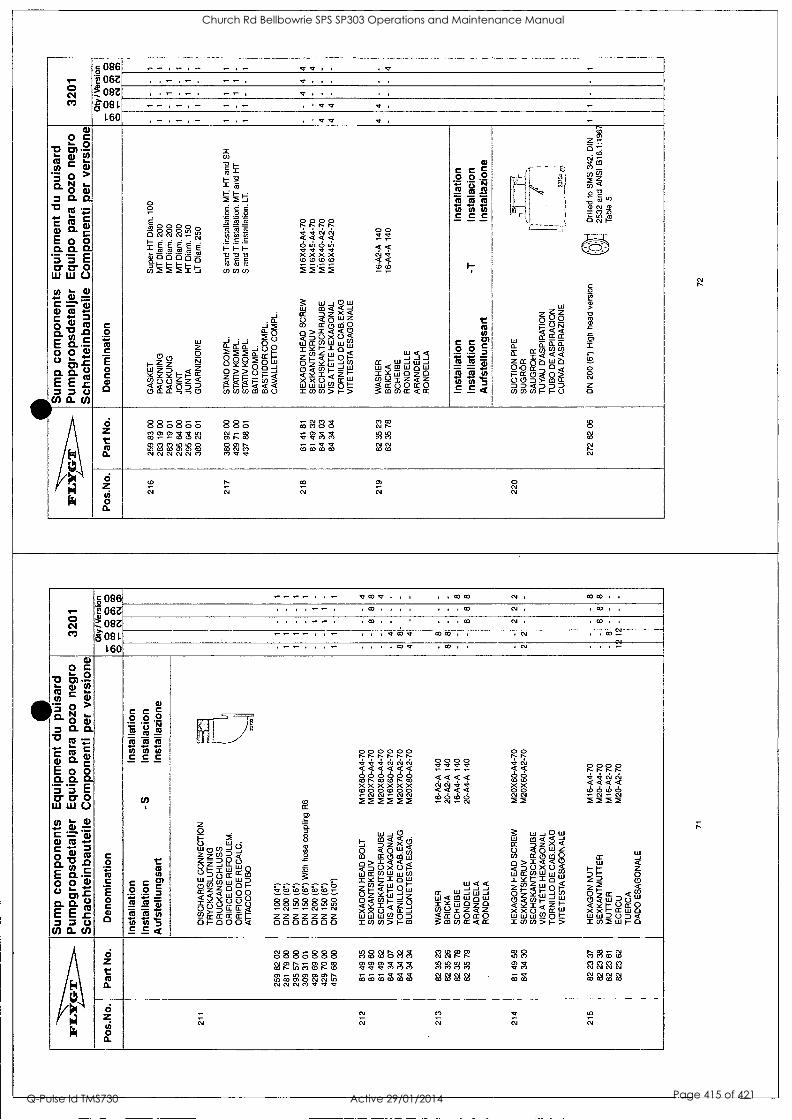
r- ° C1 ce)
2 086 L" 06Z 1301M -. gni.
460
-- . .- . .- 4 , . . c
, . - . - , --, cr .. . . . ,
, . - . - . - - . 4t . . . . . ,
- - , - , - _ , _ 3'.41. a, '-
- - . ...4- a nt . - 0 0 C L 0 '0 01 - a- ill co
a: E .05
N S 0 > a. N ).. 0 0 c CL Ct.
4. ..1.- C C 0
0- E o 0 O. O. O. L c = = ' Ill 111 (..)
0 " CD r 0 c - al
C 4-. 3 0 0 03 cl.V.,..0 . c E 0. .t... 00W o " .c sos Q .., - E E .c = = C.)
a. CO
c o :e as
C E J.,
0 0
0
Vc38800 ...,NNN'u, ts. 1- E E z E , .5 .5 .5 .e_ cg vpoo0.0 ''i-i-i-F-.- cn2 M M i 5
w z 0 00 RI 1- z z
w 2m <z . , o o _ z < < <OD oa_a,,o
x U)
'i 1-,2 x , i 1- ,_4 M M -J
oos
.1717 Ti
s s .E I- I- I- -,,,,,, 8 8 8 WWW
_i CI_
...i g a- o m 0
-, --, o CL.,CLCL_J00 .= M M o_ cc r 0 09920W o 0 _ o >>0 pp « a Pco> F- I- I- < < < wmcommo
0000 r-r-r-.N. 4466 < < < < 6666 NI.Tfd-ct xxxx w(000 - .-- ...-e- M M 2 2
3 w_iow w co a a -. IX D Z X < 0 <OWZ cr) cC 0 ai 0 <Doxor& 0000wrd IYI-I0 (r)z ui < Zi- < 1_0 ,n1- 0 Z Y'Lli DI - 0 ICO I- 1:U_ m<Zw xxo x WWWUJOI= xwm>,->
00 -a v- -- aa 64 as 66
W<< W_IW CC 0-J0_1 W<COW0W TX1.710Z0 w,,mz.tz < EuOcc0
co co cc a cc
as e c c opP 7., r, F71 al co to
TO To To' , c c c
I-
r as
C C a) 0 0 C = :i li = - - w "I ...., U) (1) = C C 4
w
w a w zwob 00CC,0,4 OOD>- DD<DDD cococol..-0
4- - -- kll 1
g N..,, '1
I
.
)
co oa
Z 7. -6 vi oi A c° CD (7) 2z u) <11 2 5 ,.,,
RoJo -,..-=2 ,-, cm I-
..... _
0 0 72
g."
-o fli r .. i r0 0 . cv Z o
_,
w Z z Z 0 0 _ 0 - Rio t-
1 EEE mmOm , < < < WO , in
'CO
I.
CIB
iii
6 Z co a.
885866 2?)523an S22 000 mmco NNN01010
886 (..,-. r-, co
QMr- wNcl M.11.
c70888 Zr-r $4'.'AA
W,-.-0.< WWW
co N Nr- 88 WW NN
8 8 cm r- CO
6 z f/i
13. 0
0 CO
r..
c;
CO
C.1
co 0 CO
7.1 Cs,
r 0 ( N J
CI
=N6 .2 e 06Z 3) - - 0 8 Z
ant. 460
-- .... .-- - aco.e... ,.00W CO t MWom . . . , -- . . ea . . . . . co N. J CO . J
. . . . -- . . c o . . . , . . m CO . . co . .
---- , . - .....4cov cow., . cm . . co ..- ea
oi ....cov . co . . ,N . . . -
0 0 C " -0 0) as C L U)
1.5 0 > r 0. N 6.
0 a) = 0- 0.
73 cs .- 4- ,t c C ... 0)
E 0 0 0- 0. 0- 3 '3 E cr cr 0
11.1 11.1 0 co L 0)
..-. 0
r = 0 .0 CO D. .0
CO c E 0.c 0 0 0
1- 4- o .0 CD 0. 0. ti/
E E .c 3 3 C.) 0 0. CA
C 0 IP ei C :-- t c0
4) 0
0 c e c 0 p o *t_ ,5 caR
To To t7)
.73 th tri
C C C
CO
t CO rb
C C It> 0 0 = 14 fly 43-
ru 75 ti ifs Th = c c cc
0 ix
F .- t o
8
03
.=
g ---- . . b
O w 0 0 cO 0 .-
885328,9 N.-J.-N0J zzzzzzz 0000000
m0000m NiNifiriiii: acrctmcmcm a a a a a a 666666 Of.WOPW xxxxxx 000)000 2 M 2 M 2 2
w w 0 1- c a a d < 0 < 0 U40) CO Cr 0 CO ui 0 > i a -a < < D C.) X 0 1- w cC cl) ui Lu c0 S Y I- 1 0 W cozw_I- Z J.- < J.- CJ w 0 z Y-w z,' z co a co 1- -cp <Yi<Z_, XX0 Ct_i WILI1110)0D ic0,051-co
0000 crcr.ctst - - - - 11<< 4 4 < < 6660' -6-6
ilia< -J -I -J
CC 0 .-111.1_J W<MWoW IcTiaz0 00mZ<Z <CC 0 0 cr 0 3 co w cc a ix
00 Pi':
as a a 66 Oa, xx 00 66 M M
Li,
ww0w 0.<<-1 CC D Z X < 0 <OWZ CO CC 010
J.9 i ...,00I JX 0w3 .93
wzii, a t.- e<1... OL, 0 z Y w :-.', LI 0 .¢ to 1- - ayi<z x >cc> cc P._ WWW0°'--- mww>1->
0000 0000 4.466 `,C<<< 6666 M M M M
Lii
w < , r z D 0 ZD cn
1_2 < 0 cc a Ci)
0 W 0 a 1-0c0 XX,MWD WWDOD< x co 2 w 1.- 0
I
z o
to - 000 -I 0 , Z z CO z Duo Z _1 U- w 1-mW...0
D 0 ct u- WWwwWD °V.ZO°1- CC .,-- < w 0 0 <2Y05° I 0 V- -0 0,_,Li_u_< u)fr-ccEEEr 5,-000
N
6 Z
CI a
8886888 Nmtmoco .0 f U, Co co r- co
mm .- m0omN NN Nth NNNM,r<v
88868A Z'WF4-CAAg cOCE/r6ggg
MOWM NNI...-1.--
8882 WW NNNN WW
WO ,om glA
a
c%268 mmmm cv cm cm cm
cmmoiN co CO co W
gui
0 N
CO
CO
co
CO
ar
CO
to CO
Church Rd Bellbowrie SPS SP303 Operations and Maintenance Manual
Q-Pulse Id TMS730 Active 29/01/2014 Page 415 of 421

iFia
rGir
.
Sum
p co
mpo
nent
s E
quip
men
t du
pu
isar
d P
umpg
rops
deta
ljer
Equ
ipo
para
poz
o ne
gro
Sch
acht
einb
aute
ile C
ompo
nent
i pe
r ve
rsio
ne
3201
Pos
.No.
P
art N
o.
Den
omin
atio
n O
ty/V
ersi
on
g O
g 2
ig 2
0
r- C
4 C
NI
CO
220.
1 81
52
49
H
EX
AG
ON
HE
AD
SC
RE
W
4 4
- 4
SE
XK
AN
TS
KR
UV
S
CH
RA
UB
E
VIS
T
OR
NIL
LO
VIT
E E
SA
GO
NA
LE
220.
2 27
4 45
00
CLE
AN
ING
DO
OR
1
1 -
- 1
RE
NS
LUC
KA
R
EIN
IGU
NG
SD
EC
KE
L R
EG
AR
D D
E N
ET
TO
YA
GE
P
UE
RT
A D
E L
IMP
IEZ
A
PO
RT
A P
ULI
TU
RA
220.
3 27
4 48
00
GA
SK
ET
1
1 -
1
PA
CK
NIN
G
PA
CK
UN
G
JOIN
T
JUN
TA
G
UA
RN
IZIO
NE
220
272
82 0
7 D
N 2
00 (
6")
Hig
h he
ad v
ersi
on
i T
Drib
Illed
ltio
BS
462
2:19
70
1 1
- -
1
220.
1 81
52
49
HE
XA
GO
N H
EA
D S
CR
EW
4
4 -
- 4
SE
XK
AN
TS
KR
UV
S
CH
RA
UB
E
VIS
T
OR
NIL
LO
VIT
E E
SA
GO
NA
LE
220.
2 27
4 45
00
CLE
AN
ING
DO
OR
1
1 -
- 1
RE
NS
LUC
KA
R
EIN
IGU
NG
SD
EC
KE
L R
EG
AR
D D
E N
ET
TO
YA
GE
P
UE
RT
A D
E L
IMP
IEZ
A
PO
RT
A P
ULI
TU
RA
220.
3 27
4 48
00
GA
SK
ET
1
1 -
1
PA
CK
NIN
G
PA
CK
UN
G
JOIN
T
JUN
TA
G
UA
RN
IZIO
NE
220
320
06 0
1 O
N 4
00 (
161
Low
hea
d ve
rsio
n D
rille
d to
SM
S 3
42 a
nd
1 1
- -
1
DIN
25
32
73
IFIL
Art
Glr
Sum
p co
mpo
nent
s E
quip
men
t du
pu
isar
d P
umpg
rops
deta
ljer
Equ
ipo
para
poz
o ne
gro
Sch
acht
einb
aute
ile
Com
pone
nti
per
vers
ione
32
01
Pos
.No.
P
art N
o.
Den
omin
atio
n O
ty/V
ersi
on
000C
r) c
o 0 C
O
CO
C
O
0 - C
NI
01
435
220.
1 81
41
55
H
EX
AG
ON
HE
AD
SC
RE
W
4 4
- -
SE
XK
AN
TS
KR
UV
S
CH
RA
UB
E
VIS
T
OR
NIL
LO
VIT
E E
SA
GO
NA
LE
220.
2 32
0 19
00
CLE
AN
ING
DO
OR
1
1 -
-
RE
NS
LUC
KA
R
EIN
IGU
NG
SD
EC
KE
L R
EG
AR
D D
E N
ET
TO
YA
GE
P
UE
RT
A D
E L
IMP
IEZ
A
PO
RT
A P
ULI
TU
RA
220.
3 32
0 07
00
GA
SK
ET
1
1 -
-
PA
CK
NIN
G
PA
CK
UN
G
JOIN
T
JUN
TA
G
UA
RN
IZIO
NE
220.
4 82
71
78
PLU
G
1 1
- -
PR
OP
P
PF
RO
PF
EN
B
OU
CH
ON
T
AP
ON
T
AP
PO
/ S
PIN
A
220
320
06 0
5 D
N 40
0 (1
6")
Low
hea
d ve
rsio
n /k
Dril
led
to A
NS
I 01
6.1:
1967
1
1 -
-
V.;)
_ T
able
5
220.
1 81
41
55
H
EX
AG
ON
H
EA
D S
CR
EW
4
4 -
-
SE
XK
AN
TS
KR
UV
S
CH
RA
UB
E
VIS
T
OR
NIL
LO
VIT
E E
SA
GO
NA
LE
220.
2 32
0 19
00
C
LEA
NIN
G D
OO
R
1 1
-
RE
NS
LUC
KA
R
EIN
IGU
NG
SD
EC
KE
L R
EG
AR
D D
E N
ET
TO
YA
GE
P
UE
RT
A D
E L
IMP
IEZ
A
PO
RT
A P
ULI
TU
RA
220.
3 32
0 07
00
GA
SK
ET
1
1 -
-
PA
CK
NIN
G
PA
CK
UN
G
JOIN
T
JUN
TA
G
UA
RN
IZIO
NE
74
Church Rd Bellbowrie SPS SP303 Operations and Maintenance Manual
Q-Pulse Id TMS730 Active 29/01/2014 Page 416 of 421

FLY
GT
.
Sum
p co
mpo
nent
s E
quip
men
t du
pu
isar
d P
umpg
rops
deta
ljer
Equ
ipo
para
poz
o ne
gro
Sch
acht
einb
aute
ile
Com
pone
nti
per
vers
ione
32
01
Pos
.No.
P
art N
o.
Den
omin
atio
n O
ty /
Ver
sion
.-
000
0 O
c0
c0
cr)
ca
0 .-
Csl
C
V
a>
220.
4 82
71
78
PLU
G
1 1
- 1
PR
OP
P
PF
RO
PF
EN
B
OU
CH
ON
T
AP
ON
T
AP
PO
/SP
INA
220
320
06 0
7 D
N
400
(16"
) Lo
w h
ead
vers
ion
lDril
led
to
BS
450
4:19
69
1 1
- 1
Tab
le 5
220.
1 81
41
55
H
EX
AG
ON
HE
AD
SC
RE
W
4 4
- -
4 S
EX
KA
NT
SK
RU
V
SC
HR
AU
BE
V
IS
TO
RN
ILLO
V
ITE
ES
AG
ON
ALE
220.
2 32
0 19
00
CLE
AN
ING
DO
OR
1
1 -
- 1
RE
NS
LUC
KA
R
EIN
IGU
NG
SD
EC
KE
L R
EG
AR
D D
E N
ET
TO
YA
GE
P
UE
RT
A D
E L
IMP
IEZ
A
PO
RT
A P
ULI
TU
RA
220.
3 32
0 07
00
GA
SK
ET
1
1 -
- 1
PA
CK
NIN
G
PA
CK
UN
G
JOIN
T
JUN
TA
G
UA
RN
IZIO
NE
220.
4 82
71
78
PLU
G
1 1
- 1
PR
OP
P
PF
RO
PF
EN
B
OU
CH
ON
T
AP
ON
T
AP
PO
/SP
INA
220
381
77 0
1 D
N
250
(10"
) M
ediu
m h
ead
vers
ion
i D
rille
d to
SM
S 3
42 a
nd
1 1
- -
1
' D
IN 2
532
220.
1 81
41
56
H
EX
AG
ON
H
EA
D S
CR
EW
M
12x3
5-A
2-70
4
4 -
- 4
SE
XK
AN
TS
KR
UV
S
CH
RA
UB
E
VIS
T
OR
NIL
LO
VIT
E E
SA
GO
NA
LE
75
EIL
IVIG
T
Sum
p co
mpo
nent
s E
quip
men
t du
pu
isar
d P
umpg
rops
deta
ljer
Equ
ipo
para
poz
o ne
gro
Sch
acht
einb
aute
ile
Com
pone
nti
per
vers
ione
32
01
Pos
.No.
P
art N
o.
Den
omin
atio
n Q
ty /V
ersi
on
r-00
00
0)
CO
C
O
0)
CO
0
,--
CM
C
s1 al
220.
2 27
4 45
01
CLE
AN
ING
DO
OR
1
1 -
- 1
RE
NS
LUC
KA
R
EIN
IGU
NG
SD
EC
KE
L R
EG
AR
D D
E N
ET
TO
YA
GE
P
UE
RT
A D
E L
IMP
IEZ
A
PO
RT
A P
ULI
TU
RA
220.
3 27
4 48
00
GA
SK
ET
1
1 -
- 1
PA
CK
NIN
G
PA
CK
UN
G
JOIN
T
JUN
TA
G
UA
RN
IZIO
NE
220
381
77 0
5 D
N 25
0 (1
0°)
Med
ium
hea
d ve
rsio
n O
;
Dril
led
to A
NS
I B
16.1
:196
7 !
Tab
le
5
1 1
- -
1
220.
1 81
41
56
H
EX
AG
ON
H
EA
D S
CR
EW
M
12x3
5-A
2-70
4
4 -
- 4
SE
XK
AN
TS
KR
UV
S
CH
RA
UB
E
VIS
T
OR
NIL
LO
VIT
E E
SA
GO
NA
LE
220.
2 27
4 45
01
CLE
AN
ING
DO
OR
1
1 -
- 1
RE
NS
LUC
KA
R
EIN
IGU
NG
SD
EC
KE
L R
EG
AR
D D
E N
ET
TO
YA
GE
P
UE
RT
A D
E L
IMP
IEZ
A
PO
RT
A P
ULI
TU
RA
220.
3 27
4 48
00
GA
SK
ET
1
1 -
- 1
PA
CK
NIN
G
PA
CK
UN
G
JOIN
T
JUN
TA
G
UA
RN
IZIO
NE
220
381
77 0
7 D
N
250
(10"
) M
ediu
m h
ead
vers
ion
Dril
led
to B
S 4
622:
1970
1
1 -
- 1
, T
able
11
220.
1 81
41
56
H
EX
AG
ON
H
EA
D S
CR
EW
M
12x3
5-A
2-70
4
4 -
- 4
SE
XK
AN
TS
KR
UV
S
CH
RA
UB
E
VIS
T
OR
NIL
LO
VIT
E E
SA
GO
NA
LE
76
Church Rd Bellbowrie SPS SP303 Operations and Maintenance Manual
Q-Pulse Id TMS730 Active 29/01/2014 Page 417 of 421

81
31AN
YT
IV.0 ,viiN
n viN
tiviv 30 1V1.11N
30 34,11:1V
1V 30 31V
1:11N30
31V81N
3Z1111:1V
1V
1V1:11N
3O1 O:N
1 1
1 1
1 I-
II uSV
ON
11114 lIN
fl 1411:1V
1V
LS 89 C
8 00£
3N01Z
11012:1 la owl.
OO
VH
ON
I1S 30
V1:13110N
V11
30%1131:1d 30 nvA
ni H
ontr1HO
SJcIM
EIH
OS
0N
V1S
dINA
HN
4.0
4.6 01 3901-1)1N
D:11-1S
8L 00 £6
l£Z
CO
IV
IV
- ID
C
O
CO
C
O
CO
C
D
0000-, U
OIM
OIW
OO
ea O
N lied
'ON
'SO
d uoisnA
titto auolsaan
_lad guauodwo3 analnequppiom
ps L
OZ
E
0.160U ozod end odrib3
Jaheopsdoa6dLund pm
s!nd np luatudob3
siusuodwoo dw
nqi, ,LO
Aia
LI.
0A1S
3avoinv O
CIT
IOO
ND
VIN
VI:Id
J1831-10%1
NV
43111:1
N3d131.1193931>
i 1V
>130
1 1
1 1
1 1:J3)10119
10 04 L99 6Z
Z
01W-110-11113S
01N
3IVItrld0O
V R
AM
S
IN31,1131dn000v
11,1139
3.13lYH
SO
NIT
Iddn>1
1 -
- 1
- .,9
1:1 V
A1V
H9O
NIlddO
N
9£ 61 £9
.a 11:1V
d ON
Ildnoo 8Z
91 98
LeZ
- -
- Z
1 el 0L-Z
V-06X
0MA
I '0V
S3 V
iS3.1.3N
oTine
se be 49
- -
- 8
8 O
L-ZN
Y-O
SX
0M
OV
X313V
0 30 0111Nb101
Fle be
178
0L-N-O
LX9101
1VN
00VX
3H 3131V
SIA
60
PC
178
Z1
- -
- -
OL-4V
-06X0M
39114/8H
OS
INV
>iS
HO
3S
£9 S
S
19
0L-17V-09X
06141 A
lltDIS
1NIV
NX
3S
95 60 48
8 0L-17V
-OLX
9 1 IN
1108 0,413H
N
OO
VX
31-1 LE
64 19
ZiZ
3 NO
IZIN
iono viN
nr IN
IOr
t -
- t
I 04Z
tue!O
O
N0>
10Vd
00 tt, SP
E
t -
l I
006 'tlie!O
ON
INN
3Vd
00 91 VIZ
-
- l
I. 04 N
d 00E .u1u10
.13)1SV
O
08 S
9 48 166
3NO
IZIN
I:IVf10
VIN
nr .LN
1Cr
ON
11)43Vd
ON
IN>
10Vd
1 -
- 1
1 J3N
SV
O
00 84 Pa
6.076
VIdninnd V
.LdOd
VZ
31dINI1 30 V
11:13rld 30V
A0113N
30 01:1V038
13)1030S0N
r1eIN131:1
V>
10111SN
31:1 1
- -
1 1
1:1000 ON
INV
310 10
SO
Pa
7'076
CD
N
IV -. 0
CO
C
D
CO
O
D
CD
0000-,
uogeultuouoa 'oN
Ind 'oN
'SO
d uom
IGA
/Am
OuO
ISilan Jed guauodw
o3 apinequmm
oeyos L
OZ
E
0.16OU
ozod end ()climb]
JafielapsdoAdLund
paesiind np tuawd!nb3
swauoduuo3 (R
uns 1,0A
-rid(
Church Rd Bellbowrie SPS SP303 Operations and Maintenance Manual
Q-Pulse Id TMS730 Active 29/01/2014 Page 418 of 421

IFL
YG
'r R
ecom
men
ded
spar
e pa
rts
3201
80 3
2 79
601
89
32
IS K
IT
IS S
AT
S
IS S
AT
Z
JEU
DE
IS
JU
EG
O D
E I
S
BA
SIC
RE
PA
IR K
IT
GR
UN
DR
EP
AR
AT
ION
SS
AT
S
GR
UN
DR
EP
AR
AT
UR
SA
TZ
K
IT P
ALI
ER
JU
EG
O B
AS
ICO
DE
RE
P.
KIT
DI
RIP
AR
AZ
ION
E
I= I
nter
med
iate
Ser
vice
Kit;
par
ts f
or I
nspe
ctio
n an
d m
aint
enan
ce
1= In
term
edia
te S
ervi
ce K
it; a
rtik
lar
for
insp
ektio
n oc
h un
derh
all
1= In
term
edia
te S
ervi
ce K
it; T
elle
10r
Kon
trol
le a
nd W
artu
ng
I= I
nter
med
iate
Ser
vice
Kit;
pie
ces
pour
ins
pect
ion
at m
aint
enan
ce
1=
Inte
rmde
iate
Ser
vice
Kit;
pie
zas
pare
ins
pect
ion
y m
ante
nim
ient
o I_
In
term
edia
te S
ervi
ce K
it; p
arti
per
ispe
zion
e e
man
teni
men
to
B=
Bas
ic R
epai
r K
it;
part
s fo
r m
ajor
ove
rhau
l 13
= B
asic
Rep
air
Kit;
ar
tikla
r for
ste
rre
geno
mga
ng
B=
Bas
ic
Rep
air
Kit;
Tei
le f
ar G
ener
alO
berh
olun
g
B=
Bas
ic R
epai
r K
it; p
iece
s po
ur r
evis
ion
com
plet
e B
= B
asic
Rep
air
Kit;
pie
zas
pars
re
visi
ones
impo
rtan
tes
B=
Bas
ic R
epai
r K
it;
part
i pe
r re
visi
oni
com
plet
e
Sta
ndar
d 31
70/3
201.
090/
091/
120/
180
3170
.090
/180
+32
01.0
91/1
80
800
IWT
ER
ICO
IAT
E S
EP
VIT
,g,
900
e em
R.4
,,,re
] s
CO
s
Item
No.
P
art
No.
I Den
omin
atio
n Q
ty
Item
No
Par
t No.
B
Den
omin
atio
n O
ty
33
82 7
4 93
0-
RIN
G
1 80
0 80
32
79
0-R
ING
KIT
1
(Ent
ranc
e co
ver)
72
82
75
01
0-R
ING
1
58
319
09 0
1 C
OV
ER
1
(Sta
tor
hous
ing)
83
82
75
05
0-R
ING
1
61
84 5
3 76
R
OLL
ER
BE
AR
ING
1
(Coo
ling
jack
et)
84
82 7
8 80
0-
RIN
G
1 63
56
3 93
00
PR
OT
EC
TIV
E W
AS
HE
R
1
(Coo
ling
jack
et)
122
, 82
73
90
0-R
ING
1
109
83 3
6 98
B
ALL
BE
AR
ING
1
82 7
3 93
(I
nspe
ctio
n sc
rew
) 11
4 28
8 10
04
ME
CH
AN
ICA
L S
EA
L 1
137
382
83 0
0 W
EA
R P
RO
TE
CT
ION
1
141
384
03 0
7 M
EC
HA
NIC
AL
SE
AL
1
79
Rec
omm
ende
d sp
are
part
s 32
01
Item
No
Par
t N
o.
Den
omin
atio
n Q
ty
122
82 7
7 30
0-
RIN
G
1
(Ins
pect
ion
scre
w)
130
82 7
5 08
0-
RIN
G
1
(Pum
p ho
usin
g)
131
82 7
5 09
0-
RIN
G
1
(Pum
p ho
usin
g)
132
646
59 0
0 P
acki
ng C
ompl
. 1
(Coo
ling
syst
em)
160
384
79 0
0 P
acki
ng
1
(Im
pelle
r sc
rew
) 16
1 82
74
65
0-R
ING
1
(Im
pelle
r sc
rew
)
80
Church Rd Bellbowrie SPS SP303 Operations and Maintenance Manual
Q-Pulse Id TMS730 Active 29/01/2014 Page 419 of 421

IFIL
IDE
VIr
.....
Par
ts f
or S
ervi
ce
3201
Qty
/ Ver
sion
P
os.N
o.
Par
t No.
D
enom
inat
ion
e...0
000
CO
0 C
T)
CO
C
O
Or-
CV
C
V
CI)
901
90 1
7 52
P
AR
AF
FIN
OIL
M
OB
IL O
IL W
HIT
ER
EX
309
7.
5 P
AR
AF
FIN
OLJ
A
PA
RA
FF
IN&
H
UIL
E D
E P
AR
AF
FIN
E
AC
EIT
E D
E P
AR
AF
INA
O
LIO
DI
PA
RA
FF
INA
902
90 2
0 54
B
EA
RIN
G G
RE
AS
E
ES
SO
UN
IRE
X N
3 LA
GE
RF
ET
T
LAG
ER
FE
TT
G
RA
ISS
E A
RO
ULE
ME
NT
G
RA
SA
DE
CO
JIN
ET
E
GR
AS
SO
CU
SC
INE
TT
I
Too
ls
Ran
ge o
f us
e
8206
60
SO
CK
ET
HE
AD
SC
RE
W
SC
RE
W M
12X
140
ST
-CU
RV
ES
: X63
-X65
(TO
GE
TH
ER
W. 84
1363
)
8230
90
LIF
TIN
G E
YE
BO
LT
LIF
T P
UR
PO
SE
8230
91
LIF
TIN
G E
YE
BO
LT
340K
GS
. LI
FT
PU
RP
OS
E
8230
92
LIF
TIN
G E
YE
BO
LT
700K
GS
. R
OT
OR
8408
02
CIR
CLI
P P
LIE
R
SG
A 1
9-60
mm
S
EA
L
8408
10
CIR
CLI
P P
LIE
R
SG
H 4
0-10
0mm
IN
NE
R B
EA
RIN
G
8410
16
RA
TC
HE
T
HA
ND
LE
1/2"
DR
IVE
S
OC
KE
TS
8411
35
CO
MB
INA
TIO
N W
RE
NC
H
N=
8mm
C
AB
LE R
ELI
EF
, H
D-A
DJU
ST
ING
, O
UT
.EA
RT
H IN
G
8411
45
CO
MB
INA
TIO
N W
RE
NC
H
N=
30m
m
HD
-AD
JUS
TIN
G
8412
30
TR
IAN
GU
LAR
WR
EN
CH
M
12
TR
IAN
GU
LAR
HE
AD
SC
RE
WS
(.
120E
X)
8413
01
HE
XA
GO
N B
IT A
DA
PT
OR
N
=14
mm
IM
P.S
CR
EW
(NO
T S
T),
PU
MP
HS
G.
81
'WV
VI if
iGIT
P
arts
for
Ser
vice
32
01
Qty
/Ver
sion
P
os.N
o.
Par
t No.
D
enom
inat
ion
,000
0 0
03
CO
C
O
CO
,-
CN
ICV
CD
8413
03
HE
XA
GO
N B
IT A
DA
PT
OR
N
=S
mm
C
OO
LIN
G S
HU
TT
ING
OF
F,
CA
BLE
RE
LIE
F(E
X)
8413
05
HE
XA
GO
N B
IT A
DA
PT
OR
,
N =
Bm
m
OIL
HS
G, B
OT
TO
M
8413
06
HE
XA
GO
N B
IT A
DA
PT
OR
N
=10
mm
JU
NC
TIO
N B
OX
CO
VE
R,
ST
AT
OR
HS
G.
8413
60
PU
LLE
R C
OM
PL.
S
PR
D20
0/R
CH
150
BE
AR
ING
8413
61
AR
M
JAW
EX
TE
NS
ION
B
EA
RIN
G (
TO
GE
TH
ER
W. 8
4136
0)
8413
63
PU
LLE
R C
OM
PL.
S
P R
D30
0/R
CH
300
ST
-CU
RV
ES
: X63
-X65
(T
OG
ET
HE
R W
. 82
0660
)
8413
84
SO
CK
ET
WR
EN
CH
N
=10
mm
T
ER
MIN
ALS
(.0
90F
M,
.120
EX
)
8413
87
SO
CK
ET
WR
EN
CH
N
=13
mm
T
ER
MIN
AL
BO
AR
D
8413
91
SO
CK
ET
WR
EN
CH
N
=18
mm
C
AB
LE E
NT
RY
8413
92
SO
CK
ET
WR
EN
CH
N
=19
mm
IN
SP
.SC
RE
W T
OO
L (E
X-V
ER
SIO
N)
8413
95
SO
CK
ET
WR
EN
CH
N
=16
mm
IN
SP
.SC
RE
W,
BE
AR
ING
CO
VE
R
8413
96
SO
CK
ET
WR
EN
CH
N
=24
mm
O
IL-P
LUG
, LI
FT
HA
ND
LE
8415
51
EX
TE
NS
ION
BA
R
1/2"
D
RIV
E
IMP
.SC
RE
W
8415
64
TO
RQ
UE
WR
EN
CH
60
-320
N m
TO
RQ
UE
TIG
TH
EN
ING
8416
50
SC
RE
WD
RIV
ER
T
IP=
1.2X
8.0m
m
TE
RM
INA
LS, C
OO
LIN
G V
EN
T T
UB
E
8416
60
SC
RE
WD
RIV
ER
T
IP=
1.0X
5.5m
m
CA
BLE
RE
LIE
F
8416
73
SC
RE
WD
RIV
ER
T
IP=
1.6X
10.0
mm
T
ER
MIN
ALS
, CLS
-SE
NS
OR
82
Church Rd Bellbowrie SPS SP303 Operations and Maintenance Manual
Q-Pulse Id TMS730 Active 29/01/2014 Page 420 of 421

Pmuki 8V19A1311.1* COTO 'IN( 11.0 1,0 'L0'1.0Z£
eopuos JO) sped
T. 0 ty (")
= 086 E 06Z >) .... 08Z 5 >. On
L60
0) o .- > a)
Cl) L 0 FI W .. i CO
0. c 0 tr. to c - E
C 41)
CI
cm 0 x g x iti w
E> EM
CO D COY
:II 2
I- Z D CC 111 _1 _1 D a. cc w -I CO
0.W 0 CC 2 0
si .°,
x". >5
6 c'i; ;-, x eri 6 w
E w.... > E.Ecr
CO ,r -09 01 0 3 t'.1 5
I- Z D CC w _1 _J D a cc w _I 0 W 0 0-
CC 2 0
A x >c
A A x x wow eri w o w
E ,.0 > Ell"-cc OD..6 D 0 9 u-) 0 .1 ,- 3 3 li
I- I- Z Z D D Cr CC CO w _I _i _I _I n D a a. cc c w w _I (f) _I CJ)
CL CL CL CC CC 2020
E E Ln CO
7 _I
w
ILI < _I LLI co cn
-03'
,,,a' =, X 41
_ c0 cm --- s CO tyi w i
1- CO D o °W0 i 13 b
o_ < 1-
6 c' 0 P V ,L CO
N
V) w tu I
ui D o 00 /3 b
cc 11.1
Cl)
< 3
cr w
0 0 0 Z < Ili m EC w Z Z
cr w __/ D a
cn co 8 x
N /- =x 0 CL co"
OW o > Tr cc
CCU CL CO -1
_i CL
0 0 cc w _I D a
CO
< 11.1
CO
CC CO
3 a_ _1 < w CL Co
_I < Lil co
cc W _I _, D a_
(.1 z Fr CL co
z 0 Ft) CO CO
? 6 w
0 F-
w CC
co0 c co z
-J 0 0 1-
cc 0 co
0 z E 71 0 E S < T 1
cr cs, 0
o 1.7( pi- _ co
w CO _I _1 D a CC 0 I- < I- 0
E E o
te 11
_1
I- CO
CO
0 z p z
< OW 2a)
E E
Ln
1, _1
CO
W < _JW cn cn
E E 10 cn
co II
_I
I- CO Y 8 co 0 z P z D < OW m co
/ENI\ 0 ki ii Ril
6 Z
g
O 0 N co o CO
N cm 0 C3 co CO cn CO
.:1- 0 0 0 0 co co o co cn a, co CO
o 0 on Tr- co cn CO
0 0 co co co n Tr
0 0 Tr CO CO n Tr
0 0 co 0 o o Ln
CD Tr O co Tr CO
0 0 CO CO o vc;
0 0 Cin- co o CO
EI (0 co on oo CO
0 0 0 N cr,' CO
o 0 cr N CO m CO
o 0 cn Ln o cn CO
0 0 0 CO co Ci CO
6 Z ui 0 O.
co co
Church Rd Bellbowrie SPS SP303 Operations and Maintenance Manual
Q-Pulse Id TMS730 Active 29/01/2014 Page 421 of 421