
Lloyd St Aspley SPS Backup Generator Set OM Manual
339
MEN 11=3 CI W IE IR OPERATION & MAINTENANCE MANUALS For BRISBANE CITY COUNCIL At BRISBANE WATER SEWAGE PUMP STATION ASPLEY - LLOYD STREET Manuals Prepared by: S E Power Equipment 47 Proprietary Street Tingalpa, Qld 4173 Phone No. 07 3890 1744 Copyright © 2002 All Rights Reserved REVISION A: September 2007 Lloyd St Aspley SPS Backup Generator Set OM Manual Q-Pulse Id TMS1098 Active 10/12/2014 Page 1 of 339
-
Upload
khangminh22 -
Category
Documents
-
view
0 -
download
0
Transcript of Lloyd St Aspley SPS Backup Generator Set OM Manual
MEN
11=3 CI W IE IR
OPERATION & MAINTENANCE MANUALS
For
BRISBANE CITY COUNCIL
At
BRISBANE WATER SEWAGE PUMP STATION ASPLEY - LLOYD STREET
Manuals Prepared by:
S E Power Equipment 47 Proprietary Street Tingalpa, Qld 4173
Phone No. 07 3890 1744
Copyright © 2002 All Rights Reserved
REVISION A: September 2007
Lloyd St Aspley SPS Backup Generator Set OM Manual
Q-Pulse Id TMS1098 Active 10/12/2014 Page 1 of 339
OPERATION and MAINTENANCE MANUALS
Revision Status
Revision Date Initials Comments
A 13.09.07 JP Issued for approval
Prepared by: Jim Pringle Date: 13 / 09 / 07
Reviewed by: Project Manager: Date: / /
16041_Brisbane_Water_O&M_Manual_Aspley.doc Page 2 of 4
Lloyd St Aspley SPS Backup Generator Set OM Manual
Q-Pulse Id TMS1098 Active 10/12/2014 Page 2 of 339
OPERATION and MAINTENANCE MANUALS
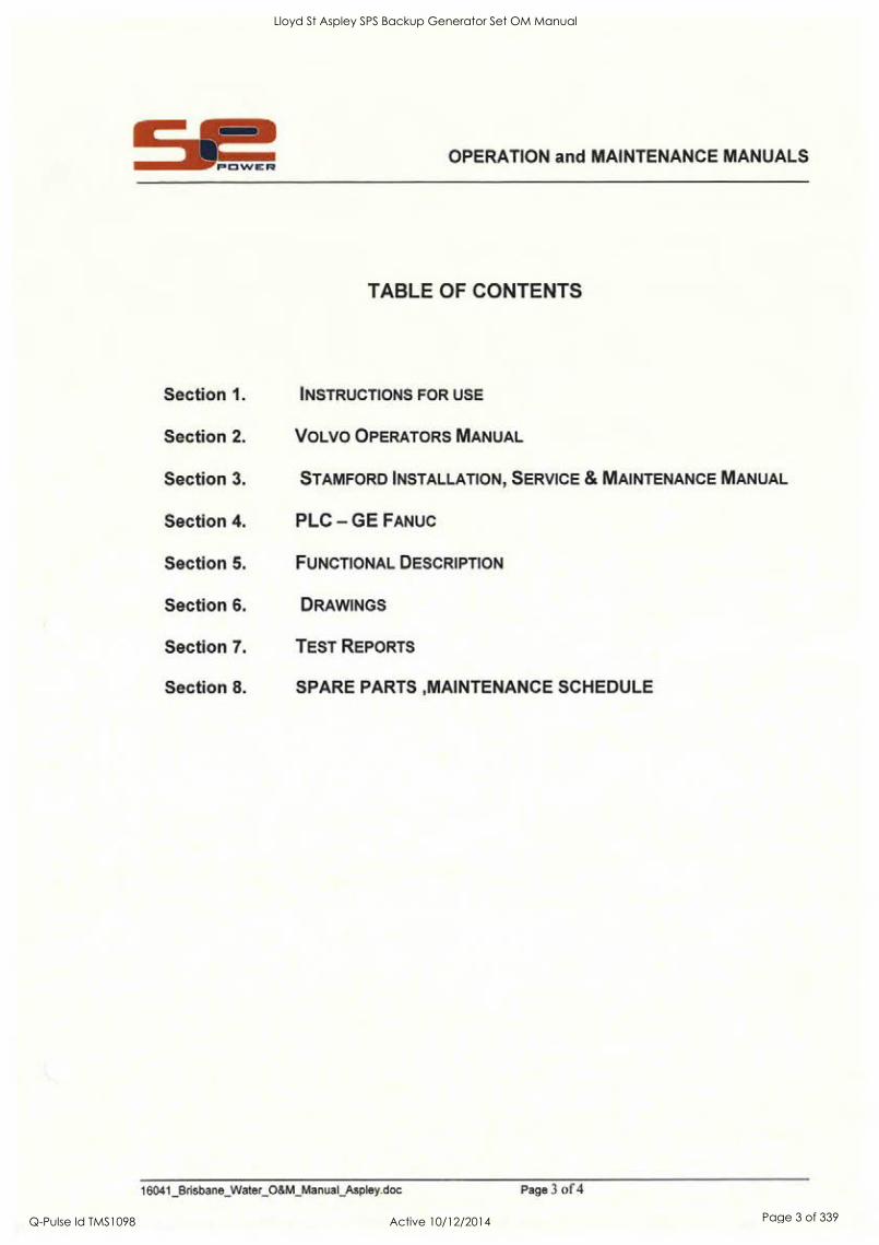
TABLE OF CONTENTS
Section 1. INSTRUCTIONS FOR USE
Section 2. VOLVO OPERATORS MANUAL
Section 3. STAMFORD INSTALLATION, SERVICE & MAINTENANCE MANUAL
Section 4. PLC - GE FANUC
Section 5. FUNCTIONAL DESCRIPTION
Section 6. DRAWINGS
Section 7. TEST REPORTS
Section 8. SPARE PARTS ,MAINTENANCE SCHEDULE
16041_Brisbane_Water_O&M_Manual_Aspley.doc Page 3 of 4
Lloyd St Aspley SPS Backup Generator Set OM Manual
Q-Pulse Id TMS1098 Active 10/12/2014 Page 3 of 339

I I
s I
Lloyd St Aspley SPS Backup Generator Set OM Manual
Q-Pulse Id TMS1098 Active 10/12/2014 Page 4 of 339

II
Lloyd St Aspley SPS Backup Generator Set OM Manual
Q-Pulse Id TMS1098 Active 10/12/2014 Page 5 of 339

OPERATION and MAINTENANCE MANUALS
INSTRUCTIONS FOR USE
1 Units placed on site using Crane Truck or Mobile Crane..
2. Cable pit to be under switchboard section of unit (rear).
3. Attach hold down / anti-theft chains to location points at rear of unit (beside switchboard).
4. Check engine lube oil level.
5. Check engine coolant level.
6. Check the battery is connected and the electrolyte level is correct.
7. Connect cables to plugs via colour-coded sequence.
8. Connect power inlet socket (240V).
9. Connect communication socket.
10. Connect pump station control socket.
11. Check fuel level (mechanical gauge beside fill point).
12. Refer to section 5, Functional Description for start/run and connection procedure.
13. Remember SAFETY is important ALWAYS wear your Personal Protection Equipment (PPE)
16041_Brisbane_Water_O&M_Manual_Aspley.doc Page 4 of 4
Lloyd St Aspley SPS Backup Generator Set OM Manual
Q-Pulse Id TMS1098 Active 10/12/2014 Page 6 of 339

II
I
8
e
Lloyd St Aspley SPS Backup Generator Set OM Manual
Q-Pulse Id TMS1098 Active 10/12/2014 Page 7 of 339

e S
S
I
S
9
Lloyd St Aspley SPS Backup Generator Set OM Manual
Q-Pulse Id TMS1098 Active 10/12/2014 Page 8 of 339

OPERATOR'S MANUAL Generating set and industrial engines
16 liter (EMS 2)
Lloyd St Aspley SPS Backup Generator Set OM Manual
Q-Pulse Id TMS1098 Active 10/12/2014 Page 9 of 339

Foreword Volvo Penta industrial engines are relied upon throughout the world, in both mobile and stationary applications, under some of the most rigorous conditions imaginable. This is not by chance.
After more than 90 years of producing engines the name Volvo Penta has come to symbolize reliability, technical ingenuity, first-class perfor- mance and longevity. We believe that these characteristics are also ultimately your requirements and expectations for new Volvo Penta industrial engines.
To make certain that your expectations are matched, we ask that you read carefully through the instruction book before starting the engine.
Sincerely
AB VOLVO PENTA
Engine data
Engine designation Product number
Serial number
Clutch, type/nr.
Nearest Volvo Penta service location
Name Telephone
Address
© 2007 AB VOLVO PENTA Volvo reserves the right to make changes Printed on environmentally friendly paper
Lloyd St Aspley SPS Backup Generator Set OM Manual
Q-Pulse Id TMS1098 Active 10/12/2014 Page 10 of 339
.6 le of content
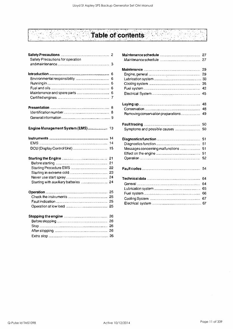
Safety Precautions 2 Maintenance schedule 27 Safety Precautions for operation Maintenance schedule 27 and maintenance 3
Maintenance 29 Introduction 6 Engine, general 29 Environmental responsibility 6 Lubrication system 33 Running in 6 Cooling system 35 Fuel and oils 6 Fuel system 42 Maintenance and spare parts 6 Electrical System 45 Certified engines 7
Laying up 48 Presentation 8 Conservation 48
Identification number 8 Removing conservation preparations 49 General information 9
Fault tracing 50 Engine Management System (EMS) 13 Symptoms and possible causes 50
Instruments 14 Diagnostics function 51
EMS 14 Diagnostics function 51
DCU (Display Control Unit) 15 Messages concerning malfunctions 51
Effect on the engine 51
Starting the Engine 21 Operation 52
Before starting 21
Starting Procedure EMS 22 Fault codes 54 Starting in extreme cold 23 Never use start spray 24 Technical data 64 Starting with auxiliary batteries 24
General 64 Lubrication system 65
Operation 25 Fuel system 66 Check the instruments 25
Cooling System 67 Fault indication 25 Electrical system 67 Operation at low load 25
Stopping the engine 26
Before stopping 26 Stop 26
After stopping 26
Extra stop 26
Lloyd St Aspley SPS Backup Generator Set OM Manual
Q-Pulse Id TMS1098 Active 10/12/2014 Page 11 of 339
Safety Precautions
Read this chapter very carefully. It has to do with your safety. This describes how safety precaution is presented in the Operators Manual and on the product. It also gives you an introduction to the basic safety rules for using and looking after the engine.
Check that you have received the correct operator's manual before you read on. If not, please contact your Volvo Penta dealer.
Incorrect operation can lead to personal injury and damage to products or property. So read the Operators Manual through very carefully before you start the engine or do any maintenance or service. If there is still something which is unclear or if you feel unsure about it, please contact your Volvo Penta dealer for assistance.
This symbol is used in the Operators Manual and on the product, to call your attention to the fact that this is safety information. Always read such information very carefully.
Safety texts in the Operators Manual have the following order of priority:
WARNING! Warns for the risk of personal injury, major damage to product or property, or serious malfunctions if the instruction is ignored.
IMPORTANT! Is used to call attention to things which could cause damage or malfunctions to product or property.
NOTE: Used to draw your attention to important information that will facilitate the work or operation in progress.
II This symbol is used on our products in some cases and refers to important information in
the Operators Manual. Make sure that warning and information symbols on the engine are clearly visible and legible. Replace symbols which have been damaged or painted over.
2
Lloyd St Aspley SPS Backup Generator Set OM Manual
Q-Pulse Id TMS1098 Active 10/12/2014 Page 12 of 339

Safety Precautions
Safety rules for operation and maintenance
Daily checks Make it a habit to give the engine and engine bay a vi- sual check before starting (before the engine is started) and after operation (once the engine has stopped). This helps you to quickly discover whether any leakage of fuel, coolant, oil or any other abnormal event has happened, or is about to happen.
Fuel filling There is always a risk of fire and explosion during fuel filling. Smoking is forbidden, and the engine should be stopped.
Never over-fill the tank. Shut the tank cap securely.
Only use the fuel recommended in the Operators Manu- al. The wrong grade of fuel can cause malfunctions or stop the engine. In a diesel engine, it can also cause the injection pump to seize and the engine will over-rev, entailing a strong risk of personal injury and machinery damage.
Carbon monoxide poisoning Only start the engine in a well- ventilated area. When operated in a confined space, exhaust fumes and crankcase gases must be ventilated.
Z, Operation The engine must not be operated in environments which contain explosive media since none of the elec- trical and mechanical components are explosion proof.
Going close to a running engine is a safety risk. Hair, fingers, loose clothes, or dropped tools can catch on rotating components and cause severe injury.
When engines are supplied without touch guards, all
rotating components and hot surfaces must be protect- ed after installation in their application, if necessary for personal safety.
Starting lock If the instrument panel does not have a key switch, the engine room must be lockable, to prevent unau- thorized persons from starting the engine. Alternative- ly, a lockable main switch can be used.
Care and maintenance Knowledge
The Operators Manual contains instructions for doing the most common service and maintenance tasks in a
safe and correct manner. Read them carefully before starting work.
Literature for more major tasks is available from your Volvo Penta dealer.
Never do a job if you are not entirely sure about how to do it. Please contact your Volvo Penta dealer and ask for assistance instead.
Stopping the engine
Stop the engine before opening or removing the en- gine hatch/hood. Service and maintenance work should be done with the engine stopped unless other- wise specified.
Prevent the engine from being started by pulling out the starter key and disconnect the power with the main switch. Lock them in the "Off' position. Fix a
notice by the operator position to say that work is in
progress.
Working with, or approaching a running engine is a
safety risk. Hair, fingers, loose clothes, or dropped tools can catch on rotating components and cause se- vere injury. Volvo Penta recommends that all service work which requires the engine to be running should be done by an authorized Volvo Penta workshop.
3
Lloyd St Aspley SPS Backup Generator Set OM Manual
Q-Pulse Id TMS1098 Active 10/12/2014 Page 13 of 339
Safety Precautions
Safety rules for operation and maintenance (contd.)
Lifting the engine
The lifting eyes fitted on the engine should be used for lifting. Always check that the lifting devices are in good condition and that they have the correct capacity for the lift (engine weight together with auxiliaries, if
fitted). The engine should be lifted with an adjustable lifting boom for safe handling. All chains or cables should be parallel to each other and should be as square as possible to the top of the engine. Please note that auxiliary equipment installed on the engine could change its center of gravity. Special lifting de- vices may then be needed to obtain the correct bal- ance and safe handling. Never carry out work on an engine that is only suspended in a hoist.
Before starting
Re-install all guards which have been removed during service work, before re-starting the engine. Make sure that there are no tools or other objects left behind on the engine.
Never start a turbocharged engine without the air filter in place. The rotating compressor turbine in the turbo- charger can cause severe injury. There is also a risk that foreign bodies could be sucked in and cause damage to the machinery.
j:, Fire and explosion Fuel and lubrication oil
All fuel, most lubricants and many chemicals are flammable. Always read and observe the advice on the packages.
Work on the fuel system must be done with the en- gine cold. Fuel leakage and spills on hot surfaces or electrical components can cause fires.
Store oil and fuel soaked rags and other flammable material in a fire-proof manner. Oil soaked rags can self-ignite in certain circumstances.
Never smoke when filling fuel, lubrication oil or when close to fuel filling stations or the engine bay.
Non-original spare parts
Components in fuel systems and electrical systems on Volvo Penta engines are designed and manufac- tured to minimize the risk of explosions and fire, in ac- cordance with applicable legal requirements.
The use of non-original spare parts can cause an ex- plosion or fire.
4
Batteries
Batteries contain and give off an explosive gas, espe- cially when charged. This gas is very flammable and highly explosive.
Smoking, open flames or sparks must never occur in or near to batteries or the battery locker.
Incorrect connection of a battery cable or start cable can cause a spark which can be sufficient, in its turn, to make the battery explode.
Start spray
Never use start spray or similar preparations to help in starting an engine with air pre-heating (glow plugs / starting heater). They may cause an explosion in the inlet manifold. Danger of personal injury.
Hot surfaces and fluids A hot engine always increases the risk for burns. Be on your guard against hot surfaces: the exhaust mani- fold, turbocharger, oil pan, charge air pipe, starting heater, hot coolant and hot lubricating oil in pipes, hoses etc.
Chemicals Most chemicals, such as glycol, rust preventer, con- servation oils, degreasers etc. are hazardous. Always read and observe the advice on the packages.
Some chemicals, such as conservation oil, are flam- mable and are also dangerous to breathe. Ensure good ventilation and use a protective mask for spray- ing. Always read and observe the advice on the pack- ages.
Store chemicals and other hazardous material out of the reach of children. Hand in surplus or used chemi- cals to a recycling station for destruction.
,L Lubrication System Hot oil can cause burns. Avoid skin contact with hot oil. Make sure that the oil system is de-pressurized before starting work. Never start or run the engine with the oil filler cap removed, because of the risk of oil spillage.
Lloyd St Aspley SPS Backup Generator Set OM Manual
Q-Pulse Id TMS1098 Active 10/12/2014 Page 14 of 339
Safety Precautions
Cooling System Avoid opening the coolant filling cap when the engine is hot. Steam or hot coolant can spray out at the same time as the pressure built up is lost.
If the filler cap, coolant hose etc., still has to be opened or removed when the engine is hot, undo the filler cap slowly and carefully, to let the pressure out before removing the filler cap completely and starting work. Note that the coolant can still be hot and cause scalding.
Z, Fuel System Always protect your hands when searching for leaks. Fluids which leak under pressure can force their way into body tissue and cause severe injury. There is a risk of blood poisoning (septicemia). Always cover the alternator if it is located beneath the fuel filters. Fuel spillage can damage the alternator.
Electrical System Disconnect the power
Before any work is done on the electrical system, the engine must be stopped and the power removed by switching off the main switch(es). Any external power supply for engine heaters, battery chargers or other auxiliary equipment connected to the engine must be disconnected.
Batteries
Batteries contain a highly corrosive electrolyte. Pro- tect your eyes, skin and clothes during charging and other handling of batteries. Always use protective gog- gles and gloves.
If acid comes into contact with your skin, wash at
once with soap and a lot of water. If you get battery acid in your eyes, flush at once with a lot of cold wa- ter, and get medical assistance at once.
Electric welding Remove the positive and negative cables from the batteries. Then disconnect all cables connected to the alternator.
Disconnect both connectors from the engine control module.
Always connect the welder earth clamp to the compo- nent to be welded, and as close as possible to the weld site. The clamp must never be connected to the engine or in such a way that current can pass through a bearing.
When welding is completed: Always connect the cables to the alternator and engine control unit con- nector before reconnecting the battery cables.
5
Lloyd St Aspley SPS Backup Generator Set OM Manual
Q-Pulse Id TMS1098 Active 10/12/2014 Page 15 of 339

Introduction This Operators Manual has been prepared to give you the greatest possible benefit from your Volvo Penta indus- trial engine. It contains the information you need to be able to operate and maintain the engine safely and correct- ly. Please read the Operators Manual carefully and learn to handle the engine, controls and other equipment in a safe manner before you start the engine.
IMPORTANT! This Operators Manual describes the engine and equipment sold by Volvo Penta. Variations in appearance and function of the controls and instruments may occur in certain variants. In these cases, please refer to the Operators Manual for the relevant application.
Environmental responsibility We all want to live in a clean, healthy environment, where we can breathe clean air, see healthy trees, have clean water in lakes and seas, and be able to enjoy the sunlight without fearing for our health. Unfor- tunately, this is not a matter of course these days, it
is something all of us must work for.
As an engine manufacturer, Volvo Penta has particu- lar responsibility and for this reason, environmental care is an obvious foundation of our product develop- ment. Volvo Penta has a wide engine program these days, where considerable progress has been made in
reducing exhaust fumes, fuel consumption, engine noise etc.
We hope that you will want to preserve these values. Always observe the advice in the Operators Manual about fuel grades, operation and maintenance, to avoid unnecessary environmental impact. Please con- tact your Volvo Penta dealer if you notice any chang- es such as increased fuel consumption or increased exhaust smoke.
Please remember to always hand in hazardous waste such as drained oil, coolant, old batteries etc. for de- struction at an approved recycling facility.
If we all pull together, we can make a valuable contri- bution to the environment together.
Running in The engine must be "run in" during its first 10 hours, as follows: Run the engine in normal operation. Full load should however, only be applied for short periods. Never run the engine for a long period of time at constant speed during this period, this does not apply to GE engines.
Higher oil consumption is normal during the first 100- 200 hours of operation. For this reason, check the oil level more frequently than normally recommended.
When an operable clutch is installed, this should be checked more carefully during the first days. Adjust- ment may need to be done to compensate for bedding in of the friction plates.
6
Fuel and oils Only use the grades of fuels and oils recommended in
the Operators Manual (please refer to the "Maintenance" chapter under the fuel and lubrication system headings). Other grades of fuel and oils can cause malfunctions, increased fuel consumption and eventually even short- en the life of the engine.
Always change the oil, oil filter and fuel filter at the spec- ified intervals.
Maintenance and spare parts Volvo Penta engines are designed for maximum reli- ability and long life. They are built to withstand a de- manding environment, but also to have the smallest possible environmental impact. These qualities are re- tained through regular service and use of Volvo Penta original spare parts.
Volvo Penta has a world-wide network of authorized dealers. They are Volvo Penta product specialists, and have the accessories, original spares, test equip- ment and special tools needed for high quality service and repair work.
Always observe the maintenance intervals in the Operators Manual, and remember to note the en- gine/transmission identification number when you order service and spare parts.
Lloyd St Aspley SPS Backup Generator Set OM Manual
Q-Pulse Id TMS1098 Active 10/12/2014 Page 16 of 339
Introduction
Certified Engines If you own an emission certified engine, which is used in an area where exhaust emissions are regu- lated by law, it is important to be aware of the fol- lowing:
Certification means that an engine type has been checked and approved by the relevant authority. The engine manufacturer guarantees that all engines made of the same type are equivalent to the certified en- gine.
This makes special demands on the care and maintenance you give your engine, as follows:
Maintenance and Service intervals recommended by Volvo Penta must be followed.
Only Volvo Penta original spares may be used.
Service to injection pumps, pump settings and in- jectors must always be performed by an autho- rized Volvo Penta workshop.
The engine must not be converted or modified, ex- cept for the accessories and service kits which Volvo Penta has developed for the engine.
No installation changes to the exhaust pipe and engine air inlet ducts may be made.
Any security seals on the engine may not be bro- ken by unauthorized persons.
The general advice in the Operator's Manual about op- eration, service and maintenance applies.
IMPORTANT! Neglected or poorly performed maintenance/service, as well as use of non-origi- nal spare parts, entails that AB Volvo Penta can no longer guarantee that the engine conforms to the certified model.
Damage, injury and/or costs which arise from this will not be compensated by Volvo Penta.
Warranty Your new Volvo Penta industrial engine is covered by a limited warranty, under the conditions and in- structions compiled in the Warranty and Service Book.
Please note that AB Volvo Penta's liability is limited to the specification in the Warranty and Service Book. Read it carefully, as soon as possible after delivery. It contains important information about the warranty card, service intervals and service that the owner must be aware of, check and perform. If this is not done, AB Volvo Penta may fully or partly refuse to honor its warranty undertakings.
Please contact your Volvo Penta dealer if you have not received a Warranty and Service Book, or a customer copy of the warranty card.
Lloyd St Aspley SPS Backup Generator Set OM Manual
Q-Pulse Id TMS1098 Active 10/12/2014 Page 17 of 339

Presentation TAD1640GE, TAD1641GE, TAD1642GE, TAD 1641VE, TAD1642VE and TWD1643GE are in-line, directly inject- ed, 6-cylinder industrial diesel engines.
All engines are equipped with electronically controlled fuel management (EMS), turbocharger, charge air cooler, thermostatically controlled cooling systems and electronic speed control.
Identification numbers Location of engine signs
1 2 3
8
1
CHASSIS ID:
VP 000103
Ill SERIAL NO:
D1665143 111111111111111111111
2
3
110.-Orkirs-
(t. XXXYXXX1cPC in Xl% 131
A Engine designation
B Engine power, net, (without fan)
C Max. engine speed
D Main software
E Data set 1
F Data set 2
G Product number
(1) Engine designation
(2) Serial number
(3) Specification number
Explanation of engine designation:
E.g. TAD1641GETTAD941VE
T Turbo
A Air to charge air cooler
W Water cooled
D Diesel engine
16 Cylinder volume, liter
4 Generation
1 Version
G Generator unit engine
Stationary and mobile operation
E Emission certified
Lloyd St Aspley SPS Backup Generator Set OM Manual
Q-Pulse Id TMS1098 Active 10/12/2014 Page 18 of 339

Lloyd St Aspley SPS Backup Generator Set OM Manual
Q-Pulse Id TMS1098 Active 10/12/2014 Page 19 of 339
Presentation
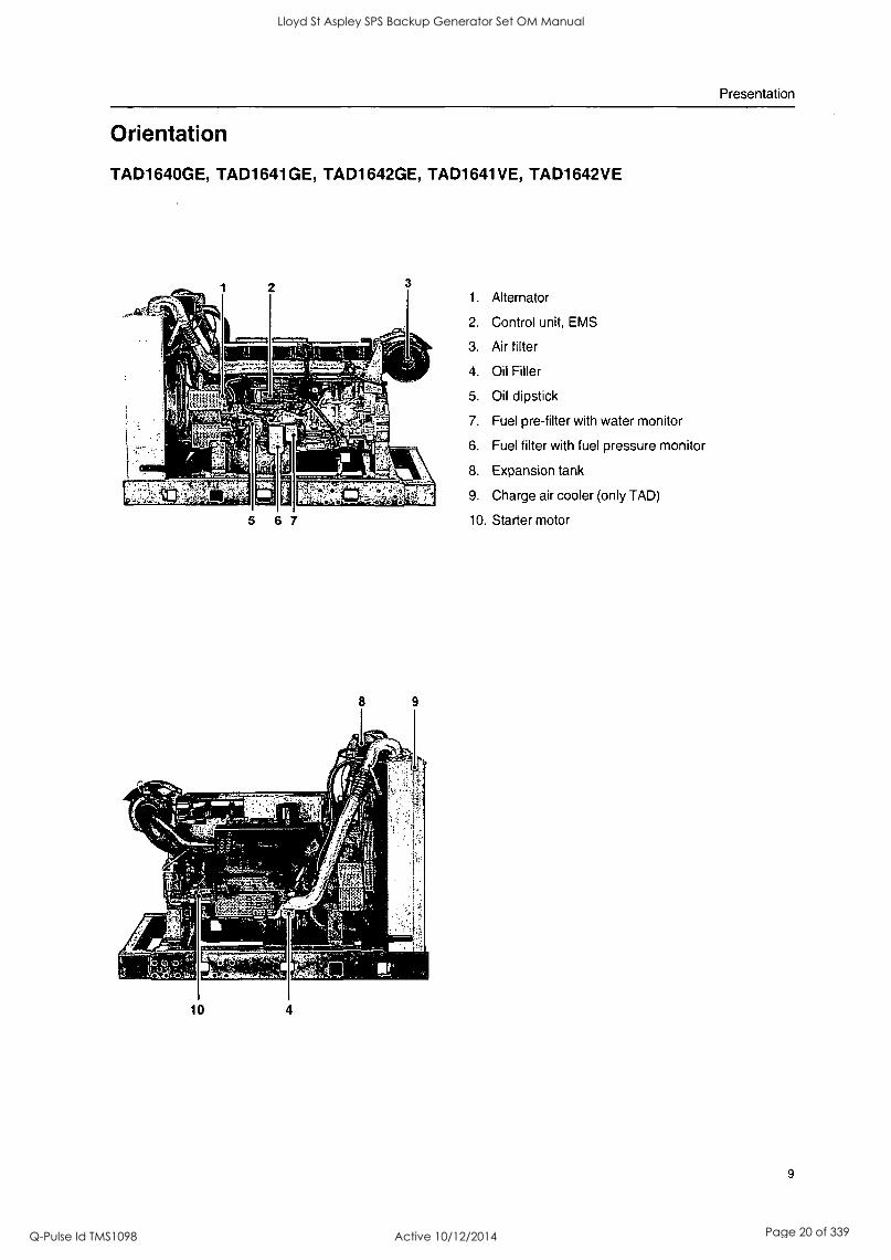
Orientation
TAD1640GE, TAD1641GE, TAD1642GE, TAD1641VE, TAD1642VE
5 6 7
10 4
1. Alternator
2. Control unit, EMS
3. Air filter
4. Oil Filler
5. Oil dipstick
7. Fuel pre-filter with water monitor
6. Fuel filter with fuel pressure monitor
8. Expansion tank
9. Charge air cooler (only TAD)
10. Starter motor
9
Lloyd St Aspley SPS Backup Generator Set OM Manual
Q-Pulse Id TMS1098 Active 10/12/2014 Page 20 of 339

Presentation
TWD1643GE
2
5 4 3
10
1. Control unit, EMS
2. Charge air cooler, HP-turbo
3. Fuel pre-filter with water monitor
4. Fuel filter with fuel pressure monitor
5. Oil dipstick
6. Oil Filler
7. Air filter
8. HP-turbo
9. LP-turbo
10. Expansion tank
11. Charge air cooler, LP-turbo
12. Starter motor, located behind charge air cooler
Lloyd St Aspley SPS Backup Generator Set OM Manual
Q-Pulse Id TMS1098 Active 10/12/2014 Page 21 of 339
Presentation
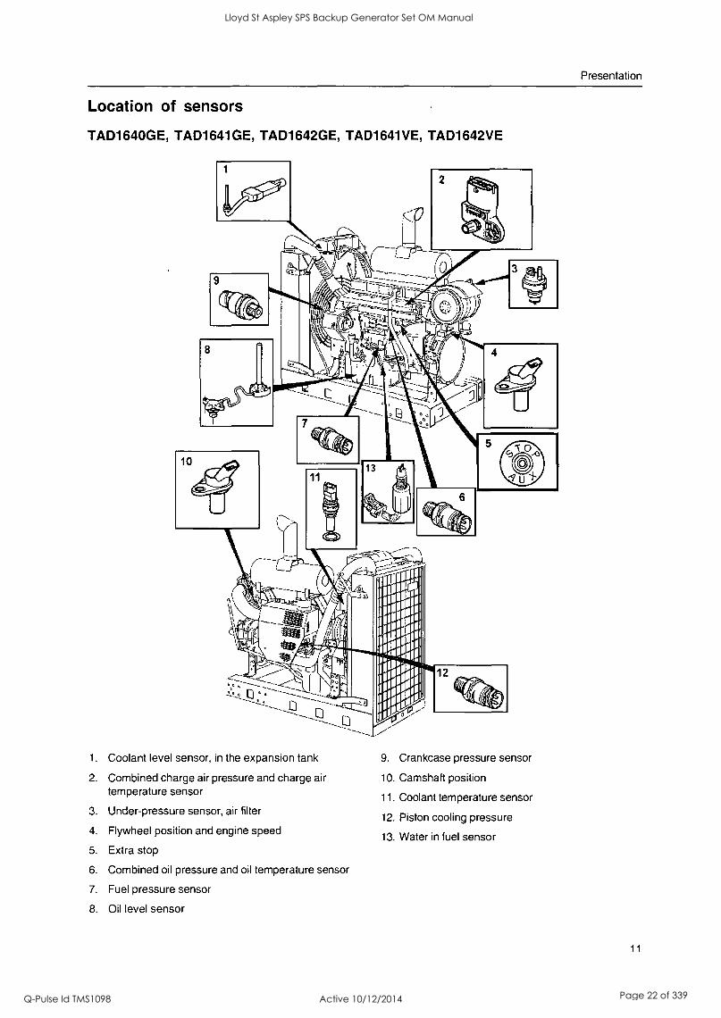
Location of sensors
TAD1640GE, TAD1641GE, TAD1642GE, TAD1641VE, TAD1642VE
1.
2.
3.
4.
5.
6.
7.
8.
Coolant level sensor, in the expansion tank
Combined charge air pressure and charge air temperature sensor
Under-pressure sensor, air filter
Flywheel position and engine speed
Extra stop
Combined oil pressure and oil temperature sensor
Fuel pressure sensor
Oil level sensor
9. Crankcase pressure sensor
10. Camshaft position
11. Coolant temperature sensor
12. Piston cooling pressure
13. Water in fuel sensor
11
Lloyd St Aspley SPS Backup Generator Set OM Manual
Q-Pulse Id TMS1098 Active 10/12/2014 Page 22 of 339
Presentation
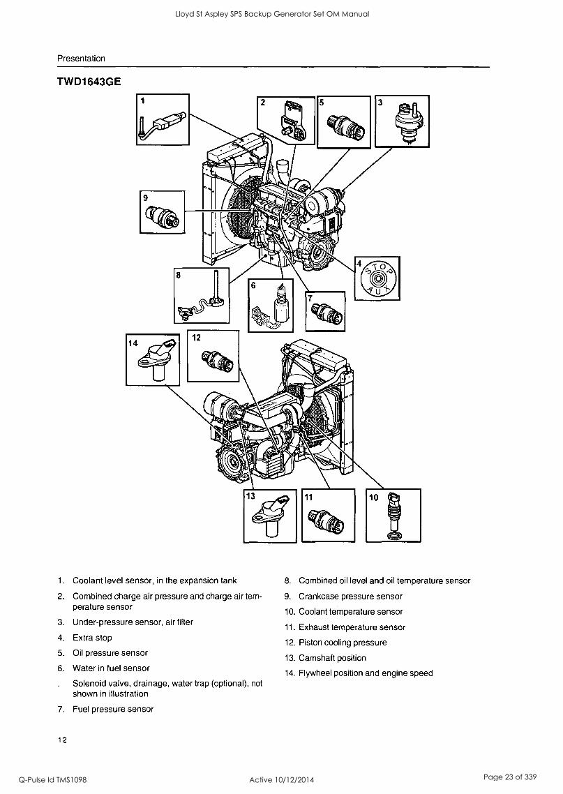
TWD1643GE
1.
2.
3.
4.
5.
6.
7.
Coolant level sensor, in the expansion tank
Combined charge air pressure and charge air tem- perature sensor
Under-pressure sensor, air filter
Extra stop
Oil pressure sensor
Water in fuel sensor
Solenoid valve, drainage, water trap (optional), not shown in illustration
Fuel pressure sensor
8. Combined oil level and oil temperature sensor
9. Crankcase pressure sensor
10. Coolant temperature sensor
11. Exhaust temperature sensor
12. Piston cooling pressure
13. Camshaft position
14. Flywheel position and engine speed
12
Lloyd St Aspley SPS Backup Generator Set OM Manual
Q-Pulse Id TMS1098 Active 10/12/2014 Page 23 of 339

Engine Management system (EMS) EMS (Engine Management System) is an electronic system with CAN communication (Controller Area Network) for diesel engine control. The system has been developed by Volvo Penta and includes fuel control and diagnostic function.
Summary
The system includes sensors, control unit and unit in- jectors. The sensors send input signals to the control unit, which controls the unit injectors in its turn.
Input signals
The control module receives input signals about the engines operating conditions and other things from the following components:
coolant temperature sensor
charge pressure/charge temperature sensor
crankcase pressure sensor
position sensor, camshaft
speed sensor, flywheel
coolant level sensor
oil level and temperature sensor
oil pressure sensor
fuel pressure sensor
water in fuel indicator
Exhaust temperature sensor (TWD1643GE)
Output signals
Based on the input signals the control module controls the following components:
unit injectors
- starter motor
main relay
pre-heating relay
Wastegate (TWD1643GE)
Cold start valve (TWD1643GE)
Information from the sensors provides exact informa- tion about current operation conditions and allows the processor in the control unit to calculate the correct fuel injection volume and timing, check engine status etc.
Fuel control
The engine fuel requirement is analyzed up to 100 times per second. The amount of fuel injected into the engine and the injection advance are fully electronical- ly controlled, via fuel valves and the unit injectors.
This means that the engine always receives the cor- rect volume of fuel in all operating conditions, which offers lower fuel consumption, minimal exhaust emis- sions etc.
Diagnostic function
The task of the diagnostic function is to discover and localize any malfunctions in the EMS system, to pro- tect the engine and to ensure operation in the event of serious malfunction.
If a malfunction is discovered, this is announced by warning lamps, a flashing diagnostic lamp or in plain language on the instrument panel, depending on the equipment used. If a fault code is obtained as a flash- ing code or in plain language, this is used for guidance in any fault tracing. Fault codes can also be read by Volvo's VODIA tool at authorized Volvo Penta work- shops.
If there is a serious malfunction, the engine will be shut down altogether, or the control unit will reduce the power delivered (depending on application). Once again, a fault code is set for guidance in any fault tracing.
13
Lloyd St Aspley SPS Backup Generator Set OM Manual
Q-Pulse Id TMS1098 Active 10/12/2014 Page 24 of 339
Instruments
Instruments, EMS NOTE: All instruments are accessories.
14
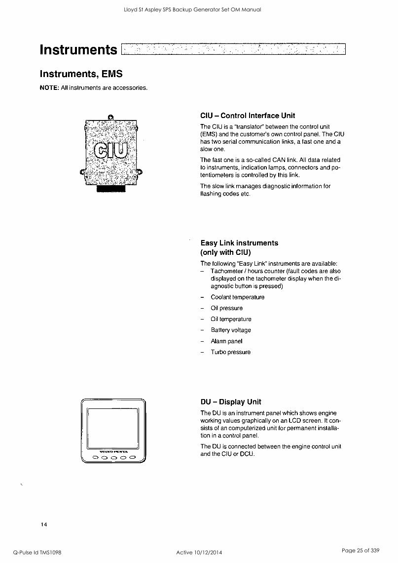
CIU - Control Interface Unit
The CIU is a "translator" between the control unit (EMS) and the customer's own control panel. The CIU has two serial communication links, a fast one and a
slow one.
The fast one is a so-called CAN link. All data related to instruments, indication lamps, connectors and po- tentiometers is controlled by this link.
The slow link manages diagnostic information for flashing codes etc.
Easy Link instruments (only with CIU)
The following "Easy Link" instruments are available: Tachometer / hours counter (fault codes are also displayed on the tachometer display when the di- agnostic button is pressed)
Coolant temperature
Oil pressure
Oil temperature
Battery voltage
Alarm panel
Turbo pressure
DU - Display Unit The DU is an instrument panel which shows engine working values graphically on an LCD screen. It con- sists of an computerized unit for permanent installa- tion in a control panel.
The DU is connected between the engine control unit and the CIU or DCU.
Lloyd St Aspley SPS Backup Generator Set OM Manual
Q-Pulse Id TMS1098 Active 10/12/2014 Page 25 of 339
Instruments
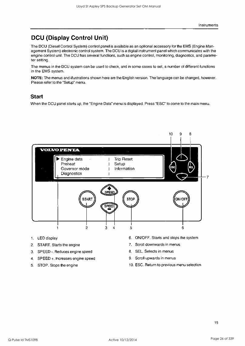
DCU (Display Control Unit) The DCU (Diesel Control System) control panel is available as an optional accessory for the EMS (Engine Man- agement System) electronic control system. The DCU is a digital instrument panel which communicates with the engine control unit. The DCU has several functions, such as engine control, monitoring, diagnostics, and parame- ter setting.
The menus in the DCU system can be used to check, and in some cases to set, a number of different functions in the EMS system.
NOTE: The menus and illustrations shown here are the English version. The language can be changed, however. Please refer to the "Setup" menu.
Start When the DCU panel starts up, the "Engine Data" menu is displayed. Press "ESC" to come to the main menu.
10 8
Engine data Preheat Governor mode Diagnostics
I Trip Reset I Setup I Information
1. LED display 6. ON/OFF. Starts and stops the system
2. START. Starts the engine 7. Scroll downwards in menus
3. SPEED -. Reduces engine speed 8. SEL. Selects in menus
4. SPEED +. Increases engine speed 9. Scroll upwards in menus
5. STOP. Stops the engine 10. ESC. Return to previous menu selection
15
Lloyd St Aspley SPS Backup Generator Set OM Manual
Q-Pulse Id TMS1098 Active 10/12/2014 Page 26 of 339

Lloyd St Aspley SPS Backup Generator Set OM Manual
Q-Pulse Id TMS1098 Active 10/12/2014 Page 27 of 339
Instruments
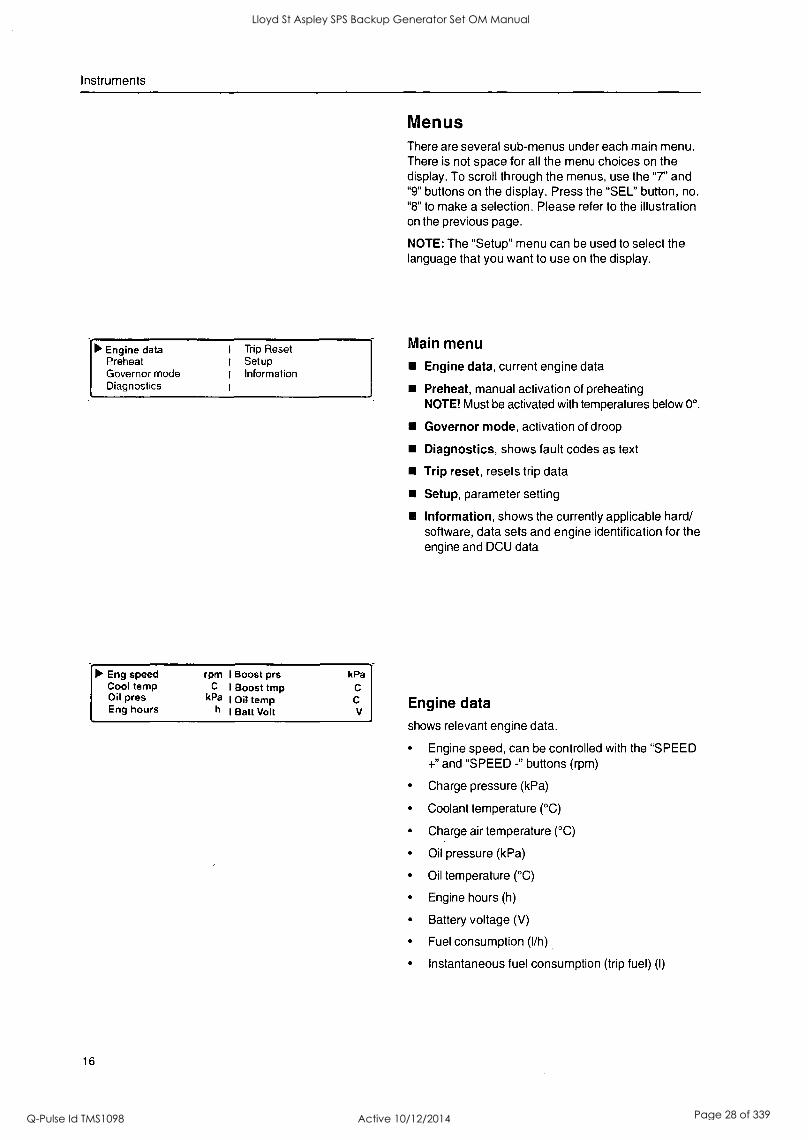
Menus There are several sub-menus under each main menu. There is not space for all the menu choices on the display. To scroll through the menus, use the "7" and "9" buttons on the display. Press the "SEL" button, no. "8" to make a selection. Please refer to the illustration on the previous page.
NOTE: The "Setup" menu can be used to select the language that you want to use on the display.
Main menu
Engine data, current engine data
Preheat, manual activation of preheating
Engine data Preheat Governor mode Diagnostics
I Trip Reset I Setup I Information 1
NOTE! Must be activated with temperatures below 0°.
Governor mode, activation of droop
Diagnostics, shows fault codes as text
Trip reset, resets trip data
Setup, parameter setting
Information, shows the currently applicable hard/ software, data sets and engine identification for the engine and DCU data
it, Eng speed rpm I Boost prs kPa Cool temp C I Boost tmp C Oil pres Eng hours
kPa I Oil temp h I Batt Volt
C
V Engine data
16
shows relevant engine data.
Engine speed, can be controlled with the "SPEED +" and "SPEED -" buttons (rpm)
Charge pressure (kPa)
Coolant temperature (°C)
Charge air temperature (°C)
Oil pressure (kPa)
Oil temperature (°C)
Engine hours (h)
Battery voltage (V)
Fuel consumption (I/h)
Instantaneous fuel consumption (trip fuel) (I)
Lloyd St Aspley SPS Backup Generator Set OM Manual
Q-Pulse Id TMS1098 Active 10/12/2014 Page 28 of 339

Instruments
* Preheat '-**
Press SEL to request preheat
"* Governor mode ***
Droop mode
Diagnostics 7/9 "' 20.0 h Engine oil pressure signal failure Inactive
** Trip Data Reset **
Press SEL to reset trip data
Preheat manual activation of pre-heating. When it is activated, the EMS system senses at start-up if pre-heating is needed. For automatic pre-heating, please refer to the "Setup"/"Pre-heat on ignition" menu.
NOTE: Must be activated with temperatures below 0°.
The pre-heating time is adjusted to suit the engine temperature, and can last for up to 50 seconds both before and after starting. Refer also to "Starting proce- dure EMS".
Press "SEL", the text "Preheat requested" is dis- played.
The display automatically returns to the "Engine Data" menu.
Governor mode activates/deactivates droop. For droop level setting, refer to menu "Setup"/"Govemor gradient" or "Governor droop ".
Select "Isochronous mode" or "Droop mode" with the SEL button.
Diagnostics shows an fault list containing the 10 latest active and inactive faults. The fault codes are shown as text on the display.
Scroll through the fault list with the arrow keys.
Trip reset resets trip data, such as fuel consumption.
Press the SEL button to reset trip data.
17
Lloyd St Aspley SPS Backup Generator Set OM Manual
Q-Pulse Id TMS1098 Active 10/12/2014 Page 29 of 339
Instruments
Setup
00 Set Application : (Versatile) Units (Metric) Language (English)
Setup (Versatile) ldle engine speed : rpm
Preheat on ignition :
Governor gradient : Nm/rpm
18
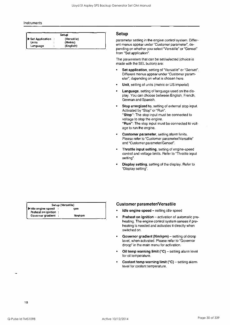
Setup parameter setting in the engine control system. Differ- ent menus appear under "Customer parameter", de- pending on whether you select "Versatile" or "Genset" from "Set application".
The parameters that can be set/selected (choice is
made with the SEL button) are:
Set application, setting of "Versatile" or "Genset". Different menus appear under "Customer param- eter", depending on what is chosen here.
Unit, setting of units (metric or US imperial)
Language, setting of language used on the dis- play. You can choose between English, French, German and Spanish.
Stop energized to, setting of external stop input. Activated by "Stop" or "Run". "Stop": The stop input must be connected to voltage to stop the engine. "Run": The stop input must be connected to volt- age to run the engine.
Customer parameter, setting alarm limits. Please refer to "Customer parameter/Versatile" and "Customer parameter/Genset".
Throttle input setting, setting of engine-speed control and voltage limits. Refer to "Throttle input setting".
Display setting, setting of the display. Refer to "Display setting".
Customer parameterNersatile Idle engine speed - setting idle speed
Preheat on ignition - activation of automatic pre- heating. The engine control system senses if pre- heating is needed and activates it directly when switched on.
Governor gradient (Nm/rpm) - setting of droop level, when activated. Please refer to "Governor droop" in the main menu for activation.
Oil temp warning limit (°C) - setting alarm level for oil temperature.
Coolant temp warning limit ( °C) - setting alarm level for coolant temperature.
Lloyd St Aspley SPS Backup Generator Set OM Manual
Q-Pulse Id TMS1098 Active 10/12/2014 Page 30 of 339
Instruments
Setup (Genset) Primary engine speed :
Preheat on ignition Governor droop
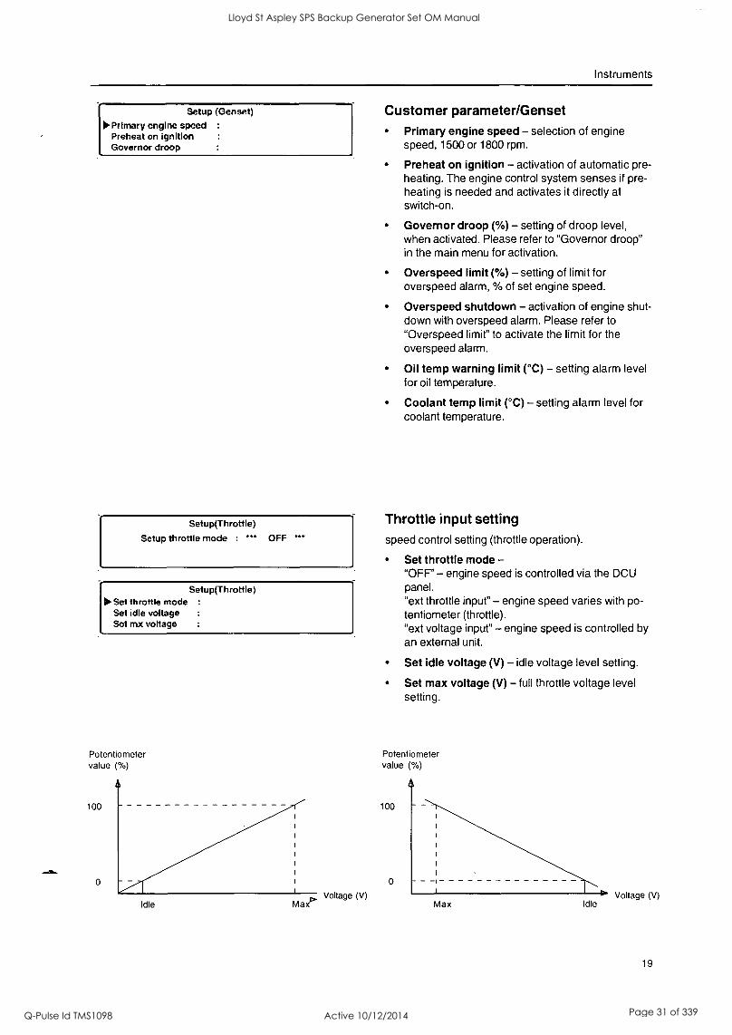
Customer parameter/Genset Primary engine speed - selection of engine speed, 1500 or 1800 rpm.
Preheat on ignition - activation of automatic pre- heating. The engine control system senses if pre- heating is needed and activates it directly at switch-on.
Governor droop (%) - setting of droop level, when activated. Please refer to "Governor droop" in the main menu for activation.
Overspeed limit (%) - setting of limit for overspeed alarm, % of set engine speed.
Overspeed shutdown - activation of engine shut- down with overspeed alarm. Please refer to
"Overspeed limit" to activate the limit for the overspeed alarm.
Oil temp warning limit (°C) - setting alarm level for oil temperature.
Coolant temp limit (°C) - setting alarm level for coolant temperature.
Throttle input setting speed control setting (throttle operation).
Setup(Throttle)
Setup throttle mode : *** OFF ***
Set throttle mode - "OFF' - engine speed is controlled via the DCU
Setup(Throttle) panel. ilo Set throttle mode :
Set idle voltage "ext throttle input" - engine speed varies with po- tentiometer (throttle).
Set mx voltage "ext voltage input" - engine speed is controlled by an external unit.
Set idle voltage (V) - idle voltage level setting.
Set max voltage (V) - full throttle voltage level setting.
Potentiometer value ( %)
100
0
Idle Ma Voltage (V)
Potentiometer value (%)
100
0
Max Idle Voltage (V)
19
Lloyd St Aspley SPS Backup Generator Set OM Manual
Q-Pulse Id TMS1098 Active 10/12/2014 Page 31 of 339
Instruments
Setup (Display) 60% 5 sec 10
Set contrast Set backlighttime Set backlight brightness
Information Engine hardware Id Engine software Id Engine Dataset1 Id
Mi
20
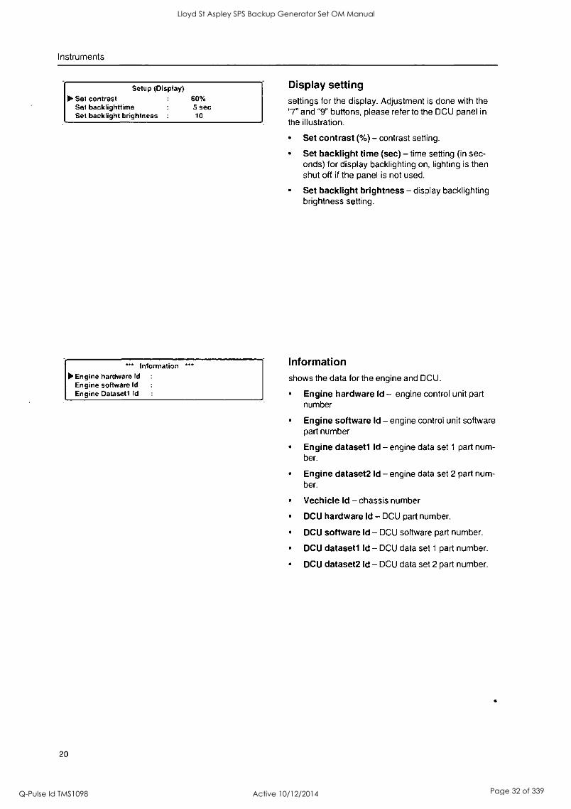
Display setting settings for the display. Adjustment is done with the "7" and "9" buttons, please refer to the DCU panel in the illustration.
Set contrast (%) - contrast setting.
Set backlight time (sec) - time setting (in sec- onds) for display backlighting on, lighting is then shut off if the panel is not used.
Set backlight brightness - display backlighting brightness setting.
Information shows the data for the engine and DCU.
Engine hardware Id - engine control unit part number
Engine software Id - engine control unit software part number
Engine datasetl Id - engine data set 1 part num- ber.
Engine dataset2 Id - engine data set 2 part num- ber.
Vechicle Id - chassis number
DCU hardware Id - DCU part number.
DCU software Id - DCU software part number.
DCU datasetl Id - DCU data set 1 part number.
DCU dataset2 Id - DCU data set 2 part number.
Lloyd St Aspley SPS Backup Generator Set OM Manual
Q-Pulse Id TMS1098 Active 10/12/2014 Page 32 of 339
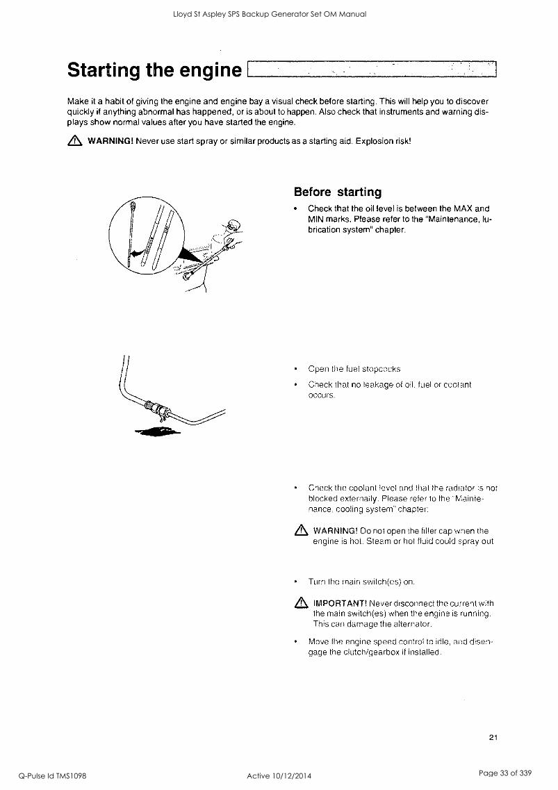
Starting the engine Make it a habit of giving the engine and engine bay a visual check before starting. This will help you to discover quickly if anything abnormal has happened, or is about to happen. Also check that instruments and warning dis- plays show normal values after you have started the engine.
WARNING! Never use start spray or similar products as a starting aid. Explosion risk!
Before starting Check that the oil level is between the MAX and MIN marks. Please refer to the "Maintenance, lu- brication system" chapter.
Open the fuel stopcocks
Check that no leakage of oil, fuel or coolant occurs.
Check the coolant level and that the radiator is not blocked externally. Please refer to the "Mainte- nance, cooling system" chapter:
,L WARNING! Do not open the filler cap when the engine is hot. Steam or hot fluid could spray out
Turn the main switch(es) on.
IMPORTANT! Never disconnect the current with the main switch(es) when the engine is running. This can damage the alternator.
Move the engine speed control to idle, and disen- gage the clutch/gearbox if installed.
21
Lloyd St Aspley SPS Backup Generator Set OM Manual
Q-Pulse Id TMS1098 Active 10/12/2014 Page 33 of 339

Starting the engine
Starting Procedure EMS The pre-heating time is adjusted to suit the engine temperature, and can last for up to 50 seconds both before and after starting.
The starter motor connection time is maximized to 20 seconds. After that, the starter motor circuit is cut for 80 seconds to protect the starter motor against over-
heating.
DCU (Display Control Unit) With pre-heating
1. Depress the "ON/OFF" button (6).
2. Press the "SEL" button (4) to come to the main menu.
3. Scroll down to Pre/heater with scroll button (5),
press "SEL"-button (4)
4. In the pre-heater menu, press the "SEL" button (4) to select pre-heating.
3. Press the "START" button (10).
Without pre-heating 1. Depress the "ONIOFF" button (6).
2. Press the "START" button (10).
Leave the engine to idle fur the first 10 seconds. Then warm the engine up at low speed and under low load.
,L IMPORTANT! Neve! race the engine when it is
cold.
Engine data I Trip Reset Preheat I Setup Governor mode I Information Diagnostics
10
22
5
Lloyd St Aspley SPS Backup Generator Set OM Manual
Q-Pulse Id TMS1098 Active 10/12/2014 Page 34 of 339
Starting the engine
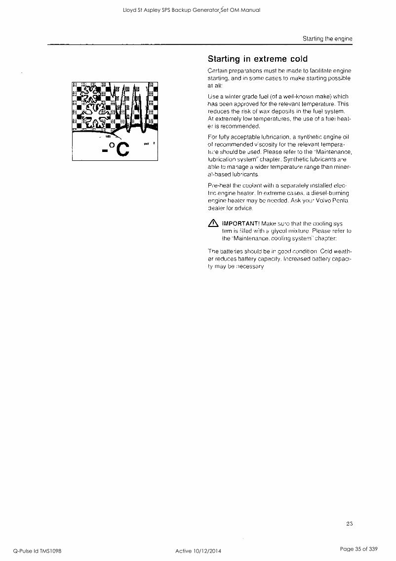
Starting in extreme cold Certain preparations must be made to facilitate engine starting, and in some cases to make starting possible at all:
Use a winter grade fuel (of a well-known make) which has been approved for the relevant temperature. This reduces the risk of wax deposits in the fuel system. At extremely low temperatures, the use of a fuel heat- er is recommended.
For fully acceptable lubrication, a synthetic engine oil of recommended viscosity for the relevant tempera- ture should be used. Please refer to the "Maintenance, lubrication system" chapter. Synthetic lubricants are able to manage a wider temperature range than miner- al-based lubricants.
Pre-heat the coolant with a separately installed elec- tric engine heater, In extreme oases, a diesel-burning engine heater may be needed. Ask your Volvo Penta dealer for advice.
,L IMPORTANT! Make sure that the cooling sys- tem is filled with a glycol mixture. Please refer to the "Maintenance. cooling system- chapter:
The batteries should be in good condition Cold weath- er reduces battery capacity. Increased battery capaci- ty may be necessary.
23
Lloyd St Aspley SPS Backup Generator Set OM Manual
Q-Pulse Id TMS1098 Active 10/12/2014 Page 35 of 339
Starting the engine
24
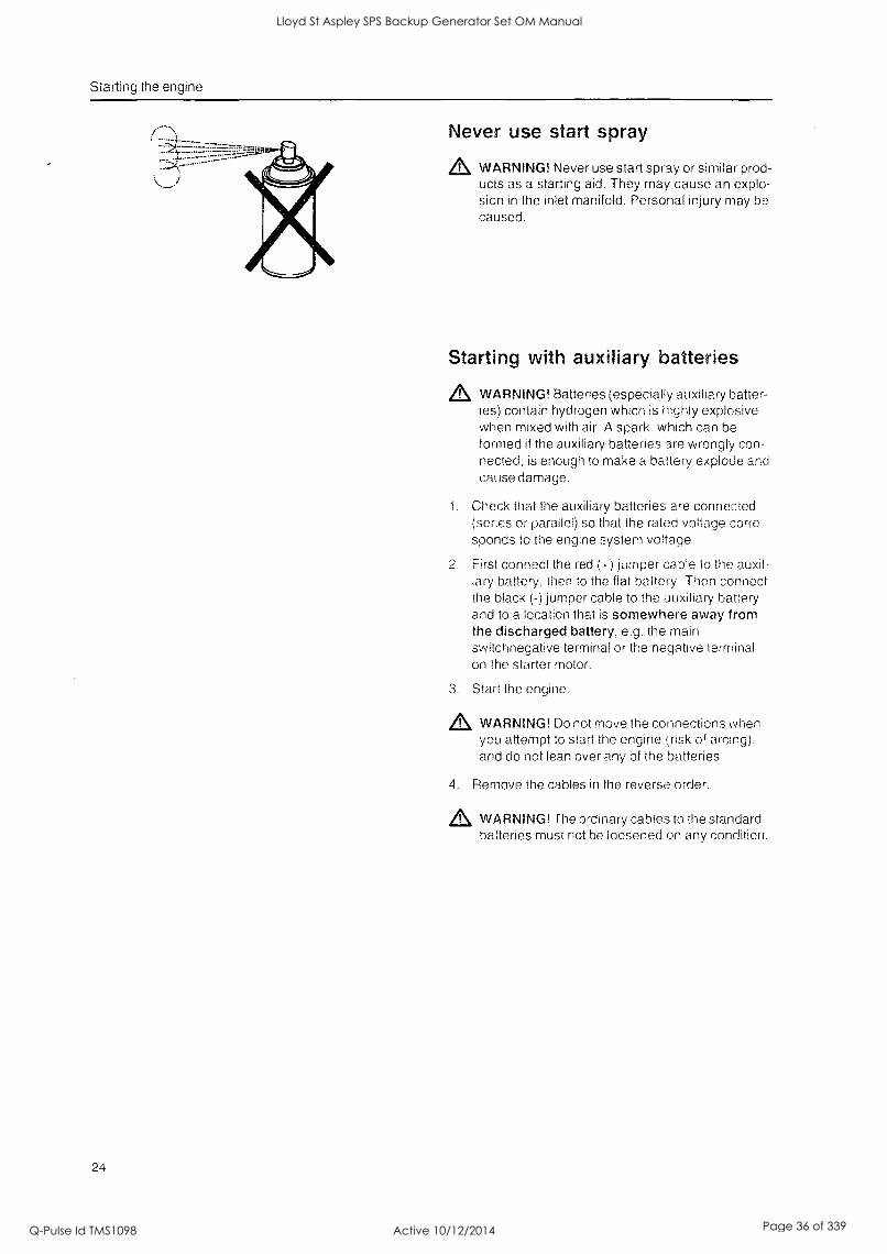
Never use start spray
A WARNING! Never use start spray or similar prod- ucts as a starting aid. They may cause an explo- sion in the inlet manifold. Personal injury may be caused.
Starting with auxiliary batteries
WARNING! Batteries (especially auxiliary batter- ies) contain hydrogen which is highly explosive when mixed with air. A spark. which can be formed if the auxiliary batteries are wrongly con- nected, is enough to make a battery explode and cause damage.
1. Check that the auxiliary batteries are connected (series or parallel) so that the rated voltage corre- sponds to the engine system voltage.
First connect the red (4-) jumper cable to the auxil- iary battery, then to the flat battery Then connect the black (-) jumper cable to the auxiliary battery and to a location that is somewhere away from the discharged battery, e.g. the main switchnegatiye terminal or the negative terminal on the starter motor.
3. Start the engine.
p WARNING! Do not move the connections when you attempt to start the engine risk of arcing), and do not lean over any of the batteries.
Remove the cables in the reverse order.
p WARNING! The ordinary cables to the standard batteries must not be loosened on any condition.
Lloyd St Aspley SPS Backup Generator Set OM Manual
Q-Pulse Id TMS1098 Active 10/12/2014 Page 36 of 339
Operatrion Correct operating technique is very important for both fuel economy and engine life. Always let the engine warm up to normal operating temperature before operating at full power. Avoid sudden throttle openings and operation at
high engine speeds.
Checking instruments Check all instruments directly after starting, and then regularly during operation.
IMPORTANT! On engines which operate continu- ously, the lubrication oil level must be checked at least every 24th hour. Refer to the "Mainte- nance. lubrication system'. chapter:
Fault indication if the EMS system receives abnormal signals from the engine. the control unit generates fault codes arid alarms. in the form of lamps and audible warnings. This is done by means of CAN signals to the instru- ment
More intormation about fault codes and fault tracing can be found in the "Diagnostic function'. chapter.
Operation at low load Avoid long-term operation at idle or at low load, since this can lead to increased oil consumption and even- tually to oil leakage from the exhaust manifold, since oil will seep past the turbocharger seals and accompa- ny the induction air into the inlet manifold at low turbo pressure.
One consequence of this is that carbon builds up on valves, piston crowns, exhaust ports and the exhaust turbine.
At low loads, the combustion temperature may be- come so low that complete combustion cannot be en- sured, resulting in possible fuel dilution of lubricating oil and eventually leakage from the exhaust manifold.
If the following points are performed as a comple- ment to normal maintenance, there will be no risk of malfunctions caused by operation at low load:
Reduce operation at low load to a minimum. If the engine is regularly test run without load once a
week, operation duration should be limited to 5
minutes.
Run the engine at full load for about 4 hours once a year. Carbon deposits in the engine and exhaust lines can then be burnt away.
25
Lloyd St Aspley SPS Backup Generator Set OM Manual
Q-Pulse Id TMS1098 Active 10/12/2014 Page 37 of 339
Stopping the engine During longer breaks in operation, the engine must be warmed up at least once every fortnight. This prevents corrosionattacks in the engine. If you expect the engine to be unused for two months or more, it must be laid up: Refer to chapter "Laying up".
IMPORTANT! If there is a risk of frost, the coolant in the cooling system must have sufficient frost protection. Please refer to the "Maintenance, cooling system" chapter: A poorly charged battery can freeze and burst.
Engine data Preheat Governor mode Diagnostics
7
26
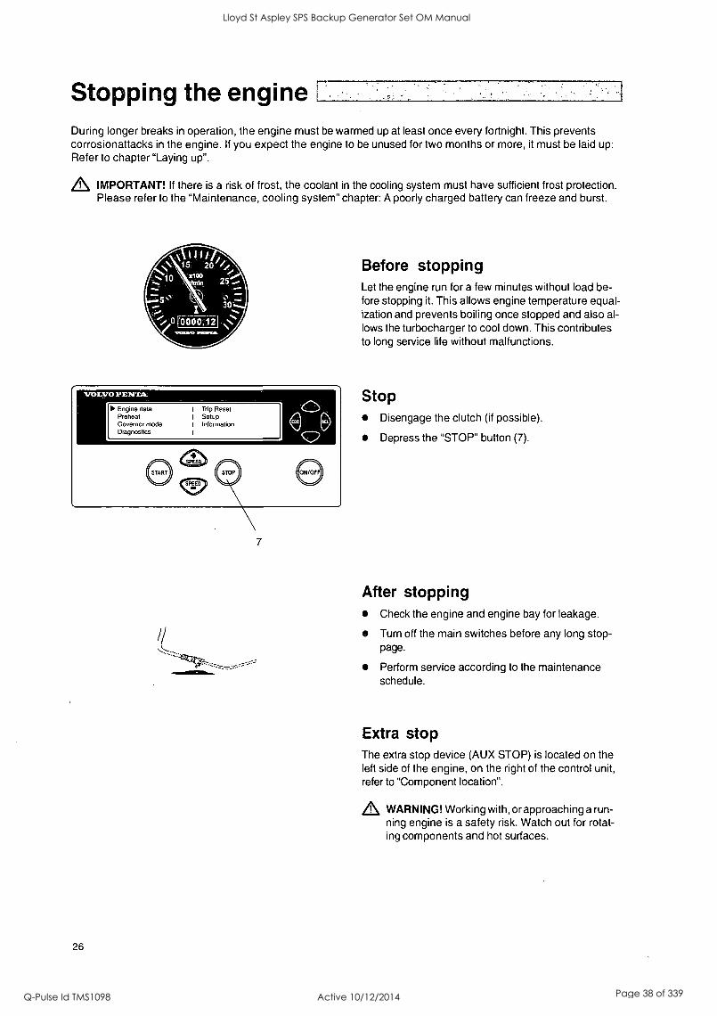
Before stopping Let the engine run for a few minutes without load be- fore stopping it. This allows engine temperature equal- ization and prevents boiling once stopped and also al- lows the turbocharger to cool down. This contributes to long service life without malfunctions.
Stop Disengage the clutch (if possible).
Depress the "STOP" button (7).
After stopping Check the engine and engine bay for leakage.
Turn off the main switches before any long stop- page.
Perform service according to the maintenance schedule.
Extra stop The extra stop device (AUX STOP) is located on the left side of the engine, on the right of the control unit, refer to "Component location".
WARNING! Working with, or approaching a run- ning engine is a safety risk. Watch out for rotat- ing components and hot surfaces.
Lloyd St Aspley SPS Backup Generator Set OM Manual
Q-Pulse Id TMS1098 Active 10/12/2014 Page 38 of 339
i
Maintenance schedule
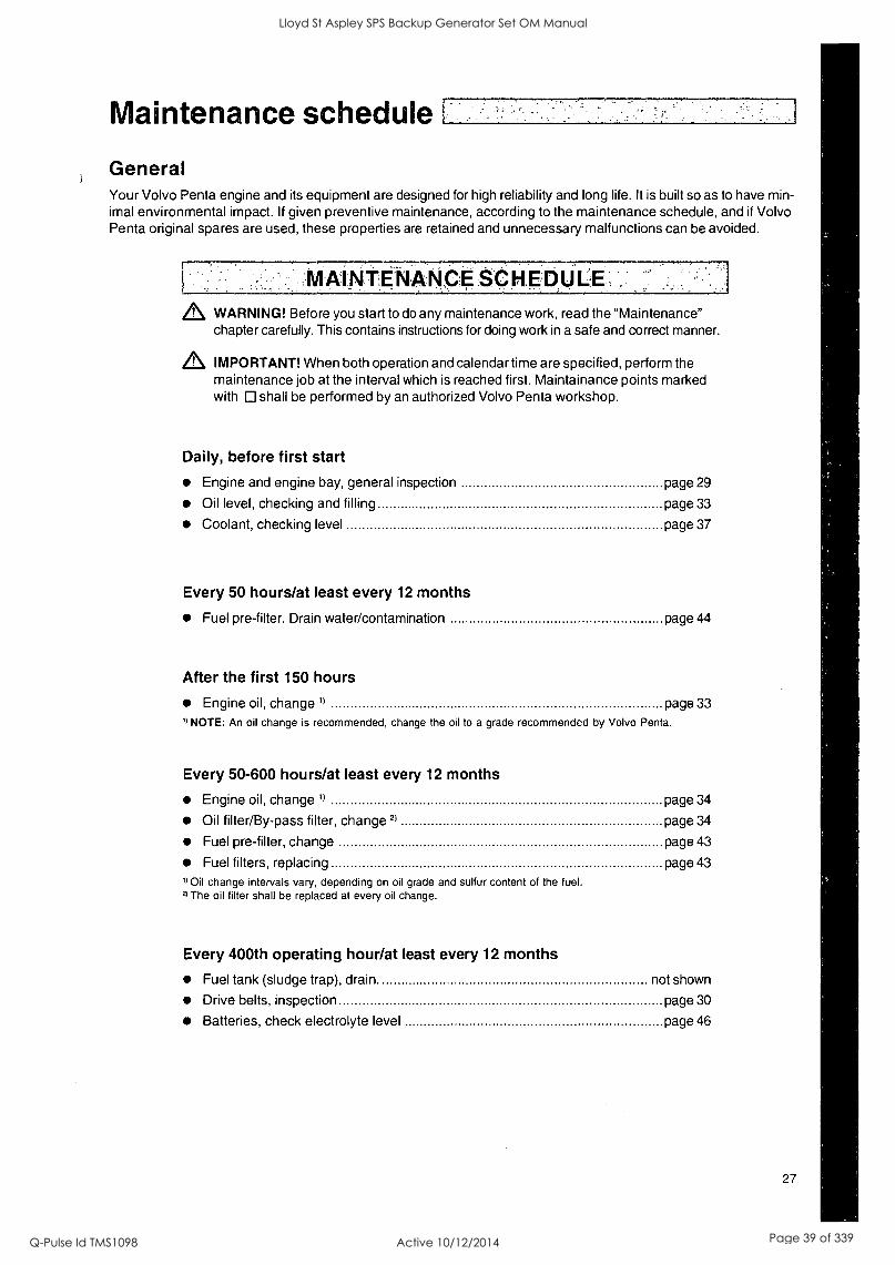
General Your Volvo Penta engine and its equipment are designed for high reliability and long life. It is built so as to have min- imal environmental impact. If given preventive maintenance, according to the maintenance schedule, and if Volvo Penta original spares are used, these properties are retained and unnecessary malfunctions can be avoided.
.RAINITNANPE.tqiEDIJLE::, A WARNING! Before you start to do any maintenance work, read the "Maintenance"
chapter carefully. This contains instructions for doing work in a safe and correct manner.
Z, IMPORTANT! When both operation and calendar time are specified, perform the maintenance job at the interval which is reached first. Maintainance points marked with shall be performed by an authorized Volvo Penta workshop.
Daily, before first start
Engine and engine bay, general inspection page 29
Oil level, checking and filling page 33
Coolant, checking level page 37
Every 50 hours/at least every 12 months
Fuel pre-filter. Drain water/contamination page 44
After the first 150 hours
Engine oil, change 1) page 33
1) NOTE: An oil change is recommended, change the oil to a grade recommended by Volvo Penta.
Every 50-600 hours/at least every 12 months
Engine oil, change') page 34
Oil filter/By-pass filter, change 2) page 34
Fuel pre-filter, change page 43
Fuel filters, replacing page 43
I) Oil change intervals vary, depending on oil grade and sulfur content of the fuel. 2) The oil filter shall be replaced at every oil change.
Every 400th operating hour/at least every 12 months
Fuel tank (sludge trap), drain. not shown
Drive belts, inspection page 30
Batteries, check electrolyte level page 46
27
Lloyd St Aspley SPS Backup Generator Set OM Manual
Q-Pulse Id TMS1098 Active 10/12/2014 Page 39 of 339
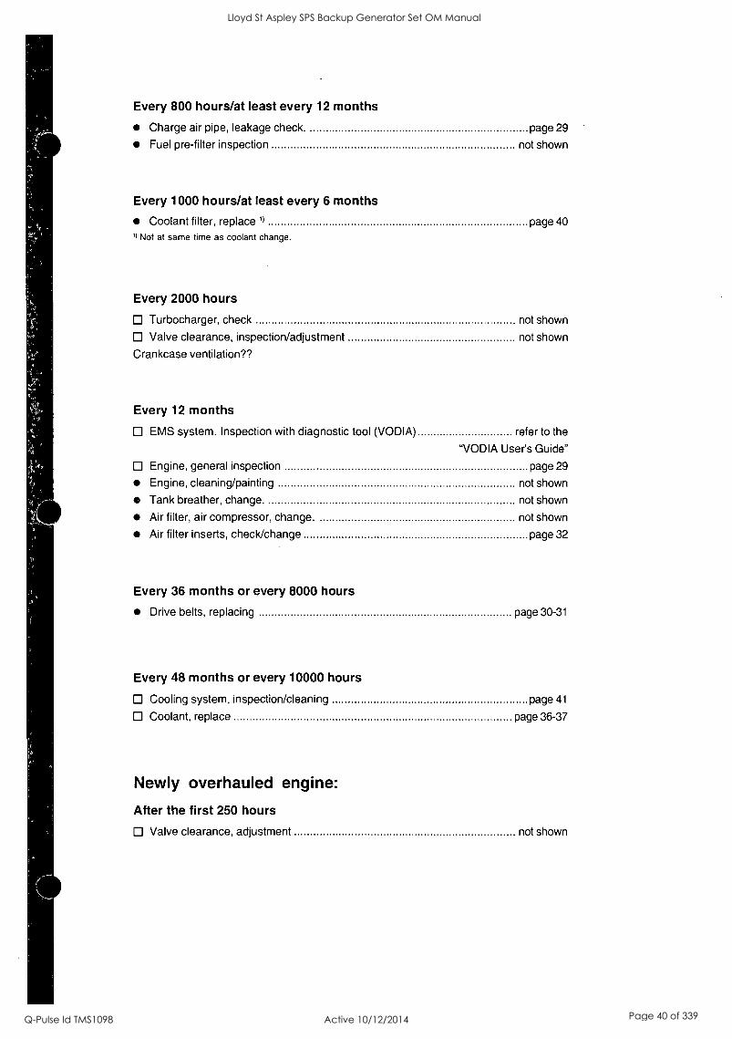
Every 800 hours/at least every 12 months
Charge air pipe, leakage check. page 29
Fuel pre-filter inspection not shown
Every 1000 hours/at least every 6 months
Coolant filter, replace 1) page 40
9 Not at same time as coolant change.
Every 2000 hours
Turbocharger, check not shown
Valve clearance, inspection/adjustment not shown
Crankcase ventilation??
Every 12 months
EMS system. Inspection with diagnostic tool (VODIA) refer to the
"VODIA User's Guide"
Engine, general inspection page 29
Engine, cleaning/painting not shown
Tank breather, change. not shown
Air filter, air compressor, change. not shown
Air filter inserts, check/change page 32
Every 36 months or every 8000 hours
Drive belts, replacing page 30-31
Every 48 months or every 10000 hours
Cooling system, inspection/cleaning page 41
Coolant, replace page 36-37
Newly overhauled engine:
After the first 250 hours
Valve clearance, adjustment not shown
Lloyd St Aspley SPS Backup Generator Set OM Manual
Q-Pulse Id TMS1098 Active 10/12/2014 Page 40 of 339

0
0
Lloyd St Aspley SPS Backup Generator Set OM Manual
Q-Pulse Id TMS1098 Active 10/12/2014 Page 41 of 339
Maintainance
This chapter describes how the specified maintenance points should be performed. Read them carefully before starting work. The times when maintenance points need to be attended to are given in the previous chapter: Main- tenance schedule.
WARNING! Read through the safety precautions for service and maintenance work in the "Safety precau- tions" chapter before starting work.
,L WARNING! Service and maintenance work should be done with the engine stopped unless otherwise speci- fied. Make it impossible to start the engine by removing the ignition key and removing the system voltage with the main switch. Working with, or approaching a running engine is a safety risk. Watch out for rotating components and hot surfaces.
Engine, general
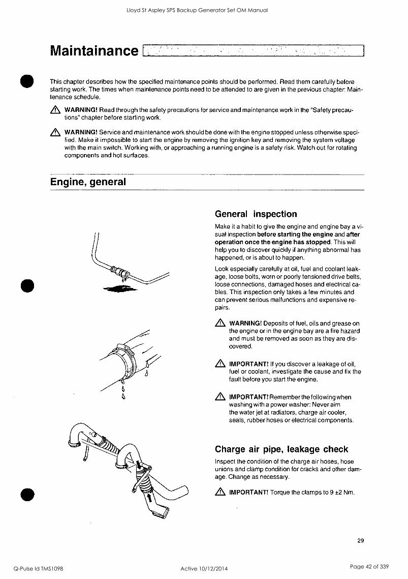
General inspection Make it a habit to give the engine and engine bay a vi- sual inspection before starting the engine and after operation once the engine has stopped. This will help you to discover quickly if anything abnormal has happened, or is about to happen.
Look especially carefully at oil, fuel and coolant leak- age, loose bolts, worn or poorly tensioned drive belts, loose connections, damaged hoses and electrical ca- bles. This inspection only takes a few minutes and can prevent serious malfunctions and expensive re- pairs.
,L WARNING! Deposits of fuel, oils and grease on the engine or in the engine bay are a fire hazard and must be removed as soon as they are dis- covered.
IMPORTANT! If you discover a leakage of oil, fuel or coolant, investigate the cause and fix the fault before you start the engine.
IMPORTANT! Remember the following when washing with a power washer: Never aim the water jet at radiators, charge air cooler, seals, rubber hoses or electrical components.
Charge air pipe, leakage check Inspect the condition of the charge air hoses, hose unions and clamp condition for cracks and other dam- age. Change as necessary.
IMPORTANT! Torque the clamps to 9 ±2 Nm.
29
Lloyd St Aspley SPS Backup Generator Set OM Manual
Q-Pulse Id TMS1098 Active 10/12/2014 Page 42 of 339

0
0
Lloyd St Aspley SPS Backup Generator Set OM Manual
Q-Pulse Id TMS1098 Active 10/12/2014 Page 43 of 339

Maintainance
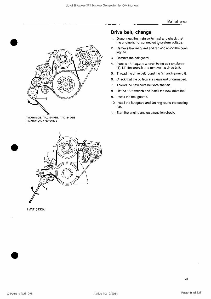
TAD1640GE, TAD1641GE, TAD1642GE TAD1641VE, TAD1642VE
TWD1643GE
30
Drive belt/Alternator belt, inspection Inspection should be done after operation, when the belts are warm.
It should be possible to press the alternator belts and drive belts down about 3-4 mm between the pulleys.
The alternator belts and drive belts have automatic belt tensioners and do not need to be adjusted. Check the condition of the drive belts. Change as necessary, refer to "Alternator belt, change" and "Drive belt, change".
Alternator belts, change
,L IMPORTANT! Always replace a drive belt that seems worn or is cracked.
1. Disconnect the main switch(es) and check that the engine is not connected to system voltage.
2. Remove the fan guard and fan ring round the cool- ing fan.
3. Remove the belt guard.
4. Place a 1/2" square wrench in the belt tensioner (1). Lift the wrench up and lift the water pump drive belt off.
5. Place a 1/2" square wrench in the belt tensioner (2). Press the wrench down and remove the alter- nator belt.
6. Check that the pulleys are clean and undamaged.
7. Press the 1/2" wrench in the belt tensioner (2) down and install the new alternator drive belt.
8. Lift the 1/2" wrench in the belt tensioner (1) and re-install the water pump drive belt.
9. Install the belt guards.
10. Install the fan guard and fan ring round the cooling fan.
11. Start the engine and do a function check.
Lloyd St Aspley SPS Backup Generator Set OM Manual
Q-Pulse Id TMS1098 Active 10/12/2014 Page 44 of 339

Lloyd St Aspley SPS Backup Generator Set OM Manual
Q-Pulse Id TMS1098 Active 10/12/2014 Page 45 of 339
Maintainance
TAD1640GE, TAD1641GE, TAD1642GE TAD1641VE, TAD1642VE
TVVD1643GE
Drive belt, change 1. Disconnect the main switch(es) and check that
the engine is not connected to system voltage.
2. Remove the fan guard and fan ring round the cool- ing fan.
3. Remove the belt guard.
4. Place a 1/2" square wrench in the belt tensioner (1). Lift the wrench and remove the drive belt.
5. Thread the drive belt round the fan and remove it.
6. Check that the pulleys are clean and undamaged.
7. Thread the new drive belt over the fan.
8. Lift the 1/2" wrench and install the new drive belt.
9. Install the belt guards.
10. Install the fan guard and fan ring round the cooling fan.
11. Start the engine and do a function check.
31
Lloyd St Aspley SPS Backup Generator Set OM Manual
Q-Pulse Id TMS1098 Active 10/12/2014 Page 46 of 339

0
0
Lloyd St Aspley SPS Backup Generator Set OM Manual
Q-Pulse Id TMS1098 Active 10/12/2014 Page 47 of 339
Maintainance
32
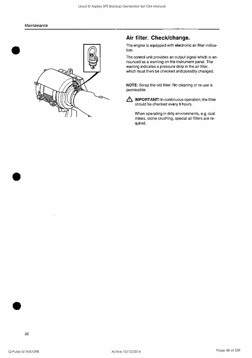
Air filter. Check/change. The engine is equipped with electronic air filter indica- tion.
The control unit provides an output signal which is an- nounced as a warning on the instrument panel. The warning indicates a pressure drop in the air filter, which must then be checked and possibly changed.
NOTE: Scrap the old filter. No cleaning or re-use is
permissible.
EL IMPORTANT! In continuous operation, the filter should be checked every 8 hours.
When operating in dirty environments, e.g. coal mines, stone crushing, special air filters are re- quired.
Lloyd St Aspley SPS Backup Generator Set OM Manual
Q-Pulse Id TMS1098 Active 10/12/2014 Page 48 of 339

Maintainance
Lubrication System
The oil change intervals can vary between 50 to 600 hours depending on the oil grade and fuel sulfur con- tent. Refer to "Technical data, Lubricating sys- tem".
NOTE: The oil change intervals shall never exceed a
period of 12 months.
If longer oil change intervals than those given in Techni- cal data are required, the condition of the oil must be checked by the oil manufacturer via regular oil tests.
Oil level, checking and filling The oil level must be inside the marked area on the dipstick and must be checked daily before the first start.
NOTE: The oil level can be read both when the engine is stationary (the STOP side of the dipstick) and with the engine running (the OPERATING side of the dip- stick).
Fill the oil via the filler opening on the left side of the engine.
Check that the correct level has been achieved. If the engine is stationary, wait for a few minutes to allow the oil to run down into the oil pan.
Z, IMPORTANT! Do not fill above the max. oil level. Only use a recommended grade of oil. Re- fer to previous page.
NOTE: The oil level sensor only measures the oil lev- el at the time when the ignition is turned on. In other words, not continually during operation.
33
Lloyd St Aspley SPS Backup Generator Set OM Manual
Q-Pulse Id TMS1098 Active 10/12/2014 Page 49 of 339

Lloyd St Aspley SPS Backup Generator Set OM Manual
Q-Pulse Id TMS1098 Active 10/12/2014 Page 50 of 339
Maintainance
34
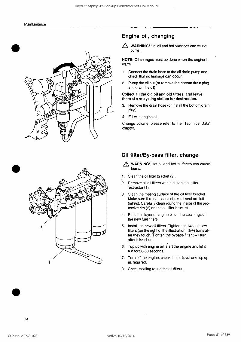
Engine oil, changing
WARNING! Hot oil and hot surfaces can cause burns.
NOTE: Oil changes must be done when the engine is
warm.
1. Connect the drain hose to the oil drain pump and check that no leakage can occur.
2. Pump the oil out (or remove the bottom drain plug and drain the oil).
Collect all the old oil and old filters, and leave them at a re-cycling station for destruction.
3. Remove the drain hose (or install the bottom drain plug).
4. Fill with engine oil.
Change volume, please refer to the "Technical Data" chapter.
Oil filter/By-pass filter, change
WARNING! Hot oil and hot surfaces can cause burns.
1. Clean the oil filter bracket (2).
2. Remove all oil filters with a suitable oil filter extractor (1).
3. Clean the mating surface of the oil filter bracket. Make sure that no pieces of old oil seal are left behind. Carefully clean round the inside of the pro- tective rim (2) on the oil filter bracket.
4. Put a thin layer of engine oil on the seal rings of the new fuel filters.
5. Install the new oil filters. Tighten the two full-flow filters (on the right of the illustration) / -3/4 turns af- ter they touch. Tighten the bypass filter 3/4 -1 turn after it touches.
6. Top up with engine oil, start the engine and let it
run for 20-30 seconds.
7. Turn off the engine, check the oil level and top up as required.
8. Check sealing round the oil filters.
Lloyd St Aspley SPS Backup Generator Set OM Manual
Q-Pulse Id TMS1098 Active 10/12/2014 Page 51 of 339

Lloyd St Aspley SPS Backup Generator Set OM Manual
Q-Pulse Id TMS1098 Active 10/12/2014 Page 52 of 339
Maintainance
Cooling System
The cooling system ensures that the engine works at the right temperature. It is a closed system and must there- fore always be filled with a mixture of at least 40 % concentrated coolant and 60 % water, to offer protection from interior corrosion, cavitation and frost rupture.
We recommend that you use "Volvo Penta Coolant, Ready Mixed", alternatively "Volvo Penta Coolant" (con- centrated) mixed with pure water according to spec, see "Coolant. Mixing". This grade of coolant is the only one that is developed for and approved by Volvo Penta.
The coolant should contain ethylene glycol of a good quality with a suitable chemical consistency that offers com- plete engine protection. Using an anti-corrosion mixture exclusively is not permitted in Volvo Penta's engines. Never use water by itself as the coolant.
L\ IMPORTANT! Coolant with a suitable chemical formula must be used all year round. This also applies in ar- eas where there never is any risk of frost, to give the engine full corrosion protection. Future warranty claims on the engine and ancillaries may be rejected if an unsuitable coolant has been used or if the instructions concerning coolant mixing have not been adhered to.
NOTE: The anti-corrosive agents become less effective after a time, which means that the coolant must be re- placed, see "Service schematic". The cooling system should be flushed when the coolant is changed, please refer to "Cooling system. Flushing".
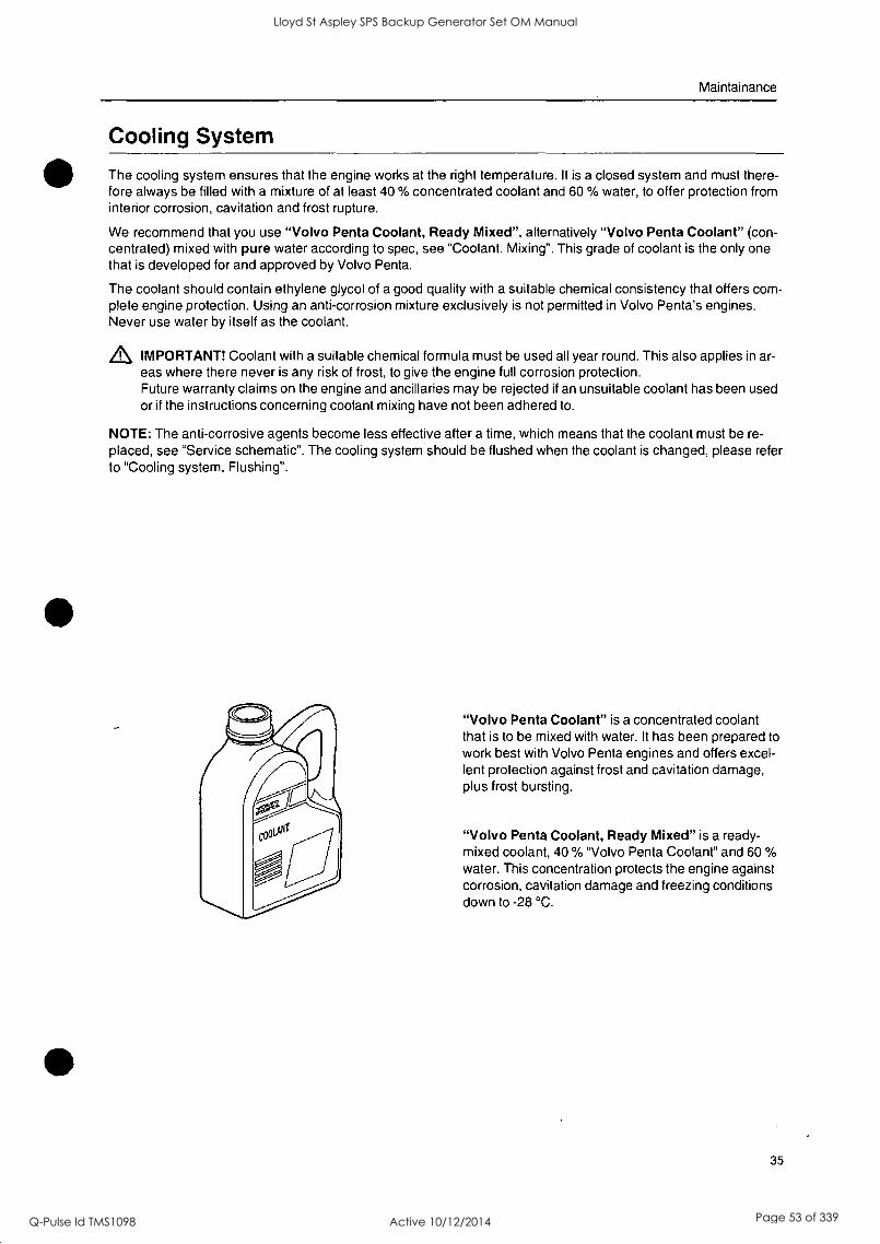
"Volvo Penta Coolant" is a concentrated coolant that is to be mixed with water. It has been prepared to work best with Volvo Penta engines and offers excel- lent protection against frost and cavitation damage, plus frost bursting.
"Volvo Penta Coolant, Ready Mixed" is a ready- mixed coolant, 40 % "Volvo Penta Coolant" and 60 % water. This concentration protects the engine against corrosion, cavitation damage and freezing conditions down to -28 °C.
35
Lloyd St Aspley SPS Backup Generator Set OM Manual
Q-Pulse Id TMS1098 Active 10/12/2014 Page 53 of 339

Lloyd St Aspley SPS Backup Generator Set OM Manual
Q-Pulse Id TMS1098 Active 10/12/2014 Page 54 of 339
Maintainance
36
Coolant. Mixing
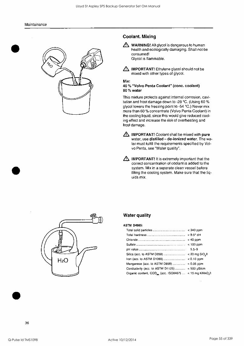
WARNING! All glycol is dangerous to human health and ecologically damaging. Shall not be consumed! Glycol is flammable.
IMPORTANT! Ethylene glycol should not be mixed with other types of glycol.
Mix: 40 % "Volvo Penta Coolant" (conc. coolant) 60 % water
This mixture protects against internal corrosion, cavi- tation and frost damage down to -28 °C. (Using 60 % glycol lowers the freezing point to -54 °C.) Never mix more than 60 % concentrate (Volvo Penta Coolant) in
the cooling liquid, since this would give reduced cool- ing effect and increase the risk of overheating and frost damage.
IMPORTANT! Coolant shall be mixed with pure water, use distilled - de-ionized water. The wa- ter must fulfill the requirements specified by Vol- vo Penta, see "Water quality".
IMPORTANT! It is extremely important that the correct concentration of coolant is added to the system. Mix in a separate clean vessel before filling the cooling system. Make sure that the liq- uids mix.
Water quality
ASTM D4985:
Total solid particles < 340 ppm
Total hardness < 9.5° dH
Chloride < 40 ppm
Sulfate < 100 ppm
pH value 5.5-9
Silica (acc. to ASTM 0859) < 20 mg SiO2/1
Iron (acc. to ASTM D1068) < 0.10 ppm
Manganese (acc. to ASTM D858) < 0.05 ppm
Conductivity (acc. to ASTM D1125) < 500 pS/cm
Organic content, COD,,,, (acc. IS08467) < 15 mg KMn04/1
Lloyd St Aspley SPS Backup Generator Set OM Manual
Q-Pulse Id TMS1098 Active 10/12/2014 Page 55 of 339
Maintainance
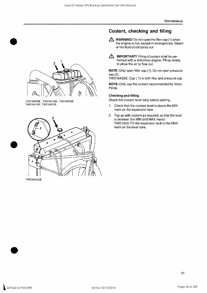
TAD1640GE, TAD1641GE, TAD1642GE TAD1641VE, TAD1642VE
TWD1643GE
Coolant, checking and filling
,L WARNING! Do not open the filler cap (1) when the engine is hot, except in emergencies. Steam or hot fluid could spray out.
IMPORTANT! Filling of coolant shall be per- formed with a stationary engine. Fill up slowly, to allow the air to flow out.
NOTE: Only open filler cap (1). Do not open pressure cap (2). TWD1643GE: Cap ( 1) is both filler and pressure cap.
NOTE: Only use the coolant recommended by Volvo Penta.
Checking and filling Check the coolant level daily before starting.
1. Check that the coolant level is above the MIN mark on the expansion tank.
2. Top up with coolant as required, so that the level is between the MIN and MAX marks. TWD1643: Fill the expansion tank to the MAX mark on the level tube.
37
Lloyd St Aspley SPS Backup Generator Set OM Manual
Q-Pulse Id TMS1098 Active 10/12/2014 Page 56 of 339

0
0
Lloyd St Aspley SPS Backup Generator Set OM Manual
Q-Pulse Id TMS1098 Active 10/12/2014 Page 57 of 339
Maintainance
TAD1640GE, TAD1641GE, TAD1642GE TAD1641VE, TAD1642VE
TWD1643GE
38
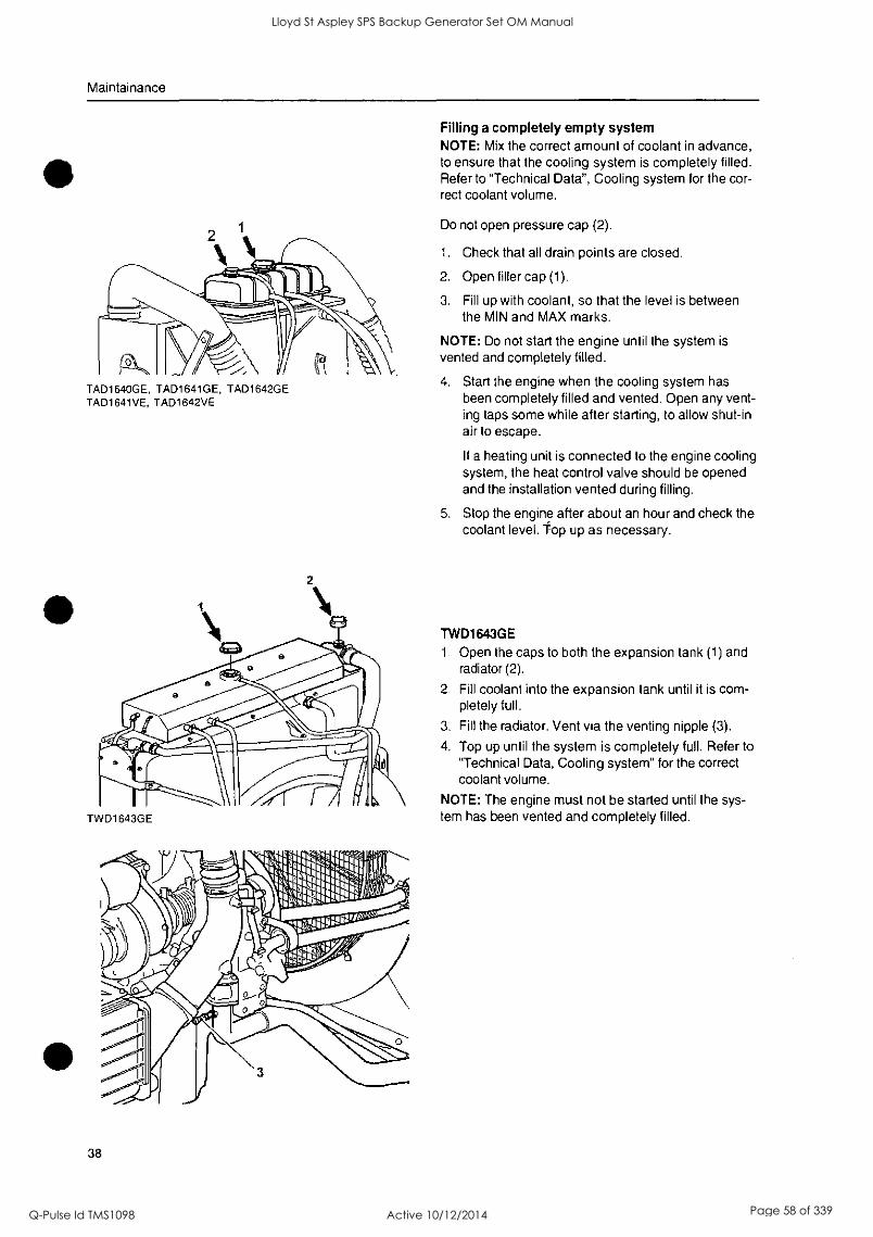
Filling a completely empty system NOTE: Mix the correct amount of coolant in advance, to ensure that the cooling system is completely filled. Refer to "Technical Data", Cooling system for the cor- rect coolant volume.
Do not open pressure cap (2).
1. Check that all drain points are closed.
2. Open filler cap (1).
3. Fill up with coolant, so that the level is between the MIN and MAX marks.
NOTE: Do not start the engine until the system is vented and completely filled.
4. Start the engine when the cooling system has been completely filled and vented. Open any vent- ing taps some while after starting, to allow shut-in air to escape.
If a heating unit is connected to the engine cooling system, the heat control valve should be opened and the installation vented during filling.
5. Stop the engine after about an hour and check the coolant level. Top up as necessary.
TWD1643GE
1. Open the caps to both the expansion tank (1) and radiator (2).
2. Fill coolant into the expansion tank until it is com- pletely full.
3. Fill the radiator. Vent via the venting nipple (3).
4. Top up until the system is completely full. Refer to "Technical Data, Cooling system" for the correct coolant volume.
NOTE: The engine must not be started until the sys- tem has been vented and completely filled.
Lloyd St Aspley SPS Backup Generator Set OM Manual
Q-Pulse Id TMS1098 Active 10/12/2014 Page 58 of 339

0
Lloyd St Aspley SPS Backup Generator Set OM Manual
Q-Pulse Id TMS1098 Active 10/12/2014 Page 59 of 339
Maintainance
TAD1640GE, TAD1641GE, TAD1642GE TAD1641VE, TAD1642VE
TWO1643GE
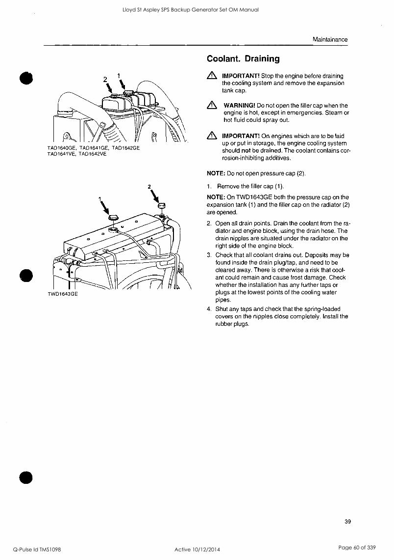
Coolant. Draining
IMPORTANT! Stop the engine before draining the cooling system and remove the expansion tank cap.
WARNING! Do not open the filler cap when the engine is hot, except in emergencies. Steam or hot fluid could spray out.
En, IMPORTANT! On engines which are to be laid up or put in storage, the engine cooling system should not be drained. The coolant contains cor- rosion-inhibiting additives.
NOTE: Do not open pressure cap (2).
1. Remove the filler cap (1).
NOTE: On TWD1643GE both the pressure cap on the expansion tank (1) and the filler cap on the radiator (2) are opened.
2. Open all drain points. Drain the coolant from the ra- diator and engine block, using the drain hose. The drain nipples are situated under the radiator on the right side of the engine block.
3. Check that all coolant drains out. Deposits may be found inside the drain plug/tap, and need to be cleared away. There is otherwise a risk that cool- ant could remain and cause frost damage. Check whether the installation has any further taps or plugs at the lowest points of the cooling water pipes.
4. Shut any taps and check that the spring-loaded covers on the nipples close completely. Install the rubber plugs.
39
Lloyd St Aspley SPS Backup Generator Set OM Manual
Q-Pulse Id TMS1098 Active 10/12/2014 Page 60 of 339

Lloyd St Aspley SPS Backup Generator Set OM Manual
Q-Pulse Id TMS1098 Active 10/12/2014 Page 61 of 339
Maintainance
40
Charge air cooler. External cleaning Remove guards as necessary, to access the cooler.
Clean with water and a mild detergent. Use a soft brush. Be careful not to damage the radiator matrix. Re-install the components
A IMPORTANT! Do not use a high pressure power washer.
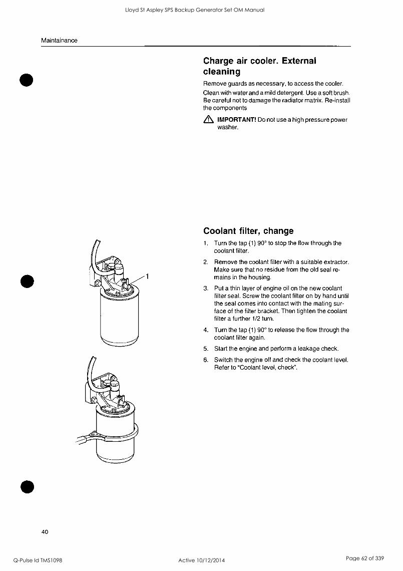
Coolant filter, change 1. Turn the tap (1) 90° to stop the flow through the
coolant filter.
2. Remove the coolant filter with a suitable extractor. Make sure that no residue from the old seal re- mains in the housing.
3. Put a thin layer of engine oil on the new coolant filter seal. Screw the coolant filter on by hand until the seal comes into contact with the mating sur- face of the filter bracket. Then tighten the coolant filter a further 1/2 turn.
4. Turn the tap (1) 90° to release the flow through the coolant filter again.
5. Start the engine and perform a leakage check.
6. Switch the engine off and check the coolant level. Refer to "Coolant level, check".
Lloyd St Aspley SPS Backup Generator Set OM Manual
Q-Pulse Id TMS1098 Active 10/12/2014 Page 62 of 339

Lloyd St Aspley SPS Backup Generator Set OM Manual
Q-Pulse Id TMS1098 Active 10/12/2014 Page 63 of 339
Maintainance
Cooling system, cleaning Cooling performance is reduced by deposits in the radi- ator and cooling galleries. The cooling system should be cleaned out when the coolant is changed.
,L IMPORTANT! Cleaning must not be done if there is any risk of the cooling system freezing, since the cleaning solution does not have any frost prevention ability.
1. Empty the cooling system. Refer to "Cooling sys- tem, draining".
2. Put a hose into the expansion tank filling hole and flush with clean water, as specified by Volvo Penta - refer to section "Water quality", until the water draining out is completely clear.
3. If there should still be some contamination left after flushing for a long time, cleaning can be done with coolant. Otherwise, continue as in item 8 below.
4. Fill the cooling system with 15-20 % mixture of concentrated coolant. Use only Volvo Penta rec- ommended concentrated coolant mixed with clean water.
5. Drain the coolant after 1-2 days of operation.
NOTE: To prevent suspended material from settling back in the system, emptying should be done rapidly, within the space of 10 minutes, when the engine has not been standing still for a long time. Remove the fill- er cap and possibly the lower radiator hose to in- crease the speed of emptying.
6. Flush the system immediately and thoroughly with clean hot water to prevent dirt from settling in the inner areas. Flush until the water that runs out is completely clean. Make sure that any heater con-
trols are set to full heating during emptying.
7. If contamination should still be left after a long pe- riod of flushing, you can do a clean-out with Volvo Penta radiator cleaner, followed by finishing-off with Volvo Penta neutralizer. Carefully follow the instruc- tions on the package. Otherwise, continue as in
item 8 below.
8. When the cooling system is completely free from contamination, close the drain taps and plugs.
9. Fill up with Volvo Penta recommended coolant, following the instructions in the chapters entitled "Coolant, mixing" and "Coolant, filling".
,L IMPORTANT! It is extremely important that the correct concentration and volume of coolant is put in the system. Mix in a separate clean ves- sel before filling the cooling system. Make sure that the liquids mix.
41
Lloyd St Aspley SPS Backup Generator Set OM Manual
Q-Pulse Id TMS1098 Active 10/12/2014 Page 64 of 339

_
0
0
0
Lloyd St Aspley SPS Backup Generator Set OM Manual
Q-Pulse Id TMS1098 Active 10/12/2014 Page 65 of 339
Maintainance
Fuel System
Only use the grades of fuel recommended in the fuel specification below. Always observe the greatest cleanliness during re-fueling and work on the fuel system.
All work on the injection system of the engine must be done by an authorized workshop.
WARNING! Fire hazard. Work on the fuel system must be done with the engine cold. Fuel spills on hot sur- faces or electrical components can cause fires. Store fuel-soaked rags in a fire-proof manner.
42
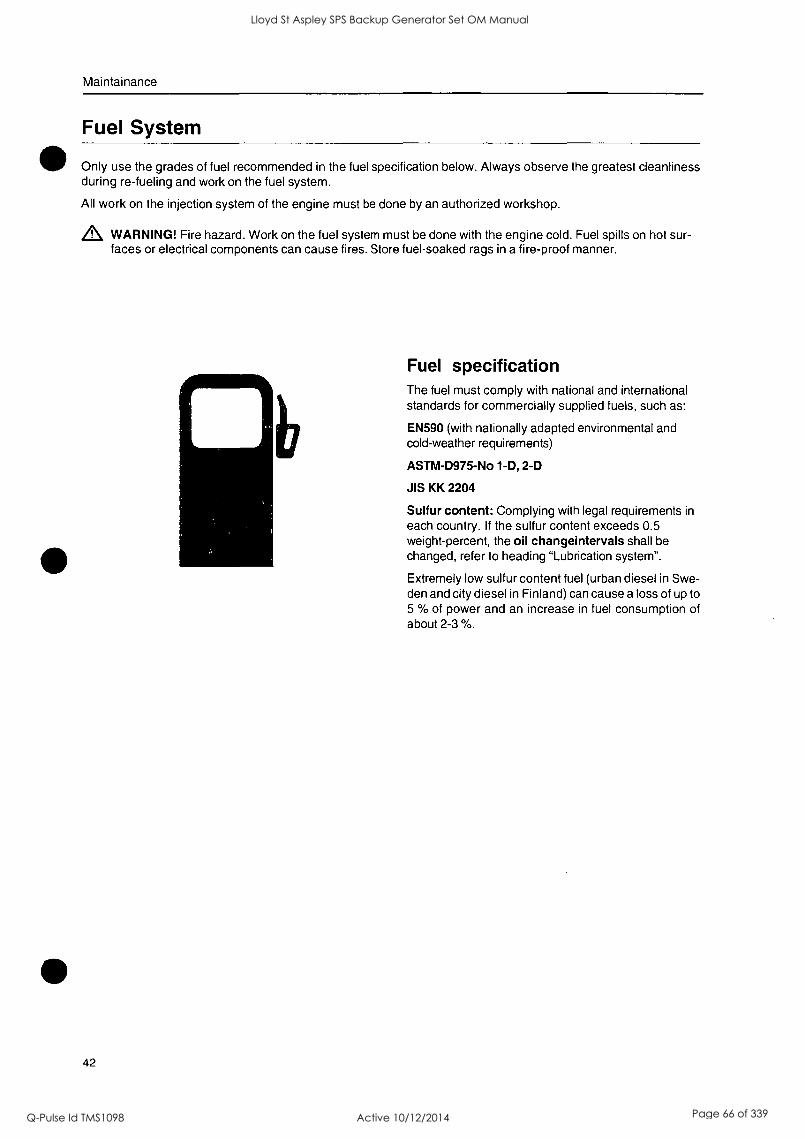
nb Fuel specification The fuel must comply with national and international standards for commercially supplied fuels, such as:
EN590 (with nationally adapted environmental and cold-weather requirements)
ASTM-D975-No 1-D, 2-D
JIS KK 2204
Sulfur content: Complying with legal requirements in
each country. If the sulfur content exceeds 0.5 weight-percent, the oil changeintervals shall be changed, refer to heading "Lubrication system".
Extremely low sulfur content fuel (urban diesel in Swe- den and city diesel in Finland) can cause a loss of up to 5 % of power and an increase in fuel consumption of about 2-3 %.
Lloyd St Aspley SPS Backup Generator Set OM Manual
Q-Pulse Id TMS1098 Active 10/12/2014 Page 66 of 339

Lloyd St Aspley SPS Backup Generator Set OM Manual
Q-Pulse Id TMS1098 Active 10/12/2014 Page 67 of 339
Maintainance
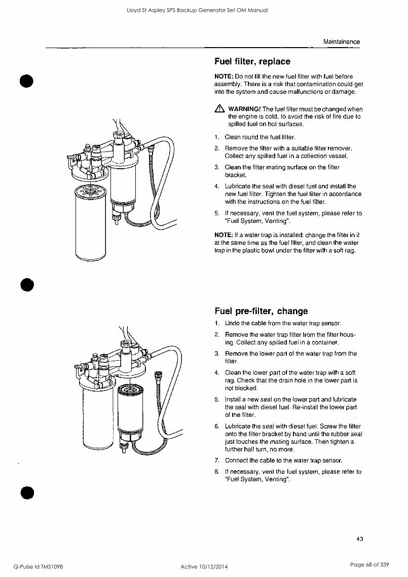
Fuel filter, replace
NOTE: Do not fill the new fuel filter with fuel before assembly. There is a risk that contamination could get into the system and cause malfunctions or damage.
WARNING! The fuel filter must be changed when the engine is cold, to avoid the risk of fire due to spilled fuel on hot surfaces.
1. Clean round the fuel filter.
2. Remove the filter with a suitable filter remover. Collect any spilled fuel in a collection vessel.
3. Clean the filter mating surface on the filter bracket.
4. Lubricate the seal with diesel fuel and install the new fuel filter. Tighten the fuel filter in accordance with the instructions on the fuel filter.
5. If necessary, vent the fuel system, please refer to "Fuel System, Venting".
NOTE: If a water trap is installed: change the filter in it
at the same time as the fuel filter, and clean the water trap in the plastic bowl under the filter with a soft rag.
Fuel pre-filter, change 1. Undo the cable from the water trap sensor.
2. Remove the water trap filter from the filter hous- ing. Collect any spilled fuel in a container.
3. Remove the lower part of the water trap from the filter.
4. Clean the lower part of the water trap with a soft rag. Check that the drain hole in the lower part is not blocked.
5. Install a new seal on the lower part and lubricate the seal with diesel fuel. Re-install the lower part of the filter.
6. Lubricate the seal with diesel fuel. Screw the filter onto the filter bracket by hand until the rubber seal just touches the mating surface. Then tighten a further half turn, no more.
7. Connect the cable to the water trap sensor.
8. If necessary, vent the fuel system, please refer to "Fuel System, Venting".
43
Lloyd St Aspley SPS Backup Generator Set OM Manual
Q-Pulse Id TMS1098 Active 10/12/2014 Page 68 of 339

Lloyd St Aspley SPS Backup Generator Set OM Manual
Q-Pulse Id TMS1098 Active 10/12/2014 Page 69 of 339
Maintainance
44
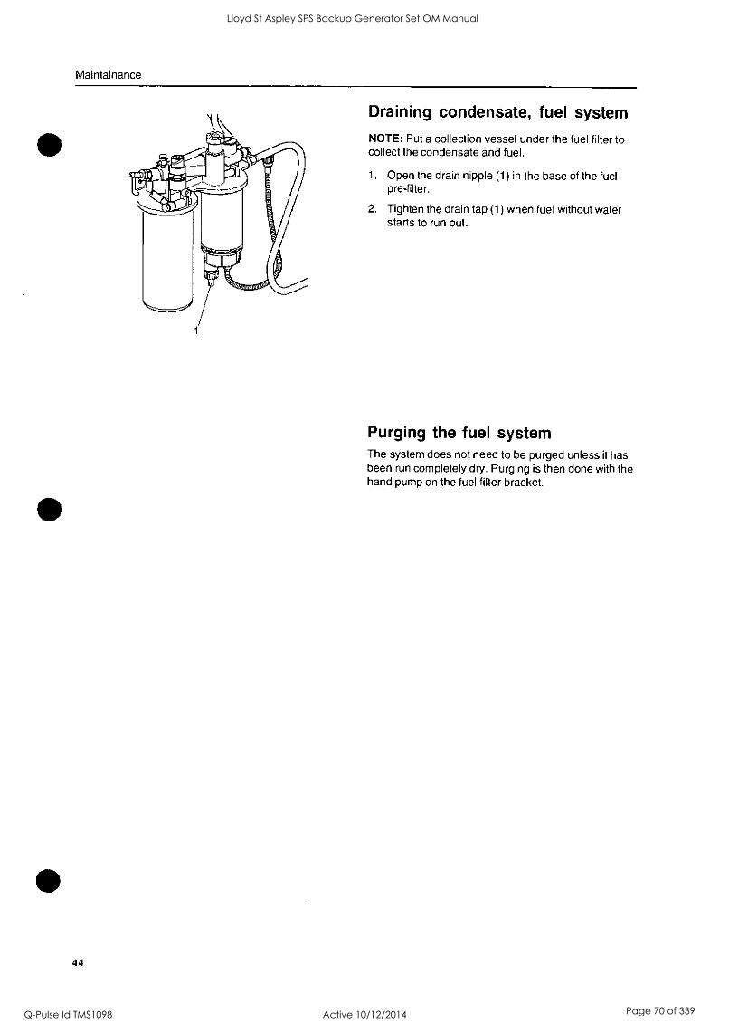
Draining condensate, fuel system
NOTE: Put a collection vessel under the fuel filter to collect the condensate and fuel.
1. Open the drain nipple (1) in the base of the fuel pre-filter.
2. Tighten the drain tap (1) when fuel without water starts to run out.
Purging the fuel system The system does not need to be purged unless it has been run completely dry. Purging is then done with the hand pump on the fuel filter bracket.
Lloyd St Aspley SPS Backup Generator Set OM Manual
Q-Pulse Id TMS1098 Active 10/12/2014 Page 70 of 339

Lloyd St Aspley SPS Backup Generator Set OM Manual
Q-Pulse Id TMS1098 Active 10/12/2014 Page 71 of 339

Maintainance
Electrical System The engine is equipped with a 2-pole electrical system and an alternator. System voltage is 24V.
WARNING! Before any work is done on the electrical system, the engine must be stopped and the power cut by switching off the main switch(es). All connections to equipment such as battery chargers or other auxil- iary equipment must be broken.
Main switch The main switches must never be disconnected be- fore the engine has been stopped. If the circuit be- tween the alternator and the battery is disconnected when the engine is running, the alternator and elec- tronics can be damaged. The charging circuits must never be re-connected with the engine running, for the same reason.
IMPORTANT! Never disconnect the current with the main switch(es) when the engine is running.
Fuses The engine is equipped with a 10 A fuse which breaks the current if overloaded.
The fuse is located on the left-hand side of the en- gine, please refer to Component Location.
Note. The engine stops if the fuse is triggered.
If the fuse trips frequently, an authorized Volvo Penta workshop should be contacted to investigate the cause of the overload.
Electrical connections Check that electrical connections are dry, free from oxide and that they are securely tightened. Spray these connections as necessary with water-repellent spray (Volvo Penta universal oil).
45
Lloyd St Aspley SPS Backup Generator Set OM Manual
Q-Pulse Id TMS1098 Active 10/12/2014 Page 72 of 339

Lloyd St Aspley SPS Backup Generator Set OM Manual
Q-Pulse Id TMS1098 Active 10/12/2014 Page 73 of 339
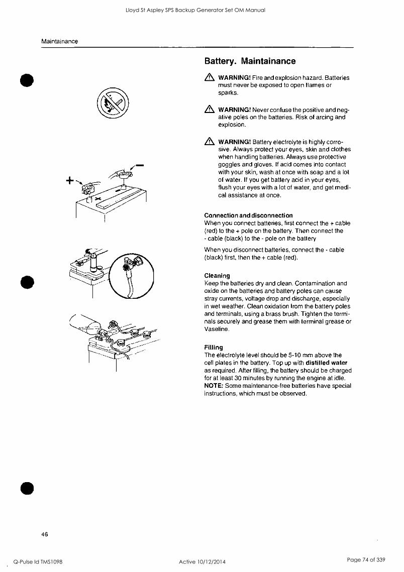
Maintainance
46
Battery. Maintainance
& WARNING! Fire and explosion hazard. Batteries must never be exposed to open flames or sparks.
& WARNING! Never confuse the positive and neg- ative poles on the batteries. Risk of arcing and explosion.
& WARNING! Battery electrolyte is highly corro- sive. Always protect your eyes, skin and clothes when handling batteries. Always use protective goggles and gloves. If acid comes into contact with your skin, wash at once with soap and a lot of water. If you get battery acid in your eyes, flush your eyes with a lot of water, and get medi- cal assistance at once.
Connection and disconnection When you connect batteries, first connect the + cable (red) to the + pole on the battery. Then connect the - cable (black) to the - pole on the battery
When you disconnect batteries, connect the - cable (black) first, then the + cable (red).
Cleaning Keep the batteries dry and clean. Contamination and oxide on the batteries and battery poles can cause stray currents, voltage drop and discharge, especially in wet weather. Clean oxidation from the battery poles and terminals, using a brass brush. Tighten the termi- nals securely and grease them with terminal grease or Vaseline.
Filling The electrolyte level should be 5-10 mm above the cell plates in the battery. Top up with distilled water as required. After filling, the battery should be charged for at least 30 minutes by running the engine at idle. NOTE: Some maintenance-free batteries have special instructions, which must be observed.
Lloyd St Aspley SPS Backup Generator Set OM Manual
Q-Pulse Id TMS1098 Active 10/12/2014 Page 74 of 339

0
Lloyd St Aspley SPS Backup Generator Set OM Manual
Q-Pulse Id TMS1098 Active 10/12/2014 Page 75 of 339
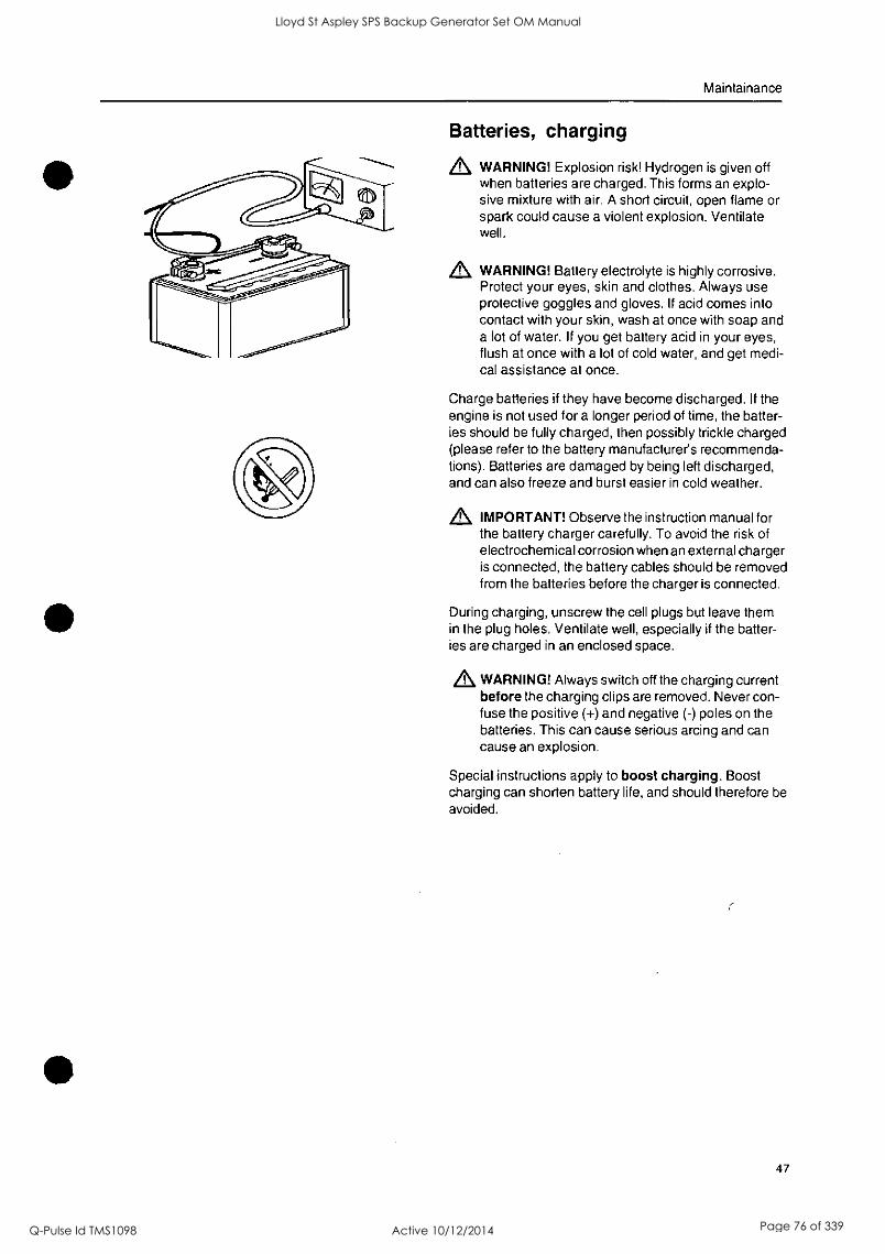
Maintainance
Batteries, charging
WARNING! Explosion risk! Hydrogen is given off when batteries are charged. This forms an explo- sive mixture with air. A short circuit, open flame or spark could cause a violent explosion. Ventilate well.
WARNING! Battery electrolyte is highly corrosive. Protect your eyes, skin and clothes. Always use protective goggles and gloves. If acid comes into contact with your skin, wash at once with soap and a lot of water. If you get battery acid in your eyes, flush at once with a lot of cold water, and get medi- cal assistance at once.
Charge batteries if they have become discharged. If the engine is not used for a longer period of time, the batter- ies should be fully charged, then possibly trickle charged (please refer to the battery manufacturer's recommenda- tions). Batteries are damaged by being left discharged, and can also freeze and burst easier in cold weather.
IMPORTANT! Observe the instruction manual for the battery charger carefully. To avoid the risk of electrochemical corrosion when an external charger is connected, the battery cables should be removed from the batteries before the charger is connected.
During charging, unscrew the cell plugs but leave them in the plug holes. Ventilate well, especially if the batter- ies are charged in an enclosed space.
WARNING! Always switch off the charging current before the charging clips are removed. Never con- fuse the positive (+) and negative (-) poles on the batteries. This can cause serious arcing and can cause an explosion.
Special instructions apply to boost charging. Boost charging can shorten battery life, and should therefore be avoided.
47
Lloyd St Aspley SPS Backup Generator Set OM Manual
Q-Pulse Id TMS1098 Active 10/12/2014 Page 76 of 339

Lloyd St Aspley SPS Backup Generator Set OM Manual
Q-Pulse Id TMS1098 Active 10/12/2014 Page 77 of 339
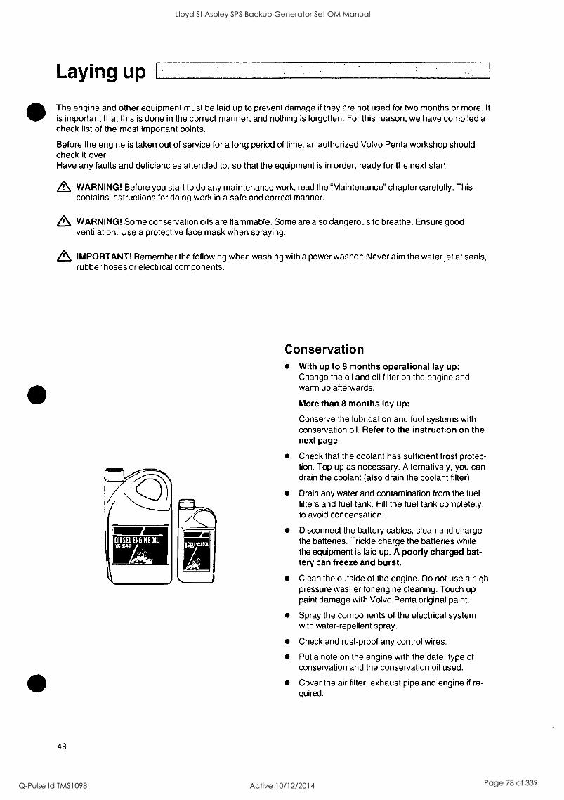
Laying up
The engine and other equipment must be laid up to prevent damage if they are not used for two months or more. It
is important that this is done in the correct manner, and nothing is forgotten. For this reason, we have compiled a check list of the most important points.
Before the engine is taken out of service for a long period of time, an authorized Volvo Penta workshop should check it over. Have any faults and deficiencies attended to, so that the equipment is in order, ready for the next start.
A WARNING! Before you start to do any maintenance work, read the "Maintenance" chapter carefully. This contains instructions for doing work in a safe and correct manner.
A WARNING! Some conservation oils are flammable. Some are also dangerous to breathe. Ensure good ventilation. Use a protective face mask when spraying.
A IMPORTANT! Remember the following when washing with a power washer: Never aim the water jet at seals, rubber hoses or electrical components.
48
(
Conservation With up to 8 months operational lay up: Change the oil and oil filter on the engine and warm up afterwards.
More than 8 months lay up:
Conserve the lubrication and fuel systems with conservation oil. Refer to the instruction on the next page.
Check that the coolant has sufficient frost protec- tion. Top up as necessary. Alternatively, you can drain the coolant (also drain the coolant filter).
Drain any water and contamination from the fuel filters and fuel tank. Fill the fuel tank completely, to avoid condensation.
Disconnect the battery cables, clean and charge the batteries. Trickle charge the batteries while the equipment is laid up. A poorly charged bat- tery can freeze and burst.
Clean the outside of the engine. Do not use a high pressure washer for engine cleaning. Touch up paint damage with Volvo Penta original paint.
Spray the components of the electrical system with water-repellent spray.
Check and rust-proof any control wires.
Put a note on the engine with the date, type of conservation and the conservation oil used.
Cover the air filter, exhaust pipe and engine if re- quired.
Lloyd St Aspley SPS Backup Generator Set OM Manual
Q-Pulse Id TMS1098 Active 10/12/2014 Page 78 of 339

Maintainance
Removing conservation preparations
Remove any covers from the engine, air filter and exhaust pipe.
Top the engine up with the correct grade of oil, if
necessary. Install a new oil filter if the filter was not changed during conservation.
Install new fuel filters and purge the fuel system.
Check the drive belt(s).
Check the condition of all rubber hoses, and re-
tighten the hose clamps.
Close any drain taps and install any drain plugs.
Check coolant level. Top up as necessary.
Connect the fully charged batteries.
Start the engine and warm it up at fast idle with no load.
Check that no oil, fuel, or coolant leaks occur.
Conservation of the lubrication and fuel systems for more than 8 months' stoppage:
Drain the oil from the engine and fill with conservation oil* to just over the MIN mark on the dipstick.
Connect the suction and return fuel lines to a
can filled with 1/3 conservation oil' and 2/3 diesel fuel.
Purge the fuel system.
Start the engine and run at a fast idle until about 2 liters of the fluid in the can has been used. Stop the engine and connect the ordinary fuel pipes.
Drain the conserving oil from the engine.
Follow the other instructions on the previous page.
Conservation oils are sold by oil companies.
49
Lloyd St Aspley SPS Backup Generator Set OM Manual
Q-Pulse Id TMS1098 Active 10/12/2014 Page 79 of 339

Lloyd St Aspley SPS Backup Generator Set OM Manual
Q-Pulse Id TMS1098 Active 10/12/2014 Page 80 of 339

Fault tracing A number of symptoms and possible causes of engine malfunctions are described in the table below. Always con- tact tact your Volvo Penta dealer if any problems occur which you cannot solve by yourself.
,L WARNING! Read the safety instructions for handling and service in the chapter "Safetyprecautions" before starting work.
Symptoms and possi6le causes
The diagnostic button indicator blinks
Engine cannot be stopped
Please refer to the "Diagnostic information" chapter
2, 5
Starter motor does not rotate 1, 2, 3, 4, 5, 6, 7, 24
Starter motor rotates slowly 1, 2
Starter motor rotates normally but engine does not start 8, 9, 10, 11,
Engine starts but stops again 8, 9, 10, 11, 13
Engine does not reach correct operating speed at full throttle 9, 10, 11, 12, 13, 21, 25, 26
Engine runs roughly 10, 11
High fuel consumption 12, 13, 15, 25
Black exhaust smoke 12, 13
Blue or white exhaust smoke 15, 22
Lubrication oil pressure too low 16
Coolant temperature too high 17, 18, 19, 20
Coolant temperature too low 20
No, or poor charge 2, 23
Exhaust temperature too high (only TWD1643GE) 13, 17, 18, 19, 21, 25, 27, 28, 29, 30
1. Discharged batteries
2. Poor contact/open circuit in
electrical wiring
3. Main switch turned off
4. Main fuse faulty
5. Faulty ignition lock
6. Faulty main relay
7. Faulty starter motor/solenoid
8. No fuel: - fuel cocks closed - fuel tank empty/wrong tank
connected
9. Blocked fuel fine-filter/ pre-filter (because of contam- ination, or stratification in the fuel at low temperature)
10. Air in the fuel system
50
11.
12.
13.
14.
15.
16.
17.
18.
19.
Water/contamination in fuel
Faulty unit injector
Insufficient air supply to the engine: - clogged air filter - air leakage between the
turbo and the engine's intake pipe
- dirty compressor part in the turbocharger
- faulty turbocharger - poor engine room ventilation
Coolant temperature too high
Coolant temperature too low
Oil level too low
Coolant level too low
Air in the coolant system
Faulty circulation pump
20. Defective thermostat
21. Blocked charge air cooler
22. Too high oil level
23. Alternator drive belt slips
24. Water entry into engine
25. High back pressure in the exhaust system
26. Break in "Pot+" cable to throttle
27. High temperature, charge air cooler
28. Blocked radiator
29. No pressure in cooling system
30. Check waste gate function
Lloyd St Aspley SPS Backup Generator Set OM Manual
Q-Pulse Id TMS1098 Active 10/12/2014 Page 81 of 339

Lloyd St Aspley SPS Backup Generator Set OM Manual
Q-Pulse Id TMS1098 Active 10/12/2014 Page 82 of 339
Diagnostic function
The diagnostic function monitors and controls that the EMS system functions normally.
The diagnostic function has the following tasks:
Detecting and locating disturbances
Reporting detection of disturbances
Providing guidance when fault tracing
Messages concerning malfunctions If the diagnostic function detects a disturbance in the system, this is reported using fault codes via the in-
struments.
Both active (un-rectified) and passive (rectified) faults are stored in the control unit.
Refer to the "Operation" heading for reading fault codes/fault messages.
All fault codes and fault messages are found in the fault code list, with information about the reason, reac- tion and measures to be taken. Refer to the "Fault codes" chapter
NOTE: All instruments are optional
Active faults DCU (Display Control Unit)
text "!! ENGINE WARNING !!" shown on the display.
NOTE: You can choose the language that the informa- tion is presented in.
CIU (Control Interface Unit)
the diagnostic lamp starts to flash.
"Easy Link" instrument (only with CIU)
- the relevant lamp on the alarm panel lights up
- after the diagnostic button has been pressed, the fault code is shown as text on the tacho- meter display.
DU (Display Unit)
Either "WARNING!" or "ALARM STOP" (a buzzer sounds) will be shown on the display, depending on the severity of the fault.
NOTE: You can choose the language that the informa- tion is presented in.
Fault codes can also be read off using the VODIA tool. For instructions, see "VODIA User's Guide".
At the same time, the fault is stored in the control unit memory. When the fault has been attended to and the ignition is switched off and on again, the fault disap- pears as active.
Inactive faults
DCU - the fault is indicated as passive
CIU - the diagnostic lamp goes out
DU - the fault message disappears (inactive faults cannot be read out)
"Easy Link" - the lamp on the alarm panel goes out
Effect on engine Engines are affected differently, depending on the se- verity of the fault discovered by the diagnostic func- tion.
A fault message in the form of a fault code is always generated when a malfunction is discovered by the di- agnostic function.
Engines are affected differently, depending on the se- verity of the fault.
The engine is not affected
Engine goes to idle
Engine torque is restricted to a certain amount
Engine is stopped
51
Lloyd St Aspley SPS Backup Generator Set OM Manual
Q-Pulse Id TMS1098 Active 10/12/2014 Page 83 of 339
Diagnostic function
Operation When a malfunction has occurred and the diagnostic system has generated one or more fault codes, these are read out differently depending on the equipment used. Please refer to "Fault code messages".
If the system indicates that a fault code has been set:
1. Cut engine speed to idle, or shut the engine off.
2. For DCU/DU Read the fault code from the display, please refer to "Reading fault codes via the DCU" or "Reading fault codes via the DU".
For CIU press the diagnostic button and read the fault code, by observing the flashing of the diagnostic lamp. Refer to "Reading fault codes via the diag- nostic lamp, CIU"
3. Look up the fault code in the "Fault Code" chapter and take the recommended measures.
Reading fault causes via the DCU (Dis- play Control Unit) When a fault code is set, the following text is shown on the display:
"!! ENGINE WARNING !!"
alternated with
"Press SEL for information".
NOTE: You can choose the language that the informa- tion is presented in.
Read the fault code as follows:
1. Press the SEL button (to come to the fault list. The fault list shows: - Operation hours - Fault message - Active/inactive
2. Look up the fault code in the "Fault Code" chapter and take the recommended measures.
3. Press the ESC button to leave the fault list.
NOTE: To enter the fault list when no fault code has been set, press the SEL button and select "Diagnos- tics" from the menu.
52
Reading fault codes via the DU (Display Unit) Depending on the severity of the fault the text, either "WARNING!" or "ALARM STOP" (a buzzer sounds) will be shown on the display.
1. Press any button to come to the fault list.
The fault list shows: - Operation hours - Fault message
2. Look up the fault code in the "Fault Code" chapter and take the recommended measures.
3. Press on ACK to acknowledge the fault code. The display background will change color (the buzzer stops sounding).
4. Press on EXIT to leave the fault list.
Lloyd St Aspley SPS Backup Generator Set OM Manual
Q-Pulse Id TMS1098 Active 10/12/2014 Page 84 of 339
Reading fault codes via the diagnostic lamp on the instrument panel, CIU
When the system has discovered a malfunction, the diagnostic lamp starts to flash. If the diagnostic but- ton is depressed and then released, a fault code is
flashed out. The fault code consists of two groups of flashes, sep- arated by a pause of two seconds. A fault code is ob- tained by counting the number of flashes in each group.
Example: -;+:- pause -;+; = Fault code 2.4
The fault code is stored and can be read as long as the malfunction remains. You can find information about cause, reaction and actions in the "Fault Code" chapter.
Read the fault code as follows:
1. Press the diagnostic button.
2. Release the diagnostic button and make a note of the fault that is flashed out.
3. Repeat items 1-2. A new fault code is flashed out if more are stored. Repeat until the first fault code is repeated.
NOTE: When the first fault code reoccurs, all the fault codes have been read. If the diagnostics button is depressed after the fault has been corrected and the fault code deleted, the code 1.1, "No fault" will be shown.
Reading the fault codes via an "Easy link" instrument (only with a CIU)
When the system has discovered a malfunction, this is reported by the diagnostic lamp which starts to flash.
1. Press the diagnostic button. The fault code is shown as text on the tachometer display.
2. Look up the fault code in the "Fault Code" chapter and take the recommended measures.
3. When the fault has been rectified, the fault code disappears from the display and the diagnostic lamp goes out.
Erasing fault codes Fault codes must be erased by means of the VODIA tool.
53
Lloyd St Aspley SPS Backup Generator Set OM Manual
Q-Pulse Id TMS1098 Active 10/12/2014 Page 85 of 339

S
0
0
_
Lloyd St Aspley SPS Backup Generator Set OM Manual
Q-Pulse Id TMS1098 Active 10/12/2014 Page 86 of 339
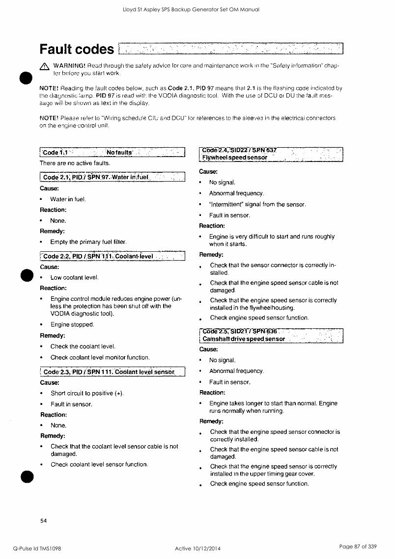
Fault codes WARNING! Read through the safety advice for care and maintenance work in the "Safety information" chap- ter before you start work.
NOTE! Reading the fault codes below, such as Code 2.1, PID 97 means that 2.1 is the flashing code indicated by the diagnostic lamp. PID 97 is read with the VODIA diagnostic tool. With the use of DCU or DU the fault mes- sage will be shown as text in the display.
NOTE! Please refer to "Wiring schedule CIU and DCU" for references to the sleeves in the electrical connectors on the engine control unit.
No faults'
There are no active faults.
1 Code 2:1,;.01131 SON:97.1Nater ititUar.
Cause:
Water in fuel.
Reaction:
None.
Remedy:
Empty the primary fuel filter.
['Code PID / SPN111:-.Coolantievel
Cause:
41) Low coolant level.
Reaction:
Engine control module reduces engine power (un- less the protection has been shut off with the VODIA diagnostic tool).
Engine stopped.
Remedy:
Check the coolant level.
Check coolant level monitor function.
1 Code 2.3, PID / SPN'111:COolant .sensOr,
Cause:
Short circuit to positive (+).
Fault in sensor.
Reaction:
None.
Remedy:
Check that the coolant level sensor cable is not damaged.
Check coolant level sensor function.
54
C07:1-672.478111227SPN 637 FlyVitheel speed sensor
Cause:
No signal.
Abnormal frequency.
"Intermittent" signal from the sensor.
Fault in sensor.
Reaction:
Engine is very difficult to start and runs roughly when it starts.
Remedy:
Check that the sensor connector is correctly in- stalled.
Check that the engine speed sensor cable is not damaged.
Check that the engine speed sensor is correctly installed in the flywheelhousing.
Check engine speed sensor function.
FC-57:1F-2-.-5;81D21 / SPN.636 Camshaft drive speed sensor
Cause:
No signal.
Abnormal frequency.
Fault in sensor.
Reaction:
Engine takes longer to start than normal. Engine runs normally when running.
Remedy:
Check that the engine speed sensor connector is correctly installed.
Check that the engine speed sensor cable is not damaged.
Check that the engine speed sensor is correctly installed in the upper timing gear cover.
Check engine speed sensor function.
Lloyd St Aspley SPS Backup Generator Set OM Manual
Q-Pulse Id TMS1098 Active 10/12/2014 Page 87 of 339

0
Lloyd St Aspley SPS Backup Generator Set OM Manual
Q-Pulse Id TMS1098 Active 10/12/2014 Page 88 of 339
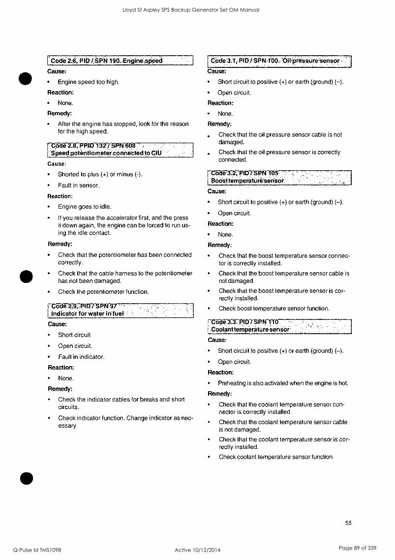
Code2:6; PID/SPN190..Erigine,Sfieed
Cause:
Engine speed too high.
Reaction:
None. Reaction:
Remedy: None.
After the engine has stopped, look for the reason Remedy: for the high speed.
Code 3.1', PIDI-SPN-100. '68;pressure'Sensor
Cause:
Short circuit to positive (+) or earth (ground) (-).
Open circuit.
IT-Code 2.8, PPID 1327/ SPN108 1 Speed potentiometer connected to CIU
Cause:
Shorted to plus (+) or minus (-).
Fault in sensor.
Reaction:
Engine goes to idle.
If you release the accelerator first, and the press it down again, the engine can be forced to run us- ing the idle contact.
Remedy:
Check that the oil pressure sensor cable is not damaged.
Check that the oil pressure sensor is correctly connected.
i-Clide73:27p1D1 SP N 105, I3oost temperature-sensor
Cause:
Short circuit to positive (+) or earth (ground) (-).
Open circuit.
Reaction:
None.
Remedy:
Check that the potentiometer has been connected Check that the boost temperature sensor connec- correctly. for is correctly installed.
Check that the cable harness to the potentiometer has not been damaged.
Check the potentiometer function.
t-a-di-27;9TP! D7/SPN87 t Indicator for water m`fuel
Cause:
Short circuit
Open circuit.
Fault in indicator.
Reaction:
None.
Remedy:
Check the indicator cables for breaks and short circuits.
Check indicator function. Change indicator as nec- essary
Check that the boost temperature sensor cable is not damaged.
Check that the boost temperature sensor is cor- rectly installed.
Check boost temperature sensor function.
Code 3.3. PID / SPN 110 1 Coolant temperatureSensor'
Cause:
Short circuit to positive (+) or earth (ground) (-).
Open circuit.
Reaction:
Preheating is also activated when the engine is hot.
Remedy:
Check that the coolant temperature sensor con- nector is correctly installed.
Check that the coolant temperature sensor cable is not damaged.
Check that the coolant temperature sensor is cor- rectly installed.
Check coolant temperature sensor function.
55
Lloyd St Aspley SPS Backup Generator Set OM Manual
Q-Pulse Id TMS1098 Active 10/12/2014 Page 89 of 339

0
Lloyd St Aspley SPS Backup Generator Set OM Manual
Q-Pulse Id TMS1098 Active 10/12/2014 Page 90 of 339
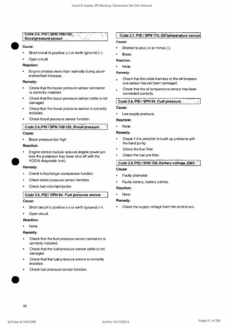
ecide..i.7,-klilbi$PN10:0111teilfp-el'atUii,'sens, 'Code 314, P11//SP.N7136/1.02,, Boost Pressure Sensor
Cause:
Short circuit to positive (+) or earth (ground) (-).
Open circuit.
Reaction:
Engine smokes more than normally during accel- eration/load increase.
Remedy:
Check that the boost pressure sensor connector is correctly installed.
Check that the boost pressure sensor cable is not damaged.
Check that the boost pressure sensor is correctly installed.
Check boost pressure sensor function.
Code 35;PID1SPN i 06/102.,Boosf PresSures-
Cause:
Boost pressure too high
Reaction:
Engine control module reduces engine power (un- less the protection has been shut off with the VODIA diagnostic tool).
Remedy:
Check turbocharger compressor function.
Check boost pressure sensor function.
Check fuel volume/injector.
r _Code SPN:94. Fual.pressUre sensor
Cause:
Short circuit to positive (+) or earth (ground) (-).
Open circuit.
Reaction:
None.
Remedy:
Check that the fuel pressure sensor connector is
correctly installed.
Check that the fuel pressure sensor cable is not damaged.
Check that the fuel pressure sensor is correctly installed.
Check fuel pressure sensor function.
56
Cause:
Shorted to plus (+) or minus (-).
Break.
Reaction:
None.
Remedy:
Check that the cable harness to the oil tempera- ture sensor has not been damaged.
Check that the oil temperature sensor has been connected correctly.
Code38,?.tp / SRN 94..FUelpresSurec
Cause:
Low supply pressure.
Reaction:
None.
Remedy:
Check if it is possible to build up pressure with the hand pump.
Check the fuel filter.
Check the fuel pre-filter.
LCOde 3.9,7:P1131_SP.N159.13pitery'vOliage,.:B
Cause:
Faulty alternator.
Faulty battery, battery cables.
Reaction:
None.
Remedy:
Check the supply voltage from the control unit.
Lloyd St Aspley SPS Backup Generator Set OM Manual
Q-Pulse Id TMS1098 Active 10/12/2014 Page 91 of 339

0
Lloyd St Aspley SPS Backup Generator Set OM Manual
Q-Pulse Id TMS1098 Active 10/12/2014 Page 92 of 339
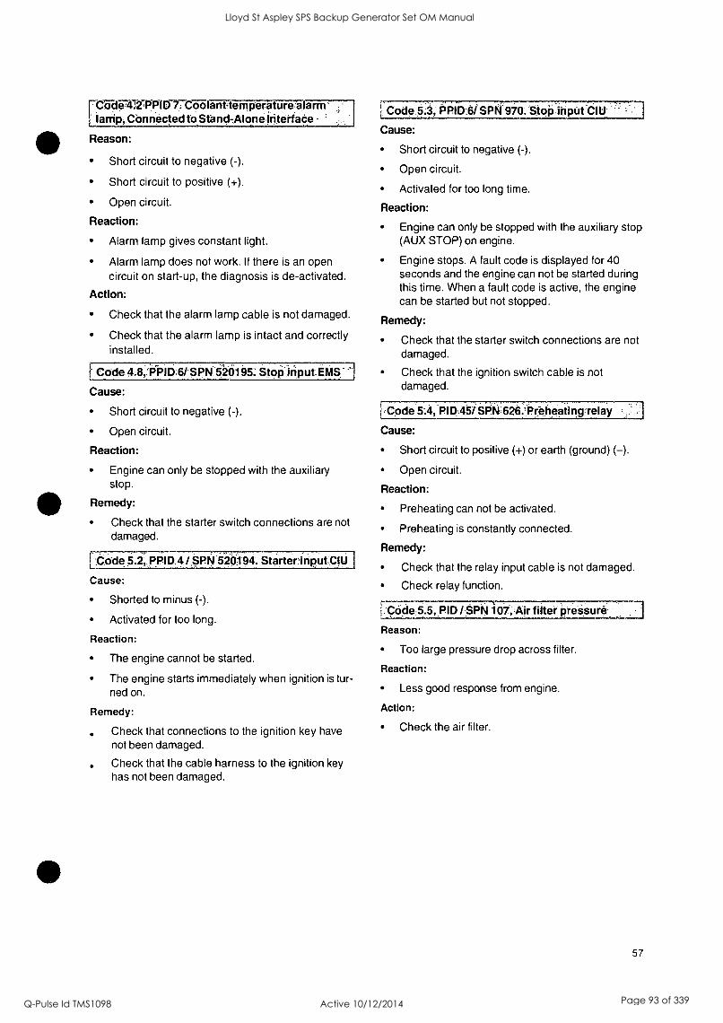
CiiF4TTP1117:C71anttem peratu re a la rm r larrip,COnnectedtbStand-AlonefriterfaCe -
Reason:
Short circuit to negative (-).
Short circuit to positive (+).
Open circuit.
Reaction:
Code 5.3, PPID:USPN 970. Stop input CIU
Cause:
Short circuit to negative (-).
Open circuit.
Activated for too long time.
Reaction:
Engine can only be stopped with the auxiliary stop Alarm lamp gives constant light. (AUX STOP) on engine.
Alarm lamp does not work. If there is an open circuit on start-up, the diagnosis is de-activated.
Action:
Check that the alarm lamp cable is not damaged.
Check that the alarm lamp is intact and correctly installed.
Code 4.8,13`011167 SPN 520135: StoPiriput.EMS. - Cause:
Short circuit to negative (-).
Open circuit.
Reaction:
Engine can only be stopped with the auxiliary stop.
Remedy:
Check that the starter switch connections are not damaged.
Loode 5.413131D 4 /,SPN 52094. S6rter inputClti
Cause:
Shorted to minus (-).
Activated for too long.
Reaction:
The engine cannot be started.
The engine starts immediately when ignition is tur- ned on.
Remedy:
Check that connections to the ignition key have not been damaged.
Check that the cable harness to the ignition key has not been damaged.
Engine stops. A fault code is displayed for 40 seconds and the engine can not be started during this time. When a fault code is active, the engine can be started but not stopped.
Remedy:
Check that the starter switch connections are not damaged.
Check that the ignition switch cable is not damaged.
[-Code 5:4, PID,457 SP.4625.10(eheatinorelay
Cause:
Short circuit to positive (+) or earth (ground) (-).
Open circuit.
Reaction:
Preheating can not be activated.
Preheating is constantly connected.
Remedy:
Check that the relay input cable is not damaged.
Check relay function.
Code 5.5, PID SPN 107; Air filter pressure
Reason:
Too large pressure drop across filter.
Reaction:
Less good response from engine.
Action:
Check the air filter.
57
Lloyd St Aspley SPS Backup Generator Set OM Manual
Q-Pulse Id TMS1098 Active 10/12/2014 Page 93 of 339

Lloyd St Aspley SPS Backup Generator Set OM Manual
Q-Pulse Id TMS1098 Active 10/12/2014 Page 94 of 339

Code 5 6, PID /SPN 107. Air filter sensor;;
Cause:
Shorted to plus (+) or minus (-).
Break.
Reaction:
None
Remedy:
Check that the air filter sensor contact is correctly installed.
Check that the cable harness to air filter sensor has not been damaged.
Check the air filter sensor functionality.
Code t./:-PID spnr 98, oiliev:61
Cause:
Oil level is too low.
Reaction:
Warning indication.
Remedy:
Check the oil level.
Code 6 1,;PID / SP.N 1;10.. Coolant temperature
Cause:
Coolant temperature is too high.
Reaction:
Engine control module reduces engine power (un- less the protection has been shut off with the VODIA diagnostic tool).
Remedy:
Check the coolant level.
Check the intercooler (cleanliness).
Check if there is air in the cooling system.
Check the pressure cap on the expansion tank.
Check coolant temperature sensor function.
Check thermostat function.
Code;6:2, PID /$141105:13postiernperatuie
Cause:
Boost temperature is too high.
Reaction:
Engine control module reduces engine power (un- less the protection has been shut off with the VODIA diagnostic tool).
Cause: Remedy:
Oil temperature is too high Check the coolant level.
Reaction: Check the intercooler (cleanliness).
Warning indication. Check boost temperature sensor function.
The engine control module limits engine output Check the function of the thermostat.
(unless protection has been turned off with the diagnosis tool VODIA). rardT6T4-P PI D-317-SP N76-7 DWI ifqcAN),
I
CIU,
Cause:
Faulty data link (CAN), CIU.
Reaction:
Instruments and warning lamps stop working.
Remedy:
Cause: Check that the 8-pin connector is not damaged.
Remedy:
Check the oil level.
Check the oil temperature.
Check the oil temperature sensor function.
.Code 5.9, PID / SPN 98.0i1 level sensor
Shorted to plus (+) or minus (-).
Break.
Reaction:
None.
Remedy:
Check that the cable harness to the oil level sen- sor has not been damaged.
Check the oil level sensor function.
58
Check that the cables between the CIU and the engine management unit are not damaged.
Lloyd St Aspley SPS Backup Generator Set OM Manual
Q-Pulse Id TMS1098 Active 10/12/2014 Page 95 of 339

0
0
Lloyd St Aspley SPS Backup Generator Set OM Manual
Q-Pulse Id TMS1098 Active 10/12/2014 Page 96 of 339
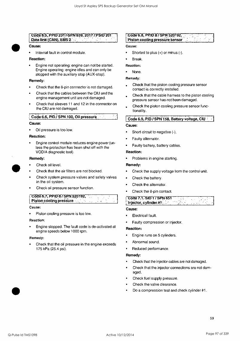
7C-67:101675,,PPID 2 al7FSF!NT6-3-0720171P
'Data link(CAN), EMS'.2
Cause:
Internal fault in control module.
Reaction:
Engine not operating: engine can not be started. Engine operating: engine idles and can only be
stopped with the auxiliary stop (AUX-stop).
Remedy:
Check that the 8-pin connector is not damaged.
Check that the cables between the CIU and the engine management unit are not damaged.
Check that sleeves 11 and 12 in the connector on the CIU are not damaged.
'COde6:6, pio,/ N op,: oil pressuro
Cause:
Oil pressure is too low.
Reaction:
Engine control module reduces engine power (un- less the protection has been shut off with the VODIA diagnostic tool).
Remedy:
Check oil level.
Check that the air filters are not blocked.
Check system pressure valves and safety valves in the oil system.
Check oil pressure sensor function.
rCiide6:7TPPI D.8 SPN1520192, pisionpOoling'preasUre
Cause:
Piston cooling pressure is too low.
Reaction:
Engine stopped. The fault code is de-activated at engine speeds below 1000 rpm.
Remedy:
Check that the oil pressure in the engine exceeds 175 kPa (25.4 psi).
rCode'6.8, PPID 8 /SPN-529192; 'Piston cooling pressure Sensor
Cause:
Shorted to plus (+) or minus (-).
Break.
Reaction:
None.
Remedy:
. Check that the piston cooling pressure sensor contact is correctly installed.
Check that the cable harness to the piston cooling pressure sensor has not been damaged.
. Check the piston cooling pressure sensor func- tionality.
Code 69; PID tSPN'158, Battery voltage, CIU I
Cause:
Short circuit to negative (-).
Faulty alternator.
Faulty battery, battery cables.
Reaction:
Problems in engine starting.
Remedy:
Check the supply voltage from the control unit.
Check the battery.
Check the alternator.
Check the 8-pin contact.
17-Code 7.1. SID 1/ SPN 651 1:InjeCtor, cylinder #1, '
Cause:
Electrical fault.
Faulty compression or injector.
Reaction:
Engine runs on 5 cylinders.
Abnormal sound.
Reduced performance.
Remedy:
Check that the injector cables are not damaged.
Check that the injector connections are not dam- aged.
Check fuel supply pressure.
Check the valve clearance.
Do a compression test and check cylinder #1.
59
Lloyd St Aspley SPS Backup Generator Set OM Manual
Q-Pulse Id TMS1098 Active 10/12/2014 Page 97 of 339

0
0
Lloyd St Aspley SPS Backup Generator Set OM Manual
Q-Pulse Id TMS1098 Active 10/12/2014 Page 98 of 339
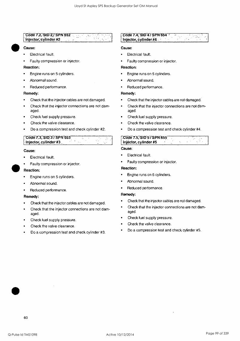
'Code 7,2,SIA,2,1SPN 652 I Injectorcylinder#2
Cause:
Electrical fault.
Faulty compression or injector.
Reaction:
Engine runs on 5 cylinders.
Abnormal sound.
Reduced performance.
Remedy:
Check that the injector cables are not damaged.
Check that the injector connections are not dam- aged.
Check fuel supply pressure.
Check the valve clearance.
Do a compression test and check cylinder #2.
f-C-6-de-7:37SID-ITSPN 653 Injector; cylinder #3
Cause:
Electrical fault.
Faulty compression or injector.
Reaction:
Engine runs on 5 cylinders.
Abnormal sound.
Reduced performance.
Remedy:
Check that the injector cables are not damaged.
Check that the injector connections are not dam- aged.
Check fuel supply pressure.
Check the valve clearance.
Do a compression test and check cylinder #3.
60
FCode 7.4,7SID 43SFN 654 Injector, Cyljnder-#4
Cause:
Electrical fault.
Faulty compression or injector.
Reaction:
Engine runs on 5 cylinders.
Abnormal sound.
Reduced performance.
Remedy:
Check that the injector cables are not damaged.
Check that the injector connections are not dam- aged.
Check fuel supply pressure.
Check the valve clearance.
Do a compression test and check cylinder #4.
rttide 7.57SID5-rsPN 655 i
Injector, cylinder #5
Cause:
Electrical fault.
Faulty compression or injector.
Reaction:
Engine runs on 5 cylinders.
Abnormal sound.
Reduced performance.
Remedy:
Check that the injector cables are not damaged.
Check that the injector connections are not dam- aged.
Check fuel supply pressure.
Check the valve clearance.
Do a compression test and check cylinder #5.
Lloyd St Aspley SPS Backup Generator Set OM Manual
Q-Pulse Id TMS1098 Active 10/12/2014 Page 99 of 339

0
Lloyd St Aspley SPS Backup Generator Set OM Manual
Q-Pulse Id TMS1098 Active 10/12/2014 Page 100 of 339
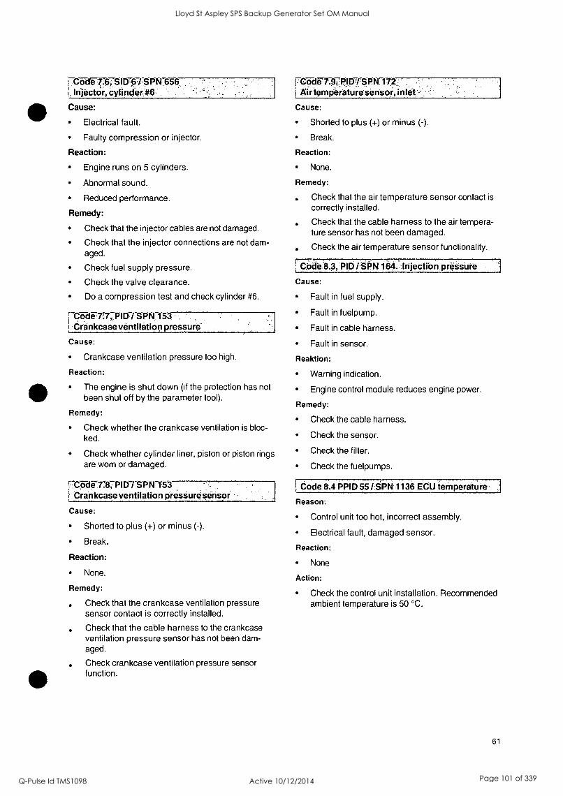
FC-5E1 SID76/ SRN 656, ( Infect Or, cylinder#6
reb-dgraTRIP SRN 17,2 ,Air, temgeraturesensoi, inlet'-
Cause: Cause:
Electrical fault.
Faulty compression or injector. Break.
Reaction: Reaction:
Engine runs on 5 cylinders. None.
Abnormal sound. Remedy:
Reduced performance.
Remedy:
Check that the injector cables are not damaged.
Check that the injector connections are not dam- aged.
Check fuel supply pressure.
Check the valve clearance.
Do a compression test and check cylinder #6.
Shorted to plus (+) or minus (-).
Code 7i7, PID / SPN 153 Crankcaseventilation pressure'
Cause:
Crankcase ventilation pressure too high.
Reaction:
The engine is shut down (if the protection has not been shut off by the parameter tool).
Remedy:
Check whether the crankcase ventilation is bloc- ked.
Check whether cylinder liner, piston or piston rings are worn or damaged.
r-CcideITCP I Cr/SPN-1`53 '
Crankcase ventilation presiure sensor
Cause:
Shorted to plus (+) or minus (-).
Break.
Reaction:
None.
Remedy:
Check that the crankcase ventilation pressure sensor contact is correctly installed.
Check that the cable harness to the crankcase ventilation pressure sensor has not been dam- aged.
Check crankcase ventilation pressure sensor function.
Check that the air temperature sensor contact is
correctly installed.
Check that the cable harness to the air tempera- ture sensor has not been damaged.
Check the air temperature sensor functionality.
I Cod6'8.3, PID /SRN 164. Injectibn pressure
Cause:
Fault in fuel supply.
Fault in fuelpump.
Fault in cable harness.
Fault in sensor.
Reaktion:
Warning indication.
Engine control module reduces engine power.
Remedy:
Check the cable harness.
Check the sensor.
Check the filter.
Check the fuelpumps.
I Code 8.4 PPID 55 /,PN 1136 ECU temperature
Reason:
Control unit too hot, incorrect assembly.
Electrical fault, damaged sensor.
Reaction:
None
Action:
Check the control unit installation. Recommended ambient temperature is 50 °C.
61
Lloyd St Aspley SPS Backup Generator Set OM Manual
Q-Pulse Id TMS1098 Active 10/12/2014 Page 101 of 339

0
0
Lloyd St Aspley SPS Backup Generator Set OM Manual
Q-Pulse Id TMS1098 Active 10/12/2014 Page 102 of 339
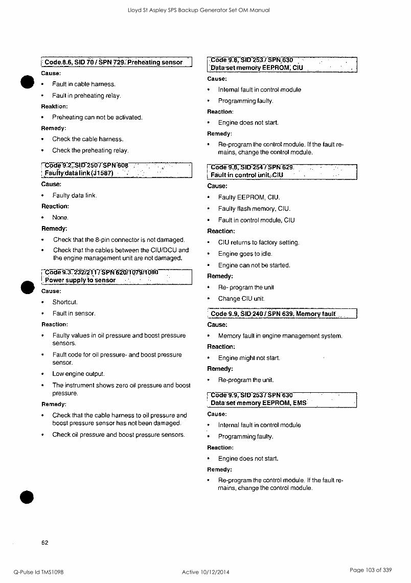
Code8.6, SID io SPN '729: Preheating sensor
Cause:
Fault in cable harness.
Fault in preheating relay.
Reaktion:
Preheating can not be activated.
Remedy:
Check the cable harness.
Check the preheating relay.
(-Code 9.2,,SID 250 / SPN608 .Faulty'data link (J1587)
Cause:
Faulty data link.
Reaction:
None.
Remedy:
Check that the 8-pin connector is not damaged.
Check that the cables between the CIU/DCU and the engine management unit are not damaged.
Code 9.3.232/211 / SPN 620/1 079/1 0-8-0--- ! Oower supply:to sensor
Cause:
Shortcut.
Fault in sensor.
Reaction:
Faulty values in oil pressure and boost pressure sensors.
Fault code for oil pressure- and boost pressure sensor.
Low engine output.
The instrument shows zero oil pressure and boost pressure.
Remedy:
Check that the cable harness to oil pressure and boost pressure sensor has not been damaged.
Check oil pressure and boost pressure sensors.
62
Cb-d-e-9afTSI D-253. / S P N,630 .:Dataset memory EEPROM; CIU
Cause:
Internal fault in control module
Programming faulty.
Reaction:
Engine does not start.
Remedy:
Re-program the control module. If the fault re- mains, change the control module.
f Code SID'254./SPN 629. Fault in control unit ,CIU
Cause:
Faulty EEPROM, CIU.
Faulty flash memory, CIU.
Fault in control module, CIU
Reaction:
CIU returns to factory setting.
Engine goes to idle.
Engine can not be started.
Remedy:
Re- program the unit
Change CIU unit.
Code 9.9, SID 240 / SPN 639. Memory fault
Cause:
Memory fault in engine management system.
Reaction:
Engine might not start.
Remedy:
Re-program the unit.
1-Cc-i-de-9.797SID-253 / SPN 630 Datasetmemory EEPROM, EMS
Cause:
Internal fault in control module
Programming faulty.
Reaction:
Engine does not start.
Remedy:
Re-program the control module. If the fault re- mains, change the control module.
Lloyd St Aspley SPS Backup Generator Set OM Manual
Q-Pulse Id TMS1098 Active 10/12/2014 Page 103 of 339

Lloyd St Aspley SPS Backup Generator Set OM Manual
Q-Pulse Id TMS1098 Active 10/12/2014 Page 104 of 339
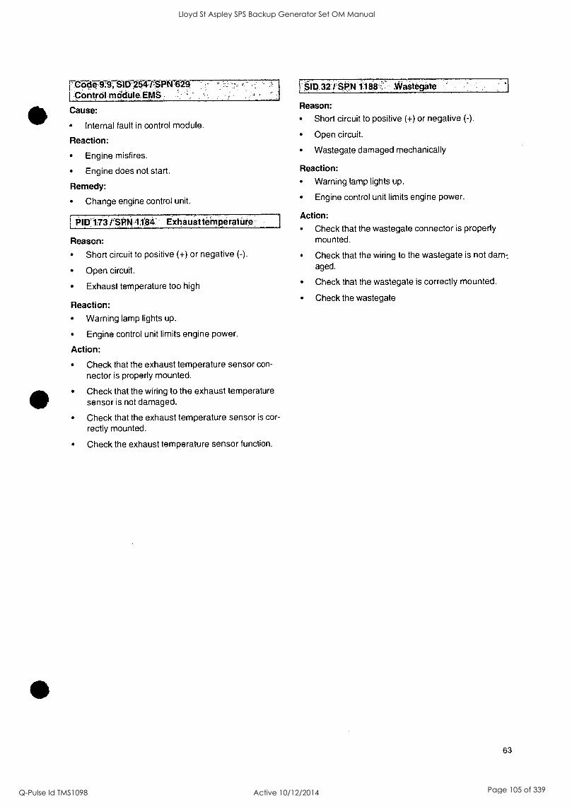
rCode 9:9; SID.254-r$PN7629 -Control module, EMS;
Cause:
Internal fault in control module.
Reaction:
Engine misfires.
Engine does not start.
Remedy:
Change engine control unit.
PIDA 73 /SPN :104 ExhauStternperature
Reason:
Short circuit to positive (+) or negative (-).
Open circuit.
Exhaust temperature too high
Reaction:
Warning lamp lights up.
Engine control unit limits engine power.
Action:
Check that the exhaust temperature sensor con-
nector is properly mounted.
Check that the wiring to the exhaust temperature sensor is not damaged.
Check that the exhaust temperature sensor is cor-
rectly mounted.
Check the exhaust temperature sensor function.
:§113.32 i1 Waitegate
Reason:
Short circuit to positive (+) or negative (-).
Open circuit.
Wastegate damaged mechanically
Reaction:
Warning lamp lights up.
Engine control unit limits engine power.
Action:
Check that the wastegate connector is properly mounted.
Check that the wiring to the wastegate is not dam-_
aged.
Check that the wastegate is correctly mounted.
Check the wastegate
63
Lloyd St Aspley SPS Backup Generator Set OM Manual
Q-Pulse Id TMS1098 Active 10/12/2014 Page 105 of 339

Lloyd St Aspley SPS Backup Generator Set OM Manual
Q-Pulse Id TMS1098 Active 10/12/2014 Page 106 of 339

Technical Data
General
Designation TAD1640GE I TAD1641GE 1 TAD1642GE 1 TAD1641VE 1 TAD1642VE
Power, Prime/Stand-by Refer to the sales literature
Torque, Prime/Stand-by Refer to the sales literature
No. of cylinders 6 6 6 6 6
Bore 144 144 144 144 144
Stroke, mm 165 165 165 165 165
Cylinder volume, dm3 16,12 16,12 16,12 16,12 16,12
Weight dry, kg 1440 1440 1480 1480 1480
Weight wet, kg 1510 1510 1550 1550 1550
Firing order 1-5-3-6-2-4 1-5-3-6-2-4 1-5-3-6-2-4 1-5-3-6-2-4 1-5-3-6-2-4
Compression ratio 17,5:1 16,5:1 16,5:1 17,5:1 17,5:1
Low idle, rpm 900 900 900 600 600
High idle, rpm 1500/1800 1500/1800 1500/1800 1800-2000 1800-2000
Type designation TWD1643GE
Power, Prime/Stand-by Refer to the sales literature
Torque, Prime/Stand-by Refer to the sales literature
No. of cylinders 6
Bore 144
Stroke, mm 165
Cylinder volume, dm3 16,12
Weight dry, kg 1700
Weight wet, kg 1770
Firing order 1-5-3-6-2-4
Compression ratio 16,5:1
Low idle, rpm 900
High idle, rpm 1500/1800
64
Lloyd St Aspley SPS Backup Generator Set OM Manual
Q-Pulse Id TMS1098 Active 10/12/2014 Page 107 of 339

0
Lloyd St Aspley SPS Backup Generator Set OM Manual
Q-Pulse Id TMS1098 Active 10/12/2014 Page 108 of 339
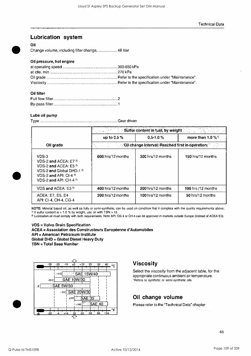
Technical Data
Lubrication system Oil Change volume, including filter change, 48 liter
Oil pressure, hot engine at operating speed 300-650 kPa
at idle, min 270 kPa
Oil grade Refer to the specification under "Maintenance". Viscosity Refer to the specification under "Maintenance".
Oil filter Full flow filter 2
By-pass filter 1
Lube oil pump Type Gear driven
Oil grade
S-Ulftir content in fuel, by weight.
up to 0.5 % 0.5-1.0 % more than 1.0 %')
.'Ouchange-intervali,i,fearohed'first imOperation:
VDS-3 VDS-2 and ACEA: E7 2)
VDS-2 and ACEA: E5 2)
VDS-2 and Global DHD-1 2)
VDS-2 and API: CI-4 2)
VDS-2 and API: CH-4 2)
600 hrs/12 months 300 hrs/12 months 150 hrs/12 months
VDS and ACEA: E3 2) 400 hrs/12 months 200 hrs/12 months 100 hrs /12 months
ACEA: E7, E5, E4 API: CI-4, CH-4, CG-4
200 hrs/12 months 100 hrs/12 months 50 hrs/12 months
NOTE: Mineral based oil, as well as fully or semi-synthetic, can be used on condition that it complies with the quality requirements above. 1) If sulfur content is > 1.0 % by weight, use oil with TBN > 15.
2) Lubrication oil must comply with both requirements. Note API: CG-4 or CH-4 can be approved in markets outside Europe (instead of ACEA E3).
VDS = Volvo Drain Specification ACEA = Association des Constructeurs Europeenne d'Automobiles API = American Petroleum Institute Global DHD = Global Diesel Heavy Duty TBN = Total Base Number
-30 -20 -10 ±0 + 0 20 30 40 °C
-15C ' SAE 15W/40
-25*C SAE 10W/30 i
SAE 5W/30 ,
-104 SAE 20W/30
icrc SAE 30 1
+lac SAE
I I I I I I I
40 I
-22 -4 +14 32 50 68 86 104
-0-
Viscosity Select the viscosity from the adjacent table, for the appropriate continuous ambient air temperature. *Refers to synthetic or semi-synthetic oils
Oil change volume Please refer to the "Technical Data" chapter
65
Lloyd St Aspley SPS Backup Generator Set OM Manual
Q-Pulse Id TMS1098 Active 10/12/2014 Page 109 of 339
Technical Data
Fuel System Feed pump Feed pressure at 600 rpm min 100 kPa
Feed pressure at 1200 rpm min 300 kPa
Feed pressure at full load min 300 kPa
By-pass valve Opening pressure 400-550 kPa
Fuel specification The fuel must comply with national and international standards for commercially supplied fuels, such as:
EN 590 (with nationally adapted environmental and cold weather requirements)
ASTM D 975 No 1-D and 2-D
JIS KK 2204
Sulfur content: Complying with legal requirements in each country.
Low density fuel (urban diesel in Sweden and city diesel in Finland) can cause a loss of up to 5 % of power and an increase in fuel consumption of about 2-3 %.
66
Lloyd St Aspley SPS Backup Generator Set OM Manual
Q-Pulse Id TMS1098 Active 10/12/2014 Page 110 of 339

S
0
Lloyd St Aspley SPS Backup Generator Set OM Manual
Q-Pulse Id TMS1098 Active 10/12/2014 Page 111 of 339
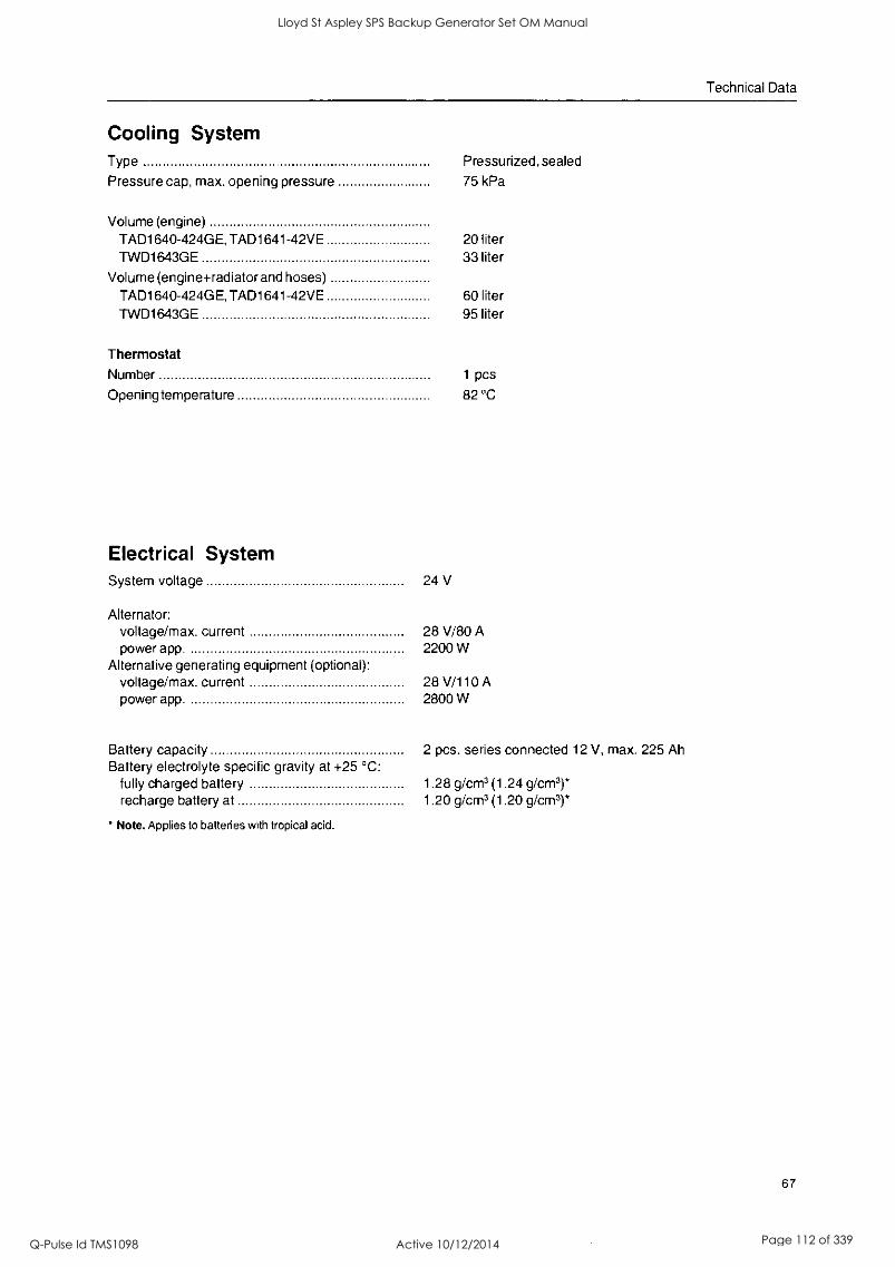
Technical Data
Cooling System Type Pressurized, sealed
Pressure cap, max. opening pressure 75 kPa
Volume (engine) TAD1640-424GE, TAD1641-42VE TWD1643GE
Volume (engine+radiator and hoses) TAD1640-424GE, TAD1641-42VE TWD1643GE
20 liter 33 liter
60 liter 95 liter
Thermostat Number 1 pcs
Opening temperature 82 °C
Electrical System System voltage 24 V
Alternator: voltage/max. current 28 V/80 A power app. 2200 W
Alternative generating equipment (optional): voltage/max. current 28 V/110 A power app. 2800 W
Battery capacity 2 pcs. series connected 12 V, max. 225 Ah Battery electrolyte specific gravity at +25 °C:
fully charged battery 1.28 g/cm3 (1.24 g/cm3)* recharge battery at 1.20 g/cm3 (1.20 g/cm3)*
Note. Applies to batteries with tropical acid.
67
Lloyd St Aspley SPS Backup Generator Set OM Manual
Q-Pulse Id TMS1098 Active 10/12/2014 Page 112 of 339

Lloyd St Aspley SPS Backup Generator Set OM Manual
Q-Pulse Id TMS1098 Active 10/12/2014 Page 113 of 339

Notes
Lloyd St Aspley SPS Backup Generator Set OM Manual
Q-Pulse Id TMS1098 Active 10/12/2014 Page 114 of 339
Post or fax this coupon to: Document & Distribution Center Order Department ARU2, Dept. 64620 SE-405 08 Goteborg Sweden
Fax: +46 31 545 772
Orders can also be placed via the Internet: http://www.volvopenta.com/ manuaVcoupon
0E79
Schicken Sie den Coupon per Post oder als Fax an:
Document & Distribution Center Order Department ARU2, Dept. 64620 SE-405 08 G6teborg Schweden Fax: +46 31 545 772
Die Bestellung kann auch Ober das Internet erfolgen: http://www.volvopenta.com/ manuaVcoupon
r
Envoyez ou faxez le bon de commande a:
Document & Distribution Center Order Department ARU2, Dept. 64620 SE-405 08 Goteborg Suede
Fax: +46 31 545 772
Vous pouvez egalement passer la commande par Internet: http://www.volvopenta.com/ manuaVcoupon
Yes please, I would like an operator's manual in English at no charge.
Publication number: 7749081
Name
11111 I 11111111111 I 11111 Address
III I I I 1111111 I I I 1 I I 1111 11111 I 11111111111 I 11111 11/11 I 1111111 I I I I I 11111
Country
11111 I I 1 I 1111111 I I II I II Please note that this offer is valid for 12 months from the date of delivery of the engine, after this it is subject to availability.
Ja danke, ich will kostenlos eine Betriebsanleitung in deutscher Sprache erhalten.
Publikationsnummer: 7749082
Name
VOLVO PE DITA.
11111 I 11111111111111111 Anschrift
11111 I 11111111111111111 11111 I 11111111111111111 11111 I 11111111111111111
Land
11111 1 111111111111111 I I
Bitte beachten Sie, dass das Angebot kir die Dauer von 12 Monaten ab dem Lieferdatum des Motors gilt, danach nur noch bis zum Aufbrauchen des Lager- bestandes.
Oui merci, Je souhaite recevoir un manuel d'instructions gratuit en francais.
Numero de publication: 7749083
Nom
VOLVO PE ATTA.
11111 I 1 I 1111 I 1111111 I 11 Adresse
11111 1 1 1 1111 1 1111111 1 11
11111 I I I I I I I I 1111111 I 11
11111 I I I 1111 I 1111111 I 11 Pays
11111 I I I 1111 I 1111111 Noter quel'offre est valable 12 mois a partir de la date de livraison du moteur, puis seulement dans la mesure des stocks disponibles.
- - -
VOLVO PE ATTA.
Lloyd St Aspley SPS Backup Generator Set OM Manual
Q-Pulse Id TMS1098 Active 10/12/2014 Page 115 of 339
Franquear o enviar fax a:
Document & Distribution Center Order Department ARU2, Dept. 64620 SE-405 08 G6teborg Suecia
Fax: +46 31 545 772
El pedido puede hacerse tam- bien por internet: http://www.volvopenta.com/ manual/coupon
r
L
Si gracias, deseo recibir gratuitamente un libro de instrucciones en espatiol.
Ntimero de publicacion: 7749084
Nombre
1111 1 111111111111111111 DirecciOn
1111 1 111111111111111111 1111 I 111111111111111111 1111 I 111111111111111111
Pars
1111 I 111111111111111111 Observe que la oferta es valida durante 12 meses a partir de la fecha de entrega del motor. A partir de la fecha de finalizacien de la oferta, la misma es valida stem-
pre que haya existencias.
Spedire it tagliando per poste o
per fax a:
Document & Distribution Center Order Department
r Si, grazie, desidero ricevere gratuitamente un manuale d'istruzioni in lingua italiana.
Public. No.: 7749085
Nome e Cognome
ARU2, Dept. 64620 1111111 11 1 111111111111 SE-405 08 Goteborg Indirizzo Svezia Fax: +46 31 545 772 1111111 I I 1 I 111111111111 L'ordinazione pub essere fatta anche su Internet:
1111111 I 11 I 111111111111 1111111 I II I 111111111111 http://www.volvopenta.com/
manuaVcoupon Paese
1111111 1 II I 111111111111 Notare the la validita dell'offerta a garantita solo per 12 mesi della consegna del motore, dopodiche si procedera lino ad esaurimento scorte.
VOLVO PE NTA.
VOLVO PE NTA. L
Ja tack, jag vill kostnadsfritt ha en instruktionsbok pa svenska.
Publikationsnummer: 7749080
Namn
Posta eller faxa kupongen till: Dokument & Distribution center Ordermottagningen ARU2, Avd. 64620 SE-405 08 G6teborg I I I I 11111 I II I III I I 11111 Sverige Adress
Fax: +46 31 545 772 II I I 11111 I 11 I III I I 11111 Bestallningen kan even gores via internet: http://www.volvopenta.com/ manual/coupon
11111 I II I I I I I l 11111 11111 I II I I 1 1 I I 1 I I 1 I
Land
11111 1 11 1 111 1 1 11111 Observera att erbjudandet galler i 12 manader Iran motorns leveransdatum, deretter endast i man av tillgang. VOLVO PE NTA.
Lloyd St Aspley SPS Backup Generator Set OM Manual
Q-Pulse Id TMS1098 Active 10/12/2014 Page 116 of 339

0
Lloyd St Aspley SPS Backup Generator Set OM Manual
Q-Pulse Id TMS1098 Active 10/12/2014 Page 117 of 339
DUT
Stuur of fax de coupon naar: Document & Distribution Center Order Department
r Ja graag, lk wil kosteloos een instructieboek in het Nederlands ontvangen.
Publicatienummer: 7749087
Naam ARU2, Dept. 64620 SE-405 08 Goteborg 11111 1 1111111 1 11111 Zweden Adres
Fax: +46 31 545 772 11111 1 1111111 1 11111 U kunt ook bestellen via Internet: http://www.volvopenta.corn/ manuaVcoupon
I 11 I 11111 J 1111111 I 11111 11111 1 1111111 1 11111
Land
11111 1 1111111 1 11111 Denk eraan dat de aanbieding geldt tot 12 maanden na levering van de motor, daama nog slechts indien beschikbaar. VOLVO
PE NTA. L
Postita tai faksaa kuponki osoitteella: Document & Distribution Center Order Department
KyIIa kiitos, haluan suomenkielisen ohjekirjan veloituksetta.
Julkaisunumero: 7749 086
Nimi
ARU2, Dept. 64 620 111111 I 1111111111 I 11 I I I
SE-405 08 Goteborg Osoite Ruotsi
Fax: +46 31 545 772 111111 I 1111111111 I I I I I I
Tilauksen voi tehda myos 11 I 1111111111 I 11 I I I
Internetissa:
11 1111111111 1 11 1 1 1
http://www.volvopenta.com/ manuaVcoupon Maa
11 I 1111111111 1 11 1 1 1
Ota huomioon, etta tatjous on voimassa 1 vuoden ajan
moottorin luovutuspaivamaarasta, sen jalkeen vain
tuotteen saatavuuden perusteella.
(13,01)2 r
Sim, obrigado(a)!
VOLVO PE NTA.
Envie o talao pelo correio ou urn fax para: Document & Distribution Center Order Department
Gostaria de receber gratuitamente urn manual de instrucoes em portugues.
IsItimero de publicacao: 7749088
Nome
ARU2, Dept. 64620 11111111111 I 11111 I 11111 SE-405 08 GOteborg Endereco Suede Fax: +46 31 545 772 11111111111 I 11111 I II III A encomenda tambem pode ser feita atraves da Internet:
11111111111 I 11111 I 11111 11111111111 I 11111 I 11111 http://www.volvopenta.com/
manuaVcoupon Pais
1111111 I III 1 11111 1 11111 Notar que a oferta a valida por um periodo de 12 meses a partir da data de entre- ga do motor. Depois desse periodo, a oferta é Aida consoante a disponibilidade. VOLVO
PE N'T.A. J
Lloyd St Aspley SPS Backup Generator Set OM Manual
Q-Pulse Id TMS1098 Active 10/12/2014 Page 118 of 339

0
0
Lloyd St Aspley SPS Backup Generator Set OM Manual
Q-Pulse Id TMS1098 Active 10/12/2014 Page 119 of 339
r
Taxu5poptiore auto TO
KOUTToVI. OTTIV napakcirea 5teti8uvari rj Create TO me Cpa
OTOV napatuirto apt8p6 tpak:
Document & Distribution Center Order Department ARU 2, Dept. 64620 SE-405 08 Goteborg Sweden
Fax: +46 31 545 772
Mnoptire ertiong va 5thaere Try napayyeXia actc paw rou Internet, arti &et:Aux/my http://www.volvopenta.com/ manuaVcoupon
Nat, Oa neeXa Eva avrirurto rou cyxetptbiou xpncrnq army ayylwoj yXthaaa xwpiq Kapui xpewcrn
Aptemoc eKboanc: 7749089
Ovo
1 1 I I I 1 I I I 1 1 1 I 1 1 1 1 1 1 1 1 1 1
Aieueuvan
1111111 I 111111111111111 1111111 I 1 1 l 1 1 I I 1 1 I I 1 1 I I
1111111 I 111111111111111 X6pa
1111 1 1 I I I I I 1 1 1 1 1 1 1 1 1 1 1
napanaAodpe animoiars or, aunf 0 frpoovapd laxdet yea 12 prfvec and niv riptpcnnwfa napddoanc my manic. Merd ea evat eipa diaecatydrnrac. VOLVO
PE NTA. L
r
OTnpaBbTe 3TOT TaJIOH
nowrotI WIN cpaKcom Ha
LIMA:
Document & Distribution Center Order Department ARU 2, Dept. 64620 SE-405 08 Goteborg Sweden
Fax: +46 31 545 772
3aKa3b1 TaK/KG MOMHO
pa3MelltaTb 401303 IIHTOpHOT:
http://www.volvopenta.com/ manual/coupon
P,a, ncmcanyOua,
1
R bbl xoren vMeTb 6eCtlflaTHOe pyKOBOACTBO oneparopa Ha pyccKom F1361Ke.
Homep "ma'am: 7749090
I I I I I I I I I I I I t I I 11 1 11 i 1 I
A.apec
111111111111 I 1111111111 111111111111 I 1111111111 I I I I I I I I I I I I I I I I 1 I I I I I I
OrpaHa
111111111111 I 1111111111 K BallielMy CB0a0HHIO, 3TO npeanomenme IjOhiCTBHTBIlbH0 B TOHOHHO 12 NOCRIHPB OT fiaTbi nocraskm pamrarenx B ganbneatuom OHO JaBHCNT OT
HaltHHHA. VOLVO PE N'rA.
Lloyd St Aspley SPS Backup Generator Set OM Manual
Q-Pulse Id TMS1098 Active 10/12/2014 Page 120 of 339

Lloyd St Aspley SPS Backup Generator Set OM Manual
Q-Pulse Id TMS1098 Active 10/12/2014 Page 121 of 339

Lloyd St Aspley SPS Backup Generator Set OM Manual
Q-Pulse Id TMS1098 Active 10/12/2014 Page 122 of 339

I
6
s
Lloyd St Aspley SPS Backup Generator Set OM Manual
Q-Pulse Id TMS1098 Active 10/12/2014 Page 123 of 339

I
0
Lloyd St Aspley SPS Backup Generator Set OM Manual
Q-Pulse Id TMS1098 Active 10/12/2014 Page 124 of 339
STAMFORD
Installation, Service & Maintenance Manual for P7 Range of AC Generators
Lloyd St Aspley SPS Backup Generator Set OM Manual
Q-Pulse Id TMS1098 Active 10/12/2014 Page 125 of 339

Safety Precautions
Safety Precautions
STAMFORD
First Steps to Safe Operation Read this manual, obey all Warnings and Cautions, and become familiar with the product.
Warnings & Notices used in this manual The various warnings are out lined below and appear in the text in this format. Warnings and Cautions appear at the appropriate position in the, to which they refer.
Warning: Information that draws attention to the risk of injury or death.
Caution: Information that draws attention to the risk of damage to the product, process or surroundings.
Note: Used to convey, or draw attention to, additional information or explanations.
Notes appear after the text to which they refer.
Skill requirements of personnel Service and maintenance procedures should only be carried out by experienced, qualified engineers, familiar with the procedures and the equipment. Before any intrusive procedures are carried out, ensure that the engine is inhibited and the generator is electrically isolated.
Electrical Equipment All electrical equipment can be dangerous if not operated correctly. Always service and maintain the generator in accordance with this manual. Always use genuine 'STAMFORD' replacement parts.
Warning: Electrical shock can cause injury or death. Ensure that all personnel operating, servicing, maintaining or working near this equipment are fully aware of the emergency procedures in case of accidents.
Before removing the protective covers to carry out service maintenance or repair, ensure that the engine is inhibited and the generator is electrically isolated. The AVR access covers are designed to be removed while the generator is on load.
Lifting Lift the generator using the points provided with the aid of a spreader and chains. The angle on the chains must be vertical during the lift. Do not lift single bearing generators without the, securely fitted, transit bar. When removing the transit bar just prior to offering the generator up to the engine, be aware that the rotor is not securely held in the generator. Keep the generator in the horizontal plane to when the transit bar is not fitted.
Warning: The lifting points provided are designed for lifting the generator only. Do not lift the Generating Set by the generator's lifting points.
Note: Due to our policy of continuous improvement, details in this manual which were correct at time of going to print and may now be due for amendment. Information included must therefore not be regarded as binding.
Note: The Front Cover drawing is representative of the range of generators. Several variations are available within this range that, are covered by this manual.
Copyright 2006 2 TD_P7 MAN G8_10.06_03_GB
Lloyd St Aspley SPS Backup Generator Set OM Manual
Q-Pulse Id TMS1098 Active 10/12/2014 Page 126 of 339

STAMFORD
Foreword
The Manual
The Manual Before operating, the generating set read this manual and all additional documentation supplied with it.
Great care has been taken with the design of this product to ensure that it is safe to operate. Misuse and the failure to follow the safety precautions contained in the manual are potential causes of accidents.
Read the manual and make sure that all personnel who work on the equipment have access to the manual. The manual should be considered as part of the product and should remain with the product. Make sure that the manual is available to all users throughout the life of the product.
Scope This manual contains guidance and instructions for the Installation, Servicing and Maintenance of the generator. It is not possible, within the scope of the manual, to teach the basic electrical and mechanical skills required to safely carry out the procedures enclosed. The manual is written for skilled electrical and mechanical technicians and engineers, who have prior knowledge and experience of generating equipment of this type. We offer a range of training courses that cover all aspects of STAMFORD generators.
Generator Designation P I 7 3 4 C 2 (example)
P - Generator type I - Applications,
I = Industrial, M = Marine. 7 - Frame size 3 - Separate excitation, PMG 4 - Number of poles, 4 or 6
C - Core Size 2 - Number of bearings, 1 or 2
The Product The product is an AVR controlled, separately excited (by a
shaft driven pilot exciter) synchronous 'ac generator'. Designed for incorporation into a generating-set. (A generating-set is defined as 'machinery' in European directives).
Serial Number Location Each generator has a unique serial number stamped into the upper section of the drive end of the frame. The serial number is also shown on the nameplate.
Two other labels are located inside the terminal box, both fixed inside of the terminal box, one on the sheet metal-work and the other on the main frame of the generator. Neither of these two labels is considered to be permanently fixed.
Rating Plate The generator has been supplied with a self-adhesive rating plate label to enable fitting after final assembly and painting. Stick the nameplate to the outside of the non-drive end of the terminal box. The surface in the area where a label is to be stuck must be flat, clean, and any paint finish must be fully dry before attempting to attach label. Recommended method for attaching label is peel and fold back sufficient of the backing paper to expose some 20 mm of label adhesive along the edge which is to be located against the sheet metal protrusions. Once this first section of label has been carefully located and stuck into position progressively peel off the backing paper and smooth down with a clean cloth. The adhesive will achieve a permanent bond in 24 hours. A factory fitted metal nameplate is available for some applications.
Caution. Do not exceed the parameters marked on the rating plate.
TD_P7 MAN GB_10.06_03_GB 3 Copyright 2006
Lloyd St Aspley SPS Backup Generator Set OM Manual
Q-Pulse Id TMS1098 Active 10/12/2014 Page 127 of 339

Contents
Contents
STAMFORD
SAFETY PRECAUTIONS 2 FIRST STEPS TO SAFE OPERATION 2 WARNINGS & NOTICES USED IN THIS MANUAL 2
SKILL REQUIREMENTS OF PERSONNEL 2 ELECTRICAL EQUIPMENT 2 LIFTING 2
FOREWORD 3 THE MANUAL 3 SCOPE 3 GENERATOR DESIGNATION 3 THE PRODUCT 3 SERIAL NUMBER LOCATION 3 RATING PLATE 3
CONTENTS 4
INTRODUCTION 8 GENERAL DESCRIPTION 8
MX341 AVR 8 MX321 AVR 8
STANDARDS. 8 EUROPEAN DIRECTIVES. 9
Applications for use within the EU 9 Unsuitable Applications 10 Additional information for EMC compliance 10
APPLICATION OF THE GENERATOR 11
ENVIRONMENTAL PROTECTION 11
Air Flow 11
AIRBORNE CONTAMINATES 11
Air Filters 11
HIGH HUMIDITY ENVIRONMENTS 11
Anti-condensation heaters 11
Enclosures 11
VIBRATION 11
Definition of BS5000 -3 12 Definition of ISO 8528 - 9 12 Vibration Monitoring 12 Excessive Vibration levels 12
BEARINGS 12 Re-greasable Bearings 12
Bearing Life 13 Health Monitoring of the Bearings 13 Bearing 'Service Life' Expectancy 13
INSTALLATION INTO THE GENERATING SET 14 DELIVERY 14 HANDLING THE GENERATOR 14 STORAGE 14 AFTER STORAGE 14 ROTOR BALANCING 14 GENERATOR VIBRATION, FREQUENCY 14 COUPLING ARRANGEMENTS 15
Coupling Two Bearing Generators 15 Coupling Single Bearing Generators 15 Single Bearing Coupling Alignment 15
EARTH ARRANGEMENT 16 PAINT FINISH 16
Copyright 2006 4 TD_P7 MAN GB_10.06_03_GB
Lloyd St Aspley SPS Backup Generator Set OM Manual
Q-Pulse Id TMS1098 Active 10/12/2014 Page 128 of 339

STAMFORD Rating Plate
WARNING LABELS 16 PRE-RUNNING CHECKS 16
Insulation resistance test 17 DIRECTION OF ROTATION 17 PHASE ROTATION 17 VOLTAGE AND FREQUENCY 17 AVR ADJUSTMENT 17
ACCESSORIES 17
INSTALLATION, ON SITE 18 GENERAL 18 CUSTOMER CABLE ENTRY 18 EARTH CONNECTIONS 18 ELECTRICAL PROTECTION 18 VOLTAGE SURGES AND MICRO- INTERRUPTIONS. 19 SYNCHRONISATION NOTES 19
AUTOMATIC VOLTAGE REGULATOR TYPE MX341 20 INITIAL CHECKS 20 INITIAL START UP 20
Voltage Set Up 20 Stability Set Up 20
AVR ADJUSTMENTS 20 UNDER FREQUENCY ROLL OFF (UFRO) 21
EXC TRIP (Excitation Trip) 21
Transient Load Switching 21
DIP. 21
SUMMARY OF CONTROLS, MX341 22
AUTOMATIC VOLTAGE REGULATOR TYPE MX321 23 INITIAL CHECKS 23 INITIAL START UP 23
Voltage Set Up 23 Stability Set Up 23
RAMP ADJUSTMENT 24 AVR ADJUSTMENTS 24 UNDER FREQUENCY ROLL OFF (UFRO) 24
EXC TRIP (Excitation Trip) 24 OVERN (Over Voltage) 25 Transient Load Switching 25 DIP. 25 DWELL 25
OVERVOLTAGE DE-EXCITATION CIRCUIT BREAKER 25 Resetting The Excitation Breaker 26
CURRENT LIMITING 26 Setting Procedure 26
SUMMARY OF CONTROLS, MX321 26
FAULT FINDING, MX321 & MX341 AVRS 28 SEPARATE EXCITATION TEST PROCEDURE 28
Checking the Permanent Magnet Generator (PMG). 28 Checking Generator Windings and Rotating Diodes 28 Balanced Main Terminal Voltages 29 Check Rectifier Diodes 29 Replacement of Faulty Diodes 29 Surge Suppressor 29 Main Excitation Windings 29 Unbalanced Main Terminal Voltages 29
EXCITATION CONTROL TEST 30 AVR Function Test 30
TD_P7 MAN GB_10.06_03_GB 5 Copyright 2006
Lloyd St Aspley SPS Backup Generator Set OM Manual
Q-Pulse Id TMS1098 Active 10/12/2014 Page 129 of 339

Contents
STAMFORD
ACCESSORIES 31 Remote Voltage Adjustment. 31
PARALLEL OPERATION 31
Load Sharing 31 Droop 31
Droop Setting Procedure 32 MANUAL VOLTAGE REGULATOR (MVR) 33 POWER FACTOR CONTROLLER (PFC3) 33
SERVICE 34 WINDING CONDITION 34
New Machines 34 At Generating Set Assemblers Works 34 Generators in Service 34 Winding Condition Assessment 34
PROCEDURE FOR INSULATION TESTING 35 METHODS OF DRYING OUT GENERATORS 35
Cold Run 35 Blown Air Drying 35 Short Circuit Method 35
TYPICAL DRYING OUT CURVE 36 AIR FILTERS 37
Air Filter Cleaning Procedure 37
MAINTENANCE 38 ANTI-CONDENSATION HEATERS 38 REMOVAL OF PERMANENT MAGNET GENERATOR (PMG) 38
Re-assembly 38 REMOVAL OF BEARINGS 38 REMOVAL OF THE NON DRIVE END BEARING. 38 DRIVE END BEARING REMOVAL 39 REMOVAL OF THE MAIN ROTOR 39 REFITTING BEARINGS 40
Equipment 40 Preparation 40 Bearing preparation 40 Bearing Cartridge 40 Assemble Bearing into Cartridge 40 Assemble Bearing onto Shaft 40
BEARING CAP & FLINGER 41 Re-lubrication pipe 41 Returning To Service 41
BEARING MAINTENANCE 41 Re-lubrication 41
PARTS IDENTIFICATION 42 SINGLE BEARING GENERATOR 42 Two BEARING GENERATOR. 43
SPARES AND AFTER SALES SERVICE 44 RECOMMENDED SPARES 44 AFTER SALES SERVICE 44 KLUBER ASONIC GHY72 GREASE 44
TECHNICAL DATA 45 Air Flow requirements 45 Winding Resistances 45 Main Stator Winding Resistances 45 Coupling disc Torque setting 46 Bending Moments 46 Customer output cables 46 Generator internal connections. 46
Copyright 2006 6 TD_P7 MAN GB_10.06_03_GB
Lloyd St Aspley SPS Backup Generator Set OM Manual
Q-Pulse Id TMS1098 Active 10/12/2014 Page 130 of 339

STAMFORD Rating Plate
Re-lubrication Details for Regreasable Bearings 46 Initial fill for Regreasable Bearings 46 Generator Weight 47 Recommended Service Parts 47 Sealed for life Bearing kit Numbers 47 Regreasable Bearings Kit Numbers 47
A.C. GENERATOR WARRANTY 48 WARRANTY PERIOD 48
Defects, After Delivery 48 EXTENSIONS TO THE WARRANTY PERIOD 48
END OF LIFE DISPOSAL 49 RECYCLABLE MATERIAL 49 ITEMS REQUIRING SPECIALIST TREATMENT. 49 WASTE MATERIAL 49
STAMFORD POWER GENERATION WORLDWIDE 50
TD_P7 MAN GB_10.06_03_GB 7 Copyright 2006
Lloyd St Aspley SPS Backup Generator Set OM Manual
Q-Pulse Id TMS1098 Active 10/12/2014 Page 131 of 339

Introduction
Introduction
General Description
7 _ $
9 10
L 1
4
= 11
2 3
1 Main rotor 7 AVR 2 Rotating diodes 8 Isolating transformer
(if fitted) 3 Exciter rotor 4 PMG rotor 9 Main stator 5 PMG stator 10 Output 6 Exciter stator 11 Shaft
STAMFORD
The Permanent Magnet Generator (PMG) provides power for the excitation of the exciter field via the Automatic Voltage Regulator (AVR) which is the controlling device governing the level of excitation provided to the exciter field. The AVR responds to a
voltage-sensing signal derived, via an isolating transformer, from the main stator winding. By controlling the low power of the exciter field, control of the high power requirement of the main field is achieved through the rectified output of the exciter armature.
MX341 AVR The Automatic Voltage Regulator (AVR) is of the thyristor type and forms part of the excitation system for a brushless generator. In addition to regulating the generator voltage, the AVR circuitry includes protective features to ensure safe reliable control of
the generator. Excitation power is derived from a permanent magnet generator (PMG) to guarantee low Radio Frequency Interference (RFI) and immunity from thyristor type loads. The AVR is linked with the main stator windings and controls the power fed to the exciter stator and hence the main rotor to maintain the machine output voltage within the specified limits, compensating for load, speed, temperature and power factor of the generator. Soft start circuitry is included to provide a smooth controlled build up of generator output voltage.
A frequency measuring circuit continually monitors the generator output and provides underspeed protection of the excitation system by reducing the generator output voltage proportionally with speed below an adjustable pre-set threshold. A further enhancement of this feature is an adjustable volts/Hz slope to improve frequency recovery time on turbo charged engines. Uncontrolled over excitation is limited to a safe period by internal shutdown of the AVR output device. This condition remains latched until the generator has been stopped. For complete protection, a circuit breaker option is available providing circuit isolation in event of a short circuit power device. In addition it
detects engine speed and provides adjustable voltage fall off with speed, below a pre-selected speed (Hz) setting, preventing over-excitation at low engine speeds and softening the effect of load switching to relieve the burden on the engine. It also provides over-excitation protection that acts following a time delay, to de-excite the generator in the event of excessive exciter field voltage. Provision is made for the connection of a remote voltage trimmer allowing the user fine control of the generator's output. Accessories are available for this AVR. Please refer to factory for further details.
MX321 AVR In addition to the above the MX321 AVR has 3 phase rms sensing for improved regulation plus:
Over-voltage protection. Adjustable recovery on underspeed protection Current limiting may be included to allow control over the amount of short circuit current flowing during three phase and single phase short circuits on the generator output. An additional current transformer is required.
Standards. STAMFORD ac generators meet the relevant parts of national and international standards pertaining to generators. The generator must be operated within the limits laid down in the relevant standards and within the parameters on the generator rating plate.
Copyright 2006 8 TD_P7 MAN GB_10.06_03_GB
Lloyd St Aspley SPS Backup Generator Set OM Manual
Q-Pulse Id TMS1098 Active 10/12/2014 Page 132 of 339

STAMFORD European Directives.
Marine generators meet the requirements of all the major marine classification societies.
European Directives.
AC generators sold for use in the European Union must meet the relevant European directives. An ac generator has no intrinsic function; it must be have a mechanic input in order to provide an electrical output. The generator is supplied as a
component part of a Generating-Set. To reflect this each generator is supplied with an 'EC Declaration of Incorporation' in accordance the Machinery Directive.
The ac generator meets the relevant directives applicable to an ac generator (component part) before it is incorporated into 'machinery'.
EC DECLARATION OF INCORPORATION
ASSOKUNCS SIN MSS... Cs IMAMS.' OAFS h ISSGsASONS ROM MT, Cs ,SASST, ;AM MEStssSMS IMI
MMESIMTM> ME EC MMKsrf CotsMre Mr,re: mrsrAMTS MIS STAINOM 01IMMTSIN WAS
MMISACTMODISI MI CO MM/ OF
LTD SME smis :sr, LI. ccu.S.st
MS OMPONIMT SISOMEISS WV NOT St KIT INTO SUMS, .111. ISE 10.4CMALMV IMO MICH IT R TOM IISCOMOMMS Ni,S OFSH DECLARED Si
COWCILMITt wmmPR OMCIO Crv+eawxraVAMIeeYIrrrcm ISEQUATIONS MSMACOINERT DIRSCTRI
.s.o, M THE ...N. Ms. tS MSS misEsIssrMu.
KW. MUMPS 1103811T SSIL
MSE COMIIMITIMMUSIT MVP DS 01. Ws FM C011114.. UIMM SISIVISSTIMMIIIMBITSIM IIIIIMENSOIMM Of ME MOMS SWIMS
IMI.0011 WMPIPIO immaysweerr--
The directives identified as pertaining to ac generators are: The Machinery (Safety) Directive, 98/37/EEC. The Low Voltage Directive, 73/23/EEC. The EMC Directive, 89/336/EEC
The generator is CE marked; CE labels are supplied loose in case the generating set manufacturer needs to paint the generating set before delivery to the end user.
Note: Once the generator is build into a generating-set (machinery), it is the responsibility of the generating-set manufacture to ensure that the generating-set complies with the relevant EC Directives.
It is contrary to the EC Directives to misrepresent compliance of the EC directives by displaying the CE mark supplied with a component part of the product. The directive requires compliance to be assessed as a component part. as the complete product and during installation on site.
Applications for use within the EU STAMFORD ac generators are supplied on the basis that:
They are used for power generation or related functions. They are to be applied in one of the following environments: Portable (open construction - temporary site supply) Portable (enclosed - temporary site supply) Containerised (temporary or permanent site supply) Ship - borne, below decks (marine auxiliary power) Commercial vehicle (road transport / refrigeration etc.) Road transport (auxiliary power) Industrial vehicle (earthmoving, cranes etc.) Fixed installation (Industrial - factory / process plant) Fixed installation (residential, commercial and light industrial - home / office / health.) Energy management (combined heat & power and/or peak lopping.) Alternative energy schemes. The standard generators are designed to meet the 'industrial' emissions and immunity standards. Where the generator is required to meet the residential, commercial and light industrial emissions and immunity standards reference must be made to document reference N4/X/011. This publication outlines the additional equipment that may be required. The installation 'earth/ground' arrangements require the connection of the generator frame to the site protective earth conductor using a minimum lead length. Maintenance and servicing with unauthorised parts, not of supply, will invalidate us from any liability for EMC compliance.
TD_P7 MAN GB_10.06_03_GB 9 Copyright 2006
Lloyd St Aspley SPS Backup Generator Set OM Manual
Q-Pulse Id TMS1098 Active 10/12/2014 Page 133 of 339

Introduction
STAMFORD
Installation, maintenance and servicing are carried out by adequately trained personnel fully aware of the requirements of the relevant EC directives.
Unsuitable Applications Synchronous generators require a constant speed for power generation. Applications where the generator is not run at a constant speed are not suitable for the standard generator. Such applications may be possible within certain parameters. Contact the factory for advice, there is every possibility that we can provide you with a satisfactory technical solution to meet your requirement.
Additional information for EMC compliance Standard generators are designed to meet the 'industrial' emissions and immunity standards. Where the generator is required to meet the residential, commercial and light industrial emissions and immunity standards, reference must be made to document reference N4/X/011. This publication outlines the additional equipment that may be required.
E
Copyright 2006 10 TD_P7 MAN GB_10.06_03_GB
Lloyd St Aspley SPS Backup Generator Set OM Manual
Q-Pulse Id TMS1098 Active 10/12/2014 Page 134 of 339

STAMFORD Environmental Protection
Application of the generator
Environmental Protection Stamford generators are protected to IP23. IP23 is not adequate protection for use outdoors without additional measures.
Ambient Temperature <40°C Humidity <60% Altitude <1000m
This table represents the normal operating conditions that the generator is designed for. Operation outside of these parameters is
possible after due consideration and will be reflected on the generator nameplate. If the operating environment for the generator
has changed after purchase, the rating of the generator needs to be revised, refer to the factory for details.
Air Flow The air flow requirements for the generator can be found in the Data section at the back of this manual. Ensure that the air inlets and outlets are not obstructed when the generator is running.
Airborne Contaminates Contaminates such as salt, oil, exhaust fumes, chemicals, dust, sand, etc., will reduce the effectiveness of the insulation and lead to premature failure of the windings. Consider using air filters or an enclosure to protect the generator.
Air Filters Air filters are available on request. Filters present a restriction to the airflow so the rating of the generator must be reduced by 5%. If the filters are supplied, factory fitted, the rating on the nameplate will include the reduced rating. The filters can be up-fitted after delivery in which case the customer must apply the power reduction. Air filters remove airborne particulates above 3 microns. The frequency of changing and cleaning the filters depend on the site conditions. We recommend that the filters are monitored frequently until a
suitable cycle of change is established. Air filters do not remove water. Additional protection must be employed to prevent the filters from getting wet. If the filters are allowed to get wet the airflow will be restricted and the generator will overheat. This will reduce the life expectancy of the insulation leading to premature failure of the generator.
High Humidity environments The humidity of the air will allow condensation to form on the windings if the temperature of the windings falls below the dew point. The dew point is a relationship between the ambient temperature and humidity. In areas of high humidity additional protection may be required even if the generator is fitted inside an enclosure.
Anti-condensation heaters Anti-condensation heaters are designed to raise the temperature of the windings above the temperature of the surrounding material so that the condensation will not form on the windings. We recommend that anti-condensation heaters are fitted to all generators that are left switched off for any period of time. The best practice is to wire the heaters such that the heaters come on when the generator is switched off. This is particularly important in applications where high humidity is a significant problem. Always check the condition of the generators windings before switching the generator on. If moisture is
observed carry out one or more of the drying-out methods outlined in the Service section of this manual.
Enclosures An enclosure should be employed to protect the generator from adverse environmental conditions. If the generator is to be fitted inside an enclosure, ensure that there is adequate airflow to support both the engine and the generator. Ensure that the generator air supply is clean (free from moisture and contaminates) and at or below the ambient temperature stated on the rating plate.
Vibration
TD_P7 MAN GB_10.06_03_GB 11 Copyright 2006
Lloyd St Aspley SPS Backup Generator Set OM Manual
Q-Pulse Id TMS1098 Active 10/12/2014 Page 135 of 339
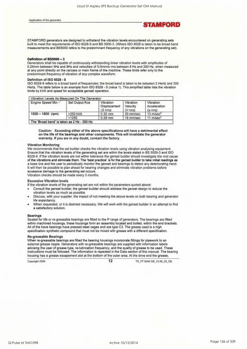
Application of the generator
STAMFORD
STAMFORD generators are designed to withstand the vibration levels encountered on generating sets built to meet the requirements of ISO 8528-9 and BS 5000-3. (Where ISO 8528 is taken to be broad band measurements and BS5000 refers to the predominant frequency of any vibrations on the generating set).
Definition of BS5000 -3 Generators shall be capable of continuously withstanding linear vibration levels with amplitudes of 0.25mm between 5Hz and 8Hz and velocities of 9.0mm/s rms between 8 Hz and 200 Hz, when measured at any point directly on the carcass or main frame of the machine. These limits refer only to the predominant frequency of vibration of any complex waveform.
Definition of ISO 8528 - 9 ISO 8528-9 refers to a broad band of frequencies; the broad band is taken to be between 2 Hertz and 300 Hertz. The table below is an example from ISO 8528 - 9 (value 1). This simplified table lists the vibration limits by kVA and speed for acceptable genset operation.
Vibration Levels As Measured On The Generator Engine Speed Min -' Set Output Kva Vibration
Displacement (S rms)
Vibration Velocity (V rms)
Vibration Acceleration (a rms)
1500 - 1800 (rpm) >250 kVA 0.32 mm 20 mm/sec 13 m/secz >1250 0.29 mm 18 mm/sec 11 m/sec2
The 'Broad band' is taken as 2 Hz - 300 Hz
Caution: Exceeding either of the above specifications will have a detrimental effect on the life of the bearings and other components. This will invalidate the generator warranty. If you are in any doubt, contact the factory.
Vibration Monitoring We recommends that the set builder checks the vibration levels using vibration analysing equipment. Ensure that the vibration levels of the generating set are within the levels stated in BS 5000-3 and ISO 8528-9. If the vibration levels are not within tolerance the genset builder should investigate the root cause of the vibrations and eliminate them. The 'best practice' is for the genset builder to take initial readings as a base line and the user to periodically monitor the genset and bearings to detect any deteriorating trend. It will then be possible to plan ahead for bearing changes and eliminate vibration problems before excessive damage to the generating set occurs. Vibration checks should be made every 3 months.
Excessive Vibration levels If the vibration levels of the generating set are not within the parameters quoted above:
Consult the genset builder; the genset builder should address the genset design to reduce the vibration levels as much as possible. Discuss, with your supplier, the impact of not meeting the above levels on both bearing and generator life expectancy. When requested, or it is deemed necessary, We will work with the genset builder in an attempt to find a satisfactory solution.
Bearings Sealed for life or re-greasable bearings are fitted to the P range of generators. The bearings are fitted within machined housings, these housings form an assembly located and bolted, within the end brackets. All of the have bearings have pressed steel cages and are type C3. The grease used is a high specification synthetic compound that must not be mixed with grease with a different specification.
Re-greasable Bearings When re-greasable bearings are fitted the bearing housings incorporate fittings for pipework to an external grease nipple. Generators with re-greasable bearings are supplied with information labels advising the user of grease type, re-lubrication frequency, and the quality of grease to be used. These instructions must be followed. The information is repeated in the Data section of this manual. The bearing housing has a grease escapement slot at the bottom of the outer area. At the drive end the grease,
Copyright 2006 12 TD_P7 MAN GB_10.06_03_GB
Lloyd St Aspley SPS Backup Generator Set OM Manual
Q-Pulse Id TMS1098 Active 10/12/2014 Page 136 of 339

Lloyd St Aspley SPS Backup Generator Set OM Manual
Q-Pulse Id TMS1098 Active 10/12/2014 Page 137 of 339

STAMFORD
expelled from the escapement slot, will discharge into the coupling area At the non-drive end the grease, from escapement slot, is deflected by a metal plate to ensure that it cannot foul the Permanent Magnet Generator (PMG). The sheet metal cover over the PMG has a slot at the bottom to enable the excess grease to escape.
Bearing Life Factors that effect bearing life: The life of a bearing in service is subject to the working conditions and the environment:
High levels of vibration from the engine or misalignment of the set will stress the bearing and reduce its service life. If the vibration limits set out in BS 5000-3 and ISO 8528-9 are exceeded bearing life will be reduced. Refer to 'Vibration' below. Long stationary periods in an environment where the generator is subject to vibration can cause false brinnelling, which puts flats on the balls and grooves on the races, leading to premature failure. Very humid atmospheric or wet conditions can emulsify the grease causing corrosion and deterioration of the grease, leading to premature failure of the bearings.
Health Monitoring of the Bearings We recommend that the user check the bearing condition, using monitoring equipment, to determine the state of the bearings. The 'best practice' is to take initial readings as a base line and periodically monitor the bearings to detect a deteriorating trend. It will then be possible to plan a bearing change at an appropriate generating set or engine service interval.
Bearing 'Service Life' Expectancy Bearing manufacturers recognise that the "service life" of their bearings is dependent upon many factors that are not in their control; they cannot therefore quote a "service life".
Although "service life" cannot be guaranteed, it can be maximised by attention to the generating set design. An understanding of the generating set's application will also help the user to maximise the service life expectancy of the bearings. Particular attention should be paid to the alignment, reduction of vibration levels, environmental protection, maintenance and monitoring procedures.
We do not quote life expectancy figures for bearings, but suggest practicable replacement intervals based on the L10 life of the bearing, the type of grease and the recommendations of the bearing and grease manufacturers.
For general-purpose applications: providing the correct maintenance is carried out, vibration levels do not exceed the levels stated in ISO 8528-9 and BS5000-3, and the ambient temperature does not exceed 50°C. Plan to replace re-greaseable bearing within 40,000 hours and sealed for life bearing within 30,000 hours of operation. (This estimate is based on the use of Kluber Asonic GHY 72 grease only.) (In theory any grease with an equivalent specification would achieved a similar performance).
It is important to note that bearings in service, under good operating conditions, can continue to run beyond the recommended replacement period. It should also be remembered that the risk of bearing failure increases with time.
If in doubt about any aspect of the 'bearing life' on STAMFORD, contact your nearest distributor or contact the Stamford factory direct.
TD_P7 MAN G6_10.06_03_GB 13 Copyright 2006
Lloyd St Aspley SPS Backup Generator Set OM Manual
Q-Pulse Id TMS1098 Active 10/12/2014 Page 138 of 339

Installation into the Generating Set
Installation into the Generating Set
STAMFORD
The generator is supplied as a component part for installation into a 'generating set'.
Delivery Upon receipt of the generator, check the generator for damage that may have occurred during transport. Also check that the rating-plate details are correct and as ordered for the application.
Handling the generator When lifting the generator use a spreader bar to ensure that the angle on the lifting chains are vertical to the lifting position on the generator.
Warning: The generator lifting points are designed to lift the generator only. Do not lift the complete generating set by the generator lifting points.
Single bearing generators have a transit bar fitted at the drive end. This bar holds the rotor in position during transit. The transit bar should be left in position until it is necessary to remove it to allow the generator to be coupled to the engine.
Warning: If the generator is moved without the transit bar be aware that the rotor could fall out of the frame. When moving the generator always keep it in the horizontal plane, this will reduce the risk of the rotor falling out.
Storage If the generator is not to be used immediately, it must be stored in a clean, dry, vibration free environment. If anti-condensation heaters are fitted, switch them on. If heaters are not fitted use other means to ensure that condensation cannot form on the windings. Spin the shaft by hand every month to prevent flat spots in the bearings and to free up the grease.
After Storage After a period of storage, carry out 'pre running checks' to determine the condition of the windings. If the winding are damp or the insulation is low, follow one of the 'drying out procedures', in the Service section of this manual. If the generator has re-greasable bearings and has been in storage for 6 months or more, re-lubricate the bearings before use. If the bearings are sealed for life, replace the bearing after 12 months in storage. (see the Maintenance section)
Rotor balancing Dynamic balancing of the generator rotor assembly has been carried out during manufacture in
accordance with BS 6861 Part 1 Grade 2.5 to ensure vibration limits of the generator are in accordance with BS 4999 Part 142.
Generator Vibration, Frequency The main vibration frequencies produced by the component generator are as follows:
1500 rpm 25 Hz 1800 rpm 30 Hz
However, vibrations induced by the engine are complex and contain frequencies of 1.5, 3, 5 or more times the fundamental frequency of vibration. These induced vibrations can result in generator vibration levels higher than those derived from the generator itself. It is the responsibility of the generating set
Copyright 2006 14 TD_P7 MAN GB_10.06_03_GB
Lloyd St Aspley SPS Backup Generator Set OM Manual
Q-Pulse Id TMS1098 Active 10/12/2014 Page 139 of 339

STAMFORD Coupling arrangements
designer to ensure that the alignment and stiffness of the bedplate and mountings are such that the vibration limits of BS5000 part 3 and ISO 8528 part 9 are not exceeded. In standby applications where the running time is limited and reduced life expectancy is accepted, higher levels than specified in BS5000 part 3 can be tolerated, up to a maximum of 18mm/sec.
Coupling arrangements Single and two bearing arrangements are available both arrangements can be close coupled. Both arrangements also need a firm level foundation.
Two bearing generators require a substantial bedplate with engine/generator mounting pads to ensure a
good base for accurate alignment. Close coupling of the engine to the generator can increase the overall rigidity of the set. A flexible coupling, designed to suit the specific engine/generator combination, is recommended to minimise the torsional effects.
Accurate alignment of single bearing generators is essential, vibration can occur due to the flexing of the flanges between the engine and generator. A substantial bedplate with engine/generator mounting pads
is required.
For the purposes of establishing set design the bending moment at the engine flywheel housing to generator adaptor interface should not exceed 275 kgm. (2000ft.lbs.)
The maximum bending moment of the engine flange must be checked with the engine manufacturer.
Torsional vibrations occur in all engine-driven shaft systems and may be of a magnitude to cause damage at certain critical speeds. It is therefore necessary to consider the torsional vibration effect on the generator shaft and couplings.
It is the responsibility of the generator set manufacturer to ensure compatibility, and for this purpose drawings showing the shaft dimensions and rotor inertias are available for customers to forward to the engine supplier. In the case of single bearing generators coupling details are included.
Caution: Torsional incompatibility and/or excessive vibration levels can cause damage or failure of the generator and/or engine components.
Coupling Two Bearing Generators A flexible coupling should be fitted and aligned in accordance with the coupling manufacturers instruction. If a close coupling adaptor is used the alignment of machined faces must be checked by offering the generator up to the engine. Shim the generator feet if necessary. Ensure adaptor guards are fitted after generator/engine assembly is complete. Open coupled sets require a suitable guard, to be provided by the set builder. Axial loading of the generator bearings should be avoided. Should it be unavoidable contact the factory for advice.
Warning: Incorrect guarding and/or generator alignment can result in injury and/or equipment damage.
Coupling Single Bearing Generators Alignment of single bearing generators is critical. If necessary, shim the generator feet to ensure alignment of the machined surfaces. For transit and storage purposes the generator frame spigot and rotor coupling plates have been coated with a rust preventative. This MUST BE removed before assembly to engine. A practical method for removal of this coating is to clean the mating surface areas with a de-greasing agent based on a petroleum solvent.
Warning: Care should be taken not to allow any cleaning agent to come into prolonged contact with skin.
Single Bearing Coupling Alignment
TD P7 MAN GB_10.06_03GB 15 Copyright 2006
Lloyd St Aspley SPS Backup Generator Set OM Manual
Q-Pulse Id TMS1098 Active 10/12/2014 Page 140 of 339

Installation into the Generating Set
STAIVIFORD
1. On the engine check the distance from the coupling mating face on the flywheel to the flywheel housing mating face. This should be within 0.5mm of nominal dimension. This is necessary to ensure that a thrust is not applied to the ac generator bearing or engine bearing.
2. Check that the bolts securing the flexible plates to the coupling hub are tight and locked into position. Refer to the Data section of the manual for tightening torques.
3. Remove air outlet covers from the drive end of the generator to gain access to coupling and adaptor bolts. Check that coupling joint interfaces are clean and lubricant free.
4. Check that coupling discs are concentric with adaptor spigot. This can be adjusted by the use of tapered wooden wedges between the fan and adaptor. Alternatively the rotor can be suspended by means of a rope sling through the adaptor opening.
5. Consider using alignment studs to ensure that the disc and the flywheel are in alignment. 6. Offer the generator to engine and engage both coupling discs and housing spigots at the same time,
pushing generator towards engine until coupling discs are against flywheel face, and the housing spigots are located.
Caution: Do not pull the generator to the engine using bolts through the flexible discs. 7. Fit housing and coupling bolts taking care to use heavy gauge washers between coupling bolt head
and coupling disc. Tighten bolts evenly around assembly sufficiently to ensure correct alignment. 8. Tighten housing bolts. 9. Tighten coupling disc to flywheel bolts. Refer to engine manufacturer's manual for correct tightening
torque. 10. Remove rotor aligning aids, the sling, or wooden wedges and replace all covers.
Caution: Incorrect generator alignment can result in damage to the generator.
Warning: Failure to replace protective covers can result in injury.
Earth arrangement The generator frame should be solidly bonded to the generating set bedplate. If anti-vibration mounts are fitted between the generator frame and its bedplate a suitably rated earth conductor (normally one half of the cross sectional area of the main line cables) should bridge across the anti-vibration mounts.
Warning: Refer to local regulations to ensure that the correct earth requirements are incorporated in the installation. Inadequate earth installations put lives at risk.
Paint Finish Unless previous arrangements have been agreed, the generator will be supplied in a water based primer coat. It is expected that the generating set assembler will want to paint the generating set with a final coat in their company livery.
Note: The primer coat is not adequate protection for many applications without additional protection.
Warning labels
As we expect the set builder to paint the generator in his own livery we supply the warning labels loose. The labels can be found in a wallet attached to the generator together with this manual.
Use the labels as per the instructions printed on the reverse of the labels.
Pre-Running Checks
Copyright 2006 16 TD_P7 MAN GB_10 06_03_GB
Lloyd St Aspley SPS Backup Generator Set OM Manual
Q-Pulse Id TMS1098 Active 10/12/2014 Page 141 of 339

STAMFORD Direction of Rotation
Before starting the generating set. Test the insulation resistance of windings. Check all connections are in the correct location and tight Check the generator air path is clear of obstructions Replace all covers.
Insulation resistance test The AVR should be disconnected during this test. A 500V Megger or similar instrument should be used. Disconnect any earth conductor connected between neutral and earth and megger an output lead terminal U, V or W to earth. The insulation resistance reading should be in excess of 5 Megohm to earth. Should the insulation resistance be less than 5 Megohm the winding must be dried out. See the Service section of this Manual.
Caution: The windings have been H.V. tested during manufacture and further H.V. testing may degrade the insulation with consequent reduction in operating life. Should it be necessary to demonstrate H.V. testing, for customer acceptance, the tests must be carried out at reduced voltage levels i.e.
Test Voltage= 0.8 (2 X Rated Voltage + 1000)
Direction of Rotation The direction of rotation of the generator is designed to be clockwise as viewed from the drive end of the generator.
Phase Rotation The output from the generator will have a phase sequence of U V W with the generator running clockwise as viewed from the drive end. If the phase rotation of the generator has to be reversed the customer must rearrange the output cables to a UVW configuration. Ask for a circuit diagram of 'reverse phase connections'.
Voltage and Frequency Check that the voltage and frequency levels required for the generating set application are as indicated on the generator nameplate.
AVR adjustment To make AVR selections and adjustments remove the AVR cover. Use the tool provided to make adjustments to the AVR settings. The AVR is factory set and will give satisfactory performance during initial running tests. Subsequent voltage adjustment both on and off load may be required. Guidance can be found in the section for the relevant AVR.
Accessories If there are accessories for control panel mounting supplied with the generator refer to the specific accessory fitting procedures inserted inside the back cover of this book.
TD_P7 MAN GB_10.06_03_GB 17 Copyright 2006
Lloyd St Aspley SPS Backup Generator Set OM Manual
Q-Pulse Id TMS1098 Active 10/12/2014 Page 142 of 339

Installation, On Site
STAMFORD
Installation, On Site
General The extent of site installation will depend upon the generating set build, e.g. if the generator is installed in
a canopied set with integral switchboards and circuit breaker, on site installation will be limited to connecting up the site load to the generating set output terminals. In this case reference should be made to the generating set manufacturer's instruction book and any pertinent local regulations.
If the generator has been installed on a set without switchboard or circuit breaker the following points relating to connecting up the generator should be noted.
Customer cable entry The terminal box can accept cable entry from either side. Both panels are removable for drilling/punching to suit glands/or gland boxes. If single core cables are taken through the terminal box side panel a non- magnetic gland plate should be fitted.
Caution: To avoid the possibility of debris entering the generator, remove the panel before drilling.
Incoming cables should be supported from either below or above the box level and at a sufficient distance from the centre line of the generating set so as to avoid a tight radius at the point of entry into the terminal box panel, and allow movement of the generator set on its anti-vibration mountings without excessive stress on the cable.
Before making final connections, test the insulation resistance of the windings. A 500V Megger or similar instrument should be used. Should the insulation resistance be less than 5.0 Megohm the windings must be dried out as detailed in the Service section of this manual.
Clean the mating surfaces and lightly abrade the mating surfaces, do not score the surface. The current carrying surfaces must connect face to face.
Earth Connections The neutral of the generator is not bonded to the generator frame when it is supplied from the factory. An earth terminal is provided inside the terminal box adjacent to the main terminals. Should it be required to operate with the neutral earthed a substantial earth conductor (normally equivalent to one half of the section of the line conductors) must be connected between the neutral and the earth terminal provided inside the terminal box. It is the responsibility of the generating set builder to ensure the generating set bedplate and generator frame are all bonded to the main earth terminal in the terminal box.
Caution: Reference should be made to local rules and regulations concerning earth requirements and ensure they are followed.
Electrical Protection It is the responsibility of the end user and his contractors/sub-contractors to ensure that the overall system protection meets the needs of any inspectorate, local electricity authority or safety rules, pertaining to the site location. To enable the system designer to achieve the necessary protection and/or discrimination, fault current curves are available on request from the factory, together with generator reactance values to enable fault current calculations to be made.
Warning: Incorrect installation and/or protective systems can result in injury and/or equipment damage. Installers must be qualified to perform electrical installation work.
Adequate electrical protection should be provided so that there will be no danger to personnel, danger of fire or damage to the generator under fault conditions.
Copyright 2006 18 TD_P7 MAN GB_10.06_03_GB
Lloyd St Aspley SPS Backup Generator Set OM Manual
Q-Pulse Id TMS1098 Active 10/12/2014 Page 143 of 339

STAMFORD Voltage Surges and Micro- Interruptions.
Voltage Surges and Micro- Interruptions. Precautions should be taken to prevent transient voltages generated by the connected load and/or the distribution system from causing damage to the generator components.
To identify any possible risk, all aspects of the generator's proposed application should be considered, especially the following:-
Loads with characteristics that result in large load step changes. Load control by Switchgear, and power control by any method likely to generate transient voltage spikes. Distribution systems susceptible to external influences, such as overhead lines and lightning strikes. Applications involving parallel operation to a mains supply, where the risk of a mains disturbance in
the form of a micro-interruption could occur.
If the generator is at risk of voltage surges or micro-interruptions adequate protection must be incorporated into the generation system. This is normally in the form of surge arrestors and suppressors.
Synchronisation notes The synchronising switch/breaker should be of a type that will not cause "contact bounce" when it
operates. The synchronising switch/breaker should be adequately rated to withstand the continuous full load current of the generator. The switch/breaker should be able to withstanding the rigorous closing cycles during synchronising and the currents produced if the generator is parallel out of synchronism. The closing time of the synchronising switch/breaker should be under the control of the synchroniser settings. The switch/breaker should be capable of operation under fault conditions such as short circuits. Generator data sheets are available to help calculate this level.
Note: The fault level may include a contribution from other generators as well as from the grid/mains utility.
The method of synchronising should be either automatic, or by check synchronising. The use of manual synchronising is not recommended. The settings on the synchronising equipment should be such that the generator will close smoothly.
Voltage difference +/- 0.5% Frequency difference 0.1 Hz/sec Phase angle +/- 10°
C/B closing time 50 ms The Phase sequence must match
The settings for the synchronising equipment to achieve this must be within these parameters. The voltage difference when paralleling with the grid/mains utility is +/- 3% .
TD_P7 MAN GB_10.06_03_GB 19 Copyright 2006
Lloyd St Aspley SPS Backup Generator Set OM Manual
Q-Pulse Id TMS1098 Active 10/12/2014 Page 144 of 339

OL, II% PT 03 PI ;II 2 2 I
Automatic Voltage Regulator Type MX341
Automatic Voltage Regulator Type MX341
STAMFORD
The MX341 AVR is powered by a 'shaft mounted Permanent Magnet Generator (PMG), Pilot Exciter. The PMG forms part of the separate excitation system for the STAMFORD synchronous, brushless. generator.
Initial Checks
The following 'jumper' connections must be in the correct position for the correct number of poles and the operating frequency of the generator.
0
0
101X341
Op ® I II 0
co
MED
0 Si Si
0
12f -- 0
EG
Frequency selection terminals 4 pole 50Hz LINK 2-3 4 pole 60Hz LINK 1-3 Stability selection terminals LINK A-B Excitation Interruption Link K1-K2
1 Volts 8 Stability section 2 Indicator led 9 Droop 3 UFRO 10 Trim 4 Frequency 11 Link (over 550kW) 5 Dip 12 Isolation link 6 Stability 13 2 x pin 2 use either 7 Excitation trip 14 Std. sensing links
Initial Start Up On completion of generating set assembly and before starting the generating set, ensure that all of the engine manufacturer's pre-running procedures have been completed, and that adjustment of the engine governor is such that the generator will not be subjected to speeds in excess of 125% of the rated speed.
Caution: Over-speeding the generator during initial setting of the speed governor can result in damage to the generator rotating components.
Voltage Set Up The voltage is factory set as per the rating plate. If necessary adjust the voltage to the no load level as required. To adjust the voltage remove the AVR access cover plate, use the insulated tool supplied.
Stability Set Up The STABILITY control potentiometer is pre-set and should not normally require adjustment. If adjustment is necessary proceed as follows:
Run the generating set on no-load and check that speed is correct and stable. Turn the STABILITY control potentiometer clockwise, and then turn slowly anti-clockwise until the generator voltage starts to become unstable. The correct setting is slightly clockwise from this position (i.e. where the machine volts are stable but close to the unstable region).
AVR adjustments Having adjusted VOLTS and STABILITY during the initial start-up procedure the other AVR control functions should not require adjustment. If instability on load is experienced, recheck STABILITY setting. If poor performance is experienced refer to the following paragraphs on each function: Check that the symptoms indicate that adjustment is necessary. Make the necessary adjustments.
Copyright 2006 20 TD_P7 MAN GB_10.06_03_GB
Lloyd St Aspley SPS Backup Generator Set OM Manual
Q-Pulse Id TMS1098 Active 10/12/2014 Page 145 of 339

STAMFORD Under Frequency Roll Off (UFRO)
Under Frequency Roll Off (UFRO) The AVR incorporates an underspeed protection circuit which gives a voltage/speed (Hz) characteristic as shown: The UFRO control potentiometer sets the "knee point" [1]. Symptoms of incorrect setting are a) The light emitting diode (LED) indicator permanently lit when the generator is on load b) Poor voltage regulation on load, i.e. operation on
the sloping part of the characteristic [2]. Clockwise adjustment lowers the frequency (speed) setting of the "knee point" and extinguishes the LED. For Optimum setting the LED should illuminate as the frequency falls just below nominal frequency, i.e. 47Hz on a 50Hz generator or 57Hz on a 60Hz generator.
100
95
85
80 75 80 85 90 95 100
X = % Speed (Hz) y = % voltage 1 = Knee point. 2 = Typical slope.
Caution: If the LED is illuminated and no output voltage is present, refer to EXC TRIP and/or OVERN sections below.
EXC TRIP (Excitation Trip) An AVR supplied from a permanent magnet generator inherently delivers maximum excitation power on a
line to line or line to neutral short circuit. In order to protect the generator windings the AVR incorporates an over excitation circuit which detects high excitation and removes it after a pre-determined time, (10 seconds). Symptoms of incorrect setting are the generator output collapses on load or small overload, and the LED is permanently illuminated. The correct setting is 70 volts +/- 5% between terminals X and XX.
Transient Load Switching The additional function controls of DIP and DWELL are provided to enable the load acceptance capability of the generating set to be optimised. The overall generating set performance depends upon the engine capability and governor response, in conjunction with the generator characteristics. It is not possible to adjust the level of voltage dip or recovery independently from the engine performance, and there will always be a 'trade off between frequency dip and voltage dip.
y
100
MON 11/111
80 E 75 80 85 90 95 100
DIP. The dip function control potentiometer adjusts the slope of the voltage/speed (Hz) characteristic below the knee point as shown below:
X = % Speed (Hz) y = % voltage 1 = Knee point 2 = Adjustable slope
TD_P7 MAN G8_10 06_03_GB 21 Copyright 2006
Lloyd St Aspley SPS Backup Generator Set OM Manual
Q-Pulse Id TMS1098 Active 10/12/2014 Page 146 of 339

Automatic Voltage Regulator Type MX341
Summary of Controls, MX341
STAMFORD
Control Function Direction Volts To adjust generator output voltage Clockwise increases output voltage Stability To prevent voltage hunting Clockwise increases stability or damping effect UFRO To set under frequency roll off knee point Clockwise reduces knee point frequency Droop To set generator droop to 5% at full load 0 PF Clockwise increases the droop V/Trim To match AVR input to accessory output Clockwise allows the accessory more control over Exc Trip To set the over excitation cut off level Clockwise increases the cut off level Dip To set the initial frequency related voltage dip Clockwise increases the voltage dip
Copyright 2006 22 TD_P7 MAN GB_10.06_03_GB
Lloyd St Aspley SPS Backup Generator Set OM Manual
Q-Pulse Id TMS1098 Active 10/12/2014 Page 147 of 339

STAMFORD
Automatic Voltage Regulator Type MX321
The MX321 is the most sophisticated AVR in the STAMFORD range. Powered by a 'shaft mounted Permanent Magnet Generator (PMG), Pilot Exciter' it forms part of the separate excitation system for the brushless generator.
Initial Checks
The following 'jumper' connections must be in
the correct position for the correct number of poles and the operating frequency of the generator.
0 12 N, P: PI
MX321
AE0E18001
0
101
04 PP A 4 I
a
0E1
I 1
PC( 4P040. sPsoks NW. dream
a O
O a
a O
O
0
MX321 jumper connections Frequency selection terminals 4 pole 50Hz operation LINK 2-3 4 pole 60Hz operation LINK 1-3 Stability selection terminals LINK A-B Excitation Interruption Link K1-K2
1 Volts 9 Stability 2 Indicator led 10 Over/v 3 I/limit 11 Exc trip 4 UFRO 12 Stability selector 5 Frequency selector 13 Droop 6 Dip 14 Trim 7 rms 15 Link (over 550kW) 8 Dwell
Initial Start Up On completion of generating set assembly and before starting the generating set, ensure that all of the engine manufacturer's pre-running procedures have been completed, and that adjustment of the engine governor is such that the generator will not be subjected to speeds in excess of 125% of the rated speed.
Caution: Overspeeding the generator during initial setting of the speed governor can result in damage to the generator rotating components.
Voltage Set Up The voltage is factory set as per the rating plate. If necessary adjust the voltage to the no load level as required. To adjust the voltage remove the AVR access cover plate, use the insulated tool supplied.
Stability Set Up The STABILITY control potentiometer is pre-set and should not normally require adjustment. If adjustment is necessary proceed as follows:
Run the generating set on no-load and check that speed is correct and stable. Turn the STABILITY control potentiometer clockwise, then turn slowly anti-clockwise until the generator voltage starts to become unstable.
Note: The correct setting is slightly clockwise from this position (i.e. where the machine volts are stable but close to the unstable region).
TD_P7 MAN GB_10.06_03_GB 23 Copyright 2006
Lloyd St Aspley SPS Backup Generator Set OM Manual
Q-Pulse Id TMS1098 Active 10/12/2014 Page 148 of 339

Automatic Voltage Regulator Type MX321
Ramp Adjustment
The AVR includes a soft start circuit to control the rate of voltage build-up when the generator runs up to speed. This is normally pre-set to give a
voltage ramp-up time of approximately three seconds. If required, this can be adjusted between the limits defined in the specification.
With the [RAMP] control fully counter-clockwise the AVR ramp time is approximately 0.5s. With the [RAMP] control fully clockwise the value is extended to approximately 4.0s.
y
100
95
90
85
80
STAMFORD
X
X = % Voltage y = time 1 = Adjustable slope 2 = Instant of load application
AVR Adjustments Having adjusted VOLTS and STABILITY during the initial start-up procedure, other AVR control functions should not normally need adjustment. If instability on load is experienced, recheck stability setting. if however, poor performance is experienced, refer to the following paragraphs on each function to: a) Check that the symptoms observed do indicate adjustment is necessary. b) Make the necessary adjustments.
Under Frequency Roll Off (UFRO) The AVR incorporates an underspeed protection circuit which gives a
voltage/speed (Hz) characteristic as 100
shown: The UFRO control potentiometer sets 95 the "knee point" [1]. Symptoms of incorrect setting are 90 a) The light emitting diode (LED) indicator permanently lit when the generator is on load b) Poor voltage regulation on load, i.e. 80 operation on the sloping part of the characteristic [2]. Clockwise adjustment lowers the frequency (speed) setting of the "knee point" and extinguishes the LED. For Optimum setting the LED should illuminate as the frequency falls just below nominal frequency, i.e. 47Hz on a 50Hz generator or 57Hz on a 60Hz generator.
y
85
2
75 80 85 90 95
X = % Voltage 1 = Knee point
100
y = % speed (Hz) 2 = Typical slope.
Caution: If the LED is illuminated and no output voltage is present, refer to EXC TRIP and/or OVERN sections below.
EXC TRIP (Excitation Trip) An AVR supplied from a permanent magnet generator inherently delivers maximum excitation power on a
line to line or line to neutral short circuit. In order to protect the generator windings the AVR incorporates an
Copyright 2006 24 TD_P7 MAN GB_10.06_03_GB
Lloyd St Aspley SPS Backup Generator Set OM Manual
Q-Pulse Id TMS1098 Active 10/12/2014 Page 149 of 339

STAMFORD Overvoltage De-Excitation Circuit Breaker
over excitation circuit which detects high excitation and removes it after a pre-determined time, i.e. 8-10 seconds. Symptoms of incorrect setting are the generator output collapses on load or small overload, and the LED is permanently illuminated. The correct setting is 70 volts +/- 5% between terminals X and XX.
OVERN (Over Voltage) Over voltage protection circuitry is included in the AVR to remove generator excitation in the event of loss of AVR sensing input. The AVR has both internal electronic de-excitation and provision of a signal to operate an external circuit breaker. The correct setting is 300 volts +/-5% across terminals El, E0. Clockwise adjustment of the OVERN control potentiometer will increase the voltage at which the circuit operates.
Transient Load Switching The additional function controls of DIP and DWELL are provided to enable the load acceptance capability of the generating set to be optimised. The overall generating set performance depends upon the engine capability and governor response, in conjunction with the generator characteristics. It is not possible to adjust the level of voltage dip or recovery independently from the engine performance, and there will always be a 'trade off between frequency dip and voltage dip.
y
100
1
414 95
8, OM go ME X
75 80 85 90 95 100
y
100
95
90
85
80
DIP. The dip function control potentiometer adjusts the slope of the voltage/speed (Hz) characteristic below the knee point as shown below:
X = % Voltage Y = % speed (Hz) 1 = Knee point 2 = Adjustable slope
DWELL The dwell function introduces a time delay between the recovery of voltage and recovery of speed. The purpose of the time delay is to reduce the generator kW below the available engine kW during the recovery period, thus allowing an improved speed recovery.
Again this control is only functional below the "knee point", i.e. if the speed stays above the knee point during load switching there is no effect from the DWELL function setting.
X X = % Voltage y = % speed (Hz) 1 = Adjustable slope 2 = Instant of load application
Overvoltage De-Excitation Circuit Breaker This accessory provides positive interruption of the excitation power in the event of overvoltage due to loss of sensing or internal AVR faults including the output power device. With the MX321 AVR this accessory is supplied loose for fitting in the control panel.
TD_P7 MAN GB_10.06_03_GB 25 Copyright 2006
Lloyd St Aspley SPS Backup Generator Set OM Manual
Q-Pulse Id TMS1098 Active 10/12/2014 Page 150 of 339

Automatic Voltage Regulator Type MX321
STAMFORD
Caution: When the Circuit Breaker is supplied loose, terminals K1&K2 at the auxiliary terminal block are fitted with a link to enable operation of the AVR. When connecting the circuit breaker this link must be removed.
Resetting The Excitation Breaker In the event of operation of the circuit breaker, indicated by loss of generator output voltage, manual
resetting is required. When in the "tripped" state the circuit breaker switch lever shows "OFF". To reset move the switch lever to the position showing "ON".
Warning: Terminals, which are LIVE with the generating set running, are exposed when the AVR access cover is removed. Resetting of the circuit breaker must be carried out with the generating set stationary, and engine starting circuits disabled.
When fitted in the generator, access to the breaker is gained by removal of the AVR access cover. The circuit breaker is mounted on the AVR mounting bracket either to the left or to the right of the AVR depending upon AVR position. After resetting the circuit breaker replace the AVR access cover before restarting the generating set.
Current Limiting This accessory works in conjunction with the MX321AVR circuits to provide an adjustment to the level of current delivered into a fault. One current transformer (CT) per phase is fitted to provide current limiting on any line to line or line to neutral fault. Note: The W phase CT can also provide "DROOP". Refer to 'Droop', for setting droop independent of current limit. Adjustment means is provided with the "I/LIMIT" control potentiometer on the AVR. If current limit transformers are supplied with the generator the limit will be set in accordance with the level specified at the time of order, and no further adjustment will be necessary. However, should the level need to be adjusted. refer to the setting procedure.
Setting Procedure Run the generating set on no-load and check that engine governor is set to control nominal speed.
Stop the generating set. Remove the link between terminals K1-K2 at the auxiliary terminal block and connect a 5A switch across the terminals K1-K2.
Turn the "I/LIMIT" control potentiometer fully anticlockwise. Short-circuit the stator winding with a bolted 3
phase short at the main terminals. An AC current clip-on ammeter is required to measure the winding lead current.
With the switch across K1-K2 open start the generating set.
Close the switch across K1& K2 and turn the "I/LIMIT" control potentiometer clockwise until required current level is observed on the clip-on ammeter. As soon as correct setting is achieved open the Kl& K2 switch.
Should the current collapse during the setting procedure, the internal protective circuits of the AVR will have operated. In this event shut down the set and open the K1&K2 switch. Restart the set and run for 10 minutes with K1&K2 switch open, to cool the generator windings, before attempting to resume the setting procedure.
Caution: Failure to carry out the correct COOLING procedure may cause overheating and consequent damage to the generator windings
Summary of Controls, MX321
Control Function Direction Volts To adjust generator output voltage Clockwise increases output voltage Stability To prevent voltage hunting Clockwise increases stability or damping effect UFRO To set under frequency roll off knee Clockwise reduces knee point frequency Droop To set generator droop to 5% at full Clockwise increases the droop V/Trim To match AVR input to accessory Clockwise allows the accessory more control Exc Trip To set the over excitation cut off level Clockwise increases the cut off level
Copyright 2006 26 TD_P7 MAN GB_10 06_03_GB
Lloyd St Aspley SPS Backup Generator Set OM Manual
Q-Pulse Id TMS1098 Active 10/12/2014 Page 151 of 339

STAMFORD Summary of Controls. MX321
Dip To set the initial frequency related Clockwise increases the voltage dip I Limit To set the maximum short cct. current Clockwise increases the short circuit current Dwell To set under frequency recovery ClOckwise increases the recovery time
TD_P7 MAN GB_10.06_03_GB 27 Copyright 2006
Lloyd St Aspley SPS Backup Generator Set OM Manual
Q-Pulse Id TMS1098 Active 10/12/2014 Page 152 of 339

Fault Finding, MX321 & MX341 AVRs
Fault Finding, MX321 & MX341 AVRs
STAMFORD
Warning: Fault finding procedures present hazards, which can result in injury or death. Only personnel qualified to perform electrical and mechanical service should carry out these procedures. Ensure engine-starting circuits are disabled before commencing service or maintenance procedures. Isolate any anti-condensation heater supply.
Note: Before commencing any fault finding procedures examine all wiring for broken or loose connections.
No voltage build-up when starting set
1) Check link K1&K2 on auxiliary terminals. Follow Separate Excitation 2) Test Procedure to check machine and AVR.
Voltage very slow to build up
Check setting of ramp potentiometer. MX321 only
Loss of voltage when set running
First stop and restart set. If no voltage or voltage collapses after short time, follow Separate Excitation Test Procedure.
Generator Voltage high followed by collapse
1) Check sensing leads to AVR. 2) Carry out Separate Excitation Test Procedure.
Voltage unstable, either on no-load or with load
1) Check speed stability. 2) Check "STAB" setting. Refer to Load Testing section for procedure.
Low voltage On-load
1) Check speed. 2) If correct check "UFRO" setting.
Excessive voltage / speed Dip on load Switching
1) Check governor response. Refer to generating set manual. 2) Check "DIP" setting.
Sluggish recovery on load switching
Check governor response. Refer to generating set manual.
Separate Excitation Test Procedure
Important: The resistances quoted apply to a standard winding. For generators having windings or voltages other than those specified refer to factory for details. Ensure all disconnected leads are isolated and free from earth.
Important: Incorrect speed setting will give proportional error in voltage output.
Checking the Permanent Magnet Generator (PMG). Start the set and run at rated speed. Measure the voltages at the AVR terminals P2, P3 and P4. These should be balanced and within the following ranges: 50Hz generators - 170-180 volts. 60Hz generators - 200-216 volts.
Should the voltages be unbalanced stop the set, remove the PMG sheet metal cover from the non-drive end bracket and disconnect the multi-pin plug in the PMG output leads. Check leads P2, P3, and P4 for continuity. Check the PMG stator resistances between output leads. These should be balanced and within +/-10% of 2.6 ohms for the 4 pole generators and 5.6 ohms on 6 pole generators. If resistances are unbalanced and/or incorrect the PMG stator must be replaced. If the voltages are balanced but low and the PMG stator winding resistances are correct - the PMG rotor must be replaced.
Checking Generator Windings and Rotating Diodes This procedure is carried out with leads Fl & F2 (X and XX) disconnected at the AVR and using a 12 V d.c. supply connected to leads Fl & F2 (X and XX).
Start the set and run at rated speed.
Copyright 2006 28 TD_P7 MAN GB_10.06_03_GB
Lloyd St Aspley SPS Backup Generator Set OM Manual
Q-Pulse Id TMS1098 Active 10/12/2014 Page 153 of 339

STAMFORD Separate Excitation Test Procedure
Measure the voltages at the main output terminals U, V and W. If voltages are balanced and within +/-1% of the generator nominal voltage, go to section on 'Balanced Main Terminal Voltages'.
Check voltages at AVR terminals 6, 7 and 8. These should be balanced and between 170-250 volts. If voltages at main terminals are balanced but voltage at 6, 7 and 8 are unbalanced, check continuity of leads 6, 7 and 8. Where an isolating transformer is fitted (MX321 AVR) check transformer windings. If faulty the transformer unit must be replaced. If voltages are unbalanced, refer to the section on 'Unbalanced Main Terminal Voltages'.
Balanced Main Terminal Voltages If all voltages are balanced within 1% at the main terminals, it can be assumed that all exciter windings, main windings and main rotating diodes are in good order, and the fault is in the AVR. Refer the section for the 'AVR Function Test'. If voltages are balanced but low, there is a fault in the main excitation windings or rotating diode assembly.
Check Rectifier Diodes The diodes on the main rectifier assembly can be checked with a multimeter. The flexible leads connected to each diode should be disconnected at the terminal end, and the forward and reverse resistance checked. A healthy diode will indicate a very high resistance (infinity) in the reverse direction, and a low resistance in the forward direction. A faulty diode will give a full deflection reading in both directions with the test meter on the 10,000 ohms scale, or an infinity reading in both directions. On an electronic digital meter a healthy diode will give a low reading in one direction, and a high reading in the other.
Replacement of Faulty Diodes The rectifier assembly is split into two plates, the positive and negative, and the main rotor is connected across these plates. Each plate carries 3 diodes, the negative plate carrying negative biased diodes and the positive plate carrying positive biased diodes. Care must be taken to ensure that the correct polarity diodes are fitted to each respective plate. When fitting the diodes to the plates they must be tight enough to ensure a good mechanical and electrical contact, but should not be over tightened. The recommended torque tightening is 4.06 - 4.74Nm (36-42 lb in).
Surge Suppressor The surge suppressor is a metal-oxide varistor connected across the two rectifier plates to prevent high transient reverse voltages in the field winding from damaging the diodes. This device is not polarised and will show a virtually infinite reading in both directions with an ordinary resistance meter. If defective this will be visible by inspection, since it will normally fail to short circuit and show signs of disintegration. Replace if faulty.
Main Excitation Windings If after establishing and correcting any fault on the rectifier assembly the output is still low when separately excited, then the main rotor, exciter stator and exciter rotor winding resistances should be checked (see Resistance Charts), as the fault must be in one of these windings. The exciter stator resistance is measured across leads Fl & F2 (X and XX). The exciter rotor is connected to six studs, which also carry the diode lead terminals. The main rotor winding is connected across the two rectifier plates. The respective leads must be disconnected before taking the readings. Resistance values should be within +/-10% of the values given in the tables at the back of this manual.
Unbalanced Main Terminal Voltages If voltages are unbalanced, this indicates a fault on the main stator winding or main cables to the circuit breaker.
Note: Faults on the stator winding or cables may also cause noticeable load increase on the engine when excitation is applied.
Disconnect the main cables and separate the winding leads U1-U2, V1-V2, W1-W2 to isolate each winding section. Measure each section resistance - values should be balanced and within +/-10% of the value given at the back of this manual
TD_P7 MAN GB_10.06_03_GB 29 Copyright 2006
Lloyd St Aspley SPS Backup Generator Set OM Manual
Q-Pulse Id TMS1098 Active 10/12/2014 Page 154 of 339

Fault Finding, MX321 & MX341 AVRs
STAMFORD
Measure insulation resistance between each phase and each phase to earth. Unbalanced or incorrect winding resistances and/or a low insulation resistance to earth indicates defective or contaminated windings. See Winding condition in the Service Section. Cleaning the windings requires specialist equipment and is therefore beyond the scope of this manual.
Excitation Control Test
AVR Function Test Remove exciter field leads X & XX (Fl & F2) from the AVR terminals X & XX (F1 & F2). Connect a 60W 240V household lamp to AVR terminals X & XX (F1 & F2). Set the AVR VOLTS control potentiometer fully clockwise. Connect a 12V, 1.0A DC supply to the exciter field leads X & XX (F1 & F2) with X (F1) to the positive. Start the generating set and run at rated speed. Check that the generator output voltage is within +/- 10% of rated voltage.
Voltages at P2, P3, P4 terminals can be found in the data section of this manual If the generator output voltage is correct but the voltage on 7-8 (or P2- P3) is low, check auxiliary leads and connections to main terminals.
The lamp connected across X & XX should glow for approximately 10 seconds and then turn off. Failure to turn off indicates faulty protection circuit and the AVR should be replaced. Turning the "VOLTS" control potentiometer fully anti-clockwise should turn off the lamp.
Should the lamp fail to light the AVR is faulty and should be replaced.
Important After this test turn VOLTS control potentiometer fully anti-clockwise.
To reset the voltage, start the generating set and run on no-load at nominal frequency. Slowly turn VOLTS control potentiometer clockwise until rated voltage is reached.
Copyright 2006 30 TD_P7 MAN GB_10.06_03_GB
Lloyd St Aspley SPS Backup Generator Set OM Manual
Q-Pulse Id TMS1098 Active 10/12/2014 Page 155 of 339

STAMFORD
Accessories
Parallel Operation
The following accessories are available with the MX321 & MX341 AVR as fitted options. These control accessories may be fitted in the generator terminal box. If fitted at the time of supply, the wiring diagram(s) in the back of this book shows the connections. When the options are supplied separately, fitting instructions are provided with the accessory.
Paralleling Droop kit
Manual Voltage Regulator
Power Factor Control
Current Limiting
Remote Voltage Adjustment. A remote voltage adjustment trimmer (hand trimmer) can be fitted. If fitted it connects across AVR terminals 1& 2. If a remote trimmer is not used, terminals 1& 2 will be linked. When the remote trimmer is
used the link across terminals 1& 2 must be removed.
Parallel Operation Understanding of the following notes on parallel operation is useful before attempting the fitting or setting of the droop kit accessory. (see synchronising notes) When operating in parallel with other generators or the mains, it is essential that the incoming generator matches the condition of the busbar.
Voltage difference +/- 0.5% Frequency difference 0.1 Hz/sec Phase angle +/- 10° C/B closing time 50 ms The Phase sequence must match
The settings for the synchronising equipment to achieve this must be within these parameters. The voltage difference when paralleling with the grid/mains utility is +/- 3% .
Caution: Failure to meet these conditions before closing the interconnecting circuit breaker between two or more running generators will generate excessive mechanical and electrical stresses, resulting in serious damage to the generators and associated equipment.
A variety of techniques, varying from simple synchronising lamps to fully automatic synchronisers, can be used to ensure these conditions are met. Once connected in parallel a minimum instrumentation level per generator of voltmeter, ammeter, wattmeter (measuring total power per generator), and frequency meter is required in order to adjust the engine and generator controls to share kW in relation to engine ratings and kVAr in relation to generator ratings.
Load Sharing It is important to recognise that:
kW load is derived from the engine, the speed governor characteristics determine the kW sharing between sets. To set up the governor Read generating set manufacturer's instructions for setting controls
kVA load is derived from the generator, and the excitation control characteristics determine the kVA sharing.
Droop Quadrature droop is the most commonly used method of kVAr sharing. The droop circuit creates a
generator voltage characteristic that falls with decreasing power factor (increasing kVAr). This is achieved with an additional current transformer (C.T.) and a burden resistor on the AVR board. The C.T. provides a
signal dependent on the current phase angle (i.e. the power factor). This and a percentage of the burden resistor voltage are summed into the AVR circuit. Increasing droop is obtained by turning the DROOP control potentiometer clockwise. Generally 5% droop at full load current zero p.f. is sufficient to ensure kVAr sharing.
TD_P7 MAN GB_10.06_03_GB 31 Copyright 2006
Lloyd St Aspley SPS Backup Generator Set OM Manual
Q-Pulse Id TMS1098 Active 10/12/2014 Page 156 of 339

Accessories
STAMFORD
If the droop accessory C.T. has been supplied with the generator it will have been tested to ensure correct polarity and set to a nominal level of droop. The final level of droop will be set during generating set commissioning.
Although nominal droop setting may be factory set it is advisable to go through the setting procedure below.
Io No.1
kW
No.2
No.1
kVAr kVAr
kW
No.2
Although nominal droop setting may be factory set it is advisable to go through the setting procedure below.
Droop Setting Procedure Depending upon available load the following settings should be used - all are based on rated current level.
0.8 p.f. load (at full load current) set droop to 3%
zero p.f. load (at full load current) set droop to 55/.
Setting the droop with low power factor load is the most accurate. Run each generator as a single unit at rated frequency or rated frequency + 4% depending upon type of governor and nominal voltage. Apply available load to rate current of the generator. Adjust 'DROOP' control potentiometer to give droop in line with above table. Clockwise rotation increases amount of droop. Refer the section for the appropriate AVR to establish the location of the droop potentiometer.
Note 1) Reverse polarity of the C.T. will raise the generator voltage with load. The polarities Si &S2 shown on the wiring diagrams are correct for clockwise rotation of the generator looking at the drive end. Reversed rotation requires S18,S2 to be reversed.
Note 2) the most important aspect is to set all generators equal. The precise level of droop is less critical.
Note 3) A generator operated as a single unit with a droop circuit set at rated load 0.8 power factor is unable to maintain the usual 0.5% regulation. A shorting switch can be connected across S1852 to restore regulation for single running.
Caution: LOSS OF FUEL to an engine can cause its generator to motor with consequent damage to the generator windings. Reverse power relays should be fitted to trip main circuit breaker.
Caution: LOSS OF EXCITATION to the generator can result in large current oscillations with consequent damage to generator windings. Excitation loss detection equipment should be fitted to trip main circuit breaker.
Copyright 2006 32 TD_P7 MAN GB_10.06_03_GB
Lloyd St Aspley SPS Backup Generator Set OM Manual
Q-Pulse Id TMS1098 Active 10/12/2014 Page 157 of 339

STAMFORD Manual Voltage Regulator (MVR)
Manual Voltage Regulator (MVR) This accessory is provided as an 'emergency excitation system, in the event of an AVR failure. Powered from a PMG output the unit is manually set, but automatically controls the excitation current, independent of generator voltage or frequency. The unit is provided with 'MANUAL, 'OFF', 'AUTO' switching facility.
'MANUAL': Position connects the exciter field to the MVR output. The generator output is then controlled by the operator adjusting the excitation current.
'OFF' Disconnects the exciter field from both MVR and the normal AVR.
'AUTO' Connects the exciter field to the normal AVR and the generator output is controlled at the pre-set voltage under AVR control.
Power Factor Controller (PFC3) This accessory is primarily designed for those generator applications where operation in parallel with the mains supply is required.
Protection against loss of mains voltage or generator excitation is not included in the unit and the system designer must incorporate suitable protection.
The electronic control unit requires both droop and kVAr current transformers. When supplied with the generator. wiring diagrams inside the back cover of this manual show the connections and the additional instruction leaflet provided gives details of setting procedures for the Power Factor Controller.
The unit monitors the power factor of the generator current and adjusts excitation to maintain the power factor constant.
This mode can also be used to control the power factor of the mains if the point of current monitoring is
moved to the mains cables. Refer to the factory for appropriate details.
It is also possible to operate the unit to control kVAr of the generator if required. Refer to the factory for appropriate details.
TD_P7 MAN GB_10.06_03_GB 33 Copyright 2006
Lloyd St Aspley SPS Backup Generator Set OM Manual
Q-Pulse Id TMS1098 Active 10/12/2014 Page 158 of 339

Service
Service
STAMFORD
Warning: Service and fault finding procedures present hazards which can result in severe personal injury or death. Only personnel qualified to perform electrical and mechanical service should carry out these procedures. Ensure engine-starting circuits are disabled before commencing service or maintenance procedures. Isolate any anti- condensation heater supply.
Winding Condition Guidance of Typical Insulation Resistance [IR] Values The following is offered as general information about IR values and is aimed at providing guidance about the typical IR values for generators from new, through to the point of refurbishment.
New Machines The generator's Insulation Resistance, along with many other critical factors, will have been measured during the generator manufacturing process. The generator will have been transported with an appropriate packaging suitable for the method of delivery to the Generating Set assembler's works. The assembler is expected to store the generator in a suitable location, protected from adverse environmental (and other) conditions.
However, absolute assurance that the generator will arrive at the Genset production line with IR values still at the factory test levels of above 100 Megohm to be guaranteed.
At Generating Set Assembler's Works The generator should have been transported and stored such that it will be delivered to the assembly area in a clean dry condition. If held in appropriate storage conditions the generator IR value should typically be 25 Megohm
If the unused/new generator's IR values fall below 5 Megohm then a drying out procedure should be implemented by one of the processes outlined below, before being despatched to the end customer's site. Some investigation should be undertaken into the storage conditions of the generator while on site.
Generators in Service It is known that a generator will give reliable service with an IR value of just 1.0 Megohm. For a relatively new generator to be so low it must have been subjected to inappropriate operating or storage conditions. Any temporary reduction in IR values can be restored to expected values by following one of the drying out procedures.
Winding Condition Assessment Caution: The AVR should be disconnected and the Resistance Temperature Detector (R.T.D.) leads grounded during this test.
Caution: The windings have been H.V. tested during manufacture and further H.V. testing may degrade the insulation with consequent reduction in operating life. Should it be necessary to demonstrate H.V. testing, for customer acceptance, the tests must be carried out at reduced voltage levels i.e.
Test Voltage= 0.8 (2 X Rated Voltage + 1000)
The condition of the windings can be assessed by measurement of insulation resistance [IR] between phase to phase, and phase to earth. Measurement of winding insulation should be carried out:
As part of a periodic maintenance plan. After prolonged periods of shutdown. When low insulation is suspected, e.g. damp or wet windings.
Care should be taken when dealing with windings that are suspected of being excessively damp or dirty. The initial measurement of the [IR] Insulation Resistance should be established using a low voltage
Copyright 2006 34 TD_P7 MAN GB_10.06_03_GB
Lloyd St Aspley SPS Backup Generator Set OM Manual
Q-Pulse Id TMS1098 Active 10/12/2014 Page 159 of 339

Lloyd St Aspley SPS Backup Generator Set OM Manual
Q-Pulse Id TMS1098 Active 10/12/2014 Page 160 of 339

STAMFORD Procedure for Insulation Testing
(500V) megger type instrument. If manually powered, the handle should initially be turned slowly so that the full test voltage will not be applied. If low values are suspected or immediately indicated the test should only continue for long enough to very quickly assess the situation.
Full megger tests (or any other form of high voltage test) should not be applied until the windings have been dried out, and if necessary cleaned.
Procedure for Insulation Testing 1. Disconnect all electronic components, AVR, electronic protection equipment etc. Ground the RTD's
(Resistance Temperature Detection devices) if fitted. 2. Short out the diodes on the rotating diode assembly. Be aware of all components connected to the
system under test that could cause false readings, or be damaged by the test voltage. 3. Carry out the insulation test in accordance with the 'operating instructions' for the test equipment. 4. The measured value of insulation resistance for all windings to earth and phase to phase should be
compared with the guidance given above for the various 'life stages' of a generator. The minimum acceptable value is 1.0 Megohm on a 500V megger.
If low winding insulation is confirmed, one or more of the methods, given below, for drying the winding should be carried out
Methods of Drying Out Generators
Cold Run In the case of a generator in otherwise good condition that has not been run for some time, and has been standing in damp, humid conditions a simple procedure may suffice. It is possible that simply running the generator set unexcited - AVR terminals "K1" "K2" open circuit - for a period of say 10 minutes will sufficiently dry the surface of the windings and raise the IR to greater than 1.0 Megohm, and so allow the unit to be put into service.
Blown Air Drying Remove the covers from all apertures to allow the escape of the water-laden air. During drying, air must be able to flow freely through the generator in order to carry off the moisture.
Direct hot air from two electrical fan heaters of around 1 -3 kW into the generator air inlet apertures. Ensure the heat source is at least 300mm away from the windings to avoid over heating and damage to the insulation.
Apply the heat and plot the insulation value at half hourly intervals. The process is complete when the parameters covered in the section entitled, 'Typical Drying Out Curve', are met.
Remove the heaters, replace all covers and re-commission as appropriate.
If the set is not to be run immediately ensure that the anti-condensation heaters are energised, and retest prior to running.
Short Circuit Method Warning: This process should only be performed by a competent engineer familiar with safe operating practices within and around generator sets of the type in question. Ensure the generator is safe to work on, initiate all mechanical and electrical safety procedures pertaining to the genset and the site.
Caution: The short circuit must not be applied with the AVR connected in circuit. Current in excess of the rated generator current will cause damage to the windings.
1. Bolt a short circuit of adequate current carrying capacity, across the main terminals of the generator. The shorting link should be capable of taking full load current.
2. Disconnect the cables from terminals "X" and "XX" of the AVR. 3. Connect a variable dc supply to the "X" (positive) and "XX" (negative) field cables. The dc supply
must be able to provide a current up to 2.0 Amp at 0 - 24 Volts.
TD_P7 MAN Gf3_10.06_03_GB 35 Copyright 2006
Lloyd St Aspley SPS Backup Generator Set OM Manual
Q-Pulse Id TMS1098 Active 10/12/2014 Page 161 of 339

Lloyd St Aspley SPS Backup Generator Set OM Manual
Q-Pulse Id TMS1098 Active 10/12/2014 Page 162 of 339
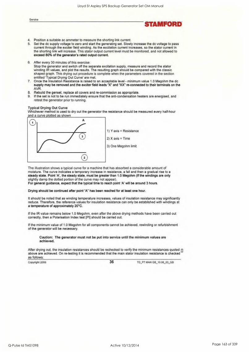
Service
STAMFORD
4. Position a suitable ac ammeter to measure the shorting link current. 5. Set the dc supply voltage to zero and start the generating set. Slowly increase the dc voltage to pass
current through the exciter field winding. As the excitation current increases, so the stator current in the shorting link will increase. This stator output current level must be monitored, and not allowed to exceed 80% of the generator's rated output current.
6. After every 30 minutes of this exercise: Stop the generator and switch off the separate excitation supply, measure and record the stator winding IR values, and plot the results. The resulting graph should be compared with the classic shaped graph. This drying out procedure is complete when the parameters covered in the section entitled 'Typical Drying Out Curve' are met.
7 Once the Insulation Resistance is raised to an acceptable level - minimum value 1.0 Megohm the dc supply may be removed and the exciter field leads "X" and "XX" re-connected to their terminals on the AVR.
8. Rebuild the genset, replace all covers and re-commission as appropriate. 9. If the set is not to be run immediately ensure that the anti-condensation heaters are energised, and
retest the generator prior to running.
Typical Drying Out Curve Whichever method is used to dry out the generator the resistance should be measured every half-hour and a curve plotted as shown
A
3
2 )
1) Y axis = Resistance
2) X axis = Time
3) One Megohm limit
The illustration shows a typical curve for a machine that has absorbed a considerable amount of moisture. The curve indicates a temporary increase in resistance, a fall and then a gradual rise to a
steady state. Point 'A', the steady state, must be greater than 1.0 Megohm (If the windings are only slightly damp the dotted portion of the curve may not appear). For general guidance, expect that the typical time to reach point 'A' will be around 3 hours.
Drying should be continued after point "A" has been reached for at least one hour.
It should be noted that as winding temperature increases, values of insulation resistance may significantly reduce. Therefore, the reference values for insulation resistance can only be established with windings at a temperature of approximately 20°C.
If the IR value remains below 1.0 Megohm, even after the above drying methods have been carried out correctly. then a Polarisation Index test [PI] should be carried out.
If the minimum value of 1.0 Megohm for all components cannot be achieved, rewinding or refurbishment of the generator will be necessary.
Caution: The generator must not be put into service until the minimum values are achieved.
After drying out, the insulation resistances should be rechecked to verify the minimum resistances quoted above are achieved. On re-testing it is recommended that the main stator insulation resistance is checked as follows:
Copyright 2006 36 TD_P7 MAN GB_10.06_03_GB
Lloyd St Aspley SPS Backup Generator Set OM Manual
Q-Pulse Id TMS1098 Active 10/12/2014 Page 163 of 339

STAMFORD Air Filters
Separate the neutral leads
Ground V and W phase and megger U phase to ground Ground U and W phase and megger V phase to ground Ground U and V phase and megger W phase to ground
Caution: The generator must not be run if the minimum insulation value of 1.0 Megohm is not obtained.
Air Filters Air filters for the removal of airborne particulate matter (dust) are offered as an addition to the standard build option. The filter elements do not remove and must not be allowed to get wet.
The frequency of filter maintenance will depend upon the severity of the site conditions. Regular inspection of the elements will be required to establish when cleaning is necessary.
Caution: Do not charge filters with oil.
Warning: Removal of filter elements enables access to LIVE parts. Only remove elements with the generator out of service.
Air Filter Cleaning Procedure
1 Remove the filter elements from the filter frames, taking care not to damage them. 2. Invert the filters dirty side down and agitate to remove particles of dirt.
To remove stubborn particles low-pressure air can be used, in the reverse direction of flow, to force out stubborn particles. If necessary use a soft brush to gently brush off any remaining dirt particles.
3. Clean the sealing gaskets and surrounding area. 4. Visually check the condition of the filter elements and sealing gaskets, replace as necessary. 5. Ensure that the filter elements are dry before putting them back into service. 6 Carefully replace the filter elements
TD_P7 MAN G8_10.06_03_GB 37 Copyright 2006
Lloyd St Aspley SPS Backup Generator Set OM Manual
Q-Pulse Id TMS1098 Active 10/12/2014 Page 164 of 339

Maintenance
Maintenance
STAMFORD
Warning: Before dissembling or assembling procedures are carried out ensure that the generating set is inhibited mechanically and isolated electrically.
Anti-Condensation Heaters Warning: The electrical supply to the heaters must be isolated before attempting any
work adjacent to the heater.
If anti condensations heaters are defect repair by replacement. Access is available via the air inlets at the non-drive end.
Removal of Permanent Magnet Generator (PMG) 1. Remove access cover (5). 2. Disconnect the multi-pin electrical connector 3. Remove the 4 bolts retaining the stator supports. 4. Tap the stator (3) out of its spigot and remove. 5. Note: As the highly magnetic rotor will attract the stator core, care must be taken to avoid a contact
which may damage the winding. 6. Remove the exciter rotor securing bolt (6) and stow safely. Firmly pull the complete rotor assembly
(4) from its location.
Note: Keep the rotor clean and avoid contact with metal dust or particles.
Note: The rotor assembly must not be dismantled.
Re-assembly Re-assembly is a reversal of the above, Ensure rotor magnet assembly is free of metal pieces or particles. Care is needed to avoid winding damage when re-assembling the stator pack, due to strong magnetic attraction.
Removal of Bearings Caution: When lifting single bearing generators, care is needed to ensure the generator frame is kept in the horizontal plane. The rotor is free to move in the frame and can slide out if not correctly lifted. Incorrect lifting can cause serious injury to personnel.
Caution: Always position the main rotor so that a full pole face of the main rotor core is at the bottom.
Note: Removal of the bearings may be effected either after the rotor assembly has been removed or more simply by removal of endbracket(s).
Note: Be sure to note the location of all components during removal to assist during the assembly process
Removal of the non drive end Bearing. Note: This procedure assumes that there is sufficient space to carry out the work, if not it will be necessary to remove the generator from the generating set. All generators covered by this manual are fitted with re-greaseable bearings.
1. Remove the PMG 2. Dissemble remove the bearing grease pipes. 3. Remove 4 bolts from the bearing cap (2). Discard the wave-washer (11). 4. Remove the bearing cap and remove 4 bolts from the end bracket, holding the bearing cartridge (13). 5. Remove 8 bolts from the endbracket (1). 6. Support the endbracket with a hoist, insert two M10 jacking bolts (on the end bracket horizontal
centre line) to drive the endbracket from the spigot. Screw in the bolts until the end bracket spigot is
Copyright 2006 38 TD_P7 MAN GB_10.06_03_GB
Lloyd St Aspley SPS Backup Generator Set OM Manual
Q-Pulse Id TMS1098 Active 10/12/2014 Page 165 of 339
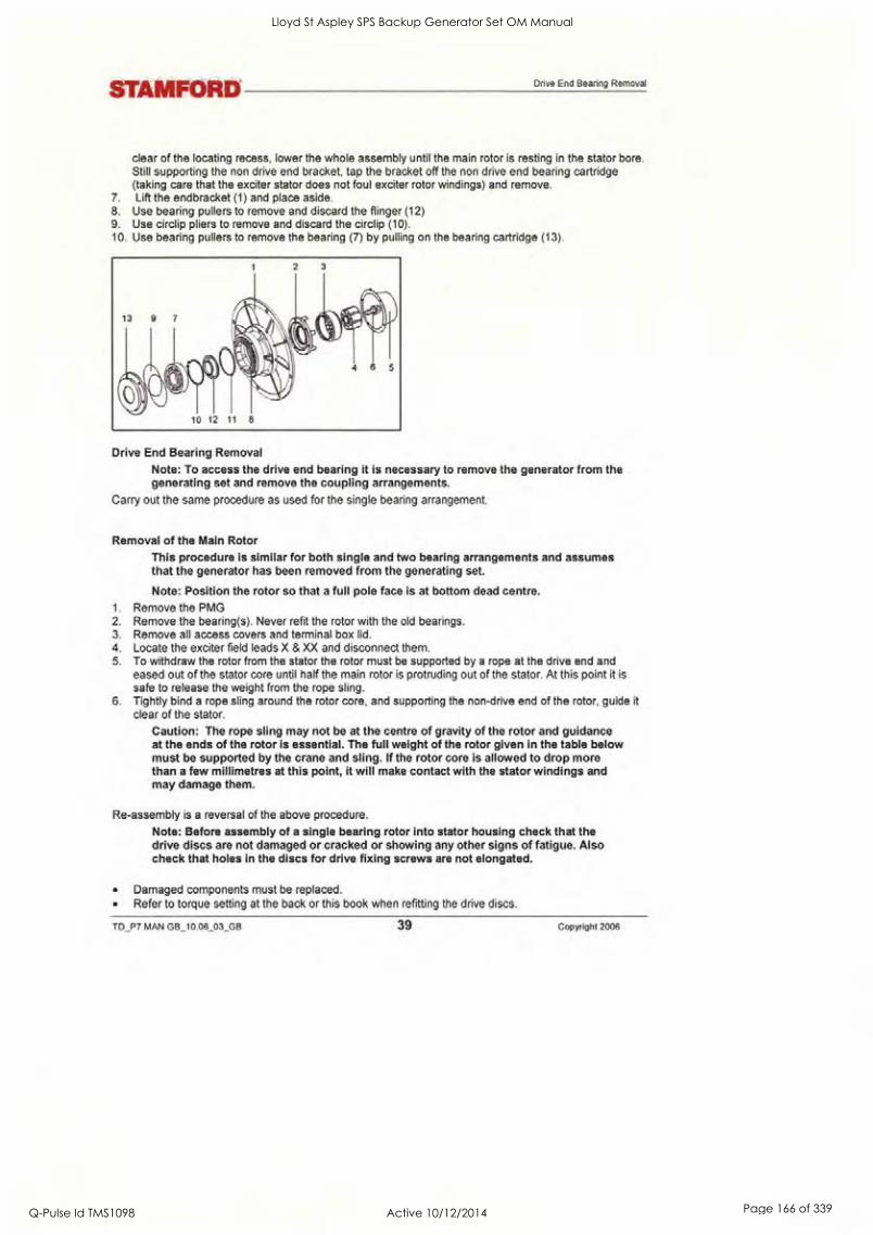
STAMFORD Drive End Bearing Removal
clear of the locating recess, lower the whole assembly until the main rotor is resting in the stator bore. Still supporting the non drive end bracket, tap the bracket off the non drive end bearing cartridge (taking care that the exciter stator does not foul exciter rotor windings) and remove.
7. Lift the endbracket (1) and place aside. 8. Use bearing pullers to remove and discard the flinger (12) 9. Use circlip pliers to remove and discard the circlip (10). 10. Use bearing pullers to remove the bearing (7) by pulling on the bearing cartridge (13).
Drive End Bearing Removal
Note: To access the drive end bearing it is necessary to remove the generator from the generating set and remove the coupling arrangements.
Carry out the same procedure as used for the single bearing arrangement.
Removal of the Main Rotor This procedure is similar for both single and two bearing arrangements and assumes that the generator has been removed from the generating set.
Note: Position the rotor so that a full pole face is at bottom dead centre. 1. Remove the PMG 2. Remove the bearing(s). Never refit the rotor with the old bearings. 3. Remove all access covers and terminal box lid. 4. Locate the exciter field leads X & XX and disconnect them. 5. To withdraw the rotor from the stator the rotor must be supported by a rope at the drive end and
eased out of the stator core until half the main rotor is protruding out of the stator. At this point it is
safe to release the weight from the rope sling. 6. Tightly bind a rope sling around the rotor core, and supporting the non-drive end of the rotor, guide it
clear of the stator.
Caution: The rope sling may not be at the centre of gravity of the rotor and guidance at the ends of the rotor is essential. The full weight of the rotor given in the table below must be supported by the crane and sling. If the rotor core is allowed to drop more than a few millimetres at this point, it will make contact with the stator windings and may damage them.
Re-assembly is a reversal of the above procedure.
Note: Before assembly of a single bearing rotor into stator housing check that the drive discs are not damaged or cracked or showing any other signs of fatigue. Also check that holes in the discs for drive fixing screws are not elongated.
Damaged components must be replaced. Refer to torque setting at the back or this book when refitting the drive discs.
TD_P7 MAN GB_10.06_03_GB 39 Copyright 2006
Lloyd St Aspley SPS Backup Generator Set OM Manual
Q-Pulse Id TMS1098 Active 10/12/2014 Page 166 of 339

Maintenance
Refer to engine manual for torque setting of disc to flywheel bolts.
STAMFORD
Refitting Bearings Caution: Every effort must be made to establish a clean area around the generator when removing and replacing bearings. Contamination is a major cause of bearing failures.
Equipment Suitable cleaning solvent Thin protective gloves Lint free cleaning cloth Induction heater.
Preparation Caution: Ensure that the bearing contact surfaces show no sign of wear or corrosion prior to fitting the bearing.
Caution: Never refit used bearings, grease flingers, wave washer or '0' rings.
Caution: Only the outer race should be used to transmit load during assembly (NEVER use the inner race).
1. The bearing cap(s) and cartridge(s) must be thoroughly flushed out with clean solvent and checked for wear or damage, before re-assembly. Damaged components should be replaced before refitting the bearing.
2. Note: Gloves must be worn at all times when handling the bearings, grease and solvent. 3. Wipe clean the assembly surface, using cleaning solvent on lint free cloth. 4. Wipe clean: Bearing Cartridge, Wave Washer, Bearing Cap, grease flinger, all re-lubrication pipes
and fittings (internal and external). Visually inspect all components after cleaning, for contamination. 5. Place all components on the clean assembly surface. 6. Caution: Do not use an air line to blow off excess fluid. 7. Thoroughly clean the external surface of the grease gun nozzle using lint free cloth.
Bearing preparation 8. Remove the bearing from its packaging. 9. Wipe off the preservative oil from the surface of the inner and outer rings - using lint free cloth only. 10. Place the bearing on the clean assembly surface, with the bearing designation marking facing down. 11. Apply half the specified bearing grease fill quantity to the upper face of the bearing (opposite side to
the bearing designation markings). 12. Thumb the applied grease into the bearing, ensuring good penetration into the raceways/balls (use
clean protective gloves).
Bearing Cartridge Note: grease quantities can be found in the back of this book
13. Apply the specified cartridge grease fill quantity to the back face of the bearing housing. 14. Apply a small amount of grease to the grooved sealing surface in the cartridge. 15. Apply anti-fretting lubricant (MP14002 - Kluber Altemp Q NB 50) to the bearing housing
circumference. Apply paste in a thin coherent layer by use of a lint free cloth (DO NOT rub in) (use clean protective gloves).
16. Non-drive end - fit new '0' Rings into the '0' Ring grooves in the bearing housing circumference.
Assemble Bearing into Cartridge 17. Heat the bearing cartridge to 25° C above ambient with an induction heater (Do not exceed 100°C). 18. With greased face of the bearing facing the cartridge bore, fit the bearing into the bearing housing.
Ensure the bearing outer race contacts the location shoulder.
Assemble Bearing onto Shaft 19. Heat the Bearing and Cartridge assembly to 80°C above ambient with an induction heater (use
Copyright 2006 40 TD_P7 MAN GB_10.06_03_GB
Lloyd St Aspley SPS Backup Generator Set OM Manual
Q-Pulse Id TMS1098 Active 10/12/2014 Page 167 of 339

STAMFORD Bearing Cap & Flinger
induction heater, no other heat source is suitable) 20. Slide the Bearing and Cartridge assembly over the shaft. pushing it firmly against the bearing seating
shoulder. 21. Rotate the assembly (including inner race) 45° in either direction, to provide correct alignment. The
bearing must be held firmly in place until it is cool enough to positively self locate. Note: Ensure cartridge is at ambient temp. before assembling bracket.
Bearing Cap & Flinger 22. Apply the specified cap grease fill quantity to the inside face of the cap. 23. Fill the grease exhaust slot with grease. 24. Apply a small amount of grease to the grooved sealing surface in the cap. 25. Fit circlip. (single bearing only). 26. Heat flinger to 120°C and place on shaft up to the bearing inner race. Hold firmly until positively
located. 27. Place wave washer in cap, fit cap to bearing cartridge.
Re-lubrication pipe 28. Fill pipe and grease nipple with grease. 29. Fit pipe work to machine.
Returning To Service After rectification of any faults found, remove all test connections and reconnect all control system leads. 30. Refit all terminal box covers/access covers and reconnect heater supply. 31. Carry out pre-running checks 32. Restart the set and adjust VOLTS control potentiometer on AVR by slowly turning clockwise until
rated voltage is obtained.
Warning: Failure to refit all guards, access covers and terminal box covers can result in injury or death.
Bearing Maintenance
Re-lubrication
Ensure that the grease, grease gun, grease gun nozzle and re-lubrication nipple are free from abrasive materials and other contaminants.
If the generator is running, apply the specified quantity of grease via the grease nipple (see table below). Keep the generator running for at least 10 minutes after applying the grease.
If the generator is not running, apply the grease as above then start the generator and run for at least 10
minutes to allow excess grease to exhaust from the bearing assembly.
Exhaust grease can build up inside of the PMG cover. At the first opportunity, when the generator in
stopped. remove the PMG cover and clean out any build up of exhaust grease.
Warning: Do not remove the PMG cover with the generator running.
TD_P7 MAN GB_10.06_03_GB 41 Copyright 2006
Lloyd St Aspley SPS Backup Generator Set OM Manual
Q-Pulse Id TMS1098 Active 10/12/2014 Page 168 of 339
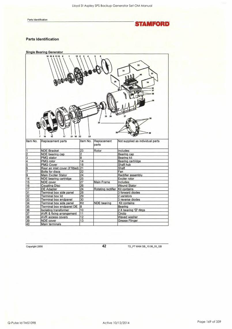
Parts Identification
Parts Identification
STAMFORD
Single Bearing Generator 14 10 8 11 13 9 1 12 2 3 4
.., 1 .,
',SI, % 0 a AI' s fe.
-----"----- rjr---
081k ol., 9?:
.....0 111 Alli ._, IlY
../.0*. 44.°
7 16 15 17 21 18 22 23
5 6
111. kik ..
1101
36 37 ), 38 Mir-
lel 39 .0
1 Alli ?. NIK ., 111.
...:. A 0111kj° 1,.`-'
25 28 27 ..
24
11 I
lit 30 - ,41112.-
Item No. Replacement parts Item No. Replacement parts
Not supplied as individual parts
1 NDE Bracket 23 Rotor Includes: 2 NDE bearing cap 2 Bearing cap 3 PMG stator 8 Bearing kit 4 PMG rotor 14 Bearing cartridge 5 PMG Cover 18 Shaft hub 6 Rear air inlet cover (if fitted) 21 Shaft 7 Bolts for discs 22 Fan 9 Main Exciter Stator 24 Rectifier assembly 14 NDE bearing cartridge 25 Exciter rotor 15 NDE cover 27 Main Frame Includes: 16 Coupling Disc 26 Wound Stator 17 DE Adapter 24 Rotating rectifier Kit contains 31 Terminal box side panel 28 3 forward diodes 32 Terminal box lid 29 2 varistors 33 Terminal box endpanel 30 3 reverse diodes 34 Terminal box side panel Kit NDE bearing Kit contains: 35 Terminal box endpanel DE 8 Bearing 36 Isolating transformer 10 2 X bearing '0' rings 37 AVR & fixing arrangement 11 Circlip 38 AVR access covers 12 Waved washer 39 NDE cover 13 Grease Flinger 40 Main terminals
Copyright 2006 42 TD_P7 MAN GB_10.06_03_GB
Lloyd St Aspley SPS Backup Generator Set OM Manual
Q-Pulse Id TMS1098 Active 10/12/2014 Page 169 of 339

STAMFORD
Two Bearing Generator.
Two Bearing Generator.
Item No. Replacement parts Item No.
Replacement parts Not supplied as individual parts
1 NDE Bracket 22 Rotor Includes: 2 NDE bearing cap 16 & 2 Bearing cap DE & NDE 3 PMG stator 18 & 8 Bearing kit DE & NDE 4 PMG rotor 14 & 19 Bearing cartridge DE & NDE 5 PMG Cover 20 Shaft 6 Rear air inlet cover (if fitted) 21 Fan 9 Main Exciter Stator 30 Rectifier assembly
14 NDE bearing cartridge 24 Exciter rotor 15 NDE cover 26 Main Frame Includes: 16 Coupling Disc 25 Wound Stator 17 DE Adapter 23 Rotating rectifier Kit contains: 30 Terminal box endpanel DE 27 3 forward diodes 31 Terminal box side panel 28 2 varistors 32 Terminal box lid 29 3 reverse diodes 33 Terminal box endpanel NDE 8 NDE bearing Kit contains: 34 Terminal box side panel 10 Bearing 35 Main terminals 2 X bearing '0' rings 36 Isolating transformer 12 Waved washer 37 AVR & fixing arrangement 13 Grease Flinger 38 AVR access covers 18 DE bearing Kit contains: 39 NDE cover Bearing
2 X bearing '0' rings Grease Flinger
TD_P7 MAN GB_10.06_03_GB 43 Copyright 2006
Lloyd St Aspley SPS Backup Generator Set OM Manual
Q-Pulse Id TMS1098 Active 10/12/2014 Page 170 of 339

Spares and After Sales Service
Spares and After Sales Service
STAMFORD
Recommended Spares We recommend the use of genuine service parts supplied from one of our service outlets; these are supplied conveniently packaged for easy identification. Genuine parts may be recognised by the.
The recommend spares for Service and Maintenance can be found in the Data section of this manual. In
critical applications a set of these service spares should be held with the generator.
When ordering parts the machine serial number or machine identity number and type should be quoted, together with the part description. The machine serial number can be found on the 'generator's name plate'.
If the nameplate is missing look for additional markings; each generator has its unique serial number stamped in to the upper section of the drive-end frame end-ring. In addition each generator is supplied with two adhesive rectangular labels fixed inside the terminal box; each carries the generator's unique identity number. One label has been fixed to the inside of the terminal box sheet metal-work, and the second label fixed to the main frame of the generator.
Orders and enquiries for parts should be addressed to:
STAMFORD Parts Department, Barnack Road, Stamford, Lincolnshire PE9 2NB England.
UK Telephone: +44 (0) 1780 484000 UK Fax: +44 (0) 1780 766074
After Sales Service Service Engineers are available to give technical support and advice as well as carry out maintenance and repair through Stamford and our subsidiary companies. An on-site service and repair facility is also available at our Stamford Works.
UK Telephone: +44 (0) 1780 484732 UK Fax: +44 (0) 1780 484104
Kluber Asonic GHY72 Grease All bearing trials and calculated life expectancy are based on the use of Kluber Asonic GHY 72. We recommend the use of this Ester Oil/Polyurea grease or an alternative grease with the same specification. The grease specification is available on request. Kluber has a world-wide distribution network, contact the manufacturers for your nearest stockist. Alternatively supplies can be purchased, from our Parts department, in handy economical packages. We also offer a suitable grease dispenser
Copyright 2006 44 TD_P7 MAN GB_10.06_03_GB
Lloyd St Aspley SPS Backup Generator Set OM Manual
Q-Pulse Id TMS1098 Active 10/12/2014 Page 171 of 339
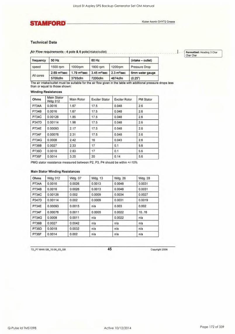
STAMFORD
Technical Data
Kluber Asonic GHY72 Grease
Air Flow requirements - 4 pole & 6 pole(intake/outlet)
frequency 50 Hz 60 Hz (intake - outlet)
speed 1500 rpm 1000rpm 1800 rpm 1200rpm Pressure Drop
All cores 2.69 m3/sec 1.79 m3/sec 3.45 ms/sec 2.3 m'/sec 6mm water gauge
5700cfm 3793cfm 7200cfm 4874cfm (0.25")
The air intake/outlet must be suitable for the air flow given in the table with additional pressure drops less than or equal to those shown:
Winding Resistances
Ohms Main Stator Wdg 312
Main Rotor Exciter Stator Exciter Rotor PM Stator
P734A 0.0016 1.67 17.5 0.048 2.6
P734B 0.0016 1.67 17.5 0.048 2.6
P734C 0.00126 1.85 17.5 0.048 2.6
P347D 0.00114 1.98 17.5 0.048 2.6
P734E 0.00093 2.17 17.5 0.048 2.6
P734F 0.00076 2.31 17.5 0.048 2.6
P734G 0.0008 2.42 16 0.043 2.6
P736B 0.0027 2.33 17 0.1 5.6
P736D 0.0018 2.83 17 0.1 5.6
P736F 0.0014 3.25 20 0.14 5.6
PMG stator resistance measured between P2, P3, P4 should be within +/-10%
Main Stator Winding Resistances
Ohms Wdg 312 Wdg. 07 Wdg. 13 Wdg. 26 Wdg. 28
P734A 0.0016 0.0026 0.0013 0.0048 0.0031
P734B 0.0016 0.0026 0.0013 0.0048 0.0031
P734C 0.00126 0.002 0.0009 0.0034 0.0027
P347D 0.00114 0.002 0.0009 0.0031 0.0019
P734E 0.00093 0.0015 n/a 0.003 0.002
P734F 0.00076 0.0011 0.0005 0.0022 10..16
P734G 0.0008 0.0011 n/a 0.0022 n/a
P736B 0.0027 0.0042 n/a n/a n/a
P736D 0.0018 0.0032 n/a n/a n/a
P736F 0.0014 0.002 n/a n/a n/a
TD_P7 MAN GB_10 06_03_GB 45 Copyright 2006
Formatted: Heading 3 Char Char Char
Lloyd St Aspley SPS Backup Generator Set OM Manual
Q-Pulse Id TMS1098 Active 10/12/2014 Page 172 of 339

Technical Data
ling disc Torque settin
STAMFORD
Frame No. Of Discs Single Disc Thickness Total Thickness Tightening Torque
P7 6 1.2 7.2 84kgm 822Nm
Bending Moments For the purposes of establishing the genset design the bending moment at the engine flywheel housing to
generator adaptor interface should not exceed 275 kgm. (2000ft.lbs.)
Customer output cables Clean plated surfaces with a degreasing agent, then lightly abrade them to remove any tarnish. Don't score the surface. The output cables should be connected to the terminals using grade 8.8 steel bolts and associated anti-vibration hardware. The table is for your guidance.
Frame Hole Size Bolt Size Torque Nm
P7 17 16 90
Generator internal connections. The torque settings for all connections within the generator, links, CTs, accessories, cables, etc are
45Nm.
Re-lubrication Details for Regreasable Bearings
Frame P7 Bearing Position Grease Quantity
Lubrication Period cm3 Grams
A, B, C, D, E Non-Drive End 85 75 4000 - 4500 Hrs
A, B, C, D, E Drive End 100 89 4000 - 4500 Hrs
F, G, Non-Drive End 85 75 4000 - 4500 Hrs
F, G, Drive End 136 121 4000 - 4500 Hrs
Initial fill for Regreasable Bearings
Frame P7 Bearing Position bearing cartridge cap
cm3 gms cm3 gms cm3 gms
A, B, C, D, E Non-Drive End 174 154 87 77 87 77
A. B, C, D, E Drive End 208 185 104 92 104 92
F, G, Non-Drive End 174 154 87 77 87 77
F, G, Drive End 272 242 136 121 136 121
Copyright 2006 46 TD_P7 MAN GB_10.06_03_Glii
Lloyd St Aspley SPS Backup Generator Set OM Manual
Q-Pulse Id TMS1098 Active 10/12/2014 Page 173 of 339
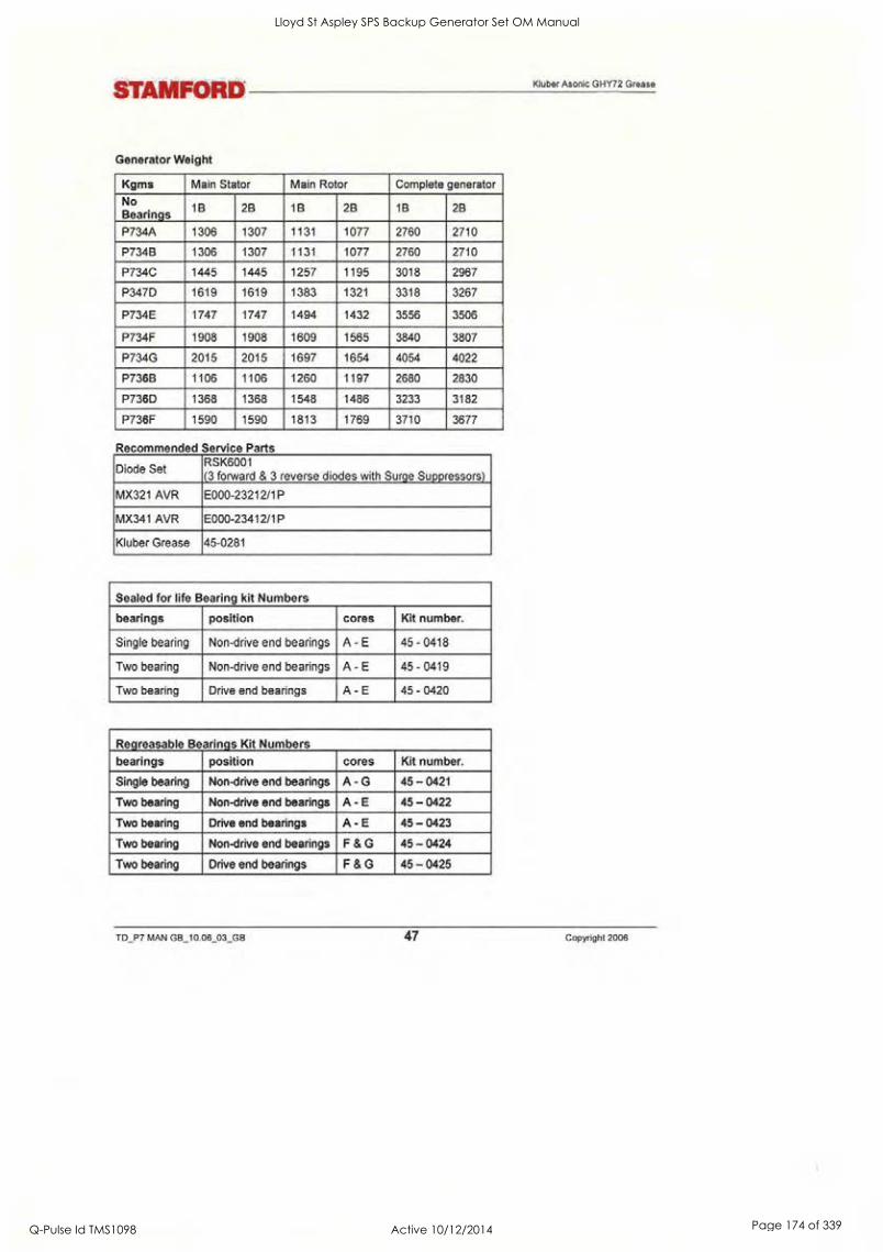
STAMFORD
Generator Weight
Kluber Asonic GHY72 Grease
Kgms Main Stator Main Rotor Complete generator
No Bearings 1B 2B 1B 2B 1B 2B
P734A 1306 1307 1131 1077 2760 2710
P734B 1306 1307 1131 1077 2760 2710
P734C 1445 1445 1257 1195 3018 2967
P347D 1619 1619 1383 1321 3318 3267
P734E 1747 1747 1494 1432 3556 3506
P734F 1908 1908 1609 1565 3840 3807
P734G 2015 2015 1697 1654 4054 4022
P736B 1106 1106 1260 1197 2680 2830
P736D 1368 1368 1548 1486 3233 3182
P736F 1590 1590 1813 1769 3710 3677
Recommended Service Parts
Diode Set RSK6001 (3 forward & 3 reverse diodes with Surge Suppressors)
MX321 AVR E000-23212/1P
MX341 AVR E000-23412/1P
Kluber Grease 45-0281
Sealed for life Bearing kit Numbers
bearings position cores Kit number.
Single bearing Non-drive end bearings A - E 45 - 0418
Two bearing Non-drive end bearings A - E 45 - 0419
Two bearing Drive end bearings A - E 45 - 0420
Regreasable Bearings Kit Numbers
bearings position cores Kit number.
Single bearing Non-drive end bearings A - G 45 - 0421
Two bearing Non-drive end bearings A - E 45 - 0422
Two bearing Drive end bearings A - E 45 - 0423
Two bearing Non-drive end bearings F & G 45 - 0424
Two bearing Drive end bearings F & G 45 - 0425
TD_P7 MAN GB_10.06_03_GB 47 Copyright 2006
Lloyd St Aspley SPS Backup Generator Set OM Manual
Q-Pulse Id TMS1098 Active 10/12/2014 Page 174 of 339

A.G. GENERATOR WARRANTY
A.C. GENERATOR WARRANTY
STAMFORD
Warranty Period In respect of a.c. generators the Warranty Period is eighteen months from the date when the goods have been notified as ready for despatch or twelve months from the date of first commissioning (whichever is the shorter period).
Defects, After Delivery We will make good by repair, or at our option, by replacement, any fault that under proper use appears in
the goods within the warranty period. Provided, on examination by us, the defect is solely due to defective material or workmanship. The defective part is to be promptly returned, carriage paid, to us at the factory, our Subsidiary of or, if appropriate to the Dealer who supplied the goods. All identification marks and numbers must be intact to aid identification. Any part repaired or replaced, under warranty, will be returned to the customer free of charge (via sea freight if outside the UK). We shall not be liable for any expenses that may be incurred in removing or replacing any part sent to us for inspection or in fitting any replacement part supplied by us.
We shall be under no liability for defects in any goods which have not been properly installed in
accordance with our recommended installation practices as detailed in the 'Installation, Service and Maintenance Manual' and 'Installation Guidelines'. We shall be under no liability for defects on products that have been improperly used or stored or which have been repaired, adjusted or altered by any person except our authorised agents or ourselves. We shall not be liable for any second-hand goods, proprietary articles or goods not of our own manufacture although supplied by us, such articles and goods are being covered by the warranty (if any) given by the manufacturers. All claims must contain full particulars of the alleged defect, the description of the goods, the Serial Number, the date of purchase, and the name and address of the Vendor (as shown on the manufacturer's identification plate). For Spare Parts, claims must contain the order reference under which the goods were supplied. Our judgement, in all cases of claims, shall be final and conclusive and the claimant shall accept our decision on all questions as to defects and the exchange of a part or parts. Our liability shall be fully discharged by either repair or replacement as above, and in any event shall not exceed the current list price of the defective goods. Our liability under this clause shall be in lieu of any warranty or condition implied by law as to the quality or fitness for any particular purpose of the goods, and save as expressly provided in this clause we shall not be under any liability, whether in contract, tort or otherwise, in respect of defects in goods delivered or for any injury, damages or loss resulting from such defects or from any work undone in connection therewith.
Extensions to the warranty period Extensions to the warranty period can be purchased, subject to additional terms and conditions pertaining to the specific application. Apply to the UK, Warranty Department
MACHINE SERIAL NUMBER
Copyright 2006 48 TD_P7 MAN GB_10.06_03_GB
Lloyd St Aspley SPS Backup Generator Set OM Manual
Q-Pulse Id TMS1098 Active 10/12/2014 Page 175 of 339

STAMFORD
End of Life Disposal
Recyclable material
Companies, specialising in reclaiming material from scrap products can reclaim most of the iron, steel and copper from the generator.
Recyclable material Mechanically separate the base materials. iron, copper and steel, removing paint, polyester resin, and insulation tape and/or plastics residues from all components. Dispose of this 'waste material'
The iron, steel and copper can now be recycled.
Items requiring specialist treatment. Remove electrical cable, electronic accessories and plastic materials from the generator. These components need special treatment to remove the waste from the reclaimable material.
Forward the reclaimed materials for recycling.
Waste material Dispose of waste material from both of the above processes via a specialist disposal company.
TD_P7 MAN GB_10.06_03_GB 49 Copyright 2006
Lloyd St Aspley SPS Backup Generator Set OM Manual
Q-Pulse Id TMS1098 Active 10/12/2014 Page 176 of 339

STAMFORD WORLDWIDE
STAMFORD WORLDWIDE
STAMFORD
Wholly Owned Subsidiaries and Manufacturing Sites* AUSTRALIA NORWAY Tel: +47 22 97 44 44
Tel: +61 2 9680 2299 Fax: +47 22 97 44 45 Fax: +61 2 9680 1545
*CHINA Tel.: +86 51 0521 6212 Fax: +86 51 0521 7673
GERMANY Tel: (49) (0) 61 03 50 39 Fax: (49) 61 03 50 39 40
*MEXICO Tel: +52 48 26 84 00 Fax: +52 48 26 84 05
0 SINGAPORE Tel: +65 6794 3730 Fax: +65 6898 9065
*INDIA Tel: +91 20 402 5329-30 SPAIN Fax: +91 20 402 5331
ITALY Tel: +39 02 380 00714 U.S.A. Fax: +39 02 380 03664
JAPAN Tel: +81 426 77 2881 Fax +81 426 77 2884
STAMFORD
Tel: +34 91 498 2000 Fax : +34 91 498 2004
Tel: +1 763 528 7301 Fax +1 763 57485082
BARNACK ROAD, STAMFORD LINCOLNSHIRE, PE9 2NB ENGLAND
Tel: +44 (0) 1780 484 000 Fax: +44 (0) 1780 484 100
'STAMFORD' is a registered trademark.
Copyright 2006 50 TD_P7 MAN GB_10 06_03_GB
Lloyd St Aspley SPS Backup Generator Set OM Manual
Q-Pulse Id TMS1098 Active 10/12/2014 Page 177 of 339

Lloyd St Aspley SPS Backup Generator Set OM Manual
Q-Pulse Id TMS1098 Active 10/12/2014 Page 178 of 339

r
I i
S
I 0
I 0
Lloyd St Aspley SPS Backup Generator Set OM Manual
Q-Pulse Id TMS1098 Active 10/12/2014 Page 179 of 339

5 nti-V.zovig,,
FAMIX;
Tlio,s.eri-ot.,sq.cel.;:30. PLCs are a family of
000030 systems and specialty
MO.01iles designed to meet the demand for
Versatile industrial solutions. With its
single overall control architecture, the
Series 90-30 has been the PLC of record in
over 200,000 applications, such as high-
speed packaging, material handling,
complex motion control, water treatment,
continuous emissions monitoring, mining,
food processing, elevator control,
injection molding and many more.
E Falun Automatioi
Series 9r-30 PLCs
'11
'E a .4
411
AY,-
,--. .b,: IV' ...,,,,,.....
..Z.:;-, ....4 , -4, -.or -......4
ici -4.,... j :,- ..-
Zrfi -4-311 PrP174 ....
.v.F., - ......7
..,.. .......
411'.egieM.1,"'gV
Thanks to its modular design, the Series 90-30 offers unmatched versatility. Configure just the system you need, saving critical space and reducing cost.
With over 100 I/O modules, the Series 90-30 PLC can be adapted to a wide range of applications.
Digital interfaces for push buttons, switches, proximity sensors, relays, contactors and many other devices
Analog modules with varying degrees of resolution for flow, temperature or pressure applications
Direct connect wiring or remote termination.
Local or remote I/O systems
Series 90-30 Ethernet communications provide a real-time link between the plant floor and the boardroom. You can begin with an
Ethernet-enabled CPU, or at a later date, choose from our selection of rack-mounted Ethernet modules. The Series 90-30 Ethernet
module supports both SRTP and Modbus TCP/IP application protocols.
leaving open the option of creating a more powerful system tomorrow -without having to change youqi cation gftware.
.
The scaleable processing power in the Series 90-30 CPU creates a clear upgrade path. Create the sy,§tetj-
Motion control integrated into the Series 90-30 fosters high performance point-to-point applications;;
givairety of Series 90-30 field bus interfaces enables distributed control and/or I/O. Cho-6'8e fr6.fh'i",
Genius®, DeviceNetTM and Interbus -STM modules. Field Bus interface modules are eastio insta,ll and;;`q ick to .,e:onfigure
into an existing system or design a new system around them.
Ease of programming is a strong suit oLthe Series 90-30. Choose the programmin.4',:OptionSliatAer yoA)leeds.:Window'st':bas'ed, I E C programming, advanced C or State Logic ®. Floating point math, PID, indirect a'.ddressilig, a4ayynoveV:and segUencifig areliiSr.a few of the over 200 instructions available.
The Series 90-30 stands out among small controls for offering redundancy options;; The Se'ries9,0::.30:1S,:thb lowit'.61t solutiMor high availability applications, with redundant CPUs and power supplies.
-
Easy trouble shooting and machine setup using a handheld PDA. CIMPLICITr:Ma:Oine Editie&OgX.:1:10yelgper PDA software . . . .
allows you to interface a Palm® handheld device to your Series 90-30 controlletNth Og ipiOeVelOPer:PRA" you c . .
monitor/change data, view diagnostics, force ON/OFF, and configure machine setups'aVing:WArtirrie and increasing phidUctivi,
Lloyd St Aspley SPS Backup Generator Set OM Manual
Q-Pulse Id TMS1098 Active 10/12/2014 Page 180 of 339
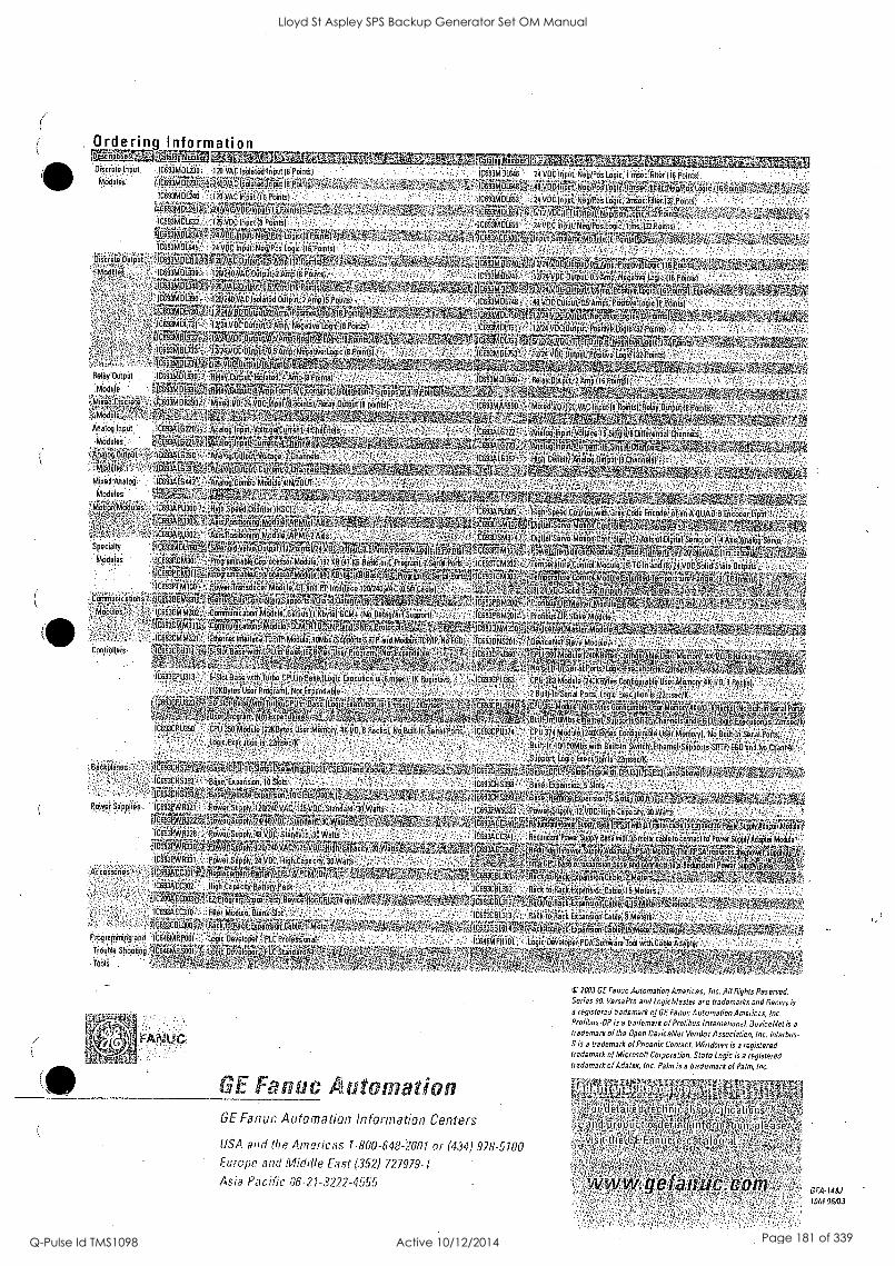
Ordering Information pzifittiamicaueisiambworam,,,,,,takelL.4 Discrete Input .1C633MDL230 ; : )20 VAC Isolated Input Ocir: i IC693M Dila 24 VDC Input; -N /P L F '
r.v160 c,jcssgi_pj23K.i.,;i.zfuj..%yacAsoloedoni;tai'poo;r4.1
IC693MDL24t.., ;:i20..VAC 7:0Poiots) ,
41.4F33.0.-.L74)t .:.16633451.02./..:Y.ii:.VDe Input f6'Pomtsl
AlgO3M pjA0.,:; ypealip.uOles/E91:Lo'gislt 1191n.t .
-
.
aiiitBriniFit.4423V,FRINIWKWEASW.','-f:;
WeggilatEMEWEDRINAIW .6100.46M7OitaiWAiii4eaiiiii6W Ogg.. 317M F7270tratgeWsWWAra
AaSbTiY OBTREMEN EKG 67445W!V:141WWMir.404.*(04i',
IMMTEISIMMITaggirgRaaniks6ii6:0go -1.044'Str' "
Relisylluipet
aodule.
axed Disc
Mod. )
Analog Input; :4441:G220
Modules hic.0,14,0 iog Output a*c.0iiii
les g r a& MixedAnaloT :,1069.3416442:
Modules..!544,-,.* 46
...:10693M1i655' :; 24 VD Input Neg /PosLOgic 1 ins '132 P
C6344.6740f, 24; 0910444;:;;:0
fe.St.1:1( ,
tragilitakkailtlirprkep . Cix ics§jm vilps#,011..06140
IC6931U301.r.7
164 pyie..* spApmio*
Specialty tig93Mifiii7to--
mOdires
toinT...n., ,a4194T.: and p.iiiiif4ficti 1 iciiiiiiiato4,6 ""':"
AiieloSgslOp0i1/914W07Ciirogj,4
titgeraitervtAlt%
l6ifF1 L
c
trIgNodbiejAM.2Aij
..."3. sY
C Input 19 Pu tai Relay Oiu
Ap719g,IiipArtATal4g0
?An lo9lnput_ea en tt 5ZONall; %;.
95r,,, .:,..i.h..,,:,,,,,,,,,..,..,.......: ,...,...,,,-. ., avuo Or ve,,. uput.9,1;;TOTt0/24VOCodp fgAlijP,P. ip'*.tip.TeiLogio.5! j
NorEgn4463.-..pjilieir4.46d;i37,1iikitii7ii''' isltId06fi .... ,. ,.:. 4sic.or,c,Pcograni)-
idC693PCM31 i'-'. '''''''''''',,001:',.,,,F.i.;,",...-,'". '...;,.....,....:,!fq.erP914gidliti!gPNQcBISOrModulir 60r34/T711?i'4;:`ii.1%;4,/, '
- ...:. . ...-.p.EMR11 Osi.niffilTA:uileaiiroiri)11§71""'Imrio"'Ve'%1 . ..- 141' !I*Iz'''''''
t,A.39::iis , :- - : !:E6...e4Ki iii:1,,-topp-'eriiiailoY6i)'uioGlirPl-14i411.:.--9.'g'fl'''''''.:.. .`4.7:-.-''''- , , enjus, 1, byteJGCM4INO-Ditig'"''S'oo' I
,.....4.,CliR31JF7.7472gri.. ..,.li , iiifill4Tuk.tCPS,..1;5SCLi. NPr4170,1.. .:6''.4:.ti. AT -rim?' u iii!'"g' !,94.,3,C74'N);4:.,i.fieiii'id ioTeitki4tififfP:Vdd14:40MiisrtSIiTPiii1A1A+1.7.dhiii \'''
01093CP3r311... ii40, .itti'T:i''''''ATti.'4'61knt Bsgse"'!;(ilBtei's;:.'-'41?::P-P''''"g' . '''''''IN.71it''''''L.1.ExpiTied'illC171P....11 .16,4;:..7?
A.....-T :"'.'41:: .
. ' ' '..,,I,Ii ..
li:E332P U3: 31].., jr37ot 8 o,'4/itt;for,tiotplf004i4;flOgig Ex oc :-.N.:i is.5iriifte),...1K Registers;
':..ii..kgryiViiiiiQ ai,;giWoi,;;;4,;: ...2:A.icili:r141algi;,,tttii41;704Vg'4VitFt.
::... ',..,;:.':. ifiglig'cil:itar67i'VI::'.'.., '. ' tz
1 i...E.5:c.F. U21,G OijialijAiiie'igiNI*Lio. 8..07::,..:,:mt.iicy. ii Fec kir146Du4146ii al fthts, I ic;Executoo;74 '22rnse
-11'0 ;,..cir:.on.kftUAD:.6 :En cod or frriitil
IC693DSM3}4 'Digital Servo Motion 1 f;019141'siirYP 444.1
fe0rArilf AC693TCM302;. e onilr mbobiolegt:.rfilifdle)-ovocsolici, state oqtr4tis,[..,..,."-- lcaregiii. itolititgariZt'ArratieWOONti)
2.0.0 c.§..6.11441441gP.. _
Tiar
NPtiMestFrAcdPie
Nat SI
11361461tVigig &NOMA US° RMer ri4 07816 0 .g,in?904tD4574)ctExec0nor1).1s.':72Risritic::q
CPU.363Modiilel240K13itei'CoofiguribleUge(;Mehooy 40/6,1 Bgai2iSidal:POOs,..L4fd:Eiodudool$'43144idech
latkeTOrktaiggitngte Mem *IC -
Cool:al NS
If rs>
ogot,:SupgoltsMTPACliennelo and>E6 13/11.g 22rnspc/K,
,;-10693C1N374 CP, U.374 Module (24014(417.16 Configurable UserMemoiyl ; NO; Dedt-In'Serial .PO4ts,,
. Ot,SUOOTts'SP.71,/E6D.'aild No C..)d000l . ..
.',.,S.tipport. LOgil"(xecidiOkid-'.12rOsociK.-', ;Amos ......
.:CIA.3.:1o2i..; .Dose,Citil4(g SI iso-wth CP1.2713-3.33rirthelloye;.,.;..t.;%-ff .'i ....;', ;:,-,:,:y":13E';3CE',3397.;:',...13a41:10V.EGIg4.4,0U.7.311.:3,i'33i1' 01..:::':.''..i.',.
1e3,53C.P.32.32 , BouO',::iiiiiiisiOO;.,10S:cts. ' -. , -.,,,,,';'....f.,;;;-: , . , ,., , ...;CE93CliS';32.'D'ald'iti"OOiiOrdO:5'-si6::',',-,' .
.... _. , . . , . ., _ .
.
-,..,.,,......,......-.,.....i...g.,-..,,,,,,,,,,,,,T.,,,,,. /,,,:,,,.70,,,,,,,,,,,v..,.-.....- .1.[.:61:igt1:41?.Mi!.34g.1391Jroje.9.411sm.-10iSJP.,43701144.ZW,Vai: ' - ':::,.' .?.::,5,-.,-,%i6tRA,S'4i1C69gcFJ5a99,1:42;QUq;FISI.WleifICP4!15419.5,S1.9.W1911.41.4W
Pot.er Soo:: es: .:1,Cti3P:1 Lll/V.FigtV.:eg *eiigg1,,-,ii0,72;ci,i.i,gi123:iD.,Ciri(iiid4iki.i4/ijii .- , . ,-;:::::::-/"..:.,..-..,,M'.'-1660.*6iV-:-:.i64ii1314i(40.614Weii..4i6Wiii..f-:;. 03....irgatilti.WLPFiliMfa'.&41:116ggillt.;:;.':::7tii:::7.7{'!..14T.'-'AZ'AR9347(6iingitcrlr117MiTuairiklahfsli.TAINirakt
9g0cotiMod000 ,- 11.,,...e,v F.3, 'Po..ver/Siipply:40VDCStinditili:.30,1tiitt's/:*?-':',! - - , -- i IC633ACC34 1..,;13Eiclunclaiir POwer;Segf4Beidy40733inidoc6Notgeafrieot.to.Po, -SupplikifgiaMOiii CigPrtlyk33 .0,7);;;;fgOrl4a4P,ArgrellPiT'im"'i?... ' .r.:.. '.';.:,i':.: ..7. :I.i...vl'agiseen
'
. 3.32. i . .',. '
'. '....4. :.
teed., 'iI - et - atl44r 1017iV eAt,ga l.-'V[iPaillieTtig
' riP r
IC33ZPVP31 wer:sio0704voc4lidkt4#4i,37:Woisr ,itsa- $A5,41,:',?,- 2 b40afditili; *4vpd ant P00?iS a
A : i ,.1c :in, I 6: 'WEP FoiNtipigOitiNr4R.aite014!i's.4.:C 16g3-301 1,c o . P Okiitagi
3;CC30: kgh.Ciikty.3eifey.Pg Ek, ,, 1C593CBLI0 :00-0:.fraik:E..#41i:iitii:catiter.**.tiiii
ArctiV AsItaolitoigg(Em-airOwsay ' aR :AC , liiterModele BlankSlot Rio(toACk cible;
tC-93050.14WOOtaSk40*4 4ors!oncobl,ro and ldgie:Devolop44-. pis Professional' IC640NIPH101 Logic Developer P1*.tOtti4a re Tod-moth AO pie:
oper..447L0 Standard
Yobli
GE Fantle, Automation GE Fanuc Automation Information Centers
LISA and the Americas 1.800-648-2001 or (434).978-5700
F.tirope and Middle East (352) 727979-7
Asia Pacific 86-21-3222-4555
(, 2003 GE Fanuc Automation Americas, Inc. Alt PightsPoSePCeff. Series 90, VersaPro and LogicMaster are trademarks and Genius is 3 registered trademark of GE Fanuc Automation Americas, Inc. Profibus -OP is a trademark of Profibus International. Doviceblet is a
trademark of the Open DeuiceNet Vendor Association, Inc. Interbus- S is a trademark of Phoenix Contact. Windows is a registered trademark of Microsoft Corporation. State Logic is a registered trademark of Adolf*, Inc. Palm is a trademark of Palm, Inc.
I48,1
IOM 06/03
Lloyd St Aspley SPS Backup Generator Set OM Manual
Q-Pulse Id TMS1098 Active 10/12/2014 Page 181 of 339
GE Fanuc Automation
PO. Box 8106 Charlottesville, VA 22906
GFZ-0085
GE Fanuc Automation
Programmable Control Products
Series 90TM30 Programmable Controller
Troubleshooting Guide
Lloyd St Aspley SPS Backup Generator Set OM Manual
Q-Pulse Id TMS1098 Active 10/12/2014 Page 182 of 339

0
Lloyd St Aspley SPS Backup Generator Set OM Manual
Q-Pulse Id TMS1098 Active 10/12/2014 Page 183 of 339

GE Fanuc Automation
Programmable Control Products
Series 90TI14-30
Programmable Controller Troubleshooting Guide
GFZ-0085 August 1993
Lloyd St Aspley SPS Backup Generator Set OM Manual
Q-Pulse Id TMS1098 Active 10/12/2014 Page 184 of 339

Notice This document is based on information available at the time of its publication. While efforts have been made to be.accurate, the in- formation contained in this document does not purport to cover all details or variations in hardware and software, nor to provide for every contingency in connection with installation, operation and maintenance. This document may describe features not present in all hardware';and software systems. GE Fanuc Automation as- sumes no obligation of notice to holders of this document with re- spect to changes subsequently made.
GE Fanuc Automation makes no representation or warranty, ex- pressed, implied, or statutory with respect to, and assumes no re- sponsibility for the accuracy, completeness or usefulness of the in- formation contained in this document. No warranties of merchantability of fitness for purpose shall apply.
The following America, Inc.
Alarm Master PROMACRO GEnet Series 90
Modelmaster ProLoop Work Master
© Copyright
are trademarks of GE Fanuc Automation North
CIMSTAR Series Six
Logiernaster CIMPLICITY 90-ADS Series. Three CIMPL1CITY PowerTRAC Genius Power TRAC
Helpmate CIMPLICITY Series One Genius VuMaster Series Five
1993 GE Fanuc Automation North America, Inc.
All Rights Reserved.
Safety Considerations
General Warnings When Troubleshooting
Stand clear of controlled equipment when power is applied. If the problem is intermittent, sudden unexpected machine motion could occur, causing injury. Also reference NFPA 70E Part II for addi- tional guidelines for safety practices.
Never reach into a machine to operate a switch since unexpected motion could occur, causing injury.
Remove all electrical power at the Main Power Disconnect to en- sure total power removal.
Always remove power before inserting or removing modules, or before connecting I/O cabling.
Lloyd St Aspley SPS Backup Generator Set OM Manual
Q-Pulse Id TMS1098 Active 10/12/2014 Page 185 of 339

Preface This guide describes a logical sequence for troubleshooting your Series 90-30 programmable controller. It includes the procedure for changing or adding a EPROM. or EEPROM to your CPU. The Series 90-30 PLC is a member of the Series 90TH family of pro- grammable logic controllers from GE Fanuc Automation.
Revisions to thiS Troubleshooting Guide This is the first release of this Troubleshooting Guide. Included are models CPU 311, 313, 321;323, 331 and 341.
Related Publications Series 907m-30 Programmable Controller Installation Manu- al (GFK- 0356).
Series 907m-30 and 90-20 PLC Hand-Held Programmer User 's Manual (GFK-0402)
Logicmasterim 90 Series 90-30 and 90-20 Programming Software User's Manual (GFK-0466)
Series 907m-30/90-20 Progranunable Controllers Reference Manual (GFK-0467)
We Welcome Your Comments and Suggestions
At GE Fanuc Automation, we strive to produce quality teclmical documentation. After you have used this troubleshooting guide, please take a few moments to write us with your comments and suggestions. Our address is: Manager Technical Publications, GE Fanuc Automation. PO Box 8106, Charlottesville, VA 22906
Drake C. Fink Sr. Staff Systems Engineer
Lloyd St Aspley SPS Backup Generator Set OM Manual
Q-Pulse Id TMS1098 Active 10/12/2014 Page 186 of 339

1,11/104111L u 1 roo UUILJE
( BEGIN AT THIS SYMBOL START , ON THE FIRST CHART.
FOLLOW THE PATH WITH THE CORRECT ANSWER IN THE DIRECTION OF THE ARROW
SYMBOLS USED THROUGHOUT THE GUIDE ARE GEOMETRICALLY CODED
A DIAMOND ASKS A QUESTION ..\
5 6) .1 -
A NUMBERED BUBBLE WITH AN ARROW INTO THE BUBBLE INDICATES THAT THE PROCEDURE IS CONTINUED AT A CORRESPONDINGLY NUMBERED BUBBLE ON THE INDICATED PAGE NUMBER.
(PAGE (
A RECTANGLE TELLS YOU TO DO SOMETHING
A NUMBERED BUBBLE WITH AN ARROW OUT OF THE BUBBLE INDICATES THE START OF A PROCEDURE ON THAT PAGE.I
Lloyd St Aspley SPS Backup Generator Set OM Manual
Q-Pulse Id TMS1098 Active 10/12/2014 Page 187 of 339

--i-
kdding or Changing the EEPROM in the 90TH -30
Application programs are normally developed in the CPU's RAM memory and executed from RAM memory. If additional program integrity is desired, or operation of the PLC with- out a battery is desired, an optional EEPROM or EPROM can be installed in a spare socket (labeled PROGRAM PROM) on the Model 311/313 backplaile or in a socket on the model 331/341 CPU module. EEPROMs can be written to and read from. EPROMs can.be read when installed in the PLC; however, they must be written to using an external PROM pro- gramming device.
Following is the procedure for adding or changing the EEPROM or EPROM. For clarity, the term. PROM is used to refer to either an EEPROM or an EPROM.
1. Remove power from the system.
2. If 311/313
o Remove all modules, including the power supply.
o Remove the plastic cover.
3. If 331/341:
o Remove CPU from backplane.
o Remove front plate and bezel. Unsnap circuit board and remove from case.
4. If the socket is the type which has a screw.near the top edge (some versions of 311/331), loosen screw at top of PROM socket (CCW twist;).
5. If present, remove old PROM from socket. Replace with or install new PROM. Orient the PROM so the end with a notch (the top of the prom) is toward the top edge of the backplane. Pin 1 of the prom is the first pin on the left as you move counter-clockwise from the notch. On the 311/331, correct installation orients the notch toward the screw.
6. When present, tighten screw at top of PROM socket (CW twist).
7. If 311/313:
Replace the plastic cover.
o Replace all modules, including the power supply.
-131 CPU:
o Assure jumper JP1, located at the bottom of the PROM socket, is in the 1-2 position for EPROM and the 3-2 position for EEPROM. This informs the CPU firmware which type of device is present.
9. If 331/341 CPU:
o Replace circuit board in case.
Reinstall front plate and bezel.
Replace CPU in backplane.
Lloyd St Aspley SPS Backup Generator Set OM Manual
Q-Pulse Id TMS1098 Active 10/12/2014 Page 188 of 339

*Changing the EEPROM (continued)
10. Apply power. The PLC follows the flowchart found in the "Power -Up Sequence" figure in the Power-Up and Power-Down Section of the Series 90-30/90-20 Programmable Controllers Reference Manual (GFK-0467) to determine if a program will be loaded from PROM to RAM.
11. For the EEPROM to be used by the CPU, the CPU configuration must be set to use EE- PROM as the "Program Source". You may use the LM90 Configuration software or the HHP to accomplish this.
12. To store the program in RAM, you may use either the Hand-Held Programmer or Logic - master 90-30, Rev 3.5 or higher. Refer to the instructions in the HHP User's Manual (GFK-0402) for HE-IF. To use Logicmaster 90-30, follow,these instructions:
Start the LM90-30 Programmer Package
Activate the Utilities Menu (F9)
O Select the EEPROM function (F10)
O Select the WRITE operation
O Verify the items you want to write to EEPROM are selected.
O Press ENTER to start the operation. Refer to the Logicmaster 90 Series 90-30 and 90-20 Programming Software User's Manual (GFK-0466) for more information.
Lloyd St Aspley SPS Backup Generator Set OM Manual
Q-Pulse Id TMS1098 Active 10/12/2014 Page 189 of 339
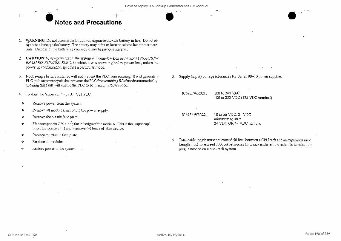
Notes and Precautions
1. WARNING: Do not discard the lithium-manganese dioxide battery in fire. Do not at- , tompt to discharge the battery. The battery may blist or bum or release hazardous mate- rials. Dispose of the battery as you would any hazardous material.
2. CAUTION: After a power fault, the system will come back on in the mode (STOP, RUN/ ENABLED, RUN/DISABLED) in which it was operating before power loss, unless the power up configuration specifies a particular Mode.
3. Not having a battery installed will not prevent. the PLC from running.* It will generate a
PLC fault on power cycle that prevents the PLC from entering R UNmode automatically. Clearing this fault will enable the PLC to be placed in RUN mode.
To short the 'super cap' on a 311/321 PLC:
o Remove power from the system.
Reinove all modules, including the power supply.
o Remove the plastic face plate.
Find component C20 along the left edge of the module. This is the 'super cap'. Short the positive (+) and negative (-) leads of this device.
Replace the plastic face plate.
Replace all modules.
Restore power to the system.
5. Supply (input) voltage tolerances for Series 90-30 power supplies:
IC693PWR321: 100 to 240 VAC 100 to 250 VDC (125 VDC nominal)
IC693PWR322: 18 to 56 VDC, 21 VDC minimum to start 24 VDC OR 48 VDC nominal
6. Total cable length must not exceed 50 feet between a CPU rack and an expansion rack. Length must not exceed 700 feet between a CPU rack and a remote rack. No termination plug is needed on a one-rack system.
Lloyd St Aspley SPS Backup Generator Set OM Manual
Q-Pulse Id TMS1098 Active 10/12/2014 Page 190 of 339
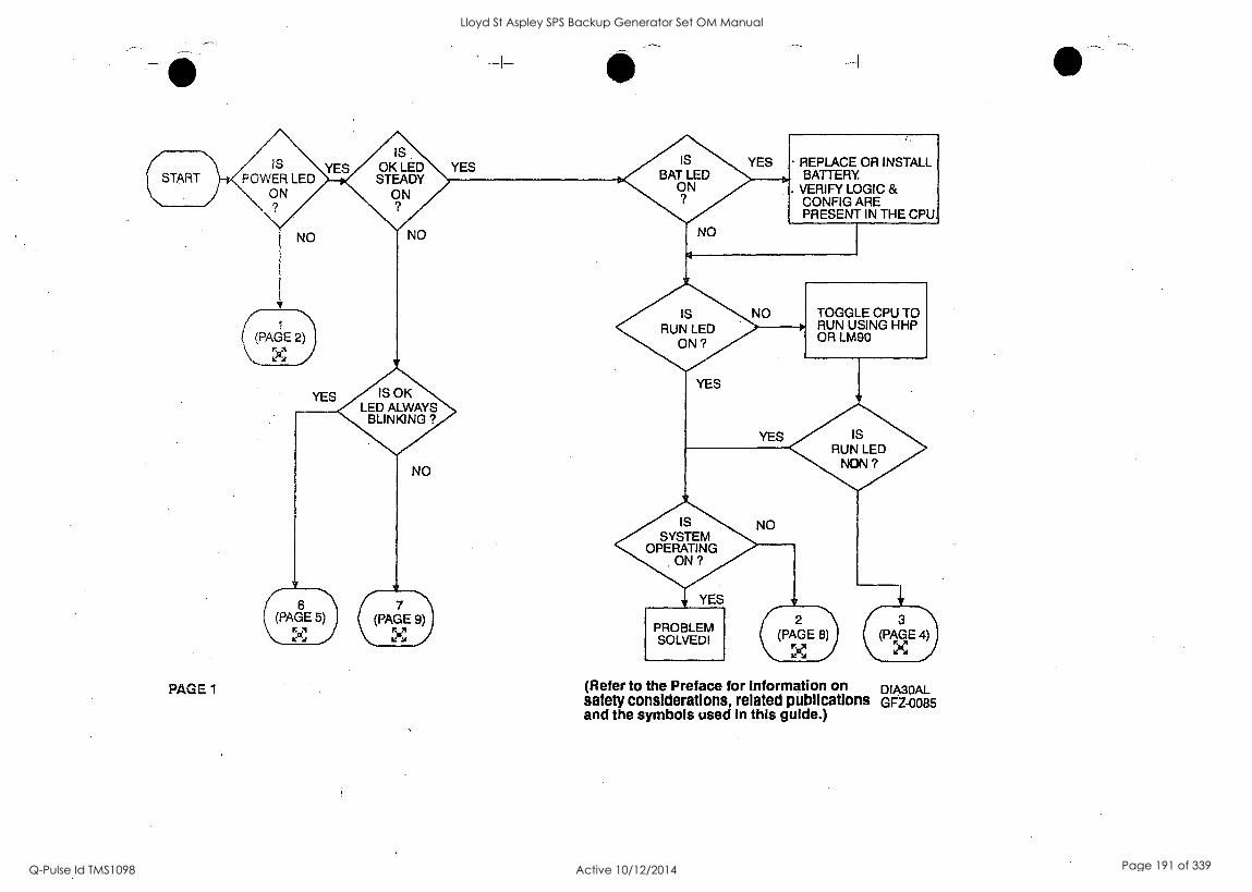
YES REPLACE OR INSTALL BATTERY
. VERIFY LOGIC & CONFIG ARE PRESENT IN THE CPU
6 7 (PAGE 5) (PAGE 9)
X X
PAGE 1
PROBLEM SOLVED!
(Refer to the Preface for information on DIA30AL safety considerations, related publications GFZ-0085 and the symbols used in this guide.)
Lloyd St Aspley SPS Backup Generator Set OM Manual
Q-Pulse Id TMS1098 Active 10/12/2014 Page 191 of 339
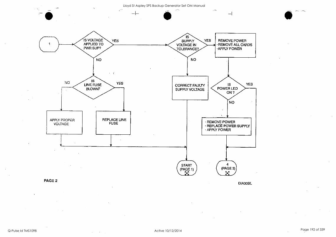
IS VOLTAGE APPLIED TO PWR SUP?
YES IS
SUPPLY VOLTAGE IN TOLERANCE?
YES REMOVE POWER REMOVE ALL CARDS
APPLY POWER
NO IS UNE FUSE
BLOWN? CORRECT FAULTY SUPPLY VOLTAGE
IS POWER LED
ON ?
YES
APPLY PROPER VOLTAGE
REPLACE LINE FUSE
(PAGE (PAGE 1)
X } PAGE 2
REMOVE POWER REPLACE POWER SUPPLY APPLY POWER
4 GE
DIA3OBL
Lloyd St Aspley SPS Backup Generator Set OM Manual
Q-Pulse Id TMS1098 Active 10/12/2014 Page 192 of 339
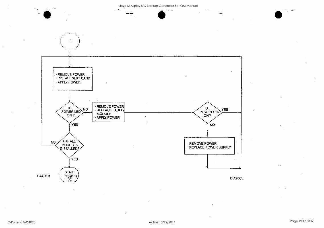
REMOVE POWER INSTALL NEXT CARD APPLY POWER
IS POWER LED
NO REMOVE POWER REPLACE FAULTY MODULE APPLY POWER
IS POWER LED
ON?
ARE ALL MODULES NSTALLED?
REMOVE POWER REPLACE POWER SUPPLY
Lloyd St Aspley SPS Backup Generator Set OM Manual
Q-Pulse Id TMS1098 Active 10/12/2014 Page 193 of 339
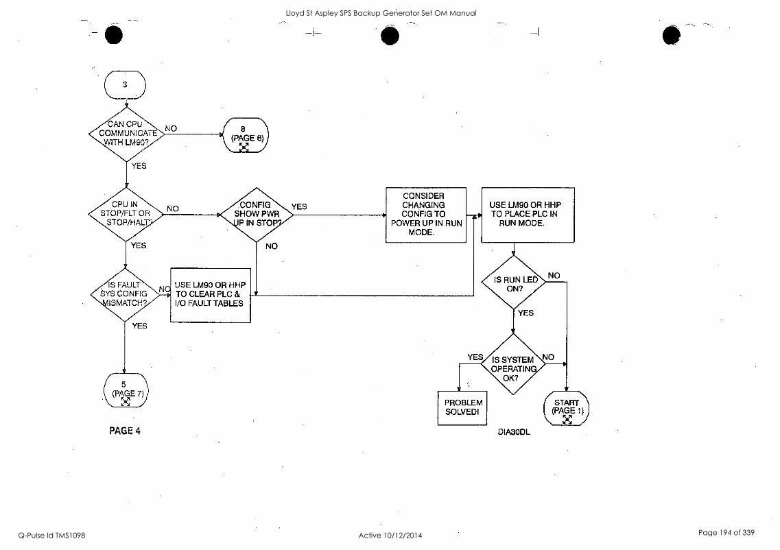
CAN CPU COMMUNICATE
WITH LM9O?
CPU IN STOP/FLT OR
STOP/HALT'
,CONFIG SHOW PWR
P IN STOP
CONSIDER CHANGING CONFIG TO
POWER UP IN RUN MODE.
USE LM90 OR HHP TO PLACE PLC IN
RUN MODE.
IS FAULT SYS CONFIG
ISMATCH9
IS RUN LED ON?
IS SYSTEM OPERATIN
OK?
PAGE 4
PROBLEM SOLVEDI
DIA3ODL
Lloyd St Aspley SPS Backup Generator Set OM Manual
Q-Pulse Id TMS1098 Active 10/12/2014 Page 194 of 339
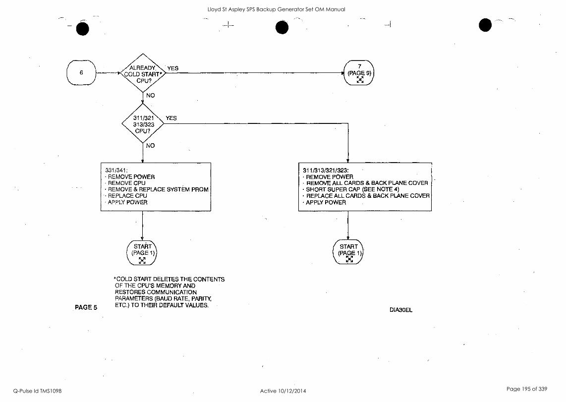
PAGE 5
331/341: REMOVE POWER REMOVE CPU REMOVE & REPLACE SYSTEM PROM REPLACE CPU APPLY POWER
/START I (PAGE 1)
*COLD START DELETES THE CONTENTS OF THE CPU'S MEMORY AND RESTORES COMMUNICATION PARAMETERS (BAUD RATE, PARITY ETC.) TO THEIR DEFAULT VALUES.
311/313/321/323. REMOVE POWER REMOVE ALL CARDS & BACK PLANE COVER SHORT SUPER CAP (SEE NOTE 4) REPLACE ALL CARDS & BACK PLANE COVER APPLY POWER
rSTAR1) (PAGE 1),
DIA30EL
Lloyd St Aspley SPS Backup Generator Set OM Manual
Q-Pulse Id TMS1098 Active 10/12/2014 Page 195 of 339
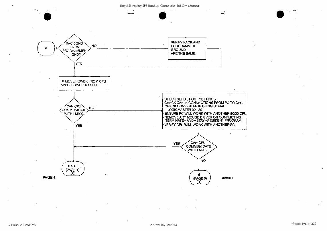
RACK GND EQUAL
PROGRAMME GND?
NO VERIFY RACK AND PROGRAMMER GROUND ARE THE SAME.
REMOVE POWER FROM CPU APPLY POWER TO CPU
PAGE 6
CAN CPU COMM UNI CAT
WITH LM90?
YES
NO
.CHECK SERIAL PORT SETTINGS. .CHECK CABLE CONNECTIONS FROM PC TO CPU. .CHECK CONVERTER IF USING SERIAL
LOGICMASTER 90-30 -ENSURE PC VVILL WORK WITH ANOTHER 90/30 CPU REMOVE ANY MOUSE DRIVER OR CONFLICTING TERMINATE-AND-STAY-RESIDENT PROGRAM.
-VERIFY CPU WILL WORK WITH ANOTHER=PC.
YES CAN CPU COMMUNICATE WITH LM90?
(START (PAGE 1)
NO
r 6 (PAGE 5) DIA30FL
Lloyd St Aspley SPS Backup Generator Set OM Manual
Q-Pulse Id TMS1098 Active 10/12/2014 Page 196 of 339
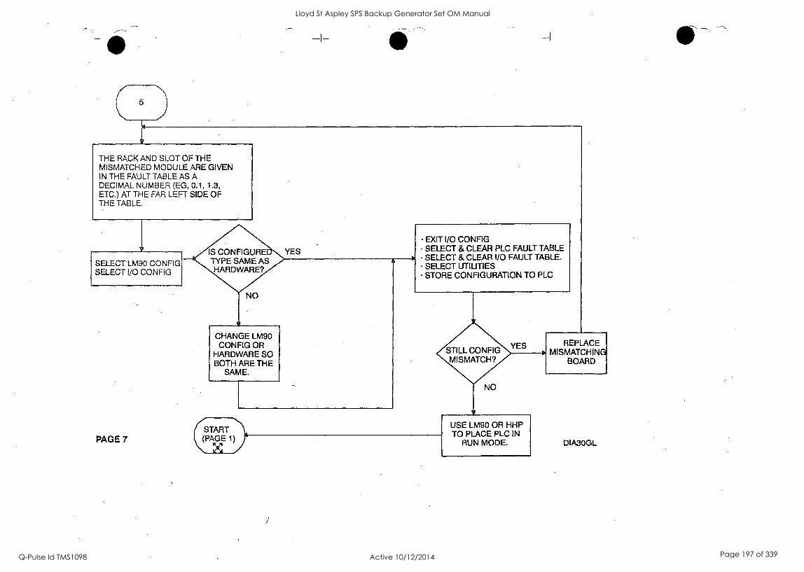
THE RACK AND SLOT OF THE MISMATCHED MODULE ARE GIVEN IN THE FAULT TABLE AS A DECIMAL NUMBER (EG, 0.1, 1.3, ETC.) AT THE FAR LEFT SIDE OF THE TABLE.
IS CONFIGURE TYPE SAME AS HARDWARE?
SELECT LM90 CONFIG SELECT I/O CONFIG
EXIT I/O CONFIG - SELECT & CLEAR PLC FAULT TABLE SELECT & CLEAR I/O FAULT TABLE. SELECT UTILITIES STORE CONFIGURATION TO PLC
CHANGE LM90 CONFIG OR
HARDWARE SO BOTH ARE THE
SAME.
YES
PAGE 7 (START
(PAGE 1)
1:4
NO
USE LM90 OR HHP TO PLACE PLC IN
RUN MODE.
REPLACE MISMATCHING
BOARD
DIA3OGL
Lloyd St Aspley SPS Backup Generator Set OM Manual
Q-Pulse Id TMS1098 Active 10/12/2014 Page 197 of 339
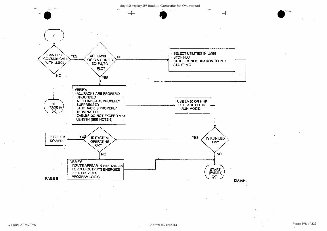
2
YES ARE LM90 LOGIC & CONFIG
EQUAL TO
PLC?
NO
8 (PAGE 6) -
YES
NO
VERIFY: ALL RACKS ARE PROPERLY GROUNDED ALL LOADS ARE PROPERLY SURPRESSED LAST RACK IS PROPERLY TERMINATED CABLES DO NOT EXCEED MAX LENGTH (SEE NOTE 6)
SELECT UTILITIES IN LM90 STOP PLC STORE CONFIGURATION TO PLC START PLC
USE LM90 OR HHP TO PLACE PLC IN
RUN MODE.
PAGE 8
VERIFY: INPUTS APPEAR IN REF TABLES. FORCED OUTPUTS ENERGIZE FIELD DEVICES
PROGRAM LOGIC
START (PAGE 1)
X I DIABOHL
Lloyd St Aspley SPS Backup Generator Set OM Manual
Q-Pulse Id TMS1098 Active 10/12/2014 Page 198 of 339
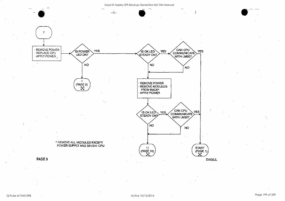
REMOVE POWER REPLACE CPU APPLY POWER
IS POWER LED ON?
'YES IS OK LED TEADY ON?
YES CAN CPU COMMUNICATE
WITH LM90?
YES
NO
1
(PAGE 2)
.11:47s
REMOVE POWER REMOVE MODULES FROM RACK*
APPLY POWER
IS OK LED STEADY ON
CAN CPU COMMUNICATE WITH LM90?
* REMOVE ALL MODULES EXCEPT POWER SUPPLY AND 331/341 CPU
PAGE 9
NO
(11 START (PAGE 10) (PAGE 1)
Yal I ,,,,..c
DIA30JL
Lloyd St Aspley SPS Backup Generator Set OM Manual
Q-Pulse Id TMS1098 Active 10/12/2014 Page 199 of 339

REMOVE POWER REPLACE BACK PLANE REPLACE POWER SUPPLY REPLACE 331/341 CPU APPLY POWER
PAGE 10
IS OK LED STEADY ON
YES CAN CPU COMMUNICAT
WITH LM909
NO
YES (START (PAGE 1)
YOUR PROBLEM IS BEYOND THE SCOPE OF THIS TROUBLESHOOTING GUIDE. CALL THE GE FANUC HOTLINE OR YOUR GE FANUC DISTRIBUTOR FOR ASSISTANCE.
DIA3OKL
Lloyd St Aspley SPS Backup Generator Set OM Manual
Q-Pulse Id TMS1098 Active 10/12/2014 Page 200 of 339
GE Fanuc Automation
Programmable Control Products
Series 90-30 PLC
Installation and Hardware Manual
GFK-0356Q August 2002
Lloyd St Aspley SPS Backup Generator Set OM Manual
Q-Pulse Id TMS1098 Active 10/12/2014 Page 201 of 339
GFL-002
Warnings, Cautions, and Notes as Used in this Publication
Warning
Warning notices are used in this publication to emphasize that hazardous voltages, currents, temperatures, or other conditions that could cause personal injury exist in this equipment or may be associated with its use.
In situations where inattention could cause either personal injury or damage to equipment, a Warning notice is used.
Caution
Caution notices are used where equipment might be damaged if care is not taken.
Note
Notes merely call attention to information that is especially significant to understanding and operating the equipment.
This document is based on information available at the time of its publication. While efforts have been made to be accurate, the information contained herein does not purport to cover all details or variations in hardware or software, nor to provide for every possible contingency in connection with installation, operation, or maintenance. Features may be described herein which are not present in all hardware and software systems. GE Fanuc Automation assumes no obligation of notice to holders of this document with respect to changes subsequently made.
GE Fanuc Automation makes no representation or warranty, expressed, implied, or statutory with respect to, and assumes no responsibility for the accuracy, completeness, sufficiency, or usefulness of the information contained herein. No warranties of merchantability or fitness for purpose shall apply.
The following are trademarks of GE Fanuc Automation North America, Inc.
Alarm Master Field Control Modelmaster Series 90 CIMPLICITY GEnet Motion Mate Series One CIMPLICITY Control Genius PowerMotion Series Six CIMPLICITY PowerTRAC Genius PowerTRAC ProLoop. Series Three CIMPLICITY 90-ADS Helpmate PROMACRO VuMaster CIMSTAR Logicmaster Series Five Workataster
©Copyright 1998-2002 GE Fanuc Automation North America, Inc. All Rights Reserved.
Lloyd St Aspley SPS Backup Generator Set OM Manual
Q-Pulse Id TMS1098 Active 10/12/2014 Page 202 of 339
RFI Standards
The Series 90-30 PLC and its associated modules have been tested and found to meet or exceed the
requirements of FCC Rule, Part 15, Subpart J. The Federal Communications Commission (FCC) requires the following note to be published according to FCC guidelines.
NOTE
This equipment generates, uses, and can radiate radio frequency energy and if not installed in
accordance with this instruction manual, may cause harmful interference to radio communications. It has been tested and found to comply with the limits for a Class A digital device pursuant to Part 15 of the FCC Rules, which are designed to provide reasonable protection against harmful interference when operated in a commercial environment. Operation of this equipment in a
residential area is likely to cause harmful interference, in which case the user will be required to correct the interference at his own expense.
The following note is required to be published by the Canadian Department of Communications.
NOTE
This digital apparatus does not exceed the Class A limits for radio noise emissions from digital apparatus set out in the radio interference regulations of the Canadian Department of Communications.
The following statements are required to appear in the Series 90_-30 Installation Manual and the Series 90_-30 I/O Specifications Manual for Class I Div 2 Hazardous Locations.
1. EQUIPMENT LABELED WITH REFERENCE TO CLASS I, GROUPS A, B, C, and D, DIV. 2 HAZARDOUS LOCATIONS IS SUITABLE FOR USE IN CLASS I, DIVISION 2,
GROUPS A, B, C, D OR NON-HAZARDOUS LOCATIONS ONLY.
2. WARNING - EXPLOSION HAZARD - SUBSTITUTION OF COMPONENTS MAY IMPAIR SUITABILITY FOR CLASS I, DIVISION 2:
3. WARNING - EXPLOSION HAZARD - DO NOT DISCONNECT EQUIPMENT UNLESS POWER HAS BEEN SWITCHED OFF OR THE AREA IS KNOWN TO BE NON-HAZARDOUS.
4. ALL UNUSED SLOTS IN ALL BASEPLATES MUST BE POPULATED WITH FILLER MODULES, IC693ACC310, OR EQUIVALENT.
GFK-0356Q iii
Lloyd St Aspley SPS Backup Generator Set OM Manual
Q-Pulse Id TMS1098 Active 10/12/2014 Page 203 of 339

--\
Lloyd St Aspley SPS Backup Generator Set OM Manual
Q-Pulse Id TMS1098 Active 10/12/2014 Page 204 of 339
Preface
This manual describes the GE Fanuc Series 90-30 Programmable Logic Controller (PLC). It contains a description of hardware components and provides basic hardware installation procedures. The Series 90-30 PLC is a member of the Series 90_ family of Programmable Logic Controllers from GE Fanuc.
For a list of product standards, refer to data sheet GFK-0867B or later, GE Fanuc Approvals, Standards, General Specifications which lists all of the standards for GE Fanuc products. Installation instructions in this manual are provided for installations that do not require special procedures for noisy or hazardous environments. For installations that must conform to more stringent requirements (such as CE Mark), see GFK-1179, Installation Requirements for Conformance to Standards.
What's New in This Manual
Added the model 374 CPU, which supports connection to an Ethernet network through two built-in 10BaseT/100BaseTx auto-negotiating full-duplex Ethernet ports. Models 364 (release 9.10 and later) and 374 are the only Series 90-30 CPUs that support Ethernet Global Data. Note that the CPU374 is supported only by the Windows®-based programmers.
o Other corrections and clarifications as necessary.
Related Publications
GFK-0356Q
For more information on Series 90-30 products, refer to these publications. (For a publication to
product catalog number cross-reference refer to Appendix G):
GFK-0255 - Series 90114 PCM and Support Software User's Manual
GFK-0256 - MegaBasicTh Programming Reference Manual
GFK-0293 - Series 90TM -30 HighSpeed Counter User's Manual
GFK-0401 - Workmaster® II PLC Programming Unit Guide to Operation
GFK-0402 - Series 90TM -30 and 90-20 PLC Hand-Held Programmer User's Manual
GFK-0412 - Genius® Communications Module User's Manual
GFK-0466 - Logic-master Wm Series 9ØTM -30/20/Micro Programming Software User's Manual
GFK-0467 - Series 90TM -30/20 /Micro Programmable Controllers Reference Manual.
OFK-0487 - Series 9QTM PCM Development Software (PCOP) User's Manual
GFK-0499 CIMPLIC1TY® 90-ADS Alphanumeric Display System User's Manual
Lloyd St Aspley SPS Backup Generator Set OM Manual
Q-Pulse Id TMS1098 Active 10/12/2014 Page 205 of 339

0
Lloyd St Aspley SPS Backup Generator Set OM Manual
Q-Pulse Id TMS1098 Active 10/12/2014 Page 206 of 339

Preface
vi
GFK-0582 - Series 90TM PLC Serial Communications User's Manual
GFK-0631 - Series 90TM -30110 LINK Interface User's Manual
GFK-0641 - CIMPLICITY® 90-ADS Alphanumeric Display System Reference Manual
GFK-0664 - Series 90Tm-30 PLC Axis Positioning Module Programmer's Manual
GFK-0685 - Series 90TM Programmable Controllers Flow Computer User's Manual
GFK-0695 - Series 90Tm-30 Enhanced Genius) Communications Module User's Manual
GFK-0726 - Series 90Tm-30 PLC State Logic Processor User's Guide
GFK-0732 - Series 90Tm-30 PLC ECLiPS User's Manual
GFK-0747 - Series 90Tm-30 PLC OnTOP User's Guide
GFK-0750 - OnTop for Series 90111-30 (State Logic) Program User's Manual
GFK-0781 - Motion MateTM APM300 for Series 90TH -30 PLC Follower Mode User's Manual
GFK-0823 - Series 90TM -30 110 LINK Master Module User's Manual
GFK-0828 - Series 90T1' -30 Diagnostic System User's Manual
GFK-0840 - Motion MateTM APM300 for Series 90TM -30 PLC Standard Mode User's Manual
GFK-0867 - GE Fantle Product Agency Approvals, Standards, General Specifications
GFK-0898 - Series 90Tm -30 PLC I/O Module Specifications
GFK-1028 - Series 90T1' -30 110 Processor Module User's Manual
GFK-1034 - Series 90TM -30 Genius Bus Controller User's Manual
GFK-1037 - Series 90TM -30 FIP Remote I/O Scanner User's Manual
GFK-1056 - Series 901m -30 State Logic Control System User's Manual
GFK-1186 - TCP/IP Ethernet Communications for the Series 90_-30 PLC Station Manager Manual
GFK-1179 - Series 901m PLC Installation Requirements for Conformance to Standards
GFK-1464 - Motion Mate DSM302 for Series 9011'1-30 PLCs User's Manual
GFK-1466 - Temperature Control Module for the Series 901m-30 PLC User's Manual
GFK -1541 - TCP/IP Ethernet Communications for the Series 90TM PLC User's Manual
Series 90Tm-30 PLC Installation and Hardware Manual - August 2002 GFK-0356Q
Lloyd St Aspley SPS Backup Generator Set OM Manual
Q-Pulse Id TMS1098 Active 10/12/2014 Page 207 of 339

Contents
Chapter 1 Overview of the Series 90-30 PLC 1-1
The Basic Parts of a Series 90-30 PLC 1-1
Assembling a Basic Series 90-30 PLC System 1-2
What else would be needed to make this basic system functional? 1-6
What if the application requires more than five modules? 1-6
What if the application requires more than ten modules? 1-7
What is the Difference Between Expansion and Remote baseplates? 1-8
What if I need to cover more than 700 feet (213 meters)? 1-9
Chapter 2 Installation 2-1
Receiving your Products - Visual Inspection 2-1
Pre-installation Check 2-1
Warranty Claims 2-1
Working with Series 90-30 Modules 2-2 Module Features 2-2 Installing a Module 2-3 Removing a Module 2-4 Installing a Module's Terminal Board 2-5 Removing a Module's Terminal Board 2-6 I/O Module Terminal Board Posts 2-7 Installing and Removing Terminal Boards with Holding Screws 2-7
Baseplate Mounting 2-8
Mounting a Baseplate to a Panel 2-8
Mounting a Baseplate to a 19" Rack 2-8
Grounding Procedures 2-11
System Grounding. Procedures 2-11 Ground Conductors 2-11
Series 90-30 PLC Equipment Grounding 2-12 Baseplate Safety Grounding 2-12 Grounding 19" Rack-Mounted Baseplates 2-13 Programmer Grounding 2-13
Module Shield Grounding 2-14 Shield Grounding Information for CPUs with External Port Connections 2-14 CPU351 and 352 Shield Grounding 2-14 CPU363, CPU364, and CPU374 Shield Grounding 2-16 Additional Modules with Shield Grounding Requirements 2-16
General Wiring Guidelines 2-17
Discrete I/O Module Connection Methods 2-18 Connections to 1/0 Module Terminal Boards 2-18
Terminal Block Quick Connect Installation for 16-Point Discrete Modules 2-19
Installation of 32-Point Discrete, 50-Pin Connector Modules 2-19 Using Weidmuller #912263 Terminal Block 2-19 Using a Generic Terminal Block or Strip 2-20 Direct Method 2-20
Installation of Discrete 32-Point, Dual 24 -Pin Connector Modules 2-20 Using a TBQC 2-20
GFK-0356Q vii
Lloyd St Aspley SPS Backup Generator Set OM Manual
Q-Pulse Id TMS1098 Active 10/12/2014 Page 208 of 339

Contents
With a Generic Terminal Block/Strip 2-20 Direct Method 2-21
General Wiring Methods for Analog Modules 2-21
Analog Input Module Wiring Methods 2-21 Using a Generic Terminal Block or Strip 2-21 Direct Method 2-21 TBQC not Recommended for Analog Modules 2-22
Analog Output Module Wiring 2-22 General 2-22 Using a Generic Terminal Block or Strip 2-22 Direct Method 2-22 TBQC not Recommended for Analog Modules 2-22
AC Power Source Connections 2-23
AC Input Wiring to AC/DC Power Supplies 2-23
Power 'Supply Overvoltage Protection Devices 2-24
Special Installation Instructions for Floating Neutral (IT) Systems 2-25
Definition of Floating Neutral Systems 2-25
Use These Special Installation Instructions for Floating Neutral Systems 2-26
DC Power Source Connections 2-27
DC Input Wiring to AC/DC and DC-Only Power Supplies 2-27 +24 VDC Output (All Supplies) 2-27
Basic Installation Procedure 2-28
Chapter 3 Baseplates 3-1
Baseplate Types 3-1
Common Baseplate Features 3-1
Two Baseplate Sizes 3-2
Baseplate Terms 3-3
CPU Baseplates 3-4
Embedded CPU Baseplates (Figures 3-2 and 3-3) 3-4
Modular CPU Baseplates (Figures 3-4 and 3-5) 3-6
Expansion Baseplates (Figures 3-6 and 3-7) 3-7
Remote Baseplates (Figures 3-8 and 3-9) 3-8
I/O Bus Expansion Cables 3-10
Differences Between Remote and Expansion Racks 3-11
Mixing Expansion and Remote Baseplates in a System 3-11
Termination Requirement for Expansion or Remote System 3-12
Powering Down Individual Expansion or Remote Baseplates 3-12
Series 90-30 PLC Backplane 3-12
Rack Number DIP Switch on Expansion and Remote Baseplates 3-13
Expansion and Remote Baseplates Connection Example .3-15
Baseplate Mounting Dimensions 3-16
Embedded CPU (311, 313, and 323) Baseplate Dimensions 3-16 Modular CPU, Expansion, and Remote Baseplate Dimensions 3-18
viii Series 90"-30 PLC Installation and Hardware Manual -August 2002 . GFK-0356Q
Lloyd St Aspley SPS Backup Generator Set OM Manual
Q-Pulse Id TMS1098 Active 10/12/2014 Page 209 of 339

0
Lloyd St Aspley SPS Backup Generator Set OM Manual
Q-Pulse Id TMS1098 Active 10/12/2014 Page 210 of 339
Contents
Load Ratings, Temperature, and Mounting Position 3-19 Baseplate Adapter Brackets for 19" Rack Mounting 3-20
Baseplate Comparison Table 3-22
Chapter 4 Power Supplies. 4-1
Power Supply Categories 4-1
Power Supply Feature Comparison 4-1
AC/DC Input Power Supplies 4-2
IC693PWR321 Standard Power Supply, 120/240 VAC or 125 VDC Input 4-2 IC693PWR330 High Capacity Power Supply, 120/240 VAC/125 VDC Input 44 Field Wiring Connections for the AC/DC Input Power Supplies 4-5
Isolated 24 VDC Supply Output Connections 4-6 DC Input Only Power Supplies - 4-7
IC693PWR322 Standard Power Supply, 24/48 VDC Input 4-7
Calculating Input Power Requirements for IC693PWR322 4-8 IC693PWR328 Standard Power Supply, 48 VDC Input 4-10 Calculating Input Power Requirements for IC693PWR328 4-11
Input Power/Current Calculation for 1C693PWR328 Power Supply 4-12 IC693PWR331 High Capacity Power Supply, 24 VDC Input 4-13 Current Derating for Higher Temperatures 4-14 Calculating Input Power Requirements for IC693PWR331 4-15 Field Wiring Connections to the DC Input-Only Power Supplies 4-15
Common Series 90-30 Power Supply Features 4-16 Status Indicator Lights on all Power Supplies Input Overvoltage Protection Devices 4-16 Output Voltage Connections to Backplane (All Supplies) 4-17 Overcurrent Protection (all Supplies) 4-18 Timing Diagram 4-18
CPU Serial Port Connector on Power Supply (All Supplies) 4-19 CPU Serial Port Information 4-19 Backup Battery for RAM Memory (All Supplies) 4-20
Chapter 5 CPUs 5-1
CPU Types for Series 90-30 PLCs 5-1
Embedded CPUs 5-1
Modular CPUs 5-2
General CPU Features 5-3 Microprocessor 5-3 CPU Serial Port (Connector on Power Supply) 5-3 Memory Volatility 5-4 RAM Memory 5-5 RAM Memory Backup/Backup Battery Information 5-5 Programmable Read-Only Memory (PROM) Types.. 5-5 Uses of PROM devices in the 90-30 CPUs 5-5
GFK-0356Q Contents tx
Lloyd St Aspley SPS Backup Generator Set OM Manual
Q-Pulse Id TMS1098 Active 10/12/2014 Page 211 of 339
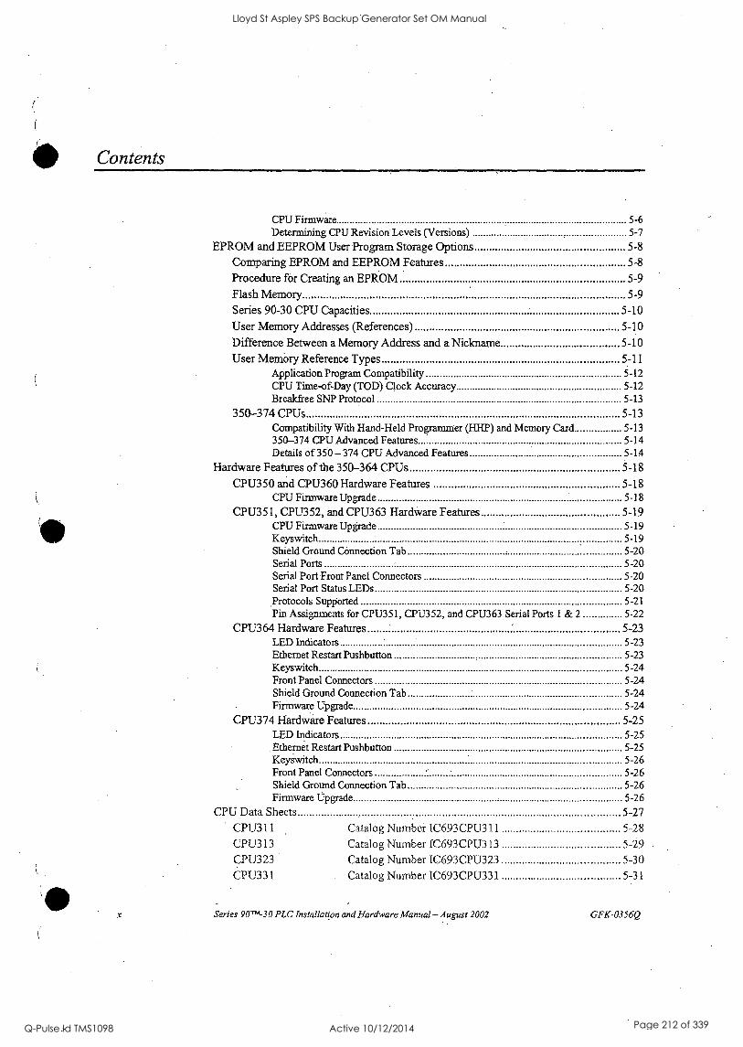
Contents
x
CPU Firmware 5-6 Determining CPU Revision Levels (Versions) 5-7
EPROM and EEPROM User Program Storage Options 5-8
Comparing EPROM and EEPROM Features 5-8
Procedure for Creating an EPROM 5-9 Flash Memory 5-9 Series 90-30 CPU Capacities 5-10
User Memory Addresses (References) 5-10
Difference Between a Memory Address and a Nickname 5-10
User Memory Reference Types 5-11 Application Program Compatibility 5-12 CPU Time-of-Day (TOD) Clock Accuracy 5-12 Breakfree SNP Protocol 5-13
350-374 CPUs 5-13 Compatibility With Hand-Held Programmer (HHP) and Memory Card 5-13 350-374 CPU Advanced Features 5-14 Details of 350 -374 CPU Advanced Features 5-14
Hardware Features of the 350-364 CPUs 5-18
CP1J350 and CPU360 Hardware Features 5-18 CPU Firmware Upgrade 5-18
CPU351, CPU352, and CPU363 Hardware Features 5-19 CPU Firmware Upgrade 5-19 Keyswitch 5-19 Shield Ground Connection Tab 5-20 Serial Ports 5-20 Serial Port Front Panel Connectors 5-20 Serial Port Status LEDs 5-20 Protocols Supported 5-21 Pin Assignments for CPU351, CPU352, and CPU363 Serial Ports 1 & 2 ......... 5-22
CPU364 Hardware Features 5-23 LED Indicators 5-23 Ethernet Restart Pushbutton 5-23 Keyswitch 5-24 Front Panel Connectors 5-24 Shield Ground Connection Tab 5-24 Firmware Upgrade 5-24
CPU374 Hardware Features 5-25 LED Indicators 5-25 Ethernet Restart Pushbutton 5-25 Keyswitch 5-26 Front Panel Connectors 5-26 Shield Ground Connection Tab 5-26 Firmware Upgrade 5-26
CPU Data Sheets 5-27
CPU311 Catalog Number IC693CPU311 5-28 CPU313 Catalog Number 1C693CPU313 5-29 CPU323 Catalog Number 1C693CPU323 5-30 CPU331 Catalog Number IC693CPU331 5-31
Series 90Thi-30 PLC Installation and Hardware Manual - August 2002 GFK-0356Q
Lloyd St Aspley SPS Backup Generator Set OM Manual
Q-Pulse Id TMS1098 Active 10/12/2014 Page 212 of 339
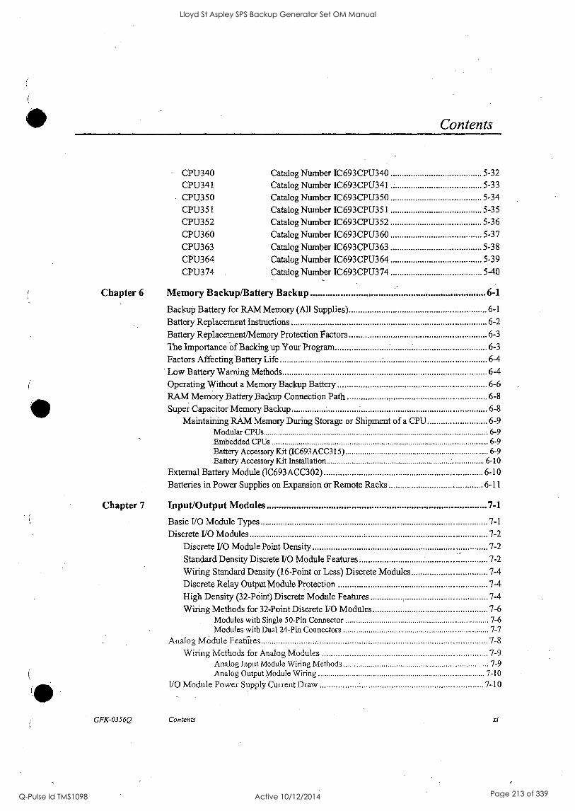
Contents
CPU340 Catalog Number IC693CPU340 5-32
CPU341 Catalog Number IC693CPU341 5-33
CPU350 Catalog Number IC693CPU350 5-34
CPU351 Catalog Number IC693CPU35 I 5-35
CPU352 Catalog Number IC693CPU352 5-36
CPU360 Catalog Number IC693CPU360 5-37
CPU363 Catalog Number IC693CPU363 5-38
CPU364 Catalog Number IC693CPU364 5-39
CPU374 Catalog Number IC693CPU374 5-40
Chapter 6 Memory Backup/Battery Backup 6-1
Backup Battery for RAM Memory (All Supplies) 6-1
Battery Replacement Instructions 6-2
Battery Replacement/Memory Protection Factors 6-3
The Importance of Backing up Your Program 6-3
Factors Affecting Battery Life 6-4
Low Battery Warning Methods 6-4
Operating Without a Memory Backup Battery 6-6
RAM Memory Battery Backup Connection Path 6-8
Super Capacitor Memory Backup 6-8
Maintaining RAM Memory During Storage or Shipment of a CPU 6-9 Modular CPUs 6-9 Embedded CPUs 6-9 Battery Accessory Kit (IC693ACC315) 6-9 Battery Accessory Kit Installation 6-10
External Battery Module (IC693ACC302) 6-10
Batteries in Power Supplies on Expansion or Remote Racks 6-11
Chapter 7 Input/Output Modules 7-1
Basic I/0 Module Types 7-1
Discrete I/O Modules 7-2
Discrete I/O Module Point Density 7-2
Standard Density Discrete I/O Module Features 7-2
Wiring Standard Density (16-Point or Less) Discrete Modules 7-4
Discrete Relay Output Module Protection 7-4
High Density (32-POint) Discrete Module Features 7-4
Wiring Methods for 32-Point Discrete I/O Modules 7-6 Modules with Single 50-Pin Connector 7-6 Modules with Dual 24-Pin Connectors 7-7
Analog Module Features 7-8
Wiring Methods for Analog Modules '7-9 Analog Input Module Wiring Methods 7-9 Analog Output Module Wiring 7-10
I/O Module Power Supply Current Draw 7-10
GFK-0356Q Contents xi
Lloyd St Aspley SPS Backup Generator Set OM Manual
Q-Pulse Id TMS1098 Active 10/12/2014 Page 213 of 339
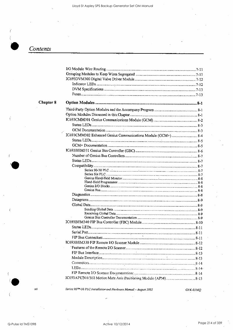
Contents
xii
I/0 Module Wire Routing 7-11 Grouping Modules to Keep Wires Segregated 7-11 IC693DVM300 Digital Valve Driver Module 7-12
Indicator LEDs 7-12 DVM Specifications 7-13 Fuses 7-13
Chapter 8 Option Modules 8-1
Third-Party Option Modules and the Accompany Program 8-1
Option Modules Discussed in this Chapter 8-1
IC693CMM301 Genius Communications Module (GCM) 8-2 Status LEDs.... 8-3 GCM Documentation 8-3
IC693CMM302 Enhanced Genius Communications Module (GCM +) 8-4 Status LEDs 8-5 GCM+ Documentation 8-5
IC693BEM331 Genius Bus Controller (GBC) 8-6 Number of Genius Bus Controllers 8-7 Status LEDs 8-7 Compatibility 8-7
Series 90-30 PLC - 8-7 Series Six PLC 8-7 Genius Hand-Held Monitor 8-8 Hand-Held Programmer 8-8 Genius 1/0 Blocks 8-8 Genius Bus 8-8
Diagnostics 8-8 Datagrams 8-9 Global Data 8-9
Sending Global Data 8-9 Receiving Global Data 8-9 Genius Bus Controller Documentation 8-9
IC693BEM340 FIP Bus Controller (FBC) Module 8-10 Status LEDs 8-11 Serial Port 8-11 FIP Bus Connectors 8-11
IC693BEM330 HP Remote I/O Scanner Module 8-12 'Features of the Remote I/O Scanner 8-12 FIP Bus Interface 8-13 Module Description 8-13 Connectors .8-14 LEDs 8-14- HP Remote 1/0 Scanner Documentation. 8-14
IC693APU3O1 /302 Motion Mate Axis Positioning Module (APM) 8-15
Series 90 '-30 PLC Installation and Hardware Manual.- August 2002 GFK-0356Q
Lloyd St Aspley SPS Backup Generator Set OM Manual
Q-Pulse Id TMS1098 Active 10/12/2014 Page 214 of 339
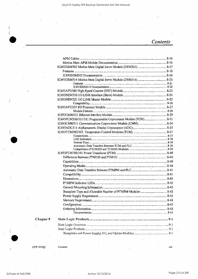
Contents
APM Cables 8-16
Motion Mate APM Module Documentation 8-16
IC693DSM302 Motion Mate Digital Servo Module (DSM302) 8-17
Features. 8-18
IC693DSM302 Documentation 8-18
IC693DSM314 Motion Mate Digital Servo Module (DSM314) 8-20 Features 8-21
1C693DSM314 Documentation 8-22
IC693APU300 High Speed Counter (HSC) Module 8-23
IC693BEM320 I/O LINK Interface (Slave) Module 8-24
IC693BEM321 I/O LINK Master Module 8-25 Compatibility 8-26
IC693APIJ305 1/0 Processor Module 8-27 Module Features 8-28
IC693CMM321 Ethernet Interface Module 8-29
IC693PCM300/301/311 Programmable Coprocessor Module (PCM) 8-31
IC693CMM311 Communications Coprocessor Module (CMM) 8-34
IC693ADC311 Alphanumeric Display Coprocessor (ADC) 8-35
IC693TCM302/303 Temperature Control Modules (TCM) ....... 8-37 Connections 8-37 LED Indicators 8-38 Internal Fuse 8-38 Automatic Data Transfers Between TCM and PLC 8-38 Comparison of TCM302 and TCM303 Modules 8-39
IC693PTM100/101 Power Transducer (PTM) 8-40
Difference Between PTM100 and PTM101 ....... 8-40
Capabilities 8-40
Operating Modes 8-40
Automatic Data Transfers Between PTMPM and PLC 8-41
Compatibility 8-41
Dimensions 8-42
PTMPM Indicator LEDs 8-42
General Mounting Information 8-42
Baseplate Type and Allowable Number of PTMPM Modules 8-43
Power Supply Requirement 8-43
Memory Requirement 8-43
Configuration 8-43
Ordering Information 8-43 Documentation 8-43
Chapter 9 State Logic Products 9- t
State Logic Overview ,9-1
State Logic Products 9-1
Baseplates and Power Supply, 1/0, and Option Modules 9-1
GFK-0356Q Contents xiii
Lloyd St Aspley SPS Backup Generator Set OM Manual
Q-Pulse Id TMS1098 Active 10/12/2014 Page 215 of 339

Contents
AD693CM1.4301 State Logic Serial Communications Module (SCM) 9-2
Description 9-2 OK LED 9-2 Reset Button 9-2 Serial Connector 9-3
Cable Information 9-3
State Logic SCM Documentation 9-3
IC693SLP300 State Logic Processor Module 9-4 Description 9-4
SLP Features 9-5
Memory 9-5
Installation 9-5
Status Light 9-6
Pushbutton 9-6 Battery 9-7
Cable Information 9-7
Hardware Specifications 9-7
State Logic Processor (SLP) Documentation 9-7
State Logic CPUs 9-8 Features of State Logic CPUs 9-8 Model CSE311, CSE313 and CSE323 Embedded CPU Baseplates 9-9
Model CSE331 and CSE340 Modular CPUs 9-10 CPU Serial Port Connector on Power Supply 9-11 Configuring the State Logic CPUs 9-11
State Logic CPU Firmware and PROM Configurations 9-13
State Logic CPU Data Sheets 9-13 CSE311 Catalog Number IC693CSE311 9-14 CSE313 Catalog Number IC693C 5E313 9-15
CSE323 Catalog Number IC693CSE323 9-16
CSE331 Catalog Number 1C693CSE331 9-17 CSE340 Catalog Number IC693CSE340 9-18
Chapter 10 Cables 10-1
Cable Data Sheets 10-7
IC647CBL704 Workstation Interface to Series 90 CPU (SNP Port) Cable 10-8 Function of cable 10-8
IC690CBL701 PCM, ADC, CMM to Workmaster (PC-XT) Cable 10-12 Function of cable 10-12 Cable Specifications 10-12 Wiring Diagram 10-12
PCM to Programmer Cable Installation 10-13
IC690CBL702 PC-AT to PCM, ADC, CMM Cable 10 -14 Function of cable 10-14 C'able Specifications 10-14
xiv Series 90T74-30 PLC Installation and Hardware Manual - August 2002 GFK-0356Q
Lloyd St Aspley SPS Backup Generator Set OM Manual
Q-Pulse Id TMS1098 Active 10/12/2014 Page 216 of 339

0
0
Lloyd St Aspley SPS Backup Generator Set OM Manual
Q-Pulse Id TMS1098 Active 10/12/2014 Page 217 of 339
Contents
GFK-0356Q
Wiring Diagram 10-14
PCM to Programmer Cable Installation 10-15
IC690CBL705 Worlcmaster II (PS/2) to PCM, ADC, CMM Cable 10-16 Function of cable 10-16 Cable Specifications 10-16 Wiring Diagram 10-16
PCM to Programmer Cable Installation 10-17
IC690CBL714A Multidrop Cable 10-18 Purpose 10-18 Specifications 10-18 IC690CBL714A Multi-Drop Cable Wiring Diagram 10-19
Connection Diagrams for IC690CBL714A Cable 10-20
IC693CBL300/301/302/312/313/314 I/0 Bus Expansion Cables 10-22 Description 10-22 Cable Lengths 10-22 Function of Cables 10-22 Connecting the Cables 10-23 Important Notes About 110 Bus Expansion Cables 10-23 Cable Application Suggestions 10-23 Using Standard Cables 10-23 Using Custom Built cables 10-24
Building Custom Length I/0 Bus Expansion Cables 10-24 Two Types of Custom Built Cables 10-24 Components Needed to Build Custom Length 110 Bus Expansion Cables 10-24 Expansion Port Pin Assignments 10-25 110 Expansion Bus Termination 10-25 Shield Treatment 10-26 Alert for Users of Early Remote Baseplate Versions 10-26 Making a 100% Shielded Cable 10-27 Wiring Diagrams 10-28 Application Examples 10-31 Expansion System Cable Connections 10-31 Remote and Expansion System Cable Connection Example 10-31
IC693CBL303 Hand-Hand Programmer and Converter (IC690ACC900) Cable 10-33
Function of cable 10-33
Cable Specifications 10-33
Wiring Diagram .10 -34
Connecting the Cable 10-34
IC693CBL304/305 Port Expansion (WYE) Cables for PCM, ADC, and CMM 10-35
Function of cable 10-35
Cable Specifications 10-35
Wiring Information 10-36
1C693CBL306/307 Extension Cables (50-Pin) for 32 Point Modules.. 10-38
Function of cable 10-38
Cable Specifications 10-38
IC693CBL308/309 1/0 Cables (50-Pin) for 32 Point Modules 10-40
Specifications 10-40
Wiring Information 10-40
Contents xv
Lloyd St Aspley SPS Backup Generator Set OM Manual
Q-Pulse Id TMS1098 Active 10/12/2014 Page 218 of 339

Contents
IC693CBL310 I/O Interface Cable (24-Pin) for 32 Point Modules Function of cable Replacement/Obsolescence Information
Connector Depth for Cable 1C693CBL310
10-42
10-42
10-43 10-43
IC693CBL311/317/319/320 1/0 Interface Cables for Power Mate APM Modules 10-45
Function of cable 10-45
Specifications 10-45
Wiring Information- 10-46
IC693CBL315 I/0 Interface Cable (24-Pin) for 32 Point Modules 10-49
Function of cable 10-49
Building Custom Length Cables for 24-Pin Connectors 10-49
Replacement/Obsolescence Information 10-51
Connector Depth for IC693CBL315 10-51
IC693CBL316 Serial Cable, 9-Pin D-Shell to RJ-11 Connector 10-53
Description 10-53
Typical Applications 10-53
IC693CBL321/322/323 I/O Faceplate Connector to Terminal Block Connector, 24-Pin1 0-54
Function of cable 10-54
Cable Specifications 10-54 Connector Depth 10-55
IC693CBL327/328 1/0 Interface Cables with Right Angle 24-Pin Connector 10-57
Description 10-57
Applications 10-57
Specifications 10-58 Connector Depth for Cables IC693CBL327/328 10-58
Building Custom Length 24-pin Connector Cables 10-59 Connector Depth for Custom Built Cables 10-60
Possible Uses for These Cables (Factory or Custom Built) 10-61
IC693CBL329/330/331/332/333/334 Cables 24-Pin I/O Faceplate Connector to Terminal Block Connector 10-62
Description 10-62 Connector Depth 10-63
Applications 10-64
IC693CBL340/341 PTM Interface Cables 10-65
Documentation 10-67
Chapter 11 Programmer Hardware Products 11 -1
Products Discussed in this Chapter 11-1
IC640W1V11310/320 Work Station Interface Boards 11-2
Replacing Workmaster Computers 11-3
1C690ACC900 RS-422/RS-485 to RS-232 Converter 11-3
IC690ACC901 Miniconverter Kit 11-4
1C693PRG300 Hand-Held Programmer (IMP) 11-5
HIIP Features 11-6
.rvi Series 90T"-30 PLC Installation and Hardware Manual - August 2002 GFK-0356Q
Lloyd St Aspley SPS Backup Generator Set OM Manual
Q-Pulse Id TMS1098 Active 10/12/2014 Page 219 of 339
Contents
HIT Memory Card (IC693ACC303) 11-6 HHP Modes of Operation 11-6 Documentation 11-6
IC693PIF301/400 Personal Computer Interface (PCIF) Cards 11-7
IC655CCM590 Isolated Repeater/Converter 11-8
IC690ACC903 Port Isolator 11-8
Chapter 12 System Design 12-1
Introduction 12-1
Step 1: Planning Your System 12-1
Step 2: Determining I/O Requirements 12-1 Additional 1/0 Module Selection Factors 12-2
Step 3: Selecting Option Modules 12-2
Step 4: Selecting a CPU 12-4
Step 5: Selecting Baseplates 12-5
Step 6: Selecting Power Supplies 12-6
Reducing PLC Module Count by Using Other GE Fanuc Products 12-7
Designing For Safety 12-8
Protection From Electrical Shock 12-8
Fire Prevention 12-8
Protection From Mechanical Hazards 12-8
Protection From Electrical Failure 12-8 Protection From Design Changes or Overrides 12-9 Safety Documentation 12-10 Guarding Against Unauthorized Operation 12-10 Labeling, Guarding, and Lighting Issues 12-10 Equipment Accessibility Issues 12-10
Number of Modules Per Series 90-30 PLC System 12-11
Calculating Power Supply Loading 12-12
Load Requirements for Hardware Components 12-12 Power Supply Loading Calculation Examples 12-14
Scan (Sweep) Time Calculation 12-15
Major Design Factors Affecting Scan Time 12-16
Where to Find Scan Time Information 12-16
Calculating PLC Heat Dissipation 12-17
System Layout Guidelines 12-17
Benefits of a Good Layout - Safe, Reliable, and Accessible 12-17
PLC Rack Location and Clearance Requirement 12-17
Location of Modules in the PLC Racks 12-18
Allowable Module Locations 12-19
Series 90-30 PLC Layout Example 12-20
PLC Mounting Position 12-21
Recommended Upright Mounting Orientation 12-21
Derated Horizontal Mounting Orientation 12-21
GFK-0356Q Contents rya
Lloyd St Aspley SPS Backup Generator Set OM Manual
Q-Pulse Id TMS1098 Active 10/12/2014 Page 220 of 339
Contents
Chapter 13 Maintenance and Troubleshooting 13-1
Troubleshooting Features of Series 90-30 Hardware 13-1
Indicator Lights (LEDs) and Terminal Board . 13-1 Module LED Indicators 13-2 Troubleshooting Features of Programming Software 13-3
Ladder Screens 13-3 Configuration Screens 13-3
Fault Tables 13-3 System Status References 13-3
Reference Tables 13-4 Override feature 13-4 Sequential Event Recorder (SER), DOIO functional instruction 13-4
Replacing Modules 13-5
Series 90-30 Product Repair 13-5
Module Fuse List 13-6 Spare/Replacement Parts 13-7 Preventive Maintenance Suggestions 13-8 Getting Additional Help'and Information 13-9
Appendix A Serial Ports and Cables A-1
RS-422 Interface A-1 Cable and Connector Specifications A-2 Series 90 PLC Serial Port A-3
Workmaster Serial Port A-4 RS-232/RS-485 Converter A-7
IC690ACC901 Miniconverter Kit A-7 IC690ACC900 Obsolete Converter A-7
Serial Cable Diagrams A-8 RS-232 Point-to-Point Connections A-8 RS-422 Point-to-Point Connection A-10 Multidrop Connections, A-10
Appendix B IC690ACC900 Converter B-1
Features B-1
Functions B-1
Location in System B-2 Installation B-2 Cable Description B -3
RS-232 interface Pin Assignments B -4
RS-422/RS-485 Interface Pin Assignments B-5 Logic Diagram B-6 Jumper Configuration B-7
xviii Series 90' -30 PLC Installation and Hardware Manual - August 2002 GFK-0356Q
Lloyd St Aspley SPS Backup Generator Set OM Manual
Q-Pulse Id TMS1098 Active 10/12/2014 Page 221 of 339

Contents
Example of Cable Configurations B-9
Appendix C IC655CCM690 Isolated Repeater/Converter C-1
Description of the Isolated Repeater/Converter C-1
Logic Diagram of the Isolated Repeater/Converter C-3
Pin Assignments for the Isolated Repeater/Converter C-4
System Configurations C-5
Simple Multidrop Configuration C-6
Complex Multidrop Configuration C-6
Rules for Using Repeater/Converters in Complex Networks C-7
Cable Diagrams C-8
Appendix D IC690ACC901 Miniconverter Kit D-1
Description of Miniconverter D-1
Pin Assignments D-2
Pin Assignments, RS-232 Port D-2
Pin Assignments, RS-422 Port D-2
System Configurations D-3
Cable Diagrams (Point-To-Point) D-3
Appendix E IC690ACC903 Port Isolator E-1
Connectors E-2
Logic Diagram E-3
Installation E-4
Specifications E-7
Appendix F Calculating Series 90-30 Heat Dissipation F-1
Overview F-1
Information Required F-1
Procedure F-2
Step 1: Basic Method to Calculate Module Dissipation F-2
Step 2: Calculation for PLC Power Supplies' F-3
Step 3: Output Calculations for Discrete Output Modules F-3
Step 4: Input Calculations for Discrete Input Modules F-4
Step 5: Final Calculation F-6
Other Information Related to Enclosure Sizing F-6
Appendix G Catalog Number to Publication Cross-Reference G-1
General System Information . (3-2
Analog I/O Modules G-2
Baseplates G-2
Communications Modules G-3
GFK-0356Q - Contents xzx
Lloyd St Aspley SPS Backup Generator Set OM Manual
Q-Pulse Id TMS1098 Active 10/12/2014 Page 222 of 339
Contents
.YX
CPU Modules, CPU311-CPU341 G-3 CPU Modules, CPU350 - CPU374 G-4 Digital Valve Driver Module G-5 Discrete 110 Modules G-5 Genius Modules G-6 Motion Modules G-6 Other Option Modules G-6 Power Supply Modules G-7 Programming Device G-7 State Logic Products G-7 Publication Revision Letters G-8 Other Sources of Information G-8
Appendix H Terminal Block Quick Connect Components H-1
Terminal Block Quick Connect Components for 16-Point Modules H-2 Terminal Blocks H-2
Cable Current Rating H-2 Cable Selection and Cross-Reference H-3 I/O Face Plate for 16-Point Modules H-3 I/O Face Plate Installation. H-3 Module Wiring Information H-4 Cable Information H-4 Connector Pin Orientation and Connection to Module Terminal H-5 Terminal Block Information H-5
IC693ACC329 TBQC Terminal Block H-6 IC693ACC330 TBQC Terminal Block H-7 IC693ACC331 TBQC Terminal Block H-8 IC693ACC332 TBQC Terminal Block H-9 IC693ACC333 TBQC Terminal Block H-10
Terminal Block Quick Connect Components for 32-Point Modules H-11
Terminal Block H-12 Cable Selection and Cross-Reference H-12 Cable Current Rating H-12 Cable Data H-13 Terminal Block Data H-13
IC693ACC337 TBQC Terminal Block H-13
Appendix I SNP Multidrop I-1
SNP Multidrop Overview I -1
Multidrop Cables.... 1-2
Limitations 1-2
Cable and Connector Specifications 1-2
MultiDrop Cable Wiring Diagram 1-3
Series 90m-30 PLC Installation and Hardware Manual - August 2002 GFK-0356Q
Lloyd St Aspley SPS Backup Generator Set OM Manual
Q-Pulse Id TMS1098 Active 10/12/2014 Page 223 of 339
Contents
SNP Multidrop Examples 1-4
Configuring and Connecting a Programmer to a Multidrop Network 1-5
Assigning a PLC SNP ID to a PLC with Logicmaster 1-6
Connecting your Logicmaster Programmer to a PLC on a Multidrop System 1-6
SNP Multidrop Troubleshooting 1-7
Appendix J Ethernet Transceivers J-1
IC649AEA102 Ethernet 10BASE-T Transceiver 3-1
Power Requirement J-1
LED Indicator Lights 3-1
IC649AEA103 Ethernet 10BASE2 Transceiver 3-2
Power Requirement J -2
LED Indicator Light J-2
Appendix K Tables and Formulas K-1
AWG to Metric Wire Size Conversion K-2
Temperature Conversion K-3 Formulas K-3
Conversion Information K-4 English and Metric Equivalents K-5
Appendix L 44A420084-001 EMI Line Filter L-1
44A720084-001 Optional EMI Line Filter L-1
44A720084-001 Line Filter Mounting Dimensions L-3
GFK-0356Q Contents xxi
Lloyd St Aspley SPS Backup Generator Set OM Manual
Q-Pulse Id TMS1098 Active 10/12/2014 Page 224 of 339

Contents
Figure 1-1. Five-Slot CPU Baseplate 1-3
Figure 1-2. Power Supply Module 1-3
Figure 1-3, CPU Module 1-4
Figure 1-4, I/O Module 1-4
Figure 1-5. Assembling the System 1-5
Figure 1-6. A Basic System 1-6
Figure 1-7. Ten-Slot Rack 1-6
Figure 1-8. I/O Bus Expansion Cable 1-7
Figure 1-9. Connecting Expansion and Remote Baseplates 1-8
Figure 1-10. Connecting PLCs Using GBC or CMM Modules 1-9
Figure 2-1. Features of Series 90-30 Module 2-2
Figure 2-2. Installing a Module 2-3
Figure 2-3. Removing a Module 2-4
Figure 2-4. Installing an I/0 Module's Terminal Board 2-5
Figure 2-5. Removing a Module's Terminal Board 2-6
Figure 2-6. Terminal Board with Holding Screws 2-7
Figure 2-7. IC693ACC308 Front Mount Adapter Bracket Installation 2-9
Figure 2-8. Dimensions for 19-inch Rack Mounting Using IC693ACC308 Adapter Bracket 2-9
Figure 2-9. IC693ACC313 Recessed Mount Adapter Bracket 2-10
Figure 2-10. Recommended System Grounding 2-11
Figure 2-11. Baseplate Grounding 2-12
Figure 2-12. CPU 351 or 352 - Attaching Shield Ground Wire 2-14
Figure 2-13. CPU 351 or 352 - Mounting the Shield Grounding Bracket and Wire 2-15
Figure 2-14. CPU 363, CPU364, or CPU374 - Attaching Ground Wire 2-16
Figure 2-15. Power Supply Terminal Boards 2-24
Figure 2-16. Overvoltage Protection Devices and Jumper Strap 2-24
Figure 3-1. Common Baseplate Features 3-2
Figure 3-2. Models IC693CPU311 and IC693CPU313 (5-Slot) Embedded CPU Baseplates 3-5
Figure 3-3. Model IC693CPU323 (10-slot) Embedded CPU Baseplate 3-5
Figure 3-4. IC693CHS397 5-Slot Modular CPU Baseplate 3-6-
Figure 3-5. IC693CHS391 10-Slot Modular CPU Baseplate 3-6
Figure 3-6. IC693CHS398 5-Slot Expansion Baseplate 3-7
Figure 3-7. 1C693CHS392 10-Slot Expansion Baseplate 3-8
Figure 3-8. 1C693CHS399 5-Slot Remote Baseplate 3-9
Figure 3-9. 1C693CHS393 10-Slot Remote Baseplate 3-9
Figure 3-10. I/O Bus Expansion Cables 3-10
xxii Series 90."4-30 PLC Installation and Hardware Manua! Agust 2002 GFK-0356Q
Lloyd St Aspley SPS Backup Generator Set OM Manual
Q-Pulse Id TMS1098 Active 10/12/2014 Page 225 of 339
Contents
Figure 3-11. Rack Number Selection Switch (Shown with Rack 2 Selected) 3-13
Figure 3-12. Example of Connecting Expansion Baseplates 3-14
Figure 3-13. Example of Connecting Expansion and Remote Baseplates 3-15
Figure 3-14. Model 311 and 313 5-Slot Baseplate Dimensions and Spacing Requirements 3-16
Figure 3-15. Model 323 10-Slot Baseplate Dimensions and Spacing Requirements 3-17
Figure 3-16. Modular CPU, Expansion, and Remote 5-Slot Baseplate Dimensions and Spacing Requirements 3-18
Figure 3-17. Modular CPU, Expansion, and Remote 10-Slot Baseplate Dimensions and Spacing Requirements 3-18
Figure 3-18. IC693ACC308 Front Mount Adapter Bracket Installation 3-20
Figure 3-19. Dimensions for 19" Rack Mounting Using IC693ACC308 Adapter Bracket 3-21
Figure 3-20. IC693ACC313 Recessed Mount Adapter Bracket 3-21
Figure 4-1. Standard AC/DC Input Power Supply - IC693PWR321 4-2
Figure 4-2. High Capacity AC/DC Input Power Supply - IC693PWR330 4-4
Figure 4-3. Overvoltage Protection Devices and Jumper Strap 4-6
Figure 4-4. Series 90-30 24/48 VDC Input Power Supply - IC693PWR322 4-7
Figure 4-5. Typical Efficiency Curve for 24/48 VDC Power Supply 4-8
Figure 4-6. Series 90-30 48 VDC Input Power Supply - IC693PWR328 4-10
Figure 4-7. Typical Efficiency Curve for IC693PWR328 Power Supply 4-11
Figure 4-8. Series 90-30 24-VDC Input High Capacity Power Supply - IC693PWR331 4-13
Figure 4-9. 5 VDC Current Output Derating for Temperatures above 50°C (122°F) ....... 4-14
Figure 4-10. Overvoltage Protection Devices and Jumper Strap 4-17
Figure 4-11. Interconnection of Power Supplies 4-17
Figure 4-12. Timing Diagram for all Series 90-30 Power Supplies 4-18
Figure 4-13. Serial Port Connector 4-19
Figure 4-14. Backup Battery for RAM Memory 4-20
Figure 5-1. Models 311 and 313 (5-Slot) Embedded CPU Baseplates 5-2
Figure 5-2. IC693CHS397 5-Slot Modular CPU Baseplate 5-3
Figure 5-3. CPU Serial Port Connector on Power Supply 54 Figure 5-4. CPUs 351, 352, and 363 5-19
Figure 6-1. Backup Battery for RAM Memory 6-1
Figure 6-2. Installing the Battery Accessory Kit 6-10
Figure 7-1. Example of Series 90-30 Standard Density Discrete Output Module 7-3
Figure 7-2. Example of 32-Point I/0 Module (10693MD1,654) With Dual Connectors 7-5
Figure 7-3. Example of 32-Point I/O Module (IC693MD1,653) With Single Connector 7-5
Figure 7-4. 50-PIN, 32 Point I/O Module Connection Method 7-6
Figure 7-5. Example of Series 90-30 Analog Current Output Module 7-9
Figure 7-6. IC693DVM300 Digital Valve Driver Module 7-12
GFK-0356Q Contents xxiii
Lloyd St Aspley SPS Backup Generator Set OM Manual
Q-Pulse Id TMS1098 Active 10/12/2014 Page 226 of 339
Contents
Figure 8-1. The IC693CMM301 GCM Module 8-2
Figure 8-2. Genius Bus Wiring Schematic 8-3
Figure 8-3. Example of Genius Communications Network 8-3
Figure 8-4. Enhanced Genius Communications Module 8-4
Figure 8-5. Genius Bus Controller Module 8-6
Figure 8-6. Example of FIP 1/0 System Configuration 8-10
Figure 8-7. Series 90-30 FIP Bus Controller 8-11
Figure 8-8. Example of FIP Remote I/O Scanner System Configuration 8-12
Figure 8-9. FIP Bus Interface Module 8-13
Figure 8-10. Motion Mate APM Module 8-15
Figure 8-11. Example of Motion Mate APM Servo System 8-16
Figure 8-12. Motion Mate DSM302 Module 8-17
Figure 8-13. Motion Mate DSM314 Module 8-20
Figure 8-14. High Speed Counter (HSC) 8-23
Figure 8-15. Example of a Series 90-30 PLC in a Fanuc I/O LINK Configuration 8-24
Figure 8-16. Example of 1/0 LINK Master System Configuration 8-25
Figure 8-17. I/O Processor Module 8-27
Figure 8-18. Ethernet Interface Module 8-29
Figure 8-19. Programmable Coprocessor Module (PCM) 8-31
Figure 8-20. Communications Control Module 8-34
Figure 8-21. Alphanumeric Display Coprocessor Module (ADC) 8-35
Figure 8-22. IC693TCM302/303 Temperature Control Module (TCM) 8-37
Figure 8-23. IC693PTM100/101 Components 8-41
Figure 8-24. IC693PTM100/101 Component Mounting 8-42
Figure 9-1. AD693CMIv1301 State Logic Serial Communications Module 9-2
Figure 9-2. IC693CBL305 WYE Cable 9-3
Figure 9-3. IC693SLP300 State Logic Processor Module for Series 90-30 9-4
Figure 9-4. State Logic Processor Module User Details 9-6
Figure 9-5. Model CSE311 or CSE313 5-Slot Embedded CPU Baseplate 9-9
Figure 9-6. Model CSE323 10-Slot Embedded CPU Baseplate 9-9
Figure 9-7. CPU Models CSE 331 or CSE 340 9-10
Figure 9-8. Serial Port Connector 9-11
Figure 10-1. Serial Port to Work Station Interface Board Cable Connection 10-8
Figure 10 -2.. Series 90 PLC to Workrnaster II Serial Cable 10-9
Figure 10-3. Example of Multidrop Configuration with Converter 10-10
Figure 10-4. Series 90 PLC to Programmer 8-Wire Multidrop, Serial Data Configuration 10-11
Figure 10-5. PCM, ADC, or CMM to Workmaster or PC-XT Serial Cable 10-12
xxiv Series 90"1-30 PLC Installation and Hardware Manual - August 2002 GFK-0356Q
Lloyd St Aspley SPS Backup Generator Set OM Manual
Q-Pulse Id TMS1098 Active 10/12/2014 Page 227 of 339
Contents
Figure 10-6. PCM to Workmaster Computer or PC-XT Personal Computer 10-13
Figure 10-7. PCM, ADC, or CMM to Workmaster or PC-AT Serial Cable 10-14
Figure 10-8. PCM to PC-AT Personal Computer 10-15
Figure 10-9. PCM, ADC, or CMM to Workmaster 11 or PS/2 Serial Cable 10-16
Figure 10-10. PCM to Workmaster II Computer or PS/2 Computer 10-17
Figure 10-11. Connecting Diagram for Multidrop Cable 1C690CBL714A 10-19
Figure 10-12. Multidrop Arrangement for Series 90-30 Redundant System 10-20
Figure 10-13. Connecting CPU and APM to Programmer with 1C690CBL714A Cable 10-20
Figure 10-14, Multidrop Arrangement for Series 90-70 TMR Redundant System 10-21
Figure 10-15. Detail of I/O Bus Expansion Cables 10-22
Figure 10-16. How to use Split-Ring Ferrules for Foil and Braided Cable Shield 10-26
Figure 10-17. Point-To-Point Cable Wiring for Continuous Shield Custom Length Cables 10-28
Figure 10-18. Point-To-Point Cable Wiring Diagram for Applications Requiring Less Noise Immunity10-28
Figure 10-19. Earlier Versions of Remote Baseplate Custom WYE Cable Wiring Diagram 10-29
Figure 10-20. Current Remote baseplate (IC693CHS393/399) Custom Wye Cable Wiring Diagram 10-30
Figure 10-21. Example of Connecting Expansion Baseplates 10-31
Figure 10-22. Example of Connecting Expansion and Remote Baseplates 10-32
Figure 10-23. Wiring Connections for 1C693CBL303 and Custom-Built Cables 10-34
Figure 10-24. Hand-Held Programmer Cable Connection to a Series 90-30 PLC 10-34
Figure 10-25. Wye Cable 10-35
Figure 10-26. Wye Cable Connections 10-36
Figure 10-27. 32 Point 1/0 Module to Weidmuller Terminal Block Assembly 10-39
Figure 10-28. 1C693CBL310 Cable 10-42
Figure 10-29. Dimensions for Depth of Connector in front of PLC 10-44
Figure 10-30. I/O Connector Cable Specifications 10-45
Figure 10-31. 1C693CBL315 Cable 10-49
Figure 10-32. Dimensions for Depth of Connector in front of PLC 10-52
Figure 10-33. 1C693CBL316A Serial Cable Illustration and Connector Pinouts 10-53
Figure 10-34. Connector Orientation on 1/0 Faceplate 10-55
Figure 10-35. 1/0 Faceplate to Terminal Block Cable 10-55
Figure 10-36. Dimensions for Depth of Connector in front of PLC 10-56
Figure 10-37. C693CBL327/328 Cables 10-57
Figure 10-38. Dimension for Depth of Connector for 1C693CBL327/328 10-58
Figure 10-39. Dimensions for Depth of Connector in front of PLC for Custom Built Cables 10-61
Figure 10-40. IC693C13L329/330/331/332/333/334 Cables 10-62
Figure 10-41. Dimension for Depth of Connector 10-63
Figure 10-42. Figure IC693CBL340/341 PTM Interface Cables 10-65
GFK-0356Q Contents xxv
Lloyd St Aspley SPS Backup Generator Set OM Manual
Q-Pulse Id TMS1098 Active 10/12/2014 Page 228 of 339

Lloyd St Aspley SPS Backup Generator Set OM Manual
Q-Pulse Id TMS1098 Active 10/12/2014 Page 229 of 339
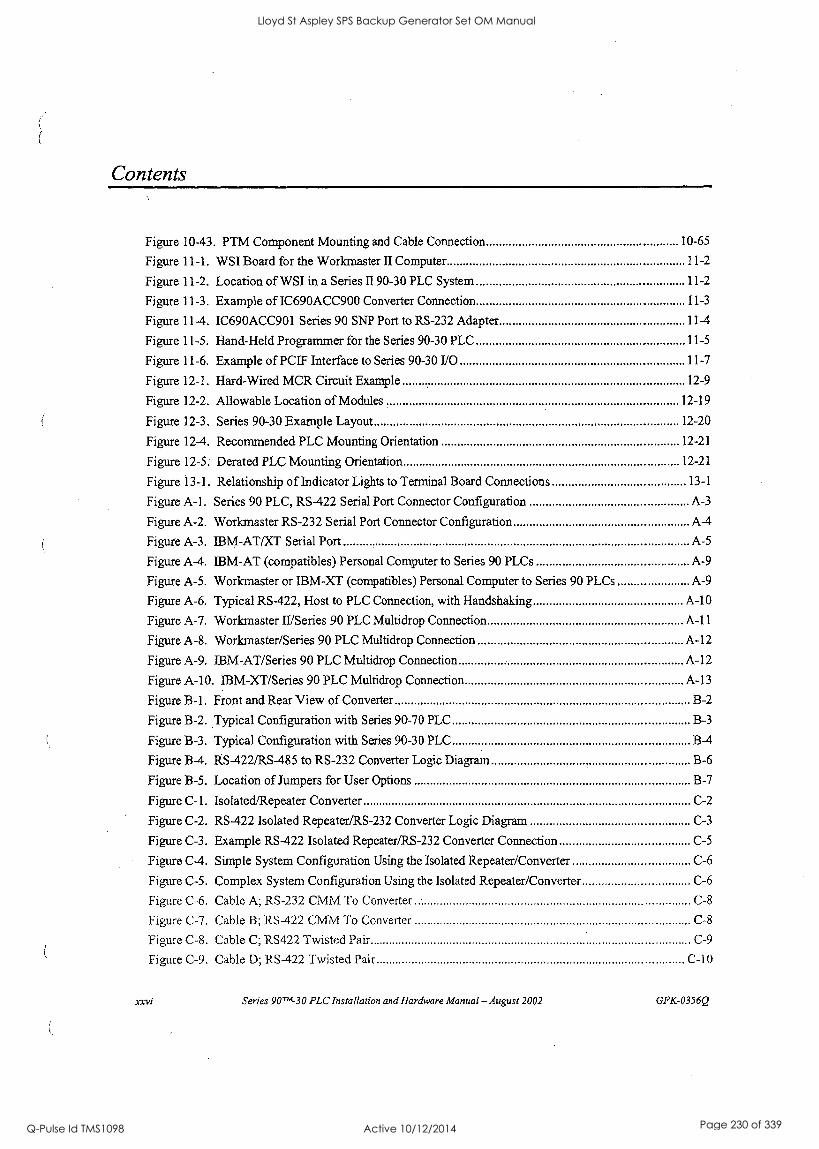
Contents
Figure 10-43. PTM Component Mounting and Cable Connection 10-65
Figure 11-1. WSI Board for the Workmaster II Computer 11-2
Figure 11-2. Location of WSI in a Series II 90-30 PLC System 11-2
Figure 11-3. Example of IC690ACC900 Converter Connection 11-3
Figure 11-4. IC690ACC901 Series 90 SNP Port to RS-232 Adapter 11-4
Figure 11-5. Hand-Held Programmer for the Series 90-30 PLC 11-5
Figure 11-6. Example of PCIF Interface to Series 90-30 I/O 11-7
Figure 12-1. Hard-Wired MCR Circuit Example 12-9
Figure 12-2. Allowable Location of Modules 12-19
Figure 12-3. Series 90-30 Example Layout 12-20
Figure 12-4. Recommended PLC Mounting Orientation 12-21
Figure 12-5. Derated PLC Mounting Orientation 12-21
Figure 13-1. Relationship of Indicator Lights to Terminal Board Connections 13-1
Figure A-1. Series 90 PLC, RS-422 Serial Port Connector Configuration A-3
Figure A-2. Workmaster RS-232 Serial Port Connector Configuration A-4
Figure A-3. IBM-AT/XT Serial Port A-5
Figure A-4. IBM-AT (compatibles) Personal Computer to Series 90 PLCs A-9
Figure A-5. Workmaster or IBM-XT (compatibles) Personal Computer to Series 90 PLCs ...... ....... A-9
Figure A-6. Typical RS-422, Host to PLC Connection, with Handshaking A-10
Figure A-7. Workmaster II/Series 90 PLC Multidrop Connection A-11
Figure A-8. Workmaster/Series 90 PLC Multidrop Connection A-12
Figure A-9. IBM-AT/Series 90 PLC Multidrop Connection A-12
Figure A-10. IBM -XT /Series 90 PLC Multidrop Connection A-13
Figure B-1. Front and Rear View of Converter B-2
Figure B-2. Typical Configuration with Series 90-70 PLC B-3
Figure B-3. Typical Configuration with Series 90-30 PLC B-4
Figure B-4. RS-422/RS-485 to RS-232 Converter Logic Diagram B-6
Figure B-5. Location of Jumpers for User Options B-7
Figure C-1. Isolated/Repeater Converter C-2
Figure C-2. RS-422 Isolated Repeater/RS-232 Converter Logic Diagram C-3
Figure C-3. Example RS-422 Isolated Repeater/RS-232 Converter Connection C-5
Figure C-4. Simple System Configuration Using the Isolated Repeater/Converter C-6
Figure C-5. Complex System Configuration Using the Isolated Repeater/Converter C-6
Figure C-6. Cable A; RS-232 CMM To Converter - C-8
Figure C-7. Cable B; RS-422 CMM To Converter C-8
Figure C-8. Cable C; RS422 Twisted Pair C-9
Figure C-9. Cable D; RS-422 Twisted Pair C-10
xxvi Series 90TK30 PLC Installation and Hardware Manual- August 2002 GFK-0356Q
Lloyd St Aspley SPS Backup Generator Set OM Manual
Q-Pulse Id TMS1098 Active 10/12/2014 Page 230 of 339
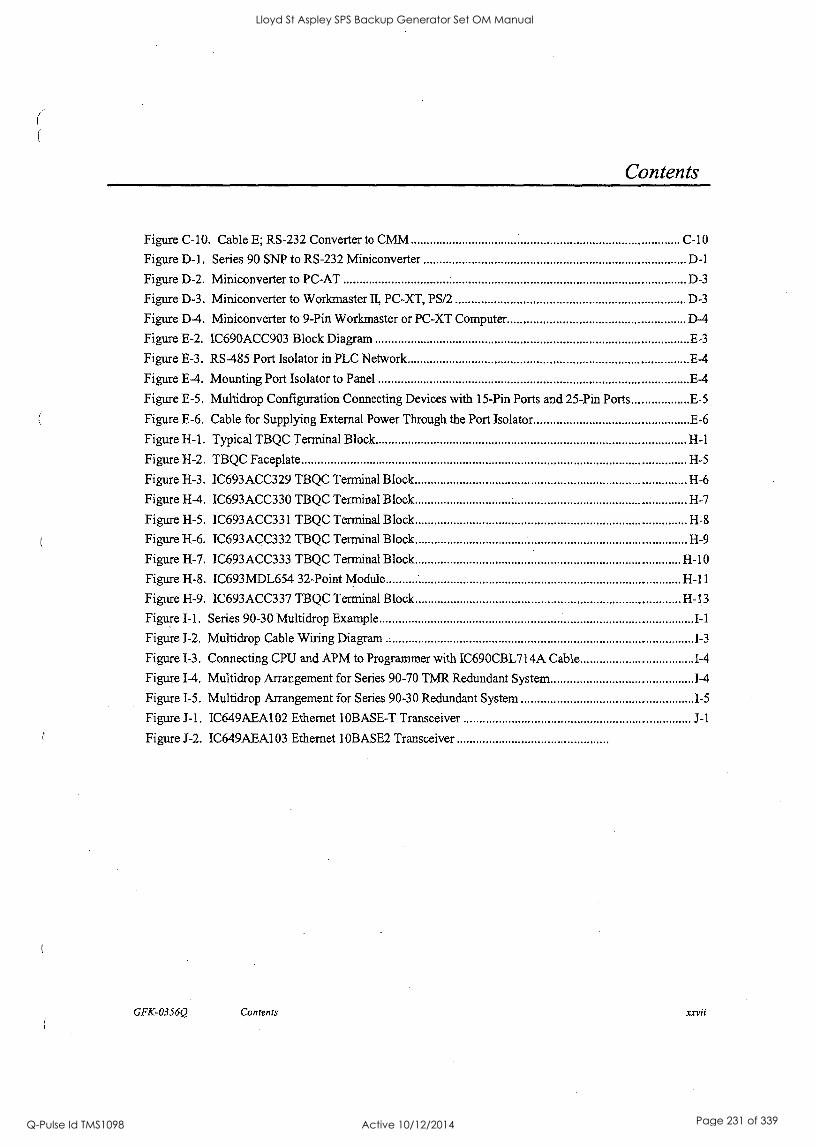
Contents
Figure C-10. Cable E; RS-232 Converter to CMM C-10
Figure D-1. Series 90 SNP to RS-232 Miniconverter D-1
Figure D-2. Miniconverter to PC-AT D-3
Figure D-3. Miniconverter to Workmaster II, PC-XT, PS/2 D-3
Figure D-4. Miniconverter to 9-Pin Workmaster or PC-XT Computer D-4
Figure E-2. IC690ACC903 Block Diagram E-3
Figure E-3. RS-485 Port Isolator in PLC Network E-4
Figure E-4. Mounting Port Isolator to Panel E-4
Figure E-5. Multidrop Configuration Connecting Devices with 15-Pin Ports and 25-Pin Ports E -5
Figure E-6. Cable for Supplying External Power Through the Port Isolator E-6
Figure H-1. Typical TBQC Terminal Block H-1
Figure 11-2. TBQC Faceplate H-5
Figure H-3. IC693ACC329 TBQC Terminal Block H-6
Figure H-4. IC693ACC330 TBQC Terminal Block H-7
Figure H-5. IC693ACC331 TBQC Terminal Block H-8
Figure H-6. IC693ACC332 TBQC Terminal Block 1-1-9
Figure H-7. IC693ACC333 TBQC Terminal Block H-10
Figure H-8. IC693MDL654 32-Point Module H-11
Figure H-9. IC693ACC337 TBQC Terminal Block 11-13
Figure I-1. Series 90-30 Multidrop Example I-1
Figure 1-2. Multidrop Cable Wiring Diagram 1-3
Figure I-3. Connecting CPU and APM to Programmer with IC690CBL714A Cable 1-4
Figure 1-4. Multidrop Arrangement for Series 90-70 TMR Redundant System 1-4
Figure 1-5. Multidrop Arrangement for Series 90-30 Redundant System 1-5
Figure J-1. IC649AEA102 Ethernet IOBASE-T Transceiver J-1
Figure J-2. 1C649AEA103 Ethernet 10BASE2 Transceiver
GFK-0356Q Contents xxvii
Lloyd St Aspley SPS Backup Generator Set OM Manual
Q-Pulse Id TMS1098 Active 10/12/2014 Page 231 of 339
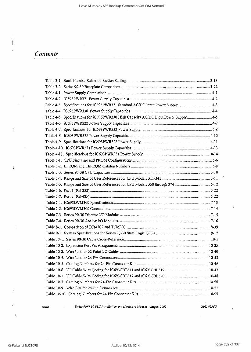
(
Contents
Table 3-1. Rack Number Selection Switch Settings 3-13
Table 3-2. Series 90-30 Baseplate Comparison 3-22
Table 4-1. Power Supply Comparison 4-1
Table 4-2. IC693PWR321 Power Supply Capacities 4-2
Table 4-3. Specifications for IC693PWR321 Standard AC/DC Input Power Supply 4-3
Table 4-4. IC693PWR330 Power Supply Capacities 4-4
Table 4-5. Specifications for IC693PWR330 High Capacity AC/DC Input Power Supply 4-5
Table 4-6. IC693PWR322 Power Supply Capacities 4-7
Table 4-7. Specifications for IC693PWR322 Power Supply 4-8
Table 4-8. IC693PWR328 Power Supply Capacities 4-10
Table 4-9. Specifications for IC693PWR328 Power Supply 4-11
Table 4-10. IC693PWR331 Power Supply Capacities 4-13
Table 4-11. Specifications for IC693PWR331 Power Supply 4-14
Table 5-1. CPU Firmware and PROM Configurations 5-6
Table 5-2. EPROM and EEPROM Catalog Numbers 5-9
Table 5-3. Series 90-30 CPU Capacities 5-10
Table 5-4. Range and Size of User References for CPU Models 311-341 5-11
Table 5-5. Range and Size of User References for CPU Models 350 through 374 5-12
Table 5-6. Port 1 (RS-232) 5-22
Table 5-7. Port 2 (RS-485) 5-22
Table 7-1. IC693DVM300 Specifications 7-13
Table 7-2. IC693DVM300 Connections 7-14
Table 7-3. Series 90-30 Discrete I/O Modules 7-15
Table 7-4. Series 90-30 Analog I/O Modules 7-16
Table 8-1. Comparison of TCM302 and TCM303 8-39
Table 9-1. System Specifications for Series 90-30 State Logic CPUs 9-12
Table 10-1. Series 90-30 Cable Cross-Reference 10-1
Table 10-2. Expansion Port Pin Assignments 10-25
Table 10-3. Wire List for 32 Point I/O Cables 10-40
Table 10-4. Wire List for 24-Pin Connectors 10-43
Table 10-5. Catalog Numbers for 24-Pin Connector Kits 10-46
Table 10-6. I/O Cable Wire Coding for IC693CBL311 and IC693CHL319 10-47
Table 10-7. I/O Cable Wire Coding for IC693CBL317 and 1C693CBL320 10-48
Table 10-8. Catalog Numbers for 24-Pin Connector Kits 10-50
Table 10-9. Wire List for 24-Pin Connectors 10-51
Table 10-10. Catalog Numbers for 24-Pin Connector Kits 10-59
xxviii genies 90"1-30 PLC Installation and Hardware Manual - August 2002 GFK-03560
Lloyd St Aspley SPS Backup Generator Set OM Manual
Q-Pulse Id TMS1098 Active 10/12/2014 Page 232 of 339
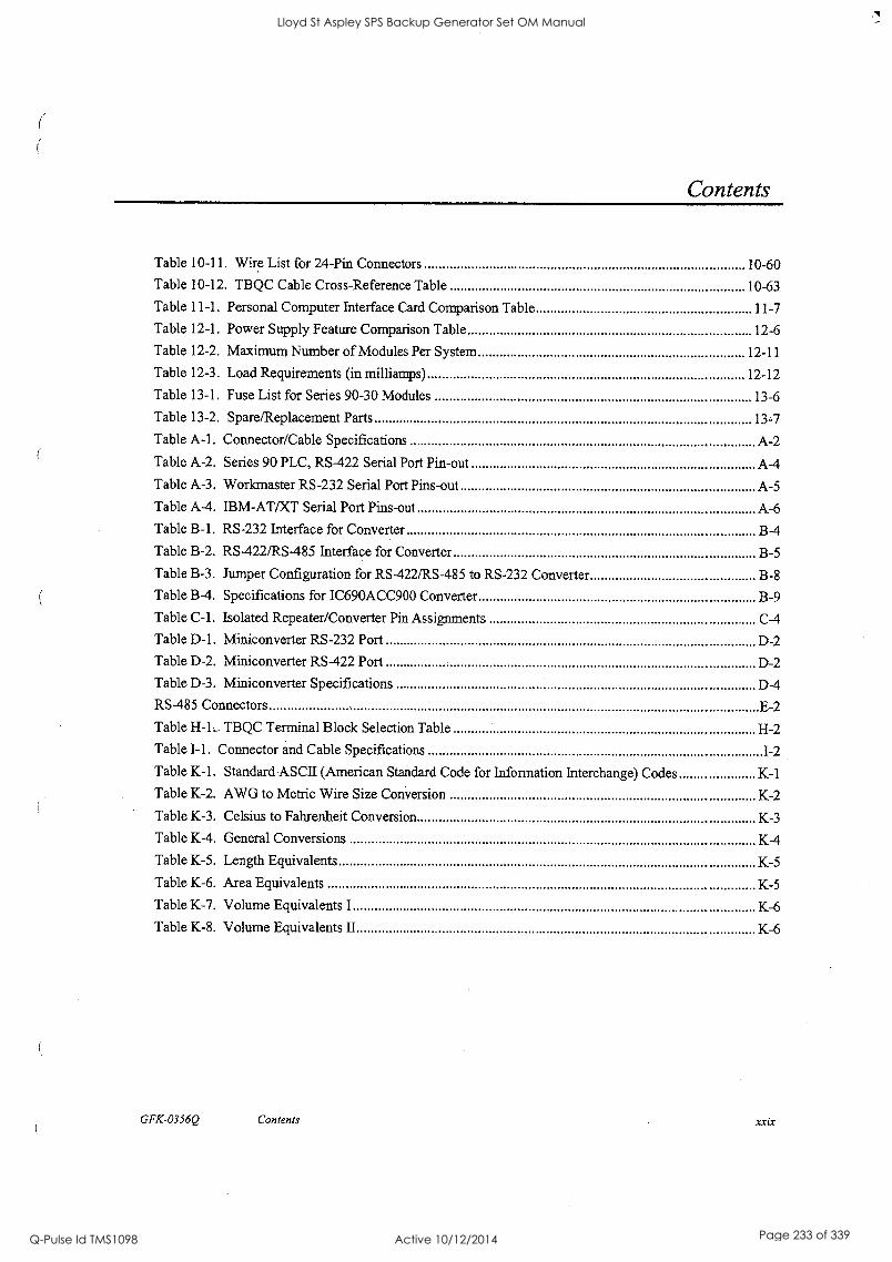
Contents
Table 10-11. Wire List for 24-Pin Connectors 10-60
Table 10-12. TBQC Cable Cross-Reference Table 10-63
Table 11-1. Personal Computer Interface Card Comparison Table 11-7
Table 12-1. Power Supply Feature Comparison Table 12-6
Table 12-2. Maximum Number of Modules Per System 12-11
Table 12-3. Load Requirements (in milliamps) 12-12
Table 13-1. Fuse List for Series 90-30 Modules 13-6
Table 13-2. Spare/Replacement Parts 13-7
Table A-1. Connector/Cable Specifications A-2
Table A-2. Series 90 PLC, RS-422 Serial Port Pin-out A-4
Table A-3. Workmaster RS-232 Serial Port Pins-out A-5
Table A-4. IBM-AT/XT Serial Port Pins-out A-6
Table B-1. RS-232 Interface for Converter B-4
Table B-2. RS-422/RS-485 Interface for Converter B-5
Table B-3. Jumper Configuration for RS-422/RS-485 to RS-232 Converter B-8
Table B-4. Specifications for IC690ACC900 Converter B-9
Table C-1. Isolated Repeater/Converter Pin Assignments C-4
Table D-1. Miniconverter RS-232 Port D-2
Table D-2. Miniconverter RS-422 Port D-2
Table D-3. Miniconverter Specifications D-4
RS-485 Connectors E-2
Table H-1._ TBQC Terminal Block Selection Table H-2
Table I-1. Connector and Cable Specifications 1-2
Table K-1. Standard ASCII (American Standard Code for Information Interchange) Codes K-1
Table K-2. AWG to Metric Wire Size Conversion K-2
Table K-3. Celsius to Fahrenheit Conversion K-3
Table K-4. General Conversions K-4
Table K-5. Length Equivalents K-5
Table K-6. Area Equivalents K-5
Table K-7. Volume Equivalents I K-6
Table K-8. Volume Equivalents II K-6
GFK-0356Q Contents xxix
Lloyd St Aspley SPS Backup Generator Set OM Manual
Q-Pulse Id TMS1098 Active 10/12/2014 Page 233 of 339
Overview of the Series 90-30 PLC
The Series 90TH-30 Programmable Logic Controller (PLC) is a member of the GE Fanuc Series 90 PLC family.
The Basic Parts of a Series 90.30 PLC
The Series 90-30 PLC is very versatile because (1) it is programmable, and (2) it is assembled from a wide variety of modular, plug-together components. Therefore, by choosing the correct components and developing an appropriate program, the PLC can be used for an almost unlimited variety of applications. Although there are many choices of individual hardware components to use in a system, there are just a few basic categories. Each of these component categories is covered in detail in a separate chapter in this manual. They are introduced in this chapter so you can see how they fit together:
s Baseplates
es Power Supplies
s CPUs
Is I/O Modules
s Option Modules
la Cables
Baseplates
The baseplates are the foundation of the PLC system because most other components mount on them. As a basic minimum, every system has at least one baseplate, which usually contains the CPU (in which case, it is referred to as "the CPU Baseplate"). Many systems require more modules than can be mounted on one baseplate, so there are also Expansion and Remote baseplates that connect together. The three categories of baseplates, CPU, Expansion, and Remote, are available in two sizes, 5-slot and 10-slot, named according to the number of modules they can hold.
Power Supply Modules
Every baseplate must have its own power supply. The power supply always mounts in a
!baseplate's left -most slot. There are several power supply models available to meet a variety of requirements.
GFK-0356Q 1-1
Lloyd St Aspley SPS Backup Generator Set OM Manual
Q-Pulse Id TMS1098 Active 10/12/2014 Page 234 of 339

CPUs
The CPU is the manager of the PLC. Every PLC system must have one. A CPU uses the instructions in its firmware and application program to direct the PLC's operation and to monitor the system to make sure there are no basic faults. Some Series 90-30 CPUs are built into baseplates, but most are contained in plug-in modules. In some cases, the CPU resides in a Personal Computer using a Personal Computer Interface Card that interfaces to Series 90-30 Input, Output, and Option modules.
Input and Output (I/O) Modules
These modules enable the PLC to interface with input and output field devices such as switches, sensors, relays, and solenoids. They are available in both discrete and analog types.
Option Modules
These modules extend the capability of the PLC beyond the basic functions. These provide such things as communications and networking options, motion control, high speed counting, temperature control, interfacing to operator interface stations, etc.
Cables
These connect the PLC components together or to other systems. Many standard prefabricated cables are available from GE Fanuc. They are primarily used to:
Interconnect baseplates
Connect a programmer to the CPU or to an option module
Connect option modules to field devices or other systems.
Assembling a Basic Series 90-30 PLC System
Let's assemble, on paper, a basic system using the following components:
ra Baseplate
Ea Power Supply module
lE1 CPU module
Ea Some I/O modules
We'll start with the baseplate. To keep it simple, we'll use a 5-slot size. Note that a 5-slot baseplate actually has six slots, but the power supply slot is not numbered. Note also, that this baseplate has a CPU slot, which is slot number 1, and it has an expansion connector on the right end, which is used for connecting to another baseplate if the system has more than one baseplate.
Series 90-30 PLC Installation and Hardware Manual - August 2002 GFK-0356Q
Lloyd St Aspley SPS Backup Generator Set OM Manual
Q-Pulse Id TMS1098 Active 10/12/2014 Page 235 of 339
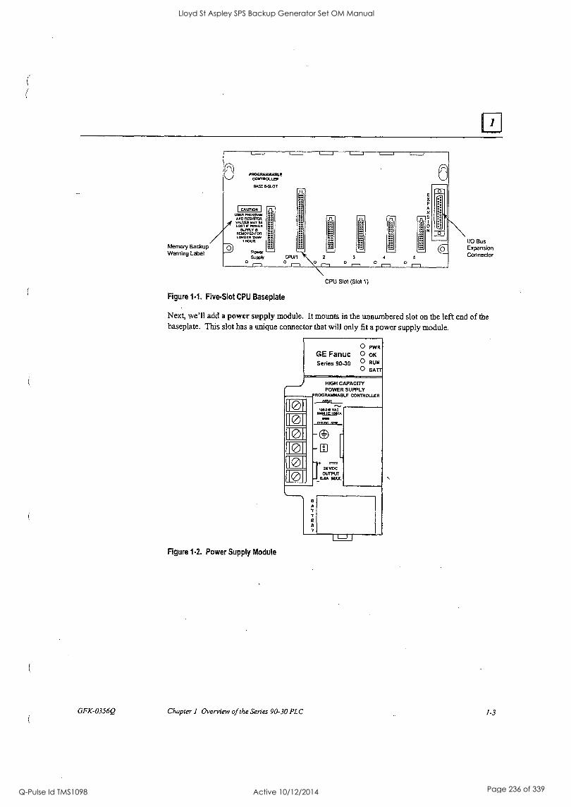
GFK-0356Q
Memory Backup Warning Label
PROGRAMMABLE CONTROLLER
EASE 6-SLOT
SS
to T1-
E
Sz
0 N
O
-6-
I CurrIOR USER PROGRAM
ARO RESISTER VALUES MAY SE LOST IF POWER
SUPPLY REMOVED FOR LONGER THAN
I HOUR.
Power Surcei
0 r-1
Figure 1.1. FiveSlot CPU Baseplate
3
0 1 5
0 0 rT
CPU Slot (Slot 1)
I/O Bus Expansion Connector
Next, we'll add a power supply module. It mounts in the unnumbered slot on the left end of the baseplate. This slot has a unique connector that will only fit a power supply module.
Figure 1.2. Power Supply Module
GE Fanuc Series 90-30
O PWR
O OK O RUN
O BATT
0
0I 0 0
HIGH CAPACITY POWER SUPPLY
ROGRAWABLE CONTROLLER INPUT
1004* VAC
O
ENVUSLIEVA
-
_©
T24 VDC OUTPUT
0.8A MAX.
B A
T E
Y
Chapter 1 Overview of the Series 90-30 PLC 1-3
Lloyd St Aspley SPS Backup Generator Set OM Manual
Q-Pulse Id TMS1098 Active 10/12/2014 Page 236 of 339
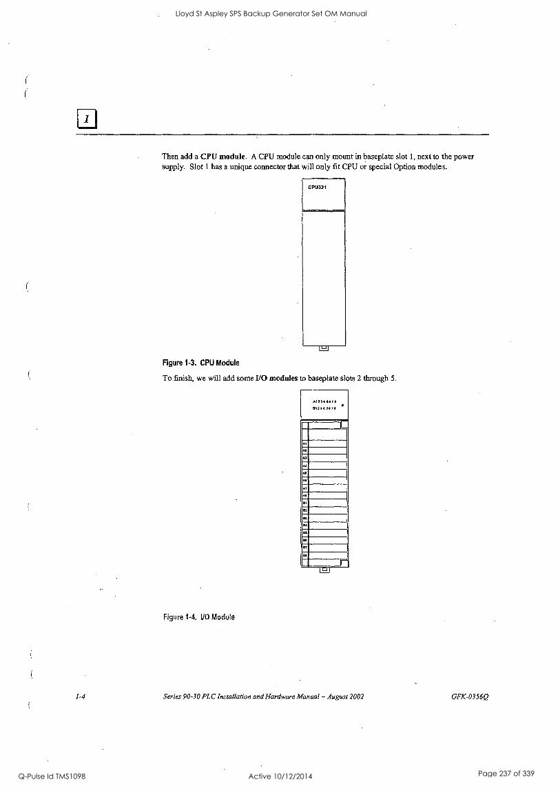
Then add a CPU module. A CPU module can only mount in baseplate slot 1, next to the power supply. Slot 1 has a unique connector that will only fit CPU or special Option modules.
Figure 1-3. CPU Module
To finish, we will add some I/O modules to baseplate slots 2 through 5.
Figure 1-4. I/O Module
Series 90-30 PLC Installation and Hardware Manual - August 2001 GFK-03560
Lloyd St Aspley SPS Backup Generator Set OM Manual
Q-Pulse Id TMS1098 Active 10/12/2014 Page 237 of 339
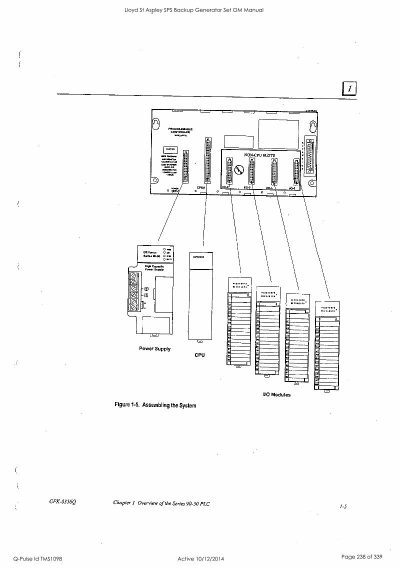
PROGRAMMABLE CONTROLLER
.Aor
O
Ong, GE Panue 0 pc Sad. 60.30 0 AP
0 SA/T
I0 I0 I0 10 I0 l0
IRO CAP.mRY Popp Supply
ED
]:
Power Supply
CP11331
CPU
I/O Modules
Figure 1.5. Assembling the System
GFK-0356Q Chapter 1 Overview of the Series 90-30 PLC 1-5
Lloyd St Aspley SPS Backup Generator Set OM Manual
Q-Pulse Id TMS1098 Active 10/12/2014 Page 238 of 339

When assembled, the system will look like this:
O- an, GE Fanuc OCK A L., A1231111711, A12111111711F A123.6711,, 5E23E3 .0413 Ow
. 0 am 512146175 812345571 5f2Z411117. 512,411 78
MOM CAPACITY POWER SUPPLY wwwwWIAOLIAT
r Figure 1-6. A Basic System
An assembly of baseplate and modules such as this one is called a "Rack."
What else would be needed to make this basic system functional?
0
To make this basic system functional, you would need:
Mounting. Safe, secure mounting for the PLC in a protective enclosure.
Wiring. This includes properly installed incoming power to the power supply, as well as
wiring from the I/O modules to field devices such as switches, sensors, solenoids, relays, etc.
Ea Program. An application program for the PLC to run. This is developed with GE Fanuc PLC programming software.
What if the application requires more than five modules?
You could use a 10-slot baseplate, shown in the next picture:
GE Fres g. D.
Figure 1-7. Ten-Slot Rack
1-6 Series 90-30 PLC Installation and Hardware Manual - August 2002
110 Bus Expansion Connector
GFK-0356Q
Lloyd St Aspley SPS Backup Generator Set OM Manual
Q-Pulse Id TMS1098 Active 10/12/2014 Page 239 of 339
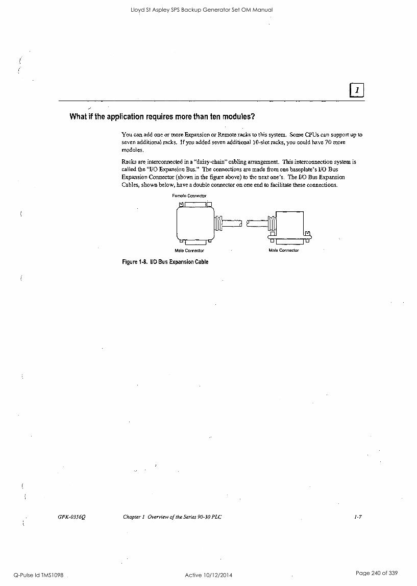
2
What if the application requires more than ten modules?
GFK-0356Q
You can add one or more Expansion or Remote racks to this system. Some CPUs can support up to seven additional racks. If you added seven additional I 0-slot racks, you could have 70 more modules.
Racks are interconnected in a "daisy-chain" cabling arrangement. This interconnection system is called the "1/0 Expansion Bus." The connections are made from one baseplate's 110 Bus Expansion Connector (shown in the figure above) to the next one's. The 1/0 Bus Expansion Cables, shown below, have a double connector on one end to facilitate these connections.
Female Connector
Male Connector
Figure 1-8. UO Bus Expansion Cable
Male Connector
Chapter 1 Overview of the Series 90-30 PLC 1-7
Lloyd St Aspley SPS Backup Generator Set OM Manual
Q-Pulse Id TMS1098 Active 10/12/2014 Page 240 of 339
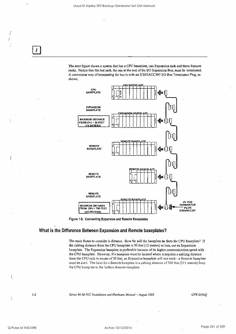
The next figure shows a system that has a CPU baseplate, one Expansion rack and three Remote racks. Notice that the last rack, the one at the end of the I/0 Expansion Bus, must be terminated. A convenient way of terminating the bus is with an IC693ACC307 I/0 Bus Terminator Plug, as shown.
CPU BASEPLATE
EXPANSION BASEPLATE
MAXIMUM DISTANCE FROM CPU = 50 FEET
115 METERS
REMOTE BASEPLATE
REMOTE BASEPLATE
REMOTE BASEPLATE
MAXIMUM DISTANCE FROM CPU = 700 FEET
(213 METERS)
mninummismilmoll
M11111111111
pmnommunnimi
MIII11111110
pommumem. Imo
.1111110
Immimmummum
MI1111111111 Figure 1-9. Connecting Expansion and Remote Baseplates
4
I
What is the Difference Between Expansion and Remote baseplates?
I/O BUS TERMINATOR
PLUG IC693ACC307
The main factor to consider is distance. How far will the baseplate be from the CPU baseplate? If the cabling distance from the CPU baseplate is 50 feet (15 meters) or less, use an Expansion baseplate. The Expansion baseplate is preferable because of its higher communication speed with the CPU baseplate. However, if a baseplate must be located where it requires a cabling distance from the CPU rack in excess of 50 feet, an Expansion baseplate will not work - a Remote baseplate must be used. The limit for a Remote baseplate is a cabling distance of 700 feet (213 meters) from the CPU baseplate to the farthest Remote baseplate.
1-8 Series 90-30 PLC Installation and Hardware Manual - August 2002 GFK-03560
Lloyd St Aspley SPS Backup Generator Set OM Manual
Q-Pulse Id TMS1098 Active 10/12/2014 Page 241 of 339
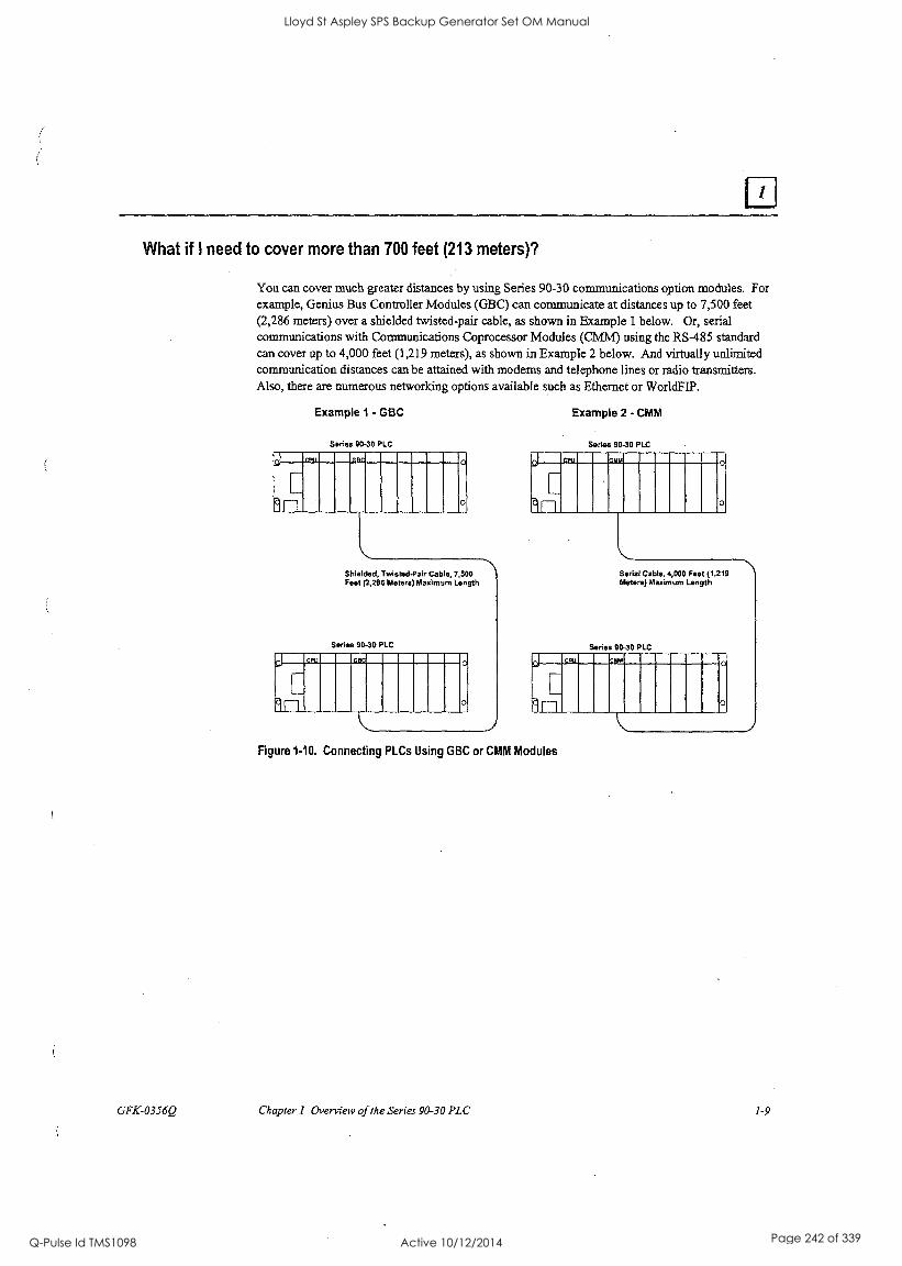
What if I need to cover more than 700 feet (213 meters)?
GFK-0356Q
You can cover much greater distances by using Series 90-30 communications option modules. For example, Genius Bus Controller Modules (GBC) can communicate at distances up to 7,500 feet (2,286 meters) over a shielded twisted-pair cable, as shown in Example 1 below. Or, serial communications with Communications Coprocessor Modules (CMM) using the RS-485 standard can cover up to 4,000 feet (1,219 meters), as shown in Example 2 below. And virtually unlimited communication distances can be attained with modems and telephone lines or radio transmitters. Also, there are numerous networking options available such as Ethernet or WorldFIP.
Example I - GBC
Series 90-30 PLC
111111M1111111111,1111111111111111IN .
I AMIN Shielded, Twisted-Pair Cable, 7,500 Feel (2,286 Meters) Maximum Length
Series 90-30 PLC
IIIIMIIIIIIIMIIMIIIIME .
II 11111111111
Example 2 - CMM
Sodas 90-30 PLC
lammummumummum .
I 211111111111
Serial Cable, 4,000 Feet (1,219 Meters) Maximum Length
Series 90-30 PLC
FIIMIIITIRIMMIIIIIMIMMINIIII .
I 11111111111
Figure 1-10. Connecting PLCs Using GBC or CMM Modules
Chapter 1 Overview of the Series 90-30 PLC 1-9
Lloyd St Aspley SPS Backup Generator Set OM Manual
Q-Pulse Id TMS1098 Active 10/12/2014 Page 242 of 339
Installation
This chapter discusses installation details only. Other information about the products such as
hardware descriptions and specifications, is covered in the applicable chapters.
Important Note
Series 90-30 PLCs must be mounted in a protective enclosure.
The installation instructions described in this chapter apply to PLC installations that do not require special procedures for noisy or hazardous environments. For installations that must conform to more stringent requirements (such as CE Mark), see GFK-1179, Installation Requirements for Conformance to Standards. Also see Glif-0867, GE Fanuc Product Agency Approvals, Standards, General Specifications.
Receiving your Products - Visual Inspection
When you receive your Series 90-30 PLC system, carefully inspect all shipping containers for damage that may have occurred during shipping. If any part of the system is damaged, notify the carrier immediately. The damaged shipping container should be saved as evidence for inspection by the carrier.
As the consignee, it is your responsibility to register a claim with the carrier for damage incurred during shipment. However, GE Fanuc will fully cooperate with you if such action is necessary.
Pre-installation Check
After unpacking Series 90-30 PLC racks, cables, modules, etc., record all serial.numbers. Serial numbers are printed on the module packaging. Serial numbers are required to make a claim during the warranty period of the equipment. All software product registration cards should be completed and returned to GE Fanuc. See "Module Features" in this chapter for location of module serial numbers. See "Common Baseplate Features" in chapter 3 for location of baseplate serial numbers.
You should verify that all components of the system have been received and that they agree with your order. If the parts received do not agree with your order, call Programmable Control Customer Service at 1-800-432-7521. A Customer Service representative will provide further instructions.
If you require assistance with your installation, GE Fanuc's Technical Support department offers expert help. Call the support number for your area from the list in Chapter 13, "Maintenance and Troubleshooting." The GE Fanuc web site support address is www.gefimuc.conilsupport/ple.
Warranty Claims
Record the serial number of the defective item and contact your distributor for instructions.
GFK-0356Q 2-1
Lloyd St Aspley SPS Backup Generator Set OM Manual
Q-Pulse Id TMS1098 Active 10/12/2014 Page 243 of 339
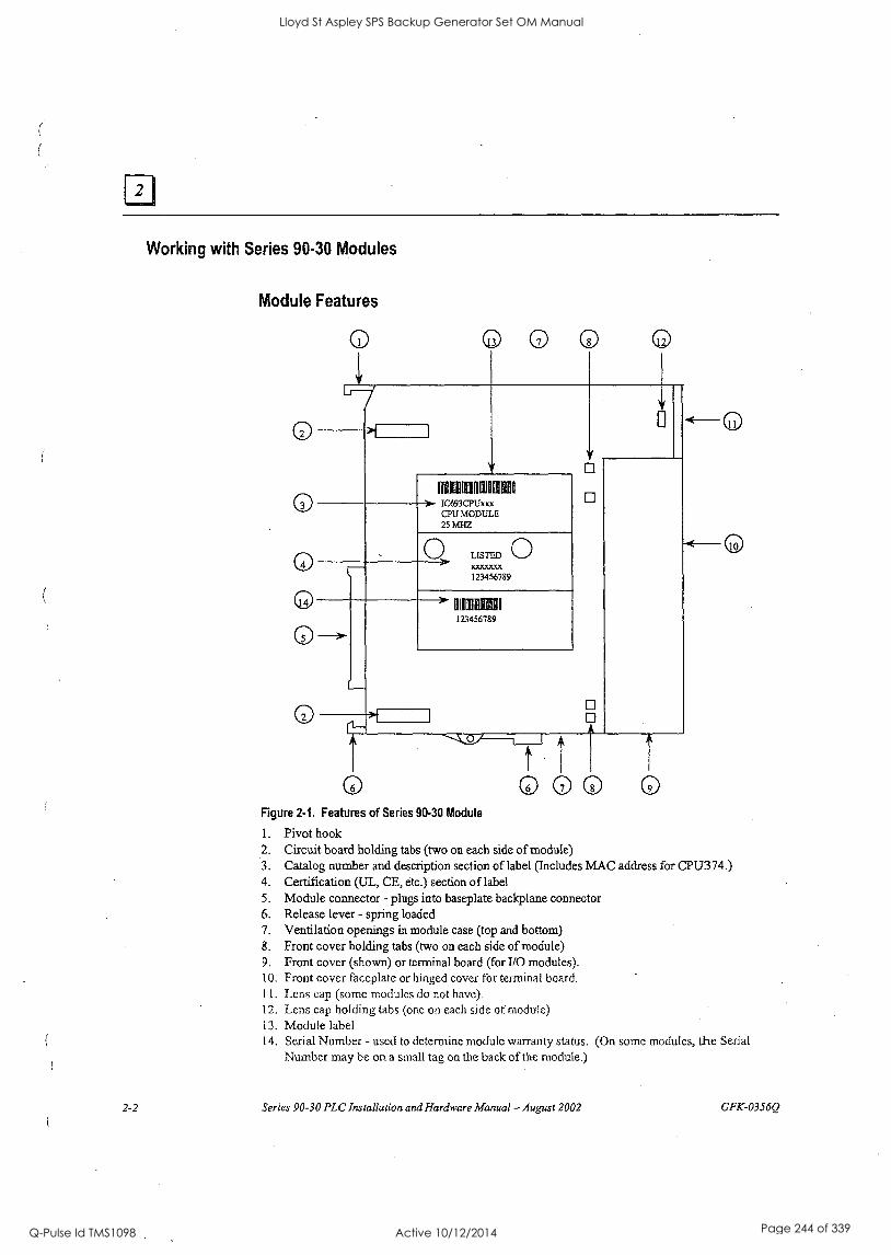
Working with Series 90.30 Modules
Module Features
0 0
HMI 1E1 E1 > IC693CPUxxx
CPU MODULE 25 MHZ
LISTED 0 xxxxxxx 123456789
MIEN I I
123456789
LTi 000 0 Figure 2-1. Features of Series 90.30 Module
1. Pivot hook 2. Circuit board holding tabs (two on each side of module) 3. Catalog number and description section of label (Includes MAC address for CPU374.) 4. Certification (UL, CE, etc.) section of label 5. Module connector - plugs into baseplate backplane connector 6. Release lever - spring loaded 7. Ventilation openings in module case (top and bottom) 8. Front cover holding tabs (two on each side of module) 9. Front cover (shown) or terminal board (for I/O modules). 10. Front cover faceplate or hinged cover for terminal board. 11. Lens cap (some modules do not have). 12. Lens cap holding tabs (one on each side of module) 13. Module label 14. Serial Number - used to determine module warranty status. (On some modules, the Serial
Number may be on a small tag on the back of the module.)
2-2 Series 90-30 PLC Installation and Hardware Manual - August 2002 GFK-0356Q
Lloyd St Aspley SPS Backup Generator Set OM Manual
Q-Pulse Id TMS1098 Active 10/12/2014 Page 244 of 339
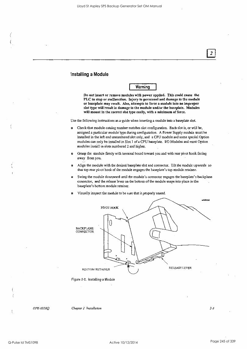
Installing a Module
Warning
Do not insert or remove modules with power applied. This could cause the PLC to stop or malfunction. Injury to personnel and damage to the module or baseplate may result. Also, attempts to force a module into an improper slot type will result in damage to the module and/or the baseplate. Modules will mount in the correct slot type easily, with a minimum of force.
Use the following instructions as a guide when inserting a module into a baseplate slot.
Check that module catalog number matches slot configuration. Each slot is, or will be, assigned a particular module' type during configuration. A Power Supply module must be installed in the left end unnumbered slot only, and a CPU module and some special Option modules can only be installed in Slot 1 of a CPU baseplate. I/O Modules and most Option modules install in slots numbered 2 and higher.
® Grasp the module firmly with terminal board toward you and with rear pivot hook facing away from you -
Fa Align the module with the desired baseplate slot and connector. Tilt the module upwards so that top rear pivot hook of the module engages the baseplate's top module retainer.
Swing the module downward until the module's connector engages the baseplate's backplane connector, and the release lever on the bottom of the module snaps into place in the baseplate's bottom module retainer.
Visually inspect the module to be sure that it properly seated.
BACKPLANE CONNECTOR
PIVOT HOOK
a43055A
BOTTOM RETAINER
Figure 2-2. Installing a Module
GFK-0356Q Chapter 2 Installation
RELEASE LEVER
2-3
Lloyd St Aspley SPS Backup Generator Set OM Manual
Q-Pulse Id TMS1098 Active 10/12/2014 Page 245 of 339
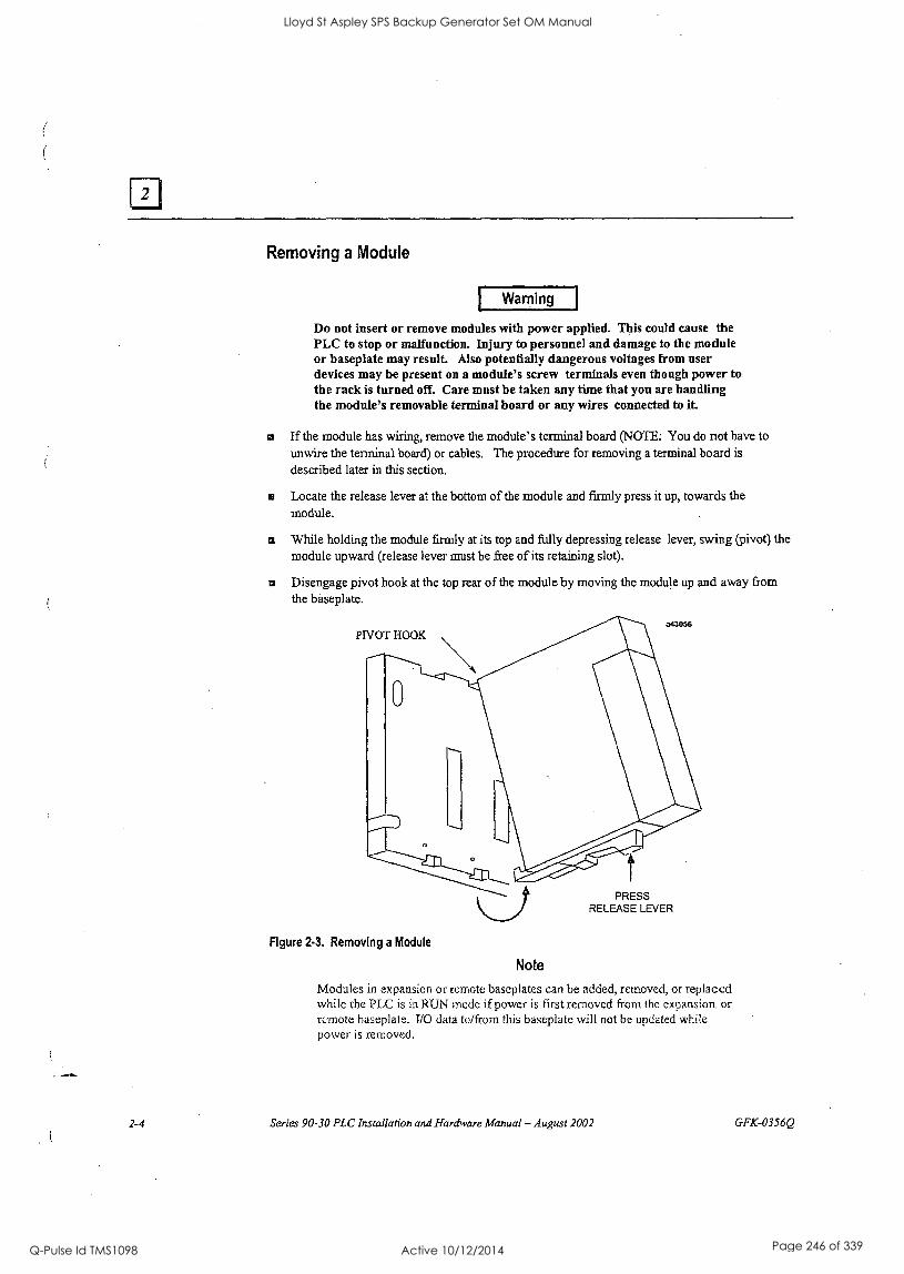
Removing a Module
Warning
Do not insert or remove modules with power applied. This could cause the PLC to stop or malfunction. Injury to personnel and damage to the module or baseplate may result. Also potentially dangerous voltages from user devices may be present on a module's screw terminals even though power to the rack is turned off. Care must be taken any time that you are handling the module's removable terminal board or any wires connected to it.
n If the module has wiring, remove the module's terminal board (NOTE: You do not have to unwire the terminal board) or cables. The procedure for removing a terminal board is
described later in this section.
Locate the release lever at the bottom of the module and firmly press it up, towards the module.
® While holding the module firmly at its top and fully depressing release lever, swing (pivot) the module upward (release lever must be free of its retaining slot).
Disengage pivot hook at the top rear of the module by moving the module up and away from the baseplate.
PIVOT HOOK a43056
Figure 2.3. Removing a Module
PRESS RELEASE LEVER
Note
Modules in expansion or remote baseplates can be added, removed, or replaced while the PLC is in RUN mode if power is first removed from the expansion or remote baseplate. I/O data to/from this baseplate will not be updated while power is removed.
2-4 Series 90-30 PLC Installation and Hardware Manual - August 2002 GFK-0356Q
Lloyd St Aspley SPS Backup Generator Set OM Manual
Q-Pulse Id TMS1098 Active 10/12/2014 Page 246 of 339

Installing a Module's Terminal Board
Note: Modules IC693MDL730F (and later) and IC693MDL731F (and later) have special terminal boards that are equipped with holding screws. For Installation and Removal instructions, please see the section "Installing and Removing Terminal Boards with Holding Screws" later in this chapter.
To install a terminal board (circled numbers refer to drawing below):
Hook the pivot hook 0, located on the bottom of the terminal board, to the lower slot on the module.
sa Push the terminal board toward the module 0 until it snaps into place.
Open the terminal board cover 0 and ensure that the latch on the module is securely holding the terminal board in place.
Caution
Compare the module catalog number on the label on the back of the hinged door (see Figure 2-6) and the label on the side of the module (see below) to ensure that they match. If a wired terminal board is installed on the wrong module type, damage to the module may occur when the system is powered up.
a43062
Module Label
REFER TO TEXT FOR INSTALLATION PROCEDURE
Figure 2-4. Installing an I/0 Module's Terminal Board
GFK-0356Q Chapter 2 Installation 2-5
Lloyd St Aspley SPS Backup Generator Set OM Manual
Q-Pulse Id TMS1098 Active 10/12/2014 Page 247 of 339
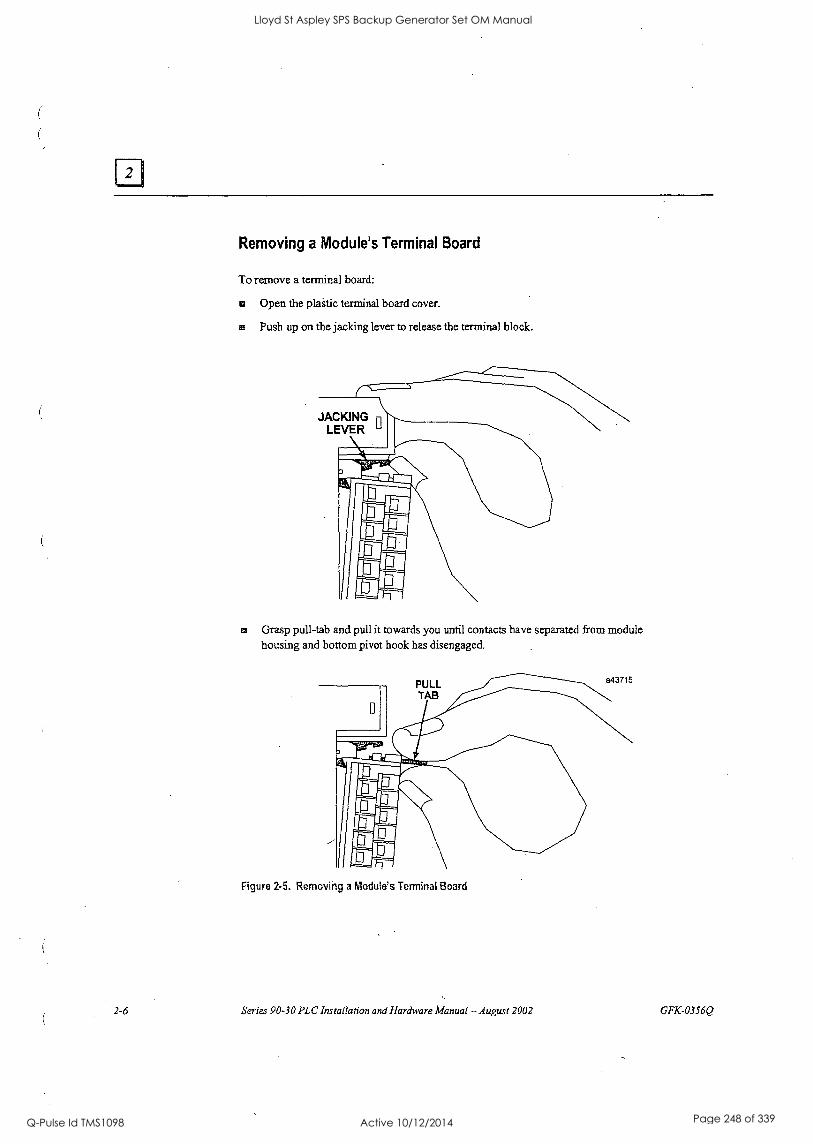
Removing a Module's Terminal Board
To remove a terminal board:
® Open the plaitic terminal board cover.
® Push up on the jacking lever to release the terminal block.
JACKING n LEVER
PI** Mr"
rom ® Grasp pull-tab and pull it towards you until contacts have separated from module
housing and bottom pivot hook has disengaged.
Figure 2-5. Removing a Module's Terminal Board
2-6 Series 90-30 PLC Installation and Hardware Manual - August 2002 GFK-0356Q
Lloyd St Aspley SPS Backup Generator Set OM Manual
Q-Pulse Id TMS1098 Active 10/12/2014 Page 248 of 339
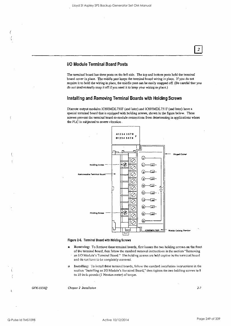
GFK-0356Q
I/O Module Terminal Board Posts
The terminal board has three posts on the left side. The top and bottom posts hold the terminal board cover in place. The middle post keeps the terminal board wiring in place. If you do not require it to hold the wiring in place, the middle post can be easily snapped off. (Be careful that you do not inadvertently snap it off if you need it to keep your wiring in place.)
Installing and Removing Terminal Boards with Holding Screws
Discrete output modules IC693MDL730F (and later) and IC693MDL73 IF (and later) have a special terminal board that is equipped with holding screws, shown in the figure below. These screws prevent the terminal board-to-module connections from deteriorating in applications where the PLC is subjected to severe vibration .
Holding Screw
A12345678 B12345878
rh' r
Removeable Terminal Board
Holding Screw
0 0
0 0 0 0
-L
a
0 0 0
ra
L
Hinged Cover
Module Catalog Number
Figure 2-6. Terminal Board with Holding Screws
Removing: To Remove these terminal boards, first loosen the two holding screws on the front of the terminal board, then follow the standard removal instructions in the section "Removing an 110 Module's Terminal Board." The holding screws are held captive in the terminal board and do not have to be completely removed.
a Installing: To install these terminal boards, follow the standard installation instructions in the
section "Installing an I/O Module's Terminal Board," then tighten the two holding screws to 8
to .10 inch-pounds (1 Newton-meter) of torque.
Chapter 2 Installation 2-7
Lloyd St Aspley SPS Backup Generator Set OM Manual
Q-Pulse Id TMS1098 Active 10/12/2014 Page 249 of 339
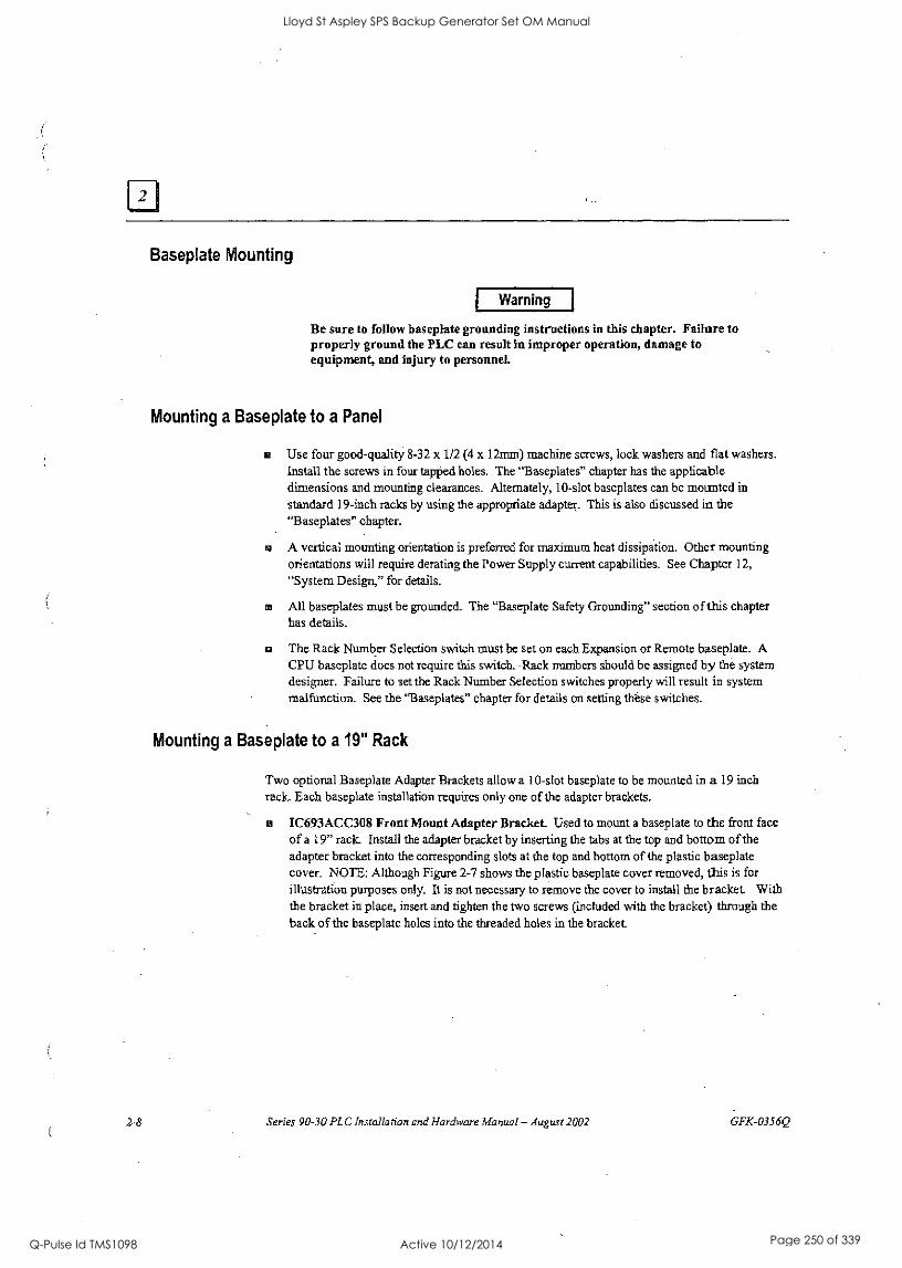
Baseplate Mounting
Warning
Be sure to follow baseplate grounding instructions in this chapter. Failure to properly ground the PLC can result in improper operation, damage to equipment, and injury to personnel.
Mounting a Baseplate to a Panel
Use four good-quality 8-32 x 1/2 (4 x 12mm) machine screws, lock washers and flat washers. Install the screws in four tapped holes. The "Baseplates" chapter has the applicable dimensions and mounting clearances. Alternately, 10-slot baseplates can be mounted in
standard 19-inch racks by using the appropriate adapter. This is also discussed in the "Baseplates" chapter.
a A vertical mounting orientation is preferred for maximum heat dissipation. Other mounting orientations will require derating the Power Supply current capabilities. See Chapter 12,
"System Design," for details.
a All baseplates must be grounded. The "Baseplate Safety Grounding" section of this chapter has details.
a The Rack Number Selection switch must be set on each Expansion or Remote baseplate. A CPU baseplate does not require this switch. Rack numbers should be assigned by the system designer. Failure to set the Rack Number Selection switches properly will result in system malfunction. See the "Baseplates" chapter for details on setting these switches.
Mounting a Baseplate to a 19" Rack
Two optional Baseplate Adapter Brackets allow a 10-slot baseplate to be mounted in a 19 inch rack. Each baseplate installation requires only one of the adapter brackets.
IC693ACC308 Front Mount Adapter Bracket Used to mount a baseplate to the front face of a 19" rack. Install the adapter bracket by inserting the tabs at the top and bottom of the adapter bracket into the corresponding slots at the top and bottom of the plastic baseplate cover. NOTE: Although Figure 2-7 shows the plastic baseplate cover removed, this is for illustration purposes only. It is not necessary to remove the cover to install the bracket. With the bracket in place, insert and tighten the two screws (included with the bracket) through the back of the baseplate holes into the threaded holes in the bracket.
2-8 Series 90-30 PLC Installation and Hardware Manual - August 2002 GFK-0356Q
Lloyd St Aspley SPS Backup Generator Set OM Manual
Q-Pulse Id TMS1098 Active 10/12/2014 Page 250 of 339
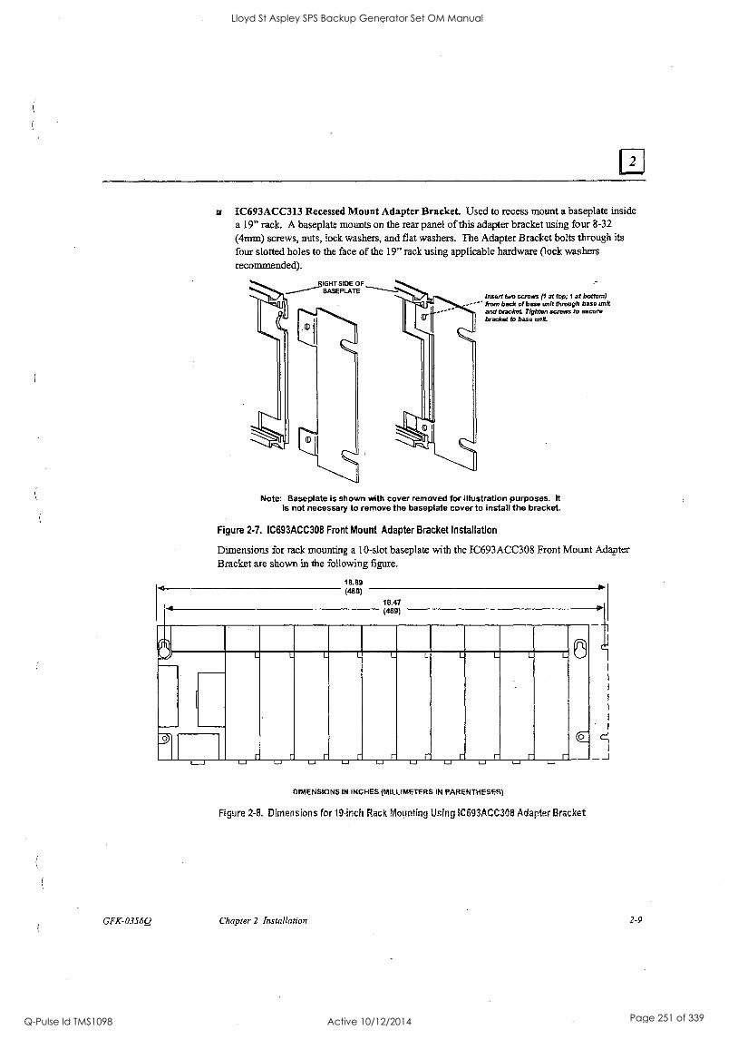
GFK-0356Q
IC693ACC313 Recessed Mount Adapter Bracket. Used to recess mount a baseplate inside a 19" rack. A baseplate mounts on the rear panel of this adapter bracket using four 8-32
(4mm) screws, nuts, lock washers, and flat washers. The Adapter Bracket bolts through its
four slotted holes to the face of the 19" rack using applicable hardware (lock washers recommended).
IGHT SIDE OF BASEPLATE
Insert two screws (1 at top; 1 at bottom) from bad* of base unit through base unit and bracket. Tighten screws to secure bracket to base unit
Note: Baseplate is shown with cover removed for illustration purposes. It is not necessary to remove the baseplate cover to install the bracket.
Figure 2.7. IC693ACC308 Front Mount Adapter Bracket Installation
Dimensions for rack mounting a 10-slot baseplate with the IC693ACC308 Front Mount Adapter Bracket are shown in the following figure.
18.89 (480)
4 (469) p
(
U L-I
DIMENSIONS IN INCHES (MILLIMETERS IN PARENTHESES)
I-J
Figure 2-8. Dimensions for 19-inch Rack Mounting Using 1C693ACC308 Adapter Bracket
J
Chapter 2 Installation 2-9
Lloyd St Aspley SPS Backup Generator Set OM Manual
Q-Pulse Id TMS1098 Active 10/12/2014 Page 251 of 339

zal so (4.041 di& 9 4
0.280(7.1)
3.540(90)
1.900(414)
I I
i I
0.842 (21.4)
16.850 (428)
18.122 (460.3)
I T
4.000 (101.6)
1.38834.7)
DIMENSIONS IN INCHES (MILLIMETERS IN PARENTHESES)
Figure 2-9. 1C693ACC313 Recessed Mount Adapter Bracket
2-10 Series 90-30 PLC Installation and Hardware Manual -August 2002 GFK-0356Q
Lloyd St Aspley SPS Backup Generator Set OM Manual
Q-Pulse Id TMS1098 Active 10/12/2014 Page 252 of 339

Grounding Procedures
System Grounding Procedures
Warning
In addition to the following grounding information, we strongly urge that you follow all applicable codes that apply to your area. For example, in the United States, most areas have adopted the National Electrical Code standard and specify that all wiring conform to its requirements. In other countries, different codes will apply. For maximum safety to personnel and property you must follow these codes. Failure to do so can mean injury or death to personnel, damage to property, or both.
All components of a programmable logic control system and the devices it is controlling must be properly grounded. This is particularly important for the following reasons.
A low resistance path from all parts of a system to earth minimizes exposure to shock in the event of short circuits or equipment malfunction.
a The Series 90-30 PLC system requires proper grounding for correct operation.
Ground Conductors
a Ground conductors should be connected in a tree fashion with branches routed to a central earth ground point, shown in the figure below. This ensures that no ground conductor carries current from any other branch. This method is shown in the following figure.
a Ground conductors should be as short and as large in size as possible. Braided straps or ground cables (typically green insulation with a yellow tracer - AWG #12 (3.3 mm2) or larger) can be used to minimize resistance. Conductors must always be large enough to carry the maximum short circuit current of the path be.ng considered.
PROGRAMMING DEVICE
0
SERIES 90-30 PLC CABINET
RACK -0 RACK H°
MOTOR DRIVES AND OTHER ELECTRICAL CONTROL
EQUIPMENT
EARTH GROUND
Figure 2.10. Recommended System Grounding
CENTRAL GROUND POINT
NOTE SIGNAL AND POWER
CONNECTIONS ARE NOT SHOWN
GFK-0356Q Chapter 2 Installation 2-11
Lloyd St Aspley SPS Backup Generator Set OM Manual
Q-Pulse Id TMS1098 Active 10/12/2014 Page 253 of 339

Series 90-30 PLC Equipment Grounding
Equipment grounding recommendations and procedures are listed below. These grounding procedures must be properly followed for safe, proper operation of your Series 90-30 PLC system.
Baseplate Safety Grounding
The following recommendations are offered, but applicable safety codes for your area or equipment type should also be consulted. The baseplate's metal back must be grounded using a separate conductor; the baseplate mounting screws are not considered to an acceptable ground connection by themselves. Use a minimum AWG #12 (3.3 mm2) wire with a ring terminal and star lock washer under the head of one of the baseplate's two lower mounting holes. These two holes have openings to the side to allow connecting a wire and ring terminal under the head of a mounting screw. Connect the other end of this ground wire to a tapped hole in the panel that the baseplate is
mounted to, using a machine screw, star lock washer, and flat washer. Alternately, if your panel has a ground stud, it is recommended you use a nut and star lock washer for each wire on the ground stud to ensure adequate grounding. Where connections are made to a painted panel, the paint should be removed so clean, bare metal is exposed at the connection point. Terminals and hardware used should be rated to work with the aluminum baseplate material.
AWG #12 or Larger Wire
PROGRAMMABLE CONTROLLER
BARE 64107
11601 PROGRAM AND REGISTER
VALUES MAY BE LOST POWER
SUPPLY O REMOVE° FOR unicyrniAN
MOIR
POWER
0 SUPPLY
CPU/1 .o °
#0.2
NON-CPU SLOTS
1/0.3 110-4 WO-5
0 11-1
o
Screw, Star Lock washer, Flat Washer, Ring Terminal, Installed In tapped hole.
Paint Removed From Panel Here
Figure 2.11. Baseplate Grounding
Warning
Alternate location for Ground connection
All baseplates must he grounded to minimize.electrical shock hazard. Failure to do so can result in severe personal injury.
2-12 Series 90-30 PLC Installation and Hardware Manual - August 2002 GFK-0356Q
Lloyd St Aspley SPS Backup Generator Set OM Manual
Q-Pulse Id TMS1098 Active 10/12/2014 Page 254 of 339
All baseplates grouped together in a Series 90-30 PLC system must have a common ground connection. This is especially important for baseplates that are not mounted in the same control cabinet.
Grounding 19" Rack-Mounted Baseplates
There are two Adapter Brackets used for mounting a 10-slot Series 90-30 baseplate to a 19" Rack. Regardless of which of the two Adapter Brackets is used, the 19" Rack should be grounded as per the instructions in "System Grounding Procedures," including Figure 2-10. (For details on the Adapter Brackets, see the "Mounting a Baseplate to a 19" Rack" section earlier in this chapter.)
Nineteen-Inch Rack-mounted PLC baseplates should be grounded according to the guidelines in the "Baseplate Safety Grounding" section, using a separate ground wire from the PLC baseplate as
shown in the previous figure (Fig. 2-11).
If using the Recessed Mount Adapter Bracket (IC693ACC313), the ground wire can be installed as shown in Figure 2-11 with the ground attached to the Recessed Mount Adapter Bracket An additional ground wire connecting the Adapter Bracket to a solid chassis ground on the 19" Rack should be installed. Use the same or equivalent hardware and paint removal scheme as shown in Figure 2-11.
If using the Surface Mount Adapter Bracket (IC693ACC308), the ground wire should be run from the baseplate as shown in Figure 2-11, to a solid chassis ground on the 19" Rack. Use the same or equivalent hardware and paint removal scheme as shown in Figure 2-11.
Programmer Grounding
For proper operation, the computer (programmer) running the PLC software must have a ground connection in common with the CPU baseplate. Normally, this common ground connection is
provided by ensuring that the programmer's power cord is connected to the same power source (with the same ground reference point) as the baseplate. If it is not possible to ensure this common ground scheme, use a port isolator (IC690ACC903) between the programmer and PLC serial connection. If the programmer ground is at a different potential than the PLC ground, a shock hazard could exist. Also, damage to the ports or converter (if used) could occur when the programmer serial cable is connected between the two.
Warning
Failure to follow programmer grounding recommendations could result in personal injury, equipment damage, or both.
GFK-0356Q Chapter 2 Installation 2-13
Lloyd St Aspley SPS Backup Generator Set OM Manual
Q-Pulse Id TMS1098 Active 10/12/2014 Page 255 of 339

Lloyd St Aspley SPS Backup Generator Set OM Manual
Q-Pulse Id TMS1098 Active 10/12/2014 Page 256 of 339
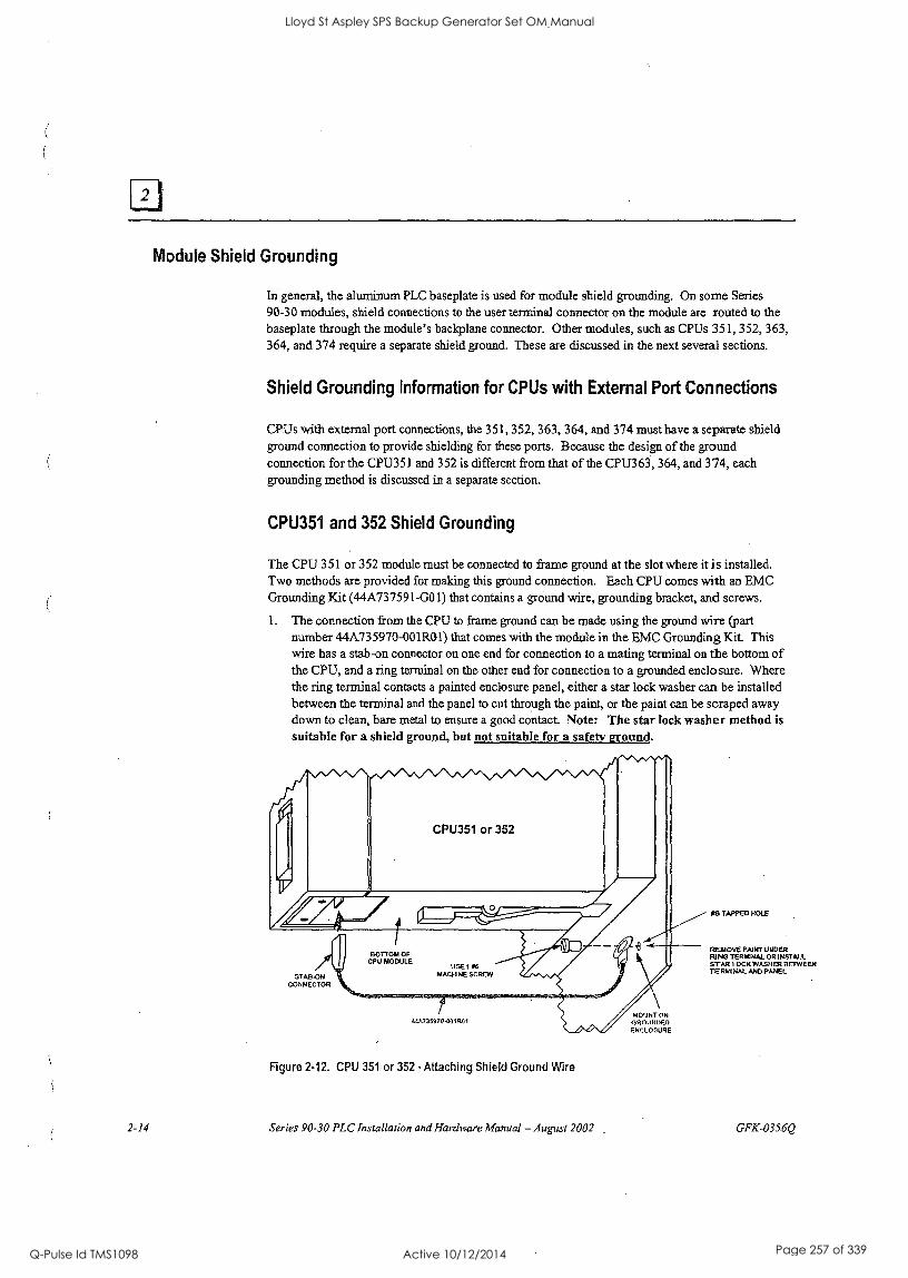
Module Shield Grounding
In general, the aluminum PLC baseplate is used for module shield grounding. On some Series 90-30 modules, shield connections to the user terminal connector on the module are routed to the baseplate through the module's backplane connector. Other modules, such as CPUs 351, 352, 363, 364, and 374 require a separate shield ground. These are discussed in the next several sections.
Shield Grounding Information for CPUs with External Port Connections
CPUs with external port connections, the 351, 352, 363, 364, and 374 must have a separate shield ground connection to provide shielding for these ports. Because the design of the ground connection for the CPU351 and 352 is different from that of the CPU363, 364, and 374, each grounding method is discussed in a separate section.
CPU351 and 352 Shield Grounding
The CPU 351 or 352 module must be connected to frame ground at the slot where it is installed. Two methods are provided for making this ground connection. Each CPU comes with an EMC Grounding Kit (44A737591-G01) that contains a ground wire, grounding bracket, and screws.
1. The connection from the CPU to frame ground can be made using the ground wire (part number 44A735970-001R01) that comes with the module in the EMC Grounding Kit. This wire has a stab-on connector on one end for connection to a mating terminal on the bottom of the CPU, and a ring terminal on the other end for connection to a grounded enclosure. Where the ring terminal contacts a painted enclosure panel, either a star lock washer can be installed between the terminal and the panel to cut through the paint, or the paint can be scraped away down to clean, bare metal to ensure a good contact Note: The star lock washer method is suitable for a shield ground, but not suitable for a safety ground.
STAB ON CONNECTOR
4,335970-MR01
Figure 2-12. CPU 351 or 352 -Attaching Shield Ground Wire
2-14 Series 90-30 PLC Installation and Hardware Manual - August 2002
MOUNT ON GROUNDED ENCLOSURE
*8 TAPPED HOLE
REMOVE PAINT UNDER RING TERMINAL OR INSTALL STAR LOCK WASHER BETWEEN TERMINAL AND PANEL
GFK-0356Q
Lloyd St Aspley SPS Backup Generator Set OM Manual
Q-Pulse Id TMS1098 Active 10/12/2014 Page 257 of 339
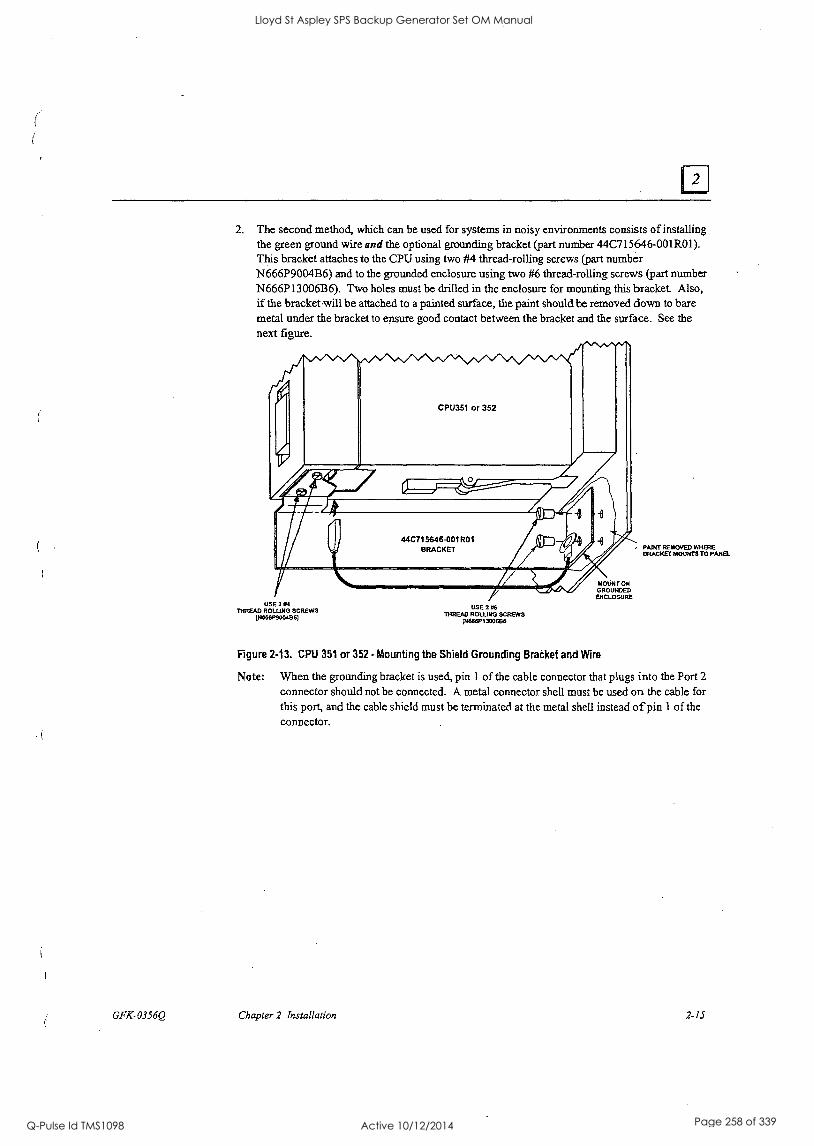
GFK-0356Q
2. The second method, which can be used for systems in noisy environments consists of installing the green ground wire and the optional grounding bracket (part number 44C715646-001R01). This bracket attaches to the CPU using two #4 thread-rolling screws (part number N666P9004B6) and to the grounded enclosure using two #6 thread-rolling screws (part number N666P13006B6). Two holes must be drilled in the enclosure for mounting this bracket Also, if the bracket-will be attached to a painted surface, the paint should be removed down to bare metal under the bracket to ensure good contact between the bracket and the surface. See the next figure.
USE 2 THREAD ROLLING SCREWS
(N6661PKKNB61
USE 2 'MEAD ROLLING SCREWS
IN868P1300886
MOUNT ON GROUNDED ENCLOSURE
PAINT REMOVED WHERE BRACKET MOUNTS TO PANEL
Figure 2.13. CPU 351 or 352 - Mounting the Shield Grounding Bradtet and Wire
Note: When the grounding bracket is used, pin 1 of the cable connector that plugs into the Port 2
connector should not be connected. A metal connector shell must be used on the cable for
this port, and the cable shield must be terminated at the metal shell instead of pin 1 of the connector.
Chapter 2 Installation 2-15
Lloyd St Aspley SPS Backup Generator Set OM Manual
Q-Pulse Id TMS1098 Active 10/12/2014 Page 258 of 339
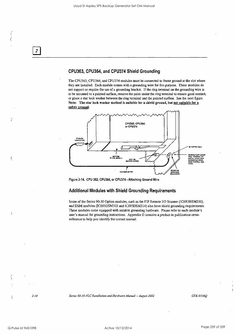
CPU363, CPU364, and CPU374 Shield Grounding
The CPU363, CPU364, and CPU374 modules must be connected to frame ground at the slot where they are installed. Each module comes with a grounding wire for this purpose. These modules do not support or require the use of a grounding bracket. If the ring terminal on the grounding wire is
to be mounted to a painted surface, remove the paint under the ring terminal to ensure good contact, or place a star lock washer between the ring terminal and the painted surface. See the next figure. Note: The star lock washer method is suitable for a shield ground, but not suitable for a
safety 2round.
CPU363, CPU364, or CPU374
BOTTOM OF CPU MOOULE
USE PS
1AACMHE SCREW
Figure 2.14. CPU 363, CPU364, or CPU374 - Attaching Ground Wire
Additional Modules with Shield Grounding Requirements
AG TAPPED HOLE
REMOVE PANT UNDER MHO lERMWAL OR NSTALL ST AR LOCK WASHER BETWEEN ROM TERMINAL AND PANEL
Some of the Series 90-30 Option modules, such as the FIP Remote I/O Scanner (IC693BEM330), and DSM modules (IC693DSM302 and IC693DSM314) also have shield grounding requirements. These modules come equipped with suitable grounding hardware. Please refer to each module's user's manual for grounding instructions. Appendix G contains a product to publication cross- reference to help you identify the correct manual.
2-16 Series 90-30 PLC Installation and Hardware Manual - August 2002 GFK-0356Q
Lloyd St Aspley SPS Backup Generator Set OM Manual
Q-Pulse Id TMS1098 Active 10/12/2014 Page 259 of 339
General Wiring Guidelines
GFK-0356Q
Warning
In addition to the following wiring suggestions, we strongly urge that you follow all wiring and safety codes that apply to your area or your type of equipment. For example, in the United States, most areas have adopted the National Electrical Code standard and specify that all wiring conform to its requirements. In other countries, different codes will apply. For maximum safety to personnel and property you must follow these codes. Failure to do so can lead to personal injury or death, property damage or destruction, or both.
Color Coding Wires
These color codes are commonly used in industrial equipment manufactured in the United States.
They are cited here as a reference. Where they are in conflict with codes that apply to your area or your type of equipment, you should follow your applicable codes instead. Besides satisfying code requirements, wire color coding makes testing and troubleshooting safer, faster, and easier.
a Green or green with stripe- Ground
a Black - Primary AC
a Red - Secondary AC
a Blue -DC
a White - Common or neutral
a Yellow - Secondary power source not controlled by the main disconnect. Alerts maintenance personnel that there may be power present (from an external source) even if the equipment is disconnected from its main power source.
Wire Routing
To reduce noise coupling among PLC wires, it is recommended you keep electrically noisy wiring, such as AC power wiring and Discrete Output Module wiring, physically separated from low-level signal wiring such as DC and Analog Input module wiring or communications cables. This can be accomplished by grouping separately, where practical, the following categories of wiring:
a AC power wiring. This includes the AC input to the PLC power supply, as well as other AC devices in the control cabinet.
a Analog Input or Output Module wiring. This should be shielded to further reduce noise coupling. See the Series 90-301/0 Module Specifications Manual, GFK-0898 for details.
Discrete Output Module wiring. These often switch inductive loads that produce noise spikes when switched off.
a DC Input Module wiring. Although suppressed internally, these low-level inputs should be further protected against noise coupling by observing these wiring practices.
a Communications Cables. Wiring such as Genius Bus or serial cables should be kept away from noise-producing wiring.
Chapter 2 Installation 2-17
Lloyd St Aspley SPS Backup Generator Set OM Manual
Q-Pulse Id TMS1098 Active 10/12/2014 Page 260 of 339

Where AC or Output wiring bundles must pass near noise-sensitive signal wiring bundles, avoid running them beside each other. Route them so that, if they have to cross, they do so at a right angle. This will minimize coupling between them.
Grouping Modules to Keep Wires Segregated
If practical, grouping similar modules together in the PLC racks can help keep wiring segregated. For example, one rack could contain only AC modules, and a different rack only DC modules, with further grouping in each rack by input and output types. For smaller systems, as an example, the left end of a rack could contain Analog modules, the middle could contain DC modules, and the right end could contain AC modules.
Discrete I/O Module Connection Methods
For modules with 16 points or less, the standard method is to use the removable terminal board which comes with these modules. The removable terminal board makes it easy to prewire field wiring to the user supplied input and output devices, and to replace modules in the field without disturbing existing field wiring.
Some discrete 16-point I/O modules can be used with an optional Terminal Block Quick Connect (TBQC) assembly. This assembly contains a module faceplate, with built-in connector, that replaces the removable terminal board. The assembly also contains a DIN-rail mounted terminal block and a cable to connect the module to the terminal block. The advantage of this method is that it saves about two hours of wiring time per module compared with hand wiring from a module's removable terminal board to a user-supplied, panel-mounted terminal block or strip.
a Older 32-point 1/0 modules have one 50-pin connector on the front of the module that is either connected by a cable with a connector on each end to a Weidmuller panel-mounted terminal block (Weidmuller catalog no. 912263), or is connected by a cable with stripped, tinned leads to a user-supplied terminal block or strip.
Newer 32-point I/O modules have two 24-pin connectors on the front of the module. These module may be wired in one of three ways. (1) Use a pair of cables (IC693CBL327/328 - see data sheet in "Cables" chapter) to connect the module to a user-supplied, panel-mounted terminal block or strip. These cables have a 24-pin connector on one end, and stripped, tinned leads with wire markers on the other end. (2) Use a pair of dual-connector cables to connect the module to a Terminal Block Quick Connect (TBQC) terminal block (IC693ACC377). See Appendix H for details. (3) Make your own custom cables. Instructions are found in the IC693CBL327/328 data sheet in Chapter 10.
Connections to I/O Module Terminal Boards
Series.90-30 PLC I/0 terminal boards have either 10 or 20 screw terminals that will accept from two AWG #22 (0.36 mm2) to two AWG #16 (1.3 mm2), or one AWG #14 (2.1 mm2) copper 90°C (194°F) wire(s). Each terminal can accept solid or stranded wires, but the wires into any given terminal should he the same type (both solid or both stranded) to ensure a good connection. Wires are routed to and from the terminals out of the bottom of the terminal board cavity. The suggested torque for the 1/0 terminal board connection screws is from 9.6 in-lbs to 11.5 in-lbs (1.1-1.3 Newton-meters).
2-18 Series 90-30 PLC Installation and Hardware Manual - August 2002 GFK-0356Q
Lloyd St Aspley SPS Backup Generator Set OM Manual
Q-Pulse Id TMS1098 Active 10/12/2014 Page 261 of 339
For 24 volt DC input modules, an internal 24 volt power connection is provided on the terminal board to supply a limited number of input devices. Also, a 24 volt DC output is available on the power supply module's terminal board to supply a limited number of output devices.
Terminal Block Quick Connect Installation for 16-Point Discrete Modules
The Terminal Block Quick Connect (TBQC) Assembly is an option for certain Series 90-30 discrete I/O modules. See Appendix H for more information.
a Remove standard terminafboard from module.
Install TBQC faceplate (it has a 24-pin connector).
Mount the TBQC terminal block. It has a 24-pin connector and a terminal strip, and mounts on a standard 35 nun DIN-rail.
a Connect a TBQC cable between the TBQC faceplate connector on the module and the connector on the TBQC terminal block.
Wire I/O devices to the terminal block.
Installation of 32-Point Discrete, 50-Pin Connector Modules
GFK-0356Q
These 50-Pin modules are an older design and are not generally used on new systems, unless to fulfill standardization requirements. They are mainly used as replacements for existing installations. For new installations, we recommend the dual 24-pin connector style because they have additional features not found on the older modules (LED indicators, TBQC), and it is much easier to fabricate custom-length cables for them. Installation information is provided here for the convenience of those still using these modules.
Using Weidmuller #912263 Terminal Block
Note: The TBQC is not available for these modules, but you may purchase a Weidmuller #912263 from your electronics distributor for this application.
a Mount the Weidmuller#912263 terminal block. It has a 50-pin connector and a terminal strip, and mounts on a standard 35 mm DIN-rail.
a Connect an IC693CBL306/307 cable between the module's fadeplate connector and the connector on the Weidmuller terminal block. See Chapter 10 for cable data.
a Wire I/O devices to the terminal block. See the Series 90-30 PLC 1/0 Module Specifications Manual, GFK-0898, for pin-out information.
Chapter 2 Installation 2-19
Lloyd St Aspley SPS Backup Generator Set OM Manual
Q-Pulse Id TMS1098 Active 10/12/2014 Page 262 of 339
Using a Generic Terminal Block or Strip
Mount terminal block/strip to the enclosure panel.
Connect an 1C693CBL308 or 309 cable, or a custom made cable, to the module's faceplate connector and wire the stripped ends of the cable to the terminal block/strip. See Chapter 10
for cable data.
® Wire 110 devices to the terminal block/strip.
Direct Method
Connect an IC693CBL308 or 309 cable, or a custom made cable, to the module's faceplate connector and wire the stripped ends of the cable directly to the field devices. See Chapter 10
for cable data. See the Series 90-30 PLC I/0 Module Specifications Manual, GFK-0898, for pin-out information.
Installation of Discrete 32-Point, Dual 24-Pin Connector Modules
Using a TBQC
Mount two TBQC terminal blocks. Each has a 24-pin connector and a terminal strip, and mounts on a standard 35 mm DIN -rail.
Connect a pair of TBQC cables (IC693CBL329 - 334) between the module's faceplate connector and the connectors on the two TBQC terminal blocks. Note that both a right side and left side cable is required. See Appendix H for a list of cables.
Wire 110 devices to the terminal blocks. See the Series 90-30 PLC I/O Module Specifications Manual, GFK-0898, for pin-out information.
The Terminal Block Quick Connect (TBQC) Assembly is an option for certain Series 90-30 discrete 1/0 modules. See Appendix H for more information.
With a Generic Terminal Block/Strip
Mount terminal block/strip to the enclosure panel.
o Connect an IC693CBL327/328 cables, or a custom made cables, to the module's faceplate connectors, and wire the stripped ends of the cables to the terminal block/strip. Note that both a right side and left side cable is required. See Appendix 11 for a list of cables. See Chapter 10 for cable data sheets.
Wire I/O devices to the terminal block/strip. See the Series 90-30 PLC 1/0 Module Specifications Manual, GFK-0898, for pin-out information.
2-20 Series 90-30 PLC Installation and Hardware Manual - August 2002 GFK-0356Q
Lloyd St Aspley SPS Backup Generator Set OM Manual
Q-Pulse Id TMS1098 Active 10/12/2014 Page 263 of 339
Direct Method
Connect an IC693CBL327/328 cable, or a custom made cable, to the module's faceplate connectors, and wire the stripped ends of the cable directly to the field devices. See Chapter 10 for cable data. See the Series 90-30 PLC I/O Module Specifications Manual, GFK-0898, for pin-out information.
General Wiring Methods for Analog Modules
Twisted, shielded instrumentation cable is strongly recommended for analog module input or output signal connections. Proper grounding of the shield is also important. For maximum electrical noise suppression, the cable shield should only be grounded at one end of the cable. For Input modules, ground the end that is in the noisiest environment (which often is at the field device end). For Output modules, ground at the module end. See GFK-0898, Series 90-30 PLC I/O Module Specifications, for more shield grounding information.
Analog Input Module Wiring Methods
GFK-0356Q
Correcting electrical noise problems can sometimes be a trial-and-error routine. However, in
general, it is generally best to ground the cable shield as close to the source of the noise as possible, which is usually at the device end. In troubleshooting noise problems, sometimes it is beneficial to experiment with the shield grounding point location. Remember, the cable shield should be grounded at one end only. Also, it is best to keep the length of stripped cable leads as short as possible to minimize the length of unshielded conductors that will be exposed to the noisy environment. See the Series 90-30 PLC I/O Module Specifications Manual, GFK-0898 for additional details.
Using a Generic Terminal Block or Strip
Mount a terminal strip inside the control enclosure and run a shielded cable from the terminal strip to each input circuit on the module's terminal board terminals.
Ea Connect each cable's shield to the metal panel next to the terminal strip. Do not connect the shields at the module end (cut shield off at module end of cable and insulate with shrink tubing).
Wire the field device to the terminal strip with a shielded cable, grounding the shield at the device end only (cut shield off at terminal strip end of cable and insulate with shrink tubing). Also, keep the length of exposed (outside of shield) leads at the terminal strip and device ends as short as possible.
Direct Method
Run a shielded cable from the field device (transducer, potentiometer, etc.) directly to the module.
ra Connect the conductors to the applicable screws on the module's terminal board.
Chapter 2 Installation 2-21
Lloyd St Aspley SPS Backup Generator Set OM Manual
Q-Pulse Id TMS1098 Active 10/12/2014 Page 264 of 339
Ground the shield at the field device end, exposing a minimum amount of conductor to the noisy environment. Do not connect the shield at the module end (cut shield off at module end of cable and insulate with shrink tubing).
TBQC not Recommended for Analog Modules
The Terminal Block Quick Connect (TBQC) Assembly is not recommended for use with analog modules due to cable shielding requirements.
Analog Output Module Wiring
General
Each output should be connected using a good quality shielded wire with the cable shield grounded at the module end. See GFK -0898, Series 90-30 PLC I/O Module Specifications, for more information.
Using a Generic Terminal Block or Strip
Mount a terminal strip inside the control enclosure and run a shielded cable from the terminal strip to each output circuit on the module's terminal board terminals.
Ground each cable's shield at the module end only. Do not connect the shields at the terminal strip end (cut shields off at terminal strip end of cables and insulate with shrink tubing).
a Wire the field device to the terminal strip with shielded cables, grounding the shields at the terminal strip end only (cut shields off at field device end of cables and insulate with shrink tubing). Also, keep the length of exposed (outside of shield) leads at the terminal strip and device ends as short as possible.
Direct Method
o Run a shielded cable from each field device (transducer, potentiometer, etc.) directly to the module.
o Connect the conductors to the applicable screws on the module's terminal board.
Ea Ground the shield at the module end only, exposing a minimum amount of conductor to the noisy environment. Do not connect the shield at the device end (cut shield off at device end of cable and insulate with shrink tubing).
TBQC not Recommended for Analog Modules
The Terminal Block Quick Connect (TBQC) Assembly is not recommended for use with analog modules due to cable shielding requirements.
2-22 Series 90-30 PLC Installation and Hardware Manual - August 2002 GFK-0356Q
Lloyd St Aspley SPS Backup Generator Set OM Manual
Q-Pulse Id TMS1098 Active 10/12/2014 Page 265 of 339
AC Power Source Connections
AC Input Wiring to AC/DC Power Supplies
GFK-0356Q
Warning
If the same AC power source is used to provide AC power to other baseplates in a Series 90-30 PLC System, ensure that all AC input connections are identical at each rack. Do not cross Line 1 (L1) and Line 2 (L2). A resulting difference in potential can injure personnel or cause damage to equipment. Each baseplate must be connected to a common ground.
Ensure that the protective cover is installed over all terminal boards. During normal operation with an AC power source either 120 VAC or 240 VAC is present on the AC Power Supply. The cover protects against accidental shock hazard which could cause severe or fatal injury to the operator or maintenance personnel.
Both the Standard (IC693PWR321) and High Capacity (IC693PWR330) AC/DC power supplies currently have six terminals for user connections. Early versions of some Series 90-30 power supplies had five terminals (see next figure). The wiring methods for both five-terminal and six- terminal types is similar, except that step 3 below does not apply to the five-terminal type.
The power supply terminal boards will accept one AWG #14 (2.1 mm2) or two AWG #16 (1.3
mm2) copper 75_ C (167_ F) wires. Each terminal can accept solid or stranded wires, but the wires in any given terminal should be the same type. The suggested torque for the power supply terminal board is 12 in-lbs (1.36 Newton-meters). Open the door protecting the terminal board and make the following connections from the AC power source, and ground connections (system grounding requirements are described in detail later in this chapter).
1. These are wide range supplies that can operate from an AC power source within the nominal range of 100 VAC to 240 VAC at 50/60 Hz. This may vary -15% to +10% for a total maximum range of 85 VAC to 264 VAC. These are auto-ranging supplies that do not require jumper or switch settings for selection of power source voltage.
2. Connect the hot and neutral wires or lines Ll and L2 to the upper two terminals on the terminal board. Connect the safety ground wire to the ground terminal, which is the third terminal from the top, and is marked with a ground symbol.
3. For power supplies with six terminals, the factory jumper between the 3rd and 4th terminals (see figure below), should be left in place for normal installations. However, this jumper must be removed and external surge suppressors installed in installations with a "Floating Neutral" input. Please see the section "Special Instructions for Floating Neutral (IT) Systems" later in this chapter for details.
4. After all connections to Power Supply terminal board have been completed, the protective cover plate should be carefully reinstalled.
Chapter 2 Installation 2-23
Lloyd St Aspley SPS Backup Generator Set OM Manual
Q-Pulse Id TMS1098 Active 10/12/2014 Page 266 of 339
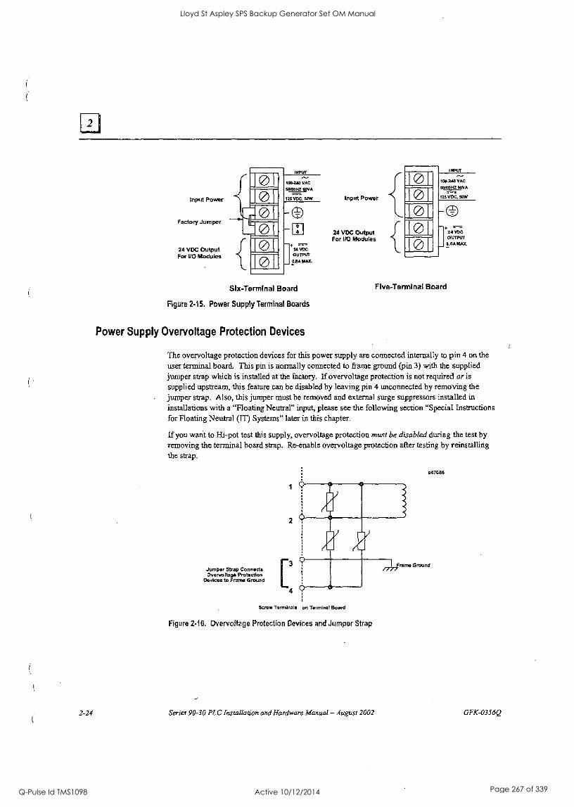
Input Power
Factory Jumper
24 VDC Output For I/O Modules
0 0
Pam
fa 0
INPUT
100240 VAC
50150HZ 90VA
125 VDC, 50W
(ED
24 VDC
OUTPUT
0.84 11142.
Slx-Terminal Board
Figure 2-15. Power Supply Terminal Boards
Power Supply Overvoltage Protection Devices
Input Power
24 VDC Output For I/O Modules
0 0 0
0
INPUT
100.240 VAC
511100HZ 90VA
125 VDC, 50W
24 VDC OUTPUT
0.134 MAX
Five - Terminal Board
The overvoltage protection devices for this power supply are connected internally to pin 4 on the user terminal board. This pin is normally connected to frame ground (pin 3) with the supplied jumper strap which is installed at the factory. If overvoltage protection is not required or is supplied upstream, this feature can be disabled by leaving pin 4 unconnected by removing the jumper strap. Also, this jumper must be removed and external surge suppressors installed in
installations with a "Floating Neutral" input, please see the following section "Special Instructions for Floating Neutral (IT) Systems" later in this chapter.
If you want to Hi-pot test this supply, overvoltage protection must be disabled during the test by removing the terminal board strap. Re-enable overvoltage protection after testing by reinstalling the strap.
Jumper Strap Connects Overvoltage Protection
Devices to Frame Ground
4
847086
Screw Terminals on Terminal Board
Figure 2-16. Overvoltage Protection Devices and Jumper Strap
2-24 Series 90-30 PLC Installation and Hardware Manual - August 2002 GFK-0356Q
Lloyd St Aspley SPS Backup Generator Set OM Manual
Q-Pulse Id TMS1098 Active 10/12/2014 Page 267 of 339
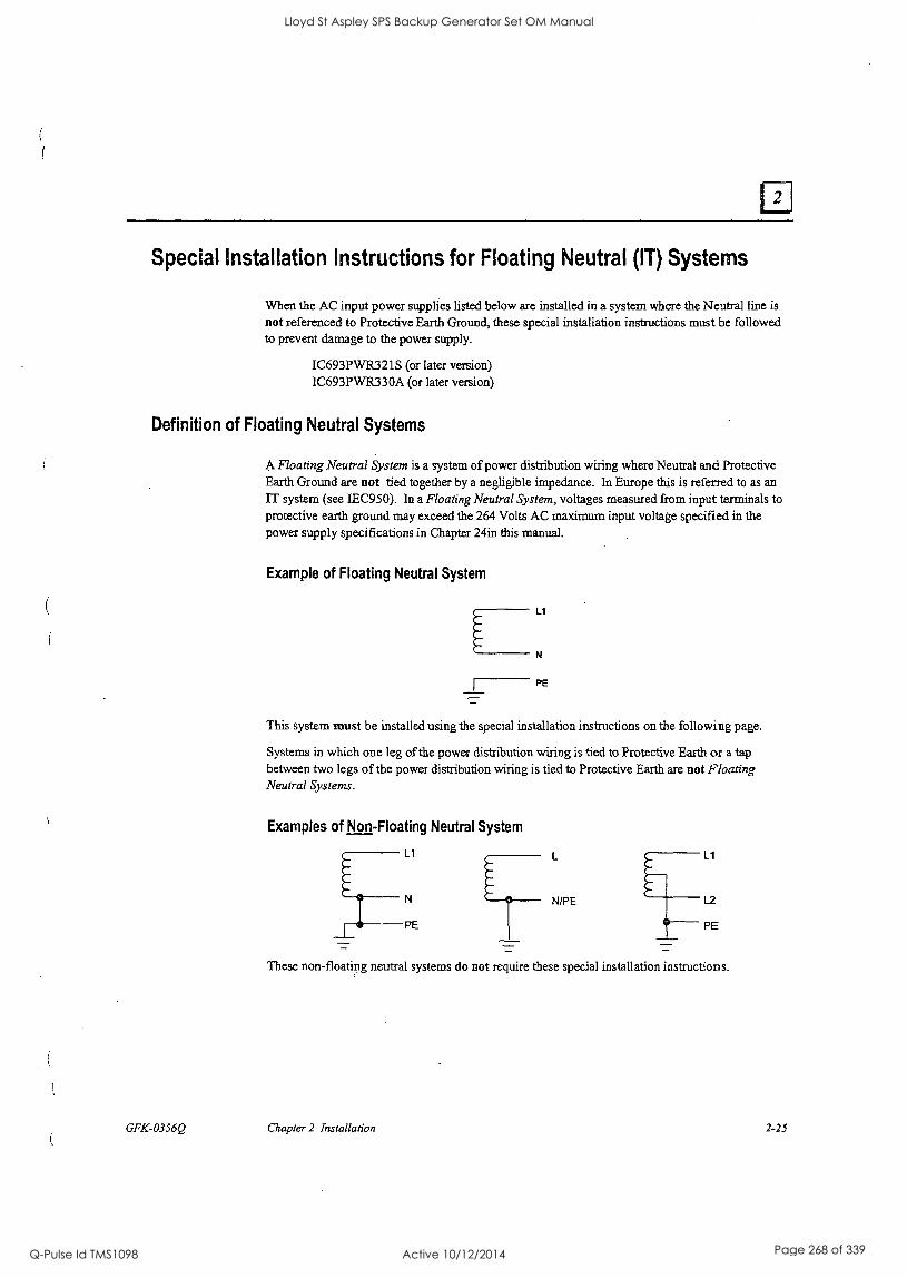
Special Installation Instructions for Floating Neutral (IT) Systems
When the AC input power supplies listed below are installed in a system where the Neutral line is
not referenced to Protective Earth Ground, these special installation instructions must be followed to prevent damage to the power supply.
IC693PWR321S (or later version) 1C693PWR330A (or later version)
Definition of Floating Neutral Systems
A Floating Neutral System is a system of power distribution wiring where Neutral and Protective Earth Ground are not tied together by a negligible impedance. In Europe this is referred to as an IT system (see IEC950). In a Floating Neutral System, voltages measured from input terminals to protective earth ground may exceed the 264 Volts AC maximum input voltage specified in the power supply specifications in Chapter 24in this manual.
Example of Floating Neutral System
Ll
N
PE
This system must be installed using the special installation instructions on the following page.
Systems in which one leg of the power distribution wiring is tied to Protective Earth or a tap between two legs of the power distribution wiring is tied to Protective Earth are not Floating Neutral Systems.
Examples of Non-Floating Neutral System
Ll Ll
L2
PE PE
These non-floating neutral systems do not require these special installation instructions.
GFK-0356Q Chapter 2 Installation 2-25
Lloyd St Aspley SPS Backup Generator Set OM Manual
Q-Pulse Id TMS1098 Active 10/12/2014 Page 268 of 339
Use These Special Installation Instructions for Floating Neutral Systems
1. The input power terminals should be wired according to the instructions in the "AC Power Source Connections" section of this chapter.
2. The factory installed jumper between terminals 3 and 4 of the Power Supply module must be
removed if using one of the Power Supplies that have this feature. See the "Overvoltage Protection Devices" section of the "Power Supplies" chapter for details.
3. Voltage surge protection devices, such as MOVs, MUST be installed between the following terminals:
ri From Ll to earth ground
From L2 (Neutral) to earth ground
The voltage surge devices must be rated such that the system is protected from power line transients that exceed Line voltage + 100V +(N-PE)A4cy.
The expression N-PE refers to the voltage potential between neutral and Protective Earth (PE) ground.
For example, in a 240 Volt AC system with neutral floating 50V above earth ground, the transient protection should be rated at:
240V + 100y +50V = 390V
2-26 Series 90-30 PLC Installation and Hardware Manual - August 2002 GFK-0356Q
Lloyd St Aspley SPS Backup Generator Set OM Manual
Q-Pulse Id TMS1098 Active 10/12/2014 Page 269 of 339
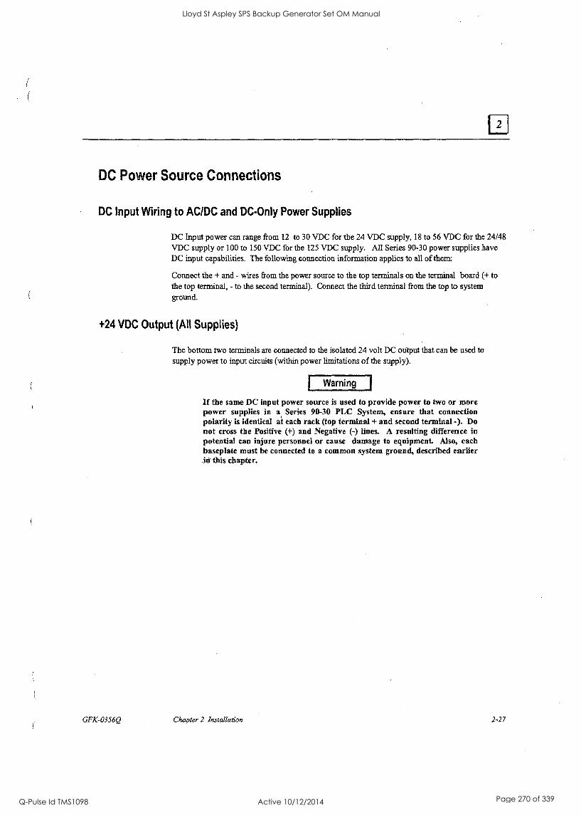
DC Power Source Connections
DC Input Wiring to AC/DC and DC-Only Power Supplies
DC Input power can range from 12 to 30 VDC for the 24 VDC supply, 18 to 56 VDC for the 24/48 VDC supply or 100 to 150 VDC for the 125 VDC supply. All Series 90-30 power supplies have DC input capabilities. The following connection information applies to all of them:
Connect the + and - wires from the power source to the top terminals on the terminal board (+ to the top terminal, - to the second terminal). Connect the third terminal from the top to system ground.
+24 VDC Output (All Supplies)
GFK-0356Q
The bottom two terminals are connected to the isolated 24 volt DC output that can be used to supply power to input circuits (within power limitations of the supply).
Warning
If the same DC input power source is used to provide power to two or more power supplies in a Series 90-30 PLC System, ensure that connection polarity is identical at each rack (top terminal + and second terminal -). Do not cross the Positive (+) and Negative (-) lines. A resulting difference in potential can injure personnel or cause damage to equipment. Also, each baseplate must be connected to a common system ground, described earlier in' this chapter.
Chapter 2 Installation 2-27
Lloyd St Aspley SPS Backup Generator Set OM Manual
Q-Pulse Id TMS1098 Active 10/12/2014 Page 270 of 339
Basic Installation Procedure
Note: Series 90-30 PLCs must be mounted in a protective enclosure. The enclosure should be capable of properly dissipating the heat produced by all of the devices mounted inside it. For details on calculating heat dissipation, refer to Appendix F.
The system design, which includes producing the layout and wiring drawings, should be completed before beginning the installation procedure. This section offers a basic step-by-step approach to
installing a Series 90-30 PLC system. Some steps refer to earlier sections of this chapter for additional details. An attempt was made to place the steps in an order that will make the process as
efficient as possible. However, due to the wide variance in system designs, this order may not be the most efficient for your system, so you may wish modify this procedure to fit your needs.
1. Gather the schematics, layouts, prints, and other information for the job.
Warning
To avoid the possibility of electrical shock to personnel or damage to your PLC, we recommend that you shut off all power to the system before mounting and wiring the PLC. Also, keep all electronic components away from the area while drilling and tapping to keep metal chips and filings out of these sensitive components.
2. From the layout drawing, determine where the baseplate(s) will be mounted. Lay out the hole locations, either using the dimensions given on your layout drawing or from the "Baseplates" chapter of this manual.
3. Mark the hole locations for the baseplate safety ground wire (see "Baseplate Safety Ground" in
this chapter).
4. Mark the hole locations for module shield ground connections (if any). See "Module Shield Ground" (and accompanying sections) in this chapter for instructions.
5. Finish laying (marking hole locations) out the rest of the system. This includes any terminal blocks you will be using. DIN-rail mounted terminal blocks for some of the 32-point I/0 modules are manufactured by Weidmuller. DIN-rail mounted GE Fanuc Terminal Block Quick Connect (TBQC) assemblies are optional for some of the 16-point and 32-point discrete 1./0 modules. If using these TBQCs, refer to Appendix H for data. Also, APM and DSM modules use DIN-rail mounted terminal blocks.
Note
We recommend drilling and tapping all holes before mounting any components. This will avoid getting chips and filings in the components.
6. Drill and tap the marked holes. For baseplate mounting, use 8-32 or 4mm size.
7. Mount the baseplates. Use good quality 8-32 x 1/2 inch or 4 x 12mm size screws. We recommend using star lock washers and flat washers under the screw heads (star lock washer should be located between screw head and flat washer) to ensure a tight baseplate ground connection, and to keep the screws from loosening. Connect each base-plate ground wire as shown in the "Baseplate Safety Ground" section of this chapter.
8. If you have Expansion or Remote racks, determine the correct rack number for each one, then set the rack numbers using the Rack Number Selection dual in-line package (DIP) switch on
2-28 Series 90-30 PLC Installation and Hardware Manual - August 2002 GFK-0356Q
Lloyd St Aspley SPS Backup Generator Set OM Manual
Q-Pulse Id TMS1098 Active 10/12/2014 Page 271 of 339

GFK-0356Q
the baseplate. Please refer to the "Baseplates" chapter for details on setting these DIP switches. Rack numbers should be assigned by the system programmer because they correspond to system configuration settings and program memory addressing.
9. If you have more than one baseplate (rack), connect the I/O Bus Expansion Cables between the I/O Bus Expansion Connectors, which are located on the right end of the baseplates. The cables are connected in a "daisy-chain" arrangement from one baseplate to the other. This is
made possible by the fact that the cables have a dual connector on one end. Therefore, when the cable is plugged into a baseplate connector, the second connector on that end of the cable provides a socket for connecting to the next cable. The data sheet for the I/0 Bus Expansion cables (IC693CBL300 etc.) in the "Cables" chapter has sample wiring figures.
10. On the last I/O Bus Expansion Connector, plug in an I/O Bus Expansion Terminator, Catalog Number IC693ACC307 (unless using a cable with built-in terminator resistors, which would either be GE Fanuc cable IC693CBL302, or your own custom-built cable).
11. Install the modules in their correct slots using your system layout drawings. (The label on the side of each module identifies the module type and catalog number.) Refer to the section "Installing Modules" if you are not familiar with how to do this.
12. Connect cables to Option modules. Route cables away from noise-producing wires. See the
'Wire Routing" section of this chapter.
13. Be sure to follow the information in the 'Wiring Guidelines" section of this chapter to protect the system from electrical noise. Install the power wires to the Power Supply and I/0 modules:
I/O modules with removable terminal boards. You can wire the terminal boards in- place on the modules or remove them from the modules before wiring. Although removing them may help make wiring easier (a previous section "Working with Removable Terminal Boards" shows how to remove a terminal board), care should be taken to avoid mixing them (each terminal board has the catalog number of the module printed on it, and the hinged cover has a wiring diagram for that module type). If you are using wire duct, routing each module's wires through the opening in the duct directly under the module will help to keep each terminal board in its correct position.
I/O Modules with terminal blocks. Some modules use terminal blocks that mount to the enclosure panel. This includes all 32-point modules and, can include other VO modules if they are fitted with the optional Terminal Block Quick Connect Assembly. Connect the terminal blocks to the connectors on the modules with the provided cables.
14. Connect the signal (switches, sensors, solenoids, etc.) wires to the terminal boards, or terminal blocks/strips. If wiring to terminal boards, these can be removed for ease of wiring, if desired. See the section "Removing a Module's Terminal Board."
15. When finished wiring the I/0 terminal boards (if used and if you removed them for ease of wiring), re-install them on the modules, being careful to match each one with the correct module.
Chapter 2 Installation 2-29
Lloyd St Aspley SPS Backup Generator Set OM Manual
Q-Pulse Id TMS1098 Active 10/12/2014 Page 272 of 339

II
II
Lloyd St Aspley SPS Backup Generator Set OM Manual
Q-Pulse Id TMS1098 Active 10/12/2014 Page 273 of 339

e
e
o
Lloyd St Aspley SPS Backup Generator Set OM Manual
Q-Pulse Id TMS1098 Active 10/12/2014 Page 274 of 339

5INCII1111
POWER
DIESEL STANDBY GENERATOR LOCAL CONTROL PANEL
FUNCTIONAL DESCRIPTION For
BRISBANE CITY COUNCIL
At
BRISBANE WATER SEWAGE PUMP STATION ASPLEY - LLOYD STREET
August 2007
16041 Brisbane Water Functional Description Page I of 14
Lloyd St Aspley SPS Backup Generator Set OM Manual
Q-Pulse Id TMS1098 Active 10/12/2014 Page 275 of 339

e
ABBREVIATIONS
G1 Generator 1 Diesel
16041 Brisbane Water Functional Description Page 2 of 14
Lloyd St Aspley SPS Backup Generator Set OM Manual
Q-Pulse Id TMS1098 Active 10/12/2014 Page 276 of 339

POWER
1. GENERAL
1.1. The PLC for the above operation is a GE Fanuc IC693CPU350. This program has been designed for the use on G1. The operation below controls G1.
1.2. A mode selector switch selects how G1 shall operate :
1.2.1. Off
1.2.2. Manual Mode
1.2.3. Test Mode.
1.2.4. Automatic Mode.
2. MANUAL MODE
2.1. To operate G1 in MANUAL Mode.
2.2. Select this operation by turning the AUTO - TEST - MAN- OFF selector switch to the MANUAL position.
2.3. Press the MANUAL START push button to start the generator.
2.4. The generator will begin to crank.
2.4.1. If it fails to start within the 10 seconds, the starter motor is stopped and a delay of 10 seconds before it will attempt to restart.
2.4.2. The generator set is allowed 3 attempts to start.
2.4.3. If it fails to start on the third attempt, the generator is locked out on FAIL TO START Alarm.
2.4.4. When the generator starts, the starter motor is stopped by a stop cranking input which measures the speed of the generator.
2.4.5. Once the generator has started, there is a 10 second time delay for the oil pressure to stabilise.
2.4.6. If the oil pressure is not up to pressure after the 10 second time delay, the generator shall shut down on LOW OIL PRESS Alarm.
2.4.7. Once the generator is running there is a 5 second warm up time before it is ready to accept load.
16041 Brisbane Water Functional Description Page 3 of 14
Lloyd St Aspley SPS Backup Generator Set OM Manual
Q-Pulse Id TMS1098 Active 10/12/2014 Page 277 of 339

POWER
2.5. To Manual Transfer to Generator in the MANUAL Mode.
2.5.1. Start the generator and wait for the generator to run up to speed and voltage and ready to accept load.
2.5.2. Press the MANUAL TRANSFER TO GEN push button.
2.5.3. The MAINS ATS shall Open.
2.5.4. After a 30 second delay the GEN ATS shall Close.
2.5.5. If the MAINS ATS fails to Open.
2.5.5.1.After a 5 second delay an Alarm shall be generated and the MAINS CONNECTED indicator shall flash to indicate the Alarm.
2.5.5.2. The system shall return back to MAINS ATS operation.
2.5.6. If the GEN ATS fails to Close.
2.5.6.1. After a 5 second delay an Alarm shall be generated and the GENERATOR CONNECTED indicator shall flash to indicate the Alarm.
2.5.6.2. The system shall return back to MAINS ATS operation.
2.6. To Manual Transfer to Mains in the MANUAL Mode.
2.6.1. The GENERATOR ATS is Closed.
2.6.2. Press the MAN TRANSFER TO MAINS push button.
2.6.3. The GEN ATS shall Open.
2.6.4. After a 30 second delay the MAINS ATS shall Close.
2.6.5. If the GEN ATS fails to Open.
2.6.5.1. After a 5 second delay an Alarm shall be generated and the GENERATOR CONNECTED indicator shall flash to indicate the Alarm.
2.6.5.2. The system shall return back to GEN ATS operation.
2.6.6. If the MAINS ATS fails to Close.
2.6.6.1. After a 5 second delay an Alarm shall be generated and the MAINS CONNECTED indicator shall flash to indicate the Alarm.
16041 Brisbane Water Functional Description Page 4 of 14
Lloyd St Aspley SPS Backup Generator Set OM Manual
Q-Pulse Id TMS1098 Active 10/12/2014 Page 278 of 339
2.6.6.2. The system shall return back to GEN ATS operation.
2.7. To stop the generator in the MANUAL Mode.
2.7.1. When the generator is running, it may be stopped by pressing the MANUAL STOP push button.
2.7.2. If the generator is still GEN ATS operation. The MANUAL TRANSFER TO MAINS is initiated.
2.7.3. When the GEN ATS is Open, the generator will enter the cool down time of 1 second.
2.7.4. After the cool down time, the generator will shut down.
2.7.5. Once the generator has shut down there is a 15 second delay before it may be restarted. This is to ensure the engine has mechanically stopped.
16041 Brisbane Water Functional Description Page 5 of 14
Lloyd St Aspley SPS Backup Generator Set OM Manual
Q-Pulse Id TMS1098 Active 10/12/2014 Page 279 of 339

-
POWER
3. NON-PERMANENT SITE, MANUAL MODE
3.1. To operate G1 in a Non-Permanent Site Location in MANUAL Mode.
3.2. Connect the generator cables to the site generator CB ensuring the site generator CB is OFF. See BCC procedures.
3.3. A plug with shorting links is required to be installed. It is required to be plugged into the 27 Pin Station Plug.
3.3.1. Pins 11 and 12 are required to be connected. This is to indicate that the Mains ATS is Closed. If they are not connected a MAINS ATS Alarm shall be indicated.
3.4. Select from the AUTO - TEST - MAN- OFF selector switch to the MANUAL position.
3.5. Press the MANUAL START push button to start the generator.
3.6. The generator will begin to crank.
3.6.1. If it fails to start within the 10 seconds, the starter motor is stopped and a delay of 10 seconds before it will attempt to restart.
3.6.2. The generator set is allowed 3 attempts to start.
3.6.3. If it fails to start on the third attempt, the generator is locked out on FAIL TO START Alarm.
3.6.4. When the generator starts, the starter motor is stopped by a stop cranking input which measures the speed of the generator.
3.6.5. Once the generator has started, there is a 10 second time delay for the oil pressure to stabilise.
3.6.6. If the oil pressure is not up to pressure after the 10 second time delay, the generator shall shut down on LOW OIL PRESS Alarm.
3.6.7. Once the generator is running there is a 5 second warm up time before it is ready to accept load.
3.7. To connect the generator to the site load.
3.7.1. Manually switch over to the generator supply via the site CB's. See BCC procedures.
16041 Brisbane Water Functional Description Page 6 of 14
Lloyd St Aspley SPS Backup Generator Set OM Manual
Q-Pulse Id TMS1098 Active 10/12/2014 Page 280 of 339
OSLIM POWER R
3.7.2. Do not use the MANUAL TRANSFER TO GEN or the MAN TRANSFER TO MAINS push buttons.
3.8. To disconnect the generator from the site load.
3.8.1. Manually switch over to the mains supply via the site CB's. See BCC procedures.
3.8.2. Do not use the MANUAL TRANSFER TO GEN or the MAN TRANSFER TO MAINS push buttons.
3.9. To stop the generator in the MANUAL Mode.
3.9.1. When the generator is running, it may be stopped by pressing the MANUAL STOP push button.
3.9.2. The generator will enter the cool down time of 1 second.
3.9.3. After the cool down time, the generator will shut down.
3.9.4. Once the generator has shut down there is a 15 second delay before it
may be restarted. This is to ensure the engine has mechanically stopped.
16041 Brisbane Water Functional Description Page 7 of 14
Lloyd St Aspley SPS Backup Generator Set OM Manual
Q-Pulse Id TMS1098 Active 10/12/2014 Page 281 of 339

4. TEST OPERATION
4.1. To operate the generator in the TEST Mode.
4.2. Select this operation by turning the AUTO - TEST - MAN- OFF selector switch to the TEST position.
4.3. If the selector is changed to MAN while the generator is operating on TEST, the system shall change to MANUAL TRANSFER TO GEN.
4.4. The generator shall begin to crank.
4.4.1. If it fails to start within the 10 seconds, the starter motor is stopped and a delay of 10 seconds before it will attempt to restart.
4.4.2. The generator is allowed 3 attempts to start.
4.4.3. If it fails to start on the third attempt, the generator is faulted on FAIL TO START Alarm.
4.5. When the generator starts, the starter motor is stopped by a stop cranking input which measures the speed of the generator.
4.6. The MAINS ATS shall Open.
4.7. Once the generator has started, there is a 10 second time delay for the oil pressure to stabilise.
4.8. If the oil pressure is not up to pressure after the 10 second time delay, the generator shall shut down on LOW OIL PRESS Alarm.
4.9. Once the generator is running there is a 5 second warm up time before it is
ready to accept load.
4.10. After the warm up time has expired and the MAINS ATS has been open for 30 seconds the GEN ATS shall Close.
4.11. If the MAINS ATS fails to Open.
4.11.1. After a 5 second delay an Alarm shall be generated and the MAINS CONNECTED indicator shall flash to indicate the Alarm.
4.11.2. The system shall shut down and return back to MAINS ATS operation.
4.12. If the GEN ATS fails to Close.
16041 Brisbane Water Functional Description Page 8 of 14
Lloyd St Aspley SPS Backup Generator Set OM Manual
Q-Pulse Id TMS1098 Active 10/12/2014 Page 282 of 339

4.12.1. After a 5 second delay an Alarm shall be generated and the GENERATOR CONNECTED indicator shall flash to indicate the Alarm.
4.12.2. The system shall shut down and return back to MAINS ATS operation.
4.13. To stop the generator in the TEST Mode.
4.13.1. Select this operation by turning the AUTO - TEST - MAN- OFF selector switch to the AUTO or OFF position.
4.13.2. The GEN ATS shall Open.
4.13.3. After a 30 second delay the MAINS ATS shall Close.
4.13.4. If the GEN ATS fails to Open.
4.13.4.1. After a 5 second delay an Alarm shall be generated and the GENERATOR CONNECTED indicator shall flash to indicate the Alarm.
4.13.4.2. The system shall return back to GEN ATS operation.
4.13.5. If the MAINS ATS fails to Close.
4.13.5.1. After a 5 second delay an Alarm shall be generated and the MAINS CONNECTED indicator shall flash to indicate the Alarm.
4.13.5.2. The system shall return back to GEN ATS operation.
4.13.6. When the GEN ATS is Open, the generator will enter the cool down time of 5 minutes.
4.13.7. After the cool down time, the generator will shut down.
4.13.8. If a Mains Failure occurs during the cool down period the generator shall transfer back to the GENERATOR ATS without shutting down.
4.13.9. Once the generator has shut down there is a 15 second delay before it may be restarted. This is to ensure the engine has mechanically stopped.
16041 Brisbane Water Functional Description Page 9 of 14
Lloyd St Aspley SPS Backup Generator Set OM Manual
Q-Pulse Id TMS1098 Active 10/12/2014 Page 283 of 339

POWER
5. AUTOMATIC OPERATION
5.1. To operate the generator in the AUTO Mode.
5.2. Select this operation by turning the AUTO - TEST - MAN- OFF selector switch to the AUTO position.
5.3. The Phase Failure Relay from the clients switch board shall give a Start Signal for the generators to run.
5.4. The Remote Start Command.
5.4.1. The generator shall begin to crank.
5.4.1.1. If it fails to start within the 10 seconds, the starter motor is
stopped and a delay of 10 seconds before it will attempt to restart.
5.4.1.2. The generator is allowed 3 attempts to start.
5.4.1.3. If it fails to start on the third attempt, the generator is faulted on FAIL TO START Alarm.
5.4.2. When the generator starts, the starter motor is stopped by a stop cranking input which measures the speed of the generator.
5.4.3. The MAINS ATS shall Open.
5.4.4. Once the generator has started, there is a 10 second time delay for the oil pressure to stabilise.
5.4.5. If the oil pressure is not up to pressure after the 10 second time delay, the generator shall shut down on LOW OIL PRESS Alarm.
5.4.6. Once the generator is running there is a 5 second warm up time before it is ready to accept load.
5.4.7. After the warm up time has expired and the MAINS ATS has been open for 30 seconds the GEN ATS shall Close.
5.4.8. If the MAINS ATS fails to Open.
5.4.8.1.After a 5 second delay an Alarm shall be generated and the MAINS CONNECTED indicator shall flash to indicate the Alarm.
16041 Brisbane Water Functional Description Page 10 of 14
Lloyd St Aspley SPS Backup Generator Set OM Manual
Q-Pulse Id TMS1098 Active 10/12/2014 Page 284 of 339

5.4.8.2. The system shall shut down and return back to MAINS ATS operation.
5.4.9. If the GEN ATS fails to Close.
5.4.9.1.After a 5 second delay an Alarm shall be generated and the GENERATOR CONNECTED indicator shall flash to indicate the Alarm.
5.4.9.2. The system shall shut down and return back to MAINS ATS operation.
5.5. To stop the generator in the AUTO Mode.
5.5.1. The Phase Failure Relay from the clients switch board shall give a
Stop Signal for the generators to run.
5.5.2. The Remote Stop Command.
5.5.3. There is a 2 minute proving time for the Phase Failure Relay.
5.5.4. After the 2 minute proving time the GEN ATS shall Open.
5.5.5. After a 30 second delay the MAINS ATS shall Close.
5.5.6. If the GEN ATS fails to Open.
5.5.6.1.After a 5 second delay an Alarm shall be generated and the GENERATOR CONNECTED indicator shall flash to indicate the Alarm.
5.5.6.2. The system shall return back to GEN ATS operation.
5.5.7. If the MAINS ATS fails to Close.
5.5.7.1.After a 5 second delay an Alarm shall be generated and the MAINS CONNECTED indicator shall flash to indicate the Alarm.
5.5.7.2. The system shall return back to GEN ATS operation.
5.5.8. When the GEN ATS is Open, the generator will enter the cool down time of 5 minutes.
5.5.9. After the cool down time, the generator will shut down.
5.5.10. If a Mains Failure occurs during the cool down period the generator shall transfer back to the GENERATOR ATS without shutting down.
16041 Brisbane Water Functional Description Page 11 of 14
Lloyd St Aspley SPS Backup Generator Set OM Manual
Q-Pulse Id TMS1098 Active 10/12/2014 Page 285 of 339

5.5.1 1. Once the generator has shut down there is a 15 second delay before it may be restarted. This is to ensure the engine has mechanically stopped.
16041 Brisbane Water Functional Description Page 12 of 14
Lloyd St Aspley SPS Backup Generator Set OM Manual
Q-Pulse Id TMS1098 Active 10/12/2014 Page 286 of 339

OSIIM POWER
6. FAULT OPERATION
6.1. Emergency Stop Operation.
6.1.1. Operation of the Emergency Stop push button immediately shuts down the generator and Opens the Generator CB. The Emergency Stop is latched, and requires manual resetting to release the Emergency Stop push button.
6.1.2. After the Emergency Stop push button is released, a fault reset will need to be initiated to reset the PLC.
6.2. HIGH HIGH Alarm Operation.
6.2.1. The Generator CB is Opened immediately.
6.2.2. The generator is shut down immediately.
6.2.3. The following alarms will initiate a HIGH HIGH Alarm condition :-
6.2.3.1. Emergency Stop Fault
6.2.3.2. MEN Fault
6.2.3.3. Low Oil Pressure Shutdown Fault, 10 Seconds Startup Delay
6.2.3.4. High Engine Temperature Shutdown Fault, 30 Second Startup Delay
6.2.3.5. Low Radiator Level Fault, 5 Second Delay
6.2.3.6. Over Speed Fault
6.3. HIGH Alarm Operation
6.3.1. The Generator CB is Opened immediately.
6.3.2. Once the generator circuit breaker is opened, the generator will run through its normal cool down time and shut down.
6.3.3. The following alarms will initiate a HIGH Alarm condition:-
6.3.3.1. Generator Under Speed Fault, 5 Second Delay
6.3.3.2. Alternator Under Voltage Fault, 5 Second Delay
16041 Brisbane Water Functional Description Page 13 of 14
Lloyd St Aspley SPS Backup Generator Set OM Manual
Q-Pulse Id TMS1098 Active 10/12/2014 Page 287 of 339
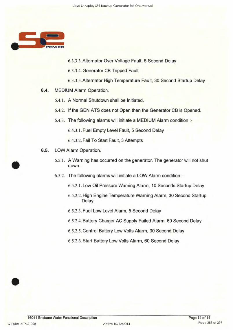
6.3.3.3.Alternator Over Voltage Fault, 5 Second Delay
6.3.3.4. Generator CB Tripped Fault
6.3.3.5.Alternator High Temperature Fault, 30 Second Startup Delay
6.4. MEDIUM Alarm Operation.
6.4.1. A Normal Shutdown shall be Initiated.
6.4.2. If the GEN ATS does not Open then the Generator CB is Opened.
6.4.3. The following alarms will initiate a MEDIUM Alarm condition :-
6.4.3.1. Fuel Empty Level Fault, 5 Second Delay
6.4.3.2. Fail To Start Fault, 3 Attempts
6.5. LOW Alarm Operation.
6.5.1. A Warning has occurred on the generator. The generator will not shut down.
6.5.2. The following alarms will initiate a LOW Alarm condition :-
6.5.2.1. Low Oil Pressure Warning Alarm, 10 Seconds Startup Delay
6.5.2.2. High Engine Temperature Warning Alarm, 30 Second Startup Delay
6.5.2.3. Fuel Low Level Alarm, 5 Second Delay
6.5.2.4. Battery Charger AC Supply Failed Alarm, 60 Second Delay
6.5.2.5. Control Battery Low Volts Alarm, 30 Second Delay
6.5.2.6. Start Battery Low Volts Alarm, 60 Second Delay
16041 Brisbane Water Functional Description Page 14 of 14
Lloyd St Aspley SPS Backup Generator Set OM Manual
Q-Pulse Id TMS1098 Active 10/12/2014 Page 288 of 339

Lloyd St Aspley SPS Backup Generator Set OM Manual
Q-Pulse Id TMS1098 Active 10/12/2014 Page 289 of 339

I
II
Lloyd St Aspley SPS Backup Generator Set OM Manual
Q-Pulse Id TMS1098 Active 10/12/2014 Page 290 of 339
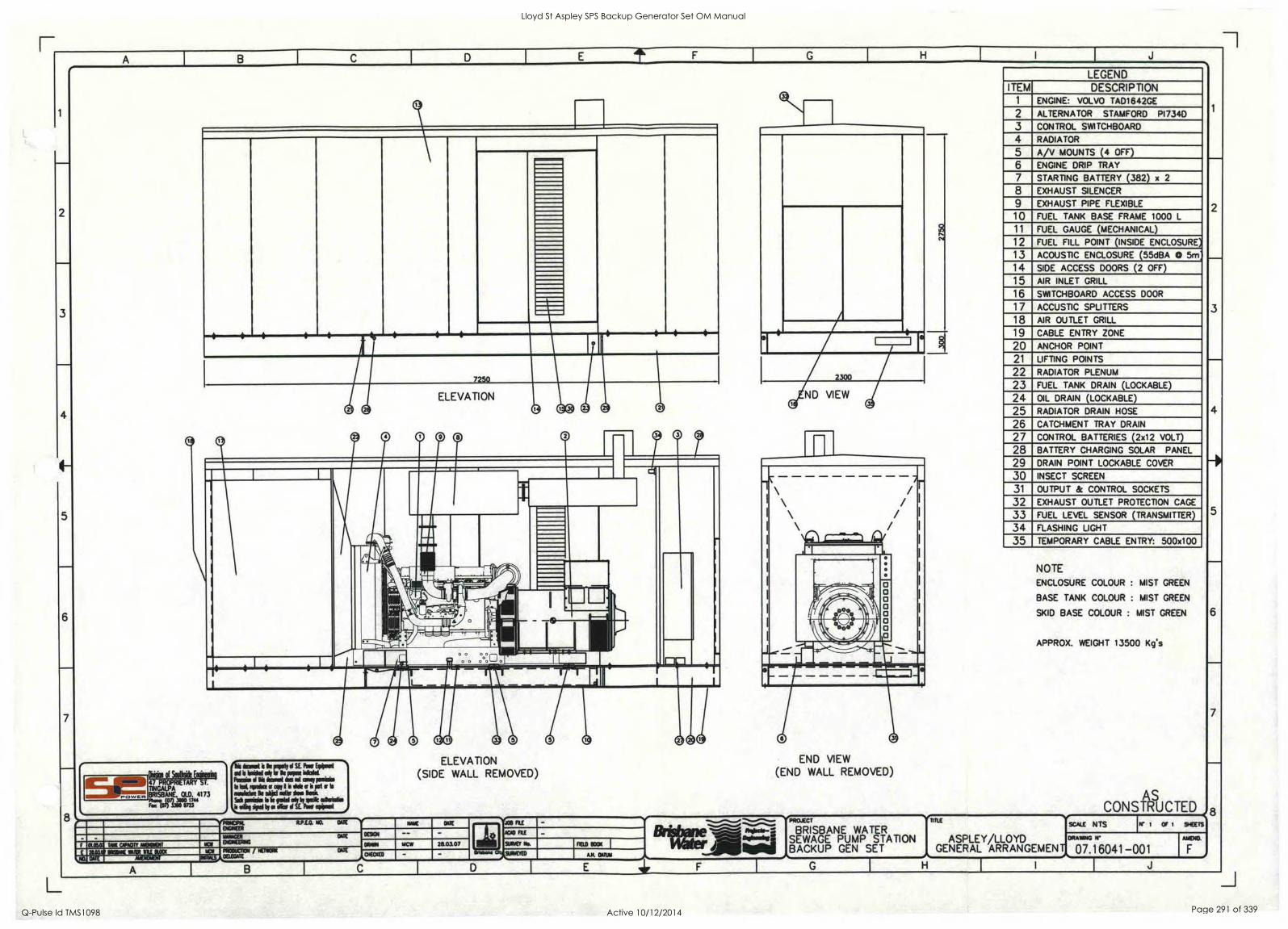
7250
it
1.1.1WMIR
44OPRIETARY ST. TINGALPA BRISBANE. OLD. 4173
7:10;07) 203.10727344
46 did I mil el SE Par FONNI al It 1 k ppm Wahl Perilui ft tamed in II cow poi. UM, make (rani: ide lir is pot Is .Ada k Wier Iwo knit Sidi whim le be nisi sly by asisetis
win lip/ enrol SE Pow eiimai
ARMOR% NOW
R.f.E.O. NO. PAIT-Nt
DATE ORSON
ELEVATION (SIDE WALL REMOVED)
TeIR COVAINT MENSIDIT
IrEft MCW 213.0.107 RI
JOS SI ADD CU
\ / \ /
I \ / I \ /
le _ . . .
E
a
E
- ; t -
%Nita 11!
J - i IN
END VIEW
(END WALL REMOVED)
NPROJECT
OMOMMI:: BRISBANE WATER SEWAGE PUMP STATION BACKUP GEN SET
FELD 99
Stammo OW stomp AM BARN
LEGEND ITEM DESCRIPTION
1 ENGINE: VOLVO TAD1642GE
2 ALTERNATOR STAMFORD P1734D
3 CONTROL SWITCHBOARD
4 RADIATOR
5 A/V MOUNTS (4 OFF)
6 ENGINE DRIP TRAY
7 STARTING BATTERY (382) x 2
8 EXHAUST SILENCER
9 EXHAUST PIPE FLEXIBLE
10 FUEL TANK BASE FRAME 1000 L
11 FUEL GAUGE (MECHANICAL)
12 FUEL FILL POINT (INSIDE ENCLOSURE)
13 ACOUSTIC ENCLOSURE (55dBA 0 5m:
14 SIDE ACCESS DOORS (2 OFF)
15 AIR INLET GRILL
16 SWITCHBOARD ACCESS DOOR
17 ACCUSTIC SPLI TTERS
18 AIR OUTLET GRILL
19 CABLE EN TRY ZONE
20 ANCHOR POINT
21 LIFTING POINTS
22 RADIATOR PLENUM
23 FUEL TANK DRAIN (LOCKABLE)
24 OIL DRAIN (LOCKABLE)
25 RADIATOR DRAIN HOSE
26 CATCHMENT TRAY DRAIN
27 CONTROL BATTERIES (2x12 VOLT)
28 BATTERY CHARGING SOLAR PANEL
29 DRAIN POINT LOCKABLE COVER
30 INSECT SCREEN
31 OUTPUT & CONTROL SOCKETS
32 EXHAUST OUTLET PROTECTION CAGE
33 FUEL LEVEL SENSOR ( TRANSMITTER)
34 FLASHING LIGHT
35 TEMPORARY CABLE ENTRY: 500x100
NOTE
ENCLOSURE COLOUR : MIST GREEN
BASE TANK COLOUR : MIST GREEN
SKID BASE COLOUR : MIST GREEN
APPROX. WEIGHT 13500 Kg's
AS CONSTRUCTED
SCALE N TS W I Cf I BEETS
ASPLEY/LLOYD GENERAL ARRANGEMENT
DRAWING 14*
07.16041-001 J A C G H I
AMEND.
Lloyd St Aspley SPS Backup Generator Set OM Manual
Q-Pulse Id TMS1098 Active 10/12/2014 Page 291 of 339

...
Lloyd St Aspley SPS Backup Generator Set OM Manual
Q-Pulse Id TMS1098 Active 10/12/2014 Page 292 of 339
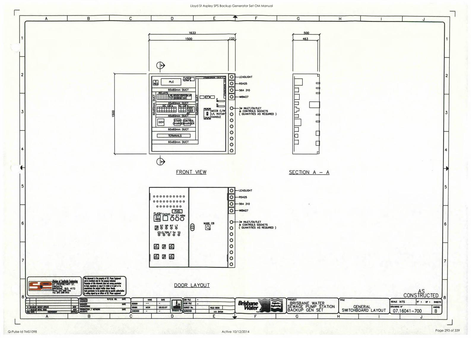
itfUtt4 Y T.
TINGALP BRISBANEA . OLD. 4173
roc wir IWO 97173"
laud it In pupil l SE Por (OW 011 I WWI OW lrwwrwr Po. 10 We hand les el cog pd. le bal ("go ar opy I ilia pet to
momich0 110 aYjd Elk its. bra Sicli mini. Is is falai* hp ink abide
by Oica I SE Far sprpri
1633
1500 /1 33/
.A.T1:1111:11111111111111
PLC TrEljan DI
t;) I. Elip
g z
,T1
P' 4 1
0 . 60x6Omm DUCT
6-
a E
to
4 d.
0 I LTRI LT-gifia a 6=I E
IAE
0-"' 0 0 0 0 0 0 0
II;DMNEDDI obeli: IIi:
1111111. ENE 1.0../3.1 MCCEI C/W IA ROTAR HANDLE
11 * 40x6Omm DUC
1-L71
GOV giTAARRGET oNOI
1HARTF R
60x6Omm DUCT
TERMINALS
60x6Omm DUCT
FRONT VIEW
1
. . 0 0 0 0 0 0 0 0
0 0 0 0 0 0 0 0 0 0
0 0 0 0 0 0 0 0
10T
I ° '
0 0 ®
FLASH TACHO op ET HRM ET 485 0 0 0
0 MAIN CB
E
l0
0 0 0 0 0 0
0
_ ST SP RT LT 0000 H) CLO T
OT T Tc?
;.ii T. 9 1 /11 ; El
DOOR LAYOUT
4119(394. 4.1)10. 143. DAlE OMER OAR JOS RI
liNNAGEN DARE
ENGNEDING
CC9C11 AGO RE
0.010 Ou NE I UCIAlE NCI ONION MC1V 290107 SUNNEY Nn FEU) 930N A 2401 109. 004 11:11
tows,,,CELEGME PROOUCTOI NENORK alE
\ NO alt muctext CHECKED wow* at suotyED AN 001134
A C
-LEADUGHT
- RS425
-56A 310
-W1BM27
-30 INLET/OUTLET & CONTROLS SOCKETS ( QUANTITIES AS REQUIRED )
-LEADLIGHT
-RS425
56A 310
WIBM27
30 INLET/OUTLET & CONTROLS SOCKETS ( QUANTITIES AS REQUIRED )
=1 =11
CI
SECTION A - A
RnE
GENERAL SWITCHBOARD LAYOUT LAYOUT
I
AS CONSTRUCTED
scALE ' NTs W 1 OF 1 911:ETS
201141.
ni1/4
BRISBANE WATER SEWAGE PUMP STATION BACKUP GEN SET
G H
ORANING 9*
07.16041 -700 J
MEMO
1
2
3
4
5
6
7
8
Lloyd St Aspley SPS Backup Generator Set OM Manual
Q-Pulse Id TMS1098 Active 10/12/2014 Page 293 of 339

- - Lloyd St Aspley SPS Backup Generator Set OM Manual
Q-Pulse Id TMS1098 Active 10/12/2014 Page 294 of 339

2
7
8
1
MO ft 67
2
5
6
8
CB6/1 ri 69 Cr- 11---
C87/1 M
0 BATTERY
ISOLATOR
SARA
41
FCRA1
081/1 C82:1;[, 16A
to
C83/1 6A
02
C84/I 64
C85/I EA
SRA
66 42
I
LR1/1 LR2 MENFR 0
PE CELL
4110 ON ROOF OF
CANOPY
U
,. 0 ELECTRONIC
GOVERNOR
SEE SHEET 5
START
BATTERY
24V
oricerctje
61
DI CONTROL
2-3 BATTERY STARTER
57
* START
BATTERY
CHARGER
Ilr 63
CONTROL
BATTERY
CHARGER e^ N A
uz PANEL I
65
I S8YSR O 1 CETVSR I
51 52
I C83/2 24V i
64
59 112
2-2
101 102
2-4
tao
101
tai ALT.
"-PANEL
LRT1 LRTZ
2-5
0 0 :AZ-- .
TO ALT.
NEUTRAL
0 0
LA* LR I 1R2 I
LRT1 LRT2 74
2-1
100
CI I .
ce1/2ci 1M
082,1 64
CC8
C84/2 EA
C85/2ci 6.4
C87/2 64 2-7 0-----
SPARE
C86/2 SA, 2-6
0---'- x__.
161 16A 161
C812 7(1,d Cell 3(bm C8I0
11 I111 IIMINID 10A
APPLIANCE
INLET SOCKET
2 EA -8
S10A
OUTLET '' 10A
OUTLET
0 0 ' 46 dmiel is Is Rik N SE Par WOW
NI I WWI lag lor k ppm crow kaki d Ili imai Is id mg ps.W. WA woke et All I *Mu 1 pit a to
alikke k akel WI las Me Mikan b k OW 'kW wig (atoning I ilk ipli bg Ilk 1 SE Pep eqopeol
AS CONSTRUCTED
,.. vv. ,,,
01 allsi 4 T.
TIN A
BRISBANE. 010. 4173
FOC (e1/30 97273" , easic st.P.r..o. NO. auc si----. as J08 FILE
AGO RE
.....................................-",-,''s- Ni
.".'".`° NON,- :: illibili"
PROJECT
BRISBANE WATER SEWAGE PUMP STATION BACKUP GEN SET
w 1 Or 5 SHEETS DOWER
ASPLEY_/LLOYD ARRANGEMENT
scALE NTS - -
74-c,- 01180 DATE
NowERNG of %NM VOX NMI 28.03.07 SW Na MU) 8001( ORAWING 1,1*
07.16041-701 AVENEL
A 81,03.07 NIA 69( 10 PRODUCTION / DUE at - AM. DATUIA NO. OW mealoort ognisArEGATE
A I B G I H I I I J
Lloyd St Aspley SPS Backup Generator Set OM Manual
Q-Pulse Id TMS1098 Active 10/12/2014 Page 295 of 339

Lloyd St Aspley SPS Backup Generator Set OM Manual
Q-Pulse Id TMS1098 Active 10/12/2014 Page 296 of 339
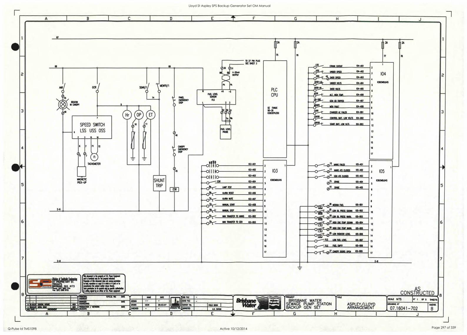
E IL
I
6
7
67
69
- - _
TO 27 PIN PLUG
SEE SHEET 3
PLC
CPU
GE Mlle 90-30 C693CPU.E0
LSS _---- CPAAw CUTOUT 04401
104
E693.645 5
10
II
12
13
14
15
16
17
30 31
89 4-20rnt OUTPUT
,,,__o_...--
a--(111-11
UNDER SPEED 104402
._o______.0oss 4 SPEED 104403
Pt PM
a___69sr......siR-1 UNDER MS 04 -904
MENFR/1 SOAR / AVA-141
OVER 911TS 104405
0 044
Iva« N OMR 3
74 Pme.
4. _ N
FUEL 1.1113.
SENSCR
ns
0_4A:Tx____t.SR NJ. RCN TEMP 104406
Co_cl).-3---g--..___O__a_MT 104-A07
9
43 0 EMERGENCT
STCP
LEN Dar 104-908
0 50
Y.
50 1
We
I1
0 52
-0
I
CIR 0_0..----t CHARGER AC WO 04-801
CBVSF1_,_ CONTROL &&TT. LOW WS 04402 II-4D'I
SPEED SWITCH
LSS USS OSS
IS II
01° 611
.>,---
01. START BATT. LOW N.TS 04-003
46
CAN
EMERGENCT
STOP
FUEL TM PROM
2-6
1 1
(1)6
6
° 7 71
TACHOMETER
45
_ - 03-/OT MK MED 05-A01
105
C693111645
5
9
10
11
12
13
14
15
16
17
-0$11110 103 ..,_(-).-----"_013
__o____-_o12
ANS MS CLOSED 105-A07 ("--0
cp_o..---
ak--Cri---
I I I JO 03-A02
110 103 .463 GO4 ATS CLOSED 105-03
MAGNETIC
P1CK-UP SHUNT
TRIP
.--01# ER 103-ADS
(693NCt645
0" SPARE I05404,
- VW TEST 03405
5 015 (1) .,..16 SPARE 105405 (.0
MOW rua 105-601
ESR I
.....4L.r.,
Be NJR11 RESET 103-A06
__01...T...-4. AWN KITE 103-A07
WM. START 10.1-413 9
WAR STCP 103-001
,______0.--±-r__G)21j5poo4ENcrar
0....&-t_038
25 LOW Ot PRESS SWAN 105402
2-8
.,_01...1.-1-id
GA we TWISTER TO MANS 1034102
10
-LooLoAms6 WARN. 105-803 0---CY WM TRANSFER TO GEN 103-133
11
aw 105-804 2_0?...r-i 12
13
14
15
16
17
1f;XZIMPOli WA. 05405
%______0-±t_029
,,e_cy-------
9,..___(-)-----LIS
-,---0--rr--037
LOw Roma uva. 05-806
FIS LOW F1 LEVEL 105-907
RR DM 05-808
CAMOPT 000Rs OPEN 105409
2-8
SOASik Engiletril iSis timed is k piety 91 SE. Res Wpm.
M's ko,o! dr M IMP. glast a Is it me come pow
M bte spoke a spy 9 il emit s S Fe cr to
eaehdle Is objel sells * Sodi inesim le Is reel sit
Oro Os * is* !ewe&
S vie SO by a Aar I SE. Pow owe AS CONSTRUCTED
sm....m
kill Oi
47 PROPRIETARY T.
11121VILAPNE, DLO. 4173
F T ot (0r1330 97.3" 72 - -- - 'v* PRIMAL R.PS-12. la DOE
0E501 - - DATE
- se ........._., -,-..._.
......"......0 ""....."...... v....J. fv.a..:: "1"61.
VPROJECT
BRISBANE WATER SEWAGE PUMP STATION BACKUP GEN SET
ETIONEOt AC/41 TILE
ASPLEYYLLOYD ARRANGEMENT
SCALE N TS w I OF 5 SHEETS E[75 . _ WAAGER DATE
COM ha DIGKERRIO MAW 1 w 28.03.07 SURVEY Tbs. TeD KM I DRANK NI
07.16041-702 AMEND.
A MIL TO FROOUCTIN / DATE CHEM - *Wm* 014. SURVEYED DARPA .0. DELEGATE
C D E 1 F 6 H I J
Lloyd St Aspley SPS Backup Generator Set OM Manual
Q-Pulse Id TMS1098 Active 10/12/2014 Page 297 of 339

_ 1
I
Lloyd St Aspley SPS Backup Generator Set OM Manual
Q-Pulse Id TMS1098 Active 10/12/2014 Page 298 of 339
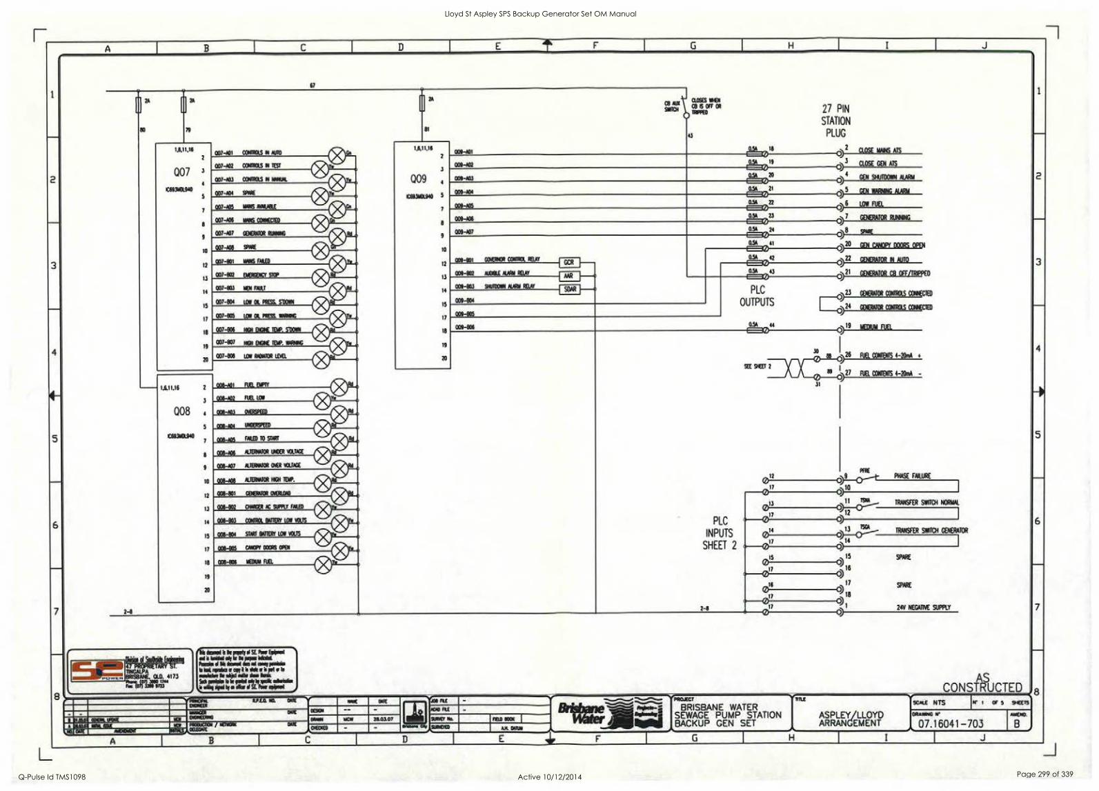
67
2-8
1.6,11,16 2
3
008 4
5
1069310L940 7
8
9
008-A01 FUEL EMPTY
008-A02 FUEL LOW
008-003 OVEREPEED
008-A04 UNCERSPEED
TARED TO START OA; 17
008406 ALTERNATOR UNDER VOLTAGE
008-447 ALTERNATOR OVER VOLTAGE
10
12
13
14
15
17
18
-A08 ALTERNATOR 11:11 TEMP.
008-801 GENERATOR OVERLOAD
008-802 CHARGER AC SUPPLY TAILED
008-803 CONTROL BATTERY LOW VOLTS
008 -804 START BATTERY LOS VOLTS
008-805 CANCPf DOORS OPEN
00e-936 SEDUM FUEL
19
20
mAti CB DES WHEN
OFF 011 So1101 wpm
2A
81
1,6,11.16 050-4411
Q09
105931111440
3
5
9
10
12
13
14
15
17
18
19
20
43
009-402
009-A03
009-104
009 -405
0.54 18
0.5A
0 19
OSA 20
CO 0.5A 21
CO
27 PIN
STATION
PLUG
O )2
O
0.54 22
009-AD6
009-407
0.5A 0 23
am 24
009-801 GOVENCR CONTROL RELAY
009-802 AUDIBLE MOON RELAY
009-833 SHUTDOWN NAM RELAY
009-804
SDAR
009 -805
009-806
0) 5
46
C)8 0. 41 LI 5A
0 0)20
0)22
0)21
23
CLOSE MAINS ATS
CLOSE GEN ATS
GEN SHUTDOWN MARIA
054 42
0.54 43
1=12)
PLC
OUTPUTS
0.SA
SM. POWER
47 PROPRIETARY T.
TINGALPA BRIS8ANE, 010. 4173
Few 0713N 071273"
4i4 `oral I k misty M SE Pas ENNIS al 1 bil N olf kr Is kw Skid !brie M Fi lerrsi Ns Id cski polio blelrpitesasiirlkaiplab ssalske We slid =Us kr kik SEI polle k rid slik sock sairldis I sirs Sped bi a ciow ol SE Wow eqipall
-vpoocrm ENGINEER
R.PLO. NO. 04W
mow Nome oscomeme
Nwoucn:m Duca
/ NETSCRIC
DOTE
OME 0/USH
CHEMED
M W W
roe FLE
ACID FYI
SURVEY Ns FELD ROCK I
Brisbane CR, SURVEYED
B
Brisbane
04R111
E
14#aterAig
`PROJECT
44
SEE SHEET 2
31
)19
GEN WARNING ALARM
LOW FUEL
GENERATOR RUNNING
SPARE
GEN CANOPY DOORS OPEN
GENERATOR IN AUTO
GENERATOR C8 OFF/TRIPPED
GENERATOR CONTROLS CONKCIE
ORATOR CONTROLS COWIECTED
MEDIUM FUEL
26 FUEL CONTENTS 4-201M +
89 )27 FUEL CONTENTS 4-20mA -
FfRE
LO 0>-0"-t- ID
17 ,.. 10 i) 013 o)11
TS02A
INPUTS 0 u)
12
PLC 17
14 c1 3-<21
SHEET 2 017 o)
_15 0)15
017 <
)16
16 17
017 0)
2-8 17
C) 1
PHASE FAILURE
TRANSFER SWITCH NORMAL
TRANSFER SWITCH GENERATOR
SPARE
SPARE
24V NEGATIVE SUPPLY
BRISBANE WATER SEWAGE PUMP STATION BACKUP GEN SET
ASPLEY /LLOYD ARRANGEMENT
AS CONSTRUCTED
SCALE NTS Pt 1 OF 5 SHEETS
DRAWING 14*
07.16041 -703
J
ATTEND.
8
Lloyd St Aspley SPS Backup Generator Set OM Manual
Q-Pulse Id TMS1098 Active 10/12/2014 Page 299 of 339

_
Lloyd St Aspley SPS Backup Generator Set OM Manual
Q-Pulse Id TMS1098 Active 10/12/2014 Page 300 of 339
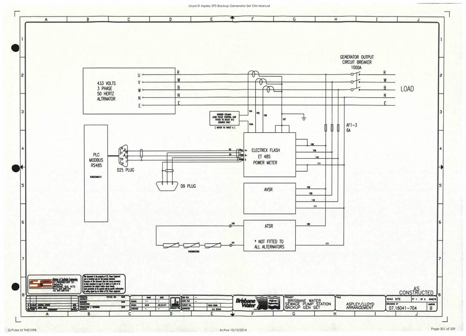
A B C D E F G H I J
2
3
7
GENERATOR OUTPUT
CIRCUIT BREAKER
1000A
3
6
7
R 0----; rP - R U°
W W
433 VOLTS V
3 PHASE B 0-----;
x
B LOAD w 50 HERTZ N N
ALTRNATOR N
E° 104
104A
105 106
AF1 -3 6A
BARBER COLMNI
LOAD PULSE CONTROL UNIT
FITTED TO DEUTZ 912
Mae CRY
107
PLC
MODBUS
RS485
10693C1414311
( REFER TO 9r1EET 5 )
A+ ELECTREX FLASH
8- ET 485 s
POWER METER
108 tfr f 2125. 109
4' J 110 ,'
ilk a
1C s,1
I I I
D25 PLUG
o
I
D9 PLUG AVSR
108
109
110
111
1C0
foi
ATSR
* NOT FITTED TO III ALL ALTERNATORS
TTIEDIMSTORS
d Scotife - 46 eaml i le porly 0 SE Pow *mg 41. p=41414= . .
444 OM/ AMMO kat woks an i it die a is .4441 a lo
08011di.e !Is 101:1_1_4.1! 41.; ilea ataintko So mem le it ma I olio irel by a Ow 41 Pau emu&
AS CONSTRUCTED
Alimmis Sr° ',NOWAK ARY T.
BRISBANE. 011 4173
PZ.Srilir727344
PIRKO/ R.P.E.0. I. DATE
MAIM 002
Mkovve Ob
AO RE -.._,....... '''...7....... AgOBANI-S
"Imills.
PROJECT
BRISBANE WATER SEWAGE PUMP STATION BACKUP GEN SET NIF:;k1E\YEITYPNYY
SCALE N TS N I OF 5 SHEETS - - AGA0 pa wmaR Oat DIONEERING I I.05.07 COCK LIME la OMAN 28.03.07 SURVEY No. nao 0001
DRAVANG A'
07.16041-704 AMEND.
A 03.07 Mt MIR ICI PRODUCTION / LIME
DEWAR MUD - SIIRVEITO AR DATUM Na DUE AND0130 NUNS
A G H I J
Lloyd St Aspley SPS Backup Generator Set OM Manual
Q-Pulse Id TMS1098 Active 10/12/2014 Page 301 of 339

- -
i
Lloyd St Aspley SPS Backup Generator Set OM Manual
Q-Pulse Id TMS1098 Active 10/12/2014 Page 302 of 339
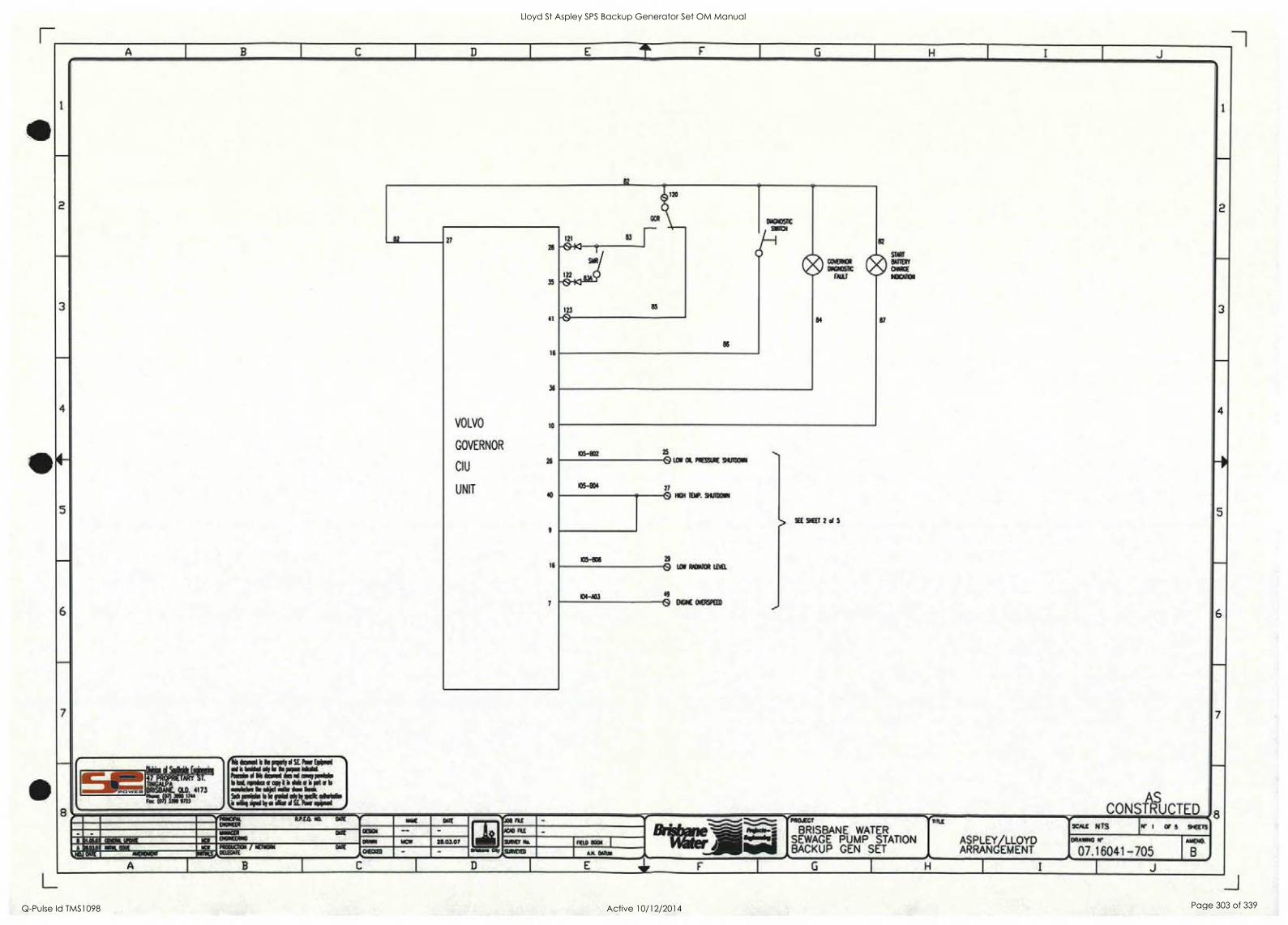
A B I C I D E 11. F I G
1 H I I I J
1
2
3
4
5
6
7
8
82
1
3
120
DIAGNOSTIC
SNITCH
a
MINX DYGNOSBC
MU
STORY
BATTERY
°PAGE N;4CAT1ON
27
28
35
41
16
36
VOLVO lo
GOVERNOR
CI U 26
UNIT 40
16
121 83
6b ?
SIR
122
123 85
-0
86
84 87
4
105-932 25
PRESSURE
SEE SHEET 2 el 5
5
® LOW CIL SHUTDOWN
105-804 27
NIGH TEMP. SHUTDOWN 0
105-806 29
0 LOW ROATOR LEVEL
134-403 49
0 mit OVERSKE0 -- 6
7
. . - 52144116/
Ii, km. b k pupate sl SE Pew Esikeel
°III loilkai oh lif ikkek :Ink Pork' 44 11111 ilmool Nes ral cog meek le kat wake a oepe I I Ask or a pats lo
advekke k sikl ask km bye: Sich poksio le be Obi sir by ekic !Mist* ie win eiped tei elks el SE Pow appeal AS
CONSTRUCTED
....v.. 4
tr* TINGALPA BRISBANE. OLD. 4173
Foc (On.190 971/3"
PIINeWIL RP.E0. NO. omE N, met MR V' xe Fu - v. -v----....---------- 'SPROJECT
BRISBANE WATER SEWAGE PUMP STATION BACKUP GEN SET
41.
vTini
ASPLEY/LLOYD ARRANGEMENT "
SCALE NTS
8 DOWER
DEMI - - .10e Flu - Blift="...--1-*"-....-1 hOcb-: '_ N' I OF 5 SHEETS walla DME ENGINEENNIC
8 MO/ COIN% LROUE Na ORMIN IACW 28.03.07 SURVEY Na FIELO Rom I ,14iNdial DRAPING H'
07.16041-705 AMEND.
B k 8LCII01 MN. ISSUE ia PROOucim / NEnvorec 0,41E
0400:0 - - Allibillillill r45. WE AMENOMOrt ww.s,,DELEcATE 11/4.
A.M. DARN _...^...L
A I B I
C I D I E lir F I G H
I_ I J
Lloyd St Aspley SPS Backup Generator Set OM Manual
Q-Pulse Id TMS1098 Active 10/12/2014 Page 303 of 339

1
Lloyd St Aspley SPS Backup Generator Set OM Manual
Q-Pulse Id TMS1098 Active 10/12/2014 Page 304 of 339

I
Lloyd St Aspley SPS Backup Generator Set OM Manual
Q-Pulse Id TMS1098 Active 10/12/2014 Page 305 of 339

e
S
S
S
S
Lloyd St Aspley SPS Backup Generator Set OM Manual
Q-Pulse Id TMS1098 Active 10/12/2014 Page 306 of 339

ELECTRICAL FUNCTIQN TEST SHEET AS 3000 WIRING RULES
Form 016
CLIENT: r;\.4)(-30L t.htk r SERIAL NO: 01 0 R 009 ENGINE TYPE: VOL/0 .r40 164-2,
ALTERNATOR TYPE: Sr0i eitc-er
CONTROLLER TYPE: PL---C.
DATE: (0 - (2 JOB NO: (6o9-1 ENG. SERIAL NO: 1 CA 61 2G e ALT. SERIAL NO: ><-0 7L iSob
MN EAVAIM cti! .
A'Pt - .0.-3Av. : alti, .4. ,*.'20001EMa7,,' CB Tripped / Alt. Overload
I Genset Running MEN Fault , 6/ .
Remote Start / Stop P1(p, -
Engine High' Temp. Alarm Engine High Temp. Shutdown Low Water Level Alarm Low Oil Pressure Alarm Low Oil PreSsure Shutdown -
Start Fail. Alarm . .
Status Lamps1 Controls / . .
Emergency Stop 71 .
Lamp Test / Fuel Low / Fuel Erripty / Starter Motor Relay ,/,,, Underspeed Shut Down , Overspeed Shut Down Alarm Shut Down Alt. Undervolts -7 Alt. Overvolts I., Charger AC Failed Control Batt. Low Volts Start Batt. Low Volts Engine Gauges Enclosure Doors Open Alternator High Temperature Audible Alarm / Mute AVN .
Remote ATS Controls
FAA NA titel
.7 v
Code: U= Data Recorded
N/A = Not Applicable
N/C = Not Compliant
Signed: 4A4/14
Technician Name: 6G(60 AniAl
SEPE Fcirm 016 Electrical Function Test Sheet.doc
Lloyd St Aspley SPS Backup Generator Set OM Manual
Q-Pulse Id TMS1098 Active 10/12/2014 Page 307 of 339
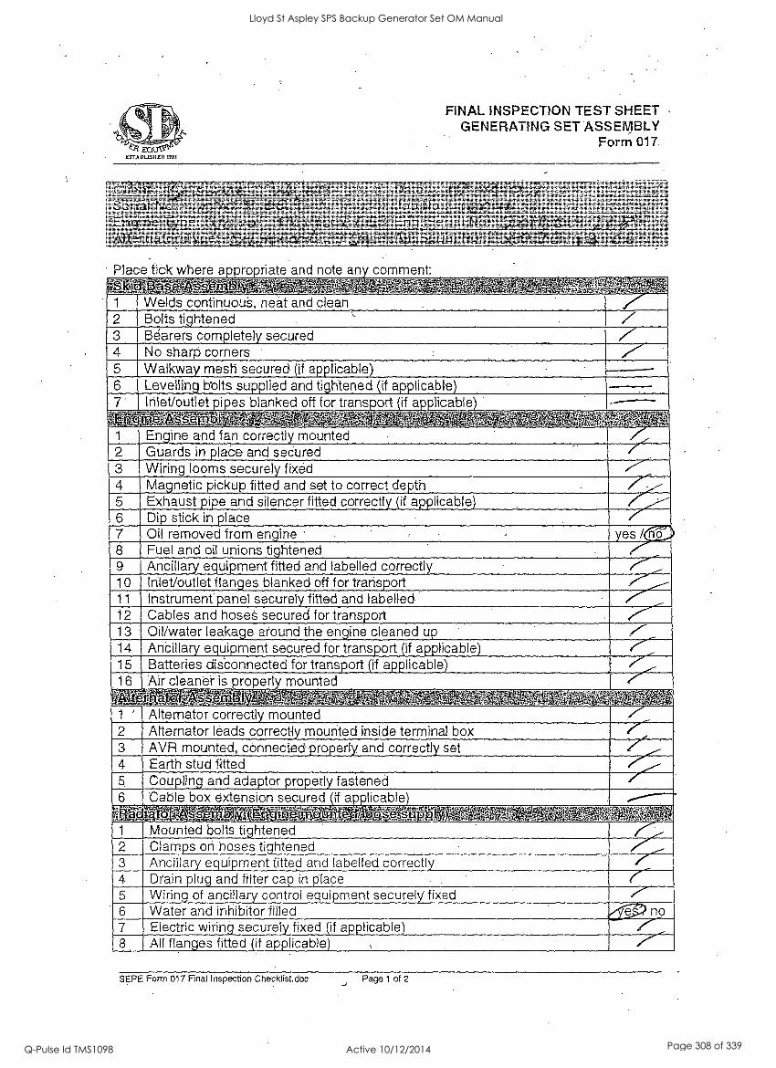
FINAL INSPECTION TEST SHEET -
GENERATING SET' SSEMBLY Form 017.
.. ' vfg,z.,?:,.. re ..4:4e.f43,,...-,,...4-4:6,
.,., , ,
-, r:.inf,-.F ,,,, - N ;`,''',;6::::
PR. ,. ...._.:154.1i Van 1,.ii ' - -ty . F,A,.-4,,;, .
, . .1A i t., ,144 it;',51% I
M1E .V
3e':. -,
--- - .,.., ,,,,
''' 1 66 Y ' ...:21WirViW Otif. 11444,4%-iltir' ' .0,4,4,
g...;::' it.4.; 0 ' eitaib.4.1!*.:' 4,15' -.t....- J.43g..41,
kailigsAilAgtiggig ' WOE§ '' w E.,......3.'..-"'Ir6 '..NIISC4.41,16t.fifir'''' gi,','14.ciii
Place tick where appropriate and note any comment: KUrfelalP I .4 lifig ' ' . ';- i ' C: ' : :, 4, If' ' ..1.,'`
' Sk:
1 Welds continuous, neat and clean 2 Bolts tightened . / 3 Bearers completely secured / 4 No sharp corners -
5 Walkway mesh secured (if applicable) 6 Levelling bolts supplied and tightened (if applicable) 7 lrilet/outlet pipes blanked off for transport (if applicable) -
trignifigrefflarfEMII .; .t . 3-itt.:- iA, `:=.^.:. 1' ,.) ., '','. 0 7., P
1 Engine and fan correctly mounted 2 Guards in place and secured /- 3 Wiring looms securely fixed 4 Magnetic pickup fitted and set to correct depth 5 Exhaust pipe and silencer fitted correctly (if applicable) 6 Dip stick in place 7 Oil removed from engine ' yes / 8 Fuel and oil unions tightened 9 Ancillary equipment fitted and labelled correctly 10 Inlet/outlet flanges blanked off for transport 11 Instrument panel securely fitted and labelled. 12 Cables and hoseS secured for transport 13 Oil/water leakage around the engine cleaned up 14 Ancillary equipment secured for transport (if applicable) 15 Batteries disconnected for transport (if applicable) 16 Air cleaner is properly mounted
MIGiViag. .i-
. 7--,,, - . . ' Ai 14, 41' .''''i
1 ' Alternator correctly mounted 2 Alternator leads correctly mounted inside terminal box 3 AVR mounted, connected properly and correctly set 4 Earth stud fitted 5 Coupling and adaptor properly fastened 6 Cable box extension secured if alitlicable
,i . . Al 713:1M5 n ve7t7; Aras;,.. P; .,:;./;_ ' ,'.'.',:':.. -:, -'1' 4 '")::,, , .,..
1 Mounted bolts tightened 2 Clamps on hoses tightened 3 Ancillary equipment fitted and labelled correctly 4 Drain plug and filter cap in place _ . (---- 5 Wiring of ancillary control equipment securely fixed .r- 6 Water and inhibitor filled no 7 Electric wiring securely fixed (if applicable) 8 All flanges fitted (if applicable)
SEPE Form 017 Final Inspection Checklist.doc Page 1 of 2
Lloyd St Aspley SPS Backup Generator Set OM Manual
Q-Pulse Id TMS1098 Active 10/12/2014 Page 308 of 339
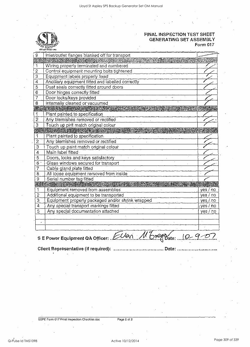
FINAL INSPECTION TEST SHEET GENERATING SET ASSEMBLY
Form 017
9 Inlet/outlet flanges blanked off for transport _____---,7
gOlinntakgaltaRriff Se 4NORROMM6264ir SEMEOMPS7, 1 Wiring properly terminated and numbered /- 2 Control equipment mounting bolts tightened 7 3 Equipment labels properly fixed 4 Ancillai'y equipment fitted and labelled correctly 5 Dust seals correct! fitted around doors 6 Door hinges correctly fitted 7 Door locks/ke s srovided 8 Internally cleaned or vacuumed
1 Plant sainted to specification ,',-;-- 2 Any blemishes removed or rectified
3 ToUch up pint match original colour
01,08MSTATAT.. , A4004V- ' ',A ' "-WM 1 Plant painted to specification 2 Any blemisheS removed or rectified 3 Touch up paint match original colour 4 Main label fitted 5 Doors, locks and keys satisfactory i- 6 ' Glass windows secured for transport 7 Cable gland plate fitted 8 All loose equipMent removed from inside 9 Serial number tag fitted
M797,.. _ Wriglarain- . 7- * . ft, Anatat 1 Equipment removed from assemblies yes / no 2 Additional equipment to be transported yes / no 3 Equipment properly packaged and/or shrink wrapped yes /. no 4 Any special transport markings fitted (yes / no 5 Any special documentation attached yes / no
,
S E Power Equipment OA Officer:
Client Representative (if required): Date:
SEPE Form 017 Final inspection Checklisl.doc Page 2 of 2
Lloyd St Aspley SPS Backup Generator Set OM Manual
Q-Pulse Id TMS1098 Active 10/12/2014 Page 309 of 339
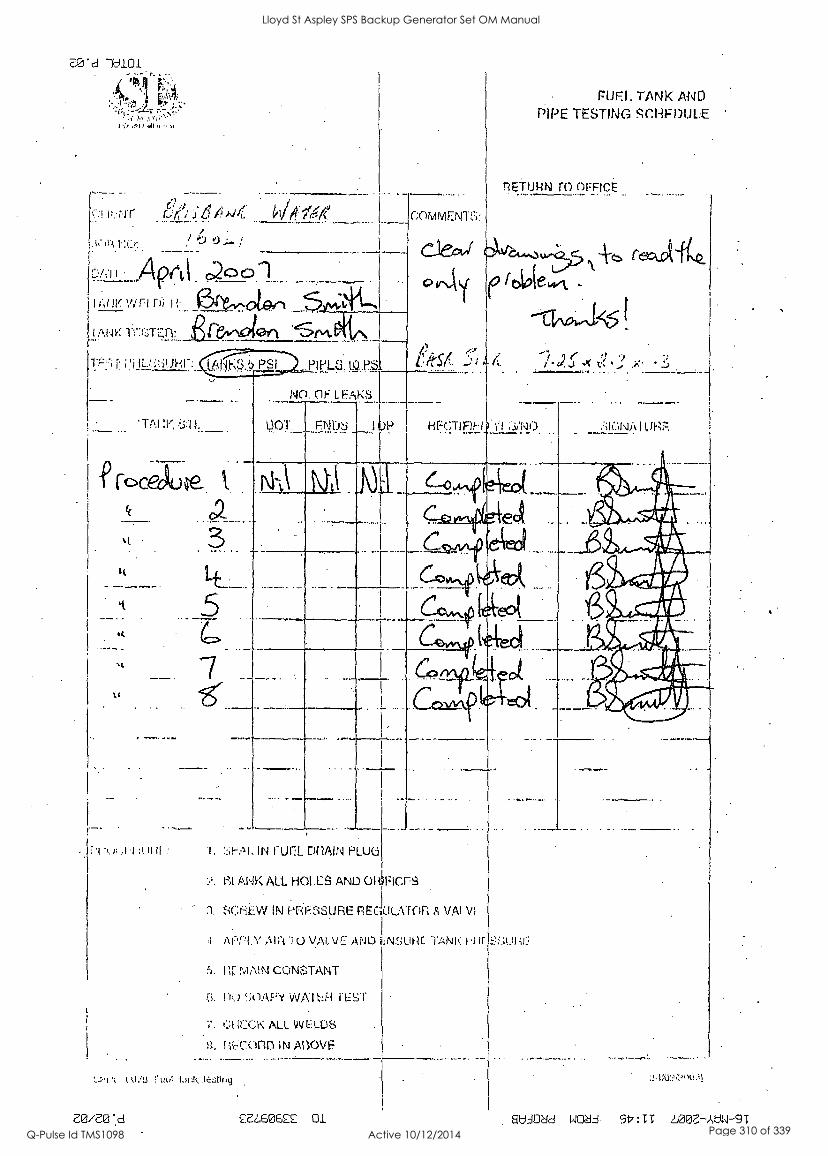
7L0_ 'd
2,r Oil btI
C.4 (..:! 11..N.i r.,w; .;t1 )44. Wttlete ........._,...... .....________...____...
, ?
- - --- at:.1 Aprt1 c2001 I Ic j v vir-1 Di 14-
'ilL
fic,eguse k.
.3,. LE.
U
-AA .4 :I. if :
Ei21/2.0 d
7
CONYIVIEN-Hi:
Flirt. TANK AND PIPE TESTING S'i".1-lizi)1,11...E '
ToorncE
ribiaewk ---Chowd%
FIECJIU--1 '11
1# '; j .I( Vs. 4 ..L....tro.t
1. IN i"LII7L r)flAIN FiLuca
). I Ai-JK ALL HOLE AND ORiFicr8
sc.:r--;LW REGULATOR VA! VI
APPLY '10 VALVE ANt) TANK 1.11i
MAIN CONSTANT
I lc.) VVAI FEST
t t.11U tIol for k.
;'. 4111CK ALL ELLIS
lif7(7.01113 IN ABOVE
2E2,60622 0.1
-
. SUADeld NOèId 917:TT LOOE-AUW-9T
Lloyd St Aspley SPS Backup Generator Set OM Manual
Q-Pulse Id TMS1098 Active 10/12/2014 Page 310 of 339
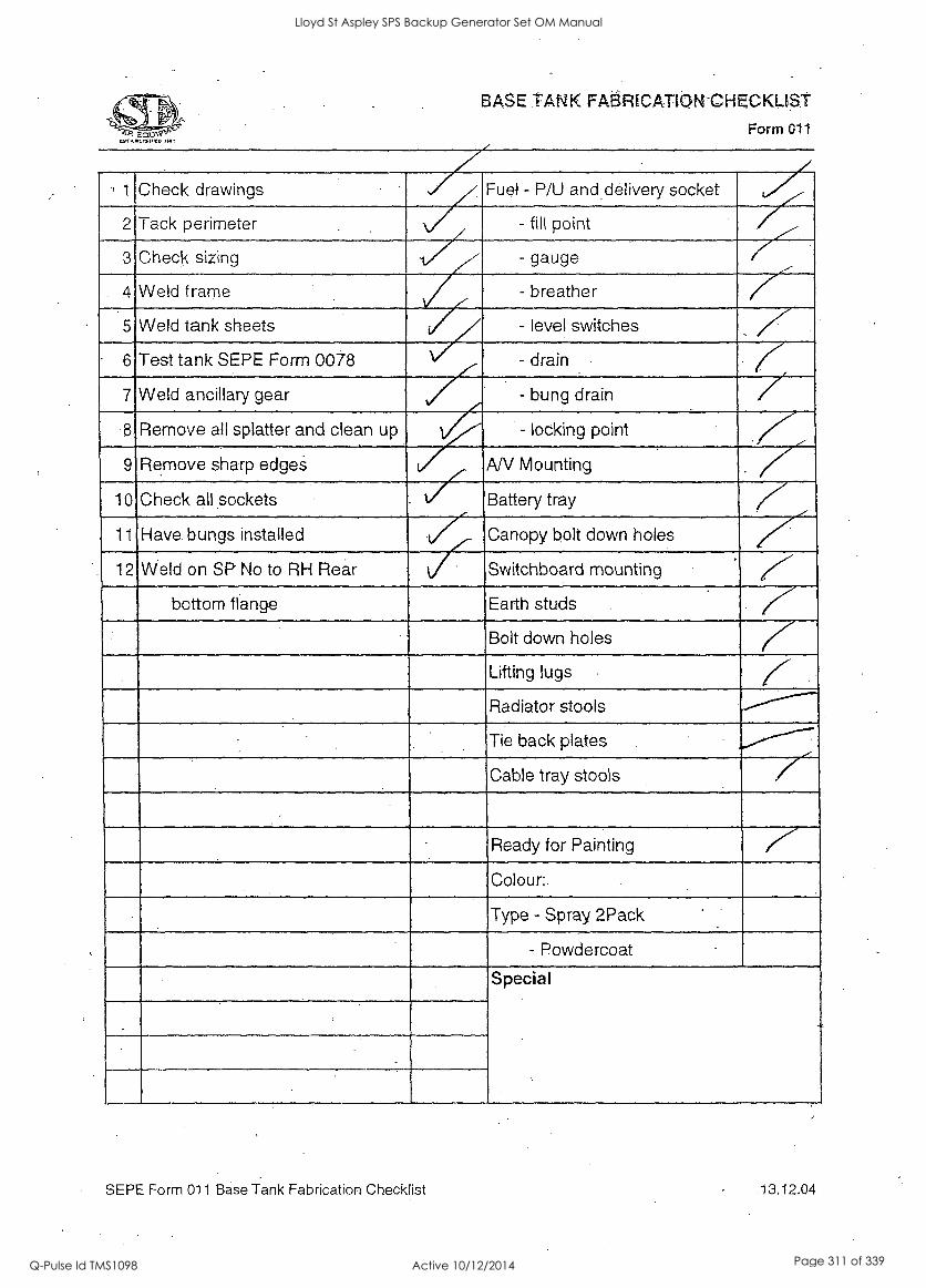
BASE TANK FABRICATIQN-CHECKLIST
Form 011
, 1 Check drawings Fuel - P/U and delivery socket
2 Tack perimeter - fill point
3 Check sizing - gauge
4 Weld frame - breather
5 Weld tank sheets - level switches
6 Test tank SEPE Form 0078 - drain
7 Weld ancillary gear / - bung drain / 8. Remove all splatter and clean up - locking point
. 7 9 Remove sharp edgeS AN Mounting
10 Check all sockets Battery tray 7 11 Have bungs installed Canopy bolt down holes
12 Weld on SP No to RH Rear f Switchboard mounting
bottom flange Earth studs
Bolt down holes K Lifting lugs
Radiator stools ,-.---------
Tie back plates -/-------- 7 Cable tray stools
Ready for Painting ,7- Colour:.
Type - Spray 2Pack
- Powdercoat
Special
. ,
SEPE Form 011 Base Tank Fabrication Checklist 13,12.04
Lloyd St Aspley SPS Backup Generator Set OM Manual
Q-Pulse Id TMS1098 Active 10/12/2014 Page 311 of 339
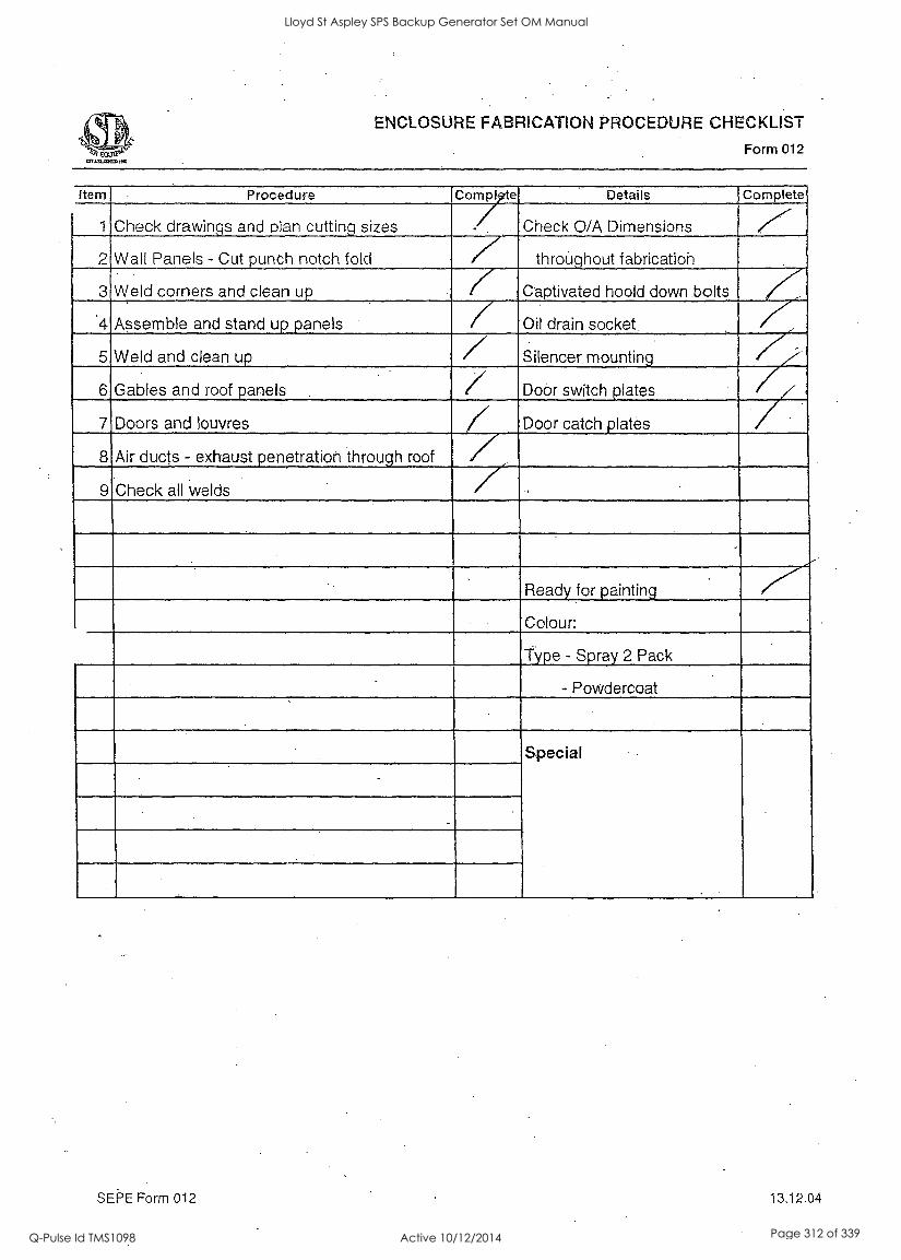
ENCLOSURE FABRICATION PROCEDURE CHECKLIST
Form 012
Item Procedure (Complete Details Complete
1 Check drawings and plan cutting sizes Check 0/A Dimensions ,r ,
2 Wall Panels - Cut punch notch fold 7 throughout fabrication
3 Weld corners and clean up l Captivated hoold down bolts
'4 Assemble and stand up panels Oil drain socket. 7 5 Weld and clean up / Silencer. mounting
6 Gables and roof panels 7 Door switch plates
7 Doors and louvres Door catch plates
8 Air ducts - exhaust penetration through roof
9 Check all welds / Ready for painting
Colour:
Type - Spray 2 Pack
- Powdercoat
Special
SEPE Form 012 13.12.04
Lloyd St Aspley SPS Backup Generator Set OM Manual
Q-Pulse Id TMS1098 Active 10/12/2014 Page 312 of 339
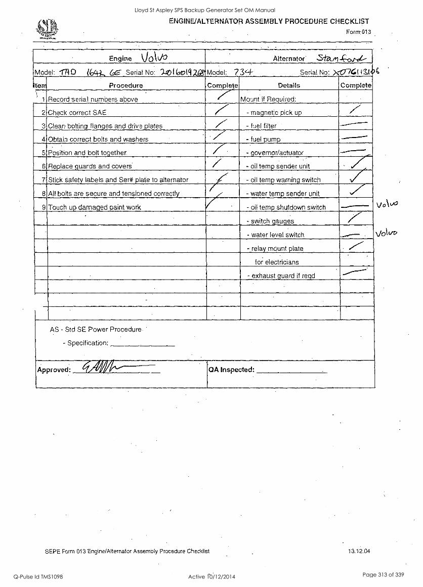
ENGINE/ALTERNATOR ASSEMBLY PROCEDURE CHECKLIST
Form 013
Engine VOktiO Alternator' ...Stati -c--0,,p,"--
Model: 17-11D ?64 -1, 6,- -- . Serial No: ')-g0 ( (90[412,65"Model: 7 3'-(- Serial No: X-fir744 lZI
iterr Procedure Complete Details Complete
Record serial numbers above .er-. Mount if Required:
2 Check correct SAE 7".. - magnetic pick up
3 Clean bolting flanges and drive plates - fuel filter .,--- 4 Obtain correct bolts and washers - fuel pump
5 Position and bolt together. / governor/actuator
- oil temp sender unit . ,7- '17
6 Replace guards and covers 7 7 Stick safety labels and Ser# plate to alternator 7 - oil temp warning switch
8 All bolts are secure and tensioned correctly - water temp sender unit
9 Touch up damaged paint work 7 - oil temp shutdown switch
- switch gauges /''' - water level switch
- relay mount plate
for electricians
- exhaust guard if reqd
AS - Std SE Power Procedure
- Specification:
OA Inspected: Approved:
SEPE Form 013 Engine/Alternator Assembly Procedure Checklist 13.12.04
Volvo
Lloyd St Aspley SPS Backup Generator Set OM Manual
Q-Pulse Id TMS1098 Active 10/12/2014 Page 313 of 339
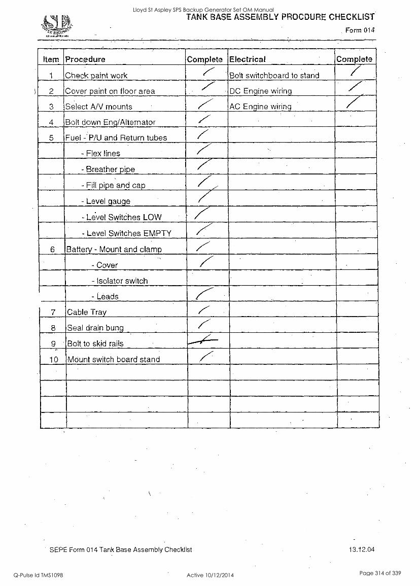
TANK BASE ASSEMBLY PROCDURE CHECKLIST
. Form 014
Item Procedure Complete Electrical Complete
1 Check paint work Bolt switchboard to stand 7 2 Cover paint on floor area DC Engine wiring r- 3 Select AN mounts AC Engine wiring
4 Bolt down Eng/Alternator -,
5 Fuel - P/U and Return tubes 7 - Flex lines
- Breather pipe
- Fill pipe and cap 77., - Level gauge 7 - Level Switches LOW
- Level Switches EMPTY K 6 Battery - Mount and clamp
- Cover 7 - Isolator switch
- Leads
7 Cable Tray
8 Seal drain bung
9 Bolt to skid rails
10 Mount switch board stand 7
SEPE Form 014 Tank Base Assembly Checklist 13.12.04
Lloyd St Aspley SPS Backup Generator Set OM Manual
Q-Pulse Id TMS1098 Active 10/12/2014 Page 314 of 339

ENCLOSURE ASSEMBLY PROCEDURE CHECKLIST
Form 015
Item Procedure .Complete
1 Clean out cavities
2 Cut and eosition insulation
3 Mount muffler
4 Wrap with high temp insulation
5 Cut and rivet perf sheets 7.-
6 Insulate and perf doors
7 Door seal and rubber on openings .7 8 Swin. doors ,- 9 Position splitters if required
10 Position plenium wall
11 Electrical - A. Power
- B. Lights
- C. Door Sw
y,- / 7 - D. Solar panel
12 Tape base to accept enclosure
13 Lift and position on base
14 Tighten hold down bolts //' 15 Check door operation
16 Mount door catches
17 Mount door open catches / 18 Complete exhaust rain hood
7--
.7 19 Rain flap
20 Exhaust protection cage
21 Screw in louvre blades / Z Z--
22 Exhaust flex and piping to engine
23 Exhaust lagging inside" canopy
24 Hook for S/B key
25 Hook for lead light
26 Fill in cable entry through wall 7' 27 Serial # Tags
1 28 SE Stickers --...7--
SEPE Form 015 Enclosure Assembly Checklist 13.12.04
Lloyd St Aspley SPS Backup Generator Set OM Manual
Q-Pulse Id TMS1098 Active 10/12/2014 Page 315 of 339
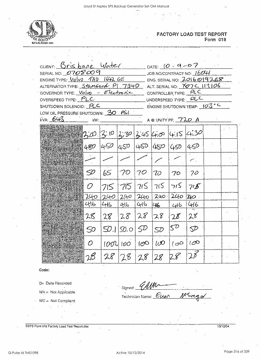
FACTORY LOAD TEST REPORT Form 018
CLIENT: r II 3 00 DATE: (0 -
SERIAL NO: 070V630 9 JOB NO/CONTRACT NO: I &xi." ENGINE -TYPE: k./0(tio /FA D ENG. SERIAL NO: 7-016 at 9 -7-.6
ALTERNATOR TYPE: S-f-A.,1-c-f>nk P l 734-0 ALT. SERIAL NO: '1C(77 C- t 11 106 GOVERNOR TYPE: Vo E ke0 47c- CONTROLLER TYPE: PL OVERSPEED TYPE: PLC- UNDERSPEED TYPE: PL-C--
SHUTDOWN SOLENOID: roc_c-- ENGINE SHUTDOWN TEMP: ° C-
LOW OIL PRESSURE SHUTDOWN: 30 kvA: 6Lk kW: A @ UNITY PF:
k.tb.5.1..v.44 w 4 % *tirg.
,. ,, ., .g.,; kisr..lat ' "VlIlt - 0 5' ;*(30 &:4-5 64--zo (-12 , S
. '
L.4. ri. .M,:::11VergrigrW it F. . VRA.;'',4''Vrii
L : PSAP'E. M ,r. e P AgzeTtAlg" ..4-4.
1 t Co 4 -5 1) C .4 -- D . 4 8 ° (- 07) 4 1"T
11 P. /4*. , -1 Liregala pI ' : .,..------
'4 wolt K ' .11.1,.
1:c1
--.-'-' /----' ./'-'' -
01' ,z ,;1T+.,,,,E(rA, .*,-*',74. ,
,;Lo ,, t py v
ID 70 g. v v. At
-1e24 .v t...1.1..
1. --)_4-o . 3.,q-0 2-,'4-0 9-4-o c,-0 - 2-4-0 xfo 4--1.6 z-tt `k lb 44 G -04 .4_6 46.
. ,'S. 2,1? 7-2 f).? 7- 3 ; -21 W' 1..
2 "j4 4'3 SO 151 " , . 0.1 0-0 SD
D
l
.. 6 - ,4 A , .. :Y
5
fi., tltly.t ....fri
0 WO% (00 (0() (0° ( (9C3 (CD
.
...1:iliNVelAsKi figNaWA VATTE z(NIOt
,gb."'F, '-til4 fer ,,,,, 1 ,
1.z. :op.-- -$.4 I., ' --)13 92 7_.:g z8' 2S af
-7
7-j Code:
'0= Data Recorded
N/A = Not ApPiicabie
N/C = Not Compliant
Signed:
Technician Name: -cue..." A"
SEPE Form 018 Factory Load Test Report.doc 13/12/04
Lloyd St Aspley SPS Backup Generator Set OM Manual
Q-Pulse Id TMS1098 Active 10/12/2014 Page 316 of 339
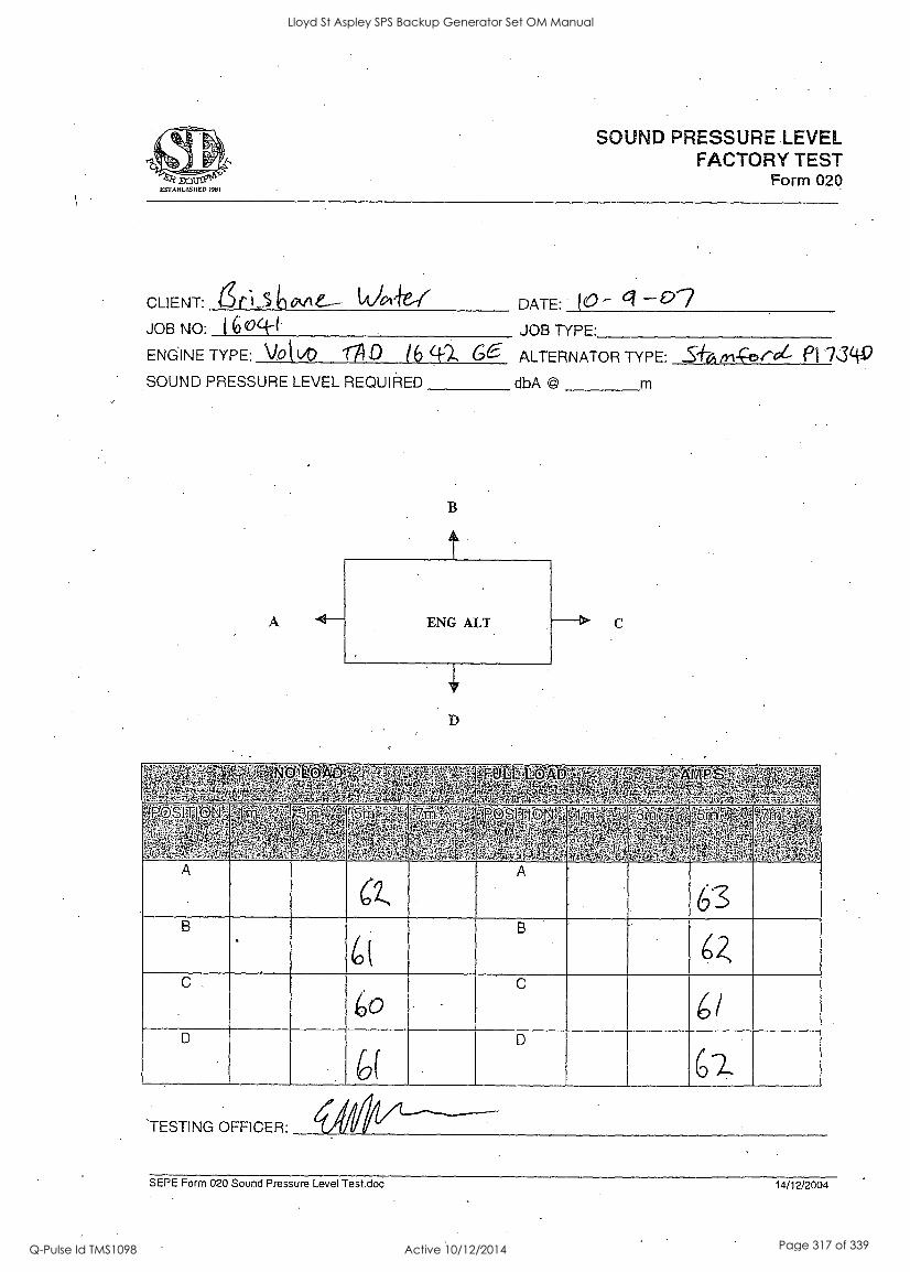
Q EgrABELISIIED 1981
SOUND PRESSURE LEVEL FACTORY TEST
Form 020
CLIENT: 66_5 10 ovie-- Vorle-1 DATE: 10 g JOB NO: ( 6 oci--( JOB TYPE:
ENGINE TYPE: VOt (AD OD 16 q)... 66-- ALTERNATOR TYPE: ..S+6 Th-c--0,ree- Pi 7349 SOUND PRESSURE LEVEL REQUIRED dbA
A
B
C
s G. tp. 44
0 R.
' . :44* ittyl
's+, 1 ., 1.7,,s4:
P
+'
-,..? '4. ,:...
N4
I - r . ,
tS f,*4 A
:, . 't ,I. i A 4 '4 * m . ' via: t- A ,-.3,. :1,
pry Y.
4,14
1h c+ba1k} '' ':;;I:V.0
f
. . q. 5"; ,TiA
ii ,
Fy 1 "Qr" ,.
t,,,4,
- '''''rq,' 2 , 4
iA, ' 'I kl:'
4
1r. ''11s,
teAth, 104K
1
tl:
ro,
k7",..
41 1 ;
t:$ el
e 1,71, ' F I ,
/
3 -.'',;'.
4_
' " ' 4..' tr-'. 3,1 .14 ,.r
tt
,,- WI* - :Y14
Pi.
ilg-
A 6-2,
A
B
(
B
64 C, c
6/ D
6( 6-1.
`TESTING OFFICER:
SEPE Form 020 Sound Pressure Level Test.doc 14/12/2004
Lloyd St Aspley SPS Backup Generator Set OM Manual
Q-Pulse Id TMS1098 Active 10/12/2014 Page 317 of 339

ESTABLISHED 1 981
TRANSIENT LOAD RESPONSE TEST SHEET
Form 019
TRANSIENT LOAD RESPONSE TEST SHEET
Transient Response for Load Changes: Load pf 0.8
eilgrlaValtir,447,570.51,SIVa- arlgefFlq,qtrric41, 6 0 , NadattMM gi Witg 40 ..= .0 .
".',05:: dir140 - t -1 ' ' . i4k N N ., , .,.
,--1.1,,o, ir,i , 1$ _ .0 ,,,NT
. i.
4P$' . :
1 ART 1, !I 1;6 .,,r 4vi Q
. 6.,
,m, .k ....,. A 0 ',11i.' ; Vt4t 4 jIrtg.C11.4.41
olipii 1,.:-T.rpl; , ;,.,WiTIT , .,,: ' =,"
r!1; qtkg.:. 1 Gt ta Change in Electrical kW
% Change Hz 0 .-1, k S k 4- 42.
% Change Volts 1 0 li 1) (./
ecovery Secs i --,
2- -5-
,,op ''t :4, i.r ,;.41*.lr . '
' . Vr.WM.efiliblrkW 7 i an eJ, ' . , .. , , 1. '4-1.>. tratittnitIgallitt.P.'
I ''''''' V
om-stOPM Ag}, ,,f' IA gt6,04: 'V%N
IIINVIAjr, W., . ' 1 i .4. --- II 0.4 1
rajt 4Y.
'.'-.' V.' 711
v. 1111:
`4f?A. c421 ,r. ).
I' . ...
0.- Pk 4 A itt.,. .0'04,P -.
k A 1 l'' f.: N'
Am, 4x ,L., ''' IF:, ,rit, .44; le .41.,;44 t, 0. 1...1)
It '1';4i
,,:
.
Change in Electrical kW .
% Change Hz :.._ kez. ?-s. Z.
% Change Volts i .
1 0 Recovery Secs
) J
SEPE Form 019 Transient Load Response Test
Lloyd St Aspley SPS Backup Generator Set OM Manual
Q-Pulse Id TMS1098 Active 10/12/2014 Page 318 of 339

I
Lloyd St Aspley SPS Backup Generator Set OM Manual
Q-Pulse Id TMS1098 Active 10/12/2014 Page 319 of 339

6
Lloyd St Aspley SPS Backup Generator Set OM Manual
Q-Pulse Id TMS1098 Active 10/12/2014 Page 320 of 339
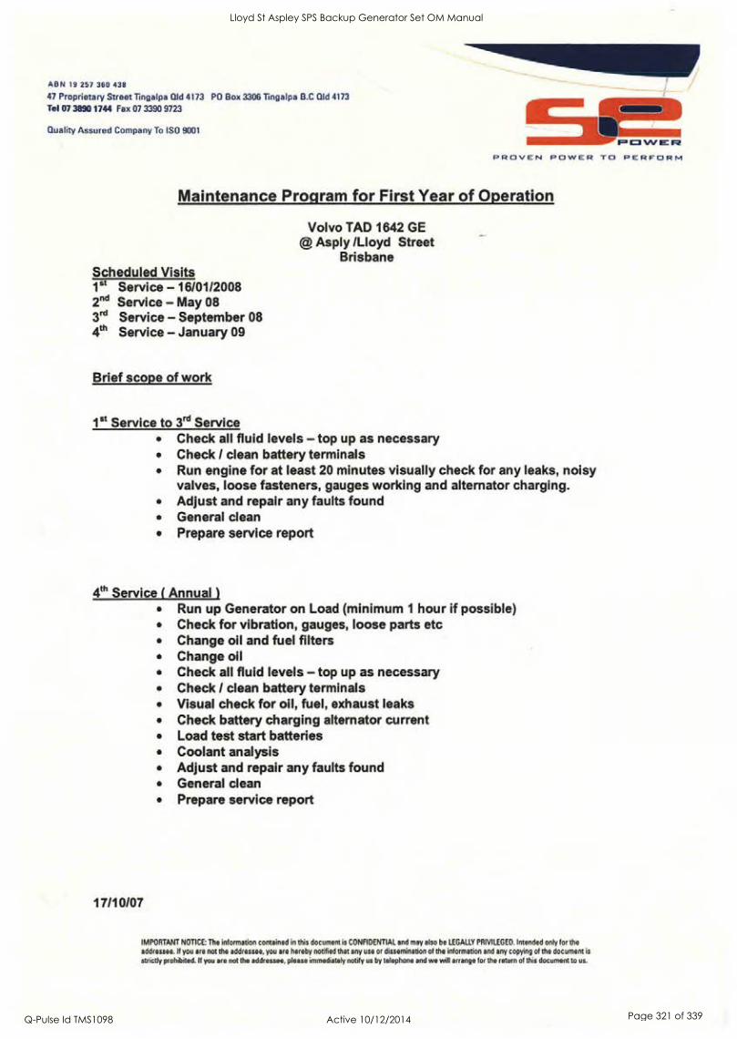
AB N 19 257 360 438
47 Proprietary Street Tingalpa Old 4173 PO Box 3306 Tingalpa B.0 Qld 4173
Tel 07 3890 1744 Fax 07 3390 9723
Quality Assured Company To ISO 9001
POWER PROVEN POWER TO PERFORM
Maintenance Program for First Year of Operation
Volvo TAD 1642 GE @ Asply /Lloyd Street
Brisbane Scheduled Visits 1st Service - 16/01/2008 2" Service - May 08 3rd Service - September 08 4th Service - January 09
Brief scope of work
1St Service to 3rd Service Check all fluid levels - top up as necessary Check / clean battery terminals Run engine for at least 20 minutes visually check for any leaks, noisy valves, loose fasteners, gauges working and alternator charging. Adjust and repair any faults found General clean Prepare service report
4th Service ( Annual )
Run up Generator on Load (minimum 1 hour if possible) Check for vibration, gauges, loose parts etc Change oil and fuel filters Change oil Check all fluid levels - top up as necessary Check / clean battery terminals Visual check for oil, fuel, exhaust leaks Check battery charging alternator current Load test start batteries Coolant analysis Adjust and repair any faults found General clean Prepare service report
17/10/07
IMPORTANT NOTICE: The information contained in this document is CONFIDENTIAL and may also be LEGALLY PRIVILEGED. Intended only for the addressee. If you are not the addressee, you are hereby notified that any use or dissemination of the information and any copying of the document is
strictly prohibited. If you are not the addressee, please immediately notify us by telephone and we will arrange for the return of this document to us.
Lloyd St Aspley SPS Backup Generator Set OM Manual
Q-Pulse Id TMS1098 Active 10/12/2014 Page 321 of 339

A BN 19 257 360 438
47 Proprietary Street Tingalpa ald 4173 PO Box 3306 Tingalpa B.0 Old 4173
Tel 07 3890 1744 Fax 07 3390 9723
Quality Assured Company To ISO 9001
VOLVO TAD 1642 GE
PROVEN POWER TO PERFORM
Description Part Number Oil filter B76
Fuel filter BF 1366
Air filter 3827643-2
Fan Belt 3827075-7
Oil Pressure sensor 20484678-6
Alternator drive belt 20430376-2
Tachometer sensor 20513343-2
IMPORTANT NOTICE: The information contained in this document is CONFIDENTIAL and may also be LEGALLY PRIVILEGED. Intended only for the
addressee. If you are not the addressee, you are hereby notified that any use or dissemination of the information and any copying of the document is
strictly prohibited. If you are not the addressee, please immediately notify us by telephone and we will arrange for the return of this document to us.
Lloyd St Aspley SPS Backup Generator Set OM Manual
Q-Pulse Id TMS1098 Active 10/12/2014 Page 322 of 339
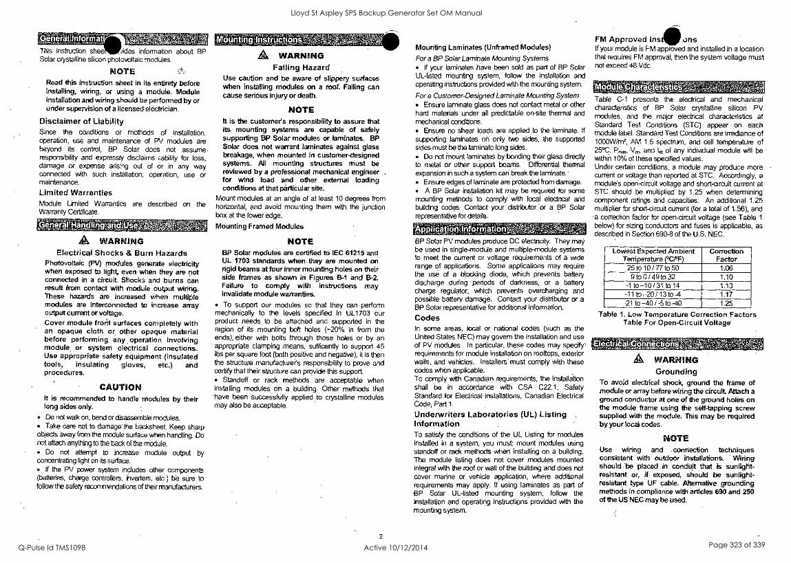
GeneratInformat, +,Ara
This instruction shee fides information about BP Solar crystalline silicon photovoltaic modules.
NOTE Read this instruction sheet in its entirety before installing, wiring, or using a module. Module installation and wiring should be performed by or under supervision of a licensed electrician.
Disclaimer of Liability Since the conditions or methods of installation; operation, use and maintenance of PV modules are beyond its control, BP Solar does not assume responsibility and expressly disclaims liability for loss, damage or expense arising out of or in any way connected with such installation, operation, use or maintenance.
Limited Warranties Module Limited Warranties are described on the Warranty Certificate.
, eneralMandlinga
A WARNING Electrical Shocks & Burn Hazards
Photovoltaic (PV) modules generate electricity when exposed to light, even when they are not connected in a circuit Shocks and burns can result from contact with module output wiring. These hazards are increased when multiple modules are interconnected to increase array output current or voltage. Cover module frorit surfaces completely with an opaque cloth or other opaque material before performing any operation involving module or system electrical connections. Use appropriate safety equipment (insulated tools, insulating gloves, etc.) and procedures.
CAUTION it is recommended to handle modules by their long sides only.
Do not walk on, bend or disassemble modules. Take care not to damage' the backsheet. Keep sharp
objects away from the module surface when handling. Do not attach anything to the back of the module.
Do not attempt to increase module output by concentrating light on its surface.
If the PV power system indudes other components (batteries, charge controllers, inverters, etc.) be sure to follow the safety recommendations of their manufacturers.
ountmg nstructions
A WARNING Falling Hazard
Use caution and be aware of slippery surfaces when installing modules on a roof. Falling can cause serious Injury or death.
NOTE it is the customer's responsibility to assure that its mounting systems are capable of safely supporting BP Solar modules or laminates. BP Solar does not warrant laminates against glass breakage, when mounted in customerdesigned systems. All mounting structures must be reviewed by a professional mechanical engineer ,
for wind load and other external loading conditions at that particular site.
Mount modules at an angle of at least 10 degrees from horizontal, and avoid mounting them with the junction box at the lower edge.
Mounting Framed Modules
NOTE BP Solar modules are certified to IEC 61215 and UL 1703 standards when they are mounted on rigid beams at four inner mounting holes on their side frames as shown in Figures B-1 and B-2. Failure to comply with instructions may invalidate module warranties.
To support our modules so that they can perform mechanically to the levels specified in UL1703 our product needs to be attached and supported in the region of its mounting bolt holes (-20% in from the ends), either with bolts through those holes or by an appropriate clamping means, sufficently to support 45 lbs per square foot (both positive and negative), it is then the structure manufacture?s responsibility to prove and certify that their structure can provide this support
Standoff or rack methods are acceptable when installing modules on a building. Other methods that have been successfully applied to crystalline modules may also be acceptable.
2
Mounting Laminates (Unframed Modules)
Fora BP Solar Laminate Mounting Systems If your laminates have been sold as part of BP Solar
UL-listed mounting system, follow the installation and operating instructions provided with the mounting system.
Fora Customer-Designed Laminate Mounting System Ensure laminate glass does not contact metal or other
hard materials under all predictable on-site thermal and mechanical conditions.
Ensure no shear loads are applied to the laminate. If
supporting laminates on only two sides, the supported sides must be the laminate long sides
Do not Mount laminates by bonding their glass directly to metal or other support beams. Differential thermal expansion in such a system can break the laminate.
Ensure edges of laminate are protected from damage. A BP Solar installation kit may be required for some
mounting methods to comply with local electrical and building codes. Contact your distributor or a BP Solar representative for details.
pplicahonlInfOrnationv.', BP Solar PV modules produce DC electricity. They may be used in single-module and multiple-module systems to meet the current or voltage requirements of a wide range of applications. Some applications may require the use of a blocking diode, which prevents battery discharge during periods of darkness, or a battery charge regulator, which prevents overcharging and possible battery damage. Contact your distributor or a BP Solar representative for additional information.
Codes In some areas, local or national codes (such as the United States NEC) may govem the installation and use of PV modules. In particular, these codes may specify, requirements for module installation on rooftops, exterior walls, and vehicles. Installers must comply with these codes when applicable To comply with Canadian requirements, the installation shall be in accordance with CSA C22.1, Safety Standard for Electrical installations, Canadian Electrical Code, Part 1.
Underwriters Laboratories (UL) Listing Information To satisfy the conditions of the UL Listing for modules installed in a system, you must mount modules using standoff or rack methods when installing on a building. The module listing does not cover modules mounted integral with the roof or wall of the building and does not cover marine or vehide application, where additional requirements may apply. If using laminates as part of BP Solar UL-listed mounting system, follow the installation and operating instructions provided with the mounting system.
FM Approved ins ons If your module is FM approved and installed in a location that requires FM approval, then the system voltage must not exceed 48 Vdc.
c XI - 0 010CParPteriStieS'A41-1'..,;',1,M+A' -_,W1,4'''',W.V4I'ag3.1.6TMTMAWW,VJNYAVVM
471 Vtevf'
Table C-1 presents the electrical and mechanical characteristics of BP Solar crystalline silicon PV modules, and the major electrical characteristics at Standard Test Conditions (STC) appear on each module label. Standard Test Conditions are irradiance of 1000W/m2, AM 1.5 spectrum, and cell temperature of 25°C. P,,,t, Vec, and I of any individual module will be within 10% of these specified values. Under certain conditions, a module may produce more current or voltage than reported at STC. Accordingly, a module's open-circuit voltage and short-circuit current at STC should be multiplied by 1.25 when determining component ratings and capacities. An additional 1.25 multiplier for short-circuit current (for a total of 1.56), and a correction factor for open-circuit voltage (see Table 1
below) for sizing conductors and fuses is applicable, as described in Section 690-8 of the U.S. NEC.
Lowest Expected Ambient Temperature ( °C/°F)
Correction Factor
25 to 10 / 77to 50 1.06 9 to 0/ 49 to 32 1.10
-1 to-10 / 31 to 14 1.13 -11 to,-20 / 13 to -4 1.17
-21 to -40 / -5 to -40 1.25
Table 1. Low Temperature Correction Factors Table For Open-Circuit Voltage
Electr17,ICiinect reaps
A WARNING Grounding
To avoid electiical shock, ground the frame of module or array before wiring the circuit Attach a ground conductor at one of the ground holes on the module frame using the self-tapping screw supplied with the module. This may be required by your local codes.
NOTE Use wiring and connection techniques consistent with outdoor installations. Wiring should 'be placed in conduit that is sunlight- resistant or, if exposed, should be sunlight- resistant type OF cable. Alternative grounding methods in compliance with articles 690 and 250 of the US NEC may be used.
Lloyd St Aspley SPS Backup Generator Set OM Manual
Q-Pulse Id TMS1098 Active 10/12/2014 Page 323 of 339

I POWER
Your RELIABLE Partner for Parts F3 Service!
For Emergency Service Call 1800 636 744
Fast Parts Delivery to where YOU are! Genuine Parts for ALL brands of Engines,
Alternators, Pumps, Lighting Towers. Service and maintenance programs
to suit YOUR requirements. Remember: Regular Servicing
(weekly, monthly, half yearly or yearly, depending on your engine) ensures Reliable Power availability!
41111111111k_
SE POWER 47 Proprietary Street, Tingalpa, Qld 4173
PO Box 3306 Tingalpa BC. Qld 4173 Phone: (07) 3890 1744 Fax: (07) 3390 9723
Email: [email protected]
tmidnitelite -Nrmegagen Nrmegapump metrolite
Proven Power to Perform
Lloyd St Aspley SPS Backup Generator Set OM Manual
Q-Pulse Id TMS1098 Active 10/12/2014 Page 324 of 339

FAST PARTS DELIVERY
ORDER FAX FORM (07) 3390 9723
S E Power Equipment 47 Proprietary Street,
Tingalpa Qid 4173
Ph: (07) 3890 1744
Fax: (07) 3890 9723
Trading Name: Date:
Contact Name: Contact Fax: Serial No.:
Contact Phone: Order No.:
0.0040 rice;
Deliver to: Freight
Sub Total
GST
Transport by: Total
Date Req.
midnitalite *IS fmegagen megapump metrolite
Proven Power to Perform
Lloyd St Aspley SPS Backup Generator Set OM Manual
Q-Pulse Id TMS1098 Active 10/12/2014 Page 325 of 339
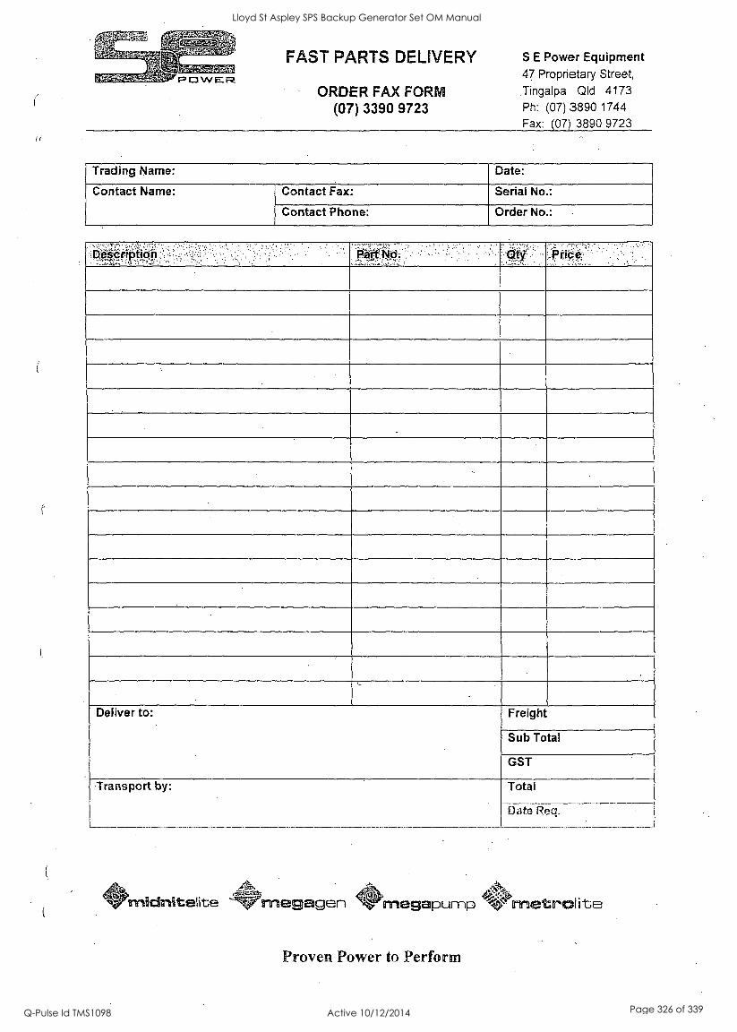
II
FAST PARTS DELIVERY
ORDER FAX FORM (07) 3390 9723
S E Power Equipment 47 Proprietary Street,
Tingalpa Qld 4173
Ph: (07) 3890 1744
Fax: (07) 3890 9723
Trading Name: Date:
Contact Name: Contact Fax: Serial No.:
Contact Phone: Order No.:
escrpton
Deliver to: Freight
Sub Total
GST
Transport by: Total
Date Reg,
midnitelite --Wrnegagen *OrrRettrolite megapump - Proven Power to Perform
Lloyd St Aspley SPS Backup Generator Set OM Manual
Q-Pulse Id TMS1098 Active 10/12/2014 Page 326 of 339

FAST PARTS DELIVERY
ORDER FAX FORM (07) 3390 9723
S E Power Equipment 47 Proprietary Street, Tingalpa Qld 4173 Ph: (07) 3890 1744
Fax: (07) 3890 9723
Trading Name: Date:
Contact Name: Contact Fax: Serial No.:
Contact Phone: Order No.:
Price
Deliver to: Freight
Sub Total
GST
Transport by: Total
Date Req.
441$, midnitelite '-'Wmegagen .00; megapump * metralite
Proven Power to Perform
Lloyd St Aspley SPS Backup Generator Set OM Manual
Q-Pulse Id TMS1098 Active 10/12/2014 Page 327 of 339

FAST PARTS DELIVERY
ORDER FAX FORM (07) 3390 9723
S E Power Equipment 47 Proprietary Street,
Tingalpa QId 4173 Ph: (07) 3890 1744
Fax: (07) 3890 9723
Trading Name: , Date:
Contact Name: Contact Fax: Serial No.:
Contact Phone: - Order No.:
escription . Part No. price
Deliver to: Freight
Sub Total
GST
Transport by: Total
Date Req.
midnitelite magagen megepump rnetrolite
Proven Power to Perform
Lloyd St Aspley SPS Backup Generator Set OM Manual
Q-Pulse Id TMS1098 Active 10/12/2014 Page 328 of 339

FAST PARTS DELIVERY
ORDER FAX FORM (07) 3390 9723
S E Power Equipment 47 Proprietary Street,
Tingalpa Old 4173
Ph: (07) 3890 1744
Fax: (07) 3890 9723
Trading Name: Date:
Contact Name: Contact Fax: Serial No.:
Contact Phone: - Order No.:
Oescripticin 9. Price
Deliver to: Freight
Sub Total
GST
Transport by: Total
Date Req.
midnitelite -krmegagen AO.
de.>:tce, megapump metrazolite
Proven Power to Perform
Lloyd St Aspley SPS Backup Generator Set OM Manual
Q-Pulse Id TMS1098 Active 10/12/2014 Page 329 of 339

SERVICE & MAINTENANCE HISTORY
Serial No.: Page No.:
Date ,Oric.C.O.rnrileted
ni 41'1 raittelite Ant,
megagen megapymp wrnietrniite
Proven Power to Perform
Lloyd St Aspley SPS Backup Generator Set OM Manual
Q-Pulse Id TMS1098 Active 10/12/2014 Page 330 of 339

FAST PARTS DELIVERY
ORDER FAX FORM (07) 3390 9723
S E Power Equipment 47 Proprietary Street,
Tingalpa Qld 4173
Ph: (07) 3890 1744
Fax: (07) 3890 9723
Trading Name: Date:
Contact Name: Contact Fax: Serial No.:
Contact Phone: Order No.:
J
Deliver to: Freight
Sub Total
GST
Transport by: Total
Date Req.
midnitelite ,.
megagen VPmegapump f metrolite
Proven Power to Perform
Lloyd St Aspley SPS Backup Generator Set OM Manual
Q-Pulse Id TMS1098 Active 10/12/2014 Page 331 of 339

SERVICE & MAINTENANCE HISTORY
Serial No.: Page No.:
-Date En Scope f Completed 7:
midnitelite -3'47Irrripgagen '.4.'megapymp 'V'metroite
Proven Power to Perform
Lloyd St Aspley SPS Backup Generator Set OM Manual
Q-Pulse Id TMS1098 Active 10/12/2014 Page 332 of 339

SERVICE & MAINTENANCE HISTORY
Serial No.: Page No.:
ate En Hr Scope of Work completed
% midnitelite '-'''''`Wmeg gen 'magapyrnp metrtzllite)
Proven Power to Perform
Lloyd St Aspley SPS Backup Generator Set OM Manual
Q-Pulse Id TMS1098 Active 10/12/2014 Page 333 of 339

I
Lloyd St Aspley SPS Backup Generator Set OM Manual
Q-Pulse Id TMS1098 Active 10/12/2014 Page 334 of 339

I
I I
S
S
Lloyd St Aspley SPS Backup Generator Set OM Manual
Q-Pulse Id TMS1098 Active 10/12/2014 Page 335 of 339

e
s
10
Lloyd St Aspley SPS Backup Generator Set OM Manual
Q-Pulse Id TMS1098 Active 10/12/2014 Page 336 of 339
Lloyd St Aspley SPS Backup Generator Set OM Manual
Q-Pulse Id TMS1098 Active 10/12/2014 Page 337 of 339
,E.:44kRite .
, I ifieratorinc osur
Cement Siab
Lloyd St Aspley SPS Backup Generator Set OM Manual
Q-Pulse Id TMS1098 Active 10/12/2014 Page 338 of 339

;
Lloyd St Aspley SPS Backup Generator Set OM Manual
Q-Pulse Id TMS1098 Active 10/12/2014 Page 339 of 339