
Westlake Drive Westlake SPS SP218 Generator Connection ...
81
Brisbene atr Operation and Maintenance Data Manual Brisbane PmiKt Management so Wateunitiod BRISBANE WATER Project STTX- generator Connection Boxes 11.1111--_ GENERATOR CONNECTION O & M Manual SP 218 Westlake Dr Issue : Book 1 of 1 Date of Issue : JUNE 2004 Author : Brisbane Water Projects Westlake Drive Westlake SPS SP218 Generator Connection Electrical Manual Q-Pulse Id TMS706 Active 29/01/2014 Page 1 of 81
-
Upload
khangminh22 -
Category
Documents
-
view
0 -
download
0
Transcript of Westlake Drive Westlake SPS SP218 Generator Connection ...

Brisbene atr
Operation and Maintenance Data Manual
Brisbane PmiKt Management so Wateunitiod BRISBANE WATER Project STTX- generator Connection Boxes
11.1111--_
GENERATOR CONNECTION O & M Manual
SP 218 Westlake Dr
Issue : Book 1 of 1
Date of Issue : JUNE 2004
Author : Brisbane Water Projects
Westlake Drive Westlake SPS SP218 Generator Connection Electrical Manual
Q-Pulse Id TMS706 Active 29/01/2014 Page 1 of 81

COMMON LOGIC PTY LTD ACN. 011 029 262
Electrical Contractors
Contract BW.30178-02/03 Switchboard Connection
Facilities for Backup Generator Sets at Sewerage PS
Electrical Manual - WB218 Westlake Drive
ISSUE NO 1
AS BUILT 21/06/2004
Unit 9/58 Wecker Road, Mansfield, Queensland 4122 Telephone (07) 3849 7449 Fax (07) 3343 5210
JHO5 JHO5Mj218Westlake Dry
Westlake Drive Westlake SPS SP218 Generator Connection Electrical Manual
Q-Pulse Id TMS706 Active 29/01/2014 Page 2 of 81

Operation and Maintenance Data Manual
Brisbane City
rjQ Project moil"Ibire0 anagenwnt Woo
a aajdo 0°-42ft m
BRISBANE WATER
GENERATOR CONNECTION 0 & M Manual
Section 1 Generator Connection Description ATS Connection Diagram
Section 2 Parts List
Section 3 Asbuilt Drawings Construction Markups
Section 4 Site Testing Site Testing Functional description Site Testing NCS alarms Site Testing Generator Electrical Test Certificate
Section 5 Parts information
Westlake Drive Westlake SPS SP218 Generator Connection Electrical Manual
Q-Pulse Id TMS706 Active 29/01/2014 Page 3 of 81

Operation and Maintenance Data Manual
7?-`z T
13tisbare City
Brisbane Plea ti Water
BRISBANE WATER
GENERATOR CONNECTION 0 & M Manual
Section 1
Generator Connection Description
Westlake Drive Westlake SPS SP218 Generator Connection Electrical Manual
Q-Pulse Id TMS706 Active 29/01/2014 Page 4 of 81

COMMON LOGIC Pty Ltd Electrical Manual Specialist Electrical Contractors
Subject: Semi Permanent Generator Change Over Switchgear Sheet: 1
Of: 10
Section 1
Page Revision No: Date: 21/06/04 Manual Issue No: 1 Date: 21/06/04
1.0 GENERAL 2
2.0 OPERATIONAL DESCRIPTION 3
2.1 GENERATOR 3 2.2 RTU 3 2.3 PUMP STARTER MCC 3 2.3.1. MCC MAIN SWITCH 3
2.3.2. MAINS AVAILABLE INDICATOR 4 2.3.3. MAINS FAIL IN MCC 4 2.3.4. GENERATOR RUNNING. 4 2.4 ATS CUBICLE 4 2.4.1. GENERATOR INTERFACE 4 2.4.2. RTU INTERFACE 5
2.4.3. ATS AND CONTROL 5
3.0 DRAWINGS 7
4.0 PART LIST 8
5.0 TEST SHEETS 9
6.0 TECHNICAL INFORMATION 10
Authorised By: Grant Kerr
JHO5MC01
Westlake Drive Westlake SPS SP218 Generator Connection Electrical Manual
Q-Pulse Id TMS706 Active 29/01/2014 Page 5 of 81

COMMON LOGIC Pty Ltd Electrical Manual Specialist Electrical Contractors
Subject: Semi Permanent Generator Change Over Switchgear Sheet: 2 Of: 10
Section 1
Page Revision No: Date: 21/06/04 Manual Issue No: 1 Date: 21/06/04 .
-
1.0 GENERAL
The following document describes the operation of the switchgear and relays installed into the change over switchgear cubicle. The document does NOT describe the detailed operation of the generator PLC or the operation of the pump starters on the site. The generator is a plug in device and can be removed from site by BW at their discretion. All sites are identical with respect to the control mechanism with only the size of the circuit breakers and associated switchgear changing.
Authorised By: Grant Kerr
JHO5MC01
Westlake Drive Westlake SPS SP218 Generator Connection Electrical Manual
Q-Pulse Id TMS706 Active 29/01/2014 Page 6 of 81

COMMON LOGIC Pty Ltd Electrical Manual Specialist Electrical Contractors
Subject: Semi Permanent Generator Change Over Switchgear Sheet: 3 Of: 10
Section 2
. Page Revision No: Date: 21/06/04 Manual Issue No: 1 Date: 21/06/04
2.0 OPERATIONAL DESCRIPTION
There are four components to the system. These are the Generator, RTU, Pump MCC, and the Generator change over switchgear. The last component will be described within this document in detail. The remaining devices will be described in the BW manual.
2.1 GENERATOR
The generator and associated PLC control all automatic aspects of the change over switchgear, in affect making the basic transfer switch into an Automatic Transfer switch (ATS). The ATS will only operate if the generator PLC is fully operational.
The operation of the ATS is NOT fail safe and will NOT return to a predetermined condition on failure of the generator PLC or associated. wiring.
Mains fail timing and return to mains timing is all controlled within the generator PLC.
2.2 RTU
The RTU monitors several generator alarm conditions and will report these conditions to the system as required.
The RTU can remotely start and stop the generator. The remote start will initiate a change over of the station to the generator. Stopping the generator will initiate a return to mains if available.
2.3 PUMP STARTER MCC
The pump starter MCC automatically starts and stops the pumps on demand determined by the wet well levels. The starter has not been modified in any way to accommodate the generator ATS with the exception of the re-routing of the sub-mains cabling.
2.3.1. MCC MAIN SWITCH
The Main Switch in all cases refers to the Energex supply point of isolation.
The existing main switch in the pump starter MCC, when labelled as the "Main Switch", will isolate the incoming Energex Mains Supply.
For complete isolation of the switchboards where an automatic generator system is supplied the generator must also be isolated.
This must be carried out at the generator CB in the generator canopy as well as switching the control to the "OFF" position.
Where a separate main switchboard has been installed the MCC Main Switch will
Authorised By: Grant Kerr
JHO5MC01
Westlake Drive Westlake SPS SP218 Generator Connection Electrical Manual
Q-Pulse Id TMS706 Active 29/01/2014 Page 7 of 81

COMMON LOGIC Pty Ltd Electrical Manual Specialist Electrical Contractors Subject: Semi Permanent Generator Change Over Switchgear Sheet: 4
Of: 10
Section 2
.
Page Revision No: Date: 21/06/04 Manual Issue No: 1 Date: 21/06/04
become the MCC Main Isolator. This isolator will isolate all incoming power to the MCC , regardless of the generator condition.
2.3.2. MAINS AVAILABLE INDICATOR
The mains available indicator mounted on the common control escutcheon is supplied by a 24VDC signal originating from the RTU control supply. The polarity of the signal on the unit is dependent on the type of RTU on the site. The signal will be "ON" when the mains are healthy.
This relay does not monitor the level or the rotation of the generator supply and has no bearing on the running of the pumps.
2.3.3. MAINS FAIL IN MCC
The mains fail relay in the MCC is the only device that assures the system has the correct rotation and supply available for the pumps to operate. When re-connecting the generator to a site it is necessary to check the rotation is also correct.
2.3.4. GENERATOR RUNNING.
. The generator running indicator is supplied by a 24VDC signal from the generator battery system. The indicator will be "ON" when the generator is running as determined by the generator PLC.
2.4 ATS CUBICLE The ATS cubicle comprises 3 sections as described below. The control function of all sites is identical including all relays and components with the exception of the size of the transfer switch and associated connection hardware.
2.4.1. GENERATOR INTERFACE
The generator interface is via a Clipsal 27 Pin plug and socket. The multicore cable is connected core 1 to pin 1 and 2-2 etc.
.
The Multicore cable is labelled wire No. 601 for core 1 to pin 1 and No.602 -Core2- Pin2 etc. This enables simple and quick reference to all wiring between the plug and the hardware within the ATS cubicle. All signals received from the generator are arranged to switch a relay powered from the generator 24VDC system. The exceptio to this is the "Generator Not On Site" signal, which wires directly to the RTU via the interface terminals.
All control signals to the Generator are via clean contacts. Both sides of the contact are issued to the generator. These contacts switch relays in the generator panel and are powered via the generator 24VDC system.
Authorised By: Grant Kerr
JHO5MC01
Westlake Drive Westlake SPS SP218 Generator Connection Electrical Manual
Q-Pulse Id TMS706 Active 29/01/2014 Page 8 of 81

COMMON LOGIC Pty Ltd Electrical Manual Specialist Electrical Contractors
Subject: Semi Permanent Generator Change Over Switchgear Sheet: 5 Of: 10
Section 2
Page Revision No: Date: 21/06/04 Manual Issue No: 1 Date: 21/06/04
2.4.2. RTU INTERFACE
The RTU interface is via a hard wired loom or multicore cable and terminals. The Loom cable is specially numbered with the terminal numbers within the ATS cubicle. IE Core 23 is connected to terminal 23 and is labelled wire 623. If a Multicore cable is utilised then core 1 is connected to Terminal 23 the labelled wire No. 623 for core 2 to terminal 24 and No.624 etc.
This enables simple and quick reference to all wiring between the RTU and the hardware within the ATS cubicle.
.
The RTU connections are different for each site and may also have different polarities for each site according to the site hardware.
All signals received from the RTU are arranged to switch a relay powered from the RTU 24VDC system. IE Remote Start and Remote Stop only.
All signals to the RTU are via clean contacts. Both sides of the contact are issued to the RTU system. These contacts switch directly into the RTU Input cards. The voltage on these signal cables is 24VDC supplied from the RTU power supply.
2.4.3. ATS AND CONTROL
The transfer switch is a Terasaki Basic Transfer switch. The control of this switch is only achieved from the generator PLC. The PLC controls the relays GTSM and GTSG within the ATS panel.
Energising GTSM if the Mains Volts are available will open the Generator CB and Close the Mains CB.
Energising GTSG if the Generator Volts are available will open the Mains CB and Close the Generator CB.
If volts are not available the motors in the BTS will not operate. (IE stay in the last condition. If the BTS does not operate the PLC will remove the transfer signal and assume a fault condition. This condition required manual operator intervention.
Manual Operation: If manual operation is desired then the following steps must be carried out.
Please note that it is not necessary to remove any covers when manually operating the CB's.
.If the PLC .is issuing an undesirable status then the operation of the CB motors must first be isolated. This is best achieved by switching the CB's QM2 and QG1 to the off position. This removes the motor charge and open close commands to the operators.
Authorised By: Grant Kerr
JHO5MC01
Westlake Drive Westlake SPS SP218 Generator Connection Electrical Manual
Q-Pulse Id TMS706 Active 29/01/2014 Page 9 of 81

COMMON LOGIC Pty Ltd Electrical Manual Specialist Electrical Contractors
Subject: Semi Permanent Generator Change Over Switchgear
. .
Sheet: 6 Of: 10
Section 2
Page Revision No: Date: 21/06/04 . Manual Issue No: 1 Date: 21/06/04
If the PLC is not affecting the transfer switch these CB's may be left in the ON state.
Manual Open: To open a CB press the trip button on the motor operator "OR" toggle the spring wind mechanism until the CB opens and the open state shows in the window.
Manual Close: To close a CB wind the motor spring wind mechanism until the CB closes and the Closed state shows in the window.
Mains Fail detection: The mains fail relay detects the condition of the mains and issues a mains fail start signal to the PLC. The mains fail relay also operates the mains available indicator on the MCC common control panel. The mains fail signal also issues a condition to the RTU to indicate mains failed when the relay is de-energised.
Authorised By: Grant Kerr
JHO5MC01
Westlake Drive Westlake SPS SP218 Generator Connection Electrical Manual
Q-Pulse Id TMS706 Active 29/01/2014 Page 10 of 81

Operation and Maintenance Data Manual
13tisbane aty Brisbane Prort
Waterjas
BRISBANE WATER
GENERATOR CONNECTION 0 & M Manual
Section 1A
ATS Connection Diagram
Westlake Drive Westlake SPS SP218 Generator Connection Electrical Manual
Q-Pulse Id TMS706 Active 29/01/2014 Page 11 of 81

Reduced print. Do not scale.
A
PONER SUPPLY
S'
N _ . I
It 1_. I-1. - - 14- -4>1 aacut:emtiER CIRCUIT BREAKER
_.i o 0 a 41 td - US u
0 l
la C.- in Z a.. cn z CL 0 1.4 CL 0
1 F ii CLI, " U. o f---f--t'---1---t -1,--:---:, 1 1.; .- -a r 1 1 1 -a t -
e.- s-. 1---.
4.7 ...-
J.......
1"-,. z-Z. its;_____L___ 1 E--;!-.
12:10P:1,i;Wi - .
-;..."'f.41-4U--LW:-;,-...."'%;-":1-1--T.Z:f..; 7,7-..--.1317,;!.....f..
41.414., ....J.."-:. _ ; .it -;.: ' , - I.
" ..f.: 1 1 . i
r7 t-L
. 1 I I. 1.
°--1 I I i I i t- 32 OFF
1 1 . __J -
-so
t I. 1 .1 -I
12 111
10
13
--.
asi 1 U I .4 1 0-4-- It 4 0-- L -9"
a
PROPOSED EXTERNAL (USER) CONNECTIONS FOR B. S. OPERATION ,. -
7
-r
20
r 1 1
POWER SUPPLY RWBN RWEIN
I et it s .
(0 (0 (9 (0 MAJ. ) o/ 'JO) r-7 1 I
-I
, A
orminarn
_Om Y.
71-
10
-0
._._-_ ___ L N. CIRCUIT BREAKER
(MARKED RED) .
1. --- DASHED ONES INDICATE COST-014O MING: 2. - - - - - DASIVOOT.UNE.1.1NOTCATE OPTIONAL CONTACTS (A1A1110; :DOTTED LIRES,AROAC&TE -LOCAC: CONTROL SCHEME WW1 NM THE CONTACTS .01=94- ; S. tk .11:211NALS ON:1.- T. S.
6. oTERKIVCOfirRoL SIGNALS uuse OE 1TECHANICALLY ELECAitiCALLY INTERLOCKED: 7. SELECTOR S'atiC11.:MI. 11E ItPLACal .14111 1-VO CONTACTS 1RO14 RELAYS OR CONUCTORS; 8. TERVITTALS. (-OR SITS 1.4003 6: Lc-Kw-lac -aux' COLOUR. 9. TERLWES FOR- eats poce 14.1401-C(1 ME '91Er C010VT AO. tELITTW kEARIN 1ER1WALS ARE FOR 3001.RHS -e WS. 11. Lair( ONCY .FOR ELECTRONt GREAKER.
co6=satit fav 1991
REFERENCE DRAWING NO.
:...733
RWBN LOAD
ISSUE
- R. K CIRCUIT BREAKER (MARKED BLUE)
4
METRIC
28/4/94 P. C.1"
6/8/93 P. C. T
200..61E.9 O
PASSED
10.9.1988
ERAS:Alit 6:MA.,17 SOeNiC:CL -442;;*(41.n/ L0,-.101
10.491 cROue orsAylAC 14°'
04 0 1 0 94a--r 2 2
Westlake Drive Westlake SPS SP218 Generator Connection Electrical Manual
Q-Pulse Id TMS706 Active 29/01/2014 Page 12 of 81

Operation and Maintenance Data Manual
Brisbane City Water P4'.miag---
BRISBANE WATER
GENERATOR CONNECTION 0 & M Manual
Section 2
Parts list
Westlake Drive Westlake SPS SP218 Generator Connection Electrical Manual
Q-Pulse Id TMS706 Active 29/01/2014 Page 13 of 81

250 Amp Site
Supplier Name Part No Item Description Manual Incert ABK CLI56A1310 APPLIANCE INLET Clipsal Web Page ABK CLI56CSC310 EXTENSION SOCKETS Clipsal Web Page ABK CLIWIPM27 27 CONTROL PIN W/P INSUL PLUG HI-IMPACT Clipsal Web Page ABK MEN368 MENNEKES 368 125A 5P PANEL INLET Mennekes Web Page NHP 93.2 JUMPER LINK 20WAY SUITS 38.5 NHP Catalogue Fl NHP 96.72 2P 12AMP RELAY BASE FOR 56.32 RLY NHP Catalogue Fl NHP 96.74 4P 12AMP RELAY BASE FOR 56.34 RLY NHP Catalogue Fl NHP 38.51 24VDC 24V DC RELAY 1C0 6A NHP Catalogue Fl NHP NHP 156.34
56.32 0074 24VDC RELAY FPIN 2C0 12A 24VDC NHP Catalogue Fl 24VDC RELAY FPIN 4C0 12A 24VDC NHP Catalogue Fl
NHP Catalogue Fl NHP 99.013-024 LED & DIODE MODULE PLUG-IN NHP CS4-22Z-240VAC 2N/0 2N/C 240VAC RELAY NHP Catalogue CA4 NHP 2H1407DAA FRONT TERMINAL COVER FOR XS125 (QTY 2) NHP Web Page NHP 2H2135DAA C/B SHROUDS FOR XS250 (QTY 2) NHP Web Page NHP BS2N233(NON AUTO) TRANSFER SW BTSS250NJ25033 NON AUTO NHP Web Page NHP CLSBB25033 250A BUSBAR LOAD SIDE 3P X23
NHP D5-3NL3A LED LAMP BLOCK CM COUPLER AMBER 24V AC/DC NHP Flyer D5-3NF
NHP D5-3NL3A LED LAMP BLOCK CM COUPLER AMBER 24V AC/DC NHP Flyer D5-3NF
NHP D5P-P5 YELLOW PILOT LIGHT STANDARD NHP Web Page NHP DPA-01-D-M48 PHASE FAIL/SEQ NHP Flyer CGM NHP DSRCB1030P 10A 2P DIN SAFE MCB WITH PIGTAIL NHP Catalogue Page NHP DSRCB1030P 10A 2P DIN SAFE MCB WITH PIGTAIL NHP Catalogue Page NHP DSRCBH1030A DINT MCB/RCD 1P 10A 30MA 10KA NHP Catalogue Page NHP DSRCBH1030A MCB/RCD 1P 10A 30MA 10KA DIN-T NHP Catalogue Page NHP NHP NHP
DSRCBH3230A MCB/RCD 1P 32A 10KA NHP Catalogue Page DTCB10332C IDINT 10KA 3P 32A CB
'DINT 6KA 1P 6A CB NHP Catalogue Page
DTCB6106C NHP Catalogue Page NHP DTCB6306C DINT 6KA 3P 6A CB NHP Catalogue Page Pheonix 441504 EARTH TERMINALS Pheonix Web Page Pheonix 800886 E/NS35N END CLAMP DIN RAIL Pheonix Web Page Pheonix 3004362 UK5N 4MM FEEDTHRU TERMINAL GREY Pheonix Web Page
Weidmuller
,
102840 WFF70 Weidmuller Catalogue Page
Weidmuller 106456 WAH70 covers Weidmuller Catalogue Page
Page 1 22/06/2004 JHO5PM01
Westlake Drive Westlake SPS SP218 Generator Connection Electrical Manual
Q-Pulse Id TMS706 Active 29/01/2014 Page 14 of 81

Operation and Maintenance Data Manual
13tisba1e City
Brisbane Prolect
Water jartiell BRISBANE WATER
GENERATOR CONNECTION 0 & M Manual
Section 3
Asbuilt Drawings
Westlake Drive Westlake SPS SP218 Generator Connection Electrical Manual
Q-Pulse Id TMS706 Active 29/01/2014 Page 15 of 81

Operation and Maintenance Data Manual
Brisbane city
Brisbane e:7"--hry
WaterAnizad""me41
BRISBANE WATER
GENERATOR CONNECTION 0 & M Manual
Section 3A
Construction Markups
Westlake Drive Westlake SPS SP218 Generator Connection Electrical Manual
Q-Pulse Id TMS706 Active 29/01/2014 Page 16 of 81

A
B
1--
C
0
7
E
la .a3
t.) W35
FE
PI-
I
3
- s
I \ e WIAL10
44
.
'
NOTES
A
B
r L
St
.
'
-
4A,
MERU.
'.. -_
Rif STN. SITE
SEC1EB PILLAR BOX
(EXISTING(
LOCALITY MAP
.
6 ______ -- AIR VENT
7
. COVER
(EXISTING) - ..' . . a
. .,, ACCESS HATCH
.
'-' ./ .
9
/1 (EXISTING) . . WATER TA'
- / (EXISTING r-1\ /
Is
II
---
/ I
r I
OXYGEN INJECTION
z a -m u z z s LI 1= I Z VI t
-
GPM 2m air 9wAL 0.864610 ow Ns 6w6.6. ea ex
bra iii... 1112) SRA RIM Dail* IA 3316 An Est ImeniesWANNLa
1160601= EINIOSEPR 01111,111-01111101173
sz
13 -
I
1 i I 1 1
N 1
in 5Z 1-
rz 1,2. I I x VO UPVC CONDUIT (POWER(
I I x 1'' UPVC CONDUIT (CONTROL) WET WELL I I r- 1 x 10 UPVC CONDutT (CommSt (EXISTING( /
D 75.01.03 COMO RUN MIMED '
16.
1
sr,
11 POINTS r / CLASS CONDUIT SYSTEM
(EXISTING( - l'so o 1 IN 650 i EP x 500 WIDE *TRENCH .. /
c stes63 GEMERAT OR AWED ALT.
6 um atilt KM AMID a
i 32mm CONDUIT
PUMP WELL / s
(EXISTING) T ING)
. 11111111111 (EXISTING /I EBI
A 29.197 AS DIRT
- SWITCHBOARD
(EXISTINGI ..
* _ Id
n SWITCHBOARD * ' LIN
CORE HOLE
(EXISTING!
FRONT '
. ./IMM MIMI. 11,
le 1 / . .1
Ir Ir , 1
DATE MOOOIT RATIA1S
AMENDMENT & ISSUE REGISTER
. . 1 "
DATE
DIRECTOR OF
TECHNOLOGY SERWCES
DATE - EXTENSION
r-- WATER .
* .
-111H1
Jr . . . 1 1
1 -. - rm *
19 TAP
21 (EXISTING)
r- n _ 72 - BUILT UP AREA FOR
73 SWITCHBOARD ACCESS
(EXISTING'
11 - 7s
16 o o n
in - 71
22
31
32
* .
dr
d,
111111
41111. CONCRETE SURFACE
Hi, (EXISTING(
MI *
OFECTOR OF
PLANING I DESIGN
DAIS:
DIRECTOR OF
WATER SUPPLY
DATE:
DIRECTOR OF
CONSTRUCTION
DATE:
1 dr
6 . I
* dr . . SCOUR dr
. (EXISTING) *
`
1
- r 1111111.
Hill
111111
111111
111111
IIIIII
11111 1
0111 1
111111
111111
111111
11 111 1
inlo 111111
Mill 11 111 1
111111
Pt__
. . . . . RASSEll,ARLA . . I.
4EXISTING) . :
dr rd . rdr
coo an% nom N MAKE
DRAWN AM SUPERVISING . TRACED
AIR
BLEED POINT
- %.3 . !STING(
z P: vl x w
CHEOCED Ax "A% A2 REDUCED
z a Z L., z (A a
REFERENCES COPYRIGHT 0 li' Zrt°anprwittei la w 16 Whoa
Me egress unseat 0 assent CITY MINIM
BEASBANE WATER
MORE Na 11110L58
IRS DRAIRE WAS PRODUCED
USW AUTOCAD
-...-..--,......
- - - I .
PROPOSED
GENERATOR SLAB
4.So 1.6m
L
^ A
T, 7
:iZri "1%.00100,10400
Waterjos_jV
I. x 80 UPVC
x
1000 OFF
Filtittrialfs PROJECT
WESTLAKE DRIVE 1SP2111
IDTS STANDARD 31kW SWITOKIARD
CONVOITEINAL SEWAGE Rif STANG! ICVS-14 CONDUITS RAISING MAIN
ELECTRICAL PIT WITH HINGED.
..
.
$.,........a...
..----:-----
LOCKABLE LIDS FOR CABLES
Ar- (667 x 667 x 915)
MU
SITE LA SITE LAYOUT
-
RI
4000 SCALE: KIS. .
DRAWN*.
I Ila 1 OF SHIET6
-. 1133-36 Amos.
486/7/82 -HDT045
2 3
4 5 7
.
Westlake Drive Westlake SPS SP218 Generator Connection Electrical Manual
Q-Pulse Id TMS706 Active 29/01/2014 Page 17 of 81

T
A
NOTES
A
E
411"...
ME 1
ZMOESI ST. ^ 5E12E8 PILLAR
BOX
!EXISTING! PUP STN. SITE
LOCALITY MAP 6
- - - - -._ AIR VENT
C
D
E
.
--- -.... COVER / -, / !EXISTING! / 0 \ / \
ACCESS HATCH
/ \ (EXISTINGI WATER
NG
TA - / (on
\ EXISTI
.
/ 1--;1 \ I 'ZItk \
.
I VIE I I :i. IS 1 1 x 1$0
PIM .
G H D an at* SW& Mem WO tkg NIS Ma* GO CM
laid leleeker en) sm. *O Rau& (a) SAS sus
INSINIOMIT fast berlaildsouN amuse 011111011MTT ' alaTirtai-iausaiss
tt I
VC CONDUIT !POWER
OXYGEN 1 I 1 1 x 1± UPVC CONDUIT 1CONTR a WET WELL
INJECTION 1 I 1 x UPVC CONDUIT ICOMMSI !EXISTING!
POINTS \., 1
1, 1
CLASS CONDUIT SYSTEM
!EXISTING' IN 650 EP x SOO WIDE TRENC
.
2.6.03 GDERATOR AIM AU
8 N831 TITLE BLOCK mom OLP.
. \ 32mm CONOU1
PUMP - .
!EXISTING) WELL
.BI
A n.1.11 AS EMT
SWITCHBOARD - !EXISTING!
[EXISTING' CORE HOLE
41/ , (EXISTING) Ir . . 61 .....%:%..4)
. .14, FitoNT
Ir .11, ...... E
-. .
DATE ANXIOTT MILS
.......** . .....*--
........' ....
N'''. N.
ELECTRICAL PIT WITH HINGED,
AMENDMENT & ISSUE REGSTER
'"I
MNNs I AGEIt
DATE:
DMIXTOR OF
TEDROW SWAGES
DATE: . .. . P. . .
WATER - . -
,
I -1".... .....
..........
TAP - . .
!EXISTING( ' . .
ITCHBOARD
amaoR OF
PLUM A tIES01
-
DATE:
ONECTOR Of
WATER SUPPLY
DATE:
DRUM OF
C016TRUTION
DATE: CO RETE SURFACE EXTENSION 1
s G
[EXISTING' r .1' * .
' - I. I
n
2) BUILT UP AREA FO SWITCHBOARD ACCESS
21.
(EXISTING)
. GRASSED.ARLA . . . I. 1
. ... . 4EXISTING1 . . . I I XN - . . - rat k
oEsio A.N. 13.11% DECKER N CHARGE
DRAWN an% SUMMING awn
( i LOCKABLE LIDS FOR CABLES 700 TRACED
AIR'
of--- 11,200 x 600 x 700) MIN.) OUXED AR 19-116 A2 Remo
I POINT
I .11 !EXISTING! 2;
-. ......-..... -...,- .
& REFERENCE COPYRIGHT 0
lk, reprtoxtim is periiii led **deal part bithsert tit wets comsat of
BRUM Olt COUNI.
BRUNE MATER
t... .11,11.1.1 -1
(ADO FILE N NUMB
'Ll
TM DRAWING WAS PRODUCED
usw RurocAo
- - _J _ _ _ ..........-......_ .............-_,._
1---....7.--..
Waterfoo ASSET MANAGEMENT
SERVICES
!.
; '>-4-r-
Brisbane' I
,
- _ 1
1 i ::Jr ....... - 1.-T :7-..
.. ;,...L._11
_
1 _ I.
....-160b- ill -II T, ....... ..' '
1
Brisbane City PROFESSIONAL
32
i - --- 1/111 air PORT
WEST LAKE ORIVE ISF'2I8)
CIS STANDARD 37kW SWITCHBOARD
CONVENTIONAL SEWAGE MR STATION KSPS-1.11
33
LOCKABLE GATES c,
es TITLE
SITE LAYOUT ,..,
APPROXIMATE
CONCRETE SLAB POSITION OF -- FENCE
GENSET SCALE ATI I No. I OF WETS
OWING Na 1133-311
486/7/82-H01045
Aga
1 a .
Westlake Drive Westlake SPS SP218 Generator Connection Electrical Manual
Q-Pulse Id TMS706 Active 29/01/2014 Page 18 of 81

a
a dl
;_
0
s
665 .
605
COW% twansl% r. trri rib tae.:. 6514
exelewle. OM dared OP It reek Ikedien
NM Vile t "IC saki eilb IN Jk dew led lek del Ine eye deft, ed weed mob dm mist Ceheed to er men Me de UY 111661101 IoL
Tr wake OW wow idled 1.1% *war. 15 TwO O.Pt %WI 11.11.1%ar l 111 Ows r Ned maiden
w arm* Md. want Ow Mow% Ike dew. elk kept eel bad Mks r kW
dew Owee le Pe ifeemet 16-411 awn el meld wed UM lei IN t a! kw M.
seed del. ached tee Pm MM. Seal okb WPM hiked WS Edo. OM 1Mew
sled dele eft Medd kr Mk el Owl Oda
OW "le filiw we MI sere Ike 191 es bed Dwel
kips Liebe 1616t SW maws Mei Ms d lop west
twIIBELKiLl Sdedhl 1i - ewee MAI 60.400 10 ow (deal 116010 Edo 1141,6 Me del
id Wm cm. Ot1K A7<M er le eid kw 1%-doVesrm.
ustarSLI Milk WACO balk MEM WPM Di de 6E0 IRMO sea. tr SEM leckeel 1146111 Ya je 111We pekil
6015 Lie I.rS Li 010 Ire wls t weeds Old to wad SEM ad.
Sipe aoselews fed lei 4.e Vt Pee 111111112
NSUIfintiMi Skid OS )41.1
kered t Immo IC Cr D OW likeeleed knew le 46 VW
kW Wake Mop ID W V
add leak Mew it VW / Xi ViL
Me Gehl PM DM ri Sid Cied knee Iv 101101 60 1 es.
Ikea d Pelledha SSIe/6119/ Pawn el Phhol'0 d bodes
di seem Sweep Wier Mikes Pisa M a.lq Mk; hue d Weida kre 1
60M% Sides ADS
Ali Sr*. humwohit PM era IN weel edit eat &Mt al demise d went Lefties /dreamt eawlwee M AS DID & 6 176
bow If d do *ow, Neal It amid 10 t do. %Iv Wow
2
3
4
S
6
7
8
9 8
11
12
13
GH D 201 OMNI SIN* 10 &a ill UNA 11110 4071
Idrpholo (07) Ins XX Nub% (CA) 3315 3333
111 Isso.01.auum
POD PI/IN- AIX RIM
C 11%03 GEKRATOR ADDED ALL
B TITLE BOOT ADDED 01P.
A 29.117 AS BURT
No OATS 10007 MALI
AMENDMENT & ISSUE REGISTER
17
MANAGER 051ECTOR OF
TECHNOLOGY SERVICES
so
20
21
OU 23
bole eim ALI1IUTO1 deer ad h assi.darget ragmalima MI t C110115 (111100113 OW her OMR all PM. 1(00 mos b....64 10k AJrIOC kV* ha 1060
1100 Ory No Dion% d arcs 3 mom Al like b be PVC TM NI WU trek die Ilwel aidelet Csded al dranwheiw dip les a! view ~led. led i dew
adlia Mid Wok waled ad wt led
agile rereedelei My of Amer aid k b dam Zbew sewed oiler adwhes.
hew are es *kW Wm. kw kid ishwenteree dodo 1 1.710 Need eel o MI MI poi
Mow es tbdew UAW we we ell. .6.14 Met Wear I.Sewa wile
kers r Wipe emblem Peed ea twee %Ma WI dew
Me k mat k kWeplid RASP owlet
de owlet we haft 1111 le cept hp Is Wee es dew.
1/1. 1511 DATE DAR:
D
M
.) D
2S
76
COAX UR
21
Rae side VJ 10 Mk Ike
Petwiel Pewee CAMP 01/ ent ledt kit DM
Cowl 116wko Sweekrol 11et laaa Oka kb Pi VAC had Me ad Pd TK eked Iket near Wee tip 14 V av s. 11s IIt 14 T MI hake X V 11111 Addeo irk bikedep sek vibe
bweredler
see & kohlem Eir beak beandire
zs
DETAL M
1.1
1151 COMM OP IP
1,11r,
a
...4.0;r,,,....... Sod Pop OM 100s
r) WC
O. . Sebeldrike lewd OS Mr Odel U
6 Sid.01.00 bird Oda MO a Pap brew
00ps lad Iblee
OA X 1671
Pe Deep Is 11100 X WU a Pap Salk Make . 1111/3
47 Pod Sled /Mid. 06.5
48 Eftered La 000th OZLS
a Pew WI Sort 1%14.0o 022$
5 laciAkeele Sider Sid olas 5 Sh Maim Moo Nod NINO. OILS
A Swr Poo Shot %1/ft OZZS
6 Sop lap SIB PIO-1W%. 0726
SO Min MAP OaS PI I Plea Odd kW R 11illieweavade 111110
6 POP
Ow* beidim Lip 6 06-5 . Swede f ..-.."---,.....,. .. _.._ .__... -
12125 wino a! 101/V teal Indlipie le Did debit
/I 30
ass
DETAIL K
WOOR SUN MID OEM
EX ISM KZ-%.
M A N.ISUOCI"
COAL RI Sy R2
160110(121 MOUT OETAU
DIRECTOR OF
PLANING & DESICil
DSIECTOR OF
WATER SUPPLY
%LECTOR OF
CONSIRUCTOI
DATE:
pESICAI
DRAWN
DATE: DAN:
Alt
ARIL 131%
OMER N CHARGE
SUPERWSING
DOUR
TRACED
MOB AH 19.196 A2 1 REDUCED
REFERENCES
CADO FILE No 7171%1
MS DRAWING WAS PRODUCED
USIIG AUTMAD
COPYRIGHT C) 110 reproduction is persitted is Ade or in part without
the egrets consent of
BRISBANE CRY COUNCIL
BRISBANE WATER
11 dm PIVPIC
81.
31
32
trek! lkdo Mad ARM
33
36 61.1. art a! V NV
RAM: MT 1MS
NW
.
, 111.1
Mew ids moor% 10 Wm* rlard Add Oro* lads ismalm le seedbed :rid we Mudd Is Mod OS U.
ke id DI I woad deft die lk ei we dem
LAW bids rend 4 t136 Nits. Owl eeld teas
35
36
31
IAA !UST itSi KM
MI FAL
111111156
SPORT MR111/17 NEM OO kw id Mk 1
& SIM Dew OM DIMS . 1
C Ian 116 DP 6 .111010 fr TIE WPM OBAIIII
RCM WM VI 01011011
IOW MAIM IRK a SIAM
kw dad EOM 1
D RIM Of 111A1 TIE
SIMI 5 11 MOTE
IQ WWI LIAM 96
kw Ild Ifbil I
C OMR 419I kw Id 21146 1
i SIM 1111161117 Mal 16016RMIS w IIM Ma 1
1Www1 lips be 15. PI eels sheiks Owl Awl di PI a Owen Wee red km&
DETAIL CI
EXTERNAL STAMESS SINE Ma OETALI
11
ewe PP 0 0 Pomp Net
374 Ti Galata
theehreer Cartel Sr hie Weeder
Serge krestets
3$
00 00 0 T1tq Nat SOP P11@ listrblia Bated
40 Peed PVC
v.tib Voro
.41 ay. fat
Brisbane MET MANAGE/ENT
PROFESSION& SERVICES
PROJECT
WESTIAKE DRIVE (SP2I81
DTS STANDARD 31kW SWITOBOAPIJ
CONVDMONAL SEWAGE PULP STATION ICSPS-111
POWER WIRING DETAIL
DETAIL No 4
10 i 3Rd e/TtEr FooK °eras
TfTLE
SWITO130ARD CONSTRUCTION NOTES
SCALE: N.T.S. I No. 1 OF WETS
ORAIMIIS N.
486/7/82-M041
103-21 Atm
Westlake Drive Westlake SPS SP218 Generator Connection Electrical Manual
Q-Pulse Id TMS706 Active 29/01/2014 Page 19 of 81

a
I
>
I
I
i
I
I
I'
I
I
I
I
I
I
I
I
I
I
I
I
Is
I
Ir
I
Is
H H
H H I
H
r-' r' r
ri
I
Ii
I
I' 11119
11111111
I
I
1.
I
F !Piid! IL
t1IIII?I
h
___
____
!D
-'
"t((
Cl)
_
I
I
-I
I-'
-4
-4
-4
rI
=
4- -4
-4
--
-4
C',
Westlake Drive Westlake SPS SP218 Generator Connection Electrical Manual
Q-Pulse Id TMS706 Active 29/01/2014 Page 20 of 81

1 1 2
A l
6
WOK a 1148318111 WO 641.9
a
7
O
12
20
22 D- B
7A
ti
26
21
71
E- 29
30
31
32
33
14
35
36
17
38
as SPRY Fe MR /MD
FIESSWIE 18116C8825 s mama 1111112
a
3 4 I S ' 6
7
S
97 v
-
2 II LS Ab
MITRES
a
aor
5
a
a- atlea
53
AnantaX= aaaaaaai iiiiiiii aiiii'li iiiaiii
1 14 ,,,,,, ,
l'Alk.414::t UUUIUUUU AltItIMMYWURVI 1212111112111,1111 W 3156144 6 l
, 7 W 44
2
6 . 1 3 S
6 44 '0 NE NE 1
6 1
- ow
...--....
. c Fri ..... SDK AIWA
0 ® PQM TELEMETRY
- e ri 565 la
0 MT
o ...
4i511 01-1- 500- - / e
as ass 4/1 Pir 11 "1144 a a.a assume.*
26V DC MUT MOIL( 3
S . g a e 1
! - a a g -a11 5 50 _Is if that pliiivi
5 g 5 a
114ii -vi* 5-=..t5-- algava5 2411 01( 112T NOME 1
S
1 ,o 404 ---1.
.-.. a.
ag- i g laN 1.4. 5 a _ if :lial firArii 211-1'1
/Ell
%1 iig- 31165i :5c.: 20 IX INPUT MOM 2
I
Per I C i
Ns 1
C li
MGM
C NP.
OUTPUT MOUE
(:)
1
I 1
MC N.
IC 4
2
C li 1 wi
.
1:1- t II
e.,3..7. i i
INIT/C OUTPUT it 2
-.A. - J.V.Y
Sg 01 1
k PO 11 1: 1: Ai 4-
. ;LI
11
I .1.
-1 g!
-1--
ANALOGUE IPUI MOOLLE 1
.g
g ht § le I r.
4 A 4 4 V V 5 t%*%- Ett.i
41. ill W W
a 141 1 ea4--1 1 4--f-- - I KT 1 a ar 1 Ar
5 a g
m-1
14-, 1 aiTtl
ANALOGUE
0
5 % el
N-i t4-74 1
1
INPUT TIOCALI 2
i .1
c) el g
g - 6- V14 il 4
a
43'
1-44-4-r 71- 1 1
g 'a'
g 1
g 1 ii '6
41
g: -1 V .
i81111111111101111. asnisxusixsuas- 0 0.114-1,,r1,41:1441.4-putzr, egvoon31:g14-1414-,
a ts a a a
an a AI Ow a 4141 a NAI as IS 11:0 tl a -9111/ ne di all a a
CO -8 IN la NIS
I 4 I
03 CA 3 a ON a .1114 = N
I
4
4
a a
/
a -a a ,401
II la a IN .101
s
6
....
II
la - a IN I
-
' I
a -a IN -la t I I
I I I
a OS -144 . I (A
6
4
N al -IA .1111
1140(
1 -.. 106 VI I A I
Na CV -IN / 1
VI CM
-IN . na
4 I
30111 ill la -/N
II In Ot I CA la
a IA la .IN 1 OE Ca a 4 al a
MI I 1
tO a 3 MI - IN Inn 111%
a 011 - I a - I 4A
as NI I fn ICA -
4 II a 114 Naga 6 a .$
4 a am - at IN a 4
NO Ill .
- I NO I IA .
111:1 a ta - I IA
a -
MIN 14131 UN WM
-4 'la . a IN
I I a
SIM a. - la 3
V
a I
tO On 11 la -
On
3 I
a a I
-a ILA 1 IA .
a .
IC . IN . a len we ' 011 a
A low - Ot
ISO I / I
:Z......an
Ana CA a A
....0
I a at all IN a I
I V a _ .
a' CA - 4 In
I IA -
a a I 134 *IA a
I CV - In
-IN .1 3 I
V ON CA IN
4 a
C a a IS
a a7/1 g
a a 5 5 3 5 ai * t
-0-
alt I 0
Oat 1
a -4
LEGEND:
RIELAT OR
CONTACTOR OM
FILO OEM
R.111. FUSE TEWMAL
R.T.U. INK TIMM
SVITOIMAM TERRILL
CAIRO PROTECT=
TERMINAL
MU KIM NWT
MU mut OUTPUT
RTU ANALOG 'PUT
MOMENT REM Na
NOTES
1. TIMM/ NUMBER MOVE EIDER MED/ATM
&LOW. WIT OR WI OF TERNINAL
ron GHD NT awl Set ligint CPO la Rim CU 4E01
Wen OR) ZIN sa Elabe 0) SU 7111
Est broftliales
11111 Ply ta-011411111-
0 20503 GENERATOR ADDED ALT.
CMS TITLE BLOCK ADOED
A 1296 AS 81111.T
Na DATE AMEAMIENT MT1ALS
AMENDMENT & ISSUE REGISTER
DATE:
DIRECTOR W TIMMY SeDMES
DATE:
MMMW KAMM L DEVON
DATE:
CMECTOR OF
WATER SUPPLY
DATE:
OIECTOR OF
CONSTRUCTION
DATE,
DESC01 Alt 26.9.96 EMMA II CHARGE
DRAWN Aries 769.96 SUPERVENE
EIMER
TRACED
CHECKED MM AZ I REDUCED
REFERFJCES
(AM FEE NU. 7821037(
ISIS DRAWING WAS PRODUCED
US/NG AUTOCAD
COPYRIGHT 0- reproextion is peeler/41
in de IT ia part wilt4401 the egress caused at
BRISBANE CITY COUNCL
BRISBANE WATER
FM 75
"'"-...../ "-...... ".....0 erumoules/ Brisbane
I ater -AMMO
Brisbane City ASSET MANAGEMENT
PROFESSIONAL SERVICES
PROJECT
WESTLME DRIVE (SF%)
DNS STANDARD 37IN WITOBOARD
(OW0111501 SEWAGE PUMP STATION ICSPS48
TITLE
PLC / RN SCHEMATIC WIRING DIAGRAM
SCALE: NIS. I NA 1 OF STEERS
ORAWIC 161
486/7/82 -HOT037
1133-10 APENO.
Westlake Drive Westlake SPS SP218 Generator Connection Electrical Manual
Q-Pulse Id TMS706 Active 29/01/2014 Page 21 of 81

ELV CONTROL
240V AC CONTROL
21.0R AL ROI MVP CONTROL
CITOR 191131 LCRS-t sa
LOIS C.> I" C LO" F-
LIE CONTACTOR
NOTES t Al WKS 6 CAW GR1S NI RN'S ON
atifelAST 10116 MIE MONK PR9D5 MOSUL
PONP 11. I I
WM PUMP Ea
CMOS 11016 6 I* R. u n. PICSOZO
WW1 ref ir.t WWI PPP A2 . I
STEP
START
2/0Y AL FROM
9.1346TPSUTION
BOARD
(sHr 5)
LOW
to"
g1/ Clodollo Shot Mho. CPO hn 1113 Mow OD 01
hood won fan 3311 3315 SISS
ENT bit bruallgtdoaus DICHESIMR oftwooma SNIV01-1111063
PUMP VAIL FLOODED ALARM'
ALARM 1p
41- ELECTROOE
FRCI1
91Ef LRE
) CATIVO( PROTEITEN
TIRE FROCK ADDED
ATTENTION RUMOR
EXTERNAL
ATTENTION RUMOR
ISWIT003011
AMENDMENT & ISSUE REGISTER
MANAGER CITTEETOR OF
TEGIO.OGY SERYKES
DIRECTOR OF
PLANNING II DESIGN
DIRECTOR OF
WATER SUPPLY
OITECTOR OF
CONSTRUCTION
IATHOOK PROTECTION
OE-ENERGISE
RECTIFER UNIT
costa REFERENCE ELECTRODES
LSo GENERATOR
CONTROL
SOCKET WART! 263.96
CATHODIC PROTECTION ALARM
OXYGEN PUMP Not
OXYGEN FhR1P 140.2
' itP71-1 is LEGEND:
Rao OR
CONTACTOR COIL CHECKED 21.9.96
TO OXYGEN
CONTROL PANEL
UM AO
FIELD DEVICE
R.T1L RISE ruttmi mu
CO R.T.U. LIE TERMINAL
ion u O SWROSOARD TERMINAL
Ati (AMOK PROTECTION
TODIMAL
RIu DYATAL MT
R1U aaTa (Imo
RIO ANALOG IWUT
0 EOLIIMENT ITEM No
REFERENCES
(ADO FL/ No. 182T03S8
THIS DRANK WAS PROOU(EO
USING AUTC(AD
COPYRIGHT 0 No reprohilion isperiit led is whole or in part without
the erress consent at
BRUNE CITY COOKIE
BRISBANE WATER .
Brisbane City
MI NO Lx 11,10 NI WI IN NI 9111 IN MI IIIII .83 tit
OP . Ca - 3 NI IN
- NA
a 1 6 6
I 6
Ca - OK . 1 NI
- IN - IRA
SIM - INC
a
6 6
6
a a 1 W I
as as -ICA - IN
a 6
. IN . I ea
a
a 6
g a
as .a -INA
1 t. Ili a1
- I IA IN
I 1 t
I I t
11 .Q IN ICA
. IN 6 6
ON - al - 11111
I II
i ..
1
- al - IND
3
1
II 7
hi -31111
- IN IIIR
I 6
6
I
1 MI all . I CAI -1111
a. '
MI .O. .IN . .1 CA
6 1 3.3
, .. - IIIR
6 a
O Ma - al . IN 6
i I , ft -1N
I I I
as - ea IN .141 . I IIIC
. I A
s
. s s
la - al - ICA -ICAO
a 1 !
a 3
1/37 - at - IN
ICA
a
a
Ala 6.3 1 Ne -011 - III 16 i . I
''- 3
1 I allIMM18
AS - al. - IN -KM
a 6 I I 33 al
. 3 C./ - I V
v AAP Mt 6 11/16 - Ca ir Iss s 1N
II 3
6 I
CD -61 - I IN -IN -IN
6 I a 6
a a I
sassasse NMI 131101
¶
RI -16, I CA a." a a A - NAI I in . pa
. ta a
I IN - OA .IN -1 a
/ 1
al - OIL . I VA 110 . I NI
6
3 6 6
a a
go . at .IN - ICA
. s
is I
1.1 .06 -IN . IN
a
6
a
6
1
ea . es ,... . f IN
,_ s
3
8
I Nom . la I
'S a
A a
- la -11111
s a a
PROJECT
VESTURE DRIVE 192)81
1DTS STANDARD 37kW SWITCISOARD
CONYENTIRIAL SEWAGE PIN STATION (C.SPS-W
TITLE
SUMP PUMP, SURCHARGE MIDI MARK
OXYGEN DOSING & (AMOK PROTECTION
SCIENATE WIRING DIAGRAM
SCALE MIS.
DRAWING*.
486/7/82-M035
1133-00
Westlake Drive Westlake SPS SP218 Generator Connection Electrical Manual
Q-Pulse Id TMS706 Active 29/01/2014 Page 22 of 81

0
rn
0
§
CONTINUED FROM
SHEET 03
IC
3C
®
674
675
POWER
FAURE RELAY
SUROULRGE MONT ELECTRODE RELAY
3 MOSE
20 AMP
OUTLET.
.4--C ® 1/2 ---C GO 00)
TC..,..0 676 C
0 M
)Ca 0 7 RTU LAPTOP GPO MONO
O Oa SWITCHMAN FLUORESCENT COOK SWITCHED I
........0 0 ...-.-.-.. 6 t, NS
679 (AMU( PROTECTION LMT
)C
663
ma PUMP WELL FLUORESCENT LIGHTS (NOT
_MO WEIR VENTILATION FAN NM
INN
(NOTE. 1)
OMEN) TRANSDUCERS AUX. SUPPLT
RTU POWER SUPPLY DOT
;4'.4.117/17111:4.
0112
669
j./ 013
690
V.1/ 014 egi
X ,,421 DRY WELL GPO
0 *A 692 OXYGEN DOSING
X CONTROL PANEL
SPARE
SPARC
694
TRIO
OXYGEN
3 PHASE
OUTLET
AVM I/O SUPPLY
ONI
lel 117 UK NO We UR WO NI WI N.'. a'1 It SRO 111 , 18. Me If
C1 - II - I IA
- I IN I al
6 1
S
4
7 -
$
. At -111111
I 6411 .IN I IN I IN
, I 1 O
6 6
A 8 8
I
IN - OIL - I IA - I VII
I 6
IA -ti . IN -ILI
, 6 6
'I 11
1
INS - MI 141
I I -
I I
MIN - el -IM 1111
I I I
I I I
1/0 - Ut I CAI
- I VO
6 6 -
1
I
: - ILI 4 6
6 6
IDS .Q - I N : 1 MOH el .IN I
8 C11 IN I WI I ER
6 I 6 6
6 4
1 tell .N 1 CA ON
II 6 4
U CR I 14
- 1 CM
6 II
. .IN , , MN UR
I VII I I I
NILI - apt - I SI
I 7 I
CO 011
/ VII
IN - I MI
0
II
D
1111 III 1 CA
-IN 1 II
1/e IA - I N .IN
6 II
II NV Oa.
11/11187411 WAIL NUN
4 PI CR I 4/10
1
I I
NM -L I WI
I / /
III -CA -1 CA
6 6
ea -N - I VO .IN
6 4
4/181100/4 6 VII IM
N 1
II
'
t
OWN - 111 IN I I I
1 IN IN IN
6 1
6
f
1 a
1
el - OK - SCA - I COO
6 0
18 .IN I 1, - ma ,,,ps
I
1
1
I
1
1
f/ -
1/1/4.
- CR IN .... 446/8.11111,6e6S .011
I WO
1
S II a
- I IN
Mr - OIL - 5 0,1
7
S
S
I
I V el al
- I NI I 1110
- I OK
1 a a
IP - COD
- sc. Hal
I I 7
las - CIL -1 69 .. St
6
I II
6 II
1
8 al
1 I 2 3 4
NOTES
1. MOM PROTECTION - FUTURE.
TH6 (JOT TO DE SUAVE!) BY OTTERS.
A 244:A9C UNE 6 MIMED TO
PROPOSED CAM= PROTECTION AREA
NKR*/ MP FOR CONNECTOR BY OTHERS
L MERINO/ IA ER SHOWN EIDER 11111110ANV
MOW. RENT OR LEFT or foamy_
GHD 201 WAN %NC &Wok CPO No SI Nike. ND OM Idephols (On XIS ON Pei& OM 3318 =3
Feat bleaNNIOdcaaar
410 IN 04 WA 161 XXI
C
1L05.63
18.1.91
GENERATOR NEED
HUE CLOCK WOW
ALT.
A an% AS BUILT
No DATE AMEIOMENT
AMENDMENT & ISSUE REGISTER
MANAGER .
DATE
INITIALS
DIRECTOR OF
TECHNOLOGY SERVICES
DATE
DIRECTOR OF
PLANING & DESIGN
DATE
DIRECTOR OF
WATER SUPPLY
DATE:
DIRECTOR OF
CONSTRUCTOR
DATE:
DESIGN AIL ENGKER
26.9.96 NI CHARGE
DRAWN AMA 26.9.% SUPERVISMG
ENGKER
-o-
OM a
ant 0
n 0
(./
LEGEND:
RELAY OR
CONTACTOR COIL
HELD DEVICE
R.T.U. FUSE TENIKAL
R.T.U. LIN TERMIIAL
SWITCHBOARD TERHIIAL
MOM PROTECTOR
TERMINI.
RTU DIGITAL INPUT
RTU DIGITAL OUTPUT
RTU ANALOG *UT
EQUIMIENT ITEM No.
TRACED
CHECKED 6.B. 27.% A2 l /EOM
REFERENCES
(ADD FILE No. 782103X -
THIS DRAWING WAS PRODUCED
USK AUTOCAD
COPYRIGHT 0 ..
-N6FfOF6duition is penit led -.
in whole or it part without the evress consent of
BRISBANE OTT COWL INSURE WATER
Brisbane City
Brisbane Wat
ASSET !AMAZEMENT PROFESSIONAL SERVICES
PROJECT
WESTLAKE DRIVE ISP218I
IDTS STANDARD 37kW SWIT0f3OARD
CONVENTIONAL SEWAGE PUMP STATION ICSPS-In
TITLE
ISCELLANEOUS POWER & LIGHTING
SCHEMATIC WIRING DIAGRAM
A
SCALE N.T.S. I No. I CE SHEETS
DRANK Na
486/7/82-HDT033
103-6 MEW
E
Westlake Drive Westlake SPS SP218 Generator Connection Electrical Manual
Q-Pulse Id TMS706 Active 29/01/2014 Page 23 of 81

2
3
LI - -- N
SECO
P
- GDIERATOR OUTPUT
POWER 600A PLUGS DCEYEDI
PPM e-N
-1160 R WI 13 NI -C6 - -X6
GENERATOR CONTROL
SOCKET (PART)
-, I 4)
10 11 j
* t1 612
3 PHASE. 4 SW SUPPLY
240 - 24V TRANSFORMER
TYPE INDICAONG Miff
ASK UTOMATKI
TRANSFER SWITCH
DOTE 11
NOTES
1. KCMG & PUIP CRC IT DREAMERS ARE
LIE SOE SHROUDED.
CROAT NIMEFS OARS TO SLIT LOAD
06111 TYPE I ORRIN= MTN CONTATTORS
MONIS TOE{ RUA
I Mow MINERS MOWN OTHER NMNATELT
IRON NWT OR 101 OF TENINAL.
ALL RAE TUNITA.S ONE TOE MTH) NMI Mai FuSE-UNICS MLESS SKANOTMANSE
ctz
ONTROL.
SHEET 6
156 C
(13
C
D
12
13
V.
19
20
/I
22
23
51I3-05TRBUTOI
BOARD ISCS-ATOR
TU Of
Mi /i-
PUKW MP No.1 37 F.LC.=664
as
240V PC AUL SUPPLY
FROM kW & CURRENT
TRANSDUCERS CIRCUIT BREMER
240V AC TUC CONTROL. SHEET 6
(n
(NOTE 142)
O CT2
1.2
PUP Nat
37KW F.LC.=66A
All 3+
240V AC AUX SUPPLY
FROM kW & CURRENT
TRANSDUCERS CIRCUIT BREAKER
AVM 11.1 kV
PUMP /10.1 AMPS
PUMP No. 2 kW
WAKEN -X6
GFAULT -5e6
6
GRUNKNG -X6
GC ONN4 13
-X6 a
C-4
C-S
GENERATOR
CONTROL
SOCKET ('ART)
IT2 151 All so
PUMP 16. 2 MPS
AMA- n 0 efl
CONTINUED ON
SHEET 05
(NOTE 180
g
111U N I
a a
a
ROI 1.11
fe -Ol f IN I -IN 1 -nu 6
-IN I -IRO 6
LW
WONSMI PUMP 2.2kW F.LC.=4.8A
maluesoliu ..
a a
M -OK
0
C
110543
WI L91
201 Cobb Mod Raft WO Bo NB Bilsok CID ION
TdWbaa (07) 3316 X= hale 672) 1316 3333
Bost bworWilsou
DV VW 1Y a NS NSW
GENERA TOR ADDED
TITLE 1E001 MD
ALL
A VI% AS BURT
No DATE APEIOPENT
AMENDMENT & ISSUE REGISTER
AUTOTRANSFORMER NOTES
1. 111111 PUMP 0 T All CONTACTORS ARE OPEN.
2. UPON RECEIVING START SCA. STAR & TRANSFORMER CONTACTORS CLOSE.
3. AFTER A PRE-OETERMINED DELAY THE STIR
CONTACTOR OP06 & THE LINE CONTACTOR
CUM.
4. DE TRAMSFORIAER CONTACTOR .THEN OP06 MMEDIATELY.
5. THE PUMP IS NOW ON LIE AT RATED
VOLTAGE & SPEED.
MANAGER
DATE:
ERECTOR OF
rcamousy SERVICES
DATE:
DIRECTOR OF
PLANNING L DESIGN
DATE
DIRECTOR OF
WATER SUPPLY
DATE:
DESIGN 26916
DRAWN 26.9.96
DIRECTOR oF
cotsgRucno
DAM
ENGNEER
11 CHARGE
SUM-ROSSO
(=NEER
-a-
-et am)
C-6 -(1)
C-7
C-I1
LEGEND:
RELAY OR
CONTACTOR COIL
rap °Eva
R.T.U. FUSE TERNIIM.
tilt INK TERMINAL
SYTTORDARD TERMINAL
CATHODE PROTECTOR
TERVINAL
RTU COITAL INPUT
RN clout OUTPUT
RTU ANALOG *PUT
EGUPNENT ITEM No
TRACED
CHECKED AIL 21.9.% A2 REDUCED
REFERENCES
CACO Elf No. 7821032(
THIS DRAWING WAS PRODUCED
USING AUTOCAD
COPYRIGHT 0 No reproduttim is perwitte4
vhde or it part without the emnss coast* of
BRISBANE CITY COUNCIL
MAME WATER
Brisbane City
Brisbane water "e
ASSET MANAGBENT PROFESSIONAL SERVICES
" 4.00"Nowoof .11
6
RI -al IL/f
a
RV -11 - IVO
ICA
a
2
_I MONERIOR IMORSIM
PROTECT
WESTLAKE DRAT (SP2M)
ITS STANDARD 311114 SWITCHBOARD
CONVENTIONAL SEWAGE PUN' STATEN ICSPS-1.)
TOLE
PUMP No.1, PUMP N1L2 3 *COMER POWER
SOMATIC WIRING DIAGRAM
SCALE: NTS Na 1 OF SHEETS
DRAWING No.
486/7/82 -HDT032
1
113343
Westlake Drive Westlake SPS SP218 Generator Connection Electrical Manual
Q-Pulse Id TMS706 Active 29/01/2014 Page 24 of 81

C. 0 0 L_ 0
C
0
a)
C 0 0
CV
CV
0
0
C 0 E E 0
a) C. 0 C.
a) _c
cn
C 0
C
0
-0 C 0
0 0
I-
60 I
ROOF SIDE VIEW
J
WESTLAKE DR
32
FALL OF ROOF
OVER 450mm
450
PAINT COLOUR MIST GREEN
MATERIAL ALLUMINIUM
2 ROOF TYPE
1200
(TOTAL OF ALL
EXTENSIONS)
220
(BASE)
NIL
160
B
J
J
IF IN DOUBT, ASK.)
20
SIDE
0/HANG
F.
maw Wee
NEW
EXTENSION
EXISTING BOARD
DEPTH
35
FRONT
0/HANG
0
d
I
I
T
1420
EXISTING
SW/BD
FRONT VIEW
G
MINIMUM SPACE
FOR ANTENNA
0
NEW
EXTENSION
100
600
75
EXISTING
SW/BD
I FRONT
TOP VIEW
50 50
Eli
L250
350
CONFIRM ALL
HOLES ARE
CLEAR INTERNALLY
(i.e.no angles,
welds, brakets etc)
TEMPLATE SIDE ADJACENT
TO EXIST. SW/BD
6011
75
(FRONT OF
BOARD)
FWN LWN SWN
10/12/03 2/10/03
AS BUILT ISSUED FOR APPROVAL
FTlY LTN STN
COMMON LOGIC PTY. LTD.
PO. BOX 2008 Mansfield OLD. 4122 Tele: 07 3849 7449
DATE 25/08/03
DRAWN YGF
SCALE NTS
APPROVED
BRISBANE WATER
SP LHS MTG AL SITES
JHO5DLO3 A3 sheet 1/1 ISSUE B
Westlake Drive Westlake SPS SP218 Generator Connection Electrical Manual
Q-Pulse Id TMS706 Active 29/01/2014 Page 25 of 81

0. 0 C.)
_0
0. a)
0 E a) .0
E 0 o
c a) -ci 47- C 0 0
0
CO ("N1
0) CNI IZ)
0
E E
- a) O. 0 L. 0. a)
-t-o
f./)
C 0 a) 4- a)
C
0
8
0 0
0
390
ri
Door Amiwitch Ip:rocket
13 OTTOM \ii
Light Bracket
i
SECT ON D-D
Screw on Perspex Shroud support ongle
DOOR HEAT INSULATION
Note: Required only on external sites. Fix to door with studs.
276
L.
1200
IF IN DOUBT, ASK
SECT ON C-C
-- '' ....",.
23236923692:12iial 111111111111 EPIPPEPIPIPIPP
..;;; IN is .. ft
. 'MI6 ,,....,.' - ..
1V116 CatERATOR
Al.=.1.0Y GENEILOGII
MU Col 1:73NN(CITAIS
a
CB Mtg Rails Bar Permeli
ON E3
4 12SM1pBTS -
L't"
1.iirr i rT-1- 1,1 1,1 Ls! 11--1 1.1-J
MCI SAW
t
I
N
FRONT VIEW (DOOR RM C) E D)
450
450
TOP \liE
IINF.M11,1 _Ong. One Swab%
RONIF VIEW
Door to hinge left or right depending on order.
1 /1 2/0'.1 AS Blift.1- 9/10/03 iSSUED FOP APPROVAL
FIWN
LWN SWN F TN LTN STN
COMMON LOGIC rn. LTD.
P0. BOX 2008 Mansfield QLD. 4122 Tele: 07 3849 7449
DATE 25/08/03 DRAWN GU<
SCALE NS APPROVED
BRISBANE YTATER
125 Amp Semi Permanent sites
Mr, A3 sheet 1/1 ISSUE B
Westlake Drive Westlake SPS SP218 Generator Connection Electrical Manual
Q-Pulse Id TMS706 Active 29/01/2014 Page 26 of 81

Operation and Maintenance Data Manual
A
Brisbane city
Brisbanefrop_f_t_ Water i-'1.*`16ftms'al
BRISBANE WATER
GENERATOR CONNECTION 0 & M Manual
Section 4
Site Testing
Westlake Drive Westlake SPS SP218 Generator Connection Electrical Manual
Q-Pulse Id TMS706 Active 29/01/2014 Page 27 of 81

,
COMMON LOGIC Pty Ltd Specialist Electrical Contractors Site Acceptance Tests
Subject: SAT for BW Generator Change Over Panels Sheet: II Of 7
Section
Page Revision No:. 0 Date: 07/05/04 Manual Issue No: 0 Date: 07/05/04
1.0
1.1
1.2
1.3
2.0
SITE ACCEPTANCE TEST
INTRODUCTION
PRODUCTION UNIT INFORMATION
SAFETY PRECAUTIONS
ELECTRICAL EARTHING SYSTEM
2
2 2 2
3
2.1 ELECTRICAL CONTINUITY AND RESISTANCE OF EARTHING SYSTEM 3 2.2 CONTINUITY TEST SHEET 3
3.0 INSULATION RESISTANCE/ HIGH POT TEST 3
3.1 INSULATION RESISTANCE TEST 3 3.2 LOW VOLTAGE SWITCHBOARDS INSULATION TEST 3
4.0 GENERAL WIRING AN) VISUAL INSPECTION 4
4.1 GENERAL WIRING AND VISUAL INSPECTION 4 4.2 SWITCHGEAR VISUAL CHECKLIST 4 4.3 TERMINAL VISUAL CHECKLIST 4 4.4 RELAY VISUAL CHECKLIST 5
5.0 CONTINUITY & PRE-COMMISSIONING TEST 6
5.1 CONTINUITY TEST 6
6.0 COMPONENT OPERATIONAL TEST 7
6.1 COMPONENT OPERATION TEST 7 6.2 AC CONTROL SYSTEMS 7
Test Carried out by Signed... Date...
Test witnessed by Signed... Date...
Authorised By:
JHOSQT02 7 May. 2004
Westlake Drive Westlake SPS SP218 Generator Connection Electrical Manual
Q-Pulse Id TMS706 Active 29/01/2014 Page 28 of 81

COMMON LOGIC Pty Ltd Site A Specialist Electrical Contractors . e Acceptance Tests
Subject: SAT for BW Generator Change Over Panels [ Sheet: 2
Of: 7
Section
Page Revision No: 0 Date: 07/05/04 Manual Issue No: 0 Date: 07/05/04
1.0 SITE ACCEPTANCE TEST
1.1 Introduction Complete EVERY box below; if items are not applicable indicate by a N/A in the check box, any comments can be completed at the end of the checklist. Aim: This Commissioning list is to be completed by the person/s who are undertaking the commissioning and testing of the switchboard in question. The commissioning list is designed to check the fundamental wiring of the switchboard. Scope: This Commissioning list is designed to test the operation of the MSB and Controls only. Building wiring is subject to test by building services qualified personnel.
Legend of Symbols Check Box, 0 Setting to be recorded, -÷ and Action to take . ...
1.2 Production Unit Information Job Number sA.,,,-)<:-- I Job Description I \,,,,,,_<,- kc,,s,,_ ,,,,,,
Name Signature Date Testing Officer Witness
1.3 Safety precautions Outlined below are some common safety procedures and First Aid Instruction.
SAFETY FIRST 1) Never test live boards alone. Always inform others of your actions and intentions. 2) Isolate mains or REMOVE TEST PLUG and locate close to testing area under your control. 3) Isolate the switchboard main switch and all circuitbreakers and fuses to completely remove all possibility of
switching a live conductor when not deliberately required. 4) Tag all Distribution as DO NOT OPERATE removing only after tested and safe. 5) Insure NO LIVE WIRES are exposed at any time and a CLEAR TESTING AREA and escape route at all times. 6) PROTECTIVE CLOTHING and eyewear should be worn at all times when working within Live board or when
appropriate.
Test Carried out by Signed... Date...
Test witnessed by Signed... Date...
Authorised By:
J1105()T02 IMP
Westlake Drive Westlake SPS SP218 Generator Connection Electrical Manual
Q-Pulse Id TMS706 Active 29/01/2014 Page 29 of 81

COMMON LOGIC Pty Ltd Specialist-Electrical Contractors Site Acceptance Tests Subject: SAT for BW Generator Change Over Panels Sheet: 3
Of: 7
[ Section 1
Page Revision No: 0 Date: 07/05/04 Manual Issue No: 0 Date: 07/05/04
2.0
2.1
a 3000:2000) 0
ELECTRICAL EARTHING SYSTEM
Electrical continuity and resistance of earthing system Maximum resistance of the Earthing system within the switchboard is 0.5 ohms (AS/NZS
Test resistance of the Earthing system < c,- _,_, ohms
2.2 Continuity Test Sheet ITEM DETAIL COMPARTMENT DESIGNATION AND TEST RESULT Test resistance of Earthing system to
compartment Answer in Ohms Extension Main Eth Bar Generator
1 All Earth's wired and continuous -,:-"-, ..1\-. ..':;-,_11- :-: _\-- 2 All metal work earthed where required _.-- ../ ./. 3 Isolate Individual Earth Systems and
check continuity. / 1/4/ AL, 41-
3.0 INSULATION RESISTANCE/ HIGH POT TEST
3.1 Insulation Resistance Test Insulation resistance of whole or part of an installation must be a minimum of 1 Meg/ohm
(AS/NZS 3000:2000) [] Insulation test conducted on all internal circuits --+ All Selector Switches, Isolators and CB's are in the off position --÷ All electronic equipment susceptible to high voltage damage to be isolated.
3.2 Low Voltage Switchboards Insulation Test MEGGAR VOLTAGE x00c.; v VOLTS INSTRUMENT DETAILS 90 4-C 0 23c_7
ACROSS RESULT High Pot (M.014M)
Join Red, White & Blue Phases and Neutral, Test to Earth ) 4 ' A -n- Red Phase to White, Blue & N IISLIRVIDAMIIIIIII
IIIFERSIMIIII White Phase to Red, Blue and N Blue Phase to Red, White & N 1111111MMIIII N to Red, White & Blue 0 . /A
Test Carried out by Signed... Date...
Test witnessed by ...... Signed... Date... Authorised By:
JHOSQT02 07 AAA.
Westlake Drive Westlake SPS SP218 Generator Connection Electrical Manual
Q-Pulse Id TMS706 Active 29/01/2014 Page 30 of 81
ty Ltd COMMON LOGIC Pty Electrical Contractors Site Acceptance Tests
Subject: SAT for BW Generator Change Over Panels Sheet: 4
Of: 7
Section
Page Revision No: 0 Date: 07/05/04 Manual Issue No: 0 Date: 07/05/04
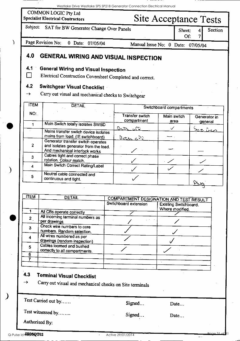
4.0 GENERAL WIRING AND VISUAL INSPECTION
4.1 General Wiring and Visual Inspection Electrical Construction Coversheet Completed and correct.
4.2 Switchgear Visual Checklist -> Carry out visual and mechanical checks to Switchgear
ITEM
NO:
DETAIL .
.
Switchboard compartments
Transfer switch comeartment
Main switch area
Generator in - 9 eneral Main Switch totally isolates SWBD
c; -z.', ,-J:: t/ -,i.- e... .'., t-re-N Mains transfer switch device isolates mains from load. (IE switchboard) CS Z A - < .r. e : C :
2 Generator transfer switch operates and isolates generator from the load. And mechanical interlock works
- Cables tight and correct phase rotation. Colour match. / /
4 Main Switch Correct Rating/Label
5 Neutral cable connected and continuous and tight. /
ITEM DETAIL COMPARTMENT DESIGNATION AND TEST RESULT Switchboard extension Existing Switchboard.
Where modified. 1 All CBs operate correctly / V
All incoming terminal numbers as per drawings I. Check wire numbers to core numbers. Random selection.
/ 4 All wires numbered as per.
drawings (random inspection) 5 Cables loomed and bushed
correctly to all compartments. 6 7
4.3 Terminal Visual Checklist ---> Carry out visual and mechanical checks on Site terminals
Test Carried out by Signed... Date...
Test witnessed by Signed... Date... Authorised By:
J1105QT02
Westlake Drive Westlake SPS SP218 Generator Connection Electrical Manual
Q-Pulse Id TMS706 Active 29/01/2014 Page 31 of 81

COMMON LOGIC Pty Ltd I Specialist Electrical Contractori Site Acceptance Tests Subject: SAT for BW Generator Change Over Panels Sheet: 5
Of: 7
Section
Page Revision No: 0 Date: 07/05/04 Manual Issue No: 0 Date: 07/05/04
ITEM DETAIL COMPARTMENT AND TEST RESULT Switchboard extension Existing Board
1 All Terminals tight ( Randomly check )
.
2 Secure by End Clamps (Check All) / /
3 Labelled correctly 4
4.4 Relay Visual Checklist --> Carry out visual and mechanical checks on Relays ITEM DETAIL COMPARTMENT AND TEST RESULT
1 Rela s labelled correct! as ier Drns / 2 All relay coils correct voltage 3 Does relay require Diode fitted? -- 4 Common Bus Link on relays fitted 5 All numbering correct
Test Carried out by Signed... Date...
Test witnessed by ...... Signed... Date...
Authorised By:
JHO5QT02 / olltkA
Westlake Drive Westlake SPS SP218 Generator Connection Electrical Manual
Q-Pulse Id TMS706 Active 29/01/2014 Page 32 of 81

COMMON LOGIC Pty Ltd Specialist Electrical Contractors Site Acceptance Tests Subject: SAT for BW Generator Change Over Panels Sheet: 6
Of: 7
Section
Page Revision No: 0 Date: 07/05/04 Manual Issue No: 0 Date: 07/05/04
5.0 CONTINUITY & PRE-COMMISSIONING TEST
5.1 Continuity Test -
Wiring of circuits and connections are correct to constructed wiring schematics. Random Continuity Test using Buzzer. Visual Check of all wiring.
-4 Open all Circuit breakers and remove all fuse links -4 Install Test plug in generator end. -> Install RTU terminal Plugs into terminals -3 By pressing the relevant buttons and observing the relevant feedback LED all circuits will be
checked. Test each circuit in turn with corresponding drawings
ITE M
NO .
Test description
Action Observation . Result of test
1 Transfer to Mains Press Button 1 Observe Relay GTSM r 2 Transfer to Gen Press Button 2 Observe Relay GTSG J 3 Generator Failed Press Button 3 Observe Relay GF / 4 Generator Fault Press Button 4 Observe Relay GFR i 5 Gen Running Press Button L Observe Relay GRUN V
.
Check Door Indicator is on when relay is ON
6 Generator Connected Press Button IP I Observe Relay GCONN r 7 Doors Opened Press Button it` -2, Observe Relay GOPEN r 8 CB Tripped Press Button s 7 Observe Relay GCBT r 9 Not in Auto Press Button S 10 Observe Relay GNAUTO r 10 Generator Not On Site Press Button 1 Observe Indicator r 11 Spare 15 Remote Start Press Button 15 Observe Relay GSTART .r 16 Remote Stop Press Button 16 Observe Relay GSTOP sr
1 Mains Failed Close QM1 Indicator ON when PFR is ON r Check Door Indicator is ON when PFR is ON i 2 ATS to Mains Manual Change to
Mains Indicator ON when TXS in Mains
3
4 5 6
ATS To Gen Manual change to Gen
Indicator ON when TSX in GEN
Remote Start Press PB 15 Indicator is on when PB is ON v Remote Sto. . Press PB 16 Indicator is on When PB is ON .
Generator is missin. Press PB 10 Indicator is on when PB is ON
Test Carried out by..S1-.4;* c--eve.- Signed.. Date IZ)-- Cs ci4
Test witnessed by... .01,. P"\`*:-c--rie''' Signed- ate >S: - -T-Cx.4.
Authorised By:
.THOSQT02 01 ill...-. MIAS'S
Westlake Drive Westlake SPS SP218 Generator Connection Electrical Manual
Q-Pulse Id TMS706 Active 29/01/2014 Page 33 of 81

COMMON LOGIC Pty Ltd Specialist Electrical Contractors - Site Acceptance Tests
Subject: SAT for BW Generator Change Over Panels Sheet: 7 Section
Of 7
Page Revision No: 0 Date: 07/05/04 Manual Issue No: 0 Date: 07/05/04
6.0 COMPONENT OPERATIONAL TEST
6.1 Component Operation Test Correct Operation and Voltages All set points and parameters set to test values if required.
6.2 AC Control Systems -÷ Open all circuit breakers and remove all fuse links -+ Test each circuit individually, replacing fuses and closing circuit breakers in turn. AFTER VOLTAGE APPLIED -> Apply mains supply
Carry out voltage and operational checks (ie switch operation etc) -> Bridge control points to check operation as per BW commissioning Sheet -> Apply generator voltage and check operation -> Return to normal and fail the mains -÷ Return the mains -> Carry out a manual transfer
ITEM NO:
DETAIL New Extension Test Result
1 Mains Incoming Voltage Measured OK 2 All CB's are turned off and isolate Crts 3 Phase Fail operates correctly V
Test Carried out by Signed... Date...
Test witnessed by Signed... Date...
Authorised By:
JI105QT02 7 ma.. 7nnA
Westlake Drive Westlake SPS SP218 Generator Connection Electrical Manual
Q-Pulse Id TMS706 Active 29/01/2014 Page 34 of 81

Operation and Maintenance Data Manual
Brisbane city
Brisbane I 3
WaterMizotana
BRISBANE WATER
GENERATOR CONNECTION 0 & M Manual
Section 4A
Site Testing Functional. Description
Westlake Drive Westlake SPS SP218 Generator Connection Electrical Manual
Q-Pulse Id TMS706 Active 29/01/2014 Page 35 of 81

Sewerage System Performance Improvements Backup Diesel Generators for Pump Stations
iu Brisbane, Water );,ovvio,
Brisbane at
PROJECTS - ENGINEERING
Sewerage System Performance Improvements Backup Diesel Generators for Pump Stations
FUNCTIONAL SITE TESTS FOR GENERATOR, AUTOMATIC TRANSFER SWITCH, AND RTU
Prepared by Alan Mooney Telephone - 07 3403 3356 Facsimile - 07 3403 0205
Document ID Genset Functional Tests
Date of Issue June 2003
Revision Rev 1
C :\Documents and Settings1CM21BW\Local Settings \Temp\Genset Functional Tests Revl .doc 1
Westlake Drive Westlake SPS SP218 Generator Connection Electrical Manual
Q-Pulse Id TMS706 Active 29/01/2014 Page 36 of 81

Sewerage System Performance Improvements Backup Diesel Generators for Porno Stations
Actions are shown in RED
1 MANUAL MODE FUNCTIONAL TESTS
1.1 Manual Mode Start Turn the AUTO - TEST - MAN- OFF selector switch to the MANUAL position. Press the MANUAL START push button to start the generator. The generator set is allowed 3 attempts to start. If it fails to start on the third attempt, the generator is locked out on FAIL TO START Alarm. Once the generator has started, there is a 10 second time delay for the oil pressure to stabilise. Once the generator is running there is a 30 second warm up time before it is ready to accept load. RESULTS: PASS/FAIL NOTES
1.2 - Stopping the generator in the Manual Mode. Press the MANUAL STOP push button. If the generator is still GEN ATS operation. The MANUAL TRANSFER TO MAINS is initiated. When the GEN ATS is Open, the generator will enter the cool down time of 1 second. After the cool down time, the generator will shut down. RESULTS: PASS/FAIL NOTES
2 TEST MODE FUNCTIONAL TESTS
2.1 Test Mode Start - and test of Manual Mode interruption Select this operation by turning the AUTO - TEST - MAN- OFF selector switch to the TEST position. The generator shall begin to crank. Change the selector MAN while the generator is operating on TEST: to test that the system shall change to MANUAL TRANSFER TO GEN. Press the MANUAL STOP push button. RESULTS: PASS/FAIL NOTES
2.2 Continue Test Select TEST operation again by turning the AUTO - TEST - MAN- OFF selector switch to the TEST position. The generator shall begin to crank. Once the generator has started, there is a 10 second time delay for the oil pressure to stabilise. Once the generator is running there is a 30 second warm up time before it is ready to accept load. After the warm up time has expired, the MAINS ATS shall Open and the GEN ATS shall Close RESULTS: PASS/FAIL NOTES
C:\Documents and Settings \CM2IBW\Local Settings\Temp\Genset Functional Tests Revl.doc 2
Westlake Drive Westlake SPS SP218 Generator Connection Electrical Manual
Q-Pulse Id TMS706 Active 29/01/2014 Page 37 of 81

Sewerage System Performance Improvements Backup Diesel Generators for Pump Stations
2.3 Stopping Generator In The Test Mode - To Test Mains Failure /Genset Restart During Shutdown
Select this operation by turning the AUTO - TEST - MAN- OFF selector switch to the AUTO or OFF position. The GEN ATS shall Open and the MAINS ATS shall Close When the GEN ATS is Open, the generator will enter the cool down time of 5 minutes.
During this time turn off the Mains to the site When Mains Failure occurs during the cool down period the generator shall transfer back to the GENERATOR ATS without shutting down. RESULTS: PASS/FAIL NOTES
2.4 Stopping generator in the Test Mode. Select this operation by turning the AUTO - TEST - MAN- OFF selector switch to the AUTO or OFF position. The GEN ATS shall Open and the MAINS ATS shall Close After the cool down time of 5 minutes, the generator will shut down. RESULTS: PASS/FAIL NOTES
2.5 Test Mode Selected with genset unavailable (fault or GEN CB off). Make GENSET unavailable Select this operation by turning the AUTO - TEST - MAN- OFF selector switch to the TEST position. Observe results - Genset discussion of preferred results (unit should not start?) RESULTS: PASS/FAIL NOTES
3 AUTOMATIC MODE FUNCTIONAL TESTS
3.1 Automatic Start Select this operation by turning the AUTO - TEST -MAN- OFF selector switch to the AUTO position. Turn off the Mains to the switchboard. The Phase Failure Relay from the clients switch board shall give a Start Signal for the generators to run. Once the generator has started, there is a 10 second time delay for the oil pressure to stabilise. Once the generator is running there is a 30 second warm up time before it is ready to accept load. After the warm up time has expired, the MAINS ATS shall Open and the GEN ATS shall Close. RESULTS: PASS/FAIL NOTES
C:\Documents and Settings \CM2 I BW\Local Sett ings\Temp\GensetFunctional Tests Rev I .doc 3
Westlake Drive Westlake SPS SP218 Generator Connection Electrical Manual
Q-Pulse Id TMS706 Active 29/01/2014 Page 38 of 81

Sewerage System Performance Improvements Backup Diesel Generators for Pump Stations'
3.2 Stopping the generator in the Auto Mode -and testing genset restart for mains failure during cool-down.
Turn on the Mains to the switchboard The Phase Failure Relay from the clients switch board shall give a Stop Signal for the generator There is a 2 minute proving time for the Phase Failure Relay. After the 2 minute proving time the GEN ATS shall Open and the MAINS ATS shall Close When the GEN ATS is Open, the generator will enter the cool down time of 5 minutes.
During this time turn off the Mains to the site When Mains Failure occurs during the cool down period the generator shall transfer back to the GENERATOR ATS without shutting down. RESULTS: PASS/FAIL NOTES
3.3 Stopping the generator in the Auto Mode - continued. Turn on the Mains to the switchboard The Phase Failure Relay from the clients switch board shall give a Stop Signal for the generator There is a 2 minute proving time for the Phase Failure Relay. After the 2 minute proving time the GEN ATS shall Open and the MAINS ATS shall Close When the GEN ATS is Open, the generator will enter the cool down time of 5 minutes. After the cool down time, the generator will shut down. RESULTS: PASS/FAIL NOTES
3.4 Automatic ATS Transfer To Genset- Mains ATS Failure Disable MAINS ATS CB Restart the generator in Auto by turning off the Mains The MAINS ATS will fail to Open: After a 5 second delay an Alarm shall be generated and the MAINS CONNECTED indicator shall flash to indicate the Alarm. The system shall then return back to MAINS ATS operation. Stop the generator using the Stop button RESULTS: PASS/FAIL NOTES
3.5 Automatic ATS Transfer - Gen ATS Failure Re-enable the MAINS ATS CB Disable GEN ATS CB Restart the generator in Auto by turning off the Mains The GEN ATS will fail to Close: After a 5 second delay an Alarm shall be generated and the GENERATOR CONNECTED indicator shall flash to indicate the Alarm. The system shall return back to MAINS ATS operation. Stop the generator using the Stop button RESULTS: PASS/FAIL NOTES
C: \Documents and Settings\CM21BW\ Local Settings\Temp\Genset Functional Tests Revl .doc 4
Westlake Drive Westlake SPS SP218 Generator Connection Electrical Manual
Q-Pulse Id TMS706 Active 29/01/2014 Page 39 of 81

Sewerage System Performance Improvements Backup Diesel Generators for Pump Stations
3.6 Automatic ATS Transfer To Mains - Gen ATS Failure Disable GEN ATS CB Restart the generator in Auto by turning off the Mains The GEN ATS will fail to Open. After a 5 second delay an Alarm shall be generated and the GENERATOR CONNECTED indicator shall flash to indicate the Alarm. The system shall return back to GEN ATS operation. Stop the generator using the Stop button RESULTS: PASS/FAIL NOTES
3.7 Automatic ATS Transfer To Mains - Mains ATS Failure Re-enable the GEN ATS CB Disable MAINS ATS CB Restart the generator in Auto by turning .off the Mains The MAINS ATS will fail to Close. After a 5 second delay an Alarm shall be generated and the MAINS CONNECTED indicator shall flash to indicate the Alarm. The system shall return back to GEN ATS operation. RESULTS: PASS/FAIL NOTES
3.8 Running in Auto and umbilical looses connection. Select this operation by turning the AUTO - TEST - MAN- OFF selector switch to the AUTO position. Turn off the Mains to the switchboard. The Phase Failure Relay from the clients switch board shall give a Start Signal for the generators to run. Once the generator has started, there is a 10 second time delay for the oil pressure to stabilise. Once the generator is running there is a 30 second warm up time before it is ready to accept load. After the warm up time has expired, the MAINS ATS shall Open and the GEN ATS shall Close. Remove umbilical plug Observe results - Genset discussion of preferred results (ATS returns to MAINS?) RESULTS: PASS/FAIL NOTES
3.9 Running in Auto and genset trips or faults. Select this operation by turning the AUTO - TEST - MAN- OFF selector switch to the AUTO position. Turn off the Mains to the switchboard. The Phase Failure Relay from the clients switch board shall give a Start Signal for the generators to run. Once the generator has started, there is a 10 second time delay for the oil pressure to stabilise. Once the generator is running there is a 30 second warm up time before it is ready to accept load. After the warm up time has expired, the MAINS ATS shall Open and the GEN ATS shall Close. Cause Genset trip or fault Observe results - Genset discussion of preferred results (ATS returns to MAINS?) RESULTS: PASS/FAIL NOTES
C:\Documents and Settings\CM2IBM Local Settings\Temp\Genset Functional Tests Revl.doc 5
Westlake Drive Westlake SPS SP218 Generator Connection Electrical Manual
Q-Pulse Id TMS706 Active 29/01/2014 Page 40 of 81

Sewerage System Performance Improvements Backup Diesel Generators for Pump Stations
4 REMOTE START/STOP TESTS
4.1 Remote start command. Select this operation by turning the AUTO - TEST - MAN- OFF selector switch to the AUTO position. Initiate a Remote Start Command from the BW Control Room Once the generator has started, there is a 10 second time delay for the oil pressure to stabilise. Once the generator is running there is a 30 second warm up time before it is ready to accept load. After the warm up time has expired, the MAINS ATS shall Open and the GEN ATS shall Close. RESULTS: PASS/FAIL NOTES
4.2 Remote stop command. Initiate a Remote Start Command from the BW Control Room The GEN ATS shall Open and the MAINS ATS shall Close When the GEN ATS is Open, the generator will enter the cool down time of 5 minutes. After the cool down time, the generator will shut down. RESULTS: PASS/FAIL NOTES
4.3 Remote Start with genset unavailable. Make GENSET unavailable Initiate a Remote Start Command from the BW Control Room Observe results - Genset discussion of preferred results (unit should not transfer to MAINS?) RESULTS: PASS/FAIL NOTES
4.4 Remote Stop with when running with MAINS not available unavailable. Select this operation by turning the AUTO - TEST - MAN- OFF selector switch to the AUTO position. Turn off the Mains to the switchboard. The Phase Failure Relay from the clients switch board shall give a Start Signal for the generators to run. Once the generator has started, there is a 10 second time delay for the oil pressure to stabilise. Once the generator is running there is a 30 second warm up time before it is ready to accept load. After the warm up time has expired, the MAINS ATS shall Open and the GEN ATS shall Close. Initiate a Remote Start Command from the BW Control Room Observe results - Genset discussion of preferred results (unit should not transfer to MAINS?) RESULTS: PASS/FAIL NOTES
5 SPECIFIC PROBLEM CHECKS (Variations to Functional Spec)
5.1 RTU I0 and MS Alarms The assumption is that all RTU I0 and alarms have been proven by NCS.
CADocuments and Settings\CM2IBM Local Settings\Temp\Genset Functional Tests Revl.doc 6
Westlake Drive Westlake SPS SP218 Generator Connection Electrical Manual
Q-Pulse Id TMS706 Active 29/01/2014 Page 41 of 81
Sewerage System Performance Improvements Backup Diesel Generators for Pump Stations
5.2 From discussions on Indooroopilly Rd: If the Genset ATS trips when genset is running - will ATS switch back to Mains? If the Genset ATS trips when genset is running (medium alarm) - will ATS switch back to Mains?
If the Genset on-board CB trips when genset is running - will ATS switch back to Mains?
If the Mains ATS trips when genset is not running - will the genset start? Eg Monitor the Mains ATS and allow the Gen ATS to take load when the Mains ATS is tripped. The problem is that genset start is initiated by PFR above the ATS.
If Mains trips amd no genset start is initiated (?) and then Remote Start signal is sent will unit start and then transfer to GENSET
Does a Remote start "reset" the tripped ATS CB or provide a "work-around"?
5.3 From M&E:
11/ The remote start ( from control room ) was sent with the Generator C/B in the off / tripped position. The generator started and the ATS Switched to generator supply. The generator continued to run with out supplying the site ( C/B was off) and failed to transfer back to.the available Energex supply with out a remote stop signal.
5.4 From Contract: Performance guarantee of not less than 0.8pu at alternator terminals during startup - measure volts drop on start-up of load.
C: \Documents and Settings\CM2IBW\Local Settings\Temp\Genset Functional Tests Revl.doc 7
Westlake Drive Westlake SPS SP218 Generator Connection Electrical Manual
Q-Pulse Id TMS706 Active 29/01/2014 Page 42 of 81

Sewerage System Performance Improvements Backup Diesel Generators for Pump Stations
6 FAULTS - TO BE TESTED WHERE REQUIRED
6.1 HIGH HIGH Alarm Operation. The Generator CB is Opened immediately. The generator is shut down immediately.
The following alarms will initiate a HIGH HIGH Alarm condition :-
Emergency Stop Fault MEN Fault Low Oil Pressure Shutdown Fault, 10 Seconds Startup Delay High Engine Temperature Shutdown Fault, 30 second Startup Delay Low Radiator Level Fault, 5 Second Delay Over Speed Fault
6.2 HIGH Alarm Operation The Generator CB is Opened immediately. Once the generator circuit breaker is opened, the generator will run through its normal cool down time and shut down.
The following alarms will initiate a HIGH Alarm condition: - Generator Under Speed Fault, 5 Second Delay Alternator Under Voltage Fault, 5 Second Delay Alternator Over Voltage Fault, 5 Second Delay Generator CB Tripped Fault Alternator High Temperature Fault, 30 Second Startup Delay
6.3 MEDIUM Alarm Operation. A Normal Shutdown shall be Initiated. If the GEN ATS does not Open then the Generator CB is Opened.
The following alarms will initiate a MEDIUM Alarm condition :-
Fuel Empty Level Fault, 5 Second Delay Fail To Start Fault, 3 Attempts
6.4 LOW Alarm Operation. A Warning has occurred on the generator. The generator will not shut down for this level of alarm.
The following alarms will initiate a LOW Alarm condition :-
Low Oil Pressure Warning Alarm, 10 Seconds Startup Delay High. Engine Temperature Warning Alarm, 30 Second Startup Delay Fuel Low Level Alarm, 5 Second Delay Battery Charger AC Supply Failed Alarm, 60 Second Delay Control Battery Low Volts Alarm, 30 Second Delay Start Battery Low Volts Alarm, 60 Second Delay
C:\Documents and Settings \CM2I BW\Local Settings\Temp\Genset Functional Tests Rev I .doc 8
Westlake Drive Westlake SPS SP218 Generator Connection Electrical Manual
Q-Pulse Id TMS706 Active 29/01/2014 Page 43 of 81

Sewerage System Performance Improvements Backup Diesel Generators for Pump Stations.
FATA LATERDATE??1
3. NON-PERMANENT SITE, MANUAL MODE 3.1. To operate GI in a Non-Permanent Site Location in MANUAL Mode. 3.2. Connect the generator cables to the site generator CB ensuring the site generator CB is
OFF. See BCC procedures. 3.3. A plug with shorting links is required to be installed. It is required to be plugged into the 27 Pin Station Plug. 3.3.1. Pins 11 and 12 are required to be connected. This is to indicate that the Mains ATS is
Closed. If they are not connected a MAINS ATS Alarm shall be indicated. 3.4. Select from the AUTO - TEST - MAN- OFF selector switch to the MANUAL position. 3.5. Press the MANUAL START push button to start the generator. 3.6. The generator will begin to crank 3.6.1. If it fails to start within the 10 seconds, the starter motor is stopped and a delay of 10 seconds before it will attempt to restart. 3.6.2. The generator set is allowed 3 attempts to start. 3.6.3. If it fails to start on the third attempt, the generator is locked out on FAIL TO START Alarm. 3.6.4. When the generator starts, the starter motor is stopped by a stop cranking input which measures the speed of the generator. 3.6.5. Once the generator has started, there is a 10 second time delay for the oil pressure to stabilise. 3.6.6. If the oil pressure is not up to pressure after the 10 second time delay, the generator shall shut down on LOW OIL PRESS Alarm. 3.6.7. Once the generator is running there is a 5 second warm up time before it is ready to accept load. 3.7. To connect the generator to the site load. 3.7.1. Manually switch over to the generator supply via the site CB's. See BCC procedures. 3.7.2. Do not use the MANUAL TRANSFER TO GEN or the MAN TRANSFER TO MAINS push buttons. 3.8. To disconnect the generator from the site load. 3.8.1. Manually switch over to the mains supply via the site CB's. See BCC procedures. 3.8.2. Do not use the MANUAL TRANSFER TO GEN or the MAN TRANSFER TO MAINS push buttons. 3.9. To stop the generator in the MANUAL Mode. 3.9.1. When the generator is running, it may be stopped by pressing the MANUAL STOP push button. 3.9.2. The generator will enter the cool down time of 1 second. 3.9.3. After the cool down time, the generator will shut down. 3.9.4. Once the generator has shut down there is a 15 second delay before it may be restarted. This is to ensure the engine has mechanically stopped.
CADocuments and Settings \CM2IBW\ Local Settings\ Temp \Genset Functional Tests Revl .doc 9
Westlake Drive Westlake SPS SP218 Generator Connection Electrical Manual
Q-Pulse Id TMS706 Active 29/01/2014 Page 44 of 81

Operation and Maintenance Data Manual
Brisbane City
- Brishane" pro,
der :nent:
BRISBANE WATER
GENERATOR CONNECTION 0 & M Manual
Section 4B
Site Testing NCS Alarms
Westlake Drive Westlake SPS SP218 Generator Connection Electrical Manual
Q-Pulse Id TMS706 Active 29/01/2014 Page 45 of 81

'U
&Mane City
Water jM
BRISBANE WATER Network Control Systems
IDTS POINT COMMISSIONING SHEET
AND GENERATOR SUPPLY
OPERATIONAL CHECKS
Pump Station Generator Connection Project (STTX- 1910)
DATE: 30/6/04
Site Name: SP218 Westlake Dr
Westlake Drive Westlake SPS SP218 Generator Connection Electrical Manual
Q-Pulse Id TMS706 Active 29/01/2014 Page 46 of 81

Brisbane Water - Network Control Systems Section
NOTE: Some (or all) of the Generator associated IDTS points may be Scan Inhibited in the IDTS system. Remove the Scan Inhibit from these points before proceeding with these tests
IDTS Point : Generator Offsite
Action Observation Result
Connect the Control interface lead to the station
Confirm that GENERATOR OFFSITE alarm return to normal is received by IDTS
Disconnect the Control interface lead to the station
Confirm that GENERATOR OFFSITE alarm is received by IDTS
Reconnect the Control interface lead to the station
IDTS Point : Security Door limit switch
Action Observation - Result
Open a canopy door on the Generator Confirm that SECURITY DOOR LIMIT SWITCH alarm is received by IDTS
Close the canopy door Confirm that SECURITY DOOR LIMIT SWITCH alarm return to normal is received by IDTS
IDTS Point : Generator Low_fuel
Action Observation Result
Make the Generator low fuel warning alarm active
Confirm that GENERATOR LOW_FUEL alarm is received by IDTS
Deactivate -the. Generator low fuel warning alarm
Confirm that GENERATOR LOW_FUEL alarm return to normal is received SY IDTS
IDTS Point : Generator Warning
Action Observation Result
Make the Generator warning alarm active (except by low fuel)
Confirm that GENERATOR WARNING alarm is received by IDTS
Deactivate the Generator warning alarm Confirm that GENERATOR WARNING alarm return to normal is received by IDTS
IDTS Point : Generator Common_ fault
Action Observation Result
Make the Generator common fault alarm active
Confirm that GENERATOR COMMON_FAULT alarm is received by IDTS
Deactivate the Generator common fault alarm
Confirm that GENERATOR COMMON_FAULT alarm return to normal is received by IDTS
,7.-.,-
'
GAGNRASSOfficer DirectorvACM21.BW\oens\commisionino \Generator. POTS Beanland..doc Pate. 2.of 5
Westlake Drive Westlake SPS SP218 Generator Connection Electrical Manual
Q-Pulse Id TMS706 Active 29/01/2014 Page 47 of 81

Brisbane Water -. Network Control Systems Section
IDTS Point : Generator Automatic
Action Observation Result
Turn the generator to local mode Confirm that GENERATOR AUTOMATIC alarm is received by IDTS
Return the generator to automatic mode Confirm that GENERATOR AUTOMATIC alarm return to normal is received by IDTS
IDTS Point : Generator CB tripped
Action Observation Result
Trip the Generator circuit breaker Confirm that GENERATOR CB_TRIPPED alarm is received by IDTS
Reset the Generator circuit breaker Confirm that GENERATOR CB_TRIF'PED alarm return to normal is received by IDTS
IDTS Point : Generator Running
Action Observation Result
Start the Generator (off line only) Confirm that GENERATOR RUNNING alarm is received by IDTS
Stop the Generator Confirm that GENERATOR RUNNING alarm return to normal is received by IDTS
IDTS Control Points : Generator Remote run request
& Generator Remote stop request
Action Observation Result
Confirm the Generator is available to run, but not running Set the IDTS control point GENERATOR REMOTE_RUN_REQUEST and send to the site
Confirm that the Generator starts and runs off-line Confirm that GENERATOR RUNNING alarm is received by IDTS
Set the IDTS control point GENERATOR REMOTE_STOP_REQUEST and send to the site
Confirm that the Generator stops
Confirm that GENERATOR RUNNING alarm return to normal is received by IDTS
IDTS Point : Power supply Energex_power
Action Observation Result
Turn the generator to local mode
Fail the Energex power Confirm that POWER_SUPPLY ENERGEX POWER alarm is received by IDTS
Restore the Energex power Confirm that POWER_SUPPLY ENERGEX POWER alarm return to normal is received by IDTS
GACNPMSS1Officer DirectonACM21E0Maenstonvnisionina1Generator IDTS Beanland.doc Paae 3 of 5
Westlake Drive Westlake SPS SP218 Generator Connection Electrical Manual
Q-Pulse Id TMS706 Active 29/01/2014 Page 48 of 81

Brisbane Water - Network Control Systems Section
IDTS Point : Generator Connected and
Generator supply operational checks
NOTE: The purpose of these operational checks is;
to confirm Generator is capable of starting all available pumps on site "simultaneously" (each pump start separated only by the RTU /PLC minimum
pump start separation time), and running all pumps continuously for at least one minute. to confirm the pumps are interlocked under Generator supply (where required) to confirm the code changes have not interfered with the operation of the Surcharge Imminent probe.
Action Observation Result
Ensure the Generator is in Automatic mode
Ensure the pumps are selected for local mode
Ensure there is enough sewage in the well for the pumps to run continuously for one minute Fail the Energex power to the Generator Confirm that the Generator starts and
supplies power to the station Confirm that GENERATOR CONNECTED alarm is received by IDTS
Press all pumps local start buttons together Confirm that all pumps (available under Generator supply) start
Sites: Billan St, Musgrave Rd, Centenary Confirm the RTU will run a maximum of one pump under generator supply. Hwy / Kooringal Dr, Manet St, Sanananda
St and Sinnamon Rd. Site: Creek Rd / Oldfield Rd Confirm the RTU will run a maximum of
two pumps under generator supply. Restore Energex power and record the time taken for the Generator controller to return the station power to Energex supply
Time for station power to return to Energex supply Confirm that GENERATOR CONNECTED alarm return to normal is received by IDTS
Record time taken for the Generator to stop after station power to returns to Energex supply
Time for Generator to stop after station power to returns to Energex supply
GACNPMSSNOfficer DirectorACM21BWaenstommisioninthGenerator IDTS Beanland.doc Paae 4 of 5
Westlake Drive Westlake SPS SP218 Generator Connection Electrical Manual
Q-Pulse Id TMS706 Active 29/01/2014 Page 49 of 81

Brisbane Water - Network Control Systems Section
Pump Automatic operation, and
Surcharge Imminent operation under Generator supply
Action Observation Result
Fail the Energex power to the Generator Confirm that the Generator starts and susples power to the station
Ensure the pumps are selected for remote mode
Fixed speed pump sites: Confirm that the duty pump lowers the well to the Duty A stop level and stops Variable speed pump sites: Confirm that the duty pump operates on variable speed control satisfactorily
Ensure the well level is below the Duty A start level using pump local control as required Ensure the pumps are selected for remote mode and are stopped Activate the surcharge imminent probe for at least 10 sec
Confirm that WET_WELL SURCHARGE_IMMINENT alarm is received by IDTS Confirm that all pumps (available under Generator supply) start
Ensure the well does not fall below the Duty A stop level by selecting local mode for the pumps as required Return the surcharge imminent probe to normal
Confirm that WET_WELL SURCHARGE_IMMINENT alarm return to normal is received by IDTS
Restore Energex power indication to the Generator and allow the Generator controller to return the station power to Energex supply
Commissioning Notes:
1. Tested and Site Left In On/Auto Position
IDTS Points and Generator Supply
Operational Checks commissioned by ...Peter Rennes Date 30/6/04
G :\CNPMSS \Officer Directorv\CM21 BW\aenstommisionina1Generator IDTS Beanland_doc Paae 5 of 5
Westlake Drive Westlake SPS SP218 Generator Connection Electrical Manual
Q-Pulse Id TMS706 Active 29/01/2014 Page 50 of 81

Operation and Maintenance Data Manual
-n71-21:1ET,
Brisbane aty Brisbane Praject
agement WaterAto' BRISBANE WATER
GENERATOR CONNECTION 0 & M Manual
Section 4C
Site Testing Generator
Westlake Drive Westlake SPS SP218 Generator Connection Electrical Manual
Q-Pulse Id TMS706 Active 29/01/2014 Page 51 of 81

SE Power Equipment 47 Proprietary Street, Tingalpa, QId 4173
Telephone: (07) 3890 1744
PO [lox 3306 lingalpa B.C. Qld 4173
DIESEL GENERATOR SET
CONTROL FUNCTION TEST REPORT
CLIENT: 13)P-AS LAJ lakTek.
SERIAL NO: CAol c7 13 ENGINE TYPE:
ALTERNATOR TYPE: ;7 c+
SP a %
SEP 009/B
DATE: q/8/0.3 JOB NO: ikel- °I
ENG. SERIAL NO: a 4 aa ALT. SERIAL NO: 011 00 5t
3ENSET CONTROL FUNCTIONS FUNCTION LAMP REMARKS Engine High Temp. Alarm ,,,
...- ..' Engine High Temp. Shutdown _ow Water Level Alarm A.,,q- ivp-
'13 Tripped/Alt., Overload ,...-/ ,....-
ow Oil Pressure Alarm ---
ow Oil Pressure Shutdown --,
me - ncv Stop .;---
_
.tart Fail Alarm enset Running ,,, ,,,' EN Fault
...v ,---
tarter Motor Relay uel Low uel Empty -,.--' .- ngine Gauges ,..7
.tatus Lamps/Controls nderspeed Shutdown -V--- verspeed Shutdown ,--
"emote Start/Ste. -m Test ,--'
I ,rm Shudown / --- It Undervolts ,-- ,-,
It Overvolts harger AC Failed
control Batt. Low Volts ./ ,---
Start Batt. Low volts 4,./ ,-/-
canopy doors Open Audible Alarm/Mute -- Remote ATS Controls ,-, "-- Alternator High Temperature A/ f4 /VA-
CUSTOMER TESTING OFFICER: TESTING OFFICER: 10114/ RoTM
Westlake Drive Westlake SPS SP218 Generator Connection Electrical Manual
Q-Pulse Id TMS706 Active 29/01/2014 Page 52 of 81

47 Proprietary Swett Tingalpa Q 4173 13R.ISBANE AUSTRALIA
CLIENT:
SERIAL NO:
ENGINE TYPE:
ALTERNATOR TYPE:
GOVERNOR TYPE:
OVERSPEED TYPE:
. W.frcrE>2
0 301 ot 3 Froc-9t2---
a-4 -BA.E.it-X
LOAD TEST REPORT
Se..Q
SHUTDOWN SOLENOID: N\,1 _ LOW OIL PRESSURE SHUTDOWN:
A: k LcA KW: 1 to
DATE: TO /03 JOB NO/CONTRACT' NO:
ENG. SERIAL NO:
ALL SERIAL NO:
STARTER MOTOR:
UNDERSPEED TYPE:
HIGH WATER:
Ser oo6yA
tf- t
1,64 6-7 CD4 551 DEv12 Dos', to k
TIME 08lic ,0/0 0 .030 1000 1030 I I3o //3
OIL PRESSURE 500 4o0 30° 2t0 0 2oo 29-o
OIL TEMPERATURE 0 8 '?0 o 90 loc.) . to
JACKET WATER TEMPERATURE
A fr'i
11'' 1 R :,. _
'7 . 7 43.'7. 4? .6 0 VOLTS
1_, 4 I _V ,, --,'
..--.
AMBIENT TEMPERATURE
20'2 2oP 20" 00° 20 20 20 HZ
5-0-2 50.2- 50 '2- 60 '2 .3-0
rk..1 0 3i 3!-- c 31 .,5 31.5
' LOAD%
0 ( P- 4ARKS
Otrtaator_ Load _Tc Report.dilc
Westlake Drive Westlake SPS SP218 Generator Connection Electrical Manual
Q-Pulse Id TMS706 Active 29/01/2014 Page 53 of 81

47 Proprietary Street Tingalpa 0 4173 BRISBANE AUSTRALIA
git0
'FINAL INSPECTION CHECKLIST
This form is to be completely filled out before any generating set leaves the
factory.
SEP 0013
It is to be signed by the person doing the inspection and by their immediate supervisor. In the case of 4 non-standard job it must also be signed by the Special Projects Manager or the Engineering Manager.
A copy of this form is to'be sent out with the plant concerned.
Please neatly tick in the. bOxes provided where applicable and note any comments in the space provided.
MODEL:
ice NO:
S(2 a I SERIAL NO: 03010i73 /
t.1.4 t DATE: 4/9e:/03 CUSTCtER:
ENGINE No: 0-3-57 . ,
BASE
(1) All welds continuous, neat and clean. (-2)- 'All bolts (3) Bearers completely secured. (4) No sharp corners.
RADIATOR
(1) Radiator correctly mounted. (2) All pipework included and secure. (3) Drain plug in place. (4) Water removed from radiator. (5) Clamps on hoses tight.
ENGINE
(1) Fan is correctly mounted. (2) All guards in place and secure. (3) Wiring loom is correct to drawing, securely fixed and marked and is
terminated in an appropriate terminal box. (4) Battery leads attached' and secure and long enough for termination to-battery. (5) Air cleaner is properly mounted. (6) Magnetic pickup is fitted and set to correct depth. (7) Exhaust pipe and silencer (where required) are fitted correctly. (8) Dip stick in place. (9) Oil removed from engine. (10) All fuel and'oil unions completely tightened. (11) All ordered options are fitted and function correctly. (12) All parts secure, no damage. (13) All earths less than 0.1 ohms. (14) Cables and hoses secure for transport.
CONTROL SYSTEM (where applicable)
(1)
(2)
(3)
(4)
(5)
(6)
(7)
Control functions as ordered. Control is mounted correctly. All leads, terminals, fuses, printed circuit boards and switchgear are completely secure and marked correctly. Dust seals are fitted around doors. Doors hinged correctly. All earths less than 0.1 ohms. Red Danger labels in cubicle.
Westlake Drive Westlake SPS SP218 Generator Connection Electrical Manual
Q-Pulse Id TMS706 Active 29/01/2014 Page 54 of 81

INSPECTION
CONTROL SYSTEM (cont)
(8) Perspex shield secure, clean and no sharp corners.
(9) Cables correct, no damage.
(10) Locks and keys satisfactory.
ALTERNATOR
(1), Alternator is correctly mounted.
(2) Alternator leads are correctly mounted inside terminal box and marked
correctly.
(3) A.V.R. is mounted, connected properly and set to correct setting.
(4) Coupling and adaptor are properly fastened between engine and alternator
with correct size and tensile grade bolts.
(5) All options ordered are fitted and function properly.
(6) Alternator is,correctly wired for the appropriate voltage as per either
Order or Bills of Material.
(7) Earth stud fitted.
FINISH
(1) Plant is painted to correct colour. (2) All blemishes in finish, especially paint runs, are completely removed.
GENERAL INSPECTION
(1) Genset is manufactured to correct engine/alternator/radiator/bases configuration as specified on Bill of Materials.
(2) All documents are in a sealed plastic bay and secured inside alternator
terminal box.
. (3) (4)
SIGNED:
a) Engine Handbook b) Alternator Handbook c) Warranty Card d) Packing List .e) Test. Sheet
No Oil/No Water label is attached to positive battery lead.
Alllabels are straight and in correct location.
S. INSPECTOR
QUALITY ASSURANCE
CGMENTS:
60/VT/?(A. 1)00/11/f /W/I Vil(S-5frii
Westlake Drive Westlake SPS SP218 Generator Connection Electrical Manual
Q-Pulse Id TMS706 Active 29/01/2014 Page 55 of 81

9.4*W
42;6 GENERATOR SET
SOUND PRESSURE LEVEL TEST REPORT
47 Proprietary Street Tingalpa Q 4173 BRISBANE AUSTRALIA
CLIENT: Bets COAT tX SPA/ 2-
SERIAL NO: 19-30)01 ENGINE TYPE: Rot--9 ALTERNATOR TYPE: cZ-11--f
SOUND LEVEL INSTRUMENT'
5 6\.
a
4 -sir
7 8
ALT
ENG
RAD
DATE*
JOB NO:
ENG. SERIAL NO:
ALT. SERIAL NO:
Lf4,) s / ot-t 0 0551
4 10
/FN 11 2 1 12
Position Layout
Remarks:
Distance: m
Height:
40/.1-P f911 ea, 4. c r-0 rd5 iN775/1.Feit 60t714-
..c5olvt) 11 POSITION SOUND LEVEL
dB(A) 1,0AD %
25 50 75 100 110
/0 2 7 (2 3 "20 4 70 5 71. 6 7/ 1 7
8 -2 / T
9 / I. 1
10 _3 I
7 i 11
12 7 I
Average
QUALITY ASSURANCE OFFICER
CUSTOMER TESTING OFFICER. TESTING OFFICER: .
0_ NI A v
WITNESS TESTING OFFICER: . DOVIO COO?trP .
Westlake Drive Westlake SPS SP218 Generator Connection Electrical Manual
Q-Pulse Id TMS706 Active 29/01/2014 Page 56 of 81

47 Proprietary Street
Tingalpa
Old
4173
PH:
(07) 3890 1744
TR
AN
SEE
NT
L
OA
D
RE
SPON
SE T
EST
SHEET
Transient response for load changes: ;Load PF 0.8
SEP0084
% Change
Electrical
kW
0-25 0-50
0-75 0-100
I 100-0
75-0
50-0
25-0
Change in E
lectrical kW
.
% Change HZ
% Change Volts
T-
O
Recovery secs
4 -2.
Cut
Ukc,
Kb
t (Or-A
c D
1 o1 013
zr
Westlake Drive Westlake SPS SP218 Generator Connection Electrical Manual
Q-Pulse Id TMS706 Active 29/01/2014 Page 57 of 81

Operation and Maintenance Data Manual
'TM
Blisbane City
Brisbane Water l'italdn-6"
BRISBANE WATER
GENERATOR CONNECTION 0 & M Manual
Section 4D
Electrical Testing Certificate
Westlake Drive Westlake SPS SP218 Generator Connection Electrical Manual
Q-Pulse Id TMS706 Active 29/01/2014 Page 58 of 81

. .-:,::,...,, : ..1-7-- 2-,.,...,-,-1 --.- - -- ... -,.. -
, A' di pirogiel ::74:----r.. ,:-.% --; ' Job Cirri Nitin 3
- -,----.74-, _ ._-, _.2z, - --_ -. -------7,:l., ---._ _ .-----, - . .4 -... -. - - -- " - ,', - .
'' .
..e.... , Variation oniTo Fixed Price
Cost Phis .,-.,',.... - --J. ,;:-_--- -_,,
,---- -:-- .. -,_ -4d:4*-,,-ZA '-'"--
... -- :': z..,z- - - ' -I'll - Fi7..f,...e-4- . P -e-t.
.:-".,.., 4.-1,--;?
. _:-.:*.k-.-47-A,
- ' .11E---_ '_0-44;:nr.,_'''='-i---Lz':".:
,,e-r,-_,/..,r..::: _ -A,4-zi---.4_. ---.:-
':.-:-.4-&-IP...11..:-..g. --. -',.--..,,, - ...-iis. , - -- -,.1-441v,,- - Tr:7.--A ...,.....--3....,:mt--- :::: .-- - ....1.=, ...: _.."...,--.."1,f-: .... _.ier_--. --': _ . --7'.-, _4; 4- 9 - ---.",--- .-:' . -' - ' 1
1,2._.-4 .j-7 - a.::;-11-= - .-..-.. ;_ii.--f_-..... ..--:-*- '-" - - -,_ -
.--,t;:---0-'4-44.., e..t. ,-...-t- :-':,:Y::z- R--....- ..-.1...7:-.1q14- _, . ,2-_,--v ,
- " 1"4. - -4' - -z..----:--. , ---: );"--...;, -
Power- c ..-...:::-, ,,_...... .-.
. ' - - ;-; -i -"A :77-717-*-t----, .--7; tizTeigyr.-1,...,:
........,,,,,,.v,....- .:- ea....i,-1111., : . ,{1, 14 ... , ,.- : .........,
--- - --- -2.- -- ----:-.--:-= -.:- -. . z Pre-Start Sale
, , -4P",- ' . 4
:.-, ,-- _2,.. -
Risk AsidSsiniiiiti. '.'' ----:'-.;--,7-7.-
4741,,,,,,,r z ,,..e..---",,,7F-ACITWW" - .12.-7V.V= 4.!.: - 2.-- ,. . ....2 ..t, ,- ,.
1--a-t- -.=',1;"-' -4......titarrig ' V Aar- ,41AML311 ...2..:-,e:TL,..
',4`...5:::. 1 _.,-1?_1,._1i, ri-.4----._,...-,A - , -1 -4 -
.
,... _ . .... . ,.. fti4eL.q,.:,.. --
- -
START FNISt DErlis .-;,,i..;caF- If..4''.771:4 -V. - -
,'-0` 6-;--!,.. ,. HARD . ' se4-',17-- --, ,--,.- '..:.'.. ,
TAVEL TO SfrEyi-- ....7.....,...i..<-,...
...A:cm-
-.:*-i: ' C'.1-.4,-..."..-- x Z '''
- - -...,,-'
, . .
, . 1. Pr 'Ai ' ' '' .
...N 4- ,-,..,
......-, ' - ' -
1.".M.:,..: .1,,
-
--.... -, -, -.`: - ,.. ." .-- ..7"-S
II N Z.e.' -
-- : ,, .:..::...
-,--
- - --."-; -
-1.-- .- :, .--r- .*--
e::"'.. '.4-111(r-4- . ,_
.
..
- ," ) yI .-.-...
- . .
7..., - - -
. ,,
- -
' ' ."--
. .
" . -,--
.. . ' - -
. .
. .. ASE SEE ATTACHED FORM FOR ADDITIONAL ' fl TOTAL LABOUR CHARGED:
ITEM No PART No -ITEM DESCRIPTION. ..
. .
ITEM cosT ITEM
TOTAL ! COST
--- CHARGED
1. . .
-
-
2. .
3.
4.
6.
7.
8.
9. -
PLEASE SEE ATTACHED FORM FOR ADDITIONAL TOTAL MATERIALS: _ .
PROGRESS CLAIM - FURTHER-WORK PROJECT COMPLETED _
WORKS NOT COMPLETED REQUIRED TO - . NO FURTHER ACTION
AND NOT TESTED .. . _COMPLETE PROJECT REQUIRED
- .. -MOTE COPY- CUSTOMER , YELLOW COPY -;.:OFF10E
above --t7.. ' ' (-1Fertify that the Electrical-Week !feted -,ifis been tested In accordanct with the -- ' -
prescribed procedure and that such work . f
complies with the requirements of the State Electricity Act.
Signature: Ci1/11)
POLARITY TEST. ,
INSULATION RES. TEST
-ETH CONTINUITY TEST
FUNCTIONAL TEST
Common Logic Pty Ltd Unit 9/58 Wecker Road, Mansfield 4122 Ph: (07) 3849 7449 Fax: (07) 3343 5210
Westlake Drive Westlake SPS SP218 Generator Connection Electrical Manual
Q-Pulse Id TMS706 Active 29/01/2014 Page 59 of 81

Operation and Maintenance Data Manual
Brisbane City Water Brisbane_
BRISBANE WATER
GENERATOR CONNECTION 0 & M Manual
Section 5
Parts Information
Westlake Drive Westlake SPS SP218 Generator Connection Electrical Manual
Q-Pulse Id TMS706 Active 29/01/2014 Page 60 of 81

_003 9 : 43 Common Logic
type 66H Polyniar Concrete Pit
dd7ottnt X 66Yretn R ,15avon depth
Pit Data lissalphan
0
peg lieleW 11ee 1p
11}7 (p! /Wm. Cower fa MN .14.4 1}71 diff Moot &med. Pk let ieilag Caves )1.211 P.O ryet41hiratt Cameo jiu Rite 7$124 11A Iyet 4 4 Poirm Ono* feautslan Idwter !Away Cott 711.13 214
Corer Data Dextfellon Part Wdifin
Al
NM a Petsage [vadat 1141. 110A1 7110 14.2
10414 Po as fettactt IM. Csiamaiettkat 11114 MI not U Istpett Cucteto lid Up:white 14.z
Teet U Gilteorbet Ate, COW 7$111
7101 teethe Volteefoott JJertf Cove' 71111. 11.1
toe a Affitlly L.dhre GeteSIMI Val Cair 11101 111.1
Int di Vett poly Refund *tea Cove lod t Seed pH? 11.1
Tfpft4AN4Pvte M o w / M a r a t a w led 11W S 7 1 2 1 1 1 1 . $
+61733435210
..
ACO CABLEMATE.
ottelisedeol
Wel oawr
6908'0N L16SL9ECLO 010 310130838V
*Wr loddme
y oww
WA* but
10$411:41011" .
pheavyte Ate Itiche 4tucht4 ta mew
i=1.611
300111/0 1110
CAPCW oargNui 1114f
6E: t1 £00Z
p.3 Westlake Drive Westlake SPS SP218 Generator Connection Electrical Manual
Q-Pulse Id TMS706 Active 29/01/2014 Page 61 of 81

Alfred Platinum Edition On The Web Page 1 of 1
Catalogue No. 56A1310
Colour Options Grey
Resistant Orange
GY
RO
More colour options may be available. Please check with your nearest Clipsal office.
Description: Appliance Inlets, 250V 10A - 3 Flat pins
Item Type 02 Industrial Products
Business Area 40 Industrial Switchgear
Product Group 400 56 Series Industrial Switchgear
Item Group 40001 Appliance Inlets
Brochures Available: 56AI Series installation instructions
56 Series flyer
56 and 66 Series technical data
56 Series Features
A Specifiers guide to Clipsal Industrial
A Specifiers guide to Clipsal Industrial
A Specifiers guide to Clipsal Industrial
http://alfred.clipsal.com/scripts/apeweb.dll?PrintCatNo&CatNo=56A1310 18/06/2004
Westlake Drive Westlake SPS SP218 Generator Connection Electrical Manual
Q-Pulse Id TMS706 Active 29/01/2014 Page 62 of 81

Alfred Platinum Edition On The Web . Page 1 of 1
Catalogue No. WIPM27
Colour Options No colour options
Transparent TR
More colour options may be available. Please check with your nearest Clipsal office.
Description: Plugs And Extension Sockets - Wilco, Low Voltage, Multipin - 27 pin maximum
Item Type 02 Industrial Products
Business Area 40 Industrial Switchgear
Product Group 403 Wilco Hi-Impact Industrial Switchgear
Item Group 40303 Plugs & Extension Sockets
Brochures Available: A Specifiers guide to Clipsal Industrial
A Specifiers guide to Clipsal Industrial
A Specifiers guide to Clipsal Industrial
http://alfred.clipsal.com/scriptslapeweb.dll?PrintCatNo&CatNo=WIPM27 18/06/2004
Westlake Drive Westlake SPS SP218 Generator Connection Electrical Manual
Q-Pulse Id TMS706 Active 29/01/2014 Page 63 of 81

Al tred Platinum Edition On The Web Page 1 of 1
Catalogue No. 56CSC310
Colour Options Electric Orange
Resistant Orange
EO
RO
More colour options may be available. Please check with your nearest Clipsal office.
Description: Plugs And Extension Sockets, 250V 10A - 3 Flat pins
Item Type 02 Industrial Products
Business Area 40 Industrial Switchgear
Product Group 400 56 Series Industrial Switchgear
Item Group 40004 Plugs & Extension Sockets
Brochures Available: 56CSC and 56P0 series wiring instructions
56CSC310, 56CSC315 wiring instructions
56 Series flyer
56 and 66 Series technical data
56 Series Features
A Specifiers guide to Clipsal Industrial
A Specifiers guide to Clipsal Industrial
A Specifiers guide to Clipsal Industrial
http://alfred.clipsal.com/scripts/apeweb.dll?PrintCatNo&CatNo756CSC310 18/06/2004
Westlake Drive Westlake SPS SP218 Generator Connection Electrical Manual
Q-Pulse Id TMS706 Active 29/01/2014 Page 64 of 81

Attrea riattnum Lc:talon on t tte wen Page 1 of 1
Catalogue No. 56CSC310
Colour Options Electric Orange
Resistant Orange
EO
RO
More colour options may be available. Please check with your nearest Clipsal office.
Description: Plugs And Extension Sockets, 250V 10A - 3 Flat pins
Item Type 02 Industrial Products
Business Area 40 Industrial Switchgear
Product Group 400 56 Series Industrial Switchgear
Item Group 40004 Plugs & Extension Sockets
Brochures Available: 56CSC and 56P0 series wiring instructions
56CSC310, 56CSC315 wiring instructions
56 Series flyer
56 and 66 Series technical data
56 Series Features
A Specifiers guide to Clipsal Industrial
A Specifiers guide to Clipsal Industrial
A Specifiers guide to Clipsal Industrial
http://alfred.clipsal.com/scripts/apel,veb.dll?PrintCatNo&CatNo=56CSC310 18/06/2004
Westlake Drive Westlake SPS SP218 Generator Connection Electrical Manual
Q-Pulse Id TMS706 Active 29/01/2014 Page 65 of 81

Ili LIl.0 l 1.0.11411. L.A.111.1VII VII l II,-
Catalogue No. 56CSC310
Colour Options Electric Orange
Resistant Orange
EO
RO
More colour options may be available. Please check with your nearest Clipsal office.
rage or i
Description: Plugs And Extension Sockets, 250V 10A - 3 Rat pins
Item Type 02 Industrial Products
Business Area 40 Industrial Switchgear
Product Group 400 56 Series Industrial Switchgear
Item Group 40004 Plugs & Extension Sockets
Brochures Available: 56CSC and 56P0 series wiring instructions
56CSC310, 56CSC315 wiring instructions
56 Series flyer
56 and 66 Series technical data
56 Series Features
A Specifiers guide to Clipsal Industrial
A Specifiers guide to Clipsal Industrial
A Specifiers guide to Clipsal Industrial
http://alfred.clipsal.com/scripts/apeweb.dIPPrintCatNo&CatNo=56CSC310 18/06/2004
Westlake Drive Westlake SPS SP218 Generator Connection Electrical Manual
Q-Pulse Id TMS706 Active 29/01/2014 Page 66 of 81

riuutictS - nome
I Products
Product Locator
Tedmicat Information
Page 1 of 1
Wiring Devices: Plugs I In-Line Connectors I Panel Mount Plugs I Panel Mount Receptacles I Internationally Rated Devices
Internationally Rated Devices
Mennekes, a global manufacturer of industrial electrical products, has products to sat electrical connection needs anywhere in the world. Our products are approved by nur international agencies. Internationally rated products range from 16 Amp to 125 Amp, A.C. through 500V A.C. 3,4, and 5 wire. All units are configured to IEC 309-1 and IEC and are VDE Approved.
PLUGS
Plugs feature screwless two-piece construction for snap tog pull apart assembly. A pivoting cable strain relief provides e. terminal access. Units have a self-sealing cable grommet wl requires no cutting to accommodate various HAR cable size Backed-out terminal screws reduce installation time.
1
CONNECTORS
Connectors' feature dead-front construction for safety and u brass solid sleeves for reliability. Units feature screwless twc construction for snap together / pull apart assembly and hav pivoting strain relief for easy terminal access. A self-sealing grommet requires no cutting to accommodate various HAR i
sizes. Backed out terminal screws reduce installation time.
INLETS
Ideal for generator or motor plug interface applications, inlet compact and can be surface mounted with available backbo
RECEPTACLES
These compact units are available for either panel or surface mount applications. Box mounted units feature top or botton entry. Both receptacle styles feature an oversized ground sli prohibit mismating of plug devices with different voltages.
1-
Company I Products I Locations I Contact Us
C)2000 Mennekes Electronics, Inc.
http://www.mennekes.com/pr_internationallyrated.htm 18/06/2004
Westlake Drive Westlake SPS SP218 Generator Connection Electrical Manual
Q-Pulse Id TMS706 Active 29/01/2014 Page 67 of 81

Ecat Product Listing Page 1 of 1
IMHOF' Item Info NHP E-Cat online website
Friday, June 18, 2004 4:12:30 PM
User: Not logged in
finder Catalogue Number:
56.32.0070 24VDC
Description:
PLEASE ORDER 5632007424VDC List Price $ (Not including GST):
Unit of Measure:
EA
Price Schedule:
B2
Relays-plug-in type Flat pin
O
Contact arrangement 2 C/O
Voltage 24V DC
Number of pins 8
Features 2 pole changeover contacts rated at 12 amps (250VAC-AC1). LED and press to test as standard. 4.8mm x 0.5mm flat pins suitable for plug-in sockets. Available in 11 AC/DC coil voltages. PCB mounting as option. Designed and manufactured to common standards. Small dimensions. Approved by international standards. A large range of bases and sockets including various types of mounting such as Din rail, rear connected panel mounting, plug-in PCB
mounting. Selection of options include manual test button, flange mounting, high temperature versions and hermetically sealed versions.
Benefits Capable of switching a number of substantial loads. Visual indication for coil operation and latching enables simultaneous testing. Can fit directly onto printed circuit boards for power switching. Reduced panel space required to keep switchboard costs to a minimum. This relay can be offered to manufacturers who export equipment that require these compliance approvals.
Ordering Information DC supply version also avail le without LED - 563224VDC
Copyright NHP Electrical Engineering Products Pty. Ltd. All prices are exclusive of GST.
http://ecat.nhp.com.au/website/search/psearch.asp?topaction=6&topvaluel=56.32.007... 18/06/2004
Westlake Drive Westlake SPS SP218 Generator Connection Electrical Manual
Q-Pulse Id TMS706 Active 29/01/2014 Page 68 of 81

.L.A.4.41. 1 Vla
NHFI Item Info
ragetorI
NHP E-Cat online website Friday, June 18, 2004 12:29:23 PM
User: Not logged in
(t) TERASAKI Catalogue Number:
2H1407DAA
Description:
COVER TERMINAL 3P FC X1
List Price $ (Not including GST):
Unit of Measure:
EA
Price Schedule:
T2
Circuit breakers-Moulded Case (MCCB) Accessories-Terminal covers
Type 3 Pole FC terminal cover
Frame size 125A
Features Protective terminal cover 3 pole (set of 2) for front connected terminals on the Tembreak XS125 series & TL3OF series MCCB's. Made from high impact dear plastic
Benefits The terminal cover is designed to protect breaker terminals and other live parts from exposure. Terminal covers are available for front or rear connection, and plug-in types.
Copyright NHP Electrical Engineering Products Pty. Ltd. AR prices are exclusive of GST.
http://ecat.nhp.com.au/website/search/psearch.asp?topaction=6&topvaluel=2H1407D... 18/06/2004
Westlake Drive Westlake SPS SP218 Generator Connection Electrical Manual
Q-Pulse Id TMS706 Active 29/01/2014 Page 69 of 81

1-.A.4L 1 I %JUL/h.-I. L.A.31I11g
INIHFI Item Info
rageiori
NHP E-Cat online website Friday, June 18, 2004 12:30:55 PM
User: Not logged in
TERASAKI Catalogue Number:
2H2135DAA
Description:
COVER TERMINAL 3P FC XS2
List Price $ (Not including GST):
Unit of Measure:
EA
Price Schedule:
T2
Circuit breakers-Moulded Case (MCCB) Accessories-Terminal covers
Type 3 Pole RC terminal cover
Frame size 250A
Features Terminal cover (2 pcs) to suit 3 pole front connect Tembreak XS250 series circuit breakers.
Benefits The terminal cover is designed to protect breaker terminals and other live parts from exposure.
Copyright PIMP Electrical Engineering Products Pty. Ltd. All prices are exclusive of GST.
http://ecat.nhp.com.au/website/search/psearch.asp?topaction=6&topvalue 1=2H2 135D... 18/06/2004
Westlake Drive Westlake SPS SP218 Generator Connection Electrical Manual
Q-Pulse Id TMS706 Active 29/01/2014 Page 70 of 81

ICA;t1L riuut.a.A. Laming
NHFI Item Info
Page 1 of 1
NHP E-Cat online website Friday, June 18, 2004 12:37:55 PM
User: Not logged in
TERASAI Catalogue Number:
BS2N233
Description:
TRANSFER SW BTSS250NJ25033 List Price $ (Not including GST):
Unit of Measure:
EA
Price Schedule:
Transfer switches Basic (BTS)
Amp rating 250A 3P / 250A 3P
kA rating 35
Features Standard model features a proven design walking beam interlock. Fully wired to terminals for 3 wire control. Terminals and wires are numbered. Optional insulated common loadside busbars 250A - 1250A. Standard TemLogic panel standardized design. Up to 12 additional features can be added to a logic panel. Logic panels can be relay or PLC logic. As an option motor operators may be padlockable in sizes up to 250A. Standard for larger sizes.
Benefits Needs to maintenance or adjustment once installed There are no coils to bum out or consume energy. Simple installation; easy connection. Fully numbered schematic diagrams are supplied. Increases safety during routine maintenance. Convenient for switchboard builders. Fast track delivery from stocked pads.
Ordering Information Assembled to order. 4 pole and other configurations available on request.
Copyright NHP Electrical Engineering Products Pty. L. All prices are exclusive of GST.
http://ecat.nhp.com.au/website/search/psearch.asp?topaction=6&topvalue 1=B S2N233... 18/06/2004
Westlake Drive Westlake SPS SP218 Generator Connection Electrical Manual
Q-Pulse Id TMS706 Active 29/01/2014 Page 71 of 81

sprecher+ 11:Crieut
4.41
_=_ff 20-2» r :133 qa_1\2
5 Colour choices Available in voltages up to 240 VAC
411111p1111111,11Malk.
11 year lamp life (100,000 hours) Maintenance free
Vibration and shock resistant Snap lockfit to existing D5 coupling latch
Superior illumination qualities IP 20 finger protection on live components
Clear identification of function Suitable for use with existing D5 illuminated operators and pilot lights
MAP ELECTRICAL ENGINEERING PRODUCTS PTY LTD A.B.N. 84 004 304 812
Westlake Drive Westlake SPS SP218 Generator Connection Electrical Manual
Q-Pulse Id TMS706 Active 29/01/2014 Page 72 of 81

Ecat Product Listing
hillp Item Info
Page 1 of 1
NHP E-Cat online website Friday, June 18, 2004 2:59:42 PM
User: Not logged in
IIsprecher +
schuh Catalogue Number:
D5P-P5
Description:
PILOT LIGHT ELEMENT YELLOW List Price $ (Not including GST):
Unit of Measure:
EA
Price Schedule:
A2
Pushbutton Products Pilot Light and Buzer
Mounting Size 22.5mm
Specification Lamp Body Only
Shape Round
Style / Frame Standard
Colour Yellow
Lamp Block Operator Only
Features SiPart of the vast D5 range of matching 22.5 mm control and signalling units providing IP 66 front protection Assembled round plastic pilot light front element Standard yellow lens cap with diffuser 4 other colours available Easy to mount Accepts coupling plate with clip-on standard lamp holder Wide range of legends availble to complete the assembly Individually packaged component
Benefits The D5 range combines aesthetic appeal with robust flexibility to suit heavy-duty industrial control applications Readily visible Choice of pre-assembled clip-on rear elements When fixing pliot light it will hold in place without a notched panel hole. Saves time and allows fitting by one person only Simplified ordering and spares holding
Copyright NHP Electrical Engineering Products Pty. Ltd. All prices are exclusive of GST.
http://ecat.nhp.com.au/website/search/psearch.asp?topaction=6&topvalue1=D5P-P5&... 18/06/2004
Westlake Drive Westlake SPS SP218 Generator Connection Electrical Manual
Q-Pulse Id TMS706 Active 29/01/2014 Page 73 of 81

IL!
Din-Safe MCBs (RCBO) _J Standard AS/NZ 61009.
J Approval N17482.
Mines Department Approval - Pending.
J Short circuit, overcurrent and earth leakage protection.
J Handle sealable and padlockable.
a DIN Rail mounting.
Din-Safe MCB with pigtail
Poles Amp rating
Short Voltage circuit Phase
Trip 4)
Sens. Cat. No
2 6 240 10 kA 1+N ') 30 mA 0 DSRCB0630P
2 10 240 10 kA 1+N ') 30 mA DSRCB1030P
2 16 240 10 kA 1+N ') 10 mA DSRCB11330P
2 20 240 10 kA 1+N ') 30 mA DSRCB2030P
2 25 240 10 kA 1+N ') 30 mA DSRCB2530P
2 32 240 10 kA. 1+N ') 30 mA DSRCB3230P
2 40 240 10 kA 1+N ') 30 mA DSRCB4030P
Din-Safe MCB standard terminal configuration Amp
Poles rating Short Trip 8)
Voltage circuit Phase Sens. Cat. No 3)
2 6 240 10 kA 1+N ') 10 mA T_IDSRCB0610A
2 6 240 10 kA 1+N ') 30 mA 3DSRCB0630 2 10 240 10 kA 1+N ') 10 mA 3DSRCB1010A 2 10 240 10 kA 1+N ') 30 mA DSRCB1030
2 10 240 10 kA 1+N -) 100 mA DSRCB10100
2 16 240 10 kA 1+N :1 10 mA :.JDSRCB1610A
2 16 240 10 kA 1-N :1 30 mA DSRCB1630
2 16 240 10 kA 1+N :1 100 mA :JDSRCB16100
2 20 240 10 kA 1-N ') 10 mA :=1DSRCB2010A
2 20 240 10 kA 1-4\1 :1 30 mA DSRCB2030
2 20 240 10 kA 1+N -) 100 mA JDSRCB20100 2 25 240 10 kA 1+N '1 30 mA DSRCB2530 9 32 240 10 kA 1+N :) 30 mA DSRCB3230
2 40 240 10 kA 1+N -) 30 mA DSRCB4030
Application Din -Safe MCB is a combined MCB /RCD providing thermal overload. short circuit and earth leakage protection in the one integral unit.
Din -Safe MCBs are suitable for use in residential. commercial and light industrial applications.
Terminal configuration
PIGTAIL IlLA SUPPLY
NEUTRAL ACTIVE 's-N NEUTRAL ACE ;LOAD) ;LOA01 ILOAOI .LCAC.
1 i
ILL!
DUMMY ACTIVE 'TERMINAL 'LINE
N
tai
NEC -GAL AC E L.NE:
DIN-Safe MCB with neutral pigtail suits standard 3 phase chassis
DIN -Sate MCB standard terminal configuration
Characteristics J Width: 2 modules.
For type AC residual currents. .J Rated voltage: 240 V/50-60 Hz.
a Tripping characteristics of MCB part: IEC 898 - C curve. Short circuit capacity: 10 kA.
- Terminal capacity: 25 mm'. High immunity to transient current. Profile as per Din-T MCB.
Test button for periodic testing.
Acce.sscres
Auxiliary/Alarm Shunt trip
Padlock bracket Link bars and terminals Enclosures
Page 1 - 31
Page 1 - 29 Page 1 - 33 Page 1 - 33. 39 Section 2
Tecnnicai iata Tripping characteristics Page 3 - 29 Dimensions Page 3 - 45 Technical data Section 3
Notes: ') Unprotected neutral, not switched. ') Unprotected neutral. switched. ') Fits Din-T chassis (special configuration)
refer page TBA. 4) Mines department approval applies to
30 mA only. Nuisance tripping may be experienced in VFD and motor starting applications refer NHP.
Available on indent only.
1 -23
Westlake Drive Westlake SPS SP218 Generator Connection Electrical Manual
Q-Pulse Id TMS706 Active 29/01/2014 Page 74 of 81

Din-Safe single pole width residual current circuit breaker (RCBO) J Standards AS/NZ 1009.
J Approval N17482.
J Mines department approval - Pending.
One module wide (18 mm).
J Short circuit, overcurrent and earth leakage protection.
:I Short circuit protection 10 kA.
J Sensitivity 10 and 30 mA.
J Din rail mount.
_I Suits CD chassis.
Amp rating
Modules (18mm)
Voltage AC
Short circuit
Trip Sensitivity 3) Cat. No
6 1 240 . 10 kA 30 mA DDSRCBH0630A 10 1 240 10 kA 30 mA DSRCBH1030A 16 1 240 10 kA 30 mA DSRCBH1630A 20 1 240 10 kA 30 mA DSRCBH2030A -
25 1 240 10 kA 30 mA DSRCBH2530A 32 1 240 10 kA 30 mA DSRCBH3230A 40 1 240 10 kA 30 mA DSRCBH4030A 6 1 240 10 kA 10 mA DSRCBFI0610A 10 1 240 10 kA 10 mA U DSRCBH1010A 16 1 240 10 kA 10 mA JDSRCBH1610A 20 240 10 kA 10 mA DSRCBH2010A 25 1 240 10 kA 10 mA DSRCBH2510A 32 1 240 10 kA 10 mA DSRCBH3210A 40 1 240 10 kA 10 mA LU DSRCBH4010A
Note: ') Neutral not switched 2) Will not accept side
mounting accessories
Mines Dept. approval applies to 30 mA units only.
Operation This unit combines the overload and short circuit protection of an MCB
Aleith earth leakage protection of an RCD. The unit occupies one, sub- glircuit (one pole) of the distribution board and provides single phase
protection against overload, short circuit and earth leakage current.
- The MCB element provides thermal and magnetic tripping protection which is rated to 10 kA prospective fault current. .
- The RCD element of the device provides core-balance detection of the difference between the active and neutral currents and amplification to provide high sensitivity. The rated residual operating current (16n) is 10 mA or 30 mA.
- The green/yellow earth reference cable in case of loss of supply neutral ensures the device will continue to provide earth leakage protection and will operate normally upon detection of an earth leakage current.
Dimensions (mm) -a- -a-
J Available on indent only.
Application The Din-Safe single pole width residual current circuit breaker will fit the standard Din-T chassis for use in NHP panelboards. The design makes it
possible to provide an MCB complete with earth leakage protection in an 18 mm wide module which allows a greater number of devices to be fitted into a distribution board.
Connection diagram.
EDN
ACTIVE (LOAD)
NEUTRAL (LOAD)
ON POSITION
OFF POSITION
Accessories
Padlock bracket Page 1 - 33 Link bars and terminals Page 1 - 33, 39 Enclosures Section 2-
Technical data
Tripping characteristics Technical data / wiring
Note:
Page 3 - 29 Page 3 - 35
Nuisance tripping may be experienced in VFD and motor starting applications refer NHP.
1 - 24
Westlake Drive Westlake SPS SP218 Generator Connection Electrical Manual
Q-Pulse Id TMS706 Active 29/01/2014 Page 75 of 81

1111 imt
Din-T 6 series 6 kA MCB
:J
J J
Standards AS3111, IEC 898.
Approval No. N17481.
Current range 2-63 Amps 1, 2 and 3 pole.
Sealable and lockable handle.
Available in curve type C and D.
Mounts on CD chassis (250 A and 355 A).
1 pole 1 module
In (A)
2
4
6
10
13
16
11120
25
32
40
50
63
C - Curve 5-10In
DTCB6102C
DTCB6104C
DTCB6106C
DTCB6110C
3 DTCB6113C
DTCB6116C
DTCB6120C
DTCB6125C
DTCB6132C
DTCB6140C
DTCB6150C
DTCB6163C
2 pole 2 modules 2
4
6
10
13
16
20
40
50
DTCB6202C
DTCB6204C
DTCB6206C
DTCB6210C
DTCB6213C
DTCB6216C
DTCB6220C
DTCB6225C
DTCB6232C
DTCB6240C
DTCB6250C
63 DTCB6263C
3 pole 3 modules 2 DTCB6302C
4 DTCB6304C
6 DTCB6306C
10 DTCB6310C
13 DTCB6313C
16 DTCB6316C
20 DTCB6320C 25 DTCB6325C 32 DTCB6332C 40
50
63
DTCB6340C
DTCB6350C
:DTCB6363C
D - Curve 10-20In
DTCB6102D
DTCB6104D
DTCB6106D
DTCB6110D
DTCB6113D
DTCB6116D
DTCB6120D
DTCB6125D
DTCB6132D
DTCB6140D
DTCB6150D
DTCB6163D
DTCB6202D
DTCB6204D
DTCB6206D
DTCB6210D
DTCB6213D
DTCB6216D
DTCB6220D
DTCB6225D
DTCB6232D
DTCB6240D
DTCB6250D
DTCB6263D
0 DTCB6302D
B DTCB6304D
DTCB6306D
DTCB6310D
DTCB6313D
rr DTCB6316D
DTCB6320D
DTCB6325D
DTCB6332D
DTCB6340D
DTCB6350D
DTCB6363D
Short circuit capacity 6 kA
In (A)
1P
2P
3P
DC use
Short circuit Max.voltage (DC)
DTCB6 1 pole
1P
20 kA
60 V
2 -63 240 V AC 240 - 415 V AC 240 - 415 V AC
2P ')
25 kA 125 V
Use at DC
When using Din-T6 in a DC application the magnetic tripping current is approximately 40 % higher than in AC 50/60 Hz.
Shock resistance (In X. Y. Z directions). 20 g with shock duration 10 ms (minimum 18 shocks). 40 g with shock duration 5 ms (minimum 18 shocks).
Vibration resistance (In X. V. Z directions). 3 g in frequency range 10 to 55 Hz (operating time at least 30 min). According to IEC 60068-2-6.
Storage temperature From -55 °C to +55 °C, according to IEC 88 part 2 - 1
(duration 96 hours).
Operating temperature From -25 °C to +55 °C, according to VDE 0664 parts 1 and 2.
Use at 400 Hz
At 400 Hz the magnetic trip current is approximately 50 % higher than in AC 50/60 Hz.
Accessories Section Add on RCD
Auxiliary/alarm 1 -21 1 -31
Shunt trip UVT
Padlockable bracket
Link bars & terminals Enclosures
1 - 29 1 - 30 1 - 33 1 - 33, 39 2
Busbar chassis 2 -35
Technical data Section Technical data 3 Tripping characteristics - 3 - 6, 8
Dimensions 3 - 22
Notes: ') 2 pole MCB connected in series.
The line side is the "OFF' (bottom) side of the MCB. 11 Available on indent only.
1 -14
Westlake Drive Westlake SPS SP218 Generator Connection Electrical Manual
Q-Pulse Id TMS706 Active 29/01/2014 Page 76 of 81

Din-T10 3 pole
In (A)
0.5
2
4
6
10
13
16
20
25
32
40
50
63
on
series 10 kA MCB (cont.) 3 modules
B - Curve C - Curve D - Curve 3-5 In 5-10 In 10-20 In
DTCB10305B DTCB10305C DTCB10305D
DTCB10301B DTCB10301C DTCB10301D
DTCB10302B DTCB10302C DTCB10302D
DTCB10304B DTCB10304C DTCB10304D
DTCB10306B DTCB10306C 3 DTCB10306D
DTCB10310B DTCB10310C DTCB10310D
DTCB10313B DTCB10313C DTCB10313D
DTCB10316B DTCB10316C DTCB10316D
DTCB10320B DTCB10320C DTCB10320D
DTCB10325B DTCB10325C DTCB10325D
DTCB10332B DTCB10332C DTCB10332D
DTCB10340B DTCB10340C DTCB10340D
DTCB10350B DTCB10350C DTCB10350D
DTCB10363B DTCB10363C DTC B10363 D
4 pole 4 modules 1)
6
10
13
16
20
25
32
40
DTCB10406B DTCB10406C DTCB10406D
DTCB10410B DTCB10410C 3 DTCB10410D
DTCB10413B DTCB10413C DTCB10413D
DTCB10416B DTCB10416C DTCB10416D
DTCB10420B DTCB10420C DTCB10420D
DTCB10425B DTCB10425C DTCB10425D
DTCB10432B DTCB10432C DTCB10432D
DTCB104408 DTCB10440C DTCB10440D
50
63
DTCB10450B DTCB10450C DTCB10450D
DTCB10463B DTCB10463C DTCB10463D
Notes: ') All poles include over-current and short circuit protection. U Available on indent only
oMM am. 1.
.
DTCB10 1 - 4 pole types
Accessories Section
1
1
- 21
- 31
- 29
Add on RCD Auxiliary/alarm Shunt trip 1
UVT 1 -30 Padlock bracket 1 - 33 Link bars and terminals 1 -33,39 Enclosures 2
Busbar chassis 2 - 35
Technical data Section
Technical data 3
Tripping characteristics _.________ 3 - 6, 8
Dimensions 3 -22
1 -16
Westlake Drive Westlake SPS SP218 Generator Connection Electrical Manual
Q-Pulse Id TMS706 Active 29/01/2014 Page 77 of 81

PHOENIX CONTACT I UK 5 N Page 1 of 1
UK5N Universal terminal block with screw connection, cross section: 0.2 - 4 mm2, AWG: 30 - 10, width: 6.2 mm, color: gray
Ituti GO add to cart 0 0 view cart
General data
Order number 3004362
Type UK 5 N
Barcode number 4017918090760
Unit pack 50 Pcs.
Customs tariff 85369010000
Max. conductor cross section, flexible 4 mm2
Conductor cross section, rigid max. 6 mm2
Conductor cross section AWG/kcmil max 10
Nominal current IN 41 A
R Accessories Technical data
R Certificates R PDF File
https://eshop.phoenixcontact.com/phoenix/produkte/descjsp?id=3004362&pid=5042... 18/06/2004
Westlake Drive Westlake SPS SP218 Generator Connection Electrical Manual
Q-Pulse Id TMS706 Active 29/01/2014 Page 78 of 81

PHOENIX CONTACT I E/NS 35 N
E/NS 35 N End bracket, width: 9.5 mm, color: gray
El
General data
liate 0 add to cart 00 view cart
Order number 0800886
Type EMS 35 N
Barcode number 4017918129309
Unit pack 50 Pcs.
Customs tariff 85369010000
Color gray
Accessories Technical data Drawings
10 PDF File
Page 1 of 1
https://eshop.phoenixcontact.corn/phoenix/produkte/desc.jsp?id=0800886&pid=5285... 18/06/2004
Westlake Drive Westlake SPS SP218 Generator Connection Electrical Manual
Q-Pulse Id TMS706 Active 29/01/2014 Page 79 of 81

PHOENIX CONTACT I USLKG 5 Page 1 of 1
USLKG 5 Ground terminal block with screw connection, cross section: 0.2 - 4 mm2, AWG: 26 - 10, width: 6.2 mm, color: green-yellow
add to cart 00
0 view cart
General data
Order number 0441504
Type USLKG 5
Barcode number 4017918002190
Unit pack 50 Pcs.
Customs tariff 85369010000
Max. conductor cross section, flexible 4 mm2
Conductor cross section, rigid max. 4 mm2
Conductor cross section AWG/kcmil max 12
Accessories Technical data PDF File
https://eshop.phoenixcontact.com/phoenix/produkte/descjsp?id=0441504&pid=5046... 18/06/2004
Westlake Drive Westlake SPS SP218 Generator Connection Electrical Manual
Q-Pulse Id TMS706 Active 29/01/2014 Page 80 of 81

Tab connection terminals WFF 35
Max technical data 168 A/50 mm-
Dimensions
- h poi: Di man 1111111 MO VIM WI mi_iiiNIM.2
WFF 70
250 A/95 mm2
Wilth/lenglh/helill Imml without WAH 27/107/54 32/132/63 WidthlengeVheight imml with WAH 27/136/60 Boll size M 6 8 VDE rated data, 0611, Part 1/8.92 / IEC 947-7-1
Rated voltage/rated current/rateo cross-sector, 1000 V/125 A'35 mm=
Rated impulse voltage/poIntion sevens) 8 kV,'3 8 kV/3 Further technical data
Tightening torque range NIT' 3.0 ..6.0 6.0...12 Clempable conductor
Cable lug DIN 46235 mm- 6 .25 16...70 Cable lug DIN 46234 mm-
2 a cable lug DIN 46235 mm:
2 a cable lug DIN 46 234 mm: 2.5.. 35 2.5. 70 mm 3 x 13 x 0
OS mm 6 x 13 x 0.5
.5
4 x 15 E x C.8
'2 x 15 5 x C.8 4 x 20 x 1
M
Strips mm 2 x 15.5 x 0.8 6x 15.5 a 0.6 Max Ccrnecticn Area r mm- Gauge ry lei ccrnecior, 50043 Size 2j0E. 50 C 4 2.06 127 C 6 Contnuous current rating o' cross.-cornectior 2-ooie. A 135 207 Continuous current ratino of cross-connector 5 -pore A 135 207 UL / MA rated data
Voltage / current conauctor size UL 800 V-15 A 14 ..2 AWG 600 V 175 A 14_210 AWG Voltage / current conoi.x...to SZE CSA 600 V '13C A 14 2 AWG 600 V 170 A 14 2/C AWG Ordering data Version 11 Cat. No. Oty. 11.._/ Cat. No. Oty.
Wernd 102830 10 102840 10 Blue Werrin 102838 10 102848 10
O
32179/71,5
1000 V/192 A/70 mm2
2.5...50 2.5...120 6_.25 16...70
I
With covers
Partition (thickness 2 mm)
Cross connection WOL
1111311M0 Auxiliary / control conductor terminal
Eli Cover
Warning sign
Wemid 102930 1C 102940 10 Wernid
Type Cat. No Oty. Type Cat. No. Oty.
WTW WFF 35 106710 10 WTW WFF 70 106720 10
WOL 2/35 106490 5 WOL 2/70 106500 5
WOL 3/35 106540 5 WOL 3/70 106550
WZAF 35 107050 10 WZAF 70 106620 10
Beige PA 66 WAH 35 106446 20 WAH 70 106456 20
Blue PA 66 WAH 35 BL 106448 20 WAH 70 BL 106458 20 Light-green PA 66 WAH 35 HG 106445 20 WAH 70 FIGi 106455 20
WAP' 106970 20 WAP- 106980 20
Sete- adhesive WD 1 156390 5 WD 1 156390 5
With lightning flash Oty. = 5 cards with 6 tables on each Oty. 5 cards with 6 Tables on each
Can be stuck to WAN only
Fixing screw
For direct assembly M 6 x 16
Screwdriver SO
COI:Ma washers
0 For aluminium conductors CPSB M 6
Marking tags Print DEK s Consecutive horizontal DEK 5 \ DEK e Consecufive vertical DEK 5 WS Blank WS 12/6,5 WS DEK WS Printed WS 12/6,5 Mounting rails, and brackets, further marking material see sctioreAooemorise"
The WAP can be used only in conenchon with the WAH. In the event that no conductor connected. it guarantees shock protection in the connection area
106370 20 M 6x16 108370
902450 - SD 902450
015829 50 CPSB M 8 015830
20
50
047346 - DEK 5 047348
047356 - DEK 5 047358
180992 - WS 12/6.5 160992
156695 - WS 12/6.5 158995
12 Wakeman.. )
Westlake Drive Westlake SPS SP218 Generator Connection Electrical Manual
Q-Pulse Id TMS706 Active 29/01/2014 Page 81 of 81