SOUTH WATER PLANT RAW WATER TRANSMISSION MAIN
41
City of Lancaster Division of Water SOUTH WATER TREATMENT PLANT RAW WATER TRANSMISSION MAIN CLEANING PROJECT Preliminary Design Report June 22, 2020
-
Upload
khangminh22 -
Category
Documents
-
view
3 -
download
0
Transcript of SOUTH WATER PLANT RAW WATER TRANSMISSION MAIN

City of Lancaster Division of Water
SOUTH WATER TREATMENT PLANT RAW WATER TRANSMISSION MAIN CLEANING PROJECT Preliminary Design Report
June 22, 2020

South Water Treatment Plant Raw Water Transmission Main Cleaning Project
arcadis.com G:\Projects\0491000 - Lancaster OH\30041927 Lancaster South WTP Raw Water Main\500 Deliverables\Raw Waterline FINAL Report.docx
SOUTH WATER
TREATMENT PLANT
RAW WATER
TRANSMISSION MAIN
CLEANING PROJECT
Preliminary Design Report
Prepared for:
City of Lancaster
Division of Water
225 North Memorial Drive
Lancaster, OH 43130
Prepared by:
Arcadis U.S., Inc.
100 E Campus View Boulevard
Suite 230
Columbus
Ohio 43235-1447
Tel 614 985 9100
Fax 614 985 9170
Our Ref.:
30041927
Date:
June 22, 2020
This document is intended only for the use of
the individual or entity for which it was
prepared and may contain information that is
privileged, confidential and exempt from
disclosure under applicable law. Any
dissemination, distribution or copying of this
document is strictly prohibited.
Rita Jones
Project Engineer
Michael Pilutti, P.E.
Principal Engineer
Chad Dunn, P.E.
Project Manager

South Water Treatment Plant Raw Water Transmission Main Cleaning Project
arcadis.com G:\Projects\0491000 - Lancaster OH\30041927 Lancaster South WTP Raw Water Main\500 Deliverables\Raw Waterline FINAL Report.docx
VERSION CONTROL
Issue Revision No Date Issued Page No Description Reviewed by
1 0 3/18/20 Draft C. Dunn
1 1 7/1/20 Final C. Dunn

South Water Treatment Plant Raw Water Transmission Main Cleaning Project
arcadis.com G:\Projects\0491000 - Lancaster OH\30041927 Lancaster South WTP Raw Water Main\500 Deliverables\Raw Waterline FINAL Report.docx i
CONTENTS
Acronyms and Abbreviations ........................................................................................................................ iv
Executive Summary ....................................................................................................................................... 1
1 INTRODUCTION.................................................................................................................................. 1-1
1.1 Project Description ....................................................................................................................... 1-1
1.2 Project Justification ...................................................................................................................... 1-1
1.3 Background Information ............................................................................................................... 1-1
2 EXISTING CONDITIONS ..................................................................................................................... 2-1
2.1 Raw Water Production System .................................................................................................... 2-1
2.2 Raw Water Piping ........................................................................................................................ 2-2
3 MECHANICAL CLEANING ASSESSMENT ........................................................................................ 3-1
3.1 Mechanical Cleaning ................................................................................................................... 3-1
3.1.1 System Modifications........................................................................................................ 3-1
3.1.2 Pigging Facilities ............................................................................................................... 3-1
3.1.3 Intermediate Pig Launching Facilities............................................................................... 3-2
3.1.4 Solids Capture Facilities ................................................................................................... 3-2
3.1.5 Water Requirements, Sources, and Availability ............................................................... 3-2
3.1.6 Cleaning Operations ......................................................................................................... 3-3
3.2 Route and Alignment Planning .................................................................................................... 3-3
3.3 Special Crossings ........................................................................................................................ 3-4
3.4 Ice Pigging ................................................................................................................................... 3-4
4 FLUSHING ASSESSMENT ................................................................................................................. 4-1
4.1 Raw Water Transmission Main Flushing ..................................................................................... 4-1
4.2 Concentrate Force Main Flushing Alternatives ............................................................................ 4-1
4.2.1 Finished Water Connection Inside West Pipe Gallery ..................................................... 4-2
4.2.2 Raw Water Connection Inside West Pipe Gallery ............................................................ 4-2
4.2.3 Raw Water Connection From Yard .................................................................................. 4-3
5 REGULATORY AND PERMIT REQUIREMENTS ............................................................................... 5-1
6 PROJECT SCHEDULE ........................................................................................................................ 6-1
7 ECONOMIC EVALUATION OF ALTERNATIVES ............................................................................... 7-1

South Water Treatment Plant Raw Water Transmission Main Cleaning Project
arcadis.com G:\Projects\0491000 - Lancaster OH\30041927 Lancaster South WTP Raw Water Main\500 Deliverables\Raw Waterline FINAL Report.docx ii
7.1 Class of Estimate ......................................................................................................................... 7-1
7.1.1 Class 5 Cost Estimate ...................................................................................................... 7-2
7.1.2 Class 4 Cost Estimate ...................................................................................................... 7-2
7.1.3 Class 3 Cost Estimate ...................................................................................................... 7-2
7.1.4 Class 2 Cost Estimate ...................................................................................................... 7-2
7.1.5 Class 1 Cost Estimate ...................................................................................................... 7-3
7.2 Opinion of Probable Project Costs ............................................................................................... 7-3
7.2.1 Mechanical Cleaning ........................................................................................................ 7-3
7.2.2 Flushing Connection in Plant Yard ................................................................................... 7-4
8 CONCLUSION ..................................................................................................................................... 8-1
TABLES
Table 2-1 Raw Water Production Well Physical Characteristics ................................................................ 2-1
Table 2-2 Raw Water Production Well Operating Characteristics ............................................................. 2-2
Table 2-3 Raw Water Main Water Velocity ................................................................................................ 2-2
Table 2-4 Raw Water Main Volume ........................................................................................................... 2-3
Table 3-1 Raw Water Main Water Velocity ................................................................................................ 3-3
Table 4-1 Concentrate Force Main Flushing Flow and Volume ................................................................. 4-1
Table 6-1 Preliminary Project Schedule ..................................................................................................... 6-1
Table 7-1 Estimate Classification Matrix ................................................................................................... 7-1
Table 7-2 OPPC Raw Water Transmission Main Improvements and Mechanical Cleaning .................... 7-4
Table 7-3 OPPC Flushing Interconnection for Concentrate Force Main Outside in Yard ......................... 7-5
FIGURES
Figure 1-1 South Water Treatment Plant Overall Plan .............................................................................. 1-0
Figure 2-1 Typical Production Well ............................................................................................................ 2-0
Figure 2-2. South Wellfield Plan ................................................................................................................. 2-0
Figure 3-1 Raw Water Piping Modifications ............................................................................................... 3-0
Figure 3-2 Production Well S1 Enlarged Site Plan .................................................................................... 3-0
Figure 3-3 Production Well S2 Enlarged Site Plan .................................................................................... 3-0

South Water Treatment Plant Raw Water Transmission Main Cleaning Project
arcadis.com G:\Projects\0491000 - Lancaster OH\30041927 Lancaster South WTP Raw Water Main\500 Deliverables\Raw Waterline FINAL Report.docx iii
Figure 3-4 Production Well S4 Enlarged Site Plan .................................................................................... 3-0
Figure 3-5 Production Well S3 Enlarged Site Plan .................................................................................... 3-0
Figure 3-6 Temporary Piping for Pigging Operations ................................................................................. 3-0
Figure 4-1 Flushing Connections for Concentrate Force Main Inside West Pipe Gallery .......................... 4-4
Figure 4-2 Flushing Connections for Concentrate Force Main Outside in Yard ........................................ 4-5

South Water Treatment Plant Raw Water Transmission Main Cleaning Project
arcadis.com G:\Projects\0491000 - Lancaster OH\30041927 Lancaster South WTP Raw Water Main\500 Deliverables\Raw Waterline FINAL Report.docx iv
ACRONYMS AND ABBREVIATIONS
AACE American Association of Cost Engineers
CFS Cubic Feet per Second
DI Ductile Iron
DIP Ductile Iron Pipe
Ea Each
Fe Iron
FPS Feet Per Second
GPM Gallons Per Minute
HDPE High Density Polyethylene
LF Linear Feet
LS Lump Sum
Mn Manganese
mg/L Milligrams per Liter
MG Million Gallons
MGD Million Gallons Per Day
MPWTP Miller Park Water Treatment Plant
NF Nanofiltration
OEPA Ohio Environmental Protection Agency
OPPC Opinion of Probable Project Cost
PDR Preliminary Design Report
PTI Permit-To-Install
RO Reverse Osmosis
SWTP South Water Treatment Plant

South Water Treatment Plant Raw Water Transmission Main Cleaning Project
arcadis.com G:\Projects\0491000 - Lancaster OH\30041927 Lancaster South WTP Raw Water Main\500 Deliverables\Raw Waterline FINAL Report.docx ES-1
EXECUTIVE SUMMARY
Raw water from the South Wellfield is conveyed to the South Water Treatment Plant (SWTP) through a
24-inch diameter transmission main. Since the plant was commissioned in 2004, oxidation of dissolved
iron (Fe) and manganese (Mn) has occurred in the production wells and raw water transmission main,
resulting in the deposition of colloidal Fe and Mn in the transmission main. Depending on the number of
production wells in use and the water velocity in the transmission main, iron sediment can be transported
to the plant where it can cause fouling of the cartridge filters, pressure filters, and reverse osmosis
system. This Preliminary Design Report (PDR) present a summary on methodologies that can be
implemented to clean the raw water transmission mains to remove solids and sediment that have
accumulated in the main over the past sixteen (16) years.
In addition, the concentrate force main conveys process residuals (RO concentrate and waste backwash
water from the pressure filters) from the SWTP to the City’s sanitary sewer system. This force main is a
14-inch diameter pipeline constructed of HDPE and is approximately 4.4 miles in length. Hydraulic
capacity in this force main has diminished somewhat since its construction and commissioning in 2004 as
a result of scale formation from the RO concentrate and from deposition of iron and manganese sediment
from the pressure filter waste backwash water. The force main requires periodic flushing to maintain
capacity, however, there is not currently a source of flushing water connected to the force main. This PDR
also provides options for constructing permanent improvements that allow for the periodic flushing of the
force main to prevent sediment buildup. The following is a summary of the key recommendations made
throughout this PDR.
CLEANING OPERATIONS
Modifications to the raw water system are required to accommodate flushing and/or mechanical cleaning
by pigging. This report examines methods for making modifications to accommodate flushing for
sediment removal, and for making modifications to accommodate mechanical pigging for solids removal.
It is recommended that modifications be made to the raw water transmission main to accommodate
flushing for several reasons including:
1. Fe and Mn sediment is relatively light and can be removed from the pipe using water flowing at a
velocity of 6 feet per second (FPS);
2. Construction of facilities to accommodate flushing are permanent allowing operators to easily
conduct flushing operations on an as-needed basis;
3. Construction of facilities to accommodate flushing are less expensive than those required to
accommodate pigging;
The modifications generally consist of the construction of a new segment of pipe connecting the
transmission main to the existing concentrate lagoon. This allows flushing water and sediment to be
discharged to the lagoon. The new connection will be made in the vicinity of the visitor car park on the
west side of the water plant building.
Construction of this pipe segment allows for an additional connection between the raw water transmission
main and the concentrate force main, allowing the use of raw water to periodically flush the force main.
Sediment accumulation in the concentrate force main can be removed using a sufficient flow of raw water

South Water Treatment Plant Raw Water Transmission Main Cleaning Project
arcadis.com G:\Projects\0491000 - Lancaster OH\30041927 Lancaster South WTP Raw Water Main\500 Deliverables\Raw Waterline FINAL Report.docx ES-2
to generate the necessary cleansing velocity. A separate branch connecting to the concentrate force
main to the raw water transmission main is required.
It is estimated that construction of connecting the raw water main to the existing concentrate force main
from the plant yard with an additional connection to connect the new raw water line to the lagoon to
accommodate periodic flushing of the concentrate force main using raw water amounts to approximately
$306,000 which includes a 25% contingency at this preliminary level.

South Water Treatment Plant Raw Water Transmission Main Cleaning Project
arcadis.com G:\Projects\0491000 - Lancaster OH\30041927 Lancaster South WTP Raw Water Main\500 Deliverables\Raw Waterline FINAL Report.docx 1-1
1 INTRODUCTION
The purpose of this Preliminary Design Report (PDR) is to evaluate existing conditions and recommend a
solution to clean the raw water transmission mains at the South Water Treatment Plant (SWTP) to
remove solids and sediment that have accumulated in the main over the past sixteen (16) years. If left in
place, the accumulated solids will adversely affect operations at the SWTP when the plant production rate
is increased above the current production rate. Prior to cleaning the existing raw water piping system,
permanent modifications will need to be constructed to not only accommodate the pigging operations, but
to facilitate periodic flushing of the mains in the future.
1.1 Project Description
This PDR presents a summary on how to implement the proposed solutions for constructing permanent
modifications for flushing or pigging. These recommendations are based on site visits, reviews of record
drawings and reports, and interviews with City staff regarding the current operation of the SWTP facilities.
The recommended implementation includes construction of permanent piping modifications to enable
flushing of the raw water transmission main and concentrate force main. Recommendations to modify
existing systems to facilitate pigging of the raw water transmission main are also presented.
1.2 Project Justification
Intermittent operation of the SWTP and operation of the plant at reduced capacity has resulted in under-
utilization of the SWTP and low flow rates in the raw water transmission main, resulting in low velocity and
subsequent deposition of oxidized iron (Fe) and manganese (Mn) sediment in the transmission main.
The City currently operates one RO array, resulting in a nominal plant production of 2 MGD. The City is
interested in activating a second RO array to increase plant production which will result in increased raw
water flows. This flow increase and resulting velocity increase in the transmission main will suspend Fe
and Mn sediment, transporting the sediment into the plant. The sediment will disrupt plant operation by
causing irreversible fouling of the cartridge filters and membrane elements. The increased sediment load
will also increase loading to the pressure filters, requiring more frequent backwashing.
Cleaning the sediment from the transmission main will mitigate the risk of fouling and will allow efficient
and continuous operation of the plant at production rates required to meets customer demand.
1.3 Background Information
The City of Lancaster owns, operates, and maintains the South Wellfield and the South Water Treatment
Plant. The SWTP was commissioned in 2004 and consists of 4 raw water production wells, cartridge
filtration and nanofiltration (NF) for dissolved solids removal and softening, pressure filtration for iron (Fe)
and manganese (Mn) removal, degasification for pH adjustment, disinfection and clearwell storage, and
high service pumping. The plant has a nominal capacity of 8 million gallons per day (MGD).
In addition to the SWTP, the City operates the Miller Park Water Treatment Plant (MPWTP), located in
downtown Lancaster, which draws water from the Miller Park wellfield, with numerous wells installed in

South Water Treatment Plant Raw Water Transmission Main Cleaning Project
arcadis.com G:\Projects\0491000 - Lancaster OH\30041927 Lancaster South WTP Raw Water Main\500 Deliverables\Raw Waterline FINAL Report.docx 1-2
the sand and gravel deposits along the Hocking River. Because both plants operate simultaneously, the
SWTP has not been continuously operated at full capacity since its construction.
The SWTP has been operated intermittently since 2004 at a nominal production of approximately 2 MGD.
The plant has 4 separate membrane arrays, with only one array having been loaded with membrane
elements. During this time, the plant has experienced oxidation of dissolved iron in the production wells
and raw water main, resulting in the deposition of colloidal iron in the transmission main. Depending on
the number of production wells in use and the water velocity in the transmission main, iron sediment is
transported to the plant where it causes fouling of the cartridge filters, pressure filters, and RO system.
This project will address the cleaning of the raw water transmission main to remove existing iron
sediment, and will provide options for constructing permanent improvements that allow for the periodic
flushing of the transmission main to prevent sediment buildup.
The overall plant site along with the existing wellfield and raw water transmission main is illustrated by Figure 1-1 South Water Treatment Plant Overall Plan
.

South Water Treatment Plant Raw Water Transmission Main Cleaning Project
arcadis.com G:\Projects\0491000 - Lancaster OH\30041927 Lancaster South WTP Raw Water Main\500 Deliverables\Raw Waterline FINAL Report.docx 1-0
Figure 1-1 South Water Treatment Plant Overall Plan
INDICATES EXISTING RAW WATER LINE
SW-X INDICATES SHEET NO. FROM
CONSTRUCTION DRAWING SET

South Water Treatment Plant Raw Water Transmission Main Cleaning Project
arcadis.com G:\Projects\0491000 - Lancaster OH\30041927 Lancaster South WTP Raw Water Main\500 Deliverables\Raw Waterline FINAL Report.docx 2-1
2 EXISTING CONDITIONS
The main facilities at the SWTP include:
South well field consisting of four (4) raw water production wells;
Raw water transmission piping;
Water treatment plant and administration building
Clearwells;
High service pump station;
Lagoon for temporary storage of RO concentrate;
Vehicle storage and spare parts garage;
Finished water transmission main and concentrate force main.
The general location of these facilities is illustrated by Figure 1-1 South Water Treatment Plant Overall Plan
.
Cleaning of the raw water piping will require facilities for inserting pigs into the raw water piping at
appropriate points, temporary piping and a sufficient water supply to move the pigs through the piping at
an appropriate velocity, and facilities for capturing spent cleaning water and debris.
2.1 Raw Water Production System
The average daily demand for the City of Lancaster is approximately 4.5 MGD. The SWTP produces
approximately 2.0 MGD and the Miller Park WTP supplies the balance of the customer demand. During
normal operation, one production well is operated as this provides sufficient water supply to the SWTP.
In the future, the SWTP will need to operate at higher production rates when the Miller Park plant is either
shut down or operated at reduced production for planned upgrades.
The South Wellfield serves as the raw water source for the SWTP and consists of four (4) ground water
production wells. Each production well is equipped with a 125 HP submersible turbine pump operating at
a nominal capacity of 2115 GPM at 145 ft TDH. Each well has a 12-inch ductile iron discharge pipe that
is equipped with an electrically actuated check valve, a 12-inch x 12-inch wye for pig insertion, a fire
hydrant for periodic flushing, and a 12-inch gate valve for isolation of the production well from the system.
Table 2-1 summarizes the general characteristics of each production well. Figure 2-1 provides a typical
plan and section of each production well.
Table 2-1 Raw Water Production Well Physical Characteristics
Parameter Production Well No.
S1 S2 S3 S4
Grade elevation (MSL) 781.7 784.51 783.9 785.64
Borehole diameter (in) 36 24 24 24
Well depth (ft) 109 110 105 110

South Water Treatment Plant Raw Water Transmission Main Cleaning Project
arcadis.com G:\Projects\0491000 - Lancaster OH\30041927 Lancaster South WTP Raw Water Main\500 Deliverables\Raw Waterline FINAL Report.docx 2-2
Parameter Production Well No.
S1 S2 S3 S4
Screen diameter (in) 20 16 16 16
Screen elevation (MSL) 712.7 – 672.7 734.51 – 674.51 733.9 – 678.9 735.64 – 675.64
Pump elevation (MSL) 696.7 699.51 698.9 700.64
Table 2-2 summarizes the operating characteristics of each well.
Table 2-2 Raw Water Production Well Operating Characteristics
Parameter Production Well No.
S1 S2 S3 S4
Static water elevation (MSL) 757.7 733.51 740.9 738.64
Pumping elevation (MSL) 726.7 719.51 730.9 726.64
Drawdown (ft) 31 14 10 12
Flow (GPM) 1953 1750 1750 1764
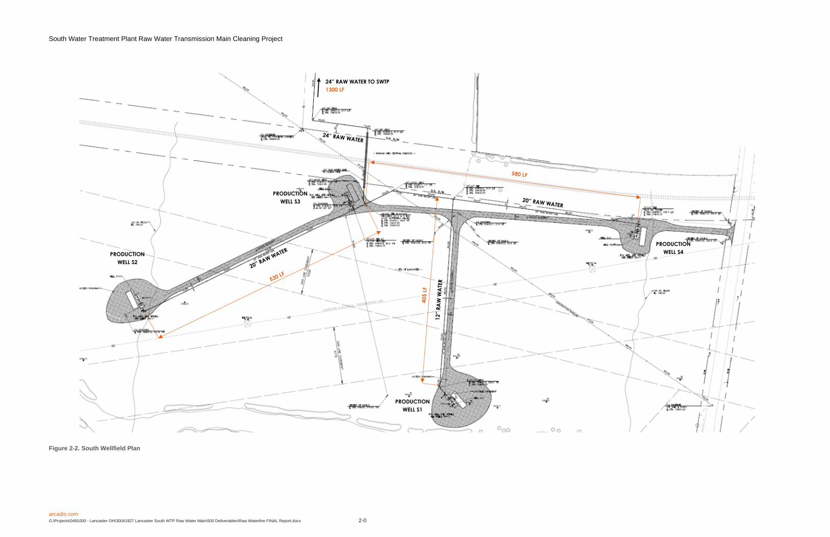
2.2 Raw Water Piping
The raw water piping system is constructed of cement-lined ductile iron pipe (DIP). The raw water piping
system consists of 405 LF of 12-inch DIP, 1,068 LF of 20-inch DIP, and 1,420 LF of 24-inch DIP.
Table 2-3 summarizes the nominal water velocity (FPS) of each segment of transmission main with
various wells in operation, assuming a production rate of 2,115 GPM for each well.
Table 2-3 Raw Water Main Water Velocity
Production Well in Operation Pipe Diameter
(IN)
Flow
(GPM)
Velocity
(FPS)
PW-1 12 2115 6
PW-2 20 2115 2.1
PW-2 or PW-3 20 2115 2.1
PW-2 and PW-3 20 4230 4.3
PW-4 20 2115 2.1
PW-1 or PW-4 20 2115 2.1

South Water Treatment Plant Raw Water Transmission Main Cleaning Project
arcadis.com G:\Projects\0491000 - Lancaster OH\30041927 Lancaster South WTP Raw Water Main\500 Deliverables\Raw Waterline FINAL Report.docx 2-3
Production Well in Operation Pipe Diameter
(IN)
Flow
(GPM)
Velocity
(FPS)
PW-1 and PW-4 20 4230 4.3
1 well operating 24 2115 1.5
2 wells operating 24 4230 3
3 wells operating 24 6345 4.5
4 wells operating 24 8460 6
The volume of water contained by the existing raw water piping is summarized in Table 2-4
Table 2-4 Raw Water Main Volume
Pipe Diameter
(in)
Area
(SF)
Length
(LF)
Volume
(CF)
Volume
(Gal)
12 0.79 405 318 2,378
20 2.18 1,110 2,420 18,105
24 3.14 1,300 4,082 30,533
TOTAL 6,820 51,016

South Water Treatment Plant Raw Water Transmission Main Cleaning Project
arcadis.com G:\Projects\0491000 - Lancaster OH\30041927 Lancaster South WTP Raw Water Main\500 Deliverables\Raw Waterline FINAL Report.docx 2-0
Figure 2-1 Typical Production Well
South Water Treatment Plant Raw Water Transmission Main Cleaning Project
arcadis.com G:\Projects\0491000 - Lancaster OH\30041927 Lancaster South WTP Raw Water Main\500 Deliverables\Raw Waterline FINAL Report.docx 2-0
Figure 2-2. South Wellfield Plan
PRODUCTION
WELL S1
PRODUCTION
WELL S2
PRODUCTION
WELL S3
PRODUCTION
WELL S4
24” RAW WATER TO SWTP
1300 LF

South Water Treatment Plant Raw Water Transmission Main Cleaning Project
arcadis.com G:\Projects\0491000 - Lancaster OH\30041927 Lancaster South WTP Raw Water Main\500 Deliverables\Raw Waterline FINAL Report.docx 3-1
3 MECHANICAL CLEANING ASSESSMENT
This section summarizes the requirements for conducting mechanical cleaning operations for the raw
water transmission piping.
3.1 Mechanical Cleaning
Mechanical cleaning, also known as pigging, is the practice of using devices known as pigs or scrapers to
remove sediment, scale, or other debris from the inside of piping systems. Pigs are inserted into the pipe
to be cleaned at a pig launching station or other appropriate entry point. Once inserted, the pig is
transported through the pipe using pressurized water as the motive force, which in this case, will be raw
water supplied from the production wells. Ideally, pigs should be propelled through the pipeline at a
nominal velocity of 3 FPS or greater.
Pipeline cleaning using pigs is generally carried out using multiple passes. During the first pass, raw
water is flushed through the pipe to the discharge point to check for flow, headloss, and to allow the
contractor to assess the general operating characteristics of the pipeline. Following the initial flushing, a
pig with a diameter smaller than the pipeline is inserted and propelled through the pipe. As the pig travels
through the pipe, a certain percentage of the carrier water flows around the pig and this is known as
bypass water. The pig along with the bypass water suspends the debris in the water stream which then
carries the debris along the pipe ahead of the pig. The pig is not meant to act as a plow, pushing the
debris ahead of it as this could result in high working pressure and could result in the pig getting stuck.
Depending on the amount of debris removed during this pass, more passes may be required, or it may be
possible to use a pig of a larger diameter on the next pass. Multiple passes are performed using larger
and larger pigs until all of the debris has been satisfactory removed from the piping system.
3.1.1 System Modifications
Permanent modifications to the raw water system are required to accommodate the pigging operations
and to facilitate periodic flushing in the future. The following modifications to the system are required:
1. Adjacent to production well S3, remove the existing 24 x 24 tee and replace with a 24 x 24 cross.
Remove the existing 20-inch butterfly valves (2 valves) and replace with two 20-inch gate valves.
2. Construct 24-inch DIP pipeline to convey pigging water to the existing concentrate lagoon.
Connection to the existing 24-inch transmission main will be made in the asphalt drive near the front
door of the administration building.
These improvements are illustrated by
Figure 3-1.
3.1.2 Pigging Facilities
Entry points must be established for each pipe segment to facilitate the insertion and launching of pigs.
Each of the production wells is equipped with a 12 x 12 wye with a blind flange, located in the check valve
vault adjacent to each well head. The only well where this wye is feasible for pig launching is production

South Water Treatment Plant Raw Water Transmission Main Cleaning Project
arcadis.com G:\Projects\0491000 - Lancaster OH\30041927 Lancaster South WTP Raw Water Main\500 Deliverables\Raw Waterline FINAL Report.docx 3-2
well S1 as the discharge line for this well is 12-inches, as illustrated by Figure 3-2. Each of other wells
(S2, S3, and S4) each discharge through a short reach of 12-inch piping and then into a 20-inch
discharge header, thus requiring a 20-inch pigs. Pigging the discharge header associated with production
well S2 can be accomplished by removing the plug from the existing 20 x 12 tee and installing temporary
piping and a temporary pig launching station as illustrated by Figure 3-3. Pigging of the piping associated
with production well S-3 is not required as this well connects to the production well S2 discharge header.
Pigging the discharge header associated with production well S4 can be accomplished by removing the
plug from the existing 20 x 12 tee and installing temporary piping and a temporary pig launching station
as illustrated by Figure 3-4. Pigging of the 24-inch transmission main from the wellfield to the water plant
can be accomplished by removing the plug from the new 24 x 24 cross adjacent to production well S3,
and installing temporary piping and a pig launching station, as illustrated by Figure 3-5.
3.1.3 Intermediate Pig Launching Facilities
Given the short pigging distances and the relatively low amount of sediment accumulation, intermediate
pig launching facilities are not required for this project.
3.1.4 Solids Capture Facilities
The raw water line conveys raw water from the south wellfield to the water plant where raw water is
directed to the cartridge filters and pressure filters. It is not appropriate to convey cleaning water and
sediment to these treatment processes as the sediment will cause harmful fouling. As a result, this
project requires a facility to intercept and capture the flushing water and sediment. The most feasible
alternative is to utilize the existing concentrate lagoon for this purpose. A new pipeline connecting the
raw water pipeline to the existing lagoon should be constructed to convey the cleaning water and
sediment to the lagoon. Sediment can be collected in the lagoon while clarified water can be decanted
and discharged to the existing stormwater system. Figure 3-1 illustrates a site plan for the installation of a
permanent line connecting the raw water transmission main to the existing concentrate lagoon.
3.1.5 Water Requirements, Sources, and Availability
The largest diameter segment of the raw water transmission piping is 24-inches. In order to maintain a
proper cleansing velocity and properly force the cleaning pigs to scarify and uplift the sediment, a
minimum cleaning velocity of 2.5 to 3.0 FPS will be required during the cleaning operations.
When cleaning pipe segment 1 (refer to Figure 3-6 for pipe segment labelling), the quantity of water produced
by production well S1 will be sufficient to generate the required pig velocity. When cleaning segment 2, raw
water from production wells S1 and S2 will be sufficient to generate the necessary pigging velocity.
Temporary piping can be installed to connect production well S1 to S2 to accomplish this, and is illustrated
by Figure 3-6. Similarly, when cleaning segment 3, raw water from production wells S1 and S4 will be
sufficient to generate the necessary pigging velocity. Temporary piping can be installed to connect
production well S1 to S4 to accomplish this, and is illustrated by Figure 3-6. Finally, when cleaning segment
4, three production wells will need to be switched on to generate the necessary pigging velocity. Any
combination of wells should be sufficient.
Table 3-1 summarizes the water sources, flows, and velocity for each piping segment. Figure 3-6
provides a site plan illustrating temporary piping requirements for pigging segments 2 and 3.

South Water Treatment Plant Raw Water Transmission Main Cleaning Project
arcadis.com G:\Projects\0491000 - Lancaster OH\30041927 Lancaster South WTP Raw Water Main\500 Deliverables\Raw Waterline FINAL Report.docx 3-3
Table 3-1 Raw Water Main Water Velocity
Segment No. Diameter (in) Water Source Flow (GPM) Velocity (FPS)
1 12 S1 2,115 6.0
2 20 S1, S2 4,230 4.3
3 20 S1, S4 4,230 4.3
4 24 Any three of the
four wells 6,360 4.5
3.1.6 Cleaning Operations
It is anticipated that the cleaning of the raw water transmission mains be accomplished through the use of
multiple pigs. A foam pig (or soft swab pig) is typically inserted in the first run. The foam pig is not
expected to dislodge significant amounts of debris, but instead acts as a diagnostic tool. The malleable
and flexible characteristics of the foam pig will reduce the risk of it getting stuck in a pipeline which is not
routinely pigged. The usually low cost of the foam pig can also make it expendable for the contractor.
Observation at the discharge point through the initial run, will allow the contractor to assess the amount
and density of the debris. Once the contractor has had the opportunity to gauge the type of sediment,
density, speed vs rate of flow and work any kinks in the system, a customized pigging plan will be
developed specifically for the system. This pigging plan will propose the diameter and quantity of pigs to
be used to accomplish the main pigging. It should also address flow control and water availability
depending on the number of runs anticipated to accomplish the goals. It may not be necessary to
implement each run individually; the contractor may opt for time releasing multiple pigs within minutes of
each other, in order to reduce the time of the cleaning operations and the amount of water required.
Among the different types of pigs that could likely be suggested for this project are the mandrel cleaning
pig, sealing pig, higher density polyurethane pigs, gel pigs, solid cast pigs or spheres to better negotiate
changes in direction. Of the pigs listed above, polyurethane pigs are the most commonly used in the
municipal industry today.
Water and sediment from each pigging run will be discharged to the existing concentrate lagoon. The
lagoon has a nominal capacity of 880,000 gallons. Given that the approximate volume of the raw water
piping system is approximately 60,000 gallons (including the additional 420 LF of 24-inch DIP connecting
the existing raw water main to the concentrate lagoon), the lagoon has the capacity to hold approximately
14 pigging runs. Pigging water should be periodically drained from the lagoon to ensure continuity of
pigging operations.

South Water Treatment Plant Raw Water Transmission Main Cleaning Project
arcadis.com G:\Projects\0491000 - Lancaster OH\30041927 Lancaster South WTP Raw Water Main\500 Deliverables\Raw Waterline FINAL Report.docx 3-4
3.2 Route and Alignment Planning
The work required to clean the raw water transmission main piping will be executed within the existing
alignments of the existing raw water piping and within property owned by the City of Lancaster. There is
no route or alignment planning necessary for this project.
3.3 Special Crossings
The proposed work does not include or require the construction of any new segments of pipe that will
require a special crossing, e.g. a road crossing, river crossing, or railroad crossing. There is a segment of
piping that was installed by jacking and boring under an existing railroad track, but this segment is the
same pipe material and diameter as the rest of the transmission main. There are no special requirements
for the cleaning of the transmission main underneath the existing railroad track.
3.4 Ice Pigging
Arcadis contacted Suez North America to inquire about the possibility of ice pigging of the raw water
transmission pipework. Suez informed Arcadis that they no long perform ice pigging services in North
America. No other contractors are permitted to perform ice pigging as Suez owns the patent. Therefore,
ice pigging is not an option for this project.

South Water Treatment Plant Raw Water Transmission Main Cleaning Project
arcadis.com G:\Projects\0491000 - Lancaster OH\30041927 Lancaster South WTP Raw Water Main\500 Deliverables\Raw Waterline FINAL Report.docx 3-0
Figure 3-1 Raw Water Piping Modifications
WATER PLANT SITE PLAN
PRODUCTION WELL S3 SITE PLAN
REMOVE EXISTING 24 x 24 TEE AND REPLACE WITH
24 X 24 CROSS. REMOVE 20-INCH BUTTERFLY
VALVES AND REPLACE WITH 20-INCH GATE VALVES
420 LF 24-INCH DIP
2 24-INCH GATE VALVES

South Water Treatment Plant Raw Water Transmission Main Cleaning Project
arcadis.com G:\Projects\0491000 - Lancaster OH\30041927 Lancaster South WTP Raw Water Main\500 Deliverables\Raw Waterline FINAL Report.docx 3-0
Figure 3-2 Production Well S1 Enlarged Site Plan
INSERT PIG USING EXISTING 12 X 12 WYE
IN VALVE VAULT. REFER TO FIGURE 2-1
FOR ADDITIONAL DETAILS

South Water Treatment Plant Raw Water Transmission Main Cleaning Project
arcadis.com G:\Projects\0491000 - Lancaster OH\30041927 Lancaster South WTP Raw Water Main\500 Deliverables\Raw Waterline FINAL Report.docx 3-0
Figure 3-3 Production Well S2 Enlarged Site Plan
REMOVE PLUG. INSTALL TEMPORARY
PIPING AND PIG LAUNCHING STATION.
REPLACE PLUG WHEN FINISHED

South Water Treatment Plant Raw Water Transmission Main Cleaning Project
arcadis.com G:\Projects\0491000 - Lancaster OH\30041927 Lancaster South WTP Raw Water Main\500 Deliverables\Raw Waterline FINAL Report.docx 3-0
Figure 3-4 Production Well S4 Enlarged Site Plan
REMOVE PLUG. INSTALL TEMPORARY
PIPING AND PIG LAUNCHING STATION.
REPLACE PLUG WHEN FINISHED

South Water Treatment Plant Raw Water Transmission Main Cleaning Project
arcadis.com G:\Projects\0491000 - Lancaster OH\30041927 Lancaster South WTP Raw Water Main\500 Deliverables\Raw Waterline FINAL Report.docx 3-0
Figure 3-5 Production Well S3 Enlarged Site Plan
REMOVE PLUG FROM NEW 24 X 24 CROSS. INSTALL
TEMPORARY PIPING AND PIG LAUNCHING STATION.
REPLACE PLUG WHEN FINISHED
24 X 24 CROSS WITH 24 X 20
REDUCERS ON N & S END
2-20-INCH GATE VALVES

South Water Treatment Plant Raw Water Transmission Main Cleaning Project
arcadis.com G:\Projects\0491000 - Lancaster OH\30041927 Lancaster South WTP Raw Water Main\500 Deliverables\Raw Waterline FINAL Report.docx 3-0
Figure 3-6 Temporary Piping for Pigging Operations
PRODUCTION
WELL S1
PRODUCTION
WELL S2
PRODUCTION
WELL S3
PRODUCTION
WELL S4

South Water Treatment Plant Raw Water Transmission Main Cleaning Project
arcadis.com G:\Projects\0491000 - Lancaster OH\30041927 Lancaster South WTP Raw Water Main\500 Deliverables\Raw Waterline FINAL Report.docx 4-1
4 FLUSHING ASSESSMENT
This section summarizes alternatives for making modifications to existing piping systems to facilitate
cleaning of the raw water transmission main via flushing. Also included are alternatives for making
permanent modifications to facilitate flushing of the concentrate force main.
4.1 Raw Water Transmission Main Flushing
Periodic flushing of the raw water transmission main to remove accumulated Fe and Mn sediment is
recommended as this activity will help prolong the life of the pressure filters, cartridge filters, and RO
system.
There are currently no methods available for flushing the transmission main, therefore construction of
permanent modifications are required. The most feasible alternative is to construct a new pipeline
connecting the existing transmission main to the existing concentrate storage lagoon. The new
connection point would be in the vicinity of the visitor parking lot on the west side of the treatment building
where the transmission main enters the plant. Construction of this pipeline will allow operators to use raw
water to flush sediment from the transmission main and discharge the water and sediment to the existing
concentrate lagoon. Clarified water could then be released from the lagoon to the onsite stormwater
collection system. Figure 4-2 illustrates the concept for the flushing interconnection.
4.2 Concentrate Force Main Flushing Alternatives
A 14-inch diameter, 4.5 mile long force main conveys process residuals (RO concentrate and waste
backwash water from the pressure filters) from the SWTP to the City’s sanitary sewer system. Hydraulic
capacity in this force main has diminished somewhat since its construction and commissioning in 2004 as
a result of scale formation from the RO concentrate and from deposition of iron and manganese sediment
from the pressure filter waste backwash water. The force main requires periodic flushing to maintain
capacity, however, there is not currently a source of flushing water connected to the force main.
Three options are available to connect a flushing water source to the concentrate force main. Two of
these options include interconnections between the concentrate force main to either the raw water main
or to the existing finished water main from inside the west pipe gallery. Another option includes a
connection from the raw water main to the concentrate force main from the plant yard with an additional
connection installed to connect the new raw water line to the existing lagoon. This section provides a
brief description of each of these options.
Flushing of the concentrate header and force main should be conducted after each plan shutdown where
the duration of the shutdown is anticipated to be 8 hours or greater. This helps to displace concentrate
from the force main and reduce the possibility of mineral scale formation. It is also recommended that the
concentrate force main be flushed at least three to four times annually to remove accumulated sediment
from the pressure filter backwash stream. Flushing for sediment removal should be conducted using a
flow rate to generate 6 FPS to suspend settled solids. Table 4-1 summarizes flow rates and water
volume required to conduct flushing operations.
Table 4-1 Concentrate Force Main Flushing Flow and Volume

South Water Treatment Plant Raw Water Transmission Main Cleaning Project
arcadis.com G:\Projects\0491000 - Lancaster OH\30041927 Lancaster South WTP Raw Water Main\500 Deliverables\Raw Waterline FINAL Report.docx 4-2
Parameter Value
Force main material HDPE DR17
ID (inches) 13.392
Area (SF) 0.98
Length (LF) 23,300
Volume (CF) 22,807
Volume (Gallons) 170,598
No. of flushing volumes (N) 3
Total flushing volume (Gallons) 511,794
Flushing velocity (FPS) 6
Flushing flow (GPM) 2636
Flushing duration (minutes) 194
4.2.1 Finished Water Connection Inside West Pipe Gallery
An existing 8-inch finished water main enters the pipe gallery in the vicinity of the existing 24-inch raw
water main (refer to Figure 4-1), and provides a source of backwash water for the pressure filters.
Connecting the finished water pipe to the concentrate header in the pipe gallery requires the following:
Cut new 8 x 8 tee into existing 8-inch main
70 LF 8-inch DIP and fittings
1 8-inch butterfly valve, electrically actuated modulating
1 8-inch pressure reducing valve
1 8-inch RPZ backflow preventer
The finished water contains a free chlorine residual (1 – 2 mg/L) and the RO concentrate contains high
concentrations of dissolved Fe and Mn. The chlorine from the finished water will oxidize the dissolved Fe
and Mn in the concentrate, converting it into particulate form, which can form additional sediment in the
force main. For this reason, it is not recommended that finished water be used for flushing of the
concentrate force main.
4.2.2 Raw Water Connection Inside West Pipe Gallery
The existing 24-inch raw water main enters the pipe gallery at the southwest end of the pipe gallery (refer
to Figure 4-1). The raw water main splits, with one leg providing raw water to the pressure filters, and the
other leg providing raw water to the cartridge filters and the RO system. The leg feeding the cartridge
filters terminates at a 24-inch blind flange in the vicinity of the RO concentrate header (refer to Figure
4-1). Connecting the raw water main to the concentrate header in the pipe gallery requires the following:
Removal of the 24-inch blind flange from the raw water header;
Removal of the 12-inch blind flange from the concentrate header;

South Water Treatment Plant Raw Water Transmission Main Cleaning Project
arcadis.com G:\Projects\0491000 - Lancaster OH\30041927 Lancaster South WTP Raw Water Main\500 Deliverables\Raw Waterline FINAL Report.docx 4-3
24 x 12 reducer;
30 LF 12-inch DIP and fittings;
1 12-inch butterfly valve, electrically actuated, modulating;
1 12-inch pressure reducing valve;
1 12-inch check valve.
The concentrate piping within the pipe gallery and between the pipe gallery and concentrate lagoon was
not designed to accommodate high flow rates and velocities that would be expected during flushing
operations. Therefore it is not recommended that this alternative be implemented.
4.2.3 Raw Water Connection From Yard
A new pipeline connecting the raw water pipeline to the concentrate force main from the plant yard with
an additional connection to connect the new raw water line to the existing lagoon would require the
following:
440 LF 16-inch DIP and fittings;
1 24-inch gate valve;
2 16-inch gate valves;
1 12-inch check valve;
50 LF 12-inch DIP and fittings;
1 12-inch gate valve;
1 Precast concrete valve vault
Connecting the raw water main to the concentrate force main from the plant yard with an additional
connection to connect the new raw water line to the lagoon is preferred alternative and is illustrated by
Figure 4-2. This will allow for periodic flushing of both the concentrate force main and the raw water
transmission main. The required flushing flow can be achieved by using any two of the existing raw water
production wells. As stated earlier, flushing should be completed when a plant shutdown is anticipated to
last for more than 8 hours and should be completed on a periodic basis to flush any accumulated
sediment.

South Water Treatment Plant Raw Water Transmission Main Cleaning Project
arcadis.com G:\Projects\0491000 - Lancaster OH\30041927 Lancaster South WTP Raw Water Main\500 Deliverables\Raw Waterline FINAL Report.docx 4-4
Figure 4-1 Flushing Connections for Concentrate Force Main Inside West Pipe Gallery
24
-IN
CH
RA
W W
ATE
R
MATCHLINE THIS SHEET
MATCHLINE THIS SHEET
24
-IN
CH
RA
W W
ATE
R
12
-IN
CH
CO
NC
EN
TRA
TE
8-I
NC
H F
INIS
HED
WA
TER
8-I
NC
H F
INIS
HED
WA
TER
FLU
SH
ING
CO
NN
EC
TIO
N
8-I
NC
H F
INIS
HED
WA
TER
FLU
SH
ING
CO
NN
EC
TIO
N
KEY
INDICATES FINISHED WATER FLUSHING CONNECTION
INDICATES RAW WATER FLUSHING CONNECTION

South Water Treatment Plant Raw Water Transmission Main Cleaning Project
arcadis.com G:\Projects\0491000 - Lancaster OH\30041927 Lancaster South WTP Raw Water Main\500 Deliverables\Raw Waterline FINAL Report.docx 4-5
Figure 4-2 Flushing Connections for Concentrate Force Main Outside in Yard
INDICATES EXISTING 24” RAW WATER LINE
INDICATES EXISTING COCENTRATE FORCE MAIN
INDICATES PROPOSED 16” FLUSHING LINE
INDICATES PROPOSED 12” FLUSHING LINE
INDICATES PROPOSED 24-INCH GATE VALVE
INDICATES PROPOSED 16-INCH GATE VALVE
INDICATES PROPOSED 16-INCH CHECK VALVE
INDICATES PROPOSED 12-INCH GATE VALVE
INDICATES PROPOSED VALVE VAULT
SW-X INDICATES SHEET NO. FROM CONSTRUCTION
DRAWING SET
16-INCH FLUSHING LINE
12-INCH FLUSHING LINE
CONNECTION TO
CONCENTRATE

South Water Treatment Plant Raw Water Transmission Main Cleaning Project
arcadis.com G:\Projects\0491000 - Lancaster OH\30041927 Lancaster South WTP Raw Water Main\500 Deliverables\Raw Waterline FINAL Report.docx 5-1
5 REGULATORY AND PERMIT REQUIREMENTS
Although an Ohio Environmental Protection Agency (OEPA) permit is not necessary for pigging activities
and line maintenance, construction of permanent modifications and/or operational protocol changes at
SWTP will need to be coordinated with the OEPA. A permit-to-install (PTI) from OEPA’s Division of
Drinking and Groundwaters will be required.
The new proposed improvements are located within the City’s property limits. Contractors will not be
required to obtain special permits for working on City property.

South Water Treatment Plant Raw Water Transmission Main Cleaning Project
arcadis.com G:\Projects\0491000 - Lancaster OH\30041927 Lancaster South WTP Raw Water Main\500 Deliverables\Raw Waterline FINAL Report.docx 6-1
6 PROJECT SCHEDULE
The preliminary project schedule is summarized in Table 6-1. The schedule assumes that design of the
facilities required to accommodate the pigging operations will need to be completed as the first step. This
includes the modifications to the 24-inch raw water transmission main to construct new connections to the
existing concentrate lagoon and concentrate force main. Following design, the City will solicit bids from
contractors to construct the necessary facilities. It is assumed that one general contract will be let for
construction of the required facilities and contracts for this work can be combined with the cleaning of the
concentrate force main.
Table 6-1 Preliminary Project Schedule
Project Milestone Days Cumulative Days
Engineering Procurement 90 90
Design Engineering 90 180
Permitting (concurrent with design and bidding) 60 180
Bidding and Contract Award 75 255
Construction 180 335
Pigging Operations (concurrent with construction) 10 335
Removal of Temporary Facilities and Restoration 10 335

South Water Treatment Plant Raw Water Transmission Main Cleaning Project
arcadis.com G:\Projects\0491000 - Lancaster OH\30041927 Lancaster South WTP Raw Water Main\500 Deliverables\Raw Waterline FINAL Report.docx 7-1
7 ECONOMIC EVALUATION OF ALTERNATIVES
This section presents an opinion of probable project cost (OPPC) of the mechanical cleaning alternatives
for the SWTP. The project cost estimates are based on the conceptual layouts and design criteria
presented and are to be considered planning level only. The costs are not to be considered final project
costs which can only be developed as a result of detailed design.
7.1 Class of Estimate
The OPPC estimate is considered a Class 4 according to the cost estimate classification system. Table
7-1 provides a summary of the estimate classes.
Table 7-1 Estimate Classification Matrix
Estimate
Class
Level of
Project
Definition
End Usage Methodology Expected Accuracy
Range
Typical
Contingency
5 <= 5%
Preliminary project
screening
estimate, capital
budget planning,
alternative
evaluation,
strategic analysis
Capacity factored,
parametric models,
judgement, analogy,
historical project
comparison
Low: -20% to - 50%
High +30% to +100% 15 – 40%
4 5 – 20%
Preliminary project
estimate, reality
check estimate,
alternative
evaluation,
feasibility study
Equipment factored
parametric models,
historical relationship
factors, broad unit cost
data
Low: -15 to -30%
High: +30% to
+100%
10 – 25%
3 20 – 60%
Project funding
estimate, fair price
check
Semi detailed unit
costs with assembly
level line items by
trade, historical
relationship factors
Low: -10% to -15%
High: +10% to +30% 5 – 15%
2 60 – 99%
Project funding
estimate, control
estimate, bid
estimate
Detailed estimating
data by trade, with
detailed takeoff
quantities
Low: -5% to -15%
High: +5% to +20% 5 – 15%
1 90 – 100% Firm bid estimate
Detailed estimating
data by trade with
detailed firm takeoff
quantities
Low: -3% to -10%
High: +3% to +15% 3– 10%

South Water Treatment Plant Raw Water Transmission Main Cleaning Project
arcadis.com G:\Projects\0491000 - Lancaster OH\30041927 Lancaster South WTP Raw Water Main\500 Deliverables\Raw Waterline FINAL Report.docx 7-2
7.1.1 Class 5 Cost Estimate
Class 5 estimates are generally prepared based on very limited information, and subsequently have wide
accuracy ranges. Typically, engineering is from 2% to 10% complete. They are often prepared for
strategic planning purposes, market studies, assessment of viability, project location studies, and long-
range capital planning. Virtually all Class 5 estimates use stochastic estimating methods such as cost
curves, capacity factors, and other parametric techniques. Expected accuracy ranges are from –20% to –
50% on the low side and +30% to 100% on the high side, depending on technological complexity of the
project, appropriate reference information, and the inclusion of an appropriate contingency determination.
Ranges could exceed those shown in unusual circumstances. As little as 1 hr. or less to perhaps more
than 200 hours may be spent preparing the estimate based on the project and estimating methodology.
7.1.2 Class 4 Cost Estimate
Class 4 estimates are generally prepared based on limited information and subsequently have fairly wide
accuracy ranges. Typically, engineering is 10% to 40% complete. They are typically used for project
screening, determination of feasibility, concept evaluation, and preliminary budget approval. Virtually all
Class 4 estimates use stochastic estimating methods such as cost curves, capacity factors, and other
parametric and modelling techniques. Expected accuracy ranges are from –15% to –30% on the low side
and +20% to 50% on the high side, depending on the technological complexity of the project, appropriate
reference information, and the inclusion of an appropriate contingency determination. Ranges could
exceed those shown in unusual circumstances. As little as 20 hours or less to perhaps more than 300
hours may be spend preparing the estimate depending on the project and estimating methodology.
7.1.3 Class 3 Cost Estimate
Class 3 estimates are generally prepared to form the basis for budget authorization, appropriation, and/or
funding. Typically, engineering is from 10% to 40% complete, and would comprise a minimum of process
flow diagrams, utility flow diagrams, preliminary piping and instrumentation diagrams, plot plan,
developed layout drawings, and essentially complete engineered process and utility equipment lists.
They are typically prepared to support full project funding requests and become the first of the project
phase "control estimates" against which all actual costs and resources will be monitored for variation to
budget. Most Class 3 estimates involve more deterministic estimating methods than stochastic methods.
Typical accuracy ranges for Class 3 estimates are from +/- 10% to 30% (sometimes higher), depending
on the technological complexity of the project, appropriate reference information, and the inclusion of an
appropriate contingency determination. As little as 300 hrs. or less to perhaps more than 2,000 hours may
be spent preparing the estimate based on the project and estimating methodology.
7.1.4 Class 2 Cost Estimate
Class 2 estimates are generally prepared to form a detailed control baseline against which all project
work is monitored in terms of cost and progress control. For contractors, this class of estimate is often
used as the “bid” estimate to establish contract value. Typically, engineering is from 30% to 70%
complete, and would comprise at a minimum of the following: process flow diagrams, utility flow diagrams,
preliminary piping and instrumentation diagrams, heat and material balances, final plot plan, final layout

South Water Treatment Plant Raw Water Transmission Main Cleaning Project
arcadis.com G:\Projects\0491000 - Lancaster OH\30041927 Lancaster South WTP Raw Water Main\500 Deliverables\Raw Waterline FINAL Report.docx 7-3
drawings, complete engineered process and utility equipment lists, single line diagrams for electrical,
electrical equipment, and motor schedules, vendor quotations, detailed project execution plans,
resourcing and work force plans, etc. Class 2 estimates always involve a high degree of deterministic
estimating methods often involving thousands of unit cost line items. Typical accuracy ranges for Class 2
estimates are –5% to –15% on the low side, and +5 to +20% on the high side, depending on the
technological complexity of the project. As little as 300 hrs. or less to perhaps more than 3,000 hours may
be spent preparing the estimate based on the project and estimating methodology. Bid estimates typically
require more effort than estimates used for funding or control purposes.
7.1.5 Class 1 Cost Estimate
Class 1 estimates are generally prepared for discrete parts or sections of the total project rather than
generating this level of detail for the entire project. These estimates may be prepared for to determine a
fair price or bid check to evaluate claims and disputes. Typically, engineering is 50% to 100% complete
and would comprise of virtually all engineering and design documentation for the project and complete
execution and commissioning plans. Expected accuracy ranges are –3% to –10% on the low side to +3%
to + 15% on the high side depending on the technological complexity of the project, appropriate reference
information and appropriate contingency determination. As little as 600 hours to more than 6,000 hours
may be spent preparing the estimate based on the project and estimating methodology. Bid estimates
typically require more effort than estimates used for funding or control purposes.
7.2 Opinion of Probable Project Costs
A preliminary opinion of probable project cost (OPPC) has been prepared for the construction of
permanent improvements required to facilitate mechanical cleaning, conducting the initial mechanical
cleaning, and periodic flushing of the raw water transmission piping.
7.2.1 Mechanical Cleaning
It is estimated that construction of permanent facilities within the wellfield and at the water treatment plant
site to accommodate mechanical cleaning amounts to approximately $479,500 which includes a 25%
contingency at this preliminary level. This OPPC contains a fee of approximately $50,000 for the actual
pigging services and $2,000 for the disposal of solids.
Table 7-2 provides an OPPC for the improvements to the raw water transmission main and pigging
operations.

South Water Treatment Plant Raw Water Transmission Main Cleaning Project
arcadis.com G:\Projects\0491000 - Lancaster OH\30041927 Lancaster South WTP Raw Water Main\500 Deliverables\Raw Waterline FINAL Report.docx 7-4
Table 7-2 OPPC Raw Water Transmission Main Improvements and Mechanical Cleaning
7.2.2 Flushing Connection in Plant Yard
It is estimated that construction of connecting the raw water main to the existing concentrate force main
from the plant yard with an additional connection to connect the new raw water line to the lagoon to
accommodate periodic flushing of the concentrate force main using raw water amounts to approximately
$306,300 which includes a 25% contingency at this preliminary level.
Table 7-3 provides an OPPC for the flushing connection for the concentrate force main outside in the
yard.

South Water Treatment Plant Raw Water Transmission Main Cleaning Project
arcadis.com G:\Projects\0491000 - Lancaster OH\30041927 Lancaster South WTP Raw Water Main\500 Deliverables\Raw Waterline FINAL Report.docx 7-5
Table 7-3 OPPC Flushing Interconnection for Concentrate Force Main Outside in Yard
1 Seeding and mulching 280 SY 5.00$ 1,400.00$
2 Curb and gutter removed 24 LF 8.00$ 192.00$
3 Full depth pavement removal and replacement 35 SY 225.00$ 7,875.00$
4 Asphalt concrete surface course, type 1 6 CY 400.00$ 2,400.00$
5 Curb and gutter 24 LF 400.00$ 9,600.00$
6 24-inch solid sleeve 1 Ea 5,000.00$ 5,000.00$
7 24 x 16 tee 1 Ea 5,000.00$ 5,000.00$
8 12 x 12 tee 1 Ea 3,500.00$ 3,500.00$
9 12-inch solid sleeve 1 Ea 3,500.00$ 3,500.00$
10 12-inch DIP waterline 50 LF 175.00$ 8,750.00$
11 16-inch DIP waterline 420 LF 200.00$ 84,000.00$
12 12-inch gate valve 1 Ea 6,500.00$ 6,500.00$
13 16-inch gate valve 2 Ea 8,500.00$ 17,000.00$
14 12-inch check valve 1 Ea 6,500.00$ 6,500.00$
15 Precast concrete valve vault 1 LS 20,000.00$ 20,000.00$
Subtotal 181,217.00$
181,217.00$
Mobilization / General Conditions 3% 5,440.00$
Contractor Overhead 7% 12,690.00$
Contractor Profit 7% 12,690.00$
Contractor Insurance / Bonds 2% 3,630.00$
Engineering Design 15% 27,190.00$
Construction Administration and Inspection 10% 18,130.00$
Construction Contingency 25% 45,310.00$
Subtotal 125,080.00$
TOTAL PROJECT COST
Low Range (AACE Class 4) -30% 268,800$
Middle Range 306,300$
High Range (AACE Class 4) 50% 459,450$
Construction
Total Construction Cost
Administrative Services
306,300$
ITEM DESCRIPTION QUAN. Unit UNIT PRICE SUBTOTAL

South Water Treatment Plant Raw Water Transmission Main Cleaning Project
arcadis.com G:\Projects\0491000 - Lancaster OH\30041927 Lancaster South WTP Raw Water Main\500 Deliverables\Raw Waterline FINAL Report.docx 8-1
8 CONCLUSION
At the May 13, 2020 Progress Meeting, it was agreed that the City will not be making modifications to the
raw water transmission main at this time to facilitate pigging operations at this time. Connecting the raw
water main to the concentrate lagoon from the plant yard with an additional connection to connect the
new raw water line to the existing concentrate force main was selected as the preferred alternative and is
used as the basis of design for this report.

Arcadis U.S., Inc.
100 E Campus View Boulevard
Suite 230
Columbus, Ohio 43235-1447
Tel 614 985 9100
Fax 614 985 9170
www.arcadis.com