Enerxon Raw Material A4 portrait assemble.indd
64
enerxon.com Engineering Solutions RAW MATERIALS
-
Upload
khangminh22 -
Category
Documents
-
view
0 -
download
0
Transcript of Enerxon Raw Material A4 portrait assemble.indd
enerxon.com
E n g i n e e r i n g S o l u t i o n s
RAW MATERIALS
contents
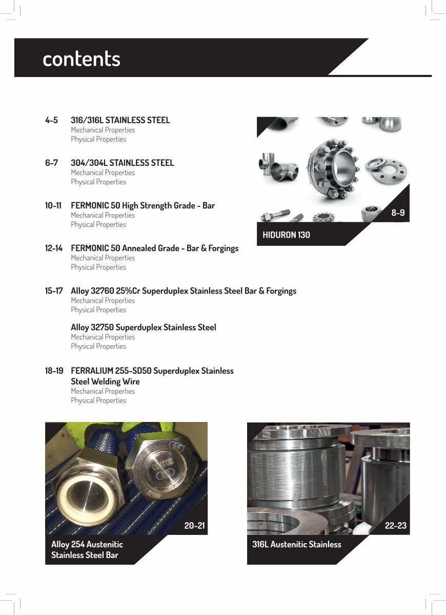
4-5 316/316L STAINLESS STEELMechanical PropertiesPhysical Properties
34-36 ALLOY K-500 Bar and ForgingsMechanical PropertiesPhysical Properties
24-26 Alloy 625 BarMechanical PropertiesPhysical Properties
36-38 FERRALIUM 255-SD50 Superduplex Stainless Steel BarMechanical PropertiesPhysical Properties
39-41 FERRALIUM 255-SD50 Superduplex Stainless Steel Plate and SheetMechanical PropertiesPhysical Properties
42-62 FERRALIUM® 255 & SD50Mechanical PropertiesPhysical Properties
62-63 Machining FERRALIUM® 255 and FERRALIUM® 255-SD50Mechanical PropertiesPhysical Properties
6-7 304/304L STAINLESS STEELMechanical PropertiesPhysical Properties
10-11 FERMONIC 50 High Strength Grade - BarMechanical PropertiesPhysical Properties
12-14 FERMONIC 50 Annealed Grade - Bar & ForgingsMechanical PropertiesPhysical Properties
15-17 Alloy 32760 25%Cr Superduplex Stainless Steel Bar & ForgingsMechanical PropertiesPhysical Properties
Alloy 32750 Superduplex Stainless SteelMechanical PropertiesPhysical Properties
18-19 FERRALIUM 255-SD50 Superduplex StainlessSteel Welding WireMechanical PropertiesPhysical Properties
8-9
HIDURON 130
26-31
ALLOY 718 Bar
31-33
ALLOY 400 Bar& Forgings
Alloy 254 AusteniticStainless Steel Bar
316L Austenitic Stainless
20-21 22-23
contents
4-5 316/316L STAINLESS STEELMechanical PropertiesPhysical Properties
34-36 ALLOY K-500 Bar and ForgingsMechanical PropertiesPhysical Properties
24-26 Alloy 625 BarMechanical PropertiesPhysical Properties
36-38 FERRALIUM 255-SD50 Superduplex Stainless Steel BarMechanical PropertiesPhysical Properties
39-41 FERRALIUM 255-SD50 Superduplex Stainless Steel Plate and SheetMechanical PropertiesPhysical Properties
42-62 FERRALIUM® 255 & SD50Mechanical PropertiesPhysical Properties
62-63 Machining FERRALIUM® 255 and FERRALIUM® 255-SD50Mechanical PropertiesPhysical Properties
6-7 304/304L STAINLESS STEELMechanical PropertiesPhysical Properties
10-11 FERMONIC 50 High Strength Grade - BarMechanical PropertiesPhysical Properties
12-14 FERMONIC 50 Annealed Grade - Bar & ForgingsMechanical PropertiesPhysical Properties
15-17 Alloy 32760 25%Cr Superduplex Stainless Steel Bar & ForgingsMechanical PropertiesPhysical Properties
Alloy 32750 Superduplex Stainless SteelMechanical PropertiesPhysical Properties
18-19 FERRALIUM 255-SD50 Superduplex StainlessSteel Welding WireMechanical PropertiesPhysical Properties
8-9
HIDURON 130
26-31
ALLOY 718
31-33
Super Duplex 32750
Alloy 254 AusteniticStainless Steel Bar
316L Austenitic StainlessSteel Bar
20-21 22-23
4 Raw Material
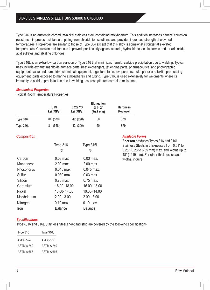
Specifications Types 316 and 316L Stainless Steel sheet and strip are covered by the following specifications
Mechanical PropertiesTypical Room Temperature Properties
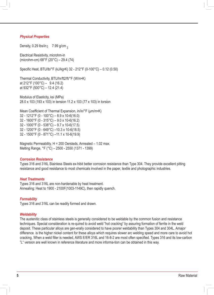
Corrosion ResistanceTypes 316 and 316L Stainless Steels ex-hibit better corrosion resistance than Type 304. They provide excellent pitting resistance and good resistance to most chemicals involved in the paper, textile and photographic industries.
Heat TreatmentsTypes 316 and 316L are non-hardenable by heat treatment.Annealing: Heat to 1900 - 2100F(1003-1149C), then rapidly quench.
FormabilityTypes 316 and 316L can be readily formed and drawn.
WeldabilityThe austenitic class of stainless steels is generally considered to be weldable by the common fusion and resistance techniques. Special consideration is re-quired to avoid weld ”hot cracking“ by assuring formation of ferrite in the weld deposit. These particular alloys are gen-erally considered to have poorer weldability than Types 304 and 304L. Amajor difference is the higher nickel content for these alloys which requires slower arc welding speed and more care to avoid hot cracking. When a weld filler is needed, AWS E/ER 316L and 16-8-2 are most often specified. Types 316 and its low-carbon ”L“ version are well known in reference literature and more informa-tion can be obtained in this way.
Physical Properties
Density, 0.29 lbs/in 7.99 g/cm
Electrical Resistivity, microhm-in(microhm-cm) 68°F (20°C) – 29.4 (74)
Specific Heat, BTU/lb/°F (kJ/kg•K) 32 - 212°F (0-100°C) – 0.12 (0.50)
Thermal Conductivity, BTU/hr/ft2/ft/°F (W/m•K)at 212°F (100°C) – 9.4 (16.2)at 932°F (500°C) – 12.4 (21.4)
Modulus of Elasticity, ksi (MPa)28.0 x 10³ (193 x 103) in tension 11.2 x 10³ (77 x 103) in torsion
Mean Coefficient of Thermal Expansion, in/in/°F (μm/m•K)32 - 1212°F (0 - 100°C) – 8.9 x 10⁻⁶(16.0) 32 - 1600°F (0 - 315°C) – 9.0 x 10⁻⁶(16.2)32 - 1000°F (0 - 538°C) – 9.7 x 10⁻⁶(17.5)32 - 1200°F (0 - 649°C) –10.3 x 10⁻⁶(18.5)32 - 1500°F (0 - 871°C) –11.1 x 10⁻⁶(19.9)
Magnetic Permeability, H = 200 Oersteds, Annealed – 1.02 max.Melting Range, °F (°C) – 2500 - 2550 (1371 - 1399)
Available Forms Enerxon produces Types 316 and 316L Stainless Steels in thicknesses from 0.01" to 0.25" (0.25 to 6.35 mm) max. and widths up to 48" (1219 mm). For other thicknesses and widths, inquire.
Type 316 is an austenitic chromium-nickel stainless steel containing molybdenum. This addition increases general corrosion resistance, improves resistance to pitting from chloride ion solutions, and provides increased strength at elevated temperatures. Prop-erties are similar to those of Type 304 except that this alloy is somewhat stronger at elevated temperatures. Corrosion resistance is improved, par-ticularly against sulfuric, hydrochloric, acetic, formic and tartaric acids; acid sulfates and alkaline chlorides.
Type 316L is an extra-low carbon ver-sion of Type 316 that minimizes harmful carbide precipitation due to welding. Typical uses include exhaust manifolds, furnace parts, heat exchangers, jet engine parts, pharmaceutical and photographic equipment, valve and pump trim, chemi-cal equipment, digesters, tanks, evaporators, pulp, paper and textile pro-cessing equipment, parts exposed to marine atmospheres and tubing. Type 316L is used extensively for weldments where its immunity to carbide precipita-tion due to welding assures optimum corrosion resistance.
316/316L STAINLESS STEELUNS S31600 & UNS31603
Type 316 84 (579) 42 (290) 50 B79
Type 316 Type 316L
Type 316 Type 316L
AMS 5524 AMS 5507ASTM A 240 ASTM A 240
ASTM A 666 ASTM A 666
Carbon 0.08 max. 0.03 max.Manganese 2.00 max. 2.00 max.Phosphorus 0.045 max 0.045 max.Sulfur 0.030 max. 0.03 max.Silicon 0.75 max. 0.75 max.Chromium 16.00- 18.00 16.00- 18.00 Nickel 10.00- 14.00 10.00- 14.00 Molybdenum 2.00 - 3.00 2.00 - 3.00Nitrogen 0.10 max. 0.10 max.Iron Balance Balance
Type 316L 81 (558) 42 (290) 50 B79
UTSksi (MPa)
0.2% YSksi (MPa)
HardnessRockwell
Elongation% in 2"
(50.8 mm)
Composition
% %
3 3
316/316L STAINLESS STEEL | UNS S31600 & UNS31603
5 Raw Material
SpecificationsTypes 316 and 316L Stainless Steel sheet and strip are covered by the following specifications
Mechanical PropertiesTypical Room Temperature Properties
Corrosion ResistanceTypes 316 and 316L Stainless Steels ex-hibit better corrosion resistance than Type 304. They provide excellent pitting resistance and good resistance to most chemicals involved in the paper, textile and photographic industries.
Heat TreatmentsTypes 316 and 316L are non-hardenable by heat treatment.Annealing: Heat to 1900 - 2100F(1003-1149C), then rapidly quench.
FormabilityTypes 316 and 316L can be readily formed and drawn.
WeldabilityThe austenitic class of stainless steels is generally considered to be weldable by the common fusion and resistance techniques. Special consideration is re-quired to avoid weld ”hot cracking“ by assuring formation of ferrite in the weld deposit. These particular alloys are gen-erally considered to have poorer weldability than Types 304 and 304L. Amajor difference is the higher nickel content for these alloys which requires slower arc welding speed and more care to avoid hot cracking. When a weld filler is needed, AWS E/ER 316L and 16-8-2 are most often specified. Types 316 and its low-carbon ”L“ version are well known in reference literature and more informa-tion can be obtained in this way.
Physical Properties
Density, 0.29 lbs/in 7.99 g/cm
Electrical Resistivity, microhm-in(microhm-cm) 68°F (20°C) – 29.4 (74)
Specific Heat, BTU/lb/°F (kJ/kg•K) 32 - 212°F (0-100°C) – 0.12 (0.50)
Thermal Conductivity, BTU/hr/ft2/ft/°F (W/m•K)at 212°F (100°C) – 9.4 (16.2)at 932°F (500°C) – 12.4 (21.4)
Modulus of Elasticity, ksi (MPa)28.0 x 10³ (193 x 103) in tension 11.2 x 10³ (77 x 103) in torsion
Mean Coefficient of Thermal Expansion, in/in/°F (μm/m•K)32 - 1212°F (0 - 100°C) – 8.9 x 10⁻⁶(16.0) 32 - 1600°F (0 - 315°C) – 9.0 x 10⁻⁶(16.2)32 - 1000°F (0 - 538°C) – 9.7 x 10⁻⁶(17.5)32 - 1200°F (0 - 649°C) –10.3 x 10⁻⁶(18.5)32 - 1500°F (0 - 871°C) –11.1 x 10⁻⁶(19.9)
Magnetic Permeability, H = 200 Oersteds, Annealed – 1.02 max.Melting Range, °F (°C) – 2500 - 2550 (1371 - 1399)
Available FormsEnerxon produces Types 316 and 316LStainless Steels in thicknesses from 0.01" to 0.25" (0.25 to 6.35 mm) max. and widths up to 48" (1219 mm). For other thicknesses and widths, inquire.
Type 316 is an austenitic chromium-nickel stainless steel containing molybdenum. This addition increases general corrosion resistance, improves resistance to pitting from chloride ion solutions, and provides increased strength at elevated temperatures. Prop-erties are similar to those of Type 304 except that this alloy is somewhat stronger at elevated temperatures. Corrosion resistance is improved, par-ticularly against sulfuric, hydrochloric, acetic, formic and tartaric acids; acid sulfates and alkaline chlorides.
Type 316L is an extra-low carbon ver-sion of Type 316 that minimizes harmful carbide precipitation due to welding. Typical uses include exhaust manifolds, furnace parts, heat exchangers, jet engine parts, pharmaceutical and photographic equipment, valve and pump trim, chemi-cal equipment, digesters, tanks, evaporators, pulp, paper and textile pro-cessing equipment, parts exposed to marine atmospheres and tubing. Type 316L is used extensively for weldments where its immunity to carbide precipita-tion due to welding assures optimum corrosion resistance.
316/316L STAINLESS STEELUNS S31600 & UNS31603
Type 316 84 (579) 42 (290) 50 B79
Type 316 Type 316L
Type 316 Type 316L
AMS 5524 AMS 5507ASTM A 240 ASTM A 240
ASTM A 666 ASTM A 666
Carbon 0.08 max. 0.03 max.Manganese 2.00 max. 2.00 max.Phosphorus 0.045 max 0.045 max.Sulfur 0.030 max. 0.03 max.Silicon 0.75 max. 0.75 max.Chromium 16.00- 18.00 16.00- 18.00 Nickel 10.00- 14.00 10.00- 14.00 Molybdenum 2.00 - 3.00 2.00 - 3.00Nitrogen 0.10 max. 0.10 max.Iron Balance Balance
Type 316L 81 (558) 42 (290) 50 B79
UTSksi (MPa)
0.2% YSksi (MPa)
HardnessRockwell
Elongation% in 2"
(50.8 mm)
Composition
% %
3 3
316/316L STAINLESS STEEL | UNS S31600 & UNS31603
6 Raw Material
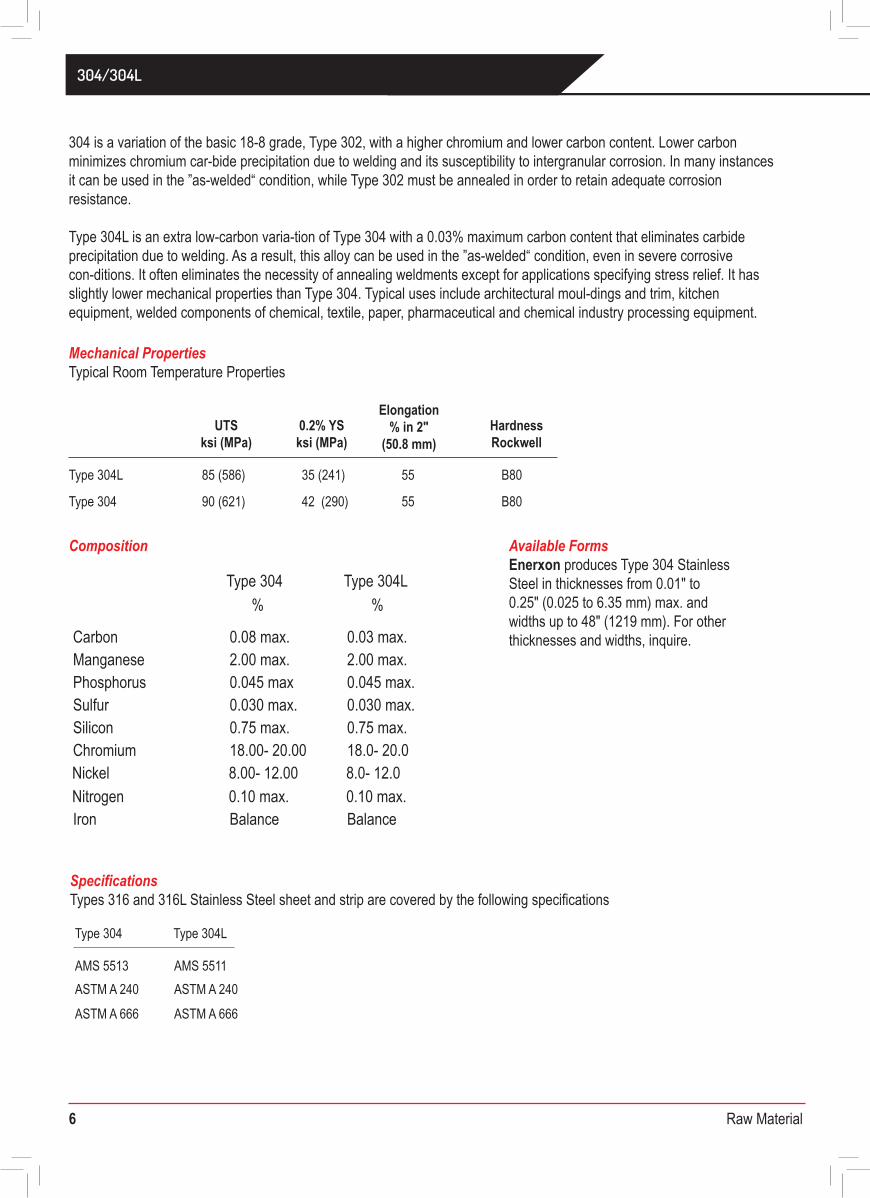
Specifications Types 316 and 316L Stainless Steel sheet and strip are covered by the following specifications
Mechanical PropertiesTypical Room Temperature Properties
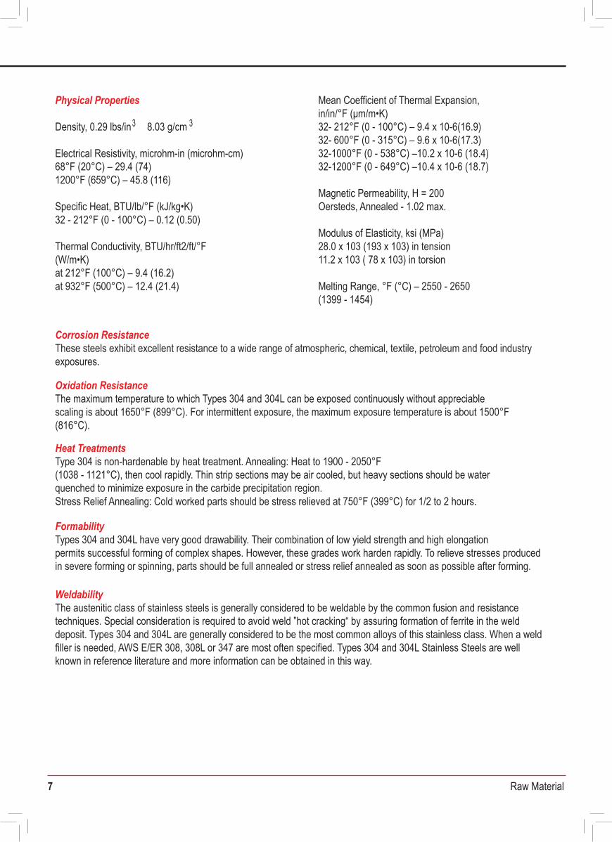
Corrosion ResistanceThese steels exhibit excellent resistance to a wide range of atmospheric, chemical, textile, petroleum and food industryexposures.
Oxidation ResistanceThe maximum temperature to which Types 304 and 304L can be exposed continuously without appreciablescaling is about 1650°F (899°C). For intermittent exposure, the maximum exposure temperature is about 1500°F(816°C).
Heat TreatmentsType 304 is non-hardenable by heat treatment. Annealing: Heat to 1900 - 2050°F(1038 - 1121°C), then cool rapidly. Thin strip sections may be air cooled, but heavy sections should be waterquenched to minimize exposure in the carbide precipitation region.Stress Relief Annealing: Cold worked parts should be stress relieved at 750°F (399°C) for 1/2 to 2 hours.
FormabilityTypes 304 and 304L have very good drawability. Their combination of low yield strength and high elongationpermits successful forming of complex shapes. However, these grades work harden rapidly. To relieve stresses producedin severe forming or spinning, parts should be full annealed or stress relief annealed as soon as possible after forming.
WeldabilityThe austenitic class of stainless steels is generally considered to be weldable by the common fusion and resistancetechniques. Special consideration is required to avoid weld ”hot cracking“ by assuring formation of ferrite in the welddeposit. Types 304 and 304L are generally considered to be the most common alloys of this stainless class. When a weldfiller is needed, AWS E/ER 308, 308L or 347 are most often specified. Types 304 and 304L Stainless Steels are wellknown in reference literature and more information can be obtained in this way.
Physical Properties
Density, 0.29 lbs/in 8.03 g/cm
Electrical Resistivity, microhm-in (microhm-cm) 68°F (20°C) – 29.4 (74)1200°F (659°C) – 45.8 (116)
Specific Heat, BTU/lb/°F (kJ/kg•K)32 - 212°F (0 - 100°C) – 0.12 (0.50)
Thermal Conductivity, BTU/hr/ft2/ft/°F(W/m•K)at 212°F (100°C) – 9.4 (16.2)at 932°F (500°C) – 12.4 (21.4)
Available Forms Enerxon produces Type 304 StainlessSteel in thicknesses from 0.01" to0.25" (0.025 to 6.35 mm) max. andwidths up to 48" (1219 mm). For otherthicknesses and widths, inquire.
304 is a variation of the basic 18-8 grade, Type 302, with a higher chromium and lower carbon content. Lower carbon minimizes chromium car-bide precipitation due to welding and its susceptibility to intergranular corrosion. In many instances, it can be used in the ”as-welded“ condition, while Type 302 must be annealed in order to retain adequate corrosion resistance.
Type 304L is an extra low-carbon varia-tion of Type 304 with a 0.03% maximum carbon content that eliminates carbide precipitation due to welding. As a result, this alloy can be used in the ”as-welded“ condition, even in severe corrosive con-ditions. It often eliminates the necessity of annealing weldments except for applications specifying stress relief. It has slightly lower mechanical properties than Type 304. Typical uses include architectural moul-dings and trim, kitchen equipment, welded components of chemical, textile, paper, pharmaceutical and chemical industry processing equipment.
304/304L
Type 304L 85 (586) 35 (241) 55 B80
Type 304 Type 304L
Type 304 Type 304L
AMS 5513 AMS 5511ASTM A 240 ASTM A 240
ASTM A 666 ASTM A 666
Carbon 0.08 max. 0.03 max.Manganese 2.00 max. 2.00 max.Phosphorus 0.045 max 0.045 max.Sulfur 0.030 max. 0.030 max.Silicon 0.75 max. 0.75 max.Chromium 18.00- 20.00 18.0- 20.0 Nickel 8.00- 12.00 8.0- 12.0 Nitrogen 0.10 max. 0.10 max.Iron Balance Balance
Type 304 90 (621) 42 (290) 55 B80
UTSksi (MPa)
0.2% YSksi (MPa)
HardnessRockwell
Elongation% in 2"
(50.8 mm)
Composition
% %
3 3
Mean Coefficient of Thermal Expansion,in/in/°F (μm/m•K)32- 212°F (0 - 100°C) – 9.4 x 10⁻⁶(16.9)32- 600°F (0 - 315°C) – 9.6 x 10⁻⁶(17.3)32-1000°F (0 - 538°C) –10.2 x 10⁻⁶ (18.4)32-1200°F (0 - 649°C) –10.4 x 10⁻⁶ (18.7)
Magnetic Permeability, H = 200Oersteds, Annealed - 1.02 max.
Modulus of Elasticity, ksi (MPa)28.0 x 10³ (193 x 103) in tension11.2 x 103 ( 78 x 103) in torsion
Melting Range, °F (°C) – 2550 - 2650(1399 - 1454)
304/304L
7 Raw Material
SpecificationsTypes 316 and 316L Stainless Steel sheet and strip are covered by the following specifications
Mechanical PropertiesTypical Room Temperature Properties
Corrosion ResistanceThese steels exhibit excellent resistance to a wide range of atmospheric, chemical, textile, petroleum and food industryexposures.
Oxidation ResistanceThe maximum temperature to which Types 304 and 304L can be exposed continuously without appreciablescaling is about 1650°F (899°C). For intermittent exposure, the maximum exposure temperature is about 1500°F(816°C).
Heat TreatmentsType 304 is non-hardenable by heat treatment. Annealing: Heat to 1900 - 2050°F(1038 - 1121°C), then cool rapidly. Thin strip sections may be air cooled, but heavy sections should be waterquenched to minimize exposure in the carbide precipitation region.Stress Relief Annealing: Cold worked parts should be stress relieved at 750°F (399°C) for 1/2 to 2 hours.
FormabilityTypes 304 and 304L have very good drawability. Their combination of low yield strength and high elongationpermits successful forming of complex shapes. However, these grades work harden rapidly. To relieve stresses producedin severe forming or spinning, parts should be full annealed or stress relief annealed as soon as possible after forming.
WeldabilityThe austenitic class of stainless steels is generally considered to be weldable by the common fusion and resistancetechniques. Special consideration is required to avoid weld ”hot cracking“ by assuring formation of ferrite in the welddeposit. Types 304 and 304L are generally considered to be the most common alloys of this stainless class. When a weldfiller is needed, AWS E/ER 308, 308L or 347 are most often specified. Types 304 and 304L Stainless Steels are wellknown in reference literature and more information can be obtained in this way.
Physical Properties
Density, 0.29 lbs/in 8.03 g/cm
Electrical Resistivity, microhm-in (microhm-cm) 68°F (20°C) – 29.4 (74)1200°F (659°C) – 45.8 (116)
Specific Heat, BTU/lb/°F (kJ/kg•K)32 - 212°F (0 - 100°C) – 0.12 (0.50)
Thermal Conductivity, BTU/hr/ft2/ft/°F(W/m•K)at 212°F (100°C) – 9.4 (16.2)at 932°F (500°C) – 12.4 (21.4)
Available FormsEnerxon produces Type 304 StainlessSteel in thicknesses from 0.01" to0.25" (0.025 to 6.35 mm) max. andwidths up to 48" (1219 mm). For otherthicknesses and widths, inquire.
304 is a variation of the basic 18-8 grade, Type 302, with a higher chromium and lower carbon content. Lower carbon minimizes chromium car-bide precipitation due to welding and its susceptibility to intergranular corrosion. In many instances, it can be used in the ”as-welded“ condition, while Type 302 must be annealed in order to retain adequate corrosion resistance.
Type 304L is an extra low-carbon varia-tion of Type 304 with a 0.03% maximum carbon content that eliminates carbide precipitation due to welding. As a result, this alloy can be used in the ”as-welded“ condition, even in severe corrosive con-ditions. It often eliminates the necessity of annealing weldments except for applications specifying stress relief. It has slightly lower mechanical properties than Type 304. Typical uses include architectural moul-dings and trim, kitchen equipment, welded components of chemical, textile, paper, pharmaceutical and chemical industry processing equipment.
304/304L
Type 304L 85 (586) 35 (241) 55 B80
Type 304 Type 304L
Type 304 Type 304L
AMS 5513 AMS 5511ASTM A 240 ASTM A 240
ASTM A 666 ASTM A 666
Carbon 0.08 max. 0.03 max.Manganese 2.00 max. 2.00 max.Phosphorus 0.045 max 0.045 max.Sulfur 0.030 max. 0.030 max.Silicon 0.75 max. 0.75 max.Chromium 18.00- 20.00 18.0- 20.0 Nickel 8.00- 12.00 8.0- 12.0 Nitrogen 0.10 max. 0.10 max.Iron Balance Balance
Type 304 90 (621) 42 (290) 55 B80
UTSksi (MPa)
0.2% YSksi (MPa)
HardnessRockwell
Elongation% in 2"
(50.8 mm)
Composition
% %
3 3
Mean Coefficient of Thermal Expansion,in/in/°F (μm/m•K)32- 212°F (0 - 100°C) – 9.4 x 10⁻⁶(16.9)32- 600°F (0 - 315°C) – 9.6 x 10⁻⁶(17.3)32-1000°F (0 - 538°C) –10.2 x 10⁻⁶ (18.4)32-1200°F (0 - 649°C) –10.4 x 10⁻⁶ (18.7)
Magnetic Permeability, H = 200Oersteds, Annealed - 1.02 max.
Modulus of Elasticity, ksi (MPa)28.0 x 10³ (193 x 103) in tension11.2 x 103 ( 78 x 103) in torsion
Melting Range, °F (°C) – 2550 - 2650(1399 - 1454)
304/304L
8 Raw Material
Bar and sections65mm (2.56”)[ksi]
Alloy
Alloy 0.2% Proof Stress, N/mm2
0.2% Proof Stress, N/mm2
Tensile StrengthN/mm2
Elongation,% on 5.65 √S0
0.2% Proof strength, N/mm2 [ksi]
Tensile strength, N/mm2 [ksi]
Elongation, % on 5.65 √S0
Brinell Hardness
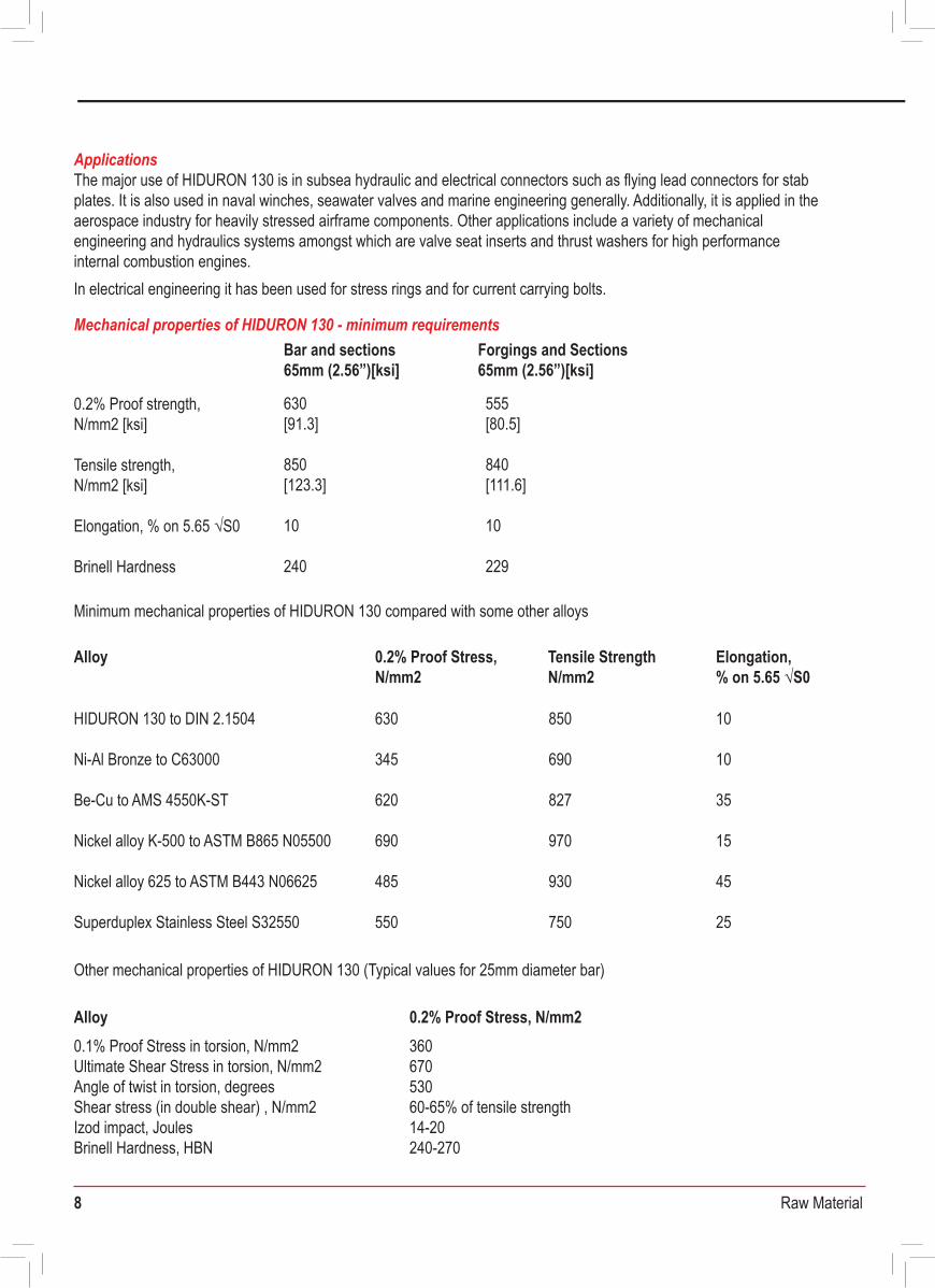
HIDURON 130 to DIN 2.1504
Ni-Al Bronze to C63000
Be-Cu to AMS 4550K-ST
Nickel alloy K-500 to ASTM B865 N05500
Nickel alloy 625 to ASTM B443 N06625
Superduplex Stainless Steel S32550
0.1% Proof Stress in torsion, N/mm2Ultimate Shear Stress in torsion, N/mm2Angle of twist in torsion, degreesShear stress (in double shear) , N/mm2Izod impact, JoulesBrinell Hardness, HBNWohler Fatigue (5 x 10⁷ reversals), N/mm2
36067053060-65% of tensile strength14-20240-270270
630[91.3]
850[123.3]
10
240
630
345
620
690
485
550
850
690
827
970
930
750
10
10
35
15
45
25
555[80.5]
840[111.6]
10
229
Forgings and Sections65mm (2.56”)[ksi]
SAF® 2205 and SAF® 2507 are registered trade marks of Sandvik Materials Technology HASTELLOY® is a registered trade mark of Haynes International, Inc ZERON® is a registered trade mark of Weir Materials Ltd
This table is intended only as a guide as corrosion performance can be affected by precise process conditions and consideration must be made of the possibility of localised rather than general corrosion for the environment indicated. The information given is for pure chemicals and the solvent is water unless stated otherwise. It must be stressed that, whenever possible, plant corrosion tests should be carried out. Samples of FERRALIUM 255-SD50 for this purpose can be supplied on request. Samples of other alloys may be supplied by the Trade Mark holders listed below.
Notes: 1 For Avesta grades only, rate of corrosion is less than 0.1mm/yr. 2 For Avesta grades only, rate of corrosion is between 0.1 mm/yr and 1.0mm/yr. 3 Pitting corrosion/Crevice corrosion/Stress Corrosion/Intergranular corrosion depending on environment. 4 If there is a high iron content, use HASTELLOY C-22®. 5 HASTELLOY C-276® resistant to about 90°C 6 HASTELLOY C-276® and HASTELLOY B-3 susceptible to stress corrosion cracking in hot strong sodium hydroxide. 7 68.9% phosphoric acid, 4.15% sulphuric acid, 1.85% iron, 5400 ppm fluorides and 2000 ppm chlorides. 8 High corrosion figures found for high concentrations of alloy. A. Prices per kg are given as an approximate guide and are correct at the time of publication (August 2001). Note that Ti is 60% density of other materials. B. In acid solutions containing oxidising salts, HASTELLOY® B-3 alloy may suffer enhanced corrosion. Guidance should be sought from Haynes International Ltd.
Comparative corrosion resistance table
Mechanical properties of HIDURON 130 - minimum requirements
2-4Cost Range Indication (£/kg) 4-8 12-16 25-35 16-20 10-13 2-4 4-8 12-16 8-12 8-12
ConcentrationEnvironment (w/w) (°C)
Temperature
316
FERR
ALIU
M®
255-S
D50
Titan
ium
HAST
ELLO
Y® B-
3
HAST
ELLO
Y® C-
2764
Carpe
nter2
0Cb-3
®
Aves
ta22
05
INCO
NEL®
625
Aves
ta25
4SMO
®
INCO
LOY®
825
MONE
L®40
0
Risk
ofloc
alise
d co
rrosio
n3`
- 20°CSea Water • • • • • • • • • • Yes-Seawater saturated with Cl2 to 65°C x • • x x• ND ND • • x Yes
0-50% 20°CSodium Hydroxide • • • • • • • • • • • All Boiling •Sodium Hydroxide 6• • 6 SC SC • • Yes
30% Boiling • • Sodium Hydroxide • 6 • 6 • • • • Yes40% BoilingSodium Hydroxide • • 6 • 6 x • • Yes
Sodium Hypochlorite 12-14% 20°C x • • • x ND ND • x60% 20°CSodium Sulphide • • • • • SC SC • • • 40% BoilingSodium Sulphide • • • • • • •
0-50% BoilingSodium Sulphide • • • • • • • 50% 20°CSodium Sulphite • • • • • • • • • • 50% Boiling NDSodium Sulphite • • • • ND • • ND ND ND20% 40°CSulphuric Acid • • x • • • • • • • • 30% 40°CSulphuric Acid x• • • • • • • 40% 40°CSulphuric Acid x • x • • • x • •
Sulphuric Acid 40-98% 40°C x • x • • • SC SC • • Sulphuric Acid 5-30% 80°C x • x • SC SC • x
5% 80°CSulphuric Acid x • x • • • • • • 10% 80°CSulphuric Acid x • x • • • • • x30% 80°CSulphuric Acid x • x • x x • x
60°C30-50%Sulphuric Acid x • x • • x x ND • x98% 100°CSulphuric Acid • x • x x ND • x98% 150°CSulphuric Acid ND x x x ND x x x x x
to 80°C x xSulphuric Acid (fuming) Oleum 15% SO3 ND ND ND x x xAllZinc Chloride 20°C ND • • • ND ND • • YesAllZinc Chloride Boiling x ND x ND ND x Yes
• Excellent corrosion resistance - rate of corrosion less than 0.15mm/yr (see note 1)Good corrosion resistance under most conditions - rate of corrosion expected to be less than 0.50mm/yr (see note 2)
x Not RecommendedND Data unavailableSC Data is supplied for specific concentrations as given in adjacent rows of the table
ApplicationsThe major use of HIDURON 130 is in subsea hydraulic and electrical connectors such as flying lead connectors for stab plates. It is also used in naval winches, seawater valves and marine engineering generally. Additionally, it is applied in the aerospace industry for heavily stressed airframe components. Other applications include a variety of mechanical engineering and hydraulics systems amongst which are valve seat inserts and thrust washers for high performance internal combustion engines.In electrical engineering it has been used for stress rings and for current carrying bolts.
Minimum mechanical properties of HIDURON 130 compared with some other alloys
Other mechanical properties of HIDURON 130 (Typical values for 25mm diameter bar)
FABRICATION
9 Raw Material
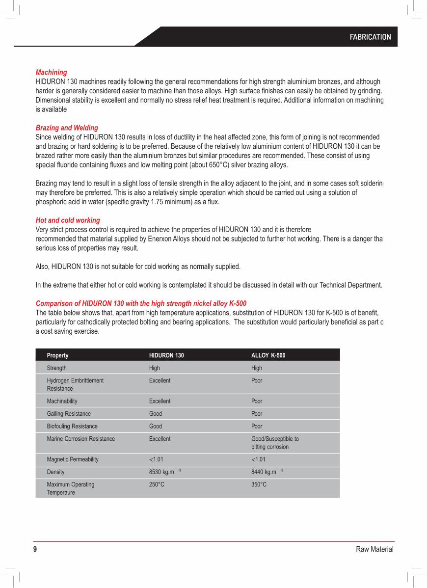
MachiningHIDURON 130 machines readily following the general recommendations for high strength aluminium bronzes, and although harder is generally considered easier to machine than those alloys. High surface finishes can easily be obtained by grinding. Dimensional stability is excellent and normally no stress relief heat treatment is required. Additional information on machining is available
Brazing and WeldingSince welding of HIDURON 130 results in loss of ductility in the heat affected zone, this form of joining is not recommended and brazing or hard soldering is to be preferred. Because of the relatively low aluminium content of HIDURON 130 it can be brazed rather more easily than the aluminium bronzes but similar procedures are recommended. These consist of using special fluoride containing fluxes and low melting point (about 650°C) silver brazing alloys.
Brazing may tend to result in a slight loss of tensile strength in the alloy adjacent to the joint, and in some cases soft soldering may therefore be preferred. This is also a relatively simple operation which should be carried out using a solution of phosphoric acid in water (specific gravity 1.75 minimum) as a flux.
Hot and cold workingVery strict process control is required to achieve the properties of HIDURON 130 and it is therefore recommended that material supplied by Enerxon Alloys should not be subjected to further hot working. There is a danger that serious loss of properties may result.
Also, HIDURON 130 is not suitable for cold working as normally supplied.
In the extreme that either hot or cold working is contemplated it should be discussed in detail with our Technical Department.
Comparison of HIDURON 130 with the high strength nickel alloy K-500 The table below shows that, apart from high temperature applications, substitution of HIDURON 130 for K-500 is of benefit, particularly for cathodically protected bolting and bearing applications. The substitution would particularly beneficial as part of a cost saving exercise.
Fabrication
Property HIDURON 130 ALLOY K-500
Strength High High
Excellent Poor
Machinability
Hydrogen Embrittlement Resistance
Excellent Poor
Galling Resistance Good Poor
Biofouling Resistance Good Poor
Marine Corrosion Resistance Excellent Good/Susceptible to pitting corrosion
<1.01Magnetic Permeability <1.01
Density 8530 kg.m -3 8440 kg.m -3
250°C 350°CMaximum Operating Temperaure
Material Purchase Specification forFERMONIC 50 High Strength Grade - Bar
DOCUMENT No. MLA-MPS-25VS-BAR/FORG Date: 2nd September 2009 Rev: 2
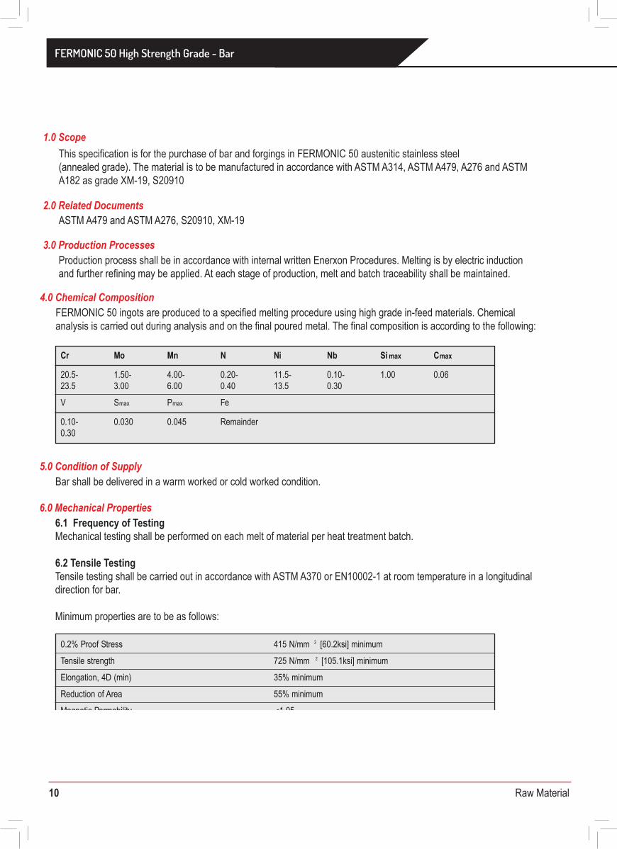
This specification is for the purchase of bar and forgings in FERMONIC 50 austenitic stainless steel(annealed grade). The material is to be manufactured in accordance with ASTM A314, ASTM A479, A276 and ASTM A182 as grade XM-19, S20910
ASTM A479 and ASTM A276, S20910, XM-19
1.0 Scope
2.0 Related Documents
Production process shall be in accordance with internal written Enerxon Procedures. Melting is by electric induction and further refining may be applied. At each stage of production, melt and batch traceability shall be maintained.
3.0 Production Processes
FERMONIC 50 ingots are produced to a specified melting procedure using high grade in-feed materials. Chemical analysis is carried out during analysis and on the final poured metal. The final composition is according to the following:
4.0 Chemical Composition
Bar shall be delivered in a warm worked or cold worked condition.5.0 Condition of Supply
Cr Mo Mn N Ni Nb Si max Cmax
20.5- 1.50- 4.00- 0.20- 11.5- 0.10- 1.00 0.0623.5 3.00 6.00 0.40 13.5 0.30
V maxS Pmax Fe
0.10- 0.030 0.045 Remainder0.30
6.1 Frequency of TestingMechanical testing shall be performed on each melt of material per heat treatment batch.
6.2 Tensile TestingTensile testing shall be carried out in accordance with ASTM A370 or EN10002-1 at room temperature in a longitudinal direction for bar.
Minimum properties are to be as follows:
6.0 Mechanical Properties
0.2% Proof Stress 415 N/mm 2 [60.2ksi] minimum
Tensile strength 725 N/mm 2 [105.1ksi] minimum
Elongation, 4D (min) 35% minimum
55% minimumReduction of Area
Magnetic Permability <1.05
FABRICATION
10 Raw Material
MachiningHIDURON 130 machines readily following the general recommendations for high strength aluminium bronzes, and although harder is generally considered easier to machine than those alloys. High surface finishes can easily be obtained by grinding. Dimensional stability is excellent and normally no stress relief heat treatment is required. Additional information on machining is available
Brazing and WeldingSince welding of HIDURON 130 results in loss of ductility in the heat affected zone, this form of joining is not recommended and brazing or hard soldering is to be preferred. Because of the relatively low aluminium content of HIDURON 130 it can be brazed rather more easily than the aluminium bronzes but similar procedures are recommended. These consist of using special fluoride containing fluxes and low melting point (about 650°C) silver brazing alloys.
Brazing may tend to result in a slight loss of tensile strength in the alloy adjacent to the joint, and in some cases soft soldering may therefore be preferred. This is also a relatively simple operation which should be carried out using a solution of phosphoric acid in water (specific gravity 1.75 minimum) as a flux.
Hot and cold workingVery strict process control is required to achieve the properties of HIDURON 130 and it is therefore recommended that material supplied by Enerxon Alloys should not be subjected to further hot working. There is a danger that serious loss of properties may result.
Also, HIDURON 130 is not suitable for cold working as normally supplied.
In the extreme that either hot or cold working is contemplated it should be discussed in detail with our Technical Department.
Comparison of HIDURON 130 with the high strength nickel alloy K-500 The table below shows that, apart from high temperature applications, substitution of HIDURON 130 for K-500 is of benefit, particularly for cathodically protected bolting and bearing applications. The substitution would particularly beneficial as part of a cost saving exercise.
Fabrication
Property HIDURON 130 ALLOY K-500
Strength High High
Excellent Poor
Machinability
Hydrogen Embrittlement Resistance
Excellent Poor
Galling Resistance Good Poor
Biofouling Resistance Good Poor
Marine Corrosion Resistance Excellent Good/Susceptible to pitting corrosion
<1.01Magnetic Permeability <1.01
Density 8530 kg.m -3 8440 kg.m -3
250°C 350°CMaximum Operating Temperaure
Material Purchase Specification forFERMONIC 50 High Strength Grade - Bar
This specification is for the purchase of bar and forgings in FERMONIC 50 austenitic stainless steel(annealed grade). The material is to be manufactured in accordance with ASTM A314, ASTM A479, A276 and ASTM A182 as grade XM-19, S20910
ASTM A479 and ASTM A276, S20910, XM-19
1.0 Scope
2.0 Related Documents
Production process shall be in accordance with internal written Enerxon Procedures. Melting is by electric induction and further refining may be applied. At each stage of production, melt and batch traceability shall be maintained.
3.0 Production Processes
FERMONIC 50 ingots are produced to a specified melting procedure using high grade in-feed materials. Chemical analysis is carried out during analysis and on the final poured metal. The final composition is according to the following:
4.0 Chemical Composition
Bar shall be delivered in a warm worked or cold worked condition.5.0 Condition of Supply
Cr Mo Mn N Ni Nb Si max Cmax
20.5- 1.50- 4.00- 0.20- 11.5- 0.10- 1.00 0.0623.5 3.00 6.00 0.40 13.5 0.30
V maxS Pmax Fe
0.10- 0.030 0.045 Remainder0.30
6.1 Frequency of TestingMechanical testing shall be performed on each melt of material per heat treatment batch.
6.2 Tensile TestingTensile testing shall be carried out in accordance with ASTM A370 or EN10002-1 at room temperature in a longitudinal direction for bar.
Minimum properties are to be as follows:
6.0 Mechanical Properties
0.2% Proof Stress 415 N/mm 2 [60.2ksi] minimum
Tensile strength 725 N/mm 2 [105.1ksi] minimum
Elongation, 4D (min) 35% minimum
55% minimumReduction of Area
Magnetic Permability <1.05
FERMONIC 50 High Strength Grade - Bar
11 Raw Material
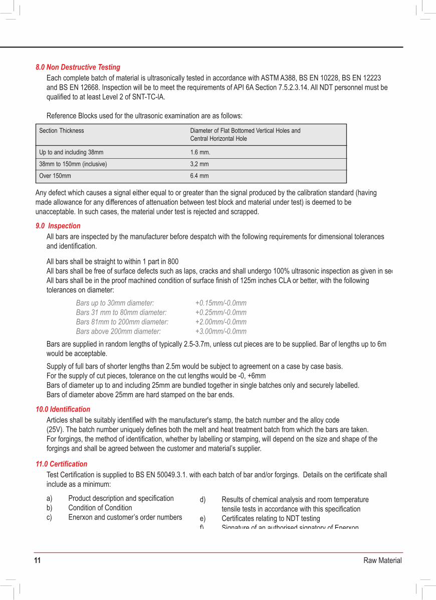
Each complete batch of material is ultrasonically tested in accordance with ASTM A388, BS EN 10228, BS EN 12223 and BS EN 12668. Inspection will be to meet the requirements of API 6A Section 7.5.2.3.14. All NDT personnel must be qualified to at least Level 2 of SNT-TC-lA.
Reference Blocks used for the ultrasonic examination are as follows:
8.0 Non Destructive Testing
All bars are inspected by the manufacturer before despatch with the following requirements for dimensional tolerances and identification.
All bars shall be straight to within 1 part in 800 All bars shall be free of surface defects such as laps, cracks and shall undergo 100% ultrasonic inspection as given in sec 8.All bars shall be in the proof machined condition of surface finish of 125m inches CLA or better, with the followingtolerances on diameter:
Bars are supplied in random lengths of typically 2.5-3.7m, unless cut pieces are to be supplied. Bar of lengths up to 6m would be acceptable.Supply of full bars of shorter lengths than 2.5m would be subject to agreement on a case by case basis.For the supply of cut pieces, tolerance on the cut lengths would be -0, +6mmBars of diameter up to and including 25mm are bundled together in single batches only and securely labelled.Bars of diameter above 25mm are hard stamped on the bar ends.
9.0 Inspection
Articles shall be suitably identified with the manufacturer's stamp, the batch number and the alloy code(25V). The batch number uniquely defines both the melt and heat treatment batch from which the bars are taken. For forgings, the method of identification, whether by labelling or stamping, will depend on the size and shape of the forgings and shall be agreed between the customer and material’s supplier.
10.0 Identification
Test Certification is supplied to BS EN 50049.3.1. with each batch of bar and/or forgings. Details on the certificate shall include as a minimum:
a) Product description and specificationb) Condition of Conditionc) Enerxon and customer’s order numbers
11.0 Certification
Any defect which causes a signal either equal to or greater than the signal produced by the calibration standard (having made allowance for any differences of attenuation between test block and material under test) is deemed to be unacceptable. In such cases, the material under test is rejected and scrapped.
Bars up to 30mm diameter: Bars 31 mm to 80mm diameter:Bars 81mm to 200mm diameter:Bars above 200mm diameter:
+0.15mm/-0.0mm+0.25mm/-0.0mm+2.00mm/-0.0mm+3.00mm/-0.0mm
Section Thickness
Up to and including 38mm 1.6 mm.
38mm to 150mm (inclusive) 3,2 mm
Diameter of Flat Bottomed Vertical Holes and Central Horizontal Hole
Over 150mm 6.4 mm
d) Results of chemical analysis and room temperaturetensile tests in accordance with this specification
e) Certificates relating to NDT testingf) Signature of an authorised signatory of Enerxon
Additional documentation can be supplied by agreement between the materials supplier and customer at the enquiry and order stage.
Material Purchase Specification forFERMONIC 50 Annealed Grade - Bar and Forgings
DOCUMENT No. MLA-MPS-25VS-BAR/FORG Date: 2nd September 2009 Rev: 2
This specification is for the purchase of bar and forgings in FERMONIC 50 austenitic stainless steel(annealed grade). The material is to be manufactured in accordance with ASTM A314, ASTM A479, A276 and ASTM A182 as grade XM-19, S20910
ASTM A479 and ASTM A276, S20910, XM-19
1.0 Scope
2.0 Related Documents
Production process shall be in accordance with internal written Enerxon Procedures. Melting is by electric induction and further refining may be applied. At each stage of production, melt and batch traceability shall be maintained.
3.0 Production Processes
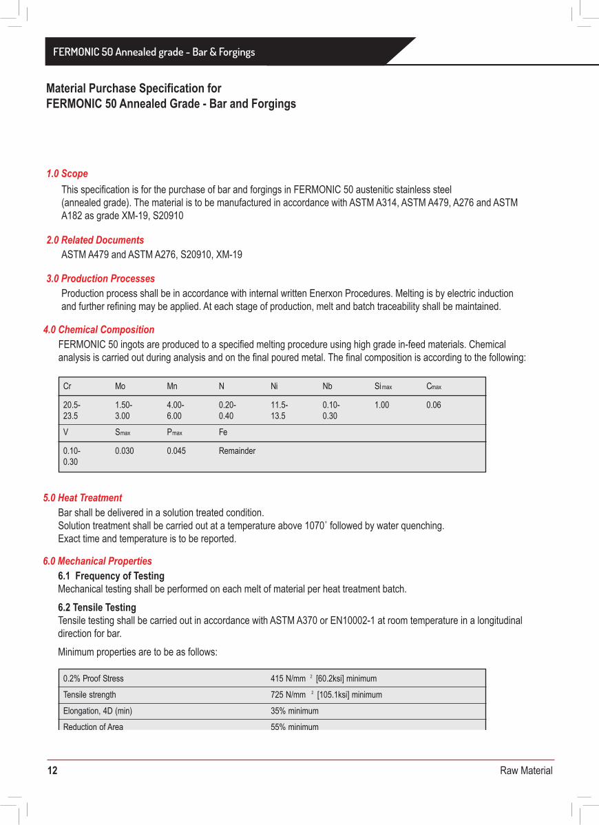
FERMONIC 50 ingots are produced to a specified melting procedure using high grade in-feed materials. Chemical analysis is carried out during analysis and on the final poured metal. The final composition is according to the following:
4.0 Chemical Composition
Cr Mo Mn N Ni Nb Simax Cmax
20.5- 1.50- 4.00- 0.20- 11.5- 0.10- 1.00 0.0623.5 3.00 6.00 0.40 13.5 0.30
V maxS Pmax Fe
0.10- 0.030 0.045 Remainder0.30
Bar shall be delivered in a solution treated condition.Solution treatment shall be carried out at a temperature above 1070˚ followed by water quenching.Exact time and temperature is to be reported.
5.0 Heat Treatment
6.1 Frequency of TestingMechanical testing shall be performed on each melt of material per heat treatment batch.6.2 Tensile TestingTensile testing shall be carried out in accordance with ASTM A370 or EN10002-1 at room temperature in a longitudinal direction for bar.Minimum properties are to be as follows:
6.0 Mechanical Properties
0.2% Proof Stress 415 N/mm 2 [60.2ksi] minimum
Tensile strength 725 N/mm 2 [105.1ksi] minimum
Elongation, 4D (min) 35% minimum
55% minimumReduction of Area
Magnetic Permability <1.05
FERMONIC 50 High Strength Grade - Bar
12 Raw Material
Each complete batch of material is ultrasonically tested in accordance with ASTM A388, BS EN 10228, BS EN 12223 and BS EN 12668. Inspection will be to meet the requirements of API 6A Section 7.5.2.3.14. All NDT personnel must be qualified to at least Level 2 of SNT-TC-lA.
Reference Blocks used for the ultrasonic examination are as follows:
8.0 Non Destructive Testing
All bars are inspected by the manufacturer before despatch with the following requirements for dimensional tolerances and identification.
All bars shall be straight to within 1 part in 800 All bars shall be free of surface defects such as laps, cracks and shall undergo 100% ultrasonic inspection as given in sec 8.All bars shall be in the proof machined condition of surface finish of 125m inches CLA or better, with the followingtolerances on diameter:
Bars are supplied in random lengths of typically 2.5-3.7m, unless cut pieces are to be supplied. Bar of lengths up to 6m would be acceptable.Supply of full bars of shorter lengths than 2.5m would be subject to agreement on a case by case basis.For the supply of cut pieces, tolerance on the cut lengths would be -0, +6mmBars of diameter up to and including 25mm are bundled together in single batches only and securely labelled.Bars of diameter above 25mm are hard stamped on the bar ends.
9.0 Inspection
Articles shall be suitably identified with the manufacturer's stamp, the batch number and the alloy code(25V). The batch number uniquely defines both the melt and heat treatment batch from which the bars are taken. For forgings, the method of identification, whether by labelling or stamping, will depend on the size and shape of the forgings and shall be agreed between the customer and material’s supplier.
10.0 Identification
Test Certification is supplied to BS EN 50049.3.1. with each batch of bar and/or forgings. Details on the certificate shall include as a minimum:
a) Product description and specificationb) Condition of Conditionc) Enerxon and customer’s order numbers
11.0 Certification
Any defect which causes a signal either equal to or greater than the signal produced by the calibration standard (having made allowance for any differences of attenuation between test block and material under test) is deemed to be unacceptable. In such cases, the material under test is rejected and scrapped.
Bars up to 30mm diameter: Bars 31 mm to 80mm diameter:Bars 81mm to 200mm diameter:Bars above 200mm diameter:
+0.15mm/-0.0mm+0.25mm/-0.0mm+2.00mm/-0.0mm+3.00mm/-0.0mm
Section Thickness
Up to and including 38mm 1.6 mm.
38mm to 150mm (inclusive) 3,2 mm
Diameter of Flat Bottomed Vertical Holes and Central Horizontal Hole
Over 150mm 6.4 mm
d) Results of chemical analysis and room temperaturetensile tests in accordance with this specification
e) Certificates relating to NDT testingf) Signature of an authorised signatory of Enerxon
Additional documentation can be supplied by agreement between the materials supplier and customer at the enquiry and order stage.
Material Purchase Specification forFERMONIC 50 Annealed Grade - Bar and Forgings
This specification is for the purchase of bar and forgings in FERMONIC 50 austenitic stainless steel(annealed grade). The material is to be manufactured in accordance with ASTM A314, ASTM A479, A276 and ASTM A182 as grade XM-19, S20910
ASTM A479 and ASTM A276, S20910, XM-19
1.0 Scope
2.0 Related Documents
Production process shall be in accordance with internal written Enerxon Procedures. Melting is by electric induction and further refining may be applied. At each stage of production, melt and batch traceability shall be maintained.
3.0 Production Processes
FERMONIC 50 ingots are produced to a specified melting procedure using high grade in-feed materials. Chemical analysis is carried out during analysis and on the final poured metal. The final composition is according to the following:
4.0 Chemical Composition
Cr Mo Mn N Ni Nb Simax Cmax
20.5- 1.50- 4.00- 0.20- 11.5- 0.10- 1.00 0.0623.5 3.00 6.00 0.40 13.5 0.30
V maxS Pmax Fe
0.10- 0.030 0.045 Remainder0.30
Bar shall be delivered in a solution treated condition.Solution treatment shall be carried out at a temperature above 1070˚ followed by water quenching.Exact time and temperature is to be reported.
5.0 Heat Treatment
6.1 Frequency of TestingMechanical testing shall be performed on each melt of material per heat treatment batch.6.2 Tensile TestingTensile testing shall be carried out in accordance with ASTM A370 or EN10002-1 at room temperature in a longitudinal direction for bar. Minimum properties are to be as follows:
6.0 Mechanical Properties
0.2% Proof Stress 415 N/mm 2 [60.2ksi] minimum
Tensile strength 725 N/mm 2 [105.1ksi] minimum
Elongation, 4D (min) 35% minimum
55% minimumReduction of Area
Magnetic Permability <1.05
FERMONIC 50 Annealed grade - Bar & Forgings
13 Raw Material
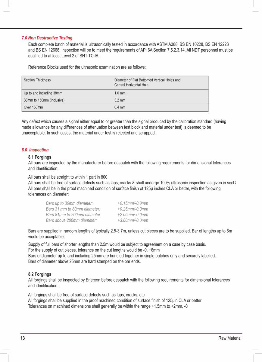
Each complete batch of material is ultrasonically tested in accordance with ASTM A388, BS EN 10228, BS EN 12223 and BS EN 12668. Inspection will be to meet the requirements of API 6A Section 7.5.2.3.14. All NDT personnel must be qualified to at least Level 2 of SNT-TC-lA.
Reference Blocks used for the ultrasonic examination are as follows:
7.0 Non Destructive Testing
Any defect which causes a signal either equal to or greater than the signal produced by the calibration standard (having made allowance for any differences of attenuation between test block and material under test) is deemed to be unacceptable. In such cases, the material under test is rejected and scrapped.
Section Thickness
Up to and including 38mm 1.6 mm.
38mm to 150mm (inclusive) 3,2 mm
Diameter of Flat Bottomed Vertical Holes and Central Horizontal Hole
Over 150mm 6.4 mm
8.1 ForgingsAll bars are inspected by the manufacturer before despatch with the following requirements for dimensional tolerances and identification.
All bars shall be straight to within 1 part in 800 All bars shall be free of surface defects such as laps, cracks & shall undergo 100% ultrasonic inspection as given in sect 8.All bars shall be in the proof machined condition of surface finish of 125μ inches CLA or better, with the followingtolerances on diameter:
All forgings shall be free of surface defects such as laps, cracks, etcAll forgings shall be supplied in the proof machined condition of surface finish of 125μin CLA or betterTolerances on machined dimensions shall generally be within the range +1.5mm to +2mm, -0
Bars are supplied in random lengths of typically 2.5-3.7m, unless cut pieces are to be supplied. Bar of lengths up to 6m would be acceptable.Supply of full bars of shorter lengths than 2.5m would be subject to agreement on a case by case basis.For the supply of cut pieces, tolerance on the cut lengths would be -0, +6mmBars of diameter up to and including 25mm are bundled together in single batches only and securely labelled.Bars of diameter above 25mm are hard stamped on the bar ends.
8.0 Inspection
Bars up to 30mm diameter: Bars 31 mm to 80mm diameter:Bars 81mm to 200mm diameter:Bars above 200mm diameter:
+0.15mm/-0.0mm+0.25mm/-0.0mm+2.00mm/-0.0mm+3.00mm/-0.0mm
8.2 ForgingsAll forgings shall be inspected by Enerxon before despatch with the following requirements for dimensional tolerances and identification.
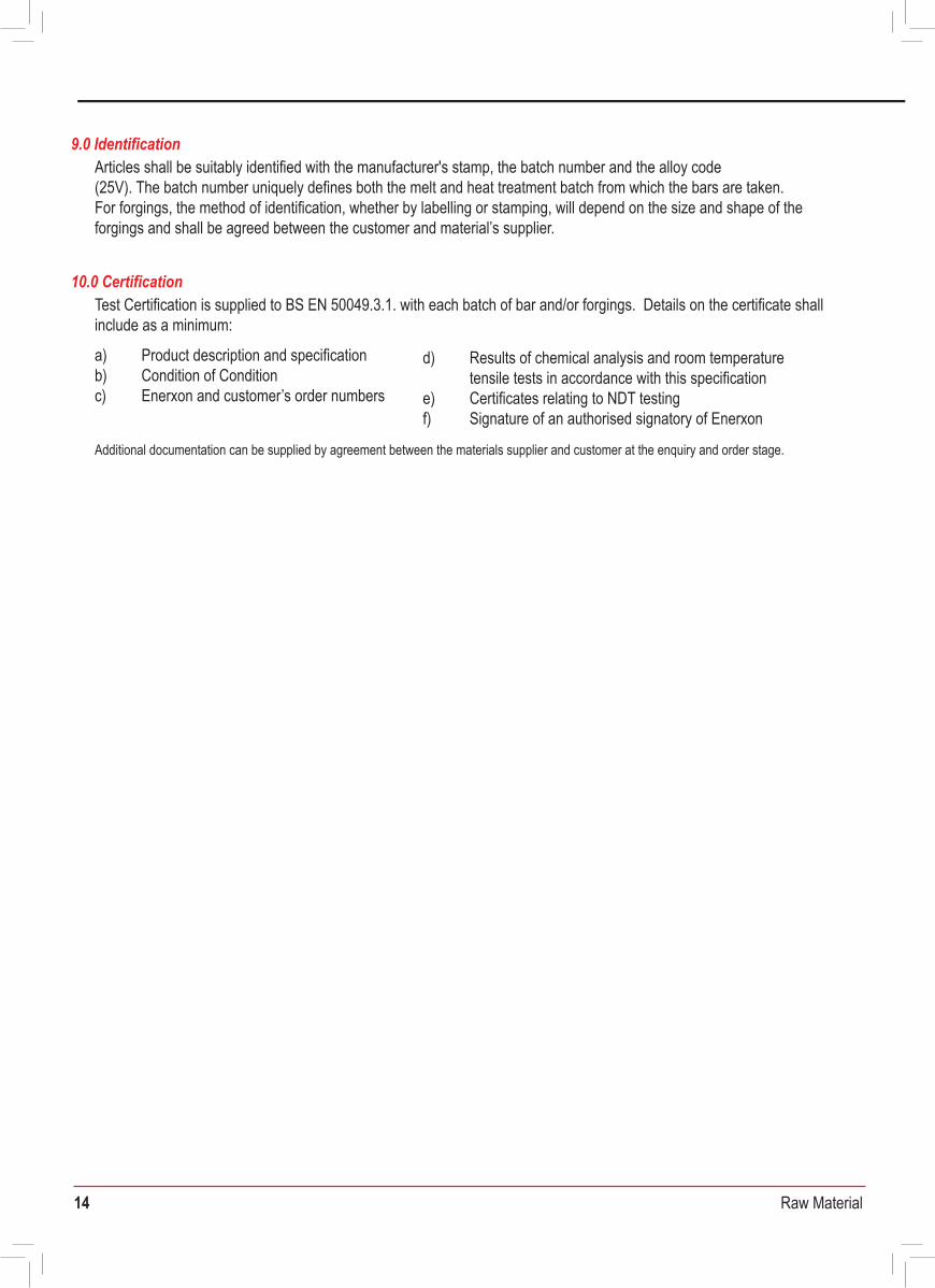
Test Certification is supplied to BS EN 50049.3.1. with each batch of bar and/or forgings. Details on the certificate shall include as a minimum:
a) Product description and specificationb) Condition of Conditionc) Enerxon and customer’s order numbers
10.0 Certification
d) Results of chemical analysis and room temperature tensile tests in accordance with this specificatione) Certificates relating to NDT testingf) Signature of an authorised signatory of Enerxon
Additional documentation can be supplied by agreement between the materials supplier and customer at the enquiry and order stage.
Articles shall be suitably identified with the manufacturer's stamp, the batch number and the alloy code(25V). The batch number uniquely defines both the melt and heat treatment batch from which the bars are taken. For forgings, the method of identification, whether by labelling or stamping, will depend on the size and shape of the forgings and shall be agreed between the customer and material’s supplier.
9.0 Identification
FERMONIC 50 Annealed grade - Bar & Forgings
14 Raw Material
Each complete batch of material is ultrasonically tested in accordance with ASTM A388, BS EN 10228, BS EN 12223 and BS EN 12668. Inspection will be to meet the requirements of API 6A Section 7.5.2.3.14. All NDT personnel must be qualified to at least Level 2 of SNT-TC-lA.
Reference Blocks used for the ultrasonic examination are as follows:
7.0 Non Destructive Testing
Any defect which causes a signal either equal to or greater than the signal produced by the calibration standard (having made allowance for any differences of attenuation between test block and material under test) is deemed to be unacceptable. In such cases, the material under test is rejected and scrapped.
Section Thickness
Up to and including 38mm 1.6 mm.
38mm to 150mm (inclusive) 3,2 mm
Diameter of Flat Bottomed Vertical Holes and Central Horizontal Hole
Over 150mm 6.4 mm
8.1 ForgingsAll bars are inspected by the manufacturer before despatch with the following requirements for dimensional tolerances and identification.
All bars shall be straight to within 1 part in 800 All bars shall be free of surface defects such as laps, cracks & shall undergo 100% ultrasonic inspection as given in sect 8.All bars shall be in the proof machined condition of surface finish of 125μ inches CLA or better, with the followingtolerances on diameter:
All forgings shall be free of surface defects such as laps, cracks, etcAll forgings shall be supplied in the proof machined condition of surface finish of 125μin CLA or betterTolerances on machined dimensions shall generally be within the range +1.5mm to +2mm, -0
Bars are supplied in random lengths of typically 2.5-3.7m, unless cut pieces are to be supplied. Bar of lengths up to 6m would be acceptable.Supply of full bars of shorter lengths than 2.5m would be subject to agreement on a case by case basis.For the supply of cut pieces, tolerance on the cut lengths would be -0, +6mmBars of diameter up to and including 25mm are bundled together in single batches only and securely labelled.Bars of diameter above 25mm are hard stamped on the bar ends.
8.0 Inspection
Bars up to 30mm diameter: Bars 31 mm to 80mm diameter:Bars 81mm to 200mm diameter:Bars above 200mm diameter:
+0.15mm/-0.0mm+0.25mm/-0.0mm+2.00mm/-0.0mm+3.00mm/-0.0mm
8.2 ForgingsAll forgings shall be inspected by Enerxon before despatch with the following requirements for dimensional tolerances and identification.
Test Certification is supplied to BS EN 50049.3.1. with each batch of bar and/or forgings. Details on the certificate shall include as a minimum:
a) Product description and specificationb) Condition of Conditionc) Enerxon and customer’s order numbers
10.0 Certification
d) Results of chemical analysis and room temperaturetensile tests in accordance with this specification
e) Certificates relating to NDT testingf) Signature of an authorised signatory of Enerxon
Additional documentation can be supplied by agreement between the materials supplier and customer at the enquiry and order stage.
Articles shall be suitably identified with the manufacturer's stamp, the batch number and the alloy code(25V). The batch number uniquely defines both the melt and heat treatment batch from which the bars are taken. For forgings, the method of identification, whether by labelling or stamping, will depend on the size and shape of the forgings and shall be agreed between the customer and material’s supplier.
9.0 Identification
Alloy 32760 25% Cr Superduplex Stainless Bar & Forgings
15 Raw Material
Material Purchase Specification forAlloy 32760 25%Cr Superduplex Stainless Steel Bar and Forgings
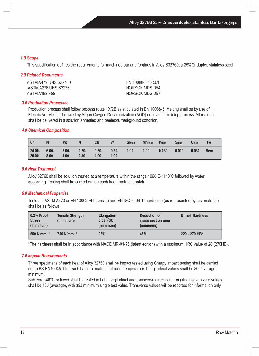
This specification defines the requirements for machined bar and forgings in Alloy S32760, a 25%Cr duplex stainless steel.
ASTM A479 UNS S32760 ASTM A276 UNS S32760ASTM A182 F55
1.0 Scope
2.0 Related Documents
Production process shall follow process route 1X/2B as stipulated in EN 10088-3. Melting shall be by use of Electric Arc Melting followed by Argon-Oxygen Decarburization (AOD) or a similar refining process. All material shall be delivered in a solution annealed and peeled/turned/ground condition.
Alloy 32760 shall be solution treated at a temperature within the range 1060˚C-1140˚C followed by water quenching. Testing shall be carried out on each heat treatment batch
*The hardness shall be in accordance with NACE MR-01-75 (latest edition) with a maximum HRC value of 28 (270HB).
3.0 Production Processes
EN 10088-3 1.4501NORSOK MDS D54NORSOK MDS D57
Cr Ni Mo N Cu W Simax Mn max Pmax Smax Cmax Fe
24.00- 6.00- 3.00- 0.20- 0.50- 0.50- 1.00 1.00 0.030 0.01026.00 8.00
0.030 Rem4.00 0.30 1.00 1.00
4.0 Chemical Composition
5.0 Heat Treatment
Three specimens of each heat of Alloy 32760 shall be impact tested using Charpy Impact testing shall be carried out to BS EN10045-1 for each batch of material at room temperature. Longitudinal values shall be 80J average minimum.Sub zero -46°C or lower shall be tested in both longitudinal and transverse directions. Longitudinal sub zero values shall be 45J (average), with 35J minimum single test value. Transverse values will be reported for information only.
7.0 Impact Requirements
Tested to ASTM A370 or EN 10002 Pt1 (tensile) and EN ISO 6506-1 (hardness) (as represented by test material) shall be as follows:
6.0 Mechanical Properties
0.2% Proof Elongation Brinell HardnessStress
Tensile Strength(minimum) 5.65 √SO
(minimum) (minimum)
550 N/mm 2
Reduction ofcross section area(minimum)
750 N/mm 2 25% 45% 220 - 270 HB*
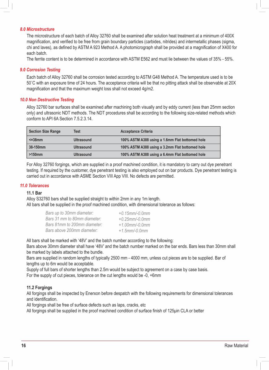
The microstructure of each batch of Alloy 32760 shall be examined after solution heat treatment at a minimum of 400X magnification, and verified to be free from grain boundary particles (carbides, nitrides) and intermetallic phases (sigma, chi and laves), as defined by ASTM A 923 Method A. A photomicrograph shall be provided at a magnification of X400 for each batch.The ferrite content is to be determined in accordance with ASTM E562 and must lie between the values of 35% - 55%.
8.0 Microstructure
Each batch of Alloy 32760 shall be corrosion tested according to ASTM G48 Method A. The temperature used is to be 50˚C with an exposure time of 24 hours. The acceptance criteria will be that no pitting attack shall be observable at 20X magnification and that the maximum weight loss shall not exceed 4g/m2.
9.0 Corrosion Testing
Alloy 32760 bar surfaces shall be examined after machining both visually and by eddy current (less than 25mm section only) and ultrasonic NDT methods. The NDT procedures shall be according to the following size-related methods which conform to API 6A Section 7.5.2.3.14.
10.0 Non Destructive Testing
For Alloy 32760 forgings, which are supplied in a proof machined condition, it is mandatory to carry out dye penetrant testing. If required by the customer, dye penetrant testing is also employed out on bar products. Dye penetrant testing is carried out in accordance with ASME Section VIII App VIII. No defects are permitted.
Section Size Range Test
<=38mm
Acceptance Criteria
Ultrasound 100% ASTM A388 using a 1.6mm Flat bottomed hole38-150mm Ultrasound>150mm
100% ASTM A388 using a 3.2mm Flat bottomed holeUltrasound 100% ASTM A388 using a 6.4mm Flat bottomed hole
11.1 BarAlloy S32760 bars shall be supplied straight to within 2mm in any 1m length. All bars shall be supplied in the proof machined condition, with dimensional tolerance as follows:
11.0 Tolerances
Bars up to 30mm diameter:Bars 31 mm to 80mm diameter: Bars 81mm to 200mm diameter: Bars above 200mm diameter:
+0.15mm/-0.0mm+0.25mm/-0.0mm+1.00mm/-0.0mm+1.5mm/-0.0mm
All bars shall be marked with ‘48V’ and the batch number according to the following:Bars above 30mm diameter shall have ‘48V’ and the batch number marked on the bar ends. Bars less than 30mm shall be marked by labels attached to the bundle.Bars are supplied in random lengths of typically 2500 mm - 4000 mm, unless cut pieces are to be supplied. Bar of lengths up to 6m would be acceptable.Supply of full bars of shorter lengths than 2.5m would be subject to agreement on a case by case basis.For the supply of cut pieces, tolerance on the cut lengths would be -0, +6mm
11.2 ForgingsAll forgings shall be inspected by Enerxon before despatch with the following requirements for dimensional tolerances and identification.All forgings shall be free of surface defects such as laps, cracks, etcAll forgings shall be supplied in the proof machined condition of surface finish of 125μin CLA or better Tolerances on machined dimensions shall generally be within the range +1.5mm to +2mm, -0
Alloy 32760 25% Cr Superduplex Stainless Bar & Forgings
16 Raw Material
Material Purchase Specification forAlloy 32760 25%Cr Superduplex Stainless Steel Bar and Forgings
DOCUMENT No. MLA-MPS-25VS-BAR/FORG Date: 2nd September 2009 Rev: 2
This specification defines the requirements for machined bar and forgings in Alloy S32760, a 25%Cr duplex stainless steel.
ASTM A479 UNS S32760 ASTM A276 UNS S32760ASTM A182 F55
1.0 Scope
2.0 Related Documents
Production process shall follow process route 1X/2B as stipulated in EN 10088-3. Melting shall be by use of Electric Arc Melting followed by Argon-Oxygen Decarburization (AOD) or a similar refining process. All material shall be delivered in a solution annealed and peeled/turned/ground condition.
Alloy 32760 shall be solution treated at a temperature within the range 1060˚C-1140˚C followed by water quenching. Testing shall be carried out on each heat treatment batch
*The hardness shall be in accordance with NACE MR-01-75 (latest edition) with a maximum HRC value of 28 (270HB).
3.0 Production Processes
EN 10088-3 1.4501NORSOK MDS D54NORSOK MDS D57
Cr Ni Mo N Cu W Simax Mn max Pmax Smax Cmax Fe
24.00- 6.00- 3.00- 0.20- 0.50- 0.50- 1.00 1.00 0.030 0.01026.00 8.00
0.030 Rem4.00 0.30 1.00 1.00
4.0 Chemical Composition
5.0 Heat Treatment
Three specimens of each heat of Alloy 32760 shall be impact tested using Charpy Impact testing shall be carried out to BS EN10045-1 for each batch of material at room temperature. Longitudinal values shall be 80J average minimum.Sub zero -46°C or lower shall be tested in both longitudinal and transverse directions. Longitudinal sub zero values shall be 45J (average), with 35J minimum single test value. Transverse values will be reported for information only.
7.0 Impact Requirements
Tested to ASTM A370 or EN 10002 Pt1 (tensile) and EN ISO 6506-1 (hardness) (as represented by test material) shall be as follows:
6.0 Mechanical Properties
0.2% Proof Elongation Brinell HardnessStress
Tensile Strength(minimum) 5.65 √SO
(minimum) (minimum)
550 N/mm 2
Reduction ofcross section area(minimum)
750 N/mm 2 25% 45% 220 - 270 HB*
The microstructure of each batch of Alloy 32760 shall be examined after solution heat treatment at a minimum of 400X magnification, and verified to be free from grain boundary particles (carbides, nitrides) and intermetallic phases (sigma, chi and laves), as defined by ASTM A 923 Method A. A photomicrograph shall be provided at a magnification of X400 for each batch.The ferrite content is to be determined in accordance with ASTM E562 and must lie between the values of 35% - 55%.
8.0 Microstructure
Each batch of Alloy 32760 shall be corrosion tested according to ASTM G48 Method A. The temperature used is to be 50˚C with an exposure time of 24 hours. The acceptance criteria will be that no pitting attack shall be observable at 20X magnification and that the maximum weight loss shall not exceed 4g/m2.
9.0 Corrosion Testing
Alloy 32760 bar surfaces shall be examined after machining both visually and by eddy current (less than 25mm section only) and ultrasonic NDT methods. The NDT procedures shall be according to the following size-related methods which conform to API 6A Section 7.5.2.3.14.
10.0 Non Destructive Testing
For Alloy 32760 forgings, which are supplied in a proof machined condition, it is mandatory to carry out dye penetrant testing. If required by the customer, dye penetrant testing is also employed out on bar products. Dye penetrant testing is carried out in accordance with ASME Section VIII App VIII. No defects are permitted.
Section Size Range Test
<=38mm
Acceptance Criteria
Ultrasound 100% ASTM A388 using a 1.6mm Flat bottomed hole38-150mm Ultrasound>150mm
100% ASTM A388 using a 3.2mm Flat bottomed holeUltrasound 100% ASTM A388 using a 6.4mm Flat bottomed hole
11.1 BarAlloy S32760 bars shall be supplied straight to within 2mm in any 1m length. All bars shall be supplied in the proof machined condition, with dimensional tolerance as follows:
11.0 Tolerances
Bars up to 30mm diameter:Bars 31 mm to 80mm diameter: Bars 81mm to 200mm diameter: Bars above 200mm diameter:
+0.15mm/-0.0mm+0.25mm/-0.0mm+1.00mm/-0.0mm+1.5mm/-0.0mm
All bars shall be marked with ‘48V’ and the batch number according to the following:Bars above 30mm diameter shall have ‘48V’ and the batch number marked on the bar ends. Bars less than 30mm shall be marked by labels attached to the bundle.Bars are supplied in random lengths of typically 2500 mm - 4000 mm, unless cut pieces are to be supplied. Bar of lengths up to 6m would be acceptable.Supply of full bars of shorter lengths than 2.5m would be subject to agreement on a case by case basis.For the supply of cut pieces, tolerance on the cut lengths would be -0, +6mm
11.2 ForgingsAll forgings shall be inspected by Enerxon before despatch with the following requirements for dimensional tolerances and identification.All forgings shall be free of surface defects such as laps, cracks, etcAll forgings shall be supplied in the proof machined condition of surface finish of 125μin CLA or better Tolerances on machined dimensions shall generally be within the range +1.5mm to +2mm, -0
17 Raw Material
In order for goods to be unloaded in a safe manner and be traceable to the associated paperwork, all goods shall conform to the following:
a) Maximum bundle weight will be 3000kg. Maximum single bar weight will be 3000kg.b) All goods are to be packed in such a way as to avoid transit damage and be suitable for unloading by forklift truck.c) Documentation shall be supplied with, or prior to, the delivery of the goods.d) Where two or more batches of the same grade or size are supplied at the same time, each batch shall be physically
separated and clearly labelled.
12.0 Delivery Conditions
Alloy S32760 certificates are to be in accordance with BS EN 10204 3.1.
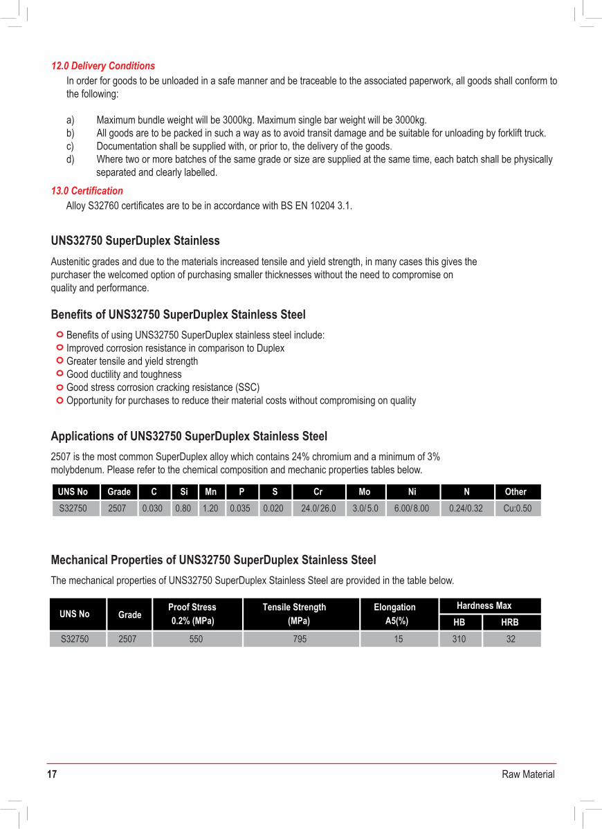
Austenitic grades and due to the materials increased tensile and yield strength, in many cases this gives the purchaser the welcomed option of purchasing smaller thicknesses without the need to compromise on quality and performance.
Benefits of using UNS32750 SuperDuplex stainless steel include:Improved corrosion resistance in comparison to DuplexGreater tensile and yield strengthGood ductility and toughnessGood stress corrosion cracking resistance (SSC)Opportunity for purchases to reduce their material costs without compromising on quality
13.0 Certification
UNS32750 SuperDuplex Stainless
Benefits of UNS32750 SuperDuplex Stainless Steel
2507 is the most common SuperDuplex alloy which contains 24% chromium and a minimum of 3% molybdenum. Please refer to the chemical composition and mechanic properties tables below.
Applications of UNS32750 SuperDuplex Stainless Steel
The mechanical properties of UNS32750 SuperDuplex Stainless Steel are provided in the table below.
Mechanical Properties of UNS32750 SuperDuplex Stainless Steel
UNS No C Si Mn P S Cr Mo Ni N OtherS32750 2507 0.030 0.80 1.20 0.035 0.020 24.0/ 26.0 3.0/5.0 6.00/8.00 0.24/0.32 Cu:0.50
Grade
UNS No Proof Stress0.2% (MPa)
Tensile Strength(MPa)
ElongationA5(%)
Hardness MaxHB HRB
S32750 2507 550 795 15 310 32
Grade
18 Raw Material
Material Purchase Specification forFERRALIUM 255-SD50 Superduplex Stainless Steel Welding Wire
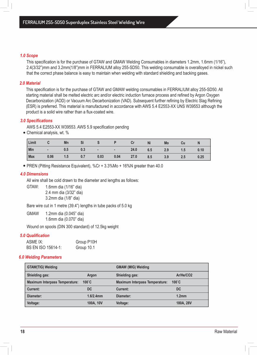
This specification is for the purchase of GTAW and GMAW Welding Consumables in diameters 1.2mm, 1.6mm (1/16”), 2.4(3/32”)mm and 3.2mm(1/8”)mm in FERRALIUM alloy 255-SD50. This welding consumable is overalloyed in nickel such that the correct phase balance is easy to maintain when welding with standard shielding and backing gases.
1.0 Scope
AWS 5.4 E2553-XX W39553. AWS 5.9 specification pendingChemical analysis, wt. %
GTAW:
GMAW
PREN (Pitting Resistance Equivalent), %Cr + 3.3%Mo + 16%N greater than 40.0
3.0 Specifications
All wire shall be cold drawn to the diameter and lengths as follows:
Bare wire cut in 1 metre (39.4”) lengths in tube packs of 5.0 kg
Wound on spools (DIN 300 standard) of 12.5kg weight
4.0 Dimensions
This specification is for the purchase of GTAW and GMAW welding consumables in FERRALIUM alloy 255-SD50. All starting material shall be melted electric arc and/or electric induction furnace process and refined by Argon Oxygen Decarbonization (AOD) or Vacuum Arc Decarbonization (VAD). Subsequent further refining by Electric Slag Refining (ESR) is preferred. This material is manufactured in accordance with AWS 5.4 E2553-XX UNS W39553 although the product is a solid wire rather than a flux-coated wire.
2.0 Material
Limit C Mn Si S P Cr Ni Mo Cu NMin - 0.5 0.3 - - 24.0 6.5 2.9 1.5 0.10
0.06 1.5Max 0.7 0.03 0.04 27.0 8.5 3.9 2.5 0.25
1.6mm dia (1/16” dia)2.4 mm dia (3/32” dia)3.2mm dia (1/8” dia)
1.2mm dia (0.045” dia)1.6mm dia (0.070” dia)
ASME IX:BS EN ISO 15614-1:
Group P10HGroup 10.1
5.0 Qualification
6.0 Welding Parameters
GTAW(TIG) Welding GMAW (MIG) Welding
Shielding gas: Argon Ar/He/CO2Shielding gas: Maximum Interpass Temperature: 100˚C Maximum Interpass Temperature: 100˚C
DCCurrent: DCCurrent:Diameter: 1.6/2.4mm Diameter: 1.2mmVoltage: 100A, 10V Voltage: 180A, 28V
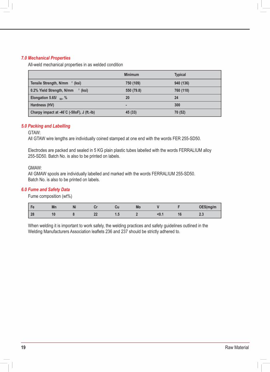
All-weld mechanical properties in as welded condition7.0 Mechanical Properties
Fume composition (wt%)
When welding it is important to work safely, the welding practices and safety guidelines outlined in the Welding Manufacturers Association leaflets 236 and 237 should be strictly adhered to.
6.0 Fume and Safety Data
GTAW:All GTAW wire lengths are individually coined stamped at one end with the words FER 255-SD50.
Electrodes are packed and sealed in 5 KG plain plastic tubes labelled with the words FERRALIUM alloy 255-SD50. Batch No. is also to be printed on labels.
GMAW:All GMAW spools are individually labelled and marked with the words FERRALIUM 255-SD50.Batch No. is also to be printed on labels.
5.0 Packing and Labelling
Minimum Typical
750 (109) 940 (136)Tensile Strength, N/mm 2 (ksi)550 (79.8) 760 (110)0.2% Yield Strength, N/mm 2 (ksi)20 24Elongation 5.65/ S0, %- 300Hardness (HV)45 (33) 70 (52)Charpy impact at -46˚C (-50oF), J (ft.-lb)
3)Fe Mn Ni Cr Cu Mo V F28
OES(mg/m10 8 22 1.5 2 <0.1 16 2.3
FERRALIUM 255-SD50 Superduplex Stainless Steel Wielding Wire
19 Raw Material
Material Purchase Specification forFERRALIUM 255-SD50 Superduplex Stainless Steel Welding Wire
This specification is for the purchase of GTAW and GMAW Welding Consumables in diameters 1.2mm, 1.6mm (1/16”), 2.4(3/32”)mm and 3.2mm(1/8”)mm in FERRALIUM alloy 255-SD50. This welding consumable is overalloyed in nickel such that the correct phase balance is easy to maintain when welding with standard shielding and backing gases.
1.0 Scope
AWS 5.4 E2553-XX W39553. AWS 5.9 specification pendingChemical analysis, wt. %
GTAW:
GMAW
PREN (Pitting Resistance Equivalent), %Cr + 3.3%Mo + 16%N greater than 40.0
3.0 Specifications
All wire shall be cold drawn to the diameter and lengths as follows:
Bare wire cut in 1 metre (39.4”) lengths in tube packs of 5.0 kg
Wound on spools (DIN 300 standard) of 12.5kg weight
4.0 Dimensions
This specification is for the purchase of GTAW and GMAW welding consumables in FERRALIUM alloy 255-SD50. All starting material shall be melted electric arc and/or electric induction furnace process and refined by Argon Oxygen Decarbonization (AOD) or Vacuum Arc Decarbonization (VAD). Subsequent further refining by Electric Slag Refining (ESR) is preferred. This material is manufactured in accordance with AWS 5.4 E2553-XX UNS W39553 although the product is a solid wire rather than a flux-coated wire.
2.0 Material
Document No. MLA-MPS-51V-WW Date: 28th June 2007 Rev: 0
Limit C Mn Si S P Cr Ni Mo Cu NMin - 0.5 0.3 - - 24.0 6.5 2.9 1.5 0.10
0.06 1.5Max 0.7 0.03 0.04 27.0 8.5 3.9 2.5 0.25
1.6mm dia (1/16” dia)2.4 mm dia (3/32” dia)3.2mm dia (1/8” dia)
1.2mm dia (0.045” dia)1.6mm dia (0.070” dia)
ASME IX:BS EN ISO 15614-1:
Group P10HGroup 10.1
5.0 Qualification
6.0 Welding Parameters
GTAW(TIG) Welding GMAW (MIG) Welding
Shielding gas: Argon Ar/He/CO2Shielding gas: Maximum Interpass Temperature: 100˚C Maximum Interpass Temperature: 100˚C
DCCurrent: DCCurrent:Diameter: 1.6/2.4mm Diameter: 1.2mmVoltage: 100A, 10V Voltage: 180A, 28V
All-weld mechanical properties in as welded condition7.0 Mechanical Properties
Fume composition (wt%)
When welding it is important to work safely, the welding practices and safety guidelines outlined in the Welding Manufacturers Association leaflets 236 and 237 should be strictly adhered to.
6.0 Fume and Safety Data
GTAW:All GTAW wire lengths are individually coined stamped at one end with the words FER 255-SD50.
Electrodes are packed and sealed in 5 KG plain plastic tubes labelled with the words FERRALIUM alloy 255-SD50. Batch No. is also to be printed on labels.
GMAW:All GMAW spools are individually labelled and marked with the words FERRALIUM 255-SD50.Batch No. is also to be printed on labels.
5.0 Packing and Labelling
Minimum Typical
750 (109) 940 (136)Tensile Strength, N/mm 2 (ksi)550 (79.8) 760 (110)0.2% Yield Strength, N/mm 2 (ksi)20 24Elongation 5.65/ S0, %- 300Hardness (HV)45 (33) 70 (52)Charpy impact at -46˚C (-50oF), J (ft.-lb)
3)Fe Mn Ni Cr Cu Mo V F28
OES(mg/m10 8 22 1.5 2 <0.1 16 2.3
FERRALIUM 255-SD50 Superduplex Stainless Steel Wielding Wire
20 Raw Material
Material Purchase Specification forAlloy 254 Austenitic Stainless Steel Bar
This specification is for the purchase of bar in Alloy 254, a high alloy austenitic stainless steel containing 6% molybdenum. The material is to be manufactured in accordance with ASTM A479 and ASTM A276 UNS S31254. supplemented by the requirements below.
1.0 Scope
Production process shall be in accordance with internal written Enerxon Procedures. Melting is by electric induction and further refining may be applied. At each stage of production melt and batch traceability shall be maintained.
3.0 Production Processes
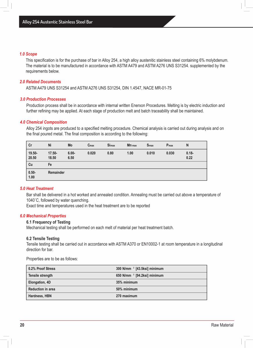
Alloy 254 ingots are produced to a specified melting procedure. Chemical analysis is carried out during analysis and on the final poured metal. The final composition is according to the following:
4.0 Chemical Composition
Bar shall be delivered in a hot worked and annealed condition. Annealing must be carried out above a temperature of 1040˚C, followed by water quenching.Exact time and temperatures used in the heat treatment are to be reported
Properties are to be as follows:
5.0 Heat Treatment
6.1 Frequency of TestingMechanical testing shall be performed on each melt of material per heat treatment batch.
6.2 Tensile TestingTensile testing shall be carried out in accordance with ASTM A370 or EN10002-1 at room temperature in a longitudinal direction for bar.
6.0 Mechanical Properties
ASTM A479 UNS S31254 and ASTM A276 UNS S31254, DIN 1.4547, NACE MR-01-752.0 Related Documents
Cr Ni Mo Cmax Simax Mn max Smax Pmax N
19.50- 17.50- 6.00- 0.020 0.80 1.00 0.010 0.030 0.18-20.50 18.50 6.50 0.22Cu Fe
0.50- Remainder1.00
0.2% Proof Stress 300 N/mm 2 [43.5ksi] minimumTensile strength 650 N/mm 2 [94.2ksi] minimumElongation, 4D 35% minimum
50% minimumReduction in area 270 maximumHardness, HBN
Each complete batch of material is ultrasonically tested in accordance with ASTM A388, BS EN 10228, BS EN 12223 and BS EN 12668. Inspection will be to Enerxon procedure PS:NDT2:01 Rev 3. All NDT personnel qualified to at least Level 2 of SNT-TC-lA.Reference Blocks used for the ultrasonic examination are as follows:
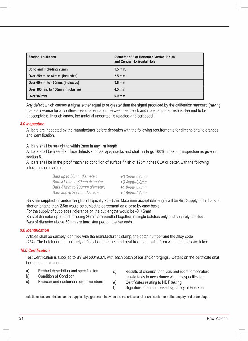
Any defect which causes a signal either equal to or greater than the signal produced by the calibration standard (having made allowance for any differences of attenuation between test block and material under test) is deemed to be unacceptable. In such cases, the material under test is rejected and scrapped.
7.0 Non Destructive Testing
Articles shall be suitably identified with the manufacturer's stamp, the batch number and the alloy code(254). The batch number uniquely defines both the melt and heat treatment batch from which the bars are taken.
9.0 Identification
10.0 Certification
All bars are inspected by the manufacturer before despatch with the following requirements for dimensional tolerances and identification.
All bars shall be straight to within 2mm in any 1m length All bars shall be free of surface defects such as laps, cracks and shall undergo 100% ultrasonic inspection as given in section 8.All bars shall be in the proof machined condition of surface finish of 125minches CLA or better, with the following tolerances on diameter:
Bars are supplied in random lengths of typically 2.5-3.7m. Maximum acceptable length will be 4m. Supply of full bars of shorter lengths than 2.5m would be subject to agreement on a case by case basis.For the supply of cut pieces, tolerance on the cut lengths would be -0, +6mmBars of diameter up to and including 30mm are bundled together in single batches only and securely labelled.Bars of diameter above 30mm are hard stamped on the bar ends.
8.0 Inspection
Section Thickness
1.5 mm.Up to and including 25mm2.5 mm.
Diameter of Flat Bottomed Vertical Holes and Central Horizontal Hole
Over 25mm. to 60mm. (inclusive)3.5 mmOver 60mm. to 100mm. (inclusive)4.5 mmOver 100mm. to 150mm. (inclusive)
Over 150mm 6.0 mm
Bars up to 30mm diameter:Bars 31 mm to 80mm diameter: Bars 81mm to 200mm diameter: Bars above 200mm diameter:
+0.3mm/-0.0mm+0.4mm/-0.0mm+1.0mm/-0.0mm+1.5mm/-0.0mm
Test Certification is supplied to BS EN 50049.3.1. with each batch of bar and/or forgings. Details on the certificate shall include as a minimum:
a) Product description and specificationb) Condition of Conditionc) Enerxon and customer’s order numbers
d) Results of chemical analysis and room temperaturetensile tests in accordance with this specification
e) Certificates relating to NDT testingf) Signature of an authorised signatory of Enerxon
Additional documentation can be supplied by agreement between the materials supplier and customer at the enquiry and order stage.
Alloy 254 Austentic Stainless Steel Bar
21 Raw Material
Material Purchase Specification forAlloy 254 Austenitic Stainless Steel Bar
Document No. MLA-MPS-254-BAR Date: 2nd September 2009 Rev: 1
This specification is for the purchase of bar in Alloy 254, a high alloy austenitic stainless steel containing 6% molybdenum. The material is to be manufactured in accordance with ASTM A479 and ASTM A276 UNS S31254. supplemented by the requirements below.
1.0 Scope
Production process shall be in accordance with internal written Enerxon Procedures. Melting is by electric induction and further refining may be applied. At each stage of production melt and batch traceability shall be maintained.
3.0 Production Processes
Alloy 254 ingots are produced to a specified melting procedure. Chemical analysis is carried out during analysis and on the final poured metal. The final composition is according to the following:
4.0 Chemical Composition
Bar shall be delivered in a hot worked and annealed condition. Annealing must be carried out above a temperature of 1040˚C, followed by water quenching.Exact time and temperatures used in the heat treatment are to be reported
Properties are to be as follows:
5.0 Heat Treatment
6.1 Frequency of TestingMechanical testing shall be performed on each melt of material per heat treatment batch.
6.2 Tensile TestingTensile testing shall be carried out in accordance with ASTM A370 or EN10002-1 at room temperature in a longitudinal direction for bar.
6.0 Mechanical Properties
ASTM A479 UNS S31254 and ASTM A276 UNS S31254, DIN 1.4547, NACE MR-01-752.0 Related Documents
Cr Ni Mo Cmax Simax Mn max Smax Pmax N
19.50- 17.50- 6.00- 0.020 0.80 1.00 0.010 0.030 0.18-20.50 18.50 6.50 0.22Cu Fe
0.50- Remainder1.00
0.2% Proof Stress 300 N/mm 2 [43.5ksi] minimumTensile strength 650 N/mm 2 [94.2ksi] minimumElongation, 4D 35% minimum
50% minimumReduction in area 270 maximumHardness, HBN
Any defect which causes a signal either equal to or greater than the signal produced by the calibration standard (having made allowance for any differences of attenuation between test block and material under test) is deemed to be unacceptable. In such cases, the material under test is rejected and scrapped.
7.0 Non Destructive Testing
Articles shall be suitably identified with the manufacturer's stamp, the batch number and the alloy code(254). The batch number uniquely defines both the melt and heat treatment batch from which the bars are taken.
9.0 Identification
10.0 Certification
All bars are inspected by the manufacturer before despatch with the following requirements for dimensional tolerances and identification.
All bars shall be straight to within 2mm in any 1m length All bars shall be free of surface defects such as laps, cracks and shall undergo 100% ultrasonic inspection as given in section 8.All bars shall be in the proof machined condition of surface finish of 125minches CLA or better, with the following tolerances on diameter:
Bars are supplied in random lengths of typically 2.5-3.7m. Maximum acceptable length will be 4m. Supply of full bars of shorter lengths than 2.5m would be subject to agreement on a case by case basis.For the supply of cut pieces, tolerance on the cut lengths would be -0, +6mmBars of diameter up to and including 30mm are bundled together in single batches only and securely labelled.Bars of diameter above 30mm are hard stamped on the bar ends.
8.0 Inspection
Section Thickness
1.5 mm.Up to and including 25mm2.5 mm.
Diameter of Flat Bottomed Vertical Holes and Central Horizontal Hole
Over 25mm. to 60mm. (inclusive)3.5 mmOver 60mm. to 100mm. (inclusive)4.5 mmOver 100mm. to 150mm. (inclusive)
Over 150mm 6.0 mm
Bars up to 30mm diameter:Bars 31 mm to 80mm diameter: Bars 81mm to 200mm diameter: Bars above 200mm diameter:
+0.3mm/-0.0mm+0.4mm/-0.0mm+1.0mm/-0.0mm+1.5mm/-0.0mm
Test Certification is supplied to BS EN 50049.3.1. with each batch of bar and/or forgings. Details on the certificate shall include as a minimum:
a) Product description and specificationb) Condition of Conditionc) Enerxon and customer’s order numbers
d) Results of chemical analysis and room temperaturetensile tests in accordance with this specification
e) Certificates relating to NDT testingf) Signature of an authorised signatory of Enerxon
Additional documentation can be supplied by agreement between the materials supplier and customer at the enquiry and order stage.
Alloy 254 Austentic Stainless Steel Bar
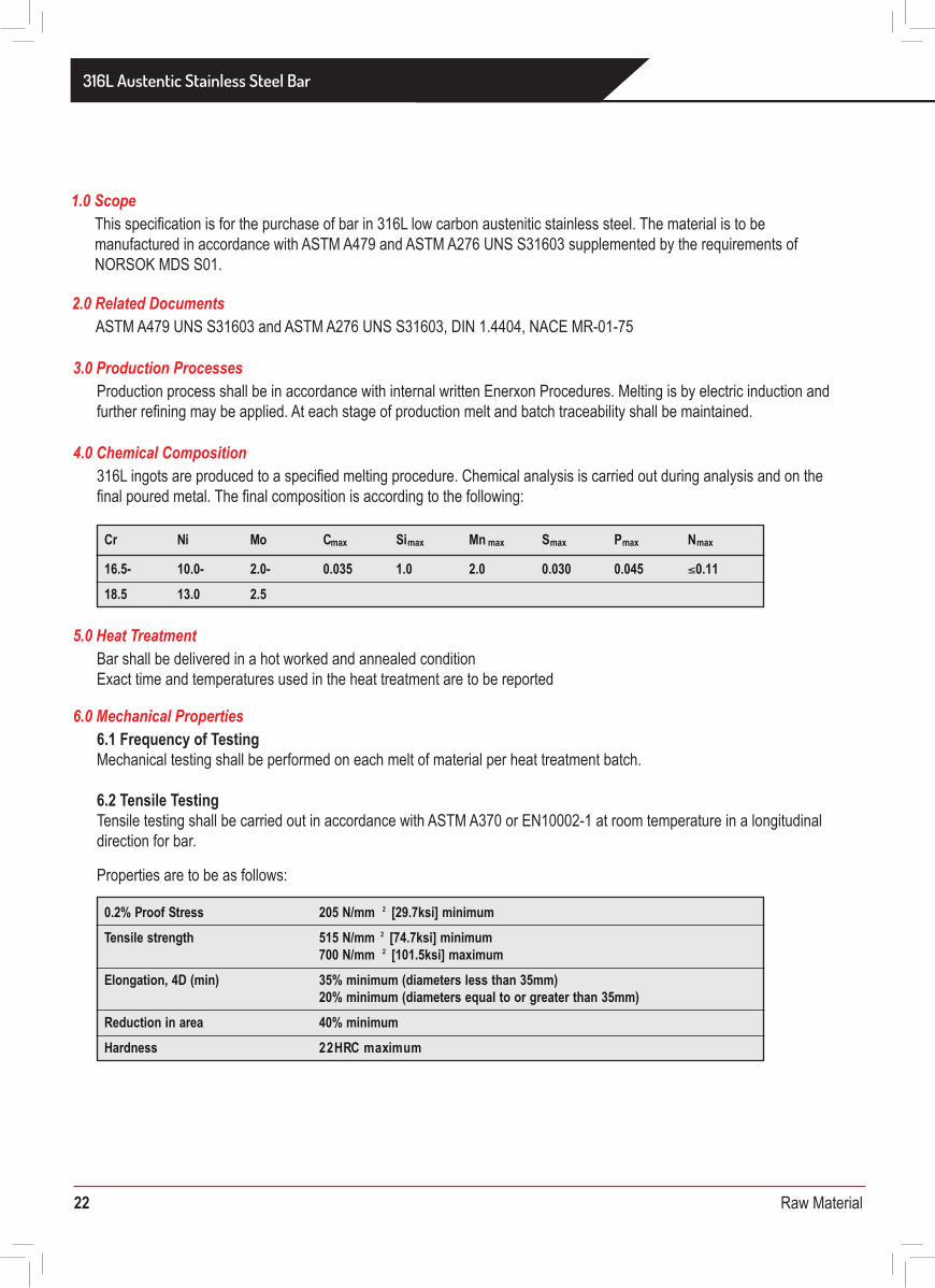
22 Raw Material
Material Purchase Specification for316L Austenitic Stainless Steel Bar
This specification is for the purchase of bar in 316L low carbon austenitic stainless steel. The material is to be manufactured in accordance with ASTM A479 and ASTM A276 UNS S31603 supplemented by the requirements of NORSOK MDS S01.
1.0 Scope
Production process shall be in accordance with internal written Enerxon Procedures. Melting is by electric induction and further refining may be applied. At each stage of production melt and batch traceability shall be maintained.
3.0 Production Processes
316L ingots are produced to a specified melting procedure. Chemical analysis is carried out during analysis and on the final poured metal. The final composition is according to the following:
4.0 Chemical Composition
ASTM A479 UNS S31603 and ASTM A276 UNS S31603, DIN 1.4404, NACE MR-01-752.0 Related Documents
Cr Ni Mo Cmax Simax Mn max Smax Pmax Nmax
16.5- 10.0- 2.0- 0.035 1.0 2.0 0.030 0.045 ≤0.1118.5 13.0 2.5
Bar shall be delivered in a hot worked and annealed conditionExact time and temperatures used in the heat treatment are to be reported
5.0 Heat Treatment
Properties are to be as follows:
6.1 Frequency of TestingMechanical testing shall be performed on each melt of material per heat treatment batch.
6.2 Tensile TestingTensile testing shall be carried out in accordance with ASTM A370 or EN10002-1 at room temperature in a longitudinal direction for bar.
6.0 Mechanical Properties
205 N/mm 2 [29.7ksi] minimum0.2% Proof Stress Tensile strength
Elongation, 4D (min)
515 N/mm 2 [74.7ksi] minimum700 N/mm 2 [101.5ksi] maximum35% minimum (diameters less than 35mm)20% minimum (diameters equal to or greater than 35mm)40% minimumReduction in area
Hardness mumixamCRH22
Each complete batch of material is ultrasonically tested in accordance with ASTM A388. All NDT personnel must be qualified to at least Level 2 of SNT-TC-lA.Reference Blocks used for the ultrasonic examination are as follows:
Any defect which causes a signal either equal to or greater than the signal produced by the calibration standard (having made allowance for any differences of attenuation between test block and material under test) is deemed to be unacceptable. In such cases, the material under test is rejected and scrapped.
7.0 Non Destructive Testing
Section Thickness
3.0 mmUp to and including 6”Over 6” 6.0 mm
Diameter of Flat Bottomed Vertical Holes and Central Horizontal Hole
8.1 BarsAll bars are inspected by the manufacturer before despatch with the following requirements for dimensional tolerances and identification.
All bars shall be straight to within 2mm in any 1m length All bars shall be free of surface defects such as laps, cracks and shall undergo 100% ultrasonic inspection as given in section 8.All bars shall be in the proof machined condition of surface finish of 125minches CLA or better, with the following tolerances on diameter:
Bars are supplied in random lengths of typically 2.5-3.7m. Maximum acceptable length will be 4m. Supply of full bars of shorter lengths than 2.5m would be subject to agreement on a case by case basis.For the supply of cut pieces, tolerance on the cut lengths would be -0, +6mmBars of diameter up to and including 30mm are bundled together in single batches only and securely labelled.Bars of diameter above 30mm are hard stamped on the bar ends.
8.0 Inspection
Bars up to 30mm diameter:Bars 31 mm to 80mm diameter: Bars 81mm to 200mm diameter: Bars above 200mm diameter:
+0.3mm/-0.0mm+0.4mm/-0.0mm+1.0mm/-0.0mm+1.5mm/-0.0mm
Articles shall be suitably identified with the manufacturer's stamp, the batch number and the alloy code(316L). The batch number uniquely defines both the melt and heat treatment batch from which the bars are taken.
9.0 Identification
10.0 CertificationTest Certification is supplied to BS EN 10204 3.1 with each batch of bar and/or forgings. Details on the certificate shall include as a minimum:
a) Product description and specificationb) Heat Treatment Conditionc) Enerxon and customer’s order numbers
d) Results of chemical analysis and room temperature tensile tests in accordance with this specificatione) Results of NDT testingf) Signature of an authorised signatory of Enerxon
Additional documentation can be supplied by agreement between the materials supplier and customer at the enquiry and order stage.
316L Austentic Stainless Steel Bar
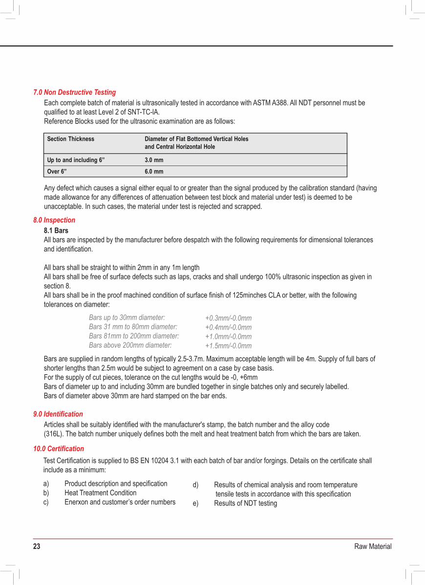
23 Raw Material
Material Purchase Specification for316L Austenitic Stainless Steel Bar
DOCUMENT No. MLA-MPS-316L-BAR Date: 2nd September 2009 Rev: 1
This specification is for the purchase of bar in 316L low carbon austenitic stainless steel. The material is to be manufactured in accordance with ASTM A479 and ASTM A276 UNS S31603 supplemented by the requirements of NORSOK MDS S01.
1.0 Scope
Production process shall be in accordance with internal written Enerxon Procedures. Melting is by electric induction and further refining may be applied. At each stage of production melt and batch traceability shall be maintained.
3.0 Production Processes
316L ingots are produced to a specified melting procedure. Chemical analysis is carried out during analysis and on the final poured metal. The final composition is according to the following:
4.0 Chemical Composition
ASTM A479 UNS S31603 and ASTM A276 UNS S31603, DIN 1.4404, NACE MR-01-752.0 Related Documents
Cr Ni Mo Cmax Simax Mn max Smax Pmax Nmax
16.5- 10.0- 2.0- 0.035 1.0 2.0 0.030 0.045 ≤0.1118.5 13.0 2.5
Bar shall be delivered in a hot worked and annealed conditionExact time and temperatures used in the heat treatment are to be reported
5.0 Heat Treatment
Properties are to be as follows:
6.1 Frequency of TestingMechanical testing shall be performed on each melt of material per heat treatment batch.
6.2 Tensile TestingTensile testing shall be carried out in accordance with ASTM A370 or EN10002-1 at room temperature in a longitudinal direction for bar.
6.0 Mechanical Properties
205 N/mm 2 [29.7ksi] minimum0.2% Proof Stress Tensile strength
Elongation, 4D (min)
515 N/mm 2 [74.7ksi] minimum700 N/mm 2 [101.5ksi] maximum35% minimum (diameters less than 35mm)20% minimum (diameters equal to or greater than 35mm)40% minimumReduction in area
Hardness mumixamCRH22
Each complete batch of material is ultrasonically tested in accordance with ASTM A388. All NDT personnel must be qualified to at least Level 2 of SNT-TC-lA.Reference Blocks used for the ultrasonic examination are as follows:
Any defect which causes a signal either equal to or greater than the signal produced by the calibration standard (having made allowance for any differences of attenuation between test block and material under test) is deemed to be unacceptable. In such cases, the material under test is rejected and scrapped.
7.0 Non Destructive Testing
Section Thickness
3.0 mmUp to and including 6”Over 6” 6.0 mm
Diameter of Flat Bottomed Vertical Holes and Central Horizontal Hole
8.1 BarsAll bars are inspected by the manufacturer before despatch with the following requirements for dimensional tolerances and identification.
All bars shall be straight to within 2mm in any 1m length All bars shall be free of surface defects such as laps, cracks and shall undergo 100% ultrasonic inspection as given in section 8.All bars shall be in the proof machined condition of surface finish of 125minches CLA or better, with the following tolerances on diameter:
Bars are supplied in random lengths of typically 2.5-3.7m. Maximum acceptable length will be 4m. Supply of full bars of shorter lengths than 2.5m would be subject to agreement on a case by case basis.For the supply of cut pieces, tolerance on the cut lengths would be -0, +6mmBars of diameter up to and including 30mm are bundled together in single batches only and securely labelled.Bars of diameter above 30mm are hard stamped on the bar ends.
8.0 Inspection
Bars up to 30mm diameter:Bars 31 mm to 80mm diameter: Bars 81mm to 200mm diameter: Bars above 200mm diameter:
+0.3mm/-0.0mm+0.4mm/-0.0mm+1.0mm/-0.0mm+1.5mm/-0.0mm
Articles shall be suitably identified with the manufacturer's stamp, the batch number and the alloy code(316L). The batch number uniquely defines both the melt and heat treatment batch from which the bars are taken.
9.0 Identification
10.0 CertificationTest Certification is supplied to BS EN 10204 3.1 with each batch of bar and/or forgings. Details on the certificate shall include as a minimum:
a) Product description and specificationb) Heat Treatment Conditionc) Enerxon and customer’s order numbers
d) Results of chemical analysis and room temperaturetensile tests in accordance with this specification
e) Results of NDT testingf) Signature of an authorised signatory of Enerxon
Additional documentation can be supplied by agreement between the materials supplier and customer at the enquiry and order stage.
316L Austentic Stainless Steel Bar
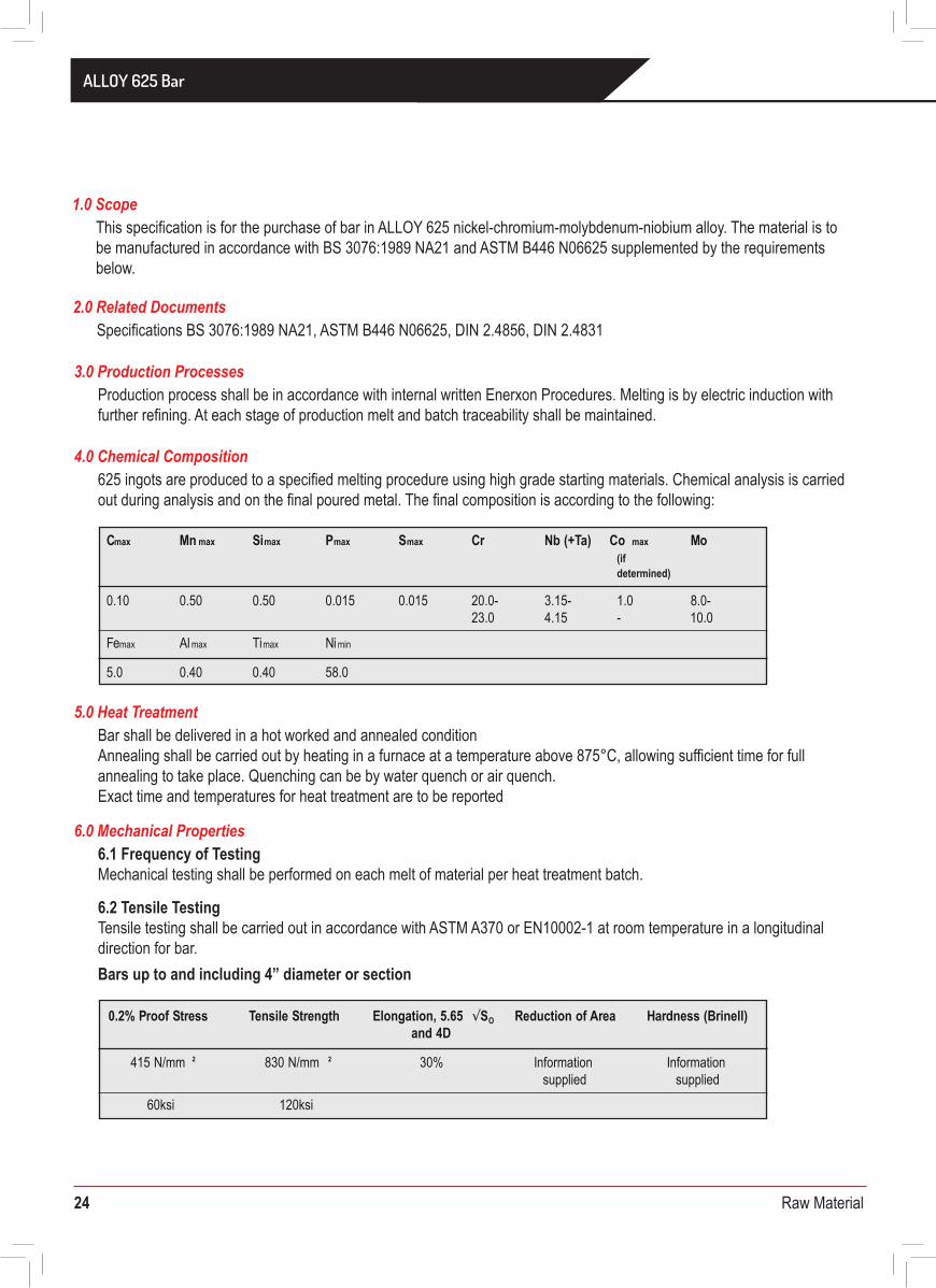
24 Raw Material
Material Purchase Specification forALLOY 625 Bar
This specification is for the purchase of bar in ALLOY 625 nickel-chromium-molybdenum-niobium alloy. The material is to be manufactured in accordance with BS 3076:1989 NA21 and ASTM B446 N06625 supplemented by the requirements below.
1.0 Scope
Production process shall be in accordance with internal written Enerxon Procedures. Melting is by electric induction with further refining. At each stage of production melt and batch traceability shall be maintained.
3.0 Production Processes
625 ingots are produced to a specified melting procedure using high grade starting materials. Chemical analysis is carried out during analysis and on the final poured metal. The final composition is according to the following:
4.0 Chemical Composition
Specifications BS 3076:1989 NA21, ASTM B446 N06625, DIN 2.4856, DIN 2.48312.0 Related Documents
Cmax Mn max Simax Pmax Smax Cr MoNb (+Ta) Co max
0.10 0.50
(if determined)
0.50 0.015 0.015 20.0- 3.15- 1.0 8.0-23.0 4.15 - 10.0
Femax Al max Timax Ni min
5.0 0.40 0.40 58.0
Bar shall be delivered in a hot worked and annealed conditionAnnealing shall be carried out by heating in a furnace at a temperature above 875°C, allowing sufficient time for full annealing to take place. Quenching can be by water quench or air quench.Exact time and temperatures for heat treatment are to be reported
5.0 Heat Treatment
6.1 Frequency of TestingMechanical testing shall be performed on each melt of material per heat treatment batch.
6.2 Tensile TestingTensile testing shall be carried out in accordance with ASTM A370 or EN10002-1 at room temperature in a longitudinal direction for bar.Bars up to and including 4” diameter or section
6.0 Mechanical Properties
0.2% Proof Stress Tensile Strength Elongation, 5.65 √SO Reduction of Areaand 4D
Hardness (Brinell)
415 N/mm 2 830 N/mm 2 30% Information Information supplied supplied
60ksi 120ksi
0.2% Proof Stress Tensile Strength Elongation, 5.65 √SO Reduction of Areaand 4D
Hardness (Brinell)
345 N/mm 2 760 N/mm 2 25% Information Informationsupplied supplied
50ksi 110ksi
Bars above 4” diameter or section
Each complete batch of material is ultrasonically tested in accordance with ASTM A388, BS EN 10228, BS EN 12223 and BS EN 12668. Inspection will be to Enerxon procedure PS:NDT2:01 Rev 3. All NDT personnel must be qualified to at least Level 2 of SNT-TC-lA.
Reference Blocks used for the ultrasonic examination are as follows:
Any defect which causes a signal either equal to or greater than the signal produced by the calibration standard (having made allowance for any differences of attenuation between test block and material under test) is deemed to be unacceptable. In such cases, the material under test is rejected and scrapped.
7.0 Non Destructive Testing
Section Thickness
1.5 mm.Up to and including 25mm
2.5 mm.
Diameter of Flat Bottomed Vertical Holes and Central Horizontal Hole
Over 25mm. to 60mm. (inclusive)
3.5 mmOver 60mm. to 100mm. (inclusive)
4.5 mmOver 100mm. to 150mm. (inclusive)
Over 150mm 6.0 mm
8.1 BarsAll bars are inspected by the manufacturer before despatch with the following requirements for dimensional tolerances and identification.
All bars shall be straight to within 4.2mm of any 1m lengthAll bars shall be free of surface defects such as laps, cracks and shall undergo 100% ultrasonic inspection as given in section 8.All bars shall be in the proof machined condition of surface finish of 125μ inches CLA or better, with the following tolerances on diameter:
Bars are supplied in random lengths of typically 2.5-5.0m, unless cut pieces are to be supplied. Bar of lengths up to 6m would be acceptable.Supply of full bars of shorter lengths than 2.5m would be subject to agreement on a case by case basis.For the supply of cut pieces, tolerance on the cut lengths would be -0, +6mmBars of diameter up to and including 25.4mm are bundled together in single batches only and securely labelled.Bars of diameter above 25.4mm are hard stamped on the bar ends.
8.0 Inspection
Bars up to 25.4mm diameter: Bars 25.4 mm to 50.8mm diameter: Bars 50.8mm to 101.6mm diameter: Bars above 101.6mm diameter:
+0.41mm/-0.41mm+0.79mm/-0.41mm+1.19mm/-0.79mm+3.18mm/-1.60mm
ALLOY 625 Bar
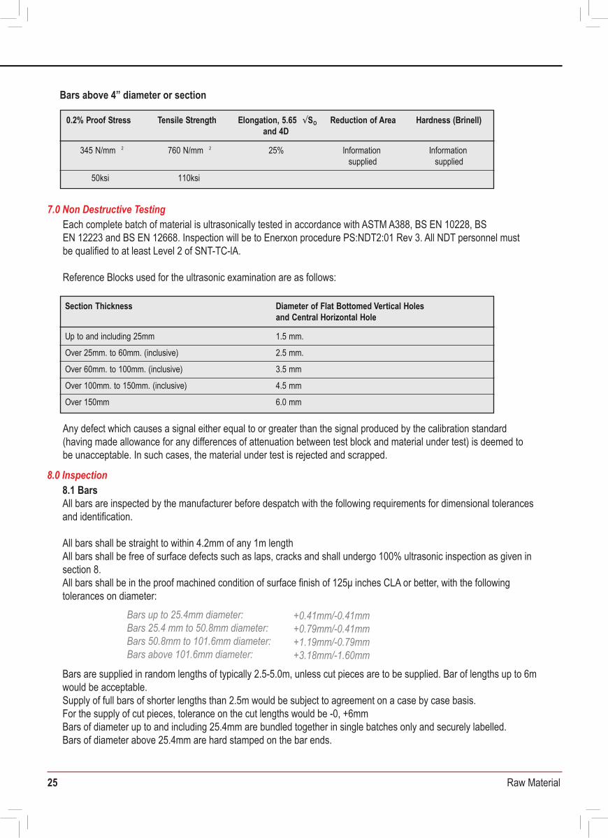
25 Raw Material
Material Purchase Specification forALLOY 625 Bar
DOCUMENT No. MLA-MPS-625-BAR Date: 2nd September 2009 Rev: 1
This specification is for the purchase of bar in ALLOY 625 nickel-chromium-molybdenum-niobium alloy. The material is to be manufactured in accordance with BS 3076:1989 NA21 and ASTM B446 N06625 supplemented by the requirements below.
1.0 Scope
Production process shall be in accordance with internal written Enerxon Procedures. Melting is by electric induction with further refining. At each stage of production melt and batch traceability shall be maintained.
3.0 Production Processes
625 ingots are produced to a specified melting procedure using high grade starting materials. Chemical analysis is carried out during analysis and on the final poured metal. The final composition is according to the following:
4.0 Chemical Composition
Specifications BS 3076:1989 NA21, ASTM B446 N06625, DIN 2.4856, DIN 2.48312.0 Related Documents
Cmax Mn max Simax Pmax Smax Cr MoNb (+Ta) Co max
0.10 0.50
(if determined)
0.50 0.015 0.015 20.0- 3.15- 1.0 8.0-23.0 4.15 - 10.0
Femax Al max Timax Ni min
5.0 0.40 0.40 58.0
Bar shall be delivered in a hot worked and annealed conditionAnnealing shall be carried out by heating in a furnace at a temperature above 875°C, allowing sufficient time for full annealing to take place. Quenching can be by water quench or air quench.Exact time and temperatures for heat treatment are to be reported
5.0 Heat Treatment
6.1 Frequency of TestingMechanical testing shall be performed on each melt of material per heat treatment batch.
6.2 Tensile TestingTensile testing shall be carried out in accordance with ASTM A370 or EN10002-1 at room temperature in a longitudinal direction for bar.Bars up to and including 4” diameter or section
6.0 Mechanical Properties
0.2% Proof Stress Tensile Strength Elongation, 5.65 √SO Reduction of Areaand 4D
Hardness (Brinell)
415 N/mm 2 830 N/mm 2 30% Information Information supplied supplied
60ksi 120ksi
0.2% Proof Stress Tensile Strength Elongation, 5.65 √SO Reduction of Areaand 4D
Hardness (Brinell)
345 N/mm 2 760 N/mm 2 25% Information Informationsupplied supplied
50ksi 110ksi
Bars above 4” diameter or section
Each complete batch of material is ultrasonically tested in accordance with ASTM A388, BS EN 10228, BS EN 12223 and BS EN 12668. Inspection will be to Enerxon procedure PS:NDT2:01 Rev 3. All NDT personnel must be qualified to at least Level 2 of SNT-TC-lA.
Reference Blocks used for the ultrasonic examination are as follows:
Any defect which causes a signal either equal to or greater than the signal produced by the calibration standard (having made allowance for any differences of attenuation between test block and material under test) is deemed to be unacceptable. In such cases, the material under test is rejected and scrapped.
7.0 Non Destructive Testing
Section Thickness
1.5 mm.Up to and including 25mm
2.5 mm.
Diameter of Flat Bottomed Vertical Holes and Central Horizontal Hole
Over 25mm. to 60mm. (inclusive)
3.5 mmOver 60mm. to 100mm. (inclusive)
4.5 mmOver 100mm. to 150mm. (inclusive)
Over 150mm 6.0 mm
8.1 BarsAll bars are inspected by the manufacturer before despatch with the following requirements for dimensional tolerances and identification.
All bars shall be straight to within 4.2mm of any 1m lengthAll bars shall be free of surface defects such as laps, cracks and shall undergo 100% ultrasonic inspection as given in section 8.All bars shall be in the proof machined condition of surface finish of 125μ inches CLA or better, with the following tolerances on diameter:
Bars are supplied in random lengths of typically 2.5-5.0m, unless cut pieces are to be supplied. Bar of lengths up to 6m would be acceptable.Supply of full bars of shorter lengths than 2.5m would be subject to agreement on a case by case basis.For the supply of cut pieces, tolerance on the cut lengths would be -0, +6mmBars of diameter up to and including 25.4mm are bundled together in single batches only and securely labelled.Bars of diameter above 25.4mm are hard stamped on the bar ends.
8.0 Inspection
Bars up to 25.4mm diameter: Bars 25.4 mm to 50.8mm diameter: Bars 50.8mm to 101.6mm diameter: Bars above 101.6mm diameter:
+0.41mm/-0.41mm+0.79mm/-0.41mm+1.19mm/-0.79mm+3.18mm/-1.60mm
ALLOY 625 Bar
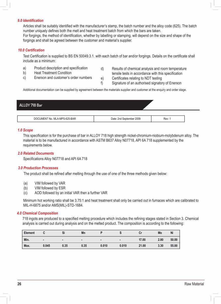
26 Raw Material
Articles shall be suitably identified with the manufacturer’s stamp, the batch number and the alloy code (625). The batch number uniquely defines both the melt and heat treatment batch from which the bars are taken. For forgings, the method of identification, whether by labelling or stamping, will depend on the size and shape of the forgings and shall be agreed between the customer and material’s supplier.
9.0 Identification
10.0 CertificationTest Certification is supplied to BS EN 50049.3.1. with each batch of bar and/or forgings. Details on the certificate shall include as a minimum:
a) Product description and specificationb) Heat Treatment Conditionc) Enerxon and customer’s order numbers
d) Results of chemical analysis and room temperaturetensile tests in accordance with this specification
e) Certificates relating to NDT testingf) Signature of an authorised signatory of Enerxon
Additional documentation can be supplied by agreement between the materials supplier and customer at the enquiry and order stage.
Material Purchase Specification forALLOY 718 Bar
DOCUMENT No. MLA-MPS-625-BAR Date: 2nd September 2009 Rev: 1
This specification is for the purchase of bar in ALLOY 718 high strength nickel-chromium-niobium-molybdenum alloy. The material is to be manufactured in accordance with ASTM B637 Alloy N07718, API 6A 718 supplemented by the requirements below.
1.0 Scope
718 ingots are produced to a specified melting procedure which includes the refining stages stated in Section 3. Chemical analysis is carried out during analysis and on the melted product. The composition is according to the following:
4.0 Chemical Composition
The product shall be refined after melting through the use of one of the three methods given below:
(a) VIM followed by VAR(b) VIM followed by ESR(c) AOD followed by an initial VAR then a further VAR
3.0 Production Processes
Specifications Alloy N07718 and API 6A 718
* Result is reported
Minimum hot working ratio shall be 3.75:1 and heat treatment shall only be carried out in furnaces which are calibrated to MIL-H-6875 and/or AMS(MIL)-STD-1684.
2.0 Related Documents
CElement Si PMn S Cr Mo Ni
Min. - - - - - 7.001 2.80 50.000.045 0.35Max. 0.35 0.010 0.010 21.00 3.30 55.00
AlElement Cu Co Nb Ta Nb+Ta B Ti
Min. 0.40 - - 4.90 - 4.90 - 0.80
Ma x. 0.60 0.15 5.201.00 0.05 5.20 0.0060 1.15
Element Fe* Ca Mg PbSn Se Bi
Min. BAL - - - - -
0.0030Max. 0.0060 Report 0.0005 0.0003 0.00003
Solution Treated: 1021-1052°C (1870°F – 1925°F) for 1 – 2 Hrs followed by water quenchingAged: 775 – 800°C (1425°F – 1475°F ) for 6 – 8 Hrs followed by air coolingA thermocouple is to be placed in or on the article. The resulting furnace charts are to be supplied with the Certification.
6.3 Hardness Testing Hardness tests shall be recorded at surface and mid-radius positions of a prolongation from each bar, using a surface preparation method which avoids the input of internal stresses. After a mandatory hardness verification against a test block (ASTM E18), three hardness readings to be taken at each of three positions 120° apart at mid-radius and outer surface locations.
Test piece 34 - 39 HRC (313 - 354 HB)Material 34 - 39 HRC (313 - 354 HB)
Aim is for 37 HRC maximum on material.Results are reported from Surface & Mid radial positions of each individual bar
Transverse (>/= 3” dia) 47 J min. – average of 3, 41 J min. – singleLongitudinal (< 3” dia) 71 J min. – average of 3, 61 J min. – singlelateral expansion 0.38 mm min. % shear – Result to be reported
5.0 Heat Treatment
Longitudinal prolongation sample to be taken from mid-radius position and tested to ASTM A370. For bars of 5” diameter or greater, a transverse test piece is also required.
6.1 Frequency of Testing0.2% P.S. 862N/mm2 [125ksi] minimum, 1000N/mm2 [145ksi] maxUTS 1 034N/mm2 [150ksi] minimum%Elongation (4D) Longitudinal test: 20% min. Transverse test: 12% min.%R of A Longitudinal test: 35% min. Transverse test: 15% min
6.2 Charpy Impact testingTest specimens shall be of a radial transverse orientation, taken at mid-radius positions. If bar diameter restricts the possibility of transverse testing, then tests should be longitudinal only. Testing to be carried out to ASTM A370 at a temperature of -75°F (-60°C).
Results shall comply with:
6.0 Mechanical Properties ALLOY 718 Bar
27 Raw Material
Articles shall be suitably identified with the manufacturer’s stamp, the batch number and the alloy code (625). The batch number uniquely defines both the melt and heat treatment batch from which the bars are taken. For forgings, the method of identification, whether by labelling or stamping, will depend on the size and shape of the forgings and shall be agreed between the customer and material’s supplier.
9.0 Identification
10.0 CertificationTest Certification is supplied to BS EN 50049.3.1. with each batch of bar and/or forgings. Details on the certificate shall include as a minimum:
a) Product description and specificationb) Heat Treatment Conditionc) Enerxon and customer’s order numbers
d) Results of chemical analysis and room temperaturetensile tests in accordance with this specification
e) Certificates relating to NDT testingf) Signature of an authorised signatory of Enerxon
Additional documentation can be supplied by agreement between the materials supplier and customer at the enquiry and order stage.
Material Purchase Specification forALLOY 718 Bar
DOCUMENT No. MLA-MPS-625-BAR Date: 2nd September 2009 Rev: 1
This specification is for the purchase of bar in ALLOY 718 high strength nickel-chromium-niobium-molybdenum alloy. The material is to be manufactured in accordance with ASTM B637 Alloy N07718, API 6A 718 supplemented by the requirements below.
1.0 Scope
718 ingots are produced to a specified melting procedure which includes the refining stages stated in Section 3. Chemical analysis is carried out during analysis and on the melted product. The composition is according to the following:
4.0 Chemical Composition
The product shall be refined after melting through the use of one of the three methods given below:
(a) VIM followed by VAR(b) VIM followed by ESR(c) AOD followed by an initial VAR then a further VAR
3.0 Production Processes
Specifications Alloy N07718 and API 6A 718
* Result is reported
Minimum hot working ratio shall be 3.75:1 and heat treatment shall only be carried out in furnaces which are calibrated to MIL-H-6875 and/or AMS(MIL)-STD-1684.
2.0 Related Documents
CElement Si PMn S Cr Mo Ni
Min. - - - - - 7.001 2.80 50.000.045 0.35Max. 0.35 0.010 0.010 21.00 3.30 55.00
AlElement Cu Co Nb Ta Nb+Ta B Ti
Min. 0.40 - - 4.90 - 4.90 - 0.80
Ma x. 0.60 0.15 5.201.00 0.05 5.20 0.0060 1.15
Element Fe* Ca Mg PbSn Se Bi
Min. BAL - - - - -
0.0030Max. 0.0060 Report 0.0005 0.0003 0.00003
Solution Treated: 1021-1052°C (1870°F – 1925°F) for 1 – 2 Hrs followed by water quenchingAged: 775 – 800°C (1425°F – 1475°F ) for 6 – 8 Hrs followed by air coolingA thermocouple is to be placed in or on the article. The resulting furnace charts are to be supplied with the Certification.
6.3 Hardness Testing Hardness tests shall be recorded at surface and mid-radius positions of a prolongation from each bar, using a surface preparation method which avoids the input of internal stresses. After a mandatory hardness verification against a test block (ASTM E18), three hardness readings to be taken at each of three positions 120° apart at mid-radius and outer surface locations.
Test piece 34 - 39 HRC (313 - 354 HB)Material 34 - 39 HRC (313 - 354 HB)
Aim is for 37 HRC maximum on material.Results are reported from Surface & Mid radial positions of each individual bar
Transverse (>/= 3” dia) 47 J min. – average of 3, 41 J min. – singleLongitudinal (< 3” dia) 71 J min. – average of 3, 61 J min. – singlelateral expansion 0.38 mm min. % shear – Result to be reported
5.0 Heat Treatment
Longitudinal prolongation sample to be taken from mid-radius position and tested to ASTM A370. For bars of 5” diameter or greater, a transverse test piece is also required.
6.1 Frequency of Testing0.2% P.S. 862N/mm2 [125ksi] minimum, 1000N/mm2 [145ksi] maxUTS 1 034N/mm2 [150ksi] minimum%Elongation (4D) Longitudinal test: 20% min. Transverse test: 12% min.%R of A Longitudinal test: 35% min. Transverse test: 15% min
6.2 Charpy Impact testingTest specimens shall be of a radial transverse orientation, taken at mid-radius positions. If bar diameter restricts the possibility of transverse testing, then tests should be longitudinal only. Testing to be carried out to ASTM A370 at a temperature of -75°F (-60°C).
Results shall comply with:
6.0 Mechanical Properties
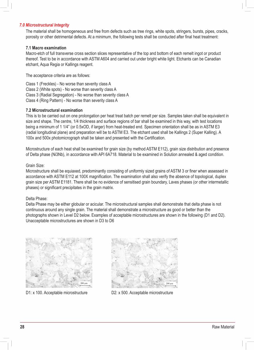
28 Raw Material
The material shall be homogeneous and free from defects such as tree rings, white spots, stringers, bursts, pipes, cracks, porosity or other detrimental defects. At a minimum, the following tests shall be conducted after final heat treatment:
7.1 Macro examinationMacro-etch of full transverse cross section slices representative of the top and bottom of each remelt ingot or product thereof. Test to be in accordance with ASTM A604 and carried out under bright white light. Etchants can be Canadian etchant, Aqua Regia or Kallings reagent.
The acceptance criteria are as follows:
7.2 Microstructural examinationThis is to be carried out on one prolongation per heat treat batch per remelt per size. Samples taken shall be equivalent in size and shape. The centre, 1/4 thickness and surface regions of bar shall be examined in this way, with test locations being a minimum of 1 1/4” (or 0.5xOD, if larger) from heat-treated end. Specimen orientation shall be as in ASTM E3 (radial longitudinal plane) and preparation will be to ASTM E3. The etchant used shall be Kallings 2 (Super Kalling). A 100x and 500x photomicrograph shall be taken and presented with the Certification.
Microstructure of each heat shall be examined for grain size (by method ASTM E112), grain size distribution and presence of Delta phase (Ni3Nb), in accordance with API 6A718. Material to be examined in Solution annealed & aged condition.
Grain Size:Microstructure shall be equiaxed, predominantly consisting of uniformly sized grains of ASTM 3 or finer when assessed in accordance with ASTM E112 at 100X magnification. The examination shall also verify the absence of topological, duplex grain size per ASTM E1181. There shall be no evidence of sensitised grain boundary, Laves phases (or other intermetallic phases) or significant precipitates in the grain matrix.
Delta Phase:Delta Phase may be either globular or acicular. The microstructural samples shall demonstrate that delta phase is not continuous around any single grain. The material shall demonstrate a microstructure as good or better than the photographs shown in Level D2 below. Examples of acceptable microstructures are shown in the following (D1 and D2). Unacceptable microstructures are shown in D3 to D6
Class 1 (Freckles) - No worse than severity class AClass 2 (White spots) - No worse than severity class AClass 3 (Radial Segregation) - No worse than severity class AClass 4 (Ring Pattern) - No worse than severity class A
7.0 Microstructural Integrity
D1: x 100. Acceptable microstructure
D3: x 100 D3: x 500
D4: x 100 D4: x 500
D5: x 100 D5: x 500
Unacceptable microstructures are as follows
Further unacceptable microstructures are as follows
D2: x 500. Acceptable microstructure D6: x 100 D6: x 500
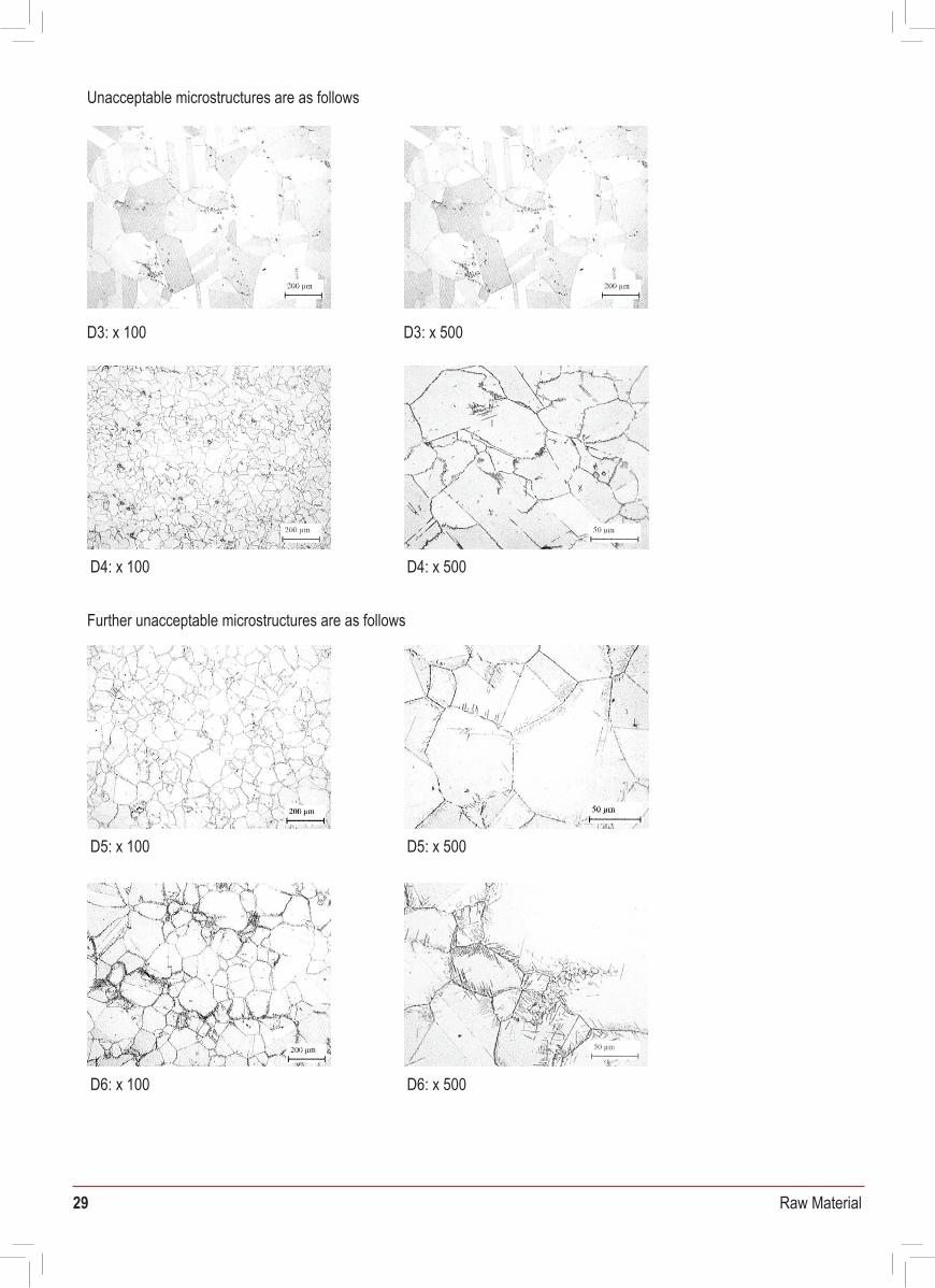
29 Raw Material
The material shall be homogeneous and free from defects such as tree rings, white spots, stringers, bursts, pipes, cracks, porosity or other detrimental defects. At a minimum, the following tests shall be conducted after final heat treatment:
7.1 Macro examinationMacro-etch of full transverse cross section slices representative of the top and bottom of each remelt ingot or product thereof. Test to be in accordance with ASTM A604 and carried out under bright white light. Etchants can be Canadian etchant, Aqua Regia or Kallings reagent.
The acceptance criteria are as follows:
7.2 Microstructural examinationThis is to be carried out on one prolongation per heat treat batch per remelt per size. Samples taken shall be equivalent in size and shape. The centre, 1/4 thickness and surface regions of bar shall be examined in this way, with test locations being a minimum of 1 1/4” (or 0.5xOD, if larger) from heat-treated end. Specimen orientation shall be as in ASTM E3 (radial longitudinal plane) and preparation will be to ASTM E3. The etchant used shall be Kallings 2 (Super Kalling). A100x and 500x photomicrograph shall be taken and presented with the Certification.
Microstructure of each heat shall be examined for grain size (by method ASTM E112), grain size distribution and presence of Delta phase (Ni3Nb), in accordance with API 6A718. Material to be examined in Solution annealed & aged condition.
Grain Size:Microstructure shall be equiaxed, predominantly consisting of uniformly sized grains of ASTM 3 or finer when assessed in accordance with ASTM E112 at 100X magnification. The examination shall also verify the absence of topological, duplex grain size per ASTM E1181. There shall be no evidence of sensitised grain boundary, Laves phases (or other intermetallic phases) or significant precipitates in the grain matrix.
Delta Phase:Delta Phase may be either globular or acicular. The microstructural samples shall demonstrate that delta phase is not continuous around any single grain. The material shall demonstrate a microstructure as good or better than the photographs shown in Level D2 below. Examples of acceptable microstructures are shown in the following (D1 and D2). Unacceptable microstructures are shown in D3 to D6
Class 1 (Freckles) - No worse than severity class AClass 2 (White spots) - No worse than severity class AClass 3 (Radial Segregation) - No worse than severity class AClass 4 (Ring Pattern) - No worse than severity class A
7.0 Microstructural Integrity
D1: x 100. Acceptable microstructure
D3: x 100 D3: x 500
D4: x 100 D4: x 500
D5: x 100 D5: x 500
Unacceptable microstructures are as follows
Further unacceptable microstructures are as follows
D2: x 500. Acceptable microstructure D6: x 100 D6: x 500
30 Raw Material
ALLOY 718 has a machinability rating 50% over that of carbon steel. For machining, carbide tipped tools should be used with water-soluble lubricant.
Recommended feeds and speeds are as follows:
8.0 Machining Properties
Articles shall be suitably identified with the manufacturer's stamp, the batch number and the alloy code (718). The batch number uniquely defines both the melt and heat treatment batch from which the bars are taken.
11.0 Identification
10.0 Inspection
Operation Depth of cutCutting Speedm/min (ft/min) mm (in)
Feed Ratemm/rev (in/rev)
Milling 7 0.2-3.0(22)
0.05-0.15 mm/tooth0.002-0.006 in/tooth (0.007-0.12)
0.02 (0.001)Drilling – 6.4mm (1/4”) dia
5-8(16-25)
0.08 (0.003)5-8(16-25)
Drilling – 12.7mm (1/2”) dia
0.13 (0.005)Drilling – 25.4mm (1”) dia
5-8(16-25)
0.2 – 0.30Turning - Roughing 2.5(0.008-0.012)
9-15(29-45) (0.1)
Turning - Finishing 0.08 – 0.20 0.25(0.003-0.008) (0.01)
15-24(45-75)
Tooling Milling/Turning: Carbide (SANDVIK CC680, CB50), point angle 118°, chisel angle 120° Drilling: HSS
All bars are inspected by the manufacturer before despatch with the following requirements for dimensional tolerances and identification.
9.0 Non Destructive Testing Each complete batch of material is ultrasonically tested using both compression and shear wave (including end-to-end) in accordance with ASTM A388, BS EN 10228, BS EN 12223 and BS EN 12668. Inspection will be to API 6A PSL Level 4. All NDT personnel must be qualified to at least Level 2 of SNT-TC-lA.
All bars shall be straight to within 2mm in any 1m length All bars shall be free of surface defects such as laps, cracks and shall undergo 100% ultrasonic inspection as given in section 9.All bars shall be in the proof machined condition of surface finish of 125m inches CLA or better, with the following tolerances on diameter:
Bars are supplied in random lengths of typically 3.05-4.00m.Bars of diameter up to and including 25mm are bundled together in single batches only and securely labelled.Bars of diameter above 25mm are hard stamped on the bar ends.
Bars up to 30mm diameter: Bars 31 mm to 80mm diameter:Bars 81mm to 200mm diameter:Bars above 200mm diameter:
+1.00mm/-0.0mm+2.00mm/-0.0mm+2.50mm/-0.0mm+3.00mm/-0.0mm
a) Chemical Analysisb) Melt practicec) Name of melt sourced) Name of company (or companies) carrying out hot working, heat treatment and testinge) Total hot working reductionf) Forging Conditionsg) Heat treatment temperatures and times with heat treatment chartsh) Macroetch and microetch photographs and details of etchantsi) Average grain size and statement of compliance with topological duplex grain size test requirementsj) Statement of compliance with delta phase morphology requirementsk) Tensile test resultsl) Impact test temperature, orientation and resultsm) Hardness test method and resultsn) NDE results
11.0 Certification
Material Purchase Specification forALLOY 400 Bar and Forgings
DOCUMENT No. MLA-MPS-A400-BAR/FORG Date: 2nd September 2009 Rev: 3
This specification is for the purchase of bar and forgings in ALLOY 400 nickel-copper alloy. The material is to be manufactured in accordance with BS 3076:1989 NA13 and ASTM B164 N04400 supplemented by the requirements below.
Specifications BS 3076:1989 NA13, ASTM B164 N04400, B564 N04400 and QQ-N-281, DIN 2.4360
1.0 Scope
Bar shall be delivered in a hot worked and annealed condition. Annealing shall be carried out by heat treatment as follows:
(a) For section thicknesses to and including 6” dia, hold for 2 1/2 hours at 850˚C ± 10˚C followed by water quenching.(b) For section thicknesses over 6” dia, hold for 3 1/2 hours at 850˚C ± 10˚C followed by water quenching.
Exact time and temperatures are to be reported.
5.0 Heat Treatment
2.0 Related Documents
Production process shall be in accordance with internal written Enerxon Procedures. Melting is by electric induction and further refining may be applied. At each stage of production melt and batch traceability shall be maintained.
3.0 Production Processes
A400 ingots are produced to a specified melting procedure using high purity virgin materials and fully cleaned self-generated remelt. Chemical analysis is carried out during analysis and on the final poured metal. The final composition is according to the following:
4.0 Chemical Composition
Nimin Cu Cmax Femax Mnmax Simax
63.0
Smax
28.0- 0.3 2.5 2.0 0.5 0.024-34.0 0.060
31 Raw Material
ALLOY 718 has a machinability rating 50% over that of carbon steel. For machining, carbide tipped tools should be used with water-soluble lubricant.
Recommended feeds and speeds are as follows:
8.0 Machining Properties
Articles shall be suitably identified with the manufacturer's stamp, the batch number and the alloy code (718). The batch number uniquely defines both the melt and heat treatment batch from which the bars are taken.
11.0 Identification
10.0 Inspection
Operation Depth of cutCutting Speedm/min (ft/min) mm (in)
Feed Ratemm/rev (in/rev)
Milling 7 0.2-3.0(22)
0.05-0.15 mm/tooth0.002-0.006 in/tooth (0.007-0.12)
0.02 (0.001)Drilling – 6.4mm (1/4”) dia
5-8(16-25)
0.08 (0.003)5-8(16-25)
Drilling – 12.7mm (1/2”) dia
0.13 (0.005)Drilling – 25.4mm (1”) dia
5-8(16-25)
0.2 – 0.30Turning - Roughing 2.5(0.008-0.012)
9-15(29-45) (0.1)
Turning - Finishing 0.08 – 0.20 0.25(0.003-0.008) (0.01)
15-24(45-75)
Tooling Milling/Turning: Carbide (SANDVIK CC680, CB50), point angle 118°, chisel angle 120° Drilling: HSS
All bars are inspected by the manufacturer before despatch with the following requirements for dimensional tolerances and identification.
9.0 Non Destructive Testing Each complete batch of material is ultrasonically tested using both compression and shear wave (including end-to-end) in accordance with ASTM A388, BS EN 10228, BS EN 12223 and BS EN 12668. Inspection will be to API 6A PSL Level 4. All NDT personnel must be qualified to at least Level 2 of SNT-TC-lA.
All bars shall be straight to within 2mm in any 1m length All bars shall be free of surface defects such as laps, cracks and shall undergo 100% ultrasonic inspection as given in section 9.All bars shall be in the proof machined condition of surface finish of 125m inches CLA or better, with the following tolerances on diameter:
Bars are supplied in random lengths of typically 3.05-4.00m.Bars of diameter up to and including 25mm are bundled together in single batches only and securely labelled.Bars of diameter above 25mm are hard stamped on the bar ends.
Bars up to 30mm diameter: Bars 31 mm to 80mm diameter:Bars 81mm to 200mm diameter:Bars above 200mm diameter:
+1.00mm/-0.0mm+2.00mm/-0.0mm+2.50mm/-0.0mm+3.00mm/-0.0mm
a) Chemical Analysisb) Melt practicec) Name of melt sourced) Name of company (or companies) carrying out hot working, heat treatment and testinge) Total hot working reductionf) Forging Conditionsg) Heat treatment temperatures and times with heat treatment chartsh) Macroetch and microetch photographs and details of etchantsi) Average grain size and statement of compliance with topological duplex grain size test requirementsj) Statement of compliance with delta phase morphology requirementsk) Tensile test resultsl) Impact test temperature, orientation and resultsm) Hardness test method and resultsn) NDE results
11.0 Certification
Material Purchase Specification forALLOY 400 Bar and Forgings
DOCUMENT No. MLA-MPS-A400-BAR/FORG Date: 2nd September 2009 Rev: 3
This specification is for the purchase of bar and forgings in ALLOY 400 nickel-copper alloy. The material is to be manufactured in accordance with BS 3076:1989 NA13 and ASTM B164 N04400 supplemented by the requirements below.
Specifications BS 3076:1989 NA13, ASTM B164 N04400, B564 N04400 and QQ-N-281, DIN 2.4360
1.0 Scope
Bar shall be delivered in a hot worked and annealed condition. Annealing shall be carried out by heat treatment as follows:
(a) For section thicknesses to and including 6” dia, hold for 2 1/2 hours at 850˚C ± 10˚C followed by water quenching.(b) For section thicknesses over 6” dia, hold for 3 1/2 hours at 850˚C ± 10˚C followed by water quenching.
Exact time and temperatures are to be reported.
5.0 Heat Treatment
2.0 Related Documents
Production process shall be in accordance with internal written Enerxon Procedures. Melting is by electric induction and further refining may be applied. At each stage of production melt and batch traceability shall be maintained.
3.0 Production Processes
A400 ingots are produced to a specified melting procedure using high purity virgin materials and fully cleaned self-generated remelt. Chemical analysis is carried out during analysis and on the final poured metal. The final composition is according to the following:
4.0 Chemical Composition
Nimin Cu Cmax Femax Mnmax Simax
63.0
Smax
28.0- 0.3 2.5 2.0 0.5 0.024-34.0 0.060
ALLOY 400 Bar & Forgings
32 Raw Material
Articles shall be suitably identified with the manufacturer's stamp, the batch number and the alloy code (718). The batch number uniquely defines both the melt and heat treatment batch from which the bars are taken.
Any defect which causes a signal either equal to or greater than the signal produced by the calibration standard (having made allowance for any differences of attenuation between test block and material under test) is deemed to be unacceptable. In such cases, the material under test is rejected and scrapped.
For ALLOY 400 forgings, which are supplied in a proof machined condition, it is mandatory to carry out dye penetrant testing. If required by the customer, dye penetrant testing is also employed out on bar products. Dye penetrant testing is carried out in accordance with ASME Section VIII App VIII. Inspection will be to Enerxon procedure PS:NDT1:01 Rev 3. No defects are permitted.
9.0 Identification
Bars are supplied in random lengths of typically 2.5-5.0m, unless cut pieces are to be supplied. Bar of lengths up to 6m would be acceptable.Supply of full bars of shorter lengths than 2.5m would be subject to agreement on a case by case basis.
For the supply of cut pieces, tolerance on the cut lengths would be -0, +6mm.
Bars of diameter up to and including 25mm are bundled together in single batches only and securely labelled.Bars of diameter above 25mm are hard stamped on the bar ends.
6.1 Frequency of TestingMechanical testing shall be performed on each melt of material per heat treatment batch.
6.2 Tensile TestingTensile testing shall be carried out in accordance with ASTM A370 or EN10002-1 at room temperature in a longitudinal direction for bar.
Minimum properties are to be as follows:
6.0 Mechanical Properties
7.0 Non Destructive Testing
6.1 Frequency of TestingAll bars are inspected by the manufacturer before despatch with the following requirements for dimensional tolerances and identification.
All bars shall be straight to within 1 part in 800 All bars shall be free of surface defects such as laps, cracks and shall undergo 100% ultrasonic inspection as given in section 8.All bars shall be in the proof machined condition of surface finish of 125m inches CLA or better, with the following tolerances on diameter:
8.2 ForgingsAll forgings shall be inspected by Enerxon before despatch with the following requirements for dimensional tolerances and identification.All forgings shall be free of surface defects such as laps, cracks, etcAll forgings shall be supplied in the proof machined condition of surface finish of 125min CLA or better. Tolerances on machined dimensions shall generally be within the range +1.5mm to +2mm, -0.
Articles shall be suitably identified with the manufacturer's stamp, the batch number and the alloy code (A400). The batch number uniquely defines both the melt and heat treatment batch from which the bars are taken. For forgings, the method of identification, whether by labelling or stamping, will depend on the size and shape of the forgings and shall be agreed between the customer and material’s supplier.
8.0 Inspection
0.2% Proof Stress 172 N/mm2 [24.94 ksi] minimum
1.0% Proof Stress 195 N/mm2 [28.27 ksi] minimum
Tensile strength 483 N/mm 2 [70.0 ksi] minimum
35% minimumElongation, 4D and 5.65 √So
Hardness (Brinell) [rings and discs only] 110-132
Section Thickness
1.5 mm.Up to and including 25mm
2.5 mm.
Diameter of Flat Bottomed Vertical Holes and Central Horizontal Hole
Over 25mm. to 60mm. (inclusive)
3.5 mmOver 60mm. to 100mm. (inclusive)
4.5 mmOver 100mm. to 150mm. (inclusive)
Over 150mm 6.0 mm
Bars up to 30mm diameter: Bars 31 mm to 80mm diameter:Bars 81mm to 200mm diameter:Bars above 200mm diameter:
+0.15mm/-0.0mm+0.25mm/-0.0mm+2.00mm/-0.0mm+3.00mm/-0.0mm
10.0 CertificationTest Certification is supplied to BS EN 50049.3.1. with each batch of bar and/or forgings. Details on the certificate shall include as a minimum:
a) Product description and specificationb) Heat Treatment Conditionc) Enerxon and customer’s order numbers
d) Results of chemical analysis and room temperaturetensile tests in accordance with this specification
e) Certificates relating to NDT testingf) Signature of an authorised signatory of Enerxon
Additional documentation can be supplied by agreement between the materials supplier and customer at the enquiry and order stage.
33 Raw Material
Articles shall be suitably identified with the manufacturer's stamp, the batch number and the alloy code (718). The batch number uniquely defines both the melt and heat treatment batch from which the bars are taken.
Any defect which causes a signal either equal to or greater than the signal produced by the calibration standard (having made allowance for any differences of attenuation between test block and material under test) is deemed to be unacceptable. In such cases, the material under test is rejected and scrapped.
For ALLOY 400 forgings, which are supplied in a proof machined condition, it is mandatory to carry out dye penetrant testing. If required by the customer, dye penetrant testing is also employed out on bar products. Dye penetrant testing is carried out in accordance with ASME Section VIII App VIII. Inspection will be to Enerxon procedure PS:NDT1:01 Rev 3. No defects are permitted.
9.0 Identification
Bars are supplied in random lengths of typically 2.5-5.0m, unless cut pieces are to be supplied. Bar of lengths up to 6m would be acceptable.Supply of full bars of shorter lengths than 2.5m would be subject to agreement on a case by case basis.
For the supply of cut pieces, tolerance on the cut lengths would be -0, +6mm.
Bars of diameter up to and including 25mm are bundled together in single batches only and securely labelled.Bars of diameter above 25mm are hard stamped on the bar ends.
6.1 Frequency of TestingMechanical testing shall be performed on each melt of material per heat treatment batch.
6.2 Tensile TestingTensile testing shall be carried out in accordance with ASTM A370 or EN10002-1 at room temperature in a longitudinal direction for bar.
Minimum properties are to be as follows:
6.0 Mechanical Properties
7.0 Non Destructive Testing
6.1 Frequency of TestingAll bars are inspected by the manufacturer before despatch with the following requirements for dimensional tolerances and identification.
All bars shall be straight to within 1 part in 800 All bars shall be free of surface defects such as laps, cracks and shall undergo 100% ultrasonic inspection as given in section 8.All bars shall be in the proof machined condition of surface finish of 125m inches CLA or better, with the following tolerances on diameter:
8.2 ForgingsAll forgings shall be inspected by Enerxon before despatch with the following requirements for dimensional tolerances and identification.All forgings shall be free of surface defects such as laps, cracks, etcAll forgings shall be supplied in the proof machined condition of surface finish of 125min CLA or better. Tolerances on machined dimensions shall generally be within the range +1.5mm to +2mm, -0.
Articles shall be suitably identified with the manufacturer's stamp, the batch number and the alloy code (A400). The batch number uniquely defines both the melt and heat treatment batch from which the bars are taken. For forgings, the method of identification, whether by labelling or stamping, will depend on the size and shape of the forgings and shall be agreed between the customer and material’s supplier.
8.0 Inspection
0.2% Proof Stress 172 N/mm2 [24.94 ksi] minimum
1.0% Proof Stress 195 N/mm2 [28.27 ksi] minimum
Tensile strength 483 N/mm 2 [70.0 ksi] minimum
35% minimumElongation, 4D and 5.65 √So
Hardness (Brinell) [rings and discs only] 110-132
Section Thickness
1.5 mm.Up to and including 25mm
2.5 mm.
Diameter of Flat Bottomed Vertical Holes and Central Horizontal Hole
Over 25mm. to 60mm. (inclusive)
3.5 mmOver 60mm. to 100mm. (inclusive)
4.5 mmOver 100mm. to 150mm. (inclusive)
Over 150mm 6.0 mm
Bars up to 30mm diameter: Bars 31 mm to 80mm diameter:Bars 81mm to 200mm diameter:Bars above 200mm diameter:
+0.15mm/-0.0mm+0.25mm/-0.0mm+2.00mm/-0.0mm+3.00mm/-0.0mm
10.0 CertificationTest Certification is supplied to BS EN 50049.3.1. with each batch of bar and/or forgings. Details on the certificate shall include as a minimum:
a) Product description and specificationb) Heat Treatment Conditionc) Enerxon and customer’s order numbers
d) Results of chemical analysis and room temperaturetensile tests in accordance with this specification
e) Certificates relating to NDT testingf) Signature of an authorised signatory of Enerxon
Additional documentation can be supplied by agreement between the materials supplier and customer at the enquiry and order stage.
34 Raw Material
7.0 Non Destructive Testing Each complete batch of material is ultrasonically tested in accordance with ASTM A388, BS EN 10228, BS EN 12223 and BS EN 12668. Inspection will be to Enerxon procedure PS:NDT2:01 Rev 3. All NDT personnel qualified to at least Level 2 of SNT-TC-lA.
Reference Blocks used for the ultrasonic examination are as follows:
8.0 Inspection8.1 BarsAll bars are inspected by the manufacturer before despatch with the following requirements for dimensional tolerances and identification.
All bars shall be straight to within 2 parts in 1000 All bars shall be free of surface defects such as laps, cracks and shall undergo 100% ultrasonic inspection as given in section 8.All bars shall be in the proof machined condition of surface finish of 125μ inches CLA or better, with the following tolerances on diameter:
Material Purchase Specification forALLOY K-500 Bar and Forgings
This specification is for the purchase of bar and forgings in ALLOY K-500 high strength nickel-copper-aluminium-titanium alloy. The material is to be manufactured in accordance with BS 3076:1989 NA18 and ASTM B865 N05500 supplemented by the requirements below.
1.0 Scope
Production process shall be in accordance with internal written Enerxon Procedures. Melting is by electric induction and further refining may be applied. At each stage of production melt and batch traceability shall be maintained.
3.0 Production Processes
Bar shall be delivered in a hot worked and precipitation hardened condition Precipitation shall be carried out by one of the following cycles
(a) 580°C- 610°C, 4-16 hours followed by furnace cooling at approximately 12°C/hr to 480°C then air cool(b) 640°C, 2 hours followed by furnace cooling at approximately 16°C/hr to 480°C then air cool
Exact time and temperatures are to be reported:
5.0 Heat Treatment
K-500 ingots are produced to a specified melting procedure using high purity virgin materials and fully cleanedself-generated remelt. Chemical analysis is carried out during analysis and on the final poured metal. The finalcomposition is according to the following:
K-500 ingots are produced to a specified melting procedure using high purity virgin materials and fully cleaned self-generated remelt. Chemical analysis is carried out during analysis and on the final poured metal. The final composition is according to the following:
4.0 Chemical Composition
Specifications BS 3076:1989 NA18, ASTM B865 N05500, AMS 4676 and QQ-N-286, DIN 2.43752.0 Related Documents
Al Ti CNi+Co min Cu Femax Comax Mn max Simax Smax
63.0 27.5- 2.60- 0.40- 0.09- 1.6 0.3 1.0 0.4 0.0132.0 3.15 0.80 0.18
6.1 Frequency of TestingMechanical testing shall be performed on each melt of material per heat treatment batch.
6.2 Tensile TestingTensile testing shall be carried out in accordance with ASTM A370 or EN10002-1 at room temperature in a longitudinal direction for bar.
Minimum properties are to be as follows:
6.0 Mechanical Properties
0.2% Proof Stress 690 N/mm 2 [100ksi] minimum
Tensile strength 970 N/mm 2 [140ksi] minimum
20.0% minimumElongation, 4D and 5.65 √So
25% minimumReduction of Area
27-35Hardness (Rockwell C)
Hardness (Brinell) Information supplied
1.01 maximum (1.002 typical)
Information supplied
Magnetic Permeability (Room Temperature at 200 Oersted)
Magnetic Permeability (-25°C)
Charpy V-notch (25°C or colder)(Temperature to be stated)
Average 42J minimum(Single minimum 33J)
Section Thickness
1.5 mm.Up to and including 25mm
2.5 mm.
Diameter of Flat Bottomed Vertical Holes and Central Horizontal Hole
Over 25mm. to 60mm. (inclusive)
3.5 mmOver 60mm. to 100mm. (inclusive)
4.5 mmOver 100mm. to 150mm. (inclusive)
Over 150mm 6.0 mm
ALLOY K-500 Bar & Forgings
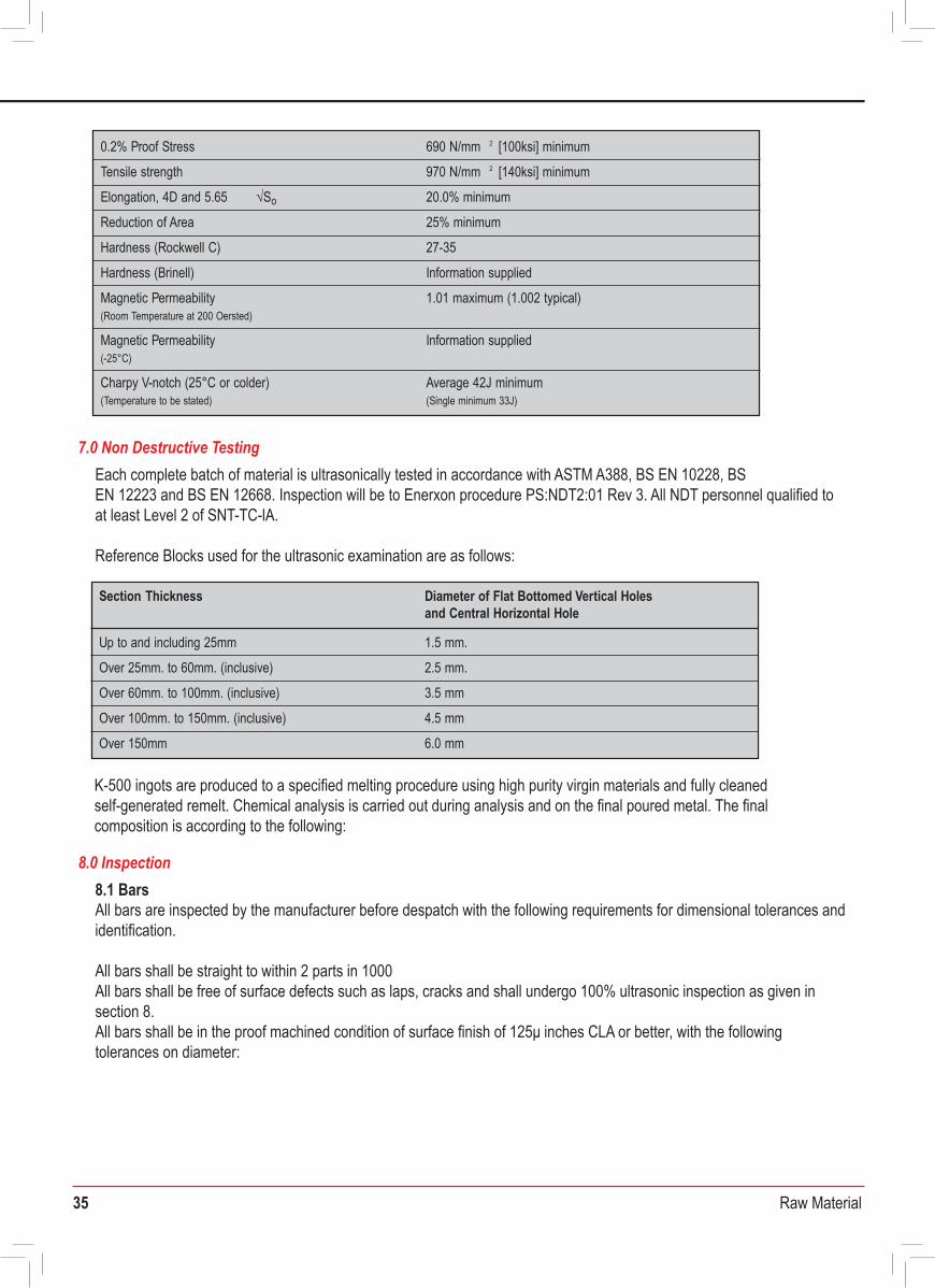
35 Raw Material
7.0 Non Destructive Testing Each complete batch of material is ultrasonically tested in accordance with ASTM A388, BS EN 10228, BS EN 12223 and BS EN 12668. Inspection will be to Enerxon procedure PS:NDT2:01 Rev 3. All NDT personnel qualified to at least Level 2 of SNT-TC-lA.
Reference Blocks used for the ultrasonic examination are as follows:
8.0 Inspection8.1 BarsAll bars are inspected by the manufacturer before despatch with the following requirements for dimensional tolerances and identification.
All bars shall be straight to within 2 parts in 1000 All bars shall be free of surface defects such as laps, cracks and shall undergo 100% ultrasonic inspection as given in section 8.All bars shall be in the proof machined condition of surface finish of 125μ inches CLA or better, with the following tolerances on diameter:
Material Purchase Specification forALLOY K-500 Bar and Forgings
DOCUMENT No. MLA-MPS-K500-BAR/FORGINGS Date: 2nd September 2009 Rev: 2
This specification is for the purchase of bar and forgings in ALLOY K-500 high strength nickel-copper-aluminium-titanium alloy. The material is to be manufactured in accordance with BS 3076:1989 NA18 and ASTM B865 N05500 supplemented by the requirements below.
1.0 Scope
Production process shall be in accordance with internal written Enerxon Procedures. Melting is by electric induction and further refining may be applied. At each stage of production melt and batch traceability shall be maintained.
3.0 Production Processes
Bar shall be delivered in a hot worked and precipitation hardened condition Precipitation shall be carried out by one of the following cycles
(a) 580°C- 610°C, 4-16 hours followed by furnace cooling at approximately 12°C/hr to 480°C then air cool(b) 640°C, 2 hours followed by furnace cooling at approximately 16°C/hr to 480°C then air cool
Exact time and temperatures are to be reported:
5.0 Heat Treatment
K-500 ingots are produced to a specified melting procedure using high purity virgin materials and fully cleaned self-generated remelt. Chemical analysis is carried out during analysis and on the final poured metal. The final composition is according to the following:
K-500 ingots are produced to a specified melting procedure using high purity virgin materials and fully cleanedself-generated remelt. Chemical analysis is carried out during analysis and on the final poured metal. The finalcomposition is according to the following:
4.0 Chemical Composition
Specifications BS 3076:1989 NA18, ASTM B865 N05500, AMS 4676 and QQ-N-286, DIN 2.43752.0 Related Documents
Al Ti CNi+Co min Cu Femax Comax Mn max Simax Smax
63.0 27.5- 2.60- 0.40- 0.09- 1.6 0.3 1.0 0.4 0.0132.0 3.15 0.80 0.18
6.1 Frequency of TestingMechanical testing shall be performed on each melt of material per heat treatment batch.
6.2 Tensile TestingTensile testing shall be carried out in accordance with ASTM A370 or EN10002-1 at room temperature in a longitudinal direction for bar.
Minimum properties are to be as follows:
6.0 Mechanical Properties
0.2% Proof Stress 690 N/mm 2 [100ksi] minimum
Tensile strength 970 N/mm 2 [140ksi] minimum
20.0% minimumElongation, 4D and 5.65 √So
25% minimumReduction of Area
27-35Hardness (Rockwell C)
Hardness (Brinell) Information supplied
1.01 maximum (1.002 typical)
Information supplied
Magnetic Permeability (Room Temperature at 200 Oersted)
Magnetic Permeability (-25°C)
Charpy V-notch (25°C or colder)(Temperature to be stated)
Average 42J minimum(Single minimum 33J)
Section Thickness
1.5 mm.Up to and including 25mm
2.5 mm.
Diameter of Flat Bottomed Vertical Holes and Central Horizontal Hole
Over 25mm. to 60mm. (inclusive)
3.5 mmOver 60mm. to 100mm. (inclusive)
4.5 mmOver 100mm. to 150mm. (inclusive)
Over 150mm 6.0 mm
ALLOY K-500 Bar & Forgings
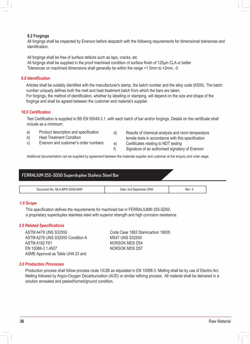
36 Raw Material
Articles shall be suitably identified with the manufacturer's stamp, the batch number and the alloy code (K500). The batch number uniquely defines both the melt and heat treatment batch from which the bars are taken. For forgings, the method of identification, whether by labelling or stamping, will depend on the size and shape of the forgings and shall be agreed between the customer and material’s supplier. K-500 ingots are produced to a specified melting procedure using high purity virgin materials and fully cleaned
self-generated remelt. Chemical analysis is carried out during analysis and on the final poured metal. The final composition is according to the following:
*The hardness shall be in accordance with NACE MR 01.75 (latest edition) with a maximum HRC value of 28 (270HB).
8.2 ForgingsAll forgings shall be inspected by Enerxon before despatch with the following requirements for dimensional tolerances and identification.
All forgings shall be free of surface defects such as laps, cracks, etcAll forgings shall be supplied in the proof machined condition of surface finish of 125μin CLA or betterTolerances on machined dimensions shall generally be within the range +1.5mm to +2mm, -0
9.0 Identification
10.0 CertificationTest Certification is supplied to BS EN 50049.3.1. with each batch of bar and/or forgings. Details on the certificate shall include as a minimum:
a) Product description and specificationb) Heat Treatment Conditionc) Enerxon and customer’s order numbers
d) Results of chemical analysis and room temperaturetensile tests in accordance with this specification
e) Certificates relating to NDT testingf) Signature of an authorised signatory of Enerxon
Additional documentation can be supplied by agreement between the materials supplier and customer at the enquiry and order stage.
Material Purchase Specification forFERRALIUM 255-SD50 Superduplex Stainless Steel Bar
Document No. MLA-MPS-SD50-BAR Date: 2nd September 2009 Rev: 5
This specification defines the requirements for machined bar in FERRALIUM® 255-SD50, a proprietary superduplex stainless steel with superior strength and high corrosion resistance.
1.0 Scope
Production process shall follow process route 1X/2B as stipulated in EN 10088-3. Melting shall be by use of Electric Arc Melting followed by Argon-Oxygen Decarburization (AOD) or similar refining process. All material shall be delivered in a solution annealed and peeled/turned/ground condition.
3.0 Production Processes
ASTM A479 UNS S32550 ASTM A276 UNS S32550 Condition AASTM A182 F61EN 10088-3 1.4507 ASME Approval as Table UHA 23 and
2.0 Related SpecificationsCode Case 1883 Stamicarbon 18005 MS47 UNS S32550NORSOK MDS D54NORSOK MDS D57
4.0 Chemical CompositionEach complete batch of material is ultrasonically tested in accordance with ASTM A388, BS EN 10228, BS EN 12223 and BS EN 12668. Inspection will be to Enerxon procedure PS:NDT2:01 Rev 3. All NDT personnel qualified to at least Level 2 of SNT-TC-lA.
Reference Blocks used for the ultrasonic examination are as follows:
5.0 Heat TreatmentFERRALIUM 255-SD50 shall be solution treated at a temperature within the range 1060°C-1080°C followed by water quenching. Testing shall be carried out on each heat treatment batch. Heat treatment details shall be stated on the Test Certificate.
6.0 Mechanical Properties Tested to ASTM A370 or EN 10002 Pt1 (tensile) and EN ISO 6506-1 (hardness) (as represented by test material) shall be as follows:
7.0 Impact RequirementsThree specimens of each heat of FERRALIUM 255-SD50 shall be impact tested using Charpy Impact testing shall be carried out to BS EN10045-1 for each batch of material at room temperature. Longitudinal values shall be 80J average minimum.Sub zero -46°C or lower shall be tested in both longitudinal and transverse directions. Longitudinal sub zero values shall be 45J (average), with 35J minimum single test value. Transverse values will be reported for information only.
8.0 Microstructure
9.0 Corrosion Testing
The microstructure of each batch of FERRALIUM 255-SD50 shall be examined after solution heat treatment at a minimum of 400X magnification, and verified to be free from grain boundary particles (carbides, nitrides) and intermetallic phases (sigma, chi and laves), as defined by ASTM A 923 Method A. A photomicrograph shall be provided at a magnification of X400 for each batch.The ferrite content is to be determined in accordance with ASTM E562 and must lie between the values of 35% - 55%.
Each batch of FERRALIUM 255-SD50 shall be corrosion tested according to ASTM G48 Method A. The temperatures used are to be 50°C, with an exposure time of 24 hours. The acceptance criteria will be that no pitting attack shall be observable at 20X magnification and that the maximum weight loss shall not exceed 0.8g/m2.
Cr Ni Mo Cu N Simax Mn max Pmax Smax Cmax Fe
24.50- 5.50- 3.10- 1.50- 0.20- 0.20- 0.80- 0.025 0.005 0.02526.50
Rem6.50 3.80 2.00 0.25 0.70 1.20
Size range Elongation 5.65 √SO Reduction of Brinell (minimum)
Tensile Strength(minimum)
0.2% Proof Stress(minimum) area (minimum) Hardness
790 N/mm 2 25% 50%790 N/mm 2 25% 50%
220 - 270 HB*220 - 270 HB*
0.5” to 4.00” 600 N/mm2
Above 4.01” 570 N/mm2
FERRALIUM 255-SD50 Superduplex Stailess Steel Bar
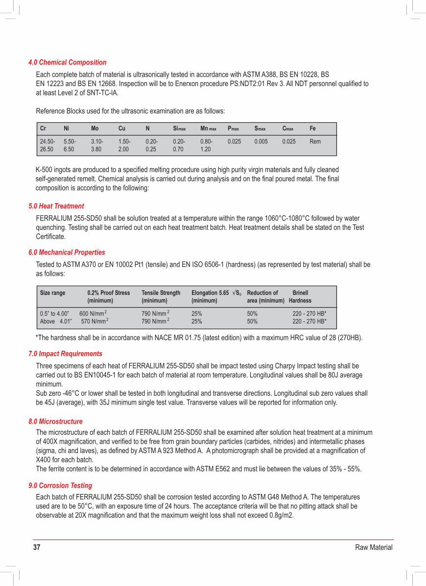
37 Raw Material
Articles shall be suitably identified with the manufacturer's stamp, the batch number and the alloy code (K500). The batch number uniquely defines both the melt and heat treatment batch from which the bars are taken. For forgings, the method of identification, whether by labelling or stamping, will depend on the size and shape of the forgings and shall be agreed between the customer and material’s supplier. K-500 ingots are produced to a specified melting procedure using high purity virgin materials and fully cleaned
self-generated remelt. Chemical analysis is carried out during analysis and on the final poured metal. The finalcomposition is according to the following:
*The hardness shall be in accordance with NACE MR 01.75 (latest edition) with a maximum HRC value of 28 (270HB).
8.2 ForgingsAll forgings shall be inspected by Enerxon before despatch with the following requirements for dimensional tolerances and identification.
All forgings shall be free of surface defects such as laps, cracks, etcAll forgings shall be supplied in the proof machined condition of surface finish of 125μin CLA or betterTolerances on machined dimensions shall generally be within the range +1.5mm to +2mm, -0
9.0 Identification
10.0 CertificationTest Certification is supplied to BS EN 50049.3.1. with each batch of bar and/or forgings. Details on the certificate shall include as a minimum:
a) Product description and specificationb) Heat Treatment Conditionc) Enerxon and customer’s order numbers
d) Results of chemical analysis and room temperaturetensile tests in accordance with this specification
e) Certificates relating to NDT testingf) Signature of an authorised signatory of Enerxon
Additional documentation can be supplied by agreement between the materials supplier and customer at the enquiry and order stage.
Material Purchase Specification forFERRALIUM 255-SD50 Superduplex Stainless Steel Bar
Document No. MLA-MPS-SD50-BAR Date: 2nd September 2009 Rev: 5
This specification defines the requirements for machined bar in FERRALIUM® 255-SD50, a proprietary superduplex stainless steel with superior strength and high corrosion resistance.
1.0 Scope
Production process shall follow process route 1X/2B as stipulated in EN 10088-3. Melting shall be by use of Electric Arc Melting followed by Argon-Oxygen Decarburization (AOD) or similar refining process. All material shall be delivered in a solution annealed and peeled/turned/ground condition.
3.0 Production Processes
ASTM A479 UNS S32550 ASTM A276 UNS S32550 Condition AASTM A182 F61EN 10088-3 1.4507 ASME Approval as Table UHA 23 and
2.0 Related SpecificationsCode Case 1883 Stamicarbon 18005 MS47 UNS S32550NORSOK MDS D54NORSOK MDS D57
4.0 Chemical CompositionEach complete batch of material is ultrasonically tested in accordance with ASTM A388, BS EN 10228, BS EN 12223 and BS EN 12668. Inspection will be to Enerxon procedure PS:NDT2:01 Rev 3. All NDT personnel qualified to at least Level 2 of SNT-TC-lA.
Reference Blocks used for the ultrasonic examination are as follows:
5.0 Heat TreatmentFERRALIUM 255-SD50 shall be solution treated at a temperature within the range 1060°C-1080°C followed by water quenching. Testing shall be carried out on each heat treatment batch. Heat treatment details shall be stated on the Test Certificate.
6.0 Mechanical Properties Tested to ASTM A370 or EN 10002 Pt1 (tensile) and EN ISO 6506-1 (hardness) (as represented by test material) shall be as follows:
7.0 Impact RequirementsThree specimens of each heat of FERRALIUM 255-SD50 shall be impact tested using Charpy Impact testing shall be carried out to BS EN10045-1 for each batch of material at room temperature. Longitudinal values shall be 80J average minimum.Sub zero -46°C or lower shall be tested in both longitudinal and transverse directions. Longitudinal sub zero values shall be 45J (average), with 35J minimum single test value. Transverse values will be reported for information only.
8.0 Microstructure
9.0 Corrosion Testing
The microstructure of each batch of FERRALIUM 255-SD50 shall be examined after solution heat treatment at a minimum of 400X magnification, and verified to be free from grain boundary particles (carbides, nitrides) and intermetallic phases (sigma, chi and laves), as defined by ASTM A 923 Method A. A photomicrograph shall be provided at a magnification of X400 for each batch.The ferrite content is to be determined in accordance with ASTM E562 and must lie between the values of 35% - 55%.
Each batch of FERRALIUM 255-SD50 shall be corrosion tested according to ASTM G48 Method A. The temperatures used are to be 50°C, with an exposure time of 24 hours. The acceptance criteria will be that no pitting attack shall be observable at 20X magnification and that the maximum weight loss shall not exceed 0.8g/m2.
Cr Ni Mo Cu N Simax Mn max Pmax Smax Cmax Fe
24.50- 5.50- 3.10- 1.50- 0.20- 0.20- 0.80- 0.025 0.005 0.02526.50
Rem6.50 3.80 2.00 0.25 0.70 1.20
Size range Elongation 5.65 √SO Reduction of Brinell (minimum)
Tensile Strength(minimum)
0.2% Proof Stress(minimum) area (minimum) Hardness
790 N/mm 2 25% 50%790 N/mm 2 25% 50%
220 - 270 HB*220 - 270 HB*
0.5” to 4.00” 600 N/mm2
Above 4.01” 570 N/mm2
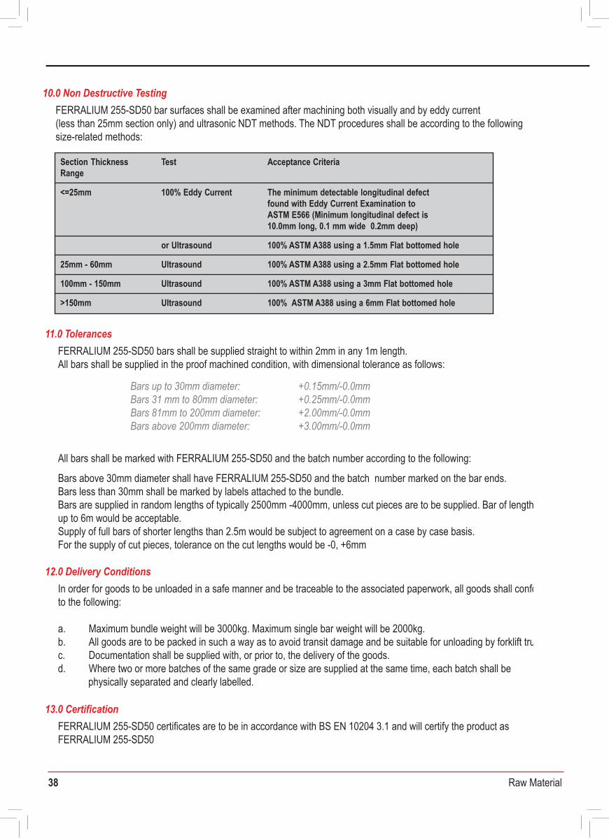
38 Raw Material
FERRALIUM 255-SD50 bar surfaces shall be examined after machining both visually and by eddy current(less than 25mm section only) and ultrasonic NDT methods. The NDT procedures shall be according to the following size-related methods:
10.0 Non Destructive Testing
FERRALIUM 255-SD50 bars shall be supplied straight to within 2mm in any 1m length. All bars shall be supplied in the proof machined condition, with dimensional tolerance as follows:
All bars shall be marked with FERRALIUM 255-SD50 and the batch number according to the following:
Bars above 30mm diameter shall have FERRALIUM 255-SD50 and the batch number marked on the bar ends.Bars less than 30mm shall be marked by labels attached to the bundle.Bars are supplied in random lengths of typically 2500mm -4000mm, unless cut pieces are to be supplied. Bar of lengths up to 6m would be acceptable.Supply of full bars of shorter lengths than 2.5m would be subject to agreement on a case by case basis.For the supply of cut pieces, tolerance on the cut lengths would be -0, +6mm
11.0 Tolerances
FERRALIUM 255-SD50 certificates are to be in accordance with BS EN 10204 3.1 and will certify the product as FERRALIUM 255-SD50
13.0 Certification
In order for goods to be unloaded in a safe manner and be traceable to the associated paperwork, all goods shall conform to the following:
a. Maximum bundle weight will be 3000kg. Maximum single bar weight will be 2000kg.b. All goods are to be packed in such a way as to avoid transit damage and be suitable for unloading by forklift truck.c. Documentation shall be supplied with, or prior to, the delivery of the goods.d. Where two or more batches of the same grade or size are supplied at the same time, each batch shall be
physically separated and clearly labelled.
12.0 Delivery Conditions
Test
<=25mm
Section Thickness Range
Acceptance Criteria
100% Eddy Current
or Ultrasound
25mm - 60mm
100% ASTM A388 using a 1.5mm Flat bottomed hole
The minimum detectable longitudinal defect found with Eddy Current Examination to ASTM E566 (Minimum longitudinal defect is 10.0mm long, 0.1 mm wide 0.2mm deep)
Ultrasound
100mm - 150mm
100% ASTM A388 using a 2.5mm Flat bottomed hole
Ultrasound
>150mm
100% ASTM A388 using a 3mm Flat bottomed hole
Ultrasound 100% ASTM A388 using a 6mm Flat bottomed hole
Bars up to 30mm diameter: Bars 31 mm to 80mm diameter:Bars 81mm to 200mm diameter:Bars above 200mm diameter:
+0.15mm/-0.0mm+0.25mm/-0.0mm+2.00mm/-0.0mm+3.00mm/-0.0mm
Material Purchase Specification forFERRALIUM 255-SD50 Superduplex Stainless Steel Plate and Sheet
Document No. MLA-MPS-SD50-PLATE Date: 2nd September 2009 Rev: 4
This specification defines the requirements for plate and sheet in FERRALIUM® 255-SD50, a proprietary superduplex stainless steel with superior strength and high corrosion resistance.
ASTM A240 UNS S32550 Sheet and PlateASTM A240 UNS S32520 Sheet and PlateEN 10088-2 1.4507ASME Approval as Table UHA 23 and Code Case 1883 NORSOK MDS-D55
1.0 Scope
2.0 Related Documents
Production process shall follow process route 1X/2B as stipulated in EN 10088-3. Melting shall be by use of Electric Arc Melting followed by Argon-Oxygen Decarburization (AOD) or similar refining process. All material shall be delivered in a solution annealed and pickled/passivated condition.
3.0 Production Processes
FERRALIUM 255-SD50 shall be solution treated at a temperature within the range 1070°C-1120°C followed by water quenching. Testing shall be carried out on each heat treatment batch. Heat treatment details shall be stated on the Test Certificate.
5.0 Heat Treatment
(as represented by test material)
*The hardness shall be in accordance with NACE MR 01.75 (latest edition) with an HRC value of 28 (270HB) max.
6.0 Mechanical Properties
A400 ingots are produced to a specified melting procedure using high purity virgin materials and fully cleaned self-generated remelt. Chemical analysis is carried out during analysis and on the final poured metal. The final composition is according to the following:PREN (%Cr+3.3%Mo+16%N) > 40.0.
4.0 Chemical Composition
Cr Ni Mo Cu N Si Mn Pmax Smax Cmax Fe
24.50 5.50- 3.10- 1.50- 0.20- 0.20- 0.80- 0.025 0.005 0.025 Rem3.80-26.50 6.50 2.00 0.25 0.50 1.20
Brinell Hardness
570 N/mm2
Tensile Strength(minimum)
0.2% Proof Stress(minimum)
Elongation 5.65 √SO
(minimum)
790 N/mm 2 25% 220 - 270 HB*
FERRALIUM 255-SD50 Superduplex Stainless Steel plate & Sheet
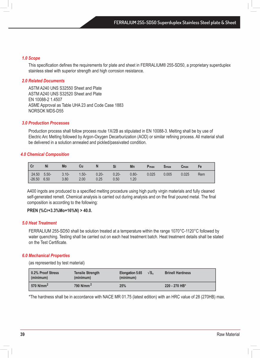
39 Raw Material
FERRALIUM 255-SD50 bar surfaces shall be examined after machining both visually and by eddy current(less than 25mm section only) and ultrasonic NDT methods. The NDT procedures shall be according to the following size-related methods:
10.0 Non Destructive Testing
FERRALIUM 255-SD50 bars shall be supplied straight to within 2mm in any 1m length. All bars shall be supplied in the proof machined condition, with dimensional tolerance as follows:
All bars shall be marked with FERRALIUM 255-SD50 and the batch number according to the following:
Bars above 30mm diameter shall have FERRALIUM 255-SD50 and the batch number marked on the bar ends.Bars less than 30mm shall be marked by labels attached to the bundle.Bars are supplied in random lengths of typically 2500mm -4000mm, unless cut pieces are to be supplied. Bar of lengths up to 6m would be acceptable.Supply of full bars of shorter lengths than 2.5m would be subject to agreement on a case by case basis.For the supply of cut pieces, tolerance on the cut lengths would be -0, +6mm
11.0 Tolerances
FERRALIUM 255-SD50 certificates are to be in accordance with BS EN 10204 3.1 and will certify the product as FERRALIUM 255-SD50
13.0 Certification
In order for goods to be unloaded in a safe manner and be traceable to the associated paperwork, all goods shall conform to the following:
a. Maximum bundle weight will be 3000kg. Maximum single bar weight will be 2000kg.b. All goods are to be packed in such a way as to avoid transit damage and be suitable for unloading by forklift truck.c. Documentation shall be supplied with, or prior to, the delivery of the goods.d. Where two or more batches of the same grade or size are supplied at the same time, each batch shall be physically separated and clearly labelled.
12.0 Delivery Conditions
Test
<=25mm
Section Thickness Range
Acceptance Criteria
100% Eddy Current
or Ultrasound
25mm - 60mm
100% ASTM A388 using a 1.5mm Flat bottomed hole
The minimum detectable longitudinal defect found with Eddy Current Examination to ASTM E566 (Minimum longitudinal defect is 10.0mm long, 0.1 mm wide 0.2mm deep)
Ultrasound
100mm - 150mm
100% ASTM A388 using a 2.5mm Flat bottomed hole
Ultrasound
>150mm
100% ASTM A388 using a 3mm Flat bottomed hole
Ultrasound 100% ASTM A388 using a 6mm Flat bottomed hole
Bars up to 30mm diameter: Bars 31 mm to 80mm diameter:Bars 81mm to 200mm diameter:Bars above 200mm diameter:
+0.15mm/-0.0mm+0.25mm/-0.0mm+2.00mm/-0.0mm+3.00mm/-0.0mm
Material Purchase Specification forFERRALIUM 255-SD50 Superduplex Stainless Steel Plate and Sheet
This specification defines the requirements for plate and sheet in FERRALIUM® 255-SD50, a proprietary superduplex stainless steel with superior strength and high corrosion resistance.
ASTM A240 UNS S32550 Sheet and PlateASTM A240 UNS S32520 Sheet and PlateEN 10088-2 1.4507ASME Approval as Table UHA 23 and Code Case 1883 NORSOK MDS-D55
1.0 Scope
2.0 Related Documents
Production process shall follow process route 1X/2B as stipulated in EN 10088-3. Melting shall be by use of Electric Arc Melting followed by Argon-Oxygen Decarburization (AOD) or similar refining process. All material shall be delivered in a solution annealed and pickled/passivated condition.
3.0 Production Processes
FERRALIUM 255-SD50 shall be solution treated at a temperature within the range 1070°C-1120°C followed by water quenching. Testing shall be carried out on each heat treatment batch. Heat treatment details shall be stated on the Test Certificate.
5.0 Heat Treatment
(as represented by test material)
*The hardness shall be in accordance with NACE MR 01.75 (latest edition) with an HRC value of 28 (270HB) max.
6.0 Mechanical Properties
A400 ingots are produced to a specified melting procedure using high purity virgin materials and fully cleaned self-generated remelt. Chemical analysis is carried out during analysis and on the final poured metal. The final composition is according to the following:PREN (%Cr+3.3%Mo+16%N) > 40.0.
4.0 Chemical Composition
Cr Ni Mo Cu N Si Mn Pmax Smax Cmax Fe
24.50 5.50- 3.10- 1.50- 0.20- 0.20- 0.80- 0.025 0.005 0.025 Rem3.80-26.50 6.50 2.00 0.25 0.50 1.20
Brinell Hardness
570 N/mm2
Tensile Strength(minimum)
0.2% Proof Stress(minimum)
Elongation 5.65 √SO
(minimum)
790 N/mm 2 25% 220 - 270 HB*
FERRALIUM 255-SD50 Superduplex Stainless Steel plate & Sheet
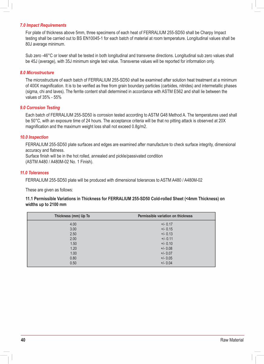
40 Raw Material
a) Product description and specificationb) Heat Treatment Conditionc) Enerxon and customer’s order numbers
d) Results of chemical analysis and room temperature tensile tests in accordance with this specificatione) Results of NDT testingf) Signature of an authorised signatory of Enerxon
For plate of thickness above 5mm, three specimens of each heat of FERRALIUM 255-SD50 shall be Charpy Impact testing shall be carried out to BS EN10045-1 for each batch of material at room temperature. Longitudinal values shall be 80J average minimum.
Sub zero -46°C or lower shall be tested in both longitudinal and transverse directions. Longitudinal sub zero values shall be 45J (average), with 35J minimum single test value. Transverse values will be reported for information only.
7.0 Impact Requirements
The microstructure of each batch of FERRALIUM 255-SD50 shall be examined after solution heat treatment at a minimum of 400X magnification. It is to be verified as free from grain boundary particles (carbides, nitrides) and intermetallic phases (sigma, chi and laves). The ferrite content shall determined in accordance with ASTM E562 and shall lie between the values of 35% - 55%
8.0 Microstructure
Each batch of FERRALIUM 255-SD50 is corrosion tested according to ASTM G48 Method A. The temperatures used shall be 50°C, with an exposure time of 24 hours. The acceptance criteria will be that no pitting attack is observed at 20X magnification and the maximum weight loss shall not exceed 0.8g/m2.
9.0 Corrosion Testing
FERRALIUM 255-SD50 plate surfaces and edges are examined after manufacture to check surface integrity, dimensional accuracy and flatness.Surface finish will be in the hot rolled, annealed and pickle/passivated condition (ASTM A480 / A480M-02 No. 1 Finish).
10.0 Inspection
11.5 Cutting TolerancesCutting of FERRALIUM 255-SD50 plate shall normally be by plasma jet cutting. For this method of cutting, the dimensional tolerance will be +1mm on the top surface. There will be a 3-5° gradient for the cut throughout the thickness increasing the tolerance accordingly.More accurate water jet cutting can be employed if particularly tight tolerances are necessary. In this case, dimensional tolerances will be +0.25mm on the top surface with an increase of 0.3mm to the bottom face, this increase not being dependent on thickness.
FERRALIUM 255-SD50 plate will be produced with dimensional tolerances to ASTM A480 / A480M-02
11.1 Permissible Variations in Thickness for FERRALIUM 255-SD50 Cold-rolled Sheet (<4mm Thickness) on widths up to 2100 mm
11.2 Permissible Variations in Flatness for FERRALIUM 255-SD50 Cold-rolled Sheet (<5mm Thickness) onwidths up to 2100 mm
11.3 Permissible Variations in Thickness for FERRALIUM 255-SD50 Hot-rolled Plate
11.4 Permissible Variations in Flatness for FERRALIUM 255-SD50 Hot-rolled Plate (>5mm Thickness)
These are given as follows:
11.0 Tolerances
Thickness (mm) Up To
4.00 +/- 0.173.00
Permissible variation on thickness
+/- 0.152.50 +/- 0.132.00 +/- 0.111.50 +/- 0.101.20 +/- 0.081.00 +/- 0.070.80 +/- 0.050.50 +/- 0.04
Thickness (mm) Length (mm)Width (mm) Flatness Tolerance (mm)
477
4.99 and under4.99 and under4.99 and under4.99 and under 7
to 1200 inclto 1200 incl
1200 and over1200 and over
to 2400 excl2400 and over
to 2400 excl2400 and over
Thickness (mm) Plate Width
To 1500 excl 1500 to 3048 excl
Tolerance over specified thickness (mm)
+/- 3.81Up to 100.0 4.06+/- 3.20Up to 75.0 3.80
50.0 +/- 1.78 1.90Up to25.0 +/- 1.52Up to 1.6520.0 +/- 1.40 1.52Up to10.0 +/- 1.14Up to 1.278.0 +/- 0.50 0.50Up to6.0 +/- 0.38Up to 0.38
5.00 +/- 0.36Up to 0.38+/- 0.303.50Up to 0.33
Up to 3.00 +/- 0.25 0.332.50 +/- 0.23 0.30Up to
Up to 2.25 +/- 0.20 0.272.00 +/- 0.18Up to 0.25
1.75 -1.50 +/- 0.081.25 - 1.00 +/- 0.06
Plate Thickness (mm) Tolerance (mm)
6.4
Flatness Tolerance (Deviation from a Horizontal Flat Surface)
6.47.97.97.99.5
117
100382520
12.79.56
5.99 and under
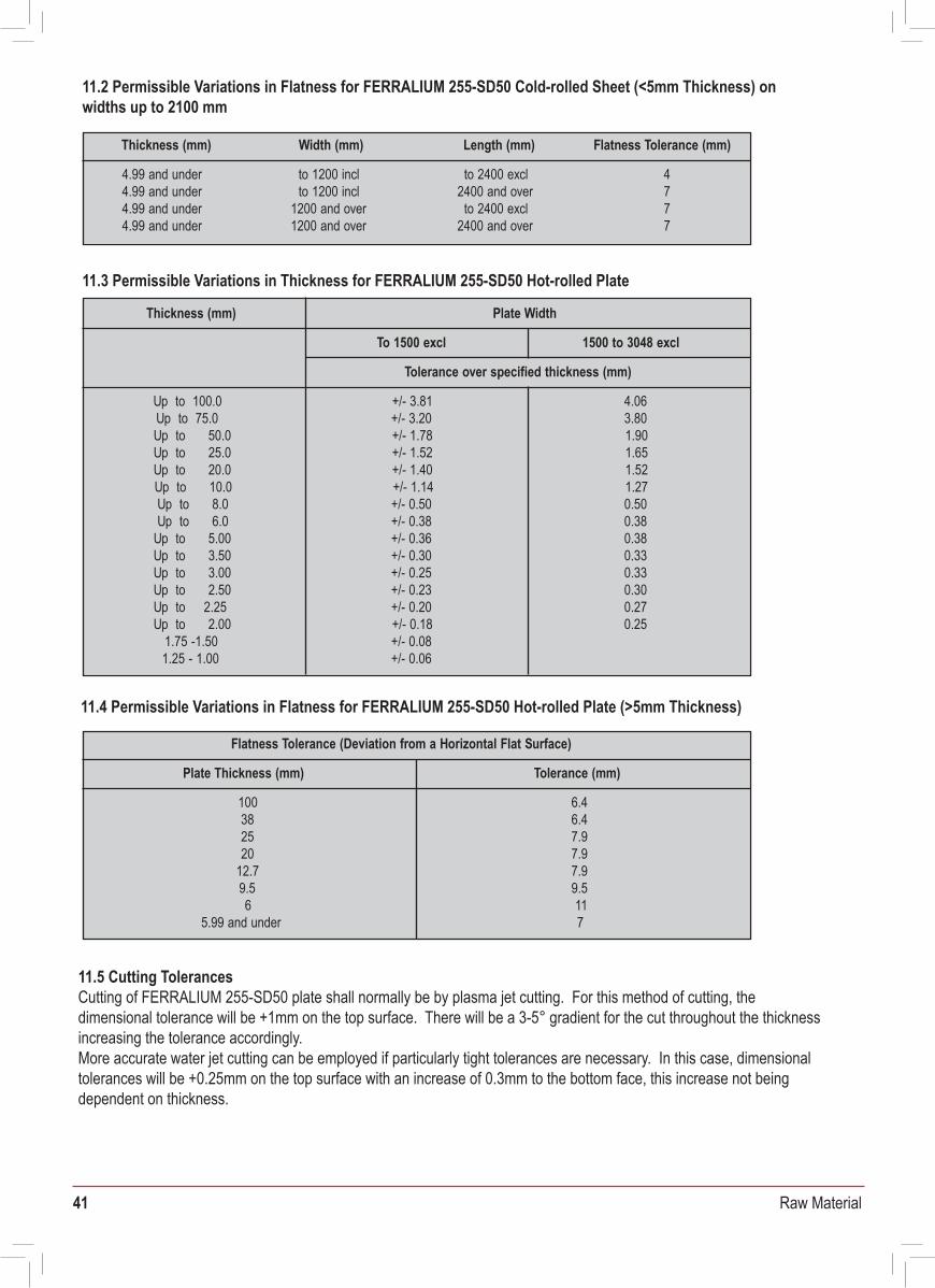
41 Raw Material
a) Product description and specificationb) Heat Treatment Conditionc) Enerxon and customer’s order numbers
d) Results of chemical analysis and room temperature tensile tests in accordance with this specificatione) Results of NDT testingf) Signature of an authorised signatory of Enerxon
For plate of thickness above 5mm, three specimens of each heat of FERRALIUM 255-SD50 shall be Charpy Impact testing shall be carried out to BS EN10045-1 for each batch of material at room temperature. Longitudinal values shall be 80J average minimum.
Sub zero -46°C or lower shall be tested in both longitudinal and transverse directions. Longitudinal sub zero values shall be 45J (average), with 35J minimum single test value. Transverse values will be reported for information only.
7.0 Impact Requirements
The microstructure of each batch of FERRALIUM 255-SD50 shall be examined after solution heat treatment at a minimum of 400X magnification. It is to be verified as free from grain boundary particles (carbides, nitrides) and intermetallic phases(sigma, chi and laves). The ferrite content shall determined in accordance with ASTM E562 and shall lie between the values of 35% - 55%
8.0 Microstructure
Each batch of FERRALIUM 255-SD50 is corrosion tested according to ASTM G48 Method A. The temperatures used shall be 50°C, with an exposure time of 24 hours. The acceptance criteria will be that no pitting attack is observed at 20X magnification and the maximum weight loss shall not exceed 0.8g/m2.
9.0 Corrosion Testing
FERRALIUM 255-SD50 plate surfaces and edges are examined after manufacture to check surface integrity, dimensional accuracy and flatness.Surface finish will be in the hot rolled, annealed and pickle/passivated condition (ASTM A480 / A480M-02 No. 1 Finish).
10.0 Inspection
11.5 Cutting TolerancesCutting of FERRALIUM 255-SD50 plate shall normally be by plasma jet cutting. For this method of cutting, the dimensional tolerance will be +1mm on the top surface. There will be a 3-5° gradient for the cut throughout the thickness increasing the tolerance accordingly.More accurate water jet cutting can be employed if particularly tight tolerances are necessary. In this case, dimensional tolerances will be +0.25mm on the top surface with an increase of 0.3mm to the bottom face, this increase not being dependent on thickness.
FERRALIUM 255-SD50 plate will be produced with dimensional tolerances to ASTM A480 / A480M-02
11.1 Permissible Variations in Thickness for FERRALIUM 255-SD50 Cold-rolled Sheet (<4mm Thickness) on widths up to 2100 mm
11.2 Permissible Variations in Flatness for FERRALIUM 255-SD50 Cold-rolled Sheet (<5mm Thickness) onwidths up to 2100 mm
11.3 Permissible Variations in Thickness for FERRALIUM 255-SD50 Hot-rolled Plate
11.4 Permissible Variations in Flatness for FERRALIUM 255-SD50 Hot-rolled Plate (>5mm Thickness)
These are given as follows:
11.0 Tolerances
Thickness (mm) Up To
4.00 +/- 0.173.00
Permissible variation on thickness
+/- 0.152.50 +/- 0.132.00 +/- 0.111.50 +/- 0.101.20 +/- 0.081.00 +/- 0.070.80 +/- 0.050.50 +/- 0.04
Thickness (mm) Length (mm)Width (mm) Flatness Tolerance (mm)
477
4.99 and under4.99 and under4.99 and under4.99 and under 7
to 1200 inclto 1200 incl
1200 and over1200 and over
to 2400 excl2400 and over
to 2400 excl2400 and over
Thickness (mm) Plate Width
To 1500 excl 1500 to 3048 excl
Tolerance over specified thickness (mm)
+/- 3.81Up to 100.0 4.06+/- 3.20Up to 75.0 3.80
50.0 +/- 1.78 1.90Up to 25.0 +/- 1.52Up to 1.6520.0 +/- 1.40 1.52Up to 10.0 +/- 1.14Up to 1.278.0 +/- 0.50 0.50Up to 6.0 +/- 0.38Up to 0.38
5.00 +/- 0.36Up to 0.38+/- 0.303.50 Up to 0.33
Up to 3.00 +/- 0.25 0.332.50 +/- 0.23 0.30Up to
Up to 2.25 +/- 0.20 0.272.00 +/- 0.18Up to 0.25
1.75 -1.50 +/- 0.081.25 - 1.00 +/- 0.06
Plate Thickness (mm) Tolerance (mm)
6.4
Flatness Tolerance (Deviation from a Horizontal Flat Surface)
6.47.97.97.99.5
117
100382520
12.79.56
5.99 and under
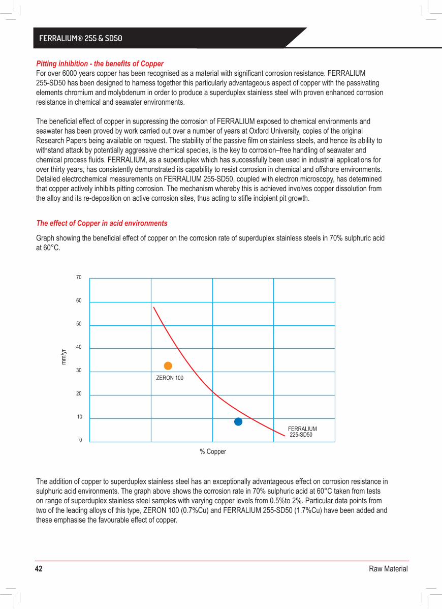
42 Raw Material
Pitting inhibition - the benefits of CopperFor over 6000 years copper has been recognised as a material with significant corrosion resistance. FERRALIUM 255-SD50 has been designed to harness together this particularly advantageous aspect of copper with the passivatingelements chromium and molybdenum in order to produce a superduplex stainless steel with proven enhanced corrosionresistance in chemical and seawater environments.
The beneficial effect of copper in suppressing the corrosion of FERRALIUM exposed to chemical environments and seawater has been proved by work carried out over a number of years at Oxford University, copies of the original Research Papers being available on request. The stability of the passive film on stainless steels, and hence its ability to withstand attack by potentially aggressive chemical species, is the key to corrosion–free handling of seawater and chemical process fluids. FERRALIUM, as a superduplex which has successfully been used in industrial applications for over thirty years, has consistently demonstrated its capability to resist corrosion in chemical and offshore environments. Detailed electrochemical measurements on FERRALIUM 255-SD50, coupled with electron microscopy, has determined that copper actively inhibits pitting corrosion. The mechanism whereby this is achieved involves copper dissolution from the alloy and its re-deposition on active corrosion sites, thus acting to stifle incipient pit growth.
Pitting prevention in Chloride environmentsThe beneficial influence of copper on the pitting resistance of superduplex stainless steels in chloride environments is shown in the accompanying polarisation curves. These graphs show a comparison of a superduplex stainless steel with a low (0.6%Cu) copper content with that of a superduplex with the same alloy make-up except for a higher (1.6%Cu) copper content. In both hydrochloric acid and sodium chloride environments, the current density trace for the 1.6%Cu alloy displays a lower passive current than that of the 0.6% copper alloy and a pitting potential which is 50-100mV more positive. In practice this means that the higher copper containing superduplex is far less likely to suffer from corrosion in chloride environments.
Effect of Copper in environments with Hydrogen Sulphide Corroborative evidence of the beneficial effect of copper has been obtained for dual phase steels and ferritic steels exposed to seawater containing dissolved hydrogen sulphide. In these cases, there is evidence that copper heightens the passivating properties of molybdenum in the steel and reacts with absorbed sulphides on the surface, forming insoluble copper sulphide which stifles the debilitating action of hydrogen sulphide.
In conclusionThe presence of copper in superduplex stainless steels has been shown to impart corrosion resistance improvements, as the copper is chemically able to stifle incipient pit growth. FERRALIUM 255-SD50, which contains between 1.5% and 2.0% copper, has been demonstrated to have superior corrosion resistance to superduplexes with lower copper levels in acid environments, seawater and seawater containing H2S.
The fact that copper has been shown to benefit corrosion resistance of superduplex emphasises the shortcomings of the use of the pitting resistance equivalent number (PREN) which does not include copper or other influential elements in its derivation. The PREN is calculated solely from the chromium, molybdenum and nitrogen content of stainless steels, and it has been widely used to give a guide to their corrosion resistance. However, the use of this empirically derived number for purposes of specification should be treated with caution as the PREN is no guarantee of corrosion performance. In order to have absolute confidence in any material to be used in service, corrosion testing to determine the critical pitting temperature (CPT) of each batch of material should be undertaken. PREN and CPT will be discussed further on page 13.
Graph showing the beneficial effect of copper on the corrosion rate of superduplex stainless steels in 70% sulphuric acid at 60°C.
The addition of copper to superduplex stainless steel has an exceptionally advantageous effect on corrosion resistance in sulphuric acid environments. The graph above shows the corrosion rate in 70% sulphuric acid at 60°C taken from tests on range of superduplex stainless steel samples with varying copper levels from 0.5%to 2%. Particular data points from two of the leading alloys of this type, ZERON 100 (0.7%Cu) and FERRALIUM 255-SD50 (1.7%Cu) have been added and these emphasise the favourable effect of copper.
The effect of Copper in acid environments
4
3
2
1
0
0 100 200 300-1-400 -300 -200 -100
Low-Cu
Curre
nt d
ensit
y (A/
cm2 )
High-Cu
60
50
40
30
20
10
1000- 0-50 50 100 150 200
Low-Cu
High-Cu
Curre
nt d
ensit
y (µA
/cm2 )
Scan Scan Rate: 1mV/s Rate: 1mV/s
Electrochemical Polarisation Curves in 1M HCl at 65°C of superduplexes of similar composition containing o.6% Cu (low-Cu) and 1.6% Cu (high Cu)
Electrochemical Polarisation Curves in 3.5% NaCl at 65°C of superduplexes of similar composition containing levels of copper at 0.6% (low copper) and 1.6% (high copper)
Potential (mVSCE) Potential (mVSCE)
Alloy Type Without Copper With Copper
30-4006000-7000
600-70030000-5000013% Cr Steels
Austenitic-Ferritic Steels
Effect of H2S Contamination on Corrosion of Copper-containing and Copper-free Duplex Steels and 13% Cr SteelsRelative loss of Material in Media Containing H2S (pH 5.5, 50°C, velocity = 50m/s)
70
60
50
40
30
20
10
0
% Copper
mm/yr
ZERON 100
FERRALIUM225-SD50
FERRALIUM® 255 & SD50
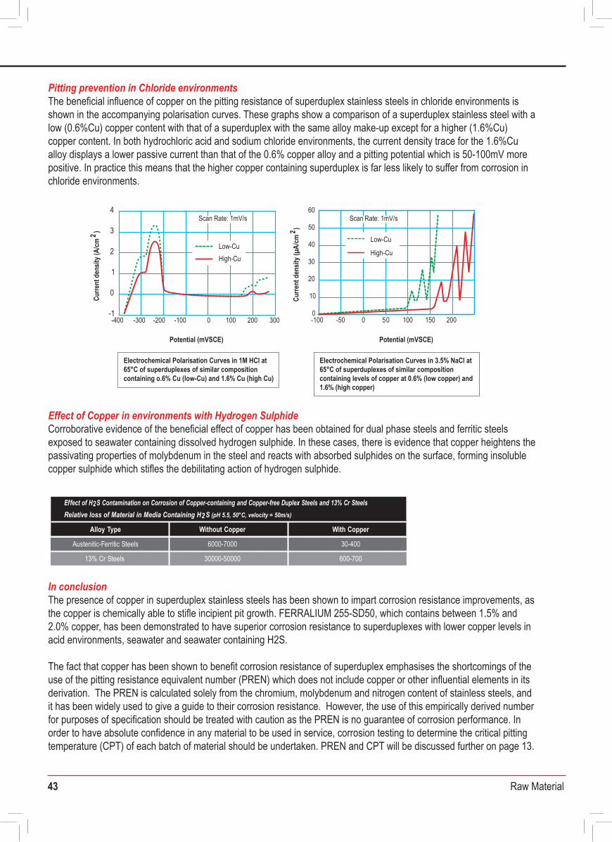
43 Raw Material
Pitting inhibition - the benefits of CopperFor over 6000 years copper has been recognised as a material with significant corrosion resistance. FERRALIUM 255-SD50 has been designed to harness together this particularly advantageous aspect of copper with the passivating elements chromium and molybdenum in order to produce a superduplex stainless steel with proven enhanced corrosion resistance in chemical and seawater environments.
The beneficial effect of copper in suppressing the corrosion of FERRALIUM exposed to chemical environments and seawater has been proved by work carried out over a number of years at Oxford University, copies of the original Research Papers being available on request. The stability of the passive film on stainless steels, and hence its ability to withstand attack by potentially aggressive chemical species, is the key to corrosion–free handling of seawater and chemical process fluids. FERRALIUM, as a superduplex which has successfully been used in industrial applications for over thirty years, has consistently demonstrated its capability to resist corrosion in chemical and offshore environments. Detailed electrochemical measurements on FERRALIUM 255-SD50, coupled with electron microscopy, has determined that copper actively inhibits pitting corrosion. The mechanism whereby this is achieved involves copper dissolution from the alloy and its re-deposition on active corrosion sites, thus acting to stifle incipient pit growth.
Pitting prevention in Chloride environmentsThe beneficial influence of copper on the pitting resistance of superduplex stainless steels in chloride environments is shown in the accompanying polarisation curves. These graphs show a comparison of a superduplex stainless steel with a low (0.6%Cu) copper content with that of a superduplex with the same alloy make-up except for a higher (1.6%Cu) copper content. In both hydrochloric acid and sodium chloride environments, the current density trace for the 1.6%Cu alloy displays a lower passive current than that of the 0.6% copper alloy and a pitting potential which is 50-100mV more positive. In practice this means that the higher copper containing superduplex is far less likely to suffer from corrosion in chloride environments.
Effect of Copper in environments with Hydrogen Sulphide Corroborative evidence of the beneficial effect of copper has been obtained for dual phase steels and ferritic steels exposed to seawater containing dissolved hydrogen sulphide. In these cases, there is evidence that copper heightens the passivating properties of molybdenum in the steel and reacts with absorbed sulphides on the surface, forming insoluble copper sulphide which stifles the debilitating action of hydrogen sulphide.
In conclusionThe presence of copper in superduplex stainless steels has been shown to impart corrosion resistance improvements, as the copper is chemically able to stifle incipient pit growth. FERRALIUM 255-SD50, which contains between 1.5% and 2.0% copper, has been demonstrated to have superior corrosion resistance to superduplexes with lower copper levels in acid environments, seawater and seawater containing H2S.
The fact that copper has been shown to benefit corrosion resistance of superduplex emphasises the shortcomings of the use of the pitting resistance equivalent number (PREN) which does not include copper or other influential elements in its derivation. The PREN is calculated solely from the chromium, molybdenum and nitrogen content of stainless steels, and it has been widely used to give a guide to their corrosion resistance. However, the use of this empirically derived number for purposes of specification should be treated with caution as the PREN is no guarantee of corrosion performance. In order to have absolute confidence in any material to be used in service, corrosion testing to determine the critical pitting temperature (CPT) of each batch of material should be undertaken. PREN and CPT will be discussed further on page 13.
Graph showing the beneficial effect of copper on the corrosion rate of superduplex stainless steels in 70% sulphuric acid at 60°C.
The addition of copper to superduplex stainless steel has an exceptionally advantageous effect on corrosion resistance in sulphuric acid environments. The graph above shows the corrosion rate in 70% sulphuric acid at 60°C taken from tests on range of superduplex stainless steel samples with varying copper levels from 0.5%to 2%. Particular data points from two of the leading alloys of this type, ZERON 100 (0.7%Cu) and FERRALIUM 255-SD50 (1.7%Cu) have been added and these emphasise the favourable effect of copper.
The effect of Copper in acid environments
4
3
2
1
0
0 100 200 300-1-400 -300 -200 -100
Low-Cu
Curre
nt d
ensit
y (A/
cm2 )
High-Cu
60
50
40
30
20
10
1000- 0-50 50 100 150 200
Low-Cu
High-Cu
Curre
nt d
ensit
y (µA
/cm2 )
Scan Scan Rate: 1mV/s Rate: 1mV/s
Electrochemical Polarisation Curves in 1M HCl at 65°C of superduplexes of similar composition containing o.6% Cu (low-Cu) and 1.6% Cu (high Cu)
Electrochemical Polarisation Curves in 3.5% NaCl at 65°C of superduplexes of similar composition containing levels of copper at 0.6% (low copper) and 1.6% (high copper)
Potential (mVSCE) Potential (mVSCE)
Alloy Type Without Copper With Copper
30-4006000-7000
600-70030000-5000013% Cr Steels
Austenitic-Ferritic Steels
Effect of H2S Contamination on Corrosion of Copper-containing and Copper-free Duplex Steels and 13% Cr SteelsRelative loss of Material in Media Containing H2S (pH 5.5, 50°C, velocity = 50m/s)
70
60
50
40
30
20
10
0
% Copper
mm/yr
ZERON 100
FERRALIUM225-SD50
FERRALIUM® 255 & SD50
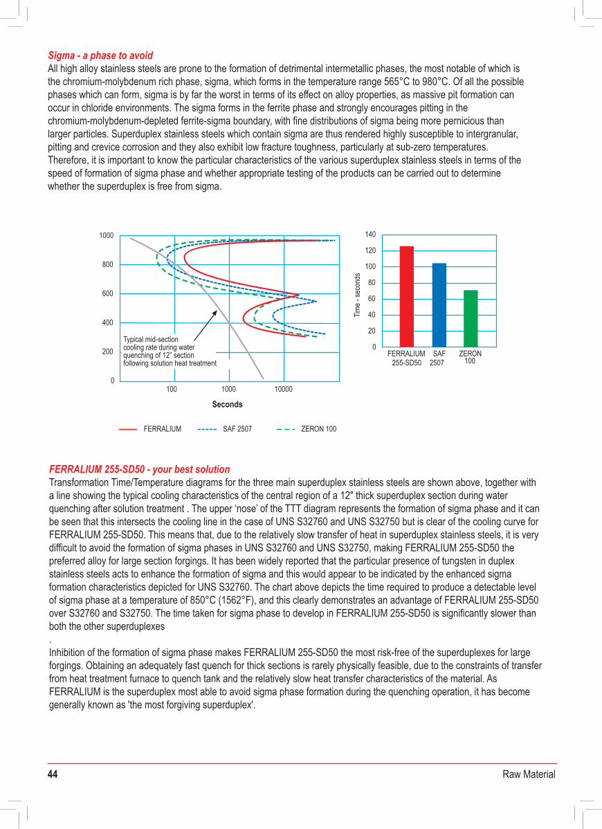
44 Raw Material
Sigma - a phase to avoidAll high alloy stainless steels are prone to the formation of detrimental intermetallic phases, the most notable of which is the chromium-molybdenum rich phase, sigma, which forms in the temperature range 565°C to 980°C. Of all the possible phases which can form, sigma is by far the worst in terms of its effect on alloy properties, as massive pit formation can occur in chloride environments. The sigma forms in the ferrite phase and strongly encourages pitting in the chromium-molybdenum-depleted ferrite-sigma boundary, with fine distributions of sigma being more pernicious than larger particles. Superduplex stainless steels which contain sigma are thus rendered highly susceptible to intergranular, pitting and crevice corrosion and they also exhibit low fracture toughness, particularly at sub-zero temperatures. Therefore, it is important to know the particular characteristics of the various superduplex stainless steels in terms of the speed of formation of sigma phase and whether appropriate testing of the products can be carried out to determine whether the superduplex is free from sigma.
FERRALIUM 255-SD50 - your best solutionTransformation Time/Temperature diagrams for the three main superduplex stainless steels are shown above, together with a line showing the typical cooling characteristics of the central region of a 12" thick superduplex section during water quenching after solution treatment . The upper ‘nose’ of the TTT diagram represents the formation of sigma phase and it can be seen that this intersects the cooling line in the case of UNS S32760 and UNS S32750 but is clear of the cooling curve for FERRALIUM 255-SD50. This means that, due to the relatively slow transfer of heat in superduplex stainless steels, it is very difficult to avoid the formation of sigma phases in UNS S32760 and UNS S32750, making FERRALIUM 255-SD50 the preferred alloy for large section forgings. It has been widely reported that the particular presence of tungsten in duplex stainless steels acts to enhance the formation of sigma and this would appear to be indicated by the enhanced sigma formation characteristics depicted for UNS S32760. The chart above depicts the time required to produce a detectable level of sigma phase at a temperature of 850°C (1562°F), and this clearly demonstrates an advantage of FERRALIUM 255-SD50 over S32760 and S32750. The time taken for sigma phase to develop in FERRALIUM 255-SD50 is significantly slower than both the other superduplexes. Inhibition of the formation of sigma phase makes FERRALIUM 255-SD50 the most risk-free of the superduplexes for large forgings. Obtaining an adequately fast quench for thick sections is rarely physically feasible, due to the constraints of transfer from heat treatment furnace to quench tank and the relatively slow heat transfer characteristics of the material. As FERRALIUM is the superduplex most able to avoid sigma phase formation during the quenching operation, it has become generally known as 'the most forgiving superduplex'.
FERRALIUM 255-SD50 - guaranteed qualityHaving determined that it is difficult to avoid sigma phase formation during the production of superduplex stainless steels, it is imperative that engineers have confidence that sufficient testing is carried out on superduplex components to ensure that sigma phase and other deleterious phases are absent. It is important to realise that the standard ASTM UNS superduplex stainless steel specifications do not stipulate adequate tests of this nature. This is demonstrated on the table below, which lists the international standards applicable to the UNS S32550, UNS 32750 and UNS S32760 superduplex grades together with their mandatory testing requirements. From this table, it is clear that only proprietary FERRALIUM 255-SD50 offers a significantly wide range of tests carried out on a mandatory basis on each batch of product. These tests are designed in the following ways to give assurance to designers, fabricators and engineers that the FERRALIUM 255-SD50 is metallurgically sound and has a consistent set of properties.
In ConclusionDue to the complex nature of superduplex stainless steels, the ease with which sigma and other deleterious phases can be formed during manufacture and the physical impossibility of sufficiently fast quenching, it is apparent that the production of large section FERRALIUM 255-SD50 is much more risk-free than other superduplexes. Thus, FERRALIUM 255-SD50 particularly lends itself to large forgings, where the formation of sigma is much less likely than it is for other superduplexes.
Impact energy test at -46°C used to give assurance that the material toughness is appropriate for offshore use. This property would be significantly debilitated, particularly at sub-zero temperatures, by the presence of sigma and other deleterious phases. Ferrite count used to give assurance that the ferrite level lies between 35% and 55%, the heat treatment was carried out at the correct temperature and the material will behave entirely as a dual phase stainless steel Micrographic examination at x500 magnification used to give assurance that no sigma or other deleterious macro phases are present in the microstructureASTM G48A corrosion test at 50°C used to give certainty that the CPT has a minimum value of 50°C. This demonstrates that the corrosion resistance is good due to the absence of sigma phase and other deleterious phases. Also, this gives assurance that the ferrite/ austenite phase balance is correct and that the general impurity content is low.Eddy Current Test used on bar product to give assurance that crack and surface defects are not presentUltrasonic Test used to give assurance that internal cracks or voids are not present
FERRALIUMGrade
Specifications
Solution • • • • • •• • • * •FERRALIUM to MSA-MDS 255-SD50Annealed • • • • • • • • • * •FERRALIUM to MSA-MDS 255-SD40
• • • • • • • • • •FERRALIUM to MSA-MDS 255-3SF (Forgings)• • • • • • • •• •
NORSOK MDS D51 to D55 and D57ASTM A479 Bar
• ••
ASTM A240 Sheet and Plate•ASTM A473 Forgings
•• •
ASTM A182 Forged Flanges/Fittings Grade F61ASTM A276 Condition A
• •• •
ASTM A790/A789 Seamless and Welded PipeASTM A815 Pipe Fittings
• •Cold Worked •
ASME Approval as Table UHA 23 and Code Case 1883• • • • • • • •FERRALIUM to MSA-MDS FG-46 Bar
• •ASTM A276 Condition SAgeHardened • • • • • • • •
• • • • • • •FERRALIUM to MSA-MDS-51VA-Bar/ForgingsStamicarbon 21022
• • • • • •Stamicarbon 18005 MS47• • • • • •Stamicarbon 53961 MS47
Castings • • •FERRALIUM to MSA-MDS-41VS-Castings•
Mech
anica
lPr
oper
ties
Hard
ness
ASTM A890 Grade 1C, UNS J93373, ACI CD3MCuN
Impa
ct (R
T)
Impa
ct (-4
6°C)
Micro
Ferri
te Co
unt
Corro
sion T
est
Corro
sion T
est G
48A
50°C
Max W
t Los
s 0.8
g/m2
Eddy
Cu
rrent
Test
Test
Ultra
sonic
Corro
sion T
est G
48A
50°C
Max W
t Los
s 4.0
g/m2
DP Te
st Testing is carried out according to specific contract details
FERRALIUM SD50 and SD40 is ultrasonic tested according to specific contract details
Eddy Current testing is carried out on smaller diameter bars only
*
FERRALIUM SAF 2507 ZERON 100
140
120
100
80
60
40
0
20
ZERONFERRALIUM SAF100255-SD50 2507
1000
800
600
400
200
0100
Time -
seco
nds
1000 10000
Seconds
Typical mid-sectioncooling rate during waterquenching of 12” sectionfollowing solution heat treatment
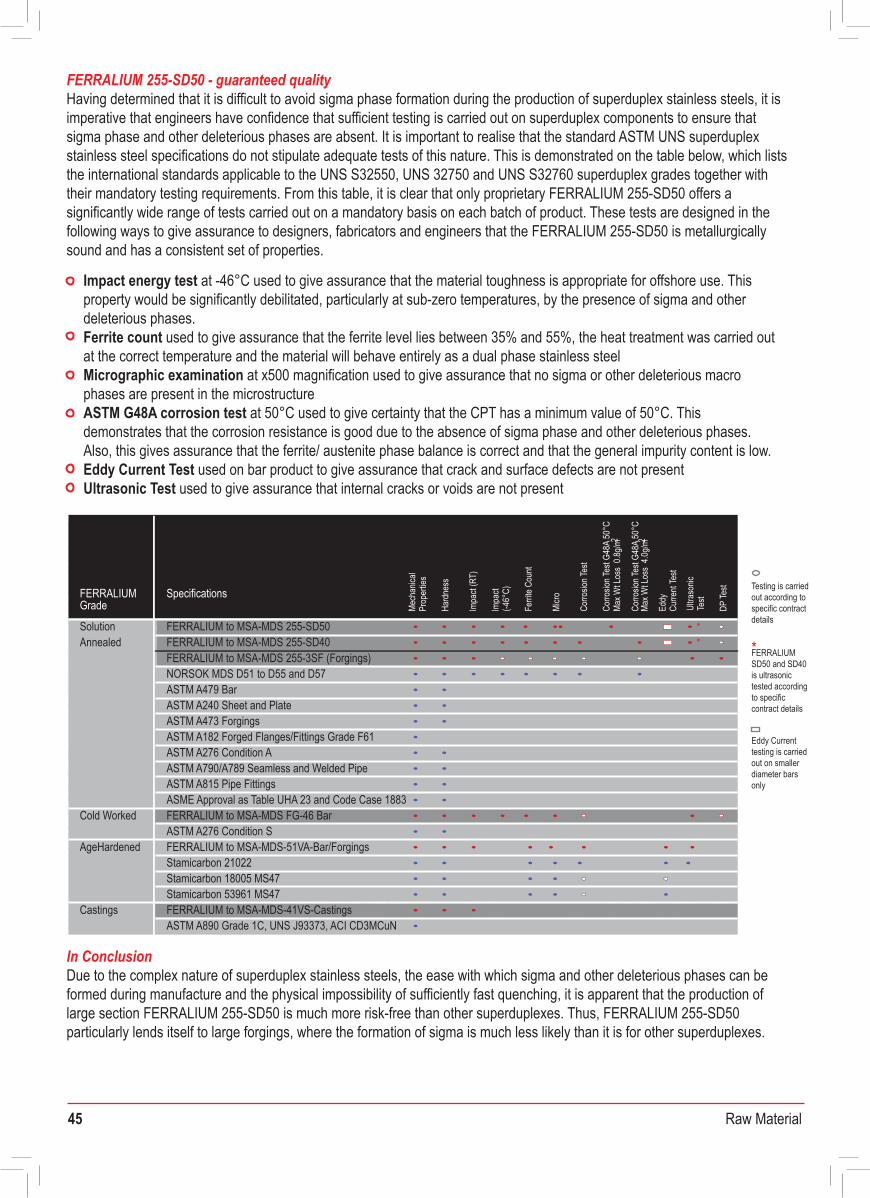
45 Raw Material
Sigma - a phase to avoidAll high alloy stainless steels are prone to the formation of detrimental intermetallic phases, the most notable of which is the chromium-molybdenum rich phase, sigma, which forms in the temperature range 565°C to 980°C. Of all the possible phases which can form, sigma is by far the worst in terms of its effect on alloy properties, as massive pit formation can occur in chloride environments. The sigma forms in the ferrite phase and strongly encourages pitting in the chromium-molybdenum-depleted ferrite-sigma boundary, with fine distributions of sigma being more pernicious than larger particles. Superduplex stainless steels which contain sigma are thus rendered highly susceptible to intergranular, pitting and crevice corrosion and they also exhibit low fracture toughness, particularly at sub-zero temperatures. Therefore, it is important to know the particular characteristics of the various superduplex stainless steels in terms of the speed of formation of sigma phase and whether appropriate testing of the products can be carried out to determine whether the superduplex is free from sigma.
FERRALIUM 255-SD50 - your best solutionTransformation Time/Temperature diagrams for the three main superduplex stainless steels are shown above, together with a line showing the typical cooling characteristics of the central region of a 12" thick superduplex section during water quenching after solution treatment . The upper ‘nose’ of the TTT diagram represents the formation of sigma phase and it can be seen that this intersects the cooling line in the case of UNS S32760 and UNS S32750 but is clear of the cooling curve for FERRALIUM 255-SD50. This means that, due to the relatively slow transfer of heat in superduplex stainless steels, it is very difficult to avoid the formation of sigma phases in UNS S32760 and UNS S32750, making FERRALIUM 255-SD50 the preferred alloy for large section forgings. It has been widely reported that the particular presence of tungsten in duplex stainless steels acts to enhance the formation of sigma and this would appear to be indicated by the enhanced sigma formation characteristics depicted for UNS S32760. The chart above depicts the time required to produce a detectable level of sigma phase at a temperature of 850°C (1562°F), and this clearly demonstrates an advantage of FERRALIUM 255-SD50 over S32760 and S32750. The time taken for sigma phase to develop in FERRALIUM 255-SD50 is significantly slower than both the other superduplexes. Inhibition of the formation of sigma phase makes FERRALIUM 255-SD50 the most risk-free of the superduplexes for large forgings. Obtaining an adequately fast quench for thick sections is rarely physically feasible, due to the constraints of transfer from heat treatment furnace to quench tank and the relatively slow heat transfer characteristics of the material. As FERRALIUM is the superduplex most able to avoid sigma phase formation during the quenching operation, it has become generally known as 'the most forgiving superduplex'.
FERRALIUM 255-SD50 - guaranteed qualityHaving determined that it is difficult to avoid sigma phase formation during the production of superduplex stainless steels, it is imperative that engineers have confidence that sufficient testing is carried out on superduplex components to ensure that sigma phase and other deleterious phases are absent. It is important to realise that the standard ASTM UNS superduplex stainless steel specifications do not stipulate adequate tests of this nature. This is demonstrated on the table below, which lists the international standards applicable to the UNS S32550, UNS 32750 and UNS S32760 superduplex grades together with their mandatory testing requirements. From this table, it is clear that only proprietary FERRALIUM 255-SD50 offers a significantly wide range of tests carried out on a mandatory basis on each batch of product. These tests are designed in the following ways to give assurance to designers, fabricators and engineers that the FERRALIUM 255-SD50 is metallurgically sound and has a consistent set of properties.
In ConclusionDue to the complex nature of superduplex stainless steels, the ease with which sigma and other deleterious phases can be formed during manufacture and the physical impossibility of sufficiently fast quenching, it is apparent that the production of large section FERRALIUM 255-SD50 is much more risk-free than other superduplexes. Thus, FERRALIUM 255-SD50 particularly lends itself to large forgings, where the formation of sigma is much less likely than it is for other superduplexes.
Impact energy test at -46°C used to give assurance that the material toughness is appropriate for offshore use. This property would be significantly debilitated, particularly at sub-zero temperatures, by the presence of sigma and other deleterious phases. Ferrite count used to give assurance that the ferrite level lies between 35% and 55%, the heat treatment was carried out at the correct temperature and the material will behave entirely as a dual phase stainless steel Micrographic examination at x500 magnification used to give assurance that no sigma or other deleterious macro phases are present in the microstructureASTM G48A corrosion test at 50°C used to give certainty that the CPT has a minimum value of 50°C. This demonstrates that the corrosion resistance is good due to the absence of sigma phase and other deleterious phases. Also, this gives assurance that the ferrite/ austenite phase balance is correct and that the general impurity content is low.Eddy Current Test used on bar product to give assurance that crack and surface defects are not presentUltrasonic Test used to give assurance that internal cracks or voids are not present
FERRALIUMGrade
Specifications
Solution • • • • • •• • • * •FERRALIUM to MSA-MDS 255-SD50Annealed • • • • • • • • • * •FERRALIUM to MSA-MDS 255-SD40
• • • • • • • • • •FERRALIUM to MSA-MDS 255-3SF (Forgings)• • • • • • • •• •
NORSOK MDS D51 to D55 and D57ASTM A479 Bar
• ••
ASTM A240 Sheet and Plate•ASTM A473 Forgings
•• •
ASTM A182 Forged Flanges/Fittings Grade F61ASTM A276 Condition A
• •• •
ASTM A790/A789 Seamless and Welded PipeASTM A815 Pipe Fittings
• •Cold Worked •
ASME Approval as Table UHA 23 and Code Case 1883• • • • • • • •FERRALIUM to MSA-MDS FG-46 Bar
• •ASTM A276 Condition SAgeHardened • • • • • • • •
• • • • • • •FERRALIUM to MSA-MDS-51VA-Bar/ForgingsStamicarbon 21022
• • • • • •Stamicarbon 18005 MS47• • • • • •Stamicarbon 53961 MS47
Castings • • •FERRALIUM to MSA-MDS-41VS-Castings•
Mech
anica
lPr
oper
ties
Hard
ness
ASTM A890 Grade 1C, UNS J93373, ACI CD3MCuN
Impa
ct (R
T)
Impa
ct (-4
6°C)
Micro
Ferri
te Co
unt
Corro
sion T
est
Corro
sion T
est G
48A
50°C
Max W
t Los
s 0.8
g/m2
Eddy
Cu
rrent
Test
Test
Ultra
sonic
Corro
sion T
est G
48A
50°C
Max W
t Los
s 4.0
g/m2
DP Te
st Testing is carried out according to specific contract details
FERRALIUM SD50 and SD40 is ultrasonic tested according to specific contract details
Eddy Current testing is carried out on smaller diameter bars only
*
FERRALIUM SAF 2507 ZERON 100
140
120
100
80
60
40
0
20
ZERONFERRALIUM SAF100255-SD50 2507
1000
800
600
400
200
0100
Time -
seco
nds
1000 10000
Seconds
Typical mid-sectioncooling rate during waterquenching of 12” sectionfollowing solution heat treatment
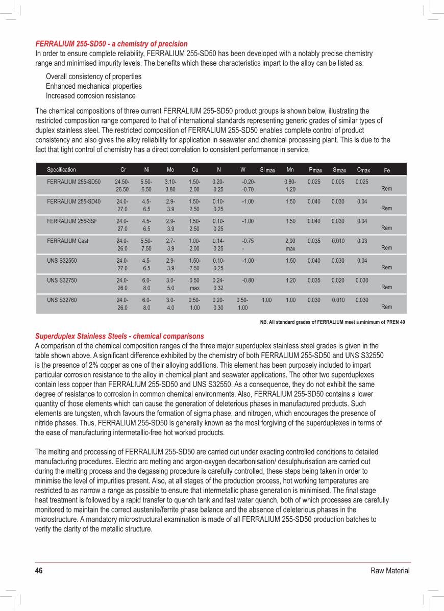
46 Raw Material
FERRALIUM 255-SD50 - a chemistry of precisionIn order to ensure complete reliability, FERRALIUM 255-SD50 has been developed with a notably precise chemistry range and minimised impurity levels. The benefits which these characteristics impart to the alloy can be listed as:
Superduplex Stainless Steels - chemical comparisonsA comparison of the chemical composition ranges of the three major superduplex stainless steel grades is given in the table shown above. A significant difference exhibited by the chemistry of both FERRALIUM 255-SD50 and UNS S32550 is the presence of 2% copper as one of their alloying additions. This element has been purposely included to impart particular corrosion resistance to the alloy in chemical plant and seawater applications. The other two superduplexes contain less copper than FERRALIUM 255-SD50 and UNS S32550. As a consequence, they do not exhibit the same degree of resistance to corrosion in common chemical environments. Also, FERRALIUM 255-SD50 contains a lower quantity of those elements which can cause the generation of deleterious phases in manufactured products. Such elements are tungsten, which favours the formation of sigma phase, and nitrogen, which encourages the presence of nitride phases. Thus, FERRALIUM 255-SD50 is generally known as the most forgiving of the superduplexes in terms of the ease of manufacturing intermetallic-free hot worked products.
The melting and processing of FERRALIUM 255-SD50 are carried out under exacting controlled conditions to detailed manufacturing procedures. Electric arc melting and argon-oxygen decarbonisation/ desulphurisation are carried out during the melting process and the degassing procedure is carefully controlled, these steps being taken in order to minimise the level of impurities present. Also, at all stages of the production process, hot working temperatures are restricted to as narrow a range as possible to ensure that intermetallic phase generation is minimised. The final stage heat treatment is followed by a rapid transfer to quench tank and fast water quench, both of which processes are carefully monitored to maintain the correct austenite/ferrite phase balance and the absence of deleterious phases in the microstructure. A mandatory microstructural examination is made of all FERRALIUM 255-SD50 production batches to verify the clarity of the metallic structure.
The chemical compositions of three current FERRALIUM 255-SD50 product groups is shown below, illustrating the restricted composition range compared to that of international standards representing generic grades of similar types of duplex stainless steel. The restricted composition of FERRALIUM 255-SD50 enables complete control of product consistency and also gives the alloy reliability for application in seawater and chemical processing plant. This is due to the fact that tight control of chemistry has a direct correlation to consistent performance in service.
Overall consistency of propertiesEnhanced mechanical propertiesIncreased corrosion resistance
Cr Ni Mo WNCuSpecification MnSi max Pmax Smax Cmax Fe
24.50- 5.50-FERRALIUM 255-SD50 3.10- 1.50- 0.20- 0.80- 0.025 0.005 0.025Rem26.50 6.50 3.80 2.00 0.25 1.20
-0.20--0.70
24.0- 4.5- 2.9-FERRALIUM 255-SD40 1.50- 0.10- -1.00 1.50 0.040 0.030 0.04Rem27.0 6.5 3.9 2.50 0.25
24.0- 4.5-FERRALIUM 255-3SF 2.9- 1.50- 0.10- -1.00 1.50 0.040 0.030 0.04Rem27.0 6.5 3.9 2.50 0.25
24.0-FERRALIUM Cast 5.50- 2.7- 1.00- 0.14- -0.75 2.00 0.035 0.010 0.03Rem26.0 7.50 3.9 2.00 0.25 - max
UNS S32550 24.0- 4.5- 2.9- 1.50- 0.10- -1.00 1.50 0.040 0.030 0.04Rem27.0 6.5 3.9 2.50 0.25
UNS S32750 24.0- 6.0- 3.0- 0.50 0.24- -0.80 1.20 0.035 0.020 0.030Rem26.0 8.0 5.0 max 0.32
UNS S32760 24.0- 6.0- 3.0- 0.50- 0.20- 0.50- 1.00 1.00 0.030 0.010 0.030Rem26.0 8.0 4.0 1.00 0.30 1.00
NB. All standard grades of FERRALIUM meet a minimum of PREN 40
*Minimum mechanical properties can be matched to specific contract details if required
FERRALIUM - mechanical properties As a continuation of FERRALIUM’s premier role at the forefront of superduplex technology, FERRALIUM 255-SD50 now sets a new bench mark for superduplex as the first to state 600N/mm2 as the minimum 0.2% Proof Stress, as shown in the table below. This advantage given by FERRALIUM allows equipment designers the ability to reduce section thickness and therefore weight and cost if FERRALIUM 255-SD50 is used as the superduplex of choice.
In ConclusionThe chemistry of FERRALIUM is be very carefully selected and tightly controlled to ensure that phase balance is correct and impurities are kept as low as is physically possible. As well as chemistry, the production technology for the melting and processing of FERRALIUM has been maintained at the forefront of materials manufacturing science, resulting in the latest grade of FERRALIUM, FERRALIUM 255-SD50, being the first superduplex to guarantee a minimum 0.2%Proof Stress of 600N/mm2.
Also, as it is imperative that engineers have confidence that sufficient testing is carried out on superduplex components to ensure that harmful phases are absent, both FERRALIUM 255-SD50 and FERRALIUM 255-SD40 must undergo a high degree of mandatory testing. These tests are designed to guarantee that the trade-marked product possesses high integrity, a correct phase balance and the absence of sigma and other deleterious phases.
In torsion FERRALIUM 255-SD50 shows typical values for 0.2% proof stress of 450N/mm2 and 850N/mm2 for ultimate tensile strength with an angle of twist of 1020°. It should be emphasised that FERRALIUM 255-SD50 in all aspects satisfies the requirements of the previous FERRALIUM alloy grades FERRALIUM 255, FERRALIUM 255-3SF and FERRALIUM SD40.
FERRALIUM - galvanic compatibilityFERRALIUM 255-SD50 is galvanically compatible with a number of metals and alloys. It is relatively ‘noble’ in a galvanic table, comparing with titanium, and has a rest potential of +0.04 volts (SCE) in 3% NaCI. Care is required when used in combination with some less noble materials where insulation between the two materials may be needed. The relative area of noble to less noble alloy is important in addition to the potential difference. FERRALIUM is used successfully in combination with the high strength cupronickels HIDURON and MARINEL in subsea control equipment and in the control gear for submarine bow planes. It is generally found to be galvanically compatible with copper alloys containing aluminium as an alumina based protective layer is formed which acts to provide a degree of electrical insulation.
Minimum mechanical properties
Grade 0.2% Proof Stress Ultimate Tensile ImpactStrength
(N/mm 2) [ksi] (N/mm 2) [ksi]
Elongation Hardness
(%)(HBN) (J) [20°C](J) [-46°C]
600 [87] 790 25[114.6] 80 45FERRALIUM 255-SD50Bars up to 4ӯ 270max
570 [82.6] 790 25[114.6] 80270max 45FERRALIUM 255-SD50Bars above 4ӯ and Plate
550 [79.8] 760 FERRALIUM 255-SD40 25[110.3] 80270max 45
550*FERRALIUM 255-3SF [79.8] 750* [108.8] 25* 80270max
720 860FERRALIUM 255-FG46 [103.5] 16 [124.8] 40220-335
570 860[82.6] FERRALIUM 255-3AF 23 [120.4] 70250-330
450 [65.3]FERRALIUM 255-3SC 700 25[101.5] 80270max
550 [79.8] 750 25[108.8]UNS 32550, UNS 32750, UNS 32760 270max
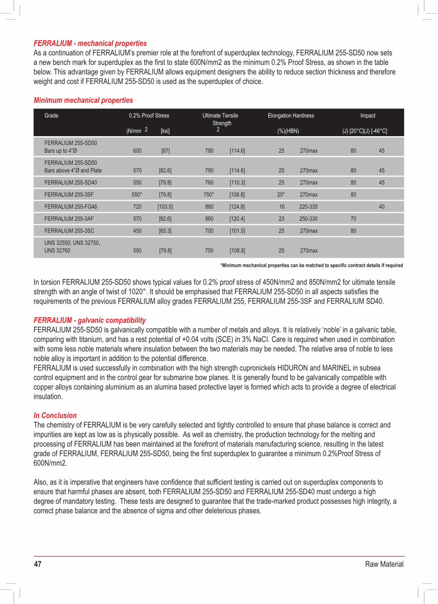
47 Raw Material
FERRALIUM 255-SD50 - a chemistry of precisionIn order to ensure complete reliability, FERRALIUM 255-SD50 has been developed with a notably precise chemistry range and minimised impurity levels. The benefits which these characteristics impart to the alloy can be listed as:
Superduplex Stainless Steels - chemical comparisonsA comparison of the chemical composition ranges of the three major superduplex stainless steel grades is given in the table shown above. A significant difference exhibited by the chemistry of both FERRALIUM 255-SD50 and UNS S32550 is the presence of 2% copper as one of their alloying additions. This element has been purposely included to impart particular corrosion resistance to the alloy in chemical plant and seawater applications. The other two superduplexes contain less copper than FERRALIUM 255-SD50 and UNS S32550. As a consequence, they do not exhibit the same degree of resistance to corrosion in common chemical environments. Also, FERRALIUM 255-SD50 contains a lower quantity of those elements which can cause the generation of deleterious phases in manufactured products. Such elements are tungsten, which favours the formation of sigma phase, and nitrogen, which encourages the presence of nitride phases. Thus, FERRALIUM 255-SD50 is generally known as the most forgiving of the superduplexes in terms of the ease of manufacturing intermetallic-free hot worked products.
The melting and processing of FERRALIUM 255-SD50 are carried out under exacting controlled conditions to detailed manufacturing procedures. Electric arc melting and argon-oxygen decarbonisation/ desulphurisation are carried out during the melting process and the degassing procedure is carefully controlled, these steps being taken in order to minimise the level of impurities present. Also, at all stages of the production process, hot working temperatures are restricted to as narrow a range as possible to ensure that intermetallic phase generation is minimised. The final stage heat treatment is followed by a rapid transfer to quench tank and fast water quench, both of which processes are carefully monitored to maintain the correct austenite/ferrite phase balance and the absence of deleterious phases in the microstructure. A mandatory microstructural examination is made of all FERRALIUM 255-SD50 production batches to verify the clarity of the metallic structure.
The chemical compositions of three current FERRALIUM 255-SD50 product groups is shown below, illustrating the restricted composition range compared to that of international standards representing generic grades of similar types of duplex stainless steel. The restricted composition of FERRALIUM 255-SD50 enables complete control of product consistency and also gives the alloy reliability for application in seawater and chemical processing plant. This is due to the fact that tight control of chemistry has a direct correlation to consistent performance in service.
Overall consistency of propertiesEnhanced mechanical propertiesIncreased corrosion resistance
Cr Ni Mo WNCuSpecification MnSi max Pmax Smax Cmax Fe
24.50- 5.50-FERRALIUM 255-SD50 3.10- 1.50- 0.20- 0.80- 0.025 0.005 0.025Rem26.50 6.50 3.80 2.00 0.25 1.20
-0.20--0.70
24.0- 4.5- 2.9-FERRALIUM 255-SD40 1.50- 0.10- -1.00 1.50 0.040 0.030 0.04Rem27.0 6.5 3.9 2.50 0.25
24.0- 4.5-FERRALIUM 255-3SF 2.9- 1.50- 0.10- -1.00 1.50 0.040 0.030 0.04Rem27.0 6.5 3.9 2.50 0.25
24.0-FERRALIUM Cast 5.50- 2.7- 1.00- 0.14- -0.75 2.00 0.035 0.010 0.03Rem26.0 7.50 3.9 2.00 0.25 - max
UNS S32550 24.0- 4.5- 2.9- 1.50- 0.10- -1.00 1.50 0.040 0.030 0.04Rem27.0 6.5 3.9 2.50 0.25
UNS S32750 24.0- 6.0- 3.0- 0.50 0.24- -0.80 1.20 0.035 0.020 0.030Rem26.0 8.0 5.0 max 0.32
UNS S32760 24.0- 6.0- 3.0- 0.50- 0.20- 0.50- 1.00 1.00 0.030 0.010 0.030Rem26.0 8.0 4.0 1.00 0.30 1.00
NB. All standard grades of FERRALIUM meet a minimum of PREN 40
*Minimum mechanical properties can be matched to specific contract details if required
FERRALIUM - mechanical properties As a continuation of FERRALIUM’s premier role at the forefront of superduplex technology, FERRALIUM 255-SD50 now sets a new bench mark for superduplex as the first to state 600N/mm2 as the minimum 0.2% Proof Stress, as shown in the table below. This advantage given by FERRALIUM allows equipment designers the ability to reduce section thickness and therefore weight and cost if FERRALIUM 255-SD50 is used as the superduplex of choice.
In ConclusionThe chemistry of FERRALIUM is be very carefully selected and tightly controlled to ensure that phase balance is correct and impurities are kept as low as is physically possible. As well as chemistry, the production technology for the melting and processing of FERRALIUM has been maintained at the forefront of materials manufacturing science, resulting in the latest grade of FERRALIUM, FERRALIUM 255-SD50, being the first superduplex to guarantee a minimum 0.2%Proof Stress of 600N/mm2.
Also, as it is imperative that engineers have confidence that sufficient testing is carried out on superduplex components to ensure that harmful phases are absent, both FERRALIUM 255-SD50 and FERRALIUM 255-SD40 must undergo a high degree of mandatory testing. These tests are designed to guarantee that the trade-marked product possesses high integrity, a correct phase balance and the absence of sigma and other deleterious phases.
In torsion FERRALIUM 255-SD50 shows typical values for 0.2% proof stress of 450N/mm2 and 850N/mm2 for ultimate tensile strength with an angle of twist of 1020°. It should be emphasised that FERRALIUM 255-SD50 in all aspects satisfies the requirements of the previous FERRALIUM alloy grades FERRALIUM 255, FERRALIUM 255-3SF and FERRALIUM SD40.
FERRALIUM - galvanic compatibilityFERRALIUM 255-SD50 is galvanically compatible with a number of metals and alloys. It is relatively ‘noble’ in a galvanic table, comparing with titanium, and has a rest potential of +0.04 volts (SCE) in 3% NaCI. Care is required when used in combination with some less noble materials where insulation between the two materials may be needed. The relative area of noble to less noble alloy is important in addition to the potential difference. FERRALIUM is used successfully in combination with the high strength cupronickels HIDURON and MARINEL in subsea control equipment and in the control gear for submarine bow planes. It is generally found to be galvanically compatible with copper alloys containing aluminium as an alumina based protective layer is formed which acts to provide a degree of electrical insulation.
Minimum mechanical properties
Grade 0.2% Proof Stress Ultimate Tensile ImpactStrength
(N/mm 2) [ksi] (N/mm 2) [ksi]
Elongation Hardness
(%)(HBN) (J) [20°C](J) [-46°C]
600 [87] 790 25[114.6] 80 45FERRALIUM 255-SD50Bars up to 4ӯ 270max
570 [82.6] 790 25[114.6] 80270max 45FERRALIUM 255-SD50Bars above 4ӯ and Plate
550 [79.8] 760 FERRALIUM 255-SD40 25[110.3] 80270max 45
550*FERRALIUM 255-3SF [79.8] 750* [108.8] 25* 80270max
720 860FERRALIUM 255-FG46 [103.5] 16 [124.8] 40220-335
570 860[82.6] FERRALIUM 255-3AF 23 [120.4] 70250-330
450 [65.3]FERRALIUM 255-3SC 700 25[101.5] 80270max
550 [79.8] 750 25[108.8]UNS 32550, UNS 32750, UNS 32760 270max
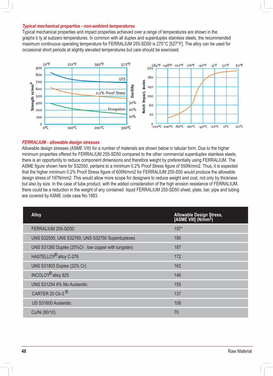
48 Raw Material
Graph showing the fatigue and corrosion fatigue properties ofFERRALIUM 255-SD50 as wrought and cast product forms
Typical mechanical properties - non-ambient temperaturesTypical mechanical properties and impact properties achieved over a range of temperatures are shown in thegraphs b ty at subzero temperatures. In common with all duplex and superduplex stainless steels, the recommended maximum continuous operating temperature for FERRALIUM 255-SD50 is 275°C [527°F]. The alloy can be used for occasional short periods at slightly elevated temperatures but care should be exercised.
FERRALIUM - allowable design stressesAllowable design stresses (ASME VIII) for a number of materials are shown below in tabular form. Due to the higher minimum properties offered for FERRALIUM 255-SD50 compared to the other commercial superduplex stainless steels, there is an opportunity to reduce component dimensions and therefore weight by preferentially using FERRALIUM. The ASME figure shown here for S32550, pertains to a minimum 0.2% Proof Stress figure of 550N/mm2. Thus, it is expected that the higher minimum 0.2% Proof Stress figure of 600N/mm2 for FERRALIUM 255-S50 would produce the allowable design stress of 197N/mm2. This would allow more scope for designers to reduce weight and cost, not only by thickness but also by size. In the case of tube product, with the added consideration of the high erosion resistance of FERRALIUM, there could be a reduction in the weight of any contained liquid FERRALIUM 255-SD50 sheet, plate, bar, pipe and tubing are covered by ASME code case No.1883.
Alloy
197*FERRALIUM 255-SD50
Allowable Design Stress,[ASME VIII] (N/mm2)
190UNS S32550, UNS S32760, UNS S32750 Superduplexes
187
172HASTELLOY® alloy C-276
UNS S31260 Duplex (25%Cr , low copper with tungsten)
162UNS S31803 Duplex (22% Cr)
146INCOLOY® alloy 825
155UNS S31254 6% Mo Austenitic
137CARTER 20 Cb-3 ®
108US S31600 Austenitic
70Cu/Ni (90/10)
FERRALIUM - fatigue characteristicsFERRALIUM possesses excellent resistance to fatigue and corrosion fatigue, as shown in the accompanying graphs. The results for FERRALIUM 255-SD50 make the alloy particularly suitable for rotating items such as shafts in seawater and chemical environments.
FERRALIUM - erosion and abrasion propertiesThe resistance of FERRALIUM 255-SD50 to erosion, abrasion and cavitation-erosion is extremely good and is superior to standard and high alloy austenitic alloys and other duplex stainless steels. Many long established applications utilise this property to advantage in agitators, pumps and valves. For instance, hot acid gypsum slurries are handled very successfully by FERRALIUM pumps, with casings and high speed impellers produced in the alloy.
FERRALIUM propellers on fast patrol boats have shown good resistance to cavitation-erosion.
620
540
460
380
300
220
140104 105 106 107 108
Stre
ss ±
N/m
m2
Cast in airCast in 3% NaClWrought in air
NaClWrought in 3%
0.4
0.3
0.2
0.1
00 10 20 30 40 50
Time hr
Mean
depth
of er
osion
mm
Steel316L Stainless Steel317L Stainless
22% Cr D uplex AlloyFERRALIUM
Graph showing comparative cavitation erosion properties of FERRALIUM 255-SD50 as determined using the ASTM G32 vibratory cavitation erosion test method
7.81Density at 20°C g/cc- 20 - 100°C 11.1 x 10⁻⁶Mean Coefficient of Thermal Expansion °K 1
20 - 200°C 11.5 x 10-620 - 300°C 12.0 x 10-620°C 14.2100°C 16.3
Thermal Conductivity, W/M°K
200°C 18.420°C 0.80 100°C 0.88200°C 0.93
Specific Electrical Resistance, Microhm-m
20°C 475100°C 500
Specific Heat, J/Kg.°K
200°C 53233Magnetic Permeability199 x 103Young’s Modulus, MPa150 x 103Compression Modulus, MPa75 x 103Torsional Modulus, MPa98 0.32
Fracture Toughness, KQ, MPa .m1/2Poisson's Ratio
FERRALIUM - typical physical properties
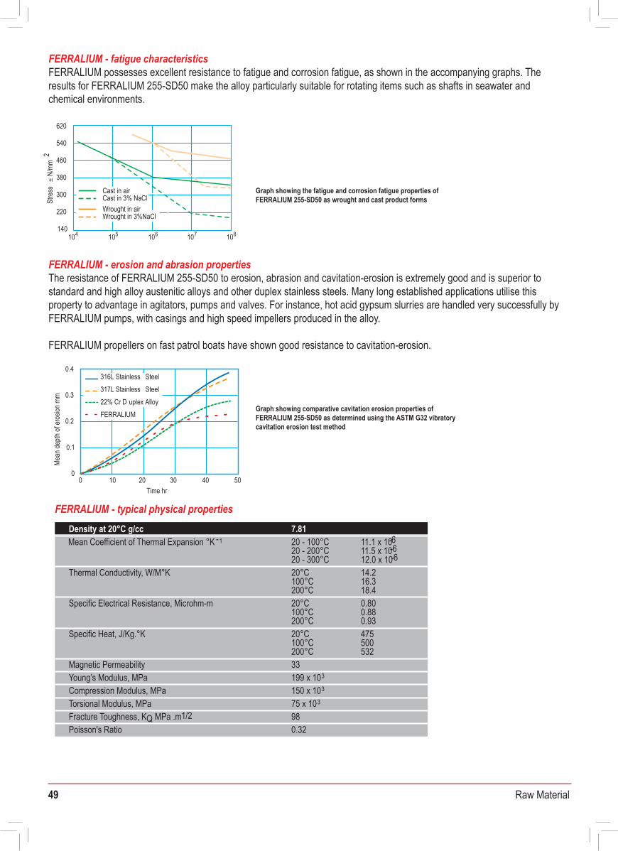
49 Raw Material
Graph showing the fatigue and corrosion fatigue properties ofFERRALIUM 255-SD50 as wrought and cast product forms
Typical mechanical properties - non-ambient temperaturesTypical mechanical properties and impact properties achieved over a range of temperatures are shown in thegraphs b ty at subzero temperatures. In common with all duplex and superduplex stainless steels, the recommended maximum continuous operating temperature for FERRALIUM 255-SD50 is 275°C [527°F]. The alloy can be used for occasional short periods at slightly elevated temperatures but care should be exercised.
FERRALIUM - allowable design stressesAllowable design stresses (ASME VIII) for a number of materials are shown below in tabular form. Due to the higher minimum properties offered for FERRALIUM 255-SD50 compared to the other commercial superduplex stainless steels, there is an opportunity to reduce component dimensions and therefore weight by preferentially using FERRALIUM. The ASME figure shown here for S32550, pertains to a minimum 0.2% Proof Stress figure of 550N/mm2. Thus, it is expected that the higher minimum 0.2% Proof Stress figure of 600N/mm2 for FERRALIUM 255-S50 would produce the allowable design stress of 197N/mm2. This would allow more scope for designers to reduce weight and cost, not only by thickness but also by size. In the case of tube product, with the added consideration of the high erosion resistance of FERRALIUM, there could be a reduction in the weight of any contained liquid FERRALIUM 255-SD50 sheet, plate, bar, pipe and tubing are covered by ASME code case No.1883.
Alloy
197*FERRALIUM 255-SD50
Allowable Design Stress,[ASME VIII] (N/mm2)
190UNS S32550, UNS S32760, UNS S32750 Superduplexes
187
172HASTELLOY® alloy C-276
UNS S31260 Duplex (25%Cr , low copper with tungsten)
162UNS S31803 Duplex (22% Cr)
146INCOLOY® alloy 825
155UNS S31254 6% Mo Austenitic
137CARTER 20 Cb-3 ®
108US S31600 Austenitic
70Cu/Ni (90/10)
FERRALIUM - fatigue characteristicsFERRALIUM possesses excellent resistance to fatigue and corrosion fatigue, as shown in the accompanying graphs. The results for FERRALIUM 255-SD50 make the alloy particularly suitable for rotating items such as shafts in seawater and chemical environments.
FERRALIUM - erosion and abrasion propertiesThe resistance of FERRALIUM 255-SD50 to erosion, abrasion and cavitation-erosion is extremely good and is superior to standard and high alloy austenitic alloys and other duplex stainless steels. Many long established applications utilise this property to advantage in agitators, pumps and valves. For instance, hot acid gypsum slurries are handled very successfully by FERRALIUM pumps, with casings and high speed impellers produced in the alloy.
FERRALIUM propellers on fast patrol boats have shown good resistance to cavitation-erosion.
620
540
460
380
300
220
140104 105 106 107 108
Stre
ss ±
N/m
m2
Cast in airCast in 3% NaClWrought in air
NaClWrought in 3%
0.4
0.3
0.2
0.1
00 10 20 30 40 50
Time hr
Mean
depth
of er
osion
mm
Steel316L Stainless Steel317L Stainless
22% Cr D uplex AlloyFERRALIUM
Graph showing comparative cavitation erosion properties of FERRALIUM 255-SD50 as determined using the ASTM G32 vibratory cavitation erosion test method
7.81Density at 20°C g/cc- 20 - 100°C 11.1 x 10⁻⁶Mean Coefficient of Thermal Expansion °K 1
20 - 200°C 11.5 x 10-620 - 300°C 12.0 x 10-620°C 14.2100°C 16.3
Thermal Conductivity, W/M°K
200°C 18.420°C 0.80 100°C 0.88200°C 0.93
Specific Electrical Resistance, Microhm-m
20°C 475100°C 500
Specific Heat, J/Kg.°K
200°C 53233Magnetic Permeability199 x 103Young’s Modulus, MPa150 x 103Compression Modulus, MPa75 x 103Torsional Modulus, MPa98 0.32
Fracture Toughness, KQ, MPa .m1/2Poisson's Ratio
FERRALIUM - typical physical properties
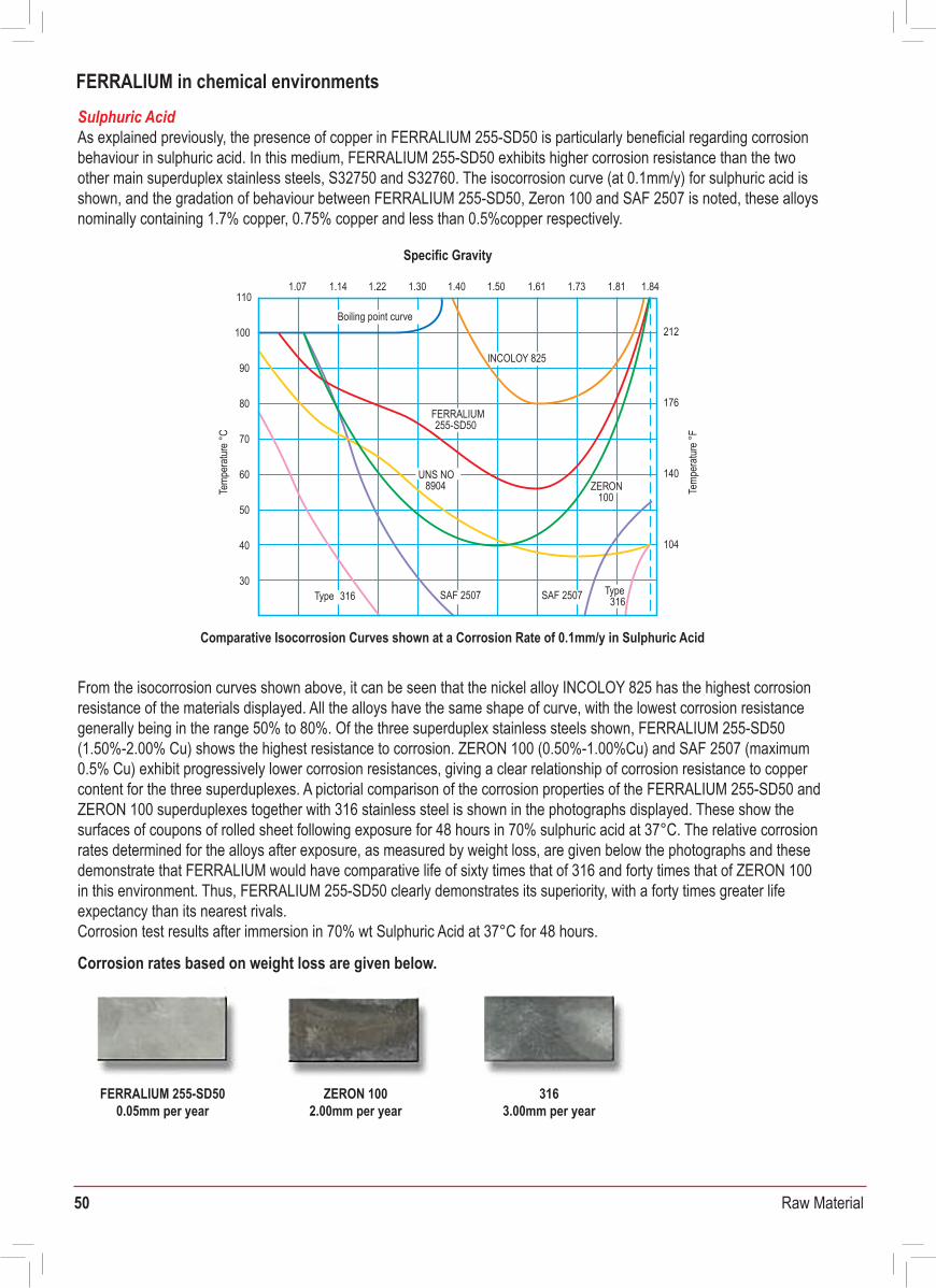
50 Raw Material
Isocorrosion Curves for FERRALIUM 255-SD50 in Phosphoric Acid shown at Corrosion Rates of 0.13mm/y, 0.51 mm/y, 1.3 mm/y and 5.1mm/y.
Isocorrosion Curve for FERRALIUM 255-SD50 in Nitric Acid shown at a Corrosion Rate of 0.13mm/y.
Sulphuric AcidAs explained previously, the presence of copper in FERRALIUM 255-SD50 is particularly beneficial regarding corrosion behaviour in sulphuric acid. In this medium, FERRALIUM 255-SD50 exhibits higher corrosion resistance than the two other main superduplex stainless steels, S32750 and S32760. The isocorrosion curve (at 0.1mm/y) for sulphuric acid is shown, and the gradation of behaviour between FERRALIUM 255-SD50, Zeron 100 and SAF 2507 is noted, these alloys nominally containing 1.7% copper, 0.75% copper and less than 0.5%copper respectively.
From the isocorrosion curves shown above, it can be seen that the nickel alloy INCOLOY 825 has the highest corrosion resistance of the materials displayed. All the alloys have the same shape of curve, with the lowest corrosion resistance generally being in the range 50% to 80%. Of the three superduplex stainless steels shown, FERRALIUM 255-SD50 (1.50%-2.00% Cu) shows the highest resistance to corrosion. ZERON 100 (0.50%-1.00%Cu) and SAF 2507 (maximum 0.5% Cu) exhibit progressively lower corrosion resistances, giving a clear relationship of corrosion resistance to copper content for the three superduplexes. A pictorial comparison of the corrosion properties of the FERRALIUM 255-SD50 and ZERON 100 superduplexes together with 316 stainless steel is shown in the photographs displayed. These show the surfaces of coupons of rolled sheet following exposure for 48 hours in 70% sulphuric acid at 37°C. The relative corrosion rates determined for the alloys after exposure, as measured by weight loss, are given below the photographs and these demonstrate that FERRALIUM would have comparative life of sixty times that of 316 and forty times that of ZERON 100 in this environment. Thus, FERRALIUM 255-SD50 clearly demonstrates its superiority, with a forty times greater life expectancy than its nearest rivals.Corrosion test results after immersion in 70% wt Sulphuric Acid at 37°C for 48 hours.
Corrosion rates based on weight loss are given below.
Phosphoric AcidAlthough 316 stainless steels are generally resistant to pure phosphoric acid in all concentrations at temperatures up to around 80°C, FERRALIUM 255-SD50 alloy shows marked superiority and is generally suitable for handling the boiling acid up to 60% concentration. For higher concentrations of phosphoric acid, there would be an operating temperature limit of 110°C. The iso-corrosion curve for FERRALIUM 255-SD50 is given below.
Nitric AcidThe iso-corrosion curve for FERRALIUM 255-SD50 in nitric acid is shown below, demonstrating that the material is resistant to corrosion in this environment over a wide range of concentrations. Thus, FERRALIUM 255-SD50 is commonly used for handling nitric acid and the alloy successfully resists a wide range of acid mixtures such as sulphuric/nitric, phosphoric/nitric and nitric/adipic.
Chemical Plant Life/Cost AssessmentChemical plant life/cost assessment can be carried out on a basis which recognises that nickel alloys are more long-lasting in sulphuric acid but with the consideration that this gain is made at an added cost which represents a 2-3 times increase in material costs , the increased expense of using INCOLOY 825 is only justified if it represents a doubling in the life of the plant.
FERRALIUM 255-SD50 shows outstanding resistance to commercial phosphoric acid containing impurities such as fluorides, chlorides and sulphuric acid (see corrosion resistance guide). This, combined with its excellent resistance to abrasion and erosion from the high gypsum solids content, renders FERRALIUM 255-SD50 of special interest for pumps, valves, agitators and other critical components in the production of fertilizer grade acid by the 'wet' process. The alloy continues to perform well in this processing environment and under other extremely demanding service conditions around the world. FERRALIUM 255-SD50 has often replaced the more costly nickel base alloys and provided economic service when considering life/cost assessment.
150°C
100°C
50°C
20 800 10 30 40 50 60 70
Boiling point curve
5.1
1.3 0.51 0.13
302°F
212°F
122°F
50°C
0
100°C
10 50 6020 30 40 70
curveBoiling point
0.13212°F
122°F
FERRALIUM in chemical environments
110
100
90
80
70
60
50
40
30
Temp
eratu
re °C
Boiling point curve
INCOLOY 825
FERRALIUM255-SD50
Type 316
UNS NO8904
SAF 2507
ZERON100
212
176
140
104
1.07 1.14 1.22 1.30 1.40
Temp
eratu
re °F
1.50 1.61 1.73 1.81 1.84
Type316SAF 2507
Specific Gravity
Concentration wt%
Comparative Isocorrosion Curves shown at a Corrosion Rate of 0.1mm/y in Sulphuric Acid
FERRALIUM 255-SD500.05mm per year
ZERON 1002.00mm per year
3163.00mm per year
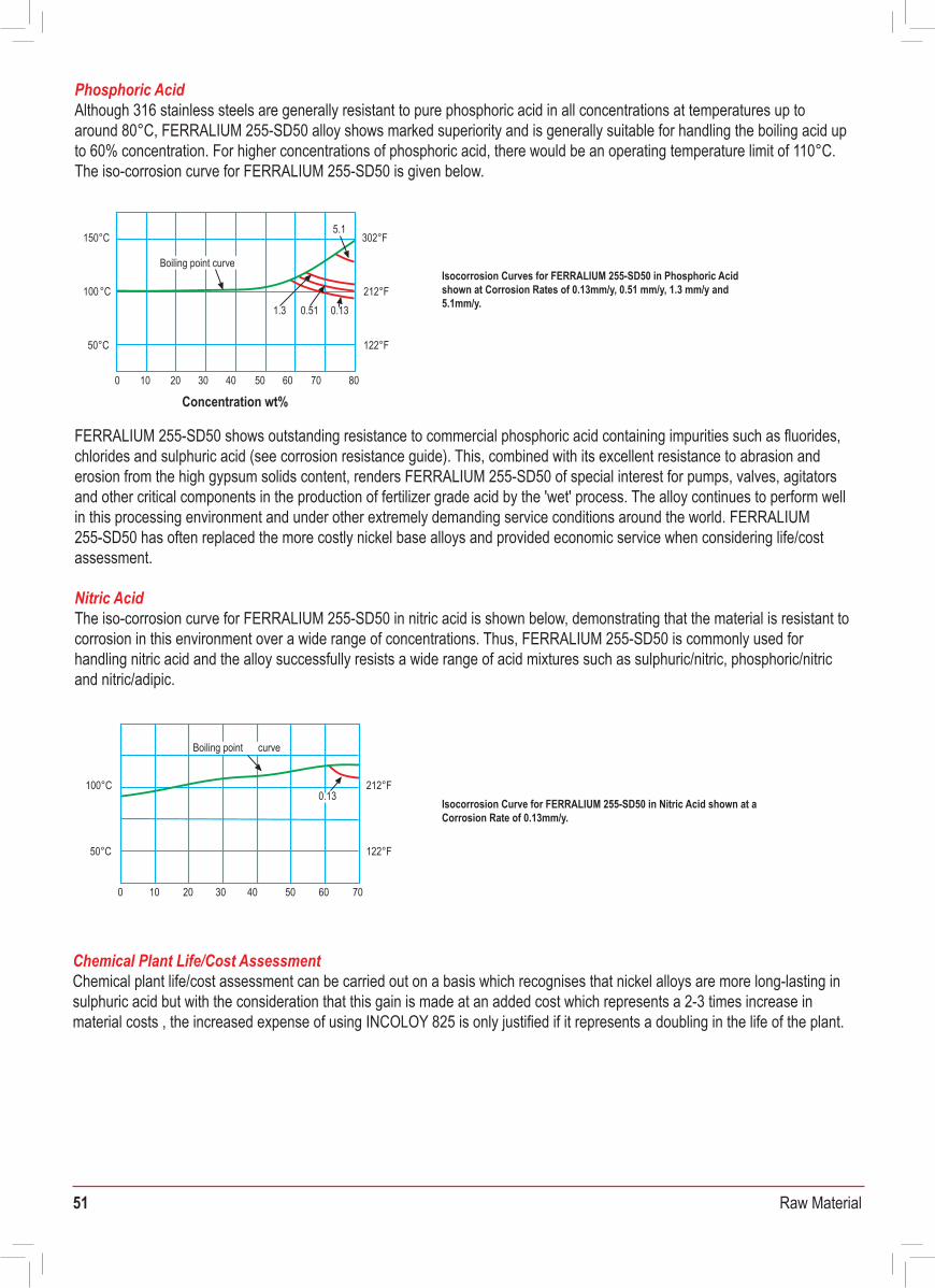
51 Raw Material
Isocorrosion Curves for FERRALIUM 255-SD50 in Phosphoric Acid shown at Corrosion Rates of 0.13mm/y, 0.51 mm/y, 1.3 mm/y and 5.1mm/y.
Isocorrosion Curve for FERRALIUM 255-SD50 in Nitric Acid shown at a Corrosion Rate of 0.13mm/y.
Sulphuric AcidAs explained previously, the presence of copper in FERRALIUM 255-SD50 is particularly beneficial regarding corrosion behaviour in sulphuric acid. In this medium, FERRALIUM 255-SD50 exhibits higher corrosion resistance than the two other main superduplex stainless steels, S32750 and S32760. The isocorrosion curve (at 0.1mm/y) for sulphuric acid is shown, and the gradation of behaviour between FERRALIUM 255-SD50, Zeron 100 and SAF 2507 is noted, these alloys nominally containing 1.7% copper, 0.75% copper and less than 0.5%copper respectively.
From the isocorrosion curves shown above, it can be seen that the nickel alloy INCOLOY 825 has the highest corrosion resistance of the materials displayed. All the alloys have the same shape of curve, with the lowest corrosion resistance generally being in the range 50% to 80%. Of the three superduplex stainless steels shown, FERRALIUM 255-SD50 (1.50%-2.00% Cu) shows the highest resistance to corrosion. ZERON 100 (0.50%-1.00%Cu) and SAF 2507 (maximum 0.5% Cu) exhibit progressively lower corrosion resistances, giving a clear relationship of corrosion resistance to copper content for the three superduplexes. A pictorial comparison of the corrosion properties of the FERRALIUM 255-SD50 and ZERON 100 superduplexes together with 316 stainless steel is shown in the photographs displayed. These show the surfaces of coupons of rolled sheet following exposure for 48 hours in 70% sulphuric acid at 37°C. The relative corrosion rates determined for the alloys after exposure, as measured by weight loss, are given below the photographs and these demonstrate that FERRALIUM would have comparative life of sixty times that of 316 and forty times that of ZERON 100 in this environment. Thus, FERRALIUM 255-SD50 clearly demonstrates its superiority, with a forty times greater life expectancy than its nearest rivals.Corrosion test results after immersion in 70% wt Sulphuric Acid at 37°C for 48 hours.
Corrosion rates based on weight loss are given below.
Phosphoric AcidAlthough 316 stainless steels are generally resistant to pure phosphoric acid in all concentrations at temperatures up to around 80°C, FERRALIUM 255-SD50 alloy shows marked superiority and is generally suitable for handling the boiling acid up to 60% concentration. For higher concentrations of phosphoric acid, there would be an operating temperature limit of 110°C. The iso-corrosion curve for FERRALIUM 255-SD50 is given below.
Nitric AcidThe iso-corrosion curve for FERRALIUM 255-SD50 in nitric acid is shown below, demonstrating that the material is resistant to corrosion in this environment over a wide range of concentrations. Thus, FERRALIUM 255-SD50 is commonly used for handling nitric acid and the alloy successfully resists a wide range of acid mixtures such as sulphuric/nitric, phosphoric/nitric and nitric/adipic.
Chemical Plant Life/Cost AssessmentChemical plant life/cost assessment can be carried out on a basis which recognises that nickel alloys are more long-lasting in sulphuric acid but with the consideration that this gain is made at an added cost which represents a 2-3 times increase in material costs , the increased expense of using INCOLOY 825 is only justified if it represents a doubling in the life of the plant.
FERRALIUM 255-SD50 shows outstanding resistance to commercial phosphoric acid containing impurities such as fluorides, chlorides and sulphuric acid (see corrosion resistance guide). This, combined with its excellent resistance to abrasion and erosion from the high gypsum solids content, renders FERRALIUM 255-SD50 of special interest for pumps, valves, agitators and other critical components in the production of fertilizer grade acid by the 'wet' process. The alloy continues to perform well in this processing environment and under other extremely demanding service conditions around the world. FERRALIUM 255-SD50 has often replaced the more costly nickel base alloys and provided economic service when considering life/costassessment.
150°C
100°C
50°C
20 800 10 30 40 50 60 70
Boiling point curve
5.1
1.3 0.51 0.13
302°F
212°F
122°F
50°C
0
100°C
10 50 6020 30 40 70
curveBoiling point
0.13212°F
122°F
FERRALIUM in chemical environments
110
100
90
80
70
60
50
40
30
Temp
eratu
re °C
Boiling point curve
INCOLOY 825
FERRALIUM255-SD50
Type 316
UNS NO8904
SAF 2507
ZERON100
212
176
140
104
1.07 1.14 1.22 1.30 1.40
Temp
eratu
re °F
1.50 1.61 1.73 1.81 1.84
Type316SAF 2507
Specific Gravity
Concentration wt%
Comparative Isocorrosion Curves shown at a Corrosion Rate of 0.1mm/y in Sulphuric Acid
FERRALIUM 255-SD500.05mm per year
ZERON 1002.00mm per year
3163.00mm per year
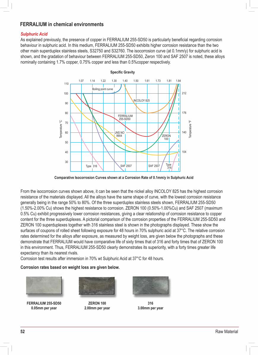
52 Raw Material
Isocorrosion Curves for FERRALIUM 255-SD50 in Phosphoric Acid shown at Corrosion Rates of 0.13mm/y, 0.51 mm/y, 1.3 mm/y and 5.1mm/y.
Isocorrosion Curve for FERRALIUM 255-SD50 in Nitric Acid shown at a Corrosion Rate of 0.13mm/y.
Sulphuric AcidAs explained previously, the presence of copper in FERRALIUM 255-SD50 is particularly beneficial regarding corrosion behaviour in sulphuric acid. In this medium, FERRALIUM 255-SD50 exhibits higher corrosion resistance than the two other main superduplex stainless steels, S32750 and S32760. The isocorrosion curve (at 0.1mm/y) for sulphuric acid is shown, and the gradation of behaviour between FERRALIUM 255-SD50, Zeron 100 and SAF 2507 is noted, these alloys nominally containing 1.7% copper, 0.75% copper and less than 0.5%copper respectively.
From the isocorrosion curves shown above, it can be seen that the nickel alloy INCOLOY 825 has the highest corrosion resistance of the materials displayed. All the alloys have the same shape of curve, with the lowest corrosion resistance generally being in the range 50% to 80%. Of the three superduplex stainless steels shown, FERRALIUM 255-SD50 (1.50%-2.00% Cu) shows the highest resistance to corrosion. ZERON 100 (0.50%-1.00%Cu) and SAF 2507 (maximum 0.5% Cu) exhibit progressively lower corrosion resistances, giving a clear relationship of corrosion resistance to copper content for the three superduplexes. A pictorial comparison of the corrosion properties of the FERRALIUM 255-SD50 and ZERON 100 superduplexes together with 316 stainless steel is shown in the photographs displayed. These show the surfaces of coupons of rolled sheet following exposure for 48 hours in 70% sulphuric acid at 37°C. The relative corrosion rates determined for the alloys after exposure, as measured by weight loss, are given below the photographs and these demonstrate that FERRALIUM would have comparative life of sixty times that of 316 and forty times that of ZERON 100 in this environment. Thus, FERRALIUM 255-SD50 clearly demonstrates its superiority, with a forty times greater life expectancy than its nearest rivals.Corrosion test results after immersion in 70% wt Sulphuric Acid at 37°C for 48 hours.
Corrosion rates based on weight loss are given below.
Phosphoric AcidAlthough 316 stainless steels are generally resistant to pure phosphoric acid in all concentrations at temperatures up to around 80°C, FERRALIUM 255-SD50 alloy shows marked superiority and is generally suitable for handling the boiling acid up to 60% concentration. For higher concentrations of phosphoric acid, there would be an operating temperature limit of 110°C. The iso-corrosion curve for FERRALIUM 255-SD50 is given below.
Nitric AcidThe iso-corrosion curve for FERRALIUM 255-SD50 in nitric acid is shown below, demonstrating that the material is resistant to corrosion in this environment over a wide range of concentrations. Thus, FERRALIUM 255-SD50 is commonly used for handling nitric acid and the alloy successfully resists a wide range of acid mixtures such as sulphuric/nitric, phosphoric/nitric and nitric/adipic.
Chemical Plant Life/Cost AssessmentChemical plant life/cost assessment can be carried out on a basis which recognises that nickel alloys are more long-lasting in sulphuric acid but with the consideration that this gain is made at an added cost which represents a 2-3 times increase in material costs , the increased expense of using INCOLOY 825 is only justified if it represents a doubling in the life of the plant.
FERRALIUM 255-SD50 shows outstanding resistance to commercial phosphoric acid containing impurities such as fluorides, chlorides and sulphuric acid (see corrosion resistance guide). This, combined with its excellent resistance to abrasion and erosion from the high gypsum solids content, renders FERRALIUM 255-SD50 of special interest for pumps, valves, agitators and other critical components in the production of fertilizer grade acid by the 'wet' process. The alloy continues to perform well in this processing environment and under other extremely demanding service conditions around the world. FERRALIUM 255-SD50 has often replaced the more costly nickel base alloys and provided economic service when considering life/cost assessment.
150°C
100°C
50°C
20 800 10 30 40 50 60 70
Boiling point curve
5.1
1.3 0.51 0.13
302°F
212°F
122°F
50°C
0
100°C
10 50 6020 30 40 70
curveBoiling point
0.13212°F
122°F
FERRALIUM in chemical environments
110
100
90
80
70
60
50
40
30
Temp
eratu
re °C
Boiling point curve
INCOLOY 825
FERRALIUM255-SD50
Type 316
UNS NO8904
SAF 2507
ZERON100
212
176
140
104
1.07 1.14 1.22 1.30 1.40
Temp
eratu
re °F
1.50 1.61 1.73 1.81 1.84
Type316SAF 2507
Specific Gravity
Concentration wt%
Comparative Isocorrosion Curves shown at a Corrosion Rate of 0.1mm/y in Sulphuric Acid
FERRALIUM 255-SD500.05mm per year
ZERON 1002.00mm per year
3163.00mm per year
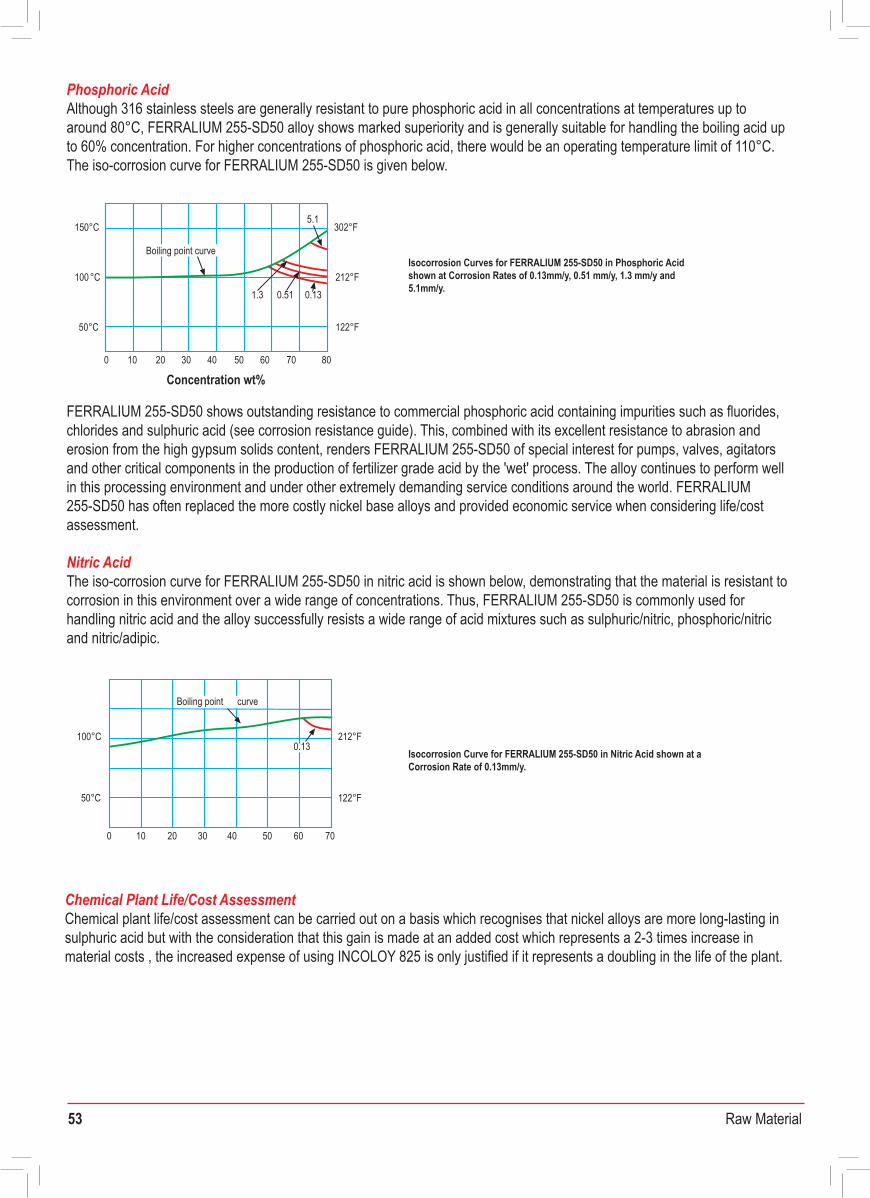
53 Raw Material
Isocorrosion Curves for FERRALIUM 255-SD50 in Phosphoric Acid shown at Corrosion Rates of 0.13mm/y, 0.51 mm/y, 1.3 mm/y and 5.1mm/y.
Isocorrosion Curve for FERRALIUM 255-SD50 in Nitric Acid shown at a Corrosion Rate of 0.13mm/y.
Sulphuric AcidAs explained previously, the presence of copper in FERRALIUM 255-SD50 is particularly beneficial regarding corrosion behaviour in sulphuric acid. In this medium, FERRALIUM 255-SD50 exhibits higher corrosion resistance than the two other main superduplex stainless steels, S32750 and S32760. The isocorrosion curve (at 0.1mm/y) for sulphuric acid is shown, and the gradation of behaviour between FERRALIUM 255-SD50, Zeron 100 and SAF 2507 is noted, these alloys nominally containing 1.7% copper, 0.75% copper and less than 0.5%copper respectively.
From the isocorrosion curves shown above, it can be seen that the nickel alloy INCOLOY 825 has the highest corrosion resistance of the materials displayed. All the alloys have the same shape of curve, with the lowest corrosion resistance generally being in the range 50% to 80%. Of the three superduplex stainless steels shown, FERRALIUM 255-SD50 (1.50%-2.00% Cu) shows the highest resistance to corrosion. ZERON 100 (0.50%-1.00%Cu) and SAF 2507 (maximum 0.5% Cu) exhibit progressively lower corrosion resistances, giving a clear relationship of corrosion resistance to copper content for the three superduplexes. A pictorial comparison of the corrosion properties of the FERRALIUM 255-SD50 and ZERON 100 superduplexes together with 316 stainless steel is shown in the photographs displayed. These show the surfaces of coupons of rolled sheet following exposure for 48 hours in 70% sulphuric acid at 37°C. The relative corrosion rates determined for the alloys after exposure, as measured by weight loss, are given below the photographs and these demonstrate that FERRALIUM would have comparative life of sixty times that of 316 and forty times that of ZERON 100 in this environment. Thus, FERRALIUM 255-SD50 clearly demonstrates its superiority, with a forty times greater life expectancy than its nearest rivals.Corrosion test results after immersion in 70% wt Sulphuric Acid at 37°C for 48 hours.
Corrosion rates based on weight loss are given below.
Phosphoric AcidAlthough 316 stainless steels are generally resistant to pure phosphoric acid in all concentrations at temperatures up to around 80°C, FERRALIUM 255-SD50 alloy shows marked superiority and is generally suitable for handling the boiling acid up to 60% concentration. For higher concentrations of phosphoric acid, there would be an operating temperature limit of 110°C. The iso-corrosion curve for FERRALIUM 255-SD50 is given below.
Nitric AcidThe iso-corrosion curve for FERRALIUM 255-SD50 in nitric acid is shown below, demonstrating that the material is resistant to corrosion in this environment over a wide range of concentrations. Thus, FERRALIUM 255-SD50 is commonly used for handling nitric acid and the alloy successfully resists a wide range of acid mixtures such as sulphuric/nitric, phosphoric/nitric and nitric/adipic.
Chemical Plant Life/Cost AssessmentChemical plant life/cost assessment can be carried out on a basis which recognises that nickel alloys are more long-lasting in sulphuric acid but with the consideration that this gain is made at an added cost which represents a 2-3 times increase in material costs , the increased expense of using INCOLOY 825 is only justified if it represents a doubling in the life of the plant.
FERRALIUM 255-SD50 shows outstanding resistance to commercial phosphoric acid containing impurities such as fluorides, chlorides and sulphuric acid (see corrosion resistance guide). This, combined with its excellent resistance to abrasion and erosion from the high gypsum solids content, renders FERRALIUM 255-SD50 of special interest for pumps, valves, agitators and other critical components in the production of fertilizer grade acid by the 'wet' process. The alloy continues to perform well in this processing environment and under other extremely demanding service conditions around the world. FERRALIUM 255-SD50 has often replaced the more costly nickel base alloys and provided economic service when considering life/costassessment.
150°C
100°C
50°C
20 800 10 30 40 50 60 70
Boiling point curve
5.1
1.3 0.51 0.13
302°F
212°F
122°F
50°C
0
100°C
10 50 6020 30 40 70
curveBoiling point
0.13212°F
122°F
FERRALIUM in chemical environments
110
100
90
80
70
60
50
40
30
Temp
eratu
re °C
Boiling point curve
INCOLOY 825
FERRALIUM255-SD50
Type 316
UNS NO8904
SAF 2507
ZERON100
212
176
140
104
1.07 1.14 1.22 1.30 1.40
Temp
eratu
re °F
1.50 1.61 1.73 1.81 1.84
Type316SAF 2507
Specific Gravity
Concentration wt%
Comparative Isocorrosion Curves shown at a Corrosion Rate of 0.1mm/y in Sulphuric Acid
FERRALIUM 255-SD500.05mm per year
ZERON 1002.00mm per year
3163.00mm per year
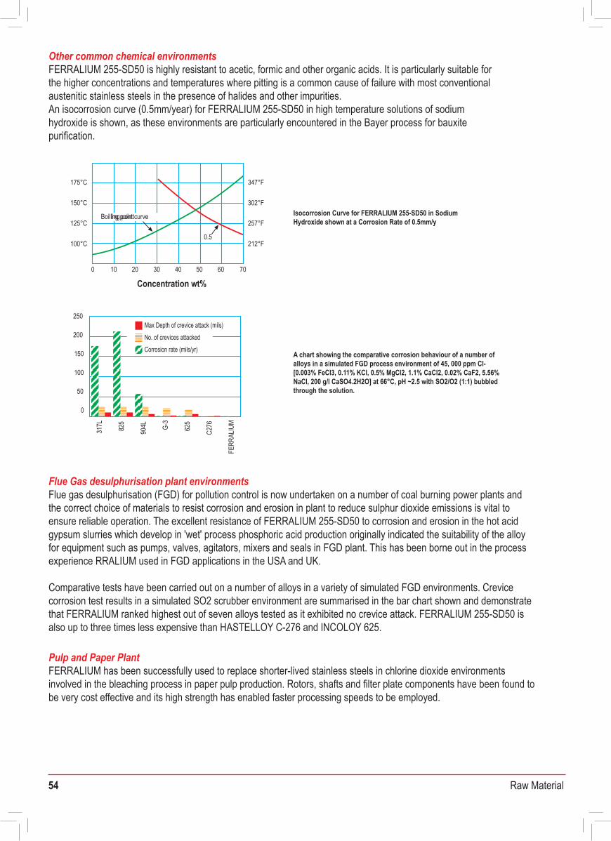
54 Raw Material
Isocorrosion Curve for FERRALIUM 255-SD50 in SodiumHydroxide shown at a Corrosion Rate of 0.5mm/y
A chart showing the comparative corrosion behaviour of a number of alloys in a simulated FGD process environment of 45, 000 ppm Cl- [0.003% FeCl3, 0.11% KCl, 0.5% MgCl2, 1.1% CaCl2, 0.02% CaF2, 5.56% NaCl, 200 g/l CaSO4.2H2O] at 66°C, pH ~2.5 with SO2/O2 (1:1) bubbled through the solution.
The table shows typical CPT values and demonstrates the superior corrosion characteristics for FERRALIUM 255-SD50. The mandatory determination of CPT for each batch of FERRALIUM 255-SD50 to ensure that it exceeds a temperature of 50°C gives confidence that the FERRALIUM manufacturing procedures are thoroughly under control.
U-Bend stress corrosion cracking tests have also been carried out on FERRALIUM 255-SD50 in a sulphide-containing acidic environment. This consisted of a solution of 70,000 ppm NaCl with 35% CO2 at 760 psi and 70 ppm sulphide. No cracking was observed to occur.
FERRALIUM has been tested by static loading in NACE TM -01-77 acidic sulphide solution at 20°C and 80°C and has been found to be not susceptible to sulphide stress corrosion cracking at 90%-100% of the 0.2% proof stress. FERRALIUM alloy in its standard solution treated and stress relieved condition meets the requirements of NACE MR-01-75 in that it has a hardness which is less than 28 HRC. Thus FERRALIUM is suitable for sour service applications.
Other common chemical environmentsFERRALIUM 255-SD50 is highly resistant to acetic, formic and other organic acids. It is particularly suitable forthe higher concentrations and temperatures where pitting is a common cause of failure with most conventionalaustenitic stainless steels in the presence of halides and other impurities.An isocorrosion curve (0.5mm/year) for FERRALIUM 255-SD50 in high temperature solutions of sodiumhydroxide is shown, as these environments are particularly encountered in the Bayer process for bauxitepurification.
Flue Gas desulphurisation plant environmentsFlue gas desulphurisation (FGD) for pollution control is now undertaken on a number of coal burning power plants and the correct choice of materials to resist corrosion and erosion in plant to reduce sulphur dioxide emissions is vital to ensure reliable operation. The excellent resistance of FERRALIUM 255-SD50 to corrosion and erosion in the hot acid gypsum slurries which develop in 'wet' process phosphoric acid production originally indicated the suitability of the alloy for equipment such as pumps, valves, agitators, mixers and seals in FGD plant. This has been borne out in the process experience RRALIUM used in FGD applications in the USA and UK.
Comparative tests have been carried out on a number of alloys in a variety of simulated FGD environments. Crevice corrosion test results in a simulated SO2 scrubber environment are summarised in the bar chart shown and demonstrate that FERRALIUM ranked highest out of seven alloys tested as it exhibited no crevice attack. FERRALIUM 255-SD50 is also up to three times less expensive than HASTELLOY C-276 and INCOLOY 625.
Pulp and Paper PlantFERRALIUM has been successfully used to replace shorter-lived stainless steels in chlorine dioxide environments involved in the bleaching process in paper pulp production. Rotors, shafts and filter plate components have been found to be very cost effective and its high strength has enabled faster processing speeds to be employed.
175°C
150°C
125°C
0
100°C
10 20 30 40 50 60 70
ling point Boiling point curve
0.5
347°F
302°F
257°F
212°F
FERRALIUM 255-SD50 - pitting resistance evaluationAssessment of resistance to pitting is often made by use of a pitting resistance equivalent number (PREN) which is a function of the chromium, molybdenum and nitrogen content of the alloy. Calculation is made on the basis of the following, using weight %:
PREN = % Cr + 3.3x% Mo + 16x% N
However, it must be appreciated that the PREN is not an absolute measure of pitting resistance as it can only give an indication of the potential corrosion properties of superduplex stainless steel. The PREN does not take into account the metallurgical state of the material after manufacture and the possible presence of deleterious phases which would promote corrosion. Also, it is also somewhat incongruous to use a single PREN for superduplex, as this material consists of two phases with different chemical compositions.
A more realistic evaluation of corrosion resistance can be made using the Critical Pitting Temperature (CPT), defined as the maximum temperature attainable without detectable weight loss or evidence of pitting corrosion when a stainless steel is exposed to 6% ferric chloride solution. CPT is determined through the use of the standard corrosion test ASTM G48 Method A. As this test is designed to be carried out on a sample taken from the final product, it gives a definitive assessment of the material’s ability to resist pitting.
FERRALIUM - Intercrystalline corrosion & stressCorrosion propertiesHigh chromium stainless steels do not normally suffer from intercrystalline corrosion. In austenitic steels, intergranular corrosion attack can occur as a result of chromium denudation along a continuous grain boundary network, due to the precipitation of carbides. The low impurity content and dual phase structure of FERRALIUM, with its network of austenite within a ferrite matrix, allows a proportion of chromium to be present in the austenite. This is able to act to prevent severe chromium denudation at the grain boundaries and thus mitigates against intergranular corrosion.
U-bend test results (30-day exposure) comparing 316 stainless steel with FERRALIUM 255-SD50 are given in the accompanying table
CPTStainless Steel
50°CFERRALIUM SD-50
20°CUNS S31803
20°CCN-7M modified (4.5 Mo)
0°C316 stainless steel
Media Exposure 316 Temperature FERRALIUM(°C)time (days) Stainless Steel 255-SD50
30 80 PittingASTM Synthetic Seawater No pitting or cracking
30 1410.8%NaCl + 0.5% Oxalic acid No cracking No cracking
30 141 Cracking0.8%NaCl + 0.5% Acetic acid No cracking
30 141 Cracking0.8%NaCl + 0.5% Citric acid No cracking
30 100 Cracking0.1%NaCl + 0.05% FeCl3 No cracking
21 -25% NaCl 200 No cracking
10030% NaCl -Boiling No cracking
Concentration wt%
250
200
150
100
0
50
317L 825
904L G-
3
625
C276
FERR
ALIU
M
Max Depth of crevice attack (mils)No. of crevices attackedCorrosion rate (mils/yr)
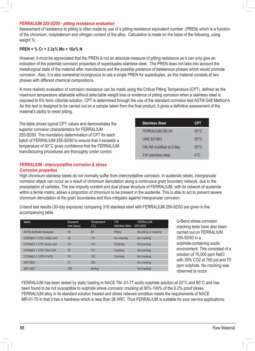
55 Raw Material
Isocorrosion Curve for FERRALIUM 255-SD50 in SodiumHydroxide shown at a Corrosion Rate of 0.5mm/y
A chart showing the comparative corrosion behaviour of a number of alloys in a simulated FGD process environment of 45, 000 ppm Cl- [0.003% FeCl3, 0.11% KCl, 0.5% MgCl2, 1.1% CaCl2, 0.02% CaF2, 5.56% NaCl, 200 g/l CaSO4.2H2O] at 66°C, pH ~2.5 with SO2/O2 (1:1) bubbled through the solution.
The table shows typical CPT values and demonstrates the superior corrosion characteristics for FERRALIUM 255-SD50. The mandatory determination of CPT for eachbatch of FERRALIUM 255-SD50 to ensure that it exceeds atemperature of 50°C gives confidence that the FERRALIUMmanufacturing procedures are thoroughly under control.
U-Bend stress corrosioncracking tests have also beencarried out on FERRALIUM255-SD50 in asulphide-containing acidic environment. This consisted of a solution of 70,000 ppm NaCl with 35% CO2 at 760 psi and 70 ppm sulphide. No cracking was observed to occur.
FERRALIUM has been tested by static loading in NACE TM -01-77 acidic sulphide solution at 20°C and 80°C and has been found to be not susceptible to sulphide stress corrosion cracking at 90%-100% of the 0.2% proof stress. FERRALIUM alloy in its standard solution treated and stress relieved condition meets the requirements of NACE MR-01-75 in that it has a hardness which is less than 28 HRC. Thus FERRALIUM is suitable for sour service applications.
Other common chemical environmentsFERRALIUM 255-SD50 is highly resistant to acetic, formic and other organic acids. It is particularly suitable forthe higher concentrations and temperatures where pitting is a common cause of failure with most conventionalaustenitic stainless steels in the presence of halides and other impurities.An isocorrosion curve (0.5mm/year) for FERRALIUM 255-SD50 in high temperature solutions of sodiumhydroxide is shown, as these environments are particularly encountered in the Bayer process for bauxitepurification.
Flue Gas desulphurisation plant environmentsFlue gas desulphurisation (FGD) for pollution control is now undertaken on a number of coal burning power plants and the correct choice of materials to resist corrosion and erosion in plant to reduce sulphur dioxide emissions is vital to ensure reliable operation. The excellent resistance of FERRALIUM 255-SD50 to corrosion and erosion in the hot acid gypsum slurries which develop in 'wet' process phosphoric acid production originally indicated the suitability of the alloy for equipment such as pumps, valves, agitators, mixers and seals in FGD plant. This has been borne out in the process experience RRALIUM used in FGD applications in the USA and UK.
Comparative tests have been carried out on a number of alloys in a variety of simulated FGD environments. Crevice corrosion test results in a simulated SO2 scrubber environment are summarised in the bar chart shown and demonstrate that FERRALIUM ranked highest out of seven alloys tested as it exhibited no crevice attack. FERRALIUM 255-SD50 is also up to three times less expensive than HASTELLOY C-276 and INCOLOY 625.
Pulp and Paper PlantFERRALIUM has been successfully used to replace shorter-lived stainless steels in chlorine dioxide environments involved in the bleaching process in paper pulp production. Rotors, shafts and filter plate components have been found to be very cost effective and its high strength has enabled faster processing speeds to be employed.
175°C
150°C
125°C
0
100°C
10 20 30 40 50 60 70
ling point Boiling point curve
0.5
347°F
302°F
257°F
212°F
FERRALIUM 255-SD50 - pitting resistance evaluationAssessment of resistance to pitting is often made by use of a pitting resistance equivalent number (PREN) which is a function of the chromium, molybdenum and nitrogen content of the alloy. Calculation is made on the basis of the following, using weight %:
PREN = % Cr + 3.3x% Mo + 16x% N
However, it must be appreciated that the PREN is not an absolute measure of pitting resistance as it can only give an indication of the potential corrosion properties of superduplex stainless steel. The PREN does not take into account the metallurgical state of the material after manufacture and the possible presence of deleterious phases which would promote corrosion. Also, it is also somewhat incongruous to use a single PREN for superduplex, as this material consists of two phases with different chemical compositions.
A more realistic evaluation of corrosion resistance can be made using the Critical Pitting Temperature (CPT), defined as the maximum temperature attainable without detectable weight loss or evidence of pitting corrosion when a stainless steel is exposed to 6% ferric chloride solution. CPT is determined through the use of the standard corrosion test ASTM G48 Method A. As this test is designed to be carried out on a sample taken from the final product, it gives a definitive assessment of the material’s ability to resist pitting.
FERRALIUM - Intercrystalline corrosion & stressCorrosion propertiesHigh chromium stainless steels do not normally suffer from intercrystalline corrosion. In austenitic steels, intergranular corrosion attack can occur as a result of chromium denudation along a continuous grain boundary network, due to the precipitation of carbides. The low impurity content and dual phase structure of FERRALIUM, with its network of austenite within a ferrite matrix, allows a proportion of chromium to be present in the austenite. This is able to act to prevent severe chromium denudation at the grain boundaries and thus mitigates against intergranular corrosion.
U-bend test results (30-day exposure) comparing 316 stainless steel with FERRALIUM 255-SD50 are given in theaccompanying table
CPTStainless Steel
50°CFERRALIUM SD-50
20°CUNS S31803
20°CCN-7M modified (4.5 Mo)
0°C316 stainless steel
Media Exposure 316 Temperature FERRALIUM(°C)time (days) Stainless Steel 255-SD50
30 80 PittingASTM Synthetic Seawater No pitting or cracking
30 1410.8%NaCl + 0.5% Oxalic acid No cracking No cracking
30 141 Cracking0.8%NaCl + 0.5% Acetic acid No cracking
30 141 Cracking0.8%NaCl + 0.5% Citric acid No cracking
30 100 Cracking0.1%NaCl + 0.05% FeCl3 No cracking
21 -25% NaCl 200 No cracking
10030% NaCl -Boiling No cracking
Concentration wt%
250
200
150
100
0
50
317L 825
904L G-
3
625
C276
FERR
ALIU
M
Max Depth of crevice attack (mils)No. of crevices attackedCorrosion rate (mils/yr)
56 Raw Material
WeldingAll product forms of FERRALIUM 255-SD50 can be easily welded, and this includes welding FERRALIUM to other stainless steels. Welding can be carried out by all the usual methods although oxy-acetylene welding and electron beam welding have been found to be not suitable. As a result of FERRALIUM 255-SD50’s welding versatility, the designer is provided with full scope to incorporate both castings and wrought forms into a single assembly. It should be emphasised that only genuine FERRALIUM 255 electrodes and filler wire should be used, so as to ensure sound welds and a satisfactory weldment in respect of mechanical strength, ductility and corrosion resistance.
FERRALIUM 255-SD50 alloy is normally supplied in the solution treated and stress relieved condition, which is ideal for welding. Welds in light sections and minor repair welds do not generally require post-weld heat treatment but heavy section welds should be given a solution heat treatment after welding to ensure maximum corrosion resistance and ductility.
A detailed welding information document is available upon request - please discuss any specific welding details required with our Technical Department. FERRALIUM 255-SD50 alloy can be welded to carbon steel, austenitic stainless steels and other metal based alloys using suitable welding consumables.
Heat TreatmentThe solution heat treatment process for FERRALIUM 255-SD50 is carried out at 1070°C (+/-10°C) and this must be followed by a rapid quench, preferably in water. Lack of temperature variation during heat treatment is essential and adequate time must be allowed so as to ensure that the section is fully soaked throughout at temperature. Quenching must be carried out immediately on removal from the furnace, with the minimum of cooling in air during transfer to the quench tank.
A stress relief heat treatment, when required, should be carried out by heating to 350°C and holding for 2 hours at temperature followed by air cool. Heating should be carried out in an air circulating furnace to ensure uniformity of temperature. Depending upon the nature of the component, the extent of machining and the tolerances required, this treatment may be carried out at one or more stages of the machining cycle.
Machining and Cutting FERRALIUM 255-SD50 alloy can be readily machined and it has been found that its machinability is superior to other superduplex stainless steels, for instance, ZERON 100 (UNS S32760). Although FERRALIUM 255-SD50 is considerably harder than the austenitic stainless steels, the same techniques can generally be used, and carbide tipped tools are recommended. A detailed machining information document is available upon request.
In common with many stainless steels and high strength materials, heavy machining on FERRALIUM 255-SD50 can set up superficial internal stress and can sometimes result in slight movement during subsequent operations. This may be accentuated by surface work hardening if blunt tools are used. Whilst this movement is not significant in most cases, components requiring specially close tolerances which have been subject to heaving machining should be given a stress relief heat treatment at 350°C.
FormingHot forming can be carried out between 1150°C and 1000°C. At temperatures below 1000°C (primarily in the range 800°C to 950°C) embrittlement takes place due to intermetallic phase precipitation, thus a solution heat treatment at 1070°C followed by rapid water quenching must be carried out after hot forming.For cold forming, when the deformation required is above 10%, a solution heat treatment at 1070°C followed by water quenching should be carried out after the forming process. For deformations higher than 20%, intermediate solution heat treatment stages at 1070°C (with water quenching) need to be carried out after the accomplishment of 20% deformation, 40% deformation and 60% deformation, as appropriate.
After any hot forging operation, such as the production of hot-headed fasteners, it must be emphasised that a solution heat treatment at 1070°C followed by a rapid water quench must be carried out after the hot forming process. Insufficiently rapid quenching from the hot heading temperature will cause the formation of deleterious phases which will markedly reduce the corrosion resistance.
The figures quoted in this publication do not constitute a specification for any specific contract. It should be noted that continuing research and development may lead to the modification of certain values.
FERRALIUM 255-SD50 - Fabrication
57 Raw Material
WeldingAll product forms of FERRALIUM 255-SD50 can be easily welded, and this includes welding FERRALIUM to other stainless steels. Welding can be carried out by all the usual methods although oxy-acetylene welding and electron beam welding have been found to be not suitable. As a result of FERRALIUM 255-SD50’s welding versatility, the designer is provided with full scope to incorporate both castings and wrought forms into a single assembly. It should be emphasised that only genuine FERRALIUM 255 electrodes and filler wire should be used, so as to ensure sound welds and a satisfactory weldment in respect of mechanical strength, ductility and corrosion resistance.
FERRALIUM 255-SD50 alloy is normally supplied in the solution treated and stress relieved condition, which is ideal for welding. Welds in light sections and minor repair welds do not generally require post-weld heat treatment but heavy section welds should be given a solution heat treatment after welding to ensure maximum corrosion resistance and ductility.
A detailed welding information document is available upon request - please discuss any specific welding details required with our Technical Department. FERRALIUM 255-SD50 alloy can be welded to carbon steel, austenitic stainless steels and other metal based alloys using suitable welding consumables.
Heat TreatmentThe solution heat treatment process for FERRALIUM 255-SD50 is carried out at 1070°C (+/-10°C) and this must be followed by a rapid quench, preferably in water. Lack of temperature variation during heat treatment is essential and adequate time must be allowed so as to ensure that the section is fully soaked throughout at temperature. Quenching must be carried out immediately on removal from the furnace, with the minimum of cooling in air during transfer to the quench tank.
A stress relief heat treatment, when required, should be carried out by heating to 350°C and holding for 2 hours at temperature followed by air cool. Heating should be carried out in an air circulating furnace to ensure uniformity of temperature. Depending upon the nature of the component, the extent of machining and the tolerances required, this treatment may be carried out at one or more stages of the machining cycle.
Machining and Cutting FERRALIUM 255-SD50 alloy can be readily machined and it has been found that its machinability is superior to other superduplex stainless steels, for instance, ZERON 100 (UNS S32760). Although FERRALIUM 255-SD50 is considerably harder than the austenitic stainless steels, the same techniques can generally be used, and carbide tipped tools are recommended. A detailed machining information document is available upon request.
In common with many stainless steels and high strength materials, heavy machining on FERRALIUM 255-SD50 can set up superficial internal stress and can sometimes result in slight movement during subsequent operations. This may be accentuated by surface work hardening if blunt tools are used. Whilst this movement is not significant in most cases, components requiring specially close tolerances which have been subject to heaving machining should be given a stress relief heat treatment at 350°C.
FormingHot forming can be carried out between 1150°C and 1000°C. At temperatures below 1000°C (primarily in the range 800°C to 950°C) embrittlement takes place due to intermetallic phase precipitation, thus a solution heat treatment at 1070°C followed by rapid water quenching must be carried out after hot forming.For cold forming, when the deformation required is above 10%, a solution heat treatment at 1070°C followed by water quenching should be carried out after the forming process. For deformations higher than 20%, intermediate solution heat treatment stages at 1070°C (with water quenching) need to be carried out after the accomplishment of 20% deformation, 40% deformation and 60% deformation, as appropriate.
After any hot forging operation, such as the production of hot-headed fasteners, it must be emphasised that a solution heat treatment at 1070°C followed by a rapid water quench must be carried out after the hot forming process. Insufficiently rapid quenching from the hot heading temperature will cause the formation of deleterious phases which will markedly reduce the corrosion resistance.
The figures quoted in this publication do not constitute a specification for any specific contract. It should be noted that continuing research and development may lead to the modification of certain values.
FERRALIUM 255-SD50 - Fabrication
58 Raw Material
FERRALIUM 255-SD50 - Applications Availability
Chemical Industry
Marine/Oil & Gas
Civil Engineering
Offshore Oil & Gas Marine
Equipment Processes
Mixers • PumpsReactor Vessals
CentrifugesValves
PipeworkDucting • Filters
Folding Tanks Evaporators
Heat ExchangersScrubbers
Sulphuric acid • Phosphoric acidTitanium Dioxide • Ammonia
Sodium Hydroxide • UreaMetal Solvent Extraction
Nitric Acid • NylonAcrylic • PolypropylenePVC • Petroleum ResinsPaper Pulp • FGD Plant
Copper SmeltingSugar Production
Equipment Applications
PumpsPump shaftsValve Bodies
ActuatorsValve Spindles
PipeworkSubsea Couplings
Bolting and FastenersCablesSeals
Seawater injectionSeawater lifting
Riser Protection SystemsChristmas Trees
Buoyancy ModulesTension Leg Monitoring
Riser Clamp Bolting • Bow PlanesAnchor Blocks & Cables
Heat Exchangers • Guide RailsPropellor Shafts
Applications Principal Examples
Support Structure • FastenersDynamic Roof Systems
Glass Facia Support Systems Roof Support Systems
US Statue of LibertyHong Kong Airport Main Building
Queen Sofia Museum, MadridLeisure Centres/Swimming Pool
Sullum Voe, Dalmeny, West Sole, Wytch Farm, N W Hutton, Forties, Sohio Alaska, Miller, Montrose, FoinavenNinian N, S & CHutton TLP, Heidrun, Victor, Viking, ValiantMurchisonRoughHewitt, Maureen, EkofiskTartan
Frigg
Beryl A & B, Statfjord A & BSaudi ArabiaAbu DhabiVenezulaSultanate of OmanAlgeriaVselefrikkRavenspurn North
Seawolf, Los Angeles Class Submarines, Aircraft Carrier launch systems
Vanguard & Trafalgar Class Submarines, Christchurch Bay Tower Project, Propellers for fast patrol boats
Chemical PlantTitanium Dioxide PlantAlcohol DistillationHypochlorite scrubbersCarbamate PlantCopper Smelting FansCentrifuge EquipmentFlue Gas DesulphurisationGibson Power Station, Indiana, USABig Rivers, Seebree, Kentucky, USADrax Power Station, UKPulp & PaperNorth American and Scandanavian paper companiesNuclearUSA and UK Nuclear processing plants
BP Amoco
ChevronConocoKerr Mcgee
British GasPhillipsTexacoTotalMobilAramcoAdcoMaracaiboPDOSonatrachStatoilHamilton
US Navy
Royal Navy
Hot Worked Products Products Size Range Availability LA Stock Availability
Unit Min Standard Bar Products Max Min Max
Diameter• Bar Standard grade 10 mm (.39”) 450 mm (17.5”) 12 mm (1/2”) 355 mm (14”)
Diameter• Bar FG-46 grade 10 mm (.39”) 50 mm (2”) 12 mm (1/2”) 50 mm (2”)
Diameter• Bar Aged grade 10 mm (.39”) 450 mm (17.5”) 25 mm (1”) 300 mm (12”)
Diameter 150 mm (6”)• Ground Reforging Bar 450 mm (17.5”) 150 mm (6”) 450 mm (17.5”)
Special Long ProductsProducts Size Range Availability
Min Dia Min Section Max Dia Max Section Max Length
• Extruded Section 300 mm (12”) 20mm (3/4”)
• Hot extruded tube 75 mm (3”) 215 mm (8.5”)
• Flat Bar 10 mm (.39”) 300 mm (12”)
• Square Section 10 mm (.39”) 450 mm (17.5”)
• Bored Bar 20 mm (3/4”) 4,000 mm (157”)
Plate & Sheet ProductsProducts Size Range Availability LA Stock Availability
Min Thickness Max Thickness Max Length Min Thickness Max Thickness Max Length
2 mm (.078”)• Hot Rolled Plate 100 mm (4”) 9,000 mm (354”) 2 mm (.078”) 90 mm (3.5”) 6,000 mm (236”)
• Cold Rolled Sheet 0.5 mm (.024”) 3 mm (.118”) 3,000 mm (118”) 0.5 mm (.024”) 3 mm (.118”) 2,000 mm (79”)
Forging capabilitiesProducts Size Range Availability
Max. Diameter Max. Section Max. Height Max. Length
1,525 mm (60”)• Hollow Forgings 1,525 mm (60”)
• Blocks 450 mm (17.5”) 450 mm (17.5”)
• Disks 2,286 mm (90”) 450 mm (17.5”)
• Shafts 450 mm (17.5”) 13,000 mm (512”)
• Rolled Ring 4,800 mm (190”) 450 mm (wall) (17.5”) 1,250 mm (Face) (50”)
Pipe and FittingsProducts Size Range Availability LA Stock Availability
Min Size Max Size. Schedule Availability
3 inch NB• Hot Extruded Pipe 8 inch NB Sch. 40 – XXS
• Cold Reduced Tube 3/8 inch NB 4 1/2 inch NB Sch. 5 – 80 1” – 6” Sch 10 – 80
• Welded tube 6 inch Ø 36 inch Ø
• Pipe Fittings
Welding Consumables
A Full Range of fittings available to Order
Products Size Range Availability LA Stock Availability
• MIG 0.8mm (.032”) 1.6mm (.064”) 1.00mm, 1.2mm
• TIG 1.2mm (.048”) 3.2mm (.128”) 1.6mm,2.4mm,3.2mm
1.6mm (.064”)• Submerged Arc 3.2mm (.128”) 3.2mm
2.4mm (.094”)• Coated Electrodes 4.0mm (.160”) 2.4mm,3.2mm,4.00mm
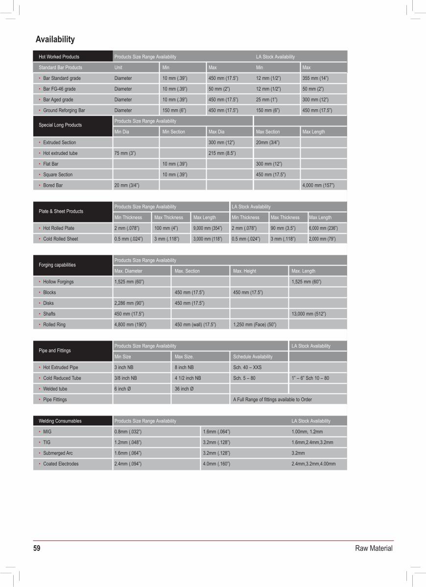
59 Raw Material
FERRALIUM 255-SD50 - Applications Availability
Chemical Industry
Marine/Oil & Gas
Civil Engineering
Offshore Oil & Gas Marine
Equipment Processes
Mixers • PumpsReactor Vessals
CentrifugesValves
PipeworkDucting • Filters
Folding Tanks Evaporators
Heat ExchangersScrubbers
Sulphuric acid • Phosphoric acidTitanium Dioxide • Ammonia
Sodium Hydroxide • UreaMetal Solvent Extraction
Nitric Acid • NylonAcrylic • PolypropylenePVC • Petroleum ResinsPaper Pulp • FGD Plant
Copper SmeltingSugar Production
Equipment Applications
PumpsPump shaftsValve Bodies
ActuatorsValve Spindles
PipeworkSubsea Couplings
Bolting and FastenersCablesSeals
Seawater injectionSeawater lifting
Riser Protection SystemsChristmas Trees
Buoyancy ModulesTension Leg Monitoring
Riser Clamp Bolting • Bow PlanesAnchor Blocks & Cables
Heat Exchangers • Guide RailsPropellor Shafts
Applications Principal Examples
Support Structure • FastenersDynamic Roof Systems
Glass Facia Support Systems Roof Support Systems
US Statue of LibertyHong Kong Airport Main Building
Queen Sofia Museum, MadridLeisure Centres/Swimming Pool
Sullum Voe, Dalmeny, West Sole, Wytch Farm, N W Hutton, Forties, Sohio Alaska, Miller, Montrose, FoinavenNinian N, S & CHutton TLP, Heidrun, Victor, Viking, ValiantMurchisonRoughHewitt, Maureen, EkofiskTartan
Frigg
Beryl A & B, Statfjord A & BSaudi ArabiaAbu DhabiVenezulaSultanate of OmanAlgeriaVselefrikkRavenspurn North
Seawolf, Los Angeles Class Submarines, Aircraft Carrier launch systems
Vanguard & Trafalgar Class Submarines, Christchurch Bay Tower Project, Propellers for fast patrol boats
Chemical PlantTitanium Dioxide PlantAlcohol DistillationHypochlorite scrubbersCarbamate PlantCopper Smelting FansCentrifuge EquipmentFlue Gas DesulphurisationGibson Power Station, Indiana, USABig Rivers, Seebree, Kentucky, USADrax Power Station, UKPulp & PaperNorth American and Scandanavian paper companiesNuclearUSA and UK Nuclear processing plants
BP Amoco
ChevronConocoKerr Mcgee
British GasPhillipsTexacoTotalMobilAramcoAdcoMaracaiboPDOSonatrachStatoilHamilton
US Navy
Royal Navy
Hot Worked Products Products Size Range Availability LA Stock Availability
Unit Min Standard Bar Products Max Min Max
Diameter• Bar Standard grade 10 mm (.39”) 450 mm (17.5”) 12 mm (1/2”) 355 mm (14”)
Diameter• Bar FG-46 grade 10 mm (.39”) 50 mm (2”) 12 mm (1/2”) 50 mm (2”)
Diameter• Bar Aged grade 10 mm (.39”) 450 mm (17.5”) 25 mm (1”) 300 mm (12”)
Diameter 150 mm (6”)• Ground Reforging Bar 450 mm (17.5”) 150 mm (6”) 450 mm (17.5”)
Special Long ProductsProducts Size Range Availability
Min Dia Min Section Max Dia Max Section Max Length
• Extruded Section 300 mm (12”) 20mm (3/4”)
• Hot extruded tube 75 mm (3”) 215 mm (8.5”)
• Flat Bar 10 mm (.39”) 300 mm (12”)
• Square Section 10 mm (.39”) 450 mm (17.5”)
• Bored Bar 20 mm (3/4”) 4,000 mm (157”)
Plate & Sheet ProductsProducts Size Range Availability LA Stock Availability
Min Thickness Max Thickness Max Length Min Thickness Max Thickness Max Length
2 mm (.078”)• Hot Rolled Plate 100 mm (4”) 9,000 mm (354”) 2 mm (.078”) 90 mm (3.5”) 6,000 mm (236”)
• Cold Rolled Sheet 0.5 mm (.024”) 3 mm (.118”) 3,000 mm (118”) 0.5 mm (.024”) 3 mm (.118”) 2,000 mm (79”)
Forging capabilitiesProducts Size Range Availability
Max. Diameter Max. Section Max. Height Max. Length
1,525 mm (60”)• Hollow Forgings 1,525 mm (60”)
• Blocks 450 mm (17.5”) 450 mm (17.5”)
• Disks 2,286 mm (90”) 450 mm (17.5”)
• Shafts 450 mm (17.5”) 13,000 mm (512”)
• Rolled Ring 4,800 mm (190”) 450 mm (wall) (17.5”) 1,250 mm (Face) (50”)
Pipe and FittingsProducts Size Range Availability LA Stock Availability
Min Size Max Size. Schedule Availability
3 inch NB• Hot Extruded Pipe 8 inch NB Sch. 40 – XXS
• Cold Reduced Tube 3/8 inch NB 4 1/2 inch NB Sch. 5 – 80 1” – 6” Sch 10 – 80
• Welded tube 6 inch Ø 36 inch Ø
• Pipe Fittings
Welding Consumables
A Full Range of fittings available to Order
Products Size Range Availability LA Stock Availability
• MIG 0.8mm (.032”) 1.6mm (.064”) 1.00mm, 1.2mm
• TIG 1.2mm (.048”) 3.2mm (.128”) 1.6mm,2.4mm,3.2mm
1.6mm (.064”)• Submerged Arc 3.2mm (.128”) 3.2mm
2.4mm (.094”)• Coated Electrodes 4.0mm (.160”) 2.4mm,3.2mm,4.00mm
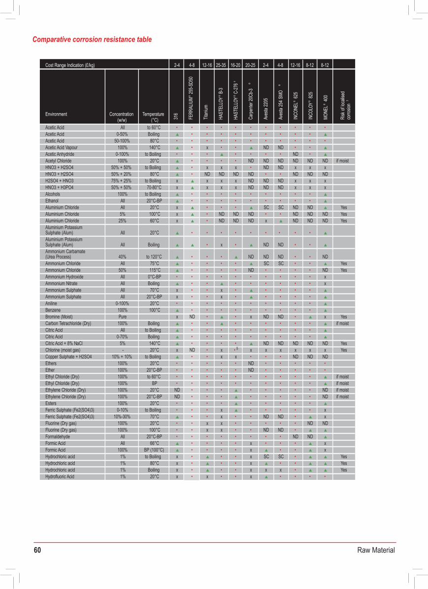
60 Raw Material
2-4 4-8Cost Range Indication (£/kg) 12-16 25-35 16-20 20-25 2-4 4-8 12-16 8-12 8-12
ConcentrationEnvironment (w/w) (°C)
Temperature
316
FERR
ALIU
M®
255-S
D50
Titan
ium
HAST
ELLO
Y® B-
3
HAST
ELLO
Y® C-
2764
Carpe
nter2
0Cb-3
®
Aves
ta22
05
INCO
NEL®
625
Aves
ta25
4SMO
®
INCO
LOY®
825
MONE
L®40
0
Risk
ofloc
alise
d co
rrosio
n3
10% 20°C x xHydrofluoric Acid •• x x • • • 0-100% 20°C x ND xHydrofluoric Acid • • x SC SC • • •
1% 40°C x NDHydrofluoric Acid ND • • ND ND • ND ND • 0.5% 50°C ND NDHydrofluoric Acid ND • • ND ND ND ND •
0-100% 50°C x NDHydrofluoric Acid x • • x SC SC x • 50% 20°C •• xHydrogen Peroxide • • • • • 50% 40°C • • xHydrogen Peroxide ND• • • • • 4% 200°C • • • • Hydrogen Sulphide (Dry gas) • • • • • • • if moist
100% to 250°C • • • • Hydrogen Sulphide (Dry gas) • • SC SC • • if moist- 20°C • • • • Hydrogen Sulphide (Moist gas) ND ND • • x Yes
20%Lactic Acid 100°C x • • • • SC SC • • 90%Lactic Acid Boiling x • ND ND ND ND • • ND ND ND
Magnesium Chloride 10-30% 20°C • • • • • • • • • • Yes5%Magnesium Chloride Boiling • • • • • • • • • • YesAll BoilingNickel Sulphate • • x • • • •
0-70% 20°CNitric Acid • • x• • • • • • • x Yes100% 20°CNitric Acid • • x •• ND ND • x Yes0-40% 70°CNitric Acid • • x • • • • • x Yes
40-70% 70°CNitric Acid • • x 8x • • • • x• Yes0-60% BoilingNitric Acid • • • x x • SC SC • • x Yes50% BoilingNitric Acid • • • x x • • • • x Yes70% BoilingNitric Acid x x ND ND • x Yes65% BoilingNitric Acid xx • x Yes100% 20°COleic Acid • • • • • • • •
AllOxalic Acid 20°C • • • SC SC • • xAllOxalic Acid to Boiling x x SC SC • • x
40%Oxalic Acid 75°C x • x • • • • • • • x50%Oxalic Acid Boiling x x x • • x20% BoilingPhosphoric Acid • x • • • • • • • x40% BoilingPhosphoric Acid • x • • • • • • x
0-40% BoilingPhosphoric Acid x• • • • SC SC • • x50% BoilingPhosphoric Acid x • x • • • • • x60% BoilingPhosphoric Acid x x • • • x80% BoilingPhosphoric Acid x x • x •• x
40-80% Boiling xPhosphoric Acid x • SC SC • • x86% 85°CPhosphoric Acid • • • • • • • • • xAllPhosphoric Acid to 80°C • • • • • SC SC • • x
44-55% 80-90°C • ND ND ND ND • • xPhosphoric Acid (‘wet’ process liquor) 7
- 85°C x ND ND ND ND ND ND • • • NDPhosphoric Acid (‘wet’ process liquor) 8
All 20°CPicric Acid • • • • • • • • xPotassium Chloride 0-30% to Boiling • • • • • ND ND • • • Yes
AllPotassium Dichromate to Boiling • • • x x • • • • • • Sodium Chloride 0-10% to Boiling • • • • • • • • • • Yes
5% xto Boiling • • Sodium Chloride + 0.1M H2SO4 (aerated) • • ND ND ND ND ND ND YesSodium Chloride +
0-8%0.5% Oxalic Acid to Boiling x • x • • ND ND ND ND ND ND YesSodium Chloride +
0-8%0.5% Citric Acid to Boiling x • • • • ND ND ND ND ND ND Yes
AllAcetic Acid to 60°C • • • • • • • • • • • Acetic Acid 0-50% Boiling • • • • • • • • • Acetic Acid 50-100% 80°C • • • • • • • • • • •
100% 140°CAcetic Acid Vapour • x • • ND ND • • 0-100%Acetic Anhydride to Boiling • • • • • • • ND • 100%Acetyl Chloride 20°C • • • • ND ND ND ND ND ND if moist
HNO3 + H2SO4 50% + 50% to Boiling • x x x • ND ND x x xHNO3 + H2SO4 80°C50% + 20% • ND ND ND ND • • ND ND NDH2SO4 + HNO3 75% + 25% to Boiling x x x x ND ND ND x x xHNO3 + H3PO4 50% + 50% 70-80°C x x x x ND ND ND x x xAlcohols 100% to Boiling • • • • • • • • • Ethanol All 20°C-BP • • • • • • • • •
AllAluminium Chloride 20°C x • • • SC SC ND ND YesAluminium Chloride 5% 100°C x • ND ND ND • • ND ND ND Yes
25%Aluminium Chloride 60°C x • ND ND ND x ND ND ND Yes
All 20°CAluminium Potassium Sulphate (Alum) • • • • • • • • •
All BoilingAluminium Potassium Sulphate (Alum) • x • ND ND • •
40% to 120°C • • Ammonium Carbamate (Urea Process) • ND ND ND •• NDAmmonium Chloride All 75°C • • • • SC SC •• YesAmmonium Chloride 50% 115°C • • • • ND • • • • ND Yes
All 0°C-BPAmmonium Hydroxide • • • • • • • • • • xAllAmmonium Nitrate Boiling • • • • • • • • xAll 70°C xAmmonium Sulphate • • x • • • • • AllAmmonium Sulphate 20°C-BP x • • x • • • • •
Aniline 0-100% 20°C • • • • • • • • • • 100%Benzene 100°C • • • • • • • • •
Bromine (Moist) xPure ND • • x ND ND • x Yes100% BoilingCarbon Tetrachloride (Dry) • • • • • • • • if moist
AllCitric Acid to Boiling • • • • • • • • • Citric Acid 0-70% Boiling • • • • • • • • •
5% 140°C • • Citric Acid + 8% NaCl • • ND ND ND ND ND Yes-Chlorine (moist gas) 20°C x ND • x x• 5 x x x x x Yes
Copper Sulphate + H2SO4 10% + 10% to Boiling • • x x • • ND• ND ND100%Ethers 20°C • • • • • ND • • • • •
Ether 100% 20°C-BP • • • • • ND • • • • • 100%Ethyl Chloride (Dry) to 60°C • • • • • • • • • • if moist100% BPEthyl Chloride (Dry) • • • • • • • • • • if moist100% 20°C NDEthylene Chloride (Dry) • • • • • • • • ND if moist100% 20°C-BP NDEthylene Chloride (Dry) • • • • • • • • ND if moist
Esters 100% 20°C • • • • • • • • • 0-10%Ferric Sulphate (Fe2(SO4)3) to Boiling • • • x • • • • x•
10%-30% 70°CFerric Sulphate (Fe2(SO4)3) • • x • • ND ND • x100% 20°CFluorine (Dry gas) • • x x • • • • ND• ND100% 100°CFluorine (Dry gas) • • x x • • ND ND •
AllFormaldehyde 20°C-BP • • • • • • • • ND NDAll 66°CFormic Acid • • • • x • • • x
100%Formic Acid BP (100°C) • • • • x • • x1%Hydrochloric acid to Boiling x • • • x SC SC • Yes1% 80°C xHydrochloric acid • • • x • • Yes1% Boiling xHydrochloric acid • • • x x x • Yes1% 20°C xHydrofluoric Acid x• • • x • • • •
2-4Cost Range Indication (£/kg) 4-8 12-16 25-35 16-20 20-25 2-4 4-8 12-16 8-12 8-12
ConcentrationEnvironment (w/w) (°C)
Temperature
316
FERR
ALIU
M®
255-S
D50
Titan
ium
HAST
ELLO
Y® B-
3
HAST
ELLO
Y® C-
2764
Carpe
nter 2
0Cb-3
®
Aves
ta 22
05
Aves
ta 25
4 SMO
®
INCO
NEL®
625
INCO
LOY®
825
MONE
L®40
0
Risk
of lo
calis
ed
corro
sion
3
Comparative corrosion resistance table
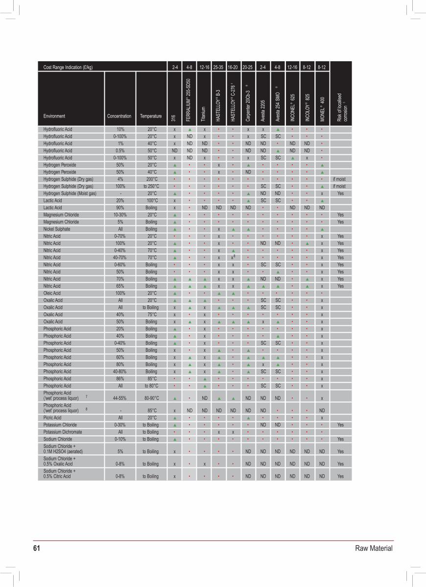
61 Raw Material
2-4 4-8Cost Range Indication (£/kg) 12-16 25-35 16-20 20-25 2-4 4-8 12-16 8-12 8-12
ConcentrationEnvironment (w/w) (°C)
Temperature
316
FERR
ALIU
M®
255-S
D50
Titan
ium
HAST
ELLO
Y® B-
3
HAST
ELLO
Y® C-
2764
Carpe
nter 2
0Cb-3
®
Aves
ta 22
05
INCO
NEL®
625
Aves
ta 25
4 SMO
®
INCO
LOY®
825
MONE
L®40
0
Risk
of lo
calis
ed
corro
sion
3
10% 20°C x xHydrofluoric Acid •• x x • • • 0-100% 20°C x ND xHydrofluoric Acid • • x SC SC • • •
1% 40°C x NDHydrofluoric Acid ND • • ND ND • ND ND • 0.5% 50°C ND NDHydrofluoric Acid ND • • ND ND ND ND •
0-100% 50°C x NDHydrofluoric Acid x • • x SC SC x • 50% 20°C •• xHydrogen Peroxide • • • • • 50% 40°C • • xHydrogen Peroxide ND• • • • • 4% 200°C • • • • Hydrogen Sulphide (Dry gas) • • • • • • • if moist
100% to 250°C • • • • Hydrogen Sulphide (Dry gas) • • SC SC • • if moist- 20°C • • • • Hydrogen Sulphide (Moist gas) ND ND • • x Yes
20%Lactic Acid 100°C x • • • • SC SC • • 90%Lactic Acid Boiling x • ND ND ND ND • • ND ND ND
Magnesium Chloride 10-30% 20°C • • • • • • • • • • Yes5%Magnesium Chloride Boiling • • • • • • • • • • YesAll BoilingNickel Sulphate • • x • • • •
0-70% 20°CNitric Acid • • x• • • • • • • x Yes100% 20°CNitric Acid • • x •• ND ND • x Yes0-40% 70°CNitric Acid • • x • • • • • x Yes
40-70% 70°CNitric Acid • • x 8x • • • • x• Yes0-60% BoilingNitric Acid • • • x x • SC SC • • x Yes50% BoilingNitric Acid • • • x x • • • • x Yes70% BoilingNitric Acid x x ND ND • x Yes65% BoilingNitric Acid xx • x Yes100% 20°COleic Acid • • • • • • • •
AllOxalic Acid 20°C • • • SC SC • • xAllOxalic Acid to Boiling x x SC SC • • x
40%Oxalic Acid 75°C x • x • • • • • • • x50%Oxalic Acid Boiling x x x • • x20% BoilingPhosphoric Acid • x • • • • • • • x40% BoilingPhosphoric Acid • x • • • • • • x
0-40% BoilingPhosphoric Acid x• • • • SC SC • • x50% BoilingPhosphoric Acid x • x • • • • • x60% BoilingPhosphoric Acid x x • • • x80% BoilingPhosphoric Acid x x • x •• x
40-80% Boiling xPhosphoric Acid x • SC SC • • x86% 85°CPhosphoric Acid • • • • • • • • • xAllPhosphoric Acid to 80°C • • • • • SC SC • • x
44-55% 80-90°C • ND ND ND ND • • xPhosphoric Acid (‘wet’ process liquor) 7
- 85°C x ND ND ND ND ND ND • • • NDPhosphoric Acid (‘wet’ process liquor) 8
All 20°CPicric Acid • • • • • • • • xPotassium Chloride 0-30% to Boiling • • • • • ND ND • • • Yes
AllPotassium Dichromate to Boiling • • • x x • • • • • • Sodium Chloride 0-10% to Boiling • • • • • • • • • • Yes
5% xto Boiling • • Sodium Chloride + 0.1M H2SO4 (aerated) • • ND ND ND ND ND ND YesSodium Chloride +
0-8%0.5% Oxalic Acid to Boiling x • x • • ND ND ND ND ND ND YesSodium Chloride +
0-8%0.5% Citric Acid to Boiling x • • • • ND ND ND ND ND ND Yes
AllAcetic Acid to 60°C • • • • • • • • • • • Acetic Acid 0-50% Boiling • • • • • • • • • Acetic Acid 50-100% 80°C • • • • • • • • • • •
100% 140°CAcetic Acid Vapour • x • • ND ND • • 0-100%Acetic Anhydride to Boiling • • • • • • • ND • 100%Acetyl Chloride 20°C • • • • ND ND ND ND ND ND if moist
HNO3 + H2SO4 50% + 50% to Boiling • x x x • ND ND x x xHNO3 + H2SO4 80°C50% + 20% • ND ND ND ND • • ND ND NDH2SO4 + HNO3 75% + 25% to Boiling x x x x ND ND ND x x xHNO3 + H3PO4 50% + 50% 70-80°C x x x x ND ND ND x x xAlcohols 100% to Boiling • • • • • • • • • Ethanol All 20°C-BP • • • • • • • • •
AllAluminium Chloride 20°C x • • • SC SC ND ND YesAluminium Chloride 5% 100°C x • ND ND ND • • ND ND ND Yes
25%Aluminium Chloride 60°C x • ND ND ND x ND ND ND Yes
All 20°CAluminium Potassium Sulphate (Alum) • • • • • • • • •
All BoilingAluminium Potassium Sulphate (Alum) • x • ND ND • •
40% to 120°C • • Ammonium Carbamate (Urea Process) • ND ND ND •• NDAmmonium Chloride All 75°C • • • • SC SC •• YesAmmonium Chloride 50% 115°C • • • • ND • • • • ND Yes
All 0°C-BPAmmonium Hydroxide • • • • • • • • • • xAllAmmonium Nitrate Boiling • • • • • • • • xAll 70°C xAmmonium Sulphate • • x • • • • • AllAmmonium Sulphate 20°C-BP x • • x • • • • •
Aniline 0-100% 20°C • • • • • • • • • • 100%Benzene 100°C • • • • • • • • •
Bromine (Moist) xPure ND • • x ND ND • x Yes100% BoilingCarbon Tetrachloride (Dry) • • • • • • • • if moist
AllCitric Acid to Boiling • • • • • • • • • Citric Acid 0-70% Boiling • • • • • • • • •
5% 140°C • • Citric Acid + 8% NaCl • • ND ND ND ND ND Yes-Chlorine (moist gas) 20°C x ND • x x• 5 x x x x x Yes
Copper Sulphate + H2SO4 10% + 10% to Boiling • • x x • • ND• ND ND100%Ethers 20°C • • • • • ND • • • • •
Ether 100% 20°C-BP • • • • • ND • • • • • 100%Ethyl Chloride (Dry) to 60°C • • • • • • • • • • if moist100% BPEthyl Chloride (Dry) • • • • • • • • • • if moist100% 20°C NDEthylene Chloride (Dry) • • • • • • • • ND if moist100% 20°C-BP NDEthylene Chloride (Dry) • • • • • • • • ND if moist
Esters 100% 20°C • • • • • • • • • 0-10%Ferric Sulphate (Fe2(SO4)3) to Boiling • • • x • • • • x•
10%-30% 70°CFerric Sulphate (Fe2(SO4)3) • • x • • ND ND • x100% 20°CFluorine (Dry gas) • • x x • • • • ND• ND100% 100°CFluorine (Dry gas) • • x x • • ND ND •
AllFormaldehyde 20°C-BP • • • • • • • • ND NDAll 66°CFormic Acid • • • • x • • • x
100%Formic Acid BP (100°C) • • • • x • • x1%Hydrochloric acid to Boiling x • • • x SC SC • Yes1% 80°C xHydrochloric acid • • • x • • Yes1% Boiling xHydrochloric acid • • • x x x • Yes1% 20°C xHydrofluoric Acid x• • • x • • • •
2-4Cost Range Indication (£/kg) 4-8 12-16 25-35 16-20 20-25 2-4 4-8 12-16 8-12 8-12
ConcentrationEnvironment (w/w) (°C)
Temperature
316
FERR
ALIU
M®
255-S
D50
Titan
ium
HAST
ELLO
Y® B-
3
HAST
ELLO
Y® C-
2764
Carpe
nter2
0Cb-3
®
Aves
ta22
05
Aves
ta25
4SMO
®
INCO
NEL®
625
INCO
LOY®
825
MONE
L®40
0
Risk
ofloc
alise
d co
rrosio
n3
Comparative corrosion resistance table
62 Raw Material
Plates shall be marked in ink with “FERRALIUM 255-SD50” and the batch number.
FERRALIUM® 255 is the original superduplex stainless steel, noted for its unique combination of mechanical properties and resistance to corrosion, erosion and cavitation.
FERRALIUM® 255-SD50 is the latest version of this product and it has much higher strength than other commercially available superduplexes. It has especially low impurities giving improved corrosion resistance and it is used extensively in the offshore and chemical industries.
The following notes are provided to assist in the ready working of these versatile and practical alloys. The speeds and feeds quoted should be regarded as a guide only; precise machining details may vary depending on set up (component geometry, machine tool capacity/rigidity).
If tight tolerances are required, then it is recommended that rough machining is carried out to as close as possible to final size and, before the final machining stage is initiated, stress relief is allowed to occur to effect dimensional stabilisation. Stress relief of rough machined articles will occur naturally through standing at room temperature for at least 12 hours or can be accelerated by heating at 350°C for 2 hours followed by air cooling.
Basic ‘Dos’ and ‘Don’ts’ that should be considered during machining are:
In order for goods to be unloaded in a safe manner and be traceable to the associated paperwork, all goods shall conform to the following:
a) Maximum bundle weight is 2000 kg.b) All goods are to be packed to avoid transit damage and be suitable for unloadingc) Documentation shall be supplied with, or prior to the delivery of, the goods.d) Where two or more batches of the same grade or size are supplied at the same time, each batch shall be
physically separated and clearly labelled.
12.0 Marking
FERRALIUM 255-SD50 certificates are in accordance with BS EN 10204 3.1 and certify the product as FERRALIUM 255-SD50
Speeds and feeds quoted above refer to carbide tipped tools (carbide grade P45) unless otherwise indicatedFERRALIUM® is the registered trademark of Enerxon Ltd.
14.0 Certification
13.0 Delivery Conditions
1. Use machine tools which are rigid and overpowered, where possible.2. Ensure work piece and tools are held rigid. In addition, minimise tool overhang.3. Flood the work with heavy-duty sulphochlorinated water soluble oil or water-based chemical emulsion oils with extreme pressure additives. Dilute as per the recommendations of the manufacturer.4. Use heavy-duty sulphochlorinated oil for drilling and tapping. Special proprietary tapping oils can also be used.5. Make sure tools are always kept sharp. Change to sharpened tools at regular intervals rather than out of necessity.6. Use positive rake tools for most machining operations. Negative rake angle can be considered for intermittent cuts and heavy stock removal.7. Use heavy, constant, feeds to maintain positive cutting action. If feed slows and the tool dwells in the cut, tool life deteriorates and close tolerance is impossible.
Do:
1. Do not make intermittent cuts, if possible. This tends to work harden the surface, making subsequent cuts more difficult.2. Do not allow conditions such as chatter and glazing. This can cause work hardening of the surface, making
subsequent machining difficult.
Don’t:
Technical DataMachining FERRALIUM® 255 and FERRALIUM® 255-SD50
Document No. TDS-M-51VS Date: 19th February 2008 Rev: 2
Operation Depth of cut Cutting speedm/min (ft/min) mm(in)
Feed ratemm/rev (in/rev)
Recommended cutting tools(Carbide unless indicated
otherwise)
30 - 45 3 SANDVIK GC235(100 - 150) (0.125)
Turning / Boring (Roughing)
0.20 - 0.38(0.008 - 0.015)
50 - 60 0.5 SANDVIK GC235(165 - 200)
Turning / Boring(Finishing) (0.02)
Milling 40
0.13 - 0.20(0.005 - 0.008)
0.05-0.13 0.5 - 6.0(130) mm/tooth (0.02 - 0.25)
(0.002-0.005
SANDVIK GC235SECO T25M
in/tooth)
Shaping 0.26mm25 - 35 0.5 - 3.0and Planing (80 - 115) (0.10 in) (0.02 - 0.125)
SANDVIK GC235SECO T25M
250 RPM -0.05 (0.002)250 RPM 0.075 (0.003)
HSS, point angle 118°,chisel angle 120°
250 RPM 0.125 (0.005)150 RPM 0.28 (0.011)100 RPM 0.33 (0.013)75 RPM 0.40 (0.016)
6 - 7.5 -
Drillingdia 3.2mm (1/8”)dia 6.4mm (1/4”)dia 12.7mm (1/2”)dia 25.4mm (1”)dia 38.1mm (1.1/2”)dia 50.8mm (2”)
(20-25)Reamingdia > 12.7mm (1/2”)
0.05 - 0.125(0.002 - 0.005)
Tapping 4.5 -7.5 - -(15-25)
HSS standard fluted reamers(for carbide tools speeds
can be increased to 20m/min (70 ft/min))
HSS taps with round threads
-Grinding - - Standard 46-60 grit wheels, Grades L-N are preferred
Machining FERRALIUM 255 & FERRALIUM 255-SD50
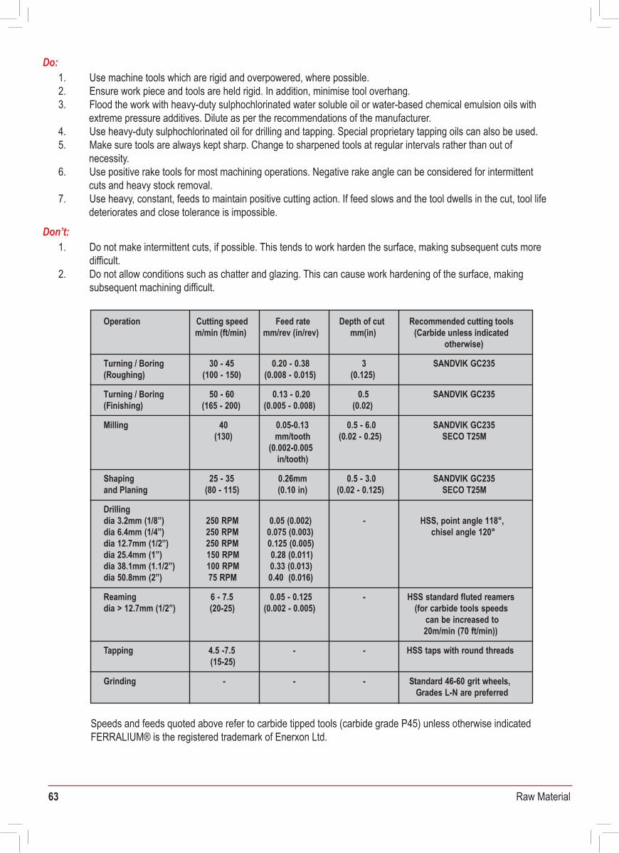
63 Raw Material
Plates shall be marked in ink with “FERRALIUM 255-SD50” and the batch number.
FERRALIUM® 255 is the original superduplex stainless steel, noted for its unique combination of mechanical properties and resistance to corrosion, erosion and cavitation.
FERRALIUM® 255-SD50 is the latest version of this product and it has much higher strength than other commercially available superduplexes. It has especially low impurities giving improved corrosion resistance and it is used extensively in the offshore and chemical industries.
The following notes are provided to assist in the ready working of these versatile and practical alloys. The speeds and feeds quoted should be regarded as a guide only; precise machining details may vary depending on set up (component geometry, machine tool capacity/rigidity).
If tight tolerances are required, then it is recommended that rough machining is carried out to as close as possible to final size and, before the final machining stage is initiated, stress relief is allowed to occur to effect dimensional stabilisation. Stress relief of rough machined articles will occur naturally through standing at room temperature for at least 12 hours or canbe accelerated by heating at 350°C for 2 hours followed by air cooling.
Basic ‘Dos’ and ‘Don’ts’ that should be considered during machining are:
In order for goods to be unloaded in a safe manner and be traceable to the associated paperwork, all goods shall conform to the following:
a) Maximum bundle weight is 2000 kg.b) All goods are to be packed to avoid transit damage and be suitable for unloadingc) Documentation shall be supplied with, or prior to the delivery of, the goods.d) Where two or more batches of the same grade or size are supplied at the same time, each batch shall be physically separated and clearly labelled.
12.0 Marking
FERRALIUM 255-SD50 certificates are in accordance with BS EN 10204 3.1 and certify the product as FERRALIUM 255-SD50
Speeds and feeds quoted above refer to carbide tipped tools (carbide grade P45) unless otherwise indicatedFERRALIUM® is the registered trademark of Enerxon Ltd.
14.0 Certification
13.0 Delivery Conditions
1. Use machine tools which are rigid and overpowered, where possible.2. Ensure work piece and tools are held rigid. In addition, minimise tool overhang.3. Flood the work with heavy-duty sulphochlorinated water soluble oil or water-based chemical emulsion oils with
extreme pressure additives. Dilute as per the recommendations of the manufacturer.4. Use heavy-duty sulphochlorinated oil for drilling and tapping. Special proprietary tapping oils can also be used.5. Make sure tools are always kept sharp. Change to sharpened tools at regular intervals rather than out of
necessity.6. Use positive rake tools for most machining operations. Negative rake angle can be considered for intermittent
cuts and heavy stock removal.7. Use heavy, constant, feeds to maintain positive cutting action. If feed slows and the tool dwells in the cut, tool life
deteriorates and close tolerance is impossible.
Do:
1. Do not make intermittent cuts, if possible. This tends to work harden the surface, making subsequent cuts moredifficult.
2. Do not allow conditions such as chatter and glazing. This can cause work hardening of the surface, makingsubsequent machining difficult.
Don’t:
Technical DataMachining FERRALIUM® 255 and FERRALIUM® 255-SD50
Document No. TDS-M-51VS Date: 19th February 2008 Rev: 2
Operation Depth of cut Cutting speedm/min (ft/min) mm(in)
Feed ratemm/rev (in/rev)
Recommended cutting tools(Carbide unless indicated
otherwise)
30 - 45 3 SANDVIK GC235(100 - 150) (0.125)
Turning / Boring (Roughing)
0.20 - 0.38(0.008 - 0.015)
50 - 60 0.5 SANDVIK GC235(165 - 200)
Turning / Boring(Finishing) (0.02)
Milling 40
0.13 - 0.20(0.005 - 0.008)
0.05-0.13 0.5 - 6.0(130) mm/tooth (0.02 - 0.25)
(0.002-0.005
SANDVIK GC235SECO T25M
in/tooth)
Shaping 0.26mm25 - 35 0.5 - 3.0and Planing (80 - 115) (0.10 in) (0.02 - 0.125)
SANDVIK GC235SECO T25M
250 RPM -0.05 (0.002)250 RPM 0.075 (0.003)
HSS, point angle 118°,chisel angle 120°
250 RPM 0.125 (0.005)150 RPM 0.28 (0.011)100 RPM 0.33 (0.013)75 RPM 0.40 (0.016)
6 - 7.5 -
Drillingdia 3.2mm (1/8”)dia 6.4mm (1/4”)dia 12.7mm (1/2”)dia 25.4mm (1”)dia 38.1mm (1.1/2”)dia 50.8mm (2”)
(20-25)Reamingdia > 12.7mm (1/2”)
0.05 - 0.125(0.002 - 0.005)
Tapping 4.5 -7.5 - -(15-25)
HSS standard fluted reamers(for carbide tools speeds
can be increased to 20m/min (70 ft/min))
HSS taps with round threads
-Grinding - - Standard 46-60 grit wheels, Grades L-N are preferred
Unit B5 Riverview Business Park, Nangor Road, Dublin 12, Ireland
[email protected] +353 1 427 8338
E n g i n e e r i n g S o l u t i o n s