soundBlade version 1.3 — User Manual - adebar acoustics
285
soundBlade User Manual Sonic Studio, LLC www.sonicstudio.com Sonic Studio
-
Upload
khangminh22 -
Category
Documents
-
view
3 -
download
0
Transcript of soundBlade version 1.3 — User Manual - adebar acoustics
soundBlade
User Manual
Sonic Studio, LLCwww.sonicstudio.com
Sonic Studio

Page 2
Page 3
Table of Contents
Chapter 1 Introduction ....................................................................................... 17
Chapter 2 Quick Start ......................................................................................... 19
2.1 Before You Begin ................................................................................................. 19
2.1.1 Requirements ............................................................................................................................19
2.1.2 Installation .................................................................................................................................19
2.2 Creating CDs With soundBlade .......................................................................... 19
First: Assemble your audio ............................................................................................................... 20
Second: Edit and process segments and tracks ................................................................................... 20
Third: Adjust crossfades ..................................................................................................................... 20
Fouth: Burn the Project to a CD .......................................................................................................... 20
2.3 Step By Step — Make A Quick CD .....................................................................20
Step 1. Open .......................................................................................................................................... 20
Step 2. Drag ........................................................................................................................................... 21
Step 3. Check ......................................................................................................................................... 21
Step 4. Burn ........................................................................................................................................... 21
Chapter 3 Basic Operation ................................................................................. 23
3.1 General Workflow & Explanation of Terms Used ..............................................23
3.2 Project Layout ......................................................................................................24
3.3 Starting a Project: Opening Files .......................................................................26
3.3.1 Opening Projects ...................................................................................................................... 26
3.3.2 Opening Sound Files ................................................................................................................ 26
3.3.3 Adding Your First Sound File ................................................................................................... 27
3.4 Waveforms ...........................................................................................................27
3.5 Auditioning Sound ..............................................................................................28
3.5.1 Playback .................................................................................................................................... 28
3.5.2 Playback from the Edit Point ................................................................................................... 29
3.5.3 Playback from Playhead........................................................................................................... 30
3.5.4 Play All....................................................................................................................................... 30
Page 4
3.5.5 Time Display ............................................................................................................................. 30
3.6 Navigating the Waveform Display .....................................................................31
3.6.1 Scrolling .................................................................................................................................... 31
3.6.2 Zooming .................................................................................................................................... 32
3.7 Selections ............................................................................................................32
3.7.1 Selecting a Region ................................................................................................................... 32
3.7.2 Selecting Segments ................................................................................................................. 35
3.8 Recording Audio ..................................................................................................36
3.8.1 Edit Recording .......................................................................................................................... 37
3.8.2 Initiating a Recording ............................................................................................................... 37
3.8.3 AutoPunch ................................................................................................................................. 38
3.9 Simple Editing .....................................................................................................38
3.9.1 The Fade Tool ............................................................................................................................ 38
3.9.2 Deleting Part of a Sound File ................................................................................................... 40
3.9.3 Splitting a segment into new segments ................................................................................. 42
3.9.4 Manipulating Fades .................................................................................................................. 42
3.9.5 Changing the order of songs ................................................................................................... 42
3.9.6 Simple Track Spacing: AutoSpace ........................................................................................... 44
3.9.7 Exporting Selections & Segments .......................................................................................... 44
3.10 PQ Marks: Defining Metadata ............................................................................45
3.10.1 Inserting PQ Marks Manually .................................................................................................. 45
3.10.2 Moving PQ Marks ..................................................................................................................... 45
3.10.3 Removing PQ Marks ................................................................................................................ 45
3.10.4 Inserting PQ Marks Automatically .......................................................................................... 45
3.10.5 Tracks ......................................................................................................................................... 46
3.10.6 The Marks Button ..................................................................................................................... 47
3.11 Delivery ................................................................................................................47
3.11.1 A Check List for Delivery ......................................................................................................... 47
3.11.2 The Mark Info Window ............................................................................................................. 48
3.11.2.8 The PQ List Button ................................................................................................................... 50
Chapter 4 Advanced Editing .............................................................................. 53
4.1 Fade Tool Options ................................................................................................53

Page 5
4.1.1 Changing Fade Parameters ..................................................................................................... 53
4.1.2 Changing the shape of the Fade ............................................................................................. 54
4.1.3 Changing the Fade Duration ................................................................................................... 55
4.1.4 Changing the Fade Type ........................................................................................................... 55
4.2 Edit Fade ..............................................................................................................56
4.2.1 Selections in the Edit Fade Panels ................................................................................................................ 57
4.2.3 Global Modes ................................................................................................................................................. 58
4.2.4 Audition Controls ........................................................................................................................................... 59
4.2.5 Additional Fade Parameters .......................................................................................................................... 59
4.2.6 Fade Selectors ................................................................................................................................................ 59
4.2.7 Nudging Fades ............................................................................................................................................... 60
4.2.8 Edit Point Offset .............................................................................................................................................. 60
4.2.9 Fade Library 61
4.2.10 Exiting Edit Fade Mode ............................................................................................................................... 61
4.3 Drag & Drop .........................................................................................................61
4.3.1 Resequencing ........................................................................................................................... 61
4.3.2 Drag–Overlay ............................................................................................................................ 64
4.3.3 Drag–Insert & Ripple ................................................................................................................ 64
4.3.3 Drag–Replace ............................................................................................................................ 64
4.4 Text Mode ............................................................................................................64
4.4.1 Gain Adjustment....................................................................................................................... 64
4.4.2 Combo Project Configuration ........................................................................................................................ 66
4.5 Gain Overlay Mode .............................................................................................66
4.6 Desk Events .........................................................................................................69
4.6.1 Plug–In Overview ..................................................................................................................... 69
4.6.2 Displaying Plug–ins in Panels ................................................................................................. 70
4.6.3 Saving plug–in settings to a separate file .............................................................................. 72
4.7 SRPs .....................................................................................................................72
4.8 Dual EDL Mode ....................................................................................................73
4.8.1 The Master/Slave Menu ............................................................................................................74
4.8.2 Playing Both EDLs .................................................................................................................... 75
4.9 Source to Destination Editing ............................................................................76
Page 6
4.9.1 Manipulating In & Out Edit Points .......................................................................................... 77
4.9.2 Edit Groups ............................................................................................................................... 78
4.9.3 Edit Targets ................................................................................................................................ 78
4.9.4 Insert versus Replace ............................................................................................................... 80
4.9.5 Types of Source/Destination Edits .......................................................................................... 80
4.10 Eight Channel Mode ...........................................................................................81
4.10.1 Edit Targets for Eight Channel ................................................................................................. 82
4.10.2 Edit Groups for Eight Channel ................................................................................................ 82
4.10.3 Other Controls .......................................................................................................................... 83
4.10.4 Eight Channel Applications ..................................................................................................... 86
4.11 Project Sample Rate ............................................................................................87
4.12 Advanced PQ .......................................................................................................87
4.12.1 Album Info ................................................................................................................................ 89
4.12.2 Track Info ................................................................................................................................... 89
4.12.3 A Word About PQ Offsets ......................................................................................................... 91
Chapter 5 Recording Audio ................................................................................ 95
5.1 4 Steps to Recording ...........................................................................................95
1 Open a new Project .................................................................................................................. 95
2 Set New Sound File Parameters ............................................................................................. 95
3 Record enable Panels ............................................................................................................... 95
4 Start your recording ................................................................................................................. 95
5.2 Audio Recordings ................................................................................................96
5.2.1 Selecting external input(s) ....................................................................................................... 96
5.2.2 New Soundfile Parameters ...................................................................................................... 98
5.2.3 Track arming and enabling recording ....................................................................................100
5.2.4 Initiating a recording ...............................................................................................................100
5.2.6 Edit Recording .........................................................................................................................101
5.3 Automated Punches .......................................................................................... 102
5.3.1 Recording a selection or segment .........................................................................................102
5.3.2 Recording using SRPs .............................................................................................................102
5.4 Bouncing ............................................................................................................ 103
Page 7
5.4.1 Simple Bounce ........................................................................................................................104
5.5 Recording and time stamps ............................................................................. 106
Chapter 6 The Desk and Meters ...................................................................... 107
6.1 Signal Flow ........................................................................................................ 107
6.2 The EDL Desk ..................................................................................................... 107
6.3 Desk Setups ....................................................................................................... 115
6.4 The Panner ......................................................................................................... 116
6.5 Meters Window: The Master Section ............................................................... 117
6.5.1 Overview .................................................................................................................................. 117
6.5.2 Master Fader ............................................................................................................................ 118
6.5.3 Additional Indicators ............................................................................................................... 119
6.5.4 Master Meters .........................................................................................................................120
6.5.5 Master Plug–ins .......................................................................................................................120
6.5.6 CPU Meter ................................................................................................................................120
6.5.7 Details Button ..........................................................................................................................121
6.5.8 Clear Button .............................................................................................................................122
6.5.9 Reset Button.............................................................................................................................122
6.5.10 Output Button ..........................................................................................................................122
6.6 Bounce Examples ....................................................................................................................122
Chapter 7 The Background Manager ............................................................... 137
7.1 The Audio Client tab .........................................................................................138
7.1.1 Applying Processes .................................................................................................................138
7.2 The Queue Manager tab .........................................................................................................140
Chapter 8 Menus ............................................................................................... 143
8.1 The File Menu ....................................................................................................143
8.1.1 New Project ..............................................................................................................................143
8.1.2 Open Project ............................................................................................................................144
8.1.5 Open Sound File… ..................................................................................................................144
8.1.6 Close Window ..........................................................................................................................145
8.1.7 Save Project .............................................................................................................................145

Page 8
8.1.8 Save Project As… ....................................................................................................................145
8.1.9 Save As Default Project ...........................................................................................................145
8.1.10 Reveal Sound In Finder ...........................................................................................................145
8.1.11 Build Sound Waveform… .......................................................................................................145
8.1.12 Export Sound File… ................................................................................................................146
8.1.13 Save Reversed .........................................................................................................................146
8.1.13 System Information ................................................................................................................147
8.1.15 Quit ...........................................................................................................................................149
8.2 The Edit Menu ...................................................................................................150
8.2.1 Undo (action) ...........................................................................................................................150
8.2.2 Redo (action) ............................................................................................................................150
8.2.3 Cut ............................................................................................................................................151
8.2.4 Copy .........................................................................................................................................151
8.2.5 Paste Commands ....................................................................................................................151
8.2.6 Select/Deselect All ...................................................................................................................152
8.2.7 Delete Selection .......................................................................................................................152
8.2.8 Clear Selection .........................................................................................................................152
8.2.9 Replace .....................................................................................................................................152
8.2.10 Insert .........................................................................................................................................153
8.2.11 Replace Left..............................................................................................................................153
8.2.12 Replace Constrained ...............................................................................................................153
8.2.13 Delete Selection .......................................................................................................................153
8.2.14 Clear Selection .........................................................................................................................153
8.2.15 Create Crossfade/Create Segment ........................................................................................153
8.2.16 Create Crossfade from In Point/Create Segment from In & Out Point(s) ...........................154
8.2.17 Delete Crossfade .....................................................................................................................154
8.2.18 Move Segments ......................................................................................................................154
8.2.19 Segment Gain ..........................................................................................................................154
8.2.20 Reverse Polarity .......................................................................................................................154
8.2.21 Nudge Segment Left/Right .....................................................................................................155
8.2.22 Edit Segment Name ................................................................................................................155
8.2.23 Sync to Edit Point ....................................................................................................................155
Page 9
8.2.24 Sync to Matching .....................................................................................................................155
8.2.25 Sync SRP to Wherever… .........................................................................................................155
8.2.26 Sync SRP to In Point................................................................................................................155
8.2.27 Edit Fade Mode ........................................................................................................................156
8.2.28 Loop And Fill ............................................................................................................................156
8.2.29 Editing Auto Tool Override ......................................................................................................156
8.2.30 Auto Space All Segments/Tracks............................................................................................156
8.3 The EDL Menu ...................................................................................................157
8.3.1 New Tracks................................................................................................................................157
8.3.2 Delete Track ..............................................................................................................................158
8.3.3 Show/Hide Text View ...............................................................................................................158
8.3.4 Show/Hide Gain Overlay ........................................................................................................158
8.3.5 Bypass/Enable Gain Overlay ..................................................................................................158
8.3.6 Show/Hide Desk Events ..........................................................................................................158
8.3.7 Show/Hide Gain Overlay ........................................................................................................158
8.3.8 Bypass Desk Events ................................................................................................................158
8.3.9 Create Gain Nodes ..................................................................................................................159
8.3.10 Select Gain Nodes ...................................................................................................................159
8.3.11 Refresh .....................................................................................................................................159
8.3.12 Small/Standard/Large Track Size ............................................................................................159
8.3.13 Select/Deselect All Tracks ........................................................................................................159
8.3.14 Move Track Up/Down ...............................................................................................................159
8.3.15 Auto Set Edit Group Selection ...............................................................................................160
8.3.16 Set To Next Available Edit Group ...........................................................................................160
8.4 The Play Menu ...................................................................................................161
8.4.1 Play From Selection ................................................................................................................161
8.4.2 Play Selection ..........................................................................................................................162
8.4.3 Play From Playhead ................................................................................................................162
8.4.4 Repeat Play ..............................................................................................................................162
8.4.5 Stop ..........................................................................................................................................162
8.4.6 Mute Track ................................................................................................................................162
8.4.7 Solo Track .................................................................................................................................162
Page 10
8.4.8 Record Arm ..............................................................................................................................162
8.4.9 Record ......................................................................................................................................162
8.4.6 Around Selection Center ........................................................................................................163
8.4.7 Play from Selection .................................................................................................................163
8.4.8 Play to End of Selection ..........................................................................................................163
8.4.9 Play to In Point .........................................................................................................................164
8.4.10 Play From In Point ...................................................................................................................164
8.4.11 Play to Out Point ......................................................................................................................164
8.4.12 Play From Out Point ................................................................................................................164
8.4.13 Play Between In and Out Points .............................................................................................164
8.4.14 Move Playhead ........................................................................................................................165
8.4.15 Hide Playhead When Stopped ................................................................................................165
8.5 The Mark Menu .................................................................................................166
8.5.1 Mark Info ..................................................................................................................................166
8.5.2 Track Start Mark .......................................................................................................................166
8.5.3 Track End Mark ........................................................................................................................166
8.5.4 Index Mark ...............................................................................................................................166
8.5.5 Delete Mark ..............................................................................................................................166
8.5.6 Lock Marks from Selection .....................................................................................................167
8.5.7 Unlock Marks from Selection .................................................................................................167
8.5.8 Lock All Marks ..........................................................................................................................167
8.5.9 Unlock All Marks ......................................................................................................................167
8.5.10 Analog Black to Marks ............................................................................................................167
8.5.11 Edited Black to Marks ..............................................................................................................168
8.6 The Selection Menu ..........................................................................................169
8.6.1 Set In Point ...............................................................................................................................170
8.6.2 Set Out Point ............................................................................................................................170
8.6.3 Set In & Out Points ..................................................................................................................170
8.6.4 Clear In Point ...........................................................................................................................170
8.6.5 Clear Out Point ........................................................................................................................170
8.6.6 Clear In & Out Points ...............................................................................................................170
8.6.7 Nudge Right/Left .....................................................................................................................170
Page 11
8.6.8 Move In Point/Out Point… ......................................................................................................171
8.6.9 Move In Point to Out Point .....................................................................................................171
8.6.10 Find & Set Points .....................................................................................................................171
8.6.11 Select Nudge Size ...................................................................................................................171
8.6.12 Set SRP .....................................................................................................................................172
8.6.13 Set SRP from selection ...........................................................................................................172
8.6.14 Lock SRPs from Selection .......................................................................................................172
8.6.15 Unlock SRPs from Selection ...................................................................................................172
8.6.16 Clear Selected SRPs ................................................................................................................172
8.6.17 Drop Edit Point at Playhead ....................................................................................................172
8.6.18 Edit Point to Playhead .............................................................................................................172
8.6.19 Move Edit Point to… ...............................................................................................................172
8.6.20 Edit Point to Next Peak ............................................................................................................173
8.6.21 Select Start to Edit Point .........................................................................................................173
8.6.22 Select Edit Point to End...........................................................................................................174
8.6.23 Selection from Selected Segments ........................................................................................174
8.6.24 Select Segment to End ...........................................................................................................174
8.6.25 Select Segment to Start ..........................................................................................................174
8.6.26 Select Segments from Selection ............................................................................................174
8.7 The View Menu ..................................................................................................175
8.7.1 Move Forward/Backward .......................................................................................................175
8.7.2 Zoom In/Out .............................................................................................................................175
8.7.3 Zoom In Around In/Out Point .................................................................................................175
8.7.4 Zoom In/Out around Edit Point ..............................................................................................176
8.7.5 Zoom In/Out around Playhead ...............................................................................................176
8.7.6 Zoom to Previous/Next ...........................................................................................................176
8.7.7 Zoom around Playhead ..........................................................................................................176
8.7.8 Zoom around Selection Center ..............................................................................................176
8.7.9 Zoom to Selection Start/End ..................................................................................................177
8.7.10 Zoom to Selection ...................................................................................................................177
8.7.11 Zoom to Entire Project/Track ..................................................................................................177
8.8 The Desk Menu ..................................................................................................177
Page 12
8.8.1 Save Desk Setup ......................................................................................................................177
8.8.2 Open Desk Setup .....................................................................................................................178
8.8.3 Bypass All Events ....................................................................................................................178
8.8.4 Bypass/Active ..........................................................................................................................179
8.8.5 Lock/Unlock ..............................................................................................................................179
8.8.6 Move Event ..............................................................................................................................179
8.8.7 Show Gain Overlay .................................................................................................................179
8.8.8 Show/Hide Gain Overlay ........................................................................................................179
8.8.9 Bypass Gain Overlay ...............................................................................................................179
8.8.10 Create Gain Nodes ..................................................................................................................179
8.8.11 Select Gain Nodes ...................................................................................................................180
8.8.12 Lock/Unlock Nodes From Selection .......................................................................................180
8.8.13 Lock/Unlock all Nodes In Track ................................................................................................180
8.9 The Windows Menu ..........................................................................................180
8.9.1 EDL Desk ..................................................................................................................................180
8.9.2 Sonic EQ ...................................................................................................................................180
8.9.3 Meters ......................................................................................................................................180
8.9.4 Panner ......................................................................................................................................180
8.9.5 Mark Info ..................................................................................................................................181
8.9.7 The Preferences Window ........................................................................................................181
8.9.8 Setting Preferences — Editing Tools Tab ................................................................................182
8.9.9 Setting Preferences — Time Display Tab ................................................................................184
8.9.10 Setting Preferences — EDL Tab ..............................................................................................185
8.9.11 Setting Preferences — Delivery Tab .......................................................................................186
8.9.12 Setting Preferences — LTC Timecode Tab ..............................................................................188
8.9.13 Setting Preferences — Desk Tab .............................................................................................189
8.9.14 New Soundfile Preferences ....................................................................................................189
8.9.15 Timecode Status .....................................................................................................................189
8.9.17 Background Manager ..............................................................................................................189
Chapter 9 NoNOISE II ....................................................................................... 191
9.1 Manual DeClick .................................................................................................. 192
9.1.1 Interpolation Algorithms .........................................................................................................192
9.1.2 Using Manual DeClick .............................................................................................................195

Page 13
9.1.3 Obscenity Reduction ...............................................................................................................196
9.2 Broadband DeNoise .......................................................................................... 196
9.2.1 Introduction .............................................................................................................................196
9.2.2 The Noise Estimate .................................................................................................................197
9.2.3 Running the Broadband DeNoiser ........................................................................................ 200
Chapter 10 Sonic EQ ........................................................................................... 205
10.1 Sonic EQ Pre–processor ...................................................................................205
10.1.1 Overview ................................................................................................................................. 205
10.1.2 Operation ................................................................................................................................ 205
10.2 Sonic EQ Plug–in ...............................................................................................215
Chapter 11 Quartet DynPEQ™ ........................................................................... 217
11.1 Introduction to DynPEQ ....................................................................................217
11.1.1 What is dynamic parametric equalization? ...........................................................................217
11.2 Roadmap for This Chapter ................................................................................218
11.2.1 Help Us Help You .....................................................................................................................218
11.3 Parameter Window Layout ............................................................................... 219
11.3.1 Fine Adjustments.....................................................................................................................219
11.3.2 Coarse Adjustments ............................................................................................................... 220
11.3.3 Operation of Parameter Window Controls ........................................................................... 222
11.3.4 Operation of Parameter Window Controls ........................................................................... 223
Appendix 1 Best Practices & Maintenance ........................................................ 247
A1.1 Introduction .......................................................................................................247
A1.2 Source Material Considerations ......................................................................247
A1.3 Naming Conventions ........................................................................................248
A1.4 Host Considerations & Routine Maintenance .................................................248
A1.4.1 File Systems ............................................................................................................................ 248
A1.4.2 Storage Systems .................................................................................................................... 248
A1.4.3 Permissions ............................................................................................................................ 249
A1.4.4 Plug–ins ................................................................................................................................... 249
A1.4.5 3rd Party Configuration Management .................................................................................. 249
A1.4.6 3rd Party Applications ............................................................................................................ 250
Page 14
A1.4.7 iLoks & Your License ............................................................................................................... 250
A1.5 Delivering DDPs ................................................................................................250
A1.6 Delivering CD-Rs ...............................................................................................251
A1.7 Delivering CD Text .............................................................................................251
Appendix 2 Keyboard Shortcuts......................................................................... 253
Appendix 3 Contextual Menus ........................................................................... 259
Appendix 4 Additional Resources ...................................................................... 261
Index .......................................................................................................... 263

Page 15

Page 16
©2006-2009 Sonic Studio, LLC — All rights reserved
This manual, as well as the software described in it, is furnished under license and may only be used or copied in accordance with the terms of such license. The information in this manual is furnished for informational use only, is subject to change with-out notice, and should not be construed as a commitment by Sonic Studio, LLC. Sonic Studio, LLC assumes no responsibility or liability for any errors or inaccuracies that may appear in this document.
Except as permitted by such license, no part of this publication may be reproduced, stored in a retrieval system, or transmitted, in any form or by any means, electronic, mechanical, recording, or otherwise, without the prior written permission of Sonic Studio, LLC.
SONIC STUDIO, LLC MAKES NO WARRANTIES, EXPRESS OR IMPLIED, INCLUDING WITHOUT LIMITATION THE IMPLIED WAR-RANTIES OF MERCHANTABILITY AND FITNESS FOR A PARTICULAR PURPOSE, REGARDING THE APPLE SOFTWARE. SONIC STUDIO, LLC DOES NOT WARRANT, GUARANTEE, OR MAKE ANY REPRESENTATIONS REGARDING THE USE OR THE RESULTS OF THE USE OF THE SONIC STUDIO, LLC SOFTWARE IN TERMS OF ITS CORRECTNESS, ACCURACY, RELIABILITY, CURRENT-NESS, OR OTHERWISE. THE ENTIRE RISK AS TO THE RESULTS AND PERFORMANCE OF THE SONIC STUDIO SOFTWARE IS AS-SUMED BY YOU. THE EXCLUSION OF IMPLIED WARRANTIES IS NOT PERMITTED BY SOME STATES. THE ABOVE EXCLUSION MAY NOT APPLY TO YOU.
IN NO EVENT WILL SONIC STUDIO, LLC, ITS DIRECTORS, OFFICERS, EMPLOYEES, OR AGENTS BE LIABLE TO YOU FOR ANY CONSEQUENTIAL, INCIDENTAL, OR INDIRECT DAMAGES (INCLUDING DAMAGES FOR LOSS OF BUSINESS PROFITS, BUSI-NESS INTERRUPTION, LOSS OF BUSINESS INFORMATION, AND THE LIKE) ARISING OUT OF THE USE OR INABILITY TO USE THE SONIC STUDIO SOFTWARE EVEN IF SONIC STUDIO HAS BEEN ADVISED OF THE POSSIBILITY OF SUCH DAMAGES. BE-CAUSE SOME STATES DO NOT ALLOW THE EXCLUSION OR LIMITATION OF LIABILITY FOR CONSEQUENTIAL OR INCIDENTAL DAMAGES, THE ABOVE LIMITATIONS MAY NOT APPLY TO YOU.
Sonic Studio, Sonic Clarity, SSE, soundBlade and the Sonic Studio logo are trademarks of Sonic Studio, LLC. All other company or product names are either trademarks or registered trademarks of their respective owners.
Chapter 11 contents Copyright © 2007-2009 by Wholegrain Digital Systems LLC. All rights reserved.
All features and specifications described within chapter 11 of this manual are subject to change. Wholegrain Digital Systems LLC makes no warranty of any kind regarding the accuracy, correctness, or sufficiency of the information in this document. However, we will make every reasonable effort to keep the document accurate, correct, and sufficient in response to your feedback.
DynPEQ, Quartet DynPEQ, and the binary spike device are trademarks of Wholegrain Digital Systems LLC. soundBlade is a trade-mark of SonicStudio, LLC.
Page 17
Chapter 1 .............................................................Introduction
soundBlade is an easy to operate yet surprisingly feature–rich general purpose application tool for audio production on your desktop. soundBlade is ideal for:
Editing, sequencing and delivering your material for a variety of distribution formats•
Composing and manipulating your material while adding AU and VST based plug–ins •to perform EQ, dynamic processing and other effects.
Restoring compromised audio to a marketable state•
Premastering and creating a reliable replication master for a CD title•
soundBlade runs on any Apple Macintosh with 10.4.3 or newer, including laptops, making it highly portable. The optional Series 300 DSP I/O Processors are high fidelity, FireWire–attached audio interfaces and signal processors and are an excellent fit for soundBlade. So, you can take your studio with you, whenever and wherever needed.

Page 18
Page 19
Chapter 2 .............................................................. Quick Start
2.1 Before You Begin
2.1.1 Requirements
At a minimum, soundBlade requires the following:
Apple Macintosh G4 1 GHz minimum, G5 1 GHz or faster preferred•
1024 x 768 pixel or larger display•
1 GB RAM minimum, 2 GB or more preferred•
OS 10.4.3 or newer•
spare USB port for • iLok Smart Key
optional • Series 300 DSP I/O Processor or FireWire Core Audio interface
For delivery of the final DPP files for replication, a data storage device, such as a CD-R, DVD-R or data tape drive, is required as well. Since soundBlade uses OS X’s Core Audio, the quality of audio playback will be entirely dependent on the hardware and driver(s) used.
Note that, though soundBlade is not tested with prior versions of Macintosh hardware, operation with older hardware should be usable as long as the CPU supports the required OS version. Slower hardware, especially older hard disks, may have difficulties “keeping up” with the application, however, resulting in drop–outs during playback and possible interruption or artifacts during deliveries.
2.1.2 Installation
To install soundBlade, please refer to the PDF copy of the Install Guide provided with the installer. Once installed, you can duplicate the folder containing the application. This enables you to run, within the capabilities of your particular host, multiple instances of soundBlade on the same machine which, in turn, allows you to have two completely different jobs in progress, running in parallel.
Also, you should set the System Preferences > CDs & DVDs > When you insert a blank CD: to Ignore. That way, the operating system does not “take control” of a blank CD inserted into any drives and interfere with a CD-R delivery.
2.2 Creating CDs With soundBlade
soundBlade makes it easy to quickly create professional quality, Red Book–formatted CD-Rs. In four steps, you can make an audio CD. Here is an overview:

Page 20
First: Assemble your audio
Start by creating a new Project and adding audio files to the Project. When you command–drag an audio file into the Project, it is imported as a segment and added as a CD track.
You can arrange and edit your audio in the Waveform View. A track is created for each new segment, and you can edit the track order with the Track Bar or the Mark Info list.
Second: Edit and process segments and tracks
You can edit segments and tracks in a variety of ways, working either graphically in the Wave-form View, or numerically in the Text View and Mark Info window. You can copy, reorder, trim, split, adjust gain, invert polarity and normalize segments. It’s also possible to combine several segments into one track, or create several tracks with only one segment. As you work, you can play all, or any part of, the Project to immediately hear the result of your work.
With the help of AU and VST plug–ins, the sound of tracks, segments or even your entire mix-can be altered according to your taste or requirements. Processing can be applied per time selection, segment(s) or during the entire mix on the output signal. Also, per channel or stereo processing is supported.
Third: Adjust crossfades
When you add a segment, soundBlade creates a CD track and adds track marks to define the pause between tracks. You can create crossfades between overlapping segments, and adjust the crossfades in the Waveform View. You can also insert Index Marks to create subdivisions within a track.
Fouth: Burn the Project to a CD
When you burn your Project, soundBlade uses supported CD burning hardware that is con-nected to, or installed in, your Macintosh. The following section walks you through the creation of a simple CD in six easy steps, using individual audio files and default settings for pauses and crossfades.
2.3 Step By Step — Make A Quick CD
This section covers four basic quick steps to create a CD:
Step 1. Open
Open soundBlade and choose File > New to create a new Project.
Page 21
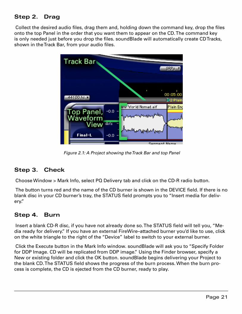
Step 2. Drag
Collect the desired audio files, drag them and, holding down the command key, drop the files onto the top Panel in the order that you want them to appear on the CD. The command key is only needed just before you drop the files. soundBlade will automatically create CD Tracks, shown in the Track Bar, from your audio files.
Figure 2.1: A Project showing the Track Bar and top Panel
Step 3. Check
Choose Window > Mark Info, select PQ Delivery tab and click on the CD-R radio button.
The button turns red and the name of the CD burner is shown in the DEVICE field. If there is no blank disc in your CD burner’s tray, the STATUS field prompts you to “Insert media for deliv-ery.”
Step 4. Burn
Insert a blank CD-R disc, if you have not already done so. The STATUS field will tell you, “Me-dia ready for delivery.” If you have an external FireWire–attached burner you’d like to use, click on the white triangle to the right of the “Device” label to switch to your external burner.
Click the Execute button in the Mark Info window. soundBlade will ask you to “Specify Folder for DDP Image. CD will be replicated from DDP image.” Using the Finder browser, specify a New or existing folder and click the OK button. soundBlade begins delivering your Project to the blank CD. The STATUS field shows the progress of the burn process. When the burn pro-cess is complete, the CD is ejected from the CD burner, ready to play.

Page 22
Page 23
Chapter 3 ..................................................... Basic Operation
3.1 General Workflow & Explanation of Terms Used
In order to prepare your finished master, soundBlade offers fast, simple audio editing along with creation and modification of metadata. Though soundBlade is designed to primarily cre-ate finished stereo programs, it also includes CD-R and DDP file creation as well. DDP or, Disc Description Protocol, is the professional’s preferred method of delivery of production masters for optical disc replication.
When opening a sound file into soundBlade, you are creating a copy of the file in memory that you can manipulate. This copy is placed into a ‘Project,’ the workspace created by soundBlade. Within the Project, you can add sound, create and edit Marks that will generate PQ codes, and place SRPs, persistent editing–related placeholders inside the Project. All this information can be saved and later recalled.
Raw sound files can be imported from various file formats, including AIFF, WAV, BWF, AIFC 32 bit floating point files and SD2 or Sound Designer II with regions. These files are edited, allow-ing you to compile a new program from various sources.
When you are satisfied that your Project is acceptable, you can create a Compact Disc that al-lows you to check the completed program. These “check discs” or “refs” are perfect for approv-als but not for replication. The audio data on these CD-Rs, technically CD-DA–formatted Orange Book discs, contain error–protected metadata but not error–protected audio data. So, errors can propagate through premaster to replication, resulting in costly rework. For disc replication, you should save your changes to the Project and “deliver” a DDP file set, a reliable, error–pro-tected file format specifically designed for interchange between facilities and optical disc repli-cation.
Page 24
3.2 Project Layout
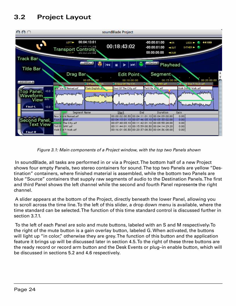
Figure 3.1: Main components of a Project window, with the top two Panels shown
In soundBlade, all tasks are performed in or via a Project. The bottom half of a new Project shows four empty Panels, two stereo containers for sound. The top two Panels are yellow “Des-tination” containers, where finished material is assembled, while the bottom two Panels are blue “Source” containers that supply raw segments of audio to the Destination Panels. The first and third Panel shows the left channel while the second and fourth Panel represents the right channel.
A slider appears at the bottom of the Project, directly beneath the lower Panel, allowing you to scroll across the time line. To the left of this slider, a drop down menu is available, where the time standard can be selected. The function of this time standard control is discussed further in section 3.7.1.
To the left of each Panel are solo and mute buttons, labeled with an S and M respectively. To the right of the mute button is a gain overlay button, labeled G. When activated, the buttons will light up “in color,” otherwise they are grey. The function of this button and the application feature it brings up will be discussed later in section 4.5. To the right of these three buttons are the ready record or record arm button and the Desk Events or plug–in enable button, which will be discussed in sections 5.2 and 4.6 respectively.
Page 25
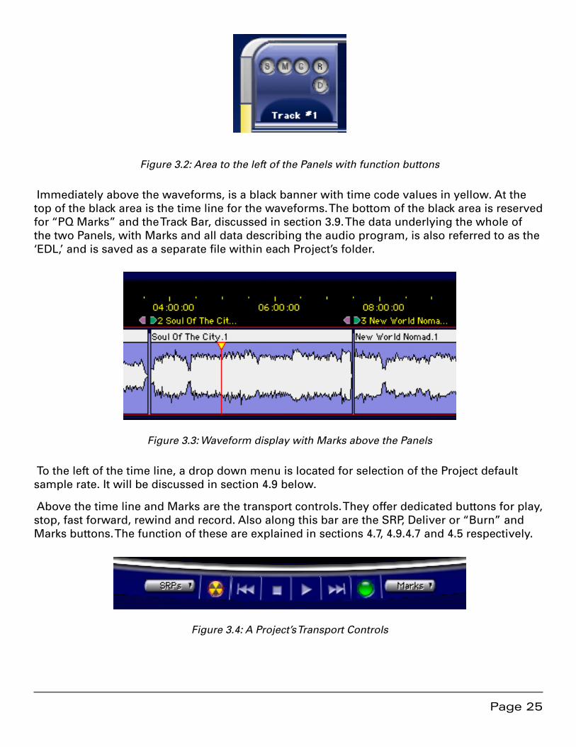
Figure 3.2: Area to the left of the Panels with function buttons
Immediately above the waveforms, is a black banner with time code values in yellow. At the top of the black area is the time line for the waveforms. The bottom of the black area is reserved for “PQ Marks” and the Track Bar, discussed in section 3.9. The data underlying the whole of the two Panels, with Marks and all data describing the audio program, is also referred to as the ‘EDL,’ and is saved as a separate file within each Project’s folder.
Figure 3.3: Waveform display with Marks above the Panels
To the left of the time line, a drop down menu is located for selection of the Project default sample rate. It will be discussed in section 4.9 below.
Above the time line and Marks are the transport controls. They offer dedicated buttons for play, stop, fast forward, rewind and record. Also along this bar are the SRP, Deliver or “Burn” and Marks buttons. The function of these are explained in sections 4.7, 4.9.4.7 and 4.5 respectively.
Figure 3.4: A Project’s Transport Controls
Page 26
Finally, at the top of the main window are time displays on the left, for the Playhead, and, on the right, for edit locations. In the middle is a display showing the current location of the Playhead and other time information related to that Project.
3.3 Starting a Project: Opening Files
3.3.1 Opening Projects
To create a new Project, select File > New Project... from the menu bar. A blank, default Project opens.
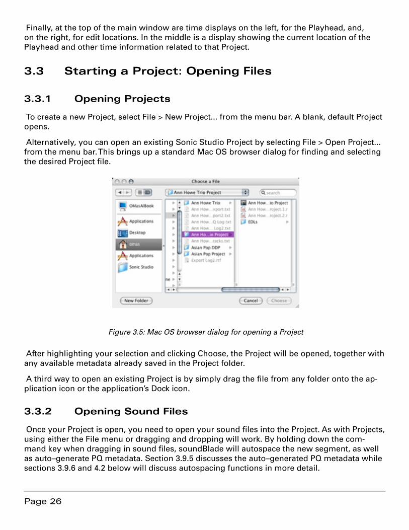
Alternatively, you can open an existing Sonic Studio Project by selecting File > Open Project... from the menu bar. This brings up a standard Mac OS browser dialog for finding and selecting the desired Project file.
Figure 3.5: Mac OS browser dialog for opening a Project
After highlighting your selection and clicking Choose, the Project will be opened, together with any available metadata already saved in the Project folder.
A third way to open an existing Project is by simply drag the file from any folder onto the ap-plication icon or the application’s Dock icon.
3.3.2 Opening Sound Files
Once your Project is open, you need to open your sound files into the Project. As with Projects, using either the File menu or dragging and dropping will work. By holding down the com-mand key when dragging in sound files, soundBlade will autospace the new segment, as well as auto–generate PQ metadata. Section 3.9.5 discusses the auto–generated PQ metadata while sections 3.9.6 and 4.2 below will discuss autospacing functions in more detail.
Page 27
By selecting File > Open Sound File... from the menu bar, you will bring up a standard Mac OS browser dialog for finding and selecting the desired audio file. soundBlade will open AIFF, WAV, BWF, AIFC 32 bit floating point files and SD2 files with regions. Confirm your selection with Choose and the sound file opens into your Project.
Broadcast WAV or BWF files can contain metadata to document production processes and con-trol how the file is handled during editorial. soundBlade will honor BWF time stamps on open. To force soundBlade to honor an existing time stamp, hold down the shift key when dragging. The sound file will open on the time line at its time stamp. See section 8.1.5.1 for more infor-mation.
3.3.3 Adding Your First Sound File
In addition to the Open Sound File… command, you may also drag and drop sound files into a Project. soundBlade makes the job of CD assembly easy by providing a special behavior for adding your sound files to a Project. Drag your first sound file into the top Panel of an empty Project and, before you let go, move your cursor to 00:00:02:00 or 2 seconds on the time line. soundBlade will display a vertical “snap” indicator when you cursor is near 2 seconds. Drop the sound file and soundBlade will snap its head to 2 seconds. See section 4.3.1.3 for more information on snap zones.
By holding down the command key before dropping all files, soundBlade will also automati-cally create PQ metadata for all the files. We recommend you get in the habit of holding down the command key when dropping sound files as it make performing basic pre–mastering chores and resequencing much easier.
Note that command–dropping only applies to drag and drop, not to the Open Sound File… command. Later in this chapter, section 3.8 discusses these topics in more detail.
3.4 Waveforms
A waveform display provides visual reinforcement of audible cues when editing. Normally, the audio file types that soundBlade opens contain metadata such as sample rate and related information, but no information on visualization. Waveform shape information therefore has to be generated by soundBlade itself. The application generates individual “waveform files,” one for each channel, in order to display high resolution waveforms in the Panels at any zoom level.
Page 28
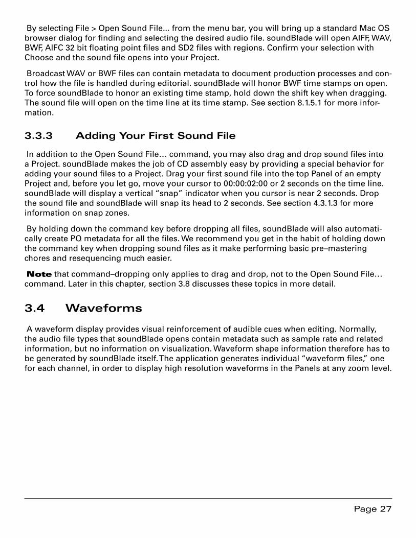
Figure 3.6: Display of a sound file without waveform metadata
Waveform files, identified by their “.r” extension, are placed in the same folder as the audio files and can be read by any other Sonic Studio product. If waveform files are absent from one or more audio files included in the Project, soundBlade can automatically start generat-ing those files in the background. The generation of waveform files can be performed in the background so normal operation is not interrupted. See section 8.9.10.1 for information on the Background Waveforms preference.
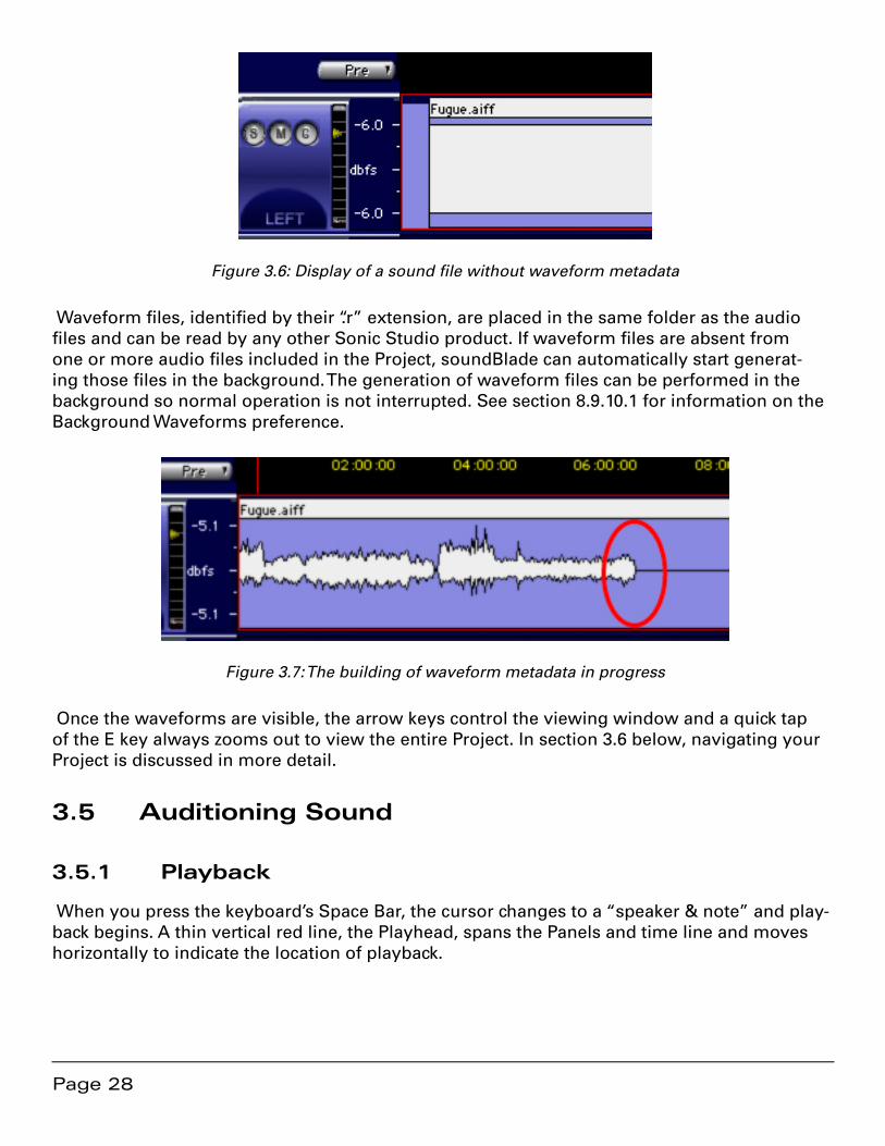
Figure 3.7: The building of waveform metadata in progress
Once the waveforms are visible, the arrow keys control the viewing window and a quick tap of the E key always zooms out to view the entire Project. In section 3.6 below, navigating your Project is discussed in more detail.
3.5 Auditioning Sound
3.5.1 Playback
When you press the keyboard’s Space Bar, the cursor changes to a “speaker & note” and play-back begins. A thin vertical red line, the Playhead, spans the Panels and time line and moves horizontally to indicate the location of playback.

Page 29
Figure 3.8: The cursor changes into a speaker & note shape during playback
When you first open a sound file and begin listening, playback, once started, will begin at the left edge of the audio. The Playhead will move to the right, across the file. When you hit the Space Bar again, playback ends and the Playhead halts its motion. When you hit the space bar a third time, the Playhead will jump back to the left side of the waveform display, the beginning of the sound file, and playback will begin again.
By default, one stereo pair in two Panels will play back simultaneously. Enabling the ‘Play All’ radio button, at the bottom left bottom of the Project, forces soundBlade to play both stereo pairs in all four Panels.
Figure 3.9: Play All radio button, selected by default.
You can also force soundBlade to repeatedly play the same material over and over via the Play > Repeat Play command. By holding down the command and option keys before tapping the space bar, soundBlade will “repeat play” a time region selection until you press the space bar again.
3.5.2 Playback from the Edit Point
When you click anywhere inside the waveform display, the entire Panel, or rectangle contain-ing the waveform display, is selected. The selected Panel has a medium blue background and hairline red border. Once selected, a click anywhere in that Panel produces a thin vertical red line, with an inverted yellow triangle on top. This is the “Edit Point.”
Page 30
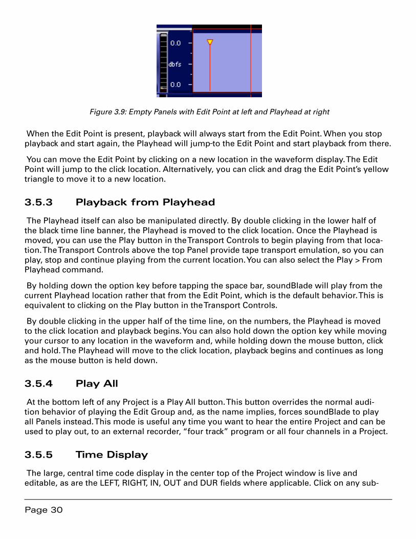
Figure 3.9: Empty Panels with Edit Point at left and Playhead at right
When the Edit Point is present, playback will always start from the Edit Point. When you stop playback and start again, the Playhead will jump to the Edit Point and start playback from there.
You can move the Edit Point by clicking on a new location in the waveform display. The Edit Point will jump to the click location. Alternatively, you can click and drag the Edit Point’s yellow triangle to move it to a new location.
3.5.3 Playback from Playhead
The Playhead itself can also be manipulated directly. By double clicking in the lower half of the black time line banner, the Playhead is moved to the click location. Once the Playhead is moved, you can use the Play button in the Transport Controls to begin playing from that loca-tion. The Transport Controls above the top Panel provide tape transport emulation, so you can play, stop and continue playing from the current location. You can also select the Play > From Playhead command.
By holding down the option key before tapping the space bar, soundBlade will play from the current Playhead location rather that from the Edit Point, which is the default behavior. This is equivalent to clicking on the Play button in the Transport Controls.
By double clicking in the upper half of the time line, on the numbers, the Playhead is moved to the click location and playback begins. You can also hold down the option key while moving your cursor to any location in the waveform and, while holding down the mouse button, click and hold. The Playhead will move to the click location, playback begins and continues as long as the mouse button is held down.
3.5.4 Play All
At the bottom left of any Project is a Play All button. This button overrides the normal audi-tion behavior of playing the Edit Group and, as the name implies, forces soundBlade to play all Panels instead. This mode is useful any time you want to hear the entire Project and can be used to play out, to an external recorder, “four track” program or all four channels in a Project.
3.5.5 Time Display
The large, central time code display in the center top of the Project window is live and editable, as are the LEFT, RIGHT, IN, OUT and DUR fields where applicable. Click on any sub-

Page 31
division or click–drag on the entire central time code display to select and modify the current address of the Playhead.
For all editable time code addresses, a single click in any HH:MM:SS:FF subdivision will high-light that subdivision, allowing you to type in a value. By click–holding and dragging up or down, the cursor will change to an arrow and the numeric value displayed will increase or decrease respectively. Click–hold for more than two seconds, and the rate of change increases. The arrow keys also let you move to a particular subdivision and increment or decrement the current value. Option–dragging a time code address allows you to quickly “clone” that value into another editable field.
Figure 3.10: Click–dragging down to edit a time code address
All modifiable time code fields in soundBlade support cut, copy and paste. Double clicking on any time field will select the entire field, allowing you to enter a complete time code address.
3.5.5.1 Capturing Playhead Time
soundBlade allows you to capture the current Playhead time, either during playback or, when stopped, and “push” its location into a selected time display field. To capture the Playhead location, make a selection in the particular time display field you want to update. Then press the space bar while holding down the shift key. The current play time will be dropped into the selected time display field.
3.6 Navigating the Waveform Display
There are many tools for quickly moving around inside of the waveform display. This section covers scrolling and zooming, in general and on selections.
3.6.1 Scrolling
If you are zoomed all the way out, the entire waveform will be displayed. If you are not zoomed out entirely, some of the waveform will be off the edges of the Panel. You can move the window view left or right by moving the slider control at the bottom of the waveform dis-play. You can also move the window view left and right by using the Left and Right Arrow key respectively.
Finally, you can drag the view left or right by simultaneously holding the control, option and command keys. When you click–hold, the cursor changes to a hand to indicate you are in Move View mode.
Page 32
3.6.2 Zooming
You can zoom in using the Down Arrow key, and zoom out using the Up Arrow key. To zoom all the way out, hit the E, for “entire,” key.
3.6.2.1 Zoom around Edit Point
As you zoom in and out, it is likely that you will want to keep the Edit Point in view. To do this, hold down the Apple or command key as you use the Up Arrow or Down arrow keys. This will keep the Edit Point centered in the middle of the display.
3.6.2.2 Zoom to Selection
Clicking and dragging on the waveform itself selects a region, highlighted in yellow–orange. Typing command-G or selecting View > Zoom to Selection... will zoom around that selected region. See section 3.7 for more information on region selection.
You can also zoom to a selection while making the selection. By holding down the command and option keys while click–dragging on the waveform will define a selection and zoom to that selection as well.
3.6.2.3 Zoom Around Time Selection
If you click and drag in the black time line banner above the top Panel while holding down the Apple or command key, the Panel will zoom to display the region of the time line that your click–drag defined.
3.7 Selections
Selections let you highlight a portion of the audio where you want to perform a desired opera-tion.
3.7.1 Selecting a Region
To select a region, click–drag on the waveform display. At the point that you want the selection to start, click and hold down the mouse button, then drag to complete your selection. An area will be highlighted in yellow–orange, indicating the selected region.
Page 33
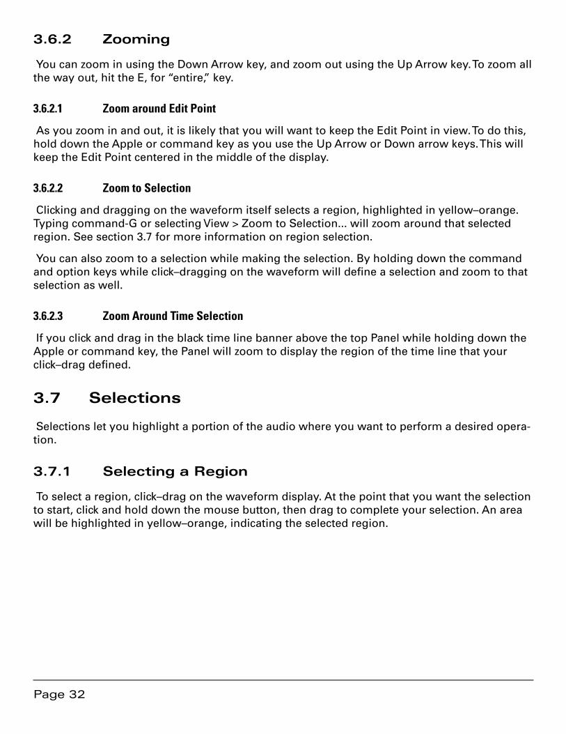
Figure 3.9: A region selected, indicated by the yellow highlight
You can click–drag either left or right to define a selection. In addition, you can fine tune the boundaries of a selected region. Hold down the shift key and click on either side of the selected region then, while continuing to hold the shift key, drag left or right to expand or contract the selection.
While selecting regions, the LEFT, RIGHT and DUR fields at the top of the Project are active and editable. See section 3.5.5 above for more information on manipulating time code addresses.
Note that the format in which all time fields are represented in soundBlade is user selectable. By clicking in the time standard display to the left of the time line slider, a drop down menu of-fering four choices becomes available.
Page 34
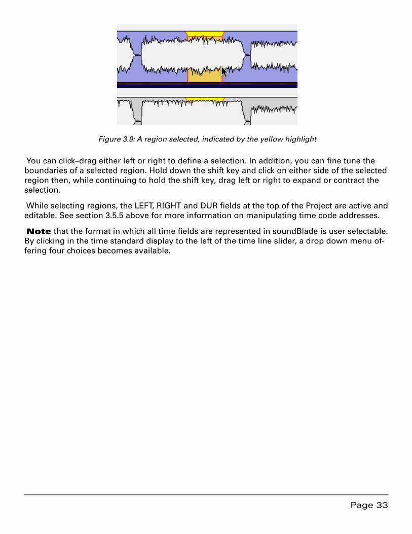
Figure 3.10: The time standard menu
Figure 3.10 above shows the time standard choices. 30 fps NDF is the default setting and signifies non–drop frame time code, the default time code format typically used by DAWs to prepare material for CD release when compact disc preparation was video tape–based. 29.97 drop and non–drop are “pull down” rates for NTSC video while 25 fps is for PAL video. The 24 fps setting is for general motion picture work while 75 fps CD Frames is the internal time code format for CD-DA discs (audio CDs). When mastering for CD release, 75 fps is the best choice.
The 35 and 16 mm setting provide minutes and seconds at non-pull down and pull down (59.9 Hz) rates referenced to 60 Hz for North America and Japan. Also included are versions with a 50 Hz reference for Europe.
The Seconds setting shows all times in multiples and fractions of seconds. Finally, Samples displays all times in absolute samples based on the selected sample rate . These same selec-tions appear in the Windows > Preference > Time Display tab, where the Project default is set. See section 4.9 for more information on time standard settings.
Note that, because soundBlade is designed, among other functions, to create the metadata necessary for Compact Disc replication, all of your PQ marking decisions are directly tied to the 75 frame standard. If you are using soundBlade for CD preparation, you should always use the 75 fps CD Frames standard.
Note also that, when a region is selected and playback is invoked, the Playhead relocates and playback starts at the beginning of the selection.
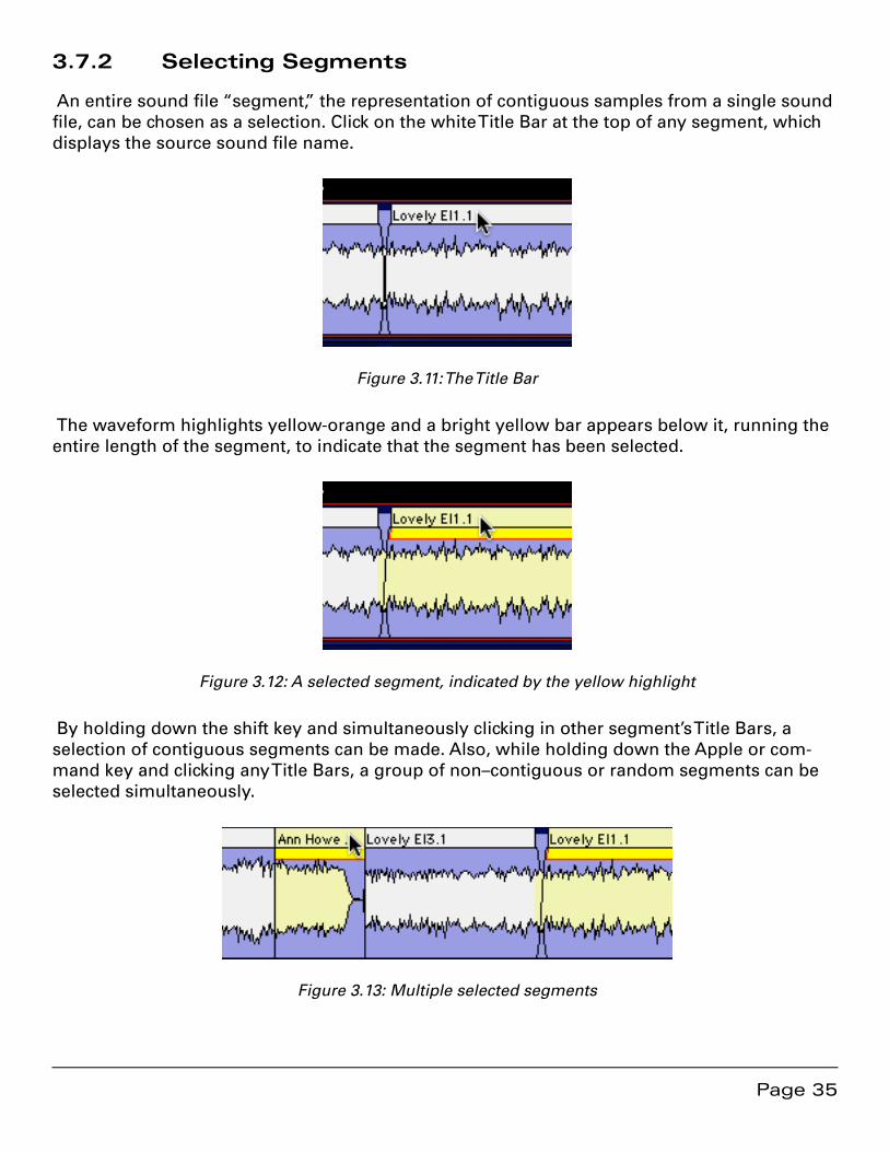
Page 35
3.7.2 Selecting Segments
An entire sound file “segment,” the representation of contiguous samples from a single sound file, can be chosen as a selection. Click on the white Title Bar at the top of any segment, which displays the source sound file name.
Figure 3.11: The Title Bar
The waveform highlights yellow-orange and a bright yellow bar appears below it, running the entire length of the segment, to indicate that the segment has been selected.
Figure 3.12: A selected segment, indicated by the yellow highlight
By holding down the shift key and simultaneously clicking in other segment’s Title Bars, a selection of contiguous segments can be made. Also, while holding down the Apple or com-mand key and clicking any Title Bars, a group of non–contiguous or random segments can be selected simultaneously.
Figure 3.13: Multiple selected segments
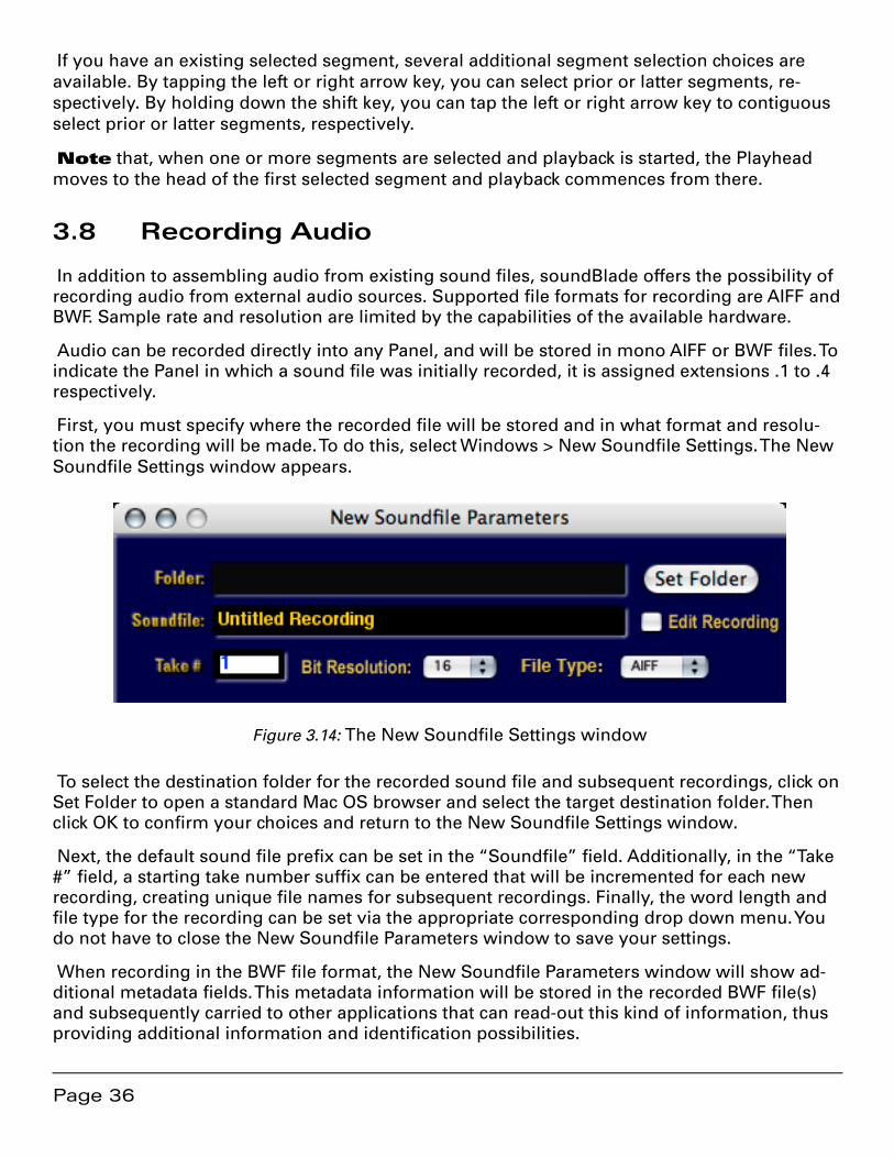
Page 36
If you have an existing selected segment, several additional segment selection choices are available. By tapping the left or right arrow key, you can select prior or latter segments, re-spectively. By holding down the shift key, you can tap the left or right arrow key to contiguous select prior or latter segments, respectively.
Note that, when one or more segments are selected and playback is started, the Playhead moves to the head of the first selected segment and playback commences from there.
3.8 Recording Audio
In addition to assembling audio from existing sound files, soundBlade offers the possibility of recording audio from external audio sources. Supported file formats for recording are AIFF and BWF. Sample rate and resolution are limited by the capabilities of the available hardware.
Audio can be recorded directly into any Panel, and will be stored in mono AIFF or BWF files. To indicate the Panel in which a sound file was initially recorded, it is assigned extensions .1 to .4 respectively.
First, you must specify where the recorded file will be stored and in what format and resolu-tion the recording will be made. To do this, select Windows > New Soundfile Settings. The New Soundfile Settings window appears.
Figure 3.14: The New Soundfile Settings window
To select the destination folder for the recorded sound file and subsequent recordings, click on Set Folder to open a standard Mac OS browser and select the target destination folder. Then click OK to confirm your choices and return to the New Soundfile Settings window.
Next, the default sound file prefix can be set in the “Soundfile” field. Additionally, in the “Take #” field, a starting take number suffix can be entered that will be incremented for each new recording, creating unique file names for subsequent recordings. Finally, the word length and file type for the recording can be set via the appropriate corresponding drop down menu. You do not have to close the New Soundfile Parameters window to save your settings.
When recording in the BWF file format, the New Soundfile Parameters window will show ad-ditional metadata fields. This metadata information will be stored in the recorded BWF file(s) and subsequently carried to other applications that can read-out this kind of information, thus providing additional information and identification possibilities.
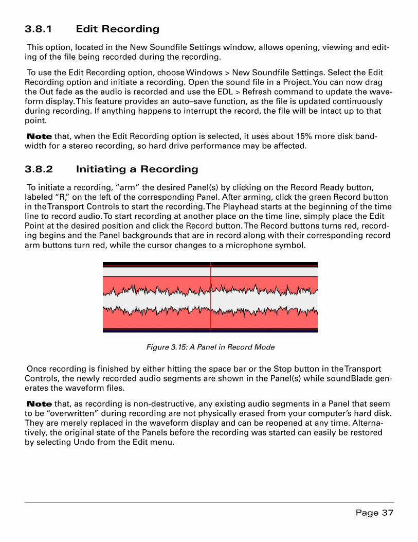
Page 37
3.8.1 Edit Recording
This option, located in the New Soundfile Settings window, allows opening, viewing and edit-ing of the file being recorded during the recording.
To use the Edit Recording option, choose Windows > New Soundfile Settings. Select the Edit Recording option and initiate a recording. Open the sound file in a Project. You can now drag the Out fade as the audio is recorded and use the EDL > Refresh command to update the wave-form display. This feature provides an auto–save function, as the file is updated continuously during recording. If anything happens to interrupt the record, the file will be intact up to that point.
Note that, when the Edit Recording option is selected, it uses about 15% more disk band-width for a stereo recording, so hard drive performance may be affected.
3.8.2 Initiating a Recording
To initiate a recording, “arm” the desired Panel(s) by clicking on the Record Ready button, labeled “R,” on the left of the corresponding Panel. After arming, click the green Record button in the Transport Controls to start the recording. The Playhead starts at the beginning of the time line to record audio. To start recording at another place on the time line, simply place the Edit Point at the desired position and click the Record button. The Record buttons turns red, record-ing begins and the Panel backgrounds that are in record along with their corresponding record arm buttons turn red, while the cursor changes to a microphone symbol.
Figure 3.15: A Panel in Record Mode
Once recording is finished by either hitting the space bar or the Stop button in the Transport Controls, the newly recorded audio segments are shown in the Panel(s) while soundBlade gen-erates the waveform files.
Note that, as recording is non-destructive, any existing audio segments in a Panel that seem to be “overwritten” during recording are not physically erased from your computer’s hard disk. They are merely replaced in the waveform display and can be reopened at any time. Alterna-tively, the original state of the Panels before the recording was started can easily be restored by selecting Undo from the Edit menu.
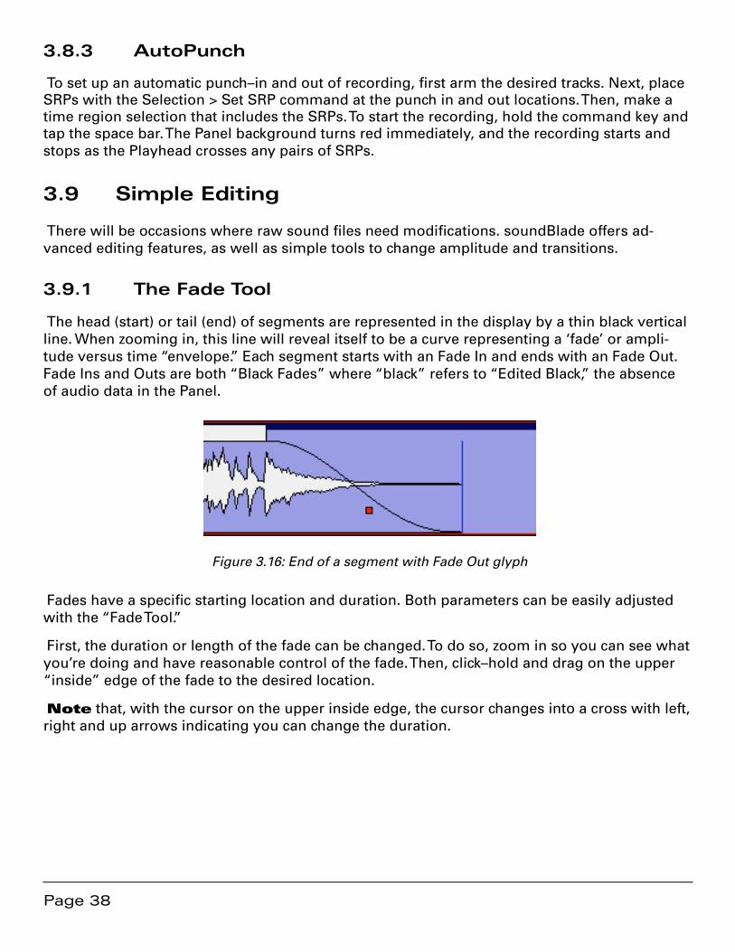
Page 38
3.8.3 AutoPunch
To set up an automatic punch–in and out of recording, first arm the desired tracks. Next, place SRPs with the Selection > Set SRP command at the punch in and out locations. Then, make a time region selection that includes the SRPs. To start the recording, hold the command key and tap the space bar. The Panel background turns red immediately, and the recording starts and stops as the Playhead crosses any pairs of SRPs.
3.9 Simple Editing
There will be occasions where raw sound files need modifications. soundBlade offers ad-vanced editing features, as well as simple tools to change amplitude and transitions.
3.9.1 The Fade Tool
The head (start) or tail (end) of segments are represented in the display by a thin black vertical line. When zooming in, this line will reveal itself to be a curve representing a ‘fade’ or ampli-tude versus time “envelope.” Each segment starts with an Fade In and ends with an Fade Out. Fade Ins and Outs are both “Black Fades” where “black” refers to “Edited Black,” the absence of audio data in the Panel.
Figure 3.16: End of a segment with Fade Out glyph
Fades have a specific starting location and duration. Both parameters can be easily adjusted with the “Fade Tool.”
First, the duration or length of the fade can be changed. To do so, zoom in so you can see what you’re doing and have reasonable control of the fade. Then, click–hold and drag on the upper “inside” edge of the fade to the desired location.
Note that, with the cursor on the upper inside edge, the cursor changes into a cross with left, right and up arrows indicating you can change the duration.
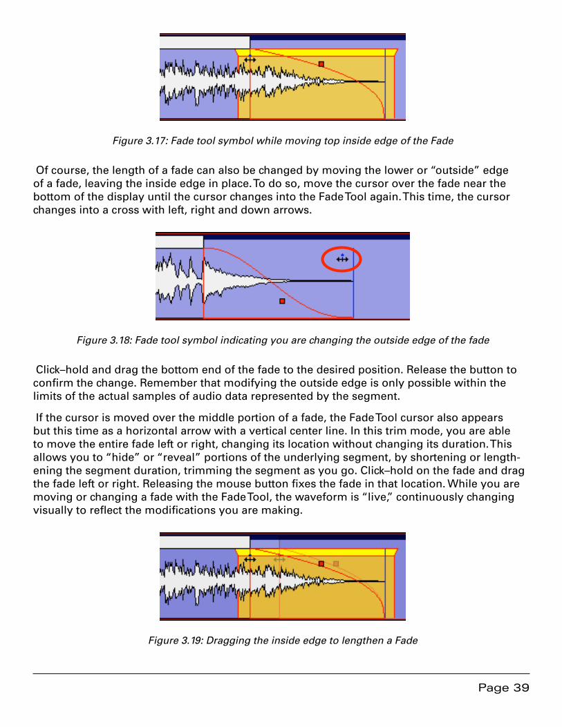
Page 39
Figure 3.17: Fade tool symbol while moving top inside edge of the Fade
Of course, the length of a fade can also be changed by moving the lower or “outside” edge of a fade, leaving the inside edge in place. To do so, move the cursor over the fade near the bottom of the display until the cursor changes into the Fade Tool again. This time, the cursor changes into a cross with left, right and down arrows.
Figure 3.18: Fade tool symbol indicating you are changing the outside edge of the fade
Click–hold and drag the bottom end of the fade to the desired position. Release the button to confirm the change. Remember that modifying the outside edge is only possible within the limits of the actual samples of audio data represented by the segment.
If the cursor is moved over the middle portion of a fade, the Fade Tool cursor also appears but this time as a horizontal arrow with a vertical center line. In this trim mode, you are able to move the entire fade left or right, changing its location without changing its duration. This allows you to “hide” or “reveal” portions of the underlying segment, by shortening or length-ening the segment duration, trimming the segment as you go. Click–hold on the fade and drag the fade left or right. Releasing the mouse button fixes the fade in that location. While you are moving or changing a fade with the Fade Tool, the waveform is “live,” continuously changing visually to reflect the modifications you are making.
Figure 3.19: Dragging the inside edge to lengthen a Fade

Page 40
Note that the maximum duration of a fade is equal to the underlying sound file duration. As mentioned above, it is not possible to move a fade past the actual start or end of an underlying sound file.
Also, moving Black Fades so more than two overlap is not allowed as well. A modal “Check-ForTripleOverlap” dialog will pop up, telling you that your command would result in three Black Fades lying on top of each other. To overcome this, click–drag to select a region that includes the area of interest, then select File > Export Sound File… and select the Edit after Ex-port check box. This will consolidate the edits, allowing you to continue with your editorial.
3.9.2 Deleting Part of a Sound File
It may be necessary to edit out some part of a sound file. soundBlade allows you to do so quickly or with great precision. To easily cut out a portion of a sound file, simply select the region that you want to remove. Then, select Edit > Delete Selection or hit the delete key to remove the selected region and “slip” all downstream segments left to close the gap. More on this later...
More precise editing can be performed with In points and Out edit points, special marks you can place in the Panel. An In Point is shown as a vertical line with a triangle at the bottom, pointing right, while an Out Point has the triangle pointing left.
Figure 3.20: In Point and Out Point with highlighted area in between
There can be only one In Point and one Out Point in a Panel at any time. If both an In Point and Out Point are present, and if the In Point is to the left of the Out Point in the waveform display, then the area between the In and Out Point will be highlighted in yellow. The Selection > Set In Point command drops an In Point at the location of the Edit Point.
Note that the IN, OUT and DUR time fields at the top right of the main Project window are always active and fully editable. These fields allow you to precisely alter the location of, and duration between, the In and Out Points, a functionality which comes out handy when the ex-act points are well known by their time value.
Once the region is defined, it can be modified in two different ways. The region can be either deleted or cleared. To clear the defined region, leaving an empty area, select the Edit > Clear Selection command.
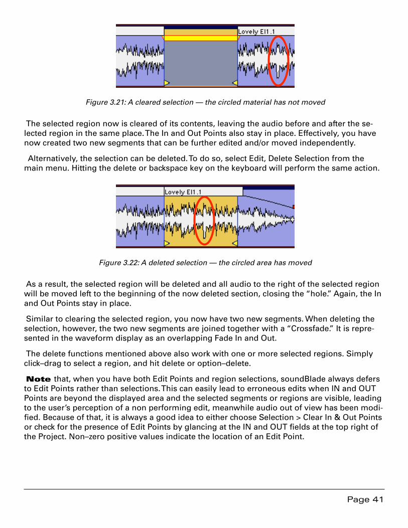
Page 41
Figure 3.21: A cleared selection — the circled material has not moved
The selected region now is cleared of its contents, leaving the audio before and after the se-lected region in the same place. The In and Out Points also stay in place. Effectively, you have now created two new segments that can be further edited and/or moved independently.
Alternatively, the selection can be deleted. To do so, select Edit, Delete Selection from the main menu. Hitting the delete or backspace key on the keyboard will perform the same action.
Figure 3.22: A deleted selection — the circled area has moved
As a result, the selected region will be deleted and all audio to the right of the selected region will be moved left to the beginning of the now deleted section, closing the “hole.” Again, the In and Out Points stay in place.
Similar to clearing the selected region, you now have two new segments. When deleting the selection, however, the two new segments are joined together with a “Crossfade.” It is repre-sented in the waveform display as an overlapping Fade In and Out.
The delete functions mentioned above also work with one or more selected regions. Simply click–drag to select a region, and hit delete or option–delete.
Note that, when you have both Edit Points and region selections, soundBlade always defers to Edit Points rather than selections. This can easily lead to erroneous edits when IN and OUT Points are beyond the displayed area and the selected segments or regions are visible, leading to the user’s perception of a non performing edit, meanwhile audio out of view has been modi-fied. Because of that, it is always a good idea to either choose Selection > Clear In & Out Points or check for the presence of Edit Points by glancing at the IN and OUT fields at the top right of the Project. Non–zero positive values indicate the location of an Edit Point.
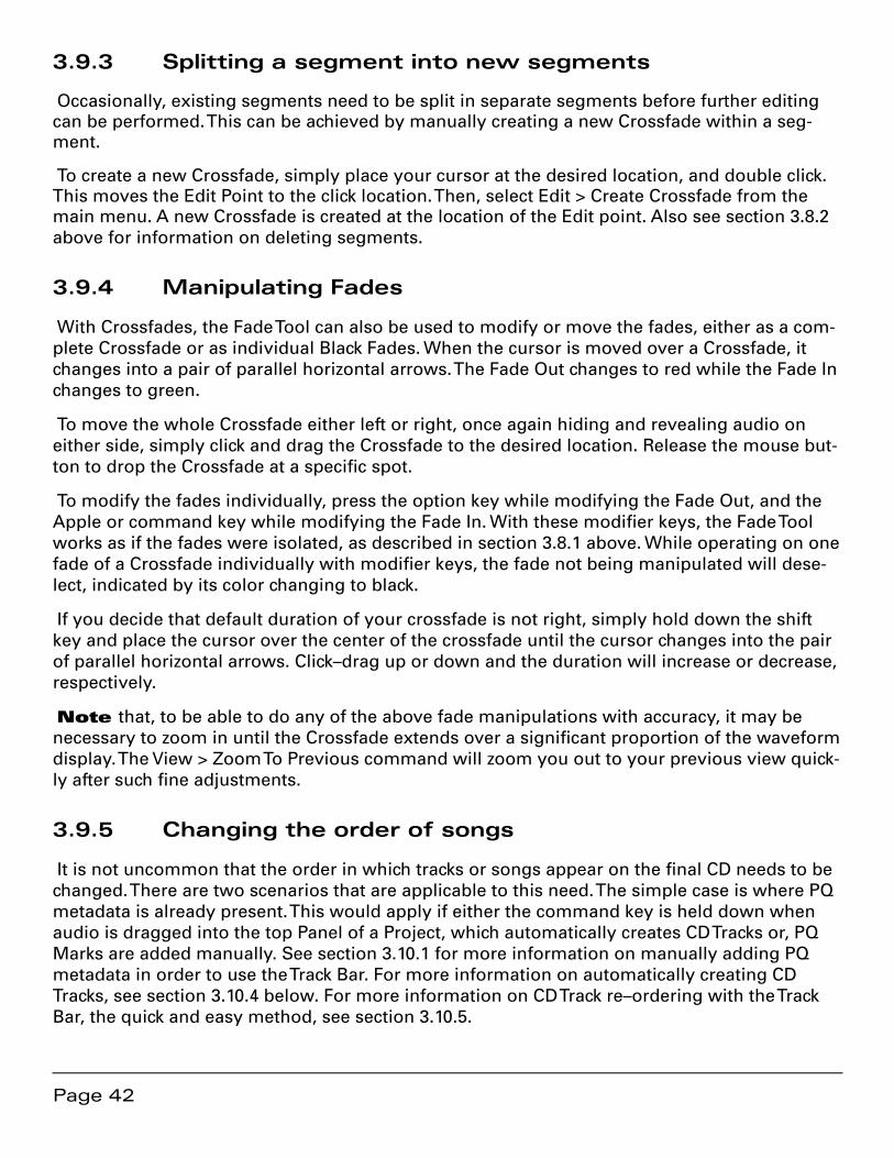
Page 42
3.9.3 Splitting a segment into new segments
Occasionally, existing segments need to be split in separate segments before further editing can be performed. This can be achieved by manually creating a new Crossfade within a seg-ment.
To create a new Crossfade, simply place your cursor at the desired location, and double click. This moves the Edit Point to the click location. Then, select Edit > Create Crossfade from the main menu. A new Crossfade is created at the location of the Edit point. Also see section 3.8.2 above for information on deleting segments.
3.9.4 Manipulating Fades
With Crossfades, the Fade Tool can also be used to modify or move the fades, either as a com-plete Crossfade or as individual Black Fades. When the cursor is moved over a Crossfade, it changes into a pair of parallel horizontal arrows. The Fade Out changes to red while the Fade In changes to green.
To move the whole Crossfade either left or right, once again hiding and revealing audio on either side, simply click and drag the Crossfade to the desired location. Release the mouse but-ton to drop the Crossfade at a specific spot.
To modify the fades individually, press the option key while modifying the Fade Out, and the Apple or command key while modifying the Fade In. With these modifier keys, the Fade Tool works as if the fades were isolated, as described in section 3.8.1 above. While operating on one fade of a Crossfade individually with modifier keys, the fade not being manipulated will dese-lect, indicated by its color changing to black.
If you decide that default duration of your crossfade is not right, simply hold down the shift key and place the cursor over the center of the crossfade until the cursor changes into the pair of parallel horizontal arrows. Click–drag up or down and the duration will increase or decrease, respectively.
Note that, to be able to do any of the above fade manipulations with accuracy, it may be necessary to zoom in until the Crossfade extends over a significant proportion of the waveform display. The View > Zoom To Previous command will zoom you out to your previous view quick-ly after such fine adjustments.
3.9.5 Changing the order of songs
It is not uncommon that the order in which tracks or songs appear on the final CD needs to be changed. There are two scenarios that are applicable to this need. The simple case is where PQ metadata is already present. This would apply if either the command key is held down when audio is dragged into the top Panel of a Project, which automatically creates CD Tracks or, PQ Marks are added manually. See section 3.10.1 for more information on manually adding PQ metadata in order to use the Track Bar. For more information on automatically creating CD Tracks, see section 3.10.4 below. For more information on CD Track re–ordering with the Track Bar, the quick and easy method, see section 3.10.5.
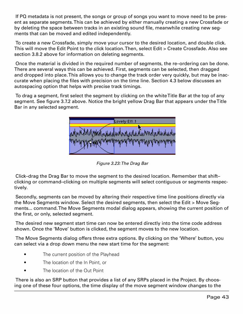
Page 43
If PQ metadata is not present, the songs or group of songs you want to move need to be pres-ent as separate segments. This can be achieved by either manually creating a new Crossfade or by deleting the space between tracks in an existing sound file, meanwhile creating new seg-ments that can be moved and edited independently.
To create a new Crossfade, simply move your cursor to the desired location, and double click. This will move the Edit Point to the click location. Then, select Edit > Create Crossfade. Also see section 3.8.2 above for information on deleting segments.
Once the material is divided in the required number of segments, the re–ordering can be done. There are several ways this can be achieved. First, segments can be selected, then dragged and dropped into place. This allows you to change the track order very quickly, but may be inac-curate when placing the files with precision on the time line. Section 4.3 below discusses an autospacing option that helps with precise track timings.
To drag a segment, first select the segment by clicking on the white Title Bar at the top of any segment. See figure 3.7.2 above. Notice the bright yellow Drag Bar that appears under the Title Bar in any selected segment.
Figure 3.23: The Drag Bar
Click–drag the Drag Bar to move the segment to the desired location. Remember that shift–clicking or command–clicking on multiple segments will select contiguous or segments respec-tively.
Secondly, segments can be moved by altering their respective time line positions directly via the Move Segments window. Select the desired segments, then select the Edit > Move Seg-ments... command. The Move Segments modal dialog appears, showing the current position of the first, or only, selected segment.
The desired new segment start time can now be entered directly into the time code address shown. Once the ‘Move’ button is clicked, the segment moves to the new location.
The Move Segments dialog offers three extra options. By clicking on the ‘Where’ button, you can select via a drop down menu the new start time for the segment:
The current position of the Playhead•
The location of the In Point, or•
The location of the Out Point•
There is also an SRP button that provides a list of any SRPs placed in the Project. By choos-ing one of these four options, the time display of the move segment window changes to the
Page 44
relevant time. SRPs, persistent markers you can place anywhere in time, are discussed later in section 4.7 below.
After choosing your option, clicking the ‘Move’ button will move the segment and close the dialog. Clicking ‘Cancel’ leaves the segment at its original position and closes the dialog.
3.9.6 Simple Track Spacing: AutoSpace
Once all your segments are placed in the right order, the AutoSpace function offers a simple but effective tool to change all pauses between songs to a pre-defined value. Simply select Edit > AutoSpace All Segments and all segments will be moved on the time line, with equal space between according to the Preference > Editing Tools > AutoSpacing Duration setting. In Prefer-ences, the length of the AutoSpace can be set to 1, 2 or 3 seconds.
Note that, if a song is composed of more than one segment, then the AutoSpace command should be used with care as the command will “break apart” the song, autospacing its compo-nent segments. Also, the AutoSpace command should be used before you place PQ marks to prevent unwanted mark (re)location.
Also Note that, if segments have had their fade durations lengthened from the default set-ting, the AutoSpace command will not necessarily result in a desirable spacing. This is because the fade duration at the head and/or tail of one or more segments may be longer that the mini-mum 1 seconds spacing that is required between PQ Marks on a CD. If you use the fade tool to lengthen fades at the head or tail of a segment, you should manually space your segments by using the Selection > Select Edit Point to End command and the Drag Bar.
3.9.7 Exporting Selections & Segments
Selections, including both selected segments and selected regions, can be exported as AIFF or BWF files, with source resolution of up to 96 kHz sample rate and 16 or 24 bit word length. To do this, use the File > Export Sound File… command. It exports the audio with amplitude changes from segment gain, plus any Gain Overlay and plug–in processing.
To use this function, first click–drag in the top Panel to create a selected region and make sure the top two Panels are assigned, via the first two Desk Strips, to M1-Out and M2-Out. Then choose the destination directory with the Set file button. Finally, set the file type, word length and speed, then click the Export button. soundBlade will “play” the selected region, exporting the audio as it plays and as you hear it. The Edit after Export check box causes soundBlade to replace–edit the exported segment back into the Project.
Another use for the export command is consolidation of a complex edit or processing. The ex-port command will cleanly “freeze” or “print” to disk a collection of instantiated plug–ins that will not play in real time due to host saturation or overload. This is because export operates out of real time and so is not constrained by real time timing and buffering issues.
Note that playing the material at 1x speed during export will not improve the quality so, it is recommended that, unless real–time playback is needed, you use the highest speed set-ting as it has better temporal resolution. Also, during high speed exports, the time display and Playhead do not operate in real time.
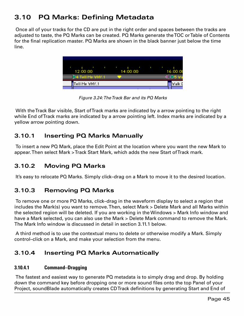
Page 45
3.10 PQ Marks: Defining Metadata
Once all of your tracks for the CD are put in the right order and spaces between the tracks are adjusted to taste, the PQ Marks can be created. PQ Marks generate the TOC or Table of Contents for the final replication master. PQ Marks are shown in the black banner just below the time line.
Figure 3.24: The Track Bar and its PQ Marks
With the Track Bar visible, Start of Track marks are indicated by a arrow pointing to the right while End of Track marks are indicated by a arrow pointing left. Index marks are indicated by a yellow arrow pointing down.
3.10.1 Inserting PQ Marks Manually
To insert a new PQ Mark, place the Edit Point at the location where you want the new Mark to appear. Then select Mark > Track Start Mark, which adds the new Start of Track mark.
3.10.2 Moving PQ Marks
It’s easy to relocate PQ Marks. Simply click–drag on a Mark to move it to the desired location.
3.10.3 Removing PQ Marks
To remove one or more PQ Marks, click–drag in the waveform display to select a region that includes the Mark(s) you want to remove. Then, select Mark > Delete Mark and all Marks within the selected region will be deleted. If you are working in the Windows > Mark Info window and have a Mark selected, you can also use the Mark > Delete Mark command to remove the Mark. The Mark Info window is discussed in detail in section 3.11.1 below.
A third method is to use the contextual menu to delete or otherwise modify a Mark. Simply control–click on a Mark, and make your selection from the menu.
3.10.4 Inserting PQ Marks Automatically
3.10.4.1 Command–Dragging
The fastest and easiest way to generate PQ metadata is to simply drag and drop. By holding down the command key before dropping one or more sound files onto the top Panel of your Project, soundBlade automatically creates CD Track definitions by generating Start and End of
Page 46
Track Marks for each file. These Track definitions can later be rearranged or modified to taste. See section 3.10.5 below for more information of resequencing.
3.10.4.2 Edited Black To Marks
Apart from placing PQ Marks manually at the desired positions, soundBlade has the ability to generate PQ Marks automatically. If the entire Project was created by editing each song or seg-ment, the most efficient way to generate PQ Marks automatically is to Edit > Select All, select-ing all segments, then select the Mark > Edited Black To Marks command. You can also click–drag to select a region, then select the Mark > Edited Black To Marks command. soundBlade automatically places Start and End of Track marks at the outside edges of all segments, using the location of Black Fades. The final result is a collection of marks accurately placed at the be-gin or end of each Black Fade.
3.10.4.3 Analog Black To Marks
If you’ve done a fair amount of fancy editing and track timing, then Edited Black To Marks may not be the ideal choice. Also, if your material consists of one long, consolidated file with few or no edits, then you may want to automatically place PQ Marks with the Analog Black to Marks function instead. This function measures the amplitude of your audio and places PQ Marks at the edges of long duration quiet passages. Both amplitude and duration are user adjustable.
To use, first click–drag to select a region on which to work. Then, select the Mark > Analog Black To Marks... command. In the resulting modal dialog, specify the amplitude and duration of the selected region you want to mark.
The results of the Analog Black To Marks function are not as accurate as Digital Black to Marks, but will provide quite usable PQ Mark placement even with un–edited material. The placement accuracy is dependent on the settings used, as well as the assumption that tracks always start and end with an increase then decrease in amplitude and quiet in between. However, it is very likely that those same criteria also apply to other moments in the course of a musical piece so, the results of the Analog Black To Marks function should always be checked for acceptable accuracy. You may also try the command, check the result and adjust the parameters prior to undoing or deleting marks and using the function again. See section 3.10.6 below for useful information on checking mark accuracy.
3.10.5 Tracks
soundBlade allows you to display and manipulate (CD) Tracks. The Windows > Preferences > EDL > Show Track Bar preference enables or disables the Track Bar. Each CD Track that will result from your current PQ placement is shown in grey while the pause between tracks is shown in blue.
3.10.5.1 Moving Tracks & Resequencing
A Track, always with its associated pause from the previous End of Track mark, can be selected by clicking on its Track Bar. Selecting a Track also selects the underlying audio that is associated with that Track. When you move a Track, you also move the associated audio. This means that
Page 47
you can quickly resequence your deliverable by dragging and dropping Tracks. The Track, with its Marks, can be moved by click–holding a Track’s track Bar, dragging left or right to a new posi-tion in the Track sequence, and dropping. The Track Bar updates to graphically display the new Track definition.
The Windows > Mark Info window is another way to move Tracks. As with the Track Bar, click–hold a Track entry and drag it up or down on a new position and drop it to resequence.
3.10.6 The Marks Button
In the Transport Controls, the Marks Button can be seen. Clicking on it reveals a list of all PQ Marks in the Project along with their timings. Selecting one of the entries in the drop down list moves the Edit Point to the selected PQ Marks, without changing the zoom level. This allows for a quick and accurate check of the position of all PQ Marks.
3.11 Delivery
After completing the necessary editing of sound and PQ Marks, the next and final step in your production workflow is to start a “Delivery.” This process creates a new DPP image file set first, incorporating all edits and changes, ready to be sent to a replication service for glass master-ing. The DDP file set is then used by soundBlade to generate your CD in the background.
DDP or Disc Description Protocol is the industry standard method for delivering all the data and metadata needed for disc replication to a “pressing plant.” Unlike audio CDs, DDP file sets contain error–protected audio data plus all ancillary metadata or, “data about the data.” DDP file sets, when used for replication, avoid potential errors that can crop up between the time you create a replication master and the moment that a “glass master” is created during rep-lication. CD-DA discs, or audio CDs, do not protect the audio data from errors since they as-sume that the CD player will hide or “conceal” any errors during playback. This situation leads to errors in replication when recordable CDs, formatted as Red Book (audio) discs, are used as replication masters.
Note that the DDP files created by soundBlade, always in their enclosing folder, can be cop-ied to any writable medium you choose, DVD-R, data tape or hard disk, for transport to the rep-licator. Of course, the medium you choose must have enough space to hold the file set. Also, always check with your replicator to determine which physical medium and format they can handle and whether they are even capable of using DDP as an premastering format. Many bar-gain companies are not ready to handle DDP deliveries so, we at Sonic Studio suggest you find a reputable facility that does accept DDP file sets of your valuable masters. Check the Support section of the Sonic Studio web site <www.sonicstudio.com> for a list of DDP–friendly replica-tion facilities worldwide.
3.11.1 A Check List for Delivery
First, when burning CD-R “check discs,” always put the unwritten, blank disc in the drive before starting the delivery process.
Page 48
Second, when delivering a DDP file set, use DVD-R blanks rather than CD-R blanks to deliver your DDP file set. That way, the replicator cannot confuse a CD-R with DDP files as a CD-ROM job and replicate 1000 CD-ROMs of your DDP file set!
Third, when delivering a DDP file set, the entire DDP folder or directory must be sent to the replicator. We suggest you ZIP the whole thing and generate a check sum for the resulting ZIP file. For more information, see the Checksums for DDP section of our Knowledgebase page:
http://www.sonicstudio.com/support
Fourth, check your Mark Info window for metacharacters, such as $, & and %, as well as ex-tended ASCII characters, like å, é, ø, ö, ü, ñ, et cetera. Mac OS, which soundBlade uses to write CD-Rs, does not handle extended ASCII and metacharacters properly.
Finally, when delivering a DDP file set, we recommend that you always create a new, empty folder to contain each DDP file set. On the Desktop is a reasonable place for that. That makes it easier to archive and seems to prevent common problems.
3.11.2 The Mark Info Window
To begin the PQ Delivery process, select the Windows > Mark Info command. This opens the Mark Info window which displays all the P through W subcode metadata you have defined.
3.11.2.1 Global Metadata
At the top of the Mark Info dialog are three fields that define global information about the disc. The Album Title and Artist generate the disc’s global information that, when placed in a trans-port that reads CD Text data, will appear on the transport’s display.
CD Text, a subset of the CD+G specification, provides for the embedding of textual informa-tion about the overall disc and tracks in the R through W codes of the “PQ” subcode stream of a Compact Disc. Many portable and in–dash car players can read CD Text data off of a disc, but few home players can.
CD Text should not be confused with network services such as Gracenote’s CDDB or FreeDB that attempt to match CDs inserted into a computer drive with an on–line database of extant CD titles. Such network services are used by iTunes and other applications for user convenience but have no relationship to the possibly embedded CD Text information on individual CD’s.
Note that soundBlade can only produce CD-Text on CD-R media. soundBlade’s DDP image file sets do not contain properly formatted CD-Text information. CD’s duplicated from a DDP file set generated by soundBlade will therefore not contain CD-Text information. However, refer-ence discs on CD-R media, created with soundBlade, do contain the CD-Text information.
Note also that, due a current limitation of Mac OS, the current version of soundBlade does not support open session CDs with CD Text.

Page 49
3.11.2.2 Track Metadata
This section provides information about individual track attributes. The next two fields, Track Ti-tle and Track Artist, are also part of the CD Text specification, and data entered into these fields will also appear on CD players equipped to read this metadata. soundBlade auto–populates the Track Title based on the segment name and, if you have provided an Album Artist prior to PQ creation, soundBlade will also auto–populate the Track Artist metadata as well.
Track Start and Track End are generated by your Mark placement. Though editable, you should assume that they are correct. Likewise, the Copy and Emphasis buttons generate the SCMS (Serial Copy Management Scheme) Copy flag and AES/EBU Emphasis flag in the PQ stream and should, in general, be left turned off. Section 4.10 below discussing PQ parameters in more detail.
3.11.2.3 Track Listing
The next section in the Mark Info dialog provides a list of details about each defined track. Name, start and end times, as well as duration are shown.
Double clicking on an entry in the list will start playback at that location in the Project. This gives you a quick method for double checking Mark placement. See section 4.10.4 for details about the Track Listing, Total Tracks and extended listing.
Note that, if you have placed your (text) insertion point in the TRACK TITLE, ARTIST and ISRC fields, the up/down arrow keys on the keyboard will move you up and down through each en-try in the list of PQ details.
3.11.2.4 PQ Status & Validation
Below the Track Details section is a single field with an indicator to its left. This is the PQ Valida-tion field, a non–editable status field that indicates whether your metadata, as defined, is valid and meets the Red Book specification for Compact Discs.
A green indicator means everything is valid, while a red indicator mean you should inspect your PQ information for non–Red Book–compliant entries. The accompanying field calls out the problem entry, making it easy to rectify the problem.
3.11.2.5 Device & Status/Validation
The Device field provides a list of available disc writing devices, and provides details about the (selected) mechanism. To the right of the Device label is a selector that, for multiple connected mechanisms, allows you to choose the target device. The Status field provides an indication of the status of your delivery media and/or progress on the delivery.
Note that you may see a “Sound begins more than 2 frames before Start Mark” message. This a reminder to check that you are not unintentionally truncating any audio at the head of your Project. Remember that, according to the Red Book specification for CD-DA discs, the first 2 seconds or 150 CD frames are “pregap,” and the first track start is at 2 seconds. Any audio before the 2 second mark will be replaced by 150 CD frames of digital zeroes on any CDs deliv-

ered and in DDP file sets. Pregap is a logical region of the disc reserved for mode changes and other non–audio functions.
3.11.2.6 The Execute Button
Once the above options are set, this button starts the process of creating a new delivery, writ-ten to the location shown in the “Path/Device” field. When you click the Execute button, a stan-dard Mac OS file browser opens where appropriate, allowing you to specify the location that will be used. A new or empty folder should be specified to contain the newly created or modi-fied DDP file set. Once the destination is specified, soundBlade begins the delivery process, with progress shown in the validation field at the bottom of the PQ Delivery window. During delivery to a CD-R when no media is present in the selected drive, soundBlade will prompt you to insert media and wait for a blank disc to be inserted.
Note that, once a delivery has started, the Execute button changes to an Abort button, allow-ing you to halt the delivery process. If a delivery is aborted, the resulting CD-R or DDP image file set is not reliably usable for either duplication or playback purposes.
3.11.2.7 The Eject Button
The Eject button will cause the host to eject an inserted disc from the selected CD writer.
3.11.2.8 The PQ List Button
This button generates a Sonic Studio–standard PQ List, the industry’s standard text represen-tation of a compact disc’s table of content. This file is typically printed and a hard copy sent, along with the DDP data set, to your replicator.
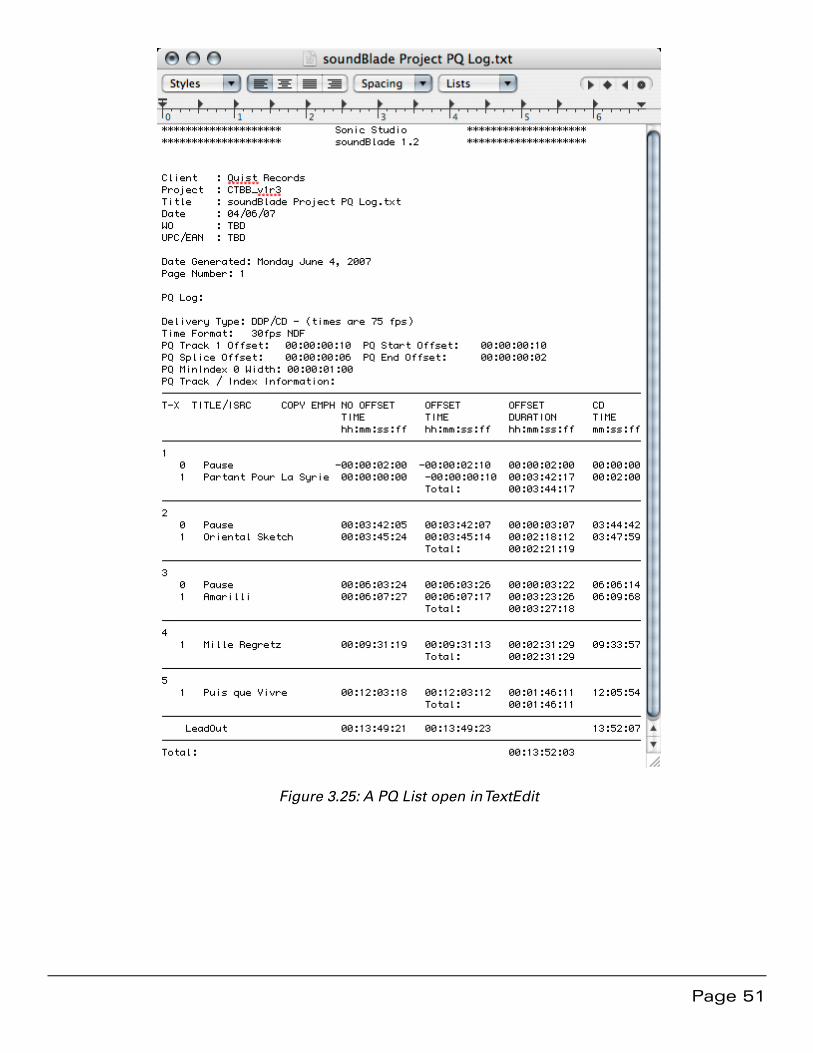
Page 51
Figure 3.25: A PQ List open in TextEdit

Page 52
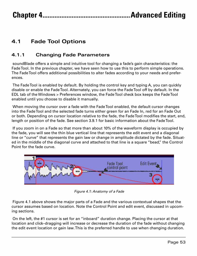
Page 53
Chapter 4 ...................................................Advanced Editing
4.1 Fade Tool Options
4.1.1 Changing Fade Parameters
soundBlade offers a simple and intuitive tool for changing a fade’s gain characteristics: the Fade Tool. In the previous chapter, we have seen how to use this to perform simple operations. The Fade Tool offers additional possibilities to alter fades according to your needs and prefer-ences.
The Fade Tool is enabled by default. By holding the control key and typing A, you can quickly disable or enable the Fade Tool. Alternately, you can force the Fade Tool off by default. In the EDL tab of the Windows > Preferences window, the Fade Tool check box keeps the Fade Tool enabled until you choose to disable it manually.
When moving the cursor over a fade with the Fade Tool enabled, the default cursor changes into the Fade Tool and the selected fade turns either green for an Fade In, red for an Fade Out or both. Depending on cursor location relative to the fade, the Fade Tool modifies the start, end, length or position of the fade. See section 3.9.1 for basic information about the Fade Tool.
If you zoom in on a Fade so that more than about 10% of the waveform display is occupied by the fade, you will see the thin blue vertical line that represents the edit event and a diagonal line or “curve” that represents the gain law or change in amplitude dictated by the fade. Situat-ed in the middle of the diagonal curve and attached to that line is a square “bead,” the Control Point for the fade curve.
Fade Toolcontrol point
Edit Event
3
2
1
➷➷
Figure 4.1: Anatomy of a Fade
Figure 4.1 above shows the major parts of a Fade and the various contextual shapes that the cursor assumes based on location. Note the Control Point and edit event, discussed in upcom-ing sections.
On the left, the #1 cursor is set for an “inboard” duration change. Placing the cursor at that location and click–dragging will increase or decrease the duration of the fade without changing the edit event location or gain law. This is the preferred handle to use when changing duration.
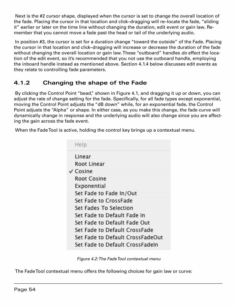
Page 54
Next is the #2 cursor shape, displayed when the cursor is set to change the overall location of the fade. Placing the cursor in that location and click–dragging will re–locate the fade, “sliding it” earlier or later on the time line without changing the duration, edit event or gain law. Re-member that you cannot move a fade past the head or tail of the underlying audio.
In position #3, the cursor is set for a duration change “toward the outside” of the Fade. Placing the cursor in that location and click–dragging will increase or decrease the duration of the fade without changing the overall location or gain law. These “outboard” handles do effect the loca-tion of the edit event, so it’s recommended that you not use the outboard handle, employing the inboard handle instead as mentioned above. Section 4.1.4 below discusses edit events as they relate to controlling fade parameters.
4.1.2 Changing the shape of the Fade
By clicking the Control Point “bead,” shown in Figure 4.1, and dragging it up or down, you can adjust the rate of change setting for the fade. Specifically, for all fade types except exponential, moving the Control Point adjusts the “dB down” while, for an exponential fade, the Control Point adjusts the “Alpha” or shape. In either case, as you make this change, the fade curve will dynamically change in response and the underlying audio will also change since you are affect-ing the gain across the fade event.
When the Fade Tool is active, holding the control key brings up a contextual menu.
Figure 4.2: The Fade Tool contextual menu
The Fade Tool contextual menu offers the following choices for gain law or curve:

Page 55
• Linear — default 6 dB down in the center
• Root Linear — 3 dB down in the center
• Cosine — default 3 dB down in the center
• Root Cosine — default 6 dB down in the center
• Exponential — provides very rapid reduction in gain across the Fade
soundBlade provides five fade shapes to allow you to produce a pleasing edit or transition, no matter what sort of material you have available. You can also use fades for less obvious pur-poses, such as applying a new Crossfade on an unwanted sound, changing the gain law to ex-ponential, and adjusting the duration to “drop out” or suppress the unwanted sound. Though each gain law is useful in certain situations, the linear fade shape is the most widely applicable.
4.1.3 Changing the Fade Duration
In the Fade Tool contextual menu, the Set Fade to Selection forces the fade duration to match the duration of a selected region that encloses the fade. When a region is selected, this option stretches or shrinks the length of the Fade to match the position and length of the selected re-gion. The contextual menu changes to reflect the currently selected Fade Type.
The Fade Tool functions also apply to a Crossfade. Figure 4.3 below shows the Fade Tool in Crossfade Mode. Notice that the cursor assumes a double horizontal arrow shape and both fades are highlighted, both green and red.
Figure 4.3: The Fade Tool in Crossfade Mode
By click–dragging left or right, the overall Crossfade location can be altered. By shift–click–dragging, notice the cursor shape changes to a vertical arrow, the Crossfade duration can be symmetrically altered. Holding the command key allows you to override symmetrical mode and alter duration with the left edge anchored while holding the option key provides the same override mode for the right edge.
4.1.4 Changing the Fade Type
The Fade Tool contextual menu also offers two choices for fade type. These choices, accessed by holding the control key while using the Fade Tool, allow you to change the context in which the fade will be used. For the purpose of CD preparation, Fade Ins and Fade Outs are funda-mentally different from Crossfades. The difference is where the actual edit event occurs in the underlying audio and this subtly but profoundly effects the accuracy of your PQ Marks and

Page 56
resulting metadata, since the edit event is where soundBlade places the PQ marks in any of the automatic modes.
With a Crossfade, the edits occur at the very center of the two Black Fades (see section 3.9.1). Fade Ins and Fade Outs, on the other hand, are designed to be used as the transition to or from “Edited Black,” where no audio is present on the time line. Use the Set Fade to Crossfade op-tion when you expect to connect its associated segment to another segment for a seamless edit between segments.
The ‘Set Fade to Default...” options force all fade parameters back to their appropriate defaults.
Set Fade to Fade In/Out: forces parameters to the appropriate default Black Fade•
Set Fade to CrossFade: forces parameters to a default Crossfade•
Set In/Out Fade(s) to Selection: forces either a Black Fade or Crossfade to the dura-•tion and overall location of a selected region.
Set Fade To Default...: changes the Fade(s) based on user defined pre–sets from the •EDL > Edit Fade Mode.
When the Fade Tool is active, any change you make using the tool, to a Fade or to the underly-ing audio is real time. The default fade shape can be selected in the Editing Tools tab in Win-dows > Preferences.
4.2 Edit Fade
While the Fade Tool provides quick but coarse fade controls, soundBlade also incorporates a full featured Edit Fade Mode or “EFM” window. The EFM window provides powerful and accu-rate facilities to control the duration, shape, and relationship of its start and end times relative to the edit event.
To enter Edit Fade Mode:
Click–drag across a fade to create a time selection or place the Edit Point within a 1. fade or cross-fade.
Choose Edit > Enter Fade Mode. If multiple fades are within region selections, then 2. soundBlade uses the top or uppermost selected Panel.
The Edit Fade Mode window displays the following Panels:
Result Panel — This Panel displays the resulting audio in real time, so you can see •the results of your manipulations.
Out Fade Panel — This Panel displays the fade out or To Black Fade of a crossfade. •Audio to the right of the Out Fade displays against a grayed background, indicating that it occurs after the fade ends and is not heard. If you are editing only an Out Fade, then only Out Fade Panel will display.
In Fade Panel — This Panel displays the fade in or From Black Fade of a crossfade. •Audio to the left of the In Fade displays against a grayed background, indicating that
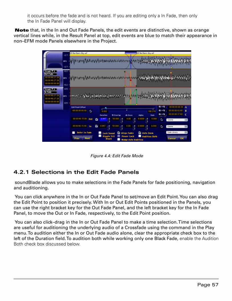
Page 57
it occurs before the fade and is not heard. If you are editing only a In Fade, then only the In Fade Panel will display.
Note that, in the In and Out Fade Panels, the edit events are distinctive, shown as orange vertical lines while, in the Result Panel at top, edit events are blue to match their appearance in non–EFM mode Panels elsewhere in the Project.
Figure 4.4: Edit Fade Mode
4.2.1 Selections in the Edit Fade Panels
soundBlade allows you to make selections in the Fade Panels for fade positioning, navigation and auditioning.
You can click anywhere in the In or Out Fade Panel to set/move an Edit Point. You can also drag the Edit Point to position it precisely. With In or Out Edit Points positioned in the Panels, you can use the right bracket key for the Out Fade Panel, and the left bracket key for the In Fade Panel, to move the Out or In Fade, respectively, to the Edit Point position.
You can also click–drag in the In or Out Fade Panel to make a time selection. Time selections are useful for auditioning the underlying audio of a Crossfade using the command in the Play menu. To audition either the In or Out Fade audio alone, clear the appropriate check box to the left of the Duration field. To audition both while working only one Black Fade, enable the Audition Both check box discussed below.
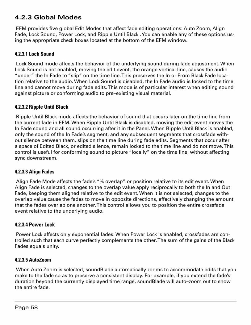
Page 58
4.2.3 Global Modes
EFM provides five global Edit Modes that affect fade editing operations: Auto Zoom, Align Fade, Lock Sound, Power Lock, and Ripple Until Black . You can enable any of these options us-ing the appropriate check boxes located at the bottom of the EFM window.
4.2.3.1 Lock Sound
Lock Sound mode affects the behavior of the underlying sound during fade adjustment. When Lock Sound is not enabled, moving the edit event, the orange vertical line, causes the audio “under” the In Fade to “slip” on the time line. This preserves the In or From Black Fade loca-tion relative to the audio. When Lock Sound is disabled, the In Fade audio is locked to the time line and cannot move during fade edits. This mode is of particular interest when editing sound against picture or conforming audio to pre–existing visual material.
4.2.3.2 Ripple Until Black
Ripple Until Black mode affects the behavior of sound that occurs later on the time line from the current fade in EFM. When Ripple Until Black is disabled, moving the edit event moves the In Fade sound and all sound occurring after it in the Panel. When Ripple Until Black is enabled, only the sound of the In Fade’s segment, and any subsequent segments that crossfade with-out silence between them, slips on the time line during fade edits. Segments that occur after a space of Edited Black, or edited silence, remain locked to the time line and do not move. This control is useful for conforming sound to picture “locally” on the time line, without affecting sync downstream.
4.2.3.3 Align Fades
Align Fade Mode affects the fade’s “% overlap” or position relative to its edit event. When Align Fade is selected, changes to the overlap value apply reciprocally to both the In and Out Fade, keeping them aligned relative to the edit event. When it is not selected, changes to the overlap value cause the fades to move in opposite directions, effectively changing the amount that the fades overlap one another. This control allows you to position the entire crossfade event relative to the underlying audio.
4.2.3.4 Power Lock
Power Lock affects only exponential fades. When Power Lock is enabled, crossfades are con-trolled such that each curve perfectly complements the other. The sum of the gains of the Black Fades equals unity.
4.2.3.5 AutoZoom
When Auto Zoom is selected, soundBlade automatically zooms to accommodate edits that you make to the fade so as to preserve a consistent display. For example, if you extend the fade’s duration beyond the currently displayed time range, soundBlade will auto–zoom out to show the entire fade.
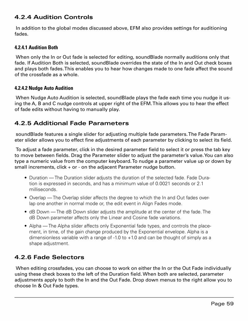
Page 59
4.2.4 Audition Controls
In addition to the global modes discussed above, EFM also provides settings for auditioning fades.
4.2.4.1 Audition Both
When only the In or Out fade is selected for editing, soundBlade normally auditions only that fade. If Audition Both is selected, soundBlade overrides the state of the In and Out check boxes and plays both fades. This enables you to hear how changes made to one fade affect the sound of the crossfade as a whole.
4.2.4.2 Nudge Auto Audition
When Nudge Auto Audition is selected, soundBlade plays the fade each time you nudge it us-ing the A, B and C nudge controls at upper right of the EFM. This allows you to hear the effect of fade edits without having to manually play.
4.2.5 Additional Fade Parameters
soundBlade features a single slider for adjusting multiple fade parameters. The Fade Param-eter slider allows you to effect fine adjustments of each parameter by clicking to select its field.
To adjust a fade parameter, click in the desired parameter field to select it or press the tab key to move between fields. Drag the Parameter slider to adjust the parameter’s value. You can also type a numeric value from the computer keyboard. To nudge a parameter value up or down by small increments, click + or - on the adjacent Parameter nudge button.
Duration — The Duration slider adjusts the duration of the selected fade. Fade Dura-•tion is expressed in seconds, and has a minimum value of 0.0021 seconds or 2.1 milliseconds.
Overlap — The Overlap slider affects the degree to which the In and Out fades over-•lap one another in normal mode or, the edit event in Align Fades mode.
dB Down — The dB Down slider adjusts the amplitude at the center of the fade. The •dB Down parameter affects only the Linear and Cosine fade variations.
Alpha — The Alpha slider affects only Exponential fade types, and controls the place-•ment, in time, of the gain change produced by the Exponential envelope. Alpha is a dimensionless variable with a range of -1.0 to +1.0 and can be thought of simply as a shape adjustment.
4.2.6 Fade Selectors
When editing crossfades, you can choose to work on either the In or the Out Fade individually using these check boxes to the left of the Duration field. When both are selected, parameter adjustments apply to both the In and the Out Fade. Drop down menus to the right allow you to choose In & Out Fade types.
Page 60
Figure 4.5: The fade selector menus above the Fade Library menu
4.2.6.1 Selecting Fade Shape
You can select the shape of the fade gain law or shape in two ways, by choosing a curve while you are working with the EFM Parameters or, by choosing a curve while working directly on the fade.
To select a Fade Curve from the EFM Parameters, click on either of the Fade Selectors to the right of the EFM window, then select from the family of available curves. To select a Fade Curve directly, control-click on a fade, as discussed in section 4.1.4 above, and select a fade type.
4.2.7 Nudging Fades
soundBlade provides controls for “nudging” or incrementally changing the position of the edit event with respect to the time line. soundBlade provides three preset nudge values labeled A, B and C respectively.
Figure 4.6: The nudge controls
The Fade Nudge buttons for each of the nudge values “advance” or “retard” the selected fade, moving the fade earlier or later by their respective A, B or C values. You can edit these values directly in the EFM window or set the default values in the Time Display tab of the Preferences window. Nudge values in the EFM window are edited by clicking in the field and typing, or using the +/- keys on the keypad to increment or decrement the selected value. This does not change the default Nudge A, B and C values in the Time Display preferences.
4.2.8 Edit Point Offset
Where the In and Out edit events in a Crossfade are located at different locations on the time line, there is an offset between them. You can set the amount of offset precisely by double clicking in the Edit Point Offset box in the upper left corner and typing the desired value.
Page 61
soundBlade moves the In Fade by the specified amount. soundBlade displays the offset be-tween the In Fade and Out edit events using the default time code units.
To eliminate an offset between fades, click the unmarked button immediately to the right of the Edit Point Offset field. You can also click to place an insertion point in any time field, then use the +/- keys of the keypad to increment/decrement the value.
4.2.9 Fade Library
soundBlade provides a library for saving and recalling fades, and includes the ability to save a Fade as the default. To save a fade as the default, In EFM, create a custom fade, then choose Fade Library > Save Custom Fade As…. soundBlade opens a Save Fade dialog. Type the Default name exactly as it appears in the Fade Library menu:
DefaultCrossFade — This defines the Default Crossfade•
DefaultCrossFadeOut — This defines the Out Fade component of the Default Cross-•fade.
DefaultCrossFadeIn — This defines the In Fade component of the Default Cross-•fade.
Note that you can save a To or From Black Fade and call it DefaultOutFade or DefaultInFade, respectively, but neither Fade will be used as a default. In soundBlade, the only default fade is the DefaultCrossFade and its respective In and Out Fade components.
4.2.9.1 Applying Fade Parameters From the Library
To apply fade parameters from the Fade Library to the currently selected fade(s), hold down the option key and type a number. This recalls fades from the Fade Library. Zero recalls the de-fault fades and numeric keys 1 through 9 corresponds to items 1–9 in the user defined area of the Fade Library. Note that this feature works only with the numeric keys along the top of the keyboard, not with the numeric keypad.
4.2.10 Exiting Edit Fade Mode
To exit Edit Fade Mode, click OK in the EFM window or select the Edit > Edit Fade command. soundBlade exits EFM and commits your fade modification to the Project. To exit EFM with-out saving your changes, click the Cancel button. soundBlade exits EFM without saving your changes made in the EFM.
4.3 Drag & Drop
4.3.1 Resequencing
For rapid assembly of program material, soundBlade provides three easy methods for auto-matically snapping to either 1, 2 or 3 seconds of Edited Black between segments.
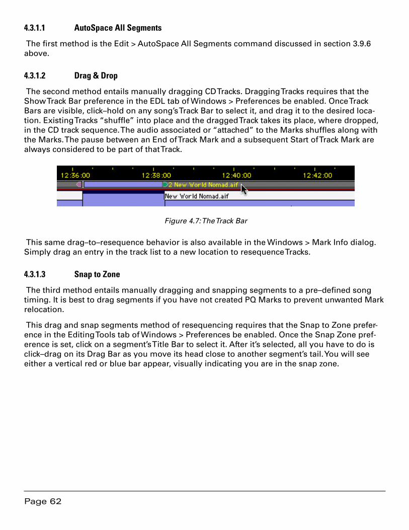
Page 62
4.3.1.1 AutoSpace All Segments
The first method is the Edit > AutoSpace All Segments command discussed in section 3.9.6 above.
4.3.1.2 Drag & Drop
The second method entails manually dragging CD Tracks. Dragging Tracks requires that the Show Track Bar preference in the EDL tab of Windows > Preferences be enabled. Once Track Bars are visible, click–hold on any song’s Track Bar to select it, and drag it to the desired loca-tion. Existing Tracks “shuffle” into place and the dragged Track takes its place, where dropped, in the CD track sequence. The audio associated or “attached” to the Marks shuffles along with the Marks. The pause between an End of Track Mark and a subsequent Start of Track Mark are always considered to be part of that Track.
Figure 4.7: The Track Bar
This same drag–to–resequence behavior is also available in the Windows > Mark Info dialog. Simply drag an entry in the track list to a new location to resequence Tracks.
4.3.1.3 Snap to Zone
The third method entails manually dragging and snapping segments to a pre–defined song timing. It is best to drag segments if you have not created PQ Marks to prevent unwanted Mark relocation.
This drag and snap segments method of resequencing requires that the Snap to Zone prefer-ence in the Editing Tools tab of Windows > Preferences be enabled. Once the Snap Zone pref-erence is set, click on a segment’s Title Bar to select it. After it’s selected, all you have to do is click–drag on its Drag Bar as you move its head close to another segment’s tail. You will see either a vertical red or blue bar appear, visually indicating you are in the snap zone.
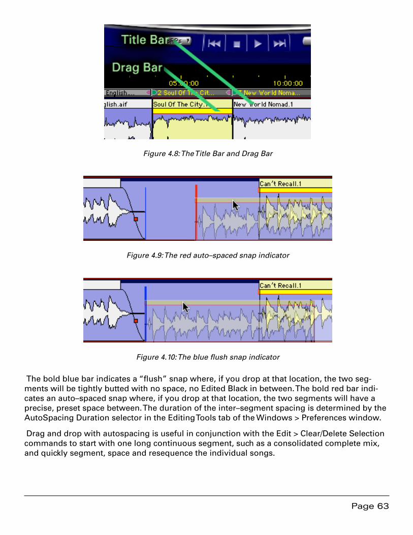
Page 63
Figure 4.8: The Title Bar and Drag Bar
Figure 4.9: The red auto–spaced snap indicator
Figure 4.10: The blue flush snap indicator
The bold blue bar indicates a “flush” snap where, if you drop at that location, the two seg-ments will be tightly butted with no space, no Edited Black in between. The bold red bar indi-cates an auto–spaced snap where, if you drop at that location, the two segments will have a precise, preset space between. The duration of the inter–segment spacing is determined by the AutoSpacing Duration selector in the Editing Tools tab of the Windows > Preferences window.
Drag and drop with autospacing is useful in conjunction with the Edit > Clear/Delete Selection commands to start with one long continuous segment, such as a consolidated complete mix, and quickly segment, space and resequence the individual songs.

Page 64
Note that, when using this fully manual method, sequencing should be performed prior to Mark placement. This will prevent erroneous repositioning of Marks as your segments are shuffled.
4.3.2 Drag–Overlay
When you drag and drop one segment on top of another, with no modifier keys employed, one segment will overlay another when you drop it on top. The two segments coexist in the same location on the time line and sum together during playback. This feature is useful when used in conjunction with Text Mode, discussed in the next section, so you can individually con-trol the overlapping segments. Also see section 4.4.2 below for creating a combination wave-form plus text Project layout.
4.3.3 Drag–Insert & Ripple
Shift–dragging segments is another useful editing feature. With the shift key held down, the dragged segment is inserted when you drop it on top. In addition, “downstream” segments, those later on the time line, are pushed or “rippled” to the right, making room for the inserted segment.
4.3.3 Drag–Replace
When you command-drag and drop one segment on top of another, then the dragged seg-ment replaces the existing audio where it’s dropped. As with all editing in Sonic Studio’s prod-ucts, this move is non–destructive.
4.4 Text Mode
Text Mode provides a playlist view of the Panel’s contents, with editable segment names along with editable start and end times. An editable Gain value, see section below, along with a non–editable Duration value are also shown. To view Text Mode, select the EDL > Show Text View command. To switch back to Waveform mode, select the EDL > Hide Text View command.
4.4.1 Gain Adjustment
Compiling audio from different sources usually makes it necessary to alter the amplitude of some of your source material. The last column in Text Mode displays the current gain of all segments. When Segments are opened or added to the EDL, the segment gain is nominally set to zero dB. By double-clicking on the Gain value of the selected segment, the Segment Gain modal dialog opens.
The Segment Gain dialog is also available via the Edit > Segment Gain… command for select-ed segments, and also via a segment’s Title Bar contextual menu. Control–click on any Title Bar to invoke the Segment Gain dialog. Other functions, like Reverse Polarity and Build Waveforms, are also available. As with other modal dialogs in soundBlade, gain changes will not be applied unless the OK button is clicked.

Page 65
Figure 4.11: The Segment Gain dialog
The Segment Gain dialog offers several options for altering segment gain. It also provides polarity inversion.
The large central field lets you enter gain directly. Alternatively, course and fine adjustments are available via up/down arrows. Simply click the arrows to increment or decrement gain in 1.0 or 0.1 dB steps.
Segment Gain can be applied in two different ways. First, it can be applied as an ‘Absolute’ value, meaning that the entry in the gain field will be applied in place of any previous value. The value entered in the gain field will replace any previous state, ignoring the existing gain of that segment.
Alternatively, the gain can be applied as a ‘Relative’ value. In relative mode, the entry in the gain field will be added to or subtracted from the previous value. Positive values will be added to the previous state while negative values will be subtracted from the previous gain state.
A third ‘Normalize’ radio button is available. Choosing this option will cause the segment’s ab-solute sample amplitude to be evaluated, after which the amount of headroom or surplus level below 0 dBFS will be entered in the central gain field. In other words, this function shows how much gain can be added before digital clipping will occur. The value given is relative to the cur-rent gain state so, the normalize function is a subset of a relative gain adjustment.
Though not a gain function, a Reverse Polarity check box is available. This check box inverts the polarity of the selected segments.
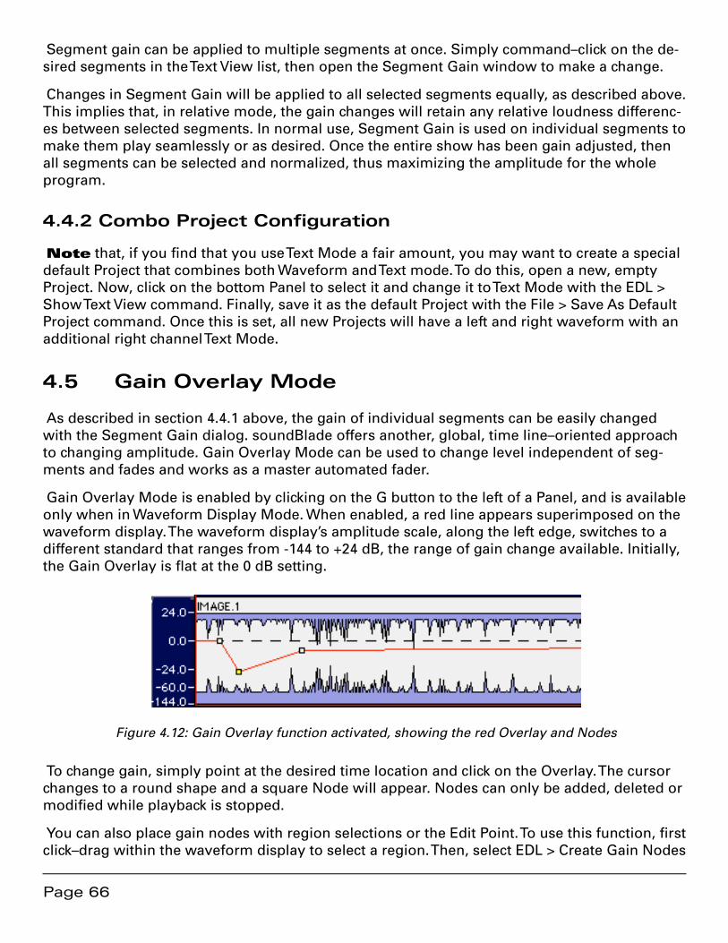
Page 66
Segment gain can be applied to multiple segments at once. Simply command–click on the de-sired segments in the Text View list, then open the Segment Gain window to make a change.
Changes in Segment Gain will be applied to all selected segments equally, as described above. This implies that, in relative mode, the gain changes will retain any relative loudness differenc-es between selected segments. In normal use, Segment Gain is used on individual segments to make them play seamlessly or as desired. Once the entire show has been gain adjusted, then all segments can be selected and normalized, thus maximizing the amplitude for the whole program.
4.4.2 Combo Project Configuration
Note that, if you find that you use Text Mode a fair amount, you may want to create a special default Project that combines both Waveform and Text mode. To do this, open a new, empty Project. Now, click on the bottom Panel to select it and change it to Text Mode with the EDL > Show Text View command. Finally, save it as the default Project with the File > Save As Default Project command. Once this is set, all new Projects will have a left and right waveform with an additional right channel Text Mode.
4.5 Gain Overlay Mode
As described in section 4.4.1 above, the gain of individual segments can be easily changed with the Segment Gain dialog. soundBlade offers another, global, time line–oriented approach to changing amplitude. Gain Overlay Mode can be used to change level independent of seg-ments and fades and works as a master automated fader.
Gain Overlay Mode is enabled by clicking on the G button to the left of a Panel, and is available only when in Waveform Display Mode. When enabled, a red line appears superimposed on the waveform display. The waveform display’s amplitude scale, along the left edge, switches to a different standard that ranges from -144 to +24 dB, the range of gain change available. Initially, the Gain Overlay is flat at the 0 dB setting.
Figure 4.12: Gain Overlay function activated, showing the red Overlay and Nodes
To change gain, simply point at the desired time location and click on the Overlay. The cursor changes to a round shape and a square Node will appear. Nodes can only be added, deleted or modified while playback is stopped.
You can also place gain nodes with region selections or the Edit Point. To use this function, first click–drag within the waveform display to select a region. Then, select EDL > Create Gain Nodes
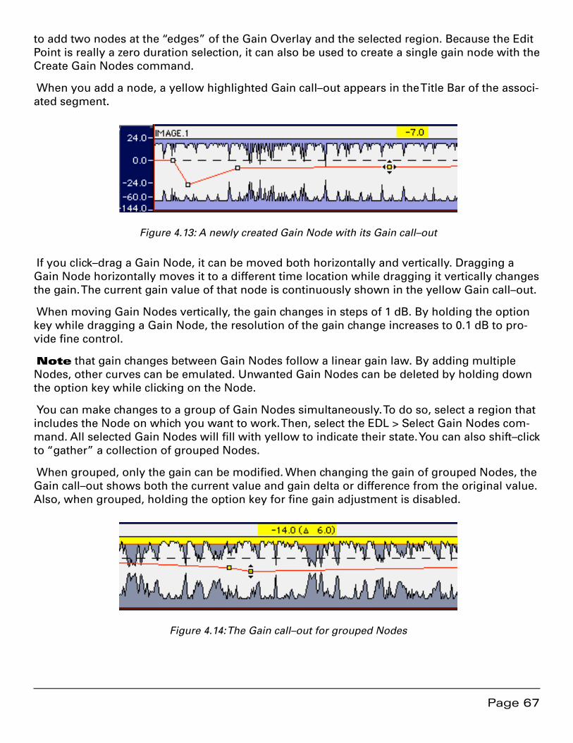
Page 67
to add two nodes at the “edges” of the Gain Overlay and the selected region. Because the Edit Point is really a zero duration selection, it can also be used to create a single gain node with the Create Gain Nodes command.
When you add a node, a yellow highlighted Gain call–out appears in the Title Bar of the associ-ated segment.
Figure 4.13: A newly created Gain Node with its Gain call–out
If you click–drag a Gain Node, it can be moved both horizontally and vertically. Dragging a Gain Node horizontally moves it to a different time location while dragging it vertically changes the gain. The current gain value of that node is continuously shown in the yellow Gain call–out.
When moving Gain Nodes vertically, the gain changes in steps of 1 dB. By holding the option key while dragging a Gain Node, the resolution of the gain change increases to 0.1 dB to pro-vide fine control.
Note that gain changes between Gain Nodes follow a linear gain law. By adding multiple Nodes, other curves can be emulated. Unwanted Gain Nodes can be deleted by holding down the option key while clicking on the Node.
You can make changes to a group of Gain Nodes simultaneously. To do so, select a region that includes the Node on which you want to work. Then, select the EDL > Select Gain Nodes com-mand. All selected Gain Nodes will fill with yellow to indicate their state. You can also shift–click to “gather” a collection of grouped Nodes.
When grouped, only the gain can be modified. When changing the gain of grouped Nodes, the Gain call–out shows both the current value and gain delta or difference from the original value. Also, when grouped, holding the option key for fine gain adjustment is disabled.
Figure 4.14: The Gain call–out for grouped Nodes
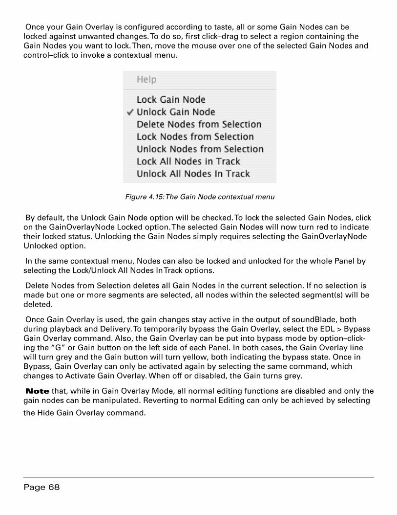
Page 68
Once your Gain Overlay is configured according to taste, all or some Gain Nodes can be locked against unwanted changes. To do so, first click–drag to select a region containing the Gain Nodes you want to lock. Then, move the mouse over one of the selected Gain Nodes and control–click to invoke a contextual menu.
Figure 4.15: The Gain Node contextual menu
By default, the Unlock Gain Node option will be checked. To lock the selected Gain Nodes, click on the GainOverlayNode Locked option. The selected Gain Nodes will now turn red to indicate their locked status. Unlocking the Gain Nodes simply requires selecting the GainOverlayNode Unlocked option.
In the same contextual menu, Nodes can also be locked and unlocked for the whole Panel by selecting the Lock/Unlock All Nodes In Track options.
Delete Nodes from Selection deletes all Gain Nodes in the current selection. If no selection is made but one or more segments are selected, all nodes within the selected segment(s) will be deleted.
Once Gain Overlay is used, the gain changes stay active in the output of soundBlade, both during playback and Delivery. To temporarily bypass the Gain Overlay, select the EDL > Bypass Gain Overlay command. Also, the Gain Overlay can be put into bypass mode by option–click-ing the “G” or Gain button on the left side of each Panel. In both cases, the Gain Overlay line will turn grey and the Gain button will turn yellow, both indicating the bypass state. Once in Bypass, Gain Overlay can only be activated again by selecting the same command, which changes to Activate Gain Overlay. When off or disabled, the Gain turns grey.
Note that, while in Gain Overlay Mode, all normal editing functions are disabled and only the gain nodes can be manipulated. Reverting to normal Editing can only be achieved by selecting
the Hide Gain Overlay command.
Page 69
4.6 Desk Events
4.6.1 Plug–In Overview
In addition to Gain Overlay, soundBlade offer the option to add “Desk Events” or plug–ins to a Project or bus. soundBlade hosts both VST and AU plug–ins.
When plug–ins are instantiated in a Project, they provide time–based, “snapshot automation.” Also in Projects, plug–ins are constant latency and are seamlessly cross-faded, even within an individual segment. This means settings change smoothly, free of audible discontinuities, even for plug–ins with high latency. All plug–in instantiations are fully latency compensated, unless the plug–in itself cannot or does not report latency.
Note that, if you use a plug–in with latency that changes based on the settings, AUPitch is one example, you need to instantiate the plug–in with particular care. In order for soundBlade to provide correct latency compensation, you must use an individual slot for any instance of that plug–in. This will allow each instance to have its own latency compensation that will not change during playback.
4.6.1.1 Plug–In Maintenance
Due to the rather poorly defined nature of the VST plug–in architecture, we recommend that all soundBlade users review their complement of plug–ins prior to installation. User feedback sug-gests that many problems when launching soundBlade can be traced to incompatibility with a particular plug-in.
If you notice instability on start–up, a plug–in may be to blame. A quick way to test this is to hold down your option key on start up, which disables all plug–ins. If you find that a particular plug–in causes problems, please e–mail us at <[email protected]> and let us know the specifics so we can work with the vendor to fully support your plug–in for future releases. Our Support FAQ provides details about disabling plug–ins.
If both an AU and a VST version of a plug–in is available from a vendor, we highly recommend that you disable any VST version that you have. To do this, simply search for all folders named “VST.” Be advised that there may be two or even three Library/Audio/Plug-Ins/VST directories in your file system. Once you have located all “VST” directories, create a “VST Disabled” folder at the same level as the “VST” folder and drag duplicate VST plug–ins to the VST Disabled folder. Log out, then in again or restart.
When first started, soundBlade validates all plug–ins. Any plug–in that does not validate cor-rectly is disabled to prevent instability or future problems. The Console Log, available by selecting File > System Information > Console Log, provides a log of plug–in status when soundBlade starts up.
soundBlade also “caches” or stores information about all your plug–ins to speed subsequent startups. The cache is stored in the “com.sonicstudio.plugincache.plist” file in the ~/Library/Preferences folder, a human readable file with either the Plist Editor or TextEdit. If you change your plug–in complement or a particular plug–in is inactive, simply throw that cache file in the
Page 70
Trash. The absence of the cache will force soundBlade to re–scan and re–cache your plug–in collection.
4.6.1.2 Plug–In Automation
While soundBlade does not support dynamic automation of parameters of plug–ins, it does support snapshot automation of plug–ins inserted into a Project, each plug–in is a snapshot, and parameters are updated as you move from event to event. You can “interleave” or place VST and AU plug–ins in any order on the time line. The minimum plug–in duration is 0.02 sec-onds or 20 milliseconds.
In addition, plug–ins are constant latency, with latency compensation, and regions cross-faded, allowing settings changes to happen smoothly without audible discontinuities, even for plug–ins with high latencies.
4.6.2 Displaying Plug–ins in Panels
As with Gain Overlay, plug–ins can be visible or hidden and the two can be used simultane-ously. By default, plug–ins are hidden and can only be made visible in the Waveform display. To show plug–ins in a Panel, select the EDL > Show Desk Events command. Alternatively, the “D” or Plug–in (Desk Events) Overlay button at the left of each Panel shows or hides the plug–ins Overlay as well.
Added as an extra layer, in standard Panel size, several horizontal rows appear delineated as dotted lines. These are plug–in “slots” or placeholders for plug–ins to be inserted. Audio pass-ing through plug–in slots is applied first to the top slot, then to each slot below, in vertical order. So, the top slot is pre–slot two while slot three is post slot two, et cetera.
[Eight Channel Option] When the Windows > Preferences > EDL > View > Multi-Channel EDLs preference is enabled, the Plug–in Overlay mode is not available. The EDL > Show Desk Events command instead creates a sub–Panel that displays the plug–in slots.
To insert a plug–in into a Panel, click–drag to define a selected region for plug–in insertion. Alter-natively, select one or more segments with which to associate the plug–in. Move the cursor over the region or selected segments, then over to one of the event plug–in slots into which plug–ins can be inserted. Once a plug–in is assigned to any slot, that slot is reserved for that plug–in type. Other plug–in types cannot be added to that slot until all instances of the original plug–in are removed.
Note that, when plug–ins are shown, a selected region will show as a green area instead of yellow. Also, over the time period of the selection or selected segment(s), the event plug–in slot becomes highlighted with a blue frame to indicate the selected Region and plug–in row.
Also Note that, if you edit a plug–in while in mono edit mode, you will “break” or discon-nect the parameter control between stereo plug–ins. To “reconnect” the plug–ins, hold the op-tion key down while moving a plug–in control.

Page 71
Figure 4.16: Plug–in slots with time selection
Control–clicking on a slot produces a contextual menu similar to the normal menu that ap-pears when control–clicking on a segment or region but, in this mode, available plug–ins are listed as well. Select the desired plug–in from the contextual menu. The selected plug–in “drops in” as an event, into the selected region or segments and shows in the events overlay as a green bar. soundBlade supports both VST and AU plug–ins and, either type can be freely intermixed in the event plug–in slots.
Figure 4.17: Plug–in inserted in the events overlay
Once a plug–in is in place, its settings and location can be modified. To modify the plug–ins settings, double click on the plug–in name and the plug–in will open. Close the opened plug–in window to save its settings. Another feature available once a plug–in is placed is, its name ap-pears at the bottom of the contextual menu when control–clicking on an empty slot.
To change the location and duration of an event, first select the event by clicking on it. The selected plug–in is marked by two red squares at its lower left and upper right edges. By click-holding either of the two red boxes, the plug–in location can be moved earlier or later, thus changing the location and duration of the event. To move the entire event without changing its length, click-hold on the middle of the event and drag it to the desired new location. To move an event from one row to another, click-hold it and move it up or down to the desired event plug–in slot. Multiple events can be selected by shift–click–holding them and dragging. All ac-tions changing the length or place of an event can now be applied to all selected events simul-taneously.
Note that, though it is possible to place plug–ins in the same slot and have them overlap-ping, this will effectively not work as overlapping Plug–ins are not supported in soundBlade. If more than one plug–in has to be applied to the same time region, simply place the necessary plug–ins in different slots.
Page 72
When control–clicking on an event, whether selected or not, a contextual menu appears. The choices are:
• Bypass/Unbypass Event: bypasses or engages the Event
• Set Selection from Plug–in: creates a region from the start point to the end point of the selected event.
• Delete Selected Plug–ins: deletes all selected plug–ins.
• Select Plug–ins in Slot in Selection: selects all plug–ins in the selected slot in the currently selected region. Plug–ins outside the selection in the same slot are not selected or deselected.
• Select All Plug–ins in Slot: selects all plug–ins in a slot.
• Select All Plug–ins: Selects all plug–ins in the entire Project in all rows.
Finally, as with Gain Overlay, active Desk events, events that are not bypassed, are always ac-tive regardless of whether the overlay is visible or not. To bypass all events, regardless of vis-ibility, control–click the “D” button at left in a Panel. When events are active, the D button turns green whereas when all events are bypassed, it turns red. When yellow, some Events are by-passed and other are still active.
4.6.3 Saving plug–in settings to a separate file
It is possible to save all characteristics of a plug–in, including the type and parameters, into a separate file. To do so, option-click on a specific plug–in instantiation and drag the resulting set-tings file to the Desktop. A file will be created on the Desktop. The file name takes the form of “sB.plug–in_name.setting.nnn” and contains all relevant information for that plug–in instance.
Dropping a settings file onto a plug–in slot will create a plug–in from the pre–defined, saved state. Dropping a parameter file back onto a plug–in will force that plug–in to the type and pa-rameters as saved in the settings file. If you need stereo instantiations of a monaural plug–in, set your plug–in to taste, then simply option–drag from that instantiation to the channel next to it.
4.7 SRPs
SRPs or Selection Reference Points are persistent placeholders that are saved in a Project. SRP commands are under the Selection menu, and are placed either with the Edit Point, the Playhead or, at the leading edge of a selected region. They can be locked to the time line, un-locked and deleted. Option–clicking allows you to drag them to a new location on the time line. They also carry an optional comment label that’s useful to jog your or someone else’s memory at a later date.
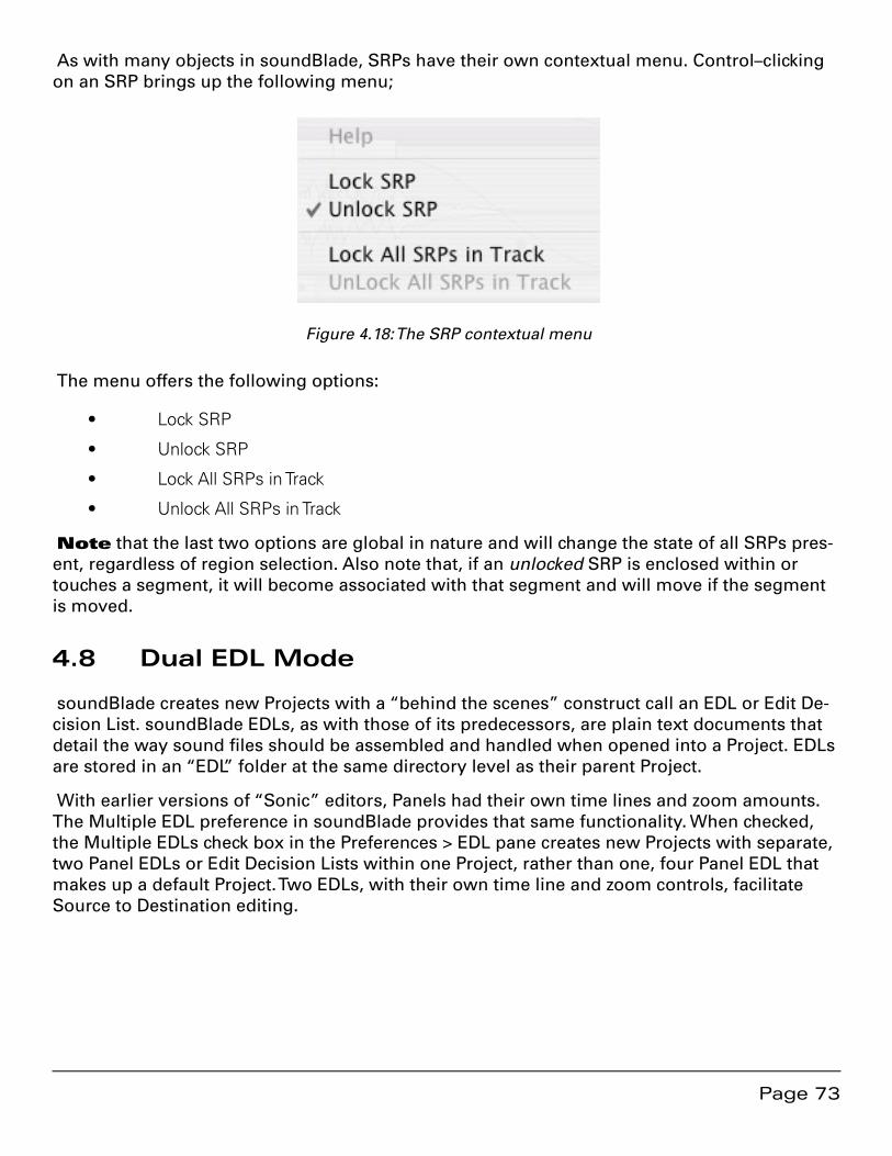
Page 73
As with many objects in soundBlade, SRPs have their own contextual menu. Control–clicking on an SRP brings up the following menu;
Figure 4.18: The SRP contextual menu
The menu offers the following options:
• Lock SRP
• Unlock SRP
• Lock All SRPs in Track
Unlock All SRPs in Track•
Note that the last two options are global in nature and will change the state of all SRPs pres-ent, regardless of region selection. Also note that, if an unlocked SRP is enclosed within or touches a segment, it will become associated with that segment and will move if the segment is moved.
4.8 Dual EDL Mode
soundBlade creates new Projects with a “behind the scenes” construct call an EDL or Edit De-cision List. soundBlade EDLs, as with those of its predecessors, are plain text documents that detail the way sound files should be assembled and handled when opened into a Project. EDLs are stored in an “EDL” folder at the same directory level as their parent Project.
With earlier versions of “Sonic” editors, Panels had their own time lines and zoom amounts. The Multiple EDL preference in soundBlade provides that same functionality. When checked, the Multiple EDLs check box in the Preferences > EDL pane creates new Projects with separate, two Panel EDLs or Edit Decision Lists within one Project, rather than one, four Panel EDL that makes up a default Project. Two EDLs, with their own time line and zoom controls, facilitate Source to Destination editing.

Page 74
Figure 4.19: Dual EDL mode
This dual EDL mode means that each EDL has its own time line and own independent zoom amount. One limitation of dual EDL mode is that, since the Desk’s state is linked to currently ac-tive Project, the Desk will switch configurations as either EDL is selected.
4.8.1 The Master/Slave Menu
When soundBlade is in dual EDL mode, an additional menu appears in the upper left corner of each EDL, the Master/Slave menu.

Page 75
Figure 4.20: The Master/Slave menu
This pop–up defaults to None, with three additional choices:
1. Master
2. Slave
3. LTC Slave
The Master setting will allow the designated EDL to “command” a Slave EDL to play in sync. Conversely, the Slave setting will cause the designated EDL to follow a Master EDL when play-ing. The LTC Slave setting, in conjunction with appropriate Series 300 hardware and an enabled LTC reader, will cause the designated EDL to follow incoming longitudinal SMPTE/EBU time code when running. See section 8.9.12 for information on the LTC time code reader.
4.8.2 Playing Both EDLs
When the Multiple EDLs preference is enabled, and the EDLs set to None, the two EDLs are completely independent, precluding their ability to play audio simultaneously. In addition, the Play All button found in the lower left corner of the Project, when the Multiple EDLs option is disabled, is not present. If you have Multiple EDLs on, setting the upper, destination EDL to Master using the Master/Slave menu, and the lower, source EDL to Slave will allow both EDLs to play in sync.
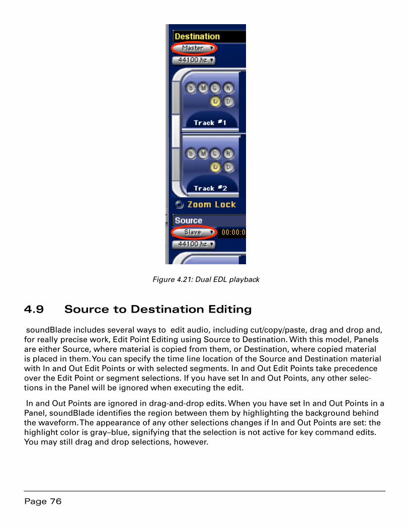
Page 76
Figure 4.21: Dual EDL playback
4.9 Source to Destination Editing
soundBlade includes several ways to edit audio, including cut/copy/paste, drag and drop and, for really precise work, Edit Point Editing using Source to Destination. With this model, Panels are either Source, where material is copied from them, or Destination, where copied material is placed in them. You can specify the time line location of the Source and Destination material with In and Out Edit Points or with selected segments. In and Out Edit Points take precedence over the Edit Point or segment selections. If you have set In and Out Points, any other selec-tions in the Panel will be ignored when executing the edit.
In and Out Points are ignored in drag-and-drop edits. When you have set In and Out Points in a Panel, soundBlade identifies the region between them by highlighting the background behind the waveform. The appearance of any other selections changes if In and Out Points are set: the highlight color is gray–blue, signifying that the selection is not active for key command edits. You may still drag and drop selections, however.
Page 77
4.9.1 Manipulating In & Out Edit Points
4.9.1.1 Placing In & Out Edit Points
To set In and Out Points, place the Edit Point where you want to set an In or Out Point. Choose Selection > Set In Point or Selection > Set Out Point.
Point to place In or Out Edit Points respectively. soundBlade places an Out Point at the Edit Point location. You can also use the command key equivalents to set In and Out Edit Points “on the fly” during playback.
A time region selection can also be used to place In and Out Edit Points using the aforemen-tioned commands or their keyboard equivalents.
4.9.1.2 Moving In or Out Edit Points
To adjust the position of an In or Out Edit Point, drag the yellow triangle at the bottom of the Edit Point. You can also choose Selection > Move In Point or Selection > Move Out Point. soundBlade will display a Move Point dialog. In that dialog, the following choices are available:
Where — Use this menu to select Playhead, In Point or Out Point. soundBlade loads 1. the current location of the selected item into the time field.
SRP — This menu displays locations of SRPs in the current time base units.2.
When you choose from this menu, soundBlade loads the location of the selected 3. SRP into the time field.
Move — Moves the In or Out Edit Point to the location specified in the time field. 4. You can edit this field in the same manner as any other time display.
Cancel — Closes the dialog without changing the location of the In or Out Edit Point.5.
You can nudge or move In or Out Edit Points by some pre–defined amount using one of the Nudge command in the Selection menu. The Nudge value for moving In and Out Edit Points is the same as that for nudging segments.
You can also move the In Edit Point to the current location of the Out Edit Point. This is useful for precisely appending new material in the Destination. To do this, choose Selection > Move In Point to Out Point.
4.9.1.3 Clearing In & Out Edit Points
To clear In and Out Edit Points, choose Selection > Clear In and Out Points. To clear only the In or Out Edit Point, choose Selection > Clear In Point or Clear Out Point respectively.
4.9.1.4 Auditioning In & Out Edit Points
When setting In and Out Edit points, you can audition your edits to “fine tune” the placement. To audition the current In Edit Point location, choose Play > To In/Out Point. soundBlade pre-
Page 78
rolls before the In or Out Edit Point and plays, stopping at the In Edit Point. You can also choose Play > From In/Out Point, in which case soundBlade starts playing at the In or Out Edit Point and plays to the end of the post roll interval. In either case, the pre/post roll duration is set by the preference defined in the Preferences > Time Display Play around In/Out Point settings.
4.9.2 Edit Groups
Source to Destination edits follow Edit Groups. Edits applied to one Panel in a Group affect all Panels in the Group simultaneously. The Source and Destination Panels can be separate Edit Groups or separate EDLs. Edits within a single Edit Group are confined to individual Panels. By definition, material cannot be moved from one Panel to another within an Edit Group by a Source/Destination edit command.
4.9.2.1 Simple Edit Groups
For basic, four Panel Projects, Edit Groups are preset and pre–defined. No user intervention is needed. The top two Panels are always in the same Edit Group, the bottom two are in another, and no change is possible.
4.9.2.2 Edit Groups for Complex Editing
When more complex, multitrack editing is required, Edit Groups can become user defined, al-lowing for more free form editing. Section 4.10.2 below discusses the more generalized, user adjustable Edit Groups available with the Eight Channel option.
4.9.3 Edit Targets
4.9.3.1 Simple Edit Targets
For the most basic, default four Panel Project, sometimes a monaural edit is needed on a ste-reo pair. soundBlade provides a simple “Edit Target” control to depart from the default behav-ior of performing edits on both channels of a stereo pair when you operate on only one. The default Edit Target mode is stereo, as indicated by the stereo Edit Target indicator.

Page 79
Figure 4.22: Stereo editing mode
The stereo target mode selector straddles the two Panels. Above and below the stereo editing mode selector are the two mono target mode selectors for each channel.
Figure 4.23: Mono editing mode
Simply click on either mono selector to make changes to one channel or the other exclusively.
4.9.3.2 Dual EDL Edit Targets
With the Preferences > EDL > Multiple EDL preference enabled, Edit Targets become more gen-eralized. The bars of a single EDL Project become round Edit Target buttons.
Panels in an Edit Group can have one of three states for Edit Target:
Page 80
Source — Designated audio is copied from these Source Panel(s) to the designated •Destination location.
Destination — Source material is inserted, or replaces, or overlays in these Panel(s).•
None — The Panel is not affected by Source/Destination editing command.•
To change the Edit Target for a group of Panels, do one of the following...Click to select any Panel in an Edit Group, then press the S, D or N key to set one of the three Source/Destination/None states respectively. soundBlade sets the Panel to the appropriate Edit Target, and all other Panels in its Edit Group follow.
To change Panels from Destination to Source, hold down the option key, then click on the Edit State button of any Panel in the Group. To change Panels from Destination to None, hold down the command key, then click on the Edit State button of any Panel in the Group. To change Pan-els from either Source or None, simply click on the Edit State button of any Panel in the Group.
[Eight Channel Option] — With the Multiple EDLs preference enabled, you can set a single Panel to a desired Edit Target, hold down the control key, then press the S, D or N key. Any other Panels in the same Edit Group will remain in their previous state.
Note that the Sync Group is forced to a new group when you use the control key so, unless you are in Multi–Channel mode, you may not be able to undo your forced Edit Target setting.
[Eight Channel Option] — Holding down the control key when pressing S, D or N causes the selected Panels to switch to the next available Edit Group and then sets the Edit Target.
4.9.4 Insert versus Replace
soundBlade supports two Source to Destination editing commands, Insert and Replace. These commands always copy the designated Source material and, you must explicitly designate Destination Panels so that soundBlade knows where you want to place the copy. This is done with the Edit Target for each Panel.
With an Insert edit, sound in the Destination is moved to the right, later on the time line, to “make room” for the inserted material. With a Replace edit, the designated Source mate-rial replaces the designated Destination material. As with all editing in soundBlade, editing is non–destructive. Only the EDL is updated during editing and no source sound files are changed during this process.
4.9.5 Types of Source/Destination Edits
There are four types of Source to Destination edits:
Two point edits1.
Three point edits2.
Four point edits3.
Constrained edits4.
Page 81
When referring to Two, Three or Four Point editing, we simply mean how many explicit places on the Source or Destination time line are given so as to define the material being copied, in the case of Source or, the location of where the copy will go, in the case of Destination.
With two point edits, there are several variations. The Destination can be marked with an In or Out Edit Point or, in the absence of these, the edit Point will stand in their place. Either way, the Source material will have its head placed at the marked location. The Edit > Replace Left Com-mand will place the tail, rather than the head, of the Source material at the marked location. Source material for two point edits can be, as mentioned above, either Edit Points or a selected segment.
With three point edits, either the Source or the Destination is a time region defined by Edit Points or, a selected segment. Since three places are defined, two of them can be in the Source to delineate both head and tail of the Source material or, they can be in the Destination to de-lineate the absolute location into which the copy will be placed.
Four-point edits, though possible to set up, are ambiguous unless both Source and Destination are exactly the same duration. In that case, then a three point edit will suffice.
Constrained edit will keep audio “in sync” on the time line, which is useful for editing sound against picture. With constrained edits using the Edit > Replace Constrained command, Source sound is copied to the Destination at its timestamped location.
4.10 Eight Channel Mode
soundBlade defaults to 4 tracks in 4 Panels, with 4 mix buses. If more tracks and more mix buses are needed, the Eight Channel option increases the number of tracks to 16 and the num-ber of buses to 8, making multichannel production possible.
The Eight Channel option adds
Additional commands to the EDL menu1.
A Multi-Channel EDLs preference to the EDL tab2.
An Edit Group Selection Menu preference to the Editing Tools tab3.
An Edit Group selector menu to Panels4.
An 5. Edit Target selector to Panels
Additional Strips to the Desk6.
Additional meters to the Master Section7.
Additional I/O selections to Audio I/O Preferences8.
Note that you must restart soundBlade after enabling this option. You should also resize both the Desk and the Master section after restart
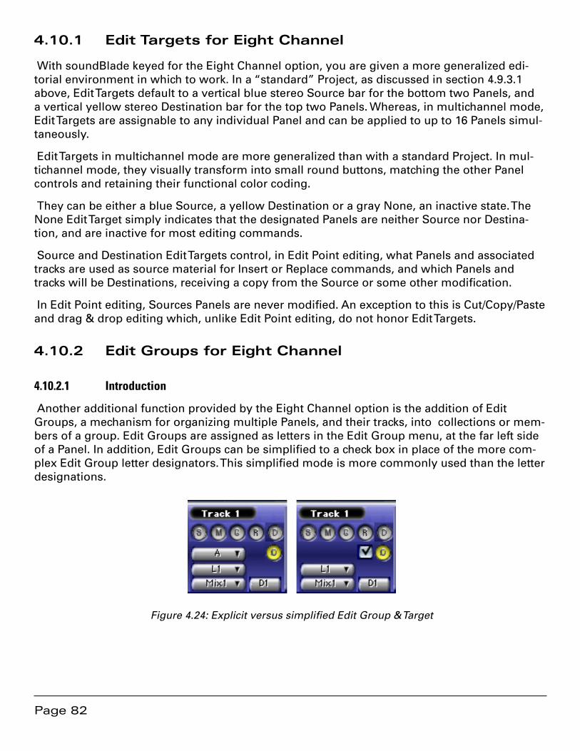
Page 82
4.10.1 Edit Targets for Eight Channel
With soundBlade keyed for the Eight Channel option, you are given a more generalized edi-torial environment in which to work. In a “standard” Project, as discussed in section 4.9.3.1 above, Edit Targets default to a vertical blue stereo Source bar for the bottom two Panels, and a vertical yellow stereo Destination bar for the top two Panels. Whereas, in multichannel mode, Edit Targets are assignable to any individual Panel and can be applied to up to 16 Panels simul-taneously.
Edit Targets in multichannel mode are more generalized than with a standard Project. In mul-tichannel mode, they visually transform into small round buttons, matching the other Panel controls and retaining their functional color coding.
They can be either a blue Source, a yellow Destination or a gray None, an inactive state. The None Edit Target simply indicates that the designated Panels are neither Source nor Destina-tion, and are inactive for most editing commands.
Source and Destination Edit Targets control, in Edit Point editing, what Panels and associated tracks are used as source material for Insert or Replace commands, and which Panels and tracks will be Destinations, receiving a copy from the Source or some other modification.
In Edit Point editing, Sources Panels are never modified. An exception to this is Cut/Copy/Paste and drag & drop editing which, unlike Edit Point editing, do not honor Edit Targets.
4.10.2 Edit Groups for Eight Channel
4.10.2.1 Introduction
Another additional function provided by the Eight Channel option is the addition of Edit Groups, a mechanism for organizing multiple Panels, and their tracks, into collections or mem-bers of a group. Edit Groups are assigned as letters in the Edit Group menu, at the far left side of a Panel. In addition, Edit Groups can be simplified to a check box in place of the more com-plex Edit Group letter designators. This simplified mode is more commonly used than the letter designations.
Figure 4.24: Explicit versus simplified Edit Group & Target
Page 83
4.10.2.2 Specifics
Panels, and their accompanying tracks within an EDL, can be assigned arbitrary Edit Groups, linking all Panels together that share an Edit Group assignment. Edits applied to any Panel in the Edit Group are applied simultaneously to all Panels in that same group. For example, when you select a time region by dragging across a Panel, that region is selected in all Panels of that same Edit Group. Similarly, selecting a segment in one Panel selects corresponding Segments, those having the same start time, in any other Panels of that same Edit Group. As mentioned above, you can designate and display EDL edit group membership using either letters or check boxes.
To designate Panels as a letter Edit Group, choose Windows > Preferences. Click the Editing Tools tab and enable the Edit Group Selection Menu preference. If you started soundBlade in stereo mode, with Preferences > EDL > Multi-Channel EDLs disabled, then you will have to en-able that preference and restart for the the Edit Group Selection Menu preference to be visible.
Once the Edit Group Selection Menu preference is enabled, Edit Group membership is shown with letters, allowing you to assign up to 32 different Edit Groups within each EDL. Select one or more tracks and use the letter menu to set the Panels to a group.
To designate Panels to an Edit Group with check boxes, choose Windows > Preferences. Click the EDL tab and deselect the Edit Group Selection Menu option. Once that preference is dese-lected, Edit Groups are shown by check boxes in each Panel. When you click in a Panel to make it active, the check boxes update to show which Panels belong to the same Group.
In this mode, only one Edit Group can be displayed at a time. Click the Edit Group check box for each Panel you want to include in the simplified Group. To remove a Panel from the Group, simply click again on its Edit Group check box.
Figure 4.24 above shows the explicit Edit Group and Target mode, with an Edit Group menu and an Edit Target designator to its right. See section 8.3 for specifics about the additional menu commands and section 8.9 for the specifics about the additional preferences.
4.10.3 Other Controls
4.10.3.1 I/O & Desk
In Waveform mode, Panels always have the five S, M, G, R and D buttons at left, as described in section 3.2 above. In addition to the Edit Group menu already discussed in the preceding sections, multichannel EDL mode reveals three additional controls at the far left side of each Panel. Below the Edit Group menu is the Input Assign followed by the Output Assign, with the (Desk) Strip Assign immediately to the right of the Output Assign.
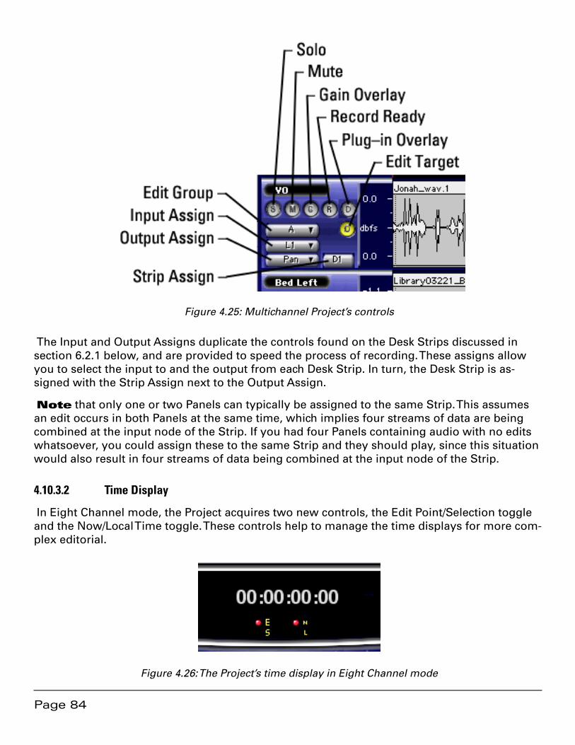
Page 84
Figure 4.25: Multichannel Project’s controls
The Input and Output Assigns duplicate the controls found on the Desk Strips discussed in section 6.2.1 below, and are provided to speed the process of recording. These assigns allow you to select the input to and the output from each Desk Strip. In turn, the Desk Strip is as-signed with the Strip Assign next to the Output Assign.
Note that only one or two Panels can typically be assigned to the same Strip. This assumes an edit occurs in both Panels at the same time, which implies four streams of data are being combined at the input node of the Strip. If you had four Panels containing audio with no edits whatsoever, you could assign these to the same Strip and they should play, since this situation would also result in four streams of data being combined at the input node of the Strip.
4.10.3.2 Time Display
In Eight Channel mode, the Project acquires two new controls, the Edit Point/Selection toggle and the Now/Local Time toggle. These controls help to manage the time displays for more com-plex editorial.
Figure 4.26: The Project’s time display in Eight Channel mode
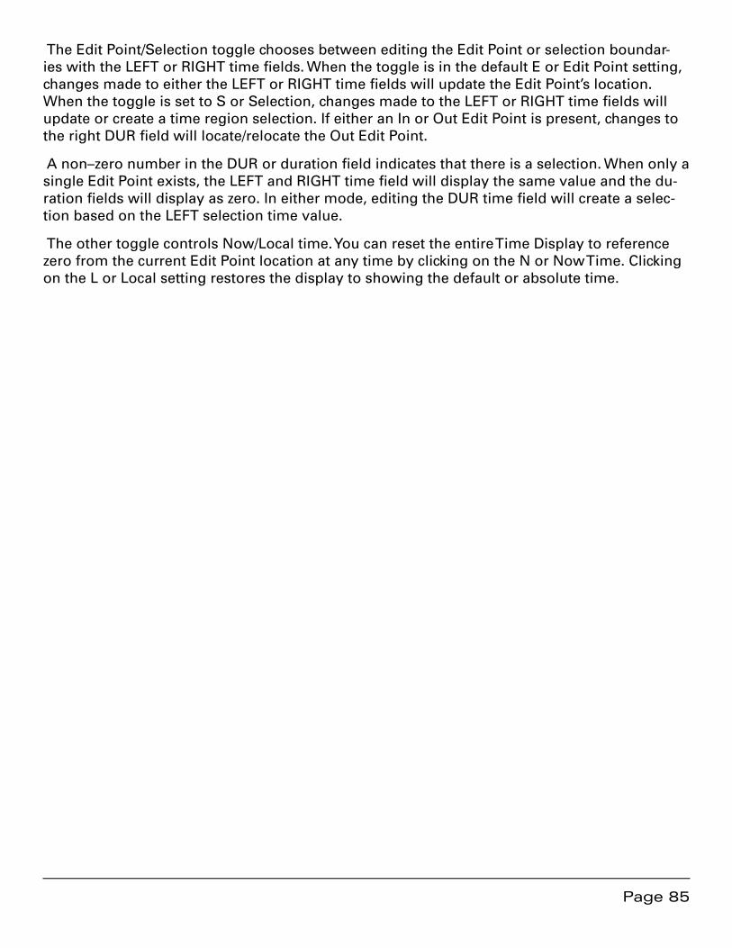
Page 85
The Edit Point/Selection toggle chooses between editing the Edit Point or selection boundar-ies with the LEFT or RIGHT time fields. When the toggle is in the default E or Edit Point setting, changes made to either the LEFT or RIGHT time fields will update the Edit Point’s location. When the toggle is set to S or Selection, changes made to the LEFT or RIGHT time fields will update or create a time region selection. If either an In or Out Edit Point is present, changes to the right DUR field will locate/relocate the Out Edit Point.
A non–zero number in the DUR or duration field indicates that there is a selection. When only a single Edit Point exists, the LEFT and RIGHT time field will display the same value and the du-ration fields will display as zero. In either mode, editing the DUR time field will create a selec-tion based on the LEFT selection time value.
The other toggle controls Now/Local time. You can reset the entire Time Display to reference zero from the current Edit Point location at any time by clicking on the N or Now Time. Clicking on the L or Local setting restores the display to showing the default or absolute time.
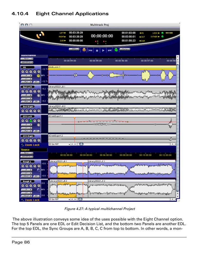
Page 86
4.10.4 Eight Channel Applications
Figure 4.27: A typical multichannel Project
The above illustration conveys some idea of the uses possible with the Eight Channel option. The top 5 Panels are one EDL or Edit Decision List, and the bottom two Panels are another EDL. For the top EDL, the Sync Groups are A, B, B, C, C from top to bottom. In other words, a mon-
Page 87
aural voice over track in the top Panel, a stereo bed in the next two Panels, and stereo effects in Panels 4 and 5. Panel one of the top EDL has the Edit Target set to (yellow) D or destination. Sync Group controls the setting of Edit Targets so, the above mentioned A, B, B, C, C settings mean that the mono track in the top Panel edits in mono while the two stereo tracks edit in stereo.
4.11 Project Sample Rate
To the left of a Project’s time line, a drop down menu is located for selection of the Project default sample rate. This menu has a simple function, to set the sample rate when making address calculations on the time line. Since, “under the hood,” soundBlade uses samples per second as the counting method for all time code, time line and address calculations, sample rate becomes the basis on which all the above calculations are made. soundBlade converts all thirteen of the alternate, non–“samples” time standard choices, discussed in section 3.7.1, to samples when constructing a Project.
Note that the Project default sample rate has nothing to do with the sample rate of any audio interface used, nor does it impact the clocking of your system. It is only for locating segments on a Project’s time line.
4.12 Advanced PQ
Section 3.10 above covers the basics of PQ creation and manipulation. This section delves into some arcana of the P through W metadata functionality in soundBlade.
All PQ information and additional metadata can be viewed and modified with the help of the Mark Info window. It can be opened by selecting the Windows > Mark Info command.

Page 88
Figure 4.28: The Mark Info window
Apart from the PQ information, this window contains additional fields for Album Title, Album Artist, Track Title and, for compilations, Track Artist. These fields provide input for the generation of CD-Text metadata. Additionally, ISR Codes or ISRC, and a Universal Product Code/European Article Number, or UPC/EAN, code can be entered as well.
ISRC or International Standard Recording Codes are unique, machine–readable identifiers for each track on a disc. On the other hand, UPC/EAN identifies the entire disc.
Creation of PQ Marks must follow a few simple rules, laid down in the “Red Book” or Compact Disc–Digital Audio (CD-DA) specification. The most important of these rules are:
Page 89
There is a maximum of 99 tracks allowed on a CD•
There is a maximum of 99 indexes allowed within each track•
Index Markers are not allowed between End of Track and Start of Track marks•
The minimum duration of a track, the minimum distance between Start of Track and •End of Track marks or two consecutive Start of Track marks, must be 4 seconds, including offsets.
Two consecutive End of Track marks are not allowed but two consecutive Start of •Track marks are allowed
soundBlade validates the PQ Marks against Red Book specifications and shows the result at the bottom of the PQ Window.
Note that Index Marks are infrequently used as most CD players available do not offer the ability to locate to Indexes.
4.12.1 Album Info
4.12.1.1 Album Title
In this field, the title of the album can be entered.
4.12.1.2 Album Artist
In this field, the artist’s name can be entered.
4.12.1.3 UPC/EAN Code
This is the product’s Universal Product Code/European Article Number, usually displayed as a barcode on the package. UPC/EAN barcodes are 13 digits and, in the United States, the leading digit or country code should be set to zero before entering the additional 12 trailing digits.
4.12.2 Track Info
4.12.2.1 Track Title and Track Artist
These text fields directly represent the title and artist of the selected track in the list below. These fields are used to generate CD Text metadata.
soundBlade assigns default names to marks and the tracks they generate. The Start Marks are numbered and named based on their associated segment’s name. The End Marks and Index Marks are not numbered, and are called End and Index respectively.
You can assign your own names to the Marks. Just select a Mark from the Track Info list, type a new name into the Track Title field, and hit the enter key. The new name will appear in the list, in the CD Text metadata, and also in the Track Bar, if visible. All this information is saved as part of the Project.
Page 90
Track Artist is entered in a like manner. Select a mark from the Track Info list, type an artist into the Track Artist field, and hit the enter key. The artist’s name will appear in the list and also in the resulting CD Text metadata. If, prior to Mark generation, you enter an Album Artist, as men-tioned in section 4.12.1 above, soundBlade will automatically use that text string for the Track Artist.
Note: You should always check your Mark Info window for metacharacters, such as $, & and %, as well as extended ASCII characters, like å, é, ø, ö, ü, ñ, et cetera. Mac OS, which soundBlade uses to write CD-Rs, does not handle extended ASCII and metacharacters properly.
4.12.2.2 Track Start
This field displays the location of individual Marks. The location can be edited by typing direct-ly into this field. The corresponding PQ mark will be moved accordingly.
4.12.2.3 Track Offset
This field shows the offset, if any, that is applied to the selected Mark. If the default offset is not appropriate, you can enter a custom offset for every Mark.
4.12.2.4 ISR Code (ISRC)
This field shows the International Standard Recording Code or ISRC, if any, that is associated with the selected Start of Track mark. When a record label provides ISR Codes for a title, as is usually the case, check the following guidelines to insure that the ISRC is valid: There must be exactly 12 characters. The first 5 places must be numeric or uppercase letters. The 6th through 12th places must all be numeric. Although often supplied with them, dashes or hyphens should be removed from the ISR Codes prior to entry in the Mark Info window. See Appendix 4.1 for more information on IFPI.
4.12.2.5 Lock Check Box
The Lock check box locks the PQ times for the selected CD Track to prevent inadvertent chang-es. When a Track is locked, its appearance in the Track Bar changes from the normal shape and color to a yellow, right pointing triangle.
4.12.2.6 Default Check Box
The Default check box forces an individual CD Track back to the default timings setting.
4.12.2.7 Copy Enabled Check Box
This check box displays and controls the state of the Copy Enable bit, the “flag,” of the SCMS or Serial Copy Management Scheme. The flag is set and copying is enabled when the Copy En-able button is red.
Page 91
The default state for this button is off. That is, copying is not allowed.
SCMS or “scums” flags, implemented for consumer digital recording devices, are generally ignored by professional audio equipment. Consumer digital audio equipment however, broad-ly recognizes the SCMS bit and inhibits the possibility of making digital copies from CD’s with the SCMS flag set. Hence it is common practice to disable the SCMS on CD-Rs or DDP masters intended for duplication.
4.12.2.8 Emphasis Check Box
This check box shows and controls the state of the AES/EBU Emphasis flag or bit of the select-ed track. When the Emphasis flag is set, a CD player will de-emphasize the track on playback. The Emphasis flag is set when the button is red.
Note that digital emphasis is rarely, if ever, used in modern production. This flag provides backward compatibility with archival material that employed emphasis as a form of perceived noise reduction at the expense of reduced high frequency headroom. Do not set the Emphasis flag unless you are sure that emphasis was applied to the original data and that it has not been de–emphasized prior to use in your soundBlade Project.
4.12.3 A Word About PQ Offsets
In the Mark Info dialog, the Track Offset field is non–editable. This because PQ Offsets are ap-plied globally, based on your Windows > Preferences > Delivery > Offsets preferences.
PQ Offsets are correction factors, subtracted from absolute song timing, to compensate for deficiencies in real world CD transports. They attempt to correct for the variation found with a CD transport’s ability to locate to an address, fill its audio data buffer, unmute the audio output and commence playback. Less expensive transports typically require back–timing, hence the PQ Offset, to make sure the buffer is full prior to track start so audio is not cut off by the trans-port’s muting circuit. With Offsets enabled, the factory defaults are very conservative and will produce satisfactory results with even the lowest quality transport but, always deliver a copy of your CD and check a range of target transports for an optimal setting.
Note that, as a rule, offsets are applied during the delivery of an original CD or DDP file set. The Windows > Preferences > Delivery > Offsets > Disable Offsets check box will enable or dis-able offset compensation. Offsets are applied globally to an entire Project.
4.12.4 PQ Track Info
4.12.4.1 Total Tracks & Extended Listing
This field shows the total number of Start Marks that will appear on the disc. To the left of the Total Tracks field is an unmarked Extended Listing check box that, when unchecked, simplifies the Track Listing by hiding End of Track Marks and Indexes. This mode, showing only the es-sential CD Track information, is designed for resequencing Tracks by dragging and dropping as discussed in section 4.12.4.3 below.
Page 92
4.12.4.2 Total Duration
This field shows the total playing time of the CD. The total playing time includes all pauses between the individual tracks as well as the “pregap” mode changing pause before the start of Track 1. The inclusion of pregap results in a different duration than would result from simply adding the disc running times, and complies with the method CD players use to calculate and display Total Duration as specified by the CD-DA Red Book.
4.12.4.3 Track Listing
This field shows a list of all Tracks present. For Start of Track marks, each entry shows the track number and name, the start and end times along with the duration. If the Extended Listing check box, mentioned in section 4.12.4.1 above, is checked, then End of Track and Indexes are also listed along with their times.
Any individual Mark can be selected by clicking on that row in the list. A selected Track is high-lighted in yellow while information on the highlighted Mark will appear in the fields above within the Track Info section. See section 4.12.2 above for more information on Track Info.
If you double click on a Track Start entry in the list, soundBlade will automatically begin playing that Track based on the current timings. This provides a quick way to confirm your Mark loca-tions.
The Track Listing also provides the ability to resequence CD Tracks. If you click–hold on any (Start of) Track entry, and drag it to a new location in the list, you can drop it and the audio implicit in the Track definition will also shuffle to the new location. This allows you to quickly resequence CD Tracks. See section 4.3 for a more general discussion of auto–snapping, includ-ing resequencing.
4.12.4.4 PQ Validator
soundBlade validates your PQ entries against the Red Book specifications. If they meet the requirements, the indicator at the lower left corner will be green and the status field will show “PQ Information is valid.” If the PQ marks violate the Red Book requirements, the button will be yellow, and a message will appear describing what is wrong with the entered parameters.
Note that you may see a “Sound begins more than 2 frames before Start Mark” message. This a reminder to check that you are not unintentionally truncating any audio at the head of your Project. Remember that, according to the Red Book specification for CD-DA discs, the first 2 seconds or 150 CD frames are “pregap,” and the first track start is at 2 seconds. Any audio before the 2 second mark will be replaced by 150 CD frames of digital zeroes on any CDs deliv-ered and in DDP file sets. Pregap is a logical region of the disc reserved for mode changes and other non–audio functions.
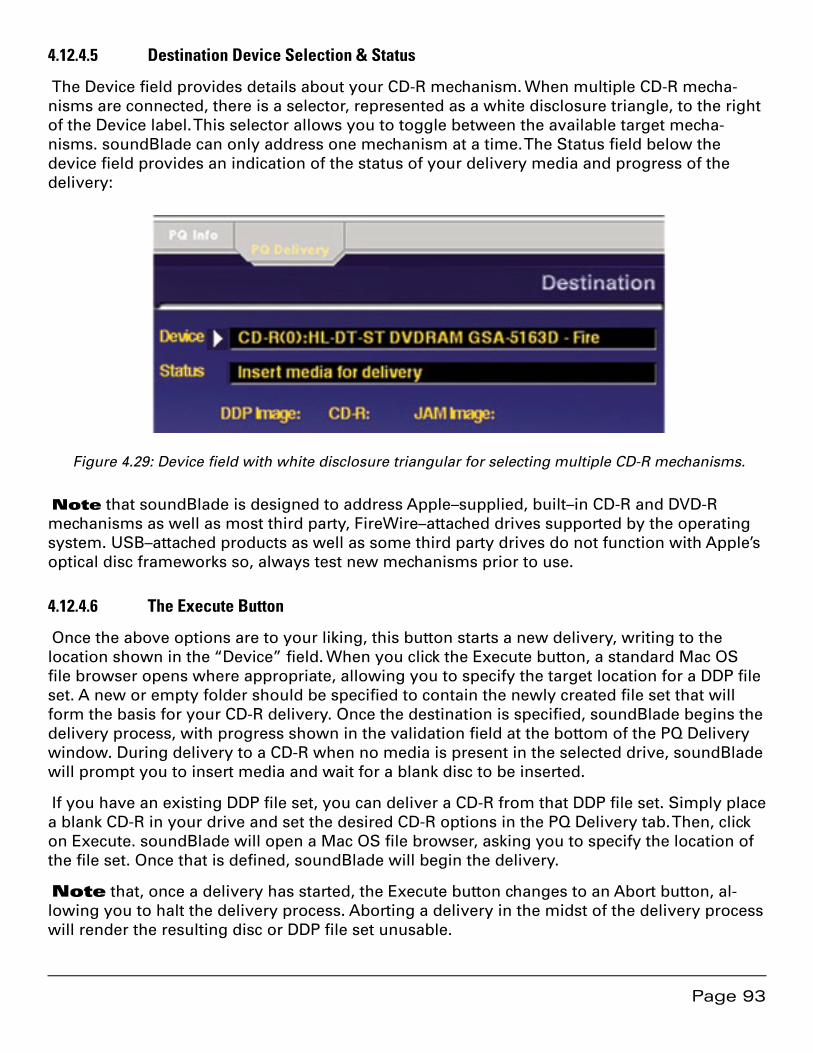
Page 93
4.12.4.5 Destination Device Selection & Status
The Device field provides details about your CD-R mechanism. When multiple CD-R mecha-nisms are connected, there is a selector, represented as a white disclosure triangle, to the right of the Device label. This selector allows you to toggle between the available target mecha-nisms. soundBlade can only address one mechanism at a time. The Status field below the device field provides an indication of the status of your delivery media and progress of the delivery:
Figure 4.29: Device field with white disclosure triangular for selecting multiple CD-R mechanisms.
Note that soundBlade is designed to address Apple–supplied, built–in CD-R and DVD-R mechanisms as well as most third party, FireWire–attached drives supported by the operating system. USB–attached products as well as some third party drives do not function with Apple’s optical disc frameworks so, always test new mechanisms prior to use.
4.12.4.6 The Execute Button
Once the above options are to your liking, this button starts a new delivery, writing to the location shown in the “Device” field. When you click the Execute button, a standard Mac OS file browser opens where appropriate, allowing you to specify the target location for a DDP file set. A new or empty folder should be specified to contain the newly created file set that will form the basis for your CD-R delivery. Once the destination is specified, soundBlade begins the delivery process, with progress shown in the validation field at the bottom of the PQ Delivery window. During delivery to a CD-R when no media is present in the selected drive, soundBlade will prompt you to insert media and wait for a blank disc to be inserted.
If you have an existing DDP file set, you can deliver a CD-R from that DDP file set. Simply place a blank CD-R in your drive and set the desired CD-R options in the PQ Delivery tab. Then, click on Execute. soundBlade will open a Mac OS file browser, asking you to specify the location of the file set. Once that is defined, soundBlade will begin the delivery.
Note that, once a delivery has started, the Execute button changes to an Abort button, al-lowing you to halt the delivery process. Aborting a delivery in the midst of the delivery process will render the resulting disc or DDP file set unusable.
Page 94
When you insert a blank CD-R into your target drive, you may see a dialog asking, “You in-serted a blank CD. Choose an action…”. Clicking on the Ignore button will close this dialog and release the mechanism for soundBlade’s use. This behavior results from the settings in the CDs & DVDs pane of the Mac OS System Preferences. You may want to set your CDs & DVDs prefer-ences to Ignore so as to eliminate that extra step.
4.12.4.7 The Burn Button
As a quick alternative to the Execute button
4.12.4.8 Delivering Multiple CDs
It is easy to deliver multiple identical CDs once you have an existing DDP file set. Click on the “Use” button when specifying delivery to a folder that already contains a DDP file set. This will re–use the existing file set, “burning” another CD. Open a new, empty Project before reusing an existing DDP file set.
4.12.4.9 The Eject Button
The Eject button will cause the host to eject an inserted disc.
4.12.4.10 The PQ List Button
This button generates a PQ List, the industry standard text representation of the current Com-pact Disc’s content. This file is typically printed and the hard copy is sent, along with the appro-priate DDP data set saved to your blank medium of choice, to the replicator.
Page 95
Chapter 5 .................................................... Recording Audio
In addition to assembling audio from existing sound files, soundBlade offers the functionality of recording audio from external audio sources. Supported file formats for recording are AIFF and broadcast WAV or BWF. Sample rate and resolution are limited by the capabilities of the available Core Audio hardware or your Series 300 I/O Processor. Audio can be recorded directly into any Panel, in either mono or stereo.
Note that audio is recorded as non-interleaved files when recording in AIFF or BWF format. Also note that USB–attached Core Audio interfaces are not supported in soundBlade.
5.1 4 Steps to Recording
1 Open a new Project
Audio can only be recorded in Panels, so a Project must be open. Choose File > New to create a new Project or File > Open… to open an existing Project. By default, soundBlade records ex-ternal audio from the first two input channels of the active interface, as defined in OS X’s Audio MIDI Setup utility.
2 Set New Sound File Parameters
Choose Windows > New Sound file Preferences. Set the destination directory, filename, word length and file type for the sound file you wish to record. See section 5.2.1 below for more information.
3 Record enable Panels
Record Enable the desired tracks for recording. To do this, click on the R button in the upper left corner of Panel 3 and 4. See section 5.2.2 for more explanation.
4 Start your recording
Initiate the recording of audio. To do this, use the Transport Controls at the top center of the Project. Clicking on the green record button will start a recording. See chapter 5.2.3 for more information.
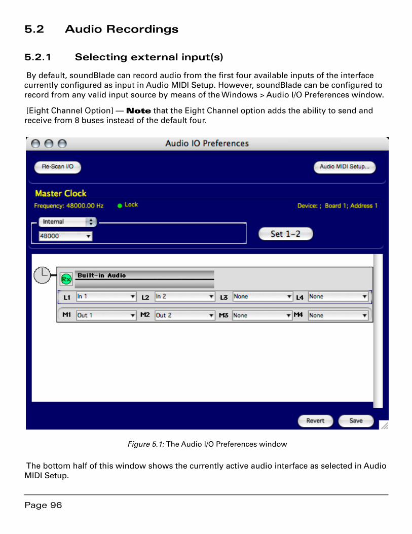
Page 96
5.2 Audio Recordings
5.2.1 Selecting external input(s)
By default, soundBlade can record audio from the first four available inputs of the interface currently configured as input in Audio MIDI Setup. However, soundBlade can be configured to record from any valid input source by means of the Windows > Audio I/O Preferences window.
[Eight Channel Option] — Note that the Eight Channel option adds the ability to send and receive from 8 buses instead of the default four.
Figure 5.1: The Audio I/O Preferences window
The bottom half of this window shows the currently active audio interface as selected in Audio MIDI Setup.
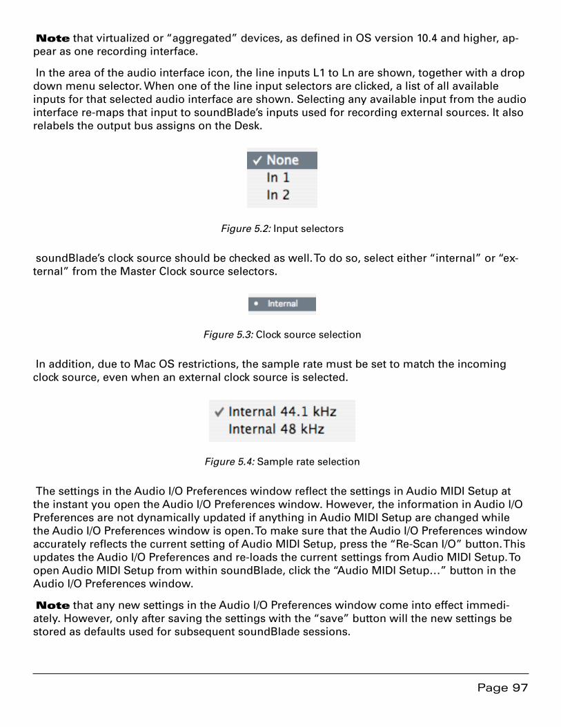
Page 97
Note that virtualized or “aggregated” devices, as defined in OS version 10.4 and higher, ap-pear as one recording interface.
In the area of the audio interface icon, the line inputs L1 to Ln are shown, together with a drop down menu selector. When one of the line input selectors are clicked, a list of all available inputs for that selected audio interface are shown. Selecting any available input from the audio interface re-maps that input to soundBlade’s inputs used for recording external sources. It also relabels the output bus assigns on the Desk.
Figure 5.2: Input selectors
soundBlade’s clock source should be checked as well. To do so, select either “internal” or “ex-ternal” from the Master Clock source selectors.
Figure 5.3: Clock source selection
In addition, due to Mac OS restrictions, the sample rate must be set to match the incoming clock source, even when an external clock source is selected.
Figure 5.4: Sample rate selection
The settings in the Audio I/O Preferences window reflect the settings in Audio MIDI Setup at the instant you open the Audio I/O Preferences window. However, the information in Audio I/O Preferences are not dynamically updated if anything in Audio MIDI Setup are changed while the Audio I/O Preferences window is open. To make sure that the Audio I/O Preferences window accurately reflects the current setting of Audio MIDI Setup, press the “Re-Scan I/O” button. This updates the Audio I/O Preferences and re-loads the current settings from Audio MIDI Setup. To open Audio MIDI Setup from within soundBlade, click the “Audio MIDI Setup…” button in the Audio I/O Preferences window.
Note that any new settings in the Audio I/O Preferences window come into effect immedi-ately. However, only after saving the settings with the “save” button will the new settings be stored as defaults used for subsequent soundBlade sessions.
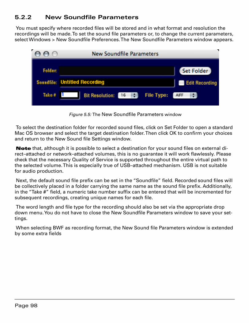
Page 98
5.2.2 New Soundfile Parameters
You must specify where recorded files will be stored and in what format and resolution the recordings will be made. To set the sound file parameters or, to change the current parameters, select Windows > New Soundfile Preferences. The New Soundfile Parameters window appears.
Figure 5.5: The New Soundfile Parameters window
To select the destination folder for recorded sound files, click on Set Folder to open a standard Mac OS browser and select the target destination folder. Then click OK to confirm your choices and return to the New Sound file Settings window.
Note that, although it is possible to select a destination for your sound files on external di-rect–attached or network–attached volumes, this is no guarantee it will work flawlessly. Please check that the necessary Quality of Service is supported throughout the entire virtual path to the selected volume. This is especially true of USB–attached mechanism. USB is not suitable for audio production.
Next, the default sound file prefix can be set in the “Soundfile” field. Recorded sound files will be collectively placed in a folder carrying the same name as the sound file prefix. Additionally, in the “Take #” field, a numeric take number suffix can be entered that will be incremented for subsequent recordings, creating unique names for each file.
The word length and file type for the recording should also be set via the appropriate drop down menu. You do not have to close the New Soundfile Parameters window to save your set-tings.
When selecting BWF as recording format, the New Sound file Parameters window is extended by some extra fields

Page 99
Figure 5.6: The New Sound file Parameters window for BWF recording format
The “Originator”, “Reference” and “Date/Time” fields can be filled with up to 22 characters. The “Description” and “Coding History” fields each hold up to 120 characters. The standardized contents of these metadata fields are stored in the header of the BWF file.
Originator — an ASCII string containing the name of the originator/producer of the •audio file.
Reference — Technically known as the “OriginatorReference,” an ASCII string con-•taining a non–ambiguous reference “allocated by the originating organization.” The EBU has defined a format for the OriginatorReference field. For more information, see EBU Recommendation R99-1999[2].
Date — Technically known as the “OriginationDate,” ASCII characters containing the •date of creation of the audio file. The format is “yyyy-mm-dd” (year-month-day).
Year is defined from 0000 to 9999, month is define from 1 to 12, day is defined from 1 to 28,29,30 or 31, while the separator between the items can be anything but it is recommended that one of the following characters is used:
- (hyphen)1.
Page 100
_ (underscore)2.
: (colon)3.
(space)4.
. (stop or period)5.
Time — Technically known as the “OriginationTime,” ASCII characters containing the •time of creation of the audio file. The format is “HH-MM-SS” (hours-minutes-sec-onds).
Hour is defined from 0 to 23, while minute and second are defined from 0 to 59. The separator between the items can be anything but it is recommended that one of the above characters.
Description — An ASCII string containing a un–formatted description of the se-•quence. To help applications which only display a short description, it is recommend-ed that a resumé of the description is contained in the first 64 characters, and the last 192 characters are use for details.
Coding History — The Coding History field is usually filled in and appended by any •application that creates and subsequently modifies a BWF sound file.
Finally, the optional “Edit Recording” check box enables files to be opened while their record-ing is in progress. This feature allows you to begin marking and making other editing decisions while a recording progresses. See section 5.2.6 below for more information.
Note that the sample rate of the sound file to be recorded is not set via this window. It is set in your host’s Audio MIDI Setup. See section 5.2.1 above for more information.
5.2.3 Track arming and enabling recording
To prepare audio for recording, any track you want to record audio into must be enabled or “armed” first. To arm the desired Panel(s), click on the Record Ready button, labeled “R,” on the left of the corresponding Panel. To disarm a Panel, simply click the Record Ready button again and the Panel will return to “Safe” mode again.
5.2.4 Initiating a recording
To initiate a recording, click the green Record button in the Transport Controls to start the re-cording. The Playhead starts at the beginning of the time line or at the Edit Point if present. The Record buttons turns red, recording begins and, the backgrounds of the Panels in record along with their corresponding Record Ready buttons turn red while the cursor changes to a micro-phone symbol.
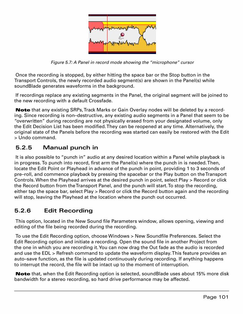
Page 101
Figure 5.7: A Panel in record mode showing the “microphone” cursor
Once the recording is stopped, by either hitting the space bar or the Stop button in the Transport Controls, the newly recorded audio segment(s) are shown in the Panel(s) while soundBlade generates waveforms in the background.
If recordings replace any existing segments in the Panel, the original segment will be joined to the new recording with a default Crossfade.
Note that any existing SRPs, Track Marks or Gain Overlay nodes will be deleted by a record-ing. Since recording is non–destructive, any existing audio segments in a Panel that seem to be “overwritten” during recording are not physically erased from your designated volume, only the Edit Decision List has been modified. They can be reopened at any time. Alternatively, the original state of the Panels before the recording was started can easily be restored with the Edit > Undo command.
5.2.5 Manual punch in
It is also possible to “punch in” audio at any desired location within a Panel while playback is in progress. To punch into record, first arm the Panel(s) where the punch in is needed. Then, locate the Edit Point or Playhead in advance of the punch in point, providing 1 to 3 seconds of pre–roll, and commence playback by pressing the spacebar or the Play button on the Transport Controls. When the Playhead arrives at the desired punch in point, select Play > Record or click the Record button from the Transport Panel, and the punch will start. To stop the recording, either tap the space bar, select Play > Record or click the Record button again and the recording will stop, leaving the Playhead at the location where the punch out occurred.
5.2.6 Edit Recording
This option, located in the New Sound file Parameters window, allows opening, viewing and editing of the file being recorded during the recording.
To use the Edit Recording option, choose Windows > New Soundfile Preferences. Select the Edit Recording option and initiate a recording. Open the sound file in another Project from the one in which you are recording it. You can now drag the Out fade as the audio is recorded and use the EDL > Refresh command to update the waveform display. This feature provides an auto–save function, as the file is updated continuously during recording. If anything happens to interrupt the record, the file will be intact up to the moment of interruption.
Note that, when the Edit Recording option is selected, soundBlade uses about 15% more disk bandwidth for a stereo recording, so hard drive performance may be affected.
Page 102
5.3 Automated Punches
When the length of a recording is known in advance, soundBlade can be set to record for a preset duration. This “timed” recording can be used for unattended recording, conserving disk space, or to replace parts of pre–existing material in one or more Panels. To automate a record-ing, a number of options are available.
5.3.1 Recording a selection or segment
Select a region of the desired length in the Panel(s) where recording should take place, then initiate the recording. When the recording is started, it will commence at the start of the selected region, and stop automatically at the end of the selected region. This is useful for a quick pick up or “one shot,” timed recording.
Alternatively, recording can replace one or more segments. Simply select the segments to be re-placed, then initiate the recording. Recording commences at the start of the first segment, and end at the end of the last selected segment.
Note that, if multiple segments are selected, the recorded sound file will appear as one continuous sound file. If the selected segments are consecutive but not contiguous, the non-selected segments in between will be “replaced” as well. See the end of section 5.2.1 above for more information.
5.3.2 Recording using SRPs
Another method of automated recording is by using SRPs. This function is useful to “allocate” a recording interval ahead of time so you can attend to other tasks. It is also useful for re–re-cording or pickups or when you want to only record a particular section of a performance.
To use SRPs to automate your recording, record arm the Panels in which you want to record. Place SRPs, via the Selection >Set SRP command, at the exact start and end locations where record-ing should punch in and out. If multiple, consecutive recordings are required, set as many even num-bered SPRs as required to define those actions.
Select the top armed Panel, then click–drag to select a region that extends from •before the first SRP to the last SRP placed for recording.
Start the recording by selecting Play > Selection from the main menu. •

Page 103
Figure 5.8: Panel with selection enclosing SRPs armed for recording
Playback commences at the start of the selection. At the first SRP, soundBlade will drop into recording, punching out at the next SRP. This repeats itself until the end of the selection is reached. Playback stops and the areas marked by SRPs are replaced by newly created sound files. If recording was still active when the end of the selection was reached (an uneven num-ber of SRPs was included in the selection), recording will stop at the end of the selection as well.
Note that for this method of “timed” recording, soundBlade only uses the SRPs in the top Panel being played and recorded. If SRPs are set in any other Panel that is armed for recording, they will be ignored and recording in those Panels will take place at the same position as in the top Panel being played.
After recording, the SRPs will be erased and in their place, default crossfades will connect the newly recorded segments to any existing audio segments.
5.4 Bouncing
Apart from recording from external sources, it is also possible to bounce or play audio from one Panel while recording into another, meanwhile applying processing with internally or externally available processing options. As soundBlade normally records from external sourc-es, soundBlade needs to be set up to record from an internal source, the Panel(s) containing sound material to be re–recorded. To perform a bounce, an extra feature of soundBlade called the “EDL Desk” will need to be used. More in-depth information on how to use and setup the Desk is given in Chapter 6. After coverage of the Desk, Chapter 6 also provides examples of bouncing audio through the Desk and back to disk.
When setting up a recording, you need to patch the Desk. Think of M1/2 as sends routed to the Core Audio or Series 300 outputs, while M3/4 act as a bus internal to soundBlade, though they are available at the output of your Series 300 I/O Processor or, Core Audio device if it supports more than 1 stereo output pair. To record audio from Panel to Panel, it is also necessary to un-derstand that sound can only be bounced from Panels 3 and/or 4, with Panels 1 and/or 2 acting as recording destinations.
Page 104
5.4.1 Simple Bounce
To perform a stereo bounce, with built–in audio, from Panels 3 and 4 into Panels 1 and 2, do the following:
Edit the audio to be captured and/or processed in Panels 3 and 4.•
Select Panels 1 and 2 and arm those Panels for recording. Remember to set or •change the desired New Soundfile Parameters if necessary.
Click the “Play All” button at the bottom of the Project.•
Set up the Desk to perform a bounce from Panels 3 and 4 into Panels 1 and 2. Patch •the Desks inputs for M3, M4, None, None and the outputs as M1-Out, M2-Out, M3-None, M4-None. The “None” designation for M3/4 indicates that, In Audio I/O, outputs M3 and M4 have been assigned to None. Also notice that the monitor mode for Strip2 1 and 2 is set for IN or input, while Strips 3 and 4 are set for O or output.
Set up the Master Section as desired by selecting Windows > Meters. Because •this bounce is a “round trip,” out of buses 3 and 4, back in 3 and 4, and to disk from buses 1 and 2, both the Desk and the Master Section are in the signal path.
If you want to bounce a stereo plug–in back to disk, be sure to instantiate stereo •plug–ins in the Master Section, not in the Desk or Project. Those locations are only for monaural plug–ins.
Select Panel 1 and start the recording by selecting Play > Record from the main •menu, or by clicking the Record button in the Transport Panel. Stop the recording by clicking on the Stop button in the Transport Panel.

Page 105
Figure 5.9: Panels and Desk prepared for Capture.
Captures can be done manually, starting and stopping at any point of choice. Capturing can also be done from different time areas in Panels 3 and 4 than the time area into which the cap-turing takes place. This can be done by deselecting “Play All” in the Project window, allowing you to start the recording first, then selecting Panels 3 and 4 and playing back from any loca-tion in those Panels.
Also, capturing can be performed using SRPs, allowing for exact time predefined insertion of sound material. To set up a capture using SPRs, first prepare for a normal capture as described above. Then, before initiating the Capture, setup SRPs’ and a necessary selection, then start the capture as if performing a recording using SRPs.
Note that, as bounces include all processing in the entire signal path. Dither may or may not be applied, according to the settings of soundBlade’s preferences and any external processors used. Also, resolution of the recorded bounces can be set to 16 or 24 bits in the New Soundfile Parameters window.
Page 106
5.5 Recording and time stamps
When recording a sound file in AIFF or BWF format, a time stamp is added to the sound file. The time stamp added is the time of the corresponding position in the Panel(s). This allows for the sound files to be placed in the exact original location on the time line in any application that recognizes and is able to handle this feature. In soundBlade, time stamps are honored when sound files are shift–dragged into a Panel.

Page 107
Chapter 6 ............................................ The Desk and Meters
6.1 Signal Flow
To provide some perspective on this and later sections, it is useful to look at the signal flow through soundBlade. Figure 6.1 is a simplified block diagram of the internal flow of data through the application as managed by the SSE, the engine that “powers” Sonic Studio prod-ucts.
Audio streams to Project
Gain: Fade Envelope +
Segment Gain
Gain: Gain Overlay +
Strip Fader
Desk Meters
Sonic EQ then BBDN Bounce
Project, Export & DDP outw/dither
Re–dithering
Plug–ins:
Master
Project & Desk Strip
Project & Desk Strip
Project & Desk Strip
PanMatrix
Project & Desk Strip
Disk
M2
M1
M3
Mn
Master Meters
Line Input Simplified Signal Flow — soundBlade
Plug–ins: Project then Desk Strip
Gain:Master Fader
Bounce Master
…
Figure 6.1: Flow diagram for soundBlade
Notice that the line inputs apply audio to both the pan matrix and directly to disk. Also notice that Project bounces, exports and DDP deliveries bypass the pan matrix and subsequent signal processing blocks.
6.2 The EDL Desk
soundBlade offers a compact and convenient solution for mixing audio signals from the Pan-els, the EDL Desk. In addition to level adjustment, routing, panning and monitoring, the Desk offers the possibility to add plug–ins for sound manipulation and modification. The Desk is made visible by selecting the Windows > Desk command.
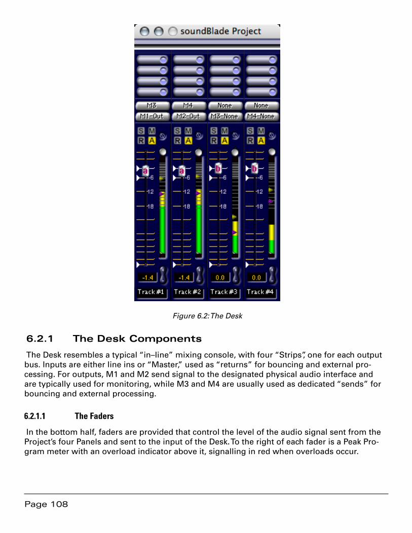
Page 108
Figure 6.2: The Desk
6.2.1 The Desk Components
The Desk resembles a typical “in–line” mixing console, with four “Strips”, one for each output bus. Inputs are either line ins or “Master,” used as “returns” for bouncing and external pro-cessing. For outputs, M1 and M2 send signal to the designated physical audio interface and are typically used for monitoring, while M3 and M4 are usually used as dedicated “sends” for bouncing and external processing.
6.2.1.1 The Faders
In the bottom half, faders are provided that control the level of the audio signal sent from the Project’s four Panels and sent to the input of the Desk. To the right of each fader is a Peak Pro-gram meter with an overload indicator above it, signalling in red when overloads occur.
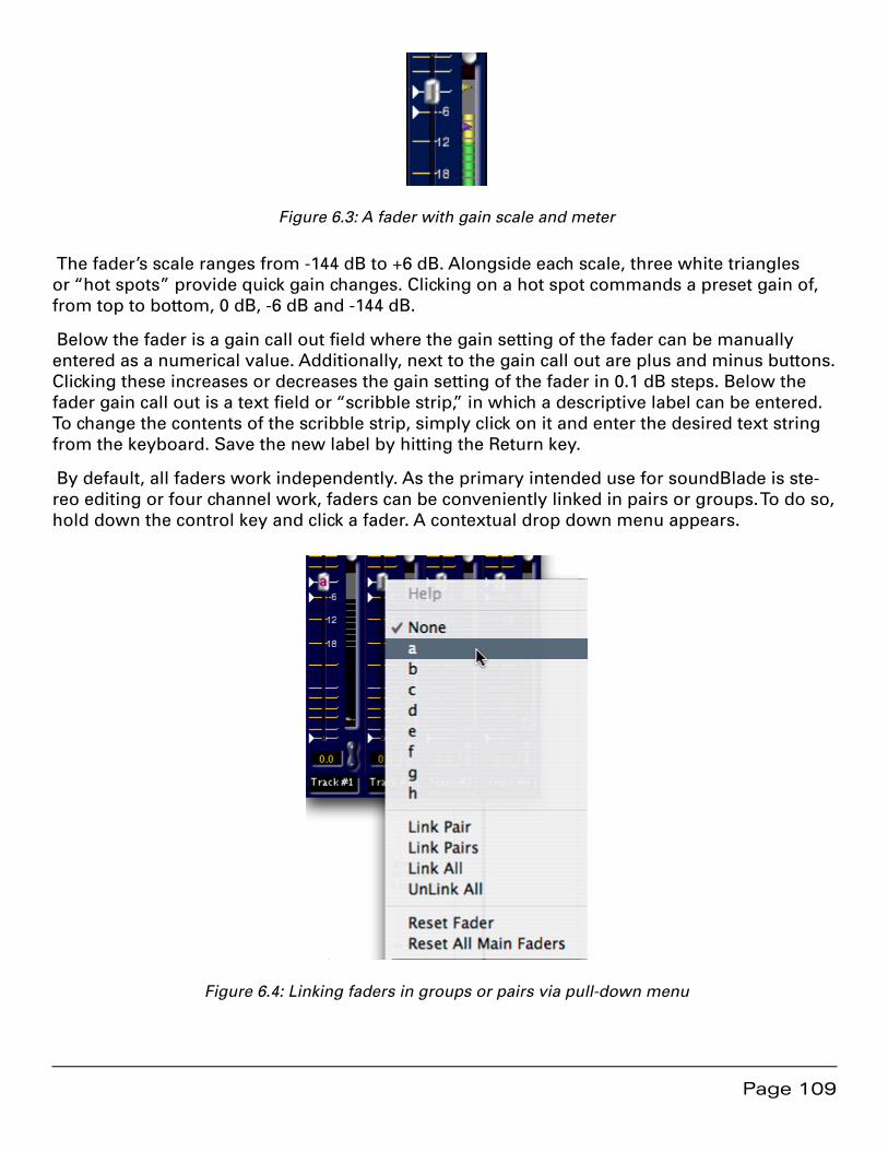
Page 109
Figure 6.3: A fader with gain scale and meter
The fader’s scale ranges from -144 dB to +6 dB. Alongside each scale, three white triangles or “hot spots” provide quick gain changes. Clicking on a hot spot commands a preset gain of, from top to bottom, 0 dB, -6 dB and -144 dB.
Below the fader is a gain call out field where the gain setting of the fader can be manually entered as a numerical value. Additionally, next to the gain call out are plus and minus buttons. Clicking these increases or decreases the gain setting of the fader in 0.1 dB steps. Below the fader gain call out is a text field or “scribble strip,” in which a descriptive label can be entered. To change the contents of the scribble strip, simply click on it and enter the desired text string from the keyboard. Save the new label by hitting the Return key.
By default, all faders work independently. As the primary intended use for soundBlade is ste-reo editing or four channel work, faders can be conveniently linked in pairs or groups. To do so, hold down the control key and click a fader. A contextual drop down menu appears.
Figure 6.4: Linking faders in groups or pairs via pull-down menu
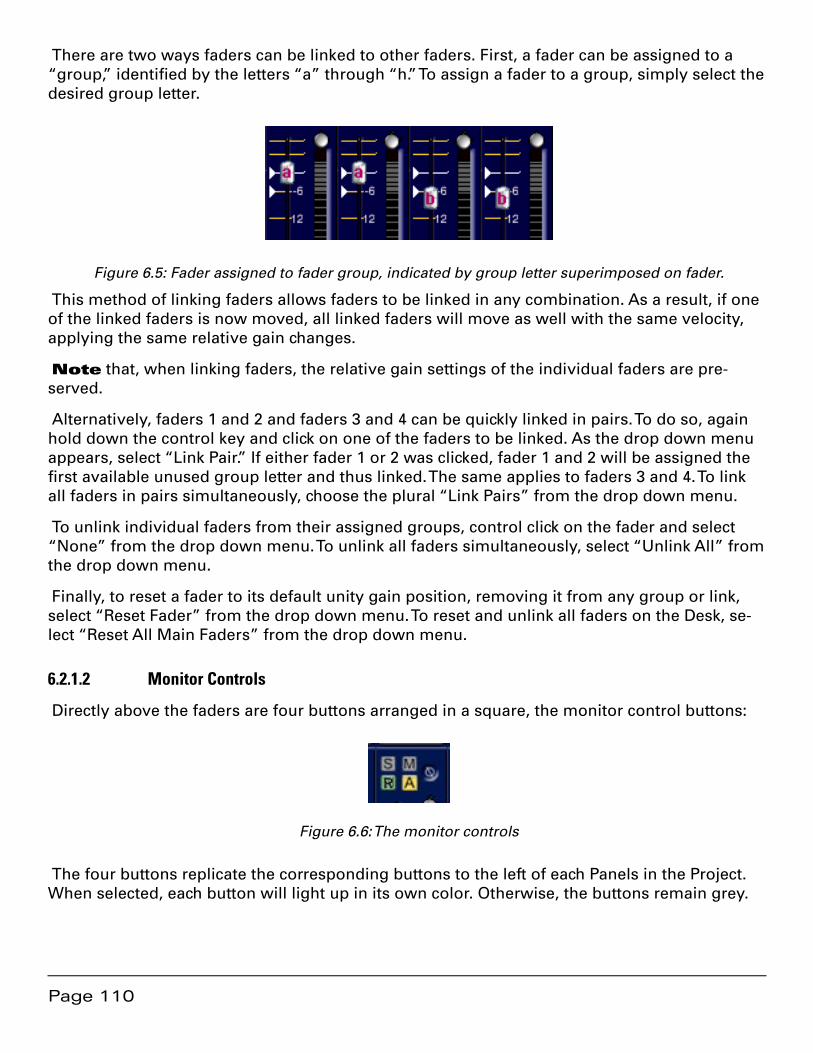
Page 110
There are two ways faders can be linked to other faders. First, a fader can be assigned to a “group,” identified by the letters “a” through “h.” To assign a fader to a group, simply select the desired group letter.
Figure 6.5: Fader assigned to fader group, indicated by group letter superimposed on fader.
This method of linking faders allows faders to be linked in any combination. As a result, if one of the linked faders is now moved, all linked faders will move as well with the same velocity, applying the same relative gain changes.
Note that, when linking faders, the relative gain settings of the individual faders are pre-served.
Alternatively, faders 1 and 2 and faders 3 and 4 can be quickly linked in pairs. To do so, again hold down the control key and click on one of the faders to be linked. As the drop down menu appears, select “Link Pair.” If either fader 1 or 2 was clicked, fader 1 and 2 will be assigned the first available unused group letter and thus linked. The same applies to faders 3 and 4. To link all faders in pairs simultaneously, choose the plural “Link Pairs” from the drop down menu.
To unlink individual faders from their assigned groups, control click on the fader and select “None” from the drop down menu. To unlink all faders simultaneously, select “Unlink All” from the drop down menu.
Finally, to reset a fader to its default unity gain position, removing it from any group or link, select “Reset Fader” from the drop down menu. To reset and unlink all faders on the Desk, se-lect “Reset All Main Faders” from the drop down menu.
6.2.1.2 Monitor Controls
Directly above the faders are four buttons arranged in a square, the monitor control buttons:
Figure 6.6: The monitor controls
The four buttons replicate the corresponding buttons to the left of each Panels in the Project. When selected, each button will light up in its own color. Otherwise, the buttons remain grey.
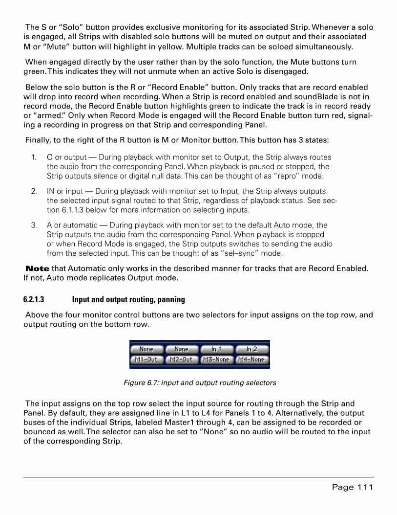
Page 111
The S or “Solo” button provides exclusive monitoring for its associated Strip. Whenever a solo is engaged, all Strips with disabled solo buttons will be muted on output and their associated M or “Mute” button will highlight in yellow. Multiple tracks can be soloed simultaneously.
When engaged directly by the user rather than by the solo function, the Mute buttons turn green. This indicates they will not unmute when an active Solo is disengaged.
Below the solo button is the R or “Record Enable” button. Only tracks that are record enabled will drop into record when recording. When a Strip is record enabled and soundBlade is not in record mode, the Record Enable button highlights green to indicate the track is in record ready or “armed.” Only when Record Mode is engaged will the Record Enable button turn red, signal-ing a recording in progress on that Strip and corresponding Panel.
Finally, to the right of the R button is M or Monitor button. This button has 3 states:
O or output — During playback with monitor set to Output, the Strip always routes 1. the audio from the corresponding Panel. When playback is paused or stopped, the Strip outputs silence or digital null data. This can be thought of as “repro” mode.
IN or input — During playback with monitor set to Input, the Strip always outputs 2. the selected input signal routed to that Strip, regardless of playback status. See sec-tion 6.1.1.3 below for more information on selecting inputs.
A or automatic — During playback with monitor set to the default Auto mode, the 3. Strip outputs the audio from the corresponding Panel. When playback is stopped or when Record Mode is engaged, the Strip outputs switches to sending the audio from the selected input. This can be thought of as “sel–sync” mode.
Note that Automatic only works in the described manner for tracks that are Record Enabled. If not, Auto mode replicates Output mode.
6.2.1.3 Input and output routing, panning
Above the four monitor control buttons are two selectors for input assigns on the top row, and output routing on the bottom row.
Figure 6.7: input and output routing selectors
The input assigns on the top row select the input source for routing through the Strip and Panel. By default, they are assigned line in L1 to L4 for Panels 1 to 4. Alternatively, the output buses of the individual Strips, labeled Master1 through 4, can be assigned to be recorded or bounced as well. The selector can also be set to “None” so no audio will be routed to the input of the corresponding Strip.
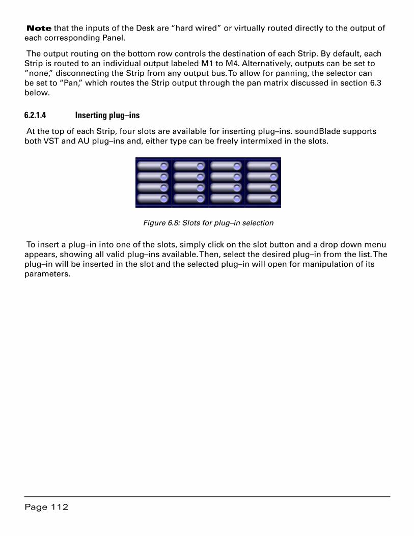
Page 112
Note that the inputs of the Desk are “hard wired” or virtually routed directly to the output of each corresponding Panel.
The output routing on the bottom row controls the destination of each Strip. By default, each Strip is routed to an individual output labeled M1 to M4. Alternatively, outputs can be set to ”none,” disconnecting the Strip from any output bus. To allow for panning, the selector can be set to “Pan,” which routes the Strip output through the pan matrix discussed in section 6.3 below.
6.2.1.4 Inserting plug–ins
At the top of each Strip, four slots are available for inserting plug–ins. soundBlade supports both VST and AU plug–ins and, either type can be freely intermixed in the slots.
Figure 6.8: Slots for plug–in selection
To insert a plug–in into one of the slots, simply click on the slot button and a drop down menu appears, showing all valid plug–ins available. Then, select the desired plug–in from the list. The plug–in will be inserted in the slot and the selected plug–in will open for manipulation of its parameters.
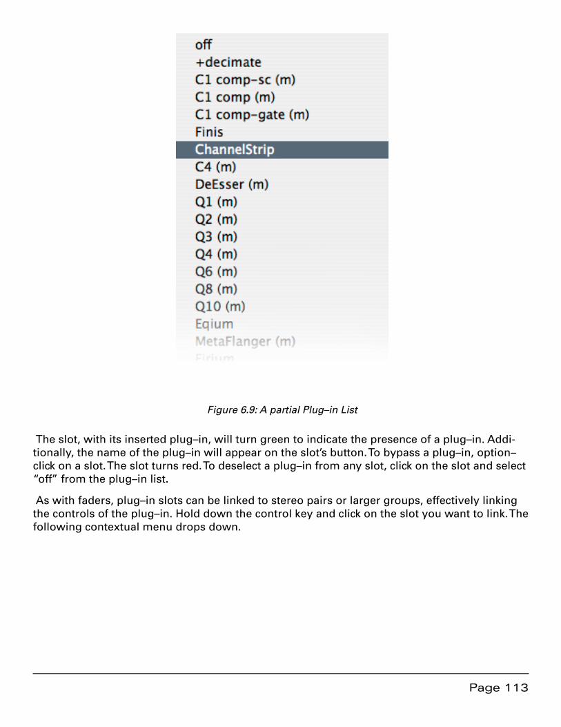
Page 113
Figure 6.9: A partial Plug–in List
The slot, with its inserted plug–in, will turn green to indicate the presence of a plug–in. Addi-tionally, the name of the plug–in will appear on the slot’s button. To bypass a plug–in, option–click on a slot. The slot turns red. To deselect a plug–in from any slot, click on the slot and select “off” from the plug–in list.
As with faders, plug–in slots can be linked to stereo pairs or larger groups, effectively linking the controls of the plug–in. Hold down the control key and click on the slot you want to link. The following contextual menu drops down.
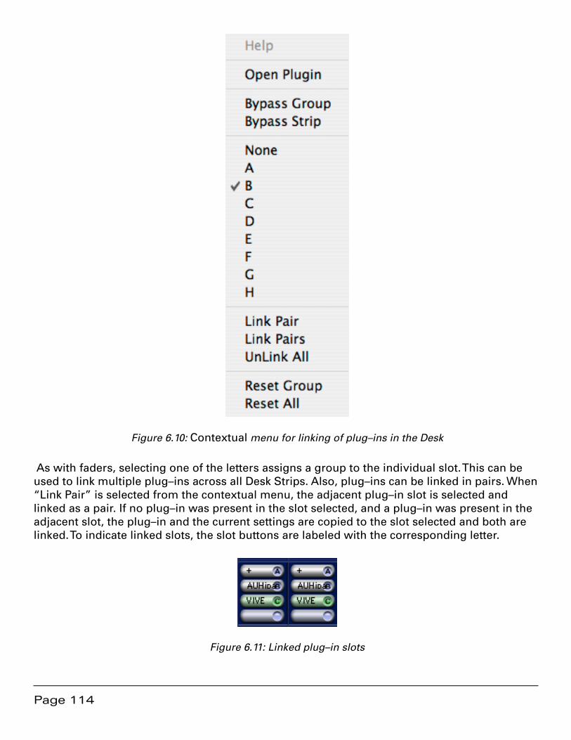
Page 114
Figure 6.10: Contextual menu for linking of plug–ins in the Desk
As with faders, selecting one of the letters assigns a group to the individual slot. This can be used to link multiple plug–ins across all Desk Strips. Also, plug–ins can be linked in pairs. When “Link Pair” is selected from the contextual menu, the adjacent plug–in slot is selected and linked as a pair. If no plug–in was present in the slot selected, and a plug–in was present in the adjacent slot, the plug–in and the current settings are copied to the slot selected and both are linked. To indicate linked slots, the slot buttons are labeled with the corresponding letter.
Figure 6.11: Linked plug–in slots
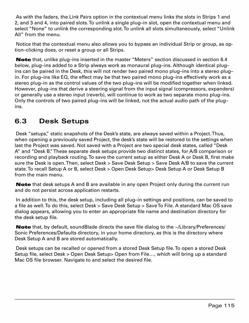
Page 115
As with the faders, the Link Pairs option in the contextual menu links the slots in Strips 1 and 2, and 3 and 4, into paired slots. To unlink a single plug–in slot, open the contextual menu and select “None” to unlink the corresponding slot. To unlink all slots simultaneously, select “Unlink All” from the menu.
Notice that the contextual menu also allows you to bypass an individual Strip or group, as op-tion–clicking does, or reset a group or all Strips.
Note that, unlike plug–ins inserted in the master “Meters” section discussed in section 6.4 below, plug–ins added to a Strip always work as monaural plug–ins. Although identical plug–ins can be paired in the Desk, this will not render two paired mono plug–ins into a stereo plug–in. For plug–ins like EQ, the effect may be that two paired mono plug–ins effectively work as a stereo plug–in as the control values of the two plug–ins will be modified together when linked. However, plug–ins that derive a steering signal from the input signal (compressors, expanders) or generally use a stereo input (reverb), will continue to work as two separate mono plug–ins. Only the controls of two paired plug–ins will be linked, not the actual audio path of the plug–ins.
6.3 Desk Setups
Desk “setups,” static snapshots of the Desk’s state, are always saved within a Project. Thus, when opening a previously saved Project, the desk’s state will be restored to the settings when last the Project was saved. Not saved with a Project are two special desk states, called “Desk A” and “Desk B.” These separate desk setups provide two distinct states, for A/B comparison or recording and playback routing. To save the current setup as either Desk A or Desk B, first make sure the Desk is open. Then, select Desk > Save Desk Setup > Save Desk A/B to save the current state. To recall Setup A or B, select Desk > Open Desk Setup> Desk Setup A or Desk Setup B from the main menu.
Note that desk setups A and B are available in any open Project only during the current run and do not persist across application restarts.
In addition to this, the desk setup, including all plug–in settings and positions, can be saved to a file as well. To do this, select Desk > Save Desk Setup > Save To File. A standard Mac OS save dialog appears, allowing you to enter an appropriate file name and destination directory for the desk setup file.
Note that, by default, soundBlade directs the save file dialog to the ~/Library/Preferences/Sonic Preferences/Defaults directory, in your home directory, as this is the directory where Desk Setup A and B are stored automatically.
Desk setups can be recalled or opened from a stored Desk Setup file. To open a stored Desk Setup file, select Desk > Open Desk Setup> Open from File…, which will bring up a standard Mac OS file browser. Navigate to and select the desired file.
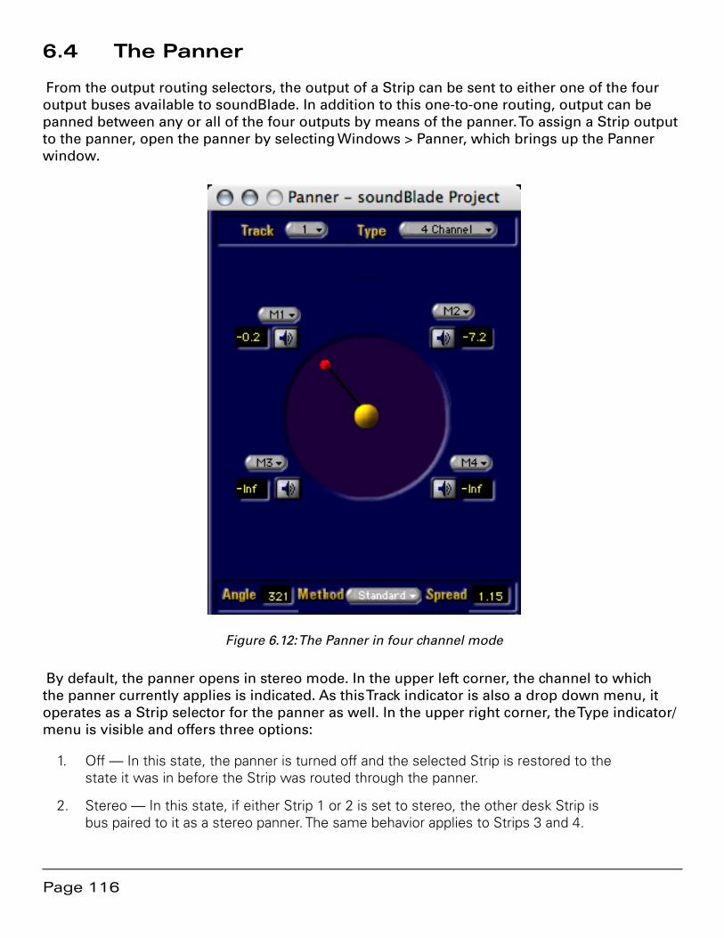
Page 116
6.4 The Panner
From the output routing selectors, the output of a Strip can be sent to either one of the four output buses available to soundBlade. In addition to this one-to-one routing, output can be panned between any or all of the four outputs by means of the panner. To assign a Strip output to the panner, open the panner by selecting Windows > Panner, which brings up the Panner window.
Figure 6.12: The Panner in four channel mode
By default, the panner opens in stereo mode. In the upper left corner, the channel to which the panner currently applies is indicated. As this Track indicator is also a drop down menu, it operates as a Strip selector for the panner as well. In the upper right corner, the Type indicator/menu is visible and offers three options:
Off — In this state, the panner is turned off and the selected Strip is restored to the 1. state it was in before the Strip was routed through the panner.
Stereo — In this state, if either Strip 1 or 2 is set to stereo, the other desk Strip is 2. bus paired to it as a stereo panner. The same behavior applies to Strips 3 and 4.

Page 117
MultiChannel — In this state,, the panner unfolds to show a circular joystick panner 3. with multichannel buses, each bus indicated by a loudspeaker symbol. Note that the multichannel plus LFE choices in this menu are not operational.
Next to each loudspeaker symbol, an output selector is located. This allows for a completely flexible assignment of outputs from the panner. Any output can be assigned to any panner po-sition. As only one output can be assigned to a single panner position, attempting to patch an already assigned Strip output to another panner output will re–assign that Strip output to the new choice, swapping positions with the Strip output formerly assigned to that output.
To change the panner state, click–hold on the red dot and drag it towards effect the desired output. The output level fields, located next to each loudspeaker symbol, indicates the panner output level in dB and are updated continuously during panner movement. Alternatively, sim-ply click on the location in the Panner circle where you want to place the panner, and the pan-ner moves to it instantly. Additionally, clicking on one of the loudspeaker symbols moves the panner to that position instantly.
At the bottom of the multichannel panner, two call outs and one selector are located. The “An-gle” call out at left shows the angular position of the panner on a 360 degree, polar coordinate scale. To manually input the angle of the panner directly as a numerical value, click in the Angle field and enter the desired value, and confirming it by hitting the Enter key.
The Method selector, in the center, should be kept at the default “Standard” setting as the “Soundfield” re–matrixing choice is not yet operational.
The Spread field is an call out showing the extent to which sound is panned across multiple available outputs. Spread varies from 1.00 to 99.9, and is at its maximum when the sound is panned equally to all outputs, with the position indicator is in the center, and equal amplitude appearing on all outputs.
6.5 Meters Window: The Master Section
6.5.1 Overview
In a separate window from the Desk, the “Meters window” provides a Master Section, the final output control for both the Project and Desk. The Master Section window can be opened by selecting the Windows > Meters command.
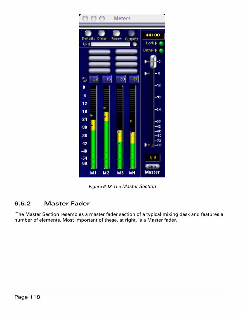
Page 118
Figure 6.13: The Master Section
6.5.2 Master Fader
The Master Section resembles a master fader section of a typical mixing desk and features a number of elements. Most important of these, at right, is a Master fader.
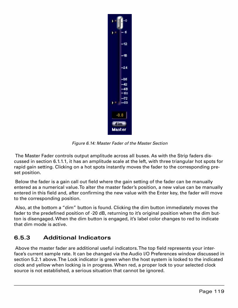
Page 119
Figure 6.14: Master Fader of the Master Section
The Master Fader controls output amplitude across all buses. As with the Strip faders dis-cussed in section 6.1.1.1, it has an amplitude scale at the left, with three triangular hot spots for rapid gain setting. Clicking on a hot spots instantly moves the fader to the corresponding pre-set position.
Below the fader is a gain call out field where the gain setting of the fader can be manually entered as a numerical value. To alter the master fader’s position, a new value can be manually entered in this field and, after confirming the new value with the Enter key, the fader will move to the corresponding position.
Also, at the bottom a “dim” button is found. Clicking the dim button immediately moves the fader to the predefined position of -20 dB, returning to it’s original position when the dim but-ton is disengaged. When the dim button is engaged, it’s label color changes to red to indicate that dim mode is active.
6.5.3 Additional Indicators
Above the master fader are additional useful indicators. The top field represents your inter-face’s current sample rate. It can be changed via the Audio I/O Preferences window discussed in section 5.2.1 above. The Lock indicator is green when the host system is locked to the indicated clock and yellow when locking is in progress. When red, a proper lock to your selected clock source is not established, a serious situation that cannot be ignored.
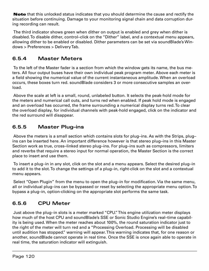
Page 120
Note that this unlocked status indicates that you should determine the cause and rectify the situation before continuing. Damage to your monitoring signal chain and data corruption dur-ing recording can result.
The third indicator shows green when dither on output is enabled and grey when dither is disabled. To disable dither, control–click on the “Dither” label, and a contextual menu appears, allowing dither to be enabled or disabled. Dither parameters can be set via soundBlade’s Win-dows > Preferences > Delivery Tab.
6.5.4 Master Meters
To the left of the Master fader is a section from which the window gets its name, the bus me-ters. All four output buses have their own individual peak program meter. Above each meter is a field showing the numerical value of the current instantaneous amplitude. When an overload occurs, these boxes turn red. soundBlade considers 3 or more consecutive samples an over-load.
Above the scale at left is a small, round, unlabeled button. It selects the peak-hold mode for the meters and numerical call outs, and turns red when enabled. If peak hold mode is engaged and an overload has occurred, the frame surrounding a numerical display turns red. To clear the overload display, for individual channels with peak-hold engaged, click on the indicator and the red surround will disappear.
6.5.5 Master Plug–ins
Above the meters is a small section which contains slots for plug–ins. As with the Strips, plug–ins can be inserted here. An important difference however is that stereo plug–ins in this Master Section work as true, cross–linked stereo plug–ins. For plug–ins such as compressors, limiters and reverbs that require a stereo input for normal operation, the Master Section is the correct place to insert and use them.
To insert a plug–in in any slot, click on the slot and a menu appears. Select the desired plug–in to add it to the slot. To change the settings of a plug–in, right-click on the slot and a contextual menu appears.
Select “Open Plugin” from the menu to open the plug–in for modification. Via the same menu, all or individual plug–ins can be bypassed or reset by selecting the appropriate menu option. To bypass a plug–in, option-clicking on the appropriate slot performs the same task.
6.5.6 CPU Meter
Just above the plug–in slots is a meter marked “CPU.” This engine utilization meter displays how much of the host CPU and soundBlade’s SSE or Sonic Studio Engine’s real–time capabil-ity is being used. When the meter reaches about 100%, the round saturation indicator just to the right of the meter will turn red and a “Processing Overload. Processing will be disabled until audition has stopped.” warning will appear. This warning indicates that, for one reason or another, soundBlade cannot operate in real time. Once the SSE is once again able to operate in real time, the saturation indicator will extinguish.
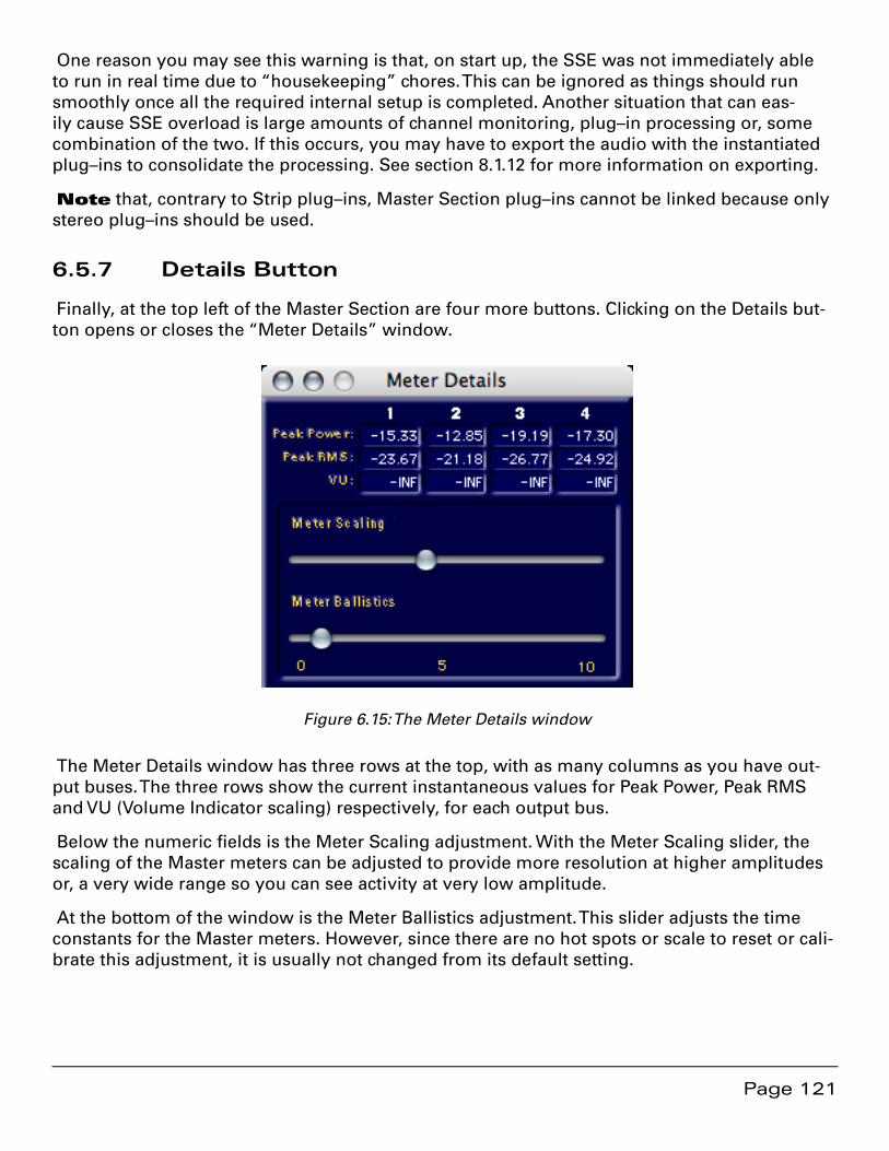
Page 121
One reason you may see this warning is that, on start up, the SSE was not immediately able to run in real time due to “housekeeping” chores. This can be ignored as things should run smoothly once all the required internal setup is completed. Another situation that can eas-ily cause SSE overload is large amounts of channel monitoring, plug–in processing or, some combination of the two. If this occurs, you may have to export the audio with the instantiated plug–ins to consolidate the processing. See section 8.1.12 for more information on exporting.
Note that, contrary to Strip plug–ins, Master Section plug–ins cannot be linked because only stereo plug–ins should be used.
6.5.7 Details Button
Finally, at the top left of the Master Section are four more buttons. Clicking on the Details but-ton opens or closes the “Meter Details” window.
Figure 6.15: The Meter Details window
The Meter Details window has three rows at the top, with as many columns as you have out-put buses. The three rows show the current instantaneous values for Peak Power, Peak RMS and VU (Volume Indicator scaling) respectively, for each output bus.
Below the numeric fields is the Meter Scaling adjustment. With the Meter Scaling slider, the scaling of the Master meters can be adjusted to provide more resolution at higher amplitudes or, a very wide range so you can see activity at very low amplitude.
At the bottom of the window is the Meter Ballistics adjustment. This slider adjusts the time constants for the Master meters. However, since there are no hot spots or scale to reset or cali-brate this adjustment, it is usually not changed from its default setting.
Page 122
6.5.8 Clear Button
Next in line to the right is the Clear button. Clicking the Clear button clears the peak values for the numerical level indicators, as well as any overloads indicated.
6.5.9 Reset Button
Next in line to the right is the Clear button. Clicking Reset resets the peak-hold of the meters, as well as any peak-hold value in the Meters Details window discussed above.
6.5.10 Output Button
The last button at the top of the Master Section is the Output button. The Outputs button acts as a source selector for the Master Section, toggling between output and input buses as source for the meters. By default, soundBlade shows outputs M1 to 4 but in input mode, line inputs L1 to L4 can be metered as well. The label below the button indicates the current input source for the meters. In addition to that, when the inputs are selected as source for the meters, the numerical value indicators above the meters have a green background to indicate the different meter mode.
Note that, though the master fader is attached to the Master Section as a whole, its function does not change with the source selector.
6.6 Bounce Examples
Overview
This section combines information from previous sections into basic “recipes,” providing four variations on re-recording or capturing edited sound with processing to a new sound file. The first two examples involve built–in audio while the last covers external or outboard processing , forcing the use of an optional Series 300 I/O Processor or Core Audio device.
One thing you should remember throughout this section: Regardless of source, always record to Panels 1 and 2, the top two Panels of your Project. Keeping that dictum in mind, you should plan your Project layout. Since the resulting audio will be “dropped into” Panels 1 and 2 when recording stops, you may want to place a sync copy of the original or “dry” material, in Panels 3 and 4, to Panels 1 and 2, so the newly processed material will be edited in sync for you when you drop out of record.
To do this, start with a basic two point edit, with both edit points in the Source. Always include “handles” or extra material on either side of the section to be worked on. This assures some latitude when editing in the final piece.
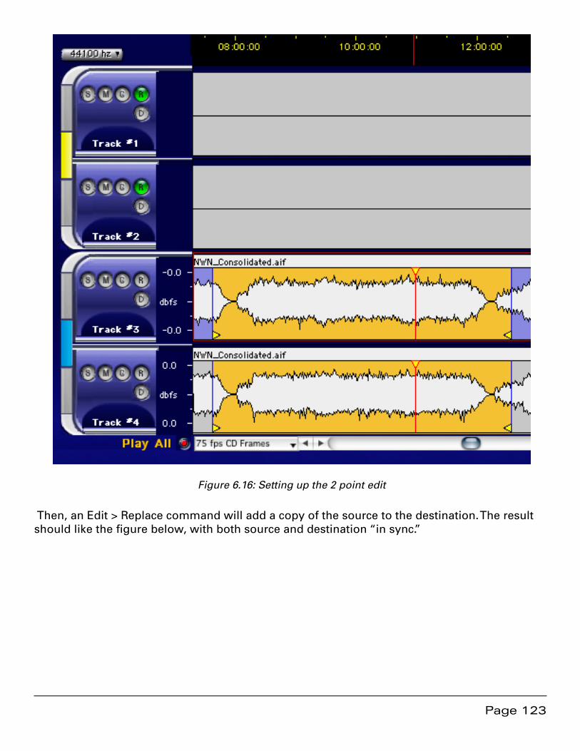
Page 123
Figure 6.16: Setting up the 2 point edit
Then, an Edit > Replace command will add a copy of the source to the destination. The result should like the figure below, with both source and destination “in sync.”
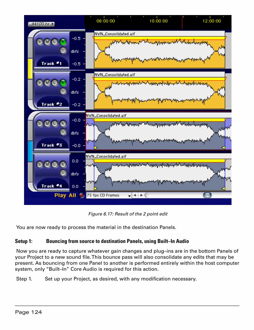
Page 124
Figure 6.17: Result of the 2 point edit
You are now ready to process the material in the destination Panels.
Setup 1: Bouncing from source to destination Panels, using Built–In Audio
Now you are ready to capture whatever gain changes and plug–ins are in the bottom Panels of your Project to a new sound file. This bounce pass will also consolidate any edits that may be present. As bouncing from one Panel to another is performed entirely within the host computer system, only “Built–In” Core Audio is required for this action.
Step 1. Set up your Project, as desired, with any modification necessary.
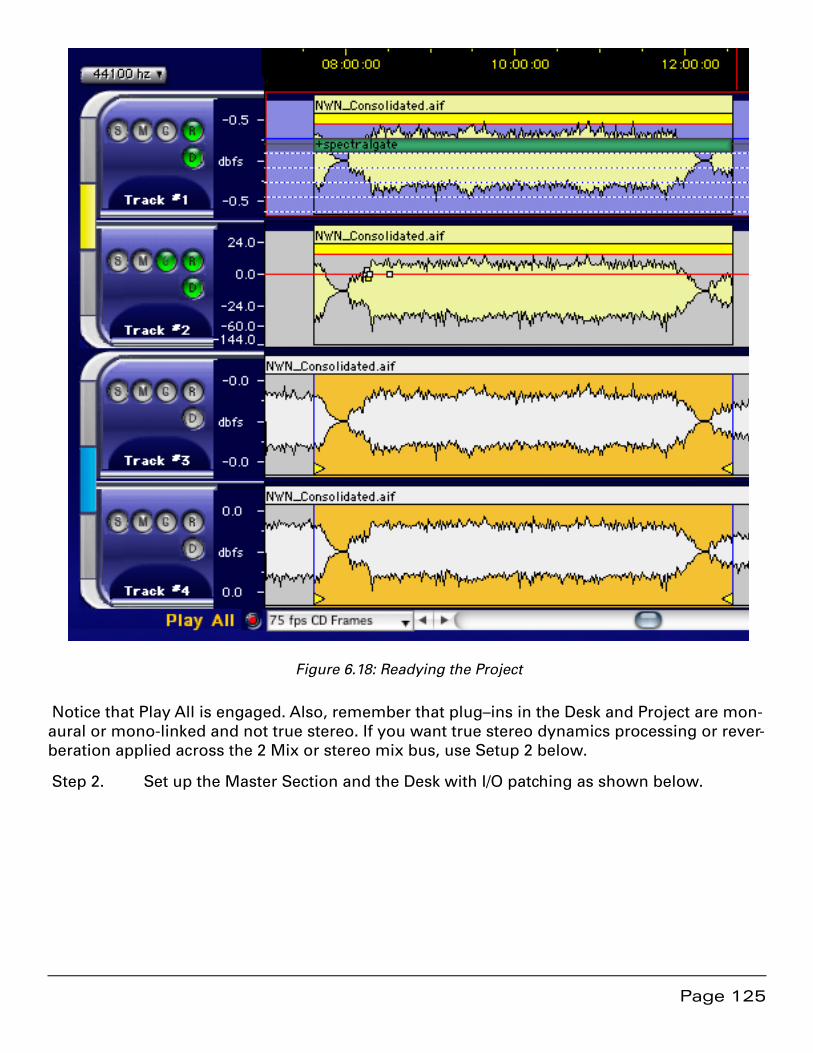
Page 125
Figure 6.18: Readying the Project
Notice that Play All is engaged. Also, remember that plug–ins in the Desk and Project are mon-aural or mono-linked and not true stereo. If you want true stereo dynamics processing or rever-beration applied across the 2 Mix or stereo mix bus, use Setup 2 below.
Step 2. Set up the Master Section and the Desk with I/O patching as shown below.
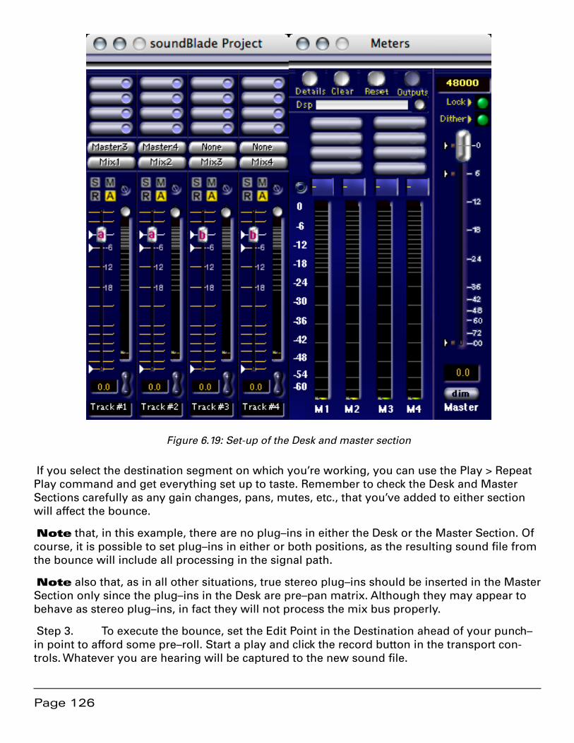
Page 126
Figure 6.19: Set-up of the Desk and master section
If you select the destination segment on which you’re working, you can use the Play > Repeat Play command and get everything set up to taste. Remember to check the Desk and Master Sections carefully as any gain changes, pans, mutes, etc., that you’ve added to either section will affect the bounce.
Note that, in this example, there are no plug–ins in either the Desk or the Master Section. Of course, it is possible to set plug–ins in either or both positions, as the resulting sound file from the bounce will include all processing in the signal path.
Note also that, as in all other situations, true stereo plug–ins should be inserted in the Master Section only since the plug–ins in the Desk are pre–pan matrix. Although they may appear to behave as stereo plug–ins, in fact they will not process the mix bus properly.
Step 3. To execute the bounce, set the Edit Point in the Destination ahead of your punch–in point to afford some pre–roll. Start a play and click the record button in the transport con-trols. Whatever you are hearing will be captured to the new sound file.
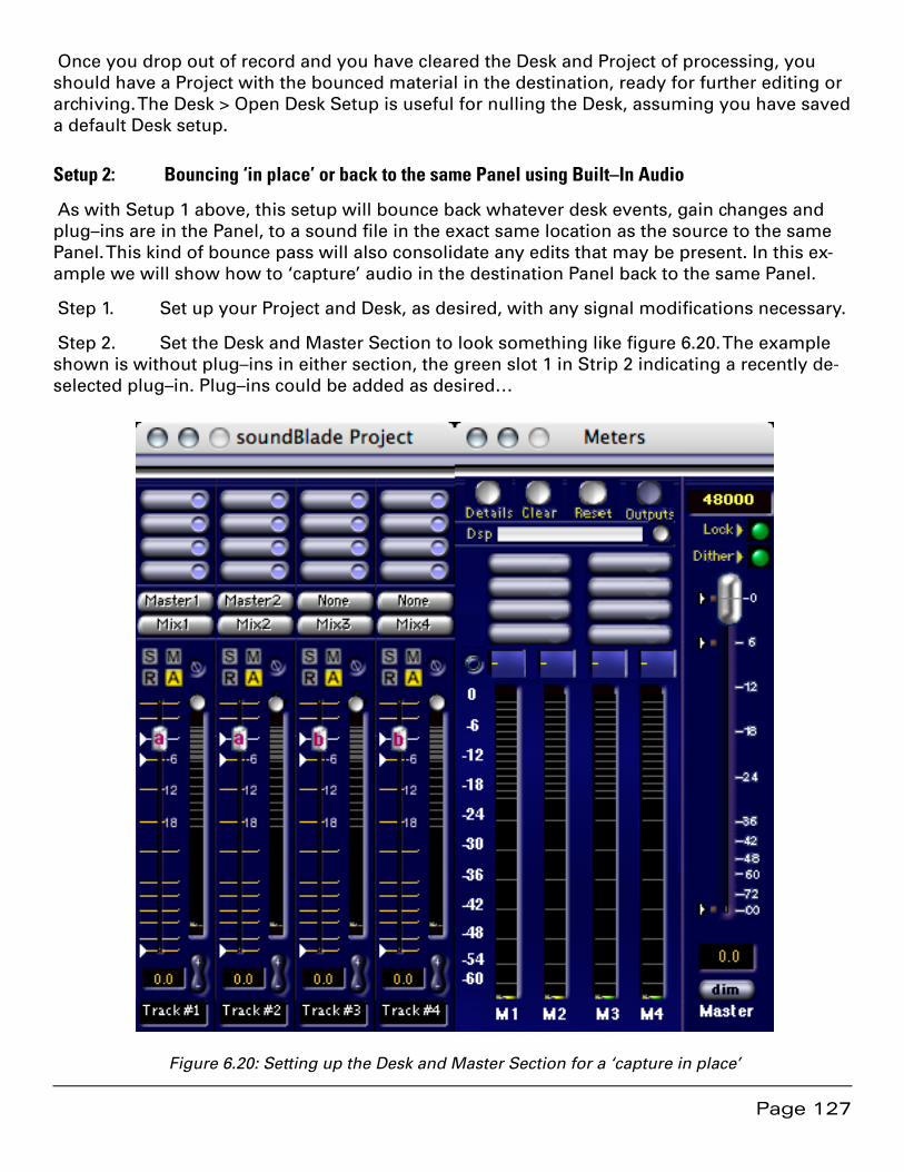
Page 127
Once you drop out of record and you have cleared the Desk and Project of processing, you should have a Project with the bounced material in the destination, ready for further editing or archiving. The Desk > Open Desk Setup is useful for nulling the Desk, assuming you have saved a default Desk setup.
Setup 2: Bouncing ‘in place’ or back to the same Panel using Built–In Audio
As with Setup 1 above, this setup will bounce back whatever desk events, gain changes and plug–ins are in the Panel, to a sound file in the exact same location as the source to the same Panel. This kind of bounce pass will also consolidate any edits that may be present. In this ex-ample we will show how to ‘capture’ audio in the destination Panel back to the same Panel.
Step 1. Set up your Project and Desk, as desired, with any signal modifications necessary.
Step 2. Set the Desk and Master Section to look something like figure 6.20. The example shown is without plug–ins in either section, the green slot 1 in Strip 2 indicating a recently de-selected plug–in. Plug–ins could be added as desired…
Figure 6.20: Setting up the Desk and Master Section for a ‘capture in place’
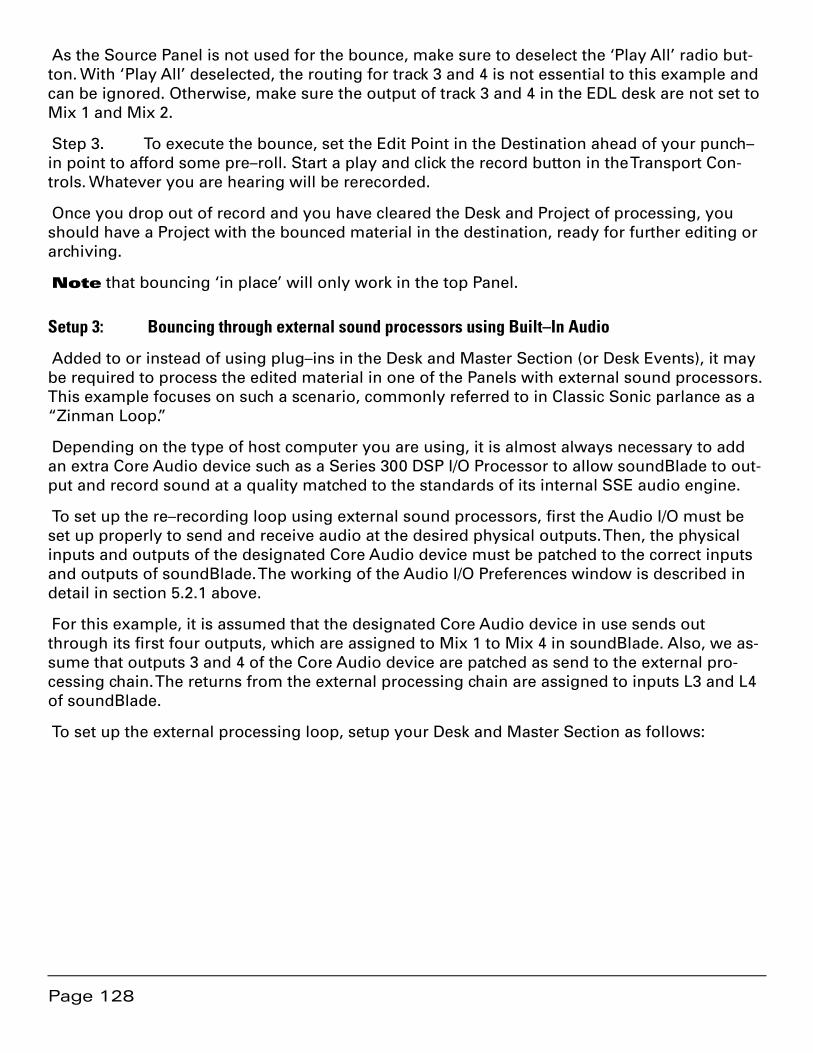
Page 128
As the Source Panel is not used for the bounce, make sure to deselect the ‘Play All’ radio but-ton. With ‘Play All’ deselected, the routing for track 3 and 4 is not essential to this example and can be ignored. Otherwise, make sure the output of track 3 and 4 in the EDL desk are not set to Mix 1 and Mix 2.
Step 3. To execute the bounce, set the Edit Point in the Destination ahead of your punch–in point to afford some pre–roll. Start a play and click the record button in the Transport Con-trols. Whatever you are hearing will be rerecorded.
Once you drop out of record and you have cleared the Desk and Project of processing, you should have a Project with the bounced material in the destination, ready for further editing or archiving.
Note that bouncing ‘in place’ will only work in the top Panel.
Setup 3: Bouncing through external sound processors using Built–In Audio
Added to or instead of using plug–ins in the Desk and Master Section (or Desk Events), it may be required to process the edited material in one of the Panels with external sound processors. This example focuses on such a scenario, commonly referred to in Classic Sonic parlance as a “Zinman Loop.”
Depending on the type of host computer you are using, it is almost always necessary to add an extra Core Audio device such as a Series 300 DSP I/O Processor to allow soundBlade to out-put and record sound at a quality matched to the standards of its internal SSE audio engine.
To set up the re–recording loop using external sound processors, first the Audio I/O must be set up properly to send and receive audio at the desired physical outputs. Then, the physical inputs and outputs of the designated Core Audio device must be patched to the correct inputs and outputs of soundBlade. The working of the Audio I/O Preferences window is described in detail in section 5.2.1 above.
For this example, it is assumed that the designated Core Audio device in use sends out through its first four outputs, which are assigned to Mix 1 to Mix 4 in soundBlade. Also, we as-sume that outputs 3 and 4 of the Core Audio device are patched as send to the external pro-cessing chain. The returns from the external processing chain are assigned to inputs L3 and L4 of soundBlade.
To set up the external processing loop, setup your Desk and Master Section as follows:
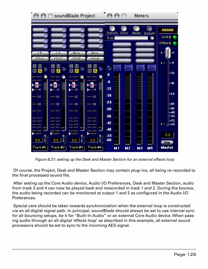
Page 129
Figure 6.21: setting up the Desk and Master Section for an external effects loop
Of course, the Project, Desk and Master Section may contain plug–ins, all being re–recorded to the final processed sound file.
After setting up the Core Audio device, Audio I/O Preferences, Desk and Master Section, audio from track 3 and 4 can now be played back and rerecorded in track 1 and 2. During the bounce, the audio being recorded can be monitored at output 1 and 2 as configured in the Audio I/O Preferences.
Special care should be taken towards synchronization when the external loop is constructed via an all-digital signal path. In principal, soundBlade should always be set to use internal sync for all bouncing setups, be it for “Built–In Audio” or an external Core Audio device. When pass-ing audio through an all-digital ‘effects loop’ as described in this example, all external sound processors should be set to sync to the incoming AES signal.

Page 130
Setup 4: Bouncing through external analog processors using a Model 302
Sonic Studio’s Series 300 DSP I/O Processors provide powerful and high fidelity routing, re-cording, mixing and processing in compact, FireWire–attached packages. The Model 302 is a two channel example and is a perfect fit for soundBlade.
This setup outlines the use of a Model 302 as an interface to outboard gear, specifically an analog processing chain. This example uses soundBlade’s Mix3 and Mix4 as the send to exter-nal processing, and line inputs L3 and L4 as the return. Remember that monaural plug–ins in the Project and Desk and stereo plug–ins in the Master Section will be in the signal path.
Step 2. Set up the Project and the Desk as shown below.
Figure 6.22: Set-up of the Project
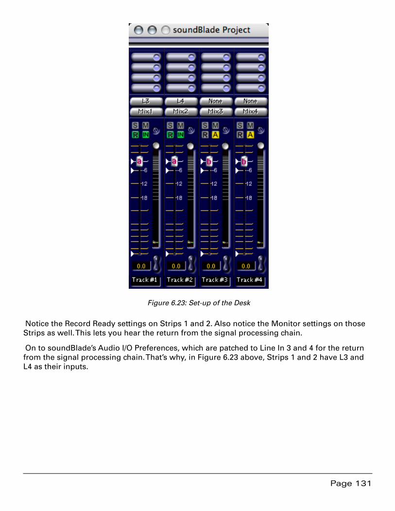
Page 131
Figure 6.23: Set-up of the Desk
Notice the Record Ready settings on Strips 1 and 2. Also notice the Monitor settings on those Strips as well. This lets you hear the return from the signal processing chain.
On to soundBlade’s Audio I/O Preferences, which are patched to Line In 3 and 4 for the return from the signal processing chain. That’s why, in Figure 6.23 above, Strips 1 and 2 have L3 and L4 as their inputs.
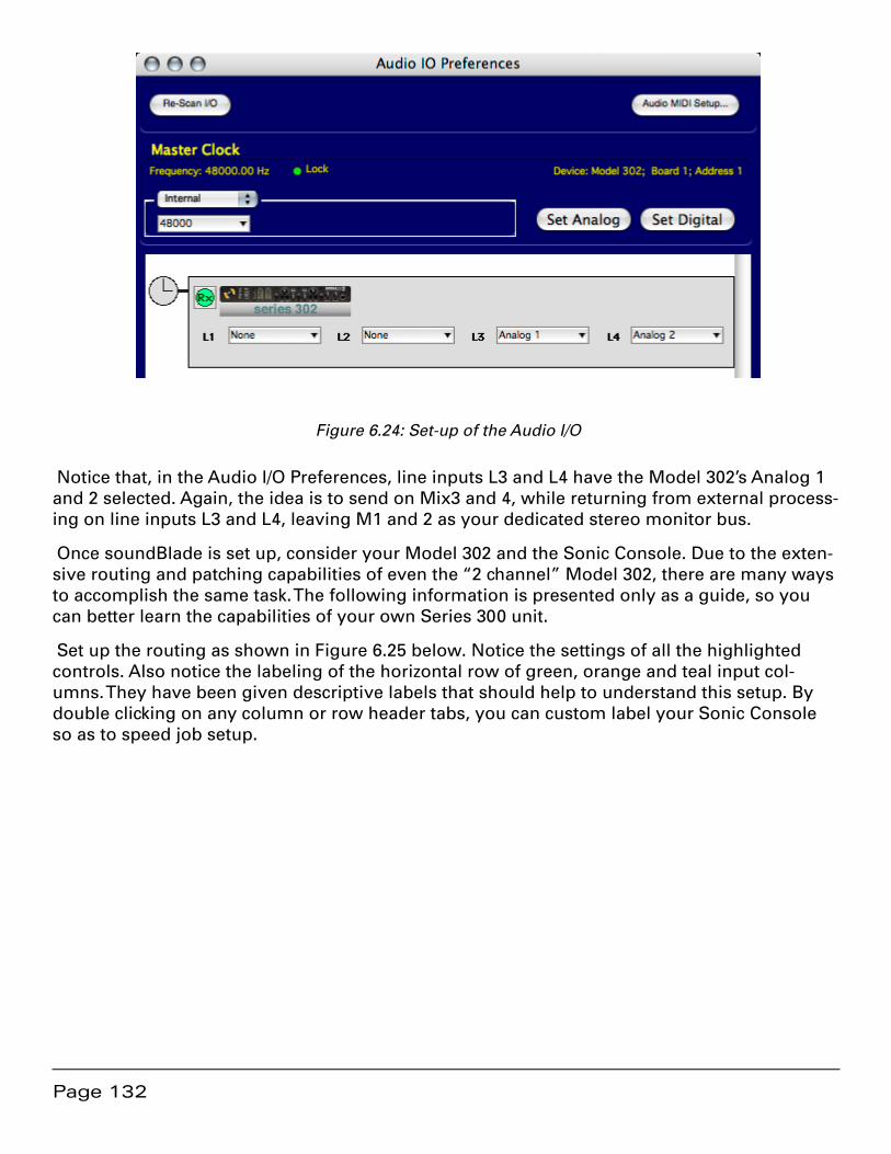
Page 132
Figure 6.24: Set-up of the Audio I/O
Notice that, in the Audio I/O Preferences, line inputs L3 and L4 have the Model 302’s Analog 1 and 2 selected. Again, the idea is to send on Mix3 and 4, while returning from external process-ing on line inputs L3 and L4, leaving M1 and 2 as your dedicated stereo monitor bus.
Once soundBlade is set up, consider your Model 302 and the Sonic Console. Due to the exten-sive routing and patching capabilities of even the “2 channel” Model 302, there are many ways to accomplish the same task. The following information is presented only as a guide, so you can better learn the capabilities of your own Series 300 unit.
Set up the routing as shown in Figure 6.25 below. Notice the settings of all the highlighted controls. Also notice the labeling of the horizontal row of green, orange and teal input col-umns. They have been given descriptive labels that should help to understand this setup. By double clicking on any column or row header tabs, you can custom label your Sonic Console so as to speed job setup.
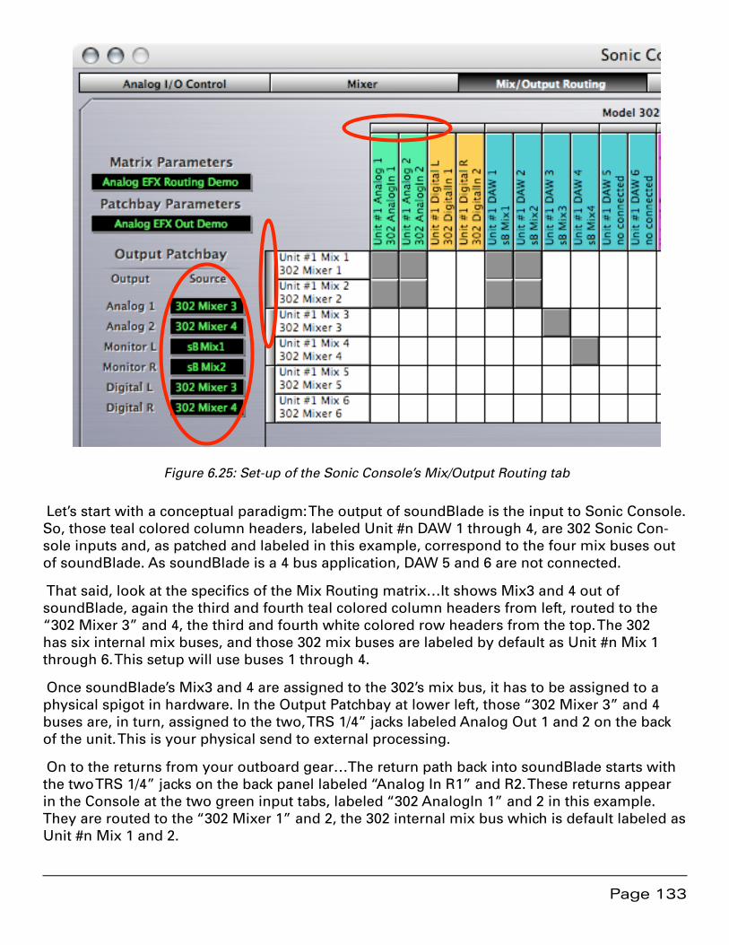
Page 133
Figure 6.25: Set-up of the Sonic Console’s Mix/Output Routing tab
Let’s start with a conceptual paradigm: The output of soundBlade is the input to Sonic Console. So, those teal colored column headers, labeled Unit #n DAW 1 through 4, are 302 Sonic Con-sole inputs and, as patched and labeled in this example, correspond to the four mix buses out of soundBlade. As soundBlade is a 4 bus application, DAW 5 and 6 are not connected.
That said, look at the specifics of the Mix Routing matrix…It shows Mix3 and 4 out of soundBlade, again the third and fourth teal colored column headers from left, routed to the “302 Mixer 3” and 4, the third and fourth white colored row headers from the top. The 302 has six internal mix buses, and those 302 mix buses are labeled by default as Unit #n Mix 1 through 6. This setup will use buses 1 through 4.
Once soundBlade’s Mix3 and 4 are assigned to the 302’s mix bus, it has to be assigned to a physical spigot in hardware. In the Output Patchbay at lower left, those “302 Mixer 3” and 4 buses are, in turn, assigned to the two, TRS 1/4” jacks labeled Analog Out 1 and 2 on the back of the unit. This is your physical send to external processing.
On to the returns from your outboard gear…The return path back into soundBlade starts with the two TRS 1/4” jacks on the back panel labeled “Analog In R1” and R2. These returns appear in the Console at the two green input tabs, labeled “302 AnalogIn 1” and 2 in this example. They are routed to the “302 Mixer 1” and 2, the 302 internal mix bus which is default labeled as Unit #n Mix 1 and 2.
Page 134
Note the setting of the stereo link bars along the top and left side of the Mix Routing matrix. These need to be set as shown, or you may not be monitoring a stereo signal correctly. This is in contrast to the direct left–to–left and right–to–right patching seen in the sB Mix3 and 4 to 302 Mixer 3 and 4 patch discussed above. The reason for this is that the more complex patch for these 302 AnalogIns 1 and 2 result in stereo faders on the Mixer tab, whereas the direct, sim-pler sB Mix3 and 4 to 302 Mixer 3 and 4 patch results in mono faders. After making the Routing patches as shown, inspect the entire Mixer for your self to discover the differences between the routing assigns.
Let’s mention another conceptual paradigm: The monitor returns for both soundBlade and the 302 are completely independent. This means that, in general, no patching in Sonic Console is necessary to produce basic monitoring or bouncing. However, the versatility of the Sonic Console means you can configure a very useful ability to A/B monitor your sends and returns, while setting send and return level, all in Sonic Console.
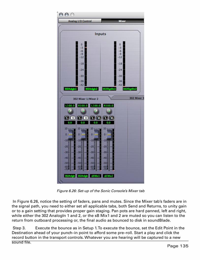
Page 135
Figure 6.26: Set-up of the Sonic Console’s Mixer tab
In Figure 6.26, notice the setting of faders, pans and mutes. Since the Mixer tab’s faders are in the signal path, you need to either set all applicable tabs, both Send and Returns, to unity gain or to a gain setting that provides proper gain staging. Pan pots are hard panned, left and right, while either the 302 AnalogIn 1 and 2, or the sB Mix1 and 2 are muted so you can listen to the return from outboard processing or, the final audio as bounced to disk in soundBlade.
Step 3. Execute the bounce as in Setup 1. To execute the bounce, set the Edit Point in the Destination ahead of your punch–in point to afford some pre–roll. Start a play and click the record button in the transport controls. Whatever you are hearing will be captured to a new sound file.

Page 136
Once you drop out of record and you have cleared the Desk and Project of processing, you should have a Project with the bounced material in the destination, ready for further editing or archiving. The Desk > Open Desk Setup is useful for nulling the Desk, assuming you have saved a default Desk setup. Just as the Desk > Open Desk Setup is useful for nulling the Desk, the Sonic Console’s Save Parameters As… command in the Mix/Output Routing tab allows you to quickly null or reset your Model 302.
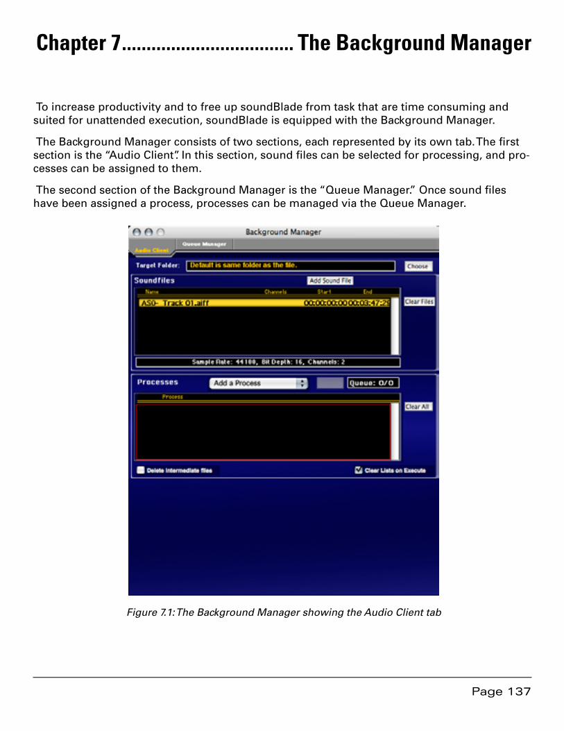
Page 137
Chapter 7 ................................... The Background Manager
To increase productivity and to free up soundBlade from task that are time consuming and suited for unattended execution, soundBlade is equipped with the Background Manager.
The Background Manager consists of two sections, each represented by its own tab. The first section is the “Audio Client”. In this section, sound files can be selected for processing, and pro-cesses can be assigned to them.
The second section of the Background Manager is the “Queue Manager.” Once sound files have been assigned a process, processes can be managed via the Queue Manager.
Figure 7.1: The Background Manager showing the Audio Client tab

Page 138
7.1 The Audio Client tab
To open the Background Manger, select the Windows > Background Manager command. By default, the Audio Client Tab is selected when the Background Manager opens. It largely con-sists of 2 areas, the “Soundfiles” area and the “Processes” area, topped by the Target Folder field.
In the Target Folder field, the target folder for newly created sound files is specified. To select a target folder, click on the Choose button at upper right. A standard Mac OS browser opens, al-lowing you to navigate, create and/or choose the desired destination folder. Option–clicking on the Choose button forces soundBlade to use the input file’s folder also as the target folder.
Note that, upon initiating a process, the Background Manager will ask to confirm the destina-tion folder.
In the Soundfiles area, sound files can be selected and added by the clicking Add Sound File button. A standard Mac OS browser opens, allowing you to navigate to the location of the desired sound file(s). Once a sound file is selected, it is placed in the Soundfiles list. When a sound file is selected in the list, the black status bar below the list displays the sample rate, word length and number of channels of the selected file. Multiple sound files can be added to the list by repeating this action.
To remove sound files from the list, click to select the list entry and delete it by hitting the back-space or delete key. To clear the list of all sound files, click the Clear All button to the right of the Soundfiles list.
7.1.1 Applying Processes
Once all sound files have been selected, one or more processes to be applied to them in the Processes area. An “Add a Process” menu allows for selection of the desired process(es).
Note that, for basic versions of soundBlade, only the ability to create waveform metadata or sample rate convert is available. More background Processes are available when optional pack-ages for soundBlade are purchased.
When a process is selected, in the space below the Processes area, details and available pa-rameters are shown for the selected Process. This enables adjustment or selection of further options, depending upon the Process selected.
Processes can be deleted from the processes list by clicking on the process and then hitting the backspace or delete key. To clear all processes from the Processes list, click the “Clear All” button to the right of the Processes list.
Once all necessary processes have been selected and placed in the right processing order, they can be automatically performed upon the selected sound files by clicking the “Execute” button. The sound files and the processes to be applied upon them are then “queued” and pro-cessing commences. To indicate this action, the “Queue” indicator to the right of the Execute button shows the number of sound files and processes queued.
Page 139
Once the processes are being executed, all sound files and processes remain in their respec-tive lists. This allows for a quick method of applying different processes to the same file(s) or visa versa. To erase both lists and start new lists for sound files and processes, simply click the “Clear Files” or “Clear All” buttons next to the lists and the Audio Client is cleared from its current list of sound files and processes, respectively. To remove all items in the lists automati-cally, enable the Clear List on Execute option.
Note that the order in which sound files are processed is fixed and dependant upon the order in which sound files and processes are listed in their respective areas. The primary processing order is defined, top to bottom, by the order in which the sound files are listed in the Sound-files area. The secondary processing order is given by the order of processes in the Processes list. So, in practice, if more than one sound file is listed and multiple processes are listed as well, first the initial sound file in the Soundfiles list is processed by all processes listed in the Processes list in the order in which they are listed. Be aware that each process is performed upon the resulting file of the previous process. When all listed processes are performed upon the first listed sound file, the following sound file is processed with the same processing in the same order. This is repeated until all sound files are processed with all listed processes.
The end result of this is one resulting sound file per process per sound file. To avoid the cre-ation of superfluous sound files, select “Delete intermediate files” at the bottom left of the Pro-cesses area. This causes the Background Manager to delete all intermediate sound files, creat-ing only one final resulting sound file per input sound file. If disk space is not at a premium, it is recommended that intermediary files are retained until the job is finished.
The following processes are available in the Background Manager, depending upon the pur-chased package of soundBlade:
7.1.1.1 Sample Rate Conversion
The SRC/varispeed background process has thirteen choices of target sample rate. As with any SRC process, if the target sample rate matches the clock rate of the playback system, then the process is considered a sample rate conversion. If, however, the target sample rate does not match the clock rate of the playback system, then the process is considered a varispeed. In ei-ther case, the actual processed data in the file is identical, only the sample rate flag is different. SRC preserves pitch and duration, while varispeed produces modified pitch and duration from the original.
The Target Sample Rate menu includes the following choices, in kiloHertz:
8•
44.056 (44.1 kHz referenced to 59.97 Hz)•
44.1•
47.952 (48 kHz referenced to 59.97 Hz)•
48•
88.112 (88.2 kHz referenced to 59.97 Hz)•
88.2•
Page 140
95.904 (96 kHz referenced to 59.97 Hz)•
96•
176.4•
192•
352.8•
384•
In addition to the Target Sample Rate menu, a Percent field is provided to set a target sample rate as specified by a percentage of the source or original sample rate. With either the Target Sample Rate menu or the Percent field, the actual sample rate, in Hertz, is provided in the Pro-cesses list for that entry.
7.1.1.2 Build Waveforms
As the name implies, this process creates waveform metadata for the queued sound files. The resulting files, with a “.r” extension, are placed in the same directory as the parent file from which they were derived.
7.2 The Queue Manager tab
To monitor and manage queued processes, the Queue Manager tab offers status information and limited options to influence the queued jobs and tasks being performed.

Page 141
Figure 7.2: The Queue Manager tab
In the top half of the window, all processing jobs in the Queue are listed.
In the bottom half, the active jobs are listed. The progress bars below this area show which file is being processes and which process of the total number of processes to be applied is cur-rently being applied.
To suspend currently running processes, click the “Pause/Resume” button. The current process is halted and queued processes are held in the queue. To resume processing, click the Pause/Resume button again.

Page 142
To abort the current process, click the Abort button and the current process will be aborted, initiating the next process in the Queue.
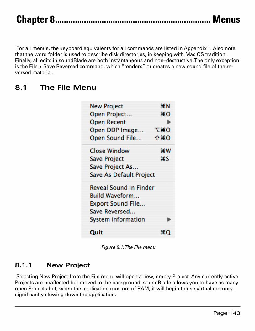
Page 143
Chapter 8 ...................................................................... Menus
For all menus, the keyboard equivalents for all commands are listed in Appendix 1. Also note that the word folder is used to describe disk directories, in keeping with Mac OS tradition. Finally, all edits in soundBlade are both instantaneous and non–destructive. The only exception is the File > Save Reversed command, which “renders” or creates a new sound file of the re-versed material.
8.1 The File Menu
Figure 8.1: The File menu
8.1.1 New Project
Selecting New Project from the File menu will open a new, empty Project. Any currently active Projects are unaffected but moved to the background. soundBlade allows you to have as many open Projects but, when the application runs out of RAM, it will begin to use virtual memory, significantly slowing down the application.
Page 144
8.1.2 Open Project
A Project file lets you save your editing work in a set of files, along with most of the editing metadata you’ve added. An additional feature of a Project is that you can save your edit deci-sions without committing them back to a DDP file set. The Project file saves all segment names, SRPs, marks and edits and, they are all restored upon re–opening that Project.
Selecting File > Open Project brings up a standard Mac OS file browser. Locate the requested Project file and select it to open the Project in a new window.
8.1.3 Open Recent
With this menu, a list of recently opened Projects and sound files is shown. Selecting one of those files will re-open it.
If you hold down the option key prior to accessing this menu command, it divides the result-ing list into Project files first and sound files second, with a divider in between. The files appear in the list with the most recently used files at the top, in the order they were opened.
Finally, if you select a sound file from this menu without any target Projects open, soundBlade will create a new (default) Project and open the sound file into that Project.
8.1.4 Open DDP Image…
[DDP File Open Option] — In addition to sound files, soundBlade can optionally open DDP file sets with the DDP File Open option. Selecting “Open DDP Image…” from this menu invokes a standard Mac OS browser. To open a DDP file set, select its containing folder and choose “Open” from the browser window.
8.1.5 Open Sound File…
This command opens a Mac OS file browser, allowing you to select any sound file recognized by soundBlade. This includes AIFF, WAV, AIFC 32 bit floating point files and BWF files along with SD2 or Sound Designer II files with region definitions. See section 8.9.4.1 for more information on importing SD2 files. soundBlade is also able to open audio files by dragging and dropping the files into the top Panel of a Project.
8.1.5.1 Broadcast WAV Files
Broadcast WAV or BWF files can contain metadata to document production processes and con-trol how the file is handled during editorial. soundBlade will honor BWF time stamps and, all existing BWF metadata is conserved during editing and on export.
To force soundBlade to honor an existing time stamp, hold down the shift key when dragging. The sound file will open on the time line at its time stamp. Once a BWF is open, by control-clicking on the segment, a contextual menu provides a Show BWF Meta-Data command to display the metadata contained in the file’s header.
Page 145
8.1.6 Close Window
This command closes the currently active window. This can be a Project, the Mark Info win-dow or, the Preferences window. Upon closing a Project that contains unsaved changes, soundBlade will open a dialog asking for changes to be saved, discarded or offering to cancel the close window operation.
8.1.7 Save Project
This will save the current state of the active Project. It is saved with its current name and path. This command will overwrite any previously saved Project file with that name and path.
8.1.8 Save Project As…
This command lets you save a copy of the active Project under a new file name or different path. soundBlade allows you to choose either a destination folder or, you can navigate to an existing folder. If the destination is empty, soundBlade simply writes the audio and/or meta-data files as directed. If, however, the destination folder is not empty, soundBlade alerts you that a potential conflict exists to overwrite files and asks for more direction.
8.1.9 Save As Default Project
This command save the foreground Project as the default document layout when new Projects are created. Since this is a literal “save as,” you should always deploy an empty Project, with-out any sound files opened into the Project, before you invoke this command.
8.1.10 Reveal Sound In Finder
This command requires a single selected segment. As the name implies, Reveal Sound In Finder switches context to the Finder and opens a new window with the source sound file high-lighted.
8.1.11 Build Sound Waveform…
Files originating from a non–Sonic Studio product includes sample values but do not contain the amplitude-specific metadata needed to draw our very detailed audio time versus ampli-tude “waveforms.” If you would like to add waveforms while working with your sound files and have unchecked the default Windows > Preferences > EDL > View > Background Waveforms preference, you must select the Build Sound Waveform… command.
First, select the parent sound file by clicking on the segment’s Title Bar. The Title Bar will turn yellow to show that it is selected. Then, select the File > Build Sound Waveform… command.

Page 146
8.1.12 Export Sound File…
This command exports sound files in either AIFF or BWF format, in 16 or 24 bit word length. It exports the audio with amplitude changes from segment gain, plus any Gain Overlay or plug–ins.
To use this function, create a selection by either clicking on a segment’s Title Bar or by click–dragging in the top Panel to create a time region selection. Make sure the top two Panels are assigned, on the first two Desk Strips, to M1-Out and M2-Out. Then choose the destination directory with the Set File button. Then, set the file type, word length and speed.
Optionally, you can specify that the newly created material replace the existing. The Edit after Export check box performs a Replace edit, synchronously replacing the material existing prior to the export with consolidated material created from the export function. Once all options are set, clicking on the Export button causes soundBlade to “play” the selected region, exporting the audio as it plays. See section 4.9.4 for more information on Replace edits.
Note that playing material at 1x speed will not improve the quality during an export so, it is recommended that, unless real–time playback is needed, you use the Max speed setting as it has better temporal resolution. Also, during high speed exports, the time display and Playhead do not operate in real time and audio is not available at the outputs.
8.1.13 Save Reversed
This command saves one or more selected segments or regions in reversed time order, creat-ing a new sound file and segment that “plays backwards.” After invoking the command, a Mac OS file browser appears in order to select the location and file name of the new reversed file to be created. After the operation is complete, the reversed material will be edited back into the Project, replacing the original segment(s) or region(s).
Note that this operation may take a lot of time, depending upon your system configuration and the length of the selected file(s) or region, during which time soundBlade may appear to be inactive.

Page 147
8.1.13 System Information
Figure 8.2: The File > System Information submenu
8.1.13.1 Show Console Log
Invoking this command launches the Console utility and opens the log associated with soundBlade. Console is the central repository for reports from running processes and applica-tions. While soundBlade is running, it outputs information to Console and that information, such as details on installed options, system status and actions undertaken, then appears in the log. Also, at the command of the user, certain information regarding EDLs or Projects can be output to the log as well. See the following sections for more information on user selectable printing to the log file.
8.1.13.2 Print EDL Sound File Paths
This commands outputs a list of all locations of all sound files in use in the current Project. The output is written into the Console Log.
This command is useful if you work in a facility with multiple drives or network–attached stor-age on which some of your material resides. Printing the explicit path allows you to keep track of the location of all source material, for both documentation and backup.
8.1.13.3 Print Segment Info
This command prints highly detailed information on all segments in the current EDL. The out-put is written into the Console Log.
Page 148
8.1.13.4 Print Selected Segment Info Formatted
This command prints user information on the currently selected segment(s). The output is writ-ten to the Console Log in the form of a table showing the file name, start and end time, dura-tion and gain in dB.
8.1.13.5 Print Selected Segment Info
This command prints highly detailed information on all selected segments in the current EDL. The output is written into the Console Log.
8.1.13.6 Print SRP Info
This command prints detailed information on all SRPs in the active Panel. The output is written into the Console Log.
8.1.13.7 Write SRP Info to File
This command prints detailed information on all SRPs in the active Panel to a new file. The output is formatted in a table with details on track location, ordinal number, lock status and type, as well as any textual label added to the SRPs. Lock status is indicated by an “L” for locked and a “U” for unlocked. Standard SRPs have a “C” type indication while Sync SRPs, used on other Sonic Studio products, show an “S” type.
SRP files can be opened by dragging them directly onto the desired Panel. If the imported in-formation is from multiple Panels, Destination Panel is treated as the first track in the group.
Note that, though the default name of the file created with this command has a “.srp” suffix, you should manually remove that suffix and replace it with a “.txt” file extension.
8.1.13.8 Import 5.4 EDL…
For backwards compatibility with legacy Sonic Solutions 5.4 DAWs, soundBlade can import EDLs created with version 5.4 of that software. To import a 5.4 EDL, first a new Project has to be created by choosing File > New Project from the main menu. Then, select “Import 5.4 EDL” and a standard Mac OS browser will appear. Navigate to the location where the 5.4 EDL is stored, select it and open it by clicking “Open” in the browser window.
8.1.13.9 Export EDL As 5.4…
For compatibility with legacy Sonic Solutions 5.4 DAWs, soundBlade can export Projects in 5.4 EDL format. To import the current Project to a 5.4 EDL, select this option and a standard Mac OS file save window will appear. Browse to the location where the 5.4 EDL must be stored and enter the desired name for the 5.4 EDL. Select “Save” to save the Project as a 5.4 EDL.
Note that, as Sonic System 5.4 will only run on original Mac OS 9–based hard and software, you must observe OS 9 file naming conventions.
Page 149
8.1.13.10 Send Crash Report
This command is designed to help Sonic Studio to diagnose problem you may be experienc-ing with your installation. It collects the most recent crash report for soundBlade and sends it via your internet connection to Sonic Studio.
8.1.13.11 Print Desk Info
This command outputs all Desk and Output Desk settings to the Console Log.
8.1.14 Update Key File
soundBlade uses an iLok USB Smart Key for validation of your license. Added to that, a “key” file is kept on your system describing the exact license you have purchased. When new options are purchased, a new key file will be sent to you and this read in to modify soundBlade so your paid options become active.
Selecting ‘Update Key File’ will open a standard OS-X browser window, allowing you to locate your key file. Select the key file, click OK and soundBlade will update its license information. For your new options to become available, you need to restart soundBlade.
Note that your iLok is your soundBlade license. If it is lost, stolen or broken, your license is lost and can only be replaced by purchasing a new copy. PACE’s “zero downtime” insurance is your best choice for protecting your soundBlade license.
8.1.15 Quit
Selecting Quit from the File menu begins the process of closing the application. Any open Projects that have been modified will produce a modal dialog asking you to determine the Project’s fate. See section 8.1.6 above for more information on this dialog.
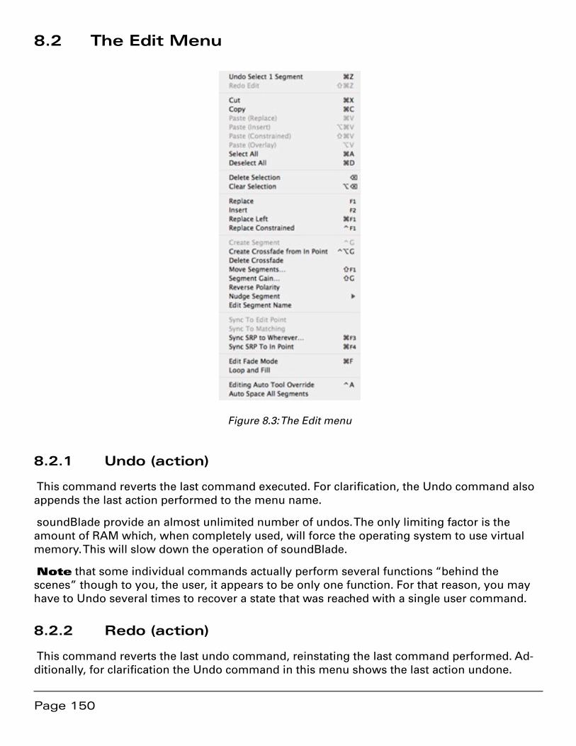
Page 150
8.2 The Edit Menu
Figure 8.3: The Edit menu
8.2.1 Undo (action)
This command reverts the last command executed. For clarification, the Undo command also appends the last action performed to the menu name.
soundBlade provide an almost unlimited number of undos. The only limiting factor is the amount of RAM which, when completely used, will force the operating system to use virtual memory. This will slow down the operation of soundBlade.
Note that some individual commands actually perform several functions “behind the scenes” though to you, the user, it appears to be only one function. For that reason, you may have to Undo several times to recover a state that was reached with a single user command.
8.2.2 Redo (action)
This command reverts the last undo command, reinstating the last command performed. Ad-ditionally, for clarification the Undo command in this menu shows the last action undone.
Page 151
8.2.3 Cut
The Cut command operates on a region within Edit Points as well as selected regions or seg-ments, removing the defined item from the Project and placing it in soundBlade’s “Clipboard.” The Clipboard is a temporary memory location reserved by the operating system for each run-ning application.
8.2.4 Copy
The Copy command operates on a region within Edit Points as well as selected regions or segments, copying the defined item from the Project and placing it in soundBlade’s Clipboard. Unlike the Cut command, the Copy command leaves the defined item intact instead of deleting it after copying the selection to the Clipboard.
8.2.5 Paste Commands
The Paste command inserts the content of the Clipboard into the Project, replacing, in order of choice, either:
A region within Edit Points1.
Selected regions or segments2.
From the Edit Point position3.
…for the duration of the audio currently on the Clipboard. The inserted content is placed be-tween Crossfades and the Edit Point is moved, for visual reference, to the end of the inserted material.
8.2.5.1 Paste (Replace)
The basic Paste command behaves as one would now expect in the world of Mac OS, with the data in the Clipboard replacing the material in the Panel(s).
8.2.5.2 Paste (Insert)
The basic Paste (Insert) command inserts the data in the Clipboard into the Panel(s), moving the existing audio downstream. No material is lost, it is simply “pushed right,” out of the way on the pasted audio.
8.2.5.3 Paste (Constrained)
Unlike the other three paste variations, the Paste (Constrained) command ignores the Edit point location, selected region or segment, etc. Instead, it pastes the data from the Clipboard into the Panel(s) based on the time stamp or location on the time line from which the copied material originally came. This command is useful for maintaining sync when editing sound for picture.
8.2.5.4 Paste (Overlay)
Page 152
The fourth variation on the Paste command places the data in the Clipboard into the Panel(s) without moving or removing the existing audio. The new material overlays the old, “lying on top of” the existing material. When you play the result, both old and new are heard together.
Because the segments now occupy the same region of the time line, it is sometimes difficult to select and manipulate these segments. For this special case, the Text view is perfect. It allows you to select, rename, gain adjust or move each individual segment at will.
Because two segments occupy the same region of the time line, it is possible that a triple over-lap would occur, when you tell soundBlade to paste the material such that three Black Fades touch each other. This is not “legal” and a modal “CheckForTripleOverlap” dialog will pop up. To overcome this prior to a Paste (Overlap), click–drag to select a region that includes the area of interest, then select File > Export Sound File… and select the Edit after Export check box. This will consolidate any existing edits, allowing you to continue with the desired Paste (Overlap) command.
8.2.6 Select/Deselect All
These commands select or deselect all segments or regions in the current Project.
8.2.7 Delete Selection
If a region or segment is selected, this command will delete the defined item. It will then “slip” or move left any audio after the deleted region or segment, filling in the space formerly occu-pied by the selected segment or region. A Crossfade is placed to transition across the deletion.
Note that, as with all editing in soundBlade, if both an In and Out Point are present, and the Out point is after the In Point, then they take precedents over both selected region and seg-ments.
If only an In Point is present, then the command will not work. Finally, if both an In and Out Point are present, the Out point is after the In Point, and the edit points are inside “Edited Black,” the empty area between segments, then that region defined by the edit points will be deleted and “downstream” audio will be moved left.
8.2.8 Clear Selection
Clear Selection works similarly to the Delete Selection command. The Clear Selection com-mand clears the selected segment, region or area defined by Edit Points, but does not move any other audio on the time line.
8.2.9 Replace
The Replace command replaces a selection or area between In and Out Points with a selection or Segment from another Panel. If the selection from the “source” Panel is empty or no selec-tion is made as a source, the “destination” will be replaced with digital silence.
Page 153
The Replace command will replace the contents of the “destination” Panel(s) with exactly the same time length as the selected “source” material. All audio within the selection to be re-placed will be discarded and replaced with the “source” material. The replace command joins the audio material before and after the replace with a default crossfade.
8.2.10 Insert
The Insert command works similar to the Replace command. Instead of replacing the audio material in the selection made in the “destination” Panel(s), it inserts the selected “source” material and moves the audio to the right of the insert point with exactly the same time as the source material’s length.
The insert command joins the audio material before and after the insert with a default cross-fade.
8.2.11 Replace Left
Like the replace command, Replace left replaces the selection with the source material, only not to the right but to the left of the Edit Point in the “destination” material.
8.2.12 Replace Constrained
Replace constrained replaces the “destination” material with the selected source material at exactly the same time position in the “destination” Panel(s) as the selected “source” material has in it’s own Panel(s)
8.2.13 Delete Selection
This command deletes the current selection or selected segments. The outer edges of the se-lection are joined with a default crossfade and all subsequent audio is shifted relatively.
8.2.14 Clear Selection
This command clears the current selection or selected segments, leaving all audio in place and replacing the audio to be cleared with digital silence. The edges of the cleared area are faded out and in with default crossfades.
8.2.15 Create Crossfade/Create Segment
This command is context sensitive and it’s appearance in the menu will change according to the current Panel’s state. It either creates a new crossfade from the current Cursor’s position when no selection is made, or it creates a new segment at the place of the selection when a selection is made. This command uses crossfade defaults when creating crossfades.
Page 154
8.2.16 Create Crossfade from In Point/Create Segment from In & Out Point(s)
As with the previous commands, this command is context sensitive and it’s appearance in the menu will change according to the current Panel’s state. It either creates a new crossfade from the current In Points position when no Out Point is seen, or it creates a new segment at the area included by a set In and Out Point. This command uses crossfade defaults when creating crossfades.
8.2.17 Delete Crossfade
The Delete Crossfade command deletes all “frivolous” Crossfades, ones that cause no audible change in the underlying audio, from the selected region. Superfluous Crossfades are usually created with the Create Crossfade command, discussed in the previous section and, after an extensive editing session, the Delete Crossfade command will clear any visual clutter, making it easier to see the operative edits.
8.2.18 Move Segments
The Move Segment command allows the user to move one or more segments to another loca-tion on the time line. Selecting this command opens the Move Segments modal dialog, which shows the current position of the Playhead or start of the first selected segment.
Entering a new start time and clicking the Move button causes the head of the first selected segment to move to the new location. All selected segments will also more by the same amount, maintaining their relative position to each other.
Additionally, this dialog offers three extra options. By clicking the Where button, you can load either the current position of the Playhead or the location of extant In point or Out Points, all from a drop down menu. Then, by clicking the Move button, the segment(s) shift to the new location. The SRP button lets you load the current position of any extant SRPs, also from a drop down menu.
The Move button moves the defined item to the location shown in the dialog’s time code ad-dress. Clicking the Cancel button leaves the selected segments at their original position.
8.2.19 Segment Gain
This command invokes the Segment Gain dialog. For more detailed information on the Seg-ment Gain dialog, see section 4.4.1.
8.2.20 Reverse Polarity
The Reverse Polarity command inverts the polarity of the selected segment(s) in all selected Panels. Segments with inverted polarity acquire a small, bright red dot in the upper left corner of their Title Bar to visually remind you of their inverted status.
Page 155
Note that, to change the polarity relationship between a stereo pair, this command must be applied to only one channel of the pair. To do this, change the Edit Target selector of one Panel, located on the left edge of both Panels, from the default stereo setting to mono. To read more about Edit Group Selectors, refer to section 4.6 for more information.
8.2.21 Nudge Segment Left/Right
The Nudge Segment commands move or “nudge” the selected segment(s) left or right, earlier or later respectively, on the time line by a predefined value. The default “Nudge B” value used is defined in the Time Display tab of Preferences window. See section 8.9.7 for more informa-tion on the Time Display preferences.
8.2.22 Edit Segment Name
When a segment is selected, choosing the Edit Segment Name command allows the user to edit the name of the segment as it appears in the Title Bar, and in Text Mode view. As with all actions in a Project, changing the Segment name has no effect on the underlying referenced sound file. This command is equivalent to double clicking on the Title Bar to change a seg-ment’s name.
8.2.23 Sync to Edit Point
The Sync to Edit Point command provides a simple, visual method for sync’ing material in the Source and Destination. If you have similar material in the two Edit Targets but one of them is misaligned in time, you can visually place the Edit Point in what you consider simultane-ous events in each Panel. Executing the command will cause the contents of the entire Source Panel to slip on the time line to “line up” the Source Edit Point with the Destination Edit Point, so both are time coincident.
8.2.24 Sync to Matching
When sections of audio in the Source and Destination groups match each other closely, you can use this command to align matching portions of audio in the groups. This match is per-formed through a numeric auto-correlation function, and can be used to match audio that doesn’t match perfectly but is similar, such as alternate takes of the same performance.
8.2.25 Sync SRP to Wherever…
This command offsets the selected segments in the current Edit Target using the first SRP in the selection as the reference point for the offset.
8.2.26 Sync SRP to In Point
This command offsets the selected segments in the current Edit Group to the In Point in the se-lected track using the first SRP in the selection as the reference point for the offset.
Page 156
8.2.27 Edit Fade Mode
When a selection contains one or more Fades, this command invokes the Edit Fade Mode win-dow. See section 4.2 for a detailed description of Edit Fade Mode.
8.2.28 Loop And Fill
This command repeats the audio contents of the clipboard and fills a selection, repeating the contents of the clipboard as many time as necessary. To invoke Loop and Fill, first copy a selec-tion or segment to the clipboard. Then, make a selection in the desired Panel where the looped audio should appear. Finally, invoke the Loop And Fill command. The selection will be filled with as many times the duration of the contents of the clipboard to match the duration of the selection. The contents of the clipboard will be joined by a default crossfade.
8.2.29 Editing Auto Tool Override
This commands toggles the Editing Auto Tools state, either enabled or disabled. See section 8.8.6 for more information on the EDL preferences.
8.2.30 Auto Space All Segments/Tracks
The AutoSpace function offers a simple but effective tool to change all pauses between tracks to a pre-defined value. Simply select Edit > AutoSpace all Segments and all segments will be moved on the time line, with equal space between according to the Preference > Editing Tools > AutoSpacing Duration setting.
If you have PQ marks already placed in the Project, the command name changes contextually from Auto Space All Segments to Auto Space All Tracks. See sections 3.8.5 and 4.2.1 above for practical discussions about the autospacing function.
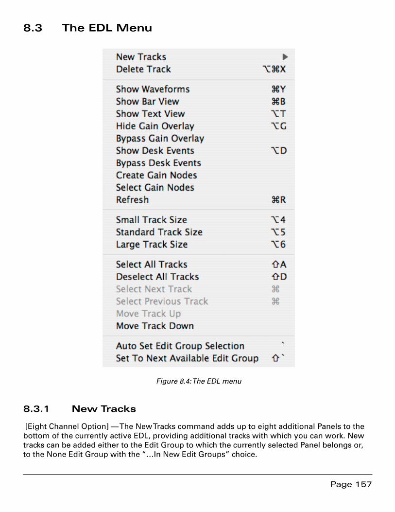
Page 157
8.3 The EDL Menu
Figure 8.4: The EDL menu
8.3.1 New Tracks
[Eight Channel Option] — The New Tracks command adds up to eight additional Panels to the bottom of the currently active EDL, providing additional tracks with which you can work. New tracks can be added either to the Edit Group to which the currently selected Panel belongs or, to the None Edit Group with the “…In New Edit Groups” choice.
Page 158
8.3.2 Delete Track
[Eight Channel Option] — The Delete Tracks command removes selected Panels from the cur-rently active EDL. soundBlade will warn you before deleting Panels. Because the Delete Track command is destructive, you may want to Save As… prior to using this function.
8.3.3 Show/Hide Text View
The Show/Hide Text View command toggles the display of the selected Panel between Text Mode and Waveform Mode views.
8.3.4 Show/Hide Gain Overlay
This command forces the selected Panel to show or hide the Gain Overlay feature. The Gain Overlay is only visible in Waveform Mode, and is shown as a thin red line superimposed on the waveform display. Projects saved with Gain Overlay will open with Gain Overlay visible upon reopening.
Note that, although Gain Overlay may not be visible, when activated it is always active in the audio output signal path. Only the EDL > Bypass Gain Overlay command will bypass any Gain Overlay functionality. See section 8.3.3 below for more information on the Bypass Gain Over-lay command.
8.3.5 Bypass/Enable Gain Overlay
This command bypasses or engages the Gain Overlay function. When in bypass, the Gain Overlay line in the waveform display turns grey and the corresponding Gain Overlay Button(s) on the left side of each Panel turn yellow.
Note that the Bypass/Enable Gain Overlay function can only be selected when Gain Overlay is shown. Option–clicking on a Gain Overlay Button will also bypass the Gain Overlay function.
8.3.6 Show/Hide Desk Events
This command shows or hides plug–ins in the Panels.
8.3.7 Show/Hide Gain Overlay
The Show/Hide Gain Overlay command shows or hides the Gain Overlay in the selected Panel(s).
8.3.8 Bypass Desk Events
When one or more plug–ins are selected, this command disables the selected plug–ins. If no plug–ins are selected, all inserted plug–ins will be bypassed. Selecting this command again re-enables all or the selected plug–ins. See section 4.6 for more detailed information on plug–ins.
Page 159
Note that enabled or active plug–ins show up as green slots in the Desk Overlay, and that disabled plug–ins show up as red slots.
8.3.9 Create Gain Nodes
With Gain Overlay enabled and a region of the time line selected, this command creates Gain Overlay nodes at the boundaries of the region. To use this function, first click–drag within the waveform display to select a region. Then, select Edit > Create Gain Nodes to add two nodes at the “edges” of the Gain Overlay and the selected region.
Because the Edit Point is really a zero duration selection, it can also be used to create a single gain node with the Create Gain Nodes command. For more detailed information on working with the Gain Overlay, see section 4.5 above.
8.3.10 Select Gain Nodes
This command selects all Gain Nodes contained within the currently selected segment(s) or region. Selected Gain Nodes can then be subject to simultaneous changes such as gain setting, lock state, or deletion.
For more information on working with Gain Overlay mode, see section 4.5 above.
8.3.11 Refresh
The Refresh command redraws the current waveform display for the selected Panel. This com-mand is especially useful after rebuilding the waveform files of one or more segments, to force the waveform display to display the updated information.
8.3.12 Small/Standard/Large Track Size
[Eight Channel Option] — The Small Track Size command re–sizes the selected Panel(s) to a very compact vertical size, allowing you to “pack” more Panels into the same amount of screen real estate.
The Standard and Large Track Size commands resize the selected Panel(s) to standard or large vertical size. Large sized Panels are two times as tall as standard size, offering a better display with larger display or desktop settings. A Large Panel also lists more segments in Text Mode.
8.3.13 Select/Deselect All Tracks
The Select All Tracks and Deselect All Tracks commands select or deselect all Panels.
8.3.14 Move Track Up/Down
[Eight Channel Option] — The Move Track commands relocate the selected track into an adja-cent Panel, allowing you to better organize the contents of your Project.
Page 160
8.3.15 Auto Set Edit Group Selection
[Eight Channel Option] — The Auto Set Edit Group Selection command is a toggle between ex-plicit and simplified Edit Group & Target choices as discussed briefly in section 4.10 above. The explicit setting is enabled by the Windows > Preferences > Editing Tools > Edit Group Selection Menu preference. With that preference off, the Panel defaults to a simplified, check box–only mode where the Edit Group is inactive and Edit Target setting are based solely on a check box just to the left of the Edit Target designator.
8.3.16 Set To Next Available Edit Group
[Eight Channel Option] — This command forces all selected Panels to the next Edit Group (let-ter) in the sequence, and is useful for configuring a Project for complex editing tasks. This com-mand is applicable only when the Windows > Preferences > Editing Tools > Edit Group Selec-tion Menu preference is enabled.
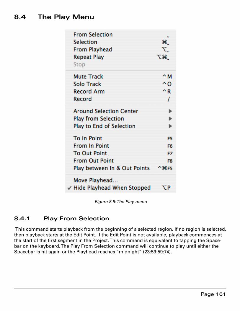
Page 161
8.4 The Play Menu
Figure 8.5: The Play menu
8.4.1 Play From Selection
This command starts playback from the beginning of a selected region. If no region is selected, then playback starts at the Edit Point. If the Edit Point is not available, playback commences at the start of the first segment in the Project. This command is equivalent to tapping the Space-bar on the keyboard. The Play From Selection command will continue to play until either the Spacebar is hit again or the Playhead reaches “midnight” (23:59:59:74).
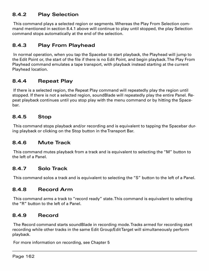
Page 162
8.4.2 Play Selection
This command plays a selected region or segments. Whereas the Play From Selection com-mand mentioned in section 8.4.1 above will continue to play until stopped, the play Selection command stops automatically at the end of the selection.
8.4.3 Play From Playhead
In normal operation, when you tap the Spacebar to start playback, the Playhead will jump to the Edit Point or, the start of the file if there is no Edit Point, and begin playback. The Play From Playhead command emulates a tape transport, with playback instead starting at the current Playhead location.
8.4.4 Repeat Play
If there is a selected region, the Repeat Play command will repeatedly play the region until stopped. If there is not a selected region, soundBlade will repeatedly play the entire Panel. Re-peat playback continues until you stop play with the menu command or by hitting the Space-bar.
8.4.5 Stop
This command stops playback and/or recording and is equivalent to tapping the Spacebar dur-ing playback or clicking on the Stop button in the Transport Bar.
8.4.6 Mute Track
This command mutes playback from a track and is equivalent to selecting the “M” button to the left of a Panel.
8.4.7 Solo Track
This command solos a track and is equivalent to selecting the “S” button to the left of a Panel.
8.4.8 Record Arm
This command arms a track to “record ready” state. This command is equivalent to selecting the “R” button to the left of a Panel.
8.4.9 Record
The Record command starts soundBlade in recording mode. Tracks armed for recording start recording while other tracks in the same Edit Group/Edit Target will simultaneously perform playback.
For more information on recording, see Chapter 5
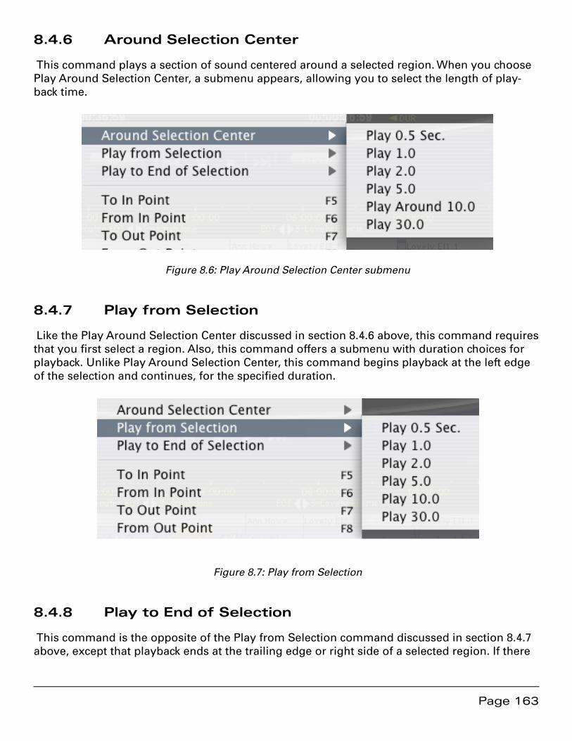
Page 163
8.4.6 Around Selection Center
This command plays a section of sound centered around a selected region. When you choose Play Around Selection Center, a submenu appears, allowing you to select the length of play-back time.
Figure 8.6: Play Around Selection Center submenu
8.4.7 Play from Selection
Like the Play Around Selection Center discussed in section 8.4.6 above, this command requires that you first select a region. Also, this command offers a submenu with duration choices for playback. Unlike Play Around Selection Center, this command begins playback at the left edge of the selection and continues, for the specified duration.
Figure 8.7: Play from Selection
8.4.8 Play to End of Selection
This command is the opposite of the Play from Selection command discussed in section 8.4.7 above, except that playback ends at the trailing edge or right side of a selected region. If there
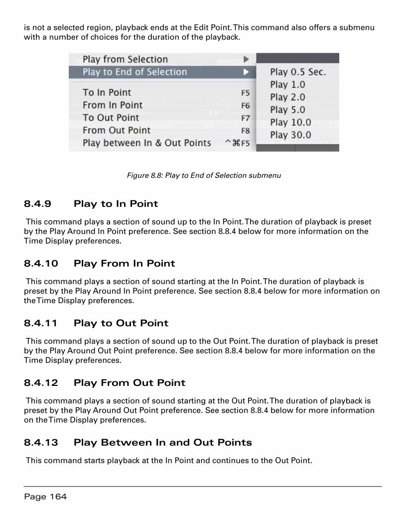
Page 164
is not a selected region, playback ends at the Edit Point. This command also offers a submenu with a number of choices for the duration of the playback.
Figure 8.8: Play to End of Selection submenu
8.4.9 Play to In Point
This command plays a section of sound up to the In Point. The duration of playback is preset by the Play Around In Point preference. See section 8.8.4 below for more information on the Time Display preferences.
8.4.10 Play From In Point
This command plays a section of sound starting at the In Point. The duration of playback is preset by the Play Around In Point preference. See section 8.8.4 below for more information on the Time Display preferences.
8.4.11 Play to Out Point
This command plays a section of sound up to the Out Point. The duration of playback is preset by the Play Around Out Point preference. See section 8.8.4 below for more information on the Time Display preferences.
8.4.12 Play From Out Point
This command plays a section of sound starting at the Out Point. The duration of playback is preset by the Play Around Out Point preference. See section 8.8.4 below for more information on the Time Display preferences.
8.4.13 Play Between In and Out Points
This command starts playback at the In Point and continues to the Out Point.
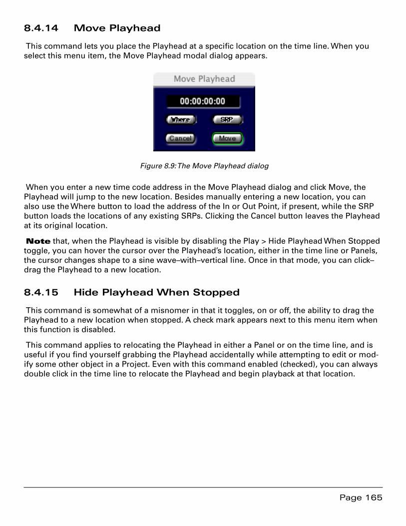
Page 165
8.4.14 Move Playhead
This command lets you place the Playhead at a specific location on the time line. When you select this menu item, the Move Playhead modal dialog appears.
Figure 8.9: The Move Playhead dialog
When you enter a new time code address in the Move Playhead dialog and click Move, the Playhead will jump to the new location. Besides manually entering a new location, you can also use the Where button to load the address of the In or Out Point, if present, while the SRP button loads the locations of any existing SRPs. Clicking the Cancel button leaves the Playhead at its original location.
Note that, when the Playhead is visible by disabling the Play > Hide Playhead When Stopped toggle, you can hover the cursor over the Playhead’s location, either in the time line or Panels, the cursor changes shape to a sine wave–with–vertical line. Once in that mode, you can click–drag the Playhead to a new location.
8.4.15 Hide Playhead When Stopped
This command is somewhat of a misnomer in that it toggles, on or off, the ability to drag the Playhead to a new location when stopped. A check mark appears next to this menu item when this function is disabled.
This command applies to relocating the Playhead in either a Panel or on the time line, and is useful if you find yourself grabbing the Playhead accidentally while attempting to edit or mod-ify some other object in a Project. Even with this command enabled (checked), you can always double click in the time line to relocate the Playhead and begin playback at that location.
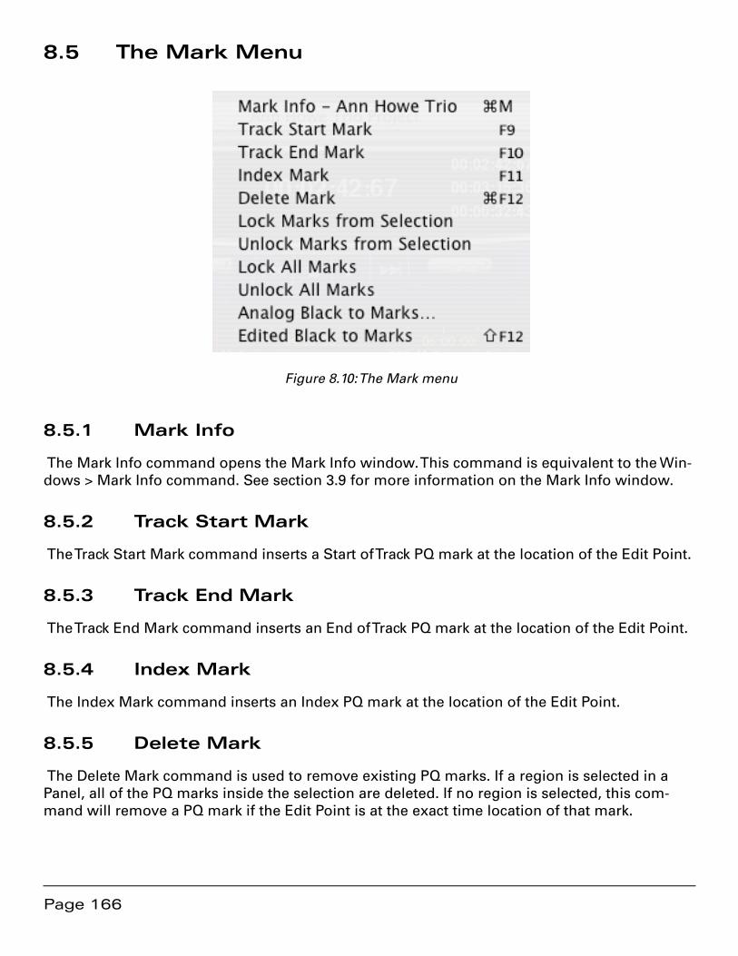
Page 166
8.5 The Mark Menu
Figure 8.10: The Mark menu
8.5.1 Mark Info
The Mark Info command opens the Mark Info window. This command is equivalent to the Win-dows > Mark Info command. See section 3.9 for more information on the Mark Info window.
8.5.2 Track Start Mark
The Track Start Mark command inserts a Start of Track PQ mark at the location of the Edit Point.
8.5.3 Track End Mark
The Track End Mark command inserts an End of Track PQ mark at the location of the Edit Point.
8.5.4 Index Mark
The Index Mark command inserts an Index PQ mark at the location of the Edit Point.
8.5.5 Delete Mark
The Delete Mark command is used to remove existing PQ marks. If a region is selected in a Panel, all of the PQ marks inside the selection are deleted. If no region is selected, this com-mand will remove a PQ mark if the Edit Point is at the exact time location of that mark.
Page 167
8.5.6 Lock Marks from Selection
The Lock Marks from Selection command is used to lock PQ marks to the time line. This com-mand locks all PQ marks inside a selected region. Once locked, mark locations cannot be modi-fied until they are unlocked. This command is equivalent to clicking the Lock button, if disabled, in the PQ Info tab of the Windows > Mark Info window.
Note that this command does not affect the ability to change Title, emphasis state, ISRC or SCMS metadata associated with a Mark. Also note that this command does not attach marks to audio segments. Editing any audio with locked PQ marks will change the time relationship between those marks and the associated audio.
8.5.7 Unlock Marks from Selection
The Unlock Marks from Selection command is used to unlock PQ marks within a selected re-gion.
8.5.8 Lock All Marks
This command locks all PQ marks on the time line, regardless of selected regions or segments. Once locked, the location of PQ marks cannot be altered until they are unlocked.
8.5.9 Unlock All Marks
This command unlocks all PQ marks on the time line.
8.5.10 Analog Black to Marks
This function measures the amplitude and duration of the audio in a selected region, placing End of Track and Start of Track marks in locations that approximate the end of one track and be-ginning of the next. Both amplitude and duration are user defined. The default amplitude is set in the Editing Tools tab of the Windows > Preferences window.
When invoking this function, the Analog Black to Marks modal dialog appears. In the dialog, the default parameters can be changed, after which the Analog Black to Marks function is start-ed by selecting OK. By clicking on the Cancel button, the operation is stopped without further action.
Note that the results of the Analog Black to Marks function is never as accurate as the Edited Black to Marks function, discussed in section 8.5.11 below. The accuracy of the mark placement depends entirely on the accuracy of the parameters used so, you may want to zoom in and, with the Show Track Scale in dB preference set (Editing Tools tab of the Windows > Preferences window), visually estimate amplitudes of your fade outs and noise floor. The result of the Ana-log Black to Marks function should always be checked for errors and unintended placement.

Page 168
8.5.11 Edited Black to Marks
The Edited Black to Marks command automatically places Start and End of Track PQ marks at the beginning and end of all Fade Ins and Fade Outs respectively. To use the Edited Black to Marks command, you must first select either segments or a region.
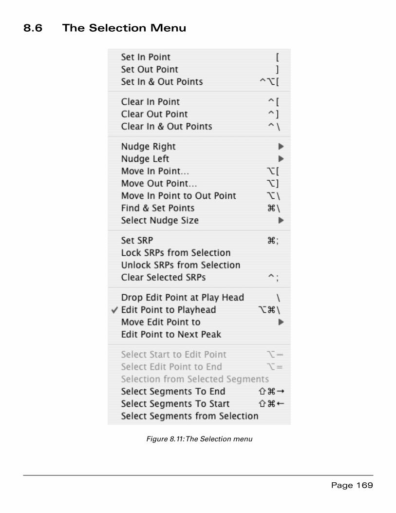
Page 169
8.6 The Selection Menu
Figure 8.11: The Selection menu
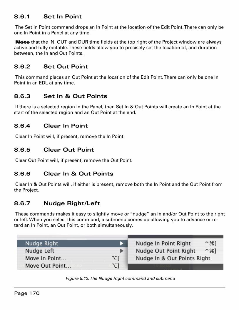
Page 170
8.6.1 Set In Point
The Set In Point command drops an In Point at the location of the Edit Point. There can only be one In Point in a Panel at any time.
Note that the IN, OUT and DUR time fields at the top right of the Project window are always active and fully editable. These fields allow you to precisely set the location of, and duration between, the In and Out Points.
8.6.2 Set Out Point
This command places an Out Point at the location of the Edit Point. There can only be one In Point in an EDL at any time.
8.6.3 Set In & Out Points
If there is a selected region in the Panel, then Set In & Out Points will create an In Point at the start of the selected region and an Out Point at the end.
8.6.4 Clear In Point
Clear In Point will, if present, remove the In Point.
8.6.5 Clear Out Point
Clear Out Point will, if present, remove the Out Point.
8.6.6 Clear In & Out Points
Clear In & Out Points will, if either is present, remove both the In Point and the Out Point from the Project.
8.6.7 Nudge Right/Left
These commands makes it easy to slightly move or “nudge” an In and/or Out Point to the right or left. When you select this command, a submenu comes up allowing you to advance or re-tard an In Point, an Out Point, or both simultaneously.
Figure 8.12: The Nudge Right command and submenu
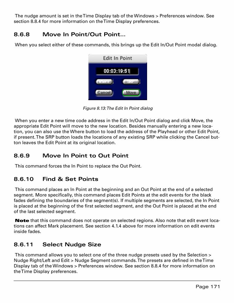
Page 171
The nudge amount is set in the Time Display tab of the Windows > Preferences window. See section 8.8.4 for more information on the Time Display preferences.
8.6.8 Move In Point/Out Point…
When you select either of these commands, this brings up the Edit In/Out Point modal dialog.
Figure 8.13: The Edit In Point dialog
When you enter a new time code address in the Edit In/Out Point dialog and click Move, the appropriate Edit Point will move to the new location. Besides manually entering a new loca-tion, you can also use the Where button to load the address of the Playhead or other Edit Point, if present. The SRP button loads the locations of any existing SRP while clicking the Cancel but-ton leaves the Edit Point at its original location.
8.6.9 Move In Point to Out Point
This command forces the In Point to replace the Out Point.
8.6.10 Find & Set Points
This command places an In Point at the beginning and an Out Point at the end of a selected segment. More specifically, this command places Edit Points at the edit events for the black fades defining the boundaries of the segment(s). If multiple segments are selected, the In Point is placed at the beginning of the first selected segment, and the Out Point is placed at the end of the last selected segment.
Note that this command does not operate on selected regions. Also note that edit event loca-tions can affect Mark placement. See section 4.1.4 above for more information on edit events inside fades.
8.6.11 Select Nudge Size
This command allows you to select one of the three nudge presets used by the Selection > Nudge Right/Left and Edit > Nudge Segment commands. The presets are defined in the Time Display tab of the Windows > Preferences window. See section 8.8.4 for more information on the Time Display preferences.
Page 172
8.6.12 Set SRP
This command places an SRP or Selection Reference Point in the selected Panel at the location of the Playhead.
8.6.13 Set SRP from selection
This command places two SRP to mark the start and end of a active selection.
8.6.14 Lock SRPs from Selection
This command locks all SRPs within a selected region.
8.6.15 Unlock SRPs from Selection
This command unlocks all SRPs within a selected region.
8.6.16 Clear Selected SRPs
This command removes all SRPs within a selected region, whether they are locked or not.
8.6.17 Drop Edit Point at Playhead
This command moves the Edit Point to the current location of the Playhead and is typically used when the Edit Point to Playhead command, discussed in section 8.6.18 below, is disabled (unchecked).
8.6.18 Edit Point to Playhead
This command toggles a mode on or off whereby, when playback is stopped, the Edit Point jumps to the location of the Playhead.
8.6.19 Move Edit Point to…
This command has a submenu, with ten possible choices.
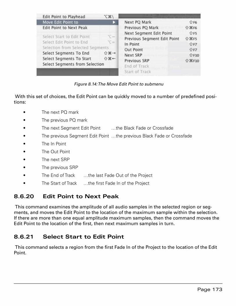
Page 173
Figure 8.14: The Move Edit Point to submenu
With this set of choices, the Edit Point can be quickly moved to a number of predefined posi-tions:
The next PQ mark•
The previous PQ mark•
The next Segment Edit Point …the Black Fade or Crossfade•
The previous Segment Edit Point …the previous Black Fade or Crossfade•
The In Point•
The Out Point•
The next SRP•
The previous SRP•
The End of Track …the last Fade Out of the Project•
The Start of Track …the first Fade In of the Project•
8.6.20 Edit Point to Next Peak
This command examines the amplitude of all audio samples in the selected region or seg-ments, and moves the Edit Point to the location of the maximum sample within the selection. If there are more than one equal amplitude maximum samples, then the command moves the Edit Point to the location of the first, then next maximum samples in turn.
8.6.21 Select Start to Edit Point
This command selects a region from the first Fade In of the Project to the location of the Edit Point.
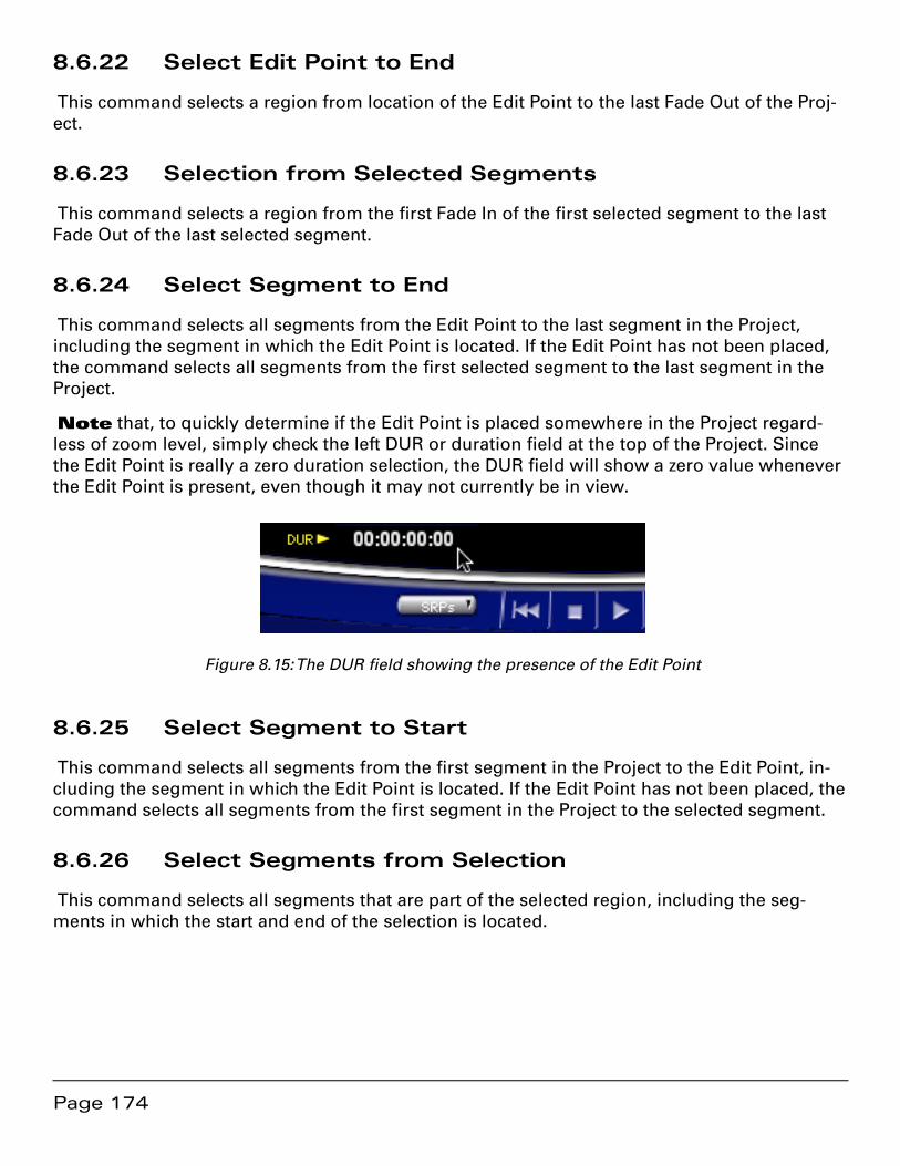
Page 174
8.6.22 Select Edit Point to End
This command selects a region from location of the Edit Point to the last Fade Out of the Proj-ect.
8.6.23 Selection from Selected Segments
This command selects a region from the first Fade In of the first selected segment to the last Fade Out of the last selected segment.
8.6.24 Select Segment to End
This command selects all segments from the Edit Point to the last segment in the Project, including the segment in which the Edit Point is located. If the Edit Point has not been placed, the command selects all segments from the first selected segment to the last segment in the Project.
Note that, to quickly determine if the Edit Point is placed somewhere in the Project regard-less of zoom level, simply check the left DUR or duration field at the top of the Project. Since the Edit Point is really a zero duration selection, the DUR field will show a zero value whenever the Edit Point is present, even though it may not currently be in view.
Figure 8.15: The DUR field showing the presence of the Edit Point
8.6.25 Select Segment to Start
This command selects all segments from the first segment in the Project to the Edit Point, in-cluding the segment in which the Edit Point is located. If the Edit Point has not been placed, the command selects all segments from the first segment in the Project to the selected segment.
8.6.26 Select Segments from Selection
This command selects all segments that are part of the selected region, including the seg-ments in which the start and end of the selection is located.
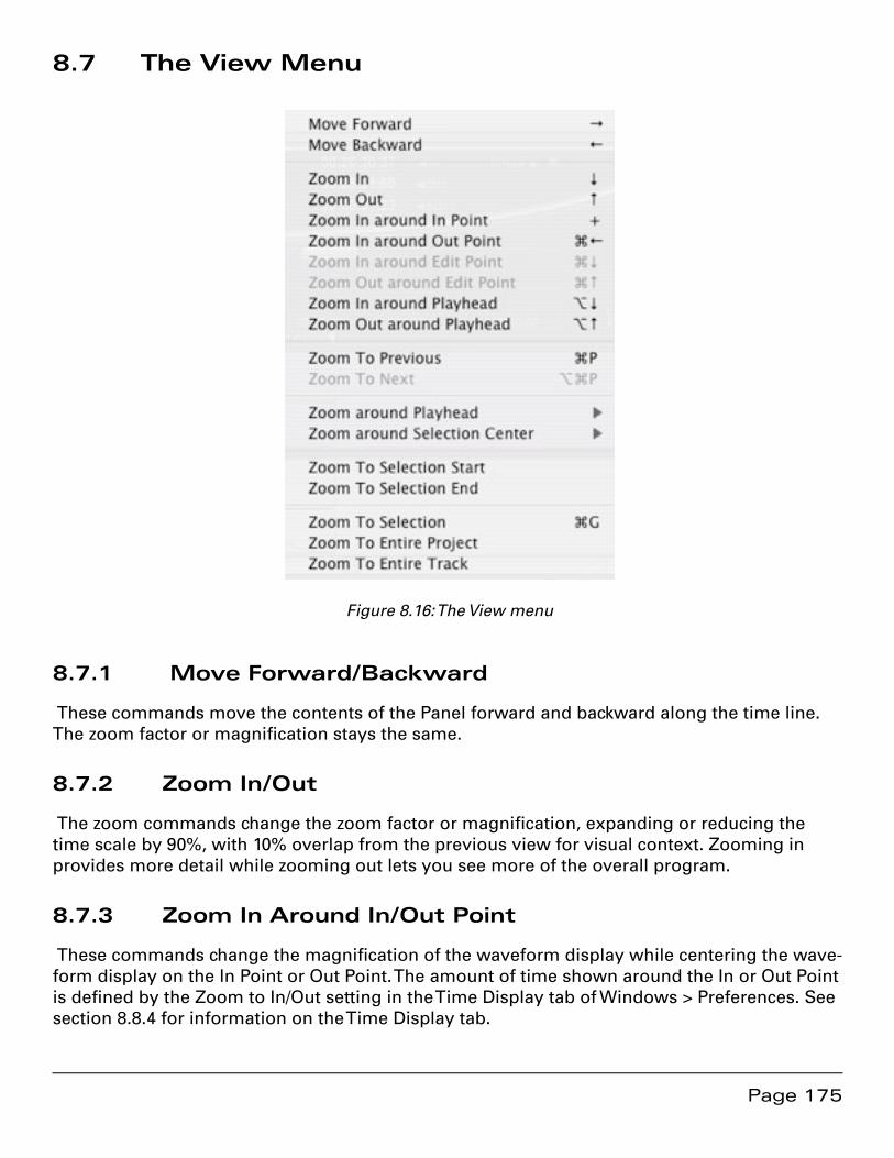
Page 175
8.7 The View Menu
Figure 8.16: The View menu
8.7.1 Move Forward/Backward
These commands move the contents of the Panel forward and backward along the time line. The zoom factor or magnification stays the same.
8.7.2 Zoom In/Out
The zoom commands change the zoom factor or magnification, expanding or reducing the time scale by 90%, with 10% overlap from the previous view for visual context. Zooming in provides more detail while zooming out lets you see more of the overall program.
8.7.3 Zoom In Around In/Out Point
These commands change the magnification of the waveform display while centering the wave-form display on the In Point or Out Point. The amount of time shown around the In or Out Point is defined by the Zoom to In/Out setting in the Time Display tab of Windows > Preferences. See section 8.8.4 for information on the Time Display tab.
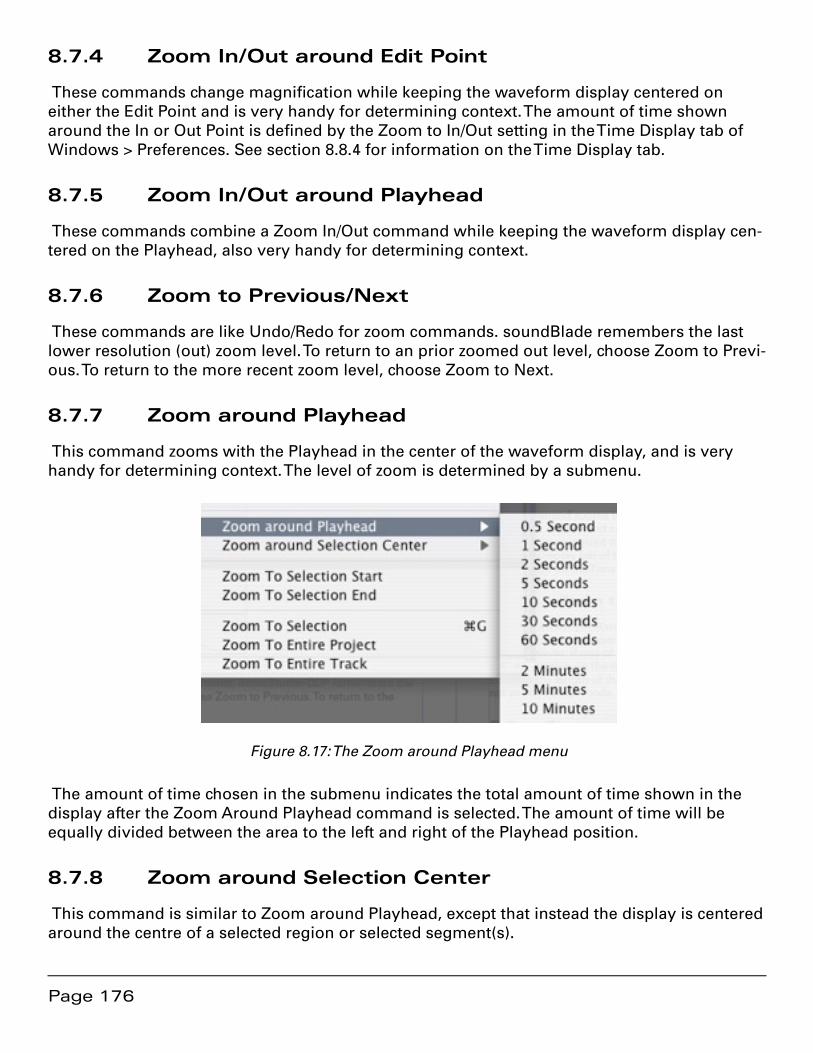
Page 176
8.7.4 Zoom In/Out around Edit Point
These commands change magnification while keeping the waveform display centered on either the Edit Point and is very handy for determining context. The amount of time shown around the In or Out Point is defined by the Zoom to In/Out setting in the Time Display tab of Windows > Preferences. See section 8.8.4 for information on the Time Display tab.
8.7.5 Zoom In/Out around Playhead
These commands combine a Zoom In/Out command while keeping the waveform display cen-tered on the Playhead, also very handy for determining context.
8.7.6 Zoom to Previous/Next
These commands are like Undo/Redo for zoom commands. soundBlade remembers the last lower resolution (out) zoom level. To return to an prior zoomed out level, choose Zoom to Previ-ous. To return to the more recent zoom level, choose Zoom to Next.
8.7.7 Zoom around Playhead
This command zooms with the Playhead in the center of the waveform display, and is very handy for determining context. The level of zoom is determined by a submenu.
Figure 8.17: The Zoom around Playhead menu
The amount of time chosen in the submenu indicates the total amount of time shown in the display after the Zoom Around Playhead command is selected. The amount of time will be equally divided between the area to the left and right of the Playhead position.
8.7.8 Zoom around Selection Center
This command is similar to Zoom around Playhead, except that instead the display is centered around the centre of a selected region or selected segment(s).
Page 177
8.7.9 Zoom to Selection Start/End
This command zooms the waveform display to the start or end of the current selection with the start or end of the selection centered in the waveform display and is very handy for refining a selection’s boundaries. The amount of time shown around the selection boundaries is defined by the Zoom to Sel Start/ setting in the Time Display tab of Windows > Preferences. See section 8.8.4 below for information on the Time Display tab.
8.7.10 Zoom to Selection
This command zooms to the currently selected region such that the selection is centered in the waveform display and covers a preset percentage of the waveform display area. The amount of time shown around the selection boundaries is defined by the Zoom to Sel Start/ setting in the Time Display tab of Windows > Preferences. See section 8.8.4 for more information on the Time Display tab.
8.7.11 Zoom to Entire Project/Track
Under normal operation with a stereo Project, these two menu commands work identically. These commands zoom so that the entire program is shown across the entire waveform dis-play. However, if one of the two Panels contains more audio information, stretching over a longer duration on the time line than the other channel, the Zoom to Entire Track command will zoom to the length of the selected track. This situation typically occurs if the two Panels contain dual mono material or a wildly “stereo” program created in mono editing mode.
8.8 The Desk Menu
soundBlade offers a compact mixing console called the ‘EDL Desk’. It can be brought up by choosing the Windows > EDL Desk command. The Desk provides traditional routing, patching, muting and gain adjustment.
8.8.1 Save Desk Setup
The Save Desk Setup command opens a submenu:
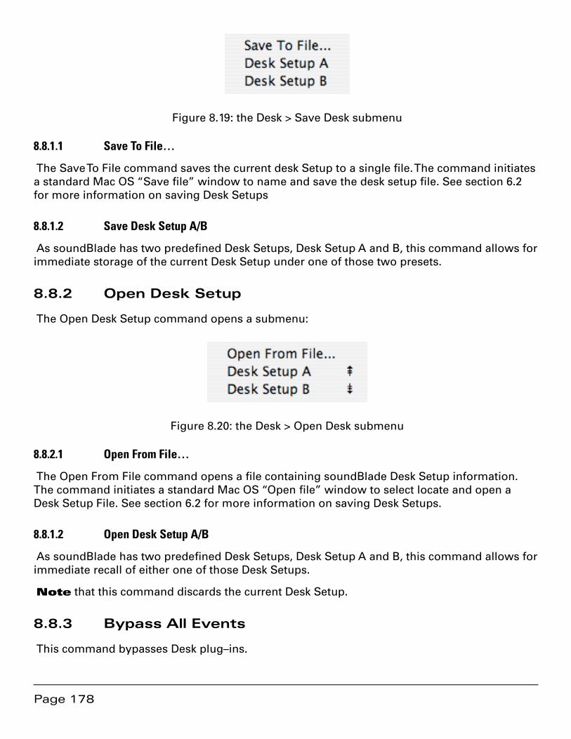
Page 178
Figure 8.19: the Desk > Save Desk submenu
8.8.1.1 Save To File…
The Save To File command saves the current desk Setup to a single file. The command initiates a standard Mac OS “Save file” window to name and save the desk setup file. See section 6.2 for more information on saving Desk Setups
8.8.1.2 Save Desk Setup A/B
As soundBlade has two predefined Desk Setups, Desk Setup A and B, this command allows for immediate storage of the current Desk Setup under one of those two presets.
8.8.2 Open Desk Setup
The Open Desk Setup command opens a submenu:
Figure 8.20: the Desk > Open Desk submenu
8.8.2.1 Open From File…
The Open From File command opens a file containing soundBlade Desk Setup information. The command initiates a standard Mac OS “Open file” window to select locate and open a Desk Setup File. See section 6.2 for more information on saving Desk Setups.
8.8.1.2 Open Desk Setup A/B
As soundBlade has two predefined Desk Setups, Desk Setup A and B, this command allows for immediate recall of either one of those Desk Setups.
Note that this command discards the current Desk Setup.
8.8.3 Bypass All Events
This command bypasses Desk plug–ins.
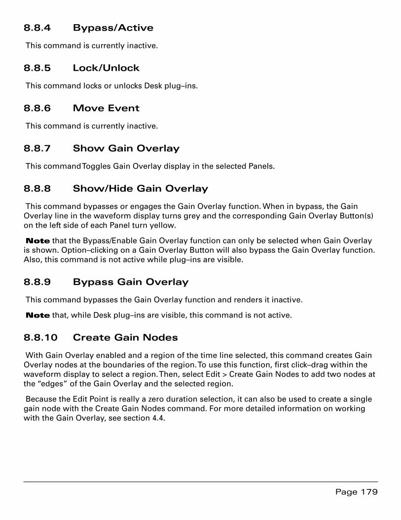
Page 179
8.8.4 Bypass/Active
This command is currently inactive.
8.8.5 Lock/Unlock
This command locks or unlocks Desk plug–ins.
8.8.6 Move Event
This command is currently inactive.
8.8.7 Show Gain Overlay
This command Toggles Gain Overlay display in the selected Panels.
8.8.8 Show/Hide Gain Overlay
This command bypasses or engages the Gain Overlay function. When in bypass, the Gain Overlay line in the waveform display turns grey and the corresponding Gain Overlay Button(s) on the left side of each Panel turn yellow.
Note that the Bypass/Enable Gain Overlay function can only be selected when Gain Overlay is shown. Option–clicking on a Gain Overlay Button will also bypass the Gain Overlay function. Also, this command is not active while plug–ins are visible.
8.8.9 Bypass Gain Overlay
This command bypasses the Gain Overlay function and renders it inactive.
Note that, while Desk plug–ins are visible, this command is not active.
8.8.10 Create Gain Nodes
With Gain Overlay enabled and a region of the time line selected, this command creates Gain Overlay nodes at the boundaries of the region. To use this function, first click–drag within the waveform display to select a region. Then, select Edit > Create Gain Nodes to add two nodes at the “edges” of the Gain Overlay and the selected region.
Because the Edit Point is really a zero duration selection, it can also be used to create a single gain node with the Create Gain Nodes command. For more detailed information on working with the Gain Overlay, see section 4.4.

Page 180
8.8.11 Select Gain Nodes
This command selects all Gain Nodes contained within the currently selected segment(s) or region. Selected Gain Nodes can then be subject to simultaneous changes such as gain setting, lock state, or deletion.
For more information on working with Gain Overlay mode, see section 4.4.
8.8.12 Lock/Unlock Nodes From Selection
These commands lock or unlock all Nodes in the Gain Overlay, enclosed in a active selection.
8.8.13 Lock/Unlock all Nodes In Track
These commands lock or unlock all Nodes in the Gain Overlay, regardless of any active selec-tion.
8.8.14 Lock/Unlock All Nodes In Edit Group
These commands lock or unlock all Nodes in the Gain Overlay. They apply to all tracks within
the current Edit Group.
8.9 The Windows Menu
The Windows menu provides quick access to all available windows within soundBlade and an active Project.
8.9.1 EDL Desk
This command toggles the Desk on or off. See section 6.1 for a detailed description of this window.
8.9.2 Sonic EQ
[Sonic EQ Option] — This command toggles the Sonic EQ window. See section 10.1 for a de-tailed description of this window.
8.9.3 Meters
This command toggles the Meters window or Master Section. See section 6.4 for a detailed description of this window.
8.9.4 Panner
This command toggles the Panner window. See section 6.4 for a detailed description of this window.

Page 181
8.9.5 Mark Info
For more information on the Mark Info window, see sections 8.5 discussing the Mark Menu and section 3.10 discussing the specifics of the Mark Info window.
8.9.7 The Preferences Window
Some of the functions and commands within soundBlade can be changed to adhere to your preferred values or behavior. All of these preferences can be adjusted in the Windows > Prefer-ence Window

Page 182
Figure 8.21: The Preference window showing the Editing Tools tab
The Preference window is displayed by selecting the Windows > Preferences command.
8.9.8 Setting Preferences — Editing Tools Tab
8.9.8.1 Editing Auto Tools
The Editing Auto Tools section has the following options:

Page 183
Fade Tool: When checked, the Fade Tool will be enabled for editing. To learn more •about the Fade Tool and its properties, see section 3.8.1 and 4.1 for a full descrip-tion.
Snap to Edit Point ON: When checked, dragging a segment near the position •of the Edit Point will cause the segment to auto–snap. This feature is really only ap-plicable when dragging audio into a Project from the Finder or another open Project.
Snap To Zone: When the zone snap is checked, dragging a segment near the start •or end of another segment will cause the segment to auto–snap to the red or blue snap locations. See section 4.2 for more information on the drag & drop, auto–snap function.
AutoSpacing Duration: As described in section 4.2, AutoSpace uses a pre-selected •time value to space the segments. Here, this value can be selected between 1 and 3 seconds. Alternatively, AutoSpace can be turned off as well.
Analog Black Threshold: This field shows the default value used by the Mark > Ana-•log Black to Marks command for the amplitude threshold. This value, expressed as dB below 0 dBFS, sets the loudness threshold below which a Start of Track or End of Track mark will be placed. See section 3.9.4 for more information on automatically placing PQ Marks.
8.9.8.2 Edit with Audio
Selection Reference Points: When editing, this setting causes SRPs to move along •with their associated segment. They are also included with the audio when it is cop-ied to the clipboard.
Gain Overlay: When editing, this setting causes gain nodes to move along with their •associated segment. They are also included with the audio when it is copied to the clipboard.
Desk Events: When Editing, this setting causes • plug–ins to move along with their associated segment. They are also included with the audio when it is copied to the clipboard.
8.9.8.3 Default Fade
This selector determines the default fade curve used when any new fades are created soundBlade. The five curve options are:
Cosine•
Root Cosine•
Linear•
Root Linear•
Exponential•
Linear fades, the default, are the most broadly applicable choice. Section 4.1.2 briefly discuss-es the five curve shape options.
Page 184
8.9.8.4 Import
SDII Regions Into Segments: When on, • Sound Designer II regions, if present, will automatically be converted to separate segments upon opening in soundBlade. When off, the entire SDII image will be imported as one continuous segment.
SDII Regions To Marks: When on, • Sound Designer II regions, if present, will force soundBlade to put marks at the region’s start points. When off, the entire SDII image will be imported as one continuous segment.
8.9.9 Setting Preferences — Time Display Tab
8.9.9.1 Time Display
The Time Display time code format selector allows you to preset the display time code format to 75 frames per second, 30 fps NDF, seconds or samples. Compact Discs use a special time code format, 75 fps, not used elsewhere while 30 fps NDF or “30 non–drop,” 30 frames per second non–drop frame, is the legacy standard used by the original, 1600/1610/1630 series of video cassette–based CD preparation systems.
8.9.9.2 Nudge A/B/C
The values in these fields define the amount of time that segments will be ‘nudged’ when the Edit > Nudge Left/Right commands are applied. For a complete description of the working of these commands, see section 8.2.13.
8.9.9.3 Zoom to In/Out
The time value entered here defines the amount of time in the total display after a View > Zoom Around In/Out Point command. See chapter 8.7.3 for a full description of these com-mands.
8.9.9.4 Zoom to Sel(ection) Start/(End)
The time value in this field defines how much time will be displayed when the View > Zoom to Selection command is applied. For a full description of this command, see section 8.7.10.
8.9.9.5 Play Around In/Out Point
The values in these fields define how much time will be auditioned when the Play > Play To/From In/Out Point commands are invoked. For a full description of these commands, please see sections 8.4.10 and 8.4.11.
8.9.9.6 Show Subframes
When enabled, all time fields at the top of the Project display additional time code subframe information.

Page 185
8.9.10 Setting Preferences — EDL Tab
8.9.10.1 View
The View section has the following options:
• Show Track Bar: When checked, an additional layer of visual feedback is enabled in the Project. This alternate view provides a graphical approach to evaluating and ma-nipulating your PQ metadata. Existing metadata is displayed from an object–oriented perspective, whereby each CD Track that will result from your current PQ placement is shown in grey while the pause between tracks is shown in blue. Section 3.9.5 above discusses the Track Bar.
• Show Segment Names: When checked, segment names will show in the Title Bar. When unchecked, the Title Bar of segments remains empty.
Multiple EDLs: When checked, new Projects are created with two separate, two •Panel EDLs or Edit Decision Lists, rather than one four Panel EDL that makes up a default Project. This dual EDL mode means that each EDL has its own time line and own independent zoom amount, which facilitates Source to Destination editing. One limitation of dual EDL mode is that, since the Desk’s state is linked to currently ac-tive Project, the Desk will switch configurations as either EDL is selected.
[• Eight Channel Option] — Multi-Channel EDLs: When checked, new Projects are created with eight Panels in one EDL. In addition, all the additional functionality dis-cussed in section 4.10 is now available.
Note• that you must restart soundBlade after enabling this option. You should also resize both the Desk and the Master section after restart.
• Zoom Factor (%): When zooming in or out, the display will be zoomed by the factor defined in this field. The default 90% means that 90% of the current waveform view will be zoomed, with 10% overlap for visual context. This preference only applies to selections.
8.9.10.2 Waveforms
Waveform metadata is created by soundBlade to allow the operator to visualize amplitude variations over time in order to aid in editing. The Waveforms section has the following op-tions:
• Create Waveforms Manually: When checked, all automatic waveform metadata generation is disabled. To create waveforms with this preference enabled, select the segment and use the File > Build Waveform… command.
• Forground Waveforms: When selected, waveforms will be generated in the fore-ground upon opening sound files for which waveform metadata has not been gener-ated.
• Background Waveforms: When selected, waveforms will be generated in the back-ground upon opening sound files for which waveform metadata has not been gener-ated.
Page 186
8.9.10.3 Display Auto Tools
The Display Auto Tools has the following options:
AutoScale On: When enabled, the display is scaled vertically so that the maximum •peak within the entire Panel becomes full scale. This preference provides overall am-plitude scaling while maintaining visual context between loud and soft passages.
Scale to View: When enabled, the display is scaled vertically so that the maximum •peak within the currently visible waveform becomes full scale. This preference pro-vides local magnification, excellent for fine editing, but requires that you refer to the numeric vertical scale to determine the general amplitude.
Show Track Scale in dB: When enabled, the amplitude scale is shown in dBFS, or •dB full scale referenced to a “full” 24 bit AES/EBU data word. When off, the Panel’s amplitude scale is shown as a non–dimensional normalized value ranging from 0 to ±1, equating to or silence or full scale, respectively.
8.9.10.4 Playing Auto Tools
The Playing Auto Tools section has the following settings:
AutoScroll Playhead: When selected, the Playhead will move as normal until it reach-•es the right edge of the waveform display. Then, the Move Forward command auto-matically takes place, moving the waveform view to the right.
AutoScroll Track: When selected, the Playhead stays centered in the waveform dis-•play while the underlying waveform display continuously scrolls.
8.9.11 Setting Preferences — Delivery Tab
8.9.11.1 Delivery
• Keep DDP Image: This check box retains the directory or folder containing the DDP files set that forms that basis for all CD-R deliveries. See section A1.4 for information on using the DDP file set for replication.
• Emulation Mode: The Emulation Mode check box causes soundBlade to emulate a CD-R “burn,” allowing you to validate your Project’s settings without writing to a disc. While disabling writes to your optical mechanism in this mode, soundBlade does write a CD’s worth of data, approximately 650 MB, to your hard disk.
• Write CD Text: This check box causes soundBlade to write CD Text–specific CD+G metadata to a delivered CD-R. CD Text metadata is not included in DDP file sets. See section 3.10.1 for specifics about CD Text.
• CD Write Speed: The speed selector calls out the speeds that the target mechanism and host are capable of providing for your delivery. When choosing CD-R delivery speed, remember that the speed is inversely proportional to pit jitter. That is, higher speeds will induce more jitter in the CD’s physical pit structures while lower speeds will result in less jittery pit structures. Lower jitter is generally better in terms of

Page 187
subjective audio quality, because it requires less vigorous clock regeneration in the digital–to–analog converter or DAC to attain a reasonable amount of jitter in the final analog output.
8.9.11.2 Offsets
• Start Offset: It takes a typical CD player about two to twenty frames to fill its buffer and start producing valid audio data after it has located the correct Track Start: The Start Offset back times the Track Start time that the player reads to ensure that the beginning of the track will not be cut off by the player.
• End Offset: The End Offset prevents the player from muting too early at the end of the track. This offset value applies to all End of Track marks, including the last.
• Track 1 Offset: This setting allows the Start of Track Mark for Track 1 to have it’s own offset value. This is because Track 1 on a Compact Disc is different from the remain-ing tracks and requires an extra long offset to allow CD transports to initialize prior to the onset of audio data recovery.
• Splice Offset: If a Start of Track mark is not preceded by an End of Track mark from the previous track, it is considered to be a “splice” or segue. The Splice Offset ap-plies only to the special case of splices. The Splice Offset must always be equal to or less than the Start Offset. Splice Offsets are typically a bit more than half of the normal Start of Track offset.
• Minimum Index Width: This field sets the minimum time between Index marks. Ac-cording to the Red Book standard, Index marks should be at least 1 second apart. End marks that are closer to the Start than the Minimum Index Width are ignored.
• Disable Offsets: If this button is enabled, the offsets shown in the offset windows will not be subtracted from the PQ mark times, either for display or for delivery.
• Restore Defaults: As a fail–safe, this button will restore all PQ offsets to their factory defaults.
8.9.11.3 Dither
Dither Type – Shaped PDF: This radio button selects Sonic Studio’s proprietary spec-•trally shaped triangular PDF (probability density function) redithering.
Dither Type – mBit+: This radio button selects iZotope’s proprietary mBit+ redither-•ing. The Shape is preset to High, the Amount is preset to normal.
• Enable Dither On Output: When on, dither will be applied to the output at all times, redithering the output to 16 bits of resolution. When off, both the monitor and de-livery outputs will be bit transparent. The DITHER indicator in the upper right of the Project window reflects the current state of the Dither on Output preference. Section A1.2 includes a discussion of redithering.
• Turn Off Delay: defines the time (in seconds) before dither is turned off after the last moment audio has been played.
Page 188
Bit Resolution: this selector allows for rounding off of the output signal to either 16 •or 24 bits.
Note that for CD delivery, 16 bit resolution is the only correct setting as the program on an audio Compact Disc is stored as 16 bit data. Setting 24 bit resolution for final CD masters will result in drastic truncation of the 17th through 24th bit, resulting in audibly reduced quality.
8.9.12 Setting Preferences — LTC Timecode Tab
8.9.12.1 Time Code Reader Preferences
Enable Time Code Reader: This check box enables or disables the longitudinal SMPTE/EBU time code reader. If you are not using the LTC time code reader function, it is best to leave this feature disable to reduce processor overhead.
Frame Rate: This menu provides the common time standards and counting methods:
30 fps time base, NonDrop Frame (NDF, 60 Hz referenced)1.
29 fps time base, Drop Frame (DF, 59.9 Hz referenced)2.
25 fps time base (50 Hz referenced)3.
24 fps time base (60 Hz referenced)4.
as well as two, less used choices, 29.97 NDF and 30 fps DF.
Offset: This field provides a mechanism for adding an offset to all incoming time addresses.
Play Trigger: This field provides a mechanism for defining a threshold address, before which, LTC Slave playback will not commence.
Play Trigger Once: This field provides a mechanism to allow soundBlade to slave to incoming code once, and to then disable LTC Slave playback. This is sometimes useful when working with film chains or other externally locked systems.
8.9.12.2 Time Code Generator Preferences
Enable Time Code Generator: This check box enables or disables the longitudinal SMPTE/EBU time code generator. If you are not using the LTC time code generator function, it is best to leave this feature disable to reduce processor overhead.
Source: Of the three choices available in this menu, Free Run provides a basic generator func-tion that runs “wild,” without reference to any particular reference. The EDL Audition setting causes the generator to generate code in sync with the foreground EDL’s playback. Lastly, the Incoming Time Code setting causes the generator to regenerate code in sync with what the time code reader is receiving.
Note that, in order to use the built–in LTC reader or generator, you must use an appropriate 8 channel Series 300 hardware unit to route the time code streams.
Page 189
8.9.13 Setting Preferences — Desk Tab
The Desk preferences has the following options:
• Save Desk Setup with Project: This check box causes, as the name implies, the Proj-ect file to include information about the configuration of the Desk. When a Project is reopened after having been saved with this option enabled, soundBlade will attempt to recreate the Desk state when the Project was last saved.
• Always Show Desk Events: This check box forces any plug–ins that are instantiated in the Project to graphically appear, even when Plug–in Overlays are disabled. With this preference enabled, any existing plug–ins in the Project appear as a light gray instance in its slot, with the plug–in name printed on the instance. This preference prevents Project plug–ins from being edited. The EDL > Show Desk Events com-mand disables this preference for the selected Panel and allows you to edit any existing plug–ins in that Panel.
• Scan VST Plugins: This check box enables attaching VST plug–ins on start–up. With this check box disabled, any installed VST plug–in will be ignored by soundBlade. Because this is a start–up option, any change to this preference requires a restart to soundBlade for it to take effect.
8.9.14 New Soundfile Preferences
This command opens the New Soundfile window. For more information on the New Soundfile Preferences Window, see section 3.8 for a detailed description.
8.9.15 Timecode Status
[Post Pac or Series 300 Option] — This command opens the Time Code Status window. The Time Code Status window shows the current state of both the LTC reader and generator, in-cluding their time base and counting method and whether or not they are disabled. It also includes enable/disable check boxes in the right corners, as a convenience. See section 8.9.12 for more information on setting time code reader and generator preferences.
8.9.16 Audio I/O Preferences
This command opens the Audio I/O Preferences window. For more information on the Audio I/O Preferences Window, see section 5.2.1 for a detailed description.
8.9.17 Background Manager
This command opens the Background Manager. For more information on the Background Manager, see section 7.1.

Page 190
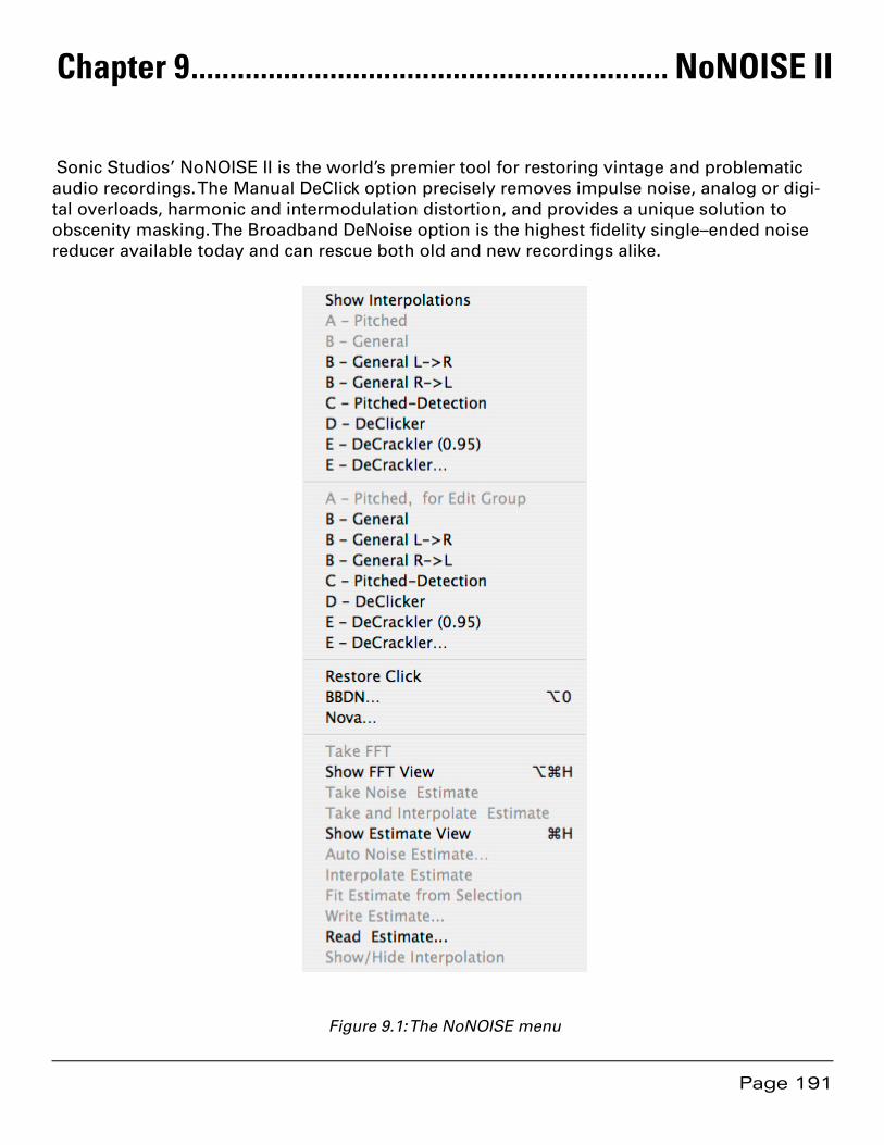
Page 191
Chapter 9 .............................................................. NoNOISE II
Sonic Studios’ NoNOISE II is the world’s premier tool for restoring vintage and problematic audio recordings. The Manual DeClick option precisely removes impulse noise, analog or digi-tal overloads, harmonic and intermodulation distortion, and provides a unique solution to obscenity masking. The Broadband DeNoise option is the highest fidelity single–ended noise reducer available today and can rescue both old and new recordings alike.
Figure 9.1: The NoNOISE menu

Page 192
9.1 Manual DeClick
The Manual DeClick option provides tools for isolating and removing individual transient im-pairments in a sound file. Manual DeClick assists in removing unwanted noises such as clicks, pops and thumps. It offers five different interpolation algorithms that are capable of correcting even difficult audio anomalies.
The algorithms analyze audio on either side of the anomaly and, based on this information, synthesizes replacement samples. Manual DeClicking substitutes the repaired samples for the original program material.
Note that Manual DeClick processes generate two new files for each sound file that is re-paired. These “.cd” and “.rl” files contain the samples removed during repair and a list of their locations, respectively. If you move or delete either of these files, you will not be able to restore the original samples, undoing the repair.
Manual DeClick is generally used, with the exception of the E Type, on very short duration re-gions; 14 msec. or less. Though the algorithms are capable of credible repairs over longer dura-tions, only experience using each algorithms will allow you to judge sensible parameters.
9.1.1 Interpolation Algorithms
There are several interpolators that are available in SoundBlade. Each is suited to a particular type of audio problem and context.
9.1.1.1 The B Type General Interpolator
The Type B interpolator is the general purpose algorithm. The majority of declicking situations can be handled by simply choosing this option.
The default Type B interpolator examines the audio on either side of the selection to determine the context for resynthesizing audio to fill the gap. For the B Type, there are two additional variations of the command that bias the context in a particular “direction,” ignoring the mate-rial before or after the impairment.
If, for example, a click occurs just after a percussive event, the default Type B interpolator would include part of the percussive event in its resynthesis, producing a unconvincing repair. The B - General R-> L option would ignore the audio to the left, using only the samples after the selection is build the repair. Conversely, the B - General L-> R option uses only samples before the selection to resynthesize a repair.
Here are three examples:

Page 193
Figure 9.2: The original material
Figure 9.3: A “repair,” using the default B Type algorithm
Figure 9.4: A better “repair,” using the B - General L-> R option
Though the above examples are extreme, a 60 msec. selection to clearly show the result, they should illustrate the concept of using the left–oriented or right–oriented B Type option when needed.
9.1.1.2 The A & C Type Pitched Interpolators
The Type A and Type C interpolators are designed for pitched or periodic material, such as solo instruments or any time the fine structure of a waveform is visually repetitive. The difference between these two options is that the C Type has validation built into it for certain cases in which the interpolator may produce less than perfect results. The A Type lacks these “protec-tions,” so its results may occasionally be unusable. In addition, both the A and C Type may fail to find an “acceptable” periodicity and will alert you to try a different algorithm. If this occurs, try the D Type or, select a slightly different region of audio and try again.
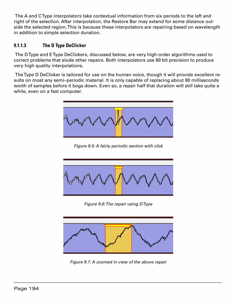
Page 194
The A and C Type interpolators take contextual information from six periods to the left and right of the selection. After interpolation, the Restore Bar may extend for some distance out-side the selected region. This is because these interpolators are repairing based on wavelength in addition to simple selection duration.
9.1.1.3 The D Type DeClicker
The D Type and E Type DeClickers, discussed below, are very high-order algorithms used to correct problems that elude other repairs. Both interpolators use 80 bit precision to produce very high quality interpolations.
The Type D DeClicker is tailored for use on the human voice, though it will provide excellent re-sults on most any semi–periodic material. It is only capable of replacing about 80 milliseconds worth of samples before it bogs down. Even so, a repair half that duration will still take quite a while, even on a fast computer.
Figure 9.5: A fairly periodic section with click
Figure 9.6: The repair using D Type
Figure 9.7: A zoomed in view of the above repair
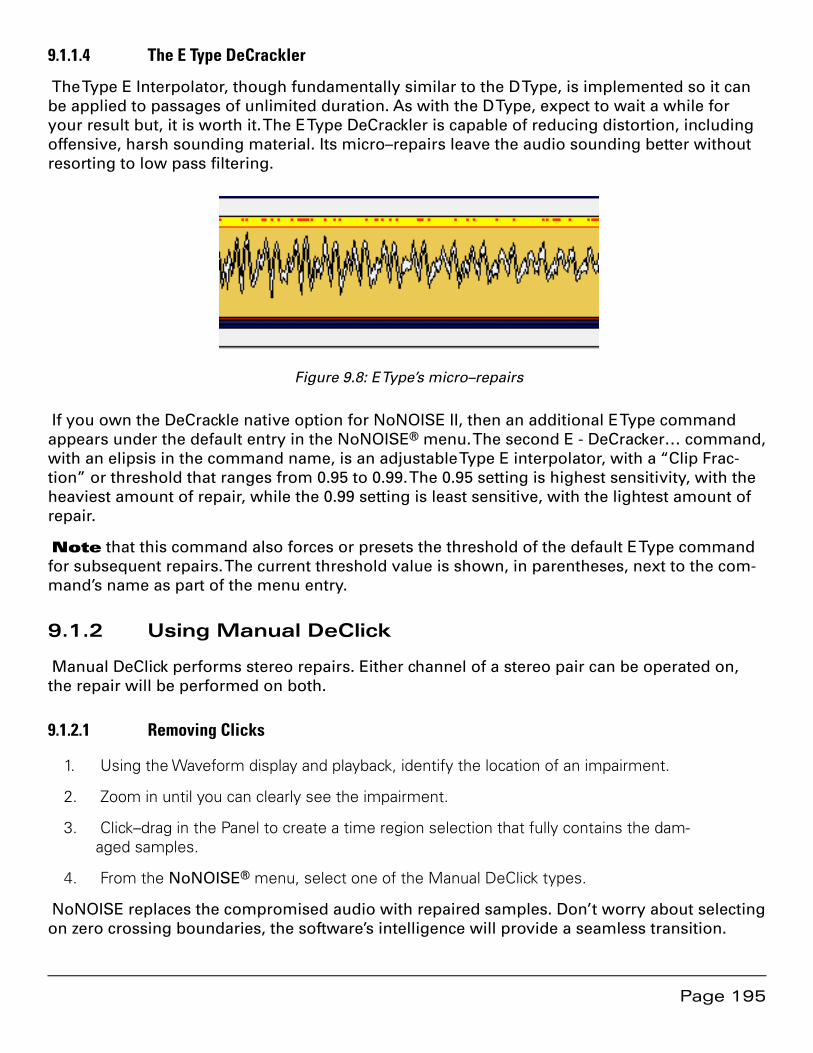
Page 195
9.1.1.4 The E Type DeCrackler
The Type E Interpolator, though fundamentally similar to the D Type, is implemented so it can be applied to passages of unlimited duration. As with the D Type, expect to wait a while for your result but, it is worth it. The E Type DeCrackler is capable of reducing distortion, including offensive, harsh sounding material. Its micro–repairs leave the audio sounding better without resorting to low pass filtering.
Figure 9.8: E Type’s micro–repairs
If you own the DeCrackle native option for NoNOISE II, then an additional E Type command appears under the default entry in the NoNOISE® menu. The second E - DeCracker… command, with an elipsis in the command name, is an adjustable Type E interpolator, with a “Clip Frac-tion” or threshold that ranges from 0.95 to 0.99. The 0.95 setting is highest sensitivity, with the heaviest amount of repair, while the 0.99 setting is least sensitive, with the lightest amount of repair.
Note that this command also forces or presets the threshold of the default E Type command for subsequent repairs. The current threshold value is shown, in parentheses, next to the com-mand’s name as part of the menu entry.
9.1.2 Using Manual DeClick
Manual DeClick performs stereo repairs. Either channel of a stereo pair can be operated on, the repair will be performed on both.
9.1.2.1 Removing Clicks
Using the Waveform display and playback, identify the location of an impairment.1.
Zoom in until you can clearly see the impairment.2.
Click–drag in the Panel to create a time region selection that fully contains the dam-3. aged samples.
From the 4. NoNOISE® menu, select one of the Manual DeClick types.
NoNOISE replaces the compromised audio with repaired samples. Don’t worry about selecting on zero crossing boundaries, the software’s intelligence will provide a seamless transition.

Page 196
9.1.2.2 Undoing — Restoring Repaired Clicks
You can undo a Manual DeClick repair at any time, restoring the original samples 1. back into the sound file. To do this, zoom in on the waveform and locate the red “Restore Bar.”
Click–drag in the Panel to select a region that contains the Restore Bar.2.
From the NoNOISE menu, choose Restore Click.3.
NoNOISE replaces the interpolated audio with the original audio samples containing the anomaly.
9.1.3 Obscenity Reduction
In addition to restoration duties, Manual DeClicking can be used to insure the public accept-ability of obscene material or to conceal any audio that may not “pass muster” with down-stream listeners. Simply select the obscenity as though it were an impairment, and choose your Type. The B Type, when given a one second region to “repair,” does a great job of remov-ing the objectionable material and inserting something that will often be preferable to editing in replacement audio. An additional consideration is that, since no material is added or re-moved, the timing or tempo is not affected.
9.2 Broadband DeNoise
9.2.1 Introduction
Broadband noise, whether white, pink or brown in spectrum, is one of the most common forms of audio degradation. Noise can be introduced from any of a number of sources, includ-ing the modulation and asperity noise inherent in analog tape recording and Johnson or ther-mal noise from microphones, preamps, and other analog signal processing equipment. Broad-band DeNoise is a single ended broadband noise reducer that, unlike less refined examples, can suppress or eliminate broadband noise with little or no audible artifacts, even at extreme settings.
To supress such noises in your program, it is necessary to analyze the noise spectrum and adapt the denoising algorithm to the characteristics of the material. Broadband DeNoise oper-ates by means of analysis and resynthesis, though it can be thought of as 2048 bandpass fil-ters, each followed by a below–threshold expander. This is somewhat analogous to the classic analog Dolby and dbx multi–band, double–ended noise reduction systems of yore.
An FFT or Fast Fourier Transform analysis is performed on a user–specified sample of noise from the material to be processed. The average amplitude of noise in each of 2048 individual frequency bands or “bins” is determined. The result of this analysis is a “Noise Estimate,” which is used to set the average threshold of the noise reduction. The Estimate sets aggregate threshold for the expansion.
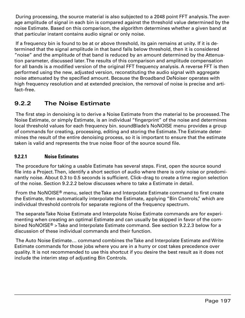
Page 197
During processing, the source material is also subjected to a 2048 point FFT analysis. The aver-age amplitude of signal in each bin is compared against the threshold value determined by the noise Estimate. Based on this comparison, the algorithm determines whether a given band at that particular instant contains audio signal or only noise.
If a frequency bin is found to be at or above threshold, its gain remains at unity. If it is de-termined that the signal amplitude in that band falls below threshold, then it is considered “noise” and the amplitude of that band is reduced by an amount determined by the Attenua-tion parameter, discussed later. The results of this comparison and amplitude compensation for all bands is a modified version of the original FFT frequency analysis. A reverse FFT is then performed using the new, adjusted version, reconstituting the audio signal with aggregate noise attenuated by the specified amount. Because the Broadband DeNoiser operates with high frequency resolution and at extended precision, the removal of noise is precise and arti-fact–free.
9.2.2 The Noise Estimate
The first step in denoising is to derive a Noise Estimate from the material to be processed. The Noise Estimate, or simply Estimate, is an individual “fingerprint” of the noise and determines local threshold values for each frequency bin. soundBlade’s NoNOISE menu provides a group of commands for creating, processing, editing and storing the Estimate. The Estimate deter-mines the result of the entire denoising process, so it is important to ensure that the estimate taken is valid and represents the true noise floor of the source sound file.
9.2.2.1 Noise Estimates
The procedure for taking a usable Estimate has several steps. First, open the source sound file into a Project. Then, identify a short section of audio where there is only noise or predomi-nantly noise. About 0.3 to 0.5 seconds is sufficient. Click–drag to create a time region selection of the noise. Section 9.2.2.2 below discusses where to take a Estimate in detail.
From the NoNOISE® menu, select the Take and Interpolate Estimate command to first create the Estimate, then automatically interpolate the Estimate, applying “Bin Controls,” which are individual threshold controls for separate regions of the frequency spectrum.
The separate Take Noise Estimate and Interpolate Noise Estimate commands are for experi-menting when creating an optimal Estimate and can usually be skipped in favor of the com-bined NoNOISE® > Take and Interpolate Estimate command. See section 9.2.2.3 below for a discussion of these individual commands and their function.
The Auto Noise Estimate… command combines the Take and Interpolate Estimate and Write Estimate commands for those jobs where you are in a hurry or cost takes precedence over quality. It is not recommended to use this shortcut if you desire the best result as it does not include the interim step of adjusting Bin Controls.
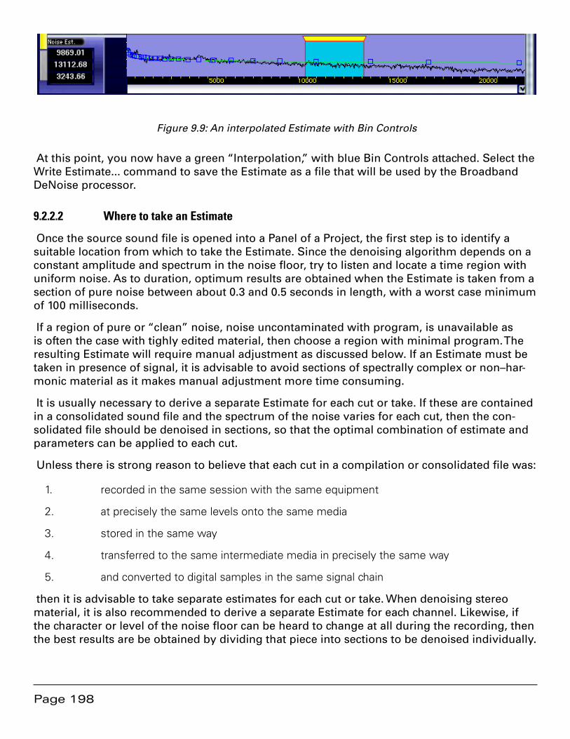
Page 198
Figure 9.9: An interpolated Estimate with Bin Controls
At this point, you now have a green “Interpolation,” with blue Bin Controls attached. Select the Write Estimate... command to save the Estimate as a file that will be used by the Broadband DeNoise processor.
9.2.2.2 Where to take an Estimate
Once the source sound file is opened into a Panel of a Project, the first step is to identify a suitable location from which to take the Estimate. Since the denoising algorithm depends on a constant amplitude and spectrum in the noise floor, try to listen and locate a time region with uniform noise. As to duration, optimum results are obtained when the Estimate is taken from a section of pure noise between about 0.3 and 0.5 seconds in length, with a worst case minimum of 100 milliseconds.
If a region of pure or “clean” noise, noise uncontaminated with program, is unavailable as is often the case with tighly edited material, then choose a region with minimal program. The resulting Estimate will require manual adjustment as discussed below. If an Estimate must be taken in presence of signal, it is advisable to avoid sections of spectrally complex or non–har-monic material as it makes manual adjustment more time consuming.
It is usually necessary to derive a separate Estimate for each cut or take. If these are contained in a consolidated sound file and the spectrum of the noise varies for each cut, then the con-solidated file should be denoised in sections, so that the optimal combination of estimate and parameters can be applied to each cut.
Unless there is strong reason to believe that each cut in a compilation or consolidated file was:
recorded in the same session with the same equipment1.
at precisely the same levels onto the same media2.
stored in the same way3.
transferred to the same intermediate media in precisely the same way4.
and converted to digital samples in the same signal chain5.
then it is advisable to take separate estimates for each cut or take. When denoising stereo material, it is also recommended to derive a separate Estimate for each channel. Likewise, if the character or level of the noise floor can be heard to change at all during the recording, then the best results are be obtained by dividing that piece into sections to be denoised individually.

Page 199
After denoising, the individual sections can edited together and sequenced to create a seam-less whole.
9.2.2.3 Post–processing an Estimate
After taking an estimate, the Panel changes to show the Estimate, a smoothed FFT. Before the Estimate can be used to provide threshold data for denoising, it must be additionally smoothed and, perhaps, manually adjusted to account for the presence of desired signal within the noise.
After deriving the Estimate, select the Interpolate Estimate command. soundBlade performs a best fit approximation from the composite FFT data, displaying it as a smooth green spline connecting a series of blue boxes, the Bin Controls mentioned above, superimposed on the composite FFT. You can toggle the Interpolation display by clicking on the checkbox located in the lower right corner of the Estimate display or with the Show/Hide Interpolation command.
If the Estimate is derived from a clean sample of noise, then Interpolate Estimate command produces an accurate measurement of the representative noise floor. In cases where a clean, program–free sample of the noise floor is not available, a smooth Interpolation can be derived from just a portion of the FFT display, provided that the noise in question is purely analog tape hiss, by using the Fit Estimate From Selection command.
Analog tape hiss has a characteristic noise curve or shape. Fit Estimate From Selection takes advantage of this property to produce a smooth Interpolation from any individual region of the Estimate based on that region’s average amplitude. Make a time region selection of a por-tion of the Estimate that appears to be outside the range of the contaminating audio program. Choose Fit Estimate From Selection from the NoNOISE® menu. soundBlade displays an In-terpolation with a characteristic tape hiss curve using the average amplitude of the Estimate’s selected region.
9.2.2.4 Editing an Estimate
The Fit Estimate From Selection technique works well for recordings containing typical tape hiss, but many recordings have other noise sources or peculularities. In such cases, it is often necessary to manually adjust the Interpolation, differentiating between the desired program content and the noise floor.
As with a waveform display in a Panel, the same Zoom In/Out and Zoom To Selection com-mands work for an Estimate. This means you can zoom to a view that provides a comfortable level of detail.
To edit an Interpolation, hold down the option key and drag a Bin Control up or down. If, for example, a number of piano harmonics are contaminating the Estimate, the Bin Controls can be moved down so that the Interpolation follows the average amplitude rather than the local amplitude. Moving a Bin Control down will command a lower threshold and cause less sensi-tivity in that Bin, resulting in less noise reduction while moving a Bin Control up sets a higher threshold, causing more noise reduction.
You can move multiple Bin Controls at once. To do so, click–drag in the Panel to create a time region selection that contains the Bin Controls. The numeric display at the left side of the Panel shows the selection’s start frequency, end frequency and span in Hertz. To edit the boxes within
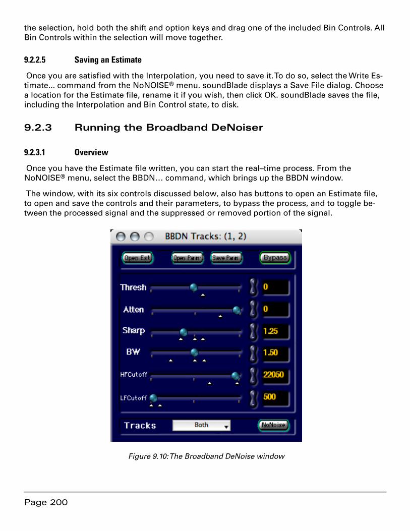
Page 200
the selection, hold both the shift and option keys and drag one of the included Bin Controls. All Bin Controls within the selection will move together.
9.2.2.5 Saving an Estimate
Once you are satisfied with the Interpolation, you need to save it. To do so, select the Write Es-timate... command from the NoNOISE® menu. soundBlade displays a Save File dialog. Choose a location for the Estimate file, rename it if you wish, then click OK. soundBlade saves the file, including the Interpolation and Bin Control state, to disk.
9.2.3 Running the Broadband DeNoiser
9.2.3.1 Overview
Once you have the Estimate file written, you can start the real–time process. From the NoNOISE® menu, select the BBDN… command, which brings up the BBDN window.
The window, with its six controls discussed below, also has buttons to open an Estimate file, to open and save the controls and their parameters, to bypass the process, and to toggle be-tween the processed signal and the suppressed or removed portion of the signal.
Figure 9.10: The Broadband DeNoise window
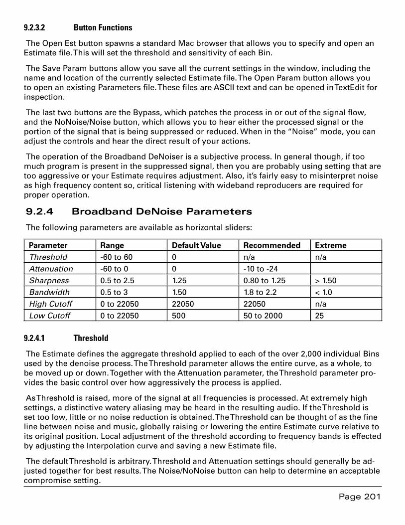
Page 201
9.2.3.2 Button Functions
The Open Est button spawns a standard Mac browser that allows you to specify and open an Estimate file. This will set the threshold and sensitivity of each Bin.
The Save Param buttons allow you save all the current settings in the window, including the name and location of the currently selected Estimate file. The Open Param button allows you to open an existing Parameters file. These files are ASCII text and can be opened in TextEdit for inspection.
The last two buttons are the Bypass, which patches the process in or out of the signal flow, and the NoNoise/Noise button, which allows you to hear either the processed signal or the portion of the signal that is being suppressed or reduced. When in the “Noise” mode, you can adjust the controls and hear the direct result of your actions.
The operation of the Broadband DeNoiser is a subjective process. In general though, if too much program is present in the suppressed signal, then you are probably using setting that are too aggressive or your Estimate requires adjustment. Also, it’s fairly easy to misinterpret noise as high frequency content so, critical listening with wideband reproducers are required for proper operation.
9.2.4 Broadband DeNoise Parameters
The following parameters are available as horizontal sliders:
Parameter Range Default Value Recommended Extreme Threshold -60 to 60 0 n/a n/a Attenuation -60 to 0 0 -10 to -24Sharpness 0.5 to 2.5 1.25 0.80 to 1.25 > 1.50 Bandwidth 0.5 to 3 1.50 1.8 to 2.2 < 1.0High Cutoff 0 to 22050 22050 22050 n/aLow Cutoff 0 to 22050 500 50 to 2000 25
9.2.4.1 Threshold
The Estimate defines the aggregate threshold applied to each of the over 2,000 individual Bins used by the denoise process. The Threshold parameter allows the entire curve, as a whole, to be moved up or down. Together with the Attenuation parameter, the Threshold parameter pro-vides the basic control over how aggressively the process is applied.
As Threshold is raised, more of the signal at all frequencies is processed. At extremely high settings, a distinctive watery aliasing may be heard in the resulting audio. If the Threshold is set too low, little or no noise reduction is obtained. The Threshold can be thought of as the fine line between noise and music, globally raising or lowering the entire Estimate curve relative to its original position. Local adjustment of the threshold according to frequency bands is effected by adjusting the Interpolation curve and saving a new Estimate file.
The default Threshold is arbitrary. Threshold and Attenuation settings should generally be ad-justed together for best results. The Noise/NoNoise button can help to determine an acceptable compromise setting.
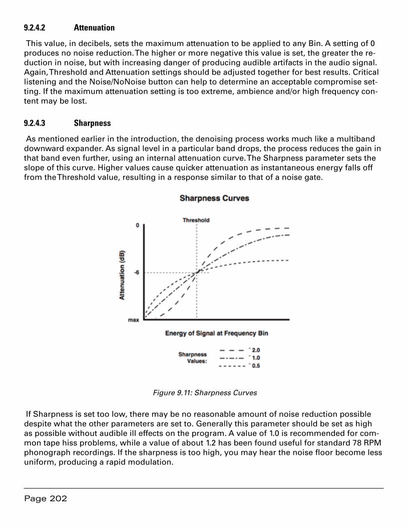
Page 202
9.2.4.2 Attenuation
This value, in decibels, sets the maximum attenuation to be applied to any Bin. A setting of 0 produces no noise reduction. The higher or more negative this value is set, the greater the re-duction in noise, but with increasing danger of producing audible artifacts in the audio signal. Again, Threshold and Attenuation settings should be adjusted together for best results. Critical listening and the Noise/NoNoise button can help to determine an acceptable compromise set-ting. If the maximum attenuation setting is too extreme, ambience and/or high frequency con-tent may be lost.
9.2.4.3 Sharpness
As mentioned earlier in the introduction, the denoising process works much like a multiband downward expander. As signal level in a particular band drops, the process reduces the gain in that band even further, using an internal attenuation curve. The Sharpness parameter sets the slope of this curve. Higher values cause quicker attenuation as instantaneous energy falls off from the Threshold value, resulting in a response similar to that of a noise gate.
Figure 9.11: Sharpness Curves
If Sharpness is set too low, there may be no reasonable amount of noise reduction possible despite what the other parameters are set to. Generally this parameter should be set as high as possible without audible ill effects on the program. A value of 1.0 is recommended for com-mon tape hiss problems, while a value of about 1.2 has been found useful for standard 78 RPM phonograph recordings. If the sharpness is too high, you may hear the noise floor become less uniform, producing a rapid modulation.
Page 203
9.2.4.4 Bandwidth
Denoising with each Bin adjusted separately produces an unnatural sounding result. In Broad-band DeNoise, individual Bins share information for more pleasing subjective result. Band-width governs this process. Higher values produce more intra–Bin sharing of gain changes. Subjectively, a higher value will, in general, create a more natural sounding result but, with a risk of noise floor modulation. A low value for Bandwidth eliminates the possibility of noise pumping, but may sound more muffled. Low values command little sharing while higher val-ues command more sharing. As with other Broadband DeNoise settings, experiment for the best compromise setting. This depends entirely on the program material and should be high enough to retain high frequency response but low enough to avoid pumping or distortion caused by the noise floor being modulated by the high order harmonics of a signal.
9.2.4.5 High Frequency Cutoff
The denoiser lets signal in frequency bins above the high frequency cutoff point pass through the process untouched. That is, they are not processed. This limits processing to frequencies below the high cutoff point. This can be used in situations where noise is not objectionable above a certain frequency, but in most cases, this parameter is left set at 22,050 Hz.
In special cases, better results may be obtained by processing your program in two passes, with a low frequency pass and a high frequency pass run separately, using different parameter values. Run your program through Broadband DeNoise twice, using the low and high cutoff frequencies to define the two bandpass ranges to be noise reduced.
9.2.4.6 Low Frequency Cutoff
This parameter, the complement to the High Frequency Cutoff parameter discussed in section 9.2.4.5 above, allows signal below the specified frequency to pass through unchanged. This can be useful if noise is not objectionable below a certain frequency and you wish to leave it unprocessed. Low Frequency Cutoff is usually left set around 50-100 Hz though setting it at 2.5 kHz or above will ensure that the critical midband will remain untouched. If this parameter is lower than 25 Hz, there may be artifacts because program wavelengths will exceed the analysis “window.”

Page 204
Page 205
Chapter 10 ................................................................ Sonic EQ
The Sonic EQ option provides seventeen different types of filtering, with some best used for restoration and damage control while other are excellent for changing color or timbre. The EQ is available in two forms, either as a EQ function in its own window or, as a plug–in for the Project, Desk or Master Section.
10.1 Sonic EQ Pre–processor
10.1.1 Overview
The first instance of Sonic EQ processing to be discussed is the separate Sonic EQ form, in a stand alone window. As shown in figure 6.1, the processing for this form appears very early in the signal path, just after segment and fade gain, and before plug–ins and the gain overlay. It can be thought of as pre-processing for your Project. A Project must be open to use this form since it is intimately associated with the Project.
10.1.2 Operation
To start the separate Sonic EQ form, select the Sonic EQ command from the Windows menu. You may open a Projects either before or after you open Sonic EQ but you must have a Project open for the pre–processor to work. The name of the Project will appear in the Title Bar of the Sonic EQ window.
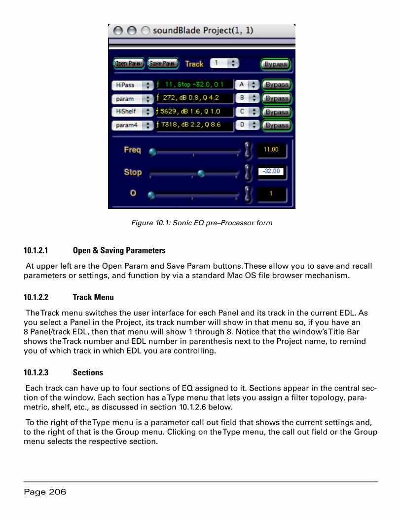
Page 206
Figure 10.1: Sonic EQ pre–Processor form
10.1.2.1 Open & Saving Parameters
At upper left are the Open Param and Save Param buttons. These allow you to save and recall parameters or settings, and function by via a standard Mac OS file browser mechanism.
10.1.2.2 Track Menu
The Track menu switches the user interface for each Panel and its track in the current EDL. As you select a Panel in the Project, its track number will show in that menu so, if you have an 8 Panel/track EDL, then that menu will show 1 through 8. Notice that the window’s Title Bar shows the Track number and EDL number in parenthesis next to the Project name, to remind you of which track in which EDL you are controlling.
10.1.2.3 Sections
Each track can have up to four sections of EQ assigned to it. Sections appear in the central sec-tion of the window. Each section has a Type menu that lets you assign a filter topology, para-metric, shelf, etc., as discussed in section 10.1.2.6 below.
To the right of the Type menu is a parameter call out field that shows the current settings and, to the right of that is the Group menu. Clicking on the Type menu, the call out field or the Group menu selects the respective section.
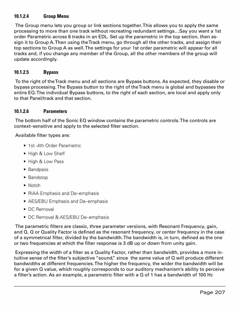
Page 207
10.1.2.4 Group Menu
The Group menu lets you group or link sections together. This allows you to apply the same processing to more than one track without recreating redundant settings…Say you want a 1st order Parametric across 6 tracks in an EDL. Set up the parametric in the top section, then as-sign it to Group A. Then using the Track menu, go through all the other tracks, and assign their top sections to Group A as well. The settings for your 1st order parametric will appear for all tracks and, if you change any member of the Group, all the other members of the group will update accordingly.
10.1.2.5 Bypass
To the right of the Track menu and all sections are Bypass buttons. As expected, they disable or bypass processing. The Bypass button to the right of the Track menu is global and bypasses the entire EQ. The individual Bypass buttons, to the right of each section, are local and apply only to that Panel/track and that section.
10.1.2.6 Parameters
The bottom half of the Sonic EQ window contains the parametric controls. The controls are context–sensitive and apply to the selected filter section.
Available filter types are:
1st -4th Order Parametric•
High & Low Shelf•
High & Low Pass•
Bandpass•
Bandstop•
Notch•
RIAA Emphasis and De–emphasis•
AES/EBU Emphasis and De–emphasis•
DC Removal•
DC Removal & AES/EBU De–emphasis•
The parametric filters are classic, three parameter versions, with Resonant Frequency, gain, and Q. Q or Quality Factor is defined as the resonant frequency, or center frequency in the case of a symmetrical filter, divided by the bandwidth. The bandwidth is, in turn, defined as the one or two frequencies at which the filter response is 3 dB up or down from unity gain.
Expressing the width of a filter as a Quality Factor, rather than bandwidth, provides a more in-tuitive sense of the filter’s subjective “sound,” since the same value of Q will produce different bandwidths at different frequencies. The higher the frequency, the wider the bandwidth will be for a given Q value, which roughly corresponds to our auditory mechanism’s ability to perceive a filter’s action. As an example, a parametric filter with a Q of 1 has a bandwidth of 100 Hz
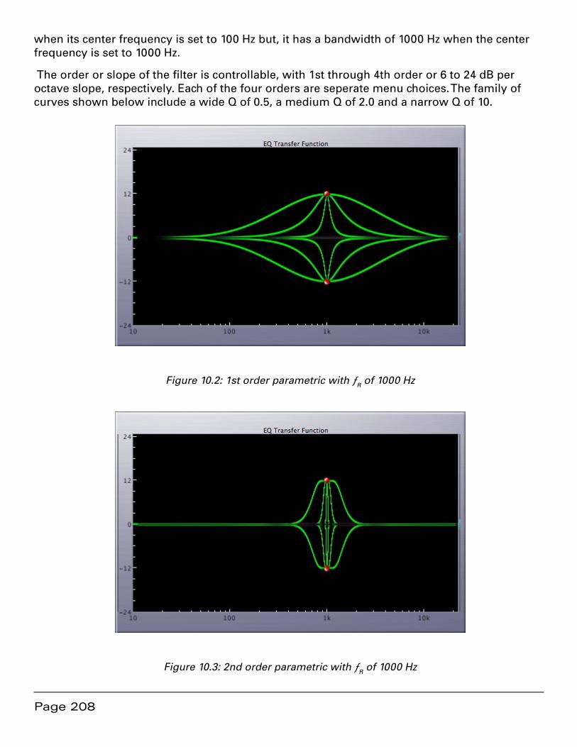
Page 208
when its center frequency is set to 100 Hz but, it has a bandwidth of 1000 Hz when the center frequency is set to 1000 Hz.
The order or slope of the filter is controllable, with 1st through 4th order or 6 to 24 dB per octave slope, respectively. Each of the four orders are seperate menu choices. The family of curves shown below include a wide Q of 0.5, a medium Q of 2.0 and a narrow Q of 10.
Figure 10.2: 1st order parametric with ƒR of 1000 Hz
Figure 10.3: 2nd order parametric with ƒR of 1000 Hz

Page 209
Figure 10.4: 3rd order parametric with ƒR of 1000 Hz
Figure 10.5: 4th order parametric with ƒR of 1000 Hz
The high and low shelves are also three parameter filters, with Resonant Frequency, gain, and order. The family of curves below include 1st through 4th order. The 4th order response is prac-tically vertical in the transition region.
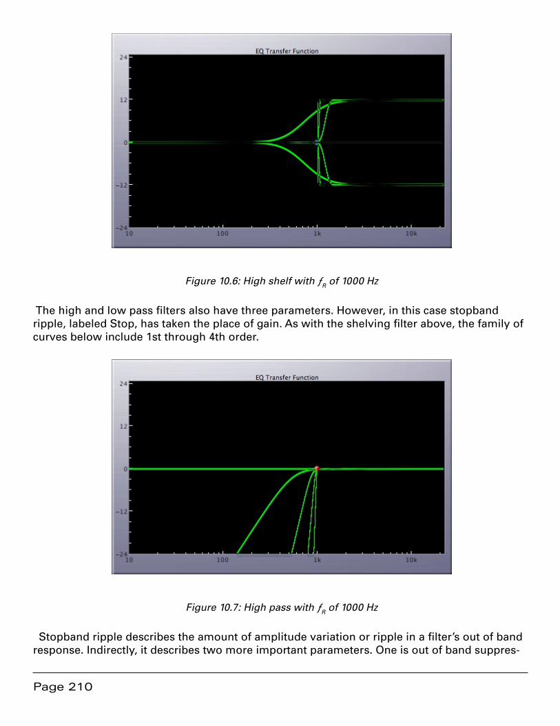
Page 210
Figure 10.6: High shelf with ƒR of 1000 Hz
The high and low pass filters also have three parameters. However, in this case stopband ripple, labeled Stop, has taken the place of gain. As with the shelving filter above, the family of curves below include 1st through 4th order.
Figure 10.7: High pass with ƒR of 1000 Hz
Stopband ripple describes the amount of amplitude variation or ripple in a filter’s out of band response. Indirectly, it describes two more important parameters. One is out of band suppres-
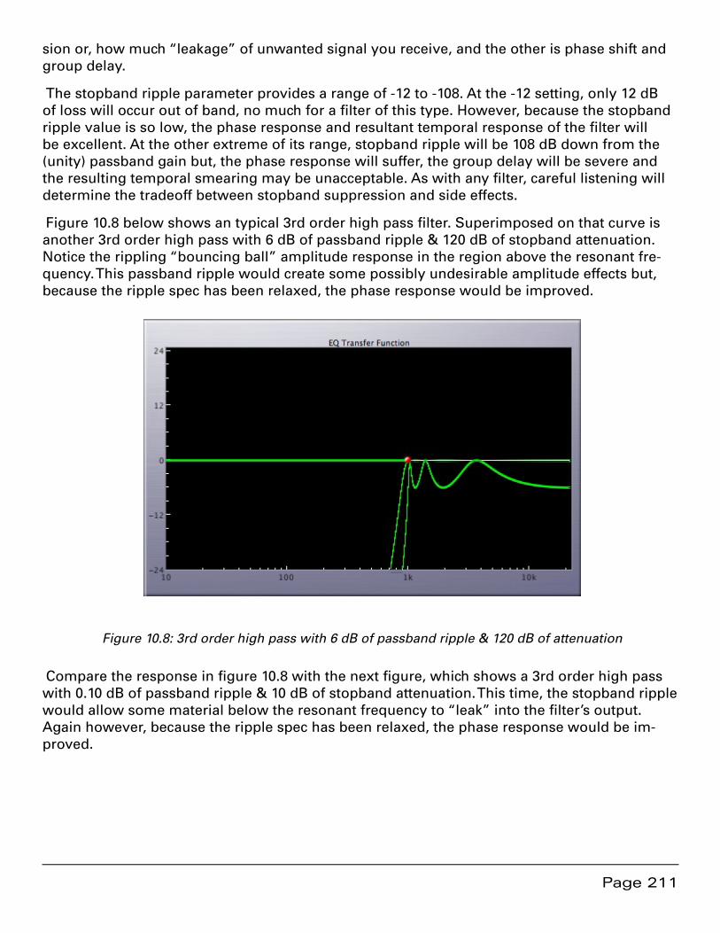
Page 211
sion or, how much “leakage” of unwanted signal you receive, and the other is phase shift and group delay.
The stopband ripple parameter provides a range of -12 to -108. At the -12 setting, only 12 dB of loss will occur out of band, no much for a filter of this type. However, because the stopband ripple value is so low, the phase response and resultant temporal response of the filter will be excellent. At the other extreme of its range, stopband ripple will be 108 dB down from the (unity) passband gain but, the phase response will suffer, the group delay will be severe and the resulting temporal smearing may be unacceptable. As with any filter, careful listening will determine the tradeoff between stopband suppression and side effects.
Figure 10.8 below shows an typical 3rd order high pass filter. Superimposed on that curve is another 3rd order high pass with 6 dB of passband ripple & 120 dB of stopband attenuation. Notice the rippling “bouncing ball” amplitude response in the region above the resonant fre-quency. This passband ripple would create some possibly undesirable amplitude effects but, because the ripple spec has been relaxed, the phase response would be improved.
Figure 10.8: 3rd order high pass with 6 dB of passband ripple & 120 dB of attenuation
Compare the response in figure 10.8 with the next figure, which shows a 3rd order high pass with 0.10 dB of passband ripple & 10 dB of stopband attenuation. This time, the stopband ripple would allow some material below the resonant frequency to “leak” into the filter’s output. Again however, because the ripple spec has been relaxed, the phase response would be im-proved.

Page 212
Figure 10.9: 3rd order high pass with 0.1 dB of passband ripple & 10 dB of attenuation
The bandpass and band stop filters are straightforward, three parameter forms, and the notch filter has only two parameters as the gain is implied to be -∞. The next two figures once again include quality factors (Q) of 0.5, 2 and 10.
Figure 10.10: 1st order bandpass with ƒR of 1000 Hz

Page 213
Figure 10.11: 3rd order bandpass with ƒR of 1000 Hz
Figure 10.12: Notch filter with ƒR of 1000 Hz
The RIAA filters provide emphasis, for creating cutting masters for lacquer, and de–emphasis for correcting material that is digitized flat from 33 1/3 RPM phonograph record. This approach means that the excellent, minimal phase characteristics of this digital RIAA de–emphasis imple-mentation can be used in place of an imprecise and potentially colored analog filter network in a phono preamplifier.
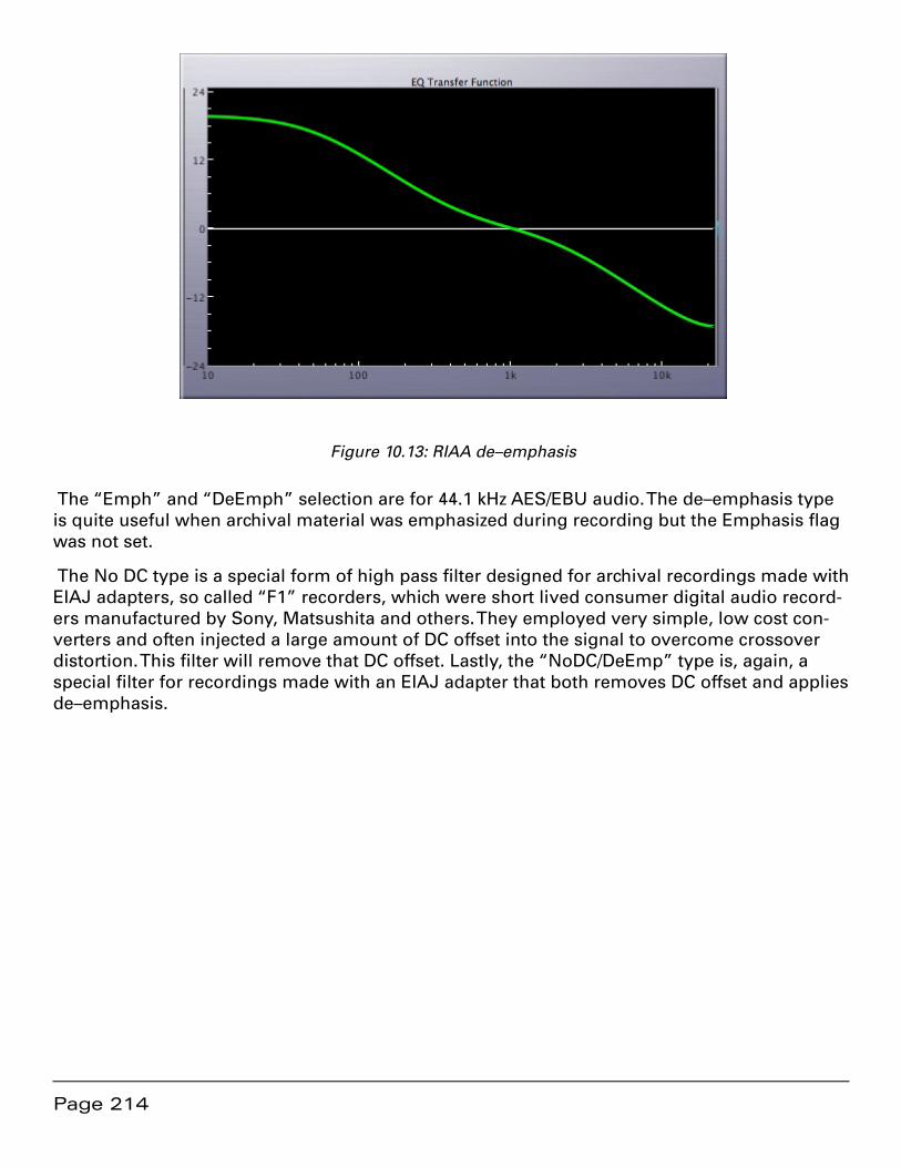
Page 214
Figure 10.13: RIAA de–emphasis
The “Emph” and “DeEmph” selection are for 44.1 kHz AES/EBU audio. The de–emphasis type is quite useful when archival material was emphasized during recording but the Emphasis flag was not set.
The No DC type is a special form of high pass filter designed for archival recordings made with EIAJ adapters, so called “F1” recorders, which were short lived consumer digital audio record-ers manufactured by Sony, Matsushita and others. They employed very simple, low cost con-verters and often injected a large amount of DC offset into the signal to overcome crossover distortion. This filter will remove that DC offset. Lastly, the “NoDC/DeEmp” type is, again, a special filter for recordings made with an EIAJ adapter that both removes DC offset and applies de–emphasis.

Page 215
Figure 10.14: DC reject plus RIAA de–emphasis, the “NoDC/DeEmp”
10.2 Sonic EQ Plug–in
The Sonic EQ option also provides a plug–in version of the same EQ seen in the pre–processor form. The only difference is that it appears as a single section and applies to wherever in the signal path it is instantiated.
Figure 10.15: Sonic EQ Plug–In Form

Page 216
In the plug–in menu, two versions are available. One is monaural while the other, SonicEQ(S), is stereo. Otherwise, the controls and parameters are the same as the pre–processor form discussed in section 10.1 above, with one exception. The plug–in version has an added conve-nience feature.
Tip: When adjusting controls with the sliders, hold down the shift key reduces the scaling and provides greater control.

Page 217
Chapter 11 ................................................Quartet DynPEQ™
11.1 Introduction to DynPEQ
This manual describes the operation of Quartet DynPEQ, both external and internal. DynPEQ refers to dynamic parametric equalization.
11.1.1 What is dynamic parametric equalization?
Audio professionals and enthusiasts alike are familiar with dynamics processors, such as com-pressors, expanders, etc., and parametric equalizers. Dynamic parametric equalization is an integrated combination of the two processors. That is to say, it is a dynamics processor, a para-metric equalizer, and a dynamically controlled parametric equalizer rolled into one package.
Quartet DynPEQ offers four bands of dynamic parametric equalization bands. Each band has controls normally associated with a parametric equalizer and a dynamics processor. The para-metric equalizer and dynamics processor portions of a band can be individually cut, which disables its respective functionality.
Shutting off the dynamics of a band turns it into a traditional parametric filter. Upon finding an appropriate parametric setting for a source, you may notice that the setting does not sound as appropriate for pianissimo or fortissimo portions of the source. In addition, you may find that details within the parametric band are too emphasized (punchy) or under-emphasized (washed out). This is where the dynamics portion of the band can be of assistance. The dynamics control of the band will operate only within the parametric band that you have tuned. Compression and/or expansion can help bring out the details or dynamic consistency that is sought after.
Similarly, shutting off the equalizer portion of a band turns it into a traditional dynamics pro-cessor. You may have experienced the ear fatigue that is associated with compression pump-ing. By reactivating the equalizer band, you may find that dynamics applied only to the spectral bands in need is “easier on the ears.”
To use an analogy, the signal processing capabilities of traditional parametric equalizers and dynamics processors project lines of capability in different directions. DynPEQ retains the two lines and projects a plane of signal processing possibilities going through the lines. It creates an extra dimension of audio processing. Try your EQ and dynamics ear training drills with both EQ and dynamics active!
The internals of Quartet DynPEQ can be described as ‘deliberate.’ By this, we mean the dynam-ics of this plug–in are designed to avoid over–reaction, which can be audible whether applied to a single band or the entire spectrum. So, while Quartet DynPEQ can be set to de-ess and perform other functions of specialized dynamics processors, you will likely find that the spe-cialty processors are very good at their specialty. By the same token, we don’t think you will find that specialty processors sound as good as Quartet DynPEQ. We at Wholegrain hope that you will find the plug–in powerful yet transparent.
Page 218
A toast to the pursuit of the golden tone…Cheers, from Wholegrain Digital Systems and Sonic Studio.
11.2 Roadmap for This Chapter
The Parameter Window Layout section outlines regions in the layout of the parameter window and their functional categories.
The Operation of Parameter Window Controls section describes the general categories of controls on the parameter window and how they can be manipulated with the mouse and key-board.
The Toolchest and Drag-and-Drop section explains the operation of the toolchest, a library where tuning settings for individual bands can be saved and retrieved along with project-spe-cific settings for the entire plug–in.
The Signal Processing and Band Configuration Tutorial section covers each specific band con-trol and how it affects band tuning and signal processing.
The Interface to the Host Workstation section documents:
the controls that the workstation software can retain1.
an auxiliary window, the About window, that controls issues that affect CPU usage2.
Lastly, the Operation Tips and Reporting Problems sections reveal hints and shortcuts for run-ning Quartet DynPEQ, along with suggestions for making a good problem report should the need arise.
11.2.1 Help Us Help You
If you find errors or factual issues with this manual, please do not hesitate to inform us. If you feel that something should be mentioned in this manual and is not, please point out what we missed. We also welcome your suggestions as to the manual’s organization and presentation.

Page 219
11.3 Parameter Window Layout
Figure 11.1 - The Main Quartet Window
11.3.1 Fine Adjustments
There are two rows of fine adjustment boxes. The top row controls the tuning parameters, and the bottom row controls the dynamics parameters. The parameters in this section are primarily text fields that can also act as continuous controllers. These fields are called slider-texts in this manual, and they will be described in the next section.
Page 220
11.3.2 Coarse Adjustments
There are two rows of coarse adjustment boxes below the fine adjustments. The top row con-trols the tuning parameters, and the bottom row controls the dynamics parameters. This sec-tion allows for control of multiple band parameters and visual feedback on DynPEQ operation.
11.3.2.1 Band Bypass
The fine and coarse adjustments are arranged in four columns. Each column is called a band. Each band has a bypass button that can enable or disable that band in the plug–in. The button labeled ‘In’ indicates the band is enabled, and ‘Out’ indicates the band is bypassed. Note that if the band is disabled either by the band cut button or the processor cut button, the coarse adjustments for that band disappear.
11.3.2.2 Input Processor
The input processor consists of two slider-text parameters that are applied to the audio input prior to the dynamic parametric equalizer. ‘Gain’ is the gain applied to the input. ‘DC Blk Cut’ is the cutoff frequency of a DC blocking filter. To disable the DC blocking filter, set the cutoff fre-quency to 0 Hz.
11.3.2.3 Peak Monitors
There are two peak monitors that operate on the interpolated peak levels after dynamic equal-ization but prior to output gain and limiting. The monitor to the left, in blue colored text, is a running maximum peak value, which can be reset by clicking on the blue text. The text of the running maximum peak will briefly turn red when a limiter hit occurs, but this will not affect the running measurement unless a new maximum has been established. The monitor to the right is a coarse peak meter. The values it displays are –10 dB to +4 dB, in increments of 2 dB.
11.3.2.4 Peak Limiter
The peak limiter employs the interpolated peak levels taken from the dynamic equalizer out-put. ‘Gain’ is the gain applied to the equalizer output prior to limiting. ‘Limit’ is the maximum interpolated level the output signal can attain. The ‘Hit’ monitor indicates whether the limiter has become active. That is, if the post-gain level has exceeded the set limit level. The Hit moni-tor is persistent, and will stay in the on state. Clicking on the Hit monitor resets it. As men-tioned previously, the running maximum peak text color is a non-persistent indicator of limiter hits. ‘Rel’ is the release time applied to the limiter when it activates. The ‘Lim In’ button enables or bypasses limiter processing, but does not affect the output gain.
11.3.2.5 A/B Registers
The A and B registers store the band, input processor, and peak limiter parameters in a local area outside of the workstation host for quick comparisons. The round unlabeled buttons to the right, under the downward arrow, store the operational parameters to the corresponding regis-ter. The Store button will turn blue whenever the operational parameter set matches that in the
Page 221
register, else it will be colorless. The square buttons to the left, under the upward arrow, trans-fer the parameters in the labeled register to the operational parameters.
11.3.2.6 Processor Bypass
The processor bypass button enables or disables dynamic equalization for comparative evalu-ation. ‘DEQ In’ signifies that dynamic equalization is enabled while ‘DEQ Out’ signifies that it is disabled.
11.3.2.7 Display Adjustments
The display adjustments to the right side of the screen affect the graphics in the coarse adjust-ments section. The selector adjacent to the coarse tuning adjustments sets the corresponding maximum y axis range. Similarly, the selector adjacent to the coarse dynamics adjustments set its minimum y axis range. The slider between the two rows adjusts the background brightness of the coarse adjustments.
11.3.2.8 Scroll View and Window Controls
The parameter window may have its size adjusted using either the diagonal drag device in the lower right corner or, the green button in the window bar. When the parameter window is less than full size, scrollbars will appear that can move the window contents within the reduced view. The yellow button in the window bar sends the parameter window to the data section of the system dock. The red button in the window bar dismisses the parameter window. In this case, only the About window, described below, can restore the parameter window into view.
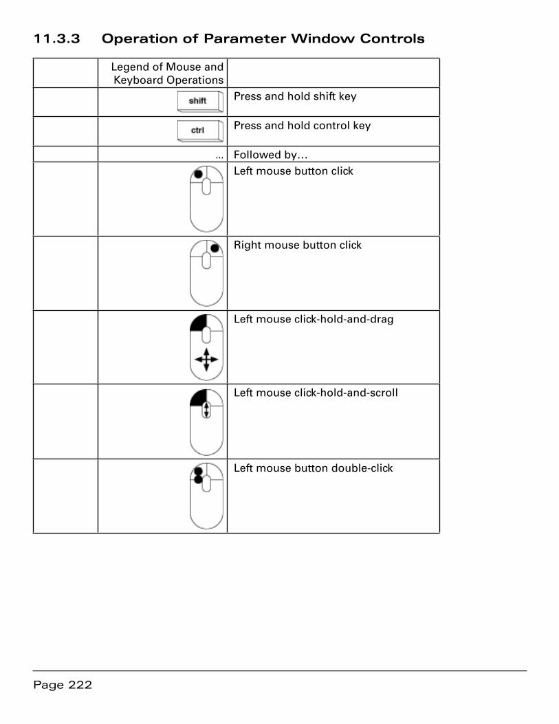
Page 222
11.3.3 Operation of Parameter Window Controls
Legend of Mouse and Keyboard Operations
Press and hold shift key
Press and hold control key
… Followed by…Left mouse button click
Right mouse button click
Left mouse click-hold-and-drag
Left mouse click-hold-and-scroll
Left mouse button double-click
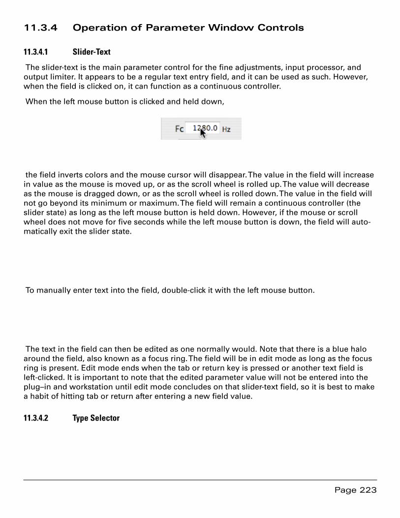
Page 223
11.3.4 Operation of Parameter Window Controls
11.3.4.1 Slider-Text
The slider-text is the main parameter control for the fine adjustments, input processor, and output limiter. It appears to be a regular text entry field, and it can be used as such. However, when the field is clicked on, it can function as a continuous controller.
When the left mouse button is clicked and held down,
the field inverts colors and the mouse cursor will disappear. The value in the field will increase in value as the mouse is moved up, or as the scroll wheel is rolled up. The value will decrease as the mouse is dragged down, or as the scroll wheel is rolled down. The value in the field will not go beyond its minimum or maximum. The field will remain a continuous controller (the slider state) as long as the left mouse button is held down. However, if the mouse or scroll wheel does not move for five seconds while the left mouse button is down, the field will auto-matically exit the slider state.
To manually enter text into the field, double-click it with the left mouse button.
The text in the field can then be edited as one normally would. Note that there is a blue halo around the field, also known as a focus ring. The field will be in edit mode as long as the focus ring is present. Edit mode ends when the tab or return key is pressed or another text field is left-clicked. It is important to note that the edited parameter value will not be entered into the plug–in and workstation until edit mode concludes on that slider-text field, so it is best to make a habit of hitting tab or return after entering a new field value.
11.3.4.2 Type Selector

Page 224
The operation of the type selector is straight forward. Left-clicking on the control presents a menu of choices, of which the desired choice is selected by left-clicking on it.
Button
The operation of the button is also straight forward. Left-clicking on the control changes its state. The button will have a different text label and graphic appearance.
Coarse Bead
The coarse adjustments are controlled by what are called beads. They are location markers that can be moved in a two-dimensional field. There are two beads in the dynamics coarse ad-justments but only one in the tuning coarse adjustments. The beads are capable of controlling most of the parameters in the fine adjustments.
A click of the right mouse button or a control-click of the left mouse button displays the type selector menu for the category. Choose the new type in the same manner as the type selector control.
Click the bead and hold with the left mouse button to move the bead within the field.
Page 225
To adjust the auxiliary parameter, which does not pertain to the x-y position of the bead, either click and hold the left mouse button and move the scroll wheel or, with the shift key pressed, click and drag with the left mouse button down.
Toolchest and Drag-and-Drop
Just below the coarse adjustments is a small row of controls, one per band.
Band Note
The control on the left side of the band column is a text field where brief user notes for the band can be typed in. This note is associated with the band when communicating with the tool-chest. To avoid confusion, the band note is cleared when a patch register, A/B or patch store, is loaded.
Band Drag-and-Drop Well
The control on the right side of the band column is a well that functions as either the source or destination of band transfers between the band toolchest.
Toolchest Window
The button on the far right edge of the parameter window toggles the toolchest window open and closed. The toolchest window will open on the right side of the parameter window, next to the button, unless there is not sufficient clearance on the right side of the computer screen, wherein the window will open on the left side.
Toolchest and Drag-and-Drop
Band Toolchest
The upper portion of the toolchest window is the band toolchest. The band toolchest is a per-sistent store of useful settings of individual bands. This store is unique to DynPEQ plug–ins and is not part of any host workstation project. The bands are represented in the toolchest view as gray circles with a band note attached. Drawers are represented by solid triangles with names attached, and they can hold both bands and other drawers.
New Drawer
Page 226
Left-clicking the new drawer button creates a new drawer and prompts for a drawer name. Note that the text edit focus ring will be around the name of the new drawer.
Delete Item
A band or drawer in the band toolchest can be selected by left-clicking on the row where the item is displayed. If an item is selected, left-clicking the delete item button will prompt for con-firmation to remove the item permanently from the band toolchest.
Rename Item
Double-clicking on the name of an item in the band toolchest will allow the name to be edited. If the new name matches the name of another item in the same drawer, the editor will not exit until the name is changed.
Moving Items within the Band Toolchest
Items in the band toolchest can be moved to another drawer by left-clicking on the item, while holding down the left mouse button dragging to the destination drawer, and releasing the left button over the destination. This operation is commonly called drag-and-drop. If the drop destination drawer has an item with the same name, a warning prompt will appear asking for confirmation to replace the existing item in the drawer. Replacing will permanently remove the existing item from the toolchest and complete the move.
Moving Bands to the Parameter Window
Bands in the toolchest can be moved to the parameter window by a drag-and-drop operation that originates at the toolchest band and ends at the desired band well.
Moving Bands from the Parameter Window
Bands in the parameter window can be moved to the toolchest by a drag-and-drop operation that originates at the desired band well and ends at the desired toolchest location. If the drop destination drawer has an item with the same name, a warning prompt will appear asking for confirmation to replace the existing item in the drawer. Replacing will permanently remove the existing item from the toolchest and complete the move.
Band Note Field and Parameter Load/Save
The band note field is for giving titles or notes to bands on the parameter window. The field will change when performing a drag-and-drop to the band well, but it will be cleared via A/B register load or patch load. The note field contents will not be saved with a workstation patch or project, only to the band toolchest as the band’s title.
Persistent Store of Band Toolchest
The band toolchest file is read when DynPEQ is instantiated, and it is written when the plug–in is shut down. The location of the band toolchest file is
$(HOME)/Library/Preferences/com.wholegrain.ds.dpeqbands.plist,
where $(HOME) represents the filesystem location of the home icon in a Finder window. This file can be restored from a system backup should the file become missing or damaged. If the

Page 227
file is missing, such as on the first time DynPEQ is instantiated on your system, the file will be initialized to a default set of bands, which is shown in the toolchest picture above.
Quartet DynPEQ is designed so that multiple instances of the plug–in should be able to safely share the band toolchest file. However, if there are multiple instances of workstation software running simultaneously on the same computer home, there is the possibility that band tool-chest changes made on one workstation can be overwritten with changes from another work-station instance. Please keep this in mind if your workstation host is a server to multiple users. In this case, each user should have a unique home directory in order to avoid this conflict.
Patch Store
The lower portion of the toolchest window is the patch store. The patch store is for saving and recalling the operational parameters of the DynPEQ plug–in. The patch store is initialized to empty for newly instantiated plug–ins. Parameter configurations, or patches, can be sequential-ly added to the store. When the workstation project is saved with an active DynPEQ plug–in, all configurations in the patch store are saved with the project file. When that project is recalled, Quartet DynPEQ will be started with the contents of the patch store at the last project save. The store shows no more than five patches at a time, but the view can be adjusted upwards and downwards to cover all of the store’s patches.
Patch Load and Patch Add/Replace
Associated with each item shown in the patch store is a load button and an add/replace button. These buttons look very similar to their counterparts for the A/B registers in the parameter win-dow, and their function is similar as well. The square button loads a patch, and the round clear button saves a patch and turns blue when the current DynPEQ parameters matches the patch. The patch load button will show the sequential number of the patch if there is a patch in that row. If there is not an active patch in the row, the load button will be blank and inactive.
The patch add/replace button will replace the patch in the row if it contains an active patch, after prompting for confirmation. The add/replace button will append a new patch to the store if its row does not contain an active patch. The extra add/replace button at the bottom is for add-ing a new patch when all rows are occupied and should remain undisturbed.
Patch Remove
To the right of the load and add/replace buttons are small buttons for deleting a patch from the store. After prompting for confirmation, the corresponding patch will be removed from the list and the remaining patches reordered.

Page 228
Patch Title
To the left of the buttons are text fields for entering a patch title. Click on a field to enter or edit a title, and press tab or return when done, for the title will not be officially recorded until the fo-cus ring disappears from the field. The patch titles are saved and restored with their respective patches in the workstation project file.
Store Capacity
At the bottom of the window is a numeric field which shows the number of active patches in the store. There is no hard limit to the number of patches that can be in the store, only the limitations of system resources. Recall that the store is saved with the project file, though, and keep only the patches that are deemed necessary for that project.
Patch and Page Up/Down
At the far left of the patch store are buttons for adjusting the range of patches that are visible. Five rows of patches make up a page in the patch store view. The patch up button, labeled “^,” will move the range one patch towards the top of the list, in the direction of lower patch num-bers. Similarly, the page up button, labeled “^^,” will move the range up by five. There are also patch down and page down buttons, labeled “v” and “vv” respectively, that move the range in the opposite direction, towards the bottom of the list.
Signal Processing and Band Configuration Tutorial
Finally, the fun part!
Band Operation: Tuning
To begin the investigation of band operation, cut all bands in the plug–in except one. To con-centrate on the tuning aspects of a band, set the dynamics type selector to off.
With the dynamics off, this band will operate as a normal parametric equalizer. Using the fine or coarse tuning control, bring the value of “g” away from zero and investigate the filter type options. The peak selection is the presence parametric filter. The value of “Fc” is the center frequency, or the crest of the peak along the x axis of the coarse view. The value of “g” is the boost or cut at the center frequency, or the maximum displacement along the y axis of the coarse view. The value of “Q” is the sharpness of the peak. Higher Q values result in a sharper, more abrupt peak.
Page 229
Dragging the bead in the coarse tuning control adjusts the cutoff frequency (x axis) and boost/cut (y axis). The auxiliary parameter for the bead, controllable by either left-mouse-hold-scroll or shift-left-mouse-drag, is the Q of the peak.
Now select the low shelf type, abbreviated to “LoSh” in the selector. The value of ‘Fc’ becomes the cutoff frequency, or the corner point where the shelf transitions between 0 dB and “g,” the boost/cut level at DC or 0 Hz. The “Q” control disappears and is replaced by “Slp,” which repre-sents the transition slope. Its value can be between 0 and 1, where 1 is the steepest transition slope. “Fc” and “g” remain controllable by dragging the bead, and the transition slope be-comes the auxiliary parameter for the bead.
Now select the high shelf type, abbreviated to “HiSh” in the selector. “Fc” remains the cutoff frequency and “g” remains the boost/cut level, but the location of the boost/cut level is now the Nyquist frequency. The meaning and control of the “Slp” parameter is unchanged.
Now select “Off” for the tuning type. The “Slp” parameter disappears, and the “Fc” and “g” fields are grayed out, which means their slider-text controls are inactive. The bead on the coarse adjustments can still be dragged around its field, however.
Note two things about the coarse adjustments. One, the bead changes its shape to reflect the tuning type selected. Two, and most important, the black line in the field represents the fre-quency response of the filter that the tuning parameters describe.
Page 230
Switch the tuning type back to “Peak” and adjust the value of “Q” downwards, noting that the band of the filter widens as the parameter goes down. Stop when the value of Q reaches zero and note that the frequency response becomes a flat line at the boost/cut level.
The peak filter with zero Q is simply a broadband gain function. The “Off” filter type is a special case of the peak filter where the applicable Q is zero and the applicable boost/cut is 0 dB.
Before moving on, play some source material through DynPEQ and experiment with filter types, connecting the filter frequency response with the way in which the source signal is modified.
Band Operation: Dynamics
Switch the tuning type back to ‘Off’ and begin the investigation of dynamics operation. Leave the dynamics type at ‘Off’ and note that the fine adjustments are grayed out for the compres-sion and expansion categories. There are two beads in the dynamics coarse field. The bead for the expansion category points to the left, and the compression bead points to the right. The compression bead will always be to the right and above the expansion bead. In the coarse field, the x axis represents input level and the y axis represents output level. There is a diagonal dashed line in the field which represents unity gain, or input level and output level being equal. Move the two beads away from unity gain and note the black line does not move along with them and stays at unity gain.
The black line is the dynamics curve, the mapping of output level to input level. Now set the dynamics type to “Expand.” At this setting, the expansion fine adjustments become active and the coarse view shows that the dynamics curve meets the expansion bead. At the expansion only setting, the slope above the expansion bead will be unity and will follow the unity gain line. The “Rat” parameter is the expansion ratio and affects the slope of the dynamics curve be-low the expansion threshold, which is the “Thr” parameter. The expansion ratio is the auxiliary parameter of the expansion bead, controllable by left click–hold–scroll or shift–left drag.
Page 231
The value of the expansion threshold applies to the input level, or the x axis of the coarse view. Adjusting the expansion threshold in the fine adjustments moves the bead along the unity gain line. The “g” parameter is the boost/cut at the expansion threshold, so the effective output level at the expansion threshold is the threshold plus boost/cut. Adjusting the expan-sion boost/cut alone moves the bead along the y axis.
Setting the dynamics type to “Compress” grays out the expansion fine adjustments and acti-vates the compression adjustments. Control of the dynamics curve passes from the expansion bead to the compression bead. At the compression only setting, the slope below the compres-sion bead will be unity and will follow the unity gain line. The “Rat” parameter is the compres-sion ratio and affects the slope of the dynamics curve above the compression threshold, which is the “Thr” parameter. The compression ratio is the auxiliary parameter of the compression bead, controllable by left click–hold–scroll or shift–left drag.
Note the button to the left of the ‘g’ parameter in the fine adjustments. This button selects the input level, x–axis location where the boost/cut is applied. When the button is set to “Thr,” the effective output level at the compression threshold is the threshold plus boost/cut, similar to the behavior of the expansion category and indicated by the arrow above.
Now left-click the button, which will give it the label “0 dB.” This button state indicates the ef-fective output level at 0 dB input is that of boost/cut, indicated by the arrow below. Note that the compression ratio does not change, so this pushes down the location of the compression bead.
The behavior of manipulating the compression bead changes when the boost/cut moves to 0 dB. The location of the compression bead becomes determined by the threshold and the com-
Page 232
pression ratio. In addition, the auxiliary parameter, beyond the control of the bead location, becomes the boost/cut value at 0 dB input.
Now set the dynamics type to “Both,” which activates both the expansion and compression points. Note that the dynamics curve obeys both beads, and that the two points are connected by a straight line.
The black line in the coarse view is the compression curve, the mapping of input levels to out-put levels. The effective gain is the ratio of the output level and the input level, and this is the boost/cut to apply to the dynamics processor.
Dynamic Parametric Equalization
Play some source material through the plug–in and not only listen for the audio effect but watch the coarse display for visual feedback on how the dynamic processing works. Start with the coarse dynamics view, where the compression curve is the black line. The x axis represents input level, and the coarse dynamics view fills in the black line with a solid color line to the point of the current input RMS level measurement. From the far left to the current input level, the path from the dynamics curve to the unity gain line is shaded with the band color. The far right edge of this shaded area is the current boost/cut applied to the input audio signal.
Note that there is also a shaded area in the coarse tuning view. This shaded area extends away from the black frequency response line. The distance from the black line to the shaded edge along the y axis is the gain applied to the signal at a particular spectral frequency, which in this case is equal to the boost/cut level from the coarse dynamics view. The y axis scaling for the two views is different, which is why the distances don’t match, but the distance within the con-text of the scaling is the same. Arrows indicate the boost/cut levels in question.
Now change the tuning type selector to ‘Peak’. The frequency response of the tuning param-eters change, so the black line in the coarse tuning view changes. The first principle of dynamic parametric equalization is that the dynamics curve produces a boost/cut value for its paramet-
Page 233
ric filter, so the shape of the edge of the shaded area in the tuning view also changes to reflect the new parametric tuning. More difficult to notice is that the input RMS level measurement decreases. With the tuning off, the input RMS level is measured broadband, so all energy is accounted for. With the band tuned to a parametric filter, a matching filter is used on the input signal when calculating RMS level. The use of this matching filter for calculating input level is the second principle of dynamic parametric equalization.
Key to the concept of dynamic parametric equalization is that the parameters labeled “g” in both the tuning and dynamics fine adjustments affect the same thing—the boost/cut. The effec-tive boost/cut at any time is the tuning “g” parameter plus the current boost/cut from the dy-namics curve. It is important to note that the maximum boost or cut that will be applied to one band is 24 dB. The enforcement of this maximum will be reflected in the coarse dynamics view.
To demonstrate, the following example display tunes a high shelf in two bands to the same cutoff frequency and slope. The band on the right sets the boost/cut for the tuning parameters to 9 dB, while the band on the left sets the dynamic curve to a constant offset of 9 dB and leaves the tuning boost/cut at 0 dB. The coarse tuning view shows that the left band has a 9 dB boost/cut due to the dynamics curve (the shaded area), while the right band has a 9 dB boost/cut due to the tuning (the black line).
Note that the input RMS level reported by the two bands, the solid colored line in the dynam-ics coarse view, is the same value. This is because the input RMS filter for the two bands is equivalent. The tuning of the input RMS filter is not dependent on the “g” parameter—just the center/cutoff frequency and Q/slope. This is in contrast to figure HNXTZZMPTLLO, where the input measurements for all active bands are different.
The input RMS level is measured with the help of an attack/release averaging filter. The attack and release times for each band are specified with the ‘Atk’ and ‘Rel’ parameters at the bottom of the dynamics fine adjustments.
Interface to the Host Workstation
Page 234
Saving and Loading Bands and Patches
When a single band is saved or loaded via the band toolchest, the following parameters are transacted.
Center/cutoff frequency
Q (for peak)
Slope (for low and high shelf)
Tuning boost/cut
Filter type
RMS attack time
RMS release time
Expansion threshold
Expansion boost/cut
Expansion ratio
Compression threshold
Compression boost/cut
Compression ratio
Compression boost/cut location (threshold or 0 dB)
Dynamics type
When a band is transferred into a band well, the band cut button will be set to ‘In’ and that band will be active.
When a workstation project using DynPEQ is saved or restored, the following parameters are transacted, which constitutes one patch.
Above band parameters for all bands
Band cut for all bands
Input gain
Input DC block cutoff
Output gain
Limiter level
Page 235
Limiter release time
In addition, the following non-patch parameters will be transacted with the project file.
All display adjustments: scaling for tuning and dynamics along with background brightness
Processor cut
Limiter cut
Background parameter window status, from the About window, discussed below
RMS calculation method, from the About window, discussed below
This means that the A/B registers, peak monitors, and limiter status will not be saved in the workstation project.
All patches in the patch store, along with their titles, are saved and restored with their respec-tive projects.
Caveat on Restoring Dynamics Parameters
Workstation software interfaces to DynPEQ by sending individual parameter values and not parameter groups. The processing of dynamics curve information prevents the creation of a curve where a segment has negative slope--this is why the compression bead should always be to the right and above the expansion bead. Since the plug–in has no guarantee of receiving parameters in a specific order (or, for that matter, receiving a complete set of parameters), it is possible (though rare) that a compression or expansion point may be moved away from the lo-cation specified in the patch or toolchest band. When this happens, the course of action to take is simply to reload the band or patch.
About Window
The parameter window appears automatically when the plug–in is instantiated. At the worksta-tion action that brings up parameter windows for most other plug–ins, Quartet DynPEQ dis-plays a second window. It is called the About window, and while most of the window contains information about the plug–in, the window does contain three controls.
Parameters Button
The button to the right displays the parameter window. It can be used if the parameter win-dow has been dismissed or is at the back of the window stack. Note that for some worksta-

Page 236
tions, having the About window and parameter window displayed at the same time can slow the reaction time of both windows. To this point, this issue has not been resolved. It is best practice to dismiss the About window using the red button in the upper left corner once the desired settings are made.
Background Parameter Window
With the volume of runtime interactive graphics elements it contains, the parameter window takes a considerable amount of CPU resources when the elements are active. In the interest of being a good computer citizen, especially when there are multiple instances of DynPEQ active, the interactive elements of the parameter window by default will be inactive when the window is not at the top of the screen. The elements inactivated are the input RMS-to-frequency re-sponse mapping--the shaded colors in the coarse parameter views, the two peak meters, and the limiter hit indicator. The maximum peak compiler will still continue to operate while the window is inactive, and the maximum peak field will update once the parameter window re-gains its status as the top on the screen.
If it is desired to have the interactive graphics elements continue to work when the window is in the background, and the host computer is sufficiently fast, set the background parameter window selector to “Graphics active (slow).”
RMS Calculation
The RMS calculation selector covers an issue of runtime behavior that has a background effect on the audio performance of DynPEQ. The issue it addresses is the input RMS level measure-ment for multiple channels and how it is carried out. Multiple input channels are converted into a single RMS measurement which appears on the coarse dynamics view. The first option, “fast,” sums all input channels into one bundled input signal and then calculates the RMS level on the sum signal, which takes less processor time to calculate. The other option, “slow,” cal-culates the RMS level on all input channels and then sums the levels. This option is slower, but results in a level calculation that is not sensitive to phase differences between channels.
Operation Tips
The maximum peak indicator can be used to record the highest level encountered with a source program and dynamic parametric equalizer settings. To attain a setting that will adjust this peak to 0 dB, or the highest setting without encountering a limiter hit, one may wish to adjust the input level to accomplish this. Adjusting the input level, however, cannot guarantee this unless there are no dynamics set in the plug–in; that is, all of the dynamics curve lines are the same slope as the unity gain guide. The way to accomplish this is to set the output gain instead. For example, if the indicator after the program reads +1.2 dB, reducing the output gain by 1.2 dB should avoid a limiter hit when the program is played again, assuming the other set-tings are not changed. Note, however, the peak indicators will still indicate values over 0 dB, as the peak measurement is made prior to output gain.
Page 237
The DC block filter is for removing a DC component in the input signal. A DC component can bias the RMS measurements if the band tuning type is low shelf, peak with a Q value of zero, or off. While it is possible to set the DC block cutoff all the way down to 1 Hz, this will make the DC block filter slow to respond to a bias and may pass bias drift. It is best to set the DC block cutoff to as high a value as is comfortable.
The highest center or cutoff frequency allowable is 40,960 Hz. However, if the sample rate pro-cessed by the plug–in is 48 kHz or 44.1 kHz, the maximum frequency becomes 20,480 Hz. The maximum frequency in the coarse tuning display is 40,960 Hz regardless of sample rate. If the Nyquist frequency, one half the sample rate, is less than the maximum of the coarse display, the frequency response at the Nyquist frequency is plotted out from Nyquist rightwards. This can look odd for a low sample rate and a peak filter with a high center frequency.
There is no “best” way to make band adjustments, but a good starting point is to apply a static equalizer band to spots in the spectrum that can use help. Drag and drop a “Generic” band type from the band toolchest for this. If the band adjustment is not all to satisfaction, activate the dynamics for the band and experiment with compression and expansion.
The parameter window can take much real estate on a small screen. The screen size can be reduced using the lower right drag element to the point where the top is the RMS attack and release times. The smallest height the window can take reflects this. Within this smaller screen, all DynPEQ parameters can still be controlled with the exception of the compressor boost/cut location or “auto-gain” buttons.
Note that there are no channel-specific controls, yet this is a multichannel plug–in. The RMS level calculation is designed to draw equally from all channels to make a single control signal, and the DynPEQ filters apply the control signal equally to all input audio channels. While this plug–in can alter the level balance between areas of the audio spectrum, it cannot alter the bal-ance between channels.
The DynPEQ filters are designed to dynamically modify the boost/cut with a minimal amount of audible artifacts. This means that making sudden and large changes to the other tuning pa-rameters, such as frequency, Q, or slope, may lead to an audible “tick” sound. This cannot be avoided.
Operational Issues

Page 238
The following issues have been mentioned in previous sections, and they are repeated here for your information.
For some host workstations, having both the About window and parameter window displayed at the same time can occasionally slow the reaction time of both windows. To this point, this issue has not been resolved. When clicking on a parameter window control and nothing seems to happen, the click appears to be lost in the system, and the course of action to take is clicking on the parameter window again and moving the mouse around, which should clear the action of the previous click and re-focus the window interface. It is best practice to dismiss the About window using the red button in the upper left corner once the desired settings on the About window are made.
Workstation software connects to DynPEQ by sending individual parameter values and not parameter groups. The processing of dynamics curve information within the plug–in prevents the creation of a curve where a segment has negative slope--this is why the compression bead should always be to the right and above the expansion bead. Since the plug–in has no guaran-tee of receiving parameters in a specific order or, for that matter, receiving a complete set of parameters, it is possible, though rare, that a compression or expansion point may be moved away from the location specified in the patch or toolchest band. When this happens, the course of action to take is reloading the band or patch.
Quartet DynPEQ is designed so that multiple instances of the plug–in should be able to safely share the band toolchest file. However, if there are multiple instances of workstation software running simultaneously on the same computer home, there is the possibility that band tool-chest updates made on one workstation can be overwritten with updates from another work-station instance. Please keep this in mind if your workstation host is a server to multiple users. In this case, each user should have a unique home directory in order to avoid this conflict.
The following issue is not mentioned in previous sections, and it is recorded here as an issue that is known to us and is in the process of resolution.
Quartet DynPEQ’s parameter window acts as an adjunct to the plug–in, as a plug–in to the plug–in in a manner of speaking. The workstation software is not directly aware of its presence. As such, some of the workstation keystroke commands that will bypass other plug–ins may not bypass the parameter window. So far, the solution involves blinking the parameter window off the screen and back on. While the parameter window is not visible, the keystroke is redirected to the workstation. However, if the toolchest drawer is open, this keystroke redirection may not seem to work at all. If this happens, one remedy is to close the toolchest, but this behavior may happen again when the toolchest is reopened. A more permanent remedy is to click a worksta-tion window or the About window, if it is open, and then return to the parameter window. We
Page 239
are working with workstation engineers in coming up with a comprehensive solution that does not involve the parameter window blinking and that supports the toolchest being open.
Reporting Problems
Upon encountering an anomaly in the plug–in operation or user interface, it is best to docu-ment the events around the issue before sending in a report. Most importantly, determine whether the problem is repeatable by attempting to duplicate the sequence of workstation and plug–in operations that lead to the issue. If our service personnel are able to re-create the prob-lem in the lab, the problem is much more likely to be resolved.
If the problem is with the processed sound from DynPEQ, it is best to capture the parameter settings and include them with the report. There are three way to do this. One, save the project with the DynPEQ parameters and send in the project file. Two, use the MacOS application /Ap-plications/Utilities/Grab to obtain a screenshot of the parameter window. The menu item to do this is Capture > Window. Three, label the bands something like “problem band 1,” “problem band 2,” etc., move the bands over to the band toolchest, quit the plug–in, which saves the tool-box file, and send in the toolbox file
$(HOME)/Library/Preferences/com.wholegrain.ds.dpeqbands.plist,
where $(HOME) represents the filesystem location of the home icon in a Finder window.
If it is necessary to send in a sound file for DynPEQ input, please keep its length to a mini-mum, no more than 10 seconds or so.
Quartet DynPEQ for soundBlade Operation Manual
Page PAGE 32
Input Processor
Processor Cut
A/B Registers
Peak Monitors
Page 240
Peak Limiter
Display Adjustments
Fine Control: Dynamics
Fine Control: Tuning
Coarse Control: Dynamics
Coarse Control: Tuning
Band Cut
Band Drag-and-Drop Well
Toolchest Drawer
Band Note
Band Toolchest
Patch Store
Patch and Page Up
Patch and Page Down

Page 241
Patch Title
Patch Load
Patch Add /
Replace
Patch Remove
Store Capacity

Page 242

Page 243

Page 244

Page 245

Page 246

Page 247
Appendix 1 .......................Best Practices & Maintenance
A1.1 Introduction
Although versatile in many ways, not every function that soundBlade offers is the best way of structuring your CD creation and replication workflow. Some solutions are better than others, either for quality reasons or other reasons beyond the scope of this manual. In this appendix, we’d like to provide some guidelines in order to get the best out your software and establish a smooth and efficient production flow.
A1.2 Source Material Considerations
soundBlade handles a variety of source file formats. It is thereforee very tempting to “grab” what you need and add it to your Project. However, some source material might be in formats other than the final 44.1 kHz sample rate and 16 bits word length necessary for CD production. soundBlade determines the characteristics of the files you import based on the metadata they contain. It will warn you if the sample rate is not the required 44.1 kHz where necessary, while resolutions longer than 16 bits are rounded down and redithered to 16 bits during the delivery stage. Although all of the conversions implemented by soundBlade are of very high quality, you may consider modifying your audio material beforehand with your favorite utilities.
In recording and production environments, the AES/EBU data used for digital interchange may contain a resolution of up to 24 bits of linear PCM–encoded data, sampled at up to 192 kHz. Au-dio Compact Discs, on the other hand, carry only 16 bit data. That’s one very good reason not to use these CD–DA—formatted “audio CDs,” as a mastering source. Engineers always appreci-ate source material at the highest possible resolution and sample rate in order to produce the best possible result.
Because all your material destined for inclusion in a final CD replication master will eventu-ally be rounded off, where necessary, to a 16 bit word length, any material using 17 to 24 bits must be word length–reduced to match the CD-DA standard. This is usually accomplished by “rounding down” longer length words to 16 bits. Because the audio data is being modified, it must also be redithered or subtly randomized with an injection of tiny amounts of “shaped” noise in order to prevent distortion. In the Window> Preferences > Delivery pane, you will find that soundBlade has a default preference to always redither the data when delivering either a CD, DDP or when simply playing back audio. This is necessary whenever any audio data is modified, as with a fade or gain change, in order to “linearize” or reduce subtle distortion in the resulting data. Redithering is always a trade off between lower distortion and a slightly but audibly elevated noise floor. soundBlade uses an exclusive, spectrally shaped “2nd order” or triangular PDF redithering scheme. PDF or Probability Density Function describes the ampli-tude versus frequency plot of the dither generator. Our shaped dither is an excellent trade off between audibility and optimal linearity.
Page 248
It’s a good practice to prepare all source material needed before moving forward with se-quencing, editing and finishing a new replication master. By organizing your source material and storing all relevant data in the same directory, your projects will be highly portable and you’ll avoid situations where files have “gone missing” from a job because they were not in-cluded in the Project subfolder.
A1.3 Naming Conventions
Do not use different audio files with the same file name within a Project. Rename 1. beforehand, where necessary, with a descriptive name for later ease of archiving, restoration and project interchange.
The2. P&E wing of the National Academy of Recording Arts & Sciences has pub-lished recommendation for naming conventions and other workflow methods to improve project interchange and archiving. See section A4.1 below…
A1.4 Host Considerations & Routine Maintenance
In this day and age of a BSD–based operating system and a journaling, self healing file sys-tem, it still is incumbent upon the cautious and wise engineer to perform routine maintenance and practice sensible management on your host computer. Here are some tips we recom-mend…
A1.4.1 File Systems
If you own a copy of DiskWarrior <www.alsoft.com>, run it monthly or when you host behaves strangely. If you don’t own a copy, you should. Periodic maintenance is still needed with OS 10 and there is no better file system maintenance utility than DiskWarrior.
A1.4.2 Storage Systems
soundBlade is fully compliant with Mac OS 10.4.3 and higher. Therefore, sound material can be used from any drive that your computer can access. This includes network–attached and removable drives as well near–line optical drives. That said, not all mountable storage devices are suitable for reliable real-time or higher speed reads and writes of sound files. Always run soundBlade from the boot volume. Always store all files involved in your jobs on direct-at-tached, local volumes: internal ATA, FireWire, FC, SATA or SAS are acceptable. USB-attached storage peripherals of any kind should never be used. Also, disks must have more than enough free space, to store, record and playback all of your sound files.
Although you may find it will actually work, never use LAN or WAN–networked, flex-1. ible media or optical drives to record or playback sound files due to their excessive latency. Always copy files from those storage types to a dedicated, local, direct–at-tached hard disk or FC–networked storage (Fibre Channel) first, then use that disk for all soundBlade work.
Page 249
When creating, copying or moving files, consider the file name and path name. Use 2. short path names and employ only alphanumeric characters. The only non-alphanu-meric characters that should be used are the hyphen ( - ) and underscore ( _ ) charac-ters. Other characters, such as !, @, #, $, %, ^, &, *, {, }, |, [, ], \ and / will very likely cause problems in your work.
A1.4.3 Permissions
Check that you have read and write permissions for the entire application package. Holding down the control key and highlighting the application will spawn a contextual menu with the choice to “Show Package Contents.” Showing the package contents allows you to set yourself as read/write, the group should be “admin,” also with read/write privileges.
You should also boot from the Apple-supplied install disc that came with your computer. Run the Disk Utility application and perform a Repair Permissions pass on your host. This is a rou-tine maintenance task that, along with DiskWarrior, should be run about once a month.
A1.4.4 Plug–ins
We recommend that you disable any VST plug-ins for which you have an AU equivalent. To do that, locate all plug–in folders. One is located at:
~ (your home directory)/Library/Audio/Plug-Ins/
Another is at:
(boot volume)/Library/Audio/Plug-Ins/
You may have others so, search for “VST” in Spotlight. Once you find all VST directories, you need to create “VST Disabled” folders next to the existing VST folders. Drag the VST plug-ins into the disabled folder. Generally speaking, if a vendor provides both VST and AU versions, always use the AU version.
After disabling your redundant VST plug-ins, have soundBlade recreate the “plug-in cache” by deleting the:
~ (your home directory)/Library/Preferences/com.sonicstudio.plugincache.plist
file. soundBlade will recreate a new plug–in cache next time you run it.
If you have plug–ins which are currently inactive, though you would expect them to be func-tioning, it may be because of the plug–in cache. The plug–in cache may have listed them as inactive so, simply quit soundBlade, delete the cache as described above, and relaunch soundBlade.
A1.4.5 3rd Party Configuration Management
As with OS 9, OS 10 employs “extensions” to the operating system that extend and some-times complicate your life. Mac OS 9 had the Extensions Manager but, OS 10 does not ship with such a utility.
Page 250
Fortunately, several vendors provide shareware or freeware versions of an Extensions Man-ager equivalent for OS 10. One is White Box’s free Diablotin, available from <http://s.sudre.free.fr/> and the other is Teng Chou Ming & Scott Mitchell’s X Overload2, a shareware utility avail-able from <http://www.xoverload.com/>. Neither of these products can manage audio plug–ins.
A1.4.6 3rd Party Applications
We recommend that you do not run non–audio applications while performing audio produc-tion. Microsoft’s Office suite is poor at multitasking with audio applications, as is Retrospect and other “chatty” applications that routinely scan or address volumes or network ports. Such activity can cause drop–outs in you finished material.
A1.4.7 iLoks & Your License
Your iLok is your soundBlade license. If it is lost, stolen or broken, your license is lost and can only be replaced by purchasing a new copy. PACE’s “zero downtime” insurance is your best choice for protecting your soundBlade license.
A1.5 Delivering DDPs
DDP file sets created by soundBlade, always in their enclosing folder, can be copied to any writable medium you choose, DVD-R or hard disk, for transport to your replicator. Check that the medium you choose has enough space to hold the file set. Also check with your replicator to determine which medium they can handle and whether they are even capable of using DDP as an premastering format. Many bargain companies are not ready to handle DDP deliveries so, we at Sonic Studio suggest you find a reputable facility that does accept DDP file sets of your valuable masters.
Here are some specific suggestions…First, use DVD-R blanks rather than CD-Rs to deliver your DDP file set. That way, the replicator is less likely to confuse your CD-R with DDP files as a CD-ROM job and replicate 1000 CD-ROMs of your DDP file set!
Second, the entire DDP folder or directory is usually sent to the replicator. A few replicators ex-pect the file set at the root level of the delivered disc. Always check with your replicator before sending your master to make sure they receive just what they expect.
For best file integrity, we suggest you ZIP the whole thing and generate a check sum for the resulting ZIP file. For more information, see the Checksums for DDP section of our Knowledge-base page:
http://www.sonicstudio.com/support
Always check with your replicator before sending ZIP’d file sets. Also, clearly identify the mas-ter disc and jewel case as “DDP Files.”
Finally, we recommend that you always create a new, empty folder to contain each DDP file set. On the Desktop is a reasonable location for that new folder, making it easier to archive and helping to prevent common problems.
Page 251
A1.6 Delivering CD-Rs
When delivering a CD-DA–formatted CD-R, consider these recommendations:
Do set the System Preferences > CDs & DVDs > When you insert a blank CD: to •Ignore.
Always use a high quality burner running the latest official firmware•
Always use a high quality blank media specifically designed for “audio” CDs•
Always record at low speed for lowest jitter•
Never write on or mark up the CD blank with a hard stylus, such a ball point pen.•
Always use a manufacturer–approved label and marker.•
A1.7 Delivering CD Text
To insure a smooth replication process, we recommend that you generate a PQ List and in-clude a printed copy with your replication master, whether your job includes CD Text or not. Use the PQ List button in the Windows Mark Info PQ Delivery tab. This file is an essential check list for your replicator, so their quality control can be maintained. In addition, a PQ List is a per-fect way to ensure that CD Text information is delivered to replication.
Since CD Text metadata does not appear in DDP file sets generated by soundBlade, the PQ List is the vehicle to move this information into replication. The PQ listing uses the information you enter in the Mark Info dialog to generate a “plain text” or ASCII text file so, before you create a PQ list and a CD-R with CD Text, double check your information in Mark Info. Remember to avoid metacharacters in CD Text strings, like #, / and $, just as you would if you were naming computer files. Click on the PQ List button to save and open a soundBlade PQ Log. Then, re-view, edit and append any information missing or in need of expansion. Fill in the Client name, Date, Work Order (WO) number, and the UPC/EAN. Edit the Project name and disc Title to make sure it’s correct. Add the disc Artist under disc Title. Check each track name and make any cor-rections necessary.
If your job is a compilation, be sure to add Track Artist to your listing, preferably after the indi-vidual track names. Finally, be sure to indicate, on both the printed soundBlade PQ Log and the text file accompanying the DDP file set, that you want CD Text to appear on the final, replicated Compact Disc. Include your contact information right on the soundBlade PQ Log in case any questions arise.

Page 252
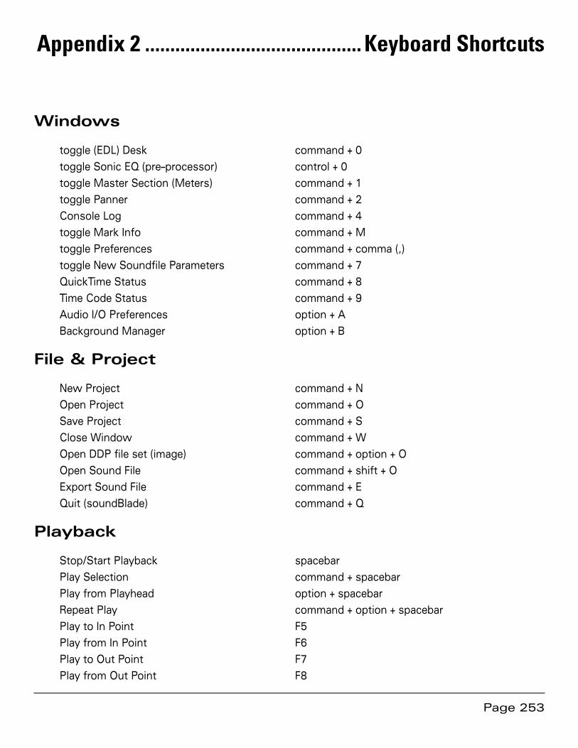
Page 253
Appendix 2 ........................................... Keyboard Shortcuts
Windows
toggle (EDL) Desk command + 0
toggle Sonic EQ (pre–processor) control + 0
toggle Master Section (Meters) command + 1
toggle Panner command + 2
Console Log command + 4
toggle Mark Info command + M
toggle Preferences command + comma (,)
toggle New Soundfile Parameters command + 7
QuickTime Status command + 8
Time Code Status command + 9
Audio I/O Preferences option + A
Background Manager option + B
File & Project
New Project command + N
Open Project command + O
Save Project command + S
Close Window command + W
Open DDP file set (image) command + option + O
Open Sound File command + shift + O
Export Sound File command + E
Quit (soundBlade) command + Q
Playback
Stop/Start Playback spacebar
Play Selection command + spacebar
Play from Playhead option + spacebar
Repeat Play command + option + spacebar
Play to In Point F5
Play from In Point F6
Play to Out Point F7
Play from Out Point F8

Page 254
Play between In & Out Points command + control + F5
Hide Playhead When Stopped option + P
Solo Track control + O
Mute Track control + M
Recording
Record Arm control + R
Stop/Start Recording forward slash (/)
Editing
Undo last Edit command + Z
Redo last Undo command + shift + Z
Select All command + A
Deselect All command + D
Cut command + X
Copy command + C
Paste (Replace) command + V
Paste (Insert) command + option + V
Paste (Constrained) command + shift + V
Paste (Overlay) option + V
Select All command + A
Deselect All command + D
Delete Selection delete (backspace)
Clear Selection option + delete (backspace)
Create Crossfade control + G
Create Crossfade from In/In & Out Point control + option + G
Replace F1
Insert F2
Replace Left command + F1
Replace Constrained control + F1
Set In Point left bracket ([)
Set Out Point right bracket (])
Set In & Out Points control + option + left bracket ([)
Clear In Point control + left bracket ([)
Clear Out Point control + right bracket (])
Clear In & Out Points control + backslash (\)
Nudge In Point Right command + control + left bracket ([)
Nudge Out Point Right command + control + right bracket (])
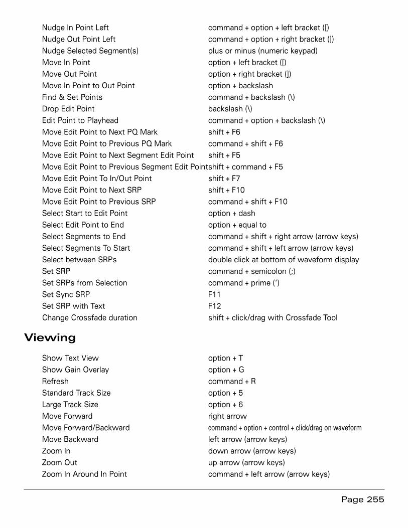
Page 255
Nudge In Point Left command + option + left bracket ([)
Nudge Out Point Left command + option + right bracket (])
Nudge Selected Segment(s) plus or minus (numeric keypad)
Move In Point option + left bracket ([)
Move Out Point option + right bracket (])
Move In Point to Out Point option + backslash
Find & Set Points command + backslash (\)
Drop Edit Point backslash (\)
Edit Point to Playhead command + option + backslash (\)
Move Edit Point to Next PQ Mark shift + F6
Move Edit Point to Previous PQ Mark command + shift + F6
Move Edit Point to Next Segment Edit Point shift + F5
Move Edit Point to Previous Segment Edit Point shift + command + F5
Move Edit Point To In/Out Point shift + F7
Move Edit Point to Next SRP shift + F10
Move Edit Point to Previous SRP command + shift + F10
Select Start to Edit Point option + dash
Select Edit Point to End option + equal to
Select Segments to End command + shift + right arrow (arrow keys)
Select Segments To Start command + shift + left arrow (arrow keys)
Select between SRPs double click at bottom of waveform display
Set SRP command + semicolon (;)
Set SRPs from Selection command + prime (‘)
Set Sync SRP F11
Set SRP with Text F12
Change Crossfade duration shift + click/drag with Crossfade Tool
Viewing
Show Text View option + T
Show Gain Overlay option + G
Refresh command + R
Standard Track Size option + 5
Large Track Size option + 6
Move Forward right arrow
Move Forward/Backward command + option + control + click/drag on waveform Move Backward left arrow (arrow keys)
Zoom In down arrow (arrow keys)
Zoom Out up arrow (arrow keys)
Zoom In Around In Point command + left arrow (arrow keys)
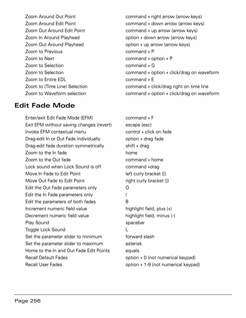
Page 256
Zoom Around Out Point command + right arrow (arrow keys)
Zoom Around Edit Point command + down arrow (arrow keys)
Zoom Out Around Edit Point command + up arrow (arrow keys)
Zoom In Around Playhead option + down arrow (arrow keys)
Zoom Out Around Playhead option + up arrow (arrow keys)
Zoom to Previous command + P
Zoom to Next command + option + P
Zoom to Selection command + G
Zoom to Selection command + option + click/drag on waveform
Zoom to Entire EDL command + E
Zoom to (Time Line) Selection command + click/drag right on time line
Zoom to Waveform selection command + option + click/drag on waveform
Edit Fade Mode
Enter/exit Edit Fade Mode (EFM) command + F
Exit EFM without saving changes (revert) escape (esc)
Invoke EFM contextual menu control + click on fade
Drag-edit In or Out Fade individually option + drag fade
Drag-edit fade duration symmetrically shift + drag
Zoom to the In fade home
Zoom to the Out fade command + home
Lock sound when Lock Sound is off command +drag
Move In Fade to Edit Point left curly bracket ({)
Move Out Fade to Edit Point right curly bracket (})
Edit the Out Fade parameters only O
Edit the In Fade parameters only I
Edit the parameters of both fades B
Increment numeric field value highlight field, plus (+)
Decrement numeric field value highlight field, minus (-)
Play Sound spacebar
Toggle Lock Sound L
Set the parameter slider to minimum forward slash
Set the parameter slider to maximum asterisk
Home to the In and Out Fade Edit Points equals
Recall Default Fades option + 0 (not numerical keypad)
Recall User Fades option + 1-9 (not numerical keypad)

Page 257
Desk
Select Desk Setup A page up
Select Desk Setup B page down
CD Prep
Create Track Start Mark F9
Create Track End Mark F10
Delete Marks command + F12
Edited Black to Marks command + option + F9
Edited Black to Start Marks command + F9
Mark Info (window) command + M
System
Audio I/O Setup option + A
Preferences command + comma
Select Nudge Size A control + 1
Select Nudge Size B control + 2
Select Nudge Size C control + 3

Page 258
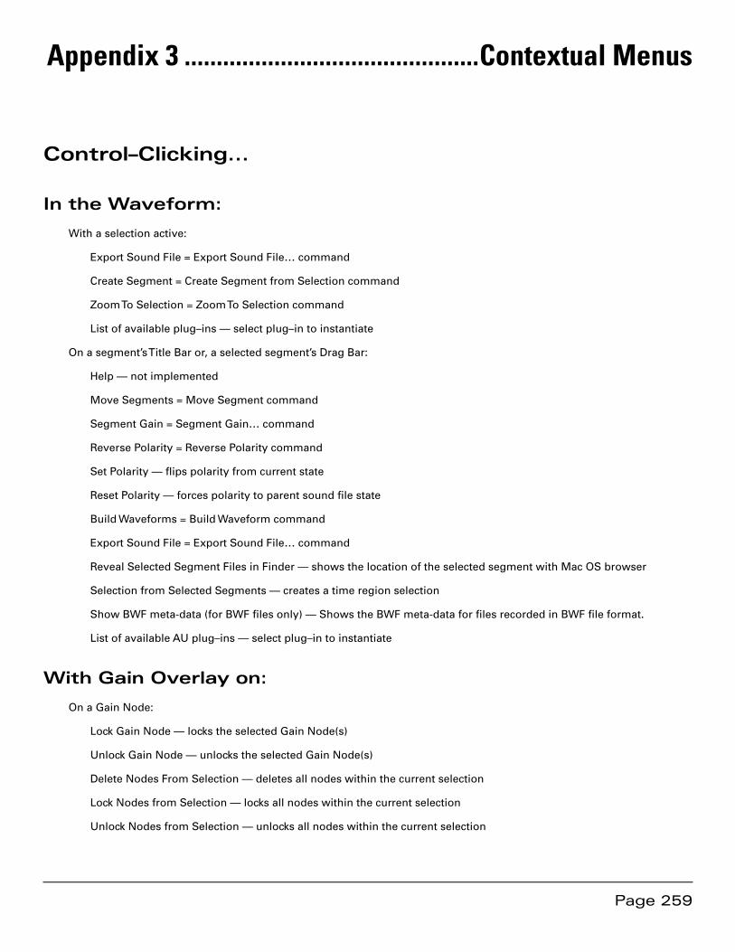
Page 259
Appendix 3 ..............................................Contextual Menus
Control–Clicking...
In the Waveform:
With a selection active:
Export Sound File = Export Sound File… command
Create Segment = Create Segment from Selection command
Zoom To Selection = Zoom To Selection command
List of available plug–ins — select plug–in to instantiate
On a segment’s Title Bar or, a selected segment’s Drag Bar:
Help — not implemented
Move Segments = Move Segment command
Segment Gain = Segment Gain… command
Reverse Polarity = Reverse Polarity command
Set Polarity — flips polarity from current state
Reset Polarity — forces polarity to parent sound file state
Build Waveforms = Build Waveform command
Export Sound File = Export Sound File… command
Reveal Selected Segment Files in Finder — shows the location of the selected segment with Mac OS browser
Selection from Selected Segments — creates a time region selection
Show BWF meta-data (for BWF files only) — Shows the BWF meta-data for files recorded in BWF file format.
List of available AU plug–ins — select plug–in to instantiate
With Gain Overlay on:
On a Gain Node:
Lock Gain Node — locks the selected Gain Node(s)
Unlock Gain Node — unlocks the selected Gain Node(s)
Delete Nodes From Selection — deletes all nodes within the current selection
Lock Nodes from Selection — locks all nodes within the current selection
Unlock Nodes from Selection — unlocks all nodes within the current selection

Page 260
Lock All Nodes in Track — locks all nodes in the Panel
Unlock All Nodes in Track — unlocks all nodes in the Panel
In the Track Bar:
Hovering over a PQ Start, End or Index Mark :
Move Edit Point to Mark —
Move Mark to Edit Point —
PQ Mark Locked — Locks the selected PQ Mark.
PQ Mark Unlocked — unlocks the selected PQ Mark.
Lock marks From Selection — Locks all PQ Marks in a selected Region or Segments.
Unlock marks From Selection — Unlocks all PQ Marks in a selected Region or Segments.
Lock All Marks — Locks all PQ marks in a track.
Unlock All Marks — unlocks all PQ marks in a track.
Set Emphasis — sets emphasis flag for the selected PQ Mark.
Reset Emphasis flag — resets emphasis flag for the selected PQ mark.
Delete Mark — deletes selected PQ mark.
In the waveform display:
Hovering over a fade-in, fade-out or crossfade with Fade Tool enabled:
Linear — set the fade curve to be 6dB down in the center of the Fade.
Root-linear — set the fade curve to be 6dB down in the center of the Fade.
Cosine — default 3 dB down in the center.
Root Cosine — default 6 dB down in the center.
Exponential — provides very rapid reduction in gain across the Fade.
Set Fade to Fade In/Out/Crossfade - change the Fade type to one of the default Fade types.
Set Fade To Selection — Sets the Fade duration to match the current selection.
Set Fade To Default Fade In/Out/Crossfade — changes all Fade’s parameters to the default Fade’s characteristics.

Page 261
Appendix 4 ........................................Additional Resources
Below is a list of internet resources on subjects relating to soundBlade and it’s intended field of use…
A4.1 Professional Organizations
International Federation of Phonographic Industries. Assigns ISRC label codes;
http://www.ifpi.com/
The P&E wing of the National Academy of Recording Arts & Sciences provides recommended practices for production and interchange formats.
http://www.grammy.com/Recording_Academy/Producers_and_Engineers/
The Audio Engineering Society promotes select industry recommendations in the field of pro-fessional audio;
http://www.aes.org/
The Society of Motion Picture & Television Engineers sets standards and guides the industries involved in all technical aspects of film and television production, including audio;
http://www.smpte.org/
A4.2 Commercial Businesses
Doug Carson Associates, creators of the DDP protocol and related industry standards;
http://www.dcainc.com/
Philips Intellectual Property & Standards is responsible for the maintenance of the Red and Scarlet Books, along with related standards;
http://www.licensing.philips.com/

Page 262
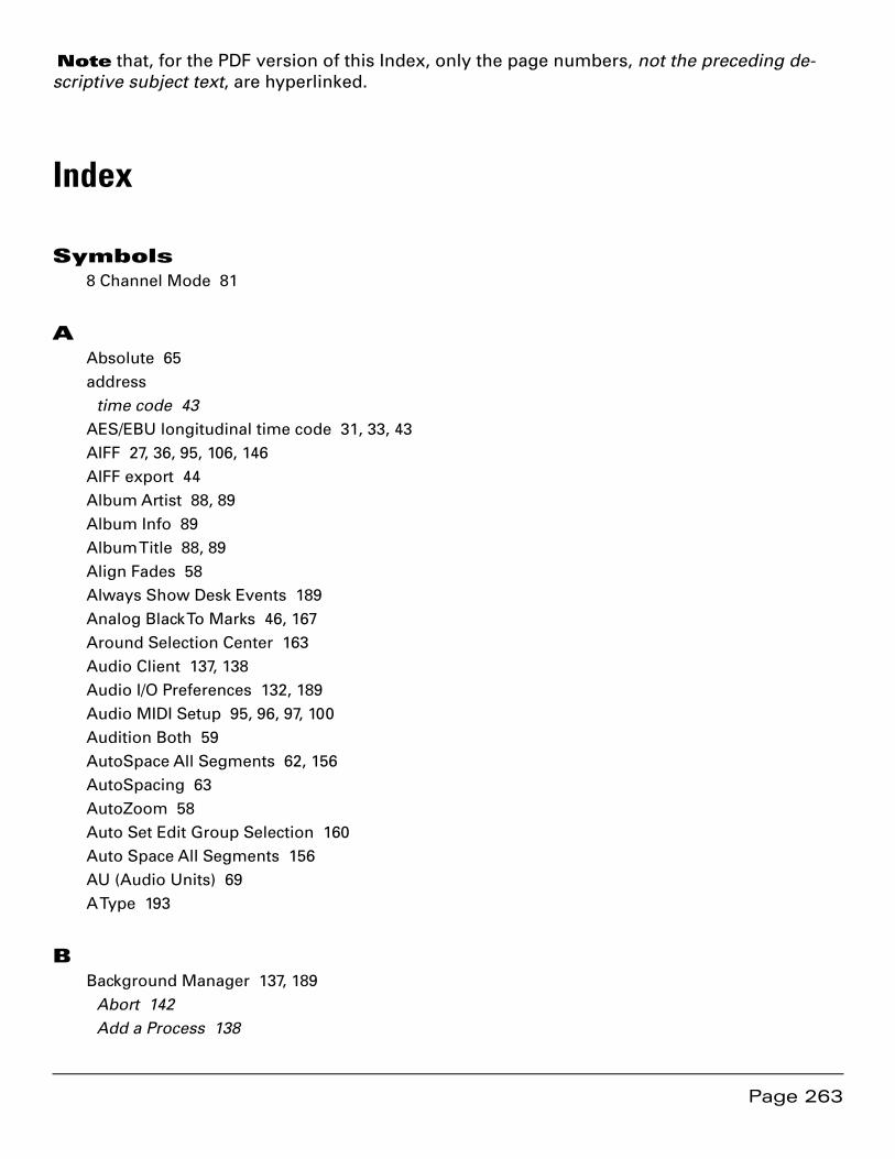
Page 263
Index
Symbols8 Channel Mode 81
AAbsolute 65address
time code 43AES/EBU longitudinal time code 31, 33, 43AIFF 27, 36, 95, 106, 146AIFF export 44Album Artist 88, 89Album Info 89Album Title 88, 89Align Fades 58Always Show Desk Events 189Analog Black To Marks 46, 167Around Selection Center 163Audio Client 137, 138Audio I/O Preferences 132, 189Audio MIDI Setup 95, 96, 97, 100Audition Both 59AutoSpace All Segments 62, 156AutoSpacing 63AutoZoom 58Auto Set Edit Group Selection 160Auto Space All Segments 156AU (Audio Units) 69A Type 193
BBackground Manager 137, 189
Abort 142Add a Process 138
Note that, for the PDF version of this Index, only the page numbers, not the preceding de-scriptive subject text, are hyperlinked.
Page 264
Audio Client 137, 138Clear All 138, 139Clear Files 139Clear List on Execute 139Delete intermediate files 139Execute 138Pause/Resume 141Percent 140Processes area 138Queue 138Queue Manager 137, 140sample rate conversion 138, 139Soundfiles area 138SRC 139Target Sample Rate 139varispeed 139
Background Waveforms 28, 185Bin Controls 197, 199Bouncing 103, 107
examples 104, 122printing Master section effects 127, 128, 130
Broadband DeNoise 196Broadband DeNoiser 200Broadcast WAV 27, 144Build Waveforms
Build Sound Waveform… 145Build Waveforms (Background Mgr.) 140
Built-In audio 124burning CDs 19, 20, 47, 93Burn Button 94BWF 23, 27, 95, 98, 106Bypass/Activate Gain Overlay 158Bypass/Unbypass Event 72Bypass All Events 178Bypass Desk Events 158Bypass Gain Overlay 179B Type 192
CCD
Album Artist 88Album Title 88
Page 265
ISR Codes 88Track Artist 88Track Title 88UPC/EAN 88
CD+G 48CD-DA discs 34, 47, 49, 92, 247CD-R delivery 19, 20, 23, 47, 93
delivering multiple CDs 94using multiple mechanisms 93
CD Text 48, 89CD Track metadata 49CD Write Speed 186changing Fade parameters 53changing Fade shape 54changing Fade type 55changing track order 42Clear All 139Clear button 122Clear Files 139Clear In & Out Points 170Clear In Point 170Clear List on Execute 139Clear Out Point 170Clear Selected SRPs 172Clear Selection 152, 153combo Text+Waveform Project 66Console Log 69, 147, 148, 149Copy 151Copy Enabled 90cosine Fades 55Create Crossfade 153Create Crossfade from In Point 154Create Gain Nodes 159, 179Create Segment 153Create Segment from In & Out Points 154Create Waveforms Manually 185crossfade 55Crossfades 41
deleting 154Cut 151C Type 193
Page 266
Ddbx 196DDP 23, 50, 92
DDP File Open option 144Delivery 47, 107file sets
opening 26, 144
DDP File Open Option 144Default Fade 183default Project 145
combo Text+Waveform 66default time code format 34Delete Crossfade 154Delete intermediate files 139Delete Mark 166Delete Selected Plug-ins 72Delete Selection 152, 153Delete Track 158deleting part of a sound file 40delivering multiple CDs 94Delivery 47, 186
CD-Rs from existing DDPs 93CD Write Speed 186Emulation Mode 186Keep DDP Image 186Use button 94Write CD Text 186
Delivery preferences 186Desk
Desk A/B 115Desk components 108Desk preferences 189opening Desk setups 178Open Desk Setup 115Save Desk Setup 115saving Desk Setups 177, 189setups 115
Desk A/B 115Desk Events (also see plug-ins)
Always Show Desk Events 189Bypass Desk Events 158Show/Hide Desk Events 158

Page 267
Desk Menu 177Desk Setups 115Details button 121Details window 121Device (CD-R/DVD-R) 93, 111dim 119Disable Offsets 187disc replication 47DiskWarrior 248Display Auto Tools 186dither 187
2nd order 247Dither On Output 187PDF 247triangular 247Turn Off Delay 187
Dither On Output 187Dolby 196Drag-Insert & Ripple 64Drag-Overlay 64Drag-Replace 64drag & drop 61
ReSequence 61Drag Bar 43, 62Drop Edit Point at Playhead 172Dual EDL Mode 73, 185DUR field 30, 33, 40, 174DUR time field 85D Type 194
EE/S toggle 84Edit
Insert 80Replace 80
Edited Black to Marks 168editing 154
Auto Space All Segments 156Auto Tool Override 156Clear Selection 153Create Crossfade 153Create Segment 153
Page 268
Create Segment from In & Out Points 154Crossfades 41Delete Selection 153deleting 40Drag-Insert & Ripple 64Drag-Overlay 64Drag-Replace 64drag & drop 61DUR field 174Edit Fade Mode 156Edit Point 174
placing & moving 172
Fade Tool 38Insert 153Loop And Fill 156Replace 152Replace Constrained 153Replace Left 153ReSequence 61selecting Regions 32selecting Segments 35Source to Destination 76SRPs 72
Editing Auto Tools 182Editing Auto Tool Override 156Editing Tools preferences 182Edit after Export 40, 44, 146, 152Edit Decision List 86edit event 53, 55, 171Edit Fade Mode 56, 156
additional fade parameters 59Align Fades 58Audition Both 59Audition Controls 59AutoZoom 58Edit Point Offset 60exiting Edit Fade Mode 61fade library 61fade selectors 59global modes 58Lock Sound 58Nudge Auto Audition 59
Page 269
nudging fades 60Power Lock 58Ripple Until Black 58selecting fade shape 60
Edit Groups 78, 162, 180simplified Edit Group 78, 82, 160
Edit menu 150Edit Point/Selection toggle 84Edit Points 67, 174
auditioning 77clearing 77In & Out Edit Points 77Move Edit Point to submenu 173moving 77, 172placing 172Sync to Edit Point 155
Edit Point Offset 60Edit Point to Next Peak 173Edit Point to Playhead 172Edit Recording 101Edit Segment Name 155Edit Targets 78, 81, 82, 83, 87, 155Edit with Audio 183EDL 73, 86, 101
Auto Set Edit Group Selection 160backwards compatibility 148Delete Track 158dual EDL mode 73, 185LTC Slave 75, 188Master 75Master/Slave menu 74Move Track Up/Down 159Multiple EDLs 75, 185New Track 157Select/Deselect All Tracks 159Set To Next Available Edit Group 160Slave 75
EDL Desk 180EDL menu 157EDL preferences 185Eight Channel option 70, 78, 80, 81, 82, 84, 86, 96, 157, 158, 159, 160, 185
applications 86
Page 270
Multi-Channel EDLs 185Eject 50, 94, 108Emphasis flag 49, 91Emulation Mode 186End Offset 187Execute 50, 93exponential Fades 55exporting audio 107
Edit after Export 40, 44, 146, 152Selections & Segments 44
Export EDL As 5.4 148extended (Track) listing 49, 91E Type 195
Ffaders
hot spots 109Link Pair(s) 110, 115Reset Fader 110Unlink All 110, 115
Fades 38edit events 53, 55, 171shape
changing 54gain laws 55
Fade Library 61Fade Tool 38, 53
changing parameters 53changing the shape 54changing the type 55
File menu 143file systems 248Find & Set Points 171Fit Estimate From Selection 199Forground Waveforms 185freezing 44
GGain 64
Absolute 65changing multiple segments 66Normalize 65
Page 271
Relative 65Segment Gain 154
Gain Adjustment 64Gain Nodes
creating 159, 179locking/unlocking Gain Nodes 180locking & unlocking 68selecting 159, 180
Gain Overlay 66, 146, 179Bypass/Activate 158bypassing Gain Overlay 179Show/Hide 158showing/hiding Gain Overlay 179
Gain Overlay Mode 66
HHH:MM:SS:FF 31Hide Gain Overlay 179Hide Playhead When Stopped 165host
saturation 44hot spots 109, 119
IiLok 19, 149, 250Import 184importing
sound file types 23, 144importing SD2 files 184Import 5.4 EDL 148Index Mark 166Insert 80, 153inserting PQ Marks
automatically 45manually 45
installation 19Interpolate Noise Estimate 197Interpolation Algorithms 192In Edit Point 77IN field 30, 40, 41, 170ISRC 88, 90
Mark Info 90

Page 272
the IFPI 90
KKeep DDP Image 186
LLEFT/RIGHT time fields 85LEFT field 30, 33linear Fades 55Link Pair 110, 115Listings 92
PQ List 94Lock/Unlock 179Lock/Unlock All Nodes In Edit Group 180Lock/Unlock all Nodes In Track 180Lock/Unlock All SRPs in Track 73Lock/Unlock Nodes From Selection 180Lock All Marks 167Lock Gain Node 68Lock Marks from Selection 167Lock Sound 58Lock SRP 73Loop And Fill 156LTC (see time code) 188LTC Slave 75, 188
MM1-4 44, 103, 108, 112, 122, 146Mac OS 248maintenance
DiskWarrior 248file systems 248permissions 249plug-ins 249storage systems 248
Manual DeClick 192, 195Marks
Analog Black to Marks 167Delete Mark 166Edited Black to Marks 168End Mark 166

Page 273
Index Mark 166locking Marks 167Mark Info 166Start Mark 166Start of Track 90unlocking Marks 167
Mark Info 48, 87, 90, 166, 181Extended Listing 91Total Tracks 49, 91Track Listing 49
Mark menu 166Master 75Master/Slave menu 74Master1-4 111Master Section 117
Clear button 122Details button 121dim 119hot spots 119Lock indicator 119Master plug-ins 120Output button 122plug-ins 120Reset button 122
metadata 247BWF 27, 144CD Text 186, 251PQ 167, 185Project 144, 145waveform 145
meters 180peak-hold mode 120
Meters window 117Meter Details 121Minimum Index Width 187Model 302 130
Sonic Console 132monitor controls 110
Mute 111Solo 111
mono editing mode 79, 177Move Edit Point to submenu 173
Page 274
Move Forward/Backward 175Move In/Out Point 171Move In Point to Out Point 171Move Playhead 165Move Segments 154Move Track Up/Down 159Move View mode 31moving PQ Marks 45Mute Track 162
NN/L toggle 84New Project 143New Soundfile Preferences 189New Track 157Noise Estimate 197NoNOISE II
A Type 193Bin Control 199Bin Controls 197, 199Broadband DeNoise 196, 200
Attenuation 202Bandwidth 203High Frequency Cutoff 203Low Frequency Cutoff 203NoNoise/Noise button 201Open Est button 201Open Param button 201parameters 201Sharpness 202Threshold 201
B Type 192C Type 193D Type 194editing the noise Estimate 199E Type 195Fit Estimate From Selection 199Interpolate Noise Estimate 197interpolation algorithms 192Manual DeClick 192, 195noise Estimate 197obscenity reduction 196post-processing the noise Estimate 199
Page 275
saving a noise Estimate 200Take Noise Estimate 197Write Estimate... 200
Normalize 65Now/Local Time toggle 84Nudge A/B/C 184Nudge Auto Audition 59Nudge Right/Left 170Nudge Segment 155
OObscenity Reduction 196Offsets 187
Disable Offsets 187End Offset 187Minimum Index Width 187Restore Defaults 187Splice Offset 187Start Offset 187Track 1 Offset 187Track Start 187
offsets 90Opening
Broadcast WAV 27, 144DDP file sets 144
Open DDP Image… 144Open Desk Setup 115, 178Open Desk Setup A/B 178Open From File... 178Open Project 144Open Recent 144Open Sound File 144Orange Book 23Output button 122Out Edit Point 77OUT field 30, 40, 41
PPanels
Show/Hide Gain Overlay 158Show/Hide Text 158standard/large size 159

Page 276
Panner 116, 180Paste 151
Paste (Constrained) 151Paste (Insert) 151Paste (Overlay) 151Paste (Replace) 151
peak-hold mode 120Percent field 140permissions 249playback 28
Around Selection Center 163Between In and Out Points 164From In Point 164From Out Point 164From Playhead 162From Selection 161, 163Move Playhead 165Repeat Play 162Selection 162Stop All 162to End of Selection 163to In Point 164to Out Point 164
Playhead 28hiding the Playhead when stopped 165moving the Playhead 165
Playing Auto Tools 186Play Around In/Out Point 184Play Between In and Out Points 164Play From In Point 164Play From Out Point 164Play From Playhead 162Play From Selection 161Play menu 161Play Selection 162Play to End of Selection 163Play to In Point 164Play to Out Point 164plug-ins 44, 69, 70, 112, 120, 249
AU 69automation 70Bypass/Unbypass Event 72
Page 277
bypassing 178Bypass Desk Events 158displaying 70, 189inserting in a Project 70latency compensation 69locking/unlocking 179maintenance 69plug-in cache 69, 249saving plug-in settings 72scanning VSTs on start-up 189Select All Plug-ins 72Select Plug-ins in Slot in Selection 72Set Selection from Plug-in 72slots 70VST 69, 249
Power Lock 58PQ 27, 185
Copy Enabled 90Emphasis Flag 91Listings 92offsets 91PQ Marks 46
Analog Black To Marks 46Edited Black To Marks 46inserting
automatically 45
manually 45
moving 45removing 45
P through W metadata 87UPC/EAN Codes 89validating 92
PQ List 94PQ Listing
Listing 92PQ Marks 25, 89PQ Validator 92Preferences
Audio I/O Preferences 189Default Fade 183Delivery 186Display Auto Tools 186Dither 187
Page 278
Editing Auto Tools 182Edit with Audio 183Import 184New Soundfile Preferences 189Nudge A/B/C 184Offsets 187Playing Auto Tools 186Play Around In/Out Point 184Show Subframes 184Time Display 184View 185Zoom to In/Out 184Zoom to Sel(ection) Start/(End) 184
Preferences Window 181Print
EDL Sound File Paths 147Segment Info 147SRP Info 148
printing effects 44printing Master section effects to disk 127, 128Processing Overload warning 120Project
combo Text+Waveform 66default 66, 145DUR time field 85E/S toggle 84layout 24LEFT/RIGHT time fields 85LTC Slave 75, 188Master 75Master/Slave menu 74new 26, 143
adding the 1st sound file 27
Now/Local Time toggle 84open 26, 144Panel 16, 24, 29sample rate 87Slave 75time display 30time display (Eight Channel) 84
punch in 101

Page 279
Quality Factor 207Quality Factor 207Queue Manager 137, 140
Rrecording 95, 162
automatic punch-in/out 38Edit Recording 101punch in 101recording and time stamps 106recording using SRPs 102Record Enable 111sel-sync mode 111timed 102
Record Arm 162redithering 187, 247Redo 150Red Book 47, 49, 92, 187Refresh 159Relative 65removing PQ Marks 45Repeat Play 162Replace 80, 146, 152Replace Constrained 153Replace Left 153Resequence 46, 61, 92Reset button 122Reset Fader 110Restore Defaults 187Reveal Sound In Finder 145reverberation 125reversed sound 146Reverse Polarity 65, 154RIGHT field 30, 33Ripple Until Black 58root cosine Fades 55root linear Fades 55
SSample Rate Conversion 139

Page 280
Percent 140Target Sample Rate 139
Save Desk Setup 115, 177, 178Save Desk Setup with Project 189Save Project 145Save Project As... 145Save Reversed 146Save To File... 178Scan VST Plugins 189SCMS 49, 91Scrolling 31SD2 23, 27, 144Segments
Auto-space 26, 44changing order 42deleting 40Drag Bar 43Move Segments 154moving segments 155Nudge Segment 155nudging segments 155Reverse Polarity 154Segment Gain 64segment gain 154segment names 155snapping 63snap zone 62Title Bar 35, 64
Segment Gain 154Absolute 65Normalize 65relative 65Reverse Polarity 65
sel-sync mode 111Select/Deselect 152
Clear Selection 152Delete Selection 152selecting a Region 32selecting Segments 35, 174select Regions 174
Select/Deselect All Tracks 159Selections 32

Page 281
zooming to selections 177Selection from Selected Segments 174Selection menu 169Selection Reference Points 72Select All Plug-ins 72Select Edit Point to End 174Select Gain Nodes 159, 180Select Nudge Size 171Select Plug-ins in Slot in Selection 72Select Segments from Selection 174Select Segment to End 174Select Segment to Start 174Select Start to Edit Point 173Sending a Crash Report 149Serial Copy Management Scheme 49, 90Series 300 DSP I/O Processors 19, 95, 103, 122, 128Set File 146Set In & Out Points 170Set In Point 170Set Out Point 170Set Selection from Plug-in 72Set SRP 172
Set SRP from selection 172Set SRP from selection 172Set To Next Available Edit Group 160Show/Hide Desk Events 158Show/Hide Gain Overlay 158Show/Hide Text View 64, 158Show Gain Overlay 179Show Segment Names 185Show Subframes 184Show Track Bar 62, 185signal flow 107Slave 75snapshot automation 69snap zone 27, 62Solo Track 162Sonic Console 132Sonic EQ 180, 205
Bypass 207Group menu 207Open Param 206
Page 282
parameters 207plug-in 215pre-processor 205Q or Quality Factor 207Save Param 206sections 206stopband ripple 210Track Menu 206
Sonic Solutions 148sound begins more than 2 frames… 49, 92Sound Designer files 184sound files
adding the 1st sound file 27importing 23opening 23, 26, 144Sound Designer II 184source material 247
source material considerations 247spacing tracks: AutoSpace 44Splice Offset 187SRC 139SRPs 72, 102, 144
auto-punch 38clearing 172printing SRP info to a file 148setting 172SRP contextual menu 73Sync SRP to In Point 155Sync SRP to Wherever... 155
SRP from Segment Edit Points 172SRP from Selection 172SSE 120Standard/Large Track Size 159Start Offset 187Status (CD-R/DVD-R) 93stereo dynamics 125stereo editing mode 79Stop All 162storage systems 248Sync SRP to In Point 155Sync SRP to Wherever... 155Sync to Edit Point 155
Page 283
Sync to Matching 155System Information
Console Log 69, 147, 148, 149
TTake Noise Estimate 197Target Sample Rate 139Text Mode
Gain 64Show/Hide Text View 64, 158
Timecode Status 189timed records 102time code 31, 33, 34, 75, 188
Status 189time code generator 188time code reader 188
time code address 31, 33, 43Time Code Status 189time display 30, 84Time Display preferences 184time line 24, 30, 32, 45
moving forward/backward 175time stamps 27, 144Title Bar 35, 64, 145, 146, 154, 155, 185Total Duration 92Total Tracks 49, 91Track 1 Offset 187Track Artist 89Track Bar 25, 46, 62, 185Track End Mark 166Track Listing 49Track Start 90, 187Track Start Mark 166TRACK TITLE 49Track Title 88, 89transport controls 25, 126, 135triangular dither 247Turn Off Delay 187
UUndo 150Universal Product Code/European Article Number 89
Page 284
Unlink All 110, 115Unlock All Marks 167Unlock Gain Node 68Unlock Marks from Selection 167Unlock SRP 73UPC/EAN 88, 89Updating your Key File 149Use button 94utilization meter 120
Vvarispeed 139View
Background Waveforms 185Show Segment Names 185Zoom Factor 185
View menu 175VST (Virtual Studio Technology) 69, 249VU (Volume Indicator) 121
WWAV 23, 27, 95, 144waveforms 27, 31, 145, 175, 185
background 185building new waveforms 145creating waveforms manually 185foreground 185moving forward/backward 175refresh 159scrolling 31zooming 32, 175, 176, 177
Waveform Mode 66, 158Windows
EDL Desk 180Mark Info 181Meters 180Panner 180
Windows Menu 180Write CD Text 186Write SRP Info to File 148
Page 285
Created by Sonic Studio, LLC <www.sonicstudio.com>, using soundBlade 1.2, Mac OS, Adobe InDesign and the Univers family of typefaces. From all of us at Sonic Studio, we thank you for your support. We would also like to thank all our dedicated testers for their assistance in bringing this product to your studio.
Comments, corrections and suggestions regarding this manual are always welcome. Please contact us at <[email protected]>. 071218v1r13
Zzooming 32, 175, 176, 177Zoom around Playhead 176Zoom Factor 185Zoom In/Out 175Zoom In/Out around Edit Point 176Zoom In/Out around Playhead 176Zoom In Around In/Out Point 175Zoom to In/Out 184Zoom to Previous/Next 176Zoom to Sel(ection) Start/(End) 184Zoom to Selection 177Zoom to Selection Start/End 177