SONOS 7500/5500
133
SONOS 7500/5500 Using 3-Dimensional and BiPlane Imaging And Other System Changes for Software Revision D.1
-
Upload
khangminh22 -
Category
Documents
-
view
0 -
download
0
Transcript of SONOS 7500/5500

SONOS 7500/5500 Using 3-Dimensional and BiPlane Imaging And Other System Changes for Software Revision D.1

User�s Guide
Using 3-Dimensional and BiPlane ImagingAnd Other System Changesfor Software Revision D.1Philips SONOS 7500 and 5500 Systems
C:\WINDOWS\Desktop\Philips\D.1\D.1 3D Book for

Philips Ultrasound3000 Minuteman RoadAndover, MA 01810-1099 USA978 687 1501www.medical.philips.com
© 2003 Philips Electronics North America Corporation
All rights are reserved.Reproduction in whole or in part is prohibited without the prior written consent of the copyright holder.
Publication numberM2424-30000-3d-03
Edition 5Published June, 2003Printed in U.S.A.
WarrantyThe information contained in this document is subject to change without notice.Philips Ultrasound makes no warranty of any kind with re-gard to this material, including, but not limited to, the implied warranties of merchantability and fitness for a particular pur-pose.Philips Ultrasound shall not be liable for errors contained herein or for incidental or con-sequential damages in connec-tion with the furnishing, performance, or use of this ma-terial.This product may contain re-manufactured parts equivalent to new in performance or that have had incidental use.
WARNING
Electrical Shock HazardDo not remove system covers. To avoid electrical shock, use only supplied power cords and connect only to properly grounded wall (wall/mains) outlets.Explosion HazardDo not operate the system in the presence of flammable an-esthetics.Safety InformationBefore you use any transducer for the first time, be sure to read all applicable usage, patient-safety, operator-safety, and electrical-safety guidelines in the Safety-and-Standards and Transducer documentation for your system.Pay special attention to the �Warnings� and �Cautions.� The warnings explain the dan-gers of electrical shock and ex-plosion hazard, the safety of ultrasound, applications, guidelines for fetal use, and guidelines for setting controls that affect acoustic output and accuracy of clinical measure-ments.The cautions explain po-tential dangers to equipment.Warning Symbol Used in the Text:
Caution Symbol Used in the Text:
WARNING
CAUTION
Warning Symbols Used on the System:
Instruction manual symbol: the product will be marked with this symbol when it is neces-sary for the user to refer to the instruction manual in order to protect the product against damage.
Dangerous voltages symbol: Indicates potential for electri-cal shock.
Monitor RadiationThe monitor used in this sys-tem complies with the FDA regulations that were applica-ble at the date of manufacture (21 CFR Subcategory J).
Prescription DeviceThe United States Food and Drug Administration requires the following labeling state-ment:Caution�Federal Law restricts this device to use by or on the order of a physician.Important
0123 marking is for Council Directive 93/42/EEC.This system complies with the Medical Device Directive.Authorized EU Representative:Philips Medical Systems Nederland B.V.Corporate Quality and Regulatory GroupVeenpluis 45684 PC Best,The [email protected]
!

iii
Printing History
Edition Date Software Revision
Edition 1 April 1999 B.0
Edition 2 June 2000 B.1
Edition 3 January 2002 C.0
Edition 4 November 2002 D.0
Edition 5 June 2003 D.1

0Preface
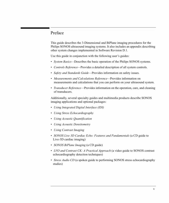
This guide describes the 3-Dimensional and BiPlane imaging procedures for the Philips SONOS ultrasound imaging systems. It also includes an appendix describing other system changes implemented in Software Revision D.1.
Use this guide in conjunction with the following user�s guides:
� System Basics�Describes the basic operation of the Philips SONOS systems.
� Controls Reference�Provides a detailed description of all system controls.
� Safety and Standards Guide�Provides information on safety issues.
� Measurements and Calculations Reference�Provides information on measurements and calculations that you can perform on your ultrasound system.
� Transducer Reference�Provides information on the operation, care, and cleaning of transducers.
Additionally, several specialty guides and multimedia products describe SONOS imaging applications and optional packages:
� Using Integrated Digital Interface (IDI)
� Using Stress Echocardiography
� Using Acoustic Quantification
� Using Acoustic Densitometry
� Using Contrast Imaging
� SONOS Live 3D Cardiac Echo: Features and Fundamentals (a CD guide to Live-3D cardiac imaging)
� SONOS BiPlane Imaging (a CD guide)
� LVO and Contrast CK: A Practical Approach (a video guide to SONOS contrast echocardiography detection techniques)
� Stress Audio CD (a spoken guide to performing SONOS stress echocardiography studies)
v

Conventions Used in This Guide
The following conventions are used in this guide:
� Touch control and rotary control names appear in bold text. For example, Acquire Loop.
� The names of the function keys on the system keyboard appear in a box. For example, .
Foot Switch Warning
The SONOS foot switch is not approved for use in operating-room environments.
Enter
WARNING
vi

0Some SONOS System Changes for Software Revision D.1
This section describes some changes that were made to the SONOS 7500 system for software Revision D.1 (other than the changes made to Live 3D, Full Volume, 3D Color, and BiPlane functions). Changes to the Live-3D, Full Volume, 3D Color, and BiPlane functions are described elsewhere in this manual.
The following material is covered in this section:
� Maximum Live 3D frame rate� Report to Serial Pt control� Disk Space control� IDI beeps � Password access to full test mode� Network utilities access through full test mode
Maximum Live 3D frame rate
The maximum Live 3D frame rate increased from 21 Hz to 28 Hz. This improved frame rate can be observed at depths of 10 cm or less.
Report to Serial Pt control
When set to On, the Report to Serial Port touch control sends analysis reports to a device connected to the system�s serial port. When set to Off, the control sends analysis reports to a selected printer.
Type: Touch control toggle
Location: > System > Report to Serial Pt control on right primary touch panel
Values: On/Off
In prior software revisions, this functionality was accessed through the Analysis > Serial Output control.
Setup
NOTE
vii

Disk Space control
The Disk Space touch control displays the amount of space available on the disk and the approximate number of 1-beat loops that may be stored in the remaining space.
This control is not available for the Live-3D disk drive, which uses different storage displays.
Type: Touch control
Location: Disk > Disk Space control on left touch panel
IDI beeps
During IDI processes, the system beeps to indicate that
� IDI processes are running.
� Image files are stored.
� Study transfers are complete.
Password access to full test mode
Access to system information, such as serial number, configuration, and software revision, is available without entering a password. However, access to full test and configuration modes requires a valid user name and password in the Test Mode Login screen. This opens access to the full SONOS test menu.
Single-day passwords may be obtained at the discretion of the Philips customer-service representative. One can also obtain permanent access by purchasing a separate software option.
Network utilities access through test mode
The Test Mode Login screen now permits access to SONOS network utilities. To access these utilities, select Network Utility in the Login Dialog box.
In prior software revisions, network utilities were accessed through > Other Tests & Utilities.
NOTE
NOTE TEST
viii

ContentsContents
Preface . . . . . . . . . . . . . . . . . . . . . . . . . . . . . . . . . . . . . . . . . . . . . . . . vConventions Used in This Guide . . . . . . . . . . . . . . . . . . . . . . . . . viFoot Switch Warning . . . . . . . . . . . . . . . . . . . . . . . . . . . . . . . . . . vi
Some SONOS System Changes for Software Revision D.1 . . . . . . viiMaximum Live 3D frame rate. . . . . . . . . . . . . . . . . . . . . . . . . . . . viiReport to Serial Pt control. . . . . . . . . . . . . . . . . . . . . . . . . . . . . . . viiDisk Space control . . . . . . . . . . . . . . . . . . . . . . . . . . . . . . . . . . . viiiIDI beeps . . . . . . . . . . . . . . . . . . . . . . . . . . . . . . . . . . . . . . . . . . . viiiPassword access to full test mode . . . . . . . . . . . . . . . . . . . . . . . . viiiNetwork utilities access through test mode. . . . . . . . . . . . . . . . . viii
Chapter 1 Introduction
3-Dimensional and BiPlane Imaging Overview . . . . . . . . . . . . . . . 1-1
Introducing the x4 Matrix Array Transducer . . . . . . . . . . . . . . . . . . 1-2
x4 Matrix Transducer Autocool . . . . . . . . . . . . . . . . . . . . . . . . . 1-3
Introducing Live 3D Echo Imaging . . . . . . . . . . . . . . . . . . . . . . . . . 1-5
3D Zoom . . . . . . . . . . . . . . . . . . . . . . . . . . . . . . . . . . . . . . . . . . . 1-5
Introducing Full Volume Acquisition . . . . . . . . . . . . . . . . . . . . . . . 1-6
Introducing 3D Color Imaging . . . . . . . . . . . . . . . . . . . . . . . . . . . . 1-7
Introducing BiPlane Imaging . . . . . . . . . . . . . . . . . . . . . . . . . . . . . . 1-8
BiPlane Color . . . . . . . . . . . . . . . . . . . . . . . . . . . . . . . . . . . . . . . 1-8
Using Dual Triggering . . . . . . . . . . . . . . . . . . . . . . . . . . . . . . . . . . . 1-9
Shutting Down the System. . . . . . . . . . . . . . . . . . . . . . . . . . . . . . . 1-10
Foot Switch Warning . . . . . . . . . . . . . . . . . . . . . . . . . . . . . . . . . . . 1-11
Contents-ix

Contents
Chapter 2 Live 3D Echo Imaging
Live 3D Imaging at a Glance . . . . . . . . . . . . . . . . . . . . . . . . . . . . . . 2-1
Live 3D Echo Imaging Overview . . . . . . . . . . . . . . . . . . . . . . . . . . 2-2
Live 3D Controls . . . . . . . . . . . . . . . . . . . . . . . . . . . . . . . . . . . . . . . 2-3
Live 3D Control Descriptions . . . . . . . . . . . . . . . . . . . . . . . . . . . 2-4
Understanding Line Density . . . . . . . . . . . . . . . . . . . . . . . . . . . . 2-7
Setting the line density . . . . . . . . . . . . . . . . . . . . . . . . . . . . 2-8
Using Live 3D . . . . . . . . . . . . . . . . . . . . . . . . . . . . . . . . . . . . . . . . 2-10
Creating a Live 3D Preset . . . . . . . . . . . . . . . . . . . . . . . . . . . . . 2-10
Acquiring a Live 3D Image. . . . . . . . . . . . . . . . . . . . . . . . . . . . 2-12
Storing Live 3D Images to Disk . . . . . . . . . . . . . . . . . . . . . . . . 2-13
Using 3D Zoom. . . . . . . . . . . . . . . . . . . . . . . . . . . . . . . . . . . . . 2-14
Full Volume Overview. . . . . . . . . . . . . . . . . . . . . . . . . . . . . . . . . . 2-17
Full Volume Controls . . . . . . . . . . . . . . . . . . . . . . . . . . . . . . . . 2-18
Acquiring a Triggered Full Volume Image. . . . . . . . . . . . . . . . 2-21
Acquiring a Nontriggered Full Volume Image . . . . . . . . . . . . . 2-23
3D Color Overview . . . . . . . . . . . . . . . . . . . . . . . . . . . . . . . . . . . . 2-25
3D Color Image Preview. . . . . . . . . . . . . . . . . . . . . . . . . . . . . . 2-26
Sample screen and touch panels . . . . . . . . . . . . . . . . . . . . 2-26
Control descriptions . . . . . . . . . . . . . . . . . . . . . . . . . . . . . 2-27
Using 3D Color preview . . . . . . . . . . . . . . . . . . . . . . . . . . 2-30
3D Color Image Acquisition . . . . . . . . . . . . . . . . . . . . . . . . . . . 2-30
3D Color Image Review . . . . . . . . . . . . . . . . . . . . . . . . . . . . . . 2-31
Sample screen and touch panels . . . . . . . . . . . . . . . . . . . . 2-31
Control descriptions . . . . . . . . . . . . . . . . . . . . . . . . . . . . . 2-32
Contents-x

Contents
Cropping 3D Images . . . . . . . . . . . . . . . . . . . . . . . . . . . . . . . . . . . 2-36
Crop Box . . . . . . . . . . . . . . . . . . . . . . . . . . . . . . . . . . . . . . . . . . 2-36
Accessing the crop box . . . . . . . . . . . . . . . . . . . . . . . . . . . 2-38
Using the crop box . . . . . . . . . . . . . . . . . . . . . . . . . . . . . . 2-39
Arbitrary Crop Plane . . . . . . . . . . . . . . . . . . . . . . . . . . . . . . . . . 2-40
Accessing the arbitrary crop plane . . . . . . . . . . . . . . . . . . 2-40
Using the arbitrary crop plane . . . . . . . . . . . . . . . . . . . . . . 2-42
Saving Images . . . . . . . . . . . . . . . . . . . . . . . . . . . . . . . . . . . . . . . . 2-44
3D Loop Display . . . . . . . . . . . . . . . . . . . . . . . . . . . . . . . . . . . . . . 2-45
Sample Screen and Touch Panels . . . . . . . . . . . . . . . . . . . . . . . 2-45
Control Descriptions . . . . . . . . . . . . . . . . . . . . . . . . . . . . . . . . . 2-46
Subpages . . . . . . . . . . . . . . . . . . . . . . . . . . . . . . . . . . . . . . . . . . 2-48
Setup Controls for Live 3D Imaging . . . . . . . . . . . . . . . . . . . . . . . 2-49
Chapter 3 Live BiPlane Imaging
Live BiPlane Imaging at a Glance . . . . . . . . . . . . . . . . . . . . . . . . . . 3-1
Live BiPlane Overview . . . . . . . . . . . . . . . . . . . . . . . . . . . . . . . . . . 3-2
Lateral Tilt. . . . . . . . . . . . . . . . . . . . . . . . . . . . . . . . . . . . . . . . . . 3-3
Elevation Tilt. . . . . . . . . . . . . . . . . . . . . . . . . . . . . . . . . . . . . . . . 3-4
BiPlane Color and BiPlane Zoom Overview . . . . . . . . . . . . . . . 3-5
BiPlane Controls . . . . . . . . . . . . . . . . . . . . . . . . . . . . . . . . . . . . . . . 3-6
Acquiring a BiPlane Image . . . . . . . . . . . . . . . . . . . . . . . . . . . . . . . 3-9
Contents-xi

Contents
Chapter 4 Managing Images
Managing Live 3D Echo Images . . . . . . . . . . . . . . . . . . . . . . . . . . . 4-1
3D Hard Disk Capacity . . . . . . . . . . . . . . . . . . . . . . . . . . . . . . . . 4-2
3D Hard Disk Retrieval. . . . . . . . . . . . . . . . . . . . . . . . . . . . . . . . 4-2
Storing Live 3D Images . . . . . . . . . . . . . . . . . . . . . . . . . . . . . . . 4-3
Storing images on the 3D hard disk . . . . . . . . . . . . . . . . . . 4-3
Storing images to a CD-R . . . . . . . . . . . . . . . . . . . . . . . . . . 4-4
Storing images as AVI files . . . . . . . . . . . . . . . . . . . . . . . . 4-7
Retrieving Live 3D Images from the 3D Hard Disk . . . . . . . . . . 4-8
Deleting Live 3D Files from the 3D Hard Drive . . . . . . . . . . . 4-11
Managing BiPlane Images . . . . . . . . . . . . . . . . . . . . . . . . . . . . . . . 4-14
Chapter 5 Gated, Sequential 3D Imaging
Gated, Sequential 3D at a Glance . . . . . . . . . . . . . . . . . . . . . . . . . . 5-1
Gated Sequential 3D Controls . . . . . . . . . . . . . . . . . . . . . . . . . . . . . 5-2
Setup Controls . . . . . . . . . . . . . . . . . . . . . . . . . . . . . . . . . . . . . . . . . 5-4
Optical Disk Setup Controls . . . . . . . . . . . . . . . . . . . . . . . . . . . . 5-5
Preset Controls . . . . . . . . . . . . . . . . . . . . . . . . . . . . . . . . . . . . . . 5-5
3D Protocols. . . . . . . . . . . . . . . . . . . . . . . . . . . . . . . . . . . . . . . . . . . 5-6
Setting Up for a Gated Sequential 3D Acquisition . . . . . . . . . . . . . 5-7
Conducting a Gated Sequential 3D Acquisition . . . . . . . . . . . . . . 5-13
Using Review Mode . . . . . . . . . . . . . . . . . . . . . . . . . . . . . . . . . . . 5-18
Retrieving a Gated Sequential 3D Study from Disk . . . . . . . . . . . 5-20
3D Imaging Tips and Troubleshooting . . . . . . . . . . . . . . . . . . . . . 5-22
Contents-xii

Chapter 1 Introduction
INTRO
DU
CTIO
N
3-Dimensional and BiPlane Imaging Overview
This guide includes information on 3-Dimensional (3D) and BiPlane imaging. Live 3D imaging is the real-time acquisition and rendering of ultrasound data. Full Volume, 3D Color, and 3D Zoom further enhance your ability to investigate 3D anatomy and function. BiPlane imaging allows the display of two views simultaneously. You can use previously existing controls as they are used during 2D imaging.
The acoustic data for the imaging methods described in chapters 1, 2, 3, and 4 is obtained using the x4 Matrix array transducer.
If ECG leads are attached to the patient, ECG waveforms may be displayed and stored with forward-acquired ECG loops. These loops include Live 3D, 3D Zoom, Full Volume, and 3D Color.
The ECG is not displayed during Live 3D modes or during acoustic replay (freeze and replay) for Live 3D.
For more information about setting up and collecting ECG waveforms, see the System Basics chapter �Physios.�
NOTE
1-1

IntroductionIntroducing the x4 Matrix Array Transducer
Introducing the x4 Matrix Array Transducer
The x4 Matrix array transducer technology enables Live 3D and BiPlane imaging by allowing the ultrasound beam to be steered in both the lateral direction (left or right like a sector transducer) and the elevation direction (front to back). This allows rapid acquisition of BiPlane or volume data without moving the transducer. The x4 transducer is optimized for the high frame rates typically used in cardiac ultrasound.
The following illustration shows the three axes in which the x4 transducer sends and receives acoustic data.
The matrix transducer has several coefficient tables for transmit and receive parameters. These coefficient tables use large amounts of memory and may be loaded when:
� The system is powered up and the x4 transducer is activated
� The density is changed
The tables also may be recalculated after a software upgrade.
x4 x4 x4
Lateral ElevationDepth
1-2ahb C:\WINDOWS\Desktop\Philips\D.1\D.1 3D Book

IntroductionIntroducing the x4 Matrix Array Transducer
The following dialog box is displayed whenever loading is necessary, showing the progress of the calculation.
If you press Postpone, the loading of coefficients is canceled, but can be done later when modes requiring those coefficients are used.
For more information about x4 transducer technology, see the Reference Manual, Transducer Reference.
x4 Matrix Transducer Autocool
If the x4 Matrix transducer reaches a computed temperature of 42.0° C (107.6° F) during imaging, imaging continues, but the following message appears:
If the x4 Matrix transducer reaches a computed temperature of 42.5° C (108.5° F) during imaging, imaging stops and the following message appears.
When the x4 Matrix transducer temperature drops below 40.5° C (104.9° F), the system resumes imaging.
Preparing Scanner.
Postpone
Autocool Warning
Autocool Active
1-3

IntroductionIntroducing the x4 Matrix Array Transducer
At temperatures above 47.7° C, if autocool detection fails, or if the transducer connector is not seated properly, the following message appears.
Reconnect the Transducer, thenpress Reset. If problem persists, contact your Philipsservice representative.
1-4ahb C:\WINDOWS\Desktop\Philips\D.1\D.1 3D Book

IntroductionIntroducing Live 3D Echo Imaging
Introducing Live 3D Echo Imaging
Live 3D Echo is an integrated feature that acquires and renders 3-dimensional acoustic data in real time. Because a Live 3D image is a volume of data, more information is obtained than in a typical 2D image. You can rotate the volume by using the trackball, and enhance the image with the traditional 2D controls as well as the new 3D controls. Harmonic imaging is also available.
If ECG leads are attached to the patient, ECG waveforms may be displayed and stored with forward-acquired ECG loops. These loops include Live 3D, 3D Zoom, Full Volume, and 3D Color.
The ECG is not displayed during Live 3D modes or during acoustic replay (freeze and replay) for Live 3D.
For more information about setting up and collecting ECG waveforms, see the System Basics chapter �Physios.�
3D Zoom
The 3D Zoom Preview and keys and the 3D Zoom display modes operate similarly to 2D zoom modes. You can use 3D Zoom to view a smaller volume of interest in greater detail. The preview box moves in the lateral and depth dimensions. You can change the size of the zoom box in the depth dimension.
The elevation and lateral dimensions of the zoom box are fixed, but can be changed indirectly using the High Density control in the secondary touch panel.
In Zoom mode, two reference images are available to maintain orientation and perspective:
� The left reference image is the lateral plane and is fixed in elevation. This displays the transducer�s current imaging plane.
� The right image displays the elevation plane and is fixed in the lateral dimension.
The Reference Image data is not calibrated. Do not make measurements from the Reference Images.
For more information, see Chapter 2, �Live 3D Echo Imaging.�
NOTE
Size Position
NOTE
NOTE
1-5

IntroductionIntroducing Full Volume Acquisition
Introducing Full Volume Acquisition
Full Volume is a mode in which four subvolumes are compiled to create a larger volume of 3-dimensional information. The system uses either ECG triggering or no triggering for the Full Volume acquisition cycle. Triggered acquisition is used for non-static anatomy. In triggering mode, the system gathers four different subvolumes and combines them into one volume. Nontriggered acquisition is used to acquire images of static objects, and one frame per subvolume is acquired.
Any triggered acquisition mode has the potential for temporal artifacts. Due to the triggered nature of a Full Volume acquisition, temporal artifacts might occur due to fast moving structures, rapidly changing flow patterns, respiration, or probe movement.
If ECG leads are attached to the patient, ECG waveforms may be displayed and stored with forward-acquired ECG loops. These loops include Live 3D, 3D Zoom, Full Volume, and 3D Color.
The ECG is not displayed during Live 3D modes or during acoustic replay (Freeze and Replay) for Live 3D.
For more information about setting up and collecting ECG waveforms, see the System Basics chapter �Physios.�
For more information, see Chapter 2, �Live 3D Echo Imaging.�
NOTE
NOTE
1-6ahb C:\WINDOWS\Desktop\Philips\D.1\D.1 3D Book

IntroductionIntroducing 3D Color Imaging
Introducing 3D Color Imaging
3D Color mode uses the Doppler shift to detect velocities in a 3-dimensional anatomical volume. As in 2D color-flow imaging, this additional information helps to assess general blood flow properties.
3D Color combines seven triggered subvolumes into a larger volume color image. This volume can be rotated and cropped along multiple planes, allowing you to see blood flow from several perspectives, as well as relative to tissue and walls. In cardiac applications, the acquisition is synchronized with the R-wave so that the subvolumes are time-aligned for the final rendered image.
� No velocity or geometry measurements are available in 3D Color mode. Velocities displayed are average projected velocities, and are not necessarily indicative of flow velocities displayed in 2D color-flow imaging. 3D Color velocities, therefore, differ from what you might see in 2D Color images.
� Any triggered acquisition mode has the potential for temporal artifacts. In triggered 3D Color acquisition, temporal artifacts might occur due to fast moving structures, rapidly changing flow patterns, respiration, or probe movement.
NOTE
1-7

IntroductionIntroducing BiPlane Imaging
Introducing BiPlane Imaging
BiPlane imaging allows for simultaneous side-by-side viewing of two separate live 2D images and takes advantage of the 2-dimensional array in the x4 Matrix transducer. This allows you to see cardiac function from two simultaneous live image planes.
The default view is two images perpendicular to each other. The left image is the lateral plane and displays the current 2D transducer image plane (conventional orientation). The left image is fixed and cannot be adjusted for rotation or tilt. The right image is the elevation plane and is initially perpendicular to the left image. You can rotate and tilt the right image in reference to the left image as follows:
� 360o rotation of right image (during rotation, all tilts are zeroed)
� Lateral tilt at 90o rotation
� Elevation tilt at 0o rotation
BiPlane mode also supports Zoom, which allows for detailed investigation of anatomy. For more information on Zoom mode, see Chapter 3, �Live BiPlane Imaging.�
BiPlane Color
Color flow imaging is supported in BiPlane mode. BiPlane color flow imaging appears in the color box on each of the two images. The behavior of the color box on the left image is the same as in 2D Color mode. In most imaging modes, you use the
and keys in conjunction with the trackball to resize or reposition the color box on the image. Except in elevation tilt, the box on the right image tracks the left color box vertically, but does not move left or right because the color boxes together define a contiguous color volume. In elevation tilt, however, the boxes in both images move together.
For more information see Chapter 3, �Live BiPlane Imaging.�
Size Position
1-8ahb C:\WINDOWS\Desktop\Philips\D.1\D.1 3D Book

IntroductionUsing Dual Triggering
Using Dual Triggering
Dual triggering lets you set two triggered acquisition points anywhere in the cardiac cycle. Dual triggering can be used in Full Volume and 3D LVO imaging modes. In these modes, two individual frames are captured and processed for each subvolume of the image.
For more information about dual triggering, see the SONOS 7500/5500 Controls Reference.
1-9
IntroductionShutting Down the System
Shutting Down the System
When you turn off the main power switch on the SONOS system, there is a short delay while the 3D PC shuts down. After the 3D PC shuts down, the system shuts down.
If you disconnect the power cord before the system shutdown is complete, the PC may not shut down properly.
To shut down the system:
� Turn the main power switch off and leave it in the off position for more than three seconds.
The following message appears:
PLEASE WAIT WHILE THE SYSTEM SHUTS DOWN
After approximately 25 seconds, the 3D PC shuts down. Approximately 15 seconds later, the SONOS system completes shutdown.
Do not unplug the system before shutdown ends. Doing so may cause data loss or corrupt the hard disk, damages that may not be covered by the system warranty.
If you turn the main power switch back on within three seconds after turning it off, the shutdown stops. The system and 3D PC remain on.
While the SONOS system displays the shutdown message, it ignores further changes to the main power switch, and shutdown completes. If you set the power switch to on while the shutdown message is displayed, both the system and PC power up immediately after shutdown completes.
For detailed information about system power, see the Reference Manual, System Basics and Safety and Standards.
CAUTION
WARNING
NOTE
NOTE
1-10ahb C:\WINDOWS\Desktop\Philips\D.1\D.1 3D Book

IntroductionFoot Switch Warning
Foot Switch Warning
In image preview mode, the function key and Acquire foot switch behave the same as the Acquire touch control.
The SONOS foot switch is not approved for use in operating-room environments.
Acquire
WARNING
1-11

IntroductionFoot Switch Warning
1-12ahb C:\WINDOWS\Desktop\Philips\D.1\D.1 3D Book

Chapter 2 Live 3D Echo Imaging
INTRO
DU
CTIO
N
Live 3D Imaging at a Glance
Density
Acoustic
Transducername
Depth
Preset
MI:0.9X4
7 APR 200312:07:44A/5/F3Philips Medical SystemsAdult
3D GAIN 423D COMP 50
16 CM20 HZ
T
R4
P2
output index
selection
Icon
rateFrame
2-1

Live 3D Echo ImagingLive 3D Echo Imaging Overview
Live 3D Echo Imaging Overview
Live 3D Echo imaging enables the capture of 3D images and volume rendering on the SONOS system. Using the x4 matrix transducer, Live 3D Echo images are acquired and displayed. After acquiring the images, you can optimize and manipulate them to view the anatomy of interest. You can then store the acquired images to the 3D hard disk.
If ECG leads are attached to the patient, ECG waveforms may be displayed and stored with forward-acquired ECG loops. These loops include Live 3D, 3D Zoom, Full Volume, and 3D Color.
The ECG is not displayed during Live 3D modes or during acoustic replay (freeze and replay) for Live 3D.
For more information about setting up and collecting ECG waveforms, see the System Basics chapter �Physios.�
Live 3D Echo imaging display modes include:
� Live 3D
� 3D Zoom
� Full Volume
� 3D Color
NOTE
2-2ahb C:\WINDOWS\Desktop\Philips\D.1\D.1 3D Book

Live 3D Echo ImagingLive 3D Controls
Live 3D Controls
To activate Live 3D imaging:� Touch Live 3D on the right touch panel.
The Live 3D primary touch controls appear.
To display additional 3D controls:� Touch Secondary Controls on the right touch panel.
The 3D secondary controls appear:
The Gain and Compress dedicated rotary controls on the SONOS keyboard are also important for optimizing Live 3D images.Many Live 3D controls are named the same as 2D imaging controls. But Live 3D controls may be used slightly differently, as described in the following tables.
Color
Secondary Controls
2D
Live3D
FullVolume
BiPlane Zoom
3DHome
Frequency Fusion 1 Focus
3D VisionA
XRESOff
Magnify100
HarmonicFusion
U/DInvert
2D
SecondaryControls
Reference Images
3DHome
3D Swivel
HighDensity
Reset Cropping
AutoCrop Colorize Shading
Crop AdjOff
Smoothing5
Power0.0 dB
Brightness50
NOTE
2-3

Live 3D Echo ImagingLive 3D Controls
Live 3D Control Descriptions
The following table describes the Live 3D controls:
=
Control Name Description
3D Color Turns on 3D Color preview.
3D Home Sets the volume viewing angle to Home�the original transducer orientation.
3D Swivel When 3D Swivel is toggled on, it oscillates the rendered volume to improve 3D visualization. The volume stops oscillating if you use the trackball to rotate or tilt it, but then resumes oscillating from its new position.
To access this control, use the Live 3D secondary controls. The control is also available in Loop Display on the right touch panel.
NOTE: AVI images can be stored with 3D Swivel activated in the images.
3D Vision Controls predefined combinations of contrast, transparency, lighting, and compositing algorithms in the rendered 3D image.
Acquire Starts image acquisition.
When you are in Preview mode, the Acquire function key and Acquire foot switch behave the same as the touch control.
WARNING: The SONOS foot switch is not approved for use in operating-room environments.
Auto Crop Activates the crop box controls and suppresses the front part of the 3D image.
Brightness Adjusts the overall brightness of the rendered image.
Cancel Allows you to cancel a Full Volume acquire. The Cancel key appears after you press the Acquire key.
Colorize Optimizes contrast resolution by activating a colorization map that overlays the grayscale image.
2-4ahb C:\WINDOWS\Desktop\Philips\D.1\D.1 3D Book

Live 3D Echo ImagingLive 3D Controls
Compress(dedicated rotary control)
In all 3D modes, Compress mimics the 2D effect. At low Compress settings, the 3D grayscale image has more contrast, with increased delineation between myocardial surfaces and the blood pool. At high Compress settings, the 3D grayscale image takes on a softer look (more grays), and the delineation between tissue and blood is not as abrupt.
NOTE: Unlike in 2D imaging, this control continues to operate after acquisition (in 3D Loop Review).
Crop Adj Selects the type of tool (Box, Plane, or Off) used for cropping.
Delay Sets the amount of time between the R-wave trigger and the start of each sub-volume acquisition in Full Volume and 3D Color modes. Delay is in 5 millisecond intervals.
ECG Trigger Selects whether to use ECG triggering (on) or nontriggered (off) acquisition in Full Volume and 3D Color modes. Works in conjunction with the Delay control.
NOTE: If ECG Trigger is Off, then an ECG is not required for an acquisition.
Focus Repositions the acoustic depth of the focal zone, which is indicated by a caret.
Frequency Fusion Optimizes frequencies for penetration, texture, or resolution.
Full Cycle When Full Cycle is toggled on, data is acquired over the entire R-R interval in Full Volume and 3D Color modes. After acquisition of the subvolume is complete, preparation is made for the next subvolume acquisition. This results in a non-consecutive beat acquisition cycle.
When Full Cycle is toggled off, data is acquired in consecutive R-wave triggered beats. Variations may result in skipped beats.
NOTE: Full Cycle trades off acquisition time (number of beats) versus number of frames captured.
NOTE: The SONOS system automatically switches to Full Cycle mode when the patient�s heart rate reaches or exceeds 80 bpm.
Control Name Description
2-5

Live 3D Echo ImagingLive 3D Controls
Full Volume Turns Full Volume Preview mode on or off.
Gain(dedicated rotary control)
In Live 3D imaging, Gain should be set to show both valvular structures and surrounding tissue.
� If Gain is set too high, tissue in front becomes too bright to see inside the chamber.
� If Gain is set too low, the image becomes more black-and-white, loses detail, and contains imaging holes.
A good way to set Gain is to set it slightly high and lower it until you see both valves and surrounding tissue.
NOTE: Unlike in 2D imaging, this control continues to operate after acquisition (in 3D Loop Review).
High Density Sets the size of the volume to be displayed by adjusting the line density. Size is set separately for Live 3D, Live 3D Zoom, Full Volume, and 3D Color.
Live 3D Activates Live 3D mode.
Magnify Adjusts the size of the rendered image by percentage of the default display size.
Power Sets acoustic output power.
Reference Images Displays a pair of fixed 2D reference images derived from the center of the volume. The left image orientation is the same as the conventional 2D imaging plane. The right image is on a plane that is orthogonal to both the left image and the transducer face.
Reset Cropping Redisplays the original uncropped volume and turns off the cropping controls.
Rotate Volume When on, allows you to use the trackball to rotate volume images. When off, in cine loop display mode, allows you to scroll through the cine loop image or adjust loop speed.
Shading Adjusts the shading recipe applied to the rendered image to improve the depth perception.
Smoothing Averages voxels (volume pixels) to adjust the smoothing or filtering recipe that is applied to the rendered image.
Control Name Description
2-6ahb C:\WINDOWS\Desktop\Philips\D.1\D.1 3D Book

Live 3D Echo ImagingLive 3D Controls
Understanding Line Density
The size of the image is related to its resolution on the screen. The smaller the image size, the greater the resolution of the image. The line density state (high, medium, or low) determines the volume of the image displayed. The higher the density, the smaller the image volume.
The line density resulting from each combination of Low Density and High Density control settings is as follows:
Live 3D mode does not support �low� line density. Full Volume, 3D Zoom, and 3D Color modes do support �low� line density. Setting the density in Live 3D does not change the density setting in Full Volume, 3D Zoom, or 3D Color modes. Whatever density you choose for 3D Zoom is also set for Full Volume, 2D Color, and vice versa.
� The Low Density control is activated through and controls the line density used when the High Density control is off.
� Lower line densities may compromise color sensitivity.
U/D Invert Controls the up-down orientation of the 3D rendered image. When ON (inverted orientation) 3D Home maintains the inverted orientation. The volume is rotated 180° around the elevation axis.
XRES Improves tissue texture and better defines margins and borders.
Zoom Magnifies an area of interest within the zoom volume.
High Density setting
Off On
Low Density setting
Off medium high
On low high
Control Name Description
NOTE Setup
2-7

Live 3D Echo ImagingLive 3D Controls
The following table shows the meaning of the density icons that appear on the SONOS screen.
Setting the line density
The matrix transducer has several coefficient tables for transmit and receive parameters. These coefficient tables use large amounts of memory and must be loaded when you change the line density setting.
To change the density from �medium� to �high� in Live 3D:
� Touch High Density on the right touch panel.
The following message appears while the system changes settings:
The �Preparing Scanner� message may not appear immediately, but will appear later when you access a mode that requires the scanner to prepare.
Icon Description
When High Density is on, a smaller volume size with higher resolution is displayed. This is the density setting when the High Density touch control is highlighted.
When High Density is off, a larger volume size with lower resolution is displayed. This density is in effect when the High Density touch control is not highlighted and Low Density is off.
When High Density is off and Low Density is on, the largest volume available and the lowest resolution is displayed.
Preparing Scanner.
NOTE
2-8ahb C:\WINDOWS\Desktop\Philips\D.1\D.1 3D Book

Live 3D Echo ImagingLive 3D Controls
To set low density for Full Volume or 3D Zoom modes:
1 Press .
2 Touch Live 3D on the right touch panel.
3 Touch Low Density on the right touch panel.
If High Density is already turned off, the �Preparing Scanner� message appears while the system changes to low density.
Setup
2-9

Live 3D Echo ImagingUsing Live 3D
Using Live 3D
Before you begin acquiring Live 3D images, you may want to create a preset to use when acquiring. For details on creating and saving presets, see the Reference Manual, System Basics. After you have created your preset, you can use it to acquire Live 3D images.
Creating a Live 3D Preset
Philips recommends that you create a Live 3D preset with the following settings in the Comment system menus:
� Disk Autostore off�To control how studies are stored on the 3D hard disk and to avoid filling the disk too quickly.
� Auto Comment off�For flexibility in writing comments for stored studies.
� Comment Options set to Manual Entry�For flexibility in writing comments for stored studies.
Since protocols vary between labs, check with your lab administrator before creating or customizing the Live 3D preset.
To create a Live 3D preset:
1 Select the Adult and Cardiac presets.
2 On the left touch panel, touch Loop and deselect Disk Autostore to turn it off.
3 Touch Disk and press .
NOTE
Setup
2-10ahb C:\WINDOWS\Desktop\Philips\D.1\D.1 3D Book

Live 3D Echo ImagingUsing Live 3D
4 Touch Comment Options.
The Disk Storage Comment Options screen appears.
a. Select Manual Entry for the Storage Comment Type.b. Deselect Automatic Commenting.c. Select OK and press .
5 Press and touch Preset on the left touch panel.
6 Touch Save Preset.
The Save Preset screen appears.
7 Select Create New and press .
8 In the screen that appears, type a name for the preset, select Okay, and then press .
Disk Storage Comment Options
Storage Comment Type
Exam-Type List
System Generate
Manual Entry
Automatic CommentingComment Auto-Advance
View Exam Comments
Okay Cancel
Enter
Setup
Save Preset
Active Exam Type: CardiacActive Preset Type: AdultActive Preset Name: Adult
Create New
Modify Current Cancel
Enter
Enter
2-11

Live 3D Echo ImagingUsing Live 3D
Acquiring a Live 3D Image
Before you begin to acquire a Live 3D image:
1 Select the x4 transducer.
2 Attach ECG leads to the patient (to add ECG waveforms to acquired image files).
3 Set the system to the correct preset.
For more information about setting up the system, see the Reference Manual, System Basics.
Creating a 3D image requires many steps. Finding the best settings will take experience in your imaging environment. Use the following procedure as a guideline to help optimize image quality.
1 Obtain an optimal 2D image.
2 Touch Live 3D.
3 Use the trackball to rotate the image to the view you want.
4 Beginning with the defaults, use the 3D touch controls to optimize the image as needed:
If you want to � Then �
adjust image grays adjust the Compress
improve the visualization of the tissue or adjust the 3-dimensional appearance of the image
adjust the Gain
use predefined combinations of settings to obtain an optimal image
choose a 3D Vision setting
improve the depth perception turn Shading on or off
decrease or increase the overall brightness of the image adjust Brightness
increase or decrease the image size adjust Magnify
make the texture of the image appear smoother adjust Smoothing
NOTE
2-12ahb C:\WINDOWS\Desktop\Philips\D.1\D.1 3D Book

Live 3D Echo ImagingUsing Live 3D
5 To acquire an image, do one of the following:
� Touch Acquire Loop.
� Press .
� Press , touch Replay, and then press .
Storing Live 3D Images to Disk
To guarantee being able to recapture what you are seeing in the Live 3D image, store it to the 3D hard disk as follows:
1 Touch Create Subpage on the right touch panel.
2 Touch Disk Store on the left touch panel.
If Disk Autostore is on, the image is automatically stored to the 3D hard disk when the acquire is accepted.
For more information about creating subpages, see �Subpages� on page 2-48. For more information on storing images, see Chapter 4, �Managing Images.�
improve tissue texture and better define margins and borders
adjust XRES
after adjustments, return to the original rotation touch 3D Home
use color to optimize contrast resolution touch Colorize
suppress portions of the image to view inner anatomy crop the image. For details, see page 2-36.
If you want to � Then �
Acquire
Freeze Acquire
NOTE
2-13

Live 3D Echo ImagingUsing Live 3D
Using 3D Zoom
You can access 3D Zoom in two ways:
� In Live 3D mode, touch Zoom.
� In 2D zoom, touch Live 3D. When you access 3D Zoom this way, the zoom size is locked and the size of the 2D zoom image may differ from the size of the Live 3D zoom image.
After you obtain an optimal Live 3D image, use 3D Zoom as follows:
1 In Live 3D mode, touch Zoom.
You are now in Zoom Preview mode. The 3D Zoom box appears on the image and the Zoom touch control outline is highlighted on the touch panel.
2 On entering 3D Preview mode, the control is highlighted, and you can use the trackball to move the zoom box to the region of interest by moving it up and down or side to side.
MI:0.9X4
7 APR 200312:07:44A/5/F3Philips Medical SystemsAdult
3D GAIN 503D COMP 50
16 CM20 HZ
Zoom box
T
R4
P2
Position
2-14ahb C:\WINDOWS\Desktop\Philips\D.1\D.1 3D Book

Live 3D Echo ImagingUsing Live 3D
3 To adjust the size of the volume of interest, press and resize the zoom box vertically. You cannot resize it laterally.
4 Touch Zoom again or press .
As shown in the following illustration, the 3D Zoom volume of interest is displayed with two smaller reference images. The colored lines represent the following:
� Red�lateral axis� Green�elevation axis� Blue�depth axis
The reference images are not calibrated. Do not make measurements from them.
Size
Enter
CAUTION
MI:1.2X47 APR 200312:07:44A/5/F3Philips Medical SystemsAdult
3D GAIN 503D COMP 50
8 CM27 HZ
Represents the transducer�s Represents 90° from the transducer�scurrent 2D imaging plane current 2D imaging plane
Redlateral axis
Greenelevation axis
Blue depth axis
T
R4
P2
2-15

Live 3D Echo ImagingUsing Live 3D
5 Use the trackball to rotate the image to the anatomy of interest.
6 Touch Reference Images to remove them from the screen.
7 Crop the image as needed. For more information on cropping, see page 2-36.
8 Turn the Magnify control to adjust the magnification as needed.
9 To acquire an image, do one of the following:
� Touch Acquire Loop.
� Press .
� Press , touch Replay, and then press .
10 To capture a cropped image, touch Create Subpage on the right touch panel.
11 To store the images to hard disk, touch Disk Store on the left touch panel.
If Disk Autostore is on, the image is automatically stored to the 3D hard disk when is pressed.
For more information about creating subpages, see �Subpages� on page 2-48. For more information about storing images, see Chapter 4, �Managing Images.�
Acquire
Freeze Acquire
NOTEAcquire
2-16ahb C:\WINDOWS\Desktop\Philips\D.1\D.1 3D Book

Live 3D Echo ImagingFull Volume Overview
Full Volume Overview
Full Volume is an acquisition mode that captures acoustic data in subvolumes and combines them to create a larger rendered volume.
If ECG leads are attached to the patient, ECG waveforms may be displayed and stored with forward-acquired ECG loops. These loops include Live 3D, 3D Zoom, Full Volume, and 3D Color.
The ECG is not displayed during Live 3D modes or during acoustic replay (freeze and replay) for Live 3D.
For more information about setting up and collecting ECG waveforms, see the System Basics chapter �Physios.�
There are two Full Volume acquisition modes:� ECG triggered� Nontriggered
In the ECG triggered mode, a series of four subvolumes is acquired. The acquisition is synchronized with the R-wave so that the subvolumes are time-aligned for the final rendered Full Volume. Because of the short acquisition times, you can use a breath-hold technique with most patients for a comprehensive image with minimal spatial or temporal artifacts.
You use the nontriggered mode to image static objects. In the nontriggered mode, a single frame of each subvolume is acquired when you acquire an image.
Full Volume Preview shows fixed BiPlane images to allow for transducer and volume positioning. After Full Volume acquisition is complete, the system automatically enters Loop Display mode and displays the Full Volume image if Auto Display has been turned on in .
For cardiac applications, the acquisition is triggered on the ECG, and the image should be acquired while the patient suspends breathing. The system automatically determines how many frames are needed to acquire the image from R-wave to R-wave.
NOTE
Setup
2-17

Live 3D Echo ImagingFull Volume Overview
You can store a Full Volume loop as a single page or as subpages, with one or more subpages having different image optimizations.
Any triggered acquisition mode has the potential for temporal artifacts. In triggered Full Volume acquisition, temporal artifacts might occur due to fast moving structures, rapidly changing flow patterns, respiration, or probe movement.
Full Volume Controls
To activate Full Volume imaging:
� Touch Full Volume on the right touch panel.
The Full Volume Preview mode is displayed and the Full Volume primary controls appear on the right touch panel.
NOTE
NOTE
Live3D
2D
Color
SecondaryControls
BiPlane FullVolume
Acquire
Frequency Fusion 3
Focus
HarmonicFusion
2-18ahb C:\WINDOWS\Desktop\Philips\D.1\D.1 3D Book
Live 3D Echo ImagingFull Volume Overview
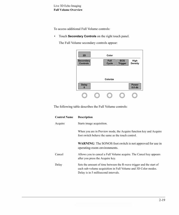
To access additional Full Volume controls:
� Touch Secondary Controls on the right touch panel.
The Full Volume secondary controls appear:
The following table describes the Full Volume controls:
Control Name Description
Acquire Starts image acquisition.
When you are in Preview mode, the Acquire function key and Acquire foot switch behave the same as the touch control.
WARNING: The SONOS foot switch is not approved for use in operating-room environments.
Cancel Allows you to cancel a Full Volume acquire. The Cancel key appears after you press the Acquire key.
Delay Sets the amount of time between the R-wave trigger and the start of each sub-volume acquisition in Full Volume and 3D Color modes. Delay is in 5 millisecond intervals.
High Density
2D
Color
Secondary Controls
FullCycle
ECG Trigger
Delay0
Power0.0 db
Colorize
2-19

Live 3D Echo ImagingFull Volume Overview
ECG Trigger Selects whether to use ECG triggering (on) or nontriggered (off) acquisition in Full Volume and 3D Color modes. Works in conjunction with the Delay control.
NOTE: If ECG Trigger is Off, then an ECG is not required for an acquisition.
Full Cycle When Full Cycle is toggled on, data is acquired over the entire R-R interval in Full Volume and 3D Color modes. After acquisition of the subvolume is complete, preparation is made for the next subvolume acquisition. This results in a non-consecutive beat acquisition cycle.
When Full Cycle is toggled off, data is acquired in consecutive R-wave triggered beats. Variations or very high pulse rates may result in skipped beats.
NOTE: Full Cycle trades off acquisition time (number of beats) versus number of frames captured.
NOTE: The SONOS system automatically switches to Full Cycle mode when the patient�s heart rate reaches or exceeds 80 bpm.
Full Volume Turns Full Volume Preview mode on or off.
Power Sets acoustic output power.
Control Name Description
2-20ahb C:\WINDOWS\Desktop\Philips\D.1\D.1 3D Book

Live 3D Echo ImagingFull Volume Overview
Acquiring a Triggered Full Volume Image
Before acquiring, obtain an optimal 2D image with a stable ECG baseline and prominent R-wave. Acquire the image while the patient is suspending respiration. For details about triggered acquisition, see �Full Volume Overview� on page 2-17.
To acquire a triggered Full Volume image:
1 Touch Full Volume.
The Full Volume Preview mode is activated. The blue dashed lines on the right image show the edges of each subvolume in the Full Volume image. Due to the triggered acquisition, a spatial artifact may appear where the subvolumes are joined for the Full Volume display. Therefore, it is crucial to line up the anatomy of interest between the dashed lines. For example, if you want to view the papillary muscle, position the papillary muscle between the dashed lines.
Orientation Image(transducer plane)
Orthogonal Image(90° from transducer plane)
SubvolumesECG Trace
MI:0.9 X407 APR 03 12:07:44 2/0/D/F3 16CMGAIN 50 COMP 70 30HZ89BPM
Philips MedicalSystemsAdult
T
R4
P2
2-21

Live 3D Echo ImagingFull Volume Overview
2 Make sure ECG Trigger is selected on the right secondary touch panel.
� Turn Delay to select a time delay from trigger to acquisition start.
� Touch Full Cycle to select whether the acquisition duration is Full Cycle or truncated to obtain consecutive beats.
3 Use the standard 2D or Full Volume Preview controls to optimize the image.
4 While the patient suspends breathing, press .
An indicator shows the progress of the acquisition.
To cancel the acquisition, touch Cancel on the right touch panel.
After the subvolumes are acquired, the Full Volume is displayed in cine memory.
When you image fast-moving structures, such as valves, you may experience temporal artifacts in the rendered image. If you see such an artifact, acquire the same image in 3D Zoom mode to determine if it is actually an artifact.
5 To activate the crop box controls and suppress the front part of the 3D image, touch Auto Crop.
6 To return to the original acquired image, touch Reset Cropping.
7 Rotate the volume with the trackball as needed.
8 Use the cropping controls to view the anatomy of interest. For more information about cropping controls, see page 2-36.
9 After you obtain the optimal cropped image, touch Create Subpage on the right touch panel.
The cropped image is stored in cine memory.
10 To store the image to the 3D hard disk, touch Disk Store on the left touch panel.
If Disk Autostore is on, the image is automatically stored to the 3D hard disk when the acquire is accepted.
Acquire
Acquiring 25%
CAUTION
NOTE
2-22ahb C:\WINDOWS\Desktop\Philips\D.1\D.1 3D Book

Live 3D Echo ImagingFull Volume Overview
For more information about creating subpages, see �Subpages� on page 2-48. For more information on storing images, see Chapter 4, �Managing Images.�
If you videotape an image, include the Full Volume Preview image. This can help identify whether an apparent abnormality is an artifact.
Acquiring a Nontriggered Full Volume Image
For additional details about nontriggered acquisition, see �Full Volume Overview� on page 2-17.
To acquire a nontriggered Full Volume image:
1 Touch Full Volume.
The image appears in Full Volume Preview mode. Make sure the part of the image you want to acquire appears between the blue guide lines.
2 If ECG Trigger is selected on the right secondary touch panel, touch it to turn it off.
3 Touch Secondary Controls to return the display to the primary controls on the right touch panel.
4 Use the Live 3D controls to optimize the image.
5 While the patient suspends breathing, press .
An indicator shows the progress of the acquisition.
To cancel the acquisition, touch Cancel on the right touch panel.
After the subvolumes are acquired, the Full Volume is displayed in cine memory.
6 To activate the crop box controls and suppress the front part of the 3D image, touch Auto Crop.
7 To return to the original acquired image, touch Reset Cropping.
NOTE
NOTE
Acquire
Acquiring 25%
2-23

Live 3D Echo ImagingFull Volume Overview
8 Use the cropping controls to view the anatomy of interest. For more information on cropping controls, see page 2-36.
9 After you obtain the optimal cropped image, touch Create Subpage on the right touch panel.
The cropped image is stored in cine memory.
10 To store the image to the 3D hard disk, touch Disk Store on the left touch panel.
If Disk Autostore is on, the image is automatically stored to the 3D hard disk when the acquire is accepted.
For more information about creating subpages, see �Subpages� on page 2-48. For more information about storing images, see Chapter 4, �Managing Images.�
NOTE
2-24ahb C:\WINDOWS\Desktop\Philips\D.1\D.1 3D Book

Live 3D Echo Imaging3D Color Overview
3D Color Overview
3D Color mode uses the Doppler shift to detect velocities in a 3-dimensional anatomical volume. As in 2D color-flow imaging, this additional information helps to assess general blood flow properties.
3D Color combines seven triggered subvolumes into a larger volume color image. This volume can be rotated and cropped along multiple planes, allowing you to see blood flow from several perspectives, as well as relative to tissue and walls.
In cardiac applications, the acquisition is synchronized with the R-wave so that the subvolumes are time-aligned for the final rendered image. You can use a breath-hold technique with most patients for a comprehensive image with minimal spatial or temporal artifacts. The system automatically determines how many frames are needed to acquire the image from R-wave to R-wave.
� No velocity or geometry measurements are available in 3D Color mode. Velocities displayed are average projected velocities, and are not necessarily indicative of flow velocities displayed in 2D color-flow imaging. 3D Color velocities, therefore, differ from what you might see in 2D Color images.
� You can store a 3D Color loop as a single page or as subpages, with one or more subpages having different image optimizations.
� Any triggered acquisition mode has the potential for temporal artifacts. In triggered 3D Color acquisition, temporal artifacts might occur due to fast moving structures, rapidly changing flow patterns, respiration, or probe movement.
NOTE
2-25

Live 3D Echo Imaging3D Color Overview
3D Color Image Preview
Sample screen and touch panels
In the 3D Color preview mode, you manipulate pre-acquisition images using the following controls.
T
R4
P2
MI:0.9 TIS:0.5 X411 APR 03 14:36:172/0/D/M2/A 16CMGAIN 50 COMP 70 10HZ
Philips MedicalSystemsAdult
CM/S
60
2.5MHZ 60
2D
BiPlane
ColorSuppress
Acquire
Baseline
FocusFrequency Fusion 3
Color
SecondaryControls
3DColor
Gain70%
Scale
Filter2
Primary touch panel
2-26ahb C:\WINDOWS\Desktop\Philips\D.1\D.1 3D Book

Live 3D Echo Imaging3D Color Overview
Control descriptions
Control Name Description
Agile(secondary control)
Adjusts the frequency used for color flow imaging.
Baseline Adjusts the baseline level of the color bar.
Color Gain Controls color gain. It is important to adjust 2D Color gain in preview mode where it can improve Signal-to-Noise ratios and Dynamic Range.
NOTE: Use the Gain dedicated rotary control on the SONOS keyboard to adjust only the grayscale image gain.
Delay(secondary control)
Sets the amount of time between the R-wave trigger and the start of each sub-volume acquisition in Full Volume and 3D Color modes. Delay is in 5 millisecond intervals.
High Density
2D
Color
Secondary Controls
FullCycle
ECG Trigger
Agile
Power0.0 dB
MapInvert
Delay0
MapA
Smoothing5
Secondary touch panel
Packet M
2-27

Live 3D Echo Imaging3D Color Overview
ECG Trigger(secondary control)
Selects whether to use ECG triggering (on) or nontriggered (off) acquisition in Full Volume and 3D Color modes. Works in conjunction with the Delay control.
NOTE: If ECG Trigger is Off, then an ECG is not required for an acquisition.
Filter Removes low-level signals (such as flash) and reduces noise in the image.
Focus Repositions the acoustic depth of the focal zone, which is indicated by a caret. The focus tracks the region of interest and affects both grayscale and color components of 2D and 3D images.
Frequency Fusion
This frequency fusion rotary control optimizes transmit frequencies for penetration, texture, or resolution. It also affects 3D grayscale images.
Full Cycle(secondary control)
When Full Cycle is toggled on, data is acquired over the entire R-R interval in Full Volume and 3D Color modes. After acquisition of the subvolume is complete, preparation is made for the next subvolume acquisition. This results in a non-consecutive beat acquisition cycle.
When Full Cycle is toggled off, data is acquired in consecutive R-wave triggered beats. Variations or very high pulse rates may result in skipped beats.
NOTE: Full Cycle trades off acquisition time (number of beats) versus number of frames captured.
NOTE: The SONOS system automatically switches to Full Cycle mode when the patient�s heart rate reaches or exceeds 80 bpm.
High Density(secondary control)
Sets the size of the 3D Color volume to be displayed by adjusting the line density.
NOTE: Trades off volume size versus resolution and sensitivity.
Control Name Description
2-28ahb C:\WINDOWS\Desktop\Philips\D.1\D.1 3D Book

Live 3D Echo Imaging3D Color Overview
� Some 3D Color controls seem similar to those for 2D color, but the two sets of controls function independently. Use both sets of controls to optimize images in their respective imaging modes.
� The following controls are also available and can be used during 3D Color image preview. However, their effect on the preview image does not necessarily translate to the acquired Color 3D image:� Color Suppress� Map� Map Invert� Smoothing
Packet(secondary control)
Selects the color-flow packet size (small, medium, or large), which determines how the system samples and processes color-flow information.
NOTE: Packet size determines the number of acoustic lines in each packet. Increasing the packet size increases the number of lines in each packet. Decreasing the packet size decreases the number of lines in each packet. Packet size trades off color sensitivity versus frame rate.
Power(secondary control)
Sets acoustic output power.
NOTE: Since power can negatively affect sensitivity, it should normally be set at 0.0 dB.
Scale In both 2D and 3D imaging, this control trades off the Pulse Repetition Frequency (PRF), low-velocity sensitivity, frame rate, and aliasing.
Control Name Description
NOTE
2-29

Live 3D Echo Imaging3D Color Overview
Using 3D Color preview
To enhance a 3D Color preview image:
1 Once you obtain an optimized 2D Color image, touch 3D Color on the right touch panel to display the 3D Color preview screen.
As in Full Volume, the image on the left represents the active transducer plane, and the image on the right is at right angles to this active plane.
You can also access 3D Color preview mode from Full Volume, Live 3D, or Live 3D Zoom modes by touching Color in the right touch panel. The Full Volume control then becomes 3D Color.
2 Use the and keys, along with the trackball, to position the 3D Color preview boxes around the anatomy of interest.
You can size the boxes vertically, but not horizontally.
3 Apply the 3D Color preview controls to enhance the image.
3D Color Image Acquisition
When you obtain an optimized 3D Color preview image, you can acquire the 3D Color image in any of the following ways:
� Touch Acquire on the right touch panel.
� Press the key on the keyboard.
� Push down on the Acquire foot switch.
The SONOS foot switch is not approved for use in operating-room environments.
NOTE
Size Position
Acquire
WARNING
2-30ahb C:\WINDOWS\Desktop\Philips\D.1\D.1 3D Book

Live 3D Echo Imaging3D Color Overview
3D Color Image ReviewSample screen and touch panels
In the 3D Color loop display mode, you can manipulate or edit one or more pages of acquired images using the following controls, and then crop and save the images as described in following sections.
MI:0.9 TIS:0.7X4
11 APR 200314:41:10A/5/M3/APhilips Medical SystemsAdult
3D GAIN 503D COMP 50
40BPM
16 CM13 HZ
T
R4
P2
CM/S
60
2.5MHZ 60
Color box
2D
LoopDisplay
ColorControls
ReferenceImages
3DSwivel
3DHome
RotateVolume
XRESOff
Magnify100
ResetCropping
AutoCrop Colorize Shading Create
Subpage
Crop AdjOff
Smoothing5
3D VisionA
Brightness50
Primary touch panel
2-31

Live 3D Echo Imaging3D Color Overview
Control descriptions
Control Name Description
3D Swivel When 3D Swivel is toggled on, it oscillates the rendered volume to improve 3D visualization. The volume stops oscillating if you use the trackball to rotate or tilt it, but then resumes oscillating from its new position.
NOTE: AVI images can be stored with 3D Swivel activated in the images.
2D
LoopDisplay
ColorControls
Filter3
B/WSuppress
ColorSuppress
MapInvert
Gain50%
C Vision1
Smoothing3
Baseline
Color Controls touch panel
2-32ahb C:\WINDOWS\Desktop\Philips\D.1\D.1 3D Book

Live 3D Echo Imaging3D Color Overview
3D Vision The following 3D Vision settings may be used to adjust Live 3D, Zoom, or Full Volume images based on the echogenicity of the patient. These settings should be used in addition to other 3D optimization controls and are not meant to replace them:
A�Optimized for echogenic patients. Has lots of grays.
B�Optimized for average patients, with more emphasis on penetrating through ventricular clutter. The image is more black and white, with less grays and more smoothing.
C�Optimized for difficult-to-image patients, with many of the visual attributes of 3D Vision setting B.
D�Traditional volume rendering with relatively softer images.
NOTE: 3D Vision setting D is not optimized for use in 3D Color applications.
E�Optimized for interventional structures such as catheters. This setting has poor 3D effect because there is no foreground occlusion, but it is good for penetrating through clutter. This setting may be useful for viewing the aortic valve.
F�Provides the best 3D image quality for more echogenic images. It is a high-resolution version of 3D Vision setting A.
Baseline(Color Controls)
Adjusts the baseline level of the color bar just as in 2D color-flow imaging.
NOTE: 3D Color baseline shift is intended for use with the C Vision setting 1 and is not optimized for use with the C Vision settings 2, 3, and 4.
Control Name Description
2-33

Live 3D Echo Imaging3D Color Overview
C Vision(Color Controls)
The following settings provide customized color map and visualization controls. To accommodate 3D depth, velocities are average projected velocities, which may result in display colors that are not shown in the color bar:
1�Uses traditional color-flow mapping to represent blood flow direction and velocity.
2�Enhances visualization of flow direction by overlaying forward and reverse flows. As a result, colors can be produced that are not visible in the color bar. For example, overlapped forward and reverse flows are represented by the color purple.
3�Uses enhanced color mapping for better visualization of depth cues. The color bar represents flow velocity in the blood flow nearest to the viewer. Lighter colors in the image also represent blood flow that is closer to the person viewing the image. Darker (more saturated) colors that are not included in the color bar represent blood flow that is farthest from the person viewing the image.
4�Similar to 2D Power Angio. Uses absolute velocity to represent the structure, size, and position of flow pathologies.
NOTE: This setting mimics the 2D Color Map X and is best used when flow direction is not critical.
Color Controls Toggles between the black-and-white 3D controls and a set of secondary 3D Color cine-loop-display controls.
Color Gain(Color Controls)
Affects color opacity.
NOTE: Use the Gain dedicated rotary control on the SONOS keyboard to adjust only the grayscale image gain.
Compress(Dedicated keyboard rotary)
In all 3D modes, Compress mimics the 2D effect. At low Compress settings, the 3D grayscale image has more contrast, with increased delineation between myocardial surfaces and the blood pool. At high Compress settings, the 3D grayscale image takes on a softer look (more grays), and the delineation between tissue and blood is not as abrupt.
NOTE: Unlike in 2D imaging, this control continues to operate after acquisition (in 3D Loop Review).
Control Name Description
2-34ahb C:\WINDOWS\Desktop\Philips\D.1\D.1 3D Book

Live 3D Echo Imaging3D Color Overview
� Some 3D Color controls seem similar to those for 2D color, but the two sets of controls function independently. Use both sets of controls to optimize images in their respective imaging modes.
� The following controls are also available, and can be used during 3D Color image review:� Brightness� B/W Suppress� Color Suppress� Colorize� Magnify� Map Invert� Reference Images� Rotate Volume� Shading� XRES
Filter(Color Controls)
This wall-filter control trades off low-velocity sensitivity versus Flash suppression during 3D Color review. This control can be used to better isolate high-velocity pathologic flows from normal flows.
Gain(Dedicated keyboard rotary)
Adjusts the amplification of received acoustic signals to adjust the grayscale image gain.
Smoothing(Color Controls)
Averages just the 3D Color voxels (volume pixels) in the image to make its texture appear smoother and its surfaces more uniform.
Control Name Description
NOTE
2-35

Live 3D Echo ImagingCropping 3D Images
Cropping 3D Images
The SONOS system offers two types of 3-dimensional cropping tools:
� Crop box (page 2-36)
� Arbitrary crop plane (page 2-40)
Crop Box
The crop box allows you to suppress the surface of an image along the six planes of the crop box to better visualize structures of interest. You can crop a live image or an acquired image in loop display.
The cropping lines correspond to the three axes in which the x4 transducer transmits and receives acoustic data as shown in the following illustration. For more details about the x4 transducer, see �Introducing the x4 Matrix Array Transducer� on page 1-2.
x4
Lateral axis
Depth axis
Elevation axis
2-36ahb C:\WINDOWS\Desktop\Philips\D.1\D.1 3D Book

Live 3D Echo ImagingCropping 3D Images
When the crop box is on, the active cropping plane is displayed in purple. When the crop box is off, the active cropping plane is displayed in the color of the axis along which it moves, as follows:
� Red�lateral axis
� Green�elevation axis
� Blue�depth axis �
Turn the crop box display on and off in .
Crop Box
Lateral axis
Elevation axis
Depth axis
(Green)
(Red)
(Blue)
MI:0.9X4
7 APR 200312:07:44A/5/F3Philips Medical SystemsAdult
3D GAIN 503D COMP 50
16 CM20 HZ
T
R4
P2
NOTE Setup
2-37

Live 3D Echo ImagingCropping 3D Images
Accessing the crop box
� Turn Crop Adj to Box on the right secondary touch panel.
The following illustration shows the crop box controls:
The following table describes the crop box controls:
Control Name Description
Auto Crop Activates the crop box controls and suppresses the front part of the 3D image.
Crop Adj Selects the type of cropping tool (Box, Plane, or Off).
Reset Cropping Redisplays the original uncropped volume and turns off the cropping controls.
Red Min, Red Max From the original acquisition, adjusts cropping along the lateral axis of the rendered image.
Green Min, Green Max
From the original acquisition, adjusts cropping along the elevation axis of the rendered image.
Blue Min, Blue Max
From the original acquisition, adjusts cropping along the depth axis of the rendered image. (That is, increasing depths away from the probe�s face.)
2D
Color
SecondaryControls
Reference Images
HighDensity
3DHome
RedMin
GreenMin
BlueMin
ResetCropping
AutoCrop Colorize Shading
Crop Adj Box
RedMax
GreenMax
BlueMax
3D Swivel
2-38ahb C:\WINDOWS\Desktop\Philips\D.1\D.1 3D Book

Live 3D Echo ImagingCropping 3D Images
Using the crop box
1 Turn Crop Adj to Box.
The crop box appears if the Crop Box is enabled in .
2 In the right secondary touch panel, touch the control for the axis along which you want to crop (Red Min, Green Max, and so on).
3 Turn the corresponding rotary control to move the active cropping plane.
When the crop box is on, the active cropping plane is displayed in purple. When the crop box is off, the active cropping plane is displayed in the color of the axis along which it moves.
4 Use the trackball to rotate the image to better see the anatomy of interest.
If Disk Autostore is on, the image is automatically stored to the 3D hard disk when the acquire is accepted.
5 Touch Reset Cropping to return to the original image.
Setup
Blue Min
Blue Max
Red Max
Green Max
Red Min
Green Max
Green Min
NOTE
2-39

Live 3D Echo ImagingCropping 3D Images
Arbitrary Crop Plane
The Live-3D crop box described earlier allows you to crop images along lateral, depth, and elevation axes. But the anatomy of interest may not be parallel to these axes. In such cases, the arbitrary crop plane allows you to transcend the 3D crop axes, to freely crop a 3D volume from any angle. The arbitrary crop plane is freely rotated around the volume by using the trackball.
If you use the Retain Crop control to save this cropped image, you can then apply another arbitrary crop plane to it. In this way, you can apply multiple freely positioned crop planes to a single rendered volume, before saving it as a subpage.
You can use any combination of crop box and crop-plane cropping in the same volume, as long as you touch Retain Crop to retain results from the arbitrary crop plane. Crop box results are automatically retained in the displayed image.
Accessing the arbitrary crop plane
� Turn Crop Adj to Plane on the right secondary touch panel.
The following illustration shows the arbitrary crop plane controls:
NOTE
RetainCrop
SecondaryControls
2D
Color
Reference Images
HighDensity
3DHome
Reset Cropping Colorize Shading
Crop Adj Plane
Plane Adj PlaneLockOff
3D Swivel
2-40ahb C:\WINDOWS\Desktop\Philips\D.1\D.1 3D Book

Live 3D Echo ImagingCropping 3D Images
The following table describes the arbitrary crop plane controls:
Control Name Description
Crop Adj Selects the type of cropping tool (Box, Plane, or Off).
Plane Adj From its home position, moves the crop plane toward or away from the rendered image.
PlaneLock When turned on, locks the crop plane and the rendered image in their relative positions. They can be rotated and tilted as a unit to view the cropped anatomy.
When turned off, frees the crop plane to be moved to another position.
Reset Cropping Redisplays the original uncropped volume and turns off the cropping controls.
Retain Crop Retains the cropped image and returns the crop plane to its home position for further cropping.
2-41

Live 3D Echo ImagingCropping 3D Images
Using the arbitrary crop plane
1 Turn Crop Adj to Plane on the right secondary touch panel.
The crop plane appears in its home position.
2 Using the trackball, move the crop plane vertically and horizontally around the rendered image.
If the crop plane motion is uncomfortable to watch, turn swivel off, freeze the image, and then move the crop plane more slowly.
3 Turn the Plane Adj rotary control to move the crop plane into or away from the rendered image.
MI:0.9X4
7 APR 200312:07:44A/5/F3Philips Medical SystemsAdult
3D GAIN 503D COMP 50
16 CM20 HZ
T
R4
P2
Arbitrary crop planeFront surface purpleBack surface green
NOTE
2-42ahb C:\WINDOWS\Desktop\Philips\D.1\D.1 3D Book

Live 3D Echo ImagingCropping 3D Images
4 Turn the Plane Lock rotary control to On to lock the crop plane and the rendered image in their current relative position so that you can move them together as a unit.
5 Use the trackball to rotate the combined image for a better view of the cropped anatomy.
6 Turn the Plane Lock rotary control to Off to release the crop plane for further positioning.
7 Repeat steps 2 through 6 until you obtain the best view of the anatomy of interest.
8 Touch Retain Crop to retain the current cropped image and return the crop plane to its home position for further cropping.
2-43

Live 3D Echo ImagingSaving Images
Saving Images
1 In 3D loop display mode, touch Create Subpage on the right touch panel to add a subpage with the current cropping settings to the existing loop.
2 In 3D loop display mode, touch Disk Store on the left touch panel to save the image, with all subpages, to the 3D hard disk.
� Subpages are temporarily held in SONOS system RAM and will be lost unless stored to the 3D hard disk.
� If Disk Autostore is on, the image is automatically stored to the 3D hard disk when the acquire is accepted.
For more information about creating subpages, see �Subpages� on page 2-48. For more information on storing images, see Chapter 4, �Managing Images.�
NOTE
2-44ahb C:\WINDOWS\Desktop\Philips\D.1\D.1 3D Book

Live 3D Echo Imaging3D Loop Display
3D Loop Display
In 3D Loop Display mode, you can manipulate or edit one or more pages of acquired images
Sample Screen and Touch Panels
MI:0.9X4
7 APR 200312:07:44D/5/F3Philips Medical SystemsAdult
3D GAIN 503D COMP 50
16 CM20HZ
Loop Length
Start EndImage
2:27SEC
Position
T
R4
P2
P 5
FrameIndicator
2-45

Live 3D Echo Imaging3D Loop Display
The following illustration shows the controls that are used in Live 3D Loop Display mode.
Control Descriptions=
Control Name Description
3D Home Sets the volume viewing angle to Home�the original transducer orientation.
3D Swivel When 3D Swivel is toggled on, it oscillates the rendered volume to improve 3D visualization. The volume stops oscillating if you use the trackball to rotate or tilt it, but then resumes oscillating from its new position.
NOTE: AVI images can be stored with 3D Swivel activated in the images.
3D Vision Controls predefined combinations of contrast, transparency, lighting, and compositing algorithms in the rendered 3D image.
Auto Crop Activates the crop box controls and suppresses the front part of the 3D image.
Brightness Adjusts the overall brightness of the rendered image.
2D
LoopDisplay
ColorControls
ReferenceImages
3DSwivel
3DHome
RotateVolume
DeleteSubpage
XRESOff
Magnify100
ResetCropping
AutoCrop Colorize Shading Create
Subpage
Crop AdjOff
Smoothing5
3D VisionA
Brightness50
Primary touch panel
Subpage3/4
2-46ahb C:\WINDOWS\Desktop\Philips\D.1\D.1 3D Book

Live 3D Echo Imaging3D Loop Display
Color Controls Toggles between the black-and-white 3D controls and a set of secondary 3D Color cine-loop-display controls.
Colorize Optimizes contrast resolution by activating a colorization map that overlays the grayscale image.
Compress(dedicated rotary control)
Adjusts the dynamic range of returning echoes, thereby affecting the grayscale displayed within the image. The amount of compression used is displayed on the screen.
Create Subpage Saves Live 3D images and optimization settings to loop memory. The Subpage�rotary control then automatically increments the working page number.
Crop Adj Selects the type of tool (Box, Plane, or Off) used for cropping.
Delete Subpage Immediately deletes the current subpage.
Gain(dedicated rotary control)
In Live 3D imaging, Gain should be set to show both valvular structures and surrounding tissue.
� If Gain is set too high, tissue in front becomes too bright to see inside the chamber.
� If Gain is set too low, the image becomes more black-and-white, loses detail, and contains imaging holes.
A good way to set Gain is to set it slightly high and lower it until you see both valves and surrounding tissue.
Magnify Adjusts the size of the rendered image by percentage of the default display size.
Reference Images Displays a pair of fixed 2D reference images derived from the center of the volume. The left image orientation is the same as the conventional 2D imaging plane. The right image is on a plane that is orthogonal to both the left image and the transducer face.
Reset Cropping Redisplays the original uncropped volume and turns off the cropping controls.
Rotate Volume When on, allows you to use the trackball to rotate volume images. When off, in cine loop display mode, allows you to scroll through the cine loop image or adjust loop speed.
Control Name Description
2-47

Live 3D Echo Imaging3D Loop Display
If you record Live 3D images on videotape, they appear larger when played back on a review station than they do on the SONOS system.
Subpages
Each 3D subpage displays one independent set of rendered settings for the current loop. You can store multiple versions of optimized 3D images on subpages. For example, each 3D image may have subpages that use the same data set. However, each subpage may have different rotation, cropping, lighting, smoothing, magnification, shading, gain, compression, 3D Vision, XRES, and colorization settings applied to it.
When you store a Live 3D loop to disk, all subpages associated with that loop are also stored.
To view the subpages, use the Subpage rotary control on the right touch panel.
Shading Adjusts the shading recipe applied to the rendered image to improve the depth perception.
Smoothing Averages voxels (volume pixels) to adjust the smoothing or filtering recipe that is applied to the rendered image.
Subpage Selects Live 3D loop subpages for viewing and storing.
Control Name Description
NOTE
2-48ahb C:\WINDOWS\Desktop\Philips\D.1\D.1 3D Book

Live 3D Echo ImagingSetup Controls for Live 3D Imaging
Setup Controls for Live 3D Imaging
You configure several important 3D imaging features using controls, as follows:
1 Press and touch Live 3D on the right primary touch panel.
2 Configure the following options on the right primary touch panel:
The above settings are presettable. Once you create a configuration you like, save them as a preset.
3 Press again to return to imaging mode.
Control Name Description
3D Cursor Controls visibility of the red, green, and blue crop axis indicators that are centered in the 3D volume. This control is applicable in crop box mode and with 3D Zoom images. It has no effect when using the arbitrary crop plane.
3D Low Density Displays the largest possible volume using the lowest line density when High Density is off. You can access the control in 3D Zoom or Full Volume Preview modes.
Crop Box Enables the crop box, if you would like to use it around the 3D volume. This control can be used with zoomed images.
ECG Color Displays each of the Full Volume or 3D Color subvolume ECG cycles as a different color (7 cycles for 3D Color images or 4 cycles for Full Volume images).
ECG Overlay Superimposes the displayed ECG cycles on top of each other (7 cycles for 3D Color images or 4 cycles for Full Volume images). This display is useful for seeing differences between the individual ECG segments in triggered imaging modes.
Setup
Setup
NOTE
Setup
2-49

Live 3D Echo ImagingSetup Controls for Live 3D Imaging
2-50ahb C:\WINDOWS\Desktop\Philips\D.1\D.1 3D Book

Chapter 3 Live BiPlane Imaging
INTRO
DU
CTIO
N
Live BiPlane Imaging at a Glance
The following illustration shows an example BiPlane image. The left sector represents the fixed reference scan plane, which always has the same orientation as in 2D mode. The right sector represents the rotated or tilted scan plane. The icon between the two sectors represents how the two planes relate to each other in a top-down view from the x4 probe.
When using BiPlane from an Apical approach, use Right Invert to make the right-side image an ASE recommended view.
Transducer Rotation or tilt icon
Lateral tiltindicators
MI:0.9 X407 APR 03 12:07:44 2/0/D/F3 16CMGAIN 50 COMP 70 30HZ89BPM
T
R4
P2
Philips MedicalSystemsAdult
90
Tactile dot(corresponds to thetransducer ridge)
NOTE
3-1

Live BiPlane ImagingLive BiPlane Overview
Live BiPlane Overview
BiPlane imaging mode uses xMatrix transducer technology to display two simultaneous live images. The following illustration shows the relation of these two image planes to the BiPlane rotation icon and to the x4 transducer head. The default images are orthogonal. You can rotate this right image plane through a full 360 degrees or you can tilt it laterally or in elevation.
90
Rotated image
Fixed reference image
BiPlane screen display
Rotation icon
BiPlane imaging planes
3-2ahb C:\WINDOWS\Desktop\Philips\D.1\D.1 3D Book

Live BiPlane ImagingLive BiPlane Overview
Lateral Tilt
You can apply lateral tilt to the right image when its rotation is 90o or 270o. The right image remains at 90o or 270o rotation to the left image. In lateral tilt, the trackball sweeps the elevation plane of the right image across the lateral plane that provides the left image, without having to move the transducer.
The following illustration shows the relation of these two image planes to the lateral tilt icon and to the x4 transducer head. The default tilt angle is 0o.
30
BiPlane screen display
Lateral tilt icon
Lateral tilt image
Fixed reference image
Lateral tilt plane
3-3
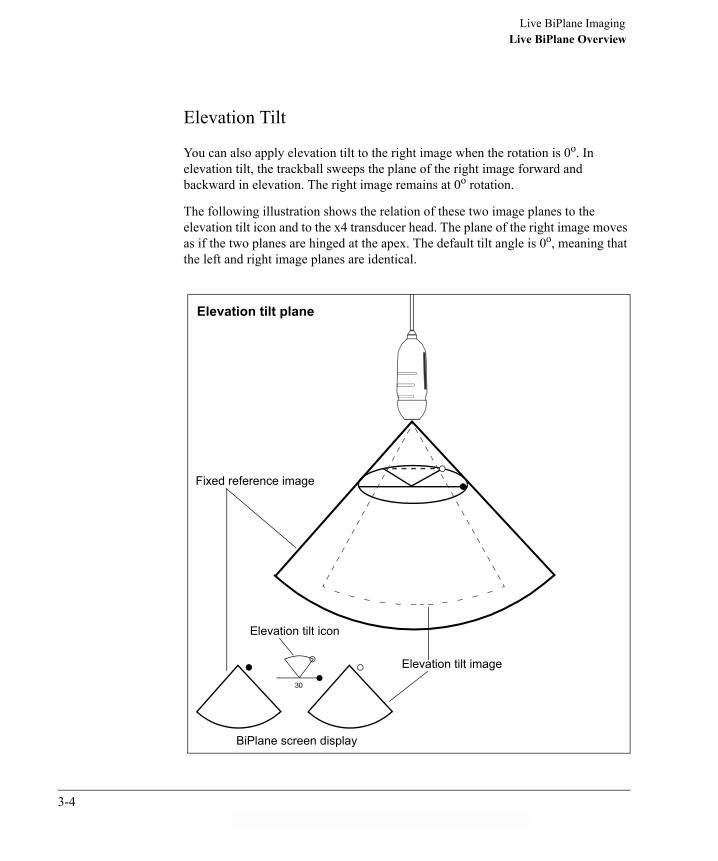
Live BiPlane ImagingLive BiPlane Overview
Elevation Tilt
You can also apply elevation tilt to the right image when the rotation is 0o. In elevation tilt, the trackball sweeps the plane of the right image forward and backward in elevation. The right image remains at 0o rotation.
The following illustration shows the relation of these two image planes to the elevation tilt icon and to the x4 transducer head. The plane of the right image moves as if the two planes are hinged at the apex. The default tilt angle is 0o, meaning that the left and right image planes are identical.
BiPlane screen display
Elevation tilt icon
Fixed reference image
Elevation tilt image
Elevation tilt plane
30
3-4ahb C:\WINDOWS\Desktop\Philips\D.1\D.1 3D Book

Live BiPlane ImagingLive BiPlane Overview
� You can save BiPlane images to the 2D hard disk, a magneto optical disk (MOD), or transfer the images over a network. For more information on storing BiPlane images, see �Managing BiPlane Images� on page 4-14.
� Harmonics is available in BiPlane mode.
BiPlane Color and BiPlane Zoom Overview
BiPlane Color mode is an extension of BiPlane mode. BiPlane Color and BiPlane Zoom modes work very much like 2D Color and 2D Zoom modes. The color box or zoom preview box on the left image behaves the same as it would in 2D Color or 2D Zoom Preview mode. You use the and keys to resize or reposition the color box or zoom preview box on the image using the trackball. The following illustration shows an example BiPlane Color image.
In lateral tilt and rotation modes, the box on the right image tracks the left color box vertically, but does not move left or right because the color boxes together define a contiguous color volume. In elevation tilt, however, the boxes in both images move together.
NOTE
Size Position
Color Boxes
MI:0.7 TIS:0.3 X404 MAR 03 14:10:59 2/0/D/M2/A 16CMGAIN 50 COMP 70 8HZ89BPM
T
R4
P2
Philips Medical 2.5MHZSystems 60Adult
90
CM/S
60
3-5

Live BiPlane ImagingBiPlane Controls
BiPlane Controls
To access BiPlane imaging:
� Touch BiPlane on the right touch panel.
The BiPlane primary controls appear on the right touch panel.
To access additional BiPlane controls:
� Touch Secondary Controls on the right touch panel.
The BiPlane secondary controls appear:
ElevationTilt
Magnify1.0
PostprocDFocus
RightInvert
2D
Color
SecondaryControls
Live3D BiPlane Zoom
Full Volume
Frequency Fusion 3
Rotate90
Harmonic Fusion
2D
Secondary Controls
LGC
Persist0
Power0.0 dB
ColorizeU/D
InvertSweep
50
3-6ahb C:\WINDOWS\Desktop\Philips\D.1\D.1 3D Book

Live BiPlane ImagingBiPlane Controls
The following table describes the BiPlane controls:
Control Name Description
Color Density Selects either medium or high line densities for BiPlane color images.To access the Density rotary control, touch BiPlane, Color, and
on the right touch panel.
Elevation Tilt Turns elevation tilt on or off.
In elevation tilt, the trackball sweeps the plane of the right image forward and backward in elevation. The plane of the right image moves as if the two planes are hinged at the apex. The default tilt angle is 0o, meaning that the left and right image planes are identical.
To activate elevation tilt, do one of the following:
� Touch Elevation Tilt, if it is not highlighted.
� Move the trackball quickly up or down.
� Set Rotate to 0.
NOTES: Elevation tilt ranges from -30o to +30o.When elevation tilt is off, the trackball adjusts lateral tilt. When elevation tilt is on, the Rotate control setting is 0.
Lateral tilt) In lateral tilt, the trackball sweeps the elevation plane of the right image across the lateral plane that provides the left image, without having to move the transducer. The default tilt angle is 0o.
To activate lateral tilt, do one of the following:
� Touch Elevation Tilt, if it is highlighted.
� Move the trackball quickly to the right or left.
NOTE: Lateral tilt ranges from -45o to +45o.
Right Invert Controls L/R Invert for the right image by changing the Rotate rotary control by 180o.
NOTE: This control disappears when Elevation Tilt is on.
Density-_ _^_ _+
3-7

Live BiPlane ImagingBiPlane Controls
For more information about applying BiPlane imaging controls, see SONOS BiPlane Imaging (a CD guide), provided with your system documentation.
Rotate Rotates the viewing angle of the BiPlane image on the right of the screen. The rotation icon follows the rotation angle. Rotate settings other than 0, 90, and 270 automatically center tilt to 0o.
NOTE: When set to 0, Elevation Tilt automatically comes on.
Control Name Description
NOTE
3-8ahb C:\WINDOWS\Desktop\Philips\D.1\D.1 3D Book

Live BiPlane ImagingAcquiring a BiPlane Image
Acquiring a BiPlane Image
You can manipulate BiPlane images by rotating, tilting, and using the BiPlane controls.
1 Obtain an optimized 2D image before you begin using the BiPlane mode.
2 Touch BiPlane on the right touch panel.
The BiPlane screen appears. When the trackball is moved, a dashed line on the left image represents the lateral tilt indicator (the position of the right image plane with respect to the left).
MI:0.9 X404 MAR 03 14:10:05 2/0/D/F3 16CMGAIN 50 COMP 70 30HZ89BPM
T
R4
P2
Philips MedicalSystemsAdult
90Lateral tilt indicators
3-9

Live BiPlane ImagingAcquiring a BiPlane Image
3 Select the type of tilt (lateral or elevation), as described below and in the control descriptions starting on page 3-7.
Set tilt prior to entering Zoom or Color modes. The only way to alter tilt in Zoom or Color modes is to pan the zoom area or reposition the color box.
4 Use the trackball to place the tilt indicator along the anatomy of interest.
When the trackball motion stops, the tilt angle changes to the selected position.
� Lateral tilt sweeps the elevation plane of the right image across the lateral plane that provides the left image, without having to move the transducer.
Scan results at the default lateral-tilt angle (0o) are shown in the fixed, left reference image. The left and right image planes remain perpendicular at all lateral-tilt settings. These settings range from -45o to +45o.
When using lateral tilt, an indicator on the left image shows the orientation of the right image relative to the left reference plane. A tilt icon between the images shows the direction and degree of lateral deflection away from the left reference plane, when looking down from above.
NOTE
45
The lateral tilt icon sweeps right (+) and left (-).
The filled and open dots in the icon correspond to the same dots on the sides of the left and right BiPlane images.
Shows the angle of lateral tilt from -45o to +45o.
Represents the edge of the left reference image in the BiPlane display corresponding to the tactile dot.
Represents the laterally tilted right image in the BiPlane display.
Represents the edge of the right image in the BiPlane display corresponding to the open dot.
3-10ahb C:\WINDOWS\Desktop\Philips\D.1\D.1 3D Book

Live BiPlane ImagingAcquiring a BiPlane Image
� Elevation tilt sweeps the plane of the right image forward and backward in elevation, without having to move the transducer. The plane of the right image moves as if the two planes are hinged at the apex.
The default tilt angle is 0o, meaning that the left and right image planes are identical. Elevation-tilt settings range from -30o to +30o.
When using elevation tilt, a tilt icon between the images shows the direction of elevation tilt with respect to the left reference plane and the angle between the left and right image planes.
Both elevation tilt image planes are at 0o rotation.
5 Touch Color to apply this tilt to a color-flow image, if desired.
The elevation tilt icon sweeps up and down.
The filled and open dots in the icon correspond to the same dots on the sides of the left and right BiPlane images.
Shows the angle of elevation tilt from -30o to +30o.
Represents the edge of the left reference image in the BiPlane display corresponding to the tactile dot.
Represents the tilted right image in the BiPlane display.
Represents the edge of the right image in the BiPlane display corresponding to the open dot.
30
NOTE
3-11
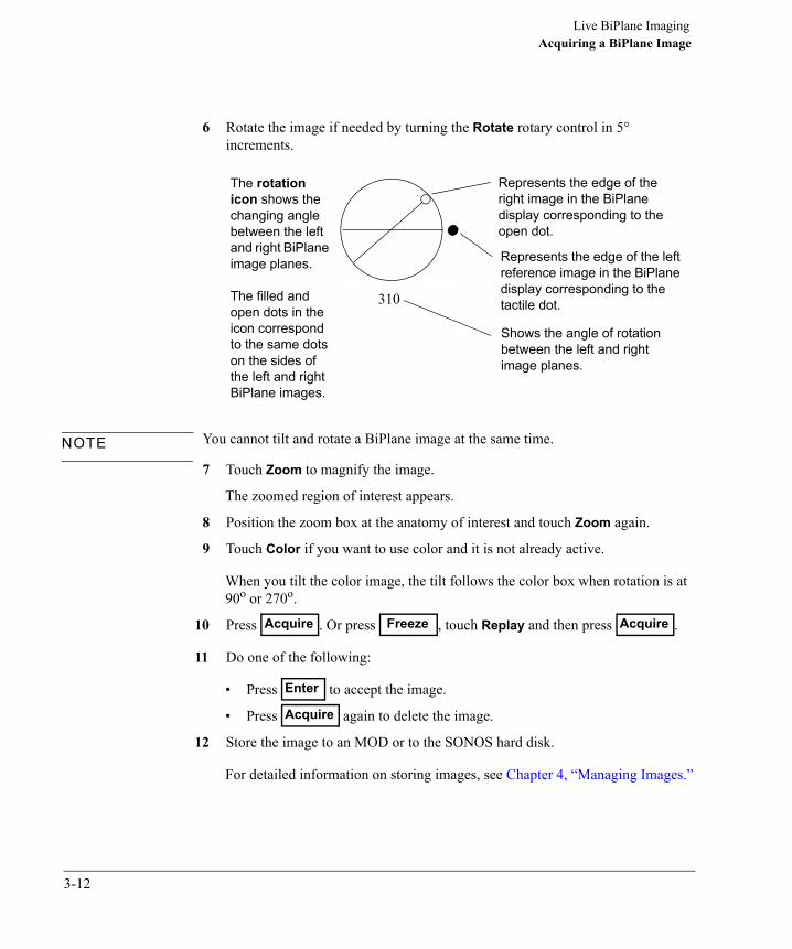
Live BiPlane ImagingAcquiring a BiPlane Image
6 Rotate the image if needed by turning the Rotate rotary control in 5° increments.
You cannot tilt and rotate a BiPlane image at the same time.
7 Touch Zoom to magnify the image.
The zoomed region of interest appears.
8 Position the zoom box at the anatomy of interest and touch Zoom again.
9 Touch Color if you want to use color and it is not already active.
When you tilt the color image, the tilt follows the color box when rotation is at 90o or 270o.
10 Press . Or press , touch Replay and then press .
11 Do one of the following:
� Press to accept the image.
� Press again to delete the image.
12 Store the image to an MOD or to the SONOS hard disk.
For detailed information on storing images, see Chapter 4, �Managing Images.�
310
Shows the angle of rotation between the left and right image planes.
Represents the edge of the left reference image in the BiPlane display corresponding to the tactile dot.
Represents the edge of the right image in the BiPlane display corresponding to the open dot.
The rotation icon shows the changing angle between the left and right BiPlane image planes.
The filled and open dots in the icon correspond to the same dots on the sides of the left and right BiPlane images.
NOTE
Acquire Freeze Acquire
Enter
Acquire
3-12ahb C:\WINDOWS\Desktop\Philips\D.1\D.1 3D Book

INTR
Chapter 4 Managing Images
ODU
CTIO
N
Managing Live 3D Echo Images
The location to which you store and export images on the SONOS system depends on the image type and SONOS model number. The following tables summarize the storage and export locations.
Table 4-1 SONOS 7500 Storage and Export Options
Table 4-2 SONOS 5500 Storage and Export Options
SONOS 7500 systems with Live 3D have a 3D hard disk. All Live 3D images are stored as either SONOS files or AVI files. You can review SONOS files, identified by the 3D icon, on the system. Although you cannot review AVI files on the SONOS system, they are useful if you want to export the images for review on an offline computer.
When the SONOS system is storing or retrieving, no other functions can be performed on the system. You may cancel the saving or retrieving operation. When the system is writing files to the CD-R, you can cancel the process, but all CD-R data is lost and the CD-R cannot be reused.
Image Type MOD 3D Hard Disk IDI(for export)
CD-R(for export)
2D yes no yes no
Live 3D Echo no yes no yes
Gated Sequential 3D yes no no no
Image Type MOD 3D Hard Disk IDI(for export)
CD-R(for export)
2D yes N/A yes N/A
Live 3D Echo N/A N/A N/A N/A
Gated Sequential 3D yes N/A no N/A
4-1

Managing ImagesManaging Live 3D Echo Images
3D Hard Disk Capacity
Before using storage and retrieval functions, the system checks the 3D hard disk space. If the system is running low on available disk space, a screen message appears, showing the remaining space and suggesting that some files be deleted.
Select Okay and press to acknowledge the message.
For information about deleting files, see �Deleting Live 3D Files from the 3D Hard Drive� on page 4-11.
3D Hard Disk Retrieval
You access the 3D retrieval features using the Disk Retrieve - Studies and Disk Retrieve - Images dialog boxes. The following illustration shows the Disk Retrieve - Studies dialog box:
In this and similar retrieval and export windows, you can click on a column heading to sort the listings according to that column�s contents.
r
Enter
NOTE
Accepts your selections
Displays individual images stored in study
Closes the dialog boxand returns to the previous process
Selects all of the displayed studies
Deselects any
Allows you to select morethan one study at a time
Available space on the 3D Hard Disk
List of patient information
selected studies
Dialog box title
OK
List Contents
Cancel
Select All
Select None
Free Disk Space: 9610 / 17492 MBytes
Multi-Select
Disk Retrieve - Studies
HANS SCHMITT
Patient Name Comment Date
JOHN PHILIPS
SALLY MAY
SAMANTHA JONES
3D Loops & AVI�s
3D Loops & AVI�s
3D Loops & AVI�s
3D Loops & AVI�s
07 APR 2003
07 APR 2003
07 APR 2003
07 APR 2003
14:25:24
14:21:56
14:23:59
14:27:37
X
4-2ahb C:\WINDOWS\Desktop\Philips\D.1\D.1 3D Book
Managing ImagesManaging Live 3D Echo Images
When you use the List Contents button, the Disk Retrieve - Images screen appears and the List Contents button changes to List Studies. Use the List Studies button to return to the Disk Retrieve - Studies dialog box.
A dialog box displays the progress of retrieving files from the disc.
If you retrieve an entire study that is too large, the �Loop Memory Full� message appears and some images are not retrieved.
Storing Live 3D Images
Live 3D loops are stored on the 3D hard disk. The amount of data you can store is limited only by the amount of 3D hard disk space available. However, you should not use the 3D hard disk for long-term storage. You should export and archive Live 3D images daily.
There is no back-up mechanism for restoring images that may be lost if a hard disk failure occurs. Be sure to export Live 3D images daily.
You can store multiple versions of optimized 3D images on subpages. When you create a subpage, the settings are stored in loop memory. When you store the loop to disk, the original image and all associated subpages are stored.
You can manually label the images if the system is set to manual commenting in the comment options under Disk Setup. Make sure auto commenting is off.
Storing images on the 3D hard disk
To store Live 3D Echo images with optimization settings to the 3D hard disk:
1 After acquiring and optimizing a loop, touch Create Subpage on the right touch panel.
The subpage is stored to loop memory. The page number in the Subpage rotary increments by one.
2 To create additional subpages, repeat step 1.
3 To store your image to the 3D Hard Disk, touch Disk Store.
The original image and the subpages you created are stored to the 3D hard disk.
NOTE
NOTE
CAUTION
4-3

Managing ImagesManaging Live 3D Echo Images
Storing images to a CD-R
Always use high quality, brand name CD-R media. Handle the CD-R by the edges only and store the CD-R in its case when not in use.
To store images to a CD-ROM:
1 Touch Disk.
2 Touch Export to CD.
The CD Export - Studies dialog box appears:
OK
List Contents
Cancel
Select All
Select None
200MB of 640 MB available CD space used
Multi-Select
CD Export - Studies
HANS SCHMITT
JOHN PHILIPS
SALLY MAY
SAMANTHA JONES
3D Loops & AVI�s
3D Loops & AVI�s
3D Loops & AVI�s
3D Loops & AVI�s
07 APR 2003
07 APR 2003
07 APR 2003
07 APR 2003
14:... 50MB
14:... 50MB
14:... 50MB
14:... 50MB
X
Export Options
Patient Name Comment Date Size
As you select studies for export, this bar shows how much storage spaceis used on the CD and how much storage space remains.
4-4ahb C:\WINDOWS\Desktop\Philips\D.1\D.1 3D Book

Managing ImagesManaging Live 3D Echo Images
3 Use the Export Options button to choose between the following options:
� Create third-party compatible export files
This option allows you to choose whether to export third-party compatible files along with the raw SONOS files.
When checked (the default setting), the system exports both types of files. This allows third-party 3D software to use the images, but also uses more space on the CD.
When unchecked, the system exports only raw files, which saves space on the CD.
NOTE: If you uncheck this box and later want to use third-party 3D software with images exported only as SONOS raw files, load the raw files into the SONOS system, resave them to the 3D hard disk, and then export them to a different CD with this option enabled.
� Revert to backwards compatible third-party export files
This option allows you to choose whether to compress files being exported.
When unchecked (the default setting), the SONOS system compresses files being exported. This prevents older SONOS systems (and some third-party software) from using the files, but uses less space on the CD.
When checked, the SONOS system does not compress files being exported. This allows older SONOS systems (and some third-party software) to use the uncompressed files, but uses more space on the CD.
NOTE: This option is available only if the option Create third-party compatible export files is selected.
� Default media size
This option allows you to enter the specific size of the media being used. This value is used only to estimate how much space will be used on the CD.
� The system continues to use these export-option settings until they are changed.
� A SONOS D.1 system can read any SONOS D.0 CD data, regardless of how these options are set on the D.1 system.
NOTE
4-5

Managing ImagesManaging Live 3D Echo Images
4 To select the files to export, do one of the following:
A dialog box appears, requesting that you insert an approved blank disk into the CD drive.
When you click on a study, there could be a brief delay while the system computes its size.
5 Insert a CD-R into the CD drive, select Begin, and then press .
The CD Operation Progress dialog box displays the progress of converting files, preparing the disk, adding data to the disk image, writing disk contents, and closing the disk.
If you select Cancel during the write operation, the data is not stored on the CD and the CD will be unusable.
When the write operation is finished, a dialog box appears, confirming that the CD write operation completed successfully.
If the amount of disc space required to export your files exceeds the capacity of the CD-R, a dialog box prompts you to continue exporting to another disk. Use Verify to verify the current CD contents or use Next Disk to export to an additional disk.
If you want to � Then �
export an entire study a. Select the study and press .b. Select Okay and press .
choose individual images in a study to export
a. Select the study and press .b. Select List Contents and press .c. Select the image or images to export, select
Okay, and then press .
EnterEnter
EnterEnter
Enter
NOTE
Enter
CAUTION
NOTE
4-6ahb C:\WINDOWS\Desktop\Philips\D.1\D.1 3D Book

Managing ImagesManaging Live 3D Echo Images
6 To confirm the data was successfully written to the CD, select Verify and press .
The CD Operation Progress dialog box displays the progress of verifying the files.
When the files on the CD are verified, a dialog box appears, confirming that the write and verification operations were successful.
7 Select Okay and press .
Storing images as AVI files
To store Loop Display images as AVI files to the 3D hard disk:
� In Loop Display mode, touch AVI Store.
A window may appear for adding a comment.
You can manually label the images if the system is set to manual commenting in the Comments Options under Disk Setup. Make sure auto commenting is off.
The AVI Store touch control remains highlighted while the image is stored.
AVI images can be stored with 3D swivel activated, for better anatomy depth perception.
Enter
Enter
NOTE
NOTE
4-7

Managing ImagesManaging Live 3D Echo Images
Retrieving Live 3D Images from the 3D Hard Disk
To retrieve Live 3D images from the 3D hard disk:
1 In Live 3D mode, touch Loop.
2 Touch Disk Retrieve.
The following dialog box appears:
3 Select 3D Hard Disk, select Okay, and then press .
The list of stored studies appears in the Disk Retrieve - Studies dialog box.
Target Disk Selection
Optical Disk
2D Hard Disk
Okay
3D Hard Disk
CD-R Disk
Enter
4-8ahb C:\WINDOWS\Desktop\Philips\D.1\D.1 3D Book

Managing ImagesManaging Live 3D Echo Images
The following table describes the icons that might appear in the Patient Name column:
You can bookmark Live 3D files. If a 3D file is bookmarked, its symbol appears with a yellow background. For more information on bookmarking loops, see the Reference Manual, System Basics.
Symbol Definition
Live 3D file
Bookmarked Live 3D image
Live 3D image exported to CD-ROM
Live 3D image exported to CD-ROM and verified
3D study
Entire study exported to CD-ROM
Entire study exported to CD-ROM and verified
AVI file
AVI exported to CD-ROM
AVI exported to CD-ROM and verified
NOTE
4-9

Managing ImagesManaging Live 3D Echo Images
If automatic commenting is on, the following mnemonics for the 3D and BiPlane modes might appear in the Comments column:
4 To view the individual images in a study, select the study folder, press , select List Contents, and then press .
The list of the images in the selected study appears:
Although AVI files appear in the list, you cannot retrieve them on the SONOS system.
5 Select the files to retrieve, select Okay, and then press .
Mnemonic System Mode
3D Live 3D
3DZ 3D Zoom
3FV Full Volume
BP BiPlane
3DC 3D Color
EnterEnter
OK
List Studies
Cancel
Select All
Select None
Free Disk Space: 9610 / 17492 MBytes
Multi-Select
Disk Retrieve - Images
JOHN PHILIPS
Patient Name Comment Date
JOHN PHILIPS
JOHN PHILIPS
JOHN PHILIPS
Car Adult 3D
Car Adult 3D
none
Car Adult 3D
07 APR 2003
07 APR 2003
07 APR 2003
07 APR 2003
14:22:53
14:22:53
14:21:51
14:22:06
X
JOHN PHILIPS
JOHN PHILIPS
SAMANTHA JONES
SAMANTHA JONES
SAMANTHA JONES
SAMANTHA JONES
SAMANTHA JONES
Car Adult 3D
Car Adult 3D
Car Adult 3D
Car Adult 3D
Car Adult 3D
Car Adult 3D
Car Adult 3D
07 APR 2003
07 APR 2003
07 APR 2003
07 APR 2003
07 APR 2003
07 APR 2003
07 APR 2003
14:22:06
14:21:51
14:27:35
14:27:35
14:27:35
14:27:35
14:27:35
NOTENOTE
Enter
4-10ahb C:\WINDOWS\Desktop\Philips\D.1\D.1 3D Book
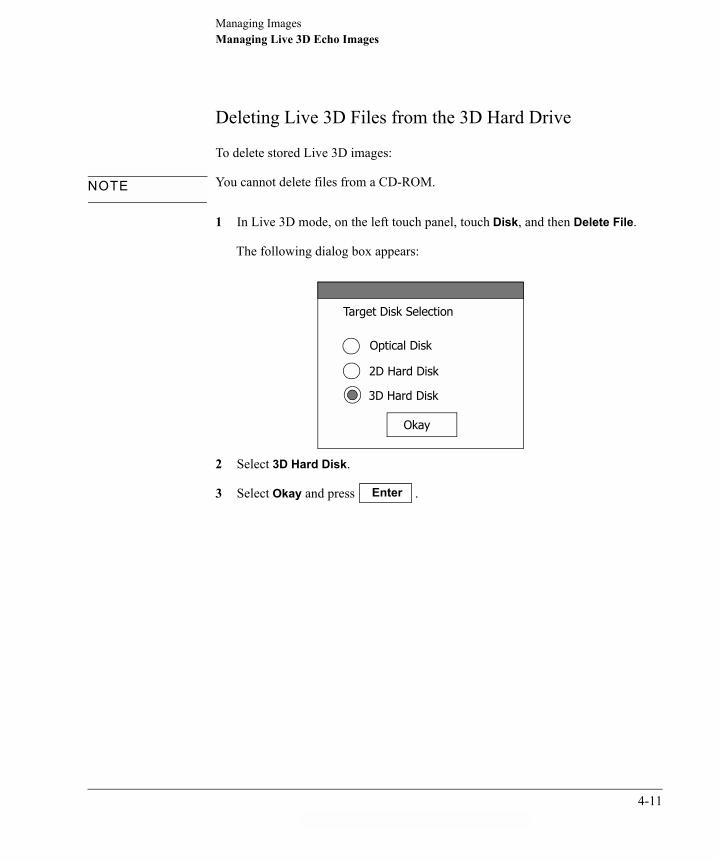
Managing ImagesManaging Live 3D Echo Images
Deleting Live 3D Files from the 3D Hard Drive
To delete stored Live 3D images:
You cannot delete files from a CD-ROM.
1 In Live 3D mode, on the left touch panel, touch Disk, and then Delete File.
The following dialog box appears:
2 Select 3D Hard Disk.
3 Select Okay and press .
NOTE
Target Disk Selection
Optical Disk
3D Hard Disk
Okay
2D Hard Disk
Enter
4-11

Managing ImagesManaging Live 3D Echo Images
The Delete Files - Studies dialog box appears:
4 To select the files to delete, do one of the following:
5 Select Okay and press .
The Digital Storage dialog box appears, for confirming that you want to delete the files.
If you want to � Then �
delete an entire study a. Select the study and press .b. Select Okay and press .
choose individual images in a study to delete
a. Select the study and press .b. Select List Contents and press .c. Select the image or images to delete, select
Okay, and then press .
OK
List Contents
Cancel
Select All
Select None
Free Disk Space: 9610 / 17492 MBytes
Multi-Select
Delete Files - Studies
HANS SCHMITT
Patient Name Comment Date
JOHN PHILIPS
SALLY MAY
SAMANTHA JONES
3D Loops & AVI�s
3D Loops & AVI�s
3D Loops & AVI�s
3D Loops & AVI�s
07 APR 2003
07 APR 2003
07 APR 2003
07 APR 2003
14:25:24
14:21:56
14:23:59
14:27:37
X
EnterEnter
EnterEnter
Enter
Enter
4-12ahb C:\WINDOWS\Desktop\Philips\D.1\D.1 3D Book

Managing ImagesManaging Live 3D Echo Images
6 If you are sure you want to delete the files, select Yes and press .
A dialog box appears showing the progress of the deletion.
7 Select Okay and press .
The Delete Operation Progress dialog box appears to confirm the deletion.
Enter
Enter
4-13

Managing ImagesManaging BiPlane Images
Managing BiPlane ImagesYou store and retrieve BiPlane images the same way you do 2D images. You can store BiPlane images to a magneto optical disk (MOD) or the 2D hard disk.
For more information about storing and retrieving 2D images, see the Reference Manual, System Basics. For more information about sending BiPlane images over a network with IDI, see the Applications Manual, IDI User�s Guide.
To store a BiPlane image to MOD:
1 After acquiring an image, put a formatted optical disk in the drive and touch Loop on the left touch panel.
If IDI is installed, you must select Enable Optical in Disk Setup before acquiring the first loop of a study.
2 Touch Disk Store on the left touch panel.
If you have Disk Autostore enabled, the image will be stored when accepted following acquire.
The following dialog box appears when IDI is enabled and Enable Optical is on.:
NOTE
NOTE
Target Disk Selection
Optical Disk
2D Hard Disk
Okay
4-14ahb C:\WINDOWS\Desktop\Philips\D.1\D.1 3D Book

Managing ImagesManaging BiPlane Images
3 Select Optical Disk, select Okay, and then press .
A disk icon displays the progress of the saving operation. When the operation is complete, the disk icon disappears.
For more information on retrieving stored images, see the Reference Manual, System Basics.
Enter
4-15

Managing ImagesManaging BiPlane Images
4-16ahb C:\WINDOWS\Desktop\Philips\D.1\D.1 3D Book

Chapter 5 Gated, Sequential 3D Imaging
INTRO
DU
CTIO
N
Gated, Sequential 3D at a Glance
********
Ti
me
* * * * * * * * * ** * * * * * * * * * * *
Acoustic output index
Transducer label
Depth selection
ECG and Respiration graphs
MI: 1.0
R5012
GAIN 50
COMP 70
16CM
ECG R-R (msec)
200 1300 2400
Resp Amplitude
300e004
Time
Tools Preset Probe Disk 3D
Image Physio Annotate Analysis VCR
Learn Acquire
Graphs Down Up Seek
ECG Min 750
ECG Max 917
Resp Min 0
Resp Max 137
Seek Ang 90
2DZoom
ColorizeU/D
InvertSweep
50Persist
0Sepia
Postproc B
Focal Zones
FocusFrequency
Fusion
SelectRegion
5-1

Gated, Sequential 3D ImagingGated Sequential 3D Controls
Gated Sequential 3D Controls
Acquire Starts and pauses the 3D acquisition.
Cancel Stops the 3D acquisition.
Delay 1 Sets the delay from the R-wave to start the acquisition. Only available in triggered protocols.
Delay 2 Sets the delay from the R-wave to stop the acquisition for 4D timed protocols. Starts the acquisition of the second frame in 3D Dual Frame protocols. Only available in triggered protocols.
Down Moves the OmniPlane TEE or Transthoracic OmniPlane transducer sensor from any angle down to zero degrees. Touch the Up or Down control to stop it.
ECG Min Adjusts minimum ECG R-to-R interval gating limit. Only present when Graphs is on and ECG triggering is selected.
End Acquire Ends an acquisition when Advance Manual is active.
Format CROPPED Selects a cropped quad format for acquiring images. When active, use the Select Region control to determine the area of the image to be stored. This looping format provides the highest quad format image resolution.
Format FULL Selects full-screen format for acquiring and displaying looping images.
Format REDUCED
Selects a reduced quad format for acquiring images. This looping format lets you store the entire imaging sector at a reduced resolution.
Format VSPLIT Selects vertical split format for acquiring images.
Frames Sets the number of frames for both Multiple Frames and Non-triggered 4D acquisitions.
Not all systems have the 3D option.
These controls are described in more detail in the Alphabetical Control Summary.
Do not turn the system off or press Reset while storing to disk. This could damage all disk files.
5-2ahb C:\WINDOWS\Desktop\Philips\D.1\D.1 3D Book

Gated, Sequential 3D ImagingGated Sequential 3D Controls
Graphs Turns the display of the respiration and ECG gating graphs on and off.
Learn Calculates respiration and ECG gating limits.
Power Adjusts maximum transmit power in decibels (dB) where 0.0dB = maximum power, -30.0dB = minimum power. With 2D active, touch Secondary Controls and touch Power to adjust this control.
Resp Max Adjusts the maximum respiration amplitude gating limit when Graphs is on and Respiration Gate is selected.
Resp Min Adjusts the minimum respiration amplitude gating limit when Graphs is on and Respiration Gate is selected.
Seek Moves the transducer sensor from any angle to the angle specified by the Seek Angle control.
Seek Angle Selects the angle in degrees to which the transducer sensor will move. Touch Seek to move the sensor to this location.
Select Region Displays and removes outline markers that indicate the area of the image that will be captured in a cropped quad-loop format.
Up Moves the OmniPlane TEE or Transthoracic OmniPlane transducer sensor from any angle up to 180 degrees. Touch the Up or Down control to stop it.
5-3
Gated, Sequential 3D ImagingSetup Controls
Setup Controls
Advance Auto Automatically positions the rotatable array of the OmniPlane TEE or Transthoracic OmniPlane during acquisition.
Advance A/confirm
Automatically positions the OmniPlane TEE or Transthoracic OmniPlane transducer but waits for manual confirmation before continuing with the acquisition.
Advance Manual
Lets you control the transducer manually. The system will acquire the data once you indicate that the transducer is in place by choosing Okay in the dialog box and pressing Enter.
Increment Sets the angle increment used with automatic advancement of OmniPlane TEE or Transthoracic OmniPlane transducers.
Learn Exhale Calculates respiration limits based on the exhale portion of the respiration cycle. Only available with respiration gating.
Learn Inhale Calculates respiration limits based on the inhale portion of the respiration cycle. Only available with respiration gating.
Resp. Gate Turns respiration gating on and off.
Review Off Turns off Review mode.
Review Rotate Displays a rotating loop containing slices of the acquisition at every acquired transducer position upon completion of the acquisition. For two degree increments, shows slices at every 4th degree. Review Rotate is not available with Advance Manual.
Review Sum-mary
Displays six thumbnail images at evenly spaced acquisition angles and two composite images, upon completion of the acquisition. If Advance Manual is chosen, up to 12 thumbnail images will be displayed.
To retain changes, save them to a preset. See the System Basics guide for details.
An angle increment of 2-3 degrees is recommended.
5-4ahb C:\WINDOWS\Desktop\Philips\D.1\D.1 3D Book

Gated, Sequential 3D ImagingSetup Controls
Optical Disk Setup Controls
Preset Controls
Study Mode Selects a subdirectory storage format (study format) for saving files to disk. Storing and retrieving files with Study Mode on facilitates file management. When Study Mode is off, the system stores files into the root directory (file format).
Protocol Displays the Protocol menu, which contains the 3D and 4D protocols.
To facilitate file management, Study Mode is defaulted on.
5-5

Gated, Sequential 3D Imaging3D Protocols
3D Protocols
Protocol Acquisition Type Description
3D Single Frame Acquires a single frame at Delay 1. The acquisition is triggered and gated by ECG and also respiration limits, if enabled.
Dual Frame Acquires two frames: one at Delay 1 and one at Delay 2. The acquisition is triggered and gated by ECG and respiration limits.
Non-triggered Acquires a single frame at each increment without ECG gating. Respiration gating can be used if it is enabled.
4D Average Heart Cycle Acquires frames throughout the heart cycle at each increment. The acquisition is triggered and gated by ECG and also respiration limits, if enabled.
Multiple Frames Acquires multiple frames at each transducer position. The acquisition is triggered and gated by ECG and also respiration limits, if enabled.
Timed Acquisition Acquires multiple frames at each transducer position starting at Delay 1 and ending at Delay 2. The acquisition is triggered and gated by ECG and also respiration limits, if enabled.
Non-triggered Acquires multiple, consecutive frames at each transducer position without ECG gating. Respiration gating can be used if it is enabled.
5-6ahb C:\WINDOWS\Desktop\Philips\D.1\D.1 3D Book

Gated, Sequential 3D ImagingSetting Up for a Gated Sequential 3D Acquisition
Setting Up for a Gated Sequential 3D Acquisition
1 Touch Preset, Cardiac Exam, and then touch either Adult, Pediatric, TEE, or a 3D preset that you created.
2 Enter the patient information and insert a formatted, initialized disk in the optical drive.
If you select your own 3D preset, you can start the acquisition after you enter the patient information.
Cardiac Exam
Adult
Protocol
Preset
Be sure to check the available disk space.
Enter
Patient ID
5-7

Gated, Sequential 3D ImagingSetting Up for a Gated Sequential 3D Acquisition
3 Touch Protocol to display the Protocol menu.
4 Use the trackball to move the arrow to the 3D or 4D protocol you are using, and press .
5 Move the arrow to Okay, and press .
Preset
Cardiac Exam
Adult
Protocol
Enter
Acquisition Protocol SelectionCLR3D
4D
StandardSingle Frame Dual Frame Non-triggeredAverage Heart CycleMultiple Frames Time Acquisition Non-triggered
Okay Cancel
EnterAfter you select a 3D or 4D protocol, the 3D control replaces the Loop control on the left touch panel.
Enter
5-8ahb C:\WINDOWS\Desktop\Philips\D.1\D.1 3D Book

Gated, Sequential 3D ImagingSetting Up for a Gated Sequential 3D Acquisition
6 Insert the ECG cable connector into the receptacle under the keyboard.If you are using a nasal thermistor, plug it into the Resp connector located under the keyboard. Then set Physio Resp to 2.
PATIENT CONNECTION ELECTRICALLY ISOLATED
ECG
ECG AUX RESP PULSEHEART SOUND
300e003a
5-9

Gated, Sequential 3D ImagingSetting Up for a Gated Sequential 3D Acquisition
7 Connect the pin connector to the ECG cable.
8 Attach the electrodes and ECG leads to the patient as shown.
Left Arm
Right Arm
Left Leg
ECG leads also provide information about respiration, if your system has this physio and it is set to Resp Normal.Proper ECG lead placement is critical for receiving a good ECG and respiration signal.
Left Leg
Left Arm
Right Arm
5-10ahb C:\WINDOWS\Desktop\Philips\D.1\D.1 3D Book

Gated, Sequential 3D ImagingSetting Up for a Gated Sequential 3D Acquisition
9 Press , and touch 3D to choose the Setup options. Select the Resp. Gate, Advance, Increment, and Review settings for the acquisition.
10 Touch Physio and select the input sources for the waveforms you want to view. Select Off for those you don�t need.
11 Press to return to live imaging.
SetupBe sure to select the Review mode now. Review settings can only be changed before the acquisition starts.
3D
Learn Inhale
Learn Exhale
RespGate
Advance Auto
Increment 3
Review Summary
Physio
ECG Normal
RESP Normal
Pulse Aux 3
Hrtsound Normal
SetupAfter exiting Setup, you can save the settings by touching the Save Preset control (located in the lower left corner of the left touch panel).
Setup
5-11

Gated, Sequential 3D ImagingSetting Up for a Gated Sequential 3D Acquisition
12 Touch Physio and adjust the ECG or Resp. Gain control to ensure a strong signal.
Physio
ECG
ECG Gain 17%
5-12ahb C:\WINDOWS\Desktop\Philips\D.1\D.1 3D Book

Gated, Sequential 3D ImagingConducting a Gated Sequential 3D Acquisition
Conducting a Gated Sequential 3D Acquisition
1 Touch 3D.
2 Select the looping Format for your acquisition.
This section describes the steps for an Average Heart Cycle acquisition. For setup information, see �Setting Up for a Gated Sequential 3D Acquisition� on page 5-7.
3D
AcquireLearnSelect Region
Graphs
Format CROPPED is active for Philips presets. Using other looping formats requires more disk space.
If the Format control is not visible, turn Graphs off and select the looping format for your acquisition.
3D
AcquireLearnSelect Region
GraphsFormat
CROPPED
5-13

Gated, Sequential 3D ImagingConducting a Gated Sequential 3D Acquisition
3 Touch Graphs to display the ECG and respiration graphs.
4 Adjust the Depth setting so that the graphs do not interfere with viewing the anatomy.
Use the graphs during acquisition to display the patient�s ECG and respiration.
ECG and respiration should be stable during acquisition to ensure good quality data for 3D reconstruction and to reduce acquisition time.
********* *
* * * * * * * * * * * * * * *
ECG R-R (msec)T i
m e
200 1300 2400
Resp Amplitude
Time
Gain Compress DepthReset Test Setup
Patient ID
1 2 3 4 5 6 7
Q W E R Y UTTab
A S F G HDCtrl
Shift Z X V BC
5-14ahb C:\WINDOWS\Desktop\Philips\D.1\D.1 3D Book

Gated, Sequential 3D ImagingConducting a Gated Sequential 3D Acquisition
5 Use the trackball to position the region indicator.
6 Obtain an optimal image in which the area of interest is in the center and maintains good image quality through 180 degrees.
7 Touch Learn to establish ECG and respiration gating limits for the acquisition.
The selected region should be centered on the anatomy of interest and include anatomic landmarks for reconstruction.
Adjust all imaging controls now. No imaging controls should be changed during acquisition.
For details, see �3D Imaging Tips and Troubleshooting� on page 5-22.
3D
AcquireLearnSelect Region
GraphsFormat
CROPPED
After Learn has finished setting the gating limits, use the ECG, Resp Max, and Resp Min controls to adjust the gating limits, if necessary. Narrow gating limits increase the quality of reconstruction and acquisition time. The use of narrow gatings for valves and other small structures is recommended.
3D
Acquire
Select RegionGraphs
ECG Min 900
ECG Max 1100
Resp Min 30
Resp Max 138
Learn
5-15
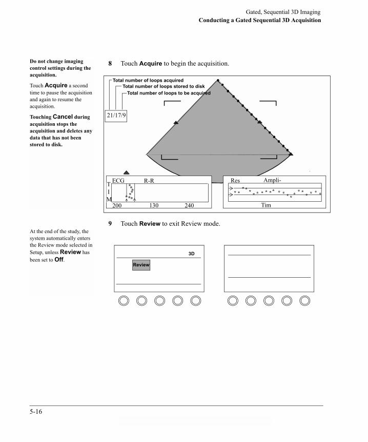
Gated, Sequential 3D ImagingConducting a Gated Sequential 3D Acquisition
8 Touch Acquire to begin the acquisition.
9 Touch Review to exit Review mode.
********* *
* * * * * * * * * * * * * * * ** * * *
21/17/9
Total number of loops acquiredTotal number of loops stored to disk
Total number of loops to be acquired
ECG R-R T I M
200 130 240
Res Ampli-
Tim
Do not change imaging control settings during the acquisition.
Touch Acquire a second time to pause the acquisition and again to resume the acquisition.
Touching Cancel during acquisition stops the acquisition and deletes any data that has not been stored to disk.
At the end of the study, the system automatically enters the Review mode selected in Setup, unless Review has been set to Off.
3D
Review
5-16ahb C:\WINDOWS\Desktop\Philips\D.1\D.1 3D Book

Gated, Sequential 3D ImagingConducting a Gated Sequential 3D Acquisition
10 To exit 3D and return to standard Loop mode, touch Preset, and touch either Adult or Pediatric.After you change presets,
the Loop control replaces the 3D control on the left touch panel.
Preset
Cardiac Exam
Adult
Protocol
5-17

Gated, Sequential 3D ImagingUsing Review Mode
Using Review Mode
To use Review Summary, move the trackball to change the display speed. You can also press and use the trackball to review the images frame-by-frame.
Fig. 1 shows an example where the first and last images line up correctly at 0 and 180 degrees. Fig. 2 shows an example where the images do not line up and another acquisition should be considered.
FreezeAt the end of the study, the system automatically enters the Review mode selected in Setup, unless Review has been set to Off.Review mode lets you identify problems in image acquisition due to transducer or patient movement.
00 900
300 1200
600 1500
00 1800
1500
The first and last images acquired should line up, as if they were a single image. Use this comparison mode to determine if you need to do another acquisition. Fig. 1 Fig. 2
00 1800 00 1800
5-18ahb C:\WINDOWS\Desktop\Philips\D.1\D.1 3D Book

Gated, Sequential 3D ImagingUsing Review Mode
To use Review Rotate, move the trackball to change the display speed. You can also press and use the trackball to review the images frame-by-frame.
Touch Review to exit Review mode.
Freeze
Review Rotate presents a rotating composite at each acquired increment. As the composite images rotate, you can identify problems in image acquisition due to transducer or patient movement.
Review mode loops are stored to optical disk and can be identified by the comment; either Summary or Rotate.
3D
Review
5-19
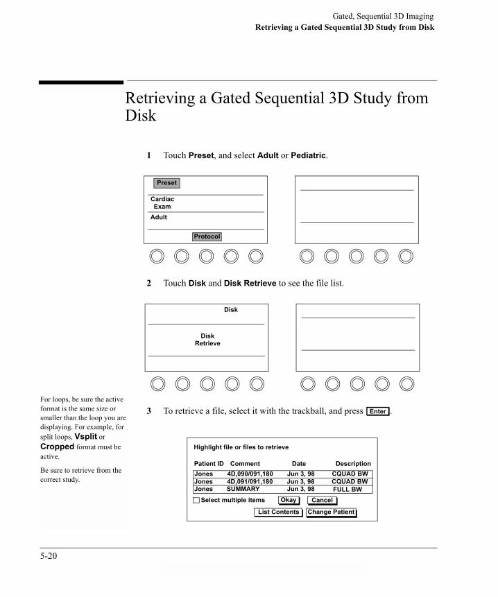
Gated, Sequential 3D ImagingRetrieving a Gated Sequential 3D Study from Disk
Retrieving a Gated Sequential 3D Study from Disk
1 Touch Preset, and select Adult or Pediatric.
2 Touch Disk and Disk Retrieve to see the file list.
3 To retrieve a file, select it with the trackball, and press .
Preset
Cardiac Exam
Adult
Protocol
Disk
Disk Retrieve
Enter
For loops, be sure the active format is the same size or smaller than the loop you are displaying. For example, for split loops, Vsplit or Cropped format must be active.
Be sure to retrieve from the correct study.
Patient ID
Highlight file or files to retrieve
Comment Date DescriptionJones 4D,090/091,180 Jun 3, 98 CQUAD BWJones 4D,091/091,180 Jun 3, 98 CQUAD BWJones SUMMARY Jun 3, 98 FULL BW
Okay Cancel
List Contents Change Patient
Select multiple items
5-20ahb C:\WINDOWS\Desktop\Philips\D.1\D.1 3D Book
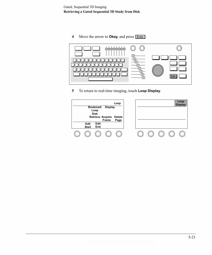
Gated, Sequential 3D ImagingRetrieving a Gated Sequential 3D Study from Disk
4 Move the arrow to Okay, and press .
5 To return to real-time imaging, touch Loop Display.
Enter
Enter
LoopDisplay
Delete Page
AcquireFrame
Edit End
Edit Start
Disk Retrieve
Loop Display
BookmarkLoop
5-21

Gated, Sequential 3D Imaging3D Imaging Tips and Troubleshooting
3D Imaging Tips and Troubleshooting
Symptoms Suggestions
Motion artifacts appear in reconstruction
Be sure that the transducer does not move during acquisition.
When using an OmniPlane TEE transducer, hold it at the mouth and handle to minimize movement.
Make sure that the patient is comfortable and able to remain still throughout the entire acquisition.
If the heart rate is decreasing and the patient is alert, instruct the patient to make a fist or open his eyes to increase the heart rate.
If the heart rate is increasing and the patient is alert, instruct the patient to close his eyes and relax.
Gating limits may be too wide.
Adjust monitor settings.
Breathing should be relaxed, slow, and even. The patient should not talk, cough, etc., during acquisition.
Resolution of anatomy is poor or image is only partially visible
Use the highest frequency and Frequency Fusion setting acceptable.
Make sure the target area can be viewed through 180 degrees.
Be sure the region of interest includes anatomic landmarks for reconstruction.
Adjust Gain to improve signal strength.
5-22ahb C:\WINDOWS\Desktop\Philips\D.1\D.1 3D Book

Gated, Sequential 3D Imaging3D Imaging Tips and Troubleshooting
Image is too soft, hazy, or gray
Make sure that the object of interest is positioned at the center of the sector that is the axis of rotation. This is the area of highest resolution.
Set Gain settings a little higher than normal to prevent loss of data during reconstruction.
Check the Persistence control. It should be set to 0.
Adjust monitor settings.
Gating problems The placement of the leads is critical for ensuring proper gating limits. See �Setting Up for a Gated Sequential 3D Acquisition� on page 5-7.
The most important issue in 3D acquisitions is proper ECG and respiratory gating. The R-R interval limits should be less than or equal to 150 ms. The respiratory gating should be set to Learn Exhale, to exclude images during the inhale phase.
Narrower gating limits will increase the acquisition time, so a balance between reconstruction quality and acquisition time must be achieved.
The Delay 1 value must be shorter than the current R-to-R interval. If Delay 1 is longer than the R-to-R interval, decrease the value of Delay 1.
For 3D Dual acquisitions, the Delay values must be set apart enough to allow each frame to be acquired independently.
Angle increments Two degree increments are ideal for greatest reconstruction resolution. However, this increases the duration of the acquisition, allowing a greater potential for artifacts.
Three degree increments present a reasonable compromise between resolution and duration of acquisition.
5-23

Gated, Sequential 3D Imaging3D Imaging Tips and Troubleshooting
Philips does not provide off-line 3D-reconstruction software. The company providing the 3D-reconstruction software has the sole responsibility of validating the measurements that occur during reconstruction.
Philips suggests that you contact the company that supplied the reconstruction software for additional information on the implementation and accuracy of the reconstruction measurements.
Transducer issues Advance Auto and Advance A/Confirm can only be used with an OmniPlane or a Transthoracic OmniPlane transducer. If one is not available, change to Advance Manual in Setup.
Make sure the OmniPlane transducer is positioned correctly to allow remote controlling and for proper calibration.
The control buttons on the OmniPlane transducer handle will be disabled during an Advance Auto or Advance A/Confirm acquisition.
Cannot retrieve disk images while in a 3D protocol
You must select CLR Standard to retrieve disk images. To select CLR Standard, touch Preset, Cardiac Exam, Protocol, and select CLR Standard from the protocol menu.
NOTE
5-24ahb C:\WINDOWS\Desktop\Philips\D.1\D.1 3D Book

IndexIndex
Numerics3D Color
acquisition 2-25definition 2-4overview 1-7, 2-25Preview, accessing controls 2-26Preview, acquiring image 2-30Preview, control descriptions 2-27Preview, using 2-30Review, accessing controls 2-31Review, acquiring image 2-30Review, control descriptions 2-32Review, using 2-32volume, overview 1-7
3D Cursor, Setup control 2-493D hard disk
capacity 4-2deleting files 4-11overview 4-1retrieving images 4-8storing images 2-44, 4-3
3D Home, definition 2-4, 2-463D imaging 2-23D loop display 2-45, 2-46
accessing controls 2-45control descriptions 2-46subpages 2-48
3D Low Density, Setup control 2-49
3D Swivel, definition 2-4, 2-32, 2-463D Vision, definition 2-4, 2-33, 2-463D Zoom
overview 1-5using 2-14
AAbout this manual 1-1Acquire, control definition 2-4, 2-19Acquisition
3D Color 2-253D Color preview 2-303D Color review 2-30BiPlane 3-9Conducting 5-13Controls 1-11Full Volume 2-17Full Volume, not triggered 2-23Full volume, triggered 2-21Live 3D 2-10, 2-12Setting up 5-7
Agile, definition 2-27Arbitrary crop plane
accessing controls 2-40control descriptions 2-41definition 2-40using 2-42
Auto Crop, definition 2-4, 2-38, 2-46Autocool 1-3Automatic comments 4-10Average Heart Cycle 5-6
AVIfile storage 4-1storing images as 4-7
BBaseline, definition 2-27, 2-33BiPlane
accessing controls 3-6acquiring images 3-9color 3-5color, overview 1-8control descriptions 3-7elevation tilt 3-4, 3-11icon, elevation tilt 3-4, 3-11icon, lateral tilt 3-3, 3-10icon, rotation 3-12imaging planes 3-2lateral tilt 3-3, 3-10overview 1-8, 3-2rotation 3-12saving images 3-5storing images 4-14views 1-8
Blue Max, definition 2-38Blue Min, definition 2-38Bookmarks 4-9Brightness, definition 2-4, 2-46
Index-1ssn February 11, 1999 C:\WINDOWS\Desktop\Philips\D.1\D.1 3D Book for

Index
CC Vision, definition 2-34Cancel, definition 2-4, 2-19CD-R
export options 4-5storing images to 4-4
Coefficient calculations 1-2Color Controls, definition 2-34, 2-47Color Density, definition 3-7Color Gain, definition 2-27, 2-34Color, BiPlane 3-5Colorize, definition 2-4, 2-47Comments, automatic 4-10Compress (dedicated rotary), definition 2-5, 2-34, 2-47Controls
3D Color 2-43D Color Preview 2-26, 2-273D Color Review 2-31, 2-323D Cursor 2-493D Home 2-4, 2-463D loop display 2-45, 2-463D Low Density 2-493D Swivel 2-4, 2-32, 2-463D Vision 2-4, 2-33, 2-46Acquire 2-4, 2-19Agile 2-27Arbitrary crop plane 2-40, 2-41Auto Crop 2-4, 2-38, 2-46
Baseline 2-27, 2-33BiPlane 3-6, 3-7Blue Max 2-38Blue Min 2-38Brightness 2-4, 2-46C Vision 2-34Cancel 2-4, 2-19Color Controls 2-34, 2-47Color Density 3-7Color Gain 2-27, 2-34Colorize 2-4, 2-47Compress (dedicated rotary) 2-5, 2-34, 2-47Create Subpage 2-47Crop Adj 2-5, 2-38, 2-41, 2-47Crop Box 2-38, 2-49Crop plane, arbitrary 2-40, 2-41Delay 2-5, 2-19, 2-27Delete Subpage 2-47Disk Space i-viiiECG Color 2-49ECG Overlay 2-49ECG Trigger 2-5, 2-20, 2-28Elevation Tilt 3-7Filter 2-28, 2-35Focus 2-5, 2-28Frequency Fusion 2-5, 2-28Full Cycle 2-5, 2-20, 2-28Full Volume 2-6, 2-18, 2-19, 2-20Gain (dedicated rotary) 2-6, 2-35, 2-47
Green Max 2-38Green Min 2-38High Density 2-6, 2-28Lateral Tilt 3-7Live 3D 2-3, 2-4, 2-6Magnify 2-6, 2-47Packet 2-29Plane Adj 2-41Plane Lock 2-41Power 2-6, 2-20, 2-29Red Max 2-38Red Min 2-38Reference Images 2-6, 2-47Report to Serial Pt i-viiReset Cropping 2-6, 2-38, 2-41, 2-47Retain Crop 2-41Right Invert 3-7Rotate 3-8Rotate Volume 2-6, 2-47Scale 2-29Setup, Live 3D 2-49Shading 2-6, 2-48Smoothing 2-6, 2-35, 2-48Subpage 2-48U/D Invert 2-7XRES 2-7Zoom 2-7
Conventions viCreate Subpage, definition 2-47Creating preset 2-10Crop Adj, definition 2-5, 2-38, 2-41, 2-47
Index-2

Index
Crop boxaccessing controls 2-38control descriptions 2-38definition 2-36Setup control 2-49using 2-39
Crop plane, arbitraryaccessing controls 2-40control descriptions 2-41definition 2-40using 2-42
Croppingarbitrary crop plane tool 2-40crop box tool 2-36options 2-36planes 2-37using 2-39, 2-42
DDelay, definition 2-5, 2-19, 2-27Delete Subpage, definition 2-47Deleting files 4-11Density, see Line densityDepth axis, cropping plane 2-37Disconnect power 1-10Disk Retrieve screen 4-2Disk Space, definition i-viiiDisk, retrieving gated sequential 3D study from 5-20Dual Frame 5-6Dual triggering, overview 1-9
EECG
leads 1-1triggering 2-17
ECG Color, Setup control 2-49ECG Overlay, Setup control 2-49ECG Trigger, definition 2-5, 2-20, 2-28Elevation axis, cropping plane 2-37Elevation tilt
BiPlane, overview 3-4control definition 3-7icon 3-4, 3-11using 3-11
Export optionsCD-R 4-5media 4-1
FFile symbols 4-9Files
deleting 4-11saving 4-3
Filter, definition 2-28, 2-35Focus, definition 2-5, 2-28Foot switch, warning i-vi, 1-11Frame rate, Live 3D i-viiFrequency Fusion, definition 2-5, 2-28Full Cycle, definition 2-5, 2-20, 2-28
Full Volumeaccessing controls 2-18acquiring image 2-21acquiring nontriggered 2-23acquisition 2-17control descriptions 2-19definition 2-6, 2-20ECG triggered 2-17nontriggered 2-17overview 1-6, 2-17
GGain (dedicated rotary), definition 2-6, 2-35, 2-47Green Max, definition 2-38Green Min, definition 2-38
HHard disk, 3D 4-1
capacity 4-2retrieval 4-2storing images 4-3
High Density, definition 2-6, 2-28
IIcon
elevation tilt 3-4, 3-11file 4-9lateral tilt 3-3, 3-10line density 2-8rotation 3-12
IDI, beeps i-viii
Index-3ssn February 11, 1999 C:\WINDOWS\Desktop\Philips\D.1\D.1 3D Book for

Index
Imagescropping 2-39, 2-42managing 4-1resolution of 2-7retrieving 4-2, 4-8saving 2-44storing as AVI 4-7storing BiPlane 4-14storing Live 3D 2-13, 4-3storing on CD 4-4storing on hard disk 4-3viewing 2-45
LLateral axis, cropping plane 2-37Lateral tilt
BiPlane, overview 3-3control definition 3-7icon 3-3, 3-10using 3-10
Line densitychanging 2-8icons 2-8overview 2-7
List Contents 4-3Live 3D
accessing controls 2-3acquiring image 2-12control descriptions 2-4creating preset 2-10definition 1-1deleting files 4-11frame rate, maximum i-viiline density 2-7
managing images 4-1overview 1-5, 2-2retrieving images 4-8Setup controls 2-49storing images 2-13, 4-3touch control 2-6using 2-10Zoom 2-14
Loop display 2-45, 2-46
MMagnify, definition 2-6, 2-47Managing images 4-1Manuals, related vMatrix transducer, see x4 transducerMaximum Live 3D frame rate i-viiMultiple Frames 5-6
NNetwork utilities, access i-viiiNon-triggered 3D protocol 5-6Nontriggered Full Volume
acquiring 2-23overview 2-17
OOperating rooms, footswitch warning i-vi, 1-11
PPacket, definition 2-29Password, access to full test mode i-viiiPlane Adj, definition 2-41Plane Lock, definition 2-41Planes, cropping 2-37Power down 1-10Power, definition 2-6, 2-20, 2-29Preface vPreparing scanner message 1-2Preset, creating Live 3D 2-10Preview
3D Color 2-26, 2-27BiPlane 3-5, 3-6Full Volume 2-17
Protocols 5-6
RRed Max, definition 2-38Red Min, definition 2-38Reference Images
definition 2-6, 2-47overview 1-5
Report to Serial Pt, definition i-viiReset Cropping, definition 2-6, 2-38, 2-41, 2-47Resolution
line density 2-7settings 2-8
Retain Crop, definition 2-41Retrieving images 4-2, 4-8
Index-4
Index
Review3D Color 2-31, 2-323D loops 2-45, 2-46BiPlane 3-9, 3-12Gated Sequential 3D 5-18
Right Invert, definition 3-7Rotate Volume, definition 2-6, 2-47Rotate, control definition 3-8Rotation
icon, BiPlane 3-12using 3-12
SSafety information iiSaving images 2-44
as AVI files 4-7BiPlane 3-5CD export options 4-5Live 3D 4-3to CD 4-3
Scale, definition 2-29Setting line density 2-8Setup controls, Live 3D 2-49Shading, definition 2-6, 2-48Shutdown, system 1-10Single Frame 5-6Smoothing, definition 2-6, 2-35, 2-48Storage
capacity, 3D hard disk 4-2location options 4-1
StoringAVI files 4-7BiPlane images 4-14CD export options 4-5images on CD 4-4images on hard disk 4-3Live 3D images 2-13, 4-3
Study,gated sequential 3D, retrieving from disk 5-20Subpage
control definition 2-48using 2-48
Subvolumes 1-6Symbols
file 4-9warning ii
System shutdown 1-10
TTest mode
network utilities access i-viiipassword access i-viii
Tiltelevation 3-4, 3-11indicators 3-9lateral 3-3, 3-10
Timed Acquisition 5-6Tips 5-22Triggered Full Volume
acquisition 2-21overview 2-17
Triggering, dual 1-9Troubleshooting 5-22
UU/D Invert, definition 2-7User�s Guides, related v
VViewing images 2-45
WWarning
foot switch i-vi, 1-11symbols ii
Warranty iiWriting images to CD-R 4-4
Xx4 transducer
autocool 1-3overview 1-2
XRES, definition 2-7
ZZoom
3D, overview 1-5control definition 2-7
Index-5ssn February 11, 1999 C:\WINDOWS\Desktop\Philips\D.1\D.1 3D Book for

Index
Index-6