Segment Routing Configuration Guide for Cisco NCS 5500 ...
312
Segment Routing Configuration Guide for Cisco NCS 5500 Series Routers, IOS XR Release 7.2.x First Published: 2020-08-14 Last Modified: 2021-01-29 Americas Headquarters Cisco Systems, Inc. 170 West Tasman Drive San Jose, CA 95134-1706 USA http://www.cisco.com Tel: 408 526-4000 800 553-NETS (6387) Fax: 408 527-0883
-
Upload
khangminh22 -
Category
Documents
-
view
1 -
download
0
Transcript of Segment Routing Configuration Guide for Cisco NCS 5500 ...
Segment Routing Configuration Guide for Cisco NCS 5500 SeriesRouters, IOS XR Release 7.2.xFirst Published: 2020-08-14
Last Modified: 2021-01-29
Americas HeadquartersCisco Systems, Inc.170 West Tasman DriveSan Jose, CA 95134-1706USAhttp://www.cisco.comTel: 408 526-4000
800 553-NETS (6387)Fax: 408 527-0883

THE SPECIFICATIONS AND INFORMATION REGARDING THE PRODUCTS IN THIS MANUAL ARE SUBJECT TO CHANGE WITHOUT NOTICE. ALL STATEMENTS,INFORMATION, AND RECOMMENDATIONS IN THIS MANUAL ARE BELIEVED TO BE ACCURATE BUT ARE PRESENTED WITHOUT WARRANTY OF ANY KIND,EXPRESS OR IMPLIED. USERS MUST TAKE FULL RESPONSIBILITY FOR THEIR APPLICATION OF ANY PRODUCTS.
THE SOFTWARE LICENSE AND LIMITED WARRANTY FOR THE ACCOMPANYING PRODUCT ARE SET FORTH IN THE INFORMATION PACKET THAT SHIPPED WITHTHE PRODUCT AND ARE INCORPORATED HEREIN BY THIS REFERENCE. IF YOU ARE UNABLE TO LOCATE THE SOFTWARE LICENSE OR LIMITED WARRANTY,CONTACT YOUR CISCO REPRESENTATIVE FOR A COPY.
The Cisco implementation of TCP header compression is an adaptation of a program developed by the University of California, Berkeley (UCB) as part of UCB's public domain version ofthe UNIX operating system. All rights reserved. Copyright © 1981, Regents of the University of California.
NOTWITHSTANDING ANY OTHERWARRANTY HEREIN, ALL DOCUMENT FILES AND SOFTWARE OF THESE SUPPLIERS ARE PROVIDED “AS IS" WITH ALL FAULTS.CISCO AND THE ABOVE-NAMED SUPPLIERS DISCLAIM ALL WARRANTIES, EXPRESSED OR IMPLIED, INCLUDING, WITHOUT LIMITATION, THOSE OFMERCHANTABILITY, FITNESS FOR A PARTICULAR PURPOSE AND NONINFRINGEMENT OR ARISING FROM A COURSE OF DEALING, USAGE, OR TRADE PRACTICE.
IN NO EVENT SHALL CISCO OR ITS SUPPLIERS BE LIABLE FOR ANY INDIRECT, SPECIAL, CONSEQUENTIAL, OR INCIDENTAL DAMAGES, INCLUDING, WITHOUTLIMITATION, LOST PROFITS OR LOSS OR DAMAGE TO DATA ARISING OUT OF THE USE OR INABILITY TO USE THIS MANUAL, EVEN IF CISCO OR ITS SUPPLIERSHAVE BEEN ADVISED OF THE POSSIBILITY OF SUCH DAMAGES.
Any Internet Protocol (IP) addresses and phone numbers used in this document are not intended to be actual addresses and phone numbers. Any examples, command display output, networktopology diagrams, and other figures included in the document are shown for illustrative purposes only. Any use of actual IP addresses or phone numbers in illustrative content is unintentionaland coincidental.
All printed copies and duplicate soft copies of this document are considered uncontrolled. See the current online version for the latest version.
Cisco has more than 200 offices worldwide. Addresses and phone numbers are listed on the Cisco website at www.cisco.com/go/offices.
The documentation set for this product strives to use bias-free language. For purposes of this documentation set, bias-free is defined as language that does not imply discrimination based onage, disability, gender, racial identity, ethnic identity, sexual orientation, socioeconomic status, and intersectionality. Exceptions may be present in the documentation due to language thatis hardcoded in the user interfaces of the product software, language used based on standards documentation, or language that is used by a referenced third-party product.
Cisco and the Cisco logo are trademarks or registered trademarks of Cisco and/or its affiliates in the U.S. and other countries. To view a list of Cisco trademarks, go to this URL:https://www.cisco.com/c/en/us/about/legal/trademarks.html. Third-party trademarks mentioned are the property of their respective owners. The use of the word partner does not imply apartnership relationship between Cisco and any other company. (1721R)
© 2020–2021 Cisco Systems, Inc. All rights reserved.

C O N T E N T S
Preface xiP R E F A C E
Changes to This Document xi
Communications, Services, and Additional Information xi
New and Changed Information for Segment Routing Features 1C H A P T E R 1
New and Changed Segment Routing Features 1
About Segment Routing 3C H A P T E R 2
Scope 3
Need 4
Benefits 4
Workflow for Deploying Segment Routing 5
Configure Segment Routing over IPv6 (SRv6) 7C H A P T E R 3
Segment Routing over IPv6 Overview 7
Configuring SRv6 under IS-IS 13
Configuring SRv6 IS-IS Flexible Algorithm 14
Configuring SRv6 IS-IS TI-LFA 16
Configuring SRv6 IS-IS Microloop Avoidance 20
SRv6 Services: IPv4 L3VPN 21
SRv6 Services: IPv6 L3VPN 26
SRv6 Services: IPv4 L3VPN Active-Standby Redundancy using Port-Active Mode 33
SRv6 Services for L3VPN Active-Standby Redundancy using Port-Active Mode: Operation 34
Configure SRv6 Services L3VPN Active-Standby Redundancy using Port-Active Mode 34
Configuration Example 34
Running Configuration 35
Segment Routing Configuration Guide for Cisco NCS 5500 Series Routers, IOS XR Release 7.2.xiii

Verification 35
SRv6 Services: IPv4 L3VPN Active-Active Redundancy 37
SRv6 Services: BGP Global IPv4 38
SRv6 Services: BGP Global IPv6 40
SRv6 Services: EVPN VPWS— All-Active Multi-Homing 44
SRv6 Services: EVPN VPWS— IPv6 QoS Traffic-Class Marking 45
SRv6 Services: SRv6 Services TLV Type 5 Support 46
SRv6 SID Information in BGP-LS Reporting 47
SRv6 OAM— SID Verification 47
DHCPv4 Relay Agent and Proxy Support over SRv6 50
DHCPv6 Relay Agent Support over SRv6 50
Configure Segment Routing Global Block and Segment Routing Local Block 53C H A P T E R 4
About the Segment Routing Global Block 53
About the Segment Routing Local Block 55
Understanding Segment Routing Label Allocation 56
Setup a Non-Default Segment Routing Global Block Range 59
Setup a Non-Default Segment Routing Local Block Range 60
Configure Segment Routing for IS-IS Protocol 63C H A P T E R 5
Enabling Segment Routing for IS-IS Protocol 63
Configuring a Prefix-SID on the IS-IS Enabled Loopback Interface 65
Configuring an Adjacency SID 68
Manually Configure a Layer 2 Adjacency SID 71
Configuring Bandwidth-Based Local UCMP 74
IS-IS Multi-Domain Prefix SID and Domain Stitching: Example 75
Configure IS-IS Multi-Domain Prefix SID 76
Configure Common Router ID 76
Distribute IS-IS Link-State Data 77
Conditional Prefix Advertisement 78
Segment Routing ECMP-FEC Optimization 79
Configure Segment Routing for OSPF Protocol 83C H A P T E R 6
Enabling Segment Routing for OSPF Protocol 83
Segment Routing Configuration Guide for Cisco NCS 5500 Series Routers, IOS XR Release 7.2.xiv
Contents

Configuring a Prefix-SID on the OSPF-Enabled Loopback Interface 85
Segment Routing ECMP-FEC Optimization 87
Configure Segment Routing for BGP 89C H A P T E R 7
Segment Routing for BGP 89
Configure BGP Prefix Segment Identifiers 90
Segment Routing Egress Peer Engineering 91
Usage Guidelines and Limitations 91
Configure Segment Routing Egress Peer Engineering 91
Configuring Manual BGP-EPE Peering SIDs 93
Configure BGP Link-State 96
Use Case: Configuring SR-EPE and BGP-LS 100
Configure BGP Proxy Prefix SID 102
Configure SR-TE Policies 107C H A P T E R 8
SR-TE Policy Overview 107
Usage Guidelines and Limitations 108
Instantiation of an SR Policy 108
On-Demand SR Policy – SR On-Demand Next-Hop 108
SR-ODN Configuration Steps 110
Configuring SR-ODN: Examples 112
Configuring SR-ODN for EVPN-VPWS: Use Case 121
Manually Provisioned SR Policy 142
PCE-Initiated SR Policy 142
SR-TE Policy Path Types 142
Dynamic Paths 143
Optimization Objectives 143
Constraints 144
Configure SR Policy with Dynamic Path 146
Anycast SID-Aware Path Computation 147
Explicit Paths 147
Configure SR-TE Policy with Explicit Path 147
Configuring Explicit Path with Affinity Constraint Validation 150
Protocols 152
Segment Routing Configuration Guide for Cisco NCS 5500 Series Routers, IOS XR Release 7.2.xv
Contents

Path Computation Element Protocol 152
Configure the Head-End Router as PCEP PCC 152
BGP SR-TE 157
Configure BGP SR Policy Address Family at SR-TE Head-End 157
Traffic Steering 160
Automated Steering 160
Color-Only Automated Steering 161
Setting CO Flag 161
Address-Family Agnostic Automated Steering 162
Per-Flow Automated Steering 163
Using Binding Segments 167
Stitching SR-TE Polices Using Binding SID: Example 169
L2VPN Preferred Path 172
Static Route over Segment Routing Policy 172
Miscellaneous 176
LDP over Segment Routing Policy 176
SR-TE MPLS Label Imposition Enhancement 179
SR-TE Head-End IPv4 Unnumbered Interface Support 180
SR-TE Reoptimization Timers 182
Segment Routing Tree Segment Identifier 185C H A P T E R 9
Behaviors and Limitations 188
Bud Node Support 188
Configure Segment Routing Tree-SID 189
Running Config 191
Enabling Segment Routing Flexible Algorithm 193C H A P T E R 1 0
Prerequisites for Flexible Algorithm 193
Building Blocks of Segment Routing Flexible Algorithm 193
Flexible Algorithm Definition 193
Flexible Algorithm Membership 194
Flexible Algorithm Definition Advertisement 194
Flexible Algorithm Prefix-SID Advertisement 194
Calculation of Flexible Algorithm Path 194
Segment Routing Configuration Guide for Cisco NCS 5500 Series Routers, IOS XR Release 7.2.xvi
Contents
Installation of Forwarding Entries for Flexible Algorithm Paths 195
Flexible Algorithm Prefix-SID Redistribution 195
Flexible Algorithm Prefix Metric 195
Configuring Flexible Algorithm 196
Example: Configuring IS-IS Flexible Algorithm 197
Example: Configuring OSPF Flexible Algorithm 198
Example: Traffic Steering to Flexible Algorithm Paths 199
BGP Routes on PE – Color Based Steering 199
Configure Segment Routing Path Computation Element 203C H A P T E R 1 1
About SR-PCE 203
Configure SR-PCE 204
Configure the Disjoint Policy (Optional) 207
PCE-Initiated SR Policies 208
SR-PCE Flexible Algorithm Multi-Domain Path Computation 210
Example: SR-PCE Flexible Algorithm Multi-Domain Path Computation Use Case 211
ACL Support for PCEP Connection 214
Anycast SID-Aware Path Computation 215
SR-PCE IPv4 Unnumbered Interface Support 218
Inter-Domain Path Computation Using Redistributed SID 220
Example: Inter-Domain Path Computation Using Redistributed SID 222
PCE Support for MPLS-TE LSPs 223
Configuring the North-Bound API on SR-PCE 225
Configure Performance Measurement 229C H A P T E R 1 2
Measurement Modes 230
Usage Guidelines and Limitations 231
Link Delay Measurement 232
Delay Normalization 243
SR Policy End-to-End Delay Measurement 245
Configure Topology-Independent Loop-Free Alternate (TI-LFA) 253C H A P T E R 1 3
Usage Guidelines and Limitations 255
Configuring TI-LFA for IS-IS 256
Segment Routing Configuration Guide for Cisco NCS 5500 Series Routers, IOS XR Release 7.2.xvii
Contents
Configuring TI-LFA for OSPF 258
TI-LFA Node and SRLG Protection: Examples 260
Configuring Global Weighted SRLG Protection 261
SR-MPLS over GRE as TI-LFA Backup Path 264
Limitations 267
Example: SR-MPLS over GRE as TI-LFA Backup Path 267
Configure Segment Routing Microloop Avoidance 277C H A P T E R 1 4
About Segment Routing Microloop Avoidance 277
Configure Segment Routing Microloop Avoidance for IS-IS 277
Configure Segment Routing Microloop Avoidance for OSPF 278
Configure Segment Routing Mapping Server 281C H A P T E R 1 5
Segment Routing Mapping Server 281
Usage Guidelines and Restrictions 282
Segment Routing and LDP Interoperability 282
Example: Segment Routing LDP Interoperability 282
Configuring Mapping Server 284
Enable Mapping Advertisement 286
Configure Mapping Advertisement for IS-IS 286
Configure Mapping Advertisement for OSPF 287
Enable Mapping Client 288
Using Segment Routing OAM 289C H A P T E R 1 6
MPLS Ping and Traceroute for BGP and IGP Prefix-SID 289
Examples: MPLS Ping, Traceroute, and Tree Trace for Prefix-SID 290
MPLS LSP Ping and Traceroute Nil FEC Target 292
Examples: LSP Ping and Traceroute for Nil_FEC Target 292
Segment Routing Ping and Traceroute 294
Segment Routing Ping 294
Segment Routing Traceroute 296
Segment Routing Ping and Traceroute for Flexible Algorithm 298
Segment Routing Ping for Flexible Algorithm 298
Segment Routing Traceroute for Flexible Algorithm 299
Segment Routing Configuration Guide for Cisco NCS 5500 Series Routers, IOS XR Release 7.2.xviii
Contents

Segment Routing over IPv6 OAM 299
Segment Routing Configuration Guide for Cisco NCS 5500 Series Routers, IOS XR Release 7.2.xix
Contents

Segment Routing Configuration Guide for Cisco NCS 5500 Series Routers, IOS XR Release 7.2.xx
Contents

Preface
The Segment Routing Configuration Guide for for Cisco NCS 5500 Series Routers preface contains thesesections:
• Changes to This Document, on page xi• Communications, Services, and Additional Information, on page xi
Changes to This DocumentThis table lists the changes made to this document since it was first printed.
Change SummaryDate
Initial release of this documentAugust 2020
Replublished for Release 7.2.2January 2021
Communications, Services, and Additional Information• To receive timely, relevant information from Cisco, sign up at Cisco Profile Manager.
• To get the business impact you’re looking for with the technologies that matter, visit Cisco Services.
• To submit a service request, visit Cisco Support.
• To discover and browse secure, validated enterprise-class apps, products, solutions and services, visitCisco Marketplace.
• To obtain general networking, training, and certification titles, visit Cisco Press.
• To find warranty information for a specific product or product family, access Cisco Warranty Finder.
Cisco Bug Search Tool
Cisco Bug Search Tool (BST) is a web-based tool that acts as a gateway to the Cisco bug tracking systemthat maintains a comprehensive list of defects and vulnerabilities in Cisco products and software. BST providesyou with detailed defect information about your products and software.
Segment Routing Configuration Guide for Cisco NCS 5500 Series Routers, IOS XR Release 7.2.xxi

Segment Routing Configuration Guide for Cisco NCS 5500 Series Routers, IOS XR Release 7.2.xxii
PrefaceCommunications, Services, and Additional Information

C H A P T E R 1New and Changed Information for SegmentRouting Features
This table summarizes the new and changed feature information for the Segment Routing Configuration Guidefor Cisco NCS 5500 Series Routers, and lists where they are documented.
• New and Changed Segment Routing Features, on page 1
New and Changed Segment Routing FeaturesSegment Routing Features Added or Modified in IOS XR Release 7.2.x
Where DocumentedIntroduced/Changed inRelease
DescriptionFeature
DHCPv6 Relay AgentSupport over SRv6, onpage 50
Release 7.2.2This feature is introduced.DHCPv6 Relay AgentSupport over SRv6
SRv6 Services: BGPGlobal IPv6, on page 40
Release 7.2.2This feature is introduced.SRv6 Services: BGPGlobal IPv6
SRv6 Services: IPv6L3VPN, on page 26
Release 7.2.2This feature is introduced.SRv6 Services: IPv6L3VPN
Per-Flow AutomatedSteering, on page 163
Release 7.2.1This feature is introduced.Per-Flow AutomatedSteering
SR-PCE FlexibleAlgorithm Multi-DomainPath Computation, onpage 210
Release 7.2.1This feature is introduced.SR-PCE FlexibleAlgorithm Multi-DomainPath Computation
Inter-Domain PathComputation UsingRedistributed SID, onpage 220
Release 7.2.1This feature is introduced.SR-PCE Inter-DomainPath Computation UsingRedistributed SID
Segment Routing Configuration Guide for Cisco NCS 5500 Series Routers, IOS XR Release 7.2.x1

Where DocumentedIntroduced/Changed inRelease
DescriptionFeature
About SR-PCE, on page203
Release 7.2.1This feature is introduced.SR-PCE TCPAuthentication Option
PCE Support forMPLS-TE LSPs, on page223
Release 7.2.1This feature is introduced.SR-PCE Support forMPLS-TE LSPs
Segment Routing overIPv6 Overview, on page7
Release 7.2.1This feature is introduced.SRv6 Anycast Locator
Configuring SRv6 IS-ISFlexible Algorithm, onpage 14
Release 7.2.1This feature is introduced.SRv6 IS-IS Flex-AlgoFlexible Algorithm PrefixSummarization
Configuring GlobalWeighted SRLGProtection, on page 261
Release 7.2.1This feature is introduced.Global Weighted SRLGProtection for OSPFTI-LFA
#unique_18Release 7.2.1This feature is introduced.SR-MPLS over GRE asTI-LFA Backup Path
Configuring ManualBGP-EPE Peering SIDs,on page 93
Release 7.2.1This feature is introduced.ManualBGP-EPEPeeringSIDs
Segment Routing EgressPeer Engineering, on page91
Release 7.2.1This feature is introduced.BPG Peer Set SID
On-Demand SR Policy –SROn-DemandNext-Hop, on page 108
Release 7.2.1This feature is introduced.EVPN (ELAN & ELINEmultihoming)On-Demand Next Hop
DHCPv4RelayAgent andProxy Support over SRv6,on page 50
Release 7.2.1This feature is introduced.DHCPv4RelayAgent andProxy Support for SRv6IPv4 L3VPN
Flexible Algorithm PrefixMetric, on page 195
Release 7.2.1This feature is introduced.IS-IS Flexible AlgorithmPrefix Metric
Delay Normalization, onpage 243
Release 7.2.1This feature is introduced.IS-IS Flexible AlgorithmDelay Normalization
Segment Routing Configuration Guide for Cisco NCS 5500 Series Routers, IOS XR Release 7.2.x2
New and Changed Information for Segment Routing FeaturesNew and Changed Segment Routing Features

C H A P T E R 2About Segment Routing
This chapter introduces the concept of segment routing and provides a workflow for configuring segmentrouting.
• Scope, on page 3• Need, on page 4• Benefits, on page 4• Workflow for Deploying Segment Routing, on page 5
ScopeSegment routing is a method of forwarding packets on the network based on the source routing paradigm.The source chooses a path and encodes it in the packet header as an ordered list of segments. Segments arean identifier for any type of instruction. For example, topology segments identify the next hop toward adestination. Each segment is identified by the segment ID (SID) consisting of a flat unsigned 20-bit integer.
Segments
Interior gateway protocol (IGP) distributes two types of segments: prefix segments and adjacency segments.Each router (node) and each link (adjacency) has an associated segment identifier (SID).
• A prefix SID is associated with an IP prefix. The prefix SID is manually configured from the segmentrouting global block (SRGB) range of labels, and is distributed by IS-IS or OSPF. The prefix segmentsteers the traffic along the shortest path to its destination. A node SID is a special type of prefix SID thatidentifies a specific node. It is configured under the loopback interface with the loopback address of thenode as the prefix.
A prefix segment is a global segment, so a prefix SID is globally unique within the segment routingdomain.
• An adjacency segment is identified by a label called an adjacency SID, which represents a specificadjacency, such as egress interface, to a neighboring router. An adjacency SID can be allocated dynamicallyfrom the dynamic label range or configured manually from the segment routing local block (SRLB) rangeof labels. The adjacency SID is distributed by IS-IS or OSPF. The adjacency segment steers the trafficto a specific adjacency.
An adjacency segment is a local segment, so the adjacency SID is locally unique relative to a specificrouter.
Segment Routing Configuration Guide for Cisco NCS 5500 Series Routers, IOS XR Release 7.2.x3

By combining prefix (node) and adjacency segment IDs in an ordered list, any path within a network can beconstructed. At each hop, the top segment is used to identify the next hop. Segments are stacked in order atthe top of the packet header. When the top segment contains the identity of another node, the receiving nodeuses equal cost multipaths (ECMP) to move the packet to the next hop.When the identity is that of the receivingnode, the node pops the top segment and performs the task required by the next segment.
Dataplane
Segment routing can be directly applied to the Multiprotocol Label Switching (MPLS) architecture with nochange in the forwarding plane. A segment is encoded as an MPLS label. An ordered list of segments isencoded as a stack of labels. The segment to process is on the top of the stack. The related label is poppedfrom the stack, after the completion of a segment.
Services
Segment Routing integrates with the richmulti-service capabilities ofMPLS, including Layer 3 VPN (L3VPN),Virtual Private Wire Service (VPWS), Virtual Private LAN Service (VPLS), and Ethernet VPN (EVPN).
Segment Routing for Traffic Engineering
Segment routing for traffic engineering (SR-TE) takes place through a policy between a source and destinationpair. Segment routing for traffic engineering uses the concept of source routing, where the source calculatesthe path and encodes it in the packet header as a segment. Each segment is an end-to-end path from the sourceto the destination, and instructs the routers in the provider core network to follow the specified path insteadof the shortest path calculated by the IGP. The destination is unaware of the presence of the policy.
NeedWith segment routing for traffic engineering (SR-TE), the network no longer needs to maintain a per-applicationand per-flow state. Instead, it simply obeys the forwarding instructions provided in the packet.
SR-TE utilizes network bandwidth more effectively than traditional MPLS-TE networks by using ECMP atevery segment level. It uses a single intelligent source and relieves remaining routers from the task of calculatingthe required path through the network.
Benefits• Ready for SDN: Segment routing was built for SDN and is the foundation for Application EngineeredRouting (AER). SR prepares networks for business models, where applications can direct networkbehavior. SR provides the right balance between distributed intelligence and centralized optimizationand programming.
• Minimal configuration: Segment routing for TE requires minimal configuration on the source router.
• Load balancing: Unlike in RSVP-TE, load balancing for segment routing can take place in the presenceof equal cost multiple paths (ECMPs).
• Supports Fast Reroute (FRR): Fast reroute enables the activation of a pre-configured backup pathwithin 50 milliseconds of path failure.
Segment Routing Configuration Guide for Cisco NCS 5500 Series Routers, IOS XR Release 7.2.x4
About Segment RoutingNeed

• Plug-and-Play deployment: Segment routing policies are interoperable with existing MPLS controland data planes and can be implemented in an existing deployment.
Workflow for Deploying Segment RoutingFollow this workflow to deploy segment routing.
1. Configure the Segment Routing Global Block (SRGB)
2. Enable Segment Routing and Node SID for the IGP
3. Configure Segment Routing for BGP
4. Configure the SR-TE Policy
5. Configure the SR-PCE
6. Configure TI-LFA and Microloop Avoidance
7. Configure the Segment Routing Mapping Server
Segment Routing Configuration Guide for Cisco NCS 5500 Series Routers, IOS XR Release 7.2.x5
About Segment RoutingWorkflow for Deploying Segment Routing

Segment Routing Configuration Guide for Cisco NCS 5500 Series Routers, IOS XR Release 7.2.x6
About Segment RoutingWorkflow for Deploying Segment Routing

C H A P T E R 3Configure Segment Routing over IPv6 (SRv6)
Segment Routing for IPv6 (SRv6) is the implementation of Segment Routing over the IPv6 dataplane.
• Segment Routing over IPv6 Overview, on page 7• Configuring SRv6 under IS-IS, on page 13• Configuring SRv6 IS-IS Flexible Algorithm, on page 14• Configuring SRv6 IS-IS TI-LFA, on page 16• Configuring SRv6 IS-IS Microloop Avoidance, on page 20• SRv6 Services: IPv4 L3VPN, on page 21• SRv6 Services: IPv6 L3VPN, on page 26• SRv6 Services: IPv4 L3VPN Active-Standby Redundancy using Port-Active Mode, on page 33• SRv6 Services: IPv4 L3VPN Active-Active Redundancy , on page 37• SRv6 Services: BGP Global IPv4, on page 38• SRv6 Services: BGP Global IPv6, on page 40• SRv6 Services: EVPN VPWS— All-Active Multi-Homing , on page 44• SRv6 Services: EVPN VPWS— IPv6 QoS Traffic-Class Marking, on page 45• SRv6 Services: SRv6 Services TLV Type 5 Support, on page 46• SRv6 SID Information in BGP-LS Reporting, on page 47• SRv6 OAM— SID Verification, on page 47• DHCPv4 Relay Agent and Proxy Support over SRv6, on page 50• DHCPv6 Relay Agent Support over SRv6, on page 50
Segment Routing over IPv6 OverviewSegment Routing (SR) can be applied on both MPLS and IPv6 data planes. This feature extends SegmentRouting support with IPv6 data plane. In an SR-MPLS enabled network, anMPLS label is used as the SegmentIdentifier (SID) and the source router chooses a path to the destination and encodes the path in the packetheader as a stack of labels. However, in a Segment Routing over IPv6 (SRv6) network, an IPv6 address servesas the SID. The source router encodes the path to destination as an ordered list of segments (list of IPv6addresses) in the IPv6 packet. To encode an ordered list of IPv6 addresses in an IPv6 packet, a new routingheader which is an extension header is used. This new header for SRv6 is called Segment Routing Header(SRH). In an SRv6 enabled network, the active segment is indicated by the destination address of the packet,and the next segment is indicated by a pointer in the SRH.
The following list explains the fields in SRH:
• Next header—Identifies the type of header immediately following the SRH.
Segment Routing Configuration Guide for Cisco NCS 5500 Series Routers, IOS XR Release 7.2.x7

• Hdr Ext Len (header extension length)—The length of the SRH in 8-octet units, not including the first8 octets.
• Segments left—Specifies the number of route segments remaining. That means, the number of explicitlylisted intermediate nodes still to be visited before reaching the final destination.
• Last Entry—Contains the index (zero based) of the last element of the segment list.
• Flags— Contains 8 bits of flags.
• Tag—Tag a packet as part of a class or group of packets like packets sharing the same set of properties.
• Segment list—128-bit IPv6 addresses representing the nth segment in the segment list. The segment listencoding starts from the last segment of the SR policy (path). That means the first element of the segmentlist (Segment list [0]) contains the last segment of the SR policy, the second element contains thepenultimate segment of the SR policy and so on.
Each node along the SRv6 packet path has a different functionality:
• Source node—A node that can generate an IPv6 packet with an SRH (an SRv6 packet), or an ingressnode that can impose an SRH on an IPv6 packet.
• Transit node—A node along the path of the SRv6 packet (IPv6 packet and SRH). The transit node doesnot inspect the SRH. The destination address of the IPv6 packet does not correspond to the transit node.
• End point node—A node in the SRv6 domain where the SRv6 segment is terminated. The destinationaddress of the IPv6 packet with an SRH corresponds to the end point node. The segment endpoint nodeexecutes the function bound to the SID
Table 1: Example of a Segment Routing Header
Segments LeftRouting TypeHdr Ext LenNext Header
TagFlagsLast Entry
Segment List[0]
(128-bit IPv6 address)
. . .
Segment List[n]
(128-bit IPv6 address)
Optional Type Length Value objects (variable)
In SRv6, a SID represents a 128-bit value, consisting of the following three parts:
• Locator: This is the first part of the SID with most significant bits and represents an address of a specificSRv6 node.
• Function: This is the portion of the SID that is local to the owner node and designates a specific SRv6function (network instruction) that is executed locally on a particular node, specified by the locator bits.
• Args: This field is optional and represents optional arguments to the function.
The locator part can be further divided into two parts:
Segment Routing Configuration Guide for Cisco NCS 5500 Series Routers, IOS XR Release 7.2.x8
Configure Segment Routing over IPv6 (SRv6)Segment Routing over IPv6 Overview

• SID Block: This field is the SRv6 network designator and is a fixed or known address space for an SRv6domain. This is the most significant bit (MSB) portion of a locator subnet.
• Node Id: This field is the node designator in an SRv6 network and is the least significant bit (LSB) portionof a locator subnet.
Configuring SRv6
To enable SRv6 globally, you should first configure a locator with its prefix. The IS-IS protocol announcesthe locator prefix in IPv6 network and SRv6 applications (like ISIS, BGP) use it to allocate SIDs.
The following usage guidelines and restrictions apply while configuring SRv6.
• All routers in the SRv6 domain should have the same SID block (network designator) in their locator.
• The locator length should be 64-bits long.
• The SID block portion (MSBs) cannot exceed 40 bits. If this value is less than 40 bits, user shoulduse a pattern of zeros as a filler.
• The Node Id portion (LSBs) cannot exceed 24 bits.
• You can configure up to 8 locators to support SRv6 Flexible Algorithm. All locators prefix must sharethe same SID block (first 40-bits).
Enabling SRv6 with Locator
This example shows how to globally enable SRv6 and configure locator.Router(config)# segment-routing srv6Router(config-srv6)# locatorsRouter(config-srv6-locators)# locator myLoc1Router(config-srv6-locator)# prefix 2001:db8:0:a2::/64
(Optional) Configuring SRv6 Anycast Locator
An SRv6 Anycast locator is a type of locator that identifies a set of nodes (END SIDs). SRv6 Anycast Locatorsand their associated END SIDs may be provisioned at multiple places in a topology.
The set of nodes (Anycast group) is configured to advertise a shared Anycast locator and END SID. Anycastrouting enables the steering of traffic toward multiple advertising nodes. Packets addressed to an Anycastaddress are forwarded to the topologically nearest nodes.
One use case is to advertise Anycast END SIDs at exit points from an SRv6 network. Any of the nodes thatadvertise the common END SID could be used to forward traffic out of the SRv6 portion of the network tothe topologically nearest node.
Unlike a normal locator, IS-IS does not program or advertise END.X SIDs associated with an anycast locator.
END SIDs allocated fromAnycast locators will not be used in constructing TI-LFA backup paths orMicroloopAvoidance primary paths. TI-LFA backup and Microloop Avoidance paths for an Anycast locator prefix mayterminate on any node advertising that locator, which may be different from the node terminating the originalprimary path.
Note
Segment Routing Configuration Guide for Cisco NCS 5500 Series Routers, IOS XR Release 7.2.x9
Configure Segment Routing over IPv6 (SRv6)Segment Routing over IPv6 Overview

SRv6 anycast locators may have non-zero algorithm (Flexible Algorithm) values.Note
The following example shows how to globally enable SRv6 and configure Anycast locator.
For CiscoNCS 5500 Series Routers, youmust first use the hw-module profile segment-routing srv6 commandto enable SRv6 functionality. Then, reload the line card after enabling this command.
Note
Router(config)# hw-module profile segment-routing srv6Router(config)# segment-routing srv6Router(config-srv6)# locatorsRouter(config-srv6-locators)# locator myLoc1 anycastRouter(config-srv6-locator)# prefix 2001:db8:0:a2::/64
Optional: Configuring Encapsulation Parameters
This example shows how to configure encapsulation parameters when configuring SRv6. These optionalparameters include:
• Source Address of outer encapsulating IPv6 header: The default source address for encapsulation is oneof the loopback addresses.
• The hop limit of outer-encapsulating IPv6 header. The range is from 1 to 254 for NCS 5500 and from 1to 255 for NCS 5700; the default value for hop-limit is 254.
Router(config)# segment-routing srv6Router(config-srv6)# encapsulation source-address 1::1Router(config-srv6)# hop-limit 60
Optional: Enabling Syslog Logging for Locator Status Changes
This example shows how to enable the logging of locator status.Router(config)# segment-routing srv6Router(config-srv6)# logging locator status
Verifying SRv6 Manager
This example shows how to verify the overall SRv6 state from SRv6 Manager point of view. The outputdisplays parameters in use, summary information, and platform specific capabilities.
Router# show segment-routing srv6 managerParameters:Parameters:SRv6 Enabled: YesSRv6 Operational Mode:Base:SID Base Block: 2001:db8::/40
Encapsulation:Source Address:Configured: 1::1Default: 5::5
Hop-Limit: DefaultTraffic-class: Default
Segment Routing Configuration Guide for Cisco NCS 5500 Series Routers, IOS XR Release 7.2.x10
Configure Segment Routing over IPv6 (SRv6)Segment Routing over IPv6 Overview

Summary:Number of Locators: 1 (1 operational)Number of SIDs: 4 (0 stale)Max SIDs: 64000OOR:Thresholds: Green 3200, Warning 1920Status: Resource Available
History: (0 cleared, 0 warnings, 0 full)Block 2001:db8:0:a2::/64:
Number of SIDs free: 65470Max SIDs: 65470Thresholds: Green 3274, Warning 1965Status: Resource Available
History: (0 cleared, 0 warnings, 0 full)Platform Capabilities:SRv6: YesTILFA: YesMicroloop-Avoidance: YesEndpoint behaviors:End (PSP)End.X (PSP)End.DX6End.DX4End.DT6End.DT4End.DX2End.OPuN (PSP/USD)uA (PSP/USD)uDT6uDT4uDX2uB6 (Insert.Red)
Headend behaviors:TH.Insert.RedH.Encaps.Red
Security rules:SEC-1SEC-2SEC-3
Counters:CNT-1CNT-3
Signaled parameters:Max-SL : 3Max-End-Pop-SRH : 3Max-H-Insert : 3 sidsMax-H-Encap : 3 sidsMax-End-D : 4
Configurable parameters (under srv6):Encapsulation:Source Address: YesHop-Limit : value=Yes, propagate=NoTraffic-class : value=Yes, propagate=Yes
Max SIDs: 64000SID Holdtime: 3 mins
Verifying SRv6 Locator
This example shows how to verify the locator configuration and its operational status.
Segment Routing Configuration Guide for Cisco NCS 5500 Series Routers, IOS XR Release 7.2.x11
Configure Segment Routing over IPv6 (SRv6)Segment Routing over IPv6 Overview

Router# show segment-routing srv6 locator myLoc1 detailName ID Prefix Status-------------------- ------- ------------------------ -------myLoc1* 5 2001:db8:0:a2::/64 Up(*): is-defaultInterface:Name: srv6-myLoc1IFH : 0x00000170IPv6 address: 2001:db8:0:a2::/64
Chkpt Obj ID: 0x2fc8Created: Apr 25 06:21:57.077 (00:03:37 ago)
Verifying SRv6 SIDs
This example shows how to verify the allocation of SRv6 local SIDs off locator(s).
Router# show segment-routing srv6 locator myLoc1 sid
SID Function Context OwnerState RW
-------------------------- ----------- ------------------------------ ----------------------- --
2001:db8:0:a2:1:: End (PSP) 'default':1 sidmgrInUse Y
2001:db8:0:a2:40:: End.DT4 'VRF1' bgp-100InUse Y
2001:db8:0:a2:41:: End.X (PSP) [Hu0/1/0/1, Link-Local] isis-srv6InUse Y
The following example shows how to display detail information regarding an allocated SRv6 local SID.
Router# show segment-routing srv6 locator myLoc1 sid 2001:db8:0:a2:40:: detail
SID Function Context OwnerState RW
-------------------------- ----------- ------------------------------ ----------------------- --
2001:db8:0:a2:40:: End.DT4 'VRF1' bgp-100InUse Y
SID context: { table-id=0xe0000011 ('VRF1':IPv4/Unicast) }Locator: myLoc1'Allocation type: DynamicCreated: Feb 1 14:04:02.901 (3d00h ago)
Similarly, you can display SID information across locators by using the show segment-routing sid command.
show Commands
You can use the following show commands to verify the SRv6 global and locator configuration:
DescriptionCommand
Displays the summary information from SRv6manager, including platform capabilities.
show segment-routing srv6 manager
Displays the SRv6 locator information on the router.show segment-routing srv6 locator locator-name[detail]
Segment Routing Configuration Guide for Cisco NCS 5500 Series Routers, IOS XR Release 7.2.x12
Configure Segment Routing over IPv6 (SRv6)Segment Routing over IPv6 Overview

DescriptionCommand
Displays the information regarding SRv6 local SID(s)allocated from a given locator.
show segment-routing srv6 locator locator-namesid [[sid-ipv6-address [detail]
Displays SID information across locators. By default,only “active” (i.e. non-stale) SIDs are displayed.
show segment-routing srv6 sid [sid-ipv6-address |all | stale] [detail]
Displays all SRv6 local-SID prefixes in IPv6 RIB.show route ipv6 local-srv6
Configuring SRv6 under IS-ISIntermediate System-to-Intermediate System (IS-IS) protocol already supports segment routing with MPLSdataplane (SR-MPLS). This feature enables extensions in IS-IS to support Segment Routing with IPv6 dataplane (SRv6). The extensions include advertising the SRv6 capabilities of nodes and node and adjacencysegments as SRv6 SIDs.
SRv6 IS-IS performs the following functionalities:
1. Interacts with SID Manager to learn local locator prefixes and announces the locator prefixes in the IGPdomain.
2. Learns remote locator prefixes from other IS-IS neighbor routers and installs the learned remote locatorIPv6 prefix in RIB or FIB.
3. Allocate or learn prefix SID and adjacency SIDs, create local SID entries, and advertise them in the IGPdomain.
Usage Guidelines and Restrictions
The following usage guidelines and restrictions apply for SRv6 IS-IS:
• An IS-IS address-family can support either SR-MPLS or SRv6, but both at the same time is not supported.
Configuring SRv6 under IS-IS
To configure SRv6 IS-IS, use the following command:
• router isis instance address-family ipv6 unicast segment-routing srv6 locator locator [level {1 |2}]—Enable SRv6 under the IS-IS IPv6 address-family and assign SRv6 locator(s) to it. Use the level{1 | 2} keywords to advertise the locator only in the specified IS-IS level.
The following example shows how to configure SRv6 under IS-IS.
Router(config)# router isis coreRouter(config-isis)# address-family ipv6 unicastRouter(config-isis-af)# segment-routing srv6Router(config-isis-srv6)# locator myLoc1 level 1Router(config-isis-srv6-loc)# exit
For more information about configuring IS-IS, refer to the "Implemeting IS-ISImplemeting IS-IS" chapter inthe Routing Configuration Guide for Cisco NCS 5500.
Segment Routing Configuration Guide for Cisco NCS 5500 Series Routers, IOS XR Release 7.2.x13
Configure Segment Routing over IPv6 (SRv6)Configuring SRv6 under IS-IS

Configuring SRv6 IS-IS Flexible AlgorithmThis feature introduces support for implementing Flexible Algorithm using IS-IS SRv6.
SRv6 Flexible Algorithm allows operators to customize IGP shortest path computation according to their ownneeds. An operator can assign custom SRv6 locators to realize forwarding beyond link-cost-based SPF. As aresult, Flexible Algorithm provides a traffic engineered path automatically computed by the IGP to anydestination reachable by the IGP.
Restrictions and Usage Guidelines
The following restrictions and usage guidelines apply:
• You can configure up to 8 locators to support SRv6 Flexible Algorithm:
• All locators prefix must share the same SID block (first 40-bits).
• The Locator Algorithm value range is 128 to 255.
Configuring SRv6 IS-IS Flexible Algorithm
The following example shows how to configure SRv6 IS-IS Flexible Algorithm.
Complete the Configuring SRv6 before performing these steps.Note
For CiscoNCS5500 Series Routers, youmust first use the hw-module profile segment-routing srv6 commandto enable SRv6 functionality. Then, reload the line card after enabling this command.
Note
Router(config)# hw-module profile segment-routing srv6
Router(config)# segment-routing srv6Router(config-srv6)# locatorsRouter(config-srv6-locators)# locator Loc1-BE // best-effortRouter(config-srv6-locator)# prefix 2001:db8:0:a2::/64Router(config-srv6-locator)# exitRouter(config-srv6-locators)# locator Loc1-LL // low latencyRouter(config-srv6-locator)# prefix 2001:db8:1:a2::/64Router(config-srv6-locator)# algorithm 128Router(config-srv6-locator)# exitRouter(config-srv6)# exit
Configuring SRv6 IS-IS
The following example shows how to configure SRv6 IS-IS.
Router(config)# router isis test-igpRouter(config-isis)# flex-algo 128Router(config-isis-flex-algo)# exitRouter(config-isis)# address-family ipv6 unicastRouter(config-isis-af)# summary-prefix 2001:db8:0::/48
Segment Routing Configuration Guide for Cisco NCS 5500 Series Routers, IOS XR Release 7.2.x14
Configure Segment Routing over IPv6 (SRv6)Configuring SRv6 IS-IS Flexible Algorithm
Router(config-isis-af)# summary-prefix 2001:db8:1::/48 algorithm 128 explicitRouter(config-isis-af)# segment-routing srv6Router(config-isis-srv6)# locator Loc1-BERouter(config-isis-srv6-loc)# exitRouter(config-isis-srv6)# locator Loc1-LLRouter(config-isis-srv6-loc)# exit
Configuring SRv6 IS-IS Prefix Summarization
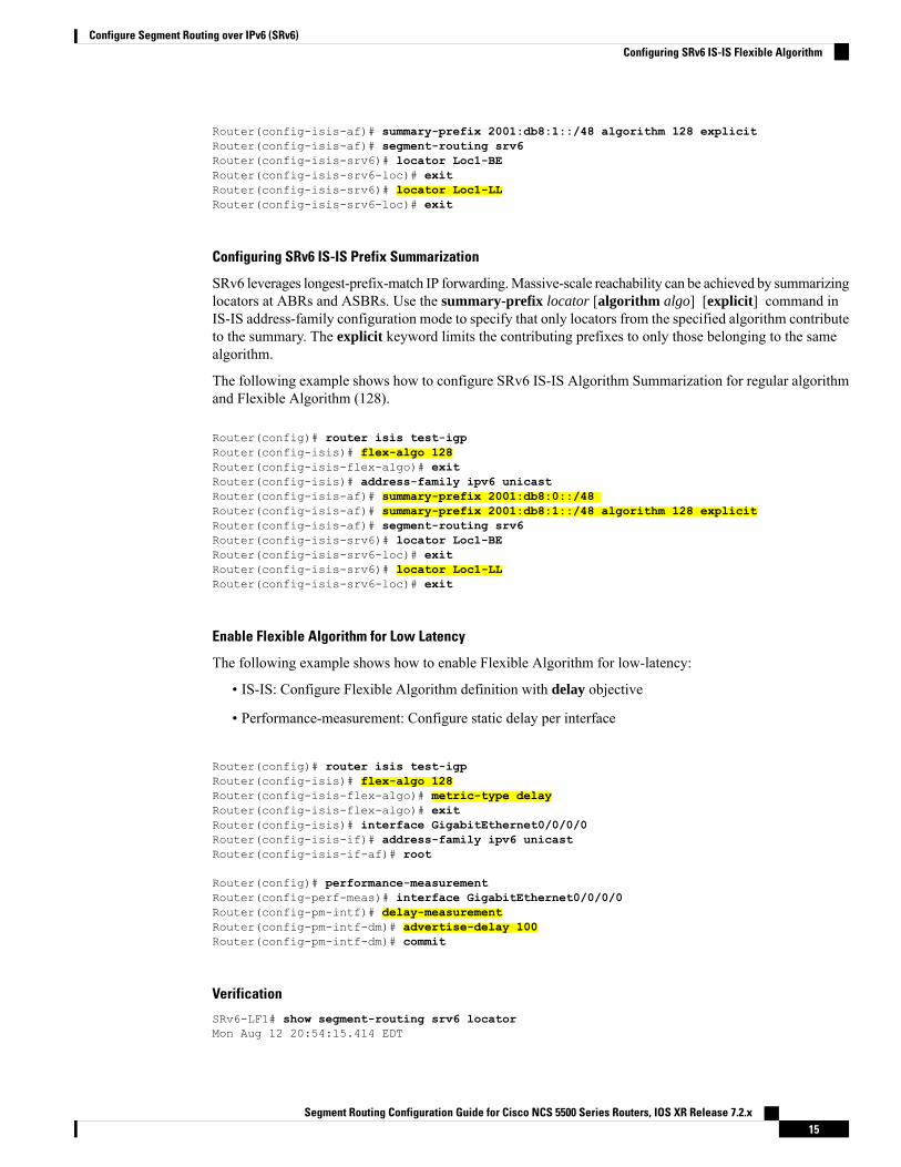
SRv6 leverages longest-prefix-match IP forwarding.Massive-scale reachability can be achieved by summarizinglocators at ABRs and ASBRs. Use the summary-prefix locator [algorithm algo] [explicit] command inIS-IS address-family configuration mode to specify that only locators from the specified algorithm contributeto the summary. The explicit keyword limits the contributing prefixes to only those belonging to the samealgorithm.
The following example shows how to configure SRv6 IS-IS Algorithm Summarization for regular algorithmand Flexible Algorithm (128).
Router(config)# router isis test-igpRouter(config-isis)# flex-algo 128Router(config-isis-flex-algo)# exitRouter(config-isis)# address-family ipv6 unicastRouter(config-isis-af)# summary-prefix 2001:db8:0::/48Router(config-isis-af)# summary-prefix 2001:db8:1::/48 algorithm 128 explicitRouter(config-isis-af)# segment-routing srv6Router(config-isis-srv6)# locator Loc1-BERouter(config-isis-srv6-loc)# exitRouter(config-isis-srv6)# locator Loc1-LLRouter(config-isis-srv6-loc)# exit
Enable Flexible Algorithm for Low Latency
The following example shows how to enable Flexible Algorithm for low-latency:
• IS-IS: Configure Flexible Algorithm definition with delay objective
• Performance-measurement: Configure static delay per interface
Router(config)# router isis test-igpRouter(config-isis)# flex-algo 128Router(config-isis-flex-algo)# metric-type delayRouter(config-isis-flex-algo)# exitRouter(config-isis)# interface GigabitEthernet0/0/0/0Router(config-isis-if)# address-family ipv6 unicastRouter(config-isis-if-af)# root
Router(config)# performance-measurementRouter(config-perf-meas)# interface GigabitEthernet0/0/0/0Router(config-pm-intf)# delay-measurementRouter(config-pm-intf-dm)# advertise-delay 100Router(config-pm-intf-dm)# commit
Verification
SRv6-LF1# show segment-routing srv6 locatorMon Aug 12 20:54:15.414 EDT
Segment Routing Configuration Guide for Cisco NCS 5500 Series Routers, IOS XR Release 7.2.x15
Configure Segment Routing over IPv6 (SRv6)Configuring SRv6 IS-IS Flexible Algorithm

Name ID Algo Prefix Status-------------------- ------- ---- ------------------------ -------Loc1-BE 17 0 2001:db8:0:a2::/64 UpLoc1-LL 18 128 2001:db8:1:a2::/64 Up
SRv6-LF1# show isis flex-algo 128Mon Aug 12 21:00:54.282 EDT
IS-IS test-igp Flex-Algo Database
Flex-Algo 128:
Level-2:Definition Priority: 128Definition Source: SRv6-LF1.00, (Local)Definition Equal to Local: YesDisabled: No
Level-1:Definition Priority: 128Definition Source: SRv6-LF1.00, (Local)Definition Equal to Local: YesDisabled: No
Local Priority: 128FRR Disabled: NoMicroloop Avoidance Disabled: No
Configuring SRv6 IS-IS TI-LFAThis feature introduces support for implementing Topology-Independent Loop-Free Alternate (TI-LFA) usingIS-IS SRv6.
TI-LFA provides link protection in topologies where other fast reroute techniques cannot provide protection.The goal of TI-LFA is to reduce the packet loss that results while routers converge after a topology changedue to a link failure. TI-LFA leverages the post-convergence path which is planned to carry the traffic andensures link and node protection within 50 milliseconds. TI-LFA with IS-IS SR-MPLS is already supported.
TI-LFA provides link, node, and Shared Risk Link Groups (SRLG) protection in any topology.
For more information, see Configure Topology-Independent Loop-Free Alternate (TI-LFA), on page 253.
Usage Guidelines and Restrictions
The following usage guidelines and restrictions apply:
• TI-LFA provides link protection by default. Additional tiebreaker configuration is required to enablenode or SRLG protection.
• Usage guidelines for node and SRLG protection:
• TI-LFA node protection functionality provides protection from node failures. The neighbor nodeis excluded during the post convergence backup path calculation.
• Shared Risk Link Groups (SRLG) refer to situations in which links in a network share a commonfiber (or a common physical attribute). These links have a shared risk: when one link fails, other
Segment Routing Configuration Guide for Cisco NCS 5500 Series Routers, IOS XR Release 7.2.x16
Configure Segment Routing over IPv6 (SRv6)Configuring SRv6 IS-IS TI-LFA

links in the group might also fail. TI-LFA SRLG protection attempts to find the post-convergencebackup path that excludes the SRLG of the protected link. All local links that share any SRLG withthe protecting link are excluded.
• When you enable link protection, you can also enable node protection, SRLG protection, or both,and specify a tiebreaker priority in case there are multiple LFAs.
• Valid priority values are from 1 to 255. The lower the priority value, the higher the priority of therule. Link protection always has a lower priority than node or SRLG protection.
Configuring SRv6 IS-IS TI-LFA
The following example shows how to configure SRv6 IS-IS TI-LFA.
Complete the Configuring SRv6 before performing these steps.Note
Router(config)# router isis coreRouter(config-isis)# address-family ipv6 unicastRouter(config-isis-af)# segment-routing srv6Router(config-isis-srv6)# locator locator1Router(config-isis-srv6-loc)# exitRouter(config-isis)# interface loopback 0Router(config-isis-if)# passiveRouter(config-isis-if)# address-family ipv6 unicastRouter(config-isis-if-af)# exitRouter(config-isis)# interface bundle-ether 1201Router(config-isis-if)# address-family ipv6 unicastRouter(config-isis-if-af)# fast-reroute per-prefixRouter(config-isis-if-af)# fast-reroute per-prefix ti-lfaRouter(config-isis-if-af)# exitRouter(config-isis)# interface bundle-ether 1301Router(config-isis-if)# address-family ipv6 unicastRouter(config-isis-if-af)# fast-reroute per-prefixRouter(config-isis-if-af)# fast-reroute per-prefix ti-lfaRouter(config-isis-if-af)# fast-reroute per-prefix tiebreaker node-protecting index 100Router(config-isis-if-af)# fast-reroute per-prefix tiebreaker srlg-disjoint index 200Router(config-isis-if-af)# exit
Configuring SRv6 IS-IS TI-LFA with Flexible Algorithm
TI-LFA backup paths for particular Flexible Algorithm are computed using the same constraints as thecalculation of the primary paths for such Flexible Algorithm. These paths use Prefix-SIDs advertised specificallyfor such Flexible Algorithm in order to enforce a backup path.
The following example shows how to configure SRv6 IS-IS TI-LFA with Flexible Algorithm.
Router(config)# router isis coreRouter(config-isis)# flex-algo 128Router(config-isis-flex-algo)# exitRouter(config-isis)# address-family ipv6 unicastRouter(config-isis-af)# segment-routing srv6Router(config-isis-srv6)# locator locator1Router(config-isis-srv6-loc)# exit
Segment Routing Configuration Guide for Cisco NCS 5500 Series Routers, IOS XR Release 7.2.x17
Configure Segment Routing over IPv6 (SRv6)Configuring SRv6 IS-IS TI-LFA
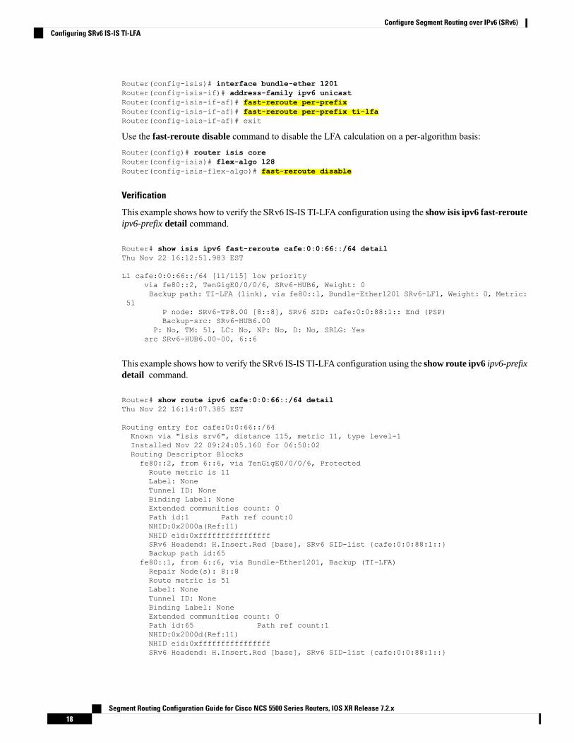
Router(config-isis)# interface bundle-ether 1201Router(config-isis-if)# address-family ipv6 unicastRouter(config-isis-if-af)# fast-reroute per-prefixRouter(config-isis-if-af)# fast-reroute per-prefix ti-lfaRouter(config-isis-if-af)# exit
Use the fast-reroute disable command to disable the LFA calculation on a per-algorithm basis:Router(config)# router isis coreRouter(config-isis)# flex-algo 128Router(config-isis-flex-algo)# fast-reroute disable
Verification
This example shows how to verify the SRv6 IS-IS TI-LFA configuration using the show isis ipv6 fast-rerouteipv6-prefix detail command.
Router# show isis ipv6 fast-reroute cafe:0:0:66::/64 detailThu Nov 22 16:12:51.983 EST
L1 cafe:0:0:66::/64 [11/115] low priorityvia fe80::2, TenGigE0/0/0/6, SRv6-HUB6, Weight: 0Backup path: TI-LFA (link), via fe80::1, Bundle-Ether1201 SRv6-LF1, Weight: 0, Metric:
51P node: SRv6-TP8.00 [8::8], SRv6 SID: cafe:0:0:88:1:: End (PSP)Backup-src: SRv6-HUB6.00
P: No, TM: 51, LC: No, NP: No, D: No, SRLG: Yessrc SRv6-HUB6.00-00, 6::6
This example shows how to verify the SRv6 IS-IS TI-LFA configuration using the show route ipv6 ipv6-prefixdetail command.
Router# show route ipv6 cafe:0:0:66::/64 detailThu Nov 22 16:14:07.385 EST
Routing entry for cafe:0:0:66::/64Known via "isis srv6", distance 115, metric 11, type level-1Installed Nov 22 09:24:05.160 for 06:50:02Routing Descriptor Blocksfe80::2, from 6::6, via TenGigE0/0/0/6, ProtectedRoute metric is 11Label: NoneTunnel ID: NoneBinding Label: NoneExtended communities count: 0Path id:1 Path ref count:0NHID:0x2000a(Ref:11)NHID eid:0xffffffffffffffffSRv6 Headend: H.Insert.Red [base], SRv6 SID-list {cafe:0:0:88:1::}Backup path id:65
fe80::1, from 6::6, via Bundle-Ether1201, Backup (TI-LFA)Repair Node(s): 8::8Route metric is 51Label: NoneTunnel ID: NoneBinding Label: NoneExtended communities count: 0Path id:65 Path ref count:1NHID:0x2000d(Ref:11)NHID eid:0xffffffffffffffffSRv6 Headend: H.Insert.Red [base], SRv6 SID-list {cafe:0:0:88:1::}
Segment Routing Configuration Guide for Cisco NCS 5500 Series Routers, IOS XR Release 7.2.x18
Configure Segment Routing over IPv6 (SRv6)Configuring SRv6 IS-IS TI-LFA

MPLS eid:0x1380800000001
This example shows how to verify the SRv6 IS-IS TI-LFA configuration using the show cef ipv6 ipv6-prefixdetail location location command.
Router# show cef ipv6 cafe:0:0:66::/64 detail location 0/0/cpu0Thu Nov 22 17:01:58.536 ESTcafe:0:0:66::/64, version 1356, SRv6 Transit, internal 0x1000001 0x2 (ptr 0x8a4a45cc) [1],0x0 (0x8a46ae20), 0x0 (0x8c8f31b0)Updated Nov 22 09:24:05.166local adjacency fe80::2Prefix Len 64, traffic index 0, precedence n/a, priority 2gateway array (0x8a2dfaf0) reference count 4, flags 0x500000, source rib (7), 0 backups
[5 type 3 flags 0x8401 (0x8a395d58) ext 0x0 (0x0)]LW-LDI[type=3, refc=1, ptr=0x8a46ae20, sh-ldi=0x8a395d58]gateway array update type-time 1 Nov 22 09:24:05.163LDI Update time Nov 22 09:24:05.163LW-LDI-TS Nov 22 09:24:05.166via fe80::2/128, TenGigE0/0/0/6, 8 dependencies, weight 0, class 0, protected [flags
0x400]path-idx 0 bkup-idx 1 NHID 0x2000a [0x8a2c2fd0 0x0]next hop fe80::2/128via fe80::1/128, Bundle-Ether1201, 8 dependencies, weight 0, class 0, backup (TI-LFA)
[flags 0xb00]path-idx 1 NHID 0x2000d [0x8c2670b0 0x0]next hop fe80::1/128, Repair Node(s): 8::8local adjacencySRv6 H.Insert.Red SID-list {cafe:0:0:88:1::}
Load distribution: 0 (refcount 5)
Hash OK Interface Address0 Y TenGigE0/0/0/6 fe80::2
This example shows how to verify the SRv6 IS-IS TI-LFA configuration using the show cef ipv6fast-reroute-db command.
Router# show cef ipv6 fast-reroute-dbSun Dec 9 20:23:08.111 EST
PROTECT-FRR: per-prefix [1, 0x0, 0x0, 0x98c83270]protect-interface: Te0/0/0/6 (0x208)protect-next-hop: fe80::2/128ipv6 nhinfo [0x977397d0]Update Time Dec 9 17:29:42.427
BACKUP-FRR: per-prefix [5, 0x0, 0x2, 0x98c83350]backup-interface: BE1201 (0x800002c)backup-next-hop: fe80::1/128ipv6 nhinfo [0x977396a0 protect-frr: 0x98c83270]
Update Time Dec 9 17:29:42.428
PROTECT-FRR: per-prefix [1, 0x0, 0x0, 0x98c830b0]protect-interface: BE1201 (0x800002c)protect-next-hop: fe80::1/128ipv6 nhinfo [0x977396a0]Update Time Dec 9 17:29:42.429
BACKUP-FRR: per-prefix [5, 0x0, 0x1, 0x98c83190]backup-interface: Te0/0/0/6 (0x208)backup-next-hop: fe80::2/128
Segment Routing Configuration Guide for Cisco NCS 5500 Series Routers, IOS XR Release 7.2.x19
Configure Segment Routing over IPv6 (SRv6)Configuring SRv6 IS-IS TI-LFA

ipv6 nhinfo [0x977397d0 protect-frr: 0x98c830b0]Update Time Dec 9 17:29:42.429
Configuring SRv6 IS-IS Microloop AvoidanceThis feature introduces support for implementing microloop avoidance using IS-IS SRv6.
Microloops are brief packet loops that occur in the network following a topology change (link down, link up,or metric change events). Microloops are caused by the non-simultaneous convergence of different nodes inthe network. If nodes converge and send traffic to a neighbor node that has not converged yet, traffic may belooped between these two nodes, resulting in packet loss, jitter, and out-of-order packets.
The SRv6 Microloop Avoidance feature detects if microloops are possible following a topology change. If anode computes that a microloop could occur on the new topology, the node creates a loop-free SR-TE policypath to the destination using a list of segments. After the RIB update delay timer expires, the SR-TE policyis replaced with regular forwarding paths.
Restrictions and Usage Guidelines
The following restrictions and usage guidelines apply:
• The Routing Information Base (RIB) update delay value specifies the amount of time the node uses themicroloop avoidance policy before updating its forwarding table. The delay-time range is from 1 to 60000milliseconds; the default value is 5000.
Configuring SRv6 IS-IS Microloop Avoidance
The following example shows how to configure SRv6 IS-IS Microloop Avoidance and set the RoutingInformation Base (RIB) update delay value.
Complete the Configuring SRv6 before performing these steps.Note
Router(config)# router isis test-igpRouter(config-isis)# address-family ipv6 unicastRouter(config-isis-af)# microloop avoidance segment-routingRouter(config-isis-af)# microloop avoidance rib-update-delay 2000Router(config-isis-af)# commit
Configuring SRv6 IS-IS Microloop Avoidance with Flexible Algorithm
Microloop Avoidance paths for particular Flexible Algorithm are computed using the same constraints as thecalculation of the primary paths for such Flexible Algorithm. These paths use Prefix-SIDs advertised specificallyfor such Flexible Algorithm in order to enforce a microloop avoidance path.
The following example shows how to configure SRv6 IS-IS Microloop Avoidance with Flexible Algorithm.Router(config)# segment-routing srv6Router(config-srv6)# locatorsRouter(config-srv6-locators)# locator myLoc1Router(config-srv6-locator)# prefix 2001:db8:1:a2::/64
Segment Routing Configuration Guide for Cisco NCS 5500 Series Routers, IOS XR Release 7.2.x20
Configure Segment Routing over IPv6 (SRv6)Configuring SRv6 IS-IS Microloop Avoidance
Router(config-srv6-locator)# algorithm 128Router(config-srv6-locator)# root
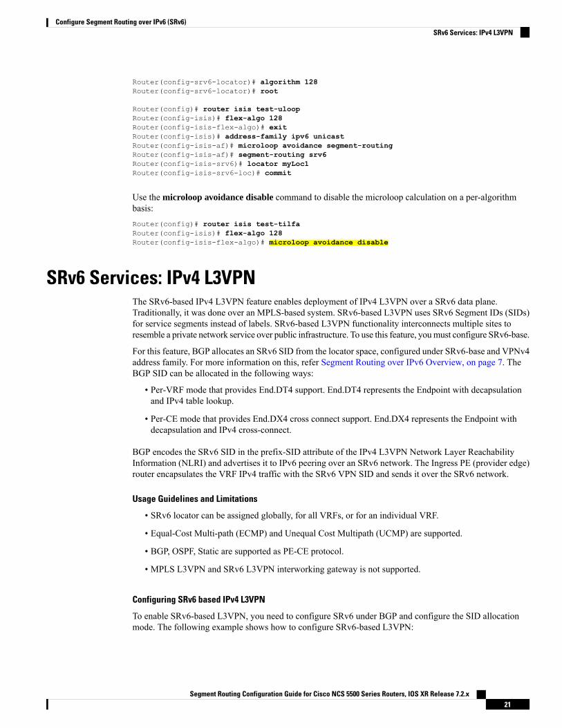
Router(config)# router isis test-uloopRouter(config-isis)# flex-algo 128Router(config-isis-flex-algo)# exitRouter(config-isis)# address-family ipv6 unicastRouter(config-isis-af)# microloop avoidance segment-routingRouter(config-isis-af)# segment-routing srv6Router(config-isis-srv6)# locator myLoc1Router(config-isis-srv6-loc)# commit
Use the microloop avoidance disable command to disable the microloop calculation on a per-algorithmbasis:Router(config)# router isis test-tilfaRouter(config-isis)# flex-algo 128Router(config-isis-flex-algo)# microloop avoidance disable
SRv6 Services: IPv4 L3VPNThe SRv6-based IPv4 L3VPN feature enables deployment of IPv4 L3VPN over a SRv6 data plane.Traditionally, it was done over an MPLS-based system. SRv6-based L3VPN uses SRv6 Segment IDs (SIDs)for service segments instead of labels. SRv6-based L3VPN functionality interconnects multiple sites toresemble a private network service over public infrastructure. To use this feature, youmust configure SRv6-base.
For this feature, BGP allocates an SRv6 SID from the locator space, configured under SRv6-base and VPNv4address family. For more information on this, refer Segment Routing over IPv6 Overview, on page 7. TheBGP SID can be allocated in the following ways:
• Per-VRF mode that provides End.DT4 support. End.DT4 represents the Endpoint with decapsulationand IPv4 table lookup.
• Per-CE mode that provides End.DX4 cross connect support. End.DX4 represents the Endpoint withdecapsulation and IPv4 cross-connect.
BGP encodes the SRv6 SID in the prefix-SID attribute of the IPv4 L3VPN Network Layer ReachabilityInformation (NLRI) and advertises it to IPv6 peering over an SRv6 network. The Ingress PE (provider edge)router encapsulates the VRF IPv4 traffic with the SRv6 VPN SID and sends it over the SRv6 network.
Usage Guidelines and Limitations
• SRv6 locator can be assigned globally, for all VRFs, or for an individual VRF.
• Equal-Cost Multi-path (ECMP) and Unequal Cost Multipath (UCMP) are supported.
• BGP, OSPF, Static are supported as PE-CE protocol.
• MPLS L3VPN and SRv6 L3VPN interworking gateway is not supported.
Configuring SRv6 based IPv4 L3VPN
To enable SRv6-based L3VPN, you need to configure SRv6 under BGP and configure the SID allocationmode. The following example shows how to configure SRv6-based L3VPN:
Segment Routing Configuration Guide for Cisco NCS 5500 Series Routers, IOS XR Release 7.2.x21
Configure Segment Routing over IPv6 (SRv6)SRv6 Services: IPv4 L3VPN
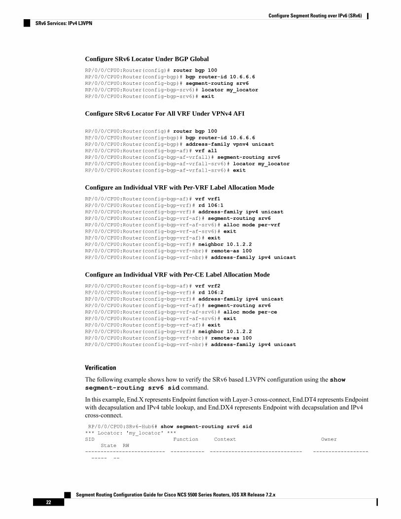
Configure SRv6 Locator Under BGP Global
RP/0/0/CPU0:Router(config)# router bgp 100RP/0/0/CPU0:Router(config-bgp)# bgp router-id 10.6.6.6RP/0/0/CPU0:Router(config-bgp)# segment-routing srv6RP/0/0/CPU0:Router(config-bgp-srv6)# locator my_locatorRP/0/0/CPU0:Router(config-bgp-srv6)# exit
Configure SRv6 Locator For All VRF Under VPNv4 AFI
RP/0/0/CPU0:Router(config)# router bgp 100RP/0/0/CPU0:Router(config-bgp)# bgp router-id 10.6.6.6RP/0/0/CPU0:Router(config-bgp)# address-family vpnv4 unicastRP/0/0/CPU0:Router(config-bgp-af)# vrf allRP/0/0/CPU0:Router(config-bgp-af-vrfall)# segment-routing srv6RP/0/0/CPU0:Router(config-bgp-af-vrfall-srv6)# locator my_locatorRP/0/0/CPU0:Router(config-bgp-af-vrfall-srv6)# exit
Configure an Individual VRF with Per-VRF Label Allocation Mode
RP/0/0/CPU0:Router(config-bgp-af)# vrf vrf1RP/0/0/CPU0:Router(config-bgp-vrf)# rd 106:1RP/0/0/CPU0:Router(config-bgp-vrf)# address-family ipv4 unicastRP/0/0/CPU0:Router(config-bgp-vrf-af)# segment-routing srv6RP/0/0/CPU0:Router(config-bgp-vrf-af-srv6)# alloc mode per-vrfRP/0/0/CPU0:Router(config-bgp-vrf-af-srv6)# exitRP/0/0/CPU0:Router(config-bgp-vrf-af)# exitRP/0/0/CPU0:Router(config-bgp-vrf)# neighbor 10.1.2.2RP/0/0/CPU0:Router(config-bgp-vrf-nbr)# remote-as 100RP/0/0/CPU0:Router(config-bgp-vrf-nbr)# address-family ipv4 unicast
Configure an Individual VRF with Per-CE Label Allocation Mode
RP/0/0/CPU0:Router(config-bgp-af)# vrf vrf2RP/0/0/CPU0:Router(config-bgp-vrf)# rd 106:2RP/0/0/CPU0:Router(config-bgp-vrf)# address-family ipv4 unicastRP/0/0/CPU0:Router(config-bgp-vrf-af)# segment-routing srv6RP/0/0/CPU0:Router(config-bgp-vrf-af-srv6)# alloc mode per-ceRP/0/0/CPU0:Router(config-bgp-vrf-af-srv6)# exitRP/0/0/CPU0:Router(config-bgp-vrf-af)# exitRP/0/0/CPU0:Router(config-bgp-vrf)# neighbor 10.1.2.2RP/0/0/CPU0:Router(config-bgp-vrf-nbr)# remote-as 100RP/0/0/CPU0:Router(config-bgp-vrf-nbr)# address-family ipv4 unicast
Verification
The following example shows how to verify the SRv6 based L3VPN configuration using the showsegment-routing srv6 sid command.
In this example, End.X represents Endpoint function with Layer-3 cross-connect, End.DT4 represents Endpointwith decapsulation and IPv4 table lookup, and End.DX4 represents Endpoint with decapsulation and IPv4cross-connect.RP/0/0/CPU0:SRv6-Hub6# show segment-routing srv6 sid*** Locator: 'my_locator' ***SID Function Context Owner
State RW-------------------------- ----------- ------------------------------ ----------------------- --
Segment Routing Configuration Guide for Cisco NCS 5500 Series Routers, IOS XR Release 7.2.x22
Configure Segment Routing over IPv6 (SRv6)SRv6 Services: IPv4 L3VPN

cafe:0:0:66:1:: End (PSP) 'my_locator':1 sidmgrInUse Y
cafe:0:0:66:40:: End.X (PSP) [Te0/0/0/2, Link-Local] isis-srv6InUse Y
cafe:0:0:66:41:: End.X (PSP) [BE6801, Link-Local] isis-srv6InUse Y
cafe:0:0:66:42:: End.X (PSP) [BE5601, Link-Local] isis-srv6InUse Y
cafe:0:0:66:43:: End.X (PSP) [BE5602, Link-Local] isis-srv6InUse Y
cafe:0:0:66:44:: End.DT4 'VRF1' bgp-100InUse Y
cafe:0:0:66:45:: End.DT4 'VRF2' bgp-100InUse Y
cafe:0:0:66:46:: End.DX4 'VRF2’:3 bgp-100InUse Y
cafe:0:0:66:47:: End.DX4 'VRF2’:4 bgp-100InUse Y
The following example shows how to verify the SRv6 based L3VPN configuration using the showsegment-routing srv6SID-prefixdetail command.
RP/0/RP0/CPU0:SRv6-Hub6# show segment-routing srv6 sid cafe:0:0:66:44:: detailSun Dec 9 16:52:54.015 EST*** Locator: ‘my_locator' ***SID Function Context Owner
State RW-------------------------- ----------- ------------------------------ ----------------------- --
cafe:0:0:66:44:: End.DT4 'VRF1' bgp-100InUse Y
SID context: { table-id=0xe0000001 ('VRF1':IPv4/Unicast) }Locator: ‘my_locator'Allocation type: DynamicCreated: Dec 8 16:34:32.506 (1d00h ago)
RP/0/RP0/CPU0:SRv6-Hub6# show segment-routing srv6 sid cafe:0:0:66:47:: detailSun Dec 9 16:54:26.073 EST*** Locator: 'my_locator' ***SID Function Context Owner
State RW-------------------------- ----------- ------------------------------ ----------------------- --
cafe:0:0:66:47:: End.DX4 'VRF2’:4 bgp-100InUse Y
SID context: { table-id=0xe0000002 ('VRF2':IPv4/Unicast), nh-set-id=4 }Locator: ‘my_locator'Allocation type: DynamicCreated: Dec 9 16:49:44.714 (00:04:41 ago)
The following example shows how to verify the SRv6 based L3VPN configuration using the show bgp vpnv4unicast rdroute-distinguisher/prefix command on Egress PE.
RP/0/RP0/CPU0:SRv6-Hub6# show bgp vpnv4 unicast rd 106:1 10.15.0.0/30Wed Nov 21 16:08:44.765 ESTBGP routing table entry for 10.15.0.0/30, Route Distinguisher: 106:1Versions:Process bRIB/RIB SendTblVerSpeaker 2282449 2282449SRv6-VPN SID: cafe:0:0:66:44::/128
Last Modified: Nov 21 15:50:34.235 for 00:18:10Paths: (2 available, best #1)
Segment Routing Configuration Guide for Cisco NCS 5500 Series Routers, IOS XR Release 7.2.x23
Configure Segment Routing over IPv6 (SRv6)SRv6 Services: IPv4 L3VPN
Advertised to peers (in unique update groups):2::2
Path #1: Received by speaker 0Advertised to peers (in unique update groups):2::2
20010.1.2.2 from 10.1.2.2 (10.7.0.1)Origin IGP, localpref 200, valid, internal, best, group-best, import-candidateReceived Path ID 0, Local Path ID 1, version 2276228Extended community: RT:201:1
Path #2: Received by speaker 0Not advertised to any peer20010.2.2.2 from 10.2.2.2 (10.20.1.2)Origin IGP, localpref 100, valid, internalReceived Path ID 0, Local Path ID 0, version 0Extended community: RT:201:1
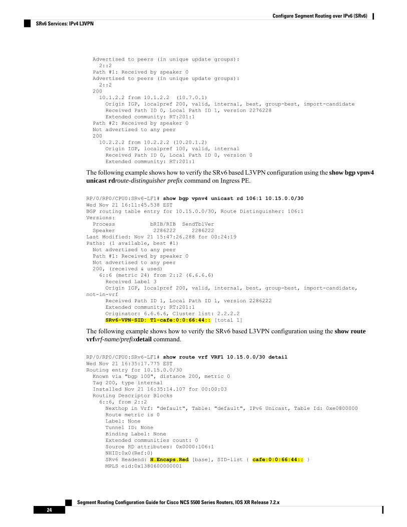
The following example shows how to verify the SRv6 based L3VPN configuration using the show bgp vpnv4unicast rdroute-distinguisher prefix command on Ingress PE.
RP/0/RP0/CPU0:SRv6-LF1# show bgp vpnv4 unicast rd 106:1 10.15.0.0/30Wed Nov 21 16:11:45.538 ESTBGP routing table entry for 10.15.0.0/30, Route Distinguisher: 106:1Versions:Process bRIB/RIB SendTblVerSpeaker 2286222 2286222
Last Modified: Nov 21 15:47:26.288 for 00:24:19Paths: (1 available, best #1)Not advertised to any peerPath #1: Received by speaker 0Not advertised to any peer200, (received & used)6::6 (metric 24) from 2::2 (6.6.6.6)Received Label 3Origin IGP, localpref 200, valid, internal, best, group-best, import-candidate,
not-in-vrfReceived Path ID 1, Local Path ID 1, version 2286222Extended community: RT:201:1Originator: 6.6.6.6, Cluster list: 2.2.2.2SRv6-VPN-SID: T1-cafe:0:0:66:44:: [total 1]
The following example shows how to verify the SRv6 based L3VPN configuration using the show routevrfvrf-name/prefixdetail command.
RP/0/RP0/CPU0:SRv6-LF1# show route vrf VRF1 10.15.0.0/30 detailWed Nov 21 16:35:17.775 ESTRouting entry for 10.15.0.0/30Known via "bgp 100", distance 200, metric 0Tag 200, type internalInstalled Nov 21 16:35:14.107 for 00:00:03Routing Descriptor Blocks6::6, from 2::2Nexthop in Vrf: "default", Table: "default", IPv6 Unicast, Table Id: 0xe0800000Route metric is 0Label: NoneTunnel ID: NoneBinding Label: NoneExtended communities count: 0Source RD attributes: 0x0000:106:1NHID:0x0(Ref:0)SRv6 Headend: H.Encaps.Red [base], SID-list { cafe:0:0:66:44:: }MPLS eid:0x1380600000001
Segment Routing Configuration Guide for Cisco NCS 5500 Series Routers, IOS XR Release 7.2.x24
Configure Segment Routing over IPv6 (SRv6)SRv6 Services: IPv4 L3VPN

Route version is 0xd (13)No local labelIP Precedence: Not SetQoS Group ID: Not SetFlow-tag: Not SetFwd-class: Not SetRoute Priority: RIB_PRIORITY_RECURSIVE (12) SVD Type RIB_SVD_TYPE_REMOTEDownload Priority 3, Download Version 3038384No advertising protos.
The following example shows how to verify the SRv6 based L3VPN configuration for per-ce allocation modeusing the show bgp vrfvrf-namenexthop-set command.
RP/0/RP0/CPU0:SRv6-Hub6# show bgp vrf VRF2 nexthop-setWed Nov 21 15:52:17.464 ESTResilient per-CE nexthop set, ID 3Number of nexthops 1, Label 0, Flags 0x2200SRv6-VPN SID: cafe:0:0:66:46::/128Nexthops:10.1.2.2Reference count 1,Resilient per-CE nexthop set, ID 4Number of nexthops 2, Label 0, Flags 0x2100SRv6-VPN SID: cafe:0:0:66:47::/128Nexthops:10.1.2.210.2.2.2Reference count 2,
The following example shows how to verify the SRv6 based L3VPN configuration using the show cefvrfvrf-name prefix detail locationline-card command.
RP/0/RP0/CPU0:SRv6-LF1# show cef vrf VRF1 10.15.0.0/30 detail location 0/0/cpu0Wed Nov 21 16:37:06.894 EST151.1.0.0/30, version 3038384, SRv6 Transit, internal 0x5000001 0x0 (ptr 0x9ae6474c) [1],0x0 (0x0), 0x0 (0x8c11b238)Updated Nov 21 16:35:14.109Prefix Len 30, traffic index 0, precedence n/a, priority 3gateway array (0x8cd85190) reference count 1014, flags 0x2010, source rib (7), 0 backups
[1 type 3 flags 0x40441 (0x8a529798) ext 0x0 (0x0)]LW-LDI[type=0, refc=0, ptr=0x0, sh-ldi=0x0]gateway array update type-time 1 Nov 21 14:47:26.816LDI Update time Nov 21 14:52:53.073Level 1 - Load distribution: 0[0] via cafe:0:0:66::/128, recursivevia cafe:0:0:66::/128, 7 dependencies, recursive [flags 0x6000]path-idx 0 NHID 0x0 [0x8acb53cc 0x0]next hop VRF - 'default', table - 0xe0800000next hop cafe:0:0:66::/128 via cafe:0:0:66::/64SRv6 H.Encaps.Red SID-list {cafe:0:0:66:44::}Load distribution: 0 (refcount 1)Hash OK Interface Address0 Y Bundle-Ether1201 fe80::2
Segment Routing Configuration Guide for Cisco NCS 5500 Series Routers, IOS XR Release 7.2.x25
Configure Segment Routing over IPv6 (SRv6)SRv6 Services: IPv4 L3VPN

SRv6 Services: IPv6 L3VPNTable 2: Feature History Table
Feature DescriptionRelease InformationFeature Name
With this feature, the egress PE cansignal an SRv6 Service SID withthe BGP overlay service route. Theingress PE encapsulates theIPv4/IPv6 payload in an outer IPv6header where the destinationaddress is the SRv6 Service SIDprovided by the egress PE. BGPmessages between PEs carry SRv6Service SIDs as a means tointerconnect PEs and form VPNs.
Release 7.2.2SRv6 Services: IPv6 L3VPN
Building on the messages and procedures defined in IETF draft "BGP/MPLS IP Virtual Private Networks(VPNs)", this feature provides IPv6 L3VPNs (VPNv6) over an SRv6 network.
In SRv6-based L3VPNs, the egress PE signals an SRv6 Service SID with the BGP overlay service route. Theingress PE encapsulates the IPv4/IPv6 payload in an outer IPv6 header where the destination address is theSRv6 Service SID provided by the egress PE. BGP messages between PEs carry SRv6 Service SIDs as ameans to interconnect PEs and form VPNs.
SRv6 Service SID refers to a segment identifier associated with one of the SRv6 service-specific behaviorson the advertising VPNv6 PE router, such as END.DT6 (Endpoint with decapsulation and IPv6 table lookup)or END.DX6 (cross-connect to a nexthop) behaviors.
Based on the messages and procedures defined in IETF draft "SRv6 BGP based Overlay services", BGPencodes the SRv6 Service SID in the prefix-SID attribute of the IPv6 L3VPN Network Layer ReachabilityInformation (NLRI) and advertises it to its IPv6 BGP peers.
BGP allocates an SRv6 Service SID from the locator space, configured under SRv6 and VPNv6 addressfamily. For more information on this, see Segment Routing over IPv6 Overview. The SRv6 Service SID canbe allocated in the following ways:
• Per-VRF mode that provides End.DT6 support. End.DT6 represents the Endpoint with decapsulationand IPv6 table lookup.
• Per-CE mode that provides End.DX6 cross connect support. End.DX6 represents the Endpoint withdecapsulation and IPv6 cross-connect.
Usage Guidelines and Restrictions
• SRv6 locator can be assigned globally, for all VRFs, or for an individual VRF.
• Equal-Cost Multi-path (ECMP) and Unequal Cost Multipath (UCMP) are supported.
• BGP, OSPF, Static are supported as PE-CE protocol.
• MPLS L3VPN and SRv6 L3VPN interworking gateway is not supported.
Segment Routing Configuration Guide for Cisco NCS 5500 Series Routers, IOS XR Release 7.2.x26
Configure Segment Routing over IPv6 (SRv6)SRv6 Services: IPv6 L3VPN
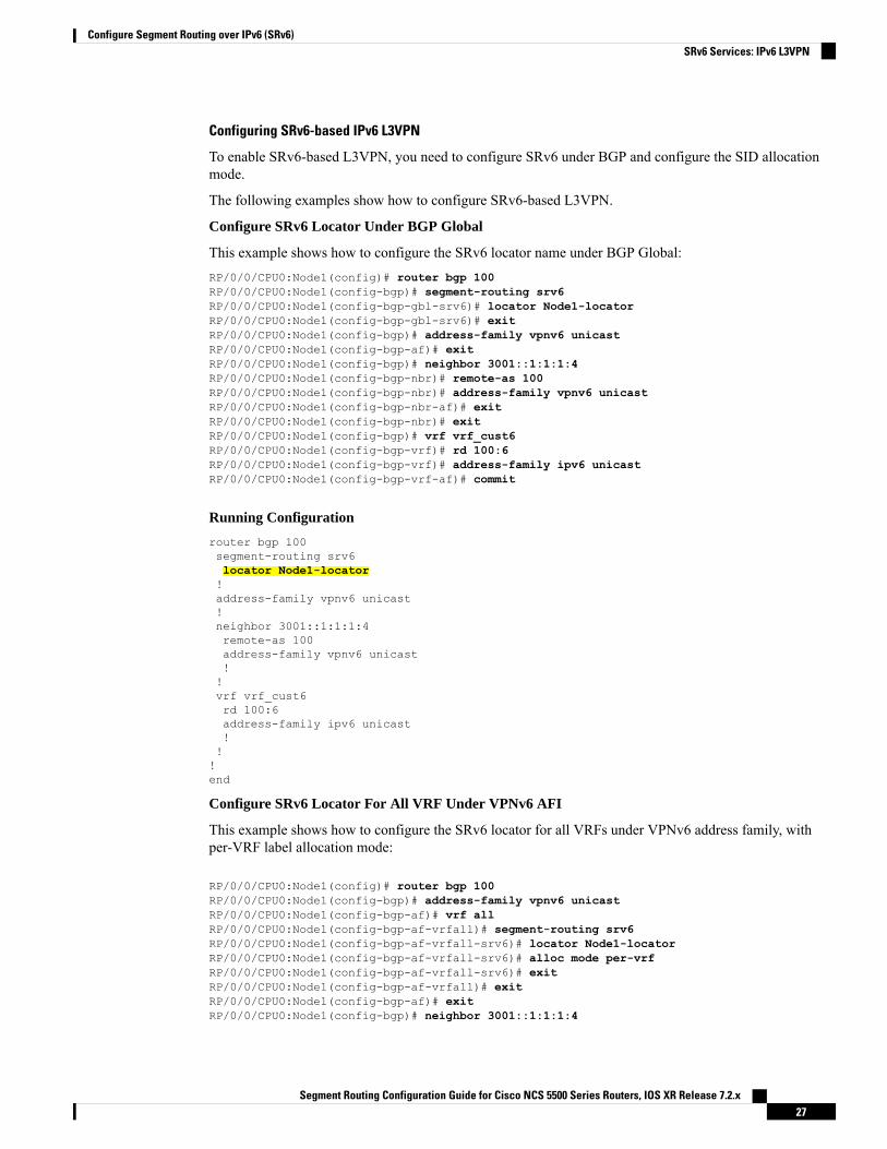
Configuring SRv6-based IPv6 L3VPN
To enable SRv6-based L3VPN, you need to configure SRv6 under BGP and configure the SID allocationmode.
The following examples show how to configure SRv6-based L3VPN.
Configure SRv6 Locator Under BGP Global
This example shows how to configure the SRv6 locator name under BGP Global:RP/0/0/CPU0:Node1(config)# router bgp 100RP/0/0/CPU0:Node1(config-bgp)# segment-routing srv6RP/0/0/CPU0:Node1(config-bgp-gbl-srv6)# locator Node1-locatorRP/0/0/CPU0:Node1(config-bgp-gbl-srv6)# exitRP/0/0/CPU0:Node1(config-bgp)# address-family vpnv6 unicastRP/0/0/CPU0:Node1(config-bgp-af)# exitRP/0/0/CPU0:Node1(config-bgp)# neighbor 3001::1:1:1:4RP/0/0/CPU0:Node1(config-bgp-nbr)# remote-as 100RP/0/0/CPU0:Node1(config-bgp-nbr)# address-family vpnv6 unicastRP/0/0/CPU0:Node1(config-bgp-nbr-af)# exitRP/0/0/CPU0:Node1(config-bgp-nbr)# exitRP/0/0/CPU0:Node1(config-bgp)# vrf vrf_cust6RP/0/0/CPU0:Node1(config-bgp-vrf)# rd 100:6RP/0/0/CPU0:Node1(config-bgp-vrf)# address-family ipv6 unicastRP/0/0/CPU0:Node1(config-bgp-vrf-af)# commit
Running Configuration
router bgp 100segment-routing srv6locator Node1-locator!address-family vpnv6 unicast!neighbor 3001::1:1:1:4remote-as 100address-family vpnv6 unicast!!vrf vrf_cust6rd 100:6address-family ipv6 unicast!!!end
Configure SRv6 Locator For All VRF Under VPNv6 AFI
This example shows how to configure the SRv6 locator for all VRFs under VPNv6 address family, withper-VRF label allocation mode:
RP/0/0/CPU0:Node1(config)# router bgp 100RP/0/0/CPU0:Node1(config-bgp)# address-family vpnv6 unicastRP/0/0/CPU0:Node1(config-bgp-af)# vrf allRP/0/0/CPU0:Node1(config-bgp-af-vrfall)# segment-routing srv6RP/0/0/CPU0:Node1(config-bgp-af-vrfall-srv6)# locator Node1-locatorRP/0/0/CPU0:Node1(config-bgp-af-vrfall-srv6)# alloc mode per-vrfRP/0/0/CPU0:Node1(config-bgp-af-vrfall-srv6)# exitRP/0/0/CPU0:Node1(config-bgp-af-vrfall)# exitRP/0/0/CPU0:Node1(config-bgp-af)# exitRP/0/0/CPU0:Node1(config-bgp)# neighbor 3001::1:1:1:4
Segment Routing Configuration Guide for Cisco NCS 5500 Series Routers, IOS XR Release 7.2.x27
Configure Segment Routing over IPv6 (SRv6)SRv6 Services: IPv6 L3VPN

RP/0/0/CPU0:Node1(config-bgp-nbr)# remote-as 100RP/0/0/CPU0:Node1(config-bgp-nbr)# address-family vpnv6 unicastRP/0/0/CPU0:Node1(config-bgp-nbr-af)# exitRP/0/0/CPU0:Node1(config-bgp-nbr)# exitRP/0/0/CPU0:Node1(config-bgp)# vrf vrf_cust6RP/0/0/CPU0:Node1(config-bgp-vrf)# rd 100:6RP/0/0/CPU0:Node1(config-bgp-vrf)# address-family ipv6 unicastRP/0/0/CPU0:Node1(config-bgp-vrf-af)# commit
Running Configuration
router bgp 100address-family vpnv6 unicastvrf allsegment-routing srv6locator Node1-locatoralloc mode per-vrf!!!neighbor 3001::1:1:1:4remote-as 100address-family vpnv6 unicast!!vrf vrf_cust6rd 100:6address-family ipv6 unicast!!!end
Configure an Individual VRF with Per-VRF Label Allocation Mode
This example shows how to configure the SRv6 locator for an individual VRF, with per-VRF label allocationmode:
RP/0/0/CPU0:Node1(config)# router bgp 100RP/0/0/CPU0:Node1(config-bgp)# address-family vpnv6 unicastRP/0/0/CPU0:Node1(config-bgp-af)# exitRP/0/0/CPU0:Node1(config-bgp)# neighbor 3001::1:1:1:4RP/0/0/CPU0:Node1(config-bgp-nbr)# remote-as 100RP/0/0/CPU0:Node1(config-bgp-nbr)# address-family vpnv6 unicastRP/0/0/CPU0:Node1(config-bgp-nbr-af)# exitRP/0/0/CPU0:Node1(config-bgp-nbr)# exitRP/0/0/CPU0:Node1(config-bgp)# vrf vrf_cust6RP/0/0/CPU0:Node1(config-bgp-vrf)# rd 100:6RP/0/0/CPU0:Node1(config-bgp-vrf)# address-family ipv6 unicastRP/0/0/CPU0:Node1(config-bgp-vrf-af)# segment-routing srv6RP/0/0/CPU0:Node1(config-bgp-vrf-af-srv6)# locator Node1-locatorRP/0/0/CPU0:Node1(config-bgp-vrf-af-srv6)# alloc mode per-vrfRP/0/0/CPU0:Node1(config-bgp-vrf-af-srv6)# commit
Running Configuration
router bgp 100address-family vpnv6 unicast!neighbor 3001::1:1:1:4remote-as 100address-family vpnv6 unicast
Segment Routing Configuration Guide for Cisco NCS 5500 Series Routers, IOS XR Release 7.2.x28
Configure Segment Routing over IPv6 (SRv6)SRv6 Services: IPv6 L3VPN

!!vrf vrf_cust6rd 100:6address-family ipv6 unicastsegment-routing srv6locator Node1-locatoralloc mode per-vrf!!!!end
Verification
The following examples shows how to verify the SRv6 based L3VPN configurations for an Individual VRFwith per VRF label allocation mode.
In this example, End.X represents Endpoint function with Layer-3 cross-connect, and End.DT6 representsEndpoint with decapsulation and IPv6 table lookup.RP/0/RSP0/CPU0:Node1# show segment-routing srv6 sidFri Jan 15 18:58:04.911 UTC
*** Locator: 'Node1-locator' ***
SID Behavior Context OwnerState RW
-------------------------- ---------------- ------------------------------------------------ ----- --cafe:0:0:1:1:: End (PSP) 'default':1 sidmgr
InUse Ycafe:0:0:1:11:: End.OP 'default' sidmgr
InUse Ycafe:0:0:1:40:: End.X (PSP) [Hu0/0/0/0, Link-Local] isis-1
InUse Ycafe:0:0:1:41:: End.X (PSP) [Hu0/0/0/1, Link-Local] isis-1
InUse Ycafe:0:0:1:47:: End.X (PSP) [Hu0/0/0/0, Link-Local]:P isis-1
InUse Ycafe:0:0:1:48:: End.X (PSP) [Hu0/0/0/1, Link-Local]:P isis-1
InUse Ycafe:0:0:1:49:: End.DT6 'default' bgp-100
InUse Ycafe:0:0:1:4a:: End.DT6 'vrf_cust6' bgp-100
InUse Y
The following examples show how to verify the SRv6 based L3VPN configuration using the show bgp vpnv6unicast commands on the Ingress PE.RP/0/RSP0/CPU0:Node1# show bgp vpnv6 unicast summaryFri Jan 15 18:37:04.791 UTCBGP router identifier 1.1.1.1, local AS number 100BGP generic scan interval 60 secsNon-stop routing is enabledBGP table state: ActiveTable ID: 0x0 RD version: 0BGP main routing table version 21BGP NSR Initial initsync version 4 (Reached)BGP NSR/ISSU Sync-Group versions 0/0BGP scan interval 60 secs
Segment Routing Configuration Guide for Cisco NCS 5500 Series Routers, IOS XR Release 7.2.x29
Configure Segment Routing over IPv6 (SRv6)SRv6 Services: IPv6 L3VPN
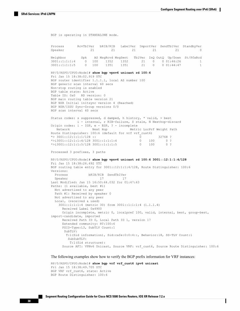
BGP is operating in STANDALONE mode.
Process RcvTblVer bRIB/RIB LabelVer ImportVer SendTblVer StandbyVerSpeaker 21 21 21 21 21 0
Neighbor Spk AS MsgRcvd MsgSent TblVer InQ OutQ Up/Down St/PfxRcd3001::1:1:1:4 0 100 1352 1352 21 0 0 01:46:26 13001::1:1:1:5 0 100 1351 1351 21 0 0 01:44:47 1
RP/0/RSP0/CPU0:Node1# show bgp vpnv6 unicast rd 100:6Fri Jan 15 18:38:02.919 UTCBGP router identifier 1.1.1.1, local AS number 100BGP generic scan interval 60 secsNon-stop routing is enabledBGP table state: ActiveTable ID: 0x0 RD version: 0BGP main routing table version 21BGP NSR Initial initsync version 4 (Reached)BGP NSR/ISSU Sync-Group versions 0/0BGP scan interval 60 secs
Status codes: s suppressed, d damped, h history, * valid, > besti - internal, r RIB-failure, S stale, N Nexthop-discard
Origin codes: i - IGP, e - EGP, ? - incompleteNetwork Next Hop Metric LocPrf Weight Path
Route Distinguisher: 100:6 (default for vrf vrf_cust6)*> 3001::12:1:1:1/128 :: 0 32768 ?*>i3001::12:1:1:4/128 3001::1:1:1:4 0 100 0 ?*>i3001::12:1:1:5/128 3001::1:1:1:5 0 100 0 ?
Processed 3 prefixes, 3 paths
RP/0/RSP0/CPU0:Node1# show bgp vpnv6 unicast rd 100:6 3001::12:1:1:4/128Fri Jan 15 18:38:26.492 UTCBGP routing table entry for 3001::12:1:1:4/128, Route Distinguisher: 100:6Versions:Process bRIB/RIB SendTblVerSpeaker 17 17
Last Modified: Jan 15 16:50:44.032 for 01:47:43Paths: (1 available, best #1)Not advertised to any peerPath #1: Received by speaker 0Not advertised to any peerLocal, (received & used)3001::1:1:1:4 (metric 30) from 3001::1:1:1:4 (1.1.1.4)Received Label 0x4900Origin incomplete, metric 0, localpref 100, valid, internal, best, group-best,
import-candidate, importedReceived Path ID 0, Local Path ID 1, version 17Extended community: RT:100:6PSID-Type:L3, SubTLV Count:1SubTLV:T:1(Sid information), Sid:cafe:0:0:4::, Behavior:18, SS-TLV Count:1SubSubTLV:T:1(Sid structure):
Source AFI: VPNv6 Unicast, Source VRF: vrf_cust6, Source Route Distinguisher: 100:6
The following examples show how to verify the BGP prefix information for VRF instances:RP/0/RSP0/CPU0:Node1# show bgp vrf vrf_cust6 ipv6 unicastFri Jan 15 18:38:49.705 UTCBGP VRF vrf_cust6, state: ActiveBGP Route Distinguisher: 100:6
Segment Routing Configuration Guide for Cisco NCS 5500 Series Routers, IOS XR Release 7.2.x30
Configure Segment Routing over IPv6 (SRv6)SRv6 Services: IPv6 L3VPN

VRF ID: 0x60000008BGP router identifier 1.1.1.1, local AS number 100Non-stop routing is enabledBGP table state: ActiveTable ID: 0xe0800017 RD version: 21BGP main routing table version 21BGP NSR Initial initsync version 4 (Reached)BGP NSR/ISSU Sync-Group versions 0/0
Status codes: s suppressed, d damped, h history, * valid, > besti - internal, r RIB-failure, S stale, N Nexthop-discard
Origin codes: i - IGP, e - EGP, ? - incompleteNetwork Next Hop Metric LocPrf Weight Path
Route Distinguisher: 100:6 (default for vrf vrf_cust6)*> 3001::12:1:1:1/128 :: 0 32768 ?*>i3001::12:1:1:4/128 3001::1:1:1:4 0 100 0 ?*>i3001::12:1:1:5/128 3001::1:1:1:5 0 100 0 ?
Processed 3 prefixes, 3 paths
RP/0/RSP0/CPU0:Node1# show bgp vrf vrf_cust6 ipv6 unicast 3001::12:1:1:4/128Fri Jan 15 18:39:05.115 UTCBGP routing table entry for 3001::12:1:1:4/128, Route Distinguisher: 100:6Versions:Process bRIB/RIB SendTblVerSpeaker 17 17
Last Modified: Jan 15 16:50:44.032 for 01:48:21Paths: (1 available, best #1)Not advertised to any peerPath #1: Received by speaker 0Not advertised to any peerLocal, (received & used)3001::1:1:1:4 (metric 30) from 3001::1:1:1:4 (1.1.1.4)Received Label 0x4900Origin incomplete, metric 0, localpref 100, valid, internal, best, group-best,
import-candidate, importedReceived Path ID 0, Local Path ID 1, version 17Extended community: RT:100:6PSID-Type:L3, SubTLV Count:1SubTLV:T:1(Sid information), Sid:cafe:0:0:4::, Behavior:18, SS-TLV Count:1SubSubTLV:T:1(Sid structure):
Source AFI: VPNv6 Unicast, Source VRF: vrf_cust6, Source Route Distinguisher: 100:6
The following examples show how to verify the current routes in the Routing Information Base (RIB):RP/0/RSP0/CPU0:Node1# show route vrf vrf_cust6 ipv6 unicastFri Jan 15 18:39:20.619 UTC
Codes: C - connected, S - static, R - RIP, B - BGP, (>) - Diversion pathD - EIGRP, EX - EIGRP external, O - OSPF, IA - OSPF inter areaN1 - OSPF NSSA external type 1, N2 - OSPF NSSA external type 2E1 - OSPF external type 1, E2 - OSPF external type 2, E - EGPi - ISIS, L1 - IS-IS level-1, L2 - IS-IS level-2ia - IS-IS inter area, su - IS-IS summary null, * - candidate defaultU - per-user static route, o - ODR, L - local, G - DAGR, l - LISPA - access/subscriber, a - Application routeM - mobile route, r - RPL, t - Traffic Engineering, (!) - FRR Backup path
Gateway of last resort is not set
L 3001::12:1:1:1/128 is directly connected,21:14:10, Loopback105
Segment Routing Configuration Guide for Cisco NCS 5500 Series Routers, IOS XR Release 7.2.x31
Configure Segment Routing over IPv6 (SRv6)SRv6 Services: IPv6 L3VPN
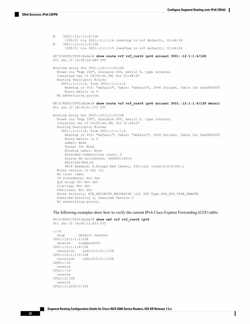
B 3001::12:1:1:4/128[200/0] via 3001::1:1:1:4 (nexthop in vrf default), 01:48:36
B 3001::12:1:1:5/128[200/0] via 3001::1:1:1:5 (nexthop in vrf default), 01:46:56
RP/0/RSP0/CPU0:Node1# show route vrf vrf_cust6 ipv6 unicast 3001::12:1:1:4/128Fri Jan 15 18:39:39.689 UTC
Routing entry for 3001::12:1:1:4/128Known via "bgp 100", distance 200, metric 0, type internalInstalled Jan 15 16:50:44.381 for 01:48:55Routing Descriptor Blocks3001::1:1:1:4, from 3001::1:1:1:4Nexthop in Vrf: "default", Table: "default", IPv6 Unicast, Table Id: 0xe0800000Route metric is 0
No advertising protos.
RP/0/RSP0/CPU0:Node1# show route vrf vrf_cust6 ipv6 unicast 3001::12:1:1:4/128 detailFri Jan 15 18:39:51.573 UTC
Routing entry for 3001::12:1:1:4/128Known via "bgp 100", distance 200, metric 0, type internalInstalled Jan 15 16:50:44.381 for 01:49:07Routing Descriptor Blocks3001::1:1:1:4, from 3001::1:1:1:4Nexthop in Vrf: "default", Table: "default", IPv6 Unicast, Table Id: 0xe0800000Route metric is 0Label: NoneTunnel ID: NoneBinding Label: NoneExtended communities count: 0Source RD attributes: 0x0000:100:6NHID:0x0(Ref:0)SRv6 Headend: H.Encaps.Red [base], SID-list {cafe:0:0:4:49::}
Route version is 0x1 (1)No local labelIP Precedence: Not SetQoS Group ID: Not SetFlow-tag: Not SetFwd-class: Not SetRoute Priority: RIB_PRIORITY_RECURSIVE (12) SVD Type RIB_SVD_TYPE_REMOTEDownload Priority 3, Download Version 3No advertising protos.
The following examples show how to verify the current IPv6 Cisco Express Forwarding (CEF) table:RP/0/RSP0/CPU0:Node1# show cef vrf vrf_cust6 ipv6Fri Jan 15 18:40:15.833 UTC
::/0drop default handler
3001::12:1:1:1/128receive Loopback105
3001::12:1:1:4/128recursive cafe:0:0:4::/128
3001::12:1:1:5/128recursive cafe:0:0:5::/128
fe80::/10receive
ff02::/16receive
ff02::2/128receive
ff02::1:ff00:0/104
Segment Routing Configuration Guide for Cisco NCS 5500 Series Routers, IOS XR Release 7.2.x32
Configure Segment Routing over IPv6 (SRv6)SRv6 Services: IPv6 L3VPN
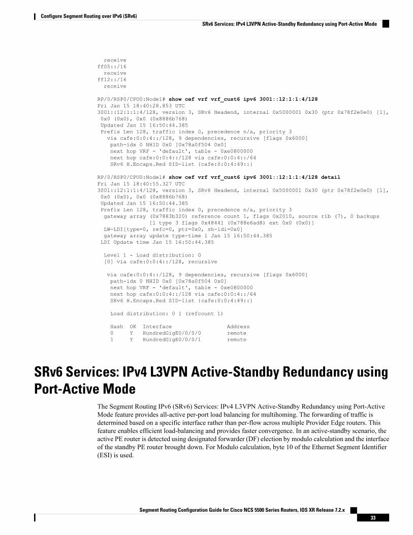
receiveff05::/16receive
ff12::/16receive
RP/0/RSP0/CPU0:Node1# show cef vrf vrf_cust6 ipv6 3001::12:1:1:4/128Fri Jan 15 18:40:28.853 UTC3001::12:1:1:4/128, version 3, SRv6 Headend, internal 0x5000001 0x30 (ptr 0x78f2e0e0) [1],0x0 (0x0), 0x0 (0x8886b768)Updated Jan 15 16:50:44.385Prefix Len 128, traffic index 0, precedence n/a, priority 3via cafe:0:0:4::/128, 9 dependencies, recursive [flags 0x6000]path-idx 0 NHID 0x0 [0x78a0f504 0x0]next hop VRF - 'default', table - 0xe0800000next hop cafe:0:0:4::/128 via cafe:0:0:4::/64SRv6 H.Encaps.Red SID-list {cafe:0:0:4:49::}
RP/0/RSP0/CPU0:Node1# show cef vrf vrf_cust6 ipv6 3001::12:1:1:4/128 detailFri Jan 15 18:40:55.327 UTC3001::12:1:1:4/128, version 3, SRv6 Headend, internal 0x5000001 0x30 (ptr 0x78f2e0e0) [1],0x0 (0x0), 0x0 (0x8886b768)Updated Jan 15 16:50:44.385Prefix Len 128, traffic index 0, precedence n/a, priority 3gateway array (0x7883b320) reference count 1, flags 0x2010, source rib (7), 0 backups
[1 type 3 flags 0x48441 (0x788e6ad8) ext 0x0 (0x0)]LW-LDI[type=0, refc=0, ptr=0x0, sh-ldi=0x0]gateway array update type-time 1 Jan 15 16:50:44.385LDI Update time Jan 15 16:50:44.385
Level 1 - Load distribution: 0[0] via cafe:0:0:4::/128, recursive
via cafe:0:0:4::/128, 9 dependencies, recursive [flags 0x6000]path-idx 0 NHID 0x0 [0x78a0f504 0x0]next hop VRF - 'default', table - 0xe0800000next hop cafe:0:0:4::/128 via cafe:0:0:4::/64SRv6 H.Encaps.Red SID-list {cafe:0:0:4:49::}
Load distribution: 0 1 (refcount 1)
Hash OK Interface Address0 Y HundredGigE0/0/0/0 remote1 Y HundredGigE0/0/0/1 remote
SRv6 Services: IPv4 L3VPN Active-Standby Redundancy usingPort-Active Mode
The Segment Routing IPv6 (SRv6) Services: IPv4 L3VPN Active-Standby Redundancy using Port-ActiveMode feature provides all-active per-port load balancing for multihoming. The forwarding of traffic isdetermined based on a specific interface rather than per-flow across multiple Provider Edge routers. Thisfeature enables efficient load-balancing and provides faster convergence. In an active-standby scenario, theactive PE router is detected using designated forwarder (DF) election by modulo calculation and the interfaceof the standby PE router brought down. For Modulo calculation, byte 10 of the Ethernet Segment Identifier(ESI) is used.
Segment Routing Configuration Guide for Cisco NCS 5500 Series Routers, IOS XR Release 7.2.x33
Configure Segment Routing over IPv6 (SRv6)SRv6 Services: IPv4 L3VPN Active-Standby Redundancy using Port-Active Mode

Usage Guidelines and Restrictions
• This feature can only be configured for bundle interfaces.
• When an EVPN Ethernet Segment (ES) is configured with port-active load-balancing mode, you cannotconfigure ACs of that bundle on bridge-domains with a configured EVPN instance (EVI). EVPN Layer2 bridging service is not compatible with port-active load-balancing.
SRv6 Services for L3VPN Active-Standby Redundancy using Port-Active Mode:Operation
Under port-active operational mode, EVPN Ethernet Segment (ES) routes are exchanged across BGP for therouters servicing the multihomed ES. Each PE router then builds an ordered list of the IP addresses of all PEsconnected to the ES, including itself, and assigns itself an ordinal for its position in the list. The ordinals areused with the modulo calculation to determine which PE will be the Designated Forwarder (DF) for a givenES. All non-DF PEs will take the respective bundles out of service.
In the case of link or port failure, the active DF PE withdraws its ES route. This re-triggers DF election forall PEs that service the ES and a new PE is elected as DF.
ConfigureSRv6ServicesL3VPNActive-StandbyRedundancyusingPort-ActiveMode
This section describes how you can configure SRv6 services L3VPN active-standby redundancy usingport-active mode under an Ethernet Segment (ES).
Configuration Example
/* Configure Ethernet Link Bundles */Router# configureRouter(config)# interface Bundle-Ether10Router(config-if)# ipv4 address 10.0.0.2 255.255.255.0Router(config-if)# ipv6 address 2001:DB8::1Router(config-if)# lacp period shortRouter(config-if)# mac-address 1.2.3Router(config-if)# bundle wait-while 0Router(config-if)# exitRouter(config)# interface GigabitEthernet 0/2/0/5Router(config-if)# bundle id 14 mode activeRouter(config-if)# commit
/* Configure load balancing. */Router# configureRouter(config)# evpnRouter(config-evpn)# interface Bundle-Ether10Router(config-evpn-ac)# ethernet-segmentRouter(config-evpn-ac-es)# identifier type 0 11.11.11.11.11.11.11.11.14Router(config-evpn-ac-es)# load-balancing-mode port-activeRouter(config-evpn-ac-es)# commit!/* Configure address family session in BGP. */Router# configureRouter(config)# router bgp 100Router(config-bgp)# bgp router-id 192.168.0.2
Segment Routing Configuration Guide for Cisco NCS 5500 Series Routers, IOS XR Release 7.2.x34
Configure Segment Routing over IPv6 (SRv6)SRv6 Services for L3VPN Active-Standby Redundancy using Port-Active Mode: Operation

Router(config-bgp)# address-family l2vpn evpnRouter(config-bgp)# neighbor 192.168.0.3Router(config-bgp-nbr)# remote-as 200Router(config-bgp-nbr)# update-source Loopback 0Router(config-bgp-nbr)# address-family l2vpn evpnRouter(config-bgp-nbr)# commit
Running Configuration
interface Bundle-Ether14ipv4 address 14.0.0.2 255.255.255.0ipv6 address 14::2/64lacp period shortmac-address 1.2.3bundle wait-while 0!interface GigabitEthernet0/2/0/5bundle id 14 mode active!evpninterface Bundle-Ether14ethernet-segmentidentifier type 0 11.11.11.11.11.11.11.11.14load-balancing-mode port-active!!!router bgp 100bgp router-id 192.168.0.2address-family l2vpn evpn!neighbor 192.168.0.3remote-as 100update-source Loopback0address-family l2vpn evpn!!!
VerificationVerify the SRv6 services L3VPN active-standby redundancy using port-active mode configuration.
/* Verify ethernet-segment details on active DF router */Router# show evpn ethernet-segment interface Bundle-Ether14 detailEthernet Segment Id Interface Nexthops------------------------ ---------------------------------- --------------------0011.1111.1111.1111.1114 BE14 192.168.0.2
192.168.0.3ES to BGP Gates : Ready
ES to L2FIB Gates : ReadyMain port :
Interface name : Bundle-Ether14Interface MAC : 0001.0002.0003IfHandle : 0x000041d0State : UpRedundancy : Not Defined
ESI type : 0Value : 11.1111.1111.1111.1114
ES Import RT : 1111.1111.1111 (from ESI)Source MAC : 0000.0000.0000 (N/A)
Segment Routing Configuration Guide for Cisco NCS 5500 Series Routers, IOS XR Release 7.2.x35
Configure Segment Routing over IPv6 (SRv6)Running Configuration

Topology :Operational : MHConfigured : Port-Active
Service Carving : Auto-selectionMulticast : Disabled
Peering Details :192.168.0.2 [MOD:P:00]192.168.0.3 [MOD:P:00]
Service Carving Results:Forwarders : 0Permanent : 0Elected : 0Not Elected : 0
MAC Flushing mode : STP-TCNPeering timer : 3 sec [not running]Recovery timer : 30 sec [not running]Carving timer : 0 sec [not running]Local SHG label : NoneRemote SHG labels : 0
/* Verify bundle Ethernet configuration on active DF router */Router# show bundle bundle-ether 14Bundle-Ether14Status: UpLocal links <active/standby/configured>: 1 / 0 / 1Local bandwidth <effective/available>: 1000000 (1000000) kbpsMAC address (source): 0001.0002.0003 (Configured)Inter-chassis link: NoMinimum active links / bandwidth: 1 / 1 kbpsMaximum active links: 64Wait while timer: OffLoad balancing:Link order signaling: Not configuredHash type: DefaultLocality threshold: None
LACP: OperationalFlap suppression timer: OffCisco extensions: DisabledNon-revertive: Disabled
mLACP: Not configuredIPv4 BFD: Not configuredIPv6 BFD: Not configured
Port Device State Port ID B/W, kbps-------------------- --------------- ----------- -------------- ----------Gi0/2/0/5 Local Active 0x8000, 0x0003 1000000
Link is Active
/* Verify ethernet-segment details on standby DF router */Router# show evpn ethernet-segment interface bundle-ether 10 detail
Router# show evpn ethernet-segment interface Bundle-Ether24 detailEthernet Segment Id Interface Nexthops------------------------ ---------------------------------- --------------------0011.1111.1111.1111.1114 BE24 192.168.0.2
192.168.0.3ES to BGP Gates : ReadyES to L2FIB Gates : ReadyMain port :
Interface name : Bundle-Ether24
Segment Routing Configuration Guide for Cisco NCS 5500 Series Routers, IOS XR Release 7.2.x36
Configure Segment Routing over IPv6 (SRv6)Verification

Interface MAC : 0001.0002.0003IfHandle : 0x000041b0State : StandbyRedundancy : Not Defined
ESI type : 0Value : 11.1111.1111.1111.1114
ES Import RT : 1111.1111.1111 (from ESI)Source MAC : 0000.0000.0000 (N/A)Topology :
Operational : MHConfigured : Port-Active
Service Carving : Auto-selectionMulticast : Disabled
Peering Details :192.168.0.2 [MOD:P:00]192.168.0.3 [MOD:P:00]
Service Carving Results:Forwarders : 0Permanent : 0Elected : 0Not Elected : 0
MAC Flushing mode : STP-TCNPeering timer : 3 sec [not running]Recovery timer : 30 sec [not running]Carving timer : 0 sec [not running]Local SHG label : NoneRemote SHG labels : 0
/* Verify bundle configuration on standby DF router */Router# show bundle bundle-ether 24
Bundle-Ether24Status: LACP OOS (out of service)Local links <active/standby/configured>: 0 / 1 / 1Local bandwidth <effective/available>: 0 (0) kbpsMAC address (source): 0001.0002.0003 (Configured)Inter-chassis link: NoMinimum active links / bandwidth: 1 / 1 kbpsMaximum active links: 64Wait while timer: OffLoad balancing:Link order signaling: Not configuredHash type: DefaultLocality threshold: None
LACP: OperationalFlap suppression timer: OffCisco extensions: DisabledNon-revertive: Disabled
mLACP: Not configuredIPv4 BFD: Not configuredIPv6 BFD: Not configured
Port Device State Port ID B/W, kbps-------------------- --------------- ----------- -------------- ----------Gi0/0/0/4 Local Standby 0x8000, 0x0002 1000000
Link is in standby due to bundle out of service state
SRv6 Services: IPv4 L3VPN Active-Active RedundancyThis feature provides active-active connectivity to a CE device in a L3VPN deployment. The CE device canbe Layer-2 or Layer-3 device connecting to the redundant PEs over a single LACP LAG port.
Segment Routing Configuration Guide for Cisco NCS 5500 Series Routers, IOS XR Release 7.2.x37
Configure Segment Routing over IPv6 (SRv6)SRv6 Services: IPv4 L3VPN Active-Active Redundancy

Depending on the bundle hashing, an ARP or IPv6 Network Discovery (ND) packet can be sent to any of theredundant routers. As a result, not all entries will exist on a given PE. In order to provide complete awareness,Layer-3 local route learning is augmented with remote route-synchronization programming.
Route synchronization between service PEs is required in order to provide minimum interruption to unicastand multicast services after failure on a redundant service PE. The following EVPN route-types are used forLayer-3 route synchronization:
• EVPN route-type 2 for synchronizing ARP tables
• EVPN route-type 7/8 for synchronizing IGMP JOINS/LEAVES
In a Layer-3 CE scenario, the router that connects to the redundant PEs may establish an IGP adjacency onthe bundle port. In this case, the adjacency will be formed to one of the redundant PEs, and IGP customerroutes will only be present on that PE. To synchronize Layer-3 customer subnet routes (IP Prefixes), the EVPNroute-type 5 is used to carry the ESI and ETAG as well as the gateway address (prefix next-hop address).
Gratuitous ARP (GARP) or IPv6 Network Advertisement (NA) replay is not needed for CEs connected tothe redundant PEs over a single LAG port.
Note
The below configuration enables Layer-3 route synchronization for routes learned on the Ethernet-segmentmain-port or any of its sub-interfaces.evpnroute-sync vrf default!vrf REDevi route-sync 10!vrf BLUEevi route-sync 20!
SRv6 Services: BGP Global IPv4This feature extends support of SRv6-based BGP services to include Internet (IPv4) services by implementingEnd.DT4 SRv6 functions at the PE node (draft-ietf-bess-srv6-services).
Usage Guidelines and Limitations
• SRv6 locator can be assigned globally or under IPv4 unicast address family
• Equal-Cost Multi-path (ECMP) and Unequal Cost Multipath (UCMP) are supported.
• BGP, OSPF, Static are supported as PE-CE protocol.
Use Case 1: BGP Global IPv4 Over SRv6 with Per-VRF SID Allocation Mode (End.DT4)
The following example shows how to configure BGP global IPv4 over SRv6 with per-VRF SID allocation.Node1(config)# router bgp 1Node1(config-bgp)# bgp router-id 10.1.0.1Node1(config-bgp)# address-family ipv4 unicast
Segment Routing Configuration Guide for Cisco NCS 5500 Series Routers, IOS XR Release 7.2.x38
Configure Segment Routing over IPv6 (SRv6)SRv6 Services: BGP Global IPv4
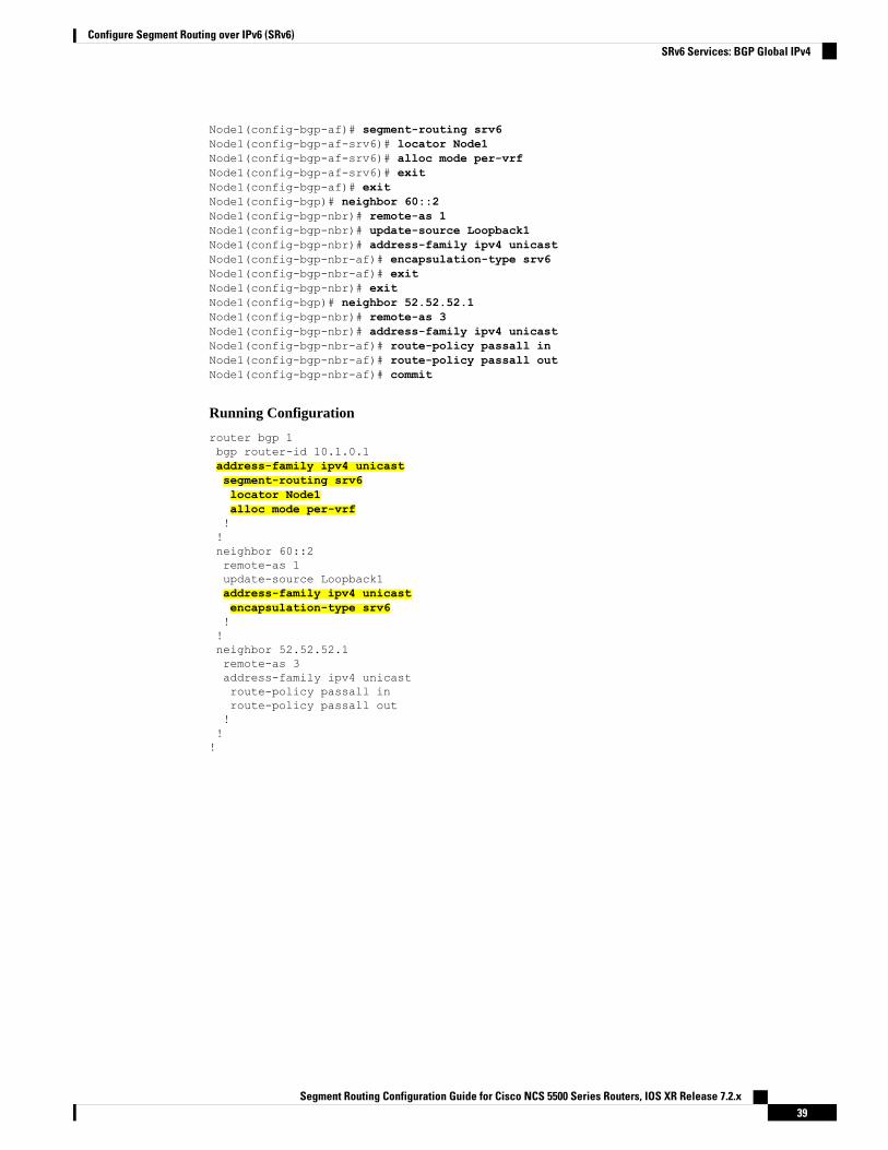
Node1(config-bgp-af)# segment-routing srv6Node1(config-bgp-af-srv6)# locator Node1Node1(config-bgp-af-srv6)# alloc mode per-vrfNode1(config-bgp-af-srv6)# exitNode1(config-bgp-af)# exitNode1(config-bgp)# neighbor 60::2Node1(config-bgp-nbr)# remote-as 1Node1(config-bgp-nbr)# update-source Loopback1Node1(config-bgp-nbr)# address-family ipv4 unicastNode1(config-bgp-nbr-af)# encapsulation-type srv6Node1(config-bgp-nbr-af)# exitNode1(config-bgp-nbr)# exitNode1(config-bgp)# neighbor 52.52.52.1Node1(config-bgp-nbr)# remote-as 3Node1(config-bgp-nbr)# address-family ipv4 unicastNode1(config-bgp-nbr-af)# route-policy passall inNode1(config-bgp-nbr-af)# route-policy passall outNode1(config-bgp-nbr-af)# commit
Running Configuration
router bgp 1bgp router-id 10.1.0.1address-family ipv4 unicastsegment-routing srv6locator Node1alloc mode per-vrf!!neighbor 60::2remote-as 1update-source Loopback1address-family ipv4 unicastencapsulation-type srv6!!neighbor 52.52.52.1remote-as 3address-family ipv4 unicastroute-policy passall inroute-policy passall out!!!
Segment Routing Configuration Guide for Cisco NCS 5500 Series Routers, IOS XR Release 7.2.x39
Configure Segment Routing over IPv6 (SRv6)SRv6 Services: BGP Global IPv4

SRv6 Services: BGP Global IPv6Table 3: Feature History Table
Feature DescriptionRelease InformationFeature Name
With this feature, the egress PE cansignal an SRv6 Service SID withthe BGP overlay service route. Theingress PE encapsulates theIPv4/IPv6 payload in an outer IPv6header where the destinationaddress is the SRv6 Service SIDprovided by the egress PE. BGPmessages between PEs carry SRv6Service SIDs as a means tointerconnect PEs.
Release 7.2.2SRv6 Services: BGP Global IPv6
This feature extends support of SRv6-based BGP services to include Internet (IPv6) services by implementingEnd.DT6 SRv6 functions at the PE node, as defined in IETF draft "SRv6 BGP based Overlay services".
Usage Guidelines and Limitations
• SRv6 locator can be assigned globally or under IPv4 unicast address family
• Equal-Cost Multi-path (ECMP) and Unequal Cost Multipath (UCMP) are supported.
• BGP, OSPF, Static are supported as PE-CE protocol.
BGP Global IPv6 Over SRv6 with Per-VRF SID Allocation Mode (End.DT6)
To configure BGP global IPv6 over SRv6, use the following commands:
• router bgp as-number address-family ipv6 unicast segment-routing srv6: Enable SRv6
• router bgp as-number address-family ipv6 unicast segment-routing srv6 alloc mode per-vrf: Specifythe SID behavior (allocation mode).
The per-vrf keyword specifies that the same label is be used for all the routes advertised from a uniqueVRF.
• router bgp as-number address-family ipv6 unicast segment-routing srv6 locator WORD: Specifythe locator
• router bgp as-number {af-group WORD| neighbor-group WORD | neighbor ipv6-addr} address-familyipv6 unicast encapsulation-type srv6: Specify the encapuslation type for SRv6.
• Use af-group WORD to apply the SRv6 encapsulation type to the address family group for BGPneighbors.
• Use neighbor-group WORDto apply the SRv6 encapsulation type to the neighbor group for BorderGateway Protocol (BGP) neighbors.
• Use neighbor ipv6-addr to apply the SRv6 encapsulation type to the specific BGP neighbor.
Segment Routing Configuration Guide for Cisco NCS 5500 Series Routers, IOS XR Release 7.2.x40
Configure Segment Routing over IPv6 (SRv6)SRv6 Services: BGP Global IPv6

Use Case 1: BGP Global IPv6 over SRv6 with Per-AFI SID Allocation
The following example shows how to configure BGP global IPv6 over SRv6 with per-VRF SID allocation.Node1(config)# router bgp 100Node1(config-bgp)# bgp router-id 1.1.1.1Node1(config-bgp)# segment-routing srv6Node1(config-bgp-gbl-srv6)# locator Node1Node1(config-bgp-gbl-srv6)# exitNode1(config-bgp)# address-family ipv6 unicastNode1(config-bgp-af)# segment-routing srv6Node1(config-bgp-af-srv6)# locator Node1Node1(config-bgp-af-srv6)# alloc mode per-vrfNode1(config-bgp-af-srv6)# exitNode1(config-bgp-af)# exitNode1(config-bgp)# neighbor 3001::1:1:1:4Node1(config-bgp-nbr)# address-family ipv6 unicastNode1(config-bgp-nbr-af)# encapsulation-type srv6Node1(config-bgp-nbr-af)# exitNode1(config-bgp-nbr)# exitNode1(config-bgp)# neighbor 3001::1:1:1:5Node1(config-bgp-nbr)# address-family ipv6 unicastNode1(config-bgp-nbr-af)# encapsulation-type srv6Node1(config-bgp-nbr-af)# commit
Running Configuration
router bgp 100bgp router-id 1.1.1.1segment-routing srv6locator Node1!address-family ipv6 unicastsegment-routing srv6locator Node1alloc mode per-vrf!!neighbor 3001::1:1:1:4address-family ipv6 unicastencapsulation-type srv6!!neighbor 3001::1:1:1:5address-family ipv6 unicastencapsulation-type srv6
Verification
The following examples show how to verify the BGP global IPv6 configuration using the show bgp ipv6unicast commands.RP/0/RSP0/CPU0:Node1# show bgp ipv6 unicast summaryFri Jan 15 21:07:04.681 UTCBGP router identifier 1.1.1.1, local AS number 100BGP generic scan interval 60 secsNon-stop routing is enabledBGP table state: ActiveTable ID: 0xe0800000 RD version: 4BGP main routing table version 4BGP NSR Initial initsync version 1 (Reached)
Segment Routing Configuration Guide for Cisco NCS 5500 Series Routers, IOS XR Release 7.2.x41
Configure Segment Routing over IPv6 (SRv6)SRv6 Services: BGP Global IPv6

BGP NSR/ISSU Sync-Group versions 0/0BGP scan interval 60 secs
BGP is operating in STANDALONE mode.
Process RcvTblVer bRIB/RIB LabelVer ImportVer SendTblVer StandbyVerSpeaker 4 4 4 4 4 0
Neighbor Spk AS MsgRcvd MsgSent TblVer InQ OutQ Up/Down St/PfxRcd3001::1:1:1:4 0 100 1502 1502 4 0 0 04:16:26 13001::1:1:1:5 0 100 1501 1501 4 0 0 04:14:47 1
RP/0/RSP0/CPU0:Node1# show bgp ipv6 unicastFri Jan 15 21:07:26.818 UTCBGP router identifier 1.1.1.1, local AS number 100BGP generic scan interval 60 secsNon-stop routing is enabledBGP table state: ActiveTable ID: 0xe0800000 RD version: 4BGP main routing table version 4BGP NSR Initial initsync version 1 (Reached)BGP NSR/ISSU Sync-Group versions 0/0BGP scan interval 60 secs
Status codes: s suppressed, d damped, h history, * valid, > besti - internal, r RIB-failure, S stale, N Nexthop-discard
Origin codes: i - IGP, e - EGP, ? - incompleteNetwork Next Hop Metric LocPrf Weight Path
*> 3001::13:1:1:1/128 :: 0 32768 i*>i3001::13:1:1:4/128 3001::1:1:1:4 0 100 0 i*>i3001::13:1:1:5/128 3001::1:1:1:5 0 100 0 i
Processed 3 prefixes, 3 paths
RP/0/RSP0/CPU0:Node1# show bgp ipv6 unicast 3001::13:1:1:4/128Fri Jan 15 21:07:50.309 UTCBGP routing table entry for 3001::13:1:1:4/128Versions:Process bRIB/RIB SendTblVerSpeaker 4 4
Last Modified: Jan 15 17:13:50.032 for 03:54:01Paths: (1 available, best #1)Not advertised to any peerPath #1: Received by speaker 0Not advertised to any peerLocal3001::1:1:1:4 (metric 30) from 3001::1:1:1:4 (1.1.1.4)Origin IGP, metric 0, localpref 100, valid, internal, best, group-bestReceived Path ID 0, Local Path ID 1, version 4PSID-Type:L3, SubTLV Count:1SubTLV:T:1(Sid information), Sid:cafe:0:0:4:4b::, Behavior:18, SS-TLV Count:1SubSubTLV:T:1(Sid structure):
The following examples show how to verify the current routes in the Routing Information Base (RIB):RP/0/RSP0/CPU0:Node1# show route ipv6 3001::13:1:1:4/128Fri Jan 15 21:08:05.499 UTC
Routing entry for 3001::13:1:1:4/128Known via "bgp 100", distance 200, metric 0, type internalInstalled Jan 15 17:13:50.431 for 03:54:15
Segment Routing Configuration Guide for Cisco NCS 5500 Series Routers, IOS XR Release 7.2.x42
Configure Segment Routing over IPv6 (SRv6)SRv6 Services: BGP Global IPv6

Routing Descriptor Blocks3001::1:1:1:4, from 3001::1:1:1:4Route metric is 0
No advertising protos.
RP/0/RSP0/CPU0:Node1# show route ipv6 3001::13:1:1:4/128 detailFri Jan 15 21:08:22.628 UTC
Routing entry for 3001::13:1:1:4/128Known via "bgp 100", distance 200, metric 0, type internalInstalled Jan 15 17:13:50.431 for 03:54:32Routing Descriptor Blocks3001::1:1:1:4, from 3001::1:1:1:4Route metric is 0Label: NoneTunnel ID: NoneBinding Label: NoneExtended communities count: 0NHID:0x0(Ref:0)SRv6 Headend: H.Encaps.Red [base], SID-list {cafe:0:0:4:4b::}
Route version is 0x1 (1)No local labelIP Precedence: Not SetQoS Group ID: Not SetFlow-tag: Not SetFwd-class: Not SetRoute Priority: RIB_PRIORITY_RECURSIVE (12) SVD Type RIB_SVD_TYPE_LOCALDownload Priority 4, Download Version 93No advertising protos.
The following examples show how to verify the current IPv6 Cisco Express Forwarding (CEF) table:RP/0/RSP0/CPU0:Node1# show cef ipv6 3001::13:1:1:4/128Fri Jan 15 21:08:41.483 UTC3001::13:1:1:4/128, version 93, SRv6 Headend, internal 0x5000001 0x40 (ptr 0x78a100d4) [1],0x0 (0x0), 0x0 (0x8886b840)Updated Jan 15 17:13:50.433Prefix Len 128, traffic index 0, precedence n/a, priority 4via cafe:0:0:4::/128, 9 dependencies, recursive [flags 0x6000]path-idx 0 NHID 0x0 [0x78a0f504 0x0]next hop cafe:0:0:4::/128 via cafe:0:0:4::/64SRv6 H.Encaps.Red SID-list {cafe:0:0:4:4b::}
RP/0/RSP0/CPU0:Node1# show cef ipv6 3001::13:1:1:4/128 detailFri Jan 15 21:08:59.789 UTC3001::13:1:1:4/128, version 93, SRv6 Headend, internal 0x5000001 0x40 (ptr 0x78a100d4) [1],0x0 (0x0), 0x0 (0x8886b840)Updated Jan 15 17:13:50.433Prefix Len 128, traffic index 0, precedence n/a, priority 4gateway array (0x7883b5d8) reference count 1, flags 0x2010, source rib (7), 0 backups
[1 type 3 flags 0x48441 (0x788e6c40) ext 0x0 (0x0)]LW-LDI[type=0, refc=0, ptr=0x0, sh-ldi=0x0]gateway array update type-time 1 Jan 15 17:13:50.433LDI Update time Jan 15 17:13:50.433
Level 1 - Load distribution: 0[0] via cafe:0:0:4::/128, recursive
via cafe:0:0:4::/128, 9 dependencies, recursive [flags 0x6000]path-idx 0 NHID 0x0 [0x78a0f504 0x0]next hop cafe:0:0:4::/128 via cafe:0:0:4::/64SRv6 H.Encaps.Red SID-list {cafe:0:0:4:4b::}
Load distribution: 0 1 (refcount 1)
Segment Routing Configuration Guide for Cisco NCS 5500 Series Routers, IOS XR Release 7.2.x43
Configure Segment Routing over IPv6 (SRv6)SRv6 Services: BGP Global IPv6

Hash OK Interface Address0 Y HundredGigE0/0/0/0 remote1 Y HundredGigE0/0/0/1 remote
SRv6 Services: EVPN VPWS — All-Active Multi-HomingEVPN VPWS All-Active Multi-Homing over SRv6 provides an ELINE (P2P) service with all-activemultihoming capability over an SRv6 network.
All-ActiveMulti-Homing enables an operator to connect a customer edge (CE) device to two or more provideredge (PE) devices to provide load balancing and redundant connectivity. With All-Active Multi-Homing, allthe PEs can forward traffic to and from the multi-homed device.
For information about EVPN VPWS, refer to the "EVPN Virtual Private Wire Service (VPWS)" chapter inthe L2VPN and Ethernet Services Configuration Guide for Cisco NCS 5500 Series Routers.
Note
Configuring EVPN VPWS over SRv6
An SRv6 Locator for an EVPN VPWS service can be configured at 3 different levels independently:
• global_locator is the default locator for all EVPN-VPWS services
• evi_locator is applied to all EVPN-VPWS services for the specific EVI
• evi_service_locator is applied to an individual EVI service
When locators are configured at different levels at the same time, the following priority is implemented:
1. evi_service_locator
2. evi_locator
3. global_locator
This example shows how to configure an EVPN VPWS over SRv6 using a global locator for EVPN:evpnsegment-routing srv6locator sample_global_loc
l2vpnxconnect group sample_xcgp2p sample-vpws-12001-2002interface Bundle-Ether12001.2002neighbor evpn evi 12001 service 2002 segment-routing srv6
This example shows how to configure EVPN VPWS over SRv6 using specific EVI locator:evpnevi 11001 segment-routing srv6locator sample_evi_loc
l2vpn
Segment Routing Configuration Guide for Cisco NCS 5500 Series Routers, IOS XR Release 7.2.x44
Configure Segment Routing over IPv6 (SRv6)SRv6 Services: EVPN VPWS — All-Active Multi-Homing
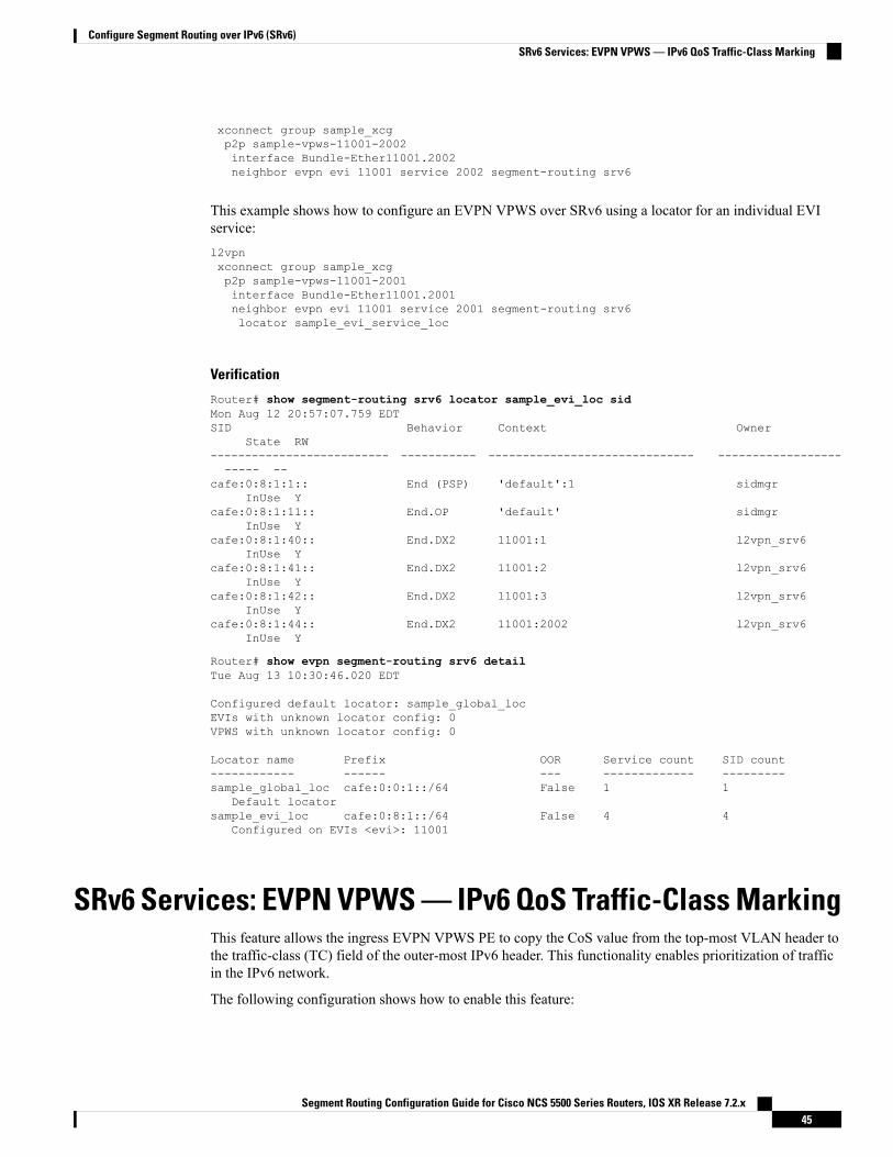
xconnect group sample_xcgp2p sample-vpws-11001-2002interface Bundle-Ether11001.2002neighbor evpn evi 11001 service 2002 segment-routing srv6
This example shows how to configure an EVPN VPWS over SRv6 using a locator for an individual EVIservice:l2vpnxconnect group sample_xcgp2p sample-vpws-11001-2001interface Bundle-Ether11001.2001neighbor evpn evi 11001 service 2001 segment-routing srv6locator sample_evi_service_loc
Verification
Router# show segment-routing srv6 locator sample_evi_loc sidMon Aug 12 20:57:07.759 EDTSID Behavior Context Owner
State RW-------------------------- ----------- ------------------------------ ----------------------- --
cafe:0:8:1:1:: End (PSP) 'default':1 sidmgrInUse Y
cafe:0:8:1:11:: End.OP 'default' sidmgrInUse Y
cafe:0:8:1:40:: End.DX2 11001:1 l2vpn_srv6InUse Y
cafe:0:8:1:41:: End.DX2 11001:2 l2vpn_srv6InUse Y
cafe:0:8:1:42:: End.DX2 11001:3 l2vpn_srv6InUse Y
cafe:0:8:1:44:: End.DX2 11001:2002 l2vpn_srv6InUse Y
Router# show evpn segment-routing srv6 detailTue Aug 13 10:30:46.020 EDT
Configured default locator: sample_global_locEVIs with unknown locator config: 0VPWS with unknown locator config: 0
Locator name Prefix OOR Service count SID count------------ ------ --- ------------- ---------sample_global_loc cafe:0:0:1::/64 False 1 1
Default locatorsample_evi_loc cafe:0:8:1::/64 False 4 4
Configured on EVIs <evi>: 11001
SRv6 Services: EVPN VPWS — IPv6 QoS Traffic-Class MarkingThis feature allows the ingress EVPN VPWS PE to copy the CoS value from the top-most VLAN header tothe traffic-class (TC) field of the outer-most IPv6 header. This functionality enables prioritization of trafficin the IPv6 network.
The following configuration shows how to enable this feature:
Segment Routing Configuration Guide for Cisco NCS 5500 Series Routers, IOS XR Release 7.2.x45
Configure Segment Routing over IPv6 (SRv6)SRv6 Services: EVPN VPWS — IPv6 QoS Traffic-Class Marking
This command requires you to reload the router for the configuration to take effect.Note
Router# configureRouter(config)# hw-module profile segment-routing srv6 encapsulation traffic-class propagate
The functionality covers the following scenarios:
• Use case 1: Without additional QoS configuration, the CoS in the outer VLAN tag of incoming Ethernetframes is propagated to the traffic-class field in the encapsulated IPv6 header.
• Use case 2: With additional QoS configuration, DSCP in the IPv4/IPv6 header of incoming IP packetsis propagated to the traffic-class field in the encapsulated IPv6 header.
The following configuration shows how to define specific classification criteria:class-map match-any prec-0match precedence ipv4 0match precedence ipv6 0end-class-map…class-map match-any prec-7match precedence ipv4 7match precedence ipv6 7end-class-map
The following configuration shows how to define a QoS policy map:policy-map prec-to-tcclass prec-0set qos-group 0
…class prec-7set qos-group 7
The following configuration shows how to apply a QoS policy-map to an attachment-circuit (AC)interface:interface Bundle-Ether1.1 l2transportencapsulation untaggedservice-policy input prec-to-tc
SRv6 Services: SRv6 Services TLV Type 5 SupportIOS XR 6.6.1 supports IETF draft draft-dawra-idr-srv6-vpn-04, in which the SRv6-VPN SID TLV (TLVType 4) carries the SRv6 Service SID information. This SID TLV is inconsistent with the SRv6 SID Structure.
In IOS XR 7.0.2 and later releases, the implementation is compliant with draft-ietf-bess-srv6-services-00,which defines a new SRv6 Services TLV (TLV Type 5/6) and SRv6 SID Structure Sub-Sub-TLV to addressthis inconsistency.
Segment Routing Configuration Guide for Cisco NCS 5500 Series Routers, IOS XR Release 7.2.x46
Configure Segment Routing over IPv6 (SRv6)SRv6 Services: SRv6 Services TLV Type 5 Support

SRv6 SID Structure Sub-Sub-TLV describes mechanisms for signaling of the SRv6 Service SID by transposinga variable part of the SRv6 SID value (function and/or the argument parts) and carrying them in existing labelfields to achieve more efficient packing of VPN and EVPN service prefix NLRIs in BGP update messages.
In order to allow backward compatibility between the newer software and the older software, use thesegment-routing srv6 prefix-sid-type4 command in Router BGP Neighbor VPNv4 Address-Familyconfiguration mode to advertise BGP VPNv4 NLRIs in TLV Type 4 format. The newer software can receiveeither TLV Type 4 or TLV Type 5 formats.
The following configuration shows how to enable the advertisement of BGP VPNv4 NLRIs in TLV Type 4format:RP/0/RSP0/CPU0:Rtr-a(config)# router bgp 65000RP/0/RSP0/CPU0:Rtr-a(config-bgp)# neighbor 6::6RP/0/RSP0/CPU0:Rtr-a(config-bgp-nbr)# address-family vpnv4 unicastRP/0/RSP0/CPU0:Rtr-a(config-bgp-nbr-af)# segment-routing srv6 prefix-sid-type4RP/0/RSP0/CPU0:Rtr-a(config-bgp-nbr-af)#
SRv6 SID Information in BGP-LS ReportingBGP Link-State (BGP-LS) is used to report the topology of the domain using nodes, links, and prefixes. Thisfeature adds the capability to report SRv6 Segment Identifier (SID) Network Layer Reachability Information(NLRI).
The following NLRI has been added to the BGP-LS protocol to support SRv6:
• Node NLRI: SRv6 Capabilities, SRv6 MSD types
• Link NLRI: End.X, LAN End.X, and SRv6 MSD types
• Prefix NLRI: SRv6 Locator
• SRv6 SID NLRI (for SIDs associated with the node): Endpoint Function, BGP-EPE Peer Node/Set
This example shows how to distribute IS-IS SRv6 link-state data using BGP-LS:Router(config)# router isis 200Router(config-isis)# distribute link-state instance-id 200
When you distribute IS-IS SRv6 link-state data, SRv6 ping or traceroute operations using the use-srv6-op-sidkeyword can retrieve and use the corresponding END.OP SID automatically. See SRv6 OAM— SIDVerification, on page 47 for details about SRv6 ping and traceroute.
Note
SRv6 OAM — SID VerificationThis feature provides enhanced Operations, Administration, and Maintenance (OAM) in Segment RoutingNetworks with IPv6 Data plane (SRv6).
Existing OAM mechanisms to ping and trace a remote IPv6 prefix, along the shortest path, continue to workwithout any modification in an SRv6 network.
Segment Routing Configuration Guide for Cisco NCS 5500 Series Routers, IOS XR Release 7.2.x47
Configure Segment Routing over IPv6 (SRv6)SRv6 SID Information in BGP-LS Reporting

However, classic IPv6 OAMcannot be used to ping or trace a remote SRv6 SID function. This feature augmentsping and traceroute operations to target remote SRv6 SIDs. An SRv6-enabled router now allocates a newSRv6 OAM SID known as END.OP (OAM Endpoint with Punt).
Use the following commands to performs SRv6 ping and traceroute:
ping B:k:F:: [use-srv6-op-sid [ end.op-sid-value]]
traceroute B:k:F:: [use-srv6-op-sid [ end.op-sid-value]]
Where B:k:F:: is the target SID at node k with locator block B and function F.
Ping/Traceroute to SID Without OAM SID
The user can issue ping or traceroute to an SRv6 SID using the classic CLI. A ping or traceroute to an SRv6SID does not require the user to enter the “use-end-op” keyword when pinging or tracing a SID function. Inthis case, and as usual, the packet is pre-routed as an ICMP echo request or UDP packet.
Ping/Traceroute to SID With OAM SID
When ping or traceroute operations include the use-srv6-op-sid keyword, the packet is pre-routed withEND.OP SID as Destination Address (DA) and the target SID in the SRH.
The END.OP SID value is an optional 128 bit value in IPv6 address format. See END.OP SID Derivationbelow for details on this value.
Note
At the target node, the END.OP SID forces the punt of the packet to the OAM process, which verifies thatthe next SID is local and valid. If the next SID received by the target node is a local valid address that is nota SID, the target node still replies to indicate ping success. The ping reply contains a subtype to indicate thetarget was a SID or a local address.
A target remote SID include the following:
• END
• END.DT4/END.DX4 (used by L3 Services over SRv6)
• END.DX2 (used by L2 Services over SRv6)
END.OP SID Derivation
The ingress node can automatically derive the END.OP SID associatedwith a specified target SID by leveragingthe IGP topology database in that node. The database will contain END.OP SIDs from remote nodes.
An END.OP SID associated with a locator will be advertised by IS-IS within an IGP domain in an area/level,which is added to the topology database. However, END.OP SIDs are not redistributed by IS-IS across IGPdomains or across different area/level within an IGP domain. In this case, the topology database in a nodecontains END.OP SIDs only from the nodes within the same IGP domain in an area/level. An END.OP SIDcannot be determine automatically if the specified target SID is external to the domain. For target SIDs acrossIGP domains or across different area/level within an IGP domain, the end.op-sid-value must be explicitlyprovided.
If end.op-sid-value is not provided and the END.OP SID cannot be automatically derived, an error is displayedprompting the user to provide the end.op-sid-value.
Segment Routing Configuration Guide for Cisco NCS 5500 Series Routers, IOS XR Release 7.2.x48
Configure Segment Routing over IPv6 (SRv6)SRv6 OAM — SID Verification

Configuration Examples
The following example shows using ping to a SID without OAM SID.Router# ping cafe:0:0:a3:40::Wed Jul 24 19:24:50.812 UTCType escape sequence to abort.Sending 5, 100-byte ICMP Echos to cafe:0:0:a3:40::, timeout is 2 seconds:!!!!!Success rate is 100 percent (5/5), round-trip min/avg/max = 1/1/2 ms
The following example shows using ping to a SID with an OAM SID. Note that the output shows "S" toindicate that this is a response from a SID target.Router# ping cafe:0:0:a3:40:: use-srv6-op-sidWed Jul 24 19:24:50.812 UTCType escape sequence to abort.Sending 5, 100-byte ICMP Echos to cafe:0:0:a3:40::, timeout is 2 seconds:SSSSSSuccess rate is 100 percent (5/5), round-trip min/avg/max = 1/1/2 ms
The following example shows using ping to a SID with an explicit OAM SID. Note that the output shows "S"to indicate that this is a response from a SID target.Router# ping cafe:0:0:a3:40:: use-srv6-op-sid cafe:0:0:a3:11::Wed Jul 24 19:24:50.812 UTCType escape sequence to abort.Sending 5, 100-byte ICMP Echos to cafe:0:0:a3:40::, timeout is 2 seconds:SSSSSSuccess rate is 100 percent (5/5), round-trip min/avg/max = 1/1/2 ms
The following example shows using traceroute to a SID without OAM SID.Router# traceroute cafe:0:0:a3:1::Wed Jul 24 19:40:19.192 UTC
Type escape sequence to abort.Tracing the route to cafe:0:0:a3:1::
1 2001::1:1:1:1 2 msec 2 msec 2 msec2 2001:10:10:13::2 2 msec 2 msec 2 msec
The following example shows using traceroute to a SID with OAM SID.Router# traceroute cafe:0:0:a3:40:: use-srv6-op-sid
Type escape sequence to abort.Tracing the route to cafe:0:0:a3:40::
1 2001::1:1:1:1[IP tunnel: DA=cafe:0:0:a3:11:: SRH Stack 0 =(cafe:0:0:a3:40:: ,SL=1) ] 2
msec2 2001::33:33:33:33
[IP tunnel: DA=cafe:0:0:a3:11:: SRH Stack 0 =(cafe:0:0:a3:40:: ,SL=1) ] 3msec
The following example shows using traceroute to a SID with an explicit OAM SID.Router# traceroute cafe:0:0:a3:40:: use-srv6-op-sid cafe:0:0:a3:11::
Type escape sequence to abort.
Segment Routing Configuration Guide for Cisco NCS 5500 Series Routers, IOS XR Release 7.2.x49
Configure Segment Routing over IPv6 (SRv6)SRv6 OAM — SID Verification

Tracing the route to cafe:0:0:a3:40::
1 2001::1:1:1:1[IP tunnel: DA=cafe:0:0:a3:11:: SRH Stack 0 =(cafe:0:0:a3:40:: ,SL=1) ] 2
msec2 2001::33:33:33:33
[IP tunnel: DA=cafe:0:0:a3:11:: SRH Stack 0 =(cafe:0:0:a3:40:: ,SL=1) ] 3msec
DHCPv4 Relay Agent and Proxy Support over SRv6This feature introduces support for DHCPv4 Relay Agent and Proxy over SRv6.
An IOS XR router can act as a DHCPv4 relay agent/proxy with a DHCPv4 server connected over an SRv6network.
The following functionality is supported:
• DHCPv4 relay agent/proxy over SRv6 with DHCPv4 server (helper-address) located in default VRF(global)
• DHCPv4 relay agent/proxy over SRv6with DHCPv4 server (helper-address) located in non-default VRF
• DHCPv4 relay agent/proxy on interfaces associated with a default VRF (global)
• DHCPv4 relay agent/proxy on interfaces associated with a non-default VRF
• DHCPv4 relay agent/proxy on Ethernet physical interfaces
• DHCPv4 relay agent/proxy on Ethernet bundle interfaces
For information on configuring DHCPv4 relay agent and proxy, refer to the “Implementing the Dynamic HostConfiguration Protocol” chapter in the IP Addresses and Services Configuration Guide for Cisco NCS 5500Series Routers.
DHCPv6 Relay Agent Support over SRv6Table 4: Feature History Table
Feature DescriptionRelease InformationFeature Name
An IOS XR router can act as aDHCPv6 relay agent with aDHCPv6 server connected over anSRv6 network.
A DHCP relay agent is a host thatforwards DHCP packets betweenclients and servers that do notreside on a shared physical subnet.
Release 7.2.2DHCPv6 Relay Agent Support onSRv6
This feature introduces support for DHCPv6 Relay Agent over SRv6.
Segment Routing Configuration Guide for Cisco NCS 5500 Series Routers, IOS XR Release 7.2.x50
Configure Segment Routing over IPv6 (SRv6)DHCPv4 Relay Agent and Proxy Support over SRv6

An IOS XR router can act as a DHCPv6 relay agent with a DHCPv6 server connected over an SRv6 network.
The following functionality is supported:
• DHCPv6 relay agent over SRv6 with DHCPv6 server (helper-address) located in default VRF (global)
• DHCPv6 relay agent over SRv6 with DHCPv6 server (helper-address) located in non-default VRF
• DHCPv6 relay agent on interfaces associated with a default VRF (global)
• DHCPv6 relay agent on interfaces associated with a non-default VRF
• DHCPv6 relay agent on Ethernet physical interfaces
• DHCPv6 relay agent on Ethernet bundle interfaces
For information on configuring DHCPv6 relay agent, refer to the “Implementing the Dynamic HostConfiguration Protocol” chapter in the IP Addresses and Services Configuration Guide for Cisco NCS 5500Series Routers.
Segment Routing Configuration Guide for Cisco NCS 5500 Series Routers, IOS XR Release 7.2.x51
Configure Segment Routing over IPv6 (SRv6)DHCPv6 Relay Agent Support over SRv6

Segment Routing Configuration Guide for Cisco NCS 5500 Series Routers, IOS XR Release 7.2.x52
Configure Segment Routing over IPv6 (SRv6)DHCPv6 Relay Agent Support over SRv6
C H A P T E R 4Configure Segment Routing Global Block andSegment Routing Local Block
Local label allocation is managed by the label switching database (LSD). The Segment Routing Global Block(SRGB) and Segment Routing Local Block (SRLB) are label values preserved for segment routing in theLSD.
• About the Segment Routing Global Block, on page 53• About the Segment Routing Local Block, on page 55• Understanding Segment Routing Label Allocation, on page 56• Setup a Non-Default Segment Routing Global Block Range, on page 59• Setup a Non-Default Segment Routing Local Block Range, on page 60
About the Segment Routing Global BlockThe Segment Routing Global Block (SRGB) is a range of labels reserved for Segment Routing global segments.A prefix-SID is advertised as a domain-wide unique index. The prefix-SID index points to a unique labelwithin the SRGB range. The index is zero-based, meaning that the first index is 0. The MPLS label assignedto a prefix is derived from the Prefix-SID index plus the SRGB base. For example, considering an SRGBrange of 16,000 to 23,999, a prefix 1.1.1.65/32 with prefix-SID index of 65 is assigned the label value of16065.
Segment Routing Configuration Guide for Cisco NCS 5500 Series Routers, IOS XR Release 7.2.x53
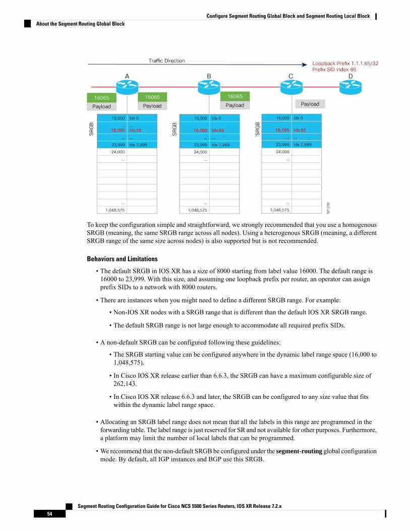
To keep the configuration simple and straightforward, we strongly recommended that you use a homogenousSRGB (meaning, the same SRGB range across all nodes). Using a heterogenous SRGB (meaning, a differentSRGB range of the same size across nodes) is also supported but is not recommended.
Behaviors and Limitations
• The default SRGB in IOS XR has a size of 8000 starting from label value 16000. The default range is16000 to 23,999. With this size, and assuming one loopback prefix per router, an operator can assignprefix SIDs to a network with 8000 routers.
• There are instances when you might need to define a different SRGB range. For example:
• Non-IOS XR nodes with a SRGB range that is different than the default IOS XR SRGB range.
• The default SRGB range is not large enough to accommodate all required prefix SIDs.
• A non-default SRGB can be configured following these guidelines:
• The SRGB starting value can be configured anywhere in the dynamic label range space (16,000 to1,048,575).
• In Cisco IOS XR release earlier than 6.6.3, the SRGB can have a maximum configurable size of262,143.
• In Cisco IOS XR release 6.6.3 and later, the SRGB can be configured to any size value that fitswithin the dynamic label range space.
• Allocating an SRGB label range does not mean that all the labels in this range are programmed in theforwarding table. The label range is just reserved for SR and not available for other purposes. Furthermore,a platform may limit the number of local labels that can be programmed.
• We recommend that the non-default SRGB be configured under the segment-routing global configurationmode. By default, all IGP instances and BGP use this SRGB.
Segment Routing Configuration Guide for Cisco NCS 5500 Series Routers, IOS XR Release 7.2.x54
Configure Segment Routing Global Block and Segment Routing Local BlockAbout the Segment Routing Global Block
• You can also configure a non-default SRGB under the IGP, but it is not recommended.
SRGB Label Conflicts
When you define a non-default SRGB range, there might be a label conflict (for example, if labels are alreadyallocated, statically or dynamically, in the new SRGB range). The following system log message indicates alabel conflict:
%ROUTING-ISIS-4-SRGB_ALLOC_FAIL : SRGB allocation failed: 'SRGB reservation notsuccessful for [16000,80000], SRGB (16000 80000, SRGB_ALLOC_CONFIG_PENDING, 0x2)(So far 16 attempts). Make sure label range is free'
To remove this conflict, you must reload the router to release the currently allocated labels and to allocate thenew SRGB.
After the system reloads, LSD does not accept any dynamic label allocation before IS-IS/OSPF/BGP haveregistered with LSD. Upon IS-IS/OSPF/BGP registration, LSD allocates the requested SRGB (either thedefault range or the customized range).
After IS-IS/OSPF/BGP have registered and their SRGB is allocated, LSD starts serving dynamic label requestsfrom other clients.
To avoid a potential router reload due to label conflicts, and assuming that the default SRGB size is largeenough, we recommend that you use the default IOS XR SRGB range.
Note
Allocating a non-default SRGB in the upper part of the MPLS label space increases the chance that the labelsare available and a reload can be avoided.
Note
Modifying a SRGB configuration is disruptive for traffic and may require a reboot if the new SRGB is notavailable entirely.
Caution
About the Segment Routing Local BlockA local segment is automatically assigned an MPLS label from the dynamic label range. In most cases, suchas TI-LFA backup paths and SR-TE explicit paths defined with IP addresses, this dynamic label allocation issufficient. However, in some scenarios, it could be beneficial to allocate manually local segment label valuesto maintain label persistency. For example, an SR-TE policy with a manual binding SID that is performingtraffic steering based on incoming label traffic with the binding SID.
The Segment Routing Local Block (SRLB) is a range of label values preserved for the manual allocation oflocal segments, such as adjacency segment identifiers (adj-SIDs) , Layer 2 adj-SIDs, binding SIDs (BSIDs),and BGP peering SIDs. These labels are locally significant and are only valid on the nodes that allocate thelabels.
Segment Routing Configuration Guide for Cisco NCS 5500 Series Routers, IOS XR Release 7.2.x55
Configure Segment Routing Global Block and Segment Routing Local BlockAbout the Segment Routing Local Block

Behaviors and Limitations
• The default SRLB has a size of 1000 starting from label value 15000; therefore, the default SRLB rangegoes from 15000 to 15,999.
• A non-default SRLB can be configured following these guidelines:
• The SRLB starting value can be configured anywhere in the dynamic label range space (16,000 to1,048,575).
• In Cisco IOS XR release earlier than 6.6.3, the SRLB can have a maximum configurable size of262,143.
• In Cisco IOS XR release 6.6.3 and later, the SRLB can be configured to any size value that fitswithin the dynamic label range space.
SRLB Label Conflicts
When you define a non-default SRLB range, there might be a label conflict (for example, if labels are alreadyallocated, statically or dynamically, in the new SRLB range). In this case, the new SRLB range will be accepted,but not applied (pending state). The previous SRLB range (active) will continue to be in use.
To remove this conflict, you must reload the router to release the currently allocated labels and to allocate thenew SRLB.
You can use the clear segment-routing local-block discrepancy all command to clear label conflicts.However, using this command is disruptive for traffic since it forces all other MPLS applications withconflicting labels to allocate new labels.
Caution
To avoid a potential router reload due to label conflicts, and assuming that the default SRGB size is largeenough, we recommend that you use the default IOS XR SRLB range.
Note
Allocating a non-default SRLB in the upper part of the MPLS label space increases the chance that the labelsare available and a reload can be avoided.
Note
Understanding Segment Routing Label AllocationIn IOS XR, local label allocation is managed by the Label Switching Database (LSD). MPLS applicationsmust register as a client with the LSD to allocate labels. Most MPLS applications (for example: LDP, RSVP,L2VPN, BGP [LU, VPN], IS-IS and OSPF [Adj-SID], SR-TE [Binding-SID]) use labels allocated dynamicallyby LSD.
With Segment Routing-capable IOS XR software releases, the LSD preserves the default SRLB label range(15,000 to 15,999) and default SRGB label range (16,000 to 23,999), even if Segment Routing is not enabled.
Segment Routing Configuration Guide for Cisco NCS 5500 Series Routers, IOS XR Release 7.2.x56
Configure Segment Routing Global Block and Segment Routing Local BlockUnderstanding Segment Routing Label Allocation

This preservation of the default SRLB/SRGB label range makes future Segment Routing activation possiblewithout a reboot. No labels are allocated from this preserved range. When you enable Segment Routing withthe default SRLB/SRGB in the future, these label ranges will be available and ready for use.
The LSD allocates dynamic labels starting from 24,000.
If an MPLS label range is configured and it overlaps with the default SRLB/SRGB label ranges (for example,mpls label range 15000 1048575), then the default SRLB/SRGB preservation is disabled.
Note
Example 1: LSD Label Allocation When SR is not Configured
• Special use: 0-15
• MPLS static: 16 to 14,999
• SRLB (preserved): 15,000 to 15,999
• SRGB (preserved): 16,000 to 23,999
• Dynamic: 24,000 to max
Example 2: LSD Label Allocation When SR is Configured with Default SRGB and Default SRLB
• Special use: 0-15
• MPLS static: 16 to 14,999
• SRLB (reserved): 15,000 to 15,999
• SRGB (reserved): 16,000 to 23,999
• Dynamic: 24,000 to max
Segment Routing Configuration Guide for Cisco NCS 5500 Series Routers, IOS XR Release 7.2.x57
Configure Segment Routing Global Block and Segment Routing Local BlockUnderstanding Segment Routing Label Allocation

Example 3: LSD Label Allocation When SR is Configured with Non-default SRGB and Non-default SRLB
• Special use: 0-15
• MPLS static: 16 to 14,999
• SRLB (preserved): 15,000 to 15,999
• SRGB (preserved): 16,000 to 23,999
• Dynamic: 24000 to 28,999
• SRLB (reserved): 29,000 to 29,999
• SRGB (reserved): 30,000 to 39,999
• Dynamic: 40,000 to max
Segment Routing Configuration Guide for Cisco NCS 5500 Series Routers, IOS XR Release 7.2.x58
Configure Segment Routing Global Block and Segment Routing Local BlockUnderstanding Segment Routing Label Allocation

Setup a Non-Default Segment Routing Global Block RangeThis task explains how to configure a non-default SRGB range.
SUMMARY STEPS
1. configure2. segment-routing global-block starting_value ending_value
3. Use the commit or end command.
DETAILED STEPS
PurposeCommand or Action
Enters global configuration mode.configure
Example:
Step 1
RP/0/RP0/CPU0:router# configure
Enter the lowest value that you want the SRGB range toinclude as the starting value. Enter the highest value thatyou want the SRGB range to include as the ending value.
segment-routing global-block starting_value ending_value
Example:
RP/0/RP0/CPU0:router(config)# segment-routing
Step 2
global-block 16000 80000
commit —Saves the configuration changes and remainswithin the configuration session.
Use the commit or end command.Step 3
end —Prompts user to take one of these actions:
Segment Routing Configuration Guide for Cisco NCS 5500 Series Routers, IOS XR Release 7.2.x59
Configure Segment Routing Global Block and Segment Routing Local BlockSetup a Non-Default Segment Routing Global Block Range
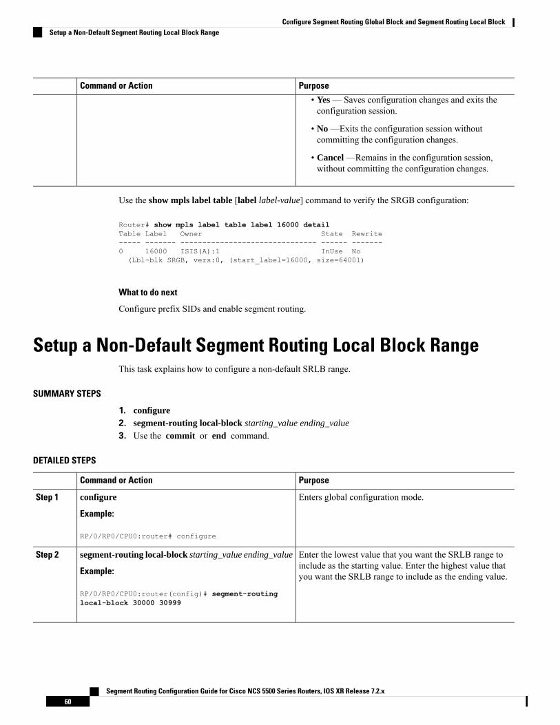
PurposeCommand or Action
• Yes — Saves configuration changes and exits theconfiguration session.
• No —Exits the configuration session withoutcommitting the configuration changes.
• Cancel —Remains in the configuration session,without committing the configuration changes.
Use the show mpls label table [label label-value] command to verify the SRGB configuration:
Router# show mpls label table label 16000 detailTable Label Owner State Rewrite----- ------- ------------------------------- ------ -------0 16000 ISIS(A):1 InUse No(Lbl-blk SRGB, vers:0, (start_label=16000, size=64001)
What to do next
Configure prefix SIDs and enable segment routing.
Setup a Non-Default Segment Routing Local Block RangeThis task explains how to configure a non-default SRLB range.
SUMMARY STEPS
1. configure2. segment-routing local-block starting_value ending_value
3. Use the commit or end command.
DETAILED STEPS
PurposeCommand or Action
Enters global configuration mode.configure
Example:
Step 1
RP/0/RP0/CPU0:router# configure
Enter the lowest value that you want the SRLB range toinclude as the starting value. Enter the highest value thatyou want the SRLB range to include as the ending value.
segment-routing local-block starting_value ending_value
Example:
RP/0/RP0/CPU0:router(config)# segment-routing
Step 2
local-block 30000 30999
Segment Routing Configuration Guide for Cisco NCS 5500 Series Routers, IOS XR Release 7.2.x60
Configure Segment Routing Global Block and Segment Routing Local BlockSetup a Non-Default Segment Routing Local Block Range
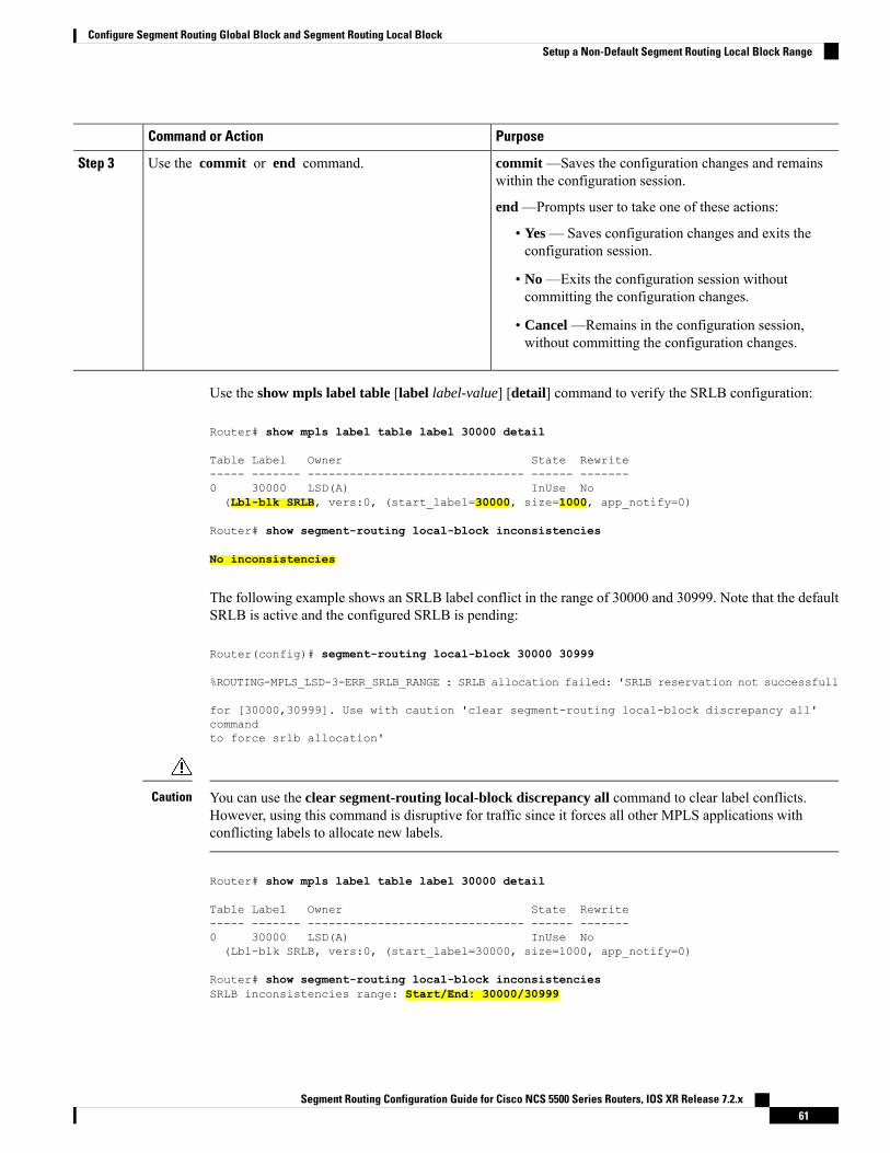
PurposeCommand or Action
commit —Saves the configuration changes and remainswithin the configuration session.
Use the commit or end command.Step 3
end —Prompts user to take one of these actions:
• Yes — Saves configuration changes and exits theconfiguration session.
• No —Exits the configuration session withoutcommitting the configuration changes.
• Cancel —Remains in the configuration session,without committing the configuration changes.
Use the show mpls label table [label label-value] [detail] command to verify the SRLB configuration:
Router# show mpls label table label 30000 detail
Table Label Owner State Rewrite----- ------- ------------------------------- ------ -------0 30000 LSD(A) InUse No(Lbl-blk SRLB, vers:0, (start_label=30000, size=1000, app_notify=0)
Router# show segment-routing local-block inconsistencies
No inconsistencies
The following example shows an SRLB label conflict in the range of 30000 and 30999. Note that the defaultSRLB is active and the configured SRLB is pending:
Router(config)# segment-routing local-block 30000 30999
%ROUTING-MPLS_LSD-3-ERR_SRLB_RANGE : SRLB allocation failed: 'SRLB reservation not successfull
for [30000,30999]. Use with caution 'clear segment-routing local-block discrepancy all'commandto force srlb allocation'
You can use the clear segment-routing local-block discrepancy all command to clear label conflicts.However, using this command is disruptive for traffic since it forces all other MPLS applications withconflicting labels to allocate new labels.
Caution
Router# show mpls label table label 30000 detail
Table Label Owner State Rewrite----- ------- ------------------------------- ------ -------0 30000 LSD(A) InUse No(Lbl-blk SRLB, vers:0, (start_label=30000, size=1000, app_notify=0)
Router# show segment-routing local-block inconsistenciesSRLB inconsistencies range: Start/End: 30000/30999
Segment Routing Configuration Guide for Cisco NCS 5500 Series Routers, IOS XR Release 7.2.x61
Configure Segment Routing Global Block and Segment Routing Local BlockSetup a Non-Default Segment Routing Local Block Range

Router# show mpls lsd private | i SRLB
SRLB Lbl Mgr:Current Active SRLB block = [15000, 15999]Configured Pending SRLB block = [30000, 30999]
Reload the router to release the currently allocated labels and to allocate the new SRLB:
Router# reload
Proceed with reload? [confirm]yes
After the system is brought back up, verify that there are no label conflicts with the SRLB configuration:
Router# show mpls lsd private | i SRLB
SRLB Lbl Mgr:Current Active SRLB block = [30000, 30999]Configured Pending SRLB block = [0, 0]
Router# show segment-routing local-block inconsistencies
No inconsistencies
What to do next
Configure adjacency SIDs and enable segment routing.
Segment Routing Configuration Guide for Cisco NCS 5500 Series Routers, IOS XR Release 7.2.x62
Configure Segment Routing Global Block and Segment Routing Local BlockSetup a Non-Default Segment Routing Local Block Range
C H A P T E R 5Configure Segment Routing for IS-IS Protocol
Integrated Intermediate System-to-Intermediate System (IS-IS), Internet Protocol Version 4 (IPv4), is astandards-based Interior Gateway Protocol (IGP). The Cisco IOS XR software implements the IP routingcapabilities described in International Organization for Standardization (ISO)/International EngineeringConsortium (IEC) 10589 and RFC 1995, and adds the standard extensions for single topology andmultitopologyIS-IS for IP Version 6 (IPv6).
This module provides the configuration information used to enable segment routing for IS-IS.
For additional information on implementing IS-IS on your Cisco NCS 5500 Series Router, see the ImplementingIS-IS module in the Routing Configuration Guide for Cisco NCS 5500 Series Routers.
Note
• Enabling Segment Routing for IS-IS Protocol, on page 63• Configuring a Prefix-SID on the IS-IS Enabled Loopback Interface, on page 65• Configuring an Adjacency SID, on page 68• Configuring Bandwidth-Based Local UCMP, on page 74• IS-IS Multi-Domain Prefix SID and Domain Stitching: Example, on page 75• Conditional Prefix Advertisement, on page 78• Segment Routing ECMP-FEC Optimization, on page 79
Enabling Segment Routing for IS-IS ProtocolSegment routing on the IS-IS control plane supports the following:
• IPv4 and IPv6 control plane
• Level 1, level 2, and multi-level routing
• Prefix SIDs for host prefixes on loopback interfaces
• Adjacency SIDs for adjacencies
• MPLS penultimate hop popping (PHP) and explicit-null signaling
This task explains how to enable segment routing for IS-IS.
Segment Routing Configuration Guide for Cisco NCS 5500 Series Routers, IOS XR Release 7.2.x63

Before you begin
Your network must support the MPLS Cisco IOS XR software feature before you enable segment routing forIS-IS on your router.
You must enter the commands in the following task list on every IS-IS router in the traffic-engineered portionof your network.
Note
SUMMARY STEPS
1. configure2. router isis instance-id
3. address-family { ipv4 | ipv6 } [ unicast ]4. metric-style wide [ level { 1 | 2 }]5. router-id loopback loopback interface used for prefix-sid
6. segment-routing mpls7. exit8. Use the commit or end command.
DETAILED STEPS
PurposeCommand or Action
Enters global configuration mode.configure
Example:
Step 1
RP/0/RP0/CPU0:router# configure
Enables IS-IS routing for the specified routing instance,and places the router in router configuration mode.
router isis instance-id
Example:
Step 2
You can change the level of routing to beperformed by a particular routing instance byusing the is-type router configuration command.
NoteRP/0/RP0/CPU0:router(config)# router isis isp
Specifies the IPv4 or IPv6 address family, and enters routeraddress family configuration mode.
address-family { ipv4 | ipv6 } [ unicast ]
Example:
Step 3
RP/0/RP0/CPU0:router(config-isis)# address-familyipv4 unicast
Configures a router to generate and accept only wide linkmetrics in the Level 1 area.
metric-style wide [ level { 1 | 2 }]
Example:
Step 4
RP/0/RP0/CPU0:router(config-isis-af)# metric-stylewide level 1
Configures router ID for each address-family (IPv4/IPv6).router-id loopback loopback interface used for prefix-sidStep 5
Example:
Segment Routing Configuration Guide for Cisco NCS 5500 Series Routers, IOS XR Release 7.2.x64
Configure Segment Routing for IS-IS ProtocolEnabling Segment Routing for IS-IS Protocol
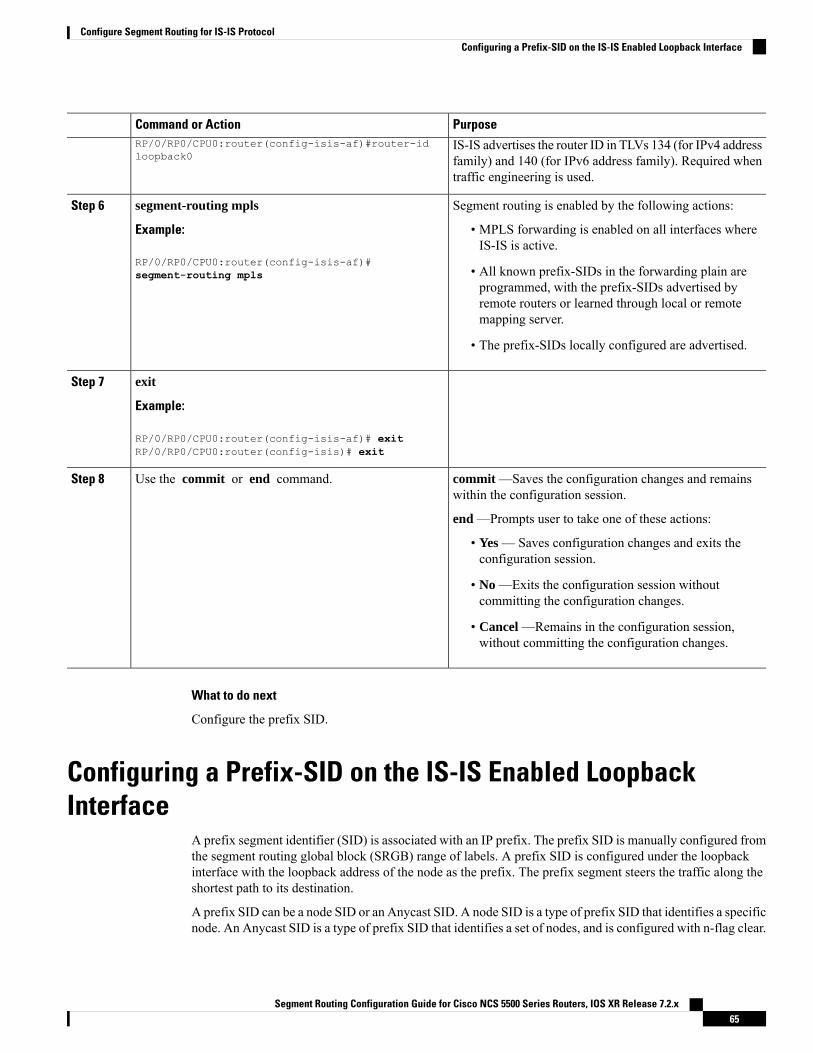
PurposeCommand or Action
IS-IS advertises the router ID in TLVs 134 (for IPv4 addressfamily) and 140 (for IPv6 address family). Required whentraffic engineering is used.
RP/0/RP0/CPU0:router(config-isis-af)#router-idloopback0
Segment routing is enabled by the following actions:segment-routing mplsStep 6
Example: • MPLS forwarding is enabled on all interfaces whereIS-IS is active.
RP/0/RP0/CPU0:router(config-isis-af)#segment-routing mpls • All known prefix-SIDs in the forwarding plain are
programmed, with the prefix-SIDs advertised byremote routers or learned through local or remotemapping server.
• The prefix-SIDs locally configured are advertised.
exitStep 7
Example:
RP/0/RP0/CPU0:router(config-isis-af)# exitRP/0/RP0/CPU0:router(config-isis)# exit
commit —Saves the configuration changes and remainswithin the configuration session.
Use the commit or end command.Step 8
end —Prompts user to take one of these actions:
• Yes — Saves configuration changes and exits theconfiguration session.
• No —Exits the configuration session withoutcommitting the configuration changes.
• Cancel —Remains in the configuration session,without committing the configuration changes.
What to do next
Configure the prefix SID.
Configuring a Prefix-SID on the IS-IS Enabled LoopbackInterface
A prefix segment identifier (SID) is associated with an IP prefix. The prefix SID is manually configured fromthe segment routing global block (SRGB) range of labels. A prefix SID is configured under the loopbackinterface with the loopback address of the node as the prefix. The prefix segment steers the traffic along theshortest path to its destination.
A prefix SID can be a node SID or an Anycast SID. A node SID is a type of prefix SID that identifies a specificnode. An Anycast SID is a type of prefix SID that identifies a set of nodes, and is configured with n-flag clear.
Segment Routing Configuration Guide for Cisco NCS 5500 Series Routers, IOS XR Release 7.2.x65
Configure Segment Routing for IS-IS ProtocolConfiguring a Prefix-SID on the IS-IS Enabled Loopback Interface
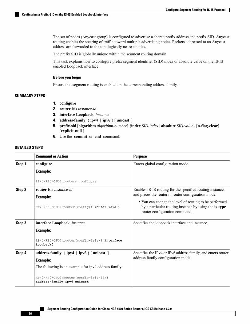
The set of nodes (Anycast group) is configured to advertise a shared prefix address and prefix SID. Anycastrouting enables the steering of traffic toward multiple advertising nodes. Packets addressed to an Anycastaddress are forwarded to the topologically nearest nodes.
The prefix SID is globally unique within the segment routing domain.
This task explains how to configure prefix segment identifier (SID) index or absolute value on the IS-ISenabled Loopback interface.
Before you begin
Ensure that segment routing is enabled on the corresponding address family.
SUMMARY STEPS
1. configure2. router isis instance-id
3. interface Loopback instance
4. address-family { ipv4 | ipv6 } [ unicast ]5. prefix-sid [algorithm algorithm-number] {index SID-index | absolute SID-value} [n-flag-clear]
[explicit-null ]6. Use the commit or end command.
DETAILED STEPS
PurposeCommand or Action
Enters global configuration mode.configure
Example:
Step 1
RP/0/RP0/CPU0:router# configure
Enables IS-IS routing for the specified routing instance,and places the router in router configuration mode.
router isis instance-id
Example:
Step 2
• You can change the level of routing to be performedby a particular routing instance by using the is-typerouter configuration command.
RP/0/RP0/CPU0:router(config)# router isis 1
Specifies the loopback interface and instance.interface Loopback instance
Example:
Step 3
RP/0/RP0/CPU0:router(config-isis)# interfaceLoopback0
Specifies the IPv4 or IPv6 address family, and enters routeraddress family configuration mode.
address-family { ipv4 | ipv6 } [ unicast ]
Example:
Step 4
The following is an example for ipv4 address family:
RP/0/RP0/CPU0:router(config-isis-if)#address-family ipv4 unicast
Segment Routing Configuration Guide for Cisco NCS 5500 Series Routers, IOS XR Release 7.2.x66
Configure Segment Routing for IS-IS ProtocolConfiguring a Prefix-SID on the IS-IS Enabled Loopback Interface

PurposeCommand or Action
Configures the prefix-SID index or absolute value for theinterface.
prefix-sid [algorithm algorithm-number] {index SID-index| absolute SID-value} [n-flag-clear] [explicit-null ]
Step 5
Example: Specify algorithm algorithm-number to configure SRFlexible Algorithm. See Enabling Segment Routing FlexibleAlgorithm, on page 193.RP/0/RP0/CPU0:router(config-isis-if-af)# prefix-sid
index 1001Specify index SID-index for each node to create a prefixSID based on the lower boundary of the SRGB + the index.
RP/0/RP0/CPU0:router(config-isis-if-af)# prefix-sid Specify absolute SID-value for each node to create aspecific prefix SID within the SRGB.absolute 17001
By default, the n-flag is set on the prefix-SID, indicatingthat it is a node SID. For specific prefix-SID (for example,Anycast prefix-SID), enter the n-flag-clear keyword.IS-IS does not set the N flag in the prefix-SID sub TypeLength Value (TLV).
To disable penultimate-hop-popping (PHP) and addexplicit-Null label, enter explicit-null keyword. IS-ISsets the E flag in the prefix-SID sub TLV.
commit —Saves the configuration changes and remainswithin the configuration session.
Use the commit or end command.Step 6
end —Prompts user to take one of these actions:
• Yes — Saves configuration changes and exits theconfiguration session.
• No —Exits the configuration session withoutcommitting the configuration changes.
• Cancel —Remains in the configuration session,without committing the configuration changes.
Verify the prefix-SID configuration:
RP/0/RP0/CPU0:router# show isis database verbose
IS-IS 1 (Level-2) Link State DatabaseLSPID LSP Seq Num LSP Checksum LSP Holdtime ATT/P/OLrouter.00-00 * 0x0000039b 0xfc27 1079 0/0/0Area Address: 49.0001NLPID: 0xccNLPID: 0x8eMT: Standard (IPv4 Unicast)MT: IPv6 Unicast 0/0/0Hostname: routerIP Address: 10.0.0.1IPv6 Address: 2001:0db8:1234::0a00:0001Router Cap: 10.0.0.1, D:0, S:0Segment Routing: I:1 V:1, SRGB Base: 16000 Range: 8000SR Algorithm:Algorithm: 0
Segment Routing Configuration Guide for Cisco NCS 5500 Series Routers, IOS XR Release 7.2.x67
Configure Segment Routing for IS-IS ProtocolConfiguring a Prefix-SID on the IS-IS Enabled Loopback Interface

<...>Metric: 0 IP-Extended 10.0.0.1/32Prefix-SID Index: 1001, Algorithm:0, R:0 N:1 P:0 E:0 V:0 L:0
<...>
What to do next
Configure the SR-TE policy.
Configuring an Adjacency SIDAn adjacency SID (Adj-SID) is associated with an adjacency to a neighboring node. The adjacency SID steersthe traffic to a specific adjacency. Adjacency SIDs have local significance and are only valid on the node thatallocates them.
An adjacency SID can be allocated dynamically from the dynamic label range or configured manually fromthe segment routing local block (SRLB) range of labels.
Adjacency SIDs that are dynamically allocated do not require any special configuration, however there aresome limitations:
• A dynamically allocated Adj-SID value is not known until it has been allocated, and a controller will notknow the Adj-SID value until the information is flooded by the IGP.
• Dynamically allocated Adj-SIDs are not persistent and can be reallocated after a reload or a processrestart.
• Each link is allocated a unique Adj-SID, so the same Adj-SID cannot be shared by multiple links.
Manually allocated Adj-SIDs are persistent over reloads and restarts. They can be provisioned for multipleadjacencies to the same neighbor or to different neighbors. You can specify that the Adj-SID is protected. Ifthe Adj-SID is protected on the primary interface and a backup path is available, a backup path is installed.By default, manual Adj-SIDs are not protected.
Adjacency SIDs are advertised using the existing IS-IS Adj-SID sub-TLV. The S and P flags are defined formanually allocated Adj-SIDs.
0 1 2 3 4 5 6 7+-+-+-+-+-+-+-+-+|F|B|V|L|S|P| |+-+-+-+-+-+-+-+-+
Table 5: Adjacency Segment Identifier (Adj-SID) Flags Sub-TLV Fields
DescriptionField
This flag is set if the same Adj-SID value has been provisioned on multipleinterfaces.
S (Set)
This flag is set if the Adj-SID is persistent (manually allocated).P (Persistent)
Segment Routing Configuration Guide for Cisco NCS 5500 Series Routers, IOS XR Release 7.2.x68
Configure Segment Routing for IS-IS ProtocolConfiguring an Adjacency SID

Manually allocated Adj-SIDs are supported on point-to-point (P2P) interfaces.
This task explains how to configure an Adj-SID on an interface.
Before you begin
Ensure that segment routing is enabled on the corresponding address family.
Use the show mpls label table detail command to verify the SRLB range.
SUMMARY STEPS
1. configure2. router isis instance-id
3. interface type interface-path-id
4. point-to-point5. address-family { ipv4 | ipv6 } [ unicast ]6. adjacency-sid {index adj-SID-index | absolute adj-SID-value } [protected ]7. Use the commit or end command.
DETAILED STEPS
PurposeCommand or Action
Enters global configuration mode.configure
Example:
Step 1
RP/0/RP0/CPU0:router# configure
Enables IS-IS routing for the specified routing instance,and places the router in router configuration mode.
router isis instance-id
Example:
Step 2
• You can change the level of routing to be performedby a particular routing instance by using the is-typerouter configuration command.
RP/0/RP0/CPU0:router(config)# router isis 1
Specifies the interface and enters interface configurationmode.
interface type interface-path-id
Example:
Step 3
RP/0/RP0/CPU0:router(config-isis)# interfaceGigabitEthernet0/0/0/7
Specifies the interface is a point-to-point interface.point-to-point
Example:
Step 4
RP/0/RP0/CPU0:router(config-isis-if)#point-to-point
Specifies the IPv4 or IPv6 address family, and enters routeraddress family configuration mode.
address-family { ipv4 | ipv6 } [ unicast ]
Example:
Step 5
The following is an example for ipv4 address family:
Segment Routing Configuration Guide for Cisco NCS 5500 Series Routers, IOS XR Release 7.2.x69
Configure Segment Routing for IS-IS ProtocolConfiguring an Adjacency SID

PurposeCommand or Action
RP/0/RP0/CPU0:router(config-isis-if)#address-family ipv4 unicast
Configures the Adj-SID index or absolute value for theinterface.
adjacency-sid {index adj-SID-index | absoluteadj-SID-value } [protected ]
Step 6
Example: Specify index adj-SID-index for each link to create anAjd-SID based on the lower boundary of the SRLB + theindex.RP/0/RP0/CPU0:router(config-isis-if-af)#
adjacency-sid index 10Specify absolute adj-SID-value for each link to create aspecific Ajd-SID within the SRLB.
RP/0/RP0/CPU0:router(config-isis-if-af)# Specify if the Adj-SID is protected. For each primary path,if the Adj-SID is protected on the primary interface and aadjacency-sid absolute 15010
backup path is available, a backup path is installed. Bydefault, manual Adj-SIDs are not protected.
commit —Saves the configuration changes and remainswithin the configuration session.
Use the commit or end command.Step 7
end —Prompts user to take one of these actions:
• Yes — Saves configuration changes and exits theconfiguration session.
• No —Exits the configuration session withoutcommitting the configuration changes.
• Cancel —Remains in the configuration session,without committing the configuration changes.
Verify the Adj-SID configuration:
RP/0/RP0/CPU0:router# show isis segment-routing label adjacency persistentMon Jun 12 02:44:07.085 PDT
IS-IS 1 Manual Adjacency SID Table
15010 AF IPv4GigabitEthernet0/0/0/3: IPv4, Protected 1/65/N, ActiveGigabitEthernet0/0/0/7: IPv4, Protected 2/66/N, Active
15100 AF IPv6GigabitEthernet0/0/0/3: IPv6, Not protected 255/255/N, Active
Verify the labels are added to the MPLS Forwarding Information Base (LFIB):
RP/0/RP0/CPU0:router# show mpls forwarding labels 15010Mon Jun 12 02:50:12.172 PDTLocal Outgoing Prefix Outgoing Next Hop BytesLabel Label or ID Interface Switched------ ----------- ------------------ ------------ --------------- ------------
Segment Routing Configuration Guide for Cisco NCS 5500 Series Routers, IOS XR Release 7.2.x70
Configure Segment Routing for IS-IS ProtocolConfiguring an Adjacency SID

15010 Pop SRLB (idx 10) Gi0/0/0/3 10.0.3.3 0Pop SRLB (idx 10) Gi0/0/0/7 10.1.0.5 016004 SRLB (idx 10) Gi0/0/0/7 10.1.0.5 0 (!)16004 SRLB (idx 10) Gi0/0/0/3 10.0.3.3 0 (!)
What to do next
Configure the SR-TE policy.
Manually Configure a Layer 2 Adjacency SIDTypically, an adjacency SID (Adj-SID) is associated with a Layer 3 adjacency to a neighboring node, to steerthe traffic to a specific adjacency. If you have Layer 3 bundle interfaces, where multiple physical interfacesform a bundle interface, the individual Layer 2 bundle members are not visible to IGP; only the bundle interfaceis visible.
You can configure a Layer 2 Adj-SID for the individual Layer 2 bundle interfaces. This configuration allowsyou to track the availability of individual bundle member links and to verify the segment routing forwardingover the individual bundle member links, for Operational Administration and Maintenance (OAM) purposes.
A Layer 2 Adj-SID can be allocated dynamically or configured manually.
• IGP dynamically allocates Layer 2 Adj-SIDs from the dynamic label range for each Layer 2 bundlemember. A dynamic Layer 2 Adj-SID is not persistent and can be reallocated as the Layer 3 bundle linkgoes up and down.
• Manually configured Layer 2 Adj-SIDs are persistent if the Layer 3 bundle link goes up and down. Layer2 Adj-SIDs are allocated from the Segment Routing Local Block (SRLB) range of labels. However, ifthe configured value of Layer 2 Adj-SID does not fall within the available SRLB, a Layer 2 Adj-SIDwill not be programmed into forwarding information base (FIB).
Restrictions
• Adj-SID forwarding requires a next-hop, which can be either an IPv4 address or an IPv6 address, butnot both. Therefore, manually configured Layer 2 Adj-SIDs are configured per address-family.
• Manually configured Layer 2 Adj-SID can be associated with only one Layer 2 bundle member link.
• A SID value used for Layer 2 Adj-SID cannot be shared with Layer 3 Adj-SID.
• SR-TE using Layer 2 Adj-SID is not supported.
This task explains how to configure a Layer 2 Adj-SID on an interface.
Before you begin
Ensure that segment routing is enabled on the corresponding address family.
Use the show mpls label table detail command to verify the SRLB range.
SUMMARY STEPS
1. configure2. segment-routing3. adjacency-sid
Segment Routing Configuration Guide for Cisco NCS 5500 Series Routers, IOS XR Release 7.2.x71
Configure Segment Routing for IS-IS ProtocolManually Configure a Layer 2 Adjacency SID

4. interface type interface-path-id
5. address-family { ipv4 | ipv6 } [ unicast ]6. l2-adjacency sid {index adj-SID-index | absolute adj-SID-value } [next-hop {ipv4_address |
ipv6_address } ]7. Use the commit or end command.8. end9. router isis instance-id
10. address-family { ipv4 | ipv6 } [ unicast ]11. segment-routing bundle-member-adj-sid
DETAILED STEPS
PurposeCommand or Action
Enters global configuration mode.configure
Example:
Step 1
RP/0/RP0/CPU0:router# configure
Enters segment routing configuration mode.segment-routing
Example:
Step 2
Router(config)# segment-routing
Enters adjacency SID configuration mode.adjacency-sid
Example:
Step 3
Router(config-sr)# adjacency-sid
Specifies the interface and enters interface configurationmode.
interface type interface-path-id
Example:
Step 4
Router(config-sr-adj)# interfaceGigabitEthernet0/0/0/3
Specifies the IPv4 or IPv6 address family, and enters routeraddress family configuration mode.
address-family { ipv4 | ipv6 } [ unicast ]
Example:
Step 5
Router(config-sr-adj-intf)# address-family ipv4unicast
Configures the Adj-SID index or absolute value for theinterface.
l2-adjacency sid {index adj-SID-index | absoluteadj-SID-value } [next-hop {ipv4_address |ipv6_address } ]
Step 6
Specify index adj-SID-index for each link to create anAjd-SID based on the lower boundary of the SRLB + theindex.
Example:
Router(config-sr-adj-intf-af)# l2-adjacency sid Specify absolute adj-SID-value for each link to create aspecific Ajd-SID within the SRLB.
absolute 15015 next-hop 10.1.1.4
Segment Routing Configuration Guide for Cisco NCS 5500 Series Routers, IOS XR Release 7.2.x72
Configure Segment Routing for IS-IS ProtocolManually Configure a Layer 2 Adjacency SID

PurposeCommand or Action
For point-to-point interfaces, you are not required tospecify a next-hop. However, if you do specify thenext-hop, the Layer 2 Adj-SID will be used only if thespecified next-hop matches the neighbor address.
For LAN interfaces, you must configure the next-hop IPv4or IPv6 address. If you do not configure the next-hop, theLayer 2 Adj-SID will not be used for LAN interface.
commit —Saves the configuration changes and remainswithin the configuration session.
Use the commit or end command.Step 7
end —Prompts user to take one of these actions:
• Yes — Saves configuration changes and exits theconfiguration session.
• No —Exits the configuration session withoutcommitting the configuration changes.
• Cancel —Remains in the configuration session,without committing the configuration changes.
endStep 8
Enables IS-IS routing for the specified routing instance,and places the router in router configuration mode.
router isis instance-id
Example:
Step 9
Router(config)# router isis isp
Specifies the IPv4 or IPv6 address family, and enters routeraddress family configuration mode.
address-family { ipv4 | ipv6 } [ unicast ]
Example:
Step 10
Router(config-isis)# address-family ipv4 unicast
Programs the dynamic Layer 2 Adj-SIDs, and advertisesboth manual and dynamic Layer 2 Adj-SIDs.
segment-routing bundle-member-adj-sid
Example:
Step 11
This command is not required to programmanual L2 Adj-SID, but is required to programthe dynamic Layer 2 Adj-SIDs and to advertiseboth manual and dynamic Layer 2 Adj-SIDs.
NoteRouter(config-isis-af)# segment-routingbundle-member-adj-sid
Verify the configuration:
Router# show mpls forwarding detail | i "Pop|Outgoing Interface|Physical Interface"Tue Jun 20 06:53:51.876 PDT. . .15001 Pop SRLB (idx 1) BE1 10.1.1.4 0
Outgoing Interface: Bundle-Ether1 (ifhandle 0x000000b0)
Segment Routing Configuration Guide for Cisco NCS 5500 Series Routers, IOS XR Release 7.2.x73
Configure Segment Routing for IS-IS ProtocolManually Configure a Layer 2 Adjacency SID
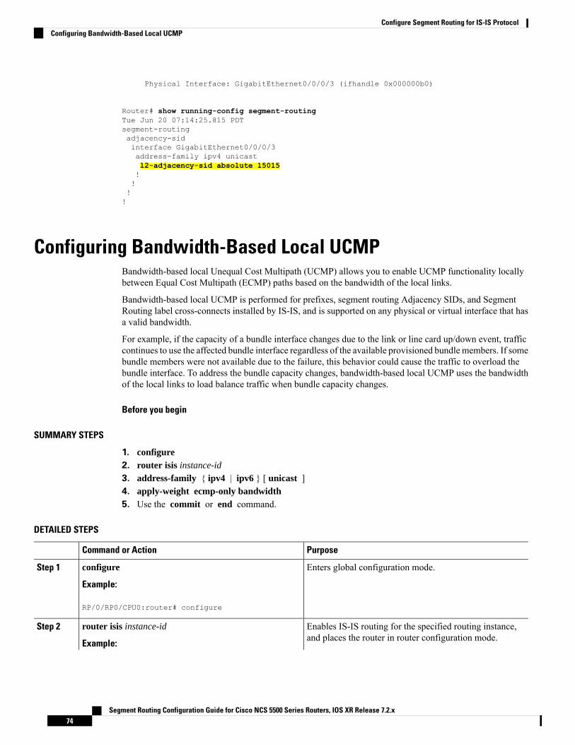
Physical Interface: GigabitEthernet0/0/0/3 (ifhandle 0x000000b0)
Router# show running-config segment-routingTue Jun 20 07:14:25.815 PDTsegment-routingadjacency-sidinterface GigabitEthernet0/0/0/3address-family ipv4 unicastl2-adjacency-sid absolute 15015!!!!
Configuring Bandwidth-Based Local UCMPBandwidth-based local Unequal Cost Multipath (UCMP) allows you to enable UCMP functionality locallybetween Equal Cost Multipath (ECMP) paths based on the bandwidth of the local links.
Bandwidth-based local UCMP is performed for prefixes, segment routing Adjacency SIDs, and SegmentRouting label cross-connects installed by IS-IS, and is supported on any physical or virtual interface that hasa valid bandwidth.
For example, if the capacity of a bundle interface changes due to the link or line card up/down event, trafficcontinues to use the affected bundle interface regardless of the available provisioned bundle members. If somebundle members were not available due to the failure, this behavior could cause the traffic to overload thebundle interface. To address the bundle capacity changes, bandwidth-based local UCMP uses the bandwidthof the local links to load balance traffic when bundle capacity changes.
Before you begin
SUMMARY STEPS
1. configure2. router isis instance-id
3. address-family { ipv4 | ipv6 } [ unicast ]4. apply-weight ecmp-only bandwidth5. Use the commit or end command.
DETAILED STEPS
PurposeCommand or Action
Enters global configuration mode.configure
Example:
Step 1
RP/0/RP0/CPU0:router# configure
Enables IS-IS routing for the specified routing instance,and places the router in router configuration mode.
router isis instance-id
Example:
Step 2
Segment Routing Configuration Guide for Cisco NCS 5500 Series Routers, IOS XR Release 7.2.x74
Configure Segment Routing for IS-IS ProtocolConfiguring Bandwidth-Based Local UCMP

PurposeCommand or Action
You can change the level of routing to be performed by aparticular routing instance by using the is-type routerconfiguration command.
RP/0/RP0/CPU0:router(config)# router isis 1
Specifies the IPv4 or IPv6 address family, and enters IS-ISaddress family configuration mode.
address-family { ipv4 | ipv6 } [ unicast ]
Example:
Step 3
The following is an example for ipv4 address family:
RP/0/RP0/CPU0:router(config-isis)# address-familyipv4 unicast
Enables UCMP functionality locally between ECMP pathsbased on the bandwidth of the local links.
apply-weight ecmp-only bandwidth
Example:
Step 4
RP/0/RP0/CPU0:router(config-isis-af)# apply-weightecmp-only bandwidth
commit —Saves the configuration changes and remainswithin the configuration session.
Use the commit or end command.Step 5
end —Prompts user to take one of these actions:
• Yes — Saves configuration changes and exits theconfiguration session.
• No —Exits the configuration session withoutcommitting the configuration changes.
• Cancel —Remains in the configuration session,without committing the configuration changes.
IS-IS Multi-Domain Prefix SID and Domain Stitching: ExampleIS-IS Multi-Domain Prefix SID and Domain Stitching allows you to configure multiple IS-IS instances onthe same loopback interface for domain border nodes. You specify a loopback interface and prefix SID undermultiple IS-IS instances to make the prefix and prefix SID reachable in different domains.
This example uses the following topology. Node 5 and 9 are border nodes between two IS-IS domains (Domain1and Domain2). Node 10 is configured as the Segment Routing Path Computation Element (SR-PCE) (seeConfigure Segment Routing Path Computation Element).
Segment Routing Configuration Guide for Cisco NCS 5500 Series Routers, IOS XR Release 7.2.x75
Configure Segment Routing for IS-IS ProtocolIS-IS Multi-Domain Prefix SID and Domain Stitching: Example

Figure 1: Multi-Domain Topology
Configure IS-IS Multi-Domain Prefix SIDSpecify a loopback interface and prefix SID under multiple IS-IS instances on each border node:
Example: Border Node 5router isis Domain1interface Loopback0address-family ipv4 unicastprefix-sid absolute 16005
router isis Domain2interface Loopback0address-family ipv4 unicastprefix-sid absolute 16005
Example: Border Node 9router isis Domain1interface Loopback0address-family ipv4 unicastprefix-sid absolute 16009
router isis Domain2interface Loopback0address-family ipv4 unicastprefix-sid absolute 16009
Border nodes 5 and 9 each run two IS-IS instances (Domain1 and Domain2) and advertise their Loopback0prefix and prefix SID in both domains.
Nodes in both domains can reach the border nodes by using the same prefix and prefix SID. For example,Node 3 and Node 22 can reach Node 5 using prefix SID 16005.
Configure Common Router IDOn each border node, configure a common TE router ID under each IS-IS instance:
Segment Routing Configuration Guide for Cisco NCS 5500 Series Routers, IOS XR Release 7.2.x76
Configure Segment Routing for IS-IS ProtocolConfigure IS-IS Multi-Domain Prefix SID

Example: Border Node 5router isis Domain1address-family ipv4 unicastrouter-id loopback0
router isis Domain2address-family ipv4 unicastrouter-id loopback0
Example: Border Node 9router isis Domain1address-family ipv4 unicastrouter-id loopback0
router isis Domain2address-family ipv4 unicastrouter-id loopback0
Distribute IS-IS Link-State Data
Configure BGP Link-state (BGP-LS) on Node 13 and Node 14 to report their local domain to Node 10:
Example: Node 13router isis Domain1distribute link-state instance-id instance-id
Example: Node 14router isis Domain2distribute link-state instance-id instance-id
Segment Routing Configuration Guide for Cisco NCS 5500 Series Routers, IOS XR Release 7.2.x77
Configure Segment Routing for IS-IS ProtocolDistribute IS-IS Link-State Data

Link-state ID starts from 32. One ID is required per IGP domain. Different domain IDs are essential to identifythat the SR-TE TED belongs to a particular IGP domain.
Nodes 13 and 14 each reports its local domain in BGP-LS to Node 10.
Node 10 identifies the border nodes (Nodes 5 and 9) by their common advertised TE router ID, then combines(stitches) the domains on these border nodes for end-to-end path computations.
Conditional Prefix AdvertisementIn some situations, it’s beneficial to make the IS-IS prefix advertisement conditional. For example, an AreaBorder Router (ABR) or Autonomous System Boundary Router (ASBR) that has lost its connection to oneof the areas or autonomous systems (AS) might keep advertising a prefix. If an ABR or ASBR advertises theSegment Routing (SR) SID with this prefix, the label stack of the traffic routed toward the disconnected areaor AS might use this SID, which would result in dropped traffic at the ABR or ASBR.
ABRs or ASBRs are often deployed in pairs for redundancy and advertise a shared Anycast prefix SID.Conditional Prefix Advertisement allows an ABR or an ASBR to advertise its Anycast SID only whenconnected to a specific area or domain. If an ABR or ASBR becomes disconnected from the particular areaor AS, it stops advertising the address for a specified interface (for example, Loopback).
Configure the conditional prefix advertisement under a specific interface. The prefix advertisement on thisinterface is associated with the route-policy that tracks the presence of a set of prefixes (prefix-set) in theRouting Information Base (RIB).
For faster convergence, the route-policy used for conditional prefix advertisement uses the new event-basedrib-has-route async condition to notify IS-IS of the following situations:
• When the last prefix from the prefix-set is removed from the RIB.
• When the first prefix from the prefix-set is added to the RIB.
Configuration
To use the conditional prefix advertisement in IS-IS, create a prefix-set to be tracked. Then create a routepolicy that uses the prefix-set.Router(config)# prefix-set prefix-set-nameRouter(config-pfx)# prefix-address-1/length[, prefix-address-2/length,,,prefix-address-16/length]Router(config-pfx)# end-set
Router(config)# route-policy rpl-nameRouter(config-rpl)# if rib-has-route async prefix-set-name thenRouter(config-rpl-if)# passRouter(config-rpl-if)# endifRouter(config-rpl)# end-policy
To advertise the loopback address in IS-IS conditionally, use the advertise prefix route-policy commandunder IS-IS interface address-family configuration sub-mode.Router(config)# router isis 1Router(config-isis)# interface Loopback0Router(config-isis-if)# address-family ipv4 unicastRouter(config-isis-if-af)# advertise prefix route-policy rpl-name
Segment Routing Configuration Guide for Cisco NCS 5500 Series Routers, IOS XR Release 7.2.x78
Configure Segment Routing for IS-IS ProtocolConditional Prefix Advertisement
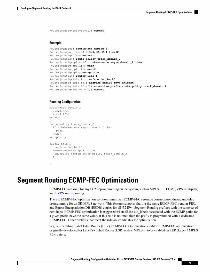
Router(config-isis-if-af)# commit
Example
Router(config)# prefix-set domain_2Router(config-pfx)# 2.3.3.3/32, 2.4.4.4/32Router(config-pfx)# end-setRouter(config)# route-policy track_domain_2Router(config-rpl)# if rib-has-route async domain_2 thenRouter(config-rpl-if)# passRouter(config-rpl-if)# endifRouter(config-rpl)# end-policyRouter(config)# router isis 1Router(config-isis)# interface Loopback0Router(config-isis-if)# address-family ipv4 unicastRouter(config-isis-if-af)# advertise prefix route-policy track_domain-2Router(config-isis-if-af)# commit
Running Configuration
prefix-set domain_22.3.3.3/32,2.4.4.4/32
end-set!route-policy track_domain_2if rib-has-route async domain_2 thenpass
endifend-policy!router isis 1interface Loopback0address-family ipv4 unicastadvertise prefix route-policy track_domain_2!!!
Segment Routing ECMP-FEC OptimizationECMP-FECs are used for any ECMP programming on the system, such asMPLS LSP ECMP, VPNmultipath,and EVPN multi-homing.
The SR ECMP-FEC optimization solution minimizes ECMP-FEC resource consumption during underlayprogramming for an SR-MPLS network. This feature supports sharing the same ECMP-FEC, regular FEC,and Egress Encapsulation DB (EEDB) entries for all /32 IPv4 Segment Routing prefixes with the same set ofnext hops. ECMP-FEC optimization is triggered when all the out_labels associated with the ECMP paths fora given prefix have the same value. If this rule is not met, then the prefix is programmed with a dedicatedECMP-FEC. Other prefixes that meet the rule are candidates for optimization.
Segment Routing Label Edge Router (LER) ECMP-FEC Optimization enables ECMP-FEC optimizationoriginally developed for Label Switched Router (LSR) nodes (MPLS P) to be enabled on LER (Layer 3MPLSPE) routers.
Segment Routing Configuration Guide for Cisco NCS 5500 Series Routers, IOS XR Release 7.2.x79
Configure Segment Routing for IS-IS ProtocolSegment Routing ECMP-FEC Optimization

Usage Guidelines and Limitations
• SR ECMP-FEC Optimization is not supported on Cisco NCS 5500 series routers that have the CiscoNC57 line cards installed and operating in the native or compatible modes.
• For prefixes with LFA backup paths, the SR ECMP-FEC Optimization is possible since these backuppaths do not require an extra label to be pushed; all paths associated with the prefix (primary and backup)have the same outgoing label value.
• For prefixes with TI-LFA backup paths requiring extra labels to be pushed on to the backup, the SRECMP-FEC Optimization is not possible since all the paths associated with the prefix do not have thesame outgoing label value.
• For the duration of time that prefixes are programmed to avoid microloops (when SR MicroLoopAvoidance is triggered), SR ECMP-FEC Optimization is not possible since all the paths associated withthe prefix do not have the same outgoing label value. After removal of the microloop-avoidanceprogramming, the SR ECMP-FEC Optimization might be possible again.
• For scenarios with prefixes where the SR ECMP-FECOptimization is not possible, dedicated ECMP-FECis allocated per prefix. This could potentially lead to ECMP FEC out-of-resource (OOR) considering thebaseline usage of ECMP FEC resources at steady state. During ECMP-FECOOR, prefixes with multiplepaths are programmed with a single path in order to avoid traffic disruption.
• SR ECMP-FEC optimization is applicable in the following instances:
• Label Switched Router (LSR) nodes (MPLS P)
• L3VPN Label Edge Router (LER) nodes
• SR ECMP-FEC optimization should not be enabled in the following instances:
• L2VPN LER nodes
• L2VPN/L3VPN LER nodes with VPN over BGP-LU over SR
• BGP PIC is not supported
Enable SR ECMP-FEC Optimization
To enable SR ECMP-FEC optimization, use the hw-module fib mpls label lsr-optimized command in globalconfiguration mode. After enabling this feature, reload the line card.Router(config)# hw-module fib mpls label lsr-optimizedRouter(config)# commit
LC/0/0/CPU0:Oct 11 20:19:12.540 UTC: fia_driver[185]:%FABRIC-FIA_DRVR-4-MPLS_HW_PROFILE_MISMATCH :
Mismatch found, reload LC to activate the new mpls profile
Router# reload location 0/0/CPU0
Proceed with reload? [confirm]Reloading node 0/0/CPU0
Verification
The following example shows NPU usage before enabling SR ECMP-FEC optimization.
Segment Routing Configuration Guide for Cisco NCS 5500 Series Routers, IOS XR Release 7.2.x80
Configure Segment Routing for IS-IS ProtocolSegment Routing ECMP-FEC Optimization
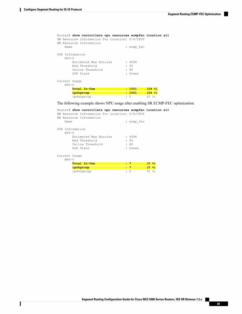
Router# show controllers npu resources ecmpfec location allHW Resource Information For Location: 0/0/CPU0HW Resource Information
Name : ecmp_fec
OOR InformationNPU-0
Estimated Max Entries : 4096Red Threshold : 95Yellow Threshold : 80OOR State : Green
Current UsageNPU-0
Total In-Use : 1001 (24 %)ipnhgroup : 1001 (24 %)ip6nhgroup : 0 (0 %)
The following example shows NPU usage after enabling SR ECMP-FEC optimization.Router# show controllers npu resources ecmpfec location allHW Resource Information For Location: 0/0/CPU0HW Resource Information
Name : ecmp_fec
OOR InformationNPU-0
Estimated Max Entries : 4096Red Threshold : 95Yellow Threshold : 80OOR State : Green
Current UsageNPU-0
Total In-Use : 7 (0 %)ipnhgroup : 7 (0 %)ip6nhgroup : 0 (0 %)
Segment Routing Configuration Guide for Cisco NCS 5500 Series Routers, IOS XR Release 7.2.x81
Configure Segment Routing for IS-IS ProtocolSegment Routing ECMP-FEC Optimization

Segment Routing Configuration Guide for Cisco NCS 5500 Series Routers, IOS XR Release 7.2.x82
Configure Segment Routing for IS-IS ProtocolSegment Routing ECMP-FEC Optimization

C H A P T E R 6Configure Segment Routing for OSPF Protocol
Open Shortest Path First (OSPF) is an Interior Gateway Protocol (IGP) developed by the OSPFworking groupof the Internet Engineering Task Force (IETF). Designed expressly for IP networks, OSPF supports IPsubnetting and tagging of externally derived routing information. OSPF also allows packet authentication anduses IP multicast when sending and receiving packets.
This module provides the configuration information to enable segment routing for OSPF.
For additional information on implementing OSPF on your , see the Implementing OSPF module in the .Note
• Enabling Segment Routing for OSPF Protocol, on page 83• Configuring a Prefix-SID on the OSPF-Enabled Loopback Interface, on page 85• Segment Routing ECMP-FEC Optimization, on page 87
Enabling Segment Routing for OSPF ProtocolSegment routing on the OSPF control plane supports the following:
• OSPFv2 control plane
• Multi-area
• IPv4 prefix SIDs for host prefixes on loopback interfaces
• Adjacency SIDs for adjacencies
• MPLS penultimate hop popping (PHP) and explicit-null signaling
This section describes how to enable segment routingMPLS andMPLS forwarding in OSPF. Segment routingcan be configured at the instance, area, or interface level.
Before you begin
Your network must support the MPLS Cisco IOS XR software feature before you enable segment routing forOSPF on your router.
Segment Routing Configuration Guide for Cisco NCS 5500 Series Routers, IOS XR Release 7.2.x83

Youmust enter the commands in the following task list on every OSPF router in the traffic-engineered portionof your network.
Note
SUMMARY STEPS
1. configure2. router ospf process-name
3. segment-routing mpls4. area area
5. segment-routing mpls6. exit7. Use the commit or end command.
DETAILED STEPS
PurposeCommand or Action
Enters global configuration mode.configure
Example:
Step 1
RP/0/RP0/CPU0:router# configure
Enables OSPF routing for the specified routing process andplaces the router in router configuration mode.
router ospf process-name
Example:
Step 2
RP/0/RP0/CPU0:router(config)# router ospf 1
Enables segment routing using the MPLS data plane on therouting process and all areas and interfaces in the routingprocess.
segment-routing mpls
Example:RP/0/RP0/CPU0:router(config-ospf)# segment-routingmpls
Step 3
Enables segment routing fowarding on all interfaces in therouting process and installs the SIDs received by OSPF inthe forwarding table.
Enters area configuration mode.area area
Example:
Step 4
RP/0/RP0/CPU0:router(config-ospf)# area 0
(Optional) Enables segment routing using the MPLS dataplane on the area and all interfaces in the area. Enables
segment-routing mpls
Example:
Step 5
segment routing fowarding on all interfaces in the area andinstalls the SIDs received by OSPF in the forwarding table.RP/0/RP0/CPU0:router(config-ospf-ar)#
segment-routing mpls
exitStep 6
Example:
Segment Routing Configuration Guide for Cisco NCS 5500 Series Routers, IOS XR Release 7.2.x84
Configure Segment Routing for OSPF ProtocolEnabling Segment Routing for OSPF Protocol
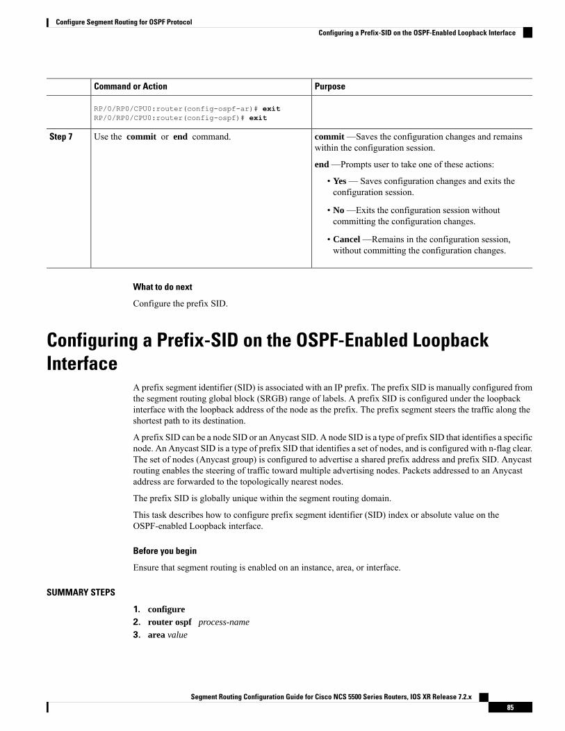
PurposeCommand or Action
RP/0/RP0/CPU0:router(config-ospf-ar)# exitRP/0/RP0/CPU0:router(config-ospf)# exit
commit —Saves the configuration changes and remainswithin the configuration session.
Use the commit or end command.Step 7
end —Prompts user to take one of these actions:
• Yes — Saves configuration changes and exits theconfiguration session.
• No —Exits the configuration session withoutcommitting the configuration changes.
• Cancel —Remains in the configuration session,without committing the configuration changes.
What to do next
Configure the prefix SID.
Configuring a Prefix-SID on the OSPF-Enabled LoopbackInterface
A prefix segment identifier (SID) is associated with an IP prefix. The prefix SID is manually configured fromthe segment routing global block (SRGB) range of labels. A prefix SID is configured under the loopbackinterface with the loopback address of the node as the prefix. The prefix segment steers the traffic along theshortest path to its destination.
A prefix SID can be a node SID or an Anycast SID. A node SID is a type of prefix SID that identifies a specificnode. An Anycast SID is a type of prefix SID that identifies a set of nodes, and is configured with n-flag clear.The set of nodes (Anycast group) is configured to advertise a shared prefix address and prefix SID. Anycastrouting enables the steering of traffic toward multiple advertising nodes. Packets addressed to an Anycastaddress are forwarded to the topologically nearest nodes.
The prefix SID is globally unique within the segment routing domain.
This task describes how to configure prefix segment identifier (SID) index or absolute value on theOSPF-enabled Loopback interface.
Before you begin
Ensure that segment routing is enabled on an instance, area, or interface.
SUMMARY STEPS
1. configure2. router ospf process-name
3. area value
Segment Routing Configuration Guide for Cisco NCS 5500 Series Routers, IOS XR Release 7.2.x85
Configure Segment Routing for OSPF ProtocolConfiguring a Prefix-SID on the OSPF-Enabled Loopback Interface

4. interface Loopback interface-instance
5. prefix-sid [algorithm algorithm-number] {index SID-index | absolute SID-value } [n-flag-clear][explicit-null]
6. Use the commit or end command.
DETAILED STEPS
PurposeCommand or Action
Enters global configuration mode.configure
Example:
Step 1
RP/0/RP0/CPU0:router# configure
Enables OSPF routing for the specified routing process,and places the router in router configuration mode.
router ospf process-name
Example:
Step 2
RP/0/RP0/CPU0:router(config)# router ospf 1
Enters area configuration mode.area value
Example:
Step 3
RP/0/RP0/CPU0:router(config-ospf)# area 0
Specifies the loopback interface and instance.interface Loopback interface-instance
Example:
Step 4
RP/0/RP0/CPU0:router(config-ospf-ar)# interfaceLoopback0 passive
Configures the prefix-SID index or absolute value for theinterface.
prefix-sid [algorithm algorithm-number] {index SID-index| absolute SID-value } [n-flag-clear] [explicit-null]
Step 5
Example: Specify algorithm algorithm-number to configure SRFlexible Algorithm. See Enabling Segment Routing FlexibleAlgorithm, on page 193.RP/0/RP0/CPU0:router(config-ospf-ar)# prefix-sid
index 1001Specify index SID-index for each node to create a prefixSID based on the lower boundary of the SRGB + the index.RP/0/RP0/CPU0:router(config-ospf-ar)# prefix-sid
absolute 17001Specify absolute SID-value for each node to create aspecific prefix SID within the SRGB.
By default, the n-flag is set on the prefix-SID, indicatingthat it is a node SID. For specific prefix-SID (for example,Anycast prefix-SID), enter the n-flag-clear keyword.OSPF does not set the N flag in the prefix-SID sub TypeLength Value (TLV).
To disable penultimate-hop-popping (PHP) and add anexplicit-Null label, enter the explicit-null keyword. OSPFsets the E flag in the prefix-SID sub TLV.
Segment Routing Configuration Guide for Cisco NCS 5500 Series Routers, IOS XR Release 7.2.x86
Configure Segment Routing for OSPF ProtocolConfiguring a Prefix-SID on the OSPF-Enabled Loopback Interface

PurposeCommand or Action
commit —Saves the configuration changes and remainswithin the configuration session.
Use the commit or end command.Step 6
end —Prompts user to take one of these actions:
• Yes — Saves configuration changes and exits theconfiguration session.
• No —Exits the configuration session withoutcommitting the configuration changes.
• Cancel —Remains in the configuration session,without committing the configuration changes.
Verify the prefix-SID configuration:
RP/0/RP0/CPU0:router# show ospf database opaque-area 7.0.0.1 self-originateOSPF Router with ID (10.0.0.1) (Process ID 1)
Type-10 Opaque Link Area Link States (Area 0)<...>
Extended Prefix TLV: Length: 20Route-type: 1AF : 0Flags : 0x40Prefix : 10.0.0.1/32
SID sub-TLV: Length: 8Flags : 0x0MTID : 0Algo : 0SID Index : 1001
What to do next
Configure SR-TE Policies
Segment Routing ECMP-FEC OptimizationECMP-FECs are used for any ECMP programming on the system, such asMPLS LSP ECMP, VPNmultipath,and EVPN multi-homing.
The SR ECMP-FEC optimization solution minimizes ECMP-FEC resource consumption during underlayprogramming for an SR-MPLS network. This feature supports sharing the same ECMP-FEC, regular FEC,and Egress Encapsulation DB (EEDB) entries for all /32 IPv4 Segment Routing prefixes with the same set ofnext hops. ECMP-FEC optimization is triggered when all the out_labels associated with the ECMP paths fora given prefix have the same value. If this rule is not met, then the prefix is programmed with a dedicatedECMP-FEC. Other prefixes that meet the rule are candidates for optimization.
Segment Routing Label Edge Router (LER) ECMP-FEC Optimization enables ECMP-FEC optimizationoriginally developed for Label Switched Router (LSR) nodes (MPLS P) to be enabled on LER (Layer 3MPLSPE) routers.
Segment Routing Configuration Guide for Cisco NCS 5500 Series Routers, IOS XR Release 7.2.x87
Configure Segment Routing for OSPF ProtocolSegment Routing ECMP-FEC Optimization

For usage guidelines, limitations, and configuration options, see Segment Routing ECMP-FECOptimization,on page 79.
Segment Routing Configuration Guide for Cisco NCS 5500 Series Routers, IOS XR Release 7.2.x88
Configure Segment Routing for OSPF ProtocolSegment Routing ECMP-FEC Optimization

C H A P T E R 7Configure Segment Routing for BGP
Border Gateway Protocol (BGP) is an Exterior Gateway Protocol (EGP) that allows you to create loop-freeinter-domain routing between autonomous systems. An autonomous system is a set of routers under a singletechnical administration. Routers in an autonomous system can use multiple Interior Gateway Protocols (IGPs)to exchange routing information inside the autonomous system and an EGP to route packets outside theautonomous system.
This module provides the configuration information used to enable Segment Routing for BGP.
For additional information on implementing BGP on your router, see the BGP Configuration Guide for CiscoNCS 5500 Series Routers.
Note
• Segment Routing for BGP, on page 89• Configure BGP Prefix Segment Identifiers, on page 90• Segment Routing Egress Peer Engineering, on page 91• Configure BGP Link-State, on page 96• Use Case: Configuring SR-EPE and BGP-LS, on page 100• Configure BGP Proxy Prefix SID, on page 102
Segment Routing for BGPIn a traditional BGP-based data center (DC) fabric, packets are forwarded hop-by-hop to each node in theautonomous system. Traffic is directed only along the external BGP (eBGP) multipath ECMP. No trafficengineering is possible.
In anMPLS-based DC fabric, the eBGP sessions between the nodes exchange BGP labeled unicast (BGP-LU)network layer reachability information (NLRI). An MPLS-based DC fabric allows any leaf (top-of-rack orborder router) in the fabric to communicate with any other leaf using a single label, which results in higherpacket forwarding performance and lower encapsulation overhead than traditional BGP-based DC fabric.However, since each label value might be different for each hop, an MPLS-based DC fabric is more difficultto troubleshoot and more complex to configure.
BGP has been extended to carry segment routing prefix-SID index. BGP-LU helps each node learn BGPprefix SIDs of other leaf nodes and can use ECMP between source and destination. Segment routing for BGPsimplifies the configuration, operation, and troubleshooting of the fabric. With segment routing for BGP, youcan enable traffic steering capabilities in the data center using a BGP prefix SID.
Segment Routing Configuration Guide for Cisco NCS 5500 Series Routers, IOS XR Release 7.2.x89
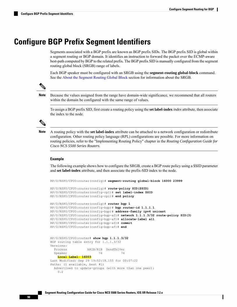
Configure BGP Prefix Segment IdentifiersSegments associated with a BGP prefix are known as BGP prefix SIDs. The BGP prefix SID is global withina segment routing or BGP domain. It identifies an instruction to forward the packet over the ECMP-awarebest-path computed by BGP to the related prefix. The BGP prefix SID is manually configured from the segmentrouting global block (SRGB) range of labels.
Each BGP speaker must be configured with an SRGB using the segment-routing global-block command.See the About the Segment Routing Global Block section for information about the SRGB.
Because the values assigned from the range have domain-wide significance, we recommend that all routerswithin the domain be configured with the same range of values.
Note
To assign a BGP prefix SID, first create a routing policy using the set label-index index attribute, then associatethe index to the node.
A routing policy with the set label-index attribute can be attached to a network configuration or redistributeconfiguration. Other routing policy language (RPL) configurations are possible. For more information onrouting policies, refer to the "Implementing Routing Policy" chapter in the Routing Configuration Guide forCisco NCS 5500 Series Routers.
Note
Example
The following example shows how to configure the SRGB, create a BGP route policy using a $SID parameterand set label-index attribute, and then associate the prefix-SID index to the node.
RP/0/RSP0/CPU0:router(config)# segment-routing global-block 16000 23999
RP/0/RSP0/CPU0:router(config)# route-policy SID($SID)RP/0/RSP0/CPU0:router(config-rpl)# set label-index $SIDRP/0/RSP0/CPU0:router(config-rpl)# end policy
RP/0/RSP0/CPU0:router(config)# router bgp 1RP/0/RSP0/CPU0:router(config-bgp)# bgp router-id 1.1.1.1RP/0/RSP0/CPU0:router(config-bgp)# address-family ipv4 unicastRP/0/RSP0/CPU0:router(config-bgp-af)# network 1.1.1.3/32 route-policy SID(3)RP/0/RSP0/CPU0:router(config-bgp-af)# allocate-label allRP/0/RSP0/CPU0:router(config-bgp-af)# commitRP/0/RSP0/CPU0:router(config-bgp-af)# end
RP/0/RSP0/CPU0:router# show bgp 1.1.1.3/32BGP routing table entry for 1.1.1.3/32Versions:Process bRIB/RIB SendTblVerSpeaker 74 74Local Label: 16003
Last Modified: Sep 29 19:52:18.155 for 00:07:22Paths: (1 available, best #1)Advertised to update-groups (with more than one peer):0.2
Segment Routing Configuration Guide for Cisco NCS 5500 Series Routers, IOS XR Release 7.2.x90
Configure Segment Routing for BGPConfigure BGP Prefix Segment Identifiers

Path #1: Received by speaker 0Advertised to update-groups (with more than one peer):0.2
399.3.21.3 from 99.3.21.3 (1.1.1.3)Received Label 3Origin IGP, metric 0, localpref 100, valid, external, best, group-bestReceived Path ID 0, Local Path ID 1, version 74Origin-AS validity: not-foundLabel Index: 3
Segment Routing Egress Peer EngineeringSegment routing egress peer engineering (EPE) uses a controller to instruct an ingress provider edge, or acontent source (node) within the segment routing domain, to use a specific egress provider edge (node) anda specific external interface to reach a destination. BGP peer SIDs are used to express source-routedinter-domain paths.
Below are the BGP-EPE peering SID types:
• PeerNode SID—To an eBGP peer. Pops the label and forwards the traffic on any interface to the peer.
• PeerAdjacency SID—To an eBGP peer via interface. Pops the label and forwards the traffic on the relatedinterface.
• PeerSet SID—To a set of eBGP peers. Pops the label and forwards the traffic on any interface to the setof peers. All the peers in a set might not be in the same AS.
Multiple PeerSet SIDs can be associated with any combination of PeerNode SIDs or PeerAdjacencySIDs.
The controller learns the BGP peer SIDs and the external topology of the egress border router through BGP-LSEPE routes. The controller can program an ingress node to steer traffic to a destination through the egressnode and peer node using BGP labeled unicast (BGP-LU).
EPE functionality is only required at the EPE egress border router and the EPE controller.
Usage Guidelines and LimitationsWhen enabling BGP EPE, you must enable MPLS encapsulation on the egress interface connecting to theeBGP peer. This can be done by enabling eitherMPLS static or BGP labeled unicast (BGP-LU) address familyfor the eBGP peer.
For information about MPLS static, refer to the “Implementing MPLS Static Labeling” chapter in the MPLSConfiguration Guide for Cisco ASR 9000 NCS 5500 NCS 5000 NCS 560 NCS 540 Series Routers.
For information about BGP-LU, refer to the “Implementing BGP” chapter in the Routing Configuration Guidefor Cisco ASR 9000 NCS 6000 Series RoutersBGP Configuration Guide for Cisco NCS 5500 NCS 5000 NCS560 NCS 540 Series Routers.
Configure Segment Routing Egress Peer EngineeringThis task explains how to configure segment routing EPE on the EPE egress node.
Segment Routing Configuration Guide for Cisco NCS 5500 Series Routers, IOS XR Release 7.2.x91
Configure Segment Routing for BGPSegment Routing Egress Peer Engineering

SUMMARY STEPS
1. router bgp as-number
2. neighbor ip-address
3. remote-as as-number
4. egress-engineering5. exit6. mpls static7. interface type interface-path-id
8. Use the commit or end command.
DETAILED STEPS
PurposeCommand or Action
Specifies the BGP AS number and enters the BGPconfiguration mode, allowing you to configure the BGProuting process.
router bgp as-number
Example:
RP/0/RSP0/CPU0:router(config)# router bgp 1
Step 1
Places the router in neighbor configuration mode for BGProuting and configures the neighbor IP address as a BGPpeer.
neighbor ip-address
Example:
RP/0/RSP0/CPU0:router(config-bgp)# neighbor
Step 2
192.168.1.3
Creates a neighbor and assigns a remote autonomous systemnumber to it.
remote-as as-number
Example:
Step 3
RP/0/RSP0/CPU0:router(config-bgp-nbr)# remote-as3
Configures the egress node with EPE for the eBGP peer.egress-engineering
Example:
Step 4
RP/0/RSP0/CPU0:router(config-bgp-nbr)#egress-engineering
exitStep 5
Example:
RP/0/RSP0/CPU0:router(config-bgp-nbr)# exitRP/0/RSP0/CPU0:router(config-bgp)# exitRP/0/RSP0/CPU0:router(config)#
Segment Routing Configuration Guide for Cisco NCS 5500 Series Routers, IOS XR Release 7.2.x92
Configure Segment Routing for BGPConfigure Segment Routing Egress Peer Engineering

PurposeCommand or Action
Configure MPLS static on the egress interface connectingto the eBGP peer.
mpls static
Example:
Step 6
RP/0/RSP0/CPU0:router(config)# mpls static
Specifies the egress interface connecting to the eBGP peer.interface type interface-path-id
Example:
Step 7
RP/0/RSP0/CPU0:router(config-mpls-static)#interface GigabitEthernet0/0/1/2
commit —Saves the configuration changes and remainswithin the configuration session.
Use the commit or end command.Step 8
end —Prompts user to take one of these actions:
• Yes — Saves configuration changes and exits theconfiguration session.
• No —Exits the configuration session withoutcommitting the configuration changes.
• Cancel —Remains in the configuration session,without committing the configuration changes.
Example
Running Config:
router bgp 1neighbor 192.168.1.3remote-as 3egress-engineering!!mpls staticinterface GigabitEthernet0/0/1/2!!
Configuring Manual BGP-EPE Peering SIDsConfiguring manual BGP-EPE Peer SIDs allows for persistent EPE label values. Manual BGP-EPE SIDs areadvertised through BGP-LS and are allocated from the Segment Routing Local Block (SRLB). See ConfigureSegment Routing Global Block and Segment Routing Local Block, on page 53 for information about theSRLB.
Each PeerNode SID, PeerAdjacency SID, and PeerSet SID is configured with an index value. This indexserves as an offset from the configured SRLB start value and the resulting MPLS label (SRLB start label +
Segment Routing Configuration Guide for Cisco NCS 5500 Series Routers, IOS XR Release 7.2.x93
Configure Segment Routing for BGPConfiguring Manual BGP-EPE Peering SIDs

index) is assigned to these SIDs. This label is used by CEF to perform load balancing across the individualBGP PeerSet SIDs, BGP PeerNode SID, or ultimately across each first-hop adjacency associated with thatBGP PeerNode SID or BGP PeerSet SID.
Configuring Manual PeerNode SID
Each eBGP peer will be associated with a PeerNode SID index that is configuration driven.RP/0/0/CPU0:PE1(config)# router bgp 10RP/0/0/CPU0:PE1(config-bgp)# neighbor 10.10.10.2RP/0/0/CPU0:PE1(config-bgp-nbr)# remote-as 20RP/0/0/CPU0:PE1(config-bgp-nbr)# egress-engineeringRP/0/0/CPU0:PE1(config-bgp-nbr)# peer-node-sid index 600
Configuring Manual PeerAdjacency SID
Any first-hop for which an adjacency SID is configured needs to be in the resolution chain of at least oneeBGP peer that is configured for egress-peer engineering. Otherwise such a kind of “orphan” first-hop withregards to BGP has no effect on this feature. This is because BGP only understands next-hops learnt by theBGP protocol itself and in addition only the resolving IGP next-hops for those BGP next-hops.RP/0/0/CPU0:PE1(config)# router bgp 10RP/0/0/CPU0:PE1(config-bgp)# adjacenciesRP/0/0/CPU0:PE1(config-bgp-adj)# 1.1.1.2RP/0/0/CPU0:PE1(config-bgp-adj)# adjacency-sid index 500
Configuring Manual PeerSet SID
The PeerSet SID is configured under global Address Family. This configuration results in the creation of aPeer-Set SID EPE object.RP/0/0/CPU0:PE1(config)# router bgp 10RP/0/0/CPU0:PE1(config-bgp)# address-family ipv4 unicastRP/0/0/CPU0:PE1(config-bgp-afi)# peer-set-id 1RP/0/0/CPU0:PE1(config-bgp-peer-set)# peer-set-sid 300
Example
Topology
The example in this section uses the following topology.
Segment Routing Configuration Guide for Cisco NCS 5500 Series Routers, IOS XR Release 7.2.x94
Configure Segment Routing for BGPConfiguring Manual BGP-EPE Peering SIDs

In this example, BGP-EPE peer SIDs are allocated from the default SRLB label range (15000 – 15999). TheBGP-EPE peer SIDs are configured as follows:
• PeerNode SIDs to 10.10.10.2 with index 600 (label 15600), and for 20.10.10.2 with index 700 (label15700)
• PeerAdj SID to link 1.1.1.2 with index 500 (label 15500)
• PeerSet SID 1 to load balance over BGP neighbors 10.10.10.1 and 20.10.10.2 with SID index 300 (label15300)
• PeerSet SID 2 to load balance over BGP neighbor 20.10.10.2 and link 1.1.1.2 with SID index 400 (label15400)
Configuration on R1
router bgp 10address-family ipv4 unicastpeer-set-id 1peer-set-sid index 300!peer-set-id 2peer-set-sid index 400!!adjacencies1.1.1.2adjacency-sid index 500peer-set 2!!neighbor 10.10.10.2remote-as 20egress-engineeringpeer-node-sid index 600peer-set 1!neighbor 20.10.10.2egress-engineeringpeer-node-sid index 700peer-set 1
Segment Routing Configuration Guide for Cisco NCS 5500 Series Routers, IOS XR Release 7.2.x95
Configure Segment Routing for BGPConfiguring Manual BGP-EPE Peering SIDs

peer-set 2!
To further show the load balancing of this example:
• 15600 is load balanced over {1.1.1.1 and 2.1.1.1}
• 15700 is load balanced over {3.1.1.1 and 4.1.1.1}
• 15500 is load balanced over {1.1.1.1}
• 15300 is load balanced over {1.1.1.1, 2.1.1.1, 3.1.1.1 and 4.1.1.1}
• 15400 is load balanced over {1.1.1.1, 3.1.1.1 and 4.1.1.1}
Configure BGP Link-StateBGPLink-State (LS) is an Address Family Identifier (AFI) and Sub-address Family Identifier (SAFI) originallydefined to carry interior gateway protocol (IGP) link-state information through BGP. The BGPNetwork LayerReachability Information (NLRI) encoding format for BGP-LS and a new BGP Path Attribute called theBGP-LS attribute are defined in RFC7752. The identifying key of each Link-State object, namely a node,link, or prefix, is encoded in the NLRI and the properties of the object are encoded in the BGP-LS attribute.
The BGP-LS Extensions for Segment Routing are documented in RFC9085.
BGP-LS applications like an SR Path Computation Engine (SR-PCE) can learn the SR capabilities of thenodes in the topology and the mapping of SR segments to those nodes. This can enable the SR-PCE to performpath computations based on SR-TE and to steer traffic on paths different from the underlying IGP-baseddistributed best-path computation.
The following figure shows a typical deployment scenario. In each IGP area, one or more nodes (BGP speakers)are configured with BGP-LS. These BGP speakers form an iBGP mesh by connecting to one or moreroute-reflectors. This way, all BGP speakers (specifically the route-reflectors) obtain Link-State informationfrom all IGP areas (and from other ASes from eBGP peers).
Segment Routing Configuration Guide for Cisco NCS 5500 Series Routers, IOS XR Release 7.2.x96
Configure Segment Routing for BGPConfigure BGP Link-State

Usage Guidelines and Limitations
• BGP-LS supports IS-IS and OSPFv2.
• The identifier field of BGP-LS (referred to as the Instance-ID) identifies the IGP routing domain wherethe NLRI belongs. The NLRIs representing link-state objects (nodes, links, or prefixes) from the sameIGP routing instance must use the same Instance-ID value.
• When there is only a single protocol instance in the network where BGP-LS is operational, we recommendconfiguring the Instance-ID value to 0.
• Assign consistent BGP-LS Instance-ID values on all BGP-LS Producers within a given IGP domain.
• NLRIs with different Instance-ID values are considered to be from different IGP routing instances.
• Unique Instance-ID values must be assigned to routing protocol instances operating in different IGPdomains. This allows the BGP-LS Consumer (for example, SR-PCE) to build an accurate segregatedmulti-domain topology based on the Instance-ID values, even when the topology is advertised via BGP-LSby multiple BGP-LS Producers in the network.
• If the BGP-LS Instance-ID configuration guidelines are not followed, a BGP-LS Consumer may seeduplicate link-state objects for the same node, link, or prefix when there are multiple BGP-LS Producersdeployed. This may also result in the BGP-LS Consumers getting an inaccurate network-wide topology.
Segment Routing Configuration Guide for Cisco NCS 5500 Series Routers, IOS XR Release 7.2.x97
Configure Segment Routing for BGPConfigure BGP Link-State
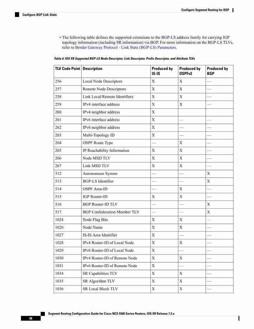
• The following table defines the supported extensions to the BGP-LS address family for carrying IGPtopology information (including SR information) via BGP. For more information on the BGP-LS TLVs,refer to Border Gateway Protocol - Link State (BGP-LS) Parameters.
Table 6: IOS XR Supported BGP-LS Node Descriptor, Link Descriptor, Prefix Descriptor, and Attribute TLVs
Produced byBGP
Produced byOSPFv2
Produced byIS-IS
DescriptionTLV Code Point
—XXLocal Node Descriptors256
—XXRemote Node Descriptors257
—XXLink Local/Remote Identifiers258
—XXIPv4 interface address259
XIPv4 neighbor address260
——XIPv6 interface address261
——XIPv6 neighbor address262
——XMulti-Topology ID263
—X—OSPF Route Type264
—XXIP Reachability Information265
—XXNode MSD TLV266
—XXLink MSD TLV267
X——Autonomous System512
X——BGP-LS Identifier513
—X—OSPF Area-ID514
—XXIGP Router-ID515
X——BGP Router-ID TLV516
X——BGP Confederation Member TLV517
—XXNode Flag Bits1024
—XXNode Name1026
——XIS-IS Area Identifier1027
—XXIPv4 Router-ID of Local Node1028
——XIPv6 Router-ID of Local Node1029
—XXIPv4 Router-ID of Remote Node1030
——XIPv6 Router-ID of Remote Node1031
—XXSR Capabilities TLV1034
—XXSR Algorithm TLV1035
—XXSR Local Block TLV1036
Segment Routing Configuration Guide for Cisco NCS 5500 Series Routers, IOS XR Release 7.2.x98
Configure Segment Routing for BGPConfigure BGP Link-State

Produced byBGP
Produced byOSPFv2
Produced byIS-IS
DescriptionTLV Code Point
—XXFlex Algo Definition (FAD) TLV1039
—XXFlex Algorithm Prefix Metric (FAPM)TLV
1044
—XXAdministrative group (color)1088
—XXMaximum link bandwidth1089
—XXMax. reservable link bandwidth1090
—XXUnreserved bandwidth1091
—XXTE Default Metric1092
—XXLink Protection Type1093
—XXMPLS Protocol Mask1094
—XXIGP Metric1095
—XXShared Risk Link Group1096
—XXAdjacency SID TLV1099
—XXLAN Adjacency SID TLV1100
X——PeerNode SID TLV1101
X——PeerAdj SID TLV1102
X——PeerSet SID TLV1103
—XXUnidirectional Link Delay TLV1114
—XXMin/MaxUnidirectional LinkDelay TLV1115
—XXUnidirectional Delay Variation TLV1116
—XXUnidirectional Link Loss1117
—XXUnidirectional Residual Bandwidth1118
—XXUnidirectional Available Bandwidth1119
—XXUnidirectional Utilized Bandwidth1120
—XXApplication-Specific Link Attribute TLV1122
—XXIGP Flags1152
—XXIGP Route Tag1153
——XIGP Extended Route Tag1154
—XXPrefix Metric1155
—X—OSPF Forwarding Address1156
—XXPrefix-SID1158
—XXRange1159
Segment Routing Configuration Guide for Cisco NCS 5500 Series Routers, IOS XR Release 7.2.x99
Configure Segment Routing for BGPConfigure BGP Link-State
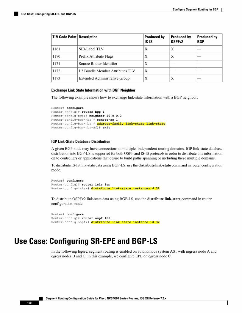
Produced byBGP
Produced byOSPFv2
Produced byIS-IS
DescriptionTLV Code Point
—XXSID/Label TLV1161
—XXPrefix Attribute Flags1170
——XSource Router Identifier1171
——XL2 Bundle Member Attributes TLV1172
—XXExtended Administrative Group1173
Exchange Link State Information with BGP Neighbor
The following example shows how to exchange link-state information with a BGP neighbor:
Router# configureRouter(config)# router bgp 1Router(config-bgp)# neighbor 10.0.0.2Router(config-bgp-nbr)# remote-as 1Router(config-bgp-nbr)# address-family link-state link-stateRouter(config-bgp-nbr-af)# exit
IGP Link-State Database Distribution
A given BGP node may have connections to multiple, independent routing domains. IGP link-state databasedistribution into BGP-LS is supported for both OSPF and IS-IS protocols in order to distribute this informationon to controllers or applications that desire to build paths spanning or including these multiple domains.
To distribute IS-IS link-state data using BGP-LS, use the distribute link-state command in router configurationmode.
Router# configureRouter(config)# router isis ispRouter(config-isis)# distribute link-state instance-id 32
To distribute OSPFv2 link-state data using BGP-LS, use the distribute link-state command in routerconfiguration mode.
Router# configureRouter(config)# router ospf 100Router(config-ospf)# distribute link-state instance-id 32
Use Case: Configuring SR-EPE and BGP-LSIn the following figure, segment routing is enabled on autonomous system AS1 with ingress node A andegress nodes B and C. In this example, we configure EPE on egress node C.
Segment Routing Configuration Guide for Cisco NCS 5500 Series Routers, IOS XR Release 7.2.x100
Configure Segment Routing for BGPUse Case: Configuring SR-EPE and BGP-LS

Figure 2: Topology
Step 1 Configure node C with EPE for eBGP peers D and E.
Example:
RP/0/RSP0/CPU0:router_C(config)# router bgp 1RP/0/RSP0/CPU0:router_C(config-bgp)# neighbor 192.168.1.3RP/0/RSP0/CPU0:router_C(config-bgp-nbr)# remote-as 3RP/0/RSP0/CPU0:router_C(config-bgp-nbr)# description to ERP/0/RSP0/CPU0:router_C(config-bgp-nbr)# egress-engineeringRP/0/RSP0/CPU0:router_C(config-bgp-nbr)# address-family ipv4 unicastRP/0/RSP0/CPU0:router_C(config-bgp-nbr-af)# route-policy bgp_in inRP/0/RSP0/CPU0:router_C(config-bgp-nbr-af)# route-policy bgp_out outRP/0/RSP0/CPU0:router_C(config-bgp-nbr-af)# exitRP/0/RSP0/CPU0:router_C(config-bgp-nbr)# exitRP/0/RSP0/CPU0:router_C(config-bgp)# neighbor 192.168.1.2RP/0/RSP0/CPU0:router_C(config-bgp-nbr)# remote-as 2RP/0/RSP0/CPU0:router_C(config-bgp-nbr)# description to DRP/0/RSP0/CPU0:router_C(config-bgp-nbr)# egress-engineeringRP/0/RSP0/CPU0:router_C(config-bgp-nbr)# address-family ipv4 unicastRP/0/RSP0/CPU0:router_C(config-bgp-nbr-af)# route-policy bgp_in inRP/0/RSP0/CPU0:router_C(config-bgp-nbr-af)# route-policy bgp_out outRP/0/RSP0/CPU0:router_C(config-bgp-nbr-af)# exitRP/0/RSP0/CPU0:router_C(config-bgp-nbr)# exit
Step 2 Configure node C to advertise peer node SIDs to the controller using BGP-LS.
Example:
RP/0/RSP0/CPU0:router_C(config-bgp)# neighbor 172.29.50.71RP/0/RSP0/CPU0:router_C(config-bgp-nbr)# remote-as 1RP/0/RSP0/CPU0:router_C(config-bgp-nbr)# description to EPE_controllerRP/0/RSP0/CPU0:router_C(config-bgp-nbr)# address-family link-state link-stateRP/0/RSP0/CPU0:router_C(config-bgp-nbr)# exitRP/0/RSP0/CPU0:router_C(config-bgp)# exit
Step 3 Configure MPLS static on the egress interfaces connecting to the eBGP peer.
Example:
RP/0/RSP0/CPU0:router_C(config)# mpls staticRP/0/RSP0/CPU0:router_C(config-mpls-static)# interface TenGigE 0/3/0/0RP/0/RSP0/CPU0:router_C(config-mpls-static)# interface TenGigE 0/1/0/0RP/0/RSP0/CPU0:router_C(config-mpls-static)# exit
Segment Routing Configuration Guide for Cisco NCS 5500 Series Routers, IOS XR Release 7.2.x101
Configure Segment Routing for BGPUse Case: Configuring SR-EPE and BGP-LS

Step 4 Commit the configuration.
Example:
RP/0/RSP0/CPU0:router_C(config)# commit
Step 5 Verify the configuration.
Example:
RP/0/RSP0/CPU0:router_C# show bgp egress-engineering
Egress Engineering Peer Set: 192.168.1.2/32 (10b87210)Nexthop: 192.168.1.2Version: 2, rn_version: 2Flags: 0x00000002
Local ASN: 1Remote ASN: 2Local RID: 1.1.1.3Remote RID: 1.1.1.4First Hop: 192.168.1.2
NHID: 3Label: 24002, Refcount: 3
rpc_set: 10b9d408
Egress Engineering Peer Set: 192.168.1.3/32 (10be61d4)Nexthop: 192.168.1.3Version: 3, rn_version: 3Flags: 0x00000002
Local ASN: 1Remote ASN: 3Local RID: 1.1.1.3Remote RID: 1.1.1.5First Hop: 192.168.1.3
NHID: 4Label: 24003, Refcount: 3
rpc_set: 10be6250
The output shows that node C has allocated peer SIDs for each eBGP peer.
Example:
RP/0/RSP0/CPU0:router_C# show mpls forwarding labels 24002 24003Local Outgoing Prefix Outgoing Next Hop BytesLabel Label or ID Interface Switched------ ----------- ------------------ ------------ --------------- ------------24002 Pop No ID Te0/3/0/0 192.168.1.2 024003 Pop No ID Te0/1/0/0 192.168.1.3 0
The output shows that node C installed peer node SIDs in the Forwarding Information Base (FIB).
Configure BGP Proxy Prefix SIDTo support segment routing, Border Gateway Protocol (BGP) requires the ability to advertise a segmentidentifier (SID) for a BGP prefix. A BGP-Prefix-SID is the segment identifier of the BGP prefix segment in
Segment Routing Configuration Guide for Cisco NCS 5500 Series Routers, IOS XR Release 7.2.x102
Configure Segment Routing for BGPConfigure BGP Proxy Prefix SID

a segment routing network. BGP prefix SID attribute is a BGP extension to signal BGP prefix-SIDs. However,there may be routers which do not support BGP extension for segment routing. Hence, those routers also donot support BGP prefix SID attribute and an alternate approach is required.
BGP proxy prefix SID feature allows you to attach BGP prefix SID attributes for remote prefixes learnt fromBGP labeled unicast (LU) neighbours which are not SR-capable and propagate them as SR prefixes. Thisallows an LSP towards non SR endpoints to use segment routing global block in a SR domain. Since BGPproxy prefix SID uses global label values it minimizes the use of limited resources such as ECMP-FEC andprovides more scalability for the networks.
BGP proxy prefix SID feature is implemented using the segment routing mapping server (SRMS). SRMSallows the user to configure SID mapping entries to specify the prefix-SIDs for the prefixes. The mappingserver advertises the local SID-mapping policy to the mapping clients. BGP acts as a client of the SRMS anduses the mapping policy to calculate the prefix-SIDs.
Configuration Example:
This example shows how to configure the BGP proxy prefix SID feature for the segment routing mappingserver.RP/0/RSP0/CPU0:router(config)# segment-routingRP/0/RSP0/CPU0:router(config-sr)# mapping-serverRP/0/RSP0/CPU0:router(config-sr-ms)# prefix-sid-mapRP/0/RSP0/CPU0:router(config-sr-ms-map)# address-family ipv4RP/0/RSP0/CPU0:router(config-sr-ms-map-af)# 1.1.1.1/32 10 range 200RP/0/RSP0/CPU0:router(config-sr-ms-map-af)# 192.168.64.1/32 400 range 300
This example shows how to configure the BGP proxy prefix SID feature for the segment-routing mappingclient.RP/0/RSP0/CPU0:router(config)# router bgp 1RP/0/RSP0/CPU0:router(config-bgp)# address-family ip4 unicastRP/0/RSP0/CPU0:router(config-bgp-af)# segment-routing prefix-sid-map
Verification
These examples show how to verify the BGP proxy prefix SID feature.RP/0/RSP0/CPU0:router# show segment-routing mapping-server prefix-sid-map ipv4 detailPrefix1.1.1.1/32
SID Index: 10Range: 200Last Prefix: 1.1.1.200/32Last SID Index: 209Flags:
Number of mapping entries: 1
RP/0/RSP0/CPU0:router# show bgp ipv4 labeled-unicast 192.168.64.1/32
BGP routing table entry for 192.168.64.1/32Versions:Process bRIB/RIB SendTblVerSpeaker 117 117Local Label: 16400
Last Modified: Oct 25 01:02:28.562 for 00:11:45Paths: (2 available, best #1)Advertised to peers (in unique update groups):201.1.1.1
Segment Routing Configuration Guide for Cisco NCS 5500 Series Routers, IOS XR Release 7.2.x103
Configure Segment Routing for BGPConfigure BGP Proxy Prefix SID

Path #1: Received by speaker 0 Advertised to peers (in unique update groups):201.1.1.1
Local20.0.101.1 from 20.0.101.1 (20.0.101.1) Received Label 61Origin IGP, localpref 100, valid, internal, best, group-best, multipath, labeled-unicast
Received Path ID 0, Local Path ID 0, version 117Prefix SID Attribute Size: 7Label Index: 1
RP/0/RSP0/CPU0:router# show route ipv4 unicast 192.68.64.1/32 detail
Routing entry for 192.168.64.1/32Known via "bgp 65000", distance 200, metric 0, [ei]-bgp, labeled SR, type internalInstalled Oct 25 01:02:28.583 for 00:20:09Routing Descriptor Blocks20.0.101.1, from 20.0.101.1, BGP multi pathRoute metric is 0Label: 0x3d (61)Tunnel ID: NoneBinding Label: NoneExtended communities count: 0NHID:0x0(Ref:0)
Route version is 0x6 (6)Local Label: 0x3e81 (16400)IP Precedence: Not SetQoS Group ID: Not SetFlow-tag: Not SetFwd-class: Not SetRoute Priority: RIB_PRIORITY_RECURSIVE (12) SVD Type RIB_SVD_TYPE_LOCALDownload Priority 4, Download Version 242No advertising protos.
RP/0/RSP0/CPU0:router# show cef ipv4 192.168.64.1/32 detail192.168.64.1/32, version 476, labeled SR, drop adjacency, internal 0x5000001 0x80 (ptr0x71c42b40) [1], 0x0 (0x71c11590), 0x808 (0x722b91e0)Updated Oct 31 23:23:48.733Prefix Len 32, traffic index 0, precedence n/a, priority 4Extensions: context-label:16400gateway array (0x71ae7e78) reference count 3, flags 0x7a, source rib (7), 0 backups
[2 type 5 flags 0x88401 (0x722eb450) ext 0x0 (0x0)]LW-LDI[type=5, refc=3, ptr=0x71c11590, sh-ldi=0x722eb450]gateway array update type-time 3 Oct 31 23:49:11.720LDI Update time Oct 31 23:23:48.733LW-LDI-TS Oct 31 23:23:48.733via 20.0.101.1/32, 0 dependencies, recursive, bgp-ext [flags 0x6020]path-idx 0 NHID 0x0 [0x7129a294 0x0]recursion-via-/32unresolvedlocal label 16400labels imposed {ExpNullv6}
RP/0/RSP0/CPU0:router# show bgp labelsBGP router identifier 2.1.1.1, local AS number 65000BGP generic scan interval 60 secsNon-stop routing is enabledBGP table state: ActiveTable ID: 0xe0000000 RD version: 245BGP main routing table version 245BGP NSR Initial initsync version 16 (Reached)BGP NSR/ISSU Sync-Group versions 245/0BGP scan interval 60 secs
Segment Routing Configuration Guide for Cisco NCS 5500 Series Routers, IOS XR Release 7.2.x104
Configure Segment Routing for BGPConfigure BGP Proxy Prefix SID

Status codes: s suppressed, d damped, h history, * valid, > besti - internal, r RIB-failure, S stale, N Nexthop-discard
Origin codes: i - IGP, e - EGP, ? - incompleteNetwork Next Hop Rcvd Label Local Label
*>i1.1.1.1/32 1.1.1.1 3 16010*> 2.1.1.1/32 0.0.0.0 nolabel 3*> 192.68.64.1/32 20.0.101.1 2 16400*> 192.68.64.2/32 20.0.101.1 2 16401
Segment Routing Configuration Guide for Cisco NCS 5500 Series Routers, IOS XR Release 7.2.x105
Configure Segment Routing for BGPConfigure BGP Proxy Prefix SID

Segment Routing Configuration Guide for Cisco NCS 5500 Series Routers, IOS XR Release 7.2.x106
Configure Segment Routing for BGPConfigure BGP Proxy Prefix SID

C H A P T E R 8Configure SR-TE Policies
This module provides information about segment routing for traffic engineering (SR-TE) policies, how toconfigure SR-TE policies, and how to steer traffic into an SR-TE policy.
• SR-TE Policy Overview, on page 107• Usage Guidelines and Limitations, on page 108• Instantiation of an SR Policy, on page 108• SR-TE Policy Path Types, on page 142• Protocols, on page 152• Traffic Steering, on page 160• Miscellaneous, on page 176
SR-TE Policy OverviewSegment routing for traffic engineering (SR-TE) uses a “policy” to steer traffic through the network. AnSR-TE policy path is expressed as a list of segments that specifies the path, called a segment ID (SID) list.Each segment is an end-to-end path from the source to the destination, and instructs the routers in the networkto follow the specified path instead of following the shortest path calculated by the IGP. If a packet is steeredinto an SR-TE policy, the SID list is pushed on the packet by the head-end. The rest of the network executesthe instructions embedded in the SID list.
An SR-TE policy is identified as an ordered list (head-end, color, end-point):
• Head-end – Where the SR-TE policy is instantiated
• Color – A numerical value that distinguishes between two or more policies to the same node pairs(Head-end – End point)
• End-point – The destination of the SR-TE policy
Every SR-TE policy has a color value. Every policy between the same node pairs requires a unique colorvalue.
An SR-TE policy uses one or more candidate paths. A candidate path is a single segment list (SID-list) or aset of weighted SID-lists (for weighted equal cost multi-path [WECMP]). A candidate path is either dynamicor explicit. See SR-TE Policy Path Types section for more information.
Segment Routing Configuration Guide for Cisco NCS 5500 Series Routers, IOS XR Release 7.2.x107

Usage Guidelines and LimitationsObserve the following guidelines and limitations for the platform.
• SR-TE over BVI is not supported. An SR-TE policy cannot be resolved over an MPLS-enabled BVIinterface.
• For NCS 5500:Counter implications when BVI and SR-TE co-exist in same NPU—Counters for a BVI'slogical interface are not allocated when the same NPU hosts layer-2 (sub)interface(s) associated withthe BVI alongside other port(s) used as egress interface(s) for an SR policy
• For routers that have Cisco NC57 line cards installed and operate in native or compatible modes:Counter implications when BVI and SR-TE co-exist in sameNPU—Counters for a BVI's logical interfaceare allocated when the same NPU hosts layer-2 (sub)interface(s) associated with the BVI alongside otherport(s) used as egress interface(s) for an SR policy
• GRE tunnel as primary interface for an SR policy is not supported.
• GRE tunnel as backup interface for an SR policy with TI-LFA protection is not supported.
• Head-end computed inter-domain SR policy with Flex Algo constraint and IGP redistribution is notsupported. This is supported with Flex Algo-aware path computation at SR-PCE, with or without IGPredistribution. See SR-PCE Flexible Algorithm Multi-Domain Path Computation, on page 210.
Instantiation of an SR PolicyAn SR policy is instantiated, or implemented, at the head-end router.
The following sections provide details on the SR policy instantiation methods:
• On-Demand SR Policy – SR On-Demand Next-Hop , on page 108
• Manually Provisioned SR Policy, on page 142
• PCE-Initiated SR Policy, on page 142
On-Demand SR Policy – SR On-Demand Next-HopSegment RoutingOn-DemandNext Hop (SR-ODN) allows a service head-end router to automatically instantiatean SR policy to a BGP next-hop when required (on-demand). Its key benefits include:
• SLA-aware BGP service – Provides per-destination steering behaviors where a prefix, a set of prefixes,or all prefixes from a service can be associated with a desired underlay SLA. The functionality appliesequally to single-domain and multi-domain networks.
• Simplicity – No prior SR Policy configuration needs to be configured and maintained. Instead, operatorsimply configures a small set of common intent-based optimization templates throughout the network.
• Scalability – Device resources at the head-end router are used only when required, based on service orSLA connectivity needs.
The following example shows how SR-ODN works:
Segment Routing Configuration Guide for Cisco NCS 5500 Series Routers, IOS XR Release 7.2.x108
Configure SR-TE PoliciesUsage Guidelines and Limitations

1. An egress PE (node H) advertises a BGP route for prefix T/t. This advertisement includes an SLA intentencodedwith a BGP color extended community. In this example, the operator assigns color purple (examplevalue = 100) to prefixes that should traverse the network over the delay-optimized path.
2. The route reflector receives the advertised route and advertises it to other PE nodes.
3. Ingress PEs in the network (such as node F) are pre-configured with an ODN template for color purplethat provides the node with the steps to follow in case a route with the intended color appears, for example:
• Contact SR-PCE and request computation for a path toward node H that does not share any nodeswith another LSP in the same disjointness group.
• At the head-end router, compute a path towards node H that minimizes cumulative delay.
4. In this example, the head-end router contacts the SR-PCE and requests computation for a path towardnode H that minimizes cumulative delay.
5. After SR-PCE provides the compute path, an intent-driven SR policy is instantiated at the head-end router.Other prefixes with the same intent (color) and destined to the same egress PE can share the sameon-demand SR policy. When the last prefix associated with a given [intent, egress PE] pair is withdrawn,the on-demand SR policy is deleted, and resources are freed from the head-end router.
An on-demand SR policy is created dynamically for BGP global or VPN (service) routes. The followingservices are supported with SR-ODN:
• IPv4 BGP global routes
• IPv6 BGP global routes (6PE)
• VPNv4
• VPNv6 (6vPE)
• EVPN-VPWS (single-homing)
Segment Routing Configuration Guide for Cisco NCS 5500 Series Routers, IOS XR Release 7.2.x109
Configure SR-TE PoliciesOn-Demand SR Policy – SR On-Demand Next-Hop
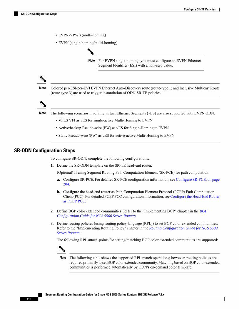
• EVPN-VPWS (multi-homing)
• EVPN (single-homing/multi-homing)
For EVPN single-homing, you must configure an EVPN EthernetSegment Identifier (ESI) with a non-zero value.
Note
Colored per-ESI/per-EVI EVPN Ethernet Auto-Discovery route (route-type 1) and Inclusive Multicast Route(route-type 3) are used to trigger instantiation of ODN SR-TE policies.
Note
The following scenarios involving virtual Ethernet Segments (vES) are also supported with EVPN ODN:
• VPLS VFI as vES for single-active Multi-Homing to EVPN
• Active/backup Pseudo-wire (PW) as vES for Single-Homing to EVPN
• Static Pseudo-wire (PW) as vES for active-active Multi-Homing to EVPN
Note
SR-ODN Configuration StepsTo configure SR-ODN, complete the following configurations:
1. Define the SR-ODN template on the SR-TE head-end router.
(Optional) If using Segment Routing Path Computation Element (SR-PCE) for path computation:
a. Configure SR-PCE. For detailed SR-PCE configuration information, see Configure SR-PCE, on page204.
b. Configure the head-end router as Path Computation Element Protocol (PCEP) Path ComputationClient (PCC). For detailed PCEP PCC configuration information, see Configure the Head-End Routeras PCEP PCC.
2. Define BGP color extended communities. Refer to the "Implementing BGP" chapter in the BGPConfiguration Guide for NCS 5500 Series Routers.
3. Define routing policies (using routing policy language [RPL]) to set BGP color extended communities.Refer to the "Implementing Routing Policy" chapter in the Routing Configuration Guide for NCS 5500Series Routers.
The following RPL attach-points for setting/matching BGP color extended communities are supported:
The following table shows the supported RPL match operations; however, routing policies arerequired primarily to set BGP color extended community. Matching based on BGP color extendedcommunities is performed automatically by ODN's on-demand color template.
Note
Segment Routing Configuration Guide for Cisco NCS 5500 Series Routers, IOS XR Release 7.2.x110
Configure SR-TE PoliciesSR-ODN Configuration Steps

MatchSetAttach Point
XXVRF export
X–VRF import
–XEVI export
XXEVI import
XXNeighbor-in
XXNeighbor-out
X–Inter-AFI export
X–Inter-AFI import
–XDefault-originate
4. Apply routing policies to a service. Refer to the "Implementing Routing Policy" chapter in the RoutingConfiguration Guide for NCS 5500 Series Routers.
Configure On-Demand Color Template
• Use the on-demand color color command to create an ODN template for the specified color value. Thehead-end router automatically follows the actions defined in the template upon arrival of BGP global orVPN routes with a BGP color extended community that matches the color value specified in the template.
The color range is from 1 to 4294967295.Router(config)# segment-routing traffic-engRouter(config-sr-te)# on-demand color 10
Matching based on BGP color extended communities is performedautomatically via ODN's on-demand color template. RPL routingpolicies are not required.
Note
• Use the on-demand color color dynamic command to associate the template with on-demand SR policieswith a locally computed dynamic path (by SR-TE head-end router utilizing its TE topology database) orcentrally (by SR-PCE). The head-end router will first attempt to install the locally computed path;otherwise, it will use the path computed by the SR-PCE.Router(config)# segment-routing traffic-engRouter(config-sr-te)# on-demand color 10 dynamic
• Use the on-demand color color dynamic pcep command to indicate that only the path computed bySR-PCE should be associated with the on-demand SR policy. With this configuration, local pathcomputation is not attempted; instead the head-end router will only instantiate the path computed by theSR-PCE.
Segment Routing Configuration Guide for Cisco NCS 5500 Series Routers, IOS XR Release 7.2.x111
Configure SR-TE PoliciesSR-ODN Configuration Steps
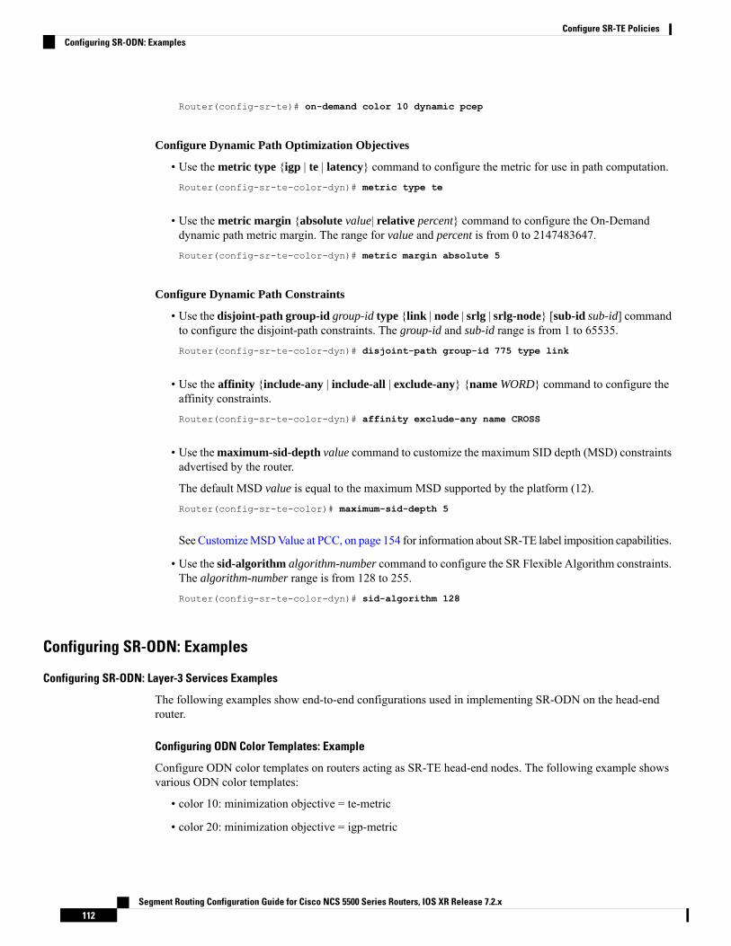
Router(config-sr-te)# on-demand color 10 dynamic pcep
Configure Dynamic Path Optimization Objectives
• Use the metric type {igp | te | latency} command to configure the metric for use in path computation.Router(config-sr-te-color-dyn)# metric type te
• Use the metric margin {absolute value| relative percent} command to configure the On-Demanddynamic path metric margin. The range for value and percent is from 0 to 2147483647.Router(config-sr-te-color-dyn)# metric margin absolute 5
Configure Dynamic Path Constraints
• Use the disjoint-path group-id group-id type {link | node | srlg | srlg-node} [sub-id sub-id] commandto configure the disjoint-path constraints. The group-id and sub-id range is from 1 to 65535.Router(config-sr-te-color-dyn)# disjoint-path group-id 775 type link
• Use the affinity {include-any | include-all | exclude-any} {name WORD} command to configure theaffinity constraints.Router(config-sr-te-color-dyn)# affinity exclude-any name CROSS
• Use the maximum-sid-depth value command to customize the maximum SID depth (MSD) constraintsadvertised by the router.
The default MSD value is equal to the maximum MSD supported by the platform (12).Router(config-sr-te-color)# maximum-sid-depth 5
See CustomizeMSDValue at PCC, on page 154 for information about SR-TE label imposition capabilities.
• Use the sid-algorithm algorithm-number command to configure the SR Flexible Algorithm constraints.The algorithm-number range is from 128 to 255.Router(config-sr-te-color-dyn)# sid-algorithm 128
Configuring SR-ODN: Examples
Configuring SR-ODN: Layer-3 Services Examples
The following examples show end-to-end configurations used in implementing SR-ODN on the head-endrouter.
Configuring ODN Color Templates: Example
Configure ODN color templates on routers acting as SR-TE head-end nodes. The following example showsvarious ODN color templates:
• color 10: minimization objective = te-metric
• color 20: minimization objective = igp-metric
Segment Routing Configuration Guide for Cisco NCS 5500 Series Routers, IOS XR Release 7.2.x112
Configure SR-TE PoliciesConfiguring SR-ODN: Examples
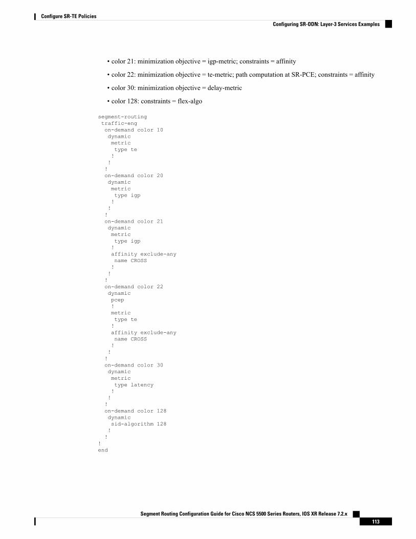
• color 21: minimization objective = igp-metric; constraints = affinity
• color 22: minimization objective = te-metric; path computation at SR-PCE; constraints = affinity
• color 30: minimization objective = delay-metric
• color 128: constraints = flex-algo
segment-routingtraffic-engon-demand color 10dynamicmetrictype te!!!on-demand color 20dynamicmetrictype igp!!!on-demand color 21dynamicmetrictype igp!affinity exclude-anyname CROSS!!!on-demand color 22dynamicpcep!metrictype te!affinity exclude-anyname CROSS!!!on-demand color 30dynamicmetrictype latency!!!on-demand color 128dynamicsid-algorithm 128!!
!end
Segment Routing Configuration Guide for Cisco NCS 5500 Series Routers, IOS XR Release 7.2.x113
Configure SR-TE PoliciesConfiguring SR-ODN: Layer-3 Services Examples

Configuring BGP Color Extended Community Set: Example
The following example shows how to configure BGP color extended communities that are later applied toBGP service routes via route-policies.
In most common scenarios, egress PE routers that advertise BGP service routes apply (set) BGP color extendedcommunities. However, color can also be set at the ingress PE router.
Note
extcommunity-set opaque color10-te10
end-set!extcommunity-set opaque color20-igp20
end-set!extcommunity-set opaque color21-igp-excl-cross21
end-set!extcommunity-set opaque color30-delay30
end-set!extcommunity-set opaque color128-fa128128
end-set!
Configuring RPL to Set BGP Color (Layer-3 Services): Examples
The following example shows various representative RPL definitions that set BGP color community.
The first 4 RPL examples include the set color action only. The last RPL example performs the set color actionfor selected destinations based on a prefix-set.route-policy SET_COLOR_LOW_LATENCY_TEset extcommunity color color10-tepass
end-policy!route-policy SET_COLOR_HI_BWset extcommunity color color20-igppass
end-policy!route-policy SET_COLOR_LOW_LATENCYset extcommunity color color30-delaypass
end-policy!route-policy SET_COLOR_FA_128set extcommunity color color128-fa128pass
end-policy!
prefix-set sample-set88.1.0.0/24
end-set
Segment Routing Configuration Guide for Cisco NCS 5500 Series Routers, IOS XR Release 7.2.x114
Configure SR-TE PoliciesConfiguring SR-ODN: Layer-3 Services Examples
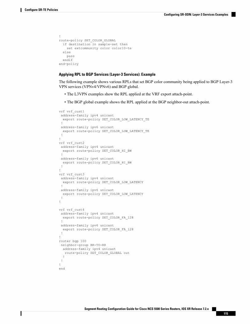
!route-policy SET_COLOR_GLOBALif destination in sample-set thenset extcommunity color color10-te
elsepass
endifend-policy
Applying RPL to BGP Services (Layer-3 Services): Example
The following example shows various RPLs that set BGP color community being applied to BGP Layer-3VPN services (VPNv4/VPNv6) and BGP global.
• The L3VPN examples show the RPL applied at the VRF export attach-point.
• The BGP global example shows the RPL applied at the BGP neighbor-out attach-point.
vrf vrf_cust1address-family ipv4 unicastexport route-policy SET_COLOR_LOW_LATENCY_TE!address-family ipv6 unicastexport route-policy SET_COLOR_LOW_LATENCY_TE!!vrf vrf_cust2address-family ipv4 unicastexport route-policy SET_COLOR_HI_BW!address-family ipv6 unicastexport route-policy SET_COLOR_HI_BW!!vrf vrf_cust3address-family ipv4 unicastexport route-policy SET_COLOR_LOW_LATENCY!address-family ipv6 unicastexport route-policy SET_COLOR_LOW_LATENCY!!
vrf vrf_cust4address-family ipv4 unicastexport route-policy SET_COLOR_FA_128!address-family ipv6 unicastexport route-policy SET_COLOR_FA_128!!router bgp 100neighbor-group BR-TO-RRaddress-family ipv4 unicastroute-policy SET_COLOR_GLOBAL out!!!end
Segment Routing Configuration Guide for Cisco NCS 5500 Series Routers, IOS XR Release 7.2.x115
Configure SR-TE PoliciesConfiguring SR-ODN: Layer-3 Services Examples
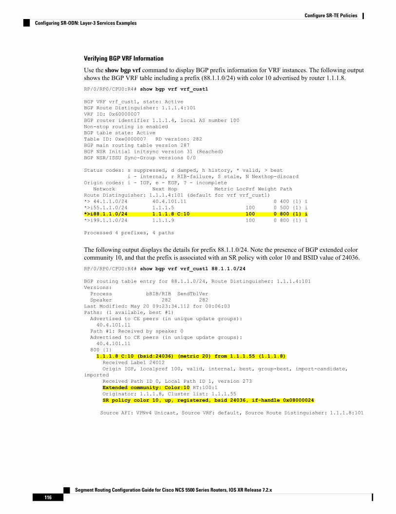
Verifying BGP VRF Information
Use the show bgp vrf command to display BGP prefix information for VRF instances. The following outputshows the BGP VRF table including a prefix (88.1.1.0/24) with color 10 advertised by router 1.1.1.8.RP/0/RP0/CPU0:R4# show bgp vrf vrf_cust1
BGP VRF vrf_cust1, state: ActiveBGP Route Distinguisher: 1.1.1.4:101VRF ID: 0x60000007BGP router identifier 1.1.1.4, local AS number 100Non-stop routing is enabledBGP table state: ActiveTable ID: 0xe0000007 RD version: 282BGP main routing table version 287BGP NSR Initial initsync version 31 (Reached)BGP NSR/ISSU Sync-Group versions 0/0
Status codes: s suppressed, d damped, h history, * valid, > besti - internal, r RIB-failure, S stale, N Nexthop-discard
Origin codes: i - IGP, e - EGP, ? - incompleteNetwork Next Hop Metric LocPrf Weight Path
Route Distinguisher: 1.1.1.4:101 (default for vrf vrf_cust1)*> 44.1.1.0/24 40.4.101.11 0 400 {1} i*>i55.1.1.0/24 1.1.1.5 100 0 500 {1} i*>i88.1.1.0/24 1.1.1.8 C:10 100 0 800 {1} i*>i99.1.1.0/24 1.1.1.9 100 0 800 {1} i
Processed 4 prefixes, 4 paths
The following output displays the details for prefix 88.1.1.0/24. Note the presence of BGP extended colorcommunity 10, and that the prefix is associated with an SR policy with color 10 and BSID value of 24036.RP/0/RP0/CPU0:R4# show bgp vrf vrf_cust1 88.1.1.0/24
BGP routing table entry for 88.1.1.0/24, Route Distinguisher: 1.1.1.4:101Versions:Process bRIB/RIB SendTblVerSpeaker 282 282
Last Modified: May 20 09:23:34.112 for 00:06:03Paths: (1 available, best #1)Advertised to CE peers (in unique update groups):40.4.101.11
Path #1: Received by speaker 0Advertised to CE peers (in unique update groups):40.4.101.11
800 {1}1.1.1.8 C:10 (bsid:24036) (metric 20) from 1.1.1.55 (1.1.1.8)Received Label 24012Origin IGP, localpref 100, valid, internal, best, group-best, import-candidate,
importedReceived Path ID 0, Local Path ID 1, version 273Extended community: Color:10 RT:100:1Originator: 1.1.1.8, Cluster list: 1.1.1.55SR policy color 10, up, registered, bsid 24036, if-handle 0x08000024
Source AFI: VPNv4 Unicast, Source VRF: default, Source Route Distinguisher: 1.1.1.8:101
Segment Routing Configuration Guide for Cisco NCS 5500 Series Routers, IOS XR Release 7.2.x116
Configure SR-TE PoliciesConfiguring SR-ODN: Layer-3 Services Examples
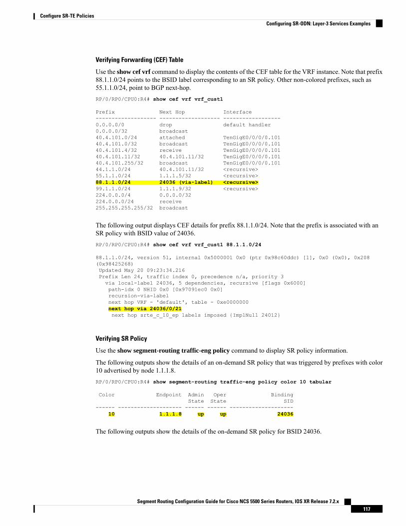
Verifying Forwarding (CEF) Table
Use the show cef vrf command to display the contents of the CEF table for the VRF instance. Note that prefix88.1.1.0/24 points to the BSID label corresponding to an SR policy. Other non-colored prefixes, such as55.1.1.0/24, point to BGP next-hop.RP/0/RP0/CPU0:R4# show cef vrf vrf_cust1
Prefix Next Hop Interface------------------- ------------------- ------------------0.0.0.0/0 drop default handler0.0.0.0/32 broadcast40.4.101.0/24 attached TenGigE0/0/0/0.10140.4.101.0/32 broadcast TenGigE0/0/0/0.10140.4.101.4/32 receive TenGigE0/0/0/0.10140.4.101.11/32 40.4.101.11/32 TenGigE0/0/0/0.10140.4.101.255/32 broadcast TenGigE0/0/0/0.10144.1.1.0/24 40.4.101.11/32 <recursive>55.1.1.0/24 1.1.1.5/32 <recursive>88.1.1.0/24 24036 (via-label) <recursive>99.1.1.0/24 1.1.1.9/32 <recursive>224.0.0.0/4 0.0.0.0/32224.0.0.0/24 receive255.255.255.255/32 broadcast
The following output displays CEF details for prefix 88.1.1.0/24. Note that the prefix is associated with anSR policy with BSID value of 24036.RP/0/RP0/CPU0:R4# show cef vrf vrf_cust1 88.1.1.0/24
88.1.1.0/24, version 51, internal 0x5000001 0x0 (ptr 0x98c60ddc) [1], 0x0 (0x0), 0x208(0x98425268)Updated May 20 09:23:34.216Prefix Len 24, traffic index 0, precedence n/a, priority 3via local-label 24036, 5 dependencies, recursive [flags 0x6000]path-idx 0 NHID 0x0 [0x97091ec0 0x0]recursion-via-labelnext hop VRF - 'default', table - 0xe0000000next hop via 24036/0/21next hop srte_c_10_ep labels imposed {ImplNull 24012}
Verifying SR Policy
Use the show segment-routing traffic-eng policy command to display SR policy information.
The following outputs show the details of an on-demand SR policy that was triggered by prefixes with color10 advertised by node 1.1.1.8.RP/0/RP0/CPU0:R4# show segment-routing traffic-eng policy color 10 tabular
Color Endpoint Admin Oper BindingState State SID
------ -------------------- ------ ------ --------------------10 1.1.1.8 up up 24036
The following outputs show the details of the on-demand SR policy for BSID 24036.
Segment Routing Configuration Guide for Cisco NCS 5500 Series Routers, IOS XR Release 7.2.x117
Configure SR-TE PoliciesConfiguring SR-ODN: Layer-3 Services Examples
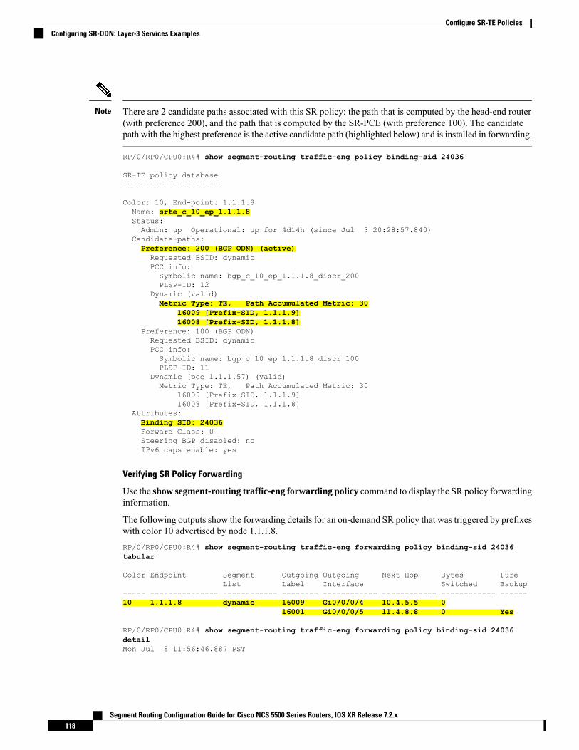
There are 2 candidate paths associated with this SR policy: the path that is computed by the head-end router(with preference 200), and the path that is computed by the SR-PCE (with preference 100). The candidatepath with the highest preference is the active candidate path (highlighted below) and is installed in forwarding.
Note
RP/0/RP0/CPU0:R4# show segment-routing traffic-eng policy binding-sid 24036
SR-TE policy database---------------------
Color: 10, End-point: 1.1.1.8Name: srte_c_10_ep_1.1.1.8Status:Admin: up Operational: up for 4d14h (since Jul 3 20:28:57.840)
Candidate-paths:Preference: 200 (BGP ODN) (active)Requested BSID: dynamicPCC info:Symbolic name: bgp_c_10_ep_1.1.1.8_discr_200PLSP-ID: 12
Dynamic (valid)Metric Type: TE, Path Accumulated Metric: 30
16009 [Prefix-SID, 1.1.1.9]16008 [Prefix-SID, 1.1.1.8]
Preference: 100 (BGP ODN)Requested BSID: dynamicPCC info:Symbolic name: bgp_c_10_ep_1.1.1.8_discr_100PLSP-ID: 11
Dynamic (pce 1.1.1.57) (valid)Metric Type: TE, Path Accumulated Metric: 30
16009 [Prefix-SID, 1.1.1.9]16008 [Prefix-SID, 1.1.1.8]
Attributes:Binding SID: 24036Forward Class: 0Steering BGP disabled: noIPv6 caps enable: yes
Verifying SR Policy Forwarding
Use the show segment-routing traffic-eng forwarding policy command to display the SR policy forwardinginformation.
The following outputs show the forwarding details for an on-demand SR policy that was triggered by prefixeswith color 10 advertised by node 1.1.1.8.RP/0/RP0/CPU0:R4# show segment-routing traffic-eng forwarding policy binding-sid 24036tabular
Color Endpoint Segment Outgoing Outgoing Next Hop Bytes PureList Label Interface Switched Backup
----- --------------- ------------ -------- ------------ ------------ ------------ ------10 1.1.1.8 dynamic 16009 Gi0/0/0/4 10.4.5.5 0
16001 Gi0/0/0/5 11.4.8.8 0 Yes
RP/0/RP0/CPU0:R4# show segment-routing traffic-eng forwarding policy binding-sid 24036detailMon Jul 8 11:56:46.887 PST
Segment Routing Configuration Guide for Cisco NCS 5500 Series Routers, IOS XR Release 7.2.x118
Configure SR-TE PoliciesConfiguring SR-ODN: Layer-3 Services Examples

SR-TE Policy Forwarding database--------------------------------
Color: 10, End-point: 1.1.1.8Name: srte_c_10_ep_1.1.1.8Binding SID: 24036Segment Lists:SL[0]:Name: dynamicPaths:Path[0]:Outgoing Label: 16009Outgoing Interface: GigabitEthernet0/0/0/4Next Hop: 10.4.5.5Switched Packets/Bytes: 0/0FRR Pure Backup: NoLabel Stack (Top -> Bottom): { 16009, 16008 }Path-id: 1 (Protected), Backup-path-id: 2, Weight: 64
Path[1]:Outgoing Label: 16001Outgoing Interface: GigabitEthernet0/0/0/5Next Hop: 11.4.8.8Switched Packets/Bytes: 0/0FRR Pure Backup: YesLabel Stack (Top -> Bottom): { 16001, 16009, 16008 }Path-id: 2 (Pure-Backup), Weight: 64
Policy Packets/Bytes Switched: 0/0Local label: 80013
Configuring SR-ODN: EVPN Services Examples
Configuring BGP Color Extended Community Set: Example
The following example shows how to configure BGP color extended communities that are later applied toBGP service routes via route-policies.extcommunity-set opaque color-4444
end-set
extcommunity-set opaque color-5555
end-set
extcommunity-set opaque color-7777
end-set
extcommunity-set opaque color-8888
end-set
Configuring RPL to Set BGP Color (EVPN Services): Examples
The following examples shows various representative RPL definitions that set BGP color community.
The following RPL examples match on EVPN route-types and then set the BGP color extended community.route-policy sample-export-rplif evpn-route-type is 1 thenset extcommunity color color-44
endif
Segment Routing Configuration Guide for Cisco NCS 5500 Series Routers, IOS XR Release 7.2.x119
Configure SR-TE PoliciesConfiguring SR-ODN: EVPN Services Examples

if evpn-route-type is 3 thenset extcommunity color color-55
endifend-policy
route-policy sample-import-rplif evpn-route-type is 1 thenset extcommunity color color-77
elseif evpn-route-type is 3 thenset extcommunity color color-88
elsepass
endifend-policy
The following RPL example sets BGP color extended community while matching on the following:
• Route Distinguisher (RD)
• Ethernet Segment Identifier (ESI)
• Ethernet Tag (ETAG)
• EVPN route-types
route-policy sample-bgpneighbor-rplif rd in (1.1.1.1:3504) thenset extcommunity color color3504
elseif rd in (1.1.1.1:3505) thenset extcommunity color color3505
elseif rd in (1.1.1.1:3506) thenset extcommunity color color99996
elseif esi in (0010.0000.0000.0000.1201) and rd in (1.1.1.1:3508) thenset extcommunity color color3508
elseif etag in (30509) and rd in (1.1.1.1:3509) thenset extcommunity color color3509
elseif etag in (0) and rd in (1.1.1.1:2001) and evpn-route-type is 1 thenset extcommunity color color82001
elseif etag in (0) and rd in (1.1.1.1:2001) and evpn-route-type is 3 thenset extcommunity color color92001
endifpass
end-policy
Applying RPL to BGP Services (EVPN Services): Example
The following examples show various RPLs that set BGP color community being applied to EVPN services.
The following 2 examples show the RPL applied at the EVI export and import attach-points.
RPLs applied under EVI import or export attach-point also support matching on the following:
• Ethernet Segment Identifier (ESI)
• Ethernet Tag (ETAG)
• EVPN-Originator
Note
evpnevi 101
Segment Routing Configuration Guide for Cisco NCS 5500 Series Routers, IOS XR Release 7.2.x120
Configure SR-TE PoliciesConfiguring SR-ODN: EVPN Services Examples

bgproute-target 101:1route-target import 100:1route-target export 101:1route-policy import sample-import-rpl!advertise-mac!!evi 102bgproute-target 102:1route-target import 100:2route-target export 102:1route-policy export sample-export-rpl!advertise-mac!!!
The following example shows the RPL applied at the BGP neighbor-out attach-point.
RPLs defined under BGP neighbor-out attach-point also support matching on the following:
• EVPN-Originator
Note
router bgp 100bgp router-id 1.1.1.1address-family l2vpn evpn!neighbor-group evpn-rrremote-as 100update-source Loopback0address-family l2vpn evpn!neighbor 10.10.10.10use neighbor-group evpn-rraddress-family l2vpn evpnroute-policy sample-bgpneighbor-rpl out
Configuring SR-ODN for EVPN-VPWS: Use CaseThis use case shows how to set up a pair of ELINE services using EVPN-VPWS between two sites. Servicesare carried over SR policies that must not share any common links along their paths (link-disjoint). The SRpolicies are triggered on-demand based on ODN principles. An SR-PCE computes the disjoint paths.
This use case uses the following topology with 2 sites: Site 1 with nodes A and B, and Site 2 with nodes Cand D.
Segment Routing Configuration Guide for Cisco NCS 5500 Series Routers, IOS XR Release 7.2.x121
Configure SR-TE PoliciesConfiguring SR-ODN for EVPN-VPWS: Use Case
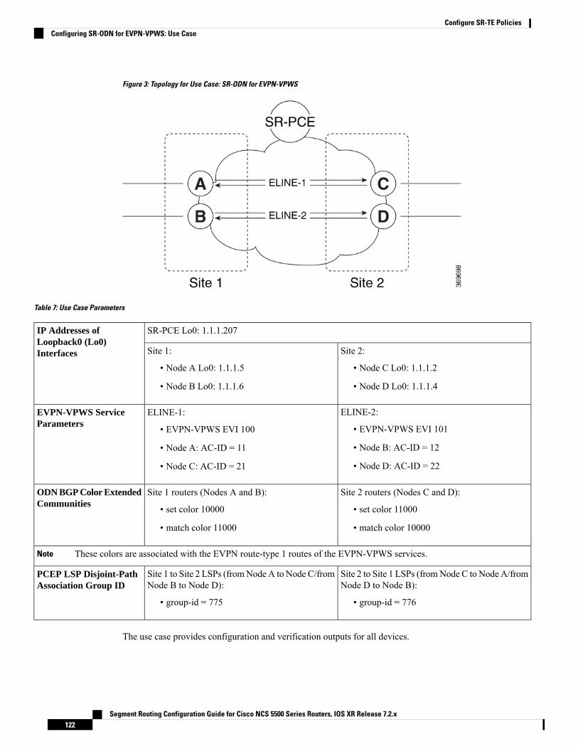
Figure 3: Topology for Use Case: SR-ODN for EVPN-VPWS
Table 7: Use Case Parameters
SR-PCE Lo0: 1.1.1.207IP Addresses ofLoopback0 (Lo0)Interfaces Site 2:
• Node C Lo0: 1.1.1.2
• Node D Lo0: 1.1.1.4
Site 1:
• Node A Lo0: 1.1.1.5
• Node B Lo0: 1.1.1.6
ELINE-2:
• EVPN-VPWS EVI 101
• Node B: AC-ID = 12
• Node D: AC-ID = 22
ELINE-1:
• EVPN-VPWS EVI 100
• Node A: AC-ID = 11
• Node C: AC-ID = 21
EVPN-VPWS ServiceParameters
Site 2 routers (Nodes C and D):
• set color 11000
• match color 10000
Site 1 routers (Nodes A and B):
• set color 10000
• match color 11000
ODN BGP Color ExtendedCommunities
These colors are associated with the EVPN route-type 1 routes of the EVPN-VPWS services.Note
Site 2 to Site 1 LSPs (fromNode C to Node A/fromNode D to Node B):
• group-id = 776
Site 1 to Site 2 LSPs (fromNode A to Node C/fromNode B to Node D):
• group-id = 775
PCEP LSP Disjoint-PathAssociation Group ID
The use case provides configuration and verification outputs for all devices.
Segment Routing Configuration Guide for Cisco NCS 5500 Series Routers, IOS XR Release 7.2.x122
Configure SR-TE PoliciesConfiguring SR-ODN for EVPN-VPWS: Use Case

VerificationConfiguration
Verification: SR-PCE, on page 127Configuration: SR-PCE, on page 123
Verification: Site 1 Node A, on page 131Configuration: Site 1 Node A, on page 123
Verification: Site 1 Node B, on page 134Configuration: Site 1 Node B, on page 124
Verification: Site 2 Node C, on page 137Configuration: Site 2 Node C, on page 125
Verification: Site 2 Node D, on page 139Configuration: Site 2 Node D, on page 126
Configuration: SR-PCE
For cases when PCC nodes support, or signal, PCEP association-group object to indicate the pair of LSPs ina disjoint set, there is no extra configuration required at the SR-PCE to trigger disjoint-path computation.
SR-PCE also supports disjoint-path computation for cases when PCC nodes do not support PCEPassociation-group object. See Configure the Disjoint Policy (Optional), on page 207 for more information.
Note
Configuration: Site 1 Node A
This section depicts relevant configuration of Node A at Site 1. It includes service configuration, BGP colorextended community, and RPL. It also includes the corresponding ODN template required to achieve thedisjointness SLA.
Nodes in Site 1 are configured to set color 10000 on originating EVPN routes, while matching color 11000on incoming EVPN routes from routers located at Site 2.
Since both nodes in Site 1 request path computation from SR-PCE using the same disjoint-path group-id(775), the PCE will attempt to compute disjointness for the pair of LSPs originating from Site 1 toward Site2./* EVPN-VPWS configuration */
interface GigabitEthernet0/0/0/3.2500 l2transportencapsulation dot1q 2500rewrite ingress tag pop 1 symmetric!l2vpnxconnect group evpn_vpws_groupp2p evpn_vpws_100interface GigabitEthernet0/0/0/3.2500neighbor evpn evi 100 target 21 source 11!!!!
/* BGP color community and RPL configuration */
extcommunity-set opaque color-1000010000
end-set!route-policy SET_COLOR_EVPN_VPWS
Segment Routing Configuration Guide for Cisco NCS 5500 Series Routers, IOS XR Release 7.2.x123
Configure SR-TE PoliciesConfiguring SR-ODN for EVPN-VPWS: Use Case

if evpn-route-type is 1 and rd in (ios-regex '.*..*..*..*:(100)') thenset extcommunity color color-10000
endifpass
end-policy!router bgp 65000neighbor 1.1.1.253address-family l2vpn evpnroute-policy SET_COLOR_EVPN_VPWS out!!!
/* ODN template configuration */
segment-routingtraffic-engon-demand color 11000dynamicpcep!metrictype igp!disjoint-path group-id 775 type link!!!!
Configuration: Site 1 Node B
This section depicts relevant configuration of Node B at Site 1./* EVPN-VPWS configuration */
interface TenGigE0/3/0/0/8.2500 l2transportencapsulation dot1q 2500rewrite ingress tag pop 1 symmetric!l2vpnxconnect group evpn_vpws_groupp2p evpn_vpws_101interface TenGigE0/3/0/0/8.2500neighbor evpn evi 101 target 22 source 12!!!!
/* BGP color community and RPL configuration */
extcommunity-set opaque color-1000010000
end-set!route-policy SET_COLOR_EVPN_VPWSif evpn-route-type is 1 and rd in (ios-regex '.*..*..*..*:(101)') thenset extcommunity color color-10000
endifpass
end-policy!
Segment Routing Configuration Guide for Cisco NCS 5500 Series Routers, IOS XR Release 7.2.x124
Configure SR-TE PoliciesConfiguring SR-ODN for EVPN-VPWS: Use Case
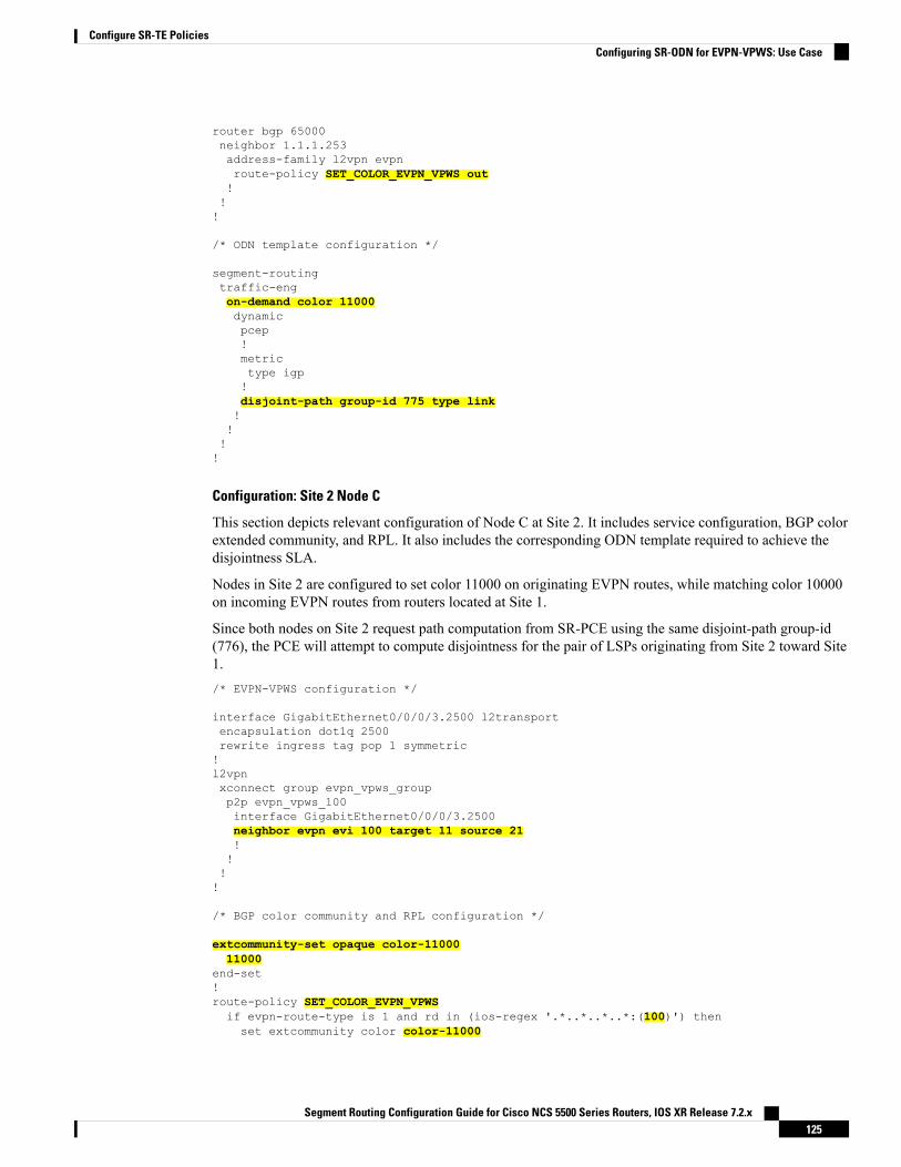
router bgp 65000neighbor 1.1.1.253address-family l2vpn evpnroute-policy SET_COLOR_EVPN_VPWS out!!!
/* ODN template configuration */
segment-routingtraffic-engon-demand color 11000dynamicpcep!metrictype igp!disjoint-path group-id 775 type link!!!!
Configuration: Site 2 Node C
This section depicts relevant configuration of Node C at Site 2. It includes service configuration, BGP colorextended community, and RPL. It also includes the corresponding ODN template required to achieve thedisjointness SLA.
Nodes in Site 2 are configured to set color 11000 on originating EVPN routes, while matching color 10000on incoming EVPN routes from routers located at Site 1.
Since both nodes on Site 2 request path computation from SR-PCE using the same disjoint-path group-id(776), the PCE will attempt to compute disjointness for the pair of LSPs originating from Site 2 toward Site1./* EVPN-VPWS configuration */
interface GigabitEthernet0/0/0/3.2500 l2transportencapsulation dot1q 2500rewrite ingress tag pop 1 symmetric!l2vpnxconnect group evpn_vpws_groupp2p evpn_vpws_100interface GigabitEthernet0/0/0/3.2500neighbor evpn evi 100 target 11 source 21!!!!
/* BGP color community and RPL configuration */
extcommunity-set opaque color-1100011000
end-set!route-policy SET_COLOR_EVPN_VPWSif evpn-route-type is 1 and rd in (ios-regex '.*..*..*..*:(100)') thenset extcommunity color color-11000
Segment Routing Configuration Guide for Cisco NCS 5500 Series Routers, IOS XR Release 7.2.x125
Configure SR-TE PoliciesConfiguring SR-ODN for EVPN-VPWS: Use Case

endifpass
end-policy!router bgp 65000neighbor 1.1.1.253address-family l2vpn evpnroute-policy SET_COLOR_EVPN_VPWS out!!!
/* ODN template configuration */
segment-routingtraffic-engon-demand color 10000dynamicpcep!metrictype igp!disjoint-path group-id 776 type link!!!!
Configuration: Site 2 Node D
This section depicts relevant configuration of Node D at Site 2./* EVPN-VPWS configuration */
interface GigabitEthernet0/0/0/1.2500 l2transportencapsulation dot1q 2500rewrite ingress tag pop 1 symmetric!l2vpnxconnect group evpn_vpws_groupp2p evpn_vpws_101interface GigabitEthernet0/0/0/1.2500neighbor evpn evi 101 target 12 source 22!!!!
/* BGP color community and RPL configuration */
extcommunity-set opaque color-1100011000
end-set!route-policy SET_COLOR_EVPN_VPWSif evpn-route-type is 1 and rd in (ios-regex '.*..*..*..*:(101)') thenset extcommunity color color-11000
endifpass
end-policy!router bgp 65000neighbor 1.1.1.253
Segment Routing Configuration Guide for Cisco NCS 5500 Series Routers, IOS XR Release 7.2.x126
Configure SR-TE PoliciesConfiguring SR-ODN for EVPN-VPWS: Use Case

address-family l2vpn evpnroute-policy SET_COLOR_EVPN_VPWS out!!!
/* ODN template configuration */
segment-routingtraffic-engon-demand color 10000dynamicpcep!metrictype igp!disjoint-path group-id 776 type link!!!!
Verification: SR-PCE
Use the show pce ipv4 peer command to display the SR-PCE’s PCEP peers and session status. SR-PCEperforms path computation for the 4 nodes depicted in the use-case.RP/0/0/CPU0:SR-PCE# show pce ipv4 peerMon Jul 15 19:41:43.622 UTC
PCE's peer database:--------------------Peer address: 1.1.1.2State: UpCapabilities: Stateful, Segment-Routing, Update, Instantiation
Peer address: 1.1.1.4State: UpCapabilities: Stateful, Segment-Routing, Update, Instantiation
Peer address: 1.1.1.5State: UpCapabilities: Stateful, Segment-Routing, Update, Instantiation
Peer address: 1.1.1.6State: UpCapabilities: Stateful, Segment-Routing, Update, Instantiation
Use the show pce association group-id command to display information for the pair of LSPs assigned to agiven association group-id value.
Based on the goals of this use case, SR-PCE computes link-disjoint paths for the SR policies associated witha pair of ELINE services between site 1 and site 2. In particular, disjoint LSPs from site 1 to site 2 are identifiedby association group-id 775. The output includes high-level information for LSPs associated to this group-id:
• At Node A (1.1.1.5): LSP symbolic name = bgp_c_11000_ep_1.1.1.2_discr_100
• At Node B (1.1.1.6): LSP symbolic name = bgp_c_11000_ep_1.1.1.4_discr_100
In this case, the SR-PCE was able to achieve the desired disjointness level; therefore the Status is shown as"Satisfied".
Segment Routing Configuration Guide for Cisco NCS 5500 Series Routers, IOS XR Release 7.2.x127
Configure SR-TE PoliciesConfiguring SR-ODN for EVPN-VPWS: Use Case

RP/0/0/CPU0:SR-PCE# show pce association group-id 775Thu Jul 11 03:52:20.770 UTC
PCE's association database:----------------------Association: Type Link-Disjoint, Group 775, Not StrictAssociated LSPs:LSP[0]:PCC 1.1.1.6, tunnel name bgp_c_11000_ep_1.1.1.4_discr_100, PLSP ID 18, tunnel ID 17,
LSP ID 3, Configured on PCCLSP[1]:PCC 1.1.1.5, tunnel name bgp_c_11000_ep_1.1.1.2_discr_100, PLSP ID 18, tunnel ID 18,
LSP ID 3, Configured on PCCStatus: Satisfied
Use the show pce lsp command to display detailed information of an LSP present in the PCE's LSP database.This output shows details for the LSP at Node A (1.1.1.5) that is used to carry traffic of EVPN VPWS EVI100 towards node C (1.1.1.2).RP/0/0/CPU0:SR-PCE# show pce lsp pcc ipv4 1.1.1.5 name bgp_c_11000_ep_1.1.1.2_discr_100Thu Jul 11 03:58:45.903 UTC
PCE's tunnel database:----------------------PCC 1.1.1.5:
Tunnel Name: bgp_c_11000_ep_1.1.1.2_discr_100Color: 11000Interface Name: srte_c_11000_ep_1.1.1.2LSPs:LSP[0]:source 1.1.1.5, destination 1.1.1.2, tunnel ID 18, LSP ID 3State: Admin up, Operation upSetup type: Segment RoutingBinding SID: 80037Maximum SID Depth: 10Absolute Metric Margin: 0Relative Metric Margin: 0%Preference: 100Bandwidth: signaled 0 kbps, applied 0 kbpsPCEP information:PLSP-ID 0x12, flags: D:1 S:0 R:0 A:1 O:1 C:0
LSP Role: Exclude LSPState-sync PCE: NonePCC: 1.1.1.5LSP is subdelegated to: NoneReported path:Metric type: IGP, Accumulated Metric 40SID[0]: Adj, Label 80003, Address: local 11.5.8.5 remote 11.5.8.8SID[1]: Node, Label 16007, Address 1.1.1.7SID[2]: Node, Label 16002, Address 1.1.1.2
Computed path: (Local PCE)Computed Time: Thu Jul 11 03:49:48 UTC 2019 (00:08:58 ago)Metric type: IGP, Accumulated Metric 40SID[0]: Adj, Label 80003, Address: local 11.5.8.5 remote 11.5.8.8SID[1]: Node, Label 16007, Address 1.1.1.7SID[2]: Node, Label 16002, Address 1.1.1.2
Recorded path:None
Disjoint Group Information:Type Link-Disjoint, Group 775
This output shows details for the LSP at Node B (1.1.1.6) that is used to carry traffic of EVPN VPWS EVI101 towards node D (1.1.1.4).
Segment Routing Configuration Guide for Cisco NCS 5500 Series Routers, IOS XR Release 7.2.x128
Configure SR-TE PoliciesConfiguring SR-ODN for EVPN-VPWS: Use Case
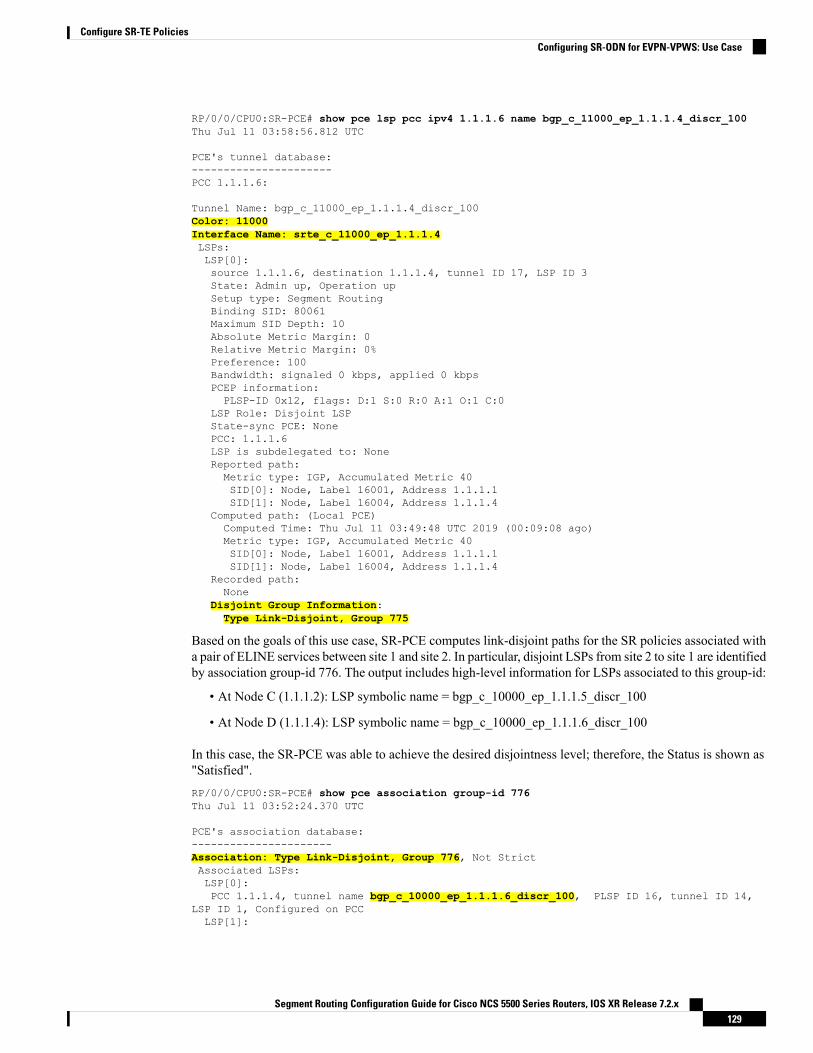
RP/0/0/CPU0:SR-PCE# show pce lsp pcc ipv4 1.1.1.6 name bgp_c_11000_ep_1.1.1.4_discr_100Thu Jul 11 03:58:56.812 UTC
PCE's tunnel database:----------------------PCC 1.1.1.6:
Tunnel Name: bgp_c_11000_ep_1.1.1.4_discr_100Color: 11000Interface Name: srte_c_11000_ep_1.1.1.4LSPs:LSP[0]:source 1.1.1.6, destination 1.1.1.4, tunnel ID 17, LSP ID 3State: Admin up, Operation upSetup type: Segment RoutingBinding SID: 80061Maximum SID Depth: 10Absolute Metric Margin: 0Relative Metric Margin: 0%Preference: 100Bandwidth: signaled 0 kbps, applied 0 kbpsPCEP information:PLSP-ID 0x12, flags: D:1 S:0 R:0 A:1 O:1 C:0
LSP Role: Disjoint LSPState-sync PCE: NonePCC: 1.1.1.6LSP is subdelegated to: NoneReported path:Metric type: IGP, Accumulated Metric 40SID[0]: Node, Label 16001, Address 1.1.1.1SID[1]: Node, Label 16004, Address 1.1.1.4
Computed path: (Local PCE)Computed Time: Thu Jul 11 03:49:48 UTC 2019 (00:09:08 ago)Metric type: IGP, Accumulated Metric 40SID[0]: Node, Label 16001, Address 1.1.1.1SID[1]: Node, Label 16004, Address 1.1.1.4
Recorded path:None
Disjoint Group Information:Type Link-Disjoint, Group 775
Based on the goals of this use case, SR-PCE computes link-disjoint paths for the SR policies associated witha pair of ELINE services between site 1 and site 2. In particular, disjoint LSPs from site 2 to site 1 are identifiedby association group-id 776. The output includes high-level information for LSPs associated to this group-id:
• At Node C (1.1.1.2): LSP symbolic name = bgp_c_10000_ep_1.1.1.5_discr_100
• At Node D (1.1.1.4): LSP symbolic name = bgp_c_10000_ep_1.1.1.6_discr_100
In this case, the SR-PCE was able to achieve the desired disjointness level; therefore, the Status is shown as"Satisfied".RP/0/0/CPU0:SR-PCE# show pce association group-id 776Thu Jul 11 03:52:24.370 UTC
PCE's association database:----------------------Association: Type Link-Disjoint, Group 776, Not StrictAssociated LSPs:LSP[0]:PCC 1.1.1.4, tunnel name bgp_c_10000_ep_1.1.1.6_discr_100, PLSP ID 16, tunnel ID 14,
LSP ID 1, Configured on PCCLSP[1]:
Segment Routing Configuration Guide for Cisco NCS 5500 Series Routers, IOS XR Release 7.2.x129
Configure SR-TE PoliciesConfiguring SR-ODN for EVPN-VPWS: Use Case
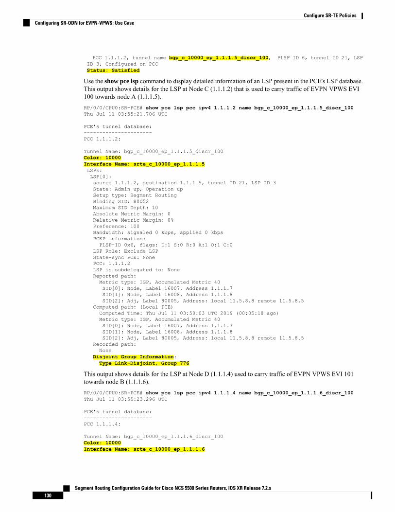
PCC 1.1.1.2, tunnel name bgp_c_10000_ep_1.1.1.5_discr_100, PLSP ID 6, tunnel ID 21, LSPID 3, Configured on PCCStatus: Satisfied
Use the show pce lsp command to display detailed information of an LSP present in the PCE's LSP database.This output shows details for the LSP at Node C (1.1.1.2) that is used to carry traffic of EVPN VPWS EVI100 towards node A (1.1.1.5).RP/0/0/CPU0:SR-PCE# show pce lsp pcc ipv4 1.1.1.2 name bgp_c_10000_ep_1.1.1.5_discr_100Thu Jul 11 03:55:21.706 UTC
PCE's tunnel database:----------------------PCC 1.1.1.2:
Tunnel Name: bgp_c_10000_ep_1.1.1.5_discr_100Color: 10000Interface Name: srte_c_10000_ep_1.1.1.5LSPs:LSP[0]:source 1.1.1.2, destination 1.1.1.5, tunnel ID 21, LSP ID 3State: Admin up, Operation upSetup type: Segment RoutingBinding SID: 80052Maximum SID Depth: 10Absolute Metric Margin: 0Relative Metric Margin: 0%Preference: 100Bandwidth: signaled 0 kbps, applied 0 kbpsPCEP information:PLSP-ID 0x6, flags: D:1 S:0 R:0 A:1 O:1 C:0
LSP Role: Exclude LSPState-sync PCE: NonePCC: 1.1.1.2LSP is subdelegated to: NoneReported path:Metric type: IGP, Accumulated Metric 40SID[0]: Node, Label 16007, Address 1.1.1.7SID[1]: Node, Label 16008, Address 1.1.1.8SID[2]: Adj, Label 80005, Address: local 11.5.8.8 remote 11.5.8.5
Computed path: (Local PCE)Computed Time: Thu Jul 11 03:50:03 UTC 2019 (00:05:18 ago)Metric type: IGP, Accumulated Metric 40SID[0]: Node, Label 16007, Address 1.1.1.7SID[1]: Node, Label 16008, Address 1.1.1.8SID[2]: Adj, Label 80005, Address: local 11.5.8.8 remote 11.5.8.5
Recorded path:None
Disjoint Group Information:Type Link-Disjoint, Group 776
This output shows details for the LSP at Node D (1.1.1.4) used to carry traffic of EVPN VPWS EVI 101towards node B (1.1.1.6).RP/0/0/CPU0:SR-PCE# show pce lsp pcc ipv4 1.1.1.4 name bgp_c_10000_ep_1.1.1.6_discr_100Thu Jul 11 03:55:23.296 UTC
PCE's tunnel database:----------------------PCC 1.1.1.4:
Tunnel Name: bgp_c_10000_ep_1.1.1.6_discr_100Color: 10000Interface Name: srte_c_10000_ep_1.1.1.6
Segment Routing Configuration Guide for Cisco NCS 5500 Series Routers, IOS XR Release 7.2.x130
Configure SR-TE PoliciesConfiguring SR-ODN for EVPN-VPWS: Use Case

LSPs:LSP[0]:source 1.1.1.4, destination 1.1.1.6, tunnel ID 14, LSP ID 1State: Admin up, Operation upSetup type: Segment RoutingBinding SID: 80047Maximum SID Depth: 10Absolute Metric Margin: 0Relative Metric Margin: 0%Preference: 100Bandwidth: signaled 0 kbps, applied 0 kbpsPCEP information:PLSP-ID 0x10, flags: D:1 S:0 R:0 A:1 O:1 C:0
LSP Role: Disjoint LSPState-sync PCE: NonePCC: 1.1.1.4LSP is subdelegated to: NoneReported path:Metric type: IGP, Accumulated Metric 40SID[0]: Node, Label 16001, Address 1.1.1.1SID[1]: Node, Label 16006, Address 1.1.1.6
Computed path: (Local PCE)Computed Time: Thu Jul 11 03:50:03 UTC 2019 (00:05:20 ago)Metric type: IGP, Accumulated Metric 40SID[0]: Node, Label 16001, Address 1.1.1.1SID[1]: Node, Label 16006, Address 1.1.1.6
Recorded path:None
Disjoint Group Information:Type Link-Disjoint, Group 776
Verification: Site 1 Node A
This section depicts verification steps at Node A.
Use the show bgp l2vpn evpn command to display BGP prefix information for EVPN-VPWS EVI 100 (rd1.1.1.5:100). The output includes an EVPN route-type 1 route with color 11000 originated at Node C (1.1.1.2).RP/0/RSP0/CPU0:Node-A# show bgp l2vpn evpn rd 1.1.1.5:100Wed Jul 10 18:57:57.704 PSTBGP router identifier 1.1.1.5, local AS number 65000BGP generic scan interval 60 secsNon-stop routing is enabledBGP table state: ActiveTable ID: 0x0 RD version: 0BGP main routing table version 360BGP NSR Initial initsync version 1 (Reached)BGP NSR/ISSU Sync-Group versions 0/0BGP scan interval 60 secs
Status codes: s suppressed, d damped, h history, * valid, > besti - internal, r RIB-failure, S stale, N Nexthop-discard
Origin codes: i - IGP, e - EGP, ? - incompleteNetwork Next Hop Metric LocPrf Weight Path
Route Distinguisher: 1.1.1.5:100 (default for vrf VPWS:100)*> [1][0000.0000.0000.0000.0000][11]/120
0.0.0.0 0 i*>i[1][0000.0000.0000.0000.0000][21]/120
1.1.1.2 C:11000 100 0 i
Segment Routing Configuration Guide for Cisco NCS 5500 Series Routers, IOS XR Release 7.2.x131
Configure SR-TE PoliciesConfiguring SR-ODN for EVPN-VPWS: Use Case

The following output displays the details for the incoming EVPN RT1. Note the presence of BGP extendedcolor community 11000, and that the prefix is associated with an SR policy with color 11000 and BSID valueof 80044.RP/0/RSP0/CPU0:Node-A# show bgp l2vpn evpn rd 1.1.1.5:100[1][0000.0000.0000.0000.0000][21]/120Wed Jul 10 18:57:58.107 PSTBGP routing table entry for [1][0000.0000.0000.0000.0000][21]/120, Route Distinguisher:1.1.1.5:100Versions:Process bRIB/RIB SendTblVerSpeaker 360 360
Last Modified: Jul 10 18:36:18.369 for 00:21:40Paths: (1 available, best #1)Not advertised to any peerPath #1: Received by speaker 0Not advertised to any peerLocal1.1.1.2 C:11000 (bsid:80044) (metric 40) from 1.1.1.253 (1.1.1.2)Received Label 80056Origin IGP, localpref 100, valid, internal, best, group-best, import-candidate,
imported, rib-installReceived Path ID 0, Local Path ID 1, version 358Extended community: Color:11000 RT:65000:100Originator: 1.1.1.2, Cluster list: 1.1.1.253SR policy color 11000, up, registered, bsid 80044, if-handle 0x00001b20
Source AFI: L2VPN EVPN, Source VRF: default, Source Route Distinguisher: 1.1.1.2:100
Use the show l2vpn xconnect command to display the state associated with EVPN-VPWS EVI 100 service.RP/0/RSP0/CPU0:Node-A# show l2vpn xconnect group evpn_vpws_groupWed Jul 10 18:58:02.333 PSTLegend: ST = State, UP = Up, DN = Down, AD = Admin Down, UR = Unresolved,
SB = Standby, SR = Standby Ready, (PP) = Partially Programmed
XConnect Segment 1 Segment 2Group Name ST Description ST Description ST------------------------ ----------------------------- -----------------------------evpn_vpws_group
evpn_vpws_100UP Gi0/0/0/3.2500 UP EVPN 100,21,1.1.1.2 UP
----------------------------------------------------------------------------------------
The following output shows the details for the service. Note that the service is associated with the on-demandSR policy with color 11000 and end-point 1.1.1.2 (node C).RP/0/RSP0/CPU0:Node-A# show l2vpn xconnect group evpn_vpws_group xc-name evpn_vpws_100detailWed Jul 10 18:58:02.755 PST
Group evpn_vpws_group, XC evpn_vpws_100, state is up; Interworking noneAC: GigabitEthernet0/0/0/3.2500, state is upType VLAN; Num Ranges: 1Rewrite Tags: []VLAN ranges: [2500, 2500]MTU 1500; XC ID 0x120000c; interworking noneStatistics:packets: received 0, sent 0bytes: received 0, sent 0drops: illegal VLAN 0, illegal length 0
EVPN: neighbor 1.1.1.2, PW ID: evi 100, ac-id 21, state is up ( established )
Segment Routing Configuration Guide for Cisco NCS 5500 Series Routers, IOS XR Release 7.2.x132
Configure SR-TE PoliciesConfiguring SR-ODN for EVPN-VPWS: Use Case
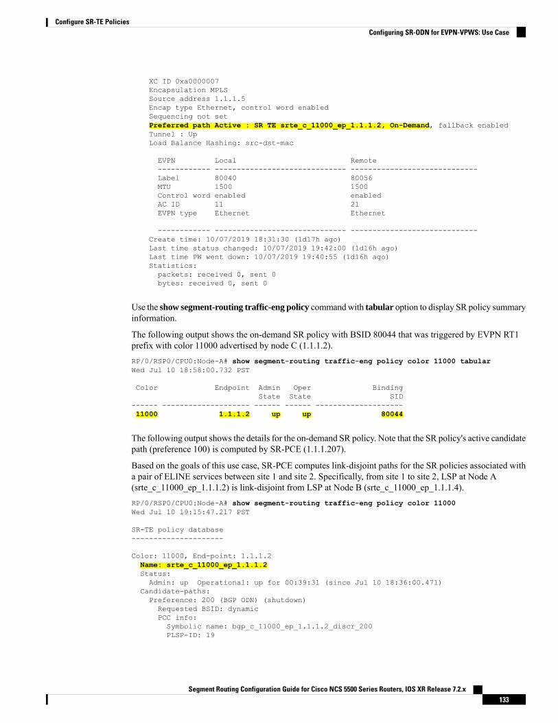
XC ID 0xa0000007Encapsulation MPLSSource address 1.1.1.5Encap type Ethernet, control word enabledSequencing not setPreferred path Active : SR TE srte_c_11000_ep_1.1.1.2, On-Demand, fallback enabledTunnel : UpLoad Balance Hashing: src-dst-mac
EVPN Local Remote------------ ------------------------------ -----------------------------Label 80040 80056MTU 1500 1500Control word enabled enabledAC ID 11 21EVPN type Ethernet Ethernet
------------ ------------------------------ -----------------------------Create time: 10/07/2019 18:31:30 (1d17h ago)Last time status changed: 10/07/2019 19:42:00 (1d16h ago)Last time PW went down: 10/07/2019 19:40:55 (1d16h ago)Statistics:packets: received 0, sent 0bytes: received 0, sent 0
Use the show segment-routing traffic-eng policy commandwith tabular option to display SR policy summaryinformation.
The following output shows the on-demand SR policy with BSID 80044 that was triggered by EVPN RT1prefix with color 11000 advertised by node C (1.1.1.2).RP/0/RSP0/CPU0:Node-A# show segment-routing traffic-eng policy color 11000 tabularWed Jul 10 18:58:00.732 PST
Color Endpoint Admin Oper BindingState State SID
------ -------------------- ------ ------ --------------------11000 1.1.1.2 up up 80044
The following output shows the details for the on-demand SR policy. Note that the SR policy's active candidatepath (preference 100) is computed by SR-PCE (1.1.1.207).
Based on the goals of this use case, SR-PCE computes link-disjoint paths for the SR policies associated witha pair of ELINE services between site 1 and site 2. Specifically, from site 1 to site 2, LSP at Node A(srte_c_11000_ep_1.1.1.2) is link-disjoint from LSP at Node B (srte_c_11000_ep_1.1.1.4).RP/0/RSP0/CPU0:Node-A# show segment-routing traffic-eng policy color 11000Wed Jul 10 19:15:47.217 PST
SR-TE policy database---------------------
Color: 11000, End-point: 1.1.1.2Name: srte_c_11000_ep_1.1.1.2Status:Admin: up Operational: up for 00:39:31 (since Jul 10 18:36:00.471)
Candidate-paths:Preference: 200 (BGP ODN) (shutdown)Requested BSID: dynamicPCC info:Symbolic name: bgp_c_11000_ep_1.1.1.2_discr_200PLSP-ID: 19
Segment Routing Configuration Guide for Cisco NCS 5500 Series Routers, IOS XR Release 7.2.x133
Configure SR-TE PoliciesConfiguring SR-ODN for EVPN-VPWS: Use Case

Dynamic (invalid)Preference: 100 (BGP ODN) (active)Requested BSID: dynamicPCC info:Symbolic name: bgp_c_11000_ep_1.1.1.2_discr_100PLSP-ID: 18
Dynamic (pce 1.1.1.207) (valid)Metric Type: IGP, Path Accumulated Metric: 4080003 [Adjacency-SID, 11.5.8.5 - 11.5.8.8]16007 [Prefix-SID, 1.1.1.7]16002 [Prefix-SID, 1.1.1.2]
Attributes:Binding SID: 80044Forward Class: 0Steering BGP disabled: noIPv6 caps enable: yes
Verification: Site 1 Node B
This section depicts verification steps at Node B.
Use the show bgp l2vpn evpn command to display BGP prefix information for EVPN-VPWS EVI 101 (rd1.1.1.6:101). The output includes an EVPN route-type 1 route with color 11000 originated at Node D (1.1.1.4).RP/0/RSP0/CPU0:Node-B# show bgp l2vpn evpn rd 1.1.1.6:101Wed Jul 10 19:08:54.964 PSTBGP router identifier 1.1.1.6, local AS number 65000BGP generic scan interval 60 secsNon-stop routing is enabledBGP table state: ActiveTable ID: 0x0 RD version: 0BGP main routing table version 322BGP NSR Initial initsync version 7 (Reached)BGP NSR/ISSU Sync-Group versions 0/0BGP scan interval 60 secs
Status codes: s suppressed, d damped, h history, * valid, > besti - internal, r RIB-failure, S stale, N Nexthop-discard
Origin codes: i - IGP, e - EGP, ? - incompleteNetwork Next Hop Metric LocPrf Weight Path
Route Distinguisher: 1.1.1.6:101 (default for vrf VPWS:101)*> [1][0000.0000.0000.0000.0000][12]/120
0.0.0.0 0 i*>i[1][0000.0000.0000.0000.0000][22]/120
1.1.1.4 C:11000 100 0 i
Processed 2 prefixes, 2 paths
The following output displays the details for the incoming EVPN RT1. Note the presence of BGP extendedcolor community 11000, and that the prefix is associated with an SR policy with color 11000 and BSID valueof 80061.RP/0/RSP0/CPU0:Node-B# show bgp l2vpn evpn rd 1.1.1.6:101[1][0000.0000.0000.0000.0000][22]/120Wed Jul 10 19:08:55.039 PSTBGP routing table entry for [1][0000.0000.0000.0000.0000][22]/120, Route Distinguisher:1.1.1.6:101Versions:Process bRIB/RIB SendTblVerSpeaker 322 322
Last Modified: Jul 10 18:42:10.408 for 00:26:44Paths: (1 available, best #1)
Segment Routing Configuration Guide for Cisco NCS 5500 Series Routers, IOS XR Release 7.2.x134
Configure SR-TE PoliciesConfiguring SR-ODN for EVPN-VPWS: Use Case

Not advertised to any peerPath #1: Received by speaker 0Not advertised to any peerLocal1.1.1.4 C:11000 (bsid:80061) (metric 40) from 1.1.1.253 (1.1.1.4)Received Label 80045Origin IGP, localpref 100, valid, internal, best, group-best, import-candidate,
imported, rib-installReceived Path ID 0, Local Path ID 1, version 319Extended community: Color:11000 RT:65000:101Originator: 1.1.1.4, Cluster list: 1.1.1.253SR policy color 11000, up, registered, bsid 80061, if-handle 0x00000560
Source AFI: L2VPN EVPN, Source VRF: default, Source Route Distinguisher: 1.1.1.4:101
Use the show l2vpn xconnect command to display the state associated with EVPN-VPWS EVI 101 service.RP/0/RSP0/CPU0:Node-B# show l2vpn xconnect group evpn_vpws_groupWed Jul 10 19:08:56.388 PSTLegend: ST = State, UP = Up, DN = Down, AD = Admin Down, UR = Unresolved,
SB = Standby, SR = Standby Ready, (PP) = Partially Programmed
XConnect Segment 1 Segment 2Group Name ST Description ST Description ST------------------------ ----------------------------- -----------------------------evpn_vpws_group
evpn_vpws_101UP Te0/3/0/0/8.2500 UP EVPN 101,22,1.1.1.4 UP
----------------------------------------------------------------------------------------
The following output shows the details for the service. Note that the service is associated with the on-demandSR policy with color 11000 and end-point 1.1.1.4 (node D).RP/0/RSP0/CPU0:Node-B# show l2vpn xconnect group evpn_vpws_group xc-name evpn_vpws_101Wed Jul 10 19:08:56.511 PST
Group evpn_vpws_group, XC evpn_vpws_101, state is up; Interworking noneAC: TenGigE0/3/0/0/8.2500, state is upType VLAN; Num Ranges: 1Rewrite Tags: []VLAN ranges: [2500, 2500]MTU 1500; XC ID 0x2a0000e; interworking noneStatistics:packets: received 0, sent 0bytes: received 0, sent 0drops: illegal VLAN 0, illegal length 0
EVPN: neighbor 1.1.1.4, PW ID: evi 101, ac-id 22, state is up ( established )XC ID 0xa0000009Encapsulation MPLSSource address 1.1.1.6Encap type Ethernet, control word enabledSequencing not setPreferred path Active : SR TE srte_c_11000_ep_1.1.1.4, On-Demand, fallback enabledTunnel : UpLoad Balance Hashing: src-dst-mac
EVPN Local Remote------------ ------------------------------ -----------------------------Label 80060 80045MTU 1500 1500Control word enabled enabledAC ID 12 22EVPN type Ethernet Ethernet
Segment Routing Configuration Guide for Cisco NCS 5500 Series Routers, IOS XR Release 7.2.x135
Configure SR-TE PoliciesConfiguring SR-ODN for EVPN-VPWS: Use Case

------------ ------------------------------ -----------------------------Create time: 10/07/2019 18:32:49 (00:36:06 ago)Last time status changed: 10/07/2019 18:42:07 (00:26:49 ago)Statistics:packets: received 0, sent 0bytes: received 0, sent 0
Use the show segment-routing traffic-eng policy commandwith tabular option to display SR policy summaryinformation.
The following output shows the on-demand SR policy with BSID 80061 that was triggered by EVPN RT1prefix with color 11000 advertised by node D (1.1.1.4).RP/0/RSP0/CPU0:Node-B# show segment-routing traffic-eng policy color 11000 tabularWed Jul 10 19:08:56.146 PST
Color Endpoint Admin Oper BindingState State SID
------ -------------------- ------ ------ --------------------11000 1.1.1.4 up up 80061
The following output shows the details for the on-demand SR policy. Note that the SR policy's active candidatepath (preference 100) is computed by SR-PCE (1.1.1.207).
Based on the goals of this use case, SR-PCE computes link-disjoint paths for the SR policies associated witha pair of ELINE services between site 1 and site 2. Specifically, from site 1 to site 2, LSP at Node B(srte_c_11000_ep_1.1.1.4) is link-disjoint from LSP at Node A (srte_c_11000_ep_1.1.1.2).RP/0/RSP0/CPU0:Node-B# show segment-routing traffic-eng policy color 11000Wed Jul 10 19:08:56.207 PST
SR-TE policy database---------------------
Color: 11000, End-point: 1.1.1.4Name: srte_c_11000_ep_1.1.1.4Status:Admin: up Operational: up for 00:26:47 (since Jul 10 18:40:05.868)
Candidate-paths:Preference: 200 (BGP ODN) (shutdown)Requested BSID: dynamicPCC info:Symbolic name: bgp_c_11000_ep_1.1.1.4_discr_200PLSP-ID: 19
Dynamic (invalid)Preference: 100 (BGP ODN) (active)Requested BSID: dynamicPCC info:Symbolic name: bgp_c_11000_ep_1.1.1.4_discr_100PLSP-ID: 18
Dynamic (pce 1.1.1.207) (valid)Metric Type: IGP, Path Accumulated Metric: 4016001 [Prefix-SID, 1.1.1.1]16004 [Prefix-SID, 1.1.1.4]
Attributes:Binding SID: 80061Forward Class: 0Steering BGP disabled: noIPv6 caps enable: yes
Segment Routing Configuration Guide for Cisco NCS 5500 Series Routers, IOS XR Release 7.2.x136
Configure SR-TE PoliciesConfiguring SR-ODN for EVPN-VPWS: Use Case
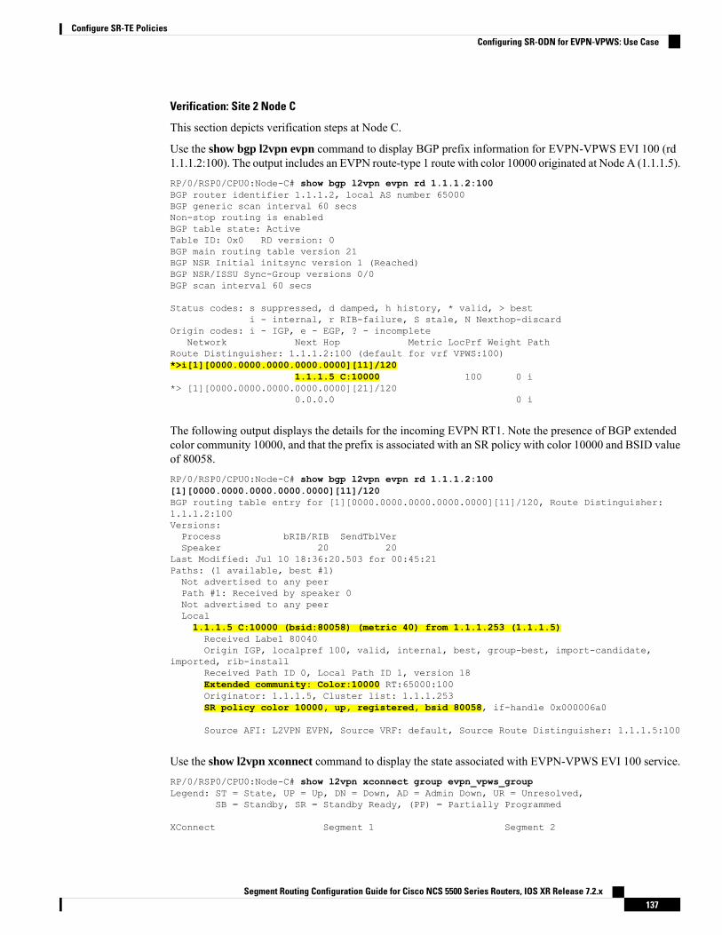
Verification: Site 2 Node C
This section depicts verification steps at Node C.
Use the show bgp l2vpn evpn command to display BGP prefix information for EVPN-VPWS EVI 100 (rd1.1.1.2:100). The output includes an EVPN route-type 1 route with color 10000 originated at Node A (1.1.1.5).RP/0/RSP0/CPU0:Node-C# show bgp l2vpn evpn rd 1.1.1.2:100BGP router identifier 1.1.1.2, local AS number 65000BGP generic scan interval 60 secsNon-stop routing is enabledBGP table state: ActiveTable ID: 0x0 RD version: 0BGP main routing table version 21BGP NSR Initial initsync version 1 (Reached)BGP NSR/ISSU Sync-Group versions 0/0BGP scan interval 60 secs
Status codes: s suppressed, d damped, h history, * valid, > besti - internal, r RIB-failure, S stale, N Nexthop-discard
Origin codes: i - IGP, e - EGP, ? - incompleteNetwork Next Hop Metric LocPrf Weight Path
Route Distinguisher: 1.1.1.2:100 (default for vrf VPWS:100)*>i[1][0000.0000.0000.0000.0000][11]/120
1.1.1.5 C:10000 100 0 i*> [1][0000.0000.0000.0000.0000][21]/120
0.0.0.0 0 i
The following output displays the details for the incoming EVPN RT1. Note the presence of BGP extendedcolor community 10000, and that the prefix is associated with an SR policy with color 10000 and BSID valueof 80058.RP/0/RSP0/CPU0:Node-C# show bgp l2vpn evpn rd 1.1.1.2:100[1][0000.0000.0000.0000.0000][11]/120BGP routing table entry for [1][0000.0000.0000.0000.0000][11]/120, Route Distinguisher:1.1.1.2:100Versions:Process bRIB/RIB SendTblVerSpeaker 20 20
Last Modified: Jul 10 18:36:20.503 for 00:45:21Paths: (1 available, best #1)Not advertised to any peerPath #1: Received by speaker 0Not advertised to any peerLocal1.1.1.5 C:10000 (bsid:80058) (metric 40) from 1.1.1.253 (1.1.1.5)Received Label 80040Origin IGP, localpref 100, valid, internal, best, group-best, import-candidate,
imported, rib-installReceived Path ID 0, Local Path ID 1, version 18Extended community: Color:10000 RT:65000:100Originator: 1.1.1.5, Cluster list: 1.1.1.253SR policy color 10000, up, registered, bsid 80058, if-handle 0x000006a0
Source AFI: L2VPN EVPN, Source VRF: default, Source Route Distinguisher: 1.1.1.5:100
Use the show l2vpn xconnect command to display the state associated with EVPN-VPWS EVI 100 service.RP/0/RSP0/CPU0:Node-C# show l2vpn xconnect group evpn_vpws_groupLegend: ST = State, UP = Up, DN = Down, AD = Admin Down, UR = Unresolved,
SB = Standby, SR = Standby Ready, (PP) = Partially Programmed
XConnect Segment 1 Segment 2
Segment Routing Configuration Guide for Cisco NCS 5500 Series Routers, IOS XR Release 7.2.x137
Configure SR-TE PoliciesConfiguring SR-ODN for EVPN-VPWS: Use Case

Group Name ST Description ST Description ST------------------------ ----------------------------- -----------------------------evpn_vpws_group
evpn_vpws_100UP Gi0/0/0/3.2500 UP EVPN 100,11,1.1.1.5 UP
----------------------------------------------------------------------------------------
The following output shows the details for the service. Note that the service is associated with the on-demandSR policy with color 10000 and end-point 1.1.1.5 (node A).RP/0/RSP0/CPU0:Node-C# show l2vpn xconnect group evpn_vpws_group xc-name evpn_vpws_100
Group evpn_vpws_group, XC evpn_vpws_100, state is up; Interworking noneAC: GigabitEthernet0/0/0/3.2500, state is upType VLAN; Num Ranges: 1Rewrite Tags: []VLAN ranges: [2500, 2500]MTU 1500; XC ID 0x1200008; interworking noneStatistics:packets: received 0, sent 0bytes: received 0, sent 0drops: illegal VLAN 0, illegal length 0
EVPN: neighbor 1.1.1.5, PW ID: evi 100, ac-id 11, state is up ( established )XC ID 0xa0000003Encapsulation MPLSSource address 1.1.1.2Encap type Ethernet, control word enabledSequencing not setPreferred path Active : SR TE srte_c_10000_ep_1.1.1.5, On-Demand, fallback enabledTunnel : UpLoad Balance Hashing: src-dst-mac
EVPN Local Remote------------ ------------------------------ -----------------------------Label 80056 80040MTU 1500 1500Control word enabled enabledAC ID 21 11EVPN type Ethernet Ethernet
------------ ------------------------------ -----------------------------Create time: 10/07/2019 18:36:16 (1d19h ago)Last time status changed: 10/07/2019 19:41:59 (1d18h ago)Last time PW went down: 10/07/2019 19:40:54 (1d18h ago)Statistics:packets: received 0, sent 0bytes: received 0, sent 0
Use the show segment-routing traffic-eng policy commandwith tabular option to display SR policy summaryinformation.
The following output shows the on-demand SR policy with BSID 80058 that was triggered by EVPN RT1prefix with color 10000 advertised by node A (1.1.1.5).RP/0/RSP0/CPU0:Node-C# show segment-routing traffic-eng policy color 10000 tabular
Color Endpoint Admin Oper BindingState State SID
------ -------------------- ------ ------ --------------------10000 1.1.1.5 up up 80058
Segment Routing Configuration Guide for Cisco NCS 5500 Series Routers, IOS XR Release 7.2.x138
Configure SR-TE PoliciesConfiguring SR-ODN for EVPN-VPWS: Use Case

The following output shows the details for the on-demand SR policy. Note that the SR policy's active candidatepath (preference 100) is computed by SR-PCE (1.1.1.207).
Based on the goals of this use case, SR-PCE computes link-disjoint paths for the SR policies associated witha pair of ELINE services between site 1 and site 2. Specifically, from site 2 to site 1, LSP at Node C(srte_c_10000_ep_1.1.1.5) is link-disjoint from LSP at Node D (srte_c_10000_ep_1.1.1.6).RP/0/RSP0/CPU0:Node-C# show segment-routing traffic-eng policy color 10000
SR-TE policy database---------------------
Color: 10000, End-point: 1.1.1.5Name: srte_c_10000_ep_1.1.1.5Status:Admin: up Operational: up for 00:12:35 (since Jul 10 19:49:21.890)
Candidate-paths:Preference: 200 (BGP ODN) (shutdown)Requested BSID: dynamicPCC info:Symbolic name: bgp_c_10000_ep_1.1.1.5_discr_200PLSP-ID: 7
Dynamic (invalid)Preference: 100 (BGP ODN) (active)Requested BSID: dynamicPCC info:Symbolic name: bgp_c_10000_ep_1.1.1.5_discr_100PLSP-ID: 6
Dynamic (pce 1.1.1.207) (valid)Metric Type: IGP, Path Accumulated Metric: 4016007 [Prefix-SID, 1.1.1.7]16008 [Prefix-SID, 1.1.1.8]80005 [Adjacency-SID, 11.5.8.8 - 11.5.8.5]
Attributes:Binding SID: 80058Forward Class: 0Steering BGP disabled: noIPv6 caps enable: yes
Verification: Site 2 Node D
This section depicts verification steps at Node D.
Use the show bgp l2vpn evpn command to display BGP prefix information for EVPN-VPWS EVI 101 (rd1.1.1.4:101). The output includes an EVPN route-type 1 route with color 10000 originated at Node B (1.1.1.6).RP/0/RSP0/CPU0:Node-D# show bgp l2vpn evpn rd 1.1.1.4:101BGP router identifier 1.1.1.4, local AS number 65000BGP generic scan interval 60 secsNon-stop routing is enabledBGP table state: ActiveTable ID: 0x0 RD version: 0BGP main routing table version 570BGP NSR Initial initsync version 1 (Reached)BGP NSR/ISSU Sync-Group versions 0/0BGP scan interval 60 secs
Status codes: s suppressed, d damped, h history, * valid, > besti - internal, r RIB-failure, S stale, N Nexthop-discard
Origin codes: i - IGP, e - EGP, ? - incompleteNetwork Next Hop Metric LocPrf Weight Path
Route Distinguisher: 1.1.1.4:101 (default for vrf VPWS:101)*>i[1][0000.0000.0000.0000.0000][12]/120
Segment Routing Configuration Guide for Cisco NCS 5500 Series Routers, IOS XR Release 7.2.x139
Configure SR-TE PoliciesConfiguring SR-ODN for EVPN-VPWS: Use Case

1.1.1.6 C:10000 100 0 i*> [1][0000.0000.0000.0000.0000][22]/120
0.0.0.0 0 i
Processed 2 prefixes, 2 paths
The following output displays the details for the incoming EVPN RT1. Note the presence of BGP extendedcolor community 10000, and that the prefix is associated with an SR policy with color 10000 and BSID valueof 80047.RP/0/RSP0/CPU0:Node-D# show bgp l2vpn evpn rd 1.1.1.4:101[1][0000.0000.0000.0000.0000][12]/120BGP routing table entry for [1][0000.0000.0000.0000.0000][12]/120, Route Distinguisher:1.1.1.4:101Versions:Process bRIB/RIB SendTblVerSpeaker 569 569
Last Modified: Jul 10 18:42:12.455 for 00:45:38Paths: (1 available, best #1)Not advertised to any peerPath #1: Received by speaker 0Not advertised to any peerLocal1.1.1.6 C:10000 (bsid:80047) (metric 40) from 1.1.1.253 (1.1.1.6)Received Label 80060Origin IGP, localpref 100, valid, internal, best, group-best, import-candidate,
imported, rib-installReceived Path ID 0, Local Path ID 1, version 568Extended community: Color:10000 RT:65000:101Originator: 1.1.1.6, Cluster list: 1.1.1.253SR policy color 10000, up, registered, bsid 80047, if-handle 0x00001720
Source AFI: L2VPN EVPN, Source VRF: default, Source Route Distinguisher: 1.1.1.6:101
Use the show l2vpn xconnect command to display the state associated with EVPN-VPWS EVI 101 service.RP/0/RSP0/CPU0:Node-D# show l2vpn xconnect group evpn_vpws_groupLegend: ST = State, UP = Up, DN = Down, AD = Admin Down, UR = Unresolved,
SB = Standby, SR = Standby Ready, (PP) = Partially Programmed
XConnect Segment 1 Segment 2Group Name ST Description ST Description ST------------------------ ----------------------------- -----------------------------evpn_vpws_group
evpn_vpws_101UP Gi0/0/0/1.2500 UP EVPN 101,12,1.1.1.6 UP
----------------------------------------------------------------------------------------
The following output shows the details for the service. Note that the service is associated with the on-demandSR policy with color 10000 and end-point 1.1.1.6 (node B).RP/0/RSP0/CPU0:Node-D# show l2vpn xconnect group evpn_vpws_group xc-name evpn_vpws_101
Group evpn_vpws_group, XC evpn_vpws_101, state is up; Interworking noneAC: GigabitEthernet0/0/0/1.2500, state is upType VLAN; Num Ranges: 1Rewrite Tags: []VLAN ranges: [2500, 2500]MTU 1500; XC ID 0x120000c; interworking noneStatistics:packets: received 0, sent 0bytes: received 0, sent 0
Segment Routing Configuration Guide for Cisco NCS 5500 Series Routers, IOS XR Release 7.2.x140
Configure SR-TE PoliciesConfiguring SR-ODN for EVPN-VPWS: Use Case

drops: illegal VLAN 0, illegal length 0EVPN: neighbor 1.1.1.6, PW ID: evi 101, ac-id 12, state is up ( established )XC ID 0xa000000dEncapsulation MPLSSource address 1.1.1.4Encap type Ethernet, control word enabledSequencing not setPreferred path Active : SR TE srte_c_10000_ep_1.1.1.6, On-Demand, fallback enabledTunnel : UpLoad Balance Hashing: src-dst-mac
EVPN Local Remote------------ ------------------------------ -----------------------------Label 80045 80060MTU 1500 1500Control word enabled enabledAC ID 22 12EVPN type Ethernet Ethernet
------------ ------------------------------ -----------------------------Create time: 10/07/2019 18:42:07 (00:45:49 ago)Last time status changed: 10/07/2019 18:42:09 (00:45:47 ago)Statistics:packets: received 0, sent 0bytes: received 0, sent 0
Use the show segment-routing traffic-eng policy commandwith tabular option to display SR policy summaryinformation.
The following output shows the on-demand SR policy with BSID 80047 that was triggered by EVPN RT1prefix with color 10000 advertised by node B (1.1.1.6).RP/0/RSP0/CPU0:Node-D# show segment-routing traffic-eng policy color 10000 tabular
Color Endpoint Admin Oper BindingState State SID
------ -------------------- ------ ------ --------------------10000 1.1.1.6 up up 80047
The following output shows the details for the on-demand SR policy. Note that the SR policy's active candidatepath (preference 100) is computed by SR-PCE (1.1.1.207).
Based on the goals of this use case, SR-PCE computes link-disjoint paths for the SR policies associated witha pair of ELINE services between site 1 and site 2. Specifically, from site 2 to site 1, LSP at Node D(srte_c_10000_ep_1.1.1.6) is link-disjoint from LSP at Node C (srte_c_10000_ep_1.1.1.5).RP/0/RSP0/CPU0:Node-D# show segment-routing traffic-eng policy color 10000
SR-TE policy database---------------------
Color: 10000, End-point: 1.1.1.6Name: srte_c_10000_ep_1.1.1.6Status:Admin: up Operational: up for 01:23:04 (since Jul 10 18:42:07.350)
Candidate-paths:Preference: 200 (BGP ODN) (shutdown)Requested BSID: dynamicPCC info:Symbolic name: bgp_c_10000_ep_1.1.1.6_discr_200PLSP-ID: 17
Dynamic (invalid)
Segment Routing Configuration Guide for Cisco NCS 5500 Series Routers, IOS XR Release 7.2.x141
Configure SR-TE PoliciesConfiguring SR-ODN for EVPN-VPWS: Use Case

Preference: 100 (BGP ODN) (active)Requested BSID: dynamicPCC info:Symbolic name: bgp_c_10000_ep_1.1.1.6_discr_100PLSP-ID: 16
Dynamic (pce 1.1.1.207) (valid)Metric Type: IGP, Path Accumulated Metric: 4016001 [Prefix-SID, 1.1.1.1]16006 [Prefix-SID, 1.1.1.6]
Attributes:Binding SID: 80047Forward Class: 0Steering BGP disabled: noIPv6 caps enable: yes
Manually Provisioned SR PolicyManually provisioned SR policies are configured on the head-end router. These policies can use dynamicpaths or explicit paths. See the SR-TE Policy Path Types, on page 142 section for information on manuallyprovisioning an SR policy using dynamic or explicit paths.
PCE-Initiated SR PolicyAn SR-TE policy can be configured on the path computation element (PCE) to reduce link congestion or tominimize the number of network touch points.
The PCE collects network information, such as traffic demand and link utilization. When the PCE determinesthat a link is congested, it identifies one or more flows that are causing the congestion. The PCE finds a suitablepath and deploys an SR-TE policy to divert those flows, without moving the congestion to another part of thenetwork. When there is no more link congestion, the policy is removed.
To minimize the number of network touch points, an application, such as a Network Services Orchestrator(NSO), can request the PCE to create an SR-TE policy. PCE deploys the SR-TE policy using PCC-PCEcommunication protocol (PCEP).
For more information, see the PCE-Initiated SR Policies, on page 208 section.
SR-TE Policy Path TypesA dynamic path is based on an optimization objective and a set of constraints. The head-end computes asolution, resulting in a SID-list or a set of SID-lists. When the topology changes, a new path is computed. Ifthe head-end does not have enough information about the topology, the head-endmight delegate the computationto a Segment Routing Path Computation Element (SR-PCE). For information on configuring SR-PCE, seeConfigure Segment Routing Path Computation Element chapter.
An explicit path is a specified SID-list or set of SID-lists.
An SR-TE policy initiates a single (selected) path in RIB/FIB. This is the preferred valid candidate path.
A candidate path has the following characteristics:
• It has a preference – If two policies have same {color, endpoint} but different preferences, the policywith the highest preference is selected.
Segment Routing Configuration Guide for Cisco NCS 5500 Series Routers, IOS XR Release 7.2.x142
Configure SR-TE PoliciesManually Provisioned SR Policy

• It is associated with a single binding SID (BSID) – A BSID conflict occurs when there are different SRpolicies with the same BSID. In this case, the policy that is installed first gets the BSID and is selected.
• It is valid if it is usable.
A path is selected when the path is valid and its preference is the best among all candidate paths for that policy.
The protocol of the source is not relevant in the path selection logic.Note
Dynamic Paths
Behaviors and Limitations
For a dynamic path that traverses a specific interface between nodes (segment), the algorithm may encodethis segment using an Adj-SID. The SR-TE process prefers the protected Adj-SID of the link, if one is available.
Optimization ObjectivesOptimization objectives allow the head-end router to compute a SID-list that expresses the shortest dynamicpath according to the selected metric type:
• IGP metric — Refer to the "Implementing IS-IS" and "Implementing OSPF" chapters in the RoutingConfiguration Guide for Cisco NCS 5500 Series Routers.
• TEmetric—See the Configure Interface TEMetrics, on page 144 section for information about configuringTE metrics.
This example shows a dynamic path from head-end router 1 to end-point router 3 that minimizes IGP or TEmetric:
• The blue path uses the minimum IGP metric: Min-Metric (1→ 3, IGP) = SID-list <16003>; cumulativeIGP metric: 20
• The green path uses the minimumTEmetric: Min-Metric (1→ 3, TE) = SID-list <16005, 16004, 16003>;cumulative TE metric: 23
Segment Routing Configuration Guide for Cisco NCS 5500 Series Routers, IOS XR Release 7.2.x143
Configure SR-TE PoliciesDynamic Paths

Configure Interface TE Metrics
Use the metric value command in SR-TE interface submode to configure the TE metric for interfaces. Thevalue range is from 0 to 2147483647.Router# configureRouter(config)# segment-routingRouter(config-sr)# traffic-engRouter(config-sr-te)# interface type interface-path-idRouter(config-sr-te-if)# metric value
Configuring TE Metric: Example
The following configuration example shows how to set the TE metric for various interfaces:segment-routingtraffic-enginterface TenGigE0/0/0/0metric 100!interface TenGigE0/0/0/1metric 1000!interface TenGigE0/0/2/0metric 50!!end
ConstraintsConstraints allow the head-end router to compute a dynamic path according to the selected metric type:
• Affinity — You can apply a color or name to links or interfaces by assigning affinity bit-maps to them.You can then specify an affinity (or relationship) between an SR policy path and link colors. SR-TEcomputes a path that includes or excludes links that have specific colors,or combinations of colors. Seethe Named Interface Link Admin Groups and SR-TE Affinity Maps, on page 144 section for informationon named interface link admin groups and SR-TE Affinity Maps.
• Disjoint— SR-TE computes a path that is disjoint from another path in the same disjoint-group. Disjointpaths do not share network resources. Path disjointness may be required for paths between the same pairof nodes, between different pairs of nodes, or a combination (only same head-end or only same end-point).
• Flexible Algorithm — Flexible Algorithm allows for user-defined algorithms where the IGP computespaths based on a user-defined combination of metric type and constraint.
Named Interface Link Admin Groups and SR-TE Affinity Maps
Named Interface Link Admin Groups and SR-TEAffinityMaps provide a simplified and more flexible meansof configuring link attributes and path affinities to compute paths for SR-TE policies.
In the traditional TE scheme, links are configured with attribute-flags that are flooded with TE link-stateparameters using Interior Gateway Protocols (IGPs), such as Open Shortest Path First (OSPF).
Named Interface Link Admin Groups and SR-TE Affinity Maps let you assign, or map, up to 256 color namesfor affinity and attribute-flag attributes instead of 32-bit hexadecimal numbers. After mappings are defined,the attributes can be referred to by the corresponding color name in the CLI. Furthermore, you can defineconstraints using include-any, include-all, and exclude-any arguments, where each statement can contain upto 10 colors.
Segment Routing Configuration Guide for Cisco NCS 5500 Series Routers, IOS XR Release 7.2.x144
Configure SR-TE PoliciesConfigure Interface TE Metrics
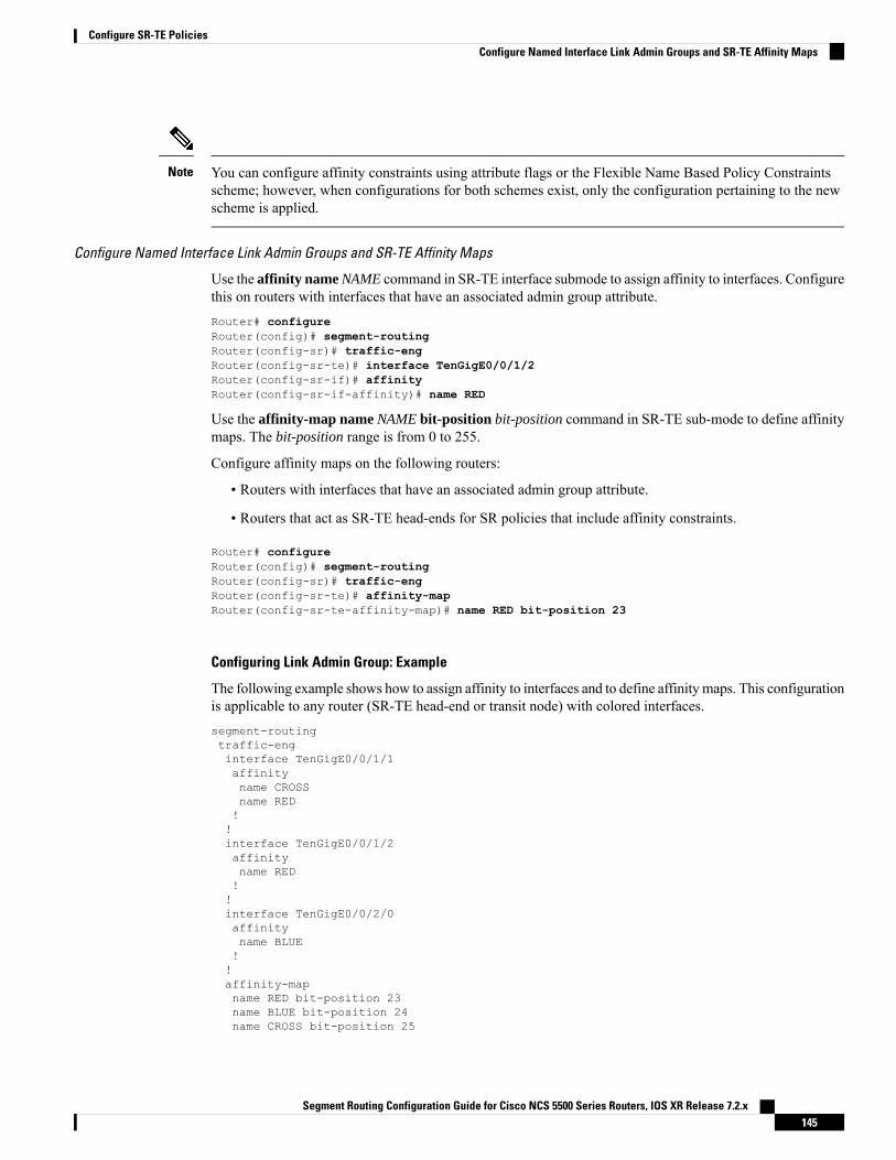
You can configure affinity constraints using attribute flags or the Flexible Name Based Policy Constraintsscheme; however, when configurations for both schemes exist, only the configuration pertaining to the newscheme is applied.
Note
Configure Named Interface Link Admin Groups and SR-TE Affinity Maps
Use the affinity name NAME command in SR-TE interface submode to assign affinity to interfaces. Configurethis on routers with interfaces that have an associated admin group attribute.Router# configureRouter(config)# segment-routingRouter(config-sr)# traffic-engRouter(config-sr-te)# interface TenGigE0/0/1/2Router(config-sr-if)# affinityRouter(config-sr-if-affinity)# name RED
Use the affinity-map name NAME bit-position bit-position command in SR-TE sub-mode to define affinitymaps. The bit-position range is from 0 to 255.
Configure affinity maps on the following routers:
• Routers with interfaces that have an associated admin group attribute.
• Routers that act as SR-TE head-ends for SR policies that include affinity constraints.
Router# configureRouter(config)# segment-routingRouter(config-sr)# traffic-engRouter(config-sr-te)# affinity-mapRouter(config-sr-te-affinity-map)# name RED bit-position 23
Configuring Link Admin Group: Example
The following example shows how to assign affinity to interfaces and to define affinity maps. This configurationis applicable to any router (SR-TE head-end or transit node) with colored interfaces.segment-routingtraffic-enginterface TenGigE0/0/1/1affinityname CROSSname RED!!interface TenGigE0/0/1/2affinityname RED!!interface TenGigE0/0/2/0affinityname BLUE!!affinity-mapname RED bit-position 23name BLUE bit-position 24name CROSS bit-position 25
Segment Routing Configuration Guide for Cisco NCS 5500 Series Routers, IOS XR Release 7.2.x145
Configure SR-TE PoliciesConfigure Named Interface Link Admin Groups and SR-TE Affinity Maps
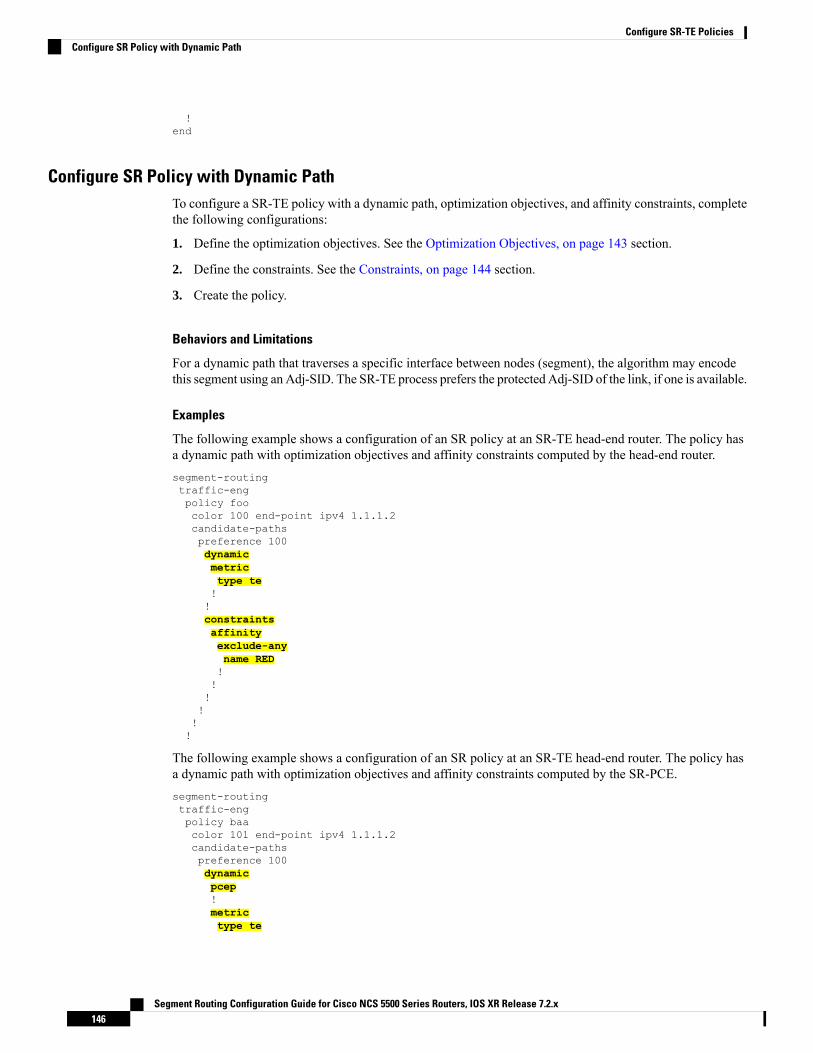
!end
Configure SR Policy with Dynamic PathTo configure a SR-TE policy with a dynamic path, optimization objectives, and affinity constraints, completethe following configurations:
1. Define the optimization objectives. See the Optimization Objectives, on page 143 section.
2. Define the constraints. See the Constraints, on page 144 section.
3. Create the policy.
Behaviors and Limitations
For a dynamic path that traverses a specific interface between nodes (segment), the algorithm may encodethis segment using an Adj-SID. The SR-TE process prefers the protected Adj-SID of the link, if one is available.
Examples
The following example shows a configuration of an SR policy at an SR-TE head-end router. The policy hasa dynamic path with optimization objectives and affinity constraints computed by the head-end router.segment-routingtraffic-engpolicy foocolor 100 end-point ipv4 1.1.1.2candidate-pathspreference 100dynamicmetrictype te!!constraintsaffinityexclude-anyname RED!!!!!!
The following example shows a configuration of an SR policy at an SR-TE head-end router. The policy hasa dynamic path with optimization objectives and affinity constraints computed by the SR-PCE.segment-routingtraffic-engpolicy baacolor 101 end-point ipv4 1.1.1.2candidate-pathspreference 100dynamicpcep!metrictype te
Segment Routing Configuration Guide for Cisco NCS 5500 Series Routers, IOS XR Release 7.2.x146
Configure SR-TE PoliciesConfigure SR Policy with Dynamic Path

!!constraintsaffinityexclude-anyname BLUE!!!!!!
Anycast SID-Aware Path ComputationThis feature allows the SR-TE head-end or SR-PCE to compute a path that is encoded using Anycast prefixSIDs of nodes along the path.
An Anycast SID is a type of prefix SID that identifies a set of nodes and is configured with n-flag clear. Theset of nodes (Anycast group) is configured to advertise a shared prefix address and prefix SID. Anycast routingenables the steering of traffic toward multiple advertising nodes, providing load-balancing and redundancy.Packets addressed to an Anycast address are forwarded to the topologically nearest nodes.
For more information about this feature, see the Anycast SID-Aware Path Computation topic in the ConfigureSegment Routing Path Computation Element chapter.
For information on configuring Anycast SID, see Configuring a Prefix-SID on the IS-IS Enabled LoopbackInterface, on page 65 and Configuring a Prefix-SID on the OSPF-Enabled Loopback Interface, on page 85.
Note
Explicit Paths
Configure SR-TE Policy with Explicit PathTo configure an SR-TE policy with an explicit path, complete the following configurations:
1. Create the segment lists.
2. Create the SR-TE policy.
Behaviors and Limitations
A segment list can use IP addresses or MPLS labels, or a combination of both.
• The IP address can be link or a Loopback address.
• Once you enter an MPLS label, you cannot enter an IP address.
When configuring an explicit path using IP addresses of links along the path, the SR-TE process prefers theprotected Adj-SID of the link, if one is available.
Configure Local SR-TE Policy Using Explicit Paths
Create a segment list with IP addresses:
Segment Routing Configuration Guide for Cisco NCS 5500 Series Routers, IOS XR Release 7.2.x147
Configure SR-TE PoliciesAnycast SID-Aware Path Computation

Router# configureRouter(config)# segment-routingRouter(config-sr)# traffic-engRouter(config-sr-te)# segment-list name SIDLIST1Router(config-sr-te-sl)# index 10 mpls adjacency 1.1.1.2Router(config-sr-te-sl)# index 20 mpls adjacency 1.1.1.3Router(config-sr-te-sl)# index 30 mpls adjacency 1.1.1.4Router(config-sr-te-sl)# exit
Create a segment list with MPLS labels:Router(config-sr-te)# segment-list name SIDLIST2Router(config-sr-te-sl)# index 10 mpls label 16002Router(config-sr-te-sl)# index 20 mpls label 16003Router(config-sr-te-sl)# index 30 mpls label 16004Router(config-sr-te-sl)# exit
Create a segment list with invalid MPLS label:Router(config-sr-te)# segment-list name SIDLIST4Router(config-sr-te-sl)# index 10 mpls label 16009Router(config-sr-te-sl)# index 20 mpls label 16003Router(config-sr-te-sl)# index 30 mpls label 16004Router(config-sr-te-sl)# exit
Create a segment list with IP addresses and MPLS labels:Router(config-sr-te)# segment-list name SIDLIST3Router(config-sr-te-sl)# index 10 mpls adjacency 1.1.1.2Router(config-sr-te-sl)# index 20 mpls label 16003Router(config-sr-te-sl)# index 30 mpls label 16004Router(config-sr-te-sl)# exit
Create the SR-TE policy:Router(config-sr-te)# policy POLICY2Router(config-sr-te-policy)# color 20 end-point ipv4 1.1.1.4Router(config-sr-te-policy)# candidate-pathsRouter(config-sr-te-policy-path)# preference 100Router(config-sr-te-policy-path-pref)# explicit segment-list SIDLIST2Router(config-sr-te-pp-info)# exitRouter(config-sr-te-policy-path-pref)# exitRouter(config-sr-te-policy-path)# preference 200Router(config-sr-te-policy-path-pref)# explicit segment-list SIDLIST1Router(config-sr-te-pp-info)# exitRouter(config-sr-te-policy-path-pref)# explicit segment-list SIDLIST4Router(config-sr-te-pp-info)# exitRouter(config-sr-te-policy-path-pref)# exit
Running Configuration
Router# show running-configurationsegment-routingtraffic-engsegment-list SIDLIST1index 10 address ipv4 1.1.1.2index 20 address ipv4 1.1.1.3index 30 address ipv4 1.1.1.4!segment-list SIDLIST2index 10 mpls label 16002index 20 mpls label 16003
Segment Routing Configuration Guide for Cisco NCS 5500 Series Routers, IOS XR Release 7.2.x148
Configure SR-TE PoliciesConfigure SR-TE Policy with Explicit Path

index 30 mpls label 16004!segment-list SIDLIST3index 10 address ipv4 1.1.1.2index 20 mpls label 16003index 30 mpls label 16004!segment-list SIDLIST4index 10 mpls label 16009index 20 mpls label 16003index 30 mpls label 16004!policy POLICY1color 10 end-point ipv4 1.1.1.4candidate-pathspreference 100explicit segment-list SIDLIST1!!!!policy POLICY2color 20 end-point ipv4 1.1.1.4candidate-pathspreference 100explicit segment-list SIDLIST1!!preference 200explicit segment-list SIDLIST2!explicit segment-list SIDLIST4!!!!policy POLICY3color 30 end-point ipv4 1.1.1.4candidate-pathspreference 100explicit segment-list SIDLIST3!!!!
!!
Verification
Verify the SR-TE policy configuration using:Router# show segment-routing traffic-eng policy name srte_c_20_ep_1.1.1.4
SR-TE policy database---------------------
Color: 20, End-point: 1.1.1.4Name: srte_c_20_ep_1.1.1.4Status:Admin: up Operational: up for 00:00:15 (since Jul 14 00:53:10.615)
Candidate-paths:Preference: 200 (configuration) (active)
Segment Routing Configuration Guide for Cisco NCS 5500 Series Routers, IOS XR Release 7.2.x149
Configure SR-TE PoliciesConfigure SR-TE Policy with Explicit Path

Name: POLICY2Requested BSID: dynamicProtection Type: protected-preferredMaximum SID Depth: 8
Explicit: segment-list SIDLIST2 (active)Weight: 1, Metric Type: TE160021600316004
Attributes:Binding SID: 51301Forward Class: Not ConfiguredSteering labeled-services disabled: noSteering BGP disabled: noIPv6 caps enable: yesInvalidation drop enabled: no
Configuring Explicit Path with Affinity Constraint ValidationTo fully configure SR-TE flexible name-based policy constraints, you must complete these high-level tasksin order:
1. Assign Color Names to Numeric Values
2. Associate Affinity-Names with SR-TE Links
3. Associate Affinity Constraints for SR-TE Policies
/* Enter the global configuration mode and assign color names to numeric valuesRouter# configureRouter(config)# segment-routingRouter(config-sr)# traffic-engRouter(config-sr-te)# affinity-mapRouter(config-sr-te-affinity-map)# blue bit-position 0Router(config-sr-te-affinity-map)# green bit-position 1Router(config-sr-te-affinity-map)# red bit-position 2Router(config-sr-te-affinity-map)# exit
/* Associate affinity-names with SR-TE linksRouter(config-sr-te)# interface Gi0/0/0/0Router(config-sr-te-if)# affinityRouter(config-sr-te-if-affinity)# blueRouter(config-sr-te-if-affinity)# exitRouter(config-sr-te-if)# exitRouter(config-sr-te)# interface Gi0/0/0/1Router(config-sr-te-if)# affinityRouter(config-sr-te-if-affinity)# blueRouter(config-sr-te-if-affinity)# greenRouter(config-sr-te-if-affinity)# exitRouter(config-sr-te-if)# exitRouter(config-sr-te)#
/* Associate affinity constraints for SR-TE policiesRouter(config-sr-te)# segment-list name SIDLIST1Router(config-sr-te-sl)# index 10 mpls adjacency 1.1.1.2Router(config-sr-te-sl)# index 20 mpls adjacency 2.2.2.23Router(config-sr-te-sl)# index 30 mpls adjacency 1.1.1.4
Segment Routing Configuration Guide for Cisco NCS 5500 Series Routers, IOS XR Release 7.2.x150
Configure SR-TE PoliciesConfiguring Explicit Path with Affinity Constraint Validation

Router(config-sr-te-sl)# exitRouter(config-sr-te)# segment-list name SIDLIST2Router(config-sr-te-sl)# index 10 mpls adjacency 1.1.1.2Router(config-sr-te-sl)# index 30 mpls adjacency 1.1.1.4Router(config-sr-te-sl)# exitRouter(config-sr-te)# segment-list name SIDLIST3Router(config-sr-te-sl)# index 10 mpls adjacency 1.1.1.5Router(config-sr-te-sl)# index 30 mpls adjacency 1.1.1.4Router(config-sr-te-sl)# exit
Router(config-sr-te)# policy POLICY1Router(config-sr-te-policy)# color 20 end-point ipv4 1.1.1.4Router(config-sr-te-policy)# binding-sid mpls 1000Router(config-sr-te-policy)# candidate-pathsRouter(config-sr-te-policy-path)# preference 200Router(config-sr-te-policy-path-pref)# constraints affinity exclude-any redRouter(config-sr-te-policy-path-pref)# explicit segment-list SIDLIST1Router(config-sr-te-pp-info)# exitRouter(config-sr-te-policy-path-pref)# explicit segment-list SIDLIST2Router(config-sr-te-pp-info)# exitRouter(config-sr-te-policy-path-pref)# exitRouter(config-sr-te-policy-path)# preference 100Router(config-sr-te-policy-path-pref)# explicit segment-list SIDLIST3
Running Configuration
Router# show running-configurationsegment-routingtraffic-eng
interface GigabitEthernet0/0/0/0affinityblue!!interface GigabitEthernet0/0/0/1affinitybluegreen!!
segment-list name SIDLIST1index 10 mpls adjacency 1.1.1.2index 20 mpls adjacency 2.2.2.23index 30 mpls adjacency 1.1.1.4!segment-list name SIDLIST2index 10 mpls adjacency 1.1.1.2index 30 mpls adjacency 1.1.1.4!segment-list name SIDLIST3index 10 mpls adjacency 1.1.1.5index 30 mpls adjacency 1.1.1.4!policy POLICY1binding-sid mpls 1000color 20 end-point ipv4 1.1.1.4candidate-pathspreference 100
Segment Routing Configuration Guide for Cisco NCS 5500 Series Routers, IOS XR Release 7.2.x151
Configure SR-TE PoliciesConfiguring Explicit Path with Affinity Constraint Validation

explicit segment-list SIDLIST3!!preference 200explicit segment-list SIDLIST1!explicit segment-list SIDLIST2!constraintsaffinityexclude-anyred!!!!!!affinity-mapblue bit-position 0green bit-position 1red bit-position 2!!!
Protocols
Path Computation Element ProtocolThe path computation element protocol (PCEP) describes a set of procedures by which a path computationclient (PCC) can report and delegate control of head-end label switched paths (LSPs) sourced from the PCCto a PCE peer. The PCE can request the PCC to update and modify parameters of LSPs it controls. The statefulmodel also enables a PCC to allow the PCE to initiate computations allowing the PCE to perform network-wideorchestration.
Configure the Head-End Router as PCEP PCCConfigure the head-end router as PCEP Path Computation Client (PCC) to establish a connection to the PCE.The PCC and PCE addresses must be routable so that TCP connection (to exchange PCEP messages) can beestablished between PCC and PCE.
Configure the PCC to Establish a Connection to the PCE
Use the segment-routing traffic-eng pcc command to configure the PCC source address, the SR-PCE address,and SR-PCE options.
A PCE can be given an optional precedence. If a PCC is connected to multiple PCEs, the PCC selects a PCEwith the lowest precedence value. If there is a tie, a PCE with the highest IP address is chosen for computingpath. The precedence value range is from 0 to 255.Router(config)# segment-routingRouter(config-sr)# traffic-engRouter(config-sr-te)# pccRouter(config-sr-te-pcc)# source-address ipv4 local-source-address
Segment Routing Configuration Guide for Cisco NCS 5500 Series Routers, IOS XR Release 7.2.x152
Configure SR-TE PoliciesProtocols
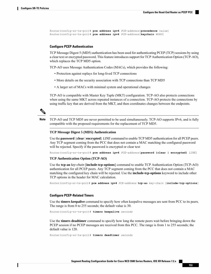
Router(config-sr-te-pcc)# pce address ipv4 PCE-address[precedence value]Router(config-sr-te-pcc)# pce address ipv4 PCE-address[keychain WORD]
Configure PCEP Authentication
TCPMessage Digest 5 (MD5) authentication has been used for authenticating PCEP (TCP) sessions by usinga clear text or encrypted password. This feature introduces support for TCPAuthentication Option (TCP-AO),which replaces the TCP MD5 option.
TCP-AO uses Message Authentication Codes (MACs), which provides the following:
• Protection against replays for long-lived TCP connections
• More details on the security association with TCP connections than TCP MD5
• A larger set of MACs with minimal system and operational changes
TCP-AO is compatible with Master Key Tuple (MKT) configuration. TCP-AO also protects connectionswhen using the same MKT across repeated instances of a connection. TCP-AO protects the connections byusing traffic key that are derived from the MKT, and then coordinates changes between the endpoints.
TCP-AO and TCP MD5 are never permitted to be used simultaneously. TCP-AO supports IPv6, and is fullycompatible with the proposed requirements for the replacement of TCP MD5.
Note
TCP Message Digest 5 (MD5) Authentication
Use the password {clear | encrypted} LINE command to enable TCPMD5 authentication for all PCEP peers.Any TCP segment coming from the PCC that does not contain a MAC matching the configured passwordwill be rejected. Specify if the password is encrypted or clear textRouter(config-sr-te-pcc)# pce address ipv4 PCE-address[password {clear | encrypted} LINE]
TCP Authentication Option (TCP-AO)
Use the tcp-ao key-chain [include-tcp-options] command to enable TCP Authentication Option (TCP-AO)authentication for all PCEP peers. Any TCP segment coming from the PCC that does not contain a MACmatching the configured key chain will be rejected. Use the include-tcp-options keyword to include otherTCP options in the header for MAC calculation.Router(config-sr-te-pcc)# pce address ipv4 PCE-address tcp-ao key-chain [include-tcp-options]
Configure PCEP-Related Timers
Use the timers keepalive command to specify how often keepalive messages are sent from PCC to its peers.The range is from 0 to 255 seconds; the default value is 30.Router(config-sr-te-pcc)# timers keepalive seconds
Use the timers deadtimer command to specify how long the remote peers wait before bringing down thePCEP session if no PCEP messages are received from this PCC. The range is from 1 to 255 seconds; thedefault value is 120.Router(config-sr-te-pcc)# timers deadtimer seconds
Segment Routing Configuration Guide for Cisco NCS 5500 Series Routers, IOS XR Release 7.2.x153
Configure SR-TE PoliciesConfigure the Head-End Router as PCEP PCC

Use the timers delegation-timeout command to specify how long a delegated SR policy can remain upwithout an active connection to a PCE. The range is from 0 to 3600 seconds; the default value is 60.Router(config-sr-te-pcc)# timers delegation-timeout seconds
PCE-Initiated SR Policy Timers
Use the timers initiated orphans command to specify the amount of time that a PCE-initiated SR policy willremain delegated to a PCE peer that is no longer reachable by the PCC. The range is from 10 to 180 seconds;the default value is 180.Router(config-sr-te-pcc)# timers initiated orphans seconds
Use the timers initiated state command to specify the amount of time that a PCE-initiated SR policy willremain programmed while not being delegated to any PCE. The range is from 15 to 14440 seconds (24 hours);the default value is 600.Router(config-sr-te-pcc)# timers initiated state seconds
To better understand how the PCE-initiated SR policy timers operate, consider the following example:
• PCE A instantiates SR policy P at head-end N.
• Head-end N delegates SR policy P to PCE A and programs it in forwarding.
• If head-end N detects that PCEA is no longer reachable, then head-end N starts the PCE-initiated orphanand state timers for SR policy P.
• If PCE A reconnects before the orphan timer expires, then SR policy P is automatically delegated backto its original PCE (PCE A).
• After the orphan timer expires, SR policy P will be eligible for delegation to any other surviving PCE(s).
• If SR policy P is not delegated to another PCE before the state timer expires, then head-end N willremove SR policy P from its forwarding.
Enable SR-TE SYSLOG Alarms
Use the logging policy status command to enable SR-TE related SYSLOG alarms.Router(config-sr-te)# logging policy status
Enable PCEP Reports to SR-PCE
Use the report-all command to enable the PCC to report all SR policies in its database to the PCE.Router(config-sr-te-pcc)# report-all
Customize MSD Value at PCC
Use the maximum-sid-depth value command to customize the Maximum SID Depth (MSD) signaled byPCC during PCEP session establishment.
The default MSD value is equal to the maximum MSD supported by the platform (12).Router(config-sr-te)# maximum-sid-depth value
Segment Routing Configuration Guide for Cisco NCS 5500 Series Routers, IOS XR Release 7.2.x154
Configure SR-TE PoliciesConfigure the Head-End Router as PCEP PCC

The platform's SR-TE label imposition capabilities are as follows:
• Up to 12 transport labels when no service labels are imposed
• Up to 9 transport labels when service labels are imposed
Note
For cases with path computation at PCE, a PCC can signal its MSD to the PCE in the following ways:
• During PCEP session establishment – The signaled MSD is treated as a node-wide property.
• MSD is configured under segment-routing traffic-eng maximum-sid-depth value command
• During PCEP LSP path request – The signaled MSD is treated as an LSP property.
• On-demand (ODN) SR Policy: MSD is configured using the segment-routing traffic-engon-demand color color maximum-sid-depth value command
• Local SR Policy: MSD is configured using the segment-routing traffic-eng policy WORDcandidate-paths preference preference dynamic metric sid-limit value command.
If the configured MSD values are different, the per-LSP MSD takesprecedence over the per-node MSD.
Note
After path computation, the resulting label stack size is verified against the MSD requirement.
• If the label stack size is larger than the MSD and path computation is performed by PCE, then the PCEreturns a "no path" response to the PCC.
• If the label stack size is larger than the MSD and path computation is performed by PCC, then the PCCwill not install the path.
A sub-optimal path (if one exists) that satisfies the MSD constraint could be computed in the following cases:
• For a dynamic path with TEmetric, when the PCE is configured with the pce segment-routing te-latencycommand or the PCC is configured with the segment-routing traffic-eng te-latency command.
• For a dynamic path with LATENCY metric
• For a dynamic path with affinity constraints
For example, if the PCCMSD is 4 and the optimal path (with an accumulated metric of 100) requires 5 labels,but a sub-optimal path exists (with accumulated metric of 110) requiring 4 labels, then the sub-optimal pathis installed.
Note
Customize the SR-TE Path Calculation
Use the te-latency command to enable ECMP-aware path computation for TE metric.
Segment Routing Configuration Guide for Cisco NCS 5500 Series Routers, IOS XR Release 7.2.x155
Configure SR-TE PoliciesConfigure the Head-End Router as PCEP PCC
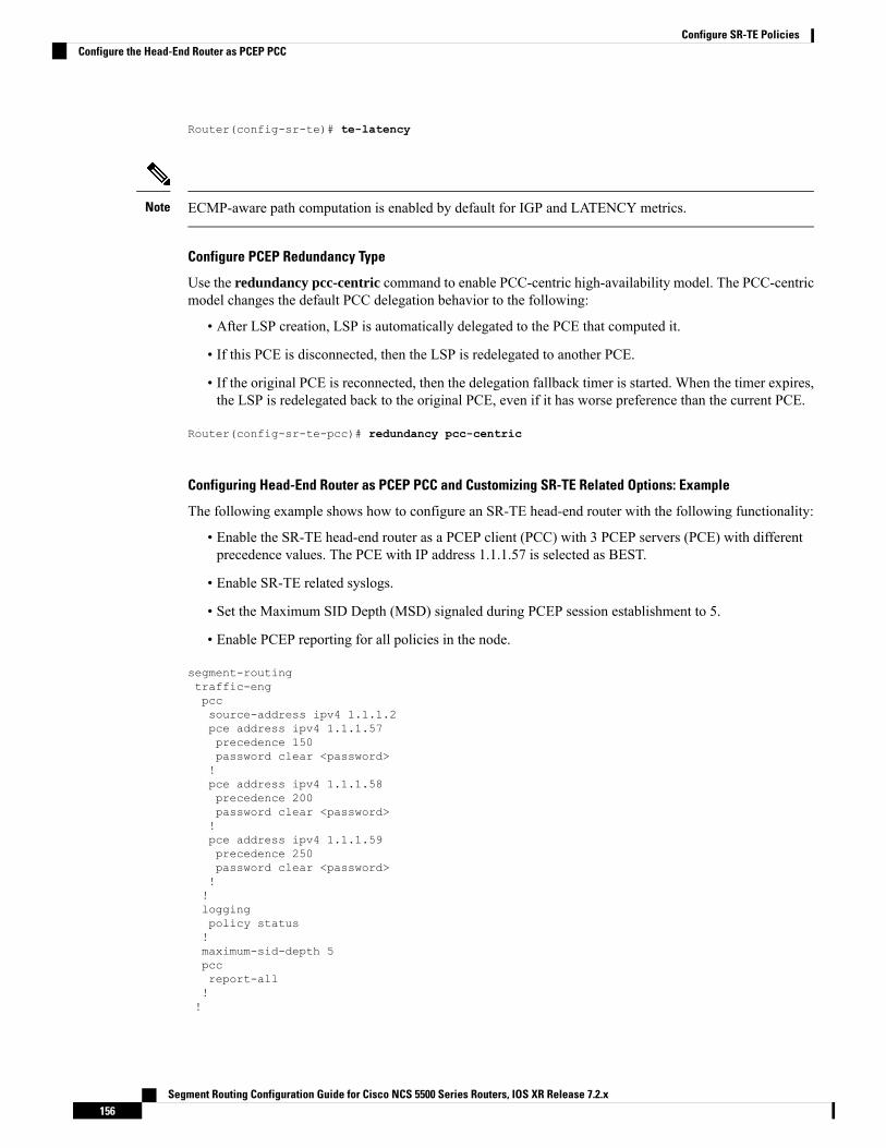
Router(config-sr-te)# te-latency
ECMP-aware path computation is enabled by default for IGP and LATENCY metrics.Note
Configure PCEP Redundancy Type
Use the redundancy pcc-centric command to enable PCC-centric high-availability model. The PCC-centricmodel changes the default PCC delegation behavior to the following:
• After LSP creation, LSP is automatically delegated to the PCE that computed it.
• If this PCE is disconnected, then the LSP is redelegated to another PCE.
• If the original PCE is reconnected, then the delegation fallback timer is started. When the timer expires,the LSP is redelegated back to the original PCE, even if it has worse preference than the current PCE.
Router(config-sr-te-pcc)# redundancy pcc-centric
Configuring Head-End Router as PCEP PCC and Customizing SR-TE Related Options: Example
The following example shows how to configure an SR-TE head-end router with the following functionality:
• Enable the SR-TE head-end router as a PCEP client (PCC) with 3 PCEP servers (PCE) with differentprecedence values. The PCE with IP address 1.1.1.57 is selected as BEST.
• Enable SR-TE related syslogs.
• Set the Maximum SID Depth (MSD) signaled during PCEP session establishment to 5.
• Enable PCEP reporting for all policies in the node.
segment-routingtraffic-engpccsource-address ipv4 1.1.1.2pce address ipv4 1.1.1.57precedence 150password clear <password>!pce address ipv4 1.1.1.58precedence 200password clear <password>!pce address ipv4 1.1.1.59precedence 250password clear <password>!!loggingpolicy status!maximum-sid-depth 5pccreport-all!!
Segment Routing Configuration Guide for Cisco NCS 5500 Series Routers, IOS XR Release 7.2.x156
Configure SR-TE PoliciesConfigure the Head-End Router as PCEP PCC

!end
Verification
RP/0/RSP0/CPU0:Router# show segment-routing traffic-eng pcc ipv4 peer
PCC's peer database:--------------------
Peer address: 1.1.1.57, Precedence: 150, (best PCE)State upCapabilities: Stateful, Update, Segment-Routing, Instantiation
Peer address: 1.1.1.58, Precedence: 200State upCapabilities: Stateful, Update, Segment-Routing, Instantiation
Peer address: 1.1.1.59, Precedence: 250State upCapabilities: Stateful, Update, Segment-Routing, Instantiation
BGP SR-TEBGP may be used to distribute SR Policy candidate paths to an SR-TE head-end. Dedicated BGP SAFI andNLRI have been defined to advertise a candidate path of an SR Policy. The advertisement of Segment Routingpolicies in BGP is documented in the IETF drafthttps://datatracker.ietf.org/doc/draft-ietf-idr-segment-routing-te-policy/
SR policies with IPv4 and IPv6 end-points can be advertised over BGPv4 or BGPv6 sessions between theSR-TE controller and the SR-TE headend.
The Cisco IOS-XR implementation supports the following combinations:
• IPv4 SR policy advertised over BGPv4 session
• IPv6 SR policy advertised over BGPv4 session
• IPv4 SR policy advertised over BGPv6 session
• IPv6 SR policy advertised over BGPv6 session
Configure BGP SR Policy Address Family at SR-TE Head-EndPerform this task to configure BGP SR policy address family at SR-TE head-end:
SUMMARY STEPS
1. configure2. router bgp as-number
3. bgp router-id ip-address
4. address-family {ipv4 | ipv6} sr-policy5. exit6. neighbor ip-address
7. remote-as as-number
Segment Routing Configuration Guide for Cisco NCS 5500 Series Routers, IOS XR Release 7.2.x157
Configure SR-TE PoliciesBGP SR-TE
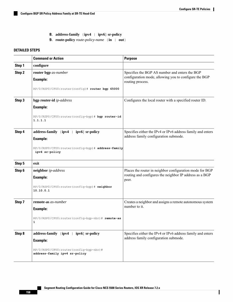
8. address-family {ipv4 | ipv6} sr-policy9. route-policy route-policy-name {in | out}
DETAILED STEPS
PurposeCommand or Action
configureStep 1
Specifies the BGP AS number and enters the BGPconfiguration mode, allowing you to configure the BGProuting process.
router bgp as-number
Example:
RP/0/RSP0/CPU0:router(config)# router bgp 65000
Step 2
Configures the local router with a specified router ID.bgp router-id ip-address
Example:
Step 3
RP/0/RSP0/CPU0:router(config-bgp)# bgp router-id1.1.1.1
Specifies either the IPv4 or IPv6 address family and entersaddress family configuration submode.
address-family {ipv4 | ipv6} sr-policy
Example:
Step 4
RP/0/RSP0/CPU0:router(config-bgp)# address-familyipv4 sr-policy
exitStep 5
Places the router in neighbor configuration mode for BGProuting and configures the neighbor IP address as a BGPpeer.
neighbor ip-address
Example:
RP/0/RSP0/CPU0:router(config-bgp)# neighbor
Step 6
10.10.0.1
Creates a neighbor and assigns a remote autonomous systemnumber to it.
remote-as as-number
Example:
Step 7
RP/0/RSP0/CPU0:router(config-bgp-nbr)# remote-as1
Specifies either the IPv4 or IPv6 address family and entersaddress family configuration submode.
address-family {ipv4 | ipv6} sr-policy
Example:
Step 8
RP/0/RSP0/CPU0:router(config-bgp-nbr)#address-family ipv4 sr-policy
Segment Routing Configuration Guide for Cisco NCS 5500 Series Routers, IOS XR Release 7.2.x158
Configure SR-TE PoliciesConfigure BGP SR Policy Address Family at SR-TE Head-End

PurposeCommand or Action
Applies the specified policy to IPv4 or IPv6 unicast routes.route-policy route-policy-name {in | out}
Example:
Step 9
RP/0/RSP0/CPU0:router(config-bgp-nbr-af)#route-policy pass out
Example: BGP SR-TE with BGPv4 Neighbor to BGP SR-TE Controller
The following configuration shows the an SR-TE head-end with a BGPv4 session towards a BGP SR-TEcontroller. This BGP session is used to signal both IPv4 and IPv6 SR policies.router bgp 65000bgp router-id 1.1.1.1!address-family ipv4 sr-policy!address-family ipv6 sr-policy!neighbor 10.1.3.1remote-as 10description *** eBGP session to BGP SRTE controller ***address-family ipv4 sr-policyroute-policy pass inroute-policy pass out!address-family ipv6 sr-policyroute-policy pass inroute-policy pass out!!!
Example: BGP SR-TE with BGPv6 Neighbor to BGP SR-TE Controller
The following configuration shows an SR-TE head-endwith a BGPv6 session towards a BGP SR-TE controller.This BGP session is used to signal both IPv4 and IPv6 SR policies.router bgp 65000bgp router-id 1.1.1.1address-family ipv4 sr-policy!address-family ipv6 sr-policy!neighbor 3001::10:1:3:1remote-as 10description *** eBGP session to BGP SRTE controller ***address-family ipv4 sr-policyroute-policy pass inroute-policy pass out!address-family ipv6 sr-policyroute-policy pass inroute-policy pass out!!!
Segment Routing Configuration Guide for Cisco NCS 5500 Series Routers, IOS XR Release 7.2.x159
Configure SR-TE PoliciesConfigure BGP SR Policy Address Family at SR-TE Head-End

Traffic Steering
Automated SteeringAutomated steering (AS) allows service traffic to be automatically steered onto the required transport SLApath programmed by an SR policy.
With AS, BGP automatically steers traffic onto an SR Policy based on the next-hop and color of a BGP serviceroute. The color of a BGP service route is specified by a color extended community attribute. This color isused as a transport SLA indicator, such as min-delay or min-cost.
When the next-hop and color of a BGP service route matches the end-point and color of an SR Policy, BGPautomatically installs the route resolving onto the BSID of the matching SR Policy. Recall that an SR Policyon a head-end is uniquely identified by an end-point and color.
When a BGP route has multiple extended-color communities, each with a valid SR Policy, the BGP processinstalls the route on the SR Policy giving preference to the color with the highest numerical value.
The granularity of AS behaviors can be applied at multiple levels, for example:
• At a service level—When traffic destined to all prefixes in a given service is associated to the sametransport path type. All prefixes share the same color.
• At a destination/prefix level—When traffic destined to a prefix in a given service is associated to aspecific transport path type. Each prefix could be assigned a different color.
• At a flow level—When flows destined to the same prefix are associated with different transport pathtypes
AS behaviors apply regardless of the instantiation method of the SR policy, including:
• On-demand SR policy
• Manually provisioned SR policy
• PCE-initiated SR policy
See the Verifying BGP VRF Information, on page 116 and Verifying Forwarding (CEF) Table, on page 117sections for sample output that shows AS implementation.
Segment Routing Configuration Guide for Cisco NCS 5500 Series Routers, IOS XR Release 7.2.x160
Configure SR-TE PoliciesTraffic Steering

Color-Only Automated SteeringColor-only steering is a traffic steering mechanism where a policy is created with given color, regardless ofthe endpoint.
You can create an SR-TE policy for a specific color that uses a NULL end-point (0.0.0.0 for IPv4 NULL, and::0 for IPv6 NULL end-point). This means that you can have a single policy that can steer traffic that is basedon that color and a NULL endpoint for routes with a particular color extended community, but differentdestinations (next-hop).
Every SR-TE policy with a NULL end-point must have an explicit path-option. The policy cannot have adynamic path-option (where the path is computed by the head-end or PCE) since there is no destination forthe policy.
Note
You can also specify a color-only (CO) flag in the color extended community for overlay routes. The CO flagallows the selection of an SR-policy with amatching color, regardless of endpoint Sub-address Family Identifier(SAFI) (IPv4 or IPv6). See Setting CO Flag, on page 161.
Configure Color-Only Steering
Router# configureRouter(config)# segment-routingRouter(config-sr)# traffic-engRouter(config-sr-te)# policy P1Router(config-sr-te-policy)# color 1 end-point ipv4 0.0.0.0
Router# configureRouter(config)# segment-routingRouter(config-sr)# traffic-engRouter(config-sr-te)# policy P2Router(config-sr-te-policy)# color 2 end-point ipv6 ::0
Router# show running-configurationsegment-routingtraffic-engpolicy P1color 1 end-point ipv4 0.0.0.0!policy P2color 2 end-point ipv6 ::!!!end
Setting CO FlagThe BGP-based steering mechanism matches BGP color and next-hop with that of an SR-TE policy. If thepolicy does not exist, BGP requests SR-PCE to create an SR-TE policy with the associated color, end-point,and explicit paths. For color-only steering (NULL end-point), you can configure a color-only (CO) flag aspart of the color extended community in BGP.
Segment Routing Configuration Guide for Cisco NCS 5500 Series Routers, IOS XR Release 7.2.x161
Configure SR-TE PoliciesColor-Only Automated Steering

See Color-Only Automated Steering, on page 161 for information about color-only steering (NULL end-point).Note
The behavior of the steering mechanism is based on the following values of the CO flags:
1. The BGP next-hop and color <N, C> is matched with an SR-TE policy of same<N, C>.
2. If a policy does not exist, then IGP path for the next-hop N is chosen.
co-flag 00
1. The BGP next-hop and color <N, C> is matched with an SR-TE policy of same<N, C>.
2. If a policy does not exist, then an SR-TE policy with NULL end-point with thesame address-family as N and color C is chosen.
3. If a policy with NULL end-point with same address-family as N does not exist,then an SR-TE policy with any NULL end-point and color C is chosen.
4. If no match is found, then IGP path for the next-hop N is chosen.
co-flag 01
Configuration Example
Router(config)# extcommunity-set opaque overlay-colorRouter(config-ext)# 1 co-flag 01Router(config-ext)# end-setRouter(config)#Router(config)# route-policy colorRouter(config-rpl)# if destination in (5.5.5.1/32) thenRouter(config-rpl-if)# set extcommunity color overlay-colorRouter(config-rpl-if)# endifRouter(config-rpl)# passRouter(config-rpl)# end-policyRouter(config)#
Address-Family Agnostic Automated SteeringAddress-family agnostic steering uses an SR-TE policy to steer both labeled and unlabeled IPv4 and IPv6traffic. This feature requires support of IPv6 encapsulation (IPv6 caps) over IPV4 endpoint policy.
IPv6 caps for IPv4 NULL end-point is enabled automatically when the policy is created in Segment RoutingPath Computation Element (SR-PCE). The binding SID (BSID) state notification for each policy contains an"ipv6_caps" flag that notifies SR-PCE clients (PCC) of the status of IPv6 caps (enabled or disabled).
An SR-TE policy with a given color and IPv4 NULL end-point could have more than one candidate path. Ifany of the candidate paths has IPv6 caps enabled, then all of the remaining candidate paths need IPv6 capsenabled. If IPv6 caps is not enabled on all candidate paths of same color and end-point, traffic drops can occur.
You can disable IPv6 caps for a particular color and IPv4 NULL end-point using the ipv6 disable commandon the local policy. This command disables IPv6 caps on all candidate paths that share the same color andIPv4 NULL end-point.
Segment Routing Configuration Guide for Cisco NCS 5500 Series Routers, IOS XR Release 7.2.x162
Configure SR-TE PoliciesAddress-Family Agnostic Automated Steering
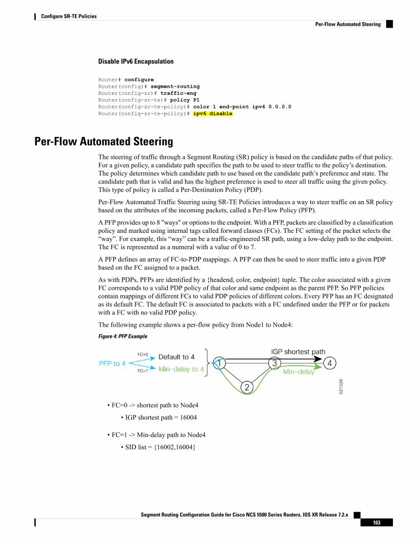
Disable IPv6 Encapsulation
Router# configureRouter(config)# segment-routingRouter(config-sr)# traffic-engRouter(config-sr-te)# policy P1Router(config-sr-te-policy)# color 1 end-point ipv4 0.0.0.0Router(config-sr-te-policy)# ipv6 disable
Per-Flow Automated SteeringThe steering of traffic through a Segment Routing (SR) policy is based on the candidate paths of that policy.For a given policy, a candidate path specifies the path to be used to steer traffic to the policy’s destination.The policy determines which candidate path to use based on the candidate path’s preference and state. Thecandidate path that is valid and has the highest preference is used to steer all traffic using the given policy.This type of policy is called a Per-Destination Policy (PDP).
Per-Flow Automated Traffic Steering using SR-TE Policies introduces a way to steer traffic on an SR policybased on the attributes of the incoming packets, called a Per-Flow Policy (PFP).
A PFP provides up to 8 "ways" or options to the endpoint. With a PFP, packets are classified by a classificationpolicy and marked using internal tags called forward classes (FCs). The FC setting of the packet selects the“way”. For example, this “way” can be a traffic-engineered SR path, using a low-delay path to the endpoint.The FC is represented as a numeral with a value of 0 to 7.
A PFP defines an array of FC-to-PDP mappings. A PFP can then be used to steer traffic into a given PDPbased on the FC assigned to a packet.
As with PDPs, PFPs are identified by a {headend, color, endpoint} tuple. The color associated with a givenFC corresponds to a valid PDP policy of that color and same endpoint as the parent PFP. So PFP policiescontain mappings of different FCs to valid PDP policies of different colors. Every PFP has an FC designatedas its default FC. The default FC is associated to packets with a FC undefined under the PFP or for packetswith a FC with no valid PDP policy.
The following example shows a per-flow policy from Node1 to Node4:
Figure 4: PFP Example
• FC=0 -> shortest path to Node4
• IGP shortest path = 16004
• FC=1 -> Min-delay path to Node4
• SID list = {16002,16004}
Segment Routing Configuration Guide for Cisco NCS 5500 Series Routers, IOS XR Release 7.2.x163
Configure SR-TE PoliciesPer-Flow Automated Steering

The same on-demand instantiation behaviors of PDPs apply to PFPs. For example, an edge node automatically(on demand) instantiates Per-Flow SR Policy paths to an endpoint by service route signaling. AutomatedSteering steers the service route in the matching SR Policy.
Figure 5: PFP with ODN Example
Like PDPs, PFPs have a binding SID (BSID). Existing SR-TE automated steering (AS) mechanisms forlabeled traffic (via BSID) and unlabeled traffic (via BGP) onto a PFP is similar to that of a PDP. For example,a packet having the BSID of a PFP as the top label is steered onto that PFP. The classification policy on theingress interface marks the packet with an FC based on the configured class-map. The packet is then steeredto the PDP that corresponds to that FC.
Usage Guidelines and Limitations
The following guidelines and limitations apply to the platform when acting as a head-end of a PFP policy:
• BGP IPv4 unicast over PFP (steered via ODN/AS) is supported
• BGP IPv6 unicast (with IPv4 next-hop [6PE]) over PFP (steered via ODN/AS) is supported
• BGP IPv6 unicast (with IPv6 next-hop) over PFP (steered via ODN/AS) is supported
• BGP VPNv4 over PFP is not supported
• BGP VPNv6 (6VPE) over PFP is not supported
• BGP EVPN over PFP is not supported
• Pseudowire and VPLS over PFP are not supported
• BGP multipath is not supported
• BGP PIC is not supported
• Labeled traffic (Binding SID) steered over PFP is not supported
• When not explicitly configured, FC 0 is the default FC.
• A PFP is considered valid as long as its default FC has a valid PDP.
• An ingress QoS policy applied to an input interface is used to classify flows and set correspondingforward-class (FC) values.
• The following counters are supported:
• PFP’s BSID counter (packet, bytes)
• Per-FC counters (packet, byte)
Segment Routing Configuration Guide for Cisco NCS 5500 Series Routers, IOS XR Release 7.2.x164
Configure SR-TE PoliciesPer-Flow Automated Steering

• Collected from the PDP’s segment-list-per-path egress counters
• If an SR policy is used for more than one purpose (as a regular policy as well as a PDP underone or more PFPs), then the collected counters will represent the aggregate of all contributions.To preserve independent counters, it is recommended that an SR policy be used only for onepurpose.
• Inbound packet classification, based on the following fields, is supported:
• IP precedence
• IP DSCP
• L3 ACL-based (L3 source/destination IP; L4 source/destination port)
• A color associated with a PFP SR policy cannot be used by a non-PFP SR policy. For example, if aper-flow ODN template for color 100 is configured, then the system will reject the configuration of anynon-PFP SR policy using the same color. You must assign different color value ranges for PFP andnon-PFP SR policies.
Configuring ODN Template for PFP Policies: Example
The following example depicts an ODN template for PFP policies that includes three FCs.
The example also includes the corresponding ODN templates for PDPs as follows:
• FC0 (default FC) mapped to color 10 = Min IGP path
• FC1 mapped to color 20 = Flex Algo 128 path
• FC2 mapped to color 30 = Flex Algo 129 path
segment-routingtraffic-engon-demand color 10dynamicmetrictype igp!!!on-demand color 20dynamicsid-algorithm 128!!on-demand color 30dynamicsid-algorithm 129!!on-demand color 1000per-flowforward-class 0 color 10forward-class 1 color 20forward-class 2 color 30
Segment Routing Configuration Guide for Cisco NCS 5500 Series Routers, IOS XR Release 7.2.x165
Configure SR-TE PoliciesPer-Flow Automated Steering
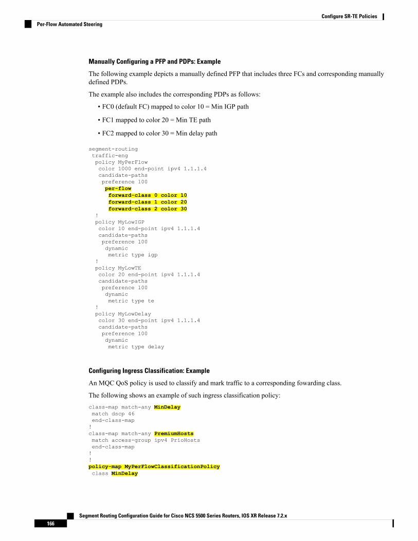
Manually Configuring a PFP and PDPs: Example
The following example depicts a manually defined PFP that includes three FCs and corresponding manuallydefined PDPs.
The example also includes the corresponding PDPs as follows:
• FC0 (default FC) mapped to color 10 = Min IGP path
• FC1 mapped to color 20 = Min TE path
• FC2 mapped to color 30 = Min delay path
segment-routingtraffic-engpolicy MyPerFlowcolor 1000 end-point ipv4 1.1.1.4candidate-pathspreference 100per-flowforward-class 0 color 10forward-class 1 color 20forward-class 2 color 30
!policy MyLowIGPcolor 10 end-point ipv4 1.1.1.4candidate-pathspreference 100dynamicmetric type igp
!policy MyLowTEcolor 20 end-point ipv4 1.1.1.4candidate-pathspreference 100dynamicmetric type te
!policy MyLowDelaycolor 30 end-point ipv4 1.1.1.4candidate-pathspreference 100dynamicmetric type delay
Configuring Ingress Classification: Example
An MQC QoS policy is used to classify and mark traffic to a corresponding fowarding class.
The following shows an example of such ingress classification policy:class-map match-any MinDelaymatch dscp 46end-class-map!class-map match-any PremiumHostsmatch access-group ipv4 PrioHostsend-class-map!!policy-map MyPerFlowClassificationPolicyclass MinDelay
Segment Routing Configuration Guide for Cisco NCS 5500 Series Routers, IOS XR Release 7.2.x166
Configure SR-TE PoliciesPer-Flow Automated Steering

set forward-class 2!class PremiumHostsset forward-class 1!class class-default!end-policy-map!interface GigabitEthernet0/0/0/0description PE_Ingress_Interfaceservice-policy input MyPerFlowClassificationPolicy!
Determining Per-Flow Policy State
A PFP is brought down for the following reasons:
• The PDP associated with the default FC is in a down state.
• All FCs are associated with PDPs in a down state.
• The FC assigned as the default FC is missing in the forward class mapping.
Scenario 1—FC 0 (default FC) is not configured in the FC mappings below:policy foocolor 1 end-point ipv4 1.1.1.1per-flowforward-class 1 color 10forward-class 2 color 20
Scenario 2—FC 1 is configured as the default FC, however it is not present in the FC mappings:policy foocolor 1 end-point ipv4 1.1.1.1per-flowforward-class 0 color 10forward-class 2 color 20forward-class default 1
Using Binding SegmentsThe binding segment is a local segment identifying an SR-TE policy. Each SR-TE policy is associated witha binding segment ID (BSID). The BSID is a local label that is automatically allocated for each SR-TE policywhen the SR-TE policy is instantiated.
In Cisco IOS XR 6.3.2 and later releases, you can specify an explicit BSID for an SR-TE policy. See thefollowing Explicit Binding SID section.
Note
BSID can be used to steer traffic into the SR-TE policy and across domain borders, creating seamless end-to-endinter-domain SR-TE policies. Each domain controls its local SR-TE policies; local SR-TE policies can bevalidated and rerouted if needed, independent from the remote domain’s head-end. Using binding segmentsisolates the head-end from topology changes in the remote domain.
Segment Routing Configuration Guide for Cisco NCS 5500 Series Routers, IOS XR Release 7.2.x167
Configure SR-TE PoliciesUsing Binding Segments

Packets received with a BSID as top label are steered into the SR-TE policy associated with the BSID. Whenthe BSID label is popped, the SR-TE policy’s SID list is pushed.
BSID can be used in the following cases:
• Multi-Domain (inter-domain, inter-autonomous system)—BSIDs can be used to steer traffic acrossdomain borders, creating seamless end-to-end inter-domain SR-TE policies.
• Large-Scale within a single domain—The head-end can use hierarchical SR-TE policies by nesting theend-to-end (edge-to-edge) SR-TE policy within another layer of SR-TE policies(aggregation-to-aggregation). The SR-TE policies are nested within another layer of policies using theBSIDs, resulting in seamless end-to-end SR-TE policies.
• Label stack compression—If the label-stack size required for an SR-TE policy exceeds the platformcapability, the SR-TE policy can be seamlessly stitched to, or nested within, other SR-TE policies usinga binding segment.
Explicit Binding SID
Use the binding-sid mpls label command in SR-TE policy configuration mode to specify the explicit BSID.Explicit BSIDs are allocated from the segment routing local block (SRLB) or the dynamic range of labels. Abest-effort is made to request and obtain the BSID for the SR-TE policy. If requested BSID is not available(if it does not fall within the available SRLB or is already used by another application or SR-TE policy), thepolicy stays down.
Use the binding-sid explicit {fallback-dynamic | enforce-srlb} command to specify how the BSID allocationbehaves if the BSID value is not available.
• Fallback to dynamic allocation – If the BSID is not available, the BSID is allocated dynamically and thepolicy comes up:
Router# configureRouter(config)# segment-routingRouter(config-sr)# traffic-engRouter(config-sr-te)# binding-sid explicit fallback-dynamic
• Strict SRLB enforcement – If the BSID is not within the SRLB, the policy stays down:
Router# configureRouter(config)# segment-routingRouter(config-sr)# traffic-engRouter(config-sr-te)# binding-sid explicit enforce-srlb
This example shows how to configure an SR policy to use an explicit BSID of 1000. If the BSID is notavailable, the BSID is allocated dynamically and the policy comes up.segment-routingtraffic-engbinding-sid explicit fallback-dynamicpolicy goobinding-sid mpls 1000!!!
Segment Routing Configuration Guide for Cisco NCS 5500 Series Routers, IOS XR Release 7.2.x168
Configure SR-TE PoliciesUsing Binding Segments

Stitching SR-TE Polices Using Binding SID: ExampleIn this example, three SR-TE policies are stitched together to form a seamless end-to-end path from node 1to node 10. The path is a chain of SR-TE policies stitched together using the binding-SIDs of intermediatepolicies, providing a seamless end-to-end path.
Figure 6: Stitching SR-TE Polices Using Binding SID
Table 8: Router IP Address
Prefix SID/Adj-SIDPrefix AddressRouter
Prefix SID - 16003Loopback0 - 1.1.1.33
Prefix SID - 16004
Adjacency SID - dynamic
Loopback0 - 1.1.1.4
Link node 4 to node 6 - 10.4.6.4
4
Prefix SID - 16005Loopback0 - 1.1.1.55
Prefix SID - 16006
Adjacency SID - dynamic
Loopback0 - 1.1.1.6
Link node 4 to node 6 - 10.4.6.6
6
Prefix SID - 16009Loopback0 - 1.1.1.99
Prefix SID - 16010Loopback0 - 1.1.1.1010
Step 1 On node 5, do the following:a) Define an SR-TE policy with an explicit path configured using the loopback interface IP addresses of node 9 and
node 10.b) Define an explicit binding-SID (mpls label 15888) allocated from SRLB for the SR-TE policy.
Example:
Node 5
segment-routingtraffic-engsegment-list PATH-9_10index 10 address ipv4 1.1.1.9index 20 address ipv4 1.1.1.10!policy foobinding-sid mpls 15888color 777 end-point ipv4 1.1.1.10
Segment Routing Configuration Guide for Cisco NCS 5500 Series Routers, IOS XR Release 7.2.x169
Configure SR-TE PoliciesStitching SR-TE Polices Using Binding SID: Example

candidate-pathspreference 100explicit segment-list PATH5-9_10!!!!!!
RP/0/RSP0/CPU0:Node-5# show segment-routing traffic-eng policy color 777
SR-TE policy database---------------------
Color: 777, End-point: 1.1.1.10Name: srte_c_777_ep_1.1.1.10Status:Admin: up Operational: up for 00:00:52 (since Aug 19 07:40:12.662)
Candidate-paths:Preference: 100 (configuration) (active)Name: fooRequested BSID: 15888PCC info:Symbolic name: cfg_foo_discr_100PLSP-ID: 70
Explicit: segment-list PATH-9_10 (valid)Weight: 1, Metric Type: TE16009 [Prefix-SID, 1.1.1.9]16010 [Prefix-SID, 1.1.1.10]
Attributes:Binding SID: 15888 (SRLB)Forward Class: 0Steering BGP disabled: noIPv6 caps enable: yes
Step 2 On node 3, do the following:a) Define an SR-TE policy with an explicit path configured using the following:
• Loopback interface IP address of node 4
• Interface IP address of link between node 4 and node 6
• Loopback interface IP address of node 5
• Binding-SID of the SR-TE policy defined in Step 1 (mpls label 15888)
This last segment allows the stitching of these policies.Note
b) Define an explicit binding-SID (mpls label 15900) allocated from SRLB for the SR-TE policy.
Example:
Node 3
segment-routingtraffic-engsegment-list PATH-4_4-6_5_BSIDindex 10 address ipv4 1.1.1.4index 20 address ipv4 10.4.6.6index 30 address ipv4 1.1.1.5index 40 mpls label 15888!
Segment Routing Configuration Guide for Cisco NCS 5500 Series Routers, IOS XR Release 7.2.x170
Configure SR-TE PoliciesStitching SR-TE Polices Using Binding SID: Example

policy baabinding-sid mpls 15900color 777 end-point ipv4 1.1.1.5candidate-pathspreference 100explicit segment-list PATH-4_4-6_5_BSID!!!!!!
RP/0/RSP0/CPU0:Node-3# show segment-routing traffic-eng policy color 777
SR-TE policy database---------------------
Color: 777, End-point: 1.1.1.5Name: srte_c_777_ep_1.1.1.5Status:Admin: up Operational: up for 00:00:32 (since Aug 19 07:40:32.662)
Candidate-paths:Preference: 100 (configuration) (active)Name: baaRequested BSID: 15900PCC info:Symbolic name: cfg_baa_discr_100PLSP-ID: 70
Explicit: segment-list PATH-4_4-6_5_BSID (valid)Weight: 1, Metric Type: TE16004 [Prefix-SID, 1.1.1.4]80005 [Adjacency-SID, 10.4.6.4 - 10.4.6.6]16005 [Prefix-SID, 1.1.1.5]15888
Attributes:Binding SID: 15900 (SRLB)Forward Class: 0Steering BGP disabled: noIPv6 caps enable: yes
Step 3 On node 1, define an SR-TE policy with an explicit path configured using the loopback interface IP address of node 3and the binding-SID of the SR-TE policy defined in step 2 (mpls label 15900). This last segment allows the stitching ofthese policies.
Example:
Node 1
segment-routingtraffic-engsegment-list PATH-3_BSIDindex 10 address ipv4 1.1.1.3index 20 mpls label 15900!policy barcolor 777 end-point ipv4 1.1.1.3candidate-pathspreference 100explicit segment-list PATH-3_BSID!!!
Segment Routing Configuration Guide for Cisco NCS 5500 Series Routers, IOS XR Release 7.2.x171
Configure SR-TE PoliciesStitching SR-TE Polices Using Binding SID: Example

!!!
RP/0/RSP0/CPU0:Node-1# show segment-routing traffic-eng policy color 777
SR-TE policy database---------------------
Color: 777, End-point: 1.1.1.3Name: srte_c_777_ep_1.1.1.3Status:Admin: up Operational: up for 00:00:12 (since Aug 19 07:40:52.662)
Candidate-paths:Preference: 100 (configuration) (active)Name: barRequested BSID: dynamicPCC info:Symbolic name: cfg_bar_discr_100PLSP-ID: 70
Explicit: segment-list PATH-3_BSID (valid)Weight: 1, Metric Type: TE16003 [Prefix-SID, 1.1.1.3]15900
Attributes:Binding SID: 80021Forward Class: 0Steering BGP disabled: noIPv6 caps enable: yes
L2VPN Preferred PathEVPN VPWS Preferred Path over SR-TE Policy feature allows you to set the preferred path between the twoend-points for EVPN VPWS pseudowire (PW) using SR-TE policy.
L2VPNVPLS or VPWS Preferred Path over SR-TE Policy feature allows you to set the preferred path betweenthe two end-points for L2VPN Virtual Private LAN Service (VPLS) or Virtual Private Wire Service (VPWS)using SR-TE policy.
Refer to the EVPN VPWS Preferred Path over SR-TE Policy and L2VPN VPLS or VPWS Preferred Pathover SR-TE Policy sections in the "L2VPN Services over Segment Routing for Traffic Engineering Policy"chapter of the L2VPN and Ethernet Services Configuration Guide.
Static Route over Segment Routing PolicyThis feature allows you to specify a Segment Routing (SR) policy as an interface type when configuring staticroutes for MPLS data planes.
For information on configuring static routes, see the "Implementing Static Routes" chapter in the RoutingConfiguration Guide for Cisco NCS 5500 Series Routers.
Configuration Example
The following example depicts a configuration of a static route for an IPv4 destination over an SR policyaccording to following parameters:
Segment Routing Configuration Guide for Cisco NCS 5500 Series Routers, IOS XR Release 7.2.x172
Configure SR-TE PoliciesL2VPN Preferred Path

• Target SR policy:
• Color = 200
• End-point = 1.1.1.4
• Auto-generated SR policy name = srte_c_200_ep_1.1.1.4
Use the auto-generated SR-TE policy name to attach the SRpolicy to the static route. Auto-generated SR policy names usethe following naming convention:srte_c_color_val_ep_endpoint-address.
Use the show segment-routing traffic-eng policy color<color_val> endpoint ipv4 <ip_addr> command to display theauto-generated policy name.
Note
• Admin distance = 40
• Load metric = 150
• Install the route in RIB regardless of reachability
Router(config)# router staticRouter(config-static)# address-family ipv4 unicastRouter(config-static-afi)# 1.1.1.4/32 sr-policy srte_c_200_ep_1.1.1.4 40 permanent metric150
Running Configuration
router staticaddress-family ipv4 unicast1.1.1.4/32 sr-policy srte_c_200_ep_1.1.1.4 40 permanent metric 150!!
Verification
RP/0/RP0/CPU0:RTR-1# show run segment-routing traffic-eng policy sample-policy-fooTue Feb 16 17:40:16.759 PSTsegment-routingtraffic-engpolicy sample-policy-foocolor 200 end-point ipv4 1.1.1.4candidate-pathspreference 100dynamicmetrictype te!!!!!
Segment Routing Configuration Guide for Cisco NCS 5500 Series Routers, IOS XR Release 7.2.x173
Configure SR-TE PoliciesStatic Route over Segment Routing Policy
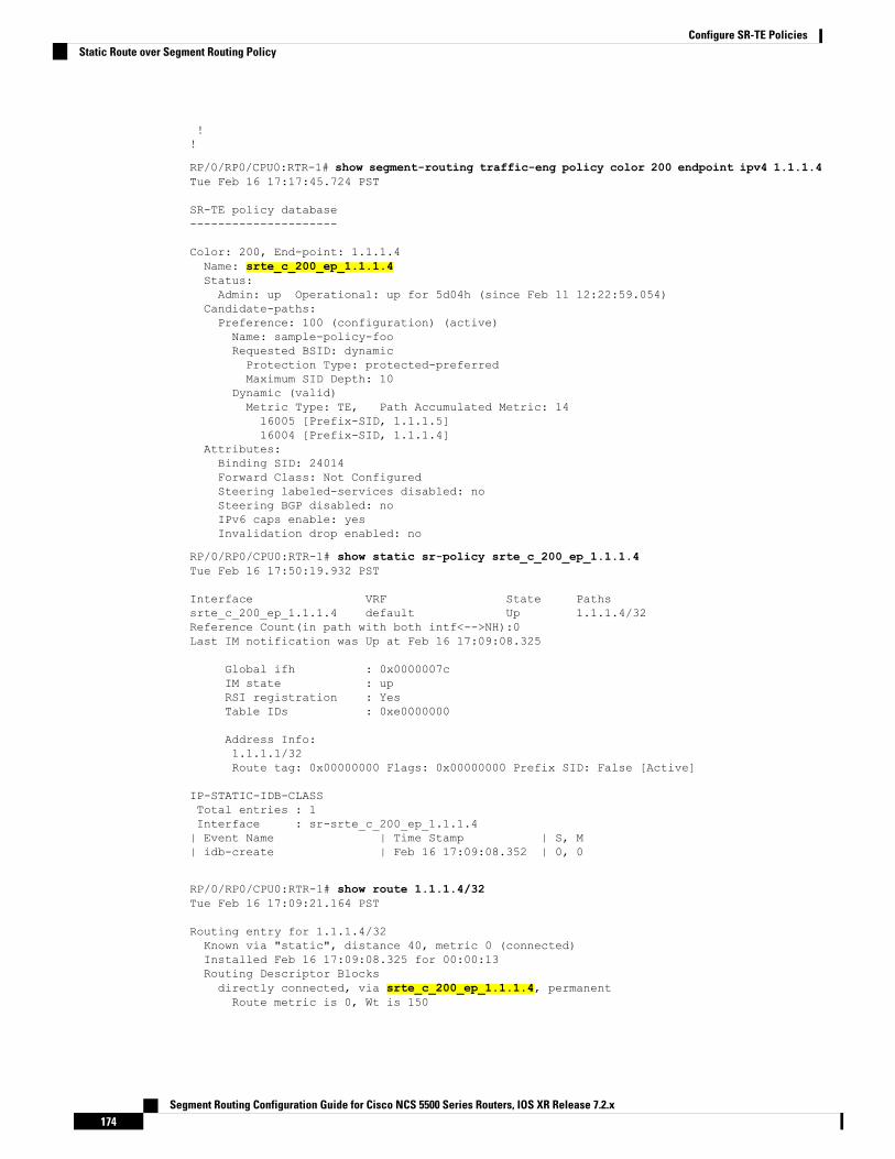
!!
RP/0/RP0/CPU0:RTR-1# show segment-routing traffic-eng policy color 200 endpoint ipv4 1.1.1.4Tue Feb 16 17:17:45.724 PST
SR-TE policy database---------------------
Color: 200, End-point: 1.1.1.4Name: srte_c_200_ep_1.1.1.4Status:Admin: up Operational: up for 5d04h (since Feb 11 12:22:59.054)
Candidate-paths:Preference: 100 (configuration) (active)Name: sample-policy-fooRequested BSID: dynamicProtection Type: protected-preferredMaximum SID Depth: 10
Dynamic (valid)Metric Type: TE, Path Accumulated Metric: 1416005 [Prefix-SID, 1.1.1.5]16004 [Prefix-SID, 1.1.1.4]
Attributes:Binding SID: 24014Forward Class: Not ConfiguredSteering labeled-services disabled: noSteering BGP disabled: noIPv6 caps enable: yesInvalidation drop enabled: no
RP/0/RP0/CPU0:RTR-1# show static sr-policy srte_c_200_ep_1.1.1.4Tue Feb 16 17:50:19.932 PST
Interface VRF State Pathssrte_c_200_ep_1.1.1.4 default Up 1.1.1.4/32Reference Count(in path with both intf<-->NH):0Last IM notification was Up at Feb 16 17:09:08.325
Global ifh : 0x0000007cIM state : upRSI registration : YesTable IDs : 0xe0000000
Address Info:1.1.1.1/32Route tag: 0x00000000 Flags: 0x00000000 Prefix SID: False [Active]
IP-STATIC-IDB-CLASSTotal entries : 1Interface : sr-srte_c_200_ep_1.1.1.4| Event Name | Time Stamp | S, M| idb-create | Feb 16 17:09:08.352 | 0, 0
RP/0/RP0/CPU0:RTR-1# show route 1.1.1.4/32Tue Feb 16 17:09:21.164 PST
Routing entry for 1.1.1.4/32Known via "static", distance 40, metric 0 (connected)Installed Feb 16 17:09:08.325 for 00:00:13Routing Descriptor Blocksdirectly connected, via srte_c_200_ep_1.1.1.4, permanentRoute metric is 0, Wt is 150
Segment Routing Configuration Guide for Cisco NCS 5500 Series Routers, IOS XR Release 7.2.x174
Configure SR-TE PoliciesStatic Route over Segment Routing Policy

No advertising protos.
RP/0/RP0/CPU0:RTR-1# show route 1.1.1.4/32 detailTue Feb 16 17:09:36.718 PST
Routing entry for 1.1.1.4/32Known via "static", distance 40, metric 0 (connected)Installed Feb 16 17:09:08.325 for 00:00:28Routing Descriptor Blocksdirectly connected, via srte_c_200_ep_1.1.1.4, permanentRoute metric is 0, Wt is 150Label: NoneTunnel ID: NoneBinding Label: NoneExtended communities count: 0NHID:0x0(Ref:0)
Route version is 0x4a (74)Local Label: 0x3e84 (16004)IP Precedence: Not SetQoS Group ID: Not SetFlow-tag: Not SetFwd-class: Not SetRoute Priority: RIB_PRIORITY_RECURSIVE (9) SVD Type RIB_SVD_TYPE_LOCALDownload Priority 3, Download Version 258No advertising protos.
RP/0/RP0/CPU0:RTR-1# show cef 1.1.1.4/32 detailTue Feb 16 17:10:06.956 PST1.1.1.4/32, version 258, attached, internal 0x1000441 0x30 (ptr 0xd3f0d30) [1], 0x0(0xe46f960), 0xa20 (0xe9694e0)Updated Feb 16 17:09:08.328Prefix Len 32, traffic index 0, precedence n/a, priority 3gateway array (0xe2d9a08) reference count 2, flags 0x8068, source rib (7), 0 backups
[3 type 4 flags 0x108401 (0xe9aeb98) ext 0x0 (0x0)]LW-LDI[type=1, refc=1, ptr=0xe46f960, sh-ldi=0xe9aeb98]gateway array update type-time 1 Feb 16 17:07:59.946LDI Update time Feb 16 17:07:59.946LW-LDI-TS Feb 16 17:07:59.946via srte_c_200_ep_1.1.1.4, 5 dependencies, weight 0, class 0 [flags 0xc]path-idx 0 NHID 0x0 [0xf3b1a30 0x0]local adjacencylocal label 16004 labels imposed {None}
Load distribution: 0 (refcount 3)
Hash OK Interface Address0 Y srte_c_200_ep_1.1.1.4 point2point
RP/0/RP0/CPU0:RTR-1# show mpls forwarding labels 16004 detailTue Feb 16 17:27:59.831 PSTLocal Outgoing Prefix Outgoing Next Hop BytesLabel Label or ID Interface Switched------ ----------- ------------------ ------------ --------------- ------------16004 Unlabelled SR Pfx (idx 4) srte_c_200_e point2point 990
Updated: Feb 16 17:07:59.945Path Flags: 0xc [ ]Version: 258, Priority: 3Label Stack (Top -> Bottom): { Unlabelled Unlabelled }NHID: 0x0, Encap-ID: N/A, Path idx: 0, Backup path idx: 0, Weight: 0MAC/Encaps: 0/0, MTU: 0Outgoing Interface: srte_c_200_ep_1.1.1.4 (ifhandle 0x0000007c)Packets Switched: 20
Segment Routing Configuration Guide for Cisco NCS 5500 Series Routers, IOS XR Release 7.2.x175
Configure SR-TE PoliciesStatic Route over Segment Routing Policy

Miscellaneous
LDP over Segment Routing PolicyThe LDP over Segment Routing Policy feature enables an LDP-targeted adjacency over a Segment Routing(SR) policy between two routers. This feature extends the existing MPLS LDP address family neighborconfiguration to specify an SR policy as the targeted end-point.
LDP over SR policy is supported for locally configured SR policies with IPv4 end-points.
For more information about MPLS LDP, see the "Implementing MPLS Label Distribution Protocol" chapterin the MPLS Configuration Guide.
For more information about Autoroute, see the Autoroute Announce for SR-TE section.
Before you configure an LDP targeted adjacency over SR policy name, you need to create the SR policy underSegment Routing configuration. The SR policy interface names are created internally based on the color andendpoint of the policy. LDP is non-operational if SR policy name is unknown.
Note
The following functionality applies:
1. Configure the SR policy – LDP receives the associated end-point address from the interface manager (IM)and stores it in the LDP interface database (IDB) for the configured SR policy.
2. Configure the SR policy name under LDP – LDP retrieves the stored end-point address from the IDB anduses it. Use the auto-generated SR policy name assigned by the router when creating an LDP targetedadjacency over an SR policy. Auto-generated SR policy names use the following naming convention:srte_c_color_val_ep_endpoint-address. For example, srte_c_1000_ep_1.1.1.2
Configuration Example
/* Enter the SR-TE configuration mode and create the SR policy. This example correspondsto a local SR policy with an explicit path. */Router(config)# segment-routingRouter(config-sr)# traffic-engRouter(config-sr-te)# segment-list sample-sid-listRouter(config-sr-te-sl)# index 10 address ipv4 1.1.1.7Router(config-sr-te-sl)# index 20 address ipv4 1.1.1.2Router(config-sr-te-sl)# exitRouter(config-sr-te)# policy sample_policyRouter(config-sr-te-policy)# color 1000 end-point ipv4 1.1.1.2Router(config-sr-te-policy)# candidate-pathsRouter(config-sr-te-policy-path)# preference 100Router(config-sr-te-policy-path-pref)# explicit segment-list sample-sid-listRouter(config-sr-te-pp-info)# end
/* Configure LDP over an SR policy */Router(config)# mpls ldpRouter(config-ldp)# address-family ipv4Router(config-ldp-af)# neighbor sr-policy srte_c_1000_ep_1.1.1.2 targetedRouter(config-ldp-af)#
Segment Routing Configuration Guide for Cisco NCS 5500 Series Routers, IOS XR Release 7.2.x176
Configure SR-TE PoliciesMiscellaneous

Do one of the following to configure LDP discovery for targeted hellos:
• Active targeted hellos (SR policy head end):mpls ldpinterface GigabitEthernet0/0/0/0!!
• Passive targeted hellos (SR policy end-point):mpls ldpaddress-family ipv4discovery targeted-hello accept!!
Note
Running Configuration
segment-routingtraffic-engsegment-list sample-sid-listindex 10 address ipv4 1.1.1.7index 20 address ipv4 1.1.1.2!policy sample_policycolor 1000 end-point ipv4 1.1.1.2candidate-pathspreference 100explicit segment-list sample-sid-list!!!!!!
mpls ldpaddress-family ipv4neighbor sr-policy srte_c_1000_ep_1.1.1.2 targeteddiscovery targeted-hello accept!!
Verification
Router# show mpls ldp interface briefInterface VRF Name Config Enabled IGP-Auto-Cfg TE-Mesh-Grp cfg--------------- ------------------- ------ ------- ------------ ---------------Te0/3/0/0/3 default Y Y 0 N/ATe0/3/0/0/6 default Y Y 0 N/ATe0/3/0/0/7 default Y Y 0 N/ATe0/3/0/0/8 default N N 0 N/ATe0/3/0/0/9 default N N 0 N/Asrte_c_1000_ default Y Y 0 N/A
Router# show mpls ldp interfaceInterface TenGigE0/3/0/0/3 (0xa000340)
VRF: 'default' (0x60000000)
Segment Routing Configuration Guide for Cisco NCS 5500 Series Routers, IOS XR Release 7.2.x177
Configure SR-TE PoliciesLDP over Segment Routing Policy
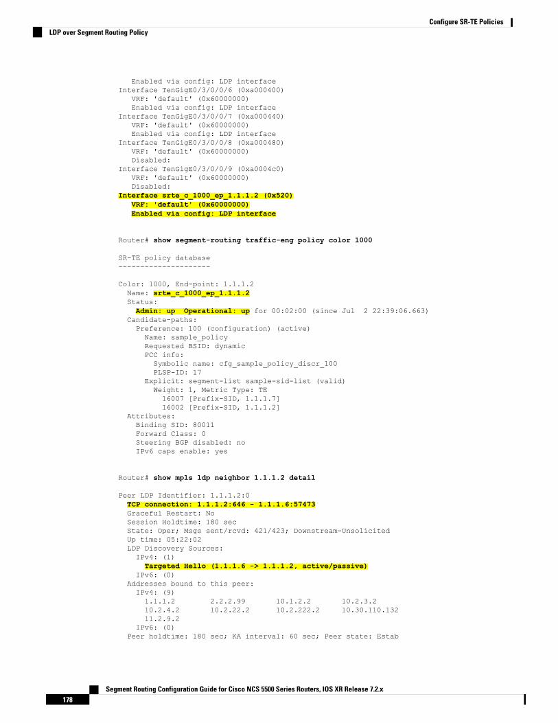
Enabled via config: LDP interfaceInterface TenGigE0/3/0/0/6 (0xa000400)
VRF: 'default' (0x60000000)Enabled via config: LDP interface
Interface TenGigE0/3/0/0/7 (0xa000440)VRF: 'default' (0x60000000)Enabled via config: LDP interface
Interface TenGigE0/3/0/0/8 (0xa000480)VRF: 'default' (0x60000000)Disabled:
Interface TenGigE0/3/0/0/9 (0xa0004c0)VRF: 'default' (0x60000000)Disabled:
Interface srte_c_1000_ep_1.1.1.2 (0x520)VRF: 'default' (0x60000000)Enabled via config: LDP interface
Router# show segment-routing traffic-eng policy color 1000
SR-TE policy database---------------------
Color: 1000, End-point: 1.1.1.2Name: srte_c_1000_ep_1.1.1.2Status:Admin: up Operational: up for 00:02:00 (since Jul 2 22:39:06.663)
Candidate-paths:Preference: 100 (configuration) (active)Name: sample_policyRequested BSID: dynamicPCC info:Symbolic name: cfg_sample_policy_discr_100PLSP-ID: 17
Explicit: segment-list sample-sid-list (valid)Weight: 1, Metric Type: TE16007 [Prefix-SID, 1.1.1.7]16002 [Prefix-SID, 1.1.1.2]
Attributes:Binding SID: 80011Forward Class: 0Steering BGP disabled: noIPv6 caps enable: yes
Router# show mpls ldp neighbor 1.1.1.2 detail
Peer LDP Identifier: 1.1.1.2:0TCP connection: 1.1.1.2:646 - 1.1.1.6:57473Graceful Restart: NoSession Holdtime: 180 secState: Oper; Msgs sent/rcvd: 421/423; Downstream-UnsolicitedUp time: 05:22:02LDP Discovery Sources:IPv4: (1)Targeted Hello (1.1.1.6 -> 1.1.1.2, active/passive)
IPv6: (0)Addresses bound to this peer:IPv4: (9)1.1.1.2 2.2.2.99 10.1.2.2 10.2.3.210.2.4.2 10.2.22.2 10.2.222.2 10.30.110.13211.2.9.2
IPv6: (0)Peer holdtime: 180 sec; KA interval: 60 sec; Peer state: Estab
Segment Routing Configuration Guide for Cisco NCS 5500 Series Routers, IOS XR Release 7.2.x178
Configure SR-TE PoliciesLDP over Segment Routing Policy
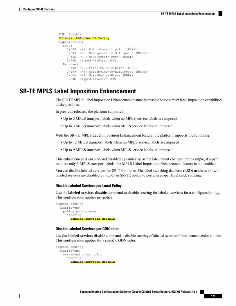
NSR: DisabledClients: LDP over SR PolicyCapabilities:Sent:0x508 (MP: Point-to-Multipoint (P2MP))0x509 (MP: Multipoint-to-Multipoint (MP2MP))0x50a (MP: Make-Before-Break (MBB))0x50b (Typed Wildcard FEC)
Received:0x508 (MP: Point-to-Multipoint (P2MP))0x509 (MP: Multipoint-to-Multipoint (MP2MP))0x50a (MP: Make-Before-Break (MBB))0x50b (Typed Wildcard FEC)
SR-TE MPLS Label Imposition EnhancementThe SR-TEMPLS Label Imposition Enhancement feature increases the maximum label imposition capabilitiesof the platform.
In previous releases, the platform supported:
• Up to 5 MPLS transport labels when no MPLS service labels are imposed
• Up to 3 MPLS transport labels when MPLS service labels are imposed
With the SR-TE MPLS Label Imposition Enhancement feature, the platform supports the following:
• Up to 12 MPLS transport labels when no MPLS service labels are imposed
• Up to 9 MPLS transport labels when MPLS service labels are imposed
This enhancement is enabled and disabled dynamically, as the label count changes. For example, if a pathrequires only 3 MPLS transport labels, the MPLS Label Imposition Enhancement feature is not enabled.
You can disable labeled services for SR-TE policies. The label switching database (LSD) needs to know iflabeled services are disabled on top of an SR-TE policy to perform proper label stack splitting.
Disable Labeled Services per Local Policy
Use the labeled-services disable command to disable steering for labeled services for a configured policy.This configuration applies per policy.segment-routingtraffic-engpolicy policy namesteeringlabeled-services disable
Disable Labeled Services per ODN color
Use the labeled-services disable command to disable steering of labeled-services for on-demand color policies.This configuration applies for a specific ODN color.segment-routingtraffic-engon-demand color colorsteeringlabeled-services disable
Segment Routing Configuration Guide for Cisco NCS 5500 Series Routers, IOS XR Release 7.2.x179
Configure SR-TE PoliciesSR-TE MPLS Label Imposition Enhancement

Disable Labeled Services per Policy Type
Use the labeled-services disable command to disable steering of labeled services for all policies for thefollowing policy types:
• all — all policies
• local — all locally configured policies
• on-demand — all BGP on-demand color policies
• bgp-srte — all controller-initiated BGP SR-TE policies
• pcep — all PCE-initiated policies
You can specify more than one policy type.Note
segment-routingtraffic-engsteeringlabeled-services
disable {all | local | on-demand | bgp-srte | pcep}
Verification
Use the show segment-routing traffic-eng policy command to display SR policy information. The followingoutput shows that steering of labeled services for the on-demand SR policy are disabled.Router# show segment-routing traffic-eng policy color 10Thu Jul 18 11:35:25.124 PDT
SR-TE policy database---------------------
Color: 10, End-point: 1.1.1.8Name: srte_c_10_ep_1.1.1.8Status:Admin: up Operational: up for 00:00:06 (since Jul 18 11:35:19.350)
Candidate-paths:Preference: 1 (configuration) (active)Name: test_pol_2Requested BSID: dynamicDynamic (valid)Metric Type: TE, Path Accumulated Metric: 1024004 [Adjacency-SID, 1.1.1.1 - 1.1.1.2]
Attributes:Binding SID: 24011Forward Class: 0Steering labeled-services disabled: yesSteering BGP disabled: noIPv6 caps enable: yes
SR-TE Head-End IPv4 Unnumbered Interface SupportThis feature allows IPv4 unnumbered interfaces to be part of an SR-TE head-end router topology database.
An unnumbered IPv4 interface is not identified by its own unique IPv4 address. Instead, it is identified by therouter ID of the node where this interfaces resides and the local SNMP index assigned for this interface.
Segment Routing Configuration Guide for Cisco NCS 5500 Series Routers, IOS XR Release 7.2.x180
Configure SR-TE PoliciesSR-TE Head-End IPv4 Unnumbered Interface Support
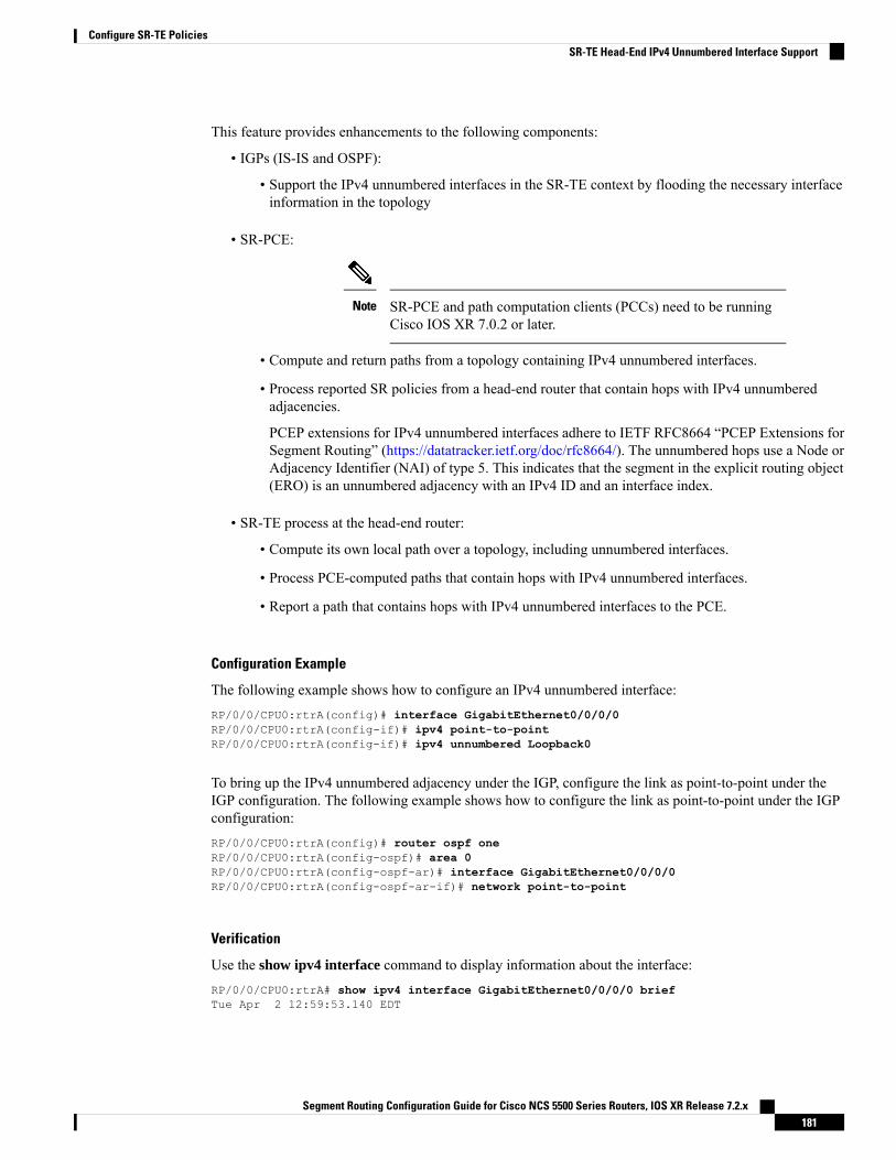
This feature provides enhancements to the following components:
• IGPs (IS-IS and OSPF):
• Support the IPv4 unnumbered interfaces in the SR-TE context by flooding the necessary interfaceinformation in the topology
• SR-PCE:
SR-PCE and path computation clients (PCCs) need to be runningCisco IOS XR 7.0.2 or later.
Note
• Compute and return paths from a topology containing IPv4 unnumbered interfaces.
• Process reported SR policies from a head-end router that contain hops with IPv4 unnumberedadjacencies.
PCEP extensions for IPv4 unnumbered interfaces adhere to IETF RFC8664 “PCEP Extensions forSegment Routing” (https://datatracker.ietf.org/doc/rfc8664/). The unnumbered hops use a Node orAdjacency Identifier (NAI) of type 5. This indicates that the segment in the explicit routing object(ERO) is an unnumbered adjacency with an IPv4 ID and an interface index.
• SR-TE process at the head-end router:
• Compute its own local path over a topology, including unnumbered interfaces.
• Process PCE-computed paths that contain hops with IPv4 unnumbered interfaces.
• Report a path that contains hops with IPv4 unnumbered interfaces to the PCE.
Configuration Example
The following example shows how to configure an IPv4 unnumbered interface:RP/0/0/CPU0:rtrA(config)# interface GigabitEthernet0/0/0/0RP/0/0/CPU0:rtrA(config-if)# ipv4 point-to-pointRP/0/0/CPU0:rtrA(config-if)# ipv4 unnumbered Loopback0
To bring up the IPv4 unnumbered adjacency under the IGP, configure the link as point-to-point under theIGP configuration. The following example shows how to configure the link as point-to-point under the IGPconfiguration:RP/0/0/CPU0:rtrA(config)# router ospf oneRP/0/0/CPU0:rtrA(config-ospf)# area 0RP/0/0/CPU0:rtrA(config-ospf-ar)# interface GigabitEthernet0/0/0/0RP/0/0/CPU0:rtrA(config-ospf-ar-if)# network point-to-point
Verification
Use the show ipv4 interface command to display information about the interface:RP/0/0/CPU0:rtrA# show ipv4 interface GigabitEthernet0/0/0/0 briefTue Apr 2 12:59:53.140 EDT
Segment Routing Configuration Guide for Cisco NCS 5500 Series Routers, IOS XR Release 7.2.x181
Configure SR-TE PoliciesSR-TE Head-End IPv4 Unnumbered Interface Support

Interface IP-Address Status ProtocolGigabitEthernet0/0/0/0 192.168.0.1 Up Up
This interface shows the IPv4 address of Loopback0.
Use the show snmp interface command to find the SNMP index for this interface:RP/0/0/CPU0:rtrA# show snmp interfaceTue Apr 2 13:02:49.190 EDTifName : Null0 ifIndex : 3ifName : Loopback0 ifIndex : 10ifName : GigabitEthernet0/0/0/0 ifIndex : 6
The interface is identified with the pair (IPv4:192.168.0.1, index:6).
Use the show ospf neighbor command to display the adjacency:RP/0/0/CPU0:rtrA# show ospf neighbor gigabitEthernet 0/0/0/0 detail…Neighbor 192.168.0.4, interface address 192.168.0.4
In the area 0 via interface GigabitEthernet0/0/0/0Neighbor priority is 1, State is FULL, 6 state changes…Adjacency SIDs:
Label: 24001, Dynamic, UnprotectedNeighbor Interface ID: 4
The output of the show segment-routing traffic-eng ipv4 topology command is enhanced to display theinterface index instead of the IP address for unnumbered interfaces:RP/0/0/CPU0:rtrA# show segment-routing traffic-eng ipv4 topology…Link[2]: Unnumbered local index 6, remote index 4Local node:OSPF router ID: 192.168.0.1 area ID: 0 ASN: 0
Remote node:TE router ID: 192.168.0.4OSPF router ID: 192.168.0.4 area ID: 0 ASN: 0
Metric: IGP 1, TE 1, Latency 1 microsecondsBandwidth: Total 125000000 Bps, Reservable 0 BpsAdmin-groups: 0x00000000Adj SID: 24001 (unprotected)
The output of the show segment-routing traffic-eng policy detail command includes unnumbered hops:RP/0/0/CPU0:rtrA# show segment-routing traffic-eng policy detail…
Dynamic (pce 192.168.0.5) (valid)Metric Type: TE, Path Accumulated Metric: 324001 [Adjacency-SID, unnumbered 192.168.0.1(6) - 192.168.0.4(4)]24002 [Adjacency-SID, unnumbered 192.168.0.4(7) - 192.168.0.3(7)]24000 [Adjacency-SID, unnumbered 192.168.0.3(5) - 192.168.0.2(5)]
…
SR-TE Reoptimization TimersSR-TE path re-optimization occurs when the head-end determines that there is a more optimal path availablethan the one currently used. For example, in case of a failure along the SR-TE LSP path, the head-end coulddetect and revert to a more optimal path by triggering re-optimization.
Segment Routing Configuration Guide for Cisco NCS 5500 Series Routers, IOS XR Release 7.2.x182
Configure SR-TE PoliciesSR-TE Reoptimization Timers

Re-optimization can occur due to the following events:
• The explicit path hops used by the primary SR-TE LSP explicit path are modified
• The head-end determines the currently used path-option are invalid due to either a topology pathdisconnect, or a missing SID in the SID database that is specified in the explicit-path
• A more favorable path-option (lower index) becomes available
For event-based re-optimization, you can specify various delay timers for path re-optimization. For example,you can specify how long to wait before switching to a reoptimized path
Additionally, you can configure a timer to specify how often to perform reoptimization of policies. You canalso trigger an immediate reoptimization for a specific policy or for all policies.
SR-TE Reoptimization
To trigger an immediate SR-TE reoptimization, use the segment-routing traffic-eng reoptimization commandin Exec mode:
Router# segment-routing traffic-eng reoptimization {all | name policy}
Use the all option to trigger an immediate reoptimization for all policies. Use the name policy option to triggeran immediate reoptimization for a specific policy.
Configuring SR-TE Reoptimization Timers
Use these commands in SR-TE configuration mode to configure SR-TE reoptimization timers:
• timers candidate-path cleanup-delay seconds—Specifies the delay before cleaning up candidate paths,in seconds. The range is from 0 (immediate clean-up) to 86400; the default value is 120
• timers cleanup-delay seconds—Specifies the delay before cleaning up previous path, in seconds. Therange is from 0 (immediate clean-up) to 300; the default value is 10.
• timers init-verify-restart seconds —Specifies the delay for topology convergence after the topologystarts populating due to a restart, in seconds. The range is from 10 to 10000; the default is 40.
• timers init-verify-startup seconds—Specifies the delay for topology convergence after topology startspopulating for due to startup, in seconds. The range is from 10 to 10000; the default is 300
• timers init-verify-switchover seconds—Specifies the delay for topology convergence after topologystarts populating due to a switchover, in seconds. The range is from 10 to 10000; the default is 60.
• timers install-delay seconds—Specifies the delay before switching to a reoptimized path, in seconds.The range is from 0 (immediate installation of new path) to 300; the default is 10.
• timers periodic-reoptimization seconds—Specifies how often to perform periodic reoptimization ofpolicies, in seconds. The range is from 0 to 86400; the default is 600.
Example Configuration
Router(config)# segment-routing traffic-engRouter(config-sr-te)# timersRouter(config-sr-te-timers)# candidate-path cleanup-delay 600Router(config-sr-te-timers)# cleanup-delay 60Router(config-sr-te-timers)# init-verify-restart 120
Segment Routing Configuration Guide for Cisco NCS 5500 Series Routers, IOS XR Release 7.2.x183
Configure SR-TE PoliciesSR-TE Reoptimization Timers
Router(config-sr-te-timers)# init-verify-startup 600Router(config-sr-te-timers)# init-verify-switchover 30Router(config-sr-te-timers)# install-delay 60Router(config-sr-te-timers)# periodic-reoptimization 3000
Running Config
segment-routingtraffic-engtimersinstall-delay 60periodic-reoptimization 3000cleanup-delay 60candidate-path cleanup-delay 600init-verify-restart 120init-verify-startup 600init-verify-switchover 30!!!
Segment Routing Configuration Guide for Cisco NCS 5500 Series Routers, IOS XR Release 7.2.x184
Configure SR-TE PoliciesSR-TE Reoptimization Timers
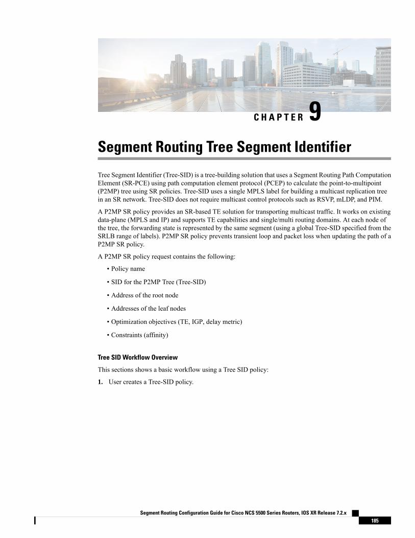
C H A P T E R 9Segment Routing Tree Segment Identifier
Tree Segment Identifier (Tree-SID) is a tree-building solution that uses a Segment Routing Path ComputationElement (SR-PCE) using path computation element protocol (PCEP) to calculate the point-to-multipoint(P2MP) tree using SR policies. Tree-SID uses a single MPLS label for building a multicast replication treein an SR network. Tree-SID does not require multicast control protocols such as RSVP, mLDP, and PIM.
A P2MP SR policy provides an SR-based TE solution for transporting multicast traffic. It works on existingdata-plane (MPLS and IP) and supports TE capabilities and single/multi routing domains. At each node ofthe tree, the forwarding state is represented by the same segment (using a global Tree-SID specified from theSRLB range of labels). P2MP SR policy prevents transient loop and packet loss when updating the path of aP2MP SR policy.
A P2MP SR policy request contains the following:
• Policy name
• SID for the P2MP Tree (Tree-SID)
• Address of the root node
• Addresses of the leaf nodes
• Optimization objectives (TE, IGP, delay metric)
• Constraints (affinity)
Tree SID Workflow Overview
This sections shows a basic workflow using a Tree SID policy:
1. User creates a Tree-SID policy.
Segment Routing Configuration Guide for Cisco NCS 5500 Series Routers, IOS XR Release 7.2.x185
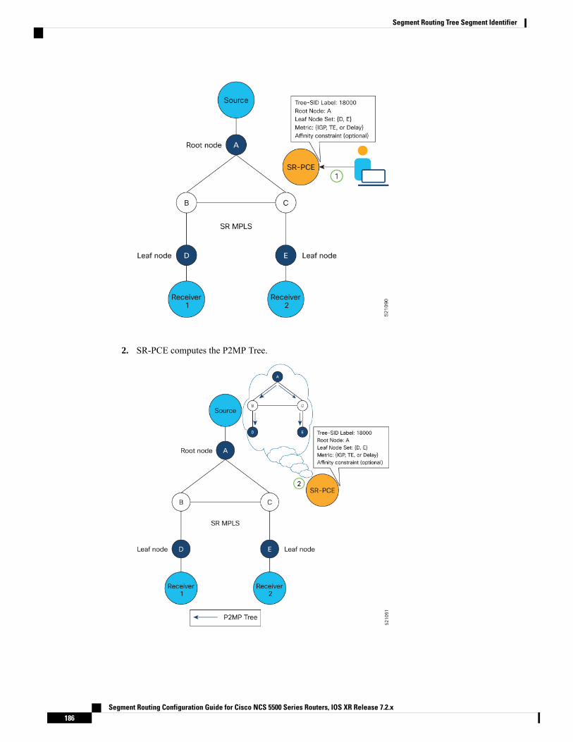
2. SR-PCE computes the P2MP Tree.
Segment Routing Configuration Guide for Cisco NCS 5500 Series Routers, IOS XR Release 7.2.x186
Segment Routing Tree Segment Identifier
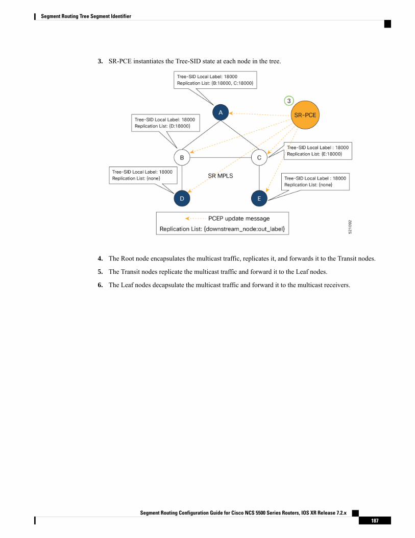
3. SR-PCE instantiates the Tree-SID state at each node in the tree.
4. The Root node encapsulates the multicast traffic, replicates it, and forwards it to the Transit nodes.
5. The Transit nodes replicate the multicast traffic and forward it to the Leaf nodes.
6. The Leaf nodes decapsulate the multicast traffic and forward it to the multicast receivers.
Segment Routing Configuration Guide for Cisco NCS 5500 Series Routers, IOS XR Release 7.2.x187
Segment Routing Tree Segment Identifier
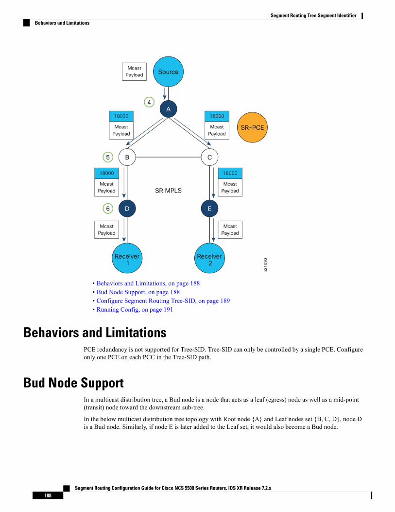
• Behaviors and Limitations, on page 188• Bud Node Support, on page 188• Configure Segment Routing Tree-SID, on page 189• Running Config, on page 191
Behaviors and LimitationsPCE redundancy is not supported for Tree-SID. Tree-SID can only be controlled by a single PCE. Configureonly one PCE on each PCC in the Tree-SID path.
Bud Node SupportIn a multicast distribution tree, a Bud node is a node that acts as a leaf (egress) node as well as a mid-point(transit) node toward the downstream sub-tree.
In the below multicast distribution tree topology with Root node {A} and Leaf nodes set {B, C, D}, node Dis a Bud node. Similarly, if node E is later added to the Leaf set, it would also become a Bud node.
Segment Routing Configuration Guide for Cisco NCS 5500 Series Routers, IOS XR Release 7.2.x188
Segment Routing Tree Segment IdentifierBehaviors and Limitations

The tree computation algorithm on SR-PCE has been enhanced to detect a Bud node based on knowledge ofthe Leaf set, and to handle Leaf/Transit node transitions to Bud node. The role of the Bud node is also explicitlysignaled in PCEP.
Configure Segment Routing Tree-SIDTo configure Segment Routing Tree-SID for Point-to-Multipoint (P2MP) SR policies, complete the followingconfigurations:
1. Configure Path Computation Element Protocol (PCEP) Path Computation Client (PCC) on all nodesinvolved in the Tree-SID path (root, mid-point, leaf)
2. Configure Affinity Maps on the SR-PCE
3. Configure P2MP SR Policy on SR-PCE
4. Configure Multicast on the Root and Leaf Nodes
Configure PCEP PCC on All Nodes in Tree-SID Path
Configure all nodes involved in the Tree-SID path (root, mid-point, leaf) as PCEP PCC. For detailed PCEPPCC configuration information, see Configure the Head-End Router as PCEP PCC, on page 152.
Segment Routing Configuration Guide for Cisco NCS 5500 Series Routers, IOS XR Release 7.2.x189
Segment Routing Tree Segment IdentifierConfigure Segment Routing Tree-SID

Configure Affinity Maps on the SR-PCE
Use the affinity bit-map COLOR bit-position command in PCE SR-TE sub-mode to define affinity maps.The bit-position range is from 0 to 255.Router# configureRouter(config)# pceRouter(config-pce)# segment-routing traffic-engRouter(config-pce-sr-te)# affinity bit-map RED 23Router(config-pce-sr-te)# affinity bit-map BLUE 24Router(config-pce-sr-te)# affinity bit-map CROSS 25Router(config-pce-sr-te)#
Configure P2MP SR Policy on SR-PCE
Configure the end-point name and addresses, Tree-SID label, and constraints for the P2MP policy.
Use the endpoint-set NAME command in SR-PCE P2MP sub-mode to enter the name of the end-point setand to define the set of end-point addresses.Router(config-pce-sr-te)# p2mpRouter(config-pce-sr-te-p2mp)# endpoint-set BARRouter(config-pce-p2mp-ep-set)# ipv4 1.1.1.2Router(config-pce-p2mp-ep-set)# ipv4 1.1.1.3Router(config-pce-p2mp-ep-set)# ipv4 1.1.1.4Router(config-pce-p2mp-ep-set)# exitRouter(config-pce-sr-te-p2mp)#
Use the policy policy command to configure the P2MP policy name and enter P2MP Policy sub-mode.Configure the source address, endpoint-set color, Tree-SID label, affinity constraints, and metric type.Router(config-pce-sr-te-p2mp)# policy FOORouter(config-pce-p2mp-policy)# source ipv4 1.1.1.6Router(config-pce-p2mp-policy)# color 10 endpoint-set BARRouter(config-pce-p2mp-policy)# treesid mpls 15200Router(config-pce-p2mp-policy)# candidate-pathsRouter(config-pce-p2mp-policy-path)# constraintsRouter(config-pce-p2mp-path-const)# affinityRouter(config-pce-p2mp-path-affinity)# exclude BLUERouter(config-pce-p2mp-path-affinity)# exitRouter(config-pce-p2mp-path-const)# exitRouter(config-pce-p2mp-policy-path)# preference 100Router(config-pce-p2mp-policy-path-preference)# dynamicRouter(config-pce-p2mp-path-info)# metric type teRouter(config-pce-p2mp-path-info)# rootRouter(config)#
Configure Multicast on the Root and Leaf Nodes
On the root node of the SR P2MP segment, use the router pim command to enter Protocol IndependentMulticast (PIM) configuration mode to statically steer multicast flows into an SR P2MP policy.
Enter this configuration only on an SR P2MP segment. Multicast traffic cannot be steered into a P2P policy.Note
Router(config)# router pimRouter(config-pim)# vrf nameRouter(config-pim-name)# address-family ipv4Router(config-pim-name-ipv4)# sr-p2mp-policy FOO
Segment Routing Configuration Guide for Cisco NCS 5500 Series Routers, IOS XR Release 7.2.x190
Segment Routing Tree Segment IdentifierConfigure Segment Routing Tree-SID

Router(config-pim-name-ipv4-srp2mp)# static-group 235.1.1.5 1.1.1.6Router(config-pim-name-ipv4-srp2mp)# rootRouter(config)#
On the root and leaf nodes of the SR P2MP tree, use the mdt static segment-routing command to configurethe multicast distribution tree (MDT) core as Tree-SID from the multicast VRF configuration submode.Router(config)# multicast-routingRouter(config-mcast)# vrf TESTRouter(config-mcast-TEST)# address-family ipv4Router(config-mcast-TEST-ipv4)# mdt static segment-routing
On the leaf nodes of an SR P2MP segment, use the static sr-policy p2mp-policy command to configure thestatic SR P2MP Policy from the multicast VRF configuration submode to statically decapsulate multicastflows.Router(config)# multicast-routingRouter(config-mcast)# vrf TESTRouter(config-mcast-TEST)# address-family ipv4Router(config-mcast-TEST-ipv4)# static sr-policy FOO
Running ConfigThe following example shows how to configure the end point addresses and P2MP SR policy with affinityconstraints on SR-PCE.pcesegment-routingtraffic-engaffinity bit-mapRED 23BLUE 24CROSS 25!p2mpendpoint-set BARipv4 1.1.1.2ipv4 1.1.1.3ipv4 1.1.1.4!policy FOOsource ipv4 1.1.1.6color 10 endpoint-set BARtreesid mpls 15200candidate-pathspreference 100dynamicmetrictype te!!!constraintsaffinityexcludeBLUE!!
Segment Routing Configuration Guide for Cisco NCS 5500 Series Routers, IOS XR Release 7.2.x191
Segment Routing Tree Segment IdentifierRunning Config

!!!!!!!
The following example shows how to statically decapsulate multicast flows on the leaf nodes.multicast-routingvrf TESTaddress-family ipv4static sr-policy FOO!!!
The following example shows to configure the multicast distribution tree (MDT) core as Tree-SID on the rootand leaf nodes.multicast-routingvrf TESTaddress-family ipv4mdt static segment-routing!!!
The following example shows how to steer traffic to the SR P2MP policy on the root node.router pimvrf TESTaddress-family ipv4sr-p2mp-policy FOOstatic-group 232.1.1.5 1.1.1.6!!!!
Segment Routing Configuration Guide for Cisco NCS 5500 Series Routers, IOS XR Release 7.2.x192
Segment Routing Tree Segment IdentifierRunning Config

C H A P T E R 10Enabling Segment Routing Flexible Algorithm
Segment Routing Flexible Algorithm allows operators to customize IGP shortest path computation accordingto their own needs. An operator can assign custom SR prefix-SIDs to realize forwarding beyond link-cost-basedSPF. As a result, Flexible Algorithm provides a traffic engineered path automatically computed by the IGPto any destination reachable by the IGP.
The SR architecture associates prefix-SIDs to an algorithm which defines how the path is computed. FlexibleAlgorithm allows for user-defined algorithms where the IGP computes paths based on a user-definedcombination of metric type and constraint.
This document describes the IS-IS and OSPF extensions to support Segment Routing Flexible Algorithm onan MPLS data-plane.
• Prerequisites for Flexible Algorithm, on page 193• Building Blocks of Segment Routing Flexible Algorithm, on page 193• Configuring Flexible Algorithm, on page 196• Example: Configuring IS-IS Flexible Algorithm, on page 197• Example: Configuring OSPF Flexible Algorithm, on page 198• Example: Traffic Steering to Flexible Algorithm Paths, on page 199
Prerequisites for Flexible AlgorithmSegment routing must be enabled on the router before the Flexible Algorithm functionality is activated.
Building Blocks of Segment Routing Flexible AlgorithmThis section describes the building blocks that are required to support the SR Flexible Algorithm functionalityin IS-IS and OSPF.
Flexible Algorithm DefinitionMany possible constraints may be used to compute a path over a network. Some networks are deployed withmultiple planes. A simple form of constraint may be to use a particular plane. A more sophisticated form ofconstraint can include some extended metric, like delay, as described in [RFC7810]. Even more advancedcase could be to restrict the path and avoid links with certain affinities. Combinations of these are also possible.To provide a maximum flexibility, the mapping between the algorithm value and its meaning can be defined
Segment Routing Configuration Guide for Cisco NCS 5500 Series Routers, IOS XR Release 7.2.x193

by the user. When all the routers in the domain have the common understanding what the particular algorithmvalue represents, the computation for such algorithm is consistent and the traffic is not subject to looping.Here, since the meaning of the algorithm is not defined by any standard, but is defined by the user, it is calleda Flexible Algorithm.
Flexible Algorithm MembershipAn algorithm defines how the best path is computed by IGP. Routers advertise the support for the algorithmas a node capability. Prefix-SIDs are also advertised with an algorithm value and are tightly coupled with thealgorithm itself.
An algorithm is a one octet value. Values from 128 to 255 are reserved for user defined values and are usedfor Flexible Algorithm representation.
Flexible Algorithm Definition AdvertisementTo guarantee the loop free forwarding for paths computed for a particular Flexible Algorithm, all routers inthe network must share the same definition of the Flexible Algorithm. This is achieved by dedicated router(s)advertising the definition of each Flexible Algorithm. Such advertisement is associated with the priority tomake sure that all routers will agree on a single and consistent definition for each Flexible Algorithm.
Definition of Flexible Algorithm includes:
• Metric type
• Affinity constraints
To enable the router to advertise the definition for the particular Flexible Algorithm, advertise-definitioncommand is used. At least one router in the area, preferably two for redundancy, must advertise the FlexibleAlgorithm definition. Without the valid definition being advertised, the Flexible Algorithm will not befunctional.
Flexible Algorithm Prefix-SID AdvertisementTo be able to forward traffic on a Flexible Algorithm specific path, all routers participating in the FlexibleAlgorithm will install a MPLS labeled path for the Flexible Algorithm specific SID that is advertised for theprefix. Only prefixes for which the Flexible Algorithm specific Prefix-SID is advertised is subject to FlexibleAlgorithm specific forwarding.
Calculation of Flexible Algorithm PathA router may compute path for multiple Flexible Algorithms. A router must be configured to support particularFlexible Algorithm before it can compute any path for such Flexible Algorithm. A router must have a validdefinition of the Flexible Algorithm before Flexible Algorithm is used.
When computing the shortest path tree for particular Flexible Algorithm:
• All nodes that don't advertise support for Flexible Algorithm are pruned from the topology.
• If the Flexible Algorithm definition includes affinities that are excluded, then all links for which any ofsuch affinities are advertised will be pruned from the topology.
Segment Routing Configuration Guide for Cisco NCS 5500 Series Routers, IOS XR Release 7.2.x194
Enabling Segment Routing Flexible AlgorithmFlexible Algorithm Membership
• Router uses the metric that is part of the Flexible Algorithm definition. If the metric isn't advertised forthe particular link, the link is pruned from the topology.
Configuring Microloop Avoidance for Flexible Algorithm
By default, Microloop Avoidance per Flexible Algorithm instance followsMicroloop Avoidance configurationfor algo-0. For information about configuringMicroloopAvoidance, see Configure Segment RoutingMicroloopAvoidance, on page 277.
You can disable Microloop Avoidance for Flexible Algorithm using the following commands:router isis instance flex-algo algo microloop avoidance disable
router ospf process flex-algo algo microloop avoidance disable
Configuring LFA / TI-LFA for Flexible Algorithm
By default, LFA/TI-LFA per Flexible Algorithm instance follows LFA/TI-LFA configuration for algo-0. Forinformation about configuring TI-LFA, see Configure Topology-Independent Loop-Free Alternate (TI-LFA),on page 253.
You can disable TI-LFA for Flexible Algorithm using the following commands:router isis instance flex-algo algo fast-reroute disable
router ospf process flex-algo algo fast-reroute disable
Installation of Forwarding Entries for Flexible Algorithm PathsFlexible Algorithm path to any prefix must be installed in the forwarding using the Prefix-SID that wasadvertised for such Flexible Algorithm. If the Prefix-SID for Flexible Algorithm is not known, such FlexibleAlgorithm path is not installed in forwarding for such prefix..
Only MPLS to MPLS entries are installed for a Flexible Algorithm path. No IP to IP or IP to MPLS entriesare installed. These follow the native IPG paths computed based on the default algorithm and regular IGPmetrics.
Flexible Algorithm Prefix-SID RedistributionPreviously, prefix redistribution from IS-IS to another IS-IS instance or protocol was limited to SR algorithm0 (regular SPF) prefix SIDs; SR algorithm 1 (Strict SPF) and SR algorithms 128-255 (Flexible Algorithm)prefix SIDs were not redistributed along with the prefix. The Segment Routing IS-IS Flexible AlgorithmPrefix SID Redistribution feature allows redistribution of strict and flexible algorithms prefix SIDs from IS-ISto another IS-IS instance or protocols. This feature is enabled automatically when you configure redistributionof IS-IS Routes with strict or Flexible Algorithm SIDs.
Flexible Algorithm Prefix MetricA limitation of the existing Flexible Algorithm functionality in IS-IS is the inability to compute the best pathto a prefix in a remote area or remote IGP domain. Prefixes are advertised between IS-IS areas or betweenprotocol domains, but the existing prefix metric does not reflect any of the constraints used for FlexibleAlgorithm path. Although the best Flexible Algorithm path can be computed to the inter-area or redistributedprefix inside the area, the path may not represent the overall best path through multiple areas or IGP domains.
Segment Routing Configuration Guide for Cisco NCS 5500 Series Routers, IOS XR Release 7.2.x195
Enabling Segment Routing Flexible AlgorithmInstallation of Forwarding Entries for Flexible Algorithm Paths

The Flexible Algorithm Prefix Metric feature introduces a Flexible Algorithm-specific prefix-metric in theIS-IS prefix advertisement. The prefix-metric provides a way to compute the best end-to-end Flexible Algorithmoptimized paths across multiple areas or domains.
The Flexible Algorithm definition must be consistent between domains or areas. Refer to section 8 in IETFdraft https://datatracker.ietf.org/doc/draft-ietf-lsr-flex-algo/.
Note
Configuring Flexible AlgorithmThe following ISIS and OSPF configuration sub-mode is used to configure Flexible Algorithm:
router isis instance flex-algo algo
router ospf process flex-algo algo
algo—value from 128 to 255
Configuring Flexible Algorithm Definitions
The following commands are used to configure Flexible Algorithm definition under the flex-algo sub-mode:
• IS-ISmetric-type delay
By default the regular IGP metric is used. If delay metric is enabled,the advertised delay on the link is used as a metric for FlexibleAlgorithm computation.
Note
OSPFmetric-type {delay | te-metric}
By default the regular IGP metric is used. If delay or TE metric isenabled, the advertised delay or TE metric on the link is used as ametric for Flexible Algorithm computation.
Note
• affinity {include-any | include-all | exclude-any} name1, name2, …
name—name of the affinity map
• priority priority value
priority value—priority used during the Flexible Algorithm definition election.
The following command is used to to include the Flexible Algorithm prefix metric in the advertised FlexibleAlgorithm definition in IS-IS :
Segment Routing Configuration Guide for Cisco NCS 5500 Series Routers, IOS XR Release 7.2.x196
Enabling Segment Routing Flexible AlgorithmConfiguring Flexible Algorithm

router isis instance flex-algo algo prefix-metric
The following command is used to enable advertisement of the Flexible Algorithm definition in IS-IS:router isis instance flex-algo algo advertise-definition
Configuring Affinity
The following command is used for defining the affinity-map. Affinity-map associates the name with theparticular bit positions in the Extended Admin Group bitmask.router isis instance flex-algo algo affinity-map name bit-position bit number
router ospf process flex-algo algo affinity-map name bit-position bit number
• name—name of the affinity-map.
• bit number—bit position in the Extended Admin Group bitmask.
The following command is used to associate the affinity with an interface:router isis instance interface type interface-path-id affinity flex-algo name 1, name 2, …
router ospf process area area interface type interface-path-id affinity flex-algo name 1,name 2, …
name—name of the affinity-map
Configuring Prefix-SID Advertisement
The following command is used to advertise prefix-SID for default and strict-SPF algorithm:router isis instance interface type interface-path-id address-family {ipv4 | ipv6} [unicast]prefix-sid [strict-spf | algorithm algorithm-number] [index | absolute] sid value
router ospf process area area interface Loopback interface-instance prefix-sid [strict-spf| algorithm algorithm-number] [index | absolute] sid value
• algorithm-number—Flexible Algorithm number
• sid value—SID value
Example: Configuring IS-IS Flexible Algorithmrouter isis 1affinity-map red bit-position 65affinity-map blue bit-position 8affinity-map green bit-position 201
flex-algo 128advertise-definitionaffinity exclude-any redaffinity include-any blue
Segment Routing Configuration Guide for Cisco NCS 5500 Series Routers, IOS XR Release 7.2.x197
Enabling Segment Routing Flexible AlgorithmExample: Configuring IS-IS Flexible Algorithm
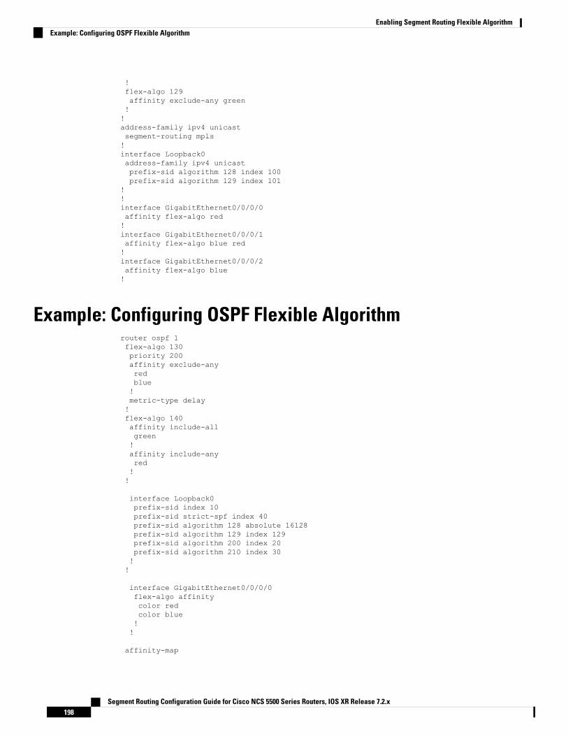
!flex-algo 129affinity exclude-any green!!address-family ipv4 unicastsegment-routing mpls!interface Loopback0address-family ipv4 unicastprefix-sid algorithm 128 index 100prefix-sid algorithm 129 index 101
!!interface GigabitEthernet0/0/0/0affinity flex-algo red!interface GigabitEthernet0/0/0/1affinity flex-algo blue red!interface GigabitEthernet0/0/0/2affinity flex-algo blue!
Example: Configuring OSPF Flexible Algorithmrouter ospf 1flex-algo 130priority 200affinity exclude-anyredblue!metric-type delay!flex-algo 140affinity include-allgreen!affinity include-anyred!!
interface Loopback0prefix-sid index 10prefix-sid strict-spf index 40prefix-sid algorithm 128 absolute 16128prefix-sid algorithm 129 index 129prefix-sid algorithm 200 index 20prefix-sid algorithm 210 index 30!!
interface GigabitEthernet0/0/0/0flex-algo affinitycolor redcolor blue!!
affinity-map
Segment Routing Configuration Guide for Cisco NCS 5500 Series Routers, IOS XR Release 7.2.x198
Enabling Segment Routing Flexible AlgorithmExample: Configuring OSPF Flexible Algorithm
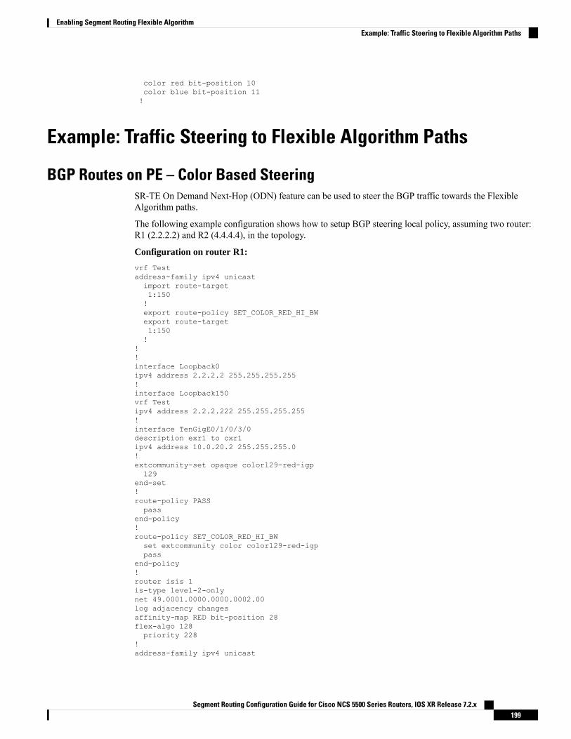
color red bit-position 10color blue bit-position 11!
Example: Traffic Steering to Flexible Algorithm Paths
BGP Routes on PE – Color Based SteeringSR-TE On Demand Next-Hop (ODN) feature can be used to steer the BGP traffic towards the FlexibleAlgorithm paths.
The following example configuration shows how to setup BGP steering local policy, assuming two router:R1 (2.2.2.2) and R2 (4.4.4.4), in the topology.
Configuration on router R1:
vrf Testaddress-family ipv4 unicastimport route-target1:150!export route-policy SET_COLOR_RED_HI_BWexport route-target1:150!
!!interface Loopback0ipv4 address 2.2.2.2 255.255.255.255!interface Loopback150vrf Testipv4 address 2.2.2.222 255.255.255.255!interface TenGigE0/1/0/3/0description exr1 to cxr1ipv4 address 10.0.20.2 255.255.255.0!extcommunity-set opaque color129-red-igp129
end-set!route-policy PASSpass
end-policy!route-policy SET_COLOR_RED_HI_BWset extcommunity color color129-red-igppass
end-policy!router isis 1is-type level-2-onlynet 49.0001.0000.0000.0002.00log adjacency changesaffinity-map RED bit-position 28flex-algo 128priority 228
!address-family ipv4 unicast
Segment Routing Configuration Guide for Cisco NCS 5500 Series Routers, IOS XR Release 7.2.x199
Enabling Segment Routing Flexible AlgorithmExample: Traffic Steering to Flexible Algorithm Paths

metric-style wideadvertise link attributesrouter-id 2.2.2.2segment-routing mpls
!interface Loopback0address-family ipv4 unicastprefix-sid index 2prefix-sid algorithm 128 index 282!
!interface TenGigE0/1/0/3/0point-to-pointaddress-family ipv4 unicast!
!!router bgp 65000bgp router-id 2.2.2.2address-family ipv4 unicast!address-family vpnv4 unicastretain route-target all
!neighbor-group RR-services-groupremote-as 65000update-source Loopback0address-family ipv4 unicast!address-family vpnv4 unicast!
!neighbor 4.4.4.4use neighbor-group RR-services-group
!vrf Testrd autoaddress-family ipv4 unicastredistribute connected!
segment-routingtraffic-engloggingpolicy status!segment-list sl-cxr1index 10 mpls label 16294!policy pol-foocolor 129 end-point ipv4 4.4.4.4candidate-pathspreference 100explicit segment-list sl-cxr1!!!!
!!
Configuration on router R2:
vrf Testaddress-family ipv4 unicast
Segment Routing Configuration Guide for Cisco NCS 5500 Series Routers, IOS XR Release 7.2.x200
Enabling Segment Routing Flexible AlgorithmBGP Routes on PE – Color Based Steering

import route-target1:150!export route-policy SET_COLOR_RED_HI_BWexport route-target1:150!
!!interface TenGigE0/1/0/1description cxr1 to exr1ipv4 address 10.0.20.1 255.255.255.0!extcommunity-set opaque color129-red-igp129
end-set!route-policy PASSpass
end-policy!route-policy SET_COLOR_RED_HI_BWset extcommunity color color129-red-igppass
end-policy!router isis 1is-type level-2-onlynet 49.0001.0000.0000.0004.00log adjacency changesaffinity-map RED bit-position 28affinity-map BLUE bit-position 29affinity-map GREEN bit-position 30flex-algo 128priority 228
!flex-algo 129priority 229
!flex-algo 130priority 230
!address-family ipv4 unicastmetric-style wideadvertise link attributesrouter-id 4.4.4.4segment-routing mpls
!interface Loopback0address-family ipv4 unicastprefix-sid index 4prefix-sid algorithm 128 index 284prefix-sid algorithm 129 index 294prefix-sid algorithm 130 index 304!
!interface GigabitEthernet0/0/0/0point-to-pointaddress-family ipv4 unicast!
!interface TenGigE0/1/0/1point-to-pointaddress-family ipv4 unicast
Segment Routing Configuration Guide for Cisco NCS 5500 Series Routers, IOS XR Release 7.2.x201
Enabling Segment Routing Flexible AlgorithmBGP Routes on PE – Color Based Steering

!!router bgp 65000bgp router-id 4.4.4.4address-family ipv4 unicast!address-family vpnv4 unicast!neighbor-group RR-services-groupremote-as 65000update-source Loopback0address-family ipv4 unicast!address-family vpnv4 unicast!
!neighbor 1.1.1.1use neighbor-group RR-services-group
!neighbor 2.2.2.2use neighbor-group RR-services-group
!vrf Testrd autoaddress-family ipv4 unicastredistribute connected!neighbor 25.1.1.2remote-as 4address-family ipv4 unicastroute-policy PASS inroute-policy PASS out!!
!!segment-routing!end
Segment Routing Configuration Guide for Cisco NCS 5500 Series Routers, IOS XR Release 7.2.x202
Enabling Segment Routing Flexible AlgorithmBGP Routes on PE – Color Based Steering

C H A P T E R 11Configure Segment Routing Path ComputationElement
The Segment Routing Path Computation Element (SR-PCE) provides stateful PCE functionality by extendingthe existing IOS-XR PCEP functionality with additional capabilities. SR-PCE is supported on the MPLS dataplane and IPv4 control plane.
The Cisco IOS XRv 9000 is the recommended platform to act as the SR-PCE. Refer to the Cisco IOS XRv9000 Router Installation and Configuration Guide for more information.
Note
• About SR-PCE, on page 203• Configure SR-PCE, on page 204• PCE-Initiated SR Policies, on page 208• SR-PCE Flexible Algorithm Multi-Domain Path Computation, on page 210• ACL Support for PCEP Connection, on page 214• Anycast SID-Aware Path Computation, on page 215• SR-PCE IPv4 Unnumbered Interface Support, on page 218• Inter-Domain Path Computation Using Redistributed SID, on page 220• PCE Support for MPLS-TE LSPs, on page 223• Configuring the North-Bound API on SR-PCE, on page 225
About SR-PCEThe path computation element protocol (PCEP) describes a set of procedures by which a path computationclient (PCC) can report and delegate control of head-end label switched paths (LSPs) sourced from the PCCto a PCE peer. The PCE can request the PCC to update and modify parameters of LSPs it controls. The statefulmodel also enables a PCC to allow the PCE to initiate computations allowing the PCE to perform network-wideorchestration.
SR-PCE learns topology information by way of IGP (OSPF or IS-IS) or through BGP Link-State (BGP-LS).
SR-PCE is capable of computing paths using the following methods:
• TE metric—SR-PCE uses the TE metric in its path calculations to optimize cumulative TE metric.
• IGP metric—SR-PCE uses the IGP metric in its path calculations to optimize reachability.
Segment Routing Configuration Guide for Cisco NCS 5500 Series Routers, IOS XR Release 7.2.x203

• LSP Disjointness—SR-PCE uses the path computation algorithms to compute a pair of disjoint LSPs.The disjoint paths can originate from the same head-end or different head-ends. Disjoint level refers tothe type of resources that should not be shared by the two computed paths. SR-PCE supports the followingdisjoint path computations:
• Link – Specifies that links are not shared on the computed paths.
• Node – Specifies that nodes are not shared on the computed paths.
• SRLG – Specifies that links with the same SRLG value are not shared on the computed paths.
• SRLG-node – Specifies that SRLG and nodes are not shared on the computed paths.
When the first request is received with a given disjoint-group ID, the first LSP is computed, encodingthe shortest path from the first source to the first destination. When the second LSP request is receivedwith the same disjoint-group ID, information received in both requests is used to compute two disjointpaths: one path from the first source to the first destination, and another path from the second source tothe second destination. Both paths are computed at the same time.
TCP Authentication Option
TCPMessage Digest 5 (MD5) authentication has been used for authenticating PCEP (TCP) sessions by usinga clear text or encrypted password. This feature introduces support for TCPAuthentication Option (TCP-AO),which replaces the TCP MD5 option.
TCP-AO uses Message Authentication Codes (MACs), which provides the following:
• Protection against replays for long-lived TCP connections
• More details on the security association with TCP connections than TCP MD5
• A larger set of MACs with minimal system and operational changes
TCP-AO is compatible with Master Key Tuple (MKT) configuration. TCP-AO also protects connectionswhen using the same MKT across repeated instances of a connection. TCP-AO protects the connections byusing traffic key that are derived from the MKT, and then coordinates changes between the endpoints.
TCP-AO and TCP MD5 are never permitted to be used simultaneously. TCP-AO supports IPv6, and is fullycompatible with the proposed requirements for the replacement of TCP MD5.
Note
Configure SR-PCEThis task explains how to configure SR-PCE.
Before you begin
The Cisco IOS XRv 9000 is the recommended platform to act as the SR-PCE.
SUMMARY STEPS
1. configure
Segment Routing Configuration Guide for Cisco NCS 5500 Series Routers, IOS XR Release 7.2.x204
Configure Segment Routing Path Computation ElementConfigure SR-PCE

2. pce3. address ipv4 address
4. state-sync ipv4 address
5. tcp-buffer size size
6. password {clear | encrypted} password
7. tcp-ao key-chain [include-tcp-options] [accept-ao-mismatch-connection]8. segment-routing {strict-sid-only | te-latency}9. timers10. keepalive time
11. minimum-peer-keepalive time
12. reoptimization time
13. exit
DETAILED STEPS
PurposeCommand or Action
Enters global configuration mode.configure
Example:
Step 1
RP/0/RP0/CPU0:router# configure
Enables PCE and enters PCE configuration mode.pce
Example:
Step 2
RP/0/RP0/CPU0:router(config)# pce
Configures a PCE IPv4 address.address ipv4 address
Example:
Step 3
RP/0/RP0/CPU0:router(config-pce)# address ipv4192.168.0.1
Configures the remote peer for state synchronization.state-sync ipv4 address
Example:
Step 4
RP/0/RP0/CPU0:router(config-pce)# state-sync ipv4192.168.0.3
Configures the transmit and receive TCP buffer size foreach PCEP session, in bytes. The default buffer size is256000. The valid range is from 204800 to 1024000.
tcp-buffer size size
Example:
RP/0/RP0/CPU0:router(config-pce)# tcp-buffer size
Step 5
1024000
Segment Routing Configuration Guide for Cisco NCS 5500 Series Routers, IOS XR Release 7.2.x205
Configure Segment Routing Path Computation ElementConfigure SR-PCE

PurposeCommand or Action
Enables TCPMD5 authentication for all PCEP peers. AnyTCP segment coming from the PCC that does not contain
password {clear | encrypted} password
Example:
Step 6
aMACmatching the configured password will be rejected.Specify if the password is encrypted or clear text.
RP/0/RP0/CPU0:router(config-pce)# passwordencrypted pwd1 TCP-AO and TCPMD5 are never permitted to
be used simultaneously.Note
Enables TCP Authentication Option (TCP-AO)authentication for all PCEP peers. Any TCP segment
tcp-ao key-chain [include-tcp-options][accept-ao-mismatch-connection]
Step 7
coming from the PCC that does not contain a MACmatching the configured key chain will be rejected.Example:
RP/0/RP0/CPU0:router(config-pce)# tcp-ao • include-tcp-options—Includes other TCP options inthe header for MAC calculation.pce_tcp_ao include-tcp-options
• accept-ao-mismatch-connection—Acceptsconnection even if there is a mismatch of AO optionsbetween peers.
TCP-AO and TCPMD5 are never permitted tobe used simultaneously.
Note
Configures the segment routing algorithm to use strict SIDor TE latency.
segment-routing {strict-sid-only | te-latency}
Example:
Step 8
This setting is global and applies to all LSPsthat request a path from this controller.
NoteRP/0/RP0/CPU0:router(config-pce)# segment-routingstrict-sid-only
Enters timer configuration mode.timers
Example:
Step 9
RP/0/RP0/CPU0:router(config-pce)# timers
Configures the timer value for locally generated keep-alivemessages. The default time is 30 seconds.
keepalive time
Example:
Step 10
RP/0/RP0/CPU0:router(config-pce-timers)# keepalive60
Configures the minimum acceptable keep-alive timer thatthe remote peer may propose in the PCEP OPENmessage
minimum-peer-keepalive time
Example:
Step 11
during session establishment. The default time is 20seconds.
RP/0/RP0/CPU0:router(config-pce-timers)#minimum-peer-keepalive 30
Segment Routing Configuration Guide for Cisco NCS 5500 Series Routers, IOS XR Release 7.2.x206
Configure Segment Routing Path Computation ElementConfigure SR-PCE

PurposeCommand or Action
Configures the re-optimization timer. The default timer is1800 seconds.
reoptimization time
Example:
Step 12
RP/0/RP0/CPU0:router(config-pce-timers)#reoptimization 600
Exits timer configuration mode and returns to PCEconfiguration mode.
exit
Example:
Step 13
RP/0/RP0/CPU0:router(config-pce-timers)# exit
Configure the Disjoint Policy (Optional)This task explains how to configure the SR-PCE to compute disjointness for a pair of LSPs signaled by PCCsthat do not include the PCEP association group-ID object in their PCEP request. This can be beneficial fordeployments where PCCs do not support this PCEP object or when the network operator prefers to managethe LSP disjoint configuration centrally.
SUMMARY STEPS
1. disjoint-path2. group-id value type {link | node | srlg | srlg-node} [sub-id value]3. strict4. lsp {1 | 2} pcc ipv4 address lsp-name lsp_name [shortest-path]
DETAILED STEPS
PurposeCommand or Action
Enters disjoint configuration mode.disjoint-path
Example:
Step 1
RP/0/RP0/CPU0:router(config-pce)# disjoint-path
Configures the disjoint group ID and defines the preferredlevel of disjointness (the type of resources that should notbe shared by the two paths):
group-id value type {link | node | srlg |srlg-node} [sub-id value]
Example:
Step 2
• link—Specifies that links are not shared on thecomputed paths.RP/0/RP0/CPU0:router(config-pce-disjoint)# group-id
1 type node sub-id 1• node—Specifies that nodes are not shared on thecomputed paths.
• srlg—Specifies that links with the same SRLG valueare not shared on the computed paths.
Segment Routing Configuration Guide for Cisco NCS 5500 Series Routers, IOS XR Release 7.2.x207
Configure Segment Routing Path Computation ElementConfigure the Disjoint Policy (Optional)

PurposeCommand or Action
• srlg-node—Specifies that SRLG and nodes are notshared on the computed paths.
If a pair of paths that meet the requested disjointness levelcannot be found, then the paths will automatically fallbackto a lower level:
• If the requested disjointness level is SRLG or node,then link-disjoint paths will be computed.
• If the requested disjointness level was link, or if thefirst fallback from SRLG or node disjointness failed,then the lists of segments encoding two shortest paths,without any disjointness constraint, will be computed.
(Optional) Prevents the automatic fallback behavior of thepreferred level of disjointness. If a pair of paths that meet
strict
Example:
Step 3
the requested disjointness level cannot be found, the disjoint
RP/0/RP0/CPU0:router(config-pce-disjoint)# strictcalculation terminates and no new path is provided. Theexisting path is not modified.
Adds LSPs to the disjoint group.lsp {1 | 2} pcc ipv4 address lsp-name lsp_name[shortest-path]
Step 4
The shortest-path keyword forces one of the disjoint pathsto follow the shortest path from the source to the destination.Example:This option can only be applied to the the first LSPspecified.RP/0/RP0/CPU0:router(config-pce-disjoint)# lsp 1
pcc ipv4 192.168.0.1 lsp-name rtrA_t1 shortest-pathRP/0/RP0/CPU0:router(config-pce-disjoint)# lsp 2pcc ipv4 192.168.0.5 lsp-name rtrE_t2
PCE-Initiated SR PoliciesAn SR-TE policy can be configured on the path computation element (PCE) to reduce link congestion or tominimize the number of network touch points.
The PCE-initiated SR-TE policies are entered in PCE configurationmode. For more information on configuringSR-TE policies, see the SR-TE Policy Overview, on page 107.
Note
To minimize the number of network touch points, an application, such as a Network Services Orchestrator(NSO), can request the PCE to create an SR-TE policy. PCE deploys the SR-TE policy using PCC-PCEcommunication protocol (PCEP).
1. PCE sends a PCInitiate message to the PCC.
2. If the PCInitiate message is valid, the PCC sends a PCRpt message; otherwise, it sends PCErr message.
3. If the PCInitiate message is accepted, the PCE updates the SR-TE policy by sending PCUpd message.
Segment Routing Configuration Guide for Cisco NCS 5500 Series Routers, IOS XR Release 7.2.x208
Configure Segment Routing Path Computation ElementPCE-Initiated SR Policies

You can achieve high-availability by configuring multiple PCEs with SR-TE policies. If the head-end (PCC)loses connectivity with one PCE, another PCE can assume control of the SR-TE policy.
Configuration Example: PCE-Initiated SR Policy with Explicit SID List
To configure a PCE-initiated SR-TE policy, you must complete the following configurations:
1. Enter PCE configuration mode.
2. Create the segment list.
When configuring an explicit path using IP addresses of intermediate links, the SR-TE processprefers the protected Adj-SID of the link, if one is available.
Note
3. Create the policy.
/* Enter PCE configuration mode and create the SR-TE segment lists */Router# configureRouter(config)# pce
/* Create the SR-TE segment lists */Router(config-pce)# segment-routingRouter(config-pce-sr)# traffic-engRouter(config-pce-sr-te)# segment-list name addr2aRouter(config-pce-sr-te-sl)# index 10 address ipv4 1.1.1.2Router(config-pce-sr-te-sl)# index 20 address ipv4 10.2.3.2Router(config-pce-sr-te-sl)# index 30 address ipv4 1.1.1.4Router(config-pce-sr-te-sl)# exit
/* Create the SR-TE policy */Router(config-pce-sr-te)# peer ipv4 1.1.1.1Router(config-pce-sr-te)# policy P1Router(config-pce-sr-te-policy)# color 2 end-point ipv4 2.2.2.2Router(config-pce-sr-te-policy)# candidate-pathsRouter(config-pce-sr-te-policy-path)# preference 50Router(config-pce-sr-te-policy-path-preference)# explicit segment-list addr2aRouter(config-pce-sr-te-pp-info)# commitRouter(config-pce-sr-te-pp-info)# endRouter(config)#
Running Config
pcesegment-routingtraffic-engsegment-list name addr2aindex 1 address ipv4 14.14.14.4!peer ipv4 1.1.1.1policy P1color 2 end-point ipv4 2.2.2.2candidate-pathspreference 50explicit segment-list addr2a!
Segment Routing Configuration Guide for Cisco NCS 5500 Series Routers, IOS XR Release 7.2.x209
Configure Segment Routing Path Computation ElementPCE-Initiated SR Policies
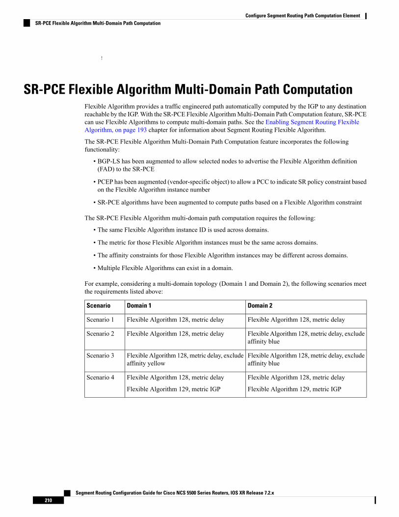
!
SR-PCE Flexible Algorithm Multi-Domain Path ComputationFlexible Algorithm provides a traffic engineered path automatically computed by the IGP to any destinationreachable by the IGP.With the SR-PCE Flexible AlgorithmMulti-Domain Path Computation feature, SR-PCEcan use Flexible Algorithms to compute multi-domain paths. See the Enabling Segment Routing FlexibleAlgorithm, on page 193 chapter for information about Segment Routing Flexible Algorithm.
The SR-PCE Flexible Algorithm Multi-Domain Path Computation feature incorporates the followingfunctionality:
• BGP-LS has been augmented to allow selected nodes to advertise the Flexible Algorithm definition(FAD) to the SR-PCE
• PCEP has been augmented (vendor-specific object) to allow a PCC to indicate SR policy constraint basedon the Flexible Algorithm instance number
• SR-PCE algorithms have been augmented to compute paths based on a Flexible Algorithm constraint
The SR-PCE Flexible Algorithm multi-domain path computation requires the following:
• The same Flexible Algorithm instance ID is used across domains.
• The metric for those Flexible Algorithm instances must be the same across domains.
• The affinity constraints for those Flexible Algorithm instances may be different across domains.
• Multiple Flexible Algorithms can exist in a domain.
For example, considering a multi-domain topology (Domain 1 and Domain 2), the following scenarios meetthe requirements listed above:
Domain 2Domain 1Scenario
Flexible Algorithm 128, metric delayFlexible Algorithm 128, metric delayScenario 1
Flexible Algorithm 128, metric delay, excludeaffinity blue
Flexible Algorithm 128, metric delayScenario 2
Flexible Algorithm 128, metric delay, excludeaffinity blue
Flexible Algorithm 128, metric delay, excludeaffinity yellow
Scenario 3
Flexible Algorithm 128, metric delay
Flexible Algorithm 129, metric IGP
Flexible Algorithm 128, metric delay
Flexible Algorithm 129, metric IGP
Scenario 4
Segment Routing Configuration Guide for Cisco NCS 5500 Series Routers, IOS XR Release 7.2.x210
Configure Segment Routing Path Computation ElementSR-PCE Flexible Algorithm Multi-Domain Path Computation
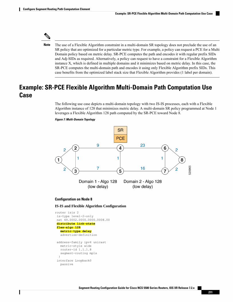
The use of a Flexible Algorithm constraint in a multi-domain SR topology does not preclude the use of anSR policy that are optimized for a particular metric type. For example, a policy can request a PCE for a MultiDomain policy based on metric delay. SR-PCE computes the path and encodes it with regular prefix SIDsand Adj-SIDs as required. Alternatively, a policy can request to have a constraint for a Flexible Algorithminstance X, which is defined in multiple domains and it minimizes based on metric delay. In this case, theSR-PCE computes the multi-domain path and encodes it using only Flexible Algorithm prefix SIDs. Thiscase benefits from the optimized label stack size that Flexible Algorithm provides (1 label per domain).
Note
Example: SR-PCE Flexible Algorithm Multi-Domain Path Computation UseCase
The following use case depicts a multi-domain topology with two IS-IS processes, each with a FlexibleAlgorithm instance of 128 that minimizes metric delay. A multi-domain SR policy programmed at Node 1leverages a Flexible Algorithm 128 path computed by the SR-PCE toward Node 8.
Figure 7: Multi-Domain Topology
Configuration on Node 8
IS-IS and Flexible Algorithm Configuration
router isis 2is-type level-2-onlynet 49.0002.0000.0000.0008.00distribute link-stateflex-algo 128metric-type delayadvertise-definition
address-family ipv4 unicastmetric-style widerouter-id 1.1.1.8segment-routing mpls!interface Loopback0passive
Segment Routing Configuration Guide for Cisco NCS 5500 Series Routers, IOS XR Release 7.2.x211
Configure Segment Routing Path Computation ElementExample: SR-PCE Flexible Algorithm Multi-Domain Path Computation Use Case

address-family ipv4 unicastprefix-sid absolute 16008prefix-sid algorithm 128 absolute 16808
!
Configuration on Node 4 (ABR/ASBR)
IS-IS and Flexible Algorithm Configuration
router isis 1is-type level-2-onlynet 49.0001.0000.0000.0004.00distribute link-state instance-id 100flex-algo 128metric-type delayadvertise-definition
address-family ipv4 unicastmetric-style widerouter-id 1.1.1.4segment-routing mpls!interface Loopback0passiveaddress-family ipv4 unicastprefix-sid absolute 16004prefix-sid algorithm 128 absolute 16804
!router isis 2is-type level-2-onlynet 49.0002.0000.0000.0004.00distribute link-state instance-id 200flex-algo 128metric-type delayadvertise-definition
address-family ipv4 unicastmetric-style widerouter-id 1.1.1.4segment-routing mpls!interface Loopback0passiveaddress-family ipv4 unicastprefix-sid absolute 16004prefix-sid algorithm 128 absolute 16804
!
BGP-LS Configuration
router bgp 65000bgp router-id 1.1.1.4address-family link-state link-state!neighbor-group AS65000-LS-groupremote-as 65000update-source Loopback0address-family link-state link-state!!neighbor 1.1.1.10use neighbor-group AS65000-LS-group
Segment Routing Configuration Guide for Cisco NCS 5500 Series Routers, IOS XR Release 7.2.x212
Configure Segment Routing Path Computation ElementExample: SR-PCE Flexible Algorithm Multi-Domain Path Computation Use Case

description *** To SR-PCE ***!!!
Configuration on Node 1
IS-IS and Flexible Algorithm Configuration
router isis 1is-type level-2-onlynet 49.0001.0000.0000.0001.00distribute link-stateflex-algo 128metric-type delayadvertise-definition
address-family ipv4 unicastmetric-style widerouter-id 1.1.1.1segment-routing mpls!interface Loopback0passiveaddress-family ipv4 unicastprefix-sid absolute 16001prefix-sid algorithm 128 absolute 16801
!
SR Policy Configuration
segment-routingtraffic-engpolicy FOOcolor 100 end-point ipv4 1.1.1.8candidate-pathspreference 100dynamicpcep!!constraintssegmentssid-algorithm 128!!!!!!!
PCC Configuration
segment-routingtraffic-engpccsource-address ipv4 1.1.1.1pce address ipv4 1.1.1.10precedence 10!report-all!
Segment Routing Configuration Guide for Cisco NCS 5500 Series Routers, IOS XR Release 7.2.x213
Configure Segment Routing Path Computation ElementExample: SR-PCE Flexible Algorithm Multi-Domain Path Computation Use Case

!!
Configuration on PCE
pceaddress ipv4 1.1.1.10rest!!router bgp 65000bgp router-id 1.1.1.10address-family link-state link-state!neighbor-group AS65000-LS-groupremote-as 65000update-source Loopback0address-family link-state link-state!!neighbor 1.1.1.4use neighbor-group AS65000-LS-groupdescription *** To Node-4 ***!!neighbor 1.1.1.5use neighbor-group AS65000-LS-groupdescription *** To Node-5 ***!!!
ACL Support for PCEP ConnectionPCE protocol (PCEP) (RFC5440) is a client-server model running over TCP/IP, where the server (PCE) opensa port and the clients (PCC) initiate connections. After the peers establish a TCP connection, they create aPCE session on top of it.
The ACL Support for PCEP Connection feature provides a way to protect a PCE server using an AccessControl List (ACL) to restrict IPv4 PCC peers at the time the TCP connection is created based on the sourceaddress of a client. When a client initiates the TCP connection, the ACL is referenced, and the client sourceaddress is compared. The ACL can either permit or deny the address and the TCP connection will proceed ornot.
Refer to the Implementing Access Lists and Prefix Lists chapter in the IP Addresses and Services ConfigurationGuide for Cisco NCS 5500 Series Routers for detailed ACL configuration information.
To apply an ACL to the PCE, use the pce peer-filter ipv4 access-list acl_name command.
The following example shows how to configure an ACL and apply it to the PCE:
pceaddress ipv4 1.1.1.5peer-filter ipv4 access-list sample-peer-filter!ipv4 access-list sample-peer-filter10 permit ipv4 host 1.1.1.6 any20 permit ipv4 host 1.1.1.7 any
Segment Routing Configuration Guide for Cisco NCS 5500 Series Routers, IOS XR Release 7.2.x214
Configure Segment Routing Path Computation ElementACL Support for PCEP Connection

30 deny ipv4 any any!
Anycast SID-Aware Path ComputationThis feature allows the SR-TE head-end or SR-PCE to compute a path that is encoded using Anycast prefixSIDs of nodes along the path.
An Anycast SID is a type of prefix SID that identifies a set of nodes and is configured with n-flag clear. Theset of nodes (Anycast group) is configured to advertise a shared prefix address and prefix SID. Anycast routingenables the steering of traffic toward multiple advertising nodes, providing load-balancing and redundancy.Packets addressed to an Anycast address are forwarded to the topologically nearest nodes.
For information on configuring Anycast SID, see Configuring a Prefix-SID on the IS-IS Enabled LoopbackInterface, on page 65 and Configuring a Prefix-SID on the OSPF-Enabled Loopback Interface, on page 85.
Note
This example shows how Anycast SIDs are inserted into a computed SID list.
The following figure shows 3 isolated IGP domains without redistribution and without BGP 3107. Each AreaBorder Router (ABR) 1 through 4 is configured with a node SID. ABRs 1 and 2 share Anycast SID 16012and ABRs 3 and 4 share Anycast SID 16034.
Consider the case where nodes A and Z are provider edge (PE) routers in the same VPN. Node A receives aVPN route with BGP next-hop to node Z. Node A resolves the SR path to node Z based on ODN behaviorswith delegation of path computation to SR-PCE.
Before considering Anycast SIDs, the head-end router or SR-PCE computes the SID list.
Segment Routing Configuration Guide for Cisco NCS 5500 Series Routers, IOS XR Release 7.2.x215
Configure Segment Routing Path Computation ElementAnycast SID-Aware Path Computation

Assume that the computed path from node A to node Z traverses node 2 and node 4. This translates to SIDlist {16002, 16004, 1600Z} when node SIDs are leveraged to encode the path.
When an Anycast SID-aware path is requested, the path computation algorithm performs the following:
• Path Computation—Computes the path according to optimization objectives and constraints
• Path Encoding—Encodes the path in a SID list leveraging node-SIDs and adj-SIDs as applicable
• Anycast SID Replacement—Reiterates the original SID list by replacing node SIDs with Anycast SIDspresent on the nodes along the computed path.
• Optimality Validation—The new paths are validated against the original optimization objectives andconstraints (maintain same cumulative metric as original SID list and do not violate path constraints).
• Anycast SID Promotion—If the optimality validation is successful, then the Anycast-encoded SID listis signaled and instantiated in the forwarding.
The following figure depicts cumulative metrics between nodes in the network.
Under these conditions, the optimality check is met, and therefore, the Anycast-encoded SID list from nodeA to node Z is {16012,16034,1600Z}.
The Anycast SID aware path computation also provides resiliency. For example, if one of the ABRs (in thiscase, ABR 1) becomes unavailable or unreachable, the path from node A to node Z {16012,16034,1600Z}will still be valid and usable.
Segment Routing Configuration Guide for Cisco NCS 5500 Series Routers, IOS XR Release 7.2.x216
Configure Segment Routing Path Computation ElementAnycast SID-Aware Path Computation
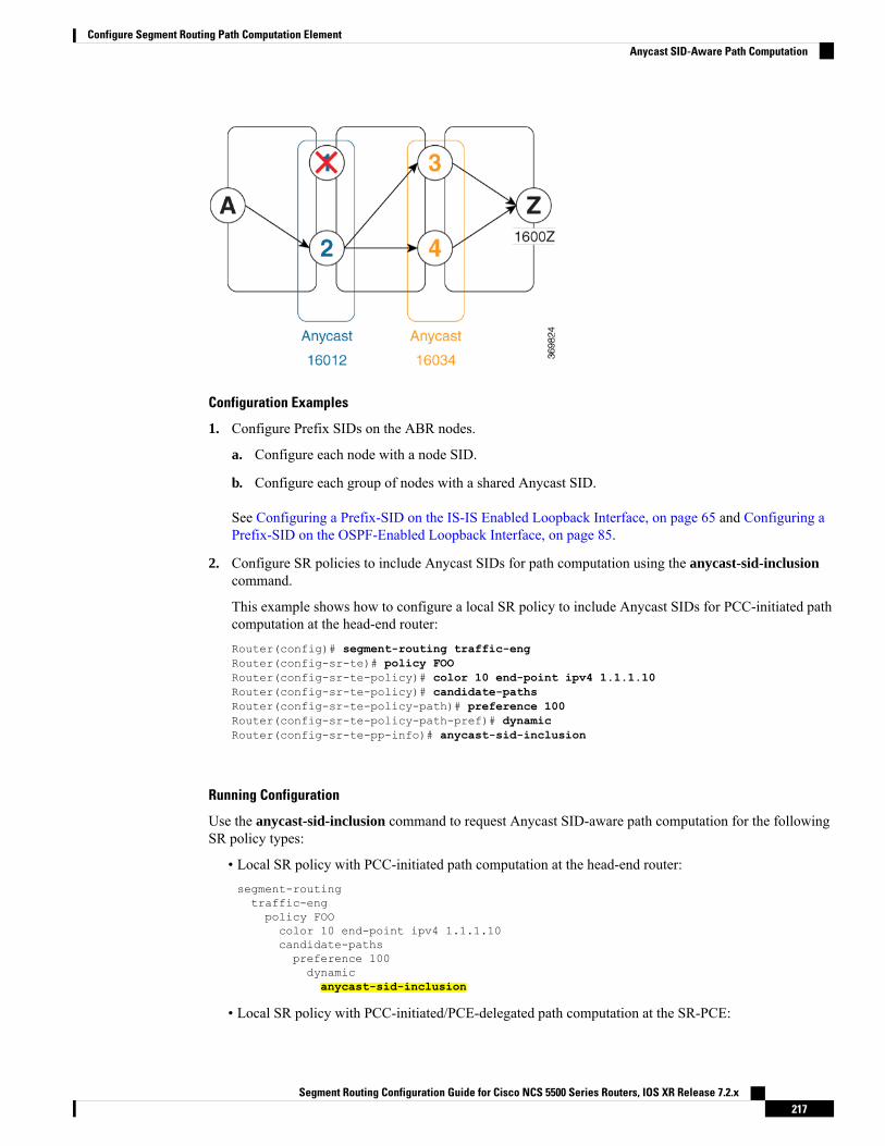
Configuration Examples
1. Configure Prefix SIDs on the ABR nodes.
a. Configure each node with a node SID.
b. Configure each group of nodes with a shared Anycast SID.
See Configuring a Prefix-SID on the IS-IS Enabled Loopback Interface, on page 65 and Configuring aPrefix-SID on the OSPF-Enabled Loopback Interface, on page 85.
2. Configure SR policies to include Anycast SIDs for path computation using the anycast-sid-inclusioncommand.
This example shows how to configure a local SR policy to include Anycast SIDs for PCC-initiated pathcomputation at the head-end router:Router(config)# segment-routing traffic-engRouter(config-sr-te)# policy FOORouter(config-sr-te-policy)# color 10 end-point ipv4 1.1.1.10Router(config-sr-te-policy)# candidate-pathsRouter(config-sr-te-policy-path)# preference 100Router(config-sr-te-policy-path-pref)# dynamicRouter(config-sr-te-pp-info)# anycast-sid-inclusion
Running Configuration
Use the anycast-sid-inclusion command to request Anycast SID-aware path computation for the followingSR policy types:
• Local SR policy with PCC-initiated path computation at the head-end router:segment-routingtraffic-engpolicy FOOcolor 10 end-point ipv4 1.1.1.10candidate-pathspreference 100dynamicanycast-sid-inclusion
• Local SR policy with PCC-initiated/PCE-delegated path computation at the SR-PCE:
Segment Routing Configuration Guide for Cisco NCS 5500 Series Routers, IOS XR Release 7.2.x217
Configure Segment Routing Path Computation ElementAnycast SID-Aware Path Computation

segment-routingtraffic-engpolicy BARcolor 20 end-point ipv4 1.1.1.20candidate-pathspreference 100dynamicpcepanycast-sid-inclusion
• On-demand SR policies with a locally computed dynamic path at the head-end, or centrally computeddynamic path at the SR-PCE:segment-routingtraffic-engon-demand color 10dynamicanycast-sid-inclusion
• On-demand SR policies with centrally computed dynamic path at the SR-PCE:segment-routingtraffic-engon-demand color 20dynamicpcepanycast-sid-inclusion
SR-PCE IPv4 Unnumbered Interface SupportThis feature allows IPv4 unnumbered interfaces to be part of an SR-PCE topology database.
An unnumbered IPv4 interface is not identified by its own unique IPv4 address. Instead, it is identified by therouter ID of the node where this interfaces resides and the local SNMP index assigned for this interface.
This feature provides enhancements to the following components:
• IGPs (IS-IS and OSPF):
• Support the IPv4 unnumbered interfaces in the SR-TE context by flooding the necessary interfaceinformation in the topology
• SR-PCE:
SR-PCE and path computation clients (PCCs) need to be runningCisco IOS XR 7.0.2 or later.
Note
• Compute and return paths from a topology containing IPv4 unnumbered interfaces.
• Process reported SR policies from a head-end router that contain hops with IPv4 unnumberedadjacencies.
PCEP extensions for IPv4 unnumbered interfaces adhere to IETF RFC8664 “PCEP Extensions forSegment Routing” (https://datatracker.ietf.org/doc/rfc8664/). The unnumbered hops use a Node orAdjacency Identifier (NAI) of type 5. This indicates that the segment in the explicit routing object(ERO) is an unnumbered adjacency with an IPv4 ID and an interface index.
Segment Routing Configuration Guide for Cisco NCS 5500 Series Routers, IOS XR Release 7.2.x218
Configure Segment Routing Path Computation ElementSR-PCE IPv4 Unnumbered Interface Support
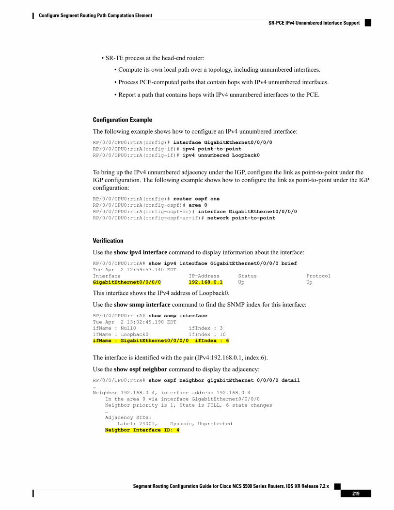
• SR-TE process at the head-end router:
• Compute its own local path over a topology, including unnumbered interfaces.
• Process PCE-computed paths that contain hops with IPv4 unnumbered interfaces.
• Report a path that contains hops with IPv4 unnumbered interfaces to the PCE.
Configuration Example
The following example shows how to configure an IPv4 unnumbered interface:RP/0/0/CPU0:rtrA(config)# interface GigabitEthernet0/0/0/0RP/0/0/CPU0:rtrA(config-if)# ipv4 point-to-pointRP/0/0/CPU0:rtrA(config-if)# ipv4 unnumbered Loopback0
To bring up the IPv4 unnumbered adjacency under the IGP, configure the link as point-to-point under theIGP configuration. The following example shows how to configure the link as point-to-point under the IGPconfiguration:RP/0/0/CPU0:rtrA(config)# router ospf oneRP/0/0/CPU0:rtrA(config-ospf)# area 0RP/0/0/CPU0:rtrA(config-ospf-ar)# interface GigabitEthernet0/0/0/0RP/0/0/CPU0:rtrA(config-ospf-ar-if)# network point-to-point
Verification
Use the show ipv4 interface command to display information about the interface:RP/0/0/CPU0:rtrA# show ipv4 interface GigabitEthernet0/0/0/0 briefTue Apr 2 12:59:53.140 EDTInterface IP-Address Status ProtocolGigabitEthernet0/0/0/0 192.168.0.1 Up Up
This interface shows the IPv4 address of Loopback0.
Use the show snmp interface command to find the SNMP index for this interface:RP/0/0/CPU0:rtrA# show snmp interfaceTue Apr 2 13:02:49.190 EDTifName : Null0 ifIndex : 3ifName : Loopback0 ifIndex : 10ifName : GigabitEthernet0/0/0/0 ifIndex : 6
The interface is identified with the pair (IPv4:192.168.0.1, index:6).
Use the show ospf neighbor command to display the adjacency:RP/0/0/CPU0:rtrA# show ospf neighbor gigabitEthernet 0/0/0/0 detail…Neighbor 192.168.0.4, interface address 192.168.0.4
In the area 0 via interface GigabitEthernet0/0/0/0Neighbor priority is 1, State is FULL, 6 state changes…Adjacency SIDs:
Label: 24001, Dynamic, UnprotectedNeighbor Interface ID: 4
Segment Routing Configuration Guide for Cisco NCS 5500 Series Routers, IOS XR Release 7.2.x219
Configure Segment Routing Path Computation ElementSR-PCE IPv4 Unnumbered Interface Support
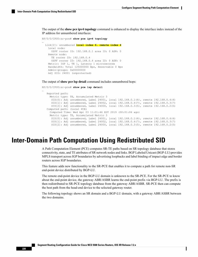
The output of the show pce ipv4 topology command is enhanced to display the interface index instead of theIP address for unnumbered interfaces:RP/0/0/CPU0:sr-pce# show pce ipv4 topology…Link[2]: unnumbered local index 6, remote index 4Local node:OSPF router ID: 192.168.0.1 area ID: 0 ASN: 0
Remote node:TE router ID: 192.168.0.4OSPF router ID: 192.168.0.4 area ID: 0 ASN: 0
Metric: IGP 1, TE 1, Latency 1 microsecondsBandwidth: Total 125000000 Bps, Reservable 0 BpsAdmin-groups: 0x00000000Adj SID: 24001 (unprotected)
The output of show pce lsp detail command includes unnumbered hops:RP/0/0/CPU0:sr-pce# show pce lsp detail…
Reported path:Metric type: TE, Accumulated Metric 3SID[0]: Adj unnumbered, Label 24001, local 192.168.0.1(6), remote 192.168.0.4(4)SID[1]: Adj unnumbered, Label 24002, local 192.168.0.4(7), remote 192.168.0.3(7)SID[2]: Adj unnumbered, Label 24000, local 192.168.0.3(5), remote 192.168.0.2(5)
Computed path: (Local PCE)Computed Time: Wed Apr 03 11:01:46 EDT 2019 (00:01:06 ago)Metric type: TE, Accumulated Metric 3SID[0]: Adj unnumbered, Label 24001, local 192.168.0.1(6), remote 192.168.0.4(4)SID[1]: Adj unnumbered, Label 24002, local 192.168.0.4(7), remote 192.168.0.3(7)SID[2]: Adj unnumbered, Label 24000, local 192.168.0.3(5), remote 192.168.0.2(5)
Inter-Domain Path Computation Using Redistributed SIDA Path Computation Element (PCE) computes SR-TE paths based on SR topology database that storesconnectivity, state, and TE attributes of SR network nodes and links. BGP Labeled Unicast (BGP-LU) providesMPLS transport across IGP boundaries by advertising loopbacks and label binding of impact edge and borderrouters across IGP boundaries.
This feature adds new functionality to the SR-PCE that enables it to compute a path for remote non-SRend-point device distributed by BGP-LU.
The remote end-point device in the BGP-LU domain is unknown to the SR-PCE. For the SR-PCE to knowabout the end-point device, the gateway ABR/ASBR learns the end-point prefix via BGP-LU. The prefix isthen redistributed to SR-PCE topology database from the gateway ABR/ASBR. SR-PCE then can computethe best path from the head-end device to the selected gateway router.
The following topology shows an SR domain and a BGP-LU domain, with a gateway ABR/ASBR betweenthe two domains.
Segment Routing Configuration Guide for Cisco NCS 5500 Series Routers, IOS XR Release 7.2.x220
Configure Segment Routing Path Computation ElementInter-Domain Path Computation Using Redistributed SID

1. The gateway ABR/ASBR is configured with BGP/IGP helper to learn the remote prefix through BGP-LUand redistribute the remote prefix to the IGP helper, then to SR-PCE.
2. The SR-PCE selects the best gateway node to BGP-LU domain and computes the path to reach the remoteprefix through the gateway node.
3. The head-end device in the SR domain requests a path to the remote destination and signals the SR profileinterworking with the BGP-LU domain.
The BGP-LU prefix advertisement to SR-PCE Traffic Engineer Database (TED) is done by creating an IGPhelper on the ABR/ASBR to redistribute BGP-LU prefix information to IGP. IGP then sends the prefixinformation to the SR-PCE via BGP-LS.
If there are multiple ABR/ASBRs advertising the same remote BGP-LU prefix, the SR-PCE selects the bestgateway node to the BGP-LU domain using the accumulative metric from the head-end device to the gatewayand the advertised metric from the gateway to the destination.
Segment Routing Configuration Guide for Cisco NCS 5500 Series Routers, IOS XR Release 7.2.x221
Configure Segment Routing Path Computation ElementInter-Domain Path Computation Using Redistributed SID
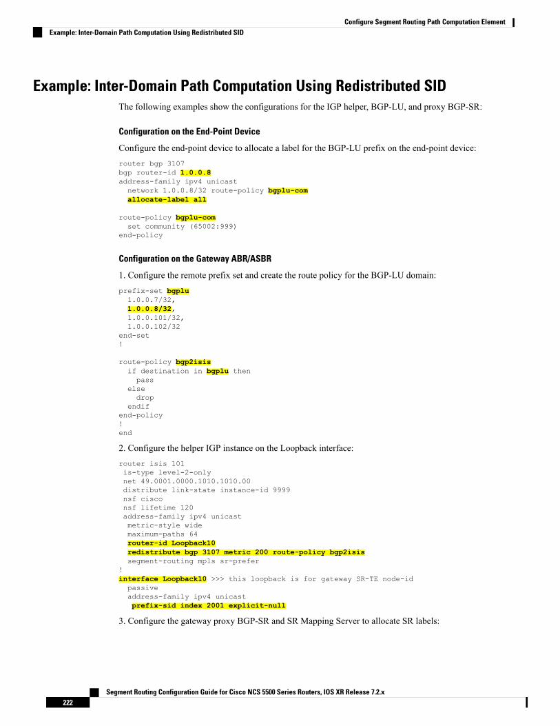
Example: Inter-Domain Path Computation Using Redistributed SIDThe following examples show the configurations for the IGP helper, BGP-LU, and proxy BGP-SR:
Configuration on the End-Point Device
Configure the end-point device to allocate a label for the BGP-LU prefix on the end-point device:router bgp 3107bgp router-id 1.0.0.8address-family ipv4 unicastnetwork 1.0.0.8/32 route-policy bgplu-comallocate-label all
route-policy bgplu-comset community (65002:999)
end-policy
Configuration on the Gateway ABR/ASBR
1. Configure the remote prefix set and create the route policy for the BGP-LU domain:prefix-set bgplu1.0.0.7/32,1.0.0.8/32,1.0.0.101/32,1.0.0.102/32
end-set!
route-policy bgp2isisif destination in bgplu thenpass
elsedrop
endifend-policy!end
2. Configure the helper IGP instance on the Loopback interface:router isis 101is-type level-2-onlynet 49.0001.0000.1010.1010.00distribute link-state instance-id 9999nsf cisconsf lifetime 120address-family ipv4 unicastmetric-style widemaximum-paths 64router-id Loopback10redistribute bgp 3107 metric 200 route-policy bgp2isissegment-routing mpls sr-prefer
!interface Loopback10 >>> this loopback is for gateway SR-TE node-idpassiveaddress-family ipv4 unicastprefix-sid index 2001 explicit-null
3. Configure the gateway proxy BGP-SR and SR Mapping Server to allocate SR labels:
Segment Routing Configuration Guide for Cisco NCS 5500 Series Routers, IOS XR Release 7.2.x222
Configure Segment Routing Path Computation ElementExample: Inter-Domain Path Computation Using Redistributed SID

router bgp 3107address-family ipv4 unicastsegment-routing prefix-sid-mapallocate-label all
segment-routingglobal-block 16000 23999mapping-serverprefix-sid-mapaddress-family ipv41.0.0.7/32 20071.0.0.8/32 20081.0.0.101/32 21011.0.0.102/32 2102
PCE Support for MPLS-TE LSPsThis feature allows Cisco's SR-PCE to act as a Path Computation Element (PCE) forMPLS Traffic EngineeringLabel Switched Paths (MPLS-TE LSPs).
For more information about MPLS-TE, refer to the "Implementing MPLS Traffic Engineering" chapter in theMPLS Configuration Guide for Cisco NCS 5500 Series Routers.
Note
The supported functionality is summarized below:
• PCE type: Active Stateful PCE
• MPLS-TE LSP initiation methods:
• PCE Initiated—An active stateful PCE initiates an LSP and maintains the responsibility of updatingthe LSP.
• PCC Initiated—A PCC initiates the LSP and may delegate the control later to the Active statefulPCE.
• MPLS-TE LSP metric—Metric optimized by the path computation algorithm:
• IGP metric
• TE metric
• Latency metric
• MPLS-TE LSP constraints—TE LSP attributes to be taken into account by the PCE during pathcomputation:
• Resource Affinities
• Path Disjointness
• MPLS-TE LSP parameters:
• Setup priority—The priority of the TE LSP with respect to taking resources
• Hold priority—The priority of the TE LSP with respect to holding resources
Segment Routing Configuration Guide for Cisco NCS 5500 Series Routers, IOS XR Release 7.2.x223
Configure Segment Routing Path Computation ElementPCE Support for MPLS-TE LSPs

• FRR L flag—The "Local Protection Desired" bit. Can be set from an application instantiating anMPLS-TE LSP via SR-PCE. SR-PCE passes this flag to the PCC, and the PCC will enable FRRfor that LSP.
• Signaled Bandwidth—This value can be set from an application instantiating anMPLS-TE LSP viaSR-PCE. SR-PCE passes this value to the PCC.
• Binding SID—A segment identifier (SID) that a headend binds to an MPLS-TE LSP. When theheadend receives a packet with active segment (top MPLS label) matching the BSID of a localMPLS-TE LSP, the headend steers the packet into the associated MPLS-TE LSP.
Cisco Crosswork Optimization Engine is an application that leverages the SR-PCE in order to visualize andinstantiate MPLS-TE LSPs. For more information, refer to the Visualize SR Policies and RSVP-TE Tunnelschapter in the Cisco Crosswork Optimization Engine 1.2.1 User Guide.
No extra configuration is required to enable MPLS-TE support at SR-PCE.Note
Example: Configuring a PCEP Session (Stateful Mode) on MPLS-TE PCC
The following example shows the configuration for an MPLS-TE PCC to establish a PCEP session with aPCE (IPv4 address 1.1.1.100).
MPLS-TE PCC must operate in the stateful PCEP mode when connecting to SR-PCE.Note
The instantiation keyword enables the PCC to support MPLS-TE LSP instantiation by PCE (PCE-initiated).
The report keyword enables the PCC to report all the MPLS-TE LSPs configured on that node.
PCE-initiated LSPs are automatically reported to all configured PCEs.Note
The autoroute-announce keyword enables autoroute-announce globally for all PCE-initiated LSPs on thePCC.
The redundancy pcc-centric keywords enable PCC-centric high-availability model for PCE-initiated LSPs.The PCC-centric model changes the default PCC delegation behavior to the following:
• After LSP creation, LSP is automatically delegated to the PCE that computed it.
• If this PCE is disconnected, then the LSP is redelegated to another PCE.
• If the original PCE is reconnected, then the delegation fallback timer is started. When the timer expires,the LSP is redelegated back to the original PCE, even if it has worse preference than the current PCE.
mpls traffic-engpcepeer ipv4 1.1.1.100!stateful-client
Segment Routing Configuration Guide for Cisco NCS 5500 Series Routers, IOS XR Release 7.2.x224
Configure Segment Routing Path Computation ElementPCE Support for MPLS-TE LSPs
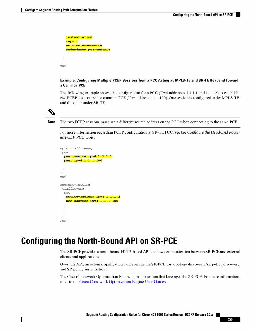
instantiationreportautoroute-announceredundancy pcc-centric!!!end
Example: Configuring Multiple PCEP Sessions from a PCC Acting as MPLS-TE and SR-TE Headend Towarda Common PCE
The following example shows the configuration for a PCC (IPv4 addresses 1.1.1.1 and 1.1.1.2) to establishtwo PCEP sessions with a common PCE (IPv4 address 1.1.1.100). One session is configured underMPLS-TE,and the other under SR-TE.
The two PCEP sessions must use a different source address on the PCC when connecting to the same PCE.Note
For more information regarding PCEP configuration at SR-TE PCC, see the Configure the Head-End Routeras PCEP PCC topic.
mpls traffic-engpcepeer source ipv4 1.1.1.1peer ipv4 1.1.1.100!!!end
segment-routingtraffic-engpccsource-address ipv4 1.1.1.2pce address ipv4 1.1.1.100!!!!end
Configuring the North-Bound API on SR-PCEThe SR-PCE provides a north-bound HTTP-based API to allow communication between SR-PCE and externalclients and applications.
Over this API, an external application can leverage the SR-PCE for topology discovery, SR policy discovery,and SR policy instantiation.
The Cisco Crosswork Optimization Engine is an application that leverages the SR-PCE. For more information,refer to the Cisco Crosswork Optimization Engine User Guides.
Segment Routing Configuration Guide for Cisco NCS 5500 Series Routers, IOS XR Release 7.2.x225
Configure Segment Routing Path Computation ElementConfiguring the North-Bound API on SR-PCE

Use the following commands under PCE configuration mode to configure the API to allow communicationbetween SR-PCE and external clients or applications.
The API server is enabled by default when SR-PCE is configured.Note
DescriptionCommand
(Optional) Specify basic (plaintext) authentication.By default, authentication is disabled.
rest authentication basic
Add credentials when connecting to API.
This command is used only ifauthentication is configured.
Note
rest username password {clear | encrypted}password
Opens a synchronization channel to another PCE inthe same high availability (HA) pair.
For more information regarding SR-PCEHA pairs, refer to the Multiple CiscoSR-PCE HA Pairs chapter of the CiscoCrossworkOptimization Engine 1.2.1 UserGuide.
Note
rest sibling ipv4 address
DescriptionCommand
Specify the type of authentication:
• basic – Use HTTP Basic authentication(plaintext)
• digest – Use HTTPDigest authentication (MD5)
api authentication {basic | digest}
Add credentials when connecting to API.api username password {clear | encrypted}password
Opens a synchronization channel to another PCE inthe same high availability (HA) pair.
For more information regarding SR-PCEHA pairs, refer to the Multiple CiscoSR-PCE HA Pairs chapter of the CiscoCrossworkOptimization Engine 1.2.1 UserGuide.
Note
api sibling ipv4 address
Example: Configuring API on SR-PCE
pceaddress ipv4 1.1.1.100restuser adminpassword encrypted 1304131F0202
Segment Routing Configuration Guide for Cisco NCS 5500 Series Routers, IOS XR Release 7.2.x226
Configure Segment Routing Path Computation ElementConfiguring the North-Bound API on SR-PCE

!authentication basicsibling ipv4 1.1.1.200!!end
pceaddress ipv4 1.1.1.100apiuser adminpassword encrypted 1304131F0202!authentication digestsibling ipv4 1.1.1.200!!end
The following example shows the current active connections:
RP/0/0/CPU0:pce1# show tcp brief | i 8080Thu Aug 6 00:40:15.408 PDT0xe9806fb8 0x60000000 0 0 :::8080 :::0 LISTEN0xe94023b8 0x60000000 0 0 1.1.1.100:50487 1.1.1.200:8080 ESTAB0xeb20bb40 0x60000000 0 0 1.1.1.100:8080 1.1.1.200:44401 ESTAB0xe98031a0 0x60000000 0 0 0.0.0.0:8080 0.0.0.0:0 LISTEN
The first and fourth entries show the API server listening for IPv4 and IPv6 connections.
The second and third entries show the established sibling connection between PCE1 (1.1.1.100) and PCE2(1.1.1.200).
Segment Routing Configuration Guide for Cisco NCS 5500 Series Routers, IOS XR Release 7.2.x227
Configure Segment Routing Path Computation ElementConfiguring the North-Bound API on SR-PCE

Segment Routing Configuration Guide for Cisco NCS 5500 Series Routers, IOS XR Release 7.2.x228
Configure Segment Routing Path Computation ElementConfiguring the North-Bound API on SR-PCE
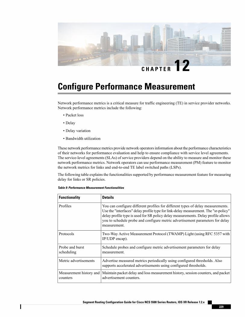
C H A P T E R 12Configure Performance Measurement
Network performance metrics is a critical measure for traffic engineering (TE) in service provider networks.Network performance metrics include the following:
• Packet loss
• Delay
• Delay variation
• Bandwidth utilization
These network performancemetrics provide network operators information about the performance characteristicsof their networks for performance evaluation and help to ensure compliance with service level agreements.The service-level agreements (SLAs) of service providers depend on the ability to measure and monitor thesenetwork performance metrics. Network operators can use performance measurement (PM) feature to monitorthe network metrics for links and end-to-end TE label switched paths (LSPs).
The following table explains the functionalities supported by performance measurement feature for measuringdelay for links or SR policies.
Table 9: Performance Measurement Functionalities
DetailsFunctionality
You can configure different profiles for different types of delay measurements.Use the "interfaces" delay profile type for link-delaymeasurement. The "sr-policy"delay profile type is used for SR policy delay measurements. Delay profile allowsyou to schedule probe and configure metric advertisement parameters for delaymeasurement.
Profiles
Two-Way ActiveMeasurement Protocol (TWAMP) Light (using RFC 5357 withIP/UDP encap).
Protocols
Schedule probes and configure metric advertisement parameters for delaymeasurement.
Probe and burstscheduling
Advertise measured metrics periodically using configured thresholds. Alsosupports accelerated advertisements using configured thresholds.
Metric advertisements
Maintain packet delay and loss measurement history, session counters, and packetadvertisement counters.
Measurement history andcounters
Segment Routing Configuration Guide for Cisco NCS 5500 Series Routers, IOS XR Release 7.2.x229

• Measurement Modes, on page 230• Usage Guidelines and Limitations, on page 231• Link Delay Measurement, on page 232• SR Policy End-to-End Delay Measurement , on page 245
Measurement ModesThe following table compares the different hardware and timing requirements for the measurement modessupported in SR PM.
Table 10: Measurement Mode Requirements
PTP Clock Synchronizationbetween Sender and Reflector
Reflector:
PTP-Capable HW and HWTimestamping
Sender:
PTP-Capable HW and HWTimestamping
Measurement Mode
RequiredRequiredRequiredOne-way
Not RequiredRequiredRequiredTwo-way
One-Way
One-way measurement mode provides the most precise form of one-way delay measurement. PTP-capablehardware and hardware timestamping are required on both Sender and Reflector, with PTP ClockSynchronization between Sender and Reflector.
Delay measurement in one-way mode is calculated as (T2 – T1).
Figure 8: One-Way
The PM query and response for one-way delay measurement can be described in the following steps:
1. The local-end router sends PM query packets periodically to the remote side once the egress line card onthe router applies timestamps on packets.
2. The ingress line card on the remote-end router applies time-stamps on packets as soon as they are received.
Segment Routing Configuration Guide for Cisco NCS 5500 Series Routers, IOS XR Release 7.2.x230
Configure Performance MeasurementMeasurement Modes
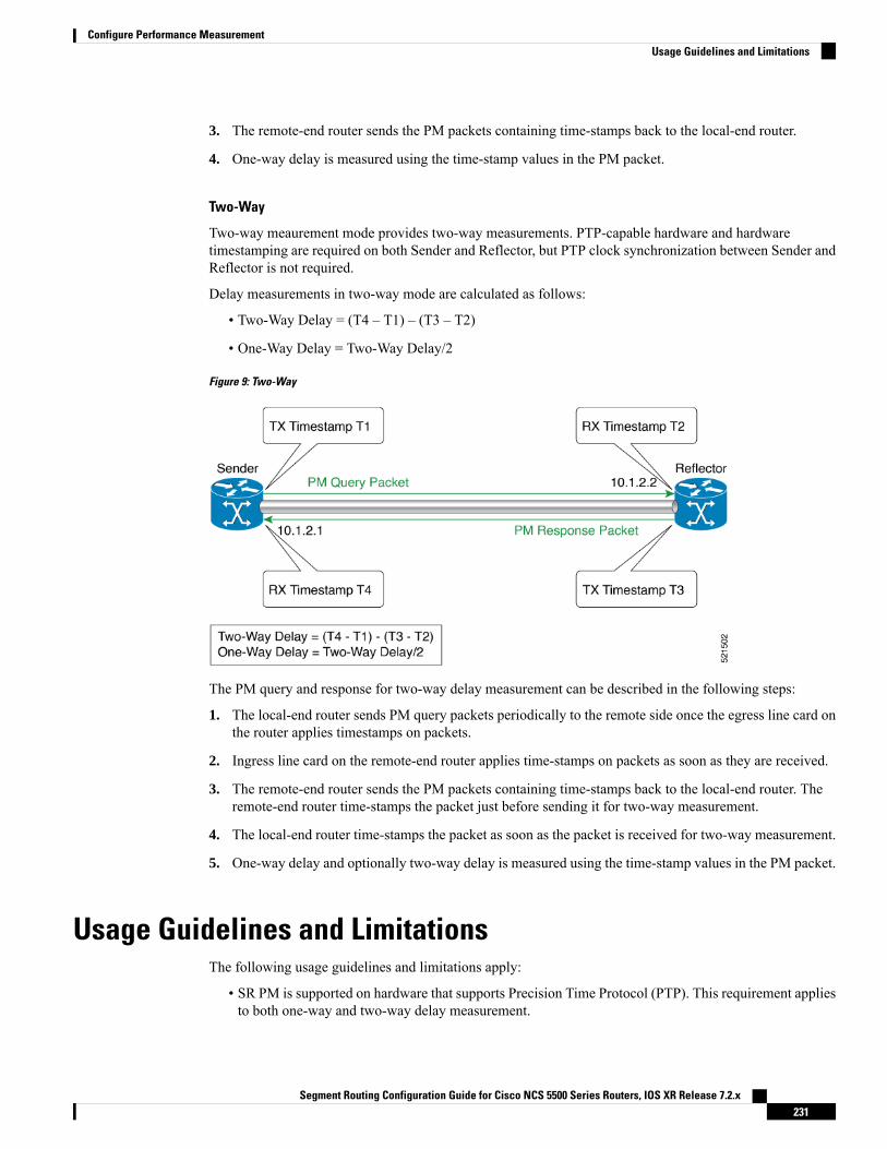
3. The remote-end router sends the PM packets containing time-stamps back to the local-end router.
4. One-way delay is measured using the time-stamp values in the PM packet.
Two-Way
Two-way meaurement mode provides two-way measurements. PTP-capable hardware and hardwaretimestamping are required on both Sender and Reflector, but PTP clock synchronization between Sender andReflector is not required.
Delay measurements in two-way mode are calculated as follows:
• Two-Way Delay = (T4 – T1) – (T3 – T2)
• One-Way Delay = Two-Way Delay/2
Figure 9: Two-Way
The PM query and response for two-way delay measurement can be described in the following steps:
1. The local-end router sends PM query packets periodically to the remote side once the egress line card onthe router applies timestamps on packets.
2. Ingress line card on the remote-end router applies time-stamps on packets as soon as they are received.
3. The remote-end router sends the PM packets containing time-stamps back to the local-end router. Theremote-end router time-stamps the packet just before sending it for two-way measurement.
4. The local-end router time-stamps the packet as soon as the packet is received for two-way measurement.
5. One-way delay and optionally two-way delay is measured using the time-stamp values in the PM packet.
Usage Guidelines and LimitationsThe following usage guidelines and limitations apply:
• SR PM is supported on hardware that supports Precision Time Protocol (PTP). This requirement appliesto both one-way and two-way delay measurement.
Segment Routing Configuration Guide for Cisco NCS 5500 Series Routers, IOS XR Release 7.2.x231
Configure Performance MeasurementUsage Guidelines and Limitations

See the Configuring Precision Time Protocol chapter in the System Management Configuration Guidefor Cisco NCS 5500 Series Routers for Restrictions for PTP and the Timing Hardware Support Matrix.
Link Delay MeasurementThe PM for link delay uses the IP/UDP packet format defined in RFC 5357 (TWAMP-Light) for probes.Two-Way Active Measurement Protocol (TWAMP) adds two-way or round-trip measurement capabilities.TWAMP employs time stamps applied at the echo destination (reflector) to enable greater accuracy. In thecase of TWAMP Light, the Session-Reflector doesn’t necessarily know about the session state. TheSession-Reflector simply copies the Sequence Number of the received packet to the Sequence Number fieldof the reflected packet. The controller receives the reflected test packets and collects two-way metrics. Thisarchitecture allows for collection of two-way metrics.
Usage Guidelines and Restrictions for PM for Link Delay
The following restrictions and guidelines apply for the PM for link delay feature for different links.
• For broadcast links, only point-to-point (P2P) links are supported. P2P configuration on IGP is requiredfor flooding the value.
• For link bundles, the hashing function may select a member link for forwarding but the reply may comefrom the remote line card on a different member link of the bundle.
• For one-way delaymeasurement, clocks should be synchronized on two end-point nodes of the link usingPTP.
Configuration Example: PM for Link Delay
This example shows how to configure performance-measurement functionalities for link delay as a globaldefault profile. The default values for the different parameters in the PM for link delay is given as follows:
• probe measurement mode: The default measurement mode for probe is two-way delay measurement.If you are configuring one-way delay measurement, hardware clocks must be synchronized between thelocal-end and remote-end routers using precision time protocol (PTP). SeeMeasurementModes, on page230 for more information.
• protocol: Interface delay measurement using RFC 5357 with IP/UDP encap (TWAMP-Light).
• burst interval: Interval for sending probe packet. The default value is 3000 milliseconds and the rangeis from 30 to 15000 milliseconds.
• computation interval: Interval for metric computation. Default is 30 seconds; range is 1 to 3600 seconds.
• periodic advertisement: Periodic advertisement is enabled by default.
• periodic-advertisement interval: The default value is 120 seconds and the interval range is from 30 to3600 seconds.
• periodic-advertisement threshold: Checks the minimum-delay metric change for threshold crossingfor periodic advertisement. The default value is 10 percent and the range is from 0 to 100 percent.
• periodic-advertisement minimum change: The default value is 1000microseconds (usec) and the rangeis from 0 to 100000 microseconds.
Segment Routing Configuration Guide for Cisco NCS 5500 Series Routers, IOS XR Release 7.2.x232
Configure Performance MeasurementLink Delay Measurement

• accelerated advertisement: Accelerated advertisement is disabled by default.
• accelerated-advertisement threshold: Checks the minimum-delay metric change for threshold crossingfor accelerated advertisement. The default value is 20 percent and the range is from 0 to 100 percent.
• accelerated-advertisement minimum change: The default value is 500 microseconds and the range isfrom 0 to 100000 microseconds.
RP/0/0/CPU0:router(config)# performance-measurement delay-profile interfacesRP/0/0/CPU0:router(config-pm-dm-intf)# probeRP/0/0/CPU0:router(config-pm-dm-intf-probe)# measurement-mode one-wayRP/0/0/CPU0:router(config-pm-dm-intf-probe)# burst-interval 60RP/0/0/CPU0:router(config-pm-dm-intf-probe)# computation-interval 60RP/0/0/CPU0:router(config-pm-dm-intf-probe)# exit
RP/0/0/CPU0:router(config-pm-dm-intf)# advertisement periodicRP/0/0/CPU0:router(config-pm-dm-intf-adv-per)# interval 120RP/0/0/CPU0:router(config-pm-dm-intf-adv-per)# threshold 20RP/0/0/CPU0:router(config-pm-dm-intf-adv-per)# minimum-change 1000RP/0/0/CPU0:router(config-pm-dm-intf-adv-per)# exit
RP/0/0/CPU0:router(config-pm-dm-intf)# advertisement acceleratedRP/0/0/CPU0:router(config-pm-dm-intf-adv-acc)# threshold 30RP/0/0/CPU0:router(config-pm-dm-intf-adv-acc)# minimum-change 1000RP/0/0/CPU0:router(config-pm-dm-intf-adv-per)# exit
Configure the UDP Destination Port
Configuring the UDP port for TWAMP-Light protocol is optional. By default, PM uses port 862 as theTWAMP-reserved UDP destination port for delay.
The UDP port is configured for each PMmeasurement probe type (delay, loss, protocol, authentication mode,etc.) on querier and responder nodes. If you configure a different UDP port, the UDP port for each PMmeasurement probe type must match on the querier and the responder nodes.
The same UDP destination port is used for delay measurement for links and SR Policy.Note
This example shows how to configure the UDP destination port for delay.Router(config)# performance-measurement
Router(config-perf-meas)# protocol twamp-light
Router(config-pm-protocol)# measurement delay unauthenticatedRouter(config-pm-proto-mode)# querier-dst-port 12000
Enable PM for Link Delay Over an Interface
This example shows how to enable PM for link delay over an interface.RP/0/0/CPU0:router(config)# performance-measurementRP/0/0/CPU0:router(config-perf-meas)# interface TenGigE0/0/0/0RP/0/0/CPU0:router(config-pm-intf)# next-hop ipv4 10.10.10.2 // Optional IPv4 or IPv6next-hop addressRP/0/0/CPU0:router(config-pm-intf)# delay-measurementRP/0/0/CPU0:router(config-pm-intf-dm)# exit
Segment Routing Configuration Guide for Cisco NCS 5500 Series Routers, IOS XR Release 7.2.x233
Configure Performance MeasurementLink Delay Measurement

The source and destination IP addresses used in the OAM packet are determined by the IP address present onthe interface where the delay-measurement operation is enabled and the setting of the optional next-hopaddress.
When the next-hop address is not specified, the following rules apply to determine the source and destinationIP addresses used in the OAM packet:
• If an IPv4 address is configured under the interface, then:
• OAM packet source IP address = Interface's IPv4 address
• OAM packet destination IP address = 127.0.0.0
• Else, if an IPv6 global address is configured under the interface, then:
• OAM packet source IP address = Interface's IPv6 global address
• OAM packet destination IP address = 0::ff:127.0.0.0
When the next-hop {ipv4 | ipv6} address is configured, the following rules apply to determine the sourceand destination IP addresses used in the OAM packet:
• If a next-hop IPv4 address is configured, then:
• OAM packet source IP address = Interface's IPv4 address
• OAM packet destination IP address = Configured next-hop IPv4 address
If there is no IPv4 address configured under the interface, then thedelay-measurement probe does not send OAM packets.
Note
• If a next-hop IPv6 address is configured, then:
• OAM packet source IP address = Interface's IPv6 global address
• OAM packet destination IP address = Configured next-hop IPv6 address
If there is no IPv6 global address configured under the interface, thenthe delay-measurement probe does not send OAM packets.
Note
This example shows how to enable PM for link delay over an interface with IPv4 address configured:
interface TenGigE0/0/0/0ipv4 address 10.10.10.1 255.255.255.0
performance-measurementinterface TenGigE0/0/0/0delay-measurement
This example shows how to enable PM for link delay over an interface IPv6 address configured:
Segment Routing Configuration Guide for Cisco NCS 5500 Series Routers, IOS XR Release 7.2.x234
Configure Performance MeasurementLink Delay Measurement
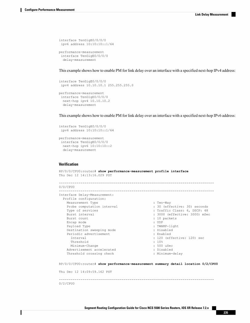
interface TenGigE0/0/0/0ipv6 address 10:10:10::1/64
performance-measurementinterface TenGigE0/0/0/0delay-measurement
This example shows how to enable PM for link delay over an interface with a specified next-hop IPv4 address:
interface TenGigE0/0/0/0ipv4 address 10.10.10.1 255.255.255.0
performance-measurementinterface TenGigE0/0/0/0next-hop ipv4 10.10.10.2delay-measurement
This example shows how to enable PM for link delay over an interface with a specified next-hop IPv6 address:
interface TenGigE0/0/0/0ipv6 address 10:10:10::1/64
performance-measurementinterface TenGigE0/0/0/0next-hop ipv6 10:10:10::2delay-measurement
Verification
RP/0/0/CPU0:router# show performance-measurement profile interfaceThu Dec 12 14:13:16.029 PST
-------------------------------------------------------------------------------0/0/CPU0-------------------------------------------------------------------------------Interface Delay-Measurement:Profile configuration:Measurement Type : Two-WayProbe computation interval : 30 (effective: 30) secondsType of services : Traffic Class: 6, DSCP: 48Burst interval : 3000 (effective: 3000) mSecBurst count : 10 packetsEncap mode : UDPPayload Type : TWAMP-lightDestination sweeping mode : DisabledPeriodic advertisement : EnabledInterval : 120 (effective: 120) secThreshold : 10%Minimum-Change : 500 uSec
Advertisement accelerated : DisabledThreshold crossing check : Minimum-delay
RP/0/0/CPU0:router# show performance-measurement summary detail location 0/2/CPU0
Thu Dec 12 14:09:59.162 PST
-------------------------------------------------------------------------------0/2/CPU0
Segment Routing Configuration Guide for Cisco NCS 5500 Series Routers, IOS XR Release 7.2.x235
Configure Performance MeasurementLink Delay Measurement

-------------------------------------------------------------------------------Total interfaces : 1Total SR Policies : 0Total RSVP-TE tunnels : 0Total Maximum PPS : 2000 pkts/secTotal Interfaces PPS : 0 pkts/secMaximum Allowed Multi-hop PPS : 2000 pkts/secMulti Hop Requested PPS : 0 pkts/sec (0% of max allowed)Dampened Multi Hop Requested PPS : 0% of max allowedInuse Burst Interval Adjustment Factor : 100% of configuration
Interface Delay-Measurement:Total active sessions : 1Counters:Packets:Total sent : 26Total received : 26
Errors:TX:Reason interface down : 0Reason no MPLS caps : 0Reason no IP address : 0Reason other : 0
RX:Reason negative delay : 0Reason delay threshold exceeded : 0Reason missing TX timestamp : 0Reason missing RX timestamp : 0Reason probe full : 0Reason probe not started : 0Reason control code error : 0Reason control code notif : 0
Probes:Total started : 3Total completed : 2Total incomplete : 0Total advertisements : 0
SR Policy Delay-Measurement:Total active sessions : 0Counters:Packets:Total sent : 0Total received : 0
Errors:TX:Reason interface down : 0Reason no MPLS caps : 0Reason no IP address : 0Reason other : 0
RX:Reason negative delay : 0Reason delay threshold exceeded : 0Reason missing TX timestamp : 0Reason missing RX timestamp : 0Reason probe full : 0Reason probe not started : 0Reason control code error : 0Reason control code notif : 0
Probes:Total started : 0Total completed : 0Total incomplete : 0
Segment Routing Configuration Guide for Cisco NCS 5500 Series Routers, IOS XR Release 7.2.x236
Configure Performance MeasurementLink Delay Measurement

Total advertisements : 0
RSVP-TE Delay-Measurement:Total active sessions : 0Counters:Packets:Total sent : 0Total received : 0
Errors:TX:Reason interface down : 0Reason no MPLS caps : 0Reason no IP address : 0Reason other : 0
RX:Reason negative delay : 0Reason delay threshold exceeded : 0Reason missing TX timestamp : 0Reason missing RX timestamp : 0Reason probe full : 0Reason probe not started : 0Reason control code error : 0Reason control code notif : 0
Probes:Total started : 0Total completed : 0Total incomplete : 0Total advertisements : 0
Global Delay Counters:Total packets sent : 26Total query packets received : 26Total invalid session id : 0Total missing session : 0
RP/0/0/CPU0:router# show performance-measurement interfaces detailThu Dec 12 14:16:09.692 PST
-------------------------------------------------------------------------------0/0/CPU0-------------------------------------------------------------------------------
-------------------------------------------------------------------------------0/2/CPU0-------------------------------------------------------------------------------
Interface Name: GigabitEthernet0/2/0/0 (ifh: 0x1004060)Delay-Measurement : EnabledLoss-Measurement : DisabledConfigured IPv4 Address : 10.10.10.2Configured IPv6 Address : 10:10:10::2Link Local IPv6 Address : fe80::3a:6fff:fec9:cd6bConfigured Next-hop Address : UnknownLocal MAC Address : 023a.6fc9.cd6bNext-hop MAC Address : 0291.e460.6707Primary VLAN Tag : NoneSecondary VLAN Tag : NoneState : Up
Delay Measurement session:Session ID : 1
Last advertisement:Advertised at: Dec 12 2019 14:10:43.138 (326.782 seconds ago)Advertised reason: First advertisement
Segment Routing Configuration Guide for Cisco NCS 5500 Series Routers, IOS XR Release 7.2.x237
Configure Performance MeasurementLink Delay Measurement

Advertised delays (uSec): avg: 839, min: 587, max: 8209, variance: 297
Next advertisement:Threshold check scheduled in 1 more probe (roughly every 120 seconds)Aggregated delays (uSec): avg: 751, min: 589, max: 905, variance: 112Rolling average (uSec): 756
Current Probe:Started at Dec 12 2019 14:15:43.154 (26.766 seconds ago)Packets Sent: 9, received: 9Measured delays (uSec): avg: 795, min: 631, max: 1199, variance: 164Next probe scheduled at Dec 12 2019 14:16:13.132 (in 3.212 seconds)Next burst packet will be sent in 0.212 secondsBurst packet sent every 3.0 secondsProbe samples:Packet Rx Timestamp Measured Delay (nsec)Dec 12 2019 14:15:43.156 689223Dec 12 2019 14:15:46.156 876561Dec 12 2019 14:15:49.156 913548Dec 12 2019 14:15:52.157 1199620Dec 12 2019 14:15:55.156 794008Dec 12 2019 14:15:58.156 631437Dec 12 2019 14:16:01.157 656440Dec 12 2019 14:16:04.157 658267Dec 12 2019 14:16:07.157 736880
You can also use the following commands for verifying the PM for link delay on the local-end router.
DescriptionCommand
Displays the PM link-delay probe history forinterfaces.
show performance-measurement history probeinterfaces [interface]
Displays the PM link-delay aggregated history forinterfaces.
show performance-measurement historyaggregated interfaces [interface]
Displays the PM link-delay advertisement history forinterfaces.
show performance-measurement historyadvertisement interfaces [interface]
Displays the PM link-delay session counters.show performance-measurement counters [interfaceinterface] [location location-name]
You can also use the following commands for verifying the PM for link-delay configuration on the remote-endrouter.
DescriptionCommand
Displays the PM for link-delay summary on theremote-end router (responder).
show performance-measurement respondersummary [location location-name]
Displays PM for link-delay for interfaces on theremote-end router.
show performance-measurement responderinterfaces [interface]
Displays the PM link-delay session counters on theremote-end router.
show performance-measurement respondercounters [interface interface] [locationlocation-name]
Segment Routing Configuration Guide for Cisco NCS 5500 Series Routers, IOS XR Release 7.2.x238
Configure Performance MeasurementLink Delay Measurement
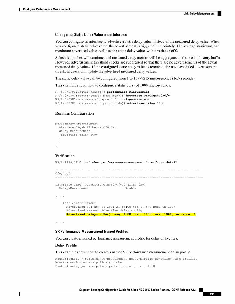
Configure a Static Delay Value on an Interface
You can configure an interface to advertise a static delay value, instead of the measured delay value. Whenyou configure a static delay value, the advertisement is triggered immediately. The average, minimum, andmaximum advertised values will use the static delay value, with a variance of 0.
Scheduled probes will continue, and measured delay metrics will be aggregated and stored in history buffer.However, advertisement threshold checks are suppressed so that there are no advertisements of the actualmeasured delay values. If the configured static delay value is removed, the next scheduled advertisementthreshold check will update the advertised measured delay values.
The static delay value can be configured from 1 to 16777215 microseconds (16.7 seconds).
This example shows how to configure a static delay of 1000 microseconds:RP/0/0/CPU0:router(config)# performance-measurementRP/0/0/CPU0:router(config-perf-meas)# interface TenGigE0/0/0/0RP/0/0/CPU0:router(config-pm-intf)# delay-measurementRP/0/0/CPU0:router(config-pm-intf-dm)# advertise-delay 1000
Running Configuration
performance-measurementinterface GigabitEthernet0/0/0/0delay-measurementadvertise-delay 1000!!!
Verification
RP/0/RSP0/CPU0:ios# show performance-measurement interfaces detail
--------------------------------------------------------------------------------0/0/CPU0--------------------------------------------------------------------------------
Interface Name: GigabitEthernet0/0/0/0 (ifh: 0x0)Delay-Measurement : Enabled
. . .
Last advertisement:Advertised at: Nov 29 2021 21:53:00.656 (7.940 seconds ago)Advertised reason: Advertise delay configAdvertised delays (uSec): avg: 1000, min: 1000, max: 1000, variance: 0
. . .
SR Performance Measurement Named Profiles
You can create a named performance measurement profile for delay or liveness.
Delay Profile
This example shows how to create a named SR performance measurement delay profile.Router(config)# performance-measurement delay-profile sr-policy name profile2Router(config-pm-dm-srpolicy)# probeRouter(config-pm-dm-srpolicy-probe)# burst-interval 60
Segment Routing Configuration Guide for Cisco NCS 5500 Series Routers, IOS XR Release 7.2.x239
Configure Performance MeasurementLink Delay Measurement
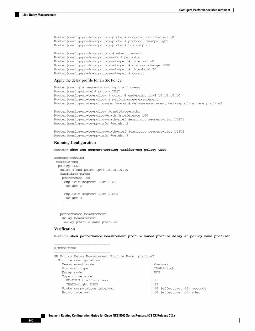
Router(config-pm-dm-srpolicy-probe)# computation-interval 60Router(config-pm-dm-srpolicy-probe)# protocol twamp-lightRouter(config-pm-dm-srpolicy-probe)# tos dscp 63
Router(config-pm-dm-srpolicy)# advertisementRouter(config-pm-dm-srpolicy-adv)# periodicRouter(config-pm-dm-srpolicy-adv-per)# interval 60Router(config-pm-dm-srpolicy-adv-per)# minimum-change 1000Router(config-pm-dm-srpolicy-adv-per)# threshold 20Router(config-pm-dm-srpolicy-adv-per)# commit
Apply the delay profile for an SR Policy.Router(config)# segment-routing traffic-engRouter(config-sr-te)# policy TESTRouter(config-sr-te-policy)# color 4 end-point ipv4 10.10.10.10Router(config-sr-te-policy)# performance-measurementRouter(config-sr-te-policy-perf-meas)# delay-measurement delay-profile name profile2
Router(config-sr-te-policy)#candidate-pathsRouter(config-sr-te-policy-path)#preference 100Router(config-sr-te-policy-path-pref)#explicit segment-list LIST1Router(config-sr-te-pp-info)#weight 2
Router(config-sr-te-policy-path-pref)#explicit segment-list LIST2Router(config-sr-te-pp-info)#weight 3
Running Configuration
Router# show run segment-routing traffic-eng policy TEST
segment-routingtraffic-engpolicy TESTcolor 4 end-point ipv4 10.10.10.10candidate-pathspreference 100explicit segment-list LIST1weight 2!explicit segment-list LIST2weight 3!!!performance-measurementdelay-measurementdelay-profile name profile2
Verification
Router# show performance-measurement profile named-profile delay sr-policy name profile2
----------------------------0/RSP0/CPU0----------------------------SR Policy Delay Measurement Profile Name: profile2Profile configuration:Measurement mode : One-wayProtocol type : TWAMP-lightEncap mode : UDPType of service:PM-MPLS traffic class : 6TWAMP-light DSCP : 63
Probe computation interval : 60 (effective: 60) secondsBurst interval : 60 (effective: 60) mSec
Segment Routing Configuration Guide for Cisco NCS 5500 Series Routers, IOS XR Release 7.2.x240
Configure Performance MeasurementLink Delay Measurement
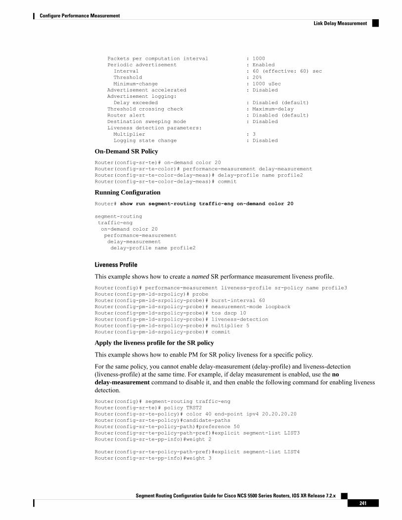
Packets per computation interval : 1000Periodic advertisement : EnabledInterval : 60 (effective: 60) secThreshold : 20%Minimum-change : 1000 uSec
Advertisement accelerated : DisabledAdvertisement logging:Delay exceeded : Disabled (default)
Threshold crossing check : Maximum-delayRouter alert : Disabled (default)Destination sweeping mode : DisabledLiveness detection parameters:Multiplier : 3Logging state change : Disabled
On-Demand SR Policy
Router(config-sr-te)# on-demand color 20Router(config-sr-te-color)# performance-measurement delay-measurementRouter(config-sr-te-color-delay-meas)# delay-profile name profile2Router(config-sr-te-color-delay-meas)# commit
Running Configuration
Router# show run segment-routing traffic-eng on-demand color 20
segment-routingtraffic-engon-demand color 20performance-measurementdelay-measurementdelay-profile name profile2
Liveness Profile
This example shows how to create a named SR performance measurement liveness profile.Router(config)# performance-measurement liveness-profile sr-policy name profile3Router(config-pm-ld-srpolicy)# probeRouter(config-pm-ld-srpolicy-probe)# burst-interval 60Router(config-pm-ld-srpolicy-probe)# measurement-mode loopbackRouter(config-pm-ld-srpolicy-probe)# tos dscp 10Router(config-pm-ld-srpolicy-probe)# liveness-detectionRouter(config-pm-ld-srpolicy-probe)# multiplier 5Router(config-pm-ld-srpolicy-probe)# commit
Apply the liveness profile for the SR policy
This example shows how to enable PM for SR policy liveness for a specific policy.
For the same policy, you cannot enable delay-measurement (delay-profile) and liveness-detection(liveness-profile) at the same time. For example, if delay measurement is enabled, use the nodelay-measurement command to disable it, and then enable the following command for enabling livenessdetection.Router(config)# segment-routing traffic-engRouter(config-sr-te)# policy TRST2Router(config-sr-te-policy)# color 40 end-point ipv4 20.20.20.20Router(config-sr-te-policy)#candidate-pathsRouter(config-sr-te-policy-path)#preference 50Router(config-sr-te-policy-path-pref)#explicit segment-list LIST3Router(config-sr-te-pp-info)#weight 2
Router(config-sr-te-policy-path-pref)#explicit segment-list LIST4Router(config-sr-te-pp-info)#weight 3
Segment Routing Configuration Guide for Cisco NCS 5500 Series Routers, IOS XR Release 7.2.x241
Configure Performance MeasurementLink Delay Measurement
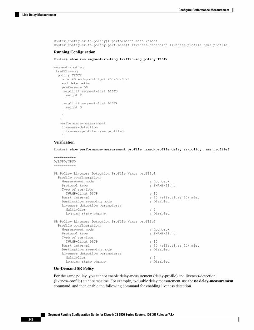
Router(config-sr-te-policy)# performance-measurementRouter(config-sr-te-policy-perf-meas)# liveness-detection liveness-profile name profile3
Running Configuration
Router# show run segment-routing traffic-eng policy TRST2
segment-routingtraffic-engpolicy TRST2color 40 end-point ipv4 20.20.20.20candidate-pathspreference 50explicit segment-list LIST3weight 2!explicit segment-list LIST4weight 3!!!performance-measurementliveness-detectionliveness-profile name profile3!
Verification
Router# show performance-measurement profile named-profile delay sr-policy name profile3
-----------0/RSP0/CPU0-----------
SR Policy Liveness Detection Profile Name: profile1Profile configuration:Measurement mode : LoopbackProtocol type : TWAMP-lightType of service:TWAMP-light DSCP : 10
Burst interval : 60 (effective: 60) mSecDestination sweeping mode : DisabledLiveness detection parameters:Multiplier : 3Logging state change : Disabled
SR Policy Liveness Detection Profile Name: profile3Profile configuration:Measurement mode : LoopbackProtocol type : TWAMP-lightType of service:TWAMP-light DSCP : 10
Burst interval : 60 (effective: 60) mSecDestination sweeping mode : DisabledLiveness detection parameters:Multiplier : 3Logging state change : Disabled
On-Demand SR Policy
For the same policy, you cannot enable delay-measurement (delay-profile) and liveness-detection(liveness-profile) at the same time. For example, to disable delaymeasurement, use the no delay-measurementcommand, and then enable the following command for enabling liveness detection.
Segment Routing Configuration Guide for Cisco NCS 5500 Series Routers, IOS XR Release 7.2.x242
Configure Performance MeasurementLink Delay Measurement

Router(config-sr-te)#on-demand color 30Router(config-sr-te-color)#performance-measurementRouter(config-sr-te-color-pm)# liveness-detection liveness-profile name profile1Router(config-sr-te-color-delay-meas)# commit
Running Configuration
Router# show run segment-routing traffic-eng on-demand color 30
segment-routingtraffic-engon-demand color 30performance-measurementliveness-detectionliveness-profile name profile3!
Verification
Router# show performance-measurement profile named-profile liveness sr-policy name profile3
--------------------0/RSP0/CPU0--------------------SR Policy Liveness Detection Profile Name: profile3Profile configuration:Measurement mode : LoopbackProtocol type : TWAMP-lightType of service:TWAMP-light DSCP : 10
Burst interval : 60 (effective: 60) mSecDestination sweeping mode : DisabledLiveness detection parameters:Multiplier : 3Logging state change : Disabled
Delay NormalizationPerformance measurement (PM) measures various link characteristics like packet loss and delay. Suchcharacteristics can be used by IS-IS as a metric for Flexible Algorithm computation. Low latency routingusing dynamic delay measurement is one of the primary use cases for Flexible Algorithm technology.
Delay is measured in microseconds. If delay values are taken as measured and used as link metrics during theIS-IS topology computation, some valid ECMP paths might be unused because of the negligible differencein the link delay.
The Delay Normalization feature computes a normalized delay value and uses the normalized value instead.This value is advertised and used as a metric during the Flexible Algorithm computation.
The normalization is performed when the delay is received from the delay measurement component. Whenthe next value is received, it is normalized and compared to the previous saved normalized value. If the valuesare different, then the LSP generation is triggered.
The following formula is used to calculate the normalized value:
• Dm – measured Delay
• Int – configured normalized Interval
• Off – configured normalized Offset (must be less than the normalized interval Int)
• Dn – normalized Delay
Segment Routing Configuration Guide for Cisco NCS 5500 Series Routers, IOS XR Release 7.2.x243
Configure Performance MeasurementDelay Normalization

• a = Dm / Int (rounded down)
• b = a * Int + Off
If the measured delay (Dm) is less than or equal to b, then the normalized delay (Dn) is equal to b. Otherwise,Dn is b + Int.
Example
The following example shows a low-latency service. The intent is to avoid high-latency links (1-6, 5-2). Links1-2 and 5-6 are both low-latency links. The measured latency is not equal, but the difference is insignificant.
We can normalize the measured latency before it is advertised and used by IS-IS. Consider a scenario withthe following:
• Interval = 10
• Offset = 3
The measured delays will be normalized as follows:
• Dm = 29
a = 29 / 10 = 2 (2.9, rounded down to 2)
b = 2 * 10 + 3 = 23
In this case, Dm (29) is greater than b (23); so Dn is equal to b+I (23 + 10) = 33
• Dm = 31
a = 31 / 10 = 3 (3.1, rounded down to 3)
b = 3 * 10 + 3 = 33
In this case, Dm (31) is less than b (33); so Dn is b = 33
Segment Routing Configuration Guide for Cisco NCS 5500 Series Routers, IOS XR Release 7.2.x244
Configure Performance MeasurementDelay Normalization
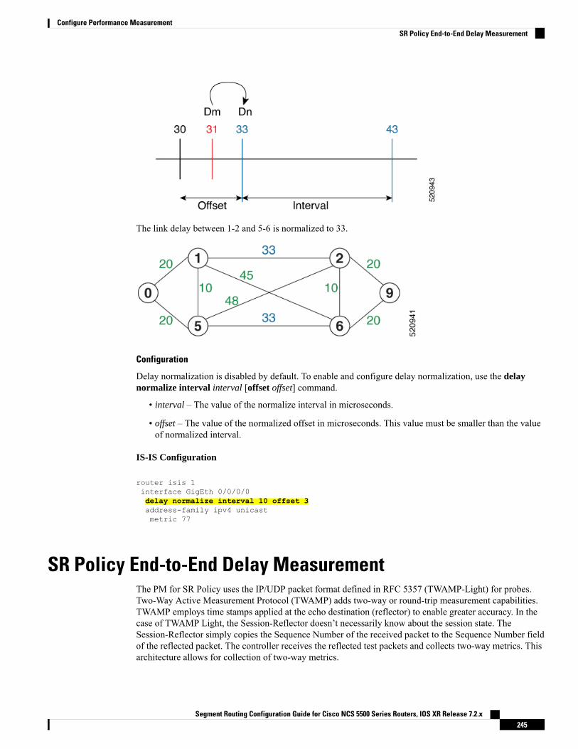
The link delay between 1-2 and 5-6 is normalized to 33.
Configuration
Delay normalization is disabled by default. To enable and configure delay normalization, use the delaynormalize interval interval [offset offset] command.
• interval – The value of the normalize interval in microseconds.
• offset – The value of the normalized offset in microseconds. This value must be smaller than the valueof normalized interval.
IS-IS Configuration
router isis 1interface GigEth 0/0/0/0delay normalize interval 10 offset 3address-family ipv4 unicastmetric 77
SR Policy End-to-End Delay MeasurementThe PM for SR Policy uses the IP/UDP packet format defined in RFC 5357 (TWAMP-Light) for probes.Two-Way Active Measurement Protocol (TWAMP) adds two-way or round-trip measurement capabilities.TWAMP employs time stamps applied at the echo destination (reflector) to enable greater accuracy. In thecase of TWAMP Light, the Session-Reflector doesn’t necessarily know about the session state. TheSession-Reflector simply copies the Sequence Number of the received packet to the Sequence Number fieldof the reflected packet. The controller receives the reflected test packets and collects two-way metrics. Thisarchitecture allows for collection of two-way metrics.
Segment Routing Configuration Guide for Cisco NCS 5500 Series Routers, IOS XR Release 7.2.x245
Configure Performance MeasurementSR Policy End-to-End Delay Measurement

The extended TE link delay metric (minimum-delay value) can be used to compute paths for SR policies asan optimization metric or as an accumulated delay bound.
There is a need to monitor the end-to-end delay experienced by the traffic sent over an SR policy to ensurethat the delay does not exceed the requested “upper-bound” and violate SLAs. You can verify the end-to-enddelay values before activating the candidate-path or the segment lists of the SR policy in forwarding table, orto deactivate the active candidate-path or the segment lists of the SR policy in forwarding table.
The end-to-end delay value of an SR policy will be different than the path computation result (for example,the sum of TE link delay metrics) due to several factors, such as queuing delay within the routers.
Note
Restrictions and Usage Guidelines for PM for SR Policy Delay
Hardware clocks must be synchronized between the querier and the responder nodes of the link using PTPfor one-way delay measurement.
Configuring Performance Measurement Parameters
This example shows how to configure performance-measurement parameters for SR policy delay as a globaldefault profile. The default values for the different parameters in the PM for SR policy delay is given asfollows:
• probe: The default mode for probe is one-way delay measurement. See Measurement Modes, on page230 for more information.
• burst interval: Interval for sending probe packet. The default value is 3000 milliseconds and the rangeis from 30 to 15000 milliseconds.
• computation interval: Interval for metric computation. Default is 30 seconds; range is 1 to 3600 seconds.
• protocol:
• twamp-light: SR Policy delay measurement using RFC 5357 with IP/UDP encap. This is the defaultprotocol.
• tos: Type of Service
• dscp value: The default value is 48 and the range is from 0 to 63.
• traffic-class value: The default value is 6 and the range is from 0 to 7.
• advertisement threshold-check: minimum-delay/maximum-delay - The default value of periodicadvertisement threshold-check is maximum-delay.
• periodic advertisement: Periodic advertisement is enabled by default.
• periodic-advertisement interval: The default value is 120 seconds and the interval range is from 30 to3600 seconds.
• periodic-advertisement threshold: Checks the minimum-delay metric change for threshold crossingfor periodic advertisement. The default value is 10 percent and the range is from 0 to 100 percent.
• periodic-advertisement minimum-change: The default value is 500 microseconds (usec) and the rangeis from 0 to 100000 microseconds.
Segment Routing Configuration Guide for Cisco NCS 5500 Series Routers, IOS XR Release 7.2.x246
Configure Performance MeasurementSR Policy End-to-End Delay Measurement

• accelerated advertisement: Accelerated advertisement is disabled by default.
• accelerated-advertisement threshold: Checks the minimum-delay metric change for threshold crossingfor accelerated advertisement. The default value is 20 percent and the range is from 0 to 100 percent.
• accelerated-advertisement minimum: The default value is 500 microseconds and the range is from 1to 100000 microseconds.
Router(config)# performance-measurement delay-profile sr-policyRouter(config-pm-dm-srpolicy)# probeRouter(config-pm-dm-srpolicy-probe)# burst-interval 60Router(config-pm-dm-srpolicy-probe)# computation-interval 60Router(config-pm-dm-srpolicy-probe)# protocol twamp-lightRouter(config-pm-dm-srpolicy-probe)# tos dscp 63Router(config-pm-dm-srpolicy-probe)# exit
Router(config-pm-dm-srpolicy)# advertisementRouter(config-pm-dm-srpolicy-adv)# periodicRouter(config-pm-dm-srpolicy-adv-per)# interval 60Router(config-pm-dm-srpolicy-adv-per)# minimum-change 1000Router(config-pm-dm-srpolicy-adv-per)# threshold 20Router(config-pm-dm-srpolicy-adv-per)# exit
Router(config-pm-dm-srpolicy-adv)# acceleratedRouter(config-pm-dm-srpolicy-adv-acc)# minimum-change 1000Router(config-pm-dm-srpolicy-adv-acc)# threshold 10Router(config-pm-dm-srpolicy-adv-acc)# exit
Router(config-pm-dm-srpolicy-adv)# threshold-check minimum-delayRouter(config-pm-dm-srpolicy-adv)# exitRouter(config-pm-dm-srpolicy)#
Configure the UDP Destination Port
Configuring the UDP port for TWAMP-Light protocol is optional. By default, PM uses port 862 as theTWAMP-reserved UDP destination port for delay.
The UDP port is configured for each PMmeasurement probe type (delay, loss, protocol, authentication mode,etc.) on querier and responder nodes. If you configure a different UDP port, the UDP port for each PMmeasurement probe type must match on the querier and the responder nodes.
The same UDP destination port is used for delay measurement for links and SR Policy.Note
This example shows how to configure the UDP destination port for delay.Router(config)# performance-measurement
Router(config-perf-meas)# protocol twamp-light
Router(config-pm-protocol)# measurement delay unauthenticatedRouter(config-pm-proto-mode)# querier-dst-port 12000
Enable Performance Measurement for SR Policy
This example shows how to enable PM for SR policy delay for a specific policy.
Segment Routing Configuration Guide for Cisco NCS 5500 Series Routers, IOS XR Release 7.2.x247
Configure Performance MeasurementSR Policy End-to-End Delay Measurement

Router(config)# segment-routing traffic-engRouter(config-sr-te)# policy fooRouter(config-sr-te-policy)# performance-measurementRouter(config-sr-te-policy-perf-meas)# delay-measurement
SR Policy Probe IP/UDP ECMP Hashing Configuration
This example shows how to configure SR Policy ECMP IP-hashing mode.
• The destination IPv4 address 127.x.x.x – 127.y.y.y is used in the Probe messages to take advantages of3-tuple IP hashing (source-address, destination-address, and local router ID) for ECMP paths of SR-MPLSPolicy.
The destination IPv4 address must be 127/8 range (loopback),otherwise it will be rejected.
Note
• One PM session is always created for the actual endpoint address of the SR Policy.
• You can specify the number of IP addresses to sweep. The range is from 0 (default, no sweeping) to 128.
• Platforms may have a limitation for large label stack size to not check IP address for hashing.
Router(config)# performance-measurement delay-profile sr-policyRouter(config-pm-dm-srpolicy)# probeRouter(config-pm-dm-srpolicy-probe)# sweepRouter(config-pm-dm-srpolicy-probe-sweep)# destination ipv4 127.0.0.1 range 28
Verification
Router# show performance-measurement sr-policy briefMon Jan 20 18:48:41.002 PST
-------------------------------------------------------------------------------0/0/CPU0-------------------------------------------------------------------------------
Policy Name LSP ID Tx/Rx Avg/Min/Max/Variance-----------------------------------------------------------------------------srte_c_10_ep_192.168.0.4 2 6/6 27012/26906/27203/106
Router# show performance-measurement sr-policy name srte_c_10_ep_192.168.0.4 detail verboseMon Jan 20 18:44:22.400 PST
-------------------------------------------------------------------------------0/0/CPU0-------------------------------------------------------------------------------SR Policy name: srte_c_10_ep_192.168.0.4Color : 10Endpoint : 192.168.0.4Number of candidate-paths : 1
Candidate-Path:Instance : 2Preference : 100Protocol-origin : ConfiguredDiscriminator : 100
Segment Routing Configuration Guide for Cisco NCS 5500 Series Routers, IOS XR Release 7.2.x248
Configure Performance MeasurementSR Policy End-to-End Delay Measurement

Source address : 192.168.0.2Reverse path label : Not configuredNumber of segment-lists : 1Last advertisement:No advertisements have occured
Next advertisement:Check scheduled at the end of the current probe (roughly every 30 seconds)Aggregated delays (uSec): avg: 45218, min: 26512, max: 82600, variance: 18706Rolling average (uSec): 45218
Last probe:Packets Sent: 9, received: 9Measured delays (uSec): avg: 45218, min: 26512, max: 82600, variance: 18706
Current Probe:Started at Jan 20 2020 18:44:19.170 (3.453 seconds ago)Packets Sent: 3, received: 3Measured delays (uSec): avg: 26588, min: 26558, max: 26630, variance: 30
Next probe scheduled at Jan 20 2020 18:44:34.166 (in 11.543 seconds)Next burst packet will be sent in 1.543 secondsBurst packet sent every 5.0 secondsLiveness Detection: Disabled
Segment-List : R416004
Number of atomic paths : 3Last advertisement:No advertisements have occured
Next advertisement:Aggregated delays (uSec): avg: 45218, min: 26512, max: 82600, variance: 18706Rolling average (uSec): 45218
Last probe:Packets Sent: 9, received: 9Measured delays (uSec): avg: 45218, min: 26512, max: 82600, variance: 18706
Current probe:Packets Sent: 3, received: 3Measured delays (uSec): avg: 26588, min: 26558, max: 26630, variance: 30
Liveness Detection: Disabled
Atomic path:Hops : 127.0.0.0Session ID : 33554434Last advertisement:No advertisements have occured
Next advertisement:Aggregated delays (uSec): avg: 45407, min: 26629, max: 82600, variance: 18778Rolling average (uSec): 45407
Last Probe:Packets Sent: 3, received: 3Measured delays (uSec): avg: 45407, min: 26629, max: 82600, variance: 18778
Current Probe:Packets Sent: 1, received: 1Measured delays (uSec): avg: 26630, min: 26630, max: 26630, variance: 0
Probe samples:Packet Rx Timestamp Measured Delay (nsec)Jan 20 2020 18:44:19.198 26630730
Liveness Detection: Disabled
Atomic path:Hops : 127.0.0.1Session ID : 33554435Last advertisement:No advertisements have occured
Next advertisement:Aggregated delays (uSec): avg: 45128, min: 26521, max: 81961, variance: 18607Rolling average (uSec): 45128
Segment Routing Configuration Guide for Cisco NCS 5500 Series Routers, IOS XR Release 7.2.x249
Configure Performance MeasurementSR Policy End-to-End Delay Measurement
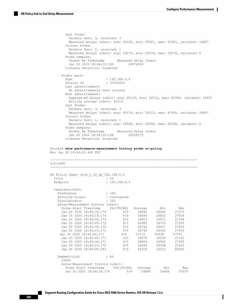
Last Probe:Packets Sent: 3, received: 3Measured delays (uSec): avg: 45128, min: 26521, max: 81961, variance: 18607
Current Probe:Packets Sent: 1, received: 1Measured delays (uSec): avg: 26576, min: 26576, max: 26576, variance: 0
Probe samples:Packet Rx Timestamp Measured Delay (nsec)Jan 20 2020 18:44:19.198 26576938
Liveness Detection: Disabled
Atomic path:Hops : 192.168.0.4Session ID : 33554433Last advertisement:No advertisements have occured
Next advertisement:Aggregated delays (uSec): avg: 45119, min: 26512, max: 81956, variance: 18607Rolling average (uSec): 45119
Last Probe:Packets Sent: 3, received: 3Measured delays (uSec): avg: 45119, min: 26512, max: 81956, variance: 18607
Current Probe:Packets Sent: 1, received: 1Measured delays (uSec): avg: 26558, min: 26558, max: 26558, variance: 0
Probe samples:Packet Rx Timestamp Measured Delay (nsec)Jan 20 2020 18:44:19.198 26558375
Liveness Detection: Disabled
Router# show performance-measurement history probe sr-policyMon Jan 20 18:46:55.445 PST
-------------------------------------------------------------------------------0/0/CPU0-------------------------------------------------------------------------------
SR Policy name: srte_c_10_ep_192.168.0.4Color : 10Endpoint : 192.168.0.4
Candidate-Path:Preference : 100Protocol-origin : ConfiguredDiscriminator : 100Delay-Measurement history (uSec):Probe Start Timestamp Pkt(TX/RX) Average Min MaxJan 20 2020 18:46:34.174 9/9 26880 26684 27070Jan 20 2020 18:46:19.174 9/9 26899 26822 27004Jan 20 2020 18:46:04.173 9/9 26813 26571 27164Jan 20 2020 18:45:49.172 9/9 26985 26713 27293Jan 20 2020 18:45:34.172 9/9 26744 26557 27005Jan 20 2020 18:45:19.171 9/9 26740 26435 27093Jan 20 2020 18:45:04.171 9/9 27115 26938 27591Jan 20 2020 18:44:49.171 9/9 26878 26539 27143Jan 20 2020 18:44:34.171 9/9 26824 26562 27265Jan 20 2020 18:44:19.170 9/9 26944 26558 27422Jan 20 2020 18:44:06.543 9/9 45218 26512 82600
Segment-List : R416004Delay-Measurement history (uSec):Probe Start Timestamp Pkt(TX/RX) Average Min MaxJan 20 2020 18:46:34.174 9/9 26880 26684 27070
Segment Routing Configuration Guide for Cisco NCS 5500 Series Routers, IOS XR Release 7.2.x250
Configure Performance MeasurementSR Policy End-to-End Delay Measurement

Jan 20 2020 18:46:19.174 9/9 26899 26822 27004Jan 20 2020 18:46:04.173 9/9 26813 26571 27164Jan 20 2020 18:45:49.172 9/9 26985 26713 27293Jan 20 2020 18:45:34.172 9/9 26744 26557 27005Jan 20 2020 18:45:19.171 9/9 26740 26435 27093Jan 20 2020 18:45:04.171 9/9 27115 26938 27591Jan 20 2020 18:44:49.171 9/9 26878 26539 27143Jan 20 2020 18:44:34.171 9/9 26824 26562 27265Jan 20 2020 18:44:19.170 9/9 26944 26558 27422Jan 20 2020 18:44:06.543 9/9 45218 26512 82600
Atomic path:Hops : 127.0.0.0Delay-Measurement history (uSec):Probe Start Timestamp Pkt(TX/RX) Average Min MaxJan 20 2020 18:46:34.174 3/3 26927 26747 27070Jan 20 2020 18:46:19.174 3/3 26982 26970 27004Jan 20 2020 18:46:04.173 3/3 26895 26647 27164Jan 20 2020 18:45:49.172 3/3 27054 26764 27293Jan 20 2020 18:45:34.172 3/3 26801 26694 27005Jan 20 2020 18:45:19.171 3/3 26807 26524 27093Jan 20 2020 18:45:04.171 3/3 27226 26938 27591Jan 20 2020 18:44:49.171 3/3 26976 26644 27143Jan 20 2020 18:44:34.171 3/3 26880 26679 27265Jan 20 2020 18:44:19.170 3/3 26994 26630 27422Jan 20 2020 18:44:06.543 3/3 45407 26629 82600
Atomic path:Hops : 127.0.0.1Delay-Measurement history (uSec):Probe Start Timestamp Pkt(TX/RX) Average Min MaxJan 20 2020 18:46:34.174 3/3 26865 26705 26988Jan 20 2020 18:46:19.174 3/3 26846 26822 26881Jan 20 2020 18:46:04.173 3/3 26787 26581 26939Jan 20 2020 18:45:49.172 3/3 26954 26728 27180Jan 20 2020 18:45:34.172 3/3 26724 26577 26957Jan 20 2020 18:45:19.171 3/3 26705 26452 27032Jan 20 2020 18:45:04.171 3/3 27043 26972 27124Jan 20 2020 18:44:49.171 3/3 26848 26550 27062Jan 20 2020 18:44:34.171 3/3 26800 26562 27204Jan 20 2020 18:44:19.170 3/3 26927 26576 27327Jan 20 2020 18:44:06.543 3/3 45128 26521 81961
Atomic path:Hops : 192.168.0.4Delay-Measurement history (uSec):Probe Start Timestamp Pkt(TX/RX) Average Min MaxJan 20 2020 18:46:34.174 3/3 26848 26684 26967Jan 20 2020 18:46:19.174 3/3 26871 26833 26913Jan 20 2020 18:46:04.173 3/3 26759 26571 26876Jan 20 2020 18:45:49.172 3/3 26947 26713 27163Jan 20 2020 18:45:34.172 3/3 26708 26557 26939Jan 20 2020 18:45:19.171 3/3 26708 26435 27075Jan 20 2020 18:45:04.171 3/3 27078 27016 27138Jan 20 2020 18:44:49.171 3/3 26812 26539 27043Jan 20 2020 18:44:34.171 3/3 26793 26582 27181Jan 20 2020 18:44:19.170 3/3 26911 26558 27308Jan 20 2020 18:44:06.543 3/3 45119 26512 81956
Router# show performance-measurement counters sr-policy name srte_c_10_ep_192.168.0.4Mon Jan 20 18:47:55.499 PST
-------------------------------------------------------------------------------0/0/CPU0
Segment Routing Configuration Guide for Cisco NCS 5500 Series Routers, IOS XR Release 7.2.x251
Configure Performance MeasurementSR Policy End-to-End Delay Measurement

-------------------------------------------------------------------------------SR Policy name: srte_c_10_ep_192.168.0.4Candidate-Path:Instance : 2Preference : 100Protocol-origin : ConfiguredDiscriminator : 100Packets:Total sent : 141Total received : 141
Errors:Total sent errors : 0Total received errors : 0
Probes:Total started : 16Total completed : 15Total incomplete : 0Total advertisements : 2
Segment-List : R416004Packets:Total sent : 141Total received : 141
Errors:Total sent errors : 0Total received errors : 0
Probes:Total started : 16Total completed : 15Total incomplete : 0Total advertisements : 2
Segment Routing Configuration Guide for Cisco NCS 5500 Series Routers, IOS XR Release 7.2.x252
Configure Performance MeasurementSR Policy End-to-End Delay Measurement

C H A P T E R 13Configure Topology-Independent Loop-FreeAlternate (TI-LFA)
Topology-Independent Loop-Free Alternate (TI-LFA) uses segment routing to provide link, node, and SharedRisk Link Groups (SRLG) protection in topologies where other fast reroute techniques cannot provideprotection.
• Classic Loop-Free Alternate (LFA) is topology dependent, and therefore cannot protect all destinationsin all networks. A limitation of LFA is that, even if one or more LFAs exist, the optimal LFA may notalways be provided.
• Remote LFA (RLFA) extends the coverage to 90-95% of the destinations, but it also does not alwaysprovide the most desired repair path. RLFA also adds more operational complexity by requiring a targetedLDP session to the RLFAs to protect LDP traffic.
TI-LFA provides a solution to these limitations while maintaining the simplicity of the IPFRR solution.
The goal of TI-LFA is to reduce the packet loss that results while routers converge after a topology changedue to a link or node failure. Rapid failure repair (< 50 msec) is achieved through the use of pre-calculatedbackup paths that are loop-free and safe to use until the distributed network convergence process is completed.
The optimal repair path is the path that the traffic will eventually follow after the IGP has converged. This iscalled the post-convergence path. This path is preferred for the following reasons:
• Optimal for capacity planning — During the capacity-planning phase of the network, the capacity of alink is provisioned while taking into consideration that such link with be used when other links fail.
• Simple to operate — There is no need to perform a case-by-case adjustments to select the best LFAamong multiple candidate LFAs.
• Fewer traffic transitions— Since the repair path is equal to the post-convergence path, the traffic switchespaths only once.
The following topology illustrates the optimal and automatic selection of the TI-LFA repair path.
Segment Routing Configuration Guide for Cisco NCS 5500 Series Routers, IOS XR Release 7.2.x253

Figure 10: TI-LFA Repair Path
Node 2 protects traffic to destination Node 5.
With classic LFA, traffic would be steered to Node 4 after a failure of the protected link. This path is notoptimal, since traffic is routed over edge node Node 4 that is connected to lower capacity links.
TI-LFA calculates a post-convergence path and derives the segment list required to steer packets along thepost-convergence path without looping back.
In this example, if the protected link fails, the shortest path from Node2 to Node5 would be:
Node2→ Node6→ Node7→ Node3→ Node5
Node7 is the PQ-node for destination Node5. TI-LFA encodes a single segment (prefix SID of Node7) in theheader of the packets on the repair path.
TI-LFA Protection Types
TI-LFA supports the following protection:
• Link protection — The link is excluded during the post-convergence backup path calculation.
• Node protection— The neighbor node is excluded during the post convergence backup path calculation.
• Shared Risk Link Groups (SRLG) protection — SRLG refer to situations in which links in a networkshare a common fiber (or a common physical attribute). These links have a shared risk: when one linkfails, other links in the group might also fail. TI-LFA SRLG protection attempts to find thepost-convergence backup path that excludes the SRLG of the protected link. All local links that shareany SRLG with the protecting link are excluded.
Segment Routing Configuration Guide for Cisco NCS 5500 Series Routers, IOS XR Release 7.2.x254
Configure Topology-Independent Loop-Free Alternate (TI-LFA)

When you enable link protection, you can also enable node protection, SRLG protection, or both, and specifya tiebreaker priority in case there are multiple LFAs.
The following example illustrates the link, node, and SRLG protection types. In this topology, Node2 appliesdifferent protection models to protect traffic to Node7.
Figure 11: TI-LFA Protection Types
• Usage Guidelines and Limitations, on page 255• Configuring TI-LFA for IS-IS, on page 256• Configuring TI-LFA for OSPF, on page 258• TI-LFA Node and SRLG Protection: Examples, on page 260• Configuring Global Weighted SRLG Protection, on page 261• SR-MPLS over GRE as TI-LFA Backup Path, on page 264
Usage Guidelines and LimitationsThe TI-LFA guidelines and limitations are listed below:
OSPFv2IS-IS1TI-LFA Functionality
Protected Traffic Types
SupportedSupportedProtection for SR labeled traffic
SupportedSupported(IS-ISv4)
Protection of IPv4 unlabeled traffic
N/AUnsupportedProtection of IPv6 unlabeled traffic
Protection Types
Segment Routing Configuration Guide for Cisco NCS 5500 Series Routers, IOS XR Release 7.2.x255
Configure Topology-Independent Loop-Free Alternate (TI-LFA)Usage Guidelines and Limitations

OSPFv2IS-IS1TI-LFA Functionality
SupportedSupportedLink Protection
SupportedSupportedNode Protection
SupportedSupportedLocal SRLG Protection
SupportedSupportedWeighted Remote SRLG Protection
UnsupportedSupportedLine Card Disjoint Protection
Interface Types
SupportedSupportedEthernet Interfaces
SupportedSupportedEthernet Bundle Interfaces
SupportedSupportedTI-LFA over GRE Tunnel as Protecting Interface
Additional Functionality
SupportedSupportedBFD-triggered
N/ASupportedBFDv6-triggered
SupportedSupportedPrefer backup path with lowest total metric
SupportedSupportedPrefer backup path from ECMP set
SupportedSupportedPrefer backup path from non-ECMP set
SupportedSupportedLoad share prefixes across multiple backups paths
SupportedSupportedLimit backup computation up to the prefix priority
1 Unless specified, IS-IS support is IS-ISv4 and IS-ISv6
Configuring TI-LFA for IS-ISThis task describes how to enable per-prefix Topology Independent Loop-Free Alternate (TI-LFA) computationto converge traffic flows around link, node, and SRLG failures.
Before you begin
Ensure that the following topology requirements are met:
• Router interfaces are configured as per the topology.
• Routers are configured with IS-IS.
• Segment routing for IS-IS is configured. See Enabling Segment Routing for IS-IS Protocol, on page 63.
SUMMARY STEPS
1. configure2. router isis instance-id
Segment Routing Configuration Guide for Cisco NCS 5500 Series Routers, IOS XR Release 7.2.x256
Configure Topology-Independent Loop-Free Alternate (TI-LFA)Configuring TI-LFA for IS-IS

3. interface type interface-path-id
4. address-family ipv4 [unicast]5. fast-reroute per-prefix6. fast-reroute per-prefix ti-lfa7. fast-reroute per-prefix tiebreaker {node-protecting | srlg-disjoint} index priority
DETAILED STEPS
PurposeCommand or Action
Enters global configuration mode.configure
Example:
Step 1
RP/0/RP0/CPU0:router# configure
Enables IS-IS routing for the specified routing instance,and places the router in router configuration mode.
router isis instance-id
Example:
Step 2
You can change the level of routing to beperformed by a particular routing instance byusing the is-type router configuration command.
NoteRP/0/RP0/CPU0:router(config)# router isis 1
Enters interface configuration mode.interface type interface-path-id
Example:
Step 3
RP/0/RP0/CPU0:router(config-isis)# interfaceGigabitEthernet0/0/2/1
Specifies the IPv4 address family, and enters router addressfamily configuration mode.
address-family ipv4 [unicast]
Example:
Step 4
RP/0/RP0/CPU0:router(config-isis-if)#address-family ipv4 unicast
Enables per-prefix fast reroute.fast-reroute per-prefix
Example:
Step 5
RP/0/RP0/CPU0:router(config-isis-if-af)#fast-reroute per-prefix
Enables per-prefix TI-LFA fast reroute link protection.fast-reroute per-prefix ti-lfa
Example:
Step 6
RP/0/RP0/CPU0:router(config-isis-if-af)#fast-reroute per-prefix ti-lfa
Enables TI-LFA node or SRLG protection and specifies thetiebreaker priority. Valid priority values are from 1 to 255.
fast-reroute per-prefix tiebreaker {node-protecting |srlg-disjoint} index priority
Step 7
Segment Routing Configuration Guide for Cisco NCS 5500 Series Routers, IOS XR Release 7.2.x257
Configure Topology-Independent Loop-Free Alternate (TI-LFA)Configuring TI-LFA for IS-IS

PurposeCommand or Action
The lower the priority value, the higher the priority of therule. Link protection always has a lower priority than nodeor SRLG protection.
Example:
RP/0/RP0/CPU0:router(config-isis-if-af)#fast-reroute per-prefix tie-breaker srlg-disjoint
The same attribute cannot be configured morethan once on an interface.
Noteindex 100
For IS-IS, TI-LFA node protection and SRLGprotection can be configured on the interface orthe instance.
Note
TI-LFA has been successfully configured for segment routing.
Configuring TI-LFA for OSPFThis task describes how to enable per-prefix Topology Independent Loop-Free Alternate (TI-LFA) computationto converge traffic flows around link, node, and SRLG failures.
TI-LFA can be configured on the instance, area, or interface. When configured on the instance or area, allinterfaces in the instance or area inherit the configuration.
Note
Before you begin
Ensure that the following topology requirements are met:
• Router interfaces are configured as per the topology.
• Routers are configured with OSPF.
• Segment routing for OSPF is configured. See Enabling Segment Routing for OSPF Protocol, on page83.
SUMMARY STEPS
1. configure2. router ospf process-name
3. area area-id
4. interface type interface-path-id
5. fast-reroute per-prefix6. fast-reroute per-prefix ti-lfa7. fast-reroute per-prefix tiebreaker {node-protecting | srlg-disjoint} index priority
Segment Routing Configuration Guide for Cisco NCS 5500 Series Routers, IOS XR Release 7.2.x258
Configure Topology-Independent Loop-Free Alternate (TI-LFA)Configuring TI-LFA for OSPF
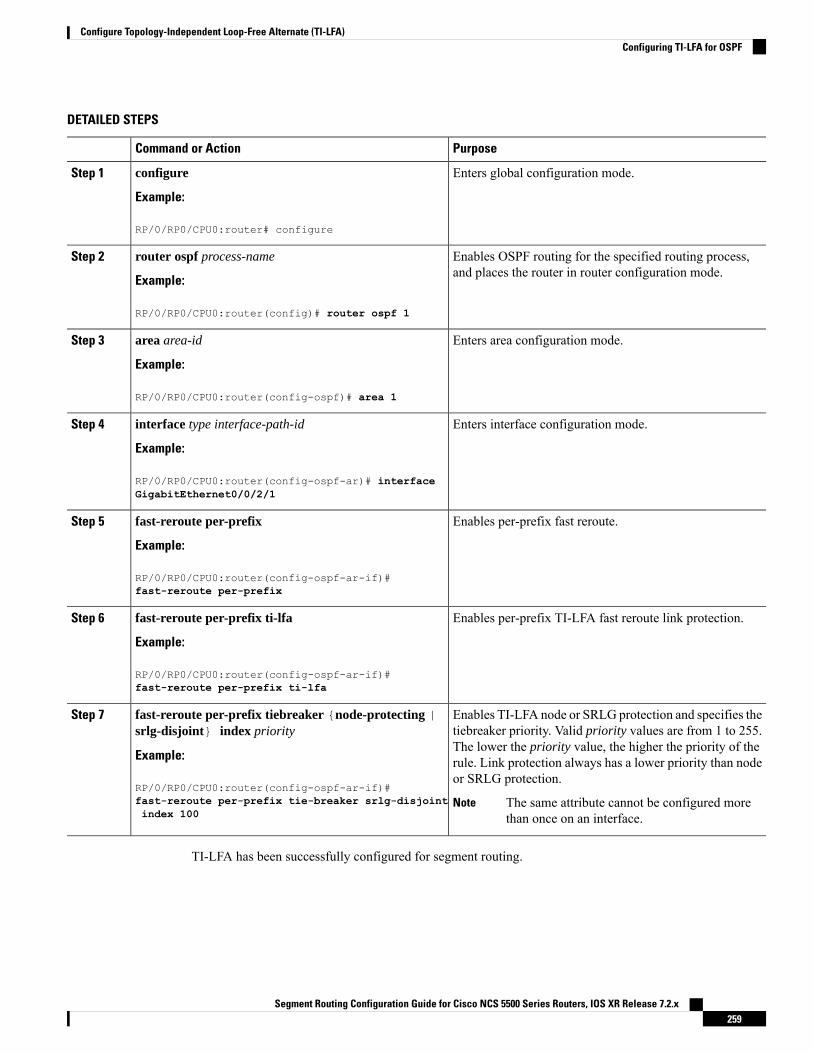
DETAILED STEPS
PurposeCommand or Action
Enters global configuration mode.configure
Example:
Step 1
RP/0/RP0/CPU0:router# configure
Enables OSPF routing for the specified routing process,and places the router in router configuration mode.
router ospf process-name
Example:
Step 2
RP/0/RP0/CPU0:router(config)# router ospf 1
Enters area configuration mode.area area-id
Example:
Step 3
RP/0/RP0/CPU0:router(config-ospf)# area 1
Enters interface configuration mode.interface type interface-path-id
Example:
Step 4
RP/0/RP0/CPU0:router(config-ospf-ar)# interfaceGigabitEthernet0/0/2/1
Enables per-prefix fast reroute.fast-reroute per-prefix
Example:
Step 5
RP/0/RP0/CPU0:router(config-ospf-ar-if)#fast-reroute per-prefix
Enables per-prefix TI-LFA fast reroute link protection.fast-reroute per-prefix ti-lfa
Example:
Step 6
RP/0/RP0/CPU0:router(config-ospf-ar-if)#fast-reroute per-prefix ti-lfa
Enables TI-LFA node or SRLG protection and specifies thetiebreaker priority. Valid priority values are from 1 to 255.
fast-reroute per-prefix tiebreaker {node-protecting |srlg-disjoint} index priority
Step 7
The lower the priority value, the higher the priority of theExample: rule. Link protection always has a lower priority than node
or SRLG protection.RP/0/RP0/CPU0:router(config-ospf-ar-if)#fast-reroute per-prefix tie-breaker srlg-disjointindex 100
The same attribute cannot be configured morethan once on an interface.
Note
TI-LFA has been successfully configured for segment routing.
Segment Routing Configuration Guide for Cisco NCS 5500 Series Routers, IOS XR Release 7.2.x259
Configure Topology-Independent Loop-Free Alternate (TI-LFA)Configuring TI-LFA for OSPF

TI-LFA Node and SRLG Protection: ExamplesThe following examples show the configuration of the tiebreaker priority for TI-LFA node and SRLG protection,and the behavior of post-convergence backup-path. These examples use OSPF, but the same configurationand behavior applies to IS-IS.
Example: Enable link-protecting and node-protecting TI-LFA
router ospf 1area 1interface GigabitEthernet0/0/2/1fast-reroute per-prefixfast-reroute per-prefix ti-lfafast-reroute per-prefix tiebreaker node-protecting index 100
Both link-protecting and node-protecting TI-LFA backup paths will be computed. If the priority associatedwith the node-protecting tiebreaker is higher than any other tiebreakers, then node-protecting post-convergencebackup paths will be selected, if it is available.
Example: Enable link-protecting and SRLG-protecting TI-LFA
router ospf 1area 1interface GigabitEthernet0/0/2/1fast-reroute per-prefixfast-reroute per-prefix ti-lfafast-reroute per-prefix tiebreaker srlg-disjoint index 100
Both link-protecting and SRLG-protecting TI-LFA backup paths will be computed. If the priority associatedwith the SRLG-protecting tiebreaker is higher than any other tiebreakers, then SRLG-protectingpost-convergence backup paths will be selected, if it is available.
Example: Enable link-protecting, node-protecting and SRLG-protecting TI-LFA
router ospf 1area 1interface GigabitEthernet0/0/2/1fast-reroute per-prefixfast-reroute per-prefix ti-lfafast-reroute per-prefix tiebreaker node-protecting index 100fast-reroute per-prefix tiebreaker srlg-disjoint index 200
Link-protecting, node-protecting, and SRLG-protecting TI-LFA backup paths will be computed. If the priorityassociated with the node-protecting tiebreaker is highest from all tiebreakers, then node-protectingpost-convergence backup paths will be selected, if it is available. If the node-protecting backup path is notavailable, SRLG-protecting post-convergence backup path will be used, if it is available.
Segment Routing Configuration Guide for Cisco NCS 5500 Series Routers, IOS XR Release 7.2.x260
Configure Topology-Independent Loop-Free Alternate (TI-LFA)TI-LFA Node and SRLG Protection: Examples
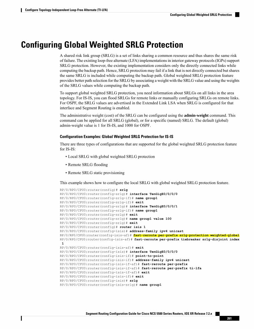
Configuring Global Weighted SRLG ProtectionA shared risk link group (SRLG) is a set of links sharing a common resource and thus shares the same riskof failure. The existing loop-free alternate (LFA) implementations in interior gateway protocols (IGPs) supportSRLG protection. However, the existing implementation considers only the directly connected links whilecomputing the backup path. Hence, SRLG protection may fail if a link that is not directly connected but sharesthe same SRLG is included while computing the backup path. Global weighted SRLG protection featureprovides better path selection for the SRLG by associating a weight with the SRLG value and using the weightsof the SRLG values while computing the backup path.
To support global weighted SRLG protection, you need information about SRLGs on all links in the areatopology. For IS-IS, you can flood SRLGs for remote links or manually configuring SRLGs on remote links.For OSPF, the SRLG values are advertised in the Extended Link LSA when SRLG is configured for thatinterface and Segment Routing is enabled.
The administrative weight (cost) of the SRLG can be configured using the admin-weight command. Thiscommand can be applied for all SRLG (global), or for a specific (named) SRLG. The default (global)admin-weight value is 1 for IS-IS, and 1000 for OSPF.
Configuration Examples: Global Weighted SRLG Protection for IS-IS
There are three types of configurations that are supported for the global weighted SRLG protection featurefor IS-IS:
• Local SRLG with global weighted SRLG protection
• Remote SRLG flooding
• Remote SRLG static provisioning
This example shows how to configure the local SRLG with global weighted SRLG protection feature.RP/0/RP0/CPU0:router(config)# srlgRP/0/RP0/CPU0:router(config-srlg)# interface TenGigE0/0/0/0RP/0/RP0/CPU0:router(config-srlg-if)# name group1RP/0/RP0/CPU0:router(config-srlg-if)# exitRP/0/RP0/CPU0:router(config-srlg)# interface TenGigE0/0/0/1RP/0/RP0/CPU0:router(config-srlg-if)# name group1RP/0/RP0/CPU0:router(config-srlg)# exitRP/0/RP0/CPU0:router(config-srlg)# name group1 value 100RP/0/RP0/CPU0:router(config-srlg)# exitRP/0/RP0/CPU0:router(config)# router isis 1RP/0/RP0/CPU0:router(config-isis)# address-family ipv4 unicastRP/0/RP0/CPU0:router(config-isis-af)# fast-reroute per-prefix srlg-protection weighted-globalRP/0/RP0/CPU0:router(config-isis-af)# fast-reroute per-prefix tiebreaker srlg-disjoint index1RP/0/RP0/CPU0:router(config-isis-af)# exitRP/0/RP0/CPU0:router(config-isis)# interface TenGigE0/0/0/0RP/0/RP0/CPU0:router(config-isis-if)# point-to-pointRP/0/RP0/CPU0:router(config-isis-if)# address-family ipv4 unicastRP/0/RP0/CPU0:router(config-isis-if-af)# fast-reroute per-prefixRP/0/RP0/CPU0:router(config-isis-if-af)# fast-reroute per-prefix ti-lfaRP/0/RP0/CPU0:router(config-isis-if-af)# exitRP/0/RP0/CPU0:router(config-isis-if)# exitRP/0/RP0/CPU0:router(config-isis)# srlgRP/0/RP0/CPU0:router(config-isis-srlg)# name group1
Segment Routing Configuration Guide for Cisco NCS 5500 Series Routers, IOS XR Release 7.2.x261
Configure Topology-Independent Loop-Free Alternate (TI-LFA)Configuring Global Weighted SRLG Protection

RP/0/RP0/CPU0:router(config-isis-srlg-name)# admin-weight 5000
This example shows how to configure the global weighted SRLG protection feature with remote SRLGflooding. The configuration includes local and remote router configuration. On the local router, the globalweighted SRLG protection is enabled by using the fast-reroute per-prefix srlg-protection weighted-globalcommand. In the remote router configuration, you can control the SRLG value flooding by using the advertiseapplication lfa link-attributes srlg command. You should also globally configure SRLG on the remoterouter.
The local router configuration for global weighted SRLG protection with remote SRLG flooding is as follows:RP/0/RP0/CPU0:router(config)# router isis 1RP/0/RP0/CPU0:router(config-isis)# address-family ipv4 unicastRP/0/RP0/CPU0:router(config-isis-af)# fast-reroute per-prefix srlg-protection weighted-globalRP/0/RP0/CPU0:router(config-isis-af)# fast-reroute per-prefix tiebreaker srlg-disjoint index1RP/0/RP0/CPU0:router(config-isis-af)# exitRP/0/RP0/CPU0:router(config-isis)# interface TenGigE0/0/0/0RP/0/RP0/CPU0:router(config-isis-if)# point-to-pointRP/0/RP0/CPU0:router(config-isis-if)# address-family ipv4 unicastRP/0/RP0/CPU0:router(config-isis-if-af)# fast-reroute per-prefixRP/0/RP0/CPU0:router(config-isis-if-af)# fast-reroute per-prefix ti-lfaRP/0/RP0/CPU0:router(config-isis-if-af)# exitRP/0/RP0/CPU0:router(config-isis-if)# exitRP/0/RP0/CPU0:router(config-isis)# srlgRP/0/RP0/CPU0:router(config-isis-srlg)# name group1RP/0/RP0/CPU0:router(config-isis-srlg-name)# admin-weight 5000
The remote router configuration for global weighted SRLG protection with remote SRLG flooding is asfollows:RP/0/RP0/CPU0:router(config)# srlgRP/0/RP0/CPU0:router(config-srlg)# interface TenGigE0/0/0/0RP/0/RP0/CPU0:router(config-srlg-if)# name group1RP/0/RP0/CPU0:router(config-srlg-if)# exitRP/0/RP0/CPU0:router(config-srlg)# interface TenGigE0/0/0/1RP/0/RP0/CPU0:router(config-srlg-if)# name group1RP/0/RP0/CPU0:router(config-srlg-if)# exitRP/0/RP0/CPU0:router(config-srlg)# name group1 value 100RP/0/RP0/CPU0:router(config-srlg)# exitRP/0/RP0/CPU0:router(config)# router isis 1RP/0/RP0/CPU0:router(config-isis)# address-family ipv4 unicastRP/0/RP0/CPU0:router(config-isis-af)# advertise application lfa link-attributes srlg
This example shows configuring the global weighted SRLG protection feature with static provisioning ofSRLG values for remote links. You should perform these configurations on the local router.
RP/0/RP0/CPU0:router(config)# srlgRP/0/RP0/CPU0:router(config-srlg)# interface TenGigE0/0/0/0RP/0/RP0/CPU0:router(config-srlg-if)# name group1RP/0/RP0/CPU0:router(config-srlg-if)# exitRP/0/RP0/CPU0:router(config-srlg)# interface TenGigE0/0/0/1RP/0/RP0/CPU0:router(config-srlg-if)# name group1RP/0/RP0/CPU0:router(config-srlg-if)# exitRP/0/RP0/CPU0:router(config-srlg)# name group1 value 100RP/0/RP0/CPU0:router(config-srlg)# exitRP/0/RP0/CPU0:router(config)# router isis 1RP/0/RP0/CPU0:router(config-isis)# address-family ipv4 unicastRP/0/RP0/CPU0:router(config-isis-af)# fast-reroute per-prefix srlg-protection weighted-global
Segment Routing Configuration Guide for Cisco NCS 5500 Series Routers, IOS XR Release 7.2.x262
Configure Topology-Independent Loop-Free Alternate (TI-LFA)Configuring Global Weighted SRLG Protection

RP/0/RP0/CPU0:router(config-isis-af)# fast-reroute per-prefix tiebreaker srlg-disjoint index1RP/0/RP0/CPU0:router(config-isis-af)# exitRP/0/RP0/CPU0:router(config-isis)# interface TenGigE0/0/0/0RP/0/RP0/CPU0:router(config-isis-if)# point-to-pointRP/0/RP0/CPU0:router(config-isis-if)# address-family ipv4 unicastRP/0/RP0/CPU0:router(config-isis-if-af)# fast-reroute per-prefixRP/0/RP0/CPU0:router(config-isis-if-af)# fast-reroute per-prefix ti-lfaRP/0/RP0/CPU0:router(config-isis-if-af)# exitRP/0/RP0/CPU0:router(config-isis-if)# exitRP/0/RP0/CPU0:router(config-isis)# srlgRP/0/RP0/CPU0:router(config-isis-srlg)# name group1RP/0/RP0/CPU0:router(config-isis-srlg-name)# admin-weight 5000RP/0/RP0/CPU0:router(config-isis-srlg-name)# static ipv4 address 10.0.4.1 next-hop ipv4address 10.0.4.2RP/0/RP0/CPU0:router(config-isis-srlg-name)# static ipv4 address 10.0.4.2 next-hop ipv4address 10.0.4.1
Configuration Examples: Global Weighted SRLG Protection for OSPF
There are two types of configurations that are supported for the global weighted SRLG protection feature forOSPF:
• Local SRLG with global weighted SRLG protection
• Remote SRLG static provisioning
There is no specific configuration to enable SRLG flooding in OSPF. The SRLG values are advertised in theExtended Link LSA if SRLG is configured for that interface and Segment Routing is enabled.
Note
This example shows how to configure the local SRLG with global weighted SRLG protection feature.Router(config)# srlgRouter(config-srlg)# interface hundredGigE 0/0/0/0Router(config-srlg-if)# name group1Router(config-srlg-if)# exitRouter(config-srlg)# interface hundredGigE 0/0/0/1Router(config-srlg-if)# name group1Router(config-srlg-if)# exitRouter(config-srlg)# name group1 value 100Router(config-srlg)# exitRouter(config)# router ospf 1Router(config-ospf)# fast-reroute per-prefix srlg-protection weighted-globalRouter(config-ospf)# fast-reroute per-prefix tiebreaker srlg-disjoint index 1Router(config-ospf-ar)# interface hundredGigE 0/0/0/0Router(config-ospf-ar-if)# fast-reroute per-prefixRouter(config-ospf-ar-if)# fast-reroute per-prefix ti-lfaRouter(config-ospf-ar-if)# exitRouter(config-ospf-ar)# exitRouter(config-ospf)# srlgRouter(config-ospf-srlg)# admin-weight 3000Router(config-ospf-srlg)# name group1Router(config-ospf-srlg-name)# admin-weight 5000
This example shows configuring the global weighted SRLG protection feature with static provisioning ofSRLG values for remote links. You should perform these configurations on the remote router.
Segment Routing Configuration Guide for Cisco NCS 5500 Series Routers, IOS XR Release 7.2.x263
Configure Topology-Independent Loop-Free Alternate (TI-LFA)Configuring Global Weighted SRLG Protection

Router(config)# srlgRouter(config-srlg)# interface hundredGigE 0/0/0/0Router(config-srlg-if)# name group1Router(config-srlg-if)# exitRouter(config-srlg)# interface hundredGigE 0/0/0/1Router(config-srlg-if)# name group1Router(config-srlg-if)# exitRouter(config-srlg)# name group1 value 100Router(config-srlg)# exitRouter(config)# router ospf 1Router(config-ospf)# area 1Router(config-ospf-ar)# interface hundredGigE 0/0/0/0Router(config-ospf-ar-if)# exitRouter(config-ospf-ar)# exit
SR-MPLS over GRE as TI-LFA Backup PathThis feature allows the router (as ABR) to program a Generic Routing Encapsulation (GRE) tunnel as anoutgoing interface for TI-LFA backup paths computed by the IGP in a Segment Routing network.Single-segment TI-LFA scenario is supported. In this scenario, the router pushes one extra label whenprogramming the backup path.
GRE is a tunneling protocol that provides a simple generic approach to transport packets of one protocol overanother protocol by means of encapsulation. See the Configuring GRE Tunnels chapter in the Interface andHardware Component Configuration Guide for Cisco NCS 5500 Series Routers.
Note
Multi-Level Network Topology
The following example shows a multi-level network topology with interconnecting links between ABRs.
This could also be a multi-instance network topology.Note
Two links between ABR 2 and ABR 3 are required, one in each IS-IS level. These links provide protectionin each direction and ensure that there is always an alternate path inside the IGP domain.
Segment Routing Configuration Guide for Cisco NCS 5500 Series Routers, IOS XR Release 7.2.x264
Configure Topology-Independent Loop-Free Alternate (TI-LFA)SR-MPLS over GRE as TI-LFA Backup Path

Alternatively, a single link with two logical sub-interfaces could be used between the ABRs.Note
TI-LFA performs the backup path calculation inside the domain (process, level, or area) of the failed link.
For example, if the link between nodes 2 and 5 failed, the link between ABR 2 and 3 would create a TI-LFApath in L1 IS-IS level. If the link between nodes 1 and 2 failed, the link between ABR 2 and 3 would createa TI-LFA path in L2 IS-IS level.
However, if the interconnecting link between ABRs are in the same Shared Risk Link Groups (SRLG) asother links inside the domain (for example, the link between Nodes 2 and 3 are in the same SRLG as linkbetween Nodes 2 and 5), TI-LFA with local SRLG protection would not find an alternate path.
In cases where it is not feasible to provide interconnecting links between ABRs (for example, the ABR nodesmight be in different locations with no connectivity options), TI-LFA will not be able to compute backuppaths for all of the prefixes.
To address these issues, you can create a GRE tunnel in each domain, between the ABRs, which can be usedas TI-LFA backup paths.
Segment Routing Configuration Guide for Cisco NCS 5500 Series Routers, IOS XR Release 7.2.x265
Configure Topology-Independent Loop-Free Alternate (TI-LFA)SR-MPLS over GRE as TI-LFA Backup Path
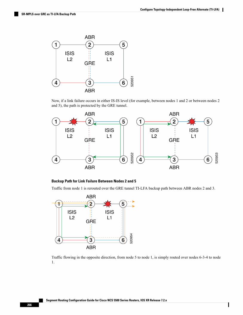
Now, if a link failure occurs in either IS-IS level (for example, between nodes 1 and 2 or between nodes 2and 5), the path is protected by the GRE tunnel.
Backup Path for Link Failure Between Nodes 2 and 5
Traffic from node 1 is rerouted over the GRE tunnel TI-LFA backup path between ABR nodes 2 and 3.
Traffic flowing in the opposite direction, from node 5 to node 1, is simply routed over nodes 6-3-4 to node1.
Segment Routing Configuration Guide for Cisco NCS 5500 Series Routers, IOS XR Release 7.2.x266
Configure Topology-Independent Loop-Free Alternate (TI-LFA)SR-MPLS over GRE as TI-LFA Backup Path

LimitationsThe following behaviors and limitations apply to the router when a GRE tunnel is programmed as backupinterface for TI-LFA:
• TheMPLS label of a protected prefix must be the same in the primary and backup paths (SWAP scenario)
• Single-segment TI-LFA is supported. In this scenario, the router pushes one extra label when programmingthe backup path. The total label stack is 2, including the primary label and backup label.
• Double-segment (or more) TI-LFA is not supported. In this scenario, the router pushes two or more extralabels when programming the backup path.
• GRE tunnel as a primary or backup path for an SR policy with TI-LFA protection is not supported.
Example: SR-MPLS over GRE as TI-LFA Backup PathThe examples in this section use the following network topology:
Configurations Without Interconnecting ABR Links
The following sample configurations showOSPF configurations for nodes 2, 3 and 5. Nodes 2 and 3 are ABRsbetween Area 0 and Area 100. There is no connection between the ABRs.
Segment Routing Configuration Guide for Cisco NCS 5500 Series Routers, IOS XR Release 7.2.x267
Configure Topology-Independent Loop-Free Alternate (TI-LFA)Limitations

Configuration on ABR 2 for Area 0 and Area 100
router ospf 100router-id 2.2.2.2segment-routing mplssegment-routing forwarding mplsfast-reroute per-prefixfast-reroute per-prefix ti-lfa enablesegment-routing sr-preferarea 0interface Loopback0prefix-sid index 2!!interface TenGigE0/0/1/10network point-to-point!!area 100interface TenGigE0/0/1/11network point-to-point
RP/0/RSP0/CPU0:ABR2# show ospf neighbor area-sortedFri Jul 19 09:43:59.328 UTC
Neighbors for OSPF 100Area 0
Neighbor ID Pri State Dead Time Address Up Time Interface1.1.1.1 1 FULL/ - 00:00:35 10.1.2.1 1d20h Te0/0/1/10
Total neighbor count: 1
Area 100
Neighbor ID Pri State Dead Time Address Up Time Interface5.5.5.5 1 FULL/ - 00:00:33 10.2.5.5 1d20h Te0/0/1/11
Total neighbor count: 1
Configuration on ABR 3 for Area 0 and Area 100
router ospf 100router-id 3.3.3.3segment-routing mplssegment-routing forwarding mplsfast-reroute per-prefixfast-reroute per-prefix ti-lfa enablesegment-routing sr-preferarea 0interface Loopback0prefix-sid index 3!interface TenGigE0/0/0/9network point-to-point!!area 100interface TenGigE0/0/0/3network point-to-point!
RP/0/RSP0/CPU0:ABR3# show ospf neighbor area-sortedFri Jul 19 09:33:35.816 UTC
Segment Routing Configuration Guide for Cisco NCS 5500 Series Routers, IOS XR Release 7.2.x268
Configure Topology-Independent Loop-Free Alternate (TI-LFA)Example: SR-MPLS over GRE as TI-LFA Backup Path

Neighbors for OSPF 100Area 0
Neighbor ID Pri State Dead Time Address Up Time Interface4.4.4.4 1 FULL/ - 00:00:36 10.3.4.4 2d17h Te0/0/0/9
Total neighbor count: 1
Area 100
Neighbor ID Pri State Dead Time Address Up Time Interface6.6.6.6 1 FULL/ - 00:00:36 10.3.6.6 2d19h Te0/0/0/3
Total neighbor count: 1
Configuration on Node 5
segment-routing mpls!set-attributesaddress-family ipv4sr-label-preferred
!connected-prefix-sid-mapaddress-family ipv45.5.5.5/32 index 5 range 1
!interface TenGigabitEthernet0/0/26description ***Connected to ABR 2ip address 10.2.5.5 255.255.255.0ip ospf network point-to-pointcdp enable!interface TenGigabitEthernet0/0/27description ***Connected to Node 6ip address 10.5.6.5 255.255.255.0ip ospf network point-to-pointcdp enable
router ospf 100router-id 5.5.5.5segment-routing area 100 mplssegment-routing mplsfast-reroute per-prefix enable prefix-priority lowfast-reroute per-prefix ti-lfafast-reroute per-prefix ti-lfa area 100passive-interface defaultno passive-interface TenGigabitEthernet0/0/26no passive-interface TenGigabitEthernet0/0/27network 10.2.5.0 0.0.0.255 area 100network 10.5.5.0 0.0.0.255 area 100network 10.5.6.0 0.0.0.255 area 100network 5.5.5.5 0.0.0.0 area 100
RP/0/RSP0/CPU0:Node5# show ip ospf neighborLoad for five secs: 4%/1%; one minute: 4%; five minutes: 4%Time source is NTP, 09:50:51.417 UTC Fri Jul 19 2019
Neighbor ID Pri State Dead Time Address Interface6.6.6.6 0 FULL/ - 00:00:32 10.5.6.6 TenGigabitEthernet0/0/272.2.2.2 0 FULL/ - 00:00:36 10.5.2.5 TenGigabitEthernet0/0/26
Segment Routing Configuration Guide for Cisco NCS 5500 Series Routers, IOS XR Release 7.2.x269
Configure Topology-Independent Loop-Free Alternate (TI-LFA)Example: SR-MPLS over GRE as TI-LFA Backup Path
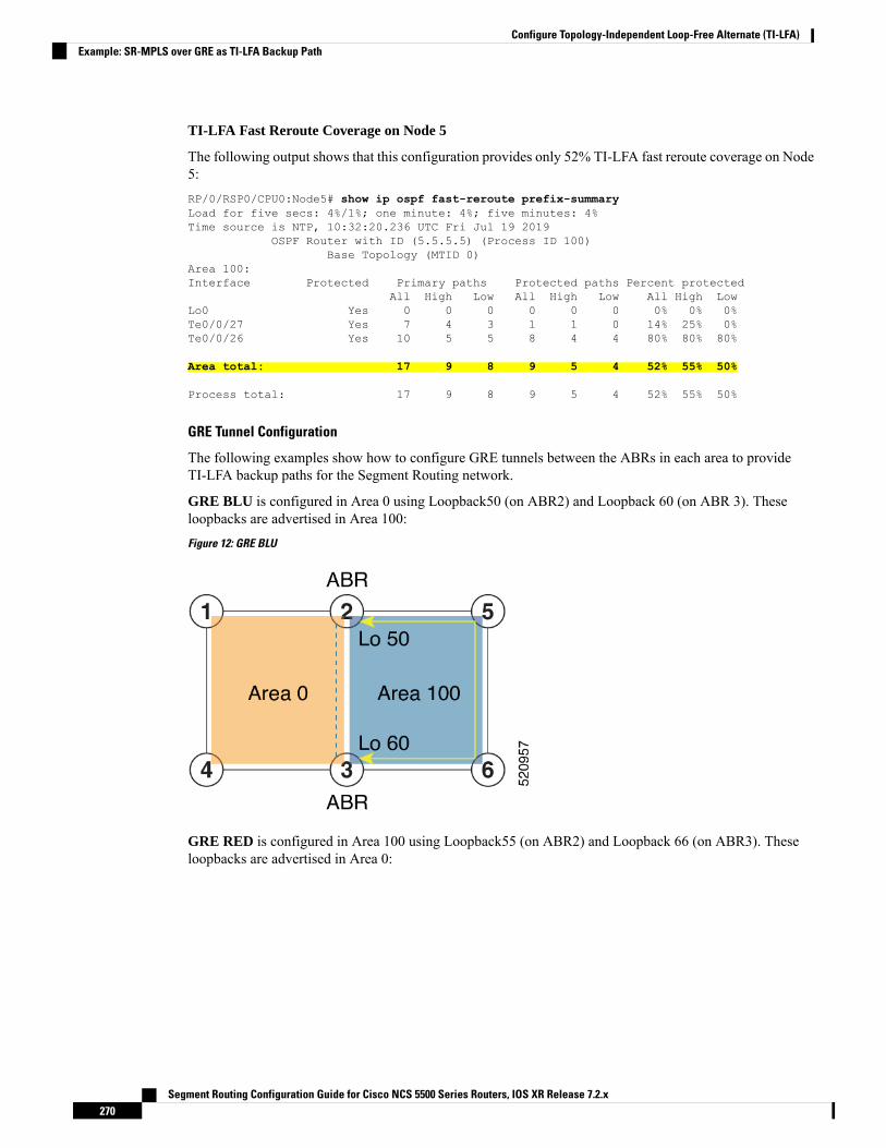
TI-LFA Fast Reroute Coverage on Node 5
The following output shows that this configuration provides only 52% TI-LFA fast reroute coverage on Node5:RP/0/RSP0/CPU0:Node5# show ip ospf fast-reroute prefix-summaryLoad for five secs: 4%/1%; one minute: 4%; five minutes: 4%Time source is NTP, 10:32:20.236 UTC Fri Jul 19 2019
OSPF Router with ID (5.5.5.5) (Process ID 100)Base Topology (MTID 0)
Area 100:Interface Protected Primary paths Protected paths Percent protected
All High Low All High Low All High LowLo0 Yes 0 0 0 0 0 0 0% 0% 0%Te0/0/27 Yes 7 4 3 1 1 0 14% 25% 0%Te0/0/26 Yes 10 5 5 8 4 4 80% 80% 80%
Area total: 17 9 8 9 5 4 52% 55% 50%
Process total: 17 9 8 9 5 4 52% 55% 50%
GRE Tunnel Configuration
The following examples show how to configure GRE tunnels between the ABRs in each area to provideTI-LFA backup paths for the Segment Routing network.
GRE BLU is configured in Area 0 using Loopback50 (on ABR2) and Loopback 60 (on ABR 3). Theseloopbacks are advertised in Area 100:
Figure 12: GRE BLU
GRE RED is configured in Area 100 using Loopback55 (on ABR2) and Loopback 66 (on ABR3). Theseloopbacks are advertised in Area 0:
Segment Routing Configuration Guide for Cisco NCS 5500 Series Routers, IOS XR Release 7.2.x270
Configure Topology-Independent Loop-Free Alternate (TI-LFA)Example: SR-MPLS over GRE as TI-LFA Backup Path
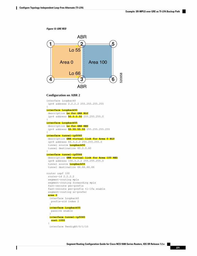
Figure 13: GRE RED
Configuration on ABR 2
interface Loopback0ipv4 address 2.2.2.2 255.255.255.255!interface Loopback50description Lo for GRE BLUipv4 address 50.0.0.50 255.255.255.0!interface Loopback55description Lo for GRE REDipv4 address 55.55.55.55 255.255.255.255!interface tunnel-ip5060description GRE virtual link for Area 0 BLUipv4 address 66.3.2.2 255.255.255.0tunnel source Loopback50tunnel destination 60.0.0.60!interface tunnel-ip5566description GRE virtual link for Area 100 REDipv4 address 100.3.2.2 255.255.255.0tunnel source Loopback55tunnel destination 66.66.66.66
router ospf 100router-id 2.2.2.2segment-routing mplssegment-routing forwarding mplsfast-reroute per-prefixfast-reroute per-prefix ti-lfa enablesegment-routing sr-preferarea 0interface Loopback0prefix-sid index 2!interface Loopback55passive enable!interface tunnel-ip5060cost 1000
!interface TenGigE0/0/1/10
Segment Routing Configuration Guide for Cisco NCS 5500 Series Routers, IOS XR Release 7.2.x271
Configure Topology-Independent Loop-Free Alternate (TI-LFA)Example: SR-MPLS over GRE as TI-LFA Backup Path

network point-to-point!!area 100interface Loopback50passive enable!interface tunnel-ip5566cost 1000!interface TenGigE0/0/1/11network point-to-point
In the above configuration, GRE tunnel-ip5060 belongs to area 0, but its source and destination addresses areadvertised in area 100. This ensures disjointness between the GRE tunnel and the links in area 0 that it protects.The same applies to GRE tunnel-ip5566 which belongs to area 100 and its source and destination addressesare advertised in area 0.
A high cost is applied to the GRE tunnel interfaces so that they are used only as a backup path.
Note
Configuration on ABR 3
interface Loopback0ipv4 address 3.3.3.3 255.255.255.255!interface Loopback60description Lo for GRE BLUipv4 address 60.0.0.60 255.255.255.0!interface Loopback66description Lo for GRE REDipv4 address 66.66.66.66 255.255.255.255!interface tunnel-ip5060description GRE virtual link for Area 0 BLUipv4 address 66.3.2.3 255.255.255.0tunnel source Loopback60tunnel destination 50.0.0.50!interface tunnel-ip5566description GRE virtual link for Area 100 REDipv4 address 100.3.2.3 255.255.255.0tunnel source Loopback66tunnel destination 55.55.55.55
router ospf 100router-id 3.3.3.3segment-routing mplssegment-routing forwarding mplsfast-reroute per-prefixfast-reroute per-prefix ti-lfa enablesegment-routing sr-preferarea 0interface Loopback0prefix-sid index 3!interface TenGigE0/0/0/9network point-to-point!interface Loopback66
Segment Routing Configuration Guide for Cisco NCS 5500 Series Routers, IOS XR Release 7.2.x272
Configure Topology-Independent Loop-Free Alternate (TI-LFA)Example: SR-MPLS over GRE as TI-LFA Backup Path
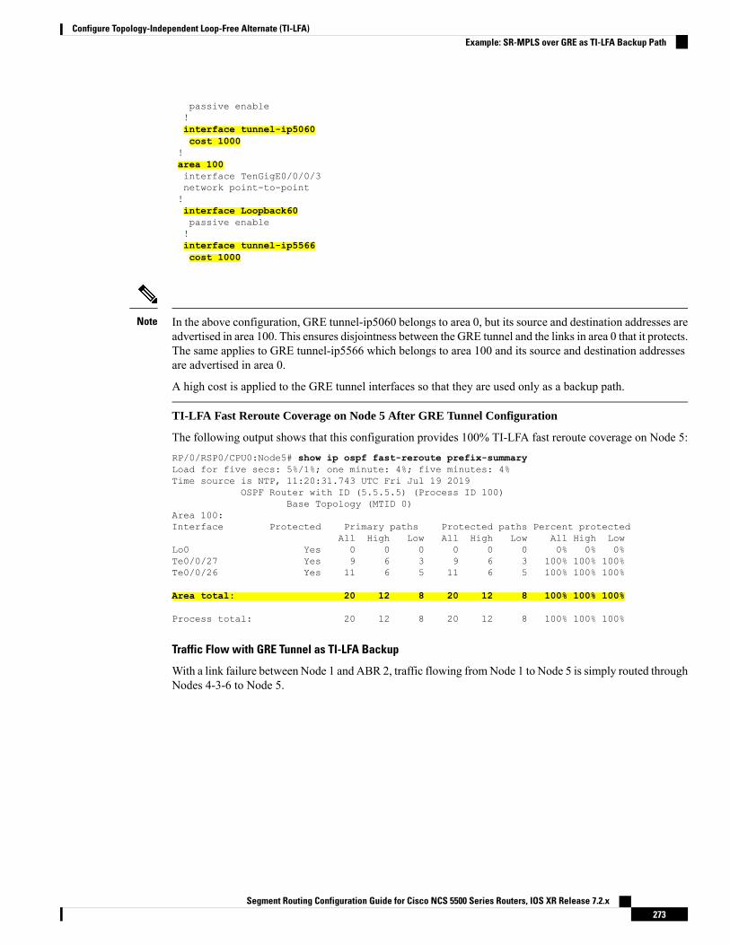
passive enable!interface tunnel-ip5060cost 1000
!area 100interface TenGigE0/0/0/3network point-to-point!interface Loopback60passive enable!interface tunnel-ip5566cost 1000
In the above configuration, GRE tunnel-ip5060 belongs to area 0, but its source and destination addresses areadvertised in area 100. This ensures disjointness between the GRE tunnel and the links in area 0 that it protects.The same applies to GRE tunnel-ip5566 which belongs to area 100 and its source and destination addressesare advertised in area 0.
A high cost is applied to the GRE tunnel interfaces so that they are used only as a backup path.
Note
TI-LFA Fast Reroute Coverage on Node 5 After GRE Tunnel Configuration
The following output shows that this configuration provides 100% TI-LFA fast reroute coverage on Node 5:RP/0/RSP0/CPU0:Node5# show ip ospf fast-reroute prefix-summaryLoad for five secs: 5%/1%; one minute: 4%; five minutes: 4%Time source is NTP, 11:20:31.743 UTC Fri Jul 19 2019
OSPF Router with ID (5.5.5.5) (Process ID 100)Base Topology (MTID 0)
Area 100:Interface Protected Primary paths Protected paths Percent protected
All High Low All High Low All High LowLo0 Yes 0 0 0 0 0 0 0% 0% 0%Te0/0/27 Yes 9 6 3 9 6 3 100% 100% 100%Te0/0/26 Yes 11 6 5 11 6 5 100% 100% 100%
Area total: 20 12 8 20 12 8 100% 100% 100%
Process total: 20 12 8 20 12 8 100% 100% 100%
Traffic Flow with GRE Tunnel as TI-LFA Backup
With a link failure between Node 1 and ABR 2, traffic flowing fromNode 1 to Node 5 is simply routed throughNodes 4-3-6 to Node 5.
Segment Routing Configuration Guide for Cisco NCS 5500 Series Routers, IOS XR Release 7.2.x273
Configure Topology-Independent Loop-Free Alternate (TI-LFA)Example: SR-MPLS over GRE as TI-LFA Backup Path

With GRE tunnel as TI-LFA backup, traffic flowing from Node 5 to Node 1 will be encapsulated at ABR2and routing over the GRE tunnel.
With a link failure between Node 5 and ABR 2, traffic flowing fromNode 5 to Node 1 is simply routed throughNodes 6-3-4 to Node 1.
With GRE tunnel as TI-LFA backup, traffic flowing from Node 1 to Node 5 will be encapsulated at ABR2and routing over the GRE tunnel.
Segment Routing Configuration Guide for Cisco NCS 5500 Series Routers, IOS XR Release 7.2.x274
Configure Topology-Independent Loop-Free Alternate (TI-LFA)Example: SR-MPLS over GRE as TI-LFA Backup Path

Segment Routing Configuration Guide for Cisco NCS 5500 Series Routers, IOS XR Release 7.2.x275
Configure Topology-Independent Loop-Free Alternate (TI-LFA)Example: SR-MPLS over GRE as TI-LFA Backup Path

Segment Routing Configuration Guide for Cisco NCS 5500 Series Routers, IOS XR Release 7.2.x276
Configure Topology-Independent Loop-Free Alternate (TI-LFA)Example: SR-MPLS over GRE as TI-LFA Backup Path
C H A P T E R 14Configure Segment Routing Microloop Avoidance
The Segment Routing Microloop Avoidance feature enables link-state routing protocols, such as IS-IS andOSPF, to prevent or avoid microloops during network convergence after a topology change.
• About Segment Routing Microloop Avoidance, on page 277• Configure Segment Routing Microloop Avoidance for IS-IS, on page 277• Configure Segment Routing Microloop Avoidance for OSPF, on page 278
About Segment Routing Microloop AvoidanceMicroloops are brief packet loops that occur in the network following a topology change (link down, link up,or metric change events). Microloops are caused by the non-simultaneous convergence of different nodes inthe network. If nodes converge and send traffic to a neighbor node that has not converged yet, traffic may belooped between these two nodes, resulting in packet loss, jitter, and out-of-order packets.
The Segment Routing Microloop Avoidance feature detects if microloops are possible following a topologychange. If a node computes that a microloop could occur on the new topology, the node creates a loop-freeSR-TE policy path to the destination using a list of segments. After the RIB update delay timer expires, theSR-TE policy is replaced with regular forwarding paths.
Configure Segment Routing Microloop Avoidance for IS-ISThis task describes how to enable Segment Routing Microloop Avoidance and set the Routing InformationBase (RIB) update delay value for IS-IS.
Before you begin
Ensure that the following topology requirements are met:
• Router interfaces are configured as per the topology.
• Routers are configured with IS-IS.
• Segment routing for IS-IS is configured. See Enabling Segment Routing for IS-IS Protocol, on page 63.
SUMMARY STEPS
1. configure
Segment Routing Configuration Guide for Cisco NCS 5500 Series Routers, IOS XR Release 7.2.x277

2. router isis instance-id
3. address-family ipv4 [ unicast ]4. microloop avoidance segment-routing5. microloop avoidance rib-update-delay delay-time
DETAILED STEPS
PurposeCommand or Action
Enters global configuration mode.configure
Example:
Step 1
RP/0/RP0/CPU0:router# configure
Enables IS-IS routing for the specified routing instance,and places the router in router configuration mode.
router isis instance-id
Example:
Step 2
You can change the level of routing to be performed by aparticular routing instance by using the is-type routerconfiguration command.
RP/0/RP0/CPU0:router(config)# router isis 1
Specifies the IPv4 address family and enters router addressfamily configuration mode.
address-family ipv4 [ unicast ]
Example:
Step 3
RP/0/RP0/CPU0:router(config-isis)# address-familyipv4 unicast
Enables Segment Routing Microloop Avoidance.microloop avoidance segment-routing
Example:
Step 4
RP/0/RP0/CPU0:router(config-isis-af)# microloopavoidance segment-routing
Specifies the amount of time the node uses the microloopavoidance policy before updating its forwarding table. The
microloop avoidance rib-update-delay delay-time
Example:
Step 5
delay-time is in milliseconds. The range is from 1-60000.The default value is 5000.
RP/0/RP0/CPU0:router(config-isis-af)# microloopavoidance rib-update-delay 3000
Configure Segment Routing Microloop Avoidance for OSPFThis task describes how to enable Segment Routing Microloop Avoidance and set the Routing InformationBase (RIB) update delay value for OSPF.
Before you begin
Ensure that the following topology requirements are met:
• Router interfaces are configured as per the topology.
Segment Routing Configuration Guide for Cisco NCS 5500 Series Routers, IOS XR Release 7.2.x278
Configure Segment Routing Microloop AvoidanceConfigure Segment Routing Microloop Avoidance for OSPF
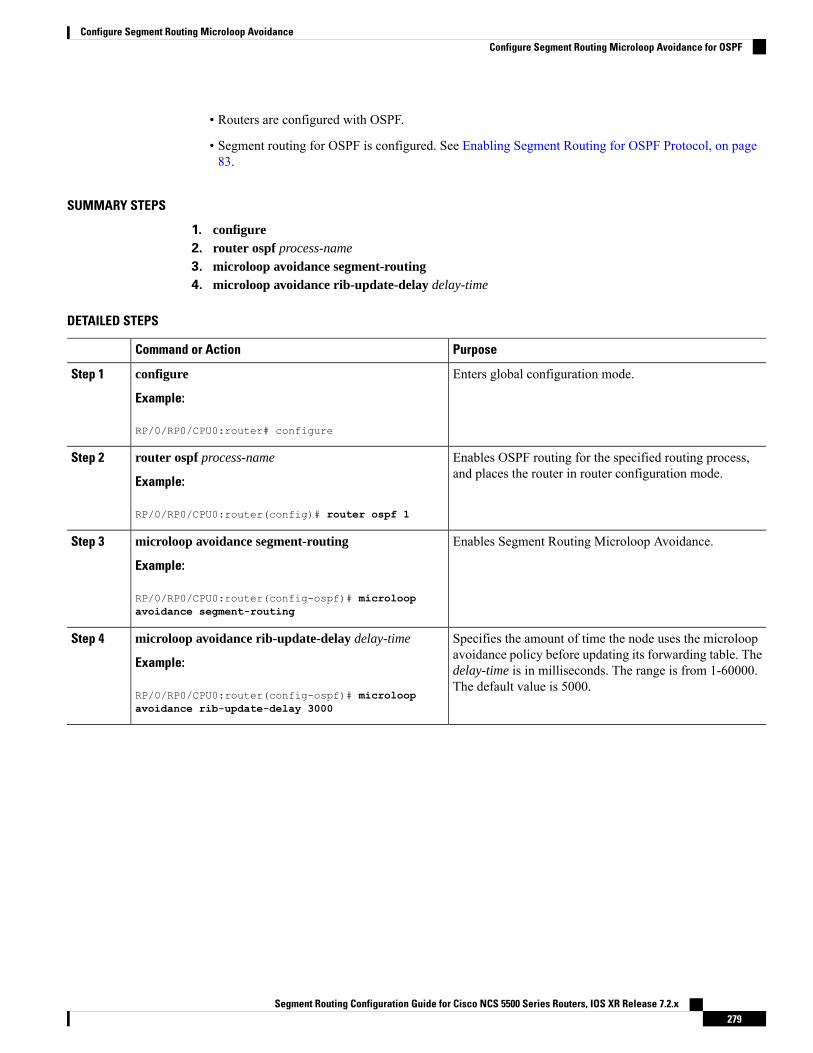
• Routers are configured with OSPF.
• Segment routing for OSPF is configured. See Enabling Segment Routing for OSPF Protocol, on page83.
SUMMARY STEPS
1. configure2. router ospf process-name
3. microloop avoidance segment-routing4. microloop avoidance rib-update-delay delay-time
DETAILED STEPS
PurposeCommand or Action
Enters global configuration mode.configure
Example:
Step 1
RP/0/RP0/CPU0:router# configure
Enables OSPF routing for the specified routing process,and places the router in router configuration mode.
router ospf process-name
Example:
Step 2
RP/0/RP0/CPU0:router(config)# router ospf 1
Enables Segment Routing Microloop Avoidance.microloop avoidance segment-routing
Example:
Step 3
RP/0/RP0/CPU0:router(config-ospf)# microloopavoidance segment-routing
Specifies the amount of time the node uses the microloopavoidance policy before updating its forwarding table. The
microloop avoidance rib-update-delay delay-time
Example:
Step 4
delay-time is in milliseconds. The range is from 1-60000.The default value is 5000.
RP/0/RP0/CPU0:router(config-ospf)# microloopavoidance rib-update-delay 3000
Segment Routing Configuration Guide for Cisco NCS 5500 Series Routers, IOS XR Release 7.2.x279
Configure Segment Routing Microloop AvoidanceConfigure Segment Routing Microloop Avoidance for OSPF

Segment Routing Configuration Guide for Cisco NCS 5500 Series Routers, IOS XR Release 7.2.x280
Configure Segment Routing Microloop AvoidanceConfigure Segment Routing Microloop Avoidance for OSPF
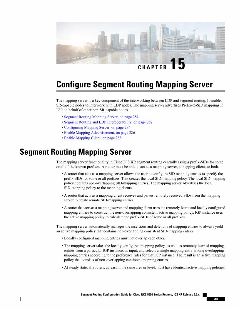
C H A P T E R 15Configure Segment Routing Mapping Server
The mapping server is a key component of the interworking between LDP and segment routing. It enablesSR-capable nodes to interwork with LDP nodes. The mapping server advertises Prefix-to-SID mappings inIGP on behalf of other non-SR-capable nodes.
• Segment Routing Mapping Server, on page 281• Segment Routing and LDP Interoperability, on page 282• Configuring Mapping Server, on page 284• Enable Mapping Advertisement, on page 286• Enable Mapping Client, on page 288
Segment Routing Mapping ServerThe mapping server functionality in Cisco IOS XR segment routing centrally assigns prefix-SIDs for someor all of the known prefixes. A router must be able to act as a mapping server, a mapping client, or both.
• A router that acts as a mapping server allows the user to configure SID mapping entries to specify theprefix-SIDs for some or all prefixes. This creates the local SID-mapping policy. The local SID-mappingpolicy contains non-overlapping SID-mapping entries. The mapping server advertises the localSID-mapping policy to the mapping clients.
• A router that acts as a mapping client receives and parses remotely received SIDs from the mappingserver to create remote SID-mapping entries.
• A router that acts as a mapping server and mapping client uses the remotely learnt and locally configuredmapping entries to construct the non-overlapping consistent active mapping policy. IGP instance usesthe active mapping policy to calculate the prefix-SIDs of some or all prefixes.
The mapping server automatically manages the insertions and deletions of mapping entries to always yieldan active mapping policy that contains non-overlapping consistent SID-mapping entries.
• Locally configured mapping entries must not overlap each other.
• The mapping server takes the locally configured mapping policy, as well as remotely learned mappingentries from a particular IGP instance, as input, and selects a single mapping entry among overlappingmapping entries according to the preference rules for that IGP instance. The result is an active mappingpolicy that consists of non-overlapping consistent mapping entries.
• At steady state, all routers, at least in the same area or level, must have identical active mapping policies.
Segment Routing Configuration Guide for Cisco NCS 5500 Series Routers, IOS XR Release 7.2.x281

Usage Guidelines and Restrictions• The position of the mapping server in the network is not important. However, since the mappingadvertisements are distributed in IGP using the regular IGP advertisement mechanism, the mappingserver needs an IGP adjacency to the network.
• The role of the mapping server is crucial. For redundancy purposes, you should configure multiplemapping servers in the networks.
• The mapping server functionality does not support a scenario where SID-mapping entries learned throughone IS-IS instance are used by another IS-IS instance to determine the prefix-SID of a prefix. For example,mapping entries learnt from remote routers by 'router isis 1' cannot be used to calculate prefix-SIDs forprefixes learnt, advertised, or downloaded to FIB by 'router isis 2'. A mapping server is required for eachIS-IS instance.
• Segment Routing Mapping Server does not support Virtual Routing and Forwarding (VRF) currently.
Segment Routing and LDP InteroperabilityIGP provides mechanisms through which segment routing (SR) interoperate with label distribution protocol(LDP). The control plane of segment routing co-exists with LDP.
The Segment Routing Mapping Server (SRMS) functionality in SR is used to advertise SIDs for destinations,in the LDP part of the network, that do not support SR. SRMS maintains and advertises segment identifier(SID) mapping entries for such destinations. IGP propagates the SRMS mapping entries and interacts withSRMS to determine the SID value when programming the forwarding plane. IGP installs prefixes andcorresponding labels, into routing information base (RIB), that are used to program the forwarding informationbase (FIB).
Example: Segment Routing LDP InteroperabilityConsider a network with a mix of segment routing (SR) and label distribution protocol (LDP). A continuousmultiprotocol label switching (MPLS) LSP (Labeled Switched Path) can be established by facilitatinginteroperability. One or more nodes in the SR domain act as segment routing mapping server (SRMS). SRMSadvertises SIDmappings on behalf of non-SR capable nodes. Each SR-capable node learns about SID assignedto non-SR capable nodes without explicitly configuring individual nodes.
Consider a network as shown in the following image. This network is a mix of both LDP and SR-capablenodes.
In this mixed network:
• Nodes P6, P7, P8, PE4 and PE3 are LDP-capable
• Nodes PE1, PE2, P5 and P6 are SR-capable
• Nodes PE1, PE2, P5 and P6 are configured with segment routing global block (SRGB) of (100, 200)
• Nodes PE1, PE2, P5 and P6 are configured with node segments of 101, 102, 105 and 106 respectively
Segment Routing Configuration Guide for Cisco NCS 5500 Series Routers, IOS XR Release 7.2.x282
Configure Segment Routing Mapping ServerUsage Guidelines and Restrictions

A service flow must be established from PE1 to PE3 over a continuous MPLS tunnel. This requires SR andLDP to interoperate.
LDP to SR
The traffic flow from LDP to SR (right to left) involves:
1. PE3 learns a service route whose nhop is PE1. PE3 has an LDP label binding from the nhop P8 for theFEC PE1. PE3 forwards the packet P8.
2. P8 has an LDP label binding from its nhop P7 for the FEC PE1. P8 forwards the packet to P7.
3. P7 has an LDP label binding from its nhop P6 for the FEC PE1. P7 forwards the packet to P6.
4. P6 does not have an LDP binding from its nhop P5 for the FEC PE1. But P6 has an SR node segment tothe IGP route PE1. P6 forwards the packet to P5 and swaps its local LDP label for FEC PE1 by theequivalent node segment 101. This process is called label merging.
5. P5 pops 101, assuming PE1 has advertised its node segment 101 with the penultimate-pop flag set andforwards to PE1.
6. PE1 receives the tunneled packet and processes the service label.
The end-to-end MPLS tunnel is established from an LDP LSP from PE3 to P6 and the related node segmentfrom P6 to PE1.
SR to LDP
Suppose that the operator configures P5 as a Segment Routing Mapping Server (SRMS) and advertises themappings (P7, 107), (P8, 108), (PE3, 103) and (PE4, 104). If PE3 was SR-capable, the operator may haveconfigured PE3 with node segment 103. Because PE3 is non-SR capable, the operator configures that policyat the SRMS; the SRMS advertises the mapping on behalf of the non-SR capable nodes. Multiple SRMSservers can be provisioned in a network for redundancy. Themapping server advertisements are only understoodby the SR-capable nodes. The SR capable routers install the related node segments in the MPLS data planein exactly the same manner if node segments were advertised by the nodes themselves.
The traffic flow from SR to LDP (left to right) involves:
1. PE1 installs the node segment 103 with nhop P5 in exactly the same manner if PE3 had advertised nodesegment 103.
2. P5 swaps 103 for 103 and forwards to P6.
3. The nhop for P6 for the IGP route PE3 is non-SR capable. (P7 does not advertise the SR capability.)However, P6 has an LDP label binding from that nhop for the same FEC. (For example, LDP label 103.)P6 swaps 103 for 103 and forwards to P7. We refer to this process as label merging.
4. P7 swaps this label with the LDP label received from P8 and forwards to P8.
5. P8 pops the LDP label and forwards to PE3.
6. PE3 receives the packet and processes as required.
The end-to-end MPLS LSP is established from an SR node segment from PE1 to P6 and an LDP LSP fromP6 to PE3.
Segment Routing Configuration Guide for Cisco NCS 5500 Series Routers, IOS XR Release 7.2.x283
Configure Segment Routing Mapping ServerExample: Segment Routing LDP Interoperability

Configuring Mapping ServerPerform these tasks to configure the mapping server and to add prefix-SID mapping entries in the active localmapping policy.
SUMMARY STEPS
1. configure2. segment-routing3. mapping-server4. prefix-sid-map5. address-family ipv4 |ipv66. ip-address/prefix-length first-SID-value range range
7. Use the commit or end command.
DETAILED STEPS
PurposeCommand or Action
Enters global configuration mode.configure
Example:
Step 1
RP/0/RP0/CPU0:router# configure
Enables segment routing.segment-routing
Example:
Step 2
RP/0/RP0/CPU0:router(config)# segment-routing
Enables mapping server configuration mode.mapping-server
Example:
Step 3
RP/0/RP0/CPU0:router(config-sr)# mapping-server
Enables prefix-SID mapping configuration mode.prefix-sid-mapStep 4
Example: Two-way prefix SID can be enabled directlyunder IS-IS or through a mapping server.
Note
RP/0/RP0/CPU0:router(config-sr-ms)# prefix-sid-map
Configures address-family for IS-IS.address-family ipv4 |ipv6
Example:
Step 5
This example shows the address-family for ipv4:
RP/0/RP0/CPU0:router(config-sr-ms-map)#address-family ipv4
Segment Routing Configuration Guide for Cisco NCS 5500 Series Routers, IOS XR Release 7.2.x284
Configure Segment Routing Mapping ServerConfiguring Mapping Server
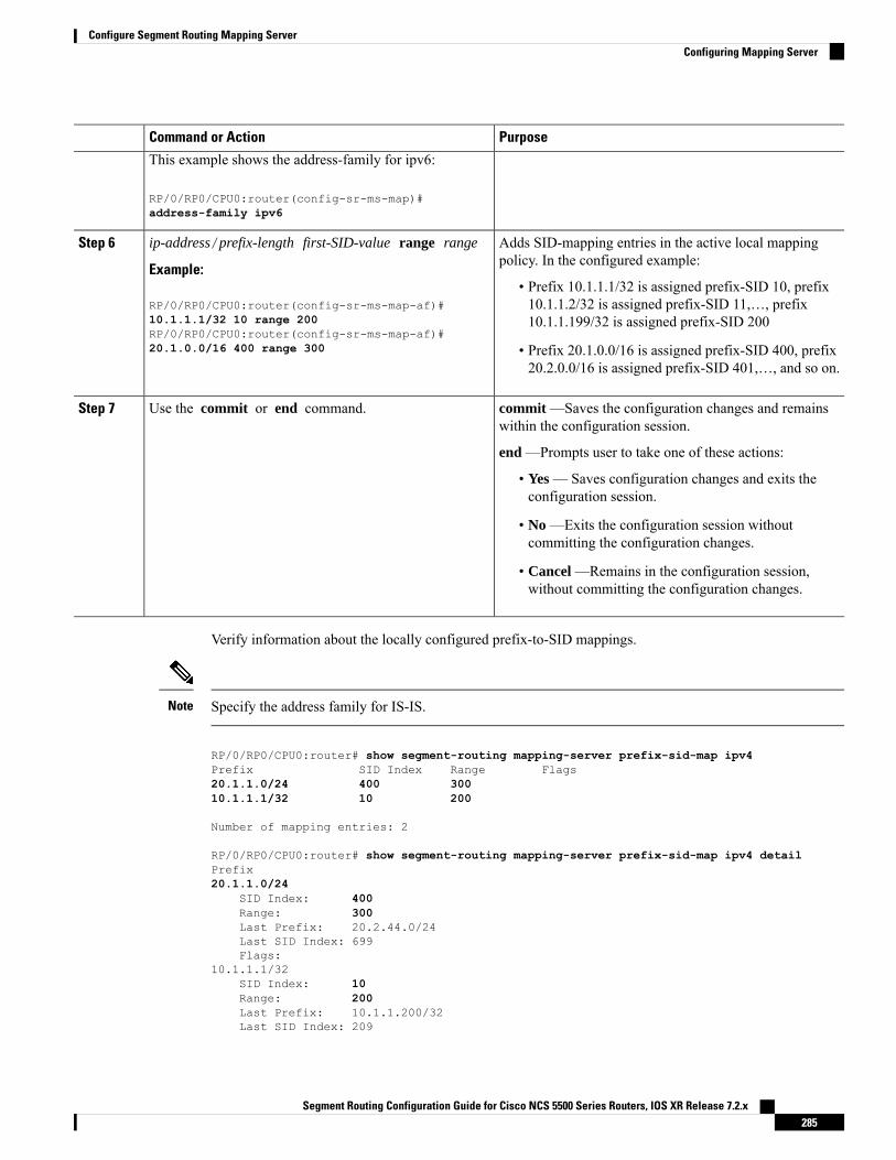
PurposeCommand or Action
This example shows the address-family for ipv6:
RP/0/RP0/CPU0:router(config-sr-ms-map)#address-family ipv6
Adds SID-mapping entries in the active local mappingpolicy. In the configured example:
ip-address/prefix-length first-SID-value range range
Example:
Step 6
• Prefix 10.1.1.1/32 is assigned prefix-SID 10, prefix10.1.1.2/32 is assigned prefix-SID 11,…, prefix10.1.1.199/32 is assigned prefix-SID 200
RP/0/RP0/CPU0:router(config-sr-ms-map-af)#10.1.1.1/32 10 range 200RP/0/RP0/CPU0:router(config-sr-ms-map-af)#20.1.0.0/16 400 range 300 • Prefix 20.1.0.0/16 is assigned prefix-SID 400, prefix
20.2.0.0/16 is assigned prefix-SID 401,…, and so on.
commit —Saves the configuration changes and remainswithin the configuration session.
Use the commit or end command.Step 7
end —Prompts user to take one of these actions:
• Yes — Saves configuration changes and exits theconfiguration session.
• No —Exits the configuration session withoutcommitting the configuration changes.
• Cancel —Remains in the configuration session,without committing the configuration changes.
Verify information about the locally configured prefix-to-SID mappings.
Specify the address family for IS-IS.Note
RP/0/RP0/CPU0:router# show segment-routing mapping-server prefix-sid-map ipv4Prefix SID Index Range Flags20.1.1.0/24 400 30010.1.1.1/32 10 200
Number of mapping entries: 2
RP/0/RP0/CPU0:router# show segment-routing mapping-server prefix-sid-map ipv4 detailPrefix20.1.1.0/24
SID Index: 400Range: 300Last Prefix: 20.2.44.0/24Last SID Index: 699Flags:
10.1.1.1/32SID Index: 10Range: 200Last Prefix: 10.1.1.200/32Last SID Index: 209
Segment Routing Configuration Guide for Cisco NCS 5500 Series Routers, IOS XR Release 7.2.x285
Configure Segment Routing Mapping ServerConfiguring Mapping Server

Flags:
Number of mapping entries: 2
What to do next
Enable the advertisement of the local SID-mapping policy in the IGP.
Enable Mapping AdvertisementIn addition to configuring the static mapping policy, you must enable the advertisement of the mappings inthe IGP.
Perform these steps to enable the IGP to advertise the locally configured prefix-SID mapping.
Configure Mapping Advertisement for IS-IS
SUMMARY STEPS
1. router isis instance-id
2. address-family { ipv4 | ipv6 } [ unicast ]3. segment-routing prefix-sid-map advertise-local4. Use the commit or end command.
DETAILED STEPS
PurposeCommand or Action
Enables IS-IS routing for the specified routing instance,and places the router in router configuration mode.
router isis instance-id
Example:
Step 1
• You can change the level of routing to be performedby a particular routing instance by using the is-typerouter configuration command.
RP/0/RP0/CPU0:router(config)# router isis 1
Specifies the IPv4 or IPv6 address family, and enters routeraddress family configuration mode.
address-family { ipv4 | ipv6 } [ unicast ]
Example:
Step 2
The following is an example for ipv4 address family:
RP/0/RP0/CPU0:router(config-isis)# address-familyipv4 unicast
Configures IS-IS to advertise locally configured prefix-SIDmappings.
segment-routing prefix-sid-map advertise-local
Example:
Step 3
RP/0/RP0/CPU0:router(config-isis-af)#segment-routing prefix-sid-map advertise-local
Segment Routing Configuration Guide for Cisco NCS 5500 Series Routers, IOS XR Release 7.2.x286
Configure Segment Routing Mapping ServerEnable Mapping Advertisement

PurposeCommand or Action
commit —Saves the configuration changes and remainswithin the configuration session.
Use the commit or end command.Step 4
end —Prompts user to take one of these actions:
• Yes — Saves configuration changes and exits theconfiguration session.
• No —Exits the configuration session withoutcommitting the configuration changes.
• Cancel —Remains in the configuration session,without committing the configuration changes.
Verify IS-IS prefix-SID mapping advertisement and TLV.
RP/0/RP0/CPU0:router# show isis database verbose
<...removed...>
SID Binding: 10.1.1.1/32 F:0 M:0 S:0 D:0 A:0 Weight:0 Range:200SID: Start:10, Algorithm:0, R:0 N:0 P:0 E:0 V:0 L:0
SID Binding: 20.1.1.0/24 F:0 M:0 S:0 D:0 A:0 Weight:0 Range:300SID: Start:400, Algorithm:0, R:0 N:0 P:0 E:0 V:0 L:0
Configure Mapping Advertisement for OSPF
SUMMARY STEPS
1. router ospf process-name
2. segment-routing prefix-sid-map advertise-local3. Use the commit or end command.
DETAILED STEPS
PurposeCommand or Action
Enables OSPF routing for the specified routing instance,and places the router in router configuration mode.
router ospf process-name
Example:
Step 1
RP/0/RP0/CPU0:router(config)# router ospf 1
Configures OSPF to advertise locally configured prefix-SIDmappings.
segment-routing prefix-sid-map advertise-local
Example:
Step 2
RP/0/RP0/CPU0:router(config-ospf)# segment-routingprefix-sid-map advertise-local
commit —Saves the configuration changes and remainswithin the configuration session.
Use the commit or end command.Step 3
Segment Routing Configuration Guide for Cisco NCS 5500 Series Routers, IOS XR Release 7.2.x287
Configure Segment Routing Mapping ServerConfigure Mapping Advertisement for OSPF

PurposeCommand or Action
end —Prompts user to take one of these actions:
• Yes — Saves configuration changes and exits theconfiguration session.
• No —Exits the configuration session withoutcommitting the configuration changes.
• Cancel —Remains in the configuration session,without committing the configuration changes.
Verify OSP prefix-SID mapping advertisement and TLV.
RP/0/RP0/CPU0:router# show ospf database opaque-area
<...removed...>
Extended Prefix Range TLV: Length: 24AF : 0Prefix : 10.1.1.1/32Range Size: 200Flags : 0x0
SID sub-TLV: Length: 8Flags : 0x60MTID : 0Algo : 0SID Index : 10
Enable Mapping ClientBy default, mapping client functionality is enabled.
You can disable the mapping client functionality by using the segment-routing prefix-sid-map receivedisable command.
You can re-enable the mapping client functionality by using the segment-routing prefix-sid-map receivecommand.
The following example shows how to enable the mapping client for IS-IS:
RP/0/RP0/CPU0:router(config)# router isis 1RP/0/RP0/CPU0:router(config-isis)# address-family ipv4 unicastRP/0/RP0/CPU0:router(config-isis-af)# segment-routing prefix-sid-map receive
The following example shows how to enable the mapping client for OSPF:
RP/0/RP0/CPU0:router(config)# router ospf 1RP/0/RP0/CPU0:router(config-ospf)# segment-routing prefix-sid-map receive
Segment Routing Configuration Guide for Cisco NCS 5500 Series Routers, IOS XR Release 7.2.x288
Configure Segment Routing Mapping ServerEnable Mapping Client

C H A P T E R 16Using Segment Routing OAM
Segment Routing Operations, Administration, and Maintenance (OAM) helps service providers to monitorlabel-switched paths (LSPs) and quickly isolate forwarding problems to assist with fault detection andtroubleshooting in the network. The Segment Routing OAM feature provides support for BGP prefix SIDs,IGP prefix and Flexible Algorithm SIDs, and Nil-FEC (forwarding equivalence classes) LSP Ping andTraceroute functionality.
• MPLS Ping and Traceroute for BGP and IGP Prefix-SID, on page 289• Examples: MPLS Ping, Traceroute, and Tree Trace for Prefix-SID, on page 290• MPLS LSP Ping and Traceroute Nil FEC Target, on page 292• Examples: LSP Ping and Traceroute for Nil_FEC Target , on page 292• Segment Routing Ping and Traceroute, on page 294• Segment Routing Ping and Traceroute for Flexible Algorithm, on page 298• Segment Routing over IPv6 OAM, on page 299
MPLS Ping and Traceroute for BGP and IGP Prefix-SIDMPLS Ping and Traceroute operations for Prefix SID are supported for various BGP and IGP scenarios, forexample:
• Within an IS-IS level or OSPF area
• Across IS-IS levels or OSPF areas
• Route redistribution from IS-IS to OSPF and from OSPF to IS-IS
• Anycast Prefix SID
• Combinations of BGP and LDP signaled LSPs
The MPLS LSP Ping feature is used to check the connectivity between ingress Label Switch Routers (LSRs)and egress LSRs along an LSP. MPLS LSP ping uses MPLS echo request and reply messages, similar toInternet ControlMessage Protocol (ICMP) echo request and replymessages, to validate an LSP. The destinationIP address of the MPLS echo request packet is different from the address used to select the label stack. Thedestination IP address is defined as a 127.x.y.z/8 address and it prevents the IP packet from being IP switchedto its destination, if the LSP is broken.
The MPLS LSP Traceroute feature is used to isolate the failure point of an LSP. It is used for hop-by-hopfault localization and path tracing. The MPLS LSP Traceroute feature relies on the expiration of the Time to
Segment Routing Configuration Guide for Cisco NCS 5500 Series Routers, IOS XR Release 7.2.x289

Live (TTL) value of the packet that carries the echo request. When the MPLS echo request message hits atransit node, it checks the TTL value and if it is expired, the packet is passed to the control plane, else themessage is forwarded. If the echo message is passed to the control plane, a reply message is generated basedon the contents of the request message.
The MPLS LSP Tree Trace (traceroute multipath) operation is also supported for BGP and IGP Prefix SID.MPLS LSP Tree Trace provides the means to discover all possible equal-cost multipath (ECMP) routing pathsof an LSP to reach a destination Prefix SID. It uses multipath data encoded in echo request packets to queryfor the load-balancing information that may allow the originator to exercise each ECMP. When the packetTTL expires at the responding node, the node returns the list of downstream paths, as well as the multipathinformation that can lead the operator to exercise each path in theMPLS echo reply. This operation is performedrepeatedly for each hop of each path with increasing TTL values until all ECMP are discovered and validated.
MPLS echo request packets carry Target FEC Stack sub-TLVs. The Target FEC sub-TLVs are used by theresponder for FEC validation. The BGP and IGP IPv4 prefix sub-TLV has been added to the Target FECStack sub-TLV. The IGP IPv4 prefix sub-TLV contains the prefix SID, the prefix length, and the protocol(IS-IS or OSPF). The BGP IPv4 prefix sub-TLV contains the prefix SID and the prefix length.
Examples: MPLS Ping, Traceroute, and Tree Trace for Prefix-SIDThese examples use the following topology:
MPLS Ping for Prefix-SID
RP/0/RP0/CPU0:router-arizona# ping mpls ipv4 1.1.1.4/32Thu Dec 17 01:01:42.301 PST
Sending 5, 100-byte MPLS Echos to 1.1.1.4,timeout is 2 seconds, send interval is 0 msec:
Codes: '!' - success, 'Q' - request not sent, '.' - timeout,'L' - labeled output interface, 'B' - unlabeled output interface,'D' - DS Map mismatch, 'F' - no FEC mapping, 'f' - FEC mismatch,'M' - malformed request, 'm' - unsupported tlvs, 'N' - no rx label,'P' - no rx intf label prot, 'p' - premature termination of LSP,'R' - transit router, 'I' - unknown upstream index,'X' - unknown return code, 'x' - return code 0
Type escape sequence to abort.
!!!!!Success rate is 100 percent (5/5), round-trip min/avg/max = 2/2/3 ms
Segment Routing Configuration Guide for Cisco NCS 5500 Series Routers, IOS XR Release 7.2.x290
Using Segment Routing OAMExamples: MPLS Ping, Traceroute, and Tree Trace for Prefix-SID
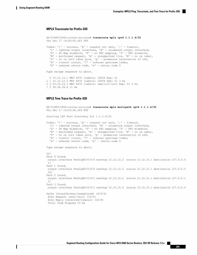
MPLS Traceroute for Prefix-SID
RP/0/RP0/CPU0:router-arizona# traceroute mpls ipv4 1.1.1.4/32Thu Dec 17 14:45:05.563 PST
Codes: '!' - success, 'Q' - request not sent, '.' - timeout,'L' - labeled output interface, 'B' - unlabeled output interface,'D' - DS Map mismatch, 'F' - no FEC mapping, 'f' - FEC mismatch,'M' - malformed request, 'm' - unsupported tlvs, 'N' - no rx label,'P' - no rx intf label prot, 'p' - premature termination of LSP,'R' - transit router, 'I' - unknown upstream index,'X' - unknown return code, 'x' - return code 0
Type escape sequence to abort.
0 12.12.12.1 MRU 4470 [Labels: 16004 Exp: 0]L 1 12.12.12.2 MRU 4470 [Labels: 16004 Exp: 0] 3 msL 2 23.23.23.3 MRU 4470 [Labels: implicit-null Exp: 0] 3 ms! 3 34.34.34.4 11 ms
MPLS Tree Trace for Prefix-SID
RP/0/RP0/CPU0:router-arizona# traceroute mpls multipath ipv4 1.1.1.4/32Thu Dec 17 14:55:46.549 PST
Starting LSP Path Discovery for 1.1.1.4/32
Codes: '!' - success, 'Q' - request not sent, '.' - timeout,'L' - labeled output interface, 'B' - unlabeled output interface,'D' - DS Map mismatch, 'F' - no FEC mapping, 'f' - FEC mismatch,'M' - malformed request, 'm' - unsupported tlvs, 'N' - no rx label,'P' - no rx intf label prot, 'p' - premature termination of LSP,'R' - transit router, 'I' - unknown upstream index,'X' - unknown return code, 'x' - return code 0
Type escape sequence to abort.
LL!Path 0 found,output interface TenGigE0/0/0/0 nexthop 12.12.12.2 source 12.12.12.1 destination 127.0.0.0L!Path 1 found,output interface TenGigE0/0/0/0 nexthop 12.12.12.2 source 12.12.12.1 destination 127.0.0.2LL!Path 2 found,output interface TenGigE0/0/0/1 nexthop 15.15.15.5 source 15.15.15.1 destination 127.0.0.1L!Path 3 found,output interface TenGigE0/0/0/1 nexthop 15.15.15.5 source 15.15.15.1 destination 127.0.0.0
Paths (found/broken/unexplored) (4/0/0)Echo Request (sent/fail) (10/0)Echo Reply (received/timeout) (10/0)Total Time Elapsed 53 ms
Segment Routing Configuration Guide for Cisco NCS 5500 Series Routers, IOS XR Release 7.2.x291
Using Segment Routing OAMExamples: MPLS Ping, Traceroute, and Tree Trace for Prefix-SID

MPLS LSP Ping and Traceroute Nil FEC TargetThe Nil-FEC LSP ping and traceroute operations are extensions of regular MPLS ping and traceroute.
Nil-FEC LSP Ping/Traceroute functionality supports segment routing and MPLS Static. It also acts as anadditional diagnostic tool for all other LSP types. This feature allows operators to provide the ability to freelytest any label stack by allowing them to specify the following:
• label stack
• outgoing interface
• nexthop address
In the case of segment routing, each segment nodal label and adjacency label along the routing path is putinto the label stack of an echo request message from the initiator Label Switch Router (LSR); MPLS dataplane forwards this packet to the label stack target, and the label stack target sends the echo message back.
The following table shows the syntax for the ping and traceroute commands.
Table 11: LSP Ping and Traceroute Nil FEC Commands
Command Syntax
ping mpls nil-fec labels {label[,label]} [output {interface tx-interface} [nexthop nexthop-ip-addr]]
traceroute mpls nil-fec labels {label[,label]} [output {interface tx-interface} [nexthop nexthop-ip-addr]]
Examples: LSP Ping and Traceroute for Nil_FEC TargetThese examples use the following topology:
Node loopback IP address: 172.18.1.3 172.18.1.4 172.18.1.5 172.18.1.7Node label: 16004 16005 16007Nodes: Arizona ---- Utah ------- Wyoming ---- Texas
Interface: GigabitEthernet0/2/0/1 GigabitEthernet0/2/0/1Interface IP address: 10.1.1.3 10.1.1.4
RP/0/RP0/CPU0:router-utah# show mpls forwarding
Tue Jul 5 13:44:31.999 EDTLocal Outgoing Prefix Outgoing Next Hop BytesLabel Label or ID Interface Switched------ ----------- ------------------ ------------ --------------- ------------16004 Pop No ID Gi0/2/0/1 10.1.1.4 1392
Pop No ID Gi0/2/0/2 10.1.2.2 016005 16005 No ID Gi0/2/0/0 10.1.1.4 0
16005 No ID Gi0/2/0/1 10.1.2.2 016007 16007 No ID Gi0/2/0/0 10.1.1.4 4752
16007 No ID Gi0/2/0/1 10.1.2.2 024000 Pop SR Adj (idx 0) Gi0/2/0/0 10.1.1.4 024001 Pop SR Adj (idx 2) Gi0/2/0/0 10.1.1.4 0
Segment Routing Configuration Guide for Cisco NCS 5500 Series Routers, IOS XR Release 7.2.x292
Using Segment Routing OAMMPLS LSP Ping and Traceroute Nil FEC Target
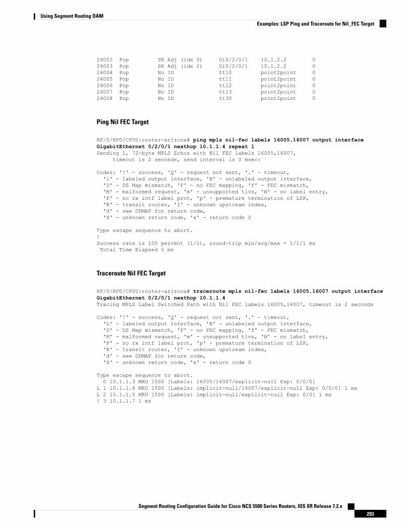
24002 Pop SR Adj (idx 0) Gi0/2/0/1 10.1.2.2 024003 Pop SR Adj (idx 2) Gi0/2/0/1 10.1.2.2 024004 Pop No ID tt10 point2point 024005 Pop No ID tt11 point2point 024006 Pop No ID tt12 point2point 024007 Pop No ID tt13 point2point 024008 Pop No ID tt30 point2point 0
Ping Nil FEC Target
RP/0/RP0/CPU0:router-arizona# ping mpls nil-fec labels 16005,16007 output interfaceGigabitEthernet 0/2/0/1 nexthop 10.1.1.4 repeat 1Sending 1, 72-byte MPLS Echos with Nil FEC labels 16005,16007,
timeout is 2 seconds, send interval is 0 msec:
Codes: '!' - success, 'Q' - request not sent, '.' - timeout,'L' - labeled output interface, 'B' - unlabeled output interface,'D' - DS Map mismatch, 'F' - no FEC mapping, 'f' - FEC mismatch,'M' - malformed request, 'm' - unsupported tlvs, 'N' - no label entry,'P' - no rx intf label prot, 'p' - premature termination of LSP,'R' - transit router, 'I' - unknown upstream index,'d' - see DDMAP for return code,'X' - unknown return code, 'x' - return code 0
Type escape sequence to abort.!Success rate is 100 percent (1/1), round-trip min/avg/max = 1/1/1 msTotal Time Elapsed 0 ms
Traceroute Nil FEC Target
RP/0/RP0/CPU0:router-arizona# traceroute mpls nil-fec labels 16005,16007 output interfaceGigabitEthernet 0/2/0/1 nexthop 10.1.1.4Tracing MPLS Label Switched Path with Nil FEC labels 16005,16007, timeout is 2 seconds
Codes: '!' - success, 'Q' - request not sent, '.' - timeout,'L' - labeled output interface, 'B' - unlabeled output interface,'D' - DS Map mismatch, 'F' - no FEC mapping, 'f' - FEC mismatch,'M' - malformed request, 'm' - unsupported tlvs, 'N' - no label entry,'P' - no rx intf label prot, 'p' - premature termination of LSP,'R' - transit router, 'I' - unknown upstream index,'d' - see DDMAP for return code,'X' - unknown return code, 'x' - return code 0
Type escape sequence to abort.0 10.1.1.3 MRU 1500 [Labels: 16005/16007/explicit-null Exp: 0/0/0]
L 1 10.1.1.4 MRU 1500 [Labels: implicit-null/16007/explicit-null Exp: 0/0/0] 1 msL 2 10.1.1.5 MRU 1500 [Labels: implicit-null/explicit-null Exp: 0/0] 1 ms! 3 10.1.1.7 1 ms
Segment Routing Configuration Guide for Cisco NCS 5500 Series Routers, IOS XR Release 7.2.x293
Using Segment Routing OAMExamples: LSP Ping and Traceroute for Nil_FEC Target

Segment Routing Ping and Traceroute
Segment Routing PingThe MPLS LSP ping feature is used to check the connectivity between ingress and egress of LSP. MPLS LSPping uses MPLS echo request and reply messages, similar to Internet Control Message Protocol (ICMP) echorequest and reply messages, to validate an LSP. Segment routing ping is an extension of the MPLS LSP pingto perform the connectivity verification on the segment routing control plane.
Segment routing ping can only be used when the originating device is running segment routing.Note
You can initiate the segment routing ping operation only when Segment Routing control plane is available atthe originator, even if it is not preferred. This allows you to validate the SR path before directing traffic overthe path. Segment Routing ping can use either generic FEC type or SR control-plane FEC type (SR-OSPF,SR-ISIS). In mixed networks, where some devices are running MPLS control plane (for example, LDP) ordo not understand SR FEC, generic FEC type allows the device to successfully process and respond to theecho request. By default, generic FEC type is used in the target FEC stack of segment routing ping echorequest. Generic FEC is not coupled to a particular control plane; it allows path verification when the advertisingprotocol is unknown or might change during the path of the echo request. If you need to specify the targetFEC, you can select the FEC type as OSPF, IS-IS, or BGP. This ensures that only devices that are runningsegment routing control plane, and can therefore understand the segment routing IGP FEC, respond to theecho request.
Configuration Examples
These examples show how to use segment routing ping to test the connectivity of a segment routing controlplane. In the first example, FEC type is not specified. You can also specify the FEC type as shown in the otherexamples.RP/0/RP0/CPU0:router# ping sr-mpls 10.1.1.2/32
Sending 5, 100-byte MPLS Echos to 10.1.1.2/32,timeout is 2 seconds, send interval is 0 msec:
Codes: '!' - success, 'Q' - request not sent, '.' - timeout,'L' - labeled output interface, 'B' - unlabeled output interface,'D' - DS Map mismatch, 'F' - no FEC mapping, 'f' - FEC mismatch,'M' - malformed request, 'm' - unsupported tlvs, 'N' - no rx label,'P' - no rx intf label prot, 'p' - premature termination of LSP,'R' - transit router, 'I' - unknown upstream index,'X' - unknown return code, 'x' - return code 0
Type escape sequence to abort.
!!!!!Success rate is 100 percent (5/5), round-trip min/avg/max = 1/2/5 ms
RP/0/RP0/CPU0:router# ping sr-mpls 10.1.1.2/32 fec-type generic
Sending 5, 100-byte MPLS Echos to 10.1.1.2/32,timeout is 2 seconds, send interval is 0 msec:
Codes: '!' - success, 'Q' - request not sent, '.' - timeout,
Segment Routing Configuration Guide for Cisco NCS 5500 Series Routers, IOS XR Release 7.2.x294
Using Segment Routing OAMSegment Routing Ping and Traceroute

'L' - labeled output interface, 'B' - unlabeled output interface,'D' - DS Map mismatch, 'F' - no FEC mapping, 'f' - FEC mismatch,'M' - malformed request, 'm' - unsupported tlvs, 'N' - no rx label,'P' - no rx intf label prot, 'p' - premature termination of LSP,'R' - transit router, 'I' - unknown upstream index,'X' - unknown return code, 'x' - return code 0
Type escape sequence to abort.
!!!!!Success rate is 100 percent (5/5), round-trip min/avg/max = 1/1/2 ms
RP/0/RP0/CPU0:router# ping sr-mpls 10.1.1.2/32 fec-type igp ospf
Sending 5, 100-byte MPLS Echos to 10.1.1.2/32,timeout is 2 seconds, send interval is 0 msec:
Codes: '!' - success, 'Q' - request not sent, '.' - timeout,'L' - labeled output interface, 'B' - unlabeled output interface,'D' - DS Map mismatch, 'F' - no FEC mapping, 'f' - FEC mismatch,'M' - malformed request, 'm' - unsupported tlvs, 'N' - no rx label,'P' - no rx intf label prot, 'p' - premature termination of LSP,'R' - transit router, 'I' - unknown upstream index,'X' - unknown return code, 'x' - return code 0
Type escape sequence to abort.
!!!!!Success rate is 100 percent (5/5), round-trip min/avg/max = 1/1/2 ms
RP/0/RP0/CPU0:router# ping sr-mpls 10.1.1.2/32 fec-type igp isis
Sending 5, 100-byte MPLS Echos to 10.1.1.2/32,timeout is 2 seconds, send interval is 0 msec:
Codes: '!' - success, 'Q' - request not sent, '.' - timeout,'L' - labeled output interface, 'B' - unlabeled output interface,'D' - DS Map mismatch, 'F' - no FEC mapping, 'f' - FEC mismatch,'M' - malformed request, 'm' - unsupported tlvs, 'N' - no rx label,'P' - no rx intf label prot, 'p' - premature termination of LSP,'R' - transit router, 'I' - unknown upstream index,'X' - unknown return code, 'x' - return code 0
Type escape sequence to abort.
!!!!!Success rate is 100 percent (5/5), round-trip min/avg/max = 1/1/2 ms
RP/0/RP0/CPU0:router# ping sr-mpls 10.1.1.2/32 fec-type bgp
Sending 5, 100-byte MPLS Echos to 10.1.1.2/32,timeout is 2 seconds, send interval is 0 msec:
Codes: '!' - success, 'Q' - request not sent, '.' - timeout,'L' - labeled output interface, 'B' - unlabeled output interface,'D' - DS Map mismatch, 'F' - no FEC mapping, 'f' - FEC mismatch,'M' - malformed request, 'm' - unsupported tlvs, 'N' - no rx label,'P' - no rx intf label prot, 'p' - premature termination of LSP,'R' - transit router, 'I' - unknown upstream index,'X' - unknown return code, 'x' - return code 0
Type escape sequence to abort.
Segment Routing Configuration Guide for Cisco NCS 5500 Series Routers, IOS XR Release 7.2.x295
Using Segment Routing OAMSegment Routing Ping

!!!!!Success rate is 100 percent (5/5), round-trip min/avg/max = 1/1/2 ms
Segment Routing TracerouteThe MPLS LSP traceroute is used to isolate the failure point of an LSP. It is used for hop-by-hop faultlocalization and path tracing. The MPLS LSP traceroute feature relies on the expiration of the Time to Live(TTL) value of the packet that carries the echo request. When the MPLS echo request message hits a transitnode, it checks the TTL value and if it is expired, the packet is passed to the control plane, else the messageis forwarded. If the echo message is passed to the control plane, a reply message is generated based on thecontents of the request message. Segment routing traceroute feature extends the MPLS LSP traceroutefunctionality to segment routing networks.
Similar to segment routing ping, you can initiate the segment routing traceroute operation only when SegmentRouting control plane is available at the originator, even if it is not preferred. Segment Routing traceroute canuse either generic FEC type or SR control-plane FEC type (SR-OSPF, SR-ISIS). By default, generic FECtype is used in the target FEC stack of segment routing traceroute echo request. If you need to specify thetarget FEC, you can select the FEC type as OSPF, IS-IS, or BGP. This ensures that only devices that arerunning segment routing control plane, and can therefore understand the segment routing IGP FEC, respondto the echo request.
The existence of load balancing at routers in an MPLS network provides alternate paths for carrying MPLStraffic to a target router. The multipath segment routing traceroute feature provides a means to discover allpossible paths of an LSP between the ingress and egress routers.
Configuration Examples
These examples show how to use segment routing traceroute to trace the LSP for a specified IPv4 prefix SIDaddress. In the first example, FEC type is not specified. You can also specify the FEC type as shown in theother examples.RP/0/RP0/CPU0:router# traceroute sr-mpls 10.1.1.2/32
Tracing MPLS Label Switched Path to 10.1.1.2/32, timeout is 2 seconds
Codes: '!' - success, 'Q' - request not sent, '.' - timeout,'L' - labeled output interface, 'B' - unlabeled output interface,'D' - DS Map mismatch, 'F' - no FEC mapping, 'f' - FEC mismatch,'M' - malformed request, 'm' - unsupported tlvs, 'N' - no rx label,'P' - no rx intf label prot, 'p' - premature termination of LSP,'R' - transit router, 'I' - unknown upstream index,'X' - unknown return code, 'x' - return code 0
Type escape sequence to abort.
0 10.12.12.1 MRU 1500 [Labels: implicit-null Exp: 0]! 1 10.12.12.2 3 ms
RP/0/RP0/CPU0:router# traceroute sr-mpls 10.1.1.2/32 fec-type generic
Tracing MPLS Label Switched Path to 10.1.1.2/32, timeout is 2 seconds
Codes: '!' - success, 'Q' - request not sent, '.' - timeout,'L' - labeled output interface, 'B' - unlabeled output interface,'D' - DS Map mismatch, 'F' - no FEC mapping, 'f' - FEC mismatch,'M' - malformed request, 'm' - unsupported tlvs, 'N' - no rx label,
Segment Routing Configuration Guide for Cisco NCS 5500 Series Routers, IOS XR Release 7.2.x296
Using Segment Routing OAMSegment Routing Traceroute

'P' - no rx intf label prot, 'p' - premature termination of LSP,'R' - transit router, 'I' - unknown upstream index,'X' - unknown return code, 'x' - return code 0
Type escape sequence to abort.
0 10.12.12.1 MRU 1500 [Labels: implicit-null Exp: 0]! 1 10.12.12.2 2 ms
RP/0/RP0/CPU0:router# traceroute sr-mpls 10.1.1.2/32 fec-type igp ospf
Tracing MPLS Label Switched Path to 10.1.1.2/32, timeout is 2 seconds
Codes: '!' - success, 'Q' - request not sent, '.' - timeout,'L' - labeled output interface, 'B' - unlabeled output interface,'D' - DS Map mismatch, 'F' - no FEC mapping, 'f' - FEC mismatch,'M' - malformed request, 'm' - unsupported tlvs, 'N' - no rx label,'P' - no rx intf label prot, 'p' - premature termination of LSP,'R' - transit router, 'I' - unknown upstream index,'X' - unknown return code, 'x' - return code 0
Type escape sequence to abort.
0 10.12.12.1 MRU 1500 [Labels: implicit-null Exp: 0]! 1 10.12.12.2 2 ms
RP/0/RP0/CPU0:router# traceroute sr-mpls 10.1.1.2/32 fec-type igp isis
Tracing MPLS Label Switched Path to 10.1.1.2/32, timeout is 2 seconds
Codes: '!' - success, 'Q' - request not sent, '.' - timeout,'L' - labeled output interface, 'B' - unlabeled output interface,'D' - DS Map mismatch, 'F' - no FEC mapping, 'f' - FEC mismatch,'M' - malformed request, 'm' - unsupported tlvs, 'N' - no rx label,'P' - no rx intf label prot, 'p' - premature termination of LSP,'R' - transit router, 'I' - unknown upstream index,'X' - unknown return code, 'x' - return code 0
Type escape sequence to abort.
0 10.12.12.1 MRU 1500 [Labels: implicit-null Exp: 0]! 1 10.12.12.2 2 ms
RP/0/RP0/CPU0:router#traceroute sr-mpls 10.1.1.2/32 fec-type bgp
Tracing MPLS Label Switched Path to 10.1.1.2/32, timeout is 2 seconds
Codes: '!' - success, 'Q' - request not sent, '.' - timeout,'L' - labeled output interface, 'B' - unlabeled output interface,'D' - DS Map mismatch, 'F' - no FEC mapping, 'f' - FEC mismatch,'M' - malformed request, 'm' - unsupported tlvs, 'N' - no rx label,'P' - no rx intf label prot, 'p' - premature termination of LSP,'R' - transit router, 'I' - unknown upstream index,'X' - unknown return code, 'x' - return code 0
Type escape sequence to abort.
0 10.12.12.1 MRU 1500 [Labels: implicit-null/implicit-null Exp: 0/0]! 1 10.12.12.2 2 ms
Segment Routing Configuration Guide for Cisco NCS 5500 Series Routers, IOS XR Release 7.2.x297
Using Segment Routing OAMSegment Routing Traceroute

This example shows how to use multipath traceroute to discover all the possible paths for a IPv4 prefix SID.RP/0/RP0/CPU0:router# traceroute sr-mpls multipath 10.1.1.2/32
Starting LSP Path Discovery for 10.1.1.2/32
Codes: '!' - success, 'Q' - request not sent, '.' - timeout,'L' - labeled output interface, 'B' - unlabeled output interface,'D' - DS Map mismatch, 'F' - no FEC mapping, 'f' - FEC mismatch,'M' - malformed request, 'm' - unsupported tlvs, 'N' - no rx label,'P' - no rx intf label prot, 'p' - premature termination of LSP,'R' - transit router, 'I' - unknown upstream index,'X' - unknown return code, 'x' - return code 0
Type escape sequence to abort.
!Path 0 found,output interface GigabitEthernet0/0/0/2 nexthop 10.13.13.2source 10.13.13.1 destination 127.0.0.0!Path 1 found,output interface Bundle-Ether1 nexthop 10.12.12.2source 10.12.12.1 destination 127.0.0.0
Paths (found/broken/unexplored) (2/0/0)Echo Request (sent/fail) (2/0)Echo Reply (received/timeout) (2/0)Total Time Elapsed 14 ms
Segment Routing Ping and Traceroute for Flexible AlgorithmFlexible Algorithm validation method is based on segment identifier (SID) label and label switched path (LSP)destination, instead of being based on IP address. The assigner is validated against the topology prefixinformation provided by SR-PCE database. If the assigner is valid, then the label given is also validated againstthe SR-PCE database. On the egress side, the destination label is contained in a new SR Label sub-TLV. Thislabel is verified against a SID list provided by SR-PCE.
Observe the following guidelines and restrictions:
• All routers within an area must share the same Flexible Algorithm definition for a Flexible Algorithmto be valid.
• All routers within the domain must be configured with the same SRGB range of values.
• BGP-LS must be enabled.
• Only prefix SIDs and Flexible Algorithm SIDs are supported.
• Only single label stack is supported.
Note
Segment Routing Ping for Flexible AlgorithmRouter# ping sr-mpls labels 16131 lsp-end-point 1.1.1.5Fri Dec 13 19:26:29.517 IST
Segment Routing Configuration Guide for Cisco NCS 5500 Series Routers, IOS XR Release 7.2.x298
Using Segment Routing OAMSegment Routing Ping and Traceroute for Flexible Algorithm

Sending 5, 100-byte MPLS Echos with SR Label FEC with lsp end point 1.1.1.5, SID Label(s)[16131],
timeout is 2 seconds, send interval is 0 msec:
Codes: '!' - success, 'Q' - request not sent, '.' - timeout,'L' - labeled output interface, 'B' - unlabeled output interface,'D' - DS Map mismatch, 'F' - no FEC mapping, 'f' - FEC mismatch,'M' - malformed request, 'm' - unsupported tlvs, 'N' - no rx label,'P' - no rx intf label prot, 'p' - premature termination of LSP,'R' - transit router, 'I' - unknown upstream index,'X' - unknown return code, 'x' - return code 0
Type escape sequence to abort.
!!!!!Success rate is 100 percent (5/5), round-trip min/avg/max = 4/4/6 ms
Segment Routing Traceroute for Flexible AlgorithmRouter# traceroute sr-mpls labels 16130 lsp-end-point 1.1.1.5Fri Dec 13 19:26:59.368 IST
Tracing MPLS Label Switched Path to SR Label FEC with lsp end point 1.1.1.5, SID Label(s)[16130], timeout is 2 seconds
Codes: '!' - success, 'Q' - request not sent, '.' - timeout,'L' - labeled output interface, 'B' - unlabeled output interface,'D' - DS Map mismatch, 'F' - no FEC mapping, 'f' - FEC mismatch,'M' - malformed request, 'm' - unsupported tlvs, 'N' - no rx label,'P' - no rx intf label prot, 'p' - premature termination of LSP,'R' - transit router, 'I' - unknown upstream index,'X' - unknown return code, 'x' - return code 0
Type escape sequence to abort.
0 13.13.13.1 MRU 1500 [Labels: 16130 Exp: 0]L 1 13.13.13.3 MRU 1500 [Labels: 16130 Exp: 0] 5 msL 2 16.16.16.4 MRU 1500 [Labels: implicit-null Exp: 0] 4 ms! 3 18.18.18.5 4 ms
Segment Routing over IPv6 OAMSegment Routing over IPv6 data plane (SRv6) implementation adds a new type of routing extension header.Hence, the existing ICMPv6 mechanisms including ping and traceroute can be used in the SRv6 network.There is no change in the way ping and traceroute operations work for IPv6- or SRv6-capable nodes in anSRv6 network.
Restrictions and Usage Guidelines
The following restriction applies for SRv6 OAM:
• Ping to an SRv6 SID is not supported.
Segment Routing Configuration Guide for Cisco NCS 5500 Series Routers, IOS XR Release 7.2.x299
Using Segment Routing OAMSegment Routing Traceroute for Flexible Algorithm
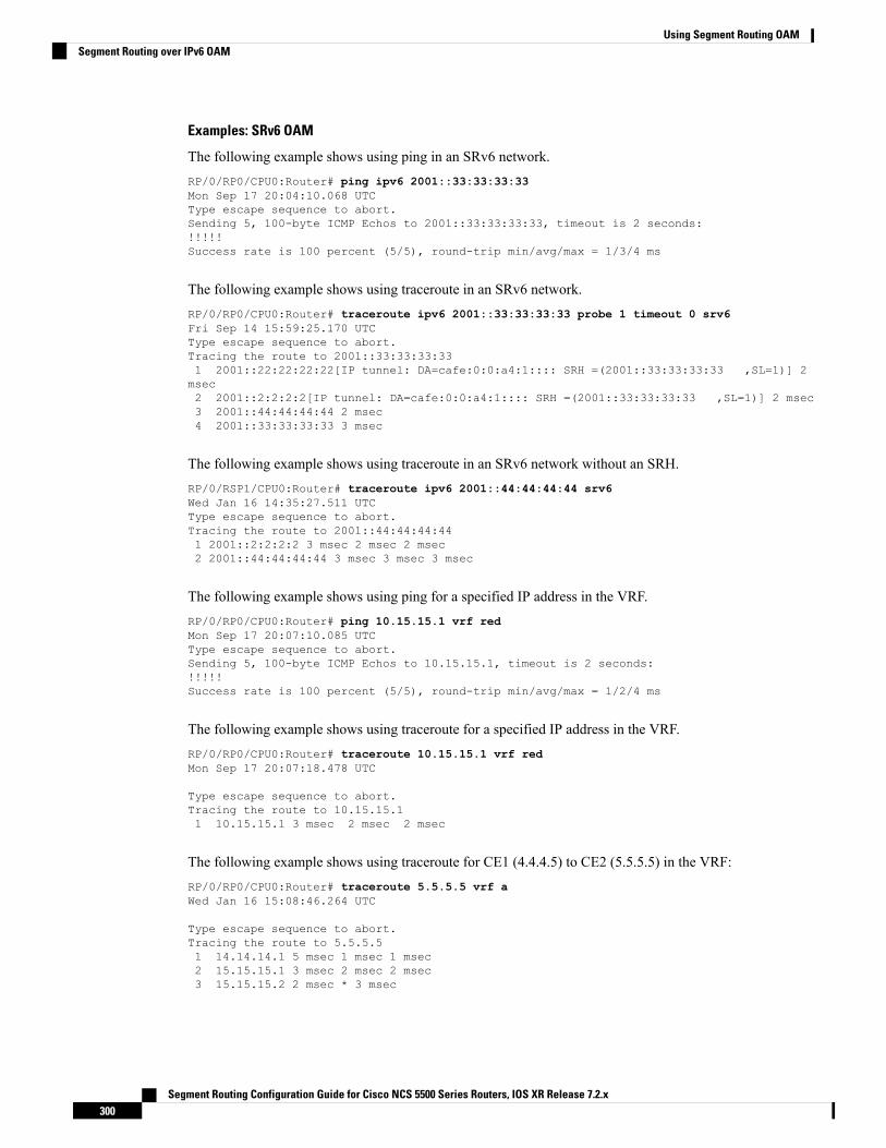
Examples: SRv6 OAM
The following example shows using ping in an SRv6 network.RP/0/RP0/CPU0:Router# ping ipv6 2001::33:33:33:33Mon Sep 17 20:04:10.068 UTCType escape sequence to abort.Sending 5, 100-byte ICMP Echos to 2001::33:33:33:33, timeout is 2 seconds:!!!!!Success rate is 100 percent (5/5), round-trip min/avg/max = 1/3/4 ms
The following example shows using traceroute in an SRv6 network.RP/0/RP0/CPU0:Router# traceroute ipv6 2001::33:33:33:33 probe 1 timeout 0 srv6Fri Sep 14 15:59:25.170 UTCType escape sequence to abort.Tracing the route to 2001::33:33:33:331 2001::22:22:22:22[IP tunnel: DA=cafe:0:0:a4:1:::: SRH =(2001::33:33:33:33 ,SL=1)] 2msec2 2001::2:2:2:2[IP tunnel: DA=cafe:0:0:a4:1:::: SRH =(2001::33:33:33:33 ,SL=1)] 2 msec3 2001::44:44:44:44 2 msec4 2001::33:33:33:33 3 msec
The following example shows using traceroute in an SRv6 network without an SRH.RP/0/RSP1/CPU0:Router# traceroute ipv6 2001::44:44:44:44 srv6Wed Jan 16 14:35:27.511 UTCType escape sequence to abort.Tracing the route to 2001::44:44:44:441 2001::2:2:2:2 3 msec 2 msec 2 msec2 2001::44:44:44:44 3 msec 3 msec 3 msec
The following example shows using ping for a specified IP address in the VRF.RP/0/RP0/CPU0:Router# ping 10.15.15.1 vrf redMon Sep 17 20:07:10.085 UTCType escape sequence to abort.Sending 5, 100-byte ICMP Echos to 10.15.15.1, timeout is 2 seconds:!!!!!Success rate is 100 percent (5/5), round-trip min/avg/max = 1/2/4 ms
The following example shows using traceroute for a specified IP address in the VRF.RP/0/RP0/CPU0:Router# traceroute 10.15.15.1 vrf redMon Sep 17 20:07:18.478 UTC
Type escape sequence to abort.Tracing the route to 10.15.15.11 10.15.15.1 3 msec 2 msec 2 msec
The following example shows using traceroute for CE1 (4.4.4.5) to CE2 (5.5.5.5) in the VRF:RP/0/RP0/CPU0:Router# traceroute 5.5.5.5 vrf aWed Jan 16 15:08:46.264 UTC
Type escape sequence to abort.Tracing the route to 5.5.5.51 14.14.14.1 5 msec 1 msec 1 msec2 15.15.15.1 3 msec 2 msec 2 msec3 15.15.15.2 2 msec * 3 msec
Segment Routing Configuration Guide for Cisco NCS 5500 Series Routers, IOS XR Release 7.2.x300
Using Segment Routing OAMSegment Routing over IPv6 OAM