
Some limitations in the practical delivery of intensity modulated radiation therapy
10
Some limitations in the practical delivery of intensity modulated radiation therapy 1 J MEYER, BSc, Dipl. Ing. (FH), 2 J A MILLS, BSc, PhD, 1 O C L HAAS, MSc, PhD, 3 E M PARVIN, BSc, PhD and 1 K J BURNHAM, MSc, PhD 1 Control Theory and Applications Centre, Coventry University, Priory Street, Coventry CV1 5FB, 2 Walsgrave Hospitals NHS Trust, Clifford Bridge Road, Coventry CV2 2DX and 3 Department of Physics, University of Warwick, Coventry CV4 7AL, UK Abstract. The resolution characteristics of intensity modulated beam (IMB) profiles produced by milled compensators and by multileaf collimators (MLCs) are independently investigated with respect to the primary fluence. It is shown that both methods have different characteristics in the longitudinal and lateral direction and, as a consequence, the resolutions of the longitudinal and lateral delivered IMB profiles differ. For both methods, the restrictions are identified. For compensators, the maximum slopes in the machining process, which should not be exceeded, are quantified. For MLCs, emphasis is given to the direction perpendicular to leaf movement. A number of test modulations were created and the effect of different size MLCs on the intensity profile revealed that unacceptable errors can be introduced if the profiles are heavily modulated. The production of intensity modulated radiation therapy (IMRT) beams by both machined compensators or by MLCs is limited by physical constraints. Having identified these constraints, some steps should now be taken to accommodate them either in the objective function for the calculation of the beam profiles or in the delivery system. The degree of conformation of radiotherapy treatment has improved considerably over the last decade owing to advances in treatment machines, delivery techniques, beam modelling and treat- ment planning [1, 2]. The overall aim of radio- therapy is to focus the radiation to the tumour whilst minimizing the dose to the surrounding healthy tissue. The potential clinical efficacy of intensity modulated conformal radiation therapy has been discussed [3] and the benefits of dose escalation and sparing of the surrounding healthy tissue has been demonstrated (see, for example, [4, 5]). Initially, beam modulation was achieved by placing metal compensators into the beam path to attenuate the radiation appropriately [6, 7]. Currently, multileaf collimators MLCs [8] seem set to supersede conventional compensators. To date there are a number of MLCs available on the market with leaf widths of 1.25 cm (GE), 1.00 cm (Elekta, Siemens, Varian), 0.50 cm (Varian), 0.30 cm (Radionics, Varian/Brainlab) and 0.10 cm (MRC) 1 . In addition, Siemens offer high definition intensity (HDI), where a standard plan is generated for 1 cm leaves and, during treatment, the beam is automatically interrupted and the couch and leaves are shifted slightly to improve the resolution down to 0.50, 0.30, or 0.20 cm (Personal communication, L Roppelt, Siemens Medical, Germany, 1999). It should be noted that the increase in resolution leads to an increase in complexity of the delivery system, either by an increased number of leaves or by an increased complexity of the control software. Techniques using both compensators and MLCs have inherent advantages and disadvan- tages, with the common objective to deliver a homogeneous dose to the tumour within ¡5% [9] of the dose prescription and to keep the dose to the organs at risk (OAR) below a certain value. It has been indicated [10] that the tolerable error includes dose calibration, dose prediction, patient set-up and treatment delivery inaccuracies. Hence, it is essential to keep each single source of error as low as possible. This paper focuses solely on treatment delivery inaccuracies. The output from inverse treatment planning methods is a set of optimal intensity modulated beam (IMB) profiles. However, in practice it is not always feasible actually to deliver these beams with the same accuracy. This is due to mechanical and physical limitations of the deliv- ery method. If the limitations can be identified and quantified for the different modulating devices/methods, then they can be accommodated Received 25 November 1999 and in revised form 24 February 2000, accepted 22 March 2000. 1 Note that some multileaf collimators (MLCs) possess larger leaves for the outer pairs; a leaf width of 1 cm refers to a resolution of 1 cm at source-to-skin distance (SSD); the physical width of the MLC is hence smaller due to the beam divergence. The British Journal of Radiology, 73 (2000), 854–863 E 2000 The British Institute of Radiology 854 The British Journal of Radiology, August 2000
Transcript of Some limitations in the practical delivery of intensity modulated radiation therapy
Some limitations in the practical delivery of intensity
modulated radiation therapy
1J MEYER, BSc, Dipl. Ing. (FH), 2J A MILLS, BSc, PhD, 1O C L HAAS, MSc, PhD,3E M PARVIN, BSc, PhD and 1K J BURNHAM, MSc, PhD
1Control Theory and Applications Centre, Coventry University, Priory Street, Coventry CV1 5FB, 2Walsgrave
Hospitals NHS Trust, Clifford Bridge Road, Coventry CV2 2DX and 3Department of Physics, University of
Warwick, Coventry CV4 7AL, UK
Abstract. The resolution characteristics of intensity modulated beam (IMB) pro®les produced by
milled compensators and by multileaf collimators (MLCs) are independently investigated with
respect to the primary ¯uence. It is shown that both methods have different characteristics in the
longitudinal and lateral direction and, as a consequence, the resolutions of the longitudinal and
lateral delivered IMB pro®les differ. For both methods, the restrictions are identi®ed. For
compensators, the maximum slopes in the machining process, which should not be exceeded, are
quanti®ed. For MLCs, emphasis is given to the direction perpendicular to leaf movement. A
number of test modulations were created and the effect of different size MLCs on the intensity
pro®le revealed that unacceptable errors can be introduced if the pro®les are heavily modulated.
The production of intensity modulated radiation therapy (IMRT) beams by both machined
compensators or by MLCs is limited by physical constraints. Having identi®ed these constraints,
some steps should now be taken to accommodate them either in the objective function for the
calculation of the beam pro®les or in the delivery system.
The degree of conformation of radiotherapy
treatment has improved considerably over the last
decade owing to advances in treatment machines,
delivery techniques, beam modelling and treat-
ment planning [1, 2]. The overall aim of radio-
therapy is to focus the radiation to the tumour
whilst minimizing the dose to the surrounding
healthy tissue. The potential clinical ef®cacy of
intensity modulated conformal radiation therapy
has been discussed [3] and the bene®ts of dose
escalation and sparing of the surrounding healthy
tissue has been demonstrated (see, for example,
[4, 5]). Initially, beam modulation was achieved
by placing metal compensators into the beam path
to attenuate the radiation appropriately [6, 7].
Currently, multileaf collimators MLCs [8] seem
set to supersede conventional compensators. To
date there are a number of MLCs available on the
market with leaf widths of 1.25 cm (GE), 1.00 cm
(Elekta, Siemens, Varian), 0.50 cm (Varian),
0.30 cm (Radionics, Varian/Brainlab) and
0.10 cm (MRC)1. In addition, Siemens offer
high de®nition intensity (HDI), where a standard
plan is generated for 1 cm leaves and, duringtreatment, the beam is automatically interruptedand the couch and leaves are shifted slightly toimprove the resolution down to 0.50, 0.30, or0.20 cm (Personal communication, L Roppelt,Siemens Medical, Germany, 1999). It should benoted that the increase in resolution leads to anincrease in complexity of the delivery system,either by an increased number of leaves or by anincreased complexity of the control software.
Techniques using both compensators andMLCs have inherent advantages and disadvan-tages, with the common objective to deliver ahomogeneous dose to the tumour within ¡5% [9]of the dose prescription and to keep the dose tothe organs at risk (OAR) below a certain value. Ithas been indicated [10] that the tolerable errorincludes dose calibration, dose prediction, patientset-up and treatment delivery inaccuracies. Hence,it is essential to keep each single source of error aslow as possible.
This paper focuses solely on treatment deliveryinaccuracies. The output from inverse treatmentplanning methods is a set of optimal intensitymodulated beam (IMB) pro®les. However, inpractice it is not always feasible actually to deliverthese beams with the same accuracy. This is due tomechanical and physical limitations of the deliv-ery method. If the limitations can be identi®edand quanti®ed for the different modulatingdevices/methods, then they can be accommodated
Received 25 November 1999 and in revised form 24February 2000, accepted 22 March 2000.
1Note that some multileaf collimators (MLCs) possesslarger leaves for the outer pairs; a leaf width of 1 cmrefers to a resolution of 1 cm at source-to-skin distance(SSD); the physical width of the MLC is hence smallerdue to the beam divergence.
The British Journal of Radiology, 73 (2000), 854±863 E 2000 The British Institute of Radiology
854 The British Journal of Radiology, August 2000
in the objective function of the inverse planningprocedure to ``force'' the algorithms to producepractical IMBs. This should result in intensitymodulated treatment plans that are feasible andwith errors within de®ned limits.
Accurate production of compensators withcomplex surface pro®les is best achieved bycomputer numerical control (CNC) millingmachines. These can be used either to machinemetal directly or to produce a mould [11]made of material that can be machined faster.Considerations need to be given to shrinkage anddistortion of the moulded compensators; thispotential for inaccuracy is overcome with directmachining of the metal [12]. However, limitationsdue to the ®nite size of the cutter will apply equallyto both methods of compensator production.
MLCs can deliver intensity modulated radi-ation therapy (IMRT) using static and/ordynamic delivery methods. Both are subject tomechanical restrictions due to the ®nite width oftheir leaves.
In this paper, a general outline is given of theresolution characteristics of intensity modulated®elds generated by milled compensators and bystatic/dynamic MLCs. For each method, differ-ences in accuracy of the delivered pro®le for boththe longitudinal and lateral direction are identi-®ed. Test modulations with clinical relevance arepresented and the resolution in the producedpro®le is investigated.
Compensators
Methods
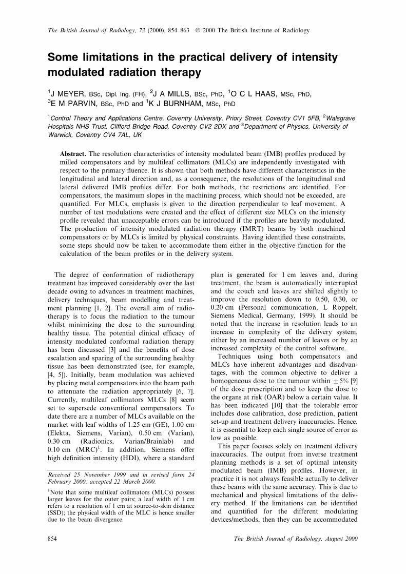
The major drawback of compensators com-pared with other beam modulation devices/techniques is the amount of time required tomanufacture each individual beam modi®er[13±15]. For convenience, a cutter with a sphericaltip is assumed for the manufacturing of allcompensators (Figure 1a). Figure 1 shows acomparison between compensators and a MLC.A milling tool of large diameter and relativelylarge distance between adjacent cuts, denotedas step-over, results in a coarse surface but speedsup the manufacturing time. This is achieved atthe expense of surface smoothness and henceresolution of the intensity pro®les in the lateraldirection. A small tool diameter and/or smallerstep-over, on the other hand, will produce a betterresolution but the manufacturing time may wellincrease unacceptably. Furthermore, a smallertool is more susceptible to tool break and weardue to the stress it encounters. The effect of thissurface unevenness is more signi®cant for a highdensity material than for a lower density one.Hence, it is essential to ®nd the optimum
relationship between cutter diameter, step-over
distance, compensator material, machining time
and the resulting resolution of the delivered
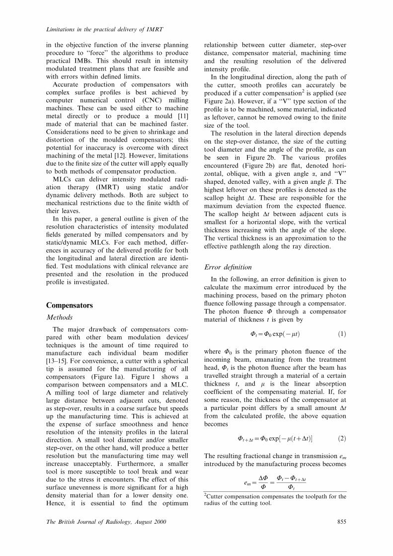
intensity pro®le.In the longitudinal direction, along the path of
the cutter, smooth pro®les can accurately be
produced if a cutter compensation2 is applied (see
Figure 2a). However, if a ``V'' type section of the
pro®le is to be machined, some material, indicated
as leftover, cannot be removed owing to the ®nite
size of the tool.The resolution in the lateral direction depends
on the step-over distance, the size of the cutting
tool diameter and the angle of the pro®le, as can
be seen in Figure 2b. The various pro®les
encountered (Figure 2b) are ¯at, denoted hori-
zontal, oblique, with a given angle a, and ``V''
shaped, denoted valley, with a given angle b. The
highest leftover on these pro®les is denoted as the
scallop height Dt. These are responsible for the
maximum deviation from the expected ¯uence.
The scallop height Dt between adjacent cuts is
smallest for a horizontal slope, with the vertical
thickness increasing with the angle of the slope.
The vertical thickness is an approximation to the
effective pathlength along the ray direction.
Error de®nition
In the following, an error de®nition is given to
calculate the maximum error introduced by the
machining process, based on the primary photon
¯uence following passage through a compensator.
The photon ¯uence W through a compensator
material of thickness t is given by
Wt~W0 exp�{kt� �1�
where W0 is the primary photon ¯uence of the
incoming beam, emanating from the treatment
head, Wt is the photon ¯uence after the beam has
travelled straight through a material of a certain
thickness t, and m is the linear absorption
coef®cient of the compensating material. If, for
some reason, the thickness of the compensator at
a particular point differs by a small amount Dt
from the calculated pro®le, the above equation
becomes
WtzDt~W0 exp�{k�tzDt�� �2�
The resulting fractional change in transmission em
introduced by the manufacturing process becomes
em~DW
W~
Wt{WtzDt
Wt2Cutter compensation compensates the toolpath for theradius of the cutting tool.
Limitations in the practical delivery of IMRT
855The British Journal of Radiology, August 2000
and, combined with Equations (1) and (2), thisresults in
em~1{ exp�{kDt� �3�
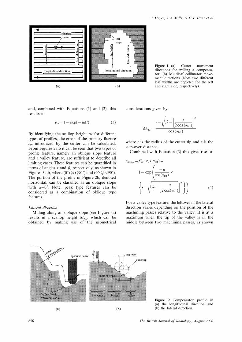
By identifying the scallop height Dt for differenttypes of pro®les, the error of the primary ¯uenceem introduced by the cutter can be calculated.From Figures 2a,b it can be seen that two types ofpro®le feature, namely an oblique slope featureand a valley feature, are suf®cient to describe alllimiting cases. These features can be quanti®ed interms of angles a and b, respectively, as shown inFigures 3a,b, where (0Ê¡a¡90Ê) and (0Ê,b,90Ê).The portion of the pro®le in Figure 2b, denotedhorizontal, can be classi®ed as an oblique slopewith a50Ê. Note, peak type features can beconsidered as a combination of oblique typefeatures.
Lateral directionMilling along an oblique slope (see Figure 3a)
results in a scallop height Dtalat, which can be
obtained by making use of the geometrical
considerations given by
Dtalat~r{
�������������������������������������r2{
s2 cos �alat�� �2s
cos �alat�
where r is the radius of the cutter tip and s is the
step-over distance.Combined with Equation (3) this gives rise to
em;alat~f �k; r; s; alat�~
1{ exp{k
cos�alat�|0@
r{
��������������������������������r2{
�s
2 cos�alat�
s �2( )!�4�
For a valley type feature, the leftover in the lateral
direction varies depending on the position of the
machining passes relative to the valley. It is at a
maximum when the tip of the valley is in the
middle between two machining passes, as shown
Figure 2. Compensator pro®le in(a) the longitudinal direction and(b) the lateral direction.
Figure 1. (a) Cutter movementdirections for milling a compensa-tor. (b) Multileaf collimator move-ment directions (Note two differentleaf widths are depicted for the leftand right side, respectively).
J Meyer, J A Mills, O C L Haas et al
856 The British Journal of Radiology, August 2000
in Figure 3b, and the angle of the steeper side isinserted for b. For this case, the scallop heightDtblat
is given by
Dtblat~ cot 90{blat� � r
sin�blat�z
s2
� �{�������������������
r2{s2
� �2r
and combined with Equation (3), em becomes
em;blat~f �k; r; s; blat�~
1{ exp
{k
(cot�90{blat�|
�r
sin�blat�z
s2
�{
��������������������r2{
�s2
�2s )!
�5�
Longitudinal directionAn oblique slope can be machined accurately in
the longitudinal direction without any signi®cantdeviations from the desired pro®le, hence no errorde®nition is given here. If a cutter compensationis applied, the cutter can follow the desired pro®le
appropriately unless a valley type section isencountered.
A valley type pro®le in the longitudinal
direction is a special case of the lateral one,with a step-over distance s equal to zero, whichresults in a scallop height Dtblong
of
Dtblong~r
1cos blongÿ �{1
" #
and combined with Equation (3) this results in
em;blong~f �k; r; s; blong�~
1{ exp {kr1
cos�blong�{1
" #( )�6�
Variations of milling machine settings
From Equations (4±6) it follows that the
quality of the intensity modulation produced
depends on the linear attenuation coef®cient m,
the radius of the cutter r, the step-over distance s
and the angles alat, blat and blong and of the
respective slopes. MCP200Ô (Mining & Chemical
Products Ltd, Laverstoke, Whitchurch, UK) has
been selected for this work for its material
and absorption properties, having a density
of 7.27 g cm23, a melting point of 197 ÊC,
which makes it reusable, and a linear absorp-
tion coef®cient m of 0.30 cm21 for 6 MV beams.Cutters with radii of 0.20 cm, 0.25 cm, 0.30 cm,
0.40 cm and 0.50 cm were selected. Smaller tools
are not reasonable for reasons of strength and
speed of manufacturing and larger tools for
reasons of achievable resolution in the produced
intensity modulated pro®le. The maximum allow-
able absolute fractional error in the intensity
pro®le per beam was chosen to be em,max55%.
Effectively, this results in a maximum variability
of ¡2.5%. The maximum angles of alat, blat and
blong are calculated for different step-over dis-
tances s. These angles should not be exceeded in
the manufacturing process to maintain em,max.
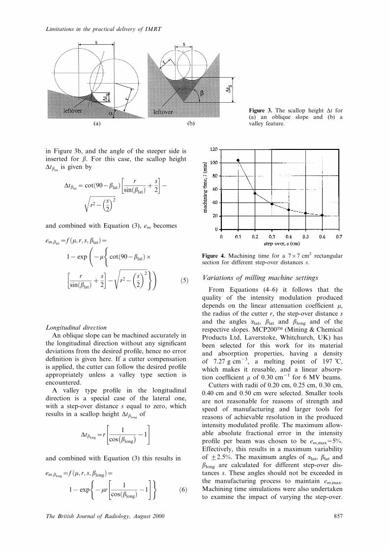
Machining time simulations were also undertaken
to examine the impact of varying the step-over.
Figure 3. The scallop height Dt for(a) an oblique slope and (b) avalley feature.
Figure 4. Machining time for a 767 cm2 rectangularsection for different step-over distances s.
Limitations in the practical delivery of IMRT
857The British Journal of Radiology, August 2000
In¯uence of the tool diameter on the overallmachining time was found to be insigni®cant. Thetoolpath for a ¯at 767 cm2 compensator, whichcorresponds approximately to a 10610 cm2 ®eldat 100 cm SSD, was generated with different step-over distances. The time required to machine a®nishing cut was simulated using a commerciallyavailable software package for CNC machines[16]. These values represent a measure of therelative importance of the step-over distance s onthe overall machining time.
Results
In Figure 4, the signi®cance of keeping the step-over distance s large is shown in the inverserelationship to the machining time. The overalltime is reduced to nearly half its value for a step-over of 0.2 cm (T554 min) rather than 0.1 cm(T5104 min). However, this is at the cost of a loss
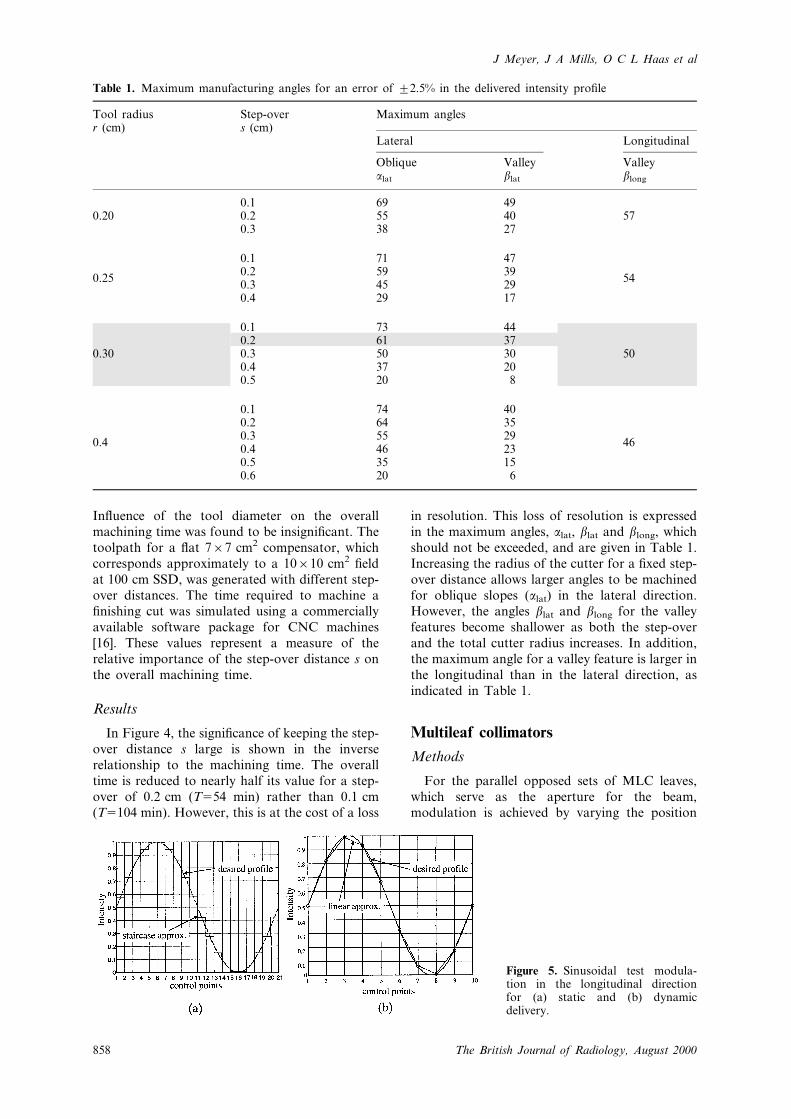
in resolution. This loss of resolution is expressedin the maximum angles, alat, blat and blong, whichshould not be exceeded, and are given in Table 1.Increasing the radius of the cutter for a ®xed step-over distance allows larger angles to be machinedfor oblique slopes (alat) in the lateral direction.However, the angles blat and blong for the valleyfeatures become shallower as both the step-overand the total cutter radius increases. In addition,the maximum angle for a valley feature is larger inthe longitudinal than in the lateral direction, asindicated in Table 1.
Multileaf collimators
Methods
For the parallel opposed sets of MLC leaves,which serve as the aperture for the beam,modulation is achieved by varying the position
Figure 5. Sinusoidal test modula-tion in the longitudinal directionfor (a) static and (b) dynamicdelivery.
Table 1. Maximum manufacturing angles for an error of ¡2.5% in the delivered intensity pro®le
Tool radiusr (cm)
Step-overs (cm)
Maximum angles
Lateral Longitudinal
Oblique Valley Valleyalat blat blong
0.1 69 490.20 0.2 55 40 57
0.3 38 27
0.1 71 47
0.250.2 59 39
540.3 45 290.4 29 17
0.1 73 440.2 61 37
0.30 0.3 50 30 500.4 37 200.5 20 8
0.1 74 400.2 64 350.3 55 29
0.40.4 46 23
46
0.5 35 150.6 20 6
J Meyer, J A Mills, O C L Haas et al
858 The British Journal of Radiology, August 2000
of the leaves over time during irradiation.Software tools, referred to as the ``interpreter'',have been developed by various institutions/manufacturers to convert the desired intensitypro®le into continuous leaf movements, which arediscretized into a number of leaf positions. Thereare then two methods of delivering this intensitymodulated pro®le, static and dynamic.
Longitudinal directionThe static and dynamic methods are only
available in the longitudinal direction. To producea static two-dimensional (2D) intensity modulatedpro®le, the leaves of the MLC move in stepsacross the ®eld, with the radiation ``on'' while theleaves are in position and ``off'' during leafmovement. These designated positions serve ashalting points for the leaves at which the radiationis then switched on for a de®nite time beforebeing switched off again while the leaves aremoving to the next leaf position. The correspond-ing beam pro®les for a sinusoidal test modulationare shown in Figures 5a and 5b, respectively. Forstatic delivery, the resulting pro®le is a ``staircase''approximation, whilst for dynamic delivery it is alinear approximation. By increasing the numberof leaf positions, the resolution increases and boththe ``staircase'' approximation and the linearapproximation of the pro®le becomes smoother.
Lateral directionMuch attention has been paid to improving the
leaf sequencing in the leaf movement direction[17] and hence adapting/improving the accuracyof the delivered pro®le. By contrast, only limitedattention has been paid to the direction across theleaves [18, 19]. In the longitudinal direction, theleaf positions theoretically do not have to beequally spaced and could be adjusted to highspatial frequencies in the appropriate parts of the
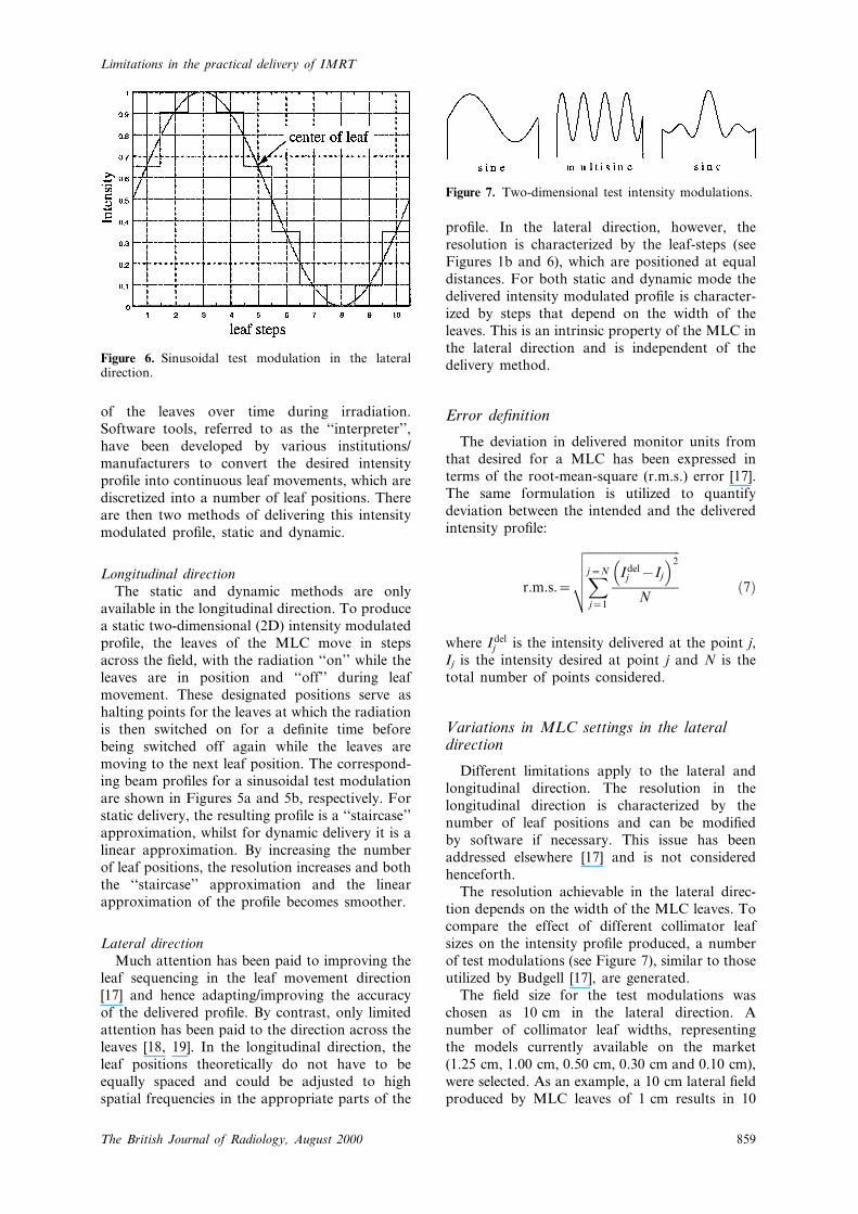
pro®le. In the lateral direction, however, theresolution is characterized by the leaf-steps (seeFigures 1b and 6), which are positioned at equaldistances. For both static and dynamic mode thedelivered intensity modulated pro®le is character-ized by steps that depend on the width of theleaves. This is an intrinsic property of the MLC inthe lateral direction and is independent of thedelivery method.
Error de®nition
The deviation in delivered monitor units fromthat desired for a MLC has been expressed interms of the root-mean-square (r.m.s.) error [17].The same formulation is utilized to quantifydeviation between the intended and the deliveredintensity pro®le:
r.m.s.~
�������������������������������Xj~N
j~1
Idelj {Ij� �2
N
vuuut �7�
where Idelj is the intensity delivered at the point j,Ij is the intensity desired at point j and N is thetotal number of points considered.
Variations in MLC settings in the lateraldirection
Different limitations apply to the lateral andlongitudinal direction. The resolution in thelongitudinal direction is characterized by thenumber of leaf positions and can be modi®edby software if necessary. This issue has beenaddressed elsewhere [17] and is not consideredhenceforth.
The resolution achievable in the lateral direc-tion depends on the width of the MLC leaves. Tocompare the effect of different collimator leafsizes on the intensity pro®le produced, a numberof test modulations (see Figure 7), similar to thoseutilized by Budgell [17], are generated.
The ®eld size for the test modulations waschosen as 10 cm in the lateral direction. Anumber of collimator leaf widths, representingthe models currently available on the market(1.25 cm, 1.00 cm, 0.50 cm, 0.30 cm and 0.10 cm),were selected. As an example, a 10 cm lateral ®eldproduced by MLC leaves of 1 cm results in 10
Figure 6. Sinusoidal test modulation in the lateraldirection.
Figure 7. Two-dimensional test intensity modulations.
Limitations in the practical delivery of IMRT
859The British Journal of Radiology, August 2000
leaf-steps (see also Figure 6), equally spaced alongthe pro®le.
Results
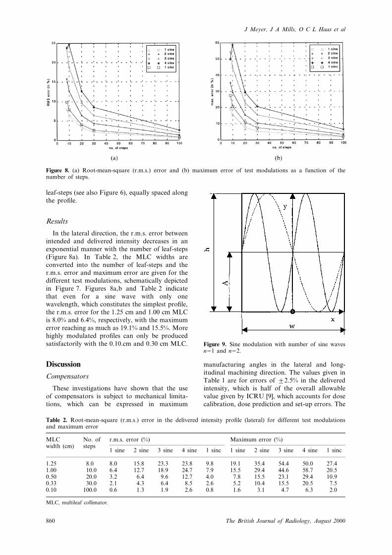
In the lateral direction, the r.m.s. error betweenintended and delivered intensity decreases in anexponential manner with the number of leaf-steps(Figure 8a). In Table 2, the MLC widths areconverted into the number of leaf-steps and ther.m.s. error and maximum error are given for thedifferent test modulations, schematically depictedin Figure 7. Figures 8a,b and Table 2 indicatethat even for a sine wave with only onewavelength, which constitutes the simplest pro®le,the r.m.s. error for the 1.25 cm and 1.00 cm MLCis 8.0% and 6.4%, respectively, with the maximumerror reaching as much as 19.1% and 15.5%. Morehighly modulated pro®les can only be producedsatisfactorily with the 0.10.cm and 0.30 cm MLC.
Discussion
Compensators
These investigations have shown that the useof compensators is subject to mechanical limita-tions, which can be expressed in maximum
manufacturing angles in the lateral and long-itudinal machining direction. The values given inTable 1 are for errors of ¡2.5% in the deliveredintensity, which is half of the overall allowablevalue given by ICRU [9], which accounts for dosecalibration, dose prediction and set-up errors. The
Figure 8. (a) Root-mean-square (r.m.s.) error and (b) maximum error of test modulations as a function of thenumber of steps.
Table 2. Root-mean-square (r.m.s.) error in the delivered intensity pro®le (lateral) for different test modulationsand maximum error
MLCwidth (cm)
No. ofsteps
r.m.s. error (%) Maximum error (%)
1 sine 2 sine 3 sine 4 sine 1 sinc 1 sine 2 sine 3 sine 4 sine 1 sinc
1.25 8.0 8.0 15.8 23.3 23.8 9.8 19.1 35.4 54.4 50.0 27.41.00 10.0 6.4 12.7 18.9 24.7 7.9 15.5 29.4 44.6 58.7 20.50.50 20.0 3.2 6.4 9.6 12.7 4.0 7.8 15.5 23.1 29.4 10.90.33 30.0 2.1 4.3 6.4 8.5 2.6 5.2 10.4 15.5 20.5 7.50.10 100.0 0.6 1.3 1.9 2.6 0.8 1.6 3.1 4.7 6.3 2.0
MLC, multileaf collimator.
Figure 9. Sine modulation with number of sine wavesn51 and n52.
J Meyer, J A Mills, O C L Haas et al
860 The British Journal of Radiology, August 2000

values calculated are maximum errors, without
taking into account the smoothing effect of
scattered radiation [20]. If scatter is included,
the maximum errors would be smaller for the
same angles. Hence, the values given in Table 1
correspond to the worst case with no scatter. The
difference in blong and blat is a clear indication
that the direction of the machining process should
be orientated such that the steepest slopes are in
the longitudinal direction to allow for maximum
intensity modulation.Alternatively, the limitations determined here
could be converted into maximum differences in
the original IMB pro®le. This could then be
incorporated as a practical constraint or a penalty
function in the objective function of the inverse
planning process.Practically, for compensator manufacture,
MCP200Ô is a high density material (r57.27 g
cm23), which can be recycled. However, the cutter
encounters a high stress and, from practical
experience, the minimum radius should not be
less than 0.3 cm. Furthermore, Figure 4 reveals
that the step-over should not drop below 0.2 cm
to keep the machining time acceptable. The values
selected are hence r50.3 cm and s50.2 cm. The
angles obtained for a maximum tolerable error of
em5¡2.5% are highlighted in Table 1 and are
alat561Ê and blat537Ê for an oblique and valley
feature in the lateral direction respectively, and
blong550Ê for a valley feature in longitudinal
direction.The limitations on the use of compensators for
the production of highly modulated beam pro®les,
such as the pro®les in Figure 7, can be deter-
mined. For a 10 cm wide ®eld, the maximum
angle, which would be encountered for full
modulation in a 7 cm thick block of MCP200Ô,
is as shown schematically in Figure 9. The
depicted sine function is given by
y~AzA sin�xnw
2n�
where n denotes the number of sine waves, A the
amplitude and w56.7 cm is the width. Maximum
angles are at x50 and can be obtained from
dydx
~nw2n.A cos
�xnw
2n�
at x~0; dydx~A2nn
w
They are given in Table 3. This shows that for theselected radius and step-over and a one cyclemodulation (n51), the angle alat is exceeded.Based upon the ¡2.5% criteria with no allowancefor scattered radiation, a compensator is theo-retically limited to 0.55 cycles in the lateraldirection. Or, in other words, the maximumamplitude A will be reduced from 3.5 cm to1.9 cm.
MLC
The effects of different MLC leaf widths andhence the pro®le resolution in the lateral directionclearly indicates that the errors become moresigni®cant as the width of the leaves and themodulation of the beam increases. It has beenshown that local underdosage or overdosage canoccur as well as there being a large difference inthe r.m.s. error between delivered and intendedintensity for highly modulated ®elds. Again, thisdrawback might be overcome by including thelimitations of the MLC when generating theIMBs. Another suggested method would be toswap the longitudinal/lateral leaf direction of theleaves halfway through the treatment.
The relevance of this issue can be illustrated bymeans of a prostate treatment plan. The con-siderations are only of theoretical nature butshould nevertheless stress the importance of thematter. An example of a highly modulated single®eld in an IMRT treatment plan can be found inHaas [12]. A ®ve-®eld plan has been found to bea good compromise between complexity and
Table 3. Maximum angles alat for multi-sine waves(n5number of sine waves)
n alat
0.5 591 732 813 844 86
Figure 10. Five-®eld prostate treatment plan.
Limitations in the practical delivery of IMRT
861The British Journal of Radiology, August 2000
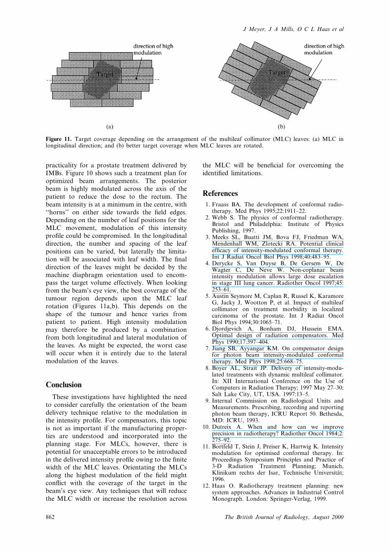
practicality for a prostate treatment delivered byIMBs. Figure 10 shows such a treatment plan foroptimized beam arrangements. The posteriorbeam is highly modulated across the axis of thepatient to reduce the dose to the rectum. Thebeam intensity is at a minimum in the centre, with``horns'' on either side towards the ®eld edges.Depending on the number of leaf positions for theMLC movement, modulation of this intensitypro®le could be compromised. In the longitudinaldirection, the number and spacing of the leafpositions can be varied, but laterally the limita-tion will be associated with leaf width. The ®naldirection of the leaves might be decided by themachine diaphragm orientation used to encom-pass the target volume effectively. When lookingfrom the beam's eye view, the best coverage of thetumour region depends upon the MLC leafrotation (Figures 11a,b). This depends on theshape of the tumour and hence varies frompatient to patient. High intensity modulationmay therefore be produced by a combinationfrom both longitudinal and lateral modulation ofthe leaves. As might be expected, the worst casewill occur when it is entirely due to the lateralmodulation of the leaves.
Conclusion
These investigations have highlighted the needto consider carefully the orientation of the beamdelivery technique relative to the modulation inthe intensity pro®le. For compensators, this topicis not as important if the manufacturing proper-ties are understood and incorporated into theplanning stage. For MLCs, however, there ispotential for unacceptable errors to be introducedin the delivered intensity pro®le owing to the ®nitewidth of the MLC leaves. Orientating the MLCsalong the highest modulation of the ®eld mightcon¯ict with the coverage of the target in thebeam's eye view. Any techniques that will reducethe MLC width or increase the resolution across
the MLC will be bene®cial for overcoming theidenti®ed limitations.
References
1. Fraass BA. The development of conformal radio-therapy. Med Phys 1995;22:1911±22.
2. Webb S. The physics of conformal radiotherapy.Bristol and Philadelphia: Institute of PhysicsPublishing, 1997.
3. Meeks SL, Buatti JM, Bova FJ, Friedman WA,Mendenhall WM, Zlotecki RA. Potential clinicalef®cacy of intensity-modulated conformal therapy.Int J Radiat Oncol Biol Phys 1998;40:483±95.
4. Derycke S, Van Duyse B, De Gersem W, DeWagter C, De Neve W. Non-coplanar beamintensity modulation allows large dose escalationin stage III lung cancer. Radiother Oncol 1997;45:253±61.
5. Austin Seymore M, Caplan R, Russel K, KaramoreG, Jacky J, Wootton P, et al. Impact of multileafcollimator on treatment morbidity in localizedcarcinoma of the prostate. Int J Radiat OncolBiol Phys 1994;30:1065±71.
6. Djordjevich A, Bonham DJ, Hussein EMA.Optimal design of radiation compensators. MedPhys 1990;17:397±404.
7. Jiang SB, Ayyangar KM. On compensator designfor photon beam intensity-modulated conformaltherapy. Med Phys 1998;25:668±75.
8. Boyer AL, Strait JP. Delivery of intensity-modu-lated treatments with dynamic multileaf collimator.In: XII International Conference on the Use ofComputers in Radiation Therapy; 1997 May 27±30;Salt Lake City, UT, USA. 1997:13±5.
9. Internal Commission on Radiological Units andMeasurements. Prescribing, recording and reportingphoton beam therapy, ICRU Report 50. Bethesda,MD: ICRU, 1993.
10. Dutreix A. When and how can we improveprecision in radiotherapy? Radiother Oncol 1984;2:275±92.
11. Bortfeld T, Stein J, Preiser K, Hartwig K. Intensitymodulation for optimised conformal therapy. In:Proceedings Symposium Principles and Practice of3-D Radiation Treatment Planning; Munich,Klinikum rechts der Isar, Technische UniversitaÈt;1996.
12. Haas O. Radiotherapy treatment planning: newsystem approaches. Advances in Industrial ControlMonograph. London: Springer-Verlag, 1999.
Figure 11. Target coverage depending on the arrangement of the multileaf collimator (MLC) leaves: (a) MLC inlongitudinal direction; and (b) better target coverage when MLC leaves are rotated.
J Meyer, J A Mills, O C L Haas et al
862 The British Journal of Radiology, August 2000
13. Stein J, Hartwig K, Levegruen S, Zhang G, PreiserK, Rhein B, et al. Intensity modulated treatments:compensators vs. multileaf modulation. In: XIIInternational Conference on the Use of Computersin Radiation Therapy; 1997 May 27±30; Salt LakeCity, UT, USA. 1997:338±41.
14. Helyer SJ, Heisig S. Multileaf collimation versusconventional shielding blocks: a time and motionstudy of beam shaping in radiotherapy. RadiotherOncol 1995;37:61±4.
15. Helyer SJ, Wilcox S, Heisig S, Westbrook K. Astudy of measuring the possible time savings of amultileaf collimator compared to conventionalbeam shaping in radiotherapy. Br J Cancer 1994;77:32.
16. Mastercam, CAD/CAM Systems. Tolland, CT:CNC Software Inc., 1998.
17. Budgell GJ. Temporal resolution requirements forintensity modulated radiation therapy delivered bymultileaf collimators. Phys Med Biol 1999;44:1581±96.
18. Kubo HD, Wilder RB, Pappas CTE. Impact ofcollimator leaf width on stereotactic radiosurgeryand 3D conformal radiotherapy treatment plans.Int J Radiat Oncol Biol Phys 1999;44:937±45.
19. Xu CX, Yan D, Du MN, Zhou S, Verhey LJ.Optimization of leaf positions when shaping aradiation-®eld with a multileaf collimator. PhysMed Biol 1995;40:305±8.
20. Meyer J, Mills JA. Demonstration of a combined®lter to improve the ®eld uniformity of a 90 kVsuper®cial X-ray therapy machine for differenttreatment ®eld sizes. Br J Radiol 1997;70:201±6.
Limitations in the practical delivery of IMRT
863The British Journal of Radiology, August 2000