Solving arithmetic problems using feed-forward neural networks
27
-
Upload
independent -
Category
Documents
-
view
1 -
download
0
Transcript of Solving arithmetic problems using feed-forward neural networks

Solving arithmetic problems using feed-forward neuralnetworks.
Leonardo Franco 1
Sergio A. Cannas 2
Facultad de Matem�atica, Astronom��a y F��sica, Universidad Nacional de C�ordoba,
Haya de la Torre y Medina Allende S/N, Ciudad Universitaria,
5000 C�ordoba, Argentina.
e-mail : ffranco, cannasg@.�s.uncor.edu
Abstract
We design new feed-forward multi-layered neural networks which perform di�erent el-ementary arithmetic operations, such as bit shifting, addition of N p-bit numbers, andmultiplication of two n-bit numbers. All the structures are optimal in depth and are poli-nomialy bounded in the number of neurons and in the number of synapses. The whole setof synaptic couplings and thresholds are obtained exactly.
Keywords: Neural Networks, Arithmetic operations, Shifter Circuit.
1Fellow of the Consejo Provincial de Investigaciones Cient���cas y Tecnol�ogicas de la provincia de C�ordoba.(CONICOR-Argentina).
2Member of the National Research Council. (CONICET-Argentina).
1
1 Introduction
One of the most important issues in the Neural Network �eld is learning [15], i.e., synapticmodi�cation algorithms (also known as learning algorithms) that allow an arbitrarily con-nected network to develop an internal structure appropriated for a particular task. Althoughlearning algorithms can be (in principle) implemented for any kind of neural structure, feed-forward layered networks presents a simple architecture that makes them specially suitablefor the study of general learning properties (besides their utility for solving speci�cal prob-lems, see, for instance, [9]). These networks are basically input-output devices: parallelcircuits composed by layers of processing units (neurons) connected by synaptic couplings;the information ows in only one direction from the input to the output layer and eventuallypasses through one or more hidden layers. The simplest feed-forward network is the so-calledsimple perceptron [12], which possesses only two layers: input and output. Learning in feed-forward networks is achieved by minimizing some cost function in order to associate a set ofinputs (stimulus) to a set of desired outputs (responses).
In this work we consider networks composed of binary neurons, i.e, neurons whose activitycan only take two values: zero and one. The activity of a neuron �i in a given layer isdetermined by computing a linear threshold function of the form
�i = �
24X
j
WijSj � Ti
35 (1)
where �(x) is 1 if x � 0 and 0 otherwise, Wij are the synaptic weights, Sj = 0; 1 are theactivities of the neurons in a previous layer and Ti is the activation threshold of the neuron�i. In this case, every output neuron computes a boolean function of the input values.
The �rst problem one faces when trying to apply a learning algorithm to a speci�cproblem is that of solvability. There exists a large class of problems (the so-called linearly
inseparable) that cannot be solved by simple perceptrons, being the exclusive-or (XOR)boolean function the most famous one [5]. Arithmetic problems, the topic of the presentwork, also fall into this category. On the other hand, linearly inseparable problems canalways be solved by adding hidden layers. Moreover, it can be easily shown that any booleanfunction can be computed using only one hidden layer with a number of neurons which growsexponentially with the number of variables (or input neurons). However, this exponentialdependency is highly undesirable in practical implementations. Hence, the important pointis to determine the minimum number of hidden layers polinomially bounded in the
number of entries needed to solve a given function. Let us de�ne the depth of a networkas the number of layers with threshold units, i.e., the input layer is not taken into account.The minimal depths for some arithmetic problems are known. It was proven by A. Hajnalet al [4] that the addition of N numbers can be computed by networks of depth 2, whilemultiplication of two numbers needs at least a depth 3 network. In fact, both problemsare closely related and after solving the former a solution of the latter can be immediatelyobtained, as we will show in this work. Generally speaking, arithmetic problems, if solubleby feed-forward neural networks, admit several solutions with di�erent architectures, andfor some of them analytical solutions have been obtained (see [8,6,3]). Besides the depth,another important factor to take into account in the choice of a given architecture is themaximum fan-in of the circuit, which is de�ned as the maximum number of inputs of asingle neuron. Both features (depth and fan-in) are very important by the time of chip
2
implementation. The depth of the network gives the overall delay in computation (which isalso important for parallel processing software) and the hardware puts an upper limit to thenumber of inputs of a single gate.
Returning to the general topic of learning in multilayer networks, several optimizationalgorithms have been introduced in the last years but, up to now, no general convergencetheorem has been proved for any of them. Moreover, a current problem in the �eld is thesearch of standards for performance comparison of di�erent learning algorithms [11].
Even in cases in which the algorithms are successful, their general underlying theory stillremains far from being understood and several important problems remain open. Which isthe minimum number of hidden neurons needed to perform a certain task? Which is thebest architecture for the hidden layers? How many examples are needed for learning certaininput-output mapping and how does the network performance depend on the choice of aparticular set of training examples?
Having exact solutions of particular networks that solve non-trivial problems like thearithmetic ones aid signi�cantly for the analysis of such type of questions. They also serveas standards for testing how the di�erent algorithms work. Moreover, statistical mechanicshas often illustrated that exactly soluble models could also reveal unexpected new facts.
In this work we obtain analytically soluble neural networks for three arithmetic problems,namely, addition of N numbers of p-bit length, multiplication of two n-bit numbers and bit-shifting of a M -bit number. All these structures are optimal in depth and we analyze theirstructures in terms of size, connections, maximum fan-in, etc. The results are also comparedwith other implementations.
The bit-shifting problem has an additional interest. Shifter circuits have been proposedto explain dynamic control of information ow between arrays of neurons at di�erent levels ofthe visual pathway, related to distinct aspects of perception, such as directed visual attention,stereopsis, and others [2]. Hence, besides its possible utility in neurophysiological modeling,we think that the present network may serve to design e�cient visual processing networks,since, to the best of our knowledge, this is the �rst implementation of a shifter network ofdepth-2 for an arbitrary shifting range. By the way, this is a constructive proof thatthe lower bound for the depth of this problem is two (it is a linearly inseparable problem).
The paper is organized as follows: in section 2 we present the construction of a depth-2network for addition of N numbers; these results are applied in section 3 to the constructionof a depth-3 network for multiplication of two numbers. In section 4 we construct a networkwhich shifts an arbitrary number of places all the bits of a number of length M . Thisstructure is straightforwardly generalized for performing both left and right shifts. Someconclusions and remarks are presented in section 5.
2 A depth-2 network for addition of N numbers.
It was proven by Hajnal et Al. [4] that the addition of N numbers can be computed bypolynomial size Neural Networks of depth 2. The proof is nonconstructive and up to ourknowledge no such network has been constructed. Recently Siu & Roychowdhury [14] showedthat a depth 2 net is feasible. We have found a depth-2 neural network composed by linearthreshold units, polynomialy bounded in the number of gates and connections, for solvingthe problem of adding N numbers of p-bits length. This problem is very closely related tomultiplication, powering and other ones.
3
The main problem we face in designing such net is the di�culty introduced by the carryfrom the sum of the bits. In almost all the previous designs the procedure, mainly, consistsof transforming the sum of the N numbers to the sum of two numbers, using techniques asthe Dortmunder method [6], Carry Save Addition [10] and Block Save Addition [8]. Theseprocedures introduce, at least, 2 intermediate layers of linear threshold units leading tostructures that exceed the known lower bound. Hence, we decide not to use those techniquesand proceed with the sum of the numbers in just one step.
The network architecture is the following: In the input layer there are Np neuronscorresponding to the N p-bit numbers to be added. The output layer has M = log2(N(2p �1)+1) neurons, enough to express the result from the sum that could be, at most, N(2p�1).The log operation is assumed to give an integer value result, which is greater or equal thanthe exact real result.
Every input number Sj (j = 1; : : : ; N) will be represented by a set of p binary neurons:Sj = Sp�1
j ; Sp�2j ; : : : ; S0
j . The input layer is arranged in p groups of N bits each, dependingon its signi�cant value, i.e., the corresponding neurons are arranged in the following order:Sp�1N ; Sp�1
N�1; : : : ; Sp�11 ; Sp�2
N ; Sp�2N�1; : : : ; S
p�21 ; : : : ; S0
N ; S0N�1; : : : ; S
01. The signi�cant value of a
bit SpN is 2p and it is assumed that the neurons could take the values one and zero, i.e.,Sij = f0; 1g. The output neurons are denoted by So
M�1; SoM�2; : : : ; S
o0.
In this way the total number of neurons will be completely determined by the number ofneurons in the intermediate layer, because the size of the input and output layers is clearlyde�ned by the problem itself. The neurons in the intermediate layer will be arranged in Mgroups. The group k will have Nk neurons, whose outputs are connected only to the outputneuron So
k.We analyze every output bit separately. Let us �rst consider the synapses structure which
determines the least signi�cant output bit So0 (corresponding to the value 2
0). We shall paya special attention to this case, since this structure will be essentially repeated with minorchanges for the other bits.
The least signi�cant bit, namely So0, has to be one if the result of the sum H of the input
bits
H =NXi=1
S0i (2)
is odd, and zero if it is even:
So0 =
8><>:
1 if H is odd
0 if H is even(3)
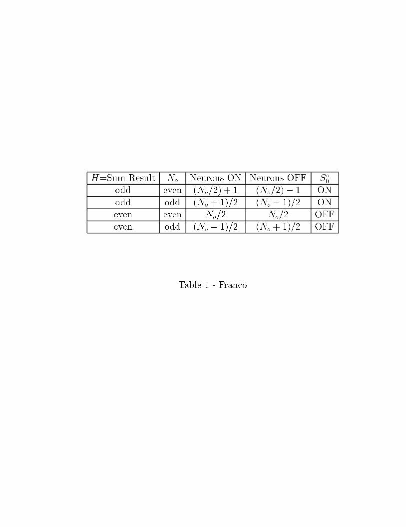
In other words, this bit computes the parity of H. The solution of this problem will bethe key to compute the sum of N numbers. It can be solved as follows: �rst, we put in thispart of the intermediate layer (group k = 0) N0 = N neurons �0i = 0; 1 (i = 0; :::; N0 � 1).The synaptic connections between these neurons and the k = 0 input ones are chosen insuch way that more than half of the intermediate neurons are ON (that means �0i = 1) whenH is odd while less than half of them are OFF (�0i = 0) when H is even.
How should we select the value of the connections? Since in the parity problem all thebits have the same weight, it is reasonable to set all the connections from the input neuronsto an intermediate one �0i equal to a single value w
0;0i . Therefore, we have that
�0i = �
0@w0;0
i
NXj=1
S0j � Ti
1A = �
�w0;0i H � Ti
�: (4)
4
Now we select the following values:
fTig =
(�1;�3;�5; ::::;
�(N0 � 2); N0 if N0 is odd�(N0 � 1) if N0 is even
)(5)
and
w0;0i =
(1 if Ti > 0
�1 if Ti < 0(6)
Notice that, for even values of H, the intermediate neurons whose thresholds have thesame absolute value jTij are always one ON and the other OFF. This is also true when H isodd for all intermediate neurons except those with jTij = H, which are both ON. Moreover,for odd values of N the neuron with Ti = N is OFF for all even values of H. Therefore, wehave that
N0�1Xi=0
�0i =
(> N=2 if H is odd� N=2 if H is even
(7)
for all values of N , as desired (see table 1). Finally, we can see from table 1 that setting thesynapses from the intermediate group (k = 0) toward the output neuron So
0 all equal to one,
i.e., So0 = �
�PN0�1i=0 �0i � T0
�, and taking
N0=2 < T0 � (N0 + 1)=2; (8)
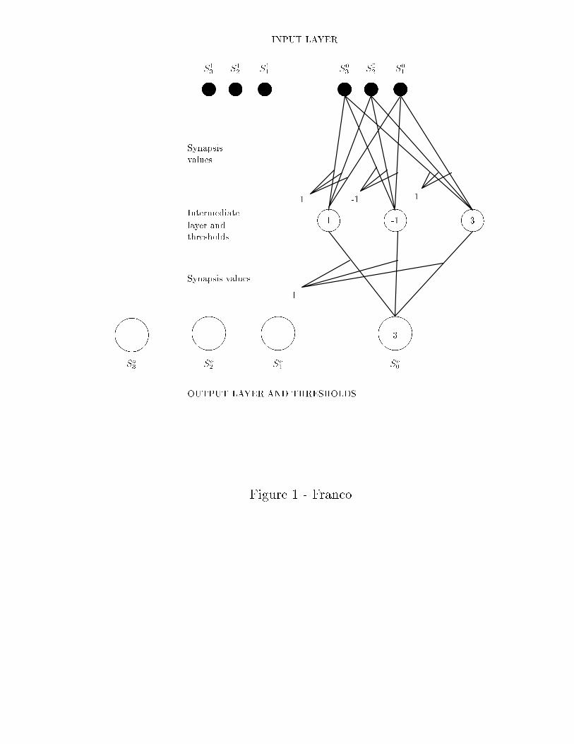
So0 computes the parity problem for all values of N . In Fig. 1 we show an example of the
resulting net structure for the least signi�cant output bit.The solution we have found is a particular and simple one. A more general solution can
be obtained from the previous one by allowing the thresholds fTig to take a wider range ofvalues. Following the same ideas as before, any threshold that in the previous solution tookthe value m (m = �1;�3; : : :) , now is allowed to take an arbitrary value in the interval(m � 1;m]. For instance, the threshold that was Ti = 1 now can take the values in theinterval (0; 1] and the one that was Ti = �1 now can be in the interval (�2;�1]. All theother values of thresholds and synapses remain as before.
Having computed the least signi�cant output bit, we consider the other output bits. Tocompute the second least signi�cant output bit So
1, we have to perform the addition of theN input bits belonging to the group k = 1 (corresponding to the signi�cant value 21) plusthe carry from the N input bits of the group k=0 (signi�cant value 20). We proceed in thesame manner as before, but considering that two bits of signi�cant value 20 are necessary toform one with signi�cant value 21. Hence, the bits of signi�cant value 20 are connected tothe intermediate neurons by synapses that are half of the value of the synapses that connectthese neurons with the corresponding ones with absolute value 21.
Now, we proceed as if we were summing N1 = N + int(N=2) bits (therefore we have toput this number of intermediate neurons) and we repeat the procedure we used in the �rstcase (the int operation takes the integer part of the argument).
Therefore, we have that
�1i = �
24w1;1
i
NXj=1
S1j + w1;0
i
NXj=1
S0j � Ti
35 (9)
5
for i = 0; : : : ; N1 � 1, with
fTig =
(�1;�3;�5; ::::;
�(N1 � 2); N1 if N1 is odd�(N1 � 1) if N1 is even
)(10)
and
w1;ji =
(1
21�jif Ti > 0
� 121�j if Ti < 0
(j = 0; 1) (11)
This procedure can be further generalized to any output bit. When k < p, the output bitSok results from the addition of the N input bits of the group k, plus the carrying from the
preceding k � 1 input groups. This operation is equivalent to the addition of Nk numbers,where
Nk = Int�N +N=2 + � � �+N=2k
�=
= 2N � InthN
2k
ifor k < p. On the other hand, when p � k �M � 1, the output bit So
k results only from thecarrying of the p input groups, because there are no input groups with k0 � p. Therefore,the number of intermediate neurons in the group k will be
Nk =
8<: 2N � Int
hN2k
iif k < p
Np
2k�p+1= Int
hN
2k�p(1 � 1
2p+1)i
if k � p(12)
and
�ki = �
24 kXl=0
wk;li
NXj=1
Slj � Ti
35 (13)
for i = 0; : : : ; Nk � 1, with
fTig =
(�1;�3;�5; ::::;
�(Nk � 2); Nk if Nk is odd�(Nk � 1) if Nk is even
)(14)
and
wk;li =
(1
2k�lif Ti > 0
� 12k�l if Ti < 0
(l = 0; : : : ; k) (15)
The total number of neurons in the intermediate layer results:
NI =p�1Xk=0
�2N � Int
�N
2k
��+
M�1Xk=p
Int�N
2k�p(1�
1
2p+1)�'
' 2Np � 2 + Int�N
2p�
1
2p � 1
�(16)
Finally, we set
Sok = �(
Nk�1Xi=0
�ki � T k
0 ) (17)
withNk=2 < T k
0 � (Nk + 1)=2 (18)
for k = 0; : : : ;M � 1:
6

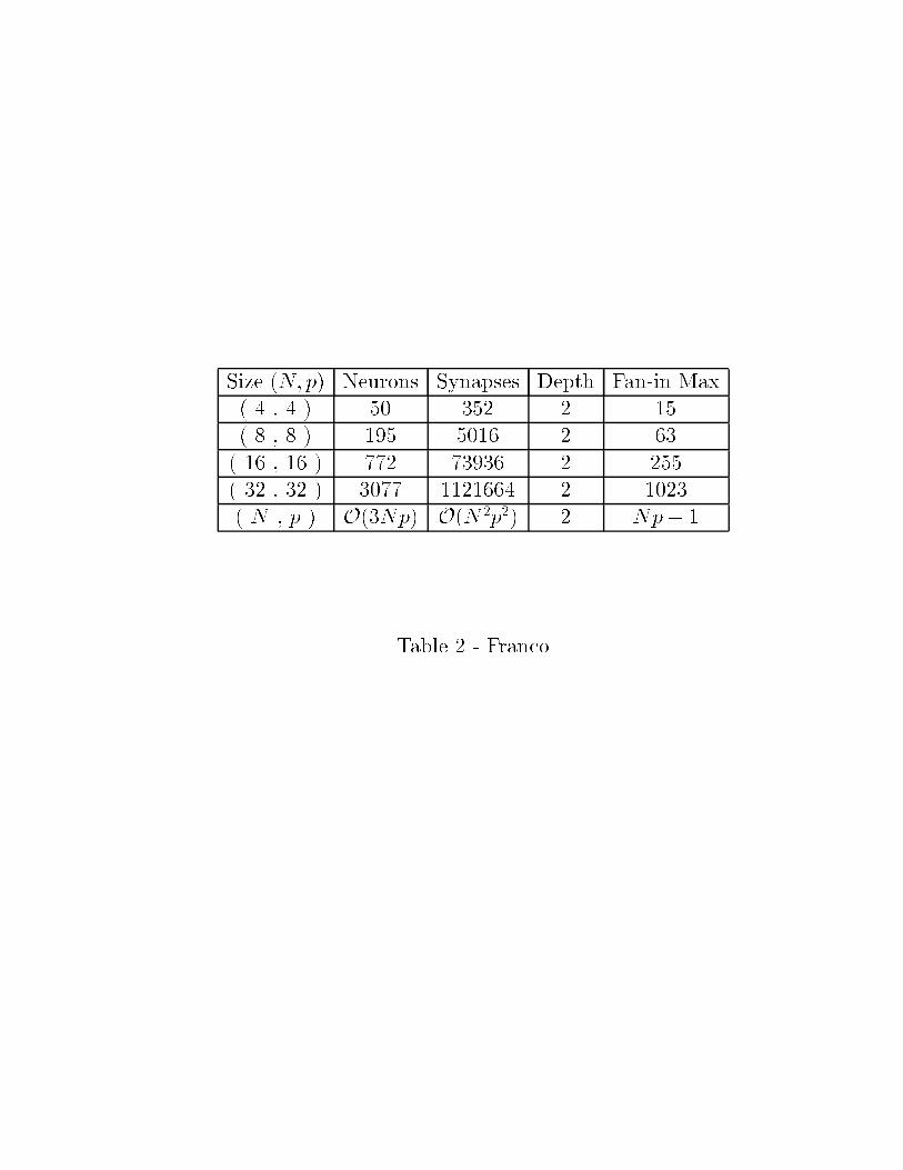
The whole structure of a net for summing N numbers of p bits involvesO(3Np) neuronsand a number of synapses O(N2p2).
As seen, all the sum procedure could be carried out just knowing how to compute theparity problem.
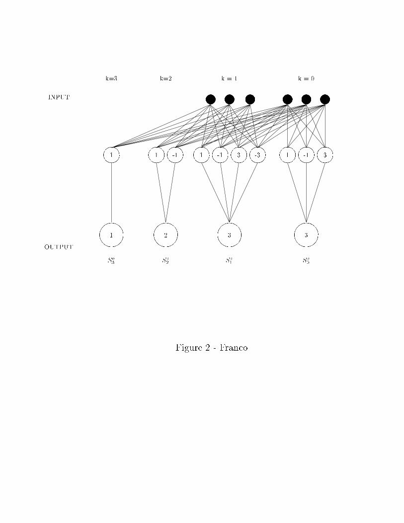
The full structure of a net for the particular case N = 3 p = 2 is shown in �gure 2. Somenetwork parameters for di�erent values of N and p are shown in table 2.
3 Depth-3 Neural Multiplier
The two n-bit number multiplier consists of a 4-layer neural network. The multiplicationis performed in two transformation steps. The �rst one transforms the product of themultiplicand and the multiplier to a sum of n numbers of 2n-1 bit length. The secondtransformation adds all these n numbers.
We begin by arranging the two n-bit numbers in the input layer.The �rst transformation step consists in multiplying the bits of the multiplicand by every
bit of the multiplier, in the same way as in hand calculations. We need no intermediate layerfor this process, since it involves binary products, which are equivalent to perform a bit tobit boolean operation AND, which is indeed linearly separable [5]. Hence, the �rst step canbe carried out by a simple perceptron. We obtain n numbers of 2n-1 bits that have to beadded. We arrange them in the �rst hidden layer. Notice that just n out of the 2n-1 bits ofevery number are di�erent from zero. This fact allows us to reduce the number of neuronsfrom 2(n2 � n) down to n2 in this layer. The neurons from this layer are connected to theinput by two synapses, one to a bit from the multiplicand and one to the multiplier. Thevalues of the synapses and the thresholds can be chosen in a simple form. It is enough toset all the synaptic weights equal to +1 and all the thresholds to +2 to compute the aboveoperation. This is a simple particular solution, but a more general form is to put everythreshold (T ) to a positive value and the two correspondent synapses (W1;W2) such that:
W1;W2 < T �W1 +W2: (19)
In this way the �rst transformation step involves 2n neurons in the input layer, n2 in the�rst hidden layer and 2n2 synapses between both layers.
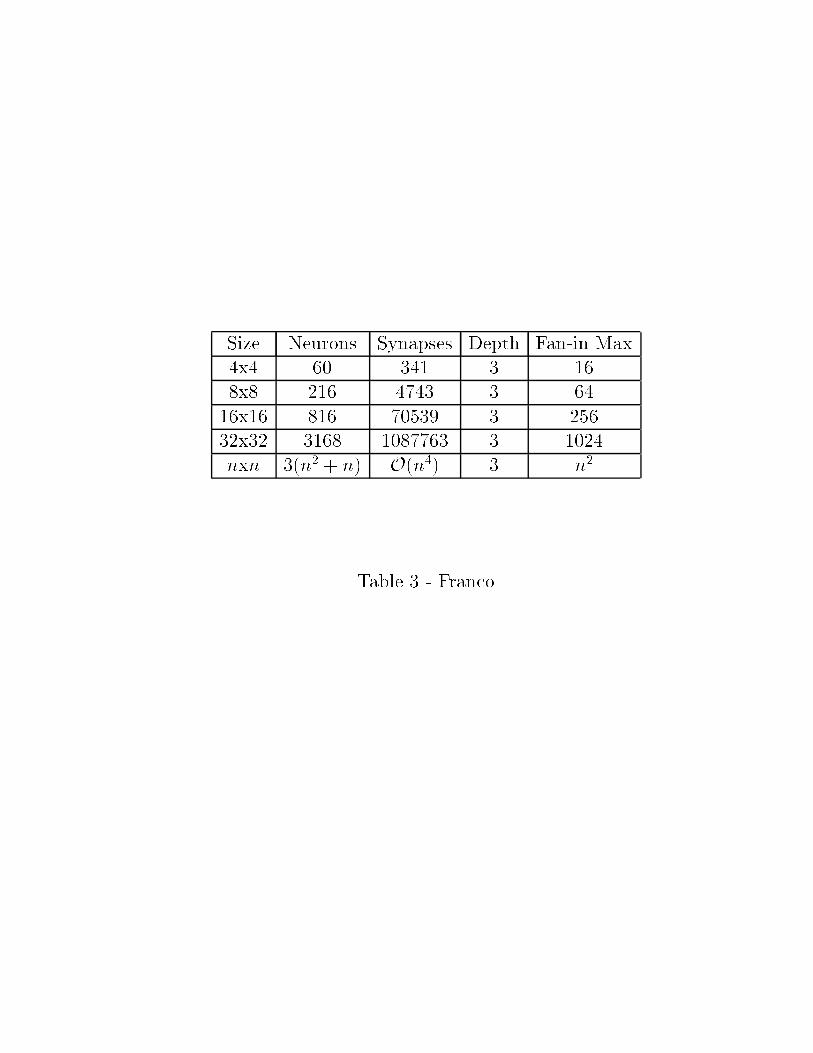
The second and last transformation consists in adding the n numbers of 2n-1 bits, wehave obtained from the �rst step. We have solved this problem in the previous section ina more general form of adding N numbers of p bits. For this case, in which the numberscome from a product, a minimization can be done in the number of neurons, due to the factthat n-1 bits of every number are zero. Thus, this second step needs 2n2 � n neurons inthe second hidden layer that, together with the 2n in the output layer totalizes 3(n2 + n)neurons for the whole net. The number of required connections is of order n4.
An example of the structure of a multiplier for the case of two numbers of 2 bits lengthis shown in �gure 3.
In table 3 some parameters of the network for some classical sizes, as well as for thegeneral case, are shown.
7
4 A bit shifting network
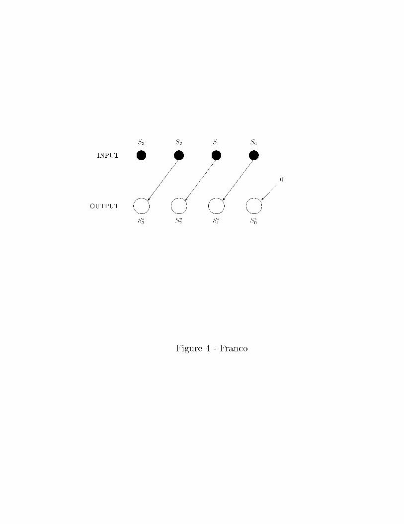
Given an input number of M -bits S = SM�1SM�2::::S1S0, with Si = f0,1g, a 1-place leftbit-shifting consists in obtaining a new M -bit number in which all the bits from the inputnumber are carried one place to the left and a zero is put in the remaining empty site (see�gure 4). The leftmost bit SM�1 is simply thrown away.
Generalizing this procedure, a c-bit shifting consists on the transformation in which wecarry all the input digits c places to the left and put zeros in the c empty places from theright, while the c bits SM�1; : : : ; SM�c are discarded.
We constructed a depth-2 network which performs this operation. It is optimal in depthbecause it can be shown that this is a linearly inseparable problem.
The structure is the following. The input layer contains the M bits of the input numberS plus K = log2(M + 1) neurons indicating the number c of places to be shifted (c � M),i.e., c = Sc
K�1 : : : Sc1 S
c0. The output layer contains just M neurons corresponding to the
shifted number So = SoM�1 : : : S
o1S
o0. In our model the intermediate layer acts as a set of
gates letting pass the correspondent values of the input bits towards the output, dependingon the values of the indicating neurons.
This network is straightforwardly generalized to a bi-directional shifter which allows toperform both left and right shift in a single structure.
In order to explain the functioning of the intermediate layer, let us start presenting thesimple case of a 1-bit shifting. This structure will be generalized later (with minor changes)to a c-bit shifter.
4.1 The 1-bit shifter
For the 1-bit shifting it is necessary to put just one indicating neuron Sc = Sc0. When Sc
0 = 0the output will be equal to the input So
i = Si 8i (no shift is performed), while for Sc0 = 1
we shift all the input bits one place, i.e., Soi = Si�1 for i = 1; : : : ;M � 1 and So
0 = 0. Wesee that the state of the output neuron So
i depends only on the values of Si, Si�1 and Sc0.
Hence, we put only two intermediate neurons �i;0 and �i;1 in every group i (see Fig.5) fori = 1; : : : ;M �1 (the i = 0 case will be considered later). The leftmost neuron �i;0 will carrythe information about the value of Si toward So
i , letting pass this value or not dependingon the state of Sc
0. Therefore, it will be connected only to Si (via a synapse ui;i) and to Sc0
(via a synapse v0i;0). On the other hand, the neuron �i;1 will carry the information aboutthe state of the previous neuron Si�1 toward So
i , and therefore it will be connected onlyto Si�1 (with synapse ui;i�1) and to Sc
0 (with synapse v0i;1). Denoting by Ti;j the thresholdsof �i;j (j = 0; 1) we have that
�i;j = �hui;i�jSi�j + v0i;jS
c0 � Ti;j
i(i = 1; : : : ;M � 1 ; j = 0; 1) (20)
The intermediate group i = 0 has to be considered separately. Since there is no previousinput bit to i = 0 we need only one intermediate neuron �0;0 = �
hu0;0S0 + v00;0S
c0 � T0;0
i.
Finally, both neurons �i;0 and �i;1 will be connected to Soi with synapses wi;0 and wi;1:
Soi = � [wi;0�i;0 + wi;1�i;1 � Ti] (21)
In �gure 5 a schematic structure of a group i is shown.
8

The structure works as follows: when Sc0 = 0 we have that �i;0 = Si and �i;1 = 0 8i. On
the other hand, when Sc0 = 1 we have that �i;0 = 0 and �i;1 = Si�1 for i = 1; : : : ;M � 1.
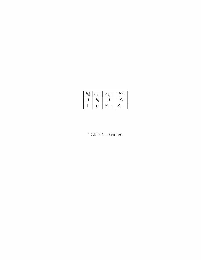
This results are summarized in table 4 and replacing them into Eq.(20) we �nd that
ui;i � Ti;0 > 0 (22)
v0i;0 < Ti;0 � ui;i (23)
for i = 0; : : : ;M � 1 and
0 < ui;i�1 < Ti;1 (24)
0 < v0i;1 < Ti;1 (25)
ui;i�1 + v0i;1 � Ti;1 (26)
for i = 1; : : : ;M � 1. From table 4 we see that Soi must satisfy So
i = �i;0 if Sc0 = 0 and
Sc0 = �i;1 if Sc
0 = 1. Since �i;0 and �i;1 can never be both equal to one at the same time,the above condition can be satis�ed if So
i = (�i;0OR�i;1) (logic OR operation). This lastoperation can be performed by taking Ti � 0 and
wi;j � Ti (j = 0; 1) (27)
for all i.We have completed the construction of the 1-bit shifting net, obtaining a structure which,
for an input number ofM -bits, is composed by 4M�1 neurons, 6M�3 synaptic connectionsand a maximum number of inputs per neuron equal to two.
4.2 The c-bit shifter
We will now consider the most general case of a c-bit shifter, which allows to shift from noneto all the bits of the input number.
In this case the intermediate group i has to be able of carrying information about thestate of any one of the i + 1 input neurons fSi; Si�1; : : : ; S1; S0g towards the output So
i ,letting pass only the value of Si�c. Therefore, we put in this group i + 1 neurons �i;j withj = 0; : : : ; i, which give a total number of M(M + 1)=2 intermediate neurons; �i;j will beconnected to Si�j through a synapse ui;i�j and to all the K indicating neurons Sc
l throughsynapses vli;j (l = 0; : : : ;K � 1):
�i;j = �
"ui;i�jSi�j +
K�1Xl=0
vli;jScl � Ti;j
#(i = 1; : : : ;M � 1 ; j = 0; : : : ; i): (28)
Now, the synapses fui;i�j; vli;jg will be set in such a way that, for a c-bit shifting we willhave, in every group i, �i;j = 0 for j 6= c and �i;c = Si�c.
Let start with the �rst intermediate neuron of every group �i;0. We have that
�i;0 =
(Si if Sc
l = 0 8l0 otherwise:
(29)
Replacing into Eq.(28) we �nd that
9
ui;i � Ti;0 > 0 (30)
vli;0 < Ti;0 � ui;i 8l (31)
for i = 0; : : : ;M � 1. Note that all the synapses are inhibitories except ui;i.Let us now consider the rest of the intermediate neurons. Since �i;j = 0 8j > 0 if Sc
l = 08l, we �nd from Eq.(28) that Ti;j > 0 for all values of i and j, and
ui;i�j < Ti;j 8j > 0 (32)
For the second neuron of every group �i;1 we have that
�i;1 =
(Si�1 if Sc
0 = 1 and Scl = 0 8l 6= 0
0 otherwise(33)
for i = 1; : : : ;M � 1. Replacing into Eq.(28) we �nd that
v0i;1 < Ti;1 (34)
ui;i�1 + v0i;1 � Ti;1 (35)
Ti;1 � (ui;i�1 + v0i;1) > vli;1 8l 6= 0: (36)
From Eqs.(32), (34) and (35) we see that ui;i�1 > 0 and v0i;1 > 0, i.e., both synapses areexcitatory while the rest are all inhibitory. Notice that a similar set of inequalities will beencountered for the synapses associated with any intermediate neuron that can be ON whenonly one indicating bit Sc
l is ON, i.e., when c = 2m with m = 0; 1; : : : ;K�1. In other words,for any group i � 2m we have that
�i;2m =
(Si�2m if Sc
m = 1 and Scl = 0 8l 6= m
0 otherwise(37)
and therefore
0 < vmi;2m < Ti;2m (38)
ui;i�2m + vmi;2m � Ti;2m (39)
Ti;2m � (ui;i�2m + vmi;2m) > vli;m 8l 6= m: (40)
Then, in all these cases only the two synapses ui;i�2m and vmi;2m are excitatories and lessthan their respective threshold, while all the rest of the synapses are inhibitories accordingto (39) and (40).
The above outlined procedure can be applied to any one of the intermediate neurons.Then, given �i;j, suppose that there are p bits Sc
l = 1 when c = j. Let fl1; : : : ; lpg the set ofindex for which Sc
l = 1. Then
0 < vli;j < Ti;j 8l 2 fl1; : : : ; lpg (41)
10
ui;j + vli;j � Ti;j 8l 2 fl1; : : : ; lpg (42)
Ti;j � (ui;j +X
8l2fl1;:::;lpg
vli;j) > vl0
i;m 8l0 62 fl1; : : : ; lpg: (43)
Finally, note that for any value of c only the neuron �i;c = Si�c for every group i � c,while the rest of the intermediate neurons �i;j = 0 8j 6= c. Hence, the output So
i can becalculated as So
i = (�i;0 OR �i;1 OR : : : �i;i�1 OR �i;i). This operation can be performed bysetting Ti > 0 8i and wi;j � Ti for j = 0; : : : ; i.
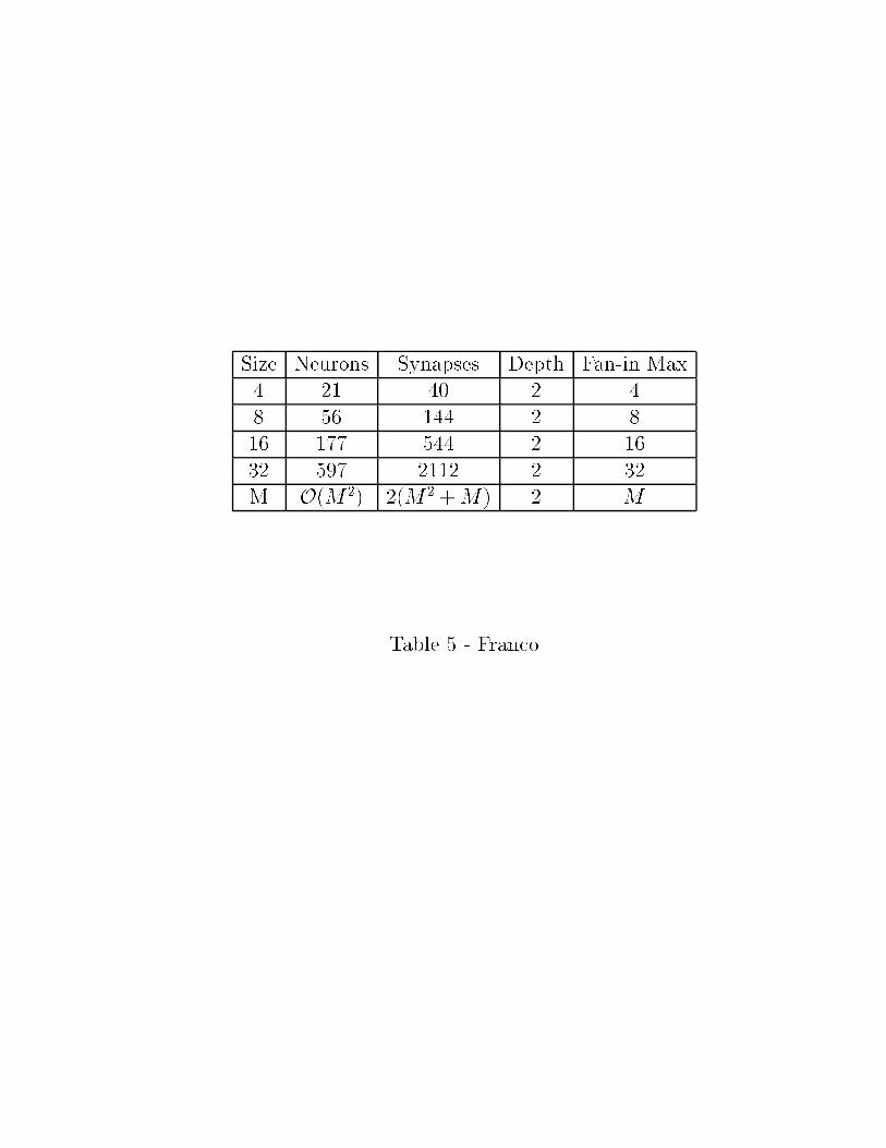
This procedure leads to a 3-layer structure for a M -bit shifter with a total number ofneurons of order O(M2), 2(M2 +M) synapses and with a Fan-in Max equal to M .
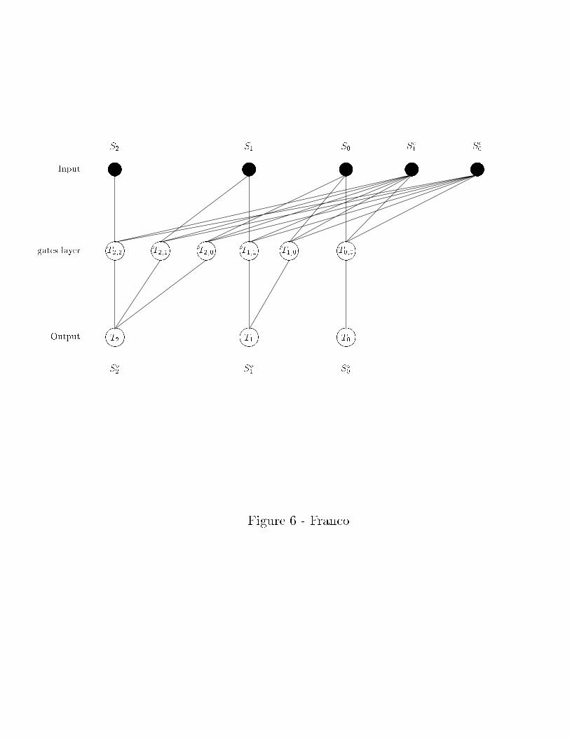
A scheme of a left bit shifter for the case M=3 is shown in �gure 6, and some net featuresfor di�erent sizes are shown in table 5.
4.3 Bi-directional shifter
The previous structures can be generalized in order to allow both left and right shifting. Thefunctioning scheme is esentially the same as the previous one, but with the addition of newintermediate neurons to perform the right shift.
A net for right shifting would have the same structure described in the preceding subsec-tion, with the di�erence that the intermediate neurons have to be arranged in a reverse way:the intermediate neurons corresponding to the �rst output bit have to be swapped with theones corresponding to the last output bit and so on.
Finally, both structures can be combined into a single bi-directional shifter with the addi-tion of a new input neuron Ssh that indicates which operation have to be carried out: Ssh = 0corresponds to a left shift and Ssh = 1 to a right one. In this case every intermediate group icontainsM neurons �i;j with j = i�(M+1); i�M; : : : ;�1; 0; 1; : : : ; i, each one connected toone input neuron Si�j and to all the indicating neurons Sc
l . Ssh has an inhibitory connectionwith all the neurons �i;j for j = 1; : : : ; 0, so that �i;j = 0 when Ssh = 1 independently of theinput. This e�ect can be seen as a dynamic raising of all the thresholds for this subgroupof neurons when Ssh = 1. The reverse e�ect can be obtained for the intermediate neurons�i;j with j = i � (M + 1); i �M; : : : ;�1 as follows. We raise all their thresholds so that�i;j = 0 for any input when Ssh = 0 and we put an excitatory connection from Ssh to all ofthem that supress this e�ect when Ssh = 1. This dynamic switch of the thresholds can bemodelled as follows:
�i;j = �
"ui;i�jSi�j +
K�1Xl=0
vli;jScl � T 0
i;j(Ssh)
#; (44)
for = 1; : : : ;M � 1, j = i� (M + 1); i�M; : : : ;�1; 0; 1; : : : ; i, with
T 0i;j(Ssh) =
(Ti;j + Ji;j(1� Ssh) for j = i� (M � 1); : : : ;�1Ti;j + Ji;jSsh for j = 1; : : : ; i
(45)
where Ji;j > ui;i�j +PK�1
l=0 jvli;jj � Ti;j and all the parametersnui;i�j; v
li;j; Ti;j
oremain as
before. The intermediate neurons �i;0 are the only ones that are not connected to Ssh sincethey only carry information towards the output neuron So
i when no shift is performed. Thisnetwork has M2 intermediate neurons and a total number of M2(K + 3) �M synapses.
11
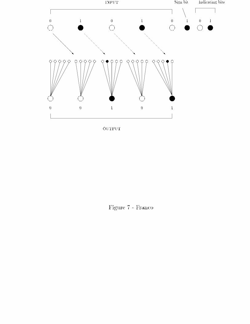
In Fig. 7 we present an example of a bi-directional shifter with 5 input neurons. (theconnections between the input and the intermediate layers are not shown for clarity). In thisexample the input is 01010 and the network performs a 1-place right shift giving the ouput00101.
5 Conclusions and Remarks
We have presented the construction of 3 neural nets for the multiplication of two n-bitintegers, the addition of N integer numbers and for the bit-shifting problem. The designof the �rst two compared favorably with the previous designs [8,6], with the remarkableadvantage of reducing the numbers of layers down to the optimal depth, 4 and 3 layersrespectively. The adder network presents a backward connection structure, i.e., hiddenneurons in a given group i are only connected to neurons of the corresponding input group andto all the preceding input neurons. The corresponding synaptic weights decay exponentiallywith the distance to the input neuron (see eq. (15)). This structure results from the carryprocess and it has been already encountered in other networks for a related problem [3].Di�erent features of a network for adding N integers numbers of N bits by di�erent methodsare shown in table 6.
We constructed a depth-2 bi-directional shifter. The depth of this network is independenton the shifting range 2k. This is, to the best of our knowledge, the �rst solution of theshifting problem with this characteristic. This result has to be compared to that proposedby Anderson and Van Hessen [2], which is composed of k hidden layers.
The same ideas used for the construction of our shifter can be readily extended to twodimensions.
It is worth noting that, being the shifting problem a linearly inseparable one, the con-struction of a depth-2 network proves that this is the optimal depth.
Acknowledgments
This work was partially supported by the following agencies: CONICET (Argentina), CON-ICOR (C�ordoba, Argentina) and Secretar��a de Ciencia y T�ecnica de la Universidad Nacionalde C�ordoba (Argentina).
12
References
(1) N. Alon and J. Bruck, Explicit constructions of depth-2 majority circuits for compar-ison and addition, SIAM J. Discrete. Math. 7 (1991) 1-8.
(2) C.H. Anderson and D.C. Van Essen, Shifter circuits: A computational strategy fordynamic aspects of visual processing, Proc. Natl. Acad. Sci. USA 84 (1987) 6297-6301.
(3) S. Cannas 1995. Arithmetic Perceptrons, Neural Computation 7 (1) (1995) 173-181.(4) A. Hajnal, W. Maass, P. Pudlak, M. Szegedy and G. Turan, Threshold Circuits of
bounded depth, IEEE Symp. Found. Comp. Sci. 28 (1987) 99-110.(5) J.Hertz, A. Krogh and R. Palmer, Introduction to the Theory of Neural Computation
(Addison Wesley, Santa fe Institute, 1991).(6) T. Hofmeister, W. Hohberg and S. Kohling, Some notes on Threshold Circuits and
multiplication in depth 4, Inform. Proccesing Lett. 39 (1991) 99-110.(7) E. Klingman, Microprocessor systems design (Prentice Hall, New Jersey, 1977) 54-65.(8) R. Lauwereins and J. Bruck, E�cient Implementation of a Neural Multiplier, IBM
Research, Tech. Report RJ 8138 (1991).(9) B. Muller and J. Reinhardt, Neural Networks: An introduction. (Springer Verlag,
Berlin, 1991).(10) M. Paterson, N. Pippenger and U. Zwick, Optimal Carry Save Networks, Research
Report RR166, Dept. of Computer Science, Univ. of Warwick, Coventry, UK. (1990)(11) L. Prechelt, A Quantitative Study of Experimental Evaluations of Neural Network
Learning Algorithms: Current Research Practice, Neural Networks 9 (3) (1996) 457-462.(12) F. Rosenblatt, Principles of Neurodynamics (Spartan, New York, 1962).(13) K. Siu, J. Bruck and T. Kailath, Depth E�cient Neural Networks for Division and
Related problems, IEEE Transactions on information Theory 39 (3) (1993).(14) K. Siu and V. Roychowdhury. On optimal depth threshold circuits for multiplication
and related problems. SIAM J. Discrete Math. 7 (2) (1994)(15) T.L.H. Watkin, A. Rau, and M. Biehl, The statistical mechanics of learning a rule,
Rev. Mod. Phys. 65 (2) (1993) 499-556.
13
Captions for �gures and tables
Fig. 1: Net structure example for solving the addition of the rightmost bit (correspond-ing to 20) of three binary numbers Sj (j = 1; 2; 3). The numbers inside the circles indicatethe thresholds values of the corresponding neurons.
Fig. 2: Net structure for adding three 2-bit numbers. The values inside the circlesindicate the thresholds of the corresponding neurons. (see the text for the synapses values).
Fig. 3: Schematic network architecture for computing the product of the two 2-bitnumbers: �a = �1a�
0a and �b = �1b�
0b (�i
a;b = 0; 1), where �0 = �a � �b is the output.Every neuron in the �rst hidden layer performs a binary product between one bit of themultiplicand �a and one bit of the multiplier �b. The second hidden and output layers aredesigned, as described in Section 2 to perform the addition of the previous results, like inhand calculations. Filled and open circles indicate active (ON) and rest (OFF) neuronsrespectively. In this particular example the input �a = 10 and �b = 11 is transformed intothe numbers ho = 10 and h1 = 100, which in turn are added to give the output S0 = 0110.
Fig. 4: Schematic representation of a 1-bit shifting transformation. In this example theinput number S = S3S2S1S0 (Si = 0; 1) is transformed into So = So
3So2S
o1S
o0 with So
i = Si�1
for i = 1; 2; 3 and So0 = 0.
Fig. 5: Network connectivity associated with the ith output neuron Soi for a 1-bit (left)
shifter. The variables inside the open circles are the thresholds of the corresponding neurons,while the variables besides the solid lines are the synaptic weights.
Fig. 6: Network architecture for a bit shifter of a 3-bit number S = S2S1S0. Thenumber of shifting places is given by Sc = Sc
1Sc0. (see text for details).
Fig. 7: Example of a 1-place right shift with a bi-directonal shifter. Filled and opencircles indicate active (ON) and rest (OFF) neurons respectively. In this example the inputis 01010, Ssh = 1, and Sc = 01, so the network performs a 1-place right shift.
Table 1: Number of neurons OFF and ON in the intermediate group (k = 0 : �oi ,
i = 0; : : : ; N0 � 1), for di�erent parity combinations of N0 and the sum of the input bits H(Eq. 2). The last column indicates the desired values of the output So
0, in order to computethe parity of H (Eq. 3).
Table 2: Several network parameters for classical size values of a Neural adder.Table 3: Several network parameters for classical size values of a Neural multiplier.Table 4: Activation states of the intermediate neurons associated with the output bit
S0i for a 1- bit shifter.Table 5: Several Networks parameters for classical size values of a bit-shifter.Table 6: Comparison between the principal parameters of di�erent methods for con-
stucting a network that computes the Sum of N numbers of N -bit length.(y) Lauwereins & Bruck (1991).
14
~ ~ ~
����
��������
"!#
"!#
"!#
"!#
1 -1 3
3
~ ~ ~
Intermediate
layer andthresholds
OUTPUT LAYER AND THRESHOLDS
Synapsis values
Synapsisvalues
INPUT LAYER
1 -1 1
1
So3
So2
So1
So0
S1
3S1
2S1
1S0
3S0
2S0
1
Figure 1 - Franco
~ ~ ~
����
��������
������������
��������
"!#
"!#
"!#
"!#
����
3321
~ ~ ~k = 1 k = 0
So3
So2
So1
So0
INPUT
OUTPUT
����
1 1 -1 1 -1 3 -3 1 -1 3
k=2k=3
Figure 2 - Franco

| l | |
| l | l
l ||ll l
| ll |S3 S2 S1 S0
�1a �0a �1b �0b
h11= �0a � �1b h1
0= �1a � �0b h0
0= �0a � �0bh2
1= �1a � �1b
1 0 = �a�
1 1 = �b
1 0 = �a � �0b = h0
0 = �a � �1b = h11
1 0 = S1
Input
bit to bitboolean AND layer
Addition layer
Output
0
Figure 3 - Franco
~ ~ ~ ~
����������������
0
�������/
�������/
�������/
���
S3 S2 S1 S0
So3
So2
So1
So0
INPUT
OUTPUT
Figure 4 - Franco

~ ~ ~
����
����
����
Si Si�1 Sc0
Ti;0 Ti;1
Ti
Soi
q q q q
�i;0 �i;1
wi;0 wi;1
ui;i ui;i�1 v0i;0 v0i;1
Figure 5 - Franco
~ ~ ~ ~ ~
����
����
����
����
����
����
����
����
����
S2 S1 S0 Sc1
Sc0
T2;2 T2;1 T2;0 T1;1 T1;0 T0;0
T2 T1 T0
Input
gates layer
Output
So2
So1
So0
Figure 6 - Franco
e e e e e e e e e e e e e e e
|l|
Sign bit Indicating bits
e e e e e e e e e e
l l l l l
l l l l l
| |
||
p uu
INPUT
OUTPUT
0 1 0 1 0 1 0 1
0 0 1 0 1
@@@@@@R
@@@@@@R
@@@@@@R
@@@@@@R
Figure 7 - Franco
H=Sum Result No Neurons ON Neurons OFF So0
odd even (No=2) + 1 (No=2)� 1 ON
odd odd (No + 1)=2 (No � 1)=2 ONeven even No=2 No=2 OFFeven odd (No � 1)=2 (No + 1)=2 OFF
Table 1 - Franco
Size (N; p) Neurons Synapses Depth Fan-in Max( 4 , 4 ) 50 352 2 15( 8 , 8 ) 195 5016 2 63
( 16 , 16 ) 772 73936 2 255( 32 , 32 ) 3077 1121664 2 1023( N , p ) O(3Np) O(N 2p2) 2 Np� 1
Table 2 - Franco
Size Neurons Synapses Depth Fan-in Max4x4 60 341 3 168x8 216 4743 3 64
16x16 816 70539 3 25632x32 3168 1087763 3 1024nxn 3(n2 + n) O(n4) 3 n2
Table 3 - Franco
Sc0 �i;0 �i;1 S0
i
0 Si 0 Si
1 0 Si�1 Si�1
Table 4 - Franco
Size Neurons Synapses Depth Fan-in Max4 21 40 2 4
8 56 144 2 816 177 544 2 16
32 597 2112 2 32M O(M 2) 2(M 2 +M ) 2 M
Table 5 - Franco

Method Neurons Synapses Fan-in Max Depth
Block Save Addition (BSA) y O(N3) O(N4logN ) O(N2) 3
BSA optimized & Dortmunder y O(N2) O(N3logN ) O(NlogN ) 3Our O(N2) O(N4) O(N2) 2
Table 6 - Franco