Finite Field Arithmetic for Cryptography
17
40 IEEE CIRCUITS AND SYSTEMS MAGAZINE 1531-636X/10/$26.00©2010 IEEE SECOND QUARTER 2010 Digital Object Identifier 10.1109/MCAS.2010.936785 Erkay Savas ¸ and Çetin Kaya Koç Abstract Cryptography is one of the most prominent application areas of the finite field arithmetic. Almost all public-key cryptographic algo- rithms including the recent algo- rithms such as elliptic curve and pairing-based cryptography rely heavily on finite field arithmetic, which needs to be performed ef- ficiently to meet the execution speed and design space con- straints. These objectives con- stitute massive challenges that necessitate interdisciplinary re- search efforts that will render the best algorithms, architectures, implementations, and design prac- tices. This paper aims to provide a concise perspective on design- ing architectures for efficient fi- nite field arithmetic for usage in cryptography. We present differ- ent architectures, methods and techniques for fast execution of cryptographic operations as well as high utilization of resources in the realization of cryptographic algorithms. While it is difficult to have a complete coverage of all related work, this paper aims to reflect the current trends and im- portant implementation issues of finite field arithmetic in the con- text of cryptography. 1. Introduction E fficient implementation of cryptographic algo- rithms has been in the focal point of major research efforts for the last two decades. Different metrics such as execution time (speed), implementation space (silicon area, code size, memory usage, etc.) and power usage/energy consumption are used to quantitatively measure the performance of a design/implementation. Efficiency can be defined as one of these metrics depend- ing on the application requirements. While execution time is important for applications where latency and through- put is of utmost importance, implementation space is crucial for constrained platforms. Energy and power are also important for the latter case. Since there is almost always a trade-off in execution time and implementation space, faster designs generally require more area. Efficiency of the design can also be thought as a combined performance metric and is usually measured Finite Field Arithmetic for Cryptography Erkay Savas ¸ and Çetin Kaya Koç Feature © BRAND X PICTURES Authorized licensed use limited to: CityU. Downloaded on May 30,2010 at 02:22:54 UTC from IEEE Xplore. Restrictions apply.
-
Upload
independent -
Category
Documents
-
view
4 -
download
0
Transcript of Finite Field Arithmetic for Cryptography

40 IEEE CIRCUITS AND SYSTEMS MAGAZINE 1531-636X/10/$26.00©2010 IEEE SECOND QUARTER 2010
Digital Object Identifier 10.1109/MCAS.2010.936785
Erkay Savas and Çetin Kaya Koç
AbstractCryptography is one of the most prominent application areas of the finite field arithmetic. Almost all public-key cryptographic algo-rithms including the recent algo-rithms such as elliptic curve and pairing-based cryptography rely heavily on finite field arithmetic, which needs to be performed ef-ficiently to meet the execution speed and design space con-straints. These objectives con-stitute massive challenges that necessitate interdisciplinary re-search efforts that will render the best algorithms, architectures, implementations, and design prac-tices. This paper aims to provide a concise perspective on design-ing architectures for efficient fi-nite field arithmetic for usage in cryptography. We present differ-ent architectures, methods and techniques for fast execution of cryptographic operations as well as high utilization of resources in the realization of cryptographic algorithms. While it is difficult to have a complete coverage of all related work, this paper aims to reflect the current trends and im-portant implementation issues of finite field arithmetic in the con-text of cryptography.
1. Introduction
Efficient implementation of cryptographic algo-
rithms has been in the focal point of major research
efforts for the last two decades. Different metrics
such as execution time (speed), implementation space
(silicon area, code size, memory usage, etc.) and power
usage/energy consumption are used to quantitatively
measure the performance of a design/implementation.
Efficiency can be defined as one of these metrics depend-
ing on the application requirements. While execution time
is important for applications where latency and through-
put is of utmost importance, implementation space is
crucial for constrained platforms. Energy and power are
also important for the latter case. Since there is almost
always a trade-off in execution time and implementation
space, faster designs generally require more area.
Efficiency of the design can also be thought as a
combined performance metric and is usually measured
Finite Field Arithmetic for Cryptography Erkay Savas and
Çetin Kaya Koç
Feature
© BRAND X PICTURES
Authorized licensed use limited to: CityU. Downloaded on May 30,2010 at 02:22:54 UTC from IEEE Xplore. Restrictions apply.

SECOND QUARTER 2010 IEEE CIRCUITS AND SYSTEMS MAGAZINE 41
Erkay Savas ([email protected]) is with Sabanci University and Çetin Kaya Koç ([email protected]) is with Istanbul S ehir University and the
University of California, Santa Barbara.1Carry-Free adders that eliminate the carry-propagation are the most popular adders in cryptographic applications.
using area-time product that shows how effectively the
design space is utilized. Related with this, compactness of
the implementation of a cryptographic algorithm is also
an issue attracting increasing attention. A design is com-
pact if its implementation space is small compared to its
execution speed. Another criteria is the design’s versa-
tility. A design is versatile if it can be used in diverse set
cryptographic operations. Versatility and compactness
of a design assist improve the {area 3 time} metric.
Majority of cryptographic algorithms utilize arithmetic
in finite mathematical structures such as finite multiplica-
tive groups, rings, and finite fields. Having a complete set
of arithmetic operations, finite fields feature a superset
of operations of rings and multiplicative groups. While
multiplicative groups have only one defined operation
and rings do not have multiplicative inversion defined for
its every element, finite fields feature addition/subtrac-
tion, multiplication/division, and both multiplicative and
additive inversion operations. Since overwhelming per-
centage of execution time of cryptographic algorithms
is spent on these arithmetic operations, efficient imple-
mentation of these operations determines the efficiency
of the overall cryptographic system.
The basic arithmetic operations (i.e. addition, mul-
tiplication, and inversion) in finite fields, GF 1q 2 , where
q 5 pk and p is a prime integer, are heavily used in many
cryptographic algorithms such as RSA algorithm, Diffie-
Hellman key exchange algorithm [13], the US federal
Digital Signature Standard [36], elliptic curve cryptogra-
phy [27, 33], and also recently pairing-based cryptogra-
phy [3, 48]. Most popular finite fields that are commonly
used in cryptographic applications due to elliptic curve
based schemes are prime fields GF 1p 2 and binary exten-
sion fields GF 12n 2 . Recently, pairing-based cryptogra-
phy based on bilinear pairings over elliptic curve points
stimulated a significant level of interest in the arithmetic
of ternary extension fields, GF 13n 2 .
The aforementioned three popular finite fields feature
dissimilar mathematical structures. Therefore, it is impor-
tant to design algorithms and architectures that will ex-
ploit the specific properties of the underlying field to give
the best performance for the chosen efficiency metric. On
the other hand, elements of different finite fields are rep-
resented using similar data structures inside the digital
circuits and computers. Furthermore, similarity of algo-
rithms for basic arithmetic operations in these fields allow
diverse utilization of the functional units in the design.
A paramount example of diverse utilization of the func-
tional units is the unified module design [47]. For exam-
ple, the steps of the original Montgomery multiplication
algorithm [35], which is one of the most efficient methods
for multiplication in finite fields and rings, GF 1p 2 and Zn,
slightly differ from those of the Montgomery multiplica-
tion algorithm for binary extension fields, GF 12n 2 , given in
[28]. In addition, it is almost straightforward to extend the
Montgomery multiplication algorithm for ternary exten-
sion fields, GF 13n 2 , by essentially keeping the steps of the
algorithm intact. Similarly, addition or inversion opera-
tions can be performed using similar algorithms that can
be realized together in the same digital circuit. To summa-
rize, an arithmetic module which is versatile in the sense
that it can be adjusted to operate in more than one of the
three fields is feasible, provided that this extra functional-
ity does not lead to an excessive increase in area and dra-
matic decrease in speed. One important result from the
recent research is that a unified module that is capable of
performing arithmetic in more than one field in the same,
unified datapath brings about many advantages, one of
which is the improved {area 3 time} product.
Exploiting the same set of functional units in the com-
putations of a variety of cryptographic operations is es-
sential in designing efficient and compact architectures
and implementations. For instance, any field operation can
be performed using only adder circuits. Subtraction can
easily transformed into addition (the two are identical in
finite fields of characteristic two), multiplication can be
seen as repeated addition, efficient multiplicative inver-
sion algorithms feature only addition, subtraction and shift
operations. Therefore, an architecture for finite field opera-
tions can be designed around a set of fast adder circuits1.
In this paper, we provide a survey of algorithms, ar-
chitectures, and design practices that allow fast, efficient
and compact implementations of finite field arithmetic.
We target three categories of cryptographic algorithms:
Cryptographic algorithms that use fi nite multipli- ■
cative groups and rings such as RSA,
Elliptic curve cryptography, ■
Pairing-based cryptography. ■
Cryptographic algorithms utilize arithmetic in finite mathematical structures such as finite multiplicative groups, rings, and finite fields.
Authorized licensed use limited to: CityU. Downloaded on May 30,2010 at 02:22:54 UTC from IEEE Xplore. Restrictions apply.

42 IEEE CIRCUITS AND SYSTEMS MAGAZINE SECOND QUARTER 2010
We present algorithms for arithmetic operations
that can be generically applied. For example, we focus
on the usage of the polynomial base for binary, ternary
and general extension fields. Special polynomials (e.g.
trinomials, pentanomials) that can be beneficial in field
multiplication are not emphasized here since they may
not be generic; except for the general extension fields
where computations can be made considerably faster
when specific irreducible polynomials are used.
2. Fundamentals of Finite Fields
and Their Arithmetic
The elements of the prime finite field GF 1p 2 are the in-
tegers in the set 50, 1, 2, c, p 2 16 where p is an odd
prime. The addition and multiplication operations in
GF 1p 2 are modular operations performed in two steps:
regular integer addition or multiplication, and 1)
reduction by the prime modulus 2) p if the result of the
fi rst step is greater than or equal to the modulus.
The elements of the binary extension field GF 12n 2 can
be represented as binary polynomials of degree less than
n if polynomial basis representation is used. Analogous
to the odd prime used in GF 1p 2 , a binary irreducible
polynomial of degree n is used to construct GF 12n 2 . The
addition in GF 12n 2 is modulo-2 addition of correspond-
ing coefficients of two polynomials. Since it is basically
a polynomial addition there is no carry propagation and
the degree of the resulting polynomial cannot exceed
n 2 1. On the other hand, multiplication in GF 12n 2 is more
complicated and sometimes it is beneficial to use other
types of representation techniques than standard poly-
nomial basis such as Gaussian normal basis [18]. Here,
we always use polynomial basis for GF 12n 2 because of its
suitability to the proposed design principles.
Polynomial basis representation of GF 12n 2 is deter-
mined by an irreducible binary polynomial p 1x 2 of degree
n. Given p 1x 2 , all the binary polynomials of degree less than
n, which has the form A 1x 2 5 an21xn21 1 c1 a1x 1 a0,
are the elements of GF 12n 2 . Multiplication in GF 12n 2 , simi-
lar to multiplication in GF 1p 2 , is performed in two steps:
polynomial multiplication followed by 1)
a polynomial division of the result from Step 1 by 2)
the irreducible polynomial p 1x 2 .
Similar to binary extension fields, the elements of
ternary extension fields GF 13n 2 can be represented as
(ternary) polynomials of degree at most n 2 1, whose co-
efficients are from the base field GF 13 2 . In order to utilize
polynomial basis for ternary arithmetic, an irreducible
ternary polynomial p 1x 2 of degree n is needed. The ad-
dition operation in GF 13n 2 is polynomial addition where
the corresponding coefficients of two ternary polyno-
mials are added modulo-3 and there is no carry propa-
gation. The multiplication is also done in two steps: a
polynomial multiplication followed by reduction by the
irreducible ternary polynomial p 1x 2 of the field.
3. Compact Architectures for
Addition and Subtraction
The most fundamental arithmetic operation in finite
fields and rings, on which all other arithmetic opera-
tions are based, is the addition operation. The key point
to an efficient finite field arithmetic is to design fast and
light-weight adder circuits. In many cryptographic appli-
cations in order to balance the speed and area efficiency,
adders utilizing redundant representation are preferred.
The most basic form of redundant representation is the
carry-save form in which an integer is represented as
the sum of two other integers, namely x 5 xC 1 xS where
xC and xS are known as carry and sum parts of the in-
teger, respectively. The addition operation with carry-
save form can be performed using full-adders which
have three binary inputs and two binary outputs. Full-
adders connected to each other can perform addition
where one of the operands are in redundant form while
the other in non-redundant form. For n-bit operands, the
carry-save adder will need n full adders.
It is possible to perform both GF 1p 2 and GF 12n 2 addi-
tion operation using so-called dual-field adder (DFA) [47],
which is illustrated in Figure 1. DFA shown in Figure 1
is basically a full-adder equipped with the capability of
performing bit addition both with and without carry. It
has an input denoted as fsel that provides this function-
ality. When fsel 5 1, the dual-adder circuit performs bit-
wise addition with carry which enables the circuit to op-
erate in GF 1p 2 -mode. When fsel 5 0, on the other hand,
the output C out is forced to 0 regardless of the values of
the inputs. Consequently, the output S produces the re-
sult of modulo-2 addition of three binary input values.
At most only two of the three binary input values of DFA
can have nonzero values in GF 12n 2 -mode.
An important aspect of designing a DFA is not to in-
crease the critical path delay (CPD) of the circuit, which
otherwise would have a negative effect in the maximum
applicable clock frequency. However, a small amount of
overhead in area can be accommodated. Gate level re-
alization of DFA shown in Figure 1 clearly demonstrates
The key point to an efficient finite field arithmetic is to design fast and light-weight adder circuits.
Authorized licensed use limited to: CityU. Downloaded on May 30,2010 at 02:22:54 UTC from IEEE Xplore. Restrictions apply.

SECOND QUARTER 2010 IEEE CIRCUITS AND SYSTEMS MAGAZINE 43
that there is no increase in the CPD since the two XOR
gates dominate the CPD as in the case of a regular full
adder. Area differs slightly due to one extra input, i.e. fsel
and additional gates that are used to suppress the carry
out, C out, in GF 12n 2 -mode. However, this increase in area
is very small, therefore tolerable, compared to the case
where we have two separate adders for GF 1p 2 and GF 12n 2
which would incur much more overhead in area.
As described above, 3 3 2 adder arrays in carry-save
adders are in many cases sufficient since addition op-
eration is mostly needed in multiplications where one of
the operands is always in non-redundant form as in [51].
In this case, the carry-save form is only used for par-
tial product during the multiplication and the result of
the multiplication has to be converted to non-redundant
form using a carry-propagation adder after the multipli-
cation is completed. However, when the two operands
are both in carry-save redundant form, then 3 3 2 adder
arrays cannot be used. Instead, 4 3 2 adder arrays are
needed to operate on operands that are in redundant
form. Using 4 3 2 adder arrays eliminate the need for
an immediate conversion after multiplication, which is
especially useful in elliptic curve cryptography where
there are many addition and subtraction operations in
between multiplication operations.
Classical carry-save redundant representation meth-
od has one major drawback due to the difficulty of per-
forming subtraction operation. When two’s complement
representation is used to facilitate the representation of
negative numbers as well as subtraction operation, the
carry-save representation poses certain difficulties. For
example, during the subtraction of two’s complement
operands, a carry overflow indicate whether the result
is negative or positive. Since there can be a hidden car-
ry overflow in carry-save representation, computation-
ally intensive operations may be needed to determine
the sign of the result, which in turn incurs significant
increase in CPD and area.
Avizienis [1] proposed the redundant signed digit
(RSD) representation to overcome this difficulty. Arith-
metic in the RSD representation
is almost identical to carry-save
arithmetic. An integer is still rep-
resented by two positive integers;
however, this time the integer is
now represented as the differ-
ence (as opposed to the sum in
carry-save representation) of two
other integers. An integer x, there-
fore, is represented by x1 and x2,
where x 5 x1 2 x2. As can easily
be deduced from the definition
of RSD, there is no need for two’s
complement representation to handle negative numbers
and subtraction operation. The RSD is, thus, a more natu-
ral representation when both addition and subtraction
operations need to be supported. This is indeed the case
in elliptic curve cryptography and Montgomery multipli-
cation and inversion algorithms. An additional benefit
of RSD representation is the fact that the comparison
operation in GF 1p 2 -mode is now possible and efficient.
Integer comparison in GF 1p 2 -mode can be performed uti-
lizing a subtraction operation. After subtracting one inte-
ger from the other, a sign test can be performed directly
by checking the first nonzero bit in significant positions
of the result. This is in general an easy method that can
be implemented by masking the most significant bits to
determine which number is greater.
Realization of RSD arithmetic is very similar to car-
ry-save arithmetic. RSD arithmetic needs generalized
full adders which are shown in Figure 2. As observable
from Figure 2, GFA-0 is a conventional full adder. From
the realization perspective, GFA-1, GFA-2 and GFA-3 are
equivalent to GFA-0 realization in ASIC and thus there is
no associated overhead in either CPD or area.
The addition of two n-bit RSD integers, x and y,
z 5 x 1 y, can be done by connecting two layers of GFAs
of types 1 and 2 as shown in Figure 3. An additional cir-
cuitry is needed to force the digit instances of (1, 1) to
(0, 0) since 1 2 1 5 0. Subtraction of two n-bit integers,
Figure 1. The dual-field adder circuit.
S
Cout
C in
xiyi
fsel
+
Figure 2. Generalized full adders.
Logic Symbol
Type
Function
GF-0 GF-1 GF-2 GF-3
x x x xy y y y
z z z z
C C C CS S S S
x + y + z = 2C + S
x – y + z = 2C – S
–x + y – z = –2C + S
–x – y – z = –2C – S
Authorized licensed use limited to: CityU. Downloaded on May 30,2010 at 02:22:54 UTC from IEEE Xplore. Restrictions apply.

44 IEEE CIRCUITS AND SYSTEMS MAGAZINE SECOND QUARTER 2010
t 5 x 2 y can be realized using the same addition circuit
in Figure 3 by swapping y1 and y2. The adder (or sub-
tracter) circuit which is originally designed for GF 1p 2
arithmetic can easily be converted into a dual-field ad-
der (or subtracter) by forcing the carry output of each
GFA into 0 in GF 12n 2 -mode.
Another side benefit of RSD representation and as-
sociated adder structures is their suitability to a fully
unified arithmetic that incorporates addition/subtrac-
tion in three major finite fields, namely GF 1p 2 , GF 12n 2
and GF 13n 2 . Below is the RSD representation of elements
of these three fields:
Prime fi eld ■ GF 1p 2 : Elements of prime fi elds can be
represented as integers in binary form. Assuming
that the digits are signed, the values that digits
have and their corresponding representations are
50, 1, 2 16 and 5 10, 0 2 , 11, 0 2 , 10, 1 2 6.
Binary extension fi eld ■ GF 12n 2 : A common practice
is to consider elements of binary extension fi eld
as polynomials with coeffi cients from GF 12 2 . This
allows to represent GF 12n 2 elements by simply ar-
ranging the coeffi cients of the polynomial into a
binary string. A digit in GF 12n 2 -mode can take the
values of 1 and 0, which can be represented as
5 10, 0 2 , 11, 0 2 6.
Ternary extension fi eld ■ GF 13n 2 : Elements of terna-
ry extension fi elds can be considered as polynomi-
als whose coeffi cients are from GF 13 2 . Thus, each
coeffi cient can take the values 22, 21, 2, 1, 2.
The digit values 2 2 and 2 are congruent to 1 and
21 modulo 3, respectively. Therefore, the RSD
representations for possible coeffi cient values of
0, 1, and 21 are 5 10, 0 2 , 11, 0 2 , 10, 1 2 6.
A unified adder that operates in three fields can be
derived from the addition circuit in Figure 3. When com-
pared to GF 1p 2 -only adder, the unified adder circuit has
only marginally higher CPD while the overhead in area
can be higher. However, the area cost of three non-uni-
fied adders implemented in three separate circuits far
outweighs this overhead in the
unified design as shown in [39].
4. Multiplication
In this section, we firstly provide
efficient architectures for Mont-
gomery multiplication algorithm.
These architectures are suitable for
ASIC as well as FPGA implementa-
tions. We then introduce the unified
Montgomery multiplication algo-
rithm in [47], which operates only
in GF 1p 2 and GF 12n 2 . We then pres-
ent a dual-radix unified multiplier
in [46] where the multiplier calculates faster in GF 12n 2
-mode than in GF 1p 2 -mode. We finally discuss the support
in the unified multiplier for multiplication in GF 13n 2 .
4.1. Montgomery Multiplication Algorithm
In [35], Montgomery described a modular multiplication
method which proved to be very efficient in both hard-
ware and software implementations. An obvious advan-
tage of the method is that it replaces division operations
with simple shift operations. The method adds multiples
of the modulus rather than subtracting it from the partial
result. And unlike the subtraction of modulus in the regu-
lar modular multiplication which can be performed after
all the digits of the multiplicand are processed for a given
multiplier digit, the addition operation can start immedi-
ately after the least significant digit of the multiplicand is
processed. Especially the second feature accounts for the
inherent concurrency in the algorithm. Refer to [35, 14,
29] for detailed explanation of the algorithm.
Given two integers a and b, and a prime modulus
p, the Montgomery multiplication algorithm computes
c 5 MonMult 1a, b 2 5 a # b # R21 1mod p2 where R 5 2n
usually and a, b , p , R and p is an n-bit prime number.
The Montgomery multiplication does not directly com-
pute c 5 a # b 1mod p2, therefore certain transformation
operations must be applied to the operands a and b be-
fore the multiplication and to the intermediate result c in
order to obtain the final result c. These transformations
are applied as in the following example:
a 5 MonMult 1a, R2 25 a # R2 # R21 1mod p25 a # R 1mod p2,
b 5 MonMult 1b, R2 25 b # R2 # R21 1mod p25 b # R 1modp2,
c 5 MonMult 1c, 1 25 c # R # R21 1modp 2 5 c 1modp2.
Provided that R2 1modp2 is precomputed and saved, we
need only a single MonMult operation to carry out each
of these transformations. However, because of these
transformation operations, performing a single modular
multiplication using MonMult might not be advantageous
Figure 3. Addition circuit with GFAs for two n-bit operands in RSD form.
0
0
0
00
xn – 1–
zn – 1– zn – 1
+ zn – 2–zn + 1
+zn + 1– zn
– zn +
xn – 2–
x0+
y0–
z0+
z0–z1
+ z0+
y0+
x0–
yn – 1–
yn – 1+ yn – 2
+
yn – 2–
xn – 1+ xn – 2
+
Authorized licensed use limited to: CityU. Downloaded on May 30,2010 at 02:22:54 UTC from IEEE Xplore. Restrictions apply.

SECOND QUARTER 2010 IEEE CIRCUITS AND SYSTEMS MAGAZINE 45
even though there is an attempt to make it efficient for a
few modular multiplications by eliminating the need for
these transformations [37]. Its advantage, on the other
hand, becomes obvious in applications requiring multi-
plication-intensive calculations such as modular expo-
nentiation, elliptic curve point operations, and pairing
calculations over elliptic curve points.
The Montgomery multiplication algorithm with radix-
2k for GF 1p 2 can be given as in the following:
Algorithm A
Input: a, b [ 31, p 2 1 4, p, and m
Output: c [ 31, p 2 1 4
Step 1: c J 0
Step 2: for i 5 0 to m 2 1
Step 3: q J 1c0 1 ai# b0 2 # 1p r0 2 1mod 2k 2
Step 4: c J 1c 1 ai# b 1 q # p 2 /2k
where p r0 5 2k 2 p021mod 2k. In the algorithm, the multipli-
er a is written with base (radix)- 2k as an array of digits ai
so that a 5 am21
i50ai# 2k # i, where m is the number of digits
in a and m 5 <n/k=. In Step 4, the multiplicand b, the mod-
ulus p, and the partial result c enter the computations as
full-precision integers. However, in the real implementa-
tions b, p, and c can be treated as multi-word integers in
order to design a scalable multiplier and in each clock
cycle one word of these values will be processed. One
may also consider this representation as writing the
multiplicand, the modulus and the partial result with
digits b1 j 2, p1 j2, and c1j2 of w bits, so that b 5 ae21
j50b1 j 2 # 2w # j,
p 5ae21
j50p1 j 2 # 2w # j, and c 5a
e21
j50c1 j 2 # 2w # j where e 5 <n/w=.
Note that the base-2w used to represent b, p, and c in
Step 4 is different from the radix-2k used to represent the
multiplier digit ai in Step 3 and 4. Note also that q, c0, b0,
and p r0 are all k-bit integers.
In order to avoid a possible confusion due to the us-
age of two different bases, we use the term word refer the
digits of b, p and c when implementing Step 4, and use
the term digit exclusively for the multiplier a, and for b0,
p r0, and c0 in Step 3 when they are in the same equation
with the digits of a. Digits can be easily distinguished
by the subscript notation (e.g. ai or b0) from superscript
notation of word (e.g. b1 j 2 ). We will also use the notation
xi, j to denote the jth bit in the ith digit of x. The notation
c 0ck
1 j 2 represents k least significant bits of the word c1j2. In
addition, the radix of the multiplier architecture is deter-
mined by the base used to represent the multiplier a.
The Montgomery multiplication algorithm for GF 12n 2
is given below:
Algorithm B
Input: a 1x 2 , b 1x 2 , p 1x 2 , and m
Output: c 1x 2
Step 1: c 1x 2 J 0
Step 2: for i 5 0 to m 2 1
Step 3: q 1x 2 J 1c01x 21 ai 1x2 # b0 1x22 # p0r 1x2 1mod xk 2
Step 4: c 1x 2 J 1c 1x 2 1 ai 1x 2 # c 1x 2 1 q 1x 2 # p 1x 2 2 /xk
where p0r 1x 2 5 p021 1x 2 1mod xk 2 . As one easily observes,
the two algorithms are almost identical except that the
addition operation in GF 1p 2 becomes a bitwise modulo-2
addition in GF 12n 2 . Although the operands are integers
in the former algorithm and binary polynomials in the
latter, the representations of both are identical in digital
systems. Note that in Algorithm A, there must be an extra
reduction step at the end to reduce the result into the de-
sired range if it is greater than the modulus. On the other
hand, this step is not an essential part of the algorithm
and there are simple conditions that can be added to the
algorithm in order to eliminate it [55, 17], hence we inten-
tionally exclude it from the algorithm definitions.
One can also observe that the computations per-
formed in Step 3 are of different nature in two algorithms
and depending on the magnitude of the radix used, the
part of the circuit in charge of implementing them might
become very complicated. However, one can easily dem-
onstrate that these computations can be performed in a
unified circuitry for small radices.
From this point on, we will only use the notation in-
troduced in Algorithm A for both GF 1p 2 and GF 12n 2 and
polynomial notation is only used when it is necessary.
Operations will be deduced from the mode (GF 1p 2 or
GF 12n 2) in which the module is operated.
4.1.1. Processing Unit
In this section, we explain the design details of the pro-
cessing unit (PU) with radix-2k, which is basically respon-
sible for performing Step 3 and Step 4 of Algorithm A:
Step 3: q J 1c0 1 ai# b0 2 # 1p r0 2 1mod 2k 2
Step 4: c J 1c 1 ai# b 1 q # p 2 /2k.
In Figure 4 the execution graph of the Montgomery
multiplication algorithm and dependencies between
Advantage of Montgomery arithmetic is in applications requiring multiplication-intensive calculations such as modular exponentiation
and elliptic curve point operations.
Authorized licensed use limited to: CityU. Downloaded on May 30,2010 at 02:22:54 UTC from IEEE Xplore. Restrictions apply.

46 IEEE CIRCUITS AND SYSTEMS MAGAZINE SECOND QUARTER 2010
the operations are illustrat-
ed. Type I circle in the graph
represents the operations in
Step 3 and Step 4 for the least sig-
nificant words of b and p without
the right shift operation. Type II
circle represents Step 4 for the
current words of b and p without
the right shift operation and the
shift operation for the previous
words of b and p.
Each column in the dependen-
cy graph represents the computa-
tion which can be undertaken by a
module which we call processing
unit (PU) for one digit of the mul-
tiplicand a. Each PU scans every
word of the modulus p and the
multiplicand b. Each circle repre-
sents the operations for one word
of p, b and c. The time advances
from top to bottom.
Figure 5 illustrates the archi-
tecture of a processing unit (PU).
Two k 3 w multipliers compute
ai# b and q # p, respectively, where
ai and q are k-bit digits. Note that a
PU processes c, b, and a one word
at a time. The shift and alignment
module shifts the previous word of
the partial result c by k-bit to the
right and fills the leftmost k-bits
of the result with the least signifi-
cant k-bit of the current word of
the partial result c. The circuit for Step 3 is not shown in
Figure 5.
In FPGA implementations, the digits of the multiplier and
the words of the multiplicand can be of the same length to
take advantage of the fast hardwired multipliers [38]. On
the other hand, in ASIC implementations where the high
radix multipliers are expensive, the radix for the multiplier
is usually chosen as a small number. When radix is rela-
tively a small number, the multipliers in Figure 5 becomes
simple circuits [53, 52, 47]. For unified implementations,
both the multipliers and adders are designed to operate in
both prime and binary extension fields. For this, the partial
result is kept in carry-save form in GF 1p 2 mode.
The multiplier architecture consists of one or (gen-
erally) more processing units (PU), identical to the one
shown in Figure 5, organized in a pipeline. An example
of pipeline organization with t PUs is shown in Figure 6.
Each PU takes a digit (k-bits) from the multiplier a, the
size of which depends on the radix, and operates on the
Figure 4. Execution graph of Montgomery multiplication algorithm [51].
a0
a1
a2
0
0
0
0
0
b(1), p(1)
b(1), p(1)
b(0), p(0)
b(0), p(0)
b(0), p(0)
b(2), p(2)
b(2), p(2)
b(e – 2),
p(e – 2)
b(e – 4),
p(e – 4)
b(e – 3),
p(e – 3)
b(e – 2),
p(e – 2)
b(e – 1),
p(e – 1)
c (0)
c (0)
c (1)
c (2)
c (e – 1)
c (e)
b(3), p(3)
b(4), p(4)
0, 0
Time
I
I
I
II
II
II
II
II
II
II
II
II
II
II
II
II
0, 0
Figure 5. Processing unit with radix-2k and word size of w.
k × w-bit
Multiplier
k × w-bit
Multiplier
ai
q
b( j )
p( j)
c( j )
Adder
w
Adder
k w
wNext PU
w
wk
k
Shift and Alignment
Module
Authorized licensed use limited to: CityU. Downloaded on May 30,2010 at 02:22:54 UTC from IEEE Xplore. Restrictions apply.
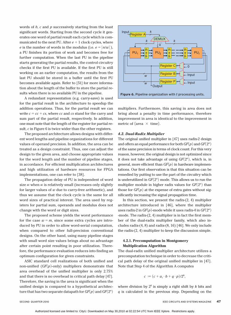
SECOND QUARTER 2010 IEEE CIRCUITS AND SYSTEMS MAGAZINE 47
words of b, c and p successively starting from the least
significant words. Starting from the second cycle it gen-
erates one word of partial result each cycle which is com-
municated to the next PU. After e 1 1 clock cycles, where
e is the number of words in the modulus (i.e. e 5 <n/w= ),
a PU finishes its portion of work and becomes free for
further computation. When the last PU in the pipeline
starts generating the partial results, the control circuitry
checks if the first PU is available. If the first PU is still
working on an earlier computation, the results from the
last PU should be stored in a buffer until the first PU
becomes available again. Refer to [51] for more informa-
tion about the length of the buffer to store the partial re-
sults when there is no available PU in the pipeline.
A redundant representation (e.g. carry-save) is used
for the partial result in the architecture to speedup the
addition operations. Thus, for the partial result we can
write c 5 cc 1 cs, where cc and cs stand for the carry and
sum part of the partial result, respectively. In addition,
one must note that the length of the register for partial re-
sult, c in Figure 6 is twice wider than the other registers.
The proposed architecture allows designs with differ-
ent word lengths and pipeline organizations for different
values of operand precision. In addition, the area can be
treated as a design constraint. Thus, one can adjust the
design to the given area, and choose appropriate values
for the word length and the number of pipeline stages,
in accordance. For efficient multiplication architectures
and high utilization of hardware resources for FPGA
implementations, one can refer to [38].
The propagation delay of PU is independent of word
size w when w is relatively small (increases only slightly
for larger values of w due to carry-free arithmetic), and
thus we assume that the clock cycle is the same for all
word sizes of practical interest. The area used by reg-
isters for partial sum, operands and modulus does not
change with the word or digit sizes.
The proposed scheme yields the worst performance
for the case w 5 m, since some extra cycles are intro-
duced by PU in order to allow word-serial computation,
when compared to other full-precision conventional
designs. On the other hand, using many pipeline stages
with small word size values brings about no advantage
after certain point resulting in poor utilization. There-
fore, the performance evaluation reduces into finding an
optimum configuration for given constraints.
ASIC standard cell realizations of both unified and
non-unified (GF 1p 2 -only) multipliers demonstrate that
area overhead of the unified multiplier is only 2.75%
and that there is no overhead in critical path delay [47].
Therefore, the saving in the area is significant when the
unified design is compared to a hypothetical architec-
ture that has two separate datapath for GF 1p 2 and GF 12n 2
multipliers. Furthermore, this saving in area does not
bring about a penalty in time performance, therefore
improvement in area is identical to the improvement in
metric of 5area 3 time6.
4.2. Dual-Radix Multiplier
The original unified multiplier in [47] uses radix-2 design
and offers an equal performance for both GF 1p 2 and GF 12n 2
of the same precision in terms of clock count. For this very
reason, however, the original design is not optimized since
it does not take advantage of using GF 12n 2 , which is, in
general, more efficient than GF 1p 2 in hardware implemen-
tations. Our first observation is that this situation can be
remedied by putting to use the part of the circuitry which
is underutilized in GF 12n 2 mode. This allows us to run the
multiplier module in higher radix values for GF 12n 2 than
those for GF 1p 2 at the expense of extra gates without sig-
nificantly increasing the signal propagation time.
In this section, we present the radix-(2, 4) multiplier
architecture introduced in [46], where the multiplier
uses radix-2 in GF 1p 2 -mode while it uses radix-4 in GF 12n 2
-mode. The radix-(2, 4) multiplier is in fact the first mem-
ber of the dual-radix multiplier family, which also in-
cludes radix-(4, 8) and radix-(8, 16) [46]. We only include
the radix-(2, 4) multiplier to keep the discussion simple.
4.2.1. Precomputation in Montgomery
Multiplication Algorithm
The dual-radix unified multiplier architecture utilizes a
precomputation technique in order to decrease the criti-
cal path delay of the original unified multiplier in [47].
Note that Step 4 of the Algorithm A computes
c J 1c 1 ai# b 1 q # p 2 /2k,
where division by 2k is simply a right shift by k bits and
q is calculated in the previous step. Depending on the
Figure 6. Pipeline organization with t processing units.
PU1 PU2 PUt
Register A
DEMUX
kInput
kk
k
w
w
0
Input
InputOutput
Reg.
Reg.
Reg.
Register C
Register B
Register P
Authorized licensed use limited to: CityU. Downloaded on May 30,2010 at 02:22:54 UTC from IEEE Xplore. Restrictions apply.

48 IEEE CIRCUITS AND SYSTEMS MAGAZINE SECOND QUARTER 2010
radix value chosen for the multiplier, the k-bit digit q
can be determined by the least significant digits (LSD)
of b, p and c, and the current digit of a. Similarly, the
multiple of b that participates in the addition is deter-
mined solely by ai. As a result, the LSDs of the operands,
ai, b0, and c0 will determine which one of the values in
50, b, p, b 1 p, 2p, 2b, 2b 1 2p, c6 is added to the partial
result c. If one precomputes and stores the value of b 1 p,
the calculations in Step 4 can be significantly simplified.
There are two implications of the precomputation
technique. Firstly, the precomputed value must be
stored, implying an increase in the register space. And
secondly, there must be a so-called selection logic to se-
lect which multiples of b and p must participate in the
addition in Step 4. The selection logic can be designed
in such a way that it is parallel to PU and thus it results
in no overhead in the critical path delay. On the other
hand, the precomputation technique also simplifies the
design since Step 4 can be performed with only one ad-
dition, once the selection logic generates its output.
4.2.2. Processing Unit for Dual-Radix Multiplier
As pointed out earlier, a processing unit (PU) is ba-
sically responsible for performing Step 3 and Step 4
of Algorithm A. Since the multiplier uses radix-2 for
GF 1p 2 , the least-significant bits (LSB) of the oper-
and digits, ai, b0, and c0 determine which one of the
values in 50, b, p, b 1 p6 will be added to the partial
result c. Multiplication is performed in radix-4 in
GF 12n 2 . Therefore, the LSDs (least significant digits)
of b, p, and c and of the current digit of a are required
to determine q. The LSB of p is always 1, then only
p0, 1, the second least significant bit of the modulus,
is included in the computations. Consequently,
ai, 1, ai, 0, b0, 1, b0, 0, c0, 1, c0, 0 and p0, 1 determine one of the
following values to be added to the partial result:
50, b, p, b 1 p, x # b, x # p, x # 1b 1 p 2 6 (Note that ai, j is the
jth least significant bit of ith digit of a). Multiplication
by x results in shifting one bit to the left, hence it is
identical to multiplication by 2. Division by xk and 2k
are identical operations and the latter is used to de-
note the right shift operation by k bits.
In Figure 7, the architecture of the processing unit
(PU) used in the dual-radix multiplier is illustrated. The
local control circuit in Figure 7 contains the selection
logic which generates the signals, to determine which
multiples of b and p will be in the calculations. For
example, the selection signal ( 110 2 , 111 2) indicates that
Step 4 will be c J 1c 1 3b 1 2p 2 /2k.
4.3. Support for Ternary Extension Fields, GF(3n)
The Montgomery multiplication algorithm for GF 13n 2 ,
which is very similar to Algorithm B, is given below [39]:
Algorithm C
Input: a 1x 2 , b 1x 2 , p 1x 2 , and m
Output: c 1x 2
Step 1: c 1x 2 J 0
Step 2: for i 5 0 to m 2 1
Step 3: q 1x 2 J 1c0 1x21 ai 1x2 # b0 1x22 # p0r 1x2 1mod xk2
Step 4: c 1x 2 J 1c 1x21 ai 1x2 # c 1x21 q 1x2 # p 1x22 /xk
Only difference is due to the computation of p0r 1x 2 , which
is p0r 1x 2 5 2 # p021 1x 2mod xk (instead of p0r 1x 2 5 p0
21 1x 2
mod xk in Algorithm B).
Original unified multiplier architecture [47] utilizes two
layers of (3 3 2) dual-field adder
arrays to perform addition op-
erations in Steps 3 and 4 of Mont-
gomery multiplication algorithm.
This is due to the fact that multi-
plicand (b or b 1x 2) and modulus
(p or p 1x 2) are assumed to be al-
ways in non-redundant form. If the
result of a multiplication, which
is produced in redundant form
(e.g. carry-save representation), is
needed for subsequent multiplica-
tions, it is immediately converted
to non-redundant representation.
In order to eliminate the need
for conversion from redundant
to non-redundant representation
and associated circuitry, all op-
erands can be kept in redundant
form throughout the entire elliptic
Figure 7. Processing unit of dual-radix architecture with radix-2 for GF 1p2 and ra-dix-4 for GF 12n 2 .
Multiplexer
Selection
LogicDual-Field
Adder Shift and
Alignment
Layer
Multiplexer
<< 1 << 1 << 1
00
b ( j) + p ( j )
Next PU
Next PU
aib0
p0c0
fsel
b ( j )
c ( j )
p ( j )
R
e
g.
Authorized licensed use limited to: CityU. Downloaded on May 30,2010 at 02:22:54 UTC from IEEE Xplore. Restrictions apply.

SECOND QUARTER 2010 IEEE CIRCUITS AND SYSTEMS MAGAZINE 49
curve computations (e.g. elliptic curve scalar point mul-
tiplication). This, however, requires using (4 3 2) ad-
der arrays to perform addition (or subtraction) of two
redundant form integers. Although it is laden with area
and CPD overhead, one slice of (4 3 2) adder can easily
be modified to perform one-digit addition in three fields
GF 1p 2 , GF 12n 2 , and GF 13n 2 as explained in [39]. A multipli-
er that can operate in three fields can be designed in the
same way the original unified multiplier [47] is designed.
Two important differences of the new unified multiplier
from the original unified multiplier is that it has two con-
trol bits (as opposed to one in the original multiplier) to
select the field mode (GF 1p 2 , GF 12n 2 , or GF 13n 2), and that
the processing unit (PU) has now two layers of (4 3 2)
modified-adder arrays. In addition, RSD arithmetic is em-
ployed instead of carry-save arithmetic.
In order to asses the merits of unified multiplier that
performs multiplications of three fields in the same data-
path, one needs to compare the unified multiplier against
a hypothetical architecture which has three separate
multipliers for these three fields. The {area 3 CPD} met-
ric can be used in order to figure out the balance between
saving in the area and overhead in the critical path delay
that the unified multiplier will have when compared to
the hypothetical design. Implementations of both new
unified multiplier and hypothetical design in ASIC stan-
dard cell library demonstrate that the new unified multi-
plier considerably improves {area 3 time} metric when
compared to the hypothetical design in [39] and the clas-
sical unified design in [47].
5. Inversion
In this section, we give multiplicative inversion algo-
rithms, which allow very fast and area-efficient unified
hardware implementations. The presented algorithms
are based on the Montgomery inversion algorithms
given in [23]. While there are several unified inversion
units reported in the literature [16, 43, 45] that compute
in two fields GF 1p 2 and GF 12n 2 there has been no uni-
fied inversion unit proposed to operate in three fields.
Therefore, we limit our discussion, which is based on
the techniques and algorithms in [45], only to GF 1p 2
and GF 12n 2 .
5.1. The Montgomery Inversion
Algorithms for GF(p) and GF(2n)
The Montgomery inversion algorithm as defined in
[23] computes
b 5 a212n 1mod p 2 , (1)
given a , p, where p is a prime number and n 5 <log2 p=.
The algorithm consists of two phases: Phase I (Al-
gorithm D) whose output is the integer r such that
r 5 a212k 1mod p 2 , where n # k # 2n and Phase II is a
correction step and can be modified as shown in [44]
in order to calculate a slightly different inverse that can
more precisely be called Montgomery inverse:
b 5 MonInv 1a2n 2 5 a212n 1mod p 2 , (2)
Algorithm D
Phase I
Input: a2n [ 31, p 2 1 4 and p
Output: r [ 31, p 2 1 4 and k,
where r 5 a212k2n 1mod p2 and n # k # 2n
Step 1: u J p, v J a2n, r J 0, and s J 1
Step 2: k J 0
Step 3: while (v . 0)
Step 4: if u is even then u J u/2, s J 2s
Step 5: else if v is even then v J v/2, r J 2r
Step 6: else if u . v then
u J 1u 2 v 2 /2, r J r 1 s, s J 2s
Step 7: else v J 1v 2 u 2 /2, s J s 1 r, r J 2r
Step 8: k J k 1 1
Step 9: if r $ p then r J r 2 p
Step 10: return r J p 2 r and k
The second phase of the Montgomery inversion al-
gorithm simply performs 2n 2 k left (modular) shifts
as a correction step to obtain a212n 1modp 2 from
a212k2n 1mod p2 . The left shift operations are modular in
the sense that a modular reduction operation is performed
whenever the shifted value exceeds the modulus.
In cases where word multiplications can be efficiently
computed, another method based on Montgomery mul-
tiplication is proposed for Phase II computation in [44].
Considering R2 ; 22n 1mod p 2 is already a precomputed
value in Montgomery arithmetic, two Montgomery mul-
tiplications are required to implement Phase II of the
Montgomery inverse:
MonMult 1r, R22 ; 1a # 2n 221 # 2k # 22n # 22n
1mod p 2 ; a21 # 2k 1mod p2
MonMult 1a21 # 2k, 22n2k 2 ; a21 # 2k # 22n2k # 22n
1mod p 2 ; a21 # 2n 1mod p2 .
Implementations of unified multiplier in ASIC standard cell library demonstrate that unified multiplier significantly improves area x time metric.
Authorized licensed use limited to: CityU. Downloaded on May 30,2010 at 02:22:54 UTC from IEEE Xplore. Restrictions apply.

50 IEEE CIRCUITS AND SYSTEMS MAGAZINE SECOND QUARTER 2010
The cost of the Phase II in the latter method is two
Montgomery multiplication operation while the former
method requires 2n 2 k multi-word shifts and expect-
edly 12n 2 k 2 /2 multi-word additions. The experiments
in [44] show that the latter method gives a considerable
speedup in software implementations whereby word
size multiplier units facilitate fast Montgomery mul-
tiplication operation. However, the former method is
more suitable for hardware implementations since shift
operations are usually inexpensive in hardware. With
increasing number of hardwired multipliers in FPGA tar-
get devices, the latter method [44] may offer advantages
for FPGA implementations.
We aptly call this new inversion Montgomery in-
version since it takes a field element in the form of
a2n 1mod p2 and returns a212n 1mod p2 . This is known
as the residue form of a field element. In cryptographic
calculations (RSA, elliptic curve or pairing-based) all in-
puts are first transformed to the residue form, interme-
diate and final results are all obtained in residue form.
The final results are transformed back to normal form
after the cryptographic calculations are finished.
Montgomery multiplication and Montgomery inver-
sion as defined here together form what we call Mont-
gomery arithmetic for finite fields, whereby all values
are in residue form. Note that Montgomery addition/
subtraction operations are identical normal modular ad-
dition/subtraction operations. Having a full set of Mont-
gomery arithmetic is especially useful in elliptic curve
and pairing-based cryptography.
The Montgomery inversion algorithm for GF 12n 2 is ob-
tained as follows. We first replace all additions and sub-
tractions in Algorithm D with addition in GF 12n 2 . Since it
is possible to perform addition (and subtraction) with
carry and addition without carry in a single arithmetic
unit, this difference does not cause a change in the con-
trol unit of a unified inversion unit. However, Step 3 and
Step 6 of Algorithm D need to be modified as follows:
Step 3: while (u 1x 2 2 0)
c
Step 6: else if deg 1u 1x 2 2 $ deg 1v 1x 2 2 then
u 1x 2 J 1u 1x 2 1 v 1x 22 /x,
r 1x 2 J r 1x 2 1 s 1x 2 , s 1x 2 J xs 1x 2 .
In addition, Step 8 through 9 must also be modified:
Step 9: if sn11 5 1 then s 1x 2 J s 1x 2 1 xp 1x 2
Step 10: if sn 5 1 then s 1x 2 J s 1x 2 1 p 1x 2
Step 11: return s 1x 2 and k.
While these changes are small, they may necessitate
a significant change to the control circuitry. The most
important challenge is to design a unified version of
Step 6 since other steps can easily be performed in uni-
fied fashion. In literature, several solutions are proposed
to circumvent this problem. In [45], the unified archi-
tecture implements Step 6 as comparison of bit lengths
of variables u and v. The method adopted in [16] is to
implement Step 6 as an integer comparison, where the
integer values of u 1x 2 and v 1x 2 are used. Since binary
polynomials are just bit strings, all needs to be done is
to treat these binary strings as integers.
An efficient way to accelerate inversion operation is
to apply a technique known as multibit shifting as de-
scribed in both [16] and [45]. Algorithm D terminates
when v 5 0 and u 5 1. Right shifting operations by one
bit applied to u and v in Steps 4 through 7, play a domi-
nant role to diminish them to their final values. If we
can shift them more than one bit to the right in every
iteration of the while loop, we accelerate the execution
of the algorithm. Indeed, u and v may happen to have
more than one 0 bit in the least significant positions of
their binary representations (e.g. 00, and 000). To detect
two or three consecutive 0 bits in the least significant
bit positions is not expensive in hardware. However, in-
creasing the number of least significant bits to check
has two important drawbacks. Firstly, detection circuit
will be very complicated. And secondly, the probability
that a variable having more than three 0 bits in its least
significant positions will quickly diminish. The experi-
ments in [16] and [45] show that 3-bit shifting provides
considerable advantage, which disappear for larger
shift amounts.
6. Other Techniques for Accelerating
Finite Field Operations
In this section, we briefly outline several other tech-
niques to accelerate finite field operations proposed in
the literature.
6.1. Incomplete Modular Arithmetic for GF(p)
The finite field arithmetic for GF 1p 2 produces com-
pletely reduced integers. In other words, the result of
an arithmetic operation is integer r , p. However, in
platforms where word-based arithmetic is adopted (e.g.
An efficient way to accelerate inversion operation is to apply a technique known as multibit shifting.
Authorized licensed use limited to: CityU. Downloaded on May 30,2010 at 02:22:54 UTC from IEEE Xplore. Restrictions apply.

SECOND QUARTER 2010 IEEE CIRCUITS AND SYSTEMS MAGAZINE 51
microprocessor-based systems), allowing a number to
grow to the word boundary can be advantageous. Assum-
ing that n 5 <log2 p= and m 5 ew $ n where w is the word
size and that e is the number of words needed to repre-
sent p, for an element r [ GF 1p 2 we may have r . p and
r # 2m 2 1. Note that 2m 2 1 $ p. The number is reduced
whenever we have r . 2m 2 1, which can be detected by
checking whether the s 1 1st word of r is 1. This check is
much easier than checking r . p since the latter requires
bit manipulation in a word-based computer.
Incomplete modular arithmetic avoids bit-level oper-
ations which are slow on microprocessors and performs
word-level operations which are significantly faster.
Yanik et al. [57] propose algorithms for incomplete mod-
ular arithmetic, namely modular addition, subtraction
and multiplication using Montgomery arithmetic for
GF 1p 2 . They report a speedup of around 10% in elliptic
curve cryptography through incomplete modular arith-
metic. Algorithms for incomplete modular inversion can
be found in [44].
6.2. Scaled Modulus for effi cient GF(p) arithmetic
The modulus scaling was introduced by Walter [54].
The method is based on multiplying the prime mod-
ulus p by a small integer s to obtain a new modulus,
m 5 p # s. Here, p is a prime of random form for which
the modular reduction can be difficult while the new
modulus m has special form (e.g. 2k 2 c) that facilitates
reducing the modular reduction into simple addition/
subtraction operations.
Working with new modulus m will produce a result
a that is congruent to the residue obtained by reducing
a modulo p. This follows from the fact that reduction
is a repetitive subtraction of the modulus. Subtract-
ing m is equivalent to subtracting p, s times and thus
1a mod m2 mod p ; a mod p. When a scaled modulus is
used, residues will be in the range 30, m 2 1 45 30, sp 2 1 4.
The number is partially reduced and essentially rep-
resented using <log2 s= more bits than necessary. Con-
sequently, it will be necessary that the final result is
reduced by p to obtain a fully reduced representation.
Naturally, this final reduction can be postponed to the
end of cryptographic operation.
Öztürk et al. [40] proposed a new method for finding
appropriate scaled moduli and reported a low-power im-
plementation of elliptic curve cryptography based on the
technique. The implementation uses the scaled moduli
2167 1 1 5 3 # 0x2AAAAAAAAAAAAAAAAAAAAAAAAAAA
AAAAAAAAAAAAAB, where the prime is a 166-bit integer.
Taking advantage of a simple modular reduction due to
low-weight special modulus 2167 1 1, the implementation
in [40] is one of the most compact realizations of elliptic
curve cryptography in literature.
6.3. Arithmetic for General Extension Fields
With the increasing importance of pairing-based cryp-
tography, developing efficient algorithms for general
extension field arithmetic becomes a popular research
area. Pairing operations uses arithmetic in extension
GF 1qk 2 of the finite field GF 1q 2 where the elliptic curve
group is originally defined over the base field GF 1q 2 .
The elements of an extension field are represented as
polynomials of degree of at most k 2 1, where the co-
efficients of the polynomial are in the base field GF 1q 2 .
The arithmetic of extension field GF 1qk 2 is usually per-
formed as regular polynomial arithmetic. The most
important operation of GF 1qk 2 is again multiplication,
which comprises polynomial multiplication and re-
duction by the irreducible polynomial of degree k
used to define the extension field. Using irreducible
polynomials of low-weight is a preferred method to
decrease the complexity of the reduction phase of the
multiplication in GF 1qk 2 . For prime extension fields,
the polynomial xk 2 b is an irreducible polynomial for
specifically chosen values of b [12]. xk 2 b, where b is
a small number, will transform the polynomial reduc-
tion into simple polynomial addition operations.
The polynomial multiplication, which is the first
part of GF 1qk 2 multiplication is generally harder to
implement. For efficient computation of pairing opera-
tion, k is usually chosen as a relatively small integer
in the range of [2, 12]. Some of the typical extension
fields used in pairing operations are GF 1p2 2 , GF 1p12 2 ,
GF 1 12m 22 2 , and GF 1 13m 26 2 . For small extension degrees
such as GF 1p2 2 and GF 1 12m 22 2 , Karatsuba-based meth-
ods [12] usually provides the best performance. For
larger extension degrees, tower field constructions re-
sult in better implementations.
In tower field constructions, there may be several al-
ternatives for the representation of the field elements.
For instance, the ternary extension field GF 1 13m 26 2 can
be constructed as GF 1 1 13m 22 23 2 . This means that we need
an irreducible polynomial of degree two over GF 13m 2
first to construct GF 132m 2 . Then an irreducible poly-
nomial of degree three over GF 132m 2 is needed to con-
struct GF 1 132m 23 2 . The choice of irreducible polynomials
Pairing-based cryptography necessitates efficient algorithms for general extension field arithmetic.
Authorized licensed use limited to: CityU. Downloaded on May 30,2010 at 02:22:54 UTC from IEEE Xplore. Restrictions apply.

52 IEEE CIRCUITS AND SYSTEMS MAGAZINE SECOND QUARTER 2010
will greatly influence the efficiency of the implementa-
tion. Similarly, the fact that multiplication in the tower
field consists of many independent GF 13m 2 arithmetic
operations facilitates different arrangements to take
advantage of the parallelism due to the independent
operations. This is especially useful in hardware imple-
mentations where a functional unit for an arithmetic
operation can be replicated as many times as needed to
render faster implementations [32]. There is a need for
further research in the area of tower field arithmetic to
accelerate pairing-based cryptography.
7. Finite Field Arithmetic as a Building Block
of Cryptographic Algorithms
7.1. RSA
Rivest, Shamir and Adleman proposed a novel crypto-
graphic algorithm in 1978 [41] that can be used for key
exchange and electronic signature as well as encryp-
tion. Its security relies on the Integer Factorization Prob-
lem which is, generally believed to be a hard problem if
the related numbers are sufficiently large.
7.1.1. RSA Setup
Let us assume that Bob wants to send a secret message
to Alice who should have a public-private key pair. Her
public key is a pair of two large integers (n, e) and her
private key is d, which is another large integer. The in-
teger n, called the modulus, is the multiplication of two
large prime numbers, p and q. It is computationally in-
feasible to factor n into p and q when they are sufficient-
ly large. Euler’s Totient function, F 1n 2 5 1p 2 1 2 1q 2 1 2 ,
is used to determine the public exponent e and private
exponent d. The public exponent e can be chosen ran-
domly provided that GCD 1e, F 1n 2 2 5 1; however it is
usually chosen as a small number for fast encryption.
The private exponent d is the multiplicative inverse of e
with respect to modulus F 1n 2 .
7.1.2. RSA Encryption/Decryption
To send a message m securely to Alice, Bob performs
the modular exponentiation operation c ; me 1mod n 2 .
Upon receiving the ciphertext message c, Alice per-
forms the modular exponentiation cd 1mod n 2 5 m.
Since Alice is the only one who knows her private key
d, only she can perform this computation and obtains
the plaintext message m. As one can easily observe,
both RSA encryption and decryption operations are
nothing but modular exponentiations over very large
numbers. A modular exponentiation is comprised of
many modular multiplications, which are usually dif-
ficult to perform efficiently since the operands are
large integers.
7.1.3. RSA Implementation
Since RSA modulus n is a composite number, RSA arith-
metic is performed in the ring Zn. In our context, the
basic difference between a ring of this type and prime
finite field is that inversion in Zn is not defined for
every element of Zn. However, RSA does not require
inversion but only multiplication in Zn. Moreover, RSA
modulus is an odd integer. Therefore, the Montgom-
ery multiplication architectures for prime finite field
multiplication can be used for RSA operations without
any modification.
For RSA encryption and decryption, we perform
modular exponentiation, which are nothing but re-
peated modular multiplications with an odd modulus.
Algorithm A is a generic description of the Montgomery
modular multiplication where radix can be anything
from 2 to the wordsize of a computer. A pipelined orga-
nization of the multiplier as shown in Figure 6 is usually
the best way for the hardware implementation of Algo-
rithm A both in terms of area and time complexities.
These types of architectures are both parametric and
scalable. Optimum number of pipeline stages can be de-
termined for a given precision and available resources.
Similarly, the radix selection is also determined by
the available resources. In ASIC realizations, small radix
values (e.g. 2, 4, 8) are preferred [53, 52] since higher
radix values necessitates the design of fast high-radix
multipliers, which may not yield the desired efficiency.
On the other hand, in software and FPGA realizations
[28, 49, 38] higher radices are preferred since those
platforms feature highly-efficient and fast (hardwired in
FPGA) word-based multipliers. For example, Spartan 3E
FPGA devices [56] contain very-fast hardwired 18 3 18
bit multipliers. The design in [38] makes use of these
multipliers and pipeline organization to obtain the most
compact and fast Montgomery multipliers. The required
speed, available resources and utilization determine the
number of pipeline stages for a given precision. Utiliza-
tion is an important metric that needs to be inspected to
see whether the used resources are put into good use.
If utilization is low, this may mean that it is possible to
obtain similar efficiency using less resources. However,
Montgomery multiplication architectures for prime finite field multiplication can be used for RSA operations without any modification.
Authorized licensed use limited to: CityU. Downloaded on May 30,2010 at 02:22:54 UTC from IEEE Xplore. Restrictions apply.

SECOND QUARTER 2010 IEEE CIRCUITS AND SYSTEMS MAGAZINE 53
this is, most of the time, not immediate and the optimum
designs require careful time and dependency analyses of
the used algorithm.
Building a modular exponentiation circuit over an ef-
ficient modular multiplier is usually straightforward. De-
pending on the modular exponentiation algorithm used,
there exists some parallelism to accelerate the compu-
tation [38, 50]. Attacks on specific implementations of
the modular exponentiation such as [30, 31] and fault-
attacks [2] can compromise or weaken RSA algorithm.
Several exponentiation algorithms [22, 20, 21] and some
randomization techniques [15] can help protect the RSA
implementation against these attacks. In most applica-
tions, certain degree of protection against these attacks
is necessary.
7.2. Elliptic Curve Cryptography
Elliptic curve cryptography was proposed by Neal Ko-
blitz [27] and Victor Miller [34], independently. The so-
lutions to the equation y2 ; x3 1 ax 1 b in GF 1p 2 along
with an abstract point at infinity O forms an additive
group G, which is suitable for cryptographic usage2.
Discrete logarithm defined over the elliptic curve group
is believed to be harder than discrete logarithm in the
multiplicative group Zp*.
The solutions are also known as points, represented
by two coordinates P 5 1x, y 2 [ GF 1p 2 , which are referred
as affine coordinates. The group addition (i.e. point ad-
dition or doubling) requires a couple of multiplications,
several additions and one inversion operation in GF 1p 2 .
If affine coordinates are used, multiplicative inversion
is generally the most time consuming operation. Pro-
jective coordinates that represent elliptic curve points
using three coordinates in GF 1p 2 eliminate most of the
inversions operation at the expense of more multiplica-
tion operations. Nevertheless, projective coordinates
require much more temporary storage space during the
computations. For point arithmetic with projective coor-
dinates, refer to [11].
Elliptic curve cryptography is the main motivation
for unified arithmetic since it is possible and sometimes
more efficient to use elliptic curves over different finite
fields. Therefore, it is definitely useful to have an archi-
tecture that can efficiently perform arithmetic in diverse
set of finite fields in the same datapath. This will decrease
the cost of the design and increase the compactness.
7.2.1. Coordinate Selection: Projective or Affine?
An important design issue is whether to use projective
or affine coordinates. If the inversion is roughly more
than 10 times slower than multiplication, then using
projective coordinates results in a faster computation of
elliptic curve arithmetic. In software implementations,
inversion is usually very slow compared to multiplica-
tion; therefore it is almost always better to use projec-
tive coordinates. Moreover, a large main memory elimi-
nates the concerns about higher storage requirements
of projective coordinates.
However, hardware implementations offer a different
perspective. The inversion operation can be computed
considerably faster through a specifically designed hard-
ware module than in software. If we have a fast inversion
module, affine coordinates can provide better or compa-
rable timings. The question here is whether the hardware
cost of an inversion unit outweighs its advantage. On the
other hand, using projective coordinates has also an area
overhead due to its higher demands on temporary regis-
ters. In ASIC, registers are expensive to realize compared
to combinational circuits. Consequently, area used to
implement inversion unit can become comparable to the
area used for additional temporary registers used in pro-
jective coordinates. This fact was first pointed out in [43].
Recently, an extensive study in elliptic curve realizations
in ASIC [25] finds out that an affine coordinate implemen-
tation performs much better than a projective coordinate
implementation in terms of both timing and area.
FPGA implementations of elliptic curve cryptography
may have a similar perspective to software implementa-
tion whereby using projective coordinates is likely to
be a better choice. Two factors affect this conclusion:
i) registers are not very expensive compared to combi-
national logic where both are implemented similar ways
and ii) fast, hardwired digit multipliers FPGAs facilitate
much faster field multiplication compared to the inver-
sion operation in prime fields. However, for a decisive
conclusion, further research is necessary.
7.2.2. Recycling of Hardware Modules
Unlike RSA that mainly requires modular multiplication,
elliptic curve cryptography needs different field op-
erations, namely addition/subtraction, multiplication/
squaring, and inversion/division. A compact (area-effi-
cient) architecture, is only possible through maximizing
2Elliptic curves over binary extension or general extension fields are defined similarly. See [33] for more details.
In software implementations, inversion is usually very slow compared to multiplication.
Authorized licensed use limited to: CityU. Downloaded on May 30,2010 at 02:22:54 UTC from IEEE Xplore. Restrictions apply.

54 IEEE CIRCUITS AND SYSTEMS MAGAZINE SECOND QUARTER 2010
hardware-sharing among these various operations.
Successful designs such as [39, 25] focus on recycling
the same set of registers and functional units for dif-
ferent field operations. Both designs in [39, 25] utilize
carry-free adders (RSD or carry-save adders) as the fun-
damental arithmetic unit in all field operations. Carry-
free adders that can be used to implement all field opera-
tions are very fast since carries do
not propagate. A finite field arith-
metic unit based on carry-free ad-
ders that can be utilized in differ-
ent cryptographic applications is
illustrated in Figure 8.
7.3. Pairing-Based
Cryptography
Bilinear pairing operation defined
over elliptic curves emerges as an
important cryptographic primi-
tive after a plethora of recent cryp-
tographic protocols employs them,
such as non-interactive key agree-
ment scheme by [42], three par-
ty Diffie-Hellman key exchange
scheme by [19], identity based
encryption scheme proposed by
Boneh and Franklin [5], short group signatures [4], iden-
tity based ring signature schemes [10] and finally direct
anonymous attestation schemes [6, 7, 9, 8].
Let G1, G2 and GM be cyclic groups of some large prime
order q. Then, e:G1 3 G2 S GM is a bilinear map, which
is efficiently computable and has the following proper-
ty: 4P [ G1, and 4Q [ G2, and 4a, b [ Zq, ê 1aP, bQ 2 5
ê 1P, Q 2ab (Bilinearity).
Efficient constructions use ad-
ditive groups of elliptic curves
for G1 and G2, and multiplicative
group GM in an extension of a fi-
nite field GF 1qk 2 . GF 1q 2 here is the
finite field over which G1 is defined
and k is known as the embedding
degree of G1. Embedding degree
serves as a security parameter.
For efficiency reasons the finite
fields GF 1p 2 , GF 12n 2 , and GF 13m 2
are three popular fields used to
construct additive elliptic curve
groups, G1 and G2. Therefore, for
fast pairing computations, arithme-
tic in these three fields and in their
extensions (i.e. prime extension
GF 1pk 2 , and tower fields GF 1 12n 2k 2
and GF 1 13m 2k 2) needs to be per-
formed efficiently. The embedding
degree k cannot be too large for the
pairing operation to be efficiently
computable. The practical range of
k is usually [2, 12].
Pairing operation requires both
finite field (extension and base) Figure 9. Block diagram of a multipurpose cryptographic unit.
FAU
Registers
Multiplexers
Control Unit for
Point Multiplication
MUXDEMUX
Registers
MUX
Inputs
Control Unit for
Pairing Operation
Control Unit for
Cryptographic Operation
Control Unit for
Point Addition
and Doubling
Point Addition and
Doubling Unit (PADU)
Figure 8. finite field arithmetic unit for multipurpose cryptographic usage.
Carry-Free Adder
Units
Registers
Multiplexers
Inputs
Finite Field Arithmetic Unit (FAU)
Outputs
Control
Input and
Output
Control Unit for
Finite and Extension
Field Arithmetic
Authorized licensed use limited to: CityU. Downloaded on May 30,2010 at 02:22:54 UTC from IEEE Xplore. Restrictions apply.

SECOND QUARTER 2010 IEEE CIRCUITS AND SYSTEMS MAGAZINE 55
and elliptic curve point arithmetic (point addition and
doubling). A block diagram of a multi-purpose crypto-
graphic unit that can perform diverse set of arithmetic
operations is shown in Figure 9. The hierarchical design
of control units allows using the same units in different
cryptographic operations. This design approach also fa-
cilitates replication of finite field arithmetic units to ex-
ploit the concurrency in the computations.
Importance of pairing operation is that it forms a mo-
tivation for designing efficient arithmetic architectures
for extension and tower fields, elliptic curves defined
over larger finite fields (e.g. prime field with a 512-bit
prime), and elliptic curves over ternary fields. Since effi-
ciency and security requirements of pairing-based cryp-
tography still pose design challenges, there is a room
for further research on the design and implementation
of novel architectures for the arithmetic operations in-
volved in pairing computations.
8. Conclusions
This paper covers algorithms and architectures for
multiplicative groups, rings, finite fields for imple-
menting the RSA and Diffie-Hellman, elliptic curve
and pairing-based cryptography. The algorithms we
present can be generically applied; particularly, we
focused on polynomial bases for binary, ternary and
general extension fields. We gave a comprehensive
summary of finite field arithmetic in cryptography,
covering all basic algorithms, architectures, and
building blocks in order to create time-, power-, and
space-efficient implementations of finite field opera-
tions. The basic arithmetic operations, i.e., addition,
multiplication, and inversion in finite fields GF 1q 2
where q 5 pk, particularly, p is 2 or 3 or an arbitrary
large prime. While these choices seem to imply a di-
verse set of design possibilities, it is also possible to
create unified and versatile implementations where a
single hardware architecture supports several differ-
ent fields with a little extra cost.
Erkay Savas received the BS (1990)
and MS (1994) degrees in electrical
engineering from the Electronics and
Communications Engineering Depart-
ment at Istanbul Technical University.
He completed the Ph.D. degree in the
Department of Electrical and Computer
Engineering at Oregon State University in June 2000.
He had worked for various companies and research
institutions before he joined Sabanci University as an
assistant professor in 2002. He is the director of the
Cryptography and Information Security Group (CISec)
of Sabanci University. His research interests include
cryptography, data and communication security, priva-
cy in biometrics, trusted computing, security and pri-
vacy in data mining applications, embedded systems
security, and distributed systems. He is a member of
IEEE, ACM, the IEEE Computer Society, and the Interna-
tional Association of Cryptologic Research (IACR).
Cetin Kaya Koç received his Ph.D. in
Electrical & Computer Engineering from
University of California Santa Barbara in
1988. He was an Assistant Professor at
University of Houston (1988–1992), As-
sistant, Associate and Full Professor at
Oregon State University (1992–2007). He
established Information Security Laboratory at Oregon
State University, and received Award for Outstanding
and Sustained Research Leadership in September 2001.
His research interests are in cryptographic hardware
and embedded systems, secure hardware design, side-
channel attacks and countermeasures, algorithms and
architectures for computer arithmetic and finite fields.
Koç has also been in the editorial boards of IEEE Trans-
actions on Computers (2003–2008) and IEEE Transactions
on Mobile Computing (2003–2007). Furthermore, he was
a guest co-editor of two issues (April 2003 & November
2008) of IEEE Transactions on Computers on cryptograph-
ic and cryptanalytic hardware and embedded systems.
Koç was elected as IEEE Fellow in 2007 for his contri-
butions to cryptographic engineering.
Currently, Koç is a professor of Computer Science at
Istanbul Sehir University and an adjunct professor in the
Department of Computer Science and the College of Cre-
ative Studies at University of California Santa Barbara.
References[1] A. Avizienis, “Signed-digit number representations for fast parallel
arithmetic,” IRE Trans. Electron. Comput., vol. EC, no. 10, pp. 389–400,
Sept. 1961.
[2] D. Boneh, R. A. Demillo, and R. J. Lipton, “On the importance of
eliminating errors in cryptographic computations,” J. Cryptology, vol.
14, pp. 101–119, 2001.
[3] D. Boneh and M. K. Franklin, “Identity-based encryption from the
Weil pairing,” in CRYPTO (LNCS, vol. 2139), J. Kilian, Ed. New York:
Springer-Verlag, 2001, pp. 213–229.
[4] D. Boneh, X. Boyen, and H. Shacham, “Short group signatures,” in
CRYPTO (LNCS, vol. 3152), M. K. Franklin, Ed. New York: Springer-Ver-
lag, 2004, pp. 41–55.
[5] D. Boneh and M. K. Franklin, “Identity-based encryption from the
Weil pairing,” in CRYPTO (LNCS, vol. 2139), J. Kilian, Ed. New York:
Springer-Verlag, 2001, pp. 213–229.
[6] E. F. Brickell, J. Camenisch, and L. Chen, “Direct anonymous attesta-
tion,” in Proc. ACM Conf. Computer and Communications Security, V. Atluri,
B. Pfi tzmann, and P. D. McDaniel, Eds. ACM, 2004, pp. 132–145.
[7] E. Brickell, L. Chen, and J. Li, “A new direct anonymous attestation
scheme from bilinear maps,” in TRUST (LNCS, vol. 4968), P. Lipp, A.-R. Sa-
deghi, and K.-M. Koch, Eds. New York: Springer-Verlag, 2008, pp. 166–178.
[8] L. Chen, P. Morrissey, and N. Smart. (2009). DAA: Fixing the pair-
ing based protocols. Cryptology ePrint Archive, Rep. 2009/198 [Online].
Available: http://eprint.iacr.org/
Authorized licensed use limited to: CityU. Downloaded on May 30,2010 at 02:22:54 UTC from IEEE Xplore. Restrictions apply.

56 IEEE CIRCUITS AND SYSTEMS MAGAZINE SECOND QUARTER 2010
[9] L. Chen, P. Morrissey, and N. P. Smart, “Pairings in trusted comput-
ing,” in Pairing (LNCS, vol. 5209), S. D. Galbraith and K. G. Paterson, Eds.
New York: Springer-Verlag, 2008, pp. 1–17.
[10] S. S. M. Chow, L. C. K. Hui, and S.-M. Yiu, “Identity based threshold
ring signature,” in ICISC (LNCS, vol. 3506), C. Park and S. Chee, Eds. New
York: Springer-Verlag, 2004, pp. 218–232.
[11] H. Cohen, A. Miyaji, and T. Ono, “Effi cient elliptic curve exponentia-
tion using mixed coordinates,” in ASIACRYPT (LNCS, vol. 1514), K. Ohta
and D. Pei, Eds. New York: Springer-Verlag, 1998, pp. 51–65.
[12] A. J. Devegili, C. Higeartaigh, and M. Scott. (2006). Multiplication
and squaring on pairing-friendly fields. Cryptology ePrint Archive, Rep.
2006/471 [Online]. Available: http://eprint.iacr.org/
[13] W. Diffi e and M. E. Hellman, “New directions in cryptography,” IEEE
Trans. Inform. Theory, vol. 22, pp. 644–654, Nov. 1976.
[14] S. E. Eldridge, “An faster modular multiplication algorithm,” Int. J.
Comput. Math., vol. 40, no. 1, pp. 63–68, 1991.
[15] C. Giraud, “An RSA implementation resistant to fault attacks and
to simple power analysis,” IEEE Trans. Comput., vol. 55, no. 9, pp. 1116–
1120, 2006.
[16] A. A.-A. Gutub, A. F. Tenca, E. Savas, and Ç. K. Koç, “Scalable and
unifi ed hardware to compute Montgomery inverse in GF 1p 2 and GF 12k 2 ,”
in CHES (LNCS, vol. 2523), B. S. Kaliski, Jr., Ç. K. Koç, and C. Paar, Eds.
New York: Springer-Verlag, 2002, pp. 484–499.
[17] G. Hachez and J.-J. Quisquater, “Montgomery exponentiation with
no fi nal subtractions: Improved results,” in CHES (LNCS, vol. 1965), Ç. K.
Koç and C. Paar, Eds. New York: Springer-Verlag, 2000, pp. 293–301.
[18] Standard Specifications for Public-Key Cryptography, IEEE P1363,
2000.
[19] A. Joux, “A one round protocol for tripartite Diffi e-Hellman,” in
ANTS (LNCS, vol. 1838), W. Bosma, Ed. New York: Springer-Verlag, 2000,
pp. 385–394.
[20] M. Joye, “Highly regular right-to-left algorithms for scalar multi-
plication,” in CHES (LNCS, vol. 4727). New York: Springer-Verlag, 2007,
pp. 135–147. [21] M. Joye, “Highly regular m-ary powering ladders,” in
Selected Areas in Cryptography (LNCS, vol. 5867), M. J. J. Jr., V. Rijmen,
and R. Safavi-Naini, Eds. New York: Springer-Verlag, 2009, pp. 350–363.
[22] M. Joye and S.-M. Yen, “The Montgomery powering ladder,” in CHES
(LNCS, vol. 2523), B. S. Kaliski, Jr., Ç. K. Koç, and C. Paar, Eds. New York:
Springer-Verlag, 2002, pp. 291–302.
[23] B. S. Kaliski, Jr., “The Montgomery inverse and its applications,”
IEEE Trans. Comput., vol. 44, no. 8, pp. 1064–1065, Aug. 1995.
[24] B. S. Kaliski, Jr., Ç. K. Koç, and C. Paar, Eds., “Cryptographic
hardware and embedded systems—CHES 2002,” in Proc. 4th Int.
Workshop (LNCS, vol. 2523), Redwood Shores, CA, Aug. 13–15, 2002.
New York: Springer-Verlag, 2003.
[25] D. Karakoyunlu, F. K. Gurkaynak, B. Sunar, and Y. Leblebici, “Effi cient
and side-channel-aware implementations of elliptic curve cryptosystems
over prime fi elds,” IET Inform. Security, vol. 4, no. 1, pp. 30–43, 2010.
[26] J. Kilian, Ed., Advances in Cryptology—CRYPTO 2001 (LNCS, vol.
2139). New York: Springer-Verlag, 2001.
[27] N. Koblitz, “Elliptic curve cryptosystems,” Math. Comput., vol. 48,
no. 177, pp. 203–209, Jan. 1987.
[28] Ç. K. Koç and T. Acar, “Montgomery multiplication in GF 12k 2 ,” Des.,
Codes Cryptogr., vol. 14, no. 1, pp. 57–69, Apr. 1998.
[29] Ç. K. Koç, T. Acar, and B. S. Kaliski, Jr., “Analyzing and comparing
Montgomery multiplication algorithms,” IEEE Micro, vol. 16, no. 3, pp.
26–33, June 1996.
[30] P. C. Kocher, “Timing attacks on implementations of Diffi e-Hellman,
RSA, DSS, and other systems,” in CRYPTO (LNCS, vol. 1109), N. Koblitz,
Ed. New York: Springer-Verlag, 1996, pp. 104–113.
[31] P. C. Kocher, J. Jaffe, and B. Jun, “Differential power analysis,” in
CRYPTO (LNCS, vol. 1666), M. J. Wiener, Ed. New York: Springer-Verlag,
1999, pp. 388–397.
[32] G. Kömürcü and E. Savas, “An effi cient hardware implementation
of the Tate pairing in characteristic three,” in ICONS. IEEE Computer
Society, 2008, pp. 23–28. [33] A. J. Menezes, Elliptic Curve Public Key
Cryptosystems. Norwell, MA: Kluwer, 1993.
[34] V. S. Miller, “Use of elliptic curves in cryptography,” in CRYPTO
(LNCS, vol. 218), H. C. Williams, Ed. New York: Springer-Verlag, 1985,
pp. 417–426.
[35] P. L. Montgomery, “Modular multiplication without trial division,”
Math. Comput., vol. 44, no. 170, pp. 519–521, Apr. 1985.
[36] National Institute for Standards and Technology, “Digital signature
standard (DSS),” Fed. Reg., vol. 56, p. 169, Aug. 1991.
[37] J.-H. Oh and S.-J. Moon, “Modular multiplication method,” IEE Proc.
Comput. Digital Tech., vol. 145, no. 4, pp. 317–318, July 1998.
[38] E. Öksüzoglu and E. Savas, “Parametric, secure and compact im-
plementation of RSA on FPGA,” in RECONFIG ’08: Proc. 2008 Int. Conf.
Reconfigurable Computing and FPGAs. Washington, DC: IEEE Computer
Society, 2008, pp. 391–396.
[39] E. Öztürk, B. Sunar, and E. Savas, “A versatile Montgomery mul-
tiplier architecture with characteristic three support,” Comput. Electr.
Eng., vol. 35, no. 1, pp. 71–85, 2009.
[40] E. Öztürk, B. Sunar, and E. Savas, “Low-power elliptic curve cryp-
tography using scaled modular arithmetic,” in CHES (LNCS, vol. 3156),
M. Joye and J.-J. Quisquater, Eds. New York: Springer-Verlag, 2004, pp.
92–106.
[41] R. L. Rivest, A. Shamir, and L. M. Adleman, “A method for obtaining
digital signatures and public-key cryptosystems,” Commun. ACM, vol.
21, no. 2, pp. 120–126, 1978.
[42] R. Sakai, K. Ohgishi, and M. Kasahara, “Cryptosystems based on
pairing,” in Proc. Symp. Cryptography and Information Security, Okinawa,
Japan, Jan. 2000, pp. 26–28.
[43] E. Savas and Ç. K. Koç, “Architectures for unifi ed fi eld inversion
with applications in proc. vol. 3,” in Proc. 9th IEEE Int. Conf. Electronics,
Circuits and Systems—ICECS 2002, Sept. 2002, pp. 1155–1158.
[44] E. Savas and Ç. K. Koç, “The Montgomery modular inverse—revis-
ited,” IEEE Trans. Comput., vol. 49, no. 7, pp. 763–766, July 2000.
[45] E. Savas, M. Naseer, A. A.-A. Gutub, and Ç. K. Koç, “Effi cient unifi ed
Montgomery inversion with multibit shifting,” IEE Proc. Comput. Digital
Tech., vol. 152, no. 4, pp. 489–498, July 2005.
[46] E. Savas, A. F. Tenca, M. E. Çiftçibasi, and Ç. K. Koç, “Multiplier ar-
chitectures for GF (p) and GF (2k),” IEE Proc. Comput. Digital Tech., vol.
151, no. 2, pp. 147–160, Mar. 2004.
[47] E. Savas, A. F. Tenca, and Ç. K. Koç, “A scalable and unifi ed
multiplier architecture for fi nite fi elds GF 1p 2 and GF 12m 2 ,” in Cryp-
tographic Hardware and Embedded Systems—CHES 2000 (LNCS, vol.
1965), Ç. K. Koç and C. Paar, Eds. New York: Springer-Verlag, 2000,
pp. 281–296.
[48] A. Shamir, “Identity-based cryptosystems and signature schemes,”
in Proc. CRYPTO, 1984, pp. 47–53.
[49] D. Suzuki, “How to maximize the potential of FPGA resources for
modular exponentiation,” in CHES (LNCS, vol. 4727). New York: Spring-
er-Verlag, 2007, pp. 272–288.
[50] S. H. Tang, K. S. Tsui, and P. H. W. Leong, “Modular exponentiation
using parallel multipliers,” in Proc. 2003 IEEE Int. Conf. Field Program-
mable Technology (FPT), 2003, pp. 52–59.
[51] A. F. Tenca and Ç. K. Koç, “A scalable architecture for Montgom-
ery multiplication,” in Cryptographic Hardware and Embedded Systems
(LNCS, vol. 1717), Ç. K. Koç and C. Paar, Eds. New York: Springer-Verlag,
1999, pp. 94–108.
[52] A. F. Tenca and L. A. Tawalbeh, “An effi cient and scalable radix-4
modular multiplier design using recoding techniques,” in Proc. 37th
Asilomar Conf. Signals, Systems, and Computers. Pacific Grove, CA: IEEE
Press, Nov. 9–12, 2003, no. 2, pp. 1445–1450.
[53] A. F. Tenca, G. Todorov, and Ç. K. Koç, “High-radix design of a
scalable modular multiplier,” in CHES, (LNCS, vol. 2162), Ç. K. Koç,
D. Naccache, and C. Paar, Eds. New York: Springer-Verlag, 2001, pp.
185–201.
[54] C. D. Walter, “Faster modular multiplication by operand scaling,”
in Advances in Cryptology—CRYPTO’91 (LNCS, No. 576), J. Feigenbaum,
Ed. New York: Springer-Verlag, 1992, pp. 313–323.
[55] C. D. Walter, “Montgomery exponentiation needs no fi nal subtrac-
tions,” Electron. Lett., vol. 35, no. 21, pp. 1831–1832, Oct. 1999.
[56] Xilinx Inc. TrustZone technology overview [Online]. Available: http://
www.xilinx.com/support/documentation/data_sheets/ds312.pdf.
[57] T. Yanık, E. Savas, and Ç. K. Koç, “Incomplete reduction in modular
arithmetic,” IEE Proc. Comput. Digital Tech., vol. 149, no. 2, pp. 46–52,
Mar. 2002.
Authorized licensed use limited to: CityU. Downloaded on May 30,2010 at 02:22:54 UTC from IEEE Xplore. Restrictions apply.