Solar Satellite: A Green Energy Infrastructure for Power Challenged Environments, a Case for Solar...
12
Vol 6. No. 5, December 2013 African Journal of Computing & ICT © 2013 Afr J Comp & ICT – All Rights Reserved - ISSN 2006-1781 www.ajocict.net 69 Solar Satellite: A Green Energy Infrastructure for Power Challenged Environments, a Case for Solar Cell I-V Behaviour * K.C. Okafor, I.M. Onwusuru & I.C. Okoro Electronics Development Institute Awka National Agency for Science and Engineering Infrastructure, (Nigeria) Awka, Anambra State, Nigeria. C.O. Onwusuru Mainstreet Bank Ltd, Awka Branch Awka, Anambra State, Nigeria. ABSTRACT Past government efforts in addressing power challenges in Nigeria have yielded little results despite huge investments made in the energy sector. For meaningful economic growth, the importance of a sustainable power system cannot be overemphasized. However, with worlds advocacy on climate change and carbon footprint emissions reduction, renewable energy alternatives will offer a better solution. In this regard, this paper proposes a power model that will serve as a compliment to the current distribution grid network called Solar Satellite. This can be adapted for powering banks, government institutions, IT DataCenter, etc. We present an in-depth discussion on the design framework of a generic Solar Power System. In particular, a comprehensive outline of the design steps, considerations as well as the implementation strategies is presented. To further facilitate our work, we used Electronics Development Institute as our study testbed. In this regard, MATLAB Simulink tool was used to characterize the initial phase of the proposed system in the context of current-voltage sensor outputs. Also, we presented the optimal Solar Cell block's parameters as well as the I-V characteristics at 25 0 C. This work observes that a hybrid grid system will save downtime scenarios in case of drops in solar irradiation. Keywords: Solar Satellite, Green Energy, Infrastructure, Power, Environments, Solar Cell I-V Behaviour African Journal of Computing & ICT Reference Format: K.C. Okafor, I.M. Onwusuru, I.C. Okoro & C.O. Onwusuru (2013). Solar Satellite: A Green Energy Infrastructure for Power Challenged Environments, a Case for Solar Cell I-V Behaviour Project. Afr J. of Comp & ICTs. Vol 6, No. 5. Pp 69-80. 1. INTRODUCTION This research is part of an on-going work on SMART Green Energy Management framework which seeks to realize a reliable energy system leveraging the potentials associated with renewable energy solutions. A good definition of renewable energy as found in [1] are those derived from resources that are naturally regenerative or are practically inexhaustible, such as biomass, heat (geothermal, solar, thermal gradient), moving water (hydro, tidal, and wave power), and wind energy. Municipal solid waste may also be considered a source of renewable (thermal) energy [1]. Owing to the abundant supply of sun in Africa, this work will focus on solar generated energy system. 1.1 Solar PV Array A PV array consists of multiple photovoltaic modules, casually referred to as solar panels, to convert solar radiation (sunlight) into usable direct current (DC) electricity. A PV system can be for either large scale environments or a residential, commercial, or industrial energy supply and will always contain an array of photovoltaic (PV) modules, Inverters, a racking system that supports the solar modules, electrical wiring and interconnections, and mounting for other components. In some cases, a PV based system may include viz [1]: a g: renewable energy credit revenue-grade meter, Maximum Power Point Tracker (MPPT), battery system and controller, GPS solar tracker, an energy management software, solar concentrators, solar irradiance sensors, anemometer, or task-specific accessories designed to meet specialized requirements for a system owner. The amount of PV modules and its interface systems determines the total DC watts capable of being generated by the solar array. The feeding of electricity into the grid requires the transformation of DC into AC by a special, grid-controlled, inverter [1]. Also, photovoltaic systems (stand-alone, grid-connected) [2], are systems which use solar cells to convert light into electricity. These systems consist of multiple components, including cells, mechanical and electrical connections and mountings and means of regulating and/or modifying the electrical output.
Transcript of Solar Satellite: A Green Energy Infrastructure for Power Challenged Environments, a Case for Solar...
Vol 6. No. 5, December 2013 African Journal of Computing & ICT
© 2013 Afr J Comp & ICT – All Rights Reserved - ISSN 2006-1781
www.ajocict.net
69
Solar Satellite: A Green Energy Infrastructure for Power Challenged
Environments, a Case for Solar Cell I-V Behaviour
*K.C. Okafor, I.M. Onwusuru & I.C. Okoro Electronics Development Institute
Awka National Agency for Science and Engineering Infrastructure, (Nigeria)
Awka, Anambra State, Nigeria.
C.O. Onwusuru
Mainstreet Bank Ltd, Awka Branch
Awka, Anambra State, Nigeria.
ABSTRACT Past government efforts in addressing power challenges in Nigeria have yielded little results despite huge investments
made in the energy sector. For meaningful economic growth, the importance of a sustainable power system cannot be
overemphasized. However, with worlds advocacy on climate change and carbon footprint emissions reduction, renewable
energy alternatives will offer a better solution. In this regard, this paper proposes a power model that will serve as a
compliment to the current distribution grid network called Solar Satellite. This can be adapted for powering banks,
government institutions, IT DataCenter, etc. We present an in-depth discussion on the design framework of a generic
Solar Power System. In particular, a comprehensive outline of the design steps, considerations as well as the
implementation strategies is presented. To further facilitate our work, we used Electronics Development Institute as our
study testbed. In this regard, MATLAB Simulink tool was used to characterize the initial phase of the proposed system
in the context of current-voltage sensor outputs. Also, we presented the optimal Solar Cell block's parameters as well as
the I-V characteristics at 250C. This work observes that a hybrid grid system will save downtime scenarios in case of
drops in solar irradiation.
Keywords: Solar Satellite, Green Energy, Infrastructure, Power, Environments, Solar Cell I-V Behaviour
African Journal of Computing & ICT Reference Format: K.C. Okafor, I.M. Onwusuru, I.C. Okoro & C.O. Onwusuru (2013). Solar Satellite: A Green Energy Infrastructure for Power
Challenged Environments, a Case for Solar Cell I-V Behaviour Project. Afr J. of Comp & ICTs. Vol 6, No. 5. Pp 69-80.
1. INTRODUCTION
This research is part of an on-going work on SMART
Green Energy Management framework which seeks to
realize a reliable energy system leveraging the potentials
associated with renewable energy solutions. A good
definition of renewable energy as found in [1] are those
derived from resources that are naturally regenerative or
are practically inexhaustible, such as biomass, heat
(geothermal, solar, thermal gradient), moving water
(hydro, tidal, and wave power), and wind energy.
Municipal solid waste may also be considered a source of
renewable (thermal) energy [1]. Owing to the abundant
supply of sun in Africa, this work will focus on solar
generated energy system.
1.1 Solar PV Array A PV array consists of multiple photovoltaic modules,
casually referred to as solar panels, to convert solar
radiation (sunlight) into usable direct current (DC)
electricity. A PV system can be for either large scale
environments or a residential, commercial, or industrial
energy supply and will always contain an array of
photovoltaic (PV) modules, Inverters, a racking system
that supports the solar modules, electrical wiring and
interconnections, and mounting for other components. In
some cases, a PV based system may include viz [1]: a g:
renewable energy credit revenue-grade meter, Maximum
Power Point Tracker (MPPT), battery system and
controller, GPS solar tracker, an energy management
software, solar concentrators, solar irradiance sensors,
anemometer, or task-specific accessories designed to
meet specialized requirements for a system owner. The
amount of PV modules and its interface systems
determines the total DC watts capable of being generated
by the solar array. The feeding of electricity into the grid
requires the transformation of DC into AC by a special,
grid-controlled, inverter [1].
Also, photovoltaic systems (stand-alone, grid-connected)
[2], are systems which use solar cells to convert light into
electricity. These systems consist of multiple
components, including cells, mechanical and electrical
connections and mountings and means of regulating
and/or modifying the electrical output.
Vol 6. No. 5, December 2013 African Journal of Computing & ICT
© 2013 Afr J Comp & ICT – All Rights Reserved - ISSN 2006-1781
www.ajocict.net
70
Usually, grid-connected systems are connected to a large
independent grid (typically the public electricity grid) and
feed power into the grid. PV systems may be built in
various configurations viz [3]:
• Off-grid without battery (Array-direct)
• Off-grid with battery storage for DC-only
appliances
• Off-grid with battery storage for AC & DC
appliances
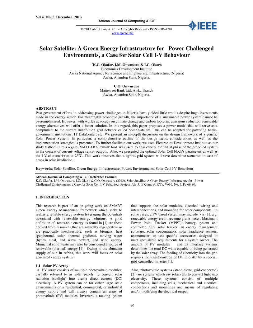
• Grid-tie without battery
• Grid-tie with battery storage. Figure 3 shows a
typical solar farm. Electric power can be
obtained from solar energy by two means,
photovoltaic effect and solar thermal generator
[5]
Figure 1: Solar Park/farm [3]
1.2 Solar Energy (Green Power) Benefits i. Solar energy is a renewable and clean energy
resource, which produces neither greenhouse
effect gases nor hazardous wastes through its
utilization. Environmentally sustainable- unlike
oil, solar power does not emit greenhouse gases
or carcinogens into the air.
ii. Light and energy from the sun are in abundant
supply and as such costs nothing.
iii. Solar cells require little maintenance and cells
can last a lifetime.
iv. Solar power is noise free.
1.3 Research Objectives
This work defines a Solar Satellite as a PV system with
integrated SMART subsystems and components designed
to supply usable electric power for a variety of purposes,
using either of sun, wind, etc as the power source for end
users. With the enormous benefits of solar energy, the
work seeks to achieve the following objectives:
- To propose a Solar PV I-V model that is very
efficient and innovative while satisfying the
requirements of SMART grid open framework.
- To determine the I-V characteristics of an
optimized PV- solar cell which will grant
optimal performance for the DC interfaces in
the solar farm.
-
- To present an in-depth design framework of a
generic Solar Power System. In context, a
comprehensive outline of the design steps,
considerations as well as the implementation
strategies will be presented.
2. RELATED WORKS
The work in [5] explained that Nigeria is endowed with
an annual daily sunshine that is averagely 6.25 hours,
which is ranging between about 3.5 hours at the coastal
areas of the northern boundary of the nations. It also has
an annual average daily solar radiation of about 3.5
KWm2/ day in the coastal area which is in the southern
part and 7.0 KWm2/ day at the northern boundary.
Nigeria also receives about 4909.212 kWh of energy
from the sun which is equivalent to about 1.082 million
tonnes of oil; this is about 4000 times the current crude
oil production per day, and also put at about 13 thousand
times of daily natural gas production based on energy
unit. The annual insolation of the solar energy is value
about 27 times the national conventional energy
resources in energy units and also over 117,000 times the
amount of electric power that was generated in 1998 [6].
Using the Nigerian environment, we believe that a
sustainable energy future based on solar energy
technologies will address current power challenges. Some
contributions as studied in literature is presented below.
Vol 6. No. 5, December 2013 African Journal of Computing & ICT
© 2013 Afr J Comp & ICT – All Rights Reserved - ISSN 2006-1781
www.ajocict.net
71
The paper in [7] explored the introduction of passive
solar cooling, photovoltaic (PV) lighting and energy
saving lighting bulbs in houses considering the national
housing policy. It presented the erection of energy
efficient building as a great strategy for reducing energy
consumption in households thus making surplus energy
available for greater populace. Consequently, the authors
presented solar passive cooling as a pure structural and
mechanical issue compared to the generally used
electromechanical cooling system. The work in [8]
explained that the field of green technology encompasses
a broad range of subjects from new energy generation
techniques to the study of advanced materials to be used
in our daily life. The authors opined that green
technology focuses on reducing the environmental impact
of industrial processes and innovative technologies
caused by the Earth’s growing population.
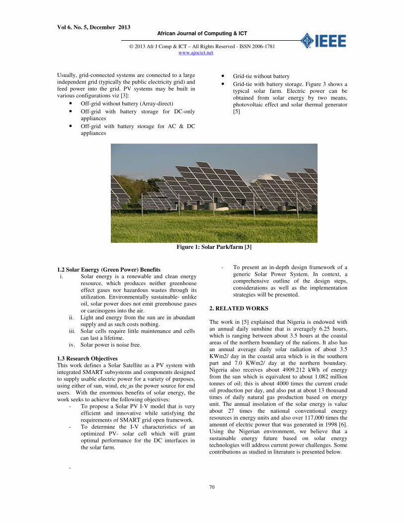
The work in [4], [9], [10] discussed on solar chimney
power plant, which is expected to provide electric power
for remote locations as depicted in figure 2. A detailed
analysis on this system is found in the sampled
literatures. The system comprises of solar collector, the
chimney, and the turbine. The design and the analytical
formulations [12] considered the physical dimensions
with relevant assumptions as well.
Figure 2: Schematic illustration of a solar chimney
power plant [9], [10].
Since early 1970’s, Solar Power Satellite which is used to
power the satellite system has been undergoing research.
Space-based solar power (SBSP) is the concept of
collecting solar power in space for use on Earth. As
found in literature [12], its operational methods differs
from exiting solar based systems. In this case, the
orbiting satellite houses the solar collector instead of the
collector being on the earth surface. Some projected
benefits of such a system are a higher collection rate and
a longer collection period due to the lack of a diffusing
atmosphere and night time in space. Part of the solar
energy is lost on its way through the atmosphere by the
effects of reflection and absorption. Space-based solar
power systems convert sunlight to microwaves outside
the atmosphere, avoiding these losses, and the downtime
(and cosine losses, for fixed flat-plate collectors) due to
the Earth's rotation [12].
The focus of this paper is on grid-connected centralised
PV power plants for power challenged environments.
Future work will address the integration designs among
the interacting components in the DC and AC conversion
modules. We will now present an overview on the PV
power plant subsystems below:
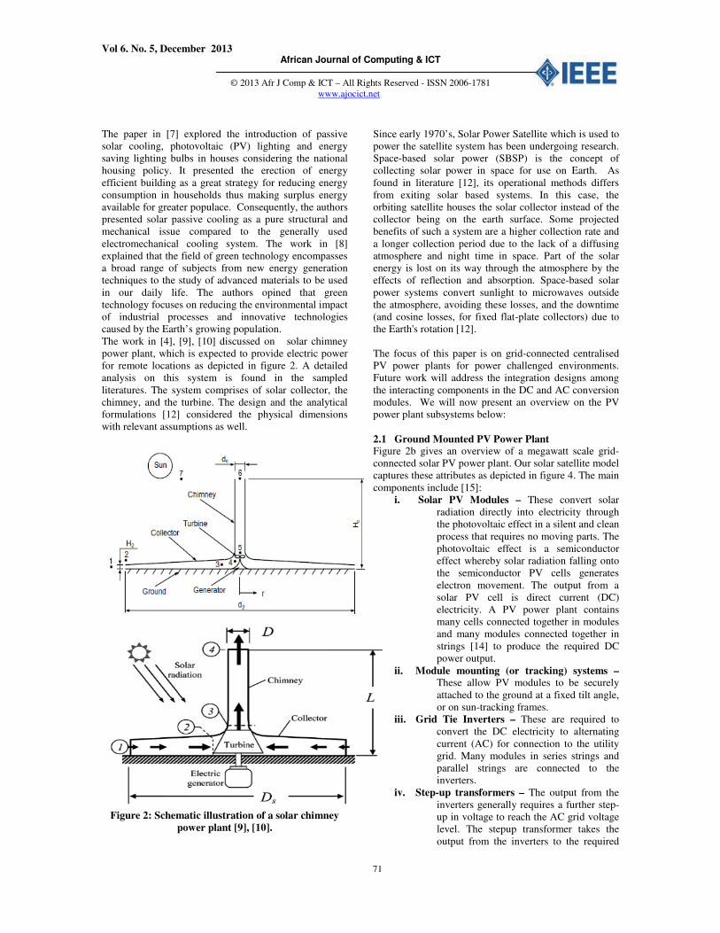
2.1 Ground Mounted PV Power Plant Figure 2b gives an overview of a megawatt scale grid-
connected solar PV power plant. Our solar satellite model
captures these attributes as depicted in figure 4. The main
components include [15]:
i. Solar PV Modules – These convert solar
radiation directly into electricity through
the photovoltaic effect in a silent and clean
process that requires no moving parts. The
photovoltaic effect is a semiconductor
effect whereby solar radiation falling onto
the semiconductor PV cells generates
electron movement. The output from a
solar PV cell is direct current (DC)
electricity. A PV power plant contains
many cells connected together in modules
and many modules connected together in
strings [14] to produce the required DC
power output.
ii. Module mounting (or tracking) systems – These allow PV modules to be securely
attached to the ground at a fixed tilt angle,
or on sun-tracking frames.
iii. Grid Tie Inverters – These are required to
convert the DC electricity to alternating
current (AC) for connection to the utility
grid. Many modules in series strings and
parallel strings are connected to the
inverters.
iv. Step-up transformers – The output from the
inverters generally requires a further step-
up in voltage to reach the AC grid voltage
level. The stepup transformer takes the
output from the inverters to the required
Vol 6. No. 5, December 2013 African Journal of Computing & ICT
© 2013 Afr J Comp & ICT – All Rights Reserved - ISSN 2006-1781
www.ajocict.net
72
grid voltage (for example 25 kV, 33 kV,
38 kV, 110 kV depending on the grid
connection point and requirements).
v. The grid connection interface – This is where
the electricity is exported into the grid
network. The substation will also have the
required grid interface switchgear such as
circuit breakers and disconnects for
protection and isolation of the PV power
plant as well as generation and supply
metering equipment. The substation and
metering point are often external to the PV
power plant boundary and are typically
located on the network operator’s property
[15]
Figure 2b: A Conventional Solar PV Power Plant [15]
Summarily, in power challenged environments where
enterprises and business needs to be making transactions
24/7, leveraging on green power supplies will facilitate
operations and reduce capital expenditures if properly
implemented. However, most works on solar power
systems [9], [10], [12] are capital intensive considering
the PV I-V curve output requirements. In this paper, we
present a simplified framework for Solar Satellite design,
using the PV tesbed parameters, while presenting the I-V
characteristics.
3. METHODOLOGY
3.1 Parasol and ELDI Solar Plant Solar Satellite is formulated from the architectural design
principles of two existing testbed viz Parasol and ELDI
Solar Plant. As a result of the study, we outlined a
practical framework for Solar PV system design below.
Vol 6. No. 5, December 2013 African Journal of Computing & ICT
© 2013 Afr J Comp & ICT – All Rights Reserved - ISSN 2006-1781
www.ajocict.net
73
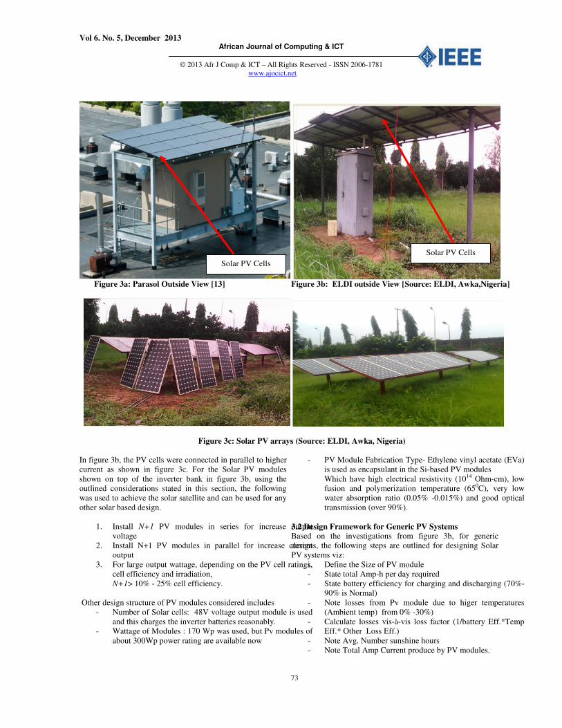
Figure 3a: Parasol Outside View [13] Figure 3b: ELDI outside View [Source: ELDI, Awka,Nigeria]
Figure 3c: Solar PV arrays (Source: ELDI, Awka, Nigeria)
In figure 3b, the PV cells were connected in parallel to higher
current as shown in figure 3c. For the Solar PV modules
shown on top of the inverter bank in figure 3b, using the
outlined considerations stated in this section, the following
was used to achieve the solar satellite and can be used for any
other solar based design.
1. Install N+1 PV modules in series for increase output
voltage
2. Install N+1 PV modules in parallel for increase current
output
3. For large output wattage, depending on the PV cell ratings,
cell efficiency and irradiation,
N+1> 10% - 25% cell efficiency.
Other design structure of PV modules considered includes
- Number of Solar cells: 48V voltage output module is used
and this charges the inverter batteries reasonably.
- Wattage of Modules : 170 Wp was used, but Pv modules of
about 300Wp power rating are available now
- PV Module Fabrication Type- Ethylene vinyl acetate (EVa)
is used as encapsulant in the Si-based PV modules
Which have high electrical resistivity (1014 Ohm-cm), low
fusion and polymerization temperature (650C), very low
water absorption ratio (0.05% -0.015%) and good optical
transmission (over 90%).
3.2 Design Framework for Generic PV Systems Based on the investigations from figure 3b, for generic
designs, the following steps are outlined for designing Solar
PV systems viz:
i. Define the Size of PV module
- State total Amp-h per day required
- State battery efficiency for charging and discharging (70%-
90% is Normal)
- Note losses from Pv module due to higer temperatures
(Ambient temp) from 0% -30%)
- Calculate losses vis-à-vis loss factor (1/battery Eff.*Temp
Eff.* Other Loss Eff.)
- Note Avg. Number sunshine hours
- Note Total Amp Current produce by PV modules.
Solar PV Cells
Solar PV Cells
Vol 6. No. 5, December 2013 African Journal of Computing & ICT
© 2013 Afr J Comp & ICT – All Rights Reserved - ISSN 2006-1781
www.ajocict.net
74
- State peak power capacity of the PV module (from 10 –
300Wp,etc)
- State peak current and peak voltage of the choosen PV
modules
- Configure Total number of PV modules in parallel
ii. Define load estimation, Inverter ratings and System voltage
- State daily AC loads in terms of Watt-h
- State the efficiency of the charge controller, Estimate Watt-
h load
- Obtain exact load by dividing estimate Watt-h by Charge
controller Efficiency
- State the system Voltage by choice
- Estimate the total daily Amp-h load or Ah load for AC
loads (ie Wh/system Voltage-V) and for DC loads
iii. Define the battery capacity for storage
- Obtain daily Amp-h load per day required to be supplied
from solar array
- Obtain numbers of days of autonomy for system reliability
- Estimate total Amp-h required with autonomy
- Consider batteries of higher Depth of Discharge DoD viz-a-
viz useful charge capacity (20%-80%)
- Consider Effective Amp-h required after considering DoD
- Depending on the size of the load, choose battery caapacity
(12Ah, 50Ah, 100Ah, 150Ah, 250Ah, etc)
- Connect the battery network in parallel to obtaine the
desired Amp-h from the battery
- Desired system voltage = System voltage/battery voltage
We now present the system architecture of the proposed Solar
Satellite system while discussing its functionalities.
3.3 Solar Satellite Architecture In this work, a prosed Solar Satellite addresses the following issues,
viz: Optimal current and volatage outputs, optimal solar concentration
at maxium tilt angle (300), load stability, resource avaliability,
reliability, open support for scalability and interface supports for
manageability. A high power switching feedback system (3phase),
Advance Metering System (Smart Meter), and a coomunication
interface for the Distributed Cloud Datacneter network are the
additional improvements captured. This paper will only show our
results on I-V characteristics plots for the solar light PV farm.
Vol 6. No. 5, December 2013 African Journal of Computing & ICT
© 2013 Afr J Comp & ICT – All Rights Reserved - ISSN 2006-1781
www.ajocict.net
75
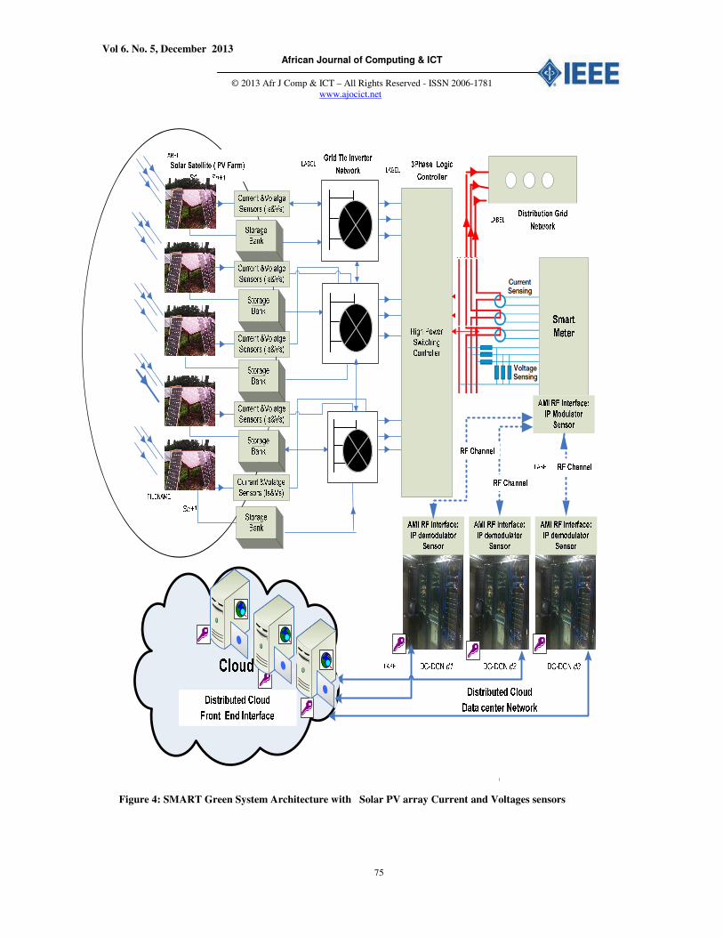
Figure 4: SMART Green System Architecture with Solar PV array Current and Voltages sensors
Vol 6. No. 5, December 2013 African Journal of Computing & ICT
© 2013 Afr J Comp & ICT – All Rights Reserved - ISSN 2006-1781
www.ajocict.net
76
From figure 4, the proposed Smart Green System Components includes the following as earlier discussed, viz:
- 3-Phase distribution network
- Renewable Energy Sources Such as Wind, Solar, etc (Generation Plants)
- Battery Banking Systems (Storage Reservoir)
- DC-DC Converters (PWM Feedback Frequency Oscillators/ MMPT Current boosters)
- Grid tie Inverters (DC-AC Converters)
- Switching Summer Control (Grid tie Inverter to Transmission Grid or Vice versa)
- Fault Detection Sensors ( Current and Voltage Sensors)
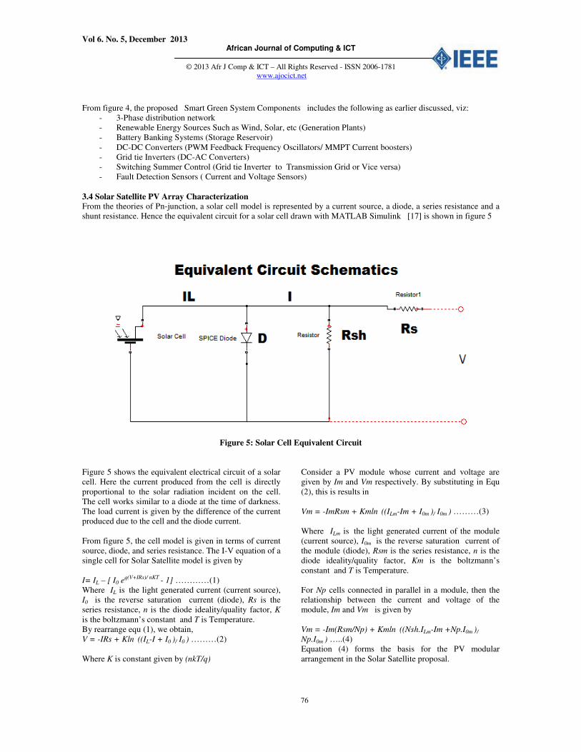
3.4 Solar Satellite PV Array Characterization From the theories of Pn-junction, a solar cell model is represented by a current source, a diode, a series resistance and a
shunt resistance. Hence the equivalent circuit for a solar cell drawn with MATLAB Simulink [17] is shown in figure 5
Figure 5: Solar Cell Equivalent Circuit
Figure 5 shows the equivalent electrical circuit of a solar
cell. Here the current produced from the cell is directly
proportional to the solar radiation incident on the cell.
The cell works similar to a diode at the time of darkness.
The load current is given by the difference of the current
produced due to the cell and the diode current.
From figure 5, the cell model is given in terms of current
source, diode, and series resistance. The I-V equation of a
single cell for Solar Satellite model is given by
I= IL – [ I0 eq(V+IRs)/ nKT - 1] …………(1)
Where IL is the light generated current (current source),
I0 is the reverse saturation current (diode), Rs is the
series resistance, n is the diode ideality/quality factor, K
is the boltzmann’s constant and T is Temperature.
By rearrange equ (1), we obtain,
V = -IRs + Kln ((IL-I + I0 )/ I0 ) ………(2)
Where K is constant given by (nkT/q)
Consider a PV module whose current and voltage are
given by Im and Vm respectively. By substituting in Equ
(2), this is results in
Vm = -ImRsm + Kmln ((ILm-Im + I0m )/ I0m ) ………(3)
Where ILm is the light generated current of the module
(current source), I0m is the reverse saturation current of
the module (diode), Rsm is the series resistance, n is the
diode ideality/quality factor, Km is the boltzmann’s
constant and T is Temperature.
For Np cells connected in parallel in a module, then the
relationship between the current and voltage of the
module, Im and Vm is given by
Vm = -Im(Rsm/Np) + Kmln ((Nsh.ILm-Im +Np.I0m )/
Np.I0m ) …..(4)
Equation (4) forms the basis for the PV modular
arrangement in the Solar Satellite proposal.
Vol 6. No. 5, December 2013 African Journal of Computing & ICT
© 2013 Afr J Comp & ICT – All Rights Reserved - ISSN 2006-1781
www.ajocict.net
77
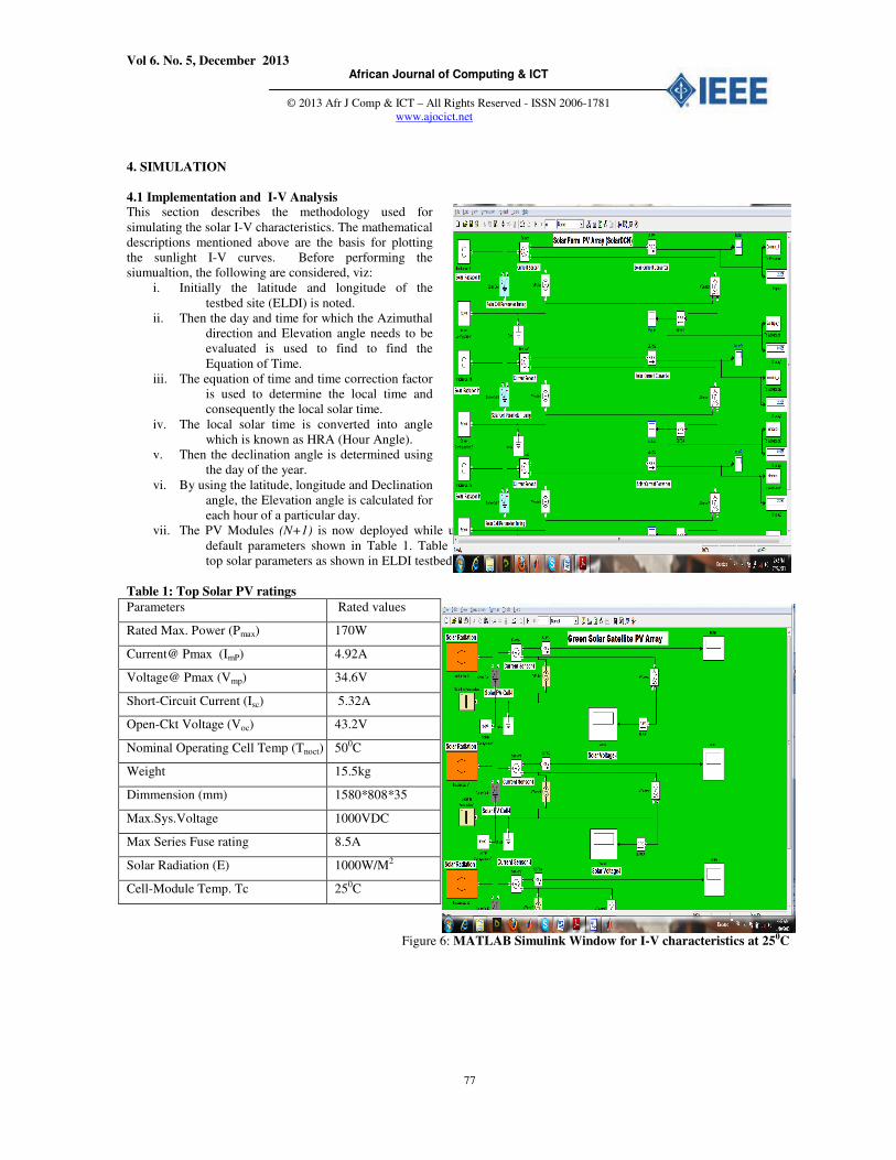
4. SIMULATION
4.1 Implementation and I-V Analysis This section describes the methodology used for
simulating the solar I-V characteristics. The mathematical
descriptions mentioned above are the basis for plotting
the sunlight I-V curves. Before performing the
siumualtion, the following are considered, viz:
i. Initially the latitude and longitude of the
testbed site (ELDI) is noted.
ii. Then the day and time for which the Azimuthal
direction and Elevation angle needs to be
evaluated is used to find to find the
Equation of Time.
iii. The equation of time and time correction factor
is used to determine the local time and
consequently the local solar time.
iv. The local solar time is converted into angle
which is known as HRA (Hour Angle).
v. Then the declination angle is determined using
the day of the year.
vi. By using the latitude, longitude and Declination
angle, the Elevation angle is calculated for
each hour of a particular day.
vii. The PV Modules (N+1) is now deployed while using the
default parameters shown in Table 1. Table 1 shows
top solar parameters as shown in ELDI testbed.
Table 1: Top Solar PV ratings
Parameters Rated values
Rated Max. Power (Pmax) 170W
Current@ Pmax (ImP) 4.92A
Voltage@ Pmax (Vmp) 34.6V
Short-Circuit Current (Isc) 5.32A
Open-Ckt Voltage (Voc) 43.2V
Nominal Operating Cell Temp (Tnoct) 500C
Weight 15.5kg
Dimmension (mm) 1580*808*35
Max.Sys.Voltage 1000VDC
Max Series Fuse rating 8.5A
Solar Radiation (E) 1000W/M2
Cell-Module Temp. Tc 250C
Figure 6: MATLAB Simulink Window for I-V characteristics at 250C
Vol 6. No. 5, December 2013 African Journal of Computing & ICT
© 2013 Afr J Comp & ICT – All Rights Reserved - ISSN 2006-1781
www.ajocict.net
78
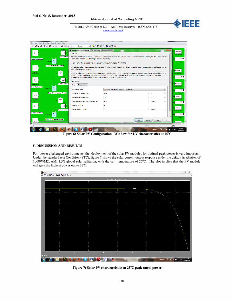
Figure 6: Solar PV Configuration Window for I-V characteristics at 250C
5. DISCUSSION AND RESULTS
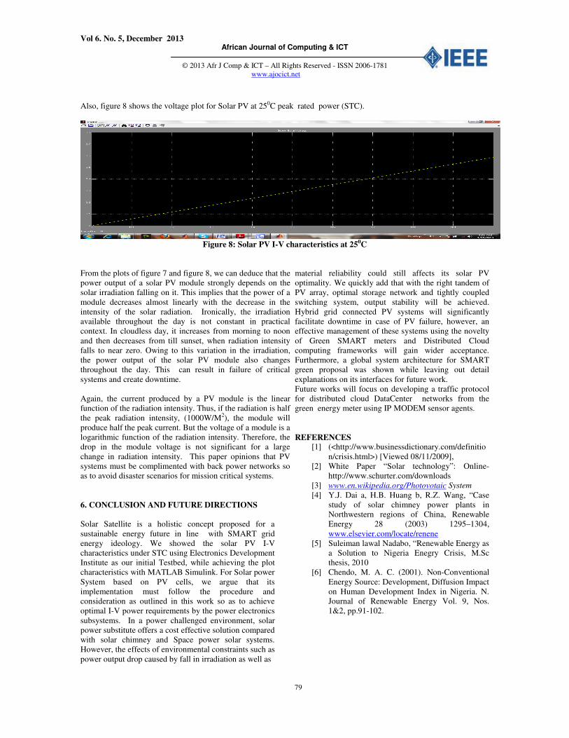
For power challenged environments, the deployment of the solar PV modules for optimal peak power is very important.
Under the standard test Condition (STC), figure 7 shows the solar current output response under the default irradiation of
1000W/M2, AMI 1.5G global solar radiation, with the cell temperature of 250C. The plot implies that the PV module
will give the highest power under STC.
Figure 7: Solar PV characteristics at 250C peak rated power
Vol 6. No. 5, December 2013 African Journal of Computing & ICT
© 2013 Afr J Comp & ICT – All Rights Reserved - ISSN 2006-1781
www.ajocict.net
79
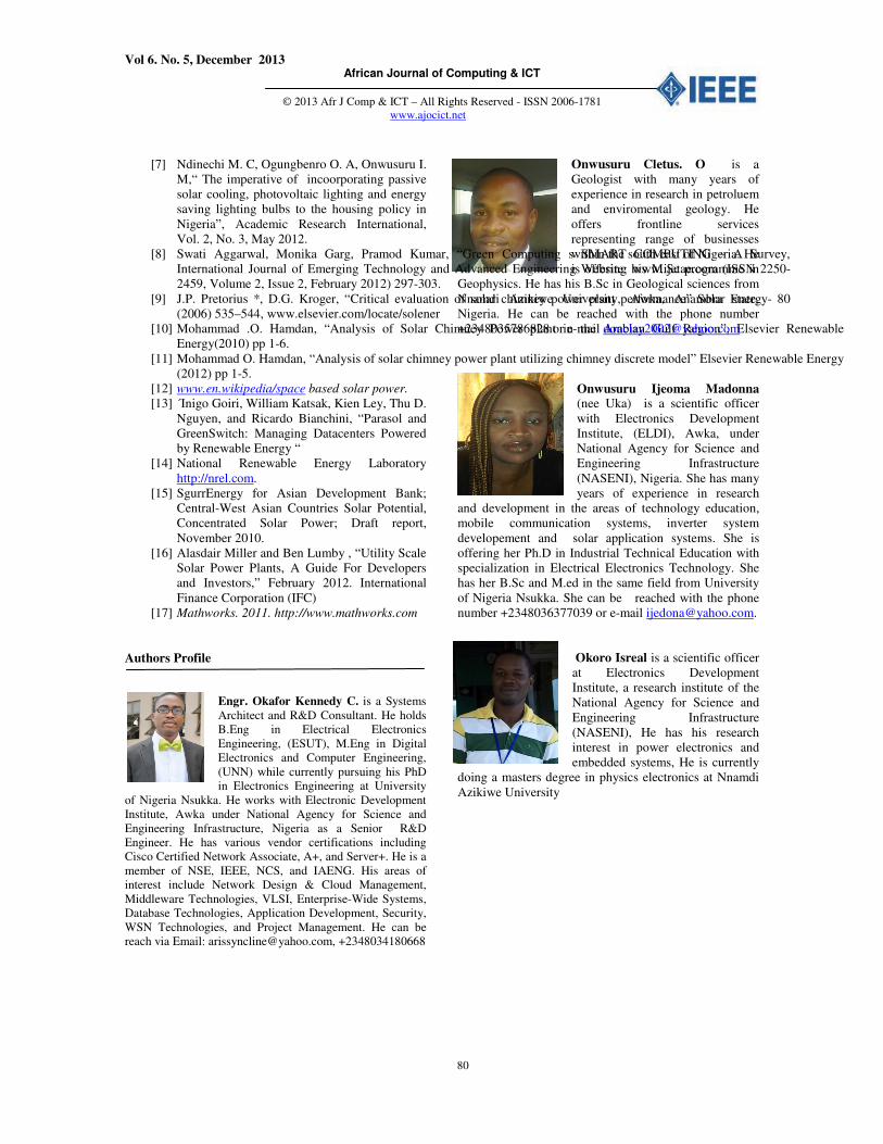
Also, figure 8 shows the voltage plot for Solar PV at 250C peak rated power (STC).
Figure 8: Solar PV I-V characteristics at 250C
From the plots of figure 7 and figure 8, we can deduce that the
power output of a solar PV module strongly depends on the
solar irradiation falling on it. This implies that the power of a
module decreases almost linearly with the decrease in the
intensity of the solar radiation. Ironically, the irradiation
available throughout the day is not constant in practical
context. In cloudless day, it increases from morning to noon
and then decreases from till sunset, when radiation intensity
falls to near zero. Owing to this variation in the irradiation,
the power output of the solar PV module also changes
throughout the day. This can result in failure of critical
systems and create downtime.
Again, the current produced by a PV module is the linear
function of the radiation intensity. Thus, if the radiation is half
the peak radiation intensity, (1000W/M2), the module will
produce half the peak current. But the voltage of a module is a
logarithmic function of the radiation intensity. Therefore, the
drop in the module voltage is not significant for a large
change in radiation intensity. This paper opinions that PV
systems must be complimented with back power networks so
as to avoid disaster scenarios for mission critical systems.
6. CONCLUSION AND FUTURE DIRECTIONS
Solar Satellite is a holistic concept proposed for a
sustainable energy future in line with SMART grid
energy ideology. We showed the solar PV I-V
characteristics under STC using Electronics Development
Institute as our initial Testbed, while achieving the plot
characteristics with MATLAB Simulink. For Solar power
System based on PV cells, we argue that its
implementation must follow the procedure and
consideration as outlined in this work so as to achieve
optimal I-V power requirements by the power electronics
subsystems. In a power challenged environment, solar
power substitute offers a cost effective solution compared
with solar chimney and Space power solar systems.
However, the effects of environmental constraints such as
power output drop caused by fall in irradiation as well as
material reliability could still affects its solar PV
optimality. We quickly add that with the right tandem of
PV array, optimal storage network and tightly coupled
switching system, output stability will be achieved.
Hybrid grid connected PV systems will significantly
facilitate downtime in case of PV failure, however, an
effective management of these systems using the novelty
of Green SMART meters and Distributed Cloud
computing frameworks will gain wider acceptance.
Furthermore, a global system architecture for SMART
green proposal was shown while leaving out detail
explanations on its interfaces for future work.
Future works will focus on developing a traffic protocol
for distributed cloud DataCenter networks from the
green energy meter using IP MODEM sensor agents.
REFERENCES [1] (<http://www.businessdictionary.com/definitio
n/crisis.html>) [Viewed 08/11/2009],
[2] White Paper “Solar technology”: Online-
http://www.schurter.com/downloads
[3] www.en.wikipedia.org/Photovotaic System
[4] Y.J. Dai a, H.B. Huang b, R.Z. Wang, “Case
study of solar chimney power plants in
Northwestern regions of China, Renewable
Energy 28 (2003) 1295–1304,
www.elsevier.com/locate/renene
[5] Suleiman lawal Nadabo, “Renewable Energy as
a Solution to Nigeria Enegry Crisis, M.Sc
thesis, 2010
[6] Chendo, M. A. C. (2001). Non-Conventional
Energy Source: Development, Diffusion Impact
on Human Development Index in Nigeria. N.
Journal of Renewable Energy Vol. 9, Nos.
1&2, pp.91-102.
Vol 6. No. 5, December 2013 African Journal of Computing & ICT
© 2013 Afr J Comp & ICT – All Rights Reserved - ISSN 2006-1781
www.ajocict.net
80
[7] Ndinechi M. C, Ogungbenro O. A, Onwusuru I.
M,“ The imperative of incoorporating passive
solar cooling, photovoltaic lighting and energy
saving lighting bulbs to the housing policy in
Nigeria”, Academic Research International,
Vol. 2, No. 3, May 2012.
[8] Swati Aggarwal, Monika Garg, Pramod Kumar, “Green Computing s SMART COMPUTING – A Survey,
International Journal of Emerging Technology and Advanced Engineering Website: www.ijetae.com (ISSN 2250-
2459, Volume 2, Issue 2, February 2012) 297-303.
[9] J.P. Pretorius *, D.G. Kroger, “Critical evaluation of solar chimney power plant performance” Solar Energy- 80
(2006) 535–544, www.elsevier.com/locate/solener
[10] Mohammad .O. Hamdan, “Analysis of Solar Chimney Power plant in the Arabian Gulf Region”, Elsevier Renewable
Energy(2010) pp 1-6.
[11] Mohammad O. Hamdan, “Analysis of solar chimney power plant utilizing chimney discrete model” Elsevier Renewable Energy
(2012) pp 1-5.
[12] www.en.wikipedia/space based solar power.
[13] ´Inigo Goiri, William Katsak, Kien Ley, Thu D.
Nguyen, and Ricardo Bianchini, “Parasol and
GreenSwitch: Managing Datacenters Powered
by Renewable Energy “
[14] National Renewable Energy Laboratory
http://nrel.com.
[15] SgurrEnergy for Asian Development Bank;
Central-West Asian Countries Solar Potential,
Concentrated Solar Power; Draft report,
November 2010.
[16] Alasdair Miller and Ben Lumby , “Utility Scale
Solar Power Plants, A Guide For Developers
and Investors,” February 2012. International
Finance Corporation (IFC)
[17] Mathworks. 2011. http://www.mathworks.com
Authors Profile
Engr. Okafor Kennedy C. is a Systems
Architect and R&D Consultant. He holds
B.Eng in Electrical Electronics
Engineering, (ESUT), M.Eng in Digital
Electronics and Computer Engineering,
(UNN) while currently pursuing his PhD
in Electronics Engineering at University
of Nigeria Nsukka. He works with Electronic Development
Institute, Awka under National Agency for Science and
Engineering Infrastructure, Nigeria as a Senior R&D
Engineer. He has various vendor certifications including
Cisco Certified Network Associate, A+, and Server+. He is a
member of NSE, IEEE, NCS, and IAENG. His areas of
interest include Network Design & Cloud Management,
Middleware Technologies, VLSI, Enterprise-Wide Systems,
Database Technologies, Application Development, Security,
WSN Technologies, and Project Management. He can be
reach via Email: [email protected], +2348034180668
Onwusuru Cletus. O is a
Geologist with many years of
experience in research in petroluem
and enviromental geology. He
offers frontline services
representing range of businesses
within the south east of Nigeria. He
is offering his M.Sc programme in
Geophysics. He has his B.Sc in Geological sciences from
Nnamdi Azikiwe University, Awka, Anambra state,
Nigeria. He can be reached with the phone number
+2348035786828 or e-mail [email protected]
Onwusuru Ijeoma Madonna (nee Uka) is a scientific officer
with Electronics Development
Institute, (ELDI), Awka, under
National Agency for Science and
Engineering Infrastructure
(NASENI), Nigeria. She has many
years of experience in research
and development in the areas of technology education,
mobile communication systems, inverter system
developement and solar application systems. She is
offering her Ph.D in Industrial Technical Education with
specialization in Electrical Electronics Technology. She
has her B.Sc and M.ed in the same field from University
of Nigeria Nsukka. She can be reached with the phone
number +2348036377039 or e-mail [email protected].
Okoro Isreal is a scientific officer
at Electronics Development
Institute, a research institute of the
National Agency for Science and
Engineering Infrastructure
(NASENI), He has his research
interest in power electronics and
embedded systems, He is currently
doing a masters degree in physics electronics at Nnamdi
Azikiwe University