Software systems for operation, control, and monitoring of the EBEX instrument
11
Software systems for operation, control, and monitoring of the EBEX instrument Michael Milligan, a Peter Ade, b Fran¸coisAubin, c Carlo Baccigalupi, d Chaoyun Bao, a Julian Borrill, e Christopher Cantalupo, e Daniel Chapman, f Joy Didier, f Matt Dobbs, c Will Grainger, b Shaul Hanany, a Seth Hillbrand, f Johannes Hubmayr, g Peter Hyland, c Andrew Jaffe, h Bradley Johnson, i Theodore Kisner, e Jeff Klein, a Andrei Korotkov, j Sam Leach, d Adrian Lee, i Lorne Levinson, k Michele Limon, f Kevin MacDermid, c Tomotake Matsumura, l Amber Miller, f Enzo Pascale, b Daniel Polsgrove, a Nicolas Ponthieu, m Kate Raach, a Britt Reichborn-Kjennerud, f Ilan Sagiv, a Huan Tran, i Gregory S. Tucker, j Yury Vinokurov, j Amit Yadav, n Matias Zaldarriaga, n Kyle Zilic a a University of Minnesota School of Physics and Astronomy, Minneapolis, MN 55455; b Cardiff University, Cardiff, CF24 3AA, United Kingdom; c McGill University, Montr´ eal, Quebec, H3A 2T8, Canada; d Scuola Internazionale Superiore di Studi Avanzati, Trieste 34151, Italy; e Lawrence Berkeley National Laboratory, Berkeley, CA 94720; f Columbia University, New York, NY 10027; g National Institute of Standards and Technology, Boulder CO 80303; h Imperial College, London, SW7 2AZ, England, United Kingdom; i University of California, Berkeley, Berkeley, CA 94720; j Brown University, Providence, RI 02912; k Weizmann Institute of Science, Rehovot 76100, Israel; l California Institute of Technology, Pasadena, CA 91125; m Institut d’Astrophysique Spatiale, Universite Paris-Sud, Orsay, 91405, France; n Institute for Advanced Study, Princeton, NJ 08540 ABSTRACT We present the hardware and software systems implementing autonomous operation, distributed real-time mon- itoring, and control for the EBEX instrument. EBEX is a NASA-funded balloon-borne microwave polarimeter designed for a 14 day Antarctic flight that circumnavigates the pole. To meet its science goals the EBEX instrument autonomously executes several tasks in parallel: it collects attitude data and maintains pointing control in order to adhere to an observing schedule; tunes and operates up to 1920 TES bolometers and 120 SQUID amplifiers controlled by as many as 30 embedded computers; coordinates and dispatches jobs across an onboard computer network to manage this detector readout system; logs over 3 GiB/hour of science and housekeeping data to an onboard disk storage array; responds to a variety of commands and exogenous events; and downlinks multiple heterogeneous data streams representing a selected subset of the total logged data. Most of the systems implementing these functions have been tested during a recent engineering flight of the payload, and have proven to meet the target requirements. The EBEX ground segment couples uplink and downlink hardware to a client-server software stack, enabling real-time monitoring and command responsibility to be distributed across the public internet or other standard computer networks. Using the emerging dirfile standard as a uniform intermediate data format, a variety of front end programs provide access to different components and views of the downlinked data products. This distributed architecture was demonstrated operating across multiple widely dispersed sites prior to and during the EBEX engineering flight. Keywords: CMB, millimeter-wave telescopes, flight control systems, ballooning, data handling arXiv:1006.5256v2 [astro-ph.IM] 5 Jul 2010
-
Upload
independent -
Category
Documents
-
view
0 -
download
0
Transcript of Software systems for operation, control, and monitoring of the EBEX instrument

Software systems for operation, control, and monitoring ofthe EBEX instrument
Michael Milligan,a Peter Ade,b Francois Aubin,c Carlo Baccigalupi,d Chaoyun Bao,a JulianBorrill,e Christopher Cantalupo,e Daniel Chapman,f Joy Didier,f Matt Dobbs,c Will Grainger,b
Shaul Hanany,a Seth Hillbrand,f Johannes Hubmayr,g Peter Hyland,c Andrew Jaffe,h BradleyJohnson,i Theodore Kisner,e Jeff Klein,a Andrei Korotkov,j Sam Leach,d Adrian Lee,i LorneLevinson,k Michele Limon,f Kevin MacDermid,c Tomotake Matsumura,l Amber Miller,f EnzoPascale,b Daniel Polsgrove,a Nicolas Ponthieu,m Kate Raach,a Britt Reichborn-Kjennerud,f
Ilan Sagiv,a Huan Tran,i Gregory S. Tucker,j Yury Vinokurov,j Amit Yadav,n MatiasZaldarriaga,n Kyle Zilica
aUniversity of Minnesota School of Physics and Astronomy, Minneapolis, MN 55455;bCardiff University, Cardiff, CF24 3AA, United Kingdom;cMcGill University, Montreal, Quebec, H3A 2T8, Canada;
dScuola Internazionale Superiore di Studi Avanzati, Trieste 34151, Italy;eLawrence Berkeley National Laboratory, Berkeley, CA 94720;
fColumbia University, New York, NY 10027;gNational Institute of Standards and Technology, Boulder CO 80303;
hImperial College, London, SW7 2AZ, England, United Kingdom;iUniversity of California, Berkeley, Berkeley, CA 94720;
jBrown University, Providence, RI 02912;kWeizmann Institute of Science, Rehovot 76100, Israel;
lCalifornia Institute of Technology, Pasadena, CA 91125;mInstitut d’Astrophysique Spatiale, Universite Paris-Sud, Orsay, 91405, France;
nInstitute for Advanced Study, Princeton, NJ 08540
ABSTRACT
We present the hardware and software systems implementing autonomous operation, distributed real-time mon-itoring, and control for the EBEX instrument. EBEX is a NASA-funded balloon-borne microwave polarimeterdesigned for a 14 day Antarctic flight that circumnavigates the pole.
To meet its science goals the EBEX instrument autonomously executes several tasks in parallel: it collectsattitude data and maintains pointing control in order to adhere to an observing schedule; tunes and operatesup to 1920 TES bolometers and 120 SQUID amplifiers controlled by as many as 30 embedded computers;coordinates and dispatches jobs across an onboard computer network to manage this detector readout system;logs over 3 GiB/hour of science and housekeeping data to an onboard disk storage array; responds to a varietyof commands and exogenous events; and downlinks multiple heterogeneous data streams representing a selectedsubset of the total logged data. Most of the systems implementing these functions have been tested during arecent engineering flight of the payload, and have proven to meet the target requirements.
The EBEX ground segment couples uplink and downlink hardware to a client-server software stack, enablingreal-time monitoring and command responsibility to be distributed across the public internet or other standardcomputer networks. Using the emerging dirfile standard as a uniform intermediate data format, a variety offront end programs provide access to different components and views of the downlinked data products. Thisdistributed architecture was demonstrated operating across multiple widely dispersed sites prior to and duringthe EBEX engineering flight.
Keywords: CMB, millimeter-wave telescopes, flight control systems, ballooning, data handling
arX
iv:1
006.
5256
v2 [
astr
o-ph
.IM
] 5
Jul
201
0

1. INTRODUCTION
1.1 Science goals
The E and B EXperiment (EBEX) is balloon-borne microwave polarimeter designed to study the polarization ofthe cosmic microwave background (CMB) and the foreground emission of thermal dust in our galaxy.1,2 Thesemeasurements will: detect or constrain the primordial B-mode polarization of the CMB, a predicted signatureof gravity waves produced by cosmic inflation;3,4 characterize the polarized foreground dust emission, which isa necessary step in determining the CMB B-mode signal;5,6 and measure the predicted effect of gravitationallensing on the CMB.7 The science goals of EBEX are described more fully in other publications.1,2, 8
1.2 Instrument description
The EBEX instrument consists of a 1.5 meter clear aperture Gregorian-type telescope that feeds a cryogenicreceiver, all of which are mounted on the inner frame of the EBEX gondola. Pointing control is maintained bydriving the inner frame in elevation, while a pivot and reaction wheel turn the outer frame azimuthally relativeto the balloon flight line. Attitude sensors including a sun sensor, star cameras, differential GPS, gyroscopes,magnetometer, and clinometers are mounted as appropriate on the inner and outer frames. The flight computers,Attitude Control System (ACS) crate, and disk storage pressure vessels are mounted on the outer frame. Insidethe cryostat reimaging optics focus the input radiation onto two focal planes each carrying up to 960 transitionedge sensor (TES) bolometers, up to 1920 total bolometers. A polarimetric system, consisting of a half wave plate(HWP)9 spinning on a superconducting magnetic bearing10 and a wire grid, modulates polarization informationinto the phase and amplitude of the component of the radiation intensity at the focal plane corresponding tofour times the HWP rotation frequency.11 The TES are read out through SQUID amplifiers via a frequencydomain multiplexing scheme that connects up to 16 TES to each SQUID. The SQUIDs in turn are connectedin groups of four to digital frequency-domain multiplexing readout (DfMux) boards.12 The design of the EBEXinstrument is detailed elsewhere,2,8, 13 and the bolometer readout system is described in Hubmayr et al14 andAubin et al.15 EBEX completed a 13 hour engineering flight from Ft. Sumner, New Mexico in June 2009. Inthis paper we describe the software and data flow architecture that make up the EBEX control and monitoringsystems.
1.3 Computing and system control overview
In order to meet the science goals, EBEX autonomously executes several tasks in parallel.
The instrument maintains real-time pointing control to better than the 0.5◦ requirement and logs sufficientdata from the pointing sensors to allow post-flight pointing reconstruction to better than the 9′′ requirement.The pointing system can realize several predefined instrument scan modes, as well as drift, slew, and coordinatetracking motions. The two redundant flight computers (see Sec. 2.1) execute all pointing actions synchronously,with a watchdog card selecting the less-recently rebooted computer to control the instrument. The pointingsystem is discussed in detail by Reichborn-Kjennerud.16
Both SQUIDs and TES bolometers periodically require active tuning, such as during cycling of the sub-Kelvinadsorption refrigerators.17 This instrument reads out up to 1792 of the 1920 bolometers, multiplexed through112 SQUIDs, operated by 28 DfMux boards. These setup and tuning operations are managed over the gondolaEthernet network by the flight computers, as discussed in Sec. 2.2.
Bolometers are read out at 190.73 Hz 16-bit samples. Depending on the multiplexing level each DfMux boardreads out between 32 and 64 bolometers, producing a data stream of between 21 and 42 kilobytes/s, or 2.1 to4.2 gigabytes per hour for the full complement of 28 boards. The ACS generates an additional data stream ofapproximately 20 KB/s (70 megabytes per hour), and the angular encoders on the rotating HWP produce acombined 21 KB/s (75 MB/h). This output data is transferred over the ethernet network to the flight computerand logged to disk. Consequently for a 14 day flight the onboard disk array must provide over 1.5 terabytes totalstorage per redundant copy written. The storage system is discussed in Sec. 2.3.
In addition to planned housekeeping operations, the possibility of unplanned events demands that EBEXpossess the ability to respond to some exogenous contingencies, that sufficient operational data be downlinkedto enable human diagnosis of unexpected conditions, and that the telecommanding interface be flexible enough
to exercise the full range of recovery options available in the flying hardware. The necessary downlink (Sec. 2.4)is provided by a 1 Mbit/s line-of-sight (LOS) transmitter available for roughly the first day of flight, and a muchslower TDRSS satellite relay afterwards. The telecommanding uplink relies on satellite relay or an HF-bandLOS transmission, and in practice is limited to less than ten 15-bit command tokens per second.
All of the above activities can be triggered from the ground via uplinked commands, as well as scheduledvia onboard schedule files. The scheduling system operates in local sidereal time, allowing planned observationsto account for the motion of the balloon in longitude, which cannot be precisely known in advance. Withinthe limits of the underlying operating system, actions can be scheduled arbitrarily far in the future. Uplinkedcommands can select between alternative stored schedules.
The communications infrastructure of the Columbia Scientific Balloon Facility (CSBF) provides the LOSdownlink signal at the launch site, and provides connections to satellite-based telemetry and telecommanding viathe Operations Control Center in Palestine, Texas.18 During a long duration balloon flight, many collaborationpersonnel will be positioned at the launch site, while other collaborators may be geographically dispersed. Tosupport this scenario the EBEX ground segment couples uplink and downlink hardware to a client-server softwarestack (see Sec. 2.5 and Fig. 2). The full high rate LOS data stream is available at multiple client workstationsat the launch site, and portions of this data can be made available via the public internet for remote real-timeexamination. Likewise telecommanding is forwarded over network links to the EBEX ground station and CSBFuplink.
To meet the reliability and development time requirements of this project we use commercially availablehardware and existing software whenever practical. With the exception of the FPGA-based DfMux and ACSboards, onboard computers and networking hardware are available industrial embedded models which we havequalified in thermal and vacuum conditions approximating balloon flight. The ACS, many aspects of the gondolaand pointing system design, and several components of the software chain described here originate with theBLAST project,19 and are described by Wiebe.20 The housekeeping system makes extensive use of embeddedmonitoring boards21 originally developed for the ATLAS experiment at CERN.22,23
2. SYSTEMS
The EBEX gondola comprises several subsystems of networked components, with the flight computer crate actingas the point of intersection.
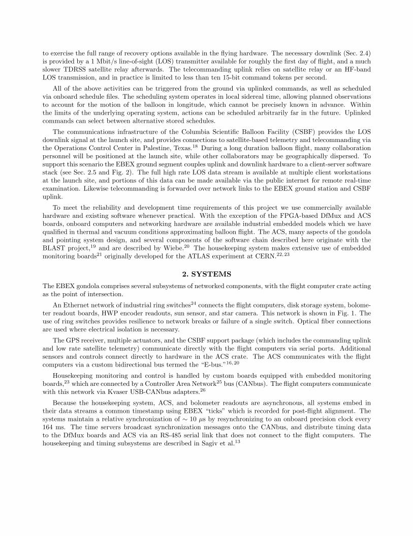
An Ethernet network of industrial ring switches24 connects the flight computers, disk storage system, bolome-ter readout boards, HWP encoder readouts, sun sensor, and star camera. This network is shown in Fig. 1. Theuse of ring switches provides resilience to network breaks or failure of a single switch. Optical fiber connectionsare used where electrical isolation is necessary.
The GPS receiver, multiple actuators, and the CSBF support package (which includes the commanding uplinkand low rate satellite telemetry) communicate directly with the flight computers via serial ports. Additionalsensors and controls connect directly to hardware in the ACS crate. The ACS communicates with the flightcomputers via a custom bidirectional bus termed the “E-bus.”16,20
Housekeeping monitoring and control is handled by custom boards equipped with embedded monitoringboards,23 which are connected by a Controller Area Network25 bus (CANbus). The flight computers communicatewith this network via Kvaser USB-CANbus adapters.26
Because the housekeeping system, ACS, and bolometer readouts are asynchronous, all systems embed intheir data streams a common timestamp using EBEX “ticks” which is recorded for post-flight alignment. Thesystems maintain a relative synchronization of ∼ 10 µs by resynchronizing to an onboard precision clock every164 ms. The time servers broadcast synchronization messages onto the CANbus, and distribute timing datato the DfMux boards and ACS via an RS-485 serial link that does not connect to the flight computers. Thehousekeeping and timing subsystems are described in Sagiv et al.13
EBEX ethernet network Uses ring switches to make
self-healing rings:Withstands failure of one connection
in each ring;Loss of a switch: loses only its clients.
7 disks 7 disks
ringswitch
ringswitch
ring switch
ring switch
Pressure vessels for disks
LJ Lebex002V5
standby connection
flightcomputer
flightcomputer
star camera 0
star camera 1
sun sensor
Gnd Stn
HWP 0 HWP 1
Flight computer box
dual optical fiber
near four bolo readout crates,in Faraday cages near cryostat
8 boloreadouts
ringswitch
ringswitch
8 boloreadouts
ringswitch
6 boloreadouts
ringswitch
6 boloreadouts
Figure 1. Configuration of the EBEX gondola ethernet network planned for the long duration Antarctic flight.
2.1 Flight control program – fcp
The flight computer crate contains two Ampro single board computers,27 each configured with a 1.0 GHz Celeronprocessor, 256 MiB RAM, and a 1 GB solid state flash disk module. The module stores the computer operatingsystem, currently Debian GNU/Linux 4.028 with Linux kernel 2.6.18 and additional modular drivers for the ACSE-bus and USB-CANbus adapter. The flight control program fcp resides on the flash module as well, which theoperating system is configured to run immediately after the computer boots.
fcp is a derivative of the BLAST experiment’s mcp,20 and preserves its overall architecture as a monolithicprogram running multiple concurrent, event-driven threads, with a main loop handling pointing, frame genera-tion, and data logging clocked to the E-bus. We have added code modules implementing control and readout ofthe DfMux boards, housekeeping via the CANbus, storage to the networked disk storage array, and the downlinkscheme discussed below. Other modules have been modified as needed.
Flight computer redundancy is implemented via a watchdog card connected to the IEEE 1284 parallel portof each computer. In nominal operation the fcp WatchDog thread toggles a pin on the parallel port at 25 Hz. Ifthis action ceases for more than a configurable length of time, a fault is inferred. The watchdog card will powercycle the faulty computer and switch control to the other computer. Besides crashes in the software or hardwareof the flight computer, fcp can programmatically trigger this sequence of events by terminating the WatchDog
thread in response to certain error conditions. The identity of the computer in control is communicated to bothflight computers via the E-bus, and recorded as the incharge variable. During the North American engineeringflight dataset the value of this variable changes only once, at 8:19 UTC, due to an intentional pre-flight reboot ofthe then-active flight computer. This indicates that there were no such reboots of the in-charge flight computerbetween launch at 14:01 UTC and termination after 03:18 UTC.
2.2 Distributed networked bolometer readout architecture
Each DfMux readout board combines analog signal processing hardware with an FPGA implementing digitalsignal processing modules and a soft CPU running an embedded Linux distribution. The DfMux hardware is

dfM
UX
bo
ard
s
PCI card
US
BC
AN
PC
I ca
rd
seri
al I
/O
seri
al I
/O
oth
er s
eria
ld
evic
es
net
work
Eth
ernet
Gondola
bit
syn
c
dec
om
LIN
UX
ker
nel
dec
om
d
har
d d
isk
sto
rag
e
inte
rlo
qu
end
i
CS
BF
GS
E
Op
erat
or
Co
nso
le
def
ile
sto
rag
ed
isk
pal
anti
r
KS
T
Op
erat
or
Co
nso
le
lau
nch
er s
crip
t
ebex
cmd
nar
sil
chan
nel
s
seri
al I
/Ose
rial
I/O
TD
RS
S /
Irid
ium
DA
S C
rate
s
Fli
gh
t C
om
pu
ter
Att
itu
de
Co
ntr
ol
Sy
stem
Gro
un
d S
tati
on
Co
mp
ute
r
ebex
cmd
Go
nd
ola
CA
Nb
us
net
wo
rk +
dev
ices
AT
Ao
E D
isk
Arr
ay
CS
BF
Su
pp
ort
Pac
kag
e
biphase
E−bus
bip
has
e
Eth
ernet
Eth
ernet
Eth
ernet
Eth
ernet
Eth
ernet
Eth
ernet
FC
P
Fig
ure
2.
Sch
emati
cdia
gra
mof
com
mand
and
data
flow
sin
the
EB
EX
flig
ht
and
gro
und
syst
ems.
Square
corn
erb
oxes
repre
sent
physi
cal
com
ponen
ts,
and
rounded
box
esgen
erally
repre
sent
soft
ware
module
s.T
he
left
side
of
the
figure
com
pri
ses
flig
ht
syst
ems,
incl
udin
gth
eflig
ht
com
pute
rru
nnin
gfc
p(S
ec.
2.1
)co
nnec
ted
toD
fMux
board
sin
the
Data
Acq
uis
itio
nSyst
em(S
ec.
2.2
)and
the
dis
kst
ora
ge
syst
em(S
ec.
2.3
).T
he
cente
rof
the
figure
repre
sents
the
gro
und
stati
on,
conta
inin
gth
ein
terf
ace
toC
SB
Fdow
nlink
equip
men
t(b
iph
ase
,d
eco
m,
dec
om
d,
Sec
.2.4
),and
the
serv
erp
ort
ion
of
the
data
dis
trib
uti
on
soft
ware
chain
(in
terl
oqu
end
i).
Sam
ple
op
erato
rco
nso
leco
nfigura
tions
(Sec
.2.5
)are
show
non
the
right.
Adata
monit
ori
ng
term
inal
at
top
illu
stra
tes
the
clie
nt
(defi
le)
and
dis
pla
y(K
ST
,pa
lan
tir)
port
ions
of
the
data
dis
trib
uti
on
chain
.B
elow
,a
com
mandin
gst
ati
on
illu
stra
tes
the
com
mand
uplink
chain
via
na
rsil
and
ebex
cmd.
The
hea
vy
dash
edlines
repre
sent
radio
com
munic
ati
ons
bet
wee
nth
egondola
on
the
left
and
gro
und
on
the
right.
Inth
ein
tere
stof
space
data
path
sfo
rsa
tellit
edow
nlinks
are
om
itte
d.

described in detail by Dobbs et al.12 Operations comprising the setup, tuning, and maintenance of the detectorsand readout system are controlled by the flight computer via requests over the Ethernet network, and readoutdata are returned over the same network.
Low level operations are exposed via small programs in the DfMux firmware implementing the CommonGateway Interface.29 More complex algorithms are invoked as jobs through an interface called “AlgorithmManager,” which passes data using JavaScript Object Notation.30 On each DfMux board a program, implementedby code in a subset of the Python language,31 listens on a network port for requests to start, stop, or collectthe output of jobs. Because of memory and CPU constraints in the embedded environment, no more than twojobs may run at a time on each board. In fcp the algMan module maintains queues of pending and running jobsand attempts to run all requested jobs as soon as possible, while ensuring that on a per-board basis all jobs arerun in the order requested. To the rest of fcp, algMan exposes routines to trigger algorithm requests to a singleboard. It also provides a higher level interface based on stored parameter files. In these files sets of algorithmparameters are defined on a per-SQUID basis. After commanding fcp to parse one of the stored files, algManwill respond to these high-level commands by dispatching algorithm requests for the corresponding operation foreach SQUID defined in the parameter file.
Regardless of the method of invocation, requested operations will produce output strings in the JavaScriptObject Notation format which are returned to algMan. These strings, generically termed “algorithm results,”are logged to disk and added to the file downlink system queue.
DfMux boards output data samples by broadcasting User Datagram Protocol32 packets to a multicast addressover the Ethernet network. Each packet is 1428 bytes and consists of a header and 13 frame structures. In thecase of the bolometer readout boards in the configuration flown in the 2009 engineering flight, with 8 bolometerper SQUID multiplexing (32 total bolometer channels per board) these frames contain a timestamp and one16-bit sample for each of the 32 channels recorded at the corresponding time. For a 190.73 Hz sample rate eachboard broadcasts packets at 14.67 Hz. Within each bolometer readout crate, the DfMux boards are synchronizedto a common 25 MHz oscillator so that the bolometers for all boards in the crate are sampled at the same time.
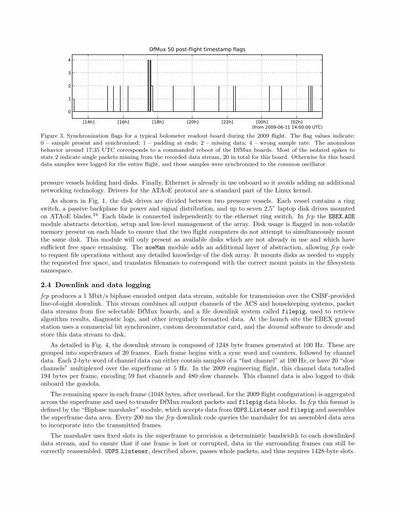
In fcp the UDPS Listener packet reader thread listens on the multicast address. Each packet is inspected todetermine its origin, and the pdump module writes it to disk in a packet dump (.pdump) file corresponding tothe originating board. The .pdump files are rotated every 15 minutes to limit the maximum file size produced.Fig. 3 demonstrates the performance of this readout system for a typical readout board. Excluding a briefperiod around 17:35 UTC when the boards were commanded to reboot during a SQUID tuning procedure, noboard is missing more than 65 packets from the logged packet data, for a loss rate of < 0.01%. Testing onthe ground shows that under simulated load equivalent to the full planned complement of 28 boards, loss ratesremain similarly low. 11 of the 12 bolometer readout boards were synchronized to the common oscillators intheir respective crates for the entire flight. The twelfth board was left unsynchronized due to a misconfiguredstartup script.
Two DfMux boards are also used to read the optical angular encoder on the HWP. They each sample a singlechannel at 3.052 KHz. Each HWP encoder packet contains 416 samples, and thus each board broadcasts packetsat 7.34 Hz. The structure of the bolometer readout packets is reused for the HWP encoder readout, so the samecode processes both types of packet stream.
The code defining the packet format is written in portable C that is compiled into the packet streamerprogram onboard the DfMux CPU, UDPS Listener, and the standalone parser program used to extract datafrom packet streams and saved dumps.
2.3 ATAoE onboard storage
EBEX will fly with over 3 terabytes of hard disk storage. This allows the flight computers to write two redundantcopies of all data produced in flight to separate disks. We use the ATA over Ethernet (ATAoE) protocol33 inorder to implement the onboard disk storage array. Ethernet has several attractive features. It provides a many-to-many topology so that redundant disks can be provided without foreknowledge of which flight computer willneed one. It is physically straightforward to route signals from the flight computer crate in vacuum into the
[14h] [16h] [18h] [20h] [22h] [00h] [02h](from 2009-06-11 14:00:00 UTC)
0
1
2
3
4
DfMux 50 post-flight timestamp flags
Figure 3. Synchronization flags for a typical bolometer readout board during the 2009 flight. The flag values indicate:0 – sample present and synchronized; 1 – padding at ends; 2 – missing data; 4 – wrong sample rate. The anomalousbehavior around 17:35 UTC corresponds to a commanded reboot of the DfMux boards. Most of the isolated spikes tostate 2 indicate single packets missing from the recorded data stream, 20 in total for this board. Otherwise for this boarddata samples were logged for the entire flight, and those samples were synchronized to the common oscillator.
pressure vessels holding hard disks. Finally, Ethernet is already in use onboard so it avoids adding an additionalnetworking technology. Drivers for the ATAoE protocol are a standard part of the Linux kernel.
As shown in Fig. 1, the disk drives are divided between two pressure vessels. Each vessel contains a ringswitch, a passive backplane for power and signal distribution, and up to seven 2.5” laptop disk drives mountedon ATAoE blades.34 Each blade is connected independently to the ethernet ring switch. In fcp the EBEX AOE
module abstracts detection, setup and low-level management of the array. Disk usage is flagged in non-volatilememory present on each blade to ensure that the two flight computers do not attempt to simultaneously mountthe same disk. This module will only present as available disks which are not already in use and which havesufficient free space remaining. The aoeMan module adds an additional layer of abstraction, allowing fcp codeto request file operations without any detailed knowledge of the disk array. It mounts disks as needed to supplythe requested free space, and translates filenames to correspond with the correct mount points in the filesystemnamespace.
2.4 Downlink and data logging
fcp produces a 1 Mbit/s biphase encoded output data stream, suitable for transmission over the CSBF-providedline-of-sight downlink. This stream combines all output channels of the ACS and housekeeping systems, packetdata streams from five selectable DfMux boards, and a file downlink system called filepig, used to retrievealgorithm results, diagnostic logs, and other irregularly formatted data. At the launch site the EBEX groundstation uses a commercial bit synchronizer, custom decommutator card, and the decomd software to decode andstore this data stream to disk.
As detailed in Fig. 4, the downlink stream is composed of 1248 byte frames generated at 100 Hz. These aregrouped into superframes of 20 frames. Each frame begins with a sync word and counters, followed by channeldata. Each 2-byte word of channel data can either contain samples of a “fast channel” at 100 Hz, or have 20 “slowchannels” multiplexed over the superframe at 5 Hz. In the 2009 engineering flight, this channel data totalled194 bytes per frame, encoding 59 fast channels and 480 slow channels. This channel data is also logged to diskonboard the gondola.
The remaining space in each frame (1048 bytes, after overhead, for the 2009 flight configuration) is aggregatedacross the superframe and used to transfer DfMux readout packets and filepig data blocks. In fcp this format isdefined by the “Biphase marshaler” module, which accepts data from UDPS Listener and filepig and assemblesthe superframe data area. Every 200 ms the fcp downlink code queries the marshaler for an assembled data areato incorporate into the transmitted frames.
The marshaler uses fixed slots in the superframe to provision a deterministic bandwidth to each downlinkeddata stream, and to ensure that if one frame is lost or corrupted, data in the surrounding frames can still becorrectly reassembled. UDPS Listener, described above, passes whole packets, and thus requires 1428-byte slots.

������������������������������������������������������������������������������������
����������������������������������������������������������������������������������������������������������������������������������������
������������������������������������������������������������������������������������������������������������
��������������������������������������������������������
��������������������������������������������������������������������������������������������������������������������������������������������
���������������������������������������������������������
���������������������������������������������������������
��������
������������������������������������������������������������������������������������������������������������������������
������������������������������������������������������������������������������������������������������������������������
������������������������������������������
������������������������������������������
������������������������
������������������������
������������������������������������������������������������������������������������������������������������������������
������������������������������������������������������������������������������������������������������������������������
��������������������������������
����������������������������������������������������������������������������������������������������������������������������
����������
����������������������������������������������������������������
����������������������������������������������������������������������������
����������������������������������������������������������������������������������������������������������������������������������������������������������������������������
����������������������������������������������������������������������������������������������������
���������������������������������������������������������������������������������������������
���������������������������������������������������������������������������������������������
������������������������������������������������������������������������
������������������������������������������������������������������������
���������������������������������������������������������������������������������������������������������������
���������������������������������������������������������������������������������������������������������������
������������������������������������������������������������������������
���������������������������������������������������������������������������������������
���������������������������������������������������������������������������������������������������������������������
������������������������
��������������������������������������������������������������������������������
��������������������������������������������������������������������������������������������������������������������
����������������������������������������������������������������������������������������������������������������������������������������������������������������������������������������
����������������������������������������������������������������������������������������������������������
��������������������������������������������������������������������������������������������������������������������������������������������������������������������������������������������
����������������������������������������������������������������������������������������������
����������������������������������������������������������������������������������������������
����������������������������������������������������������������������������������������������
����������������������������������������������������������������������������������������������
����������������������������������������������������������������������������������������������
����������������������������������������������������������������������������������������������
����������������������������������������������������������������������������������������������
����������������������������������������������������������������������������������������������
��������������������������������������������������������������������������������������������������������������������������������������������������������������������������������������������
����������������������������������������������������������������������������������������������
����������������������������������������������������������������������������������������������
����������������������������������������������������������������������������������������������
����������������������������������������������������������������������������������������������Bolometer packet stream #4
Housekeeping
HWP Encoder packet stream
Bolometer packet stream #1
Bolometer packet stream #3
Bolometer packet stream #2
File downlink space: 968 bytes
200 bytes
20 f
ram
es
1048 bytes x 20 frames = 20960 byte data area
1248 bytes
Figure 4. Schematic of the line-of-sight downlink superframe discussed in Sec. 2.4. This structure is repeated at 5 Hzover the 1 Mbit/s transmitter. The horizontal rows indicate the 20 individual 1248 byte frames, transmitted at 100 Hz.Each frame starts with 200 bytes of header and housekeeping channel data. The remaining 1048 bytes in each frame isaggregated across the superframe to form a 20960 byte data area. 14 slots of 1428 bytes each are allotted for DfMuxpackets and are grouped into five logical streams (denoted here by matching hatch patterns), accomodating the completedata output of four bolometer readout boards and one HWP encoder readout board. The final 968 bytes of the superframeis used by the filepig file downlink system.
In 200 ms a bolometer readout board produces on average 2.93 packets, and a HWP encoder board produces 1.47.Thus a group of three slots for bolometer readout or two slots for encoder readout yields a stream with adequatecapacity to downlink the entire packet data output of a DfMux board. With 14 slots, streams are defined todownlink the output of four bolometer readout boards and one HWP encoder board. Uplinked commands selectwhich five boards out of the total complement are allotted a downlink stream.
filepig, so named because it allows files to “piggyback” on a frame-based protocol, claims the odd-sizedchunk of space at the end of the data area after packet streams have been allocated. It exposes an interface bywhich fcp code may queue the filenames of data objects already written to disk. Files are broken into chunkstogether with minimal header and error detection data and downlinked. Support exists, presently unused, toplug in transformations for more robust error correction or data compression, and to resend corrupted data inresponse to uplinked commands. For the engineering flight 968 bytes per superframe were left for the filepig
data chunk, providing about 4.2 KB/s file downlink bandwidth. Over the 13 hour flight 10898 files totalling 61MB were retrieved.
2.5 Ground tools and architecture
The BLAST telemetry chain20 is employed largely unmodified on the ground. As illustrated in Fig. 2, the biphaseencoded bitstream is converted back into data frames in the Ground Station computer and logged to disk. Theinterloquendi server permits clients to fetch streams of frames remotely via TCP/IP connections. defile thendecodes the channel data in these frames into dirfile35-format data files. Front end programs such as palantirand KST 36 allow real-time display of the streamed channels.
To this EBEX adds support in the frame handling code for the superframe data area, and support in defile forextracting packet streams and downlinked files from those frames. These additional data products are writtenalongside the channel-based data on each connecting client workstation. Scripts employing the parser program

automate the production of bolometer and HWP encoder time streams in dirfile format from extracted .pdump
files.
Time streams can be displayed in real-time using either KST or Python tools that understand the dirfileformat. The EBEX Alignment Tools is a suite of programs for further processing these streams, includinginterpolation and alignment to a common sample rate and timing, decoding the HWP angular encoder signal toHWP position, and template-based removal of the HWP rotation signal from bolometer timestreams.
We have also written a Python/TK front end to the Algorithm Manager system. By monitoring the namesof the files downlinked through filepig, it is possible to select those corresponding to algorithm result strings.Parsing these files permits display on a board-by-board basis, in close to real time, of the job execution activityoccurring in the readout system DfMux boards. A dashboard interface presents selected information from eachboard using labels and color coding, and the user can select individual boards or jobs for more detailed display.This front end provides immediate visual feedback on complex operations, such as detector system tuning, thatentail parallel execution of a sequence of jobs on each bolometer readout board.
ebexcmd accepts fcp commands in textual format, which it can either relay to a listening ebexcmd over anetwork connection, or convert to the binary representation suitable for transmission over CSBF uplink hardware.Commands can therefore be generated on any host permitted to connect to the ground station, and thosecommands will then be uplinked. Commands are most commonly selected through the narsil front end, but arealso generated by Python scripts and may even be entered manually from a command line.
This ground infrastructure provides network transparency in both data distribution and commanding, allow-ing flight operators to monitor and control the instrument from an arbitrary number of networked workstations.During the 2009 integration campaign and flight, this system routinely connected as many as ten client worksta-tions over the private internal network at the New Mexico launch site. Late in the flight line-of-sight communi-cations were only possible from the downrange station in Arizona, and commands were successfully relayed fromthe launch site through the downrange ground station ebexcmd. Streaming of frame data via interloquendi fromthe downrange station to the launch site, and from the launch site to collaborators at their home institutions,worked only intermittently due to bandwidth constraints at the launch site.
3. CONCLUSION
EBEX combines a large format bolometer array, and the correspondingly large data volume, with a complexreadout system architecture. As a result, EBEX solves for a balloon flight environment problems in data han-dling, communications, and control that are typically associated with ground based observatories. The required3 terabyte in-flight storage capacity is achieved using a high speed gondola ethernet network and networked diskstorage arrays. The readout system is controlled from a central flight computer using a custom distributed jobcontrol scheduler, and it is monitored by extending a frame-oriented telemetry system to support asynchronouspacket streams and event-driven downlink of arbitrary data in files. On the ground, a networked real-time datadistribution and command relay architecture allows shared monitoring and control of the instrument.
ACKNOWLEDGMENTS
EBEX is supported by NASA through grants number NNG04GC03G, NNG05GE62G, NNX08AG40G, andNNX07AP36H. Additional support comes from the National Science Foundation through grant number AST0705134, the French Centre national de la recherche scientifique (CNRS), and the UK Science and TechnologyFacilities Council (STFC). This project makes use of the resources of the Minnesota Supercomputing Instituteand of the National Energy Research Scientific Computing Center (NERSC), which is supported by the officeof Science of the U.S. Department of Energy under contract No. DE-AC02-05CH11231. The McGill authorsacknowledge funding from the Canadian Space Agency, Natural Sciences and Engineering Research Council,Canadian Institute for Advanced Research, Canadian Foundation for Innovation and Canada Research Chairsprogram.
We thank the Columbia Scientific Balloon Facility for their energetic support. We gratefully acknowledgethe efforts of our colleagues in the BLAST project that produced the foundation for much of this work.
REFERENCES
[1] Oxley, P. et al., “The EBEX experiment,” Infrared Spaceborne Remote Sensing XII 5543(1), 320–331, SPIE(2004).
[2] Grainger, W. et al., “EBEX: the E and B Experiment,” Millimeter and Submillimeter Detectors and In-strumentation for Astronomy IV 7020(1), 70202N, SPIE (2008).
[3] Seljak, U. and Zaldarriaga, M., “Signature of Gravity Waves in the Polarization of the Microwave Back-ground,” Physical Review Letters 78, 2054–2057 (Mar. 1997).
[4] Hu, W., Seljak, U., White, M., and Zaldarriaga, M., “Complete treatment of CMB anisotropies in a FRWuniverse,” Phys. Rev. D 57, 3290–3301 (Mar. 1998).
[5] Brandt, W. N., Lawrence, C. R., Readhead, A. C. S., Pakianathan, J. N., and Fiola, T. M., “Separation offoreground radiation from cosmic microwave background anisotropy using multifrequency measurements,”ApJ 424, 1–21 (Mar. 1994).
[6] Baccigalupi, C., “Cosmic microwave background polarisation: foreground contrast and component separa-tion,” New Astronomy Review 47, 1127–1134 (Dec. 2003).
[7] Zaldarriaga, M. and Seljak, U., “Gravitational lensing effect on cosmic microwave background polarization,”Phys. Rev. D 58, 023003–+ (July 1998).
[8] Reichborn-Kjennerud, B. et al., “EBEX: a balloon-borne CMB polarization experiment,” Millimeter, Sub-millimeter, and Far-Infrared Detectors and Instrumentation for Astronomy V 7741, SPIE (2010).
[9] Hanany, S., Hubmayr, J., Johnson, B. R., Matsumura, T., Oxley, P., and Thibodeau, M., “Millimeter-waveachromatic half-wave plate,” Appl. Opt. 44, 4666–4670 (Aug. 2005).
[10] Hull, J. R., Hanany, S., Matsumura, T., Johnson, B., and Jones, T., “Characterization of a high-temperaturesuperconducting bearing for use in a cosmic microwave background polarimeter,” Superconductor Scienceand Technology 18(2), S1 (2005).
[11] Johnson, B. R., MAXIPOL: A bolometric, balloon-borne experiment for measuring the polarizationanisotropy of the cosmic microwave background radiation, PhD thesis, University of Minnesota (2004).
[12] Dobbs, M., Bissonnette, E., and Spieler, H., “Digital Frequency Domain Multiplexer for Millimeter-Wavelength Telescopes,” IEEE Transactions on Nuclear Science 55, 21–26 (2008).
[13] Sagiv, I. et al., “The EBEX cryostat and supporting electronics,” to appear in Proceedings of the TwelthMarcel Grossmann Meeting37 (2010).
[14] Hubmayr, J., Aubin, F., Bissonnette, E., Dobbs, M., Hanany, S., Lee, A. T., MacDermid, K., Meng, X., Sa-giv, I., and Smecher, G., “Design and characterization of TES bolometers and SQUID readout electronics fora balloon-borne application,” Millimeter and Submillimeter Detectors and Instrumentation for AstronomyIV 7020(1), 70200J, SPIE (2008).
[15] Aubin, F. et al., “SQUID-based multiplexed readout electronics and TES bolometer array during an engi-neering flight of the EBEX stratospheric balloon,” Millimeter, Submillimeter, and Far-Infrared Detectorsand Instrumentation for Astronomy V 7741, SPIE (2010).
[16] Reichborn-Kjennerud, B., Building and Flying the E and B Experiment to Measure the Polarization of theCosmic Microwave Background, PhD thesis, Columbia University (2010).
[17] Chase, S., [Two-stage sub-Kelvin 3He cooler ], Chase Research Cryogenics Ltd., 140 Manchester Road,Sheffield S10 5DL, England.
[18] NASA Columbia Scientific Balloon Facility, LDB Science Enclosures (2010).
[19] Pascale, E. et al., “The Balloon-borne Large Aperture Submillimeter Telescope: BLAST,” ApJ 681, 400–414 (July 2008).
[20] Wiebe, D. V., BLAST: A Balloon-borne, Large-aperture, Submillimetre Telescope, PhD thesis, Universityof Toronto (Feb. 2009).
[21] Boterenbrood, H. and Hallgren, B., “The development of the Embedded Local Monitor Board (ELMB),” in[PROCEEDINGS of the Ninth Workshop on Electronics for LHC Experiments ], 9th Workshop on Electronicsfor LHC Experiments, 331–334 (2003).
[22] Boterenbrood, H., Burckhart, H. J., Cook, J., Filimonov, V., Hallgren, B., Heubers, W., Khomoutnikov, V.,Ryabov, Y., and Varela, F., “Design and Implementation of the ATLAS Detector Control System,” IEEETransactions on Nuclear Science 51, 495–501 (June 2004).
[23] Boterenbrood, H., Burckhart, H., and Kvedalen, H., “The Embedded Local Monitor Board (ELMB) in theLHC front-end I/O control system,” in [PROCEEDINGS of the Seventh Workshop on Electronics for LHCExperiments ], 7th Workshop on Electronics for LHC Experiments, 325–330 (2001).
[24] Sixnet LLC, http://sixnet.com, EtherTRAK Industrial Ethernet Real-Time Ring switch. various models.
[25] ISO 11898-1:2003, [Road vehicles – Controller area network (CAN) – Part 1: Data link layer and physicalsignalling ], International Organization for Standardization, Geneva, Switzerland (2003).
[26] Kvaser Inc., http://www.kvaserinc.com, Leaf SemiPro HS.
[27] Ampro ADLINK Technology, Inc., http://ampro.com, MightyBoard 800.
[28] Debian Project, http://debian.org, Debian GNU/Linux 4.0 (”Etch”).
[29] Robinson, D. and Coar, K., “The Common Gateway Interface (CGI) Version 1.1.” RFC 3875 (Informational)(Oct. 2004).
[30] Crockford, D., “The application/json Media Type for JavaScript Object Notation (JSON).” RFC 4627(Informational) (July 2006).
[31] van Rossum, G. et al., Python Language Reference. http://www.python.org/.
[32] Postel, J., “User Datagram Protocol.” RFC 768 (Standard) (Aug. 1980).
[33] Hopkins, S. and Coile, B., ATA over Ethernet Specification. The Brantley Coile Company, Inc. (Feb. 2009).
[34] CORAID Inc., http://www.coraid.com, EtherDrive storage solutions.
[35] Wiebe, D. V., Dirfile Standards. http://getdata.sourceforge.net.
[36] Netterfield, B. et al., KST. KDE Project, http://kst.kde.org/.
[37] Damour, T., Jantzen, R. T., and Ruffini, R., eds., [Proceedings of the Twelfth Marcel Grossmann Meetingon General Relativity ], World Scientific (2010).