Soft Error-Tolerant Design of MRAM-based Non-Volatile Latches for Sequential Logics
15
1 Soft Error-Tolerant Design of MRAM-based Non-Volatile Latches for Sequential Logics Ramin Rajaei, Mahdi Fazeli, Mahmood Tabandeh Abstract- Magneto resistive memories like Spin-Transfer Torque RAM (STT-RAM) and Magnetic latches (M-latch) are emerging memory technology that offer attractive features such as high density, low leakage, and non-volatility as compared with conventional static memory. In this paper, we have proposed two Single Event Upset (SEU) tolerant M-latch circuits in which their CMOS peripheral circuits are robust against radiation effects. Similar to the conventional M-latch circuit, our proposed M-latches employ two Magnetic Tunnel Junction (MTJ) elements. Therefore, they consume almost the same energy consumption in comparison with non-protected M-latch circuit. The simulation results of comparison with previous work show that, our proposed radiation hardened M- latches consume less energy, occupy less area and in case of a particle strike, offer lower restoring time. Furthermore, we have thoroughly investigated the robustness of our proposed radiation hardened M-latches against Single Event Multiple Effects (SEMEs) and also in presence of process variation as serious reliability challenges in emerging nanometer scale technologies. Keywords- Magnetic RAM (MRAM), Magnetic Tunnel Junction (MTJ), Magnetic latch (M-latch), Single Event Upset (SEU), Single Event Multiple Effect (SEME). I. INTRODUCTION Static power caused by leakage and sub-threshold currents has become a challenging issue in Nano-scale CMOS technology. In addition, in such technologies, storage elements such as the conventional SRAM, latch and flip-flop circuits have become much more sensitive to Single Event Upset (SEU) induced by radiation effects [1-4]. Magnetic storage devices (MSDs) and logics are considered as a promising replacement for CMOS-based memories and logics thanks to their low static power consumption, high density, non-volatility and scalability [5]. The basic element of magnetic storage devices is Magnetic Tunnel Junction (MTJ) formed by two ferromagnetic layers and one oxide thin barrier [4-6] (see Fig.1). Fig.1. MTJ structure and two resistance mode: a) low resistance mode and b) high resistance mode MTJs are inherently robust against radiation effects, i.e. the direction of the ferromagnetic layers will not change as a result of an energetic particle strike [7-8]. Therefore, the magnetic-based memory devices are considered as radiation hardened memories. However, CMOS circuits employed as Pre-Charge Sense Amplifier (PCSA) circuit for read/write operations make them vulnerable to radiation induced soft errors [3-4]. In [8-12] different magnetic storage and logic circuits have been proposed and evaluated. Although the previously proposed storage/logic circuits offer higher density, non-volatility and lower static power consumption, however, they are still sensitive to radiation induced soft errors. The soft error robustness of the MSDs is still an open problem that has not been addressed in the literature expediently. To the best of our knowledge, the only works regarding SEU robustness of MSDs are the works presented in [3-4]. In [3], it has been shown that the MSD pre-charge sense amplifier that is based on CMOS technology is vulnerable to radiation induced faults. In [3-4], two SEU-tolerant Magnetic Latch circuits (M-latch) have been proposed. In these papers, it has been shown that, the proposed circuit can tolerate radiation effects and will not flip to an erroneous value. The main shortcoming of the proposed M-latch in [3] is its high area overhead as it exploits duplication with comparison approach. In addition, it cannot cope with multiple effects caused by a single particle strike event, the so called Single Event Multiple Effect (SEME). SEME refers to a phenomenon in which a particle striking a chip affects multiple
Transcript of Soft Error-Tolerant Design of MRAM-based Non-Volatile Latches for Sequential Logics

0018-9464 (c) 2013 IEEE. Personal use is permitted, but republication/redistribution requires IEEE permission. Seehttp://www.ieee.org/publications_standards/publications/rights/index.html for more information.
This article has been accepted for publication in a future issue of this journal, but has not been fully edited. Content may change prior to final publication. Citation information: DOI10.1109/TMAG.2014.2375273, IEEE Transactions on Magnetics
1
Soft Error-Tolerant Design of MRAM-based
Non-Volatile Latches for Sequential Logics
Ramin Rajaei, Mahdi Fazeli, Mahmood Tabandeh
Abstract- Magneto resistive memories like Spin-Transfer
Torque RAM (STT-RAM) and Magnetic latches (M-latch) are
emerging memory technology that offer attractive features such
as high density, low leakage, and non-volatility as compared
with conventional static memory. In this paper, we have
proposed two Single Event Upset (SEU) tolerant M-latch
circuits in which their CMOS peripheral circuits are robust
against radiation effects. Similar to the conventional M-latch
circuit, our proposed M-latches employ two Magnetic Tunnel
Junction (MTJ) elements. Therefore, they consume almost the
same energy consumption in comparison with non-protected
M-latch circuit. The simulation results of comparison with
previous work show that, our proposed radiation hardened M-
latches consume less energy, occupy less area and in case of a
particle strike, offer lower restoring time. Furthermore, we have
thoroughly investigated the robustness of our proposed
radiation hardened M-latches against Single Event Multiple
Effects (SEMEs) and also in presence of process variation as
serious reliability challenges in emerging nanometer scale
technologies.
Keywords- Magnetic RAM (MRAM), Magnetic Tunnel
Junction (MTJ), Magnetic latch (M-latch), Single Event Upset
(SEU), Single Event Multiple Effect (SEME).
I. INTRODUCTION
Static power caused by leakage and sub-threshold
currents has become a challenging issue in Nano-scale CMOS
technology. In addition, in such technologies, storage elements
such as the conventional SRAM, latch and flip-flop circuits
have become much more sensitive to Single Event Upset (SEU)
induced by radiation effects [1-4].
Magnetic storage devices (MSDs) and logics are
considered as a promising replacement for CMOS-based
memories and logics thanks to their low static power
consumption, high density, non-volatility and scalability [5].
The basic element of magnetic storage devices is Magnetic
Tunnel Junction (MTJ) formed by two ferromagnetic layers
and one oxide thin barrier [4-6] (see Fig.1).
Fig.1. MTJ structure and two resistance mode: a) low resistance mode
and b) high resistance mode
MTJs are inherently robust against radiation effects, i.e.
the direction of the ferromagnetic layers will not change as a
result of an energetic particle strike [7-8]. Therefore, the
magnetic-based memory devices are considered as radiation
hardened memories. However, CMOS circuits employed as
Pre-Charge Sense Amplifier (PCSA) circuit for read/write
operations make them vulnerable to radiation induced soft
errors [3-4]. In [8-12] different magnetic storage and logic
circuits have been proposed and evaluated. Although the
previously proposed storage/logic circuits offer higher density,
non-volatility and lower static power consumption, however,
they are still sensitive to radiation induced soft errors. The soft
error robustness of the MSDs is still an open problem that has
not been addressed in the literature expediently. To the best of
our knowledge, the only works regarding SEU robustness of
MSDs are the works presented in [3-4]. In [3], it has been
shown that the MSD pre-charge sense amplifier that is based on
CMOS technology is vulnerable to radiation induced faults. In
[3-4], two SEU-tolerant Magnetic Latch circuits (M-latch) have
been proposed. In these papers, it has been shown that, the
proposed circuit can tolerate radiation effects and will not flip
to an erroneous value. The main shortcoming of the proposed
M-latch in [3] is its high area overhead as it exploits duplication
with comparison approach. In addition, it cannot cope with
multiple effects caused by a single particle strike event, the so
called Single Event Multiple Effect (SEME). SEME refers to a
phenomenon in which a particle striking a chip affects multiple

0018-9464 (c) 2013 IEEE. Personal use is permitted, but republication/redistribution requires IEEE permission. Seehttp://www.ieee.org/publications_standards/publications/rights/index.html for more information.
This article has been accepted for publication in a future issue of this journal, but has not been fully edited. Content may change prior to final publication. Citation information: DOI10.1109/TMAG.2014.2375273, IEEE Transactions on Magnetics
2
sensitive nodes and produces an upset or bit flip even in SEU-
tolerant storage devices or could even cause multiple bit flips
(It is called Single Event Multiple Upset or SEMU) [13-14].
SEMEs as well as SEMUs are becoming the main effect of
energetic particle strikes in emerging Nano-scale CMOS
technology. The proposed M-latch in [4] employs lower area
than the one in [3]. However, its stability in read operation is
rather low especially in presence of process variation and
radiation effects. The related results are presented in section IV.
In this paper, we have proposed two SEU-tolerant M-latch
circuits that offer lower overhead in comparison with the
proposed latch in [3-4]. In addition, we have thoroughly
evaluated the robustness of our M-latch circuits in presence of
SEMEs and have compared them with the proposed circuit in
[3-4] using HSpice simulations.
The rest of the paper is organized as follows: In section II,
some preliminaries regarding magnetic-based storage devices
as well as their sensitivity to radiation effects are presented. In
section III, two novel SEU-tolerant M-latch circuits are
proposed and described. In section IV, the SEU tolerance
capability of the proposed M-latch circuits are investigated.
Also, our proposed M-latch circuits are compared with the
proposed ones in [3-4] in terms of performance, energy
consumption, restoring time and read current. In this section,
the effect of process variation on reliability, energy
consumption, and delay are also investigated. Moreover, an
analytical evaluation of soft error rate (SER) for our proposed
M-latches in comparison with the previous M-latches is also
provided. In section V, an investigation of soft error robustness
of our proposed M-Latch circuits in the presence of SEMEs in
comparison with other M-latch circuits is presented.
II. BACKGROUND
A. Preliminaries in Magnetic–based Storage Devices
The conventional MRAM cell is depicted in Fig.2.a (the
reference M-latch circuit). In this circuit, two complementary
Magnetic Tunnel Junction (MTJs) are employed to keep the
stored value in the latch in a non-volatile way. In this
configuration, one of the MTJs has always parallel layers while
the other MTJ has anti-parallel layers. The MTJs have a high
resistance (RAP) in opposite direction mode and a low resistance
in same direction mode (RP). In the configuration presented in
Fig.2.a that the connected MTJ to N1 has an opposite direction
mode, node QB has the logic value of ‘1’ and node Q has the
logic value of ‘0’ when the clock signal gets its logic value of
‘1’[15].
To read the stored value on the MRAM cell, a 7-transistor
peripheral circuit consisting of four PMOS transistors (P1 to
P4) and three NMOS transistors (N1 to N3) that is a pre-charge
sense amplifier (PCSA) circuit detects the difference and reads
the latched value [3, 6]. To write a new value into the MRAM
cell, various techniques such as spin torque transfer (STT) [16],
field induced magnetic switching (FIMS) [17], thermally
assisted switching (TAS) [18-19] and Spin Orbit Torque (SOT)
[20-22] have been proposed. In [5-6] a comparison on these
various writing techniques of MSDs has been provided.
Generally, the STT technique is the widely used technique as it
needs lower current and also has higher performance during
writing process [3].
In comparison with other non-volatile storage
technologies including Flash, RRAM and PCRAM, generally,
MRAM has a significantly faster read/write process as well as
much higher endurance [6]. Furthermore, compared with
CMOS SRAM, MRAM has the advantage of smaller area,
lower read latency, lower read/write access energy and lower
leakage power [5]. Moreover, the non-volatility of MRAMs is a
prominent feature that increases its chance for being an
alternative to CMOS SRAMs. In Table.1, a comparison
between few storage technologies is presented. For the sake of
clarity in comparison, some of the values are normalized to a
relative value of SRAM memory (bolded). The original values
are presented in [5].
The notable point in Table 1 is that, the consumed write
energy of STT-MRAM is about 9 times more than that of read
energy. Therefore, it can be concluded that, most of the
consumed energy in MRAMs is used in write operation (that is
mainly for switching of the MTJs). Long endurance of the STT-
MRAMs similar to the SRAMs as well as its acceptable
latency, make it suitable for employing in high access RAM
memory applications.
(a) (b)
Fig.2. Conventional RAM circuits: a) Basic MSD nonvolatile storage
cell based on pre-charge sense amplifier (PCSA) and using two MTJs.
b) Conventional CMOS storage circuit consisting of two back-to-back
inverters.

0018-9464 (c) 2013 IEEE. Personal use is permitted, but republication/redistribution requires IEEE permission. Seehttp://www.ieee.org/publications_standards/publications/rights/index.html for more information.
This article has been accepted for publication in a future issue of this journal, but has not been fully edited. Content may change prior to final publication. Citation information: DOI10.1109/TMAG.2014.2375273, IEEE Transactions on Magnetics
3
Table1. Comparison of various memory technologies
Technology SRAM Flash STT-MRAM PC-RAM R-RAM
Non-volatility No Yes Yes Yes Yes
Endurance ∞ 106 ∞ 1012 106
Area (normalized) 1.00 0.06 0.59 0.11 0.24
Read Latency (normalized) 1.00 >260 0.55 0.25 0.53
Write Latency (normalized) 0.95 >92000 5.17 69.31 9.52
Read Energy (normalized) 1.00 6.68 0.44 0.62 0.33
Write Energy (normalized) 0.60 11.76 3.98 >100 1.01
Leakage Power (normalized) 1.00 0.08 0.42 0.16 0.12
B. Radiation Effects on MSDs
CMOS-based storage circuits (Fig.2.b) are prone to
radiation induced faults. An energetic particle hitting drain of
an off-state transistor, would deposit some charge in the struck
region. The deposited charges are capable of charging/dis-
charging the capacitance of the struck node and cause a logic
level change at the node. This change could be propagated
through the feedback path of the memory circuit and a bit flip
may incur. This fault, the so called Single Event Upset (SEU),
takes part in sequential logic circuits.
In [1-2, 23-27] some soft error-tolerant CMOS SRAM
cells or latch circuits have been proposed. A CMOS latch is
susceptible to SEU when it is in the latching mode. In the
proposed SEU-tolerant CMOS storage circuits in [25] and [26],
Qcrit (the minimum amount of charge needed for bit flip in a
storage device) has been increased as compared with the
conventional non-protected circuits. The proposed SRAM/latch
circuits in [1-2, 23-24, 27] are perfectly immune from any
particle strikes affecting any of their single nodes i.e., Qcrit of all
of their nodes are infinite.
In [3-4], the vulnerability of MRAM-based latches (M-
latches) has been discussed and an SEU-tolerant M-latch has
been proposed. As stated in [3-4], the M-latches are still
vulnerable to SEU similar to the CMOS latches. To investigate
this issue, we have also carried out some sort of simulations.
Based on the simulation results, the M-latches are sensitive to
SEU when their clock signal is high (Fig.2.a). In other words,
when the clock signal is high and the M-latch is in the read
phase, an energetic particle can change the stored value. On the
contrary, when the clock signal is low, the M-latch circuits are
quite robust against particle strikes. In Fig.3, the simulation
results are presented. In Fig.3.a, 6.8fc charge has been injected
into node Q when clock signal is high (Qcrit of the unprotected
M-latch circuit has been concluded to be 6.8fc). In this
simulation, we used the STT-MRAM model presented in [28]
as well as PTM-45nm technology library presented in [29]. The
considered critical parameters for MTJs are listed in Table 2.
As illustrated in Fig.2.a, the connected MTJ to N1 is in
opposite direction mode, while the other one is in the same
direction mode. In Fig.3.a that a bit flip has happened, 6.8fc
charge is injected whilst in Fig.3.b with a 25fc charge injection,
we see the MRAM cell has tolerated the injected charge and bit
flip has not occurred.
When the clock signal is high, the PCSA circuit is active
in order to read the stored value. In this condition, the NMOS
transistor of N3 (see Fig.2.a) is ON. Also, as the MTJ
connected to N1 is in opposite direction mode and
consequently, has higher resistance in comparison with the
connected MTJ to N2 (with same direction mode), transistors
P2 and N2 are ON and the other transistors are in OFF state.
Therefore, node QB has logic value of ‘1’ and node Q has logic
value of ‘0’. In this case, if an energetic particle strikes drain of
P3 (or N1) which is in OFF state mode, a transient positive
pulse would be generated in this node (i.e. Q). As a result,
transistor N1 will turn ON and voltage of the node QB will
drop. As the result, N2 will turn OFF and the new state will
remain unchanged and the stored value will be altered.
As stated before, the proposed M-latch in [3] (we will
hereafter refer to it as DM-latch in this paper), is based on
duplication with comparison strategy, i.e. two simple M-latches
(shown in Fig.2.a) are employed to store the two copies of the
stored value and an XOR circuit is also employed to compare
the stored values. If one of the M-latch circuits flips as a result
of a particle strike during the time that clock is high, the fault
will be detected by the XOR gate and clock will become zero.
After that, since the MTJ elements have not been affected, the
faulty M-latch circuit will regain its correct value. Although
this technique is quite robust against SEU, however, it incurs
more than 100% overhead in area and power consumption [4].
In fact, the number of MTJs as well as CMOS transistors is
twice the reference M-latch. Another SEU-tolerant M-latch
circuit is proposed in [4] (we refer to it as Kang’s M-latch in
the rest of the paper). This circuit has lower area, energy
consumption and delay than DM-latch. However, as we will
show in section IV, its stability in read operation in presence of
process variation is rather low.

0018-9464 (c) 2013 IEEE. Personal use is permitted, but republication/redistribution requires IEEE permission. Seehttp://www.ieee.org/publications_standards/publications/rights/index.html for more information.
This article has been accepted for publication in a future issue of this journal, but has not been fully edited. Content may change prior to final publication. Citation information: DOI10.1109/TMAG.2014.2375273, IEEE Transactions on Magnetics
4
(a) (b)
Fig.3. SEU injection to node Q of the MRAM cell shown Fig.2.a
when: a) the clock signal is high b) the clock signal is low
Table 2. Critical parameters and variables of the considered STT MTJ
model
Parameter Description Default Value
tox Oxide barrier height 0.85 nm
Area MTJ surface 65nm x 65nm
TMR(0) tunnel magneto-resistance
ratio with Vbias of 0 200%
V Volume of free layer Surface x 1.3nm
R.A Resistance-area product 10 Ωμm2
IC0 Critical switching current 50 μA
Δ Thermal stability factor 70
In the next section, we propose two novel SEU-tolerant
M-latch circuits and compare them with the DM-latch as well
as Kang’s M-latch circuits. Our proposed M-latch circuits,
similar to the reference circuit (shown in Fig.2.a) and Kang’s
circuit employ two MTJs while the DM-latch circuit employs
four MTJs. Also, our M-latch circuits have fewer transistors in
comparison with DM-latch circuit. As we show in sections IV
and V, our first proposed M-latch, (the so called 13T M-latch)
has lower design overhead in comparison with our second
proposed M-latch (the so called 21T M-latch), the DM-latch
(proposed in [3]) and the Kang’s M-latch (proposed in [4]).
Also, our 21T M-latch circuit shows the best robustness against
process variation and SEMEs.
III. PROPOSED SEU-TOLERANT M-LATCH
CIRCUITS
As discussed before, an M-latch circuit is sensitive to
particle strikes when it is in the read mode. The same condition
also exists for MRAM cells, i.e. MRAM cell suffers from
particle strikes when it is in the read mode. However, the SEUs
and SEMEs in M-latches are much more problematic than those
in MRAM cells. This is because, M-latches used in sequential
logic like instruction pipelines are read in each clock cycle, i.e.
the values stored in latches are valid and used in each cycle.
Therefore, M-latches are sensitive to particle strikes in 50% of
times. In contrast, the value stored in MRAM cells such as
cache is read only when it is requested by an instruction as its
operands. As the MRAM is only sensitive to soft errors just in
read mode and the read frequency of an MRAM cell is much
less than that of M-latch circuits, the soft error rate of MRAM
will be significantly less than that of M-latch. It should be
noted that, there is a big difference between robustness of
SRAM and MRAM against radiation effects. SRAM cells are
vulnerable in both holding and read modes while the MRAM
cells are just vulnerable to soft errors in read mode. This makes
SRAM cells much more sensitive to soft errors than MRAM
cells. However, there is little work on design of robust M-latch
circuits against soft errors. As stated before, to the best of our
knowledge, the only works on design of soft error-tolerant M-
latch are the works presented in [3-4].
Fig.4 shows the SEU-tolerant M-latches proposed in [3-
4]. The DM-latch (Fig.4.a) is based on duplication with
comparison approach to detect the bit flips (faults) in one of the
M-latch circuits and corrects it by the robust MTJs. The Kang’s
M-latch (Fig.4.b) uses some more transistors than the reference
but provides a robust structure against SEUs. It has lower
overhead than the prior rad-hard DM-latch. In Fig. 5, we have
shown our first proposed SEU-tolerant M-latch circuit (the 13T
M-latch circuit) and in Fig.6, we have shown our second SEU-
tolerant M-latch circuit (the 21T M-latch circuit). Compared
with the DM-latch, both our proposed SEU-tolerant M-latch
circuits (shown in Fig.5 and Fig.6) have lower design overhead
as they employ fewer transistors as well as MTJs (13 and 21
transistors and 2 MTJs instead of 26 transistors and 4 MTJs).
(a) (b)
Fig.4. The previous proposed SEU-tolerant M-latch circuits a) the DM-latch [3] b) the Kang’s M-latch [4]

0018-9464 (c) 2013 IEEE. Personal use is permitted, but republication/redistribution requires IEEE permission. Seehttp://www.ieee.org/publications_standards/publications/rights/index.html for more information.
This article has been accepted for publication in a future issue of this journal, but has not been fully edited. Content may change prior to final publication. Citation information: DOI10.1109/TMAG.2014.2375273, IEEE Transactions on Magnetics
5
Fig.5. Our proposed SEU-tolerant13T M-latch circuit Fig.6. Our proposed SEU-tolerant 21TM-latch circuit
Fig. 5 presents the circuit schematic of our proposed 13T
M-latch. In this M-latch, when clock signal is high, nodes N2
and N4 stay in the high state while nodes N1 and N3 go to zero
state. As N5 is connected to the parallel MTJ with lower
resistance in comparison with the N6 which is connected to
anti-parallel MTJ, a pull down path from N5 to ground will be
constructed during the positive level of the clock signal and
consequently, nodes N1 and N3 are pulled down and fall to a
zero logic value. In the lower level of the clock signal, all nodes
of N1 to N4 turn to high state and the circuit becomes ready to
be programmed by switching of the MTJs states.
As each sensitive node has a dual node, a particle
affecting a single node cannot alter the stored data when clock
is high. Nodes N1 and N2 are dual of nodes N3 and N4
respectively. A particle with enough energy would be able to
alter the stored value of 13T M-latch, if it affects nodes N1 and
N3 simultaneously. Similarly, if a particle strike affects nodes
QB0 and QB1 in DM-latch (see Fig.4.a) or nodes S0 and S3 of
Kang’s M-latch (see Fig.4.b) simultaneously, it would be able
to alter the stored value. In section V, we investigate the effect
of particle strikes causing multiple effects in order to evaluate
the robustness of our proposed M-latches in presence of
SEMEs and compare them with the reference M-latch (shown
in Fig.2.a), the DM-latch (shown in Fig.4.a) and the Kang’s M-
latch (shown in Fig.4.b).
Our proposed 21T M-latch shown in Fig.6 is similar to
our 13T M-latch as it has dual nodes. For this latch, a particle
striking any nodes in the latch, regardless of the amount of
charge it deposits, cannot alter the stored value. This latch
includes few more transistors in comparison with our 13T M-
latch and the Kang’s M-latch (proposed in [4]), but it still has
fewer transistors compared with the DM-latch (proposed in
[3]). Also, we will show in section V that it has an excellent
robustness in the presence of SEMEs significantly.
In our 21T M-latch shown in Fig.6 (similar to the 13T M-
latch), when the clock signal goes to zero, nodes N1, N2, N5
and N6 connect to Vdd and therefore, take a high logic value.
As one can be found from the presented schematic in
Fig.6, the proposed 21T M-latch is consisted of four C-element
circuits (determined as C1 to C4 in Fig.6). A C-element is a 4-
transistor, 2-input gate whose single output will be inverted of
its inputs when they have same logic values. When its inputs
have different logic values, the output will go to high
impedance state and the previous output will remain [23]. As
the C-elements with output of N1 and N6 (C-elements C1 and
C4) are connected to the parallel MTJ (with lower resistance
than the anti-parallel state of MTJ) a pull down path will be
formed when clock signal goes high. It causes nodes N1 and
N6 turning to ‘0’. On the contrary, nodes N2 and N5 stay in
logical value of ‘1’. As Fig.6 shows, C-elements C1 and C4 are
joined (similar to C2 and C3). That is, inputs of C1 and C4 (and
also C2 with C3) are connected together. The output of C1 and
C4 are connected to inputs of C2 and C3 and similarly, the
output of C2 and C3 are connected to joined inputs of C1 and
C4. This way, a CMOS keeper is made when clock signal goes
high. When clock signal goes to zero state, the M-latch circuit
is ready for switching of the MTJs i.e. write operation. In our
proposed 21T circuit, any alteration in one of the input lines of
C-elements will not affect the output. Therefore, no transient
effect caused by a particle strike will propagate through a
feedback path, and consequently, no single glitch will cause a
bit flip. In the next section, SEU tolerance capability of our
proposed M-latch circuits is investigated. We inject a wide
range of charges into all sensitive nodes of our proposed M-
latch circuits in order to evaluate their robustness against
radiation effects.
IV. SIMULATION RESULTS
A. Investigation of SEU tolerance capability
In order to investigate the SEU tolerance capability of our
proposed M-latch circuits, similar to the performed simulations
in section II, we used the presented STT-MRAM model in [28]
as well as PTM-45nm CMOS library proposed in [29] in
HSpice tool. To inject SEU in the circuits, we used the

0018-9464 (c) 2013 IEEE. Personal use is permitted, but republication/redistribution requires IEEE permission. Seehttp://www.ieee.org/publications_standards/publications/rights/index.html for more information.
This article has been accepted for publication in a future issue of this journal, but has not been fully edited. Content may change prior to final publication. Citation information: DOI10.1109/TMAG.2014.2375273, IEEE Transactions on Magnetics
6
employed model in [1-4, 10, 30] in Hspice simulations. This
model is a double exponential current source connected to a
sensitive node. The current source is given by the following
equation:
)()( 21
21
ttinjinj ee
QtI
(1)
Where, Qinj is the amount of injected charge in struck
region and τ1as well as τ2 are material dependent time constants
[31-32].
All the performed simulations for M-latch circuits are
performed in HSpice environment in room temperature with
supply voltage of 1.2v. The tunnel magneto-resistance ratio
(TMR) of the MTJs is considered equal to 200%. TMR is the
readability metric and is defined as [3-4, 33]:
100
Rp
RRTMR
pAP (2)
Where, RAP and RP are the resistances of MTJs in anti-
parallel and parallel modes respectively. A higher TMR means
a larger difference between resistances in the parallel and anti-
parallel modes and facilitates reading [34].
Fig.7.a shows the behavior of our proposed robust 13T
M-latch in presence of a particle strike on node N1. In this
experiment, we have assumed that, the M-latch has the
configuration shown in Fig.5. As the figure shows, this node
regained its original state after a short time. Respectively, in
Fig.7.b to Fig.7.d SEU is injected into nodes N2 to N4. We
have examined large values of Qinj (injected charge) for both of
our proposed M-latch circuits. As expected, our proposed SEU-
tolerant M-latch circuits are both fully SEU immune. In other
words, regardless of the amount of injected charge into any
node of any one of our proposed latches, their output would not
change, i.e. they can tolerate the injected charge with no bit flip
occurrence.
In Fig.8, the response of our proposed 21T M-latch to
SEU injected to some nodes is depicted. In this figure, injection
to nodes N1 to N6 has been shown. Injection to other nodes
causes a similar response to these nodes. In the presented
configuration in Fig.6, the node N2 has logic value of ‘1’ and
node N1 has logic value of ‘0’. Nodes N3 and N4 are drain of
OFF state transistors of PMOS and NMOS respectively and
therefore, they are sensitive to particle strikes. It is notable that,
nodes N1, N2, N5 and N6 are the cardinal nodes of the 21T M-
latch circuit. In other words, it is important that, after a fault
injection, these four nodes regain their original value. As
shown, in Fig.8, all of these four nodes (i.e. N1, N2, N5 and
N6) have regained their original state a short time after charge
injection or have stayed with no change. Consequently, similar
to our proposed 13T M-latch, our 21T M-latch has complete
immunity against SEUs as well.
(a) (b)
(c) (d)
Fig.7. SEU injection to sensitive nodes of our 13T M-latch: a) injection to node N1, b) injection to node N2, c) injection to
node N3, d) injection to node N4.

0018-9464 (c) 2013 IEEE. Personal use is permitted, but republication/redistribution requires IEEE permission. Seehttp://www.ieee.org/publications_standards/publications/rights/index.html for more information.
This article has been accepted for publication in a future issue of this journal, but has not been fully edited. Content may change prior to final publication. Citation information: DOI10.1109/TMAG.2014.2375273, IEEE Transactions on Magnetics
7
(a) (b)
(c) (d)
(e) (f)
Fig.8. SEU injection into sensitive nodes of 21T M-latch: a) injection to node N1, b) injection to node N2, c) injection to node N3, d)
injection to node N4, e) injection to node N5, f) injection to node N6.
B. Comparative Analysis
To compare our proposed M-latch circuits with DM-latch
and Kang’s M-latch, it should be noted that, our proposed
radiation hardened M-latches as well as Kang’s similar to the
reference M-latch (shown in Fig.2.a), employ only two MTJs,
while the DM-latch employs four MTJs. Therefore, the DM-

0018-9464 (c) 2013 IEEE. Personal use is permitted, but republication/redistribution requires IEEE permission. Seehttp://www.ieee.org/publications_standards/publications/rights/index.html for more information.
This article has been accepted for publication in a future issue of this journal, but has not been fully edited. Content may change prior to final publication. Citation information: DOI10.1109/TMAG.2014.2375273, IEEE Transactions on Magnetics
8
latch suffers from more energy consumed in the switching
process of the MTJs and consequently, more energy during
write operation. As the main portion of consumed energy in
MSDs is their write energy that is mainly consumed by MTJs
[5], the robust DM-latch consumes twice the write energy of
either our 13T or 21T M-latches and the Kang’s M-latch.
In Table 3, the results of a comparison of our proposed
two robust M-latch circuits with the robust DM-latch, Kang’s
M-latch and the reference M-latch (shown in Fig.2.a) is
presented. In the first column of this table, a comparison for the
occupied area is provided. In addition, the layout of our
proposed M-latches (the PCSA part) is shown in Fig.9. It
should be noted that, M-latches consisted of two different
technologies including CMOS for transistors and nano-
magnetic technology for the MTJs. The MTJs need additional
layers in the layout and more processing in fabrication process
[5]. In the second column of Table 3, the number of employed
MTJs is shown. In the third and fourth columns, delay and the
consumed energy for read operation are represented. All of the
values are normalized with the associated value of the 21T M-
latch.
As the presented results in Table 3 reveal, our proposed
M-latch circuits have considerably lower read energy
consumption and also lower read delay in comparison with the
DM-latch and Kang’s M-latch. In addition, as also stated
before, the DM-latch employs four MTJs while our robust M-
latches and the Kang’s M-latch employ only two MTJs. As a
result, the DM-latch suffers from about 2X more energy
consumption for write operation which is a very important issue
in design of MSDs [4-6]. As declared in Table.1, in STT-
MSDs, the consumed energy for write operation is about 9
times more than the read energy [5-6]. Therefore, we can
assume that, the dominant factor in total energy consumption of
the STT-MSDs is their write energy. Our robust M-latches
contain two MTJs and therefore, their write energy
consumption is very close to that consumed in the unprotected
M-latch shown in Fig.2.a. In contrast, the DM-latch has about
2X more energy consumption. Therefore, we can conclude
roughly that, 1) energy consumption of our robust M-latches is
close to the reference M-latch, i.e. our design energy overhead
would be negligible and 2) energy consumption of our M-
latches is half of the consumed energy in DM-latch.
Another parameter that we believe is important in design
of an M-latch circuit is restoring time. We define this parameter
as the time between the instant when a transient event affects
the voltage of a node to the time that the node regains its
original state. For example, suppose an energetic particle
strikes a specific node at time t0. Then suppose that, the node
regains its original logic value at time t1. We call this duration
(i.e. t1 -t0) to restoring time. If after time t0, a bit flip occurs and
the node does not return to its original logic value, we assume
that, the restoring time is infinite in this case.
Technology down scaling and logic depth reduction in
nanometer circuits makes it possible to increase operating
frequency in order to enhance the performance. In such high
frequency sequential logic circuits, a large restoring time
increases the probability that a transient glitch caused by a
particle strike is latched by the next stage sequential circuit like
latches or FFs. In other words, when a particle strike changes a
node voltage for a few nano-seconds in an SEU-tolerant latch,
it is quite probable that the generated transient pulse is latched
by the next sequential logic circuit. In [35], a magnetic-based
flip flop circuit has been proposed. This flip flop circuit is
consisted of two cascaded latches. The first latch that is the
master latch is an M-latch and the second latch (the slave latch)
is a CMOS latch. In this topology, if an SEU-tolerant M-latch
employed as the master latch, it is probable that, the transient
generated pulse at the output (as a result of a particle strike)
reaches the latching window of the slave and cause a soft error.
Longer restoring time would increase latching probability of
the erroneous value by the slave latch. Restoring time of SEU-
tolerant M-latches is dependent on the amount of deposited
charge by the particle strike as well as the M-latch circuit
topology. In fifth column of Table.3 normalized restoring time
of the M-latches with 20fc charge injection has been reported.
Fig.10 shows the restoring time of node N1 of our
proposed 13T M-latch circuit in presence of various charge
injections. In Fig.11, we have compared the restoring time of
our proposed M-latches with the DM-latch as well as Kang’s
M-latch using different amounts of injected charge. As can be
seen in this figure, our proposed M-latch circuits have
significantly lower restoring time in comparison with the
proposed circuits in [3] and [4]. Therefore, we can claim that,
our proposed M-latches are more reliable against SEU
especially in Nano-scale high performance circuits.
In the last column of Table.3, read current of our
proposed M-latches as well as the previously proposed DM-
latch and Kang’s are compared. An important issue in design of
STT-MRAMs is the reading error [33-34]. Error in read
operation could be caused by a low TMR and high read current
[3, 33-34]. TMR is dependent on the material and the structure
of MTJs [33-34]. An MTJ structure for obtaining higher TMR
is explored and addressed in [36-37]. We are assuming that
TMR has been properly selected to avoid read error due to low
difference between the resistances of the MTJ two modes.
Therefore, we have focused on the possible read errors as a
result of a high read current that may cause in unwanted
switching of the MTJs during read operation. Indeed, the PCSA

0018-9464 (c) 2013 IEEE. Personal use is permitted, but republication/redistribution requires IEEE permission. Seehttp://www.ieee.org/publications_standards/publications/rights/index.html for more information.
This article has been accepted for publication in a future issue of this journal, but has not been fully edited. Content may change prior to final publication. Citation information: DOI10.1109/TMAG.2014.2375273, IEEE Transactions on Magnetics
9
circuit structure may affect the amount of the current which in
turn may result in read errors. As, the probability of having read
errors increases by current increase, we have reported the read
current of the under evaluation M-latches in the last column of
Table.3. What can be inferred from the reported results which
are normalized is that, our proposed M-latches have remarkably
lower read current as compared with DM-Latch. Also, our 21T
M-latch has a considerable lower read current than the Kang’s.
Lower read current of our proposed M-latches indicates their
higher robustness in read operation.
(a) (b)
Fig.9. Layout of our proposed M-latches (the PCSA circuit): a) Layout of 13T M-latch b) Layout of 21T M-latch
Fig.10. Restoring time of node N1 in our 13T M-latch versus
various charge injection (20fc to 100fc) Fig.11. Comparison of the restoring time of our proposed M-latches
with proposed M-latches in [3-4] for various injected charges.
Table.3. Comparison of different parameters of the proposed and the previous SEU-tolerant latches
M-latch circuit Area
(normalized)
# of
MTJs
Read time
(normalized)
Read Energy
(normalized)
Restoring time for
20fc charge injection
(normalized)
Read current
(normalized)
CMOS latch 0.60 0 1.19 1.08 ∞ -
Reference M-latch (unprotected) 0.35 2 0.76 0.53 ∞ 0.82
DM-latch (proposed in [3]) 1.34 4 0.81 1.59 1.68 1.26
Kang’s M-latch (proposed in [4]) 0.71 2 1.02 1.24 1.21 1.12
Our proposed 13T M-latch 0.68 2 0.98 0.89 0.83 1.13
Our proposed 21T M-latch 1 2 1.00 1.00 1 1.00
0
0.5
1
1.5
2
2.5
10 20 30 40 50 60 70 80 90 100 110 120 130 140 150
Re
sto
rin
g Ti
me
(n
s)
Injected Charge (fc)
DM-Latch [3] Kang's M-latch [4]
Our 13T M-latch Our 21T M-latch

0018-9464 (c) 2013 IEEE. Personal use is permitted, but republication/redistribution requires IEEE permission. Seehttp://www.ieee.org/publications_standards/publications/rights/index.html for more information.
This article has been accepted for publication in a future issue of this journal, but has not been fully edited. Content may change prior to final publication. Citation information: DOI10.1109/TMAG.2014.2375273, IEEE Transactions on Magnetics
10
(a) (b) (c)
Fig.12. Process variation effects on normal operation (read latency/energy) of the proposed M-latches in comparison with the reference M-latch: a)
the reference M-latch, b) our proposed 13T M-latch, c) our proposed 21T M-latch.
C. Investigation of process variation effects on
operation and reliability of the M-latches
Process variation (PV) is an emerging reliability challenge
in sub-100nm technology [2, 13, 38]. For this reason, in this
section we investigate the effects of process variation including
width (W), length (L) and threshold voltage (Vth) of CMOS
transistors along with MTJ variation (their resistance) on the
normal operation of our proposed M-latch circuits [39].
Furthermore, we evaluated the effects of W, L, Vth and
resistance of parallel as well as anti-parallel MTJ (RP and RAP)
variations on SEU tolerance capability of our proposed M-
latches using a set of Monte-Carlo (MC) simulation.
To evaluate the effects of process variation on normal
operation of the proposed M-latches, we selected a value as the
percent of variation on the mentioned parameters (including W,
L, Vth, RP and RAP). The mentioned parameters are varied up to
10% from their original values (similar to [40-41]) using a
normal distribution [2, 38, 43]. The results obtained are
presented in Fig.12. In these plots, X axis shows deviations
from original value of read energy and Y axis shows deviations
from original value of read latency. Presented results in
Fig.12.a shows the effect of process variation on normal
operation of the reference M-latch. Similarly, Fig.12.b and
Fig.12.c show the resulted effects of process variation on our
proposed 13T and 21T M-latches respectively. As the presented
results in Fig.12 reveal, process variation has lower effect on
read latency of our proposed 21T M-latch in comparison with
the reference as well as 13T M-latches. Also, effects of PV on
read energy of our proposed 13T M-latch is less than other M-
latches (the reference and the 21T).
In order to evaluate the SEU tolerance capability of our
proposed M-latch circuits in presence of process variation, we
set another MC-simulation using 100 sextuple values of
injected charge as well as variation on W, L, Vth, RP and RAP.
To select charge values for injecting SEU, we used a uniform
distribution from 10fc to 150fc [42-45]. In addition, for
variation on W, L, Vth, RP and RAP, we used a normal
distribution [2]. It should be noted that, values of W, L, Vth, RP
and RAP have been varied up to 10% form their original values
[40-41]. In Table.4, for various maximum deviations caused by
PV as well as various maximum injected charge, the resulted
bit flips are reported. In this set of MC-simulation, for every of
DM, Kang’s, 13T and 21T M-latches, their cardinal nodes are
selected. Nodes Q0, Q1, QB0 and QB1 for DM-latch (Fig.4.a),
nodes S0, S1, S2 and S3 for Kang’s M-latch (Fig.4.b), nodes
N1 to N4 for our 13T (Fig. 5) and nodes N1, N2, N5 and N6 for
our 21T M-latch (Fig.6) are selected. Per each column of
Table.4, for each node, 100 MC-simulations are performed. In
second column of Table.4 for maximum deviation of 5% and
maximum injected charge of 50fc, either of our proposed M-
latches has no bit flip while 6% for the DM-latch and 9% for
the Kang’s M-latch false read has been observed. Similarly, for
other maximum deviation and injected charges, percentage of
false reads is determined. It should be noted that, the observed
false reads of the DM-latch and Kang’s M-latch are mainly due
to missing the functionality resulted by PV. As the simulation
results reported in Table.4 show, our proposed 21T M-latch has
a high degree of stability in presence of PV as well as radiation.
Also, our proposed 13T M-latch has higher stability than the
DM-latch as well as Kang’s. In Fig.13, stability of our M-
latches in presence of up to 5% deviation resulted by PV and
also up to 100fc charge injections is shown. In this case, no
false read has been observed in either of our proposed M-
latches.
Table.4. Percentage of read disturbance as result of process variation and radiation effects for various deviations from original value and injected
charge
M-latch circuit 5%, 50fc 5%, 100fc 5%, 150fc 10%, 50fc 10%, 100fc 10%, 150fc
DM-latch (proposed in [3]) 6% 7% 9% 21% 27% 39%
Kang’s M-latch (proposed in [4]) 9% 12% 19% 31% 41% 54%
Our proposed 13T M-latch 0% 0% 17% 0% 13% 32%
Our proposed 21T M-latch 0% 0% 0% 0% 0% 9%
0.8
0.9
1
1.1
1.2
0.5 1 1.5
Rea
d L
ate
ncy
(no
rm
ali
zed
)
Read Energy (normalized)
Reference M-Latch
0.8
0.9
1
1.1
1.2
0.5 1 1.5
Rea
d L
ate
ncy
(no
rm
ali
zed
)
Read Energy (normalized)
13T
0.8
0.9
1
1.1
1.2
0.5 1 1.5
Rea
d L
ate
ncy
(no
rm
ali
zed
)
Read Energy (normalized)
21T

0018-9464 (c) 2013 IEEE. Personal use is permitted, but republication/redistribution requires IEEE permission. Seehttp://www.ieee.org/publications_standards/publications/rights/index.html for more information.
This article has been accepted for publication in a future issue of this journal, but has not been fully edited. Content may change prior to final publication. Citation information: DOI10.1109/TMAG.2014.2375273, IEEE Transactions on Magnetics
11
(a) (b)
Fig.13. Investigation of process variation effects on SEU tolerance capability of: a) proposed 13T M-latch b) proposed 21T M-latch for up to 5%
resulted variation due to PV and up to 100fc charge injection
D. Soft error rate investigation
In this section, the robustness of our proposed M-latches
is compared with the reference M-latch, the DM-latch and the
Kang’s M-latch. To evaluate the robustness of the considered
M-latches, we used methods presented in [27-28]. As stated in
[27], soft error rate (SER) can be obtained by:
)(.
1
iQcritn
i
i
CLK
i ekT
WOVSER
(3)
Where, n is the number of nodes, ki is a constant
proportional to the node i area, α and β are some fitting
parameters [46] and Qcrit is critical charge of node i [27].
In [27], it is concluded that, in order to compare the SER
of latch A with latch B, we can use the following equation:
B
A
n
j
jQcrit
TOT
Dj
n
i
iQcrit
TOT
Di
B
A
eA
A
eA
A
SER
SER
1
)(.
1
)(.
(4)
Where, ADi is the area of drain junction of node i and ATOT
is normalization factor that is the area of all compared latches.
In [27], it is discussed that, the nodes of a latch can be
classified into three types. Type-I are those nodes in which,
regardless of the amount of deposited charge, no effect emerges
at the output. Type-II are those nodes in which, depositing
some charge, an SET pulse would emerge at the output. Critical
charge of such nodes is considered as the minimum charge that
can incur a glitch with amplitude equal to half the supply
voltage. Finally, the type-III of the nodes are those in which
having an energetic particle strike, a bit flip would appear at the
output of the latch. It should be noted that, our proposed 13T
and 21T M-latches have 4 and 8 type-II nodes. As we
discussed, neither one of them has any of type-III nodes. The
DM-latch and Kang’s M-latch both have 4 type-II and no type-
III nodes. The reference M-latch has two type-III and no type-II
nodes.
As discussed in [42, 44], not all the SET pulses would get
to the next sequential logic step and be captured as a faulty
value. Considering latch-window masking that is one of the
three masking factors of combinational logics [42, 44], we
improve the accuracy of equation (4) with equation (5) given
by:
B
A
n
j
jQcrit
TOT
Dj
n
i
iQcrit
TOT
Di
B
A
PP(j)eA
A
iPPeA
A
SER
SER
1
)(.
1
)(. )(
(5)
Where, PP(i) denotes propagation probability of the
transient fault and can be obtained by equation (6).
nodesIkindfor
nodesIIkindforT
i
nodesIIIkindfor
iPPCLK
,0
,5.0
)( timeRestoring
,1
)( (6)
In equation (4), it would not be fair to consider the effect
of type-III nodes with the same weight as type-II nodes in SER

0018-9464 (c) 2013 IEEE. Personal use is permitted, but republication/redistribution requires IEEE permission. Seehttp://www.ieee.org/publications_standards/publications/rights/index.html for more information.
This article has been accepted for publication in a future issue of this journal, but has not been fully edited. Content may change prior to final publication. Citation information: DOI10.1109/TMAG.2014.2375273, IEEE Transactions on Magnetics
12
evaluation of the M-latch circuits. It should be noted that, the
type-III nodes cause a wrong output to the end of latching time
while the type-II nodes only cause a transient pulse on the
output within the restoring time. In fact, it is probable that the
transient pulse is masked by a masking mechanism such as
latch-window masking [42, 44]. For type-II nodes that a
particle strike would cause a glitch at the output node, we
define the probability propagation in equation (5) as the ratio of
restoring time (the duration that output data has a faulty value)
to the half of clock period (TCLK) that clock is high and transient
fault could take place.
In Fig.14, we have compared SER of the considered M-
latches in three cases. In case-1, injected charge is 20fc and
TCLK is 10ns. In case-2, injected charge is 40fc and TCLK is 5ns
and in case-3, injected charge is 60fc and TCLK is 2.5ns (a worst
case that injected charge is considered high for all particle
strikes). It should be noted that, the restoring time of the
considered M-latches depends on the injected charge. As the
results in Fig.14 show, since the DM-latch has a rather high
restoring time, its SER is higher than that of the reference M-
latch in case-3. In addition, it is notable that, our proposed 13T
and 21T M-latches have a significant lower SER in comparison
with other considered latches.
Fig.14: SER of the considered M-latches for three cases
V. SINGLE EVENT MULTIPLE-NODE CHARGE
COLLECTION
Until recently, Single Event Upset was considered as the
main effect of an energetic particle strike in semiconductor
devices. However, much smaller transistor sizes and very low
supply voltages in 100nm technologies and bellow, makes
Single Event Multiple Effects (SEME) to be the dominant
effect of particle strikes [13-14]. In fact, an energetic particle
strike can cause multiple effects in adjacent sensitive nodes in
such technologies. In [13-14], SEME issue is taken into
consideration and it is discussed that, some of the proposed
SEU-tolerant latches or SRAM cells may have no appropriate
robustness in the presence of SEMEs.
In this section, we investigate the robustness of our
proposed M-latches as well as the DM-latch and Kang’s against
SEMEs. In our experiments, we have assumed that, a particle
strike affects two sensitive nodes of a circuit. Therefore, we
need to identify node-pairs that can be affected simultaneously.
Obviously, the nodes which considered as pair should be
connected to the drain of an off-state transistor at the time of
charge injection. In addition, they should be close to each other
in the physical layout to be considered as adjacent sensitive
nodes. However, we have neglected the latter constraint i.e. the
adjacency of node-pairs. This is because; it depends on the
layout of the circuit, the underlying technology and the amount
of deposited charge. In fact, neglecting this constraint, the
results would be for the worst case, as we have considered all
possible node-pairs based on the first constraint in our charge
injection experiments.
To this regard, as the first step, we have identified
sensitive pairs of our M-latch circuits as well as those of the
DM-latch in [3], Kang’s M-latch and the reference M-latch
shown in Fig.2.a. Then, we extract the Qcirit of primary affected
node versus Qcrit of the secondary one for each sensitive pairs.
In this investigation, for our 13T M-latch, any node-pair among
N1, N2, N3 and N4 is considered as a sensitive pair. Similarly,
for our 21T M-latch, any node-pair among N1, N2, N5 and N6
is considered as a sensitive pair as well.
Similar to [13], we refer to the pairs with the lowest Qcrits
among all combination of sensitive pairs as critical pair. In
Fig.15, we have compared Qcrits of the critical pairs of our M-
latch circuits with DM-latch, Kang’s M-latch and the
unprotected M-latch circuit shown in Fig.2a. The presented
results shown in Fig.15 have been obtained using HSpice
simulations and the current injection model used in sections II
and IV. In this figure, axis X depicts injected charge to primary
node and axis Y shows the charge injected to the secondary
node of critical pair.
Considering the plots of Fig.15 (they show Qcirt of
primary node vs. that of secondary node for critical pair of
considered M-latches), any combination of charge pairs that
falls above (bellow) the curve of each M-latch circuit can (not)
alter the latched value. Therefore, a circuit has better robustness
against single event multiple-node effects, if it has larger area
under its related curve. As can be seen in the figure, our
proposed 21T M-latch has the best tolerance of SEMEs among
the other M-latches. In addition, our 13T M-latch has better
robustness than the reference M-latch and the DM-latch. As the
results shown in Fig.15 reveal, the 13T and Kang’s M-latches
Case
1
Case
2
Case
3
Standard CMOS latch 2.04 2.04 2.04
Standard M-latch 1.00 1.00 1.00
DM-Latch 0.41 0.99 2.26
Kang's M-latch 0.11 0.27 0.54
Our 13T M-latch 0.07 0.16 0.37
Our 21T M-latch 0.09 0.21 0.43
0.00
0.50
1.00
1.50
2.00
2.50
SE
R (
no
rma
lize
d)

0018-9464 (c) 2013 IEEE. Personal use is permitted, but republication/redistribution requires IEEE permission. Seehttp://www.ieee.org/publications_standards/publications/rights/index.html for more information.
This article has been accepted for publication in a future issue of this journal, but has not been fully edited. Content may change prior to final publication. Citation information: DOI10.1109/TMAG.2014.2375273, IEEE Transactions on Magnetics
13
have a comparable critical charge pairs. It should be noted that,
our M-latches, the DM-latch (proposed in [3]) and the Kang’s
M-latch (proposed in [4]) are all capable of tolerating any
particle strike affecting a single node with no corruption in their
latched value. In order to investigate the SER of sequential
logic in the presence of SEME, we use a MC-based simulation
method. In each simulation batch, we inject a range of charge
into a sensitive node-pair of an under evaluation latch. For each
sensitive node-pair, we perform this batch of simulations. The
critical charge of a latch with respect to the specific amount of
charge deposited into the primary node of the latch is defined as
the minimum amount of charge required to be deposited into
the secondary node to make a flip in the latch. As stated before,
the critical charge is measured for the critical node-pair i.e. the
most sensitive node-pair. In Fig.15, along with the curves
associated with critical charge of critical pairs, three different
distributions for charge injections are shown namely: 1)
distribution low that refers to a case in which we select the
amount of charge injections in a narrow range of charge i.e. 0
to 15fc; 2) distribution medium that refers to a case in which
we select the amount of charge injections in a medium range of
charge i.e. 0 to about 25fc; 3) distribution high that refers to a
case in which we select the amount of charge injections in a
large range of charge i.e. 0 to about 45fc. In Fig.15, axis X
represents the injected charge into primary node and axis Y
represents the injected one into the secondary node of sensitive
pairs. In this figure, there are five curves representing the
critical charge of five different latches including DM, Kang’s
13T, 21T, and reference M-latches. There are also three
different regions each of which shows the distribution of our
charge injections. In each region, the corresponding markers
show the amount of charge injected into the primary and the
secondary node. Based on this figure, almost all of the injected
charges in the low distribution region and large fraction of the
medium distribution region fall below the critical charge curve
of our proposed 21T M-latch which represents that the
proposed M-latches offer more robustness as compared with
other M-latches. Similar to [23], we assume the failure
probability ratio (POF) of M-latch A to M-latch B as:
injectionSEUofnumbertotal
flipsofnumberE
EA
A
EA
A
POF
POF
i
n
j
jTOT
j
n
i
iTOT
i
B
A
B
A
1
1
(7)
Where, Ai is diffusion area occupied by node-pair i, ATOT
is total area of compared M-latches as a normalizing factor and
Ei is the probability of bit-flip resulted by a double-node
effecting particle strike. To obtain Ei, we used 1000 MC-
simulations employing three charge distributions of low (D-L),
medium (D-M) and high (D-H) shown in Fig.15.
In Fig.16, simulation results of our POF evaluation are
shown. As the results reveal, our proposed 21T M-latch is the
best among other considered M-latches in terms of reliability
(POF) in presence of SEME. The critical charges associated
with sensitive pairs of this M-latch are also higher than those of
the compared latches. This is because; the capacitance of its
nodes is more than that of the other M-latches. As an example,
comparing the node N1 of 21T M-latch with N1 of 13T, the
equivalent capacitance of node N1 in 21T is greater than node
N1 in 13T. Similarly, the node N2 of 21T has a higher
capacitance than node N2 of 13T. Therefore, critical charge of
node-pair N1-N2 in 21T is higher than the node-pair of 13T.It
is notable that, the SER of DM-latch in case of distribution high
(D-H) is even higher than the reference M-latch.
Fig.15. Critical charges of sensitive pairs of the considered M-latches
as well as the three charge distribution
Fig.16. Simulation results of POF evaluation for three charge
distribution of D-L, D-M and D-H (normalized to POF of DM-latch in
D-H case).
0.00
0.10
0.20
0.30
0.40
0.50
0.60
0.70
0.80
0.90
1.00
D-L D-M D-H
No
rma
lize
d P
OF
Charge distribution
Reference M-latch DM-latch [3] Kang's M-latch [4]
Our 13T M-latch Our 21T M-latch
0018-9464 (c) 2013 IEEE. Personal use is permitted, but republication/redistribution requires IEEE permission. Seehttp://www.ieee.org/publications_standards/publications/rights/index.html for more information.
This article has been accepted for publication in a future issue of this journal, but has not been fully edited. Content may change prior to final publication. Citation information: DOI10.1109/TMAG.2014.2375273, IEEE Transactions on Magnetics
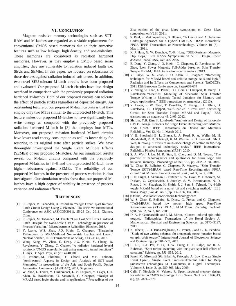
14
VI. CONCLUSION
Magneto resistive memory technologies such as STT-
RAM and M-latches are regarded as a viable replacement for
conventional CMOS based memories due to their attractive
features such as low leakage, high density, and non-volatility.
These memories are considered as radiation hardened
memories. However, as they employ a CMOS based sense
amplifier, they are vulnerable to radiation induced faults i.e.
SEUs and SEMEs. In this paper, we focused on robustness of
these devices against radiation induced soft errors. In addition,
two novel SEU-tolerant M-latch circuits have been proposed
and evaluated. Our proposed M-latch circuits have less design
overhead in comparison with the previously proposed radiation
hardened M-latches. Both of our proposed circuits can tolerate
the effect of particle strikes regardless of deposited energy. An
outstanding feature of our proposed M-latch circuits is that they
employ only two MTJs similar to the unprotected M-latch. This
feature makes our proposed M-latches to have significantly less
write energy as compared with the previously proposed
radiation hardened M-latch in [3] that employs four MTJs.
Moreover, our proposed radiation hardened M-latch circuits
have lower read energy consumption as well as lower delay for
restoring to its original state after particle strikes. We have
thoroughly investigated the Single Event Multiple Effects
(SEMEs) of our proposed M-latches. As our simulation results
reveal, our M-latch circuits compared with the previously
proposed M-latches in [3-4] and the unprotected M-latch have
higher robustness against SEMEs. The reliability of our
proposed M-latches in the presence of process variation is also
investigated. Our simulation results show that, our proposed M-
latches have a high degree of stability in presence of process
variation and radiation effects.
REFERENCES
[1] R. Rajaei, M. Tabandeh, B. Rashidian, “Single Event Upset Immune
Latch Circuit Design Using C-Element,” The IEEE 9th International
Conference on ASIC (ASICON2011), 25-28 Oct, 2011, Xiamen,
China.
[2] R. Rajaei, M. Tabandeh, M. Fazeli, “Low Cost Soft Error Hardened
Latch Designs for Nano-scale CMOS Technology in presence of
Process Variation,” Microelectronic Reliability, Elsevier, 2013.
[3] Y. Lakys, W.S. Zhao, J.O. Klein, C. Chappert, “Hardening
Techniques for MRAM-Based Nonvolatile Latches and Logic,”
Nuclear Science, IEEE Transactions on 59 (4), 1136-1141, 2013.
[4] Wang Kang, W. Zhao, E. Deng, J-O. Klein, Y. Cheng, D.
Ravelosona, Y. Zhang, C. Chapert “A radiation hardened hybrid
spintronic/CMOS nonvolatile unit using magnetic tunnel junctions”
J. Phys, D: Appl. Phys, 47 (2014) 405003.
[5] R. Bishnoi, M. Ebrahimi, F. Oboril and M.B. Tahoori,
"Architectural Aspects in Design and Analysis of SOT-based
Memories," in proceedings of the Asia and South Pacific Design
Automation Conference (ASPDAC), 2014, Singapore
[6] W. Zhao, L. Torres, Y. Guillemenet, L. V. Cargnini, Y. Lakys, J. O.
Klein, D. Ravelosona, G. Sassatelli, C. Chappert, “Design of
MRAM based logic circuits and its applications,” Proceedings of the
21st edition of the great lakes symposium on Great lakes
symposium on VLSI, 2011.
[7] S. Paul, S. Mukhopadhyay, S. Bhunia, “A Circuit and Architecture
Codesign Approach for a Hybrid CMOS–STTRAM Nonvolatile
FPGA,”IEEE Transactions on Nanotechnology, Volume 10 (3) –
May 1, 2011.
[8] K. J. Hass, G. W. Donohoe, Y.-K. Hong, “SEU-Resistant Magnetic
Flip Flops,” 12th NASA Symposium on VLSI Design, Coeur
d’Alene, Idaho, USA, Oct. 4-5, 2005.
[9] E. Deng, Y. Zhang, J. O. Klein , C. Chappert, D. Ravelosona, W.
Zhao, “Low Power Magnetic Full-Adder based on Spin Transfer
Torque MRAM,” IEEE transactions on magnetics , 2013.
[10] Y. Lakys, W. S. Zhao, J. O. Klein, C. Chappert, “Hardening
techniques for MRAM-based non-volatile storage cells and logic,”
Radiation and Its Effects on Components and Systems (RADECS),
2011 12th European Conference on, Pages669-674
[11] Y. Zhang, w. Zhao, G. Prenat, J.O. Klein, C. Chappert, B. Dieny, D.
Ravelosona, “Electrical Modeling of Stochastic Spin Transfer
Torque Writing in Magnetic Tunnel Junctions for Memory and
Logic Applications,” IEEE transactions on magnetics , (2013).
[12] Y. Lakys, S. W. Zhao, T. Devolder, Y. Zhang, J. O. Klein, D.
Ravelsona, C. Chappert, “Self-Enabled “Error-Free” Switching
Circuit for Spin Transfer Torque MRAM and Logic,” IEEE
transactions on magnetics 48, 2403, 2012.
[13] Sh. Lin, Y.B. Kim, F. Lombardi. “Analysis and Design of nanoscale
CMOS Storage Elements for Single Event Hardening with Multiple
Node Upset,” IEEE Transactions on Device and Materials
Reliability, Vol 12, No. 1, March 2012.
[14] V. B. Sheshadri, B. L. Bhuva, R. A. Reed, R. A. Weller, M. H.
Mendenhall, R. D. Schrimpf, K. M. Warren, B. D. Sierawski, Sh. J.
Wen, R. Wong. “Effects of multi-node charge collection in flip-flop
designs at advanced technology nodes,” IEEE International
Reliability Physics Symposium (IRPS), 2010.
[15] S. A. Wolf, J. Lu, M. R. Stan, E. Chen, and D. M. Treger, “The
promise of nanomagnetics and spintronics for future logic and
universal memory,” Proceedings of the IEEE, pp. 2155–2168, 2010.
[16] W. Zhao, E. Belhaire, C. Chappert, P. Mazoye., “Spin Transfer
Torque (STT)-MRAM based Run-Time Reconfiguration FPGA
circuit,” ACM Trans. Embed Comput. Syst., vol. 9, no. 2, 2009.
[17] B. N. Engel, J. Akerman, B. Butcher, R. W. Dave, M. Deherrera, M.
Durlam, G. Grynkewich, J. Janesky, S. V. Pietambaram, N. D.
Rizzo, J. M. Slaughter, K. Smith, J. J. Sun, S. Tehrani, “A 4-Mb
toggle MRAM based on a novel bit and switching method,” IEEE
Trans. Magn., vol. 41, no. 1, pp. 132–136, Jan. 2005.
[18] [Online]. Available: www.crocus-technology.com
[19] W. S. Zhao, E. Belhaire, B. Dieny, G. Prenat, and C. Chappert,
“TAS-MRAM based low power, high speed Run-Time
Reconfiguration (RTR) FPGA,” ACM Trans. Reconfig. Technol.
Syst., vol. 2, no. 2, Jun. 2009.
[20] D. A. P. Gambardella and I. M. Miron, “Current-induced spin-orbit
torques,” Philosophical Transactions of the Royal Society A:
Mathematical, Physical and Engineering Sciences, pp. 3175–3197,
2011.
[21] K. Jabeur, L. D. Buda-Prejbeanu, G. Prenat, , and G. D. Pendina,
“Study of two writing schemes for a magnetic tunnel junction based
on spin orbit torque,” International Journal of Electronics Science
and Engineering, pp. 501–507, 2013.
[22] L. Liu, C.-F. Pai, Y. Li, H. W. Tseng, D. C. Ralph, and R. A.
Buhrman, “Spin-torque switching with the giant spin hall effect of
tantalum,” Science, pp. 555–558, 2012.
[23] Fazeli M, Miremadi SG, Ejlali A, Patooghy A. Low Energy Single
Event Upset / Single Event Transient-Tolerant Latch for Deep
SubMicronTechnologies.IET Computers & Digital Techniques,
Volume: 3, Issue: 3, pp. 289-303, May 2009.
[24] Calin T, Nicoladis M, Velazco R. Upset hardened memory design
for submicron CMOS technology. IEEE Trans. Nucl. Sci., 1996, 43,
(6), pp. 2874–2878

0018-9464 (c) 2013 IEEE. Personal use is permitted, but republication/redistribution requires IEEE permission. Seehttp://www.ieee.org/publications_standards/publications/rights/index.html for more information.
This article has been accepted for publication in a future issue of this journal, but has not been fully edited. Content may change prior to final publication. Citation information: DOI10.1109/TMAG.2014.2375273, IEEE Transactions on Magnetics
15
[25] SM Jahinuzzaman, DJ Rennie, M Sachdev, A soft error tolerant 10T
SRAM bit-cell with differential read capability, Nuclear Science,
IEEE Transactions on 56 (6), 3768-3773
[26] Omana M, Rossi D, Metra C. Latch susceptibility to transient faults
and new hardening approach. IEEE Trans. Comput., 2007, 56, (9),
pp. 1255–1268.
[27] M. Omaña, D. Rossi, C. Metra, “High Performance Robust
Latches”, IEEE Transactions on Computers, vol. 59, no. 11,
November 2010, pp. 1455-1465.
[28] W. Guo, G. Prenat, V. Javerliac, M. E. Baraji, N. de Mestier, C.
Baraduc, and B. Diny, “SPICE modelling of magnetic tunnel
junctions written by spin-transfer torque,” Journal of Physics D:
Applied Physics, p. 215001, May 2010.
[29] Predictive technology model for Spice tool (<http://ptm.asu.edu/>).
[30] P. Wang, W. Zhang, R. Joshi, R. Kanj, Y. Chen, “A Thermal and
Process Variation Aware MTJ Switching Model and Its
Applications in Soft Error Analysis,” IEEE/ACM International
Conference on Computer-Aided Design (ICCAD) San Jose,
California, USA, 2012.
[31] M. Singh and I. Koren, “Fault-sensitivity analysis and reliability
enhancement of analog-to-digital converters,” IEEE Trans. Very
Large Scale Integration (VLSI) Syst., vol. 11, no. 5, pp. 839–852,
Oct. 2003.
[32] H. Cha, E. M. Rudnick, J. H. Patel, R. K. Iyer, and G. S. Choi, “A
gate-level simulation environment for alpha-particle-induced
transient faults,” IEEE Trans. Comput., vol. 45, no. 11, pp. 1248–
1256, Nov. 1996. [33] W. S. Zhao et al., “Design considerations and strategies for high-
reliable STT-MRAM,” Microelectron. Rel., vol. 51, pp. 1454–1458,
2011.
[34] S. Chatterjee, M. Rasquinha, S. Yalamanchili, S. Mukhopadhyay,
“A Scalable Design Methodology for Energy Minimization of
STTRAM: A Circuit and Architecture Perspective,” IEEE
Transactions on Very Large Scale Integration Systems (TVLSI),
Vol. 19, No. 5, 2011.
[35] W. Zhao, E. Belhaire, C. Chappert, Spin-MTJ based Non-Volatile
Flip-Flop, Proceedings of the 7th IEEE International Conference on
Nanotechnology August 2 - 5, 2007, Hong Kong.
[36] Y. Huai, D. Apalkov, Z. Diao, Y. Ding, A. Panchula, M. Pakala, L.
Wang, E. Chi, and Y. Huai, “Structure, materials and shape
optimization of magnetic tunnel junction devices: Spin-transfer
switching current reduction for future magnetoresistive random
access memory application,” Japan J. Appl. Phys. Pt. 1, vol. 45, no.
5A, pp. 3835–3841, 2006.
[37] Y. Huai, M. Pakala, Z. Diao, and Y. Ding, “Spin-transfer switching
current distribution and reduction in magnetic tunneling junction-
based structures,” IEEE Trans. Magn., vol. 41, no. 10, pp. 2621–
2626, Oct. 2005.
[38] Nan H, Choi K. Novel radiation hardened latch design considering
process, voltage and temperature variations for nanoscale CMOS
technology. Elsevier Microelectron Reliab; 2011.
[39] D. Suzuki, M. Natsui, T. Endoh, H. Ohno, and T. Hanyu, “Six-input
lookup table circuit with 62% fewer transistors using nonvolatile
logic-in-memory architecture with series/parallel-connected
magnetic tunnel junctions,” Journal of Applied Physics111, 07E318
(2012).
[40] Y. Zhang, X. Wang, Y. Chen “STT-RAM Cell Design Optimization
for Persistent and Non-Persistent Error Rate Reduction: A Statistical
Design View,” IEEE/ACM International Conference on Computer-
Aided Design (ICCAD), 2011.
[41] K. Chen, J. Han, F. Lombardi, “Design and Evaluation of two MTJ-
Based Content Addressable Non-Volatile Memory Cells,” 13th
IEEE Conference on Nanotechnology (IEEE-NANO), 2013.
[42] Rajaei R, Tabandeh M, Fazeli M, "Soft Error Rate Estimation for
Combinational Logic in Presence of Single Event Multiple
Transients," Journal of Circuits, Systems, and Computers, World
Scientific, 2014.
[43] Rajaei R, Tabandeh M, Fazeli M, "Single Event Multiple Upset
(SEMU) Tolerant Latch Designs in Presence of Process and
Temperature Variations," Journal of Circuits, Systems, and
Computers, World Scientific, 2014.
[44] H. Asadi, M. B. Tahoori, Soft error modeling and remediation
techniques in asicdesigns,J. Elsevier Microelc. 41 (2010).
[45] R. C. Baumann, Soft errors in advanced semiconductor devices—
part I: The three radiation sources, IEEE Trans. Dev. Mater. Reliab.
1 (2002).
[46] P. Hazucha and C. Svensson, “Impact of CMOS Technology
Scaling on the Atmospheric Neutron Soft-Error Rate,” IEEE Trans.
Nuclear Science, vol. 47, no. 6, pp. 2586-2594, Dec. 2000.
Ramin Rajaei received his M.Sc. degree
from Sharif University of Technology in
2009. From fall 2010 he is a PhD student
at department of electrical engineering in
Sharif University of Technology, Tehran,
IRAN. His research interests include
reliability issues in VLSI circuits and
emerging technology (soft errors, process
variation), reliability modeling/estimation and fault tolerant
embedded processors design.
Mahdi Fazeli received the M.Sc and Ph.D.
degrees in computer engineering from the
Sharif University of Technology, Tehran,
Iran, in 2005 and 2011, respectively.
He has been with the department of
computer engineering, Iran University of
science and technology (IUST), since 2011,
where he is currently an Assistant Professor.
He has established and chaired the Dependable Systems and
Architectures Laboratory (DSA Lab) at IUST, since 2012. He has
authored or co-authored more than 40 papers in reputable journals
and conferences. His current research interests include reliable
issues in VLSI circuits and emerging technologies, dependable
embedded systems, Low power circuits and systems, fault-tolerant
computer architectures, and reliability modeling and evaluation.
Mahmoud Tabandeh received his
Engineering Diploma in Electronics from
INSA, Lyon, France, in 1967, M.S. degree
in Control Systems from LSU, Baton
Rouge, Louisiana, in 1969, and Ph.D.
degree in Computer Hardware from the
University of California, Berkley, in 1974.
He is currently an Associate Professor with
the Department of Electrical Engineering, Sharif University of
Technology, Tehran, Iran. His research interests include digital
systems, hardware and software in general, and image and video
processing in particular.