Hybrid Routing in Delay Tolerant Networks
242
Hybrid Routing in Delay Tolerant Networks zur Erlangung des akademischen Grades eines DOKTORS DER I NGENIEURWISSENSCHAFTEN der Fakultät für Informatik des Karlsruher Instituts für Technologie (KIT) genehmigte Dissertation von Dipl.-Inform. Christoph P. Mayer aus Lörrach Tag der mündlichen Prüfung: 21. Oktober 2011 Erste Gutachterin: Prof. Dr. Martina Zitterbart Karlsruher Institut für Technologie (KIT) Zweiter Gutachter: Prof. Dr. Jörg Ott Aalto Universität, Finnland
-
Upload
khangminh22 -
Category
Documents
-
view
3 -
download
0
Transcript of Hybrid Routing in Delay Tolerant Networks

Hybrid Routing in Delay Tolerant Networks
zur Erlangung des akademischen Grades eines
DOKTORS DER INGENIEURWISSENSCHAFTEN
der Fakultät für Informatikdes Karlsruher Instituts für Technologie (KIT)
genehmigte
Dissertation
von
Dipl.-Inform. Christoph P. Mayer
aus Lörrach
Tag der mündlichen Prüfung: 21. Oktober 2011
Erste Gutachterin: Prof. Dr. Martina ZitterbartKarlsruher Institut für Technologie (KIT)
Zweiter Gutachter: Prof. Dr. Jörg OttAalto Universität, Finnland


FÜR MEINE ELTERN
HELMA UND HANS-PETER


Vorwort
DIE vorliegende Arbeit entstand in den letzten vier Jahren während mei-ner Tätigkeit als wissenschaftlicher Mitarbeiter am Institut für Telematik desKarlsruher Institut für Technologie (KIT). An erster Stelle gilt mein Dank FrauProf. Dr. Martina Zitterbart, die mir durch die Anstellung an ihrem Institutdie Promotion ermöglichte und mich während der gesamten Zeit mit hilfrei-chen Diskussionen und Ratschlägen begleitete. Ebenso bedanken möchte ichmich bei Herrn Prof. Dr. Jörg Ott, der sich trotz zahlreicher Verpflichtungenin Forschung und Lehre sofort bereit erklärte, das Korreferat für meine Pro-motion zu übernehmen.
Allen Kolleginnen und Kollegen des Instituts für Telematik möchte ich herz-lich für die letzten vier Jahre danken. Mein besonderer Dank gilt Dr. ThomasGamer für die Betreuung meiner Studien- und Diplomarbeit und die Heran-führung an die wissenschaftliche Arbeit. Weiter danke ich Christian Hübschfür die Freundschaft und die vielen spannenden und anregenden Diskussio-nen. Allen voran möchte ich Dr. Oliver P. Waldhorst danken, der mich stetsan seinem wissenschaftlichen Scharfsinn teilhaben ließ, was meine Promoti-onszeit zu der bis jetzt lehrreichsten Zeit machte.
Während meiner gesamten Promotionszeit haben mich all meine Freunde un-terstützt und begleitet, insbesondere meine aktuellen und ehemaligen Mitbe-wohner. Mein besonderer Dank gilt Christoph Schmid für eine unvergleich-bare Freundschaft. Mein größter Dank gilt meiner Familie und meinen Eltern,die mir die Möglichkeit zum Studium und zur Promotion gaben und ohnedie diese Arbeit nicht zustande gekommen wäre. Ihnen ist diese Arbeit ge-widmet. Schließlich gilt mein allergrößter Dank meiner Freundin, die immerfür mich da war und mich immer unterstützt und ermutigt hat.
Karlsruhe, im Januar 2012


iii
Zusammenfassung
Mobile Geräte wie Smartphones gewinnen sowohl im privaten als auch imgeschäftlichen Sektor zunehmend an Bedeutung. Das von diesen Geräten er-zeugte Verkehrsaufkommen weist exponentielles Wachstum auf und führt zueiner starken Belastung der heutigen rein Infrastruktur-basierten Netze. Diegroße Anzahl mobiler Geräte birgt jedoch auch Möglichkeiten zum Betriebneuartiger Infrastruktur-loser Netze, sogenannter Delay Tolerant Networks, wel-che durch opportunistische ad-hoc Kommunikation Nachrichten Ende-zu-Ende zustellen. Ziel dieser Dissertation ist die Integration von Infrastruktur-basierten und Infrastruktur-losen Netzen. Hierdurch kann zum einen Ende-zu-Ende Kommunikation ermöglicht werden, wenn Infrastruktur nur in ge-ringem Umfang vorhanden ist, wie beispielsweise in Entwicklungsländern.Zum anderen kann im Fall von umfangreich vorhandener Infrastruktur Ver-kehr in Infrastruktur-lose Netze ausgelagert und somit eine Entlastung derInfrastruktur erreicht werden.
Die Mobilität von Geräten ist für die Funktion von Delay Tolerant Networkseine notwendige Voraussetzung, da diese auf dem store-carry-forward Prin-zip basieren. Hierbei werden Nachrichten über einen längeren Zeitraum aufGeräten gespeichert, durch Mobilität von Geräten physikalisch in RichtungZielgerät transportiert und bei Kontakt mit anderen Geräten weitergereichtoder repliziert. Der erste Teil dieser Dissertation untersucht den Einfluss vondurch Graphen modellierter Beschränkungen auf diese Mobilität und im Spe-ziellen auf die aus Mobilität resultierenden Kontakte zwischen Geräten. Gra-phen werden in dieser Arbeit verwendet um Straßennetze zu modellieren.Die in dieser Dissertation entwickelte Methodik kann jedoch auch zur Mo-dellierung anderer Beschränkungen der Mobilität verwendet werden. Zuerstwird der Einfluss unterschiedlicher Graphen auf die in der Literatur als wich-tig angesehene Metrik der Zwischenkontaktzeit mit Hilfe von Simulationenaufgezeigt. Hierbei werden zum einen Graphen realer Städtekarten verwen-det und zum anderen Gitter-basierte Graphen mit unterschiedlicher Gitter-dichte. Der Einfluss dieser Graphen auf die Verteilung von Zwischenkontakt-zeiten bei zufälligem sowie sozialem Mobilitätsmodell wird analysiert unddurch Annäherung an Modelle numerisch charakterisiert. Hiermit wird einnumerischer Vergleich des Einflusses von Graphen auf die Zwischenkontakt-zeit etabliert. Hierauf basierend wird ein analytischer Zusammenhang vonEigenschaften des Graphen sowie deren Einfluss auf Parameter der Vertei-lung von Zwischenkontaktzeiten erarbeitet. Dieser Zusammenhang ist aufSpektraleigenschaften des Graphen sowie auf Random Walk Prozessen be-gründet. Die gewonnenen Ergebnisse unterstützen das Verständnis, die Kon-figuration sowie die Ausbringung von Delay Tolerant Networks.

iv
Im zweiten Teil dieser Dissertation wird ein dezentrales System entwickelt,welches das Routing über Infrastruktur-basierte und Infrastruktur-lose Netze– sogenannte hybride Netze – hinweg ermöglicht. Für beide Netztypen existie-ren heute getrennte Routingverfahren, welche nicht direkt miteinander inte-griert oder gekoppelt werden können, da sie auf unterschiedlichen Paradig-men beruhen. Beim Routing in Infrastruktur-basierten Netzen werden Ende-zu-Ende Pfade aufgebaut und gewartet. Dieser Ansatz ist für Infrastruktur-lose Netze nicht einsetzbar, da die dortigen Pfade instabil sind und meist zukeinem Zeitpunkt durchgängig Ende-zu-Ende existieren. Routing in Infra-struktur-losen Netzen basiert daher auf probabilistischen Entscheidungen diebei opportunistischen Kommunikationsmöglichkeiten autonom von Gerätengetroffen werden. In dieser Dissertation wird eine Integration der beiden Pa-radigmen durch ein neues Routingsystem realisiert, welches in beiden Netz-typen das jeweils bewährte Routingverfahren betreibt und eine Verbindungder Routingverfahren durch Austausch von Information zwischen den Net-zen schafft. Hinsichtlich Infrastruktur-loser Netze kann durch eine neue Ka-tegorisierung eine Vielzahl existierender Protokolle im Bereich Delay TolerantNetworks eingesetzt werden. Im Hinblick auf Infrastruktur-basierte Netzekommen strukturierte Overlaynetze zum Einsatz, welche durch ihre flacheAdressierung, Skalierbarkeit und Identifizierer-basiertes Routing eine guteGrundlage zur Integration bereitstellen. Mit dem in dieser Dissertation entwi-ckelten dezentralen System für Kommunikation über hybride Netze werdenzwei beispielhafte Anwendungsfälle implementiert und simulativ evaluiert:Falls ein nur geringer Anteil Infrastruktur vorhanden ist, erbringt das hybri-de Routingsystem trotz heterogener Infrastruktur-Fähigkeiten Ende-zu-EndeKommunikation zwischen Teilnehmern. Beispielhaft erhöht sich der Anteilerfolgreich zugestellter Nachrichten um den Faktor 3, sobald nur 20% der mo-bilen Geräte Infrastruktur-fähig sind. Falls ein hoher Anteil an Infrastrukturvorhanden ist, kann das hybride Routingsystem verwendet werden um Ver-kehr in das Infrastruktur-lose Netz auszulagern und somit die Infrastrukturzu entlasten. Bei einer akzeptierten Zustellverzögerung von maximal 5 Stun-den kann somit beispielsweise über 35% des Verkehrsaufkommens aus derInfrastruktur ausgelagert werden.
Die Implementierung und Ausbringung des entwickelten hybriden Routing-systems gestaltet sich auf Grund der heute zunehmend komplexer werden-den Netze schwierig. Im dritten Teil dieser Dissertation wird eine Netzab-straktion entwickelt, welche einerseits die einfache Implementierung und Aus-bringung des hybriden Routingsystems ermöglicht und andererseits allge-meine Anwendbarkeit als Rahmenwerk zur einfachen Implementierung undAusbringung von Diensten zur Verfügung stellt. Das mit Kollegen entwickel-te Rahmenwerk basiert auf Overlaynetzen und ermöglicht eine Abstraktionvon unterliegenden Netzen. Mit Hilfe des Rahmenwerks können Dienste ein-fach entwickelt sowie skalierbar, sicher und kostengünstig betrieben werden.

Contents
Zusammenfassung iii
List of Figures ix
List of Tables xiii
List of Algorithms xv
List of Symbols xvii
1 Introduction 11.1 Problem Statement . . . . . . . . . . . . . . . . . . . . . . . . . . 21.2 Objectives and Contributions . . . . . . . . . . . . . . . . . . . . 31.3 Structure . . . . . . . . . . . . . . . . . . . . . . . . . . . . . . . . 6
2 Background and State of the Art 92.1 Delay Tolerant Networks . . . . . . . . . . . . . . . . . . . . . . . 9
2.1.1 Mobile Ad hoc Networks . . . . . . . . . . . . . . . . . . 102.1.2 From Mobile Ad hoc to Delay Tolerant Networks . . . . 112.1.3 Applicability of MANET Protocols for DTN . . . . . . . 122.1.4 History of Delay Tolerant Networks . . . . . . . . . . . . 132.1.5 Overview of DTN Approaches . . . . . . . . . . . . . . . 132.1.6 Protocols for Human-centric DTN . . . . . . . . . . . . . 16
2.2 Evaluation Methodologies for Delay Tolerant Networks . . . . . 192.2.1 Delay/Capacity Scaling . . . . . . . . . . . . . . . . . . . 192.2.2 DTN Performance . . . . . . . . . . . . . . . . . . . . . . 22
2.3 Mobility Modeling . . . . . . . . . . . . . . . . . . . . . . . . . . 24

vi Contents
2.3.1 Stochastic Background . . . . . . . . . . . . . . . . . . . . 242.3.2 Properties of Human Mobility . . . . . . . . . . . . . . . 282.3.3 Mobility Models for Human Behavior . . . . . . . . . . . 322.3.4 Markov Chains and Random Walks . . . . . . . . . . . . 33
2.4 Routing in Hybrid Networks . . . . . . . . . . . . . . . . . . . . 342.4.1 Hybrid Routing Approaches . . . . . . . . . . . . . . . . 342.4.2 Infrastructure Elements . . . . . . . . . . . . . . . . . . . 352.4.3 Empirical Evaluation . . . . . . . . . . . . . . . . . . . . . 352.4.4 Infrastructure Offloading . . . . . . . . . . . . . . . . . . 362.4.5 DTN and MANET Integration . . . . . . . . . . . . . . . 36
2.5 Overlay Networks . . . . . . . . . . . . . . . . . . . . . . . . . . 372.5.1 History of Overlay Networks . . . . . . . . . . . . . . . . 382.5.2 Peer-to-Peer Networks . . . . . . . . . . . . . . . . . . . . 392.5.3 Unstructured Overlay Networks . . . . . . . . . . . . . . 40
2.5.3.1 NICE . . . . . . . . . . . . . . . . . . . . . . . . 402.5.4 Structured Overlay Networks . . . . . . . . . . . . . . . . 41
2.5.4.1 Chord . . . . . . . . . . . . . . . . . . . . . . . . 422.5.4.2 Kademlia . . . . . . . . . . . . . . . . . . . . . . 422.5.4.3 Pastry . . . . . . . . . . . . . . . . . . . . . . . . 432.5.4.4 Internet Indirection Infrastructure . . . . . . . . 432.5.4.5 Virtual Ring Routing . . . . . . . . . . . . . . . 44
2.5.5 Frameworks for Creating Overlay-based Services . . . . 442.6 Summary and Discussion . . . . . . . . . . . . . . . . . . . . . . 46
3 Mobility Modeling on Graphs 473.1 Impact of Graph Structure on Mobility . . . . . . . . . . . . . . . 483.2 City and Grid-based Graphs . . . . . . . . . . . . . . . . . . . . . 513.3 Simulation . . . . . . . . . . . . . . . . . . . . . . . . . . . . . . . 523.4 Model Fitting . . . . . . . . . . . . . . . . . . . . . . . . . . . . . 543.5 Random Walks and Spectral Analysis . . . . . . . . . . . . . . . 593.6 Correlation . . . . . . . . . . . . . . . . . . . . . . . . . . . . . . . 633.7 Summary and Conclusion . . . . . . . . . . . . . . . . . . . . . . 64
4 Hybrid Routing System 674.1 Problem Statement and Requirements . . . . . . . . . . . . . . . 684.2 Network Model . . . . . . . . . . . . . . . . . . . . . . . . . . . . 714.3 Categorization of DTN Protocols . . . . . . . . . . . . . . . . . . 73
Contents vii
4.3.1 Existing Categorizations . . . . . . . . . . . . . . . . . . . 744.3.2 Categorization for Hybrid Routing . . . . . . . . . . . . . 75
4.4 Architecture . . . . . . . . . . . . . . . . . . . . . . . . . . . . . . 814.5 Hybrid DTN Protocol . . . . . . . . . . . . . . . . . . . . . . . . . 85
4.5.1 Mixed DTN Metric . . . . . . . . . . . . . . . . . . . . . . 854.5.2 Protocol Details . . . . . . . . . . . . . . . . . . . . . . . . 86
4.6 Hybrid Overlay Protocol . . . . . . . . . . . . . . . . . . . . . . . 894.6.1 Functional Requirements . . . . . . . . . . . . . . . . . . 904.6.2 Protocol Details . . . . . . . . . . . . . . . . . . . . . . . . 924.6.3 vHRS: Virtual Nodes-based Hybrid Routing System . . . 934.6.4 iHRS: Indirection-based Hybrid Routing System . . . . . 98
4.7 Integration of Existing DTN Protocols . . . . . . . . . . . . . . . 1004.8 Implementing Use Cases . . . . . . . . . . . . . . . . . . . . . . . 103
4.8.1 Providing Communication . . . . . . . . . . . . . . . . . 1034.8.2 Offloading Infrastructure . . . . . . . . . . . . . . . . . . 104
4.9 Evaluation and Analysis . . . . . . . . . . . . . . . . . . . . . . . 1064.9.1 Assumptions and Simplifications . . . . . . . . . . . . . . 1074.9.2 Performance Metrics and Setup . . . . . . . . . . . . . . . 1084.9.3 Use Case: Providing Communication . . . . . . . . . . . 1104.9.4 Use Case: Offloading Infrastructure . . . . . . . . . . . . 122
4.10 Review of Requirements and Comparison to Related Work . . . 1344.11 Summary and Conclusion . . . . . . . . . . . . . . . . . . . . . . 136
5 Framework for Overlay-based Services 1395.1 Problems and Requirements . . . . . . . . . . . . . . . . . . . . . 141
5.1.1 Functional Requirements . . . . . . . . . . . . . . . . . . 1425.1.2 Non-functional Requirements . . . . . . . . . . . . . . . . 145
5.2 Architecture . . . . . . . . . . . . . . . . . . . . . . . . . . . . . . 1465.2.1 BaseCommunication . . . . . . . . . . . . . . . . . . . . . 1495.2.2 BaseOverlay . . . . . . . . . . . . . . . . . . . . . . . . . . 1515.2.3 Security Component . . . . . . . . . . . . . . . . . . . . . 1525.2.4 Utilities . . . . . . . . . . . . . . . . . . . . . . . . . . . . . 161
5.3 Interfaces . . . . . . . . . . . . . . . . . . . . . . . . . . . . . . . . 1615.3.1 Developer Interface . . . . . . . . . . . . . . . . . . . . . . 1625.3.2 Legacy Interface . . . . . . . . . . . . . . . . . . . . . . . 163
5.4 Implementation . . . . . . . . . . . . . . . . . . . . . . . . . . . . 1645.5 Enabling Platform for HRS . . . . . . . . . . . . . . . . . . . . . . 165

viii Contents
5.6 Summary and Conclusion . . . . . . . . . . . . . . . . . . . . . . 168
6 Summary and Perspectives 1696.1 Results of this Thesis . . . . . . . . . . . . . . . . . . . . . . . . . 1706.2 Perspectives . . . . . . . . . . . . . . . . . . . . . . . . . . . . . . 173
A Simulation Environment 175A.1 Simulative vs. Trace-Driven Evaluation . . . . . . . . . . . . . . 175A.2 ONE Simulator . . . . . . . . . . . . . . . . . . . . . . . . . . . . 176A.3 Overview of Simulator Extensions . . . . . . . . . . . . . . . . . 180A.4 Mobile Infrastructure Access . . . . . . . . . . . . . . . . . . . . 181A.5 Overlay Simulation . . . . . . . . . . . . . . . . . . . . . . . . . . 182
A.5.1 None Overlay . . . . . . . . . . . . . . . . . . . . . . . . . 183A.5.2 Centralized Overlay . . . . . . . . . . . . . . . . . . . . . 183A.5.3 OverSim Overlay . . . . . . . . . . . . . . . . . . . . . . . 184
A.6 Hybrid Routing Variants . . . . . . . . . . . . . . . . . . . . . . . 187A.7 DTN Protocol Interface . . . . . . . . . . . . . . . . . . . . . . . . 188A.8 Copy-Modes . . . . . . . . . . . . . . . . . . . . . . . . . . . . . . 189A.9 Mobility Model . . . . . . . . . . . . . . . . . . . . . . . . . . . . 190A.10 Real-World Street Maps . . . . . . . . . . . . . . . . . . . . . . . 191A.11 Reporting . . . . . . . . . . . . . . . . . . . . . . . . . . . . . . . . 193
Bibliography 195

List of Figures
1.1 Overview of contributions in this thesis. . . . . . . . . . . . . . 4
2.1 Mobile ad hoc network with multi-hop communication. . . . . 102.2 Message delivery in a Delay Tolerant Network. . . . . . . . . . 122.3 Categorization of DTN protocols, based on [259]. . . . . . . . . 142.4 Overview of delay/capacity scaling results, based on [83]. . . 212.5 Scale invariance of power-laws. . . . . . . . . . . . . . . . . . . 252.6 Power-law distribution with different ω and different scaling
of x and y-axis. . . . . . . . . . . . . . . . . . . . . . . . . . . . . 262.7 Exponential distribution with different rate λ and different
scaling of x and y-axis. . . . . . . . . . . . . . . . . . . . . . . . 272.8 Power-law with exponential cutoff on log-log and lin-log axis. 282.9 Visual representation of contact time, and inter-contact time. . 292.10 Inter-contact time and contact time CCDF for real-world ex-
periments [214–217]. The legend shows the name of the dataset. 302.11 Underlay network and exemplary overlay network. . . . . . . 382.12 Structured overlay networks (left) build up a structure of nodes
based on their NodeID. In contrast, unstructured overlay net-works (right) do not exhibit structure that resides on NodeIDs. 40
3.1 Generation of device contacts through social intention andmovement restrictions of an underlying graph. . . . . . . . . . 48
3.2 Mobility modeling approach based on two kinds of mobilitymodels, and two types of graph sets. . . . . . . . . . . . . . . . 49
3.3 Analyzed city graphs based on 10 urban cities. . . . . . . . . . 503.4 Least-square fits for grid-based graphs. . . . . . . . . . . . . . 563.5 Least-square fits for city graphs. . . . . . . . . . . . . . . . . . . 57

x List of Figures
3.6 Maximum-likelihood fits for grid-based graphs. . . . . . . . . 583.7 Maximum-likelihood fits for city graphs. . . . . . . . . . . . . . 593.8 Eigenvalues of grid-based graphs with grid-id 10, 30, 50, 70
(top to bottom) shown on logarithmic scale [163]. . . . . . . . . 613.9 Spectral gap for grid-based graphs and city graphs [163]. . . . 623.10 Correlation of spectral gap with power-law slope for least-
square fit and maximum-likelihood fit [163]. . . . . . . . . . . 633.11 Average number of contacts per hour for grid-based graphs
and city graphs. . . . . . . . . . . . . . . . . . . . . . . . . . . . 65
4.1 Hybrid Routing System as probabilistic extension of overlay-based communication into DTNs. Arrows indicate dissemi-nation of routing information. . . . . . . . . . . . . . . . . . . . 68
4.2 Topology of a hybrid network made of up devices from dif-ferent infrastructure-capability classes, and infrastructure ac-cess. . . . . . . . . . . . . . . . . . . . . . . . . . . . . . . . . . . 73
4.3 Illustration of the categorization based on awareness. . . . . . 764.4 Flat representation of destination-awareness from perspec-
tive of one exemplary device. . . . . . . . . . . . . . . . . . . . 804.5 Architecture of the Hybrid Routing System. . . . . . . . . . . . 824.6 Protocol states in hybrid routing. . . . . . . . . . . . . . . . . . 844.7 Overlay structure of vHRS based on virtual nodes. . . . . . . . 954.8 Virtual node placement placement for device dk with identi-
fier idk in a ring-based symmetric overlay protocol. . . . . . . . 964.9 Overlay structure of iHRS based on indirection. . . . . . . . . 984.10 α(·) function for determining routing strategy [162]. . . . . . . 1054.11 Influence of the α parameter on iHRS delivery ratio. . . . . . . 1114.12 Influence of fraction of infrastructure-capable devices on over-
all message delivery performance in iHRS. . . . . . . . . . . . 1124.13 Delivery performance without taking communication between
both infrastructure-capable sender and destination into ac-count. . . . . . . . . . . . . . . . . . . . . . . . . . . . . . . . . . 112
4.14 Mean delivery delay in single-copy and multi-copy, based onfraction of infrastructure-capable devices. . . . . . . . . . . . . 113
4.15 Influence of fraction of devices with WiFi access and WiFicoverage. . . . . . . . . . . . . . . . . . . . . . . . . . . . . . . . 114
4.16 Ad hoc and infrastructure communication per created message.1154.17 Communication cost per device in messages per hour. . . . . . 1174.18 Local device queues including DTN and overlay message queue.118

List of Figures xi
4.19 Performance vs. cost trade-off in delivery ratio and messagereplication. . . . . . . . . . . . . . . . . . . . . . . . . . . . . . . 119
4.20 Behavior of HRS under scaling the number of devices withfixed network area. . . . . . . . . . . . . . . . . . . . . . . . . . 121
4.21 Overlay behavior and HRS delivery ratio with long-term DTNcontact awareness under stabilization. . . . . . . . . . . . . . . 122
4.22 Estimation error of γ over time [162]. . . . . . . . . . . . . . . . 1234.23 Performance metrics for variation of infrastructure access γ ∈
[0, 1], all devices ad hoc capable δ = 1 [162]. . . . . . . . . . . . 1244.24 Offloading and cost metrics for variation of infrastructure ac-
cess γ ∈ [0, 1], all devices ad hoc capable δ = 1 [162]. . . . . . . 125
4.25 Upper bounds O(−γ−1γ ) on virtual nodes in vHRS (lin-log). . 127
4.26 Bounds on registration update rate (general case left, N = 100right). . . . . . . . . . . . . . . . . . . . . . . . . . . . . . . . . . 129
4.27 Performance metrics for variation of ad hoc capability δ ∈[0, 1], all devices infrastructure-capable γ = 1 [162]. . . . . . . 130
4.28 Offloading and cost metrics for variation of ad hoc capabilityδ ∈ [0, 1], all devices infrastructure-capable γ = 1 [162]. . . . . 131
4.29 Performance and cost metrics for variation of message size,all devices ad hoc and infrastructure-capable (δ = 1, γ =1) [162]. . . . . . . . . . . . . . . . . . . . . . . . . . . . . . . . . 132
4.30 Mean queue size, all devices ad hoc and infrastructure-capable(δ = 1, γ = 1) [162]. . . . . . . . . . . . . . . . . . . . . . . . . . 133
4.31 Aborted ad hoc message transfers (γ = 1, δ = 1) [162]. . . . . . 133
5.1 Exemplary network topology that poses several challenges tofor development and deployment of services [110]. . . . . . . . 141
5.2 Architecture of the framework for overlay-based services [28]. 1475.3 Virtual links maintained by the BaseCommunication. . . . . . 1505.4 Security Component [106]. . . . . . . . . . . . . . . . . . . . . . 1535.5 Authentication of Node A using crypto-based identifier. . . . 1575.6 Proof of initiation of overlay instance k. . . . . . . . . . . . . . 1585.7 TLS key exchange with mutual authentication [206, Sec. 4.3]. . 1605.8 Overview of the developer interface usage and event callbacks.1625.9 Transparent integration of legacy services into the framework. 1645.10 Integration of ariba as enabling platform for HRS. . . . . . . . . 166
A.1 Interrelation of trace-driven and simulative evaluation. . . . . 177

xii List of Figures
A.2 Architectural view of the main components of the ONE sim-ulator. . . . . . . . . . . . . . . . . . . . . . . . . . . . . . . . . . 178
A.3 Architectural view of the simulator coupling for ONE andOverSim based upon XML-RPC for parallel simulation of theDTN in ONE, and simulation of the HRS overlay in OverSim. 185
A.4 Exemplary city street maps converted from OpenStreetMapdata. . . . . . . . . . . . . . . . . . . . . . . . . . . . . . . . . . . 193

List of Tables
2.1 DTN evaluation methodology. . . . . . . . . . . . . . . . . . . . 222.2 DTN evaluation mobility details. . . . . . . . . . . . . . . . . . . 232.3 DTN evaluation metrics. . . . . . . . . . . . . . . . . . . . . . . . 23
3.1 Graph metrics of analyzed city maps [163]. . . . . . . . . . . . . 513.2 Evaluation parameters for mobility simulation. . . . . . . . . . . 54
4.1 Existing categorizations for DTN protocols. . . . . . . . . . . . . 744.2 Categories with exemplary DTN protocols. . . . . . . . . . . . . 764.3 Categories with exemplary DTN protocols as well as informa-
tion used for routing. . . . . . . . . . . . . . . . . . . . . . . . . . 784.4 Mapping to awareness values. Notation based on original pa-
per of respective DTN protocol. . . . . . . . . . . . . . . . . . . . 794.5 Simulation parameters. . . . . . . . . . . . . . . . . . . . . . . . . 1104.6 Copy-mode combinations and resulting performance/cost. High-
lighted rows represent optimal combinations. . . . . . . . . . . . 1204.7 Related hybrid routing schemes compared to HRS with focus
on use case of providing communication (“+” yes, “-” no, “◦”partly, “n/a” not applicable). . . . . . . . . . . . . . . . . . . . . 134
4.8 Related offloading schemes compared to HRS with focus onuse case of offloading infrastructure [162]. . . . . . . . . . . . . . 136
5.1 Overview of the framework components and the features theysupport [28]. . . . . . . . . . . . . . . . . . . . . . . . . . . . . . . 148
5.2 Exemplary endpoint-descriptor of underlay addresses, and NodeID [28,115]. . . . . . . . . . . . . . . . . . . . . . . . . . . . . . . . . . . . 149
5.3 Overview of the developer interface [28, 115]. . . . . . . . . . . . 163


List of Algorithms
1 Algorithm run locally by a mobile device to implement the hy-brid DTN protocol. . . . . . . . . . . . . . . . . . . . . . . . . . . . 87
2 Mobile device algorithm for the hybrid overlay protocol. . . . . . 94


List of Symbols
di mobile deviceidi identifier of device diD set of mobile devicesn number of mobile devices, n = |D|k overlay instanceN number of nodes in overlayb number of infrastructure access pointsqi message queue of device dir wireless communication range in meterr(n) wireless communication range as function of nmij message with sender di, destination djmj message with destination djc allowed message replicationsti i’th step in discrete timeA network area sizeDp/Dt/Dn infrastructure-capability classesP(x) probability of xCi infrastructure capability classes of encountered devicesTi destination-awareness table of device dipi(dj) awareness of device di for device dj, pi(dj) ∈ [0, 1]p‘i(dj) normalized awareness∆ time durationdI virtual device for infrastructure accessidI identifier for virtual infrastructure accessα static mixed metric parametrizationα(mij) α(·) function based on message mijDignore ignored list of devicesVi virtual set, subset of devices in Tivmax maximal number of device in virtual set, |Vi| ≤ vmaxpjoin awareness threshold for virtual set

xviii List of Algorithms
idij virtual identifier of di for representing dj
ti(m) initial TTL of message mte(m) elapsed lifetime of message mγ fraction of infrastructure enabled devices, γ ∈ [0, 1]δ fraction of ad hoc enabled devices, δ ∈ [0, 1]si ∈ S state si, set of states SP = (pij) probability transition matrixG = (V, E) graph G with vertices vi ∈ V and edges ei ∈ Edeg(vi) degree of vertex viπ steady-state distribution vectorω power-law slopexmin power-law lower boundλk k-th eigenvalueχ challenge value, e. g. random numberh(x) one-way hash functionprivi/pubi asymmetric private and public key of di

1. Introduction
Mobile devices like smartphones gain increasing importance, both in privateand professional sectors. 7.1 billion mobile-connected devices are estimatedto exist by 2015, equaling the world’s population1 [47]. Traffic volume gener-ated by these devices shows exponential growth with an expected 26-fold in-crease between 2010 and 2015, reaching over 6 Exabyte per month in 2015 [47].Already today, such traffic volumes put heavy load on wireless networks, re-sulting in high cost [10, 11], and network unavailability [2, 140, 180, 249]. Thistrend is expected to continue, especially as the fraction of users accessing In-ternet resources solely through mobile devices grows steadily, reaching anestimated 788 million by 2015—a 25-fold increase compared to 2010 [47]. Instrong contrast to ubiquitous Internet access in the developed world, only21% of the population in developing countries have access to Internet re-sources [127]. Out of those, 48 million mobile phone users—138 million esti-mated by 2015—have no electricity in their homes [47]; underlining the im-portance and people’s desire for information access. Still, technical availabil-ity of Internet infrastructure does not guarantee free access to information:Repressing regimes censor, shut down, and destroy infrastructure-based net-works [52, 75], with countermeasures being taken, e. g., through deploymentof infrastructure-less ad hoc networks [85].Such overload and unavailability issues in today’s networks result from theirinfrastructure-based nature: Communication between end-system devices re-quires infrastructure. While today’s networks are infrastructure-based by de-sign, the large number of mobile devices can be used to deploy infrastructure-
1[34] gives a per-country overview of mobile phone usage and average number of mobile phonesper capita.

2 1. Introduction
less networks, based upon opportunistic communication. So-called Delay Tol-erant Networks (DTN) [51, 259] forward messages opportunistically and co-operatively on occurrence of physical device contacts that arise when mobiledevices come into mutual communication range. Delay Tolerant Networksemploy a store-carry-forward routing strategy where messages are stored forlonger duration, carried through mobility devices are exposed to, and for-warded if the destination device or a better suited device is encountered. Dueto their infrastructure-less nature, Delay Tolerant Networks can be deployedwhen infrastructure access is not available or possible, or to offload trafficfrom congested infrastructure networks.
1.1 Problem StatementWhile Delay Tolerant Networks have shown to provide promising additionsto infrastructure-based networks [91, 153, 188], they introduce new complex-ity, e. g. due to stochastic mobility. Routing protocols exploit mobility-induceddevice contacts for message forwarding or replication; i. e. mobility is themain “driver” of Delay Tolerant Networks. This mobility is subject to con-straints that limit possible movement paths. One such constraint in urbancity scenarios is the street graph of a city that prevents arbitrary movement.Impact of such graph-based constraints on mobility is important to under-stand Delay Tolerant Network performance in different environments, how-ever, such impact is insufficiently understood.Both approaches of infrastructure-based networks and Delay Tolerant Net-works represent extremes: While infrastructure-based networks offer goodperformance at high cost, Delay Tolerant Networks have low cost but compa-rably poor performance due to mobility. Depending on existence and cover-age of infrastructure—as well as communication requirements by the applica-tion—both approaches of infrastructure-based as well as infrastructure-lessnetworks can be applicable. Studies [120, 123, 156] have empirically shownthat the combination of infrastructure-based networks and infrastructure-lessDelay Tolerant Networks is promising. Those studies analyzed the communi-cation benefits under an idealized model by assuming a routing scheme withperfect global knowledge that performs optimal forwarding decisions. On theone hand, such hybrid networks offer the possibility of outsourcing traffic fromcongested infrastructure networks into cheap Delay Tolerant Networks [98,203, 253], and on the other hand enable shortcuts for Delay Tolerant Net-work routing through the infrastructure network; e. g. by enabling commu-nication between geographically distant Delay Tolerant Networks [92]. How-ever, no system for hybrid routing integrates the routing paradigms used ininfrastructure-based and infrastructure-less networks seamlessly and trans-parently without employing dedicated systems.For implementation of hybrid routing, distributed systems are preferred, asthey allow for scalability, cost-efficiency, and manageability. For deployment

1.2. Objectives and Contributions 3
of new routing schemes upon today’s networks, overlay networks have provenbeneficial as they do not require changes to the underlying network—the so-called underlay—and can be set up flexibly. From a developer’s perspective,however, development and deployment of distributed overlay networks ismore complex in contrast to centralized server-based systems. New chal-lenges arise such as management of mobility, handling of middleboxes likeNetwork Address Translation, heterogeneous network access and protocols,and multihoming [100]. Solutions for each challenge exist, their integration,deployment, and developer usage are, however, complex. While decentral-ized systems are cheap, can be deployed spontaneously, and provide manage-ability through mechanisms of self-organization, they are more complex fromthe protocol and algorithmic perspective compared to centralized server-basedsystems. For development and deployment of a decentralized system for hy-brid routing, a framework is required that abstracts from the complexity ofthe underlying network, as well as the complexity of distributed systems.
1.2 Objectives and ContributionsFirst objective of this thesis is to enhance the understanding of mobility thatdevices in Delay Tolerant Networks are exposed to. While mobility in scenar-ios of human-carried devices is determined by social intention, movementpaths are restricted by underlying graphs, e. g. streets, that can be modeledas graphs. Understanding of the impact that such underlying graphs have onmobility is important for development, deployment, and configuration of De-lay Tolerant Networks. Especially the mobility metric of inter-contact timeshas shown of importance for performance of Delay Tolerant Networks andhas to be analyzed.Second objective of this thesis is the integration of infrastructure-based net-works, and infrastructure-less Delay Tolerant Networks into hybrid networks.Distributed overlay networks have in the past proven beneficial for develop-ing and deploying novel routing schemes and are to be explored in this thesisfor hybrid networks. While development of new routing protocols for DelayTolerant Networks is no objective of this thesis, focus is on generic applica-bility for integration of existing routing protocols. Two important use casesare focus in this thesis and are to be supported by the developed system: Pro-viding communication if infrastructure access is sparse, and offloading trafficfrom infrastructure networks if infrastructure access is widely available.Third objective of this thesis is development of an underlay abstraction thatallows seamless development and deployment of the routing system for hy-brid networks. While focus is on supporting aforementioned communica-tion over infrastructure-based, and infrastructure-less networks, generic ap-plicability as general abstraction framework is desired. Overlay networkshave proven beneficial for developing network abstractions and are to be ex-plored. Security mechanisms can be integrated directly into such a frame-

4 1. Introduction
Hybrid Routing System
extension to DTN communication
Framework for Overlay-based Services
flexible and spontaneous service overlays
Mobility Modeling on Graphs
impact of graph structure on mobility
Figure 1.1 Overview of contributions in this thesis.
work to transparently provide cryptographic goals like, e. g., confidentiality.The integration of security mechanisms into the abstraction framework pro-vides benefits for services and applications and is to be explored.Figure 1.1 shows an overview of contributions in this thesis:
• Mobility Modeling on Graphs is performed through simulative andanalytical analysis of the impact of graph structure on mobility, withfocus on urban city graphs, and synthetic grid-based graphs.
• A Hybrid Routing System that integrates infrastructure-based, and infra-structure-less networks with the help of overlay-based systems. A novelcategorization is the basis for integration of existing Delay Tolerant Net-work routing protocols. Two overlay schemes are presented that areapplicable for different time scales of device contact stability.
• A Framework for Overlay-based Services that allows seamless devel-opment and deployment of distributed services over heterogeneous anddynamic networks. The framework is used as enabling platform for theHybrid Routing System.
Mobility Modeling on GraphsAnalysis of real-world mobility traces provides insight into human and socialbehavior [43, 86, 136]. Especially the inter-contact time distribution betweenpairs of devices has shown to allow conclusions on performance of DelayTolerant Networks. While the destination of a movement path is dictated

1.2. Objectives and Contributions 5
by social intention, the actual path towards this destination is restricted byan underlying city street graph. While most simulations and models use aplain network area where devices can move freely on shortest line of sighttowards their destination, it is not realistic. This thesis contributes to the un-derstanding of mobility processes through analysis how mobility is impactedthrough underlying graphs that restrict movement. Using simulation, socialand random mobility models are analyzed upon real-world city graphs, andsynthetic grid-based graphs. Model fitting of simulation data is used to com-pare inter-contact time distributions. An analytical model is developed basedon spectral graph theory. A graph’s spectral gap is found to give insight intomobility behavior and a correlation is derived with inter-contact time. Ana-lytical and simulative results are then combined. The underlying graph hasstrong impact on the slope of the inter-contact times distribution. This vari-ation in slope describes the change in probability of inter-contact time dura-tion and is important for routing protocols. Over grid-based graphs undersocial mobility a variation in power-law slope of 0.25 between 0.76 to 1.01 isobserved. City street graphs are not so different to another and only showvariation of 0.1 between 0.89 and 0.99.
Hybrid Routing SystemThe Hybrid Routing System developed in this thesis provides seamless andtransparent routing over infrastructure-based, and infrastructure-less networks.Its design is based on a novel probabilistic extension of distributed overlaynetworks into Delay Tolerant Networks. Mobile devices act as opportunisticgateways to provide routing towards infrastructure, and register at a distrib-uted announcement system according to their applicability for routing in theDelay Tolerant Network towards other mobile devices. Two overlay-baseddesigns are presented that implement this announcement system, each appli-cable for different time-scales of device contact stability. Addressing is basedon flat identifiers alone, without requiring knowledge of geographic locationsor current network attachment of devices. Using a novel categorization, ex-isting Delay Tolerant Network routing protocols can be integrated into theHybrid Routing System. This categorization is built upon how routing infor-mation is structured, and used. The framework for overlay-based services isused as enabling platform for the announcement system that is built up inthe infrastructure-based part of the hybrid network. General steps for the in-tegration of existing Delay Tolerant Network routing protocols are explained,and three exemplary protocols integrated. Two use cases are implementedusing the Hybrid Routing System: Providing communication in face of fewinfrastructure-capable devices, and offloading infrastructure-based networksin case of a large number of infrastructure-capable devices. Extensive simula-tions provide insight into performance and cost metrics. For example, equip-ping 40% of mobile devices in a Delay Tolerant Network with infrastructureaccess boosts the message delivery probability 6× compared to a pure Delay

6 1. Introduction
Tolerant Network, even when only routing a single copy of a message and re-signing from replication. For infrastructure offloading, over 30% of traffic canbe relieved from infrastructure by accepting a maximal delay of 5 h, and over50% by accepting maximal delay of 10 h. Compared to the state of the art, theHybrid Routing Systems does not require dedicated systems, does not requireinformation about geographic location or current network access of devices,and can integrate existing Delay Tolerant Network routing protocols.
Framework for Overlay-based ServicesThe framework for overlay-based services provides an underlay abstractionto ease development and deployment of distributed services. It is used asenabling platform for the Hybrid Routing System. The framework buildsup one distributed overlay per service instance to provide a separation of ser-vices. The two main components of the framework are the BaseCommunication,and the BaseOverlay: The BaseCommunication provides end-to-end connectiv-ity between devices and provides the abstraction of virtual links. Such vir-tual links are end-to-end contexts that are established through one or multi-ple connections, and—if required—through the help of other devices fromthe same service instance, so-called relays. Upon the BaseCommunication, theBaseOverlay implements a distributed control structure that provides logarith-mic scaling with growing number of nodes. It implements an identifier/lo-cator split that is the enabler for mobility and multihoming support. A de-veloper interface allows to implement novel services, and a legacy interfaceenables to transparently run existing services upon the framework. Underlaychallenges such as middleboxes, mobility, multihoming, heterogeneous pro-tocols, complexity of distributed systems, and complexity of network securityare abstracted internally through the framework. Novel services can benefitfrom this underlay abstraction and focus on their actual service functionality.The framework has been developed with colleagues in the Spontaneous Vir-tual Networks (SpoVNet) [28] project, and is implemented in the Open Sourcesoftware library Ariba [110–112].
1.3 StructureBackground and related work is introduced in Chapter 2. First, as alterna-tive for costly infrastructure-based communication, Delay Tolerant Networksare reviewed. Such networks can work in disconnected environments whencontinuous end-to-end paths are not available. As Delay Tolerant Networksare driven by mobility of devices, background and state of the art in mobilitymodeling is given. Related work in hybrid network routing and backgroundon overlay networks completes this chapter.Delay Tolerant Networks are powered by mobility that devices are exposedto. While prior mobility modeling focused on social intentions that describemovement destinations, underlying street graphs constrain mobility paths to-wards those destinations. Chapter 3 analyzes the impact of different graph

1.3. Structure 7
structures—real-world city graphs and synthetic grid-based graphs—on mo-bility of devices with focus on inter-contact times.Infrastructure-based networks and Delay Tolerant Networks both representextremes. Chapter 4 develops the Hybrid Routing System that integratesinfrastructure-based networks, and infrastructure-less Delay Tolerant Net-works. This allows communication in mixed infrastructure-based and infra-structure-less networks and can be used to provide communication when in-frastructure is sparse, or to offload infrastructure networks through DelayTolerant Networks.Chapter 5 presents a framework for overlay-based services that enables flex-ible and spontaneous development and deployment of distributed services.The framework provides an important abstraction of complex heterogeneousand dynamic underlay networks. It is used as example for an enabling plat-form for the Hybrid Routing System but has general applicability for distrib-uted overlay-based services.Finally, Chapter 6 concludes, provides a summary of this thesis, and discussesfuture work.

8 1. Introduction

2. Background and State of the Art
In this chapter background and state of the art required for the understand-ing of this thesis is presented. First, Section 2.1 introduces Delay TolerantNetworks that build up disconnected ad hoc networks and perform proba-bilistic routing through store-carry-forward. Different aspects for evaluationof Delay Tolerant Networks are discussed in Section 2.2. As Delay TolerantNetworks build upon contacts of devices that are generated through devicemobility, Section 2.3 introduces mobility modeling. Pure Delay Tolerant Net-works have limited applicability as mobility becomes a limiting factor to over-come distance. Related work for the integration of Delay Tolerant Networkswith infrastructure-based networks is given in Section 2.4. The system pre-sented in this thesis for routing in hybrid networks is based on overlay net-works, which are introduced in Section 2.5. Section 2.6 reviews the presentedstate of the art and discusses how the remainder of this thesis enhances it.
2.1 Delay Tolerant NetworksDelay Tolerant Networks (DTN) [51, 259] are store-carry-forward networks thatexploit mobility that devices are exposed to for routing in intermittently con-nected networks. Opportunistic communication possibilities are exploitedthat occur when mobile devices come into mutual communication range oftheir wireless transceivers. While infrastructure-based mobile networks arecostly [10, 11] and increasingly overloaded [2, 140, 180], DTNs are cheapas they do not require any infrastructure components. Especially in face ofexponential increase in traffic volumes in infrastructure-based mobile net-work [47]—growing from 0.6 Exabyte in 2011 up to 6.3 Exabyte in 2015—DTNs become an interesting way to offload data that is not delay-critical. On

10 2. Background and State of the Art
����������A�
B�C���DD�CEF��
�����F�AE���F�
��F�
Figure 2.1 Mobile ad hoc network with multi-hop communication.
the other hand, in case of non-existent infrastructure access—the case for 79%of the population in developing countries [127] and in rural areas [153, 188]—DTNs can be used to provide communication.
2.1.1 Mobile Ad hoc NetworksIn comparison to infrastructure-based wireless networks, Mobile Ad hoc Net-works (MANET) are wireless networks made up solely of mobile devices.Routing in MANETs is challenging as the network is highly dynamic in struc-ture and subject to link failure due to device mobility. This results in constantrestructuring of the network graph and adaptation of routes. Still, routing inmobile ad hoc networks assumes availability of end-to-end paths, either in theform of direct, or relayed connectivity. Routing is based on the assumptionthat a continuous end-to-end paths exists between a sender and a destina-tion. To implement routing functionality, routes in MANETs are maintainedin a proactive or reactive manner: Proactive protocols signal end-to-end pathsfor all source-destination pairs in advance of actual communication and re-pair routes on failure. In contrast, reactive protocols only build up end-to-endpaths on demand. Figure 2.1 shows a MANET: Circular areas indicate wire-less transmission range of devices and straight lines indicate wireless links.For communication between two devices, a path must be built up based uponintermediate devices in mutual wireless communication range.The history of MANETs originated from research on wireless communicationin the 1970’s in the Packet Radio Network (PRNET) [135] project, and during the1980’s in the Survivable Adaptive Radio Networks (SURAN) [202] project. Bothprojects were military-driven with the goal of deploying infrastructure-lesscommunication in the battlefield. During the 1990’s the emergence of portable

2.1. Delay Tolerant Networks 11
computers in the form of laptops resulted in interest in ad hoc communicationfor the civil sector. The seminal papers by Perkins and Bhagwat [191], andby Johnson [132] presented routing protocols to form infrastructure-less net-works of mobile devices. The term ad hoc network was, according to Perkins [191],coined by the IEEE 802.11 subcommittee in an early description of wirelessmedium access control in 1993. There, Diepstraten and Ennis [63] define theterm ad hoc network as follows:
• [63, Sec. 1.1]: “[An] Ad Hoc Wireless LAN, [. . . ] is a [. . . ] network of stations,normally all within range of each other station’s wireless transceivers.”
• [63, Sec. 2.2]: “A special case is a single ESA that does not have an Infrastruc-ture. This is called an Ad-Hoc Network, which can be formed by a number ofstations (such as in a meeting room, for instance). This network should be ableto be set up fast, and would perhaps only last for the duration of the meeting,without the need for any infrastructure provisions. It would further allow com-munication between stations without the need to be registered to an availableinfrastructure, and is independent of any installed infrastructure.”
MANET routing protocols can be broadly categorized into reactive and proac-tive protocols. Reactive protocols like Dynamic Source Routing (DSR) [132],or Ad-hoc On-Demand Distance Vector Routing (AODV) [190] build up routesupon request and therefore have low maintenance overhead but longer routesetup-duration. This is in contrary to proactive routing protocols like Destination-Sequenced Distance Vector routing (DSDV) [191], or Virtual Ring Routing (VRR) [37]that detect and compute routes ahead of time, and perform maintenance torepair route failures. This proactive behavior results in higher protocol over-head compared to reactive protocols, especially if the actual communicationis relatively infrequent in comparison to route maintenance.
2.1.2 From Mobile Ad hoc to Delay Tolerant NetworksA special class of intermittently connected MANETs—called Delay TolerantNetworks, or Disruption Tolerant Networks (DTN)—does not obey the conditionthat a continuous link over a connected graph must exist between sender anddestination device at one point in time. DTNs support varying degrees ofstrong partitioning as they to not require continuous end-to-end paths. Suchpartitioning is inherent to these networks and does not represent exceptionalnetwork conditions that only occur rarely. Figure 2.2 shows an exemplaryDTN scenario where a message is carried through mobility of a device to-wards the destination device: At time t1 device 5 forwards a message withdestination device 7 to device 3, as device 3 is more applicable for carryingthe message towards device 7. At time t2 device 3 and destination device7 are in mutual communication range and the message can be delivered tothe final destination device 7. Note, that the communication path where themessage is delivered does not exist in a continuous way at any given point

12 2. Background and State of the Art
����
5
3
Message for 7
7Ne
two
rk a
t ti
me
t1
Ne
two
rk a
t ti
me
t2
����
5 3
Message for 7
7
Figure 2.2 Message delivery in a Delay Tolerant Network.
in time. Rather, the path only exists in parts over time. While a MANET canbe modeled as graph, a DTN can be modeled as time-varying graph whereon-off processes are attached to its edges [130].While in MANETs mobility of devices is a challenge that protocols have tocope with, mobility is seen as beneficial and an enabler for routing in DTNs,as the low device density in DTNs requires mobility of devices for carryingmessages towards their destinations. To achieve end-to-end routing, mobil-ity of devices is exploited using store-carry-forward schemes: Devices storemessages—or groups of messages called bundles—and carry them throughmobility closer towards the destination. A special kind of DTNs—sometimescalled Pocket Switched Networks—are built around human-carried devices [42].Such DTNs base their routing decisions on the non-randomness of human be-havior by exploiting knowledge about social relations and human habits forefficient routing decisions [55, 121, 155, 176].To give an overview on the broad topic of DTN routing protocols the clas-sification from Zhang [259] is used. The main differentiation is determin-istic routing and stochastic routing. Deterministic approaches are based onthe fact that device movement—and therewith future ad hoc communicationopportunities—are completely known. Such protocols are described later inSection 2.1.5. When device movement is not known, random, or follows aprobability distribution, stochastic routing mechanisms are employed whichare described later in Section 2.1.6.
2.1.3 Applicability of MANET Protocols for DTNMANETs are based on the assumption that a connected graph of devicesexists, i. e., each device can communicate with any other device through a

2.1. Delay Tolerant Networks 13
connected path of relay devices. When the network area where mobile de-vices move is large compared to the number of devices—i. e. device densityis low—and no connected graph can be established, DTNs arise. In contrast toMANETs, DTNs relax the assumption on connectivity, but on the other handcan often only provide probabilistic delivery guarantees.Routing protocols employed in MANETs are not applicable in DTNs, mainlydue to long delays, and unstable topology. In case of reactive protocols thefollowing problems arise [230]:• Route requests can not reach the destination due to long delay.• Topology changes result in breaking of paths during build-up, or right
after a path has been established.• Flooding of the network to discover routes is not possible in DTNs due
to long delays.Proactive protocols, on the other hand, have the following problems whenemployed in DTNs [230]:• They fail to converge due to the highly dynamic topology.• Topology updates fail due to long delays.• Flooding on topology changes is not possible due to long delays.
2.1.4 History of Delay Tolerant NetworksWhile DTNs can be seen as a special type of MANET, their origin is different.Delay Tolerant Networks evolved from work in Interplanetary Internetwork-ing [107, 165]. As spacecrafts are often out of sight for direct communicationwith earth stations and contemporaneous end-to-end paths are rare, proto-cols were required that are able to cope with long delays and frequent disrup-tions. Research on delay and disruption tolerance emerged as a key factor forcommunication in the interplanetary environment and was mainly discussedin the Internet Society’s Interplanetary Internet Special Interest Group (IPNSIG)which resulted in the IRTF’s Interplanetary Internet Research Group (IPNRG).Recognizing the potential of the delay tolerant communication paradigm forthe broader networking area marked the beginning of the IRTF’s Delay Toler-ant Networking Research Group (DTNRG) that is developing the DTN ReferenceArchitecture [41] and corresponding protocols [152, 201, 219].With the emergence of small portable mobile devices like smartphones theapplicability of DTNs for infrastructure-less communication between suchdevices was realized, sometimes called Pocket Switched Networks (PSN) [117].This spawned a new research area for protocols [130, 155], architectures [218],and analysis of mobility [43, 136]. A good overview of current research areasin Delay Tolerant Networks is given by Conti and Kumar [51].
2.1.5 Overview of DTN ApproachesWhile the remainder of this thesis focuses around human-centric networksmade up of mobile devices such as smartphones, this section gives a broader

14 2. Background and State of the Art
����������AB
�C�C�DEFEB�E �����B�E
���C��EDC
��CC
���E�EC�������CB������
��E�CDE���F��D������
�EB�������C�E�E�F
���CA������CDCF���F�E��FDCF�
��F���A����CDCF�
���EF�
� D�F�C
F��E��
��
Figure 2.3 Categorization of DTN protocols, based on [259].
overview of DTNs. Goal of this section is to introduce a wide range of possi-ble DTN routing mechanisms and give insight into their internal working.Figure 2.3 shows an overview of DTN protocol categories, based on the cate-gorization by Zhang [259]. A first differentiation is made based on determin-istic approaches, and stochastic approaches. Deterministic approaches makeuse of exact and known mobility patterns to perform scheduling of messagesover time-varying links. Stochastic approaches work based on probabilitiesthat e. g. describe contacts of devices, or recurrence of devices to specific geo-graphic areas. Protocols in subcategories Epidemic/Random Spray, and His-tory/Prediction are applicable for DTNs built upon human-carried devices.
Deterministic ApproachesAn example of deterministic DTNs are inter-planetary satellite communica-tion networks where the exact times of communication opportunities betweendevices can be calculated due to known device movement. The network dy-namics are deterministic in such networks and routing can be pre-computed.Space-time: Space-time routing presented in [167] predicts characteristic de-vice movement profiles over time using space-time graphs. Such graphs arethen used as input for shortest path and dynamic programming algorithmsto compute routing paths.Tree: In [102] protocols for deterministic routing are proposed that build uptrees based on the time variance of device contacts. In the simplest case globalknowledge about device movement is available to all devices in the network.Each device can build up a tree that reflects the most time-efficient path toroute a message to its destination device.Modified Shortest Path: Jain et al. [130] present a set of protocols based onavailable global information oracles for device contacts, device queuing, and

2.1. Delay Tolerant Networks 15
traffic demands. Depending on which oracles are available, the authors presentalgorithms based on linear programming and Dijkstra variants to calculateshortest paths over time-varying graphs. Such time-varying graphs representdevice contacts through on-off processes that are attached to its edges.
Stochastic ApproachesWhen device movement can not be described with exact contact times butonly through stochastic models, deterministic approaches are not applicableas they require exact information. Stochastic routing mechanisms are used inthis case, e. g. based on probabilities of device contacts [154], or the use ofsocial structure [55, 121, 176].Epidemic/Random Spray: The simplest DTN protocol is Direct-delivery wherethe source device waits until it directly encounters the destination device [230].This scheme has smallest overhead but highest message delay. On the otherside of extremes lies the Epidemic [244] protocol where messages are floodedthrough the network. Under infinite bandwidth and storage models, Epi-demic exhibits lowest bound in delay and upper bound in overhead. In be-tween those two extreme protocols of Direct-delivery and Epidemic are pro-tocols that perform limited flooding [15, 35, 241], or control the number ofreplications per message [179, 228, 229].History/Prediction: Several protocols learn contact patterns of devices overtime and use this information to perform routing. Lindgren et al. proposeProphet [154] where devices collect probabilities of encounter with other de-vices. Collected contact probabilities are exchanged transitively through adamping factor. A message is replicated to another device if its probabil-ity of encountering the destination device is higher. MobySpace by Leguayet al. [149, 150] builds up a high-dimensional space, based upon device mo-bility patterns, with dimensions reflecting geographic locations. The spacedescribes the probability of a device for being found in the respective loca-tion. Routing in MobySpace is based on the assumption that a device is agood forwarder if its MobySpace is similar to that of the destination device.Model of Movement/Environment: If more information about device move-ment is known through externally given models, better routing decisions canbe performed. Model Based Routing (MBR) [25] uses external information suchas road maps or building charts, as well as user profiles to perform routing.Control Movement: Prior approaches assumed that devices are autonomousin their movement. If the protocol can control some devices in their move-ment, new possibilities arise. Message ferries [260], or data mules [223] buildupon control of devices to collect and deliver messages. The general goal ofsuch approaches is to introduce non-randomness into the device movementand therewith achieve better performance. Depending on the specific variant,devices are aware of the controlled devices and can adjust their own behavior.Data mules [223] allow collection of data from static devices though a mobile

16 2. Background and State of the Art
data mule device. Those data mule devices have large storage and strongpower resources to collect data and carry it, e. g., towards a WiFi access pointthat provides Internet connectivity and allows to send out the collected data.Coding: Erasure coding and network coding techniques can be used to makeup for the missing reliability due to message loss, or link failure. Throughreplication redundant messages are created that are sent over different linksto achieve higher resilience in the message transfer. The application of suchreplication-based schemes to DTNs has been presented in [129]. Widmer andBoudec [254], e. g., showed how to use network coding for stateless routingin DTNs, based on flooding.
2.1.6 Protocols for Human-centric DTNUsing DTN for communication with human-carried devices, mobility pat-terns of humans are of interest as mobile devices are directly exposed to themobility patterns of their human carrier. As human mobility is not deter-ministic, only stochastic protocols are applicable. While an overview of DTNapproaches was given in the prior section, now specific DTN protocols aredescribed to give insight into their internal mechanisms. Presented proto-cols that can be deployed for human-centric DTNs are from the subcategoriesEpidemic/Random Spray, and History/Prediction, shown in Figure 2.3.Prophet: The Prophet [152, 154, 155] protocol proposed by Lindgren et al. wasone of the first protocols to perform limited flooding based on the forward-ing quality of devices. Each device locally gathers meeting probabilities withother devices when in mutual communication range. Meeting probabilitiesare updated when devices are in contact, are propagated transitively througha damping factor, and age over time. Replication of a message between twodevices in transmission range is performed if the device currently not storingthe message has a higher meeting probability for the message’s destinationdevice than the device currently storing the message. Several extensions havebeen proposed, e. g. automatic parameter adaptation depending on mobilityof devices [137]. Prophet is an experimental Internet draft [152] within theDTN Research Group1.FRESH: Dubois-Ferriere et al. [69] exploit the time-distance correlation in mo-bile ad hoc networks. This states that a device A currently close to device Bwill be still in the nearer neighborhood after a short time, and with high prob-ability nearer to B than to another device C that it was close a longer time ago.This so-called “distance-effect” holds true under the assumption of homoge-neous mobility processes, i. e. device velocities are similar. Based on time-distance correlation the authors present the FResher Encounter SearcH (FRESH)[69] protocol that iteratively moves messages closer to the destination by for-warding it to devices that were in contact with the destination more recently.
1http://www.dtnrg.org

2.1. Delay Tolerant Networks 17
EASE: Grossglauser and Vetterli present Exponential Age SEarch (EASE) [90].EASE routes messages based on timestamps and geographic location of lastdevice encounters. Messages are routed greedy towards the destination de-vice, exploiting the distance effect—similar to FRESH—while taking the geo-graphic location into account. EASE is based on the following three observa-tions: (1) The last location where a device was encountered is still a relativelygood estimate for a device’s current location, (2) the elapsed time since last en-counter is an estimate for the quality of this last location, and (3) the localityin the mobility process leads to the distance-effect in that better estimates forthe destination device become available as the message travels closer towardsits destination.Spray&Wait: To prevent uncontrolled flooding of the network, Spyropou-los et al. [228] present the quota-based protocol Spray&Wait. Given an initialnumber of allowed replicas per message c, the protocol sprays the message tothe first encountered devices, keeping dc/2e replicas and forwarding bc/2creplicas. This process is continued recursively until c = 1. Then the pro-tocol switches into the wait phase where the devices wait to encounter themessage’s destination device directly, i. e. Direct-delivery.Spray&Focus: Spray&Wait [228] does not work well if mobility results in ge-ographical clusters, e. g., due to social behavior. To cope with such clustering,Spyropoulos et al. present an extension of Spray&Wait called Spray&Focus [229].Spray&Focus performs the spraying phase identical to Spray&Wait but dif-fers in the second phase. Whereas in Spray&Wait devices wait to encounterthe destination directly, Spray&Focus adapts the approach of FRESH [69]based on encounter ages. Every device stores local tables that store times-tamps of last device encounters. The elapsed time since last encounter is usedto perform a single-copy forwarding scheme in the focus phase. Furthermore,devices exchange encounter tables to calculate transitivity.Mobility Pattern Space: Mobility Pattern Space (MobySpace) by Leguay et al.[149, 150] is a high-dimensional space that is based upon mobility patterns ofdevices. The dimension of the space reflects the number of locations wherea device potentially resides. Values on those axis for each dimension indi-cate the probability to find the device in the respective location. Routing inMobySpace is based on the assumption that a device is a good forwarder if ithas a MobySpace similar to the MobySpace of the destination device. Main-taining the local MobySpace requires a way to track locations for a device torealize that it resides in a specific location. To be able to forward the mes-sage to a device who’s MobySpace is similar to the destination’s MobySpace,the destination’s MobySpace must be known. The authors propose flood-ing of the MobySpaces through the DTN to distribute the MobySpaces of in-dividual devices. Different distance metrics for comparing of MobySpacesare presented, as well as reduction of the high-dimensional MobySpaces tolower dimensions.

18 2. Background and State of the Art
SimBet: One of the first protocols to exploit social structure in ad hoc net-works was proposed by Daly and Haahr, called SimBet [55]. SimBet performsdistributed detection of device similarity, and betweenness centrality; bothsocial graph metrics. Betweenness centrality is used to identify bridge de-vices in the network, while similarity is used for identifying clusters. TheSimBet utility value is a weighted combination of normalized similarity andcentrality measures. Messages are routed based on comparison of SimBetutility values. Taking the strength of social ties additionally into account, thesame authors present SimBetTS [56] as extension of SimBet. Further exten-sions in form of time-variant aging links have been presented by Link et al. toaccount for temporal changes in the network [7].Label: Hui and Crowcroft [118, 119] first used the concept of communities forforwarding in human-centric DTNs. They present the Label protocol that usesaffiliation labels assigned to pre-defined simple static communities. Labelis based on the observation that devices within the same community meetmore often than devices from different communities. The protocol requiresknowledge about the destination device’s community. Routing is based onforwarding of messages to devices that are within the same community asthe destination device, i. e. have the same label.Bubble: In [120, 121] Hui et al. present the Bubble protocol for forwarding insocial-based DTNs by taking advantage of the inter-human social structures.Bubble performs community detection and selects highly central devices andcommunity members as relays. Using a global ranking that defines the globalcentrality of a device, and a local ranking that defines the centrality of a devicewithin its local community, the Bubble protocols works as follows: A messageis first passed up the hierarchical ranking tree by using the global ranking ofdevices. This forwarding is performed until the message reaches a device thatis member of the same community as the destination device. Then, the localranking is used to further forward the message up the local hierarchy untilthe destination device is reached. Therefore, the message “bubbles” up, firstthrough the global and then through the local community. Bubble requirescommunity information, either detected through the distributed version ofcommunity detection DiBuBB [124], or given through external information.PeopleRank: Mtibaa et al. showed that online social contacts and real-worldcontacts can be mapped well [175]. Using this idea the authors present Peo-pleRank [176], a DTN routing protocol that builds upon social contact informa-tion for routing, based upon physical device encounters. The metric used byPeopleRank defines how important a device is in the social network, inspiredby PageRank calculation based on social graph structure. Routing is basedby forwarding messages towards devices with higher PeopleRank value. Theauthors present a distributed algorithm for calculating PeopleRank values,based on knowledge about the local view of the social contact graph.

2.2. Evaluation Methodologies for Delay Tolerant Networks 19
Encounter-based Routing: Nelson et al. present Encounter-based Routing (EBR)[179], a DTN protocol that builds upon the frequency of device encounters.EBR is built upon the idea that in scenarios such as disaster recovery cer-tain devices have a special function and are more mobile, e. g. ambulance orpolice. Detecting the encounter rate allows prediction of the future rate ofencounters, which is used for DTN routing. EBR routes messages towardsdevices with higher encounter values, based on the idea that these devicesencounter the destination device, too, with higher probability. The number ofmessages exchanged between two devices is relative to the difference in theirencounter values.MaxProp: Burgess et al. focus on DTNs where duration of wireless links be-tween devices is short. They present MaxProp [35] that decides on the orderof messages to replicate. This order is based on delivery likelihoods of de-vices, based on historical data of device encounters. Probabilities reflect linkweights in a time-space variant graph. Link weights are computed on devicecontact and distributed to obtain a more complete view of the contact graph.This way, the local view of the graph is enhanced with each device contact.RAPID: The RAPID protocol presented by Balasubramanian et al. [14, 15]takes a generic approach on DTN routing with different pluggable metrics.Their approach is based on the resource allocation problem, by taking into ac-count the utility of a message replication. A message is replicated if the util-ity generated by the replication is higher than the utility by not replicating themessage. The authors present three different metrics for calculating the utilityof replication: minimizing average delay, minimizing missed deadlines, andminimizing maximum delay. At every message transfer the marginal util-ity of performing this transfer is calculated to decide whether the replicationjustifies the increase in resource consumption. For calculating the marginalutility based on the three metrics, RAPID uses additional metadata that isdistributed in the network, including past replications of messages, availablebandwidth, and expected meeting times with other devices.
2.2 Evaluation Methodologies for Delay Toler-ant Networks
The analysis of DTN behavior can be roughly divided into Delay/Capacity Scal-ing, and DTN Performance, which will be presented in Section 2.2.1 and Sec-tion 2.2.2, respectively. While Delay/Capacity scaling analyzes the interplaybetween wireless interference and device density in models of asymptoticallylarge networks, DTN performance analyzes the forwarding and replicationstrategy of DTN protocols.
2.2.1 Delay/Capacity ScalingIncreasing the number of devices in a wireless network results in increasedinterference on the wireless channel. By reducing transmission range, inter-

20 2. Background and State of the Art
ference can be reduced but delivery of messages becomes complicated andsubject to delay as multi-hop communication is required. The methodologyof analyzing the performance of wireless networks under variation of devicedensity, transmission range, and mobility is called delay/capacity scaling. Be-fore background in delay/capacity scaling is presented, required definitionsare given:
• Throughput capacity of a single/multi-hop source-destination pair of de-vices is the average number of bits delivered from source device to desti-nation device per second. Summing up over all source-destination pairs,the throughput capacity of the complete network results.
• Transport capacity is the number of bits that are transported by the com-plete network towards destination devices. The unit of transport capac-ity is bit · m
s , i. e. the number of bits transported per second over distancein meters.
• Delay is the duration from sending a message from the original messagesender, to delivery of the message at the message’s destination device.
The network is made up of n devices, each with transmission range r, placedon an area A. If the transmission range is scaled and a function of the numberof overall devices n, it is written as r(n). For simplicity of analysis, devicesare placed on a circle disc of unit size A = 1 m2, i. e. the diameter of the areais 2 ·
√A/π ≈ 1.13 m. The analysis of delay/capacity scaling is concerned
with the performance under asymptotically large networks, i. e. n → ∞ un-der fixed area A. If no variation in wireless transmission is performed, thisresults in increasing density of devices on the network area. Figure 2.4 givesan overview of the most important results from delay/capacity scaling thatwill be described in the following. The static, one-hop and multi-hop resultsare due to [94], the mobile multi-hop result are due to [89].Static, one-hop: In a static network of n devices the transmission range can bescaled up so that every device can directly reach any other device without anyintermediate hops. This way messages are delivered directly with constantdelay of Θ(1). However, interference is increased as a single sending deviceprevents all other n − 1 devices from sending and reduces the throughputcapacity of a device as Θ(1/n).Static, multi-hop: In 2000 Gupta and Kumar published their seminal article“The Capacity of Wireless Networks” [94] that describes the interplay betweenachievable throughput and wireless interference. Gupta and Kumar focus ona network of stationary devices that are placed uniformly at random on a cir-cle disc of unit size, allowing scaling of transmission range and multi-hopdelivery of messages. They show that the throughput capacity of each deviceis Θ(1/
√n log n) and therewith falls quickly as the network size increases.

2.2. Evaluation Methodologies for Delay Tolerant Networks 21
���������� A�AB�C
DEFAC
��A�B����E����
��A�B����F�B����
���BFE���������
����� ��
�
������ ��� �
�� ����� �
Figure 2.4 Overview of delay/capacity scaling results, based on [83].
The resulting average delay per message is Θ(√
n/ log n)
[83]. Even underoptimal scheduling strategy, optimal placement of devices, and optimal trans-mission range, the throughput capacity can only be raised up to Θ(1/
√n).
The transport capacity of the complete network is in the order of Θ(√
n) bit-meters per second. This led Gupta and Kumar to the conclusion that “Perhapsefforts should be targeted at designing networks with small numbers of nodes” [94],as an increase of network size results in strong decrease of performance.Mobile, two-hop: Grossglauser and Tse showed that using devices whichare mobile, a per-device throughput of Θ (1) can be achieved [89], i. e. thethroughput scales constantly with the number of devices, at the cost of delayin the order of Θ(n). Their scheme uses intermediate mobile devices to storeand carry messages, i. e. store-carry-forward routing. Their results show thatlarge networks are feasible, by exploiting the mobility of devices and multi-hop communication.Variation in transmission range: Generally, an increase in wireless trans-mission range results in higher probability to reach another device directly,and therewith increase capacity. However, interference limits capacity on theother hand. Garetto et al. show that the capacity of a network can not beincreased by scaling the transmission range beyond Θ(1/
√n) [84].
Critical connectivity threshold: Gupta and Kumar showed in [93] the condi-tion for a network to be connected with high probability. Under asymptoti-cally large networks of n → ∞, the network is connected with high probabil-ity if πr2(n) = (log n + const(n))/n for communication range r(n) and con-stant const(n) → +∞. They further proved that the network is disconnectedwith high probability if nπ · r2(n) = ln n + const(n) with lim supn const(n) <+∞. For example following the argumentation in [21, p. 196] that uses astronger result of Penrose [187], the network is connected with probability

22 2. Background and State of the Art
Work Trace mobility Simulative mobility AnalyticalProphet [154, 155] no yes noFRESH [69] no yes yesEASE [90] no yes yesSpray&Wait [228] no yes yesSpray&Focus [229] no yes yesMobySpace [149, 150] no yes noSimBet [55] yes no noLabel [118, 119] yes no noBubble [120, 121] yes no noPeopleRank [175] yes no noEBR [179] no yes yesMaxProp [35] yes no noRAPID [14, 15] yes yes yes
Table 2.1 DTN evaluation methodology.
e−1/n if for the transmission range r(n) holds nπr2(n) = 2 ln n. Note, that theprobability of connectivity holds as n→ ∞, but is smaller in case of low n [21,p. 196]. Lee et al. summarize the connectivity results by stating that the net-work becomes disconnected with high probability if the transmission rangescales below Θ(
√log n/n) [148].
Hybrid Networks While work presented so far analyzed pure ad hoc net-works made up of end-user devices, the works presented in the followinganalyzed hybrid networks made up of ad hoc end-user devices, and infra-structure support in the form of base stations. Base stations are connectedthrough a high-capacity backbone. In contrast to devices in ad hoc networks,base stations are neither message sources nor destinations, they rather relaydata and allow to overcome long distance with short delay compared to de-vice mobility. Liu et al. [157] show that if the number of base stations b growsfaster than
√n, the throughput capacity increases linearly with b. Otherwise,
if b grows slower than n, the benefit of adding infrastructure is small. Agar-wal and Kumar [6] show that through scaling of base station’s power-levels,a throughput of Θ(1) can be achieved for a subset of devices Θ(n). Consid-ering all devices n, a throughput of Θ(1/ log n) is possible. Kozat and Tas-siulas [144] show that a per-source capacity of Θ(1/ log n) can be achievedby a hybrid network, compared to a static multi-hop ad hoc network whichachieves Θ(1/
√n log n). The results show that hybrid networks provide
strong improvements in terms of delay/capacity scaling compared to puread hoc networks.
2.2.2 DTN PerformanceMost works presenting a new DTN protocol include a performance analysisevaluation and comparison to other protocols. The methodology and scenar-ios used for these evaluations, however, differ strongly. Generally, a differen-tiation between trace-driven and simulative evaluation can be made. Table 2.1

2.2. Evaluation Methodologies for Delay Tolerant Networks 23
Work Mobility Model Speed Network area and network sizeProphet [154, 155] community 0–20 m
s 1500 m × 300 m, 50 devicesFRESH [69] random – fixed area, 1 000–64 000EASE [90] random 0.3/step fixed density, 1 000 devicesSpray&Wait [228] random – 500×500, 100 devices, range 10 mSpray&Focus [229] random, community – 500×500, 100 devicesMobySpace [149, 150] trace trace 25 locations, 50 devicesSimBet [55] trace trace 100 devicesLabel [118, 119] trace trace 80 devicesBubble [120, 121] trace trace 37–97PeopleRank [175] trace trace 27–414EBR [179] random, disaster 2.7–13.9 m
s 5 000 m×3 000 m, 25–250 devicesMaxProp [35] trace trace 30 busesRAPID [14, 15] power-law, trace –, trace 20, 40
Table 2.2 DTN evaluation mobility details.
gives an overview of the DTN protocols presented in Section 2.1 and the eval-uation methodology used by their authors. Most works either follow a trace-driven evaluation, or simulative evaluation using mobility models. Abouthalf of the works further include analytical observations. Section A.1 arguesthat traces should be used to develop new mobility models, however actualevaluation of DTN protocols should be performed based on mobility modelsand simulations. More information on mobility characteristics is given in Ta-ble 2.2. A broad scale of mobility models and parameters can be observed.Information in publications are sometimes incomplete which prevents repro-ducibility of results.Table 2.3 gives an overview of performance and cost metrics that are usedfor evaluation and comparison with other protocols. Normally, delivery ra-tio and delivery delay are used as performance metric, and the number oftransmissions and hop count as cost metric.
Work Performance metrics Cost metricsProphet [154, 155] delivered messages, delay, no TTL queue size, transmissionsFRESH [69] route quality, delay search cost, route length, overheadEASE [90] no TTL transmission cost, hopsSpray&Wait [228] TTL 4 000–6 000, delay transmissionsSpray&Focus [229] TTL 1 000–10 000, delay transmissionsMobySpace [149, 150] delay hopsSimBet [55] delivered, delay hops, transmissionsLabel [118, 119] delivery, delay hops, transmissionsBubble [120, 121] delivery transmissions, hopsPeopleRank [175] delay number of replicasEBR [179] delivery, delay goodputMaxProp [35] delivery, delay hop count, bufferRAPID [14, 15] delivery, delay channel utilization
Table 2.3 DTN evaluation metrics.

24 2. Background and State of the Art
2.3 Mobility ModelingThis thesis focuses on DTNs in the context of human-carried mobile deviceslike smartphones [42, 117]. As mobility of DTN-participating devices has in-fluence on routing performance, understanding human mobility is of interestfor the design and evaluation of routing protocols. To understand the prop-erties of human mobility, stochastic background is presented in Section 2.3.1before state of the art in modeling of human mobility is presented in Sec-tion 2.3.2. Based on this modeling, several mobility models have been pro-posed. They are presented in Section 2.3.3 and can, e. g., be used for simula-tion. For analytical modeling Random walks are introduced in Section 2.3.4.
2.3.1 Stochastic BackgroundIn this section an overview of power-law, exponential, and mixed distribu-tions is given that are required to understand modeling of human mobilityand parameter estimation used in this thesis. As reference the reader is re-ferred to the overview article by Newman [181].
Power-law DistributionA power-law describes a mathematical relationship between two quantities,one being the frequency of an event and one being the occurrence of the event.The law states that small events are very common and occur with high fre-quency, whereas large events are extremely rare and occur with very low fre-quency. Technically, a power-law is a polynomial relationship that exhibitsscale invariance. This relationship between the two quantities is commonlyexpressed as2
f (x) = Cx−ω (2.1)
with C = exp(c) being a function of a constant c, and ω being the exponent ofthe power-law. Of interest is the exponent ω, C is implicitly given by requir-ing that the sum over the distribution is 1. Functions that follow a power-lawexhibit the property of scale invariance, expressed as
f (gx) ∝ f (x) (2.2)
with g being a constant. Scale invariance results in a linear relationship of thetwo quantities on double logarithmic scales—short log-log scale3—that can bewritten based on Equation 2.1 as
log( f (x)) = c− log(xω). (2.3)
2Normally α is used as power-law slope. In this thesis α has a different meaning, to preventconfusion the power-law slope is depicted ω.
3Logarithmic x and y-axis are called log-log, linear x and logarithmic y axis called lin-log, logarith-mic x and linear y axis called log-lin, and linear x and y axis called lin-lin.

2.3. Mobility Modeling 25
1e-10
1e-08
1e-06
0.0001
0.01
1
1 10
f(x)
x
ω=1.0ω=5.0
ω=10.0
(a) Power-law on small scale
1e-30
1e-25
1e-20
1e-15
1e-10
1e-05
1
1 10 100 1000
f(x)
x
ω=1.0ω=5.0
ω=10.0
(b) Power-law on large scale
Figure 2.5 Scale invariance of power-laws.
Figure 2.5 shows the scale-invariance property of power-laws: Both figuresshow the same functions but on different scales of x and y-axis The visualcharacteristic and relations of the function does not chance under scale. Dueto this relationship, a power-law function appears as linear line on a log-logplot. A distribution that follows a power-law has the following basic form
f (x) =ω− 1xmin
(x
xmin
)−ω
, x ∈ [xmin,+∞] . (2.4)
Parameter xmin defines the point where the distribution turns into power-law,i. e. the point where the data set becomes heavy tailed. Using e. g. a timescaleof [1,+∞] and xmin = 1, it results
f (x) = (ω− 1)x−ω (2.5)
and after normalizing the y-axis to y ∈ [0, 1] this can be simplified to
f (x) =1
ω− 1((ω− 1)x−ω
). (2.6)
In a last step Equation 2.6 can be simplified to the most basic form of a power-law distribution
f (x) = x−ω. (2.7)
Figure 2.6 shows the impact of the ω parameter on the shape of the functionas well as different scales of x and y-axis on the appearance of the power-law.

26 2. Background and State of the Art
1e-07
1e-06
1e-05
0.0001
0.001
0.01
0.1
1
1 10
f(x)
x
ω=0.5ω=1.0ω=2.0ω=3.0ω=4.0ω=5.0ω=6.0ω=7.0
(a) Log-log axis
1e-07
1e-06
1e-05
0.0001
0.001
0.01
0.1
1
1 2 3 4 5 6 7 8 9 10
f(x)
x
ω=0.5ω=1.0ω=2.0ω=3.0ω=4.0ω=5.0ω=6.0ω=7.0
(b) Lin-log axis
0
0.1
0.2
0.3
0.4
0.5
0.6
0.7
0.8
0.9
1
0 2 4 6 8 10
f(x)
x
ω=0.5ω=1.0ω=2.0ω=3.0ω=4.0ω=5.0ω=6.0ω=7.0
(c) Lin-lin axis
Figure 2.6 Power-law distribution with different ω and different scaling of xand y-axis.
Instead of the Probability Density Function (PDF) the Cumulative DistributionFunction (CDF), or the Complementary Cumulative Distribution Function (CCDF)are often used as they are continuous. The functions are defined as• Probability Density Function (PDF): P(X = x),• Cumulative Distribution Function (CDF): P(X ≤ x), and• Complementary Cumulative Distribution Function (CCDF) = P(X > x) =
1− P(X ≤ x).The CCDF of a power-law can be described in its general form as
P(X > x) =(
xxmin
)−ω+1(2.8)
and by using xmin = 1 as example it follows
P(X > x) = x−ω+1. (2.9)
Comparing with Equation 2.7 the CCDF of a power-law is again a power-lawfunction, however with shallower slope by adding +1 to the exponent.
Exponential DistributionBesides power-law distributions exponential distributions are required back-ground for this thesis. A Poisson process generates independent events at arate λ. The time between such successive events can be described by an ex-ponential distribution
f (x; λ) =
{λe−λx, x ≥ 0,0, x < 0.
(2.10)
f (x; λ) describes the probability of occurrence of the duration x between twosuccessive events in a Poisson process with rate λ. Figure 2.7 shows expo-nential distributions with different λ values and different scaling of x and

2.3. Mobility Modeling 27
1e-30
1e-25
1e-20
1e-15
1e-10
1e-05
1
1 10
f(x)
x
λ=0.5λ=1.0λ=2.0λ=3.0λ=4.0λ=5.0λ=6.0λ=7.0
(a) Log-log axis
1e-30
1e-25
1e-20
1e-15
1e-10
1e-05
1
1 2 3 4 5 6 7 8 9 10
f(x)
x
λ=0.5λ=1.0λ=2.0λ=3.0λ=4.0λ=5.0λ=6.0λ=7.0
(b) Lin-log axis
0
0.2
0.4
0.6
0.8
1
0 2 4 6 8 10
f(x)
x
λ=0.5λ=1.0λ=2.0λ=3.0λ=4.0λ=5.0λ=6.0λ=7.0
(c) Lin-lin axis
Figure 2.7 Exponential distribution with different rate λ and different scal-ing of x and y-axis.
y-axis. It can be observed that an exponential distribution falls faster than apower-law distribution, i. e. the occurrence of rare events falls fast, while in apower-law these events make up for the heavy tail. While a power-law distri-bution appears as straight line on a log-log plot, an exponential distributionappears as straight line on a lin-log plot.
Power-law with Exponential CutoffImportant for the analysis in this thesis is a special combination of exponen-tial and power-law, called power-law with exponential cutoff. By multiplying apower-law with an exponential distribution, the initial behavior of the power-law maintains up to a point on the x-axis where the exponential distributionbecomes stronger and drags the power-law down. Based on Equation 2.7 andEquation 2.10 this combined distribution can be defined for x ≥ 1 as
f (x; ω, λ) = x−ω · λe−λx. (2.11)
Figure 2.8 shows such mixed distributions with exemplary parameters.
Power-law EstimationSeveral methods for estimation of power-law parameter ω are used in litera-ture. A stable method for estimation of ω is the maximum likelihood method,which is discussed in the work of Clauset, Shalizi, and Newman [50]. Givenn data samples4 x = (x1, . . . , xn) the ω parameter can be estimated accordingto Clauset et al. as [50, Sec. 3.1]
ω = 1 + n
[n
∑i=1
lnxi
xmin
]−1
. (2.12)
4Data samples are the samples from the real data, not from the PDF or CDF/CCDF.

28 2. Background and State of the Art
1e-22
1e-20
1e-18
1e-16
1e-14
1e-12
1e-10
1e-08
1e-06
0.0001
0.01
1
1 10 100 1000
f(x)
x
ω=0.5, l=0.01ω=0.5, l=0.02ω=3.5, l=0.01ω=3.5, l=0.02
(a) Log-log axis
1e-22
1e-20
1e-18
1e-16
1e-14
1e-12
1e-10
1e-08
1e-06
0.0001
0.01
1
0 200 400 600 800 1000
f(x)
x
ω=0.5, l=0.01ω=0.5, l=0.02ω=3.5, l=0.01ω=3.5, l=0.02
(b) Lin-log axis
Figure 2.8 Power-law with exponential cutoff on log-log and lin-log axis.
Equation 2.12 is based on the so-called Hill estimator which is known to con-verge for large number of samples n, i. e. lim
n→∞ω = ω. While estimation of
ω is comparably easy, estimating the point xmin where the power-law beginsis more difficult. Clauset et al. describe in [50, Sec. 3.3] an iterative methodbased on the Kolmogorov-Smirnov test. Using
D = maxx≥xmin
|S(x)− P(x)| (2.13)
with S(x) being defined as P(X ≤ x) of the real data (i. e. its CDF), and P(x)defined as CDF of the power-law model that can fit the data best in the regionx ≥ xmin. The final estimate for xmin minimizes D. I. e. xmin defines the regionwhere the power-law fits best.
2.3.2 Properties of Human MobilityDTNs directly rely on the mobility of devices to perform the carrying partof store-carry-forward routing. Insight into mobility processes is thereforeessential to understand the behavior of DTNs. In this section state of the arton modeling of mobility in the context of human behavior is presented.
Inter-Contact Time
Several works have analyzed mobility metrics, and found that the inter-contacttime between pairs of devices has strong impact on DTN performance. Chain-treau et al. define inter-contact time as [43]: “The time elapsed between two suc-cessive contact periods for a given pair of devices”. Figure 2.9 gives a visual repre-sentation of inter-contact time between two devices. The inter-contact time isthe timespan between the end of one contact phase and the beginning of the

2.3. Mobility Modeling 29
����
������� �A��
����BC������� ����
������� ��D
������� ����
������� �A��������� ��D
������� ����
Figure 2.9 Visual representation of contact time, and inter-contact time.
next contact phase. More formally, given a pair of mobile devices (d, d‘) anda slotted time t = 0, 1, . . . the contact process U(d,d‘)
t can be defined [43] as
(U(d,d‘)
t
)t≥0
=
{1 if d and d‘ in contact at t,0 else.
(2.14)
Based on the times t where (d, d‘) are in contact, a sequence of time slots canbe defined where U(d,d‘)
t = 1:
T(d,d‘)0 < . . . < T(d,d‘)
k . (2.15)
The inter-contact time is defined [43] as the time between two successive con-tact phases T(d,d‘)
k and T(d,d‘)k+1 for the device pair (d, d‘) as
τ(d,d‘)k = T(d,d‘)
k+1 − T(d,d‘)k . (2.16)
The distribution P(X = t) of inter-contact times is made up of all inter-contacttime samples over all pairs d× d‘.
Power-law of Inter-Contact Times
The distribution made up of all pairwise inter-contact times has a special formthat is characteristic for human mobility [43, 86, 136]: a power-law distri-bution. Chaintreau et al. [43] first discovered that the distribution of inter-contact times between humans follows an approximate power-law with pa-rameter ω < 1. This observation questions the validity of several mobility-models that have been used in research. E. g. the Random Waypoint model (seee. g. [26]) produces an exponential inter-contact times distribution [3, 88] thatcan e. g. be modeled through a Poisson processes [18].The power-law in human inter-contact times can be best observed in theCCDF of inter-contact time distribution where it exhibits as straight line onlog-log scale (cf. Section 2.3.1). Figure 2.10 shows such a representation ofinter-contact time and contact time CCDF of four real-world experiments that

30 2. Background and State of the Art
0.001
0.01
0.1
1
0.1 1 10 100
P(X
> x
)
Time [h]
INFOCOM 2005INFOCOM 2006
IntelCambridge
ω=0.3ω=0.4ω=0.5ω=0.6
(a) Inter-contact time
0.001
0.01
0.1
1
0.1 1 10
P(X
> x
)
Time [h]
INFOCOM 2005INFOCOM 2006
IntelCambridge
(b) Contact time
Figure 2.10 Inter-contact time and contact time CCDF for real-world experi-ments [214–217]. The legend shows the name of the dataset.
have been carried out within the scope of the Haggle5 project. Two of the ex-periments have been carried out in conference environments (datasets calledINFOCOM 2005 [215], INFOCOM 2006 [217]), and two in daily work environ-ments (datasets called Intel [216], Cambridge [214]). Participants have beengiven small Bluetooth devices that log contacts with other devices when inmutual wireless communication range. During the experiments—that lastedmultiple days—the participants carried the devices so that contacts betweenthe devices represent potential communication opportunities as well as hu-man contacts in the sense that participants are, aware or unaware, geograph-ically close within distance of a few meters.Chaintreau et al. provide an analytical analysis of the performance of DTNsunder different power-law slopes ω [43, Theorem 2]:
1. For ω > 2 a simple algorithm—operating without knowledge about de-vice movements, nor device contacts—achieves a delivery delay withfinite mean using only one copy of a message.
2. For 1 < ω < 2 the 2-hop relaying algorithm [89] is not stable but canachieve a delay with finite mean by using m > 1
ω−1 relays that the mes-sage is replicated to, given a network with ≥ 2m = 2
ω−1 devices.
3. For ω < 1 not even flooding can achieve a delay with finite expectation.
In most real-world traces a slope of ω < 1 has been observed, e. g. betweenω ≈ 0.3 and ω ≈ 0.6 in the datasets shown in Figure 2.10a. This indicates thatsimple DTN protocols fail in these scenarios and protocols are required that
5http://www.cl.cam.ac.uk/research/srg/netos/haggle/

2.3. Mobility Modeling 31
perform strategic forwarding/replication, e. g. using probabilities of deviceencounters based on historic observations. Only probabilistic delivery guar-antees can be given under such scenarios, as the mean expectation of deliverydelay is infinite.
Power-law and Exponential Decay of Inter-Contact Times
Shortly after Chaintreau et al. [43] published their findings on the power-lawnature of inter-contact times in human traces, Karagiannis et al. found thatinter-contact time follows a combination of power-law and exponential distri-bution [136]. They confirm the power-law nature of inter-contact times butfurther argue that this only holds true up to a timescale of about half a day.The remaining distribution of inter-contact times larger than half a day fol-lows an exponential model. While the exponential drop is visually obvious,e. g. the vertical line at x = 12 h in Figure 2.10a, such a behavior can resultfrom the finite time duration of the experiment so that probability of longerinter-contact time samples is artificially decreased. Karagiannis et al. showed,however, that the exponential drop is not an artifact of the experiment dura-tion, but rather an inherent characteristic. This indicates that the analysis offorwarding algorithms in [43] may be overly pessimistic. To explain the ef-fect of a combined distribution the authors argue that devices have specificlocations to which they return regularly, e. g. their home or work location.Through analysis of traces the authors show that the return time—the prob-ability of a device to return to a location—exhibits the same dichotomy ofpower-law with exponential decay found in inter-contact times. Further, theauthors show that device contacts are mostly performed in a small number ofgeographic sites. Those two properties—return time of power-law with ex-ponential decay, and regular device contacts at few geographic sites—are thebasic properties that result in the inter-contact times being power-law withexponential cutoff. The analysis of return time is further interesting as it isgenerated by a single device and presents a more elementary property of hu-man behavior than inter-contact time that is generated by pairs of devices.In [43] it was shown that power-law inter-contact times result in infinite deliv-ery delay in case ω < 1. The analysis that the distribution turns exponentialafter a characteristic time eliminates this infinite delivery delay. Forwardingschemes that are based on the assumption of finite mean inter-contact time—e. g. throwboxes that are stationary devices acting as message exchange re-lays [261]—do not work under the model of [43] but work under the modelof Karagiannis et al. [136].Cai and Eun presented in [38, 39] further analysis of the anatomy of inter-contact time distributions. They e. g. found that the position of the drop be-tween power-law and exponential decay results from the finite network areain which devices move, due to their finite movement speed.

32 2. Background and State of the Art
2.3.3 Mobility Models for Human Behavior
Several mobility models have been proposed with the goal of reproducing hu-man behavior. In the following, four popular mobility models are presented.Random Waypoint with Hotspots: Abdulla and Simon showed analyticallythat the inter-contact time in Random Waypoint and Random Direction mo-bility models can be approximated using an exponential distribution [3]. Sim-ulative validation is given in [4], where additionally a modified RandomWaypoint mobility model is described that exhibits power-law and exponen-tial decay inter-contact times. Devices have common pre-defined hotspotswhere they move with higher probability. Additionally, waiting times insidea hotspot are higher than outside.Working Day Movement Model: Ekman et al. present in [73] a mobilitymodel based upon a typical human working day. Each device initially se-lects a home location, and working places which are shared between devices.Based upon mobility sub-models—like home-activity model, office-activitymodel, evening-activity model, and transport model—the model provides in-tuitive human behavior and generates characteristic power-law and exponen-tial decay inter-contact times.SLAW: The Self-similar Least-Action Walk (SLAW) mobility model presentedby Lee et al. [146] combines four features of human mobility found in real-world traces: truncated power-law flights and pause-times, heterogeneouslybounded mobility areas, truncated power-law inter-contact times, and fractalwaypoints. The authors show that those features are related to each other—e. g. that fractal waypoints induce power-law flights—and provide a mobil-ity model that exhibits all four features. SLAW models social context amongdevices through common gathering places, and further expresses regular andspontaneous path patterns that have been observed in human mobility. SLAWfirst generates fractal waypoints and then power-law flights on top of them.Each device is given an individual walker model based on a subset of fractalwaypoint clusters.SWIM: Social behavior exhibits geographical clustering of devices [43]. SmallWorld in Motion (SWIM) [142, 166] generates such small world behavior. SWIMsegments the network area into square cells, with the diagonal of a cell beingequal to the wireless transmission range. Two devices within the same cellare therewith sure to be able to communicate. Every device has an indepen-dent weighting for all cells, based on the distance from its randomly selectedhome location, and the number of devices that have been encountered withinthe respective cell. The next destination is chosen by random selection of a cellaccording to cell weights. One parameter αswim ∈ [0, 1] allows to trade off theweighting of cells according to distance from home location, and number ofdevices that have been met in the cell. SWIM needs a longer warmup phase,

2.3. Mobility Modeling 33
as the cell weights need to stabilize over time into steady state, resulting insocial clusters.
2.3.4 Markov Chains and Random WalksChapter 3 will use Random walk theory to analyze mobility on graphs, basicbackground is given in this section. The definitions for Markov chains andRandom walks summarized in the following can be found in [158, 256].A Markov chain is defined as set of states S = {s1, . . . , sr} and a probabilitymatrix P = (pij). The chain initially starts in state si and moves to state sj withtransition probability pij. A probability distribution defined on S specifiesthe initial distribution probabilities of states si ∈ S. The next state st+1 onlydepends on the current state st at time t, and not on prior states st−1, st−2, . . . .Using the vertices of a graph as states S, the Random walk on a graph canbe defined as follows: Let G = (V, E) be a graph with vertices V and edgesE. A Random walk on G starts at vertex v0 and moves to neighboring verticesin each step t. Being currently at vertex vt at time t, the next vertex vt+1 isselected from the set of neighbors n(vt) = {vi ∈ V|(vt, vi) ∈ E} with prob-ability 1
deg(vt)uniformly at random. The function deg(vt) gives the degree
of vt, i. e. the number of edges connected to vt. The probability to move avertex depends only on the number of neighboring vertices, and not on howthe Random walk has reached vt, i. e. the Random walk is memory-less. Thesequence of vertices, or states, (vt : t = 0, 1, . . .) is a Markov chain.Let Pt(i) be the probability of the Random walk residing on vi at the t’th step,and AG the |V| × |V| adjacency matrix that represents the graph G in binary0/1 form. The diagonal matrix D = (dii) with dii =
1deg(vi)
defines a matrixover all degrees of all vertices vi ∈ V. The rule of the Random walk is de-fined as follows: Let M = D · AG = (pij)i,j∈V be the transition probabilitymatrix of the Random walk. The rule of the Random walk, i. e. moving fromstep t to step t + 1 is defined as Pt+1 = MTPt, or Pt+1 = (MT)t+1P0. Thevector P0 describes the initial probability distribution over all vertices, andPt describes the probability distribution over all vertices at time t. Note, thatthe sum of elements over Pt is always 1, i. e. the Random walk is definedto “exist” and sure to reside on one of the vertices V. Most importantly, ifPt = Pt−1 the Random walk has converged and the vector π = Pt is calledthe steady state distribution of the Random walk. The steady state distribu-tion assigns each vertex a probability that describes the relative frequency theRandom walk will be on this vertex in the long run, based on the Law of LargeNumbers. There can be none, one, or multiple steady-state distributions de-pending on the type of Random walk. If a steady state distribution is sure toexist—which is the case for Random walks in this thesis—one such distribu-tion (although not necessarily unique) is, according to [158], always definedthrough πi =
deg(vi)2|E| . Note, that the graphs in this thesis are defined to be

34 2. Background and State of the Art
symmetric, i. e. an edge introduces two degree points, one to each vertex it isattached to. Therewith, the overall sum of degrees over G is 2|E|. The steadystate distribution πi =
deg(vi)2|E| is therewith defined as the fraction of degrees
deg(vi) of vertex vi, in relation to the overall 2|E| degrees of the graph.
2.4 Routing in Hybrid NetworksA hybrid network is a combination of an ad hoc network, and an infrastructure-based network. The infrastructure-based network is made up of wireless ac-cess, e. g. WiFi or cellular networks, that are interconnected through a back-bone, e. g. the Internet. The ad-hoc network is made up of the mobile devicesand ad-hoc communication links that are time-variant. Section 2.2.1 describeddelay/capacity scaling and the beneficial effect of hybrid networks in termsof interference and hop-count. In this section, protocols, architectures, andsystems are described that support communication over hybrid networks. Acomparison to the system developed in this thesis is given in Section 4.10.
2.4.1 Hybrid Routing ApproachesSeth et al. present in [91, 220, 221] the KioskNet architecture for Internet accessin rural areas. Kiosks are stationary systems that provide delay tolerant In-ternet access through mechanical backhaul, e. g. a motorbike that commutesbetween the kiosks and the next city that provides an Internet uplink. Theassociation of mobile devices to kiosks is reflected in a hierarchical address-ing scheme, i. e. addressing of a device includes its stationary kiosk. If theresponsible kiosk is unknown, messages are replicated to all kiosks. Kiosksstore received messages until they are picked up by the destination devicewhen it is in geographic proximity to the kiosk.The MeDeHa framework [198–200] allows for communication over hetero-geneous networks made up of different protocols, and integrates networksthat are connected and disconnected. At the core MeDeHa uses a notificationprotocol. Neighborhood information is exchanged through this protocol todisseminate gateway information and build up routes to support communi-cation with disconnected devices. For identifier-based addressing and sup-port of mobility MeDeHa runs a location and lookup service, called HeNNA,inside the infrastructure part of the network.Pitkänen et al. show in [192] how the strict association between a device and aWiFi access point can be relaxed to support communication if the associationis short due to device mobility, or a device can not access an access point it-self. With focus on web access, the authors relax the assumption that a HTTPrequest and response must be routed through the same path. DTN commu-nication is used behind access points to provide connectivity for otherwiseunconnected devices, either due to coverage, or non-authorization. Accesspoints additionally support DTN routing and caching functionality. Different

2.4. Routing in Hybrid Networks 35
strategies are presented for routing HTTP replies back to the mobile devicewhich might have moved, and is no longer associated with the access pointthe query was routed through. This reply routing is e. g. based on dissemi-nating the reply to several access points within a geographic region.
2.4.2 Infrastructure ElementsMobility of devices in DTNs results in temporal mismatch of contacts, i. e. de-vices miss a communication opportunity as they are in the same geographicplace at different times. To increase contact opportunities, Zhao et al. [17, 19,261] propose the deployment of stationary devices, called throwboxes, that actas message relays, and can be placed strategically. Compared to DTN de-vices that perform store-carry-forward, a throwbox performs only store andforward steps as it is stationary. For placing a limited number of throwboxesinto an existing DTN the authors present optimization algorithms for calculat-ing optimal placement. As example the authors show that by placing a singlethrowbox into a vehicular DTN [35] the network capacity can be increased,and delivery delay decreased heavily.The work of Banerjee et al. provides a framework for comparison of elementsfor infrastructure enrichment [18]. Three infrastructure enrichments are pre-sented: (1) Base stations that are all fully connected through an Internet in-frastructure, (2) mesh nodes that are not connected to the Internet but con-nected to each other using a mesh topology and perform store-and-forward,and (3) static relays like throwboxes that make up for timely missed contacts,act as store-and-forward devices, but are not connected with each other. Theauthors show that when end-to-end delay can be reduced by a factor of 2through addition of x base stations, the same reduction requires 2 · x meshnodes, or 5 · x throwboxes.
2.4.3 Empirical EvaluationSeveral works analyzed the impact of enriching DTNs with partial oppor-tunistic infrastructure. Lindgren et al. [156] empirically studied how the inte-gration of infrastructure changes the characteristics of the inter-contact timedistribution. The authors show that, first, integration of infrastructure doesnot remove the power-law characteristic of the inter-contact time distribu-tion, and second, infrastructure increases communication opportunities–andtherewith DTN routing—significantly.Hui et al. [122, 123] analyzed mobility traces by artificially introducing wire-less access points that are connected through a backbone. They find a phasetransition, i. e. the utility of additional access points decreases after a certaindensity. Evaluations show that pure DTN-based forwarding, and infrastructure-supported forwarding complement each other. To achieve the same perfor-mance with an infrastructure-based scenario alone, the amount of access pointsneeds to be increased heavily, i. e. high coverage. In case of short-delay re-quirements a combination of DTN and infrastructure-supported network is

36 2. Background and State of the Art
required. In case long delay is acceptable, both pure DTN networks, andpure infrastructure-based networks can be deployed.
2.4.4 Infrastructure OoadingDTNs can be used to offload infrastructure by routing messages over oppor-tunistic mobile device contacts. Han et al. [98, 99] investigate the target-setselection problem for content dissemination. They present MADNet, a systemfor infrastructure offloading. Content is distributed from the infrastructurenot to all devices, but only a subset, called the target-set. Devices in the target-set further disseminate the content to devices outside the target-set throughopportunistic DTN communication. Compared to today’s usage of sendingcontent to all devices over cellular networks—i. e. all devices are in the target-set—cellular load decreases as the size of the target-set decreases. Differentstrategies for target-set selection are evaluation through simulations. The au-thors show that a greedy strategy, where the additional utility of adding adevice to the target-set is evaluated, performs best.Whitbeck et al. [253] follow a similar idea with Push-and-Track. Push-and-Track determines how many copies of a message should be disseminatedfrom a central server to a subset of mobile devices, which devices to sendthe copies to, and when to send the copies. Devices receiving the contentopportunistically disseminate it further through epidemic spreading in theDTN. Based on the elapsed TTL of a message, an objective function is usedthat determines replication strength. The authors find that strong replicationof young messages is beneficial—similar to the finding of Burgess et al. [35].Devices acknowledge the receipt of messages to the central server, which canthen send the messages to devices that did not receive it through the DTN.In contrast to cellular networks, WiFi provides cheaper communication interms of operational cost, and energy cost for the mobile device. As WiFicoverage in urban cities is not yet comprehensive, delaying of data trans-fer requests until WiFi is available can offload cellular networks. Lee et al.study [147] how much traffic can be offloaded to WiFi networks under ac-ceptance of different delay-tolerance. They find that already 65% of mobiledata traffic is routed over WiFi networks today, as smartphones automati-cally switch to WiFi if available. By additionally accepting delay of severalminutes or hours to wait for WiFi access, load in the cellular network can befurther decreased. A similar study has been presented by Balasubramanianet al. [16] using vehicular DTNs. Additionally, the authors present mecha-nisms to quickly switch between 3G and WiFi, and vice versa.
2.4.5 DTN and MANET IntegrationSeveral works proposed the integration of MANETs with DTNs. Chen et al.consider in [46] a hybrid scenario of connected MANET clusters, where com-munication between clusters is performed through delay tolerant message

2.5. Overlay Networks 37
ferries. A single message ferry operates on a fixed route between clusters.Each cluster has a well-defined gateway device that performs communica-tion with the ferry. When no MANET communication path inside a clustercan be established for a destination, this destination is assumed to be in a dif-ferent cluster. In this case the message is sent to the cluster-specific gatewayand stored until it is offloaded to the ferry. Every time the ferry comes intocontact with a cluster gateway, messages with destination addresses insidethis cluster are transferred to the gateway and sent over the cluster-specificMANET routing protocol.Hybrid DTN and MANET Routing (HYMAD) [252] performs routing betweendisconnected clusters of devices. Within clusters MANET routing is employed,while DTN routing is used to connect clusters. HYMAD periodically broad-casts hop-distances, lists of messages, and information on whether a device isa border device that can connect to another cluster inside a cluster. This way,all devices in the same cluster are aware of all messages stored on any de-vice of their cluster. A message with destination outside its cluster is routedthrough the DTN. The authors use Spray&Wait [228] (cf. Section 2.1.6) todistribute messages with one copy being given to each cluster that is encoun-tered. Once the message counter in Spray&Wait reaches c = 1, the protocolwaits until the correct destination cluster is encountered.Ott, Kutscher, and Dwertmann present an integration of DTN with AODVMANET routing [186]. Based on the (non-)existence of an end-to-end path—determined with AODV—applications can decide whether to use DTN rout-ing or not. Sending a message from a MANET to a DTN-reachable device isperformed in two steps: First, AODV is used to perform an expanding ringsearch for the destination device. If the destination device is not found, eachdevice in the MANET returns its applicability for DTN routing, and a qual-ity metric that describes their applicability for routing the message towardsits destination in the DTN. If the destination device is reachable throughMANET routing, the sender device can directly employ the MANET for fi-nal delivery. If the destination device is not reachable, the message is routedto the MANET device with best applicability for routing in the DTN, and isthen routed through the DTN towards the destination device.
2.5 Overlay NetworksEnd-systems exchange data over a network of communication links, routers,and gateways—commonly referred to as the underlay. Generally, such under-lays perform routing based on the Internet Protocol (IP) [195]. IP has been de-signed as overlay for end-to-end communication upon heterogeneous layer 2protocols. Upon the network layer, transport layer protocols are operatede. g. Transmission Control Protocol (TCP) [196], User Datagram Protocol [194],or Stream Control Transmission Protocol (SCTP) [235]. Such protocols allow for

38 2. Background and State of the Art
������� �A�
B�A����� A��CD�
B�A����� �C�E
������� �C�E
������� �A� F���A�����
A��CD� ����C��
Figure 2.11 Underlay network and exemplary overlay network.
communication between two devices if a stable, and continuous end-to-endcommunication path exists in the underlay’s routing layer.Often, services require communication between a—static or dynamic—groupof devices. Examples for such applications are instant messaging, file shar-ing, games, or video conferencing. Such groups of devices are often het-erogeneous in their energy resources, communication links, protocols, andcapabilities. To overcome heterogeneity in both underlay and device capabil-ities, Overlay Networks [159]—commonly referred to as Overlays—have beenused to implement new functionality, and provide network abstractions. Abroad range of services, functional, and non-functional properties can be im-plemented using overlays, ranging from routing, to data storage, over qualityof service, and data distribution. Overlays can overcome protocol hetero-geneity, and allow for scalability, robustness, and self-organization. Overlaysbuild up logical links between participating devices using structured, or un-structured forms.Figure 2.11 shows an exemplary underlay and overlay network. One or mul-tiple overlay nodes can be deployed upon an underlay device. The structure ofthe overlay network and respective links are independent of the structure ofthe underlay. Therefore, overlay links are considered logical.
2.5.1 History of Overlay NetworksWhile the general idea of overlay networks has, e. g., been used in the IP pro-tocol to overcome heterogeneous layer 2 protocols, overlay networks havebeen used as experimental tool for researching new protocols and mecha-nisms upon existing networks. Back in 1997 the DARPA-funded X-Bone project[243] was one of the first to propose the use of virtual networks that allowed torun different networks as overlays in parallel on top of a common IP underlay.X-Bone was designed as experimental facility for research on virtual networksand overlays. Individual overlay topologies allowed deployment of new andexperimental mechanisms upon a shared common underlay through a levelof abstraction, and to adapt to new topologies and requirements of services.

2.5. Overlay Networks 39
Other networks for flexible experiments based on virtual networks are e. g.the multicast network M-Bone [212], or the IPv6 testbed 6-Bone [1].An important design principle of virtual networks—as defined in the X-Boneproject [243]—is recursion. Recursion describes the fact that virtual networkscan be run on top of other virtual networks without modifications, and with-out being aware of their virtual underlay. Furthermore, the principle of con-currency must allow to run multiple virtual networks in parallel upon thesame underlay, and even allow devices to take part in multiple virtual net-works in parallel, called revisitation. Finally, security of the virtual networkcan be decoupled from security of the underlay.Overlay networks were originally never meant to be used as productive sys-tems [53]. They were developed as experimental facility to research novelmechanisms that—once mature—would be built into the underlay directly.However, the complexity of integrating new mechanisms into widely de-ployed underlays and the flexibility provided by overlay networks resultedin strong growth of overlay-based systems.
2.5.2 Peer-to-Peer NetworksA special class of overlay networks are Peer-to-Peer Networks (P2P) [159]. Suchnetworks are deployed purely upon end-systems—called peers—and provideservices without costly infrastructure. Notably, peers contribute resources tothe overall system, in contrast to client-server systems. The server-less archi-tecture of P2P networks requires mechanisms for self-organization, as well asalgorithms that allow them to work in a decentralized setting. P2P systemstherefore pose several challenges in contrast to client-server systems [233]:• Peers exhibit heterogeneous hardware, processing power, and network
connectivity, amongst others.• As peers are generally employed by end-users, they are subject to sud-
den leave and unexpected behavior, resulting in churn.• As all peers have equal impact and responsibility, malicious or malfunc-
tioning peers pose critical threats to the system.End-systems participating in the P2P system are denoted peers, the virtualinstances participating in the overlay structure and running the overlay pro-tocol are called nodes. Every node owns a unique Node IDentifier (NodeID)that describes its identity. A peer can join the overlay with one or multiplenodes. Depending on whether the overlay protocol uses the NodeIDs to ar-range nodes using a distance metric, or not, the resulting network is eithercalled unstructured overlay network, or structured overlay network [233]. Fig-ure 2.12 shows two overlay networks, one being structured using NodeIDs tobuild up a tree, and the other being unstructured. The following Sections 2.5.3and 2.5.4 will describe protocols for structured, and unstructured overlays inmore detail.

40 2. Background and State of the Art
��
��
��
��
�
�
�
(a) Structured
��
��
��
��
�
�
�
(b) Unstructured
Figure 2.12 Structured overlay networks (left) build up a structure of nodesbased on their NodeID. In contrast, unstructured overlay net-works (right) do not exhibit structure that resides on NodeIDs.
The concept of peers and nodes does not yet give information on the central-ized or decentralized implementation of an overlay. Early P2P systems likeNapster [103] employed a central server for administrative tasks, as well assearch. Later systems showed a complete decentralized P2P design withoutany central servers, e. g. Freenet [49], or KAD [232]. The KAD network isone of most famous real-world deployments of structured overlay networks,based upon the Kademlia [164] protocol. Furthermore, hybrid schemes suchas Gnutella2 [103] don’t rely on central servers but rather select strong peersthat take over special administrative tasks, so called super peers.
2.5.3 Unstructured Overlay NetworksIn unstructured overlay networks node identifiers are not used for structur-ing of the topology. This, however, does not imply that unstructured overlaynetworks don’t exhibit a structure. E. g. the NICE [20] overlay protocol forApplication Layer Multicast (ALM) builds up a hierarchical clustering topol-ogy, but does not base the structure upon node identifiers. Rather, a metricthat takes latency measurements between nodes into account is used. Un-structured overlay networks can, on the one hand, not provide routing basedupon identifiers, but on the other hand, have a more stable structure that doesnot depend on the node identifiers of nodes that join or leave the network.Unstructured overlay networks are not of interest in this thesis, however, thenext section shortly describes the unstructured NICE overlay to make the dif-ference of between structured and unstructured overlay networks clear.
2.5.3.1 NICENICE [20] was one of the first overlay protocols for scalable provisioning ofmulticast upon the application layer, a concept called Application Layer Multi-cast (ALM). Traditional IP Multicast [61] requires support in the underlay—arequirement that resulted in deployment issues [65], e. g, due to necessity forprovider trust. ALM can be deployed upon the application layer withoutsupport from the underlay.

2.5. Overlay Networks 41
NICE clusters nodes that are “close” with respect to a latency metric. A clusterleader is elected based upon the graph-theoretic center with respect to latencywithin a cluster. If the number of nodes within a cluster exceeds 3k − 1 thecluster is split into two clusters, based on design-time parameter k. Clusterleaders within the single clusters form a higher-layer cluster. This process ofcluster splitting is continued recursively, i. e. higher layer clusters made up ofcluster leaders are split again and a new cluster leader for the resulting clusteris elected. Data dissemination in NICE is based on forwarding the data to thecluster leader, and forwarding received data to cluster members. This way,a “wave”-like scheme is implemented that distributes multicast data to allnodes in the NICE overlay network.The NICE protocol has been analyzed extensively, both in terms of behaviorunder bulk churn [20], as well as realistic real-world churn models [116].
2.5.4 Structured Overlay Networks
Structured overlay networks make use of NodeIDs to build up a structurethrough arrangement of nodes. Nodes are assigned NodeIDs—e. g. ran-domly generated 160 bit identifiers—that are used for addressing of nodesand that determine the position in the overlay topology. The use of structurein the overlay is key to a number of services that the overlay can provide,especially routing upon NodeIDs—called Key-based Routing (KBR)—or to de-termine responsibilities of nodes dependent on their NodeIDs for distributeddata storage—called Distributed Hash Tables (DHT). KBR and DHT are bothbased on the principle of responsibility for an identifier-range, with respectto a node’s own NodeID. Given a distance metric, a node is responsible foran identifier if its NodeID is closest to this identifier with respect to the givenmetric. While early systems such as Chord [238] did not differentiate betweenDHT and KBR, in this thesis the architectural view of [54] is used: KBR is anunderlying routing mechanism, and DHT a key-value-store built upon KBR.Structured overlay networks allow for efficient implementation of distributedstorage through DHTs, with lookup time inO(log N), N being the number ofnodes in the overlay. In contrast, early systems for file sharing such as Napsterimplemented the file index through a central server. Next generation systemsas Gnutella used flooding of keys in the complete network to locate files. Toimplement applications such as file-sharing through DHTs, file hashes or key-words are distributed and stored in the DHT, providing information whichnode in the network stores the actual file content. This decoupling throughindirection enables that only key-value pairs need to be moved to other nodesin case of churn, but leave the actual file content on the node responsible forthe key. Importantly, searching for files is implemented in logarithmic num-ber of steps with respect to the network size.

42 2. Background and State of the Art
2.5.4.1 ChordA ring-based structure is built up through the Chord [238, 239] overlay pro-tocol that arranges nodes in a clockwise circle with respect to their 128 bitNodeIDs; with circle wrap-around at 0 and 2128 − 1. Originally, Chord wasdesigned as DHT for storing key-value pairs, but can also be used to per-form KBR functionality. Chord uses a linear distance metric to arrange nodes.NodeIDs are chosen through uniform hashing, e. g. by hashing the device’sIP address. Each node in Chord manages a successor and a predecessor nodewhich are numerically closest in the identifier space. For routing, each nodestores a set of so-called fingers which form the finger table: Connections to fur-ther nodes in the overlay with NodeIDs in logarithmic distance to the node’sown NodeID. The i’th finger of a node has a clockwise distance of 2i.KBR in Chord is based upon logarithmically distributed fingers. Sending amessage to the identifier idi is implemented by forwarding the message tothe farthest finger with NodeID preceding idi. The node where the fingerpoints to is therewith a better suited node as it is closer to the node respon-sible for idi. Depending on the routing mode, the node pointed to by thefinger either forwards the message further (recursive mode), or returns thesender address information of the closer node (iterative mode). Through thismechanism, Chord can deliver messages in O(log N) steps, with N being thenumber of nodes in the overlay.For structured overlays to work efficiently, distribution of NodeIDs must berandom at best. If this is not the case, and the distribution is skewed, run-time to locate a key can be higher. Having random NodeIDs, however, meansthat neighbors in the overlay are with high probability not close in the under-lay, resulting in longer underlay routes. To cope with this problem, severalapproaches have been proposed to make underlay routes more efficient instructured overlay networks [104, 262].
2.5.4.2 KademliaThe Kad network [231] is a real-world large-scale deployment of the Kadem-lia [164] structured overlay protocol in the eDonkey network. Kad has beensubject to analysis in terms of churn [232], and resilience [250] and is one ofthe few large-scale overlay networks. The structured Kademlia protocol isbased upon the XOR metric to define distance between NodeIDs. This is incontrast to, e. g., the Chord protocol which uses a linear distance metric tobuilt up its structure of nodes. Similar to Chord, Kademlia allows to locatethe node responsible for a certain key inO(log N) steps. In contrast to Chord,Kademlia provides better resilience for Churn and failure of nodes, even if alarge number of nodes fail concurrently.Routing tables in Kademlia are made up of so-called buckets. A bucket is a listof NodeIDs (together with IP address and port), where each bucket defines aspecific distance of all contained NodeIDs towards the local NodeID. Given

2.5. Overlay Networks 43
a NodeID length of 128 bit, Kademlia manages at most 128 buckets, the ex-act number being a configuration parameter. Each bucket can hold up to kentries—therefore the buckets are often called k-buckets. The distance is de-fined as follows: If a NodeID resides in the n’th bucket, this NodeID has n− 1common bits with the local NodeID, differing in the n’th bit with the localNodeID. Note, that NodeIDs appear in different buckets and redundancy isachieved depending on the value of k (e. g. k = 20 in [164]). Furthermore,k-buckets are kept sorted by the time a node has recently been contacted. Thisway the probability that entries at the top of a bucket are reachable is in-creased. Routing in Kademlia is based upon the k-buckets, contacting nodeswhich are closer to the destination key with respect to the XOR metric.
2.5.4.3 PastrySimilar to Chord, the Pastry [211] protocol by Rowstron and Druschel buildsup a ring-based structure of nodes with respect to their NodeIDs and wrap-around at 0 and 2128 − 1. Each node maintains three data structures usedfor routing: LeafSet, RoutingTable, and NeighborhoodSet. Neighboring nodeswith numerically close NodeIDs are stored in the LeafSet. In contrast to e. g.Chord, Pastry is a symmetric protocol that stores nodes as neighbors whoseNodeIDs are smaller or larger with respect to the local node’s NodeID. TheLeafSet has a size of e. g. 16 or 32 nodes. Pastry stores NodeIDs of phys-ically closest NodeIDs in the NeighborhoodSet. Mechanisms for underlaymeasurement are required that are not part of the Pastry protocol. Rather, theauthors suggest that the application should provide such underlay measure-ment functionality.
2.5.4.4 Internet Indirection InfrastructureThe original Internet architecture was developed for unicast end-to-end com-munication. This model poses several issues in the evolving Internet, e. g.integrating support for anycast, or mobility. Stoica et al. present in [237] theInternet Indirection Infrastructure (i3) that provides an abstraction of traditionalcommunication using overlay-based indirection. i3 provides an abstractionin that sources send messages to an identifier rather than a destination IPaddress, and receivers register for messages sent to such identifiers. Such aregistration is called trigger in the context of i3, follows a soft-state behavior,and therefore must be refreshed periodically by the receiver. Triggers can beevaluated strict, or with prefix-matching of an identifier—broadening the usecases of i3. The i3 scheme is heavily based on rendezvous mechanisms: i3decouples senders from receivers and performs delivery through rendezvousidentifiers. This way, senders must not be aware of e. g. the number of re-ceivers, or their location—the same holds true for senders. A central rolerepresent i3-servers that manage triggers, and perform matching of messagessent to an identifier with registered triggers. To deploy an i3 system scalableand perform efficient identifier matching, the authors use the Chord [239]

44 2. Background and State of the Art
overlay protocol that provides KBR functionality to implement a distributedversion of an i3 server. Each node in Chord is responsible for a range of iden-tifiers through the DHT. This mechanism is used to determine responsibilityfor administrating a specific trigger. A source, sending a message into i3, willdeliver the messages through KBR to the responsible node that administratesthe trigger. KBRs closest-match routing behavior allows for inexact identifiersto be delivered to the correct i3 server in Chord, which can then evaluate theprefix-matching locally. i3 does not store messages but just forwards them—providing a best-effort service similar to IP. In case nodes leave and join theoverlay, i3 does not move state to new responsible nodes but employs soft-state for the triggers. i3 clients periodically refresh triggers, and i3 serversdelete triggers if they are not refreshed within a deadline. Triggers that nor-mally should be moved to another node when responsibilities change due tochurn are deleted at timeout, and the periodic refresh reestablishes the trig-gers at the new responsible node.
2.5.4.5 Virtual Ring RoutingBased on the principle of KBR, Caesar et al. present in [37] the Virtual RingRouting (VRR) protocol. In contrast to the indirection step taken by protocolssuch as Chord or Kademlia, VRR performs routing directly upon NodeIDsand does not require an underlay routing protocol such as IP. VRR can be di-rectly implemented upon the link layer, with applicability mainly in the fieldof MANETs (cf. Section 2.1.1). Nodes are organized in a virtual ring withrespect to their NodeIDs. Two routing tables are maintained: First, the phys-ical neighbor set (pset) maintains the NodeIDs and MAC addresses of devicesit can communicate with directly through the link layer. Second, VRR main-tains routing tables for virtual neighbors on the ring—which are mostly notphysical neighbors—in the virtual neighbor set (vset). Next hops for reachingvirtual neighbors are stored as vset-paths. A vset-path identifies the local andremote vset-path’s endpoint, as well as the next hop. Actual identifier-basedrouting is performed based on a distance metric. Therewith, no translationfrom NodeID to underlay identifier is required in VRR. Routing tables aremaintained proactively in VRR, which is best suited for the KBR approach astraffic is not only generated locally, but messages can reach a node which hasto forward it with respect to the closest virtual neighbor.
2.5.5 Frameworks for Creating Overlay-based ServicesSeveral frameworks exist for development of overlay-based services. In thefollowing, those frameworks are divided into research-driven, and software-driven. Research-driven frameworks introduce new concepts resulting fromresearch work. The actual software library is therefore mainly a side-productand proof-of-concept. On the other hand, software-driven frameworks havethe main goal of providing a fully-functional software library. They, how-ever, often do not provide state-of-the-art algorithms from current research,

2.5. Overlay Networks 45
e. g. complete decentralization. Examples for research-driven frameworks areSATO [236], Hypercast [151], FreePastry [108], UIA [80], MACEDON [209],ProtoPeer [82], and Overlay Weaver [226]. Prominent examples for software-driven frameworks are JXTA [183], Microsoft’s Peer-to-Peer API [169], or Cir-rus [5] from Adobe.In most cases the frameworks provide an abstraction layer to hide complex-ity of the underlay: Hypercast provides the concept of overlay sockets that hideall functionality related to the overlay structure and maintenance through anextension of the Berkeley socket interface. The SATO project has defined theAmbient Service Interface for hiding transport complexity in the underlay. AnAPI similar to the Common API [54] is provided by Overlay Weaver. Theconcept of peer groups and pipes is introduced in JXTA [183]. A peer grouprepresents a logical clustering of nodes, while a pipe provides a virtual com-munication channel concept that can distribute messages either in a unicast1-to-1 style, or a multicast 1-to-n style. In terms of extensibility, the frame-works provide different concepts. For integration new overlay structures,Hypercast[183] allows to add new overlay socket types. Services like multi-cast can be added on top of FreePastry[183] and benefit from its connectivityfeatures. An approach based on finite state machines is provided by MACE-DON [209]. ProtoPeer [82] provides an abstraction environment to ease sim-ulation, emulation, and real-world deployment. The abstraction covers im-portant aspects such as time, and network abstraction. Overlay Weaver is atoolkit of loosely coupled tools, namely an emulator for distributed environ-ments, scenario generator, overlay visualizer, and message counter [226].With respect to functional properties, the frameworks differ much stronger:The basic service provided by all frameworks is end-to-end connectivity, how-ever with different levels of support, especially in face of middleboxes, mobil-ity, multihoming, and protocol heterogeneity. FreePastry, e. g., provides NATtraversal but no support for heterogeneous protocols. This assumption on ho-mogeneous protocols is further adapted by MACEDON and Overlay Weaver.SATO provides some degree of heterogeneity support through the help of theNodeID architecture [8]. Support for heterogeneous protocols is provided byJXTA, UIA, and Hypercast; based on the assumption that an overlay structurecan be built up, and messages are routed along the overlay. JXTA requires inpractice accessibility to a central bootstrap server hosted in the public Inter-net, limiting flexibility and spontaneous deployment. All projects implement-ing an identifier/locator split naturally provide support for mobility. Not alloverlay frameworks automatically detect mobility changes and do not nec-essarily repair connections, i. e. do not handle underlay changes but onlysimplify overlay development. In face of multihoming, SATO provides cross-layer information to support selection of access links.Microsoft’s P2P API is a software-driven project, but has influences from aresearch-driven project. Its origins can be assumed in the Pastry [211] proto-
46 2. Background and State of the Art
col. While this is not officially stated by Microsoft, it can be assumed as theDistributed Routing Table sub-API contains the concept of leaf-sets which wasintroduced by Rowstron and Druschel in [211], funded by Microsoft.
2.6 Summary and DiscussionDTNs are a promising way to provide communication if infrastructure is notavailable, or to offload traffic from infrastructure networks. Performance ofDTNs is directly dependent on mobility of devices. Understanding of mobil-ity processes is important for development of protocols, their configuration,and deployment. While most mobility modeling approaches are performedon plain network areas where devices move on straight lines, in reality streetsand buildings restrict mobility. While resulting contacts and inter-contactsare well understood, how restrictions impact mobility is insufficiently un-derstood. Chapter 3 will analyze this impact by modeling possible move-ment paths as graphs, i. e. using street graphs of real-world cities, and syn-thetic grid-based graphs. In addition to simulative analysis of an underlyinggraph’s impact, a formal analysis is performed based on Random walks, andspectral graph theory.DTNs alone have limited applicability as their performance is bound by mo-bility of devices. E. g. in large geographic areas mobility becomes a limitingfactor. Most often a certain degree of infrastructure access is available, e. g.through WiFi. In terms of delay/capacity scaling such hybrid networks arebeneficial as they allow to overcome long distance through a wired backbonethat does not generate wireless interference. Existing protocols and architec-tures to support hybrid networks have, however, limited applicability. Theyrequire additional information, e. g. on the geographic location of devices, oruse central components that prevent scalability, and spontaneous and cost-efficient deployment. Chapter 4 will present the Hybrid Routing Systemthat implements transparent hybrid routing through distributed overlay net-works. Existing DTN protocols can be integrated, based on a novel catego-rization. The Hybrid Routing System can be used to collaboratively providecommunication in face of few infrastructure access, e. g. in rural areas. In ur-ban city scenarios where a large number of devices are infrastructure capable,the Hybrid Routing System can be used to offload traffic from infrastructureusing DTN.Development and deployment of a distributed system such as the HybridRouting System is complex. Available frameworks for overlay-based servicesare limited in their support of challenges such as mobility, multihoming, andheterogeneity. Chapter 5 presents a Framework for Overlay-based Servicesthat provides seamless development and deployment of distributed services.While the framework has general applicability, it is used in this thesis as en-abling platform for the Hybrid Routing System.

3. Mobility Modeling on Graphs
Devices in DTNs are in this thesis assumed to be carried by humans on a dailybasis, e. g. smartphones. Such devices are exposed to the mobility of their hu-man owner. This mobility has shown to be non-random in several analysisof real-world traces [43, 136, 208]. Routing protocols for DTNs exploit thisnon-randomness for building up routing state to perform strategic forward-ing/replication of messages, as described in Section 2.1.6. It has been shown,that performance of DTNs is directly influenced by mobility, e. g. Chaintreauet al. [43] showed how the power-law slope of the inter-contact time betweenmobile devices has direct impact on the expected end-to-end delivery de-lay. The results have been confirmed through simulations by Rhee et al. whoshowed that inter-contact time directly affects performance of DTNs [207].Modeling of the mobility process describes and analyzes the movement andcontacts of mobile devices on a predefined area. While analytical works of-ten use a circular network area for ease of modeling, simulations mainly userectangular areas. Besides structure of the network area that bounds move-ment, movement paths can be further constrained by streets or buildings.Such restrictions can be modeled by an underlying graph that dictates pos-sible movement paths, preventing arbitrary movement. While graph-basedmodels have been used to analyze their impact on DTN performance [40, 242],an underlying graph actually impacts mobility of devices. Only in a secondstep this mobility impacts performance of networks, as devices in DTNs canonly exchange messages when in mutual communication range. This directimpact of graph structure on mobility is insufficiently understood. Impor-tance of graph-based mobility models has been recognized early: Camp et al.concluded in their well-cited survey on mobility models in 2002 that “Fur-

48 3. Mobility Modeling on Graphs
����������A��B
���������������A
CBD�AE�F����B
�A���������D��B�
�B�������C�����DA
�����C��������A��
����E�����B��E�����A��
����D���B�AD��
Figure 3.1 Generation of device contacts through social intention and move-ment restrictions of an underlying graph.
ther development of this model [graph-based mobility model] (e. g., to use realisticcity maps) is desired.” [40, p. 25]. However, there is insufficient insight on theimpact of underlying graphs on mobility. This chapter is dedicated to thisproblem and will answer the question: How do underlying graphs impact themobility metric of inter-contact time under random and social mobility models?The reader is referred to Section 2.3 for an introduction to stochastic back-ground, and state of the art in mobility modeling. This chapter is structuredas follows: An introduction to the problem of graph impact on mobility isgiven in Section 3.1. Real-world city and grid-based graphs are presented inSection 3.2 that are used for analysis of mobility. Simulation of mobility onthose graphs and model fitting of simulation data is presented in Section 3.3,and Section 3.4. As simulation alone does not provide insight into the prop-erties of the graph that generates mobility behavior, Section 3.5 performs ananalytical analysis of graph properties through Random walk theory. A cor-relation of simulative data and analytical models is given in Section 3.6. Sum-mary and concluding remarks are given in Section 3.7.The work on mobility modeling has been published in [163].
3.1 Impact of Graph Structure on MobilityA large number of research evolved in the area of mobility modeling, basedon the information that was gained from analysis of real-world traces. Chain-treau et al. [43] were the first to analyze the power-law characteristic of inter-contact times. Shortly after, Karagiannis et al. [136] showed that the distri-bution of inter-contact times not completely follows a power-law, but ratherturns into an exponential distribution after a characteristic time of approxi-mate half a day (cf. Section 2.3.2). Several mobility models have been pro-

3.1. Impact of Graph Structure on Mobility 49
���������ABACD
E�FA�B���ABACD
���B����B��FACD�
�C���C�������
ED�C��CAF���A��������
��ABACD��
���B� �
������
���B�
����������C��������
�������C�������AF��
��ABACD�����B�C��C�
�AB��������FA�B�FB��C���
���B������FACD��C���C�
�����F�����C��������
����EC���C���
ED�C��CAF���A�������
B�CCAF��������
Figure 3.2 Mobility modeling approach based on two kinds of mobility mod-els, and two types of graph sets.
posed that can generate the observed distributions by simulating social be-havior of humans (cf. Section 2.3.3). Besides complex mobility models thatemulate human behavior it was shown that very simple mobility models likeRandom walk can produce the characteristic of power-law and exponentialdecay, when performed on a graph structure such as a ring [136]: While aRandom walk on an infinite line Z1 produces a power-law behavior for theprobability of return at time t [256, p. 1], limiting the size of the line usinga modulo operation to length k, i. e. Random walk on the modulo spaceZ1/kZ1, results in a mix of power-law and exponential decay [44, p. 4]. Thisindicates that the underlying graph where devices move can strongly influence themobility behavior. While in a Random walk model the movement is directlydetermined by the vertex degree, the question arises how strong a social mo-bility model is influenced by an underlying graph.Most analysis of mobility and proposed mobility models are based on plainnetwork area where devices can move freely on straight lines towards theirnext destination. In reality, however, movement paths are restricted by thestreet graph of a city. There has been work to show the impact of differ-ent underlying graphs on performance of MANET and DTN routing proto-cols [40, 242], however, such protocol performance directly relies on mobility,while mobility relies on the underlying graph that restricts movement. Fig-ure 3.1 characterizes the interplay of social intention and underlying graphused in this chapter: Social intention determines the next destination wherethe device wants to move to. The underlying graph restricts possible move-ment paths towards this destination. As this interplay is a per-device process,contacts between devices are a result of each device’s social intention and theunderlying graph that restricts both device’s movement paths. This chapter

50 3. Mobility Modeling on Graphs
0
500
1000
1500
2000
2500
3000
0 500 1000 1500 2000 2500 3000
(a) Cairo 0
500
1000
1500
2000
2500
0 500 1000 1500 2000 2500
(b) Chennai 0
500
1000
1500
2000
2500
0 500 1000 1500 2000 2500
(c) Tokyo 0
500
1000
1500
2000
2500
0 500 1000 1500 2000 2500 3000
(d) Los Angeles
0
500
1000
1500
2000
2500
0 500 1000 1500 2000 2500
(e) Manhattan 0
500
1000
1500
2000
2500
3000
3500
4000
4500
5000
0 500 1000 1500 2000 2500 3000 3500 4000 4500 5000
(f) New Dehli 0
500
1000
1500
2000
2500
0 500 1000 1500 2000 2500
(g) Richmond 0
500
1000
1500
2000
2500
0 500 1000 1500 2000 2500
(h) San Francisco
0
500
1000
1500
2000
2500
0 500 1000 1500 2000 2500
(i) Karlsruhe
0
500
1000
1500
2000
2500
0 500 1000 1500 2000 2500
(j) Venice
Figure 3.3 Analyzed city graphs based on 10 urban cities.
analyzes how different underlying graphs restrict movement of devices andimpact the inter-contact times behavior.In this chapter an analysis of mobility on graphs is performed, a methodologyfor correlating properties of the graph with properties of the resulting mo-bility developed, and analysis of real-world city graphs and synthetic grid-based graphs together with random and social mobility models performed.Figure 3.2 shows the combinations of graphs and mobility models used in thisthesis: Real-world city maps of urban cities and synthetic grid-based graphsare used in combination with a social mobility model, and a random mobil-ity model.

3.2. City and Grid-based Graphs 51
City |V| |E| L(E) ∅L(e) ∅ deg(v) τ 1− λ2
Cairo, Egypt 1 024 1 580 100 725 m 63 m 3.08 43 613 0.000648Chennai, India 822 1 255 89 025 m 70 m 3.05 25 016 0.001153Karlsruhe, Germany 2 902 4 853 129 352 m 26 m 3.34 47 311 0.000569Los Angeles, CA, USA 480 775 92 624 m 119 m 3.22 10 125 0.002909Manhattan, NY, USA 1 032 1 852 119 059 m 64 m 3.58 16 702 0.001651New Dehli, India 387 590 59 814 m 101 m 3.04 6 635 0.004383Richmond, VA, USA 569 927 80 895 m 87 m 3.25 14 592 0.001998San Francisco, CA, USA 792 1 287 94 839 m 73 m 3.25 12 665 0.002200Tokyo, Japan 1 888 2577 81 661 m 31 m 2.72 32 672 0.000853Venice, Italy 4 750 6 459 141 002 m 21 m 2.71 80 859 0.000324
Table 3.1 Graph metrics of analyzed city maps [163].
3.2 City and Grid-based GraphsFor analysis of the impact of underlying graphs on mobility, 10 metropoli-tan city graphs have been selected and converted from OpenStreetMap1 data.Section A.10 describes the required conversion steps for simulation and anal-ysis of the map data. An area of 2× 2 km has been selected around the citycenter of each city graph to keep the spatial layout constant, and enable faircomparison. This area size is reasonable as movement to every destinationis possible within time limit of few hours. The city graphs are shown in Fig-ure 3.3, and graph metrics introduced during this chapter in Table 3.1. Thespatial area of graphs is always 2× 2 km, overall length of all edges is denotedL(E), average length of edges ∅L(e), average degree of vertices ∅deg(), Ran-dom walk mixing time τ, and spectral gap 1− λ2.Cities have been selected to cover a large diversity of different graph struc-tures of urban cities. There are mainly two types of cities [143]:
• Planned cities like Manhattan or Karlsruhe exhibit a well-defined struc-ture that was planned early.
• Unplanned cities like Venice or Tokyo exhibit a more chaotic structurethat evolved over time.
Interesting analysis of city graphs in terms of social behavior (like crime, ordevelopment of slums), and development of the city structure over time canbe found in the work of Blanchard and Volchenkov [27, 246]. The New Dehlimap in Figure 3.3f shows a most likely incomplete data set2, however, it willbe shown that regardless of this incompleteness the graph exhibits the sameinherent properties in-line with the other cities.A graph G = (V, E) is modeled as follows: Street parts are edges ei ∈ Eand street crossings are vertices vi ∈ V. A complete street st ∈ S is made
1http://www.openstreetmap.org2OpenStreetMap is a community data mapping project with no guarantees on map completeness.

52 3. Mobility Modeling on Graphs
up of several street parts, modeled through a set of connected edges: st ={ei, . . . , ej} = {(vi, vj), (vj, vk), . . . , (vx, vy), (vy, vz)}. For simplicity, however,only individual street parts are modeled as the edges of a graph. The lengthof a street part (i. e. of an edge) is denoted L(ei), and the length of a completestreet st as the sum of its edge lengths: L(st) = ∑ei∈st L(ei). Table 3.1 showsthe summed and average lengths, as well as average vertex degree. Othermetrics shown in Table 3.1 will be described later in this chapter.Besides real-world city graphs, grid-based graphs are used in the followingsimulation and analysis. Note, that the spatial layout of all city and grid-based graphs used in this thesis is always 2× 2 km. The difference betweengrid-based graphs is determined by the density of horizontal and verticaledges. A k × k grid is modeled through a graph G = (V, E) with vertex setV = {1, . . . , k}2, and edge set E = {((i, j) , (i‘, j‘)) : |i− i‘|+ |j− j‘| = 1}, i. e.vertices are connected to their direct neighbors. Note, that edges at bordersare not wrapped for simplicity, therewith the graphs are not completely reg-ular. This non-regularity will be revisited later. In the following, a k× k gridis denoted grid-id k. As the spatial layout is 2× 2 km, the distance betweenparallel edges in grid-id k is 2 km/(k− 1).
3.3 SimulationSimulation and analytical modeling approaches both have benefits and draw-backs: While analytical methods provide direct insight into a process, simu-lation enables analysis and easy variation of parameters that are complex tomodel. In this thesis analytical methods are used to gain insight into the im-pact of the underlying graph on mobility, and simulative approaches are usedas they allow for detail. Such detail—that is complex to model but compara-bly easy to simulate—is e. g. the wireless communication range of mobiledevices. While in an analytical Random walk model two devices are definedto be able to communicate when they reside on the same graph vertex, sim-ulation allows the use of wireless communication range, i. e. two devices aredefined to be able to communicate when they are within mutual communica-tion range. Similarly, the spatial layout of a graph is not taken into account inan analytical modeling approach. While mobile devices in simulations havemovement speed, and edges a specific length, such details make the analyticalmodeling approach overly complex. The combination of analytical methodsand simulative approach allows the correlation of otherwise hidden charac-teristics, and—in focus of this chapter—enables to classify the impact of un-derlying graphs on the mobility of devices.The analytical part is described in Section 3.5. In the following the simulativeapproach is described. Figure 3.2 shows an overview of the components inthe simulative approach: Two mobility models are used for simulative evalu-ation, a random mobility model, and a social mobility model. While the socialmobility model is used to describe human behavior and is of most importance

3.3. Simulation 53
in this thesis, the random mobility model allows to analyze border cases. De-vices move towards their next destination at a uniformly distributed speedbetween 1–3 m
s , depicting human walking speed [78]. The effect of differentmovement speed is discussed in Section 3.7.The metric of inter-contact time is of main interest, as conclusions on the per-formance of DTN protocols are available in literature, as described in Sec-tion 2.3.2. Simulation of two devices suffices in random mobility to gatherinter-contact time samples, however 40 devices are used to gather more inter-contact time samples more quickly. Under social mobility, several devices arenecessary as each device has in itself a different social behavior in relation tothe other devices.
Random MobilityIn the random mobility model a device selects its next destination uniformlyat random over the complete network area, i. e. an (x, y) coordinate that isuniformly at random with x, y ∈ [0 km, 2 km] each. Based on the selected co-ordinate, a graph vertex is chosen that is closest to the geographic point in eu-clidean distance. Length-shortest paths are calculated over the graph towardsthe next destination, and movement speed selected uniformly at random outof the aforementioned 1–3 m
s . Selection of the next destination vertex basedon the network area is performed to prevent bias in case a larger number ofgraph vertices lie spatially close. This is e. g. the case for rounded streets thatare modeled through several small edges which are connected by a largernumber of vertices.
Social MobilityAs social mobility model Small World in Motion (SWIM) [142, 166], describedin Section 2.3.3, is used due to its ability to run on different graphs with-out manual configuration. SWIM is a state of the art mobility model thathas been studied extensively by its authors and shown to generate realisticmobility behavior found in real-world traces. In contrast to mobility mod-els such as [73], SWIM requires very few configuration. Especially, SWIMdoes not require configuration that is graph-dependent. Therefore, it can beapplied to different underlying graphs. A configuration value of αswim = 0is used as this generates the strongest power-law behavior in inter-contacttimes, and enables best analysis of the graph’s impact. Parameters for gener-ation of power-law waiting times are taken from recommendations in [166]:power-law slope of 1.45 with cut-off at 12 h.
Simulation SetupTable 3.2 shows the simulation parameters. City maps described in Section 3.2are simulated each with random, and with social mobility. Furthermore,grid-based graphs—as described in Section 3.2—are generated and, too, sim-ulated with both random and social mobility models. All scenarios resulting

54 3. Mobility Modeling on Graphs
Category ValueMobile devices n = 40Movement speed uniformly in [1, 3] m
sAd hoc comm. range r = 50 mSocial mobility model SWIM [166], αswim = 0, wait-time slope 1.45, cutoff 12 hNetwork area size city and grid-based graphs, A = 2×2 kmSeeds per scenario 30Simulation warmup 7 daysSimulation reporting 7 days
Table 3.2 Evaluation parameters for mobility simulation.
from these combinations are simulated each with 30 statistically independentseeds using a wireless communication range of 50 m. Simulations performa warmup phase of 7 days where the social mobility model generates state,and the random mobility model reaches steady state distribution of deviceson the graph. The next 7 days are used for actual measurement of contact andinter-contact behavior.
3.4 Model FittingThe numeric inter-contact time distributions gathered through simulationsare non-trivial to compare. Two fitting methods are used in the following forquantitative comparison of inter-contact time distributions for mobility ondifferent graphs:
• To determine a good fit for the complete distribution and understandthe evolution of parameters, least-square fitting is used. This is per-formed through a combination of power-law and exponential distribu-tion, based upon the CCDF of inter-contact times. Goal of this fit is notin determining whether the distribution really is power-law, but ratherto see the evolution of the distribution’s shape.
• The first fitting method outputs parameters for a distribution made upof power-law and exponential part, but it does not give informationwhether the distribution really follows a power-law, i. e. whether it re-ally is heavy-tailed. This is evaluated using a maximum likelihood esti-mator on the inter-contact time samples directly.
Least-square Fit EstimationAs described in Section 2.3.2, inter-contact times can be modeled through acombination of power-law and exponential distribution. In the random mo-bility model, a continuous shift from power-law to exponential can be ob-served, while in the social mobility model a more abrupt cut-off from power-law to exponential appears at about half a day. Two different functions are
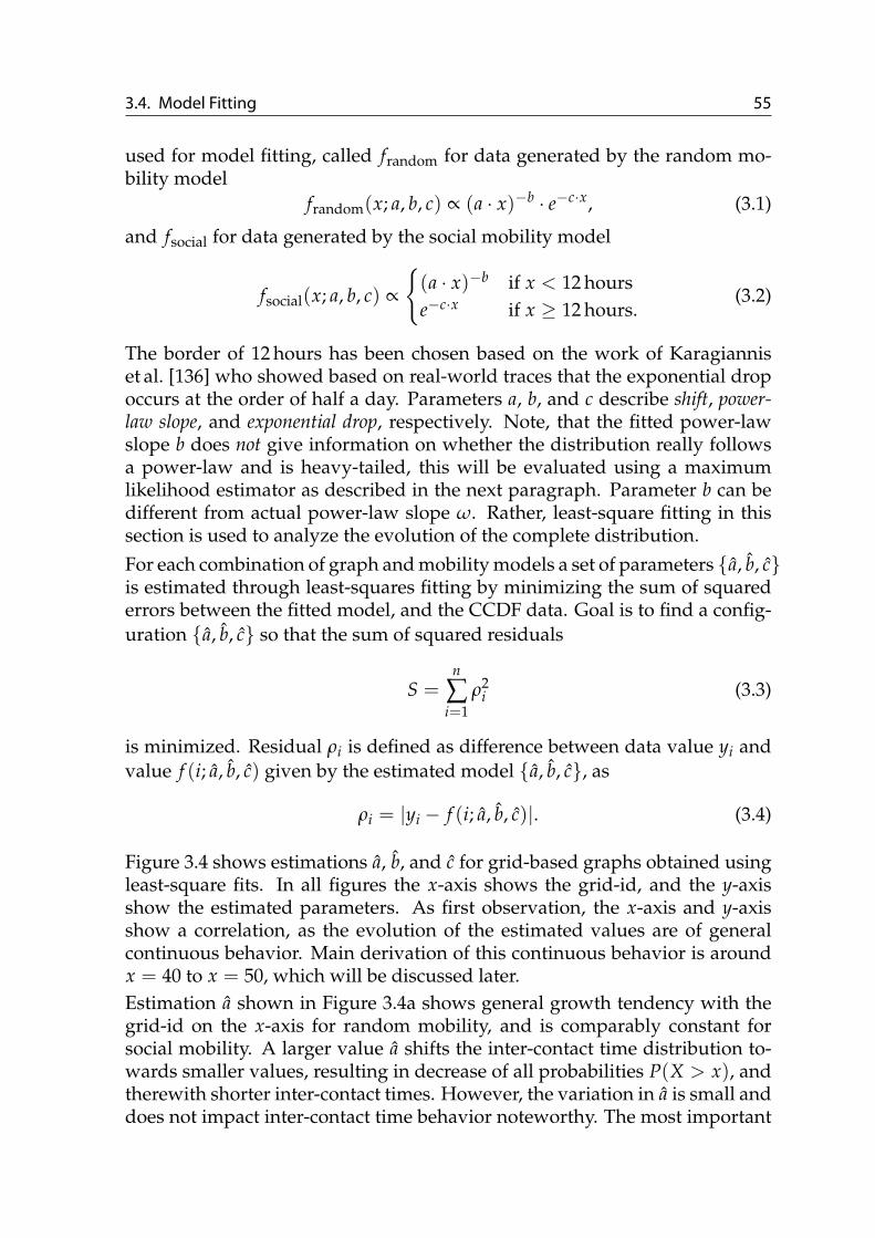
3.4. Model Fitting 55
used for model fitting, called frandom for data generated by the random mo-bility model
frandom(x; a, b, c) ∝ (a · x)−b · e−c·x, (3.1)
and fsocial for data generated by the social mobility model
fsocial(x; a, b, c) ∝
{(a · x)−b if x < 12 hourse−c·x if x ≥ 12 hours.
(3.2)
The border of 12 hours has been chosen based on the work of Karagianniset al. [136] who showed based on real-world traces that the exponential dropoccurs at the order of half a day. Parameters a, b, and c describe shift, power-law slope, and exponential drop, respectively. Note, that the fitted power-lawslope b does not give information on whether the distribution really followsa power-law and is heavy-tailed, this will be evaluated using a maximumlikelihood estimator as described in the next paragraph. Parameter b can bedifferent from actual power-law slope ω. Rather, least-square fitting in thissection is used to analyze the evolution of the complete distribution.For each combination of graph and mobility models a set of parameters {a, b, c}is estimated through least-squares fitting by minimizing the sum of squarederrors between the fitted model, and the CCDF data. Goal is to find a config-uration {a, b, c} so that the sum of squared residuals
S =n
∑i=1
ρ2i (3.3)
is minimized. Residual ρi is defined as difference between data value yi andvalue f (i; a, b, c) given by the estimated model {a, b, c}, as
ρi = |yi − f (i; a, b, c)|. (3.4)
Figure 3.4 shows estimations a, b, and c for grid-based graphs obtained usingleast-square fits. In all figures the x-axis shows the grid-id, and the y-axisshow the estimated parameters. As first observation, the x-axis and y-axisshow a correlation, as the evolution of the estimated values are of generalcontinuous behavior. Main derivation of this continuous behavior is aroundx = 40 to x = 50, which will be discussed later.Estimation a shown in Figure 3.4a shows general growth tendency with thegrid-id on the x-axis for random mobility, and is comparably constant forsocial mobility. A larger value a shifts the inter-contact time distribution to-wards smaller values, resulting in decrease of all probabilities P(X > x), andtherewith shorter inter-contact times. However, the variation in a is small anddoes not impact inter-contact time behavior noteworthy. The most important

56 3. Mobility Modeling on Graphs
0
0.05
0.1
0.15
0.2
0.25
0.3
0.35
0 20 40 60 80 100
a
Grid-id
(a) Estimation a
0 0.1 0.2 0.3 0.4 0.5 0.6 0.7 0.8 0.9
0 20 40 60 80 100
b
Grid-id
social mobilityrandom mobility
(b) Estimation b
0
5e-05
0.0001
0.00015
0.0002
0.00025
0.0003
0.00035
0.0004
0.00045
0 20 40 60 80 100
c
Grid-id
(c) Estimation c
Figure 3.4 Least-square fits for grid-based graphs.
estimation b—comparable to ω—shows a general correlation with the grid-idon the x-axis. b decreases until stabilization at around x ≈ 0.5 for social mobil-ity, while for random mobility b increases steadily, i. e. the underlying graphand mobility model impacts the slope of the power-law. An increasing valueb makes the slope of the inter-contact time distribution steeper, increasing theprobabilities of shorter inter-contact times. Estimation c is stable for socialmobility, and initially falls quickly for random mobility. However, the actualvalues of c vary only slightly and are negligible in the actual inter-contacttime distribution.Transition from grid-id 40 to 50 is a characteristic point where the generalcontinuous behavior of the estimated values is invalidated. From grid-id 40on the grid becomes so dense that two devices on parallel edges are nearly inmutual wireless communication range. For all grid-ids > 40, devices reallyare in mutual wireless communication range when moving on parallel edges.So grid-id 40 is a worst case grid where movement has very high path diver-sity, but comparably few contacts between devices; compared to a grid-id > 40with similar path diversity but much more contacts. This behavior can theo-retically be observed at further grid-ids where wireless communication acrossdifferent edges becomes possible. However, the actual derivation in values isrelatively small and does not impact the inter-contact times noteworthy.The estimations a, b, c for city graphs are shown in Figure 3.5. The orderingof city graphs on the x-axis is based on the graph’s spectral gap that will bedescribed in detail in Section 3.5. The value of a is overall very small andadditionally behaves on a small range. However, the variance is higher forrandom mobility, and very stable for social mobility, which is in-line withthe observation on grid-based graphs in Figure 3.4a. For estimation b and ca correlation with the given ordering of cities is visible for random mobility.The actual values b and c are within similar range compared to grid-basedgraphs. Estimate b is higher for social mobility than for random mobility overall graphs, i. e. stronger slope of inter-contact times CCDF. I. e. the probability

3.4. Model Fitting 57
0
0.02
0.04
0.06
0.08
0.1
0.12
0.14
0.16
New
Delhi
Los Angeles
San Francisco
Richm
ond
Manhattan
Chennai
Tokyo
Cairo
Karlsruhe
Venice
a
(a) Estimation a
0.1
0.2
0.3
0.4
0.5
0.6
0.7
New
Delhi
Los Angeles
San Francisco
Richm
ond
Manhattan
Chennai
Tokyo
Cairo
Karlsruhe
Venice
b social mobilityrandom mobility
(b) Estimation b
0
2e-05
4e-05
6e-05
8e-05
0.0001
0.00012
New
Delhi
Los Angeles
San Francisco
Richm
ond
Manhattan
Chennai
Tokyo
Cairo
Karlsruhe
Venice
c
(c) Estimation c
Figure 3.5 Least-square fits for city graphs.
of shorter inter-contact times is higher in social mobility, compared to randommobility. However, relative comparison of the values between city graphs onthe same mobility model are marginal, indicating that city graphs are notdiverse enough to impact inter-contact times within the same mobility modelon the same graph model.
Power-law Maximum-Likelihood EstimationWhile the prior method gives information on the complete distribution, itdoes not answer the question whether the data really follows a power-law,and if it does, what is the lower bound xmin and the exact power-law slopeparameter ω, introduced in Section 2.3.1. The unit of xmin is given in min-utes and is the smallest inter-contact sample so that the data set of all samplesgreater xmin exhibit a power-law behavior. The methodology of [50] is used3
for determining the power-law slope through a maximum likelihood esti-mator, and determining xmin through the Kolmogorov-Smirnov test, as de-scribed in Section 2.3.1. The estimation is based on the inter-contact time datasamples directly, in contrast to the least-square fit that is based on the CCDFdistribution. The values of ω are in the following figures decreased by 1 toreflect the CCDF power-law slope comparable to the least-square fits (cf. therelation of power-law slope for PDF and CCDF in Section 2.3.1). The combina-tion of power-law and exponential distribution found in inter-contact times isa special case of the family of power-law distributions. Therefore, the power-law estimation can be employed despite the mixed distribution [50, Sec. 5.2].Figure 3.6 shows maximum likelihood estimations xmin, and ω. Not all com-binations of mobility model and graph really exhibit a power-law in inter-contact times. Data items that do not exhibit power-law behavior are notshown. For grid-based graphs the social mobility model exhibits a power-law for grid-id ≥ 10, and random mobility exhibits a power-law for grid-id
3Implementation from Adam Ginsburg available at https://code.google.com/p/agpy/wiki/PowerLaw is used that implements the methods from [50].

58 3. Mobility Modeling on Graphs
5
5.2
5.4
5.6
5.8
6
6.2
6.4
6.6
6.8
7
7.2
0 50 100 150 200
Po
we
r-la
w x
min
so
cia
l [m
inu
tes]
Po
we
r-la
w x
min
ra
nd
om
[m
inu
tes]
Grid-id
social mobilityrandom mobility
(a) Power-law start xmin
0.2
0.3
0.4
0.5
0.6
0.7
0.8
0.9
1
1.1
0 50 100 150 200
Pow
er-
law
slo
pe
Grid-id
social mobilityrandom mobility
(b) Power-law slope ω
Figure 3.6 Maximum-likelihood fits for grid-based graphs.
≥ 120. The power-law values in social mobility are in-line with characteristicsfound in real-world traces [43, 136]. Figure 3.6b shows that this behavior is ir-respective of the underlying density of grid-based graphs. Random mobilityshows a power-law for large grid-ids, i. e. high density, however the actualpower-law slope ω is small and the CCDF therefore shallow.The evolution of xmin in Figure 3.6a does not correlate with the grid-id. How-ever, the actual values on the y-axis behave in a comparably small rangewithin 2 minutes, i. e. the inter-contact time samples on different graphs dif-fer in a small range with respect to the beginning of the power-law behavior.This variation can be neglected when focusing on the overall inter-contacttimes distribution.For social mobility the power-law slope ω shown in Figure 3.6b has a generalsimilar behavior compared to the least-square fit in Figure 3.5b. However, theactual values on the y-axis differ. Within one fitting methodology, the vari-ation of the power-law slope between graphs is comparable, confirming thegeneral difference in inter-contact time slope between grid-based graphs. Therandom mobility model does not generate noteworthy power-law behavior.For city graphs, the maximum likelihood estimates xmin and ω are shownin Figure 3.7, but only for social mobility, as random mobility never exhibitsa power-law when run on city graphs. The Chennai graph is surprisinglythe only city graph that does not exhibit power-law behavior, for reasons un-known. The value of xmin in Figure 3.7a differs between city graphs max-imal 6 min and can—compared to the inter-contact time samples of hoursand days—be neglected. The power-law slope ω shown in Figure 3.7b varieswithin small range ω ∈ [0.89, 0.99]. For grid-based graphs a strong variationof ω is observed when the grid becomes dense. Due to stability of power-law slope resulting from social behavior it can be argued that real-world citygraphs are not diverse enough in structure to impact ω noteworthy. Inter-

3.5. Random Walks and Spectral Analysis 59
350
400
450
500
550
600
650
700
750
New
Delhi
Los Angeles
San Francisco
Richm
ond
Manhattan
Chennai
Tokyo
Cairo
Karlsruhe
Venice
Po
we
r-la
w x
min
(a) Power-law start xmin
0.88
0.9
0.92
0.94
0.96
0.98
1
New
Delhi
Los Angeles
San Francisco
Richm
ond
Manhattan
Chennai
Tokyo
Cairo
Karlsruhe
Venice
Po
we
r-la
w s
lop
e
(b) Power-law slope ω
Figure 3.7 Maximum-likelihood fits for city graphs.
contact time behavior mainly depends on the social mobility behavior. Forevaluation of mobility and Delay Tolerant Networks on city graphs, the inter-contact times between different real-world cities are comparable.
3.5 Random Walks and Spectral AnalysisGoal of this thesis is to provide insight into the impact of underlying graphson mobility. In Section 3.3 simulative analysis has been performed and fit-ting of simulation data to models described in Section 3.4. While simulationstake into account communication range and speed of devices, i. e. the spa-tial layout of the graph, they do not provide insight into properties of thegraph that generate the inter-contact time behavior. In this section an analyt-ical approach based on spectral properties of the graph is performed. Goalis to derive a graph metric that provides a correlation with parameters of theinter-contact times distribution, and therewith gives direct insight into theproperties of a graph that impacts mobility behavior. Both simulative andanalytical results are finally correlated in Section 3.6.
Modeling Inter-contact Time in Random WalkRandom walk theory does not cover inter-contact times between pairs ofwalkers. However, conclusions about inter-contact time behavior are pos-sible for regular graphs. As described by Grinstead and Snell [87, p.17], givena vertex (0, 0) ∈ V of a Random walk on Z2: “The paths of two walkers in twodimensions who meet after n steps can be considered to be a single path that starts at(0, 0) and returns to (0, 0) after 2n steps. This means that the probability that tworandom walkers in two dimensions meet is the same as the probability that a singlewalker in two dimensions ever returns to the starting point”. This is formalized inthe following. Two definitions are necessary for the theorem:• A graph is regular: ∀vi, vj ∈ V : deg(vi) = k, with k constant. The graph
is called k-regular.

60 3. Mobility Modeling on Graphs
• The Random walk is simple: the transition probabilities only depend onthe vertex degree, e. g. if the Random walk resides on vi which has edgesto vj and vk, the transition probability of the Random walk to move to vjor vk is 1/deg(vi), respectively.
Theorem 1. Given a regular graph G, the probability that two independent simpleRandom walks Xt, Yt on G that start at the same vertex vi meet again after t steps atvj equals the probability that a single Random walk starting at vi returns to its originvi after 2t steps.
Proof. Let Xt and Yt be two independent simple Random walks, both residingat the same vertex vi at time t. This means that the probabilities of Xt andYt to reside at vi are equal: P(Xt = vi) = P(Yt = vi). Let G be regularand the Random walk simple, then holds that the transition probabilities aresymmetric: ∀x, y ∈ V with (x, y) ∈ E: p(x, y) = p(y, x). This means thatpt(x, y) · pt(x, y) can be written as pt(x, y) · pt(y, x), i. e. a Random walk thatmoves from x to y after t steps, and returns from y to x again after t steps.Therewith the Random walk has returned to x after 2t steps, i. e P(X2t = x),with same probability that Xt and Yt meet after t steps.
Theorem 1 shows that on regular graphs the probability of inter-contact timeat time t can be modeled as probability of return to a starting vertex at time2t. The synthetic grid-based graphs in this thesis are regular, but not at theborders of the grid. While vertices inside the graph have degree 4, vertices atthe border of the graph have degree 3, and four vertices only have degree 2which are in the four corners. Therewith the average vertex degree for grid-id k is4 deg(k) = 4(k2 − k)/k2, a function that converges quickly to 4, e. g.deg(k = 20) = 3.8, deg(k = 100) = 3.96. The deviation from a completelyregular graph with wrapper borders is small and the non-regularity in a strictsense ignored in the following. For a regular graph the return time equalsthe number of vertices |V|, as described in [158]. For grid-id k the number ofvertices is |V| = k2. Therewith, the mean return time on grid-id k is k2.Spectral graph theory allows to analyze the Random walk in terms of thegraphs eigenstructure, i. e. its eigenvalues and eigenvectors. Given a Randomwalk and steady state probability π, it holds that π = (MT)t · π, i. e. π isthe eigenvector to the eigenvalue 1. Further conclusions on the Random walkbehavior on the graph in terms of its eigenvalues can be made. A correlationexists between steady state probability π, the eigenvalues λk, and the hittingtimes of the Random walk. The hitting time H(s, u) is the expected numberof steps the Random walk requires, starting at vertex s, to reach vertex u. Let
4Grid-id k has k2− 2k− 2(k− 2) vertices with degree 4, has 4(k− 2) vertices with degree 3, and has4 vertices with degree 2. Summing over all degrees and dividing by the overall number of verticesk2 gives 4(k2 − k)/k2.

3.5. Random Walks and Spectral Analysis 61
1 0 -1
Figure 3.8 Eigenvalues of grid-based graphs with grid-id 10, 30, 50, 70 (topto bottom) shown on logarithmic scale [163].
Γ(s) be the set of neighbors of vertex s, then H(s, u) can be defined recursivelyas [158, p. 15]
H(s, u) = 1 +1
deg(s) ∑w∈Γ(vi)
H(w, u). (3.5)
The metric of hitting time provides a more general metric in comparison toreturn time. Note, that a graph with |V| vertices has the same number of|V| eigenvalues, each with an eigenvector of size |V|. The relation betweenhitting time and the eigenvalues of the graph is given through [158, p. 17]
∑u
π(u)H(s, u) =n
∑k=2
11− λk
. (3.6)
In this form the eigenvalues λk are normalized so that −1 ≤ λk ≤ 1, withλ1 = 1. Eigenvalues are calculated as follows: Let AG be the adjacency matrixof the graph G and D the diagonal matrix with (D)ii = 1/deg(i). DefineN = D1/2AGD1/2 = D−1/2MD1/2. The matrix N has the same eigenvaluesas M = DAG (that was introduced above as probability transition matrixof the Random walk) but is symmetric and its eigenvalues real. From thePerron-Frobenius theorem it follows that the eigenvalues are in the range:1 = λ1 ≥ λ2 ≥ . . . ≥ λn ≥ −1. It can be seen that λ2 in the denominatorof Equation 3.6 has strongest impact on the sum, and therewith is of mostimportance. This eigenvalue λ2 bounds the other eigenvalues and therewithgives conclusions on the eigenstructure of the graph which is used to drawconclusions about the Random walk behavior.Figure 3.8 shows the eigenvalues of four grid-based graphs with differentgrid densities on log-scale. Each vertical impulse defines the position of oneeigenvalue λi. The leftmost impulse that is smaller 1 is the value of the sec-ond largest eigenvalue λ2 that bounds the other eigenvalues, and the leftmost

62 3. Mobility Modeling on Graphs
0
0.0005
0.001
0.0015
0.002
0.0025
0.003
0.0035
0.004
0.0045
0.005
New
Delhi
Los Angeles
San Francisco
Richm
ond
Manhattan
Chennai
Tokyo
Cairo
Karlsruhe
Venice
25 30 35 40 45 50 55 60 65 70 75 80 85 90
Spectr
al gap
Grid-id
(a) City graphs and grid-based graphs.
0.0001
0.001
0.01
0.1
1
1 10 100
Sp
ectr
al g
ap
Grid-id
- city -
(b) Grid-based graphs.
Figure 3.9 Spectral gap for grid-based graphs and city graphs [163].
white space the spectral gap, defined as 1− λ2. The evolution of the spectralgap for grid-based graphs and city graphs is shown in Figure 3.9. Spectralgap for grid-based graphs is based on grid-id shown as continuous curve inFigure 3.9a, aligned to x2-axis. Real-world city graphs are shown as bars inFigure 3.9a, aligned to x1-axis. The x1-axis and x2-axis in Figure 3.9a havebeen manually aligned. Figure 3.9b shows the spectral gap for grid-basedgraphs based on grid-id and log-log scales for diverse grid densities. Thetwo vertical lines indicate the borders of the area where spectral gaps of citygraphs are. Intuitively, the spectral gap defines how the number of closedpaths increases as the path length tends to infinity [160], i. e. a smaller spec-tral gap results in more closed paths for a given path length.The city graphs in Figure 3.9a are ordered with respect to decreasing spectralgap, which is the ordering used in prior figures in this chapter. For grid-basedgraphs, high density of the grid results in a small spectral gap. With respectto the grid-id, the spectral gap falls very fast like a power-law, i. e. the pathdiversity increases quickly.For correlating properties of the graphs with inter-contact time of the mobil-ity, the line of arguments is as follows:
1. Inter-contact time can be described as return time on regular graphswhere transition probabilities are equal over all vertices. While the real-world graphs used in this thesis are not completely regular the variationof overall degree is small as described above. Section 3.6 will show thata correlation emerges.
2. The hitting time of the Random walk describes the expected number ofsteps, starting from vs until vt is reached. In this step the probabilityinformation is lost and therewith only mean inter-contact time can bemodeled, i. e. the expected number of steps until two independent Ran-

3.6. Correlation 63
0
0.2
0.4
0.6
0.8
1
0 50 100 150 200
0.028598 0.000703 0.00025 0.000092841
Po
we
r-la
w s
lop
e
Grid-id
Spectral gap
grids social mobilitycities social mobility
grids random mobilitycities random mobility
(a) Least-square fit b
0
0.2
0.4
0.6
0.8
1
0 50 100 150 200
0.028598 0.000703 0.00025 0.000092841
Po
we
r-la
w s
lop
e
Grid-id
Spectral gap
(b) Maximum-likelihood fit ω
Figure 3.10 Correlation of spectral gap with power-law slope for least-square fit and maximum-likelihood fit [163].
dom walkers meet. Section 3.6 will show that this mean determines theshape of the distribution and can be used to correlate with the power-law slope of inter-contact time.
3. The eigenstructure of the graph is correlated with the hitting time. There-with conclusions on the mobility inter-contact behavior in terms of thegraphs eigenvalues can be made. Specifically, the second largest eigen-value λ2 has strongest impact on hitting times.
3.6 CorrelationBased on the spectral gap—that has been identified in the prior Section 3.5 asimportant graph metric for mobility—correlations are in the following iden-tified with the fitted models from Section 3.4. Figure 3.9 shows the orderingof graphs with respect to decreasing spectral gap. A higher path diversitygenerally results in a smaller spectral gap. As the spatial layout of graphs isfixed, more and shorter streets result in smaller spectral gap. For grid-basedgraphs this ordering equals an increasing grid-id, for city graphs the orderingis New Dehli, Los Angeles, San Francisco, Richmond, Manhattan, Chennai,Tokyo, Cairo, Karlsruhe, Venice. It is intuitive that Venice has the smallestspectral gap due to large number of short streets and the resulting high diver-sity in movement paths.
Correlation with Inter-Contact TimeFigure 3.10 shows a complete correlation of previously shown data of theinter-contact time power-law slope with the spectral gap for city and grid-based graphs, both for the random and social mobility models. Missing com-binations in Figure 3.10b do not exhibit a power-law behavior. Ordering

64 3. Mobility Modeling on Graphs
is based on the spectral gap shown in Figure 3.9. Power-law slope b ob-tained using least-square fit is shown in Figure 3.10a, and ω using maximum-likelihood fit in Figure 3.10b. The x-axis of both Figure 3.10a and Figure 3.10buses the grid-id of graphs which has been aligned with the x2-axis for thecorresponding spectral gap. Circles are city graphs which have been alignedwith respect to their spectral gap to the x2-axis. For the maximum-likelihoodfit in Figure 3.10b only combinations of graph and mobility model are shownthat actually exhibit power-law behavior. The general tendencies in both fig-ures are comparable, especially the behavior in the power-law slope for ran-dom mobility on grid-based graphs. Focusing on the y-axis and x2-axis whichrelate the power-law slope and spectral gap, a correlation can be observed forall combinations of graph model and mobility model except social mobilityon city graphs. In this case the social intention is stronger than the forcedmobility behavior resulting from the underlying graph.
Correlation with Number of ContactsWhile inter-contact time and the power-law slope have important impact onDTN routing performance, as described in Section 2.3.2, the number of contactsis of importance, too, especially for finding multi-hop paths in a DTN. Whileinter-contact time is based on pairs of devices, the number of contacts ana-lyzed in the following counts the number of contacts that a device encountersper hour in average. Figure 3.11 shows the average number of contacts perhour per device, based on successfully built up wireless ad hoc associations.Again, the ordering of graphs is based on the spectral gap, both for grid-basedgraphs and city graphs. Figure 3.11a shows a decrease in contacts for increas-ing grid density. Recall that Section 3.5 stated that the spectral gap describeshow the number of closed paths increases as the path length turns to infinity.As movement paths of devices becomes more diverse, the number of contactswith other devices decrease. Again, this decrease is until grid-id 40 wherepath diversity is high but distance between parallel edges prevents commu-nication. For grid-id 50 the number of contacts is disproportional higher withrespect to the slightly higher path diversity, compared to grid-id 40.The number of contacts on city graphs are shown in Figure 3.11b. No cor-relation with spectral-gap is observed and the number of contacts relativelystable. The general increase of contacts from random to social mobility resultsfrom geographical social clustering where devices reside for longer duration.Generally, the graph impacts number of contacts strongly, as shown for grid-based graphs. Again, city graphs are not diverse enough to further impactthe number of contacts.
3.7 Summary and ConclusionWhile DTNs provide cheap communication, they open up a new dimensionof complexity due to non-deterministic mobility of devices. Human mobility

3.7. Summary and Conclusion 65
2
4
6
8
10
12
14
16
18
20
0 20 40 60 80 100
Conta
cts
per
devic
e p
er
hour
Grid id
social mobilityrandom mobility
(a) Grid-based graphs
2
4
6
8
10
12
14
16
New
Delhi
Los Angeles
San Francisco
Richm
ond
Manhattan
Chennai
Tokyo
Cairo
Karlsruhe
Venice
Conta
cts
per
devic
e p
er
hour
social mobilityrandom mobility
(b) City graphs
Figure 3.11 Average number of contacts per hour for grid-based graphs andcity graphs.
is not random, which enables DTN protocols to build up routing state andperform strategic forwarding. Social intention dictates a persons next desti-nation. Movement towards this destination is restricted by the underlyingnetwork area, its structure, and spatial layout. This chapter analyzed the im-pact of such underlying restrictions on mobility using graphs, and developeda correlation based on the graph’s spectral gap.The following conclusions can be drawn from the analysis in this chapter:
• The graph structure has strong impact on the mobility metric of inter-contact time. Graph structure can be analyzed in terms of the spectralgap that provides a correlation with the most important parameters ofthe inter-contact time distribution, especially with its power-law slope.
• Grid-based graphs strongly impact inter-contact times in social and ran-dom mobility over diverse grid densities.
• Real-world city maps—and their resulting street graphs—exhibit no suf-ficient difference in structure to influence the power-law slope of inter-contact times for a social mobility model.
Diverse street maps have been used in this thesis. They are, however, notdiverse enough to impact social mobility. This analysis supports the assump-tion of Rhee et al. who stated in [207] that “these tendencies [in mobility] arelikely caused by human intentions in deciding travel directions ... but not by geo-graphical constraints such as roads ...”. While an underlying graph generallydoes impact mobility, this impact is equal over graph structures of real-worldcity maps under social mobility. This conclusion is important for develop-ment and configuration of DTNs in human-centric environments.The model developed in this chapter has limitations which were introducedto limit complexity. First, the graph structure does not take obstacles like

66 3. Mobility Modeling on Graphs
buildings into account. Those limit wireless communication and therewithimpact the number of contacts and inter-contact times. Second, the move-ment speed of devices has been defined as human walking speed. Highermovement speed on the one hand result in shorter inter-contact times andhigher number of contacts. However, due to a finite bandwidth model, tooshort contacts can not be used to build up a communication association, oronly allow for very limited message exchange. Both aspects are interestingto analyze in future work. For the aspect of obstacles, this can be modeledinto the graph structure directly, i. e. taking reduced wireless communicationinto account by arranging the graph edges. This allows to use the presentedevaluation methodology by performing a first graph preprocessing step. Forthe second aspect of movement speed, it can be assumed that higher move-ment speed is not realistic with today’s wireless technology to build up adhoc communications. Therewith, mainly lower movement speed is of interestthat results in a generally lower number of contacts. However, it can be as-sumed that the general trends in inter-contact times and number of contactsobserved in this chapter will remain valid.

4. Hybrid Routing System
Delay Tolerant Networks can provide end-to-end communication without in-frastructure support at the cost of increased delay and probabilistic deliveryguarantees. In reality, however, a mix of infrastructure-based and mobileDTN-based networks exist. Both networks are reality today, however theirusage is different: Infrastructure-based networks are the prevailing commu-nication form today, while DTNs are used in a handful of experimental de-ployments [68, 77, 91, 153, 188, 227]. Generally, the large number of mobiledevices like smartphones carried by humans on a daily basis—7 billion ex-pected 2015 [47]—make mobile ad hoc communication opportunities realitytoday. Those opportunities are, however, not used for DTN communication,i. e. opportunistic device-to-device contacts do exist, they are, however, notused for deploying networks.Infrastructure-based communication and DTN-based communication both rep-resent extremes, as they either only make use of infrastructure, or only makeuse of opportunistic device-to-device communication. The integration of bothnetwork types has empirically shown beneficial, as it can enrich DTN com-munication [122, 123, 156], and offload infrastructure-based networks [98, 99,253]. Furthermore, such integration is beneficial for wireless interference overpure ad hoc networks in terms of delay/capacity scaling, as described in Sec-tion 2.2.1. Actual integration of infrastructure-based and opportunistic DTN-based networks is, however, complex due to different paradigms; e. g. forrouting of messages.This chapter presents the design and architecture of the Hybrid Routing Sys-tem (HRS) that allows for cooperative routing in mixed DTN and infrastruc-ture networks, called hybrid networks. On the one hand, HRS can boost DTN

68 4. Hybrid Routing System
Infrastructure-based overlay networkProbabilistic extension Probabilistic extension
Figure 4.1 Hybrid Routing System as probabilistic extension of overlay-based communication into DTNs. Arrows indicate disseminationof routing information.
routing performance through the help of infrastructure-capable devices, andenable routing in large, or even partitioned and distant geographic areas. Onthe other hand, HRS can offload infrastructure networks by routing messagespreferably in infrastructure-less DTNs.HRS builds upon a cooperative approach, based on the principles of decen-tralization and self-organization, without relying on central servers. This al-lows to deploy HRS flexibly and spontaneously. The main idea of HRS is toextend the reach of overlay-based communication into DTNs by announcingDTN contact information in the overlay, as shown in Figure 4.1.This chapter is structured as follows: Problem statement and requirementsfor hybrid routing are discussed in Section 4.1. Section 4.2 presents a modelfor hybrid networks that is used in this chapter. For integrating DTN pro-tocols through a generic approach, a categorization of DTN protocols suit-able for hybrid routing is presented in Section 4.3. The architecture of HRSis described in Section 4.4, before DTN-specific and overlay-specific proto-cols are described in Section 4.5 and Section 4.6, respectively. HRS provides ageneric system for integrating existing DTN protocols of a wide range, whichis shown in Section 4.7. Section 4.8 describes how two important use casescan be implemented with HRS: providing communication with few infra-structure, and offloading infrastructure networks through DTNs. Extensiveevaluation of HRS is presented in Section 4.9 with focus on the two use cases.The design of HRS is reviewed in Section 4.10 and compared to related work.Section 4.11 summarizes and concludes this chapter.
4.1 Problem Statement and RequirementsDTNs can support communication of mobile devices within a limited geo-graphic area. The network in this area can be defined as “one DTN” if mobil-

4.1. Problem Statement and Requirements 69
ity of devices allows for communication through store-carry-forward routing.As mobility is geographically bounded and movement speed limited, DTNscan only work within certain geographic extent and on longer time-scales ofdelay tolerance. Such limitations prevent widespread applicability of DTNs.In reality, however, infrastructure access is often available at least to a sub-set of participating devices, e. g. cellular or WiFi access. Empirical analysishas shown that incorporating partial infrastructure access can strongly boostperformance of DTNs [122, 123, 156]. However, integration of opportunisticDTNs with infrastructure networks faces several challenges:Routing DTN protocols for non-deterministic networks are based on op-
portunistic hop-by-hop routing decisions. In contrast, infrastructure-based networks use link-state, or distance-vector protocols to establishand maintain end-to-end links. Integrating the two routing paradigmsis non-trivial: Link-state or distance-vector protocols can not be de-ployed in DTNs, as described in Section 2.1.3. Deploying opportunis-tic protocols in infrastructure-based networks results in unacceptableperformance due to route instability.
Addressing In infrastructure-based networks, addressing is hierarchical anddirectly suites the routing process by forwarding messages towardsthe address-encoded destination network. In DTNs the network graphevolves over time and its instability prevents hierarchical routing. Morestable higher-layer structures such as social graphs have been used inDTNs [120]. Most often, however, a flat addressing scheme is appli-cable for opportunistic DTNs that decouples the device identities fromthe network structure.
Mobility Wireless ranges are shorter for ad hoc than for infrastructure-basedcommunication, i. e. few 10 m for ad hoc wireless vs. several 100 m forinfrastructure-based wireless, resulting in shorter contact durations.Additionally, in DTNs both wireless transceivers are mobile, resultingin more challenging duration and prediction of contacts1.
Gateways Mobility results in the need for dual-stacked gateways that trans-late between DTN routing and infrastructure-based routing. Whilegateways can be explicitly deployed through static infrastructure [77,91], the use of opportunistic gateways through mobile devices them-selves—that are DTN-capable and infrastructure-capable—allows formore flexibility and self-organizing in hybrid networks.
1Assuming a plain network area and equally distributed movement angles, shorter contact dura-tions arise when both devices are mobile, compared to one devices being static—i. e. infrastructure—and one mobile. This can be modeled through an equilateral triangle under constant movementspeed. If movement directions are within 60◦, distance is kept less or equal over time, than if onedevice was static. Given movement direction of one device, chances that the second devices moveswithin 60◦ left or right are 2·60◦
360◦ = 33%, i. e. DTN wireless links are of shorter duration 66% of times,not event taking into account the shorter range of wireless ad hoc communication.

70 4. Hybrid Routing System
After problems of integrating infrastructure-based and DTN-based networks,in the following requirements for a hybrid routing system are described.Unicast End-to-End Routing While multicast and concast communication re-
ceived considerable attention, still end-to-end unicast communicationis the predominant paradigm in today’s communication networks. Asystem for hybrid routing must support end-to-end unicast communi-cation between all participating mobile devices.
Stable Flat Addressing Each device must have a stable identifier that doesnot change with device mobility. The identifier must be flat and notencode network structure, geographic region, or gateway association.
Heterogeneous Infrastructure Capabilities Mobile devices have heteroge-neous infrastructure capabilities. While some devices may have contin-uous infrastructure access, others may not be able to access infrastruc-ture at all, or only at times. Irrespective of such infrastructure capabil-ities a hybrid routing system must allow for communication betweenall pairs of sender/destination devices.
Transparency of Destination Sending a message must be possible with knowl-edge of the destination device’s identifier alone. Information such asgeographic area, mobility patterns, current gateway, or infrastructurecapabilities must not be required.
Geographic Scale DTNs only work on comparably small geographic scaledue to delay introduced by carrying of messages through mobility.Integration of infrastructure enables geographic shortcuts. A systemfor hybrid routing must make use of infrastructure-based shortcuts toovercome long distance. This enables coupling of geographically re-mote, or strongly clustered DTNs.
Cooperative Routing Devices in DTNs are cooperative by design and carrymessages—sent by, and destined for—other devices. In face of hetero-geneous infrastructure access, cooperativeness must be used to estab-lish end-to-end routing, e. g. by sending messages into the infrastruc-ture network on behalf of a device that is not infrastructure-capable.
Opportunistic Mobile Gateways Devices in a DTN are mobile and reducethe duration of contact association for cooperative devices, e. g. pro-viding infrastructure access for another device. Gateway devices mustbe used in opportunistic ways, both for sending messages to the in-frastructure, and receiving messages from the infrastructure. Similarto DTN protocols that route messages towards devices that are morelikely to encounter the destination device, messages can be routed to-wards devices more likely to encounter infrastructure access.
Decentralized, Autonomous, and Scalable To allow spontaneous and flexi-ble deployment, a system for hybrid routing must be decentralized andautonomous. No central unit must be required to configure or control

4.2. Network Model 71
the system, rather, new devices must be integrated into the system in aself-organizing way. Similarly, new infrastructure opportunities mustbe integrated autonomously. A potentially large number of devicesmust be supported and the system be scalable.
Generic Applicability The system must not present a point-solution that canonly be deployed for one specific DTN protocol. A large number ofDTN protocols have been developed [7, 14, 35, 36, 59, 74, 119, 120, 154,176, 179, 228, 229, 259], all with focus on specific scenarios and environ-ments. At best, the system for hybrid routing must be applicable for adefined category of DTN protocols.
4.2 Network ModelIn this section a model for hybrid networks is introduced. A formalism isdescribed that is used in the categorization of DTN protocols in Section 4.3,and later for description of algorithms.
• Device: A mobile device is defined di, and the set of mobile devices D.A device is exposed to mobility of its human owner.
• Identifier: Device di has a stable identifier idi. The identifier has a lengthof e. g. 128 bit or 160 bit, is flat in its structure and has no semantics. Twodevices must not share the same identifier. Generation of identifiers canbe random, by hashing of e. g. di’s MAC address, or cryptographically2.
• Message: Every device di has a local process that generates messagesmij. The message’s destination device dj is selected uniformly at randomover all devices in the network. Every message has a Time-to-Live (TTL)counter that is initialized on message creation. A message is deletedwhen its TTL expired. Upon replication of a message the value of itsTTL counter is copied.
• Device-to-Device Communication: Two devices di and dj can exchangemessages when in mutual communication range r. Communication rangeis modeled through the Unit Disk Model [125] that provides an abstrac-tion of wireless channel characteristics and medium access. A devicecan only take part in one device-to-device communication at a time. Thenumber of messages exchanged depends on the bandwidth, messagesize, and contact duration. If devices move out of mutual communica-tion range during exchange of a message, the exchange failed and trans-mitted data is deleted.
• Copy Mode: After transferring a message, the copy mode decides howthe sending device handles the sent message. In single-copy mode the
2Due to the large identifier space the probability of collision is small. Ensuring collision-freeidentifiers is out of scope of this thesis.

72 4. Hybrid Routing System
sending device locally deletes the message, i. e. forwarding. In multi-copy mode the sending devices keeps a copy of the message, i. e. repli-cation. In multi-copy mode two copies of the same message result afterthe message transfer.
• Device Queue: Device di has a local message queue qi for storing mes-sages not destined for di. Queues are modeled as infinite in this thesis toprevent replacement effects, and to analyze queue size requirements.
• Infrastructure: Communication infrastructure provides wireless accessto a communication backbone. Devices in communication range of wire-less infrastructure can communicate using IP over the backbone.
• Infrastructure Access: Devices have different capabilities for infrastruc-ture access. Permanent infrastructure access denotes devices that havecontinuous access to infrastructure. Temporary infrastructure access de-pends on current geographic location and availability of wireless accessin this location. Finally, devices can be not capable of access infrastructureat all.
• Infrastructure Access Classes: Devices D are classified with respect totheir infrastructure access class asDp for devices with permanent access,Dt for devices with temporary access, andDn for devices that are not ca-pable of infrastructure access. The probability of a device to be assignedto one of those classed is denoted P(Dp), P(Dt), and P(Dn), respectively.It holds P(Dp) + P(Dt) + P(Dn) = 1.
Network Model: A set of devices di, dj, . . . ∈ D with identifiers idi, idj, . . .move on a network area A. Every device di ∈ D generates messages mij des-tined for other devices dj ∈ D\di. When in mutual communication range rtwo devices can exchange a limited number of messages. Messages are eitherdeleted on the sending devices, or replicated, called single-copy or multi-copymode. Device di has a local message queue qi for storing messages not des-tined for itself. When connected to the infrastructure a device can communi-cate with all other infrastructure-connected devices. Access to infrastructuredepends on capabilities of a device.Steps in Hybrid Routing: Figure 4.2 shows an exemplary hybrid DTN net-work. In the most general case of routing, message mak is generated by daand destined for dk (da, dk ∈ Dn). The hybrid routing process requires thefollowing three steps:
(a) Routing in the source DTN towards the infrastructure: Forwarding mak from daby DTN routing to a device that has, or is likely to encounter, infrastruc-ture access (e. g. over db to dc).

4.3. Categorization of DTN Protocols 73
���������A �� BC�D�EF����� �����AD��D��� ��AA �A��� ����
���������A �� BC���������AD��D��� ��AA
���������A �� BC�F��A�AD��D �����AD��D��� ��AA
��������� ��������� ��AA �����
��
��
��
��
��
��
A�����
��AD���D���
������F��
��AD���
Figure 4.2 Topology of a hybrid network made of up devices from differentinfrastructure-capability classes, and infrastructure access.
(b) Routing in the infrastructure: Forwarding mak across the infrastructure-based network from dc to a device with current infrastructure access(e. g. dg). This device must have a good probability of forwarding themessage towards the destination device dk.
(c) Routing in the destination DTN towards the destination device: Forwardingmak by DTN routing through dj to the destination device dk.
By implementing the routing steps (a)–(c) hybrid DTNs can overcome largedistance by using infrastructure, i. e. in step (b) of the presented example.Note, that da is required to only know the identifier idk of dk, neither its ge-ographic location, social cluster, nor infrastructure capability class. While daitself does not have infrastructure access, there might exist a multi-hop paththat includes infrastructure.
4.3 Categorization of DTN ProtocolsNumerous DTN protocols exist that have been developed for specific usecases and environments. A hybrid routing design that can be employed witha larger set of DTN protocols is preferred, allowing the DTN protocol thatworks best in a given scenario to be employed. However, the different mech-anisms that DTN protocols use make a completely generic solution unlikely.Goal of this section is to develop a categorization of DTN protocols that issuitable for hybrid routing, and determine the best suited category. Existingcategorizations are described in Section 4.3.1 and analyzed for their applica-bility for hybrid routing. In Section 4.3.2 a novel categorization is presentedthat is specifically designed for hybrid routing.

74 4. Hybrid Routing System
Work CategorizationBalasubramanian et al. [14, 15] Storage, bandwidth, routingBurns et al. [36] Structure in movement, control of devicesChaintreau et al. [42] Stateful vs. statelessJones et al. [133] Replication and knowledgeNelson et al. [179] Forwarding and replicationYuan et al. [258] Mobile resource, opportunity, predictionZhang [259] Epidemic, history, model, control, coding
Table 4.1 Existing categorizations for DTN protocols.
4.3.1 Existing CategorizationsOften newly proposed DTN protocols come with their own categorization todescribe the integration of the new protocol into the set of existing protocols.Table 4.1 gives an overview of existing categorizations for DTN protocols.Stateful vs. stateless: Chaintreau et al. analyze in [42] the characteristicsof real-world contact traces and perform a theoretical study of DTN perfor-mance. They differentiate between stateful and stateless DTN protocols. State-ful protocols collect contact information and infer patterns that are used topredict contacts and route messages. In contrast, stateless protocols do notcollect historical data and do not try to infer future events from historicaldata. Rather, such protocols perform (limited) replication, or apply utilityfunctions to evaluate the benefit of message replication.Structure in movement, control of devices: Burns et al. [36] focus on vehi-cles like buses that run on predefined routes. Such devices expose structurein movement that can be exploited by a routing algorithm. In contrast, de-vices which underlie control of users, like taxi cabs, are on the other side ofextremes. Their movement does not exhibit structure in movement, but canbe controlled up to a certain degree.Epidemic, history, model, control, coding: Zhang [259] provides an exten-sive survey of DTN protocols. The main categorization is based on determin-istic vs. stochastic routing. The important branch of stochastic protocols isfurther divided into epidemic, history, model control, and coding. This cate-gorization was used in Section 2.1.5 to given an overview of DTN protocols.Replication and knowledge: Jones et al. [133] categorize DTN protocols basedon replication and knowledge. Replication is further divided into direct-delivery,two-hop relaying, tree-based flooding, and epidemic routing. The knowledgecategory is refined through location-based routing, gradient routing, and met-rics of the communication link.Storage, bandwidth, routing: Balasubramanian et al. [14, 15] categorize DTNprotocols with respect to storage, bandwidth, and routing. For storage a dif-ferentiation is made of infinite vs. finite device queues. Exchange of mes-

4.3. Categorization of DTN Protocols 75
sages between two devices is either limited in bandwidth, or unlimited. Therouting strategy is classified as replication-based, or forwarding-based; i. e.multi-copy vs. single-copy.Forwarding and replication: Nelson et al. [179] present a categorization basedon number of replicas in the network: forwarding-based, and replication-based;i. e. single-copy vs. multi-copy.Mobile resource, opportunity, prediction: Yuan et al. classify in [258] DTNprotocols as: mobile resource-based, opportunity-based, and prediction-based. Pro-tocols in the mobile resource-based category are e. g. data mules that canbe controlled and directed to pick up data at specific geographic locations.Opportunity-based protocols work on opportunistic and unscheduled basis.Prediction-based protocols calculate deterministic future contacts, e. g. satel-lite communication networks.While existing categorizations have eligibility for the respective works, theyare not applicable to the problem of hybrid routing. Especially, they to notexhibit information on the applicability of a device for routing towards an-other device that could be announced in the infrastructure. This applicabilityis called awareness in the following. A collaborative hybrid routing approachmust distribute this awareness information in the infrastructure-part of thenetwork to enable selection of good devices as proxies for routing from infra-structure back to DTN.
4.3.2 Categorization for Hybrid RoutingThe categorization presented in this thesis for hybrid routing is based on twomain ideas: First, the structure of routing information that the DTN protocolmaintains, and second, how this routing information is employed in the DTNprotocol. DTN protocols are categorized as• Destination-aware,• Self-aware, and• Unaware.
Figure 4.3 illustrates the different categories: Destination-aware protocols main-tain destination-specific information, self-aware protocols maintain informa-tion about their own general applicability, and unaware protocols route mes-sages based on metadata stored in the messages themselves.
Destination-awareProtocols categorized as Destination-aware use routing information to de-cide how well-suited a device is for routing towards a specific destination de-vice. Information is gathered locally on device encounters, possibly takingindirect device encounters through a third device—i. e. transitivity—into ac-count. Information is aged as a device becomes less valuable over time, and re-freshed upon new device contacts. Prophet [154] is a well-known Destination-

76 4. Hybrid Routing System
ID Awareness
idi
0.4
idj 0.8
…
Awareness
for idj
is 0.8
Self-
awareness
is 0.7
0.7 Metadata of
mij?
Destination-aware Self-aware Unaware
Message
mij for
device dj
Message
mij for
device dj
Message
mij for
device dj
Figure 4.3 Illustration of the categorization based on awareness.
Category Description, exemplary protocols
Destination-aware
Device-specific awarenessProphet [154], MaxProp [35], Spray&Focus [229],FRESH [69], EASE [90], SEPR [240], NECTAR [59],David et al. [58], CAR [178], RAPID [15]
Self-awareLocal awareness of deviceLabel [119], Bubble [120], PeopleRank [176],
SimBet [55], EBR [179], MobySpace [150]
UnawareForward/replicate message based on metadataSpray&Wait [228], RAPID [15], Epidemic [244],Random (Epidemic), Direct Delivery
Table 4.2 Categories with exemplary DTN protocols.
aware routing protocol that builds up probabilities of future device encoun-ters based on historical observation.
Self-aware
Self-aware protocols evaluate the applicability of a device as forwarder in gen-eral, irrespective of the message’s destination. SimBet [55] e. g. locally man-ages a device-specific rating out of social similarity and betweenness. Similar,EBR [179] uses a locally computed encounter-rate that reflects how frequentlythe device comes into contact with other devices.
Unaware
The third class of Unaware protocols does not evaluate forwarding qualityof devices, but rather performs (limited) flooding [228, 244], or replication on aper-message utility [15].

4.3. Categorization of DTN Protocols 77
Some protocols such as RAPID [15] implement multiple categories. Depend-ing on the metric employed, RAPID is categorized as Destination-aware, orUnaware. Table 4.2 shows exemplary DTN protocols for each category. Build-ing upon the network model from Section 4.2, the categories can be formallydefined as follows:
• Destination-aware: Every device di ∈ D manages a table
Ti = {(idj, pi(dj)
), (idk, pi(dk)) , (idl, pi(dl)) , . . .}
for devices dj, dk, dl, . . . it has come into direct or transitive contact. Thedestination-awareness pi(dj) ∈ [0, 1) reflects the applicability of di for for-warding a message to dj, with di 6= dj. For di = dj the destination-awareness is defined pi(di) = 1, i. e. the awareness for a device itself iscomplete and therewith 1.
• Self-aware: Each device di ∈ D locally manages the self-awareness pi thatreflects the general applicability of di for forwarding messages, irrespec-tive of the message’s destination.
• Unaware: Each message mij with sender di and destination dj stores acounter c that reflects the number of replicas allowed for m. Forwardingis based on metadata in m, e. g. replication counter c or TTL counter,irrespective of any awareness.
The DTN routing process can be defined for each category in simplified form:
Definition 1. Routing mij from di to dj using DTN is a recursive process basedon store-carry-forward. Message mij carried by ds is forwarded/replicated to dt ifdt = dj, or• Destination-aware: pt(dj) > ps(dj),• Self-aware: pt > ps,• Unaware: c > 1.
Note, that this is an abstract definition that does not take additional protocol-specific mechanisms into account, but provides a simple way to describe thebasic idea behind the proposed categorization and the mechanism of eachcategory. In Table 4.3 exemplary DTN protocols are shown with respectiverouting information used. This verbally described routing information re-quires a formalism for actual integration, which is described for exemplaryDestination-aware protocols in the following.An important goal of hybrid routing is to efficiently route messages into thecurrent destination device’s geographic area using infrastructure, as describedin Section 4.2. To implement this routing step a device needs to be found

78 4. Hybrid Routing System
Category Protocol Information
Destination-awareProphet [154] future encounter probabilityMaxProp [35] normalized relative encounterSpray&Focus [229] time elapsed since encounter
Self-awarePeopleRank [176] rank in social networkSimBet [55] similarity/betweennessEBR [179] frequency of device encounters
Unaware
Spray&Wait [228] initial c > 1Epidemic [244] initial c = ∞Random Epidemic randomly per contact c ∈ {1, 2}Direct Delivery initial c = 1
Table 4.3 Categories with exemplary DTN protocols as well as informationused for routing.
and selected that is currently reachable through the infrastructure and pro-vides good forwarding possibilities to the message’s destination device, i. e.a device with a high destination-awareness for the message’s destination de-vice. Destination-aware protocols exhibit a strong advantage over self-awareand unaware protocols, since even in case of strong clustering—like remotecities—destination-aware protocols implicitly encode geographic information:iff pi(dj) > 0, then a time-space path existed between devices di and dj. Thisfurther means that di and dj are located in the same geographic area withprobability depending on pi(dj). If di gets connected to the infrastructure net-work, announcing its applicability for routing to dj with respect to pi(dj), en-ables other infrastructure-capable and potentially geographically remote de-vices to forward messages with destination dj to di. This is not possible inself-aware and unaware protocols as they do not encode destination-specificinformation. Destination-aware protocols are used in the remainder of thischapter to implement hybrid routing with focus on unicast communication.The three exemplary Destination-aware DTN protocols Prophet, MaxProp,and Spray&Focus, shown in Table 4.3, are in the following described from atechnical perspective and their mapping to destination-awareness presented.Description of the basic protocols themselves can be found in Section 2.1.6.Table 4.4 shows the mapping for the three protocols from internal data struc-tures towards destination-awareness.Prophet Prophet [154] maintains encounter probabilities P(i,j) locally on each
device. On first device-to-device contact between di and dj the en-counter probability is initialized using P(i,j) = Pinit ∈ (0, 1] on di, andusing P(j,i) = Pinit ∈ (0, 1] on dj, respectively. On future encoun-ters the encounter probability is updated through P(i,j) = P(i,j)old +
(1− P(i,j)old) · Pinit. Encounter probabilities are time-variant and aged

4.3. Categorization of DTN Protocols 79
Protocol MappingProphet [154] pi(dj) := P(i,j)
Time-dependent exponential decay, aging parameterdefined at design time.
MaxProp [35] pi(dj) := 1− c(i,...,j)n = 1− 1
n ·j−1
∑x=i
[1− ( f x
x+1)]
Normalization of ∑ f ji on encounter to 1. Calculation
of pi(dj) based on cost and maximal path length n,e. g. n = 10 set in [35].
Spray&Focus [229] pi(dj) := 1−min{1, k∆}
Linear decrease with elapsed time k since encounter,design-time parameter ∆ for time scale.
Table 4.4 Mapping to awareness values. Notation based on original paperof respective DTN protocol.
through P(i,j) = P(i,j)old · γk, with aging constant γ ∈ [0, 1) and elapsedtime k. When two devices are in contact they exchange their encounterprobability tables to implement transitivity through a damping factor βusing P(i,k) = P(i,k)old + (1− P(i,k)old) · P(i,j) · P(j,k) · β. Encounter prob-abilities in Prophet can be directly mapped to destination-awarenessvalues by defining pi(dj) := P(i,j).
MaxProp MaxProp [35] handles the problem of ordering messages to repli-cate, which is necessary under a finite bandwidth model. Each de-vice locally calculates meeting probabilities f j
i that are—in contrast toe. g. Prophet or Spray&Wait—not time-variant, rather, on device en-counters all meeting probabilities are adjusted so their sum is normal-ized to 1. Therewith, probabilities are more stable, but interdependent.MaxProp distributes meeting probabilities in a control channel on de-vice contacts. This way, devices gather a more complete view of thecontact graph used for deciding on message order, based on shortestpaths over the contact graph with link costs set to 1− f j
i . For model-ing destination-awareness, the local view of MaxProp is used that isa combination of locally encountered devices and meeting probabili-ties distributed through the control channel. For each destination de-vice the shortest paths are calculated and inverse path costs used asdestination-awareness.
Spray&Focus Spray&Focus [229] is based on two mechanism, spraying andencounter ages. Messages have a replication counter c defined at de-sign time. In the “spray” phase messages are replicated and for eachforwarded replica the replication counter c decreased by 1. If c = 1the protocol switches to the “focus” phase based on time elapsed since

80 4. Hybrid Routing System
0
0.2
0.4
0.6
0.8
1
0 5 10 15 20 25 30
Aw
are
ness
Time [h]
(a) Prophet
0
0.2
0.4
0.6
0.8
1
0 1 2 3 4 5 6 7 8 9 10
Aw
are
ness
Time [days]
(b) Prophet (long-term)
0
0.2
0.4
0.6
0.8
1
0 5 10 15 20 25 30
Aw
are
ness
Time [h]
(c) MaxProp
0
0.2
0.4
0.6
0.8
1
0 5 10 15 20 25 30
Aw
are
ness
Time [h]
(d) Spray&Focus
Figure 4.4 Flat representation of destination-awareness from perspective ofone exemplary device.
last device encounter, similar to [69]. Messages are recursively for-warded to devices with younger encounter ages. Defining encounterages as awareness-values, awareness is set to (1− ε) when the deviceis encountered, ε being a very small value to keep awareness < 1,and decrease it over time. For mapping encounter ages to awareness-values pi(dj) ∈ [0, 1), a function that maps time k elapsed since lastencounter linearly during a design-time timespan of ∆ using pi(dj) =
1−min{1, k∆}.
The time-variant characteristics of Destination-aware protocols vary betweenprotocols. Understanding this dynamic behavior is important for the designof hybrid routing that must manage such awareness information. Figure 4.4shows a flat representation of one device’s routing table over a period of 30 hfor different destination-aware protocols. For analyzing the awareness be-havior the mobility model in Section A.9 is used. It emulates human workingday behavior and allows to analyze the increase and decrease of awarenessover time.

4.4. Architecture 81
Figure 4.4a and Figure 4.4b both show the awareness characteristics of theProphet protocol. While Figure 4.4a is based on the normal Prophet protocolwith configuration based on short-term contact behavior, Figure 4.4b uses theparameter-estimation variant from [137] with focus on long-term contact be-havior. Prophet’s aging function performs an exponential decrease in aware-ness over time. Devices met more often gain higher awareness. Specificallyin Figure 4.4b long-term contact behavior results in a separation of devicesmet on a regular basis, and devices met rarely—resulting from periodicity ofthe social-based mobility behavior. In comparison to Prophet that maintainsawareness values independently for each device, MaxProp integrates an in-terrelation in that the sum of all awareness values is normalized to 1. Throughthis mechanism, MaxProp does not require an aging function, rather, aging isperformed on each device contact for all other devices. Figure 4.4c shows theMaxProp behavior, it can be clearly seen that awareness values are more sta-ble, as they are not time-dependent but rather depend on the device’s contactrate with other devices. Spray&Focus shown in Figure 4.4d is based on last-encounter time, i. e. elapsed time since the device was encountered. This is 0 sat the moment of encounter, i. e. a high destination-awareness of 1− ε whichis decreased linearly over time.A system for hybrid routing must cope with different dynamics in awarenessvalues. Depending on awareness behavior and stability, different variantsof hybrid routing might be applicable. Two hybrid routing designs will bepresented for different awareness stability in the remainder of this chapter.
4.4 ArchitectureFigure 4.5 shows the architecture of HRS, split into two main parts: On theleft, the Overlay part uses infrastructure-based communication to announceawareness for other devices, and provide communication between infrastruc-ture-connected devices through the Hybrid overlay protocol. On the right, theDTN part runs the Hybrid DTN protocol that uses the Mixed DTN metric, andinformation acquired through an Existing DTN protocol to decide which howmessages are to be routed.HRS is not designed to be run as a global routing service to integrate the In-ternet with all existing DTN-enabled mobile devices. Rather, HRS is designedto be run on a per-application basis to collaboratively support routing withinthis application. The DTN—made up of mobile devices that participate in thesame application—together with the infrastructure-based overlay is called aHRS-instance. Such a HRS-instance is application-specific and has an iden-tifier that is used to differentiate between mobile devices in the same, anddifferent HRS-instances.

82 4. Hybrid Routing System
����������A BCD���A
E�FF�����������
�������BCD�
��A����
�������FF�����A������
��������
E�����BCD���A���
�����������������A����
E�FF���������
��FA����BCD���A����
!�"��FA���A�������������A��� ��#$������������A���
%�&� 'C (EC) *���A��A$ ��#$���%�&�
Figure 4.5 Architecture of the Hybrid Routing System.
Ad hoc communicationMobile devices periodically scan for other devices in their geographic prox-imity. The HRS-instance identifier is used to only build up associations withdevices from the same HRS-instance. This identifier can be encoded in theSSID for ad hoc WiFi, or the service record name in the Bluetooth Service Dis-covery Protocol (SDP). When two devices di and dj from the same HRS-instanceare in mutual communication range r an association is built up. During as-sociation the devices di and dj can exchange a limited number of control anddata message. Ad hoc communication can be implemented, e. g., using Blue-tooth, or ad hoc WiFi.
Infrastructure communicationBesides ad hoc communication with other mobile devices when in mutualproximity, devices can make use of infrastructure-based communication, e. g.cellular networks such as UMTS or LTE, or infrastructure-based WiFi. De-vices from infrastructure-capability classesDt andDp can perform infrastruc-ture-based communication. Infrastructure access provides bidirectional com-munication with other devices that currently have infrastructure access, i. e.Internet connectivity based on IP. Section 5.5 will show how the frameworkfor overlay-based services presented in Chapter 5 provides an enabling plat-form to implement this communication and how it enables identifier-basedrouting and addressing.
Hybrid DTN protocolThe Hybrid DTN protocol implements the opportunistic ad hoc routing de-cision, i. e. it decides which messages to forward/replicate in case of an adhoc contact between devices. To implement this decision, information fromthe integrated DTN protocol, and information about the hybrid network areused in a mixed DTN routing metric.

4.4. Architecture 83
Awareness maintenanceAd hoc communication between two devices is the basis for maintenance ofawareness tables Ti. Through initial exchange of identifiers idi and idj, bothdevices update their awareness table. The exact mechanism for table up-dates depends on the integrated existing DTN protocol. Besides awarenessfor other mobile devices, awareness for infrastructure access is maintained tomanage a device’s applicability for routing towards infrastructure access.
Mixed DTN metricWhile pure DTN routing uses the applicability of a device for routing to-wards the destination device, in hybrid routing the applicability of a devicefor routing towards the infrastructure is integrated through a mixed metric.Section 4.5 will describe the mixed metric, and Section 4.8 show how it is usedfor implementing different use cases by trading off awareness for a message’sdestination device and awareness for infrastructure access.
Message queueDTN protocols are based on store-carry-forward routing. For storage of mes-sages device have local queues. The hybrid routing approach makes addi-tional use of those message queues for storing messages sent through the in-frastructure that are destined for other devices. Devices periodically deletemessages from their queue whose lifetime has expired.
Hybrid overlay protocolThe hybrid overlay protocol enables communication between infrastructure-connected devices and implements an announcement system. The announce-ment system allows a device di to announce its awareness pi(dj) for routingtowards another device dj through ad hoc DTN routing. Device di is calledproxy for dj. Multiple proxies can announce their awareness for a device. An-nouncement is performed in the infrastructure-part of the hybrid networkand is accessible to all currently infrastructure-connected devices, irrespectiveof their geographic location. Two distributed designs for the announcementsystem will be presented in Section 4.6. From an architectural perspective anannouncement system must provide mechanisms for managing and lookingup announcements.
Copy modeDTN routing is either single-copy, or multi-copy. Hybrid routing splits therouting process into three routing parts, as shown in Figure 4.6. Depending onthe current routing part, a message is assigned a different protocol state and ishandled differently. Those protocol states are:• Protocol state 1: Routing in the source DTN.

84 4. Hybrid Routing System
���������������A
B��C�D�C�ED�BF��E�����BF�
��E��
��DA��
��������
�����A�E���������ECE�E�
��ECE�E���C�C���
��ECE�E���C�C���
��ECE�E���C�C���
��
�� ��
�
!E�����A������
�����A�BF���ECE�E�
"E�C�D�����C�� "E�C�D�����C�� "E�C�D�����C��
Figure 4.6 Protocol states in hybrid routing.
• Protocol state 2: Routing in the infrastructure announcement system.• Protocol state 3: Routing in the destination DTN.
Each of the protocol states can be individually configured to perform eithersingle-copy routing, or multi-copy routing. The three states result in fourcopy decisions:• C1: Single-copy or multi-copy in source DTN.• C2: Single-copy or multi-copy when moving messages from source DTN
into the announcement system, i. e. keeping a message copy in the DTN,or not.• C3: Single-copy or multi-copy when moving a message from the an-
nouncement system into the destination DTN, i. e. keeping a messagecopy in the announcement system, or not.• C4: Single-copy or multi-copy in the destination DTN.
Overall 24 = 16 copy-mode combinations for hybrid routing exist. Depend-ing on quality of information in the protocol states, different combination ofcopy-modes can be beneficial for trading off performance vs. cost.
Message marking
After a message has been forwarded from infrastructure into DTN the mes-sage is marked, as shown in Figure 4.6 at point C3. Message marking allowsto differentiate between protocol states and implement the aforementionedcombination of copy-modes. Additionally, message marking is used to pre-vent a message being routed through the infrastructure twice. While infra-structure allows to overcome long distance and find a good proxy for routingin the destination DTN, a second infrastructure transfer does not provide ad-ditional benefit.

4.5. Hybrid DTN Protocol 85
4.5 Hybrid DTN ProtocolThe hybrid DTN protocol performs DTN routing based on awareness for thedestination device, and awareness for infrastructure access. The mixed DTN met-ric used in this protocol is described in the following Section 4.5.1. Section 4.5.2describes the hybrid DTN protocol run by mobile devices that integrates themixed metric.
4.5.1 Mixed DTN MetricFor the hybrid routing approach messages must be explicitly routed throughad hoc communication towards devices more likely to encounter infrastruc-ture access. For every device di its awareness table Ti is extended by awarenessfor infrastructure access through a virtual entry (idI , pi(idI)) ∈ Ti, reflectingapplicability of di for routing a message towards infrastructure I . Based oninfrastructure capability classes defined in Section 4.2, pi(idI) is defined as
pi(idI) =
0, di ∈ Dn,[0, 1], di ∈ Dt,1, di ∈ Dp,
(4.1)
or if the used DTN protocol supports transitive spreading of awareness (e. g.Prophet [154]), defined as
pi(idI) =
[0, 1) di ∈ Dn,[0, 1], di ∈ Dt,1, di ∈ Dp.
(4.2)
While pi(idI) is stable for Dp, it is time-variant for Dn and Dt. Similar toawareness for another device dj, awareness for infrastructure is maintainedby the mechanism of the integrated DTN protocol every time the device be-comes connected to infrastructure access.Based on awareness for mobile devices and awareness for infrastructure ac-cess, a mixed DTN routing metric is defined. Given two devices ds and dtthat are in communication range and can exchange messages, the decisionwhether a message mij with destination device dj should be forwarded/repli-cated from ds to dt is based on the relative normalized awareness-values fordestination device dj, defined as
p‘s(dj) =ps(dj)
ps(dj) + pt(dj), (4.3)
and
p‘t(dj) =pt(dj)
pt(dj) + ps(dj). (4.4)

86 4. Hybrid Routing System
The relative normalized infrastructure-awareness is calculated as
p‘s(idI) =ps(idI)
ps(idI) + pt(idI), (4.5)
and
p‘t(idI) =pt(idI)
pt(idI) + ps(idI). (4.6)
Message mij with destination device dj is forwarded/replicated from ds to dtbased on weight parameter α ∈ [0, 1] if:(
α · p‘t(idI) + (1− α) · p‘t(dj))>(
α · p‘s(idI) + (1− α) · p‘s(dj))
(4.7)
Equation 4.7 implements a forwarding decision in the DTN that allows totrade off destination-device awareness, and infrastructure-awareness. A valueα → 1 puts emphasis on infrastructure-awareness, while a value α → 0 putsemphasis on destination device-awareness. The value of α can be either static,or defined as function. Section 4.8 will present two use cases that are mainlyimplemented through the choice of α: In one use case α is static, in the otheruse case α is a function of mij’s TTL, elapsed lifetime, and additional informa-tion about the network.
4.5.2 Protocol DetailsAlgorithm 1 is run locally by the DTN part of a mobile device to implementthe hybrid DTN protocol.
Device Discovery, line 6Device-to-device communication is based on short-range communication suchas Bluetooth, or ad hoc WiFi that can provide infrastructure-less ad hoc com-munication (see [79] for an overview). Mobile devices periodically scan forother devices in their proximity, based upon the unique name of the HRS-instance. In WiFi this name can be implemented as Service Set Identifier (SSID),while Bluetooth allows to use the service name of a Service Discovery Proto-col (SDP) record. A locally maintained ignore list Dignore, based on MAC ad-dresses, is used to prevent successive communication sessions with the samedevice. Entries are periodically removed from the ignore list after a precon-figured timeout.
Communication Association, line 12After the point-to-point link has been established, two devices di and dj per-form an initial handshake. The point-to-point link allows mutual addressingbetween the devices through MAC addresses. First, devices exchange theiridentifiers idi and idj and store a temporary association between MAC andidentifier for the duration of the communication session.

4.5. Hybrid DTN Protocol 87
Algorithm 1: Algorithm run locally by a mobile device to implement the hy-brid DTN protocol.local device di and local identifier idi;1
message queue qi;2
ignore list Dignore = ∅;3
infrastructure capability table Ci;4
while running do5
/*Device Discovery*/Dscan = scan for other devices;6
if Dscan = ∅ then7
sleep, continue scanning;8
for dj ∈ Dscan do9
if device from other HRS-instance or dj ∈ Dignore then10
continue;11
/*(Secure) Communication Association*/build up communication association;12
/*Awareness Exchange and Update*/exchange awareness tables T ;13
update awareness for dj;14
/*Infrastructure Capability Exchange and Update*/exchange infrastructure capability table Ci;15
update infrastructure capability for dj;16
/*(Secure) Message Exchange*/for mk ∈ qi do17
if destination of mk is dj then18
send mk to dj;19
else20
if mk is not marked then21
calculate awareness through mixed metric;22
else23
calculate awareness using destination device only;24
if dj has higher awareness for destination of mk then25
forward or replicate mk to dj;26
store received messages in qi;27
/*Session Teardown*/teardown communication with dj;28
add dj to Dignore;29
remove old entries from Dignore;30

88 4. Hybrid Routing System
Secure Communication Association, line 12Based on the large identifier space (e. g. 160 bit as described in Section 4.2) asecure mutually authenticated association can be designed based on Crypto-graphically Generated Addresses (CGA) [12, 13], and a protocol such as Trans-port Layer Security (TLS) [64]. Every device di owns a public/private key pair{pubi,privi}. Device di’s identifier idi is created through a one-way hash func-tion h(x) using idi = h(pubi). For 160 bit identifiers h(x) can be implementedusing SHA1 [71]. Device di can perform a proof of ownership for its identifier idiagainst a device dj during build up of a communication association. Devicedj sends a challenge χ to di. Device di encrypts χ using its private key priviand sends back enc(χ) together with its identifier idi and public key pubi.Device dj validates that h(pubi) = idi and decrypts dec(χ) = χ using pubi.Device di therewith proves to dj that it owns the identifier idi through a proofof ownership using privi. This scheme requires that identifiers can be chosenat random. If this is not possible, Identity Based Encryption (IBE) [31] schemescan be used based on a central entity to generate key pairs for arbitrary iden-tifiers. The authentication scheme can be used to build up a confidential andintegrity secured communication association, e. g. using TLS. Section 5.2.3and Section 5.5 give more details on security mechanisms.
Awareness Exchange and Update, line 13–14Devices update their awareness tables with awareness for the other device,i. e. di updates pi(dj) ∈ Ti, while dj updates pj(di) ∈ Tj. Next, devices ex-change their complete awareness tables Ti and Tj for protocols that build uptransitivity [155], or disseminate a more complete view of the network [35].
Infrastructure Capability Exchange and Update, line 15–16Devices exchange collected information about infrastructure capabilities ofother devices in Ci, and exchange information about their own infrastructurecapability classD{p,t,n}. This information is used in Equation 4.8 to decide forwhich devices to announce awareness in the overlay.
Message Exchange, line 17–27Messages with final destination for the currently connected devices are ex-changed. Messages for other destinations are forwarded (in single-copy mode)or replicated (in multi-copy mode) between di and dj, based on the mixedmetric described in Section 4.5.1, and specific mechanisms employed by theintegrated DTN protocol.
Secure Message Exchange, line 17–27A device can forge its awareness for another device. Nelson et al. describein [179] a scheme based on signing of timestamps to prove that another devicehas been encountered. Devices in proximity mutually sign a current times-tamp. This signed timestamp can be used to proof encounter to a third device.The scheme requires loosely synchronized clocks with drift within minutes.

4.6. Hybrid Overlay Protocol 89
Session Teardown, line 28–30
Finally, the communication association is torn down. Devices add each othermutually to their ignore list Dignore to prevent continuous build-up and tear-down of communication sessions. Quickly recurring sessions have no valueas messages and state on devices only change slowly over time.
4.6 Hybrid Overlay ProtocolIn Destination-aware protocols every device di maintains a table Ti that re-flects applicability of di for routing messages in the DTN towards other de-vices dj, described by its awareness pi(dj) ∈ [0, 1). Devices Dp and Dt withcurrent infrastructure access announce such device-specific awareness fromTi in the announcement system built-up in the infrastructure part of the hy-brid network. Other infrastructure connected devices can query the announce-ment system for devices with high awareness for a message’s destination, so-called proxies. The main idea is based on the fact that if a device di announcesits applicability for dj through its awareness pi(dj), a time-variant DTN pathfrom di to dj existed in the past. The value of pi(dj) reflects the probabilityof this path in the future, based upon the requirement of non-randomness inhuman mobility.The announcement system is used for lookups to find shortcuts, overcominglong geographic distance even in strongly clustered DTNs. It does not intro-duce noteworthy delay compared to DTN routing which is driven by compa-rably slow mobility of devices. Routing a message through infrastructure bymaking use of the announcement system only makes sense one time. Then,either the destination DTN has been reached, or there exists no infrastructure-enhanced shortcut that could be exploited.In its simplest form an announcement system can be implemented using acentral server. However, such a design is not scalable and does not allow forspontaneous and flexible deployment. Two distributed announcement sys-tems for HRS are presented, based on virtual nodes in Section 4.6.3, and basedon indirection in Section 4.6.4. Both announcement systems are distributed innature, use different mechanisms, have different overhead, and are applicablefor different scenarios, as will be shown later.
Selecting Devices to Announce
It is not feasible for di to announce itself as proxy for all devices in Ti, as mostof them have a low awareness pi(dj). The virtual-set Vi ⊆ Ti announced bydevice di is defined as
Vi = {idj ∈ Ti | pi(dj) > pjoin ∧ dj /∈ Dp}, with |Vi| ≤ vmax. (4.8)

90 4. Hybrid Routing System
Let the items of Ti be sorted by decreasing awareness. The components of Viare then:• pjoin ∈ [0, 1) defines the lower bound the awareness value must satisfy,
i. e. pi(dj) > pjoin must hold for announcing as proxy for dj. Device dionly announces itself as proxy for a device dj if it has a high awarenessfor dj.• dj /∈ Dp states that no announcements are to be performed for devices
that have permanent infrastructure access themselves. Information aboutinfrastructure-capabilities of devices is exchanged on device encounterand is therefore sure to be known if awareness for a device is > 0.• vmax defines the maximum number of entries to announce. Based an
awareness table Ti, at most vmax entries with the highest awareness val-ues pi(dj) are selected. Herewith the load of a proxy device is controlledby itself.
Message Marking
Section 4.5.1 described the mixed metric and how it is used in the hybrid DTNprotocol in Section 4.5.2. To prevent messages from being routed towards andthrough the announcement system a second time, a simple mechanism calledmessage marking is used. Each message has a single bit that states whetherthis message has already been routed through the infrastructure by using theannouncement system.Given a message mij with sender di and destination dj, if mij is not marked:• The mixed metric is used for DTN routing towards the infrastructure.• Once mij arrives at an infrastructure connected device, it is routed through
the announcement system towards a proxy device. Upon leaving the in-frastructure and entering the DTN, mij is marked.
If mij is marked:• The mixed metric uses α = 0, resulting in normal DTN routing that
involves only awareness for mij’s destination device.• Infrastructure access is ignored and mij not routed through the overlay.
This simple mechanism allows to differentiate between the routing states. Itroutes a message initially in the source DTN towards infrastructure-capabledevices and through the announcement system. After delivering mij to one ormultiple proxy devices, mij is routed in the destination DTN while ignoringinfrastructure-awareness.
4.6.1 Functional RequirementsThis section describes functional requirements for an announcement system.Two distributed designs that implement these requirements are presented inSection 4.6.3, and Section 4.6.4.

4.6. Hybrid Overlay Protocol 91
Device RegistrationDescription Registering a device di is based on its flat identifier idi. A
device registers upon access to the infrastructure. Registra-tion ends when infrastructure access ends. During a regis-tration the device has a communication association with theannouncement system.
Input Device di, identifier idi.Effect Device di is registered using idi.Output Success or failure.
Device CommunicationDescription Devices registered at the announcement system can ex-
change messages using identifier-based addressing.Input Message mij, destination device identifier idj.Effect Delivery of mij to device dj if dj is currently registered.Output Success if mij was delivered to dj, failure otherwise.
Proxy RegistrationDescription Device di registers as proxy for other devices dj, dk, . . .. A
registration is defined as triple(idj, idi, pi(dj)
). Multiple
devices can register as proxy for one device dj, each withtheir specific awareness. Unregistering an active registra-tion
(idj, idi, pi(dj)
)is performed by di using only idi and
idj as input.Input Registration
(idj, idi, pi(dj)
).
Effect The announcement system registers idi as proxy for idj withawareness pi(dj). Multiple proxies can register for idj.
Output Success or failure.
Proxy MaintenanceDescription Awareness can increase and decrease over time. Such
changes must be reflected in the announcement system.Proxy maintenance allows to update an existing registra-tion. Increasing awareness must be explicitly signaledto the announcement system. Depending on the inte-grated DTN protocol, decrease of awareness can be im-plemented autonomously in the announcement system ifthe aging process is purely time-based (e. g. Prophet [155],Spray&Focus [229]).
Input Updated awareness pi(dj) for device with identifier idj.Effect Update of awareness in proxy registration for idj.Output Success or failure.

92 4. Hybrid Routing System
Proxy RequestDescription Proxies registered for idi can be requested from the an-
nouncement system. Additionally, a threshold for aware-ness values or a maximal number of proxies to return canbe specified.
Input Identifier idi to request proxies for, awareness threshold,maximal number of proxies to return.
Effect Announcement system collects a maximal number of prox-ies registered for idi with awareness higher given threshold.
Output List of proxies idk, idl, . . . with awareness-valuespk(dj), pl(dj), . . ..
Proxy Forward RequestDescription Device di request the announcement system to forward
message mij with destination idj to one or multiple prox-ies with highest awareness for dj. If no proxy satisfies theawareness threshold criteria, the announcement system canstore mij and fulfill the request at a later point in time.
Input Destination device dj, message mij, awareness threshold.Effect Delivery to one or multiple proxies that satisfy the aware-
ness threshold, or storage of mi in the announcement sys-tem if no proxy satisfies the awareness threshold.
Output Message sent, not sent, stored.
4.6.2 Protocol DetailsAlgorithm 2 is run locally by the overlay-part of a mobile device to imple-ment the hybrid routing overlay protocol. Whenever a device encountersinfrastructure access it registers at the announcement system and updates itsawareness for infrastructure access (lines 6–11). For entries Vi ⊆ Ti a registra-tion is sent out (lines 12–14). Registrations are updated during association atthe announcement system (lines 15–17).Unmarked messages in the local queue contain messages generated locally,or received through DTN routing. If the destination device for a messageis registered itself at the announcement system, the message is directly sentto this device (lines 22–23). Otherwise, the announcement system is queriedfor a proxy device that has a higher awareness for the message’s destinationthan the local device (line 25). If such a proxy is found, the message is sent tothe proxy (lines 26–27). If a message is received through the announcementsystem destined for the local device, it is received successfully and given tothe application (lines 28–30). If a message is received with destination foranother device due to a proxy registration, the message is marked, and storedin the local message queue (lines 31–33). Generally, the announcement systemis used as lookup system. Lookups are routed semi-recursive [23, Sec. 6.3.1.1]

4.6. Hybrid Overlay Protocol 93
based on identifiers. A lookup includes the sender’s underlay address. Thesystem receiving the lookup can send back its own underlay address directlyin the underlay. Data messages are then exchanged directly in the underlay.In the remainder of this chapter semi-recursive lookups and routing of datamessages in the underlay are used.If a message is sent out towards the final destination or a proxy device, it isrequired that the message is not marked, otherwise it has already traversedthe infrastructure before. A message is sent through the infrastructure if α ≥1. The value of α can be either defined statically, or as function α(·) of themessage’s metadata. This allows to influence message routing and is used toimplement use cases in Section 4.8.
4.6.3 vHRS: Virtual Nodes-based Hybrid Routing SystemStructured overlay networks provide routing based on identifiers, i. e. theyallow a message mij to be routed based on the flat destination identifier idjto the device with identifier closest to idj, as described in Section 2.5.4. Thisso-called key-based routing functionality together with explicit placement ofvirtual nodes in the overlay is used for the hybrid overlay protocol presentedin this section, called virtual nodes-based Hybrid Routing System (vHRS). Themain idea of vHRS is to insert additional virtual nodes into the structuredoverlay at strategic positions in the identifier space to implement proxy regis-trations. vHRS is completely distributed and does not require a central serveror coordinator as each participating device performs autonomous decisions.Any key-based routing overlay with closest match behavior can be employedfor vHRS, if the distance metric used by the protocol allows to calculate iden-tifiers given distance from another identifier. Chord [239] or Pastry [211]—described in Section 2.5.4.1, Section 2.5.4.3—are two such overlay structuresthat can be employed for vHRS.
Calculating Virtual Node Identifiers
vHRS is based on the idea of inserting additional virtual nodes into the overlay,shown in Figure 4.7 as example. The lower graph represents the DTN con-tact graph and thickness of links describe strength of awareness. The vHRSoverlay is shown as ring-based overlay network. Devices di and dj with in-frastructure access join the overlay network using their identifiers idi and idj.Device dk is not infrastructure-capable and can not join the overlay. Devicedj often has regular contacts with dk, resulting in high awareness values, andplaces a virtual node as proxy in the overlay, close to the identifier positionidk (step 1 ). The virtual node for device dk with identifier idk—inserted byproxy device dj—is not inserted with idk as overlay identifier, but with a vir-
tual node identifier idjk that reflects dj’s awareness for dk. With respect to the

94 4. Hybrid Routing System
Algorithm 2: Mobile device algorithm for the hybrid overlay protocol.local device di with identifier idi, and message queue qi;1
awareness table Ti;2
infrastructure capability table Ci;3
while running do4
/*Infrastructure Discovery*/Iscan = scan for infrastructure access;5
if Iscan = ∅ then6
sleep, continue scanning;7
/*Device Registration*/associate with infrastructure access;8
connect to announcement system;9
register with idi at announcement system;10
/*Infrastructure Awareness Maintenance*/update awareness for infrastructure access pi(idI );11
/*Proxy Registration*/select virtual set Vi from Ti;12
for idj ∈ Vi do13
register in announcement system as proxy for idj using pi(dj);14
while connected to infrastructure do15
/*Proxy Maintenance*/unregister entries no longer in Vi, register new entries in Vi;16
registration update for entries in Vi with strongly changed pi(dj);17
/*Send Messages*/for mk ∈ qi do18
message mk destination is dp;19
if mk not marked and α(mk) ≥ 1 then20
request destination device dp;21
if destination dp online then22
/*Destination online*/deliver mk to destination dp;23
else24
/*Find good proxy*/request proxy for mk with highest awareness ps(dp);25
if ps(dp) > pi(dp) then26
/*proxy awareness higher*/forward/replicate message through infrastructure to proxy ds27
/*Receive Messages*/receive message mk through infrastructure;28
if mk destination is idi then29
/*Message for me*/send message to higher layer module;30
else31
/*Message for other destination, route in DTN*/mark message mk;32
enqueue message mk into qi;33

4.6. Hybrid Overlay Protocol 95
���������A
B�CDEDF���
����
��
���
������� E�����D C������A ��� ��
����
��E� ���D��C��� ��� ��
�
�
� �����A C���
D�����D�E� ����D��C ���C�C��C���D��ED���E���� ����E�
C�C��C���D��ED���E���� ����E�
�C���D��ED���E���� ����E�
��F�����C���
���D�� C���
��� ���C���
E����C�ED��C
���
Figure 4.7 Overlay structure of vHRS based on virtual nodes.
awareness of dj for dk, the higher pj(dk), the closer to the real identifier idk ofdk the virtual node is placed and it holds:
limpj(dk)→1
idjk = idk. (4.9)
Exploiting the closest-match behavior of key-based routing protocols, a mes-sage destined for idk (step 2 ) is delivered in the overlay either to dk itself—ifdk is currently joined in the overlay—or to the closest overlay node at positionidj
k (step 3 ). This closest overlay node has been placed by device dj with bestawareness for dk—and therewith closest placement of virtual node to idk inthe overlay.For positioning of virtual nodes a rough approximation on the expected num-ber of nodes N in the overlay is required (design-time, or runtime estima-tion [222]). Figure 4.8 illustrates the placement of a virtual node: A virtualnode for device dk is placed by device dj either “left” (idj
k < idk) or “right”
(idjk > idk) of the actual node identifier idk (± in Equation 4.10) with distance
1−pj(dk)1−pjoin
. Denominator 1 − pjoin guarantees better utilization of the overlayidentifier space by considering awareness threshold for proxies. This way,granularity of placement in the identifier space is refined. The virtual nodeidentifier idj
k is calculated as
idjk = idk ±
(1− pj(dk)
1− pjoin· 2160
2N
). (4.10)

96 4. Hybrid Routing System
������
���
������� �������������
��ABCBDE F���E��ABCBDE �B�E
���� ���� ������
Figure 4.8 Virtual node placement placement for device dk with identifier idkin a ring-based symmetric overlay protocol.
For example, using an identifier space of 160 bit, expected 50 000 nodes, thresh-old pjoin = 0.7, and pj(dk) = 0.99999 the resulting distance of idj
k from idk inthe identifier space is still > 231 due to the large identifier space of 2160. De-pending on the key-based routing protocol, placement can be randomly leftor right from the actual node position [211], or must specifically be on onepredefined side [239].
Sending Message in vHRSSending message mi with destination di in vHRS is performed using a lookupbased on key-based routing using the identifier idi of di, and in a second stepdirect delivery of the message through the underlay. The sender of the lookupincludes its awareness pj(di), so the receiver can check whether it really hasa higher awareness for mi’s destination di. This way, the protocol forward-ing/replication precondition for destination-aware protocols pt(dj) > ps(dj),presented in Section 4.3.2, is integrated into the overlay part of hybrid rout-ing. In case the sender has a non-empty virtual-set Vi, sending is performedfrom the virtual node with identifier closest to the message destination iden-tifier, resulting in shorter key-based routing paths.
Implementing Functional RequirementsThe functional requirements presented in Section 4.6.1 are implemented invHRS as follows.Device Registration Registration of device di is performed by joining the
vHRS overlay through an overlay node with identifier idi. Nodes ar-range with respect to a distance metric in the overlay. Unregistering isperformed by leaving the overlay structure.
Device Communication Communication between devices is performed us-ing key-based routing. Sending a message from di to an identifier dj

4.6. Hybrid Overlay Protocol 97
is performed using a semi-recursive lookup for the destination identi-fier idj.
Proxy Registration Registering a proxy is performed by joining the overlaywith an additional virtual node. The identifier of this virtual node iscalculated with respect to awareness: A device di registering as proxyfor dj with awareness pi(dj) calculates an identifier idi
j, as defined inEquation 4.10. All communication this virtual node is involved in isactually performed by device di. Unregistering is performed by remov-ing the virtual node from the overlay.
Proxy Maintenance Maintaining proxy registration in case of awareness-change requires removing the virtual node from the overlay, calculat-ing a new identifier idi
j based on new awareness, and rejoining the vir-tual node. Fine-grained adaptation of awareness is not possible as itinduces high churn. Proxy maintenance is only possible within prede-fined thresholds, i. e. it is only possible to update virtual nodes whenawareness-values change remarkably to keep churn manageable.
Proxy Request Performing a proxy request for dj is implemented by sendinga request-message through the key-based routing overlay towards idj.The receiving node is either dj itself, the currently best proxy for dj thatis placed closest to idj, or a node that is not involved with dj. Devicedk of the receiving node replies with its awareness for dj, pk(dj): 1 ifdk = dj, pk(dj) ∈ (0, 1) if dk has placed a proxy for dj, or 0 if dk is notinvolved with dj.
Proxy Forward Request A proxy forward request is implemented similar toa proxy request. However, awareness pk(dj) is sent back as result toindicate whether destination device dj itself has received the message,the device that placed its proxy nearest receives the message, or themessage can not be processed as the receiving device is not involvedwith dj.
Discussion and ApplicabilityUse of virtual nodes in vHRS has the advantage that state is only managedlocally, i. e. besides state of the structured overlay, additional informationabout proxy devices is not distributed. A proxy can control its load by thenumber of inserted virtual nodes and is not affected by other proxies. vHRSallows for short overlay paths, as messages accepted by a virtual node aredirectly received through the respective proxy device. Sending a messageacross the overlay does not require knowledge whether the destination deviceitself participates in the overlay, as either the destination device, or a goodproxy will receive the message. On the downside, vHRS imposes load asvirtual nodes are inserted and removed from the overlay to reflect changedvirtual sets V resulting from time-variance of awareness values. Thresholdsare used to prevent fast changes to the virtual set V in case of slight awareness

98 4. Hybrid Routing System��������AB
C�DEAFE��A��
������
���
���F����E������B�A���D ��� ���
���
��
�����E�� A������B ��� ����
�
�A���D���� � ���
�
F�DEAFE����B ���
�
�����
�����
����AB D���
E�����E�FA ����E��D ���D�D��D��A�E��FE���FA�A�� ����F�
D�D��D��A�E��FE���FA�A�� ����F�
�D��A�E��FE���FA�A�� ����F�
�����A�A��D���
����B�A���D
�� A�A��D���
F����D�FAE��D
Figure 4.9 Overlay structure of iHRS based on indirection.
changes. vHRS enables hybrid routing in case of awareness values pi(dj) thatare not subject to heavy fluctuation. This is the case if the DTN protocol buildupon long-term contact stability, e. g. [137].
4.6.4 iHRS: Indirection-based Hybrid Routing SystemWhile vHRS generates few state, dynamic awareness results in churn due tocoupling of awareness values to virtual node positioning. Using indirection,the indirection-based Hybrid Routing System (iHRS) decouples awareness fromplacement in the overlay. iHRS introduces more state, but is generally ap-plicable, even for short-term contact stability. iHRS implements indirectionby means of so-called proxy-admins. Whereas in vHRS devices manage theirproxy registrations through virtual nodes themselves, iHRS employs proxy-admins that manage proxy registrations on behalf of proxy devices. The gen-eral idea of indirection is similar to i3 [237] (cf. Section 2.5.4.4). Similar tovHRS, any key-based routing overlay can be used; an extensive evaluation ofsuch protocols can be found in [23, Sec. 6].Figure 4.9 shows the overlay structure of iHRS. Device dj registers itself asproxy for device dk, due to high awareness (step 1 ). This registration isrouted to the node closest to idk in the overlay, i. e. dp with identifier idp(step 2 ). Device dp herewith becomes proxy-admin and manages registra-tions for dk (step 3 ). Device di performs a lookup for idk (step 4 ). Thislookup either reaches dk itself, if dk is joined in the overlay using idk, or thenode closest in the overlay, i. e. dp with identifier idp. Device dp replies withthe stored mapping that states idj as proxy for idk (step 5 ). Device di can nowcontact the proxy dj for dp (step 6 ).

4.6. Hybrid Overlay Protocol 99
Proxy Registrations and Proxy Admins
Upon joining the overlay, device di sends out registrations for its virtual-setVi, defined in Equation 4.8, through the key-based routing overlay. Build-ing upon the closest match behavior, a registration
(idj, idi, pi(dj)
)is routed
and managed by the node with identifier idk, being closest to idj in the iden-tifier space. Device dk is therewith elected as proxy-admin and manages allproxies that register for dj. Proxy-admins are not predetermined, but ratherevery node in the overlay dynamically becomes proxy-admin when a regis-tration reaches it. A message from dl to di is sent across the overlay towardsidi, and will reach either di directly, or the proxy-admin dk. Device dk for-wards or replicates the message further in the overlay, based on proxy regis-trations it has received for idi. If multiple devices have registered, selectioncan be performed based on awareness values. If no, or insufficient registra-tions with appropriate awareness are available, proxy-admin dk can store themessage. This provides time-decoupling, similar to Throwboxes [261], in adecentralized way. If new registrations with appropriate awareness reachesdk, the message can be delivered to the registering proxy. Actual deliveryfrom proxy-admin to proxies is performed by key-based routing through theproxy’s identifier which was sent in the registration.
Managing Awareness
Awareness-values in destination-aware protocols are subject to temporal vari-ance due to aging and refreshing (cf. Section 4.3.2). vHRS must reflect thischanges in a device’s virtual-set Vi through joins and leaves of virtual nodes,as awareness directly affects node identifiers. Through indirection, iHRS canhandle temporal variance of awareness-values by proxy-admins themselvesthrough simple adaptation of registration-based awareness-values. Aging ofawareness-values can be performed by proxy-admins autonomously, if an ag-ing function can be defined. This is, e. g, possible in Prophet [154] but not pos-sible in MaxProp [35]. In case awareness-values need to be refreshed whendevices come into contact and the virtual-set Vi changes, the proxy sends anupdate to the proxy-admin to update its registration table.
Handling Churn
In case of churn through graceful leave, registration tables as well as storedmessages are transferred to a new proxy-admin that is located closest in theidentifier space to the destination device identifier. Same is true for a newjoining device whose identifier is closer to the destination device. In this caseall state and messages are transferred to this new proxy-admin. If the desti-nation device itself joins the overlay, all registrations as well as all messagesare automatically transferred, as the new device is closest with zero distance.Registrations are, nevertheless, kept so they can be transferred further in casethe destination device leaves the overlay again quickly. If a device leaves

100 4. Hybrid Routing System
ungraceful, registrations are lost. iHRS relies on soft-state behavior whereawareness-values are updated due to real-world contacts. To prevent suchloss of information, replication stategies [23, Sec. 8.4] can be employed to dis-tribute awareness information to other nodes in the overlay.
Implementing Functional RequirementsFunctional requirements introduced in Section 4.6.1 are implemented in iHRSas follows.Device Registration Device di registers in iHRS by joining a node into the
overlay with identifier idi. Unregistering is performed by removingthe node from the overlay.
Device Communication Devices di and dj joined into iHRS can communicatethrough key-based routing.
Proxy Registration Device di can register as proxy for dj by sending a regis-tration in the key-based routing overlay to idj that includes its identifieridi and its awareness-value pi(dj) for dj. Device dk currently closest toidj is elected proxy-admin and stores registrations for idj. Unregister-ing is performed respectively.
Proxy Maintenance Maintenance of awareness information that is distrib-uted in the overlay is performed by sending updates to proxy-adminsthrough key-based routing. In case of decreasing awareness the proxy-admins can perform aging autonomously if the aging function can bedefined, depending on the integrated DTN protocol.
Proxy Request A request for proxies with highest awareness for dj is sentto idj using key-based routing and received by current proxy-admindk with idk being closest to idj. The proxy-admin returns the table ofregistered proxies.
Proxy Forward Request Similar to the proxy request, the proxy-admin can beinstructed to directly forward a message to e. g. the proxy with high-est awareness, or all proxies with an awareness higher a given thresh-old. Further, a proxy-admin can be instructed to store a message incase no appropriate registration is available. When new registrationsor maintenance updates reach the proxy-admin at later points in time,the proxy-admin can decide to send out stored messages.
4.7 Integration of Existing DTN ProtocolsSection 4.5 described the hybrid DTN protocol run by a mobile device. Ex-isting DTN protocols are integrated into the hybrid DTN protocol and definehandling and maintenance of destination-awareness, and metadata in mes-sages. In the following the general steps for integration of existing destination-aware DTN protocols are presented:• Mapping contact information to destination-awareness pi(dj) ∈ [0, 1].

4.7. Integration of Existing DTN Protocols 101
• Integration of awareness for infrastructure pi(idI) ∈ [0, 1].• Awareness maintenance for iHRS proxy-admins.• Adaptation of DTN protocol-specific replication for single-copy, and multi-
copy mode.In the following, those steps are described in general and applied to integratethree DTN protocols: Prophet [155], MaxProp [35], and Spray&Focus [229].
Mapping of Contact Information to Destination-awarenessMapping of contact information to destination-awareness values, has beenexplained in Section 4.3.2, and an overview given in Table 4.4. The mappingis shortly described now for completeness:
• Prophet: For integrating Prophet, the Prophet-probability values can bedirectly mapped to destination-awareness.
• MaxProp: MaxProp builds up a contact graph by disseminating locallygathered contact information. Shortest paths are calculated over thiscontact graph to determine path costs. Through an inverse cost func-tion, path costs are mapped to destination-awareness, i. e. di has a highawareness for dj if the path over the contact graph is cheap.
• Spray&Focus: Spray&Focus uses time elapsed since last encounter, calledencounter ages. Encounter ages are mapped to awareness-values by lin-early decreasing awareness, i. e. young encounters have high awareness.
Integration of Awareness for InfrastructureHRS uses awareness for infrastructure in the mixed routing metric, as de-scribed in Section 4.5.1, to trade off routing towards devices that often en-counter infrastructure access, and routing towards a message’s destinationdevice. For integrating infrastructure-awareness, a virtual device I is definedwith identifier idI , and awareness of di for infrastructure access defined aspi(idI). Devices maintain this entry autonomously through the integratedDTN protocol.
• Prophet: Prophet is extended with a virtual device I that represents in-frastructure-encounter probability, updated upon infrastructure access,and propagated transitively.
• MaxProp: MaxProp distributes the local view of the network—includingthe virtual device for infrastructure access—for deciding on messagereplication/forwarding. A device locally builds up a more completeview of the contact graph and calculates shortest paths to decide whichmessage has the highest chance to be delivered when it is replicated tothe currently connected device. The virtual infrastructure device is inte-grated and used for calculating shortest paths.

102 4. Hybrid Routing System
• Spray&Focus: Same as with Prophet and MaxProp, a virtual device en-try is integrated that represents infrastructure access. This entry is han-dled through the normal Spray&Focus protocol, being refreshed, aged,and distributed to other devices.
Awareness Maintenance for iHRS Proxy-admins• Prophet: Prophet’s aging constant is defined at design-time and aging is
time-based. An iHRS proxy-admin can calculate the aging for managedregistrations, and autonomously age awareness values.
• MaxProp: MaxProp performs contact-driven adaptation of awarenessvalues. Autonomous aging through an iHRS proxy-admin is not possi-ble. If the device contact rate is known the aging function can be derived,however, normally a device needs to update its registration in case of in-crease and decrease of awareness values.
• Spray&Focus: The aging function is defined at design-time and is time-based. An iHRS proxy-admin can compute aging autonomously, similarto the Prophet protocol.
Adaptation for Single-copy and Multi-copyDTN protocols normally have a predefined replication mode. HRS splits upthe routing process into different parts, resulting in 16 possible configurationsfor copy-modes, as described in Section 4.4. To make full use of those com-binations, it is necessary to adapt the DTN protocol to perform routing insingle-copy mode and in multi-copy mode. Such adaptation might not be in-tended in the original DTN protocol design, but is recommended for hybridrouting as it provides flexibility for fine-grained performance/cost tradeoff,as will be shown in Section 4.9.3.
• Prophet: Prophet replicates message to devices with higher awarenessfor the destination device, i. e. Prophet runs in multi-copy mode by de-fault. To extend Prophet for single-copy mode, a message is forwarded ifthe encountered device has higher awareness for the destination device.
• MaxProp: In single-copy mode the initial replication boost of MaxPropfor messages with young lifetime is removed as it would result in ran-dom forwarding. A message is forwarded in single-copy mode if thepath cost over the contact graph for delivering the message is smallerthrough the encountered device than for the device currently carryingthe message. The virtual device entry for representing infrastructureis integrated when calculating shortest paths for finding shortcut pathsover HRS. For ordering of messages to replicate, path cost is calculatedusing device awareness alone, and using infrastructure, depending onthe value of α.

4.8. Implementing Use Cases 103
• Spray&Focus: In multi-copy mode Spray&Focus works as by design,in single-copy mode the initial replication counter is set to c = 1. Theprotocol therewith enters the focus phase immediately and performs for-warding based on encounter ages.
4.8 Implementing Use CasesHRS provides a routing system independent of a concrete use case. In thefollowing, two use cases are described and shown what configuration is re-quired to implement them:• How HRS can provide communication with few infrastructure-capable
devices is shown in Section 4.8.1.• If a large fraction, or all devices, are infrastructure-capable, Section 4.8.2
shows how HRS uses the DTN for offloading traffic from infrastructure.Both use cases are implemented by influencing:
1. Routing in the DTN through the mixed metric.2. Deciding when messages are sent into the HRS overlay.
4.8.1 Providing CommunicationHRS can provide communication in face of few infrastructure-capable de-vices. Using shortcuts through the infrastructure to overcome long distance,HRS allows to provide communication in otherwise unconnected areas. Whilein this use case every device is DTN-capable, only few devices are infrastruc-ture-capable.Reasons for partial or complete unavailability of infrastructure are:• Isolated areas: In isolated areas with low population density infrastruc-
ture is not deployed due to cost reasons [68, 153, 188]3.• Developing countries: While in the developed world Internet access is
widely available, only 21% of the population in developing countrieshave access to infrastructure-based Internet access4 [91, 127, 188].• Repressive regimes: In face of repressive regimes infrastructure is often
shut down or destroyed to prevent dissemination of incriminating ma-terial, e. g. video. Efforts to create parallel networks that can not be shutdown by such regimes, based upon wireless mesh technology, are e. g.currently performed by the U. S. government [85].• Disaster scenarios: In disaster scenarios infrastructure can get destroyed
or partitioned and is no longer fully functional [131, 179]. HRS can beused in such scenarios for applications that are not time critical, e. g. col-lecting information about the destruction of streets and buildings.
3Video about the Saami Network Connectivity project [68] for providing delay tolerant Inter-net access for a population in Lapland is available at http://www.youtube.com/watch?v=veK77SFgsGo.
4Video about the VLink project which evolved from KioskNet [91] for connectivity in rural areasis available at http://www.youtube.com/watch?v=zxohVroSVIE.

104 4. Hybrid Routing System
HRS can enable communication in face of partial infrastructure through hy-brid routing. Mechanisms described above are implemented as follows:
1. Routing in the DTN through the mixed metric: Strong emphasis shouldbe placed to route towards infrastructure-capable devices. Even if onlya small fraction of devices are infrastructure-capable. The evaluation inSection 4.9 will show that a static value of α = 1 provides best messagedelivery performance.
2. Deciding when messages are sent into the HRS overlay: Whenever in-frastructure access is encountered a message should be sent through theHRS overlay immediately. This, too, is implemented by setting α = 1.Either a proxy with better awareness of the message is found through theoverlay, or the current device is affirmed to have the highest awareness.In case of iHRS, additionally replicating the message into the overlay isbeneficial as devices accessing the infrastructure at a later point in timecan carry the message back into the DTN.
This strategy results in messages being routed in the source DTN towards in-frastructure-capable devices first and result in immediate transfer in the HRSoverlay. The overlay either provides a shortcut to a device with higher aware-ness for the destination device, or the lookup will indicate that the devicecurrently storing the message is best suited.
4.8.2 Ooading InfrastructureIn case a large number or all devices are infrastructure-capable, the DTN canbe used to offload data from infrastructure. Messages can be routed prefer-ably in the DTN and be delivered in a cheap way without putting load oninfrastructure—if increased delay up to a preconfigured TTL can be accepted.If a message could not be delivered before its TTL elapsed, the infrastruc-ture can be used to directly deliver the message to its destination device. Thescheme presented in the following has been published in [162].Reasons to offload traffic from infrastructure networks are:• Overloaded infrastructure networks: Due to strong growth in number
of mobile devices, infrastructure networks have to handle a large andgrowing volume of traffic [180]. Cisco forecasts an increase in mobiledata traffic from 0.6 Exabyte in 2011 up to 6.3 Exabyte in 2015—a strongincrease with expected exponential growth [47].• Low value of data: Infrastructure access is generally coupled with provider
cost, either based on flat rate data plan, or volume-based rates. If, how-ever the monetary value of data is low compared to cost of infrastructureusage, data can be routed in cheap DTN networks. Examples are statis-tical data obtained through urban sensing.• Keeping traffic local: Infrastructure generally introduces paths often ge-
ographically longer than ad hoc communication paths. If traffic is to bekept local, DTN routing can be employed.

4.8. Implementing Use Cases 105
0
0.2
0.4
0.6
0.8
1
0 20 40 60 80 100
α
Elapsed TTL [%]
γ=0.0γ=0.1γ=0.2γ=0.3γ=0.4γ=0.5γ=0.6γ=0.7γ=0.8γ=0.9γ=1.0
(a) α(·) function based on Equation 4.11
0
0.2
0.4
0.6
0.8
1
0 20 40 60 80 100
α
Elapsed TTL [%]
(b) α(·) function with shift based on γ,based on Equation 4.12
Figure 4.10 α(·) function for determining routing strategy [162].
HRS can be used to offload traffic from infrastructure networks by prefer-ring routing in the DTN over routing in the infrastructure. The main idea ofthe presented scheme is based on assurance that a message can be deliveredthrough the infrastructure in case delivery in the DTN becomes unlikely orfails. The higher this assurance, the longer delivery of a message in the DTNis attempted. This routing strategy is implemented in HRS as follows:
1. Routing in the DTN through the mixed metric: Instead of a static αvalue, an α(·) function is used on a per message basis by taking theelapsed message lifetime and information about the device heterogene-ity for infrastructure access into account. Goal is to keep the messagefor longer duration in the DTN for delivery, and use the overlay if DTNdelivery fails.
2. Deciding when messages are sent into the HRS overlay: The same α(·)function is applied per message, and a message sent through the overlayif α(·) ≥ 1.
Let ti(m) be the TTL of a message m, and te(m) the age of the message, i. e.ti(m)− te(m) is the remaining lifetime, and te(m)/ti(m) the elapsed fractionof lifetime. If te(m) > ti(m) the message has expired. The percentage ofinfrastructure-capable devices in the network is denoted γ ∈ [0, 1]. For usein the mixed metric, and for deciding when to send messages through theoverlay, the α(·) function is defined as5
α(ti(m), te(m), γ
)=
(te(m)
ti(m)
)γ/(1−γ)
. (4.11)
5In case γ = 1, α(·) is defined to be 0 if te(m) < ti(m), and 1 if te(m) ≥ ti(m) to prevent divisionby zero.

106 4. Hybrid Routing System
Figure 4.10a shows the α(·) function with different degree of infrastructure γ,and elapsed fraction of lifetime on the x-axis. Irrespective of γ, the α(·) func-tion becomes ≥ 1 when te(m) ≥ ti(m), as can be easily shown6. Dependingon γ, additional time needs to be considered for routing towards a device thatactually is infrastructure-capable. This additional time directly depends on γ,therefore Equation 4.11 is shifted along the x-axis using (1− γ), resulting in
α(ti(m), te(m), γ
)=
(te(m)
ti(m)+ (1− γ)
)γ/(1−γ)
. (4.12)
This shifted function is shown in Figure 4.10b. The point where α(·) becomes≥ 1 now directly depends on the fraction of infrastructure-capable devices γ,in contrast to Equation 4.11.The α(·) function is used to decide on routing through the mixed metric inSection 4.5.1 on a per-message basis in the DTN, based on the elapsed life-time of a message, and the fraction γ of infrastructure-capable devices. It isevaluated on every routing decision in the DTN, and every time a decision isto be made whether the message is to be sent into the overlay. The value of γis sampled by every device on its own when in contact with other devices. Ifα(·) ≥ 1, the message is sent through the overlay towards its destination.In case of γ = 1, i. e. all devices are infrastructure-capable, the strategy re-sults in routing of the message in the DTN until its TTL “nearly” expired, andsending of the message through the overlay if delivery in the DTN was notsuccessful. The value of γ reflects the assurance of successful delivery throughthe infrastructure, which is complete if γ = 1. The higher this assurance, thelonger DTN routing can be performed. For implementation, the time requiredfor sending the message through the overlay has to be accounted. For evalu-ation in Section 4.9 the message is made artificially older 5 min to account forthe overlay transfer.While DTN protocols often use multi-copy routing, the offloading scheme isbuilt around single-copy mode. In case of multi-copy mode, feedback wouldbe required whether a copy of the message was already delivered success-fully. Otherwise, multiple copies of the same message get delivered throughthe infrastructure.
4.9 Evaluation and AnalysisIn this section simulative evaluation and analysis of the Hybrid Routing Sys-tem using the simulation environment and methodology described in Ap-pendix A is performed. Goal of this evaluation is to analyze suitable param-
6If α(ti(m), te(m), γ
)≥ 1, it holds
(te(m)ti(m)
)γ/(1−γ)≥ 1 and therewith te(m)
ti(m)≥ 1−γ/(1−γ). It must
hold te(m)ti(m)
≥ 1, and it follows te(m) ≥ ti(m). �

4.9. Evaluation and Analysis 107
eters for configuring and tuning the system, and to give insight into perfor-mance and load metrics with respect to the presented use cases.
4.9.1 Assumptions and Simpli�cationsWireless Channel Characteristics of the wireless channel are simplified us-
ing the Unit Disk Model7 [125]. Devices exchange messages under afinite constant bandwidth model when they undercut a configuration-specific communication range, and otherwise not. Wireless connectiv-ity is a binary decision, and not subject to noise or interference. A de-vice can have only one concurrent ad hoc communication session. Sim-plification of the wireless channel is necessary to keep simulation timeand complexity manageable. While communication range impacts thenumber of contacts in DTNs and therewith performance [66], goal ofthis evaluation is to show the inherent performance gains through hy-brid routing.
Overlay Model Two overlay models are used: A centralized model calculatessymmetric key-based routing routes. For validation of the centralizedmodel, a distributed version based upon simulator coupling with Over-Sim [24] is used, as described in Section A.5. Simulation results pre-sented are based on the centralized model, which is comparable to asymmetric Chord [239] protocol. Stabilization of the central overlayis atomic, i. e. the centralized overlay state is always consistent. Onlygraceful leave of nodes is assumed. Section 4.6.4 describes mechanismsfor handling of ungraceful leave, those are, however, not employed inthe simulation model to reduce complexity. Simplifications in the over-lay model allow to focus on the inherent trade-offs of hybrid routingwithout effects from the specific key-based routing overlay protocol.
Device Queues Devices have local queues for storing messages not destinedfor them. One queue is employed for DTN routing, in case of iHRSan additional queue is employed for overlay message storage. Bothqueues are separate and messages not mixed, i. e. the DTN protocolcan not forward messages from the iHRS queue and vice versa. Unitof queue size is given in number of messages. To prevent effects re-sulting from limited queue size such as replacement effects, unlimitedqueue size is used in simulations. This allows analysis of queue sizerequirements on mobile devices. Evaluation results show, if not statedotherwise, the sum of messages in both DTN queue and iHRS queue toreflect message load on a device.
Infrastructure Access Section A.4 describes simulator extensions to providepersistent and temporary infrastructure access. Similar to ad hoc com-munication, the Unit Disc Model is used for communication between
7Originally called “Unit Disc Graph”, the model describes the intersection graph of unit circles,based on euclidean distance in a 2D plane.

108 4. Hybrid Routing System
mobile devices and infrastructure access. Persistent infrastructure ac-cess is assumed to be implemented using cellular networks with per-fect coverage. For temporary infrastructure access, WiFi access pointsare placed uniformly at randomly over the network area. In this casethe geographic coverage is used as metric.
4.9.2 Performance Metrics and SetupMessage performance metricsMost interesting performance metrics are message delivery ratio, and mes-sage delivery delay. Note, that the goal of this evaluation is not a comparisonof DTN protocols, but rather evaluation of the hybrid routing in general andHRS in special. Performance measures are therefore only comparable withinone setup.
• Message delivery ratio: The message delivery ratio gives informationon communication performance. It is defined as number of unique mes-sages successfully delivered, divided by the number of unique messagesgenerated by sources. Message replication is not accounted in this met-ric, i. e. only unique messages are of interest.
• Message delivery delay: Delay of delivered messages is important foranalyzing the potential use cases and applications that can be built upona hybrid network. Note, that only successfully delivered messages areaccounted for delay measure. As messages have a fixed TTL, the TTLvalue is the upper delay bound a delivered message can have.
Message CostDTN routing presents a trade-off between performance and cost. Throughreplication higher performance can be achieved up to a point where the net-work gets congested, or wireless interference reduces efficiency. These met-rics analyze the cost in the network that results in load on mobile devices.
• Message Redundancy Degree: This metric analyzes the average num-ber of replicas per originally sent message in the network.
• Worst device queues: Devices have local message queues. This metricanalyzes the worst device message queue over a scenario to find a worst-case estimation of queue size requirements.
• Ad hoc communication per delivered message: This metric describesthe number of ad hoc communications that directly resulted in a suc-cessful delivery of a message, divided by the overall message transfersin the network. It gives information on the average communication costthat is required to successfully delivery one message.

4.9. Evaluation and Analysis 109
• Ad hoc communication per device: This metric analyzes the ad hoccommunication overhead per device in a given time duration. It givesinformation on the device load in terms of wireless communication.
• DTN hops: Similar to communication cost, the number of DTN hops re-quired to successfully deliver a message is of interest. Only successfullydelivered messages are included. DTN hops exclude the sender device,but include the destination device, i. e. a hop is counted for every devicethat receives the message.
OverlayThe overlay schemes developed in this thesis results in additional commu-nication overhead for sending/receiving/forwarding/storing of messages,both for control and data. It is important that the gains of the hybrid approachjustify the additional overhead.
• Overlay size: Overlay size is defined as number of nodes joined in theoverlay. This is an important metric for resulting load and scalability. Itis mainly used for cross-checks and validation of other overlay metrics.
• Key-based routing path length: Overlay load in terms of message for-warding is directly influenced by the overlay size, and length of key-based routing paths. Typical scalable overlay networks provide loga-rithmic path length with the number of nodes in the overlay.
• Overlay load per node: Devices taking part in the overlay need to han-dle load in terms of data and control messages that are sent, received,and forwarded. The additional load introduced through the overlaymust be justified by increased network delivery performance and bemanageable by the mobile device.
• Overlay stability: In case of vHRS, virtual nodes are placed in the over-lay at strategic positions to reflect awareness. Awareness changes overtime and virtual nodes have to be joined and removed from the over-lay with adapted node identifiers. This result in churn in the overlay,characterized as number of nodes joining and leaving over time.
Simulation SetupParameters used for evaluation are given in Table 4.5. If the mobility modelis not explicitly stated, SWIM is used (cf. Section 2.3.3). In case human work-ing day specific behavior is required the mobility model described in Sec-tion A.9 is used. If not stated otherwise, 100 mobile devices8 are simulated
8Note, that especially the density of devices on the network area is of importance, not so muchthe overall number of devices. Simulations with a larger number of mobile devices become unman-ageable in terms of simulation duration due to the high number of simulation setups evaluated inthis chapter.

110 4. Hybrid Routing System
Category ValueMobile devices n = 100Movement speed 1–3 m/s, uniformly distributedAd hoc comm. range r = 15 mBandwidth 2.1 MBit/s (Bluetooth v2 EDR)Infra. comm. range r = 50 m, b = 50 access points or variableMobility model ◦ SWIM [166], wait-time slope 1.45, cutoff 12, αswim = 0.8
◦Working day model described in Section A.9Message generation every 15 min–20 min per device processMessage size ◦ Providing comm.: 250 kByte
◦ Offloading infra.: 250 kByte up to 8 MByteMessage destination uniformly at random over all devicesMessage TTL ◦ Providing comm.: 1 h
◦ Offloading infra.: 1 h, 3 h, 5 h, 10 hInfrastructure-capable P(Dp) = γ ∈ [0, 1] of mobile devicesAd hoc capable ◦ Providing comm.: all devices
◦ Offloading infra.: δ ∈ [0, 1] of mobile devicesDTN routing protocol Prophet [154, 155], MaxProp [35], Spray&Focus [229]Network area map of Karlsruhe, Germany, 2×2 kmpjoin 0.7vmax 10Prophet ◦ unit 30 s, Pinit = 0.5, transitive β = 0.2, aging γ = 0.996
◦ long-term contact stability using Ptarget = 0.7Spray&Focus awareness duration ∆ = 12 h, multi-copy mode c = 10 [229]
(multi-copy set according to [229] to c = 10% of devices)Seeds per scenario 30Simulation warmup 7 daysSimulation reporting 1 day
Table 4.5 Simulation parameters.
on a 2× 2 km map of Karlsruhe, Germany. Infrastructure-capability classesdiffer in most scenarios and are described in the respective sections. Mes-sage generation is a stochastic per-device process, with a new message beinggenerated every 15–20 min. The message’s destination device is chosen uni-formly at random over all devices except the sender. Bluetooth v2.0 EDR datarates of 2.1 MBit/s are assumed together with a message size of 250 KByte upto 8 MByte. This results in transfer of approximately 1 message per secondbetween devices in mutual communication range. Figures show mean valuesbased on at least 30 seeds with 95% confidence intervals.
4.9.3 Use Case: Providing CommunicationThis section presents performance and cost metrics of HRS when used to pro-vide communication, as described in the use case in Section 4.8.1.

4.9. Evaluation and Analysis 111
0.1
0.15
0.2
0.25
0.3
0.35
0.4
0.45
0.5
0 0.2 0.4 0.6 0.8 1
De
live
ry r
atio
α
ProphetMaxProp
SprayFocus
(a) Single-copy
0.4
0.42
0.44
0.46
0.48
0.5
0.52
0.54
0.56
0.58
0.6
0 0.2 0.4 0.6 0.8 1
De
live
ry r
atio
α
ProphetMaxProp
SprayFocus
(b) Multi-copy
Figure 4.11 Influence of the α parameter on iHRS delivery ratio.
Routing directionAn initial decision has to be made whether to route based on awareness fora message’s destination device, or route based on awareness for infrastruc-ture access. This decision is implemented using the α parameter of the mixedmetric, as described in Section 4.5.1. Figure 4.11 shows the impact of α onthe delivery ratio for iHRS using the three reference protocols in single-copymode, and multi-copy mode. A mix of infrastructure-capability classes areused with P(Dp) = 0.2, P(Dt) = 0.4, and P(Dn) = 0.4. Using α = 1 results instrong focus for routing towards infrastructure-capable devices and immedi-ate transfer of the message through the overlay. While the performance gainis clearly visible in the single-copy case, the increased replication throughmulti-copy diminishes the effect of α. It can be concluded that initial focus forrouting towards infrastructure-capable devices using α = 1 is beneficial forthe use case of providing communication. Remaining evaluation of this usecase employs a static parametrization of α = 1.
PerformanceIncreasing the fraction of devices with persistent infrastructure access P(Dp)naturally results in higher delivery ratio, as the probability that two devicescan communicate directly through the overlay is increased. To analyze thiseffect, in the following no devices with temporary infrastructure-access areused (P(Dt) = 0), and it is defined γ = P(Dp) and 1− γ = P(Dn), i. e. γ ∈[0, 1] represents the fraction of infrastructure-capable devices and is shown onthe x-axis.A higher fraction γ increases the chance that source and destination devicesare both infrastructure-capable and can exchange messages directly throughthe overlay. Additionally, cooperative routing works better with more infra-structure-capable devices as routing state distributed in the overlay is kept

112 4. Hybrid Routing System
0
0.2
0.4
0.6
0.8
1
0 0.2 0.4 0.6 0.8 1
De
live
ry r
atio
Fraction of infrastructure-capable devices
ProphetMaxProp
SprayFocus
(a) Single-copy
0
0.2
0.4
0.6
0.8
1
0 0.2 0.4 0.6 0.8 1
De
live
ry r
atio
Fraction of infrastructure-capable devices
ProphetMaxProp
SprayFocus
(b) Multi-copy
Figure 4.12 Influence of fraction of infrastructure-capable devices on overallmessage delivery performance in iHRS.
0
0.2
0.4
0.6
0.8
1
0 0.2 0.4 0.6 0.8 1
No
n-t
rivia
l d
eliv
ery
ra
tio
Fraction of infrastructure-capable devices
ProphetMaxProp
SprayFocus
(a) Single-copy
0
0.2
0.4
0.6
0.8
1
0 0.2 0.4 0.6 0.8 1
No
n-t
rivia
l d
eliv
ery
ra
tio
Fraction of infrastructure-capable devices
ProphetMaxProp
SprayFocus
(b) Multi-copy
Figure 4.13 Delivery performance without taking communication betweenboth infrastructure-capable sender and destination into account.
more up-to-date. Figure 4.12 shows the message delivery ratio for iHRS onthe y-axis with different fraction of infrastructure-capable devices γ on thex-axis. γ = 0 results in a pure DTN scenario, while γ = 1 results in a pureoverlay-based scenario. A pure DTN scenario has delivery ratio of under 20%in single-copy mode, and under 30% in multi-copy mode for the scenarioanalyzed. A pure overlay-based scenario has, as expected, a full deliveryratio of 1. Adding a small fraction of infrastructure-capable devices to a DTNscenario increases the message delivery performance of the overall network.Note, that the general performance increase is dependent on the allowed TTLof messages, a higher TTL results in higher absolute delivery performance.This visually pulls the delivery ratio curves into the upper left corner.

4.9. Evaluation and Analysis 113
0
5
10
15
20
25
30
35
0 0.2 0.4 0.6 0.8 1
Me
an
de
live
ry d
ela
y [
min
]
Fraction of infrastructure-capable devices
ProphetMaxProp
SprayFocus
(a) Single-copy
0
5
10
15
20
25
30
35
0 0.2 0.4 0.6 0.8 1
Me
an
de
live
ry d
ela
y [
min
]
Fraction of infrastructure-capable devices
ProphetMaxProp
SprayFocus
(b) Multi-copy
Figure 4.14 Mean delivery delay in single-copy and multi-copy, based onfraction of infrastructure-capable devices.
Increasing the fraction of infrastructure-capable devices increases the prob-ability that both sender and destination device are infrastructure-capable.This probability that both source and destination devices of a message areinfrastructure-capable, and can communicate directly through the overlay,is γ2, as the message destination device is selected uniformly at random.Communication between such devices can be considered “trivial” from per-spective of HRS. Figure 4.13 shows message delivery ratio without takingmessages into account that were exchanged between infrastructure-capablesender and destination devices. HRS has an optimal support point wherethe hybrid approach supports the overall network at best, which is aroundγ = 0.4 for the considered scenario. Generally, this best support point isexpected to be in the area where heterogeneity in terms of infrastructure-capability is highest.Figure 4.14 shows the mean delivery delay for single-copy and multi-copyrouting, again based on the fraction of infrastructure-capable devices. Note,that TTL counters are used in the metadata of messages to ensure that amessage is either delivered within its TTL time bound, or—if delivery wasnot possible within the TTL—messages are deleted and do not load the net-work unnecessarily. This mean delivery delay is in the order of TTL/2 forpure DTN scenarios, and decreases as more infrastructure-capable devicesare added that allow for faster delivery. Note, that only successfully deliv-ered messages are taken into account for calculating mean delivery delay.Note, that mean delivery delay in multi-copy routing is higher. Single-copyrouting is only able to deliver messages that are “easy” to deliver. Such “easy”messages have a short DTN path and therefore get delivered within shorttime. Multi-copy routing is able to additionally deliver messages that require

114 4. Hybrid Routing System
0
0.2
0.4
0.6
0.8
1
0 0.2 0.4 0.6 0.8 1
De
live
ry r
atio
Fraction of WiFi-capable devices
400 APs = 36% coverage125 APs = 11% coverage
50 APs = 4% coverage
(a) Delivery
0
5
10
15
20
25
30
0 0.2 0.4 0.6 0.8 1
Me
an
De
live
ry d
ela
y [
min
]
Fraction of WiFi-capable devices
400 APs = 36% coverage125 APs = 11% coverage
50 APs = 4% coverage
(b) Delay
Figure 4.15 Influence of fraction of devices with WiFi access and WiFi cover-age.
longer routing paths and therefore have longer resulting delay. Averagingover all messages, the mean delivery delay using multi-copy routing is higher.The impact of scaling the number of devices Dt and Dn with no infrastruc-ture-capable devices Dp is shown in Figure 4.15 for delivery ratio and de-livery delay, using Prophet as DTN protocol and iHRS. Different geographiccoverage of WiFi access points is considered, while access points are placeduniformly at random over the network area9. Integrating devices Dt gener-ates two new dimensions of complexity: First, the actual fraction of devicesDt, and second, the WiFi coverage in the network area. Both dimensions arecorrelated and further have a dependency with the mobility of devices. Whileincreasing coverage of access points increases the delivery ratio as shown inFigure 4.15a, increasing the fraction of devices that can actually make use ofaccess points, shown on the x-axis, has higher benefits in terms of deliveryratio. It can be stated, that increasing the number of devices that can accessinfrastructure through WiFi is beneficial in terms of delivery ratio, comparedto increasing WiFi coverage: In the analyzed scenario, using a coverage of4% and P(Dt) = 1.0 results in the same delivery ratio as 11% coverage withP(Dt) = 0.5, or 36% coverage with P(Dt) = 0.3. In the considered setting de-livery delay is initially around TTL/2 for a pure DTN scenario. The strengthin the decrease of mean delivery delay shown in Figure 4.15b depends onthe fraction of WiFi-capable devices and the WiFi coverage. The main reasonfor the decrease in mean delivery delay is the time-decoupling provided byiHRS. As source and destination devices are not required to be infrastructure-
9Percentaged coverage includes overlapping, resulting from independent uniform distribution ofaccess point over the network area.

4.9. Evaluation and Analysis 115
0
0.5
1
1.5
2
2.5
0 0.2 0.4 0.6 0.8 1Ad
-ho
c c
om
m.
p.
cre
ate
d m
essa
ge
Fraction of infrastructure-capable devices
ProphetMaxProp
SprayFocus
(a) Single-copy, ad hoc
0
2
4
6
8
10
12
14
16
18
0 0.2 0.4 0.6 0.8 1Ad
-ho
c c
om
m.
p.
cre
ate
d m
essa
ge
Fraction of infrastructure-capable devices
ProphetMaxProp
SprayFocus
(b) Multi-copy, ad hoc
0
0.1
0.2
0.3
0.4
0.5
0.6
0.7
0.8
0.9
1
0 0.2 0.4 0.6 0.8 1
Infr
a.
co
mm
. p
. cre
ate
d m
essa
ge
Fraction of infrastructure-capable devices
ProphetMaxProp
SprayFocus
(c) Single-copy, infrastructure
0
1
2
3
4
5
6
0 0.2 0.4 0.6 0.8 1
Infr
a.
co
mm
. p
. cre
ate
d m
essa
ge
Fraction of infrastructure-capable devices
ProphetMaxProp
SprayFocus
(d) Multi-copy, infrastructure
Figure 4.16 Ad hoc and infrastructure communication per created message.
connected at the same time, shorter routing paths can be used with the helpof iHRS proxies.
CostDTN routing is a trade-off between performance and cost. Cost is in thefollowing divided into communication cost that describes communicationefforts, and storage cost that describes device queue size. Increased repli-cation results in better performance, up to a point where the network con-gests. Replication, however, increases wireless communication cost as mul-tiple copies of the same message are routed in the network. Furthermore,routing multiple message copies increases storage requirements on the mo-bile devices.Figure 4.16a and Figure 4.16b show the average number of ad hoc messageexchanges in the network, generated per created message, dependent on theratio of infrastructure-capable devices on the x-axis. For single-copy rout-ing this cost factor shows a general decreasing behavior with the fraction

116 4. Hybrid Routing System
of infrastructure-capable devices, up to the point where no DTN routing isperformed and all messages are delivered through the overlay. Ad hoc com-munication cost for multi-copy routing shows initial increase due to strongerreplication, and then decreases until a pure overlay-based scenario. Com-pared to single-copy routing, in multi-copy the general ad hoc communica-tion overhead is higher as one created message is replicated into multiplemessages, resulting in more messages being routed in the network throughad hoc communication. The DTN protocol itself determines how often mes-sages are forwarded/replicated in the DTN, which is reflected in the differentabsolute values in Figure 4.16b. From the point of strongest heterogeneity atx ≈ 0.5 a decrease with increasing infrastructure-capable devices is observed.In hybrid routing additional cost results from maintenance of the overlaystructure, and routing of messages towards proxies. This cost factor is shownfor single-copy routing in Figure 4.16c, and for multi-copy routing in Fig-ure 4.16d, again per created message. In case of single-copy routing, the y-axis depicts the absolute, but also the fraction of messages that traverse theinfrastructure. Those messages increase strongly, already with small fractionof infrastructure-capable devices, resulting from α = 1 in the mixed metricthat routes messages preferably towards infrastructure. In case of multi-copyrouting a message replica is only allowed to traverse the infrastructure once,however, several copies of the same message might traverse the infrastruc-ture. In case of strongest heterogeneity in infrastructure at around x ≈ 0.5a peak in infrastructure load is observed due to message strong replication.In case x = 1 a pure overlay-based scenario results, with every message be-ing delivered without replication through the infrastructure directly, both insingle-copy routing and multi-copy routing.Prior cost metrics analyzed cost generated by additional messages and are im-portant to understand how the message generation process has impact ondevice and network load. Cost from perspective of an individual device isanalyzed to understand load generated on devices, resulting from the coop-erative routing approach. Figure 4.17 shows communication cost from per-spective of one device as the average number of messages per hour that haveto be processed in ad hoc communication, and infrastructure communication.Ad hoc communication cost in Figure 4.17a and Figure 4.17b shows generalsmall overhead in single-copy mode, while multi-copy mode shows muchhigher overhead due to replication of messages. Overhead for ad hoc com-munication decreases quickly for both single-copy and multi-copy, as alreadya small fraction of infrastructure-capable devices support the overall networkstrongly. Cost for infrastructure communication grows quickly with smallfraction of infrastructure-capable devices. While in single-copy this cost fac-tor grows steadily, in multi-copy routing the highest infrastructure cost isreached at high heterogeneity of the network around x ≈ 0.5 to x ≈ 0.7.

4.9. Evaluation and Analysis 117
0
2
4
6
8
10
0 0.2 0.4 0.6 0.8 1
Co
st
pe
r d
evic
e [
me
ssa
ge
s/h
ou
r]
Fraction of infrastructure-capable devices
ProphetMaxProp
SprayFocus
(a) Single-copy, ad hoc
0
10
20
30
40
50
60
70
80
0 0.2 0.4 0.6 0.8 1
Co
st
pe
r d
evic
e [
me
ssa
ge
s/h
ou
r]
Fraction of infrastructure-capable devices
ProphetMaxProp
SprayFocus
(b) Multi-copy, ad hoc
0
1
2
3
4
5
0 0.2 0.4 0.6 0.8 1
Co
st
pe
r d
evic
e [
me
ssa
ge
s/h
ou
r]
Fraction of infrastructure-capable devices
ProphetMaxProp
SprayFocus
(c) Single-copy, infrastructure
0
5
10
15
20
25
0 0.2 0.4 0.6 0.8 1
Co
st
pe
r d
evic
e [
me
ssa
ge
s/h
ou
r]
Fraction of infrastructure-capable devices
ProphetMaxProp
SprayFocus
(d) Multi-copy, infrastructure
Figure 4.17 Communication cost per device in messages per hour.
From this point on infrastructure cost decreases, converging to a pure overlay-based approach with cost equal to single-copy routing. This resulting infra-structure cost directly depends on the message generation process run by ev-ery device.Cost in terms of queue size is shown in Figure 4.18. Queue size is definedas sum of DTN queue and overlay queue in iHRS, calculated as number ofmessages. Mean queue size in Figure 4.18a for single-copy and Figure 4.18bfor multi-copy behave very different. While for single-copy routing meanqueue size decreases linearly with the fraction of infrastructure-capable de-vices, mean queue size either decreases slowly, or even initially grows formulti-copy routing. In both copy schemes, mean queue size decreases steadilywith a larger fraction of infrastructure-capable devices. Worst case queue sizeare shown in Figure 4.18c and Figure 4.18d, again for single-copy and multi-copy routing, respectively. The general trend of worst case queue size is sim-ilar to that of mean queue size, however with much higher actual values.While in single-copy routing worst queue size is up to 70× of mean queue

118 4. Hybrid Routing System
0
0.5
1
1.5
2
2.5
3
3.5
4
0 0.2 0.4 0.6 0.8 1
Me
an
de
vic
e q
ue
ue
[m
essa
ge
s]
Fraction of infrastructure-capable devices
ProphetMaxProp
SprayFocus
(a) Single-copy, mean queue
0
5
10
15
20
25
30
35
40
45
50
0 0.2 0.4 0.6 0.8 1
Me
an
de
vic
e q
ue
ue
[m
essa
ge
s]
Fraction of infrastructure-capable devices
ProphetMaxProp
SprayFocus
(b) Multi-copy, mean queue
0
10
20
30
40
50
60
70
0 0.2 0.4 0.6 0.8 1
Wo
rst
de
vic
e q
ue
ue
[m
essa
ge
s]
Fraction of infrastructure-capable devices
ProphetMaxProp
SprayFocus
(c) Single-copy, worst queue
0
20
40
60
80
100
120
140
160
180
0 0.2 0.4 0.6 0.8 1
Wo
rst
de
vic
e q
ue
ue
[m
essa
ge
s]
Fraction of infrastructure-capable devices
ProphetMaxProp
SprayFocus
(d) Multi-copy, worst queue
Figure 4.18 Local device queues including DTN and overlay message queue.
size, in multi-copy routing a maximal of 4× of mean queue size is observed.The difference in messages queue size between the protocols depends on thereplication strength, and the message delivery ratio. Using a message size of250 kByte and a worst queue size of 170 messages results in ≈ 42 MByte ofstorage under the analyzed message generation process and TTL. Given to-day’s smartphones with Gigabytes of available storage, this storage require-ment is manageable.
Performance vs. CostSection 4.4 described different combinations of copy-modes in hybrid routing.Overall, 16 combinations can be defined, based on single-copy and multi-copy for the different parts of the hybrid routing protocol. Table 4.6 shows IDsof respective copy-mode combinations used in the following. Figure 4.19 usesthose IDs to show a performance vs. cost comparison between delivery ratioon the y-axis, and average number of replicas created per message on the x-axis. Every data point describes one of the 16 copy mode combinations. Note,that the y-axis is inverted, so that an optimal performance-cost trade-off is in

4.9. Evaluation and Analysis 119
0.7
0.65
0.6
0.55
0.5
0.45
0 1 2 3 4 5 6 7 8 9 10
De
live
ry r
atio
Message replication degree
ID 0
ID 4
ID 14
ID 15
Figure 4.19 Performance vs. cost trade-off in delivery ratio and messagereplication.
direction of the origin, i. e. 1 replica per message and perfect message deliveryratio of 1. All points closest to the origin are optimal, i. e. they all representoptimal solutions under different conditions. Those points are linked throughthe dotted line in Figure 4.19, and highlighted in Table 4.6.No single optimal solution can exist in such a scenario, as scaling of the x-axis and y-axis to another can not be fixed. Copy-mode combination ID 0 ispure single-copy routing, and ID 15 pure multi-copy routing in all steps of theprotocol. Based on the notation from Section 4.4, ID 4 describes single-single-multi-single, and ID 14 describes multi-multi-multi-single. Copy-mode com-bination ID 4 is interesting from the load perspective as it only performsmulti-copy when moving a message from overlay to DTN. Generally, it can beobserved that single-copy routing in the destination DTN suffices, as the de-vice found in HRS provides a good proxy for routing in the destination DTN.The HRS overlay allows to maintain DTN routing information in an aggre-gated and up-to-date form, therefore routing decisions in the overlay part ofHRS are generally better than in the DTN.
OverlayFigure 4.20 shows the overlay behavior for iHRS and vHRS, based on multi-copy mode and Prophet as DTN protocol. Prophet is beneficial for iHRS asit allows for autonomous aging in the proxy devices themselves. A mix ofP(Dp) = 0.5 and P(Dn) = 0.5 is used, as previous evaluation showed thatsuch strongly heterogeneous scenarios are most challenging. The number ofoverall devices is increased with the x-axis. Note, that the size of the networkarea is fixed, therefore increase of number of devices results in increased de-

120 4. Hybrid Routing System
ID C1 C2 C3 C4 Delivery ratio Redundancy degree0 single single single single 0.47 1.001 single single single multi 0.49 2.272 single single multi single 0.58 2.033 single single multi multi 0.56 3.144 single multi single single 0.47 1.355 single multi single multi 0.50 2.696 single multi multi single 0.57 2.497 single multi multi multi 0.58 6.468 multi single single single 0.53 5.489 multi single single multi 0.55 5.13
10 multi single multi single 0.60 6.0111 multi single multi multi 0.59 6.2012 multi multi single single 0.61 7.2213 multi multi single multi 0.62 6.7414 multi multi multi single 0.65 8.5615 multi multi multi multi 0.65 9.38
Table 4.6 Copy-mode combinations and resulting performance/cost. High-lighted rows represent optimal combinations.
vice density. Figure 4.20a shows the overlay load per device in terms of mes-sages per second, including data and HRS control messages. Generally, iHRShas higher load due to the indirection and maintenance of distributed state. Alogarithmic growth can be observed, due to the distributed overlay character.The decrease in load for vHRS can be explained due to increased density ofdevices in the DTN, resulting in a larger fraction of messages being deliveredin the DTN directly, without requiring routing through the overlay10.Figure 4.20b shows the fraction of successfully delivered messages that havebeen routed through the overlay. iHRS is able to better help in delivery ofmessages compared to vHRS, due to additional storage of messages in theoverlay and freshness of awareness values that allow for better routing deci-sions. The decrease of this fraction with increasing number of devices showsthat pure DTN routing becomes more successful with increased device den-sity. The size of the overlay in number of nodes is shown in Figure 4.20c.iHRS generally results in smaller overlay size, as vHRS places additional vir-tual nodes to manage awareness information. The size of the virtual set Viis configuration-bounded using vmax and the actual size converges to thisbound, as increased density of devices results in higher awareness. Underlow device density the awareness values do not reach the configured thresh-old pjoin, which is required for inclusion into Vi. Figure 4.20d shows the mes-sage delivery ratio. The decrease when using iHRS is the result of conges-tion in the network due to finite bandwidth in ad hoc communication, andincreasing device density due to fixed network area size. vHRS shows a dif-
10With high probability this scaling behavior becomes visible for iHRS, too, however such largesimulations were not manageable in reasonable time.

4.9. Evaluation and Analysis 121
0
0.05
0.1
0.15
0.2
0.25
0.3
0.35
0 100 200 300 400 500
Overlay load p
er
devic
e [m
sg/s
]
Devices
iHRSvHRS
(a) Load per overlay node
0.3
0.4
0.5
0.6
0.7
0.8
0.9
1
0 100 200 300 400 500
Messages d
eliv
ere
d w
ith o
verlay
Devices
iHRSvHRS
(b) Fraction of messages routed in overlay
0
200
400
600
800
1000
1200
1400
0 100 200 300 400 500012345678
Overlay n
odes
Avera
ge #
vset
Devices
iHRSvHRS
vHRS #vset
(c) Overlay size
0
0.2
0.4
0.6
0.8
1
0 100 200 300 400 500
Deliv
ery
ratio
Devices
iHRSvHRS
(d) Delivery ratio behavior
Figure 4.20 Behavior of HRS under scaling the number of devices with fixednetwork area.
ferent behavior due to fewer replication than iHRS that stores in multi-copymode a replica of the message in the overlay.
Awareness StabilityAs described in Section 4.6, iHRS can work for dynamic, as well as for long-term contact awareness, due to its indirection-based maintenance of aware-ness values. vHRS, on the other hand, induces churn in the overlay if con-tact awareness changes and is best suited if contact awareness is comparablystable. Such stability can be achieved if the long-term behavior of the con-tact graph is considered. Karvo and Ott [137] present awareness-stabilizationfor Prophet that is used in the following to achieve stable awareness with atarget-time scale of one week. For evaluation the mobility model described inSection A.9 is used as it provides deterministic periodicity. It can be seen, thatas contact behavior stabilizes and awareness becomes stable, churn is reducedin vHRS, as shown in Figure 4.21a, as adjustment of virtual nodes becomes in-frequent. After stabilization of contact awareness churn is reduced to at most1 join/leave per hour. Delivery ratio shown in Figure 4.21b increases over

122 4. Hybrid Routing System
0
10
20
30
40
50
60
70
80
90
0 1 2 3 4 5 6 7 8 9 10
0
1
2
3
4
No
de
s in
ove
rla
y
Jo
in+
lea
ve
pe
r h
ou
r
Time [days]
Nodes in overlayJoin+leave per hour
(a) vHRS overlay churn
0.2
0.25
0.3
0.35
0.4
0.45
0.5
0.55
0.6
0.65
0.7
0 1 2 3 4 5 6 7 8 9 10
Deliv
ery
ratio
Time [days]
iHRS multivHRS multiiHRS single
vHRS single
(b) HRS delivery ratio
Figure 4.21 Overlay behavior and HRS delivery ratio with long-term DTNcontact awareness under stabilization.
the course of stabilization: First, the stabilization of contact awareness resultsin better routing decisions in the DTN routing itself. Second, HRS can per-form better routing decisions inside the overlay due to more accurate contactawareness. iHRS generally has a higher delivery ratio due to more replicationinside the overlay, and more accurate awareness values through the indirec-tion step. Notably, the single-copy variants of both vHRS and iHRS achieve astrong performance boost resulting from stabilization of contact awareness.
4.9.4 Use Case: Ooading InfrastructureWhen a large fraction, or even all, devices are infrastructure-capable, HRS canbe used to offload infrastructure networks by routing messages preferably inthe DTN. Section 4.8.2 described this use case and how to implement it usinga dynamic α(·) function that determines the message routing strategy in theDTN, and determines when messages are sent through the overlay. Goal isto first try to deliver messages in the DTN, and use the overlay if deliverywas not possible within the message’s TTL. The higher the TTL, the moretime is available for routing in the DTN, and the higher the chances that themessage can be delivered in the DTN without residing to infrastructure. FourTTL classes are analyzed in the following: 1 h, 3 h, 5 h, and 10 h. Higher TTLvalues are not of realistic interest, as wired or high-bandwidth wireless accessis normally encountered after a period of at most half a day [136].Note, that infrastructure offloading only makes sense with a larger fractionof infrastructure-capable devices, i. e. γ = P(Dp) → 1. Two dimensionsof heterogeneity are analyzed in the following: Using a different fraction ofinfrastructure-capable devices γ ∈ [0, 1], and using a different fraction of adhoc-capable devices δ ∈ [0, 1]. The following restrictions are used to keep theanalysis manageable and the scenarios realistic:

4.9. Evaluation and Analysis 123
0.1
0.1 1 10
Mean a
bsolu
te e
rror
Time [h]
γ=0.1γ=0.3γ=0.5γ=0.7γ=0.9
(a) Mean absolute error of γ over time (log-log axis).
0
0.1
0.2
0.3
0.4
0.5
0.6
0.7
0.8
0.9
1
0 10 20 30 40 50 60 70 80 90 100
γ e
stim
ation
Time [h]
max assumptionmin assumption
(b) Worst min/max estimation over time forγ = 0.5.
Figure 4.22 Estimation error of γ over time [162].
• If not all devices are infrastructure-capable, then all devices are ad hoccapable: γ ∈ [0, 1)→ δ = 1.• If not all devices are ad hoc capable, then all devices are infrastructure-
capable: δ ∈ [0, 1)→ γ = 1.
Sampling Infrastructure Capabilities
The routing strategy does not depend on the value of δ, as the main goal is tooffload infrastructure. The fraction of infrastructure-capable devices γ, how-ever, is required for implementing the routing strategy through the α(·) func-tion (cf. Section 4.8.2). Devices independently sample the value of γ when incontact with other devices, and build up a local estimation γ. For evaluationof this estimation accuracy simple averaging is used where devices exchangetheir infrastructure-capability classes during contact, and average over thecollected values; defining γ = 1 for devices Dp, and γ = 0 for devices Dn.Figure 4.22a shows the mean absolute error on log-log axis for different net-work heterogeneity γ, averaged over all devices in the network, i. e. the meanerror is calculated as (∑di∈D |γi − γ|)/#devices. This mean error falls veryquickly within a few hours after contact with a few devices. Estimation ofγ is most challenging with highest heterogeneity in the network, which is atγ = 0.5. For this scenario, Figure 4.22b shows the two worst case estimatesobserved over time in the network. At every point in time the γ estimation ofall devices is analyzed and the worst case estimates shown, in both positiveand negative direction. While worst-case estimation does not fall as quicklyas the mean error, an acceptable value of < 0.1 is reached after ≈ 2 days.Simulations show that it is feasible for devices to sample the value of γ au-tonomously. Note, that only a simple averaging scheme has been used thatalready performs acceptably. Using transitive distribution of estimates can

124 4. Hybrid Routing System
0
0.2
0.4
0.6
0.8
1
0 0.1 0.2 0.3 0.4 0.5 0.6 0.7 0.8 0.9 1
De
live
ry r
atio
Fraction of infrastructure-capable devices
ttl 10httl 5httl 3httl 1h
(a) Delivery ratio
0
1
2
3
4
5
6
7
0 0.1 0.2 0.3 0.4 0.5 0.6 0.7 0.8 0.9 1
Me
an
De
live
ry d
ela
y [
h]
Fraction of infrastructure-capable devices
ttl 10httl 5httl 3httl 1h
(b) Delivery delay
Figure 4.23 Performance metrics for variation of infrastructure access γ ∈[0, 1], all devices ad hoc capable δ = 1 [162].
further decrease convergence time. In the remaining simulations the value ofγ is set through an oracle to exclude effects resulting from estimation errors.
Variation in Infrastructure-capabilityWhen varying the fraction of infrastructure-capable devices γ, different α(·)functions result, which are used to find a compromise between offloading ofinfrastructure under the restriction of acceptable delivery ratio. Figure 4.23ashows the achievable delivery ratio, based on γ on the x-axis, and with dif-ferent TTL. As not all devices are infrastructure-capable, no full delivery ratiocan be achieved. Note, that for the use case of offloading only large γ valuesare reasonable, i. e. γ � 0.5. For such scenarios a delivery ratio of over 60%can be achieved using a TTL of 1 h, and up to 90% using a TTL of 10 h. Thesteep initial rise of delivery ratio results in initial drop in delay, as shown inFigure 4.23b, as with increasing infrastructure a larger fraction of devices canbe delivered more quickly. Delay rises afterward as more focus is put onto of-floading, and therewith longer routing of messages in the DTN. Generally, thescheme guarantees that if a message is successfully delivered, it is deliveredwithin the application-defined TTL.Offloading and cost metrics are shown in Figure 4.24. Generally, the offloadedfraction is highly dependent on the TTL of messages which determines thetime the routing scheme tries to deliver messages through DTN. The frac-tion of traffic that is offloaded from the infrastructure is approximated in Fig-ure 4.24a. It can only be calculated exactly for γ = 0, and γ = 1, and is ap-proximated for 0 < γ < 1. The offloaded fraction is approximated using thefraction of messages delivered purely in the DTN, multiplied by γ for nor-malization. As the fraction of infrastructure-capable devices γ is increased,

4.9. Evaluation and Analysis 125
0
0.1
0.2
0.3
0.4
0.5
0.6
0 0.1 0.2 0.3 0.4 0.5 0.6 0.7 0.8 0.9 1
Off
loa
de
d t
raff
ic f
ractio
n
Fraction of infrastructure-capable devices
ttl 10httl 5httl 3httl 1h
(a) Offloaded fraction
0
5
10
15
20
25
30
0 0.1 0.2 0.3 0.4 0.5 0.6 0.7 0.8 0.9 1
Me
an
me
ssa
ge
qu
eu
e
Fraction of infrastructure-capable devices
ttl 10httl 5httl 3httl 1h
(b) Message queue size
5
10
15
20
25
30
35
0 0.1 0.2 0.3 0.4 0.5 0.6 0.7 0.8 0.9 1
Ad
-ho
c c
om
m.
pe
r d
evic
e/h
ou
r
Fraction of infrastructure-capable devices
ttl 10httl 5httl 3httl 1h
(c) Ad hoc overhead
3
4
5
6
7
0 0.1 0.2 0.3 0.4 0.5 0.6 0.7 0.8 0.9 1
DT
N h
op
s
Fraction of infrastructure-capable devices
ttl 10httl 5httl 3httl 1h
(d) DTN hops
Figure 4.24 Offloading and cost metrics for variation of infrastructure accessγ ∈ [0, 1], all devices ad hoc capable δ = 1 [162].
more messages are successfully delivered which otherwise would not havebeen delivered. In addition to this increase in delivery ratio—that dependson γ—the fraction of offloaded traffic increases due to higher assurance ofdelivery through the infrastructure.Mean message queue size resulting from DTN routing is shown in Figure 4.24b.Initial decrease results from the strong increase of delivery ratio in Figure 4.23a.This is the result of messages being delivered within short time and not resid-ing in queues. The following increase is the result of the offloading schemetrying to keep messages routed in the DTN for longer duration, based onthe γ value on the x-axis. Generally, the mean message queue size is accept-able for mobile devices. A further cost factor is the ad hoc communicationoverhead per device per hour resulting from the DTN scheme, as shown inFigure 4.24c. Its behavior is similar to message queue size, due to same rea-sons. With increasing TTL messages are routed longer in the DTN and there-with result in more ad hoc communication overhead on mobile devices. With

126 4. Hybrid Routing System
γ = 1 the behavior of ad hoc communication cost is comparable to a pureDTN of γ = 0. Correlated with ad hoc communication overhead is the num-ber of DTN hops a messages has to traverse until successful delivery, shownin Figure 4.24d. Note, that only successfully delivered messages are takeninto account. While under short TTL of 1 h the DTN hop count is around 3,under longer TTL of 10 h longer paths over 7 hops are found. While limitingthe TTL results in fewer messages being offloaded from the infrastructure, itdecreases the ad hoc communication overhead; i. e. a trade-off exists betweenthe cost accepted on the mobile devices, and the fraction of traffic that can beoffloaded from the infrastructure.
Bounding Hybrid Routing Control Overhead
The last section presented performance and cost metrics for offloading withheterogeneous infrastructure-capabilities. However, HRS generates additionalcontrol traffic in the infrastructure part of the network for coordination, ifγ < 1. This overhead must be small enough to not destroy the desired of-floading effect.Starting point scenario for the analysis is an overlay-based communicationsystem where N infrastructure-capable devices communicate using semi-re-cursive key-based routing11. Delivery of a message is a three-step process:• First, the sender uses the flat identifier of the destination node to send
a message through the overlay using key-based routing. This messageincludes the sender’s underlay address.• Second, the destination device replies with its underlay address by send-
ing a message directly in the underlay using the sender’s underlay ad-dress as message destination.• In a third step, the actual data transfer between source and destination
is performed directly in the underlay. Per data message this results inO(log N + 1) control messages for step one and two, and 1 data messagefor step three.
Using HRS results in additional control overhead for proxy lookups. The dataoverhead stays the same as in the starting point scenario, as data messages aretransferred directly in the underlay.• In vHRS the overlay size grows due to virtual nodes. This increases the
asymptotic load per overlay node due to longer key-based routing pathsand maintenance.• In iHRS the number of control messages increases for registering, and
updating proxy registrations.It is important to understand that the number of data messages sent throughthe infrastructure is constant, as single-copy routing is performed and HRS
11In semi-recursive mode requests are sent through key-based routing and include the sender’sunderlay address. Replies are sent directly using the underlay address, see [23, Sec. 6.3.1.1]

4.9. Evaluation and Analysis 127
0.01
0.1
1
10
100
0 0.2 0.4 0.6 0.8 1
-(γ -
1)/γ
γ
Figure 4.25 Upper bounds O(−γ−1γ ) on virtual nodes in vHRS (lin-log).
in this case used as lookup system. In case of heterogeneous infrastructure-capabilities, out of an overall N devices, M devices are not infrastructure-capable, and N − M the number of devices that are infrastructure capable;i. e. M = (1− γ) · N.For vHRS the number of additional virtual nodes must be bound by the num-ber of devices not infrastructure-capable to be comparable with the startingpoint scenario, i. e. maximal M virtual nodes are allowed to be placed inthe overlay. As those virtual nodes are placed by the N − M infrastructure-capable devices, every such device is in average allowed to place a virtual-setof size O(|Vi|) with
|Vi| =M
N −M(4.13)
=(1− γ) · N
N − (1− γ) · N (4.14)
= −γ− 1γ
. (4.15)
This function only depend on γ, which is sampled by devices for determiningthe α(·) function, as described in Section 4.8.2. Figure 4.25 shows the result-ing function that bounds the maximum number of virtual nodes that can beplaced per infrastructure-capable device. In case γ > 0.5 this function be-comes < 1. In this case devices have to decide probabilistically whether toplace a virtual node. Remember, that virtual nodes are only placed for non-infrastructure capable devices with high awareness for. The number of suchdevices decreases with an increasing value of γ, and naturally follows thetrend of this bound.For iHRS the upper bound is not based on the number of virtual nodes, butrather on control traffic volume. Control traffic results from overlay stabiliza-

128 4. Hybrid Routing System
tion. In the starting point scenario every node periodically sends stabilizationmessages toO(log N) nodes. This results in overallO(N · log N) control mes-sages in the underlay during one stabilization interval, generated by all nodesin the overlay. If the overall number of nodes in the overlay decreases fromN to N − M, the control overhead in the underlay per stabilization intervalreduces to
O((N −M) · log(N −M)) = O(γN · log(γN)). (4.16)
The “saved” control overhead in the underlay is then the difference
O(N · log(N)− γN · log(γN)). (4.17)
To not destroy the offloading effect, the additional control overhead generatedby iHRS must be smaller than the saved overhead in Equation 4.17.This bound describes the overall traffic generated in the underlay. As suchtraffic is only generated by infrastructure-capable devices, it can be distrib-uted over γN devices. This results in an upper bound on the control trafficthat one infrastructure-capable device is allowed to generate in the underlay
O(
N · log(N)− γN · log(γN)
γN
), (4.18)
which can be simplified to
O(
log(N)− γ · log(γN)
γ
). (4.19)
iHRS registrations are implemented using key-based routing, which gener-ates logarithmic number of messages in the underlay. The number of suchiHRS messages that can be sent is then
O(
log(N)− γ · log(γN)
γ · log(γN)
). (4.20)
As worst-case scenario, every infrastructure-capable device performs proxyregistrations for all other (1− γ) · N non-infrastructure-capable devices. Thisis worst case as normally social clusters separate devices and due to aware-ness thresholds only registrations are performed for well-known devices thatare encountered regularly. The allowed registrations per infrastructure-capabledevice are then split up over all non-infrastructure-capable devices (1− γ) ·N, resulting in
O(
log(N)− γ · log(γN)
γ · log(γN) · (1− γ) · N
)(4.21)

4.9. Evaluation and Analysis 129
0 0.2
0.4 0.6
0.8 1
γ
200 400
600 800
1000N
0.001 0.01 0.1
1 10
100
Maximal rate
0.001
0.01
0.1
1
10
100
(a) Bound on registration update rate
0.01
0.1
1
10
100
1000
0 0.2 0.4 0.6 0.8 1
Maxim
al ra
te
γ
(b) Bound using N = 100
Figure 4.26 Bounds on registration update rate (general case left, N = 100right).
iHRS control messages per infrastructure-capable device, per one non infra-structure-capable device. This maximal number of control messages is shownin Figure 4.26a as function of γ and N. The unit of this bound is the numberof iHRS registrations per overlay stabilization interval. Figure 4.26b shows anexample of N = 100 devices with varying fraction of infrastructure-capabledevices γ on the x-axis.For example, let γ = 0.8, and overlay stabilization interval every 20 s. Aninfrastructure-capable device is allowed to send iHRS updates for every non-infrastructure-capable device every
(20 s÷ log(100)−0.8·log(0.8·100)
0.8·log(0.8·100)·(1−0.8)·100
)= 1275 s ≈
35 min. Note, that this is an upper bound on the registration update rate.Normally a device registers not for all non-infrastructure capable devices, butrather only for few devices it encounters regularly. In this case the update ratecan be increased. However, even this upper bound on resulting update rateis sufficient as awareness changes only slowly due to the underlying contactprocess. If the DTN protocol further allows autonomous aging of awarenessthrough proxy-admins, the update rate further decreases. Note, that this is abound on the number of control messages. When observing this bound, everydata message that is delivered in the DTN is beneficial for the overall goal ofoffloading traffic from the infrastructure network.
Variation in Ad hoc CapabilityIn this paragraph all devices are considered infrastructure-capable, but onlya fraction of devices ad hoc capable, i. e. γ = 1 and δ ∈ [0, 1]. The frac-tion δ of devices being ad hoc capable does not impact the routing strategy,it rather impacts how well the DTN routing performs and how many mes-sages can be offloaded from the infrastructure. In this case the α(·) functionturns into a step-wise function where DTN routing is performed until the TTLnearly elapsed.

130 4. Hybrid Routing System
0
0.2
0.4
0.6
0.8
1
0 0.1 0.2 0.3 0.4 0.5 0.6 0.7 0.8 0.9 1
De
live
ry r
atio
Fraction of DTN-enabled devices
ttl 10httl 5httl 3httl 1h
(a) Delivery ratio
0
1
2
3
4
5
6
7
0 0.1 0.2 0.3 0.4 0.5 0.6 0.7 0.8 0.9 1
Me
an
De
live
ry d
ela
y [
h]
Fraction of DTN-enabled devices
ttl 10httl 5httl 3httl 1h
(b) Delivery delay
Figure 4.27 Performance metrics for variation of ad hoc capability δ ∈ [0, 1],all devices infrastructure-capable γ = 1 [162].
Delivery through the infrastructure is always assured and all messages aredelivered successfully as shown in Figure 4.27a. If a devices itself is not adhoc capable it can not forward messages in the DTN. Such devices immedi-ately send the message through the overlay. This results in average messagedelay being dependent on the fraction of ad hoc capable devices, as shown inFigure 4.27b. As γ = 1, DTN routing is performed longest, based on the TTLthat then depicts the duration of DTN routing. Message delay increases withδ and is dependent on the TTL, reaching message delay of ≈ 80% of the TTLin case of all devices being ad hoc capable.Offloading and cost metrics shown in Figure 4.28 all evolve similar to deliv-ery delay—with steady increase as δ grows. The increase in the offloadedtraffic fraction in Figure 4.28a behaves exponential over δ, with the exponentdepending on the TTL, therewith making offloading more and more inter-esting for messages that can tolerant longer delay, and over a larger numberof ad hoc capable devices. Similar to message delay, message queue size inFigure 4.28b behaves like a square-root function over the number of ad hoccapable devices δ. In contrast, ad hoc communication per device per hourin Figure 4.28c grows exponential, again correlated with the number of DTNhops of successfully delivered messages shown in Figure 4.28d.
Variation in Message SizePrior simulations used a message size of 250 kByte under a bandwidth modelcomparable to Bluetooth 2 EDR with 2.1 MBit/s. This results on average intransfer of one message per second over an ad hoc communication connec-tion. With growing message size, successful ad hoc transfer between devicesin mutual communication range is only possible if the contact duration be-tween mobile devices is long enough. In the following, message sizes are

4.9. Evaluation and Analysis 131
0
0.1
0.2
0.3
0.4
0.5
0.6
0 0.1 0.2 0.3 0.4 0.5 0.6 0.7 0.8 0.9 1
Off
loa
de
d t
raff
ic f
ractio
n
Fraction of DTN-enabled devices
ttl 10h
ttl 5h
ttl 3h
ttl 1h
(a) Offloaded fraction
0
5
10
15
20
25
30
0 0.1 0.2 0.3 0.4 0.5 0.6 0.7 0.8 0.9 1
Me
an
me
ssa
ge
qu
eu
e
Fraction of DTN-enabled devices
ttl 10httl 5httl 3httl 1h
(b) Message queue size
0
5
10
15
20
25
30
35
0 0.1 0.2 0.3 0.4 0.5 0.6 0.7 0.8 0.9 1
Ad
-ho
c c
om
m.
pe
r d
evic
e/h
ou
r
Fraction of DTN-enabled devices
ttl 10httl 5httl 3httl 1h
(c) Ad hoc overhead
2
3
4
5
6
7
0 0.1 0.2 0.3 0.4 0.5 0.6 0.7 0.8 0.9 1
DT
N h
op
s
Fraction of DTN-enabled devices
ttl 10httl 5httl 3httl 1h
(d) DTN hops
Figure 4.28 Offloading and cost metrics for variation of ad hoc capability δ ∈[0, 1], all devices infrastructure-capable γ = 1 [162].
considered ranging from 250 KByte up to 8 MByte, requiring from 1 s up to32 s of contact duration for successful ad hoc message transfer. With growingmessage size a successful message delivery over multiple DTN hops becomesmore and more unlikely, as besides complexity of finding a multi-hop path inthe DTN, message transfers fail more often due to shorter contact durations.No fragmentation of messages is considered, rather a message is successfullyforwarded if the contact duration is long enough. The fraction of ad hoc ca-pable devices is set to δ = 1, as well as the fraction of infrastructure-capabledevices set to γ = 1. Note, that message delivery ratio is always complete(and therefore not shown), as all devices are infrastructure-capable throughγ = 1. Depending on the message size enough time must be accounted forthe overlay transfer, i. e. by making the message artificially older, as describedin Section 4.8.2.The DTN hop count in Figure 4.29d gives information on the multi-hop pathsthat could be found in the DTN. This path length decreases quickly with

132 4. Hybrid Routing System
0
0.1
0.2
0.3
0.4
0.5
0.6
0.25 1 2 3 4 5 6 7 8
Off
loa
de
d t
raff
ic f
ractio
n
Message size [MByte]
ttl 10httl 5httl 3httl 1h
(a) Offloaded fraction
0
1
2
3
4
5
6
7
8
9
10
0.25 1 2 3 4 5 6 7 8
Deliv
ery
dela
y [h]
Message size [MByte]
ttl 10httl 5httl 3httl 1h
(b) Delivery delay
0
5
10
15
20
25
30
35
0.25 1 2 3 4 5 6 7 8
Ad
-ho
c c
om
m.
pe
r d
evic
e/h
ou
r
Message size [MByte]
ttl 10httl 5httl 3httl 1h
(c) Ad hoc overhead
1
2
3
4
5
6
7
8
0.25 1 2 3 4 5 6 7 8
DT
N h
ops
Message size [MByte]
ttl 10httl 5httl 3httl 1h
(d) DTN hops
Figure 4.29 Performance and cost metrics for variation of message size, alldevices ad hoc and infrastructure-capable (δ = 1, γ = 1) [162].
increasing message size and converges to 1, i. e. messages in the DTN canonly be delivered in a direct-delivery fashion when both sender and desti-nation device meet directly. Further convergence for larger messages can beassumed to 0 when the message size is too large to even allow for direct-delivery between source and destination device. While TTL defines the ab-solute value of DTN hops, it becomes less important with growing messagesize. As DTN hop count converges to 1 for the message sizes analyzed, ad hoccommunication overhead per device per hour converges to the message gen-eration process of 4 messages per hour, as shown in Figure 4.29c. In this caseevery device performs successful ad hoc communication at maximum withthe destination device directly. As DTN routing becomes more impossibledue to contact duration being too small compared to the bandwidth model,the fraction of offloaded traffic in Figure 4.29a decreases. Again, the usedTTL becomes unimportant when using large message size, and the offloadedfraction is very small for large messages. Delay of successfully delivered mes-

4.9. Evaluation and Analysis 133
0
5
10
15
20
25
30
35
40
0.25 1 2 3 4 5 6 7 8
Mean m
essage q
ueue
Message size [MByte]
ttl 10httl 5httl 3httl 1h
(a) Queue in number of messages (lin-lin)
1
10
100
1000
0.25 1 2 3 4 5 6 7 8
Mean m
essage q
ueue [M
Byte
]
Message size [MByte]
ttl 10httl 5httl 3httl 1h
(b) Queue in MByte (lin-log)
Figure 4.30 Mean queue size, all devices ad hoc and infrastructure-capable(δ = 1, γ = 1) [162].
0
1
2
3
4
5
6
0.25 1 2 3 4 5 6 7 8
Ab
ort
ed
co
mm
. p
er
de
vic
e/h
ou
r
Message size [MByte]
ttl 10httl 5httl 3httl 1h
(a) Aborted per device per hour
0
0.1
0.2
0.3
0.4
0.5
0.6
0.25 1 2 3 4 5 6 7 8
Fra
ctio
n o
f a
bo
rte
d c
om
m.
Message size [MByte]
ttl 10httl 5httl 3httl 1h
(b) Average abort rate
Figure 4.31 Aborted ad hoc message transfers (γ = 1, δ = 1) [162].
sages shown in Figure 4.29b varies only slightly for short TTL, and increasesmaximal up to 30% for the longest TTL analyzed.Message queues are shown in Figure 4.30a as number of messages, and withrespect to the message queue size in MByte. The queue size in number ofmessages is relatively stable, irrespective of different DTN routing behavior.With increasing message size, the queue size in MByte increases quickly upto several hundred MByte.The reason for decreasing performance with growing message size is thebandwidth-limited ad hoc communication channel. As contact duration be-tween devices is comparably short, larger messages can only be transferredwhen longer contact durations occur. Figure 4.31a shows the absolute num-

134 4. Hybrid Routing System
Work Uni
cast
End-
to-E
ndR
outi
ng
Stab
leFl
atA
ddre
ssin
g
Het
erog
eneo
usIn
fra.
Cap
abili
ties
Tran
spar
ency
ofD
esti
nati
on
Geo
grap
hic
Scal
e
Coo
pera
tive
Rou
ting
Opp
ortu
n.M
obile
Gat
eway
s
Effic
ient
Use
ofSh
ortc
uts
for
DTN
Dec
entr
.,A
uton
omou
s,Sc
alab
le
Gen
eric
App
licab
ility
KioskNet [91, 92, 221] + ◦ ◦ - + ◦ - + ◦ ◦MeDeHa [198–200] + ◦ + ◦ + + ◦ + ◦ +Pitkänen et al. [192] + n/a + n/a ◦ + ◦ n/a n/a +Throwboxes [17, 261] + + ◦ + n/a + n/a n/a ◦ +Banerjee et al. [18] + n/a + n/a + + ◦ + n/a ◦HRS + + + + + + + + + +
Table 4.7 Related hybrid routing schemes compared to HRS with focus onuse case of providing communication (“+” yes, “-” no, “◦” partly,“n/a” not applicable).
ber of aborted ad hoc message transfers per device per hour. With growingmessage size the number of aborted transfers increases quickly. If a messagecould not be forwarded to a device, the overall number of transfers in theDTN increases, as the message stays in the DTN for longer duration. Dueto this increase in overall ad hoc communication attempts, the fraction offailed ad hoc transfers shown in Figure 4.31b has a slightly different formcompared to the absolute numbers in Figure 4.31a. In the analyzed scenarioup to 50% of ad hoc forward attempts fail at the largest considered messagesize. This makes DTN routing much more complex, as not only a DTN pathhas to be found, but additionally parts of this path fail. It can be concludedthat message fragmentation schemes, e. g. proposed in [193], are required toroute messages of larger size. Such schemes, however, complicate the rout-ing process, as several fragments must be routed through store-carry-forwardmechanisms to their final destination.
4.10 Review of Requirements and Comparisonto Related Work
Implementation of Requirements in HRS
The requirements stated in Section 4.1 for hybrid routing are now recalledand described how HRS implements them.

4.10. Review of Requirements and Comparison to Related Work 135
Devices participating in HRS have a unique flat identifier. HRS implementsUnicast End-to-End Routing by only using identifiers of devices, both in theDTN and in the overlay part. Such identifiers are flat in nature and do not ex-pose network structure. This allows for Stable Flat Addressing, as mobility ofdevices, as well as opportunistic gateways are not bound to identifiers. HRSsupports devices with Heterogeneous Infrastructure Capabilities by tracking in-frastructure awareness and employing proxies. The main concepts that allowto integrate all infrastructure capability classes and to provide communica-tion between any device in any class are the mixed metric for routing towardsthe infrastructure in Section 4.5.1, and the announcement system for routingin the overlay part of HRS, as described in Section 4.6.A device di sending a message to dj does not require information about theinfrastructure capabilities of dj, neither on the geographic area dj currentlyis, enabling Transparency of Destination. HRS provides communication be-tween geographically separated areas, e. g. distant cities. It allows for Geo-graphic Scale through infrastructure-based shortcuts in combination with im-plicit geographic information encoded in destination-awareness. The maincomponent of HRS is the decentralized announcement system described inSection 4.6 that provides for Cooperative Routing. HRS builds upon probabilis-tic use of Opportunistic Mobile Gateways. The main concepts that support theuse of opportunistic gateways are infrastructure awareness, the mixed metricdescribed in Section 4.5.1, and the announcement system in Section 4.6The mixed metric allows to trade-off between DTN routing towards the des-tination device, and routing towards the infrastructure through the α param-eter described in Section 4.5.1. This allows to route messages preferably to-wards the infrastructure where the announcement system provides EfficientUse of Shortcuts for DTN Routing. HRS is Decentralized, Autonomous, and Scal-able from two perspectives: First, HRS does not rely on central servers in theinfrastructure. Rather, an overlay-based approach is used to implement aflexible and easy to deploy the announcement system in Section 4.6. Second,devices are not required to have infrastructure access themselves. Integrationof new devices and new infrastructure possibilities is autonomous withoutrequiring manual configuration.To allow for Generic Applicability, existing DTN protocols can be used withHRS, based on the categorization in Section 4.3, and the integration steps de-scribed in Section 4.7.
Comparison to Related Work
Table 4.7 gives an overview of related work in hybrid routing that has beendescribed earlier in Section 2.4.1, and Section 2.4.2. Most related to HRS isKioskNet [91, 92, 221] developed at the University of Waterloo. Comparedto KioskNet, HRS uses mobile devices themselves as opportunistic gateways.HRS uses stable flat addressing, compared to KioskNet where a mobile device

136 4. Hybrid Routing System
Work Message direction Mobile device capabilitiesMADNet [98, 99] Infra. →mobile device All infra.-access, all DTNPush-and-Track [253] Infra. →mobile device All infra.-access, all DTNLee et al. [147] Infra. ↔mobile device All WiFi and cellular capableWiffler [16] Infra. ↔mobile device All WiFi and cellular capableHRS Mobile device↔mobile device Heterog. infra.-access/ad hoc
Table 4.8 Related offloading schemes compared to HRS with focus on usecase of offloading infrastructure [162].
has a well-defined association at a static kiosk. While this association needsto be known in KioskNet and is used for addressing, HRS does not require astatic association of mobile device to gateway.Table 4.8 gives an overview of related work for infrastructure offloading pre-sented in Section 2.4.4. HRS is most related to the work of Han et al [98, 99],and the work of Whitbeck et al. [253]. Main difference is that HRS’s goal is tosupport unicast end-to-end routing between mobile devices themselves, com-pared to content dissemination from infrastructure to mobile devices used inrelated work. While related work only uses homogeneous device capabilitiesfor ad hoc communication, and infrastructure communication, HRS worksacross heterogeneous device capabilities.
Deployment and Need for Incentive SystemsBoth use cases build upon cooperative behavior of mobile devices. The maincost factor resulting from this cooperativeness is energy for ad hoc commu-nication. For the use case of providing communication the overall goal is toenable end-to-end communication between all participating mobile devices.The benefit of the cooperativeness therefore pays back to the mobile devicesdirectly. For actual deployment an incentive system is required that providesfairness between the mobile devices. Such systems e. g. allow to trade en-ergy against a virtual currency to enable a balance between the mobile de-vices. Examples for such schemes are “MobiCent" [45], or incentive-awareDTN routing [225].For the use case of offloading infrastructure, cost is spent by the mobile de-vices in terms of energy. The actual benefit of offloading, however, pays offfor the infrastructure provider as his network has to carry less traffic. As re-sult, the infrastructure provider has to give incentives to the mobile devices toparticipate in the ad hoc communication. An incentive system that has beendeveloped for such scenarios is e. g. “Win-Coupon” [263].
4.11 Summary and ConclusionThe Hybrid Routing System (HRS) presented in this chapter allows for coopera-tive routing in mixed DTN and infrastructure-bases networks with heteroge-

4.11. Summary and Conclusion 137
neous device capabilities. While today’s networks are either infrastructure-based, or DTN-based, HRS integrates the different routing paradigms em-ployed in such networks and can route transparently over hybrid networks.Through a novel categorization existing DTN protocols can be integrated.HRS is a general routing system, its application for two use cases has beenshown: In face of few infrastructure-capable devices, HRS provides commu-nication in otherwise disconnected areas through a cooperative routing ap-proach. In face of a large number of infrastructure-capable devices, HRS canbe used to offload infrastructure networks by preferably routing messagesin DTNs. Extensive evaluation has shown the performance and cost trade-offs, both from the perspective of mobile devices, and from perspective of theoverlay network.

138 4. Hybrid Routing System

5. Framework for Overlay-basedServices
Today’s Internet evolved from a small network of computers with the initialgoal of sharing hardware resources. Due to the high cost of hardware, shar-ing was essential and the protocols developed therefore targeted to addresssystems. Routing has been based on the Internet Protocol (IP) [195] throughnumeric hierarchical IP addresses which are uniquely assigned to networkinterfaces built into systems. De-multiplexing to specific services running ona system is not defined within the scope of routing and therefore provided byhigher-layer protocols like the Transmission Control Protocol (TCP) [128, 196].Today, the strong growth of systems in the Internet leads to an exhaustion ofthe 32 bit IP address space that was decided on in the late 1970’s1, and currenttransition to the new IPv6 [62] protocol that provides a larger address spaceof 128 bit. While such a transition is not feasible through a hard changeover—a so-called flag-day—the transition is continuous. As the two IP versions are,however, not compatible, connectivity problems arise.The problem of incompatible network protocols is exemplary for today’s In-ternet and its growing complexity. While the initial design was clean andthe network small, its growth and popularity resulted in a multiplication ofmechanisms, and add-on protocols that make development and deployment
1Vint Cerf gave an explanation of the 32 bit nature of IP addresses at the Google IPv6 Conferencein 2008 [177]. The decision to use an address space of 32 bit was mainly ad hoc to solve the disputebetween different engineers who had different opinions on whether the IP address size should be32 bit, 128 bit, or variable length. As the initial network and protocols were thought of as an ex-perimental test and proof of concept, it was believed that once the tests had been performed, theprotocols and networks could be fixed towards a production version before public release. The hugesuccess, however, prevented a further revision of the protocols.

140 5. Framework for Overlay-based Services
of novel services complex [100]. To build new networks with novel charac-teristics and functionality on top of existing networks, overlay networks havebeen widely used in the past (Section 2.5.1 gives a historical view). To reliefthe developer from the complexity of today’s networks, this chapter describesa framework for overlay-based services that aims to provide an abstraction fromthe network underlay with the help of overlay networks. The frameworkhelps to develop new service overlays [48] that provide novel functionality notprovided by the underlay. An application can select a set of such service over-lays to implement its logic, irrespective of the underlying network.The framework aims for seamless development and deployment of novel ser-vices and applications2 through distributed overlay networks: It uses over-lay networks itself for abstracting from underlays, and enables developersto build new overlay networks upon this abstraction. The framework hidescomplex network issues and provides a homogeneous abstraction where de-velopers can easily develop and deploy novel services. The following benefitsare provided from a developer’s perspective:• Abstraction from underlying networks and transport protocols.• Support for mobility, and multihoming through separation of identifier
and locator.• Mechanisms of self-configuration, and self-organization to allow for flex-
ible deployment.• Distributed and cost-efficient deployment.
While several of the mechanisms and concepts used in this framework areavailable as standalone solution, they are hard to use and integrate. Goal ofthe framework presented in this chapter is to provide an integrated approachthat can be used easily from the developer perspective. For the focus in thisthesis, the framework is the enabling platform for developing and deployingthe Hybrid Routing System from Chapter 4.This chapter is structured as follows: A review of today’s problems and re-sulting functional and non-functional requirements for a framework are de-rived in Section 5.1. The architecture of the framework for overlay-based ser-vices is presented in Section 5.2, and its interfaces for developing novel ser-vices and deploying legacy services are described in Section 5.3. Implementa-tion details are given in Section 5.4. Integration of the Hybrid Routing Systemwith the framework is describes in Section 5.5. Section 5.6 summarizes andconcludes this chapter.Work presented in this chapter has been developed within the SpontaneousVirtual Networks (SpoVNet) project and published in [28, 109–113, 115, 247].
2In the following the term “service” is used interchangeably with “application”.

5.1. Problems and Requirements 141
Figure 5.1 Exemplary network topology that poses several challenges to fordevelopment and deployment of services [110].
5.1 Problems and RequirementsThe complexity of today’s networks is challenging for development and de-ployment of the Hybrid Routing System. In the following, requirements for aframework for overlay-based services are derived, based on problems posedby today‘s networks, and with focus on the Hybrid Routing System. Require-ments are split into functional and non-functional. Functional requirements inSection 5.1.1 describe functionality the system must provide, non-functionalrequirements in Section 5.1.2 describe properties of this functionality3.A variety of mechanisms and protocols have been integrated into the Inter-net to satisfy the changing service requirements that go beyond its initialdesign [100]. The resulting complexity is the main reason for the compli-cated development and deployment faced in today’s Internet; and faced bythe Hybrid Routing System. Figure 5.1 shows—exemplary for this diversityof mechanisms and protocols in today’s networks—a network topology thatposes several challenges for development and deployment of services:
• Challenge: Heterogeneous network protocols like IPv4 and IPv6 are in-compatible. They complicate development due to different developerinterfaces, and complicate end-to-end-communication through differentprotocol support in the network.→ Example: Devices D2 and D5 can not communicate as there is nohomogeneous network that connects them.
• Challenge: Point-to-point protocols such as Bluetooth RFCOMM arebecoming increasingly ubiquitous, e. g. in mobile devices like smart-
3The IEEE defines the term functional requirement as “A requirement that specifies a function that asystem or system component must be able to perform.” [197], and non-functional requirement as “A softwarerequirement that describes not what the software will do, but how the software will do it, for example, softwareperformance requirements, software external interface requirements, software design constraints, and softwarequality attributes.” [67].

142 5. Framework for Overlay-based Services
phones, but do not allow for seamless integration into networks in anend-to-end manner without complex manual configuration.→ Example: D6 can only communicate with D5. Extending reachabilityof D6 requires complex manual configuration.
• Challenge: Reachability of devices is complicated through middleboxeslike NAT.→ Example: D1 is not directly reachable from outside the private subnetbuilt up through the NAT middlebox that provides the IPv4 WiFi.
• Challenge: Mobility of devices results in changes of their network at-tachment and complicate seamless connectivity.→ Example: Movement of D6 into the IPv4 WiFi results in new locatorsfor D6 and breaks current connections.
• Challenge: Multiple network attachments result in multihoming of de-vices that makes communication complex due to multiple connectionsthat the developer must choose from.→ Example: D4 can reach D3 through either the IPv4 or IPv6 LAN.
While individual solutions for the aforementioned challenges exist, the goalof the presented framework is to provide an integrated solution that can bedeployed flexibly and spontaneously without relying on central servers.
5.1.1 Functional RequirementsHandling middleboxesNetwork Address Translation (NAT) [72] introduces private networks which areconnected with the Internet through a gateway. All devices behind the NATgateway are assigned addresses from a private IP range [205] and can notbe reached directly from the public Internet. NAT is a convenient way toprovide Internet access for a dynamic network of internal systems. Internetaccess for mobile devices through an infrastructure-based mobile network isoften based on private subnets of the provider, and therefore NAT-based In-ternet access. Generally, the use of such middleboxes hinders end-to-end con-nectivity and makes development and deployment of services complex. Ex-emplary, the Internet telephony provider Skype has put tremendous effortinto making it’s service run out-of-the-box for end-users [22], where oftenboth parties of a Voice over IP (VoIP, see e. g. [101]) conversation are behindNAT gateways. Handling of NAT gateways can often be overcome by man-ual configuration, which is, however, error-prone and complex. NAT traver-sal mechanisms (e. g. STUN [210]) are available to allow a system inside aNAT to detect the presence and type of NAT, as well as its publicly reachableIP address. Such systems, however, require additional infrastructure and ap-plication logic. Handling of middleboxes is an essential requirement for theframework to ease service development and deployment.

5.1. Problems and Requirements 143
Heterogeneous protocolsThe systems targeted with service overlays are based on groups of users, i. e.multiple users who want to cooperate through a given service. Communica-tion between all devices inside this group requires support from the under-lying networks, and support of the devices run by users. Heterogeneity ofprotocols can arise if a device runs only a subset of protocols in its networkstack, e. g. due to hardware or power constraints. Furthermore, if the under-lying networks where devices are attached to run different protocols, end-to-end communication of devices is prevented. The framework must supportprotocol heterogeneity transparently through cooperation of devices.
Mobility supportTo enable scalability of routing systems, Rekhter’s law states that “Addressingcan follow topology or topology can follow addressing. Choose one.” [204]4. How-ever, in today’s IP-based networks this does not hold as semantics of IP ad-dresses are overloaded as identifier, and as locator. An identifier describes theidentity of a device, while a locator describes its location and attachment inthe network, i. e. the locator encodes topological information. The identifier ismainly used by the application, the locator is mainly used for routing. Quot-ing [168]: “As a result, it is difficult (if not impossible) to make a single numberspace serve both purposes efficiently”.Early hardware systems were large and bound to their geographic location.Resulting, they were stable systems in the network topology and the twofoldsemantics of IP addresses was unproblematic. Today’s mobile devices likelaptops or smartphones, however, have reached size and weight that allow itsusers to carry them around easily, therewith causing problems in the routingsystem that overloads the semantics of IP addresses for identity and topologi-cal network location. Through mobility of such devices, the access technologyand/or access network changes, resulting in assignment of new IP addressesand breakage of communication sessions. Mobility is not supported by IP di-rectly, but must be added through additional mechanisms, e. g. Mobile IP [189]that uses dedicated systems—so-called home-agents—that have stable publicIP addresses, and stable topological network location. Home-agents, how-ever, require manual configuration and dedicated systems. The frameworkmust provide support for device mobility and can, if required, employ de-vices from the same service-instance for cooperation.
Multi-homing supportThe problem of overloaded semantics of IP addresses results in further prob-lems. Similar to the problem of mobility where identifiers change due to theirinterconnection with locators, multi-homing describes a system with multiple
4The source of the original quote could not be found. In Section 5.8 and Section 6 of [204] Rekhtergives those recommendations. The quota can e. g. be found in [168].

144 5. Framework for Overlay-based Services
locators that is forced to have multiple identifiers, despite being the same sys-tem. Such a setup is classically used for redundancy reasons to have multiplenetwork attachments. Today, however, even mobile devices have a multi-tude of network interfaces, e. g. cellular, WiFi, or Bluetooth, that can be easilyswitched on and off. In such dynamic scenarios, supporting multi-homingfrom the service perspective is complex and the accessibility of the systemthrough each of those locators might be different. Depending on its locatorthe device might be accessible globally from the Internet, locally in the sub-net, or geographically local, e. g. in case of near-field communication suchas Bluetooth. The framework must provide support for multi-homing in atransparent way, and decouple device identity from network locators.
BootstrappingInitial integration of a node is commonly referred to as bootstrapping. In a cen-tralized system with a well-defined server the bootstrapping problem is basedon a unique domain name of the server which must be resolved to its IP ad-dress through a lookup system, e. g. the Domain Name System (DNS) [172]. Ina distributed system, however, such a unique entry point may not be availabledue to the dynamic set of participating devices. Services can rely on caches ofearlier connected devices, or manual configuration. While caches have beenshown to be feasible for large-scale systems [248], they are not applicable forsmall-scale systems which furthermore may get deployed spontaneously andfor a limited lifetime. The framework for overlay-based services must pro-vide mechanisms for bootstrapping in decentralized scenarios, with focus onfinding other devices in local network proximity.
Interface for novel services and legacy supportThe de-facto standard for developing networked services is the Berkeley sock-ets API [234] which is implemented in all major operating systems. However,this API does not integrate well with today’s programming paradigms, re-sulting in a larger number of libraries that provide easier to use APIs on topof the Berkeley sockets API, e. g. Asio [141]. Using the Berkeley sockets APIor one of its abstraction libraries, developers still need to handle underlay ad-dress formats, such as IPv4/IPv6, explicitly. A framework for overlay-basedservices must provide convenient interfaces that abstract from the underlyingnetwork, but still provide means of control.Besides developing novel services, a large set of services exist today, mainlybased on IPv4. At best, it should be able to deploy these so-called legacy ser-vices on top of the framework transparently. This way, legacy services can stillbenefit from features provided by the framework, like e. g. mobility support.
Requirements-oriented interfacesControl provided by above-mentioned interface must not be explicit in termsof protocols, or features that are directly exposed by the framework. Rather,

5.1. Problems and Requirements 145
such control should be given to the developer in terms of stating requirements.Selection of actual protocols and mechanisms must be implemented in theframework itself and be transparent to the developer. This allows for easyintegration of new protocols and mechanisms into the framework—withoutchanging existing services—and relieves developers from selection of explicitmechanisms and protocols.
Virtual network per service instance
The target scenario of overlay-based services are groups of users that want tocollaborate. The framework must provide separation from other groups ofusers that run an instance of the same, or different service. Multiple instancesof the same or other services must be able to run in parallel with separation.
Utility functionality and framework
Besides the above mentioned requirements, a framework requires a completeand self-contained set of functionality where developers can integrate theirservices easily. Therefore, not an API where users build their services uponmust be provided, but rather a framework where users build their servicesinto. This requires a set of utility functionality that eases, e. g., threading,provides easy to use built-in types for identifiers and locators, and aforemen-tioned bootstrapping.
5.1.2 Non-functional RequirementsScalability
Scalability of a service describes its property of handling a growing number ofusers in a graceful manner. Traditionally, services are based on a client-servermodel. Such centralized services can only be scaled with (at least) linear in-crease of resources. The cost to achieve scalability are high, mainly resultingfrom the fact that the increasing number of clients do not contribute resourcesby themselves. Distributed overlay networks have the beneficial property toscale logarithmically with the number of clients, as clients themselves contributeresources. Several real-world networks have taken advantage of this beneficialproperty to flexibly handle a large and growing number of systems, e. g. theKad network [231], or Amazon’s Dynamo [60]. The framework must be scal-able, and allow for easy development of distributed systems.
Self-configuration and self-organization
Manual configuration is complex and error-prone. The framework must pro-vide self-configuration and self-organization to allow the service to run withlittle configuration and to adapt in case of changes to e. g. the underlyingnetwork, errors and failures, or churn.

146 5. Framework for Overlay-based Services
SecuritySecurity was not intended in the original design of the Internet protocols, butrather was added later during the rise of the World Wide Web and its com-mercialization. This made—and still makes—security hard to implement asit is not directly exposed by the underlay but rather through protocols thatrequire additional efforts to integrate for developers. Today, “Security is prob-ably the biggest imminent problem facing the Internet”, as stated by Handley inhis seminal article [100]. While the general topic of security is very broad, fo-cus in the framework is on communication security in terms of protocols andmechanisms that provide confidential and integrity secured communicationwith authenticated node identities.Especially in context of overlay-based networks new possibilities arise to im-plement security. In contrast to current networks where security is imple-mented through additional protocols upon the underlay, the framework al-lows to integrate security inside the framework directly; providing securityas a property of the network abstraction. This way, applications and servicescan benefit from security transparently. Properties of communication linksin terms of confidentiality or integrity can be built into the requirements-oriented interfaces directly. This decouples the developer from actual imple-mentation of security mechanisms which has shown complex and preventedwidespread use.
Extensibility and UsabilitySupport for protocols and mechanisms of the underlay must be integratedinto the framework without changes to services. The framework must pro-vide a modular architecture and interfaces that do not expose direct access tothe underlay. A broad usability must be ensured by supporting developmentof novel services, as well as transparent deployment of legacy services.
IsolationIsolation directly results from the functional requirement of Virtual networkper service instance. The degree of isolation depends on the underlying net-work. A complete isolation is only possible with in-network virtualizationtechnology. In normal environments like plain IP-based networks, servicesmust be isolated on a best-effort basis.
5.2 ArchitectureNone of the existing frameworks for overlay-based services presented in Sec-tion 2.5.5 satisfies all functional and non-functional requirements. This sec-tion introduces an architecture for a framework for overlay-based servicesthat implements all requirements and is the basic architecture for implement-ing the Hybrid Routing System.

5.2. Architecture 147
���������AB�CA�
����DE�F���
����������A��BC�DDE
��B�FAC��������C
F�������
�CC����E��D
�E���D���A�D�����A���E�����
���������A��DD�E���E�
��D�A �D��BDE
!��E�E��CC�D�
"#$����E��AFC��E
#�DE����%�A��DE���AFE���E��
��E�����F��C�F��B� ����B���C�F��B�
!��&�����
�����A
�CC����E��D
���
E��E�
���
E��E� !�D""
F�'� '�� �#�
"��( "��)
*��+ ,E-�DE �'��+ �F#��!��E��E-A�.�&
�CC����E��DA����
����
E��E� #
�CA�ACA��
/ /
�D�����
Figure 5.2 Architecture of the framework for overlay-based services [28].
Goal of the framework described in this chapter is to provide an architec-ture for seamless development and deployment of overlay-based services intoday’s and the future Internet. The framework itself is built through theuse of overlay networks, that have proven beneficial due to scalability, self-organization, and robustness. Per instance of a service—that provides thecontext for a group of users—a virtual overlay network is established thatprovides a natural separation from other instances of the same, or differ-ent services. In the following, such an instance of a service is called service-instance. It is addressed using a flat identifier called InstanceID. A device runsthe framework and can take part in one or multiple instances of the same,or different service-instances. A communication endpoint within a service-instance is called a node. Multiple nodes can run on top of one device andtake part in the same or different service-instances. Each node has a uniqueflat identifier, called its NodeID. This NodeID is from a large address space,e. g. 160 bit used in this thesis, and is stable for the node—at least for its run-time within a service-instance.

148 5. Framework for Overlay-based Services
``````````````ComponentFeature M
obili
tySu
ppor
t
Het
erog
enei
ty
End-
to-E
ndC
onne
ctiv
ity
Supp
ortf
orm
ulti
-hom
ing
Scal
abili
ty
Self
-con
f.&
mai
nten
ance
Exte
nsib
ility
Usa
bilit
y
Secu
rity
BCHeterog. Underlay Proto. × × × × ×Link Management × × × × × ×Bootstrapping × ×
BOID/Locator Split × × ×Decentr. Control Structure × × ×Distributed Hash Table × ×
SC Security Component ×UT Utilities × × × × × ×IF Developer Interface × × ×
Legacy Interface ×
Table 5.1 Overview of the framework components and the features they sup-port [28].
Figure 5.2 shows the architecture for the framework presented in this chapter.Its main components—that will be described in the following—are:
• Section 5.2.1: The BaseCommunication (BC), that provides end-to-end com-munication between device over heterogeneous protocols. Its interfaceprovides the abstraction of virtual links that describe an end-to-end link,irrespective of the transport protocols used to realize the link.
• Section 5.2.2: The BaseOverlay (BO), that allows NodeID-based address-ing and routing based on identifiers, rather than underlay specific lo-cators. It provides the context for a group of users through a commonoverlay network.
• Section 5.2.3: The Security Component (SC), that implements security func-tionality to provide authenticity, confidentiality, and integrity. Focus inthis thesis is on self-certifying cryptographic identifiers to implementsecurity without central infrastructures. An overview of the SecurityComponent can be found in [106].
• Section 5.2.4: A set of Utilities (UT), that complement the framework andallows for easy development and deployment.

5.2. Architecture 149
NodeID0x73ef71a951bbfb3af192b9093af0d04a2459487f
Endpoint Descriptorlayer 4 tcp{45002};udp{45085};layer 3 ip{192.168.1.7|129.13.1.3|2001:53:cc2c::2:36};layer 2 rfcomm{8};bluetooth{00:26:5E:BB:F9:F7};
Table 5.2 Exemplary endpoint-descriptor of underlay addresses, andNodeID [28, 115].
• Section 5.3: The Interface (IF), that provides access for implementingnovel services through the developer interface. Furthermore, the legacyinterface allows to run legacy services unchanged and transparently ontop of the framework.
Table 5.1 gives an overview of the framework’s components and the featuresthey implement. Each of the components is described in the following.
5.2.1 BaseCommunicationMost overlay protocols assume direct end-to-end connectivity between allparticipating devices to build up their overlay structure. This assumption,however, does not hold in real-world scenarios where protocol heterogeneity,middleboxes, mobility, and multihoming complicate this build-up process ofthe overlay structure. The BaseCommunication enables end-to-end commu-nication links between devices in face of such challenges and provides thebasis for the BaseOverlay. To an upper layer—in this case the BaseOverlay—the BaseCommunication provides the abstraction of virtual links that are ad-dressed through locally valid LinkIDs. A LinkID is a flat identifier, similar toa NodeID, with no semantics in its structure and validity scope on the localdevice only. It identifies an end-to-end communication link that can be usedto exchange messages between two devices. Depending on the capabilitiesof the communication partners—and the network between them—a virtuallink can be established with the help of other devices. Such a virtual link isassembled of multiple piecewise connections.The BaseCommunication operates upon addresses exposed by the underlay.The set of underlay addresses of a device is called its endpoint-descriptor. Ta-ble 5.2 shows an exemplary endpoint-descriptor made up of layer 2–4 ad-dresses, and an exemplary NodeID of 160 bit length. The endpoint-descriptoris used for establishing virtual links. Two devices exchange their endpoint de-scriptors thought the BaseOverlay—described in the next section—and buildup underlay connections in both directions.

150 5. Framework for Overlay-based Services
����
����
���������
��������
�A�BCDDE�F���FC�
��������
��ABCD
D�EF
�A��������
Figure 5.3 Virtual links maintained by the BaseCommunication.
Heterogeneous protocolsThe problem of heterogeneity is solved in the BaseCommunication throughcooperation, i. e. the BaseCommunication establishes paths to provide for com-munication with the help of third systems that can relay communication.Such third systems are participating devices, rather than dedicated infrastruc-ture systems. With the help of third devices the BaseCommunication estab-lishes end-to-end virtual links between two devices that have no commonunderlay protocols, as shown in Figure 5.3. A virtual link is made up of piece-wise underlay connections, and addressed using a locally valid LinkID. Theordered set of devices making up the path is called relay path, and intermedi-ate devices called relays. A relay path is not necessarily built over protocolsin the same network layer. Different protocols from different layers can beemployed, as long as there exists a relay path that can be established basedon mutual protocols between pairwise devices. An example are two devicesthat run different version of the IP protocol, e. g. IPv4 and IPv6. A multi-homed device that runs both IPv4 and IPv6 protocols in its protocol stackcan be used to build up a relay path that provides end-to-end connectivitybetween the two devices. Such a relay path is maintained internally and ab-stracted through a virtual link that is addressed through its LinkID. Detailson the algorithm to find and establish relay paths are not within the scope ofthis thesis. The reader is referred to [170, 171].
Link managementThe BaseCommunication provides the abstraction of virtual links that are ad-dressed locally on a device through a LinkID. The BaseCommunication hidesthe internal—and potentially piecewise—connections that make up the vir-tual link. Virtual links can be created either explicit, or implicit. On explicit

5.2. Architecture 151
creation, the upper service is responsible for closing the link. Implicitly cre-ated links are setup on demand, i. e. if a message is sent to a node withoutproviding a LinkID. Such auto-links are maintained automatically and closedafter a preconfigured idle timeout. Establishing of virtual links is performedby passing an endpoint-descriptor that contains a set of underlay addresses tothe BaseCommunication. The BaseCommunication tries to establish connec-tions with the remote device through all given protocols for which addresseshave been passed in the endpoint-descriptor. Compared to other overlay-based systems that mainly route messages along the overlay, virtual links arebuilt up directly between two devices in the underlay, if possible.
BootstrappingCentralized services build upon well-known server names that provide a cen-tral system to join other devices; called the bootstrapping process. In a decen-tralized system bootstrapping becomes more complex, as there exists no cen-tral well-known device that can be used to join the system. While in mostdecentralized systems the bootstrapping process is seen as out of scope, thepresented framework provides a number of bootstrap modules that ease theprocess of bootstrapping in decentralized scenarios. These in-built bootstrapmodules especially help small-scale systems to detect other devices to join thedistributed system.A bootstrap module provides functionality to announce service-instances it isjoined to, and to receive such announcements that can be used to join otherservice-instances. Depending on the type of bootstrap module the announce-ment must be either periodically refreshed, or is persistent. The “key” forregistering such bootstrap information is the name of the service-instance,the respective “value” is bootstrap information in the form of NodeID andendpoint-descriptor.Exemplary bootstrap modules are based on Multicast DNS, Bluetooth ServiceDiscovery Protocol, and UDP IPv4/IPv6 broadcasts.
5.2.2 BaseOverlayTo provide a common context that represents a service-instance, the Base-Overlay joins all nodes that participate in the same service-instance into a dis-tributed scalable overlay network. Each overlay network that is built up bythe BaseOverlay implements exactly one service-instance. This results in anatural separation of service-instances through closed contexts. The overlaynetwork is used as control structure and for signaling.
Identifier/locator splitThe framework decouples the identifier of a node from its locators. This iden-tifier/locator split is an enabler for multiple of the requirements stated in Sec-tion 5.1: In face of heterogeneous underlay protocols, locators are different in

152 5. Framework for Overlay-based Services
structure and semantics, whereas identifiers are stable and allow for homo-geneous addressing of nodes. Device mobility can result in changes to oneor several locators due to association to a different network—and therewithbreak connectivity. Identifiers, on the other hand, remain stable as they arenot bound to the underlying network. A device can have multiple locatorsdue to multi-homing.A NodeID can be generated by hashing of the device’s IP address, as pro-posed in [239]. Such hashing schemes are necessary to achieve consistent dis-tribution of NodeIDs in the identifier space. However, using the IP address asinput for the hashing function binds the identifier to its locator and therewithprevents the separation of identifiers and locators. The BaseOverlay providesdifferent ways to generate NodeIDs through• random generation,• hashing of a user name, or• cryptographically generated self-certifying identifiers.
Section 5.2.3 describes cryptographic generation of NodeIDs and InstanceIDs.
Decentralized control structureOne of the BaseOverlay’s main goals is to provide a common context that in-tegrates participating nodes in a common service-instance. One such service-instance is identified through its InstanceID. The number of participatingusers can become potentially large, therefore the BaseOverlay must providea scalable overlay structure. Structured overlay networks introduced in Sec-tion 2.5.4 provide beneficial properties as they allow graceful growth withthe number of participants, i. e. they scale. Furthermore, they do not requirecentral servers, i. e. they are distributed. Such overlay protocols are used to im-plement the basic control structure of the BaseOverlay. From a requirementsperspective, the BaseOverlay needs a protocol that provides Key-Based Rout-ing (KBR) functionality, e. g. [211, 239], to route messages based on NodeIDs.
Distributed Hash TableA centralized system naturally uses a central server for rendezvous function-ality, i. e. to allow participants to search/find for other nodes. In a distributedsystem there is no well-defined system that provides this functionality. Everyparticipant is subject to churn and therefore no stable rendezvous point avail-able. Built upon the KBR functionality, the BaseOverlay implements a DHTthat can be used by services to register nodes for special responsibility tasksusing well-defined keys.
5.2.3 Security ComponentThe Security Component has been developed with colleagues in the Secu-rity Task Force of the SpoVNet project. Its goal is to provide basic crypto-graphic support and protocol building blocks that can be used by the Base-Communication and BaseOverlay, as well as services developed upon the

5.2. Architecture 153
��������ABCDBE�E�
����������B�F��
A��D�B��FD����E��E�
�����������A�BCD��AEEF�C �������D���A�BCD
ABE��B��FEF��C�E�
���������B�����E�B���C�E�
Figure 5.4 Security Component [106].
framework. Focus in this section is on the conceptual use of cryptographicidentifiers for autonomous provision of node authenticity and authorization,as well as integrated use of identifiers into a key-exchange protocol. For thegeneral concepts of the Security Component, the reader is referred to [106].Modules of the Security Component are shown in Figure 5.4. The Crypto-graphic Engine provides access to ciphers, signatures, random number gener-ators, and hash functions. It can be implemented through a cryptographiclibrary such as Crypto++5. The Security Storage allows to store cryptographicmaterial such as keys, but also protocol state. It can be provided by hard-ware modules such as a Trusted Platform Module (TPM). Control Managementimplements concepts for trusted third parties, and mechanisms for resilience.Security Policy Enforcement implements access control, e. g. for running autho-rization restricted overlay instances. Similar to the goal of abstracting fromthe underlay, the goal of the Security Component is to provide easy accessto general cryptographic operations, and allow the framework to implementsecurity mechanisms transparent for services, directly in the framework. Onesuch specific security mechanism is the use of cryptographically generatedNodeIDs and InstanceIDs—which is the focus of this section—for providingauthentication, authorization, and integration with key-exchange protocols.
Crypto-Based Identifiers
Crypto-Based Identifiers (CBID) [174] use Public Key Cryptography [213, Sec. 2.5]to provide self-certifying identifiers/addresses. Such identifiers allow forproof of identifier-ownership without the help from a trusted third party.The general idea behind self-certifying identifiers is to derive the identifierdirectly from a public/private key pair. This inherently bind the identifierto the key pair and does not require a trusted third party for binding. In
5http://www.cryptopp.com

154 5. Framework for Overlay-based Services
the following the naming, notation, and concepts of Montenegro and Castel-luccia [174] are described in the context of the framework for overlay-basedservices.Cryptographic generation of addresses has first been described by O’Sheaand Roe for authenticating mobile IPv6 binding updates [185], and devel-oped in parallel by Montenegro and Castelluccia [173] in general form. Sincethen, several protocols have been presented that exploit large address sizes,mostly for IPv6, for determining addresses and identifiers through crypto-graphic generation, e. g. Secure Neighbor Discovery (SEND) [9], Site Multihom-ing by IPv6 Intermediation (Shim6) [182], or Host Identity Protocol (HIP) [95].Aura described in [12] the general model of Cryptographically Generated Ad-dresses (CGA) with focus on IPv6. In case of IPv6 the number of free bits inthe interface identifier is relatively small to achieve collision resistance. Themodel by Aura integrates the network routing prefix into the hash generationand uses hash extensions to prevent dictionary attacks; which precomputeall possible interface identifiers and corresponding public/private key-pairs6.Hash extensions increase the generation cost of valid cryptographic addressesby requiring a defined number of bits being zero’s in the beginning of the ad-dress. Depending on the length of this predefined pattern, the generationtime of valid cryptographic identifiers increases quickly, therewith prevent-ing precomputation of dictionaries.Crypto-based identifiers have the property of being self-certifying, thereforeno Public Key Infrastructure (PKI) or trust anchor is required. In a PKI a certifi-cate is generated that cryptographically binds an identity to a key-pair. Such acertificate is called Identity Certificate (ID Certificate). This binding is certifiedby a Certification Authority (CA) using its private key, and can be validatedusing its public key. The trustworthiness of a CA is again provided througha signature of a Root CA. A Root CA is self-certified and its certificate mustbe inherently trusted. Such Root CA certificates are e. g. shipped with theoperating system directly. Because in normal identity certificates the certifiedidentity is not related to the key-pair, a third key-pair must be used to crypto-graphically bind it. Crypto-based identifiers are directly generated out of thepublic key. Therewith the binding is inherent and no trusted third party orPKI required.Given a pair of private key privi and public key pubi, the crypto-based iden-tifier cidi is created based on [174, Sec. 5.3] from the public key pubi, andadditional information mod using
cidi = hmac(h(mod), h(pubi)
)(5.1)
= h(
h(mod)⊗ opad || h(h(mod)⊗ ipad||h(pubi)
)). (5.2)
6Note, that a dictionary attack requires only to find any public/private key-pair that generates thevictim’s interface identifiers. It is not required to find the exact victim key-pair to launch an attack.

5.2. Architecture 155
Function• hmac(·) is a Hash-based Message Authentication Code (HMAC) [145] with
constants7 ipad and opad,• h(·) a one-way hash function like SHA1 [71],• ⊗ defines bitwise XOR, and• || denotes concatenation.
In case the output length of h(·) is longer than the required number of bits l,the leftmost l bits are used [57, Sec. 5.1].While in a normal HMAC mod is secret and only known to the HMAC cre-ator and verifier, is can be used in different ways for crypto-based identifiers:either as secret known only to the communicating nodes, information aboutthe node that can be obtained through additional mechanisms, or publiclyknown. When publicly known, mod is used to complicate dictionary attacks.When mod must be derived through additional mechanisms, the group ofpossible attackers is limited to nodes able to acquire this information8.Crypto-based identifiers can be used to implement ID certificates without theuse of a PKI. A node can prove that it owns cidi by using privi—which is onlyknown to itself—to provide a signature on challenge data. If the signature canbe validated using pubi, and cidi generated out of pubi, the node must knowthe private key privi. This binds pubi to cidi without the use of a PKI.Besides ID certificates, crypto-based identifiers can be used to implement At-tribute Certificates (AC) [76]. Compared to an ID certificate, an attribute cer-tificate does not bind an identity to a public key—it binds an attribute toan identity. As attribute certificates attest the attribute to an identity, addi-tional identity certificates are required. One use of attribute certificates usedin this section is to implement authorization. While normally a Privilege Man-agement Infrastructure (PMI) is required to implement authorization using at-tribute certificates, crypto-based identifiers can be used to autonomously im-plement attribute certificates, as described in [174, Sec. 10.2]. A Source of Au-thority (SOA) uses the private key of its crypto-based identifier to providean authorized user a signature over authorization privileges, and the user’scrypto-based identifier. The user can provide this crypto-based authorizationcertificate to a third instance to prove that the Source of Authority signed itsauthorization.
Crypto-Based NodeIDs and InstanceIDsAs described in Section 5.2 an overlay instance is identified through an In-stanceID, and a node identified through a NodeID. Both identifier types havea length of 160 bit and are flat in nature, i. e. they do not encode topological
7Based on [145] ipad is defined as 0x36 repeated B times, and opad defined as 0x5C repeated Btimes, e. g. B = 64 for SHA1.
8E. g. if it is required to be on the same LAN segment to acquire the necessary information, onlydevices which are on the same LAN segment can know mod.

156 5. Framework for Overlay-based Services
or semantic information. Compared to the usage of cryptographic addressesthrough the interface identifier of IPv6 addresses, length of NodeIDs and In-stanceIDs does not require hash extensions to provide collision resistance.Still, the use of hash extensions can be used to prevent generation of largernumbers of valid identifiers; e. g. to make generation of large numbers ofsybil nodes more expensive.NodeIDs and InstanceIDs can be generated based on crypto-identifiers. Incase of NodeIDs every node can generate its crypto-identifier autonomously.Node i generates a public/private key-pair pubi/privi, randomly selects mod,and generates cidi according to Equation 5.1. It uses cidi as its NodeID whichis used for addressing and routing in the overlay. The modifier mod can bechanged to use the same key material for different identities, e. g. for gener-ating different NodeIDs as private person, or business person using the samekey material. A node can authenticate its NodeID by performing a challenge-response protocol where it proves that it knows the corresponding privatekey whose public key was used to generate the NodeID, as described in thenext paragraph.Cryptographic InstanceIDs are generated by the entity initiating the overlayinstance. This entity has a special role as Source of Authority. It generates apublic/private key-pair for the overlay instance k, i. e. pubk/privk, and gen-erates the overlay identifier cidk (modifier mod is not used in the following).This entity uses the private key privk to issue a signature
{cidi, cidk}privk(5.3)
to an authorized node i, i. e. attests node i with crypto-based identifier cidithat it is authorized to join the overlay instance k with InstanceID cidk. Thisprocess is performed out-of-band. It is important to understand that theSource of Authority is not necessarily an overlay node, it can e. g. be an ad-ministrator setting up the overlay instance, and providing the authorizationsignature to a first node.Validating a node’s authorization to join the overlay can be performed byany node that knows the InstanceID cidk and public key pubk; both publicinformation known to joined nodes. This allows to implement authorizationvalidation in a distributed way by every node in the overlay, under the as-sumption that successfully joined and authorized nodes are honest and donot allow unauthorized nodes to join. If the Source of Authority is an overlaynode, it can prove that it initiated the overlay by authenticating the InstanceIDusing a challenge-response protocol, i. e. a proof of InstanceID ownership, asdescribed in the next paragraph.
AuthenticationCrypto-based identifiers are used for proof-of-ownership, e. g. in IPv6 SecureNeighbor Discovery a node can prove that it owns its IPv6 address. Actual

5.2. Architecture 157
Node A, cida Node B, cidbchallenge, nonce χb (1)
sign χb us-ing priva
mapping (χb, cida)
response, {χb}priva , puba, mod (2)
validate: cida
generated frompuba/mod,
signature onχb using puba
success/failure (3)
Figure 5.5 Authentication of Node A using crypto-based identifier.
authentication in not provided in such cases as the IPv6 address does notgive information on the node’s identity that is authenticated. The frameworkfor overlay-based services presented in this chapter provides routing basedon identifiers. Such identifiers are used for routing, and used to describe anode’s identity. Performing proof of ownership on this routing informationinherently authenticates the identity of the node.Figure 5.5 shows a simple challenge-response authentication protocol usingcrypto-based identifiers where node A authenticates against node B.
(1) Node B sends an authentication request to node A together with nonceχb. Node B stores the mapping χb, cida to remember that the nonce χbwas sent to authenticate node A with identifier cida. Node A signs χbusing its private key priva.
(2) Node A sends back the signed χb, its public key puba, and its modifiermod. Node B validates that puba and mod generate the sender addresscida using Equation 5.1, and validates the signature on χb using puba. Ifboth the signature is valid and the address generation is correct, NodeA authenticated against Node B.
If the overlay instance was initiated by an overlay node cidi, a slightly modi-fied protocol, shown in Figure 5.6, can be used to challenge the initiator toprove its initiator role, i. e. the initiator cidi proves that it really initiatedthe overlay instance cidk. The InstanceID cidk and the public key pubk areknown both to the initiator and the challenging node. Node cidc challengesthe initiator using a nonce χc. The initiator provides a signature on this nonceand its own identifier using the private key of the overlay instance privk, i. e.{χn, cidi}privk
. If the signature can be validated using pubk, the initiator mustknow the private key privk of the overlay instance. This ensures that it is the

158 5. Framework for Overlay-based Services
Initiator, cidi Challenger,cidc
challenge, nonce χc (1)
sign (χc, cidi)
using overlayinstance private
key privk
mapping (χc, cidi)
response, {χc, cidi}privk, pubk (2)
validate: cidkgenerated frompubk, signature
on {χc, cidi}privk
using pubkas initiator accepted yes/no (3)
Figure 5.6 Proof of initiation of overlay instance k.
initiator of the overlay instance with InstanceID cidk that was generated outof the public key pubk. To ensure authenticity of the node that claims to beinitiator, its crypto-based NodeID cidi is integrated into the signature. Thisway, the challenged node proves that it is initiator, and additionally binds itsNodeID to the proof.This protocol can be used by a node to ensure that it is really talking to theinitiator of the overlay instance, e. g. if it wants to prove its authorization onlyto the initiator, or query information about the overlay’s configuration fromthe initiator.
AuthorizationThe initiator of the overlay instance can issue certificates to nodes whichare authorized to join. Signature {cidi, cidk}privk
provided by the Source ofAuthority—knowing privk—to node cidi states its authorization of joining theoverlay instance cidk. This authorization certificate can be validated by anyother node that is already joined in the overlay. Such joined nodes know thecrypto-based overlay instance identifier cidk, and the corresponding publickey pubk used to generate cidk. Additional information can be encoded inthe attribute certificate, e. g. a timestamp to limit the allowed authorizationtime [126, Sec. 3].Prior authentication is required to successfully validate the authorization of anode. As described in the prior paragraph a node may wish to only authorizeagainst a node that can prove its initiator role.
Identity-Based EncryptionGeneration of identifiers is based on hashing. The hash function’s output isconsistently distributed over the identifier space, i. e. uniformly distributedover
[0, 2160) in this framework. Other input to the hash function can be used

5.2. Architecture 159
that is not based on cryptography, e. g. human-readable names. Given thehuman-readable name of a node or overlay instance, its NodeID or InstanceIDcan be generated through hashing. This simplifies addressing if humans areinvolved that have to remember or type such names.In case of crypto-based identifiers the input to the hash function is a pub-lic key. Compared to a human-readable name a public key is equally badto type or remember as the resulting 160 bit identifier. Identity-Based Encryp-tion (IBE) [32, 224] allows generation of a private key, given an arbitrary publickey. Such public keys can e. g. be human-readable names. Using IBE allowsto use crypto-based identifier by regaining the benefit of human readablenames. As drawback, IBE requires a central authority, the Private Key Genera-tor, that generates the private keys corresponding to given public keys. Thisis in contrast to a pure crypto-based identifier scheme where nodes generatetheir identifier autonomously. Despite of initial centralized private key gen-eration, protocols and mechanisms described in the following work equallyfor IBE generated keys.
Confidentiality and Integrity
The presented mechanisms for authentication and authorization can be inte-grated into a key exchange protocol that allows confidentiality and integrityfor virtual links. The Transport Layer Security (TLS) [64, 206] protocol pro-vides a flexible suite for authenticated key exchange, originally developedfor securing web traffic, and today a standard protocol for providing secureend-to-end communication. In the following, the integration of crypto-basedidentifiers for authentication in the TLS handshake is described. While TLSis employed upon end-to-end TCP connections, the general concepts of TLSare valid as key exchange protocol and can be integrated for securing virtuallinks in the framework for overlay-based services presented in this chapter.The Most important part of the TLS protocol suite is the handshake protocolthat implements key exchange. Crypto-based identifiers can be implementedinto TLS as authentication module. Using TLS’s cipher suites such a new mod-ule can be integrated into the protocol seamlessly. Besides traditional server-side authentication, TLS implements client-side authentication when explic-itly triggered by the server-side. This mechanism is in the following used toimplement mutual authentication using crypto-based identifiers9.Figure 5.7 shows the TLS handshake with mutual authentication that is inthe following used for authentication, based on crypto-based identifiers. Keygeneration is performed using pre-master secrets generated by node A. Bothnode A and node B have crypto-based identifiers cida/cidb, generated frompublic keys puba/pubb with corresponding private keys priva/privb.
9Mutual host-to-host authentication using TLS is shortly described in [206, Sec. 7.15].

160 5. Framework for Overlay-based Services
Node A, cida Node B, cidbClientHello (1)
store nonce
ServerHello, Certificate, CertificateRequest,ServerHelloDone (ServerKeyExchange) (2)
validate certificate,store nonce, signprior messages,
generatepre-master
secret, generatemaster-secret Certificate, ClientKeyExchange, CertificateV-
erify, ChangeCipherSpec, Finished (enc.) (3)
validate certificate,validate signature
over priormessages,
calculate master-secret using
pre-master secretChangeCipherSpec, Finished (enc.) (4)
validateencrypted MAC
Figure 5.7 TLS key exchange with mutual authentication [206, Sec. 4.3].
(1) Node A generates nonce χa and sends it to node B with a list of sup-ported cipher suites (ClientHello). The new cipher suites are defined tosupport authentication using crypto-based identifiers.
(2) Node B replies with the selected cipher suite and nonce χb (ServerHello),its crypto-based identifier cidb and public key pubb (Certificate), a requestfor the client to authenticate (CertificateRequest), and indicates the endof its messages (ServerHelloDone). If confidentiality is not required, anadditional ServerKeyExchange message is necessary, as described later.
(3) Node A validates that pubb was used to generate cidb, and generatesa pre-master. It sends back its crypto-based identifier cida and publickey puba (Certificate), and pre-master secret encrypted with pubb (Clien-tKeyExchange). To prove that its authentication data is fresh and valid,node A sends a signature using priva over all prior messages which in-cludes B’s nonce χb (CertificateVerify). Node A calculates the master se-cret using the pre-master secret, χa, and χb. It indicates that all followingmessages are sent encrypted (ChangeCipherSpec), and sends a MAC overall prior messages, encrypted with the master secret (Finished).

5.3. Interfaces 161
(4) Node B validates that cida is generated out of puba, and validates thesigned data sent by A using puba. It decrypts the pre-master secretusing its private key privb, and generates the master secret using pre-master secret, χb, and χa. Using the pre-master secret, node B validatesthe encrypted MAC sent by node A. It then indicates that all followingmessages are sent encrypted (ChangeCipherSpec), and sends an encryptedMAC of all prior messages (Finished).
In this protocol node A proves to node B that it owns priva by signing of priormessages in CertificateVerify. Those prior messages include the nonce χb sentby node B in ServerHello. In the other direction, node B proves to node A thatit owns privb as it can decrypt the pre-master secret sent by node A whichis encrypted using node B’s public key pubb. If node B can not successfullydecrypt the pre-master secret, generation of the master-secret fails.If no confidentiality is required, authenticity of node B can not be validated,as it depends on node B being able to decrypt a pre-master secret, which doesnot exist in this mode. In such cases—described in [30] for password-basedauthentication—a ServerKeyExchange message is sent by node B in step (2). Itcontains a signature over χa and χb, besides other information. If node B canprovide such a signature over its own nonce χb and node A’s nonce χa, then itmust know privb. This verifies node B’s authenticity, even if no confidentialityis required.
5.2.4 UtilitiesBesides the architectural components described so far, the framework pro-vides a set of loosely coupled components, described as Utilities. Utilitiesare mainly provided to ease development tasks and provide a self-containedframework where novel services can be built into:• Addressing functionality for handling the different locator formats.• Configuration mechanisms that provide access to configuration files.• Logging functionality.• Message serialization and deserialization.• Threading mechanisms and startup functionality.• Simulation support for running services source-code compatible in a
simulation environment.• Data types for instance identifier, node identifier, link identifier.• Visualization mechanisms to visualize a service-instance’s overlay.
5.3 InterfacesWhile several libraries exist that allow to abstract from operating system APIaccess for networking, as explained in Section 5.1.1, the framework for overlay-based services aims at abstracting not only from the API, but from the net-work itself. It provides two interfaces for developing novel services, and for

162 5. Framework for Overlay-based Services
Communication ListenerNode Listener
Communication InterfaceNode Interface
Developer Interface
Service
init
iate
join
on
Join
Co
mp
lete
d/F
ail
ed
on
Lea
ve
Co
mp
lete
d/F
ail
ed
lea
ve
bin
d
un
bin
d
est
ab
lish
Lin
k
on
Lin
kU
p/D
ow
n
on
Lin
kC
ha
ng
ed
/Fa
ile
d
on
Lin
kR
eq
ue
st
sen
dM
ess
ag
e
on
Me
ssa
ge
Figure 5.8 Overview of the developer interface usage and event callbacks.
supporting legacy services: The Developer Interface, described in Section 5.3.1,provides a programming interface that is used to implement novel services,based upon an object-oriented event-driven paradigm. Existing legacy ser-vices can be run on top of the framework through the Legacy Interface, as de-scribed in Section 5.3.2.
5.3.1 Developer InterfaceThe Developer Interface is intended for novel services developed upon theframework presented in this chapter. It consists of a stable set of interfacefunctions, types, and event functionality. Table 5.3 gives an overview of theDeveloper Interface, Figure 5.8 shows the order of calls and events. The De-veloper Interface is split into communication-specific, and node-specific inter-face groups. Both groups provide functions and respective callbacks. Thecommunication-specific interface group is mapped to exactly one Service Iden-tifier (ServiceID), which is registered by a service, whereas the node-specificinterface is bound to exactly one Instance Identifier (InstanceID). While the Ser-viceID is used for demultiplexing incoming messages to the correct service,the InstanceID is used to distinguish between different overlay instances.An important characteristic of the Developer Interfaces is its event-drivencharacter. While traditional Socket-based programming requires the devel-oper to constantly poll or block for new data, the Developer Interfaces pro-vides an event-based interface for calling onMessage functions of a service.This eases development and simplifies implementation of protocols.

5.3. Interfaces 163
Function DescriptionN
ode
initiate Create a service-instancejoin Join the service-instanceleave Leave the service-instanceonJoinCompleted Indicate join successonJoinFailed Indicate join failureonLeaveCompleted Indicate leave successonLeaveFailed Indicate leave failure
Com
mun
icat
ion
bind Bind a service through its ServiceIDunbind Unbind a serviceestablishLink Establish a virtual link to another NodeIDdropLink Drop a virtual linksendMessage Send message, if required build up linkonLinkUp Indicate successful setup of virtual linkonLinkDown Indicate successful dropping of virtual linkonLinkChanged Indicate link mobilityonLinkFailed Indicate that the link has droppedonLinkRequest Indicate incoming link requestonMessage Incoming messages on a virtual link
Table 5.3 Overview of the developer interface [28, 115].
5.3.2 Legacy Interface
Porting existing socket-based services to the Developer Interface is expen-sive. While novel services can be implemented more easily through the pre-sented Developer Interface, it is desirable to run existing legacy services trans-parently on top of the framework. This way, legacy services can benefit atleast from a subset of features, e. g. multi-homing, or mobility support. Infocus of this thesis, legacy services are assumed to require an IPv4-based net-work interface—which is true as of today for all commonly used networkedservices—e. g. through a socket abstraction. Besides sockets which are usedfor sending and receiving datagrams or streams, DNS name resolution isrequired by applications to allow users to work with more easily readablenames, rather than numeric IPv4 addresses.The Legacy Interface is implemented through a simulated layer 3 networkinterface, a so-called Tunnel Software Network Interface (TUN Interface). It al-lows to capture traffic from the legacy service, and inject traffic back intothe legacy service. A naming scheme in the form nodename.service-instance.ariba is used:• nodename describes a human readable name for a node. The hash value
of nodename is used as NodeID.• serviceinstance describes a human readable name of a service in-
stance. The InstanceID is generated through hashing.

164 5. Framework for Overlay-based Services
���������
���������ABC�DB�A
�A�BCDEF�����B�
�����EF������DB�BDB��
��F���A������
����C��
����BC�DB�A
�����AD����C�
�A������
��D��� ��AD����C�
D����BC�C��D��!BA"�CD
Figure 5.9 Transparent integration of legacy services into the framework.
• ariba describes framework-specific addressing (ariba is the implemen-tation of the framework and described in Section 5.4).
Upon receiving a service-specific DNS request, the legacy interface returnsa locally valid IPv4 address for the requested node with name nodename.This mapping is stored locally so that subsequent traffic towards this locallyvalid IPv4 address is forwarded to the node with NodeID being the hash ofnodename. DNS requests are resolved within the local machine by settingup local mappings. Before returning the DNS request to the legacy service,a hello-message is sent to the respective node in the service-instance to see ifit is existent and responding. Respectively, a DNS reply is generated locallyand passed back to the legacy service through the TUN interface. All DNS re-quests are filtered and traffic towards the locally valid IPv4 address redirectedto the service-instance.Figure 5.9 shows an architectural view of the legacy support [111]. A TUNinterface is used to capture and inject packets. The Legacy Interface runs ontop of the framework as stub and handles the coordination with the TUN in-terface. The framework itself runs unchanged and provides properties suchas mobility support transparent to the legacy application. Actual implemen-tation of the DNS resolver and TUN interface was performed with the helpof OCALA [134].
5.4 ImplementationThe concepts and mechanisms presented in this chapter have been imple-mented as part of the Spontaneous Virtual Networks (SpoVNet) [28, 29, 109,

5.5. Enabling Platform for HRS 165
110, 112–115, 247] project in the software library ariba10. ariba is implementedin C++ on the Linux operating system with focus on the widespread Ubuntudistribution. The modular design of the architecture allows high re-use offunctionality and easy exchange of functionality, e. g. to implement new un-derlay protocols or overlay structures. Through an event-driven design theimplementation of novel services upon ariba requires filling in service-specificfunctionality. Development of ariba is an ongoing effort. ariba has been portedto several platforms, currently Linux, OpenWrt, iOS, Maemo, and Android.ariba has been presented as demo at several conferences:
• With focus on heterogeneous networks ariba has been presented at ACMSIGCOMM 2009 in Barcelona [109] and was awarded “Honorable Men-tion” [110].
• How ariba can support legacy application was shown in a demo at IEEEINFOCOM 2010 in San Diego [111].
• The developed perspective of ariba was shown in a demo at the GI/ITGKiVS 2011 conference in Kiel [113] and won the “KuVS CommunicationSoftware Award" [112].
ariba has been released as Open Source under the FreeBSD license. For sourcecode, documentation and further technical information the reader is referredto the ariba website: http://www.ariba-underlay.org.
5.5 Enabling Platform for HRSThis section discusses the use of ariba as enabling platform for HRS describedin Chapter 4.
Architectural Integration
Figure 5.10 shows the architectural integration of ariba as enabling platformfor HRS. ariba serves as underlay abstraction for both overlay-based, and adhoc communication. While ad hoc DTN communication and overlay-basedcommunication are separated in ariba, HRS integrates both paradigms byinfrastructure-based overlay communication, and DTN-based ad hoc com-munication. On the one hand ariba provides an enabling platform for HRS,on the other hand HRS is a probabilistic extension of ariba’s overlay-basedrouting into DTNs.
10The name ariba is derived from the Spanish word “arriba”, meaning “over”/“above”, describ-ing the overlay character the ariba library provides build up, hiding the underlay network and itschallenges.

166 5. Framework for Overlay-based Services
������������ABCDD��E��EC�
FE�E
����CBCDD��E��EC�
��� ���� ���A�CC�� ����CBFE�E
��A����B ��� !�"B ���
��E#�
!A��E���EC���$��AB
!�"B �C�CC�
�$��A�A��B
D�E��A���A
%C �BDC�A
�E&A�B!�"B
DA��E
���C��ADA��B
����AD
�A���'ABD��(E�' �A���'AB)�A�A
!�"B�C'E
Figure 5.10 Integration of ariba as enabling platform for HRS.
Distributed Overlay Instance
Both presented HRS variants build up a distributed overlay network per HRS-instance in the infrastructure part of the hybrid network. This integrates wellwith ariba that builds up an overlay network per service-instance.
Identifier-based Addressing
Addressing in HRS is based on flat identifiers in the DTN, and using the sameidentifiers for addressing in the overlay. ariba provides identifier-based ad-dressing in the overlay and implements key-based routing, based on a struc-ture overlay protocol. HRS directly uses the addressing scheme of ariba andespecially the KBR routing with closest-match behavior.
Security
The Hybrid Routing System is implemented as a service on top of the frame-work presented in this chapter and can make use of the crypto-based identi-fiers described in Section 5.2.3. For iHRS, the use of crypto-based identifiersis possible, in contrast to vHRS that can not be used with crypto-based iden-tifiers. In vHRS virtual nodes are placed in the overlay at strategic positionsto represent proxy registrations. NodeIDs of such virtual nodes are explicitlycalculated using awareness information. Such explicit identifier calculation isnot supported by crypto-based identifiers—and neither using Identity-BasedEncryption—as hashing of the public key is still required to achieve consistentdistribution in the overlay’s identifier key space.

5.5. Enabling Platform for HRS 167
Node authentication using crypto-based identifiers in iHRS allows proxy-admins that manage awareness information in the overlay to prove that theyare legitimate proxy-admins. Without the use of crypto-based identifiers, anattacker can place itself strategically in the overlay to affect routing towards aspecific victim device.Node authorization using crypto-based identifiers allows to build up closedhybrid routing contexts where only legitimate devices participate in the over-lay, as well as the DTN. Note, that the hybrid routing scheme uses the sameidentifiers for routing in the DTN and routing in the overlay. This enablesuse of crypto-based identifiers in the DTN. Use of authorization and build-up of closed contexts is not only possible in the overlay network, but addi-tionally in the DTN network. Devices can validate whether an encountereddevice is authorized to participate in the DTN. This prevents outsider attackswhere attackers trick other devices in communication range to forward themmessages, or where attackers inject large numbers of fake messages to floodthe network.Crypto-based identifiers do only validate legitimacy of nodes in the over-lay, and devices in the DTN. They can not protect against insider attacks,e. g. blackhole routing in the DTN where rogue devices fake their awarenessfor other devices. Solutions for such attacks exist in literature, e. g. Nelsonet al. [179] present a signature-based scheme where encountered devices mu-tually provide signatures over current timestamps. This enables to proof thatthe other device was encountered, and allows recalculation and validation ofawareness values. Use of crypto-based identifiers integrates nicely with sucha scheme, as public/private key pairs are available.Crypto-based identifiers allow for end-to-end confidentiality of messages byencrypting them with the public key of the destination device. Similar, ad hoccommunication between devices can be secured by building up authenticatedand confidential channels for message exchange.
Mobility SupportHRS integrates mobile devices with different infrastructure capabilities intohybrid networks. Such devices are subject to mobility through their humanowner, resulting in changing infrastructure access association. ariba hides mo-bility through an identifier/locator split that decouples dynamic network ad-dresses from stable node identities. ariba therewith relieves HRS from com-plex mobility handling for the infrastructure-part of the network.
Middlebox HandlingInfrastructure access is often implemented through private subnets and agateway to the Internet. Such Network Address Translation (NAT) middleboxescomplicate connectivity, especially in distributed overlay networks where end-to-end reachability is assumed by most protocols. ariba does not rely on end-to-end reachability, but rather establishes such reachability itself in a lower

168 5. Framework for Overlay-based Services
layer of its architecture. It therewith relieving HRS from complex handlingof middleboxes.
Heterogeneity SupportAccess through infrastructure-based mobile networks can be based on dif-ferent underlay protocols. ariba provides an abstraction layer that hides un-derlay heterogeneity and provides communication through a decentralizedand collaborative approach. HRS can make use of heterogeneity support inariba to enable infrastructure-based communication through a diverse set ofinfrastructure access and protocols.
Ad hoc Communicationariba supports several communication modules, based on infrastructure com-munication, but also based on ad hoc communication such as Bluetooth. Itcan support both communication requirements for HRS, and provide a flex-ible platform that is, on the one hand, used for the overlay part of HRS, butadditionally for the ad hoc communication part.
5.6 Summary and ConclusionDistributed implementation of scalable services has a complexity orders ofmagnitude higher than centralized services. The Hybrid Routing Systempresented in Chapter 4 represents such a distributed service. The SpoVNetproject has developed an architecture that allows for easy development anddeployment of novel distributed services and applications in today’s Inter-net. Through several levels of abstraction SpoVNet hides challenges posedby the underlay and provides a consistent and homogeneous network to thedeveloper. The SpoVNet architecture has been implemented in the ariba C++library and ported to several platforms.Focus in this thesis was on the security aspects, which have been built directlyinto the framework, and allow for transparent provision of security proper-ties to services. For development and deployment of the Hybrid RoutingSystem the framework presented in this chapter provides several benefits: Itsimplifies development of such distributed systems, hides underlay hetero-geneity and mobility, and integrates security transparently. From perspectiveof HRS, the framework allows for easy development of the overlay-part ofHRS. From perspective of the framework presented in this chapter, HRS rep-resents a probabilistic extension of the overlay into disconnected DTNs.

6. Summary and Perspectives
The strong growing number of mobile devices results in exponential growthof traffic volumes in infrastructure-based mobile networks [47]. On the otherhand this large number of mobile devices is an enabler for infrastructure-less opportunistic networks [51]. Such Delay Tolerant Networks [259] aremade up solely by mobile devices and exploit opportunistic device contactsfor store-carry-forward routing. While Delay Tolerant Networks on their ownhave limited applicability due to probabilistic message delivery and long de-lay, their integration with infrastructure-based networks is promising [122,123, 156]. The vision pursued in this thesis is the seamless and self-organizinginterplay between today’s infrastructure-based networks, and Delay TolerantNetworks based upon mobile devices.Goal of this thesis was the seamless integration of infrastructure-based net-works with infrastructure-less Delay Tolerant Networks into hybrid networks.It was shown through extensive evaluation that the developed Hybrid Rout-ing System can provide end-to-end communication if infrastructure accessis sparse by extending the reach of Delay Tolerant Networks through over-lays. On the other hand, if infrastructure access is widely available, the Hy-brid Routing System can offload traffic from infrastructure-based networksby preferably routing traffic through Delay Tolerant Networks.Integration of the two network types was non-trivial, e. g. due to differentrouting paradigms: While infrastructure-based routing builds up and main-tains paths in proactive or reactive manner, Delay Tolerant Networks performopportunistic per-hop routing decisions based on probabilistic models. Inte-gration required the following contributions:

170 6. Summary and Perspectives
• Mobility Modeling on Graphs, Chapter 3: Delay Tolerant Networks in-troduce complexity due to stochastic mobility of devices. Understand-ing of mobility and inter-contact behavior in different urban environ-ments is critical for development, configuration, and deployment of op-portunistic networks. To improve understanding of mobility on graphs,simulative and analytical models have been developed.• Hybrid Routing System, Chapter 4: A system for hybrid routing that
can integrate infrastructure-based overlay networks, and infrastructure-less Delay Tolerant Networks. The developed routing system is applica-ble for existing Delay Tolerant Network routing protocols that have beendeveloped for different scenarios, and allows transparent addressing ofdevices through a self-organizing system.• Framework for Overlay-based Services, Chapter 5: A framework that
supports implementation and deployment of the Hybrid Routing Sys-tem by abstracting from complexity of today’s networks, and reducingcomplexity of distributed systems.
6.1 Results of this ThesisMobility Modeling on GraphsThis thesis contributes to the understanding of mobility by analyzing impactof underlying graphs on mobility, with focus on the important metric of inter-contact time. Real-world city graphs and synthetic grid-based graphs havebeen analyzed through simulation and analytical models. Different modelfitting methods have been used to analyze the inter-contact time behaviorover different graphs from simulative data, both for determining the over-all evolution of the inter-contact time distribution, and for analyzing specificpower-law properties.While simulations give insight into the resulting mobility behavior and al-low to easily integrate real-world conditions like spatial layout and commu-nication range, they provide no insight into graph properties that generatethis behavior. For this understanding an analytical model has been devel-oped, based on Random walks and spectral graph theory. The spectral gap ofa graph has found to give insight into power-law behavior of inter-contacttimes and used for correlation with fitted data generated through simula-tions. It was shown how the power-law slope of inter-contact times varieswith underlying graphs, both under social, and under random mobility mod-els. Under social mobility the difference in power-law slope for real-worldcity graphs is small, indicating that social intention is a stronger factor for de-termining paths over real-world cities than the underlying graph itself thatrestricts movement.The contributions are summarized as follows:• Simulative evaluation of impact of real-world city graphs, and grid-
based graphs on inter-contact time.

6.1. Results of this Thesis 171
• Quantization of simulation data through model fitting to provide nu-meric comparison.• Analytical analysis using Random walks and spectral graph theory for
derivation of graph property with impact on mobility.• Correlation of fitted simulation data with analytical data.
Hybrid Routing SystemThis thesis explored the integration of infrastructure-less Delay Tolerant Net-works with infrastructure-based networks. Based upon state of the art inoverlay-based and opportunistic routing, the Hybrid Routing System has beendeveloped that integrates both types of networks seamlessly and transpar-ently. The Hybrid Routing System is used in this thesis to implement twoexemplary use cases: When infrastructure access is sparse, the Hybrid Rout-ing System enables communication for otherwise partitioned Delay TolerantNetworks in disconnected areas. If infrastructure access is widely available,the Hybrid Routing System can offload traffic from infrastructure-based net-works by preferably routing messages in Delay Tolerant Networks.Heterogeneous infrastructure access of mobile devices is supported throughautonomous management of infrastructure awareness by mechanisms of theintegrated Delay Tolerant Network protocol. Awareness for infrastructure ac-cess is used for initial routing of messages towards infrastructure through amixed routing metric. This routing metric takes awareness for the destinationdevice itself, and awareness for infrastructure access into account for routingmessages either towards the destination device directly, or towards the infra-structure that can provide a geographic shortcut with short delay to overcomelong distance.Infrastructure-capable devices build up a distributed overlay network to col-laboratively manage routing information. Two schemes for distributed over-lays have been developed that can be used to implement a distributed an-nouncement system. Routing information from Delay Tolerant Network pro-tocols is used for registering proxies in the announcement system, e. g. basedupon probability of future device encounters. The announcement system pro-vides lookup functionality to decide which infrastructure-capable devices arebest applicable for routing messages into the Delay Tolerant Network. Thisenables routing decisions without requiring knowledge of device locations,nor information about infrastructure access, or device capabilities. Rather,messages are routed purely based on stable flat identifiers, both in the De-lay Tolerant Network and in the overlay network. New infrastructure accesspossibilities and infrastructure-capabilities of devices are propagated auton-omously by devices, without manual configuration. Furthermore, no dedi-cated systems are required, but the Hybrid Routing System set up sponta-neous and self-organizing through mobile devices themselves.A novel categorization for Delay Tolerant Network routing protocol allowsto integrate existing protocols into the Hybrid Routing System. This enables

172 6. Summary and Perspectives
deployment of the Delay Tolerant Network routing protocol that works bestin a given scenario.The contributions are summarized as follows:• The Hybrid Routing System that integrates infrastructure-less Delay Tol-
erant Networks and infrastructure-based overlay networks.• Two distributed overlay schemes, applicable for different times scales of
contact stability.• Implementation and evaluation of two use cases with the Hybrid Rout-
ing System to provide communication, and offload infrastructure.• A novel categorization that allows integration of existing Delay Tolerant
Network routing protocols.
Framework for Overlay-based Services
In this thesis a framework for overlay-based services was developed that pro-vides an underlay abstraction to simplify development and deployment ofdistributed services. It abstracts from the underlay, looking homogeneousand stable to the developer, while today’s underlays actually are heteroge-neous and dynamic. This supports developers to handle the increasing com-plexity of today’s network which requires tremendous efforts to cope with.The framework is split into two main parts: In the lower layer the Base-Communication abstracts from heterogeneity in protocols, and provides end-to-end communication between participants. In the upper layer the Base-Overlay provides a distributed per-service context through a scalable overlayprotocol. While the BaseCommunication abstracts from underlay-specific ad-dressing through flat virtual link identifiers, the BaseOverlay provides theabstraction of identifier-based addressing of nodes. Two interfaces have beendeveloped for use of the framework: The developer interface provides an APIfor developing novel services, while the legacy interface allows deploymentof existing services transparently upon the framework.Fundamental security—in terms of link confidentiality, integrity, and nodeauthenticity—is provided transparently through the use of crypto-based iden-tifiers. The framework rungs on multiple platforms (Linux, Android, Open-Wrt, Maemo, iOS), and is released as Open Source for research and industry.The contributions are summarized as follows:• A framework for overlay-based services that provides seamless devel-
opment and deployment of distributed services.• Support for novel services through a developer interface, and support
for existing services through a legacy interface.• Analysis of providing fundamental security transparently through cryp-
to-based identifiers.• Open Source implementation of the framework with support for several
important platforms.

6.2. Perspectives 173
6.2 PerspectivesThis thesis analyzed the impact of graph structures on mobility which is im-portant for development and deployment for Delay Tolerant Network rout-ing protocols that heavily rely on mobility. It was shown in this thesis thatespecially random mobility models are strongly influenced by the underly-ing graph. It is an interesting question whether, given inter-contact time dis-tributions from real-world traces, graphs can be generated so that mobilityon those graphs results in the same inter-contact time distribution. Such anapproach could, e. g., be used for simulative evaluation of DTN protocols. Incontrast to replaying traces that describe just a single seed, simulation usingsuch generated graphs would allow for statistical confidence and usage ofsimple mobility models like Random walk upon the graph. Furthermore, thepresented mobility modeling approach can be extended, e. g. to take popular-ity of geographic areas into account, and model the volume of mobile devicesaccording to time of day.The Hybrid Routing System has been developed around a novel categoriza-tion, based upon structure and use of routing information. For unicast com-munication, destination-aware protocols have been identified best suited andthree such protocols integrated. It is interesting to analyze the applicability ofthe remaining two protocol categories for other communication paradigms.For example the self-aware category allows for routing towards devices withhigh self-awareness, e. g. devices that are very central in the social graph, orvery active devices. Such devices can preferably be used for message dis-semination in hybrid routing. For such use cases other requirements on theoverlay network result.The message model used for evaluation is based on uniformly distributedmessage destinations. Using social relations for messaging is interesting. Fur-thermore, the impact of different message lifetime and generation processesis interesting. Finally, analytical models are important that describe behaviorof hybrid routing, e. g. based on the number of social geographic clusters anddifferent fraction of infrastructure-capabilities inside each cluster.

174 6. Summary and Perspectives

A. Simulation Environment
In this appendix the simulation environment used for the evaluation of mo-bility modeling in Chapter 3, and the Hybrid Routing System in Chapter 4 isdescribed. Initially, insight is provided into the decision for a simulator-basedevaluation in Section A.1, which is in contrast to a trace-driven evaluation.For better understanding of the extensions that are required for the simula-tive evaluations performed in this thesis, the ONE simulator is introduced inSection A.2 as simulation basis. Extensions that have been made to this simu-lator are described in Section A.3 from an architectural perspective. The mostimportant components of this extension are then described in Sections A.4–A.8. The mobility model and work on the underlying street maps—used inChapter 3 and Chapter 4—are presented in Section A.9, and Section A.10. Fi-nally, an overview of reporting enhancements is described in Section A.11 asbasis for the performance metrics presented in Section 4.9.2.
A.1 Simulative vs. Trace-Driven EvaluationSeveral real-world experiments have been performed, mainly on universitycampuses or in conference settings. Well-known contact trace files result-ing from these experiments are e. g. DieselNet [35], INFOCOM’06 [43], orMIT Reality Mining [70]. A larger number of DTN protocols have been eval-uated on the basis of such contact traces [15, 35, 120, 257]. However, thesimulative evaluation based upon realistic mobility models provides moreflexibility, and statistical confidence. While contact traces are of high neces-sity [257] as they provide great insight into human behavior and have beenanalyzed thoroughly [42, 43, 136], they suffer from the fact that for actualprotocol evaluation they only provide “one seed”, i. e. the contact trace is re-

176 A. Simulation Environment
played and the DTN protocol evaluated based upon the mobility or contactinformation in the trace. No flexibility is given, e. g. in the configuration ofscenarios, or scaling of number of devices. Furthermore one may optimize itsprotocol unknowingly to the specific conditions that created a specific con-tact trace. Rather, the approach used in this thesis is based upon higher-levelproperties—like statistical distribution of inter-contact times—that have beenextracted from traces [42, 43, 136] and uses a mobility model that reflects thisbehavior. Therewith, the realism benefits that mobility traces inherently pro-vide is regained, but flexibility achieved, e. g. for simulation seeding.Figure A.1 gives an overview on the interrelation of contact traces and mobil-ity models. The left part of Figure A.1 shows the use of contact traces for sim-ulation, while the right part of Figure A.1 shows the use of contact traces fordeveloping mobility models which are then used for simulation. Originally,contact logging from pairs of devices are obtained in real-world experiments.In such experiments, humans are given devices that are capable of loggingproximity with other such devices, e. g. through Bluetooth, that represent po-tential communication opportunities. Logging facilities store start timestampand end timestamp, as well as addresses of encountered devices. The com-bination of multiple such contact logs is combined to an assembled contacttrace that can be directly used for replay and evaluation. Additionally, spatialinformation in form of GPS traces might be available that describes move-ment of individual devices. On the other hand, the higher-order propertiesof the contact trace can be analyzed and inherent properties of human behav-ior extracted in formal models. Together with—if available—spatial infor-mation, mobility models for use in simulations can be developed that reflectthe contact behavior of real-world experiments. In combination with real-world maps that restrict possible movement between destination locationsgenerated by the mobility model, walking paths are calculated per device,and movement as well as resulting device contacts simulated.
A.2 ONE SimulatorThe simulation environment used in this thesis is based upon the Opportunis-tic Network Environment (ONE) [138, 139]. ONE is used for evaluation of DTNprotocols and is actively developed at the Department of Communicationsand Networking at the Aalto University. ONE is written in Java and followsa strict object-oriented approach with focus on easy extensibility to allow fordevelopment of, e. g., new DTN protocols, or mobility models. A set of well-known DTN protocols and mobility models are shipped with ONE.An important characteristic of simulations is their definition of time. To de-fine time and especially a point in time—which is represented through a times-tamp—a discretization of time must be achieved. Generally, time-discretemodels can be differentiated as event-driven, and time-stepped [81, p. 30]. While

A.2. ONE Simulator 177
Device-to-device contact
ba
Contact trace14:30:52 begin contact a <--> b
14:32:22 end contact a <--> b
14:35:33 begin contact a <--> d
14:52:10 begin contact b <--> c
DTN protocol logic
Calculated
walking paths
Contact logging b14:30:52 begin a
14:32:22 end a
14:52:10 begin c
Real-world experiment
ba
Contact logging a14:30:52 begin b
14:32:22 end b
14:35:33 begin d
Formal model
Spatial observation
Mobility model
Real-world map
Contact trace
replay
analyze validate
recordd
eriv
erecord
record
derive
Figure A.1 Interrelation of trace-driven and simulative evaluation.
in event-driven simulations the simulation time is enhanced to an arbitrarytimestamp defined through an event, a time-stepped simulation advances thesimulation time based on a configuration-specific clock-step. Therewith, inan event-driven model only the exact timestamps of events do actually ex-ist, while in a time-stepped model all timestamps exist that are a multitudeof the configuration-specific clock-step. I. e. in an event-driven simulationthe simulation time advances with arbitrary and non uniform steps, whilein a time-stepped simulation the simulation time advances as a sequence ofequally sized steps.ONE follows a time-stepped approach. This is in contrast to simulators likeOMNeT++[245] that follow an event-driven approach. ONE continuouslyenhances the simulation time by a configuration-defined clock-step and callsrespective update()-functions on all registered modules that can decide toexecute protocol specific functionality. Changes in the system state can there-fore only be performed at discrete points in time which are a multitude ofthe clock-step. The clock-step has therefore important impact on the simula-tion granularity and precision. Modules in ONE can still schedule events, butthose are only processed at clock-step specific times and not arbitrary times likein an event-driven approach. In contrast, in event-driven simulators such

178 A. Simulation Environment
DTN routing protocols
Visualization and reporting
Simulation engine and core Movement models,
playground, and devices
Event generation
Contact trace14:30:52 begin contact a <--> b
14:32:22 end contact a <--> b
Simulation Coupling
Figure A.2 Architectural view of the main components of the ONE simula-tor.
events are queued and processed at the exact time defined in the event forprocessing and, notably, only by the target module. I. e. an event-driven sim-ulator orders events by their future time of processing. It can then “jump” tothe simulation time where the next event needs to be processed. Therewith, atime-stepped simulator is not as efficient, due to the clock-step based callingof protocol update functionality on all modules, even if no protocol work isto be performed. While an event-driven approach provides better simulationperformance, the time-stepped approach in ONE simplifies development.From an architectural perspective, ONE can be divided into five major com-ponents, as shown in Figure A.2:Simulation Engine and Core The Simulation Engine implements the time-
stepped simulation processing and contains e. g. the simulation clock,and event queue. Furthermore, the Core is responsible to coordinateall simulation mechanisms such as the network area, reporting, andsetup/teardown of the simulation and its objects.
Movement models, network area, and devices An important part of mobiledevice simulation is the network area where devices move. ONE sup-ports a plain network area of configurable size, but further allows to

A.2. ONE Simulator 179
use street maps as basis for movement restrictions of devices. Mapsmust be given in a subset of the Well-Known Text (WKT) [105] formatdefined by the Open Geospatial Consortium. WKT is a textual formatthat defines a set of landmarks, which together make up a street. Co-ordinates are in meters with the upper left corner of the network areabeing defined as the coordinate system origin (0, 0). Multiple mapscan be used—e. g. street maps, tram lines, or points-of-interest—whichcan be assigned to different groups of mobile devices. Similar to theDTN routing protocols, ONE provides the basic functionality for move-ment models and several well-known movement models built uponthis, e. g. RandomWaypoint [3], or Working-Day Movement Model [73] (cf.Section A.9). When movement is configured to be based on street maps,the length-shortest path through the street map is calculated and usedfor reaching the next destination, instead of walking there in a straightline in case of a plain network area (cf. Section A.10). Detecting whentwo devices are within communication range is based on the unit-discmodel introduced in [97, p. 1510]. ONE employs a grid-based algorithmthat does not require connectivity checks between all devices inO(n2),n being the number of mobile devices. Rather, each device remembersits current field in a grid which is overlayed onto the network area;with grid size depending on the device communication range. Onlydevices in the same and neighboring fields of the grid are checked forconnectivity, therewith lowering computational requirements1.
DTN routing protocols For actual DTN evaluation, ONE contains a set ofbase functionality required for simulation of mobile devices and device-to-device communication. Furthermore, trivial routing protocols likeEpidemic [244] or DirectDelivery [138] are provided as upper and lowerbounds for performance measurements. Several state of the art proto-cols are shipped with ONE such as MaxProp [35], Spray&Wait [228], orProphet [154]. The DTN protocol base classes provide common proto-col functionality so that implementation of a new DTN protocol can beachieved with comparable small effort.
Event generation Despite the time-stepped simulation processing, ONE stillallows to schedule events. These are, however, only processed dur-ing a time-step after the main simulation is updated, e. g. after all de-vices have moved and executed their routing functionality. Such eventscan be either generated internally—e. g. message generation for DTNpayload traffic—or generated externally such as reading traces for mo-
1Segmenting the network area into k fields results in an average of n/k mobile devices per field.For every of the k fields, every device within the field must be checked for connectivity with theother n/k− 1 devices in its own field, and with all devices of the 8 neighboring fields. This resultsin an overall complexity of O(k · ((n/k) · (9 · (n/k)))) = O(n2/k). The possible value for k dependsdirectly on the wireless communication range and the size of the network area, so that only commu-nication with devices in the own field, and neighboring fields is possible.

180 A. Simulation Environment
bility, or for synchronization in case of simulator coupling (cf. Sec-tion A.5), or hardware-in-the-loop real-world integration.
Visualization and Reporting For evaluation of simulation scenarios and pro-tocols ONE has a set of reporting functionality that can be extended togather performance metrics. Reports are either time-based in that theydescribe performance metrics discrete over time, or summary-based inthat they are written at the end of the simulation and provide over-all statistical values. Besides textual reporting, ONE has a graphicalvisualization that is mainly used for demonstration purpose. The visu-alization shows the network area—with underlying street map—andmovement of devices. Symbols indicate communication, as well as de-vice queue size.
A.3 Overview of Simulator ExtensionsIn the following, an overview of simulator extensions and mechanisms isgiven that have been developed in this thesis to allow for evaluation of thehybrid routing scheme presented in Chapter 4. Parts of the work described inthe following are used in Chapter 3 for mobility modeling.
• Infrastructure, Section A.4: Major extensions have been developed toincorporate mobile infrastructure access through persistent and tempo-rary mechanisms for mobile devices. This is in contrast to the pure adhoc communication originally available in ONE.
• Overlay, Section A.5: Mechanisms for overlay handling in terms of typesand data structures have been developed that are necessary to evaluatethe hybrid routing scheme. On the one hand, for handling overlay pro-tocols on the device side, and on the other hand, for managing differentoverlays. A simulator coupling with OverSim [24] has been developedthat allows to evaluate the hybrid routing scheme with a large numberof overlay protocols.
• Hybrid Routing, Section A.6: The implementation of the hybrid routingapproach has been integrated through interfaces that allow to developnew overlay-based hybrid routing protocols easily.
• DTN Integration, Section A.7: DTN protocols have been adapted throughinterfaces that allow to integrate new DTN protocols and allow the hy-brid scheme to work based upon a large set of existing DTN protocolsthrough the categorization presented in Section 4.3.2.
• Copy-mode, Section A.8: Copy-modes have been implemented generi-cally for all DTN protocols to allow for using different degrees of repli-cation in the hybrid approach. Every DTN protocol can therewith be run

A.4. Mobile Infrastructure Access 181
as single-copy and multi-copy variant to evaluate the performance gainsat additional cost. Furthermore, combination of single-copy and multi-copy in the hybrid routing is possible, depending on the four protocolsteps presented in Section 4.4.
• Mobility model, Section A.9: For evaluation, a mobility model has beenimplemented that requires only minor configuration and is based uponhuman working day behavior.
• Street maps, Section A.10: For running simulations upon realistic streetmaps, the osm2wkt tool has been developed to convert freely availablemap data from OpenStreetMap into a format usable in ONE. The mapdata is further used in Chapter 3 for analyzing the impact of differentunderlying street graphs on mobility.
• Reporting, Section A.11: Additional reporting functionality has beenimplemented to allow for in-depth evaluation of the hybrid routing ap-proach over a wide range of scenarios and configurations.
A.4 Mobile Infrastructure AccessONE has been developed to simulate mobile DTN networks that can per-form communication without the help of infrastructure. In this thesis, how-ever, the integration of infrastructure-capable devices into a hybrid scenariois of interest. To evaluate the Hybrid Routing System developed in Chap-ter 4 for such hybrid networks, two types of mobile infrastructure access arerequired: persistent infrastructure access, and temporary infrastructure access.Persistent infrastructure access presents e. g. flat-rate data plan of mobile de-vices which continuously access the infrastructure through cellular networkslike UMTS or LTE. The actual cellular network technology is abstracted toreduce complexity, rather an error-free and continuous connectivity to theinfrastructure is assumed. On the other hand, temporary infrastructure ac-cess is implemented through WiFi access points which are placed on the net-work area where devices move. Again, the WiFi access technology is modeledthrough a simplistic unit-disc model and provides infrastructure access. SeeSection 4.9.1 for simplifications made in the evaluations to reduce complexity.For infrastructure access the OverlayNode class is implemented that pro-vides infrastructure access for each DTNHost in the simulated network. Ineach call of DTNHost.update() (cf. Section A.2 for the time-stepped simu-lation model in ONE) the DTNHost updates its member object OverlayNodewhich checks whether a new infrastructure-state has been reached throughthe following functions:
• stateShouldJoin(): Infrastructure access has been achieved sincethe last update() call. Internally the DTNHost is now connected to theinfrastructure and may access the overlay through its OverlayNode.

182 A. Simulation Environment
• stateIsJoined(): The DTNHost still has access to the infrastructurein comparison to the last update() call. It can update its state throughits OverlayNode object.
• stateShouldLeave(): Since the last update() call the state of in-frastructure access has changed and access will be lost in the next up-date() call. The host can now e. g. sign-off from the overlay and movedistributed state to other nodes. Note, that churn is modeled as grace-ful behavior.
Each device has a configuration-specific parameter that assigns it an infra-structure-class InfrastructureAccess, which can be any of persistent,wifi, or none. Assignment is defined in the configuration file based on per-centage values ∈ [0, 1] per class. With each device creation at simulationstartup a random number is drawn from [0, 1] and assigned based on thepercentage values assigned by configuration-specific InfrastructureAc-cess. In case of a persistent value, stateShouldJoin() returns trueon first call and therewith allows the device infrastructure access on creation.Devices set to none are never allowed infrastructure access through state-ShouldJoin(), therewith always returning false. In case of an Infras-tructureAccess value wifi, geographical device-to-infrastructure checksare performed: For implementing device infrastructure communication checks,the same approach as the device-to-device communication checks are used,based on a grid structure for segmenting the network area.
A.5 Overlay SimulationThe infrastructure described in the previous Section A.4 allows generic accessto a communication infrastructure system, based on temporary or persistentaccess. Three different infrastructure systems have been implemented, basedon overlay networks:• NoneCommunication described in Section A.5.1 does not provide in-
frastructure access and is mainly used for easy switching in simula-tion settings.• CentralCommunication in Section A.5.2 centrally emulates a KBR
overlay with low simulation time overhead.• OverSimCommunication in Section A.5.3 provides a simulator cou-
pling with OverSim for fine-grained overlay simulation.Each infrastructure system is based upon four interfaces that have to be im-plemented:• ChurnInterface: For joining and removing nodes from the overlay
this interfaces provides respective functionality and keeps track of joinedoverlay nodes.• CommunicationInterface: This interface manages to send data to a
node in the overlay, based on identifier-based addressing.

A.5. Overlay Simulation 183
• CommunicationServerInterface: Receiving of messages from theoverlay needs to be implemented in this interface, using identifier-basedaddressing. The two interfaces for sending and receiving are separated,as they can require asynchronous implementation, e. g. in case of theOverSim coupling in Section A.5.3.• SchedulerInterface: In case of simulator coupling, this interface
allows to control the coupled simulator’s simulation time. This is ex-plained in detail for the OverSim coupling in Section A.5.3.
A.5.1 None OverlayThe NoneOverlay provides a convenient way to switch off all infrastructurecommunication without exhaustive re-configuration of the simulation, andtherewith fall back to pure DTN routing. It is mainly an empty implementa-tion of the aforementioned classes that does allow devices to access the infra-structure, but mimics that the device is the only device in the infrastructureat any times. It therewith prevents all communication through the infrastruc-ture and falls back to DTN routing.
A.5.2 Centralized OverlayFor evaluation of the Hybrid Routing System a reliable overlay is required toanalyze the inherent performance opportunities, without influence of a spe-cific overlay protocol that introduces message loss factors. Therefore, theCentralizedOverlay has been implemented that manages the set of joinednodes centrally, computes KBR paths, and performs message delivery. De-spite a centralized implementation and management of nodes, the Central-izedOverlay emulates a distributed overlay in terms of routing, mainte-nance, and overhead. While SchedulerInterface and Communication-ServerInterface interfaces are not required in this implementation, de-tails are given in the following on the ChurnInterface, and Communica-tionInterface.ChurnInterface is implemented in the centralized version as Central-Churn. It manages the set of joined nodes, and works based upon a sym-metric KBR overlay, comparable to a modified symmetric Chord [238] (cf.Section 2.5.4.1). For each node a logarithmic finger-table based upon a 160 bitidentifier-space is maintained that is used in the KBR part of the protocol forrouting messages. Furthermore, for each node its predecessor and successorare maintained. Joins and leaves are handled in an atomic way so that theyare calculated completely before the simulation is continued. This way, thecentral overlay is stabilized after every join and leave, therewith being con-sistent at every point in simulation time. The goal of this consistent overlay isto analyze the general performance gains that can be achieved with the hybridrouting approach, and in a next step analyze the impact of different distrib-uted overlay protocols separately using the OverSim integration described in

184 A. Simulation Environment
the next Section A.5.3. For sending and receiving messages, the Central-izedOverlay implements the CommunicationInterface which uses thecentralized managed set of overlay nodes and their finger-tables for calcu-lating KBR paths for actual delivery of messages. Therewith, forwardingnodes are calculated as well as the actual receiving node, based on the closest-match behavior of KBR protocols. Routing is implemented in recursive-mode(see e. g. [23] for an exhaustive overview of routing modes): nodes receiv-ing messages autonomously select the best next-hop node and forward themessage directly.
A.5.3 OverSim OverlayFor evaluation with focus on the overlay protocol a simulator coupling be-tween ONE and the OverSim overlay simulator has been implemented thatprovides a large set of state of the art overlay protocols [24]. Both ONE andOverSim implement a time-discrete simulation. But while ONE implementsa time-stepped approach where events are generated and processed every de-fined clock-step (cf. Section A.2), OverSim is event-driven and only protocolmodules generate events on demand. For coupling both simulators, ONE hasbeen chosen as the main instance that dictates simulation time and progressto OverSim, i. e. ONE controls the actual simulation as master while OverSimis used as slave simulator. This decision is built upon the fact that the mainsimulation goal is the DTN, and the overlay is an enabling protocol. Therequirement from the HRS perspective on the overlay protocol is KBR func-tionality. As OverSim provides a clean separation of functionality accordingto the Common API design [54], a KBR interface allows to employ a largenumber of overlay protocols in OverSim as control structure for HRS.The simulator coupling is implemented through several XML-RPC-based ser-vices [255] that each of the simulators provides to the other. Selection ofXML-RPC was chosen due to its simplicity, availability of libraries in bothlanguages (ONE is developed in Java, OverSim is developed in C++), sup-port for complex data types, and its ability to perform synchronous and asyn-chronous remote procedure calls.For coupling of the two simulators, extensions on both sides are required.An overall of four communication client/server pairs are required for cou-pling. Furthermore, several custom components are required for processingthe communication calls correctly on both the ONE and OverSim side. Thearchitectural view of coupling ONE and OverSim is shown in Figure A.3:
• To control simulation time of the coupled simulators, ONE runs a clientthat dictates a server instance in OverSim the simulation time. To im-plement this simulation time dictation, OverSim requires a new sched-uler module.

A.5. Overlay Simulation 185
������� ��
���ABCD�EF��BE��
��������
�E�F���C��
��������
�E��AF��CD�EF
��������
�E��AF��CD�EF
��B��FD�
���ABCD�EF��BE��
��B��FD�
�E�F���C��
��B��FD�
�E��AF��CD�EF
��B��FD�
�E��AF��CD�EF
��������
�CFACB
�����AB��
�CFACB
��A�F
�CFACB
�E��AF��CD�EF
���
���
���
���
���
���
���
���
���
���
���
���
���
���
���
���
���
����BC�
�E��
���ABCD�EF
F��F�
�!�������B��CD�EF
Figure A.3 Architectural view of the simulator coupling for ONE and Over-Sim based upon XML-RPC for parallel simulation of the DTN inONE, and simulation of the HRS overlay in OverSim.
• For joining and leaving nodes from the overlay, ONE runs a client to exe-cute the join/leave commands on an OverSim server instance. To imple-ment the join/leave operations, OverSim requires a new churn module.
• For sending and receiving message through the KBR overlay in Over-Sim, both ONE and OverSim require a combination of client/server pairfor sending and receiving, respectively. Additionally, new applicationmodules are required on both sides to support the injection of messagesfrom the other simulator.
Simulation Clock SynchronizationAs described above, ONE has a master role in the simulator coupling, whileOverSim has a slave role. Therefore, the simulation control resides in ONEwhich dictates the clock cycle for the coupled simulation. Due to the differentsimulation paradigms—time-stepped in ONE, and event-driven in OverSim—a jointly used paradigm has to be selected. A time-stepped approach has beenselected for coupling as, first, extending OverSim to perform a time-stepped-compatible simulation can be implemented through the given event-baseddesign, while extension of ONE for an event-driven processing would requirea complete redesign of the simulator core. Second, as ONE has a master rolein the coupling, therefore the simulation paradigm of ONE should be em-ployed in the coupled simulation. The configuration-specific clock interval ofONE—set to 1 s for all simulations—is used for triggering the processing of

186 A. Simulation Environment
events in OverSim up to ONE’s current simulation time. I. e. in each simula-tion step XML-RPC functionality is used to dictate OverSim the current sim-ulation time, and instruct that all events up to the given simulation time areto be processed. This enables a synchronous parallel coupled simulation ofboth simulators within time shifts bounded to a worst-case of 1 s. This worst-case time shift is within error bounds that are acceptable for DTNs simulationwhere comparably slow device mobility relaxes strong time requirements.Besides the XML-RPC client with respective communication format defini-tion, the extensions on the side of ONE are comparably low. In contrast, Over-Sim requires a new scheduler module, called ManualScheduler, that im-plements the externally generated simulation clocking. The ManualSched-uler extends the OMNeT++-specific cScheduler class and implements re-spective functions. Most notably, the getNextEvent() function returnsthe next event from the OMNeT++-managed event queue. Each event inthis queue has been scheduled with a future timestamp. The purpose ofgetNextEvent() is to decide when the next event can be processed fromthis queue. The ManualScheduler therewith implements a locking schemethrough several mutexes and conditions that allows the getNextEvent()function to block in the OMNeT++ main thread loop until ONE triggers theprocessing of events up to a simulation timestamp communicated throughXML-RPC. The getNextEvent() function then processes all events in thequeue which have timestamps that are smaller or equal to the simulationtimestamp communicated by ONE. Enabling the scheduler is configurationspecific using the scheduler-class attribute in the [General] section ofthe omnetpp.ini configuration file.
Joining and Leaving Overlay NodesSimilar to the simulation time synchronization, joining and leaving nodesfrom the OverSim overlay requires a new module ManualChurn that im-plements the ChurnGenerator interface provided by OverSim. Commu-nication for joining and leaving nodes is performed based on NodeIDs. Aschanges to the simulation state are only possible through explicitly executedevents in OMNeT++, the joining and leaving of nodes has to be triggeredthrough an event. Therefore, communication with ONE is performed throughXML-RPC, but in an asynchronous manner, i. e. XML-RPC calls return imme-diately and schedule an event in OMNeT++ for next possible execution. Thisevent then performs the actual joining or leaving of nodes in the overlay bycreating or deleting a node through OverSim’s UnderlayConfigurator.While nodes in OverSim normally chose random NodeIDs, the new churnmodule explicitly dictates the NodeID which is given to OverSim through theXML-RPC call. NodeIDs are initially generated in ONE and require a nodewith the same NodeID in OverSim.Through this mechanism both real, as well as virtual nodes are created to im-plement both HRS schemes (cf. Chapter 4). From OverSim’s perspective,

A.6. Hybrid Routing Variants 187
nodes are all equal and no differentiation for the HRS schemes necessary.Only OverSim’s KBR functionality is used for implementing HRS.
Application communicationCommunication between OverSim and ONE is required for implementingKBR functionality. I. e. an OverlayNode in ONE can send a message throughKBR towards a destination NodeID. This message, as well as source and des-tination NodeIDs, have to be transferred to OverSim and there injected into astub application of the overlay source node. This source node then performs aKBR routing request with the given message and destination NodeID. Uponreceipt of the message at a node with its NodeID closest to the destinationNodeID—with respect to an overlay-specific distance metric—the message isforwarded to ONE, and delivered in the DTN simulation to the DTN devicewhose OverlayNode has the respective NodeID.Similar to the churn functionality described above, a message sent by ONEto OverSim can only be injected through a manually scheduled event. There-fore, messages arriving from ONE through the KBR communication at theManualCommunication module in OverSim are initially queued. A peri-odic timer event in OverSim checks the queue for new messages. If a newmessage has arrived from ONE, it must first be checked whether the send-ing node has joined the overlay up to a state that allows messages to be sentout. If this is not yet the case, the message is inserted to a second queuewhich is regularly checked at a faster interval. In case a message could notbe sent from a node as this node has not joined the overlay successfully af-ter a configuration-specific timeout, the message is discarded. If the send-ing node is connected in the overlay, the message is injected into a per-nodestub application—called HybridDtnApp—of this node that can perform KBRfunctionality in terms of sending, receiving, and forwarding messages. Sim-ilarly, receipt of KBR messages through the HybridDtnApp are delivered tothe ManualCommunication module and there sent out to ONE directly. Onside of ONE, similarly, queues are employed to first store any messages thatare received from OverSim and process them in the time-stepped simulatorloop update() calls. Therefore, the respective DTNHost has to be found whoowns an OverlayNode object that is addressed with the correct NodeID themessage is destined for. Processing is then performed in the next update()call of the DTNHost.
A.6 Hybrid Routing VariantsThe OverlayNode class introduced in Section A.4 provides mechanisms forimplementing special behavior on how to register nodes in the infrastructure-based overlay for cooperative hybrid routing. For this cooperative approachtwo protocols have been implemented: HrsOverlayNode implements theHRS scheme based on virtual nodes, while HrsIndirectionOverlayN-ode implements the HRS scheme based on indirection. Both classes need to

188 A. Simulation Environment
implement the interface shown in Listing A.1 that is required by the Over-layNode class. All functions are called on one specific overlay node objectthat is bound to one DTNHost device; the algorithms therewith work in a dis-tributed way. The onJoin() and onLeave() functions are called right afterthe overlay node has joined the overlay, and right before the overlay nodeis about to leave the overlay, respectively. Request to register itself as proxyfor a set of DTN devices is performed using the joinVirtual() function,respectively the leaveVirtual() function requests to remove all registra-tions from the overlay. Similar, adaptation of registrations can be performedperiodically on every correctVirtual() call. For sending and receivingmessages to and from the overlay, the sendMessages() function requeststhe node to send all pending messages through the overlay. Finally, the call-back receiveMessage() is used to inject a message that was received inthe overlay by this node, i. e. messages where this node’s NodeID is equal orcurrently closest to the message destination’s NodeID.
Listing A.1 Simplified interface functions of the OverlayNode that need tobe implementation by HRS schemes.
void onJoin ( ) ;void onLeave ( ) ;void j o i n V i r t u a l ( ) ;void c o r r e c t V i r t u a l ( ) ;void sendMessages ( ) ;void l e a v e V i r t u a l ( ) ;boolean receiveMessage ( O v e r l a y I d e n t i f i e r source ,
O v e r l a y I d e n t i f i e r dest , O v e r l a y I d e n t i f i e rr e c e i v e r , DTNHost dtnsource , DTNHost dtndest ,DTNHost dtnrece iver , S t r i n g data ) ;
A.7 DTN Protocol Interface
The integration of DTN protocols has been extended through a generic inter-face to run hybrid routing schemes over applicable DTN protocols. Protocolsneed to exhibit information on the quality of a local device for routing to-wards a given destination device. Section 4.3.2 presented a classification andconcluded that Destination-aware protocols are best suited for hybrid routing.Respectively, an interface called DestinationAwareRouter has been ex-tracted for generic integration of DTN protocols. The simplified version ofthis interface is shown in Listing A.2.

A.8. Copy-Modes 189
Listing A.2 Simplified interface of the DestinationAwareRouter forgeneric integration of Destination-aware DTN protocols.
public i n t e r f a c e DestinationAwareRouter {public Map<DTNHost , Double> getDestAwareness ( ) ;public Double getDestAwareness (DTNHost host )public double ageAwareness ( double val ,
double timestamp ) ;}
Each DTN protocol that implements this interface can be used with any of theinfrastructure access mechanisms described in Section A.4, in combinationwith both hybrid overlay schemes described in Section A.6. Accessing theDestinationAwareRouter interface is performed from the HRS-specificOverlayNode class that decides which contacts to register in the overlay—either through virtual nodes or through indirection.
A.8 Copy-ModesWith respect to replication, DTN protocols can be classified as either single-copy, or multi-copy—sometimes also called forwarding-based, or replication-based. Protocols that work as single-copy perform routing through a singlecopy of a message, i. e. messages are never replicated but rather the messageis forwarded to another device and deleted locally. Respectively, multi-copyprotocols perform replication of messages when they are given to anotherdevice, i. e. the message is not deleted locally. As described in Chapter 4.4the decision to perform single-copy or multi-copy occurs much more oftenin the hybrid approach than in pure DTN protocols, and notably in differentstates of the protocol. While a normal DTN protocol has only one such stateand performs either single- or multi-copy in it, hybrid routing have multipleprotocol-states and the copy strategy can be differentiated on each of them:• State 1: Routing in the source DTN.• State 2: Moving the message into the overlay from the source DTN.• State 3: Moving the message from the overlay into the destination DTN.• State 4: Routing in the destination DTN.
Protocol states 2 and 3 are simple to detect as the device performing the actionexplicitly is aware of the routing between DTN and overlay. For differentia-tion of routing states 1 and 4, marking of the message is performed through asingle bit when moving the message from DTN to overlay in routing state 2.Therewith, differentiation of routing states 1 and 4 is possible as in state 1 themessage is not marked, but marked in state 4.To perform an in-depth evaluation of the impact of different combinationsof copy-modes, copying logic has been moved away from higher-layer DTNprotocols into the simulator core where more generic influence can be taken
190 A. Simulation Environment
on copying decisions. This required changes in the simulator core of ONE,and smaller changes to DTN protocols. Furthermore, the above described dif-ferentiation between protocol states has been implemented by message mark-ing and respective decisions on message replication in the simulator core. Ev-ery protocol state can be individually configured—irrespective of the DTNprotocol or overlay scheme—in the configuration file through the notation
Group.copyStyle = [copymode-copymode-copymode-copymode]
with ordered protocol states 1 to 4. Each of the copymode items is replaced byeither single, or multi to reflect application of single-copy, or multi-copyin the respective protocol state.
A.9 Mobility ModelMost evaluation in this thesis uses the SWIM [142, 166] mobility model de-scribed in Section 2.3.3, as it is well-studied and easy to apply to differentunderlying graphs. SWIM, however, has no per-day behavior but rather acontinuous behavior that does not reflect the day/night cycle of humans. Forevaluation of awareness behavior and for evaluation of long-term stability,the mobility model described here is used. This model can be seen as simpli-fied version of [73] in that it builds up periodicity of human behavior and aday-model that humans follow, i. e. they get up in the morning, to work, go tolunch, etc. This results in the observed periodicity and characteristic behaviorof the inter-contact times between pairs of humans.Initial Setup Initially a number of so-called hotspots is defined that represent
positions on the network area of special interest. Hotspots are dividedinto working-specific hotspots through HOTSPOTS_WORK, and leisure-specific hotspots through HOTSPOTS_LEISURE. Depending on the sizeof the network area employed for simulation, adaptation of these pa-rameters is required. E. g. these values are set to HOTSPOTS_WORK=10,and HOTSPOTS_LEISURE=30 for a 2x2 km square network area basedon a real-world map (cf. Section A.10). The number of leisure placesa device selects is defined as DEVICE_LEISURE=6. Furthermore, amaximal distance where devices use walking speed through is defined.Moving to a next-point on the map further away results in higher move-ment speed to emulate car driving.
Per-Device Setup A mobile device-specific working day schedule is definedthat simulates human behavior. The mobile device is exposed to themobility behavior of a human owner. At simulation startup, each de-vice selects a general device-specific time-shift between [−3, 3] hours.The regular daily schedule is further shifted on a per-device basis inthe night for the next day within [−0.5, 0.5] hours. Each device selectsits home individually on the network area, and one work location from

A.10. Real-World Street Maps 191
the prior defined set of work places. Half of DEVICE_LEISURE leisureplaces are selected from the predefined common set, and half selectedindividually from the complete map. When selecting a new leisureplace, one of the two sets individual-set and common-set is randomlyselected, and the leisure place randomly selected in the selected set.
Runtime Behavior The main schedule—with respective per-device and fur-ther per-day shifts—is defined as follows: 0 am to 7 am home, 7 am to12 am work, 12 am to 1 pm lunch, 1 pm to 5 pm work, 5 pm to 8 pmleisure1 or home, 8 pm to 10 pm leisure2 or home. For the time 5 amto 8 am, and 8 pm to 10 pm a device selects randomly either a newplace for free time, or its home as next destination. When selectinga leisure place it is randomly taken from the set of individual and com-mon leisure places, as defined in the per-device setup above. For thetime a device stays at one place, it moves within a predefined range butalways returns to the main landmark that defines the hotspot.
A.10 Real-World Street MapsFor evaluation of the protocols presented in this thesis, mobility is of high im-portance. Mobility models like Random Direction, or Random Walk do not re-flect human behavior [43]. Furthermore, DTN protocols that built up routingstate based on periodicity of devices are not able to stabilize their state in ran-dom mobility models. As described in Section A.9, a mobility model based onhuman day-to-day behavior has been implemented. Often, mobility modelsare run on plain network area, resulting in unrealistic paths being taken. TheONE simulator provides support for map-based movement, based on streetgraphs that are given in WKT format, as described in Section A.2. However,the manual creation of such maps is time-consuming and error-prone, on theother hand, purchase of high-quality map data very costly.The OpenStreetMap [96] project is a community-driven effort to create streetmaps of all around the world for free use. It is based on a similar idea suchas the well-known Wikipedia project: contributions from users. Users will-ing to participate can upload GPS traces which are assembled on the Open-StreetMap servers, resulting in complete maps editable and annotatable througha browser-interface. Finally, OpenStreetMap allows export of street data fromthe browser-interface in OpenStreetMap XML (OSM) [184] format, based uponthe Extensible Markup Language (XML) [33].For running simulations on a large variety of different street maps the osm2wkt[161] program has been implemented and released to the community as OpenSource. osm2wkt can convert OSM data into WKT for running simulationswith ONE based on street map data. In the following the steps necessaryfor conversion will be described that are implemented by osm2wkt. Whilethe two formats OSM and WKT are not described in detail, focus is given ondifferent data organization and conversion.

192 A. Simulation Environment
The OSM format is based on the concept of landmarks, called <node> in theXML structure. Each <node> has a unique numerical identifier and GPS coor-dinates in the form of latitude and longitude. Further information availableabout the user that contributed the landmark as well as timestamps are ig-nored in the following. A street is defined as <way>, again having a uniquenumerical identifier. Inside a <way> definition, an ordered set of <node>items are placed through references to their identifier. A street is therewithdefined as a <way> that is made up of multiple <node> landmarks in a spe-cific ordering. Furthermore, a <way> can have meta information—such as thestreet name, or type of street—that are ignored in the following. Further tagsare defined in OSM that are not of interest for the conversion described in thissection. The conversion requires the following steps:
1. All <node> and <way> items are parsed from XML and stored in twodata structures for landmarks, and for streets, respectively. Latitude/-longitude pairs are stored with the landmarks for later processing.
2. Next, the bounds of the map are determined by searching for the outermost landmarks. From this information the geographic dimensions arecalculated in meters.
3. All landmarks are translated based on a (0,0) coordinate system in theupper left corner. Therefore, the distance in meters between two pairsof latitude/longitude is calculated through the Haversine formula [251]that provides conversion while taking earth sphere curvature into ac-count. After this step all landmarks have (x,y) coordinates in meters withrespect to a coordinate system with upper left corner defined as (0,0).The map is herewith projected onto a flat network area with distancebetween landmarks in meters.
4. ONE requires explicit landmarks at street crossings to allow devices toturn left/right. Therefore, the data is in the next step analyzed for cross-ings with missing landmarks, and complemented if necessary. This isimplemented by calculating crossing points between every two streetparts and checking whether a landmark is defined for this crossing withinpredefined accuracy.
5. Next, the graph is checked for partitions. As ONE initially distributesthe devices randomly on the map, therewith placement of a device in apartitioned map part results falsified results as this device can not com-municate with all other devices. Often, OpenStreetMap data containscircles around buildings that are not connected to the remaining streets,therewith forming graph partitions. All partitions but the largest are re-moved in this process. In all analyzed cases this achieved that only themain graph remained while all detected partitions were of small size.

A.11. Reporting 193
6. As final cleanup step bogus street parts are searched that are smallerthan 1 m. Such street parts are removed and the main street reconnected.
After processing and cleanup the street graph is written in WKT format. Foreach street one LINESTRING definition is used. E. g. a LINESTRING(l1,l2, l3 ...) defines one edge made up of multiple vertices l1, l2, l3.... Landmarks are written as coordinates in meters with origin in the upperleft corner defined as (0,0). Figure A.4 shows exemplary street maps that havebeen converted from OpenStreetMap data with osm2wkt for use in the ONEsimulator.Finally, osm2wkt allows to assemble multiple maps. This enables to gener-ate a larger map of multiple city maps, but with no connections between thecities. Through this assembled network area multiple cities can be simulatedin parallel, whereas HRS provides for communication between the partitions.Such scenarios constitute extremes of geographic scale where pure DTNs canno longer work.
2500
2000
1500
1000
500
0
0 500 1000 1500 2000 2500
(a) Karlsruhe, Germany2500
2000
1500
1000
500
0
0 500 1000 1500 2000 2500
(b) Manhattan, NY, USA
Figure A.4 Exemplary city street maps converted from OpenStreetMap data.
A.11 ReportingAs described in Section A.2 ONE provides a rich set of reporting functionalitythat can be easily extended. Reporting is separated in event interfaces—so-called listeners—and actual reports. Listeners are loosely coupled with reportsand are registered at simulation startup with a large number of componentsin the simulator that provide information of interest. For example, ONE hasa ConnectionListener that is called whenever a connection between twodevices goes up, or down. Listeners can be implemented by any class that

194 A. Simulation Environment
wants to get notified of such events. Report classes heavily built upon theselisteners to generate either time-dependent reports, or summary reports.For the hybrid approach ONE has been extended with listeners and reportsto gather statistics on e. g. overlay load, and extended reporting to gatheradditional performance metrics that allow for conclusions on the impact ofhybrid routing. The following new reports have been implemented, reportsthat have been extended are not listed:
• DestinationAwareRoutingTableReport: Allows to store the rout-ing tables of destination-aware protocols through the interface describedin Section A.7.
• MapPartitionStatsReport: In Section A.10 it has been describedhow osm2wkt can assemble different cities towards an unconnected largemap for simulation of extreme cases of geographic partitioning. Thisreport allows to gather statistics on the partitioning situation and thenumber of devices in each partition.
• MessageRedundancyReport: For measuring load in the network thenumber of replicas of a message is important. This report allows to getperiodic snapshots of the redundancy degree of all messages that arecurrently in the network. In combination with different copy-mode com-binations that are presented in Section A.8, this allows for performancevs. cost evaluation.
• OverlayEventReport: This report is event-based and logs all activityperformed in the overlay, e. g. joins and leaves, or sending of messages.
• OverlayNodeReport: A cost-based report is generated that allows toanalyze the per-node load in terms of messages sent, received, and for-warded, for both data and control messages.
• OverlayReport: In contrast to the prior report, this report provides aview on the complete overlay in terms of e. g. number of nodes.
• OverlayStabilityReport: This report stores information on joinsand leaves of real and virtual nodes to allow for analysis of node stabil-ity. Such information is important for the choice of the overlay protocolas different protocols provide different performance under churn.

Bibliography
[1] 6bone Consortium. 6bone Legacy IPv6 Testbed. http://www.go6.net/ipv6-6bone/, 2006.
[2] ABC30. AT&T to Charge iPhone Wireless Data Hogs.http://abclocal.go.com/kfsn/story?section=news/technology&id=7162748, December 2009.
[3] Muhammad Abdulla and Robert Simon. Characteristics of CommonMobility Models for Opportunistic Networks. In Proceedings of Interna-tional Workshop on Modeling Analysis and Simulation of Wireless and MobileSystems (PM2HW2N), pages 105–109, Chanai, Crete Island, Greece, Oc-tober 2007.
[4] Muhammad Abdulla and Robert Simon. A Simulation Study of Com-mon Mobility Models for Opportunistic Networks. In Proceedings ofSpring Simulation Multi-Conference (SpringSim), pages 43–50, Ottawa,Canada, April 2008.
[5] Adobe Systems Incorporated. Cirrus. http://labs.adobe.com/technologies/cirrus, May 2011.
[6] Ashish Agarwal and P. R. Kumar. Capacity Bounds for Ad hoc andHybrid Wireless Networks. ACM SIGCOMM Computer CommunicationReview, 34(3):71–81, July 2004.
[7] Jó Ágila Bitsch Link, Nicolai Viol, André Goliath, and Klaus Wehrle.SimBetAge: Utilizing Temporal Changes in Social Networks for PocketSwitched Networks. In Proceedings of ACM Workshop on User-providedNetworking: Challenges and Opportunities (U-NET), pages 13–18, Rome,Italy, December 2009.
[8] Bengt Ahlgren, Jari Arkko, Lars Eggert, and Jarno Rajahalme. A NodeIdentity Internetworking Architecture. In Proceedings of IEEE INFO-

196 Bibliography
COM Global Internet Workshop (GI), pages 1–6, Barcelona, Spain, April2006.
[9] Jari Arkko, James Kempf, Brian Zill, and Pekka Nikander. SEcureNeighbor Discovery (SEND). RFC 3971 (Proposed Standard), March2005.
[10] AT&T. AT&T Strengthens 3G Wireless Coverage in New York andNew Jersey Areas. http://www.att.com/gen/press-room?pid=4800&cdvn=news&newsarticleid=27069, September 2009.
[11] AT&T. AT&T to Make Faster 3G Technology Available in Six MajorCities This Year. http://www.att.com/gen/press-room?pid=4800&cdvn=news&newsarticleid=27068, September 2009. Pressrelease.
[12] Tuomas Aura. Cryptographically Generated Addresses (CGA). In Pro-ceedings of International Conference on Information Security (ISC), volume2851 of Lecture Notes in Computer Science, pages 29–43, Bristol, UK, Oc-tober 2003.
[13] Tuomas Aura. Cryptographically Generated Addresses (CGA). RFC3972 (Proposed Standard), March 2005. Updated by RFCs 4581, 4982.
[14] Aruna Balasubramanian, Brian Levine, and Arun Venkataramani. DTNRouting as a Resource Allocation Problem. ACM SIGCOMM ComputerCommunication Review, 37(4):373–384, October 2007.
[15] Aruna Balasubramanian, Brian Neil Levine, and Arun Venkatara-mani. Replication Routing in DTNs: A Resource Allocation Approach.IEEE/ACM Transactions on Networking, 18(2):596–609, April 2010.
[16] Aruna Balasubramanian, Ratul Mahajan, and Arun Venkataramani.Augmenting Mobile 3G Using WiFi. In Proceedings of International Con-ference on Mobile Systems, Applications and Services (MobiSys), pages 209–222, San Francisco, CA, USA, June 2010.
[17] Nilanjan Banerjee, Mark D. Corner, and Brian Neil Levine. An Energy-Efficient Architecture for DTN Throwboxes. In Proceedings of IEEE In-ternational Conference on Computer Communications (INFOCOM), pages776–784, Anchorage, AK, USA, May 2007.
[18] Nilanjan Banerjee, Mark D. Corner, Don Towsley, and Brian N. Levine.Relays, Base Stations, and Meshes: Enhancing Mobile Networks withInfrastructure. In Proceedings of International Conference on Mobile Com-puting and Networking (MobiCom), pages 81–91, San Francisco, CA, USA,September 2008.

Bibliography 197
[19] Nilanjan Banerjee, Jacob Sorber, Mark D. Corner, Sami Rollins,and Deepak Ganesan. Triage: A Power-Aware Software Architec-ture for Tiered Microservers. Technical Report 05-22, University ofMassachusetts-Amherst, Amherst, MA, USA, April 2005.
[20] Suman Banerjee, Bobby Bhattacharjee, and Christopher Kommareddy.Scalable Application Layer Multicast. ACM SIGCOMM Computer Com-munication Review, 32(4):205–217, October 2002.
[21] Stefano Basagni, Marco Conti, Silvia Giordano, and Ivan Stojmenovic,editors. Mobile Ad Hoc Networking. Wiley-IEEE Press, 1st edition, Au-gust 2004.
[22] Salman Abdul Baset and Henning Schulzrinne. An Analysis of theSkype Peer-to-Peer Internet Telephony Protocol. In Proceedings of IEEEInternational Conference on Computer Communications (INFOCOM), pages1–11, Barcelona, Spain, April 2006.
[23] Ingmar Baumgart. Verteilter Namensdienst für dezentrale IP-Telefonie. Dis-sertation, Karlsruhe Institute of Technology (KIT), Karlsruhe, Germany,February 2010.
[24] Ingmar Baumgart, Bernhard Heep, and Stephan Krause. OverSim: AFlexible Overlay Network Simulation Framework. In Proceedings ofIEEE INFOCOM Global Internet Workshop (GI), pages 79–84, Anchorage,AK, USA, May 2007.
[25] Christian Becker and Gregor Schiele. New Mechanisms for Routingin Ad Hoc Networks through World Models. In Proceedings of PlenaryCabernet Workshop, Pisa, Italy, October 2001.
[26] Christian Bettstetter and Christian Wagner. The Spatial Node Distribu-tion of the Random Waypoint Mobility Model. In Proceedings of MobileAd-Hoc Netzwerke (WMAN), pages 41–58, Ulm, Germany, March 2002.
[27] Philippe Blanchard and Dimitri Volchenkov. Mathematical Analysis ofUrban Spatial Networks. Springer, Berlin, Germany, 1st edition, Decem-ber 2009.
[28] Roland Bless, Christian Hübsch, Christoph P. Mayer, and Oliver P.Waldhorst. Future Internet Services and Service Architectures, chapterSpoVNet: An Architecture for Easy Creation and Deployment of Ser-vice Overlays, pages 23–47. River Publishers Series in Communications.River Publishers, Aalborg, Denmark, 1st edition, June 2011.
[29] Roland Bless, Oliver P. Waldhorst, and Christoph P. Mayer. The Spon-taneous Virtual Networks Architecture for Supporting Future Internet

198 Bibliography
Services and Applications. Presentation at 1st GI/ITG KuVS Meetingon Future Internet, Heidelberg, Germany, June 2008. extended abstract.
[30] Uri Blumenthal and Purushottam Goel. Pre-Shared Key (PSK) Cipher-suites with NULL Encryption for Transport Layer Security (TLS). RFC4785 (Proposed Standard), January 2007.
[31] Dan Boneh and Matt Franklin. Identity Based Encryption from the WeilPairing. SIAM Journal of Computing, 32(3):586–615, March 2003.
[32] Dan Boneh and Matthew K. Franklin. Identity-Based Encryption fromthe Weil Pairing. In Proceedings of Annual International Cryptology Confer-ence on Advances in Cryptology (CRYPTO), pages 213–229, Santa Barbara,CA, USA, August 2001.
[33] Tim Bray, Jean Paoli, C. M. Sperberg-McQueen, Eve Maler, and FrançoisYergeau. Extensible Markup Language (XML) 1.0 (Fifth Edition).http://www.w3.org/TR/REC-xml/, November 2008.
[34] Thomas Brinkhoff. Mobile Cellular Telephones of the World. http://world.bymap.org/MobilePhones.html, October 2010.
[35] John Burgess, Brian Gallagher, David Jensen, and Brian Neil Levine.MaxProp: Routing for Vehicle-Based Disruption-Tolerant Networks. InProceedings of IEEE International Conference on Computer Communications(INFOCOM), pages 1–11, Barcelona, Spain, April 2006.
[36] Brendan Burns, Oliver Brock, and Brian Neil Levine. MV Routing andCapacity Building in Disruption Tolerant Networks. In Proceedings ofIEEE International Conference on Computer Communications (INFOCOM),pages 398–408, Miami, FL, USA, March 2005.
[37] Matthew Caesar, Miguel Castro, Edmund B. Nightingale, Greg O’Shea,and Antony Rowstron. Virtual Ring Routing: Network Routing In-spired by DHTs. ACM SIGCOMM Computer Communication Review,36(4):351–362, October 2006.
[38] Han Cai and Do Young Eun. Crossing Over the Bounded Domain:From Exponential to Power-law Inter-meeting Time in MANET. In Pro-ceedings of International Conference on Mobile Computing and Networking(MobiCom), pages 159–170, Montreal, QC, Canada, September 2007.
[39] Han Cai and Do Young Eun. Toward Stochastic Anatomy of Inter-meeting Time Distribution under General Mobility Models. In Proceed-ings of ACM Symposium on Mobile Ad hoc Networking and Computing (Mo-biHoc), pages 273–282, Hong Kong, SAR, China, May 2008.

Bibliography 199
[40] Tracy Camp, Jeff Boleng, and Vanessa Davies. A Survey of MobilityModels for Ad Hoc Network Research. Wireless Communication and Mo-bile Computing (WCMC), 2(5):483–502, August 2002.
[41] Vinton G. Cerf, Scott C. Burleigh, Adrian J. Hooke, Leigh Torgerson,Robert C. Durst, Keith L. Scott, Kevin Fall, and Howard S. Weiss. Delay-Tolerant Networking Architecture. RFC 4838 (Informational), April2007.
[42] Augustin Chaintreau, Pan Hui, Jon Crowcroft, Christophe Diot,Richard Gass, and James Scott. Pocket Switched Networks: Real-worldMobility and its Consequences for Opportunistic Forwarding. Tech-nical Report UCAM-CL-TR-617, Computer Laboratory, University ofCambridge, February 2005.
[43] Augustin Chaintreau, Pan Hui, Christophe Diot, Richard Gass, JamesScott, and Jon Crowcroft. Impact of Human Mobility on Opportunis-tic Forwarding Algorithms. IEEE Transactions on Mobile Computing,6(6):606–620, June 2007.
[44] Subrahmanyan Chandrasekhar. Stochastic Problems in Physics and As-tronomy. Review of Modern Physics, 15(1):1–89, January 1943.
[45] Bin Bin Chen and Mun Choon Chan. MobiCent: a Credit-Based In-centive System for Disruption Tolerant Network. In Proceedings of IEEEInternational Conference on Computer Communications (INFOCOM), pages1–9, San Diego, CA, USA, March 2010.
[46] Yang Chen, Wenrui Zhao, Mostafa Ammar, and Ellen Zegura. HybridRouting in Clustered DTNs with Message Ferrying. In Proceedings ofACM MobiSys Workshop on Mobile Opportunistic Networking (MobiOpp),pages 75–82, San Juan, Puerto Rico, USA, June 2007.
[47] Cisco Systems Inc. Cisco Visual Networking Index: GlobalMobile Data Traffic Forecast Update, 2010-2015. http://newsroom.cisco.com/dlls/ekits/Cisco_VNI_Global_Mobile_Data_Traffic_Forecast_2010_2015.pdf, February2011.
[48] David Dana Clark. Toward the Design of a Future Inter-net. http://groups.csail.mit.edu/ana/People/DDC/FutureInternet7-0.pdf, October 2009. version 7.0.
[49] Ian Clarke, Oskar Sandberg, Brandon Wiley, and Theodore W. Hong.Freenet: A Distributed Anonymous Information Storage and RetrievalSystem. In Proceedings of International Workshop on Designing PrivacyEnhancing Technologies: Design Issues in Anonymity and Unobservability,pages 46–66, Berkeley, CA, United States, July 2001.

200 Bibliography
[50] Aaron Clauset, Cosma Rohilla Shalizi, and Mark Newman. Power-lawDistributions in Empirical Data. SIAM Review, 51(4):661–703, Novem-ber 2009.
[51] Marco Conti and Mohan Kumar. Opportunities in Opportunistic Com-puting. IEEE Computer, 43(1):42–50, January 2010.
[52] Jim Cowie. Egypt Leaves The Internet. Presentation atNorth American Network Operators Group Meeting (NANOG),http://www.renesys.com/tech/presentations/pdf/nanog-51-Egypt-Gone.pdf, February 2011.
[53] Jon Crowcroft. Cold Topics in Networking. ACM SIGCOMM ComputerCommunication Review, 38(1):45–47, January 2008.
[54] Frank Dabek, Ben Zhao, Peter Druschel, John Kubiatowicz, and IonStoica. Towards a Common API for Structured Peer-to-Peer Overlays.In Proceedings of International Workshop on Peer-to-Peer Systems (IPTPS),pages 33–44, Berkeley, CA, USA, February 2003.
[55] Elizabeth M. Daly and Mads Haahr. Social Network Analysis for Rout-ing in Disconnected Delay-tolerant MANETs. In Proceedings of ACMSymposium on Mobile Ad hoc Networking and Computing (MobiHoc), pages32–40, Montreal, QC, Canada, September 2007.
[56] Elizabeth M. Daly and Mads Haahr. Social Network Analysis for Infor-mation Flow in Disconnected Delay-Tolerant MANETs. IEEE Transac-tions on Mobile Computing, 8(5):606–621, May 2009.
[57] Quynh Dang. Recommendation for Applications Using ApprovedHash Algorithms. NIST Special Publication 800-107, February 2009.
[58] James A. Davis, Andrew H. Fagg, and Brian N. Levine. Wearable Com-puters as Packet Transport Mechanisms in Highly-Partitioned Ad-HocNetworks. In Proceedings of IEEE International Symposium on WearableComputers (ISWC), pages 141–148, Zurich, Switzerland, October 2001.
[59] Etienne C. R. de Oliveira and Célio V. N. de Albuquerque. NECTAR:A DTN Routing Protocol Based on Neighborhood Contact History. InProceedings of ACM Symposium on Applied Computing (SAC), pages 40–46, Honolulu, Hawaii, March 2009.
[60] Giuseppe DeCandia, Deniz Hastorun, Madan Jampani, GunavardhanKakulapati, Avinash Lakshman, Alex Pilchin, Swaminathan Sivasubra-manian, Peter Vosshall, and Werner Vogels. Dynamo: Amazon’s HighlyAvailable Key-value Store. In Proceedings of ACM SIGOPS Symposiumon Operating Systems Principles (SOSP), pages 205–220, Stevenson, WA,USA, October 2007.

Bibliography 201
[61] Stephen E. Deering. Host extensions for IP multicasting. RFC 1112(Standard), August 1989. Updated by RFC 2236.
[62] Stephen E. Deering and Robert M. Hinden. Internet Protocol, Version6 (IPv6) Specification. RFC 2460 (Draft Standard), December 1998. Up-dated by RFCs 5095, 5722.
[63] Wim Diepstraten and Greg Ennis. DFWMAC - DistributedFoundation Wireless Medium Access Control. IEEE P802.11-93/190, available at http://www.ieee802.org/11/Documents/DocumentArchives/1993_docs/1193190.doc, November 1993.
[64] Tim Dierks and Eric Rescorla. The Transport Layer Security (TLS) Proto-col Version 1.2. RFC 5246 (Proposed Standard), August 2008. Updatedby RFC 5746.
[65] Christophe Diot, Brian Neil Levine, Bryan Lyles, Hassan Kassem, andDoug Balensiefen. Deployment Issues for the IP Multicast Serviceand Architecture. IEEE Network Magazine Special Issue on Multicasting,14(1):78–88, February 2000.
[66] Michael Doering, Wolf-Bastian Pöttner, Tobias Pögel, and Lars Wolf.Impact of Radio Range on Contact Characteristics in Bus-based DelayTolerant Networks. In Proceedings of International Conference on WirelessOn-Demand Network Systems and Services (WONS), pages 195–202, Bar-donecchia, Italy, January 2011.
[67] Merlin Dorfman and Richard H. Thayer, editors. Standards, Guidelines,and Examples on System and Software Requirements Engineering. IEEEComputer Society Press Tutorial, August 1994.
[68] Avri Doria, Maria Uden, and Durga Prasad Pandey. Providing Connec-tivity to the Saami Nomadic Community. In Proceedings of InternationalConference on Open Collaborative Design for Sustainable Innovation, Banga-lore, India, December 2002.
[69] Henri Dubois-Ferriere, Matthias Grossglauser, and Martin Vetterli. AgeMatters: Effcient Route Discovery in Mobile Ad Hoc Networks UsingEncounter Ages. In Proceedings of ACM Symposium on Mobile Ad hocNetworking and Computing (MobiHoc), pages 257–266, Annapolis, MD,USA, June 2003.
[70] Nathan Eagle and Alex Pentland. Reality Mining: Sensing ComplexSocial Systems. Personal and Ubiquitous Computing, 10(4):255–268, May2006.

202 Bibliography
[71] Donald E. Eastlake and Paul E. Jones. US Secure Hash Algorithm 1(SHA1). RFC 3174 (Informational), September 2001. Updated by RFC4634.
[72] Kjeld B. Egevang and Paul Francis. The IP Network Address Translator(NAT). RFC 1631 (Informational), May 1994. Obsoleted by RFC 3022.
[73] Frans Ekman, Ari Keränen, Jouni Karvo, and Jörg Ott. Working DayMovement Model. In Proceedings of MobilityModels, pages 33–40, HongKong, China, May 2008.
[74] Vijay Erramilli, Mark Crovella, Augustin Chaintreau, and ChristopheDiot. Delegation Forwarding. In Proceedings of ACM Symposium on Mo-bile Ad hoc Networking and Computing (MobiHoc), pages 251–260, HongKong, China, May 2008.
[75] Robert Faris and Jonathan Zittrain. Web Tactics. Index on Censorship,38(4):90–96, November 2009.
[76] Stephen Farrell and Russell Housley. An Internet Attribute CertificateProfile for Authorization. RFC 3281 (Proposed Standard), April 2002.Obsoleted by RFC 5755.
[77] Stephen Farrell, Alex McMahon, Eoin Meehan, Stefan Weber, and KerryHartnett. Report on an Arctic Summer DTN Trial. Wireless Networks,17(5):1127–1156, May 2011.
[78] Federal Highway Administration. Manual on Uniform Traffic ControlDevices. http://mutcd.fhwa.dot.gov, December 2009.
[79] Erina Ferro and Francesco Potorti. Bluetooth and Wi-Fi Wireless Pro-tocols: A Survey and a Comparison. IEEE Wireless Communications,12(1):12–26, February 2005.
[80] Bryan Alexander Ford. UIA: A Global Connectivity Architecture for MobilePersonal Devices. PhD Thesis, Massachusetts Institute of Technology,Cambridge, MA, USA, September 2008.
[81] Richard M. Fujimoto. Parallel and Distributed Simulation Systems. WileySeries on Parallel and Distributed Computing. John Wiley & Sons, 1stedition, January 2000.
[82] Wojciech Galuba, Karl Aberer, Zoran Despotovic, and WolfgangKellerer. ProtoPeer: A P2P Toolkit Bridging the Gap Between Simu-lation and Live Deployement. In Proceedings of International Conferenceon Simulation Tools and Techniques (SIMUTools), pages 60:1–60:9, Rome,Italy, March 2009.

Bibliography 203
[83] Abbas El Gamal, James Mammen, Balaji Prabhakar, and Devavrat Shah.Throughput-delay Trade-off in Wireless Networks. In Proceedings ofIEEE International Conference on Computer Communications (INFOCOM),pages 464–475, Hong Kong, SAR, China, March 2004.
[84] Michele Garetto, Paolo Giaccone, and Emilio Leonardi. Capacity Scal-ing in Delay Tolerant Networks with Heterogeneous Mobile Nodes. InProceedings of ACM Symposium on Mobile Ad hoc Networking and Comput-ing (MobiHoc), pages 41–50, Montreal, QC, Canada, September 2007.
[85] James Glanz and John Markof. U.S. Underwrites Internet De-tour Around Censors. https://www.nytimes.com/2011/06/12/world/12internet.html, June 2011.
[86] Marta C. González, César A. Hidalgo, and Albert-László Barabási.Understanding Individual Human Mobility Patterns. Nature,453(7196):779–782, June 2008.
[87] Charles Miller Grinstead and James Laurie Snell. Introduction to Proba-bility. American Mathematical Society, 2nd edition, July 1997.
[88] Robin Groenevelt, Philippe Nain, and Ger Koole. The Message Delayin Mobile Ad Hoc Networks. Performance Evaluation, 62(1–4):210–228,October 2005.
[89] Matthias Grossglauser and David N. C. Tse. Mobility Increases the Ca-pacity of Ad Hoc Wireless Networks. IEEE/ACM Transactions on Net-working, 10(4):477–486, August 2002.
[90] Matthias Grossglauser and Martin Vetterli. Locating Nodes with EASE:Last Encounter Routing in Ad Hoc networks through Mobility Diffu-sion. IEEE/ACM Transactions on Networking, 14(3):457–469, June 2006.
[91] Shimin Guo, Mohammad Derakhshani, Hossein Falaki, Usman Ismail,Rowena Luk, Earl Oliver, Sumair Ur Rahman, Aaditeshwar Seth, MateiZaharia, and Srinivasan Keshav. Design and Implementation of theKioskNet System. Computer Networks, 55(1):264–281, January 2011.
[92] Shimin Guo, Hossein Falaki, Earl Oliver, Sumair Ur Rahman, Aaditesh-war Seth, Matei Zaharia, Usman Ismail, and Srinivasan Keshav. De-sign and Implementation of the KioskNet System. In Proceedings ofIEEE/ACM International Conference on Information and CommunicationTechnologies and Development (ICTD), pages 1–10, Bangalore, India, De-cember 2007.
[93] Piyush Gupta and P. R. Kumar. Critical Power for Asymptotic Connec-tivity. In Proceedings of IEEE Conference on Decision and Control (CDC),pages 1106–1110, Tampa, FL , USA, December 1998.

204 Bibliography
[94] Piyush Gupta and P. R. Kumar. The Capacity of Wireless Networks.IEEE Transactions on Information Theory, 46(2):388–404, March 2000.
[95] Andrei Gurtov. Host Identity Protocol (HIP): Towards the Secure MobileInternet. Wiley, Chichester, United Kingdom, 1st edition, June 2008.
[96] Mordechai Haklay and Patrick Weber. OpenStreetMap: User-Generated Street Maps. IEEE Pervasive Computing, 7(4):12–18, October2008.
[97] William K. Hale. Frequency Assignment: Theory and Applications. Pro-ceedings of the IEEE, 68(12):1497–1514, December 1980.
[98] Bo Han, Pan Hui, Madhav V. Marathe, Guanhong Pei, Aravind Srini-vasan, and Anil Vullikanti. Cellular Traffic Offloading Through Oppor-tunistic Communications: A Case Study. In Proceedings of InternationalWorkshop on Challenged Networks (CHANTS), pages 31–38, Chicago, IL,USA, September 2010.
[99] Bo Han, Pan Hui, and Aravind Srinivasan. Mobile Data Offloading inMetropolitan Area Networks. ACM SIGMOBILE Mobile Computing andCommunications Review, 14(4):28–30, October 2010.
[100] Mark Handley. Why the Internet Only Just Works. BT Technology Jour-nal, 24(3):119–129, July 2006.
[101] Mark Handley, Henning Schulzrinne, Eve Schooler, and JonathanRosenberg. SIP: Session Initiation Protocol. RFC 2543 (Proposed Stan-dard), March 1999. Obsoleted by RFCs 3261, 3262, 3263, 3264, 3265.
[102] Radu Handorean, Christopher Gill, and Gruia-Catalin Roman. Accom-modating Transient Connectivity in Ad Hoc and Mobile Settings. InProceedings of Pervasive, pages 305–322, Vienna, Austria, April 2004.
[103] Guanghui He, Jennifer Hou, Wei-Peng Chen, and Takeo Hamada. OneSize Does Not Fit All: A Detailed Analysis and Modeling of P2P Traf-fic. In Proceedings of IEEE Global Telecommunications Conference (GLOBE-COM), pages 393–398, Washington, DC, USA, November 2007.
[104] Bernhard Heep. dCBR: A Global View on Network Coordinates forMore Efficient Peer-to-Peer Systems. In Proceedings of International Con-ference on Ubiquitous and Future Networks (ICUFN), pages 372–377, JejuIsland, South Korea, June 2010.
[105] John R. Herring. OpenGIS Implementation Standard for GeographicInformation - Simple Feature Access - Part 1: Common Architecture.OpenGIS Implementation Standard OGC 06-103r4, Open GeospatialConsortium Inc., Wayland, MA, USA, August 2010.

Bibliography 205
[106] Ralph Holz, Christoph P. Mayer, Sebastian Mies, Heiko Nieder-mayer, and Muhammad Adnan Tariq. SpoVNet Security TaskForce Report. Telematics Technical Report TM-2009-3, Institute ofTelematics, University of Karlsruhe (TH), Germany, December 2009.http://doc.tm.uka.de/tr, ISSN 1613-849X.
[107] Adrian Hooke. The Interplanetary Internet. Communications of the ACM,44(9):38–40, September 2001.
[108] Jeff Hoye. FreePastry Website. http://www.freepastry.org,March 2009.
[109] Christian Hübsch, Christoph P. Mayer, Sebastian Mies, Roland Bless,Oliver P. Waldhorst, and Martina Zitterbart. Reconnecting the Internetwith ariba: Self-Organizing Provisioning of End-to-End Connectivityin Heterogeneous Networks. In Proceedings of ACM Conference on Ap-plications, Technologies, Architectures, and Protocols for Computer Commu-nications (SIGCOMM), pages 131–132, Barcelona, Spain, August 2009.Demo.
[110] Christian Hübsch, Christoph P. Mayer, Sebastian Mies, Roland Bless,Oliver P. Waldhorst, and Martina Zitterbart. Reconnecting the Internetwith ariba: Self-Organizing Provisioning of End-to-End Connectivity inHeterogeneous Networks. ACM SIGCOMM Computer CommunicationReview, 40(1):131–132, January 2010. (an earlier version appeared inProceedings of ACM SIGCOMM 2009, Barcelona, Spain).
[111] Christian Hübsch, Christoph P. Mayer, Sebastian Mies, Roland Bless,Oliver P. Waldhorst, and Martina Zitterbart. Using Legacy Applicationsin Future Heterogeneous Networks with ariba. In Proceedings of IEEEInternational Conference on Computer Communications (INFOCOM), SanDiego, CA, USA, March 2010. Demo.
[112] Christian Hübsch, Christoph P. Mayer, Sebastian Mies, Roland Bless,Oliver P. Waldhorst, and Martina Zitterbart. ariba: Rahmenwerk fürOverlay-basierte Dienste. Praxis der Informationsverarbeitung und Kom-munikation (PIK), 34(3):151–155, 2011.
[113] Christian Hübsch, Christoph P. Mayer, Sebastian Mies, Roland Bless,Oliver P. Waldhorst, and Martina Zitterbart. ariba: Rahmenwerk fürOverlay-basierte Dienste. In Proceedings of Kommunikation in VerteiltenSystemen (KiVS), Kiel, Germany, March 2011. Demo.
[114] Christian Hübsch, Christoph P. Mayer, and Oliver P. Waldhorst. Ariba:A Framework for Developing Decentralized Services. Presentation atGI/ITG KuVS NGN Service Delivery Platforms & Service Overlay Net-works, Berlin, Germany, December 2009. extended abstract.

206 Bibliography
[115] Christian Hübsch, Christoph P. Mayer, and Oliver P. Waldhorst. TheAriba Framework for Application Development using Service Over-lays. Praxis der Informationsverarbeitung und Kommunikation (PIK),33(1):7–11, March 2010.
[116] Christian Hübsch, Christoph P. Mayer, and Oliver P. Waldhorst. User-perceived Performance of the NICE Application Layer Multicast Proto-col in Large and Highly Dynamic Groups. In Proceedings of InternationalGI/ITG Conference on "Measurement, Modelling and Evaluation of Com-puting Systems" and "Dependability and Fault Tolerance" (MMB & DFT),pages 62–77, Essen, Germany, March 2010.
[117] Pan Hui, Augustin Chaintreau, Richard Gass, James Scott, JonCrowcroft, and Christophe Diot. Pocket Switched Networking: Chal-lenges, Feasibility, and Implementation Issues. In Proceedings of Work-shop on Autonomic Communications (WAC), pages 1–12, Athens, Greece,October 2005.
[118] Pan Hui and Jon Crowcroft. How Small Labels Create Big Improve-ments. In Proceedings of ACM Conference on Emerging Networking Experi-ments and Technologies (CoNEXT) PhD Workshop, pages 34:1–34:2, Lisboa,Portugal, December 2006. Poster.
[119] Pan Hui and Jon Crowcroft. How Small Labels Create Big Improve-ments. In Proceedings of IEEE International Workshop on IntermittentlyConnected Mobile Ad hoc Networks (ICMAN), pages 65–70, New York, NY,USA, March 2007.
[120] Pan Hui, Jon Crowcroft, and Eiko Yoneki. Bubble Rap: Social-basedForwarding in Delay Tolerant Networks. In Proceedings of ACM Sympo-sium on Mobile Ad hoc Networking and Computing (MobiHoc), pages 241–250, Hong Kong, China, May 2008.
[121] Pan Hui, Jon Crowcroft, and Eiko Yoneki. BUBBLE Rap: Social-BasedForwarding in Delay Tolerant Networks. IEEE Transactions on MobileComputing, 10(11):1576–1589, November 2011.
[122] Pan Hui and Anders F. Lindgren. Phase Transitions of OpportunisticCommunications. In Proceedings of ACM MobiCom Workshop on Chal-lenged Networks (CHANTS), San Francisco, CA, USA, September 2008.digital.
[123] Pan Hui, Anders F. Lindgren, and Jon Crowcroft. Empirical Evaluationof Hybrid Opportunistic Networks. In Proceedings of International Con-ference on COMmunication Systems and NETworkS (COMSNETS), pages1–10, Bangalore, India, January 2009.

Bibliography 207
[124] Pan Hui, Eiko Yoneki, Shu-Yan Chan, and Jon Crowcroft. DistributedCommunity Detection in Delay Tolerant Networks. In Proceedings ofACM SIGCOMM Workshop on Mobility in the Evolving Internet Architec-ture (MobiArch), pages 7:1–7:8, Kyoto, Japan, August 2007.
[125] Mark L. Huson and Arunabha Sen. Broadcast Scheduling Algorithmsfor Radio Networks. In Proceedings of IEEE Military CommunicationsConference (MILCOM), pages 647–651, San Diego, CA , USA, Novem-ber 1995.
[126] International Telecommunication Union. Public-Key and Attribute Cer-tificate Frameworks. ITU-T Recommendation X.509, November 2008.
[127] International Telecommunication Union. The World in 2010:Facts and Figures. http://www.itu.int/ITU-D/ict/material/FactsFigures2010.pdf, October 2010.
[128] Van Jacobson, Bob Braden, and Dave Borman. TCP Extensions for HighPerformance. RFC 1323 (Proposed Standard), May 1992.
[129] Sushant Jain, Michael Demmer, Rabin Patra, and Kevin Fall. UsingRedundancy to Cope with Failures in a Delay Tolerant Network. InProceedings of ACM Conference on Applications, Technologies, Architectures,and Protocols for Computer Communications (SIGCOMM), pages 109–120,Philadelphia, PA, USA, August 2005.
[130] Sushant Jain, Kevin Fall, and Rabin Patra. Routing in a Delay TolerantNetwork. In Proceedings of ACM Conference on Applications, Technologies,Architectures, and Protocols for Computer Communications (SIGCOMM),pages 145–158, Portland, OR, USA, August 2004.
[131] Inwhee Joe and Sang-Bo Kim. A Message Priority Routing Protocolfor Delay Tolerant Networks (DTN) in Disaster Areas. In Proceedings ofFuture Generation Information Technology (FGIT), volume 6485 of LectureNotes in Computer Science, pages 727–737, Jeju Island, Korea, December2010.
[132] David B. Johnson. Routing in Ad Hoc Networks of Mobile Hosts. InProceedings of Workshop on Mobile Computing Systems and Applications(HotMobile), pages 158–163, Santa Cruz, CA, USA, December 1994.
[133] Evan P.C. Jones and Paul A.S. Ward. Routing Strategies for Delay-Tolerant Networks. http://ccng.uwaterloo.ca/~pasward/publications.shtml (unpublished), May 2007.
[134] Dilip Joseph, Jayanthkumar Kannan, Ayumu Kubota, Karthik Laksh-minarayanan, Ion Stoica, and Klaus Wehrle. OCALA: An Architecture

208 Bibliography
for Supporting Legacy Applications over Overlays. In Proceedings ofUSENIX/ACM Symposium on Networked Systems Design and Implementa-tion (NSDI), pages 267–280, San Jose, CA, USA, May 2006.
[135] John Jubin and Janet D. Tornow. The DARPA Packet Radio NetworkProtocols. Proceedings of the IEEE, 75(1):21–32, January 1987.
[136] Thomas Karagiannis, Jean-Yves Le Boudec, and Milan Vojnovic. PowerLaw and Exponential Decay of Inter Contact Times between Mobile De-vices. In Proceedings of International Conference on Mobile Computing andNetworking (MobiCom), pages 183–194, Montréal, QC, Canada, Septem-ber 2007.
[137] Jouni Karvo and Jörg Ott. Time Scales and Delay-tolerant RoutingProtocols. In Proceedings of ACM Workshop on Challenged Networks(CHANTS), pages 33–40, San Francisco, CA, USA, September 2008.
[138] Ari Keränen, Teemu Kärkkäinen, and Jörg Ott. Simulating Mobility andDTNs with the ONE. Journal of Communications, 5(2):92–105, February2010.
[139] Ari Keränen, Jörg Ott, and Teemu Kärkkäinen. The ONE Simulator forDTN Protocol Evaluation. In Proceedings of International Conference onSimulation Tools and Techniques (SIMUTools), pages 55–65, Rome, Italy,May 2009.
[140] Torsten Kleinz. Netzprobleme: Smartphone-Boom überfordertO2. http://www.spiegel.de/netzwelt/web/0,1518,798550,00.html, November 2011.
[141] Chris Kohlhoff. Asio C++ Library . http://think-async.com/Asio/, March 2011.
[142] Sokol Kosta, Alessandro Mei, and Julinda Stefa. Small World in Motion(SWIM): Modeling Communities in Ad-Hoc Mobile Networking. InProceedings of IEEE Communications Society Conference on Sensor, Meshand Ad Hoc Communications and Networks (SECON), pages 1–9, Boston,MA, USA, June 2010.
[143] Spiro Kostof. The Design of Cities. Places, 5(4):85–88, Spring 1989.
[144] Ulas C. Kozat and Leandros Tassiulas. Throughput Capacity of Ran-dom Ad Hoc Networks with Infrastructure Support. In Proceedings ofInternational Conference on Mobile Computing and Networking (MobiCom),pages 55–65, San Diego, CA, USA, September 2003.
[145] Hugo Krawczyk, Mihir Bellare, and Ran Canetti. HMAC: Keyed-Hashing for Message Authentication. RFC 2104 (Informational), Febru-ary 1997.

Bibliography 209
[146] Kyunghan Lee, Seongik Hong, and Seong Joon Kim. SLAW: A NewMobility Model for Human Walks. In Proceedings of IEEE InternationalConference on Computer Communications (INFOCOM), pages 855–863,Rio de Janeiro, Brazil, April 2009.
[147] Kyunghan Lee, Injong Rhee, Joohyun Lee, Song Chong, and Yung Yi.Mobile Data Offloading: How Much Can WiFi Deliver? In Proceedingsof ACM Conference on Emerging Networking EXperiments and Technologies(CoNEXT), pages 26:1–26:12, Philadelphia, PA, USA, December 2010.
[148] Uichin Lee, Soon Y. Oh, Kang-Won Lee, and Mario Gerla. Scaling Prop-erties of Delay Tolerant Networks with Correlated Motion Patterns. InProceedings of ACM Workshop on Challenged Networks (CHANTS), pages19–26, Beijing, China, September 2009.
[149] Jérémie Leguay. Heterogeneity and Routing in Delay Tolerant Networks.PhD Thesis, University Pierre and Marie Curie Paris VI, UPMC, Paris,France, July 2007.
[150] Jérémie Leguay, Timur Friedman, and Vania Conan. DTN Routing ina Mobility Pattern Space. In Proceedings of ACM SIGCOMM Workshopon Delay Tolerant Networking (WDTN), pages 276–283, Philadelphia, PA,USA, August 2005.
[151] Jörg Liebeherr, Jianping Wang, and Guimin Zhang. ProgrammingOverlay Networks with Overlay Sockets. In Proceedings of Workshop onNetworked Group Communications (NGC), number 2816 in Lecture Notesin Computer Science, pages 242–253, Munich, Germany, September2003.
[152] Anders F. Lindgren, Avri Doria, Elwyn Davies, and SamoGrasic. Probabilistic Routing Protocol for IntermittentlyConnected Networks. http://tools.ietf.org/html//draft-irtf-dtnrg-prophet-09, April 2011. Internet-Draft(experimental).
[153] Anders F. Lindgren, Avri Doria, Jan Lindblom, and Mattias Ek. Net-working in the Land of Northern Lights - Two Years of Experiencesfrom DTN System Deployments. In Proceedings of ACM Workshop onWireless Networks and Systems for Developing Regions (WiNS-DR), pages1–8, San Francisco, CA, USA, September 2008.
[154] Anders F. Lindgren, Avri Doria, and Olov Schelén. Probabilistic Rout-ing in Intermittently Connected Networks. ACM SIGMOBILE MobileComputing and Communications Review, 7(3):19–20, July 2003.

210 Bibliography
[155] Anders F. Lindgren, Avri Doria, and Olov Schelén. Probabilistic Rout-ing in Intermittently Connected Networks. In Proceedings of Service As-surance with Partial and Intermittent Resources (SAPIR), volume 3126 ofLecture Notes in Computer Science, pages 239–254, Fortaleza, Brazil, Au-gust 2004.
[156] Andres F. Lindgren, Christophe Diot, and James Scott. Impact ofCommunication Infrastructure on Forwarding in Pocket Switched Net-works. In Proceedings of ACM SIGCOMM Workshop on Challenged Net-works (CHANTS), pages 261–268, Pisa, Italy, September 2006.
[157] Benyuan Liu, Zhen Liu, and Don Towsley. On the Capacity of HybridWireless Networks. In Proceedings of IEEE International Conference onComputer Communications (INFOCOM), pages 1543–1552, San Francisco,CA, USA, March 2003.
[158] László Lovász. Random Walks on Graphs: A Survey. Combinatorics,Paul Erdos is Eighty, 2(1):1–46, January 1993.
[159] Eng Keong Lua, Jon Crowcroft, Marcelo Pias, Ravi Sharma, and StevenLim. A Survey and Comparison of Peer-to-Peer Overlay NetworkSchemes. IEEE Communications Surveys & Tutorials, 7(2):72–93, March2004.
[160] Naoki Masuda and Norio Konno. Return Times of Random Walkon Generalized Random Graphs. Physical Review E, 69(6):066113–1–066113–7, June 2004.
[161] Christoph P. Mayer. osm2wkt - OpenStreetMap to WKT Conversion.http://www.tm.kit.edu/ mayer/osm2wkt, April 2010.
[162] Christoph P. Mayer and Oliver P. Waldhorst. Offloading Infrastructureusing Delay Tolerant Networks and Assurance of Delivery. In Proceed-ings of IFIP Wireless Days (WD), pages 1–7, Niagara Falls, ON, Canada,October 2011.
[163] Christoph P. Mayer and Oliver P. Waldhorst. On the Impact of GraphStructure on Mobility in Opportunistic Mobile Networks. In Proceedingsof INFOCOM Workshop on Network Science for Communication Networks(NetSciCom, INFOCOM WKSHPS), pages 899–904, Shanghai, China,April 2011.
[164] Petar Maymounkov and David Mazières. Kademlia: A Peer-to-peerInformation System Based on the XOR Metric. In Proceedings of Inter-national workshop on Peer-To-Peer Systems (IPTPS), pages 53–65, Cam-bridge, MA, USA, March 2002.

Bibliography 211
[165] Alex McMahon and Stephen Farrell. Delay- and Disruption-TolerantNetworking. IEEE Internet Computing, 13(6):82–87, November 2009.
[166] Alessandro Mei and Julinda Stefa. SWIM: A Simple Model to Gener-ate Small Mobile Worlds. In Proceedings of IEEE International Confer-ence on Computer Communications (INFOCOM), pages 2106–2113, Rio deJaneiro, Brazil, April 2009.
[167] Shashidhar Merugu, Mostafa H. Ammar, and Ellen W. Zegura. Routingin Space and Time in Networks with Predictable Mobility. CC Techni-cal Report GIT-CC-04-07, Georgia Institute of Technology, Atlanta, GA,USA, March 2004.
[168] David Meyer, Lixia Zhang, and Kevin Fall. Report from the IAB Work-shop on Routing and Addressing. RFC 4984 (Informational), September2007.
[169] Microsoft. MSDN Library: Network Communication, Peer-to-Peer.http://msdn.microsoft.com/en-us/library/aa371704%28v=VS.85%29.aspx, July 2010.
[170] Sebastian Mies and Oliver P. Waldhorst. Autonomous Detection of Con-nectivity. In Proceedings of IEEE International Conference on Peer-to-PeerComputing (P2P), pages 44–53, Kyoto, Japan, August 2011.
[171] Sebastian Mies, Oliver P. Waldhorst, and Hans Wippel. Towards End-to-End Connectivity for Overlays Across Heterogeneous Network. InProceedings of IEEE International Conference on Communications (ICC)Workshops, pages 1–6, Dresden, Germany, June 2009.
[172] Paul Mockapetris. Domain names - implementation and specification.RFC 1035 (Standard), November 1987. Updated by RFCs 1101, 1183,1348, 1876, 1982, 1995, 1996, 2065, 2136, 2181, 2137, 2308, 2535, 2845,3425, 3658, 4033, 4034, 4035, 4343.
[173] Gabriel Montenegro and Claude Castelluccia. Statistically Unique andCryptographically Verifiable (SUCV) Identifiers and Addresses. In Pro-ceedings of Network and Distributed System Security Symposium (NDSS),pages 1–13, San Diego, CA, USA, February 2002.
[174] Gabriel Montenegro and Claude Castelluccia. Crypto-based Identifiers(CBIDs): Concepts and Applications. ACM Transactions on Informationand System Security (TISSEC), 7(1):97–127, February 2004.
[175] Abderrahmen Mtibaa, Augustin Chaintreau, Jason LeBrun, Earl Oliver,Anna-Kaisa Pietilainen, and Christophe Diot. Are you Moved by yourSocial Network Application? In Proceedings of Workshop on Online SocialNetworks (WOSN), pages 67–72, Seattle, WA, USA, August 2008.

212 Bibliography
[176] Abderrahmen Mtibaa, Martin May, Christophe Diot, and Mostafa Am-mar. PeopleRank: Combining Social and Contact Information for Op-portunistic Forwarding. In Proceedings of IEEE International Conferenceon Computer Communications (INFOCOM) Mini Conference, pages 1–5,San Diego, CA, USA, March 2010.
[177] Peter Murray. Vint Cerf on the Origins of 32-bit IP Address-ing. http://dltj.org/article/vint-cerf-ip-addressing/,March 2008.
[178] Mirco Musolesi, Stephen Hailes, and Cecilia Mascolo. Adaptive Rout-ing for Intermittently Connected Mobile Ad Hoc Networks. In Proceed-ings of IEEE International Symposium on a World of Wireless Mobile andMultimedia Networks (WoWMoM), pages 183–189, Taormina, Italy, June2005.
[179] Samuel Nelson, Mehedi Bakht, and Robin Kravets. Encounter-BasedRouting in DTNs. In Proceedings of IEEE International Conference onComputer Communications (INFOCOM), pages 846–854, Rio de Janeiro,Brazil, April 2009.
[180] New York Times. iPhones Overload AT&T’s Network, Angering cus-tomer. http://www.nytimes.com/2009/09/03/technology/companies/03att.htmls, May 2009.
[181] Mark Newman. Power laws, Pareto distributions and Zipf’s law. Con-temporary Physics, 46(5):323–351, September 2005.
[182] Erik Nordmark and Marcelo Bagnulo. Multihoming L3 Shim Approach.draft-ietf-multi6-l3shim-00.txt, January 2005. Internet-Draft.
[183] Scott Oaks, Bernard Travaset, and Li Gong. Jxta in a Nutshell. In aNutshell. O’Reilly Media, October 2002.
[184] OpenStreetMap Project. OpenStreetMap Data Primitives. http://wiki.openstreetmap.org/wiki/Data_Primitives, August2010.
[185] Greg O’Shea and Michael Roe. Child-proof authentication for MIPv6(CAM). ACM SIGCOMM Computer Communication Review, 31(2):4–8,April 2001.
[186] Jörg Ott, Dirk Kutscher, and Christoph Dwertmann. Integrating DTNand MANET Routing. In Proceedings of ACM SIGCOMM Workshop onChallenged Networks (CHANTS), pages 221–228, Pisa, Italy, September2006.

Bibliography 213
[187] Mathew D. Penrose. The Longest Edge of the Random Minimal Span-ning Tree. Annals of Applied Probability, 7(2):340–361, May 1997.
[188] Alex Pentland, Richard Fletcher, and Amir Hasson. DakNet: Rethink-ing Connectivity in Developing Nations. IEEE Computer, 37(1):78–83,January 2004.
[189] Charles E. Perkins. IP Mobility Support for IPv4. RFC 3344 (ProposedStandard), August 2002. Updated by RFC 4721.
[190] Charles E. Perkins, Elizabeth M. Belding-Royer, and Samir R. Das. Adhoc On-Demand Distance Vector (AODV) Routing. RFC 3561 (Experi-mental), July 2003.
[191] Charles E. Perkins and Pravin Bhagwat. Highly Dynamic Destination-Sequenced Distance-Vector Routing (DSDV) for Mobile Computers.ACM SIGCOMM Computer Communication Review, 24(4):234–244, Octo-ber 1994.
[192] Mikko Pitkänen, Teemu Kärkkäinen, and Jörg Ott. Opportunistic WebAccess via WLAN Hotspots. In Proceedings of IEEE International Confer-ence on Pervasive Computing and Communications (PerCom), pages 20–30,Mannheim, Germany, April 2010.
[193] Mikko Pitkänen, Ari Keränen, and Jörg Ott. Message Fragmentationin Opportunistic DTNs. In Proceedings of WoWMoM Workshop on Au-tonomic and Opportunistic Communications (AOC), pages 1–7, NewportBeach, CA, USA, June 2008.
[194] Jon Postel. User Datagram Protocol. RFC 768 (Standard), August 1980.
[195] Jon Postel. Internet Protocol. RFC 791 (Standard), September 1981. Up-dated by RFC 1349.
[196] Jon Postel. Transmission Control Protocol. RFC 793 (Standard), Septem-ber 1981. Updated by RFCs 1122, 3168.
[197] Jane Radatz. IEEE Standard Glossary of Software Engineering Termi-nology, September 1990.
[198] Rao Naveed Bin Rais. Communication Mechanisms for Message Deliveryin Heterogeneous Networks Prone to Episodic Connectivity. PhD Thesis,INRIA, Sophia Antipolis, France, February 2011.
[199] Rao Naveed Bin Rais, Marc Mendonca, Thierry Turletti, and Ka-tia Obraczka. Towards Truly Heterogeneous Internets: BridgingInfrastructure-based and Infrastructure-less Networks. In Proceedingsof International Conference on COMmunication Systems and NETworkS(COMSNETS), pages 1–10, Bangalore, India, January 2011.

214 Bibliography
[200] Rao Naveed Bin Rais, Thierry Turletti, and Katia Obraczka. MeDeHa -Efficient Message Delivery in Heterogeneous Networks with Intermit-tent Connectivity. INRIA Research Report 7227, Institut National deRecherche en Informatique et en Automatique (INRIA), Sophia Antipo-lis, France, March 2010.
[201] Manikantan Ramadas, Scott C. Burleigh, and Stephen Farrell. Lick-lider Transmission Protocol - Specification. RFC 5326 (Experimental),September 2008.
[202] Ram Ramanathan and Jason Redi. A Brief Overview of Ad Hoc Net-works: Challenges and Directions. IEEE Communications Magazine,40(5):20–22, May 2002.
[203] Joshua Reich and Augustin Chaintreau. The Age of Impatience: Op-timal Replication Schemes for Opportunistic Networks. In Proceedingsof ACM Conference on Emerging Networking Experiments and Technologies(CoNEXT), pages 85–96, Rome, Italy, December 2009.
[204] Yakov Rekhter and Tony Li. An Architecture for IP Address Allocationwith CIDR. RFC 1518 (Historic), September 1993.
[205] Yakov Rekhter, Robert G Moskowitz, Daniel Karrenberg, Geert Jande Groot, and Eliot Lear. Address Allocation for Private Internets. RFC1918 (Best Current Practice), February 1996.
[206] Eric Rescorla. SSL and TLS: Designing and Building Secure Systems.Addison-Wesley Professional, Indianapolis, IN, USA, 1st edition, Au-gust 2001.
[207] Injong Rhee, Minsu Shin, Seongik Hong, Kyunghan Lee, and SongChong. Human Mobility Patterns and Their Impact on Routing inHuman-Driven Mobile Networks. In Proceedings of ACM Hot Topics inNetworks (HotNets), Atlanta, GA, USA, November 2007. digital.
[208] Injong Rhee, Minsu Shin, Seongik Hong, Kyunghan Lee, and SongChong. On the Levy-Walk Nature of Human Mobility. In Proceedings ofIEEE International Conference on Computer Communications (INFOCOM),pages 924–932, Phoenix, AZ, USA, April 2008.
[209] Adolfo Rodriguez, Charles Killian, Sooraj Bhat, Dejan Kostic, and AminVahdat. MACEDON: Methodology for Automatically Creating, Evalu-ating, and Designing Overlay Networks. In Proceedings of USENIX Sym-posium on Networked Systems Design and Implementation (NSDI), pages20–20, San Francisco, CA, USA, March 2004.

Bibliography 215
[210] Jonathan Rosenberg, Joel Weinberger, Christian Huitema, and RohanMahy. STUN - Simple Traversal of User Datagram Protocol (UDP)Through Network Address Translators (NATs). RFC 3489 (ProposedStandard), March 2003. Obsoleted by RFC 5389.
[211] Ant Rowstron and Peter Druschel. Pastry: Scalable, Decentralized Ob-ject Location and Routing for Large-scale Peer-to-Peer Systems. In Pro-ceedings of IFIP/ACM International Conference on Distributed Systems Plat-forms (Middleware), volume 2218 of Lecture Notes in Computer Science,pages 329–350, Heidelberg, Germany, November 2001.
[212] Kevin Savetz, Neil Randall, and Yves Lepage. MBONE: MulticastingTomorrow’s Internet. Hungry Minds Inc, U.S., March 1996.
[213] Bruce Schneier. Applied Cryptography. John Wiley & Sons, New York,NY, USA, 2nd edition, October 1996.
[214] James Scott, Richard Gass, Jon Crowcroft, Pan Hui, Christophe Diot,and Augustin Chaintreau. CRAWDAD trace cambridge/hag-gle/imote/cambridge (v. 2006-01-31). Downloaded fromhttp://crawdad.cs.dartmouth.edu/cambridge/haggle/imote/cambridge, January 2006.
[215] James Scott, Richard Gass, Jon Crowcroft, Pan Hui, Christophe Diot,and Augustin Chaintreau. CRAWDAD trace cambridge/haggle/i-mote/infocom (v. 2006-01-31). Downloaded from http://crawdad.cs.dartmouth.edu/cambridge/haggle/imote/infocom, Jan-uary 2006.
[216] James Scott, Richard Gass, Jon Crowcroft, Pan Hui, Christophe Diot,and Augustin Chaintreau. CRAWDAD trace cambridge/haggle/i-mote/intel (v. 2006-01-31). Downloaded from http://crawdad.cs.dartmouth.edu/cambridge/haggle/imote/intel, January2006.
[217] James Scott, Richard Gass, Jon Crowcroft, Pan Hui, Christophe Diot,and Augustin Chaintreau. CRAWDAD trace cambridge/hag-gle/imote/infocom2006 (v. 2009-05-29). Downloaded fromhttp://crawdad.cs.dartmouth.edu/cambridge/haggle/imote/infocom2006, May 2009.
[218] James Scott, Pan Hui, Jon Crowcroft, and Christophe Diot. Haggle: aNetworking Architecture Designed Around Mobile Users. In Proceed-ings of Conference on Wireless On-demand Network Systems and Services(WONS), pages 78–86, Les Ménuires, France, January 2006.
[219] Keith L. Scott and Scott Burleigh. Bundle Protocol Specification. RFC5050 (Experimental), November 2007.

216 Bibliography
[220] Aaditeshwar Seth and Srinivasan Keshav. Practical Security for Discon-nected Nodes. In Proceedings of IEEE ICNP Workshop on Secure NetworkProtocols (NPSec), pages 31–36, Boston, MA, USA, November 2005.
[221] Aaditeshwar Seth, Darcy Kroeker, Matei Zaharia, Shimin Guo, andSrinivasan Keshav. Low-cost Communication for Rural Internet KiosksUsing Mechanical Backhaul. In Proceedings of International Conference onMobile Computing and Networking (MobiCom), pages 334–345, Los Ange-les, CA, USA, September 2006.
[222] Tallat M. Shafaat, Ali Ghodsi, and Seif Haridi. A Practical Approachto Network Size Estimation for Structured Overlays. In Proceedings ofInternational Workshop on Self-Organizing Systems (IWSOS), pages 71–83,Vienna, Austria, December 2008.
[223] Rahul C. Shah, Sumit Roy, Sushant Jain, and Waylon Brunette. DataMULEs: Modeling a Three-tier Architecture for Sparse Sensor Net-works. In Proceedings of IEEE International Workshop on Sensor NetworkProtocols and Applications, pages 30–41, Anchorage, AK, USA, May 2003.
[224] Adi Shamir. Identity-Based Cryptosystems and Signature Schemes. InProceedings of Advances in Cryptology (CRYPTO), pages 47–53, Santa Bar-bara, CA, USA, August 1984.
[225] Upendra Shevade, Han Hee, Song Lili Qiu, and Yin Zhang. Incentive-aware Routing in DTNs . In Proceedings of IEEE International Conferenceon Network Protocols (ICNP), pages 238–247, Orlando, FL, USA, October2008.
[226] Kazuyuki Shudo, Yoshio Tanaka, and Satoshi Sekiguchi. OverlayWeaver: An Overlay Construction Toolkit. Computer Communications,31(2):402– 412, February 2008.
[227] Hamed Soroush, Nilanjan Banerjee, Mark D. Corner, Brian Neil Levine,and Brian Lynn. DOME: A Diverse Outdoor Mobile Testbed. In Proceed-ings of ACM Workshop on Hot Topics of Planet-Scale Mobility Measurements(HotPlanet), pages 2:1–2:6, Kraków, Poland, June 2009.
[228] Thrasyvoulos Spyropoulos, Konstantinos Psounis, and Cauligi S.Raghavendra. Spray and Wait: An Efficient Routing Scheme for In-termittently Connected Mobile Networks. In Proceedings of ACM SIG-COMM Workshop on Delay Tolerant Networking (WDTN), pages 252–259,Philadelphia, PA, USA, August 2005.
[229] Thrasyvoulos Spyropoulos, Konstantinos Psounis, and Cauligi S.Raghavendra. Spray and Focus: Efficient Mobility-Assisted Routing for

Bibliography 217
Heterogeneous and Correlated Mobility. In Proceedings of IEEE Interna-tional Conference on Pervasive Computing and Communications Workshops(PerComW), pages 79–85, White Plains, NY, USA, March 2007.
[230] Thrasyvoulos Spyropoulos, Konstantinos Psounis, and Cauligi S.Raghavendra. Efficient Routing in Intermittently Connected MobileNetworks: The Single-Copy Case. IEEE/ACM Transactions on Network-ing, 16(1):63–76, February 2008.
[231] Moritz Steiner, Taoufik En-Najjary, and Ernst W. Biersack. A GlobalView of KAD. In Proceedings of Internet Measurement Conference (IMC),pages 117–122, San Diego, CA, USA, October 2007.
[232] Moritz Steiner, Taoufik En-Najjary, and Ernst W. Biersack. Long TermStudy of Peer Behavior in the KAD DHT. IEEE/ACM Transactions onNetworking, 17(5):1371–1384, October 2009.
[233] Ralf Steinmetz and Klaus Wehrle, editors. Peer-to-Peer Systems and Ap-plications, volume 3485 of Lecture Notes on Computer Science. SpringerPublishing, 1st edition, September 2005.
[234] W. Richard Stevens, Bill Fenner, and Andrew M. Rudoff. UNIX NetworkProgramming: The Sockets Networking API, volume 1. Addison-WesleyProfessional, 3rd edition, November 2003.
[235] Randall R. Stewart, Qiaobing Xie, Ken Morneault, Chip Sharp,Hanns Juergen Schwarzbauer, Tom Taylor, Ian Rytina, Malleswar Kalla,Lixia Zhang, and Vern Paxson. Stream Control Transmission Protocol.RFC 2960 (Proposed Standard), October 2000. Obsoleted by RFC 4960,updated by RFC 3309.
[236] Martin Stiemerling. System Design of SATO and ASI. Deliverable D12-F.1, Ambient Networks Project, 2006.
[237] Ion Stoica, Daniel Adkins, Shelley Zhuang, Scott Shenker, and SoneshSurana. Internet Indirection Infrastructure. IEEE/ACM Transactions onNetworking, 12(2):205–218, April 2004.
[238] Ion Stoica, Robert Morris, David Karger, M. Frans Kaashoek, and HariBalakrishnan. Chord: A Scalable Peer-to-peer Lookup Service for Inter-net Applications. In Proceedings of ACM Conference on Applications, Tech-nologies, Architectures, and Protocols for Computer Communications (SIG-COMM), pages 149–160, San Diego, CA, USA, August 2001.
[239] Ion Stoica, Robert Morris, David Karger, M. Frans Kaashoek, and HariBalakrishnan. Chord: A Scalable Peer-to-peer Lookup Service for In-ternet Applications. ACM SIGCOMM Computer Communication Review,31(4):149–160, August 2001.

218 Bibliography
[240] Kun Tan, Qian Zhang, and Wenwu Zhu. Shortest Path Routing inPartially Connected Ad Hoc Networks. In Proceedings of IEEE GlobalTelecommunications Conference (GLOBECOM), volume 2, pages 1038–1042, San Francisco, CA, USA, December 2003.
[241] Fabrice Tchakountio and Ram Ramanathan. Tracking Highly MobileEndpoints. In Proceedings of IEEE International Symposium on a Worldof Wireless Mobile and Multimedia Networks (WoWMoM), pages 83–94,Rome, Italy, July 2001.
[242] Jing Tian, Joerg Haehner, Christian Becker, Illya Stepanov, and KurtRothermel. Graph-Based Mobility Model for Mobile Ad Hoc NetworkSimulation. In Proceedings of Annual Simulation Symposium (SS), pages337–345, San Diego, CA, USA, April 2002.
[243] Joe Touch. The X-Bone. In Proceedings of Workshop on Research Directionsfor the Next-Generation Internet, Vienna, VA, May 1997.
[244] Amin Vahdat and David Becker. Epidemic Routing for Partially-Connected Ad Hoc Networks. Technical Report CS-200006, Departmentof Computer Science, Duke University, Durham, NC, USA, April 2000.
[245] András Varga and Rudolf Hornig. An Overview of the OMNeT++Simulation Environment. In Proceedings of International Conference onSimulation Tools and Techniques for Communications, Networks and Systems(SIMUTools), pages 60:1–60:10, Marseille, France, March 2008.
[246] Dimitry Volchenkov and Philippe Blanchard. Random Walks along theStreets and Canals in Compact Cities: Spectral Analysis, DynamicalModularity, Information, and Statistical Mechanics. Physical Review E,75(2):026104–1–026104–14, February 2007.
[247] Oliver P. Waldhorst, Christian Blankenhorn, Dirk Haage, Ralph Holz,Gerald Koch, Boris Koldehofe, Fleming Lampi, Christoph P. Mayer, andSebastian Mies. Spontaneous Virtual Networks: On the Road towardsthe Internet’s Next Generation. it – Information Technology Special Issueon Next Generation Internet, 50(6):367–375, December 2008.
[248] Oliver P. Waldhorst and Jochen Dinger. Decentralized Bootstrappingof P2P Systems: A Practical View. In Proceedings of IFIP TC6 In-ternational Conference on Networking (NETWORKING), pages 703–715,Aachen, Germany, May 2009.
[249] Wall Street Journal. iPad Struggles at SomeColleges. http://online.wsj.com/article/SB10001424052748703594404575192330930646778.html,May 2010.

Bibliography 219
[250] Peng Wang, James Tyra, Eric Chan-Tin, Tyson Malchow, Denis FooKune, Nicholas Hopper, and Yongdae Kim. Attacking the Kad Net-work. In Proceedings of International Conference on Security and Privacyin Communication Networks (SecureComm), page 23, Istanbul, Turkey,September 2008. digital.
[251] Eric W. Weisstein. Haversine. From MathWorld – A Wolfram Web Re-source. http://mathworld.wolfram.com/Haversine.html, Oc-tober 2010.
[252] John Whitbeck and Vania Conan. HYMAD: Hybrid DTN-MANETRouting for Dense and Highly Dynamic Wireless Networks. In Proceed-ings of IEEE Workshop on Autonomic and Opportunistic Communications(AOC), pages 1–7, Kos, Greece, June 2009. digital.
[253] John Whitbeck, Yoann Lopez, Jeremie Leguay, Vania Conan, andMarcelo Dias de Amorim. Relieving the Wireless Infrastructure: WhenOpportunistic Networks Meet Guaranteed Delays. In Proceedings ofIEEE International Symposium on a World of Wireless Mobile and Multi-media Networks (WoWMoM), Lucca, Italy, June 2011.
[254] Jörg Widmer and Jean-Yves Le Boudec. Network Coding for EfficientCommunication in Extreme Networks. In Proceedings of ACM SIG-COMM Workshop on Delay Tolerant Networking (WDTN), pages 284–291,Philadelphia, PA, USA, August 2005.
[255] Dave Winer. XML-RPC Specification. http://www.xmlrpc.com/spec, June 1999.
[256] Wolfgang Woess. Random Walks on Infinite Graphs and Groups. Cam-bridge University Press, 1st edition, February 2000.
[257] Eiko Yoneki. The Importance of Data Collection for Modelling ContactNetworks. In Proceedings of International Workshop on Social Computingwith Mobile Phones and Sensors: Modeling, Sensing and Sharing (SCMPS),pages 940–943, Vancouver, Canada, August 2009.
[258] Quan Yuan, Ionut Cardei, and Jie Wu. Predict and Relay: An EfficientRouting in Disruption-Tolerant Networks. In Proceedings of ACM Sym-posium on Mobile Ad Hoc Networking and Computing (MobiHoc), pages95–104, New Orleans, LA, USA, May 2009.
[259] Zhensheng Zhang. Routing in Intermittently Connected Mobile AdHoc Networks and Delay Tolerant Networks: Overview and Chal-lenges. IEEE Communications Surveys & Tutorials, 8(1):24–37, 1st quarter2006.

220 Bibliography
[260] Wenrui Zhao, Mostafa Ammar, and Ellen Zegura. A Message FerryingApproach for Data Delivery in Sparse Mobile Ad Hoc Networks. In Pro-ceedings of ACM Symposium on Mobile Ad hoc Networking and Computing(MobiHoc), pages 187–198, Roppongi Hills, Tokyo, Japan, May 2004.
[261] Wenrui Zhao, Yang Chen, Mostafa Ammar, Mark Corner, Brian Levine,and Ellen Zegura. Capacity Enhancement using Throwboxes in DTNs.In Proceedings of IEEE International Conference on Mobile Adhoc and SensorSystems (MASS), pages 31–40, Vancouver, Canada, October 2006.
[262] Hai Zhuge, Xue Chen, Xiaoping Sun, and Erlin Yao. HRing: A Struc-tured P2P Overlay Based on Harmonic Series. IEEE Transactions on Par-allel and Distributed Systems, 19(2):145–158, February 2008.
[263] Xuejun Zhuo, Wei Gao, Guohong Cao, and Yiqi Dai. Win-Coupon:An Incentive Framework for 3G Traffic Offloading. In Proceedings ofIEEE International Conference on Network Protocols (ICNP), Vancouver,BC, Canada, October 2011.