Smokey's Last Ride: A Small Scale Approach to Alternative Fuels
26
University of Tennessee, Knoxville University of Tennessee, Knoxville TRACE: Tennessee Research and Creative TRACE: Tennessee Research and Creative Exchange Exchange Chancellor’s Honors Program Projects Supervised Undergraduate Student Research and Creative Work Spring 4-2006 Smokey's Last Ride: A Small Scale Approach to Alternative Fuels Smokey's Last Ride: A Small Scale Approach to Alternative Fuels Christopher L. Stewart University of Tennessee-Knoxville Follow this and additional works at: https://trace.tennessee.edu/utk_chanhonoproj Recommended Citation Recommended Citation Stewart, Christopher L., "Smokey's Last Ride: A Small Scale Approach to Alternative Fuels" (2006). Chancellor’s Honors Program Projects. https://trace.tennessee.edu/utk_chanhonoproj/1015 This is brought to you for free and open access by the Supervised Undergraduate Student Research and Creative Work at TRACE: Tennessee Research and Creative Exchange. It has been accepted for inclusion in Chancellor’s Honors Program Projects by an authorized administrator of TRACE: Tennessee Research and Creative Exchange. For more information, please contact [email protected].
-
Upload
khangminh22 -
Category
Documents
-
view
3 -
download
0
Transcript of Smokey's Last Ride: A Small Scale Approach to Alternative Fuels

University of Tennessee Knoxville University of Tennessee Knoxville
TRACE Tennessee Research and Creative TRACE Tennessee Research and Creative
Exchange Exchange
Chancellorrsquos Honors Program Projects Supervised Undergraduate Student Research and Creative Work
Spring 4-2006
Smokeys Last Ride A Small Scale Approach to Alternative Fuels Smokeys Last Ride A Small Scale Approach to Alternative Fuels
Christopher L Stewart University of Tennessee-Knoxville
Follow this and additional works at httpstracetennesseeeduutk_chanhonoproj
Recommended Citation Recommended Citation Stewart Christopher L Smokeys Last Ride A Small Scale Approach to Alternative Fuels (2006) Chancellorrsquos Honors Program Projects httpstracetennesseeeduutk_chanhonoproj1015
This is brought to you for free and open access by the Supervised Undergraduate Student Research and Creative Work at TRACE Tennessee Research and Creative Exchange It has been accepted for inclusion in Chancellorrsquos Honors Program Projects by an authorized administrator of TRACE Tennessee Research and Creative Exchange For more information please contact traceutkedu
SMOKEYS LAST RIDE
A SMALL-SCALE APPROACH TO ALTERNATIVE FUELS
Presented to Dr Fred Weber Department of Chemical Engineering
University of Tennessee-Knoxville April 28 2006
Prepared by Christopher Luke Stewart
University Honors 458 University of Tennessee-Knoxville
SENIOR PROJECT - PROSPECTUS UNIVERSITY HONORS PROGRAM
Name -C~l1-ll~=-----ffDp1he-L-(__L==-llloltLke~S=---=Jew~ar----=----+-______
College lf)j OW f3 Department Cftemi(a eLy jaBe1 fj F~~~~A~~~~~T~J~A~n~~~__M~e~h~e~r___________ PROJECT TITLE ~S=-~~yen--~=--------~-------L-l-=d~---=~=----~--=-1-amp---=S==--C=-qL~=_
Signed ---LU4~~7pound4~I-4-J)fliltt~lL_____shy
I have discussed this research proposal with this student and agree to serve in an advisory role as faculty projec t ify the acceptability of the completed project
~~~~~=---~~=-______ Faculty Project Advisor
Return this completed form to The University Honors Program FlOl Melrose Hall
Ganuary 2006)
SENIOR HONORS PROJECT ADVISOR PROGRESS REPORT University Honors Program
Faculty Project Advisors Name Yf r-reJ ueber-I
I have met with and reviewed the progress being ans+opkr Luk ~rf made on herhis Senior Honors Project
Progress is satisfactory
Progress is unsatisfactory _
If progress is unsatisfactory please note here the plans that have been made to move the project forward
Students Signature ~~~(poundI~~1L4---JM~2tIE2(1 Date _~_-I--____
Student should return this form to University Honors by the ninth week of the term
(January 2006)
TABLE OF CONTENTS
TABLE OF CONTENTS i LIST OF FIGURES ii LIST OF TABLES ii ABSTRACT iii INTRODUCTION 1 BACKGROUND 2
Chemical Reaction 2 Chassis 4 Hydrogen Fuel Cell 5 Environmental 6 Safety 8 Calibration 9 Final Design 10
RESULTS 12 CONCLUSIONS 13 REFERENCES 14 APPENDIX 15
HCI Dilution Calculations 15 Temperature Gradient Calculations 15 Job Safety Analysis for Chem-E-Car Competition 16
11
LIST OF FIGURES
Figure 1 - Course Layout 2 Figure 2 - Magnesium Ribbon 3 Figure 3 - 2M Hydrochloric acid 4 Figure 4 - Chassis 5 Figure 5 - Typical Hydrogen Fuel Cell 6 Figure 6 - Packed Column 7 Figure 7 - Bubble Column 7 Figure 8 - Scrubber 8 Figure 9 - Calibration Plot for Smokeys Last Ride 10 Figure 10 - Smokeys Last Ride 11
LIST OF TABLES
Table 1 - Cost Analysis 11
111
ABSTRACT
The world is an ever-changing place and as more of the world becomes industrialized our dependency on fuel sources derived from petroleum increases Petroleum is a non-renewable fuel source and as our dependency grows petroleunl reserves diminish at an exponential rate Eventually the worlds supply of petroleum will be depleted and it is for this reason that we need to start exploring the use of alternative fuel sources This report will focus on the small-scale development of a car that will run on an alternative fuel that is produced from a chemical reaction
The University of Tennessee (UT) Chem-E-Car is powered by hydrogen that is produced by the deprotonation ofhydrochloric acid (HCI) by magnesium metal (Mg) Hydrogen that is created from this reaction is then used in a hydrogen fuel cell that generates the power needed for the motors on the car After the calibration and testing of the car was completed it was entered in a competition between other schools at the American Institute of Chemical Engineers (AIChE) Southern Regional Conference (SRC) The Chem-E-Car teams were given a specific distance that their cars had to traverse while carrying a specific weight load ofwater The top five teams that came closest to the given distance qualified for the national competition to be held this fall in San Francisco
The competition which was held at Mississippi State University on March 11 2006 featured 17 teams from colleges throughout the southeastern United States The required distance was 68 feet and the water load was 220 mL Each team was given two runs and their closest finish to the required distance determined their placement in the competition After the first round the UT Chem-E-Car team was in first place being 88 under the required distance Over-corrections in the second round placed the UT ChernshyE-Car team fourth overall traveling 76 over the required distance
The chemicals used by the UT Chem-E-Car team are flammable corrosive and expensive While the car proved to be successful at the competition a larger scale would not be economically feasible Producing and storing hydrogen should be the main focus of future research into the use of using it as an alternative fuel source For the national competition in the fall the team should focus on developing a more detailed calibration and correcting the alignment problem
1
INTRODUCTION
Alternative fuels have been the topic ofmuch national attention in the recent few years On Earth Day 2006 President Bush promoted the use of alternative fuels particularly fuel cells as a method to decrease dependency on foreign oi11 Several alternative fuel sources are currently being explored such as hydrogen ethanol methanol liquefied natural gas electricity and biodiese1 Of these hydrogen and methanol both use fuel cells to transfer their chemical potential energy into usable mechanical kinetic energy
There is currently much research being done on these systems at both the industrial and collegiate levels Ford Mazda Honda and General Motors have spent millions of dollars in researching fuel cells with the hope of alleviating the use of nonshyrenewable resources as fuel Each year the national chapter of the American Institute of Chemical Engineers (AIChE) holds a Chem-E-Car competition at its national conference This competition is between universities throughout the United States to develop a small car that runs off of a chenlical reaction Specifically the car cannot produce any harmful exhaust so effectively the goal is to research alternative fuels The top five finishers in each regional conference qualify for competition at the national conference
The University ofTennessee (UT) Department of Chemical Engineering Chem-EshyCar Team focused our efforts on utilizing a hydrogen fuel cell to power the car The 2005 UT Chem-E-Car produced hydrogen from the electrolysis of water which was fed to a hydrogen fuel cell The competition rules stipulate that a car must have significant modifications from previous years The first one that we considered was changing the method of hydrogen production Other problems with the previous car included an insufficient storage vessel for hydrogen fuel an inadequate fuel flow system and an improper gear ratio Our plans for 2006 were to continue the usage of the hydrogen fuel cell but alter the method ofhydrogen production and address the other issues the previous car had
2
BACKGROUND
Since the regional conference is held in the spring the work on the development of the car begins in the previous fall This project is taken as a senior design course in chemical engineering The design of the Chem-E-Car is tailored to meet the needs of the rules that are set by the national chapter of AIChE The main rules state that the car must run off of a chemical reaction traverse between 50-100 feet carry a water load between 0-500 mL of water fit in a shoe box with dimensions of 40 x 30 x 18 cm and expend all fuel and come to a stop in 2 minutes A diagram of the course layout is shown below in Figure 1
Separation depends upon race site location
1 Arc for starting line about 5-6 from vertex
Figure 1 - Course Layout
Chemical Reaction
While the previous team produced pure hydrogen gas (H2) with the electrolysis of water (splitting water atoms via electrical current) they did not have a sufficient method of storing enough H2 to traverse the maximum distance while carrying the maximum load During the development phase of the project production and storage ofH2 was one of the main focuses of the 2006 UT Chem-E-Car team We thought back to our high school chemistry lab for a possible simple solution to the problem In chemistry lab many high school students get the opportunity to produce H2 from the deprotonation of hydrochloric acid (HCI) with zinc (Zn) metal Zn is in the +2 oxidation state meaning to create a stable molecule it will accept two electrons which it does from two moles of HCl Chlorine has a formal charge of -1 and thus two chlorine atoms bond to one zinc atom to form a stable byproduct of the reaction This leaves the single hydrogen atom
3
with a charge of+1 Hydrogen only has one proton in its nucleus and thus since zinc breaks the hydrogen-chlorine bond this is called a deprotonation Two hydrogen atoms bond together to form H2 or diatomic hydrogen which is in the gas phase The formal balanced chemical reaction is shown below
Our initial idea was to use this type of H2 production for our fuel Zinc can be in mossy form which are chunks ofnon-uniform metal for increased surface area This type of Zn along with 6M HCI (6 moles ofHCI per liter of solution) was obtained from the UT chemistry department After several trial runs it was evident that zinc produced enough hydrogen to power the car but the reaction was too slow for the given time restraints We thought that this might be due to the large chunks of mossy zinc that were being used The solution to this problem would be to break up the pieces of mossy zinc to produce a more homogenous mixture Thus we obtained powdered zinc which did give a faster reaction rate but we had to use almost minute amounts of zinc in the reaction to produce the correct distance Finally we obtained magnesium (Mg) in hope of optimizing the reaction rate and required distance given the various loads This in fact did work and the final reaction is shown below
This reaction eliminates the need for a separate H2 storage vessel (which was one of the issues with the 2005 team) since the H2 is used as soon as it is produced in the on-board reaction vessel
The Mg used was in ribbon form as shown in Figure 2 below
Figure 2 - Magnesium Ribbon
Given that three equivalent lengths of Mg weighed the same the strips were of constant density and thus our calibrations could be based on lengths of Mg strips as opposed to weighing particular masses of Mg The HCI was initially in 6M form but due to its
4
harmful effects on the fuel cell (discussed later) it was diluted to 2M shown below in Figure 3
Figure 3 - 2M Hydrochloric acid
The dilution was carried out via the following equation
Equation 1
where M represents the given molarity and V represents the volume of that molarity solution To obtain a significant amount of constant molarity HCI we diluted the 6M concentration to close to a full liter of 2M HCI The actual calculation is shown in the Appendix This produced 900 mL of solution containing 300 mL of6M HCI and 600 mL of de-ionized water
Chassis
In thinking about the chassis for the 2006 car it was decided to abandon the design from the previous year and start from scratch Our Professor-In-Charge recommended the use of a Lego Mindstormtrade set due to its flexibility in design and intelligence capability3 After researching the opportunities that a Mindstormtrade set would present the team decided to proceed with the purchasing of a set to use for our chassis design Some of the opportunities included are flexibility of design ability to power individual wheels and a simple drive system that does not require a gear system As mentioned previously the chassis of the 2005 car had an improper gear ratio
During early chassis development the team was able to mold the shape of the car to house the different pieces of equipment that are involved in our reaction The chassis design is shown below in Figure 4
5
Figure 4 - Chassis
This chassis of the car is used to house the reaction vessel in the front compartment the water load ofhydrogen in the middle compartment and the hydrogen fuel cell in the rear compartment Originally only two motors one on each of the rear wheels were used to power the car However after testing was done with the maximum water load it was evident that two motors would not supply sufficient power to move the car Therefore due to the design flexibility of the Mindstormtrade set motors were added to the two front wheels on the chassis The four motors of the car were wired together in parallel and connected directly to the fuel cell
One of the reasons that the Mindstorm trade set was chosen was for the intelligence capability that it provided It was thought that a control system could be added to the car that would aide in controlling the distance that the car would travel While this is a good idea this is barred from the competition per the rules For cosmetics the body of the car was painted UT orange After the painting it was noted that the metal electrical connectors on the motors were covered with paint which dissipated the electrical current that went to the motors The paint was scraped off and the car was retested This testing revealed a distinct alignment problem that caused the car to pull to the left Our thoughts are that one of the motors was damaged by paint entering the electrical chamber of the motor In any event this alignment problem was not severe enough to warrant buying a new Mindstorm trade set so we proceeded according y
Hydrogen Fuel Cell
A hydrogen fuel cell shown in Figure 5 below is used to convert the produced hydrogen into electrical energy which is used to power the four motors on the car
6
Figure 5 - Typical Hydrogen Fuel Cell
Hydrogen enters the fuel cell through the inlet valve passes through the membranes in the fuel cell and reacts with oxygen in air to create water vapor The reaction between hydrogen and oxygen to form water vapor occurs on a platinum catalyst and is shown below
The creation ofwater vapor is an exothermic reaction and the energy released is what is converted to electrical energy As shown from the reaction above the only by-product of the energy creation is water vapor which exits via the exit valve on the opposite side of the fuel cell The motors that power the wheels of the car are wired together in parallel and connected to the metal shell of the fuel cell
Environmental
The day after initial calibration testing was carried out the car had significantly less power than when the calibration runs were performed Upon closer inspection the exit valve on the fuel cell had significant amounts of solid chlorine accumulation Thus we concluded that the fuel cell had been contaminated with Hel entrained in the Hz gas from the reaction To verify our thoughts a litmus test was performed A sheet ofblue litmus paper was held in the product gas as it was released from the reaction vessel It immediately turned red indicating that the gas contained an acidic component The HeI had apparently damaged the platinum catalyst in the fuel cell Thus a new fuel cell had to be purchased and precautionary measures had to be taken to ensure that this would no longer be an issue
To reduce or eliminate the acid becoming entrained in the products of the reaction we diluted the Hel from 6M to 2M In doing so the reaction between Hel and Mg was not quite as violent Thus the hope was that a less violent reaction would not allow the Hel to become entrained in the H2 This was confirmed by a second litmus test which suggested the gaseous product contained significantly less acid
7
However as a secondary precaution a scrubber was added as an intennediate vessel between the reaction vessel and the fuel cell A scrubber serves to contact product gases with a liquid solvent that absorbs the unwanted component from the gas (ie Hel) There are several different types of scrubber setups available One of which is the packed column shown below in Figure 6
Gas au[
Liquidin
Gas in -~t----
Liquid out
----3~__
Figure 6 Packed Column4
A packed scrubber allows the product gases to contact a solid packing material typically made from plastic ceramic or metal in order to allow for a higher surface area for mass transfer A second type of scrubber is the bubble column shown in Figure 7 below which allows the product gases to bubble up through an absorbent liquid This also allows the gases to contact a higher surface area to increase mass transfer and thus effectively remove the acid from them These two types of columns are widely used in industry due to their high mass transfer capability4
t Gas out
I$ Liquid
bull a In ~ ~I 1rdispersion
Ga-Hqud
Liquid out
L-Gasin
Figure 7 - Bubble Column4
8
The type of scrubber we settled on is a combination of the two previously mentioned Hydrochloric acid is completely soluble in water Therefore de-ionized water was used as the liquid absorbent Small ceramic saddles and glass wool were chosen as packing materials-the saddles for their high surface area and the glass wool for its demisting capabilitys The complete scrubber is shown below in Figure 8
Figure 8 - Scrubber
With the combination of diluting the acid and adding the scrubber we feel that the gas is less contaminated with HCl However adding the scrubber to the middle compartment on the chassis required an addition to the car for the water load This was facilitated by adding a trailer onto the back of the car which also added two wheels These wheels were not motorized but were free turning
Safety
The personal protective equipment (PPE) required for our chemicals included long sleeves latex gloves safety glasses pants and non-porous shoes These precautions were taken to prevent exposure to chemicals The National AIChE Safety Council requires the use of PPE and also a detailed analysis of all safety precautions taken during the design of the car This information is contained in the Job Safety Analysis which can be found in the Appendix
The reaction vessel and scrubber are both sealed with a rubber stopper Since the vessels are closed internal pressure increases as the reaction proceeds and gas is produced Per the competition rules any vessel that contains a pressure greater than that of atmospheric must have a pressure relief device The stoppers used to seal the vessels serve as pressure relief devices due to the fact they blow in the event of a pressure buildshyup
As mentioned previously the deprotonation ofHCI is an exothermic reaction meaning that it releases heat or energy to the surroundings When we ran the reaction in the same vessel multiple times we noticed that the reaction vessel did in fact get quite hot To avoid melting the paint or the Legos on the chassis a small piece of Styrofoam
9
was added to the bottom of the reaction vessel A temperature gradient calculation was carried out in order to determine an approximate temperature rise In order to complete this several assumptions had to be made Those assumptions are an HCI density of 1 gmL (since it was a dilute aqueous solution) a heat capacity ofHCI 074 calg-OC an average Mg length of about 6 in a volume of HCI is 20 mL and an average mass of Mg of 002 gin The actual temperature gradient was approximated to be 735degC Detailed calculations are shown in the Appendix6
Calibration
The wide range of water loads and required distances that we could have received at the competition facilitated the need to calibrate the car at several different weight loads and distances Calibration runs were conducted with the water load distance traveled and amount of Mg used recorded in an Exceltrade spreadsheet Two variable statistics were performed on the data to generate an equation that would accept water load and distance and return a value for needed Mg length The calibration plot is shown in Figure 9 below
As seen in this figure there is only data for three water loads To eliminate any error in acid concentration a large batch (about 1 L) solution of 2M HCI was prepared for both calibration and performance runs One liter of solution would have been sufficient to run calibrations at multiple water loads but several calibration runs were done with the old fuel cell When the fuel cell was damaged and a new one purchased the data previously taken had to be discarded There was only enough solution left to perform calibrations at three water loads and do performance runs The water loads were chosen at the minimum maximum and an intermediate value (0 mL 500 mL and 300 mL respectively) Any water load value given in between these points had to be interpolated
10
130
120
110
g 100
J 90
d 80
0
~ 70
60
50
40
30 25 35 45 5 5 65
Length of Magnesium Ribbon (inches)
Figure 9 - Calibration Plot for Smokeys Last Ride
Final Design
As mentioned previously the 2005 UT Chem-E-Car team had an elementary fuel flow system It consisted of thumb valves used to regulate the flow of H2 into the fuel cell Since the valves did not have any gauges or meters on them it was very difficult to accurately set a flow rate Therefore the 2006 team eliminated the use of these valves Each vessel had completely open flow into them through clear plastic tubing The reaction vessel was a 50 mL Erlenmeyer flask set inside a 150 mL containment vessel which was a beaker The stopper of the reaction vessel was fitted with a burette tip which was always set to open The H2 entered the scrubber via a long glass tube which was fitted into another rubber stopper The scrubbed H2 exited the scrubber via a shorter glass tube also inserted into this stopper The scrubber itself was a 250 mL Erlenmeyer flask The final design is shown in Figure 10 below
11
Figure 10 - Smokeys Last Ride
The national rules stipulate that the total cost of the car cannot exceed $1500 Shown below in Table 1 is the cost analysis From this table one can see that the most expensive item was the fuel cell Other major expenses were the Lego Mindstormtrade set and the roll ofmagnesium ribbon However our total cost of $772 is well within the stated limits
Table 1 - Cost Analysis
1 Lego Mindstorm trade set $ 20000 1 roll Mg $ 3500 1 L of 2M HCI $ 500 Paint $ 1000 ScrewsBolts $ 200 Beaker $ 100 Flask $ 100 Water Bottle for Weight $ 500 De-I water bottle $ 500 Super glue $ 400 Fuel Cell $ 47500 2 stoppers $ 100 middot Wiring $ 100 Saddles $ 500 Glass wool $ 500 Burette Tip $ 200 Tubing $ 500 Clamp $ 100 Glass tubes $ 300 StickersDecals $ 500 Styrofoam $ 100 TOTAL $ 77200
12
RESULTS
At the conference held on March 112006 at Mississippi State University the distance and water load were given about one hour prior to the competition as 68 feet and 220 mL ofwater Based on our ExceITM spreadsheet the required amount ofmagnesium was calculated to be 383 inches However in the practice runs we were obtaining data with about a 15 error on the long side Therefore we reduced the actual amount ofMg to 375 inches Due to the alignment problem with the car pulling to the left we aligned the car with the right side of the 20deg angle to give it adequate space to pull back to the left The first round of runs put the UT team in 1 st place being 88 short of the required distance Over-corrections in the second round cost our team a few positions and we finished 4th overall with a distance of76 over the required distance Since we finished in the top five we qualified to compete in the national competition to be held in San Francisco California in the fall
13
CONCLUSIONS
As our car performed well at the regional competition future work needs to be completed (including more detailed calibrations) to ensure that the car competes well at the national competition in the fall The alignment problem must also be addressed The required distance at the regional competition (68 feet) was relatively short given the possible span of 50-100 feet A longer distance would require the car to be more aligned so there is no risk ofdeviating off course
Furthermore the 2006 Chem-E-Car team was successful in improving upon the previous years design Our method ofhydrogen production the deprotonation ofHCI by Mg that we obtained from our high school chemistry labs is sufficiently different than the 2005 teams electrolysis ofwater even though we still use the hydrogen fuel cell The 2005 car had a problem with storing the hydrogen between the time it was created and the time it was used in the fuel cell Our car with the continuous reaction occurring during the run elinlinates the need for a storage vessel The previous team had an elementary fuel flow system with thumb valves which were nearly impossible to use to regulate the flow ofhydrogen Our car does not require a regulated flow system since the hydrogen generated during the reaction immediately flows into the fuel cell Finally the improper gear ratio from the previous car was eliminated by the use of the Lego Mindstormtrade set which has motors for each wheel and does not need any type of gear systenl
Finally the idea ofusing a hydrogen fuel cell as an alternative fuel source seems to be feasible Even though our design placed well in a small-scale competition it would not be economically feasible on a larger scale Further research needs to emphasize the method of hydrogen production to reduce costs
14
REFERENCES
1 httpwwwmsnbcmsncomid12436113 Obtained from the World Wide Web 23 April 2006
2httpwwwgmcomcompanygmabilityadv_tech Obtained from the World Wide Web 23 April 2006
3 Weber Dr Frederick Professor in Chemical Engineering 2006 Interview by author 6 February Knoxville Manuscript University Tennessee of Chemical Engineering Department Knoxville
4 Seader JD and Henley Ernest J Separation Process Principles John Wiley amp Sons 1998
5 Counce Dr Robert Professor in Chemical Engineering 2006 Interview by author 1 March Knoxville Manuscript University Tennessee of Chemical Engineering Department Knoxville
6 Perry Robert and Green Don Perrys Chemical Engineers Handbook 7th Edition McGraw-Hill 1997
15
APPENDIX
HCI Dilution Calculations
6 molL 300 mL = 900 mL 2 molL
Temperature Gradient Calculations
M =MMgCI - 2MHCI (-18976) 2(-3985) = -11006 kcal 2 mol
AHfMg and AHfH2 0 since they are in their standard states
002 g Mg 6 in 1 mol 2 mol HCI =000988 mol HCI in 2431 g Mg 1 mol Mg
cal ~H 110060shy degC
m=mCp~T ~T=~ --= mol =74365-000988mol=735degC
mep (20g )(074 ~~J mol
16
Job Safety Analysis for Chem-E-Car Competition
Use this fonn to identify the potential hazards for the construction and operation of the Chem-E-Car
Equipment Name Smokeys Last Ride JSA Author Dustin Tremaine
Room NumberBuilding Dougherty 223 Keffer
Faculty Supervisor Dr David
IRevision 3 Revision Date 3-7-06
Concept and Major Hazards of the Design Describe the car design concepts and state the major hazards during the construction and operation of this Chem-E-Car The car body and chassis is built from a Lego Mindstonntrade set The chemical reaction used for the propulsion of the car is the deprotonation ofhydrochloric acid with magnesium ribbon As the reaction proceeds hydrogen gas is given off This gas is then scrubbed and sent to a hydrogen fuel cell which will generate electrical power to tum the motors on the car The car will continue to run until the reaction has come to completion and all hydrogen gas is spent Hazards are as follows 1) 2M HCI is corrosive 2) Magnesium ribbon is flammable 3) Reaction between the two is exothennic 4) Hydrogen gas given off is flammable
Operating Experience Briefly describe your experience with the design and operation of the Chem-E-Car including hours of testing failures and design corrections etc During the construction of the car we ran into several problems that had to be corrected and they are as follows 1) We were going to use the same chassis from last years competition with adjustments to the motor gear ratios axles and tires In doing this we found that this idea was inadequate and decided to use the Lego Mindstonntrade set so that gear ratios were no longer an issue 2) Originally mossy zinc was going to be used to deprotonate the HCI We found that due to inconsistent densities in the pieces of zinc that calibration was difficult We then decided to try zinc powder While the density was more homogenous the reaction proceeded too slowly Magnesium tibbon was then tested since it is a more active metal This reaction proved to proceed at an acceptable rate 3) The original car design was to have only two motors one on each of the rear wheels When calibration runs were done with 500 mL of water only using two motors provided inadequate power to move the car Two additional motors were added one to each of the front wheels which proved to provide enough power 4) Initially we were going to use 6M HCI Calibration runs with this concentration proved to react too quickly and large amounts ofmagnesium were being used In addition to this problem hydrogen gas was being generated so quickly that HCL was entrained in the hydrogen gas It was then decided to dilute the acid to slow down the rate of reaction It was found that 2M HCI provided the desired rate of reaction 5) After changing the concentration and amount ofmetal used for the reaction evidence of chlorine corrosion became present on the fuel cell In order to combat this corrosion that in tum decreased perfonnance of the fuel cell it was decided that a scrubber be used to scrub the entrained HCI from the hydrogen gas The damage done to the initial fuel cell was to such an extent that a new fuel cell had to be purchased 6) Numerous hours of testing and calibration were done
I
17
on the car An estimated amount of time that each team member spent on building and calibrating the car is approximately 30 hours
Personal Protective Equipment (PPE) - Check all PPE worn during fabrication and f fth topera Ion 0 e equlpmen
C81 Long Pants C81 Safety Glasses D HardHat DApron C81 Long Sleeves
-shySplash Goggles D Insulated Gloves L shy Ear Protection
C81 Non-porous Shoes -shyFace Shield C81 Chemical Gloves L shy Other
to C dOfExpec e tdOpera Ing on I lons-Temperature Pressure
Nornnal ambient N ornnal 1 atm Minimum 40degF Minimum 1 atm Maximum 100degF Maximum 1 atm
SOl F b deg to f C dOfipecla a rica Ion or o I lons- Ch t at app ypera Ing on eck a11 h
Unattended Operation D Drying Oven D Regulated Chen1icals D Class 3b or 4 Lasers D Pressures Exceeding 2 atm (294 psia) D Temperatures Exceeding 200degC D
Available Safety Equipment - Provide the location of each item shown below Show the location of this equipment on an attached floor plan at school and at contest sites If not available type NA in the field
I Item I Location I Fire Extinguisher Dougherty 2nd Floor Hall Way Eyewash Dougherty Unit Operations Laboratory Safety Shower Dougherty Unit Operations Laboratory Telephone Dougherty 222 First Aid Kit Dougherty Unit Operations Laboratory Spill Kit Dougherty Unit Operations Laboratory Other
18 Fabrication Hazard Summary - Check all hazards that are likely to be encountered during your Chem-Car construction List the major source(s) of the hazard and describe how the hazard(s) will be controlled
I Hazard I Major Source(s) of Hazard I Control Method(s) I PPE Reguired D Arc welding D Gas welding D Lathe D Milling machine D Handheld power tools D Drill press
D Pressuregt ambient D Pressure lt ambient D Electrical D Other mechanical
Hazards D Hot Surfaces High
Temp gt 150 F D Cold Surfaces Low
Temp lt OF IZI Paint spraying Spray Paint Fumes U sed in well ventilated areas Breathing Mask IZI Flammable materials Magnesium Ribbon (metal) Keep away from open flames Fire Extinguisher
(Solid liquid or gas) D Toxic materials
(Solid liquid or gas)IZI Reactive materials Magnesium Ribbon (metal) Keep items out of contact from each Safety Glasses Long Sleeves Long
(Solid liquid or gas) Hydrochloric Acid (liquid) other until time for reaction Pants Non Porous Shoes
- Ionizing radiation Laser radiation -
- Asphyxiates _ Open flames exclusive
of welding DOther __ DOther __
I
19 Operational Hazard Summary Check all hazards that are likely to be encountered during the operation of your Chem-Car List the major source(s) of the hazard and describe how the hazard(s) will be controlled
I Hazard I Major Source(s) of Hazard I Control Method(s) I PPE Reguired I8J Flammable materials Magnesium Ribbon (metal) Keep away from open flames Fire extinguisher
(Solid liquid or gas) Hydrogen (gas) D Toxic materials
(Solid liquid or gas) I8J Reactive materials Magnesium Ribbon (metal) Keep hydrochloric acid in excess Safety Glasses Long Sleeves Long
(Solid liquid or gas) Hydrochloric Acid (liquid) while using minimal magnesium Pants Non Porous Shoes D Pressuregt ambient D Pressure lt ambient D Electrical D Rotating equipment D Pinch points D Hot Surfaces High
Tempgt 150 F D Cold Surfaces Cold
Temp ltOF
-shyBiohazard Laser radiation Ionizing radiation
-shy Asphyxiates
-shy Steam
-shy Open flames D Other D Other
I
Notice Attach the relief valve calculations to this documentation and display on Poster Board
- Smokeys Last Ride A Small Scale Approach to Alternative Fuels
-
- Recommended Citation
-
- tmp1282751643pdf46rSW
-

11
LIST OF FIGURES
Figure 1 - Course Layout 2 Figure 2 - Magnesium Ribbon 3 Figure 3 - 2M Hydrochloric acid 4 Figure 4 - Chassis 5 Figure 5 - Typical Hydrogen Fuel Cell 6 Figure 6 - Packed Column 7 Figure 7 - Bubble Column 7 Figure 8 - Scrubber 8 Figure 9 - Calibration Plot for Smokeys Last Ride 10 Figure 10 - Smokeys Last Ride 11
LIST OF TABLES
Table 1 - Cost Analysis 11
111
ABSTRACT
The world is an ever-changing place and as more of the world becomes industrialized our dependency on fuel sources derived from petroleum increases Petroleum is a non-renewable fuel source and as our dependency grows petroleunl reserves diminish at an exponential rate Eventually the worlds supply of petroleum will be depleted and it is for this reason that we need to start exploring the use of alternative fuel sources This report will focus on the small-scale development of a car that will run on an alternative fuel that is produced from a chemical reaction
The University of Tennessee (UT) Chem-E-Car is powered by hydrogen that is produced by the deprotonation ofhydrochloric acid (HCI) by magnesium metal (Mg) Hydrogen that is created from this reaction is then used in a hydrogen fuel cell that generates the power needed for the motors on the car After the calibration and testing of the car was completed it was entered in a competition between other schools at the American Institute of Chemical Engineers (AIChE) Southern Regional Conference (SRC) The Chem-E-Car teams were given a specific distance that their cars had to traverse while carrying a specific weight load ofwater The top five teams that came closest to the given distance qualified for the national competition to be held this fall in San Francisco
The competition which was held at Mississippi State University on March 11 2006 featured 17 teams from colleges throughout the southeastern United States The required distance was 68 feet and the water load was 220 mL Each team was given two runs and their closest finish to the required distance determined their placement in the competition After the first round the UT Chem-E-Car team was in first place being 88 under the required distance Over-corrections in the second round placed the UT ChernshyE-Car team fourth overall traveling 76 over the required distance
The chemicals used by the UT Chem-E-Car team are flammable corrosive and expensive While the car proved to be successful at the competition a larger scale would not be economically feasible Producing and storing hydrogen should be the main focus of future research into the use of using it as an alternative fuel source For the national competition in the fall the team should focus on developing a more detailed calibration and correcting the alignment problem
1
INTRODUCTION
Alternative fuels have been the topic ofmuch national attention in the recent few years On Earth Day 2006 President Bush promoted the use of alternative fuels particularly fuel cells as a method to decrease dependency on foreign oi11 Several alternative fuel sources are currently being explored such as hydrogen ethanol methanol liquefied natural gas electricity and biodiese1 Of these hydrogen and methanol both use fuel cells to transfer their chemical potential energy into usable mechanical kinetic energy
There is currently much research being done on these systems at both the industrial and collegiate levels Ford Mazda Honda and General Motors have spent millions of dollars in researching fuel cells with the hope of alleviating the use of nonshyrenewable resources as fuel Each year the national chapter of the American Institute of Chemical Engineers (AIChE) holds a Chem-E-Car competition at its national conference This competition is between universities throughout the United States to develop a small car that runs off of a chenlical reaction Specifically the car cannot produce any harmful exhaust so effectively the goal is to research alternative fuels The top five finishers in each regional conference qualify for competition at the national conference
The University ofTennessee (UT) Department of Chemical Engineering Chem-EshyCar Team focused our efforts on utilizing a hydrogen fuel cell to power the car The 2005 UT Chem-E-Car produced hydrogen from the electrolysis of water which was fed to a hydrogen fuel cell The competition rules stipulate that a car must have significant modifications from previous years The first one that we considered was changing the method of hydrogen production Other problems with the previous car included an insufficient storage vessel for hydrogen fuel an inadequate fuel flow system and an improper gear ratio Our plans for 2006 were to continue the usage of the hydrogen fuel cell but alter the method ofhydrogen production and address the other issues the previous car had
2
BACKGROUND
Since the regional conference is held in the spring the work on the development of the car begins in the previous fall This project is taken as a senior design course in chemical engineering The design of the Chem-E-Car is tailored to meet the needs of the rules that are set by the national chapter of AIChE The main rules state that the car must run off of a chemical reaction traverse between 50-100 feet carry a water load between 0-500 mL of water fit in a shoe box with dimensions of 40 x 30 x 18 cm and expend all fuel and come to a stop in 2 minutes A diagram of the course layout is shown below in Figure 1
Separation depends upon race site location
1 Arc for starting line about 5-6 from vertex
Figure 1 - Course Layout
Chemical Reaction
While the previous team produced pure hydrogen gas (H2) with the electrolysis of water (splitting water atoms via electrical current) they did not have a sufficient method of storing enough H2 to traverse the maximum distance while carrying the maximum load During the development phase of the project production and storage ofH2 was one of the main focuses of the 2006 UT Chem-E-Car team We thought back to our high school chemistry lab for a possible simple solution to the problem In chemistry lab many high school students get the opportunity to produce H2 from the deprotonation of hydrochloric acid (HCI) with zinc (Zn) metal Zn is in the +2 oxidation state meaning to create a stable molecule it will accept two electrons which it does from two moles of HCl Chlorine has a formal charge of -1 and thus two chlorine atoms bond to one zinc atom to form a stable byproduct of the reaction This leaves the single hydrogen atom
3
with a charge of+1 Hydrogen only has one proton in its nucleus and thus since zinc breaks the hydrogen-chlorine bond this is called a deprotonation Two hydrogen atoms bond together to form H2 or diatomic hydrogen which is in the gas phase The formal balanced chemical reaction is shown below
Our initial idea was to use this type of H2 production for our fuel Zinc can be in mossy form which are chunks ofnon-uniform metal for increased surface area This type of Zn along with 6M HCI (6 moles ofHCI per liter of solution) was obtained from the UT chemistry department After several trial runs it was evident that zinc produced enough hydrogen to power the car but the reaction was too slow for the given time restraints We thought that this might be due to the large chunks of mossy zinc that were being used The solution to this problem would be to break up the pieces of mossy zinc to produce a more homogenous mixture Thus we obtained powdered zinc which did give a faster reaction rate but we had to use almost minute amounts of zinc in the reaction to produce the correct distance Finally we obtained magnesium (Mg) in hope of optimizing the reaction rate and required distance given the various loads This in fact did work and the final reaction is shown below
This reaction eliminates the need for a separate H2 storage vessel (which was one of the issues with the 2005 team) since the H2 is used as soon as it is produced in the on-board reaction vessel
The Mg used was in ribbon form as shown in Figure 2 below
Figure 2 - Magnesium Ribbon
Given that three equivalent lengths of Mg weighed the same the strips were of constant density and thus our calibrations could be based on lengths of Mg strips as opposed to weighing particular masses of Mg The HCI was initially in 6M form but due to its
4
harmful effects on the fuel cell (discussed later) it was diluted to 2M shown below in Figure 3
Figure 3 - 2M Hydrochloric acid
The dilution was carried out via the following equation
Equation 1
where M represents the given molarity and V represents the volume of that molarity solution To obtain a significant amount of constant molarity HCI we diluted the 6M concentration to close to a full liter of 2M HCI The actual calculation is shown in the Appendix This produced 900 mL of solution containing 300 mL of6M HCI and 600 mL of de-ionized water
Chassis
In thinking about the chassis for the 2006 car it was decided to abandon the design from the previous year and start from scratch Our Professor-In-Charge recommended the use of a Lego Mindstormtrade set due to its flexibility in design and intelligence capability3 After researching the opportunities that a Mindstormtrade set would present the team decided to proceed with the purchasing of a set to use for our chassis design Some of the opportunities included are flexibility of design ability to power individual wheels and a simple drive system that does not require a gear system As mentioned previously the chassis of the 2005 car had an improper gear ratio
During early chassis development the team was able to mold the shape of the car to house the different pieces of equipment that are involved in our reaction The chassis design is shown below in Figure 4
5
Figure 4 - Chassis
This chassis of the car is used to house the reaction vessel in the front compartment the water load ofhydrogen in the middle compartment and the hydrogen fuel cell in the rear compartment Originally only two motors one on each of the rear wheels were used to power the car However after testing was done with the maximum water load it was evident that two motors would not supply sufficient power to move the car Therefore due to the design flexibility of the Mindstormtrade set motors were added to the two front wheels on the chassis The four motors of the car were wired together in parallel and connected directly to the fuel cell
One of the reasons that the Mindstorm trade set was chosen was for the intelligence capability that it provided It was thought that a control system could be added to the car that would aide in controlling the distance that the car would travel While this is a good idea this is barred from the competition per the rules For cosmetics the body of the car was painted UT orange After the painting it was noted that the metal electrical connectors on the motors were covered with paint which dissipated the electrical current that went to the motors The paint was scraped off and the car was retested This testing revealed a distinct alignment problem that caused the car to pull to the left Our thoughts are that one of the motors was damaged by paint entering the electrical chamber of the motor In any event this alignment problem was not severe enough to warrant buying a new Mindstorm trade set so we proceeded according y
Hydrogen Fuel Cell
A hydrogen fuel cell shown in Figure 5 below is used to convert the produced hydrogen into electrical energy which is used to power the four motors on the car
6
Figure 5 - Typical Hydrogen Fuel Cell
Hydrogen enters the fuel cell through the inlet valve passes through the membranes in the fuel cell and reacts with oxygen in air to create water vapor The reaction between hydrogen and oxygen to form water vapor occurs on a platinum catalyst and is shown below
The creation ofwater vapor is an exothermic reaction and the energy released is what is converted to electrical energy As shown from the reaction above the only by-product of the energy creation is water vapor which exits via the exit valve on the opposite side of the fuel cell The motors that power the wheels of the car are wired together in parallel and connected to the metal shell of the fuel cell
Environmental
The day after initial calibration testing was carried out the car had significantly less power than when the calibration runs were performed Upon closer inspection the exit valve on the fuel cell had significant amounts of solid chlorine accumulation Thus we concluded that the fuel cell had been contaminated with Hel entrained in the Hz gas from the reaction To verify our thoughts a litmus test was performed A sheet ofblue litmus paper was held in the product gas as it was released from the reaction vessel It immediately turned red indicating that the gas contained an acidic component The HeI had apparently damaged the platinum catalyst in the fuel cell Thus a new fuel cell had to be purchased and precautionary measures had to be taken to ensure that this would no longer be an issue
To reduce or eliminate the acid becoming entrained in the products of the reaction we diluted the Hel from 6M to 2M In doing so the reaction between Hel and Mg was not quite as violent Thus the hope was that a less violent reaction would not allow the Hel to become entrained in the H2 This was confirmed by a second litmus test which suggested the gaseous product contained significantly less acid
7
However as a secondary precaution a scrubber was added as an intennediate vessel between the reaction vessel and the fuel cell A scrubber serves to contact product gases with a liquid solvent that absorbs the unwanted component from the gas (ie Hel) There are several different types of scrubber setups available One of which is the packed column shown below in Figure 6
Gas au[
Liquidin
Gas in -~t----
Liquid out
----3~__
Figure 6 Packed Column4
A packed scrubber allows the product gases to contact a solid packing material typically made from plastic ceramic or metal in order to allow for a higher surface area for mass transfer A second type of scrubber is the bubble column shown in Figure 7 below which allows the product gases to bubble up through an absorbent liquid This also allows the gases to contact a higher surface area to increase mass transfer and thus effectively remove the acid from them These two types of columns are widely used in industry due to their high mass transfer capability4
t Gas out
I$ Liquid
bull a In ~ ~I 1rdispersion
Ga-Hqud
Liquid out
L-Gasin
Figure 7 - Bubble Column4
8
The type of scrubber we settled on is a combination of the two previously mentioned Hydrochloric acid is completely soluble in water Therefore de-ionized water was used as the liquid absorbent Small ceramic saddles and glass wool were chosen as packing materials-the saddles for their high surface area and the glass wool for its demisting capabilitys The complete scrubber is shown below in Figure 8
Figure 8 - Scrubber
With the combination of diluting the acid and adding the scrubber we feel that the gas is less contaminated with HCl However adding the scrubber to the middle compartment on the chassis required an addition to the car for the water load This was facilitated by adding a trailer onto the back of the car which also added two wheels These wheels were not motorized but were free turning
Safety
The personal protective equipment (PPE) required for our chemicals included long sleeves latex gloves safety glasses pants and non-porous shoes These precautions were taken to prevent exposure to chemicals The National AIChE Safety Council requires the use of PPE and also a detailed analysis of all safety precautions taken during the design of the car This information is contained in the Job Safety Analysis which can be found in the Appendix
The reaction vessel and scrubber are both sealed with a rubber stopper Since the vessels are closed internal pressure increases as the reaction proceeds and gas is produced Per the competition rules any vessel that contains a pressure greater than that of atmospheric must have a pressure relief device The stoppers used to seal the vessels serve as pressure relief devices due to the fact they blow in the event of a pressure buildshyup
As mentioned previously the deprotonation ofHCI is an exothermic reaction meaning that it releases heat or energy to the surroundings When we ran the reaction in the same vessel multiple times we noticed that the reaction vessel did in fact get quite hot To avoid melting the paint or the Legos on the chassis a small piece of Styrofoam
9
was added to the bottom of the reaction vessel A temperature gradient calculation was carried out in order to determine an approximate temperature rise In order to complete this several assumptions had to be made Those assumptions are an HCI density of 1 gmL (since it was a dilute aqueous solution) a heat capacity ofHCI 074 calg-OC an average Mg length of about 6 in a volume of HCI is 20 mL and an average mass of Mg of 002 gin The actual temperature gradient was approximated to be 735degC Detailed calculations are shown in the Appendix6
Calibration
The wide range of water loads and required distances that we could have received at the competition facilitated the need to calibrate the car at several different weight loads and distances Calibration runs were conducted with the water load distance traveled and amount of Mg used recorded in an Exceltrade spreadsheet Two variable statistics were performed on the data to generate an equation that would accept water load and distance and return a value for needed Mg length The calibration plot is shown in Figure 9 below
As seen in this figure there is only data for three water loads To eliminate any error in acid concentration a large batch (about 1 L) solution of 2M HCI was prepared for both calibration and performance runs One liter of solution would have been sufficient to run calibrations at multiple water loads but several calibration runs were done with the old fuel cell When the fuel cell was damaged and a new one purchased the data previously taken had to be discarded There was only enough solution left to perform calibrations at three water loads and do performance runs The water loads were chosen at the minimum maximum and an intermediate value (0 mL 500 mL and 300 mL respectively) Any water load value given in between these points had to be interpolated
10
130
120
110
g 100
J 90
d 80
0
~ 70
60
50
40
30 25 35 45 5 5 65
Length of Magnesium Ribbon (inches)
Figure 9 - Calibration Plot for Smokeys Last Ride
Final Design
As mentioned previously the 2005 UT Chem-E-Car team had an elementary fuel flow system It consisted of thumb valves used to regulate the flow of H2 into the fuel cell Since the valves did not have any gauges or meters on them it was very difficult to accurately set a flow rate Therefore the 2006 team eliminated the use of these valves Each vessel had completely open flow into them through clear plastic tubing The reaction vessel was a 50 mL Erlenmeyer flask set inside a 150 mL containment vessel which was a beaker The stopper of the reaction vessel was fitted with a burette tip which was always set to open The H2 entered the scrubber via a long glass tube which was fitted into another rubber stopper The scrubbed H2 exited the scrubber via a shorter glass tube also inserted into this stopper The scrubber itself was a 250 mL Erlenmeyer flask The final design is shown in Figure 10 below
11
Figure 10 - Smokeys Last Ride
The national rules stipulate that the total cost of the car cannot exceed $1500 Shown below in Table 1 is the cost analysis From this table one can see that the most expensive item was the fuel cell Other major expenses were the Lego Mindstormtrade set and the roll ofmagnesium ribbon However our total cost of $772 is well within the stated limits
Table 1 - Cost Analysis
1 Lego Mindstorm trade set $ 20000 1 roll Mg $ 3500 1 L of 2M HCI $ 500 Paint $ 1000 ScrewsBolts $ 200 Beaker $ 100 Flask $ 100 Water Bottle for Weight $ 500 De-I water bottle $ 500 Super glue $ 400 Fuel Cell $ 47500 2 stoppers $ 100 middot Wiring $ 100 Saddles $ 500 Glass wool $ 500 Burette Tip $ 200 Tubing $ 500 Clamp $ 100 Glass tubes $ 300 StickersDecals $ 500 Styrofoam $ 100 TOTAL $ 77200
12
RESULTS
At the conference held on March 112006 at Mississippi State University the distance and water load were given about one hour prior to the competition as 68 feet and 220 mL ofwater Based on our ExceITM spreadsheet the required amount ofmagnesium was calculated to be 383 inches However in the practice runs we were obtaining data with about a 15 error on the long side Therefore we reduced the actual amount ofMg to 375 inches Due to the alignment problem with the car pulling to the left we aligned the car with the right side of the 20deg angle to give it adequate space to pull back to the left The first round of runs put the UT team in 1 st place being 88 short of the required distance Over-corrections in the second round cost our team a few positions and we finished 4th overall with a distance of76 over the required distance Since we finished in the top five we qualified to compete in the national competition to be held in San Francisco California in the fall
13
CONCLUSIONS
As our car performed well at the regional competition future work needs to be completed (including more detailed calibrations) to ensure that the car competes well at the national competition in the fall The alignment problem must also be addressed The required distance at the regional competition (68 feet) was relatively short given the possible span of 50-100 feet A longer distance would require the car to be more aligned so there is no risk ofdeviating off course
Furthermore the 2006 Chem-E-Car team was successful in improving upon the previous years design Our method ofhydrogen production the deprotonation ofHCI by Mg that we obtained from our high school chemistry labs is sufficiently different than the 2005 teams electrolysis ofwater even though we still use the hydrogen fuel cell The 2005 car had a problem with storing the hydrogen between the time it was created and the time it was used in the fuel cell Our car with the continuous reaction occurring during the run elinlinates the need for a storage vessel The previous team had an elementary fuel flow system with thumb valves which were nearly impossible to use to regulate the flow ofhydrogen Our car does not require a regulated flow system since the hydrogen generated during the reaction immediately flows into the fuel cell Finally the improper gear ratio from the previous car was eliminated by the use of the Lego Mindstormtrade set which has motors for each wheel and does not need any type of gear systenl
Finally the idea ofusing a hydrogen fuel cell as an alternative fuel source seems to be feasible Even though our design placed well in a small-scale competition it would not be economically feasible on a larger scale Further research needs to emphasize the method of hydrogen production to reduce costs
14
REFERENCES
1 httpwwwmsnbcmsncomid12436113 Obtained from the World Wide Web 23 April 2006
2httpwwwgmcomcompanygmabilityadv_tech Obtained from the World Wide Web 23 April 2006
3 Weber Dr Frederick Professor in Chemical Engineering 2006 Interview by author 6 February Knoxville Manuscript University Tennessee of Chemical Engineering Department Knoxville
4 Seader JD and Henley Ernest J Separation Process Principles John Wiley amp Sons 1998
5 Counce Dr Robert Professor in Chemical Engineering 2006 Interview by author 1 March Knoxville Manuscript University Tennessee of Chemical Engineering Department Knoxville
6 Perry Robert and Green Don Perrys Chemical Engineers Handbook 7th Edition McGraw-Hill 1997
15
APPENDIX
HCI Dilution Calculations
6 molL 300 mL = 900 mL 2 molL
Temperature Gradient Calculations
M =MMgCI - 2MHCI (-18976) 2(-3985) = -11006 kcal 2 mol
AHfMg and AHfH2 0 since they are in their standard states
002 g Mg 6 in 1 mol 2 mol HCI =000988 mol HCI in 2431 g Mg 1 mol Mg
cal ~H 110060shy degC
m=mCp~T ~T=~ --= mol =74365-000988mol=735degC
mep (20g )(074 ~~J mol
16
Job Safety Analysis for Chem-E-Car Competition
Use this fonn to identify the potential hazards for the construction and operation of the Chem-E-Car
Equipment Name Smokeys Last Ride JSA Author Dustin Tremaine
Room NumberBuilding Dougherty 223 Keffer
Faculty Supervisor Dr David
IRevision 3 Revision Date 3-7-06
Concept and Major Hazards of the Design Describe the car design concepts and state the major hazards during the construction and operation of this Chem-E-Car The car body and chassis is built from a Lego Mindstonntrade set The chemical reaction used for the propulsion of the car is the deprotonation ofhydrochloric acid with magnesium ribbon As the reaction proceeds hydrogen gas is given off This gas is then scrubbed and sent to a hydrogen fuel cell which will generate electrical power to tum the motors on the car The car will continue to run until the reaction has come to completion and all hydrogen gas is spent Hazards are as follows 1) 2M HCI is corrosive 2) Magnesium ribbon is flammable 3) Reaction between the two is exothennic 4) Hydrogen gas given off is flammable
Operating Experience Briefly describe your experience with the design and operation of the Chem-E-Car including hours of testing failures and design corrections etc During the construction of the car we ran into several problems that had to be corrected and they are as follows 1) We were going to use the same chassis from last years competition with adjustments to the motor gear ratios axles and tires In doing this we found that this idea was inadequate and decided to use the Lego Mindstonntrade set so that gear ratios were no longer an issue 2) Originally mossy zinc was going to be used to deprotonate the HCI We found that due to inconsistent densities in the pieces of zinc that calibration was difficult We then decided to try zinc powder While the density was more homogenous the reaction proceeded too slowly Magnesium tibbon was then tested since it is a more active metal This reaction proved to proceed at an acceptable rate 3) The original car design was to have only two motors one on each of the rear wheels When calibration runs were done with 500 mL of water only using two motors provided inadequate power to move the car Two additional motors were added one to each of the front wheels which proved to provide enough power 4) Initially we were going to use 6M HCI Calibration runs with this concentration proved to react too quickly and large amounts ofmagnesium were being used In addition to this problem hydrogen gas was being generated so quickly that HCL was entrained in the hydrogen gas It was then decided to dilute the acid to slow down the rate of reaction It was found that 2M HCI provided the desired rate of reaction 5) After changing the concentration and amount ofmetal used for the reaction evidence of chlorine corrosion became present on the fuel cell In order to combat this corrosion that in tum decreased perfonnance of the fuel cell it was decided that a scrubber be used to scrub the entrained HCI from the hydrogen gas The damage done to the initial fuel cell was to such an extent that a new fuel cell had to be purchased 6) Numerous hours of testing and calibration were done
I
17
on the car An estimated amount of time that each team member spent on building and calibrating the car is approximately 30 hours
Personal Protective Equipment (PPE) - Check all PPE worn during fabrication and f fth topera Ion 0 e equlpmen
C81 Long Pants C81 Safety Glasses D HardHat DApron C81 Long Sleeves
-shySplash Goggles D Insulated Gloves L shy Ear Protection
C81 Non-porous Shoes -shyFace Shield C81 Chemical Gloves L shy Other
to C dOfExpec e tdOpera Ing on I lons-Temperature Pressure
Nornnal ambient N ornnal 1 atm Minimum 40degF Minimum 1 atm Maximum 100degF Maximum 1 atm
SOl F b deg to f C dOfipecla a rica Ion or o I lons- Ch t at app ypera Ing on eck a11 h
Unattended Operation D Drying Oven D Regulated Chen1icals D Class 3b or 4 Lasers D Pressures Exceeding 2 atm (294 psia) D Temperatures Exceeding 200degC D
Available Safety Equipment - Provide the location of each item shown below Show the location of this equipment on an attached floor plan at school and at contest sites If not available type NA in the field
I Item I Location I Fire Extinguisher Dougherty 2nd Floor Hall Way Eyewash Dougherty Unit Operations Laboratory Safety Shower Dougherty Unit Operations Laboratory Telephone Dougherty 222 First Aid Kit Dougherty Unit Operations Laboratory Spill Kit Dougherty Unit Operations Laboratory Other
18 Fabrication Hazard Summary - Check all hazards that are likely to be encountered during your Chem-Car construction List the major source(s) of the hazard and describe how the hazard(s) will be controlled
I Hazard I Major Source(s) of Hazard I Control Method(s) I PPE Reguired D Arc welding D Gas welding D Lathe D Milling machine D Handheld power tools D Drill press
D Pressuregt ambient D Pressure lt ambient D Electrical D Other mechanical
Hazards D Hot Surfaces High
Temp gt 150 F D Cold Surfaces Low
Temp lt OF IZI Paint spraying Spray Paint Fumes U sed in well ventilated areas Breathing Mask IZI Flammable materials Magnesium Ribbon (metal) Keep away from open flames Fire Extinguisher
(Solid liquid or gas) D Toxic materials
(Solid liquid or gas)IZI Reactive materials Magnesium Ribbon (metal) Keep items out of contact from each Safety Glasses Long Sleeves Long
(Solid liquid or gas) Hydrochloric Acid (liquid) other until time for reaction Pants Non Porous Shoes
- Ionizing radiation Laser radiation -
- Asphyxiates _ Open flames exclusive
of welding DOther __ DOther __
I
19 Operational Hazard Summary Check all hazards that are likely to be encountered during the operation of your Chem-Car List the major source(s) of the hazard and describe how the hazard(s) will be controlled
I Hazard I Major Source(s) of Hazard I Control Method(s) I PPE Reguired I8J Flammable materials Magnesium Ribbon (metal) Keep away from open flames Fire extinguisher
(Solid liquid or gas) Hydrogen (gas) D Toxic materials
(Solid liquid or gas) I8J Reactive materials Magnesium Ribbon (metal) Keep hydrochloric acid in excess Safety Glasses Long Sleeves Long
(Solid liquid or gas) Hydrochloric Acid (liquid) while using minimal magnesium Pants Non Porous Shoes D Pressuregt ambient D Pressure lt ambient D Electrical D Rotating equipment D Pinch points D Hot Surfaces High
Tempgt 150 F D Cold Surfaces Cold
Temp ltOF
-shyBiohazard Laser radiation Ionizing radiation
-shy Asphyxiates
-shy Steam
-shy Open flames D Other D Other
I
Notice Attach the relief valve calculations to this documentation and display on Poster Board
- Smokeys Last Ride A Small Scale Approach to Alternative Fuels
-
- Recommended Citation
-
- tmp1282751643pdf46rSW
-
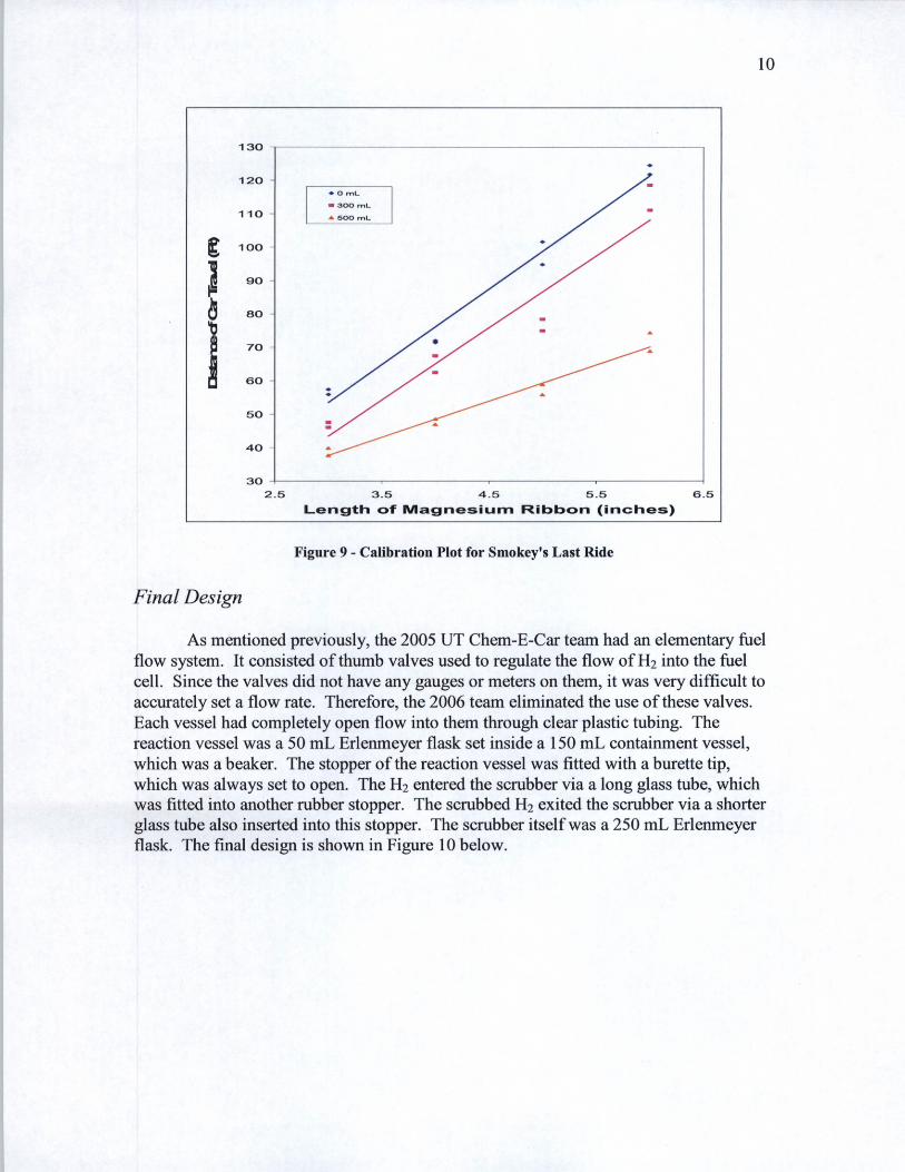