Small Community Water Supplies E.H. Hofkes L ... - IRC
442
Small Community Water Supplies Technology of Small Water Supply Systems in Developing Countries Edited by E.H. Hofkes International Reference Centre for Community Water Supply and Sanitation The Hague Prepared with contributions from and under the joint supervision of L. Huisman Professor of Sanitary Engineering Delft University of Technology Netherlands B. B. Sundaresan Director National Environmental Engineering Research Institute India J. M. De Azevedo Netto Professor ol Sanitary Engineering University of Sao Paolo Brazil J. N. Lanoix Formerly: Division of Environmental Health World Health Organization Geneva UGl-iARY, INTERNATIONAL REFERENCE CENTRE FOR COMMUNITY WATER SUPPLY AND SANiTATiON (IRC) P.O. Box 93190. 2509 AD Tha Hague Tel. (070) 8! 49 11 sxt 141/142 RN: sv\ International Reference Centre for Community Water Supply and Sanitation and JOHN WILEY & SONS Chichester • New York . Brisbane • Toronto • Singapore
-
Upload
khangminh22 -
Category
Documents
-
view
1 -
download
0
Transcript of Small Community Water Supplies E.H. Hofkes L ... - IRC

Small Community Water Supplies
Technology of Small Water Supply Systems in Developing Countries
Edited byE.H. HofkesInternational Reference Centre forCommunity Water Supply and SanitationThe Hague
Prepared with contributions from and under the joint supervision of
L. HuismanProfessor of Sanitary EngineeringDelft University of TechnologyNetherlands
B. B. SundaresanDirectorNational Environmental EngineeringResearch InstituteIndia
J. M. De Azevedo NettoProfessor ol Sanitary EngineeringUniversity of Sao PaoloBrazil
J. N. LanoixFormerly: Division ofEnvironmental HealthWorld Health OrganizationGeneva
UGl-iARY, INTERNATIONAL REFERENCECENTRE FOR COMMUNITY WATER SUPPLYAND SANiTATiON (IRC)P.O. Box 93190. 2509 AD Tha HagueTel. (070) 8! 49 11 sxt 141/142
RN:
sv\
International Reference Centre for Community WaterSupply and Sanitationand
JOHN WILEY & SONSChichester • New York . Brisbane • Toronto • Singapore
INTERNATIONAL REFERENCE CENTRE FOR COMMUNITY WATER SUPPLYAND SANITATION
IRC is an internationally operating organization dealing with information and technologysupport for water and sanitation improvement.
With its partners in developing countries and with the United Nations agencies, donororganizations and Non-Governmental Organizations, IRC assists in the generation, trans-fer and appliction of relevant knowledge. The focus of this cooperation is on rural andurban-fringe areas where the need for technical assistance is greatest.
IRC's information-oriented programmes include: 1 Information Support and Services; 2.Technology Development and Transfer; 3 Manpower Development and Training; 4 Com-munity Education and Participation; 5 Programme Planning and Evaluation.
Support is provided by means of publications and training material, seminars and courses,research and demonstration projects as well as by advisory support to the development ofnational facilities.
Requests for information on IRC should be addressed to IRC, P.O. Box 5500, 2280 HMRijswijk, The Netherlands
© Copyright 1981 Enlarged Edition 1983
International Reference Centre forCommunity Water Supply and SanitationP. O. Box 5500, 2280 HM Rijswijk (The Hague)The Netherlands
Permission to reproduce material from this handbook may begranted on application to IRC.
British Library Cataloguing in Publication Data:Small community water supplies—Enlarged cd.1. Underdeveloped areas- Water supply
I. Hofkes, E. H. II. Huisman, L.III. International Reference Centre for Community Water
Supply and Sanitation628.1'09172'4 TD201ISBN 0 471 90289 6 - Wiley Edition
This handbook is issued on the responsibility of the Interna-tional Reference Centre for Community Water Supply andSanitation. It docs not necessarily reflect the views or policies ofthe World Health Organization.
Printed in Great Britain

contentsPREFACE
1 .
2 .
3 .
4 .
5.
6.
7 .
8 .
INTRODUCTION1.1. Water and Human Health1.2. Water Supply and Development1.3. Small Community Water Supplies in
Developing Countries
PLANNING AND MANAGEMENT
913
14
2.1.2.2.2.3.2.4.2.5.2.6.
WATER3.1.3.2.
WATER4.1.4.2.4.3.
PlanningManagement and SupervisionManpower and TrainingCommunity InvolvementMaintenanceEmergency Operation . •
QUANTITY AND QUALITYWater Use and ConsumptionWater Quality
SOURCESWater Occurrence and HydrologyQuality of Water SourcesWater Source Selection
RAINWATER HARVESTING5.1.5.2.5.3.5.4.5.5.
Rainwater as a Source of Water SupplyRoof CatchmentsGround CatchmentsStorageWater Quality Preservation
SPRINGWATER TAPPING6.1.6.2.6.3.6.4.
IntroductionBasic ConsiderationsTapping Gravity SpringsTapping Artesian Springs
GROUNDWATER WITHDRAWAL7.1.7.2.7.3.7.4.7.5.7.6.
IntroductionGroundwater Occurrence and ProspectingMethods of Groundwater WithdrawalInfiltration GalleriesDug WellsTube Wells
SURFACE WATER INTAKE8.1.8.2.8.3.8.4.8.5.
River Water IntakeLake Water IntakeTypical Intake ConstructionsSmall Dams and Village PondsScreens
192426283235
3642
515355
5960636570
75798084
9192
100106109121
137140142144145

9. ARTIFICIAL RECHARGE9.1. Introduction 1499.2 Bank Infiltration 1509.3 Water Spreading 1559.4 Sand Dams 159
10. PUMPING10.1 Introduction 16310.2 Power Sources for Pumping 16310.3 Types of Pumps 16710.4 Reciprocating Pumps 17010.5 Rotary (positive displacement) Pumps 17510.6 Axial-Flow Pumps 17710.7 Centrifugal Pumps 17810.8 Pump Drive Arrangements 17910.9 Air-Lift Pumps 18310.10 Hydraulic Ram 185
11. WATER TREATMENT11.1 Introduction 19111.2 Groundwater Quality and Treatment 19411.3 Surface Water Quality and Treatment 195
12.201202208
13.213214217220222
14. SEDIMENTATION14.1 Introduction 22914.2 Settling Tank Design 23014.3 Construction 23314.4 Plate and Tube Settlers 237
15. SLOW SAND FILTRATION15.1 Introduction 24515.2 Theory of Slow Sand Filtration 24715.3 Principles of Operation 25015.4 Design Considerations 25315.5 Construction 25515.6 Cleaning 261
AERATION12.112.212.3
IntroductionWaterfall AeratorsBubble Aerators
COAGULATION AND FLOCCULATION13.113.213.313.413.5
IntroductionCoagulantsRapid MixingFlocculationHydraulic Flocculators

16. RAPID FILTRATION s
16.1 Introduction 26916.2 Theoretical Aspects 27416.3 Rapid Filter Operation and Control 275 '16.4 Design Considerations 281 ;16.5 Construction 290 |16.6 Village-Scale Rapid Filtration 293 »16.7 Roughing Filtration 295 \
I17. DISINFECTION f
17.1 Introduction 299 \17.2 Physical Disinfection 299 f17.3 Chemical Disinfectants 30017.4 Chlorination 301 :17.5 Chlorination Technology for Rural Water }
Supply 304 I17.6 Disinfection using Chlorine Gas 309 -:17.7 Disinfection of New Tanks, Pipes
and Wells 31117.8 Disinfection of Water Supply in Emergency •
Situations 312
18. WATER TRANSMISSION '•18.1 Introduction 317 V18.2 Types of Water Conduits 317 ;•18.3 Design Considerations 32018.4 Hydraulic Design 32218.5 Water Transmission by Pumping 32418.6 Pipe Materials 332 1.
19. WATER DISTRIBUTION ••:1 9 . 1 introduction 339 I19.2 Types of Distribution Systems 339 *19.3 Design Considerations 347 i19.4 Distribution System Design 356 :•19.5 Pipe Materials 359
ANNEXES ; 363
1. Sanitary Survey2. Weil Drilling3. Experimental Studies for Water Treatment Plant Design4. Chemicals Used In Water Treatment5. Measurement Units Conversion
CURRENT UPDATE 4 1 5


preface
The United Nations has designated the period 1981 - 1990 the Inter-national Drinking Water Supply and Sanitation Decade. Many hope andtrust that there will be vastly increased efforts to provide ade-quate water supply and sanitation services to all those needingthem.
The needs are enormous. Hundreds of millions of people living indeveloping countries lack reasonable access to an adequate supply ofsale drinking water. The problems are particularly acute for count-less small communities in the rural areas, as well as for urbanfringe areas. Their water supply situation often is grossly inade-quate .
In providing water supply systems to small communities, factors suchas organization, administration, community •• involvement and financeare frequently the major constraints, rather than technical consider-ations. However, the selection of suitable technology remains im-portant since other problems are compounded when techniques, methodsand equipment are used that are not compatible with the conditionsand situations of small communities.
it is a misconception to regard small community water supply systemsas 'scaled down' versions of urban installations requiring lessengineering skill or ingenuity. The exact opposite may bo the case.Simplicity and smallness should not be regarded as backward orsecond-rate, but rather as appropriate for the purpose. Technologiesmust be selected that can be integrated with the approach of commu-nity involvement which is so essential in small-scale schemes.Misapplication of technologies is likely when the designer does notclearly understand the basic assumptions implicit in them. Thisusually will result in costly overdesigns and unrealistic manpower,operation and maintenance requirements.
This handbook has been designed to provide a broad introduction intothe technology of small community water supplies. It providesinformation and guidance that should be most readily used by thosehaving some technical background in civil engineering, public healthor irrigation, but with no formal training or experience in watersupply, ft should serve engineers and public health inspectors whoare called upon to assume responsibility for the design and/ormaintenance of small water supply systems. This group also includesprovincial and town engineers who have responsibility for watersupply and sanitation, amongst many other tasks. The book, there-fore, has not been written as a textbook for engineering studentsnor as a design manual addressed to technicians. Some theoreticalexplanations have been included but such material has been kept to aminimum. For in-depth information reference is made to monographsand textbooks.
acknowledgement
This handbook has been compiled and further developed from theeontribut ions of many.
The main contributions have been made by a group of authors who eachsupplied selected chapters, and who collectively supervised thepreparation of the handbook. These authors are Prof. I,. Huisman(Netherlands), Prof. J.M. de Azevedo Net.to (Brazil), Dr. B.B. Sunda-resan (India) and Dr. J.N. Lanoix (WHO, Geneva).
Further, we are indebted to Messrs. L.G. Hutton and W. Moffat (WEDCGroup, Loughborough University of Technology, England) for thematerial they supplied on groundwater occurrence and prospecting,and to Mr. P.K. Cruse (George Stow & Co. Ltd., Water Well Engineers,Henley-on-Thames, England) who prepared the section on well drillingmethods. Mr. R. Trietsrh (DHV Consulting Engineers, Amersfoort,Netherlands) assisted by preparing from earlier assembled materialsa preliminary draft for the chapters on water transmission anddistribution. Dr. R.C.J. Zoeteman (National Institute for Water-Supply, Netherlands) advised on the presentation of water qualityand healLh aspects, and the guidelines for drinking water quality-Grateful mention is made of those who helped by reviewing the draftmanuscript; their comments were invaluable as a basis for cor-rections and improvements. We [eel the following persons should bespecially mentioned: Dr. G. Bachmann (WHO, Geneva), Mr. Edwin Lee(WHO-WPRO, Manila), Mr. D.V. Suhrahmanyam (WHO-SEARO, New Delhi),Mr. David Donaldson (PAHO, Washington), Mr. F.E. McJunkin (US AID,Washington), and Mr. T.K. Tjiook (IRC, The Hague).
in compiling and editing the various contributions, and in proces-sing the numerous comments made to the subsequent drafts, Mr. E.H.Hofkes (IRC, The Hague) found himself charged with the task ofintegrating, re-organising, revising and, in several instances,completely rewriting sections and even complete chapters.
In the editing of the material, Mr. G. Bedard provided importantassistance. Ms. Hannie Wolsink did an outstanding job of extensivetext processing and administrative coordination without which thepreparation of the handbook would not have been possible.
The present document is likely to require revision at a futurestage. It is intended to undertake that work when appropriate.
Comments and suggestions from readers for changes, corrections oradditions will be most welcome. These will be gratefully used in thefuture revision of the handbook, and will be duly acknowledgedtherein. Communications should be directed to: IRC, P.O. Box "j!iOO,2280 HM Rijswijk (The Hague), Netherlands.

introduction
introduction
1.1. Water supply and human health
Water is essential to man, animals and plants andwithout water life on earth would not exist. From thevery beginning of human civilization, people havesettled close to water sources, along rivers, besideslakes or near natural springs. Indeed where peoplelive, some water is normally available for drinking,domestic use, and possibly for watering animals. Thisdoes not imply, however, that the available source ofwater is convenient and of sufficient capacity, northat the water is safe and wholesome. On the con-trary, in many countries people live in areas wherewater is scarce. Often it has to be carried over longdistances, particularly during dry periods. Scarcityof water may also lead people to use sources that arecontaminated by human or animal faeces, and are thusdangerous to human health.
A few litres of water each day are sufficient for aperson's basic drinking and food preparation require-ments, depending on climate and lifestyle. Muchlarger quantities are necessary when water is usedfor other purposes such as personal hygiene, cleans-ing of cooking utensils, laundry and house cleaning.Safe, adequate and accessible supplies of water,combined with proper sanitation, are surely basicneeds and essential components of primary healthcare. They can help reduce many of the diseasesaffecting underprivileged populations, especiallythose who live in rural and urban fringe areas.
Safe drinking water is important in the control ofmany diseases. This is particularly well-establishedfor diseases such as diarrhoea, cholera, typhoid andparatyphoid fever, infectious hepatitis, amoebic andbacillary dysentery. It has been estimated that asmany as 80 percent of all diseases in the world areassociated with unsafe water. This association cantake a number of different forms, and diseases may begrouped accordingly (Table 1.1).

introduction
Table LLDiseases related to defieienci.es in water supply and/or sanitation
GROUP DISEASES
Diseases transmitted by water Cholera(water-borne diseases) TyphoidWater acts only as a passive vehicle ' Bacillary dysenteryfor the infant-Ing agent. IntHt-limis hepatitisAll of these diseases depend also on Leptospirosispoor sanitation. Giardiasis
Gastro enteritis
Diseases due to lack of water Scabies(water-washed diseases) Skin sepsis and ulcersLack of adequate quantity of water and Yawspour personal hygiene create conditions Leprosy .favourable for their spread. The intestinal Lice and typhusinfection^ in this group also depend on Trachomalack of proper human waste disposal. Conjunctivitis
Bacillary dysenteryAmoebic dysenterySalraoneliosis
! Enterovirus diarrhoeasParatyphoid feverAsc.ariasisTrihcuriasis
;; Whipworm (Enterobius)Hookworm (Ankylostoma)
Diseases caused by infecting agents Schistosomiasis (urinary & rectal)spreaded by contact with or ingestion Dracunculosis (guinea worm)of water. Bilharziosis(Water^based diseases) PhilariosisAn essential part of the life cycle of Qncholersosisthe infecting agf.nt. takes place in an Treadwormaquatic, animal. Some are also affectedby waste disposal.
Diseases transmitted by insects which live Yellow fever mosquitoclose to water Dengue + dengue(water-related vectors) hemorrhagie fever mosquitoInfections arc spread by mosquitoes, flies, West-Nile andinsects that breed in water or bite near it. Rift Valley'fever mosquitoThese are especially active and aggressive Arbovirusnear stagnant open water. Unaffected by Encephalitides mosquitodisposal. Bancroftian
Filariasis mosquitoMalaria(diarrhoea)* ^ mosquitoOnchocercfiasis Simulium flySleeping sickness Tsetse fly
Diseases caused by infecting agents. Mostly Clonorchiasis Fish
contracted by eating uncooked fish and Diphyilobothriasis Fishother food. Fasciolopsiasis Edible plant(Faecal-disposal diseases) Paragunimiasis Crayfish
Source:Saunders, J.; Warford, J. .Village Water Supply: Economics and policy in the Developing World.Published for the World Bank by the Johns Hopkins University Press, Baltimore, 1976
10

introduction
Water-borne diseases are those carried by water thatis contaminated with infecting agents from human oranimal origin, when the water is drunk the infectingagents will be ingested and may cause disease,control of such diseases calls for improving thequality of the water.
Diseases due to lack of water tend to be a serioushealth hazard. When people use very little water,either because there is little available or becauseit is too far away to be carried home in quantity, itmay be impossible to maintain a reasonable personalhygiene. There may be simply too little water forwashing oneself properly, or for cleaning food uten-sils and clothes. Skin or eye infections are thusallowed to develop, and intestinal infections canmuch more easily spread from one person to another.Clearly, the prevention of these water-washeddiseases depends on the availability of, and accessto adequate supplies of water rather than itsquality.
WHO Photo by A.S. KocharFigure 1.1.Water carried home over a long distance will be used verysparingly
11

introduction
Water-based diseases do not spread directly fromperson to person. They are caused by infecting agentsthat for an essential part of their life cycle de-velop in specific water animals, chiefly snails andcrustaceans. Over a period of days or weeks, theparasite larvae or eggs mature in these intermediatehosts, and then are shed into the water. The maturedlarvae or worms are infective to people drinking thewater or having contact with it.
In tropical countries biting insects are common. Mostof these, notably the mosquitoes, breed in pools orother open water, and sometimes even in householdwater containers. Tsetse flies are also active nearthe water. Such water-related vectors carrying patho-gens can transmit disease.
Health hazards also emanate from infection sourcesother than water. Diseases may spread through directcontact (e.g. soiled hands) or through food, particu-larly fish, vegetables and fruit eaten raw. Besidessafe water supply, the necessary measures to controldisease therefore should include personal hygiene andinspection of food storage and market places.
Very important is the provision of adequate sani-tation, including sanitary facilities for human wastedisposal. All the water-borne and many of the water-based diseases depend for their dispersion on infect-ing agents from human faeces getting into drinkingwater or into food. The diseases' chain of trans-mission may be broken as effectively by sanitarydisposal of faeces as by the provision of safe andadequate water supplies. There are certain agents,such as hookworm, where sanitation is much moreimportant than water supply in the prevention ofdisease because transmission is from the faeces tothe soil, and then by direct contact and penetrationthrough the human skin.
Improvements in the quality of community watersupplies will basically only affect the water-bornediseases such as bacillary dysentery, cholera,typhoid, and possibly schistosomiasis. Many of thediarrhoeal disease probably are more due to a lack ofadequate quantities of water. Certainly, skin and eyeinfections are in this group of water-relateddiseases.
The provision of a wash tap, shower or some similarwashing facility frequently has proven to improve theuser's health situation. There is, however, no con-
12

introduction
vincing evidence yet that once each family has a tapor shower, further improvement of the water supplywill appreciably affect health. When water suppliesare developed without complementary improvements inpersonal hygiene, food handling and preparation, andin general health care, they are unlikely to producethe expected health benefits.
1.2. Water supply and socio-economic development
In the industrialized countries, community watersupply systems were first provided for the largercities, smaller cities and towns followed. The watersupply systems were built by the state, district ortown authorities, or by private companies. In ruralareas, community water supplies were installed muchlater since public health considerations were lesspressing than in urban areas. In the first half ofthe 20th century many national governments startedgiving financial and technical assistance to smallcommunities and the extension of water supplies tothe rural population was then greatly accelerated.
For significant socio-economic development of acommunity, an adequate supply of safe water is aprerequisite. Factors such as time and energy savingin the collection of drinking water, and a sub-stantial reduction in the incidence of disease cancontribute to development, provided the time andenergy gained are utilized economically.
The new water supply could help activities such asfruit and vegetable processing or fish conservation.Whether potential productivity benefits are realizedor not depends on the specific circumstances. Oneimportant factor is how the time and energy saved incarrying water might otherwise be used. In somevillages the ill health of the labour force seriouslyaffects agricultural development, whereas in othersthere is underemployment and benefits may not berealized unless the water supply project forms partof an integrated rural development providing in-creased employment. A new water supply may openopportunities for handicraft manufacture, livestockkeeping or vegetable growing. Thus, when productivework is stimulated and personal hygiene, health careand food preparation are improved, side by side, acommunity water supply can be expected to have apositive socio-economic development impact.
13

introduction
This is particularly true in arid regions or areaswith a long dry season if sufficient quantities ofwater are provided to allow watering of livestock andirrigation of vegetable gardens.
It is possible that water supply systems, in combi-nation with complementary health and economic de-velopment programmes, could slow migration from therural areas to the cities. There is little evidence,however, that the provision of water supplies alonewill have any substantial effect on migration. It ismore likely that water supply systems can be used toencourage, over a period of time, the grouping ofdispersed populations into village units of somesize. The more concentrated the population to beserved the more likely it is that a financiallyviable and properly maintained water supply systemcan be provided. If the water supply enables andencourages the formation of settlements of some size,this can help improve the potential for economicdevelopment.
In most cases it is impossible to present a rigorouseconomic justification for small community watersupply projects. Instead, the justification must reston a qualitative assessment of the benefits antici-pated from the water supply. The most importantdirect benefits of improving the quality of watersupply generally are better hygiene and health,greater convenience, and benefits from stock wateringand vegetable garden irrigation. Indirect benefitscommonly cited are a redistribution of purchasingpower in favour of the rural poor, a better standardof living, and the development of community insti-tutions .
1.3 Small community water supplies in developing countries
In the urban centres of developing countries, com-munity water supply systems of the type developed inindustrialized countries can be suitable, with appro-priate adaptions. Because of economies of scale andthe large numbers of people to be served, the percapita investment and operating costs of urban watersupply systems need not be high. When a substantialnumber of houses are connected to the water distri-bution system, and water charges collected on aregular basis, the water supply undertaking canbecome self-financing.
14

introduction
In most small towns and rural communities in develop-ing countries, the prevailing water supply conditionsare very different from urban installations. Usuallythe number of people to be served by such a watersupply scheme is small and the low population densitymakes piped distribution of the water costly. Therural population often is very poor and, particularlyin subsistence farming communities, little money canbe raised. Funds are hardly available to pay for theoperation and maintenance of the water supply scheme,and small communities are unlikely to be able toobtain the investment capital without assistance fromthe national government or from external donor orlending agencies.
Trained personnel for the operation and maintenanceof the water supply scheme are generally not avail-able in small communities.
Qualified staff for design and construction may beobtained with external sources assisting the nationalinstitutes to become self-reliant. The recruitmentand training of the necessary personnel for operationand maintenance of the water supply systems can,however, be difficult.
One important factor is the requirement to use atechnology that is appropriate for the local con-ditions. This technology will differ from the con-ventional one which was mainly developed for thelarger water supply systems of cities and towns ofdeveloped countries.
Figure 1.2.Typical small community situation
15

introduction
For small communities, piped water supplies withhouse-connections are often not economically feasi-ble. In such instances, the realistic option is toprovide a number of individual or 'point' sources: aprotected well fitted with a handpump, a springtapping structure or perhaps a rainwater catchmentand storage system. For larger towns and villages, asmall water treatment plant and distribution of thewater through public standpipes may be feasible. Whenthe community to be served makes a contributiontowards the construction costs of the water supplysystem, whether by payment of funds or through theprovision of labour or construction materials, thecapital investment can be kept low. The recurrentcosts for operation and maintenance often present aproblem especially when water charges are difficultor impossible to collect.
A small community water supply system need not bedifficult to design and construct. The engineershould carefully select a technology which is simple,reliable, and adapted to the available technical andorganisational skills. This is not easy but theseproblems present a fascinating challenge and re-warding field of work.
Small community water supply systems have been builtfor a long time, and recently such schemes have beenconstructed in considerable numbers. Some weresuccessful but the overall record does not appeargood. Sometimes small water supplies proved to be un-suited to the conditions under which they have tooperate. Several schemes have been completely aban-doned within a few years after their construction.Frequent breakdowns are by no means uncommon. It isnecessary to learn from past mistakes and to recog-nize the causes of failure. From these, guidelinescan be developed for the planning, construction,operation and maintenance of small water supplysystems.
16

Introduction
Ballance, R.C.WATER SUPPLY, SANITATION AND TECHNOLOGYInterdisciplinary Science Reviews, Vol. 3, No. 3, 1978
Beyer, M.DRINKING WATER FOR EVERY VILLAGE: Choosing appropriate technologiesIn: Assignment Children 1976, No. 34 (April-June)
Cairncross, S.; Feachem, R.G.SMALL WATER SUPPLIESRoss Institute, London 1978, 78 p. (Bulletin No. 10)
COMMUNITY WATER SUPPLYWorld Health Organisation, Geneva, 1969, 21 p.(Technical Report Series No. 420)
Environmental Protection AgencyMANUAL OF INDIVIDUAL WATER SUPPLY SYSTEMSU.S. Government Printing Office, Washington, D.C., 1973,155 p.
Feachem, R.G.; McGarry, M.G.; Mara, D. (eds.)WATER; WASTES AND HEALTH IN HOT CLIMATESJohn Wiley, London, 1977
Feachem, R.G.; Burns, £.; Cairncross, S. et alWATER, HEALTH AND DEVELOPMENT: AN INTERDISCIPLINARY EVALUATIONTri-Med Books, London, 1978, 267 p.
Johnson, C.R.VILLAGE WATER SYSTEMSUNICEF, Nepal, 1977, 107 p.
Mann, H.T.; Williamson, D.WATER TREATMENT AND SANITATION: A HANDBOOK OF SIMPLE METHODSFOR RURAL AREASIntermediate Technology Publication Ltd. London, 1976, 90 p.
Pacey, A. (ed.)WATER FOR THE THOUSAND MILLIONPfcrgamon Press, Oxford, 1977 •
PEOPLE, WATER AND SANITATIONIn: Assignment Children No. 45/46 -UNICEF, Geneva, 1976
Pineo, C.S.; Subrahmanyam, D.V.COMMUNITY WATER SUPPLY AND EXCRETA DISPOSAL STTVJATTON IN THEDEVELOPING COUNTRIES: A COMMENTARYWorld Ht-alth Organisation, Geneva, 1980, 11 p.
17

Saunders, R.J.; Warford, J.J.VILLAGE WATER SUPPLY: ECONOMICS AND POLICY IN THE DEVELOPINGWORLDWorld Bank Research PublicationJohns Hopkins University Press, Baltimore, 1976, 279 p.
Secretariat des Missions d'Urbanlsme et d'Habitat (S.M.U.H.)ALIMENTATION EN EAUMinisters de la CooperationFonds d'Aide et de Cooperation (F.A.C.), Paris, 1977
Wagner, E.G.; Lanoix, J.N.WATER SUPPLY FOR RURAL AREAS AND SMALL COMMUNITIESWorld Health Organisation, Geneva, 19159, 337 p.(Monograph Series No. 42)
White, A.U.; Seviour, C.RURAL WATER SUPPLY AND SANITATION IN LESS-DEVELOPED COUNTRIESInternational Development Research Centre, Ottawa, 1974, 81 p.
White, G.F.; Bradley, D.J.; White, A.U.DRAWKRS OF WATER: Domestic Water Use in East AfricaUniversity of Chicago Press, Chicago, 1972
18

planning and management
2. planning and management
2.1 Planning
In many countries the provision of community watersupply systems is a major element in the environmen-tal health programme and they are frequently plannedin this context. However, the actual responsibilityof the public health authorities is often limited tothe quality surveillance of drinking water fromcommunity supplies, sometimes coupled with the con-trol of sanitary facilities. In some countries thehealth authorities have assumed a direct responsibi-lity for small community water supplies and sanita-tion in rural areas.
The control function in respect to water supplies andsanitary facilities would imply an active part in theplanning, management and maintenance of all schemes.But the health authorities may not be sufficientlystaffed and equipped to cope with the demands of suchan involvement. Engineering units of other governmentdepartments usually carry out the bulk of watersupply planning and construction. They are likely toconcentrate their efforts on engineering and costaspects, and may tend to overlook the health andsocial implications of drinking water supplies.
Programmes rather than projects
The planning and design of a large city water supplysystem usually is approached as a project. The termproject is used here to describe all the preparationsfor the construction of a single scheme or watersupply system. Every such major scheme is dealt withas a separate project. However, when planning watersupply systems for a large number of small rural com-munities, the approach should be that of a programmerather than a series of individual projects. A pro-gramme is here understood to be an integrated groupof continuing activities directed at the implemen-tation of a considerable number of similar watersupply schemes or systems. The key problems arelikely to be less technical and more organisationaland administrative.Community involvement aspects willassume a much greater significance.
19

planning and management
Under a programme, technical decisions often have tobe subordinated to other considerations. For example,the number of different types or models of pumps usedin a programme should be kept to a minimum in orderto reduce supply and maintenance problems. In theproject approach, a pump would be selected to fit atechnical specification, and the maintenance systemwould then be adapted to the pump's characteristicsand service requirements.
Another basic difference is how the users perceivetheir relationship to the water supply and its costand benefits. The urban dweller seldom has an alter-native water source and is mostly aware of thegeneral benefits of water supply services. Thuslittle time and effort are required to convince himof the need for more ample or safe water. In a smallrural community there is usually oo equivalent tothis urban 'demand' for water. Rural householdsfrequently have a choice between alternative watersources and people have developed their criteria tochoose between them. Water is usually seen as a freecommodity. Health considerations play a minor role.The quantities of water used are small, exceptperhaps for stock watering and plot irrigation. Astrong demand for good quality water will theninitially only exist in situations of severeshortages or of heavy pollution of the water sources.
It is, therefore, to be expected that an urban-typedemand for water will not develop in small ruralcommunities without some change in deeply ingrainedwater-use customs. An educational effort will have tobe linked to the rural water supply programme andcarried out with subtlety and knowledge of localhabits.
Financial Considerations
In urban areas inhabitants have usually accepted theprinciple, or at least are familiar with the require-ment that they must pay for the water, or rather forthe convenience of having safe water delivered nearthe point of use. In small rural communities theprinciple of paying for water is usually not widelyaccepted. People feel that water, like air, is anatural gift. It is also a fact that those living insmall communities often have little capacity to pay.Thus, developing financing schemes will be difficultand time-consuming, and requires a clear understand-
20

planning and management
ing of local habits. For example, bills may have tobe timed with local harvests.
For any rural water supply programme, it is necessaryto establish a long-range financing arrangement.Small communities frequently find it difficult toobtain the capital for construction even when theyunite into a national or provincial programme. Theinitiative for organizing and financing these pro-grammes, therefore, must usually come from thecentral or provincial government.
Revolving funds offer one excellent method of finan-cing because of their flexibility and adaptability tolocal needs and conditions. A revolving fund is acentrally established fund which finances new pro-jects using repayments on earlier loans. To getstarted, the funds need to be established at thenational or provincial level. The benefitting com-munities contribute labour and local materials forconstruction (for example, in Latin America usuallyup to 20 percent of construction costs). They thenpay a water rate that, as a rule, covers localoperation and minor repair expenses. To back up suchlocal efforts, the national programme should organizea system for major repairs and maintenance at thedistrict or provincial level. As the payments onearlier loans come in, the revolving fund is avail-able to finance other schemes.
It is important to note that, in financing an urbanscheme, basically all the required funds come fromthe community itself in the form of water revenues.In contrast, for the small rural communities, about80 percent of construction costs would come fromoutside in the form of loans, grants, etc., and onlythe remaining 20 percent are direct community contri-butions such as construction materials and labour.
Recent studies in Latin America indicate that repay-ment schemes tend to promote effective organizationat the local level. For this, the assistance of localadministrators is essential. Communities do get usedto community financing of water supply services andone of the major benefits seen is a greater communityinvolvement.
Typical designs and standardisation
As one examines the thousands of small water supplysystems required, one is struck by the number ofrepetitive elements: wells, intake structures, water
21

planning and management
tanks, pump houses, etc. Substantial cost savings canbe had if standard designs and construction tech-niques are used. In addition, costs can also bereduced by using technicians who are trained in therepetitive systems, limiting the number of profes-sional engineers needed.
An advantageous approach has been developed in LatinAmerica. Within this approach, the programme isbroken down into its component parts - communitypromotion, technical design, programme financing,etc. - and each component is considered for itseffects upon the others. A programme is developedwhich incorporates these elements into the least-costsolution that will best utilize the programme resour-ces (manpower, finance, technology and management).It is obvious that, since a rural water supply pro-gramme must repeat many tasks in thousands of villa-ges - in some countries, in tens of thousands ofvillages - the development of standard designs be-comes a necessity.
These designs must allow for rapid and effectiveconstruction techniques, through repetitive work byrelatively unskilled artisans with standard equipmentand plant. Unit design constitutes an essentialfeature. The savings in planning and supervisioncosts will almost certainly outweigh the slighttechnical inefficiency of such a design. It is possi-ble to devise a very simple form of investigationwhich will enable a technician or sanitarian tocollect in one day sufficient information about asmall water project to support its qualification fora certain type of design.
Standard design criteria should be selected, pre-designed elements (tanks, pump houses, etc.) anduniform equipment lists should be prepared. Once thedesign of a particular scheme has been reviewed by anengineer, the materials would be assembled in acentral yard and sent to the community as a package,together with all the necessary tools and items notreadily available locally. Professionals would alsodevelop techniques and strategies for involving thecommunity. These are formalized as work modules foreach phase, and used in the training of personnelassigned to implement them at the local level. Thedesign of both the technical and community involve-ment modules are determined in the context of theoverall programme.
22

planning and management
Figure 2.1.Water, health and development
WHO Photo
23

planning and management
2.2 Management and supervision
The following table outlines the principal functionscarried out at the national, provincial and locallevels. In some countries, provincial programmes areset up to operate autonomously but they are linked tothe national programme by means of standard criteria,designs and financial assistance.
Table 2.1.Functional division over different levels of government
Level Functions
National . Long-term planning.Establishment of policies(technical and administrative) andstandards.Management of national funds, andmatching these to local contributions.Supervision of the execution of thenational plan.Supervision of provincial programmes.General financial control.Provision of technical assistance,
. Training.
Provincial . Programme implementation.(and District) . Design.
Construction, and administration ofprojects.Promotion of community participation.
Local . Administration of community water supplysystems.Operation and maintenance.
. Collection of water charges.
It will not be possible to include all the existingsmall and rural communities into the national orprovincial water supply programme at once. Aselection will have to be made which will be amendedand updated periodically. The criteria for selectionand the order of priority for the construction ofschemes will be determined at the national orprovincial level taking into consideration all rele-vant factors.
The objective of any rural water supply programmeshould be as specific as possible. For instance:'All
24

planning and management
communities of 500 persons or more, and 50% of thesmaller communities will have a safe water supplywithin a distance not exceeding 500 metres from eachindividual house, within 8 years' . Or, 'The goal isto provide drinking water to 90% of the rural com-munities in districts A and B within 22 months'. Incontrast, it is vague to state the objective as'Improvement of the water supply of small communi-ties ' .
A strong commitment to the programme at the nationalpolicy level is essential in order that the programmecan operate on a long-term basis. It is often neces-sary to provide subsidies for some time until thecommunities served by the new schemes appreciate thebenefits of an adequate supply of safe water. Oncethe people understand this, the process becomes oneof a continuous upgrading of the basic service untilit, hopefully, will reach a level where it is bothfirmly supported by the community and financiallyself-sufficient.
The management, operation and maintenance of a watersupply system is a matter that should be kept in mindby policy-makers and design engineers from the ear-liest planning stage. The following statement summa-rizes this eloquently (Wagner & Lanoix, 1959):
1 The engineer who makes the preliminary field in-vestigations and designs can, by his decisions,facilitate or complicate future operation and main-tenance problems. This will depend on whether he issearching simply for a solution, or for the bestpossible solution. Often, as a result of haste, thesestudies become less thorough than they should be. Theengineer in charge of field investigations and designcontrols one of the most important phases which bearsheavily on the future functioning of the project'.
'If by diligent work he can eliminate a pump, anengine, another piece of equipment, or a treatmentprocess, he is thereby removing a possible obstacleto efficient operation. An understanding of theoperational problems of small water systems, perse-verance in the search for simple solutions, andvigilance in approval of projects are the best pos-sible measures to facilitate the operation and main-tenance of these systems, and, thus, to ensure thefulfillment of their function'.
1 From the administrative standpoint, proper manage-ment of a water supply system, no matter how small,requires operating funds, personnel and organizatio-nal services. Since these are within the control of
25

planning and management
local authorities, early negotiations should be un-dertaken, and a considerable degree of agreementshould be reached, before the project gets into theconstruction stage. These negotiations are not alwayseasy, as some officials, whether selected or ap-pointed, will jealously guard their full authority,even though they may have had no previous experiencein water supply management1.
2.3 Manpower and training
The number of personnel needed to manage and operatea small water supply greatly depends on the type ofdistribution system, if any, and whether there is awater treatment plant and/or pumping station. Itshould not be expected that qualified personnel willbe found in small towns and villages. However, itwill often be possible to recruit and train poten-tially good employees for both administrative andoperational functions. One of the methods which hasproven succesful consists of using the constructionperiod to select and train the key personnel who,later, will be responsible for operational duties.During this phase, they have an opportunity to learnhow the system is put together and works. In this waythey can best understand and perform the maintenancework which is expected of them.
The actual selection of these men may, in some in-stances, be a delicate matter inasmuch as theiremployment may be the normal function of the localgovernment. With tact and understanding, however, itshould be possible to find candidates who are accept-able to the local authorities and who possess theminimum qualifications required.
The challenge will be in the use of sub-professionalpersonnel. While managers and engineers who areexperienced in community systems should manage theprogramme, their task will be so great (and they areusually so few) that they will have to devote theirtime to directing, planning, reviewing and super-vising the programme. A special group of sub-profes-sional technicians and/or sanitarians should betrained for the day-to-day cooperation with thecommunities, the collection of field data, prospec-ting for and investigation of water sources, thepreparation of the repetitive designs as well as theinspection visits to the completed systems.
26
planning and management
In small undertakings, each person in a supervisoryposition has to perform a number of functions andwithout proper training he is bound to be inefficientin any individual function. Training is, therefore,particularly important for manpower engaged in smallcommunity water supply systems.
Training should stress the practical aspects of thesubjects covered and should include a minimum offormal lectures. The programme of training may beaccompanied, when circumstances permit, by a pro-gramme of examination and certification of watersystem technicians and operators, several gradesbeing established for each category of personnel.Such a programme, which may be undertaken in collabo-ration with local educational authorities, will helpto create an incentive on the part of the watersupply personnel for technical development and pro-gress towards more responsible positions.
One cannot overstress the need to develop in the mindof every waterworks official, whether office or fieldemployee, the concept of 'service to the community'.Both the administration and the operation of a watersystem, large or small, should be geared towards theprovision of a satisfactory service to the consumer.In many rural areas, this will be a novel idea. Oftenrural or small-town folk do not think of publicutilities as agencies from which they can expect ordemand service. To them the water supply may bethought of in terms of the mail service: poor andintermittent. Their attitude would be one of compla-cency. Much effort should be made by the responsibleagency to ensure that neither the people served northe watersupply employees develop this sort ofattitude. The objective should be to make the em-ployees understand the importance of giving asatisfactory service to consumers, and their role andresponsibility in this. On the other hand, the localpopulation needs to develop a sense of ownership andpride in the water supply system and to understandthat it has a right to demand service. These pro-cesses are neither simple nor quick. However, oncethey are established, the service concept will growand become more generally accepted. The critical timeis in the early stage.
27

planning and management
2.4 Community involvement
Acceptance of a small water supply system by a com-munity is by no means assured. The users may not besatisfied by the supply provided, if it does not meettheir expectations. Waiting in long lines to collectwater, intermittent service and insufficient suppliesduring some or many hours daily, are common problems.
Engineers and technicians sometimes go to smallcommunities, install water supply systems, and expectthe villagers to use them with care for long periodsof time. Too often, the people who are to benefitfrom the water supply system are not consulted onmatters of design, construction, use and maintenanceof the facilities. It is difficult, if not im-possible, to achieve the continuous functioning of asmall water supply without some degree of communityinvolvement. If the installations are not acceptedand supported by the community, they are likely tosuffer from misuse, pilferage or even vandalism.Conversely, it has been seen time and again that,with proper consultation and guidance, people can bemotivated to help in the planning, construction,operation and maintenance of water supply systems fortheir communities.
The positive role of community involvement in watersupply development can be illustrated by events inMalawi. Here, participation of local people was thekey to success in bringing piped water to over150,000 villagers in water-scarce areas, at a cost ofabout US$ 3 per person only. The villagers dug allthe trenches, laid the pipes (supplied by the govern-ment and aid agencies), and constructed concreteaprons and soak pits. Small-scale pilot demonstra-tions were initially used, leading to large publicmeetings where there was a chance to discuss allaspects of the new system. As the project evolved,the concept of the 'project assistant' was intro-duced; three-week training courses were conducted formen who had been carefully selected by the com-munities and were charged with responsibility for thelocal systems.
Analysis of existing small community water supplieshas shown that participation in the early designstages greatly contributes to the success of a pro-ject. The choice of water source, the level of ser-vice and the siting of the water supply facilities inparticular are decisions in which the community canbe usefully involved. A second consideration for more
28

planning and management
community involvement in the design stage, the safe-guarding of the interests of weaker sections of thecommunity, will be more difficult to accept. Yet manyof the decisions that are taken in this phase maylead to a worsening of the position of disadvantagedgroups. Social problems impairing the access to thesupply, loss of employment, loss of social contactsfor women, and the domination of local elites in thewater organization are all possible consequences of anew water supply system.
(JMCEF/WHO puoto by datheson
Figure 2.2.Community involvement in construction
Community involvement in the construction of smallwater supply systems can take many forms. Localcontributions in cash, labour, materials, servicesand organization will reduce the required capitalinvestment, stimulate feelings of local pride and
29

planning and management
commitment, develop local capabilities, and presentopportunities for the selection and training ofsuitable personnel for maintenance of the supply. Itwill also promote the proper use of the supply by thepeople. But such community involvement can make toogreat a claim on the available resources and time,resulting in a poor standard of construction, delays,difficulties in the recruitment of the requiredpersonnel and local conflicts. Generally, some in-volvement of the community in the construction of thewater supply is regarded necessary but the usefulnessof local labour depends to a considerable extent onthe type of technology adopted, the local conditionsand the availability of technical supervisors.
The delegation of operation and maintenance tasks toa community is more common today than it was someyears ago. These delegated responsibilities varywidely, from some checking and reporting, or basicroutine maintenance, up to the training of caretakersand operators. There is a considerable range of localorganisation and administrative arrangements.
Three approaches may be distinguished: a standardapproach, individual arrangements, and a compromisecombination. In Latin America, a standard approachhas been used with fixed selection procedures, formaldelegation of responsibilities and authority,supplemented by training and supervision. Elsewhere,individual arrangements are common which are adaptedto the existing community organization. However,these arrangements lack a legal base and theireffectiveness is often limited. As a compromise, someflexibility can be brought into the standard approachto suit the local, social and cultural pattern. Thisrelates to matters such as the selection procedures,scope of community organization and division ofresponsibilities and authority.
If the cooperation between the community and thewater supply agency or health deparment is to beeffective, both sides will have to be partners in afull exchange of information and views. The watersupply agency needs to set forth the desired goals ofthe community water supply system. Health educationmay be part of the motivation for the water projectand should start as early as possible. On the otherhand, local conditions, expectations, and constraintswill also play important roles. The water agencytherefore needs to receive sufficient informationabout the socio-economic and cultural background ofthe community.
30

planning and management
Project information and general health educationduring the planning phase may be followed by morespecific educational efforts, such as training fordelegated tasks. A users' education programme can bestarted before the installation is completed. Healtheducation may be continued as a more specific pro-gramme on personal, household and public hygiene andother related health aspects. The integration ofhealth education as a part of any water supply pro-ject has already been emphasized. The provision anduse of safe water alone will not be enough to achievea health impact. Usually, improvements in disposal ofwaste, nutrition, animal hygiene, housing, insect androdent control, and food hygiene will be needed aswell. In some countries water projects are part ofthe primary health care programme, or they are linkedto nutrition projects. However, even when watersupplies are planned and implemented independently,engineers should discuss with the community the rolewater can play in local development and they shouldencourage other agencies to link their programmes tothe water project.
Figure 2.3.Educating the people about water (Iran)
WHO Photo by D. Deriaz
31

planning and management
2.5 Maintenance
Experience shows that small community water suppliesare often more difficult to be kept running than toconstruct. The need for maintenance is generallyrecognized but the actual maintenance work isfrequently neglected. A basic principle in theplanning of any small community water supply shouldbe that the technical design keeps in view themaintenance requirements of the installations andequipment. The maintenance scheme should be feasible,just as the technical design should be cost-effectiveand suited to the local conditions.
Two factors contribute to most failures in smallcommunity water systems:
a) Equipment and materials are used under conditionsfor which they are not designed;
b) Operators who, due to ignorance or disinterest,do not recognize the indications which precedebreakdowns and failures.
The typical operator of a small water treatment plantalso supervises or actually makes water serviceconnections, reads meters, answers complaints andorders needed supplies and equipment. He must alsoargue his case before the town board, village chiefor water committee. He is lucky if he receives halfthe pay he is worth. Operators of small water supplyplants have limited resources available to them, andare frequently called upon to perform extensivetasks. They often get little support and appre-ciation. Yet they have to carry out their work in acreditable fashion.
By careful review of plant, design and specifi-cations, the water supply agency can prevent oreliminate most difficulties of a mechanical nature.The reduction of troubles caused by the human elementis harder to achieve. But much can be done, as pre-viously indicated, through training of field person-nel, technical assistance and supervision.
The following reasons make it particularly importantto provide for proper operation and maintenance.
effect of an inoperative community water supplyon the health of the users. This may be difficult toquantify but many studies and surveys have shown thatthe incidence of intestinal diseases is related tothe use of polluted water. Improvements in the health
32

planning and management
situation that can result from the supply of safewater, are lost when the water supply breaks down.
In small rural and urban squatter communities wherethe provision of safe water is most important, theintroduction of a new water supply is often a majorevent. Frequently this event also forms part of thehealth education towards the hygienic use of thewater. If the water supply becomes inoperative, thechances of improving the hygienic practices in thecommunity will be lost for months, if not years.Furthermore, if the water supply scheme was con-structed with contributions from the community,whether in kind or money, the people will probablyview the breakdown of the supply as evidence thattheir contribution is wasted. It is likely that theywill be unwilling to further cooperate with the watersupply agency or the government.
The above facts are difficult to analyse from astrictly economic point of view. However, a tentativeassessment of the economic impact is as follows:
A country may have some 10,000 small community watersupplies representing an average investment of about$ 30,000 each. If only 75% of these schemes arefunctioning, then 2,500 schemes are out of operationat any one time. Should an improved maintenancesystem ensure the continuous operation of 1,500 outof these 2,500 schemes, this would be equivalent to acapital investment of $ 45 million! Moreover, expe-rience shows that installations remaining out oforder for more than a few days are likely to sufferfrom pilferage and vandalism. It is not unusual thatequipment is stolen from them. Therefore, not onlythe inconvenience and health hazards of inoperativesmall water supplies should be considered but alsothe loss of equipment, spare parts and constructionmaterials.
The primary responsibility for the continuous func-tioning and maintenance of a small water supplysystem lies with the community, at the local level,backed by district support and the national watersupply programme. A good example of this comes fromthe State of Tamil Nadu, in India, where a three-tiermaintenance system was introduced. Since 1971, about15,000 deep-well hand pumps have been installed andabout an equal number of shallow-well hand pumps,serving villages in the rural areas of the State. Thethree-tier system is intended to provide maintenanceof these wells and pumps.
33

planning and management
The three-tier maintenance system comprises thefollowing service personnel:
1) Caretaker at village level
An interested and capable volunteer, who usually lives closeto the handpump, is chosen from among the villagers. He maybe a farmer, shopkeeper, artisan or social worker. He isgiven a two-day orientation course on the importance ofdrinking water supply and ori the mechanism, operation andservicing of hand pumps. He is trained to attend to minorrepairs and is supplied with basic tools. He is also givenpre-stamped and addressed postcards in the local language.When a breakdown occurs, the caretaker tr ies to fix i t . Ifhe can not do so, he specifies the type of repairs needed ontwo postcards, one of which he posts to the block-level' f i t t e r ' and the other to the District mobile team. So far,some 2,000 caretakers have been trained in Tamil Nadu State.
2) 'Fi t ter ' at the block level
One ' f i t t e r ' (service mechanic) for every 100 handpumps isappointed at the block level. He is under the supervision ofthe Block Development Officer. Upon receipt of a requestfrom a caretaker, the f i t ter proceeds to the village andattends to repairs, if the problem is located in the 'topend' of the mechanism.
3) Mobile team at the distr ict level
In case of the need for major repairs, i t is the mobile teamat the distr ict level which proceeds to the village uponreceipt of the postcard. There is one such team for every1,000 handpumps and, therefore, this often involves a delayof a week or more. To reduce this waiting, the Tamil NaduGovernment is now recommending one such team for every 500handpumps. Any expenses incurred in the repairs are sharedby Lhe government and the local 'gram panchayats' (villagecouncils).
Some breakdown of a water supply plant and equipmentis inevitable in spite of the best maintenancemeasures taken. In order to deal with such breakdownefficiently and with minimum delay, the followingfacilities should be available:
Workshop facilitySufficient stock of necessary spares, etc.Technical staffCommunication facility ;Directory of addresses and names of firms andsuppliersTraining programme.
34

planning and management
2.6 Emergency operation
Every community water supply system, large or small,should have some emergency procedures which may haveto be operated in situations such as earthquake,flood, or war damage. It must be recognized that, insuch circumstances, water is probably the most urgentneed of people who will use any available source,polluted or not, unless provision is made quickly fora supply of safe water. It is recommended that, soonafter the installation of a new water system, or evenbefore, a realistic inventory be made covering allavailable sources of water, public or private. Thisinventory should include personnel resources and theavailable emergency-type water supply equipment, handand motor pumps, water-tank trucks, pipe accessories,mobile or potable filter units, tools and spareparts, and chemicals (especially those for waterdisinfection purposes ).
During emergencies, a minimum of 2 litres of waterper person should be provided daily for drinking and3 litres for other purposes, in such places astemporary shelters. In camps with tents, a minimum of10 litres per person should be provided. This amountshould be doubled for the supply of temporary hospi-tals and first-aid stations. While ground-watersupplies from properly constructed wells, infiltra-tion galleries, and spring structures may be regardedas safe, all surface water should be considered ofdoubtful quality. It has to be disinfected by boil-ing, chlorination or disinfection by iodine com-pounds. The free chlorine residual in reasonablyclear water at times of emergencies should be notless than 0.5 mg/1 after 30 minutes of contact forwater that has not been filtered.
35

36

Planning and management
Bainbridge, M.; Sapirie, S.HEALTH PROJECT MANAGEMENTA Manual of Procedures for Formulating and Implementing HealthProjects.World Health Organisation, Geneva, 1974(WHO Offset Publication No. 12)
Barker, H.W.ASSESSMENT OF MANPOWER NEEDS AND TRAINING PROGRAMMESIn: international Training Seminar on Community Water Supplyin Developing CountriesInternational Reference Centre for Community Water Supply, TheHague, 1977 (Bulletin No. 10)
Cairncross, S.; Carruthers, I.; Curtis, D.; et alEVALUATION FOR VILLAGE WATER SUPPLY PLANNINGInternational Reference Centre for Community Water Supply, TheHague, 1980, 175 p. (Technical Paper Series No. 15)
Campbell, S.; Lehr, H.RURAL WATER SYSTEMS PLANNING AND ENGINEERING GUIDENational Water Well Association, New York, 1973
Donaldson, D.PLANNING WATER AND SANITATION SYSTEMS FOR SMALL COMMUNITIESIn: International Training Seminar on Community Water Supplyin Developing Countries. (Amsterdam, 1976)International Reference Centre ior Community Water Supply, TheHague, 1977 (Bulletin No. 10, pp. 71-105).Also presented as:LA PLANIFICACION DE S1STEMAS DE AGUA Y SANEAMIENTO PARA PEQUENASCOMUNIDASIn: Curso Corto de Planificacion y Programacion de SaneamientoBsico Rural, (Managua, Nicaragua, November 1977)Panamerican Health Organisation, Washington, D.C., 1978
Imboden, N.PLANNING AND DESIGN OF RURAL DRINKING WATER PROJECTSOECD Development Centre, Paris, 1977, 51 p.• (Occasional Paper No. 2)
Kantor, Y.RESEARCH, TRAINING AND TECHNOLOGY ASPECTS OF RURAL WATERSUPPLY AND SANITATION IN DEVELOPING COUNTRIESWorld Bank, 85 p.
Pacey, A. (Ed.)TECHNOLOGY IS NOT ENOUGH: THE PROVISION AND MAINTENANCE OFAPPROPRIATE WATER SUPPLIESIn: Water Supply & Management, Vol. 1 (1977), No. 1, pp. 1-58
37

Wijk-Sijbesma, C. vanPARTICIPATION AND EDUCATION IN COMMUNITY WATER SUPPLY ANDSANITATION PROGRAMMES (2 volumes)International Reference Centre for Community Water Supply, TheHague, 1979, 1980.- A selected and Annotated Bibliography, 238 p.
(Bulletin Series No. 13, 1980)- A literature Review, 204 p. (Technical Paper No. 12, 1979)
Pisharoti, K.A.GUIDE TO THE INTEGRATION OF HEALTH EDUCATION IN ENVIRONMENTALHEALTH PROGRAMMESWorld Health Organisation, Geneva, 1975
Schaefer, M.THE ADMINISTRATION OF ENVIRONMENTAL HEALTH PROGRAMMES:A SYSTEMS VIEWWorld Health Organisation, Geneva, 1974(Public Health Paper No. 59)
Stanley, S.BETTER PLANNING IS THE KEYIn: Reports, 6(1977)3International Development Research Centre, Ottawa, 1977
Wagner, E.G.; Lanoix, J.N.WATER SUPPLY FOR RURAL AREAS AND SMALL COMMUNITIESWorld Health Organisation, Geneva, 1959, 337 p.(Monograph Series No. 42)
WATER AND COMMUNITY DEVELOPMENTIn: Assignment Children 1976, No. 34, (April-June)UNICEF, Geneva.
White, G.F.DOMESTIC WATER SUPPLY IN THE THIRD WORLDA paper presented at the IAWPR Symposium:"Engineering, Science and Medicine in the Prevention of TropicalWater Related Diseases"; London, December 1978.In: Progress in Water Technology, Vol. 2 (1978)Nos. 1 and 2, pp. 13-19
Whyte, A.TOWARDS A USER-CHOICE PHILOSOPHY IN RURAL WATER SUPPLY PROGRAMMESAssignment Children 1976, No. 34 (April-June)UNTCEF, Geneva.
3 8 • ' • ' • >'••'•

water quantity and quality
3. water quantity and quality
3.1 Water use and consumption
Depending on climate and work load, the human bodyneeds about 3 - 1 0 litres of water per day for normalfunctioning. Part of this water is derived from food.The use of water for food preparation and cooking isrelatively constant. The amount of water used forother purposes varies widely, and is greatly in-fluenced by the type and availability of the watersupply. Factors influencing the use of water arecultural habits, pattern and standard of living,whether the water is charged for, and the cost andquality of the water.
The use of water for domestic purposes may be subdi-vided in various categories:
drinkingfood preparation and cookingcleaning, washing and personal hygienevegetable garden wateringstock watering, andother uses including waste disposal
Individual house connections provide a higher levelof service than a tap placed in the house yard('yard connection') which in its turn is generallypreferred over a communal water point such as avillage well or a standpipe. In the selection of thetype of water supply system, finance is usually animportant factor, and the choice also depends on thelocation and size of the community, the geographicalconditions, and the available water source.
Water use and consumption data are frequently ex-pressed in litres per capita (head) per day(l.c.d.)*. Although such data neglects the fact thatin a household a considerable part of the water useis shared by all members of a family (e.g. cooking,cleaning), per capita daily water usage data areuseful for making rough estimates of a community'swater demand.
Previously, per capita water use data expressed in gallonsper day was common.
39

water quantity and quality
In table 3.1 typical domestic water usage data arelisted for different types of water supply systems.
Table 3.1.Typical domestic water usage
Type of Water Supply
Communal water point(e.g. village well,
public standpost)
- at considerable distance (- at medium distance (500 -
Village well
walking distance ^ 250 m
Communal standpipe.
walking distance <C 250 m
Yard connection
(tap placed in house-yard)
House connection
- single tap- multiple tap
Typical WaterConsumption
(litre*/cap\ta/day)
> 1000 m) 71000 m) 12
20
30
40
50150
Range(litres/capita/day)
5 -10 -
15 -
20 -
20 -
30 -70 -
• 1 0
• 15
- 25
• 50
- 80
- 6 0• 250
Sometimes, the number of households (families) in a *••community is easier to determine than the number ofindividuals, and the domestic water use can then be ,:computed using an estimated average size of family. A
Usually water from the community water supply is also JLused for other than domestic purposes, and in such ;||cases additional amounts of water should be provided 'Mfor these categories. Table 3.2 gives indicative |-data. p
All the water requirements mentioned should be used Jj-for preliminary planning and design purposes only. It 4may serve as a rough guide. For the final design, i|;:
criteria are needed that are specific for the country »#•'•or area concerned. Studies of existing small com- %munity water supply systems in the same area can 1;provide very useful water usage data. Field measure- .ijments should be taken whenever possible. |
It is very difficult to estimate accurately the- '•future water demand of a community and the design ^engineer must exercise considerable judgement in his I;-analysis. '•%•,.
40 1.
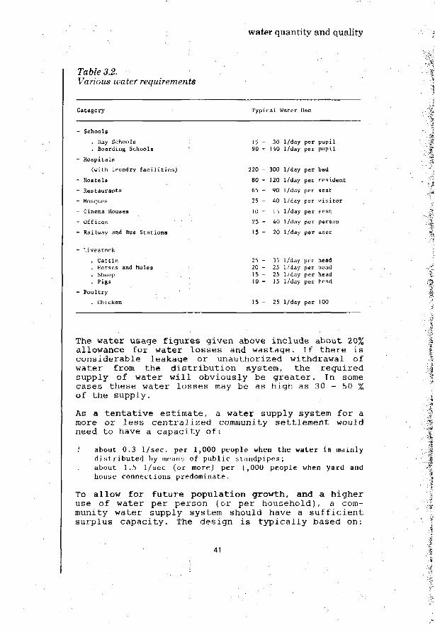
Table 3.2.Various water requirements
water quantity and quality
Category Typical Water Use
- Schools
. Day Schools
. Boarding Schools
- Hospitals
(with laundry facilities)
- Hostels
- Restaurants
- Mosques
- Cinema Houses
- Offices
- Railway and Bus Stations
- Livestock
. Cattle
. Horses and Mules
. Sheep '• Pigs
- Poultry
. Chicken
1 't - 30 I/day per pupil90 - 140 I/day per pupil
220 - 300 I/day per bed
80 - 120 I/day per resident
65 - 90 I/day per seat
25 - 40 I/day per visitor
10 - 15 I/day per seat
25 - 40 I/day per person
15 - 20 I/day per user
25 - 35 I/day per head20 - 25 I/day per head15 - 25 I/day per head10 - 15 I/day per head
15 - 25 I/day per 100
The water usage f igures given above include about 20%allowance for water losses and wastage. If there i sconsiderable leakage or unauthorized withdrawal ofwater from the d i s t r i b u t i o n system, the requiredsupply of water wi l l obviously be g rea t e r . In somecases these water losses may be as high as 30 - 50 %of the supply.
As a t e n t a t i v e es t imate , a water supply system for amore or l e s s cen t r a l i zed community se t t lement wouldneed to have a capaci ty of:
.' about 0.3 1/sec. per 1,000 people when the water is mainlydistributed by means of public standpipes;about 1.5 1/sec (or more) per 1,000 people when yard andhouse connections predominate.
To allow for future population growth, and a higheruse of water per person (or per household), a com-munity water supply system should have a sufficientsurplus capacity. The design is typically based on:
41

water quantity and quality
the daily water demand estimated for the end of aspecified period (the "design period), e.g. 10years;orthe present water demand plus 50%;orthe demand computed on the basis of the popu-lation growth estimate.
The 'population growth factor' may be read from table3.3.
Table 3.3.Population growth factor
Design period
(years)
<0
15
20
1
1
1
2 %
.22
.35
.49
Yearly growth
3 X
1.34
1 .56
l.BI
rate
1
1
2
4 %
.48
.80
.19
5 %
1.63
2.08
2,65
A community water supply system should also be ableto cater for the maximum hourly or peak water demandduring the day. (See: Chapters 18 'Water Transmis-sion' and 19 'Water Distribution').
3.2 Water quality
The relationship between water quality and healtheffects has been studied for many water qualitycharacteristics. An examination of water quality isbasically a determination of the organisms, and themineral and organic compounds contained in the water.
The basic requirements for drinking water are that itshould be:
Free from pathogenic (disease causing) organisms.Containing no compounds that have an adverseeffect acute or in the long term, on humanhealth.Fairly clear (i.e. low turbidity; little colour).Not saline (salty)Containing no compounds that cause an offensivetaste or smell.
42

water quantity and quality
Not causing corrosion or encrustration of thewater supply system, nor staining clothes washedin it.
For their ready application in engineering practice,the results of the studies and research on drinkingwater quality must be laid down in practical guide-lines. Usually these take the form of a table givingfor a number of selected water quality parameters,the highest desirable level and the maximum permis-sible level. Such values should be regarded as indi-cative only, and should not be taken as absolutestandards.
The most important parameter of drinking water quali-ty is the bacteriological quality, i.e. the contentof bacteria and viruses. It is not practicable totest the water for all organisms that it mightpossibly contain. Instead, the water is examined fora specific type of bacteria which originates in largenumbers from human and animal excreta and whosepresence in the water is indicative of faecal con-tamination. Such indicative bacteria must be spe-cifically faecal and not free-living. Faecal bacteriaare members of a much wider group of bacteria, thecoliforms. Many types of coliform bacteria arepresent in soil. Suitable indicator bacteria offaecal contamination are those coliforms known asEscherichia-coli (E-coli), and faecal streptococci.They are capable of easy multiplication. When thesebacteria are found in the water, fairly fresh faecalcontamination is indicated, and on that basis thereis the possibility of the presence of pathogenicbacteria and viruses. Either one or both of thesecoliform and streptococci bacteria may be used asindicator organisms.
In almost all small community water supply systemsfaecal bacteria are likely to be found. It would bepointless to condemn all supplies that contain somefaecal contamination, especially when the alternativesource of water is much more polluted. Rather, test-ing of the bacteriological quality of the watershould examine the level of faecal pollution, and theamount of contamination of any alternative sources.
Water samples should be collected in sterile bottlesaccording to standard procedure. They should beshaded and kept as cool as possible. It is necessaryto carry out bacteriological examination of sampleswithin a few hours after sampling, otherwise theresults will be quite unreliable.
There are two methods for conducting tests on the
43

water quantity and quality
levels of faecal coli and faecal streptococci inwater: the multiple tube method for establishing themost probable number (M.P.N.), and the membranefiltration method.
In the multiple tube method, small measured quan-tities of the water sample are incubated in 5 or 10small flasks containing a selective nutrient broth.The most probable number of bacteria in the sample(M.P.N.) can be estimated on the basis of the numberof bottles which show signs of bacterial growth.
In the membrane filtration method, water is filteredthrough a membrane of special paper which retains thebacteria. The membrane is then placed on a selectivenutrient medium and incubated. The bacteria multiplyforming visible colonies which can be counted. Theresult is expressed as number of bacteria per 100 mlof water. Direct counts of faecalv coli and faecalstreptococci can be made in 24 and 48 hours re-spectively. There is no need for confirmatory teststo check the species of bacteria as in the multipletube method.
The equipment and materials necessary in the multipletube method for faecal coli are cheaper and generallymore readily available in developing countries, thanis the case for the membrane filtration method. Theproblem with using the multiple tube method forfaecal streptococci is that the required 5 days'incubation time is not so practical. The membranefiltration method is applicable both for faecal coliand faecal streptococci. It gives rapid results whichare easy to interpret and quite accurate. Themembrane tests can be carried out on site in the backof the vehicle. The multiple tube equipment isfragile and requires special provisions duringtransport. Taking all factors into consideration, themembrane filtration method is to be recommended.
In either of the methods, the facilities for theincubation are the main constraint. The difficulty isthe accurate control of the temperature. For faecalcoli, incubation should be at an accurately con-trolled temperature of 44.5° C ± 0.2° C. This degreeof temperature control is not easy to achieve in anincubator under field conditions but special portableincubators are commercially available which canmaintain the temperature within the required narrowrange. They are relatively expensive (several hundreddollars) and require a power source such as a carbattery for operation. If incubation with an accuratetemperature control is not possible, the recommendedpractice is that only faecal streptococci should be
44 ; ' ' .

water quantity and quality
counted. For this count, incubation is required at35-37° C which can be more readily provided.
Where possible, examination for both faecal coli andfaecal streptococci should be made. This will providean important check on the validity of the results. Italso gives a basis for computing the ratio at whichthe two species of bacteria are present from which atentative conclusion can be obtained whether thefaecal pollution is of animal or human origin.
The following bacteriological guality criteria aregenerally applicable for small drinking water sup-plies :
Coliforms - less than 10 per 100 ml*(averagenumber presentin the drinkingwater sampled)E. coli - less than 2.5 per 100 ml*
There are cases where the water from a communitywater supply is bacteriologically acceptable, yetunfit as drinking water due to excessive organic ormineral contents. The main problems are caused byiron and manganese, fluoride, nitrate, turbidity andcolour.
Table 3.4 gives guidelines for a number of these andother water quality parameters.
These water guality guidelines should always beapplied with common sense, paricularly for smallcommunity and rural water supplies where the choiceof source and the opportunities for treatment arelimited. The criteria should not in themselves be thebasis for rejection of a groundwater source havingsomewhat higher values for iron, manganese, sulphatesor nitrates than in the table. Care must be exercisedin respect of toxic substances such as heavy metals.These should be allowed only after expert opinion ofthe health authorities has been obtained.
Many developing countries are aiming in their actualwater supply practice to meet as far as possible theabove guidelines that are derived from recommenda-tions formulated by the World Health Organization.
Statistically determined as most probable number(M.P.N.), or measured by membrane count.
45

water quantity and quality
Table 3.4.Guidelines for drinking water quality
Water Quality Parameter
Total dissolved solids
Turbidity
Co lour
Iron
Manganese
Nitrate
Nitrite
Sulphate
Fluoride
Sodium
Arsenic
Chromium (hexavalent)
Cyanide (free)
Lead
Mercury
Cadmium
measuredas
mg/1
FTU
mg Pt/1
mg Fe /I
mg Mn++/1
mg N03~/l
mg N/l
mg S04 /I
mg F~/l
mg Na+/1
mg As /I
mg Cr6+/1
mg CN~/1
mg Pb/1
mg Hg/1
mg Cd/1
highestdesirablelevel
500
5
5
0.1
0.05
50
1
200
1.0
120
0.05
0.05
0.1
0.05
0.001
0.005
maximumpermissiblelevel
2000
25
50
1.0
0.5
100
2
400
2.0
400
0.1
0.1
0.2
o.io0.005
0.010
This includes the major dissolved solids such as SO, ~, Cl , HCO, ,
Ca , Mg and Na . The levels indicated depend on the climate, the
type of food, and the work load of the water user. In some recorded
cases, people have lived for months on water having a total dissolved
solids content in excess of 5000 mg/1.
Although the water supply agency concerned may under-take to carry out the necessary tests on water qua-lity on a regular basis, final approval and controlof drinking water quality should remain with thehealth authorities.
46

water quantity and quality
Figure 3.1.Water Sampling (Gabon)
United Nations Photo
For small supplies which frequently are to beprovided from individual wells, boreholes or springs,the water quality criteria given above, may have tobe relaxed. Obviously, in all instances, everythingpossible should be done to limit the hazards ofcontamination of the water. Using relatively simplemeasures such as the lining and covering of a well,
47

water quantity and quality
it should be possible to reduce the bacterial contentof water (measured as coliform count) to less than 10per 100 ml, even for water from a shallow well.Persistent failure to achieve this and particularlyif E. coli is repeatedly found, should as a generalrule lead to condemnation of the supply. **
For the adequate interpretation of chemical andbacteriological analyses of drinking water supplies,a sanitary survey is essential. Many potentialhazards can be detected by a careful study of thewater source, the treatment works and the distri-bution system. No bacteriological and chemical testscan be substituted for a complete knowledge of thewater supply system and the conditions under which ithas to operate. Samples represent a single point intime and, even when samples are taken and analysedregularly, contamination may not be revealed es-pecially when it is intermittent, seasonal andrandom.
Guidelines for sanitary surveys are given in Annex 1,where essential factors are listed that should beinvestigated or considered.
** International Standards for Drinking Water(3rd Edition); World Health Organization, Geneva, 1971.
48

Water quantity and quality
Camp, T.R.WATER AND ITS IMPURITIESReinhold Book Corp., New York, 1968
Chalapatiroa, U.PUBLIC HEALTH ASPECTS OF VIRUSES IN WATERIn: Journal of the Indian Water Works Association, 1975, No 1, pp. 1-7
Giroult, E.ENSURING THE QUALITY OF DRINKING WATERIn: WHO Chronicle, 1977, No. 8, pp. 316-320
INTERNATIONAL STANDARDS FOR DRINKING WATERWorld Health Organisation, Geneva, 3rd revised edition, 1971, 70 p.
LES VIRUS HUMAIN DANS L'EAU, LES EA1JX USEES ET LE SOLOrganisation Mondiale de la Sante, Geneva, 1979(Rapport Technique 639)
Pescod, M.D.; Hanif, M.WATER QUALITY CRITERIA FOR TROPTCAL DEVELOPING COUNTRIESAsian Institute of Technology, Bangkok, 1972, lip.
Ponghis, G.MINIMUM REQUIREMENTS FOR BASIC SANITARY SERVICES IN HUMANSETTLEMENTS IN DEVELOPING COUNTRIESWorld Health Organisation, Geneva, 1972
Rajagopalan, S.; Shiftman, M.A.GUIDE ON SIMPLE SANITARY MEASURES FOR THE CONTROL OF ENTERICDISEASESWorld Health Organisation, Geneva, 1974
SIMPLIFIED PROCEDURES FOR WATER EXAMINATION - A LABORATORYMANUALAmerican Water Works Association, New York, 1975, 158 p.(supplement published in 1977)
SURVEILLANCE OF DRINKING WATER QUALITYWorld Health Organisation, Geneva, 1976, 135 p.WHO Monograph Series No. 63)
Tebbutt, T.H.Y.PRINCIPLES OF WATER QUALITY CONTROL (2nd Edition)Pergamon Press, 1977
White, J.F.; Bradley, D.J.; White, A.U.DRAWERS OF WATER: Domestic water use in East AfricaThe University of Chicago Press, Chicago, 1972
49

50

water sources
4. water sources
4.1 Water occurrence and hydrology
The first step in designing a water supply system isto select a suitable source or a combination of sour-ces of water. The source must be capable of" supply-ing enough water for the community. If not, anothersource or perhaps several sources will be required.
The water on earth, whether as water vapour in theatmosphere, as surface water in rivers, streams,lakes, seas and oceans, or as groundwater in the sub-surface ground strata is for the most part not atrest but in a state of continuous recycling movement.This is called the hydrological cycle (Fig. 4.1.).
WATER VAPOUR TRANSPORT
ICE & SNOW
INFILTRATION
SOURCE OF ENERGY
GRGUNDWATEROUTFLOW
Figure 4.1.Hydrological cycle
The driving forces are the sun's energy and theearth's gravity. Water from the atmosphere falls tothe ground as rain, hail, sleet and snow or condenseson the ground or on the vegetation. Not all thiswater adds to surface or groundwater resources, aspart of it evaporates and returns directly to the at-mosphere. Another part is intercepted by the vege-
51

water sources
tation or is retained on the ground, wetting thetopsoil.
Water accumulating on the ground in pools and marshesis exposed to evaporation*. Part of the accumulatedwater flows as surface runoff towards streams, riversand lakes. Another portion infiltrates into theground. This water may flow either at shallow depthunderneath the ground to open water courses, or itpercolates further downward to reach deeper ground-water strata. Neither the shallow nor the deepgroundwater is stagnant; it flows underground in thedirection of the downward slope of the groundwatertable. Sooner or later the water emerges again at thesurface, either in the form of a spring or as agroundwater outflow in a river or lake. From thestreams, rivers, lakes, seas and oceans, the water isreturned to the atmosphere through evaporation. Thewhole recycling process then begins again.
By far the greatest part of the water on earth isfound in the oceans and seas. However, this water issaline. The amount of fresh water is less than 3%,about two thirds of which is locked in ice caps andglaciers. The fresh water contained in the under-ground and in all lakes, rivers, streams, brooks,pools and swamps amounts to less than 1% of theworld's water stock.
Most of this liquid fresh - water is in the under-ground, an estimated 6,000,000 km3 of groundwater upto 50 metres deep, and a further 2,000,000 km3 atgreater depth. Contrary to popular belief, the amountof fresh water in lakes, rivers and streams is small,about 200,000 km3 of water. The atmosphere containsonly 13,000 km3 of water. Table 4.1 provides an over-view of the average precipitation and evaporationrates for the various continents.
Global and continental hydrological data, however, isof little use to the water supply engineer, apartfrom reminding him that all water resources are inter-
Evaporation occurs from any water surface. Transpiration isloss of water from plants. All plants take water throughtheir roots; it is expelled through transpiration from theleaves.
52

water sources
Table 4,1.Precipitation and evaporation rates by continent
Precipitation Evaporation Run-offContinent mm/year nm/year mm/year
Africa
Asia
Europe
North America
South America
Australia and New Zealand
Mean values derived afterweighting according to area
670
610
600
670
1350
470
725
510
390
360
400
860
410
482
160
220
240
270
490
60
243
connected and are part of the global hydrologicalcycle. He needs information regarding the amount ofrainfall, the flow of rivers and streams, thequantity and depth of groundwater, and evaporationrates. This information is rarely available so thatit will be necessary to take field measurements orextrapolate data from such records as available.
4.2 Quality of water sources
Both surface water and groundwater largely originatefrom rainfall. All rainwater contains constituentsthat are taken up or washed out from the atmosphere.Atmospheric gases are dissolved in the rainfall drop-lets. Above oceans and seas, salts are taken up fromthe fine spray over the water surface. Over landareas, particularly in dry regions, dust particlesare washed out.
Rainwater is usually slightly acidic due to itsreaction with carbon dioxide (CO ) in the atmosphereto form carbonic acid. When rainwater contactsgaseous pollutants in the atmosphere like sulphurdioxide (e.g. from volcanoes, industry), it maybecome quite acidic causing problems of corrosion andbitterness of taste. In rural areas, however, this isnot a common problem.
After reaching the ground surface, rainwater formssurface runoff or groundwater flow. It will pick upconsiderable amounts of mineral compounds and of
' -• ' 5 3 •• ••• ' ' '. •

water sources
organic matter, debris from vegetation and animalorigin, soil particles and micro-organisms. Fertil-izers and pesticides may be picked up in areas wherethey are used in agriculture. While flowing under-ground, the water will leach out constituents fromthe ground strata, in particular carbonates, sul-phates, chlorides, calcium, magnesium and sodiumsalts. Thus, the total dissolved solids content ofthe water is increased. At the same time, filtrationtakes place removing suspended solids. Some organicsubstances are biologically degraded. Adsorption andother processes may result in the removal ofbacteria, and of suspended and dissolved solids.
Where considerable amounts of organic matter arepresent, either in the subsoil (e.g. peat) or in theinfiltrating water, the oxygen content of the under-ground water may be exhausted through microbial pro-cesses. As a result, certain chemical reactions maybe taking place through which ammonia and hydrogensulfide are formed from the nitrates and sulphatespresent in the ground, similarly, iron and manganesewould be dissolved in the water.
When groundwater is present at a shallow depth (e.g.,less than 10 metres) it may be polluted from sourcesof faecal contamination such as pit latrines orseptic tanks. Pathogenic bacteria and viruses fromsuch sources can be carried by the groundwater,although they tend to attach themselves by adsorptionto the solid ground particles. When assessing thepossible health hazards of groundwater sources, oneshould pay more attention to the travel-time of thewater through the ground strata than to the distancethe water has to flow to the point of withdrawal. Inlimestone, karstic formations and fissured rock,human contamination may be carried over a distance ofseveral kilometres. In sand formations, groundwaterflow is much slower so that only contamination fromnearby sources need to be considered when selectingthe point of groundwater withdrawal.
Surface runoff as well as groundwater ultimately willreach streams, rivers and lakes where the water isopen to pollution from human and animal life, vege-tation, plants and algae. Many rivers in tropicalareas have high amounts of suspended solids and tur-bidity, especially under flood conditions. The qua-lity of this water varies considerably with rainfall.In the dry season, organic matter frequently gives acolouring to the river water.In surface water the processes of self-purificationare important.Aeration will bring oxygen from theatmosphere into the water with a simultaneous release
54

water sources
of carbon dioxide. In lakes and reservoirs suspendedmatter settles out, so that the water will becomeclear. Organic matter will be consumed throughbio-chemical processes, and there will be a dying-offof intestinal bacteria, viruses, and similar micro-organisms. Generally, the water can recover itsoriginal quality, if no further pollution is intro-duced. However, lakes sometimes are subject toexcessive growth of algae. 'Hafirs1, small dams andponds have similar features. Almost all surface waterwill require some treatment before it can be used fordrinking and domestic purposes.
4.3. Water source selection
The process of choosing the most suitable source ofwater for development into a public water supplylargely depends on the local conditions. Where aspring of sufficient capacity is available, this maybe the most suitable source of supply.
Where springs are not available, or not suited todevelopment, generally the best option is exploringgroundwater resources. For small supplies simpleprospecting methods will usually be adequate. Forlarger supplies, more extensive geo-hydrologicalinvestigations using special methods and techniquesare likely to be needed. Infiltration drains may beconsidered for shallow ground-water sources. Dugwells can be appropriate for reaching groundwater atmedium depth. Tubewells are generally most suitablefor drawing water from deeper water-bearing groundstrata. However, there are conditions where tubewellscan be used with advantage for tapping shallowgroundwater sources.
Dug wells often are within the local constructioncapabilities, whereas the drilling of tubewells willrequire more sophisticated equipment and considerableexpertise. In some cases, drilling may be the onlyoption available. If groundwater is not available, orwhere the costs of digging a well or drilling a tube-well would be too high, it will be necessary to con-sider surface water from sources such as rivers,streams or lakes. Surface water will almost alwaysrequire some treatment to render it safe for humanconsumption and use. The costs and difficultiesassociated with the treatment of water, particularlythe day-to-day problems of operation and maintenanceof water treatment plants, need to be carefullyconsidered.
55
water sources
Where the rainfall pattern permits rainwater harvest-ing, and storage during dry periods can be provided,rainwater harvesting may serve well for household andsmall-scale community supplies. With large groundcatchment areas, considerable quantities of water maybe obtained. Rainwater is sometimes used in conjunc-tion with other sources to supplement another supply,particularly if the latter is poorly maintained andsuffers from breakdowns.
56

Water sources
Balek, J.HYDROLOGY AND WATER RESOURCES IN TROPICAL AFRICAElsevier Scientific Publishing Co., Amsterdam, 1978
Bear, J. ; Issar, A.; Litwin, Y.ASSESSMENT OF WATER RESOURCES UNDER CONDITIONS OF SCARCITY OFDATA In: Water Supply, Proceedings of the Conference on RuralWater Supply, April, 197 1,University of Dar-es-Salaam, pp. 151-186
GROUNDWATER IN AFRICAUnited Nations, New York, 1973, 170 p.(ST/ECA/147 Sales No. E71.ll. 16)
GROUNDWATER IN THE WESTERN HEMISPHEREUnited Nations, New York, 1976, 337 p.(ST/ECA/35 Sales No. E76.ll.A.5)
Hammer, M.J.; MacKichan, K.A.HYDROLOGY AND QUALITY OF WATER RESOURCES :John Wiley & Sons Ltd., Chic:hester, 1980, 408 p.
Institute of Water EngineersMANUAL OF BRITISH WATER ENGINEERING PRACTICE, Vol. IIW. Heffer & Sons, London
Jain, J.K.INDTA: UNDERGROUND WATER RESOURCESIn: Phil., Trans. Royal Society, London, (1977), pp. 505-524
James, L.D.ECONOMICS OF WATER DEVELOPMENT IN LESS DEVELOPED COUNTRIESIn: Water Supply and Management, Vol. 2(1978), No. 4, pp. 737-386
Leeden, F. v.d. (Ed.)WATER RESOURCES OF THE WORLD, SELECTED STATISTICSWater Information Centre, inc., Port Washington, 1975, 232 p.
MORE WATER FOR ARID LANDSNational Academy of Sciences, Washington, D.C. 1974, 153 p.
Rodda, J.C.; Downing, R.A.; Law, F.M.SYSTEMATIC HYDROLOGYNewneK-Butterworth, London, 1976 '
Stern, P.H.RURAL WATER DEVELOPMENT IN ARID REGIONSPaps-r presented at 1AWPR Symposium: Engineering, Science andMedicine in the prevention of Tropical Water Related Disease;London, 1978.In: Progress in Water Technology, Vol. 2(1979) Nos. 1 and 2.
57

United NationsRESOURCES AND NEEDS, ASSESSMENT OF THE WORLD WATER SITUATIONIn: Water Supply and Management, Vol.1, No. 3, 1977, pp. 273-311(Principal Background Paper E/Conf. 7O/CBP/1 of UN WaterConference)
Wilson, E.M.ENGINEERING HYDROLOGYMatMillan Book Co., London, 1971 (3rd edition). •;
58

rainwater harvesting
5. rainwater harvesting
5-1 Rainwater as a source of water supply
In several parts of the world, rainwater catchmentsand storage reservoirs have been constructed sinceancient times and some have been preserved to thisday. Rainwater is harvested as it runs off roofs, orover natural ground, roads, yards, or specially pre-pared catchment areas. Historical sources mention theuse of rainwater for domestic water supply some 4000years ago in the Mediterranean region. Roman villagesand cities were planned to take advantage of rain-water for drinking water supply. In the hills nearBombay in India, the early Buddhist monastic cellshad an intricate series of gutters and cisterns cutinto the rock to provide domestic water on a year-round basis.
In many countries in Europe and Asia rainwater har-vesting was used widely for the provision of drinkingwater, particularly in rural areas. In some countriesit is still being practised. However, where pipedwater supplies have been provided, the importance ofrainwater as a source of supply has diminished.
On some tropical islands rainwater continues to bethe only source of domestic water supply. In aridand semi-arid areas where people mostly live inscattered or nomadic settlements, rainwaterharvesting can be a necessary means of providingwater for domestic purposes. This is especially thecase where groundwater resources are unavailable orcostly to develop. In developing countries rainwateris sometimes used to supplement the piped watersupply.
Rainwater harvesting should be considered in coun-tries where rainfall is heavy in storms of consider-able intensity, with intervals during which there ispractically no or very little rainfall. It requiresadequate provision for the interception, collectionand storage of the water. Depending on the circum-stances the catchment of the water is on the ground,or the runoff from roofs is collected.
59

rainwater harvesting
5.2 Roof catchments
Reasonably pure rainwater can be collected from houseroofs made of tiles, slates, (corrugated) galvanisediron, aluminium or asbestos cement sheeting. Thatchedor lead roofs are not suitable because of healthhazards. With very corrosive rainwater, the use ofasbestos cement sheeting for roof catchment reguiressome caution. Asbestos fibers may be leached from theroof material leading to relatively high asbestosconcentrations in the collected rainwater. Plasticsheeting is economic but often not durable. Newlydeveloped roofing materials are bituminous felt andsisal-reinforced paper. Painting the roof for water-proofing may impart taste or colour to the collectedrainwater, and should be avoided. Fig. 5.1. shows asimple roof catchment.
Figure 5.1.Simple roof catchment and storage (Thailand)
IRC Photo
The roof guttering should slope evenly towards thedownpipe, because if it sags, pools will form thatcan provide breeding places for mosquitoes.
Dust, dead leaves and bird droppings will accumulateon the roof during dry periods. These will be washedoff by the first new rains. It may be helpful to
60

rainwater harvesting
arrange the downpipe so that the first water fromeach shower (the "foul flush") can be diverted fromthe clear water container and allowed to run towaste.
To safeguard the quality of the collected rainwater,the roof and guttering should be cleaned regularly*.A wire mesh should be placed over the top of thedownpipe to prevent it from becoming clogged withwashed-off material.
An arrangement for diverting the first rainwaterrunning from the roof is shown in Fig. 5.2.
DOWN PIPEFROM ROOF
SCREEN
SEAL
\
SCREEN
SCREENEOOVERFLOW
Figure 5.2.Arrangement for diverting the 'first foul flush'
Another arrangement is an under-ground storage tankreceiving rainwater that overflows from a vesselpl'aced above the ground (Fig. 5.3). The surfacevessel thus occasionally contributes water to theunderground tank.
Bird droppings have been reported to cause healthhazards (salmonellosis) in Jamaica.
61

rainwater harvesting
•*•'.-«
Figure 5.3.Roof catchment and storage of rainwater(withdrawal by handpump)
The size of the roof will depend on the size of thehouse. The quantity of rainwater that can be collec-ted through roof catchment, will be largely deter-mined by the effective area of the roof and the localannual rainfall. One millimetre of rainfall on onesquare metre of roof will yield about 0.8 litres ofwater, allowing for evaporation and other losses.
For a roof measuring 5m x 8m (in plan), and assumingan average annual rainfall of 750 mm, the amount ofrainwater which can be collected in a year may beestimated as:
5 x 8 x 750 x 0.8 = 24,000 litres/year
or: 24,000 = 66 litres/day on average.365
62

rainwater harvesting
To allow for conditions in years that are drier thanaverage and also for dry seasons of exceptional du-ration, the roof and storage should have about 50%surplus yield over the basic water requirements ofthe people who will be dependent on the supply. Witha sufficient storage, the roof catchment could in adry year still provide some 40 litres/day which isthe basic drinking and domestic water requirement ofa family of 6 persons.
One can estimate the required storage volume byworking out the amounts of water that will be used bythe family household in the longest season which maypass without rainfall. For short dry periods theneeded storage volume will be small and can probablybe provided in the form of a simple wooden vessel, anoil drum or an other suitable container. Where rain-fall varies widely during the year, dry seasons ofconsiderable duration need to be anticipated.
For an average dry season of 3 months the storagevolume required would be: 3 x 30 x 40 = 3600 litres.To allow for longer periods without rainfall in ex-tremely dry years, a 50% surplus should be providedand the storage volume would thus have to be 5400litres.
5.3 Ground catchments
Ground catchments are used for collecting rainwaterrunoff. Part of the rainfall will serve to wet theground, is stored in depressions, or is lost throughevaporation or infiltration into the ground. A con-siderable reduction of such water losses can be ob-tained by laying tiles, concrete, asphalt or plasticsheeting to form a smooth impervious surface on theground. Another method involves chemical treatment ofthe soil surface. Sometimes simply compacting thesurface is adequate.
The amount of rainwater that can be collected inground catchments will be dependent on whether thecatchment is flat or sloping, and the watertightnessof the top layer. Through preparation of the groundsurface, a sufficiently rapid flow of the water tothe point of collection and storage can be assured inorder to reduce evaporation and infiltration losses.
The portion of rainfall that can be harvested rangesfrom about 30% for pervious, flat ground catchments,
63

rainwater harvesting
to over 90% for sloping strip catchments covered withimpervious materials.
.*
Figure 5.4.Ground catchment
Land alteration involves the construction of ditchesalong contours, the clearing of rocks and vegetation,and simple soil compaction. Attempts are often madeto achieve reduced infiltration losses of rainwaterin the ground catchment area. In rolling hills care-ful soil compaction may be sufficient to attain goodcatchment efficiency. In flat terrain a subdivisionin small, sloping strips will be needed with suchspecial preparation of the ground surface as appro-priate.
where the surface of the ground catchment is to becovered, various materials may be used. Tiles, cor-rugated iron sheets, asphalt, cement, or evenmaterials such as heavy butyl rubber or thick plasticsheets may be considered. When properly applied.,these materials can give good water catchmentefficiency with a yield as high as 90% of the rain-fall runoff from the catchment area. Additionaladvantages are low maintenance and long useful life.
64

• } * • . .
i'•''- rainwater harvesting
However, these materials are generally too expensivefor use over large ground catchment areas. Catchmentsurface coating methods that may save costs, arebeing tested. These include:
Asphalt in two coats (sealant and protection); rein-forcement with plastic- or fibreglass and covered withgraveL; and,Paraffin wax spread as granules which melt in the sun.
Thin plastic membranes covered with 1-2 cm gravel orbonded to the ground surface by a bitumen tar aremuch cheaper but they are easily damaged by sharpstones, plant roots, or animals, and repairs aredifficult to make. The water yield of such membrane-lined ground catchment sometimes proves disappointing(not higher than 30-50% of the rainfall). Goodresults can probably be obtained by treating the topsoil layer of the ground catchment area with che-micals. Sodium salts may be applied converting clayparticles to form an impervious layer, or a bitumenor tar coating may be sprayed over the ground toblock the soil pores. Such a treatment need not beexpensive and can be repeated at regular intervals(once every few years) in order to maintain thewatertightness of the ground catchment.
Treated ground catchments of sufficient size can pro-vide a domestic water supply for a number of familiesor even a whole village community but they needproper management and maintenance, and protectionagainst damage and contamination. It may be necessaryto provide fencing or hedging. An intercepting drain-age ditch at the upper end of the catchment area, anda raised curb around the circumference would beneeded to avoid the inflow of polluted surface run-off. A grass cover may be used to reduce erosion ofthe ground catchment although this will result in alower yield. Trees and shrubs surrounding the catch-ment area can be planted to limit the entry of windblown materials and dust into the ground catchmentarea.
5.4 Storage
Storage facilities can be above-ground or below-ground. Whichever type of storage is selected, ade-quate enclosure should be provided to prevent anycontamination from humans or animals, leaves, dust orother pollutants entering the storage container. Atight cover should ensure dark storage conditions so
65

rainwater harvesting
as to prevent algal growth and the breeding of mos-quito larvae. Open containers or storage ponds aregenerally unsuitable as sources of drinking water.
There is a wide choice of materials for the construc-tion of water storage containers. For small storagevolumes, vessels made of wood, cement, clay or water-proofed frameworks may be used.
Below-ground storage facilities have the general ad-vantage of being cool, and they will suffer prac-tically no loss of water through evaporation. Therecan also be a saving in space and cost of con-struction where the container is moulded directly inthe ground by simply compacting the earth. An exampleis shown in fig. 5.5.
STORED WATER
06--H
—•
^J3 -
0.8 m
nfr
—\^
4 m
, „ PLATFORM
^ I J ^ I N F L O W PIPE
ft
h0- WELL BOTTOMPROTECTIVE LAYER
Figure 5.5.Underground rainwater storage well(as used in China)
Cement applied by hand may be used for plastering thewalls of the excavation, or simple plastic sheeting.Storage tanks consisting of bee-hive structures (Fig.5.6) have been built in various countries (e.g.Sudan, Botswana, Swaziland, Brazil, Jamaica) tovolumes of 10,000 litres. Polythene tubes filled witha weak cement mixture and sealed at the ends, arelaid in place before the mixture sets; this willallow them to readily take up the required shape. Thesides of these tanks are polythene-lined.
66

rainwater harvesting
STONE RIPRAP
-PLASTIC SHEET
STONES OR BRICKS
Figure 5.6.Cistern built of polythene tubes
Two more examples of rainwater s torage are shown inf ig . 5 .7. and f ig . 5 .8 .
PUMP
SCREENEDOVERFLOW
MANHOLE COVER
OOWNPIPE FROM ROOF
DRAIN
Figure 5.7.Rainwater storage arrangement
67

rainwater harvesting
TO PUMP
HOLES IN BRICKWORK
Figure 5.8.Venetian Cistern
The cylindrical wooden rainwater barrel was afamiliar sight in most western countries until theadvent of piped water supplies. These containers maybe specially constructed for rainwater storage, butsuitable food stuff or beverage vessels may be uti-lized just as well after they have served theiroriginal purpose.
Relatively thin-walled cement containers can be builtfor moderate rainwater storage volumes. A taperedform has been developed by UNICEF, in Kenya, in whicha simple cloth bag is used as the basis for a wall3 cm thick or even less. Containers providing up to2,500 litres storage volume can be built in this way.
In many parts of Africa, Asia and Latin America, clayis available. Clay can be used to build suitablerainwater storage containers of limited volume,simple glazing techniques should be useful in impro-ving the impermeability of the clay pot or barrelwalls.
Water-proofed frameworks (e.g., from bamboo, ortwigs) can be built by lining woven baskets withcement, mortar or plastic. Using a tapered form, fullenclosure of the storage vessels should be accom-plished easily.
68

rainwater harvesting
In the construction of metal storage tanks, the mostcommon material is galvanized iron sheets which arereadily riveted and softsoldered. To avoid defor-mation of the tank when filled, a framework (wood,steel etc. ) is required. These tanks can, in someinstances, be incorporated as part of the wall struc-ture or foundation of buildings.
Corrugated iron tanks have the advantage of beingself-supporting. Tanks of this type for storagevolumes up to 10,000 litres are found in Africa andAustralia. Their construction is not difficult but aspecial 'roller' machine is required unless the cor-rugated iron sheets can be prepared manually. Localcraftsmen can be trained to build these tanks insizes suitable to the local requirements.
For larger storage volumes, tanks or cisterns con-structed of brick or stone masonry are used most.Typically the walls are cylindrical and bonded bycheap lime mortar or more expensive cement mix. Wherelarge storage volumes are built, and certainly fortank heights exceeding 2 m, reinforcement along theoutside edges becomes necessary. This can be conve-niently provided by means of one or more tightenedsteel bands around the outer circumference of thetank. The roofing of this type of tank is commonlyprovided by placing some suitable cover (e.g., gal-vanized iron sheets) over a supporting framework.
Reinforced concrete tanks are used in many areas.Double-walled formwork is used in their construction.Reinforcing material, usually steel mesh or bars, arepositioned in the space and the concrete mix ispoured in. The formwork can be removed when the con-crete has hardened enough, usually after one full dayor so. The formwork should then be deployed again forbuilding another tank. This is necessary because theformwork represents a substantial initial investment;it must be economically utilized several times forwhich organisational measures are required. Re-inforced concrete tanks have the advantage of greatdurability and they can, in principle, be built toany desired size. Because of their structuralstrength such tanks can be used as part of the wallsor foundation of a building.
Bamboo reinforced concrete tanks have been success-fully built in countries where bamboo is available insuitable length, size and strength (e.g. China,Indonesia, Thailand). Increasingly popular areferio-cement tanks in which wire is used for thereinforcement of walls and bottom that are formed byplastering cement. Such tanks are quite economical.
69

rainwater harvesting
5.5 Water quality preservation
Where storage tanks or cisterns are built belowground, special provision must be made to preventdust, sand, leaves, insects or other pollutants fromentering. For the same reason, the inlet and outletopening and any air vents should be fitted withscreens.
An intercepting ditch should be provided to drain offany excess surface runoff.
During storage, the quality of the rainwater collec-ted from the roof or ground catchment may deterioratethrough the putrefaction of organic material in thewater, or through growth of bacteria and othermicro-organisms. Measures to protect the quality ofthe stored water include the exclusion of light fromthe stored water, cool storage conditions, andregular cleaning. Simple disinfection devices such asthe pot chlorinator (see Chapter 17) may be veryuseful in rainwater storage containers.
In theory, the prefiltration of collected water priorto its storage would be disirable, but in practicefilters are not very effective for the required in-termittent operation. Nevertheless, an example isshown in Fig, 5.9.
The boilng of water drawn from the storage before itis used for drinking or food preparation, would bedesirable but it is often not practicable. In someplaces, a little bag containing a coagulant is sus-pended in the storage tank to flocculate the sus-pended solids in the water. The water drawn from thestorage tank has a clear appearance, but itsbacteriological safety is not assured.
70

rainwater harvesting
TO PUMP
FROM f ° 777'//////.CATCHMENTT
/ / / / / / /
-' / >' > OVERFLOW
/ /
n• SCREEN
• : >
Figure 5.9.Withdrawal of filtered rainwater from storage
71

72

Rainwater harvesting
Environmental Protection Agency .INDIVIDUAL WATER SUPPLY SYSTEMS .U.S. Government Printing Office, Washington, D.C., 1973
Grover, B.HARVESTING PRECIPITATION FOR COMMUNITY WATER SUPPLYWorld Bank, Washington, D.C., 110 p.
lonides, M.WATER TN DRY PLACESEngineering, London, 1967, pp. 662-666
Johnson, K.; Renwick, H.RAIN AND STORMWATER HARVESTING FOR ADDITIONAL WATER SUPPLY INRURAL AREAS: Component review of North AmericaUnited Nations Environment Programme, Nairobi, 1979.
Maddocks, D.AN INTRODUCTION TO METHODS OF RAINWATER COLLECTION AND STORAGEIn: Appropriate Technology, Vol. 2(1975) No. 3, pp. 24-25
Maddocks, D.METHODS OF CREATING LOW-COST WATERPROOF MEMBRANES FOR USE INTHE CONSTRUCTION OF RAINWATER CATCHMENT AND STORAGE SYSTEMSIntermediate Technology Publications Ltd., London, 1975
MORE WATER FOR ARID LANDSNational Academy ol Science, Washington, D.C., 1974
RAINWATER CATCHMENT PROJECT JAMAICAInter-Technology Service Ltd.; Government of JamaicaMinistry of Mining and Natural Resources, Water ResourcesDivision of Foreign and Commonwealth Office(Overseas Development Administration), London, 1972, 220 p.
RAINWATER AND STORMWATER HARVESTING FOR ADDITIONAL WATERSUPPLY IN AFRICAUniversity of Nairobi, Department of Geography, Nairobi, 1979
RAINWATER HARVESTING IN INDIA AND MIDDLE EASTIndian Institute of Science, Department of Civil EngineeringBangalore (India), 1979
THE INTRODUCTION OF RAINWATER CATCHMENT AND MICRO-IRRIGATIONTO BOTSWANAIntermediate Technology Development Group Ltd., London, 1969, 110 p.
Watt, S.B.RAINWATER STORAGE TANKS IN THAILANDIn: Appropriate Technology Vol. 5 (1978) No. 2, pp. 16-17
73

74

spring water tapping
/2 spring water tapping
6.1 Introduction
Springs are found mainly in mountainous or hilly ter-rain. A spring may be defined as a place where a na-tural outflow of groundwater occurs.
Spring water is usually fed from a sand or gravelwater-bearing ground formation (aquifer), or a waterflow through fissured rock. Where solid or claylayers block the underground flow of water, it isforced upward and can come to the surface. The watermay emerge either in the open as a spring, or invisi-bly as an outflow into a river, stream, lake or thesea (Fig. 6.1). Where the water emerges in the formof a spring, the water can easily be tapped. Theoldest community water supplies were, in fact, oftenbased on springs.
1 RAINFALL
vRECHARGE AREA
ARTESIANSPRING
OVERFLOWSPRING
OUTFLOW
Figure 6,1.Occurrence of springs
The best places to look for springs are the slopes ofhill-sides and river valleys. Green vegetation at acertain point in a dry area may also indicate a
75

spring water tapping
spring, or one may be found by following a stream upto its source. However, the local people are thebest guides, as they usually know most springs intheir area.
Real spring water is pure and usually can be usedwithout treatment, provided the spring is properlyprotected with a construction (e.g. masonry, brick orconcrete) that prevents contamination of the waterfrom outside. One should be sure that the water isreally fed from the groundwater and not a stream thathas gone underground for a short distance.
The flow of water from a spring may be through ope-nings of various shapes. There are several names:seepage or filtration springs where the water per-colates from many small openings in porous ground;fracture springs where the water issues from jointsor fractures in otherwise solid rock; and, tubularsprings where the outflow opening is more or lessround. However, to understand the possibilities ofwater tapping from springs, the distinction betweengravity springs and artesian springs is most impor-tant. A further sub-division can be made intodepression springs and overflow springs.
Gravity springs occur in unconfined aquifers. Wherethe ground surface dips below the water table, anysuch depression will be filled with water (Fig. 6.2).
DITCH OR HOLE
Figure 6,2.Gravity depression spring
Gravity depression springs usually have a small yieldand a further reduction is likely when dry season con-ditions or nearby groundwater withdrawals result, in alowering of the groundwater table.
76

spring water tapping
A larger and less variable yield from gravity springsis obtained where an outcrop of impervious material,such as a solid or clay fault zone, prevents thedownward flow of the groundwater and forces it up tothe ground surface (Fig. 6.3). At such an overflowspring, all water from the tributary recharge area isdischarged. The flow will be much more regular thanthe recharge by rainfall. Even so, an appreciablefluctuation of the discharge may occur and in periodsof drought some springs may cease to flow completely.
:::::::::WAT'E'R-BEARINGX^xGRpUND FORMATION
RAINFALL
1
Hillil
I \
'•''•^^py^r"^- SPRING
:;:;iS^:iMPERvious':::::::;::::::::.::::.::
^::::;:WYW,V.V:>::>:;.:;::.:;::.:;:;:
Figure 6.3.Gravity overflow spring
Artesian* depression springs are similar in appear-ance to gravity depression springs. However, thewater is forced out under pressure so that the dis-charge is higher and shows less fluctuation. A dropof the artesian water table during dry periods hasl i t t l e influence on the groundwater flow (Fig. 6.4).Artesian fissure springs (Fig. 6.5) form an importantvariant of this type of spring. They exist in manycountries and are widely used for community watersupplies.
Artesian groundwater is groundwater that is by anoverlaying impervious layer prevented from risingto i t s Iree water table level, and therefore isUTidi'r pressure.
77

spring water tapping
RECHARGE BY RAINFALL
MilHIGH G/W TftRI F '•'•• IMPERVIOUS LAYER
LOW G/W TABLE • j y , 1 ^ ^ ;. V '
SPRING
IMPERVIOUSBASE
Figure 6.4.Artesian depression spring
1 i 1 IINFILTRATIONAREA_^
Figure 6,5.Artesian fissure spring
Artesian overflow springs often have a large rechargearea, sometimes a great distance away (Fig. 6.6).The water is forced out under pressure, the dischargeis often considerable and shows little or no seasonalfluctuation. These springs are very well suited forcommunity water supply purposes. Artesian springs
78

spring water tapping
have the advantage that the impervious cover protectsthe water in the aquifer against contamination. Thewater from these springs will be bacteriologicallysafe.
RECHARGE AREA
GROUNDWATERTABLE
AARTESIAN SPRING C . J j ? IMPERVIOUS LAYER
Figure 6.6.Artesian overflow spring
6.2 Basic considerations
The spring chosen tor a supply is to be enclosed in astructure from which a pipe leads down conveying thewater to the point of delivery. Four factors are ofgreat importance and should be given careful atten-tion:
1. A sanitary protection to prevent contamination ofthe spring water in the tapping structure.
2. The quality of the spring water is of importance.In particular with artesian springs, the waterwill generally be free from pathogenic organisms.However, if the water differs in temperatureduring the day and the night, the water qualityis suspect.
79

spring water tapping
3. In granular aquifers, the outflow will varylittle with distance along the contour (seepagesprings). To tap this water, infiltration galle-ries of considerable length will be required buttheir location is not critical. With fracturedrock aquifers, however, the outflow will be con-centrated where water carrying fissures reach theground surface. Small-scale catchment works willprobably be adequate but they need to be sitedwith care.
4. An assessment of the yield of the spring and theseasonal variation of flow are needed. The yieldand the reliability of a spring can only beslightly influenced by the construction of thespringwater collection works.
Compared with the withdrawal of groundwater asdescribed in Chapter 7, the tapping of spring waterhas an advantage in that the natural groundwatertable will normally be lowered very little, if atall.
6.3 Tapping gravity springs
Because of the small yield and the difficulty of ob-taining satisfactory sanitary protection, a gravitydepression spring (Fig. 6.2) cannot be recommendedfor community water supplies. The presence of such aspring, however, indicates shallow groundwater thatmay be withdrawn using drains or dug wells. Thesecan be covered and protected against contamination.
Gravity overflow springs in granular ground for-mations can be tapped with drains consisting ofpipes, with open joints, placed in a gravel pack. Toprotect the spring, it is necessary to dig into thehillside so that a sufficient depth of the aquifer istapped even when the groundwater table is low (Fig,6.7).
The design of drains follows common engineeringpractice. They must be laid so deep that thesaturated ground above them will act as a storagereservoir compensating for fluctuations of thegroundwater table. The water collected by a draindischarges into a storage chamber, which is sometimesreferred to as the "spring box" (Fig. 6.8).
80

spring water tapping
'IMPERVIOUSDRAINS WITH BASEGRAVEL PACK
Figure 6.7.Tapping of a gravity spring
TO TANK OR TOCOLLECTION POINT
Figure 6.8.Spring water storage chamber ('spring box')
81

spring water tapping
The drain system and storage chamber should be soconstructed that contamination of the collected wateris prevented. Before the back of the chamber isbuilt, loose stones should be piled up. These willserve to make a wall, and will prevent the washingaway of soil. The chamber should be fitted with alocked, removable manhole cover for cleaning andaccess for maintenance work. Any air vents, overflowpipes and clean-out drains must have screenedopenings. A diversion ditch should prevent surfacerunoff running down the hillside from entering thechamber.
For sanitary protection the top of the gravel packshould be at least 3 metres below ground surface,which may be ensured by locating the spring catchmentworks in the hillside, or by raising the ground levelwith backfill from elsewhere. An area extendingalong the gallery over its full length plus 10 m ateach side and, in the other direction, to a distanceof at least 50 m upstream, should be protectedagainst contamination from cesspools, manure or pits.This area should preferably be fenced in to preventtrespassing by people and animals. Above the springsite, a drainage ditch is required to divert anysurface runoff from polluting the collected springwater.
In fractured rock aquifers, pipes packed in gravelmay be used, or the water may be collected bytunnels, lined (Fig. 6.9) or unlined, depending onthe nature of the ground formation. Where fissuresconvey local high-rate outflows of water, a smallspring tapping structure will be adequate (Fig.6.10). However, in view of the high velocity ofwater flow through fissures, the area of sanitaryprotection against contamination should extend over aconsiderable distance, at least 100 metres andpreferably up to 300 m upstream from the gallery.
82

spring water tapping
. ' • •
#* > il*- Jit-•/ la
fa' * 4
wmVhT^ff^—
, BEDROCK.% '
iiSB—is
i f
—
- — _ .
. ._
• » ~
! - ^ _
I— - — -~a r t o i £ ^ - - - •»••
si' ™r*%
Figure 6.9.Tunnel for tapping gravity overflow spring
Figure 6.10.Tapping .spring water from a fractured rock aquifer
83

spring water tapping
6.4 Tapping artesian springs
In outward appearance, artesian depression springsare quite similar to gravity depression springs buttheir yield is greater and less fluctuating, as thewater is forced out under pressure.To tap water from an artesian depression spring, theseepage area should be surrounded by a wall extendinga little above the maximum level to which the waterrises under static conditions. For sanitaryprotection the storage chamber should be covered(Fig. 6,11).
DIVERSION DITCH FORSURFACE RUNOFF
ZJL
Figure 6.11.Artesian depression spring
For artesian depression springs of large lateral ex-tent, a system of drains will have to be used dis-charging the collected water into a storage chamber.From where it flows to the supply area. To increasethe infiltration rate and for protection of the waterquality, the recharge area should be cleaned of alldebris. For granular top layers, it may be necessaryto cover the recharge area with layers of gradedgravel for the entrapment of fine suspended solids.
Fissure springs belong to the same category asartesian depression springs but the water rises froma single opening so that the catchment works can besmall (Fig. 6.12). Some increase in capacity may beobtained by removing obstacles from the mouth of the
84

spring water tapping
spring or by enlarging the outflow opening (Fig.6.13). Due to the localised outflow of water from thespring, sanitary protection is easy to arrange.
CONCRETE GUTTEROR TILE DRAIN
FISSURE DITCH TO STREAM -
SURFACE RUN-OFFDIVERSION DITCH
Figure 6.12.Fissure spring of small capacity
CLAY COVER
OVERFLOWPIPE
^TO SUPPLY
Figure. 6.13.Fissure spring of large capacity
Artesian contact springs often have a large rechargearea at a great distance from the spring. The waterflows out under pressure and is protected against
85

spring water tapping
contamination by the overlaying impervious layer. Thedischarge can be large and stable, with little or noseasonal fluctuations. Such springs are excellentsources for community water supply.
Where the outflow of water occurs at only one point,the spring water can be tapped in a small catchmentconstruction. For a large lateral spring, a retain-ing wall should be constructed over its full widthwith the abutments (borders) extending into the over-lying impervious layers and the base of the wallconstructed into the bedrock; in this way leakage ofwater and any risks of erosion and collapse areavoided. Upstream of the wall, a gallery should beconstructed (Fig. 6.14), covered with a layer of clayfor sanitary protection. From there the water dis-charges into the storage tank. Another typical springtapping structure is shown in Fig. 6.15.
86

spring water tapping
I
PLAN
COVER
SURFACE RUN-OFFDIVERSION DITCH
, i'- CROSS-SECTION '•• C-:• ,'•:'-'/-:';} *-"
Figure 6.14.Artesian contact spring of large lateral width
87

spring water tapping
SETTLING SUMP
LONGITUDINAL SECTION
CLAY
STONE RAP
CROSS-SECTION
DRAIN PIPE
Fig. 6.15.Typical spring tapping structure
88
Spring water tapping
Bryan, K.CLASSIFICATION OF SPRINGSJournal of Geology, 1919, pp. 522-561
Johnson, C.R.VILLAGE WATER SYSTEMSUNICEF, Kathmandu, Nepal, 1976.
MORE WATER FOR ARID LANDSNational Academy of Science, Washington, D.C., 1974
Savary, I.INVESTIGATION OF SPRINGS: THE MOST EFFECTIVE METHOD FOR ESTIMATINGWATER RESOURCES IN CARBONATE AQUIFERSIn; Proceedings of the International Symposium on Developmentof Groundwater Resources, Resources Journal, Vol. 1(1973), pp.53-62
89

90

groundwater withdrawal
7. groundwater withdrawal
7.1 Introduction
For community water supply systems, groundwateralways should be the preferred source. Surface watersources are very likely to be contaminated and muchmore subject to seasonal fluctuation. Groundwaterwithdrawals often can be continued long after droughtconditions have depleted the rivers and streams. Theutilisation of groundwater for community watersupplies is most likely still very much below itspotential in many countries.
Frequently, the available data on groundwaterresources are grossly inadequate. Successful develop-ment of groundwater supplies may then be promoted byprospecting (exploration studies). These would alsobring to light the physical and chemical character-istics of the groundwater.
The tapping of groundwater resources, both fordrinking water supply and for irrigation purposes,dates back to ancient times. In China, wells werealready drilled at least 3,000 years ago with hand-operated churn drills, to depths as great as 100 mand lined with bamboo casings. Hand-dug wells havebeen sunk since times immemorial, sometimes to aconsiderable depth, and such wells continue to bemade in several parts of the world. The technologyfor tapping groundwater at great depth throughtubewells is of more recent date.
The first type of water well drilling which came intogeneral use was the cable-tool (percussion) method.Over a period of several centuries it developed fromcrude forms to a number of fairly sophisticatedtechniques. The need to prevent the collapse of un-stable ground formations and the problems of con-trolling at depth the heavy tools required forpercussion drilling, encouraged the development ofother drilling methods. These use rotating cutters or"bits" that bore into the ground while a fluid ispassed through them (direct-circulation rotarydrilling). For water supply wells, the use of a clay-based mud fluid presents a hinderance as the aquifersto be tapped tend to clog up. This led to thedevelopment of the reverse-circulation rotary
91

grbundwater withdrawal
drilling method in which a high-rate flow of cleanwater is used to carry the cuttings out of thedrilled hole. A later, logical step was the pneumatictool placed at the bottom of the drill pipe. In the1950s the "down-the-hole hammer" drilling method wasintroduced. The efficiency of this tool proved to beremarkable and small-diameter holes, even in hard-rock formations, may now be drilled in a fraction ofthe time previously required.
No particular water well drilling technique isapplicable under all conditions. Each well construc-tion method can be the most suitable depending on thecircumstances although the general trend is towardsrotary drilling to reduce time and cost. Thus, thetechniques for reaching the groundwater range fromancient methods such as the simple digging of wellswith hand tools, and the excavation of the famousganats (underground galeries extending many kilo-metres) in Iran and Afghanistan, to the sophisticateddrilling machines ("drilling rigs") capable of makinga tubewell some hundreds of metres deep even in hard-rock formations.
7.2 Groundwater occurrence and prospecting
Prospecting for water requires a basic knowledge ofthe various kinds of groundwater-bearing formationsthat can be found in the earth's crust. From this,the approach to their exploration for water supplypurposes should be developed.
Occurrence
Groundwater occurs in pores, voids or fissures ofground formations. Pores are the spaces between themineral grains in sedimentary ground layers and indecomposed rocks. The amount of pore space in agi-ound formation depends upon such factors as grainsize, shape, packing and the presence of cementingmaterial. Porosity is the ratio of pore space tototal ground volume (Fig. 7.1). A high porosity doesnot always indicate good permeability (water-bearingpotential).
92

groundwater withdrawal
juoaIC)
IB)
(a) Close packing of spheres: porosity is 26%.(b) Open packing of spheres: porosity is 47%.(c) Poorly graded sand, porosity reduced by presence
of small grains.(d) Well-graded sand (i.e. grains mainly of one size),
porosity reduced by cemented deposits (stippled)between the grains.
Figure 7.1.Porosity and texture
Although clays and silts have a high porosity, thesize of the pores is too small to allow water to floweasily. All openings in rocks such as joints, bed-ding, cleavage planes and random cracks are calledfissures (in hydrogeological terminology). Igneous*rocks are not generally porous unless they are de-composed by weathering. Lavas which contain cavitiesformed by gas bubbles that escaped from it during theeruption, can be an exception. Even when a groundformation is highly porous the permeability may bevery low because the voids are not always inter-connected. Fissures may also occur in sedimentary**rocks.
* Igneous: originating from volcanic erupted material.** Sedimentary: sediments compacted by (glacial) pressure
to form solid material.
93

groundwater withdrawal
Geologically young and unweathered fissures in alltypes of ground formation tend to be closed and arelikely to contain little or no water. As weatheringproceeds, the fissures will open up near the groundsurface but remain closed at depth.
Aquifers (water-bearing ground formations) which holdmost of their water in large joints and fissures arecalled pervious whereas those with the water in poresare called porous. Table 7.1 shows common groundtypes and the way water usually occurs in them.
Table 7.1.Usual mode ofwater occurrence
Ground Type Water usually occuriilg in:
Sand and gravel PoresSandstones Pores and fissuresLimestone Fissures often expanding inco cavesChalk Pores and fissuresClay Very small pnresMassive Igneous Fissures with pores in weathered zonesLavas Fissures with pores in igneous zones
: : Fissures' with pores in weathered zones
The ease with which water can flow through a groundformation under a hydraulic head is termed the hy-draulic permeability. Hydraulic permeability is ex-pressed as the velocity of flow of water through theground per unit of hydraulic gradient, e.g. mm/sec,metre/day. It depends on the porosity, the averagepore size and the distribution of the fissures (seeTable 7.2).
Ground layers with a very low hydraulic permeability(less than about 10 mm/sec) are said to be imper-meable and those with higher hydraulic permeabilityare regarded as permeable.
94

groundwater withdrawal
Table 7.2, <Porosity and hydraulic permeability for some common groundmaterials.
Material
ClaySiltSandClean gravelSaiuly gravelSandstone
Limestone
Granite (fresh)
Porosity
45-5540-5035-4040-4525-4010-20
1-10
1
m
(pores)(fissures)(pores)(fissures)(pores)(fissures)
Hydraulic PermeabilityCoefficient in nmi/sec.
l0~2 " 10-6
;o-2 ; |°-t1 0 - 1 0
10"* - !o"6
10-6 -82
i o7IO 2
Fig. 7.3 shows the distribution of water in and abovean unconfined aquifer.
ZONE OFAERATION
CAPILLARYFRINGE
ii
ZONE OFSATURATION
i
ftO
IST
UR
ESO
IL n
r
ND
WA
TER
"
g
PORES CONTAINWATER AND AIR
WATER TABLE•
PORES FULLOF WATER
GROUND LEVEL
11
^ ^ W % SATURATIONQ & 3 J OF GROUND
\1
100
Figure 7.3.Water distribution above and in a porous unconfined aquifer.
95

groundwater withdrawal
An unconfined aquifer is open to infiltration ofwater directly from the ground surface. This is i l -lustrated in Figs. 7.4a and 7.4b.
RECHARGE
ZONE OFSATURATION
WRTEfl TABLE
UNCONFINED AQUIFER
Figure 7.4aInfiltration of water into an unconfined aquifer during the wetseason
ZONE OFAERATION
MAXIMUM RECHARGEDURING RAIN
ZONE OFSATURATION
UNCONFINED AQUIFER
Figure 7.4bInfiltration of water into an unconfined aquifer during the dryseason
A confined aquifer (Fig. 7.5) is one where the water-bearing ground formation is capped by an impermeableground layer. The water pressure in a confinedaquifer is related to the level of its recharge area.
96

groundwater withdrawal
WELL WITH WATER STANDINGAT PIEZDMETRIC LEVEL
RECHARGE AREA
Figure 7.5.Confined aquifer fed from a recharge area
The water pressure in a confined aquifer can bemeasured by drilling into it and observing the levelto which the water rises in the borehole. This waterlevel is called the piezometric level. If the piezo-metric level is above the ground surface, water fromthe aquifer will be naturally overflowing from theborehole which is then called a (free-flowing)"artesian well".
The infiltration of water from the ground surfacethrough permeable ground towards the groundwatertable will be halted where a lens of impervious ma-terial such as clay is present (Fig. 7.6). Water willthen accumulate in the ground above this lens forminga perched water table some distance above the realground water table. It is very important to identifya perched water table since the amount of water itcontains is often small. Frequently perched watertables will disappear during dry periods when thereis no recharge by infiltration from the groundsurface.
Prospecting
Successful prospecting for groundwater requires aknowledge of the manner in which water exists in thewater-bearing ground formations. Without this know-ledge, effective and efficient water exploration is
97

groundwater withdrawal
RECHARGEPERVIOUS GROUND
-CLAY LENS
WATER TABLE
UNCONFINED AQUIFER
Figure 7.6.Perched water table.
impossible, and well drilling then becomes somethinglike a game of roulette. The aim of the prospectingwork must be clearly defined. Is it for providing asmall local supply or is it to determine aquifercharacteristics for the development of the ground-water resources of an entire area?
The following approach is suggested. The availablehydrogeological information about the study areashould be collected and collated. This may include:geological maps and reports; topographical maps; logsof tubewells; surface geological reconnaissance;metereological records; and hydrological data.
To assist in the collection of information a surveyof the study area should be made, preferably towardsthe end of the dry season. In some cases this may beall that is needed for an experienced hydrogeologistto define water sources for small community suppliesand no further investigation would be required. Ifessential data are lacking, some field work would benecessary.
The survey should provide sufficient data to form abasis for the drawing up of a hydrogeological mapshowing: the distribution of aquifers; any springs orspring lines present; depth of water tables andpiezometric levels; yield of existing groundwatersources, and the quality of the water from them.Sometimes, it is possible to prepare such a map onthe basis of an examination of outcrops and existingwater supplies, in other cases it may involve the useof specially drilled boreholes and geophysics. The
98

groundwater withdrawal
drilling of special test boreholes will usually onlybe required when an aquifer is to be fully exploited;for this, a knowledge of the hydraulic permeabilityand water storage capacity is needed.
Geophysical investigations, especially electricalresistivity measurements, are very useful in under-standing the distribution and quality of groundwater.The value of the electrical resistance of a groundformation depends upon the amount, distribution andconductivity of the water it contains. Resistivitymeasurements are made by passing an electric currentthrough the ground between two electrodes andmeasuring the voltage drop between two otherelectrodes (Fig. 7.7). The depth of penetration ofthe current is controlled by the spacing of theelectrodes. By increasing the electrode spacing, thecurrent can be made to penetrate deeper, and so acomplete resistivity depth probe can be carried out.If a depth probe is done near to an existing well orborehole of which the water level, water quality andaquifer thickness are known, then the correlationbetween the resistivity values and the hydro-geological conditions can be established. This willprovide a basis for the interpretation of resistivitydepth probes done in other areas with much the samegeology, and will so establish information on watertable depth, water quality and aquifer thickness.
MILLIAMPERE METER
CURRENT ELECTRODE
\ ^ f J I W s A \ \ I RESISTIVITYMOIST SILT AND CLAY^X NlREGION MEASURED'LOW RESISTIVITY^ ^ ^ S - R \ s '
. .'. :SAND AND GRAVEL-;:.-:::.-.-:HIGH RESISTIVITY
Figure 7.7.Electrical resistivity measuring arrangement
99

groundwater withdrawal
If resistivity measurements are conducted in a gridpattern over an area, the readings can be plotted ona grid map to form patterns of high and low resisti-vity for each electrode spacing used. Lines of equalresistivity can then be drawn on the map for iden-tification of areas of low resistivity, which aremore likely to be permeable, and water-bearing groundformations than high-resistivity areas.
Sometimes, the drilling of small boreholes for pros-pecting purposes is required to supplement the dataobtained with surface geophysical methods. Thismethod is always expensive, and often difficult toemploy. For obtaining the maximum amount of in-formation from a borehole, geophysical logging may benecessary. This involves the lowering of measuringinstruments down the borehole for carrying outmeasurements on ground and water properties. Boreholelogging is a complex operation and advice shouldalways be obtained from a geophysicist before it isdecided upon. Other, more sophisticated, geophysicaltechniques for groundwater prospecting are seismicand gravity measurements.
Safe Yield
The safe yield of an aquifer is the maximum permanentwithdrawal that can be permanently obtained from agroundwater source. The safe yield of an aquifer isestimated to see whether the planned withdrawal forwater supply purposes will be safeguarded in the longrun. Basically not more water can be withdrawn thanthe natural recharge amounts to. Another limitationis that the groundwater table should not be loweredso much that polluted water from elsewhere would bedrawn into the aquifer. Sometimes, withdrawal ofwater from a new well may cause an appreciable re-duction of the yield of existing wells nearby. In anarea where little is known about the extent andcapacity of the aquifer, the new well and any nearbywells should be monitored at least during the earlyperiod of operation.
7.3 Methods of groundwater withdrawal
The oldest method of groundwater withdrawal is to diga hole in the ground, to a depth below the ground-water table. Usually the amount of water that can becollected in this way is quite limited and when morewithdrawal capacity is needed, the aquifer must betapped over a greater area of contact. This may be
100

groundwater withdrawal
done by enlarging the width of the excavation, byextending it to greater depth, or by increasing boththe width and depth. Which of these methods can andshould be applied in a particular case depends on thethickness of the water-bearing ground formation andon the depth of the groundwater table.
Horizontally extended means for groundwater with-drawal are called galleries and may be subdividedinto seepage ditches (Fig. 7.8), infiltration drains(Fig. 7.9) and tunnels (Fig. 7.10).
Because of the difficulties and costs of excavation,galleries should only be used in cases where thegroundwater table is at a shallow depth, not morethan 5-8 m below the ground surface (tunnels in con-solidated ground formation may still be economical atgreater depths). Galleries offer the only practicalsolution when groundwater is to be withdrawn fromshallow aquifers with a small saturated thickness.These aquifers have to be tapped over a large contactarea. Galleries are also to be recommended in coastalareas where the fresh water to be withdrawn floats ontop of underlying salt water. The drawdown* of thefresh water table must then be kept as small aspossible, otherwise the salt water would rise and mixwith the fresh water.
Figure 7.8.Seepage ditch
Drawdown: thp lowering of the groundwater table around agroundwater collector, resulting from the withdrawal of thewater.
101

groundwater withdrawal
GROUNDWATER TABLEDRAW DOWN
CONCRETE PIPE WITHOPEN JOINTS
Figure 7.9.Infiltration drain
U N C O N S O L I Q A T E D GROUND F O R M A T I O N •••••
Figure 7.10.Infiltration tunnel
102

groundwater withdrawal
Ditches are easy to construct, they can have a largecapacity and a long useful life. However, ditchesbeing open, the water collected in them is unprotec-ted against contamination which makes them lesssuited for water supply purposes. Infiltration drainsand tunnels are more costly to build, and theirdesign is more complicated. Drains may be subject toclogging. The advantage of drains and tunnels is thatthese collectors are completely underground so thatthe collected water is protected against any con-tamination from the ground surface.
WELL COVER
CONCRETE SEAL
ROCK CURB
Figure 7.11.Dug well
The vertical means for groundwater withdrawal may besubdivided into large diameter dug wells (Fig. 7.11)and small-diameter tubewells (or "boreholes") (Fig.7.12). Tubewells should be used when the groundwatertable is at a considerable depth below the groundsurface but they are only effective in aquifers ofsufficient thickness. Dug wells usually have a
103

ground water withdrawal
limited capacity so that their use is restricted toindividual household and other small-scale watersupplies only. The large-diameter shaft acts as astorage reservoir and thus provides for any peakwithdrawals. The capacity of tubewells varies over awide range, from less than 1 litre/sec for shallowsmall-diameter wells in fine sand aguifers, to over100 litres/sec for large-diameter deep wells incoarse sand or sedimentary rock deposits. Tubewellsare very well suited for drinking water supplies be-cause simple precautions will be adequate to safe-guard the water so withdrawn against contamination.Sometimes, a battery of tubewells placed in a seriesand pumped as one unit, can be used (Fig. 7.13).
CONCRETE CAST IN SITU
BACKFILL '4,i
Hi
PREFABRICATED CONCRETE SLAB
^ T T ^ T l ^ " • • • • "
V
CLAY OR CONCRETE SEAL
J
\ \ •• \ \ \ \
s\\AQUIFER\\^\ \ \ \ \ \ \
X\\\V\\j—-FILTER PIPE, SLOTTED PVC
Figure 7.12.Tube well
In situations where a thick water-bearing groundformation is present at shallow depth, both verticaland horizontal water collectors, or a combination ofthese, can be appropriate. The technical feasibilitywill largely depend on the local geological con-ditions. A much more difficult situation exists whengroundwater has to be withdrawn from a thin aquifersituated at a considerable depth. In view of thesmall saturated area of such an aquifer, tubewellsshould not be used. Ditches and drains are not ap-propriate since they would require an excessiveamount of excavation work. Sometimes, in consolidatedground, tunnels may be suitable. For unconsolidated
104

groundwater withdrawal
- T O PUMP
— SUMP
V
Figure 7.13.Battery of tubewells
ground, radial collector wells may be considered(Fig. 7.14). However, such wells require specialistdesign and construction and they are, therefore,generally less suited to small-scale water supplies.
2 TO 3 M.
_GROUNDWATER FORMATIONSOF LOW PERMEABILITY
PERFORATEDLATERALS
Figure 7.14.Radial collector well*
* Also called "Ranney Well"
105

groundwater withdrawal
When groundwater is withdrawn there always is alowering of the groundwater table. In principle, allother withdrawals from the same aquifer are in-fluenced. The effect of groundwater withdrawals forcommunity water supply is usually not great but forhigh-rate withdrawals that are frequently made forirrigation purposes, the possible effect of anappreciable lowering of the groundwater table shouldbe carefully investigated. It may be necessary tocarry out a test pumping to provide a basis forestimating the future drawdown of the water table(Fig. 7.15).
o0 GROUND SURFACEliHUUNU SUNhAUt 1
GROUNDWATER TABLEBEFORE AND DURING
-PUMPING
<XXXXXXXXXXXXX'IM'PERVIOUS BASEXXXX>
Figure 7.15.Test pumping
7.4 Infiltration galleries
Ditches as a means of groundwater withdrawal are justa cut in the ground to make the aquifer accessiblefrom the surface. They are easy to construct eithermanually or with mechanical equipment. The designwill also present few problems. The most importantrequirements are the following (see figure 7.16):
a. The width and depth should be sufficient toensure that the collected water flows at a lowvelocity (usually less than 0.1 m/sec) so as toprevent erosion of the ditch sides and to limitthe head losses.
106

groundwater withdrawal
The depth should be greater than 1 . 0 m and pre-ferably 1.5 m to reduce any penetration of sun-light into the water where it would stimulateplants and algae to grow and cause resistance tothe flow of the water.The ditch sides should slope gently to providefor their stability. This is particularly im-portant for the ditch side-water surface contactarea .For deep ditches, a horizontal embankment about0.5 m above the normal water level is desirableto facilitate access for cleaning and maintenancework.
GROUND SURFACE
iG/W TABLE
;AQUIFER
VVyWYYYYVWNMPERVloUS BASEYVyvYYVVVWYV
Figure 7.16.Design of seepage ditch
Seepage ditches being open, the groundwater collectedin them is subject to pollution, bacterial contamina-tion and algal growth.
Drains (Fig. 7.17) have pores, perforations or openjoints allowing the groundwater to enter. Porousdrains may be made of materials such as clay or"no-fines" concrete (using a pea-size gravel andcement mixture, without sand). Perforated drains aremostly of vitrified clay baked in a kiln, plastic orwood. Drains with open joints are usually made ofconcrete or asbestos cement.
The choice which material to employ for a particulardrain construction depends on the required strength,the corrosion resistance needed for the type of
107

grbundwater withdrawal
groundwater to be collected, and above all on costsand availability. Perforations in the drain need onlybe made all round it when the drain is placed com-pletely in the aquifer. For drains laid in the upperpart of an aquifer, perforations in the undersidewill be adequate and for drains deep down in theaquifer only upward-facinq perforations arenecessary.
EXCAVATEDMATERIAL& FORBACKFILLING
GRAVEL PACK DRAIN PIPE
Figure 7.17.Drain construction
In coarse ground formations such as gravel, the drainopenings can easily be made small enough to keep backthe ground material. In fine and medium sized sand,perforated drains and drains with open joints shouldbe packed in one or more layers of gravel or coarsesand, to prevent the fine sand of the aquifer fromentering the drains. The outside layer should be fineenough to keep back the aquifer material; the insidelayer has to be of a size that is somewhat largerthan the drain openings. For an aquifer of sandhaving an effective size of about 0.2 mm the gravelpack could consist of two layers, each about 10 cmthick, with grain sizes of 1-2 mm and 4-8 mm. Drainopenings about 3 mm wide may then be used. Whendrains with open joints 10 mm wide are applied, athird gravel pack layer of 15-30 mm grain size wouldbe necessary.
108

groundwater withdrawal
The most important factors in the design of a drainconstruction are the internal diameter of the drainpipes, and the depth at which the pipes and gravelpack are placed below the groundwater table.
In spite of the gravel pack, some suspended mattermay get into the drain. When this material is allowedto accumulate it would block the drain. To preventthis, the drains should be so sized that the velocityof flow in them is sufficiently high to flush out anysilt deposits. For drains to be self-cleaning, thevelocity should be higher than 0.5 m/sec but not morethan 1.0 m/sec, otherwise the friction losses will betoo high. This would cause an uneven drawdown andwithdrawal of groundwater along the length of thedrain. To accomodate the accumulating quantity ofwater collected and flowing through the drain, it maybe necessary to provide incremental sizes of thedrain along its length.
Obviously, in view of the excavation costs the drainsshould be laid not deeper in the ground than neces-sary. However, the drains must remain fully submergedin the groundwater with the top of the gravel pack atleast 0.5 m deep, even at the end of a long dryperiod when the groundwater table is likely to be atits lowest level. Using the existing groundwatertable as a basis, the designer should allow for anoperating drawdown of at least 1 m, plus a furtherdrop of the groundwater table of 1 m under dry con-ditions. The top of the gravel pack thus should be ata depth of 2.5 m or more under the existing watertable. When iron and manganese is present in thegroundwater, there is a serious risk of iron and man-ganese deposits clogging the drain openings andgravel pack. It is then necessary to lay the drainsdeeper, some 4-5 m under the existing water table, toprevent oxygen from penetrating to the drains andforming the iron and manganese deposits.
7.5 Dug wells
Dug wells are made simply by digging a hole in theground. They are widely used in many countries andcan be quite satisfactory if conditions are right.Usually no special equipment or skills are requiredfor their construction.
109

groundwater withdrawal
WIT PhoLo by G. de SabatinoFigure 7.18.Drawing water from a concrete-lined dug well (Togo)
110

groundwater withdrawal
Experience shows that the diameter of a dug wellshould be at least 1.2 m if two men are to work to-gether at the bottom of the well during the digging.For a well serving a single household or farm com-munity this minimum diameter is usually adequate butwhen more people are dependent on a dug well, alarger well, 2-3 m in diameter, must be provided.Further increasing the size of a well is seldomuseful since the additional water yield so obtainedis likely to be very small.
Due to their large diameter and volume, dug wellsprovide both groundwater withdrawal and storage.Because of the storage capacity, water can be tem-porarily withdrawn at a higher rate than the rechargeinflow into the well. The storage effect is particu-larly important when the users take the water mostlyat peak rates during a few hours in the morning andthe evening.
The depth to which a well can and should be duglargely depends on the type of ground and the fluc-tuation of the groundwater table. An important factoris the stability of the ground and the costs ofdigging. Private wells generally are less than 10 mdeep. Dug wells for communal use are frequently muchdeeper, 20-30 m is not unusual and greater depths of50 m and more have been achieved.
Most dug wells need an inner, lining. For this,materials are used such as brick, stone, masonry,concrete cast in a shuttering inside the hole, orprecast concrete rings. The lining serves severalpurposes. During construction, it provides protectionagainst caving and collapse and prevents crumblingground from filling up the dug hole. After completionof the well it retains the walls. In consolidatedground (e.g. rock) the well may stand unlined but alining of the upper part is always to be recommended(Fig. 7.19). In unconsolidated ground formations thewell should be lined over its entire depth (Fig.7.20), The section of the well penetrating theaquifer requires a lining with openings or per-forations enabling the groundwater to flow into thewell.
111
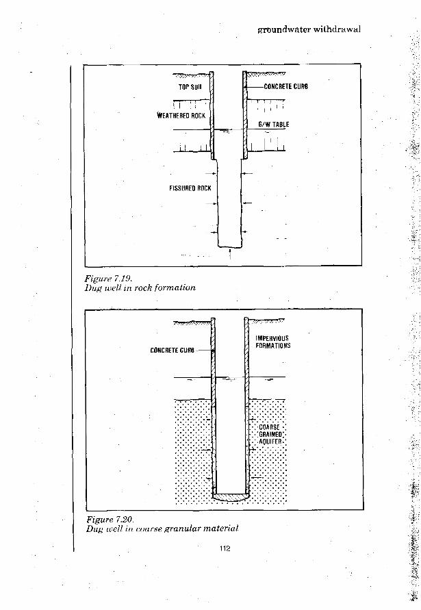
groundwater withdrawal
TOP SOIL
WEATHERED ROCK
FISSURED ROCK
CONCRETE CURB
G/W TABLE
Figure 7.19.Dug well in rock formation
CONCRETE CURB-
IMPERVIOUSFORMATIONS
i-COARSE •XGRAINED;.••AQUIFER-
7.20.e// in coarse granular material
112

groundwater withdrawal
In fine sand aquifers it is impossible to provide alining with openings or perforations small enough toretain the fine sand and prevent it from passing intothe well. In such cases the lining is frequently ex-tended over the entire depth of the well without anyopenings or perforations. The groundwater enters thewell only through the bottom which is covered withseveral layers of graded gravel keeping down the finesand of the water-bearing formation (Fig. 7.20). Forexample, three layers of graded gravel, each 15 cmthick, may be used with grain sizes of 1-2 mm for thedeepest layer, then 4-8 mm, and 20-30 mm effectivesize at the top.
IMPERVIOUSFORMATION
!''.'.'/'.'.-ir^^M
mmm:•: FINE GRAINED
::::AQUIFER
CONCRETE CURB
G/W TABLE
-COARSE GRAVEL
Figure 7.21.Dug well in fine granular aquifer
Lining a dug well will also provide a seal againstpolluted water seeping from the surface into thewell. This is not so effective if the well is open,because the water in it will then be polluted anyway,especially if the water is drawn using bucket-and -rope. As a minimal provision, the well lining shouldbe extended at least 0.5 m above the ground to form a"head wall" around the outer rim of the well. A con-crete apron should then be constructed on the groundsurface extending about 2 m all around the well. The
113

groundwater withdrawal
concrete apron also seals any fissures between thewell lining and the walls of the excavated hole andso prevents polluted surface water from seeping intothe well.
Figure 7.22.Covered dug well equipped with hand pump (Thailand)
IRC Photo
All these measures only have a limited effect, if thewell remains open. A satisfactory safeguarding of thebacteriological safety of the water from a well canonly be obtained if the well top is completely sealedwith a watertight slab on which a pump is mounted todraw the water (Fig. 7.23). A manhole that can betightly and securely locked should be provided toallow disinfection of the water in the well bychlorination. Although simple in itself, the sealingof dug wells is not always feasible, particularlywhere the standard of pump installation is poor andmaintenance requirements cannot be adequately met.
ft::-
114

groundwater withdrawal
PUMP OPENING
COVERMANHOLE
GRAVEL CEMENTED-JOINT
10 cm GRAVEL
SLAB
± 1 0 cm SAND
Figure 7.23.Dug well sealed for sanitary protection
S o u r c e : ' S h a l l o w W e l l s ' , 1978
Dug wells are sometimes constructed in a temporaryexcavation drained and braced against caving asnecessary (Fig. 7.24). Any type of building materialmay be used. For economy, strength and stability cir-cular walls are to be preferred. Masonry and brick-work are widely used; (reinforced) concrete is alsopopular, pre-fabricated or poured on the site. Toenable the groundwater to flow into the well, thecurbs of masonry and brickwork are made with openjoints. In concrete linings short pieces of tin tubeor garden hose can be cast to provide openings. Toavoid the entrance of polluted water from the groundsurface, back-filling should be done with care inthin layers that are firmly tamped.
115

groundwater withdrawal
V
x:::::lf
TEMPORARYSHEET PILING
'fW;WV+m^r GRAVEL
l ^ i i i i i i i i i i i i i i ^ !? I C K CJJRIJ WITHTJ1^?:::::'::::::::.::: OPEN JOINTS
REINFORCED CONCRETE SLAB
Figure 7.24.Dug well built in temporary excavation
Stiff, consolidated formations requiring no immediatesupport for stability allow the temporary excavationto be executed as an open hole with unsupportedwalls. However, it is prudent to carry out the dig-ging section by section as shown in Fig. 7.25.
STAGE 1REINFORCEMENT CONCRETE CURB
— B —
77777/7Y
2-4 M --B--
pr
IA
STEELSHUTTERING
'/
/
iIy//
' . • •
7///.
f
Figure 7.25.Reinforced concrete curb built on site
Each section should be 2-4 m high and is kept inplace by the surrounding ground pressing against it.
'••V
116

ground water withdrawal
The most common method of constructing a dug well isby excavation from the inside, removing the ground atthe bottom. The lining then sinks down due to its ownweight (Fig. 7.26). For wells of a diameter up to3-4 m the digging frequently is carried out with handtools. Below the groundwater table draining of thewell becomes necessary to enable further excavationto be carried out. In this construction method, cir-cular well shapes are mostly used because they settlereadily and are not liable to deformation when thewell lining sections are subjected to uneven forces.
Figure 7,26.Sinking a dug well by excavation from the inside.
Masonry work of stones, bricks or concrete blocks canbe used to build the well lining using a strong steelshoe as the base (Fig. 7.27). The shoe prevents thelining from settling unevenly which could cause de-formation and cracks. Reinforced concrete obviouslyis a more suitable construction material in thisrespect. It also allows the well lining to be con-structed above ground as the well sinking progresses.Large-diameter pipes of concrete, asbestos cement orplastic may be used for well lining material. Whenthese are not available or too expensive and dif-ficult to handle, prefabricated concrete rings may beemployed to form the lining (Fig. 7.28). There is novalid reason why prefabricated concrete rings shouldnot be widely used. They require no skilled masons,only suitable stones, bricks or gravel, and it is notdifficult to train unskilled workers for pouring con-crete. The necessary sand and gravel may usually beobtained in the neighbourhood of the well site.
117

groundwater withdrawal
••• '
• . • • • , • . • . • . • . • . • . • . / ,
:-:-:-:-:-:-.-.::-:M: \ :SAND' :;"• K
STEEL RING '.. ^ - j ^ *"S H O E • : • . . : • • : : • • • :
Figure 7.27.Dug well with brickwork lining.
CLAY OR LOAM ,
• ' • •• •
G R A V E L — v \
\
•I AQUIFER-
j i
7 nniPK
• • • • ^ 4 ^ • • * < '
LAYERS
: : . •
' \ CEMENT/ \ GROUTING
; . • . : • : • : • : • : • :
••• - I
,;i
i
••!
"h
Figure 7.28.Dug well construction with prefabricated rings,
The lower end of the starter ring is provided with ashoe having an inside cutting edge; the outside dia-
118

grmmdwater withdrawal
meter is somewhat larger to facilitate the sinkingand to reduce ground friction along the outside (Fig.7.29). The starter ring during sinking leaves a spacearound the curb. In loose formations this space willbe self-sealing but in cohesive formations it must befilled with cement grout or puddled clay as a safe-guard against seepage of polluted water from theground surface. Over the depth of the aquifer, therings are made of "no-fines" concrete (pea-sizegravel and cement, without sand) through which thegroundwater can enter the well.
REINFORCEDCONCRETE
NO-FINES'CONCRETE
STARTER RING FILTER RING
T0.6 - 0.8 M
SEAL RING
Figure 7.29.Pre-fabricated concrete rings
VDO PhotoFigure 7.30.Reinforced concrete ring for lining a dug well
119

groundwater withdrawal
Frequently, a more economic and technically betterconstruction may be obtained by combining the twomethods of construction described above. The con-struction of Fig. 7.31 gives an excellent protectionagainst any ingress of polluted seepage water fromthe surface; it also allows the well to be madedeeper when after some time the ground water wouldfall to a lower level. The design shown in Fig. 7.32does not have this advantage but it costs much lessto construct.
CLAY OR LOAM
GRAVEL -
REINFORCED CONCRETECURB CAST IN SITU
CONCRETE CURB MADE' OF PREFAB RINGS
Figure 7.31.Dug well construction using combination of methods
It will be clear that it is not so easy to protectthe water of a dug well against bacterial con-tamination. To sum up, the following precautions arerecommended:
1. The upper part of the lining should be water-tight preferably to a depth several metres belowthe lowest drawdown water level in the well;
2. The space between the walls of the dug hole andthe lining should be sealed with puddled clay, orbetter with cement grout;
120
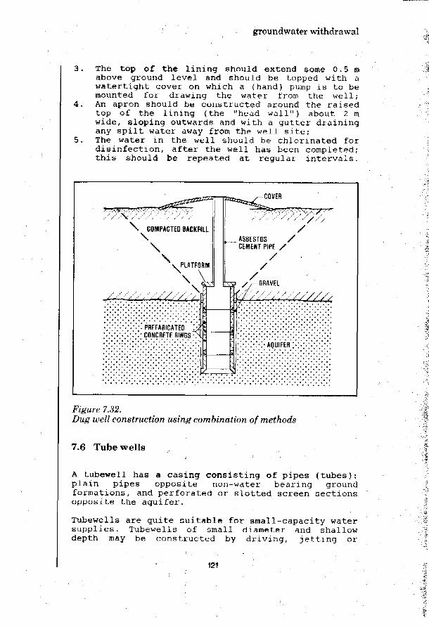
groundwater withdrawal
The top of the lining should extend some 0.5 mabove ground level and should be topped with awatertight cover on which a (hand) pump is to bemounted for drawing the water from the well;An apron should be constructed around the raisedtop of the lining (the "head wall") about 2 mwide, sloping outwards and with a gutter drainingany spilt water away from the well site;The water in the well should be chlorinated fordisinfection, after the well has been completed;this should be repeated at regular intervals.
• - . • , *
-COVER
Figure 7,32.Dug well construction using combination of methods M
7.6 Tube wells
A tubewell has a casing consisting of pipes (tubes):plain pipes opposite non-water bearing groundformations, and perforated or slotted screen sectionsopposite the aquifer.
Tubewells are quite suitable for small-capacity watersupplies. Tubewells of small diameter and shallowdepth may be constructed by driving, jetting or
121

groundwater withdrawal
boring. Drilling is more appropriate for larger -diameter tubewells designed for the withdrawal ofconsiderable amounts of water at greater depths, orfor tapping aquifers that are overlayed by hard rockor similar ground formations. Drilling is a veryversatile well construction technique which can beused for any reasonable depth and in most geologicalformations. However, it requires complicated equip-ment and considerable knowledge and experience. It ismostly done by specialist drillers. A detailed surveyof well drilling methods is given in Annex 2.
: • : • ? : • :
Figure 7.33.Well drilling
UNICEF t..oto by Bash
122

groundwater withdrawal
Tubewells can be drilled to over 200 m deep, eventhrough hard rock. However, there never is a guaran-tee that water will be found. It is, therefore, im-portant to make full use of any available prospectingand exploration data when choosing the site where atubewell is to be drilled. The assistance of ex-perienced and qualified people is essential, togetherwith the information obtained through hydrogeologicalsurveys.
Figure 7.34,Driven well
Driven wells (Fig. 7.34) are made by driving apointed screen (called a "well point") into thewater-bearing formation. To prevent damage to thewell point when driving through pebbles or thinlayers of hard material, the point at the lower endof the screen is made of solid steel, usually with aslightly larger diameter than the screen itself. Most
123

groundwater withdrawal
well points have a diameter in the 30-50 mm range. Asdriving proceeds and the well point sinks into theground, successive sections of pipe are screwed ontop so that the upper end of the casing always isabove the ground surface. The well point is driveninto the ground using a simple mechanism for hittingthe top of the pipe. Many arrangements can be used.Fig. 7.35 is indicative.
Figure 7.35,Well driving arrangement
whichever method is used, it is essential to ensurethat the blows are square and vertical, otherwise thepipe will bend and perhaps break. As it is the pipethat transmits the blows to the well point, strongthick-walled piping must be used, particularly whendifficult driving in hard formations is expected.
124

groundwater withdrawal
Figure 7.36.Well driving with inside drive bar
In the well driving method shown in Fig. 7.36, thedrive bar falls free inside the screen. The pipe ispulled into the ground rather than driven so thatpipes of normal strength classes can be used. Drivenwells are especially suitable for soft sandy for-mations which are readily penetrated by the wellpoint. Driven wells cannot be made in areas whereboulders or other obstacles are encountered in theground. In all ground formations the resistanceagainst driving increases with depth. The applicationof driven wells is therefore limited to shallow wellsof less than 10-15 m depth. For the same reason thediameter is usually small varying from as narrow as3 cm to a maximum of about 10 cm, a diameter of5-8 cm being the most common. Well pumps cannot beinstalled inside such small diameters. Driven wellsalso have the disadvantage that the screen openingsmay during the driving become clogged with clay orsimilar material. This is almost impossible to removeafter the completion of the driven well.
125

groundwater withdrawal
1— — tr
<
*—
.1 ii
I,. ,, J
I
DRIVE WEIGHT
5 ^r^T SELF-SEALING PACKER
• ^ r ^ p o i N T . • . • . - . - . •
• $ ;
Figure 7.37.Well drive point with sliding joint
The clogging of the well screen can be prevented byusing a sliding joint (Fig. 7.37). During driving thescreen is inside the casing and only after reachingthe desired depth is it then forced out to intrudethe water-bearing formation. When there are hardformations directly below the ground surface, abetter solution is to start with an earth auger forboring a hole as deep as possible with a diameterslightly larger than the size of the well point to bedriven down (Fig. 7.38). When the hole is straight,vertical and deep enough this also helps achieve aplumb well which otherwise may be difficult to ob-tain.
126

groundwater withdrawal
HAND AUGER SPIRAL AUGER
A = TRIPOD OF BAMBOO POLESB - PULLEY BLOCKC 2 cm 13/4-INCH] MANILA ROPED - E A R T H AUGERE - AUGER GUIOE
J
Figure 7.38Well boring equipment
Source: WHO(No. 7462)
If, after completion of the driven well the inside isthroughly disinfected, the water from it will be bac-teriologically safe and is likely to remain so.
127

groundwater withdrawal
However, the yield from a driven well is small, some-where between 0.1 and 1 1/sec. This will be only suf-ficient for private household use or a small commu-nity. For a larger supply of water, a number ofdriven wells may be interconnected with a centralsuction line and pumped as one unit but this solutionis rather expensive. In rural areas of developingcountries driven wells have the advantage of easy andrapid installation with no need for specializedequipment or skills.
Jetted wells outwardly do not differ much from drivenwells but the point at the lower end of the screen ishollow instead of solid, and the well is boredthrough the erosive action of a stream of waterjetting from the point (Fig. 7.39).
• . ¥ •
TO RIGPRESSURE HOSE
SWIVEL
*" "4PRESSURE PUMP & MOTOR
— SETTLING BASIN
• GROUNDWATER TABLE
-TEMPORARY CASING
- JETTING PIPE
JETTING NOZZLE
Figure 7.39.Well jetting
128

groundwater withdrawal
Compared with driven wells, jetting of wells is muchfaster. Mechanical force is not needed so thatplastic instead of steel can be used for casing andstrainer. Obviously, jetted wells can only be sunk inunconsolidated formations. Sandy aquifers are bestsuited for this method; clay and hardpan often offertoo much resistance to the jet stream of water. Aswith driven wells, boulders cannot be passed butit is a simple process to check the underground for-mation beforehand by washing the jetting pipe shownin Fig. 7.40 to the desired depth. Such a jettingpipe is also used in a well jetting technique using aseparate jetting pipe to wash the plastic casing andscreen into the ground. Compared with driven wells,the depth that can be obtained is somewhat greater,for the same diameters of about 5-8 cm. Clogging ofthe well screen openings is no problem.
JETTING PIPE-—-
• . A
I
> PLASTIC CASING
PLASTIC SCREEN
Figure 7.40.Well jetting with an outside jet pipe
Wells can also be made as bored wells. The boringtechnique lends itself best for use in soft groundsuch as sand and soft limestone. Thus, boring isparticularly used in deltaic areas where these types
129

groundwater withdrawal
of ground are most common. For shallow depth, spiralaugers are employed as shown in Fig. 7.38. Forgreater depth bucket-type augers can be applied,again rotated from the surface by means of a driveshaft. This shaft is built up from steel rod sections,3-6 m long and connected by quick-acting couplings.The upper part is called the kelly and has a squarecross-section to receive the necessary torque from arotating table. At the bottom, the auger is providedwith a cutting face which peels the soil from thehole and discharges it into the cylindrical chamberabove. When full, the auger is drawn up above groundand the hinged bottom is opened. Each time this isnecessary, the drive shaft must be dismantled andcoupled together again, a tedious and time consumingjob.
It will be clear that bored wells are mainly suitedto soft unconsolidated ground formations. In cohesiveground such as clay, a temporary casing to supportthe hole is usually not necessary above the ground-water table but in loose ground a temporary casingmust be installed. Under the water table, the augerdoes break up the ground layers but it cannot bringthe bored material to the surface as the cuttingsescape from the container when the auger is pulled upfrom the bottom of the hole. A bailer lowered in thehole with a cable must be employed to collect thecuttings. The bailer is moved up and down near thebottom of the hole; during the downstroke the cut-tings are entrapped by a closing valve. The wholeoperation greatly increases the time required for theboring of a well.
Sludger Method of Sinking Tubewells
The "sludger method" is an indigenous, low-cost,labour-intensive technique for sinking tubewells inunconsolidated alluvial ground formations such asthose found in deltaic areas. Tubewells with a depthup to 50 m may be constructed using this method undersuitable conditions. In Bangladesh, the sludgermethod has been and continues to be extensively usedfor sinking numerous tubewells to tap the abundant,shallow groundwater resources present in that deltaiccountry.
To start the drilling operation, a hole of about0.6 m diameter and 0.5 m deep is made into whichwater is poured. Some bamboo staging is erected abovethe hole. A piece of steel pipe is placed verticallyin the soil, and drilling is carried out by movingthe pipe up and down with a jerking action. For this,a bamboo rafter fastened to the pipe and supported
130

groundwater withdrawal
from the staging is operated. At the foot of thedrill pipe, soil loosened by the water enters intothe pipe allowing it to penetrate in the ground. As aresult of the jerking action of the drill pipe, theloosened soil and water is pushed upwards and comesout through the top of the pipe.
During the well sinking, one man sits on top of thestaging and takes care that the pipe is drilled per-fectly vertically. At each upward stroke, he closesthe top of the drill pipe off with his hand whichintroduces a suction action. This assists the loos-ening of the soil at the pipe bottom and the forcingup of the drilled soil. More pieces of pipe are addedas the string of drill pipe sections penetratesdeeper and deeper in the ground.
As the well sinking proceeds, soil samples are col-lected from the mud flow coming out at the top of thedrill pipe. These are taken at each 1.5 m the drillpipe is sunk further, and then examined. The drillingoperation is stopped when good water-bearing for-mations are sufficiently penetrated. The whole lengthof pipe is withdrawn piece by piece taking care tokeep the drilled hole intact. Immediately afterwithdrawal of the drill tubes, the well casingconsisting of plastic pipes complete with strainersections is fitted and lowered in the hole up to thedetermined depth.
An indication of the time and labour requirements forsinking a tubewell using the sludger method, may beobtained from an example concerning a well sunk inKonaburi District of Dacca (Bangladesh) to a depth ofabout 28.5 m. The following data are quoted:
Time required for drilling of the wellTime required for construction of platformLabour engaged for drilling well skilled
unskilledLabour engaged for construction of platform
skilledunskilled
11423
11
hourshoursmenmen
manman.
131

132

Groundwater withdrawal
Allsebrook, J.C.P.WHERE SHALL WE DIG THE WELLIn: Appropriate Technology, Vol. 4(1978) No. 4.
A.W.W.A.GROUNDWATERAWWA Manual M21, 130 p.American Water Works Assoc, New York, 1973
Beyer, M.G.DRINKTNG WATER FOR EVERY VILLAGEIn: Assignment Children, UN ICEF, 1976, No. 34
Bowen, R.GROUND WATERApplied Science Publishers Ltd., 1980, 227 p.
Brown, R.H. (Ed.)GROUND WATER STUDIESUNESCO, Paris, 1973-1977
Brush, R.E.WELLS CONSTRUCTIONPeace Corps, Washington, D.C., 1980
BURGfiAPLA CONSTRUCTION DES PUITS EN AFRIQUE TROPICALEMinistere de la Cooperation, Paris, 1974(Series Techniques Rurales en Afruque)
Castany, G.TRAITE PRATIQUE DES EAUX SOUTERRAINESDunod, Paris, 1967, Second edition
Castany, G.PROSPECTTON ET EXPLOITATION DES EAUX SOUTERRATNESDunod, Paris, 1968, 717 p.
Campbell, M.D.; Lehr, J.H.WATER WELL TECHNOLOGYMcGraw-Hill Book Co., New York, 681 p.
Cruse, K. ;A REVTEW OF WATER WELL DRILLING METHODSIn: Journal of Engineering Geology, 1979, (Vol. 12), pp. 79-95
Davis, S.N.; De Wiest, R.J.N.HYDROGEOLOGYJohn Wiley & Sons, New York, 1966
133

Eberle, M.; Persons, J.L.; Lehr, J.H. et al.APPROPRIATE WELL DRILLING TECHNOLOGIESNational Water Well Assoc,, Worthington, Ohio, USA, 95 p.
Freeze, R.A.; Cherry, J.A.GROUNDWATERPrentice-Hall, Inc., Englewood Cliffs, N.Y., USA, 1979
Gibson, U.P.; Singer, R.D.SMALL WELLS MANUALAgency for International Development, Washington, 1969, 156 p.
GROUNDWATER AND WELLSJohnson Division, UOP, St.Paul, Minnesota,(3rd printing), 1975, 440 p.
Holmes, A.PRINCPLES OF PHYSICAL GEOLOGYThomas Nelson & Sons Ltd., London, 1966
Huisman, L.GROUNDWATER RECOVERYMcMillan, London, 1972, 336 p.
Hwindl, L.A. (Ed.)HIDDEN WATER IN ARTD LANDSReport of a Workshop on Groundwater Research Needs.Paris, 25 November 1975.Association of Geoscientists for InternationalDevelopment (AGID) , 1976
Jain, J.K.HANDBOOK ON BORING AMD DEEPENING OF WELLSGovernment of India, Ministry of Food and Agriculture, NewDelhi , 1962
MANUAL OF WATER WELL CONSTRUCTION PRACTICESU.S. Environmental Protection Agency, Washington, D.C., 1975, 175 p.(EPA-57O/9-75-OO1)
McJunkin, F.E.JETTING SMALL TUBEWELLS BY HANDWashington, D.C., July 1960, p. 3(Peace Corps Technical Notes No. 1)
Moehrl, K.E.WELL GROUTTNG AND WELL PROTECTIONIn: Journal of Lhe American Water Works Assiciation, No. 4,1964(56), pp. 423-431
Romero, J.A.C.MANUAL DE POZOS RASOSOrganizacion Panamericana de la Salud, Washington, D.C., 1977
134

SHALLOW WELLS .
DHV Consulting Engineers, Amersfoort, Netherlands, 1978, p. 189
Slow, D.A.V.; Skidmore, J.; Beyer, A.R.PRELIMINARY BIBLIOGRAPHY ON GROUNDWATER IN DEVELOPING COUNTRIESAssociation of Geosciontists for International Development(AGID), November, 1976
Todd, D.K.GROUNDWATER HYDROLOGYJohn Wiley & Sons, New York, 1959
Watt, S.B.; Wood, W.E.HAND DUG WELLS AND THEIR CONSTRUCTIONIntermediate Technology Publications Ltd., London, 1976, 234 p.
135

136

surface water intake
8. surface water intake
8.1 River water intake
In tropical countries, rivers and streams often havea wide seasonal fluctuation in flow. This affects thequality of the water. In wet periods, the water maybe low in dissolved solids content but often of ahigh turbidity. In dry periods, river flows are lowand the load of dissolved solids is less diluted.
Mountain streams sometimes carry a high silt load butthe mineral content is mostly low and human pollutionfrequently absent, in plains and estuaries, riversusually flow slowly except when there is a flood. Thewater may be relatively clear but it is almost alwayspolluted, and treatment will be necessary to renderit fit for drinking and domestic purposes.
The quality of river water will usually not differmuch across the width and depth of the river bed.The intake, therefore, may be sited at any suitablepoint where the river water can be withdrawn in suf-ficient quantity. The design of a river water intakeshould be such that both clogging and scouring willbe avoided. The stability of the intake structureshould be secured, even under flood conditions.
Where the river transports no boulders or rollingstones that would damage the intake, an unprotectedintake may be adequate (Fig. 8.1).
Figure 8.1.Unprotected river intake
137
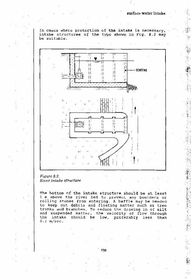
surface water intake
In cases where protection of the intake is necessary,intake structures of the type shown in Fig. 8.2 maybe suitable.
Figure 8,2,River intake structure
& • :
The bottom of the intake structure should be at least1 m above the river bed to prevent any boulders orrolling stones from entering. A baffle may be neededto keep out debris and floating matter such as treetrunks and branches. To reduce the drawing in of siltand suspended matter, the velocity of flow throughthe intake should be low, preferably less than0.1 m/sec.
% ' ' • ' •
• * : • • •
138

surface water intake
A river intake always requires a sufficient depth ofwater in the river bed. A submerged weir across theriver may have to be constructed downstream of theintake to ensure that the necessary depth of waterwill be available, even in dry periods.
Frequently, pumping is needed for the intake of waterfrom river sources. If the variation between the highand low water level in the river is not more than3.5-4 m, a suction pump placed on the river bank maybe used (Fig. 8.3).
HIGH W/L
LOW W/L
3$
^VARIATION BETWEENHIGH AND LOWWATER LEVEL.
* TO SUPPLY
UP TO3-5-4 m
Figure 8.3.Pumped river water intake
A different intake arrangement is needed if the re-quired pumping head exceeds 3.5-4 m. One arrangementworth considering uses a sump constructed in theriver bank. The river water is collected with in-filtration drains laid under the river bed; undergravity it flows into the sump. As the lowest waterlevel in the sump will probably be too deep for asuction pump placed above ground, the water isusually drawn with a submersible pump, or a spindle-driven pump, positioned down in the sump.
139

surface water intake
MINIMUMWATER LEVEL
SUBMERSIBLEMOTORS PUMP
SUITABLESAND STRATA
RIVERBED
-WELDED STEEL FLANGE
Figure. HA.Bank river intake using infiltration drains
8.2 Lake water intake
The quality of lake water is influenced by self-purification through aeration, bio-chemical pro-cesses, and settling of suspended solids. The watercan be very clear, of low organic content and withhigh oxygen saturation. Usually, human and animalpollution only present a health hazard near the lakeshores. At some distance from the shore, the lakewater is generally free from pathogenic bacteria andviruses. However, algae may be present, particularlyin the upper water layers of lakes.
In deep lakes, the wave action and turbulence causedby the wind striking the surface will not affect thedeeper strata. There being no mixing, a thermalstratification will develop with the warmer upperwater layers floating on top of the cooler deeperones which have a higher mass density. As a result ofthe thermal stratification, the deeper water layersmay differ in quality from the upper water. Thethermal stratification can be fairly stable especial-ly under tropical conditions. Fig. 8.5 gives an ex-ample.
140

surface water intake
HCO3 lre« COj pH NH3/K P Fe Mn
mg/ l mg/l mg/l mg ' l mg/l mg/ l?no 300 ,10 30 , 7 8 9 , 2 4 6 , 0 1 0 :i
Figure: 8.5.Water quality variation with depth in a deep lake, (Indonesia)
The thermal stratification should be taken into ac-count when the location and depth of a lake waterintake for water supply purposes is decided upon.The presence of algae in the upper water layers isanother relevant factor.
In deep lakes with water of a low nutrient content(nitrates, phosphates, etc), the chemical quality ofthe water will be much the same throughout the fulldepth. For water supply purposes, water from deeperstrata will have the advantage of a practically con-stant temperature. Provision should be made to with-draw the water at some depth below the surface (Fig.8.6) .
Deep lakes containing water with a high nutrientcontent show a marked difference of water quality atdifferent depths. Water should be withdrawn from theupper layers of lake water containing the highestoxygen content. However, as the top layer of watermay have become warmed up, the intake of water forwater supply should preferably be 3-5 m below thesurface.
In shallow lakes, the intake should be sufficientlyhigh above the lake bottom to avoid the entrance ofsilt (Fig. 8.7).
141

surface water intake
Figure 8.6.Variable depth lake water intake.
n\ CT\
CONCRETE ORASBESTOS CEMENT •PIPE
ik. I> 1 m
PLASTIC PIPE
CONCRETE FILL
'%•'•
' > • • •
?••; •
Figure 8.7.Intake structure at bottom of shallow lake,
8.3 Typical intake constructions
For small community water supplies the quantity ofwater needed being small, often very simple intakestructures can be used. With a per capita water useof 30 litres/ day and the peak intake 4 times theaverage water demand, 1,000 people would require anintake capacity of only 1.4 litres/sec. A 150 mm in-take pipe would be sufficient to keep the entrance
142• 1

surface water intake
velocity of flow below 0.1 m/sec. If an entrancevelocity of flow of 0.5 m/sec is allowed, a pipe assmall as 60 mm would be adequate.
For small capacity intakes, simple arrangements usingflexible plastic pipe can be used (Fig. 8.8).
FLOAT
Figure 8.8.Simple water intake structure
Another intake construction using a floating barrelto support the intake pipe, is shown in Fig. 8.9The water is pumped from the well sump.
WELL SUMPBARREL
FLEXIBLE JOINTRUBBER OB PLASTIC HOSE
Figure 8.9.Float intake
143

surface water intake
8.4 Small dams and village ponds
There are many small communities whose only source ofwater supply is a small dam or pond. These are called"hafir" (Sudan), "tapkis" (Nigeria), "represa" (SouthAmerica), "tank" (India), "pond" (Eastern Africa), orother local names. In this handbook they are allreferred to as small dams or village ponds.
Small dams and village ponds vary in area from smallto large ones of several hectares. They may beentirely natural in origin - depressions in flatareas - or specially constructed for the purpose. Ifman-made, they may have been excavated for theexpress purpose of holding water or they may be pitsfrom which clay for building has been taken. Manyare a combination of natural and man-made pools whichhave been deepened or enlarged over the years to in-crease their holding capacity.
Some are to be found inside villages or small towns.More usually, they are located just outside the vil-lage area. In India they are often stocked with fishwhich provides a valuable source of food for thevillagers.
Unfortunately, they are also used for washing andbathing. More often than not they are polluted,hazardous at best, and potential spreaders of epi-demics. Too often they harbour pathogenic bacteria,viruses and parasites which account for incalculablenumbers of illnesses and deaths, particularly amongstchildren.
The water may be full of silt or colloidal matter,especially immediately after the rains. Some villageponds have been in existence for centuries; they maybe full of aquatic vegetation. Some are the reci-pients of refuse of all sorts. Others are relativelywell-kept, beautiful in appearance and a distinctivefeature of the landscape.
In practice, it is impossible to prevent the pollu-tion of these small dams and village ponds. By theirvery nature they are at the lowest point of the sur-rounding area and all the village drainage finds itsway into them.
In a newly excavated pond, the construction of an in-take presents no difficulty if carried out before thetank fills. In an established pond, work must bedone while the water is in use. Probably all the workwill be done by hand and no special tools will be
144

surface water intake
available. In ponds where the water has high tur-bidity, the water is best drawn from just below thesurface. A floating intake device may be suitable.Plastic pipe could be used instead of galvanized ironfor the collecting pipe; bamboo might also be usedfor this purpose. The floating support may be madeof bamboo or other locally available materials.
The presence of algae and other aquatic vegetation,as well as fish, in the pond will make it necessaryto fix a strainer around the intake. The level ofthe intake opening must be below the lowest drawoffpoint, if syphoning is to be avoided. A well may bedug close to the bank and the intake pipe either-thrust (using a heavy jack) or driven from the wellinto the pond. The pipe is then capped while the wellis lined with masonry or concrete, and the floatingintake fixed. The well should be deepened to form asump which will allow some settlement of suspendedmatter.
8.5 Screens
Screening of water is done by passing the waterthrough closely spaced bars, gratings or perforatedplates. Screening does not change the chemical orbacteriological quality of the water. It serves toretain coarse material and suspended matter largerthan the screen openings. Even when screened-out ma-terial forms a filtering mat of deposits, the screen-ing still is purely of a mechanical nature.
In water supply engineering, screens are used forvarious purposes:
(i) Removal of floating and suspended matter oflarge size which otherwise might clog pipe-lines, damage pumps and other mechanicalequipment, or interfere with the satis-factory operation of the treatment pro-cesses. Fixed screens are used for this pur-pose and they are cleaned on site by hand ormechanically;
(ii) Clarification of the water by removal of sus-pended matter even of small size, to lightenthe load on the subsequent treatment pro-cesses. In particular they are used toprevent filters from becoming clogged toorapidly.
145

surface water intake
Bar screens usually consist of steel strips or barsspaced at 0.5 to 5 cm. If the amount of material ex-pected to be screened out is small the bars are setquite steeply, at an angle of 60-75° to the horizon-tal, and cleaning is done by hand using rakes. Iflarger amounts will be retained, the cleaning by handshould still be feasible; to facilitate the cleaningwork, the bars should be placed at an angle of 30-45°to the horizontal (Fig. 8.10).
The water should flow towards the bar screen at aquite low velocity, 0.1 - 0.2 m/sec. Once the waterhas passed the screen, the flow velocity should be atleast 0.3 - 0,5 m/sec in order to prevent thesettling out of suspended matter.
Figure 8.10.Fixed bar screen
In the openings between the bars the velocity of flowshould be limited to 0.7 m/sec; otherwise soft, de-formable matter will be forced through the screenopenings. A clean screen will allow the water to passwith a head loss of only a few centimetres. However,the head loss rises sharply when the clogging of thescreen builds up. Regular cleaning should keep thehead loss limited to 0.1 - 0.2 m head of water.Allowing for delayed cleaning and mechanicalfailures, it is good practice to design a bar screenfor a head loss of 0.5 - 1.0 m.
146

Surface water intake
DESIGN OF SMALL DAMS
U.S. Bureau of Reclamation, Washinlon, D.C. 1973
Instituto de. Ingenieria SanitariaABASTKCIM1ENT0S DE AQUA POTABLE A COMMUNIDADES RUKALESt'acultad de Ingeiiieria, Universitado dp Buenos Aires, 1971
Institute of Water EngineersMANUAL OF BRITISH WATER ENGINEERING PRACTICE (4th Edition)W. Heifer & Sons Ltd., Cambridge, 1969
Wood, J.L.; Richardson, J. -DESIGN OF SMALL WATER STORAGE AND EROSION CONTROL DAMSColorado State University, Fort Collins, Colorado, 1975 74 p.
147

148

artificial recharge
artificial recharge
9.1 Introduction
Groundwater usually has the great advantage over sur-face water from rivers and lakes in that it is freefrom pathogenic organisms and bacteria causing water-related diseases. However, groundwater is not alwaysavailable and the amounts that can be withdrawn areusually limited. As indicated previously, in the longrun the withdrawal of groundwater cannot exceed theamount of natural recharge. Therefore, when thisrecharge is small, the safe yield of the aquifer isalso small. Under suitable conditions it is possibleto supplement the natural recharge of an aquifer andso add to its safe yield capacity. This is calledartifical recharge. It involves measures to feedwater from rivers or lakes into the aquifer, eitherdirectly or by spreading the water over the in-filtration area allowing it to percolate downward tothe aquifer. Artificial recharge can have greatpotential for improving small community watersupplies in many parts of the world.
Apart from adding to the yield of an aquifer, artifi-cial recharge also provides purification of the in-filtrated water. When water from a river or lakeflows through a granular ground formation (Fig. 9.1),filtration will take place with a substantial removalof the suspended and colloidal impurities, bacteriaand other organisms. The aquifer acts as a slow sandfilter.
Provided that the water is recovered at a sufficientdistance from the point of recharge, preferably morethan 50 m, the water will flow underground for a con-siderable time, normally two months or more. As aresult of the bio-chemical processes, adsorption andfiltration, the water will become clear and safe fordomestic use. In many instances it can be used with-out any further treatment.
The principal methods of artificial recharge ofaquifers are bank infiltration and spreading of thewater over permeable ground surfaces.
149

artificial recharge
RECHARGE
iH
RECOVERY
' / / / / / / / / / / / / / / / / /
Figure 9.1.Artificial recharge of aquifer
If artificial recharge is combined with undergroundstorage of the water, water taken from a river in thewet season can be stored in the aquifer and recoveredduring the dry period when the river flow is small orabsent (Fig. 9.2). It will often be much easier andmore economical to provide such underground storageof water rather than surface reservoirs. This isparticularly the case in flat land. Additional ad-vantages are the great reduction of evaporationlosses of water and the prevention of algal growth.
WET SEASON DRY SEASON
Figure 9.2.Artificial recharge with underground storage of water
9.2 Bank infiltration
For bank infiltration (induced recharge), galleriesor lines of wells are placed parallel to the shore-
150

artificial recharge
line of a river or lake, at a sufficient distance.This is shown in Fig. 9.3.
ORIGINAL SITUATION LOW ABSTRACTION RATE/ / / / 7/7/ / 7/7
HIGH ABSTRACTION RATE
Figure 9.3.Bank infiltration
In the original situation the outflow of groundwaterfeeds the flow of the river. When amounts of ground-water are withdrawn, the flow of groundwater into theriver will fall. The withdrawal of groundwaterresults in a lowering of the groundwater table. Forhigh abstraction rates, the groundwater table nearthe shoreline may be drawn down below the water levelin the river. Water from the river will be induced toenter the aquifer. Provided that the permeability ofthe stream bed is adequate, considerable amounts ofwater may thus be recovered without much affectingthe groundwater table further inland (Fig. 9.4). Theabstracted water will, for the most part, be inducedrecharge, that is water originating from the river.
Apart from hydrogeological factors, the design of aninduced recharge scheme is governed by two factors:the rate of groundwater withdrawal (q) from thegallery or line of wells, and the distance (L) (seeFig. 9.4). In order to provide for sufficient timefor the purification processes in the water duringits flow from the river to the gallery, the distanceL should not be less than 20 m and preferably 50 m ormore. The important parameter is the time the watertravels underground. Three weeks is a minimum andwhenever possible, it should be two months or more.
151

artificial recharge
Of course, the travel time not only depends on thedistance L but also on the rate of withdrawal (q),and the thickness and porosity of the aquifer.
x^
/ ''- * ; L
/ / / / / / , - - / / , / / / / / / , - / / / / / / / / / / / , • /
Figure 9.4.Induced recharge
Induced recharge is particularly useful in caseswhere the natural recharge of an aquifer is small,for example, an aquifer of narrow width consisting ofthin bands of pervious ground formations runningalongside the river (Fig. 9.5). The safe yield ofsuch an aquifer obtained from the natural rechargeonly, will be very limited but large amounts of watermay be withdrawn when induced recharge is practiced.
V-.
Figure 9.5.Induced recharge and groundwater recovery from an aquifer ofsmal width
The means for recovery of the recharged water mayalso be set in the river bed itself. Fig. 9.6 showsa line of jetted well points interconnected by a cen-
152

artificial recharge
tral suction line. Another option is a horizontalcollector drain placed under the river bed (Fig. 9.7).
W E L L -
•.* >3 m .
: • ; • : • : ! : • : •
iE
, ^SUCTION LINE ^6$?.si
Figure 9.6.Line of wellpoints placed in riverbed
RIVER
"=^=lt^.
Wi^r^MB
COLLECTOR DRAIN
WELL
COVER
Horizontal collector drain under river bed
153

artificial recharge
With induced recharge, river water is made to enterthe aquifer through the stream bed. At the river bedsome clogging will take place, as a result of de-posits of suspended particles and precipitation ofdissolved solids. This clogging will gradually createan infiltration head loss (see Fig. 9.8).
!
Qi
INFILTRATION JF- "•HEAD LOSS /f-'-'-'
\ £•••'••'••••
, * * * . " * • > " V J ^1
* * ' , * • •
\ » . s t j ^ r . . . . . . . .
^: :::x :: :: :x>:.::
? '/ J / / / / / / / '/ / / V / ////'/ T7
:,*'•';
Figure 9.8. ,Infiltration head loss on river bed due to clogging
Usually, the clogging of the river bed presents noserious problems, as flood flows in the river willperiodically scour the river banks and wash away thedeposits. In rivers with dams for flood control,however, scouring of the banks may be absent or in-frequent. The clogging of the infiltration area canthen increase to the point that the rate of inducedrecharge is greatly reduced. In theory, this couldbe remedied by a cleaning of the river bed but thisis difficult and often impractical.
-CLOGGED RIVER BED
.'• SAND AND GRAVER , <• °. = . ° J ; . •'(
RECOVERY TWIN RECHARGEBASINS
SAND COVER
JGALLERY". . '.
Figure 9.9.Basi?is for recharge of aquifer using river water
154

artificial recharge
In such cases, it may be advantageous to constructtwin spreading basins that are filled with water fromthe river (Fig. 9.9). The bottom of these basins iscovered with a layer of medium coarse sand, about0.5 m thick. Clogging will now be restricted to theupper centimetres of this bed and can be readily re-moved by scraping.
9.3 Water spreading
The bank filtration described in the previous sectioncan only be used where a suitable aquifer is adjacentto the source of surface water. Sometimes, both asuitable aquifer and a water source are present butsome distance apart. Artificial recharge then can bepractised but the water from the river, lake or othersource has first to be transported to those siteswhere ground formations suitable for infiltration andunderground flow are available. This certainly re-presents a complication of the recharge scheme butimportant additional advantages are attained:
(i) The intake of water can be stopped when the riverwater is polluted or otherwise of poor quality;
(ii) A saving in cost may be achieved when therecharge scheme is situated near the water dis-tribution area.
A comprehensive scheme for artificial recharge bywater spreading is shown in Fig. 9.10. It includespre-treatment of the water before recharge in an in-filtration basin, and further treatment after re-covery.
PUMPING STATION INFILTRATION RECOVERYRIVER ,—[_ , BASIN
Figure 9.10.Scheme for artificial recharge and recovery
Pre-treatment may be necessary to avoid that silt isdeposited in the pipeline, or that microbiologicalslimes are formed which would greatly reduce the
155

artificial recharge
pipeline's carrying capacity. It will also reduce theclogging of the recharge basin so that less frequentcleaning will be needed. Further it will protect theaquifer from becoming fouled by non-degradable or-ganic substances. Treatment of the water recoveredfrom the recharge scheme is necessary in the eventthat quality is still not satisfactory. This may forinstance be the case when during its undergroundtravel the water has become anaerobic and has pickedup iron and manganese from the sub-soil.
RIVERWATER
\ .
t
_ _ .
1
t
= _ _ = =
1
• : : D R A I N -
1
i
RECHARGE
. - . - . • . • . ' 6 . - .
\
-DRAIN |„„_
. i
1
1
__J
-INFILTRATION DITCH
1 " " : ORIGINAL G/W TABLE
> ' / • '
Figure 9.11.WaU-.r recharge, in shallow aquifer using infiltration ditches anddrains
The design of an artificial recharge scheme dependson three factors:
(]) The infiltration rate of the waLcr in thewater spreading basins. This rate should be so lowthat the basins will only require cleaning after aconsiderable period of time, at least several monthsand preferably one year or more;
(ii) The travel time and length of the under-ground water I'iow;
156

(iii)
artificial recharge
The maximum allowable difference of levelbetween the water in the spreading basins and thegroundwater table.
In combination, these factors indicate that for theartificial recharge of shallow aquifers, particularlyaquifers with fine grain composition, the spreadingbasins should be constructed as ditches, with gal-leries for groundwater recovery constructed parallelto them (Fig. 9.11). For deep aquifers, particularlythose having a coarse grain composition, thespreading basin preferably should be constructed as apond surrounded by a battery of recovery wells (Fig.9.12).
\RECOVERY /WELLS \ ~ °
TO
f V INFILTRATION POND
: ORIGINAL G/W TABLE
Figure 9.12.Recharge of a deep aquifer using an infiltration pond and recoverywells.
157

artificial recharge
The artificial recharge schemes as described aboveare quite suitable for small community watersupplies, particularly in rural areas. For thelimited water requirements to be met from thesesupplies, treatment of the water is often not afeasible proposition. To serve 200 people having aper capita water use of 15 litres/capita/day, the re-quired capacity would only be 3m3/day. Using arti-ficial recharge, this can be readily provided. Toprovide a retention time of the water underground of60 days (2 months), an aquifer having 40% pore spacewould need to be 450 m3 in volume to serve the pur-pose. Assuming an average saturated thickness of 2 m,the surface area would be 225 m; for instance, 7.5 mwide and 30 m long. This can easily be constructed inthe form of an excavation of 3 m deep, lined with alayer of puddled clay or plastic sheeting to avoidseepage losses (Fig. 9.13).
RIVER WATER RECHARGE
—II
LPUDDLED CLAY
Tr:::::-::::::-::i:-:-# %&
Figure 9.13.Small-capacity recharge scheme
The possible utilization of rainwater for rechargepurposes is shown in Fig. 9.14.
158

artificial recharge
-RAINWATER CATCHMENT
EXCAVATIONwater proofed with anysuitable material andbackfilled with cleansand or gravel
WATER WITHDRAWAL WELL
Figure 9.14.Artificial recharge using rainwater
Source: fTDG
9.4 Sand dams
Sand dams are reservoirs filled with coarse sand,stones or loose rock. The water is stored in thepores of the accumulated bed of sand. This greatlyreduces the evaporation losses of water. Sand damsare, therefore, particularly useful in areas whereevaporation rates are high. They have been con-structed in many of the semi-arid areas of Africa andthe Americas. Water may be stored for long periods,and even under total drought conditions sand dams canprovide water from the stored volume.
Water is withdrawn from the sand dam by a drain pipeor from a well dug into the sand bed near to the dam(Fig. 9.15). Usually the water can be used withoutany treatment, as it is filtered while flowingthrough the sand bed.
In the semi-arid areas where the use of sand dams ismost appropriate, flood waters often carry a high se-diment load because there is little vegetation toprevent erosion of the soil. Considerable amounts ofsand and gravel are carried by the flood waters.Thus, when the dam wall for a storage reservoir isbuilt in a river bed during the dry season, the floodwaters in the wet season will deposit the sand and
159

artificial recharge
gravel behind it. The flood waters will also carrysubstantial quantities of mud. To ensure that mainlysand and gravel are deposited behind the dam, the damwall should first be built to a height of only about2 m . Later the wall should be raised as the sand andgravel deposits build up. The staged raising of thedam will enable the mud to be carried over it by theoverflowing flood waters. After four or five years,the dam may reach its full height (usually 6-12 m).
SLOTS FOR WATERINTAKE TO WELL
Figure 9.15.Sand dam (schematic)
Sand-fill dams can be used with particular advantagefor artificial recharge because they allow most ofthe finer sediments in flood water to be carried awaywith the overflow. Thus, the clogging of aquifers bysilt-laden water which can give problems in rechargesystems, is here avoided.
160

Artificial recharge
ARTIFICIAL RECHARGE AND MANAGEMENT OF AQUIFERS .Keport of Symposium, Haifa, 1967International Association of Scientific Hydrology, 1968(Publication No. 72)
Bize, J.; Bourguet, L. ; Lemoine, J.L1ALIMENTATION ARTIFICIELLE DES NAPPES SOUTERRAINESMasson et Cie, Paris, 1972
Buckan, S. .ARTIFICIAL REPLENISHMENT OF AQUIFERSIn: Journal of Institution of Water Engineers;, 1955, pp. 111-163
GROUNDWATER STORAGE AND ARTIFICIAL RECHARGEUniLed Nations, New York, ]97!">, 270 p.(Natural Resources/Water Series No. 2/ST/ESA/13)
Huisman, L.ARTIFICAl RECHARGEIn: Proceedings Sixth International Water Supply Congress,Stockholm, 1964.International Water Supply Association, pp. 11-18
Jansa, M. .ARTIFICIAL REPLENISHMENT OF UNDERGROUND WATERIn: Proceedings Second International Water Supply Congress,Paris, 1952International Water Supply Association, pp. 149-191
Meinzer, R.GENERAL PRINCIPLES OF ARTIFICIAL GROUNDWATER RECHARGEIn: Economic Geology, 1946, pp. 191-201
Muckel, D.C.REPLENISHMENT OF GROUNDWATER SUPPLIES BY ARTIFICIAL MEANSUniLed States Department oi" Agriculture, 1959(Technical Bulletin No. 1195)
161

162

pumping
10. pumping
10.1 Introduction
Water pumping technology developed parallel to the.sources of power available at the time. Indeed onecan say that our first ancestor who cupped his handsand fetched water from a stream, chose the 'pumping1
technique appropriate to him. Modern devices such ascentrifugal pumps have reached a high state of devel-opment and are widely used, particularly in developedcountries, only because suitable power sources suchas diesel engines and electric motors became avail-able.
For small communities in developing countries, humanand animal power are often the most readily availablepower for pumping water, particularly in rural areas.Under suitable conditions, wind power is of relevance.Solar energy can have potential. Diesel engines andelectric motors should only be used, if the necessaryfuel or electricity supplies are available and se-cured, together with adequate maintenance and spareparts -
10.2 Power sources for pumping
Human Power
A manual pumping device* (including devices operatedby foot) is any simple device powered by human power.They are capable of lifting relatively small amountsof water. Using human power for pumping water hascertain features that are important under the condi-tions of small and rural communities in developingcountries •.
The power requirements can be met from within theusers' group;
- The capital cost of manually-operated pumps isgenerally low;The discharge capacity of one or more manualpumping devices is usually adequate to meet thedomestic water requirements of a small community.
Often referred to as: 'hand pump1
163

pumping
Figure 10.1.Hand-pumped water supply (Bangladesh)
: MatthiJK de Vrct-de
The power available from the human muscle depends onthe individual, the environment, and the duration ofthe task. The power available for work of long dura-tion, for example 8 hours per day, by a healthy manis often estimated at 60 to 75 watts (0.08 to 0.10horsepower). This value must be reduced for women,children and the aged. It also must be reduced forhigh temperature, and work environments with highhumidity. Where the pump user and the pump are poorlymatched, much of the power input is wasted; forexample, when a person operates a pump from a stoopedposition.
Animal Power
Draught-animals are a common and vital source ofpower in many developing countries. Animal power ispoorly suited to operate small-diameter pump devicesfitted on covered wells. Animals are widely used forlifting irrigation water from large-diameter, openwells but these should not be used for communitywater supply purposes. The most efficient use ofanimals is at fixed sites where they pull rotatingcircular sweeps or push treadmills. Both methods
164

pumping
require gears and slow moving, large displacementpumps. Bullocks and donkeys are mostly used.
Windpower
The use of windpower for pumping water should befeasible if:
Winds of at least 2.5-3 m/sec. are present 60%.or more of the time;The water source can be pumped continuouslywithout excessive drawdown;
- Storage is provided, typically for at least 3days' demand, to provide for calm periods withoutwind;A clear sweep of wind to the windmill is secured,i.e. the windmill is placed above surroundingobstructions, such as trees or buildings within125 metres; preferably the windmill should be seton a tower 4.5 to 6 metres high;Windmill equipment is available that can operaterelatively unattended for long periods of time,for example six months or more. The drivingmechanism should be covered and provided with anadequate lubrication system. Vanes, and sailassemblies should be protected againstweathering.
By far the most common type of wind-powered pump isthe slow-running wind wheel driving a piston pump.The pump is generally equipped with a pump rod thatis connected to the drive axis of the windmill.Provision may be made for pumping by hand during calmperiods.
The wind wheels range in diameter from about 2 to 6metres. Even though the windmills themselves may haveto be imported, strong towers can usually be con-structed from local materials.
Modern windmills are designed to ensure that theyautomatically turn into the wind when pumping. Theyare also equipped with a 'pull-out' system to auto-matically turn the wheel out of excessive wind,stronger than 13-15 m/sec, which might damage thewindmill. The 'sails' or fan blades can be so de-signed that they furl automatically to prevent thewheel from rotating too fast in high winds. Thewindmill will normally not begin pumping until thewind velocity is about 2.5-3 m/sec. Fig. 10.2 showsseveral typical arrangements for windmill-pumpedwater supply systems.
165

pumping
\ ''-\ •
J -.;••
A] GROUNOWATER
B) SURFACE WATER
Figure 10.2.Windmill-pumped water supply systems
Electric Motors :,
Electric motors generally need less maintenance andare more reliable than diesel engines. They are,therefore, to be preferred as a source of power forpumping if a reliable supply of electric power isavailable. In such cases, electric motors can be usedto drive pumps. The electric motor should be capableof carrying the work load that will be imposed,taking into consideration the various adverseoperating conditions under which the pump has towork. If the power requirement of a pump exceeds thesafe operating load of the electric motor, the motor
166

pumping
may be damaged or burnt out. Attention must also bepaid to the characteristic of the motor and thesupply voltage.
There is a tendency to use general-purpose motorsoffered by the manufacturers without giving dueconsideration to the characteristics of the partic-ular pump used, and this results in frequent failureor burning out of the motor. Squirrel-cage motors aremostly selected for driving centrifugal pumps as theyare the simplest electric motors manufactured.
Diesel Engines
Diesel engines have the important advantage that theycan operate independently at remote sites. The prin-cipal requirement is a supply of gasoil and lubri-cants and these, once obtained, can be easily trans-ported to almost any place. Diesel engines, becauseof their capability to run independent, of electricalpower supplies, are especially suitable for drivingisolated pumping units such as raw water intakepumps.
A diesel engine operates through compression of airto a high pressure, in its combustion chambers. As aresult of the high compression, the temperature ofthe air rises to over 1,000° C. When gasoline isinjected through nozzles into the chambers, thecompressed air-gasoil mixture ignites spontaneously.
Diesel engines may be used to drive reciprocatingplunger pumps as well as centrifugal pumps. Gearingor another suitable transmission connects the enginewith the pump. For any diesel-driven pump installa-tion, it is generally prudent to select an enginewith 25-30% surplus power to allow for a possibleheavier duty than under normal conditions.
10.3 Types of pumps
The main applications of pumps in small communitywater supply systems are:
Pumping water from wells;Pumping water from surface water intakes;
- Pumping water into storage reservoirs and thedistribution system, if any.
167

pumping
Eased on the mechanical principles involved, thesepumps may be classified as follows:
Reciprocating*Rotary (positive-displacement);Axial-flow (propeller); ;Centrifugal;Air lift. ••;•
Another type of pump with limited application inwater supply systems is the hydraulic ram.
An indication of the pump type to be selected for aparticular application can be obtained from fig.10.3. Table 10.1 gives characteristics of the varioustypes of pumps.
200
100
"S 50
= 20
HEAD
o
1 5a-
2
1
A
0.1
REGI |PROCATING
PLUNGER
&&
ROTARY
0.2 0.5
•zv
•)
DISCH2
MGE |in5litres $
zzz
MULTI-STAGECENTRIFUGAL
DIAGONAL
r////
AXIAL
10 I20econd)
FLOW
FLOW
50
/ / / /
100 I
Figure 10.3.Pump type selection chart
Reciprocating pumps have a plunger (or piston) which movesup and down (reciprocates) in a closed cylinder for positivedisplacement, of water. On the upward stroke the plungerforces water out through an outlet valve, and at the sametime water is drawn into the cylinder through an inletvalve. The downward stroke brings the plunger back to itsstarting position, and a new operating cycle can begin.
168

pumping
Table 10.1.Information on types of pumps
Type of Pump
1. RECIPROCATING (plunger)
a* Suction (shallow well)
b. Lift (deep well)
2. ROTARY(positive displacement)
a* Chain and bucket pump
b. Helical rotor
3. AXIAL - FLOW
4. CENTRIFUGAL
a. Single-stage
b. Multi-stageshaft-driven
e. Multi-stagesubmersible
5, AIR LIFT
Usual depthrange
up to 1 m.
up to 10 m.
25 - 150 m.usuallysubmerged
5 - 10 ta.
20 - 35 m.
25 - 50 m.
30 - 120 m.
15 - 50 m.
low speed of operat ion; hand, windor mot or powf.red ; ef f i c: lency low(range 2$ - 60£)
capacity range: 10-50 l/min;suitable to pump against variableheads; valves and cup seals re-quire maintenance attention.
low speed of operation; hand,animal, wind powered;
capacity range: ."i-30 l/min.discharge constant under variableheads.
using gearing; hand, wind or motorpowered good efficiency; best
pumping.
high capacity - low lift pumping;can pump water containing sand orsilt.
high speed of operation - smooth,
(range 50-85%) depends on operatingspeed and pumping head.
requires skilled maintenance; notsuitable for band operation;
as for single stage. Motor accessible,above ground; alignment and lubri-cat ion of shaft, cri t ical ; capat'i tyrange 25 - 10,000 l/min.
as for multi-stage shaft'driven;smoother nperation; maintenancedifficult; repair to motor or pumprequires pulling unit from well;wide range of capacit ies and heads *subject to rapid wear when sandywater is pumped,
high capacity at low lift; verylow efficiency especially at greaterlifts; no moving parts in the wel1;well casing straightness not critical.
169

pumping
10.4 Reciprocating pumps
The type of pump most frequently used for small watersupplies, is the reciprocating (plunger) pump.*Several groups may be distinguished:
Suction; liftFree delivery; force
- Single acting; double acting.
Suction Pumps (Shallow Well)
In the suction pump, the plunger and its cylinder arelocated above the water level usually within the pumpstand itself (Fig. 10.4.).
PLUNGER
PLUNGERVALVE
NOT MORETHAN 7 IVI
- CYLINDERCHECK VALVE
SUNCTIONPIPE
LOW POSITION OF PLUNGER
Figure 10.4.Suction pump (shallow well)
"-'-' While this section focuses on the reciprocating plungerpump, the principles outlined also apply to other types ofpositive displacement pumps.
170
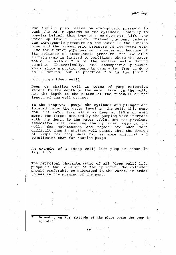
pumping
The suction pump relies on atmospheric pressure topush the water upwards to the cylinder. Contrary topopular belief, this type of pump does not 'lift1 thewater up from the source. Instead the pump reducesthe atmospheric pressure on the water in the suctionpipe and the atmospheric pressure on the water out-side the suction pipe pushes the water up. Because ofits reliance on atmospheric pressure, the use of asuction pump is limited to conditions where the watertable is within 7 m of the suction valve duringpumping. Theoretically, the atmospheric pressurewould allow a suction pump to draw water from as deepas 10 metres, but in practice 7 m is the limit.*
Lift Pumps (Deep Well)
Deep or shallow well in terms of pump selectionrefers to the depth of the water level in the well,not the depth to the bottom of the tubewell or thelength of the well casing.
In the deep-well pump, the cylinder and plunger arelocated below the water level in the well. This pumpcan lift water from wells as deep as 180 m or evenmore. The forces created by the pumping work increasewith the depth to the water table, and the problemsassociated with reaching the cylinder, deep in thewell, for maintenance and repair are much moredifficult than in shallow well pumps. Thus the designof pumps for deep well use is more critical andcomplicated than for suction pumps.
An example of a (deep well) lift pump is shown infig. 10.5.
The principal characteristic of all (deep well) liftpumps is the location of the cylinder. The cylindershould preferably be submerged in the water, in orderto assure the priming of the pump.
Depending on the altitude of the place where the pump isoperated.
171

pumping
ROD GUIDE
PUMP STAND
•; AQUIFER1:
• ^ p . ; WELL CASINGn±k PISTON ';.'•
r ^ - C H E C K VALVE
S SCREENS
UP TO180 m
i—PUMP STAND
DROP PIPE
PUMP- -CYLINDER
Figure W.5,Lift pump (deep well)
172

pumping
Force Pumps
Force pumps are designed to pump water from a sourceand to deliver i t to a higher elevation or againstpressure. All pressure-type water systems use forcepumps. They are enclosed so that the water can beforced to flow against pressure. Force pumps areavailable for use on shallow or deep wells (Fig.10.6) .
STUFFING BOXTRAP TUBE
SPOUT VALVE
PLUNGER '^
NOT MORETHAN 7 m.
PUMP CHAMBER
STUFFING BOX
PUMP CHAMBER\
ANY DEPTHUP TO 180 m
-L
PUMP Ron
A) FORCE PUMP ON SHALLOW WELL
PUMPCYLINDER
8) FORCE PUMP ON DEEP WELL
Figure 10.6.Force pumps
A shallow-well force pump is shown in Fig. 10.6a. Itsoperating principle is the same as that of the reci-procating plunger pump earlier discussed, except thatit is enclosed at the top and, therefore, can be usedto force the water to elevations higher than thepump. For this, either a separate connection or ahose or pipe is fitted to the spout.
173

pumping
Force pumps usually have an air chamber to even outthe discharge flow. On the upstroke of the plunger,the air in the air chamber is compressed and on thedownstroke the air expands to maintain the flow ofwater while the plunger goes down. The trap tubeserves to trap air in the air chamber, preventing itfrom leaking around the plunger rod.
The operation of a deep well force pump (Fig. 10.6b)is the same. The principal difference is in thelocation of the cylinder. With the cylinder down inthe well the pump can lift water from depths greaterthan 7m.
Diaphragm Pumps :
Diaphragm pumps are positive displacement pumps. Themain part of the pump is its diaphragm, a flexibledisc made of rubber or metal. Non-return valves arefitted at the inlet and outlet (Fig. 10.7).
Figure 10.7.Diaphragm pump
The edge of the diaphragm is bolted to the rim of thewater chamber but the centre is flexible. A rodfastened to the centre moves it up and down. As thediaphragm is lifted, water is drawn in through theinlet valve, and when it is pushed down, water isforced out through the outlet valve. Pumping speedusually is about 50-70 strokes per minute. Thesepumps are self-priming.
The diaphragm pumping principle is used in a numberof novel handpump designs. These pumps are beingfield tested and developed for use in rural watersupplies (e.g. Hydropompe Vergnet; Petro Pump).
174

pumping
10.5 Rotary (positive displacement) pumps
Chain Pumps
In the chain pump, discs of a suitable material (e.g.rubber) attached to an endless chain running over asprocket at the top, are pulled upward through a pipeto lift water mechanically up to the spout. This typeof pump can only be used on cisterns and shallow dugwells. It can be readily adapted for manufacture byvillage artisans (Fig. 1 0 . 8 ) . A small chain pumpusing a pipe of 20 mm diameter, with rubber discsspaced at 1 m intervals, will discharge water at arate of 5 to 15 1/minute depending on the speed ofrotation of the operating wheel (30 to 90 r p m ) .
WHEEL WITH TEETH
DISCS
Figure 10.8.Chain pump
175

pumping
Chain pumps using rags and balls instead of discswere commonly used for draining mines in WesternEurope in the 16th Century. Animal-powered chainpumps are used in Asia for irrigation pumping.
WATERDISCHARGE
GEAHBOX
-RISING MAIN
DRIVE SHAFT
V BEARINGS
-FLEXIBLE JOINT
- RUBBER STATDR
- STEEL ROTOR
— W E L L LINING
SUCTION INTAKE
Figure 10.9.Helical rotor pump
Helical Rotor Pump
The helical rotor pump consists of a single threadhelical rotor which rotates inside a double threadhelical sleeve, the stator (Fig. 10.9). The meshinghelical surfaces force the water up, creating a
176

pumping
uniform flow. The water output is proportional to therotating speed, and can be varied simply by changinga pulley. As the rotor and stator provide an ef-fective, continuous seal, the helical rotor pumprequires no valves. Helical rotor pumps are availablefor use in 4-inch (100 mm) or larger tube wells.Although relatively expensive, these pumps have givengood service on deep wells in parts of Africa andAsia where they are known as the 'Mono' pump afterits British manufacturer.
Drive arrangements suitable for helical rotor pumps,are: hand operation, electric motors, diesel andpetrol engines. Different drive heads are available.If there is plenty of space, a standard head with aV-belt drive can be used. Where a compact unit isrequired, geared heads are installed for dieselengine or electric motor drives.
10.6 Axial-flow pumps
In the axial-flow type of pump, radial fins or bladesare mounted on an impeller or wheel which rotates ina stationary enclosure (called a casing) (Fig. 10.10).
FIXED / /GUIDEBLADES \
/ n \ y
— IMPELLER
V' / \ ^
Figure 10.10.Axial-flow pump
The action of the pump is to mechanically lift thewater by the rotating impeller. The fixed guideblades ensure that the water flow has no 'whirl'velocity when it enters or leaves the impeller.
177

pumping
10.7 Centrifugal pumps
The essential components of a centrifugal pump arethe impeller and the casing (Fig. 10.11).
Figure 10.11.Centrifugal pump (Volute-type Casing)
The impeller is a wheel having vanes radiating fromthe centre to the periphery. When rotated at a suffi-ciently high speed, the impeller imparts kineticenergy to the water and produces an outward flow dueto the centrifugal forces. The casing is so shapedthat the kinetic energy of the water leaving theimpeller is partly converted to useful pressure. Thispressure will force the water into the delivery pipe.The water leaving the eye of the impeller creates asuction; it will be replaced by water drawn from thesource and forced into the casing under static head.
An impeller and the matching section of the casing iscalled a stage. If the water pressure required in aparticular centrifugal pump application is higherthan a single stage can practicably produce, a numberof stages may be placed in series (multiple-stagepump). The impellers are attached to a common shaftand therefore rotate at the same speed. The waterpasses through the successive stages, with an in-crease in pressure at each stage. Multiple-stagecentrifugal pumps are normally used for high pumpingheads.
The rotating speed of a centrifugal pump has a con-siderable effect on its performance. The pumping
178

pumping
efficiency tends to improve as the rotating speedincreases. Higher speed, however, may lead to morefrequent maintenance. A suitable balance between theinitial cost and maintenance costs has to be aimedat. A comprehensive study of the pump's character-istic is necessary before final selection.
In centrifugal pumps the angle between the directionof entry and exit of the water flow is 90°. In anaxial-flow pump (section 10.6.). the water flowcontinues through the pump in the same direction withno deviation (0°). The term 'mixed-flow pump' is usedfor those centrifugal pumps where the change in anglelies between 0° and 90°; they can be single or multi-ple-stage .
10.8 Pump drive arrangements
Two different drive arrangements exist for waterpumping from deep wells: shaft driven and close-coupled submersible electric motor.
A. SHAFT-DRIVEN
The crankshaft or motor is placed at the groundsurface and powers the pump using a verticaldrive shaft or spindle (Fig. 10.12). A long driveshaft will need support at regular intervalsalong its length and flexible couplings toeliminate any 'stresses due to misalignment. Theadvantage of a drive shaft is that the drivemechanism may be set above ground or in a dry pitand thus will be readily accessible for main-tenance and repair. An accurate alignment of theshaft is necessary; the shaft-drive arrangementis not possible in crooked tubewells.
B. CLOSE-COUPLED SUBMERSIBLE ELECTRIC MOTOR
In this pump drive arrangement, a centrifugalpump is connected directly to an electric motorin a common housing, with the pump and motor as asingle unit. This unit is constructed for sub-merged operation in the water to be pumped (Fig.10.13.).
179

pumping
CRANKSHAFTDRIVEN
ROTOR
STATOR
CHECKVALVE
HANDLE
GEAR BOX
DISCHARGEHEAD
-
\,
MOTOR DRIVEN
WELLCASING
PUMP CYLINDERI ..
STRAINER —
MOTOR
Figure 10.12.Shaft-driven pumps
180
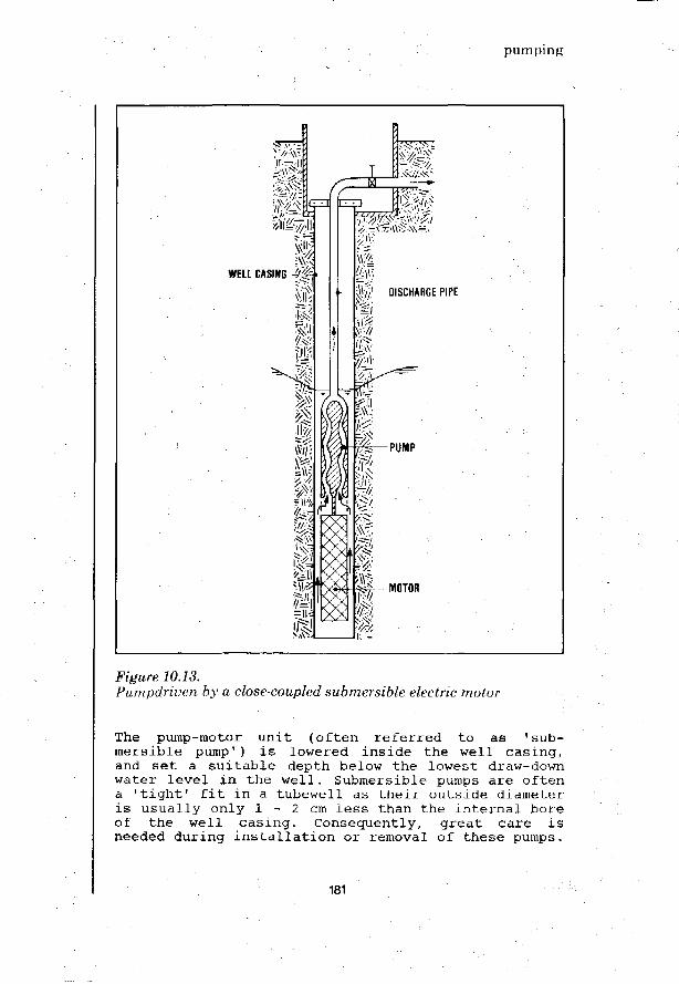
pumping
WELL CASING
-DISCHARGE PIPE
Pumpdriven by a close-coupled submersible electric motor
The pump-motor unit (often referred to as 'sub-mersible pump1) is lowered inside the well casing,and set a suitable depth below the lowest draw-downwater level in the well. Submersible pumps are oftena 'tight1 fit in a tubewell as their outside diameteris usually only 1 - 2 cm less than the internal boreof the well casing. Consequently, great care isneeded during installation or removal of these pumps.
181

pumping
A waterproof electric cable connects the motor withthe control box housing, the on-off switch and thepower connection. The electrical control should beproperly grounded to minimize the risk of shortingand damage to the motor. Fig. 10.14 shows a sub-mersible pump in exploded view.
DROP PIPE CONNECTION
-POWER CABLE
CHECK VALVE
PUMP CASING
INLET SCREEN-
DIFFUSERS & IMPELLERS<
POWER LEADSMOTOR SHAFT
MOTOR SECTION
LUBRICANT SEAL
Figure 10.14.Submersible pump (exploded view)
The submersible pump-motor unit is usually supportedby the discharge pipe which conveys the pumped waterto the connecting pipeline or tank.
182

pumping
When sand is found or anticipated in the watersource, special precautions should be taken before asubmersible pump is used. The abrasive action of sandduring pumping would shorten the life of the pumpconsiderably.
10.9 Air-lift pumps
An air-lift pump raises water by injecting smallevenly distributed bubbles of compressed air at. thefoot of a discharge pipe fixed in the well. Thisrequires an air compressor. The mixture of air andwater being lighter than the water outside the dis-charge pipe, the water/ air mixture is forced upwardby the hydrostatic head (Fig. 10.15).
LIFT, h
SUBMERGENCE.;
, — A — COMPRESSOR
— DISCHARGE PIPE
AIR FEED PIPE
Figure 10.15.Air lift pump (schematic)
183

pumping
The pumping head (h) against which an air lift pumpcan raise water, is related to the submergence (s) ofthe discharge pipe. A high lift requires a consider-able submergence to a depth under the lowest drawdownlevel of the water in the well. The point of injec-tion of compressed air is also at this depth, so thata sufficiently high air pressure is needed. The majordrawback of air-lift pumps is their low mechanicalefficiency in utilizing the energy supplied forlifting the water. The efficiency of an air-lift pumpitself is about 25-40%. Additional are the energylosses in the compressor. Overall, not more than15-30% of the total power consumption is effectivelyutilized.
However, air-lift pamps also have important ad-vantages. They are simple to operate and not affectedby sand or silt in the pumped water. All mechanicalequipment (the compressor) is above ground. A numberof air-lift pumps installed in adjacent wells can beoperated using a single compressor. Water can beair-lift pumped from wells as deep as 120 m, at aconsiderable rate. Thus, air-lift pumps should beconsidered for those applications where their ad-vantages will outweigh the drawback of high powerconsumption due to the low mechanical efficiency.They should be particularly considered in areas wherethe groundwater carries much sand or silt, and forpumping water that is acidic (low pH).
Table 10.2. is provided for preliminary guidance inair-lift pump selection.
184

pumping
Table 10,2.Preliminary guidance in air-lift pump selection
Lift(m)
102030406080ioo120
Submergence(m)
12202528404 9 •
5871 :
Air-to-waterFlow Rat io(volume/volume)
3.04.76.27.99.6 :11.613.314.8
Air pressurerequired(m I!2O)
203040456585105125
PumpingCapacity(1/sec)
2.55.07.510.015.020.040.0
DischargePipe. Diameter
(mm)
75 (3")100 (4")100 (4")125 (5")150 (6")150 (6")200 (8")
Air pipeDiameter
(mm)
25 (1")40 (1}")40 (lj")so (2") :50 (2")60 (2J") .75 (3")
CompressorPower
(HP)
1.52.5457.51020
10.10 Hydraulic ram
The hydraulic ram needs no external source of power.The ram utilizes the energy contained in a flow ofwater running through it, to lift a small volume ofthis water to a higher level. The phenomenon involvedis that of a pressure surge which develops when amoving mass of water is suddenly stopped. A steadyand reliable supply of water is required with a fallsufficient to operate the hydraulic ram. Favourableconditions are mostly found in hilly and mountainousareas. Hydraulic rams are not suited to pumping waterfrom wells.
185

pumping
CAP
AIR CHAMBER
-DRIVE PIPE
DELIVERY-VALVE PIPE
STROKEADJUSTMENTBOLT r IMPULSE
VALVE STEM SPRING-TENSION
BOLT
SPRING
IMPULSE VALVE ASSEMBLY
Figure 10.16.Typical hydraulic ram
Source: S.B. WattA Manual on the HydraulicRam for Pumping Water,I.T, Publications Ltd., 1974
The ram operates on a flow of water running from thesource down through the drive pipe into the pumpchamber. The water escapes through the opened impulsevalve (waste valve). When the flow of water throughthe impulse valve is fast enough, the upward force onthe valve will exceed the spring tension of the valveadjustment and the impulse valve is suddenly shut.The moving mass of water is stopped with its momentumproducing a pressure surge along the drive pipe. Dueto the pressure surge, water is forced through thenon-return (delivery) valve and into the delivery
186

pumping
pipe. Water continues to pass the non-return valveuntil the energy of the pressure surge in the drivepipe is exhausted. The air chamber serves to smoothout the delivery flow of water, as it absorbs part ofthe pressure surge which is released after theinitial pressure wave.
When the pressure surge is fully exhausted, a slightsuction created by the momentum of the water flow,together with the weight of the water in the deliverypipe, shuts the non-return valve and prevents thewater from running back into the pump chamber. Theadjustment spring now opens the impulse valve, waterbegins to escape through it, and a new operatingcycle is started.
Once the adjustment of the impulse valve has beenset, the hydraulic ram needs no attention providingthe water flow from the supply source is continuous,and at an adequate rate, and no foreign matter getsinto the pump blocking the valves.
An air valve is provided to allow a certain amount ofair to bleed in and keep the air chamber charged.Water under pressure will absorb air and without asuitable air valve the air chamber would soon be fullof water. The hydraulic ram would cease to function.
The advantages of the hydraulic ram are:
No power sources are needed, and there are norunning costs;Simple to make. Local materials and simpleworkshop equipment can be used;
- It has only two moving parts.
A small supply of water with plenty of fall willenable a hydraulic ram to lift as much water as alarge flow of water with a small fall. Most hydraulicrams will work at their best efficiency if the supplyhead is about 1/3 of the delivery head. The higherthe pumping head required, the smaller the amount ofwater delivered.
In cases, where the required pumping capacity isgreater than one hydraulic ram can provide, a batteryof several rams may be used, provided the supplysource is of sufficient capacity (Fig. 10.17).
187

pumping
4 HYDRAULIC RAMSEACH WITH ASEPERATEDRIVE PIPE
- SOURCE
HEADER TANK\
/ COMMONj / ~ DELIVERY PIPE
V
Figure 10.17.Hydraulic rams placed parallel
The maintenance required for a hydraulic ram is verylittle and infrequent. It includes:
Replacement of the valve rubbers when they wearout;Adjusting the tuning;Tightening bolts which work loose.
Occasionally, the hydraulic ram may need dismantlingfor cleaning. It is essential that as little debrisas possible enters the drive pipe. For this reason,it is necessary to provide a grate or strainer tokeep back floating leaves and debris.
188

Pumping
Addison, H.THE PUMP USERS HANDBOOKPitman & Sons Ltd., London, 1958, 122 p.
Addison, H.CENTRIFUGAL AND OTHER ROTODYNAMIC PUMPSChapman and Hall, London, 1956 (3rd Edition)
Benamour, A.LES MOYENS D'EXHAURE EN MILIEU RURALComite Interafricain d'Etudes Hydrauliques (C.I.E.H;),Ouagadougou, Uppi'r Volta, 1979
L'EQUIPEMENT DES VILLAGES EN PUITS ET FORAGESCommission de Coramunautes Europeenes, Brussels, 1978
Karassik, I.J.; Krutzch, W.C.; Fraser, W.H.; ct alPUMP HANDBOOKMcGraw-Hill, New York, 1958
McJmikin, F.E.HANDPUMPS FOR USE IN DRINKING WATER SUPPLIES IN DEVELOPINGCOUNTRIES International Reference Centre for Community Water Supply,The Hague, 1977, 230 p. (Technical Paper Series No. 10)
Pacey, A.HAND PUMP MAINTENANCEIntermediate Technology Publications Ltd., London, 1976, 38 p.
Romero, J.A.C.MANUAL DE POZOS RASOSOrganizacion Panamericana de Salud, Washington, D.C., 1977
Ross InstituteSMALL WATER SUPPLIESLondon School of Hygiene and Tropical Medicine, London, 1964, 67 p.
Silver, M.USE OF HYDRAULIC RAMS IN NEPALUNTCEF, Kathmandu, Nepal, September 1977, 46 p.
Thanh, N.C.; Pescod, M.B.; Venkitachalam, T.H.DESIGN OF SIMPLE AND INEXPENSIVE PUMPS FOR VILLAGE WATER SUPPLYSYSTEMSAsian Institute of Technology, 1979. (Final Report No. 67)
UNICEF Guide List OLGAUNICEF, New York, 1975, 324 p. (under revision)
Watt, S.B.A MANUAL ON THE HYDRAULIC RAM FOR PUMPING WATERIntermediate Technology Publications Ltd., London, 1974, 37 p.
189

190
water treatment
11. water treatment
11.1 Introduction
There will be situations where treatment of the wateris necessary to render it fit for drinking and do-mestic use. The px"ovision of any form of treatment ina water supply system will require a capital outlaythat may be relatively substantial. More important, itwill greatly expand the problems of maintaining thewater supply system, and the risks of failure. Somewater treatment processes are easier to operate andmaintain than others, but all need regular supervisionand attention. When designing a water treatment plant,the operational and maintenance requirements are keyfactors that must be considered carefully.
The purpose of water treatment is to convert the watertaken from a ground or surface source, the 'rawwater1, into a drinking water suitable for domesticuse. Most important is the removal of pathogenicorganisms and toxic substances such as heavy metalscausing health hazards. Other substances may also needto be removed or at least considerably reduced. Theseinclude: suspended matter causing turbidity, iron andmanganese compounds imparting a bitter taste orstaining laundry, and excessive carbon dioxidecorroding concrete and metal parts. For small commu-nity water supplies, other water quality characteris-tics such as hardness, total dissolved solids andorganic content would generally be less important.They should be reduced to acceptable levels but theextent to which the water is treated will be limitedby economic and technical considerations. The qualityguidelines for drinking water presented in Chapter 3should be a guide when the extent of the necessarytreatment is determined.
Various water treatment processes (also called 'unitoperations') have been developed. Some serve a singlepurpose, others have multiple applicability. Often atreatment result can be obtained in different ways(Table 11.1). The treatment processes mentioned, arediscussed in the chapters 12 - 17. Artificial re-charge (discussed in Chapter 9) may also be regardedas a water treatment process.
191

water treatment
Storage of water can be regarded as treatment. Forexample, schistosomiasis cercariae are normally unableto survive 48 hours of storage. The number of faecalcoliforms arid faecal streptococci will be considerablyreduced when the raw water in subjected to storage.Storage also allows sedimentation to take place re-ducing the settleable solids content of the water.Storage, however, may promote algal growth in thewater. Loss of water through evaporation often isanother drawback. These effects will be minimized ifstorage tanks are covered which also would preventdust, insects, air borne pollution and small animalsfrom contaminating the stored water.
Table ILLEffectiveness of water treatment processes in removing variousimpurities
+++ etc. - increasing positiveafFmct
o - no effect= negative effect
. TREATMENTPROCESS
WATER 'QUALITYPAHAMETER
Aeration Chemical Sediment- Rapid Slow sandCoagula- ation Filtra- Filtra-tion and tion tionFlOC.
Chlorina-tion
Dissolved OxygenContent
Carbon DioxideRemove1
Turbidity*Redaction
Colour Reduction
Taste and OdourRemove1
Bacteria Removal
Iron and Manga-nese Removal
Organic MatterRemoval
Turbidity of water is caused by the presence of suspended matter scatteringand absorbing light rays, and thus giving Che water a non-transparant, milkyappearance.
192

water treatment
Frequently, a number of water treatment processes haveto be used in combination, in order to obtain thedesired result. For groundwater and for clear surfacewater, one or a few processes will probably be suf-ficient. Slightly polluted surface water generally canbe sufficiently treated using a few processes; heavilypolluted water reguires many treatment processes, oneafter the other, to render it safe for drinking anddomestic use. For small community water supplies,complicated treatment schemes are not suited and insuch cases a better solution may be to develop an-other, unpolluted source of water even when this canonly be found at a greater distance. An alternativemay be the use of underground formations for storageof water and quality improvement (artificial re-charge ).
Once the source of water has been selected, and thevariation in its guality assessed, the engineer candecide which treatment should be applied. The follow-ing chapters give information and guidance. For smallcommunity water supplies, the most important designconsiderations are:
Low cost;Use a minimum of mechanical equipment;Avoid the use of chemicals, when possible;Easy to operate and maintain.
Simple arrangements can be effective, provided theyare well-designed. The water treatment processdiagram shown in Fig. 11.1 is illustrative.
FLOAT SUSPENDEDINTAKE
PUMP ANDPRESSURE TANK
COAGULANT MIXING TROUGH SETTLING BASINOR TANK
Figure. 11.1.Simple arrangements for water intake, coagulant mixing andsettling
193

water treatment
11.2 Groundwater quality and treatment
For the most part, groundwater originates from in-filtrated rainwater which after reaching the aquiferflows through the underground. During infiltration,the water will pick up many impurities such as in-organic and organic soil particles, debris from plantand animal life, micro-organisms, natural or man-madefertilizers, pesticides, etc. During its flow under-ground, however, a great improvement in water qualitywill occur. Suspended particles are removed by fil-tration, organic substances are degraded by oxidation,and micro-organisms die away because of lack ofnutrients. The dissolved mineral compounds are notremoved; in fact, the mineral content of the water canincrease considerably through the leaching of saltsfrom the underground layers.
Groundwater, if properly withdrawn, will be free fromturbidity and pathogenic organisms. When it origin-ates from a clean sand aquifer, other hazardous orobjectionable substances will also be absent. In thesecases, a direct use of the water as drinking water maybe permitted without any treatment. When the watercomes from an aquifer containing organic matter,oxygen will have been consumed and the carbon dioxidecontent of the water is likely to be high. The waterwill then be corrosive unless calcium-carbonate in oneform or another is present. In cases where the amountof the organic matter in the aquifer is high, theoxygen content may be completely depleted. The watercontaining no oxygen (anaerobic water) will dissolveiron, manganese and heavy metals from the underground.Through treatment these substances can be removed,i.e. by aeration. It depends on the type of aeratorwhether the carbon dioxide content of the water willbe reduced or left unchanged. A reduction isdesirable if the water is corrosive but in other casesit can result in troublesome deposits of calciumcarbonate.
Sometimes, groundwater contains excessive amounts ofiron, manganese and ammonia. In Europe, where ground-water is scarce, even such groundwater sources areabstracted and treated with chemical coagulation andflocculation or dry filtration to render them fit fordrinking and domestic purposes. However, for smallcommunity water supplies in developing countries theseprocesses are too complicated and should be avoidedwhenever possible. Table 11.2 sums up the treatmentprocesses described above.
194

water treatment
Table 11.2. ;Treatment of groundwater
WATER QUALITY
Aerobic, fairlyhard, notcorrosive
Aerobic, softand corrosive
Anaerobic,fairly hard,not corrosive
no iron andmanganese
Anaerobic,fairly hard,not corrosive
with iron andmanganese
Anaerobic, soft,
corrosive
no iron andmanganese
Anaerobic, softcorrosive
with iron andmanganese
Aeration
increasing
°2
X
X
X
X
for
reducingco2
X
X
X
Plain
Sediment-
ation
0
0
(Rapid)
Filtra-
tion
X
X
Safety- or
post- chlo-
rination
0
0
0
0
0
0
(X = necessary, 0 = optional)
11.3 Surface water quality and treatment
Surface water can be taken from streams, rivers, lakesor irrigation canals. Water in such surface sourcesoriginates partly from groundwater outflows and partlyfrom rainwater that has flowed over the ground to thereceiving bodies of surface water. The groundwateroutflows will bring dissolved solids into the surfacewater; the surface run-off is the main contributor ofturbidity and organic matter, as well as pathogenicorganisms. In the surface water bodies, the dissolvedmineral particles will remain unchanged but the or-
195

water treatment
ganic impurities are degraded through chemical andmicrobial processes. Sedimentation in impounded orslow-flowing surface water results in the removal ofsuspended solids. Pathogenic organisms will die offdue to lack of suitable food. However, new con-tamination of the surface water is likely to takeplace as a result of waste influents and algal growth.
In sparsely populated areas, clear water from riversand lakes might require no treatment to make itsuitable for drinking. However, taking into accountthe risk of incidental contamination, chlorination asa safety measure should be provided whenever feasible.Unpolluted surface water of low turbidity may bepurified by slow sand filtration as a single treatmentprocess, or by rapid filtration followed by chlorin-ation only. Slow sand filters, particularly in ruralareas of developing countries, have the great ad-vantage that local workmen can build them withlocally-available materials and without much expertsupervision.
WHO Photo by J. MageeFigure 11.2.Surface water needs treatment before it is used for drinking anddomestic purposes
196

water treatment
When the turbidity of the water to be treated is high,or when algae are present, slow sand filters wouldrapidly clog. A pretreatment will be needed, such assedimentation, rapid filtration or both processes incombination. For colloidal suspended particles, theremoval by settling can be greatly improved throughchemical coagulation and flocculation. The removal ofalgae is promoted by pre-chlorination. All theseprocesses are reguired in most instances where theorganic matter content of the raw water is high. Waterfrom rivers and lakes is of a very wide variety incomposition and it is impossible to describe in detailall the treatment systems reguired in every case.Leaving complicated processes out. Table 11.3 showsthe systems most applicable to small community watersupplies.
Table 11.3Treatment of surface water
treatment Prs-chlo- Chem.coag. Sediment- Rapid Slow Sand Safety- orproress rination and floe. ation Filtration Filtration Post-chlo-
rination"--^ _ _ _ _ „
clear and 0
unpolluted : •
slightly .polluted, 0 X 0low turbi- .diLy :
slightlypolluted,mediumturbidity
slightlypolluted,highturbidity
slightlypolluted,many algae
heavilypolluted,littleturbidity
heavilypolluted,muchturbidity
X
X
X
X
X
X
X
X
X
X
X
X
X
X
X
0
X
0
X
Pj"
(X = necessary, 0 = optional)
197

198

Water treatment
American Water Works AssociationWATKR QUALITY AND TREATMENTMcGraw-Hill Book Co., New York, 1971 (3rd Edition)
Azevedo NeLto, J.M.TRATAMENTO DE AQUAS DE ABASTECTMENTOKditora dc Univeraidade de Sao Paulo, Sao Paulo, 1966
Cox, C.R.OPERATION AND CONTROL OF WATER TREATMENT PROCESSESWorld Health Organisation, 1964, 392 p.(Monograph Series No. 49)
Fair, G.M.; Geyer, J.C.; Okun, D.A.WATER AND WASTE WATER ENGINEERING (2 Volumes)John Wiley, London, 504; 664 p.
Fair, G.M.; Geyer, J.C.; Okun, D.A.ELEMENTS OF WATER SUPPLY AND WASTE DISPOSALJohn Wiley, London, 1972
Mann, H.T.; Williamson, D.WATER TREATMENT AND SANITATIONIntermediate Technology Publications Ltd., London, 1968, 92 p.
MANUAL ON WATER SUPPLY AND TREATMENTGovernment of India Ministry of Works & Housing (Central PublicHealth Environmental Engineering Organisation),New Delhi, 1976 (2nd Edition)
Sanks, R.C.WATER TREATMENT PLANT DESIGN FOR THE PRACTICING ENGINEERArm Arbor Science, Ann Arbor, USA, 1978
Smethurst, G.BASIC WATER TREATMENT . ;Thomas Telford Ltd., London, 1979
TEORIA DESIENO CONTROL DE LOS PROCESOS DE CLARIFICACION DEL AGUACentro Panamericano de Ingenieria Sanitaria y Ciencias delAmbiente, Lima, 1974 (Serie Technica 13)
VILLAGE TECHNOLOGY HANDBOOKVolunteers in Technical AssistanceMount Rainer, Maryland, USA, 1977
199

200

aeration
12. aeration
12.1 Introduction
Aeration is the treatment process whereby water isbrought into intimate contact with air for the pur-pose of (a) increasing the oxygen content, (b) re-ducing the carbon dioxide content, and (c) removinghydrogen sulfide, methane and various volatile or-ganic compounds responsible for taste and odour. Thetreatment results mentioned under (a) and (c) arealways useful in the production of good drinkingwater. Reducing the carbon dioxide content, however,may shift the carbonate-bicarbonate equilibrium inthe water so that deposits of calcium carbonate areformed which may cause problems.
Aeration is widely used for the treatment of ground-water having too high an iron and manganese content.These substances impart a bitter taste to the water,discolour rice cooked in it and give brownish-blackstains to clothes washed. The atmospheric oxygenbrought into the water through aeration will reactwith the dissolved ferrous and manganous compoundschanging them into insoluble ferric and manganicoxide hydrates. These can then be removed by sedi-mentation or filtration. It is important to note thatthe oxidation of the iron and manganese compounds inthe water is not always readily achieved. Parti-cularly when the water contains organic matter, isthe formation of iron and manganese precipitatesthrough aeration likely to be not very effective.Chemical oxidation, a change in alkalinity or specialfilters may then be reguired for iron and manganeseremoval. These treatment methods, however, are expen-sive and complex, and for rural areas in developingcountries it would be better to search for anothersource of water. For the treatment of surface water,aeration would only be useful when the water has ahigh content of organic matter. The overall qualityof this type of water will generally be poor and tosearch for another water source would probably beappropriate.
The intimate contact between water and air, as neededfor aeration, can be obtained in a number of ways.For drinking water treatment, it is mostly achievedby dispersing the water through the air in thinsheets or fine droplets (waterfall aerators), or bymixing the water with dispersed air (bubbleaerators). In both ways the oxygen content of the
201

aeration
water can be raised to 60-80% of the maximum oxygencontent that the water could contain when fullysaturated. In waterfall aerators an appreciablerelease of gases from ther water is effected; inbubble aerators this effect is negligible. Thereduction of the carbon dioxide by waterfall aeratorscan be considerable, but is not always sufficientwhen treating very corrosive water. A chemical treat-ment such as the dosing of lime, or filtration overmarble or burned dolomite would be required for thistype of water.
12.2 Waterfall aerators
The multiple tray aerator shown in Fig. 12.1 providesa very simple and inexpensive arrangement and itoccupies little space.
tRAW WATER
/l \ /I
V !i
V-:i j
V i i
V !
vj
i\\ /I\J
A.j\Ii
t
i
JJ •• .
i i
\. -—• AERATED WATER
Figure 12.1.Multiple-tray aerator
This type of aerator consists of 4-8 trays with per-forated bottoms at intervals of 30-50 cm. Throughperforated pipes the water is divided evenly over theupper tray, from where it trickles down at a rate ofabout 0.02 m3/sec per m2 of tray surface. The drop-
202

aeration
lets are dispersed and re-collected at each followingtray. The trays can be made of any suitable material,such as asbestos cement plates with holes, small dia-meter plastic pipes or parallel wooden slats (Fig.12.2.). For finer dispersion of the water, theaerator trays can be filled with coarse gravel about10 cm deep. Sometimes a layer of coke is used whichacts as catalyst and promotes the precipitation ofiron from the water. A hand-operated aeration/filtra-tion unit for treatment of water having high iron andmanganese content is shown in Fig. 12.3.
Figure 12.2.Aerator installation
203

aeration
75 mm x 25 mmVENTILATORS
25 mm sq. VENTILATORS
*W
—i 25 mm STONE/ 15 cm LAYER
COARSE SAND30 cm LAYER
Figure 72.3.Hand-operated aeration/filtration unit
Ref.: NEERI, India
A type of aerator with similar features, is thecascade aerator (Fig. 12.4). Essentially thisaerator consists of a flight of 4-6 steps, each about30 era high with a capacity of about 0.01 m3/s permetre of width. To produce turbulence and thus pro-mote the aeration efficiency, obstacles are often setat the edge of each step. Compared with tray aerators,the space requirements of cascade aerators are some-what larger but the overall head loss is lower.Another advantage is that no maintenance is needed.
A multiple-platform aerator uses the same principles.Sheets of falling water are formed for full exposureof the water to the air (Fig. 12.5).
204

aeration
RAW WATER
AERATED WATER
Figure 12.4.Cascade aerator
WATER BASIN
PLATFORMS
Figure 12.5.Multiple-platform aerator
205

aeration
Spray aerators consist of stationary nozzles, con-nected to a distribution grid through which the wateris sprayed into the surrounding air, at velocities of5-7 m/sec.
A very simple spray aerator is shown in Fig. 12.6,with the water discharging downwards through shortpieces of pipe, of some 25 cm length and with a dia-meter of 15-30 mm. A circular disk is placed a fewcentimetres below the end of each pipe, so that thincircular films of water are formed which further dis-perse into a fine spray of water droplets.
Figure 12.6.Spray aerator
Another type of spray aerator uses nozzles fitted tofeeding pipes, which spray the water upwards (Fig.12.7). Spray aerators are usually located above thesettling tank or filter units, so as to save space,and to avoid the need for a separate collector basinfor the aerated water.
206

aeration
Figure 12.7.Nozzle.d spray aerator
To avoid clogging, the nozzle openings should befairly large, more than 5 mm, but at the same timethe construction should be such that the water isdispersed into fine droplets. Many designs have beendeveloped to meet these requirements. A simple sprayaerator using a baffle plate is shown in Fig. 12.8.
1BAFFLE PLATE c
- • - ~ . N
\ \
) FEED PIPEy WITH NOZZLES
\
J
Figure 12.8.Simple spray aerator using baffle plate
207

aeration
Fig. 12.9 presents several examples of specially de-signed nozzles.
, 30 100
VANES180 250
A95
"SACRAMENTO"
75
"NEW YORK"all measuresin mm
"WEST PALM BEACH"
REMOVABLEMOUTH PIECE
"AMSTERDAM"
#:$-
•2:*
Figure 12.9.Nozzles for spray aerators
After: Fair, Geyer & Okun, 1968
12.3 Bubble aerators
The amount of air required for bubble aeration ofwater is small, no more than 0.3-0.5 m3 of air per m3
of water and these volumes can easily be obtained bya sucking in of air. This is best demonstrated withthe venturi aerator shown in Fig. 12.10. The aeratoris set higher than the pipe carrying the raw water.In the venturi throat the velocity of flow is so highthat the corresponding water pressure falls below theatmospheric pressure. Hence, air is sucked into thewater. After passing the venturi throat, the waterflows through a widening pipe section and thevelocity of flow decreases with a corresponding riseof the water pressure. The fine air bubbles are mixedintimately with the water. From the air bubbles,oxygen is absorbed into the water. The release ofcarbon dioxide in this type of aerator is negligible,because the air volume of the bubbles is quite small.
208

aeration
Compared with spray aerators, the space requirementsof venturi aerators are low; the overall headloss isabout the same.
\—PERFORATED PIPE
1 AIR SUPPLY
/ s^^^r/ f THROAT
RAW WATER 1
*~ ^s
—^-^-sNVENTURI Y \
AERATED WATER
Figure 12.10.Venturi aerator
The submerged cascade aerator of Fig. 12.11 operatesby entrapping air in the falling sheets of waterwhich carry it deep into the water collected in thetroughs. Oxygen is then transfered from the airbubbles into the water. The total fall is about1.5m subdivided in 3-5 steps. The capacity variesbetween 0.005 and 0.05 m3/sec. per metre of width.
Figure 12.11.Submerged cascade aerator
209

210

Aeration
American Water Works Association: Committee on AerationAERATION OF WATERIn: Journal Am. Water Works Assoc. Vol.47(1975) No. 5, pp. 873-893
Azevedo Netto, J.M.TRATAMIENTO DE AQUAS DE ABASTECTMENTOEdiLora de Universidarfe de Sao Paulo, Sao Paulo, 1966
CURSO SOBRE TECHNOLOGIA DE TRATEMIENTO DE AQUA PARA PA1SES ONDESAKKOLLOCEPIS, Lima, 1977
Fair, CM.; Geyer, J.C.; Okun, D.A.WATER AND WASTEWATER ENGINEERINGVol. 2, Water Purification and Wastewater Treatment and DisposalJohn Wiley & Sons, New York, 1968
Haney, P.D.THEORETICAL PRINCIPLES OF AERATIONIn: Journal Am. Water Works Assoc, Vol. 24(1932) No. 62
Langelier1, S.THE THEORY AND PRACTICE OF AERATIONJournal Am. Waterworks Assoc. Vol. 24(1932) No. 62
211

212

coagulation and flocculation
13. coagulation and flocculation
13.1 Introduction
Coagulation and flocculation provide the water treat-ment process by which finely divided suspended andcolloidal matter in the water, is made to agglomerateand form floes. This enables their removal by sedi-mentation or filtration. colloidal particles(colloids) are midway in size* between dissolvedsolids and suspended matter. Colloids are kept insuspension ('stabilized') by electrostatic repulsionand hydration. Electrostatic repulsion occurs becausecolloids usually have a surface charge due to thepresence of a double layer of ions around eachparticle. Thus, the colloid has an electric charge,mostly a negative one. Hydration is the reaction ofparticles at their surface with the surroundingwater. The resulting particle-water agglomerates havea specific gravity which differs little from that ofwater itself.
The substances that frequently are to be removed bycoagulation and flocculation, are those that causeturbidity and colour. Surface waters in tropicalcountries often are turbid and contain colouringmaterial. Turbidity may result from soil erosion,algal growth or animal debris carried by surfacerunoff. Colour may be imparted by substances leachedfrom decomposed organic matter, leaves, or soil suchas peat. Both turbidity and colour are mostly presentas colloidal particles.
The electrostatic repulsion between colloidal parti-cles effectively cancels out the mass attractionforces (van der Waal's forces) that would bring theparticles together. Certain chemicals (called coagu-lating agents, coagulants) have the capacity tocompress the double layer of ions around the colloi-dal particles. They check the electrostatic re-pulsion, and thus enable the particles to flocculate,i.e. to form floes. These floes can grow to a suf-ficient size and specific weight to allow theirremoval by settling or filtration.
Generally, water treatment processes involving theuse of chemicals are not so suitable for small com-munity water supplies. They should be avoided when-ever possible. Chemical coagulation and flocculation
Size range: 5.10 - 2.10 millimetre
213

coagulation and flocculation
should only be used when the needed treatment resultcannot be achieved with another treatment processusing no chemicals. If the turbidity and colour ofthe raw water are not much higher than is permissiblefor drinking water, it should be possible to avoidchemical coagulation in the treatment of the water. Aprocess such as slow sand filtration would serve bothto reduce the turbidity and colour to acceptablelevels, and to improve the other water qualitycharacteristics, in a single unit. A roughing filtercan serve to reduce the turbidity load on the slowsand filter, if necessary.
13.2 Coagulants
Alum (Al?(SCO-.nH2O; aluminium sulphate) is by farthe most widely u#ed coagulant but iron salts (e.g.ferric chloride;FeCl^) can be used as well, and insome instances have advantages over alum. A signifi-cant advantage of iron salts over aluminium is thebroader pH* range for good coagulation. Thus, in thetreatment of soft coloured waters where colour re-moval is best obtained at low pH's, iron salts may bepreferred as coagulants. Iron salts should also beconsidered for coagulation at high pH's, since ferrichydroxide is highly insoluble in contrast to aluminumsalts which form soluble aluminate ions at high pH's.Sodium aluminate is mostly used for coagulation atmedium pH's. Synthetic organic polyelectrolytes havebecome available as coagulants but are generally noteconomical for small water supply systems, nor arethey readily available.
Coagulants such as soluble aluminium and iron saltsreact with the alkalinity of the water, and hydrolyzein it. For example, alum reacts to form aluminium-hydroxide floe, A1(OH3), a gelatinous precipitate.The required alkalinity may be naturally present inthe water or it has to be added through dosage oflime, Ca(OH2) or sodium carbonate, Na_CO., (alsocalled: soda-ash).
For good coagulation, the optimal dose of coagulantshould be fed into the water and properly mixed withit. The optimal dose will vary depending upon thenature of the raw water and its overall composition.It is not possible to compute the optimal coagulantdose for a particular raw water. A laboratory ex-
* Measure oi the acidity/alkalinity of water. Acid water has a :pH below 7, the pH of alkaline water is higher than 7. '.£:••
214 . I."• . • • • • -is

coagulation and flocculation
periment called the 'jar test' is generally used forthe periodic determination of the optimal dose. The'jar test1 may be briefly described as follows:
A series of samples of water are placed on a special multiplestirrer and the samples are dosed with a range of coagulant,e.g. 10, 20, 30, 40 and 50 mg/1; they are stirred vigorouslyfor about one minute. Then follows a gentle stirring (10minutes), after which the samples are allowed to stand andsettle for 30 to 60 minutes. The samples are then examined forcolour and turbidity and the lowest dose of coagulant whichgives satisfactory clarification of the water is noted.
A second test involves the preparation of samples with the pHadjusted so that the samples cover a range (e.g. pH = 5; f>; 1and 8). The coagulant dose determined previously is added toeach beaker. Then follows stirring, flocculation and settlementas before. After this, the samples are examined and the opLimumpH is determined. if necessary, a re-check of the minimumcoagulant dosp can be done.
200
150
100
50
0
4
1\A
\
5 6 l7 a 9 10
pH
Coagulation of 50 fflg/1 kaolin with aluminum sulfate andferric sulfate. Comparison of pM zones of coagulation ofclay turbidity by aluminum sulfate, curve A, and ferricsulfate, curve B. Points on the curves represent coagulantdosage required to reduce clay turbidity to one-half itsoriginal value.
Figure 13.1.pH zone-coagulation relationship
(Adapted from R.F. Packham).
215

coagulation and floccuiation
As mentioned earlier, aluminium and iron salts haveconsiderable differences in their pH zones of goodcoeigulation. For alum the pH zone for optimum coagu-lation is quite narrow, ranging from about 6.5 to7.S. The comparable range for ferric sulfate isconsiderably broader, a pH range of about 5.5 to 9.0(Fig. 13.1). When the results of a 'jar test' areplotted, this type of curve is typical.
The most common method of dosing the alum or ferricsulphate is in the form of a solution. Such a solu-tion (usually of 3 to 7% strength) is prepared inspecial tanks with a holding capacity of 10 or morehours coagulant feeding requirements. Two tanks arerequired, one in operation, while the solution isbeing prepared in the other.
WATERHANDAGITATOR
PERFORATEDBASKET
ALUM/SOLUTION(±5%)
PVC PIPE
CONSTANTLEVEL BOX
DOSING TAP
• o
Figure 13.2.Chemical, feed arrangement for alum
When using alum, one should keep in mind that insolutions of less than 1 percent strength, the chemi-cal is hydrolyzed (i.e. forms agglomerates with the
216

coagulation and flocculation
chemical feed water) before it is dosed into the rawwater. To prevent this, the solution should alwayshave a strength of more than 1.5 percent.
Various chemical feed arrangements can be used. Fig.13.2. shows an example.
The simplest method of using lime is in the form of asuspension led into a special tank (called a 'LimeSaturator'), to produce a saturated solution of cal-cium hydroxide. The size of the tank depends on therequired lime dosage.
For further information on chemicals used in watertreatment, see Annex 4.
13.3. Rapid mixing
Rapid mixing aims at the immediate dispersal of theentire dose of chemicals throughout the mass of theraw water. To achieve this, it is necessary to agi-tate the water violently and to inject the chemicalin the most turbulent zone, in order to ensure itsuniform and rapid dispersal.
The mixing has to be rapid, because the hydrolysis ofthe coagulant is almost instantaneous (within a fewseconds). The destabilisation of colloids also takesvery little time.
The location of the rapid mixer should be near to the'chemical house' where solutions of chemicals areprepared. The feeding pipes then will be of shortlength. It is also desirable to place the rapidmixing device close to the flocculators. To combineboth these requirements in the layout of a treatmentplant is often quite difficult.
Many devices are used to provide rapid mixing for thedispersal of chemicals in water. Basically, there aretwo groups:
i) Hydraulic rapid mixing;ii) Mechanical rapid mixing.
Hydraulic Rapid Mixing
For hydraulic rapid mixing, arrangements are usedsuch as: channels or chambers with baffles producingturbulent flow conditions, overflow weirs, and hy-
217

coagulation and flocculation
draulic jumps (Figs. 13.3; 13.4; 13.5). Rapid mixingmay also be achieved by feeding the chemicals at thesuction side of pumps. With a good design, a hydrau-lic mixer can be as effective as a mechanical mixingdevice.
•4*
/ / / / //
BAFFLES (45°)
/Y
/ / / / //
/ / / / /
FEED POINT OF COAGULANT
Figure. 13.3.Baffled channel for rapid mixing
FEED POINT OF COAGULANT
NOTE: THE WEIR CAN ALSO BE USEDTO MEASURE THE FLOW
Figure 13.4.Overflow weir
218

coagulation and flocculation
I • FEED POINT OF COAGULANT
Figure 13.5.Hydraulic jump
Figure 13.6.Hydraulic jump for rapid mixing (Philippines)
IRC Photo
2t9

coagulation and flocculation
Mechanical Rapid Mixing
With mechanical mixing the power required foragitation of the water is imparted by impellers,propellors or turbines ('Rapid Mixers', 'FlashMixers', 'Turbo Mixers'). See Fig. 13.7.
Generally, mechanical rapid mixers are less suitablefor small treatment plants than hydraulic ones sincethey require a reliable and continuous supply ofpower.
CHEMICALFEED
-ELECTRIC MOTOR
"TO FLOCCULATOR////777 7//
Figure 13.7.Mechanical mixer
13.4 Flocculation
Flocculation is the process of gentle and continuousstirring of coagulated water for the purpose offorming floes through the aggregation of the minutfeparticles present in the water. It is thus the con-ditioning of water to form floes that can be readilyremoved by settling or filtration. The efficiency ofthe flocculation process is largely determined by the
220

coagulation and flocculation
number of collisions between the minute coagulatedparticles per unit of time. There are mechanical andhydraulic flocculators.
In mechanical flocculators the stirring of the wateris achieved with devices such as paddles, paddlereels or rakes.
These devices can be fitted to a vertical or horizon-tal shaft. Vertical shaft flocculators are usuallyplaced in a square tank with several chambers (4 ormore). With horizontal shaft flocculators having atraverse flow, one should provide at least 4 rows ofshafts, with partitions of baffles (stop logs), so asto avoid short-circuiting.
In hydraulic flocculators, the flow of the water isso influenced by small hydraulic structures that astirring action results. Typical examples are:channels with baffles, flocculator chambers placed inseries (e.g. 'Alabama' flocculator) and gravel bedflocculators.
The main shortcomings of hydraulic flocculators are:
No adjustment is possible to changes of raw watercomposition;No adjustment is possible to the water productionrate of the treatment plant;The head loss is often appreciable;They may be difficult to clean.
Design of Flocculators
In the design of a flocculator installation not onlythe velocity gradient (G) should be taken intoaccount, but also the detention time (t). The productG-t gives a measure for the number of particle colli-sions, and thus for the floe formation action.
The formula for computing the velocity gradient is:\ /~~P *G = \y .— , in which
G = velocity gradient (sec )P = power transmitted to the water (kilowatt)V = volume of water to which the power is applied; where
Aapplicable, the volume of the mixing tank or basin (m3)
= kinematic viscosity of water (m2/sec)(1.14 x 10 y/sec at water temperature of. 15°C;1.01 x 1(T m2/sec at 20°C; 0.90 x lo" mz/sec at 25°C).
221

coagulation and flocculation
Table 13.1.Flocculator design
Design Factor
Range
Typical Value
criteria
G - l(sec )
10 to 100
45 to 90
t(sec)
1.200 to 1.800
1.800
G
30,000
50.000
. t
to
to
ISO
100
.000
.000
For each individual flocculator, the optimal G.tvalue should be carefully selected, and taken as highas is consistent with the optimal formation of floeswithout causing disruption or disintegration of thefloes after they have formed. The internal cohesionof the floes can be improved by chemicals such asactivated silica or polyelectrolytes (coagulantaids).
13.5 Hydraulic flocculators
Baffled Channel Flocculators
For horizontal-flow baffled flocculation channels(Fig. 13.8), the design water velocity usually is inthe 0.10 to 0.30 m/sec. range. Detention time normal-ly is 15 to 20 minutes.
ENTRANCE CHANNEL
| • * • "~s
i , 1
/
/
t
1
1\
BAFFLES ORPARTITIONS
/ _ \
1
•
1
\
11
i
11
t1
J
FLOCCULATEDWATER , i
1\ :
t :1
Figure. 13.8.Horizontal-flow baffled channel flocculator (plan)
222

coagulation and flocculation
This type of flocculator is well suited for verysmall treatment plants. The efficiency, however, ishighly dependent on the depth of water in the baffledchannel.
Flocculators with vertical flow through baffledchambers (Fig. 13.9) are mostly used for medium- andlarger-size water treatment plants. The water flowvelocity range is 0.1 - 0.2 m/sec. Detention time is10 - 20 minutes. Cleaning arrangements are called forbecause of deposits in the flocculator.
Figure 13.9.Vertical-flow baffled chamber flocculator (cross section)
'Alabama'-type Flocculators
'Alabama'-type flocculators are hydraulic floccula-tors having separate chambers placed in seriesthrough which the water flows in two directions (Fig.13.10). The water flows from one chamber to the next,entering each adjacent partition at the bottom endthrough outlets turned upwards. This type of floc-culator was initially developed and used in the Stateof Alabama (U.S.A.) and later introduced in LatinAmerica.
223

coagulation and flocculation
DRAINS
Fig. 13.10,'Alabama'-type flocculator
For effective flocculation in each chamber, theoutlets should be placed at a depth of about 2.50 mbelow the water level.
Common design criteria are:
Rated capacity per unit chamber:
Velocity at turnsLength of unit chamber (L)Width (B)Depth (h)Detention time (t)
25 to 50 litres/sec per square metre0.40 to 0.60 m/sec0.75 - 1.50 m0.50 - 1.25 m2.50 to 3.50 m15 to 25 minutes
The loss of head in this type of flocculator normallyis about 0.35 to 0.50 m for the entire unit. Thevelocity gradient is usually in the 40-50 secrange.
224

coagulation and flocculation
Table 13.2 provides practical guidance for the designof an 'Alabama'-type flocculator.
Table 13.2.Guidance for 'Alabama 'type flocculator design
Plow Rate
el/sec.
10
20
30
40
50
60
70
80
90
100
WidthB
(»
0.60
0.60
0.70
0.80
0.90
1.00
1.05
1.15
1.20
1 .25
LengthL
(m)
0.60
0.75
0.85
1.00
1.10
1.20
1.35
1.40
1.50
1.60
DiameterD
(mm)
150
250
300
350
350
400
450
450
500
500
Unit chamberarea
(m2)
0.35
0.45
0.6
0.8
1.0
1.2
1.4
1.6
1.8
2.0
Unit chamber
volume
1.1
1.3
1.8
2.4
3.0
3.6
4.2
4.8
5.4
6.0
Example:
Flow Q = 1.2 ra3/minute. Detention time = 15 min. Size of curvedp ipe : 250 mm (10") . Unit chamber measures 0.60 x 0.75 m2.Volume of u n i t chamber: 1.3 m3. Total volume requ i red : 15 x 1.2= 18 m3. Number of chambers 18/1.3 = 14.
Hydraulic Jet Mixer and Flocculator
In a jet flocculator the coagulant (alum) is injectedin the raw water using a special orifice device. Thewater is then jetted into a tapered cylinder placedabove the nozzle. The resulting jet pump action givesa gentle stirring of the water for floe formation,and part of the formed floes are recycled (Fig.13.11). Through these two actions, in combination,excellent flocculation results can be achieved.
225

coagulation and flocculation
RAW WATER-
RAWWATER'
TO SETTLING TANK
ORIFICE
Figure 13.11.Hydraulic jet flocculator
226

Coagulation and flocculation
Arboleda, J.TEORIA, DISENO Y CONTROL DE LOS PROCESOS DE CLARIFICACION DELAGUACentro Panamericano de Ingeriieria Saniteria y Ciencias del AmbienteLima, 1977
A.W.W.A. •; •
WATER TREATMENT PUNT DESIGNAm. Water Works Assoc, New York, 1969
Azevedo Netto, J.M. et alTECN1CA DE ABASTECIMENTO E TRATAMENTO DE AQUAVol. 2 (2nd Edition), CETESB, Sao Paulo, 1977
Camp, T.R.FLOCCULATION AND FLOCCULATION BASINSTrans Am. Soc. Civil Engineers, 1955, 120, pp. 1-16
Cox, C.R.OPERATION AND CONTROL OF WATER TREATMENT PROCESSESWorld Health Organisation, Geneva, 1964
Fair, G.M.; Geyer, J.C.; Okun, D.A.WATER AND WASTEWATER ENGINEERINGVol. 2; Water Purification and Wastewater Treatment and Disposal,John Wiley & Sons, New York, 1968
Gomella, C.; Guerree, H.LA TRAITEMENT DES EAUX DE DISTRIBUTIONEditions Eyrolles, Paris, 1973
Hudson, H.E.; Wolfner, J.P.DESIGN OF MTX1NG AND FLOCCULATING BASINSIn: Journal Am. Water Works Assoc. Vol 59(1967) No. 10, pp. 1257-1267
O'Melia, C.R.A REVIEW OF THE COAGULANT PROCESSIn: journal ot Public Works, No. 3, 1969
Singley, J.E.STATE-OF-THE-ART OF COAGULATIONPAHO Symposium on Modern Water Treatment MethodsAsuncion (Paraguay), August, 1972
Singley, J.E.; Maulding, J.S.; Harris, H.R.FERRIC SULFATE AS A COAGULANTCoagulation Symposium, Part IIIIn: Water Works and Wastes Engineering, Vol. 52(1965) No. 2
227

Stumro, W.; Morgan, J.J.CHEMICAL ASPECTS OF COAGULATIONIn: Journal Am. Water Works Assoc. Vol. 63(1971) No. 8, pp. 971-994
Vralt;, L. ; Jordan, R.M.RAPID-MIXING IN WATER TREATMENTIn: Journal Am. Water Works Assoc. Vol. 63(1971) No. 8, pp. 52-63
228

sedimentation
14. sedimentation
14.1 introduction
Sedimentation is the settling and removal of sus-pended particles that takes place when water standsstill in, or flows slowly through a basin. Due to thelow velocity of flow, turbulence will generally beabsent or negligible, and particles having a massdensity (specific weight) higher than that of thewater will be allowed to settle. These particles willultimately be deposited on the bottom of the tankforming a sludge layer. The water reaching the tankoutlet will be in a clarified condition.
Sedimentation takes place in any basin. Storagebasins through which the water flows very slowly, areparticularly effective but not always available. Inwater treatment plants, settling tanks speciallydesigned for sedimentation are widely used. The mostcommon design provides for the water flowing horizon-tally through the tank but there are also designs forvertical* or radial flow. For small water treatmentplants, horizontal-flow, rectangular tanks generallyare both simple to construct and adequate.
RAWWATER
SLUDGE
OUTLET
SETTLED WATER
Figure 14,1.Rectangular horizontal flow settling tank
The operational requirements of vertical-flow sludgeblanket-type settling tanks are so strict that t-hey aregenerally not suitable for small water treatment plants.
229

sedimentation
The efficiency of the settling process will be muchreduced, if there is turbulence or cross-circulationin the tank. To avoid this, the raw water shouldenter the settling tank through a separate inletstructure. Here the water must be divided evenly overthe full width and depth of the tank, similarly, atthe end of the tank an outlet structure is requiredto collect the clarified water evenly. The settled -out material will form a sludge layer on the bottomof the tank. Settling tanks need to be cleaned outregularly. The sludge can be drained off or removedin another way. For manual cleaning (e.g. scraping),the tank must first be drained.
14.2 Settling tank design
The efficiency of a settling tank in the removal ofsuspended particles can be determined using as abasis the settling velocity (s ) of a particle whichin the detention time (T) will lust traverse the fulldepth (H) of the tank. Using these notations (seeFig. 14.1), the following formulae are applicable:
s = 5 ; T _ BLH, sQ that g _ Q_ (m3/m2 hr _ m/hr)
° T Q ° BL
s = settling velocity (m/hr)T = detention time (hr)Q = flow rate (m3/hr)H = depth of tank (m)B = width of tank (m)L - length (m)
Assuming an even distribution of all suspendedparticles in the water over the full depth of thetank (by way of an ideal inlet structure), particleshaving a settling velocity (s) higher than s will becompletely removed, and particles that settle slowerthan s will be removed for a proportional part,
This analysis shows that the settling eficiencybasically only depends on the ratio between the in-fluent flow rate and the surface area of the tank.This is called the "surface loading". It is in-dependent of the depth of the tank. In principle,there is no difference in settling efficiency betweena shallow and a deep tank.
230

sedimentation
The settling efficiency of a tank as shown in Fig.14.1, may therefore be greatly improved by theinstallation of an extra bottom as indicated in Fig.14.2. The effective surface area would be greatlyincreased and the surface loading would be muchlower.
The design of a settling tank should properly bebased on an analysis of the settling velocities ofthe settleable particles in the raw water (see: Annex3).
RAW W A T E R _ _
S L U D G E — - =
M1 .— SETTLING ZONE
, / < : . . . . . . . . . . . . . . . . . . . - • • .
-uy ,V i _ ^ SETTLING ZPNE
SETTLED WATER
Figure 14.2.Settling tank with extra bottom
Where sedimentation is used without pre-treatment,(this is called "plain sedimentation") for the clari-fication of river water, the surface loading gene-rally should be in the range from 0.1-1 m/ hour. Forsettling tanks receiving water that has been treatedby chemical coagulation and flocculation, a higherloading is possible, somewhere between 1 and 3 m/hour.In both cases, the lower the surface loading thebetter the clarification of the water: the settledwater will have less turbidity.
The above considerations ignore the effects of tur-bulence, short-circuiting and bottom scour. To keepthese effects to a minimum, the tank should not betoo shallow, at least 2 m deep or more, and the ratiobetween length and width should be between 3 and 8.The horizontal velocity of flow, computed as v = Q/BH,will then be in the 4 to 36 m/hour range. A tSnk 2 mdeep or more could accommmodate mechanical sludge re-moval equipment but small installations are bettercleaned manually. This is done at intervals varyingfrom one to several weeks. The depth of the tankshould be adequate to accommodate the sludge accumu-lating at the bottom between the cleanings.
231

sedimentation
For a further elaboration of settling tank design,take the example of a town with a future populationof 10,000 inhabitants, requiring an average of 40litres/day per person. Assuming a maximum daily de-mand of 1,2 times the average demand, the designcapacity should be:
Q = 10,000 x ----- x 1.2 = 480 m3/day = 20 m3/hour1,000
If the raw water source is turbid river water, it maybe subjected to plain sedimentation as a first treat-ment. Two settling tanks should be built. If thesecond tank serves only as a reserve for when thefirst tank is out of operation, then each of the twosettling tanks has to be designed to take the fulldesign flow (Q = 20 m3/hour). An alternative is toprovide two tanks of 10 m3/hour capacity each; thiswould give a saving in construction costs. With oneof these tanks out of operation for cleaning, theother tank has to be overloaded for the duration ofthe cleaning operation. In many situations this canbe guite acceptable. Whether this approach may befollowed, must be determined in each individual case.
If experience with other installations using the samewater source indicates that a surface loading of 0.5m/hour gives satisfactory results, the sizing of thetank for a design capacity of 20 m3/hour would be asfollows:
_^ = 20 = 0.5, so that BL = 40 m2
BL BL
The tank dimensions could be, for instance:B = 3 m , L = 1 4 m .
With a depth of 2 m the tank would have about 0.5 mavailable for filling up with sludge deposits beforecleaning is needed. The horizontal flowvelocity would be:
v = BH = oYlh) = kM m/hour-This is well within the design limits quoted above.Assuming that during periods of high turbidity theriver water contains a suspended load of 120 mg/1which is to be reduced to 10 mg/1 by sedimentation,then 110 grammes of silt will be retained from every
232

sedimentation
cubic meter of water clarified. With a surfaceloading of 0.5 m/hour this means an average sludgeaccumulation of 55 gram/m2/hour; that is for sludgehaving a dry matter content of 3%, an amount of55 : 0.03 = 1830 cm3/m2 per hour = 1.83 mm/hour. Atthe inlet end of the tank the deposits will accu-mulate faster, probably about 4 mm/hour, so that foran allowable accumulation of 0.5 m an interval of 125hours or 5 days between cleanings is to be expected.When the periods of high turbidity are infrequent andof short duration, this is certainly acceptable.
14.3 Construction
Settling tanks with vertical walls are normally builtof masonry or concrete; dug settling basins mostlyhave sloping banks of compacted ground with aprotective lining, if necessary.
Medium and large size settling tanks generally have arectangular plan and cross-section. To facilitatesludge removal it is convenient to have the tankbottom slope lightly towards the inlet end of thetank where the sludge pocket is situated.
As described in section 14.1, a settling tank shouldhave a separate inlet arrangement ensuring an evendistribution of the water over the full width anddepth of the tank. Many designs can be used; Fig.14.3 shows a few examples. The arrangement shown tothe left consists of a channel over the full width ofthe tank with a large number of small openings in thebottom through which the water enters the settlingzone. For a uniform distribution of the influentthese openings should be spaced close to each other,less than 0.5 m apart, and their diameter should notbe too small (e.g. 3-5 cm) otherwise they may clogup. The channel should be generously sized, with across-sectional area of at least twice the combinedarea of the openings. A settling tank as elaboratedin the example given earlier, with a capacity of20 m3/hour and a width of 3 m, would have in theinlet channel about 6 holes of 4 cm diameter. Theinlet channel itself would be about 0.4 m deep and0.3 m wide.
233

sedimentation
V.
Figure, 14.3.Inlet arrangements
Frequently, the effluent water leaves the tank overweirs. Sometimes one weir is adequate but to preventthe settled material from being picked up again, thedraw-off of the water should always be gentle andmore weirs may have to be provided (combined lengthnB). The following formula can be used for computingthe total weir length required:
nB 5Hs
In the example of the preceding section:
20.5)<0.5) or n = 2
Outlet arrangements using one and more overflow weirsare shown in Fig. 14.4.
When low weir overflow rates are used, the precisehorizontal positioning of the weir crest is of im-portance . In the above example the 5 m3/hour overflowrate would give an overflow height A of only 8 mm.A slight deviation of the weir crest from thehorizontal would then already cause a very unevenwithdrawal of the settled water. To avoid this asmuch as possible, the weir crest may be made of aspecial metal strip fastened with bolts to the con-crete weir wall. The top of such a strip is not
234
•i;=-
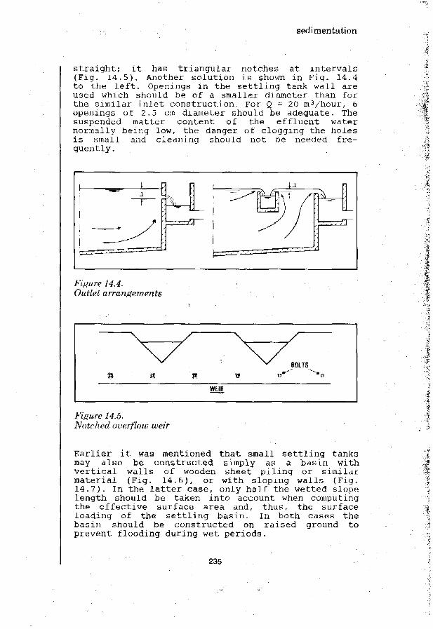
sedimentation
straight; it has triangular notches at intervals(Fig. 14.5), Another solution is shown in Fig. 14.4to the left. Openings in the settling tank wall areused which should be of a smaller diameter than forthe similar inlet construction. For Q = 20 m3/hour, 6openings of 2.5 cm diameter should be adequate. Thesuspended matter content of the effluent waternormally being low, the danger of clogging the holesis small and cleaning should not be needed fre-quently.
Figure 14.4.Outlet arrangements
1
n
\
V«/
WEIR
\
/
' BOLTS
Figure 14.5.Notched overflow weir
Earlier it was mentioned that small settling tanksmay also be constructed simply as a basin withvertical walls of wooden sheet piling or similarmaterial (Fig. 14.6), or with sloping walls (Fig.14.7). In the latter case, only half the wetted slopelength should be taken into account when computingthe effective surface area and, thus, the surfaceloading of the settling basin. In both cases thebasin should be constructed on raised ground toprevent flooding during wet periods.
235

sedimentation
INLET ZONE OUTLET ZONE
A - OVERFLOW WEIR OVERFLOW WEIR -
PLAN
I I
I ILONGITUDINAL SECTION CROSS SECTION
Figure 14.6.Settling basin constructed with wooden sheet piles
OVERFLOW WEIR MADE OF> / WODEN SHEET PILES ~ ^ \ ^
—H.\
r.-.-_-:,
I
|
1 1 1 1 1 1
| | | |
17_L
ABOVE MAX FLOOD LEVEL
Figure 14.7.Dug basin as settling tank
236

sedimentation
14.4. Tilted plate and tube settlers
The improvement in settling efficiency which can beobtained by the installation of one extra bottom(tray) in a settling tank can be greatly increased byusing more trays as shown in Fig. 14.8. The spacebetween such trays being small, it is not possible toremove the sludge deposits manually with scrapers.Hydraulic cleaning by jet washing would be feasiblebut a better solution is the use of self-cleaningplates. This is achieved by setting the platessteeply at an angle of 40 to 60° to the horizontal.The most suitable angle depends on the characteris-tics of the sludge which will vary for differenttypes of raw water. Such installations are calledtilted plate settling tanks. This type of tank isshown schematically in Fig. 14.9. Fig. 14.10 shows across-section.
Figure 14.8.Multiple-tray settling tank
Figure 14.9.Tilted plate settling tank
237

sedimentation
RAWWATER SETTLED WATER
SLUDGE
Figure 14.10.Settling tank with, tilted plates
For large tanks, quite sophisticated systems of traysor plates, have been devised but in small instal-lations flat or corrugated plates and upward flow ofthe water are frequently the most suitable. For anyclarification duty, tilted plate settling tanks havethe advantage of packing a large capacity in a smallvolume. The effective surface being large, the sur-face loading will be low, and the settling efficien-cy, therefore, high. The surface loading may becomputed as:
s = surface loading (m3/m2/hour) .Q = rate of flow (m3/hour)A = bottom area of the tank (m2)n = multiplication factor depending on the type
and position of the tilted plates.
Water enters at the bottom of the settling tank,flows upward, passes the tilted plates, and is col-lected in troughs (Fig. 14.11). As the water flowsupwards past the plates the settleable particles fallto the plates. When they strike it, they slide down-wards, eventually falling to the area beneath the
238

sedimentation
plates. An individual particle might enter the platechannels several times before it agglomerates andgathers sufficient weight to eventually settle to thetank floor.
-MSETTLED WATERCOLLECTING THROUGHS INLET PIPE
TILTED PLATESOR MODULES
Figure 14.11.Tilted plate settling tank disign parameters
Assuming h = 1.5 m, w = 0.05m, oi - 55° and platesmade of asbestos cement with a thickness of 6 mm, wefind n = 16! One should keep in mind that the sludgedeposits per unit bottom area will also be 16 timesgreater, for the same influent flow rate. Manualsludge removal will probably be impractical. In atank having a square plan, rotating sludge scrapersmight be used. Another possibility is the use ofhopper-bottomed tanks with the walls sloping at about50° to the horizontal. The depth of such a tank willbe considerable and the costs of construction arelikely to be much greater than for flat-bottomedtanks. Sludge discharge is carried out through the
239

sedimentation
draining of water from the hopper-bottom section ofthe tank (this is called "bleeding").
Instead of tilted plates, closely packed tubes may beused. These can easily be made of PVC pipes, usuallyof 3-5 cm internal diameter and sloping about 60° tothe horizontal. For large installations commerciallyavailable tube models can have merit. An example isshown in Fig. 14.12 . There are many other designsthat may give an equally good settling efficiency.
Figure 14.12.Module for tube settler
In a 5 cm dia tube, the farthest distance anyparticle must settle is from the top of the tube tothe bottom. If the particle's settling rate is 2.5cm/minute it will take only two minutes for theparticle to reach the bottom. In contrast, if thesame particle were to settle in a 3 m deep tank, itwould take 120 minutes (2 hours) for it to fall tothe tank bottom. Tube modules commonly are approxi-mately 76 cm wide, 3 m long and 54 cm deep. Becausethe tubes are at an angle of 60° the effective tubelength is 61 cm.
Tube modules can be constructed from flat sheets ofABS plastic with the passage ways formed by slabs ofPVC. The passage ways are slanted in a criss-crosspattern for structural strength so that the moduleneed be supported only at its ends. Being of plasticthese modules can be easily trimmed to fit theavailable space in a settling tank.
The effective settling surface is very great and.,thus, the "surface loading" (overflow rate) very low.To illustrate this: a flow rate of 2 m3/hour througha settling basin of 0.1 m2 surface represents a"surface loading" of 20 m3/m2/hour. If twenty rows of
240

sedimentation
tubes are used, the surface loading will be reducedto 1 m3/m2/hour. The detention time of the water ineach tube will be just a few minutes.
The possibility of increasing the efficiency of atank through the installation of tilted plates ortubes may be used with great advantage for raisingthe capacity of existing settling tanks. Where theavailable tank depth is small, less than 2 m, theinstallation of the tilted plates or tubes is likelyto meet with problems. In deeper tanks, they can bevery advantageous.
In considering the expansion of existing facilitiesby the addition of tilted plates or tubes, it isimportant to remember that more sludge will begenerated and so additional removal facilities may bereguired. Inlet and outlet pipe sizes and weircapacity should also be checked to see if they cancarry the increased loading.
241

242

SedimentationBabbitt, H.K.; Doland, J.J.; Cleasby, J.L.WATER SUPPLY ENGINEERING •McGraw-Hill, New York, 1962 (6th Edition)
Camp, T.R.SEDIMENTATION AND THE DESIGN OF SETTLING TANKS]n: Trans. ASCE, 1946, No. 3, pp. 895-903
Culp, A.M.; Kou-Ying Hsiung, Conley, W.R.TUBE CLARIFICATION PROCESS: operating experiencesIn: Proc. Am. Soc. Civil Eng. Vol. 95(1969) SA 5 October, pp. 829-836
Fair, G.M.; Geyer, J.C.; Okun, D.A.WATER AND WASTEWATER ENGINEERINGVol. 2, Water Purification and Wastewater Treatment and Disposal,John Wiley & Sons, New York, 1968
Hazen, A.ON SEDIMENTATIONIn: Trans. Am. Soc. Civil Eng., 1904, No. 53, pp. 45-51
243

244

slow sand filtration
15. slow sand filtration
15.1 Introduction
Filtration is the process whereby water is purifiedby passing it through a porous material (or 'medium').In slow sand filtration a bed of fine sand is usedthrough which the water slowly percolates downward(Fig. 15.1). Due to the fine grain size the pores ofthe filter bed are small. The suspended matterpresent in the raw water is largely retained in theupper 0.5-2 cm of the filter bed. This allows thefilter to be cleaned by scraping away the top layerof sand. As low rates of filtration are used (0.1-0.3m/hour = 2-7 m 3 / m 2 / d a y ) , the interval between twosuccessive cleanings will be fairly long, usuallyseveral months. The filter cleaning operation neednot take more than one day but after cleaning, one ortwo more days are required for the filter bed toagain become fully effective.
GATEHOUSE
"T"
INLETSUMP
|_ LATERALI UNDERDRAW
1MAINDRAIN
1"
INFLUENT^
INLET SUMP
EFFLUENT MAIN DRAIN LATERALCONDUIT
GRAVEL
Figure 15.1.Slow sand filter
245

slow sand filtration
The main purpose of slow sand filtration is theremoval of pathogenic organisms from the raw water,in particular the bacteria and viruses responsiblefor the spreading of water-related diseases. Slowsand filtration is highly efficient in this respectas it is capable of reducing the total bacteriacontent by a factor of 1,000 to 10,000, and theE.coli content by a factor 100 - 1,000. A well-operated slow sand filter will remove protozoa suchas Endamoeba histolytica and helminths such asschistosoma haematobium and Ascaris lumbricoides.When processing raw water that is only lightly con-taminated, slow sand filters will produce a bacteri-ologically safe water. E.coli will normally be absentin a 100 ml sample of the filtered water, whichsatisfies normal drinking water standards.
Figure 15.2.Slow sand filter - circular type (Pakistan).
IRC Photo
Slow sand filters are also very effective in removingsuspended matter from the raw water. However, theclogging of the filter bed may be too rapid necessi-tating frequent cleanings. Trouble-free operation isonly possible when the average turbidity of the rawwater is less than 5 F.T.U., with peak values below20 F.T.U. and occurring for periods of a few daysonly. When this is not the case, the suspended load
246

slow sand filtration
in the raw water must be reduced by a pre-treatmentprocess such as sedimentation, coagulation andflocculation, or rapid filtration, before the wateris admitted to the slow sand filter. In storagereservoirs, suspended particles will be removed by-settling but a rapid blocking of the slow sand filterbed would still take place when considerable algalgrowth occurs. Pre-treatment will then be necessary.
Slow sand filters have many advantages for use indeveloping countries. They produce a clear water,free from suspended impurities and hygienically safe.They can be built with local materials using localskills and labour. Much of the complex mechanical andelectrical equipment required for most other watertreatment processes can be avoided. Slow sand filtersdo not for their operation require coagulating chem-icals, lime or chlorine that frequently need to beimported. It is true that they occupy more land andthat their cleaning calls for ample labour but par-ticularly in the rural areas of developing countriesthese requirements generally should be no drawbacks.
15.2 Theory of slow sand filtration
In slow sand filters, the removal of impurities fromthe raw water is brought about by a combination ofdifferent processes such as sedimentation, ad-sorption, straining and, most importantly, bio-chemical and microbial actions. The purificationprocesses start in the supernatant water but themajor part of the removal of impurities from thewater and the microbial and bio-chemical processestake place in the top layer of the filter bed, the1Schmutzdecke'*.
Straining removes those suspended particles that aretoo large to pass through the pores of the filterbed. It takes place almost exclusively at the surfaceof the filter where the impurities are retained inthe top layer. This will improve the straining ef-ficiency but it also increases the resistance againstthe downward water flow. Periodically the accumulatedimpurities have to be removed by scraping off the toplayer. In this way the operating head of the filterbed is brought back to the original value.
* The 'filter skin1 or layer of deposited material that formson top of a slow sand filter.
247

slow sand filtration
Sedimentation removes fine suspended solids as theyare deposited onto the surface of the filter bed sandgrains. For fine sand as normally used in slow sandfilters the combined surface area of the grains isvery great, some 10,000 to 20,000 square metres percubic metre of filter sand. In combination with thelow rate of filtration, this gives a very low'surface loading' (as described in section 14.2). Thesettling efficiency will, therefore, be so high thateven very small particles can be completely removed.Again, this action takes mainly place in the upperpart of the filter bed and only organic matter of lowmass density is carried deeper into the bed. Theremaining suspended solids, together with colloidaland dissolved impurities, are removed by adsorptioneither onto the sticky gelatinous coating formedaround the filter bed grains or through physical massattraction and electrostatic attraction.
The electrostatic attraction is the most effective,but it occurs only between particles having oppositeelectrical charges. Clean quartz sand has a negativecharge and is, therefore, unable to adsorb negative-charged particles such as bacteria, colloidal matterof organic origin, anions of nitrate, phosphate, andsimilar chemical compounds. Thus, during the ripeningperiod of a slow sand filter, only positive-chargedparticles are adsorbed, such as floe of carbonates,iron- and aluminium hydroxide, and cations of ironand manganese. However, the adsorption of positivecharged particles will continue to a stage thatover-saturation occurs. The overall charge of thefilter bed grain coatings then reverses and becomespositive, after which negative-charged particles willbe attracted and retained. After the initial ripeningperiod the filter bed will exhibit a varied andcontinuously varying series of negative and positivecharged grain coatings that are able to adsorb mostimpurities from the passing water.
The matter accumulated on the filter sand grains doesnot remain there unchanged; it is transformed bybio-chemical and bacterial activity. Soluble ferrousand manganous compounds are turned into insolubleferric and manganic oxide hydrates that become partof the coating around the sand grains. Organic matteris partly oxidised thus providing the energy neededby the bacteria for their metabolism. Another part ofthe organic matter is transformed into cell materialwhich is used for bacterial growth. Usually, theamount of organic matter in the raw water is smalland provides food for only a limited bacterial popu-
248

slow sand filtration
lation. Thus, simultaneous with the bacterial growthmentioned above, there will be a die-off of bacteria.Organic matter is so released. It is carried awaywith the water flow and again consumed by other-bacteria deeper in the filter bed. In this way thedegradable organic matter originally present in theraw water is gradually broken down and transformedinto inorganic compounds such as carbon dioxide,nitrates, sulfates, and phosphates. Finally these aredischarged with the filter effluent.
It should be stressed that the microbial actionsmentioned above need time to establish themselves.Hence, a ripening period of sufficient time is re-quired. During this period bacteria from the rawwater are adsorbed onto the filter bed grains. There,they multiply using the organic matter present in thewater as food. The break-down of organic matter takesplace in many steps in each of which a particulartype of bacteria is active.
For the filtration process to be effective, it isnecessary that the bacteria develop and migrate tothe deeper layers of the filter bed. This takes time,and variations in the filtration rate should beintroduced slowly over a period of hours. In practiceit has been found that the full bacterial activityextends over a depth of about 0.6 m of filter bed sothat the effective bed thickness should be not lessthan 0.7 m. The initial bed thickness should be0.3-0.5 m more, to allow for a number of filterscrapings before resanding is necessary.
The most important purification effect of a slow sandfilter is the removal of bacteria and viruses.Through adsorption and other processes, bacteria areremoved from the water and retained at the surface ofthe filter bed grains. For intestinal bacteria, thefilter bed provides unfavourable conditions becausethe water is generally colder than their naturalhabitat, and usually contains not sufficient organicmatter (of animal origin) for their living require-ments .
Moreover, in the upper part of the filter bed severaltypes of predatory organisms abound feeding on bac-teria. Deeper in the filter bed bio-chemical oxi-dation will have reduced the organic matter in thewater already so much that the bacteria are starved.The various micro-organisms in a slow sand filterproduce chemical compounds (antibiotics) and micro-bial agents that kill or at least inactivate in-
249

slow sand filtration
testinal bacteria. The overall effect is a con-siderable reduction of the number of E.coli and,since pathogens are less likely to survive thanE.coli, an even greater reduction of their numbers isobtained. Treating a raw water of average bacterio-logical quality with slow sand filters, it is usualto find E.coli absent in 100 ml samples of filteredwater.
Slow sand filters are usually built in the open.Fhotosynthetic algal growth may occur. This has somedisadvantages as will be explained in section 15.5but it also promotes the filter efficiency and helpsachieve a greater removal of organic matter andbacteria. This is brought about by the thin slimymatting on top of the filter bed, consisting ofthreadlike algae and numerous other forms of aquaticlife such as plankton, diatoms, protozoa, androtifers. The filter matting is intensely active withthe various organisms entrapping, digesting andbreaking down organic matter from water passingthrough. Dead algae from the supernatant water andliving bacteria from the raw water are similarlyconsumed in the filter matting; inert suspendedmatter is strained out.
15.3 Principles of operation
Basically a slow sand filter consists of a tank, openat the top and containing the bed of sand. The depthof the tank is about 3 m and the area can vary from afew tens to several hundreds of square metres. At thebottom of the tank an underdrain system (the 'filterbottom') is placed to support the filter bed. The bedis composed of fine sand, usually ungraded, free fromclay and loam, and with as little as possible organicmatter in it. The filter bed normally is 1.0-1.2 mthick, and the water to be treated (the 'supernatantwater') stands to a depth of 1.0-1.5 m above thefilter bed.
The slow sand filter is provided with a number ofinfluent and effluent lines fitted with valves andcontrol devices. These have the function of keepingboth the raw water level and the filtration rateconstant.
For clarity of illustration all influent and effluentlines are shown separately in Fig. 15.3 but in prac-tice they are combined and placed together to save onconstruction costs.
250

slow sand filtration
RAWWATERINLET
TO DRAIN
FILTERBOX -
FILTERED
« VENTILATION
WATER SUPPLYFOR BACKFILLING
SCUM OUTLET
TO DRAIN
FILTERED"WATER
OUTLET
TO DRAIN TO DRAIN
Figure 15.3.Slow sand filter
During operation, the raw water enters the filtertank through valve A and passes the float-controlledregulating valve B; the supernatant water infiltratesinto the filter bed and percolates down toward theunderdrain system; the filtered water then passes aflow meter and the regulating valve F, and flows intothe outlet weir chamber; from there the water passesthrough valve J and flows into the clear water well.Valve B keeps the raw water at a constant level. Toobtain a constant rate of filtration, the regulatingvalve has to be opened a little bit each day in orderto compensate for the increase in resistance of thefilter bed due to clogging. When the demand forfiltered water changes, valve F is adjusted slowly,over a period of several hours, with the waterproduction rate checked by reading the flow meter.The outlet weir prevents under-pressures from oc-curring in the filter bed and makes the operation ofthe filter independent from water level variations inthe clear water well. The weir also provides aerationof the water for which the weir chamber should beventilated. Ventilation is further required for thefilter itself to provide for the release of gasesthat are liberated or produced during filtration. Tofacilitate the release of these gases, the undersideof the filter bottom should slope 1:500 upward in thedirection of flow. For drainage purposes (e.g. whenrepairs are carried out) the filter-tank floor shouldslope 1:200 downward. If considerable amounts of scum(e.g. floating algae) accumulate at the water surface
251

slow sand filtration
during filtration, scum outlets at the four cornersof the filter are handy for regular scum removal.
When after a period of operation the regulating valveF is fully open, a further increase in filter re-sistance would result in a reduction of the fil-tration rate. The production of filtered water wouldfall below the required rate, and the filter must betaken out of service for cleaning. Cleaning iscarried out by scraping off the top 1.5 to 2 cm ofdirty sand. For this the filter must first be drainedto a water level about 0.2 m below the top of thesand bed. To start the cleaning operation, valve A isclosed, usually at the end of a day, while the filtercontinues to discharge water in the normal waythrough valves F and J. The next morning, valves Fand J are closed and the remaining supernatant wateris drained off through valve C. This draining of thefilter is controlled by a box of which one wallconsists of stop logs forming a weir. The top of thisweir is kept more or less level with the top of thefilter bed. The pore water in the upper 0.2 m of thesand bed is drained off by opening valve E for ashort period of time. When the cleaning operation(see section 15.6) has been completed, valve C isclosed and the filter is slowly refilled with fil-tered water from underneath, through valve D, to alevel of about 0.1 m above the top of the sand bed.During this operation one should take care that allthe air that has accumulated in the pores of the bedis driven out.
After this, raw water is admitted from the inletthrough valve A taking care not to damage the filterbed. An effective arrangement is to locate valve Aabove the discharge box connected to valve C. Whenthe raw water level in the filter has reached itsnormal level as determined by the regulating valve B,valve K is fully opened and regulating valve F justenough for the clean filter to operate at about onequarter of its normal filtration rate.
During the next 12 hours the filtration rate isslowly raised to the normal level. After at least 12more hours - but preferably 36 hours -valve K isclosed and valve J opened; the filter is back innormal operation. When the filter has been out ofoperation for a considerable period of time, e.g. forre-sanding or repair, the ripening period of 1 to 2days mentioned earlier must be extended with severalmore days. When the filter is new, the breaking-inperiod may even take several weeks. In the event ofthe filter remaining out of operation for a long
252

slow sand filtration
period, it should be drained completely using valvesE, G and H.
The operating method for a slow sand filter as de-scribed above, is fail-safe and gives reliableresults but the installation is rather complex. Manysimplifications are possible. When the raw waterlevel on top of the filter is kept constant by mani-pulating the raw water supply rate it is possible todo without the float-operated regulating valve B.Valves D and E may be combined, and the function ofvalve H can be fulfilled by valve K. Scum outlets arenot necessary particularly for small filters, if scumremoval can be carried out manually. Fig. 15.4 showsan example of such a simplified design which has aminimal number of control valves and only a fewinfluent and effluent lines.
SUPERNATANTWATER
SUNCTIONPIPE
MAX. HEADLOSS
TO RESERVOIR
CLEAR WELL
Figure 15.4.Simplified slow sand filter
15.4 Design considerations
For the actual design of a slow sand filter fourdimensions have to be chosen in advance: the depth ofthe filter bed, the grain size distribution of thefilter material, the rate of filtration, and thedepth of supernatant water. As far as possible, thesedesign factors should be based on experience obtainedwith existing treatment plants which use the samewater source or water of a comparable nature. Whensuch experience is not available, the design shouldbe based on results obtained with pilot tests carriedout with experimental filters (see Annex 3).
253

slow sand filtration
When no actual or experimental data are available,the following procedure may be used;
a. For the initial design, the bed thickness ischosen at 1.0-1.2 m. This is sufficient to allowfor the necessary filter bed scrapings before theminimum thickness of 0.7 m is reached.
b. Analyse the grain size distribution of locallyavailable sand and determine the effective sizeand coefficient of uniformity (see Fig. 15.5).Select sand with an effective size of about 0.2mm and a coefficient of uniformity less than 3.When such sand is not available a coefficient ofuniformity up to 5 may be accepted, and an ef-fective size of the sand ranging from 0.15 to0.35 mm. Builder's grade sand often satisfiesthese requirements. Sometimes burnt rice husks of0.3 to 1.0 mm size are used.
c. For the initial design fix the depth of super-natant water at between 1 and 1.5 m.
d. Provide at least 2 and preferably 3 filter units.The combined surface area should be so large thatwith one filter out of operation for cleaning,the filtration rate in the operating units willnot exceed 0.2 m/hour.
e. Provide space for additional filter units.f. As soon as operations start, carefully note the
length of the filter runs. An average filter runof about 2 months is most appropriate. Whenfilter runs prove to be much longer, filtrationrates can be raised allowing a greater *plantoutput. If filter runs are shorter than expected,additional units will have to be constructed atan earlier date than was anticipated.
In slow sand filters under-pressure (that is waterpressure below atmospheric) must be avoided under allcircumstances as this might give serious problems.Air bubbles would form and accumulate in the filterbed increasing the resistance against the filtrationflow. Air bubbles of large size may even break up thefilter bed and create fissures through which thewater would pass without adequate purification. Themaximum allowable head loss over the filter bed isthus limited to the depth of the supernatant waterplus the resistance of the clean filter bed at theminimum filtration rate. In order to make the occur-rence of under-pressure completely impossible, anoverflow weir may be provided in the effluent line.The difference in level between the supernatant waterand the overflow weir should not exceed the maximumallowable head loss plus the head losses in theeffluent piping, again for the minimum rate offiltration.
254

•~ 3 ! s
slow sand filtration
% PASSING99 —
98 —
95 —
90 —
80 —
70 —
50 —
40 —
30 —
20 —
10 —
2 -
1 —
0.5 —
0.2 —
0.01
SIEVE SIZEUN MM)0.0630.1250,250.51.02.04.0
1 ' •0.02
CUMULATIVE WEIGHT|IN %)
0,22.6
14.548.385.795.598.4
/
| 1 M l j0.05 0.1
i•
**
•
•
• *
i
1 li ' '0.2
I0.21
/m
/ EFFECTIVE SIZE—/" d,,, 0.21 MM
/ COEFF. OF UNIFORMITY
*M - ™ = 2.90dio 0.21
SIEVE SIZE (IN MM)| I i i | i | I I |
0.5 1 2 5
0 . 6 1
Figure 15.5.Grain size distribution of filter sand
For the low filtration rates used in slow sandfilters, a small variation of the level of the super-natant water may have an appreciable influence on thefiltration rate and so affect the effluent quality.To avoid this, filtration rate control fitted in theeffluent line should be provided.
15.5 Construction
• • • • ?
As regards the construction of a slow sand filter,various elements may be distinguished the most im-portant being the filter tank, the filter bottom, thefilter bed, the supernatant water and the influentand effluent lines. Attention should also be given to
255

slow sand filtration
the layout of the slow sand filtration plant as awhole.
In continental Europe slow sand filters are built ofreinforced or pre-stressed concrete with a rect-angular form and vertical walls 3 to 4 m high. Wherepossible they are situated above the highest ground-water table to make sure that there is no seepage ofpolluted water through cracks. In Great Britain massconcrete is still very popular. Gravity walls areused and a separate floor is constructed on site,with sections placed in a checker-board pattern (Fig.15.6).
ROUGHENED SURFACETO PREVENT SHORT-CIRCUITING
PERMANENT JOINTFILLED WITH BITUMEN
CONSTRUCTION JOINT1
TTTTTTITTSTABILIZED SANDAS WORKING PLATFORM
WTTTII
I FLLLLL n' m
FLOOR SLABS3x3 M
* • : '
Figure 15.6.Slow sand filter constructed in mass concrete
In the past slow sand filters have been built ofmasonry on a foundation of puddled clay (Fig. 15.7).Such a construction may be quite appropriate in ruralareas of developing countries.
A very simple slow sand filter constructed in-groundis shown in fig 15.8.
256

slow sand filtration
ORIGINAL ^ f f jGROUND"^#7/
MAX. GROUND WATER LEVEL
^ S L O P I N G
SUPPORTING ^ 5 ^GRAVEL — ^WITH DRAINS
WALL PROTECTED BY MASONRY
SUPERNATANT WATER
:•:•:•:•••• X F I L T E R S A N D - ; •:•:•:•:•:•:•:••
Figure 15.7.Slow sand filter constructed of masonry on puddled clay
BRICKWALLWITHPLISTERLINING
FILTEREDWATEROUTLET
CONCRETEFOOTING
Figure 15.8.Simple slow sand filter
Depending on the treatment plant capacity therequired area varies from a few tens to severalhundreds of square metres. There is a tendency toreduce the maximum sizes with a view of obtaining agreater flexibility of operation as well as quickerfilter cleaning. With a maximum filtration rate of0.2 m/hour a plant with a capacity of 2 millionm3/year and a ratio between maximum and average dailyproduction rate of 1.2 would require a filter bedarea of 1,370 m2. With one unit as a reserve (i.e.cleaning) this calls for 4 units each of 460 m2 ofsurface area, or 6 units of 270 m2 each. In order toensure good effluent quality, short circuiting alongthe walls of the filter box must be prevented. Whenreinforced concrete is used, the inner wall should bemade rough over half the filter bed depth, con-
257

slow sand filtration
structing this wall slightly tilted backwards alsogreatly helps in having the filter bed tightly fittedto the filter tank wall. Careful attention should begiven to the occurrence of high groundwater levelswhich might lift the structure up and so damage thefilter structures.
The filter bottom serves the two-fold purpose ofsupporting the filter bed and draining the filteredwater off. The openings or pores of the filter bottomshould be so fine that no filter material can passthrough them. The resistance of the filter bottom tothe passage of filtered water (head loss) should besmall. As shown in Fig. 15.9 various types of filterbottom exist including stacked bricks and no-finesconcrete poured on site on recoverable steel forms.
BRICKS \ I \ \ | •VAYAAA/VAYAAAAAAYAAA/ VAAXAAA VAA VAAVAAYAAA
1 - 1 4-CROSS-SECTION LONGITUDINAL SECTION
1 1 \//^//W//^///V(//Jtf//n//AV/ DDCP1OT P
c
OPEN JOINTtJ CONCRETE
JNCRETE SLABS LAID VS ON PRECASTUBS
^ £ POROUS CONCRETE POURED ON SI\ C ~ ON RECOVERABLE STEEL FORMS
i/ITM
FE
L _
y//AX('AAAAAA/$///////)!(/////.E<S^ [^\\\
'.•*s?p
1 u.
" l r~' i
—*- r—I L .
•1 r -
. J !_.
~~\ r-i
.1 V.
•i r-
i
•i
- 1i
[-¥ [-¥ H i -
Figure 15.9.Types of filter bottoms
258

slow sand filtration
To prevent the filter material from entering andblocking the underdrainage system a series of gradedgravel layers can tie used. The under layer of coarsesize should be large enough to keep the openings inthe filter bottom free, and the upper layer so finethat the overlying filter sand will not sink into itspores. For porous filter bottoms, one layer of0.1-0.2 m thickness would be sufficient; for stackedbricks with open joints (10 mm wide) four layers willbe required, for instance of 0.4-0.6 mm, 1.5-2 mm,5-8 mm and 15-25 mm size each layer about 10 cmthick.
For small filters, perforated lateral pipes may bemore attractive. They are connected to a centraldrain leading the water out of the filter. Theperforated laterals can be made of many materialssuch as vitrified clay (full-round or half-round farmdrain tiles) or cast iron, but in waterworks practiceasbestos cement and polyvinylchloride are mostlyapplied. Locally-made porous pipes can also be usedwith advantage (Fig. 15.10). Lateral pipes with aninside diameter of about 80 mm are set at intervalsof about 1 m and are provided with holes of 5 mmdiameter on the underside; about 10 per metre oflength. The central drain is usually not perforatedand should have a cross-section of about twice thecombined cross-sectional area of the laterals con-nected to it.
Figure 15.10.Porous underdrain pipes
259

slow sand filtration
Sand for slow filters has already been discussed insection 15.4. When sand of the required effectivesize is not naturally available, it may sometimes beproduced by thoroughly mixing two types of naturalsand. However, this will result in a less uniformlygraded sand bed. Sieving the sand to remove thecoarsest grains may then be needed to obtain sand ofthe required uniformity.
The depth of supernatant water is related to themaximum allowable head loss which in its turn in-fluences the length of filter run. A free board of0.2 m above the maximum raw water level should beprovided, and the top of the walls should be at least0.8 m above ground level to minimize pollution bydust, leaves, small animals, etc.
Covering a slow sand filter is a necessity in coldclimates to prevent the freezing of the water inwinter time. In tropical climates it is sometimespracticed to prevent algal growth. In open filtersthe photosynthetic reaction
CO2 + H2O ^ . CH2O + ° 2
proceeds from left to right during daylight hours;oxygen (°2) is produced. During the night, thereaction process is in the reverse direction andoxygen is consumed. As a result, there is a con-siderable variation in the oxygen content of thefiltered water with very low values in the morningand perhaps even anaerobic water pockets in thefilter bed. Dead algae may block the filter bed andcause a shortening of filter runs. A massive die-offof algae (e.g. in autumn) may impart a bad smell andtaste to the filtered water. In tropical climates theperiod of daylight is generally relatively short,about 12 hours, and the water temperature is fairlyconstant. The growth and die-off of algae will thentake place more or less at the same rate. The dis-advantages mentioned above are thus less pronouncedand the advantageous increase of self-purificationprocesses can be fully utilized (see section 15.2).
Nowadays the various units of a slow sand filterplant are usually arranged in regular rows on bothsides of a strip of land where all influent andeffluent lines are laid. Between each row of unitsstrips are kept open to facilitate access for filtercleaning. The filters frequently are provided with asmall annex containing the valves, meters and otherequipment necessary for the daily operation andcontrol (Fig. 15.11).
260

slow sand filtration
RIVER
RAW WATER PUMPS
l ,o ,1 t t t
4 4 4SLOW SAND FILTERS
FILTERED WATERPUMPS
N s f j O f l TO SUPPLY•F" t
+ 4CLEAR WELL
NOT TO SCALE
Figure 15.11.General arrangement for slow sand filtration plant
15.6 Cleaning
The time-proven method of cleaning a slow sand filteris by scraping off the sand surface with hand shovelsto remove the top layer of dirty sand over a depth of1.5-2 cm. The scraped-off mixture of sand and impuri-ties is piled in ridges or in heaps from where it iscarried or carted to the edge of the filter usingbarrows or hand-carts wheeled over wooden planks (Fig15.12). It may also be taken out of the filter withthe help of baskets hoisted up with rope and tackle.
The dirty sand is sometimes discarded (can be usedfor landfills) but in other cases it is cleaned bywashing (Figs. 15.13 and 15.14), if this is cheaperthan buying new sand. To prevent putrefaction thesand should be washed immediately after it has beentaken out of the filter. Care should be taken not tolose too much of the finer fractions of the sandduring the washing.
261

slow sand filtration
Figure 15.12.Manual cleaning of a slow sand filter
262

slow sand filtration
WATER CARRYING SANDTO BE WASHED
SAND SETTLESAGAINST RISINGWATER
PRESSUREWATER
\OVERFLOW CARYINGWASHINGS TO WASTE
WATER CARRYINGWASHED SAND
MAKE-UP WATER(IF NEEDED)
Figure 15.13.Sand washer
263

slow sand filtration
'•' ; w . • SCRAPED-•'-•oSW,' S A N D — "'•' :/^
PLAN
WOODEN PLANK
- GUTTER
H0SE
CROSS-SECTION
Figure 15.14.Sand washing platform
The penetration of the impurities in the filter bedis largely confined to the upper layers. Scrapingaway the top layer removes the major part of thecloggings but some will remain in the deeper layersof the filter bed. These deposits accumulate littleby little and also penetrate gradually deeper intothe filter bed. This could cause problems if the sandremains in place for a very long time. When aftermany scrapings the minimum filter bed thickness isreached, it is therefore necessary to remove anadditional 0,3 m of the filter sand before the newsand is brought in. The removed' sand layer containsall the organisms necessary for the proper bio-chemical functioning of the slow sand filter andshould be placed on top of the new sand in order topromote the ripening process (Fig. 15.15).
264

slow sand filtration
1A mmm•wmm
DIRECTLY AFTERCONSTRUCTION
MINIMUIVI ALLOWABLE ADDITIONAL DEPTHDEPTH AFTER TEMPORARELYVARIOUS SCRAPINGS REMOVED
RE-SANDINGCOMPLETED
Figure 15.15.Re-sanding of a slow sand filter
The manual cleaning work described above does notrequire special equipment or skills but for largefilters a considerable number of workers are needed.Various mechanical systems of filter cleaning havebeen developed. Unfortunately, these are too complexand costly for use in small treatment plants indeveloping countries.
265

266

Slow sand filtration
Dijk, J.V. van; Oomen, J.H.C.M.SLOW SAND FILTRATION FOR COMMUNITY WATER SUPPLY IN DEVELOPINGCOUNTRIES - A DESIGN AND CONSTRUCTION MANUALInternational Reference Centre for Community Water Supply,The Hague, 1978, (Technical Paper No. 11)
Frankel, R.J.EVALUATION OF LOW-COST WATER FILTERS IN RURAL COMMUNITIES OFTHE LOWER MEKONG BASINAsian Institute of Technology, Bangkok, 1974
Huisman, L.; Woods, W.E.SLOW SAND FILTRATIONWorld Health Organisation, Geneva 1974, 122 p.
Institution of Water EngineersMANUAL OF BRITISH WATER SUPPLY PRACTICEHeffer & Sons Ltd., Cambridge, 1950
Thanh, N.C.; Pescod, M.B. .APPLICATION OF SLOW SAND FILTRATION FOR SURFACE WATER TREAT-MENT IN TROPICAL DEVELOPING COUNTRIESAsian Institute of Technology, Bankok, 1976(Environmental Engineering Division Research Report No. 65)
Wright, F.B.RURAL WATER SUPPLY AND SANITATIONJohn Wiley & Sons, Chapman & Hall, New York, 1956
267

268

rapid filtration
16. rapid filtration
16.1 Introduction
As explained in the preceding chapter on slow sandfilters, filtration is the process whereby water ispurified by passing it through a porous material (or"medium"). For rapid filtration, sand is commonlyused as the filter medium* but the process is quitedifferent from slow sand filtration. This is so be-cause much coarser sand is used with an effectivegrain size in the range 0.4-1.2 mm, and the filtra-tion rate is much higher, generally between 5 and15 m3/m2/hour (120-360 m3/m2/day). Due to the coarsesand used, the pores of the filter bed will berelatively large and the impurities contained in theraw water will penetrate deep into the filter bed.Thus the capacity of the filter bed to store de-posited impurities is much more effectively utilizedand even very turbid river water can be treated withrapid filtration. For cleaning a rapid filter bed, itis not sufficient to scrape off the top layer.Cleaning of rapid filters is effected by backwashing. This is directing a high-rate flow of waterback through the filter bed whereby it expands and isscoured. The back-wash water carries the depositedcloggings out of the filter. The cleaning of a rapidfilter can be carried out quickly; it need not takemore than about one half hour. It can be done asfrequently as required, if necessary each day.
Applications of Rapid Filtration
There are several different applications of rapidfiltration in the treatment of water for drinkingwater supplies.
In the treatment of groundwater, rapid filtration isused for the removal of iron and manganese. To assistthe filtration process, aeration is frequentlyprovided as a pretreatment to form insoluble com-pounds of iron and manganese (Fig. 16.2).
Anthracite, crushed coconut shell, pumice, and othermaterials are also used especially in multiple-layer filterbeds where one or more layers of such materials are placedon top of a (shallow) sand bed.
269

rapid filtration
WASH THRQUGHSFILTER TANK
GRADED GRAVEL
PERFORATED LATERALS
— FILTER FLOOR
Figure 16.1.Rapid filter (open,gravity-type)
RAW WATER -
RAPID FILTER-
AERATION
ililiiili-FILTEHEO WATER
Figure 16.2.Rapid filtration of pre-treated (aerated) water
270

rapid filtration
For water with a low turbidity as frequently found inlakes and sometimes in rivers, rapid filtrationshould be able to produce a clear water which, how-ever may still contain pathogenic bacteria andviruses. A final treatment such as chlorination isthen necessary to obtain a bacteriologically safewater.
In the treatment of river water with high turbidity,rapid filtration may be used as a pre-treatment toreduce the load on the following slow sand filters(Fig. 16.3), or it may be applied for treating waterthat has been clarified by coagulation, flocculationand sedimentation (Fig. 16.4). In such cases again afinal chlorination is required.
RAW WATER — =
li'ifiirifiiiii'iirtm
PREHLTER
~
• - i . - — • — — — ^ - >
SLOW SAND FILTER
— _ ^ T 0 CLEAR WATERr RESERVOIR
Figure 16.3.Rapid filtration-followed by slow sand filtration
CHEMICALFEED
= i - _ , RAW WATER
IS/ FLOCCULATION TANK
MIXINGCHAMBER
SETTLING TANK
RAPID FILTERCHLORINATION
Figure 16.4.Rapid filtration after coagulation and flocculation, andsedimentation
271

rapid filtration
Types of Rapid Filters
Rapid filters are mostly built open with the waterpassing down the filter bed by gravity (Fig. 16.1).
For certain operating conditions, other rapid filtersthan the open gravity-type are better suited. Themost important are: pressure filters, upflow filtersand multiple-media filters.
RAW WATERINLET
FILTEREDWATER -*•OUTLET
WASH-WATERDISCHARGE
WASH-WATERSUPPLY
Figure 16.5.Pressure filter
Pressure filters (Fig. 16.5) are of the same con-struction as gravity-type filters but the filter bedtogether with the filter bottom is enclosed in awater-tight steel pressure vessel. The driving forcefor the filtration process is here the water pressureapplied on the filter bed which can be so high thatalmost any desired length of filter run is obtain-able. Pressure filters are commercially available ascomplete units. They are not so easy to install,operate and maintain. For this reason they are notvery well suited for application in small treatmentplants in developing countries.
Upflow filters (Fig. 16.6) provide for a coarse-to-fine filtration process. The coarse bottom layer ofthe filter bed filters out the major part of the sus-pended impurities, even from a turbid raw water, withno great increase of the filter bed resistance, dueto the large pores. The overlaying fine layers havesmaller pores but here also the filter resistancewill increase only slowly as not much impurities areleft to be filtered out.
272

rapid filtration
In upfiow filters, sand is used as the single filtermedium. They are frequently used for the pre-treat-ment of water that is further purified by gravity-type rapid filters or by slow sand filters. In suchcases, upfiow filters can give excellent results andmay be well suited for use in small treatment plants.
One drawback is that the allowable resistance over anupfiow filter is not more than the submerged weightof the filter bed. With sand as the filter material,the available resistance head is about equal to thethickness of the bed. For very turbid river water thelength of the filter run and the allowable rate offiltration are thus very limited.
0.5 M SAND, 1,0-1,4 M M
0,75 M SAND, 1.4-2.0 M M -
0,75 M SAND. 2.0-2.8 MM
RAW WATER
FILTERED WATER
WASH WATER DISCHARGE
i—-WASH WATER SUPPLY
Figure 16.6.Upfiow filter
Multiple-media filters (Fig. 16.7) are gravity-type,downflow filters with the filter bed composed ofseveral different materials which are placed coarse-to-fine in the direction of flow. For small-sizerapid filters it is common to use only two materialsin combination: 0.3-0.5 m of sand with an effectivesize of 0.4-0.7 mm as the under layer, topped by0.5-0.7 m of anthracite, pumice or crushed coconuthusks with an effective size of 1.0-1.6 mm. As afinal treatment multiple-layer filters can give ex-cellent results and, when suitable materials areavailable locally, application in small treatmentplants is well worth considering.
273

rapid filtration
U u
O
FILTER BED COMPOSED OF:D.6 M ANTHRACITE1.6 MMSPECIFIC WEIGHT 1.5
0.4 M SAND0.8 MMSPECIFIC WEIGHT 2.6
Figure 16.7.Dual-media filter bed
16.2 Theoretical aspects
The overall removal of impurities from the water aseffected in rapid filtration, is brought about by acombination of several different processes. The mostimportant are: straining, sedimentation, adsorption,and bacterial and bio-chemical processes. These arethe same processes already described for slow sandfiltration (in section 15.2). In rapid filtration,however, the filter bed material is much coarser andthe filtration rate much higher (up to 50 timeshigher than in slow sand filtration). These factorscompletely alter the relative importance of thevarious purification processes.
The straining of impurities in a rapid filter is notimportant due to the relatively large pores in thefilter bed. Sedimentation will not be very effectivedue to the high filtration rates used. Thus, muchless impurities will be retained by straining andsedimentation than in a slow sand filter. Especiallythe upper filter bed layers will be far less ef-fective and there will be a deep penetration ofimpurities into the entire bed of a rapid filter.
By far the most important purification effect inrapid filtration is the adsorption of impuritieshaving an electric charge, onto the filter bed grainswith an opposite electric charge. In a rapid filterthe natural static charges of the filter bed materialare supplemented by the electro-kinetic charges pro-
274

rapid filtration
duced by the high-rate flow of water. Chargedparticles ("ions") are dragged away from the filterbed grains with the result that the grains are leftwith an (opposite) charge. The electro-kinetic effectgreatly reinforces the adsorption action.
In a slow sand filter the water stays several hoursin the filter bed, but with rapid filtration thewater passes in a few minutes only. From a rapidfilter, the accumulated organic cloggings are fre-quently removed when the filter is cleaned by back-washing. There is very little time and opportunityfor any bio-degradation of organic matter to develop,and for killing of pathogenic bacteria and viruses totake place. The limited degradation of organic matterneed not be a serious drawback as the accumulatedcloggings will be washed out of the filter duringbackwashing. The poor bacteriological and biochemicalactivity of a rapid filter will generally be in-sufficient to produce a bacteriologically safe water.Hence, further treatment such as slow sand filtrationor chlorination will be necessary to produce waterthat is fit for drinking and domestic purposes.
16.3 Rapid filter operation and control
Filter Operation
The operation of a rapid filter (gravity type) isshown schematically in Fig. 16.8.
During filtration the water enters the filter throughvalve A, moves down towards the filter bed, flowsthrough the filter bed, passes the underdrainagesystem (filter bottom) and flows out through valve B.Due to the gradual clogging of the pores the filterbed's resistance against the downward water flow willgradually increase. This would reduce the filtrationrate unless it is compensated by a rising raw waterlevel above the filter bed. Freguentiy, rapid filtersare disigned to operate with a constant raw waterlevel which requires that the filter is equipped witha filter rate control device in the influent or ef-fluent line. These filter rate controllers provide anadjustable resistance to the water flow. They opengradually and automatically to compensate for thefilter bed's increasing resistance and so keep theoperating conditions of the rapid filter constant.
275

rapid filtration
RAW WATERINLET
FILTERED WATEROUTLET £
.'••'•;. F ILTERED B E D : : : : : : : : : : : > :
F ILTER B O T T O M
n ^GULLEV
u1
. : * • • •
O
u
TO WASTE
BACKWASHING
LONGITUDINAL SECTION
WASH-WATERSUPPLY
CROSS-SECTION
Figure 16.8.Rapid filter (gravity-type)
When, after some time of operation, the filter ratecontroller is fully opened, a further clogging of thefilter bed cannot be further compensated and thefiltration rate would fall. The filter then is takenout of service for backwashing. For this, the valvesA and B are closed, and valve D is opened to drainthe remaining raw water out of the filter, A fewminutes later valve E is opened for admitting thewash water. The back-wash rate should be high enoughto expand the filter bed so that the filter grainscan be scoured, and the accumulated cloggings carriedaway with the wash water. The wash water is collectedin the washwater troughs from where it drains towaste. When the backwashing is completed, valves Eand D are closed and valve A is re-opened admittingraw water to begin a new filter run.
For fine filter bed material the scouring actionproduced by the wash water during backwashing, may bein the long run not sufficient to keep the filter bedclean. It is then desirable to provide an additionalscour using air and water in combination for back-washing. This, however, is much more complex thanbackwashing with water only, and air-and-water washis generally not to be recommended for small watertreatment plants.
276

rapid filtration
Filter Control
There are several types of filtration-rate con-trollers: inlet rate control devices (equal dis-tribution or "flow splitting"), and outlet ratecontrol devices (level-operated valves, overflowweirs, and siphons). Basically, filter-rate controlarrangements can be divided into three groups:
1. Each filter has an individual rate controllerthat keeps the filtered water production at thedesired constant rate.
2. The total flow of water through the filter plantis controlled by the raw water intake rate, oralternatively by the rate at which the filteredwater is withdrawn.
3. Same as under 2, but the filter units operate atindividual, declining rates.
Individual rate controllers allow each filter unit tooperate at its optimal filtration rate (Fig. 16.9).This advantage, however, is not very great and suchrate controllers are generally very expensive and noteasy to maintain.
CONSTANT WATER LEVEL
CONSTANTFILTRATIONRATE
FILTRATION RATEMEASUREMENT + CONTROL
j- CONSTANT WATER LEVEL
MAX. W.L
Figure 16.9.Filter-rate control
Filter control arrangements using an even dis-tribution of the raw water ("flow splitting") overthe filter units or uniform withdrawal of thefiltered water, are widely used in Europe and NorthAmerica. Various methods can be employed. The oneshown in Fig. 16.10b is probably the simplest asthere are no moving parts at all. In this type theraw water enters the filter over a weir. For all
277

rapid filtration
filters the weir crest is at the same level. The rawwater conduit feeding the filter units is generouslysized so that the water will flow without any ap-preciable head loss. The water level in it will bepractically the same at each entrance weir. Thus, theoverflow rate at each weir will be the same, and theraw water feed to the filter units will be equallysplit.
The filtration rate can be controlled jointly for allfilter units by the raw water feeding rate. It can bereadily adjusted to meet the demand for filteredwater. In this arrangement there will be considerablevariations of the raw water level in the filterswhich may be objectionable. If so, another arrange-ment as shown in Fig. 16.10c may be preferred. Here,a float-controlled valve is used to keep the rawwater level in each filter constant.
Frequently, rapid filters are employed to treat waterthat has been pre-treated by coagulation, floe-culation and sedimentation; they then serve to retainthe floes carried over from the settling tanks. Anybreak up of these floes must be prevented and theentrance weirs mentioned above are not suitable inthese cases. The arrangement shown in Fig. 16.10awould be much better. Each filter is equipped with afloat box in which the water level is kept constant,at the same level in all filter units, with a float-controlled valve. The effluent channel should begenerously sized to ensure that the water level willbe practically the same at each filter effluent gate.The overall production rate of all filters jointlycan now be controlled by the rate at which thefiltered water is withdrawn.
Declining-Rate Filtration
When no filtration rate controllers are used,filtration will take place at a declining rate. Thedesign of declining-rate filters is much simpler thanfor controlled-rate filters. Simple stop logs orgates can be used for filter control (Fig. 16.11).
278

rapid filtration
INFLUENTCONDUIT
- P, [
INFLUENTCONDUIT
INFLUENTCONDUIT
]
' " ' iiiiiii..Tmm
a
, MAX. W.L.
MINWL
b
——N. i-Li
-*
T
-cD-
I I1*—
-MAX. W.L
MIN. W.L
-EFFLUENT CONDUIT
L FLOAT BOX
—i
_ |
--^ -X MAX. W.L.
CLEAR WATER WELL
_MIN. W.L.
L EFFLUENT CONDUIT
1
1 MAX. W.L
CLEAR WATER WELL
MIN. W.L.
c
Figure 16.10.Filter control systems
279

rapid filtration
MAX. W.L.
MIN.W.L
I-:-:-:-:-:-:-:-:-:-:-:-:-:-:]F
Y
v, MAX. W.L
CLEAR WATER WELL
MIN. W.L
Figure 16.11.Declining- ra te filtra tion
All filters are in open connection with both the rawand filtered water conduits. Consequently, all havethe same raw water level and filtered water level sothat all filters will operate under the same head.The filtration rate for the various filter units,however, will be different: highest in the filterjust cleaned by backwashing and lowest for the onelongest underway in its current filter run. For allfilters jointly, the production will be determined bythe supply of raw water which should be high enoughto meet the demand for filtered water. Duringfiltration the filter beds are gradually clogged andthe raw water level in all filters will rise due tothe increased resistance against water flow in thefilter beds. The filter unit that has been in oper-ation for the longest period of time will probablyreach the maximum allowable raw water level first,and needs cleaning by backwashing. After its cleaningthis filter will have the lowest resistance againstflow so that a considerable portion of the raw watersupplied will pass this filter. The load on the otherfilters is temporarily reduced. These units will showa fall of the raw water level but later the furtherclogging of the filter beds will cause the raw waterlevel again to rise. When in a second filter themaximum raw water level is reached this one will bebackwashed and so forth.
If no special measures are taken, the filtration ratein a declining-rate filter just after cleaning can bevery high, up to 25 m3/m2/hour, which is much higherthan the average rate of 5-7 m3/m2/hour. When it is
280

rapid filtration
necessary to limit the filtration rate in order tosafeguard the filtered water quality, an extra flowresistance device (e.g. an orifice) should be fittedin the influent line.
For pressure filters, declining-rate filtration iscommon practice. For gravity-type rapid filters, itsapplication is gradually increasing in Great Britain,in Latin America and also, to a limited extent, inNorth America. Due to its simplicity, declining-ratefiltration is certainly worth considering for smallwater treatment plants in developing countries.
16.4 Design considerations
For the design of a rapid filter, four parametersneed to be selected. The grain size of the filtermaterial, the thickness of the filter bed, the depthof the supernatant water, and the rate of filtration.To the extent possible, these design factors shouldbe based on experience obtained in existing plantsthat treat the same or a comparable raw water. Whensuch experience does not exist, the design should bebased on the results obtained with a pilot plantoperating experimental filters (see Annex 3).
Backwash Arrangements
A rapid filter is cleaned by backwashing, that isdirecting a flow of clean water upward through thefilter bed for a period of a few minutes. Filteredwater accumulated by pumping in an elevated tank canbe used, or the effluent from the other (operating)filter units of the filtration plant directly('self-wash arrangements'). The velocity of theupward water flow should be high enough to produce anexpansion of the filter bed so that the accumulatedcloggings can be loosened and carried away with thewashwater (Fig. 16.12).
FILTER BED EXPANDED-
FILTER BED NORMAL -POSITION
WASH-WATERSUPPLY — • = r
1 "
i
BED EXPANSION - t t t x 100%
„ WASH-WATER^ * DISCHARGE
Figure 16.12.Backwashing of rapid filter
281

rapid filtration
For a filter bed of sand (specific weight: 2.65 g/cm3)typical backwash rates giving about 20 percent expan-sion are listed in Table 16.1.
Table! 6.1.Typical backwash rates
\t
10°
20
30
d
\\
\
c
mm 0.4
12
14
16
0.5 0.6
BACKWASH
17
20
23
22
26
30
0.7
RATE (ms
28
33
38
0.8
/m! /hour)
34
40
47
0.9
40
48
56
1.0
47
56
65
1.1
54
64
75
1.2
62
73
86
d = average grain size of filter sand (mm)t = back-wash water temperature (°C)v = back-wash rate (m3/mz/hour)
If the wash water is supplied with pumps, three (invery small installations two) pumps in number arenormally used of which one serves as the reserveunit, for high backwash rates and large filter bedareas these pumps would need to be of a largecapacity so that their installation and operationwould be rather expensive. A wash water reservoirsuch as the one shown in Fig. 16.13 is then prefer-able; small pumps will be adequate to fill thereservoir during the intervals between successivebackwashings. The reservoir generally should have acapacity between 3 and 6 m^ per m^ of filter bed areaand it should be placed about 4-6 metres above thewater level in the filter.
For pumping water into the wash-water tank, usuallythree pumps are provided one of which is the reserveunit. The total capacity of the two operating pumpsshould be about 10-20% of the wash-water supply rate.A special wash water tank or reservoir is notnecessary when the required wash water is taken fromthe filtered water reservoir. However, tis may causeundesirable pressure fluctuations in the distributionsystem due to the interrupted supply of water.
282

rapid filtration
VENTILATION-*
WASH WATERTANK (STEEL]
MAX. W.L
MIN. W . L V
DRAIN VALVE
OVERFLOW PIPE
REGULATINGVALVE -
TUMP
FROM CLEARWELLTO WASTE
Figure. 16.13.Wash-water tank arrangement
A simpler solution is to increase the depth of thewater standing over the filter bed and to limit themaximum filter resistance. The filtered water willthen be available at a head of some 1.5 to 2 m abovethe filter bed which should be sufficient. Theoperating units of the filtration plant must supplyenough water for the required back-wash rate. Forthis reason, a rapid filtration plant using thisback-wash arrangement should have at least six filterunits.
The wash water is admitted at the underside of thefilter bed through the underdrain system ("filterbottom"). To divide the wash water evenly over theentire filter bed area, the underdrain system mustprovide a sufficient resistance against the passageof wash water (generally 0.6-1.0 m head of water).
283

rapid filtration
LATERAL{WITH OPENINGSAT UNDERSIDE)
\AIR ESCAPE OPENINS— MANIFOLD
Figure 16.14.Lateral underdrain systems
A frequently used underdrain system consists oflaterals placed about 0.2 m apart, and connected to amanifold (Fig. 16.14). The laterals have holes at theunder side, with a diameter of about 10 mm. Pipes ofasbestos cement and rigid plastic are generally usedin this underdrain system.
To prevent the filter material from entering thelaterals through the holes, the filter bed should besupported by a layer of coarse material (e.g. gravel)that will not be dislodged by the backwash waterjetting from the underdrain holes. For example,filter sand of 0.7-1.0 mm effective size wouldrequire 4 gravel layers; from top to bottom: 0.15 m x2-2.8 mm, 0.1 m x 5.6-8 mm, 0.1 m x 16-23 mm and0.2 m x 38-54 mm; the total gravel pack would be0.55 m deep.
After passing the filter bed, the wash water carryingthe washed-out impurities is collected and drainedoff with washwater troughs. The distance the washwater will have to travel horizontally to trough,should be limited to about 1.5-2.5 m. The troughs areset with their top at 0.5-0.6 m above the unexpandedsand bed, and their cross-sectional area follows fromthe consideration that at the discharge end of the
284

rapid filtration
trough the water depth will be the free discharge('critical') depth. (Fig. 16.15).
-
n
•."'•-•;.;\ ::•'.:".':\*\ ,'r'• v ' V •';•'.'•••
h = 1 Hc \ ^
Figure 16.15.Flow condition in wash-water trough
Table 16.2 gives wash water flow r a t e s (Q) for com-bina t ions of depth of wash water flow (H) and widthof wash water trough ( b ) .
Table 16.2.Wash water carrying capacity of troughs (litres/sec)
H
Depth ofwashwaterflow in trough
0.25 m
0.35 m
0.45 m
Width of trough
0.25 m
30
53
82
0.35 m
40
75
115
0.45 m
52
96
148
The wash water troughs can be placed in several ways.Fig. 16.16 shows typical arrangements.
285

rapid filtration
1yyyyy.-y.-yyyy.::::::x:::K:::x:::i•yyyyyX-yyyy
•yyyyy}y~yy--y-•£>y'>fcy'yyy'.
±y.^
t
yyyT
t
:r:::rr: : - x:
Figure 16.16.Typical arrangements of wash-water troughs
Particularly when fine sand is used, with a grainsize less than about 0.8 mm, the scouring force ofthe rising wash water may be inadequate to keep thefilter grains clean in the long run. After some timethey could become covered with a sticky layer oforganic matter. This may cause problems such as mudballs and filter cracks (Fig. 16.17).
Figure 16.17.Mudballs and filter cracks
286

rapid filtration
These can be prevented by providing an additionalscour through air wash. Filter cleaning now starts byback washing with air at a 30-50 m/hour rate, usuallycombined with a water wash at a 10-15 m/hour rate.This should remove the coatings from the filtergrains and the loosened material is carried away bythe following water wash. For backwashing with air aseparate pipe system is necessary. An example isshown in Fig. 16.18. It should be noted thatair-and-water backwashing generally is too complex anarrangement for small water treatment plants.
AIR DUCT -
MANIFOLD-
Figure 16.18.Backwashing with air and water
An interesting arrangement for feeding air and waterfor back-washing is shown in Fig. 16.19. Back-washingstarts by allowing water from chamber 1 to flow intochamber 2. The air in chamber 2 is pressurized andadmitted for scouring the filter. Then the watercollected in chamber 2 is used to back-wash thefilter.
287

rapid filtration
-OiAIR INLET
CHAMBER 1
WATER
AIR
FILTER UNDERDRAWS
CHAMBER Z
-WATER
Figure 16.19Air-and-water back-wash arrangement
Rapid Filtration Plant Lay-out
Ref. Prof K.N. SenIndian Institute
of Techno logyKharagpur (India)
A rapid filtration plant consists of a number offilter units (minimum 2), each with an area A. Whenone filter is out of operation for cleaning, the re-maining units must be able to provide the requiredcapacity Q at the selected rate of filtration r. Thisis expressed in the formula:
Q = (n - 1) A.r
For small plants there is little choice regardingsuitable combinations of n and A, but for largerplants the choice should be such that the cost ofconstruction is minimized. As a tentative design
288
is..

rapid filtration
step, the unit filter bed area (A) expressed insquare metres may be taken about 3.5 times the numberof filter units n.
For economy in construction and operation, the filterunits should be set in a compact group with the in-fluent and effluent lines, and any chemical feedlines as short as possible. The siting of the variousunits of a rapid filtration plant is a matter thatwarrants the closest attention of the design en-gineer. Allowance should be made for a future ex-pansion of the plant. An example is shown in Fig.16.20. Common facilities such as wash-water pumps andtanks, and chemical solution feeders, are to beplaced in a service building which also should con-tain the office, laboratory and store rooms, chemicalhandling, and storage, and sanitary facilities.
FLOCCULATIONSEDIMENTATION FILTRATION
••I•
/DOSAGE AND CONTROL LINES
11CONTROL BUILDING
PLAN
Figure 16.20.Rapid filtration plant layout
Many designs place the service building in the centrewhile in the wings the various filter units are ar-ranged on one or two sides of a two level corridor,
289

rapid filtration
the upper level being the operating floor and thelower level the pipe gallery.
16.5 Construction
As explained in the preceding Sections, a rapidfilter consists of a tank containing the underdrainsystem, the filter bed and the supernatant water. Thefilter tank is mostly made of reinforced concrete,rectangular and with vertical walls. The design ofthe concrete structure follows common rules with theadded difficulty that the water retaining structuresmust be water-tight. An ample concrete cover shouldbe provided to protect the reinforcement bars againstcorrosion.
All bars should be placed far enough apart to allowthe concrete to surround them completely. Loadingstresses should be kept to a minimum. Any stressesdeveloping in the concrete due to drying, shrinkage,temperature changes and differences in soil sub-sidence should be limited as far as possible by sub-dividing the building into a number of independentsections connected with water-tight expansion joints.The concrete mix's cement content and the placing ofthe mix should aim at full watertightness and aslittle drying shrinkage during hardening as possible.A plaster finish should never be used. A good finishcan be obtained by using smooth shuttering, for in-stance made of laminated wood. To prevent short-circuiting of the water flow along the walls of thefilter box, the inside shuttering opposite the filterbed should be made of unplaned planks placed horizon-tally. Whenever possible, the filters should be setabove the highest groundwater table, if necessary onelevated land.
Numerous underdrain systems (popularly known as'filter bottoms') have been developed in the past butunfortunately many are either too expensive or unableto ensure an even distribution of the washwater overthe full underside of the filter bed. The simplesystem which was earlier described, using perforatedlaterals can be so constructed that a good washwaterdistribution is obtained. It has the added advantagethat it may be made of locally available materialsusing local skills. Another good solution is thefalse bottom and strainer underdrain system. Itconsists of prefabricated concrete slabs, about0.6 x 0.6 m2, placed on and anchored to shortconcrete columns as shown in Fig. 16.21.
290

rapid filtration
Figure 16.21.Underdrain system with false bottom and strainers
The slabs are provided with holes, about 60 persquare metre, in which the strainers are set (Fig.16.22). The slits in these strainers are narrow,about 0.5 mm, giving a sufficient resistance againstthe passage of the wash water, for an even dis-tribution of the water. This underdrain system allowsthe filter sand to be placed directly on the filterbottom with the strainers, and no supporting gravellayers are needed.
The work of a rapid filter is done by the filter bedand considerable attention should be given to itscomposition, sand as filter material has proven togxve excellent results, it is cheap and generallyavailable, and for these reasons widely used. Forsingle-medium filter beds there is no reason to useother filter materials except in very special cases.To prevent a hydraulic classification during backwashing which would bring the fine grains to the topand the coarse grains to the bottom of the filterbed, filter sand that is as uniform as possible insize should be used. It should have a coefficient ofuniformity less than 1.7 and preferably as low as1.3. The requirements for grading filter sand arebest given as maximum and minimum percentages ofmaterial that pass various sieves of standard mesh
291
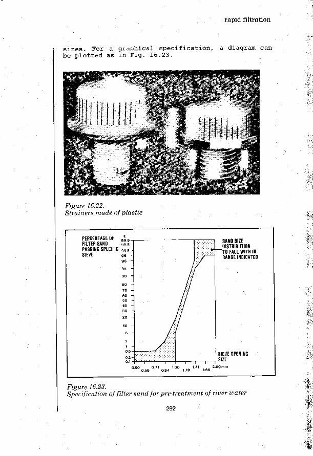
rapid filtration
sizes. For a graphical specification, a diagram canbe plotted as in Fig. 16.23.
Figure 16.22.Strainers made of plastic
PERCENTAGE OF * 9FILTER SAND 9s.e-\PASSING SPECIFIC 9 9 5 JSIEVE
SAND SIZEDISTRIBUTION
"TO FALL WITH INRANGE INDICATED
0 50 0.71 100 1.41 2.00 mm0.59 0 84 1.19 168
SIEVE OPENINGSIZE
Figure 16.23.Specification of filter sand for pre-treatment of river water
292

rapid filtration
16.6 Village-scale rapid filtration
Because of their complex design and construction, andthe need for expert operation, rapid filters are notvery well suited for application in village-scalewater treatment plants. This is especially true fortheir use as final filters in the treatment of turbidriver water. The bacteriological safety of thefiltered water then has to be secured by post-chlorination with all its associated difficulties. Itwould be better to use slow sand filters which give abacteriologically safe filtrate, but these may sufferfrom rapid clogging caused by the turbidity presentin the raw water.
Suspended matter can be removed from raw waterthrough various processes such as: storage,coagulation and flocculation, and sedimentation.However, only rapid filters are able to constantlyproduce a clear water with a turbidity of less than5 F.T.U. This will ensure the smooth operation of anyfollowing slow filters. There should be few ob-jections against such an application of rapidfilters. The use of rapid filtration for the removalof iron and manganese from groundwater also presentsfew problems as the health hazard of possible con-tamination of the treated water will be small.
Assuming a water use of 40 litres/person/day, therequired water filtration capacity for 10,000 peoplewould be 400 m3/day or 40 m3/hour for a 10-hour daylyoperating period. With a filtration rate of 5 m/hourthis calls for 8 m2 filterbed area which may beprovided in three circular filters of 2 m diametereach (one filter as reserve). The underdrain systemwould probably best be made of perforated laterals(see section 16.4), covered with graded layers ofgravel, broken stones or hard bricks chipped to thedesired size. When coarse sand is available it shouldbe graded using suitable sieves. Grading limits wouldbe 0.8 mm -1.2 mm for prefilters; 1.0 mm - 1.5 mmfor iron and manganese removing filters. For pre-filters the sand bed thickness should be taken at1.0 m and for iron and manganese removing filters at1.5 m. In the event that sand cannot be obtained,similar materials may be used, such as crushedstones, bricks, crystalline calcium-carbonate,dolomite, etc. These should be graded to a size about40 percent larger than the sizes mentioned above. Insome instances burned rice husks and crushed coconutshells have given acceptable results. Before thefilter is commissioned it should be back washed forabout half an hour to clean the filter material.
293

rapid filtration
The depth of supernatant, water may be fixed between1.5 and 2 m. The filter box will then have a totaldepth of 3.5-4 m.
The greatest difficulty encountered in village-scalerapid filtration is the backwashing process. It isuneconomical to use a wash-water pump. In the examplepresented earlier, a capacity of 100-200 m3/hourwould be needed, in duplicate to allow for mechanicalfailures. Compared with the plant capacity of 40 m3/hour, this is an enormous pump involving a con-siderable investment and high operating costs. Withan elevated washwater reservoir of 20 m3 volume, thepump capacity can be reduced to 10 m3/hour, but thecosts of the tank should be taken into account. Forvillages with low buildings, the pressure in thedistribution system generally does not need to bemore than 6 m. In these cases, a good solution willbe to use an elevated service reservoir for back-washing the filters. No separate pumps would beneeded.
INTAKE &RAW WATER PUMPING STATION
WASH WATERDISCHARGE
FILTER BOX
WASH WATER THROUGH
rT~| ... TO FURTHER
WEIRCHAMBER
TREATMENT
Figure 16.24.General layout of a rapid filtration plant
The layout of the rapid filtration plant as describedabove is shown in Fig. 16.24. The raw water entersthe filter through valve A and falls into the wash-water trough to disperse the flow energy. The branchpipes into which valves A are set, have a small dia-meter giving sufficient flow resistance (e.g. 0.5 mof head) to assure an even distribution of the rawwater over the individual filter units. The filteredwater is discharged through valve D and passes over aweir placed in the weir chamber. The top of the weiris set so high that the lowest raw water level in thefilter tank will be at least 0.2 m above the filterbed. Due to clogging the level of the supernatant
294

rapid filtration
water will rise until it reaches the water pressurelevel in the supply pipe; no more water will enterthe filter. The filter should then be cleaned byfeeding the wash water through valve C and dis-charging it through valve B. The dirty wash watershould be clarified by sedimentation after which itmay be discharged back into the river, some distancedownstream of the raw water intake.
16.7 Roughing filtration
Sometimes a more limited treatment than rapidfiltration using a sand bed, can be adequate fortreating the raw water. This can be obtained by usinggravel or plant fibres as filter material. In theupflow filter of Fig. 16.6 three layers would be usedhaving grain sizes of 10-15 mm; 7-10 mm, and 4-7 mm,from the bottom upward, and with simple underdrainsystem. This coarse ("roughing") filter will havelarge pores that are not liable to clog rapidly. Ahigh rate of filtration, up to 20 m/hour, may beused. The large pores also allow cleaning atrelatively low back-wash rates since no expansion ofthe filter bed is needed. The backwashing of roughingfilters takes a relatively long time, about 20-30minutes.
Another possibility is the use of horizontal filtersas shown in Fig. 16.25. These have a depth of 1-2 msubdivided into three zones, each about 5 m long andcomposed of gravel with sizes of 20-30 mm, 15-20 mmand 10-15 mm. The horizontal water flow rate computedover the full depth will be 0.5-1.0 m/hour.
INLET
CASCADEIMPERMEABLE BOTTOM OUTLET
Figure 16.25.Horizontal gravel filter
This represents a very low surface loading of thefilter of only 0.03-0.10 m/hour. A large area will berequired, but the advantage is that clogging of the
295

rapid filtration
filter will take place very slowly, so that cleaningwill be needed only after a period of years. Thiscleaning is carried out by excavating and washing thefilter material after which it is put back in place.
Coconut fibres have been used for filter material inan experimental filter unit similar to a sand filter.The filter bed is only 0.3-0.5 m thick and the depthof supernatant water about 1 m. The filter isoperated at rates of 0.5-1 m/hour which gives alength of filter run of several weeks. To clean thefilter it is first drained after which the coconutfibres are taken out and discarded. The filter isrepacked with new material that has previously beensoaked in water for 24 hours to remove as much or-ganic matter as possible. Coconut fibre filtersappear to be able to cope with considerable fluc-tuations in their loading while producing an effluentof almost constant quality. The experiments showed aremarkably constant behaviour of the coconut fibrefilters. The overall turbidity removal varied between60 and 80 percent.
296

Rapid filtration
Arboleda, J.METODOS SIMPLIFICADOS DE TRATAMIENTO DE AQUANuevos Metodos de Tratamiento de AquaCEPIS, Lima, August 1972 (Manual No. 14)
Arboleda, J.HYDRAULIC CONTROL SYSTEMS OF CONSTANT ANB DECLINING FLOWFILTRATIONIn: Journal Am. Water Works Assoc. Vol. 66(1974) No. 2, pp. 87-93
Baylis, J.R.VARIABLE RATE FILTRATIONIn: Pure Water, Vol. XI(1959) No. 5, pp. 86-114
Baylis, J.R.EXPERIENCE WITH HIGH-RATE FILTRATIONIn: Journal Am. Water Works Assoc. Vol. 42(1950) Mo. 7, pp. 687-694
Camp, T.R.WATER TREATMENTHandbook oi Applied Hydraulics (2nd Edition)McGraw-Hill Book Co., New York, 1962
Cleasby, J.L.FILTER RATE CONTROL WITHOUT RATE CONTROLLERSIn: Jounal Am. Water Works Assoc. Vol. 61(1969) No. 4, pp. 181-186
Cleasby, J.L.; Williamson, M.M.; Baumann, E.R.EFFECT OF FILTRATION RATE CHANGES ON QUALITYIn: Journal Am. WaLer Works Assoc. Vol. 55(1963) No. 7, pp. 869-875
Conley, W.K.EXPERIENCE WITH ANTHRACITE - SAND FILTERSIn: Journal Am. Water Works Assoc. Vol. 53(1961) No. 12,pp. 1473-1483
Fair, G.M.; Geyer, J.C.; Okun, D.A.WATER AND WASTEWATER ENGINEERINGVol. 2, Water Purification and Wastewater Treatment and Disposal,John Wiley & Sons, New York, 1968
Hudson, H.E.DECLINING RATE FILTRATIONIn: Journal Am. Water Works Assoc. Vol. 51(1959) pp. 1455-1461
297

Robeck, G.G.MODERN CONCEPTS IN WATER FILTRATIONPAHO Symposium on Modern Water Treatment Methods,Asuncion (Paraguay), 14 August, 1972CEPIS, Lima, 1972 (Manual No. 1A)
Shull, K.E.EXPERIENCES WITH MULTIPLE-BED FILTERSIn: Journal Am. Water Works Assoc, March 1965, pp. 230-314
298

disinfection
17. disinfection
17.1 Introduction
The single most important requirement of drinkingwater is that it should be free from any micro-organisms that could transmit disease or illness tothe consumer. Processes such as storage, sediment-ation, coagulation and flocculation, and rapidfiltration reduce to varying degrees the bacterialcontent of water. However, these processes cannotassure that the water they produce is bacteriol-ogically safe. Final disinfection will frequently beneeded. In cases where no other methods of treatmentare available, disinfection may be resorted to as asingle treatment against bacterial contamination ofdrinking water.
Disinfection of water provides for destruction or atleast complete inactivation of harmful micro-or-ganisms present in the water. It is carried out usingphysical or chemical means. The following factors in-fluence the disinfection of water:
1) The nature and number of the organisms to bedestroyed.
2) The type and concentration of the disinfectantused.
3) The temperature of the water to be disinfected;the higher the temperature the more rapid is thedisinfection.
4) The time of contact; the disinfection effect be-comes more complete when the disinfectant remainslonger in contact with the water.
5) The nature of water to be disinfected; if thewater contains particulate matter, especially ofa colloidal and organic nature, the disinfectionprocess generally is hampered.
6) The pH (acidity/alkalinity) of the water.7) Mixing; good mixing ensures proper dispersal of
the disinfectant throughout the water, and sopromotes the disinfection process.
17.2 Physical disinfection
The two principal physical disinfection methods areboiling of the water, and radiation with ultravioletrays.
299

disinfection
Boiling is a safe and time-honoured practice whichdestroys pathogenic micro-organisms such as viruses,bacteria, cercariae, cysts and ova. While it is ef-fective as a household treatment, it is not afeasible method for community water supplies.However, in emergency situations boiling of water maybe used as a temporary measure.
Ultraviolet light radiation is an effective dis-infection method for clear water but its effective-ness is significantly reduced when the water isturbid or contains constituents such as nitrate,sulphate and ferrous iron. This disinfection methoddoes not produce any residual that would protect thewater against new contamination, and that could servefor control and monitoring purposes. Ultravioletlight for disinfection has been used in severaldeveloped countries but is rarely applied in develop-ing countries.
17.3 Chemical disinfectants
A good chemical disinfectant should possess thefollowing important characteristics:
Quick and effective in killing pathogenic micro-organisms present in the water;Readily soluble in water in concentrations re-quired for the disinfection, and capable of pro-viding a residual;Not imparting taste, odour or colour to water;Not toxic to human and animal life;Easy to detect and measure in water;Easy to handle, transport, apply and control;Readily available at moderate cost.
The chemicals that have been successfully used fordisinfection are: chlorine, chlorine compounds andiodine dosed in suitable form; ozone and otheroxidants like potassium permanganate and hydrogenperoxide. Each one of these has its advantages andlimitations.
Chlorine and chlorine compounds: Their ability todestroy pathogens fairly quickly, and their wideavailability make them well suited for disinfection.Their cost is moderate and they are, for this reason,widely used as disinfectants throughout the world.
Iodine: In spite of its attractive properties as adisinfectant, iodine has serious limitations. Highdoses (10-15 mg/1) are required to achieve satis-
300

disinfection
factory disinfection. It is not effective when thewater to be disinfected is coloured or turbid. Thehigh volatility of iodine in aqueous solution is alsoa factor against its use except in emergency situ-ations.
Potassium Permanganate: This is a powerful oxidisingagent, and has been found to be effective againstcholera vibrio but not for other pathogens. It leavesstains in the container and hence it is not a verysatisfactory disinfectant for community water sup-plies.
Ozone: Ozone is increasingly used for disinfection ofdrinking water supplies in industrialized countries,as it is effective in eliminating compounds that giveobjectionable taste or colour to water. Like ultra-violet rays, ozone normally leaves no measurableresidual which could serve for monitoring theprocess. The absence of a residual also means thatthere is no protection against new contamination ofthe water after its disinfection. The high in-stallation and operation costs and the need forcontinuous supply of power do not make the use ofozone a recommended practice in developing countries.
17.4 Chlorination
Water disinfection by chlorination, first introducedin the early 20th century, was perhaps the most im-portant technological event in the history of watertreatment. The chlorination of water supplies indeveloping countries is extremely important. Poorsanitation resulting in the faecal pollution of watersources frequently poses the greatest threat topublic health. Effective chlorination of watersupplies has in many cases achieved a substantialreduction in those enteric diseases that areprimarily water-related. Recent studies, still inprogress, have raised the possibility that organiccompounds formed ("halogenated") when chlorine isadded to water, might cause certain forms of cancerin man. Due to the number of variables involved nodefinite evidence is available so far. On the otherhand, the disinfecting properties of chlorine arewell established and, to date, should outweigh thesuggested possible side effects when it is used tosafeguard public health.
Chlorine is a greenish yellow toxic gas found innature only in the combined state, chiefly with
301

disinfection
sodium as the common salt. It has a characteristicpenetrating and irritating odour, is heavier than airand can be compressed to form a clear amber-colouredliquid. Liquid chlorine is heavier than water. Itvapourises under normal atmospheric temperature andpressure. Commercially, chlorine is manufactured bythe electrolysis of brine with caustic soda and hy-drogen as by-products. As a dry gas, chlorine is non-corrosive but in the presence of moisture it becomeshighly corrosive to all metals except silver andlead. Chlorine is slightly soluble in water, approx-imately 1 percent by weight at 10°C.
Chlorinated Lime ("Bleaching Powder"): Before theadvent of liquid chlorine, chlorination was mostlyaccomplished by the use of chlorinated lime. It is aloose combination of slaked lime and chlorine gas,with the approximate composition CaCl .Ca(OH)2-
H2°
+
Ca(OCl)? .2Ca(OB.)?. When added to water, it decomposesto give hypochlorous acid, HOC1. When fresh, chlorin-ated lime has a chlorine content of 33 to 37 percent. Chlorinated lime is unstable; exposure to air,light and moisture makes the chlorine content fallrapidly. The compound should be stored in a dark,cool and dry place, in closed, corrosion-resistantcontainers.
High-Test Hypochlorites*: These are not only twice asstrong as chlorinated lime (60 to 70 per centavailable chlorine content) but retain their originalstrength for more than a year under normal storageconditions. They may be obtained in packages of 2-3kg, and in cans of up to 45 kg; also available ingranular or tablet form.
Sodium Hypochlorite: As a solution, sodium hypo-chlorite (NaOCl) usually contains 12 to 15 per centavailable chlorine in the commercial product. House-hold bleach solutions of sodium hypochlorite usuallycontain only 3 to 5 per cent available chlorine.
It is the characteristics of chlorine and itscompounds that have dictated the methods of handlingand application in water disinfection practice.
Chlorination Practice; Chlorination practices may begrouped under two categories depending upon thedesired level of residual chlorine and the point ofapplication.
Trade names include: 'HTH', 'Perchlorin', and 'Pittchlor'
302
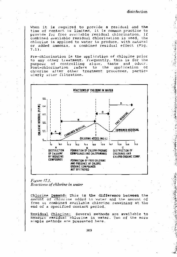
disinfection
When it is required to provide a residual and thetime of contact is limited, it is common practice toprovide for free available residual chlorination. Ifcombined available residual chlorination is used, thechlorine is applied to water to produce, with naturalor added ammonia, a combined residual effect (Fig.7.1).
Pre-chlorination is the application of chlorine priorto any other treatment. Frequently, this is for thepurpose of controlling algae, taste and odour.Post-chlorination refers to the application ofchlorine after other treatment processes, partic-ularly after filtration.
REACTIONS OF CHLORINE IN WATER
I - -»
!..••••' CHLORINE ADDED (MG/LI
•-.RESIDUAL
KM
DESTRUCTIONOF CHLORINEBY REDUCINGCOMPOUNDS
2 10.3 10.4 las 10.6B
FORMATION OF CHLORO ORGANICCOMPOUNDS AND CHLORAMINES
DFORMATION OF FREE CHLORINEAND PRESENCE OF CHLORO.ORGANIC COMPOUNDSNOT DESTROYED
la.DESTRUCTION OFCHLORINES ANDCHLORO-ORGANIC COMP.
Figure 17.1.Reactions of chlorine in water
chlorine Demand: This is the difference between theamount of chlorine added to water and the amount offree or combined available chlorine remaining at theend of a specified contact period.
Residual Chlorine: Several methods are available tomeasure residual chlorine in water. Two of the moresimple methods are presented here.
303

disinfection
a) Diethyl-para-Phenylenediamine Method (DPD).*
Free available chlorine reacts instantly withN-diethyl-para-phenylene-diamine producing a redcolouration providing iodine is absent. Standardsolutions of DPD potassium permanganate are usedto produce colours of various intensities.Colour produced by the addition of DPD ismeasured by a colorimetric method to indicate theconcentration of residual chlorine. The colourproduced by this method is more stable than thatin Orthotolidine Method.
b) Orthotolidine Method
Orthotolidine, an aromatic compound, is oxidizedin an acid solution by chlorine, chloramines andother oxidants to produce a yellow colouredcomplex the intensity of which is directlyproportional to the amount of oxidants present.The method is suitable for the routine deter-mination of chlorine residuals not exceeding 10mg/1. The presence of natural colour, turbidityand nitrate interferes with the colour develop-ment. Ortholodine has been demonstrated to causecancer and is being withdrawn from production inseveral countries.
17.5 Chlorination technology for rural water supply
Groundwater obtained from shallow dug wells continesto be the major source of supply for millions ofpeople in small communities. A number of surveys haverevealed that dug wells become quite frequently con-taminated. Surface water sources such as villageponds, canals and rivers are usually also polluted.While it is neither feasible nor always necessary toestablish complete treatment of the water from thesesources, proper disinfection should at least be pro-vided in order to protect public health.
Technically, disinfection by chlorination can give asatisfactory solution for rural and small communitywater supplies. Disinfection by gaseous chlorine isgenerally not feasible for small water supplies, dueto the problems of applying small quantities of gasaccurately and on a continuous basis. The choice islikely to fall on chlorine compounds.
Surveillance of Drinking Water Quality,WHO Monograph Series 63 (1976)
304

disinfection
Bleaching Powder: Chlorinated lime or bleachingpowder (see Annex 4 for details) is a readilyavailable and cheap chlorine compound. This chemicalis easy to transport and not dangerous to handle ifit is supplied in a suitable container. It is a free-flowing white or yellowish powder containing about 33to 37 percent available chlorine. It is unstable andwill lose chlorine during storage. In the presence ofmoisture, bleaching powder becomes corrosive; it isnecessary to use corrosion-resistant containers madeof wood, ceramic or plastics. These should be storedin a dark, cool and dry place. In order to minimizethe loss of chlorine a maximum concentration of 5percent is recommended for a bleaching powdersolution.
Disinfection of Open Dug Wells: As open dug wellswill continue to be used in considerable numbers assources of drinking water in rural and small com-munities, it is desirable to employ simple methodsfor disinfecting the water of these wells.
Pot Chlorination: An earthen pot of 7 to 10 litrescapacity with 6 to 8 mm diameter holes at the bottomis half filled with pebbles and pea gravel of 20-40mm size. Bleaching powder and sand (in a 1 to 2mixture) is placed on top of the pea gravel and thepot is further filled with pebbles up to the neck(Fig. 17.2). The pot is then lowered into the wellwith its mouth open.
/yfi'1'-1-1'
7 HOLES 10.6 CM DIA) T^
\
A - MOUTH OPEN
•^?" ::^\] : •;. --• . • J r r _ ^ BL. POWDER
\-r ''rr':'~'.i:|
^ ^ ^ E B B L E S
Figure 17.2,Chlorination pot with holes at the bottom
305

disinfection
For a well from which water is taken at a rate of1,000-1,200 litres/day, a pot containing about 1.5 kgof bleaching powder should provide adequate chlori-nation for about one week.
Double pot System: When a single chlorination pot isused in a small household well, it may be found togive too high a chlorine content to the water ("over-chlorination"). In such situations, a unit consistingof two cylindrical pots one inside the other has beenfound to work well (Fig. 17.3). The inner pot isfilled with a moistened mixture of 1 kg of bleachingpowder with 2 kg of coarse sand to a little below thelevel of the hole and is then placed inside the outerpot. The mouth of the outer pot is tied with a poly-thene sheet and the unit lowered into the well withthe help of a rope. Such a unit has been found towork effectively for 2 - 3 weeks in household wellsof 4,500 litres capacity from which water is with-drawn at a rate of 400-450 litres/day.
<
A
PLASTIC OR ,EARTHEN JAR
AVipIWim
t — —
mmm
. — • • • -
" • . - ' • • .
~ ~
— ~ _
•
BLEACHINGPOWDER &SAND
Figure 17.3.Double pot chlorinator
After: Rajagopalan & Shiftman
Drip-Type Chlorinatort An alternative device fordisinfecting wells is a drip-feed chlorinator (Fig.17.4). Clogging of the drip outlet may take place due
306

disinfection
to calcium carbonate deposits that are formed whenthe bleaching powder solution comes into contact withatmospheric carbon dioxide. A special drip outletsimilar to the one used in medical transfusions canbe inserted in the outlet tube just before the stop-cock. The outlet tube is extended right into thewell and dipped into the water. The container may beplaced on the parapet of the well.
SIEVE -
COVER COVER
FLOAT
RUBBERSTOPPER
\
PLASTIC-CAP
RUBBERf" STOPPER
J_^GLASS-TEE
-RUBBER-HOSE
PLASTIC JERRYCAN - I
Figure 17.4.Equipment for feeding chlorine solution
Solution feed devices using a constant head have beensuccessfully operated in many places. Fig. 17.5 showsa "Floating Bowl" device.
Both the regulating tube and the delivery tube musthave a tight sliding fit in the floating bowl. Thetubes are adjusted to such a level that the solutionenters into the bowl and flows down the delivery tubeat the desired feeding rate. Another feeding rate canbe set by varying the levels of the regulating anddelivery tubes.
307

disinfection
CONTAINER-
W.L.
TIGHT SLIDINGFIT
DELIVERY TUBE
FLOATING BOWL
REGULATING TUBEPLASTIC. RUBBER OR GLASS
WATERTIGHT JOINT
DISCHARGE OVER INLETOF CLEAR WATER TANK
Figure 17.5.Constant-head solution feeder for chlorine compounds
Proportioning Devices for Pumped Supplies: When waterfrom the source is pumped to an elevated servicereservoir and supplied by gravity to the distributionsystem, a bleaching powder solution may be dosed asin Fig. 17.6. From the bleaching powder solutionreservoir a direct connection is made to the suctionline of the pump. One percent bleaching powdersolution prepared earlier and allowed to settle toremove impurities, is filled in the solution con-tainer. It should provide a supply sufficient formore than one day. Air entry at the suction side ofthe pump must be prevented, it is necessary to closethe solution feed line when the pump is stopped.
308

disinfection
CONSTANT HEADDOSING DEVICE
CHEMICALSOLUTION CONNECTION TO
MAKE-UPTANK
Figure 17.6.Chlorination arrangement for pumped supplies
17.6 Disinfection using chlorine gas
The form in which the disinfectant should be used isgoverned by several factors such as the quantity ofwater to be treated, cost and availablity ofchemicals, the equipment needed for its application,and the skill required for operation and control.When the quantity of water to be treated is more than500,000 litres per day, chlorine gas has been foundto be the most economical. For smaller supplies,cylinder-mounted chlorine gas controllers are avail-able but they are not capable of accurately feedingvery small quantities of gas. Two distinct methodsare available for controlled application of chlorinegas:
1) Solution Feed: The gas is first dissolved in asmall volume of water and the resulting chlorinesolution is fed to the main stream of the waterto be disinfected. Dissolving the gas in a smallvolume of water promotes complete and rapid dis-persal at the point of application.
309

disinfection
2) Direct Feed: Here the gas is fed directly to thepoint of application. A special type of diffuseror perforated tubing (of silver or plastic) isneeded for the proper diffusion of the gas.Therefore, this method is not recommended forsmall and rural water supplies.
The equipment used for the controlled feed ofchlorine gas may be grouped under pressure-feed andvacuum-feed types. The pressure type consists of agas filter, stop valve, pressure-reducing valve, andregulating valve or orifice tube with a manometer andmoisture seal. Regardless of the pressure variationin the chlorine cylinder, a constant pressure ismaintained across the orifice by means of the pres-sure-reducing valve. The differential pressure dropacross the orifice is measured and is an indicationof the rate of gas flow. The solution feed apparatusincludes some means of introducing the metered gasinto the small stream of water which then carries thechlorine to the point of application (Fig. 17.7).
GRAVITY TYPESOLUTIONIZER
CONTROL PANEL
WATERSUPPLY
CHLORINE CYLINDERS
I Ii
DISTRIBUTOR AT POINTOF APPLICATION ELEVATION
Figure 17.7.Chlorine gas apparatus with gravity-type solutionizer * ; • ' ;
310

disinfection
17.7 Disinfection of new tanks, pipes and wells
New Tanks: All new tanks and reservoirs should bedisinfected before they are brought into service.Similarly, tanks that have been out of service forrepair or cleaning should also be disinfected beforethey are put back in service. Prior to disinfection,wells and the bottoms of tanks should be cleaned bysweeping and scrubbing to remove all dirt and loosematerial.
One of the disinfection methods used for a new tankis to fill it to the overflow level with clean waterto which enough chlorine added to produce a concen-tration of 50 mg/1. The chlorine solution is in-troduced into the water as early as possible duringthe filling operation in order to ensure thoroughmixing and contact with all surfaces to be dis-infected. After the tank is filled, it is allowed tostand, preferably for 24 hours but not for less than6 hours. The water should then be drained out andthe tank refilled for regular supply.
A second method which is quite satisfactory andpractical under rural conditions, is the directapplication of a strong solution (200 mg/1) to theinner surfaces of the tank. The surface should remainin contact with the strong solution for at least 30minutes before the tank is filled with water.
A third method, which should be used only when othermethods cannot be used, does not expose the uppersurfaces of walls to a strong chlorine solution.Water containing 50 mg/1 chlorine is fed in the tankto such a volume that when the tank is later com-pletely filled up, the resultant chlorine concen-tration will be about 2 mg/1. The water containing 50mg/1 chlorine is held in the tank for 24 hours beforethe tank is filled up with water. The tank can thenbe put into service without draining the water usedfor the disinfection providing the final residual isnot too high.
New Mains and Pipes: Distribution mains and pipe-lines are likely to be contaminated during layingirrespective of the precautions. Therefore, they mustbe disinfected before they are brought into use.Distribution systems need to be disinfected whencontaminated in the event of main breaks or floods.
Every pipeline should be cleaned by swabbing andflushing in order to remove all foreign matter.
311

disinfection
Immediately before use, the packing and jointingmaterial should be cleaned and disinfected byimmersion in a 50 mg/1 chlorine solution for at least30 minutes.
A practical means of applying chlorine solution fordisinfection of rural water supply systems is toflush out each section to be disinfected. The intakevalve is shut off and the section allowed to draindry. Then the discharge hydrant or valve is shut offand the section isolated from the rest of the system.The disinfecting solution is fed through a funnel ora hose into a hydrant or opening made specially forthis purpose at the highest part of the pipeline.Since air valves are usually placed at these highpoints removing an air valve often is a convenientway to provide a point of entry.
The solution is slowly poured in until the section iscompletely filled. Care should be taken to ensurethat air trapped in the pipe is allowed to escape. Ifthere is no air valve or other orifice, one or moreservice connections should be disconnected to providefor the release of air.
17.8 Disinfection of water supply in emergency situations
Long-term measures for the provision of safe watersupply aided by personal hygiene and health educationwill greatly help protect and promote public health.However, natural disasters like cyclones, earthguakesand floods do occur and sometimes result in completedisruption of water supplies.
These situations call for measures to provide forsupply of safe water on a.n emergency basis. Whilethere is no single measure which is the panacea forall situations, the following may be useful to ensurea safe water supply depending upon local conditionsand available resources.
When the regular water supply system is affected dueto a disaster, top priority should be given by put-ting the system back into operation. Simultaneousaction to tide over the situation should include athorough search for all possible sources of waterwithin a reasonable distance of the affected area.Water from private water supply systems and othersources may be transported by tankers to the pointsof consumption.
312

disinfection
After floods, when the water supply distributionsystem remains intact, the pressure in the pipe linesShould be raised so as to prevent polluted water fromentering the pipes. As an additional measure thechlorination of the water at the treatment plants maybe temporarily raised to a higher rate. High-dosagechlorination is recommended only in extreme circum-stances or when cleaning out new pipes.
Chlorine Tablets and Bleach Solutions: Chlorine con-taining compounds that are dosed in solution ortablet form, are readily available in manycountries*.
They are quite good for disinfecting small quantitiesof water, but are costly. After addition of thechemical in the prescribed quantity, the water isstirred and allowed to stand for 30 minutes beforeconsumption. If the water is turbid, it may benecessary to increase the dose of the chemical.
* Trade names include: 'Halazone', 'Chlor-dechlor','Hydrochlorzone', 'Hadex'.
313

314

Disinfection
DISINFECTION FOR SMALL COMMUNITY WATER SUPPLIESNational Environmental Health Engineering ResearchInstitute, Nagpur (India)
Rajagopalan, S.; Shiffman, M.A.GUIDE ON SIMPLE SANITARY MEASURES FOR THE CONTROL OF ENTERICDISEASESWorld Health Organisation, Geneva, 1974
Rivas Mijares, G.LA DISINFECCI6N DEL AQUA EN AREAS TROPICALESI t a l g r a f i c a , S . R . L . , C a r a c a s , 1 9 7 0
SURVEILLANCE OF DRINKING WATER QUALITYWorld Health Organisation, Geneva, 1976, 135 p.
315

316
water transmission
18. water transmission
18.1 introduction
Water transmission frequently forms part of a smallcommunity water supply system; in that they do notdiffer from large schemes. The water needs to betransported from the source to the treatment plant,if there is one, and onward to the area of dis-tribution. Depending on the topography and localconditions, the water may be conveyed throughfree-flow conduits (Fig. 18.1), pressure conduits(Fig. 18.2) or a combination of both (Fig. 18.3). Thetransmission of water will be either under gravity orby pumping.
Free-flow conduits must be laid under a uniform slopein order to follow closely the hydraulic grade line*.Pressure pipelines can be laid up- and downhill asneeded, as long as they remain a sufficient distancebelow the hydraulic grade line.
For community water supply purposes, pipelines aremost common means of water transmission but canals,aqueducts and tunnels are also used. Whether for freeflow or under pressure, water transmission conduitsgenerally require a considerable capital investment.A careful consideratin of all technical options andtheir costs is, therefore, necessary when selectingthe best solution in a particular case.
18.2 Types of water conduits
Canals .
Canals generally have a trapezoidal corss section butthe rectangular form is more economical when thecanal traverses solid rock. Flow conditions are moreor less uniform when a channel has the same size,slope and surface lining throughout i ts length.
The slope of the hydraulic grade line is the "hydraulicgradient". For open channels, i t is the slope of the watersurface. For closed conduits under pressure (e.g. pipe-lines), the hydraulic grade line slopes according to thehead loss per unit length of pipe.
317

water transmission
HYDRAULIC GRADELINE
WATER SOURCE
- WIN. W.L.MAX. W.L.
7S.7.Free-flow conduit
STATIC HEAD
DRAIN VALVE
-BREAK-PRESSURE TANK
STATIC HEAD
Figure 18.2.Pressure pipeline
HYDRAULIC GRADE LINE
AQUEDUCT
-FREE FLOW CONDUIT .PRESSURE,
Figure 18.3.Combined free-flow /pressure conduit
318

water transmission
Open canals have limited application in water supplypractice in view of the danger that the water willget contaminated. Open canals are never appropriatefor the conveyance of treated water but they may beused for transmission of raw water.
Aqueducts and Tunnels
Aqueducts and tunnels should be of such a size thatthey flow about three quarters full at the designflow rate. Tunnels for free-flow water transmissionfrequently are horse-shoe shaped. Such tunnels areconstructed to shorten the overall length of a watertransmission route, and to circumvent the need forany aqueducts and conduits traversing uneven terrain.To reduce head losses and infiltration seepage,tunnels are usually lined. However, when constructedin stable rock they require no lining.
The velocity of flow in these aueducts and tunnelsranges between 0.3-0.9 m/sec for unlined conduits,and up to 2 m/sec for lined conduits.
Free-flow Pipelines
In free-flow pipelines, there being no pressure,simple materials may be used. Glazed clay pipes,asbestos cement and concrete should be adequate.These pipelines must closely follow the hydraulicgrade line.
Pressure Pipelines
Obviously, the routing of pressure pipelines is muchless governed by the topography of the area to betraversed, than is the case with canals, aqueductsand free-flow pipelines. A pressure pipeline may runup- and downhill; there is considerable freedom inselecting the pipeline alignment. A routing alongsideroads or public ways is often preferred to facilitateinspection (for detection of any leakage, unoperativevalves, damage, etc.) and to provide ready access formaintenance and repair.
319

water transmission
iRC PhotoFigure 18.4.Pressure pipeline under construction (Kenya)
18.3 Design considerations
Design Flow
The water demand in a distribution area willfluctuate considerably during a day. Usually aservice reservoir is provided to accumulate and evenout the water demand fluctuation. The servicereservoir is supplied from the transmission main, andis located at a suitable position to be able tosupply the distribution system (Fig. 18.5). Thetransmission main is normally designed for thecarrying capacity that is required to supply thewater demand on the maximum day at a constant-ratebasis. All hourly variations in the water demandduring the day of maximum consumption, are thenassumed to be leveled out by the service reservoir.
The number of hours the transmission main operatesper day is another important factor. For a watersupply with diesel engine or electric motor-driven
320

water transmission
pumps, the daily pumping often is limited to 16 orless hours. In such a case, the design flow rate forthe transmission main needs to be adjusted accord-ingly.
WATERSOURCE
O— TRANSMISSION MAIN
AVERAGE FLOWON MAXIMUM DAY
RESERVOIR
©PEAK HOURFLOW
DISTRIBUTION SYSTEM
WATERSOURCEf~\ TRANSMISSION MAIN\J —*•
AVERAGE FLOWON MAXIMUM DAY
_ALTtor
ERtATI
IATON?
VE RESERVOIR_
Figure 18.5.Transmission main and service reservoir (schematic)
Design Pressure
The design pressure, of course, is only of relevancefor pressure pipelines. Such pipelines generallyfollow the topography of the ground quite closely.The hydraulic grade line indicates the water pressurein the pipeline under operating conditions. Thehydraulic grade line should lie above the pipeline,over its entire length, and for all rates of flow; infact, nowhere should the operating head of water inthe pipeline be less than 4 m (Fig. 18.6).
The pipe material must be selected to withstand thehighest pressure that can occur in the pipeline. Themaximum pressure frequently does not occur underoperating conditions but it is the static pressurewhen the pipeline is shut. In order to limit themaximum pressure in a pipeline and, thus, the cost ofthe pipes, it can be divided into sections separatedby a break-pressure tank. The function of such a
321

water transmission
break-pressure tank is to limit the static pressureby providing an open water surface at certain placesalong the pipeline. The flow from the upstreamsection can be throttled when necessary.
RESERVOIR
ELEV
ATIO
N
MINIMUM 4 M \
o U Is
STATIC PRESSURE
DISTANCE
MAXIMUMPRESSUREIN PIPELINE
\
~ —.
Iz4 128
FRICTIONHEAD
'—^~
TO DISTRIBUTIONSYSTEM
132
Figure 18.6.Design pressure determination for pipeline
Critical pressures may also develop as a result ofpressure surge or water hammer in the pipeline. Theseare caused by the instant or too rapid closure ofvalves, or by sudden pump starts or stops. Theresulting pressure surges create over- and under-pressures that may damage the pipeline.
18.4 Hydraulic design
For a given design flow rate (Q), the velocity offlow (v) and consequently the required size of thewater transmission conduit may be computed using thefollowing formulae:
Open Conduits
The Manning (or strickler) formula is widely used inthe hydraulic design of open conduits with free flowconditions. The formula reads:
V =
322

water transmission
v = (average) velocity of flow in waterconduit (m/sec.)
C = Coefficient of roughness of conduitwalls and bottom (mm)
R = Hydraulic radius (m) .I = Hydraulic gradient (m/m )
For design purposes, Table 18.1 provides indicativevalues of the coefficient of roughness for varioustypes of linings in clean, straight channels*.
Table 18.1.Indicative, values for roughness of various types of linings
Type of Lining Coefficient of roughness (K)
Planed timber, joints flush 80Sawn lumber, joints uneven 70Concrete, trowel finished 80Masonry ;
Neat cement plaster 70. Brickwork; good finish 65. Brickwork; rough 60Excavated
Earth 45Gravel 40Rock cut, smooth 30Rock cut, jagged ; 25
Pipelines
The most accurate formula for computing the head lossof water flowing through a pipeline is the Colebrook-White ('universal') formula:
H = &X_ . O? .L = l.L
Where;
H = head loss (m)L = length of pipeline (m)X = friction coefficientD = internal pipe diameter (m)Q = flow rate (m3/s)g = gravitational factor tapprox. 9.8 m/sec2)I = hydraulic gradient (m/m or m/km)
* In practice, a channel does not have a single C-value.Frequently it varies for different sections of the channel,and often there are also seasonal variations.
323

water transmission
The factor A is the friction coefficient which is afunction of the pipe wall roughness (k), the(kinematic) viscosity of water ( v~), the flowvelocity (v), and the internal pipe diameter (D). TheColebrook-White formula is too complicated fornumerical calculations. Tables and monograms havebeen prepared for different values of pipe wallroughness.
Table 18.2 is an example. It gives the head loss forwater flowing through smooth-walled pipes (wallroughness k = 0.1 mm). Figure 18.7 is an example of ahead loss determination graph for pipes with wallroughness k = 0.2 mm.
Table 18.2.Head loss in m/km
temperature 20° C
for smooth pipes (wall roughness k = 0.1 mm)
Q in
0.
0.
0.
0.
0.
0.
1.
1.
2
3
5
7
10
15
20
30
50
70
100
in nun
i
15
2
3
5
7
0zj
15 20
44.1 10.5
94.1 22.0
162 37.6
80.5
214
25
3.51
7.28
12.3
26.0
68. 1
129
30
1.45
2.97
4.99
10.5
27.0
51.0
101
50
0.85
2.13
3.94
7.60
16.2
28.0
60.9
164
70
0.76
1 .44
3.02
5.15
1 1 .0
29.1
55.7
111
100
0.88
1.86
4,81
9.09
17.9
39.2
68.6
152
120
0.76
1 .94
3.64
7.13
15.5
26.9
59.3
161
150
0.65
1.20
2.33
5.01
8.66
18.9
51.0
98.7
199
200
0.56
1 .19
2.04
4.39
11.7
22.5
45.1
324

water transmission
Example 1
What is the head loss in a pipeline 1200 m long with a diameterof 50 mm, for a flow ol" 3 m3/hour?A flow of 3 m3/hoiir is equal to 0.83 1/sec. Using the table:Q = 0.7 1/sec, i = 3.94 m/km, thus
I =/(0.83)f (3.94) = 5.54 m/km
1(0.7 V
Q = 1.0 1/sec, i = 7.60
I =/(0.83)f (7.60) - 5.24 m/km
1(1.0 VThe average is (5.54 + 5.24) : 2 = 5.4 m/km, so that over alength of 1.2 km the head loss will be(1.2)x(5.4) = 6.5 m head of water.
Figure 18.7.Head loss determination graph
Example 2
What will be the flow in a 50 mm diameter pipe to transportwater from a small dam to a tank at 600 m distance. Thedifference in elevation between the two points is 5.40 m.
325

water transmission
The hydraulic gradient thus is 5.40/0.6 = 9 m/km.According to the table, the hydraulic gradient for a flow of 1litre/sec is 7.60 m/km. Thus the actual flow will be:Q = 1.0 i/~ 9 =1.1 litres/sec, or approximately
What will be the flow in example 2 when a 55 nun diameter pipeis chosen?
Q = (1.1) n 55 )U 50 )
.51.4 litres/sec.
Indicative values of pipe wall roughness (k) aregiven below:
Pipe Material
Asbestos Cement (A.C.)Polyvinylchloride (P.V.C.)Polyethylene (P.E.)Ductile Iron (D.I.) (unlined)Ductile Iron (D.I.) (cement-lined)Steel (lined)Galvanised Steel (G.S.)
Pipe WallRoughness*
k =k =k =k =k =k =k =
0.10.10.050.250.1250.1250.15
mmmmmmmmmmmmmm
Figure 18.8.Water transmission main river crossing
* After several years of service, and allowing for the effectof the joints and some misalignment of the. pipes.
326
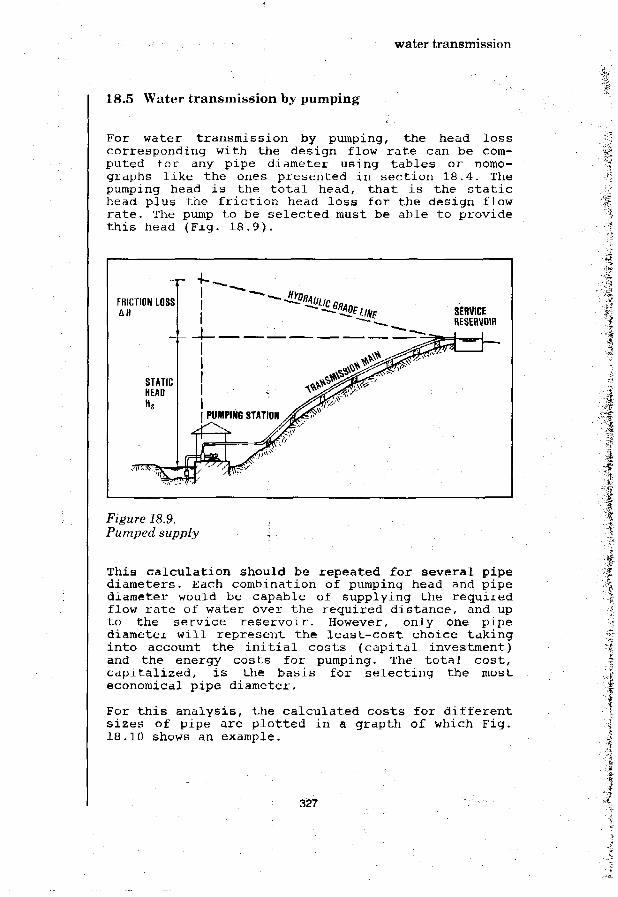
water transmission
18.5 Water transmission by pumping
For water transmission by pumping, the head losscorresponding with the design flow rate can be com-puted for any pipe diameter using tables or nomo-graphs like the ones presented in section 18.4. Thepumping head is the total head, that is the statichead plus the friction head loss for the design flowrate. The pump to be selected must be able to providethis head (Fig. 18.9).
FRICTION LOSSAH SERVICE
RESERVOIR
Figure 18.9.Pumped supply
This calculation should be repeated for several pipediameters. Each combination of pumping head and pipediameter would be capable of supplying the requiredflow rate of water over the required distance, and upto the service reservoir. However, only one pipediameter will represent the least-cost choice takinginto account the initial costs (capital investment)and the energy costs for pumping. The total cost,capitalized, is the basis for selecting the mosteconomical pipe diameter.
For this analysis, the calculated costs for differentsizes of pipe are plotted in a grapth of which Fig.18.10 shows an example.
327

water transmission
tFC
OS1
TVAL
UE (
PRES
ET
\1
\
nINVESTMENTCOSTS
>v MINIMUM TOTAL COSTS>. ^ » -
ENERGY ^ - - ^ _COSTS
MAINTENANCE COSTS
1• PIPE DIAMETER *~
MOST ECONOMICALPIPE DIAMETER
• ' !> • : .
f
Figure 18.10.Determination of most economical pipe diameter
The most economical pipe diameter will tend to belarge:
when energy costs are high,costs per linear metre of pipe low, andcapital interest rates low.
For a tentative estimate of the most economical pipediameter, this diameter may be computed using avelocity of flow of 0.75 m/sec.
Selection of Pumps
various types of pumps have been mentioned in chapter10: centrifugal, axial-flow, mixed-flow and recipro-cating pumps. The choice of pump will generallydepend on its duty in terms of pumping head andcapacity.
Pumps with rotating parts have either a horizontal ora vertical axis. The choice between these is gene-rally based on the pump-motor drive arrangement andthe site conditions. At a site subject to flooding,the motor and any other electrical equipment must beplaced above flood level.
. * • :
,f328

water transmission
In water transmission for community water supplypurposes, it is not unusual that a substantial headis required. This implies that the pumps selectedfrequently are of the centrifugal (radial-flow) type.
Many waterworks pumps are designed to run (almost)continuously for long periods of time. A high effi-ciency of a few percent may represent a considerablesaving in the running costs over a long period oftime. However for rural water supplies, an even moreimportant requirement is that any pumps installedshould be reliable.
The pumping head/capacity characteristic of a pump,and its efficiency are indicated in graphs that aresupplied by the manufacturers of the pump. Fig. 18.11shows an example.
\
TOTA
L H
^ * ^ ^ I CAPACITY AT^ " " s l MAX. EFFICIENCY
POINT OF ^ V .MAX. EFFICIENCY 1 N .
\j \
/ ^ - r 1 ^ S U W V ' i r o M ^ l \ POWER CONSUMPTION^ 5 ^ f O ^ W C U I * | AT MAX. EFFICIENCY
CAPACITY Q (mVs)] «-
tCJ
UJ
U J
ts
PTIO
NfE
RCON
SUN
Figure 18.11.Typical pump characteristic curve
In practice it is seldom possible to have the pumppermanently run at its maximum efficiency because theoperating point of the pump is determined by both thepumping head and the capacity, and these can varyconsiderably. The efficiency of small-capacity pumpsoperating under the conditions of rural areas indeveloping countries frequently is quite low. Atentative estimate would be in the range of as low as30% for a 0.4 kilowatt pump, to 60% for a 4 kilowattpump.
329

water transmission
Power Requirements
The power required for driving a pumping unit can becomputed with the following formula:
N = <o.g.Q(Hs + i.L)e
Where:
N = Power required for pumping (Watts)Q = Pumping rage (1/sec)p = Specific weight of water (kg/dm3)e = Pumping efficiency (percent)Hs = Static head (m)i = Head loss under operating conditions.
(m of head/m of pipe)L = Length of pipe (m)
For g = 9.81 m/sec2; $> = 1 g/cm3, and e for small-capacity pumps estimated at 50 percent, the aboveformula can be simplified to:
N = 20 Q(Hs + i.L) Watts
For a water supply, pumping is required at the rate of 110,000li tres per 12 hours. The static head is 26 m, and the length ofthe pipeline is 450 m. Determine the diameter of the pipelineand the power requirement for pumping.
Q = 110,000/12 x 3,600 = 2.55 1/sec.
Table 18.2 indicates, that a 50 mm-diameter pipeline might beselected with a head loss of 43 m/km for the 2.55 1/sec designflow rate. The power requirement would be:
N = 20 x 2.55(26 + 0.043 x 450) = 2.310 Watts = 2.3 Kilowatt
Pump Installtions
Pumping stations may be of the wet-pit type (withsubmersible pumps or pumps driven by motors placedabove the pump in the sump), or of the dry-pit type(pump installed in a pump room). The wet-pit type hasthe pumps immerged in the water, and the dry-pit typehas the pump in a dry room separated from the waterby a wall.
For ease of installation, horizontal pumps are some-times situated above ground level. In that case thepump must be of the self-priming type which is gene-
330

water transmission
rally a not so reliable arrangement for rural watersupply installations.
Examples of various types of pump installations areshown in Figs. 18.12 and 18.13.
BRICKWORK
REINFORCEDCONCRETE
SUCTIONPIPE
FOOT VALVETRAINER
\\W\\\\\'CROSS-SECTION
OUTLET
V///////71
Y///////APLAN
Figure 18.12.Pumping station with horizontal pumps (self-priming)
331

water transmission
SUSPENSIONROD
REINFORCEDCONCRETE
j -BRICKWORKMANHOLE
OVERFLOWPIPE
ELECTRIC MOTOR PUMP
CROSS SECTION
OUTLET INLET
L_._\ OVERFLOW |
Figure, 18.13.Pumping installation (dry pit)
18.6 Pipe materials
Pipelines frequently represent a considerable in-vestment, and selection of te right type of pipe isimportant. Pipes are available in various materials,sizes and pressure classes. The most common materials
332

water transmission
are cast iron (C.I.)/ ductile iron, steel, asbestoscement (A.C.), polyvinylchloride (P.V.C.) andhigh-density polyethylene (P.E.).
Apart from these, indigenous materials such as bamboosometimes have limited application.
The suitability of any type of pipe in a given situa-tion is influenced by its availability on the market,cost, available diameters and pressure classes, andsusceptibility to corrosion or mechanical damage.Although specific conditions will vary from onecountry to another the following general observationsapply in most cases.
Ductile iron and steel are the strongest pipe ma-terials making them the best choice when very highoperating pressures are to be expected. However, thecosts of fittings, valves, etc. increase rapidly forhigher pipe pressure classes and it is, therefore,often advisable to reduce the maximum internal pipepressure through the provision of a pressure-reducingvalve or break-pressure tank. A break-pressure tankis generally more reliable than a pressure-reducingvalve.
Asbestos cement may be less suitable for transmissionmains because non-authorised tapping of such mains ispossible. Moreover, this pipe material may be subjectto scale-bursts when tapped without sufficient skill.
Non-authorised tapping of rigid plastic (P.V.C.)mains is also difficult to prevent. Steel and ductileiron pipes are almost impossible to tap withoutspecial tools and equipment-
Plastic (P.V.C; P.E.) pipes are very corrosionresistant. P.V.C, however, suffers a certain loss instrength when exposed to sunlight for long periods oftime, and care should be taken to cover P.V.C. pipeswhen these are stocked in the open.
High-density polyethylene (P.E.) is a very suitablepipe material for small-diameter mains because it canbe supplied in rolls (for pipe diameters of 160 mmand less). Thus the number of the necessary joints isgreatly reduced. Particularly in cases where rigidpipe materials would necessitate a considerablenumber of special parts such as elbows and bends theflexible P.E. makes for an ideal pipe material.Polyethylene does not deteriorate when exposed todirect sunlight.
333

water transmission
To summarise, for pipelines of small-diameter (lessthan 150 mm) P.E. and P.V.C. may generally be best.For medium-size pipelines (diameters up to 300 to 400mm) asbestos cement should be considered. Cast iron,ductile iron and steel are generally only used forlarge-diameter mains, and also in cases where veryhigh pressures necessitate their use in smalldiameterpipes.
Table 18.3 lists the comparative characteristics ofpipe materials for pipelines.
Table 18.3,Comparison of pipe materials
Pipe Material P.V.C. A.C. C.I. and D.I. steeland P.E. unlined cement unlined cement
lined lined
1. Cost of pipe +
2. Availability oflarge diameters -
3. Mechanical strength +-
4. Resistance againstbursting whenillegally tapped +
5. Corrosion resistance ++
++ ++
++ ++ ++
++: very well suited
+ : well suited
+-: suitable
- : less suitable
Apart from the sluice ("gate") valves and non-returnvalves fitted to the pump outlets in the case of apumped supply, various types of valves and appurte-nances are used in the transmission main proper. Asthe pipeline will normally follow the terrain,provision must be made for the release of trapped airat high points and for flushing out deposits at lowpoints. Air release valves (see Fig. 18.14) should beprovided at all high points on the pipeline and mayalso be required at intermediate positions along longlengths of even gradient. To avoid underpressure, airadmission valves may also have to be used. Theseserve to draw air into the pipeline when the internalpressure falls below a certain level. At the lowest
334

water transmission
points of the pipeline, drain or discharge valvesmust be installed to facilitate emptying or scouringthe pipeline.
In long pipelines, sluice valves should be installedto enable sections of the pipeline to be isolated forinspection or repair purposes. Especially when twinmains are used it is advantageous to connect them atintervals. In the event of leakage or pipe burst onlyone section of such an interconnected twin main needsto be taken out of operation whereas the othersections of that main and the entire other main canstill be used. In this way the capacity of the twinmain as such is hardly reduced. It should be men-tioned that this advantage is obtained at a costbecause each connection between the twin mains re-quires at least five valves.
Sluice valves perform their function either fullyopened or completely closed. For pipe diameters of350 mm and less, a single valve may be used. Forlarger diameters a small-diameter by-pass with asecond valve will be needed because otherwise theclosing of the large-diameter valve might prove verydifficult. In those cases where the flow of water hasto be throttled by means of a valve, butterfly valvesshould be used. This type of valve may also be usedinstead of the sluice valves mentioned above buttheir cost is usually somewhat higher. Fig. 18.15shows various types of valves.
335

water transmission
A=VENTILATION OPENINGB=NEEDLEC=FLOATD-FLOATE-STRAINER
AIR RELEASE VALVE
GATE VALVE
AIR ADMISSION VALVE
A BOOYB = DISCC = DISC SEALD BODY SEATE = SHAFT
BUTTERFLY VALVE
Figure 18.14.Various types of valves
336

Water transmission
Azevedo Netto, J.M.; Alvarez, G.A.MANUAL DE HIDRAULICAEdgard Bliicher Editor, Sao Paulo, 1975
Bartlett, R.E.PUMPING STATIONS FOR WATER AND SEWAGEApplied Science Publishers Ltd., London, 1974
Donringuez, F.J .CURSO DE HIDRAULICAG. Gili Editor, Santiago del Chile, 1945
Fair, G.M.; Geyer, J.C.; Okun, D.A.WATER AND WASTEWATER ENGINEERING (1st Volume)John Wiley & Sons, New York, 1966
King, H.W.HANDBOOK OF HYDRAULICSMcGraw-Hill Book Co., New York, 1930
MANUAL OF BRITISH WATER SUPPLY PRACTICEInstitution of Water Engineers, London, 1950
Schlag, A.HYDRAULIQUE GENERALE ET MECANIQUE DES FLUIDSLiege, 1950
Trueba Coronel, S. \HIDRAULICA ;Mexico, 1955
337

338

water distribution
19. water distribution
19.1 Introduction
The water distribution system (or 'reticulation'system) serves to convey the water drawn from thewater source and treated when necessary, to the pointwhere it is delivered to the users. For small com-munity water supplies, the distribution system andany provision for water storage (e.g. service re-servoir) should be kept simple. Even so, it mayrepresent a substantial capital investment and thedesign must be done properly.
Generally, the distribution system of a small com-munity water supply is designed to cater for thedomestic and other residential water requirements.Stock watering and garden-plot irrigation water mayalso be provided.
A community's water demand varies considerably in thecourse of a day. Water consumption is highest duringthe hours that water is used for personal hygiene andcleaning, and when food preparation and washing ofclothes are done. During the night the water use willbe lowest.
Service reservoirs serve to accumulate and storewater during the night so that it can be suppliedduring the daytime hours of high water demand.
It is necessary to maintain a sufficient pressure inthe distribution system in order to protect itagainst contamination by the ingress of pollutedseepage water. For small community supplies, aminimum pressure of 6 m head of water should beadequate in most instances.
19.2 Types of distribution systems
There are basically two main types of distributionsystem:
1. Branched system (Fig. 19.1a)2. Looped network system (Fig. 19.1b)
339

water distribution
A.BRANCHEDDISTRIBUTION SYSTEM
LOOPED NETWORKDISTRIBUTION SYSTEM
Figure 19.1.Types of distribution systems
Iri general, branched systems are only used for small-capacity community supplies delivering the watermostly through public standpipes and having few houseconnections, if any. For larger distribution systemslooped network grids are more common.
Branched systems have the advantage that their designis straight-forward. The direction of the water flowin all pipes and the flow rate can be readily deter-mined. This is not so easy in the looped distributionnetwork, (or 'grid') where each secondary pipe can befed from two sides. This greatly influences thehydraulic design of the distribution network. It isalso of major importance in the event that one of themains is out of operation (e.g. for cleaning, or forrepair). A looped network usually has a ring of mainsto which the secondary pipes are connected. In large(urban) distribution systems, the secondary pipes areusually all inter-connected which requires manyvalves and special parts (Fig. 19.2).
For small distribution systems, over-crossing se-condary pipes that are not inter-connected may beadvantageous with a considerable cost saving (Fig.19.3).
340

water distribution
150 MM DIA
150 MM DIA
i I
0 50 MM 150 MM DIA
LOOP MAIN
Figure 19.2.Fully-interconnected pipes.
150 MM DIA
150 MM DIAt
0 50 Ml
•
fVALVE
SECOND
1
;
iRY PIPE
•
LOOP MAIN
;
i
txj-
150 MM DIA
Figure 19.3.Over-crossing single pipes
341

water distribution
The number and type of the points (service con-nections) at which the water is delivered to theusers, have considerable influence on the design of awater distribution system.
The following types of service connections may bedistinguished:
House connection,Yard connection*.Public standpipe.
A house connection is a water service pipe connectedwith in-house plumbing to one or more taps, e.g. inthe kitchen and bathroom. Usually, 3/8 in (9 mm) and1/2 in (12 mm) taps are used. A typical layout isshown in Fig. 19.4.
CONNECTION OF SERVICE PIPETO SECONDARY DISTRIBUTION PIPE
KITCHEN :V WASHROOM ANDTOILET
Figure 19.4.House connection
The service pipe is connected to the distributionmain in the street by means of a T-piece (on small-diameter pipes), a special insert piece ("ferrule")or a saddle (on larger-size secondary pipes). Aspecial insert piece is mostly used for cast iron andductile iron pipes.
A yard connection* is quite similar to a house con-nection, the only difference being that the tap(s)are placed in the yard outside the house(s). Noin-house piping and fixtures are provided (Fig.19.5).
Plastic pipes (polyvinylchloride or polyethylene),cast iron and galvanised steel pipes are used forboth house connections and yard connections.
* Also called: patio connection
342

water distribution
Figure 19.5.Ya rd~ connection
Public standpipes have long been in use for the dis-tribution of water, and, for reasons of costs andtechnical feasibility, they will have to continueserving this purpose in many countries, for a longtime to come. Each standpipe should be situated at asuitable point within the community area in order tolimit the distance the water users have to go tocollect their water. The walking distance, for thefarthest user of a standpipe should, wheneverpossible, be limited to 200 m; in sparsely populatedrural areas 500 m may be acceptable. The requireddischarge capacity of a standpipe normally is about14-18 litres/minute at each outlet. A single-tapstandpipe should preferably be used by not more than40-70 people; a multiple-tap standpipe may provide areasonable service for up to 250-300 persons; in nocase should the number of users dependent on onestandpipe exceed 500.
Public standpipes can operate at a low pressure.Distribution systems that serve only standpipes may,therefore, use low-pressure piping. Pipes for dis-tribution systems with house connections generallyhave to be of a higher pressure class.
Wastage of water from standpipes, especially whenusers fail to turn off the taps, can be a seriousproblem. It is also not uncommon for the taps to bedamaged by the users. Pilferage sometimes occurs.Poor drainage of spilled water may cause stagnantpools of dirty water with the associated healthhazards.
Water fetched at a public standpipe will have to becarried home in a container (bucket, jerrycan,vessel, pot, etc.). This means that the water whichwas safe at the moment of drawing, may no longer beso at the moment it is used in the house. Waterconsumption from standpipes generally is not higherthan 20 to 30 litres per person per day. The water
343

water distribution
use for other purposes than drinking and cooking islikely to be curtailed when the water has to befetched from a standpipe. Yard and house connectionswill usually better encourage a more generous wateruse for personal hygiene and cleaning purposes.
Public standpipes can have one or more taps. Single-tap and double-tap standpipes are the most commontypes in rural areas. They are made of brickwork,masonry, concrete, or use wooden poles and similarmaterials. Standpipes may have platforms at differentlevels, making it easy for adults and children to usethem with containers of different sizes. Examples areshown in Fig. 19.6 and 19.7. Public taps drawing froma small reservoir ("cistern") represent an alter-native method of water distribution (Fig. 19.8).
10-20 CM
BR0KEN STONE OR GRAVEL
TAP'
/,/A
Ti 0-20 CM
>0.5M
Figure. 19.6.Cross-section of simple standpipes
In spite of their shortcomings, public standpipes arereally the only practical option for water dis-tribution at minimum cost to a large number of peoplewho cannot afford the much higher costs of house oryard connections. The housing, in fact, is frequentlynot suitably constructed to allow the installation ofinternal plumbing. Furthermore, it would often beimpossible for a small community to obtain the sub-stantial capital for a water distribution system withhouse connections. Also, the costs of adequate dis-posal of the considerable amounts of waste wat,ergenerated by a house-connected water supply servicewould place an additional heavy financial burden onthe community. Consequently, public standpipes will
344

water distribution
have to be provided and the principal concern shouldbe to lessen their inherent shortcomings as much aspossible.
CEMENT PLASTER
] GROUND LEVEL
Figure 19.7.Cross-section of multiple-tap standpipe
VENTILATOR -
SCREENEDOVERFLOW
OUTLET PIPE -
FLOAT VALVE2 _
MAN-HOLE
* t ,
DRAIN
STOP VALVE
-INLET PIPE
WATER METER
(M)
Figure 19.8.Communal taps supplied from a small reservoir ('Cistern')
345

water distribution
Staged Development of Distribution Systems
Experience shows that it is possible to develop awater distribution system in stages, upgrading it insteps when a community's standard of living improvesand funds become available. Therefore, when designinga distribution system allowance should be made asmuch as possible, for its later upgrading. The designengineer has to take into account the higher percapita water demand which is associated with betterwater supply facilities.
The cost of a water distribution system dependsmainly on the total length of pipes installed, andmuch less on the diameters of these pipes. It is,therefore, generally advantageous to design a dis-tribution system, in any case its major components,directly for the ultimate capacity. This is even sowhen initially only part of the distribution systemis installed for supplying water at a few standpipes.Thus, for a start, fairly wide-spaced standpipes areprovided that probably can be supplied from one or afew mains. An elevated reservoir (or tank) will bevery useful to obtain a reliable feeding of water tothe distribution system, particularly if the water istaken from the water source by pumping.
IRC PhotoFigure 19.9.Communal standpost supplied from elevated tank (Kenya)
In the next stage, additional standpipes are in-stalled in order to reduce the spacing, and thus thedistance the water has to be carried by the users.
346

water distribution
This may require the laying of more distributionmains with secondary pipes serving the most denselypopulated clusters in the community. When this basiclevel of water service has spread throughout thecommunity, the installation of yard taps and houseconnections may follow. This will probably be con-current with the provision of yet more standpipes toimprove the service to those users dependent on thistype of supply.
The staged development of a distribution system wouldthus go parallel with the actual growth of water usein a community. It takes into account that in theinitial years many of the existing dwellings may notallow the installation of the plumbing and fixturesrequired for a house connection.
19.3 Design considerations
Water Demand; Peak Factors
The daily water demand in a community area will varyduring the year due to seasonal pattern of theclimate, the work situation (e.g. harvest time) andother factors such as cultural or religious oc-casions. The typical figures for domestic water usageand other water requirements as given in Chapter 3,are averages. The maximum daily demand is usually es-timated by adding 10 to 30 percent to the averagedaily demand. Thus, the peak factor for the dailywater demand (k ) is 1.1 to 1.3.
The hourly variation in the water demand during theday is frequently much greater. Generally, two peakperiods can be observed, one in the morning and onelate in the afternoon (Fig. 19.8). The peak hourdemand can be expressed as the average hourly demandmultiplied by the hourly peak factor (k ). For aparticular distribution area this factor depends onthe size and character of the community served. Thehourly peak factor tends to be high for small ruralvillages, it is usually less for larger communitiesand small towns. Where roof tanks or other waterstorage vessels are common, the hourly peak factorwill be further reduced. Usually the factor k~ ischosen in the 1.5-2 range.
A water distribution system typically is designed tocater for the maximum hourly demand. This peak hourdemand may be computed as k.. x k x average hourlydemand.
347

water distribution
AVERAGE WATER DEMANDOVER FULL DAY
HOURS
Figure 19.10.Variation of water demand during the day
For a particular distribution area, the average daily waterdemand is estimated (using the design figures given in Chapter3) at 500,000 litres/day.
average daypeak day
q Average houron peak day
q peak hour
500,000 litres/day1.2 x 500,000 =600,000 litres/day600,000 .- 24 =25,000 litres/hour1.8 x 25,000 =45,000 litres/hour
Storage Reservoir
If there would be no storage of water in the dis-tribution area, the source of supply and the watertreatment plant would have to be able to follow allfluctuations of the water demand of the community-served. This is generally not economical, and some-times not even technically feasible.
The design capacities of the various components of awater supply system are usually chosen as indicatedin Fig. 19.11.
348

water distribution
WATERSOURCE -
SERVICE4 RESERVOIRi ] TRANSMISSION
^ r R A W WATER INTAKE MAIN
^RAW WATER MAINS \WATER TREATMENTPLANT
TO BE DESIGNED FOR« AurnARF n nw nu »
MAXIMUM DAY
DISTRIBUTIONSYSTEM
TO BE DESIGNEtFOR PEAK-HOURFLOW CONOITIONS
Figure 19.11.Design capacities for water supply systems components
In summary: •
System Component i
Water source; rawwater main; watertreatment plantDistribution system
Design capacity
peak day waterdemand
peak hour waterdemand
The service reservoir is provided to balance the(constant) supply rate from the water source/treat-ment plant with the fluctuating water demand in thedistribution area. The storage volume should be largeenough to accomodate the cumulative differencesbetween water supply and demand.
The required storage volume can be determined asfollows. The estimated hourly water demand (examplegiven in Fig. 19.10) is expressed as a percentage ofthe total demand over the peak day and plotted in acumulative water demand curve (Fig. 19.12). Theconstant supply rate is then drawn in the samediagram, as a straight line*.
The required volume of storage can now be read fromthe graph. For a constant-rate supply, 24 hours aday, the required storage is represented by A-A1 plusB-B', about 28% of the total peak day demand. If the
In the example, the supply operates at a constant rate. Ifthe supply rate is not constant, the cumulative quantity ofwater supplied will be represented by a broken line.
349

water distribution
supply capacity is so high that the daily demand canbe met with 12 hours pumping a day, the requiredstorage is found to be C-C plus D-D1, about 22% ofthe total peak day demand.
24 HRS PUMPINGCONSTANT RATE
12 HRS PUMPINGCONSTANT RATE
Figure 19.12.Graphical determination of required storage volume (servicereservoir)
A service reservoir with a storage volume of 20 to 40percent of the peak day water demand should generallybe adequate yet a larger reservoir may be called forin situations where any interruption of the watersupply would be particularly critical.
The reservoir should be situated as close to thedistribution area as possible. It should be situatedat a higher elevation than the distribution area. Ifsuch a site is available only at some distance, thereservoir should be placed there. Fig. 19.13 showstwo possible arrangements.
In flat areas where no suitable hill sites or otherhigh points for ground reservoirs are available,water towers or elevated tanks have to be used. Inprinciple, such towers or tanks should have the samestorage volume as a ground reservoir. In practice.
350

water distribution
however, water towers and elevated tanks haverelatively small volumes because they are much morecostly to construct than a ground reservoir.
WATERSOURCE
RESERVO.R
PIPE BURST HERE WILLCUT OFF ENTIRE SUPPLYTO DISTRIBUTION AREA
A. IN-LINE RESERVOIR
DISTRIBUTIONAREA
\PIPE BURST IN ANY OF THESELOCATIONS WILL CUT OFF PARTOF THE SUPPLY ONLY
B. RESERVOIR OPPOSITE WATER SOURCE
Figure 19.13.Reservoir siting
Sometimes a combination of a ground reservoir and apumping station is used (Fig. 19.14). This, however,generally is too complex an arrangement for a smallcommunity supply.
DYNAMICWATER PRESSURE
WATER TOWER
PUMPINGSTATION
PUMPINGSTATION
DISTRIBUTION NETWORK
GROUND RESERVOIR
Figure 19.14.Ground reservoir with pumping station
Ground reservoirs of some size are normally ofreinforced concrete; small ones can be made of massconcrete or brick masonry. Elevated reservoirs are ofsteel, reinforced concrete or brickwork on concretecolumns. Steel tanks are mostly placed on a steel orwooden support framework.
351

water distribution
Examples of small service reservoirs are shown inFigs. 19.15 and 19.16.
SCREENED OVERFLOWAND VENTILATION
VALVE BOX i
PLAN
MANHOLE
SCREENEDOVERFLOWAND VENT.
- WROUGHT IRON STEPS
n SCREENED INLETj | f AND OUTLET
-ASPHALTICSEAL
SLOPE FLOOR TO DRAIN
SECTION
Figure 19.15.Construction details of small reservoir
352

water distribution
STONEMASONRY
SLATES NAILED TO RAFTER
WDODEN RAFTER
-VALVE CHAMBER
-OUTLET PIPE
-SCOUR PIPE
CROSS-SECTION
B
H.---<, -.s-.=**&=.-
PLAN
Figure 19.} 6.Small service reservoir
An elevated service reservoir (steel tank on brickmasonry support) is shown in Fig. 19.17, and Fig.19.18 features a reinforced brickwork tank supportedby masonry walls.
353

water distribution
-VENTILATION
FULL SUPPLY -LEVEL
BRICK MASONRY-
INLET P IPE- 1
0 100 MM
ENTRANCE
EXPANSION—gJOINT I]
OUTLET PIPE —W0 125 MM 11
I
SAND U
FILLING
SLAB (REINFORCED CONCRETE)
SLAB [REINFORCED CONCRETE)
LADDER
Figure 19.17.Elevated service reservoir
354

water distribution
VENTILATOR • MANHOLE1
REINFORCEDBRICKWORK
OVERFLOW -
STRAINER
' • ^ , \ ~ •• •• - ' *•
BRICKWORK
LINTEL -
DOOR-
- INLET
DRAIN] C
LADDER-
OUTLET
LADDER
INLET
Figure 19.18.Elevated service reservoir
355

water distribution
19.4 Distribution system design
After establishing the general layout of a dis-tribution system and its main components, the dis-tribution area should be divided into a number ofsectors according to topography, land use classi-fication and density of population. Boundaries may bedrawn along rivers, roads, high points or otherfeatures which distinguish each sector. The dis-tribution mains and secondary pipes can then beplotted in the plan.
Once all the sectors are fixed, the population numberfor each sector can be estimated or computed from anydata available. The water demand by sector is thencomputed using per capita water usage figures fordomestic water consumption and selected values forthe other, non-domestic water requirements.
Although in practice water will be drawn off at manypoints along the length of the pipes, it is commonengineering practice to assume that all draw-offs areconcentrated in the nodal points of the distributionnetwork. The hydraulic calculation is much simplifiedby this assumption and the errors so introduced arenegligible.
Having determined the draw-offs in the nodal points,a flow distribution over the various pipes can beassumed and the required pipe diameters estimated.One way to make the first assumption for the requiredpipe diameters is to make imaginary sections over theentire distribution network. The total water demandat the downstream end of the section being known, theselected design velocity of flow gives a first es-timate of the total cross-sectional area of the pipesthat are cut by the imaginary section (Fig. 19.19).The individual pipes can then be so sized that to-gether they would provide the required cross-sectional area.
For the preliminary design of simple distributionsystems, a quite simple method may be employed usingthe water consumption rate per linear metre of dis-tribution pipe. This rate is, of course, greatlyinfluenced by the type of water supply provided:public standpipes, yard taps, house connections, orcombinations of these.
356

water distribution
/
—+~\
\
- - - — _
\
LA
/A/qi
v IMAGINARY SECTION\THROUGH NETWORK
Figure 19.19.Imaginary section design method
The following example i l lustrates this simplifieddesign method (Fig. 19.20).
G 160m
E
F]
80 m
100m
100m
D /
7
X.Figure 19.20.Simple water distribution system (schematic)
Design Data:
Number of persons servedTotal length of pipesAverage daily water useDaily water demand peak
factor (k )Hourly water demand peak
factor (k«)
1750600 m50 litres/day/person
1.2
1.5
357

water distribution
Calculation
Average flow of water carried by distribution system:
Q = 1750 x 50 = 87.500 litres/day = 1.0 litres/sec.
Peak flow carried by system:
Q = 1.2 x 1.5 x 1.0 = 1.8 litres/sec.
pC3 KWater use rate per linear metre of distribution system:
1 8 1q = —'•— = 0.003 litre/sec, per m
600
Multiplying the cumulative length of pipe, for each individualsection, with th<? unit flow rate gives the tentative designflow from which the pipe diameter can be computed for aselected velocity of flow. The maximum flow carried by plasticpipes is for a design velocity or 0.75 m/aec tabulated in Table19.1.
Table 19.1.Maximum carrying capacity of plastic pipes (for V= 0.75 m/sec.J
Diameter Max. Flow Hydraulic Gradient
mm inches 1/sec. m/m
0.023
0.020
0.015
0.011
0.009
0.007
0.004
The tentative design calculations are most readilycarried out in a tabulated form (Table 19.2).
30
40
50
60
80
100
150
approximate
U
2
2J3
4
6
0.60.9
1.5
2.1
3.4
6.0
13.3
358

water distribution
Table 19.2. 'Tentative determination of pipe sizes in distribution system
Sections
A-C
B-C
C-F
D-E
E-F ..
F-G
Length(m)
80
80
100
100
80
160
Cumulativelength(m)
80
80
260
100
; 180
• 600
DesignFlow
(litre/sec)
0.2A
0.24
0.78
0.30
0.54
1.86
PipeDiameter
(ran)
30
30
40
30
30
60
Design velocity: 0.75 m/sec.
19.5 Pipe materials
The pipes commonly used in small water distributionsystems are of cast iron (C.I.), asbestos cement(A.C.), rigid polyvinylchloride (P.V.C.) and flexiblepolyethylene (P.E.) plastic. Galvanized steel (G.S.)is sometimes selected because of its resilience, forsituations where subsidence of the pipes is expected.Factors influencing the choice of pipe material are:the cost and availability of different types of pipe,the design pressure in the distribution system, thecorrosiveness of the water and of the soil in whichthe pipes are to be laid, and conditions such astraffic overload, proximity to sewer lines, andcrowded residential areas.
Cast iron pipes have been, and continue to be used inspite of their high initial cost because they have along service life and require hardly any maintenance.Cast iron is corrosion resistant even for water thatis somewhat corrosive. For more protection a coatingmay be applied. Asbestos cement pipes are very cor-rosion resistant, light and easy to handle. They arewidely used in sizes up to 300 mm, mainly for se-condary pipes and for low-pressure mains.
359

water distribution
In soils containing sulphate, asbestos cement pipesare liable to corrosion. Polyvinylchloride pipes havethe advantage of easy jointing and their corrosionresistance is good. They can be manufactured inseveral quality classes to meet the selected designpressure. Galvanised steel is chosen sometimes forsituations where high working pressures occur in thedistribution system but in small schemes these areusually not needed.
Table 19.3 is provided for ready reference on theavailable diameters and pressure classes for varioustypes of pipes.
Table 19.3.Pipe material selection date
Material
Cast Iron
(C.I.)
Asbestos cement
(A.C.)
PolyvinylChloride(P.V.C.)
Class
A
A
B
5
10
15
2.5 kg/cm2
4.0
6.0
10.0
Testpressurein ofwater
120
180
240
50
100
150
50
80
120
200
Workingpressurem ofwater
60
90
120
25
50
75
25
40
60
100
Availablesize (D)range, ram
50 - 900
50 - 900
50 - 900
80 - 300
80 - 300
80 - 300
90 - 315
50 - 315
40 - 315
16 - 125
360

Water distribution
Appleyard, J.R.LEAST-COST DESIGN OF BRANCHED PIPE NETWORK SYSTEMSJournal of Environmental Engineering DivisionAjnerical Society of Civil Engineers, 1975 No. 101, EE4
Azevedo Netto, J.M.LOW-COST DISTRIBUTION SYSTEMSIn: International Training Seminar on Community Water Supply inDeveloping Countries (Amsterdam, 1976)international Reference Centre for Community Water Supply,The Hague, 1977 (Bulletin No. 10, pp. 258-265)
Babbitt, H.E.; Doland, J.J.; Cleasby, J.L.WATER SUPPLY ENGINEERINGMcGraw-Hill Book, New York, 1962 (6th edition), pp. 319-346
Bonnet, L.TRA1TE PRATIQUE DE DISTRIBUTION DES EAUXBordas-Dunod, Paris, 1952.
Ginn, H.N.; Lorey, M.W.; Riddlebrooks, E.J.DESIGN PARAMETERS FOR RURAL WATER DISTRIBUTION SYSTEMSJournal Am. Water Works Assoc., New York, 1966
Gomella, C ; Guerree, H.LA DISTRIBUTION D'EAU DANS LES AGGLOMERATIONS URBA1NS ET RURALESEditions Eyrolles, Paris, 1970, 4me partie, pp. 177-220
Lauria, D.T.; Kolsky, P.J.; Middleton, R.N.DESIGN OF LOW-COST WATER DISTRIBUTION SYSTEMSThe World Bank (Energy, Water & Telecommunications Dpt.), 1977(P.U. Report No.Res. 11)
McJunkin, F.E.; Pineo, C.S.ROLE OF PLASTTC PIPE IN COMMUNITY WATER SUPPLIES IN DEVELOPINGCOUNTRIESU.S. Agency for International Development, Washington, D.C., 1969
Munizaga Diaz, E.REDES DE AGUA POTABLEEdiciones Universidad Catolica, Santiago, 1974
PUBLIC STANDPOST WATER SUPPLIESInternational Reference Centre for Community Water Supply,The Hague, 1980 (Technical Paper No. 13)
361

Trelles, R.A. ; et alABASTECTMENTOS DE AGUA POTABLE A COMUNIDADES RURALESInstituLo de Ingenieria Sanitaria, Facultad de IngenieriaBuenos Aires, 1971, pp. 255-304.
Twort, A.C.; Hoather, R.C.; Law, F.M.WATER SUPPLY (2nd e-dition)Edward Arnold (Publishers) Ltd., London, 1974
362

annexes
363

364

annex 1
sanitary survey
Definition
A sanitary survey is an on-site inspection and evaluation bya qualified person of a]1 the conditions, devices, andpractices in the water supply system which pose, or may pose,a danger to the health and well-being of the water consumer.Sanitary surveys may involve all or a part of the watersupply system, depending upon their purpose. The importanceof a sanitary survey of sources of water cannot be over-emphasised.
No bacteriological or chemical examination, however careful,can take the place of a complete knowledge of the conditionsat the sources of supply and throughout the distributionsystem. Every supply should be regularly inspected fromsource to outlet by experts, and sampling - particularly forpurposes of bacteriological examination - should be repeatedunder varying climatic conditions, especially after heavyrainfall and after major repair or construction work. Itshould be emphasised that, when sanitary inspection showsthat a water, as distributed, is liable to pollution, itshould be condemned irrespective of the results of chemicalor bacteriological examination. Contamination is oftenintermittent and may not be revealed by the chemical orbacteriological examination or a single sample, which canprovide information only on the conditions prevailing at themoment of sampling; a satisfactory result cannot guaranteethat the conditions found will persist in the future.
With a new supply, the sanitary survey should be carried outin conjunction with the collection of initial engineeringdata on the suitability of a particular source and itscapacity to meet existing and future demands. The sanitarysurvey should include the detection of all potential sourcesof pollution of the supply and an assessment of their presentand future importance. In the case of an existing supply, asanitary survey should be carried out as ofLen as requiredfor the control of pollution hazards and the maintenance ofthe quality of the water.
It is considered that the responsibility of the surveillanceauthority goes beyond that of merely pronouncing that wateras delivered satisfies, or fails to satisfy, a certainquality standard. Surveillance should include- the giving ofadvice on how defects can be removed and quality improved;this, in turn, implies a knowledge of the water supplysystem, including the treatment processes, and close liaisonwith the laboratory workers and water supply operatorsconcerned.
365

annex 1
When to carry out a sanitary survey
Sanitary surveys should be undertaken:
(1) When developing new sources of water and in sufficientdetail to determine, first, the suitability of thesource and, second, the degree of treatment requiredbefore the raw water can be considered suitable forhuman consumption. No new public water supply should beapproved without a sanitary survey by, or approved by,an agency with surveillance responsibility.
(2) When laboratory analyses of a sample taken from thewater system indicate a hazard to health, a surveyshould be begun immediately to identify source(s) ofcontamination. First attention should be given to themost common causes of contamination, e.g. failure ofchlorination.
(3) When an outbreak of a waterborne disease occurs in ornear the area served by the water supply.
(4) When interpreting bacteriological, chemical, and phy-sical analyses of water samples.
(5) When any significant change is noted that may affect thewater system, e.g. construction of a new industry on thewatershed.
The above sanitary surveys are undertaken once only or atirregular intervals.
(6) Sanitary surveys should also be undertaken on a regularbasis. Their frequency and timing will depend on systemsize and available staff and resources. Treatment plantoperators should make their own regular sanitary surveysand note them in the plant logbook. The ideal for thesurveillance agency would be to visit each plant atleast annually.
Water from large systems affects more people; yet, smallersystems often have proportionately more hazards.Nevertheless, the larger systems should be inspected morefrequently because ol their larger population at risk andgreater cost-effectiveness of surveillance. The smallersystems should also be surveyed, but with realistic fre-quency. Rural areas offer a special problem with regard tosanitary surveys, principally the physical and economicimpossibility of surveying innumerable small water suppliers.Efforts by surveillance agencies must focus primarily onencouragement and stimulation of individuals and communitygroups to make their own improvements; to provide information
366

annex 1
on proven techniques; and to provide technical assistance insite selection, design, and construction. Demonstration ofproper practice rather than mere condemnation of the improperis to be sought.
Qualifications of surveyors
The professional judgement and competence of the surveyofficer ultimately determine the reliability of the data andinformation collected. Routine external surveillance isgenerally provided by sanitarians and public healthinspectors who are not fully trained in the engineeringdisciplines related to water supply facilities. Observationof numerous programs indicates that successful surveillanceprograms can be operated using, under close and qualifiedsupervision, secondary school graduates with one-to-twoyears' technical instruction and on-the-job trainingexperience. Technical assistance should be available to theseinspectors, if needed. Larger or more complex systems shouldbe surveyed by senior staff.
The lack of adequate numbers of qualified personnel shouldnot be taken as an excuse for inaction but as a challenge toestablish appropriate training programs. Technical assistanceand fellowships art? available through several internationalorganizations and other agencies.
Most routine sanitary surveys must be made by plantoperators. This may necessitate additional operator training.The principal operator should accompany the survey officerduring his inspection, not only to remedy any defectsuncovered but the survey should also be considered as atraining session. In addition to explaining the "why" ofvarious survey activities and of treatment processes, theoperator should be shown, where applicable, proper methodsfor selection of sampling points, for taking of samples forbacterial and chemical analysis, and measurement of residualchlorine.
An absolute minimum requirement for any system, regardless ofsize, is that some one individual must be designated asresponsible for operation of the system; this individual orhis designee must be locatable ("on call") at any time duringwhich a system using surface sources and disinfection is inoperation; and, for systems employing chlorination, theprincipal operator must have on hand devices or equipment formeasurement or residual chlorine and be competent in theiruse, including the indicated adjustments in chlorine dosingrates.
367

annex 1
Reliability of the water system during both normal andemergency operation, proper maintenance, and design featuresbuild in continuity of operation. Examples include provisionof two or more wells for systems with groundwater source,standby power source or provision of elevated storage, andvalving of the distribution system to allow partial shutdownsfor repairs.
Report forms and records
A considerable aid to both surveillance agency personnel andto water supply operators has been the preparation of printedguidelines, checklists, and forms for undertaking sanitarysurveys. These are often mimeographed on inexpensive paper inthe national language. Several of the publications listed inthe references offer excellent guidance in this respect. Inaddition to their educational value and their utility aschecklists, these forms become part of the permanent recordand, as such, as useful for enforcement and follow-upactions.
The report must spell out clearly and unequivocally therecommendations made, the actions which must be taken, anddeadlines for action. Any confusion between "suggested" or"desirable" and mandatory action must be avoided.
Sampling and monitoring
Samples are taken from drinking water systems to determine ifthe water supplied is safe for human consumption. In as muchas it is impossible to analyze all of the water, the smallportion or sample must be representative of the largerquantity being used. If the sample is carelessly taken ortaken from locations not truly representative of the system,then the purpose of sampling is thwarted. Such sampling mayeven be dangerous through its creation of a false sense ofsecurity.
One sample from a water system is of limited value. Longrecords of multiple samples are desirable.
Sampling Frequency and Number
Sampling frequency for public water supplies has tradition-ally been based on a minimum monthly number keyed to thepopulation served by a given water supply, thus requiringfewer bacteriological samples from smaller supplies. However,the frequency of sampling should also take into account the
368

annex 1
past frequency of unsatisfactory samples; the quality of rawwater treated, the number of raw water sources, adequacy andcapacity of treatment, the risks oi" contamination at thesources; and, in the distribution system, the complexity andsize of the distribution system, the dangers of epidemicsarising, for example, at international ports or pilgrimagecentres, and the application of chlorination.
Superficially, chlorination might imply that less sampling isneeded. However, field studies in developing countries indicate that chlorination of water supplies is often not practiced in smaller water supplies with naturally protectedsources;for example, deep wells. Rather, chlorination ispracticed in water supply systems with actual or potentialcontamination of source or distribution where failure of thechlorination system could result in a serious hazard to thehealth of the population served. Thus, constant checks onchlorine residual concentration and bacterial quality areneeded to ensure that immediate remedial action can be taken,should suspect water enter the distribution system.
Because of the many variables outlined above and the widerange in resources available for surveillance, no universallyapplicable sampling frequency is possible. In principle,bacteriological examination of chlorinated water should bedone daily. This is feasible in the largest supplies; but, inthe smaller supplies serving a population of 10,000 or less,daily bacteriological sampling may be impracticable, andreliance may have to be placed on bacteriological analyses atweekly or monthly intervals. In the smallest supplies, totalreliance may have to be placed on sanitary surveys and, wherechlorination is practiced, frequent determination of chlorineresidual concentration.
Guideline recommendations for sample numbers and frequencyhave been published by WHO in the International Standards forDrinking Water. The actual number and frequency of samplingmust be decided by the surveillance agency and must takelocal conditions into account. The criteria or standardsadopted for local use must be clearly spelled out, distri-buted in writing to appropriate surveillance and waterworksstaff, and above all must be attainable for the type and sizewater supplies specified. Field studies in developing coun-tries indicate widespread use "on paper" of sampling numbersand frequencies adopted in the United States, the UnitedKingdom, and elsewhere; in actuality, with the exception of afew capital cities, there is little adherence to the standard.
Location of Sampling Points
The samples should not be taken from the same point on eachoccasion but should be rotated through other areas of zones
369

annex 1
of the distribtion system. A common habit which may yieldmisleading results is the collection of samples from the samepoints month after month, typically, the laboratory tap atthe municipal building, the police station, or the residenceof a waterworks employee.
A majority of the bacteriological and chlorine residualsamples should be taken in known problem areas;for example,from areas with poor results in the past, low pressure zones,areas with high leakage, densely populated areas with inade-quate sewerage, open or unprotected service reservoirs,dead-ends on pipelines, and areas on the periphery of thesystem most distant from the treatment works.
Many urban areas use water from several sources, often threeor four, and sometimes 20 or more. Location of samplingpoints in the distribution system should ensure that waterfrom each source is periodically sampled. Greater frequencyshould be given to the sources serving larger populations,surface water sources, sources serving older distributionsystems, and sources with known water quality problems in thepast.
A common method of water distribution in many large cities isby use of tank trucks or "tankers". In some cities, over halfthe population may receive their drinking water by thismeans. The watering stations where the tank trucks are filledshould be periodically sampled; and the water, as distributedfrom the trucks, should also be randomly sampled withoutwarning to the driver-purveyor.
Sample Collection
Sample collectors must be instructed in sampling proceduresincluding:
1. Location of point of sampling as described above. Sub-professionals should be specifically instructed as tosampling sites.
2. The use and purpose of dechlorinating compounds such assodium thiosulphate added to the sample bottle.
3. Measurement of OT, OTA, or DPD residual chlorine. Thesetests must be performed immediately upon taking of thesample.
4. Proper procedures for collection of samples to ensurethat they are representative and that, for bacteriolo-gical samples, the sterility of the sample bottle ismaintained. Where samples are repeatedly contaminated bythe collectors, a complacent attitude may develop withregard to samples showing positive for coliforms.
370

annex 1
5. Proper transportation and storage of samples. Samplesshould reach the laboratory within 30 hours. They nerdnot be iced but should be protected from exposure toheat or sunlight.
Transport of Samples
In many countries, sample collectors often do not havepersonal vehicles, and special arrangements may have to bemade for transport of samples. Use of public carriers,especially buses and even trains, boats, aud planes, has beensuccessful in some areas; but not where the sample collectormust pay for the charge from his own pocket. Transport ofsamples should be a key factor in location of regional labor-atories.
Co-ordination with laboratory
The need for co-ordination between sample collectors andlaboratory personnel should be obvious; but, unfortunately,many examples exist of samples arriving and remaining at bus-stations for days, arriving at the laboratory on weekendswhen the laboratory is closed, and similar practices thatimpair the usefulness of the sample.
371

372
annex 2
well drilling methods
Introduction
The most modern and expensive well drilling rig andtools is not necessarily the best equipment with whichto drill a well, although the manufacturers salesbrochure may say otherwise. Well drilling belongs tothat small group of engineering activities which is soinfluenced by local factors and perhaps unknown under-ground conditions that there is rarely a location whichinvites the application of a precise method of drillingand well construction.
To the inexperienced observer an old cable-tool rigpounding away all day with crude looking tools andunsophisticated machinery may appear to be a retrogradeapproach but it may well have been this very character-istic of simplicity which dictated the choice of method.
There is no ideal all-purpose drilling rig or system ofdrilling. If one examines the statistics of the NorthernAmerican drilling scene where three quarters of amillion water wells were put down by some nine thousandcontractors in one year (1978), the strong trend towardsrotary drilling is immediately obvious. It will also beappreciated that communications in the U.S.A. and Canadaare generally excellent allowing the rapid movement ofspare parts and skilled service engineers; in thesecountries hydrogeological data are in many instancesreadily available; and high labour costs and keencompetition demand a rapid rate of drilling.
In developing countries with limited finance, welldrilling in remote areas with largely unskilled labourand a minimum of support, must consider carefully thedegree of sophistication which can be tolerated. Yetanother set of conditions prevail in Western Europewhere the emphasis is on relatively few wells of largediameter installed with high-output pumps deliveringwater through a wide supply network over distributionareas of considerable size.
Before moving on to describe the various methods of welldrilling it roust be mentioned that there is some varia-tion between the names given to certain tools in Englishspeaking countries. Where possible, the most commonterms are used and occasionally an alternative will bequoted in brackets. Some drilling contractors callthemselves 'well borers', others 'drillers'. The terms'casing1, 'tubing' or 'lining' a well should be self
373

annex 2
explanatory, but some confusion sometimes arises overthe words 'well' and 'borehole'. Generally speaking theyrefer to the same thing, although the purists may insistthat a well is hand-sunk and a borehole is machine-drilled.
Cable-tool (percussion) driller
Cable tool percussion drilling is a very old method; itwas already used more than 1,000 years ago in China. Themethod basically has not changed, but the tools havebeen vastly improved. It is practicable for drillingboth small and large holes, to depths as great as300-500 m. Cable-tool percussion drilling usesrelatively inexpensive equipment. Its greatest dis-advantage? is that it is a very slow method. This forms alimitation of its use in developing countries, whereoften a large number of wells need to be drilled asquickly as possible.
Figure 1Cable tool or percussion drilling rig
374

annex 2
In cable tool percussion drilling, a heavy drill bit islifted and dropped to crush the rock, and thus work itsway down into the formation. A string of tools issuspended on a steel wire rope which is passed over arubber-cushioned crown sheave at the Lop of the drillrig and down under a spudding sheave at the end of abeam. It then passes up and over a heel sheave to coilin storage on a braked drum known as the bull reel ormain reel (Fig. 1).
A connecting rod transmits motion from a variable strokecrank to the free end of the beam which itself imparts areciprocating action to the rope and suspended tools.
The string of tools consists of a drill bit (chisel)surmounted by a drill stem (sinker bar), perhaps dril-ling jars, then a swivel rope socket containing amandrel into which is secured the wire rope (Fig. 2).
WIRE RDPE -
RECOVERY GROOVES-*;
ROPE SOCKET f
SPHERICAL FRICTIONMCE
MANDREL
I — STEEL WIRE ROPE
AH V - ROPE SOCKET BAILER
SAND PUMP
o
p
— JARS
COUPLING THREAD
[|— SPANNER FLATS
!i«-RECOVERY GROOVES
/ y WRENCHES (OR KEYS|
, CHISEL OR BIT
WINDOW FOREMPTYING
- PISTON
rHINGED DOOR
JACK
Figure 2Percussion tools
Bits are forged from high-carbon steel and are requiredto penetrate, crush, mix and ream. Bits for hard forma-tions have a blunt angle of penetration, a large cross-sectional area (to give strength), and have small'flutes;' or waterways in the sides; bits for a soft claystratum have a sharp edge, generous clearance angles,
375

annex 2
and large waterways coupled with a small area to allowrapid reciprocation through a viscous slurry.
Originally nearly all cable-tool rigs were equipped witha blower to provide air to a forge for bit sharpeningand reforming, but most outfits are now equipped withportable electric welding plants with which a moderatelyhard build-up can be applied to the working face.
The drill stem is located above the bit to provideweight plus directional stability. Also, by its pumpingaction, it moves the nuttings upwards, away from thebit.
Drilling jars must be fitted above the stem when thereexists the; risk of pieces of rock falling in and trap-ping the tools in the hole; they are for the purpose ofjarring tools which are stuck out of the hole. Jars inno way aid the drilling function; rather they add to thelist of mechanical weakness points and for this reasonare often omitted by the driller when prudence shouldhave prompted their inclusion. They are in effect- sli-ding links giving some 150 mm of free vertical movement,designed so as to be of a diameter only a little largerthan the stem. They are usually operated by exerting apowerful continuous pull on the cable and tools that arestuck. At the same time a coaxial weight (called a jarbumper) is run down the drilling cable. A blow on thetop of the rope socket momentarily closes the jars whichsnap back smartly to give a positive upward blow.
The topmost item in the tool string is the swivel ropesocket. This has the dual function of attaching the wirerope (drilling line) to the tools and imparting a con-tinuous rotation, inside the socket, is a mandrel intowhich the drilling line is secured. The top shoulder ofthe mandrel consists of a smooth, hardened surface whichis located inside the rope socket and it carries thefull weight of the tool string.
The drilling line is of non-performed, left-hand lay,steel wire rope. When drilling begins, the weight oftocl unwinds the rope with a clockwise rotation andtransmits this torque through the socket/mandrel face tothe tools, countering any tendency for Lhe right-handedtool joints to unscrew. The tools thus slowly beginrotating, moving the bit to a new position on eachstroke and ensuring a circular well.
Depending on several factors, such as viscosity ofcuttings, tautness of line, weight of tools, etc., thedrilling line eventually resists this unwinding processand returns to its natural 'lay1, and it does this bymomentarily breaking the friction between mandrel and
376

annex 2
socket. This occurs during each stroke or as infrequent-ly as 60 or more strokes at greater depths. The slowlyrotating mass of tools is, of course, unaffected by thissudden line reversal, which is felt by the driller withhis hand on the line.
There is now a column of tools weighing between 300 and4,000 kg reciprocating at 40-80 times per minute at astroke of between 1.2 and 0.4 in, and slowly rotating. Atthis stage the driller makes two vital adjustments tohis rig controls; firstly, the blows per minute are setso that the tool string is just-and only-just-able tokeep up with the motion imparted to it by the recipro-cating spudding beam without causing a violent snatch inthe drilling line, and secondly the drilling line ispaid off the bull reel until the bit just reaches outand gives a sharp, clean blow to the bottom of the well.The reaching-out and rapid withdrawal are assisted bythe rubber-cushioned crown sheave and, especially atdepth, the natural spring in the drilling line.
The above two settings are absolutely critical and leavelittle margin for error. Too slow a rate and the bitwill make little progress, too fast a rate and the rigwill be seriously damaged; too slack a line invitesverticality problems and poor progress; too tight a lineproduces a vertical hole but little footage and theswivel may not function, thus halting rotation of thetool.
Water is fed to the well in small quantities until suchtime as a natural supply is reached. The purpose of thewater is to produce slurry out of the cuttings and tosuspend this material above and away from the bit face.Lesser functions are to cool and lubricate the toolstring.
With the tools correctly striking the bottom of thehole, the depth of the well will increase and this willalter the two critical settings just discussed.
The driller then adjusts the secondary or 'fine' controlon the brake of the bull reel until the reel begins tocreep round and so pay off a fraction of drilling lineat every stroke.
The drilling rig is now in operation and, assuming nochange of stratum, will continue until the drillerfeels, literally, that the thickening slurry is retard-ing the tools. He will then either slow the rig blows tokeep in step with them for a while, or he will clean thehole out, an inevitable operation sootier or later.
377

annex 2
A bailer (or shell) is used for this purpose (Fig. 2).The tools are withdrawn and the bailer is run into thewell on a separate line called the sand line. The bailerconsists of a steel tube with a hinged door or clack onthe bottom. The slurry fills the bailer and is hoistedto the surface and tipped into the slurry pit (1'ig. 1),the operation being repeated until the hole is clean.
When drilling hard rock the driller may leave a littleslurry in the hole so that the rock chips are in suspen-sion. He may even introduce a little clay for thispurpose.
A sand pump (Fig. 2) is similar to a bailer but incorpo-rates a piston within the tube and the piston rod isattached to the. sand line. When lowered in the extendedposition, the tube comes to rest on the bottom of thehole. Further lowering allows the piston to travel tothe bottom of its stroke with its disc valve open. Rapidwithdrawal draws the piston with closed valve up thetube which sucks slurry through the bottom door. At thetop of the stroke the piston reaches its retainer andlifts the complete sand pump to the surface.
When drilling begins, a short guide tube or conductorpipe is always drilled or hand-sunk into the ground.This tube is essential to stabilize the ground aroundthe working area and it has to be placed in a trulyvertical alignment in order to start and maintain avertical hole.
In chalk or firm sandstone with little overburden, itmay only be necessary to drill for, and place, .some 15 mof permanent tubes as a seal against surface-watercontamination. The remainder of the well would bedrilled open-hole- and present no problems.
The opposite is the case in unconsolidated material,especially if interbedded with hard strata. Under thesecircumstances it is sometimes necessary to start at450 mm diameter and insert several tiers of intermediatetemporary tubes to produce a finished lined borehole of150 mm diameter. In any case, if the drilling engineeris anticipating problems, such as boulders, he may optto start at an extra large diameter, if only to be ableto gain some freedom with regard to verticaLity wheninserting the permanent tubes. This may of course in-troduce an undesirable element in that, a larger annularspace would require more cement grout, but this isusually compensated by the fact that the greater dia-meter provides more scope for 'swallowing' boulders andplacing emergency tubing.
378

annex 2
Two or three decades ago, it was common practice todrive tubes down to their required depth if they becametight, and indeed the standard schedule of percussiondrilling tools includes this facility. The tubes wereprovided with 'drive-heads' and 'driveshoes'. Heavyjacks were standard tools but as most of the tubes weresocketed, there were many cases where recovery wasimpossible and welLs were completed incorporatingseveral columns of unnecessary tubes.
The use of flush-jointed temporary tubes and the reali-zation of the need to keep tubes on the move by'surging' resulted in the application of persuasioninstead of force to the tubes, and their recovery is nowthe rule rather than the exception. In fact, thepractice of driving tubes should be avoided wherepossible and only used as a last resort.
Hydraulic rotary drilling
Direct Circulation - Rotary Drilling
In this system the drilling is carried out by anabraising and crushing roller bit grinding down orbreaking up the formation, while the cuttings and theloosened ground are removed from the hole by a con-tinuous circulation of flushing fluid. Rotary drillingis particularly suitable in loose ground formations andsoft rock. Large-diameter holes can be drilled to con-siderable depths. The greatest draw back is the re-quirement for substantial amounts of water which can bea serious problem especially in water-scarce areas.
The fluid, usually clay-based, is mixed in a mud pit ortank and delivered by a pump at high pressure through aflexible hose to the top of a rotating column of toolscalled the drill string. It then flows through the toolsto the bottom of the well and returns to the surface andback into the mud pit (Fig. 3).
At the bottom of the drill string is the drill bit whichis either of the roller cutter type or, less commonly,the plain drag bit type. A roller rock bit carries threeor four hard steel toothed cutters which are free to runon bearings. The body of the bit has passage ways toconduct the flow of fluid which cools and lubricates therollers, cleans the teeth and carries away cuttings.
The bit is applied to the bottom of the hole and rotatesat speeds of 3-30 rpm - depending on diameter andstrata-and weight is applied within a range of 250-2.750kg per 25 mm of diameter.
379

annex 2
t— Mini PITS — 'MUD PITS-
- DRILL PIPE
-DRILL COLLAR
DRILL BIT
Figure 3Normal direct circulation rotary drill
In hard rock the line contact of the teeth causes theformation to fail due to overloading; in softer rock therollers are skewed slightly Lo add a twisting action,and for soft rock, the teeth are formed to impart atearing action.
Drag bits carry no rollers. They have three or fourhard-faced blades and cut soft strata in a mannersimilar to a wood auger. They drill rapidly in very softconditions but tend to stress the drill pipe and over-tighten the tool joint if used through hard bands wherechatter can occur.
The verticality and straightness constraints mentionedfor percussion-drilled holes, apply equally to rotarywells, but rotary drilling suffers from a disadvantagein that a continuous weight must be placed on the bitand gravity consequently has less effect on the toolcolumn. However, a kink-free hole can generally beachieved due to the stabilizing influence of the drillcollars.
380

annex 2
Drill collars (Fig. 3) are extra heavy pipes which arefitted above the bit to provide the necessary weight,and to assist, straight drilling. In addition, as theyare of large diameter relative to the well, a smallerannulus results, causing an increased fluid velocitywhich rapidly carries away the cuttings from the bitvicinity. Ideally, most of the tool string length shouldbe in tension from the crown wheels of the drilling rigbut this is not always possible and weight is sometimesadded by means of a hydraulic or chain mechanism knownas a 'pull-down'.
The main length of the drill string consists of drillpipes (Fig. 3) which are added as depth increases; theyextend from the top of the drill collar to the surface.They are usually in lengths of about 3-10 m and thediameter is selected to suit the drilling conditions,e.g. the clear diameter through the pipe and joints mustbe such as to cause the minimum head loss on the descen-ding fluid and the drill pipe must be large enough topromote a reasonable rising fluid velocity for a givenmud-pump size.
The uppermost length of pipe is of special constructionand is called the kelly. Its purpose is to transmitrotary drive from the rotary table and it is thereforeof a square, hexagonal, or round section with grooves orflutes to fit into a corresponding aperture in therotary table. This permits free vertical movement andthus allows the kelly either to feed off down the holeas drilling proceeds, or to be withdrawn.
The swivel is located at the top of the kelly. It con-tains a bearing assembly which carries the completeweight of the tool string. It also has an entry for thedrilling fluid passing up from the mud-pump through thekelly hose and a suitable gland to control the passageof the fluid from the static swivel to the rotatingkelly.
As drilling proceeds, and cuttings are brought to thesurface, the kelly will travel down through the rotarytable until the swivel unit reaches the table. Feed offis then stopped, rotation may be slowed, and the circu-lating fluid allowed to continue for a short time tocarry the most recent cuttings up and away from the bitand rill collars. The pump is then stopped, the kellywithdrawn and unscrewed from the drill pipe, while thelatter is suspended in the rotary table slips. Anotherdrill pipe is added and lowered with the drill -pipecolumn until it is at table level, when the kelly isagain attached and the circulation re-started. Rotationis engaged and finally the bit is applied once more to
381

annex 2
the bottom of the hole. The above procedure is repeateduntil such time as final depth is reached or the toolswithdrawn to change bits.
Reverse Circulation - Rotary Drilling
This method differs from the more common 'direct circu-lation' system in that the drilling fluid is circulatedin the reverse direction. Basically the equipment issimilar in general arrangement but considerably largere.g. the water way through the tools, drill pipe,swivel, and kelly is rarely less than 150 mm in diameter(Fig.4). The minimum practical drilling diameter is inthe order of 400 mm while sizes in excess of 1.8 m arenot unknown.
'MAKE-UP'OR EMERGENCY WATER SUPPLY
DEPTH TOWATERMINIMUM2 M A N DPREFERABLY6 M
WATER & CUTTINGS BEINGBRAWN UP DRILL PIPE
GROUND LEVELWATER LEVEL
• - LARGE STABILISER
» -HEAVY DRILL COLLAR
1— COMPOSITE ROCK BIT CLEAN WATER PASSINGDOWN ANNULAR SPACEOUTSIDE DRILL PIPE
Figure 4Reverse circulation rotary drill
Conventional tricone bits within the above diameterrange would be impractical and it is, therefore, usualto fit a composite roller rock bit. This consists of asturdy bed plate, to the underside of which are fitted anumber of toothed rollers so arranged that the full faceof the well is tracked. The bed plate incorporates short
382

annex 2
passages which rise to a common bore at the couplingflange. Material dislodged by the drilling action isdrawn up through Lhe bit centre and rapidly carried tothe surface.
A full diameter flanged tube is bolted above the bit. Itcontains a central tube of the same bore as the drillpipe. Apertures in the end of the outer tube allow thedownward-flowing clean water to pass unrestricted. Thisassembly is called a stabilizer and restrains lateralwandering of the tools.
A composite bit requires weight to provide penetrationand this is achieved, as in other methods, by incorpora-ting drill collars in the drill string. These may be ofa considerably smaller diameter than the well. Undersome conditions the sequence of stabilizers and drillcollars may be rearranged. The bits as described aboveare suitable for unconsolidaLed strata, soft clay, andsoft rock. Stiff clay would call for the use of a dragbit.
Drill pipe for reverse circulation work must have cou-plings which present an unrestricted inner bore and aretherefore normally of the flanged type. They are alsorelatively short in order to employ a correspondingshort kelly to avoid high suction lifts above ground.
Suction pumps, attached to the kelly hose outlet, usedto be of the centrifugal 'paddle' type which drew outthe full flow of waLer containing all the cuttings. As aflow of 4,5 m^/min through a 150 mm system generated avelocity of nearly 213 m/min and debris with a diameterof 140 mm or more was pumped, the pump had a short life.It is now usual to combine the centrifugal pump with aventuri unit producing a suction in a circuit separatefrom the pump. A few rigs use compressed air only as thevacuum induction circuit above ground.
Water and cuttings are discharged into a large temporarylagoon the size of which is determined by the 'rule of athumb' that the volume should not be less than threetimes the volume of the drilled hole. A 750 mm welldrilled to 60 m would require a lagoon 12 m long, 8 mwide, and 1 m deep, the spoil of which takes up addi-tional area. This is but one of several factors toconsider when selecting the system of drilling and thesewill be discussed in the next section.
The lagoon is often divided or 'baffled' to encouragesettlement of the cuttings in one area well away fromthe channel returning the clean water to the borehole.
383

annex 2
Mud is seldom used because one of the advantages ofreverse-circulation drilling is that relatively cleanwater is imposed upon the aquifer and therefore Lhere isno invasion of the formation. In Europe, for watersupply wells of large capacity, rotary drilling withreverse circulation has virtually replaced all othermethods.
In the event of clays being drilled in the upper sectionof the hole, the lagoon should be cleaned out and re-filled with fresh water before proceeding into theaquifer.
The main advantage of this method is the very rapid rateof drilling at large diameters, especially in unconsoli-dated sands and gravels. Wells are sometimes drilled andlined within 24 hours as no cleaning is necessary(development is a different phase). Indeed, speed isessenLial in unconsolidated strata as the driller may berelying upon only 1 or 2 m head surcharge in the hole.The drilling should be rapid in order to preventcollapse of the hole and possible loss of tools.
It will be apparent that a head of clean water imposedupon an unconsilidated stratum will involve some waterlosses. In view of this, one of the prerequisites ofreverse-circulation drilling is the ready and closeavailability of a substantial supply of water formake-up purposes. This is often quoted as 45 m3/hour andin practice can amount to between 9 and 70 m3/hour.
While the average reverse-circulation system utilisessuction as the motive power behind the circuit, thereare circumstances, such as pipe friction at greaterdepths, or a low water table, when suction is insuffi-cient. For this reason most drilling rigs have provisionfor introducing an air-lift into the system. This isaccomplished by incorporating air pipes in the drillpipe lengths, either concentrically Or paired on theoutside, with a mixer jet arranged to discharge insidethe drill pipe at a suitable level.
Under ideal conditions penetration rates of 0.6 m/minhave been recorded and average rates of 12 m/hour arequite common. It should be noted that the flanged-and-bolted drill pipe connections most commonly used requiretime-consuming handling and there appears to be room fortechnical improvement here.
Rotational speeds are within the 8-50 rpm range anddrilling depths average 120 m; occasionally 300 m areobtained.
384

annex 2
Various drilling methods
Hydraulic Tube Racking ;
Where there is a requirement for relatively shallowwells with large diameters in loose gravels, sand,boulders, or similar ground formations, one may considerthe application of a hydraulic tube racking device inconjunction with a rig or crane.
In this method a short guide tube is hand-sunk into theground and the first of a column of permanent tubeslowered within it. The bottom edge of the column isserrated and the tubes drilled, perforated, or slottedas required.
A hydraulically-clamped spider, supported on two verti-cal cylinders, is located on to the- tube a short dis-tance above ground level. Long horizontal rams areattached on two diametrically opposite- 'ears' on thespider and are used to impart a very slow but powerfuloscillating torque to the tube column. At the same Lime,the two vertical cylinders control downward feed andapply thrust if required.
Under this force the tubes travel down and mud gathersinside them; this is removed by a grab until the top ofthe first tube is close to the spider table. Then thenext tube is placed upon it and the joint welded. Theessential principle underlying this system is themaintenance of a 'fluidity' of formation around thecontact area of the tubes and it is quite common,therefore, to weld the next tube joint without haltingthe oscillation.
Tubes of 450 mm - 1.2 m can be worked down to 30 m or sounder the right, conditions, the advantage of this systembeing that there is no need for temporary tubes (inpercussion drilling) and large lagoons (in rotarydrilling). There also is no contamination of the aquiferby drilling fluids.
Auger Drilling .
Large diameter auger drilling first appeared over 75years ago. Horses were used to power auger drills. Thedeepest wells recorded were in the 100-110 m range. Theaugers were taken down until a caving formation wasreached, after which an iron or steel 'shoe' topped bymasonry was used to cut a clearance for further masonryadded at ground level.
385

annex 2
Auger drilling is worth considering in cases where anumber of holes have to be drilled through a firm clayoverburden overlying a stratum more amenable to theusual techniques. In such a case, an auger might producea hole in 15 minutes, which might take a normal rig asmuch as one and a half days.
Essentially an auger bucket is rotated into the groundon the end of a long kelly and withdrawn frequently foremptying. Apart from the exceptional cases mentionedabove, depths were restricted in the past by the need tohave a kelly of transportable length, but when tele-scopic kellys were introduced this made holes of 25-30 mdepth possible. Another refinement is the use of soliddrill rods with an inclined plane along them. These'continuous flight1 augers carry the spoil to thesurface during rotation and it is unnecessary to removethe auger bucket.
Equipment is available covering diameters from 200 mm -3 m. The larger sizes are favoured in parts of the. USAwhere a combination of soft cohesive ground and weakaquifers make it possible to construct a cheap well of agenerous size.
Although auger drilling as discussed in this section ismostly of the machine-powered type, it must beremembered that auger drilling to shallow depths and ofdiameters less than 20 mm have been successfully carriedout using man power only. This assumes a suitable groundand a high water table. Many hundreds of this type ofwell have been constructed.
Scow Drilling
A scow tool is a tool used in cable-drilling whichcombines the cutting edge of a chisel with the handlingcapacity of a bailer. It consits of a heavy, thick-walled tube at the bottom edge of which is a hardenedfemale bevel; it may also carry a bevelled cross-bar.
Inside the tube, a few centimetres from the bottom,there is a pair of hinged doors opening upwards. At thetop of the tube, which is open, there is a swivel con-nection for attachment to the drilling line.
In operation, the scow is run into the hole and thenormal reciprocating action applied. Water for drillingis added if not present naturally. Material is dislodgedby the cutting edges, and swept into the body of thescow by the 'pumping action' set up by the non-returnfeature of the doors, A size of tool is selected that
386

annex 2
will almost fill the diameter of the temporary tubes inuse, thereby helping to 'swallow' boulders and enhancethe pump ffiect. The scow is removed for emptyingperiodi cally.
Scows are used in loose, troublesome strata, especiallywhere coarse gravel and boulders occur, and have theadvantage of dislodging and lifting the material ratherthan expending time and power on crushing, as would bethe case with a normal bit.
A secondary factor is the shock effect of the water-hammer caused by the rapidly slamming doors. Thisresults in a pulsating vibration throughout the tubecolumn and positively advances them down into unconso-lidated ground. A disadvantage is that the drilling rigand cable must be in good condition to withstand theheavy loading created by scow drilling.
Direct Air Circulation : . i
Air was applied to drilling by the quarrying and miningindustries to resolve? the problems of water haulage andfreezing conditions. It was successful and, under fa-vourable conditions, showed additional advantages suchas longer bit life, faster penetration, rapid present-ation of cuttings at the surface, etc. Other featureswill be discussed in the section on drilling fluids.
The engineering equipment is basically similar to thatused for mud drilling but some differences in detail arefound, for example, in the drilling bit design; thepassages are modified to provide air to the bearings.The water swivel packing must be capable of dryrotation. Obviously considerable compressor capacitymust also be available. Some oil-well drilling rigs usegas rather than compressed air as the cuttings vehicle.
Reverse Air Circulation
One of the problems to be faced when drilling with air,especially as the diameter increases, is the need toproduce a rising air velocity of not less than 925 m/min(Fig. 5).
To obtain this figure in, say, a 375 mm hole usingstandard 112 mm drill pipe would require air at a rateof some 100 m3/min, which is impracticable.
387

annex 2
AIR IN :
SWIVEL ASSEMBLY '
- DOUBLE TUBE DRILL PIPE
AIR SEPARATIONDEVICE OB CYCLONE —,
ALL CUTTINGS/WATER
- SURFACE PIPE/GUIDE TUBE/CONDUCTOR PIPE
- COMPRESSED AIR FEED DOWN TO BIT
- RISING AIR CUTTINGS
ANNULAR SPACE' INEAR STATIC CONDITIONS!
SKIRT OR SHROUD TO PREVENT AIR1 FROM RISING INTO ANNULAR SPACE
AIR TD BIT
CONVENTIONAL ROCK BITIAIR FLIJSHI OR CORING BIT
Figure 5Reverse circulation air drilling
In an attempt to overcome the problem, some drilling hastaken place using twin concentric drill pipes. The airis fed through the annular space between the outer andinner pipes and released around the special bit. Ashroud or skirt prevents undue escape of air into theannulus outside the rotating drilling tools and thusforces most of the air across the bit and up through itspassages, whence it travels at high speed through theinner drill pipe to the surface, carrying the cuttingswith it.
An interesting variation has been the application ofthis double-tube layout to small-diameter coring work.Water is pumped down the drill pipe annulus, carriedacross the coring crown and conducted up the inner drill
388

annex 2
pipe. There is no core barrel as such; instead a specialcore-breaking device allows the rising water to propelshort sticks of core to the surface together with thefine particles of cuttings.
This arrangement obviates the need to remove a conven-tional core barrel for emptying and enables uninterrup-ted drilling to take place. Here again, it can only beapplied under favourable drilling conditions.
'Down-the-hole1 Hammer Drilling
The introduction of the hammer drill marked a sig-nificant step forward in the development of drillingtools suitable for hard ground. The 'down-the-hole'drilling method is most valuable for drilling in hardrocks. The principal advantage of this method is itsspeed. It usually takes only 1-2 days to drill down to100 m in granite or gneiss. Furthermore, the drillequipment is very light, compared to cable-tool androtary drilling rigs. No water is required for flushing,which makes this method especially suited for water-scarce areas.
An air-actuated single piston hammer, working on thesame principle as the familiar road drill, is fittedbeneath a string of drill pipe. A tungsten carbide-setis attached to the hammer (Fig. 6).
The complete assembly is rotated at 20-50 rpm andlowered towards hard rock. The rotation is primarily tochange the position of the bit on the bottom of the holeand any 'drilling* benefit is of secondary importance.
The piston, before the tool touches the bottom of thehole, is 'idling' in it cylinder and nearly all the airis exhausted through the bit, and, where fitted, addi-tional parts in the tool body. This is because the anvilcarrying the bit is in suspension and free to hangextended out of the tool bottom where it cannot bestruck by the piston. This feature is built in to pro-vide extra cleaning facilities when running in to thehole or to expel excessive accumulations of cuttings.
When the tool lands on the bottom of the hole the sus-pended bit/anvil assembly is pushed up into the toolbody where it meets the oscillating piston which can nowstrike with a frequency of between 500 and 1,000 blowsper minute. At the same time the air, previously beingexhausted, is directed to drive the piston and is onlyreleased through ports in the bit when most of itsenergy has been expended. The expended air now cools thebit, clears the cuttings and propels them up the annularspace to a collecting box at the ground surface.
389

annex 2
ROTARY TABLE
i > )
— DRIVE KELLY
-— DUST/CUTTINGS COLLECTION
>— CONDUCTOR PIPE
-DRILL PIPE
AIR SUPPLY DDWN THROUGH DRILL PIPE
- OPE* HOLE
-SPENT AIR RISING TO SURFACE
- A M HAMMER- SUPPLEMENTARY EXHAUST PORTS
-CARBIDE-SET BIT
Figure 6'Down-the-hole' hammer drill
Hammer drills of 50-375 mm diameter are already widelyused and tools to drill up to 750 mm have recently beendeveloped. Lifting the dust and cuttings to the surfaceis a technical problem with large annular spaces, but. itmay be overcome in part by positioning an open-toppedcollector tube immediately above the tool. The collectortube is raised and emptied periodically. Alternatively,a shroud and reverse air method might be considered.
The down-the-hole hammer system has vastly improvedpenetration rates through hard rock. As early as 1960, amodel available at that time was capable of drilling 3 min one hour in very hard basalt compared with 1 m per10 hour shift by the cable tool method, for a nominaldiameter of 150 mm.
390

annex 2
As with all specialised drilling techniques, there aredisadvantages and problems. The hammer will not operatein unconsolidated ground or clays, and water may make itimpossible for the hammer to work. A seepage of waterwill cause the cuttings to congeal and stick to thewalls, although this can be relieved by the injection, ofdetergent into the air supply. A heavy flow of water,however, will be ejected as in 'air-lift' pumping, untila depth below water is reached where all the air poweris expended on pumping. Then the hammer is stifled.
Higher working pressure tools were introduced to over-come, in part, the latter problem. Double-tube drillpipe and reverse-air circulation can also help, but veryfew water drilling companies possess this type of drillpipe.
Drilling fluids
The first recorded drilling fluid was water which wasdirected through hollow rods on percussion drilling rigsin an attempt to remove cuttings without having towithdraw the tools - a very time consuming operation.
Clay was sometimes added to increase viscosity in orderto aid the lifting of rock chippings and gravel.
One of the basic principles of rotary drilling is theuse of a circulating fluid and for some 50 years thishas been a clay- or bentonite-based mud.
Clay or Bentonite !
A natural clay or bentonite mud is the most commondrilling fluid in use today for oil and water wells. Itsfunctions are lisLed as follows:
1. Remove cuttings from the face of the borehole and
transport them to the surface.
2. Lubricate and cool the bit and tool string.
3. Promote suspension of cuttings in the borehole
whilst adding further drill pipe.4. Allow settlement of fine cuttings to the bottom of
the mud pits.
5. The buildup of a 'wall-cake' to consolidate theformation and to reduce the loss of fluid into theformation.
391

annex 2
6. Control sub-surface pressures (artesian flow).
7. Provide some buoyance to long strings of tools orcasing in deep boreholes.
Looking at the above list in a little more detail, thecleaning of the bore face is essential to ensure maximumbit. lift* and optimum drilling efficiency. Having donethis, the? mud should rise to the surface at a sufficientvelocity depending upon pump capacity and speed, wellsize, and drill pipe size. The cuttings however, willnot rise? at this velocity because, they tend to sinkunder gravity. The 'slip velocity1 must never be greaterthan the annular mud velocity in order to ensure thetransport of the cuttings to the surface. If the wellhas partially collapsed in any section, it will be oflarger diameter at that, point and so the mud velocitywill be correspondingly lower, illustrating one of manyrequirements for careful control of the system.
In addition to velocity, other factors that influencethe removal of cuttings are the density of the cuttings,the size of the cuttings, the viscosity of the fluid,and the density of the fluid. The viscosity determinesthe lifting power of the mud and depends on the proper-ties and dispersal of the suspended solids in it, whiledensity affects the carrying capacity of the mud throughbuoyancy, and this is expressed in weight per unitvolume of mud.
There is a close relationship between the factors thatdetermine the behaviour of the mud, and careful con-sideration has to be taken when making any changes. Toovercome cuttingsslip one may increase the viscosity,but in so doing the pumping pressures may be raised toan unacceptable level. An increase in density may havebeneficial effects down the hole but when the mudreaches the mud pit it may fail to drop the fine solids,and the recirculation of these would cause excessivewear of the pumping plant, especially if it is anabrasive material.
Wall-cake buildup is an essential function of the dril-ling mud. When drilling in a formation with a pore sizewhich prevents the ingress of mud particles, the waterportion of the fluid filters into the formation, andleaves behind a 'filter cake' of mud solids. This filtercake remains on the well wall and will control the lossof further water into the formation.
The hydrostatic head exerted by the mud column acts uponthe wall cake and enables drilling to continue throughloose sands and gravels wi thout the need for a temporary
392

annex 2
casing. Too thin a cake and the walls may be broken downby the rotating tools, and heavy water losses can thenoccur. A very thick cake will make drill string removaldifficult and can even cause collapse of the hole due tothe swabbing effect of the bit.
Another important property found in natural and commer-cial clays is that of gelling. The gel is governed bythe thixotropic character of the mud. When actively incirculation, the mud has a given fluidity which issubstantially reduced when it comes to rest. Thisfeature is used to full advantage when shutting off theflow to add further drill pipe and it is vital to retaindebris in suspension; if the solids fall onto the shoul-ders of the drill collars and bit, the latter may becomestuck in the hole. Considerable additional pump pressurewould be required to disturb the thixotropy when cir-culation begins again. A very heavy mud may evenoverload the system, and prevent the settling of finemud particles in the mud pit.
There are very many additives commercially available forthe treatment and control of drilling mud. They rangefrom ground walnut shells and shredded leather to com-plex chemical compounds. Drilling mud is a science initself and the high pressures, temperatures, and greatdepths associated with oil-well drilling have generatedtechnology to cope with them. Water-well drilling on theother hand, can be and often is, carried out using nomore mud control than the experience of the driller onthe rig using sight and 'feel1 as his only instruments.
Organic Polymers :
We have seen in the previous section that an essentialmud property is that of forming a wall-cake and it willbe clear that under some circumstances not only will thewater phase of the mud invade the formation but the claycontent as well.
It can be extremely difficult, if not impossible, toremove all the mud from the formation; in fact such mudfrequently remains in situ between the screen and Lheformation for many years, even in a regularly pumpedwell , and many wells have been labelled as dry onlybecause the aquifer has been 'mudded off . This isparticularly so where there are several weak aquifers ofwhich the sum total yield might have provided a usefulyield. Special dispersant chemicals are not alwayscapable of removing clay particles, even if forming partof the well-development programme.
393

annex 2
To overcome this problem, organic polymers were intro-duced. Using water as a base fluid, polymer powder ismixed to form a drilling mud performing the basic essen-tial functions of conventional bentonite but with onevital difference. It has a life of about three days,after which it breaks down to a water-like consistencyand is easily drawn out of the formation. In addition,it has only a weak thixotropic property and releasessolids much more readily.
Obviously, many wells will take much longer than threedays to drill and compounds such as formalin are used toprolong the life of the mud. Some polymer muds can bestabilized indefinitely. To break down the mud at aspecific time, an additive such as chlorine (in heavydosage) can be used. This treatment should not be con-fused with the light dosage given to combat soil bac-teria.
An early problem experienced was the failure of the mudunder conditions of varying pH. It is now recognisedthat the maintenance of a high pH within a fairly closelimit will ensure mud stability. Most manufacturersprovide their own brand name additives to control themud fluid according to specific drilling requirements.
At this point it should be noted that although waterengineers throughout the world are increasingly accept-ing the usage of organic polymer muds there have beenrecorded instances of bacteria] problems which may ormay not have been associated with its use. It is withthis question in mind that manufacturing chemists areexperimenting with inorganic synthethised polymers forwater well drilling muds. These may soon be available.
Air
The use of air as a drilling fluid has already beendiscussed in a previous section when it was noted thatin appropriate circumstances considerable benefits wereobtained. Firm hard rock is an ideal drilling stratum inwhich to apply this method and fissured zones can bepenetrated without the fear of lost circulation associ-ated with muds. There is also no risk of sealing off anaquifer and normally no drilling water is required.
A disadvantage is that air cannot support a cavingformation. Problems also arise when small inflows ofwater are. encountered which tend to aggregate the cut-tings and it is sometimes necessary to inject additionalwater into the air supply in order to produce a mana-geable slurry.
394

annex 2
The rapid return of cuttings ensures representativesampling and it is sometimes even possible to evaluatethe output potential of an aquifer while actually dril-ling if the airlift principal comes into operation.However, drilling efficiency falls off with increase indepth below water.
Foam ' i .
A foaming agent has been developed to cope with a situation where (a) mud cannot be circulated due to lossesor water supply problems and (b) insufficient annularair velocity is available to clean the hole adequately.Under certain conditions a complete well may be drilledusing foam. Other circumstances may call for onlypartial application.
The introduction of additives into the air stream is notnew and detergent was used by air drillers some 20 yearsago to overcome the aggregation of cuttings in a'weeping' borehole.
A decade later the technique of injecting a bentonite-foam slurry was developed which provided a measure ofsupport to the formation but still relied on fairly highvelocity and compressor capacity. It was found thatgreater quantities of formation water could be lifted,probably because the slurry caked the wall and provideda smoother well.
Recent development work has resulted in a stable foamwhich requires quite moderate air quantities, a'starting guide1 being 0.3 m3/min per 25 mm of bitdiameter. No mud pit of lagoon is required, as the fluidis mixed in a tank and injected by a pump into the airsupply system. It travels down the drill pipe underpressure and passes through the drill bit lubricatingand cooling it. Expansion and foaming activity thentakes place and sufficient support is developed to carrythe cuttings up the annular space at a low velocity, say12-15 m/min, for air alone. The foam is similar toaerosol shaving cream in consistency and often appearsat the surface with a surging pulse, a characteristicbelieved by some to assist in cleaning the well.
The foam breaks down in 30-45 minutes, releasing itscuttings in the process. It is conducted away from thewell head by a collector ring and horizontal pipe.
A typical fluid consists of 100 1 of water per litre offoam and 0.2-0.35 kg of stabilizer; it is injected at arate of 5-7 1/min. Holes of 150-650 mm diameter may bedrilled using foam and a special fluid is available for
395

annex 2
use with down-the-hole hammers when provision must bemade for better lubrication.
Finally, although guide lines for the use of foam exist,it is a system which is still improved through ex-perience. Therefore it is the task of the drillingengineer to adjust the settings to give optimum resultsunder prevailing conditions.
396

annex 3
experimental studies for water treatmentplant design
Sedimentation
For design purposes, a settling tank can be subdividedinto four sections, i.e. inlet, settling zone, outletand sludge deposit zone (Fig. 1).
IN
mwu
LET ZONE
\
SETTLING ZONE
E—p-
— -
OUTLET ZONE
/
SETTLEDWATER
7rFigure 1Schematic subdivision of settling tank
The actual work of the tank is done in the settlingzone. The inlet zone serves to distribute the raw waterevenly over the full cross-sectional area of the tank.The outlet zone collects the clarified water uniformlyover the full depth and width of the tank. The sludgezone accomodates the suspended particles removed fromthe settled water.
The sedimentation process may be a discrete or a floccu-lent one. With discrete settling no aggregation offinely divided suspended matter into larger floes takesplace. This means that during the entire settling pro-cess the size, shape and density of the particles remainunchanged, giving a constant settling velocity. Withflocculent settling on the other hand, particles overtaking one another will coalesce and will henceforth godown at the higher rate of the aggregate. This processwill repeat itself several times, increasing the settlingvelocities as the particles grow.
For the discrete settling process, the following analy-sis is made.
397

annex 3
The path followed by a discrete particle in the settlingzone depends on two velocities: the horizontal displace-ment velocity of the water and the settling velocity ofthe particle. Under ideal conditions, the horizontalvelocity of the water and all particles contained in it,will be constant: v = v . The distribution of thesettling velocities, can be determined through an expe-riment.
For such an experiment, a cylinder is used, preferablymade of transparent plastic. Usually, the cylinderdiameter is about 20 cm and the height 2 metres* (Fig.2). The settling test usually takes about one day, andrequires on]y simple equipment.
h
Figure 2Experimental cylinder for settling velocity analysis
The container is filled with a test sample of the water.After stirring gently for even distribution of theparticles over the full depth, the test is started whenthe water has come at rest. At regular time intervals,water samples are drawn at the sampling taps. They areanalysed lor turbidity, suspended solids content or anyother factor characteristic for the settling process. Ifthe particles settle discretely and at a constantsettling velocity, then a sample taken at a time t at adepth h below water surface cannot contain particleswith a settling velocity higher than h/t (Fig. 3)
Two or more taps for water sampling should beavaila ble.
398

annex 3
+h
1
SETTLING ZONE
• * LENGTH L •—"n
TH
1
Figure 3Particles travel path in the settling zone
For example, in such a settling experiment, measurementstaken at samples drawn at a depth h = 1.25 m, are:
time t = 0 { \ I 1 H 2
suspended solids content c = 86 83 63 49 37 16 6 mg/1
From this, the cumulative frequency distribution ofsettling velocities can be calculated:
100 c/c = 100 96 73 57 42 19 7 %
s =• h/t - C O 5 2.5 1.67 1.25 0.83 0.63 m/hour
When plotted in a diagram, these data produce acumulative frequency distribution of settling velocitiescurve (Fig. 4).
To make sure that discrete settling takes place, samplesshould also be taken at another depth, say 0.5 m andanalysed in the same way. When plotted in the diagramthey should fall on the same curve.
The settling velocity s varies from one particle toanother. All particles with a settling velocity largerthan s are completely removed, while particles with alower settling velocity are partly removed, in the ratioof s/so which is the same as h/H.
399

annex 3
100
§ 0 .
6 0 -
4 0
2 0 .
0
p
/
/
/Jo I.
^»—
11 DEPTH = 1.25m
• " = 0.5 m
t S
3 U 6
Figure 4Cumulative frequency distribution of settling velocities
A graphical method to deLt-rmine the overall removalration is illustrated in Fig. 5 using the curve of Fig.4.
100
80
60
40
20
0 S
40_
20_
So 0
0 1 2 I3
13m
— EQUAL AREAS
s
1 2 3 M/HOUR
Figure 5Cumulative frequency distribution of settling velocities
For a random value of s the removal ra t io r equals
Po P
r = (1 - p ) + s •2- dp = (I - p ) + — sdp
In the right-hand formula, the integral represents theshaded area of Fig. 5 to the right, the total removalratio r can now easily be found graphically by drawing ahorizontal line in such a way that the two shadedtriangles have equal areas. Repeating this procedure forvarious values of s gives the graph of Fig. 6 in which
400

annex 3
for any desired removal ratio r the required value of scan be read.
TOO
8 0 .
6 0 .
12-
20_
o
r ^
0 1
\
i , i , u Is 8 M/HOUD
Figure 6Removal ratiofrjas function of the surface loading(s) forparticles having the cumulative frequency distribution ofsettling velocities show in figure 4).
Earlier it was shown (Fig. 3), that:
so H . „ Q— = — or with v = —Vo L ° BH
Q
BL
saying that the removal ratio depends on the so-calledsurface loading, that is the ratio between the amount ofwater to be treated and the surface area of the tank,while the depth of the tank would have no influence.
The analysis method presented here, therefore, assumesthat the settling process is not hindered by turbulencesin the water flow through the settling tank, nor byeddies or cross-currents caused by the wind. The set-tling efficiency is usually high and a fairly long andnarrow tank having a length to width ratio of about4 to 6.
Slow sand filtration
The results of filtration in terms of effluent qualityand length of filter run, are mainly influenced by fourdt-sign factors: the thickness of the filter bed; thegrain-size distribution of the filter material; the rateof filtration, and the depth of the supernatant water.
401

annex 3
With slow sand filtration this interaction is quitesimple as with a thickness of the filter bed larger than0.6 m, the improvement in water quality only dependsupon the grain-size distribution of the filter material.
The effect of the grain-size distribution on effluentquality, in particular on the presence of coliforms andE.coli, can be determined with a pilot plant, operatingexperimental filters filled with various types of local-ly available sand, having effective sizes between 0.15and 0.35 mm. These filters are easy to build, for in-stance from a section of concrete or asbestos cementpipe, 3 m long and having a diameter of 0.5-1 m. This isshown in Fig. 7.
On the basis of the first series of experiments, thesand to be applied is chosen so fine that an effluent ofacceptable quality will be obtained. The second seriesof experiments then uses this size of sand. For differ-ent filtration rates the length of filter run is deter-mined. For average conditions a filter run of 2 monthsis appropriate, while minimum values in periods of highturbidity of the raw water should not be less than 2weeks.
RAW WATER
PUMP
REGULATING VALVE
FILTERED WATER
FILTER BOTTOM
Figure 7Experimental slow sand filter
The length of filter run also depends on the maximumallowable head loss, which in its turn increases as thedepth of supernatant water goes up. With slow sandfiltration in particular, negative heads (waterpressures below atmospheric) must be avoided under allcircumstances as these might cause the liberation ofdissolved gases.
402

annex 3
Air bubbles will then accumulate in the filter bed,increasing the resistance against downward water move-ment, while rising air bubbles of larger sizes will makeholes in the filter bed through which water passes withinsufficient treatment. According to Fig. 8. this limitsthe maximum allowable head loss to the depth of super-natant water augmented with the resistance of the cleanfilter bed.
A
H - DEPTH OF SUPERNATANT WATER
W - RESISTANCE OF CLEAN FILTER BED
XX
\ • ;
MAX. ALLOWABLE _ JRESISTANCE ~ 1
Figure 8Pressure distribution in a slow sand filter bed
Rapid filtration
For the design of a rapid filtration plant, four designfactors have to be selected: the thickness of the fil-ter bed, the grain size distribution of the filter mate-rial, the depth of supernatant water and the rate offiltration. These factors are all inter-rclated, so thatboth the improvement in water quality and the length offilter run are influenced. However, the influence on thecost of construction is rather different. The grain sizedistribution has practically no influence on construc-tion costs. A smaller grain size will improve effluentquality, but it will also result in a more rapidclogging of the filter bed, with a reduction of thelength of filterrun. For grain sizes smaller than0.8 mm, an additional air scour may be required to keepthe filter bed in clean condition. A greater thicknessof the filter bed will improve effluent quality, but theinfluence on filter resistance and cost of constructionis small. The depth of supernatant water should be large
403

annex 3
enough to prevent negative heads. A larger depth of bedallows a greater head loss and a longer filter run. Theinfluence on the cost of construction is limited. Themost important factor is the filtration rate. A higherrate of filtration might result in a lower effluentquality, and a reduction of the length of filter run. Itwill always greatly reduce the cost of construction asthe required filter bed area is less for a higher filtra-tion rate.
fl*W WATER -
TOP OF FILTER —- ]BED
FILTER BED -
FILTER BOTTOM
SAMPLING POINTS
SAMPLING DEPTH BELOWPOINT TOP FILTER BED
0.05 M0,10 M0.15 M0.20 M0.30 M040 M0.60 M0.80 M
1.20 M
FILTEREO WATER
Figure 9Experimental filter
The design of a rapid filtration plant may be based onthe results obtained in a pilot plant, using an ex-perimental filter (Fig. 9).
The grain size of the filter material is first chosenafter which the influence of all other factors - filtra-tion rate, filter bed thickness and depth of supernatantwater - can be investigated. in case no acceptablecombination can be found, the experiments should berepeated with another grain size, finer or coarser asindicated by the results obtained. The reliability ofthese results, however, suffers from the abstraction ofwater at the various sampling points, disturbing themain flow through the filter column. For small plantsthis may ht*. compensated for by a somewhat lower rate offiltration or more economically by a slight increase infilter bed thickness.
404

annex 3
On the basis of the preliminary results, three filtersare for instance filled with sand of 0.8 mm grain size,to depths of 1.0, 1.2 and 1.5 m and operated at a rateof 10 m/hour, giving the results presented in Fig. 10.
SUSPENDED 2 m .SOLIDSCONTENT OFFILTEREDWATER
1
d - 0.8 MMV * 10W HOUR
THICKNESSOF FILTERBED
10.5I Tq I To Ili Il5 \2 OAVS
LENGTH OF FIITERRUN
Irs I2 OflYS
Figure 10Graph presenting experimental results
When now the desired effluent quality is chosen, forinstance a suspended matter content of the filtrate notexceeding 0.5 mg/1, the length of filter run T can beread from the upper graph drawn in Fig. 10 as a junctionof the filter bed thickness.
THICKNESSOF FILTERBED
1.5
1.21.17
1.0
0
c . • 0.5 mg/l
/
log I11
, / -
rq
LENBTH OF FIITE RRUN
h.S I2 DAYS
Figure 11Graph showing relationship of filter bed thickness andlength of filterrun (based on experimental results presentedin figure 12)
405

annex 3
As second choice the desired length of filter run mustbe fixed, for instance at 1.1 day from which in Fig. 11the required filter hed thickness can be taken at1,17 m, or rouded off 1.20 m.
As additional factor of safety, the length of filter runT with regard to filter bed resistance is chosen 10%smaller, at 1.0 day, for which in the lower graph ofFig. 10 the resistance is found at 1,5 m. As resistanceof the clean bed, at t = o, this graph gives a value of0.50 m, asking for a depth of supernatant water of 1.0 mto prevent negative heads with certainty. With rapidfilters, impurities do penetrate some distance into thefilter bed, giving an ultimate allowable pressuredistribution as indicated with the dotted line in Fig.12.
This would allow a decrease in the depth of supernatantwater to about 0.85 m. The resulting saving in the costof construction, however, is small and again as an addedfactor of safety the original value of 1.0 m will beused. Indeed, many designs use a much smaller depth,0.4 m for instance, to save on the cost of construction.
Negative heads are then likely to occur, and as thesolubility of gases is proportional to the pressure theytend to come out of solution, forming gas bubbles whichaccumulate in the filter bed, increasing the resistance.against downward water movement and prematurely endingfilter runs. This will not occur, however, when the rawwater contains larger amounts of organic matter orammonia. During filtration the oxygen content of thewater will now drop strongly, reducing the total gaspressure to values of 0.8 or 0.9 atmosphere.
Figure 12Pressure distribution in bed or rapid filter.
406

annex 3
When the experimental results of Fig. 10 have beenobtained with an average quality of the raw water, thelength of filter run will be longer when raw waterturbidities are lower. This will give no operationaldifficulties, but in order to avoid deep penetration ofimpurities into the filter bed, the filters should bebackwashed at least every i days. With the raw waterhaving a larger than average suspended load, filter runswill he shorter.
• t
407

408

oCD
Chemicalname andformula
AluminiumsjlphateAl. , '..SO,} - . H H - L O
2. 4 j Z
AlumininnsulphateAlum LiquidAljlSO^lj
Bentonite(Carriedalumino.ferro.magnesiumsi l ica te clay)
Bleaching Powder
CalciumHydroxideCa(O*}2
Ccnxnonname
AlumF i l t e r alum.Sulphate ofAlumina
Liquidalum
Colloidalclay
Hydratedlimaslaked
CQtMQN
Use
Coagulant
Coagulant
Coagulantaid, Floeweightingagent
pH adjust-ment andsoftening
CHEMICA1S USED
Availableforms
Blocks,sticks,lumps.granulespowder
SolutionSpecificgravity1 .1
Powder,Mixed sizes
Powder
IN VKTER TREMMMT
Ccmnercialstrength
lb-17%A12O3
*
_
Shippingcontainers
Bags,barrels.bulk
Iron orsteelrubberlined tanks
Bags
SEE CHLORINATED LIME
80-95%Ca(Cfl)2
eo-70% cao
Bags,barrels orbul*
Appearancesandproperties
Grey-^friiteto lightbrown.Chrystallineacidic.corrosiveslightlyhygroscopic
Brownishsolution.acidic.corrosive
Yellow brownclay
Whitepowder*caustic
Suitablehandlingmaterials
Dry: iron.steelSolution:Acic proofbrick tanks.bitumen orlead coatedconcrete orrubber linedtar-ks
Acic proofbrick tanksbitumen, leadcoatedconcrete orrubber linedta.iks
Iron or steel
_.._
Iron, steelor concrete
Attt.EX 4
usualsolution orsuspensionstrength
8-10%
Direct orin 1%solution
Colloidalsolution
Saturated or1-5% sus-pension
Feeding
Wet or dry
Crificebox, rota-meter andpropor-tionalpumps
Wet(suspension)
Dry (hopperagitationnecessary)
be fed insuspension
Remarks
pH of 1%solution: 3.4
Costs less thandry alum ifclose enough tojranufacturingsource
_
Not very solubleLead tanks shouldnot be used
otrg.o'00
w^ J
H ^
B
CalciunHypochloriteCa(CCl) .4H,0
HTH, Per-chloron,PittchlorHigh tes tKypcchlorite
DisinfectantTaste andodourcontrol
Granules,powder.tablets
60-70%availableChlorinec i 2
Cans,drums
Writegranules
Glass,rubber,plastic,stoneware twood
1-3%availablechlorinesolution
Dangerouscheanical,store dryir. well-ventilated
CDX

o
CaO
Carbon,ActivatedC
ChlorinatedlimeCaO.&aacl,.3H-
i. £
Chlorinec i 2
CoppersulphateCuSO 5H-0
Ferricchloride
burnt limechenicallime.unslakedlime
ActivatedcarbonAqja Nuchar,HydrodarcoNorite
Bleachingpowder
PChoride oflime
Chlorineg a sLiquidChlorine
Bluevitr iol ,Bluestone
a) FeCl-, solution. Ferrichlor,3
b) FeC1..6H7O3 2
c) FeCl-.3
chloride oriron
CrystalFerricchloride
Anhydrousferricchloride
pH adjust-ment andsoftening
Taste and'odourcontrolDechlo-rination
Disinfection
DisinfectionTaste &
lun(>.Peebles,granules,powder
Granules orpowder
Powder
Liquifiedgas under
odour control pressuregeneral oxi—dant
AlgicideHolluscide
Coagulant
Coagulant
Coagulant
ChrystalSrlunps,powder
Solution
Lunqps,sticks,crystal
Powdercrystals
75-99%
Not lessthan 30% C
25-37%availablechlorineCl , (whenfresh)
99-99,8%c i 2
90-99%CuSO45aq
35-45%F e C l ^
j
12—17% F e
59-60%FeCij
20—21% Fe
96% FeCl3
34% Fe
Bags,barrelsbulk
Bags orbulk
Drums
Cylinderstanks(underpressure)
Bags,barrels.drums
Carboys,tanks
Barrels
Caskskegs
White tolight grey.caustic
Blackgranulesor powarinsoluble
White,hygroscopicur.s table.pungentpowder
Green-yellow,pungent gas,corrosive,heavier than
iron, steelor concrete
Iron or steelor plast ic
Plastic,s-oneware.robbertanks
Dry: blackiron,copper.steel
air , dangerous. Vtet^gas:to handle andstore
Clear bluecrystals andpowder
Dark brownsyrucpysolution,very cor-rosiveYellow brownVery hygros-copic lumps.very cor-rosiveGreen-blackpowder
. glassnard rufctoer.silver
Stainlesssteelplastics
Glass,stonewarerubber andsyntheticresins
Rubber linedtank orstonewarecontainers.plastic
As above
1 - 5 %
solution
Dry: inbedsWee: asslurrysuspension
1-2%
_
1-2%
solution
3-5%solution
3-5%solution
3-5%solution
Dry: allowto slakebeforeapplyingWet: canbe fed insuspension
Wet: Dri?
foet
»st usingchJori-natordevices
Dry: putin linenbags anddraggedin boats
Wet pro-portionalor dripfeed
Wet pro-portionalor dripfeed
as above
Lead tankshould notbe used.pH ofsaturatedsolution:12.4
-
Deteriorates onstorage losingstrength.Store dry i nwell vent i la tedarea
Dangerouschen\ical, verycareful handlingrequired. GasjiBsks and othersafety measuresrequired
-
Optirnus pH4 - 1 1
Optimum pH4-11Store in tightcontainers
Store in tightcontainers

FerricSulphateFe {SO ) . 9H C2 4 3 2
FerrousSulphateFeSO^. 7^0
Ironsulphate
3 Ferrifloc,Ferrisul
Copperas,vitriol,sugar,sulphate
Coagulant
Coagulamt
Granules,Crystals,lumps
Lumps,granules
(when chlorinated known as cilorinated Copperas)
: Lijne
Silicon,activated
^ SiCu
Soda Ash
SodiumaluminateHajAl-Qj
SodiumCarbonateNa-GO-,
SodiumhexametaPhosphate[WaPO-.) f-
see Calcium
Silica SolActivatedSilica
Hydroxide
Coagulantaid
See Sodium Carbonate
Soda alum
Soda Ash
Calgon,phosphate.vitreousphosphate
Coagulant
pH adjust-mentSoftening
SofteningScale andcorrosionprevention
Froauced onsite asneeded fromSodiumsilicate
Crystallineflakes (orsolution)
Powder orcrystals
Powder orflakes
90-94%Fe0 (SO*)i
26s Fe
45-55%FeSQ,
4
SiQ~
8-15%
Na^
43-55*A12O3
98-99*NeuOOn
60-63*P?°l
Bagsdrums
Bags,barrelsbuLk(plastic)
Drums orbulk
Bags,drums orsolution
Bags,barrelsor bulk
Bags
Red brownpowder,crystals orgranules.HygroscopicVery corrcr-sivesolution
Green-brownishyellowcrystals;HygroscopicCakes & lumpson storageabove 20° C
Clearoftenopalescentsyrupfyliquidstronglyalkaline
White orgreycrystalsLiquidcaustic& corrosiveHygroscopic-
White powderCaustic
Claqueflakeslike brokenglass
Dry: iron,steel andconcrete.Wet: lead,stainlesssteel orplastic
Ash,Asphaltconcrete,tin andWDOd
WildsteelStainlesssteel orrubber
Iron,plastic,rubber.steel orconcrete
Iron,steelor rubber
Stainlesssteel.plastichard rubber.glass fibre
3-6%solution
4-8%solution
wet only.Batchesproducedby dilutionand acidifi-cation andthen agedbeforeaddition
5% solution
1-10%solution
0.25%solution
Wet: asabove
Wet: asabove
0.6%
Dry withhopperagitationret
Dry withhopperagitationWet
Wet onlyusing dripor propor-tionaldevices
Stains
Optimum pH8.5-10Lire additionmay be required
Appliancesliable tocloggingunless pHadjustedproperly
-
GeneratesheatpH of 1%solution Li.2
Hoids upprecimitationProtects mildsteel

SodiumHydroxideNaCH
SodiumHypochlorideNaOCl
SodiumSulphite
S SodiumThiosulphate
SulphurDioxideso2
SulphuricAcid
CausticsodaLye
•pa adjust-mentsofteningand filtercleaning
HypochloriL^ Disinfectionsolution3leachsolutionEau de Jav^Ile
Hypo
Vitriol
Deoj ygen-ationDe-chlorination
De-chlorination
De-chlccrinaticnor fil tercleaning
pH adjust-mentLowering ofalkalinity
Pellets,flakes,lumps (orsolution)
Solution
Powder,lumps
Powder,Crystals
Gas
Liquid
96-99%HaCH
10-15%Availablec l 2
(when fresh)
90-99%
95-99%
ioo% s o 2
77% H2SO4
Drums,bulk
Carboys,tankers
Bags,drums
Bags
Steel gascylinders
Glass,carboys
White,alkaline,verycorrosive,hygroscopicand dangerousto touch
Pale yellowliquid.Gives offchlorine gas.Corrosive &alkaline
White powder
Miitecrystals,or granulesVery soluble
Colourlesspungentchokingacidic gas
Colourlesssyrupyliquid.Extranelyhazardous,corrosive,hygroscopicacid
Cast iron,mild steelrubber lined
Ceramic,glass,plasnicrubber
Stainlesssteel,plastics
Cast iron,low carbonsteelstoneware
Steel
Lead, glasslined steeltanks
1-10%solution
1-3%availableci 2
1% solution
1% solution
Dry
1-2%solutionAlways addacid tolargevolume ofstirredwater
Vfet: Protectiveproportioning clothingpumps, orifice needed whenbox making
solutions.Much heatgenerated.pa of 1%solution 12.9
wet: dripfeed ordiiect
Handle withcare
Wet: S mg/1Proportional Na SCu used
to remove1 mg/i O
Wet: dripfeed
Dry
Vtetdilutesolutionorificebox dripor rota-neter
Conger; whenmixing addacid to water.Large amountof heat evolved& spitting mayoccur.
3
X

annex 5
measurements conversion factors
LENGTH
1 INC3I (TN)1 MTI.MMETRE (MM)1 TOOT (FT)1 METRE (H)1 YARD (YD)1 MILE1 KILOMETRE (KM)
2 5 . d MILLIMETRE (IM)0.0394 INCH (IN)0 . 3 0 4 3 METRE (M)3.2(303 E E L T ( r r )0 .3144 MT7TRE (M)1.6093 KILOMETRE0.6214 KILE
[no
AREA
1 SOUARE INCH fSO IN) ,1 SQUARE CKNTI.MFTRE ( O T )1 SUJAfiR FOOT (SQ FT)] KQIE\RE METRE (M2)1 SQUARE YAliU (J5Q YD)1 SQUAKE MILE *1 SQLAHE KILOMETRE (MT)1 ACHEi HECTARE (lift)
»• G.-1516 SQIRRE CENTD1ET&E (C= 0 .1530 imiAIT: TTKTI ;SQ IN)= 0.092<i SQTIARE METRE (M2)- 1O.76'J9 SQUARE JrDOr (£3Q FT)' 0 . 8 3 6 1 SQUAHL MKl'Ht; (H^)' 2 . 5 9 SQLiAiit; KIItllFTRE (KM^ 0 . 3 8 5 1 SOUAKF, MTTJ:: 0 . 4047 HEX.TAEF: (ItA)' 2 .4710 AL'I-!E
i umTc INCH (cu nj)1 aEIC CEMTUCm; (OT)1 CUBIC tixrr feu FT)1 CUBIC YARD (OJ YD)1 ACRF RX^1 (ACRE tT)1 (UK) CAIJXM* (GAL UK)1 LTTHE (L)1 IE CALLOW (tiAL US)1 LITRE (L)
= 16,8S71 CUBIC CEMTlMtTRE (C" 0.06102 CUBIC tNCH (a i IN)= 28.317 LITHR (L)= 0.764fi a m i C METRE (M )= 1233.48 C3IBTC METRE (M3)= 4.5461 TJTRE (L)= 0.2200 I1K CATJXH (CAL UK)• J.7SS.1-; LITRE (L)• 0.264 US GALLCIJ (QftL US)
FU3H
1 UK CALLCH PER KTHIJIE {UK GAL/M1N)1 LITlOi PFJi SITOWD (L/StC)1 Ut; H/U\mN PER MLNimi (US GftL/MIN)1 LITRE PER SUOONn C./SEC)
2 7 2 . 7 7 LITRES PEK HPUR (L/HR)1 3 . 1 2 UK CJJIPN PEP MINlfli: (UK GftL/MIN)2 2 7 . 1 2 I.ITFES PER HOUR (L/im)15 .85 US (2ALUSJ PER MTNUTE (US GAL/M1MJ
1 l OUND (LH)1 KILOCilWM (KG)
Q.4536 KILCXJRAH (KG)2 ,2046 POUND (LB)
1 POUND (LBF)
1 KILOGRAM >OH (K31)
O.45S64 . 4 4 8 2 NEW7XTJ (H)2 . 2 0 4 6 POUND (LIB1)
PRESSURE AND STRESS
1 POUND PER SUUAKfc: 11X31 ( P S I ) * *
1 KTTiXRAM (iOHUi) PER SQUARECFnTTTMFTRE (l-ai'/CM2)1 Pa.MJ I'EH iiQUARE F1QOT (LB/SO
1 A'lTUSPUERE (ATM)
= 0 . 0 7 0 3 KILOGRAM (FORCE) PER SQUARECENTTMETRE (KGF/CM2)
: 14 ,233 POUHDS E'Eli SOUARE INCH (PSI)
• 4 . 8 8 2 4 KILOGHAM (tURCE) PER SQUAREMETRh; (KtJF/M3)
= 1 .03322 KTTOSRAM (FQRCt;) PER ££*IARECEWTTMETRE (KGt'/CM2)
' 0 , 2 0 4 8 POUND PEK SQUARE FOOT (LB/SQ FT)
1 KILOWATT (KN)1 FCX7T PaiNt! PER SECOND (FT LB/SEC)
0 . 7 4 5 7 KIIOWiTT (1W)I . 3 4 i n HORSE-POWER (HP)
TREATMENT LOADING RATES
1 UK tiALi™ PER SQUARE itlOTPEii IO.IR (UK GAL/SO iT/Iffl)1 CUBIC MLTKE PEH SQUARE METRE
1.1744 CUBIC: METRE PER SQUARE METREPEH DAY ( M - W / D A Y )0 . 8 5 1 5 UK GALLON PER SQUARE FH7T PERHOUR (UK ISftL/KQ FT/HP)
ALSO KN0W1 AS: IMPERIAL GALLONALSO; LQF/SQ INCH
413

414

current update
415

416

3.
current update
water quantity and quality
Water quality testing
Test strips have recently been developed which can be usedto make a semi-quantitative determination of water,quality, i.e. of the dissolved solids.
The reaction zone of the strip, which is impregnated withsensitive reagents, buffer and sequestering agents, andother substances, is sealed onto a small strip of plastic.The special combination substances used make each striphighly selective for a particular ion.
The test is performed by dipping the test zone of a stripin the water sample and comparing the results with a colourscale. The individual colours on the scale are clearlygraduated so as to give a good indication of the concen-tration. With a little experience it is also possible todetect and evaluate other concentrations than those givenon the colour scale, by interpolation.
In most cases it is not necessary either to pre-treat thewater sample or subsequently to treat the test strip.
Full instructions on how to use the strips are given by themanufacturers, in each pack. When stored under cool, dryconditions, the test strips will remain stable for at leasttwo years.
The strips are particularly useful for testing fornitrates, nitrites, sulphate, iron, ammonia, copper, andhydrogen.
Also available are colour disc test kits, which containdiscs, precalibrated in concentration units, to compareagainst samples treated with fixed amounts of chemicals.The most useful of the colour comparison kits are those fortesting for chlorine, nitrate, ammonia, pH, iron, chromium,cyanide, and phosphate.
The colour disc kits can be used easily in the field and willgive more accurate results than test strips but are moreexpensive to buy and operate.
417

7.;
current update
groundwater withdrawal
Groundwater exploration
There is much more to groundwater exploration than the merelocation of subsurface water. To be reliable, groundwaterexploration must combine knowledge with experience andcommon sense. It cannot be achieved by the mere waving of amagic forked stick as may be claimed by those who practisewater witching, water dowsing, or water divining. Simplehydrogeological tools based upon the application of commonsense, intelligence and good judgement, as well as sophisti-cated techniques are used.
The approach to be used in groundwater exploration may in-clude any or all of the following steps:
- study of any available geological maps and reports- study of topographical maps (e.g. 1 : 25,000 scale)- examination of any existing wells- hydrogeological survey- geophysical investigations- drilling of test wells.
Succesful groundwater exploration requires a basic know-ledge of the manner in which water occurs in the aquifers(water-bearing formations). Without this knowledge, effec-tive and efficient exploration is impossible, and welldrilling becomes like a game of roulette.
First, it is necessary to define the area of study and togather information on that area. A frequent reason for thefailure of a groundwater investigation is that the studyarea is chosen too small and may exclude the best or per-haps the only suitable groundwater source. Later, if aftera preliminary investigation the study area appears to betoo large, the study can be narrowed to a smaller section.
Sometimes, a thorough search for information will yield aprevious study that can form a suitable basis for the newinvestigation. Assuming that no prior study is found, oneof the cheapest methods for locating suitable aquifers isto develop geological cross sections of the area. For this,all available borehole logs and any other geological dataavailable are plotted on a map. On this basis, geologicalcross sections may then be drawn. For each cross sectionline, the ground contour is read from a topographical map.
418

current update
A hydrogeological survey of the study area should also bemade, preferably towards the end of the dry season whengroundwater levels will probably be at their lowest.
In some cases this may be all that is needed for anexperienced hydrogeologist to estimate the groundwaterresources, and no further investigation would be required.If essential data are lacking, some field work will benecessary to obtain them.
Geophysical measurements (e.g. electrical resistivity,seismic refraction, well logging) are important tools ingroundwater exploration. With these methods it is possibleto obtain subsurface information about a proposed well siteas effectively and at less cost than through the drillingof test wells. However, conventional hydrogeological investi-gations continue to be important for cost-effective ground-water exploration. They should be supplemented, notreplaced, by geophysical exploration techniques. The modernexploration methods can effectively complement groundwaterdata obtained by conventional investigations. Forinstance, stream discharge monitoring can identify areaswhere streams receive inflow from aquifers that might beintercepted by wells, or where streams are losing waterinto water-bearing formations from which water may be with-drawn with wells.
Surface geophysical exploration techniques
Geophysical exploration involves the measurement ofphysical properties of the earth's crust. Experience andresearch have now made possible the interpretation of geo-physical data in terms of geological structure, type of for-mation, porosity, water content and conductivity of thewater. Geophysical measurements will seldom directlyconfirm the presence of fresh water in adequate quantitiesfor a drinking water supply. What they do produce are onlybits and pieces which, when interpreted correctly togetherwith geological information, may lead to suitable locationsfor the digging or drilling of wells.
Of all surface geophysical techniques that exist, only afew have more than limited application in groundwater explo-ration. These are: electrical resistivity method, seismicrefraction, aerial photography and satellite imagery (thescrutiny of pictures taken from satellites); further, inspecific areas, special airborne geophysical methods.
419

current update
Electrical Resistivity Method
Resistivity measurements are made by passing an electriccurrent through the ground between two electrodes andmeasuring the voltage drop between two other electrodes.The electrodes are placed in a straight line, at pointssymmetrical to a central point. The depth of penetration ofthe current is determined by the spacing, of the electrodes.By increasing the electrode spacing the current can be madeto penetrate deeper, and so a complete resistivity depthprobe can be carried out.
Different electrode arrangements are in use depending onthe specific purpose of the resistivity survey. In allarrangements, the electrodes are placed in a straight line.In practice, the Schlumberger electrode spacing arrangementis the most common.
The electrical resistivity of geological formations varyover a wide range depending on the type of material, itsdensity, and the amount, distribution and conductivity ofthe water its contains. The unit of measurement is ohm-meter.
The accurate interpretation of the results of an electricalresistivity survey requires considerable experience and isspecialist work, but it is not difficult to learn how to dothe measurements in the field.
Differences in resistivity can indicate the location of per-meable strata because materials with a low permeabilitysuch as clay, have low resistivities, and highly permeablestrata such as sands and gravels tend to have much higherresistivities. Surface resistivity measurements do notalways eliminate the need for test drilling completely, butthey may give a considerable reduction of the number ofborings required. The electrical resistivity method isparticularly useful in cases where there are marked differ-ences in the resistivity of the ground formations, e.g.alluvial sediments alternating with clay or sand layers.
Resistivity probes can, under suitable conditions, go asdeep as 300 m or more. However, for deep formations to beinvestigated, a large power source is required to producesufficient potentials that can be measured accurately.
Most of the wells that are drilled or dug for water supplypurposes are not deep, i.e. less than 40-50 m. Resistivitysurveys for this type of well can be carried out easilywith equipment using a small amount of power only. Thevoltage drop developed will be of the order of milli-volts.Thus, the resistivity equipment used for such ground waterinvestigations frequently can be simple, compact and portable.
420

current update
Very low resistivity (less than 10 ohm-meter) seldom indi-cates good aquifers; the water may be saline or the for-mation may be impermeable due to high clay content. Veryhigh resistivity (over 500 ohm-meter) indicates dry forma-tions or formations with low porosity. Good aquifersusually have resistivity values higher than 150-200 ohm-meter, if the formation material is coarse and the waterfresh. Alluvial sediments forming a good aquifer often havea resistivity between 30 and 100 ohm-meter.
With electrical resistivity measurements alone it is notpossible to differentiate sand or gravel layers containingsaline water from clays or marl containing fresh water.
Conducting the resistivity measurements, over an area, in agrid pattern makes it possible to plot the readings on agrid map. In this way patterns of high and low resistivitycan be identified.
Seismic Refraction Method
In this technique, seismic waves are initiated by strikingthe ground surface with a sledge hammer or by firing anexplosive charge (e.g. dynamite). The time required for theresulting shock wave to travel known distances is measured.A seismograph records the time elapsed between the firingand the arrival of the resulting wave at each geophone(detector). These waves may either travel directly from theshot point, or will travel along a refracted path to thegeophone. The greater the contrast in the travel time ofthe various shock waves, the more clearly the formationsand their boundaries can be identified.
In seismic exploration for water supply purposes, whereusually only moderate depths are involved, the refractiontechnique is mostly used. The time taken for the waves totravel down to a refracting interface, along the interfaceand up again to the geophone, gives a basis to compute thedepth of the interface and the composition of the geologi-cal formations passed. The depth range of seismic refrac-tion surveys is usually in the order of 100 m.
The travel time of a seismic wave depends on the geologicalformations through which it passes. Wave velocities arelowest in unsaturated, unconsolidated sediments. In satu-rated zones, they increase markedly. The more consolidatedthe material, the higher the velocity. The highest valuesare recorded in solid igneous rocks.
Explosives may only be applied with legal restrictions andregulations. For seismic exploration to moderate depths,inexpensive seismographs may be used. In quiet surroun-dings, shock waves can be initiated by using a sledgehammer.
421

current update
Two adjacent formations may have the same electrical resis-tivity, but can be distinguished with the seismograph, ifthey have different seismic refraction velocities. The seis-mograph, on the other hand, cannot notice a layer of lowrefraction velocity under a layer of high velocity, but inthis case a difference in electrical resistivity may befound.
Most seismic equipment is relatively expensive multi-channel equipment. Lately, less expensive single-channelequipment has become available for use in groundwater explo-ration to moderate depth.
Aerial Photography and Satellite Imagery
Pictures taken from aeroplanes or satellites can provideuseful information about groundwater resources and con-ditions.
In addition to conventional black-and-white and color photo-graphs, the technology and application of remote sensingtechniques such as infrared photography, multispectral andthermal infrared scanning have expanded rapidly in recentyears.
A hydrogeologist trained in the analysis of satelliteimages can interpret groundwater conditions from geologicalfeatures and structures, vegetation types, stream flowcharacteristics, and springs.
Satellite imagery has several advantages over aerial photo-graphy as a source of hydrogeological data:
The near orthographic projection due to the height ofthe satellite allows an easy conversion from the imageto a map format.
The synoptic view obtained through satellite imagerymakes it possible to study entire hydrogeologicalbasins.
Satellite images are more uniform than aerial photo-graphy in the appearance of features of the samenature, in different parts of the study area; thismakes interpretation easier.
The scale of the interpretation maps prepared fromsatellite data (e.g. 1 : 250,000 or smaller) hasproved very suitable for planning water resources on aregional basis.
Satellite imagery is particularly useful in the studyof spring discharges and seeps in arid or semi-aridregions, where the appearance of unusually abundantvegetation in sparsely vegetated areas indicates thepresence of groundwater.
422
current update
Airborne Geophysical Methods
Airborne geophysics such as magnetic, radiometric, andelectro-magnetic measurements are used for mapping andinventories of relatively large areas. These methods arerapid, relatively inexpensive (per unit of area covered),and particularly useful in locating mineral deposits. Forgroundwater exploration, they find less application.
The results of aerial geophysical investigations are in-creasingly recorded on magnetic tape and computer-processed. They are usually presented in the form of maps.
Subsurface investigations
Test well drilling gives information on the thickness andcomposition of geological formations. Subsurface geophysi-cal techniques provide guantative data about groundwateroccurrence and conditions. In groundwater exploration welllogging, radiation logging and radio isotopes as tracersare used.
Test Well Drilling
No sensible hydrogeologist will, on the basis of geologicalinformation and surface geophysical measurements alone,promise water in a given quantity and quality undergroundat a given location. A final confirmation of the hydrogeo-logist 's interpretations can only be obtained through aninvestigation down in the ground.
Test wells usually are small-diameter boreholes, and by farthe most common type of exploration borings made. Thesewells may be used for test-pumping aquifers that have beenlocated by earlier surface investigations. They also serveto obtain water samples.
Test drilling is, however, frequently regarded as an"unproductive" type of investment, and government agenciesare frequently reluctant to authorize funds for thispurpose. It is, therefore, necessary that the test drillingrig and its accessories, be as inexpensive as possible bothin capital investment and in operating costs. At the sametime, however, to fulfil the other requirements of thistype of drilling, a test rig should be able to drill athigh speed, have the ability to drill wells of differentdiameter in all kinds of geological formation, and havegood terrain properties. It should also be equipped withthe necessary accessories to carry out subsurface investi-gation involving geophysical measurements and othertechniques. It is not easy to fulfil all these require-ments simultaneously.
423

current update
Test Pumping
Test pumping is the most important and at the same time theleast complicated subsurface investigation to carry out.Test pumping must be done over a sufficiently long periodof time with a sufficiently strong pump.
If the capacity of the test pump is small and the groundwater reservoir large, it may take a long time before theground water level is drawn down enough to enable correctconclusions to be made regarding the capacity of theaquifer. Test pumping is difficult if the aquifer to betested is very permeable or has a close source of recharge.Even at a pumping rate of 4,000-7,500 m3/day possible froma 6-inch diameter well, the drawdown may not be adequate codetermine the aquifer's potential with sufficient accuracy.
In view of the high costs of test well drilling, it isfrequently more cost-effective to carry out a pumping teston an existing well, if one is available. This usuallyrequires the removal of the existing pump and installationof a temporary pump with a higher capacity. However,pumping an old well at a higher than normal rate can causeproblems such as the collapse of its casing and dislodgingground material around the well screen which may lead tosand entering the well.
Geophysical Logging
Geophysical logging provides data on the physical proper-ties and characteristics of the formations, and the compo-sition of the water in it. When geophysical measurementsare made inside a borehole, this is called well logging.
Geophysical well logging and the interpretation of measure-ments obtained with it, have mainly been developed in oilprospecting. Well logging is mostly used in connection withfast drilling methods when samples are difficult to take,e.g. with rotary drilling. Used in groundwater investi-gation, well logging can provide information on thelithology and stratigraphy and porosity of the formations,and the resistivity and salinity of the water in it. Thisinformation is used to locate the aquifers, for theplacement of the well screens) and the impervious groundlayers where blind pipes should be placed.
A wide variety of well logging techniques is available, butthe most important in groundwater exploration are; electri-cal resistivity, spontaneous potential and natural gammaradiation.
424

current update
In an electrical resistivity log the apparent resistivityof the subsurface formations is plotted against depth belowground surface. Similarly, in a spontaneous potential logthe potential is plotted against the depth below groundsurface. These two geophysical properties provide an indi-cation of the character of the subsurface formations, andthe quality of the water contained in them.
The resistivity and the spontaneous potential logs areproduced with a single instrument, and are commonly knownas electrical logs. The down-hole resistivity instrument isessentially the same as that used for surface resistivitymeasurements, except that its probes are hung down in thewell.
Readings are taken between probes placed a set distanceapart. An increase in the distance between probes increasesthe total vertical distance for which the instrument readsthe (averaged) resistivity. Down-hole resistivity valuestend to be more precise than resistivities measured formthe surface. As a rule, formations containing electricallyactive material such as clay and shale, will have a lowresistivity. Sands and gravels usually have a moderateresistivity. Resistivity is high in fresh water and denserocks.
Differences in the electrical conductivity of the water ina well can indicate the interface between stagnant (old)and flowing (new) water. If the salt content of the waterin the well differs from that of the surrounding ground-water, an eletrical potential will be set up. Thispotential, the self potential as it is called, will varyalong the walls of the bore hole with peaks at locationswhere water flows into it through cracks.
Natural (gamma ray) radioactivity logging measures changesin radiation intensity from certain radioactive elementsthat occur naturally in subsurface formations. The changesin radiation intensity are commonly associated withdifferences between types of materials, in unconsolidatedsediments, for instance, the log indicates principally claybeds where the gamma ray intensity is high, and sand stratawhere the intensity is low. Results from these logs maygive welcome additional information to be combined withother available subsurface data.
Radio Isotopes as Tracers
Radio isotopes as groundwater tracers give a direct insightinto the movement and distribution of groundwater withinthe aquifer. Groundwater in its natural state containsnumerous isotopes, and conclusions may be drawn from thevarying levels at which they are present.
425

current update
The isotopes commonly used in groundwater investigationsare the heavy stable isotopes of the water molecule,Deuterium and Oxygen-18, and the radioactive isotopes,Tritium and Carbon-14. The stable isotopes are excellentindicators of the movement of groundwater while the radio-active isotopes are of special value in detecting theresidence time.
In nature, most groundwater is recharged by direct infil-tration of precipitation, or by infiltration from surfacewater. Owing to the evaporation and exchange processes, theisotope content and its distribution in time and space canchange during the transition from precipitation to ground-water, and sometimes in the groundwater itself.
There is a global network established jointly by WHO andthe International Atomic Energy Agency, sampling precipi-tation on a monthly basis. The samples are analysed forDeuterium, Oxygen-18 and Tritium.
The average precipitation data showing the distribution ofstable isotopes correlated with the groundwater isotopecomposition, define the origin and movement of subsurfacewaters. The short half-life of Tritium provides valuableinformation on recent recharge whereas the long half-lifeof Carbon-14 dates slow-moving groundwater.
Water Sampling
Measurements of self potential and electric conductivityare strictly speaking measurements of chemical properties.Laboratory analyses carried out on collected water sampleswill yield additional information on the nature of thewater and its flow.
426
current update
7 groundwatcr withdrawal
Selection of well construction method
Several, different well construction techniques exist andthe most suitable method for constructing wells in a parti-cular area should be selected carefully. One importantfactor is the type of geological formation to be pene-trated. Table 1 provides general guidance.
Jetting and percussion drilling are particularly useful forthe drilling of test wells for exploration purposes.Driving the well casing down as the drilling progresses,permits the sampling of each formation penetrated.
Comparison of percussion and rotary drilling
The capital cost of a percussion (cable-tool) drilling rigis far less than that of a rotary rig for boreholes of thesame depth and diameter. The mechanical engineering of apercussion rig is straightforward and sturdy, and resistantto dirt, corrosion and wear. When repairs are needed,mechanics with some training can normally provide them, ifnecessary in the field. In contrast, the engineering andpower transmission of a rotary rig is of necessity muchmore complicated. When repair is needed - even if itinvolves nothing more than the replacement of a small itemsuch as a seal - workshop facilities are required as wellas the requisite spare parts.
The main drawback of percussion drilling is that, particu-larly in hard rocks, the rate of progress is very slowcompared with rotary drilling. On the other hand, there arealso types of formation such as coarse sand and gravels, orfissured rock, in which rotary drilling encounters seriousproblems due to the loss of circulating drilling fluid.Another problem with rotary drilling is that the aquiferssometimes are completely sealed off by the drilling fluid.
A truly vertical borehole is more readily obtained withpercussion drilling than with a rotary drill. Unlessspecial techniques are used with rotary drilling, the bore-hole can deviate from the vertical or wander away indifferent directions. A straight and vertical borehole isessential for the proper installation of pumping equipmentdown in the borehole.
As drilling proceeds, it is necessary to check at intervalswhether the aquifers are sufficiently penetrated in orderto determine whether drilling must continue. On a percus-sion rig, a simple bailing test will help answer thisquestion; with a rotary drilling rig this facility isusually not available.
427

Table 1.Well construction methods
Type ofWell
DUG
BORED
DRIVEN
JETTED
Max.Depth
60
25
15-20
80-100
Diameter(cm)
90-500
5-40
3-5
10-30
Geological Formationsuitable unsuitable
clay; silt; sandgravel; softsandstone;soft, fracturedlimestone
clay; silt; sand;chalk; gravel,soft sandstonesoft, fracturedlimestone;alluvial formations
clay; silt; sand;fine gravel,sandstone (inthin layers)
clay; silt; sand;pea gravel.
igneousrock
igneousrock
any formationwith boulders,cemented gravel,limestone,igneous rock
any formationwith boulders,cemented gravel,sandstone,limestone,igneous rock
PERCUSSION 300DRILLED(Cable-Tool)
ROTARY 250DRILLED(with drillingfluid circu-lation)
10-60
ROTARYDRILLED(with down-the-hole airhammer)
250
10-60
10-50
clay; silt; sand;gravel; cementedgravel; boulders(in firm bedding)sandstone;limestone; andigneous rock.
clay; silt; sand(stable); gravel;cemented gravel;sandstone;limestone, andigneous rock
particularlysuitable for:dolomite;basalts;metamorphicrocks
problems with:boulders
loose sand,gravel, clay,silt, sandstone
428

current update
On a percussion rig, the controls are easy to understand,and training of personnel to learn them how to operate therig need not be lengthy, even where it involves personnelwithout any previous experience in well drilling.
In percussion drilling, only a small quantity of water isused during actual drilling operations. Rotary drilling, bycomparison, requires a large supply of water, mud and com-pressed air. The drilling fluid circulation requires alarge pump or an air compressor with the associatedproblems of maintaining them in operating order.
A percussion rig needs only the right sizes of drill bitfor drilling holes up to 600 mm in diameter. For rotarydrilling, the borehole diameter has considerable effect onthe required volumes of circulating, drilling fluid and thenecessary bit loading.
A percussion rig can provide "surge pumping" for develop-ment of the well, and can be further used to bail out themuddy water containing the fine materials, for completionof the well prior to pump installation.
With a percussion rig a single acting surge plunger can bepositioned at the required depth, and operated with thereciprocating drill mechanism (spudding beam) on the rig.This has the great adavantage that no separate pumpingequipment needs to be brought in, as is the case withrotary drills.
The high capital and operating costs of rotary drillingrigs make it mandatory to move them to a new drilling site,as soon as a well has been completed. Thus, no hoistingfacilities are available on site after drilling finishes,and for final operations such as the handling and instal-lation of the pumping unit a small back-up unit often needsto be provided. With a percussion rig, it is usually possi-ble to keep the rig on-site, so that the rig's hoistingfacilities can be used for the final operations.
Choice of well diameter
Increasing the diameter of a well, does not substantiallyincrease its yield. The basic formula for the yield of awell, under free (open) groundwater table conditions, is:
Q _ H . P. (H2 - h?)
log R/r
429

current update
wherein:
Q = yield of wellp = permeability of the aquiferH = static water level in wellh = pumping or dynamic water level
(= water level in well during pumping)R = radius of the cone of depressionr = diameter of the wellN = numerical constant
(depending on the units of measurement used),
2r
WATER TABLE
ITT
Figure 1.Water well pumping.
With all factors excepting the well diameter kept constant,the formula converts to:
Q - _!!_•
log R/r
For an assumed cone of depression with 100 m radius (R =100 m), the yield of a 20-cm (8-inch) diameter well iscalculated to be only 10% more than that of a 10-cm(4-inch) diameter well. To illustrate an extreme, the yieldof a 150 cm (60-inch) diameter well, with a cone of depres-sion extending 25 m around it, would be only 60% more thanthat of a 15 cm (6-inch) diameter well, for the same depthof penetration. Thus, the large well with a diameter tentimes as large, would give only 60% more water, but wouldrequire excavation of a volume of material 100 times thatof the small well!
430

current update
In contrast, increasing the penetration of the aquifer (H)from 2m to 3m with a constant drawdown of 0.5m would give ayield 2.3 times greater. These examples, while oversimpli-fied, should help point out that increasing the depth of awell is, by far, the more efficient way of increasing theyield of a well.
The considerations and examples, here given, apply to wellsin alluvial formations (with open water table conditions),in which there is a homogeneous flow of water so that thepermeability of the aquifer can be represented by a singlevalue. In hard rocks, where water flows through cracks andfissures, it is impossible to establish a meaningful,single value for the permeability. However, for these typesof formation as well, experience shows that increasing thediameter of a well will generally not result in a substan-tial increase of the yield.
Obviously, in selecting the most suitable diameter of awell, it is important to save on cost and time. Thus, as ageneral rule, the diameter of a well should be kept at aminimum.
Well screens
Well screens of many different designs and materials areavailable. A well screen has openings or slots throughwhich water from the aquifer flows into the well. Theproper design of the well screen, and the way it is set inthe borehole, govern for a large part the hydraulic effi-ciency and the useful life of the well. The total area ofthe openings or slots is called the "open area"; it isexpressed as a percentage of the well screen surface. Wellscreen openings or slots must be properly sized, in relation-ship with the particle size distribution of the aquifer.
In the selection of a well screen the following basicfactors should be considered:
1) sufficient structural strength to withstand thepressure of the ground formation around it;
2) adequate open area to allow unimpeded flow of waterthrough it, from the aquifer into the well;
3) openings or slots so sized that well can operate sand-free;
4) resistant to corrosion;5) cost.
Most well screens are placed in unconsolidated, poorlycemented or broken formations. Generally, the aquifersconcerned will consist of sand, gravel or sand-and-gravelmixtures.
431

current update
The most commonly used materials for well screens are:stainless steel, galvanized steel, brass, bronze, copperand hard plastics.
Hydraulic Design
For the hydraulic efficiency of a well screen both thetotal open area of the openings or slots, and their shapeand configuration are important. The hydraulic design ofthe well screen should be such that there will be a minimalloss of head across the screen. But, rather than to designfor maximum open area, the size of the openings should bedetermined in relationship with the permeability of theformation, and its particle size distribution.
The hydraulic permeability of a formation is more dependenton the size and shape of the interstices between the groundparticles and the degree to which they are interconnected,than on the overall porosity of the formation. This isparticularly well-illustrated in silt formations which havea low permeability in spite of a porosity of 30% or more.In fine sand formations, the permeability is limitedbecause a layer of water adheres around the groundparticles by adsorption, and thus restricts the channelsavailable in the interstices for the free flow of ground-water. Excessive flow velocities in the aquifer, caused byheavy pumping of a well, may result in the transport of thefiner particles into the filter zone and well screen withconsequent clogging. Turbulent flow in the filter zone sur-rounding the well screen will produce additional head lossreducing the hydraulic efficiency of the well. More impor-tantly, too large a pressure drop over the filter zone andwell screen would cause subtle shifts in the chemical equi-librium of the water which greatly increases the potentialfor incrustation and corrosion.
There are several, different types of screens:•• •
slotted pipe screenwire-wrapped pipe base screenrodded wire wrapped screenwire gauze screenspunched or "shutter" screen
- louver screencontinuous V-slot screengravel-coated screen
The open area ratio of well screens varies considerably;e.g.
slotted pipe type 1-5%louver and punched type 3-15%rodded wire wrapped type 12-30%
432

current update
The variation indicated for each type of filter screen, isrelated to the size of opening or slot. Screens with veryfine slots (i.e. 0,2 nun) will have the lowest open areapercentage, screens with larger slot sizes (i.e. 3 mm) havea much higher open area ratio. Illustrative is Table 2presenting typical open areas for PVC well screens withdifferent slot width.
Table 2.Typical open area for PVC well screen with different slot width.
Slot Width Open Areamm inch %
_ _ _
4,35,37,710,011,212,013,1
Generally, for aquifers having a high permeability such ascoarse gravel formations, screens with a large open areashould be selected, whilst for fine sand aquifers screenswith a small open area will be more appropriate.
As a rule-of-thumb, screen openings are selected that pass60-80% of the aquifer particles. The remaining coarserparticles form a natural gravel pack, when the finermaterial is removed around the screen during well develop-ment.
Corrosion Resistance
A well screen should be made of material that is resistantagainst corrosion, electrolysis, and other types of chemicaland bacteriological attack. The nature of the water to bewithdrawn from the formation, is an important factor.
The types of corrosion most important for well screens arespot corrosion and contact corrosion. Spot corrosion occursin impure metals, where the constituent materials havedifferent electro-chemical potentials in contact with anelectrolyte such as water. Contact corrosion occurs wheretwo different metals are electrically connected, andtogether immersed in an electrolyte, such as water.
0,20 , 30 , 50,751 ,01 , 52 , 03 . 2
0.0080.0120.020.030.040.060.080.12
433

current update
Corrosion resistance may also be obtained for steel screensby covering them with a protective coating of bitumen, hardrubber, chlorinated rubber paint, plastic or, less common,enamels of vitrified clay or porcelain.
Gravel Pack
Where the aquifer formation consists of fine sand it may beuneconomical or technically impossible to provide a wellscreen with the needed very fine slots or openings. Inthese cases, a gravel pack placed around the well screen,will be appropriate. The gravel pack borders the formationand retains the fine sand, so that the screen openings canbe made much larger. In small-capacity wells a singlegravel pack should be adequate; double and triple gravelpacks should be avoided for reasons of cost and complexityof installation.
A gravel pack not only allows the use of large screenopenings, but also provides a high permeability in thefilterzone around the well screen.
As a rule-of thumb, a gravel pack is required in formationswith an effective particle size below 0.3 mm and a coeffi-cient of uniformity of less than 3. Gravel packs may alsobe applied in coarser formations, if the advantage ofimproved hydraulic efficiency of the well and reducedpotential for clogging are considered to outweigh theadditional cost of drilling a larger-diameter hole.
In formations with a coefficient of uniformity over 5,gravel packs have little purpose and are seldom used.
The gravel for a gravel pack should be of clean and roundedgrains, graded to a uniform size within a 1 : 1.5 range(10% particle size to 90% particle size ratio). During welldevelopment, the fine and medium-size particles are to beremoved from the aquifer, through the gravel pack and thewell screen, and into the well. The gravel pack should begraded to a particle size which will not keep back the fineand medium-size material from the surrounding aquiferformation. If this would happen, the permeability of thegravel pack will be seriously reduced with the associatedgreat risk of rapid clogging.
For placement of the gravel pack, the most common methodused involves the sinking of a temporary casing to thebottom of the well; then the well screen is lowered downand carefully centred; after which the gravel is placed inthe annular space between the screen and the casing. Aftercompletion of the gravel placement, the casing is pulled
434

current update
out of the hole to expose the gravel pack to the surroun-ding formation. The gravel pack should extend a littleabove the top of the well screen.
In consolidated, stable formations the temporary casing isnot needed; the gravel is simply placed in the annularspace between the hole wall and the well screen.
Gravel can also be placed around the well screen through anumber of small boreholes specially drilled for the purposein a circle closely around the well.
A fairly new development in well screen design is the pro-vision of special ribs (called "gravel ribs") on the out-side of the screen. These ribs keep the gravel pack freefrom the screen openings, and so provide for better permea-bility and flow conditions than do comparable smooth-surface well screens.
Well development
The term well development refers to the process of"stabilizing" or "developing" the formation around a wellscreen or gravel pack, by removing the fine and medium-sizeparticles around the well so as to increase the perme-ability of the formation in the vicinity of the well. Welldevelopment, thus, involves those steps necessary to givewater in the aquifer an easy path of flow into the well,and to avoid sand coming in the well under actual-use con-ditions.
In consolidated formations, wells are developed by assuringfree flow from fissures and fractures. In unconsolidatedformations it means developing a natural zone of coarseparticles around the well screen or gravel pack. There areseveral, different well development methods:
overpumpingsurging, either with a plunger or with air;backwashing (by one of several methods);jetting;the use of chemicals or explosives. .
Overpumping
In the "overpumping" method, the well is pumped with aspecial high-capacity pump (a used pump, not a new one!) ata steadily increasing rate. Beginning at a rate of 20% ofthe design capacity of the permanent pump to be installedlater, pumping is continued until the water becomes clear,and free of sand and silt. The pumping rate is then raisedto 40% and continued as before. Ultimately, the well is"overpumped" at a pumping rate of 150% of the permanentcapacity.
435
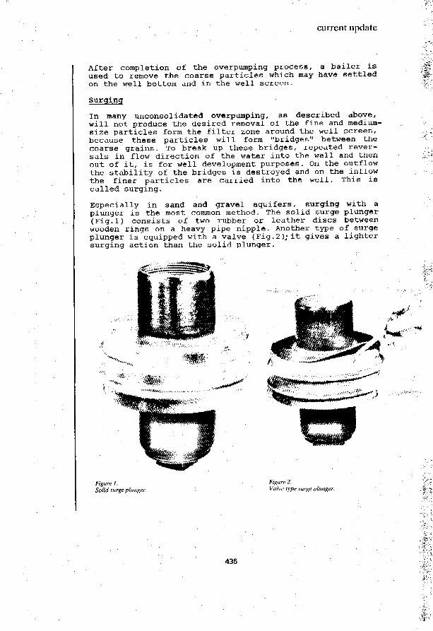
current update
After completion of the overpumping process, a bailer isused to remove the coarse particles which may have settledon the well bottom and in the well screen.
Surging
In many unconsolidated overpumping, as described above,will not produce the desired removal of the fine and medium-size particles form the filter zone around the well screen,because these particles will form "bridges" between thecoarse grains. To break up these bridges, repeated rever-sals in flow direction of the water into the well and thenout of it, is for well development purposes. On the outflowthe stability of the bridges is destroyed and on the inflowthe finer particles are carried into the well. This iscalled surging.
Especially in sand and gravel aquifers, surging with aplunger is the most common method. The solid surge plunger(Fig.l) consists of two rubber or leather discs betweenwooden rings on a heavy pipe nipple. Another type of surgeplunger is equipped with a valve (Fig. 2 )j it gives a lightersurging action than the solid plunger.
Figure 1.Solid surge plunger.
Figure 2.Valve type surge plunger.
436

current update
During the downstroke of the plunger, water is forced outof the well, and into the formation surrounding the wellscreen. The upstroke pulls thewater back into the well, and with it the dislodged silt,sand and any other material fine enough to pass thewell screen openings. The surge plunger is well-adapted tobe operated from a percussion (cable-tool) rig. The plungeris moved up and down in the well casing at a position about4m below the static water level in the well. The surgingshould begin slowly, and gradually become more rapid andvigorous.
During the surging process in the early stage aftera few minutes, later after a much longertime the well screen and well bottom will become loadedwith sand. A bailer is used to remove the sand deposits.The amount of fine material collected in the bailer willgradually become less, and so indicates how far the welldevelopment process has proceeded.
A special type of bailer (the "sand pump") is equipped witha sliding piston which is operated with the bailer line. Asthe line goes from slack to taut, the piston travels upinside the bailer, and sand is drawn in vigorously.
Figure 3.Well screen with naturally developed formation.
437

current update
Figure 4.Well with Gravel Pack, .
Another surging method is by pumping the well for some time,and suddenly stopping the pump. Then, water is poured intothe well. This method produces reversal of water flow inand out of the well. Subsequently, the muddy water contai-ning the dislodged fine material is bailed out.
The simplest method of well development is straightbailing. The bailer is alternately lifted and dropped whichgives a surging effect so that water flows into and out ofthe well. Sand and silt is trapped into the bailer and, inthis way, removed.
Backwashing with Air
In the air backwashing method the top of the well casing isclosed air-tight with a flange. The inside of the casing isconnected with a pipe to a compressor, and a drop pipe withinside air line is suspended in the well to below thestatic water level. Water is pumped out of the well through
438

current update
1-igure 5.Surging for well development.
the discharge pipe. When the water becomes clear, the airsupply is cut off and the water in the well is allowed torise back to the static level. Now, the air supply isdirected into the closed-off casing, so that the water isforced out through the screen into the formation. As thewater level falls below the bottom end of the drop pipe,air begins to escape out of it. The supply of air is cutoff and the water in the well will rise again to reach itsstatic level. The operating cycle is repeated until thewell development process is fully completed.
In the "open well air surging method", a drop pipe withinside air line is set in the well casing. The drop pipeand air line are not connected, and can be positionedindependent of each other. Well development starts with theunder end of the drop pipe in a position about 0,5 m abovethe bottom of the well, with the air line set at least0,25 m higher, when air is supplied, the well is pumped byair lift pumping action. Pumping continues until the waterbecomes clear and free of sand or silt.
439

current update
The drop pipe is then lifted to a position 0,5 to 1 mhigher, and the procedure is repeated. In this way, thewell is developed over the full length of screen.
After completion of the well development, it is advisableto return the drop pipe once more to the bottom of thewell, and then airlift pump the well in order to thoroughlyclean out any sand left.
Jetting
An effective method for well development is by jetting,i.e. high-velocity streams of water jetting from smallnozzles at the bottom end of a jetting pipe connected witha powerful water pump. This makes it possible to concen-trate the water jets at a small area of well screen, one atthe time, until the full length of screen has been deve-loped step-by-step. Through the well screen openings thewater jets will penetrate into the surrounding formationfor complete development of a gravel pack.
All that is needed for jetting are a jetting device (withsmall nozzles), high-pressure hose, piping and a powerfulpump. If water is pumped out of the well simultaneously tothe jetting, but at a slightly higher rate, water from theaquifer will flow into the well carrying with it the fineparticles dislodged by the jet streams.
Shooting or blasting
Shooting or blasting can be used in consolidated forma-tions, to open up additional crevices, cracks and fissures.However, blasting can also result in the formation becomingmore densely packed with a lower permeability.
Shooting should be carried out by a specialist, and neverbe done without expert advice.
440

current update
1 C\ water pumping
Solar energy for pumping water
Solar energy has great potential in the application ofpumping water for small-scale community water supply. Muchresearch and prototype testing is directed to the develop-ment of reliable, economical solar-powered water pumpingsystems (often referred to as "solar pumps"). Increasingly,this is supplemented by field trials and demonstration ofpromising solar pumps. A number of solar pump models arealready available in the market.
Basically, in a solar powered water pumping system, solarradiation is converted into electric power, either directly(photovoltaic cells) or indirectly using a heat-mechanicalpower-electric power conversion route. The electric poweris then used to run an electromotor which drives the waterpump. The overall energy conversion efficiency of solarpumps is in the order of 6-12% for a photo voltaic panel/electromotor/water pump system, and 1-15% for a heatcollector/thermal power/electro-generator/electromotor/water pump system.
Solar pumps using photo-voltaic cells to generate electricpower for driving the water pump, are currently morepromising than thermal solar pumps with flat-plate heatcollectors, due to the inherent low efficiency of energyconversion in the latter type of system.
To provide for storage in a solar pumping system, it ispossible to use batteries storing electric energy. However,this is costly, and adds to the maintenance requirements ofthe pump system. The recommended way of providing a storagefacility in a solar pumping system, is an overhead tank toreceive and store the pumped water. The use of batteriescan so be avoided.
A factor of great importance for the efficiency of a solarpumping system is the choice of centrifugal water pump tobe coupled to the solar power/electromotor unit. The per-formance of a solar-powered pumping system with a centrifu-gal pump can be critically impaired if centrifugal pumpsare used that are too sensitive to a variation of pumpinghead. Thus, in the choice of pump those types and modelsmust be selected, that are reasonably efficient even whenoperating away from their optimum head.
Studies and tests have shown, that for greater pumpingheads, and for large-volume water pumping, solar systemsusing a positive-displacement plunger pump are better thanthose with a centrifugal pump.
441

current update
19. water distribution
In simple water distribution systems that provide fordrinking and domestic water requirements only, pipes may beused with a diameter as small as 60 mm, in rural areas even40 mm, because these sizes of pipe should be adequate forkeeping the velocity of flow within reasonable limits (i.e.0,6 - 2,0 m/sec), at acceptable head losses (i.e. 0,01 -0,02 m/m').
Plastic pipes
PVC pipe has good resistance to chemical, electrochemicalas well as bacteriological attack. It also has the advan-tage of easy jointing.
PVC pipe is available in lengths up to 10 m which can stillbe handled by one person.
The collapse resistance of pipe is proportional to theelasticity coefficient and to the inverse of the thirdpower of the ratio of wall thickness-to-pipe diameter.
Thus, relatively thick-walled PVC pipe will have adequatecollapse resistance, in spite of its relatively low elasti-city coefficient (compared with, for instance, steel orgalvanized iron).
PVC, as all polymers, is sensitive for over-exposure toultra-violet light which can activate a process calledphotolysis leading to a disintegration, embrittlement anddiscoulouration of the PVC pipe. It is possible for manufac-turers of PVC pipe to protect their product against photo-lysis by the use of special stabilizers. However, if PVCpipe in storage is shielded from direct sunlight, andstorage periods are kept short, there should not really bea problem.
442