Hygrothermal Performance of Timber-Framed External Walls ...
J. Chin. Inst. Chem. Engrs., Vol. 34, No. 1, 123-133, 2003
Slow Motion of a Slip Spherical Particle Parallel to One or Two Plane Walls
Po Y. Chen[1] and Huan J. Keh[2] Department of Chemical Engineering, National Taiwan University
Taipei, Taiwan 106, R.O.C.
AbstractA combined analytical-numerical study for the creeping flow caused by a rigid spherical particle translating and rotating in a viscous fluid parallel to two flat plates at an arbitrary position between them is presented. The fluid, which may be a slightly rarefied gas, is allowed to slip at the surface of the particle. To solve the Stokes equations for the fluid velocity field, a general solution is constructed from fundamental solutions in both rectangular and spherical coordinate systems. Boundary conditions are enforced first at the plane walls by the Fourier transforms and then on the particle surface by a collocation technique. Numerical results for the hydrodynamic drag force and torque acting on the particle are obtained with good convergence for various values of the slip coefficient of the particle and of the separation distances between the particle and the walls. For the motion of a no-slip sphere and a perfectly-slip sphere parallel to a single plane wall or to two walls, our drag and torque results are in good agreement with the available solutions in the literature for all particle-to-wall spacings. The boundary-corrected drag force and torque exerted on the particle in general decrease with an increase in the slip coefficient for any given geometry.
Key Words : Creeping flow, Aerosol sphere, Slip-flow surface, Drag force and torque, Boundary effect
[1] 陳柏源 [2] 葛煥彰, To whom all correspondence should be addressed
INTRODUCTION
The area of the moving of solid particles or fluid drops in a continuous medium at very small Reynolds number has continued to receive much at-tention from investigators in the fields of chemical, biochemical, and environmental engineering and sci-ence. The majority of these moving phenomena are fundamental in nature, but permit one to develop ra-tional understanding of many practical systems and industrial processes such as sedimentation, flotation, spray drying, agglomeration, and motion of blood cells in an artery or vein.
The theoretical study of this subject has grown out of the classic work of Stokes (1851) for a trans-lating rigid sphere in a viscous fluid. Hadamard (1911) and Rybczynski (1911) extended independ-ently this result to the translation of a fluid sphere. Assuming continuous velocity and continuous tan-gential stress across the interface of fluid phases, they found that the force exerted on a spherical drop of radius a by the surrounding fluid of η is
UF33236
*
*
+
+−=
ηη
πηa , (1)
Here U is the migration velocity of the drop and is the internal-to-external viscosity ratio. Since the
fluid properties are arbitrary, Eq. (1) degenerates to the case of translation of a solid sphere (Stokes’ law) when and to the case of motion of a gas bubble with spherical shape in the limit .
*η
∞→*η0* →η
In most practical applications, particles or drops are not isolated. So, it is important to deter-mine if the presence of neighboring particles and/or boundaries significantly affects the movement of particles. Problems of the hydrodynamic interac-tions between two or more particles and between particles and boundaries for arbitrary values of have been treated extensively in the past. Summa-ries for the current state of knowledge in this area and some informative references can be found in Kim and Karrila (1991) and Keh and Chen (2001).
*η
When one tries to solve the Navier-Stokes equation, it is usually assumed that no slippage arises at the solid-fluid interfaces. Actually, this is an ide-alization of occurrence of the transport processes. That the adjacent fluid (especially if the fluid is a rarefied gas) can slip over a solid surface has been confirmed, both experimentally and theoretically (Kennard, 1938; Loyalka, 1990; Ying and Peters, 1991; Hutchins et al., 1995). Presumably any such slipping would be proportional to the local velocity gradient next to the solid surface (see Eq. (5)), at least so long as this gradient is small (Happel and

124 J. Chin. Inst. Chem. Engrs., Vol. 34, No. 1, 2003
Brenner, 1983). The constant of proportionality, , may be termed a “slip coefficient.” Basset
(1961) derived the following expressions for the force and torque exerted by the fluid on a translating and rotating rigid sphere with a slip-flow boundary condition at its surface (e.g., an aerosol sphere):
β/1
UFηβηβπη
326
++
−=aaa , (2a)
ΩTηβ
βπη3
8 3
+−=
aaa . (2b)
Here and are the translational and angular ve-locities, respectively, of the particle. In the particular case of , there is no slip at the particle sur-face and Eq. (2a) degenerates to Stokes’ law. When
, there is a perfect slip at the particle surface and Eq. (2a) is consistent with Eq. (1) (taking
). Note that, as can be seen from Eqs. (1) and (2a), the flow field caused by the migration of a “slip” solid sphere is the same as the external flow field generated by the same motion of a fluid drop with a value of equal to .
U
0
0
Ω
∞→β
=β
* =η
*η ηβ 3/aThe slip coefficient has been determined ex-
perimentally and found to agree with the general ki-netic theory of gases. It can be calculated from the formula
lCm=βη , (3) ,( zy ,( zφρ
where l is the mean free path of a gas molecule and is a dimensionless constant related to the mo-
mentum accommodation coefficient at the solid sur-face. Although C surely depends upon the nature of the surface, examination of the experimental data suggests that it will be in the range 1.0-1.5 (Davis, 1972; Talbot et al., 1980; Loyalka, 1990). Note that the slip-flow boundary condition is not only applica-ble in the continuum regime (the Knudsen number
), but also appears to be valid for some cases even into the molecular flow regime ( l ).
mC
/ al
m
1<<1/ ≥a
The interaction between two solid particles with finite values of is different, both physi-cally and mathematically, from that between two fluid drops of finite viscosities. Through an exact representation in spherical bipolar coordinates, Reed and Morrison (1974) and Chen and Keh (1995) ex-amined the creeping motion of two rigid spheres with slip surfaces along the line of their centers. They also investigated the slow motion of a rigid sphere normal to an infinite plane wall, where the fluid may slip at the solid surfaces. Numerical results to correct Eq. (2a) were obtained for various cases. On the other hand, the quasisteady translation and rotation of a slip spherical particle located at the cen-ter of a spherical cavity have been analyzed (Keh and Chang, 1998). Closed-form expressions for the
wall-corrected drag force and torque exerted on the particle were derived.
ηβ /a
The object of this paper is to obtain exact solu-tions for the slow translational and rotational mo-tions of a spherical particle with a slip surface paral-lel to two plane walls at an arbitrary position be-tween them. The creeping-flow equations applicable to the system are solved by using a combined ana-lytical-numerical method with a boundary colloca-tion technique (Ganatos et al., 1980) and the wall-corrected drag and torque acting on the particle are obtained with good convergence for various cases. For the special cases of movement of a particle with zero and infinite slip coefficients, our calculations show excellent agreement with the available solu-tions in the literature for the corresponding motions of a no-slip solid sphere and of a gas bubble, respec-tively.
ANALYSIS
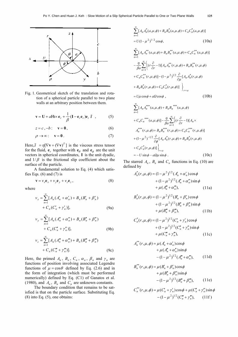
We consider the steady creeping motion caused by a rigid spherical particle of radius a translating with a velocity and rotating with an angular velocity Ω in a gaseous medium parallel to two infinite plane walls whose distances from the center of the particle are b and c, as shown in Fig.1. Here , and denote the rec-tangular, circular cylindrical, and spherical coordi-nate systems, respectively, with the origin of coordi-nates at the particle center, and e , and are the unit vectors in rectangular coordinates. We set
throughout this work, without the loss of gen-erality. The fluid is at rest far away from the particle. It is assumed that the Knudsen number l is small so that the fluid flow is in the continuum regime and the Knudsen layer at the particle surface is thin in comparison with the radius of the particle and the spacing between the particle and each wall. The ob-jective is to determine the correction to Eq. (2) for the motion of the particle due to the presence of the plane walls.
xUeU =ye
),
Ω=
),x ),,( φθr
x ye ze
cb ≤
a/
The fluid is assumed to be incompressible and Newtonian. Owing to the low Reynolds number, the luid motion is governed by the Stokes equations, f
0v =∇−∇ p2η , (4a)
0=⋅∇ v , (4b) where is the velocity field for the fluid flow and is the dynamic pressure distribution.
)(xv)(xp
The boundary conditions for the fluid velocity at the particle surface, on the plane walls, and far emoved from the particle are, r
:ar =

Po Y. Chen and Huan J. Keh : Slow Motion of a Slip Spherical Particle Parallel to One or Two Plane Walls 125
Fig. 1. Geometrical sketch of the translation and rota-
tion of a spherical particle parallel to two plane walls at an arbitrary position between them.
,:)(1 Ω τrrrra eeeIeUv −+×+=
β (5)
cz = , − : , (6) b 0v =
∞→ρ : . (7) 0v = Here, τ is the viscous stress tensor for the fluid, together with and e are the unit vectors in spherical coordinates, I is the unit dyadic, and 1 is the frictional slip coefficient about the surface of the particle.
])([ Tvv ∇+∇= ηre
β/
θe φ
A fundamental solution to Eq. (4) which satis-fies Eqs. (6) and (7) is
zzyyxx vvv eeev ++= , (8)
where
)],(
)()([1
nnn
nnnnn
nnx
CC
BBAAv
γ
βα
′+′+
′+′+′+′= ∑∞
= (9a)
)],(
)()([1
nnn
nnnnn
nny
CC
BBAAv
γ
βα
′′+′′+
′′+′′+′′+′′= ∑∞
= (9b)
)].(
)()([1
nnn
nnnnn
nnz
CC
BBAAv
γ
βα
′′′+′′′+
′′′+′′′+′′′+′′′= ∑∞
= (9c)
Here, the primed A , , , , and are functions of position involving associated Legendre functions of defined by Eq. (2.6) and in the form of integration (which must be performed numerically) defined by Eq. (C1) of Ganatos et al. (1980), and , and C are unknown constants.
n
θcos
n
nB nC nα nβ nγ
µ =
nA B nThe boundary condition that remains to be sat-
isfied is that on the particle surface. Substituting Eq. (8) into Eq. (5), one obtains:
)],,(),,(),,([ *
1
** φµφµφµ aCCaBBaAA nnn
nnnn ++∑∞
=
,cos)1( 2/12 φµ−= U (10a)
)],,(),,(),,([ **
1
**** φµφµφµ aCCaBBaAA nnn
nnnn ++∑∞
=
),,([)1()],,(
),,(),,()[1(
*212**
****
1
φµµ
µφµ
φµφµβη
rAArCC
rBBrAAr
ra
nnnn
nnnn
n
∂∂
−−+
+ −
∂∂
− ∑∞
=
arnnnn rCCrBB
=++ )],,(),,( ** φµφµ
φφµ coscos aΩU += , (10b)
∑∞
=
+1
****** ),,(),,([n
nnnn aBBaAA φµφµ
)],,(),,(),,(
)[1()],,(
*********1
***
φµφµφµ
βηφµ
rCCrBBrA
Ar
ra
aCC
nnnnn
nn
nn
++
×−∂∂
−+ ∑∞
=
arnn
nnnn
rCC
rBBrAA
=
−
+
+∂∂
−+
)],,(
),,(),,([)1(
*
**212
φµ
φµφµφ
µ
φµφ sinsin aΩU −−= . (10c) The starred , and C functions in Eq. (10) are defined by
nA nB n
),(sin)()1(
cos)()1(),,(212
212*
nn
nn
nnn
AA
ArA
αµφαµ
φαµφµ
′′′+′′′+
′′+′′−+
′+′−=
(11a)
),(sin)()1(
cos)()1(),,(212
212*
nn
nn
nnn
BB
BrB
βµφβµ
φβµφµ
′′′+′′′+
′′+′′−+
′+′−=
(11b)
),(sin)()1(
cos)()1(),,(212
212*
nn
nn
nnn
CC
CrC
γµφγµ
φγµφµ
′′′+′′′+
′′+′′−+
′+′−=
(11c)
),()1(
sin)(cos)(),,(
212
**
nn
nn
nnn
A
AArA
αµ
φαµφαµφµ
′′′+′′′−−
′′+′′+
′+′=
(11d)
),()1(
sin)(cos)(),,(
212
**
nn
nn
nnn
B
BBrB
βµ
φβµφβµφµ
′′′+′′′−−
′′+′′+
′+′=
(11e)
φγµφγµφµ sin)(cos)(),,(**nnnnn CCrC ′′+′′+′+′=
),()1( 212nnC γµ ′′′+′′′−− (11f )
126 J. Chin. Inst. Chem. Engrs., Vol. 34, No. 1, 2003
,cos)(sin)( ),,(***
φαφαφµ
nn
nnn
AArA
′′+′′+
′+′−=
(11g)
,cos)(sin)( ),,(***
φβφβφµ
nn
nnn
BBrB
′′+′′+
′+′−=
(11h)
,cos)(sin)( ),,(***
φγφγφµ
nn
nnn
CCrC
′′+′′+
′+′−=
(11i)
where the primed A , , C , , and are functions of position in Eq. (9).
n nB n nα nβ nγ
Careful examination of Eq. (10) shows that the solution of the coefficient matrix generated is inde-pendent of the coordinate of the boundary points on the surface of the sphere r To satisfy the conditions in Eq. (10) exactly along the entire sur-face of the particle would require the solution of the entire infinite array of unknown constants A , and C . However, the collocation method (O’Brien, 1968; Ganatos et al., 1980; Chen and Keh, 1995) en-forces the boundary conditions at a finite number of discrete points on the half-circular generating arc of the sphere (from θ to ) and truncates the infinite series in Eq. (9) into finite ones. If the spherical boundary is approximated by satisfying the conditions of Eq. (10) at N discrete points on its gen-erating arc, the infinite series in Eq. (9) are truncated after N terms, resulting in a system of 3N simultane-ous linear algebraic equations in the truncated form of Eq. (10). This matrix equation can be numerically solved to yield the 3N unknown constants A , and required in the truncated form of Eq. (9). The fluid velocity field is completely obtained once these coefficients are solved for a sufficiently large value of N. The accuracy of the boundary-collocation/truncation technique can be improved to any degree by taking a sufficiently large value of N. Naturally, as N the truncation error vanishes and the overall accuracy of the solution depends only on the numerical integration required in evaluating the matrix elements.
φ.a=
π
n
n
nB
nB
n
nC
0=
∞→
=θ
The drag force F and torque exerted by the fluid on the spherical particle about its enter can be determined from (Ganatos et al., 1980)
xF e = yT eT =
c , π8 1AF η−= (12a)
. 8 1CT πη−= (12b) 2π=θThese expressions show that only the lowest-order coefficients and contribute to the hydrody-namic force and couple acting on the particle. Equa-tion (12) can also be expressed in terms of the trans-ational and angular velocities of the particle as
1A 1C
l
)(32π6 rt FaΩUF
aaaF +
++
−=ηβηβη , (13a)
)(3
π8 2rt TaΩUT
aaaT +
+−=
ηββη , (13b)
where , , T and are nondimensional force and torque coefficients to be calculated using the re-sults of A and . According to the cross-effect theory for the force and torque on a rigid particle in quasistatic Stokes motion near a rigid boundary (Goldman et al., 1967), it can be shown that the cou-pling coefficients and satisfy the relation
tF rF
1
t
C
rT
1
rF tT
rt Fa
aTβ
ηβ 243 +
= . (14)
Thus, only the collocation results of the coefficients , and will be presented in the following
section. tF rF rT
RESULTS AND DISCUSSION
The solution for the slow motion of a spherical particle parallel to two plane walls at an arbitrary position between them, obtained by using the boundary collocation method described in the previous section, is presented in this section. The system of linear algebraic equations to be solved for the coefficients A , and is constructed from Eq. (10). All the numerical integrations to evaluate the primed , and functions were done by the 80-point Gauss-Laguerre guadrature. The numerical calculations were performed by using a DEC 3000/600 workstation.
n nB nC
nβ nγnα
When specifying the points along the semicir-cular generating arc of the sphere (with a constant value of ) where the boundary conditions are to be exactly satisfied, the first points that should be cho-sen are θ and , since these points define the projected area of the particle normal to the direction of motion and control the gaps between the particle and the neighboring plates. In addition, the point
φ
= 0 π
2π=θ
θ =
is also important. However, an examination of the system of linear algebraic equations in Eq. (10) shows that the matrix equations become singular if these points are used. To overcome this difficulty, these points are replaced by closely adjacent points, i.e., ,δ ,δ2 −π δ+2π and (Ganatos et al., 1980). Additional points along the boundary are selected as mirror-image pairs about the plane
δ−π
to divide the two quarter-circular arcs of the particle into equal segments. The optimum value of
in this work is found to be 0 , with which the numerical results of the hydrodynamic drag force and torque acting on the particle converge satisfacto- rily. In selecting the boundary points, any value of may be used except for and since the matrix Eq. (10) is singular for these values.
δ o1
2
.
π/ φ
,0=φ π
The collocation solutions of the dimensionless

Po Y. Chen and Huan J. Keh : Slow Motion of a Slip Spherical Particle Parallel to One or Two Plane Walls 127
Table 1. The force coefficient Ft for the translation of a spherical particle parallel to a single plane wall at various values of a/b and βa/η.
Ft a/b βa/η = 0 βa/η = 1 βa/η = 10 βa/η →∞
0.1 1.0390 1.0440 1.0547 1.0595 0.2 1.0812 1.0920 1.1152 1.1259 0.3 1.1273 1.1445 1.1824 1.2003 0.4 1.1783 1.2026 1.2578 1.2847 0.5 1.2358 1.2680 1.3439 1.3828 0.6 1.3028 1.3434 1.4449 1.5006 0.7 1.3847 1.4342 1.5687 1.6503 0.8 1.4948 1.5523 1.7312 1.8591 0.9 1.6776 1.7366 1.9772 2.2152 0.95 1.8620 1.9107 2.1848 2.5725 0.975 2.0425 2.0755 2.3568 2.9225 0.99 2.2324 2.2468 2.5213 3.3347 0.995 2.3205 2.3261 2.5958 3.5821 0.999 2.4030 2.4005 2.6657 3.9048 Table 2. The torque coefficient Tr for the rotation of a spherical particle parallel to a single plane wall at various
values of a/b and βa/η.
Tr a/b βa/η = 0.1 βa/η = 1 βa/η = 10 βa/η →∞
0.1 1.0000 1.0001 1.0002 1.0003 0.2 1.0001 1.0006 1.0019 1.0025 0.3 1.0003 1.0021 1.0066 1.0086 0.4 1.0007 1.0051 1.0158 1.0207 0.5 1.0013 1.0100 1.0316 1.0418 0.6 1.0022 1.0175 1.0570 1.0763 0.7 1.0035 1.0285 1.0965 1.1324 0.8 1.0053 1.0437 1.1590 1.2283 0.9 1.0076 1.0645 1.2655 1.4253 0.95 1.0089 1.0772 1.3524 1.6500 0.975 1.0096 1.0840 1.4112 1.8862 0.99 1.0100 1.0881 1.4526 2.1808 0.995 1.0101 1.0894 1.4672 2.3677 0.999 1.0102 1.0904 1.4790 2.6242 force and torque coefficients for the translation and rotation of a spherical particle parallel to a plane wall (with c ) for different values of the parameters
and are presented in Tables 1-3. Obvi-ously, and as for any value of . All of the results obtained under the collocation scheme converge satisfactorily to at least the significant figures shown in the tables. The accuracy and convergence behavior of the truncation technique is principally a function of the ratio a For the most difficult case with a , the number of collocation points N is sufficiently large to achieve this convergence. For the special case of translation and rotation of a no-slip sphere (with ) parallel to a plane wall, our nu-merical results agree perfectly with the semianalyti-cal solution obtained using spherical bipolar coordi-
nates (Dean and O’Neill, 1963; O’Neill, 1964; Goldman et al., 1967). For the other particular case of translation of a perfectly-slip sphere (with
) parallel to a plane wall, our results (given in Table 1) are also in perfect agreement with the boundary-collocation solution obtained for the mi-gration of a spherical gas bubble with (Keh and Chen, 2001). As expected, the results in Tables 1 and 2 illustrate that the normalized drag force ( ) and torque (T ) on the particle are monotonically in-creasing functions of
∞→a
=t TF
→ηβ /a
ηβ /a b/=r
β /a
∞
1η
0== tr TF
=
0/ =ba
999.0=b/ .
/ b42
0/ =ηβ a
0* =η
tFr
ba , and will become infinite in the limit a , for any given value of . These normalized drag force and torque in general increase with an increase in (or with a de-crease in the slip coefficient ), keeping un-changed. On the other hand, as shown in Table 3, the coupling coefficients and T are not neces-
1=b/ η/β
ba /
a
ηβ /a1−β
trF

128 J. Chin. Inst. Chem. Engrs., Vol. 34, No. 1, 2003
Table 3. The coupling coefficient Fr = Tt (4/3) βa /( βa+2η) for the motion of a spherical particle parallel to a single plane wall at various values of a/b and βa/η.
Fr a/b βa/η =0.1 βa/η =1 βa/η =10 βa/η →∞
0.1 –3.7E-9 –9.3E-7 –7.6E-6 –1.2E-5 0.2 2.1E-7 –1.3E-5 –1.2E-4 –1.8E-4 0.3 2.6E-6 –5.6E-5 –5.7E-4 –9.0E-4 0.4 1.4E-5 –1.4E-4 –0.0018 –0.0028 0.5 5.1E-5 –2.3E-4 –0.0042 –0.0067 0.6 1.5E-4 –2.1E-4 –0.0085 –0.0141 0.7 3.9E-4 3.2E-4 –0.0157 –0.0275 0.8 9.5E-4 0.0024 –0.0272 –0.0528 0.9 0.0023 0.0092 –0.0434 –0.1095 0.95 0.0037 0.0178 –0.0483 –0.1798 0.975 0.0047 0.0253 –0.0429 –0.2680 0.99 0.0056 0.0315 –0.0329 –0.4292 0.995 0.0059 0.0338 –0.0284 –0.5695 0.999 0.0061 0.0357 –0.0245 –0.8012
sarily a monotonic function of the parameter a or
, and their values can be either positive or negative depending on the combination of a and
.
b/
b/ηβ /a
ηβ /aA number of converged boundary-collocation
solutions for the dimensionless force and torque co-efficients are presented in Tables 4-6 for the transla-tion and rotation of a spherical particle parallel to two plane walls at two particular positions between them (with b and 0.5) for various val-ues of and . For the special cases of a no-slip sphere (with ) and a perfectly-slip sphere (with ), our results agree well with the previous solutions obtained by a similar colloca-tion method (Ganatos et al., 1980, in which no tabu-lated values are available for a precise comparison; Keh and Chen, 2001). Analogous to the situation of translation and rotation parallel to a single wall, for a constant value of b , Tables 4 and 5 indicate that the normalized drag force and torque on the par-ticle increase monotonically with an increase in afor a fixed value of and with an increase in
for a given value of a (with exceptions), while Table 6 shows that the coupling coefficients
and T can be either positive or negative depend-ing on the combination of the parameters a and
Again, and as for any given values of b and
.
25.0)/( =+ cbηβ /a
→ηβ /a0/ =ηβ a
)/( cb +
ηβ /a
1== rt TF
ba /
t
.0
∞
b/
b0
ηβ /a
rF
/ηβ a/ =ba
ηβ /a
b/
/=t
)c+=r TF/(b
Figures 2-4 show the force and torque coeffi-cients for the translation and rotation of a spherical particle with parallel to two plane walls. The dashed curves (with constant) illustrate the effect of the position of the second wall (at ) on the drag force and torque for various values of the sphere-to-wall spacing b . The solid curves (with
constant) indicate the variation of the
10/ =ηβ a=ba /
a
cz =
/=+ )/(2 cba
Fig. 2. Plots of the force coefficient Ft for the
translation of a spherical particle with =10 parallel to two plane walls versus the ratio b/(b+c) with a/b and 2a/(b+c) as parameters.
ηβ /a
drag force and torque as functions of the sphere posi-tion at various values of the wall-to-wall spacing
. At a given value of 2 , the par-ticle (or a particle with any other value of , whose collocation results are not exhibited here but can also be obtained accurately) experiences mini-mum drag when it is located midway between the two walls as illustrated in Figs. 2 and 3, analogous to the corresponding cases of a no-slip sphere (Ganatos et al., 1980) and of a fluid sphere (Keh and Chen, 2001). The drag force and torque become infinite as the particle approaches either of the walls. Again, Fig. 4 indicates that the coupling coefficient (and
acb 2/)( + )/( cba +ηβ /a
rF
Po Y. Chen and Huan J. Keh : Slow Motion of a Slip Spherical Particle Parallel to One or Two Plane Walls 129
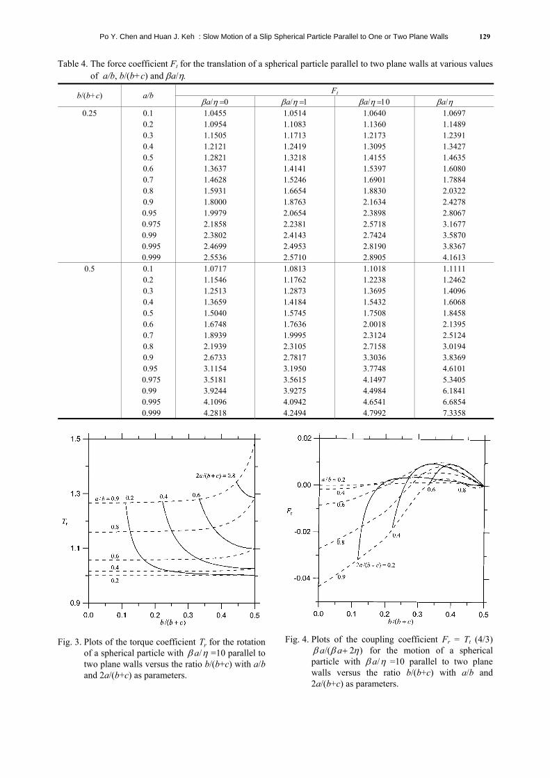
Table 4. The force coefficient Ft for the translation of a spherical particle parallel to two plane walls at various values of a/b, b/(b+c) and βa/η.
Ft b/(b+c) a/b βa/η =0 βa/η =1 βa/η =10 βa/η →∞
0.25 0.1 1.0455 1.0514 1.0640 1.0697 0.2 1.0954 1.1083 1.1360 1.1489 0.3 1.1505 1.1713 1.2173 1.2391 0.4 1.2121 1.2419 1.3095 1.3427 0.5 1.2821 1.3218 1.4155 1.4635 0.6 1.3637 1.4141 1.5397 1.6080 0.7 1.4628 1.5246 1.6901 1.7884 0.8 1.5931 1.6654 1.8830 2.0322 0.9 1.8000 1.8763 2.1634 2.4278
0.95 1.9979 2.0654 2.3898 2.8067 0.975 2.1858 2.2381 2.5718 3.1677
0.99 2.3802 2.4143 2.7424 3.5870 0.995 2.4699 2.4953 2.8190 3.8367
0.999 2.5536 2.5710 2.8905 4.1613
0.5 0.1 1.0717 1.0813 1.1018 1.1111 0.2 1.1546 1.1762 1.2238 1.2462 0.3 1.2513 1.2873 1.3695 1.4096 0.4 1.3659 1.4184 1.5432 1.6068 0.5 1.5040 1.5745 1.7508 1.8458 0.6 1.6748 1.7636 2.0018 2.1395 0.7 1.8939 1.9995 2.3124 2.5124 0.8 2.1939 2.3105 2.7158 3.0194 0.9 2.6733 2.7817 3.3036 3.8369
0.95 3.1154 3.1950 3.7748 4.6101 0.975 3.5181 3.5615 4.1497 5.3405
0.99 3.9244 3.9275 4.4984 6.1841 0.995 4.1096 4.0942 4.6541 6.6854
0.999 4.2818 4.2494 4.7992 7.3358
Fig. 3. Plots of the torque coefficient T for the rotation
of a spherical particle with =10 parallel to two plane walls versus the ratio b/(b+c) with a/b and 2a/(b+c) as parameters.
rη/aβ
Fig. 4. Plots of the coupling coefficient Fr = Tt (4/3)
for the motion of a spherical particle with =10 parallel to two plane walls versus the ratio b/(b+c) with a/b and 2a/(b+c) as parameters.
)2/( ηββ +aaηβ /a

130 J. Chin. Inst. Chem. Engrs., Vol. 34, No. 1, 2003
Table 5. The torque coefficient Tr for the rotation of a spherical particle parallel to two plane walls at various values of a/b, b/(b+c) and βa/η.
Tr b/(b+c) a/b βa/η =0.1 βa/η =1 βa/η =10 βa/η →∞
0.25 0.1 1.0000 1.0001 1.0003 1.0003 0.2 1.0001 1.0007 1.0020 1.0026 0.3 1.0003 1.0022 1.0068 1.0089 0.4 1.0007 1.0053 1.0164 1.0215 0.5 1.0013 1.0104 1.0328 1.0433 0.6 1.0023 1.0182 1.0590 1.0790 0.7 1.0037 1.0295 1.0997 1.1365 0.8 1.0055 1.0453 1.1636 1.2344 0.9 1.0079 1.0666 1.2720 1.4337 0.95 1.0092 1.0796 1.3600 1.6598 0.975 1.0099 1.0865 1.4193 1.8968 0.99 1.0103 1.0907 1.4611 2.1918 0.995 1.0105 1.0921 1.4758 2.3789
0.999 1.0106 1.0932 1.4877 2.6356 0.5 0.1 1.0000 1.0001 1.0004 1.0005
0.2 1.0001 1.0011 1.0033 1.0043 0.3 1.0005 1.0036 1.0113 1.0147 0.4 1.0011 1.0087 1.0273 1.0358 0.5 1.0022 1.0172 1.0551 1.0730 0.6 1.0038 1.0303 1.1002 1.1351 0.7 1.0061 1.0495 1.1719 1.2381 0.8 1.0093 1.0768 1.2877 1.4188 0.9 1.0133 1.1145 1.4900 1.7994 0.95 1.0157 1.1378 1.6578 2.2414 0.975 1.0169 1.1503 1.7723 2.7100 0.99 1.0176 1.1579 1.8532 3.2968 0.995 1.0178 1.1604 1.8818 3.6698
0.999 1.0180 1.1623 1.9050 4.1822
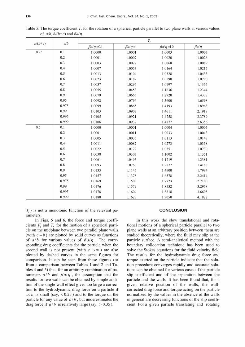
tT ) is not a monotonic function of the relevant pa-
rameters. In Figs. 5 and 6, the force and torque coeffi-
cients and for the motion of a spherical parti-cle on the midplane between two parallel plane walls (with c ) are plotted by solid curves as functions of for various values of . The corre-sponding drag coefficients for the particle when the second wall is not present (with c ) are also plotted by dashed curves in the same figures for comparison. It can be seen from these figures (or from a comparison between Tables 1 and 2 and Ta-bles 4 and 5) that, for an arbitrary combination of pa-rameters and , the assumption that the results for two walls can be obtained by simple addi-tion of the single-wall effect gives too large a correc-tion to the hydrodynamic drag force on a particle if
is small (say, < ) and to the torque on the particle for any value of a , but underestimates the drag force if a is relatively large (say, ).
tF
=b
rT
b/
b/
a /
a
b
ηβ /a
→ ∞
>
b ηβ /a
25.0a /b/
35.0
CONCLUSION
In this work the slow translational and rota- tional motions of a spherical particle parallel to two plane walls at an arbitrary position between them are studied theoretically, where the fluid may slip at the particle surface. A semi-analytical method with the boundary collocation technique has been used to solve the Stokes equations for the fluid velocity field. The results for the hydrodynamic drag force and torque exerted on the particle indicate that the solu-tion procedure converges rapidly and accurate solu-tions can be obtained for various cases of the particle slip coefficient and of the separation between the particle and the walls. It has been found that, for a given relative position of the walls, the wall-corrected drag force and torque acting on the particle normalized by the values in the absence of the walls in general are decreasing functions of the slip coeffi-cient. For a given particle translating and rotating

Po Y. Chen and Huan J. Keh : Slow Motion of a Slip Spherical Particle Parallel to One or Two Plane Walls 131
Table 6. The coupling coefficient Fr = Tt (4/3) βa /( βa+2η) for the motion of a spherical particle parallel to two plane walls at the position b/(b+c)=1/4a for various values of a/b and βa/η.
Fr a/b βa/η =0.1 βa/η =1 βa/η =10 βa/η →∞
0.1 1.1E-5 8.7E-5 2.7E-4 3.5E-4 0.2 4.7E-5 3.6E-4 0.0011 0.0014 0.3 1.1E-4 8.2E-4 0.0022 0.0028 0.4 2.2E-4 0.0015 0.0035 0.0041 0.5 3.9E-4 0.0024 0.0044 0.0046 0.6 6.6E-4 0.0038 0.0043 0.0028 0.7 0.0011 0.0059 0.0022 –0.0037 0.8 0.0019 0.0099 –0.0031 –0.0209 0.9 0.0035 0.0189 –0.0122 –0.0682 0.95 0.0050 0.0286 –0.0131 –0.1332 0.975 0.0062 0.0367 –0.0057 –0.2187 0.99 0.0071 0.0433 0.0055 –0.3783 0.995 0.0074 0.0457 0.0105 –0.5180 0.999 0.0076 0.0477 0.0146 –0.7492
a For the motion of a sphere on the midplane between two parallel plane walls (with b/(b+c)=1/2), it is obvious that Fr = Tt =0.
Fig. 5. Plots of the force coefficient F for the
translation of a spherical particle on the midplane between two parallel plane walls (with c = b) versus the ratio a/b with as a parameter. The dashed curves are plotted for the translation of an identical particle parallel to a single plane wall for comparison.
t
β η/a
between two parallel walls separated by a fixed dis-tance, the particle experiences minimum drag force and couple when it is located midway between the walls, and the drag force and couple become infinite as the particle touches either of the walls.
In Tables 1-6 and Figs. 2-6, we presented the explicit results for resistance problems, defined as those in which the drag force F and hydrodynamic torque T acting on the particle are to be determined for specified particle velocities and Ω . In a mo- U
Fig. 6. Plots of the torque coefficient T for the rotation
of a spherical particle on the midplane between two parallel plane walls (with c = b) versus the ratio a/b with as a parameter. The dashed curves are plotted for the translation of an identical particle parallel to a single plane wall for comparison.
r
ηβ /a
bility problem, on the other hand, the applied force F and torque T exerted on the particle are specified and the particle velocities U and are to be determined. For the creeping motion of a spherical particle with a finite slip coefficient located between two parallel planes considered in this work, our results expressed by Eq. (13) can also be used for its corresponding mobility problems in which the force and torque on the particle are the prescribed quantities and the par-ticle must move accordingly. For example, the trans-
Ω

132 J. Chin. Inst. Chem. Engrs., Vol. 34, No. 1, 2003
lational and angular velocities of a slip sphere paral-lel to one or two plane walls driven by an applied force under the condition of free rotation are obtained from Eq. (13) as
xF e
6=U
Ω −=
nn C ,
nn C′′ ,.nn C ′′′′ ,nn C ′′′′′′ ,,
zy e ,φe ,
r
z
1)(23 −−
++
r
trt T
TFFaa
aF
ηβηβ
πη, (15a) Ω
r
t
TT
aU . (15b)
The values of the force and torque coefficients in Eq. (15) are the same as those presented in Tables 1-6 and Figs. 2-6.
ACKOWLEDGEMENT
Part of this research was supported by the Na-tional Science Council of the Republic of China.
NOMENCLATURE
n BA ,
BA′ ,
coefficients in the expression of Eq. (9) for the fluid velocity field, ,
, 11 sm −+ ⋅n
13 sm −+ ⋅n 12 sm −+ ⋅n
nBA ′′ ,
functions of position defined by Eq. (2.6) n
BA ′′′ of Ganatos et al. (1980), ,m n−
n , 2m −−n 1m −−n
a radius of the particle, m b, c the respective distances from the particle
center to the two plates, m x ee ,
θee ,r
unit vectors in rectangular coordinates unit vectors in spherical coordinates
F ,F drag force acting on the particle, N FF ,t force and coupling coefficients defined
by Eq. (13a) N number of collocation points on the par-
ticle surface r radial spherical coordinate, m
T ,T hydrodynamic torque exerted on the par-ticle, N·m
tr TT , torque and coupling coefficients defined by Eq. (13b)
U ,U
v
translational velocity of the particle, 1s m −⋅
, v velocity field of the fluid, m 1s −⋅x , y , rectangular coordinates, m
Greek symbols
nnn γβα ′′′ , ,γβα ′′′′′′ , ,
functions of position defined by Eq. (C1) nnn
γβα ′′′′′′′′′ , , of Ganatos et al. (1980), m ,m n− ,2−−n
nnnβ
1m −−n reciprocal of the slip coefficient at the
particle surface, 12 sm kg −− ⋅⋅η m kg −⋅ viscosity of the fluid, 11 s−⋅
*η internal-to-external viscosity ratio of a fluid droplet
φθ ,µ
angular spherical coordinates θcos=
ρ radial cylindrical coordinate, m Ω , angular velocity of the particle, s 1−
REFERENCES
Basset, A. B., A Treatise on Hydrodynamics, Vol. 2, Dover, New York, U.S.A. (1961).
Chen, S. H. and H. J. Keh, “Axisymmetric Motion of Two Spherical Particles with Slip Surfaces,” J. Colloid Interface Sci., 171, 63 (1995).
Davis, M. H., “Collisions of Small Cloud Droplets: Gas Kinetic Effects,” J. Atoms. Sci., 29, 911 (1972).
Dean, W. R. and M. E. O’Neill, “A Slow Motion of Viscous Liquid Caused by the Rotation of a Solid Sphere,” Mathematica., 10, 13 (1963).
Ganatos, P., S. Weinbaum and R. Pfeffer, “A Strong Interaction Theory for the Creeping Motion of a Sphere between Plane Parallel Boundaries. Part 2. Parallel Motion,” J. Fluid Mech., 99, 755 (1980).
Goldman, A. J., R. G. Cox and H. Brenner, “Slow Viscous Motion of a Sphere Parallel to a Plane Wall-I. Motion through a Quiescent Fluid,” Chem. Eng. Sci., 22, 637 (1967).
Hadamard, J. S., “Mouvement Permanent Lent d’Une Sphere Liquid et Visqueuse dans Un Liquide Visqueux,” Compt. Rend. Acad. Sci. (Paris), 152, 1735 (1911).
Happel, J. and H. Brenner, Low Reynolds Number Hydrodynamics., Nijhoff, Dordrecht, The Netherlands (1983).
Hutchins, D. K., M. H. Harper and R. L. Felder, “Slip Correction Measurements for Solid Spherical Particles by Modulated Dynamic Light Scattering,” Aerosol Sci. Technol., 22, 202 (1995).
Keh, H. J. and J. H. Chang, “Boundary Effects on the Creeping-Flow and Thermophoretic Motions of an Aerosol Particle in a Spherical Cavity,” Chem. Eng. Sci., 53, 2365 (1998).
Keh, H. J. and P. Y. Chen, “Slow Motion of a Droplet between Two Parallel Plane Walls,” Chem. Eng. Sci., 56, 6863 (2001).
Kennard, E. H., Kinetic Theory of Gases, McGraw-Hill, New York, U.S.A. (1938).
Kim, S. and S. J. Karrila, Microhydrodynamics: Principles and Selected Applications, Butterworth-Heinemann, Boston, MA, U.S.A. (1991).
Loyalka, S. K., “Slip and Jump Coefficients for Rarefied Gas Flows: Variational Results for Lennard-Jones and n(r)-6 Potentials,” Physica A., 163, 813 (1990).

Po Y. Chen and Huan J. Keh : Slow Motion of a Slip Spherical Particle Parallel to One or Two Plane Walls 133
O’Brien, V., “Form Factors for Deformed Spheroids in Stokes Flow,” AIChE J., 14, 870 (1968).
O’Neill, M. E., “A Slow Motion of Viscous Liquid Caused by a Slowly Moving Solid Sphere,”Mathematika, 11., 67 (1964).
Reed, L. D. and F. A. Morrison, “Particle Interactions in Viscous Flow at Small Values of Knudsen Number,” J. Aerosol Sci., 5, 175 (1974).
Rybczynski, W., “Uber Die Fortschreitende Bewegung Einer Flussigen Kugel in Einem Zahen Medium,” Bull. Acad. Sci. Cracovie Ser. A, 1, 40 (1911).
Stokes, G. G., “On the Effect of the Internal Friction of Fluid on Pendulums,” Trans. Camb. Phil. Soc., 9, 8 (1851).
Talbot, L., R. K. Cheng, R. W. Schefer and D. R. Willis, “Thermophoresis of Particles in Heated Boundary Layer,” J. Fluid Mech., 101, 737 (1980).
Ying, R. and M. H. Peters, “Interparticle and Particle-Surface Gas Dynamic Interactions,” Aerosol Sci. Technol., 14, 418 (1991).
(Manuscript Received July 31, 2002)
表面滑移球形粒子平行一或二平面之緩慢運動
陳柏源 葛煥彰 國立台灣大學化學工程學系
摘 要 本文以半解析半數值的方法,研究一剛性球形粒子於兩平行平板間之黏性流體中之任意位置,進行平行平板之移動
與轉動所造成的緩流運動。所考慮之流體可為稍微稀薄之氣體,並可以在粒子的表面產生滑移現象。為便於求解主導流場之 Stokes 方程式,需要建立其在直角座標及球座標系統中之通解。首先以 Fourier 轉換,使此通解滿足平板上的邊界條件,再以邊界取點法使通解滿足球形粒子上的邊界條件。對於粒子位於兩平板間各種不同之相對位置,與各種不同之粒子表面滑移係數情形,分別計算流體施於粒子之阻力與阻力矩,可得良好之收斂數值結果。針對粒子平行單一平板與兩平板之運動,在粒子表面為不滑移與完全滑移的情況下,所計算出的阻力與阻力矩值,皆與現有文獻中之數值相吻合。而在任何粒子與平面之幾何架構情況下,粒子所受之阻力與阻力矩值,大致隨著粒子表面滑移係數之增加而有逐漸遞減的情形。

124 J. Chin. Inst. Chem. Engrs., Vol. 34, No. 1, 2003
Brenner, 1983). The constant of proportionality, , may be termed a “slip coefficient.” Basset
(1961) derived the following expressions for the force and torque exerted by the fluid on a translating and rotating rigid sphere with a slip-flow boundary condition at its surface (e.g., an aerosol sphere):
β/1
UFηβηβπη
326
++
−=aaa , (2a)
ΩTηβ
βπη3
8 3
+−=
aaa . (2b)
Here and are the translational and angular ve-locities, respectively, of the particle. In the particular case of , there is no slip at the particle sur-face and Eq. (2a) degenerates to Stokes’ law. When
, there is a perfect slip at the particle surface and Eq. (2a) is consistent with Eq. (1) (taking
). Note that, as can be seen from Eqs. (1) and (2a), the flow field caused by the migration of a “slip” solid sphere is the same as the external flow field generated by the same motion of a fluid drop with a value of equal to .
U
0
0
Ω
∞→β
=β
* =η
*η ηβ 3/aThe slip coefficient has been determined ex-
perimentally and found to agree with the general ki-netic theory of gases. It can be calculated from the formula
lCm=βη , (3) ,( zy ,( zφρ
where l is the mean free path of a gas molecule and is a dimensionless constant related to the mo-
mentum accommodation coefficient at the solid sur-face. Although C surely depends upon the nature of the surface, examination of the experimental data suggests that it will be in the range 1.0-1.5 (Davis, 1972; Talbot et al., 1980; Loyalka, 1990). Note that the slip-flow boundary condition is not only applica-ble in the continuum regime (the Knudsen number
), but also appears to be valid for some cases even into the molecular flow regime ( l ).
mC
/ al
m
1<<1/ ≥a
The interaction between two solid particles with finite values of is different, both physi-cally and mathematically, from that between two fluid drops of finite viscosities. Through an exact representation in spherical bipolar coordinates, Reed and Morrison (1974) and Chen and Keh (1995) ex-amined the creeping motion of two rigid spheres with slip surfaces along the line of their centers. They also investigated the slow motion of a rigid sphere normal to an infinite plane wall, where the fluid may slip at the solid surfaces. Numerical results to correct Eq. (2a) were obtained for various cases. On the other hand, the quasisteady translation and rotation of a slip spherical particle located at the cen-ter of a spherical cavity have been analyzed (Keh and Chang, 1998). Closed-form expressions for the
wall-corrected drag force and torque exerted on the particle were derived.
ηβ /a
The object of this paper is to obtain exact solu-tions for the slow translational and rotational mo-tions of a spherical particle with a slip surface paral-lel to two plane walls at an arbitrary position be-tween them. The creeping-flow equations applicable to the system are solved by using a combined ana-lytical-numerical method with a boundary colloca-tion technique (Ganatos et al., 1980) and the wall-corrected drag and torque acting on the particle are obtained with good convergence for various cases. For the special cases of movement of a particle with zero and infinite slip coefficients, our calculations show excellent agreement with the available solu-tions in the literature for the corresponding motions of a no-slip solid sphere and of a gas bubble, respec-tively.
ANALYSIS
We consider the steady creeping motion caused by a rigid spherical particle of radius a translating with a velocity and rotating with an angular velocity Ω in a gaseous medium parallel to two infinite plane walls whose distances from the center of the particle are b and c, as shown in Fig.1. Here , and denote the rec-tangular, circular cylindrical, and spherical coordi-nate systems, respectively, with the origin of coordi-nates at the particle center, and e , and are the unit vectors in rectangular coordinates. We set
throughout this work, without the loss of gen-erality. The fluid is at rest far away from the particle. It is assumed that the Knudsen number l is small so that the fluid flow is in the continuum regime and the Knudsen layer at the particle surface is thin in comparison with the radius of the particle and the spacing between the particle and each wall. The ob-jective is to determine the correction to Eq. (2) for the motion of the particle due to the presence of the plane walls.
xUeU =ye
),
Ω=
),x ),,( φθr
x ye ze
cb ≤
a/
The fluid is assumed to be incompressible and Newtonian. Owing to the low Reynolds number, the luid motion is governed by the Stokes equations, f
0v =∇−∇ p2η , (4a)
0=⋅∇ v , (4b) where is the velocity field for the fluid flow and is the dynamic pressure distribution.
)(xv)(xp
The boundary conditions for the fluid velocity at the particle surface, on the plane walls, and far emoved from the particle are, r
:ar =
Po Y. Chen and Huan J. Keh : Slow Motion of a Slip Spherical Particle Parallel to One or Two Plane Walls 125
Fig. 1. Geometrical sketch of the translation and rota-
tion of a spherical particle parallel to two plane walls at an arbitrary position between them.
,:)(1 Ω τrrrra eeeIeUv −+×+=
β (5)
cz = , − : , (6) b 0v =
∞→ρ : . (7) 0v = Here, τ is the viscous stress tensor for the fluid, together with and e are the unit vectors in spherical coordinates, I is the unit dyadic, and 1 is the frictional slip coefficient about the surface of the particle.
])([ Tvv ∇+∇= ηre
β/
θe φ
A fundamental solution to Eq. (4) which satis-fies Eqs. (6) and (7) is
zzyyxx vvv eeev ++= , (8)
where
)],(
)()([1
nnn
nnnnn
nnx
CC
BBAAv
γ
βα
′+′+
′+′+′+′= ∑∞
= (9a)
)],(
)()([1
nnn
nnnnn
nny
CC
BBAAv
γ
βα
′′+′′+
′′+′′+′′+′′= ∑∞
= (9b)
)].(
)()([1
nnn
nnnnn
nnz
CC
BBAAv
γ
βα
′′′+′′′+
′′′+′′′+′′′+′′′= ∑∞
= (9c)
Here, the primed A , , , , and are functions of position involving associated Legendre functions of defined by Eq. (2.6) and in the form of integration (which must be performed numerically) defined by Eq. (C1) of Ganatos et al. (1980), and , and C are unknown constants.
n
θcos
n
nB nC nα nβ nγ
µ =
nA B nThe boundary condition that remains to be sat-
isfied is that on the particle surface. Substituting Eq. (8) into Eq. (5), one obtains:
)],,(),,(),,([ *
1
** φµφµφµ aCCaBBaAA nnn
nnnn ++∑∞
=
,cos)1( 2/12 φµ−= U (10a)
)],,(),,(),,([ **
1
**** φµφµφµ aCCaBBaAA nnn
nnnn ++∑∞
=
),,([)1()],,(
),,(),,()[1(
*212**
****
1
φµµ
µφµ
φµφµβη
rAArCC
rBBrAAr
ra
nnnn
nnnn
n
∂∂
−−+
+ −
∂∂
− ∑∞
=
arnnnn rCCrBB
=++ )],,(),,( ** φµφµ
φφµ coscos aΩU += , (10b)
∑∞
=
+1
****** ),,(),,([n
nnnn aBBaAA φµφµ
)],,(),,(),,(
)[1()],,(
*********1
***
φµφµφµ
βηφµ
rCCrBBrA
Ar
ra
aCC
nnnnn
nn
nn
++
×−∂∂
−+ ∑∞
=
arnn
nnnn
rCC
rBBrAA
=
−
+
+∂∂
−+
)],,(
),,(),,([)1(
*
**212
φµ
φµφµφ
µ
φµφ sinsin aΩU −−= . (10c) The starred , and C functions in Eq. (10) are defined by
nA nB n
),(sin)()1(
cos)()1(),,(212
212*
nn
nn
nnn
AA
ArA
αµφαµ
φαµφµ
′′′+′′′+
′′+′′−+
′+′−=
(11a)
),(sin)()1(
cos)()1(),,(212
212*
nn
nn
nnn
BB
BrB
βµφβµ
φβµφµ
′′′+′′′+
′′+′′−+
′+′−=
(11b)
),(sin)()1(
cos)()1(),,(212
212*
nn
nn
nnn
CC
CrC
γµφγµ
φγµφµ
′′′+′′′+
′′+′′−+
′+′−=
(11c)
),()1(
sin)(cos)(),,(
212
**
nn
nn
nnn
A
AArA
αµ
φαµφαµφµ
′′′+′′′−−
′′+′′+
′+′=
(11d)
),()1(
sin)(cos)(),,(
212
**
nn
nn
nnn
B
BBrB
βµ
φβµφβµφµ
′′′+′′′−−
′′+′′+
′+′=
(11e)
φγµφγµφµ sin)(cos)(),,(**nnnnn CCrC ′′+′′+′+′=
),()1( 212nnC γµ ′′′+′′′−− (11f )

126 J. Chin. Inst. Chem. Engrs., Vol. 34, No. 1, 2003
,cos)(sin)( ),,(***
φαφαφµ
nn
nnn
AArA
′′+′′+
′+′−=
(11g)
,cos)(sin)( ),,(***
φβφβφµ
nn
nnn
BBrB
′′+′′+
′+′−=
(11h)
,cos)(sin)( ),,(***
φγφγφµ
nn
nnn
CCrC
′′+′′+
′+′−=
(11i)
where the primed A , , C , , and are functions of position in Eq. (9).
n nB n nα nβ nγ
Careful examination of Eq. (10) shows that the solution of the coefficient matrix generated is inde-pendent of the coordinate of the boundary points on the surface of the sphere r To satisfy the conditions in Eq. (10) exactly along the entire sur-face of the particle would require the solution of the entire infinite array of unknown constants A , and C . However, the collocation method (O’Brien, 1968; Ganatos et al., 1980; Chen and Keh, 1995) en-forces the boundary conditions at a finite number of discrete points on the half-circular generating arc of the sphere (from θ to ) and truncates the infinite series in Eq. (9) into finite ones. If the spherical boundary is approximated by satisfying the conditions of Eq. (10) at N discrete points on its gen-erating arc, the infinite series in Eq. (9) are truncated after N terms, resulting in a system of 3N simultane-ous linear algebraic equations in the truncated form of Eq. (10). This matrix equation can be numerically solved to yield the 3N unknown constants A , and required in the truncated form of Eq. (9). The fluid velocity field is completely obtained once these coefficients are solved for a sufficiently large value of N. The accuracy of the boundary-collocation/truncation technique can be improved to any degree by taking a sufficiently large value of N. Naturally, as N the truncation error vanishes and the overall accuracy of the solution depends only on the numerical integration required in evaluating the matrix elements.
φ.a=
π
n
n
nB
nB
n
nC
0=
∞→
=θ
The drag force F and torque exerted by the fluid on the spherical particle about its enter can be determined from (Ganatos et al., 1980)
xF e = yT eT =
c , π8 1AF η−= (12a)
. 8 1CT πη−= (12b) 2π=θThese expressions show that only the lowest-order coefficients and contribute to the hydrody-namic force and couple acting on the particle. Equa-tion (12) can also be expressed in terms of the trans-ational and angular velocities of the particle as
1A 1C
l
)(32π6 rt FaΩUF
aaaF +
++
−=ηβηβη , (13a)
)(3
π8 2rt TaΩUT
aaaT +
+−=
ηββη , (13b)
where , , T and are nondimensional force and torque coefficients to be calculated using the re-sults of A and . According to the cross-effect theory for the force and torque on a rigid particle in quasistatic Stokes motion near a rigid boundary (Goldman et al., 1967), it can be shown that the cou-pling coefficients and satisfy the relation
tF rF
1
t
C
rT
1
rF tT
rt Fa
aTβ
ηβ 243 +
= . (14)
Thus, only the collocation results of the coefficients , and will be presented in the following
section. tF rF rT
RESULTS AND DISCUSSION
The solution for the slow motion of a spherical particle parallel to two plane walls at an arbitrary position between them, obtained by using the boundary collocation method described in the previous section, is presented in this section. The system of linear algebraic equations to be solved for the coefficients A , and is constructed from Eq. (10). All the numerical integrations to evaluate the primed , and functions were done by the 80-point Gauss-Laguerre guadrature. The numerical calculations were performed by using a DEC 3000/600 workstation.
n nB nC
nβ nγnα
When specifying the points along the semicir-cular generating arc of the sphere (with a constant value of ) where the boundary conditions are to be exactly satisfied, the first points that should be cho-sen are θ and , since these points define the projected area of the particle normal to the direction of motion and control the gaps between the particle and the neighboring plates. In addition, the point
φ
= 0 π
2π=θ
θ =
is also important. However, an examination of the system of linear algebraic equations in Eq. (10) shows that the matrix equations become singular if these points are used. To overcome this difficulty, these points are replaced by closely adjacent points, i.e., ,δ ,δ2 −π δ+2π and (Ganatos et al., 1980). Additional points along the boundary are selected as mirror-image pairs about the plane
δ−π
to divide the two quarter-circular arcs of the particle into equal segments. The optimum value of
in this work is found to be 0 , with which the numerical results of the hydrodynamic drag force and torque acting on the particle converge satisfacto- rily. In selecting the boundary points, any value of may be used except for and since the matrix Eq. (10) is singular for these values.
δ o1
2
.
π/ φ
,0=φ π
The collocation solutions of the dimensionless

Po Y. Chen and Huan J. Keh : Slow Motion of a Slip Spherical Particle Parallel to One or Two Plane Walls 127
Table 1. The force coefficient Ft for the translation of a spherical particle parallel to a single plane wall at various values of a/b and βa/η.
Ft a/b βa/η = 0 βa/η = 1 βa/η = 10 βa/η →∞
0.1 1.0390 1.0440 1.0547 1.0595 0.2 1.0812 1.0920 1.1152 1.1259 0.3 1.1273 1.1445 1.1824 1.2003 0.4 1.1783 1.2026 1.2578 1.2847 0.5 1.2358 1.2680 1.3439 1.3828 0.6 1.3028 1.3434 1.4449 1.5006 0.7 1.3847 1.4342 1.5687 1.6503 0.8 1.4948 1.5523 1.7312 1.8591 0.9 1.6776 1.7366 1.9772 2.2152 0.95 1.8620 1.9107 2.1848 2.5725 0.975 2.0425 2.0755 2.3568 2.9225 0.99 2.2324 2.2468 2.5213 3.3347 0.995 2.3205 2.3261 2.5958 3.5821 0.999 2.4030 2.4005 2.6657 3.9048 Table 2. The torque coefficient Tr for the rotation of a spherical particle parallel to a single plane wall at various
values of a/b and βa/η.
Tr a/b βa/η = 0.1 βa/η = 1 βa/η = 10 βa/η →∞
0.1 1.0000 1.0001 1.0002 1.0003 0.2 1.0001 1.0006 1.0019 1.0025 0.3 1.0003 1.0021 1.0066 1.0086 0.4 1.0007 1.0051 1.0158 1.0207 0.5 1.0013 1.0100 1.0316 1.0418 0.6 1.0022 1.0175 1.0570 1.0763 0.7 1.0035 1.0285 1.0965 1.1324 0.8 1.0053 1.0437 1.1590 1.2283 0.9 1.0076 1.0645 1.2655 1.4253 0.95 1.0089 1.0772 1.3524 1.6500 0.975 1.0096 1.0840 1.4112 1.8862 0.99 1.0100 1.0881 1.4526 2.1808 0.995 1.0101 1.0894 1.4672 2.3677 0.999 1.0102 1.0904 1.4790 2.6242 force and torque coefficients for the translation and rotation of a spherical particle parallel to a plane wall (with c ) for different values of the parameters
and are presented in Tables 1-3. Obvi-ously, and as for any value of . All of the results obtained under the collocation scheme converge satisfactorily to at least the significant figures shown in the tables. The accuracy and convergence behavior of the truncation technique is principally a function of the ratio a For the most difficult case with a , the number of collocation points N is sufficiently large to achieve this convergence. For the special case of translation and rotation of a no-slip sphere (with ) parallel to a plane wall, our nu-merical results agree perfectly with the semianalyti-cal solution obtained using spherical bipolar coordi-
nates (Dean and O’Neill, 1963; O’Neill, 1964; Goldman et al., 1967). For the other particular case of translation of a perfectly-slip sphere (with
) parallel to a plane wall, our results (given in Table 1) are also in perfect agreement with the boundary-collocation solution obtained for the mi-gration of a spherical gas bubble with (Keh and Chen, 2001). As expected, the results in Tables 1 and 2 illustrate that the normalized drag force ( ) and torque (T ) on the particle are monotonically in-creasing functions of
∞→a
=t TF
→ηβ /a
ηβ /a b/=r
β /a
∞
1η
0== tr TF
=
0/ =ba
999.0=b/ .
/ b42
0/ =ηβ a
0* =η
tFr
ba , and will become infinite in the limit a , for any given value of . These normalized drag force and torque in general increase with an increase in (or with a de-crease in the slip coefficient ), keeping un-changed. On the other hand, as shown in Table 3, the coupling coefficients and T are not neces-
1=b/ η/β
ba /
a
ηβ /a1−β
trF

128 J. Chin. Inst. Chem. Engrs., Vol. 34, No. 1, 2003
Table 3. The coupling coefficient Fr = Tt (4/3) βa /( βa+2η) for the motion of a spherical particle parallel to a single plane wall at various values of a/b and βa/η.
Fr a/b βa/η =0.1 βa/η =1 βa/η =10 βa/η →∞
0.1 –3.7E-9 –9.3E-7 –7.6E-6 –1.2E-5 0.2 2.1E-7 –1.3E-5 –1.2E-4 –1.8E-4 0.3 2.6E-6 –5.6E-5 –5.7E-4 –9.0E-4 0.4 1.4E-5 –1.4E-4 –0.0018 –0.0028 0.5 5.1E-5 –2.3E-4 –0.0042 –0.0067 0.6 1.5E-4 –2.1E-4 –0.0085 –0.0141 0.7 3.9E-4 3.2E-4 –0.0157 –0.0275 0.8 9.5E-4 0.0024 –0.0272 –0.0528 0.9 0.0023 0.0092 –0.0434 –0.1095 0.95 0.0037 0.0178 –0.0483 –0.1798 0.975 0.0047 0.0253 –0.0429 –0.2680 0.99 0.0056 0.0315 –0.0329 –0.4292 0.995 0.0059 0.0338 –0.0284 –0.5695 0.999 0.0061 0.0357 –0.0245 –0.8012
sarily a monotonic function of the parameter a or
, and their values can be either positive or negative depending on the combination of a and
.
b/
b/ηβ /a
ηβ /aA number of converged boundary-collocation
solutions for the dimensionless force and torque co-efficients are presented in Tables 4-6 for the transla-tion and rotation of a spherical particle parallel to two plane walls at two particular positions between them (with b and 0.5) for various val-ues of and . For the special cases of a no-slip sphere (with ) and a perfectly-slip sphere (with ), our results agree well with the previous solutions obtained by a similar colloca-tion method (Ganatos et al., 1980, in which no tabu-lated values are available for a precise comparison; Keh and Chen, 2001). Analogous to the situation of translation and rotation parallel to a single wall, for a constant value of b , Tables 4 and 5 indicate that the normalized drag force and torque on the par-ticle increase monotonically with an increase in afor a fixed value of and with an increase in
for a given value of a (with exceptions), while Table 6 shows that the coupling coefficients
and T can be either positive or negative depend-ing on the combination of the parameters a and
Again, and as for any given values of b and
.
25.0)/( =+ cbηβ /a
→ηβ /a0/ =ηβ a
)/( cb +
ηβ /a
1== rt TF
ba /
t
.0
∞
b/
b0
ηβ /a
rF
/ηβ a/ =ba
ηβ /a
b/
/=t
)c+=r TF/(b
Figures 2-4 show the force and torque coeffi-cients for the translation and rotation of a spherical particle with parallel to two plane walls. The dashed curves (with constant) illustrate the effect of the position of the second wall (at ) on the drag force and torque for various values of the sphere-to-wall spacing b . The solid curves (with
constant) indicate the variation of the
10/ =ηβ a=ba /
a
cz =
/=+ )/(2 cba
Fig. 2. Plots of the force coefficient Ft for the
translation of a spherical particle with =10 parallel to two plane walls versus the ratio b/(b+c) with a/b and 2a/(b+c) as parameters.
ηβ /a
drag force and torque as functions of the sphere posi-tion at various values of the wall-to-wall spacing
. At a given value of 2 , the par-ticle (or a particle with any other value of , whose collocation results are not exhibited here but can also be obtained accurately) experiences mini-mum drag when it is located midway between the two walls as illustrated in Figs. 2 and 3, analogous to the corresponding cases of a no-slip sphere (Ganatos et al., 1980) and of a fluid sphere (Keh and Chen, 2001). The drag force and torque become infinite as the particle approaches either of the walls. Again, Fig. 4 indicates that the coupling coefficient (and
acb 2/)( + )/( cba +ηβ /a
rF

Po Y. Chen and Huan J. Keh : Slow Motion of a Slip Spherical Particle Parallel to One or Two Plane Walls 129
Table 4. The force coefficient Ft for the translation of a spherical particle parallel to two plane walls at various values of a/b, b/(b+c) and βa/η.
Ft b/(b+c) a/b βa/η =0 βa/η =1 βa/η =10 βa/η →∞
0.25 0.1 1.0455 1.0514 1.0640 1.0697 0.2 1.0954 1.1083 1.1360 1.1489 0.3 1.1505 1.1713 1.2173 1.2391 0.4 1.2121 1.2419 1.3095 1.3427 0.5 1.2821 1.3218 1.4155 1.4635 0.6 1.3637 1.4141 1.5397 1.6080 0.7 1.4628 1.5246 1.6901 1.7884 0.8 1.5931 1.6654 1.8830 2.0322 0.9 1.8000 1.8763 2.1634 2.4278
0.95 1.9979 2.0654 2.3898 2.8067 0.975 2.1858 2.2381 2.5718 3.1677
0.99 2.3802 2.4143 2.7424 3.5870 0.995 2.4699 2.4953 2.8190 3.8367
0.999 2.5536 2.5710 2.8905 4.1613
0.5 0.1 1.0717 1.0813 1.1018 1.1111 0.2 1.1546 1.1762 1.2238 1.2462 0.3 1.2513 1.2873 1.3695 1.4096 0.4 1.3659 1.4184 1.5432 1.6068 0.5 1.5040 1.5745 1.7508 1.8458 0.6 1.6748 1.7636 2.0018 2.1395 0.7 1.8939 1.9995 2.3124 2.5124 0.8 2.1939 2.3105 2.7158 3.0194 0.9 2.6733 2.7817 3.3036 3.8369
0.95 3.1154 3.1950 3.7748 4.6101 0.975 3.5181 3.5615 4.1497 5.3405
0.99 3.9244 3.9275 4.4984 6.1841 0.995 4.1096 4.0942 4.6541 6.6854
0.999 4.2818 4.2494 4.7992 7.3358
Fig. 3. Plots of the torque coefficient T for the rotation
of a spherical particle with =10 parallel to two plane walls versus the ratio b/(b+c) with a/b and 2a/(b+c) as parameters.
rη/aβ
Fig. 4. Plots of the coupling coefficient Fr = Tt (4/3)
for the motion of a spherical particle with =10 parallel to two plane walls versus the ratio b/(b+c) with a/b and 2a/(b+c) as parameters.
)2/( ηββ +aaηβ /a
130 J. Chin. Inst. Chem. Engrs., Vol. 34, No. 1, 2003
Table 5. The torque coefficient Tr for the rotation of a spherical particle parallel to two plane walls at various values of a/b, b/(b+c) and βa/η.
Tr b/(b+c) a/b βa/η =0.1 βa/η =1 βa/η =10 βa/η →∞
0.25 0.1 1.0000 1.0001 1.0003 1.0003 0.2 1.0001 1.0007 1.0020 1.0026 0.3 1.0003 1.0022 1.0068 1.0089 0.4 1.0007 1.0053 1.0164 1.0215 0.5 1.0013 1.0104 1.0328 1.0433 0.6 1.0023 1.0182 1.0590 1.0790 0.7 1.0037 1.0295 1.0997 1.1365 0.8 1.0055 1.0453 1.1636 1.2344 0.9 1.0079 1.0666 1.2720 1.4337 0.95 1.0092 1.0796 1.3600 1.6598 0.975 1.0099 1.0865 1.4193 1.8968 0.99 1.0103 1.0907 1.4611 2.1918 0.995 1.0105 1.0921 1.4758 2.3789
0.999 1.0106 1.0932 1.4877 2.6356 0.5 0.1 1.0000 1.0001 1.0004 1.0005
0.2 1.0001 1.0011 1.0033 1.0043 0.3 1.0005 1.0036 1.0113 1.0147 0.4 1.0011 1.0087 1.0273 1.0358 0.5 1.0022 1.0172 1.0551 1.0730 0.6 1.0038 1.0303 1.1002 1.1351 0.7 1.0061 1.0495 1.1719 1.2381 0.8 1.0093 1.0768 1.2877 1.4188 0.9 1.0133 1.1145 1.4900 1.7994 0.95 1.0157 1.1378 1.6578 2.2414 0.975 1.0169 1.1503 1.7723 2.7100 0.99 1.0176 1.1579 1.8532 3.2968 0.995 1.0178 1.1604 1.8818 3.6698
0.999 1.0180 1.1623 1.9050 4.1822
tT ) is not a monotonic function of the relevant pa-
rameters. In Figs. 5 and 6, the force and torque coeffi-
cients and for the motion of a spherical parti-cle on the midplane between two parallel plane walls (with c ) are plotted by solid curves as functions of for various values of . The corre-sponding drag coefficients for the particle when the second wall is not present (with c ) are also plotted by dashed curves in the same figures for comparison. It can be seen from these figures (or from a comparison between Tables 1 and 2 and Ta-bles 4 and 5) that, for an arbitrary combination of pa-rameters and , the assumption that the results for two walls can be obtained by simple addi-tion of the single-wall effect gives too large a correc-tion to the hydrodynamic drag force on a particle if
is small (say, < ) and to the torque on the particle for any value of a , but underestimates the drag force if a is relatively large (say, ).
tF
=b
rT
b/
b/
a /
a
b
ηβ /a
→ ∞
>
b ηβ /a
25.0a /b/
35.0
CONCLUSION
In this work the slow translational and rota- tional motions of a spherical particle parallel to two plane walls at an arbitrary position between them are studied theoretically, where the fluid may slip at the particle surface. A semi-analytical method with the boundary collocation technique has been used to solve the Stokes equations for the fluid velocity field. The results for the hydrodynamic drag force and torque exerted on the particle indicate that the solu-tion procedure converges rapidly and accurate solu-tions can be obtained for various cases of the particle slip coefficient and of the separation between the particle and the walls. It has been found that, for a given relative position of the walls, the wall-corrected drag force and torque acting on the particle normalized by the values in the absence of the walls in general are decreasing functions of the slip coeffi-cient. For a given particle translating and rotating

Po Y. Chen and Huan J. Keh : Slow Motion of a Slip Spherical Particle Parallel to One or Two Plane Walls 131
Table 6. The coupling coefficient Fr = Tt (4/3) βa /( βa+2η) for the motion of a spherical particle parallel to two plane walls at the position b/(b+c)=1/4a for various values of a/b and βa/η.
Fr a/b βa/η =0.1 βa/η =1 βa/η =10 βa/η →∞
0.1 1.1E-5 8.7E-5 2.7E-4 3.5E-4 0.2 4.7E-5 3.6E-4 0.0011 0.0014 0.3 1.1E-4 8.2E-4 0.0022 0.0028 0.4 2.2E-4 0.0015 0.0035 0.0041 0.5 3.9E-4 0.0024 0.0044 0.0046 0.6 6.6E-4 0.0038 0.0043 0.0028 0.7 0.0011 0.0059 0.0022 –0.0037 0.8 0.0019 0.0099 –0.0031 –0.0209 0.9 0.0035 0.0189 –0.0122 –0.0682 0.95 0.0050 0.0286 –0.0131 –0.1332 0.975 0.0062 0.0367 –0.0057 –0.2187 0.99 0.0071 0.0433 0.0055 –0.3783 0.995 0.0074 0.0457 0.0105 –0.5180 0.999 0.0076 0.0477 0.0146 –0.7492
a For the motion of a sphere on the midplane between two parallel plane walls (with b/(b+c)=1/2), it is obvious that Fr = Tt =0.
Fig. 5. Plots of the force coefficient F for the
translation of a spherical particle on the midplane between two parallel plane walls (with c = b) versus the ratio a/b with as a parameter. The dashed curves are plotted for the translation of an identical particle parallel to a single plane wall for comparison.
t
β η/a
between two parallel walls separated by a fixed dis-tance, the particle experiences minimum drag force and couple when it is located midway between the walls, and the drag force and couple become infinite as the particle touches either of the walls.
In Tables 1-6 and Figs. 2-6, we presented the explicit results for resistance problems, defined as those in which the drag force F and hydrodynamic torque T acting on the particle are to be determined for specified particle velocities and Ω . In a mo- U
Fig. 6. Plots of the torque coefficient T for the rotation
of a spherical particle on the midplane between two parallel plane walls (with c = b) versus the ratio a/b with as a parameter. The dashed curves are plotted for the translation of an identical particle parallel to a single plane wall for comparison.
r
ηβ /a
bility problem, on the other hand, the applied force F and torque T exerted on the particle are specified and the particle velocities U and are to be determined. For the creeping motion of a spherical particle with a finite slip coefficient located between two parallel planes considered in this work, our results expressed by Eq. (13) can also be used for its corresponding mobility problems in which the force and torque on the particle are the prescribed quantities and the par-ticle must move accordingly. For example, the trans-
Ω
132 J. Chin. Inst. Chem. Engrs., Vol. 34, No. 1, 2003
lational and angular velocities of a slip sphere paral-lel to one or two plane walls driven by an applied force under the condition of free rotation are obtained from Eq. (13) as
xF e
6=U
Ω −=
nn C ,
nn C′′ ,.nn C ′′′′ ,nn C ′′′′′′ ,,
zy e ,φe ,
r
z
1)(23 −−
++
r
trt T
TFFaa
aF
ηβηβ
πη, (15a) Ω
r
t
TT
aU . (15b)
The values of the force and torque coefficients in Eq. (15) are the same as those presented in Tables 1-6 and Figs. 2-6.
ACKOWLEDGEMENT
Part of this research was supported by the Na-tional Science Council of the Republic of China.
NOMENCLATURE
n BA ,
BA′ ,
coefficients in the expression of Eq. (9) for the fluid velocity field, ,
, 11 sm −+ ⋅n
13 sm −+ ⋅n 12 sm −+ ⋅n
nBA ′′ ,
functions of position defined by Eq. (2.6) n
BA ′′′ of Ganatos et al. (1980), ,m n−
n , 2m −−n 1m −−n
a radius of the particle, m b, c the respective distances from the particle
center to the two plates, m x ee ,
θee ,r
unit vectors in rectangular coordinates unit vectors in spherical coordinates
F ,F drag force acting on the particle, N FF ,t force and coupling coefficients defined
by Eq. (13a) N number of collocation points on the par-
ticle surface r radial spherical coordinate, m
T ,T hydrodynamic torque exerted on the par-ticle, N·m
tr TT , torque and coupling coefficients defined by Eq. (13b)
U ,U
v
translational velocity of the particle, 1s m −⋅
, v velocity field of the fluid, m 1s −⋅x , y , rectangular coordinates, m
Greek symbols
nnn γβα ′′′ , ,γβα ′′′′′′ , ,
functions of position defined by Eq. (C1) nnn
γβα ′′′′′′′′′ , , of Ganatos et al. (1980), m ,m n− ,2−−n
nnnβ
1m −−n reciprocal of the slip coefficient at the
particle surface, 12 sm kg −− ⋅⋅η m kg −⋅ viscosity of the fluid, 11 s−⋅
*η internal-to-external viscosity ratio of a fluid droplet
φθ ,µ
angular spherical coordinates θcos=
ρ radial cylindrical coordinate, m Ω , angular velocity of the particle, s 1−
REFERENCES
Basset, A. B., A Treatise on Hydrodynamics, Vol. 2, Dover, New York, U.S.A. (1961).
Chen, S. H. and H. J. Keh, “Axisymmetric Motion of Two Spherical Particles with Slip Surfaces,” J. Colloid Interface Sci., 171, 63 (1995).
Davis, M. H., “Collisions of Small Cloud Droplets: Gas Kinetic Effects,” J. Atoms. Sci., 29, 911 (1972).
Dean, W. R. and M. E. O’Neill, “A Slow Motion of Viscous Liquid Caused by the Rotation of a Solid Sphere,” Mathematica., 10, 13 (1963).
Ganatos, P., S. Weinbaum and R. Pfeffer, “A Strong Interaction Theory for the Creeping Motion of a Sphere between Plane Parallel Boundaries. Part 2. Parallel Motion,” J. Fluid Mech., 99, 755 (1980).
Goldman, A. J., R. G. Cox and H. Brenner, “Slow Viscous Motion of a Sphere Parallel to a Plane Wall-I. Motion through a Quiescent Fluid,” Chem. Eng. Sci., 22, 637 (1967).
Hadamard, J. S., “Mouvement Permanent Lent d’Une Sphere Liquid et Visqueuse dans Un Liquide Visqueux,” Compt. Rend. Acad. Sci. (Paris), 152, 1735 (1911).
Happel, J. and H. Brenner, Low Reynolds Number Hydrodynamics., Nijhoff, Dordrecht, The Netherlands (1983).
Hutchins, D. K., M. H. Harper and R. L. Felder, “Slip Correction Measurements for Solid Spherical Particles by Modulated Dynamic Light Scattering,” Aerosol Sci. Technol., 22, 202 (1995).
Keh, H. J. and J. H. Chang, “Boundary Effects on the Creeping-Flow and Thermophoretic Motions of an Aerosol Particle in a Spherical Cavity,” Chem. Eng. Sci., 53, 2365 (1998).
Keh, H. J. and P. Y. Chen, “Slow Motion of a Droplet between Two Parallel Plane Walls,” Chem. Eng. Sci., 56, 6863 (2001).
Kennard, E. H., Kinetic Theory of Gases, McGraw-Hill, New York, U.S.A. (1938).
Kim, S. and S. J. Karrila, Microhydrodynamics: Principles and Selected Applications, Butterworth-Heinemann, Boston, MA, U.S.A. (1991).
Loyalka, S. K., “Slip and Jump Coefficients for Rarefied Gas Flows: Variational Results for Lennard-Jones and n(r)-6 Potentials,” Physica A., 163, 813 (1990).
Po Y. Chen and Huan J. Keh : Slow Motion of a Slip Spherical Particle Parallel to One or Two Plane Walls 133
O’Brien, V., “Form Factors for Deformed Spheroids in Stokes Flow,” AIChE J., 14, 870 (1968).
O’Neill, M. E., “A Slow Motion of Viscous Liquid Caused by a Slowly Moving Solid Sphere,”Mathematika, 11., 67 (1964).
Reed, L. D. and F. A. Morrison, “Particle Interactions in Viscous Flow at Small Values of Knudsen Number,” J. Aerosol Sci., 5, 175 (1974).
Rybczynski, W., “Uber Die Fortschreitende Bewegung Einer Flussigen Kugel in Einem Zahen Medium,” Bull. Acad. Sci. Cracovie Ser. A, 1, 40 (1911).
Stokes, G. G., “On the Effect of the Internal Friction of Fluid on Pendulums,” Trans. Camb. Phil. Soc., 9, 8 (1851).
Talbot, L., R. K. Cheng, R. W. Schefer and D. R. Willis, “Thermophoresis of Particles in Heated Boundary Layer,” J. Fluid Mech., 101, 737 (1980).
Ying, R. and M. H. Peters, “Interparticle and Particle-Surface Gas Dynamic Interactions,” Aerosol Sci. Technol., 14, 418 (1991).
(Manuscript Received July 31, 2002)
表面滑移球形粒子平行一或二平面之緩慢運動
陳柏源 葛煥彰 國立台灣大學化學工程學系
摘 要 本文以半解析半數值的方法,研究一剛性球形粒子於兩平行平板間之黏性流體中之任意位置,進行平行平板之移動
與轉動所造成的緩流運動。所考慮之流體可為稍微稀薄之氣體,並可以在粒子的表面產生滑移現象。為便於求解主導流場之 Stokes 方程式,需要建立其在直角座標及球座標系統中之通解。首先以 Fourier 轉換,使此通解滿足平板上的邊界條件,再以邊界取點法使通解滿足球形粒子上的邊界條件。對於粒子位於兩平板間各種不同之相對位置,與各種不同之粒子表面滑移係數情形,分別計算流體施於粒子之阻力與阻力矩,可得良好之收斂數值結果。針對粒子平行單一平板與兩平板之運動,在粒子表面為不滑移與完全滑移的情況下,所計算出的阻力與阻力矩值,皆與現有文獻中之數值相吻合。而在任何粒子與平面之幾何架構情況下,粒子所受之阻力與阻力矩值,大致隨著粒子表面滑移係數之增加而有逐漸遞減的情形。
Copyright © 2022 FDOKUMEN