
Single-mode operation of a large optically pumped triangular laser with lateral air trenches
8
Analysis of optically pumped equilateral triangular microlasers with three mode-selective trenches Haroldo T. Hattori Department of Electronic Materials Engineering, Research School of Physical Science and Engineering, The Australian National University, Canberra Australia ACT 0200 *Corresponding author: [email protected] Received 28 November 2007; revised 28 February 2008; accepted 4 March 2008; posted 4 March 2008 (Doc. ID 90112); published 18 April 2008 Semiconductor laser devices based on triangular resonators can provide cheap, compact, and high per- formance optical sources for optical communications, computing, defense, and biological applications. I modify the original structure by introducing three trenches and analyze their effects on the electro- magnetic modes propagating in the triangular cavity. I also analyze the coupling of light into single- mode waveguides. These analyses are conducted by using two-dimensional finite difference time-domain methods. Results show that the introduction of such trenches can considerably reduce the quality factors of most of the modes, but one mode is not significantly degraded, providing nearly single-mode operation. The effects of radiation losses are further investigated by introducing a photonic crystal shielding around the triangular structure. Finally I solve the rate equations to obtain the steady-state response for these structures. © 2008 Optical Society of America OCIS codes: 140.2020, 130.3120. 1. Introduction Integrated circuits have revolutionized electronics by providing cheaper, more reliable, more compact, and more functional devices. The future of optical devices also lies on the integration of optical cir- cuits. The confinement of light into small regions can be achieved by using physical phenomena such as periodic bandgap effect [1–7] and total internal refraction. Examples of devices operating under total internal refraction include microdisk resona- tors [8–13], equilateral triangular resonators (ETRs) [14–18], and square resonators [19,20]. Microdisk resonators generally have more propa- gating modes than ETRs with similar area since it is harder to achieve total internal reflection in ETRs [16]. This means that, in general, large ETRs have less propagating resonant modes than microdisk resonators with similar area. If the dimensions of these devices are on the order of several micro- meters, they could even be fabricated by using stan- dard optical lithography and wet etching techniques. However, it should be mentioned that whispering gallery resonant modes in microdisk resonators can reach considerably higher quality factors than the modes in ETRs. In this paper, I start with a large ETR with a side of 10 μm. In the future these devices will be fabricated in an epilayered structure with an oxidized AlGaAs layer, making these devices suitable for operation under optical pumping. The propagation modes are assumed to be TM modes (the main magnetic field perpendicular to the plane of the device) since the epilayered structures were designed for these modes. After analyzing the propagating modes in this basic structure, I modify it by adding three trenches in the middle of the three facets. An adequate choice of trenches can lead to considerable reduction of the quality factors of most resonant modes in the wave- length range of 900–1150 nm, except for one special mode providing a quasi single-mode operation for this large device. A single-mode waveguide is intro- duced to the ETR to extract a considerable portion of light that is generated by the device. The modal analyses are based on two-dimensional (2D) finite 0003-6935/08/122178-08$15.00/0 © 2008 Optical Society of America 2178 APPLIED OPTICS / Vol. 47, No. 12 / 20 April 2008
Transcript of Single-mode operation of a large optically pumped triangular laser with lateral air trenches
Analysis of optically pumped equilateral triangularmicrolasers with three mode-selective trenches
Haroldo T. HattoriDepartment of Electronic Materials Engineering, Research School of Physical Science and Engineering,
The Australian National University, Canberra Australia ACT 0200
*Corresponding author: [email protected]
Received 28 November 2007; revised 28 February 2008; accepted 4 March 2008;posted 4 March 2008 (Doc. ID 90112); published 18 April 2008
Semiconductor laser devices based on triangular resonators can provide cheap, compact, and high per-formance optical sources for optical communications, computing, defense, and biological applications. Imodify the original structure by introducing three trenches and analyze their effects on the electro-magnetic modes propagating in the triangular cavity. I also analyze the coupling of light into single-mode waveguides. These analyses are conducted by using two-dimensional finite difference time-domainmethods. Results show that the introduction of such trenches can considerably reduce the quality factorsof most of the modes, but one mode is not significantly degraded, providing nearly single-mode operation.The effects of radiation losses are further investigated by introducing a photonic crystal shielding aroundthe triangular structure. Finally I solve the rate equations to obtain the steady-state response for thesestructures. © 2008 Optical Society of America
OCIS codes: 140.2020, 130.3120.
1. Introduction
Integrated circuits have revolutionized electronicsby providing cheaper, more reliable, more compact,and more functional devices. The future of opticaldevices also lies on the integration of optical cir-cuits. The confinement of light into small regionscan be achieved by using physical phenomena suchas periodic bandgap effect [1–7] and total internalrefraction. Examples of devices operating undertotal internal refraction include microdisk resona-tors [8–13], equilateral triangular resonators (ETRs)[14–18], and square resonators [19,20].Microdisk resonators generally have more propa-
gating modes than ETRs with similar area since itis harder to achieve total internal reflection in ETRs[16]. This means that, in general, large ETRs haveless propagating resonant modes than microdiskresonators with similar area. If the dimensions ofthese devices are on the order of several micro-meters, they could even be fabricated by using stan-
dard optical lithography and wet etching techniques.However, it should be mentioned that whisperinggallery resonant modes in microdisk resonatorscan reach considerably higher quality factors thanthe modes in ETRs.
In this paper, I start with a large ETRwith a side of10 μm. In the future these devices will be fabricatedin an epilayered structure with an oxidized AlGaAslayer, making these devices suitable for operationunder optical pumping. The propagation modes areassumed to be TM modes (the main magnetic fieldperpendicular to the plane of the device) since theepilayered structures were designed for these modes.After analyzing the propagating modes in this basicstructure, I modify it by adding three trenches in themiddle of the three facets. An adequate choice oftrenches can lead to considerable reduction of thequality factors of most resonant modes in the wave-length range of 900–1150nm, except for one specialmode providing a quasi single-mode operation forthis large device. A single-mode waveguide is intro-duced to the ETR to extract a considerable portionof light that is generated by the device. The modalanalyses are based on two-dimensional (2D) finite
0003-6935/08/122178-08$15.00/0© 2008 Optical Society of America
2178 APPLIED OPTICS / Vol. 47, No. 12 / 20 April 2008
difference time-domain (FDTD) methods using com-mercial software [21]. Because of the large dimen-sions of these devices, three-dimensional finitedifference methods would demand extensive memoryand time resources beyond our current capacities.In Section 5, rate equations in [17] are employedto analyze the laser performance of these devices.In order to further understand the effects of the
confinement due to total internal reflection, a tri-angular lattice photonic crystal (PhC) shielding ofair holes is added to this structure, and its effectson the number of modes in the triangular cavityare analyzed. The triangular lattice of air holes pro-vides considerably improved lateral confinement oflight within the structure when the PhC is in itsbandgap region, allowing me to assess the effectsof radiation losses in ETRs.
2. Modal Analysis of the Basic EquilateralTriangular Resonator
The epitaxially layered structure in which the laserstructure will be fabricated is shown in Fig. 1. It con-sists of an active layer of GaAs with three 7:4nmthick In0:2Ga0:8As quantum wells separated by 6nmGaAs confinement barriers. The thickness of the ac-tive layer (h1) is about 140nm. In order to provide anoptical confinement in the vertical direction, an oxi-dized Al0:98Ga0:02As layer is grown below this activelayer with a thickness (h2) of 450nm (before oxida-tion). The quantum wells are designed to operateclose to the free-space wavelength (λ) of 1090nm.This epilayered structure is primarily designed tofabricate optically pumped lasers in the future andis grown on top of a GaAs substrate.The width of the single-mode waveguide is W1 ¼
300 and the length of the ETR is assumed to beL1 ¼ 10 μm. The waveguide is not positioned alongthe z direction, but parallel to one of the facets atan angle of 60° with respect to the x axis. The reasonfor bending the waveguide is to increase the quality(Q) factor of the resonator when the trenches areintroduced, as will be further explained.
In order to analyze these devices, commercialFDTD software [21] is employed. Because of the largedimensions of these devices and due to limitations ofour computer resources, the designs will be analyzedwith 2D FDTD simulations. The mode is assumed tobe TE, with main component of the magnetic field inthe y direction (Hy). A source is placed in the middleof the ETR and is assumed to be Gaussian with aspot-size diameter of 300nm, matched to the single-mode waveguide. The computation region is ter-minated by perfectly matching layers (PML). Theeffective index of this epilayered structure for TEmodes is neff ¼ 2:9. At this stage, no material gainis added to the simulations since parameters suchas transmission through the waveguides are as-sessed and, besides that, the addition of materialgain may lead to instabilities in the FDTD codes.The grid sizes in these calculations are uniform alongthe x and z directions, ðΔx ¼ Δz ¼ 40nmÞ, and thetime step is Δt ¼ 6:7 × 10⁻¹⁷ s.
For this basic ETR, the resonant wavelengths aregiven by [17]
λp;m ¼ 3neffL1ffiffiffiffiffiffiffiffiffiffiffiffiffiffiffiffiffiffiffiffiffiffiffiffiffiffiffiffiffiffiffiffiffiffiffiffiffiffiffiffiffiffiffiffiffiffiffiffiffiffiffiðp − 3θ=πÞ2 þ 3ðmþ 1Þ2
p ; ð1Þ
where p and m are the longitudinal and transversemode indices with pþm ¼ 4; 6; 8;…, and θ is thephase shift for the wave reflected at the sides ofthe ETR. For TE modes, the phase shift θ is givenby [17]
θ ¼ π þ 2tan−1
� ffiffiffi3
pβp=ð2γoÞ
�: ð2Þ
The propagation constants βp, κm, and γo can be ex-pressed as [16]
3βpL1 þ 6θ ¼ 2 πp; ð3:1Þ
ffiffiffi3
pκmL1 ¼ 2ðmþ 1Þπ; ð3:2Þ
γo ¼ffiffiffiffiffiffiffiffiffiffiffiffiffiffiffiffiffiffiffiffiffiffiffiffiffiffiffiffiffiffiffiffiffiffiffiffiffiffiffiffiffiffiffiffiβ2p=4þ 3κ2m −
�2πλ
�2
s: ð3:3Þ
The main component of the magnetic field for TEmodes is the y component Hy. We place a magneticfield monitor in the waveguide region, which pro-vides information of the magnetic field intensity atthe center of the monitor. For the basic structure,the Hy spectrum at the center of the waveguide isshown in Fig. 2(a). This structure can resonate atseveral distinct wavelengths, but the main peaksappear at λ ¼ 1009; 1nm (mode TE89;3 with Q ¼12000); λ ¼ 1020:4nm (mode TE88;4 with Q ¼10000); λ ¼ 1042:8nm (mode TE86;4 with Q ¼21000); λ ¼ 1053:9nm (mode TE85;5 withFig. 1. Schematic of the basic equilateral triangular microlaser.
20 April 2008 / Vol. 47, No. 12 / APPLIED OPTICS 2179

Q ¼ 14000); λ ¼ 1062:9nm (mode TE85;1 with Q ¼700); λ ¼ 1078:1nm (mode TE84;0 with Q ¼ 8000);λ ¼ 1091:1nm (mode TE83;1 with Q ¼ 17000); λ ¼1103:4nm (mode TE82;0 with Q ¼ 12000); λ ¼1117nm (mode TE81;1 with Q ¼ 14000); λ ¼1129:1nm (mode TE80;2 with Q ¼ 18000); andλ¼1144:4nm (mode TE79;3 with Q ¼ 20000), whereλ and Q are the free-space wavelength and the qual-ity factor associated to this resonant mode, respec-tively. These resonant wavelengths are obtained byFDTD simulations and differ from those predictedanalytically by < 1nm. In this wavelength range,the main mode appears at λ ¼ 1042:8nm and isthe mode with the highest Q. This main mode corre-sponds to TE86;4 with a field distribution shown inFig. 2(b). A power budget analysis indicates that
∼13% of the input power is transmitted throughthe “bent” single-mode waveguide while the remain-ing power is lost through radiation. Another interest-ing mode has a resonant peak at λ ¼ 1091:1nm andcorresponds to TE83;1. At this wavelength, ∼20% istransmitted through the waveguide.
3. Modal Analysis of the Modified EquilateralTriangular Resonator with Three Trenches
We add three trenches in the middle of the sizes ofthe ETR as shown in Fig. 3. The three trenchesare similar to each other and are defined by a widthW2 and a length L2. If W2 ¼ 1:0 μm and L2 ¼ 1:5μm,there is basically only one peak with high Q at λ ¼1088:7nm with a Q of 4500 as shown in Fig. 4(a).All remaining peaks have Qs lower than 400 inthe wavelength range between 1000 and 1150nm.A power budget analysis shows that ∼40% of theinput power is transmitted through the waveguideat λ ¼ 1088:7nm. The field distribution at the mainpeak is shown in Fig. 4(b) showing that power is ac-tually being coupled into the waveguide. An explana-tion for the fact that the main peak is not be seriouslyaffected by the introduction of the trenches is thatthe electromagnetic fields are not very strong atthe center of the sides of the triangle; hence the elec-tromagnetic fields are not strongly disturbed by thetrenches. The Q would be lower (∼3600) if the wave-guide were a straight waveguide instead of beingbent.
In order to further examine the effects of W2 andL2, I keep one parameter constant and change theother. In both Figs. 5(a) and 5(b), the solid curve,
Fig. 2. (Color online) Basic ETR. (a) Magnetic field spectrum (Hy)at the center of the waveguide. (b) Magnetic field (Hy) atλ ¼ 1042:8nm. (c) Magnetic field (Hy) distribution atλ ¼ 1091:1nm.
Fig. 3. Top view of the ETR with three trenches.
2180 APPLIED OPTICS / Vol. 47, No. 12 / 20 April 2008

the solid curve with square markers, and the dashedcurve represent the modes TE86;4ðλ ¼ 1042nmÞ,TE83;1ðλ ¼ 1091nmÞ, and TE82;0ðλ ¼ 1103nmÞ, re-spectively. Figure 5(a) shows the effects on Q whenW2 is changed for L2 ¼ 1:5 μm. Initially the introduc-tion of the trenches does not significantly affect themodes in the ETR and Q does not change signifi-cantly. However, as the trenches become broader,the electromagnetic fields are considerably per-turbed and the losses increase, leading to a faster de-crease of Q with W2. It is clear that the mode TE83;1is the less affected mode by the trenches. A similareffect is observed when W2 is kept constant, butL2 is changed. In other words, when L2 is small itdoes not significantly perturb the modes in theETR, but further increasing L2 leads to a faster re-duction ofQwhile the mode TE83;1 is the less affectedmode by the trenches.In order to have a better comprehension of
these effects, I analyze two cases. In case A we haveW2 ¼ 1:0 μm and L2 ¼ 1:0 μm, and in case B we
have W2 ¼ 0:75 μm and L2 ¼ 1:5 μm. In case A thereare approximately eight significant resonantpeaks in the region between 1000nm and 1150nm;λ ¼ 1008:7nm ðQ ¼1800Þ, λ ¼ 1019:1nm ðQ ¼ 900Þ,λ ¼ 1030:2nm ðQ ¼ 3200Þ, λ ¼ 1041:8nm ðQ ¼2200Þ, λ ¼ 1065:0nm ðQ ¼ 1400Þ, λ ¼1090:1nm ðQ ¼ 8000Þ, λ ¼ 1115:7nm ðQ ¼ 2800Þ,and λ ¼ 1129:2nm ðQ ¼ 4400Þ. The Q is higher forthe mode at λ ¼ 1090:1nm, but is not much largerthan the peak at λ ¼ 1129:2nm (although they are40nm apart and many quantum wells would nothave such large gain bandwidth, the device couldstill lase at two distinct wavelengths). In case Bwe can observe eight significant resonant peaks;λ ¼ 1007:6nm ðQ ¼ 1800Þ, λ ¼ 1040:7nmQ ¼ 2100Þ,λ ¼ 1052:8nm ðQ ¼ 1600Þ, λ ¼ 1064:1nm ðQ ¼1800Þ, λ ¼ 1089:1nm ðQ ¼ 5800Þ, λ ¼ 1101:5nmðQ ¼ 820Þ, λ ¼ 1128:5nm ðQ ¼ 1300Þ, and λ ¼1142:3nm ðQ ¼ 950Þ. Based on these results, itseems that L2 has a more important effect on thereduction of the quality factors, especially for thosemodes that resonate away from λ ¼ 1089:1nm.
Fig. 4. ETR with three trenches with W2 ¼ 1:0 μm and L2 ¼1:5 μm. (a) Magnetic field spectrum (Hy) at the center of the wave-guide. (b) Magnetic field (Hy) at λ ¼ 1088:7nm.
Fig. 5. (a) Quality factor as a function of W2 for L2 ¼ 1:5 μm.(b) Quality factor as a function of L2 for W2 ¼ 1:0.
20 April 2008 / Vol. 47, No. 12 / APPLIED OPTICS 2181

Another interesting effect is that the trenches im-prove the coupling of light into the bent waveguide.One possible explanation for this effect is that thetrenches also partially reflect the electromagneticfields reaching the sides of the ETR, helping lightto be coupled into the waveguide. To further improvethe coupling of light into the waveguide, periodicstructures are added around the sides, but at theexpense of generating additional resonant peaks,as will be explained in Section 4.
4. Photonic Bandgap EquilateralTriangular Resonators
In order to examine the effects of further shieldingthe ETR, I have “shielded” three sides of the ETRwith a PhC operating at its bandgap as is shownin Fig. 6. This PhC consists of air holes with a latticeconstant of 300nm and a radius of 100nm. For theseparameters, the PhC is operating in the bandgapregion for wavelengths between 1000 and 1150nm,providing a good lateral confinement of light in theETR. As shown in Fig. 7(a), there are many moreresonating modes in this case since modes cannotpenetrate in the PhC region and cannot leak awayfrom the ETR. This better lateral confinement isreflected by the higher quality factors of certainmodes and the additional number of resonant modes.The main mode appears at λ ¼ 1057:1nm withQ ¼ 28000. Other important modes appear atλ ¼ 1002:8nm ðQ ¼ 20000Þ, λ ¼ 1014:1nm ðQ ¼24000Þ, λ ¼ 1041:9nm ðQ ¼ 21000Þ, λ ¼ 1068:7nmðQ ¼ 23000Þ, λ ¼ 1084nm ðQ ¼ 20000Þ, λ ¼1090:8nm ðQ ¼ 16000Þ, and λ ¼ 1119:9nm ðQ ¼15000Þ. The field distribution for the main resonantmode at λ ¼ 1057:1nm is shown in Fig. 7(b). Becauseof the shielding provided by the PhC, most of theinput power is transmitted through the waveguide.The main losses occur at the interface between thePhC and the ridge waveguide.
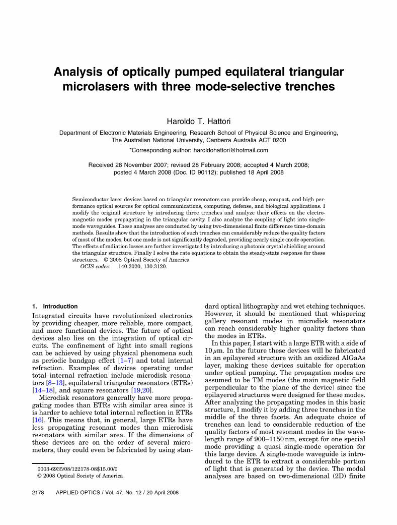
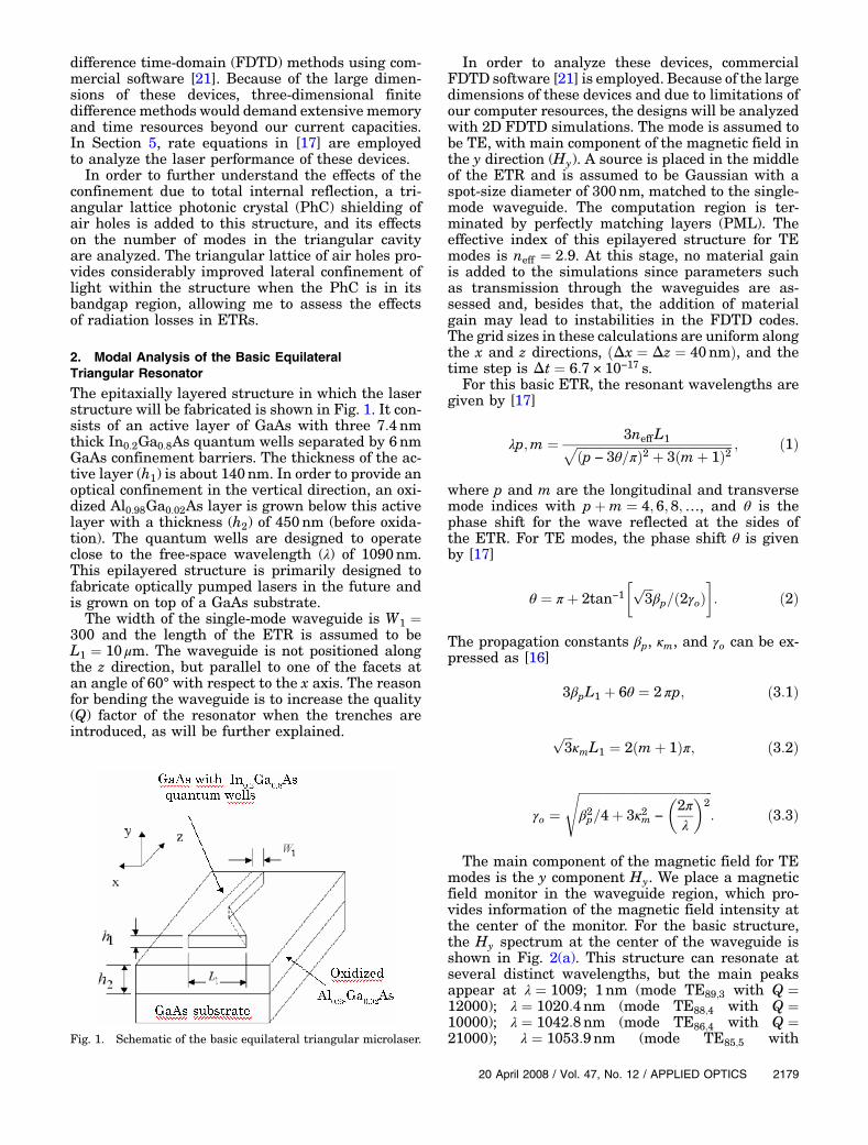
Now, PhC trenches (with same filling factor andlattice constant as the PhC shield) are introducedinside the ETR with a PhC shielding as shown inFig. 8. In Fig. 9(a), it can be noted that there aremany resonant peaks in the wavelength range be-tween λ ¼ 1000 and 1150nm. The modes with highQ appear at λ ¼ 1001:2nm (Q ¼ 12000), λ ¼1003:7nm (Q ¼ 11000), λ ¼ 1009:1nm (Q ¼ 13000),λ ¼ 1010:5nm (Q ¼ 8000), λ ¼ 1014:5nm (Q ¼11000), λ¼1016:5nm (Q ¼ 8000), λ ¼ 1023:7nm(Q ¼ 14000), λ ¼ 1027:7nm (Q ¼ 11000), λ ¼1033:8nm (Q ¼ 7000), λ ¼ 1043:6nm (Q ¼ 10000),λ ¼ 1052:6nm (Q ¼ 16000), λ ¼ 1058:5nm (Q ¼12000), λ ¼ 1062:4nm (Q ¼ 11000), λ ¼ 1066:9nm(Q ¼ 13000), λ ¼ 1069:1nm (Q ¼ 8000), λ ¼1071nm (Q ¼ 7000), λ ¼ 1076:1nm (Q ¼ 11000), λ ¼1077:6nm (Q ¼ 14000), λ ¼ 1089:1nm (Q ¼ 13000),λ ¼ 1090:1nm (Q ¼ 10000), λ ¼ 1092:5nm (Q ¼6000), λ ¼ 1094:6nm (Q ¼ 10000), λ ¼ 1100:9nmFig. 6. (Color online) Top view of the PhC ETR.
Fig. 7. (Color online) ETR with a PhC shielding L2 ¼ 1:5 μm.(a) Magnetic field spectrum (Hy) at the center of the waveguide.(b) Magnetic field distribution (Hy) at λ ¼ 1057:1nm.
2182 APPLIED OPTICS / Vol. 47, No. 12 / 20 April 2008
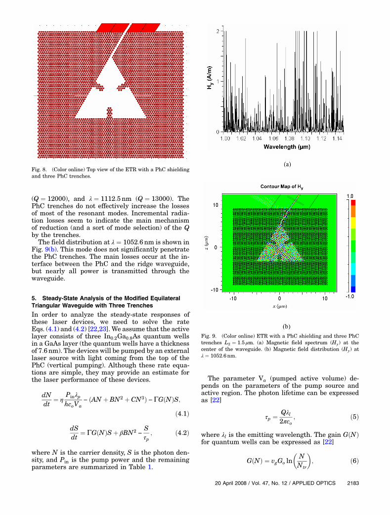
(Q ¼ 12000), and λ ¼ 1112:5nm (Q ¼ 13000). ThePhC trenches do not effectively increase the lossesof most of the resonant modes. Incremental radia-tion losses seem to indicate the main mechanismof reduction (and a sort of mode selection) of the Qby the trenches.The field distribution at λ ¼ 1052:6nm is shown in
Fig. 9(b). This mode does not significantly penetratethe PhC trenches. The main losses occur at the in-terface between the PhC and the ridge waveguide,but nearly all power is transmitted through thewaveguide.
5. Steady-State Analysis of the Modified EquilateralTriangular Waveguide with Three Trenches
In order to analyze the steady-state responses ofthese laser devices, we need to solve the rateEqs. (4.1) and (4.2) [22,23]. We assume that the activelayer consists of three In0:2Ga0:8As quantum wellsin a GaAs layer (the quantum wells have a thicknessof 7:6nm). The devices will be pumped by an externallaser source with light coming from the top of thePhC (vertical pumping). Although these rate equa-tions are simple, they may provide an estimate forthe laser performance of these devices.
dNdt
¼ η PinλphcoVa
− ðAN þ BN2 þ CN3Þ − ΓGðNÞS;ð4:1Þ
dSdt
¼ ΓGðNÞSþ βBN2−
Sτp
; ð4:2Þ
where N is the carrier density, S is the photon den-sity, and Pin is the pump power and the remainingparameters are summarized in Table 1.
The parameter Va (pumped active volume) de-pends on the parameters of the pump source andactive region. The photon lifetime can be expressedas [22]
τp ¼ Qλl2πco
; ð5Þ
where λl is the emitting wavelength. The gain GðNÞfor quantum wells can be expressed as [22]
GðNÞ ¼ vgGo ln�
NNtr
�; ð6Þ
Fig. 8. (Color online) Top view of the ETR with a PhC shieldingand three PhC trenches.
Fig. 9. (Color online) ETR with a PhC shielding and three PhCtrenches L2 ¼ 1:5 μm. (a) Magnetic field spectrum (Hy) at thecenter of the waveguide. (b) Magnetic field distribution (Hy) atλ ¼ 1052:6nm.
20 April 2008 / Vol. 47, No. 12 / APPLIED OPTICS 2183

where vg is the group velocity, Go ¼ 1:5 × 10⁵ m−1 isthe gain coefficient, and Ntr ¼ 1:5 × 1024 m−3 is thetransparency carrier concentration.Solving Eqs. (4.1) and (4.2) allow us to determine
the photon density S. The output power is then givenby [22]
Pout ¼ ηahcoλl
SVmode
τmirror; ð7Þ
where ηa is the coupling efficiency to the ridge, Vmodeis the optical mode volume, and τmirror ¼ τp is the mir-ror lifetime. In the case of structures that may emitat distinct wavelengths, the laser analyses are con-ducted only for the main resonant mode.Figure 10 shows the steady-state response for the
modified ETR with three trenches for the main modefor the structure without the PhC and W2 ¼ 1:0 μmand L2 ¼ 1:5 μm. In Fig. 10, the surface powerdensity is defined as the pump power divided byits spot-size area. The solid curve represents thesteady-state response for a pump wavelength of800nm, while the solid curve with square markersrepresents the steady-state response for a pump
wavelength of 670nm. As shown in this figure, wecan expect that the emitted power will be in therange of hundreds of microwatts.
6. Conclusions
In this paper, I have analyzed modified large equilat-eral triangular lasers and shown that the introduc-tion of three trenches can lead to a quasi single-mode operation of the device. It is expected that thisdevice will be able to couple hundreds of microwattsin a single-mode waveguide.
The author gratefully acknowledges the financialsupport of the Australian Research Council (ARC).
References1. O. Painter, R. K. Lee, A. Scherrer, A. Yariv, J. D. O’Brien, and
P. D. Dapkus, “Two-dimensional photonic bandgap defectmode laser,” Science 284, 1819–1821 (1999).
2. H. G. Park, J. K. Hwang, J. Huh, H. Y. Ryu, S. H. Kim, J. S.Kim, and Y. H. Lee, “Characteristics of modified single-defecttwo-dimensional photonic crystal lasers,” IEEE J. QuantumElectron. 38, 1353–1365 (2002).
3. D. S. Song, S. H. Kim, H. G. Park, C. K. Kim, and Y. H. Lee,“Single-fundamental-mode photonic crystal surface-emittinglasers,” Appl. Phys. Lett. 80, 3901–3903 (2002).
4. H. T. Hattori, V. M. Schneider, R. M. Cazo, and C. L. Barbosa,“Analysis of strategies to improve the directionality of squarelattice band-edge photonic crystal structures,” Appl. Opt. 44,3069–3076 (2005).
5. R. M. Cazo, C. L. Barbosa, H. T. Hattori, and V. M. Schneider,“Steady-state analysis of a directional square lattice band-edge photonic crystal laser,” Microw. Opt. Technol. Lett. 46,210–214 (2005).
6. H. T. Hattori, I. McKerracher, H. H. Tan, C. Jagadish, and R.M. De La Rue, “In-plane coupling of light from InP-basedphotonic crystal band-edge lasers into single-mode wave-guides,” IEEE J. Quantum Electron. 43, 279–286 (2007).
7. C. Seassal, C. Monat, J. Mouette, E. Touraille, B. Ben Bhakir,H. T. Hattori, J. L. Leclercq, X. Letartre, P. Rojo-Romeo, and P.Viktorovitch, “InP bonded membrane photonics componentsand circuits: toward 2.5 dimensional micro-nano-photonics,”IEEE J. Sel. Top. Quantum Electron. 11, 395–407 (2005).
8. T. Baba, “Photonic crystals and microdisk cavities based onGaInAsP/InP system,” IEEE J. Sel. Top. Quantum Electron.3, 808–830 (1997).
Table 1. Typical Laser Parameters
Symbol Quantity Typical value
η Absorption ratio of pump in QW region 0.26λp Pump wavelength 670nm or 800nmh Planck’s constant 6:626 × 10−34 m2 kg=sco Free-space velocity of light 299792458m=sηa Coupling efficiency 0.40A Propagation distance for surface recombination 2:5 × 10⁻⁸ s−1
B Bimolecular recombination coefficient 1:6 × 10⁻¹⁶ m=sC Auger nonradiative recombination rate 5 × 10−41 m6=sΓ Confinement factor 0.22β Spontaneous emission factor 10−4
Fig. 10. Steady-state response for the ETR with three trenchesand W2 ¼ 1:0 μm and L2 ¼ 1:5 μm without the PhC shielding.The solid curve is for λp ¼ 800nm and the solid curve with squaremarkers is for λp ¼ 670nm.
2184 APPLIED OPTICS / Vol. 47, No. 12 / 20 April 2008

9. M. Fujita, A. Sakai, and T. Baba, “Ultra-small and ultra-lowthreshold microdisk injection laser—design, fabrication, las-ing characteristics and spontaneous emission factor,” IEEEJ. Sel. Top. Quantum Electron. 5, 673–681 (1999).
10. A. F. J. Levi, R. E. Slusher, S. L. McCall, J. L. Glass, S. J.Pearton, and R. A. Logan, “Directional light coupling frommicrodisk lasers,” Appl. Phys. Lett. 62, 561–563 (1993).
11. S. J. Choi, K. Djordjev, and P. D. Dapkus, “Microdisk lasersvertically coupled to output waveguides,” IEEE PhotonicsTechnol. Lett. 15, 1330–1332 (2003).
12. S. V. Boriskina, T. M. Benson, P. D. Sewell, and A. I. Nosich,“Directional emission, increased free spectral range, andmodeQ-factors in 2-D wavelength-scale optical microcavity struc-tures,” IEEE J. Sel. Top. Quantum Electron. 12, 1175–1182(2006).
13. H. T. Hattori, C. Seassal, E. Touraille, P. Rojo-Romeo, X.Letartre, G. Hollinger, P. Viktorovitch, L. DiCioccio, M. Zussy,L. El Melhaoui, and J. M. Fedeli, “Heterogeneous integrationof microdisk lasers on silicon strip waveguides for optical in-terconnects,” IEEE Photonics Technol. Lett. 18, 223–225(2006).
14. S. Ando, N. Kobayashi, and H. Ando, “Triangular-facet laserwith optical waveguides grown by selective area metalorganicchemical vapor deposition,” Jpn. J. Appl. Phys. 35, L411–L413(1996).
15. S. Ando, N. Kobayashi, and H. Ando, “Triangular-facet laserscoupled by a rectangular optical waveguide,” Jpn. J. Appl.Phys. 36, L76–L78 (1997).
16. Y. Z. Huang, W. H. Guo, and Q. M. Wang, “Analysis and nu-merical simulation of eigenmode characteristics for semicon-ductor lasers with an equilateral triangle micro-resonator,”IEEE J. Quantum Electron. 37, 100–107 (2001).
17. Y. Z. Huang, W. H. Guo, L. J. Yu, and H. B. Lei, “Analysis ofsemiconductor microlasers with an equilateral triangle reso-nator by rate equations,” IEEE J. Quantum Electron. 37,1259–1264 (2001).
18. Y. Z. Huang, Y. H. Hu, Q. Chen, S. J. Wang, Y. Du, and Z. C.Fan, “Room-temperature continuous-wave electrically in-jected InP-GaInAsP equilateral-triangle-resonator lasers,”IEEE Photonics Technol. Lett. 19, 963–965 (2007).
19. W. H. Guo, Y. Z. Huang, Q. Y. Lu, and L. J. Yu, “Mode qualityfactor based on far-field emission for square resonators,” IEEEPhotonics Technol. Lett. 16, 479–481 (2004).
20. S. V. Boriskina, T. M. Benson, P. Sewell, and A. I. Nosich,“Spectral shift and Q-change of circular and square-shapedoptical micro-cavity modes due to periodic sidewall surfaceroughness,” J. Opt. Soc. Am. B 21, 1792–1796 (2004).
21. Fullwave 4.0 RSOFT design group, 1999, http://www.rsoftdesign.com
22. H. Altug and J. Vuckovic, “Photonic crystal nanocavity arraylaser,” Opt. Express 13, 8819–8828 (2005)
23. L. A. Coldren and S. W. Corzine, Diode Lasers and PhotonicIntegrated Circuits (Wiley, 1995).
20 April 2008 / Vol. 47, No. 12 / APPLIED OPTICS 2185