Simulation of tail buffet using delta wing-vertical tail configuration
12
SIMULATION OF TAIL BUFFET USING DELTA WING-VERTICAL TAIL CONFIGURATION Osama A. Kandil*, Hamdy A. Kandil**, and Steven J. Massey*** Old Dominion University, Norfolk, VA 23529 ABSTRACT Computational simulation of the vertical tail buf- fet problem is accomplished using a delta wing- vertical tail configuration. Flow conditions are se- lected such that the wing primary-vortex cores expe- rience vortex breakdown and the resulting flow in- teracts with the vertical tail. This multidisciplinary problem is solved successively using three sets of equations for the fluid flow, aeroelastic deflections and grid displacements. For the fluid dynamics part, the unsteady, compressible, full Navier-Stokes equa- tions are solved accurately in time using an im- plicit, upwind, flux-difference splitting, finite-volume scheme. For the aeroelastic part, the aeroelastic equa- tion for bending vibrations is solved accurately in time using the Galerkin method and the four-stage Runge-Kutta scheme. The grid for the fluid dynamics computations is updated every few time steps using a third set of interpolation equations. The computa- tional application includes a delta wing of aspect ra- tio 1 and a rectangular vertical tail of aspect ratio 2, which is placed at 0.5 root-chord length downstream of the wing trailing edge. The wing angle of attack is 35" and the flow Mach number and Reynolds number are 0.4 and 10,000; respectively. INTRODUCTION Recently, the design of modern fighter aircraft has been focused on the high angle of attack maneuver- ability at high loading conditions, and the interest in the tail buffet problem is again renewed. For these fighters, the ability to fly and maneuver at high angles of attack is of prime importance. This capability is achieved, for example in the F/A-18 fighter, through the combination of the leading-edge extension (LEX) of the delta wing and the use of vertical tails. The LEX maintains lift at high angles of attack by gener- ating a pair of vortices that trail aft over the top of the Professor, Eminent Scholar and Chairman of Aerospace Engineering Dept., Associate Fellow AIAA. .. Research Associate, Aerospace Engineering Dept., Member AIAA. .** Graduate Research Assistant, Aerospace Engineering Dept., Member AIAA. Copyright O 1993 by Osama Kandil. Published by The American Institute of Aeronautics and Astronautics, Inc. with permission. aircraft. The vortex entrains air over the vertical tails to maintain stability of the aircraft. This combination of LEX and vertical tails leads to the aircraft excel- lent high angle of attack performance. However, at some flight conditions, the vortices emananting from the highly-swept LEX of the delta wing breakdown before reaching the vertical tails which get bathed in a wake of highly-turbulent, swirling flow. The vortex-breakdown flow produces severe buffet on the vertical tails and has led to their premature fatigue failure. Buffeting of the vertical tails of the F/A-18 fits into this category. During flight operations of this airplane large vibrations of the vertical tails have been observed. Sellers et al.' conducted some three-component velocity surveys for a YF-17 model (a configura- tion similar to the F-18) at low speeds. Their re- sults clearly show that at 25" angle of attack the vortex produced by the LEX experiences breakdown and that there are large fluctuations in the velocity in the vicinity of the vertical tails. They measured rms fluctuations as high as 40% of the freestream stream velocity. Erickson, et a1.2 presented a wind tunnel investigation of the F/A-18 aircraft. The investiga- tion focused mainly on the measurements of steady forces and pressures on the LEX and laser light sheet measurements of the vortex structure. Some water tunnel studies conducted by wentz3 using an F-18 model also showed that the vortex produced by the LEX of the wing breaks down ahead of the vertical tails at angles of attack of 25" and higher. If these flows contain substantial energy at frequencies corre- sponding to the lower modes of vibration of the tail structure, significant structural response can result. Another wind tunnel investigation of buffeting is published by Lee and ~ r o w n ~ . The buffeting on the vertical fin of a rigid 6% model of the F/A-18 has been investigated. Unsteady pressure measurements on the vertical fin were conducted and the vortex flow structure behind the fin was studied. The study was carried out with LEX fences on and off to conclude that the LEX fence has a small influence on the steady balance measurements such as lift and pitching moment.
Transcript of Simulation of tail buffet using delta wing-vertical tail configuration

SIMULATION OF TAIL BUFFET USING DELTA WING-VERTICAL TAIL CONFIGURATION
Osama A. Kandil*, Hamdy A. Kandil**, and Steven J. Massey*** Old Dominion University, Norfolk, VA 23529
ABSTRACT
Computational simulation of the vertical tail buf- fet problem is accomplished using a delta wing- vertical tail configuration. Flow conditions are se- lected such that the wing primary-vortex cores expe- rience vortex breakdown and the resulting flow in- teracts with the vertical tail. This multidisciplinary problem is solved successively using three sets of equations for the fluid flow, aeroelastic deflections and grid displacements. For the fluid dynamics part, the unsteady, compressible, full Navier-Stokes equa- tions are solved accurately in time using an im- plicit, upwind, flux-difference splitting, finite-volume scheme. For the aeroelastic part, the aeroelastic equa- tion for bending vibrations is solved accurately in time using the Galerkin method and the four-stage Runge-Kutta scheme. The grid for the fluid dynamics computations is updated every few time steps using a third set of interpolation equations. The computa- tional application includes a delta wing of aspect ra- tio 1 and a rectangular vertical tail of aspect ratio 2, which is placed at 0.5 root-chord length downstream of the wing trailing edge. The wing angle of attack is 35" and the flow Mach number and Reynolds number are 0.4 and 10,000; respectively.
INTRODUCTION
Recently, the design of modern fighter aircraft has been focused on the high angle of attack maneuver- ability at high loading conditions, and the interest in the tail buffet problem is again renewed. For these fighters, the ability to fly and maneuver at high angles of attack is of prime importance. This capability is achieved, for example in the F/A-18 fighter, through the combination of the leading-edge extension (LEX) of the delta wing and the use of vertical tails. The LEX maintains lift at high angles of attack by gener- ating a pair of vortices that trail aft over the top of the
Professor, Eminent Scholar and Chairman of Aerospace Engineering Dept., Associate Fellow AIAA. .. Research Associate, Aerospace Engineering Dept., Member AIAA.
.** Graduate Research Assistant, Aerospace Engineering Dept., Member AIAA.
Copyright O 1993 by Osama Kandil. Published by The American Institute of Aeronautics and Astronautics, Inc. with permission.
aircraft. The vortex entrains air over the vertical tails to maintain stability of the aircraft. This combination of LEX and vertical tails leads to the aircraft excel- lent high angle of attack performance. However, at some flight conditions, the vortices emananting from the highly-swept LEX of the delta wing breakdown before reaching the vertical tails which get bathed in a wake of highly-turbulent, swirling flow. The vortex-breakdown flow produces severe buffet on the vertical tails and has led to their premature fatigue failure. Buffeting of the vertical tails of the F/A-18 fits into this category. During flight operations of this airplane large vibrations of the vertical tails have been observed.
Sellers et al.' conducted some three-component velocity surveys for a YF-17 model (a configura- tion similar to the F-18) at low speeds. Their re- sults clearly show that at 25" angle of attack the vortex produced by the LEX experiences breakdown and that there are large fluctuations in the velocity in the vicinity of the vertical tails. They measured rms fluctuations as high as 40% of the freestream stream velocity. Erickson, et a1.2 presented a wind tunnel investigation of the F/A-18 aircraft. The investiga- tion focused mainly on the measurements of steady forces and pressures on the LEX and laser light sheet measurements of the vortex structure. Some water tunnel studies conducted by wentz3 using an F-18 model also showed that the vortex produced by the LEX of the wing breaks down ahead of the vertical tails at angles of attack of 25" and higher. If these flows contain substantial energy at frequencies corre- sponding to the lower modes of vibration of the tail structure, significant structural response can result.
Another wind tunnel investigation of buffeting is published by Lee and ~ r o w n ~ . The buffeting on the vertical fin of a rigid 6% model of the F/A-18 has been investigated. Unsteady pressure measurements on the vertical fin were conducted and the vortex flow structure behind the fin was studied. The study was carried out with LEX fences on and off to conclude that the LEX fence has a small influence on the steady balance measurements such as lift and pitching moment.

Rao, Puram and shahS proposed two aerodynamic concepts for alleviating high-alpha tail buffet charac- teristics of LEX vortex dominated twin tail fightcr configurations. These concepts were explored in low specd tunnel tests on generic models via flow visu- dilations, 6-component balance measurements and monitoring of tail dynamics. Passive dorsal-fin exten- sions of the vertical tails, and an active LEX arrange- ment with up-deflected edge sections were evaluated as independent means of re-structuring the adverse vortical flow environment in the tail region. Each of these techniques successfully reduced the buffet. Used in combination, the two concepts indicated sig- nificant tail buffet relief with relatively minor impact on the high u configuration aerodynamics.
Cole, Moss and ~ o g g e t t ~ tested a rigid, 116 size, full-span model of an F-18 airplanc that was fit- tcd with flexible vertical tails of two different stiff- ncss. Vertical-tail buffct rcsponse results were ob- taincd over the range of angles of attack from -10" to +40°, and over the range of Mach numbers from 0.3 to 0.95. Their results indicated that the buffct response occurs in the first bcnding rnodc, increases with increasing dynamic pressure and is larger at M = 0.3 than that at a higher Mach number.
So far, there are no available theoretical or com- putational nlcthods to predict and control the aeroe- lastic buffet characteristics of vertical tails. The cru- cial point in predicting the buffet characteristics is thc knowledge of the driving unsteady airloads asso- ciated with flow scparations and vortex breakdown. ~dwards ' prcscnted a good assessment of the cornpu- tational cost of this problem for a full fighter aircraft. The principal author of this paper has proposed two simple models to simulate and study the vertical-tail buffet problcm at a substantially reduccd computa- tional cost in comparison with the cost of solving for the flow around a full fighter aircraft. The basic concept behind thcse models is to be able to gener- ate an unsteady, vortex-breakdown flow and to place a vcrtical tail, which is cantilevered, in thc down- stream of the vortex-brcakdown flow. In this way, the buffet problem 1s isolated from thc wholc config- uration and the computational resources are focused on a small region for high resolution. The first pro- posed model consists of a configured duct in which the inlct swirling flow is forced to breakdown either through a shock waveX (for transonic and supcrsonic inlet flows) or through a gradual adverse pressure gra- dicnt that is generated by thc duct wall (for subsonic
inlet swirling flows). Downstream of the breakdown flow, a vcrtical cantilevered tail is placed. In the sec- ond model, the configuration consists of a delta wing at a critical angle of attack which produces break- down of the leading-edge vortex cores9. Downstream of the breakdown flow, a vcrtical single or twin-tail configuration which is fixed as a cantilever is placed.
In the prcsent paper, the second model is con- sidered for the computational simulation. The model consists of a delta wing of aspect ratio 1 and a sin- gle, rectangular, vertical tail of aspect ratio 2. The tail is placed at 0.5 root-chord length downstream of the wing trailing edge. The tail is cantilevered at the lower side and the configuration is pitched at 35" an- gle of attack. The flow Mach number and Reynolds number are 0.4 and 10,000, respectively. The prob- lem is solved sequentially using the time-accurate integration of the laminar, unsteady, compressible Navier-Stokes equations, the aeroelastic equation for a bcam in a bending modc and a set of equations to update the grid-points locations.
FORMULATION
The formulation of the problem consists of three sets of governing equations along with certain ini- tial and boundary conditions. The first set is the laminar, unsteady, compressible, full Navier-Stokes equations. The second set consists of the aeroelas- tic equations for the vibration modes which could be coupled bending and torsion modes. In the present paper, only the bending vibration is considered with- out structural damping or nonlincarities, which could be addcd in the future wirhout any difficulty. The third set consists of equations for calculating the grid displacements due to the tail deflections. The liter- ature shows various nlcthods to move the grid. The simplest methods use simple interpolation functions such that the grid points adjacent to the acroclastic surface move with the surface while the grid points at the computational-region boundary do not In the more advanced methods for moving the grid, Ihe grid is simulated a a s t a t i ~ ' ~ - ~ ~ or dynamic truss. The unsteady, linearized, Navier-displacement equa- tions have also becn used successfully by Kandil ct al. to move the grid dynamically'5~'h. In the present paper, we use simple grid interpolation to move the grid. Next, the governing equations for each set are given:
Fluid Flow:
The conservative form of the dimensionless, unsteady, compressible, full NS equations in terms of time-dependent, body-conformed coordi- nates t l , t2 and ez is given by
Ern z inviscid flux
- viscous and heat-conduction flux i n t" direction
1
The first element of the three momentum elements of Eq. (5) is given by
The second and third elements of the momentum elements are obtained by replacing the subscript 1, everywhere in Eq. (7), with 2 and 3, respectively. The last element of Eq. (5) is given by
The reference parameters for the dimensionless form of the equations are c*, a,, c*/a,, p, and p, for the length, velocity, time, density and molecular vis- cosity, respectively. The Reynolds number is defined as Re = p,V,c*/p,, where c* is root-chord length of the wing. The pressure, p, is related to the total energy per unit mass and density by the gas equation
The viscosity is calculated from the Sutherland law
and the Prandtl number P, = 0.72. In Eqs. (1)-(8), the indicia1 notation is used for convenience.
Aeroelastic Deflections:
In the present paper, the vertical rectangular tail is treated as a homogeneous, uniform, cantilevered beam with rectangular section. For bending vibration, the dimensionless equation for the deflection w ( z , t ) is given by
8% a2w EI- + m- = N ( z , t )
a z 4 at';! (11)
where z is the vertical distance from the fixed sup- port along the beam length, I t , E the modulus of elasticity, I the area moment of inertia, m the mass per unit length and N is the net surface pressure force per unit length. The dimensionless form of w , z , E, I , m and N are given by
where c* is the wing root-chord length, p k the freestream air density, a, the freestream speed of sound, d* the tail thickness, b* the tail chord length and the "*" denotes dimensional quantities. The ge- ometrical and natural boundary conditions are given
by
The solution to Eq. (11) is given by
where qhj(z) are comparison functions which satisfy the boundary conditions, and they are given by the natural modes of vibration
and /3j are the eigenvalues obtained from the solution of cos @lt cosh Dlt = - 1. Substituting Eq. (14) into Eq. (11) and using the Galerkin method, the follow- ing equation is obtained for the generalized coordi- nates q j ( t ) :
j=l j=1
where
mrj elements o f mass matr ix
kr j E elements o f s t i f f n e s s matrix
N , = generalized force = l1 iVdrdz (l7.c)
Since m, I and E are constants and 4, are orthogo- nal, the mass and stiffness matrices are diagonal and the set given by Eq. (16) is decoupled. Hence, the solution to the present simple case reduces to the so- lution of a decoupled set of second-order, ordinary- differential equations, where each equation corre- sponds to one of the natural modes. The solution is obtained either by a closed-form convolution inte- gral or by a four-stage Runge-Kutta scheme. For the jth mode shape, Eq. (16) becomes
krr ,jj + -qj = - N r ( t ) ( n o summation over r ) m r r m r r
(17) The convolution integral solution for this equation is given by
where w: = = a, m q j (0 ) is the initial displace- ment and ~ ~ ( 0 ) is the initial velocity.
If m, I and E are functions of z , then Eq. (16) will be a coupled set and one needs to use a normal- mode shape transformation from q( t ) to ~ ( t ) to de- couple the resulting set. For a coupled bending and torsion vibration, the present procedure can be gen- eralized to obtain the solution. For the aeroelastic equations in the latter case, the solution is obtained using the four-stage Runge-Kutta scheme.
Grid Displacements:
In the present paper, we use simple interpolation functions to displace the grid due to the tail deflection. For bending vibrations, the tail deflection at any point on its surface, wij%h, is in the spanwise direction (y coordinate). The spanwise coordinate of a grid point $:: at the time level n + 1 is computed from the equation
where Yis,ldim/4sk is the maximum y coordinate of a grid point at the boundary of the computational domain with an index of Jd im/4 . Thus, the tail displacement w::; is distributed through a cosine function among the y coordinates of the grid. Thus, a point on the tail is displaced by the total deflection and a point at the boundary is not displaced.
Boundary and Initial Conditions:
Boundary conditions consist of conditions for the fluid flow and conditions for the aeroelastic deflection of the tail. For the fluid flow, the Riemann-invariant boundary conditions are enforced at the inflow and outflow boundaries of the computational domain. At the plane of geometric symmetry, a periodic boundary condition is specified with the exception of grid points on the tail. On the wing surfaces, the no-slip and no-penetration conditions are enforced and 2 = 0. On the tail surfaces, the no-slip and no-penetration conditions for the relative velocity components are enforced (points on the tail surface are moving). The normal pressure gradient is no longer equal to zero since points on the tail surface are accelerating. This
A condition becomes $ = -p,at, where at is the acceleration of a point on the tail, @ ( z , t ) . For the boundary conditions of the aeroelastic deflection of the tail, they are given by Eq. (13).
Initial conditions consist of conditions for the fluid flow and conditions for the aeroelastic defleclion of the tail. For the fluid flow, the initial conditions
correspond to the freestream conditions with u 1 = u2 = T L . ~ = 0 on the wing and tail. For the aeroelastic deflection of the tail, the initial conditions for any point on the tail is that the displacement and velocity
371 are zeros, w ( z , n ) = = ( z , o ) = O
METHOD O F SOLUTION
The first step is to solve for the fluid-flow prob- lem using the vortex-breakdown conditions and keep- ing the tail as a rigid beam. Equations (1)-(10) are solved time-accurately using the implicit, upwind, flux-difference splitting finite-volume scheme. The
a<"' grid speed ?ii- is set equal to zero in this step. This step provides the flow field solution along with the pressure difference across the tail. The pressure dif- ference is used to generate the force per unit length of the tail, K. Next, Eqs. (14) and (18) are used to ob- tain the tail deflections, wL,] I;. Equation (19) is used to compute the grid coordinates. The metric coeffi- cients of the coordinate Jacobian matrix are updated as well as the grid speed, g. Next. the compu- tational cycle is repeated using Eqs. (])-(lo) for the pressure difference across the tail, Eqs. (14) and (18) for the tail deflections and Eq. (19) for the grid co- ordinates. It should be noted that the time step for the fluid-flow problem, Atj , is an order of magnitude less than the time step for the aeroelastic deflection, Atd. Moreover, the maximum tail deflection r r - for each Atd is very small. Hence, one does not need to compute IL, for each time step Atf For example, if Atd = 10 At f , the computation of the aeroelas- tic deflections and grid coordinates can be performed every 10 Atp
COMPUTATIONAL APPLICATIONS
The delta wing-vertical tail configuration consists of a sharp-edged, delta wing of aspect ratio 1 and a rectangular, vertical tail of aspect ratio 2, which is placed in the plane of geometric symmetry. The vertical-tail leading edge is located at 0.5 root-chord length from the wing trailing edge. The lower edge of the tail is along the wing axis and the tail is clamped at that edge. The wing angle of attack is 35" and the freestream Mach number and Reynolds number are 0.4 and 10,000, respectively. An 0 - H grid of 125x 85x 84 grid points in the wrap-around, normal and axial directions, respectively, is used for the solution of the fluid-flow part of the problem.
The solution and analysis of this problem have progessed through rigorous steps in order to prove
the capability of the present model for simulating the present multidisciplinary problem:
Step 1. Fluid Flow Around the Configuration:
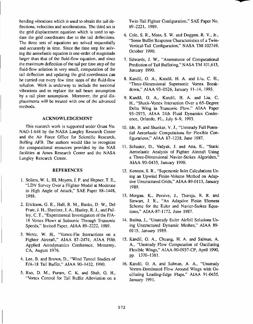
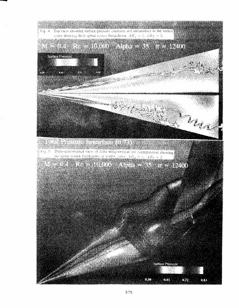
The laminar, unsteady, compressible, full Navier- Stokes equations have been integrated time accurately using the implicit, upwind, flux-difference splitting, finite-volume scheme with At = 0.003. During this step, the tail is kept rigid. Figure 1 shows the s p n - wise, surface-pressure coefficient (Cp) on the wing at different chord stations at i t = 12,400 (37.2 dimen- sionless time). At z = 0.421, the Cp-curve shows asymmetry with the pressure on the left side having less suction than the pressure on the right side (look- ing in the upstream direction). This indicates that the left-vortex-core s i x is enlarging. In Fig. 4, it is noticed that at this location a spiral saddle point is formed and a spiral vortex-breakdown mode is de- veloping downstream of that point. Returning back to Fig. 1, it is noticed that the asymmetry exists in all the cross-flow planes downstream of x = 0.421. At n: = 0.814, a rapid decrease in the suction pres- sure on the left side is observed and Fig. 4 shows several spiral saddle points at that location. At z = 0.944, a rapid decrease in the suction pressure on the right side is observed and spiral vortex breakdown develops in the right vortex core (see Fig. 4). Figure 2 shows the total-pressure-loss contours and stream- lines for the left and right sides at different chord stations. The asymmetry is very clear at n: = 0.65 and 1.0. At n: = 1.0 and on the right side, it is no- ticed that a repelling focus (two-dimensional sense of topology) exists, which indicates the existence of vortex breakdown.
Figure 3 shows the streamlines in cross-flow planes at two chord stations n: = 1.375 and n: = 2.019. The vertical-tail leading edge is located at x = 1.5 and its trailing edge is at n: = 2.0. It is clear that the vertical tail is subjected to asymmetric, unsteady, surface-pressure loads due to the vortex-breakdown flow. Figures 4 and 5 show a plan view of the wing and a three-dimensional view of the wing-tail con- figuration, respectively, along with the spiral saddle points and the asymmetric spiral vortex-breakdown modes of the leading-edge vortex cores.
Figure 6 shows snapshots of the pressure contours on the right (.I = 1) and left (.I = J d i ~ n ) surfaces of the vertical tail and the pressure-difference on it at two time levels; it = 12,400 and it = 12,600. A close inspection of these loads reveals that the tail
is subjected to both bending and torsional loads. In the present paper, only the bending vibration is taken into consideration (torsional vibrations are also under consideration). Figure 7 shows the corresponding lumped, aerodynamic force per unit length of the tail, N ( z ) , at two time levels, t = 37.2 and t = 37.8. It is noticed that within this short time of change, N ( z ) changes rapidly in magnitude and direction. The results at it = 12,600 are used for the initial conditions of the buffet problem (i.e. letting the tail deflect and interact dynamically with the flow).
Step 2. Tail Aeroelastic Deflections:
As it has been pointed out earlier, only bending vibrations are considered in the present paper. The solution for this part is given by Eqs. (14) and (18). This solution is coded in a computer program which can also use the four-stage Runge-Kutta scheme to obtain the solution, in addition to the closed-form convolution integral. The code has been tested for an isolated beam which is subjected to a harmonic forcing function per unit length of the form N ( z , t ) = 0.12 sin w f t , where wf is the forcing frequency. The beam is assumed to be homogeneous and uniform with rectangular cross section of thickness d = 0.02 and width b = 0.157. The dimensionless modulus of elasticity is E = 0.4903 x 10' and EI = 0.0513. The dimensionless mass per unit length is rn = 7.177. The dimensionless natural frequencies of this beam are 1.85795; 11.64434; 32,60776; . . . etc. Choosing the forcing frequency w f l to be 1.84, the deflection, w, is obtained using six natural modes of vibrations, 4,, T = 1 - 6 and At = 0.02. Figure 8 shows w vz t for two points on the beam (mid point and free- end point) and it is noticed that the envelope of the response reached a maximum value of 0.47 after t = 160. With zu f z = 1.858, which coincides with the fundamental frequency 1.85795, the envelope of the response grows without a bound. Having established confidence in the solution of the bending equation, the next step is to combine the fluid flow program with the aeroelastic program and the grid-displacements equation given by Eq. (19).
Step 3. Fluid Flow and Tail Deflections:
With the initial-flow conditions obtained in Step 1 at it = 12,600, the aerodynamic force per unit length AT,(z, t ) is provided discretely to the aeroelastic pro- gram and the generalized forces N, are computed for six natural mode shapes. The deflections w are computed using Eqs. (14) and (18). Next, Eq. (19)
is used to obtain the updated y-coordinates for the grid, the metric coefficients of the Jacobian matrix, the grid speed; and the velocity and acceleration of the points on the tail for the modified boundary con- ditions for the fluid-flow solution. Next, the fluid flow part is solved and N,(z , t ) is obtained and the computational cycle is repeated. The tail is treated as a homogeneous, uniform, rectangular beam with rectangular cross section of d = 0.01 and width b = 0.5. The dimensionless modulus of elasticity is E = 0.4903 x 1 0 b d EI = 0.0204 x 10 -% The di- mensionless mass per unit length is m = 11.428. Fig- ure 9 shows the tail-deflection responses and the aero- dynamic forces per unit length versus the vertical co- ordinate z every 100 time step (every 0.3 dimension- less time). The deflection versus time is also shown for the tail midpoint and its free-end point. The de- flection curves show that the deflections on the tail are positive for the early time steps (up to it = 13,000). Beyond it = 13,000, the deflections increase by one order of magnitude and become mostly negative with positive values on the upper part of the tail. The tail deflections are consistent with the aerodynamic forces per unit length due to the vortex-breakdown flow. It is concluded that vortex-breakdown flow on the left surface of the tail produces more suction pres- sure than that of the vortex-breakdown flow on the right surface of the tail. The deflection-versus-time curves show that after if = 13,000 steps (400 steps for the buffet calculations), the deflections increase very rapidly by an order of magnitude. This indicates that the unsteady vortex-breakdown loads might have excited one or more of the tail natural frequencies. However, it is too early to tell whether the tail is res- onating. Solutions for larger time are still underway.
CONCLUDING REMARKS
The buffet problem of a vertical tail due to the in- teraction of vortex-breakdown flow with the tail has been simulated computationally and efficiently using a delta wing-vertical tail configuration. The wing as- pect ratio and flow conditions have been carefully se- lected in order to produce unsteady vortex-breakdown flow. The solution has demonstrated the development of the tail buffet due to the unsteady loads produced by the vortex-breakdown flow. The problem is a multidisciplinary problem which requires three sets of equations to obtain its solution. The first set is the unsteady Navier-Stokes equation which is used to obtain the aerodynamics force per unit length on the tail. The second set is the aeroelastic equation for
bending vibrations which is used to obtain the tail de- flections, velocities and accelerations. The third set is the grid displacement equation which is used to up- date the grid coordinates due to the tail deflections. The three sets of equations are solved sequentially and accurately in time. Since the time step for solv- ing the aeroelastic equation is one-order of magnitude larger than that of the fluid-flow equation, and since the maximum deflection of the tail per time step of the fluid-flow solution is very small, computation of the tail deflection and updating the grid coordinates can be carried out every few time steps of the fluid-flow solution. Work is underway to include the torsional vibrations and to replace the tail beam assumption by a tail plate assumption. Moreover, the grid dis- placements will be treated with one of the advanced methods.
ACKNOWLEDGEMENT
This research work is supported under Grant No. NAG-1-648 by the NASA Langley Research Center and the Air Force Office for Scientific Research, Bolling AFB. The authors would like to recognize the computational resources provided by the NAS facilities at Ames Research Center and the NASA Langley Research Center.
REFERENCES
1. Sellers, W. L. 111, Meyers, J. F. and Hepner, T. E., "LDV Survey Over a Flighter Model at Moderate to High Angle of Attack," SAE Paper 88-1448, 1988.
2. Erickson, G. E., Hall, R. M., Banks, D. W., Del Frate, J. H., Shreiner, J. A., Hanley, R. J., and Pul- ley, C. T., "Experimental Investigation of the F/A- 18 Vortex Flows at Subsonic Through Transonic Speeds," Invited Paper, AIAA 89-2222, 1989.
3. Wentz, W. H., "Vortex-Fin Interactions on a Fighter Aircraft," AIAA 87-2474, AIAA Fifth Applied Aerodynamics Conference, Monterey, CA, August 1976.
4. Lee, B. and Brown, D., "Wind Tunnel Studies of FIA-18 Tail Buffet," AIAA 90-1432, 1990.
5.Ra0, D. M., Puram, C. K. and Shah, G. H., "Vortex Control for Tail Buffet Alleviation on a
Twin-Tail Fighter Configuration," SAE Paper No. 89-2221, 1989.
6. Cole, S. R., Moss, S. W. and Doggett, R. V., Jr., "Some Buffet Response Characteristics of a Twin- Vertical-Tail Configuration," NASA TM-102749. October 1990.
7. Edwards, J. W., "Assessment of Computational Prediction of Tail Buffeting," NASA TM 101,613, January 1990.
8. Kandil, 0. A., Kandil, H. A. and Liu, C. H., "Three-Dimensional Supersonic Vortex Break- down," AIAA 93-0526, January 11-14, 1993.
9. Kandil, 0. A., Kandil, H. A. and Liu, C. H., "Shock-Vortex Interaction Over a 65-Degree Delta Wing in Transonic Flow," AIAA Paper 93-2973, AIAA 24th Fluid Dynamics Confer- ence, Orlando, FL, July 6-9, 1993.
10. Ide, H. and Shankar, V. J., "Unsteady Full Poten- tial Aeroelastic Computations for Flexible Con- figurations," AIAA 87-1238, June 1987.
11. Schuster, D., Vadyak, J. and Atta, E., "Static Aeroelastic Analysis of Fighter Aircraft Using a Three-Dimensional Navier-Stokes Algorithm," AIAA 904435, January 1990.
12. Kennon, S. R., "Supersonic Inlet Calculations Us- ing an Upwind Finite-Volume Method on Adap- tive Unstructured Grids," AIAA-89-0 1 13, January 1989.
13. Morgan, K., Peraive, J., Thareja, R. R. and Stewart, J. R., "An Adaptive Finite Element Scheme for the Euler and Navier-Stokes Equa- tions," AIAA-87- l 172, June 1987.
14. Batina, J., "Unsteady Euler Airfoil Solutions Us- ing Unstructured Dynamic Meshes," AIAA 89- 01 15, January 1989.
15. Kandil, 0. A., Chuang, H. A. and Salman, A. A,, "Unsteady Flow Computation of Oscillating Flexible Wings," AIAA-90-0937-CP, April 1990, pp. 1370-1381.
16. Kandil, 0. A. and Salman, A. A., "Unsteady Vortex-Dominated Flow Around Wings with Os- cillating Leading-Edge Flaps," AIAA 91-0435, January 1991.

- 3 . 5 . , . , , , . , , , , , , , , , , , Prossur . dirtribution a t 8.629
-3.0
- 2 . 5
-2.0
0
.5
1 . 0

Fig. 2. Total-pressure-loss contours and the wing at different chord stations; Ah',, = 1, ART = 2, Jrl, = 0.4, n = 3s0, Re = 1OZ1, it = 12, 400.
X = 1 3 7 5
Fig. 3. Streamlines on the left and right sides in the wake at different chord stations; .-IRE, = 1 , ARY1 = 2, ,\I, = 0.4, (1 = 3Z0, Re = lo4, l t = 12.400.

1 . 4 9 ~ - 1 0 0 . 4 9 J=JDIM 2 . 0 0
PRESS. CONTOURS ON THE VERTICAL TAlL
Pressure-Difference on Tail Mz0.4 Re=tO.000 Alpha=35 i l= t%1m
1 . 4 ' 1 J = I 2 . 0 0 1 . 4 9 , J..JDIM 2 . 0 0
PRESS. CONTOURS ON THE VERTICAL TAlL
Pressure-Difference on Tail Mz0.4 Ro=tO.MM Alpha=35 i k 1 2 W 0
Fig. 6. Pressure contours on the right (.J = 1) and left (.J = .JDIAI) surfaces of the tail and the pressure difference at two time levels, i t = 12,400; it = 12, GOO.
.OOW - Lumped Force,N(z)
.o 001 -
O W 0.10 0 20 0 30 040 0 SO 060 0.70 0 UO 080 I00
Lumped Force,N(z)
Fig. 7. Lumped force per unit length on the tail at two time levels; it = 12, 400; i t = 12, GOO.
OW00 M=O4 Re=10.000 Alphn=35 11=12400 -
0 W70

Fig. 8. Deflection of two points vz time for an isolated beam due to a force per unit length of N ( z , t ) = 0.12 sinwrt at two values of forcing frequency, w l l = 1.84, wr2 = l.S5S, E = 0.4903 x loG, E I = 0.0513, I n = 7.177, l t = 1, At = 0.02.
Displacement Distribution
-&025 -0.002 -0.0015 -0.001 -0.0005 0 O.MW)5 0.001 Displacement, w
Force Distribution
Displacement Distribution I I I I I I
I'LO.5.dat" - . . . .. .. . .. : .. . .+.-. ?Ll:O:daty -
,' \, :.
I --. , \ 1 :
, I I '\ : ' I - , 1 . . ... \ : - : /
r \ . ! , I
' \ '
, I \ : \ .
. . . . . .
I I I I 1 I
0 200 400 600 800 1000 1200 1400 time steps
Fig. 9. Tail deflections and aerodynamic forces per unit length versus tail vertical coordinate every 100 time steps (0.3) and deflection of two points on tail (at midpoint and free end) versus time; E = 0.4903 x 10², E I = 0.0204 x 10-", ln = 11.428, l1 = 1, At = 0.003.