Force-Feedback Surgical Teleoperator: Controller Design and Palpation Experiments
Simulation of a manual gearshift
with a 2 DOF force-feedback joystick
Antonio Frisoli Carlo A. Avizzano Massimo Bergamasco
PERCRO
Scuola Superiore S. Anna
Pisa, Italy 56127
[email protected], [email protected], [email protected]
Abstract
A 2 dof force-feedback joystick was employed to sim-
ulate the force response of a manual gearshift of car
during drive. The control law is based on an hybrid
model. A state machine determines the active state of
the system, according to the simulation, and changes
the parameters of the dynamical model. The operator
can move the gearshift lever whether such a movement
would be allowed in an actual transmission under simi-
lar circumstances. The obtained performance was com-
pared to the experimental data, measured on a real car.
The simulated and experimental results match satisfac-
torily and the joystick gives a realistic feel of an actual
manual transmission.
1 IntroductionVehicle simulators, and in particular aircraft simu-
lators for use in training pilots, can be equipped with
various control devices such as acceleration, brake and
clutch pedals, gear change lever and steering wheel, to
enhance the realism of the simulation.
The adoption of Haptic Interfaces (HI) inside simu-
lator systems appears to be an added value, improving
their functionality. HI allow to logically program and
control their mechanical response. In such a way in
tests inside simulators users can evaluate the vehicle by
changing either kinesthetics or haptic parameters. This
is particularly useful when ergonomics aspects are taken
into consideration [1, 6].
In most of simulators [7, 2, 5], control commands
are employed as passive sensorized systems, replicating
the interaction forces exchanged during normal drive
conditions.
In [8] the steer wheel was replaced with a force con-
trolled Haptic Interface, whose behavior was based on
an internal numerical model of the vehicle.
The ATARI corporations patented two inventions re-
garding the simulation of a gearshift [3, 4]. The de-
vised systems are based on a mechanism allowing the
gearshift lever to pivot around at least two axes. In
the �rst invention [3] the mechanism is equipped with
electrically operable clutches, that can cause only resis-
tance to the movement of the lever. Positional sensors
and strain gauges coupled to the gearshift lever sense
the lever movements and forces.
In the second invention [4] a solenoid is coupled to the
pivoting mechanism to control the amount of applied
force.
This paper presents the design of the control law for
an HI, to be integrated as a gear change lever in a car
driving simulator, aimed at evaluating the ergonomics
of internals of car in Virtual Environments [1]. A com-
mercially available force feedback joystick was used to
assess the control algorithm. The control law will be
�nally implemented on a 2 DOF Haptic Interface pro-
totype, currently under construction at PERCRO.
The paper is organized as follows. The second section
brie y introduces the mechanical working principles of
a manual transmission gearshift. Section three explains
and discusses the analytical model of a single gear en-
gagement and compares the experimental results, mea-
sured on a real car, to the simulated ones. Finally sec-
tion four presents the control law of a complete manual
gearshift.
2 Mechanical description of a manual
transmission gearshiftThe gearshift changes the gear ratio between the pri-
mary shaft, connected by the clutch to the motor, and
the secondary shaft, conversely permanently connected
to the di�erential unit and so to the wheels shaft. In fur-
ther considerations the clutch pedal is always assumed
pushed to the oor.
In a manual transmission the driver can move the
gearshift lever transversally to select and longitudinally
to engage the gear. Later on we will call these direc-
tions respectively y and x, as illustrated in �gure 1. An
external command system connects the gearshift lever
to the gear-box, generally placed in the front part of
the car.
The external command converts the movements of
the gearshift lever in movements of a coupling in the
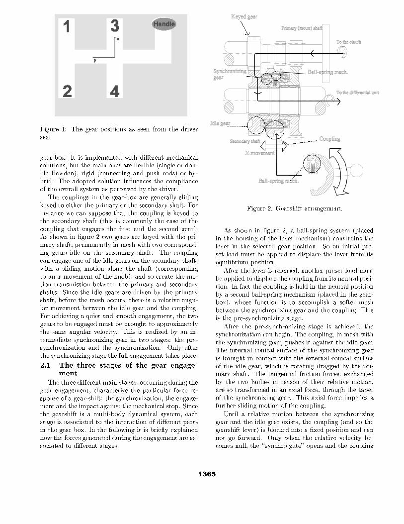
Figure 1: The gear positions as seen from the driver
seat
gear-box. It is implemented with di�erent mechanical
solutions, but the main ones are exible (single or dou-
ble Bowden), rigid (connecting and push rods) or hy-
brid. The adopted solution in uences the compliance
of the overall system as perceived by the driver.
The couplings in the gear-box are generally sliding
keyed to either the primary or the secondary shaft. For
instance we can suppose that the coupling is keyed to
the secondary shaft (this is commonly the case of the
coupling that engages the �rst and the second gear).
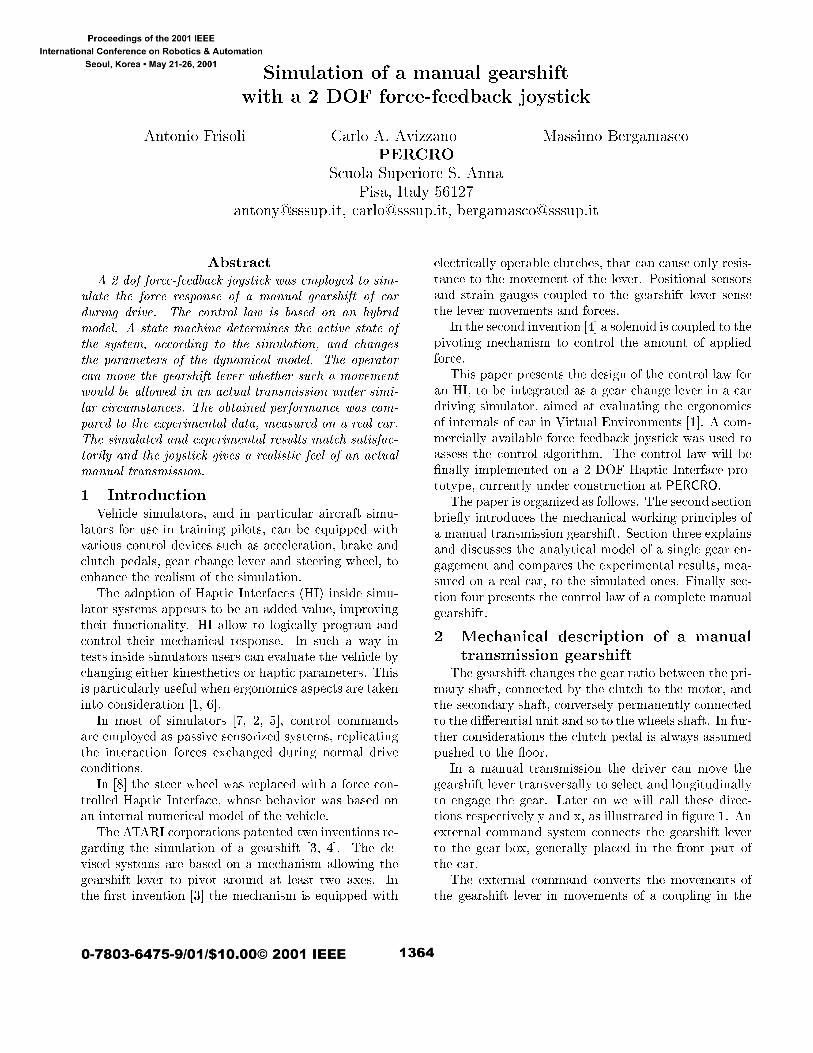
As shown in �gure 2 two gears are keyed with the pri-
mary shaft, permanently in mesh with two correspond-
ing gears idle on the secondary shaft. The coupling
can engage one of the idle gears on the secondary shaft,
with a sliding motion along the shaft (corresponding
to an x movement of the knob), and so create the mo-
tion transmission between the primary and secondary
shafts. Since the idle gears are driven by the primary
shaft, before the mesh occurs, there is a relative angu-
lar movement between the idle gear and the coupling.
For achieving a quiet and smooth engagement, the two
gears to be engaged must be brought to approximately
the same angular velocity. This is realized by an in-
termediate synchronizing gear in two stages: the pre-
synchronization and the synchronization. Only after
the synchronizing stage the full engagement takes place.
2.1 The three stages of the gear engage-ment
The three di�erent main stages, occurring during the
gear engagement, characterize the particular force re-
sponse of a gear-shift: the synchronization, the engage-
ment and the impact against the mechanical stop. Since
the gearshift is a multi-body dynamical system, each
stage is associated to the interaction of di�erent parts
in the gear-box. In the following it is brie y explained
how the forces generated during the engagement are as-
sociated to di�erent stages.
Figure 2: Gearshift arrangement.
As shown in �gure 2, a ball-spring system (placed
in the housing of the lever mechanism) constrains the
lever in the selected gear position. So an initial pre-
set load must be applied to displace the lever from its
equilibrium position.
After the lever is released, another preset load must
be applied to displace the coupling from its neutral posi-
tion. In fact the coupling is hold in the neutral position
by a second ball-spring mechanism (placed in the gear-
box), whose function is to accomplish a softer mesh
between the synchronizing gear and the coupling. This
is the pre-synchronizing stage.
After the pre-synchronizing stage is achieved, the
synchronization can begin. The coupling, in mesh with
the synchronizing gear, pushes it against the idle gear.
The internal conical surface of the synchronizing gear
is brought in contact with the external conical surface
of the idle gear, which is rotating dragged by the pri-
mary shaft. The tangential friction forces, exchanged
by the two bodies in reason of their relative motion,
are so transformed in an axial force, through the taper
of the synchronizing gear. This axial force impedes a
further sliding motion of the coupling.
Until a relative motion between the synchronizing
gear and the idle gear exists, the coupling (and so the
gearshift lever) is blocked into a �xed position and can
not go forward. Only when the relative velocity be-
comes null, the \synchro gate" opens and the coupling
can continue its sliding motion.
At the end of synchronization, the coupling teeth of
the synchronizing gear and the idle gear come into col-
lision and �nally mesh. The impact force, generated by
the coupling tooth contact is random, since it depends
on the relative position of the teeth at the moment of
the engagement. After the full engagement, the lever
reaches a mechanical stop, based on a ball-spring sys-
tem also, and it stopped.
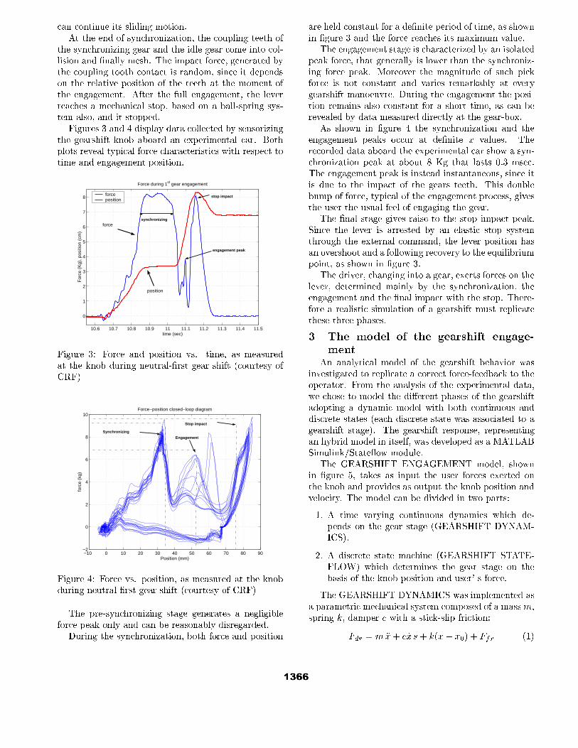
Figures 3 and 4 display data collected by sensorizing
the gearshift knob aboard an experimental car. Both
plots reveal typical force characteristics with respect to
time and engagement position.
10.6 10.7 10.8 10.9 11 11.1 11.2 11.3 11.4 11.5
0
1
2
3
4
5
6
7
8
Force during 1st gear engagement
time (sec)
For
ce (
Kg)
, pos
ition
(cm
)
force position
synchronizing
engagement peak
stop impact
position
force
Figure 3: Force and position vs. time, as measured
at the knob during neutral-�rst gear shift (courtesy of
CRF)
−10 0 10 20 30 40 50 60 70 80 90−2
0
2
4
6
8
10
Position (mm)
forc
e (k
g)
Force−position closed−loop diagram
Stop impact
Engagement
Synchronizing
Figure 4: Force vs. position, as measured at the knob
during neutral-�rst gear shift (courtesy of CRF)
The pre-synchronizing stage generates a negligible
force peak only and can be reasonably disregarded.
During the synchronization, both force and position
are held constant for a de�nite period of time, as shown
in �gure 3 and the force reaches its maximum value.
The engagement stage is characterized by an isolated
peak force, that generally is lower than the synchroniz-
ing force peak. Moreover the magnitude of such pick
force is not constant and varies remarkably at every
gearshift manoeuvre. During the engagement the posi-
tion remains also constant for a short time, as can be
revealed by data measured directly at the gear-box.
As shown in �gure 4 the synchronization and the
engagement peaks occur at de�nite x values. The
recorded data aboard the experimental car show a syn-
chronization peak at about 8 Kg that lasts 0.3 msec.
The engagement peak is instead instantaneous, since it
is due to the impact of the gears teeth. This double
bump of force, typical of the engagement process, gives
the user the usual feel of engaging the gear.
The �nal stage gives raise to the stop impact peak.
Since the lever is arrested by an elastic stop system
through the external command, the lever position has
an overshoot and a following recovery to the equilibrium
point, as shown in �gure 3.
The driver, changing into a gear, exerts forces on the
lever, determined mainly by the synchronization, the
engagement and the �nal impact with the stop. There-
fore a realistic simulation of a gearshift must replicate
these three phases.
3 The model of the gearshift engage-
mentAn analytical model of the gearshift behavior was
investigated to replicate a correct force-feedback to the
operator. From the analysis of the experimental data,
we chose to model the di�erent phases of the gearshift
adopting a dynamic model with both continuous and
discrete states (each discrete state was associated to a
gearshift stage). The gearshift response, representing
an hybrid model in itself, was developed as a MATLAB
Simulink/State ow module.
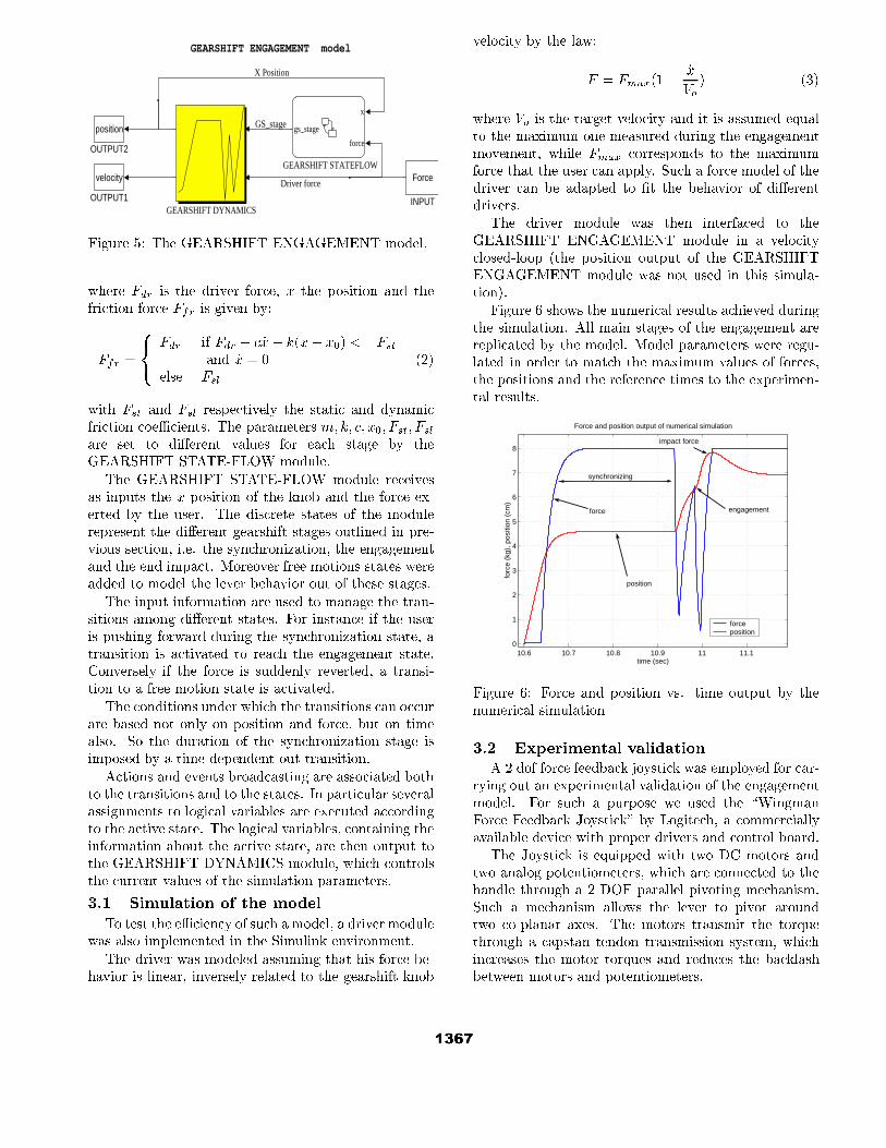
The GEARSHIFT ENGAGEMENT model, shown
in �gure 5, takes as input the user forces exerted on
the knob and provides as output the knob position and
velocity. The model can be divided in two parts:
1. A time varying continuous dynamics which de-
pends on the gear stage (GEARSHIFT DYNAM-
ICS).
2. A discrete state machine (GEARSHIFT STATE-
FLOW) which determines the gear stage on the
basis of the knob position and user' s force.
The GEARSHIFT DYNAMICS was implemented as
a parametric mechanical system composed of a massm,
spring k, damper c with a stick-slip friction:
Fdr = m �x+ c _x s+ k(x� x0) + Ffr (1)
GEARSHIFT ENGAGEMENT model
position
OUTPUT2
velocity
OUTPUT1
Force
INPUT
x
force
gs_stage
GEARSHIFT STATEFLOW
GEARSHIFT DYNAMICS
Driver force
GS_stage
X Position
Figure 5: The GEARSHIFT ENGAGEMENT model.
where Fdr is the driver force, x the position and the
friction force Ffr is given by:
Ffr =
8<:
Fdr if Fdr � c _x� k(x� x0) <= Fst
and _x = 0
else Fsl
(2)
with Fst and Fsl respectively the static and dynamic
friction coeÆcients. The parameters m; k; c; x0; Fst; Fsl
are set to di�erent values for each stage by the
GEARSHIFT STATE-FLOW module.
The GEARSHIFT STATE-FLOW module receives
as inputs the x position of the knob and the force ex-
erted by the user. The discrete states of the module
represent the di�erent gearshift stages outlined in pre-
vious section, i.e. the synchronization, the engagement
and the end impact. Moreover free motions states were
added to model the lever behavior out of these stages.
The input information are used to manage the tran-
sitions among di�erent states. For instance if the user
is pushing forward during the synchronization state, a
transition is activated to reach the engagement state.
Conversely if the force is suddenly reverted, a transi-
tion to a free motion state is activated.
The conditions under which the transitions can occur
are based not only on position and force, but on time
also. So the duration of the synchronization stage is
imposed by a time-dependent out-transition.
Actions and events broadcasting are associated both
to the transitions and to the states. In particular several
assignments to logical variables are executed according
to the active state. The logical variables, containing the
information about the active state, are then output to
the GEARSHIFT DYNAMICS module, which controls
the current values of the simulation parameters.
3.1 Simulation of the model
To test the eÆciency of such a model, a driver module
was also implemented in the Simulink environment.
The driver was modeled assuming that his force be-
havior is linear, inversely related to the gearshift knob
velocity by the law:
F = Fmax(1�_x
Vo
) (3)
where Vo is the target velocity and it is assumed equal
to the maximum one measured during the engagement
movement, while Fmax corresponds to the maximum
force that the user can apply. Such a force model of the
driver can be adapted to �t the behavior of di�erent
drivers.
The driver module was then interfaced to the
GEARSHIFT ENGAGEMENT module in a velocity
closed-loop (the position output of the GEARSHIFT
ENGAGEMENT module was not used in this simula-
tion).
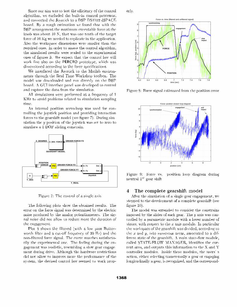
Figure 6 shows the numerical results achieved during
the simulation. All main stages of the engagement are
replicated by the model. Model parameters were regu-
lated in order to match the maximum values of forces,
the positions and the reference times to the experimen-
tal results.
10.6 10.7 10.8 10.9 11 11.10
1
2
3
4
5
6
7
8
time (sec)
forc
e (k
g), p
ositi
on (
cm)
Force and position output of numerical simulation
force position
synchronizing
engagement force
position
impact force
Figure 6: Force and position vs. time output by the
numerical simulation
3.2 Experimental validation
A 2 dof force feedback joystick was employed for car-
rying out an experimental validation of the engagement
model. For such a purpose we used the \Wingman
Force Feedback Joystick" by Logitech, a commercially
available device with proper drivers and control board.
The Joystick is equipped with two DC motors and
two analog potentiometers, which are connected to the
handle through a 2 DOF parallel pivoting mechanism.
Such a mechanism allows the lever to pivot around
two co-planar axes. The motors transmit the torque
through a capstan tendon transmission system, which
increases the motor torques and reduces the backlash
between motors and potentiometers.
Since our aim was to test the eÆciency of the control
algorithm, we excluded the built-in control processor,
and connected the Joystick to a DSP DS1102 dSPACE
board. By a rough estimation we found that with the
DSP arrangement the maximum executable force at the
knob was about 10 N, that was one tenth of the target
force of 10 Kg we needed to replicate in the application.
Also the workspace dimensions were smaller than the
required ones. In order to assess the control algorithm,
the simulated results were scaled to the experimental
ones of �gures 3. We expect that the control law will
work �ne also on the PERCRO prototype, which was
dimensioned according to the force speci�cations.
We interfaced the Joystick to the Matlab environ-
ments through the Real Time Workshop toolbox. The
model was downloaded and run directly on the DSP
board. A GUI interface panel was developed to control
and capture the data from the simulation.
All simulations were performed at a frequency of 1
KHz to avoid problems related to simulation sampling
time.
An internal position servo-loop was used for con-
trolling the joystick position and providing interaction
forces to the gearshift model (see �gure 7). During sim-
ulation the y position of the joystick was set to zero to
simulate a 1 DOF sliding constrain.
0
Y_DES
PID
PID In_Fx
In_Fy
Out_x
Out_y
Joystick
FORCEX_DES
GEARSHIFT MODEL
DRIVER FORCE FY
Y_REAL
POSITIONERROR
DRIVER FORCE FX
DRIVER FORCE FX
X_DESIRED
Figure 7: The control of a single axis
The following plots show the obtained results. The
error on the force signal was determined by the electric
noise produced by the analog potentiometers. The sig-
nal noise did not allow to reduce more the duration of
the engagement.
Plot 8 shows the �ltered (with a low pass Butter-
worth �lter and a cut-o� frequency of 20 Hz) and the
non-�ltered force signal. The curve matches satisfacto-
rily the experimental one. The feeling during the en-
gagement was realistic, resembling a slow gear engage-
ment during drive. Although the hardware restrictions
did not allow to improve more the performance of the
system, the devised control law seemed to work prop-
erly.
6.2 6.4 6.6 6.8 7 7.2 7.4 7.6 7.80
1
2
3
4
5
6
7
8
9
time (sec)
forc
e (k
g), p
ositi
on (
cm)
Force vs. time (filtered and unfiltered signal)
synchronizing
engagement
stop impact
POSITION
FORCE
Figure 8: Force signal estimated from the position error
−2 0 2 4 6 8
−6
−4
−2
0
2
4
6
8
10
position (cm)
forc
e (k
g)
Force−position closed−loop diagram
synchronization engagement end
impact
Figure 9: Force vs. position loop diagram during
neutral-1st gear shift
4 The complete gearshift modelAfter the simulation of a single gear engagement, we
stepped to the development of a complete gearshift (see
�gure 10).
The model was extended to consider the constrains
imposed by the slides of each gear. The y axis was con-
trolled by a parametric module with a lower number of
states, with respect to the x axis module. In particular
the workspace of the gearshift was divided, according to
the x and y, into numerous areas, associated to a dif-
ferent state of the gearshift. A main state- ow module,
called STATE-FLOW MANAGER, identi�es the cur-
rent area, and outputs this information to the X and Y
controller modules. Inside these modules, the users' s
action, either selecting transversally a gear or engaging
longitudinally a gear, is recognized, and the correspond-
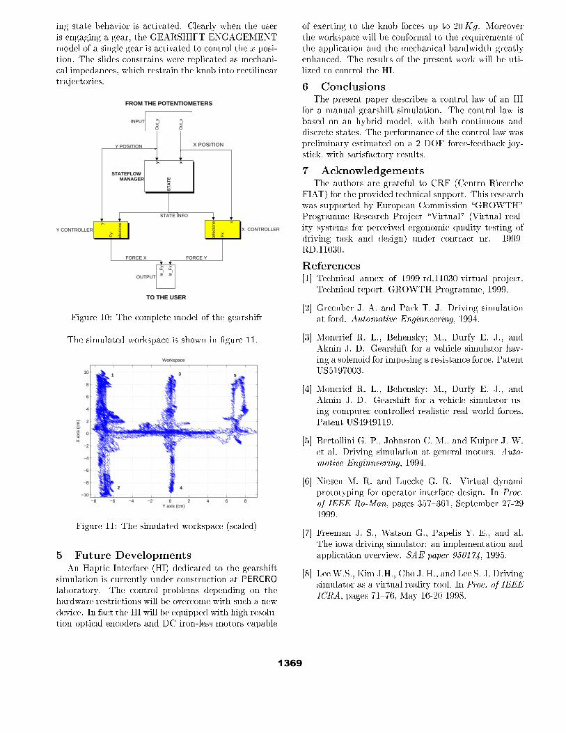
ing state behavior is activated. Clearly when the user
is engaging a gear, the GEARSHIFT ENGAGEMENT
model of a single gear is activated to control the x posi-
tion. The slides constrains were replicated as mechani-
cal impedances, which restrain the knob into rectilinear
trajectories.
X POSITION
TO THE USER
FROM THE POTENTIOMETERSy
elez
ione
Fy
Y CONTROLLER
sele
zion
e x
Fx
X CONTROLLER
y x
ST
AT
ESTATEFLOW
MANAGER
In_F
y
In_F
x
OUTPUT
Out
_y
Out
_xINPUT
STATE INFO
FORCE X FORCE Y
Y POSITION
Figure 10: The complete model of the gearshift
The simulated workspace is shown in �gure 11.
−8 −6 −4 −2 0 2 4 6 8−10
−8
−6
−4
−2
0
2
4
6
8
10
Y axis (cm)
X a
xis
(cm
)
Workspace
1
2
3
5
4
Figure 11: The simulated workspace (scaled)
5 Future DevelopmentsAn Haptic Interface (HI) dedicated to the gearshift
simulation is currently under construction at PERCRO
laboratory. The control problems depending on the
hardware restrictions will be overcome with such a new
device. In fact the HI will be equipped with high resolu-
tion optical encoders and DC iron-less motors capable
of exerting to the knob forces up to 20Kg. Moreover
the workspace will be conformal to the requirements of
the application and the mechanical bandwidth greatly
enhanced. The results of the present work will be uti-
lized to control the HI.
6 ConclusionsThe present paper describes a control law of an HI
for a manual gearshift simulation. The control law is
based on an hybrid model, with both continuous and
discrete states. The performance of the control law was
preliminary estimated on a 2 DOF force-feedback joy-
stick, with satisfactory results.
7 AcknowledgementsThe authors are grateful to CRF (Centro Ricerche
FIAT) for the provided technical support. This research
was supported by European Commission \GROWTH"
Programme Research Project \Virtual" (Virtual real-
ity systems for perceived ergonomic quality testing of
driving task and design) under contract nr. 1999-
RD.11030.
References[1] Technical annex of 1999-rd.11030-virtual project.
Technical report, GROWTH Programme, 1999.
[2] Greenber J. A. and Park T. J. Driving simulation
at ford. Automotive Enginneering, 1994.
[3] Moncrief R. L., Behensky; M., Durfy E. J., and
Aknin J. D. Gearshift for a vehicle simulator hav-
ing a solenoid for imposing a resistance force. Patent
US5197003.
[4] Moncrief R. L., Behensky; M., Durfy E. J., and
Aknin J. D. Gearshift for a vehicle simulator us-
ing computer controlled realistic real world forces.
Patent US4949119.
[5] Bertollini G. P., Johnston C. M., and Kuiper J. W.
et al. Driving simulation at general motors. Auto-
motive Enginneering, 1994.
[6] Niesen M. R. and Luecke G. R. Virtual dynami
prototyping for operator interface design. In Proc.
of IEEE Ro-Man, pages 357{361, September 27-29
1999.
[7] Freeman J. S., Watson G., Papelis Y. E., and al.
The iowa driving simulator: an implementation and
application overview. SAE paper 950174, 1995.
[8] LeeW.S., Kim J.H., Cho J. H., and Lee S. J. Driving
simulator as a virtual reality tool. In Proc. of IEEE
ICRA, pages 71{76, May 16-20 1998.
Copyright © 2022 FDOKUMEN