
Simulation-Assisted Efficient Computation of the Dispersion ...
12
HAL Id: hal-03243789 https://hal.archives-ouvertes.fr/hal-03243789 Submitted on 28 Feb 2022 HAL is a multi-disciplinary open access archive for the deposit and dissemination of sci- entific research documents, whether they are pub- lished or not. The documents may come from teaching and research institutions in France or abroad, or from public or private research centers. L’archive ouverte pluridisciplinaire HAL, est destinée au dépôt et à la diffusion de documents scientifiques de niveau recherche, publiés ou non, émanant des établissements d’enseignement et de recherche français ou étrangers, des laboratoires publics ou privés. Simulation-Assisted Effcient Computation of the Dispersion Diagram of Periodic Structures: A Comprehensive Overview With Applications to Filters, Leaky-Wave Antennas and Metasurfaces Francisco Mesa, Guido Valerio, Raul Rodriguez-Berral, Oscar Quevedo-Teruel To cite this version: Francisco Mesa, Guido Valerio, Raul Rodriguez-Berral, Oscar Quevedo-Teruel. Simulation-Assisted Effcient Computation of the Dispersion Diagram of Periodic Structures: A Comprehensive Overview With Applications to Filters, Leaky-Wave Antennas and Metasurfaces. IEEE Antennas and Propaga- tion Magazine, Institute of Electrical and Electronics Engineers, 2021, 10.1109/MAP.2020.3003210. hal-03243789
-
Upload
khangminh22 -
Category
Documents
-
view
0 -
download
0
Transcript of Simulation-Assisted Efficient Computation of the Dispersion ...

HAL Id: hal-03243789https://hal.archives-ouvertes.fr/hal-03243789
Submitted on 28 Feb 2022
HAL is a multi-disciplinary open accessarchive for the deposit and dissemination of sci-entific research documents, whether they are pub-lished or not. The documents may come fromteaching and research institutions in France orabroad, or from public or private research centers.
L’archive ouverte pluridisciplinaire HAL, estdestinée au dépôt et à la diffusion de documentsscientifiques de niveau recherche, publiés ou non,émanant des établissements d’enseignement et derecherche français ou étrangers, des laboratoirespublics ou privés.
Simulation-Assisted Efficient Computation of theDispersion Diagram of Periodic Structures: A
Comprehensive Overview With Applications to Filters,Leaky-Wave Antennas and Metasurfaces
Francisco Mesa, Guido Valerio, Raul Rodriguez-Berral, Oscar Quevedo-Teruel
To cite this version:Francisco Mesa, Guido Valerio, Raul Rodriguez-Berral, Oscar Quevedo-Teruel. Simulation-AssistedEfficient Computation of the Dispersion Diagram of Periodic Structures: A Comprehensive OverviewWith Applications to Filters, Leaky-Wave Antennas and Metasurfaces. IEEE Antennas and Propaga-tion Magazine, Institute of Electrical and Electronics Engineers, 2021, �10.1109/MAP.2020.3003210�.�hal-03243789�

IEEE ANTENNAS & PROPAGATION MAGAZINE, VOL. XX, NO. YY, MONTH 2019 1
Simulation-Assisted Efficient Computation of theDispersion Diagram of Periodic Structures
Francisco Mesa, Fellow, IEEE, Guido Valerio, Senior Member, IEEE, Raul Rodrıguez-Berral, and OscarQuevedo-Teruel, Senior Member, IEEE
Abstract—A hybrid method that combines the results of acommercial simulator with analytical post-processing is discussedand used to compute the dispersion diagrams of periodic struc-tures. The method takes advantage of the ability of commercialsimulators to deal with arbitrary geometries and materials andovercomes some of their limitations to compute the attenuationconstant. The frequency behavior of the attenuation constantis very valuable for microwave and antenna design since itprovides key information on the isolation/rejection in stopbandsand the radiation losses in periodic leaky-wave antennas. Acomprehensive overview of different theoretical and practicalissues regarding the computation of dispersion diagrams is firstcarried out. Important considerations and main assumptionsconcerning the practical implementation of the method andits interaction with the commercial simulator are thoroughlydiscussed.
Index Terms—Periodic structures, commercial simulators, dis-persion diagram, radiation losses, leaky waves.
I. INTRODUCTION
The knowledge of the dispersion diagrams of periodicstructures is of capital relevance in the general study of wavepropagation [1]–[3]. These diagrams provide insight on thebehavior and interaction of the waves with the waveguiding en-vironment: forward/backward and fast/slow wave nature, levelof anisotropy and dispersion, existence and characteristics ofband gaps, wave attenuation due to radiation or losses, etc.Assuming a time-harmonic dependence of the fields, the wavepropagation in a one-dimensional (1-D) periodic structurealong the direction of periodicity can mathematically be solvedwith a Floquet analysis. This means that the potentials/fieldsin the structure, denoted here in general as C, satisfy thefollowing condition [2]:
C(x, y, z, t) = Cp(x, y, z) e−γz e jωt (1)
where ω is the angular frequency, γ(≡ jkz) = α + jβ isthe complex propagation constant along the assumed wave-propagation direction (z), with α being the attenuation con-stant and β the phase constant [kz = −jγ = β − jα is
F. Mesa and R. Rodrıguez-Berral are with Microwaves Group, Dept. ofApplied Physics 1, ETS de Ingenierıa Informatica, Universidad de Sevilla,Spain (e-mail:[email protected], [email protected]).
G. Valerio is with Sorbonne Universite, Laboratoire d Electroniqueet Electromagnetisme, UR2, L2E, F-75005 Paris, France (e-mail:[email protected]).
O. Quevedo-Teruel is with the Division of Electromagnetic Engineering,KTH Royal Institute of Technology, 114 28 Stockholm, Sweden (e-mail:[email protected]).
This work was partly supported by the Spanish Ministerio de Ciencia,Innovacion y Universidades and European Union FEDER funds under ProjectTEC2017-84724-P, the French National Research Agency Grant NumberANR-16-CE24-0030, the Vinnova project High-5 (2018-01522), under theStrategic Programme on Smart Electronic Systems, and the Stiftelsen forskproject H-Materials (18-302). The work of F. Mesa has also been funded bythe Spanish Government (Salvador de Madariaga fellowship PRX19/00025).(Corresponding author: Oscar Quevedo-Teruel.)
the complex wavenumber along the z-direction]. The periodicfunction Cp satisfies Cp(x, y, z) = Cp(x, y, z + np), withnp being an integer multiple of period of the structure. Startingfrom the general condition (1), the dispersion relations of pe-riodic guiding/radiating electromagnetic structures have beencomputed with a large variety of methods. Following [4], thesemethods can be classified into two categories: (A) methodsthat compute the propagation constant at each frequency, and(B) methods that extract the frequency at which the unit cell ofthe periodic structure resonates when subject to a given phaseshift along the periodicity direction.
One key issue that complicates any of the possible solutionmethods is the complex nature of the propagation constant(having both imaginary and real parts), which may occurfor both bounded and unbounded waveguiding systems, evenin the absence of material losses. However, there is an im-portant difference between modal solutions of bounded andunbounded guiding structures. Bounded waveguiding systems,shielded by either electric/magnetic walls or periodic bound-ary conditions, always lead to wave equations that can beframed into the so-called Sturm-Liouville problems of thefirst kind [5]. Their modal analysis always yields eigenvalueproblems with a discrete spectrum [2], [5], whose possible so-lutions are bound, evanescent, and complex modes [2], [6]–[8].When other types of boundaries conditions and/or unboundedregions are present in the waveguiding system, the spectrumof the resulting eigenproblem has both continuous and discreteparts. As the continuous spectrum of any electromagneticproblem can be partly associated with the power radiated tothe unbounded region [2], [5], complex leaky-wave modalsolutions can now appear in the dispersion relation of thestructure [2], [9], [10]. In general, the appearance of modeswith complex propagation constants means that the solution ofthe modal characteristic equation requires extra mathematicaland numerical tasks [2], [7], [10]. The scientific literatureshows that a lot of effort has been devoted to find appropriatemethods to search for the complex roots of the characteristicequations, or directly to avoid such root-searching.
Nowadays it is a very common practice the use of com-mercial full-wave simulators (HFSS, CST, FEKO, ADS,...) inthe analysis and/or design of microwave and antenna devices.Certainly, the ability of these simulators to deal with verygeneral structures is one of theirmost appreciated assets. Theprice to pay for this wide applicability is their often elevateddemand of computational and memory resources. Concerningthe calculation of dispersion diagrams, to the best of theauthors’ knowledge, existing simulators do not compute thecomplete dispersion diagram of all the modal solutions ofperiodic waveguiding systems but only the behavior of thephase shift (βp) vs. frequency and the attenuation constant dueto material losses. However, the information of the attenuation

2 IEEE ANTENNAS & PROPAGATION MAGAZINE, VOL. XX, NO. YY, MONTH 2019
Fig. 1. Examples of (a) uniform waveguiding system, (b) one-dimensionalperiodic structure of period p.
constant is crucial for many lossless and radiating cases,specially in electromagnetic band gap structures as well asin leaky-wave antennas.
In this paper, we present a thorough discussion on how theso-called multi-mode transfer-matrix method [2], [4], [11]–[19] combines the simulator’s advantage of dealing witha wide range of material and arbitrarily-shaped structurestogether with a convenient post-processing to compute thecomplete dispersion diagram of periodic structures. With thismethod one can obtain the information of the modal atten-uation constant, regardless if they come either from losses,radiation, or the intrinsic complex/evanescent nature of themodes. Different novel aspects of the application of themethod to unbounded radiative structures as well as two-dimensional (2-D) configurations are considered. Additionally,the presence of higher symmetries in the unit cell is alsocontemplated.
II. ANALYSIS
In order to keep the discussion and analysis in this sectionas simple as possible, only 1-D periodicity will be considered.The extension to 2-D periodic structures will be treated laterin Sec. III-B.
A. Eigenproblems in guided-wave analysis
Before discussing the periodic case, some of the main fea-tures of the uniform (non-periodic) problem in the frequencydomain will be briefly outlined.
1) Uniform structures: In this situation, we have a structureinvariant to arbitrary translations along the propagating z-direction as the one shown in Fig. 1(a). Regardless of theemployed method of analysis, the procedure to find the modesof the structure [2], [20] will lead to an eigenproblem that canbe expressed, in general, as
[Γ(kz, ω)]u = 0 (2)
where kz are the eigenvalues (modal wavenumbers) of theproblem, u the corresponding eigenvectors, and [Γ] is the ma-trix associated with the projection method employed to solvethe corresponding integral equation (IE); for instance, methodof moments (MoM) [21], finite element method (FEM) [22],mode matching (MM) [23], Nystrom collocation method [24],etc. It should be noted that, in general, the above eigenprob-lem is non-linear and only under certain circumstances (forinstance, the case of a homogeneous rectangular waveguide)it turns into a linear eigenproblem [25]. The BIRME methodreported in [26] provides a procedure to linearize the eigen-problem for homogeneous waveguides with an arbitrary shape.
Notwithstanding, the dispersion relation of the structure canalways be expressed as the solution of
F (kz;ω) ≡ det {[Γ(kz, ω)]} = 0 . (3)
For each value of frequency ω, the solution of the above equa-tion means searching for the complex zeros of the complexfunction F (kz). In general, this zero-searching is not simple,being one of the recurrent problems in the literature on modalanalysis [27]–[31]. The two main reasons that make difficultto search numerically for complex zeros are: i) the functionhave poles and branch-point singularities, and ii) it is difficultto find a systematic and reliable algorithm that can explore thecomplex plane, which can comprise several Riemann sheets,without loosing any of the zeros of the function. Possiblybecause of these two underlying drawbacks, most commercialsimulators avoid this zero-searching and do not usually providethe complete dispersion relation of uniform structures.
2) Periodic structures: If the modal analysis is to be appliedto 1-D periodic structures (periodicity along the propagatingz-direction) as the one shown in Fig. 1(b), the solution ofthe corresponding IE method also leads in general to a non-linear eigenvalue problem [32]. This means that the samedifficulties involved in the obtaining of the dispersion relationof uniform structures also hold for 1-D periodic structures.Because of this, many efforts have been devoted to circumventthis problem and different alternatives have been reported inthe literature to formulate an equivalent linear eigenproblem.
One possibility is to solve directly Maxwell’s equations inthe time domain. Examples of this procedure are the finitedifferences in the time domain (FDTD) methods reported,for example, in [33]–[36]. The approaches presented in [33],[34] could only deal with real propagation constants, but thepossibility of losses/radiation was successfully incorporatedin [35], [36]. Although these time-domain methods avoid thedifficult task of searching for complex zeros, their intrinsiciterative nature involves very large, although sometimes sparse,matrices. This usually leads to intensive computational effortsand high demands of storage, apart from numerical instabil-ities that may appear when non-uniform grid meshing arerequired to deal with complex geometries as well as multi-scale structures. Similar problems can also be found in thefinite difference in the frequency domain (FDFD) method re-ported in [4]. Enhanced implementations of FDTD and FDFDmethods can partially alleviate some of the aforementionedproblems, but this issue is beyond the scope of the presentwork, more focused on frequency-domain IE methods.
Another common approach to find the dispersion diagramas the solution of a linear eigemproblem is to model the 1-Dperiodic structure as a 2-port equivalent network characterizedby its transfer (ABCD) matrix [T] and subject to periodicboundary conditions along the propagation direction [2], [25].Next, two different implementation of this method will bebriefly outlined before discussing a third method that canovercome most of the limitations of the previous two.
B. Method 1-uc: 2-port transfer matrix of a single unit cell
One of the most common and simple strategies consistsin describing the periodic structure, which is invariant under

MESA ET AL. 3
(b)
(a)(a)
Inputport
Outputport
Fig. 2. (a) Top view of a single cell whose transfer matrix [T] is to beobtained. (b) Cascade of [Tp] matrices in the infinite structure. In method1-uc it is assumed that [Tp] ≈ [T].
translations of an integer multiple of periods, as a housingwaveguide loaded by some additional periodic elements (ordiscontinuities). The housing waveguide is uniform (i.e., in-variant with respect to an arbitrary translation) and wouldsupport a certain number of modes in the absence of anyperiodic load. A transfer matrix [T] can then be associatedwith a single unit cell of the periodic structure, excited atits access ports by the fundamental mode of the housingwaveguide, as shown in Fig. 2(a). For instance, in the unitcell shown in Fig. 1(b), the housing waveguide is a microstripline and the “discontinuities” are the lateral metallic stubsplaced on both sides of the conducting strip. Although suchdistinction between the housing waveguide and discontinuityis difficult in some structures, in principle, this decompositioncan always be done. In this first simplified method, the original1-D periodic electromagnetic problem can be modelled as acascade of 2-port transfer matrices, as depicted in Fig. 2(b),where the actual transfer matrix, [Tp], of the unit cell withinthe periodic environment is assumed to be given by thetransfer matrix [T] of the single unit cell taken isolated; i.e.,[Tp] ≈ [T]. Here it is worth pointing out the differencebetween the so-called [T] and [Tp] matrices. The [T] matrixcorresponds to the transfer matrix of an isolated single unitcell, as shown in Fig. 2(a), whereas [Tp] matrix stands for thetransfer matrix of the unit cell when this unit cell is part ofthe infinitely periodic structure. In principle, this last matrixcannot directly be obtained with a commercial simulator sincethe simulator can only deal with truncated finite structureshaving input/output ports.
Often, the discontinuities inside the unit cell can be wellcharacterized by equivalent networks of reactive elementswhich are known in closed form [37], [38]. In this simplifiedsituation, the transfer matrix of the single unit cell is easilycomputed from the transfer matrices that account for thefundamental-mode propagation in two housing-waveguide sec-tions and the one corresponding to the discontinuity network.In more complex cases, the transfer matrix of the single unitcell at each frequency can be numerically obtained with the
help of commercial simulators. Once the 2×2 transfer matrix[T] of the single unit cell
[T] =
[A BC D
](4)
is obtained, the following eigenproblem is reached after apply-ing a Floquet’s analysis to solve for the complex propagationconstant γ of the infinite periodic structure [2], [3], [25]:
[T]u = eγpu . (5)
The u column matrix 2× 1 is given by
u =
[VI
](6)
with V and I being the voltage and current at the output portof the unit-cell problem. Under the assumption of reciprocity,the dispersion relation of the structure is then given by thefollowing well-known expression [25, Eq. (8.7)]:
cosh(γp) =A(ω) +D(ω)
2(7)
where the frequency dependence of the transfer-matrix entriesis explicitly shown.
In the above simple procedure, at first sight, it may seemthat the dispersion relation of the structure has been foundeluding the zero-searching problem intrinsic to the non-lineareigenproblem associated with any general modal analysis. Itshould however be noted that the solution of the transfermatrix of a single unit cell via the 3-D full-wave com-mercial simulator has actually required a modal analysis ofthe input/output port; namely, the fundamental mode of thehousing waveguide has been previously obtained. Only afterthis non-linear eigenproblem has been internally solved bythe simulator, it is possible to compute the transfer matrixthat leads to the linear eigenproblem in (5). A somewhatsimilar procedure is reported in [39] where a linear eigenvalueproblem is solved after the corresponding integral equation.Other additional relevant issues and approximations implicitin the above procedure are [40]:(i). Since only the fundamental mode of the housing waveg-uide is considered in the analysis, implicitly assumed throughthe approximation [Tp] ≈ [T], interactions between differentunit cells supported by high-order modes of the housingwaveguide are completely left out. This assumption is nolonger valid when the electric size of the period is small aswell as in many other practical situations that actually requireto account for the high-order interactions between cells [2,Sec. 9.7].(ii). If the housing waveguide is unbounded (for instance,a microstrip line without top cover), then only the discretespectrum [2] of the housing waveguide is considered. Thiscondition is intrinsically imposed by the commercial simula-tors when modelling the input and output ports as waveguidingsystems that are bounded by either electric, magnetic, orperiodic boundary conditions. As already mentioned, theseboundary conditions always lead to discrete spectra. Thus,when the housing waveguide is unbounded, there is always animplicit detrimental approximation due to the different nature

4 IEEE ANTENNAS & PROPAGATION MAGAZINE, VOL. XX, NO. YY, MONTH 2019
(b)
(a)(a)
Outputport
(a)
Inputport
Physicalinputport
Physicaloutputport
(1)(2)
(M)
(M+1)(M+2)
(2M)
(c)
Fig. 3. (a) Top view of a N -cell structure whose transfer matrix [TN ] is tobe obtained. (b) Cascade of [Tp] matrices in the infinite structure. In methodN -uc it is assumed that [Tp] ≈ N
√[TN ]. (c) Finite structure with a single
unit cell whose high-order mode transfer matrix [T] is to be obtained.
of the spectrum of the input/output ports and the one of thehousing waveguide, occasionally enhanced by their possiblemismatches. Although this drawback may be hardly relevantin many practical circumstances when dealing with boundedfields in open structures, the appropriate characterization of thereflected/transmitted power when radiation is present wouldrequire a more careful choice of the input/output ports. Inthese circumstances, one possible solution could be to ensurethat additional variations in the height of the ports do not affectthe results of the scattering parameters. More discussionsabout this issue will be further conducted when the numericalexamples are discussed in Sec. IV.
C. Method N -uc: 2-port transfer matrix of N unit cells
In principle, to the authors’ knowledge, not much canbe done to circumvent the drawback (ii) when significant,although possible alternatives, involving the development ofthe in-house full-wave eigenmode solver, have been pro-posed in [41], [42]. However, different solutions involvingcommercial simulators have been reported to overcome thedrawback (i) [43]–[46]. A common procedure, graphicallysketched in Figs. 3(a) and (b), is to consider a finite systemof multiple unit cells, say N , and assume that the 2-porttransfer matrix of this N -cell system, [TN ], is related to thetransfer matrix of the unit cell in the periodic environment asfollows [47]:
[Tp] = N√
[TN ] . (8)
The drawbacks (i) and (ii) are still present at the two portsof the N -cell system. Nevertheless, they are partially mitigatedwith the computation of the coupling between the unit cellsinside the system, since the inner boundaries between cells
are no more described by equivalent bounded and monomodalports. It is this fact what is expected to increase the precisionof the mutual interactions among cells as N increases. Still,numerical problems also affect this procedure [47]. Amongthem it can be mentioned the eventual high computational costof having to analyze a finite structure with many cells, whichcan easily lead to numerical noise and inaccuracies. Anotherrelevant problem comes from the inherent ambiguity in thepropagation-constant solutions of the N -cell problem becauseof the non-uniqueness of the N th root of a complex number.This leads to an ambiguity on the value of the phase constantwhich needs to be addressed; e.g., as in [47]. Furthermore, thecase of a LWA that required many unit cells to characterizeaccurately its complex propagation constant but with a non-small radiation attenuation could pose an important numericalproblem due to the almost negligible values of the field at theoutput port of the N -cell structure.
III. PROPOSED METHODOLOGY
A methodology that can overcome most of the aforemen-tioned drawbacks will be discussed in this section. First, itshould be reminded that the main limitation of the frequency-domain eigenmode solver of commercial simulators comesfrom the difficulties to provide the complex modal attenuationconstants of periodic structures, regardless if losses come fromeither the evanescent/complex nature of the modes or thepresence of unbounded/lossy regions in the periodic structure.Nevertheless it is apparent that commercial simulators can dealefficiently with unbounded/lossy structures with regards to thecomputation of the scattering parameters of such structure.
A. 1-D Periodic Structures
For the simpler case of 1-D periodic structures, the corre-sponding transfer matrix of an isolated unit cell can easily beobtained from the scattering matrix of the structure modeledas a 2-port network [25]. However, as previously discussedin Sec. II-A2, the use of two-port transfer matrix also bringssome drawbacks. Hence, in similarity to [2], [4], [11]–[18], itis proposed to keep on using the transfer matrix of a singleunit cell of the periodic structure but extend its capabilities bymodeling this unit cell as a multiport transfer matrix that takesinto account multiple modes of the structure. A graphical rep-resentation of this procedure is shown in Fig. 3(c). In doing so,the inter-cell coupling effect due to high-order modes can nowbe well accounted for, an effect that method 1-uc in Sec. II-Bcould not take into account. Very often the use of multiportequivalent networks is associated with the actual presence ofmore than two physical ports (terminals) in the structure [15],[48]. However, it is well known that this requirement is notnecessary, and the ports can equally be associated with thedifferent modes (propagative, evanescent,...) of a structure withjust one input and one output physical terminals [2], [3], [37].
For a multiport (or multi-mode) system, the transformationfrom the scattering matrix [49], [50] to the transfer matrix [51]is not direct but it can easily be carried out once the inputand output ports of the structure are clearly defined. For thispurpose, let us consider a balanced 2M -port system whoseinput ports are numbered 1, 2, . . . ,M , corresponding to the

MESA ET AL. 5
first M significant modes, and output ports M + 1, . . . , 2M[see Fig. 3(c)] associated with the same set of significantmodes. In order to find the multiport (multi-mode) transfermatrix, the scattering matrix is written in terms of fourpartitioned submatrices as
[S] =
[[Sii] [Sio][Soi] [Soo]
](9)
where subscripts i and o stand for input and output ports,respectively, and each submatrix corresponds to the general-ized scattering matrix that relates the input/output M modes.The multiport (multi-mode) transfer matrix can be obtainedfollowing, for instance, the derivations reported in [51], [52].Alternatively, some relatively simple algebra operations leadus to the following expressions for the block-matrix elementsof the transfer matrix:
[T] =
[[A] [B][C] [D]
](10)
where
[A] =1
2
[([1] + [Sii])[Soi]
−1([1]− [Soo]) + [Sio]]
(11)
[B] =1
2
[([1] + [Sii])[Soi]
−1([1] + [Soo])− [Sio]]
[Zo]
(12)
[C] =1
2[Zi]
−1[([1]− [Sii])[Soi]
−1([1]− [Soo])− [Sio]]
(13)
[D] =1
2[Zi]
−1[([1]− [Sii])[Soi]
−1([1] + [Soo]) + [Sio]]
[Zo]
(14)
with [1] being the M ×M unit matrix and [Zi] and [Zo]square matrices whose diagonal elements are the input/outputcharacteristic port impedances; namely
[Zi/o] = [diag(Zi/o,m)] . (15)
An interesting question that arises here is that the specificvalues of the impedances of the ports do not have any effecton the eigenvalues of the multiport transfer matrix as long asthe same value is employed for the same mode at the inputand output ports (that is, if [Zi] = [Zo]). This can easily beseen by rewriting the [T] matrix as
[T] =
[[1] [0][0] [Zi]
−1
][T1]
[[1] [0][0] [Zo]
](16)
where [T1] stands for the transfer matrix defined with unitaryport impedances and [0] for the M×M null matrix. As longas [Zi] = [Zo], [T] is similar to [T1] for any choice of theport impedances, and its eigenvalues are then invariant undera change of the impedances.
Assuming now that the above multi-mode [T] matrix is agood approximation of the multi-mode transfer matrix of theunit cell in the periodic environment, the eigenproblem to besolved is [2], [11], [12], [15]–[19]
[T]
[VI
]= eγp
[VI
](17)
where V and I are now M × 1 arrays containing the voltagesand currents at the output ports. This eigenproblem is formally
identical to (5) for the two-port case. The only relevant dif-ference is that we will find M pairs of eigenvalues associatedwith ±γmp (m = 1, . . . ,M ).
If the unit cell under study is reciprocal, the inverse of thetransfer matrix satisfies [51, Eq. (51)]
[T]−1 =
[[D]T −[B]T
−[C]T [A]T
](18)
where superscript T means transpose. For this matrix thefollowing eigenvalue problem holds:
[T]−1
[VI
]= e−γp
[VI
]. (19)
Summing the eigenproblems (17) and (19) for the multi-modetransfer and inverse-transfer matrices, the following eigenvalueproblem is obtained:[
[A] + [D]T [B]− [B]T
[C]− [C]T [D] + [A]T
] [VI
]= 2 cosh(γp)
[VI
](20)
which turns out to have two degenerate set of eigenvalues;namely, each γmp is a double solution of (20). If the structureis also symmetric, then [A] = [D]T , [B] = [B]T , and [C] =[C]T [51]. This means that the above 2M -rank eigenproblemcan be reduced to the M -rank one given by
[A]V = cosh(γp)V . (21)
The above eigenproblem clearly simplifies to the well-knowdispersion relation provided in (7) for the simplest case of a2-port symmetric periodic structure.
An interesting practical situation arises if the unit cellunder study has any kind of internal higher symmetry (forinstance, glide [53] or twist [54] symmetries). In this case,the eigenvalue problem can be set up for the so-called sub-unit cell (the size of which will be denoted as p) where thecorresponding higher symmetry operator plays the same roleas the Floquet translation-symmetry operator for a standardperiodic structure [19], [39], [53], [55]. The resulting gener-alized eigenvalue problem can then be written, following thenotation in [19], [55], as
[T]
[VI
]= eγp
[[Q] [0][0] [Q]
] [VI
](22)
where [T] is the corresponding multi-mode transfer matrix forthe sub-unit cell and [Q] is a submatrix that accounts for thecorresponding algebraic operations resulting from the effectsof the specific higher symmetry on the electric/magnetic fields;more details can be found in the Appendix and in [19],[55]. Dealing directly with the eigenvalue problem in (22)leads to numerical and accuracy advantages since it reducesconsiderably the size of the structure to be analyzed with thefull-wave simulator. If the system is reciprocal and symmetric,the eigenvalue problem can be further simplified [in analogywith (21)] into
[A]V =1
2
{eγp[Q] + e−γp[Q]−1
}V . (23)

6 IEEE ANTENNAS & PROPAGATION MAGAZINE, VOL. XX, NO. YY, MONTH 2019
Fig. 4. Top view of a unit cell of a 2-D periodic structure, with periodicityalong the x and y directions. N modes are retained on each of the fourgeometrical faces.
B. 2-D Periodic Structures
The multi-mode transfer-matrix method can straightfor-wardly be used for the study of 2-D periodic structures [19].With reference to Fig. 4, the unit cell of this problem canbe described as a region accessible through four geometricalfaces, numbered from 1 to 4. Faces 1 and 2 are here consideredas input faces, and 3 and 4 as output faces. On each face,M modes can be defined as done in the previous section.Each mode of each face is then associated with a port. Inthis way, the cell is associated with a 4M -port network. Acommercial software can easily extract the scattering matrixof this network as in (9), where each sub-matrix has nowdimensions 2M × 2M . More specifically, the 2-D version ofthe submatrices in (9) can be written in the following blockform where the couplings among the four different geometricalfaces appear explicitly:
[Sii] =
[[S11] [S12][S21] [S22]
][Sio] =
[[S13] [S14][S23] [S24]
]
[Soi] =
[[S31] [S32][S41] [S42]
][Soo] =
[[S33] [S34][S43] [S44]
].
(24)The transfer matrix can then be computed by using the same
equations (11)–(14). This matrix operates a transformationfrom the output to the input ports as
V1
V2
I1I2
= [T]
V3
V4
I3I4
. (25)
In 2-D periodic structures, Floquet boundary conditions shouldbe enforced along the two periodicity axes as V3 = e−γxpxV1
and V4 = e−γypyV2, and equivalently for the currents (beingpx and py the periods along x and y directions). From (25),these conditions can be formulated as the following eigenvalueproblem:
[T]
V3
V4
I3I4
=
eγxpxV3
eγypyV4
eγxpxI3eγypyI4
= [B(γxpx, γypy)]
V3
V4
I3I4
(26)
where
[B] =
eγxpx [1] [0] [0] [0]
[0] eγypy [1] [0] [0][0] [0] eγxpx [1] [0][0] [0] [0] eγypy [1]
. (27)
Unlike the eigenproblem (17), the one in (26) is not linearand, in general, is expected to be solved numerically for theunknown complex phase shifts γxpx and γypy . The right-handside of (26) is brought to the left thus obtaining an eigenvalueproblem of the kind given in (2). The phase shifts can then becomputed in general as the solution of
det{[T(ω)]− [B(γxpx, γypy)]} = 0 (28)
by means of an appropriate zero-searching algorithm. For-tunately, the transfer matrix [T(ω)], which is the only partof (28) requiring the solution of a full-wave problem, hasonly to be obtained once at each frequency in this zero-searching process, which simplifies considerably the numericalprocedure. In most cases, only few cuts of the Brillouindiagram are required. For example, an irreducible zone of aunit cell symmetric with respect to its center (namely, px = py)should be plotted along three spectral directions: (i) γy = 0,the problem (26) is solved for γxpx; (ii) γxpx = jπ, theproblem (26) is solved for γypy; and (iii) γx = γy , theproblem (26) is solved for γxpx = γypy . Although in thesethree cases, there is only one unknown, only the latter case (iii)leads to a standard linear eigenvalue problem.
Finally, it is interesting to remark that the multi-cell method[43]–[47], here denoted as method N -uc, cannot directly beextended to obtain the complete dispersion diagram of 2-Dperiodic structures, since at least four ports are required todefine the access to the unit cell (or, equivalently, to the N -cell system) and a 2 × 2 transfer matrix cannot describe allpossible propagation directions in this case. Actually, onlythe conditions of propagation along the principal axes of thestructure could be satisfactorily implemented with the multi-cell method. This means that the propagation along x- andy-directions (having ky = 0 and kx = 0, respectively) can beimplemented with a chain of N 2-D unit cells along the thesame direction and periodic boundary conditions in the 2-Dunit cells at y = 0 or x = 0 and y = Py or x = Px. However,propagation under any other condition (including kx = ky) isquite difficult to reproduce by a 1-D chain of 2-D unit cells.Also, it should be noted that the present multi-modal methodcould be used in a similar way for the study of 3-D periodicstructures, although this case is beyond the scope of this paper.
IV. RESULTS
The multi-mode transfer-matrix method discussed in previ-ous section will be denoted in this section as “HOm” method(from high-order modes). This proposed methodology will bevalidated with a number of examples, including some novelperiodic structures. Through these examples, we will discusssome important practical issues to be taken into account inthe implementation of the method. One of the most importantpractical consideration found by the authors concerning thesuitable application of the method is that, when computing the

MESA ET AL. 7
Method 1ucMethod HOmMethod HOm
CST - ES
p
h
g
w
s
Fig. 5. Dispersion diagram of a parallel-plate waveguide with corrugationshaving glide symmetry. Results from Method HOm are computed with M =3modes. The inset of the figure shows a cross view of the unit cell withdimensions: p = 6mm, h = 10mm, s = 2mm, w = 1mm, and g = 1mm.
generalized scattering matrix with the full-wave EM simulator,the input/output ports should be located at planes of the unitcell whose domain of definition ensures that the combinationof the multiple modes at the input/output waveguide portscan account appropriately for the spatial variations caused bythe discontinuities in these ports. This “general rule” for thelocation of the ports will lead to different port choices inthe specific application cases to be next discussed. Anotherimportant consideration concerns the number and type ofmodes to be set in the ports. Again, every specific structureunder study will demand a previous analysis of the situation,although following again the previous “general rule”, thechoice of modes should be guided by the required spatialvariations imposed by the discontinuities inside the unit cell.For instance, strong spatial variation along one of the trans-verse dimensions of the unit cell would be a hint that somehigh-order modes associated to this spatial direction wouldbe required. The above considerations have been applied inthe following study cases, with the number of modes finallyemployed in each case being dictated by the good convergenceof the values of the phase and attenuation constants.
The first validation example is the corrugated parallel-platewaveguide already studied in [40, Fig. 6]. In that work, itwas shown that, when the corrugations have glide symmetryand are electrically close, the method 1-uc did not workwell and method N -uc required at least five cells (N = 5)to match the CST results. If the present HOm method isnow applied to a single unit cell of the structure, it can bechecked in Fig. 5 that the phase shift (βp/π) given by thismethod is in very good agreement with CST results whenthree modes are employed. The HOm method also providesthe values of the attenuation constant (αp), which can be seento be only different from zero in the stop-band between 13.7and 14.7 GHz. The obtaining of the attenuation constant inthe stop-band can be very relevant from a practical point ofview because small values of αp would lead to non-negligiblelevels of transmission in finite periodic structures. Thus, forpractical finite periodic structures (made up of N unit cells),the stop-band should be defined as that frequency band whereαNp is beyond certain threshold; for instance, αNp = ln 10to ensure |S21| < −20 dB. For computing the generalizedscattering matrix with the commercial simulator, the unit-cellgeometry has been taken as shown in the inset of Fig. 5. If the
pah
xz
y
Fig. 6. Dispersion diagram (βp/π: solid lines, α/(3k0): dashed lines) of a1-D corrugated perfect-conductor surface. Dimensions: a = 0.8p, h = 2p.Our HOm data (M = 5) are compared with CST and [6, Eq. (7-22)].
unit cell were defined with input/output ports at the center ofthe metal corrugations, the performance of the HOm methodwould be rather poor since the high-order modes at the portswould be hardly congruent with the vertical variations causedby the corrugations in these ports. Also, since the present 1-Dcase has no spatial variation along the transverse direction, thetransverse electrical size of the unit cell has been taken smalland bounded by perfect magnetic walls. These last conditionswill ensure that the modes in the ports would resemble themodes of a parallel-plate waveguide.
The next structure to be analyzed is the 1-D metal cor-rugated surface [6] shown in the inset of Fig. 6. The phaseshift of this structure computed by HOm is found to be ingood agreement with the values provided by CST as wellas with the approximated formula in [6, Eq. (7-22)]. Theattenuation constant provided by the HOm method shows apartial agreement with the results provided by [6, Eq. (7-22)],fact that is somewhat expected due to the approximate natureof this expression (values of α/(3k0) are plotted in Fig. 6 inorder to fit the range of variation of the attenuation constant).The HOm results are found to converge when five modes(M = 5) are used in the method, fact that can be consideredas a test of self-consistency of the method. The CST valuesof the generalized scattering matrix for this structure wereobtained with waveguide ports located in the groove of thecorrugations. In our experience, and in similarity with thestructure above, the input/output ports should be located insidethe groove, rather than in the middle of the corrugations. In thepresent open-boundary situation, the ports have to be few timeslarger than the corrugations to correctly model the attenuationconstant. For this specific case, we have considered a portwhich is four times the height of the corrugations.
A third example, shown in Fig. 7, is a LWA already treatedin [56] consisting in a microstrip line periodically loaded withvertical central vias. In this kind of leaky-wave structures,the obtaining of the dispersion diagram for the attenuationconstant is key for design purposes and, therefore, robustmethods for its computation are of high practical relevance.The results of the HOm method are found to agree well withthose provided by the IE method reported in [32] and themultiple-cell approach discussed in [56]. Only three high-order modes are necessary to obtain a good convergence inthe HOm method in this structure. It should be noted that the

8 IEEE ANTENNAS & PROPAGATION MAGAZINE, VOL. XX, NO. YY, MONTH 2019
Fig. 7. Dispersion diagram of a microstrip leaky-wave antenna with verticalvias, already studied in [56, Fig. 10]. HOm results have been obtained withthree modes (M = 3).
Fig. 8. Dispersion diagram of a groove-gap waveguide studied in [57, Fig. 2].The groove waveguide corresponds to the standard WR-90. The dimensionsare: w = 3 mm, p = 8.5 mm, hLW = 3.5 mm, hEBG = 7.5 mm.
method accounts well for the proper and improper leaky-wavesolutions shown in Fig. 7; more details about these solutionsare discussed in [32].
A final 1-D structure to be analyzed is the groove-gapwaveguide structure shown in the inset of Fig. 8. This waveg-uide was used as the underlying leakage system for the high-performance LWA reported in [58]. The structure is composedof a central waveguide region laterally bounded on the left bythree rows of EBG pins and on the right by one row of “leaky-wave” pins that allow for radiation. Top and bottom PEC platesshield the waveguide in the vertical direction. A preliminarystudy of the dispersion diagrams of the partial waveguides thatmake up this complete waveguide was shown in [57, Fig. 2].Now, the complete waveguide unit cell is analyzed by meansof the HOm method both in the case of transverse perfectmatching layers (PML), open in CST, and perfect magneticconductors (PMC) boundary conditions. Only the results ofthis latter case are compared with the dispersion diagramcomputed using CST since the eigenmode solver of CST canonly deal with shielded scenarios, as previously discussed inSec. II-A2. The agreement for the phase shift of CST resultswith the HOm-PMC ones is very good but these results areslightly different to the HOm-Open ones corresponding tothe more realistic waveguide with open lateral conditionsthat now allows for radiation (key in this LWA structure).The attenuation constant of the leaky-wave waveguide is alsoshown in the figure and its values are found to converge when
Fig. 9. 2-D dispersion diagram of the mushroom metasurface shown in theinset. h = 1mm, px = py = 3.5mm, l = 3mm, 2r = 0.5mm, substratewith εr = 2.2. (a) Phase constant βp/π in the irreducible Brillouin zone.Normalized attenuation constant αx/k0 with (b) ky = 0 and (c) ky = kx.
five modes (M = 5) are employed in the HOm method.The scattering parameters were obtained with the time-domainsolver of CST, with waveguide ports defined at the center ofthe pins. In this manner, CST provides the three first modesas those which can propagate through the EBG pins below theEBG frequencies, a fourth mode that mainly propagates in the“leaky-wave” pin, and a fifth mode which mainly propagates inthe groove waveguide. The latter is the mode in which we aremainly interested in this specific design. PML (open conditionin CST) was defined at the right side of the “leaky-wave” pinto emulate a perfect radiation without reflections.
In order to confirm the versatility of the HOm approachwhen applied to 2-D periodic structures as described in Sec-tion III-B, two further 2-D periodic structures are analyzednext. Figure 9 shows the full dispersion diagram of the 2-Dperiodic mushroom surface in the inset. The structure wassimulated with a metallic plate on the top; since the resultsconcern bound modes, the diagram is not affected by thepresence of this top plate, as verified by varying its distancefrom the surface. The segment Γ-X shows the phase constantin the interval 0 ≤ βxpx ≤ π and ky = 0; the segment X-M shows the phase constant in the interval 0 ≤ βypy ≤ πand kxpx = π; the segment M-Γ shows the phase constantin the interval π ≥ βxpx ≥ 0 and kx = ky . The phase shiftsobtained with the HOm method (solid curves) are validatedwith the results from the CST eigenmode solver simulations(circles) when related to real modes, with a perfect agreementfound in the entire frequency range considered. The attenu-ation constants of complex modes, normalized to the free-space wavenumber, are shown in separate subfigures for eachpropagation direction. In the HOm analysis, M = 9 modeshave been employed on each one of the fours geometrical facesdefined on the boundary of the unit cell to ensure convergenceof the results shown here.
Concerning the Γ-X section of the diagram in Fig. 9, onlybound real modes propagate up to 11.2 GHz along the x di-rection of the surface (black line). At 11.2 GHz, two realmodes merge into two complex conjugate modes (only oneis shown in the picture, in red line). The phase constant of thecomplex mode varies until 16.35 GHz, and then it becomeszero at higher frequencies, but its attenuation constant stays
MESA ET AL. 9
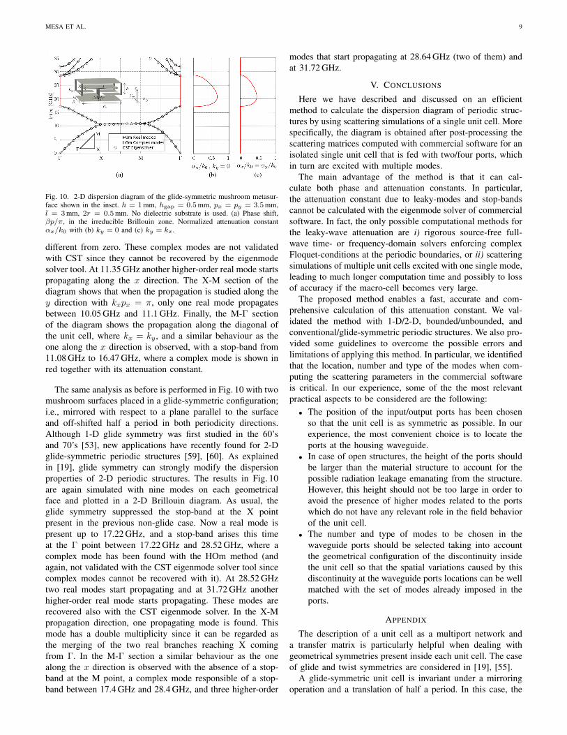
Fig. 10. 2-D dispersion diagram of the glide-symmetric mushroom metasur-face shown in the inset. h = 1mm, hgap = 0.5mm, px = py = 3.5mm,l = 3mm, 2r = 0.5mm. No dielectric substrate is used. (a) Phase shift,βp/π, in the irreducible Brillouin zone. Normalized attenuation constantαx/k0 with (b) ky = 0 and (c) ky = kx.
different from zero. These complex modes are not validatedwith CST since they cannot be recovered by the eigenmodesolver tool. At 11.35 GHz another higher-order real mode startspropagating along the x direction. The X-M section of thediagram shows that when the propagation is studied along they direction with kxpx = π, only one real mode propagatesbetween 10.05 GHz and 11.1 GHz. Finally, the M-Γ sectionof the diagram shows the propagation along the diagonal ofthe unit cell, where kx = ky , and a similar behaviour as theone along the x direction is observed, with a stop-band from11.08 GHz to 16.47 GHz, where a complex mode is shown inred together with its attenuation constant.
The same analysis as before is performed in Fig. 10 with twomushroom surfaces placed in a glide-symmetric configuration;i.e., mirrored with respect to a plane parallel to the surfaceand off-shifted half a period in both periodicity directions.Although 1-D glide symmetry was first studied in the 60’sand 70’s [53], new applications have recently found for 2-Dglide-symmetric periodic structures [59], [60]. As explainedin [19], glide symmetry can strongly modify the dispersionproperties of 2-D periodic structures. The results in Fig. 10are again simulated with nine modes on each geometricalface and plotted in a 2-D Brillouin diagram. As usual, theglide symmetry suppressed the stop-band at the X pointpresent in the previous non-glide case. Now a real mode ispresent up to 17.22 GHz, and a stop-band arises this timeat the Γ point between 17.22 GHz and 28.52 GHz, where acomplex mode has been found with the HOm method (andagain, not validated with the CST eigenmode solver tool sincecomplex modes cannot be recovered with it). At 28.52 GHztwo real modes start propagating and at 31.72 GHz anotherhigher-order real mode starts propagating. These modes arerecovered also with the CST eigenmode solver. In the X-Mpropagation direction, one propagating mode is found. Thismode has a double multiplicity since it can be regarded asthe merging of the two real branches reaching X comingfrom Γ. In the M-Γ section a similar behaviour as the onealong the x direction is observed with the absence of a stop-band at the M point, a complex mode responsible of a stop-band between 17.4 GHz and 28.4 GHz, and three higher-order
modes that start propagating at 28.64 GHz (two of them) andat 31.72 GHz.
V. CONCLUSIONS
Here we have described and discussed on an efficientmethod to calculate the dispersion diagram of periodic struc-tures by using scattering simulations of a single unit cell. Morespecifically, the diagram is obtained after post-processing thescattering matrices computed with commercial software for anisolated single unit cell that is fed with two/four ports, whichin turn are excited with multiple modes.
The main advantage of the method is that it can cal-culate both phase and attenuation constants. In particular,the attenuation constant due to leaky-modes and stop-bandscannot be calculated with the eigenmode solver of commercialsoftware. In fact, the only possible computational methods forthe leaky-wave attenuation are i) rigorous source-free full-wave time- or frequency-domain solvers enforcing complexFloquet-conditions at the periodic boundaries, or ii) scatteringsimulations of multiple unit cells excited with one single mode,leading to much longer computation time and possibly to lossof accuracy if the macro-cell becomes very large.
The proposed method enables a fast, accurate and com-prehensive calculation of this attenuation constant. We val-idated the method with 1-D/2-D, bounded/unbounded, andconventional/glide-symmetric periodic structures. We also pro-vided some guidelines to overcome the possible errors andlimitations of applying this method. In particular, we identifiedthat the location, number and type of the modes when com-puting the scattering parameters in the commercial softwareis critical. In our experience, some of the the most relevantpractical aspects to be considered are the following:
• The position of the input/output ports has been chosenso that the unit cell is as symmetric as possible. In ourexperience, the most convenient choice is to locate theports at the housing waveguide.
• In case of open structures, the height of the ports shouldbe larger than the material structure to account for thepossible radiation leakage emanating from the structure.However, this height should not be too large in order toavoid the presence of higher modes related to the portswhich do not have any relevant role in the field behaviorof the unit cell.
• The number and type of modes to be chosen in thewaveguide ports should be selected taking into accountthe geometrical configuration of the discontinuity insidethe unit cell so that the spatial variations caused by thisdiscontinuity at the waveguide ports locations can be wellmatched with the set of modes already imposed in theports.
APPENDIX
The description of a unit cell as a multiport network anda transfer matrix is particularly helpful when dealing withgeometrical symmetries present inside each unit cell. The caseof glide and twist symmetries are considered in [19], [55].
A glide-symmetric unit cell is invariant under a mirroringoperation and a translation of half a period. In this case, the

10 IEEE ANTENNAS & PROPAGATION MAGAZINE, VOL. XX, NO. YY, MONTH 2019
eigenproblem can be formulated by means of the transfermatrix of a half cell [T] and a geometric diagonal matrix [Q]:
[T]
[VI
]= eγp/2
[[Q] [0][0] [Q]
] [VI
]. (29)
The diagonal entries qii of [Q] describe the mirroring of eachmode, and are simply qii = 1 if the ith mode is even andqii = −1 if the i-th mode is odd with respect to the mirroringdirection. It should be noted that in a 2-D glide-symmetriccase, the reduced unit cell is one quarter of a non-minimal unitcell, obtained by a suitable rotation of the minimal one [19].
A twist-symmetric cell is invariant under a rotation of 2π/nand a translation of a period divided by n, with n being aninteger. In this case, the problem can still be formulated asin (29), with [T] now being the transfer matrix of one n-th ofthe period and eγp/n substituting eγp/2.
Two equivalent choices are possible for the azimuthal de-pendence of the port modes: one can adopt either a basis ofimaginary exponentials or of trigonometric functions. Let usassume that the i-th mode at the ports of the unit cell has animaginary exponential azimuthal variation ejniϕ, with ni beinga suitable integer. In this case, the [Q] matrix is a diagonalmatrix whose diagonal elements describe the rotation of eachmode, and are simply given by qii = e jni2π/n.
If the i-th mode has a sinusoidal azimuthal variation of thekind cos(niϕ) or sin(niϕ), the [Q] matrix is a block diagonalmatrix, whose blocks are defined as
[Qii] =
cos
(ni
2π
n
)sin
(ni
2π
n
)− sin
(ni
2π
n
)cos
(ni
2π
n
) . (30)
REFERENCES
[1] N. W. Ashcroft and N. D. Mermin, Solid State Physics. Orlando:Harcourt, 1976.
[2] R. E. Collin, Field Theory of Guided Waves, 2nd ed. New York: IEEEPress, 1990.
[3] K. Kurokawa, An Introduction to the Theory of Microwave Circuits.New Jersey: Academic Press, 1969.
[4] F. Xu, K. Wu, and W. Hong, “Equivalent resonant cavity model ofarbitrary periodic guided-wave structures and its application to finite-difference frequency-domain algorithm,” IEEE Trans. Microw. TheoryTechn., vol. 55, no. 4, pp. 697–702, 2007.
[5] D. G. Dudley, Mathematical Foundations for Electromagnetic Theory.New York: Wiley–IEEE Press, 1994.
[6] A. Ishimaru, Electromagnetic Wave Propagation, Radiation, and Scat-tering. New Jersey: Prentice Hall, 1991.
[7] T. Rozzi, L. Pierantoni, and M. Farina, “Eigenvalue approach to theefficient determination of the hybrid and complex spectrum of inho-mogeneous, closed waveguide,” IEEE Trans. Microw. Theory Techn.,vol. 45, no. 3, pp. 345–353, 1997.
[8] M. J. Freire, F. Mesa, and M. Horno, “Excitation of complex andbackward mode on shielded lossless printed lines,” IEEE Trans. Microw.Theory Techn., vol. 47, no. 7, pp. 1098–1105, 1999.
[9] T. Tamir and A. Oliner, “Guided Complex Waves. Part I. Fields at aninterface,” Proc. IEE, vol. 110, no. 2, pp. 310–334, 1963.
[10] F. Mesa, D. Jackson, and M. Freire, “High frequency leaky-modeexcitation on a microstrip line,” IEEE Trans. Microw. Theory Techn.,vol. 49, no. 12, pp. 2206–2215, 2001.
[11] M. Tsuji, S. Matsumoto, H. Shigesawa, and K. Takiyama, “Guided-Wave Experiments with Dielectric Waveguides Having Finite PeriodicCorrugation,” IEEE Trans. Microw. Theory Techn., vol. 31, no. 4, pp.337–344, 1983.
[12] H. K. Liu and T. L. Dong, “Propagation characteristics for periodicwaveguide based on generalized conservation of complex power tech-nique,” IEEE Trans. Microw. Theory Techn., vol. 54, no. 9, pp. 3479–3485, 2006.
[13] B. Bandlow, R. Schuhmann, G. Lubkowski, and T. Weiland, “Analysisof single-cell modeling of periodic metamaterial structures,” IEEE Trans.Magnet., vol. 44, no. 6, pp. 1662–1665, 2008.
[14] Y. Weitsch and T. F. Eibert, “Periodically loaded waveguide analysisby propagating and evanescent mode superposition,” in Proc. of theEuropean Microwave Conference, EuMC 2009., Oct. 2009, pp. 1271–1274.
[15] F. Bongard, J. Perruisseau-Carrier, and J. R. Mosig, “Enhanced periodicstructure analysis based on a multiconductor transmission line modeland application to metamaterials,” IEEE Trans. Microw. Theory Techn.,vol. 57, no. 11, pp. 2715–2726, 2009.
[16] R. Islam, M. Zedler, and G. V. Eleftheriades, “Modal analysis and wavepropagation in finite 2D transmission-line metamaterials,” IEEE Trans.Antennas Propag., vol. 59, no. 5, pp. 1562–1570, 2011.
[17] J. Naqui, A. Fernandez-Prieto, M. Duran-Sindreu, F. Mesa, J. J. Martel,F. Medina, and F. Martın, “Common-mode suppression in microstripdifferential lines by means of complementary split ring resonators:Theory and applications,” IEEE Trans. Microw. Theory Techn., vol. 60,no. 10, pp. 3023–3034, 2012.
[18] Y. Weitsch and T. F. Eibert, “Modal series expansion of eigensolutionsfor closed and open periodic waveguides,” IEEE Trans. AntennasPropag., vol. 60, no. 12, pp. 5881–5889, 2012.
[19] M. Bagheriasl, O. Quevedo-Teruel, and G. Valerio, “Bloch analysis ofartificial lines and surfaces exhibiting glide symmetry,” IEEE Trans.Microw. Theory Techn., vol. 67, no. 7, pp. 2618–2628, 2019.
[20] A. F. Peterson, S. L. Ray, and R. Mittra, Computational Methods forElectromagnetics. New York: Wiley–IEEE Press, 1997.
[21] R. F. Harrington, Field Computation by Moment Methods. New York:Wiley–IEEE Press, 1993.
[22] J.-M. Jin, The Finite Element Method in Electromagnetics, 3rd ed. NewYork: Wiley–IEEE Press, 2014.
[23] R.-B. Hwang, Periodic Structures: Mode-Matching Approach and Ap-plications in Electromagnetic Engineering. New York: Wiley–IEEEPress, 2012.
[24] M. S. Tong and W. C. Chew, The Nystrom Method in Electromagnetics.New York: Wiley–IEEE Press, 2019.
[25] D. M. Pozar, Microwave Engineering, 4th ed. New York: John Wiley,1990.
[26] G. Conciauro, M. Bressan, and C. Zuffada, “Waveguide modes via anintegral equation leading to a linear matrix eigenvalue problem,” IEEETrans. Microw. Theory Techn., vol. 32, no. 11, pp. 1495–1504, 1984.
[27] P. Lampariello and R. Sorrentino, “The ZEPLS program for solvingcharacteristic equations of electromagnetic structures (computer programdescriptions),” IEEE Trans. Microw. Theory Techn., vol. 23, no. 5, pp.457–458, 1975.
[28] M. A. Marin, S. Barkeshli, and P. H. Pathat, “On the location of properand improper surface wave poles for the grounded dielectric slab,” IEEETrans. Antennas Propag., vol. 38, no. 4, pp. 1317–1324, 1990.
[29] R. Rodrıguez-Berral, F. Mesa, and F. Medina, “Appropriate formulationof the characteristic equation for open nonreciprocal layered waveguideswith different upper and lower half-spaces,” IEEE Trans. Microw. TheoryTechn., 2005.
[30] P. Kowalczyk, “Global complex roots and poles finding algorithm basedon phase analysis for propagation and radiation problems,” IEEE Trans.Antennas Propag., vol. 66, no. 12, pp. 7198–7205, dec 2018.
[31] G. P. Zouros, “CCOMP: An efficient algorithm for complex rootscomputation of determinantal equations,” Comput. Phys. Commun., vol.222, pp. 339–350, 2018.
[32] P. Baccarelli, C. D. Nallo, S. Paulotto, and D. R. Jackson, “A full-wave numerical approach for modal analysis of 1-D periodic microstripstructures,” IEEE Trans. Microw. Theory Techn., vol. 54, no. 4, pp. 1350–1362, 2006.
[33] P. Harms, R. Mittra, and W. Ko, “Implementation of the periodicboundary condition in the finite-difference time-domain algorithm forFSS structures,” IEEE Trans. Antennas Propag., vol. 42, no. 9, pp. 1317–1324, 1994.
[34] M. Celuch-Marcysiak and W. K. Gwarek, “Spatially Looped Algorithmsfor Time-Domain Analysis of Periodic Structures,” IEEE Trans. Microw.Theory Techn., vol. 43, no. 4, pp. 860–865, 1995.
[35] M. Chen, B. Houshmand, and T. Itoh, “FDTD analysis of a metal-strip-loaded dielectric leaky-wave antenna,” IEEE Trans. Antennas Propag.,vol. 45, no. 8, pp. 1294–1301, 1997.

MESA ET AL. 11
[36] T. Kokkinos, C. D. Sarris, and G. V. Eleftheriades, “Periodic FDTDanalysis of leaky-wave structures and applications to the analysis ofnegative-refractive-index leaky-wave antennas,” IEEE Trans. Microw.Theory Techn., vol. 54, no. 4, pp. 1619–1630, 2006.
[37] N. Marcuvitz, Waveguide Handbook. New York: McGraw-Hill, 1951.[38] G. Valerio, Z. Sipus, A. Grbic, and O. Quevedo-Teruel, “Accurate
equivalent-circuit descriptions of thin glide-symmetric corrugated meta-surfaces,” IEEE Trans. Antennas Propag., vol. 65, no. 5, pp. 2695–2700,may 2017.
[39] S. Amari, R. Vahldieck, J. Bornemann, C. Forces, and C. Angel,“Accurate analysis of periodic structures with an additional symmetryin the unit cell from classical matrix eigenvalues,” IEEE Trans. Microw.Theory Techn., vol. 46, no. 10, pp. 1513–1515, 1998.
[40] F. Mesa, R. Rodrıguez-Berral, and F. Medina, “On the computationof the dispersion diagram of symmetric one-dimensionally periodicstructures,” Symmetry (Basel)., vol. 10, no. 8, p. 307, 2018.
[41] M. Bozzi, S. Germani, L. Minelli, L. Perregrini, and P. de Maagt,“Efficient calculation of the dispersion diagram of planar electromag-netic band-gap structures by the MoM/BI-RME method,” IEEE Trans.Antennas Propag., vol. 53, no. 1, pp. 29–35, 2005.
[42] J. E. Varela and J. Esteban, “Analysis of laterally open periodic waveg-uides by means of a generalized transverse resonance approach,” IEEETrans. Microw. Theory Techn., vol. 59, no. 4 PART 1, pp. 816–826,2011.
[43] M. Kahrizi, T. K. Sarkar, and Z. A. Maricevic, “Dynamic analysis ofa microstrip line over a perforated ground plane,” IEEE Trans. Microw.Theory Techn., vol. 42, no. 5, pp. 820–825, 1994.
[44] L. Zhu, “Guided-wave characteristics of periodic coplanar waveg-uides with inductive loading-unit-length transmission parameters,” IEEETrans. Microw. Theory Techn., vol. 51, no. 10, pp. 2133–2138, 2003.
[45] Y. C. Chen, C. K. C. Tzuang, T. Itoh, and T. K. Sarkar, “Modalcharacteristics of planar transmission lines with periodical perturbations:Their behaviors in bound, stopband, and radiation regions,” IEEE Trans.Antennas Propag., vol. 53, no. 1, pp. 47–58, 2005.
[46] M. Bozzi, M. Pasian, L. Perregrini, and K. Wu, “On the losses insubstrate-integrated waveguides and cavities,” Int. J. Microw. Wirel.Technol., vol. 1, no. 5, pp. 395–401, 2009.
[47] G. Valerio, S. Paulotto, P. Baccarelli, P. Burghignoli, and A. Galli,“Accurate Bloch analysis of 1-D periodic lines through the simulationof truncated structures,” IEEE Trans. Antennas Propag., vol. 59, no. 6,pp. 2188–2195, 2011.
[48] A. Morini and T. Rozzi, “On the generalized scattering matrix of alossless multiport,” IEEE Trans. Microw. Theory Techn., vol. 49, no. 1,pp. 160–165, 2001.
[49] J. A. Dobrowlski, Microwave Network Design Using the ScatteringMatrix. Englewood Cliffs (New Jersey): Artech House, 2010.
[50] J. Frei, X.-D. Cai, and S. Muller, “Multiport S-Parameter and T-Parameter Conversion With Symmetry Extension,” IEEE Trans. Microw.Theory Techn., vol. 56, no. 11, pp. 2493–2504, 2008.
[51] J. Shekel, “Matrix Analysis of Multi-Terminal Transducers,” Proc. IRE,vol. 42, no. 5, pp. 840–847, 1954.
[52] T. Reveyrand, “Multiport conversions between S , Z , Y , h , ABCD , andT parameters,” in 2018 Int. Work. Integr. Nonlinear Microw. Millimetre-wave Circuits, no. 6, 2018, pp. 1–3.
[53] A. Hessel, , M. H. Chen, R. C. Li, and A. A. Oliner, “Propagation inPeriodically Loaded Waveguides with Higher Symmetries,” Proc. IEEE,vol. 61, no. 2, pp. 183–195, 1973.
[54] F. Ghasemifard, M. Norgren, and O. Quevedo-Teruel, “Twist and polarglide symmetries: an additional degree of freedom to control thepropagation characteristics of periodic structures,” Scientific Reports,vol. 8, no. 11266, July 2018.
[55] M. Bagheriasl and G. Valerio, “Bloch analysis of electromagnetic wavesin twist-symmetric lines,” Symmetry (Basel)., vol. 11, no. 5, pp. 1–11,2019.
[56] G. Valerio, S. Paulotto, P. Baccarelli, D. R. Jackson, D. R. Wilton, W. A.Johnson, and A. Galli, “Efficient computation of 1-D periodic layeredmixed potentials for the analysis of leaky-wave antennas with verticalelements,” IEEE Trans. Antennas Propag., vol. 63, no. 6, pp. 2396–2411,2015.
[57] L. Wang, J. L. Gomez-Tornero, E. Rajo-Iglesias, and O. Quevedo-Teruel,“Low-dispersive leaky-wave antenna Integrated in groove gap waveguidetechnology,” IEEE Trans. Antennas Propag., vol. 66, no. 11, pp. 5727–5736, 2018.
[58] M. Vukomanovic, J. Vazquez-Roy, O. Quevedo-Teruel, E. Rajo-Iglesias,and Z. Sipus, “Gap waveguide leaky-wave antenna,” IEEE Trans.Antennas Propag., vol. 64, no. 5, pp. 2055–2060, May 2016.
[59] M. Ebrahimpouri, E. Rajo-Iglesias, Z. Sipus, and O. Quevedo-Teruel,“Cost-effective gap waveguide technology based on glide-symmetricholey EBG structures,” IEEE Trans. Microw. Theory Techn., vol. 66,no. 2, pp. 927–934, Feb 2018.
[60] O. Quevedo-Teruel, J. Miao, M. Mattsson, A. Algaba-Brazalez, M. Jo-hansson, and L. Manholm, “Glide-symmetric fully metallic Luneburglens for 5G communications at Ka-band,” IEEE Antennas Wirel. Propag.Lett., vol. 17, no. 9, pp. 1588–1592, Sept 2018.