Signal compression based on zonal selection methods
374
Conference Proceedings 2000 International Conference on MATHEMATICAL METHODS IN ELECTROMAGNETIC THEORY MMkT 2000 Volume 1 Kharkov. Ukraine September 12-15,2000 Q ALITYI3 4 20001025 064
-
Upload
independent -
Category
Documents
-
view
1 -
download
0
Transcript of Signal compression based on zonal selection methods
Conference Proceedings
2000 International Conference on
MATHEMATICAL METHODSIN ELECTROMAGNETIC THEORY
MMkT 2000Volume 1
Kharkov. Ukraine
September 12-15,2000
Q ALITYI3 4 20001025 064

REPORT DOCUMENTATION PAGE Form Approved OMB No. 0704-0188
Public reporting burden for tis collection of information is estimated to average 1 hour per response, including the time for reviewing instructions, searching existing data sources,gatherng and maiftainng the data needed, and completing and reviewing the collection of information. Send comments regarding this burden estimate or any other aspect of thiscollecion of inlrmtation, including suggestions for reducing this burden to Washington Headquarters Services, Directorate for Information Operations and Reports, 1215 JeffersonDavis Higlway, Suite 1204, Azlingtbm, VA 22202-4302, and to the Office of Management and Bud et, Paperwork Reduction Project (0704-0188), Washington, DC 20503.1. AGENCY USE ONLY (Leave blank) 2. REPORT DATE 3 . REPORT TYPE AND DATES COVERED
IR '3k3,kZ._5-" September 2000 Final
4. TITLE AND SUBTITLE 5. FUNDING NUMBERS
International Conference on Mathematical Methods In Electromagnetic Theory F61775-00-WF084(MMET 2000) Held in Kharkov, Ukraine on September 12-15, 2000. N68171-00-M-6175Proceedings, Volume 1.
6. AUTHOR(S)
7. PERFORMING ORGANIZATION NAME(S) AND ADDRESS(ES) Source Code: 413809 8. PERFORMING ORGANIZATION
REPORT NUMBER
National Academy of Sciences ISBN 0-7803-6347-7Institute of Radiophysics and ElectronicsUlitza Akademika Proskury 12Kharkov 310085Ukraine
9. SPONSORING/MONITORING AGENCY NAME(S) AND ADDRESS(ES) 10. SPONSORING/MONITORINGAGENCY REPORT NUMBER
European Office of Aerospace Research and DevelopmentPSC 802 Box 14 CSP 00-5084FPO 09499-0200 R&D-8915-EE-02
11. SUPPLEMENTARY NOTESSee also ADA396820 (MMET 2000, Volume. 2). This work relates to Department of the Air Force Grant underContract No. F61777-00-WF084, issued by the European Office of Aerospace Research and Development. TheUnited States has a royalty-free license throughout the world in all copyrightable material contained herein.
12a. DISTRIBUTION/AVAILABILITY STATEMENT 12b. DISTRIBUTION CODE
Approved for Public Release; distribution is unlimited. A
12. ABSTRACT (Maximum 200 words)This is Volume I of the final Conference Proceedings of the 8th International Conference on MathematicalMethods in Electromagnetic Theory (MMET 2000) held in Kharkov, Ukraine on September 12-15, 2000.Topics covered include theoretical and applied aspects of: antenna theory, asymptotic methods, particlebeams, complex media, computational techniques, eigenvalue problems, electromagnetic theory, fiberoptics, function-theoretic methods, gratings and frequently, inverse problems, lasers, linear acceleratormodels, nonlinear phenomena, open wavelengths, plasma and waves, radomes, remoting sensing models,waveguide circuits and CAD and more.
13. SUBJECT TERMS 15. NUMBER OF PAGES*NUMERICAL METHODS AND PROCEDURES, *ANTENNA ARRAYS,*ELECTROMAGNETISM, SIGNAL PROCESSING, MAXIMUM LIKELIHOOD
ESTIMATION, DIELECTRICS, MICROWAVES, ELECTROMAGNETIC WAVEPROPAGATION, ELECTROMAGNETIC SCATTERING, FINITE DIFFERENCE THEORY,INTEGRAL EQUATIONS, TIME DOMAIN, PLANE WAVES, PHASED ARRAYS, WAVEEQUATIONS, UKRAINE, SYMPOSIAFOREIGN REPORTS, PROCEEDINGS, EOARD, USARDSG-UK 16. PRICE CODE
17. SECURITY CLASSIFICATION 18. SECURITY CLASSIFICATION 19, SECURITY CLASSIFICATION 20. LIMITATION OF ABSTRACTOF REPORT OF THIS PAGE OF ABSTRACT
UNCLASSIFIED UNCLASSIFIED UNCLASSIFIED UNCLASSIFIEDNSN 7540-01-280-5500 Standard Form 298 (Rev. 2-89)
Prescribed by ANSI Std. 239-18298-102

2 MMET*2000 Proceedings
Organized and sponsored by
IEEE AP/MTT/AES/ED/GRS/LEO Societies East Ukraine Joint Chapter
in cooperation with
Ukrainian National URSI CommitteeScientific Council of NAS on Radio Physics and Microwave Electronics
Institute of Radio-Physics and Electronics of NASInstitute of Radio Astronomy of NAS
Kharkov National University
technically co-sponsored by
IEEE AP, MTT and ED SocietiesURSI
We wish to thank the following for their contribution to the successof this conference:
IEEE ED, MTT, AP and NPS SocietiesIEEE Region 8 Office
URSIEuropean Office of Aerospace R & D
European Research Office, USARDSG-UKTICRA
2000 International Conference on Mathematical Methods in Electromagnetic Theory
IEEE Catalog Number: 00EX413ISBN: 0-7803-6347-7
Library of Congress: 00-01527
This material is based upon work supported by the European Office of Aerospace Research and Development,Air Force Office of Scientific Research, Air Force Research Laboratory, under Contract No. F61775-00-WF084.
Copyright and Reprint Permission: Abstracting is permitted with credit to the source. Libraries are permitted tophotocopy beyond the limit of U. S. copyright law for private use of patrons those articles in this volume thatcarry a code in the bottom of the first page, provided the per-copy fee indicated in the code is paid throughCopyright Clearance Center, 222 Rosewood Drive, Danvers, MA 01923. For other copying, reprint orrepublication permission, write to IEEE Copyrights Manager, IEEE Service Center, 445, Hoes Lane, P. 0. Box
1331, Piscataway, NJ 08855-1331. All rights reserved. Copyright © 2000 by the IEEE, Inc.
Kharkov, Ukraine, VIII-th International Conference on Mathematical Methods in Electromagnetic Theory

MMET*2000 Proceedings 3
MMET*2000 Chairman
Prof. E. I. Veliev, IRE NAS, Kharkov
MMET*2000 Organizing Committee
Prof. V. S. Bakirov, Rector, Kharkov National University
Mrs. N. Y. Bliznyuk, IRE NAS, KharkovConference secretary and Website designer
Prof. V. I. Naidenko, National TU - Kiev Polytechnical InstituteSpecial representative in Kiev
Prof. A. B. Samokhin, Moscow TU of Radio, Electronics and AutomationSpecial representative in Moscow
Ms. I. A. Tishchenko, IRE NAS, KharkovProceedings and program editor
Mr. A. D. Ustimenko, IRE NAS, Kharkov
Dr. I. Y. Vorgul, Kharkov National UniversityArts and technical assistance
Prof. V. M. Yakovenko, Director, IRE NAS, Kharkov
Kharkov, Ukraine, VIII-th International Conference on Mathematical Methods in Electromagnetic Theory

4 MMET*2000 Proceedings
MMET*2000 Chairman
Prof. E. I. Veliev, IRE NAS, Kharkov
MMET*2000 Technical Program Committee
Co-Chairmen:
Prof. A. I. Nosich, IRE NAS, Kharkov, UkraineDr. W. Ross Stone, IEEE AP-S & URSI, La Jolla, USA
Members:
Prof. T. M. Benson, University of Nottingham, UKProf. L. Bertel, Universite de Rennes 1, FranceProf. V. S. Buldyrev, St. Petersburg University, RussiaProf. N. Engheta, University of Pennsylvania, USAProf. F. Gardiol, Ecole Polytechnique, Lausanne, SwitzerlandProf. G. Hanson, University of Wisconsin-Milwaukee, USAProf. M. Hashimoto, Osaka Electro-Communication University, JapanProf. T. Hinata, Nihon University, Tokyo, JapanProf. M. Idemen, Isik University, Istanbul, TurkeyProf. A. S. Ilinsky, Moscow State University, RussiaProf. N. A. Khizhnyak, National Center - KIPT, Kharkov, UkraineProf. A. A. Kirilenko, IRE NAS, Kharkov, UkraineProf. K. Kobayashi, Chuo University, Tokyo, JapanProf. M. Marciniak, Institute of Telecommunications, Warsaw, PolandProf. Z. T. Nazarchuk, PMI NAS, Lviv, UkraineProf. A. G. Nerukh, Kharkov TU of Radio Electronics, UkraineProf. Y. Okuno, Kumamoto University, JapanProf. Y. S. Shifrin, Kharkov TU of Radio Electronics, UkraineProf. I. A. Sukhoivanov, Kharkov TU of Radio Electronics, UkraineProf. K. Tanaka, Gifu University, JapanProf. 0. A. Tretyakov, Kharkov National University, UkraineProf. E. N. Vasiliev, Moscow Power Engn. Institute - TU, RussiaProf. D. M. Vavriv, IRA NAS, Kharkov, UkraineDr. S. N. Vorobiov, IRA NAS, Kharkov, UkraineProf. T. Yamasaki, Nihon University, Tokyo, JapanProf. G. I. Zaginailov, Kharkov National University, Ukraine
Kharkov, Ukraine, VIII-th International Conference on Mathematical Methods in Electromagnetic Theory

MMET*2000 Proceedings 5
CHAIRMEN'S WELCOME
Dear colleagues:
We are very glad to see so many new and familiar faces at MMET*2000, especially ofthose speakers who have come to MMET for the third and forth time since 1990. This provesthat mathematics, computational electromagnetics and physics of microwaves still attract timeand efforts of researchers. This also proves that the conference is held at the right place and inthe right time. One of the main features of the MMET series of conferences is English asworking language. This may be liked or not but it is clear that this single factor has openedmany new and exciting opportunities for the scientists of Ukraine and the Former SovietUnion to meet their Western colleagues and communicate in the recognized professionallanguage. Results are seen in the visits, joint projects and publications of Ukrainian scientistsand their colleagues from Europe, Japan and USA. Joint papers accepted to the program ofMMET are getting common, with some speakers coming from their posts in foreignlaboratories. Another feature is accessibility that is guaranteed by convenient location ofKharkov and good transportation network. This city has been for centuries on the crossroadsbetween Ukraine, Russia, Black Sea and the Caucasus and acquired a unique cosmopolitanspirit and broad-mindedness. Still another feature is affordability for low-income participants:registration fee is split into several convenient parts to meet variety of incomes, cheaperaccommodations are available. MMET started as a school-seminar for young scientists, andby tradition it keeps a number of absolutely one-of-a-kind opportunities for youngerparticipants. These are reduced registration fee and a moderate travel support, plus a chanceof winning an award of the conference that includes a fee waiver for the next meeting. All thiswould never be possible without very kind and efficient support of a number of internationalorganizations and professional societies.
This year the Technical Program Committee adopted more strict selection criteria. Therate of acceptance of contributed papers was 78% (186 out of 240 submitted). It means thatone of every five papers had no chance to be accepted. We hope that their authors will beluckier next time. Local Organizing Committee has shown its best in preparing theproceedings, running the facilities, managing the conference events, and arranging the socialprogram. A new feature was frequently updated Web site of the conference. We are gratefulto all the members of LOC and TPC for their contribution to the success of MMET*2000.
Thank you for coming to participate, enjoy the conference, make friends, discuss newjoint projects, and plan to attend future MMETs.
Eldar I. Veliev and Alexander I. Nosich
Kharkov, Ukraine, VIII-th International Conference on Mathematical Methods in Electromagnetic Theory

6 MMET*2000 Proceedings
TABLE OF MMET*2000 PAPERS GEOGRAPHY
| ~A !
KHARKOV 80
RUSSIA 48
UKRAINE (non-Kharkov) 20
JAPAN 7
TURKEY 6
POLAND 4
BELARUS 3
ITALY 3
UKRAINE+GERMANY 3
UKRAINE+JAPAN 3
GEORGIA 2
USA 2
UKRAINE+RUSSIA 2
UKRAINE+TURKEY 2
RUSSIA+UK 2
UK I
The NETHERLANDS I
TAIWAN I
BULGARIA+ GERMANY I
RUSSIA+POLAND 1
UKRAINE+USA I
UKRAINE+FRANCE I
UKRAINE+UK 1
UKRAINE+CANADA I
UKRAINE+ISRAEL I
UKRAINE+CHINA I
GEORGIA+USA I
S - le
Kharkov, Ukraine, VIII-th International Conference on Mathematical Methods in Electromagnetic Theory

MMET*2000 Proceedings 7
TABLE OF CONTENTS
Volume I
01 A. Kirilenko, P. Pramanick, L. Rud, V. Tkachenko, Decomposition Approach to theMulti-Layer Circuit Electromagnetic Modeling ................................... 21
02 E. A. Romanova, E. V. Bekker, P. Sewell, T. M. Benson, Fiber Mode Behavior Near theCutoff Frequency: Dispersion Characteristics, Modelling and Applications..... 27
03 N. Engheta, Fractionalization Methods and Their Applications to Radiation andScattering Problem s ................................................................... 34
04 V. P. Chumachenko, Domain-Product-Technique Analysis of ElectromagneticScattering and Radiation From Multi-Angular Cylindrical StructuresIncorporating D ielectrics ................................................................. 41
05 K. Tanaka, M. Tanaka, T. Yoshida, M. Yan, Numerical Simulations of Near FieldOptics by Boundary and Volume Integral Equation Methods .................. 47
06 G. W. Hanson, A. B. Yakovlev, Applications of Singular and Critical Point Theory tothe Analysis and Interpretation of Transform and Time-Domain Guided-WaveE lectrom agnetics .......................................................................... 54
07 A. Vertiy, S. Gavrilov, I. Voynovskiy, A. Aksoy, A. 0. Salman, Diffraction TomographyMethod Development in Wide Frequency Range ................................. 61
08 K. Van't Klooster, M. Di Fausto, I. Florio, A. Rosa, B. Robert,The Antenna Sub System for the Meteosat: Modeling Tools and Needs ..... 68
09 M. Idemen, The Concept of Confluence and the Edge Conditions for a WedgeBounded by M aterial Sheets ......................................................... 77
10 T. Shiozawa, T. Thumvongskul, Growth Characteristics of a Cherenkov Laser Filledwith Inhomogeneous and Collisional Plasma ......................................... 86
11 D. M. Vavriv, Millimeter-Wave Radar for Environmental Studies: ImageProcessing and Interpretation ........................................................ 93
12 0. I. Sukharevsky, V. A. Vasilets, S. A. Gorelyshev, A. Z. Sazonov, ElectromagneticScattering by Complex-Shape Objects Partially Coated with AbsorbingM aterials ..................................................................................... 94
13 M. Marciniak, Photonic Crystal Theory, Modelling and Technology ................. 102
01 N. Sakhnenko, A. Nerukh, F. Fedotov, Transients of an Axial Symmetric
Electromagnetic Source in a Flat Waveguide with a Time Varying Plasma .... 111
02 S. N. Dobrovol'sky, N. F. Shul'ga, Concerning Transition Radiation by a
Kharkov, Ukraine, VIII-th International Conference on Mathematical Methods in Electromagnetic Theory

8 MMET*2000 Proceedings
Relativistic Electron in a Thirk Metallic Plate ....................................... 114
03 H. F. Harmuth, K. Lukin, Dipole Currents and Interstellar Propagation ofE lectrom agnetic Signal ................................................................. 117
04 G. V. Ermakov, Numerical-Analytical Spatial-Temporal Characteristicsof a T E M H orn ........................................................................... 120
05 L. G. Velychko, A. 0. Perov, Model Problems of the Time-DomainE lectrom agnetic T heory ................................................................ 123
06 A. N. Dumin, V. A. Katrich, S. N. Pivnenko, 0. A. Tretyakov, Comparative Analysis ofApproximate and Exact Solutions of Transient Wave Radiation Problems..... 125
07 K. N. Klimov, B. V. Sestroretsky, S. V. Soldatov, Analysis of Planar Structures withArbitrary Distribution of Permittivity in the Time-Domain Mode ............... 128
08 Y. V. Tarasov,V. D. Freilikher, Fluctuation Channelling and Time Delay of a PulseSignal in a Randomly Stratified Medium ............................................ 131
09 M. I. Bakunov, V. B. Gildenburg, S. N. Zhukov, N. A. Zharova, Adiabatic Invariantsfor Electromagnetic Waves Guided by Time-Varying Plasma Structures ...... 134
10 V. Chtchekaturov, L. Vietzorreck, W. Fisch, P. Russer, Time-Domain SystemIdentification Modelling for Microwave structures ................................. 137
11 A. A. Galuza, A. S. Mazmanishvili, Modeling of Time Distortion of
Rectangular Pulse Propagating in the Scattering Lossy Media ................... 140
12 A. M. Stadnik, G. V. Ermakov, Atmospheric Distortions of Ultra-WidebandPulses: Method of Temporal Moments ................................................ 143
13 A. G. Nerukh, Time-Domain Fresnel's Formulas for a Plane Interface BetweenM e d ia ...................................................................................... 14 6
14 N. P. Yashina, One Class of Waveguide Resonators: Algorithms Based on Semi-Inversion Technique in Time and Frequency Domain ............................. 149
15 E. A. Gevorkyan, Transverse-Magnetic Electromagnetic Waves in a Waveguidewith Space-Time Multiperiodically Modulated Filling ............................ 150
16 B. V. Sestroretsky, S. A. Ivanov, V. M. Seredov, K. N. Klimov, Family of 12-, 6- and3-Parametrical Algorithms for Electromagnetic Analysis of 3D StreamR -N e t ...................................................................................... 15 3
17 K. M. Yemelyanov, A. G. Nerukh, Electromagnetic Signal Propagation in a TransientMagnetized Plasma with a Time-Varying External Magnetic Field ............. 158
01 K. Ichige, Y. Uchimura, H. Arai, Numerical Analysis of Scattering in 2-D Space byWave Equation-Based FDTD Method ................................................ 163
02 S. Martynyuk, Investigation and Optimization of a Waveguide Slot Antenna Arrayby Finite-Difference Time-Domain Method ......................................... 166
Kharkov, Ukraine, VIII-th International Conference on Mathematical Methods in Electromagnetic Theory

MMET*2000 Proceedings 9
03 A. B. Samokhin, Y. U. Kapustin, Quasi-Minimum-Residual Method in WaveElectrom agnetic Scattering .................................................................. 169
04 B. Tiiretken, S. Eren San, Comparison of Symbolic Computation Techniques for theProblem s of Electrom agnetics ........................................................ 172
05 S. V. Maly, The Technique for Calculation of the Electromagnetic Properties of
Composite Materials and Nonuniform Media ....................................... 175
06 A. B. Hashimov, Numerical Models in the Problems of the Scattered FieldsInteraction ................................................................................. 17 8
07 0. I. Ovsyannikov, Y. V. Kasyanyuk, Calculation of Singular Integrals in ScalarD iffraction Problem s .................................................................... 181
08 M. Gilman, A. Mikheev, S. Sadov, DIFFR2 - a Universal Simulation Environment forTwo-Dimensional Diffraction Problems ............................................. 184
ANALY REG ULARZA•IONS
01 K. Kobayashi, E. I. Veliev, S. Koshikawa, Diffraction of a Plane Wave by a ThinMaterial Strip: Solution by the Analytical-Numerical Approach ................. 189
02 0. V. Alpatova, Plane Wave Scattering by Slots on a Ground Plane in the Case ofOblique Incidence and Arbitrary Polarization ....................................... 193
03 A. V. Brovenko, P. N. Melezhik, A. Y. Poyedinchuk, The Electromagnetic WaveDiffraction by a Partially Screened Anisotropic Dielectric Cylinder. ............ 196
04 N. B. Pleshchinskii, D. N. Tumakov, Regularization by the Integral Identities Methodfor Integral and Series Equations in Diffraction Problems ......................... 199
05 Y. A. Tuchkin, F. Dikmen, S. I. Tarapov, Electromagnetic Wave Diffraction by anInfinitely Thin Perfectly Conducting Circular Ring ................................ 202
06 V. V. Radchenko, A. I. Nosich, S. S. Vinogradov, J.-P. Daniel, Modeling of a Slot-Excited Spherical-Circular Microstrip Antenna ..................................... 203
07 A. N. Khizhnyak, Accurate Numerical Solution of a Diffraction Problem for a Non-Equidistant Axisymmetrical Structure Consisting of Circular Disks ............ 206
08 A. Lerer, G. Kalinchenko, Mathematical Modeling of Electromagnetic WaveDiffraction by Inhomogeneous Dielectric Cylinders of Arbitrary Cross-S ectio n .................................................................................... 2 0 9
'SIGNALPROCS
01 0. Drobakhin, D. Y. Saltykov, V. G. Korotkaya, Discussion on the K-PulseC o n cep t ................................................................................... 2 15
02 R. Baran, D. Wiraszka, W. Dziech, Scalar Quantization in the PWL TransformSpectrum D om ain ....................................................................... 2 18
03 I. R. Urazgildiyev, Maximum Likelihood Technique for Direction of ArrivalEstim ation in A daptive A rrays ....................................................... 221
Kharkov, Ukraine, VIII-th International Conference on Mathematical Methods in Electromagnetic Theory

10 MMET*2000 Proceedings
04 W. Dziech, R. Baran, D. Wiraszka, Signal Compression Based on Zonal SelectionM eth o d s .................................................................................. 2 24
05 A. V. Polyarus, S. A. Kovtun, D. V. Karlov, Mathematical Method of the HeightTarget Determination in the Decametric Band on the Basis of ComputationalE lectrom agnetics ......................................................................... 227
06 V. F. Kravehenko, M. A. Basarab, Atomic Quasi-Interpolation in the Problem ofD igital Signal Processing ............................................................... 230
07 L. F. Chernogor, 0. V. Lazorenko, Application of the Wavelet Analysis forDetecting Ultra-Wideband Signals in Noise ......................................... 233
08 V. Kovalenko, S. A. Masalov, 2D Matrix Filtering of Ground Penetrating RadarD ata ........................................................................................ 2 3 6
PO AGTO AN REOESESN
01 N. V. Yurasova, K. P. Gaikovich, A. N. Reznik, V. L. Vaks, Antennas for Near-FieldR adiotherm om etry ...................................................................... 241
02 A. M. Osharin, A. V. Troitsky, Polarization of the Thermal Radiation of the CloudyAtmosphere in Millimeter Wavelength Band ........................................ 244
03 M. V. Ignatenko, M. V. Tinin, Some Peculiarities of the HF Signal when Locating theS ea S u rface .............................................................................. 24 7
04 Y. N. Ulyanov, N. G. Maksimova, The Estimation of the Air Humidity in the LowerTroposphere with the Use of the Double-Frequency RadioacousticS ounding System ......................................................................... 250
05 V. V. Bryukhanova, I. V. Samokhvalov, Lidar Signal Model from Remote AerosolFormations in Double Scattering Approach ......................................... 253
06 D. Kokody, S. Prosvirnin, Analysis of Electromagnetic Characteristics of Multi-Layered Periodic Structures with Turning Layers .......................................... 256
07 P. A. Belov, Dipole Model of Electromagnetic Wave Propagation in Regular 3DL attices of Scatterers .................................................................... 259
08 S. A. Masalov, A. 0. Puzanov, Transient Radio Wave Scattering by Typical AerationZ o n e s ...................................................................................... 2 6 2
01 E. Hasanov, Two-Reflector Non-Symmetric Shaped Antenna Systems ............... 267
02 A. Kasyanov, Focusing Systems Based on Microstrip Reflectarrays ................... 270
03 M. B. Protsenko, I. V. Tan'kov, V. V. Gromozdin, Analysis Method of the InputImpedance of a Spiral Antenna with Given Configuration ......................... 274
04 V. V. Ovsyanikov, Research of New Antennas for Mobile RadioC om m unications .......................................................................... 277
05 A. 0. Kasyanov, V. A. Obukhovets, Blindness Angles in Microstrip Phased Arrays
Kharkov, Ukraine, VIII-th International Conference on Mathematical Methods in Electromagnetic Theory

MMET*2000 Proceedings 11
P attern s .................................................................................... 2 80
S06 A. A. Beletsky, Excitation of the Infinite Perfect Conducting Bicone withIm pedance A zim uthal Slots ............................................................. 283
07 A. Bijamov, K. Tavzarashvili, R. Zaridze, G. Bit-Babik, 3-D Analysis of the CompactC ellular Phone A ntennas ................................................................ 286
08 N. Y. Bliznyuk, A. I. Nosich, Modeling of a Slot-Excited Flat Disk MicrostripA ntenn a ................................................................................... 2 89
09 V. A. Obukhovets, A. 0. Kasyanov, S. V. Piven, Reflective Type Antenna Arraysas the Sm art Cover Elem ents ............................................................. 292
10 A. S. Andrenko, Y. Ikeda, K. Mori, 0. Ishida, EM Analysis of PBG SubstrateMicrostrip Circuits for Integrated Transmitter Front End ........................... 295
11 V. V. Khakinov, Analyzing the HF Field in the Wave Zone of the Antenna Usingthe Normal-Mode Approach ................................. 298
12 S. N. Sorokin, V. V. Savelyeev, Account of Mutual Resistance of ArbitrarySeparated Two W ire A ntennas .......................................................... 301
13 A. Shishkova, L. V. Orlova, N. N. Gorobets, Mathematical Model of Radiation fromOpen-Ended Circular Waveguide Excited by Symmetrical TM01 and TE01M o d e s ...................................................................................... 30 3
14 E. A. Shorochova, O.S. Rusakova, V.A. Yashnov, Radiation of Dielectric-Coated Longitudional and Transversal Slot Antennasin a Plane W aveguide .................................................................... 306
15 A. V. Kabanov, V. V. Lukin, Analysis of Disturbed Pattern Statistical Characteristicsfor Apodized Multielement Waveguide Slot Antennas .............................. 309
16 D. Y. Razdorkin, M. V. Romanenko, Shaped Feed Systems for the Dual-ReflectorA nten n as ................................................................................. 3 12
01 I. V. Meglinsky, S. J. Matcher, Density of the Spatial Weight Distribution in theMulti-Layered Highly Scattering Randomly Inhomogeneous Media............. 317
02 I. L. Maksimova, Multiple Light Scattering by Random and DeterministicS tructu res .................................................................................. 320
03 Y. 0. Averkov, V. M. Yakovenko, Quasilinear Theory of Interaction BetweenSurface Plasmons and an Electron Beam Moving Parallel to a PlasmaSurface in V acuum ....................................................................... 323
04 K. A. Vytovtov, Investigation of the Plane Wave Behavior within BianisotropicM e d ia ...................................................................................... 3 2 6
05 V. P. Olefir, N. A. Azarenkov, A. E. Sporov, Gas Discharge Sustained by theNonpotential Symmetric Surface Wave in Magnetized HeterogeneousP lasm a C olum n ........................................................................... 329
Kharkov, Ukraine, VIII-th International Conference on Mathematical Methods in Electromagnetic Theory

12 MMET*2000 Proceedings
06 D. Churmakov, High Harmonic Generation in Classical AnharmonicO sc illato r ................................................................................. 3 3 2
07 N. T. Afanasiev, S. N. Kolesnik, M. V. Tinin, Simulation Modeling of StatisticalCharacteristics of the Radio Wave in a Layer with Random Inhomogenetiesof D ielectric Perm ittivity ................................................................ 334
08 P. N. Melezhik, Interaction of Natural Oscillations of an Open Resonator withAzimuthal Surface Waves of Plasma Column ........................................ 337
09 S. A. Derevyanko, G. B. Tkachev, V. A. Yampolskii, Peculiarities in the NonlinearElectromagnetic Response of a Thin Metal Film Carrying a Strong DCC u rren t ..................................................................................... 3 4 0
10 N. N. Beletskiy, Y. V. Bludov, Propagation of Surface Polaritons in FiniteSuperlattices w ith D issipation .......................................................... 343
11 A. A. Bulgakov, 0. V. Shramkova, Nonlinear Interaction of the Waves in PeriodicSemiconducting Superlattice Placed in a Magnetic Field ........................... 346
12 G. G. Goshin, N. E. Lugina, The Boundary Value Problems of ElectromagneticTheory of Planar Chiral Structures ................................................... 349
13 V. M. Onufrienko, E. I. Veliev, Mathematical Model of a Spherical FractalE m itte r ..................................................................................... 3 5 2
14 M. A. Ustyantsev, V. A. Antonova, G. I. Churyumov, Numerical Modeling of SolarCells B ased on Q uantum W ells ........................................................ 355
15 T. I. Frolova, G. I. Churyumov, Simulation of a Nonlinear Interaction in theC om bined M agnetron .................................................................... 358
16 A. V. Malyuskin, M. P. Perepechai, S. N. Shulga, Effective ElectromagneticParameters of Strongly Fluctuating Statistically Layered BianisotropicM ed iu m ..................................................................................... 3 6 1
17 D. N. Goryushko, A. A. Shmat'ko, Reflection of a Laser Beam from aGyromagnetic Layer with a Magneto-Dielectric Substrate ......................... 364
Volume II
01 M. Fujimoto, Y. Okuno, T. Matsuda, Numerical Evaluation of Binary OpticalElements with Subwavelength Structures ............................................. 393
02 E. Karchevskii, R. Dautov, Mathematical Analysis and Numerical Simulation ofthe Guided Modes of the Weakly Guiding Optical Fibers .......................... 396
03 A. V. Boriskin, S. V. Boriskina, Integral Equations in Electromagnetic WaveScattering by 2-D Dielectric Lenses and Shells ..................................... 397
04 D. N. Tumakov, 0. A. Raskina, Electromagnetic Wave Diffraction on an N-
Kharkov, Ukraine, VIII-th International Conlference on Mathematical Methods in Electromagnetic Theory

MMET*2000 Proceedings 13
Branching of a Plane W aveguide ..................................................... 400
05 E. V. Bekker, E. A. Romanova, L. A. Melnikov,M. Marciniak, Comparitive Analisysof Some Numerical Techniques for Modelling of Spatial Transient Regimein Irregular Planar Structures .......................................................... 403
06 V. V. Lysak, I. A. Sukhoivanov, A. A. Chernoblavskiy, Photonic Band GapStructure Created from Artificial Opals ............................................... 406
07 A. Prigoda, J. Speidel, R. Frich, I. Sukhoivanov, Research and Realization Methodsof Construction of Strict Optical Orthogonal Codes for Transfer Multimediaof Information and Distributive Appendices .......................................... 409
08 S. Greedy, P. Sewell, T. M. Benson, Spectral Index Method Applied to theAnalysis of Whispering Gallery Modes in Semiconductor DiskR esonators ................................................................................ 4 12
SATTRN AND RADA CRS ETO
01 A. G. Tyzhnenko, Low-Grazing-Angle Scattering by a Triangle Model ofan O cean W ave ...................................... .................................. 4 17
02 V. M. Onufriyenko, P. A. Samolchev, T. I. Sliusarova, Reflection of a Plane Wavefrom a Cylinder with Fractral Properties of the Surface ............................ 420
03 A. S. Ilinski, I. A. Zagorodnov, R. P. Tarasov, Aperture Coupling in the BodiesPossessing Finite Sym m etry Group .................................................... 423
04 A. Maher, N. B. Pleshchinskii, Plane Electromagnetic Wave Scattering andD iffraction in a Stratified M edium ................................................... 426
05 L. Ilyashenko, A. I. Nosich, Numerical Method of Solving the SingularIntegral Equations of Wave Scattering by a Penetrable PolygonalC ylin der ................................................................................... 4 29
06 V. Daniele, Generalized Wiener-Hopf Technique for Wedge ShapedRegions of A rbitrary A ngles ........................................................... 432
07 S. Vashtalov, 0. Dotsenko, Plane Wave Diffraction by the Right-AngledWedge Coated with the Thin Bi-Isotropic Layers .................................. 435
08 A. A. Gousenkova, Diffraction Problems for Electromagnetic Wave on a Stripand for Elastic Wave on a Defect in Comparisons .................................. 438
09 V. Daniele, M. G. Floreani, R. E. Zich, On the Sommerfeld Representation ............. 441
10 P. L. Tokarsky, Radiation Efficiency of Coupled Horizontal ElectricalD ipoles Over a Lossy Half-Space ..................................................... 444
11 V. N. Kisel, A. I. Fedorenko, Electromagnetic Scattering from Cavities withC om plex O bjects Inside ................................................................ 447
12 A. Y. Shramkov, Mathematical Modeling of Electromagnetic Wave Scatteringby the Com plicated Terrain Relief .................................................... 450
13 S. V Nechitaylo, S. V. Orechov, K. I. Tkachuk, The Scattering by a Perfectly
Kharkov, Ukraine, VlII-th International Conference on Mathematical Methods in Electromagnetic Theory

14 MMET*2000 Proceedings
Conducting Paraboloid of Rotation with an Absorbing Coating of theE d g e s ...................................................................................... 4 5 3
14 A. S. Ilinski, Approximate Methods for Solving Problems of theElectromagnetic Scattering from Local Inhomogenities and PartialR adiation C onditions ................................................................... 456
15 N. N. Kisel, A. V. Alpatova, V. N. Kisel, Combined Utilization of Eigenfunctionsand Integral Equations to Calculate the Fields Inside InhomogeneousD ielectric B odies .......................................................................... 4 59
16 Y. V. Yukhanov, Electromagnetic Wave Scattering from an Impedance PlaneCovered w ith a D ielectric Layer ....................................................... 462
17 T. Oguzer, Performance of 2D Reflector Antenna System in a CircularDielectric Radome Reinforced with an Inner Resistive Grating .................. 465
18 F. Shubitidze, K. O'Neill, S. Haider, K. D. Paulsen, K. Sun, Analysis of InductionResponses from Metal Objects Using the Method of Auxiliary Sources.........468
19 Y. V. Yukhanov, A. Y. Yukhanov, Plane Wave Scattering by a ReflectorAntenna Located Over an Impedance Plane ......................................... 471
20 A. Y. Shepilko, Y. V. Shepilko, Scattering of a Plane Electromagnetic Wave by aM etal-Dielectric Com posite Cylinder ................................................. 474
01 L. Minakova, L. Rud, Spectral Approach to the Synthesis of the WaveguideBandstop Filters Based on Dielectric Rectangular Posts ................ 479
02 D. Kulik, A. Kirilenko, Modeling of Elements with Circular Symmetry Placedin a Rectangular W aveguide M ultiport ............................................... 482
03 N. Blinova, A. Zhironkina, L. Yatsuk, Successive Approximations Method forthe Linear System of Double Longitudianal Slots in a RectangularW aveguid e ............................................................................... 4 85
04 A. Matsushima, H. Sakamoto, Numerical Analysis of AC Losses inTransmission Lines Composed of Round Wires .................................... 488
05 S. A. Komarov, V. V. Scherbinin, Self and Mutual Admittance of a WaveguideSystem with an Impedance Flange .............................. 491
06 A. Yushchenko, Physical and Mathematical Aspects of Some ModeM atching M odifications ................................................................. 494
07 V. B. Kazanskiy, V. V. Khardikov, Eigen Regimes of the Multilink WaveguideFilter w ith Reactive D iaphragm s ...................................................... 497
08 0. Kim, Generalized Ananlysis of a Coaxial Waveguide to RadialW aveguide Junction ...................................................................... 500
09 L. Mospan, A. Kirilenko, Modeling and Optimization of a New-Type BandstopFilter Based on M ultiaperture Irises ................................................... 503
Kharkov, Ukraine, VIII-th International Conference on Mathematical Methods in Electromagnetic Theory

MMET*2000 Proceedings 15
10 M. I. Ayzatsky, Electromagnetic Oscillations in Periodic Media Outsidethe P assbands ............................................................................ 506
11 V. Girka, I. Pavlenko, S. Puzirkov, Study of Surface Flute Modes Propagationin a Cylindrical Metal Waveguide with Noncircular Cross-Section andP lasm a F illing ............................................................................ 509
12 A. S. Turk, V. P. Chumachenko, Domain-Product-Technique Analysis of aDielectric-Loaded H-Plane Radiator ................................................. 512
13 V. V. Podlozny, V. V. Khardikov, High-Q Waveguide Filter .............................. 515
14 V. A. Karlov, The Analysis of a Loaded E-Plane Cross-Shaped Junctionof Rectangular W aveguides ............................................................ 518
15 L. Yatsuk, A. Lyakhovsky, A. Lyakhovsky, Longitudinal Slots in a RectangularWaveguide Loaded with a Layered Dielectric ....................................... 521
16 V. V. Kamyshan, 0. P. Kamyshan, The Vortex Lattice Method in the SpectralProblem of a Rectangular Waveguide with a Lamellar Grating .................. 524
17 0. A. Tretyakov, Zheng Yu., New Explicit Solutions in Time Domain forW aveguide Signals ...................................................................... 527
ýEIGEE PROBLEMS
01 G. I. Zaginaylov, P. V. Turbin, K. Schuenemann, J. -Y. Raguin, Spectral Properties of aPeriodic Plasm a W aveguide ........................................................... 533
02 Y. Trifonov, Y. Karchevskii, Computing Complex Propagation Constants ofD ielectric W aveguides .................................................................. 536
03 P. A. Malyshkin, A. D. Shatrov, Chiral Low Frequency Resonance on anAnisotropically Conductive Cylinder with a Thin Longitudinal Slot ............ 538
04 S. V. Boriskina, T. M. Benson, P. Sewell, A. I. Nosich, Resonant Spectra of the WGMDielectric Resonators Deformed from the Circular Geometry ................... 541
05 A. I. Makarov, Numerical Investigation of Eigen Oscillations Near System ofTwo Strips Forming a Cross in the Channel ......................................... 544
06 Y. V. Prokopenko, Y. F. Filippov, Spectral Perfomances of a Non-Isotropic DielectricResonator with Imperfect Conducting End Walls .................................. 547
07 V. F. Borulko, V. E. Ivanilov, Two-Dimentional Bragg Resonator with NonperiodicRadial and Angular Perturbation of Parameters ..................................... 550
08 K. P. Yatzuk, Complex Waves in a Planar Spiral with Three-LayeredD ielectric ................................................................................. 5 5 3
01 Y. Okuno, T. Matsuda, M. Kinoshita, Diffraction by a Multilayer-Coated
B isinusoidal G rating .................................................................... 557
02 S. A. Volkova, V. N. Pilipchuk, An Analytical Technique for Modeling of Wave
Kharkov, Ukraine, VIII-th International Conference on Mathematical Methods in Electromagnetic Theory

16 MMET*2000 Proceedings
Propagation in Periodic Structures .................................................... 560
03 Z. T. Nazarchuk, 0. I. Ovsyannikov, T. D. Senyk Problem of Plane ElectromagneticWave Diffraction by Multielement Grating Imbedded in a Half-Space .......... 563
04 V. V. Yachin, N. V. Sidorchuk, Electromagnetic Wave Scattering by a Doubly-Periodic M agnetodielectric Layer ..................................................... 566
05 T. Yamasaki, T. Hinata, T. Hosomo, Scattering of Electromagnetic Waves byDielectric Gratings with Cylindrically Layered Media .............................. 569
06 N. A. Balachonova, A. V. Kats, I. S. Spevak, The Resonance Effects in the Diffractionby Well Reflecting Gratings in the Case of the Double Resonances ............ 572
07 S. B. Panin, A. Y. Poedinchuk, The Diffraction of the Normally Incident Plane Waveby a Grating over a Chiral M edium .................................................... 575
08 Y. V. Gandel and V. V. Khoroshun, The Vortex Lattice Method in theElectromagnetic Wave Diffraction on the Method Grading with GyrotropicL ay e r ....................................................................................... 5 7 8
01 S. V. Buharov, Solution of the Direct and Inverse Problems of the WaveReflection From the Waveguide Fragment Filled with a LossyD ie lectric .................................................................................. 5 8 3
02 G. A. Alexeev, A. P. Kusaykin, A. Y. Poedinchuk, An Analytical NumericalSolution Method of the Refraction Inverse Problems .............................. 586
03 A. V. Shvets, Solution of the Lightning Intensity Distance DistributionReconstruction Problem by Using the Schumann Resonance Signal ............. 589
04 K. P. Gaikovich, A. N. Reznik, V. L. Vaks, Near-Field Effects in ThermalR adio E m ission ........................................................................... 592
05 V. I. Naidenko, L. G. Guseva, Matching of the Normally Incident H-PolarizedPlane Wave with a Layered Half-Space ............................................. 595
06 W. -T. Chen, C. -C. Chiu, Near-field and Far-field Image Reconstruction foran Im perfectly Conducting Cylinder ................................................. 598
07 A. V. Zhilin, K. P. Gaikovich, Y. N. Nozdrin, A. N. Reznik, Sheet Currents Retrieval inH igh-T Superconductor Film s .......................................................... 601
08 M.I. Andriychuk, P. 0. Savenko, Synthesis of a Waveguide Array with DueRegard for the Mutual Coupling of Radiators ....................................... 604
09 A. Pralat, R. Zdunek, Regularized Image Reconstruction in theElectromagnetic Geotomography through Use of the Wiener Filter ............ 607
10 N. E. Nikolaev, V. V. Shevchenko, Tolerance of the Solution to the Problem of aBuried W aveguide Synthesis .......................................................... 610
11 V. L. Mironov, S. A. Komarov, Y. A. Sukovatov, About Permittivity ProfilesHaving Joint Analytic Solutions For Horizontally and Vertically
Kharkov, Ukraine, VIII-th International Conference on Mathematical Methods in Electromagnetic Theory

MMET*2000 Proceedings 17
Polarized W aves .......................................................................... 613
12 A. V. Muzychenko, Imaging of "Illuminated" Part of a Smooth ConvexPerfectly Conducting Surface from Full Polarization Receiver Data.......... 615
13 P. 0. Savenko, About One Method of Solution of the Synthesis Problems ofRadiating Systems under the Given Power Directivity Pattern ..............618
14 D. 0. Batrakov, M. M. Tarasov, Applicaton of Pontryagin's Principle of Maximumto the Inverse Problems of Scattering .............................................. 621
01 S. L Martynenko, Strong Mesospheric Electric Fields and Troposphere-M esosphere Coupling ................................................................... 627
02 P. F. Denisenko, G. I. Kuleshov, A. I. Skazik, The Attenuation of a SpecularComponent of HF Signals from the Vertical Sounding of Ionosphere ........... 630
03 V. I. Taran, D. A. Dzyubanov. Y. I. Grigorenko, V. N. Lysenko, Calculation of theUpper Atmoshsphere Dynamic Characteristics from Ionospheric Data ......... 633
04 V. B. Ivanov, M. V. Tolstikov, An Analysis of the Plasma Stability in the UpperIonosphere ................................................................................ 635
05 A. P. Nickolaenko, Application of the Hurst Exponent in the Analysis of NaturalELF Electrom agnetic Noise ............................................................ 638
06 A. P. Nickolaenko, L. Rabinowicz, Accelerating the Convergence of the TimeDomain Solution for a Natural ELF Pulse ........................................... 641
07 V. N. Popov, On the Scheme for Seeking the Solution to a System ofMaxwell's Equations in a Spherically Symmetric Model of the Earth-Ionosphere W aveguide .................................................................. 644
08 T. G. Zhivolup, The Role of Excited Molecular Ions in the Variation of the E-Layer Peak Height Caused by the Solar Activity ................................... 647
09 N. A. Kazakova, A. G. Kolesnik, B. M. Shinkevich, Displays of Possible Harbingersof Earthquakes on Recordings of VLF-Signals Depending on theirC haracteristics ........................................................................... 650
10 L. F. Chernogor, L. S. Kostrov, V. T. Rozumenko, HF Doppler Probing theDisturbances Originating in the Ionosphere from Natural andA nthropogenic Sources ................................................................ 652
11 M. Gokov, S. I. Martynenko, V. T. Rozumenko, 0. F. Tyrnov, Large-Scale DisturbancesOriginating from Remote Earthquakes in the Plasma at MesosphericH eights ................................................................................... 655
12 V. N. Lysenko, Mathematical Model of the Measuring Channel for IonosphereParameter Definition by the Incohorent Scatter Radar Technique ............... 658
13 E. V. Ovcharenko, V. A. Donchenko, V. T. Kalaida, Short-Term Forecast ofAtmosphere Electrical Condition on Meteorological and Optical
Kharkov, Ukraine, Vill-th International Conference on Mathematical Methods in Electromagnetic Theory

18 MMET*2000 Proceedings
P aram eters ................................................................................ 66 1
01 C. Utku, B. Tuiretken, A New Numerical Approach to Electromagnetics: Finite-A nalytic M ethod .......................................................................... 667
02 G. N. Georgiev, T. I. Stoyanov, M. N. Georgieva-Grosse, On an Application of theKummer Confluent Hypergeometric Functions ...................................... 670
03 V. Daniele, M. Gilli, S. Grivet, A Laplace Transform Technique for WedgeShaped Isorefractive Regions ................. ....................................... 673
04 I. V. Petrusenko, L. I. Chernish, One Generalization of Projective Methods for theW ave D iffraction Problem s ............................................................. 676
05 K. Tavzarashvili, R. Zaridze, G. Bit-Babik, The Metod of Integrated AuxiliarySources for 3D Diffraction Problem Solution ........................................ 679
06 V. F. Kravchenko, M. A. Basarab, Solving Integral Equations for Ill-PosedProblems of Electromagnetics with Complex Objects Based on the AtomicF u n ctio n s ................................................................................... 6 8 2
07 N. V. Bondarenko, N. F. Shul'ga, The Method of Surface Integral in the Theoryof W ave Scattering ...................................................................... 685
08 V. I. Jordan, The Method of Eigenvalue Spectrum Diacoptic Process forR eal H essenberg M atrices .............................................................. 688
09 I. Vorgul, New Approach to Diffraction Problems by Reducing them to theV olterra Integral Equations ............................................................ 691
10 D. B. Kuryliak, S. Koshikawa, K. Kobayashi, Z. T. Nazarchuk, Wiener-Hopf Analysisof the Vector Diffraction Problem for a Cylindrical Waveguide Cavity ......... 694
11 V. K. Sorokin, L. S. Lobanova, Non-Classical Structural Mathematical Meansan d O p tics ................................................................................. 69 7
12 M. A. Basarab, Modified Algorithm of the R-Functions Method for SolvingElectromagnetic Boundary Value Problems ......................................... 700
13 K. Y. Kramarenko, N. A. Khizhnyak, Investigation of the Ifluence of PeriodicDisturbances in the Layered Medium by the Method of Averaging ofK rylov-B ogolyubov ...................................................................... 703
14 A. V. Kats, Analytical Approach to the Theory of Resonance Diffractionby Periodically Modulated Boundaries .............................................. 706
15 V. Demidtchik, Integral Equations for Dielectric-Coated Thin-WireA nten n as ................................................................................. 70 9
16 0. I. Sukharevskiy, G. S. Zalevsky, Electromagnetic Fields Scattered by the SubsurfaceS ystem of O bjects ......................................................................... 7 12
Kharkov, Ukraine, VIII-th International Conference on Mathematical Methods in Electromagnetic Theory

MMET*2 000 Proceedings 19
PEN'ARS-E'SiSIO'N.1S
Kharkov, Ukraine, VIII-th International Conference on Mathematical Methods in Electromagnetic Theory

20 MMET*2000 Proceedings
Kharkov, Ukraine, VIII-th International Conference on Mathematical Methods in Electromagnetic Theory

MMET*2000 Proceedings 21
DECOMPOSITION APPROACH TO MULTILAYER CIRCUITSELECTROMAGNETIC MODELING
Anatoly Kirilenko1 , Protap Pramanick 2, Leonid Rud', and Vladimir Tkachenko1
'Institute of Radiophysics and Electronics of NASU, Ukraine, Kharkov,fax: 038 0572 441105, e-mail: [email protected]
2 Polar Wave Consulting, Canada
ABSTRACTA system approach based on transverse resonance technique and well-equipped modelingsystem is used to calculate eigen-mode spectrum of the multiconductor lines with thepiecewise coordinate boundary of cross-section. It serves as the background for calculation ofmultilayer circuit frequency response by mode-matching and S-matrix techniques.
Modeling of multilayer circuits is now a very actualS• problem in applied electromagnetics [1,2]. It is
desirable here to have more flexible algorithmsallowing an on-line retuning to some new topology ofthe cross section within the framework of a unifiedapproach. One of the most popular techniques ofcomputing the eigen modes of the transmission linesof complicated cross- sections is the transverse reso-
Fig. 1 nance method that, in fact, reduces to the decomposition ofthe cross section into fragments with known scattering descriptors (for instance, S-matrixes).The availability of modeling systems equipped with tools for electromagnetic "assembling" ofscatterers, as well as an advanced library of key elements and archiving, buffering andinterpolation tools makes it possible to treat efficiently fairly large classes of problems on thespectrums of eigen modes, at the same time retaining a high effectiveness of solutions. Itproves to be close to the effectiveness of the methods being used at computing key elements.The goal of the given report is to demonstrate a similar unified approach to the calculation ofthe modes' spectrums of complicated lines and to the analysis of corresponding scatteringproblems. Here the modeling system SES-06, that is based on C++ classes, is employed bothat the stage of building the bases of various lines and at the final stage of calculating thefrequency response of the integral circuit. Let us note that the proposed approach to modelingmulti-layer circuits allows us also to take into consideration the width of conductors, that wasa problem in the algorithm used in the similar situation in [2].As an example of the object, the calculation of which includes the main features of thistechnology, let us consider the fragment of the integral circuit as an element of theinductance " type being put into a rectangular screen. (see Fig. 1). It follows from the veryessence of such a scatterer that it naturally splits into a set of regular segments of nonstandardtransmission lines that usually have very complicated cross sections (see Fig. 2). The planejunctions couple these lines.The calculation of the characteristics of the object being treated requires a preliminaryanalysis of the full spectrum of TEM-, TE- and TM- modes in such lines for their further usagein the projection algorithm of analyzing S-matrixes of the plane junctions of such lines. Thissimplest example already makes it clear that any possible modification of the topology of theabove-treated object, for instance, the increase of the number of layers in the integral circuit,
Kharkov, Ukraine, VIII-th International Conference on Mathematical Methods in Electromagnetic Theory

22 MMET*2000 Proceedings
brings a new set of configurations both for the transmission lines themselves and for theirjunctions. It is clear that the maximum universality can only be achieved on the basis of awell-structured approach which is the transverse resonance method realized on the basis of thecorresponding modeling system (in this case the system SES-06 was used - it is one of thelatest versions of SES-04 described in [3]). As a result, there is a possibility to freelymanipulate with the configuration of "assembling" electromagnetic objects.
4 -
Line "1" -"Lin 9 Line "3" 3
- Line "4"- Line "5"
Fig.2
Bases of TE-and TM- modes.The calculation of the spectrum of TE-and TM- modes reduces to the calculation of eigen-frequencies and oscillations of the resonator that is infinite in the longitudinal direction of lineunder consideration. Matching the fields of partial domains that were formed by the regularsegments of the rectangular WG with the help of scattering matrixes of E, (H7 )-polarizedwaves on the corresponding steps and bifurcations, we receive two systems of homogeneousequations, nontrivial solutions of which give these desired spectrums for modes of E, (H, )-
types. However, the well-known idea of transverse resonance requires some commentsconcerning possible alternatives in the formulation of the dispersion equation. Assuming thatthe transverse resonance method is known, let us discuss only the three most importantsolution schemes.In the simplest Scheme A, a homogeneous matrix equation is formulated relevant to thevector A•) of unknown amplitude waves in one of the regular partial domains of the crosssection and looks as follows (I .S(JJ)F().•(j) E(J))Aw~j =0 (1
I- •eft right
where Sj•'1 and S•ii, are matrixes of reflection correspondingly from the left and the right
boundary of a chosen partial domain, E°i=diag1exp(iý,(,"h0')} - is a diagonal transmission
matrix dealing with the waves on the segment of a plane WG with the length h(i),
4JW = k2 -(ng/ai'))2 -is the constant of propagation in the plane WG of a(j' width.The advantages of such a scheme in comparison with the others (see below) lie in a smalleramount of time spent on the calculation of the matrix operator determinant in (1), since thecalculation of and can by derived by step by step scheme. The disadvantage of
Scheme A is the following one: the determinant of the type E-Si, S~ightE 1 is
characterized by a steep response in the vicinity of the sought-for zeros that, in turn, requires adenser frequency set at the initial localization of roots. The other disadvantage is connectedwith a possible field localization of one of the oscillations in a domain different from, forinstance, a chosen j-domain. At the weak electromagnetic coupling of this domain with the
Kharkov, Ukraine, VIII-th International Conference on Mathematical Methods in Electromagnetic Theory

MMET*2 000 Proceedings 23
domain of the field localization, a missing zero is here also possible at seeking the roots of thedispersion equation.Scheme B is used in cases when the cross-section being considered has large-scale domainsand one resorts to forming a matrix equation relevant to field vectors in some of them. If wedistinguish the domains 9, 4, 0 of Line 3 (see Fig.2) as dominant, than we pass to ahomogeneous system of equations of the type:
I + S9 (9~)2 0 _s9 )E( 4 ) 0
V (E'9)I _s44 E (4) 4
(9Is4 ( ) ( 4 S (9 )( 2) (4 0 , (2)_s- ~E (4 ) 0 I +S S (0()~ AM0 ,
where Aj) and BW) are the amplitudes of forward and back waves in the j domain.The time for determinant calculation increases in comparison with (1), though the frequencydependence of the latter becomes smoother. Both in Scheme A and especially in Scheme Bthere are determinant poles on the cutoff frequencies of some domains, that makes the processof searching for the critical frequencies more difficult.Scheme C does not presuppose preliminary "assembling" of partial elements and is based onthe full initial system of equations that describes the couplings between all the vectors of thewaves in partial domains with the help of S-matrixes. Since in the general case not all partialdomains couple with each other, the matrix operator contains a great number of zeroelements. On the one hand, it leads to a more laborious algorithm and to greater timeconsumption. On the other hand, the determinants being generated by Scheme C do not havepoles; their frequency dependence is fairly smooth and, on the contrary, decreases calculationtime. In the general case, Scheme C is also more reliable.At calculations several dozens of eigen modes of H- and E-types for each transmission linewith a complicated cross section are usually taken into consideration. This part of the integralcircuit calculation algorithm turns out, for instance, to be more laborious if we lack priorinformation about the spectrums of these lines. By and large, this procedure consists of twostages: (1) Rough search for the initial approximation for the whole spectrum that in one oranother way is based on the analysis of sign variation points in the real and imaginary parts ofthe complex determinant. In Schemes A and B at the critical frequency, it is typical for one ofthe two constituents of the complex value determinant really to change its sign, and for theother 'only to touch the frequency axis. Scheme B does not have such problems, since both thereal and the imaginary part of the complex determinant change their signs at thecorresponding points. (2) The search for the spectrum of the precise values of criticalfrequencies is based on Newton method and on a special algorithm of a gradual building thewave bases being used. At each stage of such an algorithm, a simultaneous refinement of thewhole cutoffs' spectrum is carried out.
TEM-MODE BASISThe transverse resonance method can be also used for determination of the fields of TEM-modes, including those multiply degenerate. In fact, we are dealing with the determination ofthe cross (to the resonator axis) field of the resonator's main *oscillation that was formed byA0 /2 - section of the corresponding transmission line at the resonance frequency fo = cI/2d ,where c -is the light velocity in free space, d -is the resonator length. The conditions of thetransverse resonance are formed for the packages of H I1 - and E~,,, - waves that resonate in
Kharkov, Ukraine, VIII-th International Conference on Mathematical Methods in Electromagnetic Theory

24 MMET*2000 Proceedings
the volume built by the sections of the rectangular WG with the dimensions a) xd and
lengths h(i). The same approach was repeatedly used in the case of single-conductortransmission lines with internal conductors of various forms (see, for instance, [4]).If the line being analyzed has N internal conductors, than there is a problem withdetermination of the package eigen-fields N-times degenerated TEM-modes. To eliminatedegeneration of the eigen frequencies of A,/2 -resonators, an artificial approach was used
that consists in the insertion of discontinuities on the end resonator walls. Steps of Aj/2
height were inserted to both end walls for rarefaction of the field space spectrum in theresonator.Let us indicate the critical frequency of H0, -wave in the partial domain "i" where the steps
are inserted as f0'() =c/2(d - A")) , and the spectrum of "shifted" eigcn frequencies asf(k, k = 1,2,...N. It is easy to notice that f 0 _<.ffk)•f(•i ,•) where fM( corresponds to the
S , f ,,, cd to tmax
domain with the minimum value A1') . Together with it, each new value generates the new
frequency of the H0,- wave cutoffs, and also an additional "false" determinant zero. All inall, the final problem lies in the determination of the roots of the dispersion equation on theinterval f<--• f:O5m. The choice of equal Ai=A that "brings" determinant false zeros to the
boundary of the search domain fo< f:fo),= c/2(d - A) makes the task of determining the
spectrum of TEM-modes much easier.At the real choice of dimensions of the "end steps", one should take into account two factors.On the one hand, it is desirable to choose the value A as small as possible, in order to, firstly,minimize the difference of the object being viewed from the non-perturbed A0 / 2 -resonator
in general, and, secondly, in order to reduce the level of H - and E,,, -waves with
q=3,5,..., in particular. Let us note that already at A/d &10-2 the amplitudes of I,,3 and
E3 waves in the found spectrum of Fourier-expansion of the TEM-oscillation turn out to be
three or four orders lower than the amplitudes of H,,,, and E, waves. Let's point out that thetechnique of searching for the degenerate TEM-modes package used here simultaneouslydeals away with the well-known orthogonalization problem, since the found field distributionsare orthogonal within 10-5 :10-16.To check the adequacy of the data being obtained a series of internal criteria was developed. Itis clear that at integrating E. - or E. -components along L "from screen to screen" one can
estimate the value of field "potentiality" for the found TEM-mode. It turned out that alreadytaking account of 10- 15 members in the Fourier field decompositions correspondingconditions are met accurate not worse than to 10-6 + 10-7.
FIELDS OF EIGEN-MODESIn the approach that was used here the cross section of the p-WG - Cp, is presented as a sum
of partial subdomains , j = 0,1,...J, where each of them has two metallized walls 'and can
be given with a set of values P YU) a", , h() that describe the coordinates of the origin, the
width and the length of the corresponding WG segment. Practically Cp is given with some
matrix of Gp values that contain the numbers of domains and their coordinates. The fields of
Kharkov, Ukraine, VIII-th International Conference on Mathematical Methods in Electromagnetic Theory

MMET*2000 Proceedings 25
eigen modes are described in each of such subdomains by a set of the amplitudes of waves inthe corresponding plane WGs (while calculating TE- and TM-modes) or rectangular WGs (inthe case of TEM-modes). These amplitudes are nontrivial solutions of homogeneous matrixequations at transverse resonance frequencies and can be found with the aid of a specialprocedure. The latter is used in case there is lack of any data concerning possible fieldstructure, when the type of the coefficient being extracted can not be given <<a priori>> and thesearch for minor with the determinant maximum value is required.Fig. 3,4 depicts brightness electric fields' distributions for some eigen modes of lines withvarious complicity (lighter domains correspond to more intensive fields). Fig.3 shows E-field
Fig.3 Field of one of TEM-modes(E.,) Fig.4 Field of one of TM-modes (E.)
distribution for one of TEM-modes in the three-conductor Line2. In the case of lines with avery complicated geometry, it is difficult to speak about any classification of the modes insideTE(M)s. However no doubt it is possible to find some analogy between E_ -component
distribution of the sixth TM-mode represented in Fig. 4 and the field of TM31 -mode ofrectangular WG. The field of this mode takes only the right part of WG cross-section.
CALCULATION OF PLANE-PARALLEL JUNCTIONSTo calculate the scattering matrix of the plane junction in two multi-wire lines a traditionalprojection procedure has been used. (See, for instance, [5]). At calculating the couplingintegrals a preliminary analysis of reciprocal crossings of partial subdomains of the enclosingO-WG and the p-WG being enclosed is required. The thing is that in contrast to the junctionsof the WGs with "simple" cross sections (H-, H-, the rectangular coaxial), where thesecrossings are obvious, their determination for a pair of WGs with fairly exotic cross sectonsrequires a separate procedure. The implementation of the projection procedure thus starts withthe determination of the matrix of the Dop crossings that contain the coordinates crossing area
along the matrixes Go and Gp that give the configuration of the plane junction.
NUMERICAL REALIZATIONThe program realization of the complex of numerical algorithms the basic moments of whichare described above was performed on C+ + as the part of the modeling system SES-06. Themain parameters that determine calculation accuracy were the lengths of projection anddescriptor (in the S-matrixes method) bases, as well as, M~') -the number of waves taken intoaccount in expansions for the fields of eigen modes. Below the data are cited those tentativelycharacterize calculation accuracy and required resources.As an example, a four-layer integral circuit is considered that is depicted in Fig.1 with thefollowing dimensions: the thickness of one layer is - 3.7 mil; the thickness of conductors is -0.037 mil; their width is - 10 mil; the gap between the conductors of inductance in the paralleland transverse direction is 35 mil; the dimensions of the screen are - 14.8x 120 mil; the relative
Kharkov, Ukraine, VIII-th Inte~national Conference on Mathematical Methods in Electromagnetic Theory
26 MMET*2000 Proceedings
dielectric permittivity of the ceramic surface is- 7.8. In order to range the size of the bases indifferent lines, the condition of proximity of highest transverse wave numbers in each line to
some general value k was used.At k = 20.5, for instance, Line] basis encloses only one TEM-mode, 50 TE-modes and 27TM-modes, and basis Line 4 basis - 3 TEM-modes, 60 TE-modes and 16 TM-modes.Calculation time of the mode bases on IBM PC (500 MHz) for each line makes up from one(for Line]) to five (for Line 2) hours. The calculation of the matrix of coupling integrals forall line junctions requires up to an hour, and the further calculation of the frequency responseof the whole "inductance" in 250 points - up to 50 minutes.The quality of the mode basis being calculated depends on many factors, for instance, alreadyat Mt J1 = 20+ 25 we get that TEM-, TE- and TM- modes of small numbers (up to 5+6) areorthogonal accurate to the values 10-4 + 10-6.
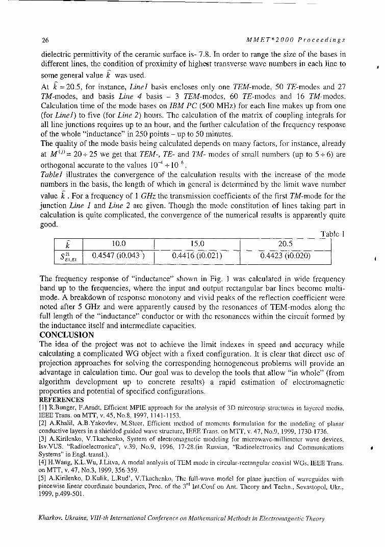
Table] illustrates the convergence of the calculation results with the increase of the modenumbers in the basis, the length of which in general is determined by the limit wave numbervalue k . For a frequency of 1 GHz the transmission coefficients of the first TM-mode for thejunction Line I and Line 2 are given. Though the mode constitution of lines taking part incalculation is quite complicated, the convergence of the numerical results is apparently quitegood.
Table I10.0 15.0 20.5
S21 0.4547 (i0.043-) 0.4416 (iO.021) 0.4423 (iO.020)
The frequency response of "inductance" shown in Fig. I was calculated in wide frequencyband up to the frequencies, where the input and output rectangular bar lines become multi-mode. A breakdown of response monotony and vivid peaks of the reflection coefficient werenoted after 5 GHz and were apparently caused by the resonances of TEM-modes along thefull length of the "inductance" conductor or with the resonances within the circui't formed bythe inductance itself and intermediate capacities.CONCLUSIONThe idea of the project was not to achieve the limit indexes in speed and accuracy whilecalculating a complicated WG object with a fixed configuration. It is clear that direct use ofprojection approaches for solving the corresponding homogeneous problems will provide anadvantage in calculation time. Our goal was to develop the tools that allow "in whole" (fromalgorithm development up to concrete results) a rapid estimation of electromagneticproperties and potential of specified configurations.REFERENCES[1] R.Bunger, F.Arndt, Efficient MPIE approach for the analysis of 3D mircostrip structures in layered media,IEEE Trans. on MTT, v. 45, No.8, 1997, 1141-1153.[2] A.Khalil, A.B.Yakovlev, M.Steer, Efficient method of moments formulation for the modeling of planarconductive layers in a shielded guided wave structure, IEEE Trans. on MTT, v. 47, No.9, 1999, 1730-1736.[3] A.Kirilenko, V.Tkachenko, System of electromagnetic modeling for microwave-millimeter wave devices,Isv.VUS. "Radioelectronica", v.39, No.9, 1996, 17-28.(in Russian, "Radioelectronics and CommunicationsSystems" in Engl. trans].).[4] H.Wang, K.L.Wu, J.Litva, A modal analysis of TEM mode in circular-rectangular coaxial WGs, IEEE Trans.on MTT, v. 47, No.3, 1999, 356-359.[5] A.Kirilenko, D.Kulik, L.Rud', V.Tkachcnko, The full-wave model for plane junction of waveguides withpiecewise linear coordinate boundaries, Proc. of the 3 rd Int.Conf on Ant. Theory and Techn., Sevastopol, Ukr.,1999, p. 4 9 9 -5 0 1.
Kharkov, Ukraine, VIII-th International Conference on Mathematical Methods in Electromagnetic Theory

MMET*2000 Proceedings 27
FIBER MODE BEHAVIOUR NEAR THE CUTOFF FREQUENCY:DISPERSION CHARACTERISTICS, MODELLING AND
APPLICATIONS
Elena A.Romanova, Ella V.Bekker, Phillip Sewell* and Trevor M. Benson*
Saratov State University,Astrakhanskaya 83, 410026 Saratov, Russia
E-mail:[email protected]
*University of Nottingham,Nottingham NG7 2RD, U.K.
E-mail:[email protected]
ABSTRACT
The spatial transient regime of a fiber mode transformation near the cutoff frequency isanalyzed both theoretically and numerically depending on material losses and radialdistribution of refractive coefficient of a guiding structure. Kerr-like nonlinearity of a fibermaterial is shown to be efficiently used to manage the transmittance of the structures near thecutoff frequency of a fiber mode.
INTRODUCTION
When a lossless fiber mode reaches the cutoff, it's longitudinal power flow ceases todecrease radially, and the mode propagates as a plane wave in the fiber cladding. Whathappens when the characteristic frequency gets lower than the cutoff one? Mathematically, allpropagation constants of the mode become complex denoting that transverse power flowappears and radiation leaks out the guiding region. Behavior of a fiber mode near the cutofffrequency (leaky mode) is known to depend on its polarization [1]. The HEl,, modes of a step-index fiber have the following kind of behavior: the mode field doesn't tend to zero at r - 0c,the power flow increasing very rapidly as V---WV. Characteristic equation has the followingasymptotic form: w2lnw - 2 = 0, which differs from the one of the other types of fiber modes.Behavior of the HEln (LPon) modes of a weakly guiding fiber was analyzed [2] by numericalsolution of the characteristic equation near the cutoff value of the characteristic frequency.The multisheeted Riemann surface of the Macdonald's function has been taken intoconsideration. Behavior of the dispersion curves was shown to depend on the material losses,the curves corresponding to the lossless fiber being located on the infinite sheet of theRiemann surface. The cutoff value of the characteristic frequency was shown to depend onthe magnitude of material losses [3].
Guiding properties of multilayered fibers were analyzed in [4] depending on the radialprofile of the refraction coefficient. Full-vectorial mode solver was used to calculate themodal numbers of the fiber modes. These modal numbers were shown to be complex ingeneral and tended to be real as the radiation wavelength decreased.
Other phenomena which can change the guiding properties of a fiber is self-focusing of thepropagating radiation resulting from Kerr-like nonlinearity of a fiber material. The
Kharkov, Ukraine, VIII-th International Conference on Mathematical Methods in Electromagnetic Theory
28 MMET*2000 Proceedings
complicated interaction of nonlineaO fiber modes is shown [5] to destroy the higher modeseven in a regular fiber.
The first part of this paper is a review of some numerical and semi-analytical techniquesuseful to analyze mode behavior and spatial transient processes of the total field propagationin waveguiding structures including into consideration longitudinal irregularities, losses andKerr-like nonlineraity of the fiber material, radial dependence of the refraction coefficient. Inthe second part the results of calculations are shown and some structures are analyzedcomparatively by numerical simulations of the guided modes transformation into the leakyones.
METHODS OF INVESTIGATION
1.Characteristic equation solution near the cutoff frequency
The amplitude of the total time-harmonic scalar field propagating along the z-axis of anirregular linear fiber can be written as a sum of the discrete set of Ng guided waves and theradiation field [6] (in the case of small discontinuities in the weakly-guiding fiber, thebackscattering can be neglected):
N,,
E(r,z) = ZA, (z)E, (r)exp(if, z) + Er,,,(r,z), (1)n=1
E,.,,,,(r, z) f . dwAJ (w,'z) Ej(w,'r)exp(i,8j (w) z) (2)0
with A, and fl,, being the amplitudes and the longitudinal wavenumbers of the n -th guidedmode, Aj and /j being the amplitudes and the longitudinal wavenumbers of the j-thradiation mode. The functions E,(r) and Ej(w,r) describe radial distributions of the guidedand the radiation modal fields, respectively. The integrands Ej(w,r) are meromorphicfunctions on the multi-sheet Riemann-surface of the complex parameter w, which is treated asthe cladding transverse wavenumber of a fiber mode [6]. The poles of the functions Ej(w,r)correspond to the leaky modes and are located in the w -plane depending on the value of thecharacteristic frequency V = kano - nt,, determined in the given cross-section of the fiber
(here k = 2TI/2 is the free-space wavenumber, a is the radius of the fiber core, n,0 and n(j arethe refraction indices in the core and in the cladding, respectively). Each pole formally is asolution of the characteristic equation of the eigenvalue problem and characterizes the fieldwhich increases exponentially in the radial direction.
In the simple case of step-index fiber with infinite cladding the characteristic equation iswell known to be of the transcendental form and can be solved numerically by an iterationmethod of Newton-Raphson. The complex w-plane was shown to be convenient [7] toanalyze the solution behavior depending on the characteristic frequency taking intoconsideration losses of the fiber material.
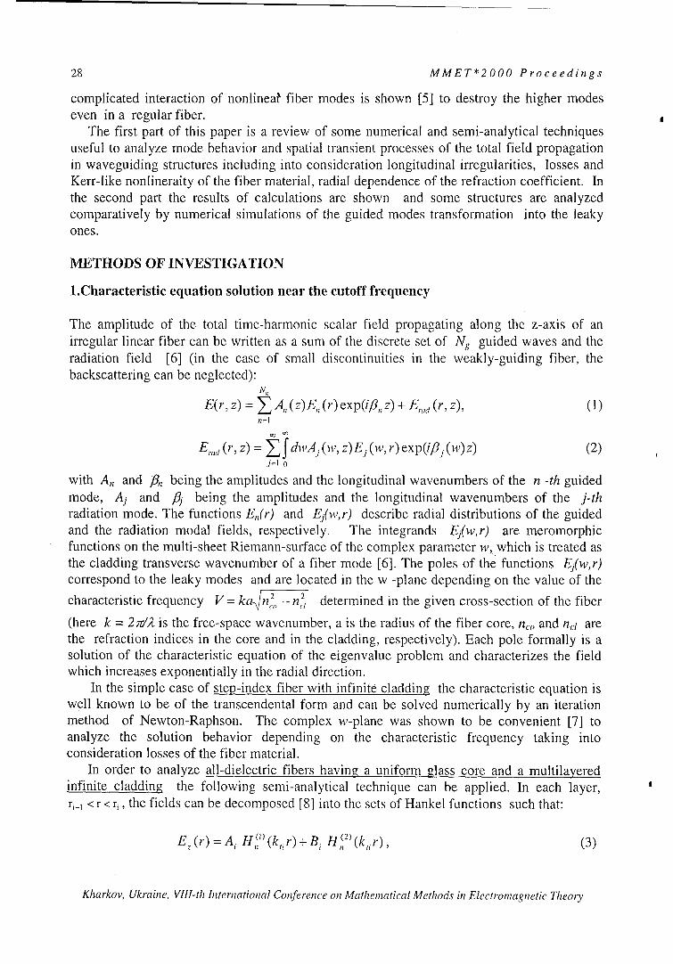
In order to analyze all-dielectric fibers having a uniform glass core and a multilayeredinfinite cladding the following semi-analytical technique can be applied. In each layer,riI < r < r, the fields can be decomposed [8] into the sets of Hankel functions such that:
Ez (r) = Ai Hl)(k r)+Bi H(2) (k, r) , (3)
Kharkov, Ukraine, VIII-th International Conference on Mathematical Methods in Electromagnetic Theory

MMET*2000 Proceedings 29
where
[21 (kr)E (ri) _- HS2, (kiri)E, (r)]
[- H 1,) (kjrji_)Ez (ri) + H,() (kijrj)Ez (r,)]"A [U") (k=ir[,1 )J( 2) (k 1ri)- _ 'H1) (kiri),J2) (k_ r_,
and H ') (x) is the Hankel function of the n-th order of the i-th kind. E,(ri) is the value of E,
at r = ri, and k=2 = n k -_32 , where 8 is a longitudinal propagation constant of the field. A
similar expansion can be found for H,. It is noted that in the core (r < a) and outercladding regions ( r > a + (dI + d2 )N -d 2) the expression (1) simplifies to:
E (r)- E=ml•) J,(ktlr) ,Ez(r) - EZ(rN) H, )(kNr) (4)J,, (k,. r,) H n2 (k Nru )
From these expressions it is straightforward to derive the tangential field components Eo andHo on each side of the boundaries between the layers in terms of the values of E, and Hz at theboundaries. Requiring continuity of Eo and Ho yields a matrix equation whose determinantwill only be zero if 83 is a modal propagation constant.
2. Numerical simulations of the spatial transient regime of the total field propagation byBeam Propagation Methods.
The most commonly used numerical method to solve the scalar wave equation is the split-stepFourier series method which is in fact an extension of the beam propagation method (BPM)originally developed by Fleck, Morris and Feit [9]. Physically the technique corresponds toreplacing the continuous refractive index distribution by an infinitesimally thin lens emergedin a homogeneous reference medium of uniform refractive index.
Conventionally to utilize this method in solution of the wave equation an algorithm isemployed which is based on the fast Fourier transformation (FFT) algorithm. The so calledbeam propagation method (FFT-BPM) proved to be an accurate and efficient tool for solvinga variety of propagation problems in waveguide geometries involving one or two transverseCartesian coordinates. However, in application of this method in cylindrical coordinates onehas to cope with the increased storage and reduced efficiency.
An alternate numerical scheme to solve the wave equation is to use a finite difference(FD) approximation [10]. Following the Finite-Difference Beam Propagation Method (FD-BPM) the wave equation is replaced by a finite-difference scheme.
In this work, the finite-difference beam propagation method (FD-BPM) is used, based onthe implicit representation of derivatives and recursive procedure known as the sweep-method[11]. Following the weakly-guiding approximation we assume the amplitude of the totalelectrical field F(rz) to be slowly varying in axial direction, so that: E(rz)=F(rz)exp(i,8'z),where )6' is the real part of the longitudinal wavenumber determined at the input endface ofthe structure. Propagation of the electrical field in a circularly-symmetric step-index weakly-guiding fiber is characterized by the scalar wave equation for the slowly varying amplitude :
2i a+ a,- + I-a + ZF(r, z) =0 (5)(2 )r
with the normalized radial and longitudinal coordinates r - ra, z --> Z/Zd. The diffraction
Kharkov, Ukraine, VIII-th International Conference on Mathematical Methods in Electromagnetic Theory

30 MMET*2000 Proceedings
length zd = f6'a 2 , with a being the core'radius determined at the input endface of the fiber. Theboundary conditions for the problem are taken to be as follows: F(ocz)=O, tF(O,z)/ 0r=0. Toavoid nonphysical reflections from the grid boundaries, a complex scaling has proved to besuitable [12].
ANALYSIS OF THE GUIDED MODE TRANSFORMATION INTO THE LEAKYONE IN DIFFERENT GUIDING STRUCTURES.
1.Down-tapered dielectric fiber.
Numerical techniques described above were used to analyze HE,, mode behavior when itpropagates through the cutoff cross-section. The model of a down-tapered fiber with a step-index profile of refraction coefficient and infinite cladding appeared to be suitable for thispurpose.
Several dispersion curves representing a path of..........C :D A"roots of the characteristic equation are shown in the D1 HFig.1. The value of V'(z) varies along every curve, the ::::Q ivalue of V" being fixed. The roots which are locatedin the zero-th sheet are marked by the empty circles, 0 ::0the roots in the first sheet are marked by the filled 2ones. Assume that some initial value of V' is above 0the cutoff. When V' decreases (this direction is 4- *
indicated by arrows), the root moves to the point w=O. "Behavior of the dispersion curves depends evidently .....on the losses of the fiber material (the curves 1-3 areobtained with V"=-0.07 ,-0.062, -0.005, ..................correspondingly). The curves can turn several timesaround the point w=O, the number of such turns A 2 . b :depending on the losses. In the limit case ofnonabsorbing waveguide the number of turns is infinite. Fig. 1.
Propagation of HE12 mode along a taper with the length L and the linear longitudinalprofile a(z) = a, - Aaz /L was simulated numerically by FD-BPM. The transverse profile ofthe field at the input end face of the taper corresponds to the guided HE12 mode of a regularstep-index fiber with a core radius a,. The fiber mode is supposed to be excited by a lightsource with the wavelength X=lmpt. The corresponding range of the characteristic frequencyvariation is 3. 7< V(z)<4 containing the cutoff value (for the lossless fiber V, ;z3.83).
When the fiber radius decreases the wavenumber7 moves along the dispersion curve and crosses the w"-
6 6 • axis. Accordingly, the guided mode reaches the cutoffScross-section of the taper, passes through it, and" forms a spatial wave which goes outsize the fiber core
S3 (Fig.2).
6 2 RHowever, a part of the radiation which propagates= 1below the cutoff close to the fiber core is of the same
0 transverse distribution as the guided mode was. The0.4 1 6 o total field can be sufficiently described here by the
14 leaky mode field. It propagates over some long distanceFig.2 along the fiber core since the imaginary part of the
Kharkov, Ukraine, VIII-th International Conference on Mathematical Methods in Electromagnetic Theory
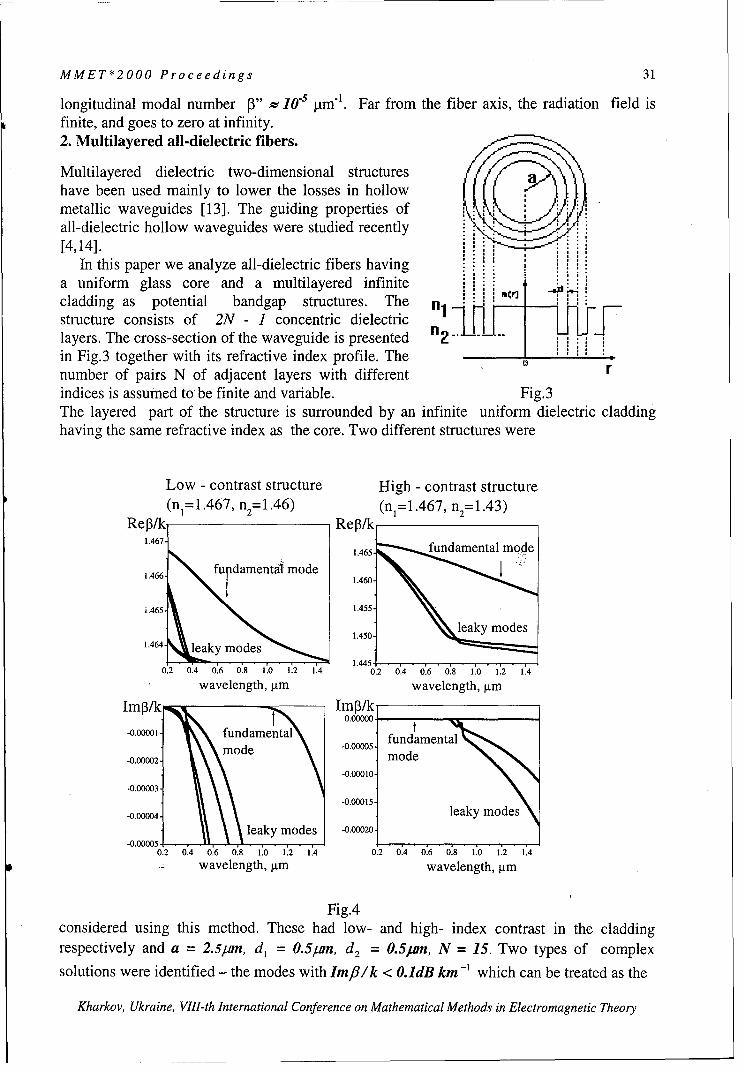
MMET*2000 Proceedings 31
longitudinal modal number p3" W 10-5 i ml. Far from the fiber axis, the radiation field isfinite, and goes to zero at infinity.2. Multilayered all-dielectric fibers.
Multilayered dielectric two-dimensional structureshave been used mainly to lower the losses in hollowmetallic waveguides [13]. The guiding properties ofall-dielectric hollow waveguides were studied recently[4,14].
In this paper we analyze all-dielectric fibers havinga uniform glass core and a multilayered infinitecladding as potential bandgap structures. The n ftr' , i'istructure consists of 2N - 1 concentric dielectric 111layers. The cross-section of the waveguide is presented "2in Fig.3 together with its refractive index profile. The ,number of pairs N of adjacent layers with different r
indices is assumed to be finite and variable. Fig.3The layered part of the structure is surrounded by an infinite uniform dielectric claddinghaving the same refractive index as the core. Two different structures were
Low - contrast structure High - contrast structure(n1=1.467, n2= 1.46) (na=1.467, n2 = 1.43)
Re3/k Re3/k1.467
1.466 fdamentAi mode 1.460.
i.465 - 1.455
1.464- leaky modes1.445-
0.2 0.4 0.6 0.8 1.0 1.2 1.4 0.2 0.4 0.6 0.8 1.0 1.2 1.4
wavelength, pim wavelength, jimIr3/k ImP3/k
1 ~0.00000--0.00001o . fundamental -0.0005. fundament
mmode-005fudmna-0.00002- J u•d• mode
-0.00010-
-0.00003--0.00015
-0.00004- leaky modesleaky modes -0.00020,
-0.00005 .0.2 0.4 0.6 0.8 1.0 1.2 1.4 0.2 0'.4 0.6 0.8 1.0 1.'2 1.4
wavelength, jtm wavelength, pim
Fig.4considered using this method. These had low- and high- index contrast in the claddingrespectively and a = 2.5pro, d, = 0.5/,Sn, d 2 = 0.5urn, N = 15. Two types of complex
solutions were identified - the modes with Im/3/k < O.1dB km -' which can be treated as the
Kharkov, Ukraine, VIII-th International Conference on Mathematical Methods in Electromagnetic Theory

32 MMET*2000 Proceedings
as the guided ones and a variety of closely locAted roots corresponding to leaky waves. Themost significant roots are shown in Fig.4. The fundamental mode behaves as the guided oneover a wide range of wavelengths depending on the refraction index contrast (n1 - n 2). The
leaky modes transform into the guided ones as the wavelength decreases.
3.Regular fiber with Kerr-like nonlinearity.
When a beam passes through the dielectric medium with a Kerr-like nonlinearity, therefraction coefficients n,, and net depend on the intensity of the electric field as n = n, + n2IF(r,z) 12, where nf is the linear coefficient and n2 is the positive nonlinear coefficient. Thischanges the guiding properties of the structure, resulting in beam self-focusing.
Nonlinear mode propagation was considered based on the model of a double-mode fiber(V=4.47) excited by a linear HE12 mode of the regular fiber. When the fiber is linear, theradial distribution of the field doesn't vary along the fiber axis (see Fig.5). In the presence ofKerr-like nonlinearity ( 2nrlIF12 ~-0.2) a small part of the input field transforms into anothermode. Two modes interact over some distance. Then just one mode is left to propagate, itsradial distribution being of the gaussian-like shape similar to the fundamental mode of a linearfiber.
Linear fiber: Nonlinear fiber:Field aimplitude (u.a.) Field amplitude (u.a.)
Fig.
1,0 ,
1,0 •~ 0,510
'~2 0,,2
ism 10 10 .z, mm 510 5 10
Sr,,u m
Fig.5
Propagation of the total field through the cutoff cross-section of the linear HE,2 mode in thedown-tapered fiber with a Kerr-like nonlinearity is depicted in Fig.6. The taper was assumed
to be excited by a linearHE,2 mode of the regularfiber with the core radius
(a) (b) a,. ' The intensity-1dependent term was taken
2150 to be of the order of A n =•0 *125 nco - nlo , the structure
75 100 , dimensions were as-• 75
50 soi follows: L=3mm, al =5 a... 25 m, Aa=1 pn, (a)-lossless
2.5 2.5
2°.0 2.o fiber, (b) -lossy fiber. It is
%,o 2 1 60 rWA seen clearly that the'N, 0.' 14 1, " 14 radiation field expansion is
Fig.6 suppressed by the nonlinear
Kharkov, Ukraine, VIII-th International Conference on Mathematical Methods in Electromagnetic Theory

MMET*2000 Proceedings 33
contraction of the beam resulting in the propagation of the HE 12 mode through the cutoff todepend on the amplitude of the input field. The high intensity beam may experience atransformation from the guided mode into the gaussian-like nonlinear guided mode of thefiber.
CONCLUSIONS
Spatial transient regime of a guided mode transformation into the leaky one is shown todepend on the features of the guiding structure material: losses, Kerr-like nonlinearity, andradial distribution of the refractive coefficient. In the presence of material losses, behavior ofa mode near the cutoff cross-section of the lossy fiber becomes more complicated comparingwith the lossless one. The length of the transient regime in the lossy fiber is less than the onepredicted by the theory of lossless fibers.
Including some layered structure into the fiber cladding one obtains a tool for efficientmanagement of the guiding properties of the fiber. The cutoff value of radiation frequency isproven to depend on the radial distribution of refractive coefficient of the multilayeredstructure.
Kerr-like nonlinearity of the fiber material causes the nonlinear interaction of the guidedmodes resulting in transformation of the higher modes into the fundamental one.Transmittance of the nonlinear structures depends on their geometry and can be managed bythe appropriate adjustment of their spatial parameters.
The phenomena analyzed above can be efficiently applied for elaboration of novel logicalelements, large-core amplifiers, mode-locked fiber lasers.
REFERENCES:
[1] IEICE Trans. Electron., vol. E78-C, No.10, 1323-1329.[2] Opt.Commun., 116(1995) 358-364.[3] Microwave Opt.Technol.Lett 25(2000), 27-33.[4] International Conference on Transparent Optical Networks, 2000, Gdansk, Poland, 57-60.[5] International Conference on Transparent Optical Networks, 2000, Gdansk, Poland, 69-72.[6] A.W.Snyder and J.D.Love, Optical Waveguide Theory, Chapman & Hall, London,England, 1983.[7] Sov.J.Radioteknics Ekectron.14 (1969), 1768-1770.[8] R.E.Collin, Field Theory of Guided Waves. IEEE Press. 1991.[9] Appl.Phys., V.10, pp.129-160, 1976.[10] J.of Quantum Electron., V.26, N.8, pp.1335-1339, 1990.[11] A.N.Tihonov and A.A.Samarskii, Equations of mathematical physics, Nauka, Moscow,Russia, 1972.[1 2]Comput.Phys.Commun. 63(1992), 323-330.[13] J. Lightwave Technol., LT-2, pp. 116-126, 1984.[14] J. Lightwave Technol., LT-17, pp. 2039-2041, 1999.
Kharkov, Ukraine, VIII-th International Conference on Mathematical Methods in Electromagnetic Theory
34 MMET*2000 Proceedings
FRACTIONALIZATION METHODS AND THEIR APPLICATIONS TORADIATION AND SCATTERING PROBLEMS
Nader EnghetaUniversity of Pennsylvania
Moore School of Electrical EngineeringPhiladelphia, Pennsylvania 19104, U.S.A.
Tel: +1 (215) 898-9777, Fax: +1 (215) 573-2068E-mail: [email protected]
Web: http://www.ee.upenn.edu/-engheta/
INTRODUCTION:
Exploring the possible links between the mathematical field of fractional calculus and theelectromagnetic theory has been one of the topics of our research interests in recent years. Wehave studied the possibility of bringing the tools of fractional calculus and electromagnetic theorytogether, and have explored and developed the topic of fractional paradigm in electromagnetictheory (see e.g., [1-10]). Fractional calculus is a branch of mathematics that addresses themathematical properties of operation of fractional differentiation and fractional integration -operators involving derivatives and integrals to arbitrary non-integer orders (see e.g., [I 1-13]).In our study in recent years, we have applied the tools of fractional calculus in various problemsin electromagnetic fields and waves, and have obtained interesting results that highlight certainnotable features and promising potential applications of these operators in electromagnetic theory[1-10]. Moreover, since fractional derivatives/integrals are effectively the result offractionalization of differentiation and integration operators, we have investigated the notion offractionalization of some other linear operators in electromagnetic theory. Searching for suchoperator fractionalization has led us to interesting solutions in radiation and scattering problems.
"FRACTIONAL SOLUTIONS" IN RADIATION AND SCATTERING PROBLEMS
Let us consider the time-harmonic Maxwell equations VxE=icoB, VxH =J-icoD,V . D =p, and V. B = 0 where the time dependence e-")' is assumed, and the electric currentdensity J may be considered either as a primary current source (in radiation problems) or as asecondary, induced current (in scattering problems). The continuity equation is of coursesatisfied as V .J = -icop. Now let us choose a linear operator L from a class of linear operators
(or mappings) where the domain and range of any linear operator of this class are similar to eachother and have the same dimensions. In other words, the linear operator L should map an
element from the space C" into generally another element in the space C". That is
L: C" ->C" (1)
Kharkov, Ukraine, VIII-th International Conference on Mathematical Methods in Electromagnetic Theory

MMET*2000 Proceedings 35
where C" is an n-dimensional vector space over the field of complex numbers. One can then
suggest a "fractional" operator Lv, where the fractionalization parameter v can be a noninteger
real number (or in some circumstances even complex number), using some techniques one of
which is reviewed in [5]. Such a fractional operator Lv, which also maps the n-dimensional
space into the n-dimensional space
Lv • "-> CC (2)
has the semigroup properties, i.e., (1) for v - 0, the fractional operator Lv approaches the unit
operator, LV -> L' =; (2) for v -> 1, the operator Lv approaches the original operator L,
Lv --> L' = L; and (3) for two parameters v, and v2 we will have Lvlo Lv2 = Lvl+v2. If the vector
fields Eo, Ho, B0 , and D. are the solutions to the time-harmonic Maxwell equations with the
current density Jo, one can pose the following question: If we apply the fractional operator L'
on these vector solutions, under which condition(s) will the resulting vector functions, LvEo,
LvH1, L"B, and LVDo, satisfy the Maxwell equations with the new current density LvJo ? One
can observe that if the fractional operator Lv and the curl operator V x commute, i.e., if
LvVx = V x Lv, (3)
one will then have
V X (LvE,,) j(L vB)
VX(LVvHo)=LVJ -iro(LvDo) (4)
which indicates that the new set of vector functions LyE, LvHo, LvBo, and LvDo does satisfy
the Maxwell equations with the current density LVJo. What this implies is that if we know a set
of solutions for an electromagnetic problem with a given current source Jo, we will be able to
find the set of solutions to the related problem in which the current source is expressed as L'Jo
by just applying the fractional operator Lv on the solutions of the first problem. This can offer
interesting mathematical applications in the treatment of certain electromagnetic problem. Assome specific cases, we have considered the operators of fractional integration, fractionalintegration, and fractional curl to show some of the interesting features of this treatment of certainradiation and scattering problems. [1, 4, 5, 6, 7, 9] In the following section, we present anexample of application of the fractional operator in a scattering problem.
FRACTIONAL OPERATION AND PHYSICAL OPTICS APPROXIMATION
Let us consider a flat rectangular patch with certain surface impedance boundary conditions (e.g.,a perfectly electric conducting (PEC) rectangular patch). This obstacle is being illuminated by amonochromatic electromagnetic wave. The incident and the scattered fields are denoted by
Kharkov, Ukraine, VIII-th International Conference on Mathematical Methods in Electromagnetic Theory

36 MMET*2000 Proceedings
E'"'(x,y,z) and E"c"'(x,y,z), respectively. Let us now apply the fractional differintegration
operator (with respect to a (dimensionless) Cartesian coordinate, say k,,z, and with a generalfractional order v on the incident and the scattered fields. That is
E'ef'rv(x, y, z)=_ D4,vzE lr (x, y, z) (5b)
where _.Dk,z indicates the operation of fractional differintegration. For the definition of
fractional integration, we use the Riemann-Liouville fractional integration [11] which is writtenas
1 !.
aD•_f(Z) f (z - u)v 1 f(u)du for Re(v) < 0 (6)
If Re(v) > 0, one will need to choose an integer m in the expression
,D Df(z)d D-"'f(z) such that Re(v - m) < 0. Then the above definition can be used to
evaluate aD'-"f(z) [11].
We ask the following question: Can the resulting field, E'Scr.V(x,y,z), be shown to beapproximately the field that would be scattered from another rectangular patch with the same sizeand shape but with a different surface impedance boundary condition that would be determinedfrom the knowledge of surface impedance of the original scatterer and the fractional parameter v?The results of our preliminary theoretical study have shown that, under certain circumstances andapproximations (such as physical optics approximation), the answer to the above question ispositive for the case of finite-size flat obstacles. In order to express the relationship for theimpedance transformation, we first describe below the case of an infinitely extent flat plate.
Let us assume an infinitely extent flat plate with a specified isotropic uniform surface impedanceboundary condition, Z . This requires that the tangential components of the total electric and
magnetic fields on the surface of this infinite plate be related as E, Z H, (See Fig. 1). A
Cartesian coordinate system (x, y, z) is used here. For the sake of brevity of discussion here, weconsider the transverse electric (TE) case for the incident electromagnetic wave illuminating thisplate (i.e. the vector E"' is polarized along the y axis). As shown in Fig. 1, the angle ofincidence is chosen to be 0, (with respect to the unit vector normal to the surface) and the angleof tilt of the plate (with respect to the x-axis) is taken to be 00. Obviously the reflected planewave can be easily written in terms of the reflection coefficient, RV, which can be explicitly givenas a function of the surface impedance Z . Since we have assumed that the surface impedance is
isotropic and uniform, one can write EYi' Zo-- , where Zo denotes the surface impedance
on this flat boundary, and Ht''"" indicates the total tangential magnetic field on the surface. Now
Kharkov, Ukraine, VIII-th International Conference on Mathematical Methods in Electromagnetic Theory

MMET*2000 Proceedings 37
we take the fractional differintegral of the total electric field Et°'OI E"C + Er•f with respect to
variable koz and with fractional order v. We have
S V'
A B
Fig. 1. Panel A depicts the problem of reflection of a TE incident plane wave from aninfinitely extent flat boundary with the isotropic uniform surface impedance Zso. (Theelectric vector is parallel with the y axis.) When the incident and reflected plane waves insuch a problem are fractionally differintegrated with order V with respect to the z variable,the resulting functions can be interpreted as the new incident and new reflected waves inanother problem (Panel B) with infinite flat boundary but with a differing surfaceimpedance Zý,. The relationship between Zý0 , Zv and other relevant parameters is
given in text.
Erotal,=v DvzE total = kic+ Dv Fref
-~ký -,Dv Elc-.D -E,
-i ikozco,(0, 0- )-ikxsin(O , - )+iv -icz cos(9,+Q )-ikkx-sin( •Q0 -)-iv"EJco20+ Ra Rcosv (0i + 0i )e 2]n
(7)
The resulting total field, which can be shown to indeed satisfy the Maxwell equations and thusrepresent electromagnetic fields, consists of a new incident field, k Itb_, Dvo E"" that may be regarded
as an incident plane wave with the incidence angle 0, illuminating the plate with the tilt angle 00,and the new reflected wave, - o -A E"rf that can be interpreted as the corresponding reflectedplane wave. The tilt angle of the plate and the incidence angle remain as 0, and 0, respectively.However, the new reflection coefficient, which relates the new incident plane wave with the newreflected plane wave is different from Ro, and is given as
Rv = Ro e-'È'z COS V(Oi + Oi)(8cosv(0-±0,) (8)
cosV(0a -o)i
Kharkov, Ukraine, VIII-th International Conference on Mathematical Methods in Electromagnetic Theory

38 MMET*2000 Proceedings
Following a series of mathematical steps, for the TE case we can show that the new plate, whichwould provide such a reflection coefficient, should have a new surface impedance, denoted asZý,, that can be explicitly written as
i e z - cosz(O,+, e
Z,' +-'I,' cog' (0, -00
A similar approach can be used to obtain the corresponding expression for the TM case. Theabove results demonstrate that when the plane wave reflected from an infinite flat plate with thesurface impedance Z,0 is fractionally differintegrated (with the order v) the result can beinterpreted as a plane wave that would have been reflected if the infinite plate (with the same tiltangle O0, and the same angle of incidence O0 for the incoming plane wave) had had a differingsurface impedance Z,, that can be explicitly given in terms of all the quantities involved.
Although the example of reflection of plane wave from an infinite flat boundary with uniformsurface impedance is an idealized example and the mathematical connections via fractionalcalculus for the infinite flat plates is rather formal, our preliminary analysis has shown that for thefinite-size flat plates the operation of fractional differintegration may be quite useful to link andrelate approximately the scattered fields for two separate problems with finite-size flat plates ofdiffering surface impedances. To demonstrate this point, let us now return to our example of flatrectangular patch, and consider the problem of electromagnetic wave scattering from arectangular, flat, thin, perfectly electric conducting (PEC) plate when the incoming plane wave isnormally incident on this patch. Using the physical optics (PO) approximation, the scattered fieldcan be easily obtained. Then we apply the fractional differintegration operator (with order v) onthe far-zone scattered electric field in the region in front of the illuminated side of the rectangularplate. We then use the impedance transformation given in Eq. (9) to find Z,,, and afterwardsusing the PO approximation we find the scattered fields from the rectangular plate with the samesize and shape but with this new surface impedance Z,v. Our analysis has shown that the result offractional differintegration of the scattered field from the PEC rectangular plate is approximatelysimilar to the scattered field from the same-size rectangular plate but with the surface impedanceZ,,V,. Figure 2 presents the scattered field in the E-plane and H-plane using the fractionalintegration (in this figure we used order v=-0.5) and using PO approximation from theimpedance plate. Good agreement in the magnitude and phase, particularly near the centralregion, can be easily observed from these plots. This example suggests that instead of re-calculating the scattered field from the impedance plate, one can use the well-known PO resultsof the scattering from the PEC plate and just apply fractional differintegration on the scatteredfields in the far zone in front of the illuminated region, which would provide us with anapproximate answer to the far-zone scattering from the impedance plate. So, when we encounterthe problem of wave scattering from a finite-size flat plate with a given impedance boundarycondition, instead of solving such a problem directly using the PO approximation, one can use theresults of PO scattering from PEC version of the same-size same-geometry flat plate, and thenapply the fractional differintegration operator on these results. If the variable with respect towhich this fractional differintegration is taken is selected appropriately and if the order of the
Kharkov, Ukraine, VIII-th International Conference on Mathematical Methods in Electromagnetic Theory

MMET*2000 Proceedings 39
fractional differintegration is chosen properly using Eq. (9), then the results of such operationwould be approximately similar to the results of scattering from the finite-size impedance plate.We have extended the above case to the situation where we can have two adjacent flat panels andthe results support the above idea for the application of fractional operators.
E-p1,tft[-0. -6,. 8=0.k-s8
oso
-• .• oso
io.
-os
o 80 -0 -40 -20 0 .0 . .0 . A B -8 200 -0 -... . .. .
1 80 4 -00 -20 0 205 0 00 80 - 8 H-P.0 -20 I 0 20 4u.5 0 2 60
0.2-1 t , ' "...... ........... . .'
0n ... . . o-.. 2 . ... . C D .. . .. Th~ .. .oo-2 .. .. .
Fig. 2. Scattering of a normally incident EM wave from a rectangular thin plate with dimensionskoa = 30 and kob = 60. First, using the physical optics (PO) approximation, the far-zone scattered
field from such a plate with perfectly electric conductor (PEC) surface impedance was obtained. Thenwe applied the fractional integration operator (with order V =-0.5) on such far-zone fields in theregion in front of the illuminated side of the rectangular plate. The solid lines show the resulting fieldsfrom such fractional integration. We then used the impedance transformation given in Eq. (9) to find
Z, for v = -0.5, Oi = 0o = 0' and Zso = 0; and afterwards using the PO approximation we
directly evaluated the scattered fields from the same-size rectangular plate with this new surfaceimpedance Z4,. The dotted lines depict such fields. Panels A and B show the amplitude and phase for
these two calculated fields in the E-plane, whereas Panels C and D show the corresponding quantities inthe H-plane. Our preliminary analysis shows that the result of fractional differintegration of thescattered fields using PO approximation from the PEC rectangular plate, (solid line), is approximatelysimilar to the scattered field from the same-size rectangular plate but with the surface impedance Zs,,
(dotted line). Good agreement between the solid line and the dotted line, particularly near the centralregion, is noticeable.
Kharkov, Ukraine, VJII-th International Conference on Mathematical Methods in Electromagnetic Theory

40 MMET*2000 Proceedings
In this talk, we will present some of the recent results of our research on applications of fractionaloperators in radiation and scattering problems and discuss their salient features and physicaljustifications.
REFERENCES:[1] N. Engheta, "Fractional Paradigm in Electromagnetic Theory" a chapter inFrontiers in Electromagnetics, D. H. Werner and R. Mittra (eds.), IEEE Press, New York,chapter 12, pp. 523-552, (2000).[2] N. Engheta, "On Fractional Paradigm and Intermediate Zones inElectromagnetism: I. Planar Observation," in Microwave and Optical Technology Letters,Vol. 22, No. 4, pp. 236-241 (August 20, 1999).[3] N. Engheta, "On Fractional Paradigm and Intermediate Zones inElectromagnetism: II. Cylindrical and Spherical Observations," in Microwave and OpticalTechnology Letters, Vol. 23, No. 2, pp. 100-103 (October 20, 1999).[4] N. Engheta, "Phase and Amplitude of the Fractional-Order Intermediate Wave" inMicrowave and Optical Technology Letters, Vol. 21, No. 5, pp. 338-343 (June 5, 1999).[5] N. Engheta, "Fractional Curl Operator in Electromagnetics," in Microwave andOptical Technology Letters, Vol. 17, No. 2, pp. 86-91 (February 5, 1998).[6] N. Engheta, "On Fractional Calculus and Fractional Multipoles inElectromagnetism," IEEE Transactions on Antennas and Propagation, Vol. 44, No. 4, pp.554-566 (April 1996).[7] N. Engheta, "Electrostatic "Fractional" Image Methods for Perfectly ConductingWedges and Cones," in IEEE Transactions on Antennas and Propagation., Vol. 44, No.12, pp. 1565-1574 (December 1996).[8] N. Engheta, "On the Role of Fractional Calculus in Electromagnetic Theory" afeature article in IEEE Antennas and Propagation Magazine, Vol. 39, No. 4, pp. 35-46(August 1997).[9] N. Engheta, "Use of Fractional Integration to Propose Some "Fractional" Solutionsfor the Scalar Helmholtz Equation," a chapter in Progress in Electromagnetics Research(PIER) Monograph Series Vol. 12, Jin A. Kong (ed.), pp. 107-132 (1996).[10] N. Engheta, "A Note on Fractional Calculus and the Image Method for DielectricSpheres," Journal of Electromagnetic Waves and Applications, Vol. 9, No. 9, pp. 1179-1188 (September 1995).[11] K. B. Oldham and J. Spanier, The Fractional Calculus, Academic Press, NewYork, (1974).[12] S. G. Samko, A. A. Kilbas, and 0. I. Marichev, Fractional Integrals andDerivatives, Theory and Applications, Gordon and Breach Science Publishers, Langhorne,Pennsylvania, 1993. (Originally published in Russian by Nauka i Tekhnika, Minsk, 1987).[13] K. S. Miller and B. Ross, An Introduction to the Fractional Calculus andFractional Differential Equations, John Wiley & Sons, New York, 1993.
Kharkov, Ukraine, VIII-th International Conference on Mathematical Methods in Electromagnetic Theory

MMET*2000 Proceedings 41
DPT ANALYSIS OF ELECTROMAGNETIC SCATTERING ANDRADIATION FROM MULTIANGULAR CYLINDRICAL STRUCTURES
INCORPORATING DIELECTRIC
Vitaliy P. Chumachenko
Electronics Engineering Department, Gebze Institute of Technology, 41400 Gebze, Kocaeli,Turkey, on leave from Technical University of Zaporizhzhya, 64 Zhukovsky Str.,
Zaporizhzhya, 330063 Ukraine
ABSTRACTApplication of the domain product technique for analysis of scattering and radiation frompenetrable cylindrical structures with arbitrarily polyhedral boundaries is described. TheMathieu function expansions are used to represent fields in both the interior and exteriorregions. The technique allows the fast and accurate evaluation of electrodynamiccharacteristics for an extensive class of the 2D structures including realistic objects of highercomplexity.
INTRODUCTIONAnalysis of electromagnetic scattering and radiation from cylindrical structures withpolyhedral boundaries plays an important role in electromagnetic theory and practice [1-5].However, study of those objects quite often meets with difficulties. Geometry is commonlyarbitrary that excludes the use of effective analytical methods. Possible application of directnumerical techniques (such as, for example, finite difference and finite element methods) iscomplicated by overcoming difficulties associated with presence of edges on the scatterercontour and with the mesh truncation in the exterior region.We present here an alternative approach , named the Domain Product Technique (DPT)[6]. Inresonant frequency range, it gives an opportunity to attain an efficient field representation inthe form of the Mathieu function series and to reduce the problem to that of determining theset of unknown expansion coefficients. In the past, the DPT was used for analysis of perfectlyconducting scatterers [6-10]. Last years, a series of works [11-18] analysing structuresincorporating dielectric have been carried out. The report is based on their content.
FIELD REPRESENTATION IN REGION WITH MULTIANGULAR BOUNDARIESLet us consider a 2D finite or infinite region that is cross-section of a polyhedral cylindricalstructure homogeneously filled with a lossless material characterised by (gCo,up 0 ). A
particular case is shown in Fig. 1 (a). Axis Oz of the basic co-ordinate system (x, y, z) isdirected along the generator of the cylinder. The structure is excited either by E- or H-polarised wave with z -component u0 (x, y) .We shall distinguish between those cases as (E)
I
and respectively (H). The time dependence is e'". The region wave number is k = (6p) 2 k0 ,
where k0 = 2z / A and 2 is the free-space wavelength. Define the longitudinal component ofthe total field as
u =u ± u, (1)
where u, is a scattering contribution due to the presence of the boundaries. The sought-for
function u must satisfy the 2D Helmholtz equation, homogeneous Dirichlet or Neumann
Kharkov, Ukraine, VIII-th International Conference on Mathematical Methods in Electromagnetic Theory

42 MMET*2000 Proceedings
L Ti =it / 2
Tj=0 14
1]. =j
L i T11. =-7rS 2 i const > 0
Y (a) (b)z Fig. I
boundary condition on the conducting part of the boundary and matching condition on thepart of the boundary corresponding to interface. In addition, the edge condition and theradiation condition (placed on u, in the case of an infinite region) must be satisfied.
N
Multiangular contour of the region is a broken line L consisting of N segments: L =U Lj. Ifj=l
boundary contour is closed, it divides all the space into two subregions, namely a physicalpart being domain of the field definition and a non-physical one completing the former to thewhole plane. For each the segment we introduce local Cartesian (xj, yj) and elliptic (ýj, 77j)
co-ordinate systems as
xj = fj cosh ýj cos 77j, yj = fj sinh ýj sini/, j =1, N (2)The systems are shown in Fig. 1 (a,b) .Then, every segment of the boundary may be taken for
a degenerate ellipse { (vj,r 7 j) j =0; 7j e (- 7r,;r] } and physical region (it does not matter
internal or external one) can be considered as a common part (product) of simple infinitedomains ýj > 0 (j = 1, N). Since Helmholtz's equation is a linear one, the quantity u. can be
written in the form of superposition of some other functions being solutions to the equation asN
U, =-uj (3)j=1
Suppose region ýj > 0 is the domain of definition of the function uj and this function
satisfies the condition needed at infinity. In elliptic co-ordinates, region ýj > 0 has separable
geometry. Assuming Li is a segment of an open boundary contour and examining boundary
conditions, we find that uj can be expressed as series of angular eigenfunctions in the form
j=1,N (4)
Here, qj = (kfj /2)and ma, (rlj, qj) stands for the even Mathieu function ce, 1 (7j, qj) in
the case of the Dirichlet boundary condition [6]. For the Neumann boundary condition,ma,, (71j, qj) coincides with the odd Mathieu function se,, (q 7, qj )[7]. M,, ( j, qj) is expressed
in terms of relevant radial Mathieu functions as Me,2( (4j, qj )/Me•(,• (0, qj) or respectively
Ne,1)(ýj,qj)/Ne, 2 ) (O, q.). Assuming Li is a part of a closed contour, we ascertain
Kharkov, Ukraine, VIII-th International Conference on Mathematical Methods in Electromagnetic Theory

MMET*2000 Proceedings 43
independently of the type of boundary condition there exists a choice of two possiblerepresentations [8,11,15]. Function us, possessing physical meaning inside or outside the
closed boundary, is continued by (3) and (4) into the whole plane out of L.For all that in the case of the even function series, expansion coefficients approach zero asDJ,. = 0(/n2+x) , n - oo provided uj represents solution of the boundary value problem
and transverse components of the field have singularities of the type O(r-r) [9]. Here,X = 1 - 2/ and y is the greatest of two powers corresponding different end points. The fast
enough convergence of series (4) is caused by the fact that both the sought-for function u andits derivatives with respect to ýj and 77j have no singularities in this problem. Transverse
components of the field, being expressed in terms of Du/D9j and au/alaj , involve factor
1/ Vrr 2 where r, and r2 are distances between an observation point and the end points of the
segment. Since usually y • 1/ 2, derivatives au/laj and au/Oqj can be only finite values or
infinitesimals of some order when r, or r2 tends to zero. Odd function expansion is, in
general, less beneficial in the sense of convergence because, unless u1 vanishes at the ends of
the segment, D, = 0(1 / n) only. The last condition holds provided L1 is cross-section of a
separate strip (H) or series relating to both segments adjoining L1 have the even function
form [17]. So, we assume further that in the (H) case all parts of the boundary contour areclosed or consist of separate strips. Since M,, (Jj, qj) -exp(-n4j) (;J fixed, n -> oo), proper
choice of the type of the expansion (4) ensures, with the above restriction, quite efficientrepresentation of the field within the region considered and at its boundary.
PECULIARITIES OF PENETRABLE STRUCTURE MODELINGFig. 2 shows a penetrable cylinder of a general type. It is y(2 (2)composed of regions I and 2. Exterior region 2 contains a n. x
source. Let NC ) and I be sets of the segment's numbers Source g
relating to the conducting part of the K -th regionboundary and to the interface. N(K N~K) U I. We ,0
define the z -component of the total field in regions 1 and
as u =•u (1) and correspondingly u (2) =u (2) +. o,Scattering contribution u(K) (K = 1,2) is expressed by , "
formulas similar to (3) and (4) where all the quantities are Y/ Cmarked by additional superscript K. nductorsSubstitution of the above expansions into boundary Zconditions on the conducting part of the boundary yields Fig. 2infinite system
KDJ KK+, a, ,,KD=K cm =1, oo, 1 c N (K) K=1,2 (5)D+In Ifll f III 5
peN(K)
with some known matrix elements [9].Substitution into matching conditions yields equations completing (5). Here, all matrixelements have the same type as those in (5) except for 12a i and 21a/, (jel) [11,15,17].
Kharkov, Ukraine, VIII-th International Conference on Mathematical Methods in Electromagnetic Theory

44 MMET*2000 Proceedings
The last elements correspond to segments that belong to different regions and are imposed oneach other along the interface. Those quantities include as a factor integral
= -- me,,t(lI , q. )ine (i(),q(1 )dr/1) (6)7/0
Since ce ,(q,q)-cosnrI and se,,(rq)-sinnrI as n--c>, functions nia,,((i'),q (2)) and
ma, (q q) are asymptotically orthogonal. Based on this property, it is possibly to rewrite"12 ja and 'a as 2
- ( jj ) , a il and 21a j, 1-(-1) 517118 / P + f,, ,i where P ,p (E)a,,,,, a ,,,, fli p,,l, /?1 MI,, III, ,,,= - ,,or P = e (H), 8,,,,, is the Kronecker delta, and a and /,8 ,are some infinitesimal sequences.
It can be shown that when ni, n -> co, they approach zero not more slowly than other matrix
elements. It means that on replacing 'D, and 2D,j (iE 1) by new unknowns-bj='D, + (_'"' 2D , and 2bD'=2Di -D(- 1),'' D , / P, we obtain a conventional DPT system.
II, IIIIIII I I
In the case of a purely conducting scatterer, equalities (5) constitute a complete set ofequations. It was shown in [9,10] that, dealing with those equations , one could applytruncation procedure provided the frequency of the incident field does not coincide withnatural frequencies of the non-physical region. Same is valid and in the case of penetrablestructure. It should be noted that natural frequencies of the last region can be easily changedby placing an auxiliary boundary segment inside it (dashed line in Fig. I(a)), adding anappropriate term into (3) and assigning a boundary condition on the segment introduced.Regarding the new segment as a perfectly conducting one, we shift natural frequencies alongthe real axis [10]. Prescribing auxiliary boundary condition of an impedance type, we makethem complex valued.
SAMPLE NUMERICAL RESULTSIn this section, we illustrate the technique described in earlier sections. First for the sake ofverification, we consider a triangular dielectric cylinder backed by a conducting strip andexcited by a plane wave. The convergence of the algorithm at point A is demonstrated inFig.3. Here, truncation number M is the order of partial sums in expansions of type (4) aftertruncation. a is the impinging angle. As seen, quantities Iau() /anI (E) and I u(1 1 (H),which are proportional to magnitudes of the surface current densities, settle down to theirfinal values for quite low truncation sizes. In a particular case of 6 = 1, solutions converge tothe known values (dashed lines) obtained by the method of separation of the variables.Corresponding far-field pattern (not given here) level more rapidly with increasing order M.Roughly, truncation number M = [lj /(0.212)] + 2 with lj = 2fj VH < 2/1 is recommended
for calculation of electrodynamic characteristics in far-zone. It is sufficient to plot qualitygraphs. This number can be reduced with increasing electrical length of the segment.Next two examples demonstrate versatility of the technique and its efficiency in dealing witharbitrary geometry. Fig. 4 shows far-field patterns of a flanged parallel-plate waveguideradiator with a plug shaped like a wedge in the case of TEM excitation. Fig. 5 presentsradiation patterns obtained for an H-plane horn with dielectric insert that behaves as a lens.Another examples of application of the DPT for analysis of scattering and radiation fromdifferent penetrable structures one can find in works [11,14,15,18]. Before closing thissection, it should be noted that technique can be also applied to other problems such aseigenmode problem for transmission lines[12,13] or analysis of waveguide discontinuities[16].
Kharkov, Ukraine, VIII-th international Conference on Mathematical Methods in Electromagnetic Theory

MMET*2 000 Proceedings 45
9
-65
1. (H) z
00
0 1 27 7 0.9 P
li( ) 0 1 2 3
In (M) 0 1ln (M)23
Fig. 3
1 .0
A 0.88JF
0. 6=2-
~0.4
0.2 0.
0.0-90 -60 -30 0 30 60 90
Fig. 4 4in degrees
/ X=0.6 *- :.6
0=200
8y a' 120'~-20 124.0
4.04
0.2-30
0 30 60 90 120 150 180
Sin degrees
Fig. 5
Kharkov, Ukraine, VIII-th International Conference on Mathematical Methods in Electromagnetic Theory

46 MMET*2000 Proceedings
REFERENCES[1] V.V. Solodukhov and E.N. Vasil'ev, "Diffraction of a plane electromagnetic wave by adielectric cylinder of arbitrary cross-section", Soviet Phys.-Tech. Phys., vol.15, pp. 32-36,July 1970.[2] R. Kastner and R. Mittra, "A spectral-iteration technique for analyzing scattering fromarbitrary bodies, part 1: cylindrical scatterers with E-wave incidence", IEEE Trans. AntennasPropagat., vol. AP-31, pp. 499-506, May 1983.[3] M. Hamid and A. Al-Sulaiman, "New types of dielectric-loaded horn antennas", Int. J.Electron., vol. 55, 729-750, May 1983.[4] E. Arvas, S.M. Rao and T.K. Sarkar, "E-field solution of TM-scattering from multipleperfectly conducting and lossy dielectric cylinders of arbitrary cross-section", IEEProceedings, vol. 133, Pt. H, pp. 115-121, Apr. 1986.[5] S. Eisler and Y. Leviatan, "Analysis of electromagnetic scattering from metallic andpenetrable cylinders with edges using a multifilament current model", IEE Proceedings, vol.136, Pt. H, pp. 431-438, Dec. 1989.[6] V.P. Chumachenko, "Diffraction of electromagnetic waves by ribbed cylindricalsurfaces", Izvestiya VUZ. Radiofizika, vol. 22, pp. 1480-1484, Dec. 1979.[7] V.P. Chumachenko, "On computation of E-plane waveguide joints having polygonboundary", Radiotekhnika i Elektronika, vol. 33, pp. 19-28, Jan. 1988.[8] V.P. Chumachenko, "Modified method of calculation of E-plane waveguide junctionshaving polygonal boundary" Radiotekhnika i Elektronika, vol. 34, pp. 1581-1587, Aug. 1989.[9] V.P. Chumachenko, "Grounding of the method for solution of two-dimensional problemsof electromagnetic wave diffraction by polygonal structures having perfect conductivity",Radiotekhnika i Elektronika, vol. 33, pp. 1600-1609, Aug. 1988.[10] V.P. Chumachenko "Basing of one method for solving two dimensional problems ofelectromagnetic waves diffraction by polygonal structures. The uniqueness theorem",Radiotekhnika i Elektronika, vol. 34, pp. 1763-1767, Aug. 1989.[11] A.M. Kotsur and V.P. Chumachenko, "Solution of the problem of electromagnetic wavediffraction by a multiangular dielectric cylinder using domain product technique", IzvestiyaVUZ. Radiofizika, vol. 34, pp. 798-805, July 1991.[12] V.P.Churnachenko, A.V. Krapyvny, and V.G. Zasovenko, "Solution method of theeigenmode problem for a generalized slot line by the domain product technique", Microwaveand optical technology letters, vol. 16, pp. 236-241, Nov. 1997.[13] V.P. Chumachenko, A.V. Krapyvny and V.G. Zasovenko, "Solution of the eigenmodeproblem for an open generalized transmission line by domain product technique", IEICETrans. on Electronics, vol. E80-C, pp. 1476-1481, Nov. 1997.[14] V.P. Chumachenko, E. Karacuha, and M. Dumanli, "Analysis of TE-scattering from amultiangular groove in a ground plane", Electronics letters, vol. 34, pp. 1425-1427, 1998.[15] V.P. Chumachenko, E. Karacuha and M. Dumanli, "An analysis of TE-scattering from amultiangular groove in a ground plane", J. Elect. Waves Appl., vol.13, pp. 381-396, Mar.1999.[16] V. P. Chumachenko, and V. P. Pyankov, "Numerical analysis of complicated waveguidecircuits on the basis of generalized scattering matrices and domain product technique", IEEETrans. Microwave Theory Tech., vol. 48, pp. 305-308, Feb. 2000.[17] V.P. Chumachenko, E. Karacuha and M. Dumanli, "TM-scattering from a multiangulargroove in a ground plane ", J. Elect. Waves Appl., vol.14, pp. 329-347, Mar. 2000.[18] V.P. Churnachenko, and A.S. Turk, "Radiation characteristics of wide-angle H-planesectoral horn loaded with dielectric of multiangular shape", Int. J. Electron. (in press).
Kharkov, Ukraine, VIII-th International Conference on Mathematical Methods in Electromagnetic Theory

MMET*2000 Proceedings 47
Numerical Simulations of Near Field Optics by Boundary and Volume IntegralEquation Methods
Kazuo Tanaka, Masahiro Tanaka, Takahiro Yoshida, and Mengyun Yan
Department of Electronics and Computer Engineering of Gifu University,Yanagido 1-1, Japan 501-1193
E-mail: tanaka tnk.info.gifu-u.ac.Jp
ABSTRACTThe two-dimensional and three-dimensional numerical simulations of scanning near-field optical
mricroscope by integral equation methods, which are performed in our laboratory, have been reported inthis paper. The Guided-Mode Extracted Boundary Integral Equations has been applied to thetwo-dimensional global-model and the conventional volume integral equation with GeneralizedMinimum Residual Method has been applied to the simplified three-dimensional global-model. Thenumerical simulations have revealed basic characteristics of near-field optical microscope.
INTRODUCTIONRecently, many researchers of electromagnetic theory have been interested in the technology of
Near- Field Optics (NFO) and have proposed various techniques for the analysis of NFO problems [1-4].Integral equation methods are the most popular method among them, because we can easily treat theNFO global-model and can apply various mathematical techniques in solving the integral equations.First, in this paper, we have applied the boundary-element method (BEM) based on integral equationscalled Guided-Mode Extracted Integral Equations (GMEIE's) to the simulation of a two-dimensional(2D) scanning near-field optical microscope (SNOM) [5-7]. In this method, the explicit expression ofthe excited guided-mode in the scanning dielectric-probe can be obtained and it is not necessary toemploy any approximations in the formulation of interaction between dielectric-probe and near-fields.Then, we have applied the Moment Method (MoM) based on the conventional volume integral equation(VEI) with Generalized Minimum Residual Method (GMRES) to the three-dimensional (3D)simulation of a simplified model of 3D-SNOM. We can understand the basic physical characteristics ofthe output image of 2D and 3D SNOM by these numerical simulations.
TWO-DIMENSIONAL SIMULATIONWe first explain numerical simulations of 2D SNOM with dielectric-probe. Although the
electromagnetic wave propagation in a 2D problem is different in principle from that in 3D one, obvioussimilarities exist. The geometry of the problem that shows 2D-PSTM considered in this paper and itsbasic structure are shown in Figs. 1(a), 1(b) and 1(c). In the operation of SNOM, followingoperation-mode are used experimentally. One is collection-mode (c-mode) and another isillumination-mode (i-mode) as shown in Figs. 1(a) and 1 (b), respectively.
In the c-mode, the object placed on the semi-infinite dielectric substrate is illuminated by thetransmitted evanescent wave which is created by the total reflection of an incident plane wave thatcomes from inner side of the substrate as shown in Fig. I(a). The object illuminated by the evanescentwave creates near-fields around the object. This near-field around the object is detected by the probe-tipas shown in Fig. 1(a). After interaction between near-fields around the object and the probe-tip, thetransmitted guided-wave is excited in the probe which is a dielectric slab waveguide in this case. If wemoved the probe along the x-direction and measure the transmitted power in the probe, we can obtainthe scanning image of the object. In the i-mode, the object is illuminated by the near-fields createdaround the probe-tip by the incident guided-mode that comes from upper direction in the probe as shownin Fig. 1(b). After interaction between near-fields around the probe-tip and the object on the substrate,the reflected guided-mode will transport information concerning the object. Moving the probe along thex-direction, we can also obtain a scanning image of the object placed on the substrate. We can expect
Kharkov, Ukraine, VIII-th International Conference on Mathematical Methods in Electromagnetic Theory

48 MMET*2000 Proceedings
that scanning images obtained by these niethods will have higher resolution than that of the conventionaloptical microscope.
A An
TEI<)E*CI)
nC2
+0) )+0) -0)
GUDD-OEEXRCEDITGRLEUAIN
Fig.a F Shcannnsearf-Fiede Optca Micrscoptatte (SNom)en (a) c-oda eect(bc i-oed (c)Paamte rsy ~ of
whe enountery1 tat diffcut thawe ms ra h niielnt boundary oCjuwhere wavguided-modempsexists
E(x)z=EC(x) + T E+(l)(x) for x on Cj. (1)
Similarly, for the ease of i-mode, we assume that the E(x) on the boundary C1 is composed of as
EOx,)=EC(x)+R E+(1)(x) ± E-(1)(x) for x on C1, (2)
where E±+ (1)(x) are guided-mode fumnctions which propagate to the upper direction (+ in the probe asshown in Fig. 1(a) and which propagate to the lower direction (- in the probe as shown in Fig. 1(b).Constants Tand R are transmission and reflection coefficients of the guided-mode in the probe as shownin Fig. 1(a) and 1(b). respectively. In Eqxs. (1) and (2), we consider that total field in the uniformwaveguide region ofthe probe is composed of the guided-mode and other field denoted by Ec(x). Whenthe probe, which is a dielectric slab waveguide in the 2D-SNOM, satisfies the single-mode condition,we can expected that EC(x) will vanish at points far away from the probe-tip. We denote the total field onthe boundary (C2 that is the boundary ofthe probe-tip as shown in Fig. 1 (c) as
E(x) - -EC(x) for x on - - 2 (3)
for convenience of notation. For the case of c-mode, we decompose the total field on the boundary C4in Fig. 1 (c) into field components as
E(x) a EC(x) + t(x) for x on the upper side of C4, (4)E(x) = EC(x) + U'(x,) + E'('x) for x on the lower side of C4, (5)
Kharkov, Ukraine, VIZI-th International Conference on Mathematical Methods in Electromagnetic Theory

MMET*2000 Proceedings 49
where Ei(x), Er(x) and Et(x) are an incident, reflected and transmitted plane waves, respectively, whichmake the total reflection by the boundary C4 as shown in Fig. 1 (a). For the case of i-mode, the boundaryC4 can be regarded as finite-length one because of finite-sized field-distribution of the guided-mode. So,we can assume that the total field on the boundary C4 can be denotes as follows:
E(x) = EC(x) forx on C4 (6)
for i-mode. The total field on the boundary C3 of the object on the substrate is denoted by
E(x) = EC(x) for x on '3 (7)for both c-mode and i-mode.
It is possible to consider that all fields EC(x) defined in Eqs. (1)-(7) will be confined in the vicinityof the probe-tip and the object as shown in Fig. 1(c). Substituting expressions Eqs. (1)-(7) into theconventional boundary integral equations and considering that the radiation field does not exist at farpoints from the probe-tip in the waveguide, we can obtain boundary integral equations for only unknownfunctions EC(x) for both c-mode and the i-modes as follows [6,7]:
EC (x)/2 =4, [P I (x4v ) 6 EC (x c) / )n '- ECrx) cPl(xc )/ 9 n ] dl '+ S I (x), (8)CI+C2 +C3 +C4
EC(x)/2- f [P2(x) 9EC(x) / On'- EC(x) dP 2(xx g)/ n 7 dl '+ S2(x), (9)
EC(x)/2= f[G 3 (4*c) &EC(x)/ On '- EC(x) $G3(xr )/ c9 n7 di (10)
Ec (x)2= f [G4 (xC ) )2EC(x)/ c n '- EC(x) c2G4 (xx )/ 9n 7 dl (11)C64
where impressed terms are given by
Sl(x)=y t(x) , SV2x)=O for c-mode, (12)
Si(x)= -Uj-(1)(x) + Ui+(1)(x) ui-( 1)(t/2)iui+(1)(,Z2) (i=1,2) for i-mode, (13)
respectively. Functions U1 ±- (1)(x) are derived by applying Green's theorem to the uniform waveguideregions surrounded by boundary C1 + ClI as shown in Fig. l(c) and they can be written as
UlI+-(1) (x)= [Gl (# ) OE+ (1)(x )/n'-E±--(1)(x') dGl (x~r')/ gn']d1'. (14)
(12Kernel functions of Eqs. (8)-(l0) are given by
P i(x ) =Gi(x•')- gi(7v'2ý ) Ui+(1)(x)/u2 W(7r/2) (i=1, 2), (15)and
Gi(x*,c H)=-j/4Ho(2) (kOnft-x '1) (i=],2,3,4), (16)
where k0 -=is a wave number in a vacuum and Ho(2)(x) is the 0-th order Hankel function of the secondkind.
We have called Eqs. (8) and (9) Guided-Mode Extracted Integral Equations (GMEIE's) so far [5-7].For fields EC(x) on boundaries of the object and the substrate, the conventional boundary integralequations are employed as Eqs. (10) and (11). Since all fields denoted by EC(x) are confined in the
Kharkov, Ukraine, VIII-th International Conference on Mathematical Methods in Electromagnetic Theory

50 MMET*2000 Proceedings
vicinity of object and probe-tip. we can regard the infinite-length boundaries C1 and C'4 as finite-lengthboundaries in Eqs. (8)-( 11). Introducing boundary conditions in each boundary, the simultaneousboundary integral equations of finite-length boundaries Eqs. (8)-( 11) can be solved by the conventionalBEM. In our numerical calculations, we used BEM in which the quadratic function as a basic functionand the delta-function as a testing function were used [8].
It OZOl
()o_ J fle dee•vndunce of I-7oll the position Fig. 2(b) D)istrihutions ofabN,-ilute values ofoflthc prwtv-tip (c-n le), el'ctric field in the vicinity ofoltiec and profbe.
When the fields EC(x) on all the boundaries have been obtained numrerically, we can calculate thetransmission coefficient T for c-mode and the reflection coefficient R for i-mode by using EC(x) [5-7].The dependence of the transmission power FT, which is defined by / T /2, for c-mode on the positionof the probe-tip are shown in Fig. 2(a) for nl=nF--n3=n4=].5, k0 X (width of the probe)-O.5, k0 X(tip-radius)=0.5. koa= koh=I.O, and Oi=60 degrees in Fig.l(a). In Figs. 2(a) and 2(b), kolx is anormalized x-direction distance between center axis of the probe and the center of the object and ko/y is anormalized y-direction distance between probe-tip and upper surface of the object as shown in Fig. 1 (a).The sign of kolx in Fig. 2(a) is positive when the probe exists in the right of the object and negative whenthe probe exists in the left of the object in Figs. l(a)-l(c). A square object is located on the substratesurface so that its center exists at kOlx=O in Figs. 2(a). Distributions of absolute values of electric field inthe vicinity of object and probe-tip are illustrated in Fig. 2(b). The incident and reflected plane waves areextracted from total field in the substrate i.e., y<O in Fig. 2(b), so that small additional fields can be seenin the dielectric substrate.
From these numerical examples, it is found that smaller value of tip-radius (sharp-tip) does not givehigher resolution in the case of dielectric-probe without metal coating. We can also find that thefollowing interesting results concerning interaction between probe-tip and evanescent fields around theobject of the c-mode. The object and the probe scatter the evanescent field and create standingevanescent fields in the region of positive x region on the substrate. Due to the effects of these standingwaves, the most of the energy of the evanescent field enters the dielectric-probe through theside-boundary of the probe, not through the probe-tip.
Figure. 3(a) shows the dependence of reflection power rR for i-mode on the position of probe-tip.The FR is normalized by the incident power in the probe. Distributions of absolute values of electricfield in the vicinity of object and probe-tip are also illustrated in Fig. 3(b). It is also found that smallervalue of tip-radius (sharp-tip) does not give higher resolution in i-mode. From above-mentionednumerical simulations, it is found that the physical process of interaction between probe-tip andnear-field around the object in c-mode is more complicated than that in i-mode.
THREE-DIMENSIONAL SIMULATIONTheoretically, it is possible to extend above-mentioned techniques to the 3D NFO global model as
Kharkov, Ukraine, VIII-th International Conference on Mathenmatical Methods in Electromiagnetic Theory

MMET*2000 Proceedings 51
shown in Figs. 1(a) and 1(b). However, it is difficult to perform numerical calculations in this techniquedue to the limited ability of our system at present, because the system of linear equations to be solvedbecomes very large even for small 3D-NFO problems. So, we consider a simplified model of the3D-SNOM and the geometry of the problem is shown in Fig. 4 [9, 10]. One 3D F-shaped planardielectric object whose index of refraction is given by n I is z
placed on the rectangular dielectric substrate whoseindex of refraction is given by n2 in a vacuum. Adielectric sphere with diameter a, which is a versionof the active part of dielectric probe and whose d
index of refraction is given by n3, is placed in the Izvicinity of the object. The dielectric sphere is used xas a scanning probe that moves along the plane parallelto the x-y plane above the object as shown in Fig.4. lX ly
The distance between the sphere center and the uppersurface of the object is maintained by a constantvalue d during the scanning. A plane wave whose Fig. 4 A simplified 3D-SNOMwavelength is given by X. is assumed to beincident to this system from the negative x-axis as shown in Fig. I and it is scattered by the object,dielectric substrate and the probe-sphere. We can consider that the dependence of the far-field scatteredpower on the position of the probe-sphere relative to the F-shaped object on the substrate corresponds toan output image of the F-shaped dielectric object of this simplified 3D-NSOM system.
It is well known that the one of the simple methods to solve the scattering by the 3D dielectricobject is the 3D-VIE method in the computational electromagnetics. The 3D-VIE to be solved for thescattering problem by 3D dielectric objects can be written as [11]
-k02 S [n2 6')-I]G(xlx') .E(x) c&, +f {[n 2(x) + 23/3}E(x) =Ei(x) (17)
Vwhere G(x* ) is a free space electric dyadic Green's function given by
GL(xlx )-= (I + 14k2 V7V7)g(x~x'). (18)
and x and x' represent the observation and source points, respectively. In Eq. (18), 1 represents a unitdyadic and g(xlx) is a scalar free space Green's function given by
g(xlx) = 1/(4 z))exp[(-ik0ox-x 'I)]1/-x'J. (19)
01
0. 10
Fig. 3(a) Dependence of 17,on the position ig. ) Dstons oa lute vaues o
of the probe-tip (i-mode), electric field in the vicinity of object and paobe.
Kharkov, Ukraine, VIII-th International Conference on Mathematical Methods in Electromagnetic Theory

52 MMET*2000 Proceedings
In Eq. (17), E(x) is the 3D total electric vectors, n2 &)represents the distribution of index of refraction ofthe dielectric objects in a vacuum, f dv' represents the principal-value of volume integration over theentire space V. We define the incident plane wave whose electric field is parallel to the x-y plane asTE-wave and define that whose electric field is perpendicular to the x-y plane as TM-wave in Fig. 4 [9,10]. It is assumed that the incident wave Ei(x) has an unit amplitude.
We apply the Moment Method (MoM) to the numerical evaluation of the integral equation (7). Weuse the pulse function as basis function and use the delta function as testing function in the application ofthe MoM to Eq. (17) [11 ]. After discretizing VIE (17), we can obtain a system of linear equations of 3Nunknowns, which are values of electric vector at N center points of the cubes that are discretizedelements of the object, substrate and probe-sphere. Since the resultant 3N X 3N coefficient-matrix of thesystem is very large, complex and dense for usual problems in 3D NFO, it is unrealistic to employGaussian-elimination (LU decomposition) method in order to solve this large-scale matrix equation.Therefore, we apply an iteration method called Generalized Minimum Residual Method (GMRES) [12,13] to the inversion of the matrix in order to solve the problem within reasonable computational cost.
The distribution of the absolute value of near-field on the plane above the F-shaped object on thesubstrate are shown in Fig. 5(a) and 5(b) for incident TE-wave and for incident TM-wave, respectively.
Fig. 5(a) Near-field distribution above the object Fig. 5(b) Near-field distribution above the objectfor incident TE-wave. for incident TM-wave.
The distance between the observing plane and the Lipper surface of the F-shaped object is d-5 nm. Otherparameter used in the nunerical calculations is given by 2. =632 rim, n= n2= n3=1.5, az10 nm, 1=50nm, w=30 nim, h=:7.5 nm, d=10 nm. [x=230 nm, I1y =250 nm and lz=20 nm. The size of the F-shapedobject is approximately 2 /12. The insets in Fig. 5(a) and 5(b) show the results for the case where thereare no dielectric substrate. We can find that the electric field distribution around the F-shaped object isvery similar to the electrostatic field distribution. The dependence of the total scattered power on theposition of the probe-sphere i.e., output image of this simplified 3D-NSOM, are shown in Fig. 6(a) and6(b) for incident TE-wave and TM-wave, respectively. Lower figures show the gray scale image of theupper figure in Figs. 6(a) and 6(b). It is found that these output images are very similar to Fig. 5(a) and5(b). So, ideally. the output images of small object compare to 2. represent the electrostatic fielddistribution around objects in 3D-SNOM as showvn in Fig. 4 [14].
CONCLUSIONWe have reported the 2D and 3D numerical simulations of NFO microscope and have found many
interesting characteristics of the NFO system. Most of basic characteristics of NFO system can beanalyzed by the classical electromagnetic theory. A lot of important. interesting and basic NFO problems
Kharkov, Ukraine, VIII-th International Con f'rence on Mathematical Methods in Electromagnetic Theory

MMET*2000 Proceedings 53
have not been solved until now. For example, the relation between the shape of probe-tip and theresolution of 3D-NSOM has not been uncovered clearly.
W(e-6.0) W(e.6.0)
56868 1300
5686613866864 1 3046
8 13044
56860 . 13042568558 1,3040<:,,<
0.01 0,01
0.02 800.8
0.03 03 Y(0)0.08 0 0.06
Fig. 6(a) Output image of 3D-NSOM as shown Fig. 6(a) Output image of 3D-NSOM as shownin Fig.4 for incident TE-wave. in Fig.4 for incident TM-wave.REFERENCES[1 ] D.W.Pohl and D.Courjon ed., "Near Field Optics", Kluwer Academic (1993).[2] M. A. Paesler and P. J. Moyer, "Near-Field Optics: Theory, Instrumentation and Applications", JohnWiley & Sons, INC. (1996).[3] J. P. Fillard, "Near Field Optics and Nanoscopy", World Scientific (1996).[4] M. Ohtsu and H. Hori, "Near-Field Nano-Optics: From Basic Principles to Nano-Fabrication andNano -Photonics". Kluwer Academic (1999).[5] M. Tanaka and K. Tanaka, .J. Op. Soc. Am. A, 15, 101(1998).[6] K. Tanaka, M. Tanaka and T. Omoya, J. Op. Soc. Am. A, 15, 1918 (1998).[7] K. Tanaka, M. Tanaka and K. Katayama, Opt. Rev. 6,249-256 (1999).[8] N. Morita, N.Kumagai, and J.R.Mautz. "Integral Equation Methods for Electromagnetics", ArtechHouse (1999).[9] 0. J. F. Martin, C. Giratrd, and A. Dereux, Phys. Rev. Lett., 74, 529 (1995).[10] 0. J. F. Martin, C. Girard and A. Dereux, J. Opt. Soc. Am. A, 13, 1801(1996).[11] J. J. H. Wang, "Generalized Moment Method in Electromagnetics: Formulation and ComputerSolution of Integral Equations", John Wiley & Sons, Inc. New York, (1991).[12] A. B. Samokhin. Journal of Communication Technology and Electronics, 38(15) 15(1993).[13] Richard Barrett et. al, "Templates for the Solution of Linear Systems: Building Blocks for IterativeMethods", Society for industrial and Applied Mathematics, (1994).[14] K. Tanaka, Mengyun Yan and M. Tanaka, The Second Asia-Pacific Workshop on Near-FieldOptics, Program & Abstract, 81(1999).
Kharkov, Ukraine, VIII-th International Conference on Mathematical Methods in Electromagnetic Theory

54 MMET*2000 Proceedings
Applications of Singular and Critical Point Theory tothe Analysis and Interpretation of Transform and
Time-Domain Guided-Wave Electromagnetics
George W. Hanson and Alexander B. Yakovlev*
Department of Electrical Engineering, University of Wisconsin-Milwaukee3200 N. Cramer St., Milwaukee, Wisconsin 53211, USA
*Department of Electrical Engineering, The University of Mississippi
University, Mississippi 38677, USA
Abstract
In this paper we summarize some recent progress in applying the theory of critical points to theanalysis of guided-wave problems. In particular, we are interested in fold singular points and Morsecritical points which occur in spatial/temporal transform space. An important observation is that thesepoints are associated with temporal transform-domain branch-point singularities, which ultimately governobservable modal interactions. Numerical results for a variety of guided-wave structures illustrate therole of critical and singular points in analysis and simulation, and their use in explaining observed modalphenomena.
I. INTRODUCTION
Guided-wave structures are fundamentally important in high-frequency systems, fromelectronic through optical regimes. Knowledge of the dispersion behavior of the naturalmodes supported by such structures is crucial for understanding system behavior, andcan be utilized for the design of novel guided-wave components. Unfortunately, the dis-persion characteristics of all but the simplest waveguiding structures must be determinednumerically, which obscures the analytical characteristics of the dispersion function. Assuch, the mathematical and physical nature of observable modal interaction is not alwaysclear from numerical simulation or experimental results. In this paper we examine modaldispersion behavior, and especially modal interaction, using the concept of critical andsingular points. Of principal interest are Morse critical points and fold singular points,and associated branch-point singularities.
The application of Morse critical point theory to the analysis of modal interactions onelectromagnetic structures was instigated in [1]- [8]. In [9] this theory was applied tomode leakage on striplines, and in [10], [14] the connection between the theory of Morsecritical points and coupled-mode theory was established. Fold points have been foundto occur in the cut-off region on waveguiding structures [9], [11], and, along with Morsepoints, are seen to be related to branch point singularities in the complex-frequency plane[11], [13], [14]. In this paper we discuss these points in a general framework, and showthat a wide range of observable modal phenomena are explained in terms of critical andsingular point theory.
II. FORMULATION
Consider a two-dimensional waveguiding structure, invariant along the waveguiding (z)axis. Subsequent to a two-dimensional Fourier transform in space and time, (z, t) -
(K, w), source-free Maxwell's equations can be converted to an operator equation for thediscrete propagation modes of the structure,
A(U-, fe , c)X = M . ecKharkov, Ukraine, VIII-th International Conference on Matheinatical Methods in Electromnagnetic Theory

MMET*2000 Proceedings 55
In (1) A is an operator-function, n is the spatial Fourier transform variable, representingthe modal propagation constant, f = wl/2r where w is the temporal Fourier transformvariable, representing frequency, ý G Ck represents a vector of k generally complex-valuedparameters associated with the physical structure of the waveguide (dielectric permittivity,dielectric thickness, etc.), and X represents a modal field distribution, typically currentdensity, electric field, or magnetic field, depending on the problem formulation. Weconsider the analytic continuation of (r,, f) into the complex plane C2, such that V =(n, f, ý) forms a vector in the complex space Cl+k.
Non-trivial field solutions are obtained from the implicit dispersion equation
H(O) = H(i, f, ý) = det(A (, f, ý)) = 0. (2)
Let O0 = (no, fo, ý0) be the set of solutions of (2), i.e., H(1O0) = 0, and note that weare usually interested in determining the implicit solution 0o(fo, ýo) of (2) for the modalpropagation constant as a function of frequency. We assume that the mapping H :C2+k --- C is continuous, and that all second partial derivatives of H exist and arecontinuous. Analytical properties of H for (ij, f, ý) corresponding to values of physicalinterest or mathematical significance (e.g., f in the vicinity of the real-frequency axis)govern observable modal characteristics.
The 2 + k-tuplet V = (tK, f, ý) belongs to one of three possible categories. If
OH( - €H ('O) 0, ""') = H -'0)# 0an- a, f_ (3)
= H" ('0) - o, .... (H d) 0
then O = VO is said to be a regular point of the mapping H. If all of the partial derivativesin (3) are zero, we call V = V, a critical point of the mapping H. Regular and criticalpoints of H do not necessarily affect solutions of the dispersion equation (2), althoughmost elements of the solution space of (2) will also be regular points of H. Critical pointsof H which either satisfy (2) (i.e., VO = V,) or occur in some sense close to solutionsof (2) (i.e., IhO - -Ooll < 6 for some 6 > 0) significantly affect modal behavior. Froma geometric view, one can consider properties of the surface (',f, ,H(•,f, )) in thevicinity of the hyperplane (r., f, ý, 0).
In addition to the solution set of (2) being comprised of either regular points or criticalpoints of H, obviously it is possible that some, but not all, of the partial derivatives in (3)may be non-zero for points 0,, H(79,) = 0. We call VO a singular point of the equationH = 0. Every solution of (2) is either a regular point (O0 = dO) of the mapping H, acritical point (,Od =%O) of H, or a singular point (O0 = O,) of the equation H = 0.
At a regular point of H which also satisfies (2), or a singular point of (2), the implicitfunction theorem states that one can obtain from (2) a unique solution for one of thevariables in terms of all of the other variables. For example, if H'(, f, ) 0 0, then (2)admits a unique solution i,(f, ý). Furthermore, if H has, for instance, continuous secondderivatives, then so does the solution n(f, ý). At regular points of H modal dispersioncurves do not exhibit modal interaction (coupling, cutoff, etc.), and so in the followingwe will concentrate on critical and singular points.
Although sometimes if is useful to work within the general framework discussed above,in what follows we will consider ý as a fixed vector in Ck, whereas (n, f) will be variableparameters. In this case we will suppress the dependence on ý and define regular points(ti, f) of the mapping H by
OH H,(, f) 7 0, a = H(, Kf) -# o. (4)
Kharkov, Ukraine, VIII-th International Conference on Mathematical Methods in Electromagnetic Theory

56 MMET*2000 Proceedings
Singular points (ri, f) of the equation H = 0 occur when one of the partial derivativesin (4) vanishes, and critical points of H occur when both partial derivatives vanish. Inthe following sections we consider two types of non-regular points of importance in modalinteraction problems, both of which lead to branch-point singularities in the temporaltransform plane.
A. Morse Critical Points
Critical points (KC, fc) of H may be broadly classified by study of the Hessian,
H" , H" - H" " K
where all partial derivatives are evaluated at (K,, f,). For simplicity we assume thatA(Kc, f,) E R, which is found to occur for critical points of interest on lossless waveguidingstructures.
If A(,c, f,) = 0 the critical point is called degenerate or nonisolated. This type ofpoint occurs, for example, at a trough-like surface (e.g., H(K, f) = f 2 ). These types ofpoints are not of interest here. If A # 0, then the critical point is nondegenerate orisolated. For A(i,,, f,) > 0 the solutions of H(r,, f,) = 0 represent an extremum point(e.g., H(n, f) = 0 + f 2), and are also not of interest here. For A(r,,, f,) < 0 the criticalpoint represents a saddle point, which is found to occur in regions of modal coupling.
In particular, we are interested in Morse critical points (MCP) (r,,, fn) of the mappingH, which satisfy the equations
H" (kc,/)K(m,/mf) = 0, Hf (r, f)(Kfm) = 0, A(i•, fin) < 0. (5)
In the lossless case for the structures examined here, the MCP (rim, f,) is obtained asa real-valued quantity, as are H(Km, fin), and H"Q(I.t, f,) for a,/3 = n, f. The Morselemma shows that H in the vicinity of a MCP can be represented by a quadratic formusing a smooth change of variables. The result is the normal form associated with theMorse critical point,
( ) 2 (f f)2 = H(mfr )
leading to the dispersion function
rz(f) = K•, + ýH(rm," f"•) + (f - f.)2.
More quantitatively useful is the Taylor polynomial of order two (the order of the
polynomial justified by the quadratic nature of the normal form),
1 ,,+ q l (f ,, f. 2H(, f) =H(Km, fm)+ 1H (K-/m)2 -+ H(- K.i)(f - fin) + -H"'(f fr)2 (6)
where again all partial derivatives are evaluated at ( , fr). In the vicinity of the MCPthe local dispersion behavior is obtained from (6) as
r(f)2 Hf (f __ fm(ff)2 2,-(Hf -H" H"f(f- f,.) - 2HK"H(r_,i,fm). (7)
It is obvious that the square root in (7) defines a two-valued function in the complexfrequency plane unless H(n,, f,) = 0, i.e., if the Morse point is also a solution of (2).This situation arises in the event of a modal degeneracy.
Kharkov, Ukraine, VIII-th International Conference on Mathematical Methods in Electromagnetic Theory

MMET*2000 Proceedings 57
The case H(rim, fm)/H ,, < 0 is particularly important, relating to co-directional modecoupling [10]. From (7) the branch point pair ('bl,2, fbl,2) is obtained as complex-conjugatepoints centered about the real-valued Morse point (Km, fin),
F /-2H.".H(,m,f)H
fbl,2 = f.. 2 H •f, H KIbl,2 - KM T 2 H " -H"'
For coupling between contradirectional waves, H(rcm, fm)/H > 0, and the branch-pointpair is obtained as
H"~~~~~ ~ -H/"' hl, imT 2HZ,.,H tcm,fm)
fbl,2 = fm ± 2/ -r,,1_ fmi, HZ,, ,H "bl,2 = K M Tý -HZ" ,. H-,
which relate to complex modes in the modal interaction region [14].A frequency contour which passes between the branch points results in mode-coupling,
i.e., mode transformation (hyperbolic dispersion) behavior, whereas passing above or be-low the pair fbl,2 results in modal interaction but no mode transformation [14]. At amodal degeneracy (of, say, even and odd modes or TM and TE modes, etc.) due to struc-tural symmetry, the branch points fbl,2 collapse together at the Morse frequency fm, suchthat multivalued behavior of the dispersion function in the complex frequency plane van-ishes. Such points are unstable with respect to symmetry-breaking perturbations, havinguniversal unfoldings with co-dimension one.
Morse critical point theory can also be shown to be locally equivalent to the traditionalcoupled-mode theory [10]. From (7), define uncoupled modes R corresponding to a modaldegeneracy (H(tKm, fi) = 0),
_H" 1 H- H,1,H•H" f))(f fr). (8)
Then, (7) becomes
KW 2 RR ) 2 H (9)
Compared with the classical coupled-mode result
S+2 ± I2 +R-(-) - K 2
(10)
where K is the coupling factor, we obtain K =
B. Fold Singular Points
Fold singular points (also known as turning or limit points) (nf, ff) of the equationH = 0 satisfy
H(t•f, f:) = H' (K, f)J(,f,'ff) 0 (11)
(K -- H (,f ) I (,) Hf(r, f) <('f,ff)
The associated normal form is
(_ )2 + (f _ff) C > 0
(t -K) 2 - (f - ff) ( < 0
Kharkov, Ukraine, VIII-th International Conference on Mathematical Methods in Electromagnetic Theory

58 MMET*2000 Proceedings
1.455 . . . .. .
1.450 *fb1
1.445
"• 14 c dc-modeS1.440
cmd
1.435 . '" 2d
1.430 iT-mode -,
1.4253.5 4.0 4.5 5.0 5.5 6.0 6.5
Frequency (GHz)
Fig. 1. Dispersion behavior for dominant modes of symmetrical and nonsymmetrical conductor-backedcoplanar strip line with infinite superstrate. Degeneracy occurs for the symmetric structure (dashedline, wi/hi = w2 /hi = 0.25), and is broken by the perturbation of symmetry due to unequal stripwidths (solid line, wi/hi = 0.25, w2/hl = 0.27), d/h, = 0.25, hi = 1cm, h 2 = 0.1hi, E, = 2.25,cs/e = 1.15. Insert shows the path of frequency variation.
leading to the dispersion function
K (f±) = ff j V/-f- f >0 (12)r'(f) == rf -- V/-] - f f < 0.
The square root in (12) clearly implicates frequency-plane branch points, although a moregeneral proof of this using the Weierstrass preparation theorem is provided in [11]. It isfound that fold singular points occur in the vicinity of cutoff on a variety of guided-wavestructures [9], [11], and are persistent with respect to small structural perturbations, hav-ing co-dimension zero. Complex singular points satisfying (11) have been also identifiedin the analysis of eigenmode coupling in open waveguide resonators [4] and cylindricalstrip and slot lines [5], [8].
III. NUMERICAL RESULTS AND DISCUSSION
It is shown above that Morse critical points and fold singular points lead to frequency-plane branch points. If those branch points lie near to a region of interest on the real-frequency axis, then as frequency is varied near to these points modal behavior will besignificantly affected. As an example, a coplanar coupled microstrip transmission lineswith a dielectric superstrate will be considered.
Fig. 1 shows the dispersion behavior for frequency variation through the point f m onthe real-frequency axis, between the branch points fbl,2. Mode coupling occurs, resultingin the transformation c-mode (-+ 7r-mode. In Fig. 2 frequency is varied along a contourthrough the branch point fbl, and in Fig. 3 frequency is varied along a contour above the
Kharkov, Ukraine, VIII-th International Conference on Mathematical Methods in Electromagnetic Theory

MMET*2000 Proceedings 59
1.455 . . . . . .. 0.0025I mUf7 f-plane
1.450 bl 0.0020 C-mde
-~ it -mode
S1.440 cmoec-mode 0.0010bKb2
1.435 - 0.0005it -mode DCm
1.430 0.00003.75 4.25 4.75 5.25 5.75 3.75 4.25 4.75 5.25 5.75
Real(f) (GHz) Real(f) (GHz)
Fig. 2. Propagation constant characteristics for dominant modes in nonsymmetrical conductor-backed
coplanar strip line versus complex frequency with Imr{f} = 0.2083 GHz. A bifurcation of character-istic curves occurs at the Kb1 point when the path of frequency variation crosses the branch point fblin the complex f-plane.
1.455 0.0025I.if
1.450 fb f-plane 0.0020 -modeo - itr-mode
"• !Re~f} _0 _._[Jn.. ... tmodeý
S1.445 Re 0.0•15.N AN2 N
S1.440 Coc-mode 0.0010 iKbKbl
1.435 n -mode 0.0005it-oec-mode c-mode
1.430 ' - 0.00003.75 4.25 4.75 5.25 5.75 3.75 4.25 4.75 5.25 5.75
Real(f) (GHz) Real(f) (GHz)
Fig. 3. Propagation constant characteristics for dominant modes in nonsymmetrical conductor-backed
coplanar strips versus complex frequency with Imr{f} = 0.25 GHz. No mode transformation occurs
when the frequency variation path is deformed above the branch point fbi in the complex f-plane.
branch point pair. Whenever the frequency contour passes outside of the region betweenthe branch point pair, mode interaction but not mode transformation occurs. For losslessstructures this phenomena does not occur for the real-valued frequencies of interest, sincethe real-frequency axis lies between the branch point pair (fbl,2). However, as loss isintroduced the Morse point (KMn, fro) and the associated branch point pair migrates intothe complex plane, as shown in Fig. 4. When the branch point pair move sufficientlyfar from the real-frequency axis, the unusual modal behavior depicted in Fig. 3 canoccur. Further numerical results will be shown in the presentation, including the effectof branch-point singularities on the transient analysis of waveguiding structures.
REFERENCES
[1] P.N. Melezhik, A.Y. Poyedinchuk, Y.A. Tuchin, and V.P. Shestopalov, "Properties of spectral characteristicsof the open two-mirror resonator," Dokl. Akad. nauk URSR, Ser. A, n. 8, pp. 51-54, 1987.
Kharkov, Ukraine, VIII-th International Conference on Mathematical Methods in Electromagnetic Theory

60 MMET*2000 Proceedings
0.7
-0.1
0.5 2m1c -I- 1 mode
-0.3hn {rrlmode 2-2 2 otuto
I 2- continuation-0.5
-0.020 -0.015 -0.010 -0.005 0.000
Imag(Fr)
Fig. 4. Evolution of complex frequency-plane branch points parameterized by dielectric loss in non-symmetrical conductor-backed coplanar strip line (see inset in Fig. 1): d/h1 = 0.25, wi/hi = 0.25,w 2/hl = 0.27, hi = 1cm, h2 = 0.1hi, Es/Re{cr} = 1.15.
[2] P.N. Melezhik, A.Y. Poyedinchuk, Y.A. Tuchin, and V.P. Shestopalov, "Analytical nature of the vibrationalmode-coupling phenomenon," Dokl. Akad. Nauk SSSR, v. 300, n. 6, pp. 1356-1359, 1988.
[3] V.P. Shestopalov, "Morse critical points of dispersion equations," Dokl. Akad. Nauk SSSR, v. 314, n. 6, pp.1396-1401, 1990.
[4] I. E. Pochanina and N.P. Yashina, "Coupling and degeneracy of eigen modes in open waveguide resonators,"Int. Seminar on Mathematical Methods in Electromagnetic Theory, Alushta, Ukraine, pp. 346-350, 1991.
[5] A. Svezhentsev, "Coupling effects for complex waves in multilayer cylindrical strip and slot lines," Int. Symp.Antennas Propagat., Sapporo, Japan, pp. 1285-1288, 1992.
[6] V.P. Shestopalov, "Morse critical points of dispersion equations of open resonators," Electromagnetics, v. 13,pp. 239-253, 1993.
[7] I. E. Pochanina and N.P. Yashina, "Electromagnetic properties of open waveguide resonators," Electromag-netics, v. 13, pp. 289-300, 1993.
[8] A. Svezhentsev, "Special points of dispersion equations of metal-dielectric cylindrical waveguides," Dokl.Akad. nauk URSR, n. 4, pp. 82-87, 1994.
[9] A.B. Yakovlev and G.W. Hanson, "On the nature of critical points in leakage regimes of a conductor-backedcoplanar strip line," IEEE Trans. Microwave Theory Tech., v. 45, pp. 87-94, Jan. 1997.
[10] A.B. Yakovlev and G.W. Hanson, "Analysis of mode coupling on guided-wave structures using Morse criticalpoints," IEEE Trans. Microwave Theory Tech., v. 46, pp. 966-974, July 1998.
[11[ G.W. Hanson and A.B. Yakovlev, "An analysis of leaky-wave dispersion phenomena in the vicinity of cutoffusing complex frequency plane singularities," Radio Science, v. 33, no. 4, pp. 803-820, July-Aug. 1998.
[12] G.W. Hanson, "An analysis of mode coupling on waveguiding structures from the theory of universal unfold-ings," USNC/URSI Nat. Radio Sci. Meeting, Atlanta, GA p. 161, June, 1998.
[13] G.W. Hanson and A.B. Yakovlev, "Investigation of mode interaction on planar dielectric waveguides withloss and gain," Radio Science, v. 34, n. 6, pp. 1349-1359, Nov.-Dec., 1999.
[14] A.B. Yakovlev and G.W. Hanson, "Mode-transformation and mode continuation regimes on waveguidingstructures," IEEE Trans. Microwave Theory Tech., v. 48, pp. 67-75, Jan. 2000.
[15] M. Golubitsky and D.G. Schaeffer, Singularities and Groups in. Bifurcation Theory, v. 1, Berlin: Springer-Verlag, 1985.
Kharkov, Ukraine, VIII-th International Conference on Mathematical Methods in Electromagnetic T7orpi,

MMET*2000 Proceedings 61
DIFFRACTION TOMOGRAPHY METHOD DEVELOPMENTIN WIDE FREQUENCY RANGE
A. Vertiy:' ' (2), S. Gavrilov 1),1 2), . Voynovskiy•1l, S. Aksoy•"3", A.O.Salman•1 )
(1) TUBITAK - MRC, Turkish-Ukrainian Joint Research Laboratory, TURKEY;(2) IRE, National Academy of Sciences of Ukraine, UKRAINE; (3) Gebze Institute of
TechnologyMailing address: Marmara Research Center, P.O. Box 21, 41470 Gebze - Kocaeli, Turkey
Telephone: +90 262 641 23 00/4794 (A. Vertiy), 4767 (S. Gavrilov, I.Voynovskiy)Fax: +90 262 643 04 67
E-mail: alex @ mam.gov.tr, [email protected], [email protected] @ mam.gov.tr,saksoy @penta.gyte.edu.tr
ABSTRACTThe described systems combine possibilities as well of tomograph operating "on passage" astomograph operating in regime of undersurface measurements.It is shown that if incident wave is arranged at Brewster angle, surface reflection is decreasedand the imaging by microwave tomography method or the stepped frequency radar method ofburied weakly scattered objects like mine etc. is better than at non Brewster angle.The new reduction method of the surface contribution in an image of subsurface objects isoffered and considered. The essence of the method consists in using leaky waves of atransmission line of electromagnetic energy, when the line is located close to a surface, forillumination of subsurface objects.The suggesting version of tomography is orientated towards applications in industry,medicine, detection and identification of abandoned objects and other fields.
INTRODUCTIONDevelopment of millimeter wave and microwave tomography for nondestructive testing andsubsurface investigations is suggested. It may be manufactured as well in waveguidemodification as in quasioptical one. Using both of these approaches will allow us to createmicrowave or millimeter wave tomograph providing the image reconstruction of the objectunder investigation.The modeling and experimental results of the image reconstruction of the buried objects aregiven and studied with the using of the angle spectrum of scattered field and the microwavetomography method. In the inverse problem, a complex function of space coordinatesrepresenting the normalized polarization currents, have been reconstructed. A modulus of thecomplex function is the image of the object under investigation. The reconstruction algorithmis based on Fourier inverse formulas.The tomography setups contain electrodynamical systems operating in frequency range 2.5-4.5 GHz, 4-12 GHz and 100 GHz. A vectorial network analyzer measures real and imaginaryparts of the scattered field and allows to sample the data about scattered field at 512 frequencypoints. Scanner can move two dielectric antennas (transmitter antenna and receiver antenna)in the plane and rotate the object studied.One of the most important problems for imaging of buried objects by microwave tomographymethod is the reflection from surface. Experiments show that the level of surface reflection isvery high. Because of this reflection from surface, it is very hard to get images from weaklyscattered objects like mine etc. if they are buried close to surface. This paper shows that if
Kharkov, Ukraine, VIII-th International Conference on Mathematical Methods in Electromagnetic Theory

62 MMET*2000 Proceedings
incident wave is arranged at Brewster angle, surface reflection is decreased and the imagingby microwave tomography method of buried weakly scattered objects like mine etc. are betterthan at non Brewster angle.The new reduction method of the surface contribution in an image of subsurface objects isoffered and considered. The essence of a method consists in using leaky waves of atransmission line of electromagnetic energy, when the line is located close to a surface, forillumination of subsurface objects.
RECONSTRUCTION OF MICROWAVE CROSS-SECTION IMAGES OFIMMERSED DIELECTRIC BODIES BY FIRST ORDER DIFFRACTIONTOMOGRAPHYThe basic equation of the diffraction tomography [1] may be obtained as a result of solutionof a scattering inverse problem of a plane electromagnetic wave by the object underinvestigation. So, the scattered field in the first-order Born approximation U(1 )(7) may be
written in integral form:
S (') ( J0(7 -G ')Q(7')U, (i')dF(1)
where G(7 - T') is Green function; Q(') is the object function; U,(7') is the incidentfield; 7 , 7'are coordinates. In inverse scattering problem, function Q(I') should be find atknown scattered field Us')(7). Solution of such problem using the integral equation (1) allows
to obtain the main equation of diffraction tomography. Results of the image reconstruction ofdielectric cylinders immersed in sand are obtained by the main equation of diffractiontomography and described in this section. Functional scheme of experiment is shown in Fig. ].
Plastic Box
CylindricalPvc Pipes
T iReceivingAntennaTransmitting -
antenna S.....Air Gap
CylindricalObject
Fig. 1. Functional scheme of experiment with dielectric objects immersed in sand.
Kharkov, Ukraine, VIII-th International Conference on Mathematical Methods in Electromagnetic Theory

MMET*2000 Proceedings 63
In the test the data are collected on distance 0.3 meter with space step Ax = 0.005m. Therotation angle step is Aý f 190, the number of slices is 19. After obtaining amplitude andphase distributions of scattered field, the image processing is carried out by using the imagereconstruction program. Only the data at 7.5 GHz (X=4cm) are used for image reconstruction.In the experiment some dielectric materials of different shapes: like paper, marble, wood,PVC (plastic) and also two kinds of landmine were used. In Fig.2 one can see cross-sectionalimages of two ceramic rods (a)) and antipersonnel mine of M14 type (b)), which wereobtained with using experimental data. In the figures, there are real cross-sections of objectsas well.
a) b)
3 -- ,,•. ,10014 431.192 - 1.0013.362.- 140031.87- .9
50 325 1376 - 84:•;;• 2e -- 1.35 0 E 1.68 - 1.76
E1,153 1.161
E E 1 145 - .1530 O E 0- 1.137 - 1.145>: • >:
-50- -50-50
-100 -100 --100 -50 6 5,0 -160 -90 6 5'0 100
X, mm X, mm
Fig.2. Images of two ceramic rods (a)) and antipersonnel mine of M14 type (b)).
SUBSURFACE TOMOGRAPHIC ALGORITHM
In this part we will briefly consider our approach [2] to the image processing in subsurfacediffraction tomography. The scattered field Vy(x, Y1) at line y = y, (1-D case, Fig.3) can berepresented in the form of Fourier integral
Y=Y1
kyY Y1
81
0 k,= 27v x
yFig.3. The region under consideration in plane x, y and projections of wave vectoron axes of the coordinates.
y(x, ) -J= y(v,y,)exp(2,ixv)dv (2)
where f(v, y, ) the Fourier image of yI(x, yJ) and it is defined as
Kharkov, Ukraine, VIII-th International Conference on Mathematical Methods in Electromagnetic Theory

64 MMET*2000 Proceedings
k(v, yJ) = ,(v)exp[- iy, k2 -(2Tv)2Y] = Q(v)exp(- iYy,); (3)
=k -(27-v) 2 ; k = (a/c) is wave number of plane wave in free space; CO is cyclic
frequency; c is velocity of light. Function q(,v) can be written as
p(v) = c (v)c2 (v) (4)
ik 2Twhere c' H 2 (5)
Y1 +722
T is Fresnel transmittance of the boundary between two media with dielectric permittivities
6l = 60 (air) and c2 = 'r2cO (cr2 is relative dielectric permittivity); y -j (2v)
ki = 0o2• 2l8 ++iWo/ooC-, j=1,2; 2,o"2 are electrodynamical parameters characterizing
medium where cylindrical dielectric objects under investigation are embedded, C2 is
dielectric permittivity; C-2 is conductivity. Function c2(v) may be written in the integral form
c2 (v)= JK(x',y')exp[- 2'i(a' + /Jy'}x',dy'] (6)
S
wherea=a(v,w,01); 8l=P(V, C/',wO, 0 r2,o-2) are functions [3]; symbol S denotes that
integration is over the cross section S of object under investigation; function K(x ,y )represents normalized the polarization current which is sought for;01 is an angle ofincidence; symbol S denotes that integration is over the cross section S of object underinvestigation; function K(x',y') represents normalized the polarization current which is
sought for. Thus desired function K(x',Iy) is found by means of inverse Fourier
transformation and by function k'(v(a,/O), y, ).
In numerical experiment, a reconstruction of imaging function k(x, y) - K(x, y)l at normal
angle of incident 0, -- 0 was carried out in the frequency band Af = 4.0÷3.52 GHz at 17frequencies (the currents were summarized) with step of Af = 0.03 GHz. Relative dielectric
permittivities and conductivities of the mediums are equal: 6r, = I ; C,, = 5; C 2 = 0.0;
8r3 = 4 (object). Relative magnetic permeabilities of the media were taken as 1. The electric
field amplitude of incident plane wave is equal I V / in and an incidence 01 = 0. Scattered field
V(x,y,)has been calculated using formula (1) in the bounded limits of integration by
v = -30 ÷ 30m- at values of x = -4/o + 4A0 (Ao = 0. ln) with constant step Ax = 0.002mn.
These values of v are used also in the inverse problem. Images were reconstructed in the field4 2o x 42o at values of x = -2A0 + 22o and at values of y = 0 + 4o.Fig.4 shows the reconstructed images of studied dielectric cylinder (black contour) by
method described above. Data about scattered field was calculated at y, = -0.012o. In thepicture 4.a) one can see the subsurface object at using in calculation of scattered fields of the
region 0.0 < v <1 .Omn-', corresponding only to the propagating waves in the spectrum of
field. We can conclude that in this case the position of the image corresponds to the position
Kharkov, Ukraine, VIII-th International Conference on Mathematical Methods in Electromagnetic Theory

MMET*2000 Proceedings 65
of object. But the cross-section shapes are different. In h -direction (into depth) the size of theimage bigger than in x -direction. The structure of the image cross-section is smooth. The bestresults can be obtained if in the image reconstruction the full range (including evanescentwaves of the field spectrum at all frequencies from 3.52 GHz to 4.0 GHz) of0.0 < jv < 30.0m- is used. In the picture 4 b) one can see the object image in this case.
00 0,0-
0.0- a) IKI, b) K,
S0 .1 5 00 - 0 .1 0 0 0 0 .0 6 5 6 -- 0 .0 7 0 00,1 0.1400 - 0.1500 0,1 , 0.0612 - 0.0656
0.1300 - 0.1400 0.0569 - 0.06120.1200 -. 0.1300 0.0525 0.0569
110.1100 - 0.1200 W-2 0.0481 -- 0.0525
0,2 0.1000 - 0.1100 0.0430 -- 0.04810,20 .0900 - 0.100 0.0394 -- 0.0438"0.0800 - 0.0 00 .0.0350 -- 0.0394
0.0700 - 0.0600 0.03062 - 0.03500.0600 - 0.0700 0.02625 0.03062
0.3 0.0500 - 0.0600 0,3 0.021:8 -- 0.026250.0400 - 0.0500 0.01750 -0 0.021880.03000 - 0.0400 0.01312 -- 0.017500.02000 _- 0.03000 0.00875 0.013120.01000 -- 0.02000 0.00437 -- 0.00875
0.4 . , . 0. 0 o- 0.01000 o,4.-0.2 .0.1 0.0 0.1 0,2 0 -- 0.00437
X, -0,2 -0,1 0,0 0,1 0,2X,m
Fig.4. Reconstructed images with using only of the nonevanescent part (a)) of theplane waves spectrum of scattered field and full spectrum (b)).
Fig.5 shows the reconstructed images of two marble rods, which are placed in the sand.Experimental data about back-scattered field were measured on the line above surface ofsand. It was used into the image processing only the nonevanescent part of the plane wavesspectrum of scattered field. In picture 5 a) one can see rods located "in depth", and picture 5b) illustrates the case when rods are distributed "in cross direction".
a) ...... b) •~ ' .:.: ......
0.20.2 'J -p
0,20 0,20eE 0
0010
0,10 0.20
0. 0,1
0,104010.0 0001 0,00 ,0100,2
0,2Y.M 0r 3 0 ,,l O Y, 0,3 0,4" O'00
Fig.5. Reconstructed images with using only of nonevanescent part of the planewaves spectrum of the back-scattered field measured by experimental setup.
Kharkov, Ukraine, VIII-th International Conference on Mathematical Methods in Electromagnetic Theory

66 MMET*2000 Proceedings
IMAGING OF BURIED OBJECTS BY MICROWAVE TOMOGRAPHY METHOD INCONDITIONS OF LOW REFLECTION ON SURFACE MEDIUMReflection coefficient between two medium with relative dielectric constans ro = 1; -. for the
case of parallel polarization are introduced according to the following equation,
(Cr - Sill 2 a,)1/2 -- • COS a,
1 C7Sil2=,11 (7)(•. -sin 2 r•)I/2 at, cos a
An important feature of q7 is that it vanishes for an angle of incidence a, = a1,, called
Brewster Angle, where from reflection coefficient equation, can be found as follow,
a, , (8)
At this particular angle of incidence, all the incidence power is transmitted into thedielectric medium.
In our case, objects such that different kinds of mines, metals etc. are buried in sandand general viewing of this subsurface experimental setup are given in Fig.6.
eNetwork Analyzer
board nn
0 ' 'i IM" Sep iotoScainenr
Horn Antennas
SanidSI i~ i i !. ............ .... .... ..................................... C E i ................ ........ ........ ........
Computer System In vest i gatedObject
Fig.6. Experimental setup for the investigations of buried objects.
According to figure 6, receiving and transmitting antennas are moved by scanner to getscattered field data for diffraction tomography processing. In our case, transmitting antenna isarranged at Brewster angle [4], which is obtained 50 degree experimentally for soil. Brewsterangle of soil is calculated experimentally and drawn graphics in figure 7. Two experimentalresults are given in Fig.8 and Fig.9. Fig. 8 shows the tomography image of buried mine at 60degree which is not Brewster angle for sand. Fig.9 shows the image of buried mine at 50degree which is Brewster angle for sand.
Kharkov, Ukraine, VIII-th International Conference on Mathematical Methods in Electromnagnetic Theory
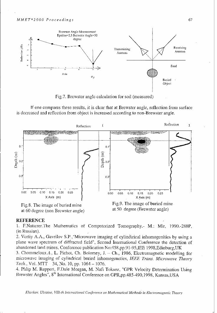
MMET*2000 Proceedings 67
Brewster Angle MeasurementEpsilon=2,5 Brewster Angle=50
degree
Transmitting Receiving
Antenna Antenna
Sand
Anle 0BuriedObject
Fig.7. Brewster angle calculation for soil (measured)
If one compares these results, it is clear that at Brewster angle, reflection from surfaceis decreased and reflection from object is increased according to non-Brewster angle.
Reflection 1 Reflection
...................... ...... .............. ..... ..................... ........... .....i•Y::i,:=•:i:............. ...................ii••:i: •..................
0.1 0.1-
0.2
0.3 03
0.00 0.05 0.10 0.15 0.20 0.25 0.00 0.05 0.10 0.15 0.20 0.25
X Axis (m) X Axis (m)
Fig.8. The image of buried mine Fig.9. The image of buried mine
at 60 degree (non Brewster angle) at 50 degree (Brewster angle)
REFERENCE ,,1. F.Natterer.The Mathematics of Computerized Tomography.- M.: Mir, 1990.-288P,(in Russian).2. Vertiy A.A., Gavrilov S.P.,"Microwave imaging of cylindirical inhomogenities by using aplane wave spectrum of diffracted field", Second International Conference the detection ofabandoned land mines, Conference publication No:458,pp.91-95,JEE 1998,Edinburg,UK3. ChommelouxA, L. Pichot, Ch. Bolomey, J. - Ch., 1986, Electromagnetic modelling formicrowave imaging of cylindrical buried inhomogeneties, IEEE Trans. Microwave TheoryTech., Vol. MTT - 34, No. 10, pp. 1064 - 1076.4. Phlip M. Reppert, F.Dale Morgan, M. Nafi Toksoz, "GPR Velocity Determination UsingBrewster Angles", 8th International Conference on GPR,pp.485-490,1998, Kansas,USA
Khicirkov, Ukraine, VIII-th International Conference on Mathematical Methods in Electromagnetic Theory

68 MMET*2000 Proceedings
ANTENNA SUB SYSTEM FOR METEOSAT SECOND GENERATIONSATELLITES: MODELING TOOLS AND NEEDS
*Kees van 't Klooster**Massimo Di Fausto, I. Floriu,
***Alessandro Rosa, (****) Bernard Robert
*ESA/ESTEC, POBox299, 2200 AG Noordwijk, The Netherlands, kvtkloos @estec.esa.nil**Alenia Spazio, Spa. Via Saccomuro 24, 00131 Roma, Italy, fax +39-06-4151-2389,
***Space Engineering, Via Berio 91, 00131 Roma, Italy, fax +39-06-2280739,****Alcatel Space Industries, 100 B., 06156 Cannes la Bocca, France, fax +33-49292-3470
ABSTRACTThe Meteosat Second Generation (MSG) program concerns the launch and operation of threenew satellites in the coming years. MSG continues meteorological services, which arecurrently provided by the very successful first generation of satellites (Meteosat OperationalProgram - MOP), operated by Eumetsat. MSG expands on services offered by MOP byproviding more frequently data in more observation bands, with higher resolution. Atelecommunication system on-board the MSG satellite transmits measured data to theprimary ground station and receives and re-transmits pre-processed images andmeteorological data as received from the latter station. Meteorological data are collectedfrom data collection platforms. The MSG satellite carries a Search and Rescue transponder.The antenna sub-system has been specifically designed for the telecommunication functionsand permits appropriate data throughput with the satellite spinning at a rate of 100revolutions per minute.The antenna sub-system for MSG is described, after a short general description.
BACKGROUNDThe first pre-operational Meteosat satellitewas launched in 1977. Meteosat OperationalProgram was started in 1983 after a 'pre-operational' period with an agreement to,/launch three operational satellites. A v// / , _______
prototype pre-operational satellite called P2, -7/ \ . Iwas prepared and launched with an ARIANE KNR4 launcher in 1988. The last MOP-satellite / . ..was launched in 1997, it continues service -today (Meteosat Transitional Program orMTP). ESA carried out operations of -_..,_..Meteosat satellites ([1] data collection, pre-processing and redistribution ofmeteorological information), until the new .• 1.European organisation Eumetsat took over L --_-
these tasks in 1995. Eumetsat operates the Figure 1: MSG Mission Scenario with RF linksjfr theMOP satellites and MTP [2] today. raw radiometer data to the primarv ground stationServices continue untill 2001 after which (with back-up) and the up- and downlinksfor the
processed data to primary and secondary users
Kharkov, Ukraine, VIII-th International Conference on Mathematical Methods in Electromagnetic Theory

MMET*2000 Proceedings 69
MSG satellites shall take over. ESA and Eumetsat are preparing this MSG program, withESA responsible for procurement of the satellites.First some descriptive information is given for both MOP and MSG satellites. It is followedby the main subject of this paper: a description of the MSG antenna-system. Modelling,optimisations and associated tools are outlined, with decisions made. Realised performancesof this specific antenna sub-system, functioning on a spinning satellite, are shown.
MOP AND MSG SATELLITESA MOP-type satellite orbits the Earth at an altitude of 35.800 km, in geostationary orbit, thusleading to a satellite position above the equator on a fixed meridian (for Meteosat theGreenwich meridian). It is a spin-stabilised spacecraft, rotating at a speed of 100 revolutionsper minute (100 RPM). It has its spin-axis perpendicular to the orbital plane. The primarypayload for MOP is a high resolution three channel radiometer instrument, which images the
Earth in less than half an hour in threespectral bands (X = 0.5-0.9 jtm, 10.5-12.5 ýtm and 5.7-7.1 jim). One image line
. is taken each revolution of the satelliteSover the Earth disc over the angular rangeSfrom +10' to -10' (as seen from the
geostationary orbit). An image composedout of 2500 scan-lines results after 2500revolutions, thus in 25 minutes.The stored image line data are re-sampled
Figure 2: MSG satellite (left) and MOP satellite at a and transmitted down to the Earth during.Vililnr srcalh, remainder part of the 3600 arc outside this
±10° interval. The data are processed at a dedicated location (at Eumetsat in Darmstadt),where also other meteorological products are derived. Processed images with additional dataare sent up again towards the satellite, which redistributes data to users within the coveragezone. Much more info is found in [1] and [2]. Meteosat (MOP and MTP) are also received inUkraine [3]. The satellite collects also meteorological data from remote (automatic) platformswithin its coverage zone and relays this information to the central ground station (this is theso-called DCP mission). A very broad basis of experiences has been created with the satellite,with its operations, with data processing and data utilisation, after more than 25 year. Itprovided a very good starting point for a configuration of a new satellite, the MeteosatSecond Generation satellite.MSG satellite will also be a spin-stabilised spacecraft, operating from a geo-stationarylocation, with a number of enhanced capabilities. The radiometer generates images at doublethe speed (15 min) and operates in 12 spectral bands with better resolution (1 km for thevisible channel, 3 km for other spectral channels). This permits to extract three-dimensionaldata about the atmospheric composition.The reader is invited to estimate the pointing and localisation correctness (1 km from 35800km). The larger amount of data from MSG is also transmitted to a new primary groundstation of Eumetsat (in Usingen in Germany), from where processed data are transmitted upto the satellite again for re-distribution to primary and secondary users within the coverage[2]. Fig.1 shows the link schema. MSG provides the data collection mission (DCP) with alarger number of channels than available on the MOP satellite. A Search and Rescuetransponder is carried. It makes use of the UHF and L-band antenna for respectivelyreception (up) of emergency messages and transmission (down).MSG is a much larger
Kharkov, Ukraine, VIII-th International Conference on Mathematical Methods in Electromagnetic Theory

70 MMET*2000 Proceedings
spacecraft than MOP, due to theenhanced capabilities with the muchlarger radiometer, the need for alonger lifetime and the associatedsupporting equipment. Fig. 2 showsthe MOP spacecraft and the MSGspacecraft (left) with relativedimensions. Fig.2 indicates alsoalready a very important constraint forthe antenna farm, located on top ofthe spacecraft. The height permittedfor the antenna farm of MSG isrelatively small, much less than theheight available on top of the MOP Figure 3: From a high elliptic trasnfer orbit to a
satellite body. This is very important; geostationary orbit. MSG will use three motorfirings
it has led to many calculations tooptimise the antennas for MSG in the presence of the satellite body as indicated below.Conversion of the transfer orbit to the geostationary orbit is also different: MOP used a solidfuel apogee boost motor to change from the transfer orbit to the geostationary orbit with onemotor firing. MSG will use a set of two apogee boost motors, which use bi-propellant fuel.Three motor firings are planned to convert the transfer orbit to geostationary orbit (fig.3).
ANTENNAS USED IN THE TELECOMMUNICATION SYSTEMThe MSG telecommunication systemperforms a number of tasks, usingdedicated antennas:* Reception of telecommands and
transmission of house keeping data.Two (redundant) S-bandtransponder are connected to adedicated telemetry and :4:telecommand antenna, (TT&Cantenna), the antenna is not j"
redundant." Transmission of measured
radiometry data, coming from the Figure 4: MSG Antenna Farm, Engineering Model,
data handling subsystem to a (courtesy Alenia Spazio)primary groundstation. Theelectronically despun antenna (EDA) is used for this task in L-band.
" Reception of pre-processed images with associated data, using a toroidal pattern S-bandantenna.
"• Transmission to users, using the L-band EDA antenna for low resolution and high-resolution data.
"* Receiving data from Data Collection Platforms (DCP) by means of an ElectronicallySwitched Circular array antenna (UHF-EDA, operating at 402 MHz).
"* Transmission of the DCP data, using the L-band EDA antenna.
Kharkov, Ukraine, VIII-th International Conference on Mathematical Methods in Electromagnetic Theory

MMET*2000 Proceedings 71
Figure 5: MSG Satellite with Antenna Farmon top (Qualification Model, courtesy Alcatel)
Figure 6: TT&C antenna for MSG, wiregridInodel for design calculations at ESTEC (right)
0.1
0°40
0.0.1
-0.00.
-0.1 -0.1
* Receiving emergency messages (Search and Rescue). The UHF - EDA is used at 406MHz.
* Transmission of S&R messages, using the L-band EDA antenna near 1544 MHz.Alenia Spazio is responsible for design, manufacture and test of the MSG antenna sub-system.The Engineering Model antenna sub-system was completed early 1999 and the first FlightModel antenna sub-system has been tested last summer on a dedicated antenna test range atAlenia.Fig.4 shows the flight model with the different antennas from top to bottom:-1- TT&C antenna on top,-2- S/L-band toroidal pattern antennas inside a black cylindrical radome,-3- L-band Electronically Despun Antenna, using 32 columns, 4 dipole radiators in each
column.-4- UHF Electronically Despun Array (16 crossed dipole radiators), in front of the L-
Band EDA.See also other references for more details on design and analyses references [5] (MOP), [6,71(MSG).Fig.5 shows the qualification (thermal/mechanical) model of the MSG satellite with theantenna platform on top, just before the spin test in Alcatel in Cannes.
TT&C ANTENNAA low-gain wide-coverage antenna, mounted on top is used for the link for telemetry andtelecommanding (TT&C) of the satellite. During launch and early orbit phase (LEOP, fig.3) amore wide coverage is needed than when MSG is in the operational phase (on-station). MOPtype satellites use such type of antenna of a much older design (quadri-filar helix). Relativepattern information for such antenna was derived from tests during the LEOP phase [41 and
compared with predictions and tests before launch. However, the MOP TT&C could not beused directly. A MOP satellite is much smaller than a MSG satelite (fig.2). A detailed designand optimisation had tod be carried out with the much larger MSG geometry taken into
Kharkov, Ukraine, VIIl-th Internatioenal Coference on Mathematical Methods in Electromagnetic Theory
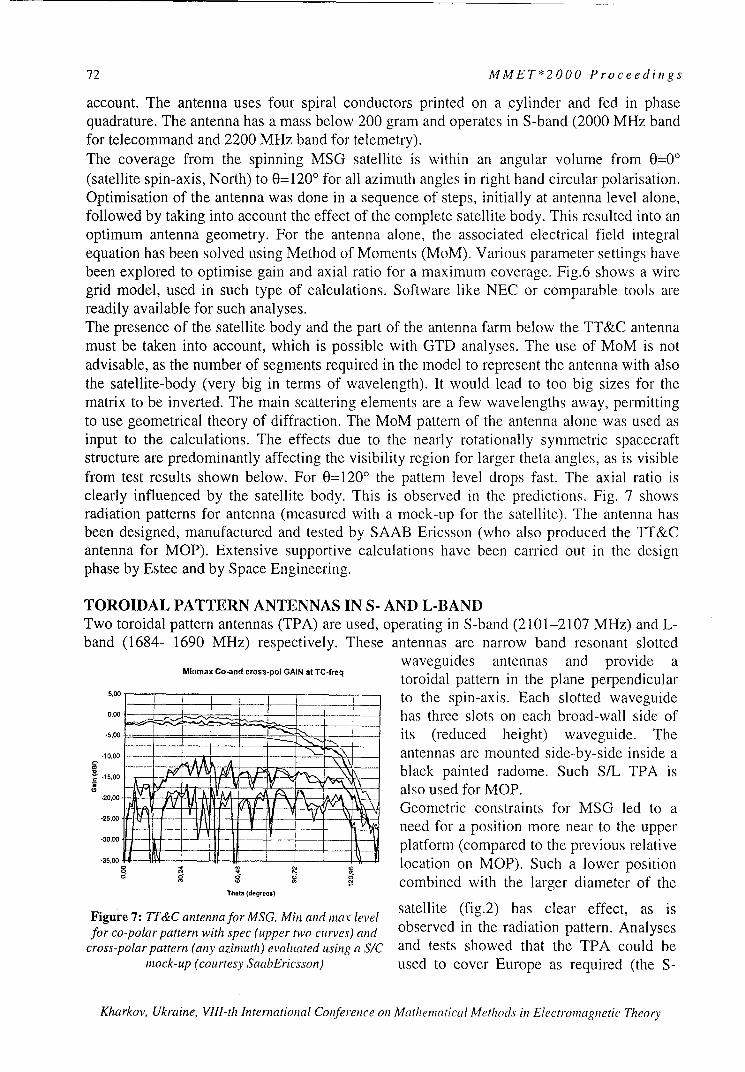
72 MMET*2000 Proceedings
account. The antenna uses four spiral conductors printed on a cylinder and fed in phasequadrature. The antenna has a mass below 200 gram and operates in S-band (2000 MHz bandfor telecommand and 2200 MHz band for telemetry).The coverage from the spinning MSG satellite is within an angular volume from 0=0°(satellite spin-axis, North) to 0=1200 for all azimuth angles in right hand circular polarisation.Optimisation of the antenna was done in a sequence of steps, initially at antenna level alone,followed by taking into account the effect of the complete satellite body. This resulted into anoptimum antenna geometry. For the antenna alone, the associated electrical field integralequation has been solved using Method of Moments (MoM). Various parameter settings havebeen explored to optimise gain and axial ratio for a maximum coverage. Fig.6 shows a wiregrid model, used in such type of calculations. Software like NEC or comparable tools arereadily available for such analyses.The presence of the satellite body and the part of the antenna farm below the TT&C antennamust be taken into account, which is possible with GTD analyses. The use of MoM is notadvisable, as the number of segments required in the model to represent the antenna with alsothe satellite-body (very big in terms of wavelength). It would lead to too big sizes for thematrix to be inverted. The main scattering elements are a few wavelengths away, permittingto use geometrical theory of diffraction. The MoM pattern of the antenna alone was used asinput to the calculations. The effects due to the nearly rotationally symmetric spacecraftstructure are predominantly affecting the visibility region for larger theta angles, as is visiblefrom test results shown below. For 0=1200 the pattern level drops fast. The axial ratio isclearly influenced by the satellite body. This is observed in the predictions. Fig. 7 showsradiation patterns for antenna (measured with a mock-up for the satellite). The antenna hasbeen designed, manufactured and tested by SAAB Ericsson (who also produced the TT&Cantenna for MOP). Extensive supportive calculations have been carried out in the designphase by Estec and by Space Engineering.
TOROIDAL PATTERN ANTENNAS IN S- AND L-BANDTwo toroidal pattern antennas (TPA) are used, operating in S-band (2101-2107 MHz) and L-band (1684- 1690 MHz) respectively. These antennas are narrow band resonant slotted
waveguides antennas and provide aMinmax Ca-and cross-po! GAIN at rC-freq toroidal pattern in the plane perpendicular
,.. ___to the spin-axis. Each slotted waveguide0.00 J _ has three slots on each broad-wall side of
.5,00 --- - - its (reduced height) waveguide. The
.10.00o _ - _ - , antennas are mounted side-by-side inside a{.5,.00 .... T m !E ___ black painted radome. Such S/L TPA is'.20k.0 ,/ , t Y Z11 Fv% A also used for MOP.
-2500 -Geometric constraints for MSG led to a"-25.00 - -_ - - need for a position more near to the upper-200 i - platform (compared to the previous relative
-•5.00 location on MOP). Such a lower positioncombined with the larger diameter of the
Theta (degrees)
satellite (fig.2) has clear effect, as isFigure 7: oT&C antenna for MSG. Mir and tax levelfor co-polar pattern with spec (upper two curves) and observed in the radiation pattern. Analyses
cross-polar pattern (any azimuth) evaluated using a S/C and tests showed that the TPA could bemock-up (courtesy SaabEricsson) used to cover Europe as required (the S-
Kharkov, Ukraine, VIII-th International Conference on Mathematical Methods in Electromagnetic Theory

MMET*2000 Proceedings 73
band uplink will be from a dedicated groundstation in Usingen - Germany). The use ofnarrow bandwidth resonant slots implies a low coupling between respective S and L-bandRx- and Tx channels. It is an interesting feature of the configuration with the antennas side-by-side, that a remarkably good (toroidal) antenna pattern is provided in the azimuth plane,even in the azimuth direction, where there is the neigh-bouring L-band antenna. The far-fieldphase behaves cosine-like, as expected due to the offset of the wave-guide axis from the spin-axis. The L-band toroidal pattern antenna is the back-up transmit antenna for a highlyunlikely situation of a failure of the L-band Electronically Despun Antenna.
L-BAND EDA ANTENNAThe L-band Electronically Despun Antenna (EDA) is a transmission-only antenna, used tosend data to the primary groundstation and to re-transmit processed images to the users. AlsoDCP messages and Search and Rescue messages are transmitted with this antenna. A toroidalpattern antenna can not achieve the necessary gain and with the limited volume available forthe antenna, one or another despun antenna is a natural choice. Mechanical despun antennasare used in several telecommunication (spinning) satellites and have been used formeteorological satellites. A mechanical despun antenna has a disadvantage, that it may givepotential disturbances due to micro-vibrations, which can lead to a degraded image quality.This is the case in particular for MSG with its resolution and localisation requirements froman orbit of 35800 km altitude.The advantage of an electronically despun antenna (EDA) was already recognised for thefirst Meteosat satellite[5]. The EDA has demonstrated itself as a very robust and elegantantenna. It has been selected also for the MSG antenna subsystem. Fig 4 shows the EDAcylindrical array, just below the black radome for the toroidal antennas. The circular array ofcrossed UHF dipoles is located around the EDA. Fig 8 shows the L-band EDA antenna withTPA and TTC antenna on top.The EDA antenna consists of a cylindrical array with 32 columns with four dipole elementsin each column. The radiating columns are connected to pin-diode switches, which regulatethe actual number of 4 or 5 active radiatingcolumns out of the 32 columns.Fig.9 gives a schema [5] for the feed network.The incoming transmit-signal is split in 4 equi-phase and equi-amplitude signals by means ofa four-way power divider (4WPDV). Each ofthe four branches is connected to a variablepower divider (VPD). Each VPD has twooutputs, each connected to pin-diode switches(single-pole, 4-through - SP4T). The SP4T'sroute the power to the radiating columns, as -
selected to form a radiating set of 4 or 5 out of32 columns on the Earth facing side. The4WPDV consists of 3 Wilkinson-type 2-waypower dividers. The VPD uses a powerdivision scheme in which an input hybriddivides the power into two channels. In one ofthe channels a phase-shift (p between 0' to -90' Figure 8: L-Band EDA with SIL TPA and TTC
is provided, synchronously with a phaseshift 9 antenna on top, before environmental testing
between 00 to +90' phase-shift in the other (courtesy Alenia)
Kharkov, Ukraine, VIII-th International Conference on Mathematical Methods in Electromagnetic Theory

74 MMET*2000 Proceedings
branch. Then the two channels are combined again SP4T
using a 3-dB hybrid circuit. The two output ports 19 5 2 6 1 7 4 1of the latter hybrid provide a power level as a 1 2 3 4 5 6 7 p
function of this phase shift 9:Pot-1 1 =/ (cos 9 + sin (P )2 VPD 1 VPD 2 VPD 3 VPD 4
P out-2 :=1/2 (cos (p - sin (p
Seven pre-selected phase settings for y lead toseven distinct power division steps, between I and 4WPV
0, respectively 0 and 1 in complement for the two inputVPD-output power levels. With this scheme, the Figure 9: Schematic representation L-band EDA
incoming power is routed to four adjacent beam-forming network [5]
columns (step '1'). One out of the four VPD's switches gradually (in 7 steps) the powerfrom the first column to the fifth column, after which a next VPD switches over fromcolumn 2 to column 6, after this the next VPD takes over, etc. In this way a set of 4(step '1' and step '7') or 5 adjacent radiating columns (step '2' through step '6') out of
the 32 available is provided, by anappropriate VPD and SP4T control. Alogical circuitry, which is synchronised
•. _ with the spinrate, provides the actualcontrol signals for VPD and SP4T. Earth-sensors are used to provide the correctangular reference to this logical circuitry. Inthis way the active set of radiating columnscan be kept automatically pointed towards
,, 'the Earth, while the satellite is spinning.
"The antenna operates between 1670 and1695 MHz and provides a link also for the
.-. Search and Rescue downlink (1544.5
a4 • MHz). The switching scheme for the VPD", 1 -- 1 ,is designed to have a minimum amplitude
Figure 10: Typical L-band EDA antenna and phase ripple. The resulting pattern ispattern for a fixed beam for VPD setting in step very characteristic for the EDA and is in fact
'4', derived from tests on the EM model on its 'fingerprint'. An example of one out ofAlenia'sfar-field test range. Courtesy
Alenia/Snace Enieerin, the seven switching states is the EDA beam
S. . .. .. . ............ for a VPD step 4 setting (the lowest
S ... ,-I •.:Iti:;1i . gain is obtained for step ' ) is given inS7TH ; fig.10. There are 32 of VPD '4' beams
7.1 realised in one revolution.The larger diameter of the MSG platform:H:;:K" (compared to MOP) causes obviously an
Figure 11: Typical L-band EDA dynamic impact on the EDA antenna pattern. This was
antenna pattern fragment, taken on the carefully analysed and precautions were
Aleniafar-field test range (2 dB/div taken. The large platform leads to a slight
vertical, 10 div horizontal) more northward pointing of the EDA beam.Installation of a UHF electronically despun
Kharkov, Ukraine, VIII-th International Conference on Mathematical Methods in Electromagnetic Theory

MMET*2000 Proceedings 75
array in front of the L-band EDA causes obviously an impact. This was thoroughly analysedand checked by testing. A characteristic fragment of a dynamic diagram over a small azimuthinterval (22.50) is shown in Fig.11. The switching sequencing (7 steps during 11.250) isnoticed.
THE UHF-BAND ELECTRONICALLY DESPUN ANTENNAThe data collection task (DCP) in the UHF band (402.1 MHz) could be handled for MOPwith an antenna with -0.5 dBi gain over the coverage. For MSG, with the increased numberof DCP channels, a higher gain has been desirable. Furthermore, the installed Search &Rescue transponder uses this antenna for its receiver at 406 MHz and requires higher gain.
Moreover, with the geometry constraints for"the satellite, the height available toaccommodate the antenna farm has beenreduced compared to MOP. It led after manyanalyses of performances to the choice of anelectronically switched antenna. Someantenna elements are needed to providesome gain and then smooth switching at thisfrequency (X=75 cm) requires a relativelarge diameter. With the available L-bandEDA antenna drum, with a diameter of 1.30meter, the UHF antenna has been designed
Figure 12: UHF antenna element in presence of with 16 elements, at a distance of about 3/¾Xthe structure and 15 terminated elements in front of the L-band EDA. The L-band
(Courtesy: Space Engineering) EDA drum is used as reflecting surface.
There are 4 out of 16 dipoles actively usedfor a beam. The other elements are switchedto a load. Every 22.5', the next UHF dipole isactively connected to this group of four,while one dipole at the other side of thegroup of 4 is switched off. In this way anactive set of 4 dipoles is switched around,thus providing an antenna with a contra-
MeteosatSecond Generalion rotating switched beam. The beamforming
Figure 13: Four UHF antenna elements in the circuitry for this receive-only antenna is more
presence of the structure and the other 12 simple than for the L-band EDA. One 4-wayterminated elements (Courtesy Space Engineering) power divider connects to four 4-way
switches, which switch in the activeelements. The control of the latter switches is also synchronised with the spin-rate. Theantenna elements are crossed dipoles, installed on a mast above the satellite platform. Fig. 4shows the dipoles. More directive elements could have been used, but at a cost of mass andalso increased blockage of the L-band EDA performances. Alenia Spazio, as responsible forthe antenna design, has been supported by Space Engineering for analysis and optimisationwork. Several extensive calculations have also been carried out at ESA-Estec. At thisfrequency the satellite is only a few wavelength in size and the configuration is rotationallysymmetric. This permits to handle the analysis work by using Method of Momentapproaches, in which rotational symmetry is exploited. It is observed, that the current
Kharkov, Ukraine, VIlI-th International Conference on Mathematical Methods in Electromagnetic Theory

76 MMET*2000 Proceedings
distributions on the antenna elements as well -4 -as on the scattering satellite structure F IT-.- fKcontribute to the pattern (the whole satellite • -"acts as antenna). The current representation-.on the structure elements of the model can be 4.-
derived and an example of such a result isshown in fig. 12, where one dipole as activeelement is located in the 16-element UHF Figure14:UIFdnanicalpatternover360°(2
a .The current distribution (and - note - dBdiv vertical, 10 div horizlontal). The periodicityaras ry. irelated to the switching evely 22.5 'is observed, co andits asymmetry) is clearly observed. Fig.1 3 cross polarisation levels are shown, ineasuredfor 5 0shows the relative current distribution for the elevation South (406 MHz) (Courtesy Alenia .Spazio)
full array. Interesting perceptions are made:the bottom locations of the UHF dipoles are important. One notes also the secondaryexcitation of dipoles not actively used in the array of 4 elements, but switched in the line to aload (in the 4way switch).It has been proved useful to add a scattering structure on top of the L-band EDA (figA). Thisstructure has been designed, such, that it is scattering at UHF, but nearly transparent in L-band. The latter structure is noticed in the models in fig.12 and 13 and the relative currentlevel indicates, that it is functional for the UHF radiation pattern (it has led to a gainimprovement of about 0.3 dB). The blockage effect of the UHF antenna for the L-band EDAhas been analysed and led to the geometry as used. Indeed, there is an impact of about 0.2 a0.3 dB, but this has to be allowed for. Fig.14 shows dynamical pattern for a UHF EDAantenna measured on Alenia's test range over 360' in azimuth at a frequency of 406 MHz.
CONCLUDING REMARKSThe specific antenna sub-system for the spinning Meteosat Second Generation satellite wasdiscussed. An initial description of the satellite tasks was given. Differences between theMOP and the MSG antenna systems were highlighted. Modeling aspects and decisions, basedon modeling, for antenna configuration selections were indicated, like for instance thelocation of the UHF array in front of the L-band array. The available analysis tools provideda possibility to take such design decisions.The impact of scattering by the spacecraft has been an important issue for all antennas. Theresulting configuration as designed. built and tested by Alenia Spazio is very interesting bothin theoretical and actual realised sense. Currently, the first Flight Model Antenna sub-systemhas been fully tested at Alenia Spazio and it has also been checked out, after installation onthe complete satellite.
REFERENCES[I ] http://www.esa.int/, also under remote sensing, /msg[2] http://www.eumetsat.de/[3] http://www.cri.cherniaov.ua/, http://www.nas.geov.ua/d/d5/nas d5i I 0.htmnl/[4] 'Antennas for Scientific and Remote Sensing Satellites', C.G.M.van 't Klooster, N.E.Jensen,Invited paper JINA Antenna Conference, Nice, 1990.[5] 'Meteosat Antenna System' Nicolai, Alenia Spazio, Alenia Revista, 1976.[6] 'The Antenna Subsystem for the New Earth Weather Observation Satellites Meteosat SecondGeneration.' P.Carati, M.Di Fausto, V.Santachiara, A.Rosa,P.Russo, JINA Antenna Conference Nice,Nov. 1998.[7] 'EMC Aspects in Meteosat Second Generation Antenna Subsystem', G. Di Benardo, P.Russo,L.Di Cecca, V.Santachiara, G.A.J. van Dooren, C.G.M. van 't Klooster, Partnership for PeaceSymposium on EMC, San Miniato, 1996, Italy.
Kharkov, Ukraine, VIII-th International Conference on Mathematical Methods in Electromagnetic Theory

MMET*200L6 Proceedings 77The Concept of Confluence and the Edge Conditions
for a Wedge Bounded by Material Sheets
Mithat IDEMEN
ISIK university, Bilyalkdere Cad.,80670 Maslak, Istanbul,Turkey.E-mail: idemen @ ISIKUN.edu.tr
Abstract. The edge conditions which dictate the asymptotic behaviour of the electromagnetic field near theedges play a crucial role in solving boundary-value problems involving boundaries having edges. In analyticalstudies they permit one to determine some unknown functions while in numerical investigations they enableone to improve the convergence of some processes by introducing beforehand the edge singularities into thefield functions. This work is devoted to the analysis of wedge configurations bounded by material sheetshaving different constitutive parameters. From mathematical point of view, the problem can be reduced to 9canonical types. These canonical types are investigated in full detail by introducing the confluence conceptwhich permits one to reveal also the logarithmic singularities, if any.
1.IntroductionFrom both experimental and theoretical works it is known that some components of the electromagnetic fieldexhibit singularities of certain types near edges. Many investigations concerning structures involving edgesrequire the knowledge of the types and orders of these singularities beforehand because their knowledge inanalytical investigations (based, for example, on the Wiener-Hopf or Riemann- Hilbert techniques) permits oneto determine some auxiliary functions while in numerical works it enables one to improve the convergence ofsome procedures if the singularities are incorporated into the field expressions explicitly. The aim of thepresent paper is to investigate the edge conditions for a wedge with boundaries formed by arbitrary materialsheets in its most general form by a rather simple but rigorous approach.
The history of the edge conditions for the electromagnetic field goes back to a work by Bouwkamp in 1946.In this work connected with a perfectly conducting half-plane located in an infinite homogeneous space, heshowed that it is possible to find many solutions satisfying both the Maxwell equations and the boundaryconditions. They differ from each other by their singularities near the edge, which are, in general, notphysically acceptable. If one knows the physically acceptable singularity, then one can find the unique,physically meaningful solution. The problem was then considered by many researchers. For example
-in 1949 Meixner [I] postulated the expansions in the form of power series of r112 , namely:
I-(r,4?) = A(ý) +B(ý)r +C(#)r3/2 +
where (rt,z) stand for the circular cylindrical coordinates such that r = 0 corresponds to the edge.-in 1972 Meixner [2] proposed a modification of his first expansion, namely:
EXr, ) = ao( )rt + a,( )rt + a2(#)r' +
(similar expressions for the other components).Here t stands for a number which will be determinedthrough both the Maxwell equations and the boundary conditions.
-in 1976 Hurd[3] proposed to use the results to be derived from the solution of the static field problemsconnected with the same geometrical and physical conditions.
-in 1985 Van Bladel [4] used the same concept.-in 1964 Jones [5] postulated an expansion which depends on the concept of separable solutions, namely:
sin voI a.vYv{(k 2"m 2) 2r}e"Ie Cos VO
where Y, stands for the usual Neumann function which is singular when r -- 0.-in 1988 Braver and his colleagues [6] proposed to write
00 m
r,')=rT 2: Y Cm,(4)rm ln" r, 0.mn=0 n=0
Kharkov, Ukraine, VIlI-th International Conference on Mathematical Methods in Electromagnetic 77eory

78 MMET*2000 Proceedings
The Ansatzes of Meixner were criticized by several investigators because i) they had no sound basis and,consequently, although the first terms they yield are correct, their higher order terms are invalid (nonexisting),and ii) they do not involve logarithmic singularities and, consequently, their results are sometimes wrong.
As to the staticfield approachs, they start from the Laplace equation and consider merely an electric (or amagnetic) field not coupled to a magnetic (or an electric) field whereas many boundary conditions which areactually in extensive use involve electric and magnetic fields simultaneously.
The critiques directed to Meixner can also be repeated for Braver. For example, according to the well-known theory of the ordinary linear differential equations, near a regula,--singular point the solution of anequation of the second order may involve only Inr but not (Irr)r with n > 2. Secondly, from the recurrencerelations to be satisfied by C.. , it is not easy to find the maximum power of the logarithms. Furthermore, it israther hard to elaborate the postulated expressions to derive results concerning rather complicated boundaryconditions and geometrical configurations.
Finally, to conclude this short historical introduction we want also to draw the attention to some methodsdepending on integral equations used by Maue [19491 and Jones [1950].Though they are much more generalas compared to the above-mentioned ones and allows directly for curved edges as well as those which changedirection discontinuously, in a situation similar to the present investigation which concerns the most generalboundary conditions they seem to result in too complicated equations.
Now, by considering the diversity of the boundary conditions which frequently appear in the openliterature as well as those which seem to have important practical applications in near future, we will try toformulate the problem in its most general form. To this end we will consider a wedge with faces formed byarbitrary material sheets and apply the above-mentioned method of separable solutions combined with theconcept of confluence, which will both produce the logarithmic singularity, if any, and clarify the reasonbehind this type of singularity. A time dependence exp(-icot) is assumed and omitted throughout the paper.
2.Formulation of the ProblemFor the sake of mathematical simplicity, we will define a coordinate system Oxyz such that the wedge issymmetrical with respect to the plane y = 0 and the edge is coincident with the z-axis. We will also assumethat the given point is the origin and the field does not depend on the z-coordinate (see Fig.-I). The faces S
S
Figure-I xS0
y.4
and 1 of the wedge are supposed to be material half-planes which may, in general, be penetrable. Hence, onehas to consider both regions B and B* separated by the wedge. Then the limiting field values on the boundaryS, observed from sides I and 2, are interrelated by two boundary conditions which can be written in thefollowing forms( see [7,8] ):
(1) alnxH+a2nx H*+a3Et+a4E,*+asnxgradH•,,+a 6nxgradH*fl+a 7gradEfl+aggradE*fl =0
(2) binxH+b2nxH*+ .......... + bagradE*n =0.
In these equations n stands for the unit normal on S directed from side 1 to side 2 while the subindices n and trefer to the normal and tangential components, respectively. As to the superindex (*), it refers to the valuesobserved inside the region B. The coefficients ai and bi are known complex constants which can be determinedthrough the constitutive parameters of the material of the sheet modelled by S [8].If the material of the sheet isisotropic in tangential directions (it may be anisotropic when both the tangent and the normal directions areconsidered together), then (1,2) can model the sheet S rather accurately [7,8lSimilar relations are also writtenfor the face E. In what follows, the coefficients related to E will be denoted by otj and j3i, namely:
Kharkov, Ukraine, VIII-th International Conference on Mathematical Methods in Electronmagnetic Theory

MMET*2000 Proceedings 79
(3) lnx H*+a2nx H+a3E*t+a4Et'•xn×gradH*.+xnx gradI+aTgradE *.+asgradEn =0
(4) P3inxH*+fP2nxH+ ....... +OggradE, =0.
If all the coefficients with even indices in (1) and odd indices in (2) are zero ( or (1) and (2) can be reducedto such a system), then S constitutes an impenetrable boundary. The same is true for (3),(4) and E also. Whenboth S and Z are impenetrable, the boundary S+E becomes a shield and separates the regions B and B*completely from each other. In such a case the regions B and B* have to be considered separately. In whatfollows we will first consider the case where the boundary S+F is penetrable. The results concerning theimpenetrable wedge will then be derived from those concerning the penetrable one by straightforwardsimplifications.
3.The Wedge With Penetrable BoundaryIn this case all the cartesian components of the electromagnetic field satisfy the same reduced wave
equation near the edge, namely:
(5) Au(r,4,) + k~u(r,4,) = 0, re [0,ro), (r,4) EB
(6) Au(r,4,) + kOu(r,4,) = 0, rr [0,ro), (r,4)rB=,
where r and 4, are the usual cylindrical polar coordinates while k and k* stand for the wave numbers of theregions B and B*, respectively. As to r0, it is a certain positive number determined by the sources.
As is well known, every particular solution to equ. (5), which satisfies certain boundary conditions,consists, in general, of discrete or continuous combinations of its separable solutions. These latter are of theform u = R,(r)ct(4,) with
( Jv(kr) when v(7) Rn(r) Jn(kr) + An Yn(kr) when v = n E {0,1,2,...}
and
[Bvcosvq + Cvsinvo when v# 0( 4)= B0 + Coo when v 0
Here v stands for the separation parameter while J, and Y, denote the usual Bessel and Neumann functions.The set of v which has to be taken into account to construct a particular solution u(r,4) is the spectrum of u.The spectrum as well as the constants A., B1 and C, appearing in (7) and (8) can be determined byconsidering also the sources as well as the boundary and radiation conditions, which is beyond our present aim.Our aim consists of revealing the asymptotic behaviours of the field components when r -- 0. In order to thisend we have to consider the following expresssions of J, and Y,,, which are valid near r = 0:
(9) J,(kr) = arv + Or"+2 + ..... (v • -1,-2....)
(10) Y.(kr) = air' + Ojr n+2 +...+ [ylrn "-2rn+2 Inn
Here cc, cc etc are certain numbers. From (9) and (10) one concludes at first glance that when r-* 0 the fieldcan become singular having infinitely large values as a negative power of r or logarithm of r. To reveal theasymptotic behaviours (and admissible singularities) of the field components for r --- 0, we will (and must!)take into account the fact that i)the field components satisfy the Maxwell equations, ii) the energy stored nearthe edge is finite, and iii) the boundary conditions on S +1 are satisfied.In what follows we will study thecontributions of these restrictions separately, In order to reduce useless mathematical complications, we willconsider the E- and H-cases separately. In E-case the electric field is parallel to the edge while in H-case themagnetic field is parallel to it.
KhIarkov, Ukraine, VIII-th International Conference on Mathematical Methods in Electromagnetic Theory

80 MMET*2000 Proceedings
3.1.The H-caseIn this case, all the non-zero components of the electromagnetic field near the edge in B can be written interms of a scalar potential u satisfying (5), namely:
(11) H7 ' k2u, E,= (io))/rau/04), E4= -ikpa8 u/Or.
By replacing k and gt in (11) by k* and Ct*, respectively, one gets the expressions valid in B*. By consideringthese expressions with the restrictions (i-iii) mentioned above we get the following results.
A.Contribution of the energy restrictionAs is well known, the densities of the stored electric and magnetic energies are proportional to IEI2and IHI2,respectively. In order for the total electromagnetic energy stored in a finite volume including the edge to befinite, one has to have
(12) (r)"2 H, (r, .), (r)'1 2E,(r, .), (r)" 2E4(r,.)e 1Q(0, rol
On the other hand, (7,8) and (9,10) yield
[ constant.rv when v * n
(13) R,(r) constant.rn + constant.Anr" when v = n > 11+ constant.A 0 In r when v = n = 0
By using (13) and (8) in (12) one gets easily
(14) 9vv>0 when v n, A = 0 when n = 0, ,... and Co 0.
Here 91v stands for the real part of v.From these we conclude that the separable solutions can notindividually involve logarithmic singularities. Such a singularity in the field may come from certain kind ofconfluence which generates nonseparable solutions ( see Sec.G below).
B.Contribution of the Maxwell equationsBecause of(14), the above-mentioned potential function u consists of a combination of certain functions u,whose dominant asymptotic expressions are as follows:
30 when v =0(15) u _ [Bvcosvi + Cv sinvo]rv when 91 v > 0.
The parameter v appearing above is the number which both belongs to the spectrum and has the smallest real
part. All the numbers v which will appear below will designate this minimal v. We suppose first that
(16) v # 1,2,....
The case where v = ne{ 1,2,... }will then be treated as to be a limiting case v -+ n as certain parametersapproach some critical values (see the remark in Sec.E below). By using (15) and (16) in (11) we get
(17a) E, - r"[P cosv4) + Q sinv4)]
(17b) E+- rv'1 [Q cosv4) - P sinv4)]
(17c) H, ~- 1B0 + ik2 /(vcot) rv[Q cosv4 - P sinv4)],
where P, Q and B0 are certain constants to be determined through the boundary conditions.The expressions related to the region B, for which 4)e(0, 2rt-0), are quite similar, namely:
Kharkov, Ukraine, VIII-th International Conference on Mathematical Methods in Electromagnetic Theory

MMET*2000 Proceedings 81
(18a) Er - rv'[P cosvý + Q* sinvfl
(l8b) E#- rv"[Q' cosv4 - P° sinvf]
(1 8c) H4 - k*2Bo + ik*2 /(vcot*) rv[Q* cosvý - P* sinvi].
C.Contribution of the boundary conditionsIf we consider (16), (17a-c) and (18a-c) in (1), then the coefficients of the powers r'-2, rv.' and rv permit us towrite
(19) 7a7,ag) = 0, g(a3,a4) + gl(a 7,as) = 0, f(a'1,a' 2) + f1(a3,a4,a7,as) = 0,
where we puta', = ik2al/(o(tgv), a' 2 = ik*2a2/(O)ýt*V),
f(a,a') = alP sinvO - Q cosv0] + a'[P* sinvO - Q* cosv0]and
g(a,a') = a[P cosvy + Q sinvO] + a'[P* cosvO + Q* sinvO].
As to the functions f1(a3,a4,a7,as) and g1(a7,ag), they exist only when the points v+1 and v+2 belong to thespectrum, and are homogeneous linear functions of their arguments as well as of the additional unknowncoefficients connected with the spectral points v+l and v+2. In what follows we will not need the explicitexpressions of f, and gi.
The result to be obtained from (19) can be summarized as below:
Cond.(1) on S =: if 1a71+lasj •0 => f(a7,as) = 0if Ia7l +1asl = 0 :> when ja31+ja 4j • 0 = g(a3,a4) = 0
when 1a3!+1a 41 0 = f(a'1 ,a' 2) = 0.
The discussion made for (1) can also be repeated for (2). The result is quite the same except that the constantsai are now replaced by bi.
Consider finally the conditions written on Z. They give the similar results
Cond.(3) on I > if Jc7 I+(asI 0 :> AV(as,a?7) = 0if I(X+fas l =0 => when Ia3+1a4 O=':X>( 4,a3)=0
when 1a31+1a4 -0=W(a'2,0',)=0.
Here we puta', = ik'2oa/(cO)A*v), OC'2 = ik2 OL2/(cOptv),
V(ca') -c[P sinvO + Qcosv0] +a'[P*sinv(2n-0) - Q*cosv(2n-0)]and
((x,a') = c[PcosvO - Qsinv0]+cc'[P*cosv(2x-0) +Q*sinv(27r-O)].
Notice that the same results are also valid when aj are replaced by Pi.
D.An exampleIn order to clarify the above discussion let us reconsider a generalization of a configuration studied earlier byboth Lang and Braver. In this example S is perfectly conducting while Y, consists of a resistive half-plane. Onesupposes also that the spaces B and B* have the same constitutive parameters.Then, the boundary conditiontables are
[o00100001l 00 1 -1000 10. 0, -11 0 0 0 0 01
S 0 0 0 1 00 0 1' -1 1/R 0 0 0 0
Kharkov, Ukraine, VIII-th International Conference on Mathematical Methods in Electromagnetic Theory

82 MMET*2000 Proceedings
which yield
Pcosv0 + Qsinv0=0 , P*cosv0 + Q sinv0=0
-Pcosv0 + Qsinv0+P*cosv(27t-0) +Q*sinv(2n-0)=0, P*cosv(21t-0) +Q*sinv(2c-0)=z0.
The compatibility of these homogeneous equations requires A(v) = -sin2v0 sin2v(7t-0) = 0 and gives
v = min{7t/20,n/2(n-0)}
whenever 0 #n/2 ( the case of 0 = it/2 will be discussed at the end of Sec.G below).
E.Determination of v and canonical typesThe four equations such as f = 0, g = 0 etc, derived in subsection C above constitute a system of linear andhomogeneous algebraic equations in terms of the constants P, Q, P* and Q*. Since at least one of these latter isdifferent from zero, the determinant formed of the coefficients appearing in these equations, say A(v), is zero.It is the equation A(v)=0 that will permit us to determine the minimal exponent v. Since the left hand-sides ofthe equations are always f or g and v or X and the numerical values of the constants aj ,bi,ai and Pi takingplace in these equations are not mathematically important, the cases which have to be considered in full detailare only the following nine canonical types:
(ffVY) (ffiy; (ffxx) (fgWY) (fgWX) (fgXX.) (ggyw) (ggwx) (ggxx)
The determinants corresponding to all these canonical cases except the fifth one can be computed veryeasily.The results are recapitulated in TABLE-I. From this table it is evidently seen that in four cases (i.e.thetypes (ffyy), (ggXX), (ffXX) and (gg~y) ) the value of v is determined only via the geometry of the wedge,i.e. via the angle 0, while in the other cases the constitutive parameters of the boundary of the wedge as well asthose of the regions B and B* affect also the value of v.To find the numerical value of v in these rathercomplicated cases except the case (fgtXp) one has to solve a trigonometric equation of the form
sin2v(7t - 0)cos2v0 = Asin2v0cos2v(n -0),
which can be solved, in general, through numerical methods. As to the most complicated case (fgyX), theresulting equation is as follows:
asinvO -acosv0 a'sinv0 -a'cosv0(20) A(v) = bcosv0 bsinv0 b'cosv0 b'sinv0 0.
ca'sinv0 a'cosv0 -ctsinv(2n - 0) acosv(27t - 0)13'cosV0 -1'sinv0 1cosv(2z - 0) P3sinv(2t - 0)
Notice that the constants appearing in (20) are the parameters which take place in the expressions of theequations (fg v X) successively, namely: f(a, a') = g(b, b') = Y(ct',c) = X(P3',3)=0.
F.Determination of the constants B0 and B*OFrom (17c) it is obvious that when B130, the dominant behaviour of E, is not like O(rv) but rather 0(1).Therefore one has always to check whether B0 and B*0 are zero or not. The first relations involving theseconstants can be obtained by considering the terms of order 0(r?) in the boundary conditions mentioned inSubsec.-C above. Now we don't want to consider this point further.
G.Confluence of the zeros of A(v). Logarithmic singularitiesThe minimal exponent v which satisfies certain equation A(v)=0, where A(v) denotes an entire function of v,is obviously a function of the parameters such as 0, aj, zq, E'. *'* etc. Let T denote any one of theseparameters. If we write now the above-mentioned entire function A(v) more explicitly as A(v,r) and considerall the roots of the equation A(vt) = 0, which are in general of infinite number, then we obtain a relationsimilar to what is shown in Fig.-2.The minimal exponent v is, in general, such that the point (r,v) is an
Kharkov, Ukraine, VIII-th International Conference on Mathematical Methods in Electromagnetic Theory

MMET*2000 Proceedings 83
ordinary point of the curve which represents all branches of the function v = v(T). In this case v v(T)
.o".........
Figure-2
0 V V0 V11 V
generates the solutions (17a-c) and (18a-c). When r tends, however, to a certain critical value, say 'r, the point(To,vo) may become a branch point of the curve mentioned above, such that at this point v'-- v"-4 vo when-r --fm. Here v'and v" stand for the first two solutions of the equationA(v,T)= 0, i.e. A(v',')=0 and A(v",r)- 0.Now it is an easy matter to show that for the couple (0 o ,vo) one has [fa/v A(v,'ro )] =o 0, which impliesthat v0 is a double root of the equation A(vjo) = 0.
Now return to the field expressions given by (17a-c) and suppose that T = To. Since this critical case can bethought as to be the limiting case when ' -* To, we have to consider both exponents v'--vo and v"--votogether and write
(21) Er - lima ,.+o{rv'l [P'cosv'ý + Q' sinv'f] + rV'"l[P" cosv"+ + Q" sinv"ý]}.
Here P',Q',P" and Q" denote certain constants which can also depend on the parameter T, or, inversely, on v'and v". If these coefficients individually tend to certain finite limits, then (21) reduces to (17a). But this is notthe only possibility which produces a finite limit. Indeed, if P', Q', P" and Q" tend individually to infinitysuch that
P'(v') --> (Po/2)/(v' - vo) + P, -- Po/(v' - v") + P1
P"(v")-(Peo/2)/(v"- Vo) + P2-4 Po/(V" - v') + P2
Q'(v') -+ (Qo/2)/(v' -vo) + QI -- Qo/(v' - v") + Q,
Q"(v")-*(Qo/2)/(v" - vo) + Q2-+Qo/(v" -v') + Q2,
where Po ,Qo ,Pj Q1, P2 and Q2 are certain constants, then (21) will also produce a finite limit, namely:
(22) E, - rv•o -[Pcosvo4 + Qsin voý]+ r--' [Qo 6cosvo4 - Po sinvof] + r°'0 Inr [Pocosvoý + Qosin vo04
The first term in (22) is quite similar to that in (17a). Therefore, by substituting vo again by v we can claimthat when the minimal exponent v is a double root of the equation A(v) = 0, the expressions (17a-c) arereplaced by the following confluent expressions:
E, - r•' [P cosvy + Q sinvf] + rv'z[-Po ýsinv4 + Qo 4cosvfhl + r' 1 inr [Pocosv4, + Qosinvf]
E*- rv'd[Q cosv4 - P sinvfhl - rv' [Qo ýsinvý + Po 4cosvfI + rv'1 inr[QocosvO - PosinvQ]
HI - k2Bo + ik2/(vog)rv[Q cosvý - P sinv#] - ik 2/(vo)[L)rv[Qo +sinvý + Po ýcosvf]+ ik2/(v•pj)rv lnr[Qocosv4 - Posinvfl].
Kharkov, Ukraine, VIII-th International Conference ontMathematical Methods in Electromagnetic Theory

84 MMET*2000 Proceedings
Notice that these expressions involve also such terms as r"'[lnr cosv4 - +sinvfI and rv''[lnr sinv4 + ýcosv•],which are not in separated form (Cf. 7,8).
The relations valid in the region B* (i.e. for ýc(0, 27c - 0)), which corresponds to (I 8a-c), are obtained fromthe above expressions through the substitution
k-- kV, Bo -> B*o, tt--ý ý*, P-4 P*, Q-- Q*, P0-+P*0 , Qo-- Q*o.
An ExampleAs an example reconsider the case studied in Sec.-D above. The first two roots of the equation A(v) = 0 arev'n= /20 and v" = n/2(t-0).They obviously depend on the angle 0 and when O--)*/2, v'->v"-4l.Thatmeans that in the case of a two-part plane with the above-mentioned physical properties there is a coalescenceof the roots, which gives rise to logarithmic singularities. Beyond this critical case, the minimal exponent isalways simple and results algebraic singularities. It is worthwhile to remark that this configuration was alsoconsidered by Lang and Braver et al. Lang has considered the cases of 0 =3n/4 (or 0 -r/4) and 0 = 7/2 whileBraver et al. have considered only the case 0x--/2. Our results are quite identical to those obtained by Braver etal. for 0 = n/2 with a different approach except for H,. According to our results Hz=o(l) while Braver et al.havegiven Hj=O(l).As to the results given by Lang for 0 = 3/4 and 0 = 7r/2, they all are quite different from ourresults,
3.2.The E-caseConsider now the case when the electric field is parallel to the edge. In this case the non-zero components ofthe electromagnetic field can be obtained from (11) by making the substitutions -P1 -_ 8', H, > E7. Er ,and E4 . -> H .But we don't dwell on this topic.
TABLE-IMinimal exponent v for the canonical types of a penetrable wedge
Type Typical equations v validity conditions(ffrV) f(a,a') = f(b,b') = 0 min{(n/(20),n/(2(t-0))} ab'-a'b # 0, 0 * 7t2
'F(a',a) = T(O3',P3) 0 (1/2<v<l) UP%"- X'D # 0v = I (double-=-og singularity). 0 -+ r/2
(ggXX) g(a,a') = g(b,b') = 0 min{n/(20), x/(2(t-0))} ab' -a'b # 0, 0 * 7t/2%(ox',Lx )= x(1',P) = 0 (1/2<v<l) az3' -ca'p3 # 0
v = I (double-=log singularity). 0 -* 7t/2
(ffix) f(a,a') = f(b,b') = 0 min{7t/(40),1t/(4(n-0))} ab'-a'b # 0(c',ac) =(',3) = 0 (1/4<v<1/2) ac3'-ct'O3 t 0
(ggvW) g(a,a') = g(b,b') = 0 min{n/(40),r/(4(nr-0))} ab'-a'b # 0Ot,) = V( ) = 0 (1/4<v<1/2) c4o'-a'fO * 0
(ffin) f(a,a') = f(b,b') = 0 tg2v(t- 0) = Atg2v0 ab'-a'b • 0a = (V',) = 0 A =
(fgWW) f(a,a') = g(b,b') = 0 tg2v(n-0) = Atg2vO a[3' - a',1 P 0J(a',a)=V,(f•',[)=O A = - ab'/(a'b)
(fgzX) f(a,a') = g(b,b') 0 tg2v(it-0) = Atg2vO ctl3' - #'1 • 0XA = x(V,3) = 0 A = -a'b/(ab')
(ggWx) g(a,a') = g(b,b') = 0 tg2v(t-0) = Atg2vO ab'- a'b * 0I(a',a) = X(3', 3) = 0 A =
(fgWX) f(a,a') = g(b,b') = 0 equa.(3.14)
Kharkov, = VIt = 0Kharkov, Ukraine, VIII-th International Conference on Mathematical Methods in Electromagnetic Theory


86 MMET*2000 Proceedings
GROWTH CHARACTERISTICS OFA CHERENKOV LASER FILLED WITH
INHOMOGENEOUS AND COLLISIONAL PLASMA
T. Shiozawa and T. ThumvongskulDepartment of Communication Engineering, Osaka University,
Yamada-oka 2-1, Suita-shi, Osaka, 565-0871, JapanE-mail: [email protected]
ABSTRACT - With the aid of the multilayer approximation method, growth charac-teristics of a two-dimensional Cherenkov laser filled with transversely inhomogeneous andcollisional background plasma at millimeter wavelengths are investigated. The accuracyof numerical results is confirmed by comparison with the available analytical solution. Weshow that the injection of a dense plasma into the background of a Cherenkov laser im-proves the beam-wave coupling and growth characteristics. Degradation due to electron-ion collisions in background plasma can be kept at an acceptable level by appropriatechoices of the plasma and beam parameters. From numerical results, we can identify themain parameter of the inhomogeneous background plasma which affects growth charac-teristics of a plasma-filled Cherenkov laser.
1 INTRODUCTION
The Cherenkov free-electron laser (CFEL) is a coherent high-power and tunable source,possessing a promising future in various applications at short millimeter and sub-millimeterwavelengths, such as space-communications, high-resolution radars, remote sensing, andso forth [1]. In a typical vacuum Cherenkov device, however, the electromagnetic (EM)field which interacts with a relativistic electron beam concentrates around the dielectricsurface of a waveguide and decays exponentially in the transverse direction, leading to aweak beam-wave interaction. This becomes more significant at higher frequencies, sincethe field decays more rapidly from the dielectric surface. In such a situation, an attemptto inject an electron beam into the region of high field intensity near the dielectric sur-face can cause more difficulties regarding dielectric breakdown and the control of beamtransport. Further, increasing the beam thickness in a weak field would not help enhancethe beam-wave interaction, but result in essentially low efficiency devices [2].
With the recent development of plasma technologies, it has been reported that theinjection of a dense plasma into the background of the CFEL provides a more effectivebeam-wave coupling, leading to a device with greatly enhanced performances coveringthose drawbacks for the vacuum device stated above [3],[4]. The background plasma alsoplays an important role in neutralizing the space-charge force in the electron beam, andfacilitating the beam transport. Since the plasma lightens the repulsive force which causesthe beam to broaden, increasing the space-charge limited current of the electron beam[5], it is easier to achieve a higher output power with a higher beam current.
In this work, on the basis of the multilayer approximation method [6], we investigatethe growth characteristics of a CFEL filled with a transversely inhomogeneous and colli-sional background plasma at millimeter wavelengths. The accuracy of numerical resultsis confirmed by comparison with the analytical results available for a cold plasma with
Kharkov, Ukraine, VIII-th International Conference on Mathematical Methods in Electromagnetic Theory

MMET*2000 Proceedings 87
y
d+a-p - perfect conductord
.......... ..-...... plasma density'.......... profile* N~py)
:~*) beamv=' pc
f •': ---: :: :- :: -t -: • . .. ... .. ... : ... -. .. :... ... .,. ., , ,
O* -rr-- -- -- -_i - - -.0. Z
x: perfect conductor
Fig. 1. Geometry of the problem.
a parabolic density profile [7],[8]. We show that the injection of a dense plasma intothe background of a CFEL improves the beam-wave coupling and growth characteristics.Degradation due to the effect of electron-ion collisions [4] in the background plasma whichcannot be ignored at millimeter wavelengths is briefly mentioned. We also discuss howthe plasma inhomogeneity affects the growth characteristics of a CFEL, and comparewith the results obtained from the simplified analysis where the plasma is assumed tobe homogeneous. From the above discussion, we can identify the main parameter of theinhomogeneous background plasma which affects the growth characteristics of the CFEL.
2 MULTILAYER APPROXIMATION METHOD AND DISPERSION RE-LATION IN THE ABSENCE OF ELECTRON BEAM
A two dimensional (2-D) parallel-plate model of a CFEL filled with a dense backgroundplasma with a parabolic density profile illustrated in Fig. 1 is considered. For simplicity,we assume that both the background plasma and the electron beam are restricted tomove only along the z direction by a sufficiently large axial magnetic field. On the basisof the multilayer approximation method [6], a plasma slab with a transverse density profiledescribed by
(a+d )2 ( a d) 2
is approximated by n homogeneous layers with different densities as shown in Fig. 2. FromMaxwell's equations, the relativistic equation of motion, and the continuity equation, wecan find the field expressions for the TM waves in each region specified in Fig. 1, aswell as in each plasma layer [4],[9]. By imposing proper boundary conditions at eachinterface on the field components, we obtain the dispersion relation which describes thecoupling between the negative-energy space-charge wave propagated along the relativisticelectron beam and the slow EM wave propagated along the dielectric waveguide filled withplasma. Then, from the dispersion relation, we can numerically determine the values of
Kharkov, Ukraine, VIII-th International Conference o'n Mathematical Methods in Electromagnetic Theory

88 MMET*2000 Proceedings
Np,peak
Sapproximation
NP
0a (a+d)/2 d
Fig. 2. Multilayer approximation method.
S2.14 5 6 ..................... ..............
numerical
†† ............ analyticalE 2.1455z p/a = 0.9a)> f/a = 1.85
24 g/a = 2.15S2.1454-0 d/a = 4N Cr =2.12Z o a/c = 2.03.E = 3.18o 2.1453 peakz
0 20 40 60 80
Number of Plasma Layers n
Fig. 3. Normalized wave number kza for the lowest-order TMmode versus the number of plasma layers n.
propagation constant kZ and spatial growth rate a for the coupled space-charge and EMwaves at a. certain frequency.
As seen from Fig. 3, the accuracy of the numerical results for the case of inhomoge-neous plasma in the absence of the electron beam can be confirmed by comparison withthe exact solution obtained from the analytical approach for a parabolic profile of plasmadensity [7],[8]. When n > 20, the values of k~a obtained from the approximation methodhave relative errors less than 0.001%, and they gradually converge to the exact valuesas n increases. Hence, with a sufficiently large n, the multilayer approximation methodgives a stable solution, and is expected to be applicable to the plasma with an arbitrarydensity profile without significant computational errors.
The dispersion curves in the absence of the electron beam calculated from the multi-layer approximation method are shown in Fig. 4. We see that, due to the presence of thebackground plasma, the modified dispersion curves are up-shifted to higher frequencies,
Kharkov, Ukraine, VIII-th International Conference on Mathematical Methods in Electromagnetic Theory

MMET*2000 Proceedings 89
3 vacuum line(d) inhomogeneous.-"
plasma ..
((op a/c)pea= 3.18-
W2 (CO P a/c) av ~. /*.;b)hoognu ' dielectric linea)r (b) homogeneous ./•.
LL plasma a -- (c) inhomogeneousSocP = - plasma
(co -. (a/c) peak= 2.2Ez - (a) vacuum
0 1 2 3 4
Normalized Wave Number kza
Fig. 4. Dispersion relation for the lowest-order TM mode in theabsence of electron beam.
depending on the value of plasma frequency w. or number density Np. Since in generalthe operating point of the coupled system can be approximately obtained at the intersec-tion of the dispersion curve for the unloaded waveguide and the beam line approximatedby w = kV 0 . Then, it is obvious from the dispersion diagram that the system withbackground plasma can operate at higher frequencies when the beam with an appropriatevalue of drift velocity is injected, or can be driven by a higher beam current at the sameoperating frequency, leading to a higher output power.
Besides the modification of EM wave branches, the background plasma also resultsin an appearance of some additional plasma modes near the dielectric asymptotic line(not shown in Fig. 4), when the background plasma owns a rather large density [3]. Arelativistic electron beam with a certain value of beam velocity can couple with both themodified up-shifted EM mode and the plasma modes. The synchronous frequency forthe fundamental plasma wave (which is expected to have the largest spatial growth rateamong the plasma modes) is well lower than those for the modified EM waves. This mayintroduce undesired lower frequency components which consume a fraction of energy inthe coupling process. However, the maximum growth rate for the plasma waves for thevalues of the parameters used in our calculation is found to be much lower than those forthe modified EM waves.
3 GROWTH CHARACTERISTICS IN THE PLASMA-FILLED DEVICE
For the coupling between the modified EM and space-charge waves which is of our interest,we see from Fig. 5 that the spatial growth rate is greatly enhanced by the injection ofbackground plasma. This is because, at a distance apart from the dielectric surface,the EM field in the plasma device is yet strong enough to interact effectively with the
Kharkov, Ukraine, VIII-th International Conference on Mathematical Methods in Electromagnetic Theory
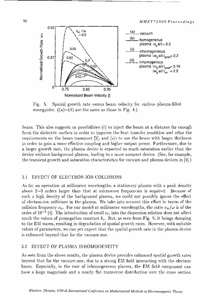
90 MMET*2000 Proceedings
0.02 0. ... (a)... vacuum
ts \0.0I (b) homogeneous
o \plasma o% a/c= 2.20.01 ..", inhomogeneous
0.01 j/ u0u0",., " plasma (% pa/Cpek 2.2
0 plasma (cP a/c)peak=. 3 18
z0 .0 (O~pa/C)av = 2.2
0 0.75 0.85 0.95
Normalized Beam Velocity a3
Fig. 5. Spatial growth rate versus beam velocity for various plasma-filledwaveguides. ((a)"-,(d) are the same as those in Fig. 4.)
beam. This also suggests us possibilities (i) to inject the beam at a distance far enoughfrom the dielectric surface in order to improve the heat transfer condition and relax therequirements on the beam transport [3], and (ii) to use the beam with larger thicknessin order to gain a more effective coupling and higher output power. Furthermore, due toa larger growth rate, the plasma device is expected to reach saturation earlier than thedevice without background plasma, leading to a more compact device. (See, for example,the transient growth and saturation characteristics for vacuum and plasma devices in [4].)
3.1 EFFECT OF ELECTRON-ION COLLISIONS
As for an operation at millimneter wavelengths, a stationary plasma with a peak densityabout 2-,,•3 orders larger than that at microwave frequencies is required. Because ofsuch a high density of the background plasma, we could not possibly ignore the effectof electron-ion collisions in the plasma. We take into account this effect in terms of thecollision frequency t-'i. For our model at millimeter wavelengths, the ratio VejiWc is of theorder of 10.2 [4]. The introduction of small Vei into the dispersion relation does not affectmuch the values of propagation constant k2. But, as seen from Fig. 5, it brings dampingto the EM waves, resulting in degradation of spatial growth rates. However, with suitablevalues of parameters, we can yet expect that the spatial growth rate in the plasma deviceis enhanced beyond that for the vacuum one.
3.2 EFFECT OF PLASMA INHOMOGENEITY
As seen from the above results, the plasma devicheprovides enhanced spatial growth ratesbeyond that for the vacuum one, due to a strong EM field interacting with the electronbeam. Especially, in the case of inhomogeneous plasma, the EM field component canhave a large magnitude and a nearly flat transverse distribution over the cross section
Kharkov, Ukraine, VIII-th International Conftrence on Mathematical Methods in Electromagnetic Theory

MMET*2000 Proceedings 91
0.01(cop a/c )peak= 2.2
SV ei (0 0 _= 0.0,.::,/:. " .. .. ', : "[.I," ........... ........... ,
0.0120.005 "
" .002,, parabolic profile '
E E0 -Plasma Profile
0 \0 '0.75 0.85 0.95 a (a+d) /2 d
Normalized Beam Velocity P
Fig. 6. Spatial growth rate versus normalized beam velocity ,3 for various plasmaprofiles. The parabolic profile is used in previous calculations (see Figs. 3-5).
of the beam. In this case, we can have a more enhanced growth rate and a more stableinteraction. From Fig. 5, in the case (c) where the inhomogeneous plasma has a peakvalue of plasma frequency equal to that for the homogeneous case (b), the spatial growthrate slightly deviates from that of (b). However, in the case (d) where the peak valueof plasma density is increased and the average value of plasma frequency equals thatfor the case (b), the spatial growth rate is greatly raised. Even in the absence of theelectron beam, the dispersion characteristics for the cases (b) and (c) are quite similar(see Fig. 4). We can therefore judge that the main parameter of the background plasmawhich affects the value of the spatial growth rate is not the average plasma density, but thepeak plasma density. This issue is confirmed by the investigation of growth characteristicsfor various plasma profiles with the same peak density. Results in Fig. 6 indicate thatdifferences in plasma profile do not affect much the growth characteristics of the plasma-filled CFEL, provided that the peak values of plasma density are the same. Consequently,for simplified analysis, we can properly treat the inhomogeneous background plasma asthe homogeneous one with a plasma density equal to the peak value.
4 CONCLUDING REMARKS
Growth characteristics of the 2-D Cherenkov free-electron laser (CFEL) filled with inho-mogeneous and collisional background plasma at millimeter wavelengths were investigatedwith the aid of the multilayer approximation method. The accuracy of the numerical re-sults was confirmed by comparison with the available analytical solution. We found thatthe CFEL with background plasma can provide a more effective beam-wave coupling andenhanced spatial growth rates, suggesting a possibility of a more compact device.
In this paper, we also discussed the effect of electron-ion collisions and plasma in-homogeneity in the background plasma. The presence of electron-ion collisions resultedin a significant decrease in the spatial growth rate for the coupled waves. However, by
Kharkov, Ukraine, VIII-th International Conference on Mathematical Methods in Electromagnetic Theory

92 MMET*2000 Proceedings
proper choices of the plasma and beam parameters, the value of the spatial growth ratewas found to remain well over that for the vacuum device. On the other hand, only alittle difference was found between the waveguides filled with homogeneous plasma andinhomogeneous one with the same peak plasma density as that of the former. From theseresults, we can conclude that the main parameter of the background plasma which affectsthe value of the spatial growth rate is the peak plasma density.
For simplicity, a sufficiently large static axial magnetic field was assumed to be appliedto our model to restrict the movement of the background plasma and the electron beamonly to the longitudinal direction. In fact, an important role of the background plasma inneutralizing the space-charge force in the electron beam can help relax the requirementson beam focusing and alignment. Therefore, the device can be down-sized by making useof smaller solenoids for generating a guiding magnetic field [3].
ACKNOWLEDGMENT
The authors would like to thank Prof. G. I. Zaginaylov, IKharkov State University,Ukraine, and Dr. A. Hirata, Osaka University, Japan, for their valuable comments onthis work.
REFERENCES
[1] A. V. Gaponov-Grekhov, and V. L. Granatstein, Eds., Applications of High-PowerMicrowave (Norwood, MA: Artech House, 1994).
[2] T. Ueda, and T. Shiozawa, Appl. Phys. Lett., vol. 67(26), p. 3838, 1995.
[3] G. S. Nusinovich, Y. Carmel, T. M. Antonsen, D. M. Goebel, and J. Santoru, IEEETrans. Plasma Sci., vol. 26(3), p. 628, 1998.
[4] T. Thumvongskul, A. Hirata, G. Zaginaylov and T. Shiozawa, J. Appl. Phys., vol.87(4), p. 1626, 2000.
[5] B. N. Brejzman, and D. D. Rutov, Nucl. Fusion, vol. 14, p. 879, 1974.
[6] S. Pasquiers, J. Appl. Phys., vol. 67(12), p. 7246, 1990.
[7] G. I. Zaginaylov, Tech. Phys., vol. 40(6), p. 542, 1995.
[8] T. Thumvongskul, and T. Shiozawa, Abstracts, P1.33, IEEE International VacuumElectronics Conference 2000.
[9] T. Shiozawa, and T. Nakashima, J. Appl. Phys, vol. 55, p. 637, 1984.
Kharkov, Ukraine, VIII-th International Conference on Mathematical Methods in Electromagnetic Theory

MMET*2000 Proceedings 93
MILLIMETER-WAVE RADAR FOR ENVIRONMENTAL STUDIES:IMAGE PROCESSING AND INTERPRETATION
D. M. VavrivInstitute of Radio Astronomy
4, Chervonopraporna St., 310002 Kharkov,Ukrainevavriv @rian.kharkov.ua
Importance of mm-wave radar as a highly efficient instrument for the environmental studies has
been generally recognised. Present-day requirements imposed on such instruments call for the
development of radar systems capable for long-term unattainable operation, which allows for
conducting real-time measurements of various atmospheric and earth surface characteristics.
In this presentation, a review is given two such devices recently developed at the Institute of
Radio Astronomy NASU that include a side-looking airborne radar remote sensing system and
cloud radar systems. These systems are designed to perform measurements at frequencies of 36
GHz and 95 GHz. The setup of these instruments, novel technical solutions, and signal processing
technique are discussed. Results obtained during measurement campaigns with such instruments
are summarized. The side-looking radar system is capable for investigation of the radar scattering
properties of various surfaces at millimeter wavelengths. At the first stage of exploitation, the
system was used for the study of millimeter-wave backscatter characteristics of water surfaces in
the presence of oil spills.
This study aims at development of efficient instruments and methods for oil-spill detection and
quantification. The developed 36 and 95 GHz cloud radar systems provide real-time
measurements of profiles of radar backscatter, Doppler spectrum and Doppler moments. Each
radar includes a reliable system of permanent calibration, with a possibility of remote control and
opportunity of a network access to the radar data. The calibration system introduced enables one
to perform a permanent accurate measurement of reflectivity in terms of dBZ through a
measurement of the transmitted power, and radar sensitivity including antenna gain.
The developed software package having client-server architecture supports both remote and local
control of radar operation, data acquisition and processing. The radar images can be viewed in a
local Ethernet in real time. The Internet access allows viewing the current images and previously
stored radar data. The cloud radar systems have demonstrated a high capability for the study of
structure and dynamics of various types of clouds, airflow, and precipitation. Results of these
measurements are also discussed in this presentation and compared to those obtained by other
instruments.
Kharkov, Ukraine, VIII-th International Conference on Aathematical Methods in Electromagnetic Theory

94 MMET*2000 Proceedings
ELECTROMAGNETIC SCATTERING BY COMPLEX-SHAPEOBJECTS PARTIALLY COATED WITH ABSORBING MATERIALS
Oleg I. Sukharevsky, Vitaliy A. Vasilets, Stanislav A. Gorelyshev, and Alexander Z.Sazonov*,
Kharkov Military University, Kharkov, UkraineE-mail: [email protected]
*Scientific and Research Institute of Radiotechnical Measurements, Kharkov, Ukraine
ABSTRACT
The calculation method is presented for scattering of plane electromagnetic wave by aperfectly conducting electrically large object wholly or partly covered with an absorbingcoating. The object admits surface breaks with toroidal absorbing coating. This method isbased on the calculation of contributions to scattering field by smooth surface parts (physicaloptics approximation) and local break scattering parts (proposed asymptotical method). TheRadar Cross Section (RCS) results are demonstrated for "Space Shuttle" and B-2 bomber.
INTRODUCTION
In a number of problem of applied electrodynamics and radar [1,2], it is necessary to get aprior information about scattering characteristics of complex shape objects wholly or partlycovered by radioabsorbing materials (RAM). Such problems, in particular, are to detectaircrafts made by "Stealth" technology.
1. SCATTERING BY SMOOTH OBJECTS WITH RADIOABSORBING COATING
We consider a plane monochromatic wave with polarization unit vector j30 and propagation
direction f)0E°(x)= y) exp (- jko (R°.o,)
W • {ý--o fi0Xi )exp (-jk,(o(•.) 1
'L0incident to a smooth electrically large object with surface S. Here 80,p 0 are dielectrical and
magnetic permeabilities of free space respectively, k. is a wave number for free space, x isvector to considered space point. Then, through Lorenz lemma [3], the object field scatteredin direction ý° is
Kharkov, Ukraine, VIII-th International Conference on Mathematical Methods in Electromagnetic Theor,

MMET*2000 Proceedings 95
P.k Rý k -ý - , (2)60 47c R
(7°)= - k 1• (!xFo)]exp(- jko(70 (.))ds (3)
where E I =iixE , /-L =iixH, (t ,/-) is a full field, h is a external normal unit vector tosurface S.Let perfectly conducting scattering object (or its part) be coated by a thin RAM layer with aconstant depth.
Taking into account the electrically large sizes of object, the values H.(x), & (x) in (3) canA A
be replaced approximatively by values ± (x),/4 E(x) on the surface of plane equidistant layer(from absorber material) on metal backing substituted in point x e S and tangent to S.Thus it is necessary to solve the model problem of (1) plane wave scattering from a planeequidistant absorber layer on a metal backing.The solution of the problem for arbitrary polarization of an incident wave and arbitraryincident angle (in particular, near normal incidence) has been obtained in this paper. We writethe expression for scattering field outside the layer
nIx) (P° x/x)p (-ik°,(R°x) (0 +' I ° exp (-ik° (Rk -))' (4)
w here R' k =F 2° - 2 / '(/ ° cn),
(osO'x) I X'= 0,P I - _i (f ./0
Coscs__ccosO+lo 0j fio(o-°)/oc~l /°•) ]
Pr ccos--- -I PT jccosO-1 T Jc-cosO 1P jcC Cos 2 01
Cos 0
A A
If we substitute the found expressions for E, H to (2) and replace the surface S by its
illuminated part S we obtain an approximate expression for scattering field:f.EP(R F° ),-jko exp(jkfR) Jf( )exp(jkoQ(?))dS, (5)
4; R so
where f(?)=h(7).•+Y(7).(WbxT°),Q(?)=-(F°+!°)., (i)=fix(fO°+f),
h(r)= iiX [(°/o < ýO)+ (fi x R )], " is vector of integration point.
Integral in (5) requires using a special cubature formulae, because its integrand function isquick-oscillating. The cubature formulae have been obtained for similar integrals in [4]. Theseformulae are based on linear approximations of functions f(T) and Q(F).
Kharkov, Ukraine, VIII-th International Conference on Mathematical Methods in Electromagnetic Theory

96 MMET*2000 Proceedings
The concept of formula [4] structure is following. Let the set of points M,(i =1,2,-,n) be given
on surface S. Points are located on S densely and unregularly. The values of f(G) and
2(-) are known in these points. S is covered by triangular system with vertices in points Mi
and integral (2) is a sum of integrals for each triangle. Inside each triangle functions f(.ý) and
Q(.ý) are interpolated by linear functions (through values in three vertices). After
transformation to baricentric system of coordinates, obtained integrals are calculatedanalytically.
Note that the object RCS is quick-oscillating function of frequency in considered high-frequency band. The RCS average has to be carried in some frequency band for obtainingstable values. In addition, in spite of certain advantages of cubature formula, if illuminationwave length is reduced, then necessary quantity of integration surface separations isincreased. For electrically large objects (for example, aircraft) it is difficult to realize thesufficiently dense separation of surface. In this case it is necessary to use RCS averaged incertain frequency band. Calculations for simple objects (sphere, ellipsoid) show, that, bydetermining the quantity of surface separation, it is possible to choose the frequency bandwidth (with prescribed mean value) such that RCS obtained by average in this band is close tothe corresponding averaged value for real surface.
2. SCATTERING BY OBJECTS WITH THE COATED SURFACE BREAKS
If breaks of object with perfectly conducting piecewise smooth S surface are coveredby toroidal absorbing coating, then the integration surface in (3) formula is
S=SI+So, (6)
where S. is surface, cross-section of which by H- plane is a part of circle with the P
center and po0 p radius. Here p is radius of circle in the section of coating by FI
plane, which is orthogonal to the rib in each of its P points, p,p 0 ((2 ; 2 is probing
signal wave length. Surface ScS , and all points of this surface in 1-H plane cross-
section are spaced from M point by a distance, that is more than p0 . Thus in (3) 7(70)
is a sum of integrals by S1, So
I (To)=is (T0)+jS ýO)- (7)
is( (F0) integral assumes the representationI'SO (ro)=H exp [J. k(V<-1-° )-7ý(1)] fi O,r° )dl, (8)
L
where Ki (l,70)exp[ - jk0 (?0e)] a(j() dq,S'
RO is an illumination unit vector, ý(I) is a radius-vector of P point with Icoordinate on L break line, So is a curve (circle part) on So surface placed in H-
Kharkov, Ukraine, VIII-th International Conference on Mathematical Methods in Electromagnetic Theory

MMET*2000 Proceedings 97
plane, which is orthogonal to L, G(i) is e vector-function containing the tangential
components of (E,/t) field at absorbing torus surface in indicated cross-section,dq=podq is S' element.
Estimating (8) integral by stationary phase method, we can obtain, that for the breakline as convex smooth curve, at least, two stationary phase points must be existed(with the exception of some special case; e.g. for body of revolution with breaks- itis a case of axial probing and monostatic receiving). In this "special" case we cancalculate fs0 (F°) by numerical integration. This is a simple task, if po/! << 1. In other
cases the stationary phase method for (8)yields
So(F°)zoexp jko(° 0 -7 0 ) -(lo)+gl-• .M Toro 2I, (9)
(1(J) L 4J VkX(10 )1(ojO T)ý;(ij )i
where z(1o), i(io) are a curvature and a main normal unit vector of L line in Po point
with 10 arc coordinate, 8 = sgn [(Ro070)i(0 )], and (1o ) symbol, under the sum shows thatsummation must be carried out by all "visible" stationary phase points (from illuminationand reception directions) [5].Taking into consideration the electrically large sizes of scatterer and small curvatures of its
surface smooth parts, -(E,H) field tangential components on S0 line approximated bycorresponding values on surface of absorbing circle cylinder covered the rib of tangentperfectly conducting wedge (p=p0 ) in P0 point. Consequently, the main problem of (9)formula is the problem of oblique plane electromagnetic wave incident on ideal conductingwedge with radioabsorbing cylinder on rib.The main difficulty of the problem is associated with the three-dimension character of itssolution. The solution cannot be represented as a union of two independent two-dimensionalproblems, so in the problem of oblique plane wave incident on ideally conducting wedge andin the problem about normal (to rib) incidence of plane wave on the considered structure.Nevertheless, we have shown, that the problem can be reduced to a system of two two-dimensional problems, solutions of which are associated with the boundary conditions (bymeans of same matrix-differential operator).
If E 3 =U(X ,X2 ) exp (ko 3 R3) H 3 = v (x1 ,x 2 )exp (jko x 3 3) 'V- , then 0 vector
is represented by Fourier-Bessel series with (262 ) matrix coefficients. For example, outsideabsorbing cylinder
ý=F . [BmJv,,, (Xor)-+C H( (Zor)]JIJ(p,), (10)
IVn=Out =0
where J,, (z) is the Bessel function, H(')(z) is the Hunkel function,
K-ak Ukan , Vh sin(vt i Cfnoa tlMo ds in/ Elcroae
Kharkov, Ukraine, VIII-th International Conference on Mathematical Methods in Electromagnetic Theory

98 MMET*2000 Proceedings
7r-(1) is the wedge opening (O • q. _ vrr(/ )) BC are matrix coefficients determined from
conjunction conditions for u,v functions and their derivatives on absorbing cylinder
boundary.
Series of (10) type converge well for r small values ( r < po ) [6].
The integral is, (TO) is estimated by the method, which is described above for smooth parts of
surface.
Using the results for monochromatic object illumination, the scattered field calculationmethods can be developed for pulse (transient) illumination.
In particular, the main term of transient asymptotics for edge contribution of scatteringfield has been obtained in bistatic case by replacing of the real surface by wedge surface nearthe break line. For example, if probing pulse signal is Q(t) (Q (t) 0at tc (0,,0 ),,50 <<1),
and its spectrum is centered near k = ko, then the response of scattering edge local parts ism in• ,-,') Q (S) d ,( 1
(10) 0 t- (0 - s
where t(lo)=(kO-Fo°)>(1o)+C, C is constant, depending from configuration of
transmitter, receiver and object. A(10 ) is vector coefficient corresponding to scattering edge
local center with 10 arc coordinate. This coordinate depends on material and parameters
coating, directions and polarizations of illumination and reception fields.
3. RCS CALCULATION RESULTS FOR COMPLEX OBJECTS ("SPACESHUTTLE" AND B-2 BOMBER)
We use the described method to calculate the averaged scattering characteristics (RCS) for"Space Shuttle" (Fig.1) and B-2 bomber (Fig.3). "Space Shuttle" (Fig.1) is covered byisolating materials for prevention of its combustion when entering the air. The mostvulnerable parts (for example, bow and leading edges of fin and wings) are covered with acarbon-carbonic composite material (CCM) (relative permeabilities are approximately
'= 4+3,5.10 li, p'= 1 ). The bottom surface of Shuttle is covered with black plates from high-
temperature isolation (HTI) made from quartz fibre (parameters are approximatelye'k= 4,5 + 3,5i, efc=1 ).
Kharkov, Ukraine, Vlll-th International Conference on Mathematical Methods in Electromagnetic Theory

MMET*2000 Proceedings 99
ON HT I
U CCM
Fig. 1. Approximated surface of "Space Shuttle".
Fig.2 illustrates the dependences of "Space Shuttle" RCS averaged in the band from 2.25 to3.75 GHz for different illumination and reception angles. The solid line corresponds to theperfectly conducting model. The dash line corresponds to the model with the coatingdescribed above.
100000- - -
10000
20
E1000. E120 20 A A
100___ _ _ 80
10 40_ ___ W1__
1 0 - - - - - -
40 60 80 100 120 140 160 0 15 30 45 60 75 90Elevation angle Bistatic angle
A) b)Fig.2. Dependences of "Space Shuttle" averaged RCS on elevation and bistatic angles for perfectly
conducting model (solid line) and model with isolating materials.
Dependence of RSC on elevation angle is illustrated in Fig.2.a. Elevation angle 900corresponds to the frontal sounding, angles less than 900 correspond to sounding from lowerhalf-sphere and angles more then 900 are from upper half-sphere. At elevation angles 45°-60'the RCS of the covered object is reduced in 4.. .5 times as the main contribution to RCS inthese angles is made by the object bottom surface covered by HTI. At elevation angles 65'-1100 the main contribution to RCS is carried in bow and leading edges of wings covered byCCM with large conductivity. So at these angles the RCS reducing by coating is small. At the
Kharkov, Ukraine, VIII-th International Conference on Mathematical Methods in Electromagnetic Theory

100 MMET*2000 Proceedings
sounding from upper half-sphere (elevation angles are 120'-145°), RCS is reduced in 1.5...2times by the coating. To the end, at the sounding angles 145°-160' the RCS is reduced in 3...4times because the main contribution to RCS is made by a bow covered by HTI. At the sameelevation angles, the RCS absolute values are more increased (values by order 105 i2).
RCS dependences of bistatic angle are presented in Fig.2.b. Analyzing Fig.2, one can madethe following conclusions:
1. Heat-insulating coatings of "Space Shuttle" can significantly reduce RCS (in 3...4 times) atcertain sounding angles in SHF band.
2. If object surface parts with IHT dominate over the RCS, then influence of heat-insulatingcoating on the RCS is most considerable.
The research of B-2 model averaged RCS (Fig.3) is partly theoretical because we do not knowthe real parameters of radioabsorbing coating. We use 5 cm material layer with constantpermeabilities -'=,u'=l+l0i as a coating. These parameters correspond to some types of real
ferromagnetic coating [3]. Some typical results have been shown in Fig.4. The middle linesin Fig.4.a,b correspond to partial covering of bomber surface (dark color in Fig.3). There areRCS values averaged in band 2.25...3.75 GHz in Fig.4.a,b. The analysis of Fig.4 allows us tomake the following conclusions:
1.The partial covering of B-2 model reduce the aircraft RCS by the same value as for whollycovered model for the certain sounding angles (in particular, for frontal sounding).
2.The RCS dependencies on bistatic angle in Fig.4.b show that if the bistatic angle is700...800 the RCS is more increased for all three models. It is a basic conception used in"Stealth" technology: the object surface geometry provides the electromagnetic scattering inside direction irrespective of coating type.
Fig.3. Approximated surface of B-2 bomber.
Kharkov, Ukraine, VIII-th International Conference on Mathematical Methods in Electromagnetic TheorY

MMET*2000 Proceedings 101
1000-- 1000 _
_8 0 2 4100,
10 -Ci \.-10 j' 0 _
1 -- - 15 30 45 0 7
40 60 80 l00 120 140 0,1. - -
Elevation angle Bistatic angle
b)
Fig.4. Dependences of B-2 averaged RCS on elevation and bistatic angles for perfectlyconducting model (solid line), model partly coated by RAM and model wholly coated by
RAM.
REFERENCES[1] Sukharevsky 0.1., Vasilets V.A., Sazonov A.Z., Tkachuk K.I. H Radiophysics andradioastronomy, 2000, v.5, 11, pp. 47-54 (in Russian).
[2] Masalov S.A., Ryzhak A.V., Sukharevsky 0.1., Shkil V.M. Physical foundations ofStealth band technologies. - S.Peterburg. Mozhaiskiy VIKU, 1999, 163p. (in Russian).[3] Vainshtein. L.A. Electromagnetic waves. - Moscow, Radio i svyaz, 1988 , 440p. (inRussian).[4] Zamyatin V.I., Bahvalov B.N., Sukharevskiy 0.1. // Radiotechnics and electronics,1978, v.23, 16, pp. 1289-1293 (in Russian).
[5] Sukharevsky 0.1., Dobrodnyak A.F.// Izvestiya vuzov USSR. Radiophysics, 1989,v.32., 1 12, pp. 15 18 -15 2 4 (in Russian).
[6] Sukharevsky 1.I., Dobrodnyak A.F.// Izvestiya vuzov USSR. Radiophysics, 1988,v.31, 1 9, pp. 1074-1081 (in Russian).
Kharkov, Ukraine, VIII-th International Conference on Mathematical Methods in Electromagnetic Theory

102 MMET*2000 Proceedings
PHOTONIC CRYSTAL THEORY, MODELLING AND TECHNOLOGY
Marian Marciniak
National Institute of TelecommunicationsDepartment of Transmission and Fibre Technology
Szachowa 1, 04-894 Warsaw, Poland
E-mail: [email protected]
ABSTRACT
The all-optical network should take the advantage of photonic devices of various kind thatabove all should provide the means for all-optical signal processing. Photonic band-gapstructures (PBG, photonic crystals) are expected to be very helpful for achievement of severalfunctions that an all-optical network asks for. In the paper the state-of-art and potential futureapplications of PBG structures in optical telecommunication systems are reviewed. Inwavelength-division-multiplexed systems the wavelength sensitivity of PBGs and theirfiltering properties resulting from it are of particular interest. Possible locations of PBG-baseddevices within the advanced all-optical network architecture are indicated and their functionalparameters are discussed.
INTRODUCTION
Photonic band-gap (PBG) structures, also known as photonic crystals, are one of the crucialtechnology factors leading to the achievement of several functions that an all-optical networkasks for. PBG-based devices have numerous potential functional locations within theadvanced all-optical network architecture. In the paper the state-of-art and also the possibilityof potential future applications of PBG structures in optical telecommunication systems arereviewed, and their impact on the development of all-optical transport networks is discussed.Although it is commonly accepted that optical fiber-based telecommunication systems areactually in an advanced and mature stage, qualitatively new concepts are still developed inlaboratories and commercially applied as well. One should mention wavelength-division-multiplexed (WDM) systems, and a concept of so-called "opticalization" of the network, anotion that stands for an observed actually trend to eliminate electronic components fromoptical transmission links and evolution towards transparent optical networks.
Transparent optical networksThe optically transparent terabit network is an ultimate goal that should lead to a much moreefficient exploitation of enormous transmission bandwidth that is offered by the fiber and thelight -itself [1]. This way the future information society needs for reliable means oftransmission and the foreseen necessity of general and easy access to multimedia andhypermedia services should be satisfied. Actually the process of migration of today's fiber-based transmission networks to future all-optical transport networks (OTN) is in an advancedstage [2].The optical transparency of the network offers various economic advantages in both cases ofbackbone and access networks. Cost-effective wavelength cross-connects and add/dropmultiplexers and high-capacity, ultra-long-reach, all-optical transmission over conventionalfibers are shown to make the economics of transparent optical networking quite compelling
Kharkov, Ukraine, VIII-th International Conference on Mathematical Methods in Electromagnetic Theory

MMET*2000 Proceedings 103
[3]. Nevertheless, the idea of transparent networks is the subject of a variety of constraintsarising from physical effects as well as operations and business issues [4]. At the present stageof the transparent network evolution it is essential to elucidate the direction networks arelikely to take.The introduction of Erbium-Doped Fibre Amplifiers (EDFA) which have replaced electronicregenerators in fibre based transmission links in early 90s resulted in optical transparency ofthe links. This was in contrary with electronic regenerator based links. In those a combinationof electronic logic circuit along with electro-optical and opto-electrical conversions of thedigital signal transmitted has been used in order to cope with signal distortion. In optical linksthe distortion results from physical limitations of the transmission of light signals throughfibres, namely from fibre attenuation, dispersion, and nonlinear distortion.Optical transparent transmission offers almost infinite optical bandwidth. This is especiallyattractive in view of future information society needs for exchange of enormous informationstreams, resulting from a general use of multimedia and hypermedia services.Transparency is very attractive also from user point of view: he/she sends his/her own datastreams and the transparent network transmits them regardless of their format, bitrate etc. Afunctional model of a transparent passive network consists of an optical telecommunicationcloud through which clients send and receive their messages of various kinds.Recent years have shown a rapid growth of demand for capacity of telecommunicationnetworks. It has inspired many laboratories to explore new techniques of more efficientutilisation of the huge bandwidth offered by optical fibre links. WDM technology is one ofthe most promising and cost effective ways to increase optical link total throughput.In a WDM system many information channels are transmitted through one fibre usingdifferent optical wavelengths modulated by independent data streams. This method isanalogous to Frequency Division Multiplexing (FDM) which is widely exploited in othercommunication systems, especially in radio broadcasting. Using WDM we can easily increasethe capacity of already existing fibre links that is particularly significant in the areas whereplacing new cables is impossible or too expensive. WDM is a technique compatible with theidea of all-optical networks, where one can create transparent optical paths connectingsuccessive network nodes by switching optical channels organised at the different lightwavelengths. One can also envision the application of WDM in broadcast networks and/or insubscriber loop [5].These and other advantages ofWDM have prompted the beginning of standardisation work[6]. Nevertheless the task is not yet completed and further research and estimations arerequired [7].
Non-Linear LimitationsIn spite of its merits the WDM technique is not free from limitations. The most characteristicand essential problem for multichannel optical systems, beside attenuation and dispersion, isinterchannel crosstalk [8]. In WDM systems the interchannel crosstalk is caused by non-linearinterplay between many different spectral components of the aggregate optical signal. Thenon-linear optical phenomena involved are self-phase modulation (SPM), cross-phasemodulation (XPM), four-wave mixing (FWM), stimulated Raman scattering (SRS), andstimulated Brillouin scattering (SBS). One can distinguish crosstalk caused by non-linearinteractions between the light in different channels or between the light and the fibre material.In spite of the intrinsically small values of the nonlinearity coefficients in fused silica, thenonlinear effects in silica glass fibres can be observed even at low power levels because of
Kharkov, Ukraine, VIII-th International Conference on Mathematical Methods in Electromagnetic Theory

104 MMET*2000 Proceedings
very large interaction distances. This is possible because of important characteristics ofsingle-mode fibres, a very small optical beam spot size, and extremely low attenuation [9].
EMERGING TECHNOLOGIES
The transparent photonic transport network insures the scalability, i.e. possibility of futureupgrades. Emerging technologies as distributed Raman amplification technique enables toconstruct large-scale transport networks. As an example, recent experiments with 10 Gbit/s x16-channel recirculating loop demonstrated that the network scale can be expanded over 2times [10]. In the commercial systems scale the European all optical transparent networkbased on the 16x 2.5 Gbit/s WDM transmission with the use of fiber gratings and dispersionmanagement technique is actually investigated [ 11].A commercial deployment of broadband D-WDM systems with hundreds of transmissionchannels is foreseen in the near future. Also systems with channel number approaching orsurpassing thousand of very closely spaced (50 GHz, 25 GHz or even less) channels areinvestigated in mature laboratory experiments. They require sophisticated narrow-band lightsources with extreme wavelength stability, as well as a variety of photonic devices for all-optical signal processing. Therefore research challenges for system components based on newconcepts arise. In that research, (quasi) periodic photonic structures in one-, two- and three-dimensions, along with nonlinear optics applications are among the most promisingtechnologies.Optically transparent technology is actually advancing very fast. Almost unlimited capacity isavailable, however, the future technology has to meet new demands especially in the field ofoptical signal digital processing, including full 3R regeneration. Moreover, a concept of the4R regeneration where the fourth "R" means the regeneration of the optical signal spectrumhas been introduced recently [12].Reduced cost of bandwidth enabled by the optical amplifier and wavelength-division-multiplexing (WDM) technologies have resulted in a dramatic reduction of cost oftransmission bandwidth. Moreover, WDM offers the orthogonality between wavelength andtime, so they can be processed independently and simultaneously [13]. However, significantresearch challenges still remain to realise the huge potential offered by optical networking.
Attractiveness of photonic crystals in all-optical networksPhotonics is a key enabling technology in telecommunications. In the last decade, thetechnology to fabricate structures on an optical to sub-optical wavelength scale has matured,and opened for a new generation of photonic devices, which once inserted in the telecomfabric is expected to increase systems performance significantly. An international co-operation in the field of wavelength-scale photonics for telecommunications is undergoingand there are several international projects exploiting advanced photonics intelecommunication applications [14].Photonic crystals are periodic structures that influence the behavior of photons in similar wayas atomic lattice of natural solid state crystals influences the behavior of electrons. Inparticular, photonic crystals forbid the propagation of photons within a certain range ofenergies, which is called photonic bandgap [15]. Those unique optical properties of photoniccrystals have great potential to stimulate development of truly-VLSI-type photonic circuits[16]. PBGs are directly scalable in frequency by a scaling of the periodicity, making the PBGconcept generic.
Kharkov, Ukraine, VIII-th International Conference on Mathematical Methods in Electromagnetic Theory

MMET*2000 Proceedings 105
Photonic crystals have a unique possibility of inhibiting spontaneous emission in activeelectno-optic devices. If the propagation is inhibited in any direction, then a complete andabsolute photonic band-gap occurs. For some applications like vertical cavity surface emittingsemiconductor lasers (VCSEL) complete and absolute band-gap is necessary. This can beachieved in photonic crystals with higher-order of symmetry [17].
1-D PBGsThe most common realization of one-dimensional photonic crystal is the optical waveguideBragg-grating. It appears in two variants: planar waveguide Bragg grating, and Fiber Bragg-Grating.Planar waveguide Bragg gratings are increasingly used in manufacturing of efficient narrow-band laser sources for telecommunications. Semiconductor waveguide lasers in DBR(Distributed Bragg-Reflector) and DFB (Distributed Feed-Back) technologies are increasinglyexploited in commercial systems and field trials. In those cases wavelength-selective Braggreflection helps to obtain single-longitudinal mode light sources that are mostly suitable forhigh-speed data modulation.A special case of 1-D grating is circular Bragg grating. In that case the refractive indexchanges in radial co-ordinate direction. The technology is used for VCSEL fabrication takingadvantage of the possibility to suppress lateral spontaneous emission.An addition to that also quasi-periodic or self-similar 1-D dielectric structures are exploitedwidely for the purpose of assuring the quasi-phase matching condition in experimentsinvolving interaction of optical beams that differ in the wavelength. The triadic Cantor and theFibonacci sequence are typical examples. The structures are obtained by alternating twodielectric layers of different refractive indices such that the highest refractive index layersbelong to some fractal set. This way an efficient second-harmonic generation is possible [18].
Fiber GratingsThe Fiber Bragg-Grating (FBG) is a short piece of fiber in which permanent refractive-indexchanges in the core are "written" by exposing to a diffraction pattern of an ultraviolet lightbeam. Fiber gratings are an emerging broad class of structures that will enhance theperformance of future generations of communication systems [ 19]. Specially designed chirpedMoir6 gratings can be used for either transmission as passband filters for WDM eitherreflection to decompose short broadband pulses for encoding/decoding operations [20]. Also,electro-optically tunable fiber Bragg gratings have been demonstrated recently [21]. TunableFBGs have strong potential applications in all-fiber amplitude modulators and high-speedtunable filters.
2-D PBGsTwo-dimensional photonic crystals exhibit periodicity of electromagnetic properties (e.g. ofthe index of refraction) in two perpendicular directions. One way to achieve this is byassembling dielectric fibers. The technology exploiting that phenomenon is known asphotonic crystal fibers.
Photonic Crystal FibersBy a proper introduction of defects into the photonic crystal fiber structure a single-modeguiding of light in a photonic crystal fiber can be obtained regardless of the opticalwavelength [22]. In addition, the dispersion curve of such fiber is very flat, and can be veryaccurately determined with the use of analytic and numerical modeling techniques as thefinite element method. E.g. the unimodal broad band behavior of photonic crystal fibers was
Kharkov, Ukraine, VIII-th International Conference oji Mathematical Methods. in Electromagnetic Theory

106 MMET*2000 Proceedings
analyzed, and the chromatic dispersion was reliably predicted at any wavelength versus thegeometric parameters [23].
3-D PBGs
The fabrication of three-dimensional photonic crystals for infrared wavelengths that are usedin optical telecommunications is at the beginning stage and serious technological difficultyresults from the fact that lattice constants of the order of micrometer are involved. Recently acomplete photonic band gap centered at 1.55p.m has been obtained with macroporous silicon[24]. Also scheme of automatic fabricating 2-D and 3-D photonic crystals with an autocloningmethod has been proposed recently [25].
Modelling of PBG structures
For photonic-crystal based optical waveguide structures standard numerical techniques asfinite-difference and finite-element methods are usually applied for investigating the modaland dispersion characteristics of the waveguide. An overview of different theoretical modelsfor analysis of photonic crystal fibers can be found in [26].
An efficient method of modeling the evolution of spatial beams and wide-band temporalpulses in 2-D photonic crystals has been reported recently [27]. In that work a time-domainbeam propagation method (BPM) based on the finite-element scheme is applied for theanalysis of reflections of both TE and TM polarized pulses in waveguiding structurescontaining arbitrarily shaped discontinuities. Perfectly matched layer boundary conditionswere introduced in that analysis in order to avoid non-physical reflections from thecomputational window edges. The method was proved to be applicable to various photoniccrystal circuit components.
Actual and prospective PBG applications in optical telecommunications
The all-optical network should take an advantage of photonic devices of various kind that alsoshould provide the means for all-optical signal processing. Photonic band-gap structures areexpected to be a crucial technology factor leading to an achievement of several functions thatan all-optical network asks for. To this purpose many proposals have been elaborated and anintense research is currently underway.
Dispersion Compensation
Chromatic dispersion is an inherent feature of an optical link that severely limits thetransmission distance of high bit-rate data streams. Although dispersion-compensating fibers(DCF) are commonly used in order to cope with dispersion, they have a substantial drawbackas they introduce additional power losses. Another way to combat dispersion effects is to usechirped fiber Bragg gratings as dispersion compensators. The transmission performance of asystem with chirped Bragg gratings has been shown to be significantly superior to that of anequivalent DCF module [28].
As a recent example, dispersion equalizers for the arbitrary dispersion characteristics ofoptical fiber links in the form of cascading chirped fiber Bragg gratings and optical circulatorswere proposed [29]. Also it has been shown that the dispersion slope can be efficientlycontrolled to match that of current transmission fibers by chirping the sampling function of asampled fiber grating [30]. Dispersion compensating gratings of 3-nm bandwidth and 700ps/nm total dispersion were fabricated [31]. A broadband dispersion-compensating gratingmodule can be efficiently used for compensation of both dispersion and dispersion slope inhigh bit-rate WDM transmission systems [32].
Kharkov, Ukraine, VIII-th International Conference on Mathematical Methods in Electromagnetic Theory

MMET*2000 Proceedings 107
Also technology possibility to manufacture tunable fiber Bragg gratings enables dynamic postdispersion compensation instead of classical fixed post compensation. That issue has beenapplied successfully in a multi-span 40 Gbit/s NRZ transmission system [33].
All-Optical SwitchingAll-optical switching is a key factor for the realization of future photonic transport network. Itcan be achieved by exploiting optical nonlinearities in the free-space, an optical waveguide orphotonic crystal structure. Recently a first observation of an all-optical switching operationbased on the bistable characteristic of a GaInAsP nonlinear directional coupler loaded withBragg reflector at telecommunication wavelength 1.55 pm has been reported [34]. Alsononlinear pulse switching using long-period fiber gratings has been demonstrated veryrecently [35].
CONCLUSIONS
Photonic crystals have fascinating properties that actually are far from being well understood.They have a potential to revolutionise fiber telecommunications and optical signal processingin new millennium in a similar way as semiconductor technology has changed electronicsover last half-century. The future transparent all-optical network, all-optical signal processing,optoelectronics, and optical computing are the domains to be mostly influenced.
ACKNOWLEDGMENT
The author expresses his thanks to Dr. Irena Yu. Vorgul and Prof. Alexander G. Nerukh fromKharkov, Ukraine, as well as to Prof. Igor S. Nefedov, Dr. Elena Romanova and Mrs. EllaBecker from Saratov, Russia, for their valuable co-operation and fruitful discussions.
REFERENCES
1 Marciniak, M., "Transparency of optical networks: How to manage it? ", I" International Conference onTransparent Optical Networks ICTON'99, Kielce, Poland, June 9-11, 1999.
2 ITU Recommendation G.709 "Network node interface for the Optical Transport Network (OTN)", planned forFebruary 2001. 1,
3 Saleh, A., "Economic advantages of optical transparencyiin backbone and access networks", ECOC'99.
4 Tkach, R.W., "How transparent should an optical network be?" ECOC'99.
5 Namihira Y., Electron. Lett. 30, 262-264 (1994).
6 Agrawal, G.P., Nonlinear fiber optics, Academic Press, San Diego, 1997.7 Marcuse, D., Chraplyvy, A.R., and Tkach, R.W., IEEE J. Lightwave Technology 12, 885-890 (1994).
8 Sabella, R., and Lugli, P., High Speed Optical Communications, Kluwer Academic Publishers,Dordrecht/Boston/London, 1999, pp. 239-245.
9 Kowalewski, M., Marciniak, M., and Sedlin, A., "Nonlinear interactions in wavelength-multiplexed opticalfibre telecommunication systems", Journal of Optics A: Pure and Applied Optics (2000).
10 Watanabe, T., et al., "Scale expansion of transparent photonic transport network based on distributed Ramanamplification", ECOC'99.
11 Joindot, M., et al, "Study of an European all optical transport transparent network", ECOC'99.
12 Thyl6n, L., "Some aspects of photonics and electronics in communications and interconnects", ]stInternational Conference on Transparent Optical Networks ICTON'99, Kielce, Poland, June 9-11, 1999.
13 Alferness, R. C., "Research challenges in optical networking", ECOC'98, 20-24 September 1998, Madrid,Spain.
Kharkov, Ukraine, VIII-th International Conference on Mathematical Methods in Electromagnetic Theory

108 MMET*2000 Proceedings
14 COST Action 268 "Wavelength scale photonic components for telecommunications", Memorandum ofUnderstanding, 1998.
15 Joannopoulos, J. D., Meade, R. D., and Winn, J. N., "Photonic Crystals", Princeton University Press,Princeton USA, 1995.
16 Krauss, T.F., and De La Rue, R. M., "The potential of photonic microstructures in optoelectronics",ECOC'97.
17 Zoorob, M.E., et al., "Complete photonic bandgaps in twelve-fold symmetric photonic quasicrystals',ECOC'99.
18 Sibilia, C., and Bertolotti, M., "Nonlinear optical propagation in periodical and quasiperiodical layeredstructures", Proceedings of the 2"d International Conference on Transparent Optical Networks ICTON 2000,Gdansk, Poland, June 9-11, 2000.
19 Strasser, T. A., "Fibre gratings in novel device structures", ECOC'99.
20 Chen, L. R., and Smith, P. W. E., "Specially designed chirped Moir6 gratings for optical communications",ECOC'99.
21 Srinivasan, B., and Jain, R.K., "First demonstration of thermally-poled electro-optically tuneable fibre Bragggratings", ECOC'99.
22 Monro, T. M., Broderick, N. G., and Richardson, D. J., "Exploring the optical properties of holey fibres",International Summer School of Quantum Electronics, 29th Course on "Nanoscale Linear and Non-LinearOptics", Erice-Sicily, Italy, 2-14 July, 2000
23 Br6chet, F., et al., "Accurate computation of the chromatic dispersion in unimodal photonic crystal fibres",ECOC'99.
24 Rowson, S., Chelnokov, A, and Lourtioz, J.M., "Macroporous silicon : photonic crystal substrates at 1.55pm", ECOC'99.
25 Kawashima, T., Sato, T., Miura, K., Ohtera, Y., Ishino, N., and Kawakami, S., "Autocloning Technology:Fabrication Method for Photonic Crystals based on Sputtering Process", International Summer School ofQuantum Electronics, 29th Course on "Nanoscale Linear and Non-Linear Optics", Erice-Sicily, Italy, 2-14July, 2000.
26 Bjarklev, A., Broeng, J., and Barkou, S.E., "Modelling of photonic crystal fibres", ECOC'99.
27 Koshiba, M., Tsuji, Y., and Hikari, M., IEEE J. of Lightwave Technology 18, 102-109 (2000).
28 Rourke, H., Pugh, B., Kanellopoulos, S., Baker, V., Napier, B., Greene, P., Goodchild, D., Fells, J., Epworth,and Collar, R., A., "Fabrication and system performance of dispersion compensating gratings", ECOC'99.
29 Komukai, T., Inui, T., and Nakazawa, M., IEEE J. Quantum Electronics 36, 409417 (2000).
30 Loh, W. H., et al., "Dispersion slope compensator based on an interleaved chirped sampled fibre Bragggrating", ECOC'99.
31 Fujii, K., Terao, Y., Kotani, K., Nishiki, A., Ozeki, Y., Nomoto, T., Rastokin, V., Tan, R., Kung, P.,Beaulieu, C., and Lefebvre, P., "Broadband chirped fibre Bragg grating for dispersion compensator",ECOC'99.
32 Gnauck, A.H., Wiesenfeld, J.M., Garrett, L.D., Eiselt, M., Forghieri, F., Arcangeli, L., Agogliati, B.,Gusmeroli, V., and Scarano, D., "16 x 20 Gbit/s - 400 km WDM transmission over NZDSF using a slope-compensating fibre-grating module", ECOC'99.
33 Nielsen, T.N., et al, Fibre Bragg grating tuneable dispersion compensator for dynamic post dispersionoptimisation at 40 Gbit/s, ECOC'99.
34 Nakatsuhara, K., et al., "All-optical switching in a nonlinear directional coupler loaded with Bragg reflector",ECOC'99.
35 Perlin, V. E., and Winful, H. G., IEEE J. Lightwave Technology 18, 329-333 (2000).
Kharkov, Ukraine, VIII-th International Conference on Mathematical Methods in Electromagnetic Theory

MMET*2000 Proceedings 109
TIME DOMAIN
METHODS
Kharkov, Ukraine, VIII-th International Conference on Mathematical Methods in Electromagnetic Theory

110 MMET*2000 Proceedings
Kharkov, Ukraine, VIII-th International Conference on Mathematical Methods in Electromagnetic Theory

MMET*2000 Proceedings 111
TRANSIENTS OF AN AXIAL SYMMETRIC ELECTROMAGNETIC
SOURCE IN A FLAT WAVEGUIDE WITH A TIME VARYING
PLASMA
N. Sakhnenko, A. Nerukh, and F. Fedotov
Kharkov Technical University of Radioelectronics, 14 Lenin Ave., Kharkov, 61166, UkraineE-mail: [email protected]
ABSTRACTA flat waveguide filled by a homogeneous cold time-varying plasma is considered. A problemof an excitation and propagation of an axial symmetric electromagnetic waves in such awaveguide is solved. To obtain a solution, the resolvent operator in a polar coordinate systemis constructed that allows to write an exact and explicit expression for the electromagneticfield.
INTRODUCTIONWhen a plasma time changing begins at zero moment then an electromagnetic field in awaveguide is described by the equation according to [1]
E(t, F)=E(t,F)- -- fdt'Jidx'dy'f dz'(t - t', F - F') (V, (t')E(t, F)) (1)C0 Wa 0
where F =-(x, y, z), 40 is the initial field, f is the transformed field, G is a tensor Green'sI tifunction, =1 (co dt'(t- t') -(c- 1)) is a medium operator written down for the case of
0
a plasma density changing from zero moment of time, e is a permittivity of a medium thathas filled a waveguide until zero moment of time, c is the light velocity in vacuum. In (1) xand y are longitudinal coordinates and z is a lateral coordinate directed across the waveguide.The distance between the planes of the waveguide is equal to b.
THE GREEN'S FUNCTION IN THE CYLINDRICAL COORDINATESFor the considered problem it is convenient to use the polar coordinates. The equation (1) inpolar coordinates is written down as
,-^2 b
/ i=/o+ kE, k -' Jdt' f p'dp' f d'of dz'G VeI) (2)0 0 0 0
cos ( sinq( 0"k is a kernel of integral equation, the matrix 1 = - sin p cos p 0
0 0 1)
takes into account the transformation of vector components. The Green's function mustsatisfy boundary conditions on the waveguide boundaries so it can be presented as a Fourierexpansion of eigenfunctions of a flat waveguide. It can be presented also as a series to axialangle. The coefficients of this expansion written down in the form of the Hankel transformwith respect to the polar radius
Kharkov, Ukraine, VIII-th International Conference on Mathematical Methods in Electromagnetic Theory

112 MMET*2000 Proceedings
a 2 2 1a 2
v= -- (graddiv I)n-'gZ (r, p, p')eik(°-f)•,, (z)•' (z'),at2 47" v t2 k,
where4v •'sin v-r S72 + A,2,
g " (1, p, p') -f SJk (sp)Jk (sp')®(v7) ds0 2 + A",
,sin A,,z 0 0
n= 0 sin A,,z J is the matrix of eigenfunctions of a flat waveguide,ý,0 0 Cos A,, z'
in =T--, n = 0,1,2..., z- = t - t', E(.) - here is the unit Heaviside function.b
THE INITIAL FIELD OF LINEAR SOURCEBy virtue of the obtained Green's function, the initial field created by the source in generalcase is presented as
- "; - P 21r b= - -(I- f dt'j o'dp'Jf d0o 'dz''GT^o
Now find the linear source arranged on axes Z, which has a random time dependence.
=dz j(p) j(t)P
We will restrict ourselves to the simplest case ( e = 1, v = c). In that case
to 2,7b idt, j'(t')O(c(t -t')- p)(4
Radiation of such source generates a lowest wave mode with the number n = 0.
THE TRANSFORMED FIELDTo obtain the transformed field, it is necessary to construct the solution of integral equation(1). The Volterra integral equation of the second kind and its solution can be derived by theresolvent method
E = E0 + REo (4)The resolvent must obey the operator equation
R-kR=k (5)where the K is the kernel of (2). The equation for the resolvent is conveniently made in theimpulse notation (the Fourier-Hankel- Laplace notation). That allows obtaining an exact andexplicit expression for the resolvent of the integral equation.
Co 2 . t 2'r d ' b 2dz, o I I sin co r sin v
R .dt'.pdp' - jf--• .d -I x[graddiv 2O2ee )
o o o 2f" o A 2,,o 2• + ý2 co co.
sin cowerI] x Jk ('P)Jk (ýp')eik(ý)- i')", (z) /,, ( )CP -0
0) we
where COwe = c 2 (A2 + 2 )+COe (6)
The transformation of an electromagnetic radiation of an axial source in the plate waveguidefilled by the flash created plasma is carried out from (4) by using the obtained resolvent.
Kharkov, Ukraine, VIII-th International Conference on Mathematical Methods in Electromagnetic Theory

MMET*2000 Proceedings 113
2)b& 0 Jo (sp) ,S= 2 f ds [f dtcssin cow, (t - t')j'(t') -
C 0 Cowe 0
co2 ° dsin(coe t + cst') sin(cOwet - cst')ClOwe + CS COwe - CS
It is also a lowest wave mode with the number n = 0.
EXCITATION OF A WAVEGUIDE BY STEP CURRENTConsider the excitation of a waveguide by the step current j(t) = 0(t - to). The incident field
in the empty waveguide from (3) is- 27ib E(ct - t0_) - )
Sc2 c 2(t-t 0 ) 2 _p 2
The field occupies the region between the source and the wave front. That differs from thecase of a flat front, when the field has 5 - singularity [2].After forming the plasma, the field is determined by the moment of switching on the source.
-Wez 2 (t)JdsJo(sp) sin(wwet+csto) sin(fwet-c or to <00 w O + CS cOwe - CS
0 we we 0 C
COb FC 2(t - 2
2 C O(c(t-to)-p)O(t-to) for to>0C2 PCc2 (t-_to) 2 fo >0
The presence of the plasma yields the oscillatory character of the wave.
CONCLUSIONThe Green's function for Maxwell's equations in a flat waveguide where a homogeneous coldtime-varying plasma is formed at the zero moment of time is derived. By virtue of theobtained Green's function the four-dimensional integral equation for an electromagnetic fieldis presented. An equation resolvent for the case of axial symmetric problems is obtained thatallows to present the exact and explicit expressions for an axial symmetric distribution of anelectromagnetic field.
REFERENCES[1] G.Nerukh, and N.A. Khizhnyak, Modern problem of Transient Macrockopic
Electrodynamics (in Russian), Test-radio Publ., Kharkov, Ukraine, 1991[2] V.V. Borisov. The transient fields in waveguides (in Russian), Leningrad State
university, Russia, 1991[3] L. Felsen, and N. Markuviz. Radiation and propagation of waves. New Jersey, USA,
1973.
Kharkov, Ukraine, VIII-th International Conference on Mathematical Methods in Electromagnetic Theory

114 MMET*2000 Proceedings
CONCERNING TRANSITION RADIATION BY A RELATIVISTICELECTRON IN A THIN METALLIC PLATE
S.N. Dobrovol'sky 1, and N.F. Shul'ga2
National Science Center <<Kharkov Institute of Physics and Technology>>,61108 Kharkov, Ukraine
E-mail: I dobrovolsky@ kipt.kharkov.ua, 2 [email protected]
ABSTRACT
In the present paper, the influence of transverse target's size on the transition radiationspectrum of relativistic electron moving through the thin metallic plate is considered. It hasbeen shown that significant spectrum distortion can occur in the millimeter range of waves incomparison to the case of an infinite metallic plate. This effect takes place for "forward" and"backward" radiation in both cases, i.e. for normal incidence of electron on the target as wellas for oblique incidence.
INTRODUCTION
A series of experiments (see, e.g. [1]) was recently performed in order to study the coherenteffects in the transition radiation emitted by bunching relativistic electrons in a thin metallictargets. The measurements were performed on electron beams with energy in the range of100MeV. The coherent transition radiation emitted by short bunches of electron beams wasstudied in the millimeter and submillimeter range of waves. The experimental results wereanalyzed using formulas from the theory of transition radiation for target with an infinitetransverse size.
THEORYThis work is devoted to the theory of transition radiation for transverse-bounded thin ideallyconducted targets. It is a "backward" transition radiation of relativistic electron movinginclined through a thin metallic plate being considered in this work for millimeter wave range.The theory that assumes the influence of the target transverse size on the transition radiationspectrum in the case of normal electron incidence on the target, was proposed in [2-3]. It wasshown that not only longitudinal ( L ; 2y 221, ), but also transversal distances (Po,, ;t y2, where
y is a Lorentz-factor of electron and %, is a radiated wave length) that are responsible fortransition radiation can be macroscopic values in this case. A consideration of finitemacroscopic transversal target sizes can lead to a significant distortion of the transitionradiation spectrum in comparison to the case of infinite target. The spectral-angular density ofradiation, emitted in both <<forward», and <<backward» directions by relativistic electron thatpenetrate the center of metallic disk is given by the equation [2,3]
Kharkov, Ukraine, VIII-th International Conference on Mathematical Methods in Electromagnetic Theory

MMET*2000 Proceedings 115
2
dE dE. (0dE _d~ E__, F(ysin 19,-) , (1)
dcadf adcodQ ca±
where dE• is the spectral-angular density of transition radiation of electron on the targetdcod2
having the infinite transverse size, dQ = sin 9d9d(d ('9 and (p are polar and azimuthal
radiation angles) and F is the function to assign influencing of the target transverse sizes onthe transition radiation.
F(y,x) =1(y2 + 1)uduK1(u)J1 (yu) (2)Y 0
Scy
Here x = 0)/ , cO ais the radius of a disk, y =ysin'9 and Kl(x),J,(x)- McDonald's/O, a
and Bessel's functions, respectively. The equations (1) and (2) show, for y • 1, that density of
transition radiation does not practically depend on the transverse target size in the frequencyrange co _> co, (in this case F -> 1). If co << co, ,then the consideration of limited transversetarget sizes leads to a significant decrease of transition radiation intensity in comparison to thecase of an infinite transverse target radius (F <<1 in this case for y ý 1 ). Thus, under the
experimental conditions [1] (A 0.1 and yr200), the value of the radiation intensitysuppression effect can reach several orders. The displacement of the main angular maximumand the appearance of new oscillating maximum (in the spectral-angular distribution ofradiation intensity) should be observed as well.We shall focus our attention on the fact that, for relativistic electrons, an influence of thetransverse size on the radiation spectrum takes place also for oblique electron incidence on thetarget. The equation for the electron "forward" and "backward" transition radiation spectrumin the case when electron is moving through a metallic disk is
d'E ee2 cos2 ((,8sin0- sin9cCos(P)2 "A2 +182 sin2 cos2 sin 2 9 'B2)
dcodQ- z'r%- ((0 -8 ,sin 0sin cos)2 _,82 cos 2 9cos 2 (,)2(
were 0 is an angle between electron velocity v and the normal vector to the target surface
(normal vector coincides with OZ axis), 86 = vc- and
f daf tdtK(t, o, a)cos a exp[-ity cos a(sin ,9-/ fsin ,9)]
A= 0
f daf tdtK(t,, a)cos aexp[-ity cos a(sin 09-1 8sin S)]-• 0
(4)
Kharkov, Ukraine, VIII-th International Conference on Mathematical Methods in Electromagnetic Theory

116 MMET*2000 Proceedings
f da ftdtK(t,Ob,a)sin aexp[-ity sin asin 19sin 0o]
B ` 0
fJdaf•tdtK(t, 0, a)sin a exp[- ity sin a•sin 9sin 9o]-Ir 0
whereK, tl1sn bcs
where u =-- K(t, 0,a) -= Sln C'5oa)v17 S C1-sin2 ýcos2 a
DISCUSSION
Values A(x,19,9,y,o) and B(x,9,ý9,y,o) in (3) are functions that define the influence of thetarget transversal size on the transition radiation in the case of oblique electron incidence.These functions are sufficiently complex even for the case of metallic disk but the maintendency that determines influence of transversal geometry of target in the case of normal
incidence remains the same for oblique incidence. For co Ž_ m, (now cw.L = - ), i. e. for thea
case when transverse size Pc,,, is less then the target radius a, we have A(x, 9,q,y,) -- 0 1,
B(x, 9, 9o,y, 0) -> 1, and spectral-angular density of radiation coincides with the well knownresult for infinite metallic plate [4]. Within the frequency range co_ Co. we haveA(x,,f9o, y, ) << 1 and B(x,19,9ýo, y, 0) << I, and consideration of the transversal target sizeresults in a significant decrease of the transition radiation intensity in the infrared and far-infrared range of waves in comparison to the case of an infinite plate.
REFERENCES
[1] Y. Shibata et al. // Phys Rev. E 49, 1994, P. 785-789.
[2] N. F. Shul'ga, and S. N. Dobrovol'sky // Phys. Lett. A259, 1999, P. 291-294.
[3] N. F. Shul'ga, and S. N. Dobrovol'sky H JETP, 2000, V.117, P.668-672. (in Russian)
[4] M.L.Ter-Mikaelian High-Energy Electromagnetic Processes in Condensed Media (Wiley-Interscience, New-York, 1972).
Kharkov, Ukraine, VlIl-th International Conference on Mathematical Methods in Electromagnetic Theory

MMET*2 000 Proceedings 117
DIPOLE CURRENTS AND INTERSTELLAR PROPAGATION OFELECTROMAGNETIC SIGNALS
Henning F. Harmuth,Formerly of The Catholic University of America, Washington DC,
and Konstantin A. Lukin,Institute of Radiophysics and Electronics, NASU, Kharkiv, Ukraine
E-mail: [email protected]; Phone: +38 0572 448349
Most of the information we have obtained about the universe beyond the planet Earth came fromelectromagnetic (EM) waves, and most of the information obtained from EM waves came fromsteady state waves. Whenever received EM waves are decomposed into sinusoidal waves withvarious frequencies one thinks and acts in terms of steady state waves theory. For instance, theDoppler shift frequency - implied every time the term red-shift is used -is a steady state concepteven though the Doppler effect is not. A power spectrum density (Fourier frequency spectrum) ofreceived waves is a steady state concept as well. However, in reality there are manyelectromagnetic events and phenomena which can not be described using a steady state concept,and one have to apply a different approach for their proper description and understanding. Forexample, a sunrise and sunset being considered as a single events provide us with non steadystate events since we can determine their beginning and ending times. In this way, we are comingto the necessity of use of a different concept in describing EM waves, namely to the concept ofEM signals. Electromagnetic signal is an electromagnetic wave that is zero before a certain finitetime and has finite energy [1, 2]. In terms of mathematics a signal can be represented by afunction of a real variable with the usual topology of the real numbers and denoted time, thefunction being zero below a certain finite value of the variable and quadratically integrable.Pulsars provide us with electromagnetic signals since we can observe the increase of the electricand magnetic filed strength from zero or the decrease to zero.In the paper, we present results of our investigations on propagation of EM signals throughinterstellar medium that is supposed to be formed by neutral atomic hydrogen gas with rather lowdensity. We describe the model under consideration and obtaining of the partial differentialequation for one of the EM field components, as well as formulation of initial-boundary valueproblem for that equation and the method for its solution in time domain. EM signals propagationover Billions light years distance through such medium is studied for various combinations of itsparameters.Step-like changing of the EM signal field requires solving of the problem in time domain andapplication of a non -conventional description of the above medium. Propagation of EM waves isgoverned by Maxwell equations. However, those equations should be modified according to themedia properties where EM waves propagate. In the case under consideration, EM signals haveto propagate through the medium consisting of atomic hydrogen gas with a very low density.Since the atoms are neutral and signals are supposed to be rather weak they cannot carry anelectric monopole current, but only dipole currents. Electric field strength will pull the positiveproton and the negative electron slightly apart and produce an electric dipole. A dipole currentflows while this pulling apart is in progress and also when the electric field strength drops to zeroand the hydrogen atom returns to its original, non-polarized state. Similarly, the hydrogen atom
Kharkov, Ukraine, VIII-th International Conference on Mathematical Methods in Electromagnetic Theory

118 MMET*2000 Proceedings
has a magnetic momentum like a little bar magnet. A magnetic field strength will rotate the atomsto make them line up with the field strength. A magnetic dipole current flows while this rotationis in progress and also when the magnetic field strength drops to zero and the magnetic dipolesreturn to their original random orientation. So, we have to take into account the reaction of themedium onto the action of the EM field of the propagating signal. Conventional approaches tosolution of that problem suppose that both intrinsic characteristic time of the media and itsrelaxation time are much smaller the characteristic time of the EM field variation. Besides, theyalso suppose performing of space averaging of the EM fields introducing into consideration bothelectric and magnetic flux densities. Since in our case we have both very low density of theneutral atomic hydrogen and very fast variation of the EM signal fields those methods are notapplicable anymore. In order to solve the problem we modify Maxwell equations for "emptyspace" using both electric and magnetic dipole current densities rather then electric and magneticflux densities [3]. This implies description of the medium in the frame of microscopic approachusing representation of a hydrogen atom as a combination of electric and magnetic dipoles. Thosedipoles produce electric and magnetic dipole currents under the EM field action that is to becalculated in a self-consistent way.Self-consistent system containing both modified Maxwell equations and equations for the dipolecurrent densities evolution under the EM field action can be written in the following form [3]:where
aIH - a- rotE = / +g,,; rotH c-- +ge; edivE = u divH = 0; (1)at at
+ 't +--CL d = d 7r1,rE; ,,,+r' e g+- ,,,,dt = 2s,,-; (2)at Z- - at -Cf,,1 2UP _ Noe 2z' _P No q1112 ' q)1 = P m1110.
O-i ; t,; q,. - ,___
mi In 2R
E and H e; ,and , op and s; c and /. ; e and mi; m...o0 and q,,
are electric and magnetic fields; dipole electric and magnetic current densities; electric andmagnetic dipole current conductances; permittivity and permeability of the vacuum; charge andmass of electron; magnetic dipole moment and fictitious magnet charge, respectively; r' and t arethe relaxation time and period of eigen-frequency of the dipoles-oscillator used as the model ofatomic hydrogen.
Let consider a planar, transverse electromagnetic (TEM) wave propagating in thedirection y. A TEM planar wave requires
E, = H,=0; E,=E__E; H H,=-HzH
With this simplification, the above system of partial integro-differential equations are reduced tothe sixth order linear PDE for either electric E or magnetic H field component [3]. In order toinvestigate propagation of EM signal through the above medium one have to solve initial-boundary-value problem for that equation with the following boundary(y=O) and initial (t = 0) conditions:
Kharkov, Ukraine, VIII-th International Conference on Mathematical Methods in Electromagnetic Theory

MMET*2000 Proceedings 119
E(y,O) - atn - j _y_ dt = dtdt'=O; n=1,2,3; (3)
E(oo,t) = finite
E (0,t E 0 S0(t) (I: t Ž0 . The above problem is solved [3]
by the variables separation method. The solution has the following form:where k is the separation constant; i(k) are six roots of characteristic equation for PDE derivedfrom Eq.(l)-(2); A(k) are six constants to be determined by six initial conditions (3). The
E(yt)=Eo w(y,t)+e-(YL1 ]; w(y,t) = f( 6 Ai(k)ey'(k)tPhJ sin(27zky)dk (4)
expressions for L(r,, r, 2(k) and A(k) have an explicit, but rather complicatedform and can be found in the monograph [3]. Here we only note that because of the highersymmetry of the modified Maxwell equations (1) we were able to find analytical solutions for thesixth order characteristic equation. This enabled us of both performing of the Eq.(4) integrandanalysis as function of k and developing of efficient algorithms for numerical evaluation of theelectric and magnetic fields of propagating signals. In particular, the solution (4) has ratherdifferent form depending on the ratio p of the dipoles relaxation time r' to its eigen-oscillationperiod c'. We found that for p <1/2 only two terms A(k) are oscillating ones in the integrand inEq.(4) while for p >1/2 all of them have an oscillating form. However, this gives a qualitativedifference for EM signal precursor only while the main lobe of the signal is p independent whenit is propagating through interstellar medium.Solutions of that equation for various combinations of the interstellar medium parameters andinitial signal-like E-field distributions are presented in the monograph [3]. Behavior of bothsignal main lobe and its precursor for various EM signals, such as exponential step function,sinusoidal and rectangular pulses when they are propagating over Billions light years distance arestudied in [3].It is worth to stress that in our model, we did not use any representation of the EM fields basedupon steady state concepts, such as Fourier transform, but obtained the solutions in time domaindirectly. In particular, this gave us possibility of studying of details in EM field transients whilesignal-like waves are propagating in a medium that permits no monopole (conductivity) currentsbut only electric and magnetic dipole currents.
REFERENCES:
[1] Henning F. Harmuth, Propagation of Nonsinusoidal Electromagnetic Waves. AcademicPress, N.-Y., 1986.[2] Henning F. Harmuth, R.N. Boules, and M.G.M Hussein. Electromagnetic Signals(Reflection, Focusing, Distortion, and Their Applications), Kluwer Academic/PlenumPublishers, N.-Y., 1999.[3] Henning F. Harmuth and Konstantin A. Lukin. Interstellar Propagation of ElectromagneticSignals. Kluwer Academic/Plenum Publishers, N.-Y., 2000.
Kharkov, Ukraine, VIII-th International Conference on Mathematical Methods in Electromagnetic Theory

120 MMET*2000 Proceedings
NUMERICAL-ANALYTICAL SPATIAL-TEMPORALCHARACTERISTICS OF A TEM-HORN
G. V. ErmakovKharkov Military University, P. 0. 9063, Kharkov 61204, Ukraine
Tel.: 380 (572) 404141 (285), E-mail [email protected]
ABSTRACTThe principles of calculation of the ultrawide-band signals radiators are considered. Theelectromagnetic analysis of a TEM - horn is carried out. The distortions of a pulse are consideredat the radiation and the peak pattern of the radiator are parsed.
One of the major problems at the construction of the videopulse radars is to develop an efficientantenna systems which will satisfy the requirement of a directed radiation alongside with therequirement of the minimal distortion of a pulse at radiating and receiving.To achieve a high gain it is necessary to use radiating structures of the surface type with largeelectrical sizes that allow forming a directed radiation of the UWB signals, as well as to provide arather smooth transition from output resistance of the generator to a wave resistance of the freespace, thus achieving a gain which is significantly larger than that of the elementary radiators.In the present paper, the numerical-analytical solution of the task on excitation of a TEM-hornwith the exponential vertical and cross-sectional profiles is offered, the distortions of the shape ofthe radiated signal are calculated and the peak pattern of the radiator are determined.To solve the task of the TEM-horn excitation we shall consider a system consisting of the twolimited ideal conductive surfaces S = S1 U $2 with the exponential profiles located in the freespace. Consider the position of the sources is constant in the space, and the electromagnetic fieldis excited by the electrical dipoles with the moment directed along the vertical axis.To define the electromagnetic field outside of the surface S it is necessary to solve a set ofequations of the Maxwell satisfying to the boundary conditions on the surface S, to the zeroinitial conditions and conditions of the radiation on the infinity.
If suppose a field Eo(Q,t), flo(Q,t), which excited by the electrical dipoles, as Fourier integrals,the solution of the given task outside of the surface S can be expressed through tangentialcomponents of the electrical and magnetic vectors on the surface S [I]:
47 _RMQ jdQ
+ I_{ gradp exp(- ik(oG)RMp ,flp,fI(P o))]] + (1)47e S [LRMp 11
Rp- iko)Rmp) exp(- ik(0)RMP)
Kharkov, Ukraine, VIII-th International Conference on Mathematical Methods in Electromagnetic Theory

MMET*2000 Proceedings 121
where J0 (Q, w) is the surfaces density of a source current, k(co) = cow - is the wave number,
Mp, RMQ is a distance between points M and P, M and Q accordingly, fip is external to area S anormal in a point P.In a case of an ideal conductive surface the tangential components of the electrical field on thesurface become zero. If we enter for a surface current, that is induced on a surface of an idealconductive body, the denotation
f(P,o0) = [iip,flI(P,o)] (2)and direct on the normal the point M to the point PO of the surface S, then, using properties of apotential of a double layer, we shall receive an equation of the Fredholm integral equations of thesecond kind for the area density of the current on an ideal conductive surface S
I(Po, )+1- r + jk(o)MJ(P,c), PPo]eXp(-ik ()RPPovýSp = 2[nIP0 ,HO(P,o))], (3)APO CO 1 + $2 •Rp '~
where R pp is a distance between the points P and P0, and Fp° is the unit vector in the direction
from point P to point Po.For the implementation of the numerical algorithm at the definition of the surfaces density of thecurrent the surface S is divided into N cells. Within the limits of each cell, as usual in similarcases, we consider the current density J as a constant (in the n cell 1 has components Jx JY ZI
in the rectangular coordinate system). The sizes of the cells are 0,12/ (2 - wavelength). For theregistration of the edge effects the Meixner condition is used [1].Having conducted a discretization (3) similarly to [2], we shall reduce it to a system of the linearalgebra equations with the unknown components of area density of the current. At thecoincidence of the integration points the kernel has a feature, to eliminate which, it is cut by acircle of radius =10-I6A. The presence of these features allows generating a system of the linearalgebraic equations with a dominant main diagonal. Taking into account the distribution of thecurrents on the surface of the horn, the field in the far-field region can be retrieved according toexpression (2).To estimate the practical applicability of the technique mentioned above, a number ofcalculations was carried out. At the realization of the numerical calculations the function of [3]type was used as a model of the a magnetic field of sources
HO (t)= B 0 ± LMn+1 expý Mt -- exp- j--X( (4)
where B0 is the normalized coefficient, and X(t) is the Heaviside step function.Model (4) satisfies the statement of the task and requirement sign-variability of the radiatedelectromagnetic field. Non-dimensional values M>1, n>O, T (there is a dimension of the time)characterize the shape and duration of a signal, and determine a spectral content. In Fig. 1, theshape radiated of the UWB signal with characteristics is represented: M=5, n=2, T=O,8 atgeometrical parameters of the antenna y=O,O05exp(2,9z); x=O,2exp(O,46z); ca=150 .At all the values of the parameters n, M, T (used during the present researches) the radiated signalrepresents the sequence of 3 signals which differs in the amplitude. Each of the partial pulses
Kharkov, Ukraine, VIII-th International Conference on Mathematical Methods in Electromagnetic Theory

122 MMET*2000 Proceedings
qualitatively keeps up the shape of the initial one. The presence of postpulse oscillationsrepresents the rereflection of the initial pulse from a source of load. The distortions of theradiated signal shape are explained by a dispersion of the reflection coefficient. For an integralestimation of the radiated signals distortions the temporary moments, described in [3], can beused.
H(t) 150
100
50
ý1 - -A ,-- 0• 1,i- - • t' I
10 15 20 50
-50
-100
Fig. 1. The shape of the radiated pulse.In Fig. 2, and 3, the peak pattern (relation of the amplitude from the direction of the radiation) inthe planes E and H, respectively, are shown. The width of the pattern on a peak amplitude on thelevel 0,5 in the E-plane is about 600, and in the H-plane - 1500. The found difference of spatialdistributions of amplitudes are connected to the distinction of the electrical sizes of the antenna inthese planes. The longitudinal size of the antenna exceeds the spatial duration of the pulse andthat provides the radiation of energy mainly in a longitudinal direction of the TEM-horn, thusnarrowing the pattern in E-plane.
90
120 ~-60 120 60
150 0 150 30
1800A 0 100 00.2 4 0. 0ý 2 04 .6 ?1
210 / 0 210 ... 330
-- -- -- .... "-
240 300 240 ........ ." 300270 270
Fig. 2 The peak pattern in E-plane Fig.3. The peak pattern in H-plane
REFERENCES[1] A.S. Ilyinsky, V.V. Kravtsov, and A.G. Sveshnikov. Mathematical Models for
Electromagnetics. M.: Vysshaya shkola, 1991.[2] R. Mittra Computer Techniques For Electromagnetics. M.: Mir, 1977.[3] A.M. Stadnik., G.V. Ermakov //Radiotechniques and electronics. 1995. V.40. X27. P. 1009.
Kharkov, Ukraine, VIII-th International Conference on Mathematical Methods in Electromagnetic Theory

MMET*2000 Proceedings 123
MODEL PROBLEMS OF THE TIME-DOMAIN ELECTROMAGNETICTHEORY
Lyudmyla Velychko and Andrey Perov
Institute of Radiophysics and Electronics, Department of Mathematical Physics,12 Acad. Proskura st., Kharkov, 61085, Ukraine; sirenko @ire.kharkov.ua
ABSTRACTSome model direct problems of pulse sensing are considered. The suggested numericalalgorithms based on the Finite-Difference Time-Domain (FDTD) schemes utilize the exactconditions on virtual boundaries for truncating the computational domain. The numericalresults obtained confirm the efficiency of the proposed approach. All programs are completedwith a vivid interface.
We present the algorithms and programs for solving model open-region plane problems in atime domain with a predictable accuracy. The algorithms are based on finite-differenceschemes with the original exact conditions on virtual boundaries of the computational domain[1,2]. On this approach we, realizing the versatility inherent in finite-difference methods,increase their efficiency without adding the model distortions into the simulated physicalprocesses.The proposed algorithms are adaptable for a wide range of geometries of scattering objects,namely, arbitrary shaped plane gratings and waveguides with compact inhomogeneities;locally-inhomogeneous objects in a free space near an irregular boundary between twodifferent media; cylindrical open resonators with perfectly conducting mirrors and arbitraryinclusions; and various plane radiating structures. There is no restrictions on the type andcharacteristics of sources and waves of excitation (concentrated sources, pulses of variousshape and duration, etc.), hence the results in time domain are convertable if required into afrequency domain. Thus, it is a relatively simple matter to solve a lot of classical problems inthe framework of the approaches developed.All algorithms were tested by the computational experiments as exemplified in Fig. 1. Herethe errors caused by the presence of virtual boundary in FDTD algorithm are shown for twosimple perfectly conducting structures (Fig. 1,a,b). Fig. 1,c-f present the local errors D(n,ml)
calculated at grid points (n,m,l) on the imaginary boundary p = 0.5, 0 < 0 < /-r (t = 0.6 inFig. l,c,d and t = 0.9 in Fig. 1,e,f). The dashed lines correspond to the classical absorbingboundary conditions of the first approximation order [3], the full lines refer to the errorsresulting from the incorporation of the exact conditions on a virtual boundary into FDTD
scheme. Fig.l,g,h display the averaged error D(1) = N-'1 -D(n,m,l) on the lth time step
within the limits of the whole grid (N is the number of grid nodes).The programs are completed with the vivid interface; their operation can be demonstrated inthe course of the presentation.
Kharkov, Ukraine, VIII-th International Conference on Mathematical Methods in Electromagnetic Theory

124 MMET*2000 Proceedings
a b
Xn~mD n, r,•0,8
S~0,8
0,440A
0,0 - ~ ~0,03""• '.
0 27t 0 7 27
c d
1,6 0A~m1
0 " ,804•(,m
0,00,0
-0,4
0 7t 27t 0 it 27t
e f
D(D()
0,06 0,12-
0,08,0,03
0,04-
0,00 ' ,, t 0,00 "
0,0 0,4 0,8 0 0,4 0,8
g hFigure 1.
REFERENCES[1] A. 0. Perov, Y. K. Sirenko, and N. P. Yashina, Explicit conditions for virtual boundaries in
initial boundary value problems in the theory of wave scattering, JEWA. 13, No.10: 1343
(1999).[2] L. G. Velychko, A. 0. Perov, Y. K. Sirenko, and E. Yaldiz, Model problems of pulse sensing,
Proc. EUROEM 2000, Edinburgh, Scotland (2000).
[3] B. B. Engquist and A. Majda, Absorbing boundary conditions for the numerical simulation of
waves, Mathematics of Computation. 31, No.39: 629 (1977).
Kharkov, Ukraine, VIII-th International Conference on Mathematical Methods in Electromagnetic Theory

MMET*2000 Proceedings 125
COMPARATIVE ANALYSIS OF APPROXIMATE AND EXACTSOLUTIONS OF TRANSIENT WAVE RADIATION PROBLEMS
Alexander N. Dumin, Victor A. Katrich, Sergey N. Pivnenko, and Oleg A. Tretyakov
Kharkov National University, Svobody Sq.4., Kharkov, 61077, Ukraine,e-mail: Alexander.N.Dumin @ univer.kharkov.ua
ABSTRACTThe problem of transient wave radiation from open end of coaxial waveguide is solved bymeans of Modal Basis Method in time domain. The analytical expressions of fields radiatedinto free space and. reflected inside the waveguide are obtained for step-wise time dependenceof amplitude of exciting TEM-wave. The solution for exciting TEM-wave with arbitrary timedependence of amplitude is obtained by calculation of Duhamel's integral. The exact solutionof the problem is compared with the same one obtained in Kirchhoff approximation. Thespatial and time dependencies of the field radiated from the coaxial aperture are obtainedexperimentally to examine theoretical results. The comparative analysis of the theoretical andexperimental results is made.
INTRODUCTIONThe essence of Modal Basis Method is the expansion of the transversal electromagnetic fieldcomponents in the cross section plane. So the three-dimensional electromagnetic problem isconverted into one-dimensional problem for the system of evolutionary equations. In the caseof a radiation problem we can obtain two independent evolutionary equations of Klein-Gordon type describing propagation TE- and TM-waves in free space [1]. Using theseparation of variables method one can get a general solution of these equations withoutemploying Fourier transform.The purpose of this work is the theoretical and experimental investigation of the transientwave diffraction on the open end of a coaxial waveguide and comparing the result with thesame one obtained by Kirchhoff approximation.
THE STATEMENT OF THE PROBLEMLet TEM-wave with step-wise time dependence propagates in the semi-infinite coaxial
waveguide with inner radius b and outer radius a. Reaching the open end of the waveguide inz = 0 the wave will be partially reflected, radiated and converted into the other modes of the
coaxial waveguide (see Figure 1).X We represent the transient
electromagnetic field in the waveguide as aninfinite sum of modes [2]. The field in free
(pPz) space is presented in terms of the Modalb 0 P (o Basis as well [1]. Using mode matching
z method and the general solution of Klein-Gordon equation [3] one can obtain analyticalexpressions for the radiated field and the fieldof reflected TEM-wave in the coaxial
Fig. 1. Problem geometry. waveguide.
Kharkov, Ukraine, VIII-th International Conference on Mathematical Methods in Electromagnetic Theory

126 MMET*2000 Proceedings
THE ANALYTICAL SOLUTION OF THE PROBLEMIt will readily be seen that the radiated field is the TM-wave with axial symmetry. According
to [I], the field in free space can be written in the following form:
0 &0 a
Ez.(p,Tz,t)=-f*jd* s(p,(p;,)B(z,t;4), where ý`(p,p;4)=Jo(p)/,F-, J Bessel0
function of the first kind, B(z,t;4) is the evolutionary coefficient, which has the formB O[J°, (4a) - J°, (ýb)]•Y ttzjt-z/t . 4t2-2-2mmlCt.z J2m~c•z +t2 •Ct 2
B=DZ J,(ýýt-z2Zý 2 t- r+ (- I
in the case of our diffraction problem, where D = cbto2a2 -b 2 /ln(a/b). The same radiation
problem was solved in Kirchhoff approximation [4]. In this case the evolutionary coefficientis of the form
[J. (4a) -J.(4b)] ( ct -z 2+ 4 CDtCt + Z g2
With the use of these expressions we can calculate numerically the amplitudes of allcomponents of radiated field for an arbitrary time dependence of exciting TEM-wave bymeans of Duhamel's integral.
EXPERIMENTAL RESEARCHThe block schematic of the experimental setup is depicted in Figure 2. Generator of shortpulses (GSP) forms a sequence of triangular pulses with the amplitude controlled in the rangefrom I to 6 kV on the load 50 Ohm, with duration 1.2 ns and with the frequency of repetitionup to 30 kHz. GSP feeds the coaxial cable with wave impedance 50 Ohm loaded to thecoaxial cone antenna with the length 10 cm and the following aperture sizes: outer diameter-67 mm, inner diameter- 2 mm.
E _<j Radiated videopulse signal is received byspecial sensor - dipole-slotline probe.Stroboscopic oscilloscope (SO) C7-13 with the
Fig. 2. Block schematic of the setup, working range from 0 to 10 GHz is exploited insetup to observe and scale the pulses under study. Scanning signal of SO is digitized by ADCand transferred into computer for the processing.
The theoretical and experimental time dependencies of the transversal and longitudinalcomponents of the electrical field are depicted in Figure 3. It is easy to see that at the angle0 = 45' ( z = 6 cm, p = 6 cm) the exact solution is in the better agreement with experiment thanthe approximate one. The dependencies of the amplitudes of the electrical field componentson p are illustrated in Figure 4. The differences between theoretical and experimental curvescan be explained by the influence of the finite sizes of the dipole-slotline probe.
CONCLUSIONS
Kharkov, Ukraine, VIH-th International Conference on Mathematical Methods in Electromagnetic Theory 126

MMET*2000 Proceedings 127
The transient TEM-wave diffraction problem is solved by Modal Basis Method for the firsttime. The exact solution and the approximate one obtained by Kirchhoff approximation arechecked by performing the experiment in time domain. It is shown that theory is in goodagreement with the experiment.
Time nE TieEs
0,,8
0,6 Ocs
0,60,40,2 0,4
-0,2 0,2
0 2 4 6 8 10 12 0 2 4 6 8 10 12Time, ns, Time, ns,z-6 cm, p=1 cm z=6 cm, p=l cm
1,0 EF p .... ;10.EE...
12K E/E
0,60
0,6 -
0,4 0,4,
0,2o,
-020. -0,
0 62 4 06 8 0 0.6 2 4 6 8, 04 02Time, ns, Time, ns,
z=6 cm,n=6 cm z=6 em, p=6 em
Fig.4. Theoretical (exact and approximate) and experimental time dependencies of theI amplitudes of the electrical field components
exact solutiond - -.A..T.e approximate solution, experiment).E /E ..
1,2 EP/Ep mz• 1,0 z1,0 O,8
0,8 0,6 "
0,6 0,4
0.40,
0,,2
0,00 ' 0,0)2 0,0)4 ' 0( ' 0,08 ' 0,10 ((d0 00 ) ,) 0)) ,) ,1
z=0,06 mM p, in z=U,06 m p, m
Fig.5. Theoretical - and experimental x dependencies of the amplitudesof the electrical field components on p .REFERENCES
[4] A.N. Dumin, O.A. Tretyakov, "Radiation of Arbitrary Signals by Plane Disk", Conf. Proc.MMET'96, Lviv, Ukraine, pp. 248-251.[2] O.A. Tretyakov. Essentials of Non-stationary and Nonlinear Electromagnetic FieldTheory. Analytical and Numerical Methods in Electromagnetic Wave Theory. Edited by M.
0 Hashimoto, M. Idemen, and O.A. Tretyakov, Tokio, Science House Co., Ltd, 1993, 572 p.[3] S. Nikitskiy, 0. Tretyakov, K. Yemnelyanov, "An Arbitrary Signal Propagation inWaveguides", Conf. Proc. MMET'96, Lviv, Ukraine, pp.260-263.[4] A.N. Dumin, O.A. Tretyakov, "Arbitrary Signal Radiation of Coaxial WaveguideAperture", Conf. Proc. MMET'98, Kharkov, Ukraine, pp. 330-332.
Kharkov, Ukraine, VIlI-th International Conference on Mathematical Methods in Electromagnetic Theory

128 MMET*2000 Proceedings
ANALYSIS OF PLANAR STRUCTURES WITH ARBITRARYDISTRIBUTION OF PERMITTIVITY IN THE TIME-DOMAIN MODE
Konstantin N. Klimov, Boris V. Sestroretsky* and Sergey V. Soldatov**
Moscow State Institute of Electronics and MathematicsBolshoy Trechsvytitelsky lane 3/12, Moscow 109028, Russia, ph. (095) -916-88-17
E-mail: [email protected]
* Lavochkin Association
Leningradskay st. 24, Chimki-2 Moscow Area 141400, Russia, ph. (095) -575-50-69E-mail: [email protected]
**Russian Research Center "Kurchatov Institute"Nuclear Fusion Institute, Kurchatov sq. I ,Moscow 123182, Russia, ph. (095)-196-16-11
E-mail: vershkov @nfi.kiae.ru
ABSTRACT
The algorithm of the electromagnetic analysis in time-domain mode of planar structures witharbitrary distribution of permittivity (c > co, E < co, c = 0, c < 0) is stated. A 2-parametric
algorithm and expressions for Rr -elements of the equivalent circuit of volume of space arepresented. The given expressions also allow to form a thin (1 layer of a grid) absorbing wallfor a flat wave and eigen wave rectangular waveguide H,,,0 . The accuracy of the method isappreciated. The technique is implemented in the Rt-H Planar Analyzer program. Theobtained characteristics of the program are described which allows to analyze the area 150x90of wavelengths (5.4-106 of nodes of a grid) on the computer Pentium-il (128 Mb, 433MHz)for 7.5 hours.
INTRODUCTION
Solving of such problems as research of biological objects and plasma requires analyzing thescattering of electromagnetic waves in structures, whose geometry allows to reduce theproblem to a planar one. The geometrical size of area of the analysis makes about1002 x 1002 (/2 -wavelength in free space). Inside the area, there is an arbitrary distribution ofpermittivity e, and c can be either > _o or < c., including the investigated area with the sites
c = 0 and c < 0. The geometry contains the following types of boundary conditions: metal,magnetic wall, absorber. Usually system is excited by using a system of waveguide horns. Inthis paper, we shall consider the approach allowing to solve the task of wave scattering in thegiven area for H polarization.
CONSIDERATION
We used an impedance analogue of electromagnetic space [1] - [3]. To analyse the system weshall decompose it to elementary cells having the sizes Ax, Ay, Az, and find equivalentcircuits with lumped parameters (Fig. la) or with distributed parameters (Fig. lb,c) to the
Kharkov, Ukraine, VIII-th International Conference on Mathematical Methods in Electromagnetic Theory

MMET*2000 Proceedings 129
obtained elementary cells [2]. The set of the equivalent circuits describing elementaryvolumes, represents an equivalent circuit (Fig. Id) analysed system - its impedance model.Then, we locate an arbitrary node in the constructed Rz- -grid. The given node is connected tofour next nodes by pieces of long lines with wave admittance Y,, Y2, Y3, Y4. The delay time
of signal distribution in lines is r0 = A 8,u, //-F2. For free space,
Y, =Y 2 = Y3 =Y4 =Y 0 = %0/p0 "A/Az/ 2 [4]. Admittance Y describes the
generalized losses in the node. At the presence of a non-uniform dielectric filling with 8 > 80,
superfluous value of capacity in the node is simulated by an open stub (Fig. 1b). Formodeling a filling with c < 8o, including 8 = 0 and 8 < 0, a short stub was used (Fig. Ic), that
was equivalent to the inductance, which reduces the capacity of an element of space. A stub,that was used for modeling the dielectric filling has a wave admittance Y5 and length
appropriate to the delay time TO / 2.2
ro ' / 2, Y, AY
. ......................
4 ................. b) To Y1 1, 1P /~ / 4-
CTo,Y2/ / / / /
0'4 _ / _/ _ / /
A0 'r0 /2,Y, - __ __ __
Ax=Ay=A 1o ,OA ' Y3
I=2'of/Az 4 Ay / / / / __
a) C) Axp d)
Figure 1. Impedance planar model
For the given circuit, similarly [2], we obtain expression that allows to organize iterative
procedure of calculation of value of a voltage in each node U' in current a time step i-, if thevalues of voltage in two previous time steps z- -1 and z- - 2 are known.
U,=2(Y1 -'W + Y2U;-I± Yu;-l± YU;'I YU;'-± YU- 2 ) -u- 2 (1)
Y+ Y2 +Y3 +Y4 +Y
The expression (1) allows to analyze domains with 8 > 8o (sign '+' for Y5) and with 8 < 80,
including 8 • 0 (sign '-' for Y5 ).
For excitation and matching of system waveguides or flat waves we derived expressionsdetermining the phase speeds of the eigen waves in the given planar Rr -grid andcorresponding wave admittance [4]. For the eigen waves of the rectangular waveguide H,,,
the phase difference of one node is am = 2;(A/2m), where A,,, is the wavelength in grid, and
is defined by the expression
a m = arccos (2 cos coz- 0 - cos m / N) (2)
where N is the number of node in cross section waveguide.
Kharkov, Ukraine, VIII-th International Conference on Mathematical Methods in Electromagnetic Theory

130 MMET*2000 Proceedings
For a flat wave extending in infinity grid structure, m = 0, and, hence, the phase difference onone spatial interval will be equaled, as it follows from the previous equations.
a = arccos2 cosco-r - 1) (3)
The value determining the characteristic admittance YOk of grids for waves H,,0 and a flat
wave was obtained [4].
YOk / YO = sin a,,, /sin coto (4)
The expression (4) is similar to the optics Snellius law and represents a condition of thematching of eigen waves at the left and to the right of border. Since Y0 is the admittance of
line of grid and a,,, is the phases difference for the eigen waves to the left of border i = 0,
Y0k is the admittance of line and cor0 is the phases difference for one time step in a line to
the right of border i = 0. The received expressions (2) - (4) allow to calculate the excitationand matching of elements of a matrix of scattering [4].The expression (2) allows to estimate a phase error and shows the difference between thewavelength of a flat wave of a grid 2' and the exact value wavelength 2 at a different stepof a grid A.
2'/1 = arccos(2, cos(cowr 0) - 1)/(- 2 coto ) (5)
where com 0 = TAI/(422).
CONCLUSION
In the present paper, the theory of the electromagnetic analysis in time-domain mode isconsidered on the basis of the planar deviceRz- of grid structures with arbitrary dielectricfilling. The suggested algorithm allows to analyze domains with c > 6o and 6 < co, including
c-=-0 and c<0.
REFERENCES
[I] B.V. Sestroretsky. RLC and R-r analogues of ED space. Proceeding of MIREA "CAD ofmicrowave devices and systems", MIREA, 1977, pp. 127-158.[2] B.V. Sestroretsky, E.S. Kuharkin. "Dialogue optimization of devices topology inelectrodynamic CAD". Moscow, MPEI, 1987.[3] B.V. Sestroretsky. Balance RLC and RT-circuits of elementary volume. Problems of radioelectronics, ser. "General problems of radio electronics", 1983, vol.5, pp 5 6 -8 5 .[4] B.V. Sestroretsky, A.S. Petrov, A.S. Ivanov, K.N. Klimov, S.A. Korolev, S.V. Fastovich.The analysis of electromagnetic processes on a basis RLC and Rr of grids. Moscow,MSIEM, 2000.
Kharkov, Ukraine, VIII-th International Conference on Mathematical Methods in Electromagnetic Theory

MMET*2000 Proceedings 131
FLUCTUATION CHANNELING AND TIME DELAYOF A PULSE SIGNAL IN A RANDOMLY STRATIFIED MEDIUM
V. D. FreilikherDepartment of Physics, Bar-Ilan University, Ramat-Gan, 52900 Israel
E-mail: freiliv @mail.biu.ac.il
Y. V. TarasovInstitute of Radiophysics and Electronics, National Academy of Sciences of Ukraine,
12 Acad. Proskura St., Kharkov 61085, UkraineE-mail: [email protected]
The method of resonance expansion of one-dimensional fields is extended to the case ofpoint-source-radiated narrow-band signals propagating in randomly layered low-dissipativemedia. Pulse ducting within a fluctuation waveguide and unification of the intensity spectrumfar away from the source are predicted. It is an interference (Anderson) localization of multi-ply scattered constituent plane harmonics that causes the appearance of the low-decayingpulse tail in a ID disordered system. The same phenomenon is responsible for the strong timedelay of the pulse as long as the receiver is slightly shifted transverse to the strata vs thesource position.
One-dimensional (ID) random systems hold a particular place in a theory of wave and parti-cle propagation in randomly inhomogeneous media. In such systems the effect of Andersonlocalization is exclusively pronounced. All eigenstates are localized in infinite 1D randomsystems, whatever strength of disorder, and the transmittance of a finite ID system falls expo-nentially when the system length exceeds the so called localization length.In the wave theory, it is exactly fluctuational channeling of the finite-source radiation in amedium with one-dimensional fluctuations of the refractive index (i.e. in a randomly stratifiedmedium [1]) that serves as a manifestation of Anderson localization. In Ref. [2], it wasshown, using the method of resonance expansion of fields, that monochromatic radiation of apoint source should be "locked" in the finite thickness parallel to the strata, even though non-uniformity is rather weak. Formation of such a "waveguide" (called the fluctuationwaveguide) without a regular refraction in the medium is caused by the interference of planeharmonics comprising the bulk signal on their multiple backscattering at medium inhomoge-neities.Interferential localization is known to appear in the case of elastic scattering only. As regardsthe classical waves, it was previously predicted for monochromatic point-source signals [2].In this paper, the problem is solved with regard to the propagation of non-stationary narrow-band signals. In this case correlation of harmonics of different genuine frequencies is of deci-sive importance and should be properly taken into account. We start from the wave equationfor the electromagnetic field G(R, R 0 It) (scalar for simplicity) radiated by a point sourcelocated at a point R0 of 3D medium which is stratified along z-axis,
[A -I-c'1 ((z)-' + 4,u)lG(RR° It)=4rc5(R -R 0 )A(t)e-t'. (1)
Here A is Laplacian, -(z)= co + &(z) is the random dielectric permeability with the mean
value -0, o- is the conductivity of the medium, A(t) is the envelope of a wave packet (pulse
signal) with the carrier frequency co,. The problem of finding the "bulk" average intensity
Kharkov, Ukraine, VIII-th International Conference on Mathematical Methods in Electromagnetic Theory

132 MMET*2000 Proceedings
<I >=< G12 > in a randomly layered medium can be easily reduced to calculating the bi-
nary correlation function of one-dimensional stochastic fields F(z, z0 I q2 ,) obeying equa-
tion (1) being Fourier-transformed over in-plane coordinates and time, but corresponding todifferent values of the "transverse energy" q2 and the genuine frequency Co. The key point ofthe calculation technique is application of so-called resonance expansion of the field F,which is valid for the case of weak scattering (WS) when all extinction lengths are large com-pared to the carrier wavelength and the correlation radius rT of medium inhomogeneities,
F(z, z0 I q2, o) = F1 (Z, Z0 )eiq(z-zo) + -2 (z, z0 )e iq(z-z) + F3(z, z)eqZ+zo)+ F4(z, 0 )i(zo) . (2)
The WS conditions imply that the "amplitude" functions E.(z,zo) in Eq. (2) are smooth ascompared to the corresponding "fast" exponentials. By this is meant that at weak inhomoge-neity of the medium not all spatial harmonics of permeability &s(z) are of decisive impor-tance for wave scattering but only resonant harmonics whose momenta are close to zero (theyare responsible for the forward scattering) and ± 2q (backward scattering).
By averaging of the exact equation for F(z,z0 I q2 ,co) over a mesoscopic space interval, forthe matrix of smooth amplitudes in Eq. 2 a set of coupled stochastic first-order differentialequations follows. It can be solved in a functional form for arbitrary random &~(z), the ap-propriate calculation procedure is described in detail in Ref. [3]. The main advantage of themethod is that it enables the field F(z, z0 I q2 ,o), which is a solution of a boundary-valueproblem, to be expressed in terms of a set of solutions of some auxiliary Cauchy problemswith initial conditions given at either of two ends of the interval - 0o < z < Co. This makes itpossible to accurately perform statistical averaging over the random &(z) to arbitrary orderof the scattering theory, thus allowing for the interference of multiply scattered waves, whichresults in Anderson localization in ID systems.Using the developed technique, in the present work it is shown that regardless of the radiatedpulse spectral content the space-time dependence of the average intensity in the wave zone ofthe fluctuation waveguide is described by the universal function
1 1- iddW,~2 exp-(I(RR, It)) c- -o r- f do W(-) (u) v'u)Iz[1 (3)
where p is the in-plane distance between the source and the receiver, L,,, ; c 2 /602r, is the
localization length of the field harmonics which is most "energetic" in z-direction. In Eq. (3),the functions W(1u) and v(/) are
,U r 2 p sinh(;Tu / 2) 1 + , 22 cosh3 (;u /2) 4
From Eq. (3), it can be readily seen that pulse radiation of the point source, similar to mono-chromatic radiation, is ducted parallel to the medium strata within the layer of - L, thick, i.e.within the fluctuation waveguide which is generated due to the Anderson localization of allplane harmonics of the pulse signal. Unification of the pulse spectral content in the wave zoneis due to narrowity of band and high selectivity of a ID random system as regards the con-stituent spatial harmonics. In Fig. 1, the pulse sweep at a given point (p, z) is shown for dif-
ferent values of the parameter ý" =1 z - /I / that characterizes the receiver displacement
Kharkov, Ukraine, VIII-th International Conference on Mathematical Methods in Electromagnetic Theory

MMET*2000 Proceedings 133
from the symmetry plane of the fluctuation waveguide. Considerable temporal extent of thereceived pulse is due to the fact that at a given moment t the local intensity of the field is de-termined by those plane harmonics that have reached a given point z after being multiply re-
scattered by irregularities of the4 medium. In a randomly stratified
medium these are proven to be0.05 the harmonics whose
A 0.075 "transverse" energies (i.e.
A- - - - 0.1 squared wave number z -compo-nents) are close toq2 = (coo / C)2[1-(p / ct)2]
The time dependence of"effective" harmonics that makeup a signal at a given space point
____accounts for such an interestingt phenomenon as the Wigner-
Fig. 1 Smith time delay of the signal. In
Fig. 2, the moment tm (in units p / c ) of the pulse burst arrival at the reception point is shown
for the case of p >> L,,,. This delay of the pulse relative to its expected arrival cannot be at-
tm tributed to lengthening of thesignal run in the waveguide. Inthe present work, the delay is in-
1,5 terpreted as being caused bymultiple re-scattering (entangle-ment) of the signal in a disor-dered medium [4,5].It should be noted that the solu-tion to the point-source problem
1,0 in a layered medium, unlike thecase of purely one-dimensional
0 0,5 1,0 source (the infinite radiative0,0 0,5 plane), enables one to make reli-Fig. 2 able conclusions about localiza-
tion effects in individual realizations of the refractive index despite the fact that intensity, aswell as a delay time, is known to be not a self-averaging quantity. It is exactly the integrationover the point-source spatial harmonics that serves as an additional averaging factor in theproblem. It is natural to expect the additional averaging to "wash out" large fluctuations of theintensity, which are typical for individual plane harmonics propagating in a medium disor-dered in one dimension.
References:
[1] Freilikher V D and Gredeskul S A 1990 J. Opt. Soc. Am. A 5 868-874[2] Freilikher V D and Tarasov Yu V 1991 IEEE Trans. on AP 39 197-203[3] Kaner E A and Tarasov Yu V 1988 Phys. Rep. 165 189-274[4] Wigner E P 1955 Phys. Rev. 98 145-147[5] Smith F T 1960 Phys. Rev. 118 349-356
Kharkov, Ukraine, VIII-th International Conference on Mathematical Methods in Electromagnetic Theory

134 MMET*2000 Proceedings
ADIABATIC INVARIANTS FOR ELECTROMAGNETIC WAVESGUIDED BY TIME-VARYING PLASMA STRUCTURES
Michael I. Bakunov*, Vladimir B. Gildenburg**, Nina A. Zharova** and Sergey N. Zhukov*
*Department of Radiophysics, University of Nizhny Novgorod,
Nizhny Novgorod 603600, RussiaE-mail: [email protected]
"**Institute of Applied Physics, Russian Academy of Sciences,
Nizhny Novgorod 603600, RussiaE-mail: [email protected]
ABSTRACT
Propagation of an electromagnetic wave along a planar waveguiding structure containinggaseous/solid-state plasma slabs with time-varying free carrier density is considered in thecase when the time-scale of density variations is much greater than the wave period. Bothionization and deionization (recombination, attachment) processes are included. General rela-tions describing frequency shifting and energy losses of a guided wave are derived for arbi-trary open/closed waveguiding structure. Adiabatic invariants, i.e. combinations of wave en-ergy and frequency conserving in the course of temporal variations of the waveguiding me-dium, are found. Detailed analyses are given for surface waves guided by the boundary of atime-varying plasma half-space and a plasma slab.
INTRODUCTION
Frequency upshifting of electromagnetic radiation via rapid plasma creation has drawn con-siderable attention in recent years due to its potential applications to the generation of tunablemicrowave radiation over a broad frequency range. However, frequency shifting of bulk ra-diation was examined only. Recently, frequency upshifting of surface electromagnetic wavesguided by the boundary of a plasma half-space [1] and a plasma slab [2] via instantaneousgrowth of the plasma density in time was considered. In the present paper we extend this workand present results of the theoretical study of the propagation of an electromagnetic wavealong an arbitrary open/closed waveguiding structure that contains gaseous/solid-state plasmaslabs with time-varying free carrier density in the case when the time scale of the densityvariation is much greater than the wave period (adiabatic approximation).
FORMULATION OF THE PROBLEM AND GENERAL RELATIONS
We consider a planar waveguiding structure layered in y-direction. The structure contains oneor several gaseous/solid-state plasma slabs with time-varying plasma density N(y,t). In gen-eral, the structure may also contain dielectric slabs and can be placed both in free-space andon a perfectly conducting (metal) substrate (open waveguide) or between two parallel metalplanes (closed waveguide). We assume that at time t = 0 the electromagnetic field in thestructure is a traveling eigenmode with longitudinal wave number h0 and transverse depend-ence which is determined by the structure. In the absence of processes of ionization and de-
Kharkov, Ukraine, VIII-th International Conference on Mathematical Methods in Electromagnetic Theory

MMET*2000 Proceedings 135
ionization (aN/at = 0) and collision losses (electron collision frequency v = 0) the wave is
monochromatic with eigenfrequency coo. If parameters of nonmonochromaticity are small, i.e.
_1__1 aN(y, t) (1)N, at
where N, = mo2 /4ite 2, the guided wave mode at t > 0 can be written in the quasi-
monochromatic form with electric and magnetic fields E, B given by the real parts of com-
plex fields E, B E F t y exp){~ {~:~exp[it) -iho x] (2)
with slow time-varying real frequency to(t) = dpD/dt and complex amplitudes R, B. The lon-gitudinal wave number h0 is fixed due to the spatial homogeneity of the waveguide in the x-direction. The amplitude and frequency of the mode (2) can change significantly after a con-siderable length of time (much longer than co-'). Under condition (1) transformation of thismode into other guided modes and outgoing radiation (for open waveguides) is negligible.Time evolution of the mode can be found within the adiabatic approximation suggested in [3].According to this approach the solution procedure is separated into two stages.The first stage of the procedure implies the solution of an eigenvalue problem on the basis ofthe stationary wave equation for monochromatic field
VXV x ( /c)E 0, (3)with real permittivity 8(y,t), and usual boundary conditions at the dielectric interfaces andmetal surfaces; for open waveguiding structure, we also use the condition of vanishing fieldsat the infinity (lyl -> oo). The permittivity of the ionized layers is taken in the form s =
EbGlwp /o)2) where cop = /47te2N/mtb is the plasma frequency and Eb is the back-
ground dielectric constant of the solid-state plasma (8b = I for gaseous plasma). By solvingEq. (3) for each time moment, we obtain the eigenfunction E(y,t) and the dispersion equation
D(co, h0) = 0, (4)that determines the real eigenfrequency (o(t). Undefined time-dependent normalization factor
in the R (y,t) should be found by solving the equation for the energy of the wave.
The complex amplitudes E(y,t) and B(y,t) and frequency 0)(t) defined from the above for-mulated eigenvalue problem satisfy the following general integral relations:
fn dy=JFBdy' (5)
rico,2 -2 2 IE12pydt LJjb Edy= -- -b Edy. (6)
Here Q is the region of the y-axis where electromagnetic fields exist (i.e., region betweenmetal walls in a closed waveguide or the (semi-)infinite interval in an open structure).As the second stage of the solution procedure, we derive the energy evolution equation whichis valid for arbitrary waveguiding structure filled with a time-varying plasma. Our analysis isbased on the Poynting's theorem in the following form,
S b!2 + t2 C -+ • (E x/f) =-(j /) (7)
at 8rc -V=and the equation for the current density J of free electrons in a time-varying plasma [4,5]
Kharkov, Ukraine, VIII-th International Conference on Mathematical Methods in Electromagnetic Theory

136 MMET*2000 Proceedings
a] e'N-, = E- (v+ ýtd)j (8)at
where ýtd is the rate of deionization (VId << o). We will use the constitutive relation (8) for theinvestigation of two practically interesting situations: when the plasma density grows in timedue to ionization (P.td 0) and in the opposite case of plasma decay (itd = -a(lnN)/at). In gen-eral, Eq. (8) is valid even when processes of ionization and deionization go simultaneouslybut only if ý1d is independent on time [6]. The later condition is realized when attachment pre-vails over recombination, otherwise Eq. (8) can be used as an approximation. By substitutingE from Eq. (8) into the right-hand side of Eq. (7), averaging the latter on the wave period2nt/o and integrating it over y, we derive the desired equation
dW_dt -Q (9)dt
f bE1 2 Fab 1W= 8tFdy, b 16 lw2 E +t2 (v+ d)%o dy. (10)
The expression in square brackets in Eq. (10) can be rewritten as Yoa 2 /at with
y = 1 + 2(v + td) / It, t = OlnN/ at. If•y is independent on y, Eq. (9) can be reduced todW W do
dt (o dtIf y is independent on time we can integrate Eq. (11) and obtain the relation between the en-ergy of the wave and its frequency (adiabatic invariant):
WoY = const. (12)The assumption of constant y is satisfied in the most important in-practice situations. The firstsituation is when ionization dominates (p>0, .>>v, »>>Pd) and y =1. Then Eq. (12) reduces to
Wo = const (13)which is valid for an arbitrary dependence of p1(t). The second situation is when the plasmadecays exponentially: N(t) = N0exp(-dt), Pd = const, 1 = --ad. This situation occurs when at-tachment prevails over recombination. In this case y = -(1 + 2v / lt.) and Eq. (12) reduces to
W/ico (l+2V/•d) = const. (14)
Moreover, if elastic collisions are negligible (v << ýld) we arrive at a simpler formulaW/o = const (15)
which is valid for an arbitrary dependence of ltd(t).The invariants (13)-(15) are valid not only for planar waveguides but for waveguides of arbi-trary cross-section as well.This work was supported by the Russian Foundation of Basic Research, Grant 00-02-17490.
REFERENCES[1] M. I. Bakunov and S. N. Zhukov, Plasma Phys. Rep. 22, 649 (1996).[2] M. I. Bakunov, A. V. Maslov, and S. N. Zhukov, J. Opt. Soc. Am. B 16, 1942 (1999).[3] B. Gildenburg, A. G. Litvak and N. A. Zharova, Phys. Rev. Lett. 78, 2968 (1997).[4] P. Kuo, A. Ren and G. Schmidt, Phys. Rev. E 49, 3310 (1994).[5] V. B. Gildenburg, A. V. Kim, V. A. Krupnov, V. E. Semenov, A. M. Sergeev and N.A. Zharova, IEEE Trans. Plasma Sci. 21, (1993).[6] N. S. Stepanov, Sov.Radiophys. and Quantum Electron. 19, 683 (1976).
Kharkov, Ukraine, VIII-th International Conference on Mathematical Methods in Electromagnetic Theory

MMET*2000 Proceedings 137
Time-Domain System Identification Modelingfor Microwave Structures
V. Chtchekatourov, L. Vietzorreck, W. Fisch, P. RusserInstitut fuer Hochfrequenztechnik, Technische Universitaet Muenchen
Arcisstrasse 21, D-80333 Muenchen, e-mail: chtchekaghft.ei.tum.de
Abstract - Some system identification (SI) and spectral analysis (SA) methods for computing the S-parametersand the admittance Foster-represented matrix (AFM) to generate the lumped element equivalent circuits for linearreciprocal distributed microwave circuits are analyzed. The methods, based on the parameter models, use measuredor simulated data obtained by the Transmission Line Matrix method (TLM). Applying the time-domain SI and SAmodeling allows us to find poles and residues system locations which satisfy AFM restrictions of the equivalent circuitstechnical feasibility. Furthermore the real-time modeling can avoid long calculation time of TLM. The behavior ofa microelectromechanical (MEMS) capacitive switch, for which the calculation time usually is extremely long, wasinvestigated by using these methods. The advantage of the applied approaches are made obvious in a dramaticreduction of computation time.
1 INTRODUCTION
The model-based parameter estimation methods to compute the S-parameters and to generate the lumpedelement equivalent circuits for linear reciprocal distributed microwave circuits were developed and investi-gated recently [1, 2]. In our paper we present some extended approaches to calculate directly the S-parameterfrom the truncated time-domain TLM-calculated signals. Furthermore we can create the equivalent modelsof microwave structures by finding the AFM [3]:
N } ~7 +A~ ( +Y(p) = A(0 )+ A + A (1
where A(n) are real, symmetric and positive semi-definite matrices, A(0n) - complex constants and an denotestable poles with R {an } < 0, N is the system order. The advantages and disadvantages of parameterestimation methods used to generate the model from the field theoretical analysis data, simulated withTLM, are shown. The 3-D full wave time-domain TLM simulation can yield to high computation effortsfor some real multi-port structures. So if input-output sequences are longtime, then parameters of theequivalent model (1) and their updates can be built in real time of TLM simulation. The validation of thecreated model and estimation of the model errors in real-time allow to generate a "stop signal" for the full-wave analysis procedure and so decrease the total time of TLM calculation. A coplanar capacitive MEMSshunt switch [4], which can be used for antenna and phased array applications for communication system,automotive radar and other applications, is analyzed with TLM and model-based parameter estimationapproaches. The purely TLM analysis of the MEMS in different switching states is time consuming becauseof the longtime oscillating behavior of the signal in time domain. The use of the above mentioned methodsreduces the needed calculation time and therefore makes the numerical analysis much more efficient andsuitable for optimization procedures. A very good consistency of simulated data, obtained by TLM andby using parameter estimation techniques, as well as measurement results are shown for different switchingstates.
2 HIGH RESOLUTION SA AND SI METHODS FOR AFM CONSTRUCTION
SI approaches, which analyze an excitation pulse and corresponding system responses simultaneously, orSA methods for separate analyze can be used to find the AFM parameters. Table 1 describes some possibil-ities for the AFM construction. The ARMA, AR, MA, non-parametrical (e.g. matrix-shifting) and Pronyapproaches seem to be the most obvious way to find the parameters an and A(W) [5]. According to the sin-gularity expansion method by Baum [1] one can express the electromagnetic response of physical structuresin an expansion of complex resonances. Furthermore the transient part of the response can be separatedfrom the driven one by considering the late-time term of system output signals. That allows us to construct
Kharkov, Ukraine, VIII-th International Conference on'Mathematical Methods in Electromagnetic Theory

138 MMET*2000 Proceedings
AFM by applying SA methods for truncated signals as it is shown in Fig.i. If the input signal band widthis not sufficiently high to overlap the natural spectrum of the system or if the investigated system has fastdecaying components, the transient time-separation will be impossible and SI methods should be applied.
Table 1
Input conditions a., determination A(n) determination
No input information; 1. ARMA, AR., MA - based parametrical and non- l)arainetrical nieth- Integral residue estimationassumed input is a white ods for system output; ARMA-MA-AR transformationnoise
No input information; 2. Prony method for the system output Prony residue estimationAssumed input is a 6(t)
Modeled wide-band 3a. ARMA, AR, MA, Prony methods for system input and output for Residue extraction from theinput the purpose of signal prolongation: Laplace transformation and direct Laplace transformation
poles extraction of prolongated signals
3b. ARMA, AR, MA, Prony methods for systemn input and output Integral residue estimationModel relations; ARMA-MA-AR transformation
3c. Finding impulse responses via deconvolution; Prony niethod for Prony residue estimationthe itmpulse responses3d. Prony methods for the system truncated output: Input modeling; Prony residue est imatimoAvailable transformation and transformations
3e. S1 methods Integral residue estimation
TLM simulator RF
1 • 3sile c
, _ _ . ~Structure ' --
Ssp"System] I I- 1tM os Assumption I. [' 3slice"o r iel•g• System -S rt.rJL J • ....... I dentification respo....
in • npt "I - tr " •, sinll command T I Correction
Driven-ITransient I ,
•ee~nlzrl Input AFM calculator Val\'idatio
M o elin "Slop ..... .... .......................... .. 2 sl c
ZVl l sliceT o the methods of the equiRalent Voncircuits modelini
Figure 1: Applying high resolution spectra analysis Figure 2: Micromechanical capacitive switch.methods for the real--time AFM construction.
3 MEMS STUDY WITH TLM AND TIME-DOMAIN MODELLING
The capacitive switch [4] tinder study (Fig. 2.) consists of a thin metallic membrane connected to the groundof a CPW-line which - when actuated by a DC voltage - forms a virtual short with the center conductorof the CPW. The TLM model of the structure exhibits 268 x 88 x 90 nodes. A time discretization intervalof 2.058- 1s was chosen for the TLM simulation. For signal processing of the TLM simulation results thesampling interval has been increased by up to two orders of magnitude. The data were preprocessed bytrend removal and SVD-based noise suppressing methods when it was necessary. The truncated signalswere determined by comparison system responses at different slices. From the big set of the SA andSI methods OE common-denominator method (SI), parametrical least square AR.-based (LS-AR) method,parametrical least square (LS-Prony) and non-parametrical matrix-shifting Prony (Pencil-of-Function, PoF-Prony) methods were chosen [5, 6]. Two different criteria - a threshold of the validation error and unchangingof the found AFM parameters can be used to estimate the quality of the created model and to generatea "stop signal" for the TLM sinmlator. All found poles should be inside of the unit circle on z-domainto avoid instability, otherwise the frequency factorization is used [5]. The validation errors for differentsample numbers, used for the AFM calculation, and for different number of AFM parameters are depictedin Fig. 3. The 10000-samples validation window was used to check the created model. The validationerrors for all the methods do not change significantly if the number of poles exceeds some value, which socan be calculated and optimized. PoF-Prony approach gave us the smallest order threshold which e.g. isless than 20 for 20000 used samples. For LS-AR, LS-Prony methods it is about 30 and for SI approach it
Kharkot, Ukraine, VIII-th International CoGiference on Ma/thematical Methods in Electronragnetic 'Theory

MMET*2000 Proceedinzs 139is more. The sample thresholdl for Prony approaches is less than for methods with usual residue positionestimation. Found with LS-Prony, LS-AR and SI poles position more regular distribute around the unitcircuit in z-domain and for small model order they do not overlap the most significant signal components,which in our case are low frequency. Matrix-shifting based PoF-Prony method puts poles in order and inthe case yields to less calculation efforts to find the correct low frequency pole set. It is especially importantwhen it is known that the physical device can produce natural frequencies up to some frequency limit. Alsoequivalent circuits modeling needs the pole positions of AFM placed in the low frequency range of interest.For big model order the positions of most significant signal components found with the methods overlapeach other. So the system order can be chosen more than is in fact and only the poles which place in thespace of interest are used for the estimation of suitable residue. Note, that SI method describes also thetransient part of the system response and so need more filter order and samples in our case. Applying loworder sequential SI algorithm or matrix-shifting SI technique can be suggested, if the input signal bandwidth is not sufficiently high or if the system components decay so fast that transient part separation is notpossible [7]. Otherwise the matrix-shifting Prony methods for truncated signals are proposed for the AFMconstruction. The "stop signal" generation and the reduction of the total calculation TLM time for AFMconstruction strongly depends on the investigated structures. E.g. by applying the PoF-Prony method forthe used MEMS structures the total time was reduced by about factor 10.
LS-Prony-Mcthod PoF-Prony-Method LS-AR Method SI-Method58 10t
44
30
110
4000 24000 44000 4000 24000 44000 4000 24000 44000 4000 24000 44000
Figure 3: The relative mean-square validation error as a function of poles number(vertical) and used forAFM construction TLM samples (horizontal)
4 CONCLUSION
Some SI and SA methods for computing the S-parameters and the admittance Foster-represented matrix(AFM) were investigated. The methods based on the OE-SI, AR, Prony models were combined with theTLM full-wave analysis. Found system poles and residues can satisfy AFM restrictions of the equivalentcircuits technical feasibility. The MEMS capacitive switch was investigated by using these methods. PoF-Prony approach gave us the smallest order threshold, which e.g. is less than 20 for 20000 used samples.Applying the PoF-Prony method the total time was reduced by about factor 10. A decreasing memory andcomputation time of TLM analysis allows us to simulate more complex structures.
References
[1] E. K. Miller and T. K. Sarkar, "An Introduction to the use of Model-Based Parameter Estimation in Electromagnetics",in Review of Radio Science, 196-99, ed. by R. Stone, Oxford University Press, August 1999, pp. 139-174.
[2] Ch. Eswarappa, W. J. R. Hoefer, "Autoregressive (AR) and Autoregressive Moving Average (ARMA) Spectral EstimationTechniques for faster TLM Analysis of Microwave Structures", IEEE Trans. on Microwave Theory and Techniques, Vol.42, No. 12, pp. 2407 ff., Dec. 1994.
[3] T. Mangold and P. Russer, "Full-Wave Modelling and Automatic Equivalent-Circuit Generation of Millimeter-WavePlanar and Multilayer Structures", IEEE Trans. on Microwave Theory and Techniques, 47, (6), pp. 851-858, June 1999.
[4] K.M.Strohm, C.N. Rheinfelder, A. Schurr, and J.-F Luy, "SIMWIC Capacitive RF Switches", in European MicrowaveConference, Muenchen, Germany, Oct.1999, pp.411-414.
[5] S. Lawrence Marple Jr., "Digital Spectral Analysis", Prentice Hall, Inc., Englewood Cliffs, NJ, 1987.
[6] V. K. Jain and T. Sarkar, "Multivariable System Identification by Pencil-of-Function Method", IEEE Trans. on Instru-mentation and Measurement, Vol. IM-34, No.4., Dec.1985.
[7] L. Ljung, "System Identification. Theory for the User", Prentice Hall PTR,Upper Saddle River, NJ, 1999.
Kharkov, Ukraine, VIII-th International Conferencle on Mathematical Methods in Electromagnetic Theory

140 MMET*2000 Proceedings
MODELING OF TIME DISTORTION OF RECTANGULAR PULSEPROPAGATING IN THE SCATTERING LOSSY MEDIA
A.A. Galuza, A.S. Mazmanishvili
Kharkov State Polytechnical University, 21 Frunze st., Kharkov, 61002, UkraineE-mail: [email protected]
ABSTRACT
The paper considers a model of EM pulse propagation in a random homogeneous lossymedium. Explicit expression for the Green's function of is problem was obtained and aalgorithm for calculating the shape of the output pulse is developed. A number of numericalexperiments for various values of parameters of the medium and the input pulse are presented.The results enable us to make conclusions concerning the extent of pulse edges distortion.
A study of a lossy scattering medium properties can be based on the analysis of evolutionof EM pulses propagating in them (Fig. 1). In this paper, we consider such an importantcharacteristic of a scattered pulse as its edge time distortion. In the case of linearscattering media it is convenient to characterize the problem of propagation of amonochromatic EM pulse Iout (t) in terms of the Green's function
S(t) = f G(t - t')Ii,, (t ')dr' ,()
where Ii, (t) is the initial (input) pulse. The Green's function G(t) and coherencefunction F(q) are connected with the Laplace transformation
G(t)=-' "F(r)exp(r/t)dtr (2)
There is a well-known problem consisting in determination of the time shape of an EMpulse incident at the entrance (z = 0) of a plane-parallel medium and received at thedistance z =L by an on-axis (r =0) receiver. It was considered by Ishimaru [1]neglecting attenuation of radiation. To take this effect into account we constructed [2]the following equation
+-V r+a +br2) F(zr; 7/) = 0, F(0,r; q) = 1. (3)
a2 A- 7 -2
Here a,=77 l2ck2 and b = ocpk2/4ap , where k is wavenumber of EM radiation; c is
the light velocity; p is the scatterers concentration; o- is the single scatterer scatteringcross section; is the angular scattering parameter. In is known [3] that solution to aparabolic differential equation with quadratic potential can be represented in terms ofconditional path integral taken over all possible paths {r(z)} starting at the plane z = 0
and finishing at point {z = L,rL = 0}. This integral is as follows:
Kharkov, Ukraine, VIII-th International Conference on Mathematical Methods in Electromagnetic Theory

MMET*2000 Proceedings 141
F(z,r;q) =fd2ro z =0,r0 exp - r(z)12 dz z=L,O). (4)0
In our case, the correlator K,7 (z, z') of the random process r(z) is given by equation
K,7(z,z')=grqexp(-itz-z'l), , O<z<L. (5)
Thus, pulse propagation in random media, under certain conditions [1], can beconsidered a diffusion process. Correlator (5) corresponds to the Ornstain-Uhlenbeckstochastic process. This process is a solution to Langevin equationdr(z) =vr(z)dz + u(z)dz with attenuation v and "white noise" u(z) as generatingprocess [3]. Within random paths model output pulses can be represented as asuperposition of sub-pulses arriving at the detector along different trajectories. Onhaving taken integral (4), one obtains that
4 vý(4+ v)2 exp(ýL)- v)2 exp(-L) 2qvg. (6)
So, (1) and (6) bring an expression for the output pulse Iout (t)
Iout W=- If dtI Iin (t')f dr 4 v4exp(77t-r7t') (7).o 2 Ji(u+ v) 2 exp(ýL)- ( - v)2 exp(-ýL)
In (7), internal integral (with integration variable qi) is taken along the Bromvichcontour and the limits of the external integral (with integration variable t') correspondto the length of the input pulse Iin(t). Expression (7) is a general solution to theproblem. By changing in (7) the length z of the rectangular pulse Iin(t), mediumparameters and distance it is not difficult to get (by numerical integration) the sets ofpulses lout(t). It is possible to show that in case of Iin(t) =3(t), the time shape oflout (t) has the following features: a) lout (0) = 0; b) lout (t) exponentially decreases ast -> oo; and c) has one maximum and two inflection points. Fig. 2 shows output pulses
for v = 10-6 m- 1 and various L. One can see that two processes influence the shape of apulse, namely, a general energy decrease and the edges distortion. Fig. 3 shows output
pulses for various lengths z of the input pulse ( v= 10-3 m-1 , L= 3km). Fig. 4 (L = lkm)and Fig. 5 (L = 3 km) illustrate pulse shape dependence on the attenuation coefficient v.Fig. 4 shows that in case the pulse is distorted slightly, v does not effect edges of thepulse and forces only its energy attenuation. But if the edges are distorted significantly(Fig. 5), then attenuation increase leads to an "improvement" of the pulse shape(Figures 5a and 5b differ only with their scales; every curve at (b) is normalized by its
maximum). All the plots were calculated for p = 108 m- 3 and - =100 ns (except ofFig. 3). Thus, evolution of time pulses out (t) propagating in the homogeneousscattering media has been studied. The plots of the output pulses are given for varioussets of medium parameters and parameters of the input pulse. Analysis of time distortionof the pulses is made. Results obtained in this work can be used to solve direct (e.g.,limiting resolution, pulse fronts distortion) and inverse problems (e.g., signalidentification, determination of the medium parameters).
Kharkov, Ukraine, VIII-th International Conference on,.Mathematical Methods in Electromagnetic Theory

142 MMET*2 000 Proceedings
1'0
* L~t)L., km
TI ur I Fiur 2,
L22
0123 0 1' 3S
Figure 3 Figure 2
1.0 0 1.0
1. o- 10'
0.5 - 009
0.8
0 1 2 3 0 1 2
Figuregur 35iur
1.Ihmr .0 P c IE E 97 o.6,13-01.02.~~ ~ ~ GauaAM zaihiiA rc n.Cn. ahmtclMtosi lc oamti
Thoy Kakv Urie 1998 p.429.3. RtovS.,KracovYu.,Tatrskj V Inrodctio toStaistcalRadophyics Pat 1. Rndo
Fil s a0a o c w 1970i u sa )
0.akov Ukan,0.5hItrainl ofrneo ahmtclMthd nEetoantcTer

MMET*2000 Proceedings 143
ATMOSPHERIC DISTORTIONS OF ULTRA-WIDEBAND PULSES:METHOD OF TEMPORAL MOMENTS
A.M. Stadnik, and G.V. Ermakov
Kharkov Military University, P.O. Box 9063, Kharkov 61204, UkraineE-mail: [email protected]
Results of numerical simulation of ultra-wideband electromagnetic pulses distortions in theEarth atmosphere using the concept of temporal moments are presented. The relativebroadening, the skewness, and the kurtosis of the ultra-wideband pulses as functions of adistance from source to the point of observation are computed under standard atmosphericconditions. Generalization of the form of ultra-wideband pulse radiated by the source usedearlier in [1] is also proposed, thereby allowing more wide and flexible variation of its initialshape.
INTRODUCTIONUltra-wideband (UWB) electromagnetic pulses used for communication and ranging purposescan be modified by propagation effects arising from dispersion and absorption. However, sofar there seems to be no studies published in the literature discussing their waveformsdistortions due to propagation effects in natural media. To describe these effectsquantitatively it was proposed to use the concept of temporal moments [1], the first few ofwhich have clear physical meaning. At present, available exact solutions [2] are limited tosome special cases, whereas numerical estimates of atmospheric distortions of UWB pulses,based on the first and the second moments only [1], are not at all sufficient.The aim of this paper is to investigate numerically the combined effects of dispersion andabsorption on the higher temporal moments of plane pulsed wave propagating through thehomogeneous earth's atmosphere. These quantities give more detailed information on thepulse shape: the third moment is related to the skewness or asymmetry of the pulse and theforth - to its kurtosis or concentration.
ASSUMPTIONS AND FORMULATIONSConsider a plane pulsed wave propagating in the positive z-axis direction in the homogenousisotropic medium. The evolution of the pulse waveform quantitatively can be estimated usingthe temporal moments, defined by the equation
tk(z) f dttkE2(z,t) fdtE2(z,t), k = 1,2,..., (1)
where E(z, t) is one of the real-valued components of the pulse field.
The travel time required by the pulse to propagate from the source at z = 0 to the point of
interest at z (mean arrival time) may be found as -, (z) = t(z) - t(O). The mean square pulse
width (effective duration) is related to the second moment by 6t(z) = _t--t(z)2 and
gives a measure of pulse broadening. In this paper the asymmetry Y3(z) W= 3(z) /2 (z) and
the kurtosis 6t(O) , defined via ptk (z) = (t(z) - t(z)k , are also computed.The initial shape E(t) = E(z = 0, t) of the ultra-wideband pulse is proposed as follows:
Kharkov, Ukraine, VIII-th International Conference on Mathematical Methods in Electromagnetic Theory

144 MMET*2000 Proceedings
E(t) = Eo(t/ T)" jMn+l exp[-(Mt/ T)'] -exp[-(t /TT) ]}H(t), (2)where H(t) is the Heaviside unit step function, which must be included in order to establishthe time origin and ensure the fulfillment of the causality principle.
The model (2) satisfies the condition fdtE(t)= 0, corresponds to the intuitive idea on the
initial form of the irradiated UWB signal, and allows us to advance the analytical calculations.In particular, initial values of the moments (1) for the waveform (2) are given by
t (0) "T k If ) cosh(-2 InnM -sin 2 (2arctan M---()F( 1 cosh 21nM -sin ni (2arctan M )
For convenience of interpretation it is assumed that the field E(t) is normalized so, that
f dtE2(t) = 1. This implies the choice of Ein the following form:
E n 2,1-I+1 2 2
n2 "' L" iNaturally, in the special case m = 1 formulas (2)-(4) are reduced to those obtained by authorsearlier in [1]. Additional degree of freedom, related to the parameter ni, enables to vary thepulse initial form more widely and flexibly.
NUMERICAL RESULTSThe computation of the UWB pulse shape requires a knowledge of the complex index ofrefraction nc(w) in the large frequency range (VHF through UHF and even into the SHFranges for picosecond pulses), so one of the most complete models of nJo) developed by
H.J. Liebe [3] was used. In Figs. 1-3 relative broadening 6t(z)/6t(O), coefficients Y3(z) and
Y4 (z) calculated using FFT under standard atmospheric conditions (air pressure was taken asp = 1013,25 mbar, temperature T = 298°K, and relative humidity RH = 25%) are presented
as functions of a distance z from the source for different initial waveforms.
8t(z)/6t(0 In all figures for pulses with 5t(0) = 0.1 ns (solidlines) the following parameters of the model (2)
1,5 were chosen:1,4 - #1-#-M=2, n=5, m= 1,2, T=0,025ns;
1,3 #2-M=2, n=5, m= 1,4, T=0,087ns;1, , 3 #3-M=3, n=4, n= 1,4, T=0,071 ns.
1,2 tFor pulses with 6t(0) = I ns (dotted lines) the
1,1 ,following parameters were chosen:1,0 #.I -M=.#1 -M=2, n=5, n= 1,2, T=0,25ns;
0 100 200 300 400 500 # 2 - M = 2, n = 5, m = 1,4, T = 0,87 ns;Fig. 1 z, km #3-M=3, n=4, m= 1,4, T=0,71 ns.
For ultra-wideband pulses of duration up to 0.1 nsunder standard atmospheric conditions the main propagation effect is attenuation of higherfrequency components mainly. In time domain this results in pulse broadening, whereas
Kharkov, Ukraine, VIII-th International Conference on Mathematical Methods in Electromagnetic Theory

MMET*2000 Proceedings 145
2 3(z) distortions due to dispersion at distances up to 500 km2-may be neglected.
As can be seen from Figs. 2 and3 effective duration isinadequate to characterize the degree and character of
1500 - the ultra-wideband pulse distortions. So, pulses withthe same initial effective duration 8t(0) may have
quite different values of 73'(z) and Y4 (z). One can1000 - - also see that while values of y3 (z) and Y4 (Z) for
------- UWB pulses with 5t(0) = 0.1 ns vary rather severally(by one or two orders), those for pulses with 5t(O) = 1500
ns at distances up to 500 km are practicallyunchanged.
----------- Given prior information about the duration of the0 - -input UWB pulses, the last observation can be used to
0 100 200 300 400 500 gain qualitative kn6wledge of initial pulse shape byFig. 2 z, km examining the
behavior of the Y4(z)
integral characteristics y3 (z) and y4 (z) along a distance. 25000
Computations like the above-mentioned ones mayestimate the upper limits of the distances from the source 20000
and the low limits of the duration of those pulses, for whichsuch considerations with some degree of error still can be 15000
made.
CONCLUSION 10000 ..
Temporal moments of the orders greater than the second are 5000 - ,-necessary in order to describe quantitatively the outcome ofthe UWB pulses in a more complete way. Behavior of the 0:- - -.output pulse waveform can be qualitatively predicted, based 0 100 200 300 400 500
on the knowledge of the spectrum and initial duration of the Fig. 3 z, km
UWB pulse under study.
REFERENCES
[1] A.M. Stadnik, G.V. Ermakov, "Ultra-wideband electromagnetic pulses distortions in theSEarth's atmosphere", Radiotekhnika i Elektronika, vol. 40, no. 7, pp. 1009-1016, 1995 (inRussian).[2] A.B. Shvartsburg, "Transient waveforms and nonperiodic waves in dispersive media(exactly solvable models)", Physics-Uspekhi, vol. 41, no. 1, pp. 77-94, 1998.[3] H.J. Liebe, "An updated model for millimeter wave propagation in moist air", Radio Sci.,vol. 20, no. 6, pp. 1069-1089, Nov. 1985.
Kharkov, Ukraine, VIII-th International Conference on Mathematical Methods in Electromagnetic Theory

146 MMET*2000 Proceedings
TIME-DOMAIN FRESNEL'S FORMULAS FOR A PLANE INTERFACEBETWEEN MEDIA
Nerukh A.G.
Kharkov Technical University of Radioelectronics,14 Lenin Ave., Kharkov, 61166, Ukraine
Tel.: +380 572 40 93 72, E-mail: [email protected]
ABSTRACTThe time-domain operators are obtained that allow to describe a transformation of an arbitraryinitial field by a flat interface between two media in the 3-D case. The medium in one of thetwo halfspaces changes its permittivity and acquires a conductivity. The description includes acase when a boundary is created at some moment of time. Transmitted and reflected signalsare determined by integral operators that take into account the field polarisationcharacteristics. Weight factors in kernels of these operators are just analogues of Fresnelformulae. The obtained resolvent consists of two parts the first of which is a meregeneralisation of a resolvent for an unbounded medium and the second occurs throughavailability of an interface between media.
THE INTEGRAL OPERATORS FOR SCATTERED FIELDThe transmitted field in the nonstationary half-space (x > 0) where the medium 'changes itspermittivity at zero moment from & into c1 is equal to E = E0 + El + E2 . Here, E0 is the
initial (source) field, E1 is the field corresponding to unbounded case
1-n 2 [ 2~ a21E1 =9(x) 2v 1 Q-----TI WO, (1)
4v L atand determined by the medium parameters and the initial field,
=I x-x'I /v) )E0 t',r') (2)00 00 0
where 0(t) is the Heaviside unit function, J0 (z) is the Bessel function, Q is the differential
matrix, I is the unit matrix, n = v1 /v = r/ -,.
The direct influence of the boundary on the electromagnetic field is described by thethird term that is determined by differential matrices QjT, I I and contains three functions -magnetic, electric and mixed - the analogues of the Fresnel coefficients.
E2 =(x)1-n2 V1 [v20 + 29e 2 VII- We (3)
are. Each term in (3) consists of four functions which dependence on time and longitudinal-
spatial variables is determined by the functions L(a )( r, x, x', k00 00 X, 00
Wa = fdt' dx'O(t - t'- f dr' JdkkJo(kR± NZ N')a" (r,x,x',k)Eo (t,r'), (4)0 0 V 00 j= 0
Kharkov, Ukraine, VIII-th International Conference on Mathematical Methods in Electromagnetic Theory

MMET*2'"000 Proceedings 147
The reflected field in the half-space x < 0 is
Er =E 0 O(x v SU It Ue (5)+o_)n oO[u 7. ej (5
where a dt'dxV(t - t' X I - ) fdr' dkkJo(kR_) Ji)Me/) (r,x,x',k)Eo(t',r'), (6)0v V0 0 j=0
S1 is the differential matrix and M( j)(r,x,x',k ) are analogues of LaI4)( t,x,x',k).
The constant coefficients N(j) in (4) and (6) are determined by a jump of the permittivity
only but their dependence on the jump magnitude is very different.
REFLECTION AND TRANSMISSION OF A PLANE WAVE ONTO FLATBOUNDARY THAT HAS COME INTO BEINGIt is known [Fante R L 1971] that transformation of a plane waveEO(x ) = E 0 exp[i(cot- sr )], where s = co/v, yields monochromatic waves only when a wave
impinges normally on a newly created flat boundary of a medium whose permittivity changesin time.An oblique incidence of the wave on a flat boundary of a medium changes the pictureof the phenomena significantly, because this process is followed by a transient, Figure 1.There are two regions. In the region x > v1t the changing medium yields two splitting waves
with new frequencies col = co v1 v
El(+) + El(-) = Vl (vv+v eidlt + v1 - v e-i°•lt)Eoei) t-isr. (7)
2v v vThese waves have the same form as the transformed field in the unbounded medium[Morgenthaler F R 1958]. In the region 0 < x < v1t remains the -inverse wave with the
frequency co, only. There are also the ordinary refracted wave Erefract with the frequency co
of the incident wave and a transient field in this region.z (+)" (-)
t < 0, z t < 0, 8; t >0, F_ E1 +
t > 0,
E- - E refract
-vt (X'
EoE trans
Figure 1. Transient in the electromagnetic field after the permittivity jump in the half-space.The transient has a complex form and in the case of an oblique incidence the process isdescribed exactly by obtained spatial-time Fresnel's formulas. The time behaviour of the
Kharkov, Ukraine, VIII-th International Conference on Mathematical Methods in Electromagnetic Theory

148 MMET*2000 Proceedings
function W0 that determines the component E1 of the transmitted field is shown in Fig. 2 and
3.
4 -- --------I - - t - - " - _ - - - -
2 2
0-
LUU
o .....- 2
ct~n 3 .3 -------: •
4 ~ .3 - - . . . -i-? . .--- ',- - - "- - - '- - - - - '- - -- - - --- - . ..- - - -----.4. . . I I
0 10 20 30 40 s0 60 0 10 20 30 40 so 60
cot 4 t
a) b)Figure 2. The time behavior of the first part of transmitted field for the case of n = 1. 7 and
coox/v = 15, o)o t front = 8.8; a) the transient part of thefield, b) the total field
6 -- -------- ------ ----- C
.-. 0 •i i. . . . .
-22
LU.4 - --
,,~ ~ ~ ~~~~~~~~L .4 --- -----..... ---.....--.....-- .... J.... .... L_
0 10 20 30 40 s0 60 0 10 20 30 40 s0 60
6ot (ot
a) b)
Figure 3. The same as in the figure 2 for the case of n = 0.7 and co0x/ v 15, o0 tf,,rot 21.4
Steady-state monochromatic waves that are identical to the case of the normal impingement ofthe initial wave are separated from this transient field asymptotically with t -* co. Exactexpression for the steady-state waves in the nonstationary half space x > 0 for an arbitrarypolarised initial wave is given in the form
E(-) + Erefract - vl(v -v) Eoe-i( 03It+sr) + Sl'+Sl Eoei(t-s'r). (8)2v 2 2s,'
It follows that the asymptotic complete suppression of the direct wave with frequency co,occurs in the case of an initial wave impingement on a medium boundary with an arbitraryangle.
Kharkov, Ukraine, VIII-th International Conference on Mathematical Methods in Electromagnetic Theory

MkFET*2000 Proceedings 149
ONE CLASS OF WAVEGUIDE RESONATORS: ALGORITHMS BASEDON SEMI-INVERSION TECHNIQUE
IN TIME AND FREQUENCY DOMAIN
N.P.Yashina
Institute of Radiophysics and Electronics, NAS of the UkraineUl. Proskury 12, Kharkov 61085, Ukraine
Tel. +380-(572)-14-10-66, e-mail: [email protected]
Among huge body of various approaches, widely used nowadays in greatly computerizedelectromagnetic theory the very special place belongs to rigorous technique [1]. As wellknown the rigorous approaches are rather complicated in their implementations both mathe-matical and numerical. These methods have quite bounded range of geometrical configura-tions and structures that may be considered. But, having great intellectual content, they pro-vide the investigator as an award for great efforts with decent advantages: they give incompa-rable chance to investigate complicated resonant electromagnetic phenomena with any re-quired in advance accuracy, practically without limits for parameters; and even to come overto the new subtle properties and features or very peculiar displaying of the known ones for thewell known structures.The approach, based on extraction and analytical inversion of the singular part of boundaryvalue problem (BVP) operator in frequency (FD) and time domain (TD) is applied to the oneclass of resonant structures in waveguides (coaxial type plane discontinuities bifurcation's,shunts, slots, irises, steps, disks etc.). Thus the initial BVP [2] and BVP [3] are reduced to thematrix equation of the second kind or to Volterra integral equation of the second kind (withstraightforward scheme of time marching). All steps of technique are mathematically proved.The convergence of numerical algorithms is proved also and estimated analytically.Special attention is paid to computer implementation of algorithms developed and varioustests of them.Thus the convergence of numerical solutions is thoroughly investigated and analytical esti-mates are illustrated by numerical results. Special study of the condition numbers of matrixequations the problems are reduced to has been carried out (FD): the limited, practically con-stant (after certain number of equation in truncated system) and rather small condition number(10-15) confirms the stability of the algorithm developed.Boundary conditions (both in FD and TD) and additional relations derived from reciprocityprinciple, various symmetry properties of the resonant structures, edge conditions and energyconservation low have been verified for wide range of parameters. The high accuracy of theirfulfillment illustrates numerically not only the validity of the algorithms, but their equivalenceto the original BVP or initial BVP under consideration.Fast convergence of the results, flexibility and accuracy of algorithms make them an efficientand powerful tool for investigation of complicated resonant phenomena in TD and FD thatcan be simulated by this class of waveguide resonators.
1. V.P.Shestopalov, Y.A.Tuchkin, A.Y.Poyedinchuck, and Y.K.Sirenko [1997], New Methods forSolving Direct and Inverse Problems in Diffraction Theory. Analytical Regularization of Bound-ary Value Problems in Electrodynamics, Kharkov, Osnova (in Russian). 385 p.
2. Y.K.Sirenko, V.P.Shestopalov, and N.P.Yashina [1997]. "New Methods in the Dynamic LinearTheory of Open Waveguide Resonators", Comp. Math. and Math. Physics, 37, No 7. pp.84 5-853 .
3. N.P.Yashina. [1999]."Accurate Analysis of Coaxial Waveguide Slot Bridge". Electronic and Opti-cal Technology Letters. 1999.Vol. 20. No.5. March 5, pp. 345-349.
Kharkov, Ukraine, VIII-th International Conference on Mathematical Methods in Electromagnetic Theory

150 MMET*2000 Proceedings
TRANSVERSE-MAGNETIC ELECTROMAGNETIC WAVES IN AWAVEGUIDE WITH SPACE-TIME
MULTIPERIODICALLY MODULATED FILLING
E.A.Gevorkyan
Moscow State University of Economics, Statistics and InformaticsContact address: Nezhinskaya str., 7, 119501, Moscow, Russia
Tel: (095)4427133, (095)4427066. Fax: (095)4427066.E - mail: vblagodatskikh @rector.mesi.ru
ABSTRACTPropagation of electromagnetic TM waves in a waveguide filled with space-timemultiperiodically modulated nonmagnetic dielectric filling is discussed. The analyticexpressions for the TM filled are obtained on the assumption of a small modulation indexes ofthe filling. The frequency of the o<strong interaction>> between the signal wave and themodulation wave is found.
Propagation of transverse-electric electromagnetic (TE) waves in a waveguide withmultiperiodically nonuniform and nonstationary dielectric filling was discussed in [1]. Herewe consider the analogous problem for transverse-magnetic electromagnetic (TM) waves.We shall consider an ideal regular waveguide whose generatrix lies along the axis OZ. Weassume that the permeability of the waveguide filling is V=l and the permitivity is modulatedmultiperiodically in space and time with help of pump wave in the following way:
e = co[Il+mlcoskj(z-ut)+m2cosk2(z-ut)]. (1)
In (1), m, and m2 are the modulation indices, ki, k2 and u are, consequently, the wavenumbers and the velocity of the pump waves, Eo is the permitivity of the filling in the absenceof modulation.The electromagnetic TM field in this case will be described with help of the longitudinalcomponent of the electric vector E,(x, y, z)=EEz(x, y, z). From Maxwell's equations we canderive the following wave equation for E,
+9z -, 0.) (2)
a 2 a2where A1 = - +-Y
aX 2 aY2
Equation (2) with variables z = z-ut, q1 -u UJ _U U 2 _
so
where '62 = U2 o0 Ic 2 , c is the velocity of the light, transforms to
A±E S 4+±zll- 2 + EJ-- 1- 2 82 =0. (3)
r EU -th ntraia C 1_ofr2nce On c M o2 i
Kharkov, Ukraine, Vlll-th International Conference on Mathematical Methods in Electromagnetic Theory

MMET*2000 Proceedings 151
If we solve the equation (3) in the form , - E im z(k,)V, (x, y), where yn (x, y) are then=0
eingenfunctions of the first boundary value problem for the transverse cross section of the
waveguide, for Ez we derive the following equation
ý 61 - 6- ) !Sp = 0, (4)
60
2 2 2
where = 2 6- A2 . (l-fl2 -.
Note that the functions V/,, (x, y) satisfy to the following equation
Ai/K, (X, Y)+ A,,.Y"f(X,Y)= O,vfl(x,y)E = 0,
where 2,, are the eigenvalues of the first boundary value problem, and I is the boundary.
Let us introduce a new variable into the equation (4) and we obtain
(mk, + mk 2 )bja_ (5)
where m,p=l,2,3,..., b=l-'8 2 , assuming that m1, 1, m2 <<1 and 11 =(mi621b) «1,
12 = (m2fl2 1b) <1<, 1~ - 12. Simple algebra then transforms the equation (4) into the Mathiew -
Hill equation, which to a first approximation with respect to m1 , m2 and l1,12 has a form
(O) e E.(S), (6)
ds2 k=-I
where
(ink 4 +>)2_2 ( ,2 -.22b (7)O° (mkl + pk2 b(C
0-,n =91i 2Y 2 _, J6 ) a sin 2,za + flsin2181),), r(mk, + pk2)2 b( -u 82 . _ -12 1 2 .(8
a- ki j k2
mk1 + pk2 mk1 + pk2
The equation (6) is solved by using the method developed in [1-4]. Then ! 11j(s) can be
represented askfz WS = ei,u- '• n ci e(92n~)epsckne2I, (9)
k=-I
where the value of P/ satisfy to the following dispersion equation
(p, =O00 _2)2 _02 + (/P. +2)2-0on (10)
Substituting (9) into equation (6) and taking into account, that P 2 0' in the region of"weak" (non-resonant) interaction between the signal wave and the modulation wave, weobtain a solution of equation (6) by the variables t and z in the form
Kharkov, Ukraine, VIII-th International Conference on Mathematical Methods in Electromagnetic Theory
152 MMET*2000 Proceedings
E, ne(AZMý"k, ikj-N (A 2 ik 1 kn i rk k it jkj
,,. 0 + ,rk[(A -k k !I'-e',(--t) -k e Jeikk2(Z-l) + c,, e"('l+Pk-X-l') } ,(ii).60 0=0 k=,l L2 2) c2 2where
cnC01c° (12)c±, (unt +± 2)2 -0on
_ + mkl + pk2 n, (mkl + pk 2 )u(3u ub 2 2 -(b3
[&i, (n+ 2kXmk + pk2 ) Y - it Ak n=[(p + 2kXink,+ pk2 ) -12.(14)[ 2k 1 ubk1 k 2k2 ubk2j
and c0" is found from condition of normalization.
As known (see [2]), the dispersion equation (10) has a complex solution, when 00'"& 1. In thiscase, at a certain frequency, the "strong" interaction between the signal wave and the
modulation wave of the filling takes place and c1 'j -cIo , c 1" ~ Il2 , i.e. the amplitude of the
mines first harmonic is of the same order as the amplitude of the zero harmonic. Theexpression for the frequency of strong interaction CO0,s can be obtained from the condition
0 1I , taking into account (7), and (13).
Then we obtain
= u(mk, + pk2 ) 420 (15)os 2f. (mk + pk2 )2b" 15
For a stationary nonhomogeneous multiperiodically modulation (u --. 0) the formulas (11)and (15) transform to
01 1 n 1 k m j~ k )
E,=-ZV1' (XyY(Ie: Z-"ck e , (16)Co n=O k=-I
= c(mk, + pk2) 1+ 422. (17)
2, F + (mk, + pk2
where the values of U'§ ±p,-h"o,andaj"o can be found by the limit from (12), and (13) when u-> 0.In conclusion note, that the transverse components of the TM field in this case are given by,6 : 1 -2 [E zt] [joVV/n(X, Y)]' 1t" An t)-2/,(x )
HI-c , =-Z o-2 (18)Cn=O at n=0 a
where z0 is a unit vector along the z axis.
REFERENCES[1] E.A.Gevorkyan, Electromagnetic waves in a waveguide with a space-time multiperiodic dielectricfilling, Proc. of Inter. Conference of MMET, Kharkov. June 2-5, 1998, p.8 5 3.[2] K.A.Barsukov, E.A. Gevorkyan, On the theory of propagation of electromagnetic waves in awaveguide filled with nonstationary and nonhomogeneous dielectric material, Radiotekhnika ielectronica. 1983,v. 28, p. 237.[3] E.A. Gevorkyan. On the theory of propagation of electromagnetic waves in a waveguide with amultiperiodically modulated filling. Physica A, 1997, v. 241, p. 236.[4] E.A. Gevorkyan. Electromagnetic waves in a waveguide with a periodically modulated filling.Proc. of Inter. Symp. on Elektr. Theory ,Thessaloniki, May 25-28, 1997, p. 236.
Kharkov, Ukraine, VIII-th International Conference on Mathematical Methods in Electromagnetic Theory

MMET*2000 Proceedings 153
FAMILY OF 12-, 6- AND 3-PARAMETRICAL ALGORITHMS FORELECTRODYNAMIC ANALYSIS OF 3D STREAM R'-NET
Boris V. Sestroretsky, Sergey A. Ivanov, Valery M. Seredov and Konstantin N. Klimov*
Lavochkin AssociationLeningradskay st. 24, Khimki-2 Moscow Region 141400, Russia, ph. (095) -575-50-69
E-mail: [email protected] State Institute of Electronics and Mathematics
Bolshoy Trechsvyatitelsky lane 3/12, Moscow 109028, Russia, ph. (095) -916-88-17E-mail: [email protected]
ABSTRACT
Efficient computing algorithms based on division of an electromagnetic process in the streamR-c grids in two independent processes are analyzed. Ii is shown that on the basis of the 12-parametric algorithm one can generate 2 variants of 6-parametric algorithms: with usage of ahalf of nodes or a half of ports. New more efficient 3-parametrical algorithm is found on thebasis of combination of ideas of the mentioned algorithms, where a half of ports and a half ofnodes are used.
INTRODUCTION
In 1983, the stream Rt operator was suggested for engineering 3D analysis of electromagneticprocesses in the time-domain mode ([1], see Fig. 1.a). Later in the Western works it has beeninvestigated under the name of 12-port symmetrical condensed node (SCN), see [2], [3]. Here,it is supposed that the whole space is divided into elementary volumes A3 (A << 2), likeshown in Fig. 1.a, each having 12 inputs (circles on the sides of A3 ) with two orthogonalinputs on each side.
13
3412 12
Is 4 10
43 2 y
9 20 17 7 2 |
16 I
a) b) 7 8 c) d)Fig. 1. Explanation of the "chess" algorithm for the Rt operator.
For this operator, it was suggested an equivalent 12-port circuit shown in Fig. 1.b containingtransmission-line sections A/2 with wave impedance Wo = 120;r and the time of delay of a
signal -L =A.•- ojo, joined at the center of A3 through ideally symmetrical transformers,
whose internal windings cross at 6 points. The arrows with indices i = 1 - 12 focused on thecoordinates x,y,z, denote voltage variations Ili and so-called scattered R-c-pulses O at
external inputs of the circuit in Fig. 1.b. The circuit in Fig. 1.b. is convenient for representing,connecting pairs of sections for each side of A3 by thick lines coming to the centraltransformer (Fig. l.c.). The orientation of waves I-I and O in the circuits in Fig. 1.b. and
Fig. 1.c. is identical. According to the circuit in Fig. 1.b. ([1]), if the pulses l-I come to 12
inputs of the circuit at the moment of time t = nr, then the scattered pulses O are formed atthe moment of time t = (n + 1)r.
Kharkov, Ukraine, VIII-th International Conference on Miathematical Methods in Electromagnetic Theory

154 MMET*2000 Proceedings
O =1 6-F1f 10+F,,2 0 n1+nl7+n9 -n1 , 0, --n 6 +nr8 +n,+nl2 04 -n+n 7-ng9 +r02 02 2 03 2 0 2
05 ______ = ___________17 - -fl 0 +r1,l,+fl+r 4 0 - (1)rl+Fl0 2 06 - 2 07 = 2 08 2•209 n,-7 4-+n 6+1n18 0 0 ,+171.± Ol5-n 7 0 F- nl,+nF4 +r+fn 8 0= n,- , +17.11
09 2 0- 2 2 2
From (1), the organization of the 12-parametric algorithm of the electromagnetic analysisfollows on the basis of grids from the Rc operators in Fig. 1.b. For each interval of time 'r, inall elements A3 NP = 12 numbers 1-Ii are stored. For the interval T, computer on the basis of
(1) makes calculation of 12 scattered pulses O, which become incident for 6 next elementary
volumes in the subsequent time interval. The total number of arithmetic operations on eachstep for one operator is N, = 30. The basic idea of new algorithms allowing to reduce N
(memory) and No (number of arithmetic operations), consists in the following: original
electromagnetic process taking place in the infinite R-r grid is split in two energeticallyindependent sub-processes. These two sub-processes can be considered independently,although they are correlate with each other in accordance with the set of equations (1). Thecorrelation of sub-processes actually means a redundancy of their simultaneous use, i.e. inelectromagnetic analysis only one of sub-processes can be kept without a loss of accuracy ofcalculations.
ALGORITHM "HALF OF NODES"
The first variant of a 6-parametrical algorithm [4] is designed as follows: the nodes in infinitegrid (Fig. 1.c) are painted in the chess order (Fig. 1.d). In Fig. 1.d, a grid with 19 nodes oftransformers, from which 13 are "black" and 6 are "white" is presented. For the central blacknode with the number 1 all set of lines of the circuit in Fig. 1.c are marked. For the nodes 2-7marked with white circles, five lines are shown. For peripheral black nodes 8-19 two lines areshown. By analogy with Fig. 1.c, thin lines show orientation of electric fields of twopolarizations. All the lines between central nodes in Fig. 1.d have geometrical length A withtime delay t. Remarkable feature of the circuit in Fig. 1 .d is that 12 pulses outgoing from theblack node 1 at the moment t = n- come, at the moment t = (n + l)t, to white nodes 2+7 and,
without reflections but with twice reduced magnitudes, go from them in the directions ofperipheral nodes 8÷ 19, coming to them at the moment t = (n + 2)-T. In the circuit in Fig. 1.d,signals are stored only at black nodes (up to 12 pulses at one black node) that enables one toreduce the required memory twice. It is necessary to store only 6 numbers in average on anode in the infinite grid. The calculations on the grid can be carried out in two steps. Supposethat at the moment t = nt the pulses-causes incoming at black nodes are known. At the samemoment the scattering on the black nodes takes place. The scattering requires 30 operations ata black node, i.e. in average 15 operations at a node for time r. At the moment t = (n + 0)t , the
pulses-effects outgoing from black nodes are interpreted as the pulses-causes incoming atwhite nodes. After that the same scattering on white nodes requiring 30 operations on a node,i.e. in average 15 operations on a node in time -r is carried out. After the scattering at themoment t = (n + 2)-t the pulses incoming at black nodes become known and the calculations
are iterated in the above-stated order. Thus, for two steps the full duration 2-C requires inaverage 15+15=30 operations at one node. Finally we obtain that given variant of calculationsneeds in average 15 operations at a node in the time c. The introduction of boundaryconditions should be carried out in specific way for the algorithm with the pulse storing only
Kharkov, Ukraine, VIII-th International Conference on Mathematical Methods in Electromagnetic Theory

MMET*2000 Proceedings 155
at black nodes (Fig. 1.d) unlike it is done for other algorithms. Fig. 2 illustrates forming ofvarious boundary conditions for new 6-parametric algorithm. In Fig. 2.a, a simplified view ofthe circuits in Fig. 1.b and Fig. 1.c is shown, where central node consisting of transformersintersecting at 6 points A, B, C, D, E, F is marked. The indexing of 12 lines is identical to Fig.1.c. Consider the cases of the cube in Fig. 2.a with a black or white node is located in theplane of magnetic or electric walls. For example, suppose that white node 2 (Fig. 1.d) islocated in the plane of electric wall (metal). Assume that the system of transformers can bedivided in certain symmetrical parts. In Fig. 2.b, the case of division of the node in two partsby a metal wall is shown. In this case the lines 1, 3, 6, 8 become shortcut, and the intrinsicimpedance for lines 2, 4, 5, 7 decreases twice because of division of them in center by thewall that is normal to electric field. It is easy to find the scattering matrix of the circuit in Fig.2.b by using the matrix in Fig. 1.b.
\1 E U A
A 1 D1D. .:Aa
FF F IkiI~,ND
d b)
Fig. 2. Boundary conditions. Fig. 3. Groups of ports.
The circuit appears not reflecting at the inputs 8 and 10, only the magnitudes of transmittedwaves in lines 2, 4, 5, 7 vary. The total 6-parametric algorithm with step 2-c is developed.Thus the node in Fig. 2.b can be both white and black. The circuit in Fig. 2.c illustrates thecase when the node is located at the edge of three metal surfaces forming a protuberantwedge. In this case all the lines are maintained in the circuit. Thus the lines 1,2,5,6,11,12 haveintrinsic impedance W0/2. In-Fig. 2.d, the case is shown where a node is located on themagnetic wall. In this circuit, only the lines 1, 3, 6, 8 with the intrinsic impedance 2W00 aremaintained. In Fig. 2.e, the circuit of a concave wedge consisting of two metal surfaces isconsidered. At the wedge, the lines 9 and 2 with intrinsic impedance W0/2 are maintainedonly. In Fig. 2.f, the circuit for a concave wedge consisting of three metal surfaces is shown.The transmission lines are ablsent in such a node. The calculations on the boundaries of thetype shown in Fig. 2 slightly complicate the algorithm in boundary areas, not breakingconsidered 6-parametric algorithm.
ALGORITHM "HALF OF PORTS"
The second variant of 6-parametrical algorithm turns out to be a generalized "chess" methodat the inputs of elementary volume. Accordingly, the sub-processes are defined not on twoarrays of nodes, but on two arrays of inputs.Divide 12 pairs of pulses H,. in the circuit in Fig. 1.b in two groups of 6 pulses according to
Fig. 3.a and 3.b. For each side of A3 , waves L-, split in two orthogonal groups. The summary
Kharkov, Ukraine, VIII-th International Conference on Mathematical Methods in Electromagnetic Theory

156 MMET*2QO0 Proceedings
excitations in Fig.-3.a and 3.b, obviously, are equivalent to excitation in Fig. 1.c. For a modein Fig. 3.a from (1) we obtain:
__________ -I16 + 118+nio+ri, nfl n,0 Fl, if2+n1Oi _ n,-nl+n1,+nl, 02 =0 0 3 = . 04=0 05= -2+ 4 06 =02 . 2 -- 6 (2)
-no+nj,,+F1,+F1 4 0 =0 09 n -n 0n0+= 0O011=0 Oi -n2+n4+ 10-+! 012 =02 2 2
For a mode in Fig. 3. b from (1) we obtain:O1= 0 02 - 2 03=0 04 - 2 05 = 0 06 2 (3)
000 ri+n,+3 o 2 (3)1 207=0 08-- 2 29 = 0 1 0 -- = 0 012 .n 2n_+_ l
0
x
a) b) b)
Fig. 4. Groups of pulses.
By analogy with Fig. l.d on the site Rt of the grid of 19 nodes (see Fig. 4.a and b) we placetwo orthogonal arrays of pulses rIi of 6 on each element of volume A3 . For the subsystem of
pulses in Fig. 4.a, to the central "black" node i, j, k (node I in Fig. 1.d) the pulses comeaccording to the variant of excitation shown in Fig. 3.a. To the neighboring to 6 "white" nodes2-6 (Fig. 1.d and Fig. 4), the pulses come according to the variant of excitation shown in Fig.3.b. Pulses in Fig. 4 are marked with rectangles, in whose plane it is located, normally to thelines, a vector of voltage I7i. To show the direction of propagation, the pulses are shifted
respectively to the middle of the dual lines connecting the next nodes of the grid, in thedirection of the node to which they propagate. The rectangles of "white" color correspond tothe mode of excitation of Fig. 3.a, and rectangles of "black" color to the mode of excitation ofFig. 3.b. In Fig 4, the arrangement of pulses is fixed at the moment of time t = nr. At thismoment of time a half of nodes, in the chess order, begin to be excited by "white" pulses, andthe second half by "black" ones. At the next time step t = (n + 1)v, incident to the node i, j,k"white" pulses leave for the next nodes as "black" ones. Thus in the next volumes after thetime step the mode in Fig. 3.b will be excited again, i.e. in the grid of Fig. 4.a, the modeshown in Fig. 3.a and 3.b will alternate repeatedly after each step. In Fig. 4.b, the second setof pulses H~i is presented. To "black" nodes, the pulses come according to (3) (Fig. 3.b), andto "white" nodes they come according to (2) (Fig. 3.a). Two modes of excitation representedin Fig. 4 illustrate an opportunity of division of general excitation (1) Fig. 1.c, in twoindependent processes, each enabling one to solve the analysis problem. For the mode in Fig.4.a (as well as for the mode shown in Fig. 4.b), at each node it is necessary to store only 6numbers (amplitudes of pulses Ili) and to run 15 arithmetic operations for determining the
amplitudes of the scattered pulses O, according to (2) for "black" nodes and according to (3)
for "white" ones. Thus, all the basic integral characteristics of the analyzed stationaryelectromagnetic process can be found: error of dispersion of propagation of plane waves in
Kharkov, Ukraine, VIIl-th International Conference on Mathematical Methods in Electromagnetic Theory

MMET*2000 Proceedings 157
the R- grid are kept [5], structure of fields and phase velocities of all the waves in regularwaveguides, parameters of matrices of dispersion of the waveguide devices, etc. If a device isexcited from a rectangular waveguide with the wave H10 , this wave can be characterized not
only by complete system of the Rt pulses according to (1), and also by a system with a half ofpulses.
ALGORITHM "HALF OF PORTS + HALF OF NODES"
Suppose that in the structure of excitation in Fig. 4 the storing of pulses Hi is done not at allthe nodes of the grid but only at a half of nodes. For example, "black" pulses pass through"white" nodes at once up to the next "black" nodes, like for the algorithm "half of nodes".Then the total numbers Np (memory) and N, (number of arithmetic operations) in
recalculation at one node for one time step decrease twice and turn to be Np = 3 and
NO = 7.5. Thus the account of boundary conditions is carried out according to Fig. 2, i.e.,
metal and magnetic walls should pass through nodes of a grid.
CONCLUSION
It has been found that electromagnetic analysis on the basis of the R-t grids formed from thestream Rc operators in vacuum can be carried out without loss of accuracy by using only ahalf of inputs for each operator, and also with using the "chess" order of operations of storingof amplitudes of pulses. As a result, an average volume of memory and number of arithmeticoperations at one node for single time step of calculations become equal to 3 and 7.5,respectively.
REFERENCES
[1] B.V. Sestroretsky. Balance RLC and R--circuits of elementary volume. Problems of radioelectronics, ser. "General problems of radio electronics", 1983, vol.5, pp 5 6 -8 5 .[2] W.Y.R. Hoefer. The Transmission Line Matrix Method - Theory and Application. IEEETrans. Vol. MTT-33,Oct. 1985, pp882-893.[3] P.B. Johns. Symmetrical condensed node for the TLM method. IEEE Trans. Vol. MTT-35,April 1987, pp 37 0 -3 7 7 .[4] B.V. Sestroretsky., S.A. Ivanov. A new 6-parametrical 3D algorithm for 12-portsymmetrical condensed node. TLM-99, III International Workshop on TLM, ModelingTheory and Applications, October 27-29, 1999, Nice, France, pp. 197-200.[5] S.A. Ivanov, B.V. Sestroretsky. Dispersion on Plane Waves in 3D Stream Type Grids.MMET-98, VII International Conference on Mathematical Methods in ElectromagneticTheory, June 2-5, 1998, Kharkov, Ukraine, vol.2, pp. 600-602.
Kharkov, Ukraine, VIII-th International Conference o; Mathematical Methods in Electromagnetic Theory
158 MMET*2000 Proceeding
AN ELECTROMAGNETIC SIGNAL PROPAGATION IN A TRANSIENTMAGNETIZED PLASMA WITH A TIME-VARYING EXTERNAL
MAGNETIC FIELD
Alexander G. Nerukh and Konstantin M. Yemelyanov *
Kharkov Technical University of Radio Electronics,14 Lenin Ave., Kharkov 61166, Ukraine, E-mail: [email protected]
* Kharkov National University
4 Svobody Sq., Kharkov 61077, Ukraine, E-mail: [email protected]
ABSTRACTIn this paper, the problem of an electromagnetic wave transformation in unbounded plasma isconsidered when an external magnetic field changes in time abruptly and the time jumpsoccur at different moments. A general expression for the transformation of theelectromagnetic wave after n jumps in the external magnetic field is obtained.
INTRODUCTIONConsider an electromagnetic field in plasma when the external magnetic field and the plasmadensity vary in time starting from the zero moment. We consider the external magnetic fieldbeing constant between jumps. The problem is formulated as the Volterra integral equation ofthe second kind and its solution is found by the resolvent method. With the aid of theresolvent the expression for the intensity of the electromagnetic field after then -th jump in the external magnetic field can be written as:
t
E I)(t,r) = F In)(t,r) + J dt'J dr'(xlRIn)Jx')F(")(t',r') . (1)0 co
The free term of this equation is equal to:n-I tk4I
F '(t'r) - F ()(t'r) f Z J dtf dr'(x{FTx')Pr ,$(t',r') + f dt'fdr'(xfF x')Pr'`) (t',r'), (2)k=1 Ik 000i a2 (t- t I - r110c
where (xf',x',= (VV - C (t 2 Ir -' , c is the velocity of light, 8(t) is a Dirac
delta function, and x = (t,r) denotes the time-spatial four-vector.The first term in (2) takes into account only the prehistory of the electromagnetic fieldinteraction with the plasma until the beginning of the change in the magnetic field, the otherterms describe after-effects caused by the external magnetic field jumps.
The polarization vector p n) is determined by the following relations:2t1p, n) (t) _ p In) (t) f a w & n (t -t) E n)( ' d '
r t L-t'E ('d' (3)47t
P'n)(t) = P(n-1)(tnI) + &(n)(t - t"1) dP~n-')(tn-,) , Pr °) = ( ,dt
Kharkov, Ukraine, Vlll-th International Conference on Mathematical Methods in Electromagnetic Theory

MMET*2000 Proceedings 159
where oe 2= 47r e2n/m is the plasma frequency, & is the susceptibility tensor, tn is the
moment of the n -th jump in the external magnetic field.
The expression for the resolvent operator of the problem R(n) is presented in [1]. It should benoted that the expression for the resolvent for the sequence of jumps is the same as theresolvent for a single jump in the external magnetic field if the Larmor frequency Q ischanged from step to step.
TRANSFORMATION OF A PLANE WAVE
Consider the initial field as a plane wave: E0(t,r)=E0 exp[i(o0t-sr)], wheres= ( 2 ) I )/c2 . Suppose that it exists till the switching on of the external magnetic field.
Let us consider that the transformations of the wave are made for a single jump in themagnetic field. For this case a general expression which determines the transformedelectromagnetic field for an arbitrary orientation of the external magnetic field is obtained [1].This expression is a bulky one so we do not write it here. It is interesting to investigate twospecial cases of the mutual orientation of the magnetic field B0 and the wave vector s.
1. The external magnetic field B0 is orientated along the propagation direction of the primary
wave, i.e. b Is = {0,0,s}, E0 = {E0,0,}. In this case, the electromagnetic field is defined by
the following expression:
E(1) (t, r) - -isr{(p+i0O)Q(O)(p)-i0e2Q22(p2+C2S2), i00e 2•QP2 (P+i00), 0), (4)2 2(6 22- 40
where H(p) = p 2(p2 +02)2 +2 2 (p 2 +C 2 S2 ) 2 , Q(l)(p)=p4 +(02 •±22)p 2 +K 2 2 S2 .
The analysis of (4) enables to conclude that the transformed electric field consists of threepairs of waves with the frequencies Pk, which are the roots of the polynomial H(p) (see
Fig. 1). Waves in each pair remain transversal, preserve the wave vector s, and propagate inthe opposite directions.2. The external magnetic field is switched on normally to the wave vector, i.e. bis = {s,0,0},
E0= { 0, E2, E3 }. Then, the transformed electric field will be determined by the expressionL 1 2 ep( ) ot-ir
E(1) (t,r) = E1 (1 exp[i(cot - sr)]+ ZE'- l exp((-1) mikt.-isr) (5)
m=Ok=l J)Q(2) ((-1) mi (ok)
where El,(') = { 0, 0, E 3 } is directed along the magnetic field and is the same as the primary
wave,Elm(1)= Q(02e -1m0 +co) i((_-1)m00Mk + 0))(_0)2 +% (02+ 2) _ e 0 Q(2 ,
link ( O-)(k + 0)),k ee 2
The new =rqece are defe a) 2+ 2 S2 .
The new frequencies are defined as:00=2 + 2Oe + n 2 , (6)
and presented in Fig. 2.In this case, the component of the primary electric vector parallel to b is not changed. Thecomponent normal to b forms two pairs of waves with the frequencies ± Onk . These waves
have both longitudinal and transversal components and correspond to the fast and the slowextraordinary waves, respectively.
Kharkov, Ukraine, VIII-th International Conference or Mathematical Methods in Electromagnetic Theory

160 MMET*2000 Proceeding
TRANSFORMATION OF THE PLASMA OSCILLATIONS
Substituting 03 = 03e in (4) yields the transformation of plasma oscillations when the externalmagnetic field is switched on at the zero moment and its vector b is normal to the electricfield in the plasma oscillations. The latter transforms into two elliptically polarizedoscillations:
2 Eo {(03)- 03 ))o 3t 29f i ))F"•• O
E_ _)(t)=•-•2_ +t Q20 C WA Qkn (9)j~W 2 )co~ CoeW~ snkto
I032 2+0•2 + (-)k-IQ &-402 + gQ•22)
where (W`o2 = () -4W0e
In the case of a weak magnetic field: Q << W3e, the both types of oscillations are almost
circularly polarized and have the frequencies WOk 2 W 03e2 ± (.k • , which are slightly different
from each other. In the case of a strong magnetic field: E2 >> 03e, the oscillation with the
frequency 1 ; Q will be a circularly polarized cyclotron oscillation with a small amplitude:
The other oscillation will have the frequency (02 22 W 03e 4/ Q1
2 and almost linear polarization.When the external magnetic field is parallel to the electric field of the plasma oscillations, i.e.b II E0 = {E0 ,0,0}, the latter are not changed as it follows from (5), (6).
3.0 e / 0W =0.3 47 -- 2 2 /2.5 W1 /
0 2 2 /
1.0
0.5 . ...............- '........................ . . .. . 1 I
0.0....... ......... ..... .... --- --- ----
0.0 0.5 1.0 1.5 2.0 2.5 3.0 0.0 0.5 1.0 1.5 2.0
Q/W0 /0
Figure 1. New frequencies in the case when Figure 2. New frequencies in the case whenthe external magnetic field is orientated the external magnetic field is normal to thealong the propagation direction of the direction of the primary wave b Is.
primary wave (b II s).
CONCLUSIONIn this paper, a solution to the problem of electromagnetic wave propagation in a plasma witha time-varying magnetic field has been obtained. The method which is used allows to considerthe simultaneous changes in the external magnetic field as well as in the plasma density. Thetransformation of the primary plane wave and plasma oscillations with respect to arbitraryorientated external magnetic field has been considered.
REFERENCES[1] A.G. Nerukh, K.M. Yemelyanov, Journal of Applied Electromagnetism, Vol. 2, No 3, pp. 5 1-64, 1999.
Kharkov, Ukraine, VIII-th International Conference on Mathematical Methods in Electromagnetic Theory

MMET*2000 Proceedings 161
COMPUTAI ONA
TECHNIQUES
Kharkov, Ukraine, VIII-th International Conference on Mathematical Methods in Electromagnetic Theory

162 MMET*2000 Proceeding
Kharkov, Ukraine, VIII-th International Conference on Mathematical Methods in Electromagnetic Theory

MMET*2000 Proceedings 163
NUMERICAL ANALYSIS OF SCATTERING IN 2-D SPACEBY WAVE EQUATION-BASED FDTD METHOD
Koichi Ichiget, Yutaka Uchimura and Hiroyuki Arai
Division of Electrical and Computer Engineering,Yokohama National University, Yokohama, Japan
tE-mail: koichiQdnj .ynu.ac.jp
ABSTRACT
This paper presents the novel concept of the condensed node FDTD method. The previousapproach by the same authors can update only E, of 2-D TM mode, and cannot update H.and H.. This paper studies to update such components. Moreover, the proposed algorithm isevaluated in comparison with Yee's FDTD method.
INTRODUCTION
It is well-known that Yee's Finite-Difference Time-Domain (FDTD) method [1] is obtained byapplying the mid-point method to Maxwell's equations. Since Maxwell's equations are first-order simultaneous differential equations, the application of the mid-point method causes a halfcell length and a half time-step distances between electric and magnetic filed components. Thedistances do not matter by Yee's spatial arrangement of field components, and this considerablearrangement causes the widespread use of his algorithm. However, it would be more adequateif any approximation does not derive such distances. Actually it is natural to evaluate all thecomponents at the same discrete points.
To solve such problem, some efficient FDTD algorithms have been already proposed based onthe finite-difference approximation of wave equation by mid-point method [2]. Those algorithmsenable to update only the electric component E, independently without calculating magneticcomponents H. and H. in the case of 2-D TM mode. However, they cannot analyze the spacesincluding magnetic objects like magnetic walls, since the algorithms are given as the finite-difference equation of only Ez, excluding H. and Hy.
The present authors have proposed an algorithm which enables to update the electric com-ponent E, when the analyzed field includes magnetic walls [3]. The remaining problem is toupdate the magnetic components H; and Hy when electric and magnetic walls are placed. Thispaper tries to update such magnetic components. The proposed algorithm is mainly based onthe Huang's wave equation approach, and partially based on the finite-difference approximationof Maxwell's equation by the trapezoid method. The proposed method can establish the con-densed node 2-D FDTD method while the computation time is almost as much as Yee's FDTDmethod. The following sections describes the case of 2-D TM mode, however, they can be easilyapplied to 2-D TE mode case.
PROPOSED APPROACH
The way to update the magnetic component H. is as follows. The proposed algorithm is mainlybased on the finite-difference approximation of wave equation by the mid-point method:
nl+ I(i,j) = 2Hn(i,j) - H- 1 (i,j) + \ {H•(i + 1,j) - 2H•'(i,j) + Hx(i - 1,j)}
+ (A)2 {Hn(i'j + 1)- 2Hxn(ij) + Hn(ij - 1)}, (1)
Kharkov, Ukraine, VIII-th International Conference on Mathematical Methods in Electromagnetic 77Teory

164 MMET*2000 Proceedings
where En (i, j) denotes the component E, at the point (iAx, jAy) when t = nAt. The parameterc denotes the speed of light in a vacuum. Note that (1) can be applied only when Hx can beregarded to be continuous at the five points (iAx, jAy), ((i ± 1)Ax, jAy) and (iAx, (j ± 1)Ay).In the case H. is discontinuous at any of those points, the following equations are applied insteadof (1).
Hx+ 1(i,j) = -Hn+l(i,j + 1) + Hn(i,j + 1) + H(i,j)At E+(i, j + 1) - En+'(i,j) + En'(i,j + 1) - En (i,j)}, (2)~iAy -
Hg+l(i,j) = -Hn~'(i,j -1)+H (ij) + ,(i,j - 1)
-(j - E '(ij - 1) + En(i,j) -En(ij - 1)}, (3)
pAy {E+
where p denotes the permeability. The equations (2) and (3) is derived by the finite-differenceapproximation of Maxwell's equation by trapezoid method.
For example, suppose the electric wall of length L is placed along the x-axis in a 2-D freespace, as the electric wall B of Fig. 1. The condition of this wall is given as
Ez(i~j)=O0, i =I, I+l,..I+ L, j =J. (4)
In this case, the behavior of H, becomes discontinuous around the wall. Here we assume thetwo magnetic values H.(i, J+) and H,(i, J-) at the point (iAx, JAy) for i = 1, 1+ 1,..., I + L,where Hx(1, J±) = lim H.(I,j). Then the components H. around the wall are undated by
+J±Othe following procedure.
1. H (i, J+) and H.,(i, J-), i = I, I + 1,..., I + L are updated by (2) and (3) respectively,while Hx(I + 1, J) and H,(I - 1, J) should be updated by (1) in advance.
2. H1(I - 1, J) is updated by (1), however, Hx(I, J) is replaced by the average {H,(I, J+) +Hx(1, JL)}/2. H,(I + L + 1, J) can be updated similarly.
The components around the other walls are updated similarly, however the space does not permitto describe them in detail. Overall, (1) is generally applied, and (2) and (3) are partially applieddue to the discontinuity of H,. Also, the component Hy can be updated in a same manner.
SIMULATION
The proposed algorithm is evaluated in comparison with Yee's FDTD method by analyzing asimple field of free space with electric and magnetic walls. The field is drawn as Fig. 1. Electricand magnetic walls are placed to surround the feed point, 25mm away from the boundary.Specifications of the simulation is shown in Table 1.
Figure 2 shows the behavior of the magnetic component H, in dB. Note that the valuesbelow -100dB are replaced by -100dB for the illustration. Figure 2 shows that the proposedmethod works almost the same with Yee's FDTD method, except the right side of the magneticwall B. This is because FDTD method deal the magnetic walls one cell longer than the original(Space does not permit to prove this fact).
CONCLUDING REMARKS
This paper presented the novel concept of the condensed node FDTD method, mainly based onthe finite-difference approximation of wave equation (1) and partially based on the trapezoidapproximation (2) and (3). The proposed realize more accurate analysis than Yee's FDTDmethod. Although only the 2-D TM mode case is described, the 2-D TE mode case can beeasily analyzed by replacing E, H., and Hy by H,, E. and Ey, respectively.
Kharkov, Ukraine, VIII-th International Conference on Mathematical Methods in Electromagnetic Theory
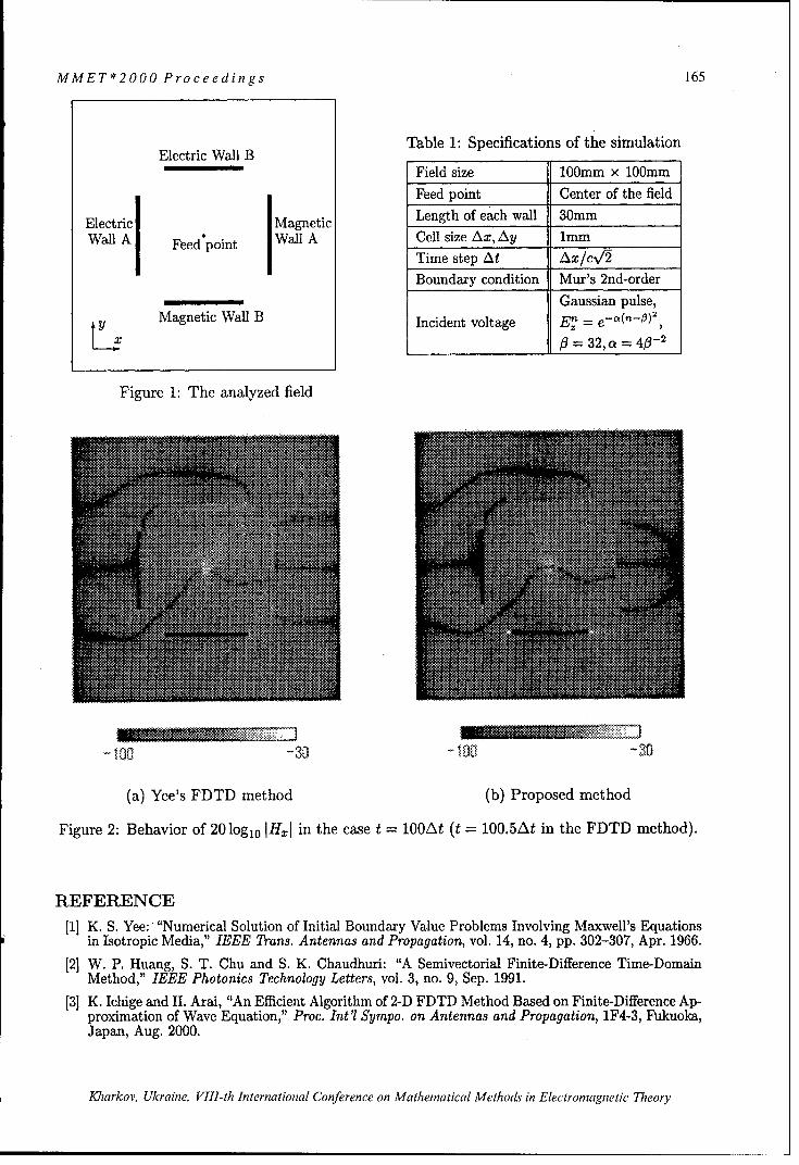
MMET*2000 Proceedings 165
Table 1: Specifications of the simulationElectric Wall B _________
"Field size 100mm x 100mm
Feed point Center of the field
Electric Magnetic Length of each wall 30mm
Wall A Feed'point Wall A Cell size Ax, Ay 1mm
I Time step At Ax/cV2Boundary condition Mur's 2nd-order
Gaussian pulse,
SMagnetic Wall B Incident voltage EE- =
x 0= 32,a - 40-2
Figure 1: The analyzed field
(a) Yee's FDTD method (b) Proposed method
Figure 2: Behavior of 20log 10 IHxI in the case t = 10OAt (t = 100.5At in the FDTD method).
REFERENCE
[1] K. S. Yee: "Numerical Solution of Initial Boundary Value Problems Involving Maxwell's Equationsin Isotropic Media," IEEE Trans. Antennas and Propagation, vol. 14, no. 4, pp. 302-307, Apr. 1966.
[2] W. P. Huang, S. T. Chu and S. K. Chaudhuri: "A Semivectorial Finite-Difference Time-DomainMethod," IEEE Photonics Technology Letters, vol. 3, no. 9, Sep. 1991.
[3] K. Ichige and H. Arai, "An Efficient Algorithm of 2-D FDTD Method Based on Finite-Difference Ap-proximation of Wave Equation," Proc. Int'l Sympo. on Antennas and Propagation, 1F4-3, Fukuoka,Japan, Aug. 2000.
Kharkov, Ukraine, VIII-th International Conference on Mathematical Methods in Electromagnetic Theory

166 MMET*2000 Proceedings
INVESTIGATION AND OPTIMIZATION OF A WAVEGUIDE SLOTANTENNA ARRAY BY FINITE-DIFFERENCE TIME-DOMAIN
METHODS. Martynyuk
Dept. of Radio-Engineering of National Technical University of Ukraine (Kiev).
INTRODUCTIONClassical planar waveguide slot antenna arrays are well-known and widely used in
frequency range from 4 to 14 GHz. Among advantages of this type of antennas are low levelof cross-polarisation (-35 dB or better is achievable), high levels of radiated power, low lossesand simplicity. The main problem is that due to the resonant nature of the slots and their serialfed in waveguide the frequency band of this arrays are usually limited by several percents.Often different tuning posts, E-plane shorted stubs and metal plates are applied to obtainimprovement of characteristics in frequency range. Method of moments (MoM) was usedbefore to analyse such arrays. But MoM can be hardly implemented in the cases, when morecomplicated waveguide structures together with radiating slots are to be studied. In this paperfinite difference time domain method (FDTD) method was used. Due to it's high flexibility itgives the opportunity to investigate different complex structures accurately and at a highspeed. Coupling between slots through the free space and waveguide and the couplingbetween slots and waveguide's discontinuities are taken into account.
Fig. 1. Fig. 2.GEOMETRY DESCRIPTION
Section of rectangular waveguide with narrow longitudinal radiated slots in broad wallare investigated in this paper (fig 1). The length of slots / is usually near to the half ofwavelength in free space at the desired frequency. Slots are assumed to be with 180 degreephase shift and placed at the distance d equal to the half of wavelength in waveguide toradiate in phase in the far zone.
FDTD APPLICATIONFDTD method was firstly proposed in [1] and its backgrounds are not discussed here.
When one analyse radiated slots in waveguide, the computational domain is obviouslysubdivided into two parts. The first is free space above waveguide. Here it is limited byperfectly match layer (PML) [2]. The second domain is the space inside the rectangularwaveguide. Here impedance boundary conditions (IBC) [3] were used at the input and outputplanes of waveguide to excite and terminate propagating modes in waveguide. If thediscontinuity in waveguide is situated far from the IBC only mode TE10 in rectangularwaveguide can be taken into account to obtain accurate results of S-parameters in waveguide.The value of impedance of IBC is chosen equal to the characteristic impedance in waveguide
Kharkov, Ukraine, VIIl-th International Conference on Mathematical Methods in Electromagnetic Theory

MMET*2000 Proceedings 167
at the frequency, where the radiation pattern is calculated. This way avoid the reflections fromthe ports in waveguide that can lead to the distorted values of radiated pattern. At the otherfrequencies we are interested only in the S-parameters of waveguide sections and radiating P-parameter (1), that indicates the radiated part of input power.
P=I2- Sl2- $212
For the calculation of radiation pattern standard near-to-far zone transformation in frequencydomain is used for the plain close to the outer metal plane of waveguide.
NUMERICAL REZULTSAt first the properties of a single longitudinal slot at the wide wall of rectangular
waveguide (cross-sections dimensions 23xl 1 mm) were investigated. Fig. 3. shows the familyof characteristics of P-parameters for the slot with the length / = 14,7mm, width 1mm and adifferent displacements x ,that vary from 11 to 6.8 mm with a step 0.7 mm (the higher curvecorresponds to the lower value of displacement x). In Fig. 4 one can see the similar familyfor the slot of length 1 = 12mm, width 1mm and the various displacements x ranged from 8 to2,4 with step 1,4 mm. In this case two propagating modes were taken into account (TE10,TE20). As it seen from figures at the resonant frequencies the radiated efficiency P increase.The slots with smaller length in waveguide of fixed cross-sectional dimensions anddisplacement x at the resonant frequencies have smaller values of parameter P. Thecharacteristic of reflection (S 11) for each slot also has maximum, which appears at thefrequency close to the resonant frequency of P-parameter. This fact is very important for theslot antenna arrays, in which the slots placed at distance equal to the half of wavelength inwaveguide, because the reflections from all slots added producing high level of VSWR.
0.3
0.20
0.2 0.16
0.12
0.1 0.08
0.04
0 .0 = , ' ' ' 0.00 -8 9 10 11 12 8 9 10 11 12 13
Frequency, GHz Frequency, GHzFig. 3. Fig. 4.
As an example four slot antenna array was calculated. It consists of equal transverseslots of length 14,4 mm with width 1mm and displacement x = 7.6mm. Distance betweenslots was 22,4 mm (2. / 2 for the waveguide with cross-sectional dimensions 23x 11 mm at thefrequency 9,42 GHz). The radiation pattern at the frequency 9,42 GHz both in H- and E-planes are given in Fig. 5. S and P parameters are presented in Fig. 6. The value of S 11 at the9,42 GHz exceed 0.26 even for the relatively short array.
To decrease the S II the waveguide slot section with E-plane shorted stub is analysed(Fig. 2). The shorted E-plane stub is used to compensate reflections from a single radiatingslot (1=13,4 mm, x=4,9 mm, width=lmm) in waveguide (23x5 mm). The E-plane stub's width
Kharkov, Ukraine, VIII-th International Conference on Mathematical Methods in Electromagnetic Theory

168 MMET*2000 Proceedings
is 2mm and it's depth is 4mm. Values of Si 1 for the single slot structure with stub andwithout it is shown in Fig 7. It should be noted that the normalised radiation pattern for thesingle slots in examined cases was almost the same as demonstrated in Fig. 8.
H-plane 1.0 - -
-------- E-plane /o- 0.8 S
- 0.6- P
0.4
-20 0
-30 0.00 40 80 120 160 8 9 10 11 12
Degrees Frequency, GHzFig. 5 Fig. 6.
without stub0.25 - 0-
-- - - - w ith stub " -/"•
'0.20 "
0.15 -
0.10 . -12- ,H-plane
0.05 - 16 ---- -16 E-plane
0.00 I -20
8 9 10 11 0 40 80 120 160Frequency, GHz Degrees
Fig. 7. Fig. 8.REFERENCES[1]. K.S. Yee. Numerical Solution of Initial Boundary Value Problems Involving Maxwell's
Equations H IEEE Trans. on AP, Vol. AP-14, pp. 302-307, May 1966.[2]. J.P. Berenger, Perfectly Matched Layer For The Absorption of electromagnetic waves H J.Comput. Phys., vol 114, pp. 185-300, Aug. 1994.[3]. T. Shibata, T. Itoh. Generalized-Scattreing-Matrix-Modelling of Waveguide CircuitsUsing FDTD Simulations.// IEEE Trans. on MTT, vol.46, No. I 1,pp. 1742-1751, November1988.
Kharkov, Ukraine, VIII-th International Conference on Mathematical Methods in Electromagnetic Theory

MMET*2000 Proceedings 169
QUASI-MINIMAL RESIDUAL METHOD INELECTROMAGNETIC SCATTERING
Alexander B. Samokhin, Yuri U. Kapustin
Moscow Institute of Radiotechnics, Electronics and Automatics, RussiaE-mail: alex @ samohin.dnttm.rssi.ru
INTRODUCTION
We consider a wide range of electromagnetic (EM) scattering problems on finiteinhomogeneous bodies characterized by general .•(x) and N(x). A system of singularintegral equations over the domain of inhomogeneity is used to formulate the problem. Aniterative quasi-minimal residual procedure is applied to solve the operator equation.
STATEMENT OF THE PROBLEM
Let arbitrary tensor functions L(x) and .(x) equal col and poi outside finite domain
Q c E 3 . According [1], the problem of EM scattering by Q can be described by thefollowing system of singular integral equations:
E(x)-= E (°) (x) - I x) -Iý(x)-[- k 2 f (g(y) -- 1 )(y)G(r)dy +3 \ --0 0 j 0
Q
+ V.p.J((• -I)E(y), Vx)VxG(r)dy + ico/.to I[(N)- Vx
H(x)= H(O)() (x)_-I)( - ]i(x)+ k2J('o -_ jt(y,_(rI)dy (1)3 p*o 0 ,(y 1 'ur '•Q
____A ' V GJ[(-{() - Y(y), Vx s(r)dy
Q Q
where G(r) = exp(- ikr)/4zr .
ITERATIVE METHOD
Consider a general system in Hilbert space H with continuous linear operator:
Au = f (2)
where A can be, for example, the result of discretization of (1) or operator (1) itself. If Asatisfies coercitivity condition, then solution of (2) exists, is unique and can be found withthe multistep minimal discrepancies method (MMD) [2]:
Kharkov, Ukraine, VIII-th International Conference on Mathematical Methods in Electromagnetic Theory

170 MMET*2000 Proceedings
u11) =u,, v, = h!°) = Au,)- f,
h(')= h!-')- r1w,, u(/)=u -1)-TrvI, = =l,m,I-I I-I
Wl=Avl, w, =Ah'-•) - akwk, v, h(-')- akvk, l = 2,m, (3)k=1 k=1
V, = K(h~ -),4h!l-))/ w 112 , a_ ( Kah( 1 ),wk)/1wk 12
U 11tI+1 = U ? (I 1 )
Effective application of (3) in scattering problems, characterized by electrically dense mediaor large domain volume, may require large values for m. For instance, let f is a sum of keigenfunctions of A corresponding to different eigenvalues and u0 = f. Then, from the fact
that the span of Aho,..., A'ho coincides with a space based on eigenfunctions, it is obviousthat m = k gives exact solution within k iterations. For m < k, the number of iterations maygreatly exceed k. Algorithm (3) with non-fixed m is often referred to as complete GMRES,whose practical application is essentially determined by available memory and CPUresources, since for each iteration number L calculation of the iteration requires storage andprocessing of L vectors v,.
An iterative method described below is based on the idea of biorthogonalization [4].
Variation iterative methods, such as MMD, can be represented as follows:
Uk =u - ý1=, I)rt-ho (4)
where uk -- u and z(k) --> T, as k -> oo. Parameters rk) differ for various iterative methods,but have the same limits.
Let introduce the following sequence
Av 1h-, +b...+b,')Aho, 1=2,N, (5)-3"VlN doe, notv depen onlI...0"-.
where b0') are complex parameters. Since subspace based on Av }, does not depend on
b(', we can write ho -== AV, and define the sequence
Uk = = Uk YkVk
Let q, E H is an arbitrary vector and p, = Av, = Ah 0 . According [3], [4] we define
P2 =Apl-a-pj, q2 =A*ql -'iqj
P1+= Ap1 - a, p, -/3 1 Pl-1q1+1 =A q -alq, -/31 qj-, (6)
a, =(Apl,q 1)/(p,,q,), 1=1,2 ....
A, =(p,,q,)/(p,-1 ,q11), 1= 2 ....
so that vectors p, =Av, and q,, satisfy biorthogonal condition (p,,q,,)=(p,,
Therefore, parameters yt and vectors v, can be calculated as follows:
Kharkov, Ukraine, VIII-th International Conference on Mathematical Methods in Electromagnetic Theory

MMET*2000 Proceedings 171
r, = (ho, q, ý(Pl,,q,
V1 = ho, V2 = AvI -alv 1 (7)
V1+1 = Av1 -a-,V -/3•lvl
Iterative procedure (6)-(7) has the two features very important for applications. (1) If thenumber of terms k in expansion of f is finite (which is the case for finite algebraic systems),then iteration k = N will give exact solution; (2) increase of N does not require morememory. Unlike MMD, the described method does not assure that discrepancies steadilydecrease to zero. Nevertheless, for a wide range of problems, the number of iterations (6)-(7)is essentially smaller than in MMD in the case of m < N. For this reason, iterative method(6)-(7) is known as quasi-minimal residual method (QMR). With respect to scatteringproblems, the number of iterations in MMD and QMR are determined solely by operator A.Hence, neither discretization method, nor collocation density or the number of basisfunctions has an essential impact.
For QMR method it is possible, however, that for some r vectors p, and q, becomeorthogonal while the entire iterative procedure is not completed. It is possible to show [4]that such situations are rather rare and can be excluded by appropriate choice of vectorsp0 , q0 .
Operator (1) of scattering problems is not self-conjugate, but satisfies condition
A= =A. (8)
Assuming q, =P5 Aho we have q, =)5,, and QMR procedure can be simplified:
ho =Auo-f, p, =Aho, v,=ho,
P 2 = Apl -alPl, V2 = Avl -- alvl
p11= Ap1 - aP - fi P-Iv1+1 Av, - alvi - Alvi-(9
a 1 =(AP1,-P1)/(P,-,1 ), /3, =(P,-P)/(PiI,-,i)
Y1 =(h 0 ,J 1)/(p 1,J5), u1 =u1-1 -yrv 1 , 1=1,2,....
REFERENCES
[1] A.B. Samokhin, Y.U. Kapustin, "Mathematical Modeling of Electromagnetic ScatteringProblems", Proceedings of MMET' 1998, pp. 618-620.[2] A.B. Samokhin, "An iterative method for the solution of integral equations applied to ascattering problem on a three-dimensional transparent body", Differential Equations, vol. 30,no. 12, 1994.[3] M. H. Gutknecht, "Lanczos-type Solvers for Nonsymmetric Linear Systems ofEquations", Technical Report of CSCS/SCSC, 1997.[4] D. K. Faddeev, V. N. Faddeeva, "Computational Methods of Linear Algebra",W. H. Freeman, 1963.
Kharkov, Ukraine, VIII-th International Conference on Mathematical Methods in Electromagnetic Theory

172 MMET*2000 Proceedings
COMPARISON OF SYMBOLIC COMPUTATION TECHNIQUES FORPROBLEMS IN ELECTROMAGNETICS
Bahattin Tiiretken] and S.Eren San2
'TIJBiTAK-UEKAE PO.Box:21 41470,Gebze, Kocaeli, TURKEY [email protected]
2TUBITAK-UME PO.Box:21 41470,Gebze, Kocaeli, TURKEY eren @ ume.tubitak.gov.tr
ABSTRACTSymbolic computation techniques (SCT) are applied for the evaluation of problems inElectromagnetic(EM) by making use of Mathematica and Macsyma packages[l,2]. Theresults are compared in terms of the obtained numerical and analytical information.
INTRODUCTIONActually in some problems it is better to use symbolic techniques rather than numericalevaluations. In some cases solutions of this kind are very useful for the interpretation ofresults. These symbolic computations are applicable for lots of mathematical manipulationsparticularly differentiation, integration, solutions of linear equations, expansion functions inseries, solutions of differential equations, curve analysis, tensor algebra and topologicalapproaches[3].In this study we have concentrated on the solution possibilities of some EM problems. It isvery important to obtain exact solutions for design applications of Radio Frequency (RF).Especially it is required to solve the problem exactly for some antenna designs and in suchcases trustability of the used program packages is very important. That is why comparison ofalternative SCT with different program packages is analysed in different problems.
INTERESTED PROBLEMSIn order to examine the results of these packages two well-known problems ofelectromagnetic were studied. One of the problems is a short wire problem (flux density Bdue to a short current carrying wire) and the other one is an antenna analysis.
Short Wire ProblemA short copper wire of length L and a cross sectional area a is concerned and current I existsin positive z direction. Current I is assumed to be uniform throughout the wire and it is timeindependent. If we deal with the situation at a large distance from the wire (r >>L) (see Fig. 1)we make use of vector potential A in order to calculate the magnetic flux density Beverywhere [4,5].The vector potential A at a distance r from wire for the current I in the z direction and
uniform is given by A=(O,0,c/r) where c - POIL
4;rA = the vector potential at the distance r from wire, Wb/m, I = the current in the wire,A, L =the length of the wire, m, r = the distance from the wire, m,P 0=the permeability of air=400pi ,nH/m
Kharkov, Ukraine, VIII-th International Conference on Mathematical Methods in Electromagnetic Theory

MMET*2000 Proceedings 173
The vector potential is in the positive z direction and is inversely proportional to the distance rfrom the wire. We obtain the flux density B by taking the curl of A
B = VxA. (1)Magnetic flux density of a short copper wire is studied and symbolically visualised in thefollowing figures by Macysma & Mathematica.
0.3C
-0.30
a) b)-. o. 0. 0.4 X 0.30
Fig. 1. Magnetic flux density (B) of the short copper wirea) By Mathematicab) By Macsyma
Antenna Analysis
The behaviour of antennas is primarily governed by Maxwell's equations [6,7]. One canobtain the electromagnetic fields at any point outside the source region for known A at thetime harmonic variations.
B=VxA,H=B , E = qVxH (2a,b,c)
We consider a conductor of the length L and cross section area a carrying a current I in zdirection of angular frequency w . Such a current element is known as a Hertz dipole. Thevector potential at an arbitrary point P is given by in Cartesian coordinatesA = (0, 0, exp (-jkr)/r) or in spherical coordinates
A = (p exp(-jkr) Cos OO,-p exp(-jkr) sin 0), (3)
r rwhere p =PL , q =1I
4;r jw6,U
Electromagnetic fields of the Hertz dipole is studied and symbolically visualised in thefollowing figures by Macysma (Fig. 2b) & Mathematica (Fig. 2a).
a) 0 b)
Fig. 2. Electromagnetic fields of Hertz dipole (r component)Kharkov, Ukraine, VIII-th International Conference on Mathematical Methods in Electromagnetic Theory

174 MMET*2000 Proceedings
1.00
S~0.50
0 zS-0,50
0.00
• 2.00
2,00 2.0 400S~3.00"44.00 6.00
50b) y 5,00
Fig. 3. Electromagnetic fields of Hertz dipole ( 0 component)a) By Mathematicab) By Macsyma
CONCLUSION
In fact these problems have been studied so that the trustability and compatibility of symboliccomputation should be presented in a commentary manner, SCT could also be applied formuch more complicated problems in different coordinate systemsIf we analyse the obtained figures by two different packages we can easily notice the fact thatthe forms of the graphs are very similar. There exist some discrepancies that are supposed tobe caused by different numerical procedures followed in the structures of these two packages.
REFERENCES
[1] MACSYMA Reference Manual Version 16, 1998, Symbolic Inc.[2] MATHEMATICA Reference Guide Version 2 1992, Addison Wesley Pub.Co.[3] ARI N., TURETKEN B., "Symbolic Comtutaions Techniques for Electromagnetics"
Second International Symposium on Mathematical & Computational Applications1999, Baku, Azerbaycan
[4] N. ARI, "Application of computer code MACSYMA for electromagnetics, Proceedingsof the lASTED International SymposiumExpert Systems Theory & Applications",Zurich, Switzerland1989,pp 77-80
[5] KRAUS J. D. Electromagnetics, McGraw-Hill Book Company, New York,1984 pp. 190-192
[6] KRAUS J. D. Antennas, 2. Edition, McGraw-Hill Book Company,New York,1988
[7] LEE KAI FONG, Principles of Antenna Theory, John Wiley & Sons, 1984,pp. 12-30
Kharkov, Ukraine, VIII-th International Conference on Mathematical Methods in Electromagnetic Theory

MMET*2000 Proceedings 175
THE TECHNIQUE FOR CALCULATIONOF THE ELECTROMAGNETIC PROPERTIES
OF COMPOSITE MATERIALS AND NONUNIFORM MEDIA
S. V. Maly
Belarus State University, Department of RadiophysicsI Kurchatova str., Minsk, 220064, Belarus
maly @ rfe.bsu.unibel.by
ABSTRACT
The basic stages of the technique of calculation of effective electromagnetic parameters ofcomposite materials and nonuniform media are presented. The technique is based on themethod of minimum autonomous blocks. The example of usage of this technique forcalculation of effective parameters of a composite containing segments of conductive fibrils isgiven.
BASIC STEPS OF THE TECHNIQUEGenerally, a method of calculation of effective electromagnetic properties of compositematerials and nonuniform media includes: a choice of the key electromagnetic problem;solution of the key problem taking account of the interior structure of composite; finding ofthe effective electromagnetic parameters through the solution of inverse problem. As a keyproblem we shall consider the interaction of a plain linearly polarized electromagnetic wavewith a flat stratum of a composite. The interior structure of a composite can be periodic orstatistically homogeneous. If the sizes of structural inhomogeneities of composite are small incomparison with the wavelength A, then the electromagnetic properties of the flat stratum ofa composite illuminated by the electromagnetic wave can be characterized with the aid of thescattering matrix S. For calculation of this matrix, the use of the technique outlined in [1] ispossible. This technique is based on the method of minimum autonomous blocks (MAB) [2]and the theory of periodic structures [3]. The basic stages of this technique are given in Fig. 1.
a) b) C)
Figure 1
In Fig. 1a, a fragment of a flat stratum of a composite relevant to the initial keyelectromagnetic problem is shown. Transition to an electromagnetic equivalent problem iscarried out. The virtual waveguide shown in Fig. lb corresponds to a single period ofcomposite. On its walls the requirements of periodicity are imposed. In view of the smallness
Kharkov, Ukraine, VIII-th International Conference on Mathematical Methods in Electromagnetic Theory

176 MMET*2000 Proceedings
of the cross section of the virtual waveguide, in the spectrum of scattered on the wavequideinhomogeneity electromagnetic field, it is possible to take into account only the zerothFloquet harmonic. The area of the virtual waveguide containing spatial inhomogeneity isdivided into system of rectangular blocks, as shown in Fig. ic. According to the MABmethod, each of these blocks is considered as an independent block, whose electromagneticproperties are characterized by the scattering matrix. The scattering matrices of separateblocks are used in calculation of a multichannel scattering matrix within the framework of theprocedure of integration of the neighboring blocks. The relations for the elements of thescattering matrices and a relevant recomposition procedure were explicitly presented in [2].The required scattering matrix of a flat stratum of a composite is obtained by the relevantaveraging of elements of a multichannel scattering matrix.For calculation of the effective electromagnetic parameters of a composite (s'f ,/p. ) it is
possible to use the relations of [4,5]:
8 , ' -z-2)2 (1)
I'f P'~ )' 27d
p=x+ x2 -1• , p1 •_1; (2)-C=(Vi - p)/(1 -VIP); (3)
x= , V,=S21+SII; V2=S21-S 1 . (4)
where S1,,S21 are the elements of the scattering matrix S of a flat stratum of a composite.
NUMERICAL RESULTSAs an example of usage of designed technique, we shall consider the results of calculation ofan effective permittivity of the composite material, whose fragment and the notations ofdesign factors are shown in Fig. 2.
A !dx
Figure 2
The composite is formed from short perfectly conducting wires having square section with theside length 8. Other parameters are as follows: d. =78,d, = 98,d, =118. The effective
Kharkov, Ukraine, VIII-th International Conference on Mathematical Methods in Electromagnetic Theory

MMET*2000 Proceedings 177
electromagnetic parameters of composite are calculated for the case of a plainelectromagnetic wave propagating along the z-axis, and electric field E II 5. The calculationswere performed in the assumption that dx, /1 2. In Fig. 3, the dependences of the effective
permittivity of the composite on value of separation between end faces of wiresA (d; - 1) are presented for different values of permittivity of material filling this gap.
6eff 25 ,-,__
20-
15-~~~~ -- =1 .......... ..
1 0 . .............. .. ...................... ................ ................. .............. ................ ............ ..... .... ....
5 - . . . .. ... .. ..
10
0,00 0,01 0,02 0,03 0,04 0,05 0,06 0,07 0,08 0,09 0,10
A/d
Figure 3
A strong dependence of ceff on A can be used in development of artificial dielectric materials
with controllable properties.
CONCLUSIONThe offered technique ensures an opportunity to calculate the effective electromagneticparameters of materials and media with a composite interior structure and does not putrestrictions on the density of particles and their shape. The usage of the technique will enableone to develop and examine composite materials with new electromagnetic properties.
REFERENCES[1] S.V.Maly. The Numerical Technique for Analysis of the Electromagnetic Scattering byComplicated Periodic Structures. Proc. Int. Conf Mathematical Methods in ElectromagneticTheory, 1996, Lviv, Ukraine, pp. 490-493.[2] V.V.Nikolsky and T.I.Nikolskaya. Decomposition Approach to Electrodynamic Problems,Nauka, Moscow, 1983 (in Russian)..[3] N.Amitay, V.Galindo, and C.P.Wu, Theory and analysis of phased array antennas, NewYork, 1972.[4] A.M.Nicolson and G.F.Ross, IEEE Trans., IM-19, 377, 1970.[5] M.S.Freeman, R.N.Nottenburg and J.B.Dubow, J.Phys. E: Sci. Instrum., 12, 899, 1979
Kharkov, Ukraine, VIII-th International Conference on Mathematical Methods in Electromagnetic Theory
178 MMET*2000 Proceedings
NUMERICAL MODELS IN THE PROBLEMS OF THE SCATTEREDFIELDS INTERACTION
Amur B. Hashimov
The South Ural State University, Chelyabinsk, RussiaE-mail: [email protected]
ABSTRACT
The numerical method is suggested for analysis of electromagnetic interaction by scatteringfields of perfect conducting obstacles. It is based on the using of cell collocation technique.Parameters of the numerical models are defined by minimizing of the regularizationfunctional. The estimations of accuracy for the different obstacles are obtained.
The electromagnetic interaction of the antenna systems and the scattering obstacles can bedetermined by integral equations method. These equations are used for determination of thescattering fields by appropriate numerical model. When an incident electromagnetic field of
the antenna system E' ,H is scattered by a perfect conducting obstacles with surface S, the
scattered fields can be determined by integration when the surface current density j. induced
on surface S is known. This surface current density can be determined from the incident fieldby solving either the magnetic field integral equation or electric field equation, which areconsequences of the boundary condition at the perfect conducting surface:
-•. = -.×II 1is =2x H + -- x fJs x grad'G(r,r')ds';271 s
2n S
where G(F,r"')= exp(-iýr -F' )/ji - 'P; i,i'- radius-vectors of the observation and source
points respectively; Div denotes the surface operator; ni is the unit normal vector in anoutward direction from S.
These equations can be arranged in the form
Lu---f,
where L is an integral operator; u is an any scalar component of the js; f is the knownincident function.
Let us consider the method for calculating the unknown functions u by using the cellcollocation technique. Assume that the integral equations solving results can be transformedinto a numerical model of the appropriate scattering problem. The cell collocation techniqueas a part of the method of weighted residuals allows approximating u in terms of a finite
series of basis functions {p, } as
Kharkov, Ukraine, VllI-th International Conference on Mathematical Methods in Electromagnetic Theory

MMET*2000 Proceedings 179
N1U= Lan~n,
n=l
where an is an arbitrary constants to be determined. For any numerical model the residualfunction can be determined as
N
F= Lan'L(Pn -f:.n=1
Then we follow the traditional procedure of the weighted residuals method [1] by using theauxiliary weight function w, which is defined as a finite series of basis function I W
Mw = Z bmym,
n=1
where M is a number of basis elements. The functional in form inner product of the residualfunction and auxiliary weight function is defined as ( ,w) and determined the weak form ofthe operator equation
(Ew J{ anl-n r f} bmNnmdS= I Ibm(E, Yn)
and equality (s, w) = 0 must be fulfilled. We obtain the system of linear equations with an tobe found
{ aIp, -f Wmds = Zan(-Lpn,XJm) -(f,Yxm); m=,...,Ms (n=l n=1
The matrix form of this system may be represented in the following way
A a=F;
Annm=(L-pn,,m); a=[a, a 2 ...aN]t; Fm=(fWm).
The appropriate choice of the pair I T }, { W M determines successive solution of the problem.
The often used pairs of functions are given in [2]. The cell collocation technique basis as
{Ir } employs as a rule the series of 6 -functions and a pulse basis as {Xm} [1]. We propose a
successive modification of the cell collocation method for calculation of the surface current
density Js. We shall use pulse basis of several shape both {"n},{Wm}
s,= {l; s' [s'-A'/2, s" + A'/2];. i1/A; se[Sn-A/2, Sn +A/2];-; s' E[s'-A'/2, s' + A'/2].' m ; s [s-A/2, s()A/2].
~{2[s' Z(sn -A'/2)]/A'; s' c[s' -A'/2, s" + A'/2]. (2)
Kharkov, Ukraine, VIII-th International Conference on Mathematical Methods in Electromagnetic Theory

180 MMET*2000 Proceedings
( F2(s, 1-A/2)/A; se[s,,,-A/2, s,,,+A/2].
where (1), (2) is rectangular and triangle two-dimensional basis respectively, A',A - pulse
basis parameters, s', s denotes coordinates of the source and observation points respectively
in the inner products. For these simple basis it is possible to calculate coefficients of linear
system by using simple three-point Simpson's integration formula. It is important to note that
the Green's function derivatives in weak form of the operator equation are absent. The surface
derivatives can be moved outside the inner integral of weak form and apply to pulse basis.
Thus, dominant diagonal elements of linear system provides stability of the numerical
computations. Obviously, optimal choice of the basis parameters is defined by properties of
surface S and prescribed accuracy. Often it is necessary to expand basis series in case of
unstable numerical integration results for sharp irregularities of S. In other cases substituting
the truncated series of the finite basis function into the integrands and integration will occur
with A',A which have no instabilities. Successive way for determining A',A is followed
from the known variational approach. According to [3], consider the functional
The choice of optimal basis parameters is reduced to minimize prescribed functional under
condition j, = const. The resulting matrix of the linear system is still valid and optimal basis
parameters satisfy main problem conditions, i.e. a stable computation, appropriate accuracy
must be fulfilled. This method was applied to the test problem of scattered field computation
by perfect conducting two-dimensional cylinder solved previously by the finite-element
method. The comparison of the numerical solutions with the exact one shows that the method
described here is more efficient. Numerical results for other cases will be presented.
REFERENCES
[1] C.A.Brebbia, J.C.F.Telles, L.C.Wrobel, Boundary Elements Techniques, Springer-Verlag, Berlin and New York, 1984.
[2] A.J.Poggio and E.K.Miller, "Integral equation of three-dimensional scattering problems",Computer Techniques for Electromagnetics, (Ed. R.Mittra), Pergamon Press, Oxfordand New York, 1973.
[3] M.I.Andriychuk, N.N.Voitovich, P.A.Savenko, V.P.Tkachuk. Synthesis of antennaaccording to amplitude radiation pattern. Numerical method and algorithms. NaukovaDumka Pub]. Kyiv, 1993. (In Russian).
Kharkov, Ukraine, VIII-th International Conference on Mathematical Methods in Electromagnetic Theory

MMET*2000 Proceedings 181
CALCULATION OF SINGULAR INTEGRALSIN SCALAR DIFFRACTION PROBLEMS
Oleg I. Ovsyannikov, and Yuriy V. Kasyanyuk
Karpenko Physico-Mechanical Instituteof the National Academy of Sciences of Ukraine, Lviv, Ukraine
E-mail: [email protected], [email protected]
ABSTRACTThe axissymmetric scalar diffraction problem is presented. The singular and hypersingular
integrals with normal derivative of double layer potential are considered. The methods of singularand hypersingular integrals calculation are proposed.
STATEMENT OF THE PROBLEM / ySuppose the scatterer is symmetric to the axis Oz
and infinitely thin with finite disclosed surface S.Generatrix of scatterer is a smooth contour L in the planexOy. Let us assume that the considered body is Oilluminated by Oz symmetric wave in the form XH*(t,z-) = H*(t)exp(- coz),t E R3 (r is time, co iscircular frequency). We have to find the solution ofthree-dimentional Helmholtz equation, that satisfies theconditions: of Neumann on the surface S; of Meixnertype near the scatterer ribs; of Sommerfeld whichexcludes waves propagating from infinity (except theexciting one). Fig. 1. Infinitely thin disclosed shell
Let us find a solution as a double layer with curvilinear profilepotential [1]:
H S(T) = j exp(ivr(T, t))),f (t)dS (1)~a (r= sT, tSatisfying the Neumann condition on the surface S and taking into account the axis symmetry ofthe problem, the ribs' conditions and applying parametric equations of surface S:x=l(v)cos(qo), y =l(-)sin(yp), z = z(vr), -1(r(1, -P • _<• _ (9is polar angle in theplane xOy) we obtain:
1 • ~ex~p[iXr+,-, o,V•)]{ 1 [ eI-To tr~~d~
fJ-l(r I-[, p rv ) (r(r, rO,1()) 2 r(, z-o, 9) i Re(tto t tol(d d-±
+ 1 J()Vi' _ [exp[izr(z-,Z0ro )]
21- ix ... X-' r(z-Oo
______- ~ 2Re O T t - tT d~d -Io(2)t (r(T, To,•] (0)) t0¢ Z- R _-to It'lt•) It'lt•) dr(d, tTO 0 00 ,2
where f(v)V -7 .
We can rewrite (2) in the following form:I 1/W exp(i~rz -,z0 p) i epi rzz',()1~ d7r - (r(z-, z-0, (p))3 (r(, z-0 , (p)) J
Kharkov, Ukraine, VIII-th International Conference on Mathematical Methods in Electromagnetic Theory

182 MMET*2 000 Proceedings
11 ITexpQi~r(z-, )+±- f pdf,~lmr)
I-]-5 j-~imoV Z 1 iyexp(ixr(mro,qr,))d d72 -1 (r-ifo'(p)
--K5 ~ fexpi~vx0 )J 7 1 7 TO (,)) S,(3- f f (pdi- = - I G~ oE 3
where gToRe _-otf gIT r)=R (-to t -'Tg(Tro> Re tto , g1tvp Re to -g( 0 , 0 =t
It is clear that integrals in (3) have logarithmic singularity and hypersingularity as 7-To2
type at T --> TO.
We shall consider the regularization method of these integrals [2].Let us make the following steps:
I3*(v 0 >zJI1 7)g&,r0 'rOV11 -iTfrf" exp[ixr&:v'ZO')]}dqdr (4)
- O 1 - exp[ix{r(, Z0 , 0]1 -Iizr('v, ZO' 0)- 2 dqod T+ (5)
where 1 33&O (Z ' p~~~ )i Idqd, 6
2 fl ~ r(z,,z'), ()Making the similar steps with integrals (6-8) we obtain singular and hypersingular integrals:
13 3 0 (To fJ 1 9 T O 1-vg 1, 1 )Jd (9)(r(r,r1_,qý))3
I33r (-CO> 1 Vi (1-, 10XvC-CO )J'T 1 d~pdzr, (10)
1Z- f(11) oX_ o)2dprI33rrr)Siig&v v-) 2 (r(r~rq, ))3 div
13 20 (ro)f J i-I-g(r ro )f I~ 2 dqpd, (12)
(r(-, z0 , (p))
13r-o=I d(d- (14)
Kharkov, Ukraine, VIII-th Interniationial Conifer-ence onMathemiatical Methiods in Electrom~agnetic Theory,

MMET*2000 Proceedings 183
Using proposed approach we can calculate all integrals. It is possible to calculateeffectively the integrals in arbitrary points of their definitions:
n - 1 Z - M ( -M(ir)•~ I I Sk(M('K), (15)
nt k=O
where Sk (-)= 1 + 2Zcos(m(pk)cos(marccos(z"-) ok = (- 1( m =1 2n
We have tested the presented approach for singular integral (13) when complex coordinate
t of contour L describes parabola t = a/ 24 + +,++)2 /2+; -a=1, c-=1:
points Integral (13) Interpolation poli- points Integral (13) Interpolation poli-nomial for (13) nomial for (13)
-0.9 11.7864 11.7864 0.1 6.85673 6.85673-0.8 9.88613 9.88613 0.2 6.74371 6.74371-0.7 8.87401 8.87401 0.3 6.61591 6.61591-0.6 8.24451 8.24451 0.4 6.46763 6.46763-0.5 7.82819 7.82819 0.5 6.29430 6.29430-0.4 7.54292 7.54292 0.6 6.09220 6.09220-0.3 7.34070 7.34070 0.7 5.85830 5.85830-0.2 7.19013 7.19013 0.8 5.59005 5.59005-0.1 7.06929 7.06929 0.9 5.28532 5.285320 6.96214 6.96220As seen, it is enough to calculate the integrals in node points.After regularization of the left part of (3) we obtain the sum of regular and singular parts.
Note that hypersingular integrals diverge in normal sense, but they converge in the sense ofHadamard's finite part [3]. All regular integrals are smooth on the integral interval. Therefore wecan use quadrature formula for these integrals [4]:
;1 •-Trf (z)dz"zZ(¢); (16)
n k=1n 1 (4 ,F2 n1where i2cOs(m'k)J,' J = J, cos(mzX- cos(z-)) + cos(z-)dr,
S7'3 m=l
Vk = cos 2k - Irk = 2k - , k = 1..n,n ,7n ,n=1( n-1 )
and J 1j(T)dT z - j(Zrk)7( , k77 =- 2-2 ' cos(mqok (-1)m.1 / (17)k=l n( m=2,4,.... (M + 1)(m - 1)"
Thus, using the proposed approach we can calculate the singular and hypersingularintegrals and then obtain the system of linear algebraic equations using quadrature formulae (16-17).
REFERENCES[1] Colton D., Kress R. Integral Equation Methods in Scattering Theory. - New York: John Wiley &
Sons, 1983, -311 p.[2] Ovsyannikov 0. I. The Numerical Method of Scalar Scattering Problem Solution// Proc. VI Intern.
Conference MMET'96. P. 121-124.[3] Nazarchuk Z. T. Singular Integral Equations in Diffraction Theory. - Lviv: Karpenko Physico-
Mechanical Institute, 1994, - 210 p.[4] Panasyuk V. V., Savruk M. P., Nazarchuk Z. T. Method of Singular Integral Equations in Two-
dimensional Diffraction Problems, - Kiev: Naukova Dumka, 1984, - 344 p. (In Russian)
Kharkov, Ukraine, VIII-th International Conference on Mathematical Methods in Electromagnetic Theory

184 MMET*2000 Proceedings
DIFFR - A UNIVERSAL SIMULATION ENVIRONMENT FORTWO-DIMENSIONAL DIFFRACTION PROBLEMS
M.Gilman, A.MikheevInstitute of Problem in Mechanics, Russian Academy of Sciences,
and S.SadovKeldysh Institute of Applied Mathematics, Russian Academy of Sciences
ABSTRACTA universal environment for computer simulation of two-dimensional time-harmonicdiffraction problems has been created. The purpose is to provide a convenient and reliabletool for testing and benchmarking of diffraction solvers with an up-to-date interface and anumber of well-tested and calibrated solvers that cover a wide domain in the space of theproblem parameters. Interface conventions will allow users to add their own solvers to theproduct's front-end. The software may be used for direct field calculation in presence of aparticular scatterer and for tests of new numerical methods that deal with diffractionproblems.
PURPOSE OF DIFFR AND DIFFR-LIKE SYSTEMSNumerical solution of diffraction problems is of crucial importance in design of elements ofwireless and optical communication lines, various nondestructive testing techniques,acoustics, etc.While a huge literature on numerical methods for diffraction problems is available (see, e.g.,our recent survey [2]), every group working in this area encounters a necessity to create itsown software, which is often "reinventing a wheel". Having a software like DIFFR cansometimes eliminate this necessity, especially for those interested primarily in runningsimulations rather than in numerical methods for their own sake. When a custom software isreally needed, DIFFR-like systems would largely reduce debugging time and help tounderstand applicability limits of custom algorithms. Another possible application of suchsoftware is testing solvers of inverse scattering problems.
ANNOTATION OF THE DIFFR SOFTWAREDIFFR is designed as an umbrella for various solvers of diffraction problems and as atesting/validation tool. It deals with a well defined, restricted, still a wide class of diffractionproblems that occur in electromagnetics and acoustics. Roughly speaking, its scope embracesmost standard problems described by a two-dimensional scalar or vector Helmholtz equation(including time-harmonic Maxwell equations) with appropriate boundary and radiationconditions.DIFFR software consists of two parts: (1) a shell - user interface for 2D diffraction solverswith modern graphical look and feel and scripting facilities for automated serialcomputations; (2) a set of diffraction solvers that covers a big part of the parameter space forcommon 2D diffraction problems. The supplied solvers are thoroughly tested; their areas ofapplicability and numerical behavior is described.Hence DIFFR may be directly used for solving many standard problems. User-suppliedsolvers can be added, too. DIFFR provides convenient and reliable tools for testing andbenchmarking of Diffraction solvers, both embedded and external.DIFFR is designed to be cross-platform portable at the code level. Currently, compilation ofthe code is carried out for Windows-9* and Linux operating systems on Intel-basedcomputers.
Kharkov, Ukraine, VIII-th International Conference on Mathematical Methods in Electromagnetic Theory

MMET*2000 Proceedings 185
CLASS OF DIFFRACTION PROBLEMSTime dependence: harmonic. This excludes transition processes.
Space dimensionality: 2. The reasons that essentially 3-dimensional problems are set aside areas follows:
* Many real diffraction problems can be treated as two-dimensional if the scatterer is along cylinder of an arbitrary cross-section.* Most important 2D scattering configurations can be easily classified, while 3Dproblems are much more individual.* A number of recent state-of the-art algorithms for two-dimensional problems combinehigh precision and excellent performance, thus making available instant on-click two-dimensional simulations."* For educational and research purposes, 2D simulations are often sufficient."* Some 3-dimensional features are preserved in a 2D-model, such as polarization anddirection of incidence (arbitrary, i.e. not necessarily orthogonal to the cylinder's grooves).
Frequency range: resonant, i.e. a typical size of the inhomogeneity is comparable to thewavelength.
Boundary conditions/polarization: all types of physical boundary conditions and/orpolarization.
Direction of incidence: arbitrary. In particular, in case of an EM wave incident on acylindrical surface and the Pointing vector not in the cross-section plane, two polarizations donot separate, and instead of a scalar Helmholtz equation one gets a vector Helmholtz equation.
Geometry of the scatterer: either a bounded obstacle or an infinite periodic diffraction grating.The boundary can be smooth or piecewise linear. In periodic case, the scatterer can be acontinuous surface or a discontinous periodic grid. Smooth boundary is described by a finitenumber of Fourier coefficients (in Cartesian or polar coordinates, depending on problemtype).
Properties of media:
From mathematical point of view, properties of the wave-carrying media determine a numberof regions where the Helmholtz equations are solved, and (together with polarization) a typeof boundary conditions. Currently, the number of media is limited to 2. The followingproblem types are possible:
"* reflection from a perfectly conducting boundary;"* reflection from an imperfectly conducting boundary (Leontovich's boundarycondition);* transmission (refraction) through an interface between two dielectric or lossymaterials.
Results of simulations
DIFFR-conforming solvers can provide amplitudes of diffracted waves in a far zone: in agiven or all possible directions (radiation pattern), or the whole scattering matrix; surfacecurrent; near-zone field where available.
Kharkov, Ukraine, VIII-th International Conference on Mathematical Methods in Electromagnetic Theory

186 MMET*2000 Proceedings
Far-zone results are considered to be more important and are in general more reliable.Classical energy criterion is used for validation of results in case of a conservative problem (ifthe whole scattering matrix is available, the energy criterion is the unitarity check). Anothersimple criterion that is employed can be called a "back flux" criterion. It consists incalculation of an "incident" field from a "diffracted" field in the problem with reversedradiation condition. This criterion is applicable even to problem with losses.Solvers may provide some data from their process of resolution, such as resolution time orcondition number of the linear system obtained as a discretization of an integral equation.
Solvers
DIFFR provides fast asymptotic solvers: for small slope profiles (Voronovich's Small SlopeApproximation), for high frequencies (Kirhhoff with corrections; GTD); simple Rayleighsolver for shallow analytical profiles; and solvers based on boundary integral equations,implementing different discretization schemes, from a robust collocation method withpiecewise constant elements to high precision quallocation schemes (due to R.Kress andothers).Smooth and piecewise linear boundaries require quite different numerical methods, so thesolvers are accordingly divided into the two categories.Besides the problem's physical parameters, each solver possesses such internal parameters asa number of mesh points, etc. They can be set up via the graphical user interface or a script.Although DIFFR is not as intelligent as to suggest a solver most appropriate for a givenproblem, the supplied solvers are provided with a description that should help in this respect.DIFFR uses a standardized gateway between the shell and solvers, which allows the users toadd their own solvers.
MORE ABOUT DIFFRPredecessor of DIFFR Version 2, which is currently being developed, DIFFR-1, had beenreleased in 1993 and described in [1].A reflection of research activity that lead to the creation of DIFFR-1, as well as results ofnumerical experiments regarding areas of validity of various asymptotic methods fordiffraction problems, can be found in [3].The authors have set up a website where an up-to-date information regarding the DIFFRproject can be found at URL: http://www.DIFFR.com.
REFERENCES[1] M.A.Gilman, A.G.Mikheev. DIFFR: a graphical software simulating diffraction by roughsurfaces. User's Manual. Moscow: Institute for Problems in Mechanics, 1993.[2] M.A.Gilman, S.Yu.Sadov, A.S.Shamaev, S.I.Shamaev. On some problems of computersimulation of scattering of electromagnetic waves by rough surfaces associated with remotesensing of sea surface. Radiotechnics and Electronics, special issue no.2, 2000 (translatedfrom Russian) (in print).[3] Methods, algorithms and facilities of aerospace computer radar tomography of Earthsurface regions (S.V. Nesterov, S.I. Shamaev, A.S. Shamaev, eds.) Moscow, Nauchnyj Mir,1997. (in Russian)
Kharkov, Ukraine, VIII-th International Conference on Mathematical Methods in Electromagnetic Theory

MMET*2000 Proceedings 187
RE GU LR! ZI ON
Kharkov, Ukraine, VIII-th International Conference on Mathematical Methods in Electromagnetic Theory

188 MMET*2000 Proceedings
Kharkov, Ukraine, VIII-th International Conference on Mathematical Methods in Electromagnetic Theory

MMET*2000 Proceedings 189
DIFFRACTION OF A PLANE WAVE BY A THIN MATERIAL STRIP:SOLUTION BY THE ANALYTICAL-NUMERICAL APPROACH
Eldar I. Veliev'), Shoichi Koshikawa2), and Kazuya Kobayashi 3)
1) Institute of Radiophysics and Electronics, National Academy of Sciences, Ulitsa Proskury,12, Kharkov 310085, Ukraine
E-mail: veliev @ dut.kharkov.ua2) Antenna Giken Co., Ltd., 4-72 Miyagayato, Omiya 330-0011, Japan
E-mail: skoshi @ mail.raidway.ne.jp3) Department of Electrical, Electronic, and Communication Engineering, Chuo University
1-13-27 Kasuga, Bunkyo-ku, Tokyo 112-8551, JapanE-mail: kazuya @ kazuya.elect.chuo-u.ac.jp
ABSTRACTThe plane wave diffraction by a thin material strip is analyzed for both E and H polarizationsusing a new analytical-numerical approach together with approximate boundary conditions.The problem is reduced to the solution of infinite systems of linear algebraic equations. Thefinal results are valid provided that the thickness of the strip is small compared with thewavelength. The scattered field is evaluated asymptotically and a far field expression is de-rived. Illustrative numerical examples on the radar cross section are presented and the far fieldscattering characteristics are discussed. Some comparisons with the other existing method arealso given.
INTRODUCTIONAnalysis of the scattering by imperfectly conducting and absorbing strips is an importantsubject in electromagnetic theory, and it is relevant to many engineering applications such asantenna and radar cross section (RCS) studies. A resistive sheet can be regarded as a suitablemodel of thin material layers and there have been investigations on the scattering by resistivestrips based on some analytical methods [1,2]. It is also known that a thin material layer witharbitrary permittivity and permeability can be modeled more accurately by a pair of modifiedresistive and conductive sheets each satisfying given boundary conditions [3-5].In a previous paper [6], we have analyzed the plane wave diffraction by a thin dielectric stripusing a new analytical-numerical approach [7] based on the orthogonal polynomial expansionin conjunction with the Fourier transform, where an efficient solution has been obtained forthe strip thickness small compared with the wavelength. In this paper, we shall consider a thinstrip consisting of a homogeneous material with arbitrary permittivity and permeability as ageneralization to our previous geometry in [6], and analyze the plane wave diffraction forboth E and H polarizations. Applying the approximate boundary conditions to an integral rep-resentation of the scattered field, the problem is formulated as two integral equations satisfiedby the unknown current density functions. Expanding the current density functions in terms ofthe orthogonal polynomials, our problem is reduced to the solution of two infinite systems oflinear algebraic equations (SLAE) satisfied by the unknown expansion coefficients. These co-efficients are determined numerically with high accuracy via appropriate truncation of theSLAE. The scattered field is evaluated asymptotically and a far field expression is derived.We shall present illustrative numerical examples on the RCS and discuss the far field scatter-ing characteristics in detail. Some comparisons with Volakis [4] are also given to validate thepresent method. In the following, the analysis procedure is presented only for the E-polarized
Kharkov, Ukraine, VIII-th International Conference on Mathematical Methods in Electromagnetic Theory

190 MMET*2000 Proceedings
case, but numerical results are given for both polarizations. The time factor is assumed to be
e-i' and suppressed throughout this paper.
SOLUTION BASED ON THE ANALYTICAL-NUMERICAL APPROACH
Let us consider the diffraction of an E-polarized plane wave by a thin material strip as shownin Fig. 1, where the relative permittivity and permeability of the strip are denoted by 6, and
/p,, respectively. Let the total field be E:(x,y)=E E•(x,y)+E E•(x,y), where Ei(x, y)
[=e-ik( x°+)7)] is the incident field with ao= cos 0, for 0<0 <zr/2 and k(=o 6cv0•,,) being the
free-space wavenumber, and E,(x,y) is the unknown scattered field. The material strip is re-placed by a strip of zero thickness satisfying the boundary condition corresponding to modi-
fied resistive and conductive sheets [5] under the conditionA *'(.E') that the strip thickness is small compared with the wave-
h, - length. Then the total field satisfies the boundary condition: y on the strip as given by
H (x,+o) + H,(x, -0) + 2Rk,[E: (x,+O) - E. (x,-O)]= 0Fig. 1. Geometry of the problem. (1 a)
F 1 +1 (1 +i 2 +1 . 02=Hr("+0
+ ',(]R - "')][Eý(x,+O)+E (x,-O)]=Hx(x,+O)-Hx(x,-O)' (1 b)L 2R, 2R, k' Oy
where Rk=iZ/[kb(r,.-1)], R,, =iY/[kb(tr -1)], and k,=iZU•1/[kb(/pr-l)] with Z(=I/Y) beingthe intrinsic impedance of free space. Using Green's formula, we can express the scatteredfield as
Es(x, y)Z["J(x')-L4 J-(x') ) [k-(x-x')2 y2] dx' (2)
with H,'(([) being the Hankel function of the first kind, where J.(x)[= H,(x,+O)-H,(x,-0)] and
J. (x) [= EK (x, +0) - EK (x, -0)] are the unknown electric and magnetic current density functions,respectively. Taking into account the boundary condition as given by (la,b), we obtain from(2) that
2ZR J.*(x) = 2 ] -ae'e + I•iM_7a J(x')H(1 ) [kl(x +) y2 ] dx', (3a)v-*0 2k y -LJ
+(R)=- ) Y-,0 2 12k 2R k y_-
Equations (3a,b) are the integral equations to this diffraction problem. Taking the finite Fou-rier transform of (3a,b) over the interval I x j< a and using the integral representation of theHankel function, we are led to
J in .(3 a0 ) 1 sin K(a - 8) a2ZR,,, F(fl)=4 s in6)a4) 1- F(a) I8a2 da, (4a)
Kharkov, Ukraine, VIII-th International Conference on Mathematical Methods in Electromagnetic Theory

MMET*2000 Proceedings 191
1 a. sic+,))Z 1 1 o a incafFý(16) =-2i + Z____ _ d
Re R) Kc(/ + ao) 27r( Re RC 1 a a 8 (4b)
+ g sin )(a-,8)+ f'v fFa)V 1-a a-fl
with K = ka, where
,(a)= J;(ax)e dx', F.(a) = J ( ztax)e ax. (5)
It can be shown that the unknown functions J (x) and J.(x) are expanded in the form
J =W T Jý',fJx=J + 2 JT.(x(6
()J,, a 'L(x)- al(a do n a ' (6)
where 7,,(03 and U,,(E) denote the Chebyshev polynomial of the first and second kinds, respec-
tively. In (6), J,•x: for n = 0,1,2,... are unknown coefficients to be determined. Substituting (6)into (4a,b) and applying some properties of the Weber-Schafheitlin discontinuous integrals,we derive the two infinite systems of linear algebraic equations (SLAE) as in
(A,,, + 2ZR,,,B,,,,,)J;x =y,, (-C,,. -D.,,, + E,,,)X' =y (7)n=0 n=0
for m=0,1,2,-.., where X' =Jo', X- =2(-i)nJ,,/n for n=1,2,3,.-.. In (7), Aý,... B,,,,, C,,,,, D,...
E,,, .. y', and y, are known coefficients. The unknowns Jx,- are determined with high accuracyby solving (7) numerically via truncation.NUMERICAL RESULTS AND DISCUSSIONWe shall now present illustrative numerical examples of the RCS for both E and H polariza-tions to discuss the far field scattering characteristics of the strip in detail. Figure 2 shows themonostatic RCS as a function of incidence angle, where the strip width is 2a 22, 32, and
10 : ! 10 : : : ! ! /
.o.....• : ; 4 : .-:...... I ...... ...... ...... /........o...... - [
C) C)-2 ... . •; , -.. .2;0''
-0 15 0 ...... 60 75 90 "0 ... 30 4. 6. 7. 9
INCIDENCE ANGLE [deg] INCIDENCE ANGLE [deg]
(a) 2a, = a2 (b) 2a = 3A.Fig. 2. Monostatic RCS versus incidence angle for b =0.05A, e, 2.5 + ii .25, ý 1.6 + A&8.. :E polarization; ----
20 20
10 .... .., , ,,.,, ,...-2....'. . . .... t / k, r ............
z 10
0) . 0
o ..
--20
z 30 ý- '. . . . . . ... . .. . .m 3 . .. . . . . . .. . .0
5 -40
"15 30 45 60 75 90 -5 30 60 90 120 150 180INCIDENCE ANGLE [deg] OBSERVATION ANGLE [deg]
Fig. 3. Monostatic RCS versus incidence angle for H po- Fig. 4. Bistatic RCS versus observation angle for H polariza-larization, 2a =2/2, b = 0.05A, e, = 4.0, p, 1.0 and its tion, 0, = P~, 2a= 2A, b =0.05A, c~, =l.5 +iO.l1, pi, =1.0comparison with Volakis [4]. : this paper; - --- : Vo- and its comparison with Volakis [4]. : this paper;
Kharkov, Ukraine, VIII-th International Conference on Mathematical Methods in Electromagnetic Theory

192 MMET*2000 Proceedings
the strip thickness is b = 0.052.
As an example of existing lossy materials, we have chosen the ferrite with r =2.5 + il.25 and
A. = 1.6 + iO.8 in numerical computation. It is obvious that the peaks at 900 in the figure corre-spond to the specular reflection from the upper surface of the strip. We also notice that theRCS shows sharp oscillation with an increase of the strip width as can be expected. It is inter-esting to note that the RCS level for the E polarization is lower than that for the H polarizationover the whole range of the incidence angle.This problem has previously been analyzed by Volakis [4] for the H-polarized case based onthe plane wave spectrum method together with the extended spectral ray method. In the for-mulation, Volakis employed the same approximate boundary conditions as in this paper. Fig-ures 3 and 4 show comparisons with the results obtained by Volakis, where the monostaticRCS as a function of incidence angle and the bistatic RCS as a function of observation angleare illustrated. It is seen from the figure that our results agree reasonably well with Volakis'sresults.
ACKNOWLEDGMENTThis work was supported in part by the Institute of Science and Engineering, Chuo University.
REFERENCES[1] Senior, T. B. A., "Backscattering from resistive strips," IEEE Trans. Antennas Propagat.
Vol. AP-27, pp. 808-813, 1979.[2] Herman, M. I., and J. L. Volakis, "High frequency scattering by a resistive strip and exten-
sion to conductive and impedance strips," Radio Sci., Vol. 22, pp. 335-349, 1987.[3] Senior, T. B. A., and J. L. Volakis, "Sheet simulation of a thin dielectric layer," Radio Sci.,
Vol. 22, pp. 1261-1272, 1987.[4] Volakis, J. L., "High frequency scattering by a thin material half-plane and strip," Radio
Sci., Vol. 23, pp. 450-462, 1988.[5] Senior, T. B. A., and J. L. Volakis, Approximate Boundary Conditions in Electromagnet-
ics, IEE, London, 1995.[6] Veliev, E. I., K. Kobayashi, T. Toda, and S. Koshikawa, "Analytical-numerical approach
for the solution of the diffraction by a thin dielectric strip," Proc. 1997 IEICE GeneralConference, No. C- 1-40, 1997.
[7] Veliev, E. I., and V. V. Veremey, "Numerical-analytical approach for the solution to thewave scattering by polygonal cylinders and flat strip structures," in Analytical and Nu-merical Methods in Electromagnetic Wave Theory, Chap. 10, M. Hashimoto, M. Idemen,and 0. A. Tretyakov, Eds., Science House, Tokyo, 1993.
Kharkov, Ukraine, VIII-th International Conference on Mathematical Methods in Electromagnetic Theory

MMET*2000 Proceedings 193
PLANE WAVE SCATTERING BY SLOTS ON A GROUND PLANE IN
THE CASE OF OBLIQUE INCIDENCE AND ARBITRARY
POLARIZATION
O.V.Alpatova
Taganrog State University of Radioengineering, Nekrasovsky, 44, GSP - 17A, Taganrog,
347928, Russia, Phone (863- 44) 6-17-33, e-mail: [email protected]
ABSTRACT
Plane wave scattering by single or double slots is investigated in the case of oblique incidence
and arbitrary polarization. To this end, systems of singular integral - integro-differential
equations of the first kind are constructed and discretized by a Krilov - Bogolubov method.
Several tests and extensive comparisons with available results were made in order to validate
the numerical results. Surface magnetic current densities, angular radiation pattern, equivalent
surface impedance and the radar cross sections were calculated for different geometrical
parameters of the structure and space parameters.
THEORY
Dielectric loads are often used as convenient means for modifying the scattering properties of
the basic slot scatterer. In particular radar cross-section reduction can be achieved by selection
of physical parameters dielectric constants, slot dimensions and angle of incidence.
The problem is formulated in the following statement. The unlimited space is divided by the
indefinitely thin perfect conducting screen into two areas V1 and V2 (Fig. 1). The area VI with
parameters Zal, 1Ata containsy
stimulating sources, located in
V1 volume Vj. Area V2 with
• -, parameters 9,'2, 1a2 is without•al '•!af
stimulating sources. The area V1
So So jj , borrows the whole top half-space
-a 0 V2 a X and is limited by a surface S1, the
"6a2 N2 area V2 - by a surface S2 . The
areas are connected by two parallel
Fig. 1 Geometry of the problem
Kharkov, Ukraine, VIII-th International Conference on Mathematical Methods in Electromagnetic Theory

194 MMET*2000 Proceedings
cracks of width So each, divided by strip conductor of width d. From the upper half-space
drops plane electromagnetic waves (Eexc, Hexc) under a angle (p, counted from perpendicular
to a surface of a screen. We consider the characteristic of exciting sources and design
parameters to be independent from coordinate z. It is necessary to define scattering field.
The solution of the problem is carried out by a method of the integral equations. Using the
relation of Lorenz lemma in the integral form, boundary conditions, conditions of radiation in
the case of H(TE)-polarization results to integral equation
f Jj' (x'( H(1 (k Ix - x'x) + '!a2 H(" (k 1 - - Hexc
wher th 2 0 0 1 d2 0 Z (xO, YO)
where JM is the equivalent surface magnetic current, k, = O talga, H(02)(k 2 tx-x') is the
Hankel function of the second kind and order 0.
Set y' = 0, x' C [- a,a] and apply the boundary condition
[,Ht2 x',) where n1 =-iy. Then, after some
transformations [1], we end up with the integrodifferential equation in the case of E(TM)-
polarization:
aX I0a _a J, a-H(2)• a '"0(l~x
+X 2)1 aI JJx')(x) H(2 (kR)dX' +° ),ga1 f J ` (x')H(2)(k2R)dx' +
axx 2 oga2 _a , ax' 2 a_
I a JM (r al(x') (k2R) d (0 C-a2 ( a (2)+x 2012a''___afd'+ jJjm(x')H0 (k R)dx) H 'X (x, yo)
2(92-a x -a)
where JM (x) is the equivalent surface magnetic current, R = -(x-x')2 +(y- y,) 2
In the solution procedure JM (x) and JM (x) are approximated by a linear combination of
known linearly independent basis functions. In this paper using pulse functions JM (x) or
jM (x) is represented in [-a,a] by a plecewise - constant approximation as
NJMZ(x))= ZC.PFn(x)
n=1
where C,, are unknown constants and the pulse functions P,, (x) are defined as
Pn (X)=l, xE(xn-AI2, xn +AI2)
0, otherwise
Kharkov, Ukraine, VIII-th International Conference on Mathematical Methods in Electromagnetic Theory
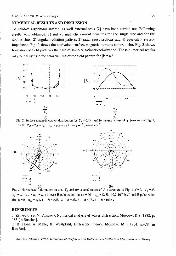
MMET*2000 Proceedings 195
NUMERICAL RESULTS AND DISCUSSION
To validate algorithms internal as well external tests [2] have been carried out. Following
results were obtained: 1) surface magnetic current densities for the single slot and for thedouble slots; 2) angular radiation pattern; 3) radar cross sections and 4) equivalent surface
impedance. Fig. 2 shows the equivalent surface magnetic currents across a slot. Fig. 3 showsformation of field pattern i the case of H-polarization/E-polarization. These numerical results
may be easily used for error valuing of the field pattern for kJR : .
800 .... . ...... ..0.
640
.. .,. . ... , "............ .. .... ... .. .... ... ....... .......
0 0... ....... ... ...
01 - 0,6 - 0,2 0.2 0.6 I0 .................................................... ................
- - 1 -0.5 0.5 1
.2 1"2 2
2x2x
S0 s
(a) (b)Fig. 2. Surface magnetic current distribution for So = O.4X and for several values of p (structure of Fig. 1,
d 0, gai I 8a2 60, 1a = N,2 =0)) 1- p = , 2-p p = 30 0
90
90 120 ...... 60
120 6(1 . .........
.. " ..... 0•3.... .0//O .... '. -OPT 30
I,5o' , • ' , 30 ' , .. , .0 3 , >- ' " "0.070''x ISO ; .. ., ........ .... ......
H go HX00S•..>: •' .\ ;;r: ,• 7.,/
... ".330 " - , .•
240 3(0 270
270 1" 22233 44
(a) (b)Fig. 3. Normalized field pattern in area V2 and for several values of R ( structure of Fig. I d =0, So =3?
'al = Io. sal = Ia2 R ) in case H-polarization (a) ( p = 600 ta2 = (2.68 -10.2 .10- 4 i)6 0 ) and E-polarization
(b) ((p = 00 g,, 2 =o). 1- R = 0.5% , 2- R = 2?,, 3- R = 7X, 4- R = 100X .
REFERENCES
1. Zaharov, Yu. V. Pimenov, Numerical analysis of waves diffraction, Moscow: RiS. 1982. p.183 [in Russian].2. H. Honl, A. Maue, K. Westpfahl, Diffraction theory, Moscow: Mir. 1964. p.4 2 8 [inRussian].
Kharkov, Ukraine, VIII-th International Conference on Mathematical Methods in Electromagnetic Theory

196 MMET*2000 Proceedings
THE ELECTROMAGNETIC WAVE DIFFRACTION BY APARTIALLY SCREENED ANISOTROPIC DIELECTRIC CYLINDER
A.V.Brovenko, P.N. Melezhik, and A.Y. Poyedinchuk
Usikov's Institute of Radiophysics and Electronics, the National Academy of Sciences of Ukraine12 Akademika Proskury Str., 61085, Kharkov, UkraineE-mail: brove@ire,kharkov.ua; [email protected]
A solution method is suggested to the difraction problem of a homogeneous plane H-polarized waveon a partially screened dielectric anisotropic (hyrotropic) cylinder. In the method, the original bound-ary value problem in terms of the Maxwell's equation is equivalently reduced to the system of dualseries equations whose singular part is converted using the direct solution of the corresponding Rie-
mann-Hilbert boundary value problem with the specially developed analytical regularization proce-dure. The result is the second-kind system of linear algebraic equations with Hilbert - Schmidt opera-
tors in the 12 -space to be effectively solved with the reduction method.
The plane electromagnetic wave diffraction is considered as applied to a partially screened circulardielectric cylinder with the related permittivity tensor as following
E1 i -2 0
=-i62 l 0.
0 0 C3
The screening is realized with an infinitely thin and perfectly conducting unclosed circular cylinderwith the generator parallel to the geometrical axis of the anisotropic cylinder taken for the oZaxis ofa Cartesian coordinate system Oxyz.The open system extends infinitely in the oz direction, and the
excitation electromagnetic field has no z- dependence, suggesting the two - dimensional diffractionproblem consideration.L.In mathematical terms, the problem is as follows. Let S be a section through the uncloused screen
in the Xo Y plane, with the completion AS of the circle, S = Su AS. The partially screened di-
electric anisotropic cylinder is illuminated with an H- polarized wave
V0(x,y) = exp(-(i30cos(q-ca))) which is incident normal to the cylinder axis. Here (r,q() are
27czpolar coordinates originating at the anisotropic cylinder axis, a is the screen radius, k - - , and,22
is the excitation wavelength. The electrodynamical system is buried in vacuum. The problem reduces
to finding the diffracted field described by two functions V1 (x, y) and V2 (x, y) which are the solu-
tion of the boundary value problem
61A V2 (p) + k 2 (I -r f)V 2 (p)= 0,r< a,(1)
AV 1(p)+ k 2 VI(p) = 0,r > a;
lim Vgo(p + hn)+ V1 (p + hn)) =
O<h->O pdS (2)
1iM (XV 2 (p-h i) XV2 (p-hfi) )I P 0O<h-->O UI nNf
Kharkov, Ukraine, VIll-th International Conference on Mathematical Methods in Electromagnetic Theory

MMET*2000 Proceedings 197
HMOn((I -- 2) V2 (p-hii)- V 0(p+hii) - V(p+h~ii)) 0
(3)lira (eI (VV2 (p - hf),ii) - i62(VV2 (p - hi),•) - (VV1 (p +hii),i) -
O<h--O-(VVo(p + hi),i)) =0.
The boundary conditions are that the tangential component of the total electric field vanishes at thescreen( condition (2)) and the tangential components of the electric and magnetic fields are continuousacross the boundary of the dielectric anisotropic cylinder ( condition (3)).
In addition, for Vm (x, y),Im = 1,2, the Meixner condition holds in any compact in R2 , and V1 (x, y)
must fit the Sommerfeld radiation condition at infinity. The time dependence is exp(- iot); f and
V are, respectively, the unit vectors of an outer normal and a tangent taken at an arbitrary point of
the screen. Functions Vl (x,y) and V2 (x,y) are related to the Hz - component of the scattered mag-
netic field as
Hz = I{(2 - e2 )V2(xy),r < a;S>a.
The rest electromagnetic field components are obtained from the Maxwell's equations using
Vl(x,,y) and V2 (x, y).
2. In terms of the Fourier series expansion of Vm(x,y),m = 1,2 in function system jetm"" }+0_ and
with Sommerfeld radiation condition imposed, original boundary value problem (1) - (3) reduces tothe system of dual series equations
+00 iý + + -- O 0
I nxn em• -x (1 + e'( .- z)n-
n=l ++00 (4)
ZxneinO =0; < 30 <•z.n=-oo
Here t{n J + are the unknown coefficients corresponding to function
Vm(x, y),m = 1,2,9 = ; -+ 9, 0 = 7r - 0, where 0 describes the considered system geometry,
2 21 -2 62_
A ~ , and r =
For reasons of space, a quite cumbersome expression of function g(') is not presented. We only no-
tice that it depends on the excitation field and coefficients xn.
(1- -)(1+ 2 z)System (4) differs from typical systems of this kind by (1 + T)(1 + A -) # 1. On the other hand, if
we use, say, the orthogonality of functions eimqp , m= 0,+1,+2,... on interval [- ;T,z,], (4) is easily
reduced to the infinite system of linear algebraic equations for coefficients Xn. This change however
Kharkov, Ukraine, VIII-th International Conference on Mathematical Methods in Electromagnetic Theory

198 MMET*2000 Proceedings
is not good in view of the Meixner condition indicating that xn =) Jn2 . This will cause a poor
convergence of the Fourier series in (4) and consequently a clow decrease of the matrix coefficients
of the corresponding infinite system of linear algebraic equations. In addition, the condition numbers
of the corresponding truncated systems of equations rapidly decrease with the truncation order. There-fore a direct computer calculation of (4) is not possible.We suggest an alternative approach to the solution of system (4). It rests on the analytical regulariza-tion of system (4) and yield a closed - form regularizer on basis of the Riemann - Hilbert boundary
value conjugation problem. This approach is presented in [1] and involves two stages.
+-o +00
At the first stage, functions X+ (z) = nx, z"n, X- (z) = - n•xn z-1n=l n=l
which are analytic, respectively, in the interior and exterior of circle Iz! < 1 make it possible to reduce
system (4) to the boundary value conjugation (Riemann - Hilbert) problem of the formX+(W - X-( W -0, r 5(1- r)(l + + 9(,)2
+() + ( ) + A- ) X - (6)
where d ...
Here)' 1 is the arc of circle 4 = I which connects points exp(- i1) and exp(i4) and passes
through point z = -1, arc 72 is the 7l extension to complete circle Iz4 = 1.
At the second stage, Riemann - Hilbert problem (6) is solved with the following application of Sok-
hotsky - Plemel formulae[2] . A change to the Fourier coefficients yields the solution of (4) in the op-
erator form
S=Bx+ . (7)
= ,whereHere B= A x U,where A = zA1 n,,,•-cx is given in [1], and U Urnc 5 ,, , where
f(1 + 61 - 2 )fo(ka); m= O,u,,, :nm : 0.
Here is the kroneccker delta, and 1;m > 0 where ,, is the smallness pa-Here•,, 5 1, + _-1 + C2 17 < 0= ;ni7 < 0,I + -I - C2
rameter, with 0, as 0in ±2
M atrix B = IB +,r,---c' gives the H ilbert - Schm idt operator in l2 and = (W n,) =_c- 1l2. On
this basis and in accordance with the Fredholm alternative and the uniqueness theorem it follows that
a solution of system (7) exists and it is unique. It can be obtained on computer with the reduction
method. A knowledge of x, readily gives VJi(x,y), m = 1,2.
REFERENCES[1] A. V. Brovenko and A. Ye. Poyedinchuk. A regularization Method for a class of dual SeriesEquation in Diffraction Theory MSMW' 98 Symposium proceedings p. 320 - 322.[2] N.I. Mushelishvily. Singular Integral Equations. M.,1962.-599 p. (in Russian).
Kharkov, Ukraine, VIII-th International Conference on Mathematical Methods in Electromagnetic Theory

MMET*2000 Proceedings 199
REGULARIZATION BY THE INTEGRAL IDENTITIES METHODFOR INTEGRAL AND SERIES EQUATIONS
IN DIFFRACTION PROBLEMS
Pleshchinskii N.B., and Tumakov D.N.
Kazan State UniversityP.O.Box 234 Kazan, 420503, Russia
E-mail: [email protected]
A method of integral identities for the regularization of some problems of the diffractiontheory of the electromagnetic waves is proposed. Two auxiliary overdetermined Cauchyproblems for the Helmholtz equation for a half-plane and for a half-strip are considered. It isshown that the Fourier transforms of the boundary functions must satisfy some condition. Thespecial integral identities can be obtained from this condition. In the periodical case theintegral identities have a summatorial identities form.Two particular problems are studied: the plane electromagnetic wave diffraction on a periodicmetallic grating and the problem of diffraction on a step in the plane waveguide with metallicwalls. It is shown that these problems are equivalent to infinite systems of linear algebraicequations (ISLAE) of the second kind.
INTEGRAL AND SUMMATORIAL IDENTITIESConsider the Cauchy problem for the Helmholtz equation in the half-plane
±u Oau 2U(XZ)=0 z>0.•-2-~k ux~z=O, >0.(1)&x2 2 '''D2
+Z
We will seek the solutions of equation (1) in the Sobolev space Hs(Rj), s>3/2 of
distributions of slow growth at infinity. Denote
7(ý):{=11:k. + ijf-k 2 ; 1<k. _J-2 2 }.It is proved in [1] (see [2], too) that
Lemma 1. The solution u(x, z) of the equation (1) belongs to the class of solutions outgoingfrom the straight line z = 0 into a half-plane z > 0 and satisfies the boundary conditions
u(xO) = Uo(XW, -O-(xO) = ul(x), -00 <x< +00OZ
if and only if when Fourier transforms of the boundary functions satisfy the equality
ul (0)-ir(ý)uo(ý) = 0. (2)
From (2) it follows that the following integral identities are valid
u,(x)= - Uo(r)l - iT(4)ei("--)dýj dr, (3)
u " (x) = ]iti(v) I _T) e'('r")d•, dr. (4)-f: - fc
Suppose that the distribution u(x,z) is /-periodical by the variable x. Denote A = 2,r/l
and y,= y(An), n = 0,+1.... We obtain two summatorial identities from (3) and (4)
Kharkov, Ukraine, VIII-th International Conference on Mathematical Methods in Electromagnetic Theory

200 MMET*2000 Proceedings
Lemma 2.f( anneiAnr +0 1 iAm(y-r(
l.,J , - dr = yane yr (0,!), (5)omo n=o j-0 n=-,
( iA 1 iA,,, -r) dr = Z.nyei nY, yý (O,1). (6)0 n=oo n nr---w rn yn=-oo
Now we consider two Cauchy problems for the equation (1) in the half-strip x> 0,
0 < z < h [2]. Denote F = ir/h, Ob,,(z) = sinnFz or On (z) = cosnFz, n = (0),1,... and
gn ={k2 -n 2 2 >0 "k 2 -n 2 1 2 ; k2 -n 2r 2 <0-: in 2 ' 2 -k 2 }.
Lemma 3. The solution u(x, z) of the equation (1) belongs to the class of solutions outgoing
from the straight line x > 0 to the right and satisfies the boundary conditions
u(0,z)=uo(z), -x(O,z)=ul(z), 0<z<h,ax
u(x,O)=O, u(xh)=O, x>0 or -(x,O)=0, -(xh)=O, x>Oaz az
if and only if when Fourier coefficients of the boundary functions satisfy the equalitiesuln + ibuo, = 0, n = (0),1,... (7)
From equalities (7) it follows thatLemma 4.
00 co
f• lanz.On(t) -2 Z lkm(t)qOm(z)dt= ylanqkn(Z), zE(0,h), (8)
0 n=(0)l nt-(00)l Yn? n=(0)1
hI 2 I 0 0m0nt~k()f a,,•n(t) -- j• ntOnZdt= Ea,,nYA(Z), zE(0,h). (9)
0 n=(0) ) h "r =(O)l n=(0)I
TWO DIFFRACTION PROBLEMSSuppose that a plane TE-polarisated wave falls on the 1-periodical ideally conductinginfinitely thin metallic grating [3]. We will search the potential functions of electromagneticfields in the forms
u+(y,z)= ZaneiyzeiAny, z>0, u-(y,z)= Zbne-ir"zeiAny, z<0.n=--o, nl=--o0
We denote by M the part of the interval (0, 1) corresponded to the metallic bands and by N therest part of the interval. It is easy to show that the diffraction problem is equivalent to thesummatorial equation
ZaneiAny =--1, y M, (10)tn=--Oo
ZanyneiAny =0, yE N. (11)rn l=-oo
Kharkov, Ukraine, VIll-th International Conference on Mathematical Methods in Electromagnetic Theory

MMET*2000 Proceedings 201
Denote
Ik. f feiAkrdr, J, =fe iAkdr, k=0,+l,...M N
From the identity (5) and the equation (11) it follows that+00eiAny 1 +0 a 0 1- M imy
ZaneLnnYn Z " In-me , yE N. (12)n=-oo n=-o m=--o Ym
Theorem 1 . The diffraction problem on the metallic periodical grating is equivalent to theISLAE of the second kind
ZaneiAny anYn nmeiamy, k=O,+1... (13)n=-oo n=-o nt=--Qo Ym
We consider the diffraction problem on the step in the planar waveguide with metallic walls[3]. Let the plane x= 0 separates two waveguides x< 0, a < z <,O and x> 0, a < z < b, here
a!a<,6<b .Wedenote N=(a,,8), M=(a,a)u(/f,b), h+=b-a, h-=/3-a,F±- =7r/h-, 0n-(z)=sinF-n(z-a), q5+(z)=sinF+n(z-a), n=(O),l,... and
n = (k-) 2 -(F-n) 2 , n = (0),1,... Let an eigen wave with the potential function
u 0 (x,z) = AOe~iýxb7W(z), x< 0falls from the left waveguide on the junction of the waveguides. The diffracted field ispresented in the form
u+(x,z)= ZAne-ix +(z), x>O, u-(xz)= ZBne+iL3vxVn-(z), x<O.n•(70)l n=(0)l
We obtain from the conjucation conditions at the media interface and from the identity (8)
Theorem 2. The diffraction problem on the step in the planar waveguide is equivalent to theISLAE of the second kind
2 _ 2 Go n +n Zn 1-n-nmk 2AOIkn,' k = (0),l,... (14)2 h- n=Ol n- m0where
'nm= Jf (t)Obm(t)dt, n,m=(0),l,...N
It is proved that the ISLAE (13) and (14) can be numerical solved by reduction method.
REFERENCES[1] I.E.Pleshchinskaya, N.B.Pleshchinskii, The Cauchy problem and potentials for elliptic
partial differential equations and some of their applications, Advances in Equations andInequalities (A.E.I) (ed. J.M.Rassias), Athens, Greece, 1999.
[2] N.B.Pleshchinskii, D.N.Tumakov, Method of fractional fields for the scalar coordinatediffraction problems of the electromagnetic waves in the classes of distributions, KazanMathematical Society, Preprint 2000-1, Kazan, 2000 (in Russian).
[3] V.P.Shestopalov, A.A.Kirilenko, S.A.Masalov, Convolution Type Matrix Equations inDiffraction Theory, Kiev: Naukova Dumka, 1984 (in Russian).
Kharkov, Ukraine, VIII-th International Conference on Mathematical Methods in Electromagnetic Theory

202 MMET*2000 Proceedings
ELECTROMAGNETIC WAVE DIFFRACTION
BY INFINITELY THIN PERFECTLY CONDUCTING
CIRCULAR RING
Y.A.Tuchkin 1,2, F.Dikmen 2, S.I.Tarapov 1,2
'Institute of Radiophysics and Electronics, NAS of theUkraine, 12 Ac. Proscura St., Kharkov 310085, Ukraine
2 Gebze Institute of Technology, PK. 141, 41400 Gebze-Kocaeli, Turkey.
Abstract
A new strong mathematically rigorous and numerically effective method for
solving a boundary value problem of electromagnetic wave diffraction by an infinitely
thin perfectly conductive circular ring screen is proposed.
The method is based on the combination of the Orthogonal Polynomials
Approach and he ideas of the Analytical Regularization Methods. As a result of the
suggested regularization procedure, the initial boundary value problem is equivalently
reduced to the infinite system of the linear algebraic equations of the second kind in
the space of square summable sequences.
This equation can be solved numerically by means of truncation method with,
in principle, any desired accuracy.
The perspective of the method also includes the solution to the problem of
electromagnetic wave diffraction by a few infinitely thin circular ring screens.
Pilot experiments show good perspective of such ring reflector for development
of individual antenna tag for rescue radar systems.
Kharkov, Ukraine, VIII-th International Conference on Mathematical Methods in Electromagnetic Theory
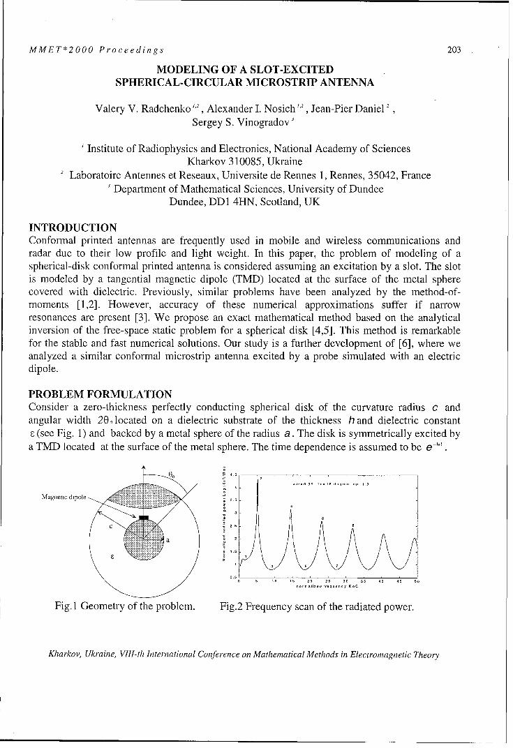
MMET*2000 Proceedings 203
MODELING OF A SLOT-EXCITEDSPHERICAL-CIRCULAR MICROSTRIP ANTENNA
Valery V. Radchenko ,,2, Alexander I. Nosich 1,2, Jean-Pier Daniel 2
Sergey S. Vinogradov'
Institute of Radiophysics and Electronics, National Academy of SciencesKharkov 310085, Ukraine
2 Laboratoire Antennes et Reseaux, Universite de Rennes 1, Rennes, 35042, France
Department of Mathematical Sciences, University of DundeeDundee, DD1 4HN, Scotland, UK
INTRODUCTIONConformal printed antennas are frequently used in mobile and wireless communications andradar due to their low profile and light weight. In this paper, the problem of modeling of aspherical-disk conformal printed antenna is considered assuming an excitation by a slot. The slotis modeled by a tangential magnetic dipole (TMD) located at the surface of the metal spherecovered with dielectric. Previously, similar problems have been analyzed by the method-of-moments [1,2]. However, accuracy of these numerical approximations suffer if narrowresonances are present [3]. We propose an exact mathematical method based on the analyticalinversion of the free-space static problem for a spherical disk [4,5]. This method is remarkablefor the stable and fast numerical solutions. Our study is a further development of [6], where weanalyzed a similar conformal microstrip antenna excited by a probe simulated with an electricdipole.
PROBLEM FORMULATIONConsider a zero-thickness perfectly conducting spherical disk of the curvature radius c andangular width 20, located on a dielectric substrate of the thickness h and dielectric constantE (see Fig. 1) and backed by a metal sphere of the radius a. The disk is symmetrically excited bya TMD located at the surface of the metal sphere. The time dependence is assumed to be e-'.
I a- gg T.=18 dSg p l.3
Magnetic dipol4
2.ý
o 10 is 20 25 0o 35 40 4 50
,,r, a1iz-d 1--qu-ncy KoC
Fig. I Geometry of the problem. Fig.2 Frequency scan of the radiated power.
Kharkov, Ukraine, VIII-th International Conference on Mathematical Methods in Electromagnetic Theory

204 MMET*2000 Proceedings
METHOD OF SOLUTIONDenote the substrate as the region «< (1) » and the outer space as the region « (2) »>. To complywith the solution uniqueness, the total field components must satisfy the following requirements:
(A) time-harmonic Maxwell's equations with the wavenumber k, or k =ko-VF, (B) the set of the
boundary and continuity conditions on the complete spherical surfaces r = a and r = c, (C) the setof dual conditions on the complementary segments of the spherical surface r = c:
E -02)r 0, E(,•1. 2 1c0 0 G (0,00), (1)(i)2
H0 rI,.=c = H(2 r '•r() rj = n(2) r=,c 0 (Ooit ), (2)
(D) the Silver-Muller radiation condition at r --> oo that can be written as an asymptotic request tothe field to behave as an outgoing electromagnetic spherical wave, (E) the power boundednesscondition in any finite space domain enclosing the disk rim. Fulfillment of these conditionsprovides uniqueness of the solution. The method of solution includes the following steps: 1)reducing of the boundary-value problem to the dual series equations in terms of a global set of theassociated Legendre functions; 2) separation of the static part of the problem of a free-space disk,3) static part inversion based on the Abel integral equation technique. To obtain the unknownfields we use the expressions for electric and magnetic Debye potentials in the form of sphericalharmonic series expansions. The problem is finally reduced to determination of the expansioncoefficients ze), z1'1 from the following matrix equation (see [4,5] for details):
zee),, R ,,,,, (00) + 2k0c(1 + r,)A R.o , (00) - B R0o,, (00) = 3 a, - ( j,,
11=1
- Iz, 7),,R,,o(0o) + 2koc(1 /--)Roo(0O)A + (I - R®(00 ))B =-Z a)R,,,(0,) ;n=OII~l n=1
z ,, -?_. z,~," •, ,• ,,,, (0 o) -- A Q 0 Q ,(O o) + B Q o, ((9 o) - ..a• ",, L ,7 -Q ,,,,(0 0o)j (3)k0c ,=1
-2k0 c(1 + e-1)A Roo(9) - B (1 - R(Oo0 )) + _z Ell,,R,,o(0o) - a,,a)R,1o(0o) m = 0fl=,
Here, 6n' is Kronecker's delta, A,B are some auxiliary constants, 6,,, i,, , c,(m', ,a "')are thefunctions ofkc,a/c,_,, , and ,
lIsin(n-m)00 sin(n + m + 1)00R," (0), Q"", (0) = -_ n-m n+i+1 (4)
The matrix equation (3) has favorable features. Its exact solution can be approximated asaccurately as desired by solving progressively larger truncated counterparts.
RADIATION CHARACTERISTICSOn solving (3), one can easily find the far-field patterns, total radiated power, directivity andsurface current density. The normalized radiated power as a function of the normalizedfrequency is shown in Fig. 2. The far-field radiation patterns computed at the frequencies markedby numbers in Fig.2 are presented in Fig.3. One can see the appearance of new sidelobes whenantenna is excited at higher-order modes of the disk.
Kharkov, Ukraine, VIII-th International Conference on Mathematical Methods in Electromagnetic Theory

MMET*2000 Proceedings 205
90 1 90
120 60 120 60
150 30 150 30
plane 90 degree plane 1=90 degree
21 3 180 0
18210 330Plane 11=O degree 210 M3Pae•0dge
'200 300 4 0
270 270
K.C=1.57 1c-o.9g To=18 degree ep=1.3 KOC=5.13 W-c=0.99 To=18 degree ep=2.3
90 1 90 1
120 6 0 120 600
008 -0.
150 80 150 30
plane 6=90 degree _ plane 14=90 degree
0i - 180 ISO 0
plane 0=0 degree plan. fi=o degree210 3 030 300
240 300 24:0 3600
270 270
KC0=9 a/c=0099 T=18 degree 1 p=1.3 KOC=14.49 .10=0.99 T1=8 degree ep=l.3
3 4Fig.3
CONCLUSIONSThe presented approach enables one to analyze the basic antenna characteristics in full-wavemanner. Due to analytical inversion of the singular part of the problem, the resulting algorithm isvery efficient. Numerical study hence delivers a reliable information on the antenna performanceboth in and off resonances. Such a study confirms intuitive considerations that a patch canenhance the radiation conductance of a slot.
References1. B. Ke, A.A. Kishk, Analysis of spherical circular microstrip antennas, Proc. lEE, Pt. H, vol. 138, pp.542-548, 1991.2. K.-L. Wong, S.-F. Hsiao, H.-T. Chen, Resonance and radiation of a superstate-loaded spherical-circularmicrostrip patch antenna, IEEE Tr.Ant. Propagat., vol. AP-41, no 5, pp. 686-690, 1993.3. G.L. Hower, R.G. Olsen, J.D. Earls, J.B. Schneider, Inaccuracies in numerical calculation of scatteringnear natural frequencies of penetrable objects, IEEE Trans. Antennas Propagat., vol. AP-41, no 7, pp.982-986, 1993.4. S.S. Vinogradov, A soft spherical cap in the field of a plane sound wave, USSR J. Comput. Maths Math.Physics (Engl. Transl.), vol. 18, no 5, pp. 244-249, 1978.5. S.S. Vinogradov, Y.A. Tuchkin, V.P. Shestopalov, Summatory equations with kernels in the form ofJacobi polynomials, Soviet Physics Doklady (Engl. Tr.), vol. 25, no 7, pp. 531-532, 1980.6. V.V. Radchenko, A.I. Nosich, J.-P. Daniel, S.S. Vinogradov, A conformal spherical-circular microstripantenna: axisymmetric excitation by an electric dipole, Microwave Optical Technol. Lett., vol. 26, no 3,pp. 176-182, 2000.
Kharkov, Ukraine, VIII-th International Conference on Mathematical Methods in Electromagnetic Theory

206 MMET*2000 Proceedings
ACCURATE NUMERICAL SOLUTION OF A DIFFRACTIONPROBLEM FOR A NON-EQUIDISTANT AXISYMMETRIC STRUC-
TURE CONSISTING OF CIRCULAR DISKS
Alexander N. Khizhnyak
Kharkov Branch of Scientific and Industrial Concern "Nauka"
Krasnoznamennaya str, 4, Kharkov, 310002, UkraineE-mail [email protected]
Wave diffraction problem associ-ated with an electric dipole radia-tion in the presence of a finite I
non-equidistant array of circularperfectly conducting identicaldisks is considered in this paper. -hAn axial dipole placed on the axisof rotational symmetry. The aim ..... hnof the work is to obtain mathe-matically and numerically exactsolution of the appropriateboundary problem. By using the Fig. I.Scattering structuremoment method combined with apartial inversion of the problem operator, the problem reduces to numerical solving of infinitematrix equation set of the 2-nd kind. The Fredholm nature of obtained equations ensures theexistence of the unique solution.The scheme to obtain the solution is as follows. The unknown scattered fields are written us-ing Hankel integral transform which is convenient accounting the problem symmetry. Fromthe boundary conditions, one can obtain the set of dual integral equations for the unknownspectral amplitudes. As obtained equation set is of the first kind, one has to provide theirregularization in order to obtain a convergent numerical algorithm. Therefore, we use themethod of the partial inversion of the problem operator. Eventually original equations are re-duced to the matrix one of the second kind, which can be solved by using standard numericalmethods. Developed approach does not contain principal limitation on geometrical parametersof the problem and provides an opportunity to compute the solution with any desired accuracyup to the machine precision.Consider the diffraction of a dipole source field by the structure consisting of N+l coaxialperfectly conducting disks with the same radii that are placed at the arbitrary distance h,, fromthe first one. The origin of the cylindrical coordinate system (r, 4 ,z) is in the center of the firstdisk so that all the other disks are placed in the domain z>O. A source field wave is incidenton the structure from the domain z<O. Time dependence supposed to be exp(-i(Ot). Accountingthe problem's symmetry one can describe the electromagnetic field using only one componentof the Herz vector. The problem is to determine a scalar function P(r, z; k), which character-izes the resulting field, here k=2t 7/ is the wave number. This function can be decomposedas a sum of the incident P0 and the scattered PS fields. It is convenient to expand the scat-
tered field by using the Hankel integral transform in r
Kharkov, Ukraine, VIII-th International Conference on Mathematical Methods in Electromagnetic Theory

MMET*2000 Proceedings 207
P (r,z;k)= ja (ý)J 0 (ý r)e 'lzw) d, z<O, (1)s0
00 i(z - hnP +s,n(r, z;k) jc n (ý)J 0 (ýr)e
0
k 00 -i(z - h ny(
P sJn(r,z;k) fb n(ý)Jo(ýr)e-0
hn-I < z < hn
00 i(z - h N WO( dý,'P (r,z;k)= fd (ý)J 0 (ýp)e z>hN,
0
Po (r, z; k) = _i f -_.jo (ýp) e iz+ d , - incident field.0 yt•')
F•) -4 2, Imy _, = 1,2,3... N, the number of disks is N+ 1, unknown spectral
amplitudes a(4),d(4),bn (4),cn (4) are to be determined.
From the boundary conditions one can arrive to the dual integral equations for the unknownspectral amplitudes. Using the moment method, these equations can be reduced to the matrixones. It is well known that efficiency of the moment method strongly depends on the proper
(m)choice of basic functions. We seek the solution as a series in terms of the functions 4 n (•)
(in) -1/2*n (x)= 1 4n+2m+3J2n+m+3/2 (x)x (2)
The following properties take place:
oo(m) (in)
fn ()d4)= ns000 (in) (in) n! 4n+2m+3 m 2 1/2 m/2) 2
f~n (9)Jm(4p)9dp =n (P)'
0
where P(a•') (x) are the Jakobi polynomials.
Kharkov, Ukraine, VIIJ-th International Conference on Mathematical Methods in Electromagnetic Theory

208 MMET*2000 Proceedings
Introduce the auxiliary functions un (n)
+ i(c ± )- i(hn- 1 -h 2)() b )ei(hn+ 1 -hn)() (3)Un - (n n b n) - 1 (nl+bn+1~ 3
On expanding the functions u+(m) (4) in terms of the functions (2):+ 00 +. (1)Un(•) = ZCn~s4bs (•)
s=O
one comes to the infinite matrix equation for the unknown coefficients Cn,s++ + + oo n-1
Bn, s= Cn, An, js-Cn, s + Z (Crl + Cn-rl, j)Dn,r; js+ (4)
j=0 j=0r=Ooc N-n-i1
-+ Z (c -c ,n=1,2...N.I E n+r+l, j n+r+l, jG n,r;js
j=O r=O
-ns+ -if"d (s1) (• ()ihn-,Y(4) ( ei(hn -h n-1y(
0
+ 00(l() s)• + -7R)1 i(h n-hn_1)7(ý)A njs =f~ (4ý (do do n (4) dý, Fn (4) = I + i--I T e )
+ ±
n,q;js =Hn-l,n-q-2; js -- Hn,n-q-2; js' Gn,q;js =Hn~q~l,n; js -- Hn~q~l,n-1; js
H*c() (1) i(h) -e y(•)d00
Un,s; js =2- J s()e 4dý
Integrand functions in the matrix elements have no singularities and decrease as -4 or as
exp(-h 4 ) if 4 -> oo, so that their calculation can be done using standard numerical methods.
Kharkov, Ukraine, VIII-th International Conference on Mathematical Methods in Electromagnetic Theory

MMET*2000 Proceedings 209
MATHEMATICAL MODELING OF ELECTROMAGNETIC WAVEDIFFRACTION BY INHOMOGENEOUS DIELECTRIC CYLINDERS
OF ARBITRARY CROSS-SECTION
A.Lerer and G. KalinchenkoRostov State University, Institute of Physics,194 Stachki Ave, 344090 Rostov on Don,
Russia,Email: [email protected]
Email:hitech @ aaanet.ru
ABSTRACT
The method of volume integral equations had been developed for simulation of 2-Delectromagnetic waves diffraction problem. The efficient codes for simulation of thescattering by inhomogeneous dielectric cylinders of arbitrary cross-sections is carried out.The method proposed is based on the idea of analytical regularization of singular integralexpression.
INTRODUCTION
For consideration of electromagnetic wave diffraction by dielectric body one can use bothsurface and volume integral equations (IE). In our opinion volume ones (VIE) have followingadvantages: VIE are more simple than surface TIE (SIE), the nonuniformity and nonlinearityof dielectric do not turn out the solution to be rather complex, a spatial electric fielddistribution can be found out directly from a solution. Meanwhile the VIE have one essentialdeficiency - IE should be satisfied not only on the surface but also everywhere inside thedielectric body.
ANALYTICAL FORMULATION
The problem of E-polarization wave E' diffraction by dielectric cylinder of nonuniform
permittivity c1(xy) have been reduced to IE solution in the same as in [1]
E(x, y)=EEe (x, y)+k 2 f (x', y')E(x', y')G(x, x', y, y')ds' (1)s
where r(x, y)=6 1 (x, Y)-_'2, 2 - free space permittivity, S - cross-section of cylinder, G -
Green function (GF). Putting into operation function F(x, y)=r(x, y)E(x, y) we can rewrite
(1) as
F(x, y)/v(x, y)=Ee(x, y)+k2f F(x', y')G(x,x', y, y')ds' (2)S
In every case the GF has logarithmic singularity G z G0 (r)= log r when r -4 0. Therefore it
is necessary to extract this singularity. Here we propose an effective method of singularityextraction. After an identical transformation (2) we get the following expression
F(x,ry),r(x, y+ era(Xty)+ki2 F(x,ey)r(xe y)+k2o a[F(x',iy')G(x, x',My,oy'd - F(xi y)Ec (r)ots', (3)s
Kharkov, Ukraine, VllI-th International Conference on Mathematical Methods in Electromagnetic Theory

210 MMET*2000 Proceedings
where I(x, y)=k2f Go(r)ds', function GO(r) has the same singularity when r -- 0 as GF.s
Using the first Green's formula with supposition u = Go and v = r 2/4 the integral I(x,y) can betransformed to one taken along the line L bounding the area S.
f Go(r)ds'=- I fr(log r- 1/2) --r dl's 4/re L On'
where r = (x-x') + (y - y) 2 , n/- vector normal to L.The expression under the integral in third term of (3) has no a singularity as well andtherefore can be easy taken numerically. Stress that for same contours, for example, circle orrectangle this integral can be taken analytically.
Hence, we can calculate it by the one of well-known formulae of numericalN
integrating: f f(x', y')ds' ZA,,f(x,,, y,,), where coefficients A,,, x,,, y,, should be defined byS
choice of integrating formula. Then, TE (3) must be satisfied when x=x ,y=y,,. As a result
we derive a set of algebraic equations (SAE). For nonlinear dielectrics C,=CI (x, y, EJ) we
get nonlinear IE, which can be solved by method of disturbance. Initially we solve the IE withmethod described before for fundamental harmonics and as the result obtained (SAE). Thepermeability here depends on electric field and therefore it is a nonlinear system, which canbe solved by approximation method. Then, for first harmonics we find IE analogous to (3)with substitution of the fundamental harmonics field instead of E e. The fields of highestharmonics can be simulated in the same manner.
Due to good convergence of series and integrals itis enough to sum 20-30 terms in series andnumerical quadrature to get a deviation up to0.1%. The order of system of algebraic equationsincreases with increasing the dielectric bodydimension via wavelength in dielectric as
N z[5max(A,B)
C RESULTS
In this paper we have calculated the powerC ! transmitting coefficients for diffraction by
dielectric cylinder situated next dielectric planarX waveguide layer shown in Fig.], grating made of
dielectric cylinders and dielectric cylinder settingFig.1 inside of planar metallic waveguide.
As the illustration of our method we present in Fig.2 the results describing the diffraction ofmode H, propagating in planar dielectric waveguide by dielectric cylinder when differentdistances of cylinder from waveguide. The curves here express the power transmission
21- dcoefficient via normalized frequency F = 2d for linear regime. The waveguides
of two geometrical dimensions are shown by different types of curves - solid and dotted ones.It is seen that resonance appears only if the inhomogeneity permeability is rather high. For
Kharkov, Ukraine, VIII-th International Conference on Mathematical Methods in Electromagnetic Theory

MMET*2000 Proceedings 211
both waveguides under consideration the reflection coefficient is not high. Therefore thepower, which is not passed through the inhomogeneity, radiates.
CONCLUSIONS
The problem of electromagneticwaves diffraction by nonuniform Pr
and nonlinear dielectric cylinders is 1,0 ...... ...........solved with integral equation 0,9-method in an efficient and accurate 0,8- ,
manner. In this paper, we have0,7-calculated the power transmitting
coefficients for diffraction 0,6- /by grating made of dielectric o,-,cylinders, dielectric cylinder setting 0,4-inside of planar metallic waveguide Q3- 0.5and dielectric cylinder situated 02
next dielectric planar waveguide 1.
layer. 0,1
Hence, this investigation can 00'.
become a basis for the studies of 0,4 0,6 0,8 1,0 1,2 1,4 1,6 1,8 2,0 2,2 24 F
propagation of complex waves innonlinear waveguide structures, Fig. 2. Solid curves - A/d = 1,B/d = 0.5, e, 2,c 2 = 1,c 10,
generation of highest harmonics, dotted -A/d=1,B/d=0.5,81 =2.343,c 2 =2.372,c=2.6,
capacity of light signal modulation, dash-dotted - emission loss Pr.the demonstration of the possibilitythe vibration control devicescreating, etc.
REFERENCES
[1] Computer Techniques for Electromagnetics, Edited by R. Mittra. New York,
Pergamon Press, 1973.
Kharkov, Ukraine, VIII-th International Conference on Mathematical Methods in Electromagnetic Theory

212 MMET*2000 Proceedings
Kharkov, Ukraine, VIII-th International Conference on Mathematical Methods in Electromagnetic Theory

MMET*2000 Proceedings 213
S!iIGNAXL
PROCESSING
Kharkov, Ukraine, VIII-th International Conference on Mathematical Methods in Electromagnetic Theory

214 MMET*2000 Proceedings
Kharkov, Ukraine, VIII-th International Conference on Mathematical Methods in Electromagnetic Theory

MMET*2000 Proceedings 215
DISCUSSION OF THE K-PULSE CONCEPTION
O.O.Drobakhin, D.Y.Saltykov, and V.G.Korotkaya
Radiophysics Dept., Dniepropetrovsk State University,13 Nauchnaya Str., Dniepropetrovsk, 49050 Ukraine
ABSTRACTA number of discrimination measures using K-pulse conception for the simplest objectcharacterized by a single complex natural frequency has been investigated by a computersimulation. Besides the traditional weight function, the Hemming's function and functionwith the Fourier transform coinciding with the Batterworth function have been used. TheHemming's function has some advantages.
Ultrawide-band schemes of radar object discrimination have been under active investigationfor last two decades [1,2]. According to K-pulse [3] conception special form of input signal isconstructed, thus, output signal in time-domain does not contain late-time component. Thelast component represents reverberations at object natural frequencies and can be expressedwith sum of exponentials. The zeros of K-pulse spectrum coincide with the poles of thefrequency response of the object. The zeros completely annihilate the poles and thus late-time component is annihilated as well. Usually rather complex objects are investigated, thatdoes not allow one to obtain fundamental properties. In this paper, object model in formR( (o) = A exp( jqp )/( co - (op - 6j ) is explored.
If a K-pulse excitation with spectrum K(wo) is used, a response of an object with frequencyfunction R(co) can be calculated according to
P( co ) = R(o ).K( o) (1)
After transformation into time-domain and obtaining signal p(t) the decision aboutcorrespondence of the object and K-pulse is made by late-time component analysis. Undercomplete coincidence of the poles of object and zeros time-domain signal is equal to functionsin(x)/x. To avoid oscillations in time domain, frequency weight function
W( o) = [I -exp(-joy )]/ jo, (2)
is used. Dirichlet weight function provides rectangular basic functions in time domain thus intime domain sharp boundary between early and late components occurs. But this problem isdual to low-pass filtering therefore the Batterworth weight functions can be appliedalternatively. Both Dirichlet and Batterworth weight function have zeros in frequencydomain, positions of which depend on value of natural frequencies of standard object.
In [I] discriminating measure
k4 Z p2ti )j rk2(ti ) (3)
h i=M e o i=0 I
Kharkov, Ukraine, VIIl-th International Conference on Mathematical Methods in Electromagnetic Theory

216 MMET*2 000 Proceedings
has been suggested. In (3) k(t) is the Fourier transformation of K(co). Discriminating measure(3) has the evidential disadvantage if an object induces various values of a response amplitudedue to a variation of an angle of an observation. Under the circumstances one can not separatea contribution of shifting of zeros and poles and changing of the amplitude in the value of k4.Other measures for investigation used are identical to measures k1, k2, k3 [4].
The requirement of providing optimal value implies the weight function with the maximalratio of energy in the main lobe and the side lobes. The Hemming function has high propertiesand simplicity simultaneously. Besides, the Hemming function has not zeros in its spectrum.Traditionally the approach was applied for video-signals but in many cases measurementshave to be carried out in frequency domain in band with nonzero initial value. In the capacityof time-domain signal can be used real, imaginary part of the Fourier transform of frequencydomain data. The approach corresponds to processing of videopulse. Alternatively, modulusof the result of the transformation can be used. The last situation corresponds to processing ofan envelope of the time-domain signal. Our numerical simulation has displayed highersensitivity of the second approach in comparison with the first one to the difference of poleand zero. If at the frequency of the pole a value of weight function for the first case is greaterthan one for the second case, the opposite situation is observed. If values of weight functionsare equal at the frequency of a pole, relation between accuracy of discrimination depends onthe type of discrimination measure. Naturally, varying the initial phase value does not inducechanging the value of a discrimination measure if the envelope of time-domain signal is used.
k k
5 -20 .
% I
2.5 ~~ 15 \I2. 10
00.16 0.19 0.22 0.25 0 .2 8 fo 0.ý16 0.19 0.22 0.25 0.28 fo
Figure I Figure 2
Some numerical measures of discrimination have been studied. The measures k1, kq, k3, k4 fornormalized frequency 0.225 are presented in Fig.l, where solid line corresponds k1 , dot linecorresponds k2 , dash line corresponds k3 , dash-dot line corresponds k4. It is evidently that kc4provides more sharp characteristics and higher accuracy of estimation but choosing too smallstep can involve missing the fact of the pole and zero coincidence. The measure k3 serves to
Kharkov, Ukraine, VIII-rh International Conference on Mathematical Methods in Electromagnetic Theory

MMET*2000 Proceedings 217
improvement of reliability. The numerical simulation has shown that simultaneous applicationof measures is appropriate.
The advantage of K-pulse is considered traditionally to be suppressing noise by weightfunction but the same function can hide the effect of zero and pole coincidence. Usually theysuppose that more high level of noise is observed at the range of high frequencies of thespectrum but for measurements in frequency domain it is not valid. A comparison of thetraditional and the Batterworth weight functions have been carried out. The view of measurek4 for the Batterworth window (solid line), the Dirihlet window (dot line), and the Hemmingwindow (dash line) is presented in Fig.2. The Hemming's window provides more sharpcharacteristic and therefore higher accuracy. According to the traditional K-pulse technique itis necessary to vary the weight function parameters in dependence from the value offrequency of standard object pole thus shifting the zero or even forming several zeros in thefrequency band of the weight function occur. The approach can imply occasionallycoincidence of weight function zero and the object pole and therefore the impossibility ofrecognition. This situation was confirmed by numerical simulation with Batterworth windowand illustrated in Fig.2, where the corresponding measure k4 has not minimum at thenormalized frequency value equal to 0.225. Thus estimation of the pole value is impossible.The coincidence of a weight function zero and the object pole does not allow us to detect thefact of coincidence of the weight function zero and the object pole. Since the weight functionserves to eliminate oscillations in time domain, discrimination can be realized with the sameweight function but the reciprocal sequence of frequencies in the object response. Forinstance, according to the suggestions normalized frequency 0.225 is transformed to value0.275. Probability of recoincidence of the weight function zero and the object pole isnegligible small. The approach suggested has been applied successfully for the polediscrimination for the Batterworth window.
REFERENCES
[1] Ilavarasan P., Ross J.E., Rothwell E.J., Chen K., and Nyquist D.P. Performance of anautomated radar target discrimination scheme using E pulses and S pulses // IEEE Trans.Antennas Propagat. 1993. vol. 41. X2 5. P. 582-588.[2] Primak S.L., Lo Vetri J., Damjanschitz Z. and Kashyap S. Auto-Regressive Filter-BasedE-Pulse Discriminating Scheme H IEEE Trans. Antennas Propagat. 1999. vol. 47. X2 1. P.216-218.[3] Fok F.Y.S., Moffat D.L. The K-Pulse and E-Pulse// IEEE Trans. Antennas Propagat.1987. vol. 35. XN 11. P. 1325-1326.[4] Drobakhin O.O.,Saltykov D.Yu. 1-D Inverse Problem Solution for Multilayered DielectricStructures using K-signal Conception H Conf. Proc. MMET-96. Lviv (Ukraine). 1996. P.432-435.
Kharkov, Ukraine, VIII-th International Conference on Mathematical Methods in Electromagnetic Theory

218 MMET*2000 Proceedings
SCALAR QUANTIZATION IN THE PWL TRANSFORM SPECTRUM DOMAIN
Remigiusz Baran, Dorota Wiraszka, Wiera DziechKielce University of Technology,
A]. 1000-lecia PP 7, 25-314 Kielce, PolandE-mail: [email protected]
ABSTRACTThe problem of image compression using the PWL (Periodic Walsh Piecewise-Linear) transform
and optimal scalar quantization of PWL spectrum has been presented in the paper. Short description ofthe PWL transform has been included. Optimal Lloyd-Max Quantization has also been presented. Theprocedure of the presented compression method is based on quantization of class of scalar variablesrepresenting blocks of the image. Effectiveness of the compression method has been examined. Visualrepresentation of the results of investigation has been included.
INTRODUCTIONNostradamus wrote is his prophecies: "I see that world is getting smaller". Now, with respect to
the new telecommunication applications, especially the Internet Network, we can say that he wasprobably right. The World Wide Web is favouring our generation, giving us incomparable with thepast access to information. Nowadays we can hear that the XXI century will be called the informationcentury. Requirement for transmitted and stored information will still be growing. Even without thegift of Nostradamus, it is possible to predict that this requirement will overtake the development oftechnology in the closest future. Thus, the problem of signal and image compression still has thefundamental priority in the field of digital signal processing. Various techniques aimed on this subjecthave been developed during the recent years. One of the most efficient methods is the transformcoding method.
THE PWL TRANSFORMThe set of non-orthogonal PWL functions is obtained by integrating the Walsh functions repeated
with T period [1 ]. The PWL functions are defined as follows [1,4,5,7,9]:k+ mOT)+t
PWL(O,t) = I for t e (-cc, +oo), PWL(i,t) =- T wal(i,r) d (1)
where: (,uiT)
i - number of the Walsh function, i = 1, 2, ... , N - 1;
k - group index of the PWL function, k = 1, 2, .... log 2 N;
rn = 0,+ 1, + 2 .... -the period number; 2k+±/T - the normalization factor;
The PWL transform, for the continuous function x(t) sampled at N points, is following:N-1 N-1N -I
x(t) =I ciPWL(i,t), for t E (-oo, + oo) co = N-YZx(11), ci k - 2 nZx~nwai~~n)(2)
i=0 /= 2 1=0
where:i= 1,2,..., N-I; x(n) - samples of the x(t)
SCALAR QUANTIZATIONQuantization [2] is the step subsequent to sampling in image digitization. The quantization process
maps a continuous variable x into a discrete variable x *, which takes values from a finite set. Thex -ý x * mapping is usually a staircase function. The scalar quantization requires definitions of twosets of increasing values: set of decision levels - p = {tk , k = 1, ... , L + 1}, with t1 and tL+I as theminimum and maximum values of x, respectively, and set of reconstruction levels -
Kharkov, Ukraine, VIII-th International Conference on Mathematical Methods in Electromagnetic Theory

MMET*2000 Proceedings 219
x* = {r, ....... , rL }, defined with accordance to the set p. If x lies in interval [tk, tk+l ), then it is
mapped to rk. The quantizer introduces distortion QE = x * -x, which any reasonable design method
must attempt to minimize. The quantizers, useful especially in image coding techniques, are a zeromemory quantizers. One of the zero memory quantizers, useful in image coding techniques, is theLloyd-Max Quantizer [2,3], which minimizes introduced distortion for a given number of decisionlevels L and for given probability density function p(x).
Two commonly used densities for quantization of image-related data are the Gaussian andLaplacian densities, which are described by following formula [2]:
1 1 r-vI xI(asin ) 2 2 exp -22 Laplacian: PL(=X)= 202exp (3)
where: a.2 and /u - the variance and mean of x, respectively.
THE COMPRESSION SCHEMEThe compression method considered in this chapter is a kind of zonal compression method [8].
The input image (N x N) is divided into blocks (M x M). Each of these blocks is then transformedusing the PWL transform, what produces (N / A) 2 tables of spectrum coefficients (M x M). Next thespectrum coefficients are grouped with respect to their position, what gives M2 new tables of groupedcoefficients (M x AM), only DC for instance. According to the grouped coefficients tables the matrix ofvariances is produced, constituting a base for the normalisation process. The normalisation processallows using the same quantizer to the data series of different variances. The variance matrix is usedalso in Integer Bit Allocation procedure [6] to produce the matrix of bit allocation, which is a basis tothe quantization process of grouped coefficient tables. One of the input parameters to the compressionscheme and the Integer Bit Allocation procedure is the average number of bits a allocated for onequantized table. As the expected probability density functions were Gaussian or Laplacian, the Lloyd-Max Quantizer has been applied. Quantization is the final step of the coder in the consideredcompression scheme. The coder sends to the transmission line: the variance matrix (M x M), M2
matrices of indices (M x Al) to the quantized values, M2 vectors of quantized values (length of eachvector depends on The Integer Bit Allocation procedure). The decoder of such a compression schemeconsists of the denormalisation process, the coefficients inverse-grouping task and the inverse PWLtransform step.
Distortions of the reconstructed image depend on a parameter. The number of information bitstransferred by the transmission line depends on a parameter, as well. The distortion can be measuredby a MSE error [10].
To count the number of information bits transferred to the decoder part, the compression factorhas been introduced:
(8. N,..N -c).lO0%
8. N .Nx (4)
where: c - the number of information bits transferred by the transmission line.
THE RESULTSSome results of application of the proposed com ression method are presented in Fig. 1.
a) b) c) d)Fig. 1. Compression results with various mean number of bits for quantized table a
Kharkov, Ukraine, VIII-th International Conference on Mathematical Methods in Electromagnetic Theory

220 MMET*2000 Proceedings
a) original image c) a = 1.0, MSE 52.6115, 7 [%]=78.7598b) a =3.0, MSE 10.0469, 17[%]=32.0801 d) a =0.5, MSE= 102.9025,77[%]=88.9160
MSE and the r factor versus the a parameter are depicted in Fig. 2.
MSE 200 7% 10
150 50.
100 0-
50 -50
0 -1000 2 4 6 8 a 0 2 4 6 8 a
a) b)rig. 2. a) error MSE versus a parameter; b) the compression factor q/ versus a parameter
CONCLUSIONSAverage number of bits a decides on the number of bits allocated for particular tables of the PWL
spectrum grouped coefficients. The smaller the a, the shorter the vectors of quantized output valuesand the more zero elements in the bit allocation table, thus smaller number of tables are beingquantized. In the other words, the value of a is proportional to the transmitted information, andinversely proportional both to the mean-square error MSE and the compression factor q. Visualanalysis of Fig.1 shows that the images obtained for a < 1 are strongly distorted (example d), whatmakes them unacceptable. The distortions obtained for a = I are hardly noticeable (example c). Fora > I the distortions are unnoticeable for the human eye (example b). Above tendencies areconfirmed by curves depicted in Fig.2. It is worth mentioning that for a > 4 the proposed methodbegins to show trends, which are inverse to the expectations: the information sent is greater than theinput information. This can be noticed in Fig.2b.
ACKNOWLEDGMENTSWe gratefully acknowledge the assistance and support provided by Professor Andrzej Dziech from
the University of Mining and Metallurgy in Cracow, Poland, who patiently supervised our work overthis paper.
REFERENCES1. Dziech A., Pizetwarzanie i przesylanie sygnal6w, Skrypty Uczelniane Politechniki Swiqtokrzyskiej, Kielce
1985.2. Jain A.K., Fundamentals of digital image processing, Prentice Hall International, Englewood Cliffs, NJ
1989.3. Max J., Quantizing for mininium distortion. IRE Transaction on Information Theory, IT-6, 7-12, 1960.4. Dziech A., Pardyka I., Biela-Wiraszka D., Chodorek R., Zagadnienia kompresji i aproksyinacji obrazow z
zastosowaniem dwityminarowych przekszbalceii odcinkowo-stalych i odcinkowo-linioitych, Materialy konf.Przetwarzanie Sygnal6w'93, Poznafi 1993.
5. Pardyka I., Smolewski I., Piecewise-Linear Transforms, Final Report of the Individual Fellowship withinEEC, Wuppertal 1993.
6. Belgassem F., H., Image and contour data compression using periodic piecewise-linear transforms,Rozprawa doktorska, AGH Krak6w 1997.
7. Pardyka I., Biela-Wiraszka D., Slusarczyk P., Baran R., Image compression using Piecewise-LinearTransforms, XX Krajowa Konferencja Teorii Obwod6w i Uklad6w Elektronicznych, Kolobrzeg 1997.
8. Pavlidis T., Grafika i przetwarzanie obraz6w, WNT, Warszawa 1987.9. Pardyka I., Chodorek R., Biela D., Problemny aproksymacji obraz6w z zastosowaniem dwuwymiarowych
przeksztalcefi PWL, Krajowe Sympozjurn Telekomunikacji, Bydgoszcz 1992.10. Skarbek W., Metody reprezentacji obraz6w c~froiwych, Akadernicka Oficyna Wydawnicza PLJ, Warszawa
1993.
Kharkov, Ukraine, VIII-th International Conference on Mathematical Methods in Electromagnetic Theory

MMET*2000 Proceedings 221
MAXIMUM LIKELIHOOD TECHNIQUE FOR DIRECTION OFARRIVAL ESTIMATION IN ADAPTIVE ARRAYS
Ildar R. Urazgildiyev
National S&R Center of Defense Technologies and Military Security of Ukraine81, Melnokova str., Kiev, 04119, Ukraine
E-mail: [email protected]
ABSTRACT
A direction of arrival estimation technique based on unification of eigenstructure andmaximum likelihood estimators is considered. The basic stages of proposed technique areestimation the number of signals, fast evaluation of the initial DOA estimates, and fastaccurate definition of initial ones.
INTRODUCTION
The estimation of directions of narrow-band signals is the basic problem arising in radar,mobile and satellite communication, radio astronomy and many other applications. Thisproblem is solved in a complex and dense environment as a rule. Therefore the adaptive (or"smart") antenna array with digital signal processing is considered to be the most efficienttool for direction of arrival (DOA) estimation.Under the conditions of a priori uncertainty as well as small signal-to-noise ratio (SNR) themaximum likelihood (ML) estimator is known to approach asymptotic efficiency. A veryserious shortcoming of the ML estimator is that it suffer from very computational cost.In this context, the eigenstructure-based algorithms achieve a compromise betweencomputational complexity and estimation performance at high SNR. However, the applicationof eigenstructure methods can be severely limited at low SNR and closely spaced sources.In this paper the DOA estimation technique based on unification of eigenstructure and MLestimators is considered. The basic stages of proposed technique are estimation the number ofsignals, fast evaluation of the rough initial DOA estimates, and fast accurate definition ofinitial ones.
PROBLEM FORMULATION
We are concerned with DOA estimation for a class of signals that can be represented as [I]-[5]
j=1
where q is the number signals, x(i) is a Nx] complex observation vector, s(i) is a qx1 complexsignal vector, n(i) is a Nx1 complex noise vector, a(0)=(1, exp[j&],..., exp[j(N-1)0j)T is theNx] vector corresponding to the DOA 0, N is the number of sensors; and L is the number ofsnapshots.The samples of noise vector n(i) are assumed to be independent Gaussian complex randomvectors with mean 0 and covariance 021, where W2 is an unknown scalar constant and I is theidentity matrix.
Kharkov, Ukraine, VIII-th International Conference on Mathematical Methods in Electromagnetic Theory

222 MMET*2000 Proceedings
With the above given model, the problem to be solved is to determine the DOA's
'§ =@)1 '2.. q 6 of signals from a finite set of observations x(1), x(2) .. x(L).
DOA ESTIMATION TECHNIQUE
To solve mentioned problem the following approach is traditionally used. On the first stage,when a-priori information about the number of signals is absent, some algorithm of signal'sdetection and estimation of signal's number is applied. Among this type of algorithms Wax &Kailath [1] one can be chosen because it has good performances at low computational cost.After calculation of the number of signals DOA estimates are found by means of the quasi-optimal eigenstructure-based algorithms like MUSIC [2] and Min-Norm [3]. Mentioned oneshave acceptable computational cost and ensure high accuracy and resolution. However, inconditions of low SNR the root mean square error of the estimates obtained with the help ofthe quasi-optimal algorithms essentially exceed the Cramer-Rao bound. Therefore with thepurpose of increasing of the DOA estimation accuracy we propose to include the third stage inthe array signal processing. The object of this stage is to define more precisely the DOAestimates obtained by means of eigenstructure-based estimators.To estimate DOA of received signals a recurrent ML algorithm can be used on the third stage.It is well known that ML estimate of Ocan be written as follows [2]:
OML = arg max pD(O), T(O)=trP(O)RL, (2)0
where tr is the trace of matrix; P(O) is the projector onto the signal subspace; R, is sampledcorrelation matrix of signals (1).According to recurrent algorithm the (k+l)st iteration for locating the parameter vector &
which maximizes a criterion function q9'&) is given by [4]
o(+1 = o(k _ (0)-' V(ot o=o( ,, (3)
where V(O)=a0p(O)/D0 is the gradient; B(6)=a 2(p(O)/DarOT is the matrix of secondderivatives and ýt is the step constant.Thus, the recurrent algorithm (3) makes it possible to define more precisely the DOAestimates obtained with the help of eigenstructure-based algorithms.
SIMULATION RESULTS
In order to demonstrate the performance of the proposed recurrent ML algorithm we compareit to the Cramer-Rao bound (CRB) and to the quasi-optimal MUSIC and Min-Normalgorithms in several simulated experiments. In all experiments to follow, a uniform lineararray of N=10 omnidirectional sensors with half-wavelength spacing and two uncorrelatedGaussian sources (q=2) with equal power have been assumed. The number of statisticallyindependent snapshots in each simulation runs was L=l00. A total of 100 independentsimulation runs were performed to obtain each simulated point. The signal scenario O=1O0,02=15° was considered in experiments. The comparison of performances is given in terms ofDOA estimation root-mean square error (RMSE). The sample RMSE's of the obtainedestimates are plotted on Fig. 1.The results confirm the theoretical prediction that is the recurrent ML technique achievesbetter performances than the MUSIC-like algorithms.
Kharkov, Ukraine, VIII-th International Conference on Mathematical Methods in Electromagnetic Theory

MMET*2000 Proceedings 223
It is important toý note that in the100 _1 case of MUSIC-like algorithms it
-........--RB is not possible to resolve1-impinging signals due to false10 • ML
""-) MUSIC estimates having significantID anomalous errors [5]. Substitutiono• • -x---MinS-Norm
1 of false estimates to the initialS.vector & lead to that of recurrentU) process (3) will converge to the
rv 0,1 -local maximum. To avoid thissituation we propose to use theapproach [5], which makes it
0,01 , , , , possible to detect false estimates.
-5 0 5 10 15 Instead of mentioned ones the
SNR, dB estimates close to the true onesmust be chosen as initial value of
Fig.]. Experimental RMSE's of DOA estimation vector 0.
versus the SNR. Computer simulations have beencarried out to compare thecomputational cost of proposed
recurrent ML estimator to that of eigenstructure-based algorithms. The simulation resultshows that when the number of sensors N= 10 and the number of observation point K=900 thecalculation time of the recurrent ML estimator is in 7 times less than that of search MLalgorithm (2) and in 2 times less than that of MUSIC one. At that calculation time does notgrow when N and K increase.
CONCLUSION
The simulation verified dramatic improvements of threshold performance as compared withconventional eigenstructure-based algorithms. The computational cost of proposed MLtechnique is much lower than that of the traditional ML estimators.
REFERENCES
[1] Wax M. and Kailath T. "Detection of Signals by Information Theoretic Criteria". IEEETrans. on Acoustics, Speech and Signal Processing, vol. 33, pp.387-392, Apr. 1985.
[2] Stoica P. and Nehorai A. "MUSIC, Maximum Likelihood and Cramer-Rao Bound". IEEETrans. on Acoustics, Speech and Signal Processing, vol. 37, pp. 720-741, May, 1989.
[3] Nickel U. "Algebraic formulation of Kumaresan and Tuft superresolution method,showing relation to ME and MUSIC methods", Proc. Inst. Elec. Eng., Pt. F., vol.135. pp.7-10, Feb.1988.
[4] Urazgildiyev I. and Vagapov A. "A Gradient Technique for Estimation of the Direction ofArrival and Carrier Frequency of Narrow-Band Signals". AP2000 Millenium Conferenceon Antennas & Propagation, Davos, vol. 1, 9-14 April 2000.
[5] Urazgildiyev I. A Strategy of Joint Estimation of the Number and Directions of Narrow-Band Signals. Izvestija VUZOV - Radioelectronica, vol. 43, pp.67-73, Aug. 2000. (inRussian).
Kharkov, Ukraine, VIIl-th International Conference on Mathematical Methods in Electromagnetic Theory

224 MMET*2000 Proceedings
SIGNAL COMPRESSION BASED ON ZONAL SELECTION METHODS
Wiera Dziech, Remigiusz Baran, and Dorota WiraszkaKielce University of Technology,
Al.1000-lecia PP 7, 25-314 Kielce, PolandE-mail: [email protected]
ABSTRACTCompression of signals in spectral domain consists in rejection of related transformcoefficients and reconstruction of signals by inverse transform. There exist two basic methodsused to select coefficients to be transmitted: Threshold Selection and Zonal Selection. Inthreshold selection the reconstruction is made with a subset of coefficients that are larger thana specified threshold. In zonal method the reconstruction is made with a subset of coefficientslying in predetermined zone. Only those coefficients are selected for further processing, theremaining coefficients are set to zero.In this paper, zonal compression technique performed on chosen signals using differenttransforms are investigated. The mean square error (MSE) is used as a measure of signalreconstruction quality. Plots of the MSE versus compression percentage are included forcomparison of methods.
INTRODUCTIONThe fundamental goal of the digital signal compression is to reduce the bit rate fortransmission and storage, while maintaining an acceptable signal reconstruction quality. Oneof the techniques for achieving signal compression is Transform Coding. In this method, theaim is to transform original signal to a new space where most of the energy would beconcentrated in only few spectrum coefficients. Thus compression can be achieved by codingonly those coefficients that have substantial energy.Transform coding is considered as one of the most efficient methods for signal processing. Anumber of transforms have been investigated by many researchers for different types ofsignals, including Fourier, Hartley, cosine, sine, as well as Walsh, Haar and piecewisetransforms. Computation complexity and compression ability are the two important factors inevaluating a transform. During the last few years, the application of wavelet transforms hasemerged as an efficient compression tool.Compression of signals in spectral domain consists in rejection of related transformcoefficients and reconstruction of signals by inverse transform. In this paper, zonalcompression technique performed on chosen signals using different transforms areinvestigated. The optimal spectral zone selection ensures achieving a minimum mean-squareerror of reconstruction.
TRANSFORM DESCRIPTIONA new class of transforms based on the integration of Walsh and Haar functions has beenconsidered for zonal compression. This class is called Piecewise - Linear Transforms andincludes WPL (Walsh Piecewise - Linear), PWL (Periodic Walsh Piecewise - Linear) andHPL (Haar Piecewise - Linear) transforms [1]. In this paper the HPL transform has beeninvestigated. The set of periodic Haar piecewise-linear functions is determined by:
Kharkov, Ukraine, VIII-th International Conference on Mathematical Methods in Electromagnetic Theory

MMET*2000 Proceedings 225
F= 1, for tc=[O,T] p~ 1HPL(O,t)= orws [ ]L(i+1,t)= f--har(i,v)dr (1)
0, otherwise 0
where: i = 0, 1, 2,...,log 2 N, k = 0, 1, 2,...,log 2 N,k - index of group of HPL functions.
har(i, -) - Haar function.
The factor (2k/7) is applied to normalise the maximum amplitude of the HPL functions.The next class of new transforms is wavelet transforms that become one of the most powerfultools in compression applications. The general idea of wavelet transform is to analyse signalaccording to its local frequency content. Detailed description can be found in chosenreferences [2,3,4]. As it is well known wavelet transform allows multi-rate digital signalprocessing because its coefficients are grouped in dyads of different length corresponding todifferent processing rates. Each dyad's coefficients are the signal expansion coefficientscalculated in appropriate subspace to another.
COMPRESSION PROCEDUREIn zonal compression the coefficients outside a specified zone are set to zero. Then the inversetransformation has the same dimension as the forward transform. In another version of zonalcompression all coefficients outside a selected zone are discarded completely (no zeros arereplaced), and the inverse transform has a dimension equal to that of the selected zone. Thusthe number of computations needed for the inverse transformation is reduced, and a zoomingstep is required to obtain the previous dimension of the reconstructed signal.Selected zones usually depend on the structure of the energy distribution of the transform
coefficients. In order to determine optimal spectral zone for chosen transform it is necessaryto obtain the estimates of spectra on a given class of input signals. This problem has beenconsidered in [6] and an upper bond on a wide class of signals has been determined.Following transforms have been investigated in this paper: HPL, PWL, Walsh, Coiflet andDaubechies.
COMPRESSION RESULTSTo investigate compression ability the zonal compression method was applied toa random speech signal. The spectrum of the signal is compressed using one of selectedtransforms with zonal method.Fig. 1. shows the original and reconstructed signals obtained by HPL transform forcompression percentage equal to 50% corresponding to compression ratio 2:1.
4 4
a) b)2 2
0
-2 -2
-4 -4
Fig. 1. a) original speech signal b) reconstructed signal
Kharkov, Ukraine, VII-th International Conference on Mathematical Methods in Electromagnetic Theory

226 MMET*2000 Proceedings
For the purpose of comparison the transform ability different transforms have been used forthis investigation, and the results of compression have been compared using MSE criterion.The percentage of rejected coefficients was varied and the corresponding mean square errorbetween the original and reconstructed signals has been calculated in each case. Plots of theMSE against the percentages of rejected coefficients are illustrated in Fig.2.
MSE [3
13.7
0-.6' Coiflet
0.6 '_ -' Daubechies
03.
'---'Walsh0 .3
• - HPL0.2
03.1 'o-o-' PWL13.
0 [%]S1 0 20 30 40 50 60 70 13 9 100 %
Fig. 2. MSE versus percentages of rejected coefficients.
CONCLUSIONBased on the simulation results obtained by using different transforms and zonal compressionmethod, the following comparison remarks are worth mentioning. The zonal compressionmethod allows reducing the number of spectrum coefficients up to compression ratio equal to60%, without significant distortion, for all investigated transforms. It can be seen from plotsof the MSE against the compression ratio that wavelet transforms give better results, in termsof the mean square error of the reconstructed signals, than the HPL and PWL transforms. It isthe result of a multi-rate approximation, which takes place when we use bases functions fromthe spaces of different resolutions. Also the MSE plot obtained for the Walsh transform isclose to that of wavelets. So these transforms are more suitable for representing consideredshape signals in zonal compression method.
REFERENCES[1] F.Belgassem, A.Dziech, ,,Fast Algorithm for the Periodic Haar Piecewise LinearTransform", Proceedings of Int'l AMSE Conference, Brno, CZ, 1996.[2] I.Daubechies, ,,Ten Lectures to Wavelets", SIAM, 1992[3] A Graps ,,An Introduction to Wavelets", IEEE CS&E, 1995.[4] N.J.Flige ,,Multirate Digital Signal Processing", JW. & Sons, 1995.[5] W.Dziech, D.Biela, ,,Problemy kompresji sygnal6w z zastosowaniem transformatyfalkowej", KST' 97, Bydgoszcz 1997.[6] A. Pietrosian, Optimal Zonal Compression of Images Based on Wavelet Transform, Proc.Of IASTED Int. Conf. SIP'98, Las Vegas,USA,Oct. 1998.
Kharkov, Ukraine, VIII-th International Conference on Mathemnatical Methods in Electromagnetic Theory

MMET*2000 Proceedings 227
MATHEMATICAL METHOD OF THE TARGET HEIGHTDETERMINATION IN THE HF BAND ON THE BASE OF
COMPUTATIONAL ELECTROMAGNETICS
A.V. Polyarus, S.A. Kovtun, and D.V. KarlovKharkov Military University, Svoboda sq.6, 61043, Ukraine
ABSTRACTThe possibility of radiating target height determination in the HF band is investigated in thispaper. The distinguishing features for the height estimation are statistical characteristics of theuseful signals that can be found by means of computational electromagnetics.
As known, communicating devices of the HF band are used now in aircraft. That is whyevery radiating aircraft can be detected at the great distances by means of the passive radar.But the latter usually determines only the azimuth of the incoming wave radiated by theairborne transmitter. The range of the target is estimated by several passive radars but thetarget height remains unknown. We confine attention here to determination of a target heightand use for that the statistical features of the signals transmitted by an airbornecommunicating device.
Ionosphere
SRS. .Fit. I
The radiating target is an element of the radar channel that consists of this target, ionosphereand the passive radar (Fig. 1). As a rule, the airborne antenna has a wide pattern in the HFband and the waves propagate to the terminal point (point R in Fig.1) by the paths TPR andTG1R, where G; is the i-th mirror point on the rough earth surface. As it has been shown in[1], the number of mirror points n is approximately equal to number of the correlationdistance p of the heights earth roughnesses placing along the length of irradiated region. Inthe presence of great surface irregularities the mirror points number can be reduced owing toshading of any part of the reflecting surface by another one. Figs. 2,a,b show the number oftotal n (dashed lines) and unshading n, (solid lines) mirror points as functions of the targetheight for earth rough surfaces with various statistical characteristics. The curves 1 werecalculated for p = 200m, a- = 3m and the curves 2 - for p = 2500m, 0- = 3m, where a-2 isvariance of earth roughness heights scintillations. As it follows from these plots the signalsforming conditions depend on the target height. The direct wave field of vertical or horizontalpolarization is determined as
•li F6 0 -Pvh F,,, (O~e j((p-k.,.,Ev,=1j,,, (1)r,
where P Gvh are the radiating power and maximum antenna gain on the vertical (v) or
horizontal (h) polarization; q is the initial wave phase; k is wave number; F1,,v is the value of
Kharkov, Ukraine, VIII-th International Conference on Mathematical Methods in Electromagnetic Theory

228 MMET*2000 Proceedings
normalized airborne antenna pattern in the vertical plane into the direction of the pathwavethat comes to the observation point R; r, is the path length between the points T and R.
" 90
89O0 -_---7 1
_ --- --- ' -- - _. ._ x - --
L. 60 / / •I
50= 40 / -
Eý 20C 10
0 1 2 3 4 5 6 7 8 9target height, km
Fig. 2
The ground reflected field at the observation pointSR (19.)j(o ,-k,E2vh = J 60P Kvi F2 (I!""i )e'" +2,-kr2, ) , (2)
i=1 r2i
where F2vh6(9i)is the value of normalized airborne transmitting antenna pattern into direction
of the i-th mirror point in the vertical plane, R,,h(9)is complex coefficient of radiowave
reflection from the earth surface, (pi is a random phase shift caused by small-scale earthirregularities height of that is h and therefore V, = 2kh sin 8,. The roughness coefficient in
formula (2) K,, = exp(-2(kh. sin 19,)2), r2i is path length between the i-th mirror point andthe observation point R. The formulas (1),(2) do not take into account the ionosphereinfluence and multiple reradiation between earth irregularities. We determine the result field
1 1 1at the point R as a sum of direct and scattering fields if - z -I & -, i. e.
r, r2i r
E(t) =j 6�PGj, e J((p-krl)!(t) (3)r
where B3(t) is modulating factor that can be easily found from the formulas (1)..(3)n,
B(t) = Flv, (O) + Zv,, ( ,)KiF 2,h,(gi9)e kAr, (4)i=l
where Ar• = r,- r2.. It depends on time accidentally as the parameters characterizing
conditions of waves reflection from the earth surface are changed owing to aircraft
Kharkov, Ukraine, VIII-th International Conference on Mathematical Methods in Electromagnetic Theory

MMET*2000 Proceedings 229
moving. Therefore the statistic simulation of modulating factor is realized for the h(t)analysis.
7
6i \S
5_
4/ -__ _ _ . _/ __
3 /
2 I -
0 1 2 3 4 5 6 7 8 9 10 11
target height, km
Fig. 3
Fig. 3 shows the graphs of dependence of the modulating factor correlation interval rzcor fromthe target height flight h for vertical polarization of waves. The results have been received forhilly areas when p = 2000m and u = 10 m. The dash line illustrates the dependence or, (h)for one accidental realization of earth rough surface and solid line is dependence averaged by10 accidental realizations. In general one can mark out some height ranges within that thecorrelation intervals of modulating factor differ considerably. For our example there are tworanges: range of small and great heights. The ionosphere influences can be taken into accountwhen the earth passive radar receives simultaneously the signal of airborne transmitter andsignal of oblique-incidence ionosphere sounding. The frequencies of these signals and theirpaths propagation must differ slightly. Similar experiments have been carried out at thebeginning of 1990s [2]. The statistical characteristics of the above mentioned signals at thegreat heights were alike in these experiments. It confirms the main conclusions of themathematical simulation.
REFERENCES[1] Mikhailovsky A.I., Fuks I. M. Statistical characteristics of the number of mirror
points on accidental surface at the small-angle incidence.- Radiotekhnika and electronika,1993, X2o1, pp. 112..122 (in Russian).
[2] Bogdanov G. F., Borsoev V. A., Zastenchik L. L., Zubarev V. P., Kolyada A. P.,Lazarenko V. M., Mazurov V. F., Naumov A. F., Ovsyannikov P. V., Polyarus A. V.,Shvaiko P. P. Statistical characteristics of the oblique-incidence ionosphere sounding signalsradiated from the board of aircraft.- Theses of reports of the XYII conference on radiowavespropagation, Ulianovsk, 1993.-p.28 (in Russian).
Kharkov, Ukraine, VIII-th International Conference on Mathematical Methods in Electromagnetic Theory

230 MMET*2000 Proceedings
ATOMIC QUASI-INTERPOLATION INTHE PROBLEM OF DIGITAL SIGNAL PROCESSING
Victor F. Kravchenko*, and Michael A. Basarab**
*Institute of Radio Engineering and Electronics of the Russian Academy of Sciences.103907, Center, GSP - 3, ul. Mokhovaya, 11, Moscow, Russia.
Tel: (095) 9024737, 9214837; Fax: (095) 9259241; E-mail: [email protected].
** A.N. Podgornyi Institute of Problems of Engineering Industry,National Academy of Sciences of Ukraine.
61046, ul. Din. Pozharskogo, 2/10, Kharkov-46, Ukraine.Tel: (0572) 959577, 942774; E-mail: rvachev @ ipmach.kharkov.ua.
ABSTRACTIterative algorithm to obtain undetermined coefficients of local quasi-interpolants is proposed.The question of the iterative scheme convergence is investigated, and optimal value of theiterative parameter is obtained.
INTRODUCTIONIn the practice of digital signal processing we usually deal with a discrete set of function'svalues defined on finite intervals. To restore the whole function it is necessary to approximateit in arbitrary way. One of the most traditional approaches is to interpolate this function bymeans of algebraic polynomial P(x). But this way has some drawbacks connected with non-compactness of polynomial support. At present, compactly supported functions (B-splines,atomic functions, etc.) are widely used as convenient mathematical tool for the approximationof local functions. This work is devoted to the numerical method of local quasi-interpolationof periodic differentiable functions defined at a discrete set of equally spaced knots. Ourtechnique does not require analytical solving of the system of linear equations and is based onJacobi iterative procedure and finite-difference theory.
SETTING OF A PROBLEM
Let f(t) V W/[-7r;7r] be periodic function with continuous derivations. Define the regular
mesh AN :ti = ih, h = ;T/N, i = - N,N and suppose thatf(t) is determined at the points
1"k = rk,r =(4k -I+ (-I)")r 1(4N).
Due to periodicity of f(t), the sets {ti}, {rk}. can be expanded to real line beyond the limits ofinterval [-7r; /7] with the mesh width h. In this work we shall approximatef(t) with the help ofelements of UPNr where the latter is a space of translations and dilatations of atomic functionup(x) [1-3]:
Y d upX+/ f k2-r
The space UPN, . has a basis consisted of translations and dilatations of compactly supported
function fupr(X); supp fup,.(x) r + 2 r + 2]. Therefore atomic interpolation for f(t) of2 ' 21
order r is realized by means of the following expression:
Kharkov, Ukraine, VIII-th International Conference on Mathematical Methods in Electromagnetic Theom,

MMET*2000 Proceedings 231
N+M'PN, r(f;t)= ECk(Or,k(t), 0)N,r(f;_Cj)= f(1_j), M =[(r+1)/2],
k=-N-M
t+_ h k) hr+2where (r,k W fUp-r(1- (-1) ( for i-tk - r +2 h. Functions2 (rk(t) always
can be normalized in a natural way:S(Plr,k (t) -1
k
Using the interpolation conditionsN+M
ON, r(f; j)= ICk(f)(Pr,k(vj) f(rj),k=-N-M
and taking into account properties of (,;k(t) and periodicity of f(t) we obtain the followinglinear system of equations with respect to unknown coefficients { cj }:
CNj =CN-j, j=0,...,[r/2],
M
Y bjklCj+k = fj j =-N,-N + 1..., N, (1)k=-M
CN+j =CN+j, j=l ..... [r/2].
where Cj =-cj(f), f j = f(rj), bk =Pr,o(kh).
QUASI-INTERPOLATION ALGORITHMBy analogy with the case of B-splines [4-5] construct the local atomic quasi-interpolant:
N+M(P (P) (. It) ck(p)(f"r)(0"
k=-N-M
The coefficients c(p) (f) are defined by values of f(ri) not on the whole mesh but only at the
points close to rk. Present (1) in matrix form:BC=F.
The Jacobi scheme [6] to obtain unknown components of vector C has the form:
C(k+l) - C(k) +BC(k) =F, k=0,1.... (2)
0Here dk) are sequential approximations; 0 _< 2 is iterative parameter; initial approximationCe°)=F. The more k is, the more high order of approximation we have. The problem is to findthe value 0 providing the best convergence of sequential approximations to exact solution ofthe system (1). By analogy with (2) let us write expressions for error Z(k)=Cek) -C and residualR(k) =BCk)- F:
Z -+Bz (k) = 0, k=0,1 .... R -R +BR (k)=o0, k =0,1,....0 0
Theorem 1. The scheme (2) provides the following rate of convergence in Euclideanmetrics: z(k+l) < (0) z(k) ; R(k+l) < p(O) R(k) L Here p(O) =j1- 2 0oaBa
where cIB and a are the minimal eigenvalues of matrices B and E-OB/2 respectively,
min p(O) = p(l) = /2(1-b 0 ).
Kharkov, Ukraine, VIII-th International Conference on Mathematical Methods in Electromagnetic Theory

232 MMET*2000 Proceedings
It can be shown that
cj =Z(-1)j aiA2j fj j = -N,-N + I...N,s=0 \i=1
where A" is a central finite difference of order n, and coefficients {aj} are defined byrecurrent expressions
SaM =bM, aMs =bMs +Z(-1) i+1 Ci( aMs+. s=1,2,...,M.= ~~ - +C2(M -s+i)a sis=,2...M
i=I
According to the scheme (2) with 0=1 and c() = fj, sequential approximations to the
components of exact solution c(k) will take the form:J
_(k) f aiA2i fj, j = -N,-N + 1...N. (3)s=0 ki=l
Denote the quasi-interpolant corresponding to coefficients (3) by 0 f(k) .M
Theorem 2. Suppose bo -2-bi =q>O and f(x)ECm(2 k±2 ). Then we have thei=1
following estimation: N(,r (f' t) - ON,," (f; t) C[-7r;Z= O(h 2k+2).
Finally, optimize (3) so that (PN(r (f; t) will be exact for polynomial of order r:M
MMCj()Z( )S F aipi A if j. (4)
s=0 {pi i=1
Here the set of indexes {pi} must satisfy the following conditions:M MZPi = s, Zipi <_M.i=1 i=1
CONCLUSIONThe main advantage of the novel quasi-interpolation algorithm is that it does not depend onregularity of the mesh, and is applicable for the case of nonregular one in the space R".
REFERENCES[1] Rvachev V.L., Rvachev V.A. Nonclassical methods of approximation theory in boundary
value problems. Kiev. Naukova Dumka, 1979. (In Russian)[2] Kravchenko V.Ph., Rvachev V.A.! Zarubezhnaya radioelectronika, N'8 (1996), 6-22.[3] Kravchenko V.F., Zamyatin A.A./ Proc. III Intern. Symp. MSMW'98, Kharkov, Sept. 15-
17, 1998, 413-415.[4] de Boor C., Fix G. Spline approximation by quasi-interpolants./ J. Approx. Th., 8, N'1
(1973), 19-45.[5] Lych T., Schumaker L.L. Local spline approximation methods! J. Approx. Th., 15, N24
(1975), 294-325.[6] Hageman L.A., Young D.M. Applied Iterative Methods, Academic Press, 1981.
Kharkov, Ukraine, VIII-th International Conference on Mathematical Methods in Electromagnetic Theory

MMET*2000 Proceedings 233
APPLICATION OF THE WAVELET ANALYSIS FOR DETECTINGULTRA-WIDEBAND SIGNALS IN NOISE
Leonid F. Chernogor and Oleg V. Lazorenko
V. Karazin Kharkiv National University, Kharkiv, UkraineE-mail: Leonid.F.Chernogor@ univer.kharkov.ua
ABSTRACT
To improve detection of anthropogenic and natural UWB signals against the background ofnoise, the wavelet analysis has been applied.
INTRODUCTION
Recently ultra-wideband (UWB) signals (an example is given in Fig. la) have found a widevariety of applications in solving different engineering and science problems. Such signalsconvey more information than ordinary narrow- and wide-band signals by a factor ofýt / [, >> 1 (here .t is the UWB signal index, and ýt, the narrow-band signal index). The en-
gineering tradeoffs in the design of any UWB system involve the development of new tech-niques for signal generation, reception, and processing. Therefore it is important to apply newmethods for the detection of anthropogenic and natural UWB signals against backgroundnoise.
WAVELET ANALYSIS APPLICATION
Each wavelet is a UWB signal by definition. Therefore the wavelet spectrum of any UWBsignal turns out to be more narrow than its Fourier spectrum because of the similarity betweenthe signals and the basic wavelet transform functions. Such a wavelet spectrum of the UWBsignal in Fig. I a was obtained using the Dobecci basic wavelet, and it is shown in Fig. 2b. Inthat figure W is a wavelet amplitude spectrum, a is the scale factor and b is the translationfactor. In Fig. 2, it can be seen that UWB signal and noise wavelet spectra are widely sepa-rated when the additive interference is weakly correlated (i.e. its correlation interval is muchless than the characteristic scale of UWB signal changes). In the time space, the signal, noiseand their mixture are represented in Fig. la-ic, and the results of the wavelet filtering withdifferent scale factors a are shown in Fig. id-In. The amplitude signal-to-noise ratio is equalto 1/5. It has been shown that there is an optimum number of terms in the inverse discretewavelet transform. This number depends, on one hand, on a sufficiently good reconstructionof the signal form, and, on the other hand, on noise minimization. The optimum number ofterms for signal reconstruction and detection has been determined as a function of the signal-to-noise ratio.
REFERENCES
[1] The transforms and applications handbook / Editor-in-chief, Alexander Poularikas. -CRCPress, USA, 1996, 1103 pp.
Kharkov, Ukraine, VIII-th International Conference on Mathematical Methods in Electromagnetic Theory

234 MMET*2000 Proceedings
a) h)
b) iSjjjIM Fs'i
-3 __________________________ -3
Si ) IMM sli D ow
d) k)
3S 3
e) .I)
Sf) S'm)0
-33
n) IAIuj
101 . N-I JI. N-I
Fig. 1. The UWB signal model (a), the noise model (b), the additive mixture of that signaland noise with the amplitude signal-to-noise relation, which is equal to 1/5 (c), and theyafter wavelet filtration with different values of wavelet spectrum parameter a (d-n).
Kharkov, Ukraine, VIII-th International Conference on Mathematical Methods in Electromagnetic Theomy

MMET*2000 Proceedings 235
b
wI I
b • .............. ...... . ..... . .......
wj a
0I; f:i
)a E)
21- ......b ..................
0 1 b
aa
c) ••F) D
11b 2 - ..............
b
Fig. 2. A and D are the noise wavelet spectra, b and E are UWB signal wavelet spectra, Cand F are the wavelet spectra for additive mixture of that signal and noise. W is the spectrumamplitude, a and b are the wavelet spectrum parameters.
Kharkov, Ukraine, VIII-th International Conference on Mathematical Methods in Electromagnetic Theory

236 MMET*2000 Proceedings
2D MATRIX FILTERING OF GROUND PENETRATING RADAR DATA
V. Kovalenko, and S.A. MasalovUsikov Institute of Radio Physics and Electronics of NAS of Ukraine
12, Ak. Proskury str., Kharkov, 61085, UkraineE-mail: [email protected]
Specially designed 2D matrix filters can provide a flexible tutorial for the processing ofground penetrating radar data. Brief overview of such filters application and design of the twofilters is presented. The first adaptive filter is well suited for separation of large non-contrastobjects, layered subsurface structures, etc. The second one provides migration of GPR datasets and increases the horizontal resolution of images.Key words: ground penetrating radar, 2D matrix filtering.
Ground penetrating radars (GPR) constitute a saturated with various problems but quickly de-veloping direction in the applied radio physics [1]. A successful use of the GPR demands in-volving of various computer aided mathematical algorithms for the obtained data treatment.The common methods of GPR data processing can be divided in three heterogeneous groups:
* Electro magnetic based approaches, which are aimed on obtaining the approximatesolution of the video pulse inverse diffraction problem. The typical algorithms of thisclass are synthetic aperture method [2,3], complex natural resonance expansion method[4], etc.* Adaptations of the geo acoustic techniques, such as predictive deconvolution, migra-tion and similar methods [5].* Image processing algorithms, which are disengaged from the data genesis.
The 2-D matrix filtration algorithms are in wide use in various images processing applicationand their construction may not be based on the specific data origin. Here we demonstrate re-sults of the common filtering [1] of the GPR data and introduce the adaptive algorithm for thetwo-dimensional edge-detective matrix filter.On the other hand, it is possible to construct the matrix filters for the optimal data processingtaking into account the specific character of the data formation. We discuss the design of thefilter, which can be used for spatial data convolution in order to increase the horizontal reso-lution of the GPR image. The filter design is based on the specific geometry relation betweenthe parts of the GPR and the subsurface object under the investigation in the bistatic soundingformation.
FORMATION OF A GPR IMAGEThe subsurface scanning routing consists of serial illuminations of the probing pulses and re-cording of the electromagnetic signals reflected by the media (echo-returns) in several pointson the surface. Usually the GPR data are stored as a set of the electromagnetic echoes re-corded in N points along the route of the scanning. The resulting matrix of M x N is calledthe echo-profile or the scan and represents the diffraction image of the subsurface section[x0 , I x [zo =0, z, ] , where M represents the quantity of the time points in each return,
[x0,x,] is the length of the scan and z, is defined by the recording time of echo-returns, the
GPR sensitivity, medium properties, etc. Then the scan can be represented as a brightnesspicture (see Fig. I a).
Kharkov, Ukraine, VIII-th International Conference on Mathematical Methods in Electromagnetic Theory

MMET*2000 Proceedings 237
COMMON MATRIX FILTERING OF THE GPR DATAThe basic matrix filtration methods involve the convolution of the matrix S, which repre-
sents the scan, with a specially formed matrix F [1] of mx m (m is odd). It means that theelements S.i of the filtered image are derived from the scan S and the sliding matrix F, as
follows:l kI S-. mm n
k=1 1=1 12 --- k,2 + -(1)
-SaI8= {Sa• 3,if O < a < M and O </M (2)Oa8 , otherwise(2
An example of the common matrix filter is the horizontal edge detector. This filter is con-stricted with the following sliding matrix F,:
'-1 -1 .. .. -1'
2 m m ... m m2m 2 -m
-41 -1 (3)
Increasing of m leads to amplifying of the filtering effect. Now let us construct the filter todetect slope edges. It can be easily seen that the sliding matrix
m -1 .. -1•
-l mF NF (4)
SNm
where NF = Z F,,k, , will produce the filter, which detects the slopes in the directions fromkJl
the left-upper to the right-lower angle of the scan (Fig. lb). Changing the angle of the matrixdiagonal filled with m's, one can construct the edge detectors F.,i that amplify images of vari-
ous inclined brinks. Let us define the set P = {F,,n' II of the matrixes with all-possible anglesof m-diagonals. Now we can construct an adaptive filter for the slopes detecting taking theelements of the filtered scan in the form:
inl ni=max { n"+ }n 5Si, = max[ .JFk•'Si+',,,l m+1el (5)
k=1 1=1 2 2
The filter designed by (5) defines the maximum slope in each point of S and amplifies the di-rection chosen. This results in the optimum detecting of large non-contrast objects, such asseam inclinations, etc. (Fig. 1c).
DESIGN OF A DECONVOLVING MATRIX FILTERIt is possible to construct matrix filters taking into account the origin of the data. Let us con-struct the filter, which deconvolves traces from subsurface objects, in the case of the bistaticsounding scheme use [3] (Fig. 2 a). It is easy to see that the variation of the path lengthStop between the receiving and transmitting antennas via the point (x*,z *) on the subsurface
Kharkov, Ukraine, VIII-th International Conference on Mathematical Methods in Electromagnetic Theory

238 MMET*2000 Proceedings
object leads to forming of the hyperbola-like trace in the scan (Fig.2 b). Denoting the trian-gulation scheme from the Fig. 2a one obtains:
stop = V(x - x*) 2 +z, 2 + (x+A-x*,)2 +z, 2 (6)
Smin - JA 2 +4z * 2 (7)
Then, we form the F sliding m x n matrix in the following form:"0 ... 0 0 1 1 1 0 0 ... 0"
0 ... 0 1 -1 -1 -1 1 0 0
F,,,, = -- (8)NF 0 0 1 -1 0 ... 0 -1 1 0 0
0 1 -1 0 0 ... 0 0 -1 1 0
1 -1 0 0 0 ... 0 0 0 -1 1
where entries of 1 and -I are placed in the hyperbola-like form. If this hyperbola is congruentto the one defined by (2) and (3), the use of the filter based on this sliding matrix focuses thedata image, transforming the object traces into spots (see Fig. 2c). As seen from the figures,such a filter significantly increases the horizontal resolution in the data set.
b Csooo50 5 00 ::••
1i50 150 ....20020
i:250 250 u 250100 200 300 400 100 200 300 400 100 200 300 400:-
Fig.1 a - The scan of a lake in Kharkiv; b - the diagonal vertex outlined scan; c - adaptively filtered scan.
Fig.2 a- The triangulation scheme; b - image of the GSSITNSIR-IITMI scan; c - previous image filtered.
REFERENCES[ 1 ] Daniels D.J. Ground Penetrating Radar. - Inspec/IEE, 1996. - 300p.[2] Osumi N., Ueno K. Microwave Holographic Imaging of Underground Objects. /IEEETransaction on Antennas and Propagation. 1985. - X22. - P. 152-159.[3] Kovalenko V., Masalov S.A. Probe Pulse Shape Estimation In Synthetic ApertureMethod. I/Proc of IEEE AP-S International Symposium, Orlando, Florida, (11-16, July). -1999 -P.1792-1796[4] Baum C.E. et al. Singularity Expansion Method. // Proc. IEEE - 1991- 79 - X210.-P. 1481-1492[5] Hagedoom J.G. A Process of Seismic Reflection Interpretation // Geophys.Prospect.- 1954.- 2.- P. 85-127.
Kharkov, Ukraine, VIII-th International Conference on Mathematical Methods in Electromagnetic Theory

MMET*2000 Proceedings 239
PROPAGATION.
AND REMOT, SENSING
Kharkov, Ukraine, VIII-th International Conference on Mathematical Methods in Electromagnetic Theory

240 MMET*2000 Proceedings
Kharkov, Ukraine, VIII-th International Conference on Mathematical Methods in Electromagnetic Theory

MMET*2000 Proceedings 241
ANTENNAS FOR NEAR-FIELD RADIOTHERMOMETRY'Yurasova N.V., Gaikovich K.P., Reznik A.N., and Vaks V.L.
Institute for Physics of Microstructures RAS, GSP-105, Nizhny Novgorod, Russia, 603600,Phone: 8312 327920, Fax: 8312 675553, E-mail: [email protected]
ABSTRACTThe application of electrically-small antennas in the area of subsurface radiometry make pos-sible measurements of the quasi-stationary field of a thermal emission (evanescent modes atinterface) [1]. New one-wavelength methods of non-invasive temperature sounding of ab-sorbing media, such as water and living tissue, can be developed using such measurements.The quasi-stationary field component is formed in media in another way in comparison withthe ordinary used wave (propagating) component. Our theoretical analysis shows that the ef-fective depth of the formation of quasi-stationary component depends on the height of antennaabove the surface of a medium and on the antenna size. At the surface this skin-depth could bevery small (for small antennas); it increases with the antenna height, and at the height compa-rable to wavelength in the medium it converges to skin-depth for the wave component ofthermal emission.
THEORETICAL ANALYSISThe main technical problem of these measurements is to achieve a good matching and highefficiency of electrically-small antenna in the near-field region above absorbing media takinginto account the strong influence of the media on antenna parameters. The measured antennatemperature Ta can be expressed for contact measurements as
T, = (I - R) [r7/T7:f + (I - r7) T(0)] + R T,., (1)
where R is the reflectivity from antenna, h is the efficiency, Tns is the temperature of radi-ometer noise at the antenna, T(0) is the temperature of antenna at the medium surface. Thegood matching minimizes the reflectivity R. At R -+ 0 and 77 -- 1 one has Ta=Teff. The effi-ciency of electrically-small dipole antennas falls proportionally to the factor (i/X) 4. Our analy-sis shows that the antenna efficiency is much higher in vicinity of a lossy medium in compari-son with the antenna in free-space. The efficiency depends also on antenna material. In Fig. 1-2 the results of theoretical analysis are shown for achievable efficiency of the simple dipoleantennas with the matching resonant circuit (made using the ordinary copper (Cu) at two dif-ferent temperatures and using high-T, superconductor film (YBaCuO)) as a function of thesize and the height above the medium surface. It is possible to see that the minimum achiev-able size of antenna at wavelength X = 30 cm could be about 1 mm. It is also difficult to ob-tain a high enough efficiency without the superconductor technology at the antenna heightsabove 1 cm. But it is clear that just now it is possible to have a good efficiency at contactmeasurements using the ordinary copper antennas in the wide region of antenna sizes. The ef-ficiency can also be enhanced by means of the more sophisticated antenna design. The resultsof our first attempts to build such antennas form the main contents of this paper.
This work is supported by Russian Science Ministry State contract No. 107-3(00-P).
Kharkov, Ukraine, VIII-th International Conference on Mathematical Methods in Electromagnetic Theory

242 MMET*2000 Proceedings
1* .,1
0,80
0,6 - 2 3 0,6 - 1 -YBCO-77; 2 -Cu-77; 3 -Cu-290.
0,4 2 0A 4
0,2 /0,2
h,cmI o°°o #°•..r • - ... ;.,. ,D/X0,, h CM
0~0
0,001 0,01 0, 0 0,2 0,4 0,6 0,8
Fig.l. Calculated antenna efficiency as a function of Fig.2. Calculated efficiensy of 1-cm dipole antenna as
the size-wavelength relation: I -superconductor, 2 - a function of the antenna size at X. = 30 cm.copper at 77 K, 3 - copper at 290 K. Solid lines -contact measurements (h=0), dashed - free-space.
ANTENNA DESIGN AND TESTINGWe have developed antennas with high enough efficiency. These copper antennas include twostripline planar dipoles and the resonant circuit to achieve the antenna-medium matching. Theantenna schema is shown in Fig.3. Effective sizes of antennas are about 1 cm, the operatingfrequency is 950±100 MHz (frequency band of the radiometer). The reflection coefficient, ef-
S32 em -ficiency, and sensitivity of antennase2xternal have been studied in dependence on
ll O0,035 dielectric plate the frequency and the dielectric pa-rameters of the measured medium(see in Fig.4,5). The water was cho-
I \sen as a medium the dielectric pa-electrically rameters of which have the strongshort dipoles dependence on the temperature and
mutching i the salinity. Thus, the temperatureresonator and salinity dependence of antenna
parameters was investigated. An-
stripline tenna in the contact with the livingto coaxial tissue also has been investigated. Inconnector Fig.6,7 one can see the reflection
coefficient R, efficiency 1I and sen-sitivity dTb of radiometer (all theparameters averaged over the radi-ometer band). These parameters are
11 nun practically independent on the tem-perature and the salinity of water.
Fig.3. Near-field antenna design.
Kharkov, Ukraine, VIII-th International Conference on Mathematical Methods in Electromagnetic Theory

MMET*2000 Proceedings 243
0,3 R 0.25 R
0,25 water 0,2h $0
•., \T.",=3o7 K 0,15
0,15 . 284 Kh
292 K 0 0,1S1..S=0%
//-
0,05 0.0
biolo _../M oz
700 800 900 1000 1100 1200 800 850 900 950 1000 1050 1100
Fig.4. Frequency dependence of the antenna Fig.5. Salinity dependence of the antenna reflectivity at
reflectivity at three different temperatures for water three different values of water salinity.
medium and for living tissue at 37 C.
1 - 100- 1,2R go -] 11 % i8Tb
0,8 -80-
70 -0,8
0,6 - 60Tb
0,4 4 0-06400,
30 -0,4
0,2 20 -8 - 0,2
10 h mm0- 0 0
0 1 2 3 0 0,5 1 1,5 2 2,5 3
Fig.6. The height dependence of antenna reflectivity in Fig.7. The height dependence of antenna efficiency andthe radiometer frequency band. radiometer sensitivity in the radiometer band.
All the parameters are very suitable for contact measurements at h = 0 (on the water surface)but they fall drastically with the increasing of the antenna height up to 1 mm. Of course, it ispossible to improve these parameters on the base of antennas with a tunable resonant circuit tomatch them at each height independently. For the further matching improvement, the possi-bilities of antennas based on high-temperature superconductor technology [2] should be used.But the achieved antenna parameters permit to solve the main problem - to detect near-fieldeffects at large temperature gradients in the temperature-stratified water.It is worth noting that the reflectivity has strong enough dependence on the dielectric parame-ters outside the radiometer frequency band (see Fig.4, 5), so it is possible to use this depend-ence for media parameters diagnostics.
REFERENCES[1] Gaikovich K.P., Reznik A.N., Vaks V.L. Near-Field Effects in Thermal Radio Emis-sion (present issue).[2] Abramov V.I., Klimov A.Y., Reznik A.N., Tagunov B.B. Electrically small strip an-tenna of a high-temperature superconductor. Tech. Phys. Lett., 1994, 20(10), 792-794.
Kharkov, Ukraine, VIIl-th International Conference on Mathematical Methods in Electromagnetic Theory

244 MMET*2000 Proceedings
POLARIZATION OF THE THERMAL RADIATIONOF THE CLOUDY ATMOSPHERE
IN MILLIMETER WAVELENGTH BAND
Alexander M. Osharin, and Arkady V. Troitsky
Radiophysical Research Institute, N.Novgorod, RussiaE-mail: [email protected], Telephone : 8312 366751, Fax : 8312 369902.
ABSTRACT
Results of the ground based radiometric observations, indicating the presence of significantpolarization differences in thermal microwave radiation of the cloudy winter-springatmosphere are reported. Interpretation of the observational data is carried out on the basis ofpolarized radiative transfer modeling in mix-phase clouds, containing ice crystals andsupercooled water drops.
APPARATUS AND MEASUREMENT PROCEDURE
The study of the thermal microwave radiation of the cloudy atmosphere was carried out by a94 GHz modulation radiometer, receiving atmospheric radiation simultaneously on the twoorthogonal linear polarizations - vertical and horizontal. Radiometer has cone-shaped hornantenna with half-power beam width 40. Fluctuational sensitivity for both channels was 0.2 Kfor integration time 1 sec. Decoupling between the two polarization channels was not worsethen 15 dB. Total transmission coefficients for both channels from antenna toPC wereequalized with accuracy not worse then 0.5% and controlled by the two unpolarizedsources -clear atmosphere and black body, placed to the far zone of antenna pattern- perpendicular tothe electric axis of the horn. Black body was kept at an ambient air temperature. The samesources were used as standards to calibrate radiometer channels in both radio brightness andpolarization difference scales. Atmosphere brightness temperature measurements were carriedout on fixed zenith angles equal to 400, 600, and 700. Absolute precision of the measuredbrightness temperature on both polarizations was-2 K. Polarization difference measurementprecision was estimated as 0.4 K.
RESULTS AND INTERPRETATION OF EXPERIMENT
Ground based polarimetric observations of the cloudy atmosphere microwave rqdiation werecarried out during January-July period of 1999 in Nizhny Novgorod, Russia, at 94 GHz. Theobservations showed significant polarization of the winter-spring clouds thermal radiation. Anexample of the registered brightness temperature on both polarizations (curves v and h) andcorresponding polarization differences(curve v-h) at zenith angle 700 is illustrated in fig. 1. Thebeginning and the end of each time realization curve corresponds to the unpolarized clear skyradiation, i.e. to the zero level of the polarization difference. For winter-spring atmosphere thepolarization difference of -1 K at 700 was detected in more then 80% of realizations forambient air temperature <+7 °C. The ambient air temperature through all the period ofobservations varied from -16 °C up to +29 °C. The polarization difference value had irregular
Kharkov, Ukraine, VIII-th International Conference on Mathematical Methods in Electromagnetic Theory

MMET*2000 Proceedings 245
character, chaotically changing its sign. Its absolute value was decreased as zenith angledecreased. The maximum absolute value of the polarization difference observed was as muchas 9 K. Polarization differences were not correlated with cloud liquid water content, whichwas determined simultaneously from the brightness temperature estimations at 94 GHz,depending mainly upon integrated water content.
TB, K 28.02.99 v
ATB, K v-h7-
-715:20 15:56 16:32 17:08 17:44 18:20 18:56 19:32 20:08 20:44 21:20
Time, LT
Fig. 1
THEORY AND COMPUTER SIMULATION
The interpretation of the observational data was carried out on the basis of the vector radiativetransfer equation (VRTE) in a plane-parallel layer, containing sparsely distributed spheroids,having statistically azimuthally symmetric space orientation [1,2]. The elements of theextinction and phase matrices, entirely expressed in terms of the scattering functionamplitudes, averaged over size and azimuth q0 orientation of the particles, were calculated byDDSCAT code [3], slightly modified to fit VRTE computations. Solution of the system ofradiative transfer equations was found numerically by using discrete ordinate eigenanalysismethod [2].
Fig.2 shows polarization differences ATB = TB', - TB7h at 94GHz versus azimuth angle for
mix-phase cloud, containing ice spheres and supercooled water drops. Fig.3 illustrates ATBangular dependency for mix-phase clouds, containing horizontally oriented ice plates.Thickness of the cloud layer was set equal to 2 km in both cases, cloud bottom height - 1 km.The surface boundary throughout all calculations was treated as black body emitter to attributeall polarization characteristics entirely to cloud particles. Maximum size of ice particles indistribution was taken to be 2 mm, corresponding maximum size for water drops-100 ,u m.The total amount of specific water content inside cloud was kept constant at Q = 0.2 gm/m 3,while the proportion between water and ice phases was varied. Thick solid curves in Figs.2
Kharkov, Ukraine, VIII-th International Conference on Mathematical Methods in Electromagnetic Theory

246 MMET*2000 Proceedings
and 3 exhibits ATB for purely crystalline cloud, dashed curves correspond to specific water
content Q,,. =0.05 gm/m 3, dotted curves - to Q,, =I gm/m 3, thin solid - Q, 0.15gm/rn 3.
3
4 -
4- ATB, K
2 -2-4
1 -6
0 o -_ _... . . e0 10 20 30 40 50 60 70 80 90 0 10 20 30 40 50 60 70 80 90
Fig.2 Fig.3
Mode diameter for spheres and plates in modified gamma-type particle size distribution was
set to be DM = 500,u m. The studies show the sign of the polarization difference depends on
the shape of the crystals and specific water drops content and may change with viewing zenithangle. It is interesting to note, that in the case of spherical ice particles polarization difference
ATB for clouds, containing moderate water fraction amount (see dashed curves in Fig.2)
prevails over that for purely crystalline cloud in a wide range of zenith angles. Nevertheless,
as the water drops content in the cloud is becoming more and more pronounced, the
polarization difference ATB reduces its value as it should be. The picture for plates (Fig.3) is
somewhat different. In this case the polarization difference is gradually depressed as water
drops content in the cloud are becoming predominant practically at all viewing angles except
for those, where ATB changes its sign. The largest absolute values of ATB in this case are
characteristic for purely crystalline clouds. Fig.3 also demonstrates how cloud water dropscontent influences the sign of the polarization differences: the more water portion inside cloud
the less zenith angle at which ATB changes its sign.
The work was supported by the Russian Foundation for Basic Research Fund, grant No.00-02-16037.
REFERENCES[1] «Light Scattering by Nonspherical Particles. Theory, Measurements, and Applications>>,
Edited by M.I. Mishchenko, J.W. Hovenier, L.D. Travis, Academic Press, 2000.[2] L.Tsang, J.A. Kong, R.T.Shin, <<Theory of microwave remote sensing>>, Wiley, N.Y.,1985.[3] B.T. Draine, <<The discrete-dipole approximation and its application to interstellargraphite grains>>, Astrophys J., 333, 1988.
Kharkov, Ukraine, VIII-th International Conference on Mathematical Methods in Electromagnetic Theory

MMET*2000 Proceedings 247
SOME PECULIARITIES OF THE HF SIGNAL WHEN LOCATINGTHE SEA SURFACE
M. V. Ignatenko *, S.N. Kolesnik** and M.V. Tinin**Irkutsk State University, 664003, Irkutsk, 20 Gagarin Blvd.
**Irkutsk Military Aviation Engineering InstituteE-mail [email protected]
ABSTRACTObtaining information about the state of the sea surface using HF radars has been the subjectof intensive studies over the last several decades. In most of the theoretical investigations aplane wave with a definite wave vector is taken as an incident wave. In real conditions, how-ever, a wave beam of a finite width is incident on the scattering sea surface, which should betaken into account when investigating the form of the spectrum and processing it to deriveinformation about the sea surface.This paper investigates the scattering of electromagnetic waves from the sea surface with dueregard for the finiteness of the beam of the receive and transmit antennas; a numerical simu-lation is used to investigate the of these beams on the spectrum structure of the received sig-nal. In addition, a study is made of the influence of the finiteness of the coherent integrationtime and the spectral width of the sounding signal on the form of the received spectrum.
In HF location, information about the sea surface is derived from the spectrum of the receivedsignal envelope. In the case of the scattering of a plane harmonic wave, of the entire continu-ous spectrum of sea waves, only one component scatters, which has a frequency approxi-mately equal to the double frequency of the sounding signal, and the received spectrum con-sists of two lines spaced from the carrier frequency by a certain frequency [1]. The amount ofshift depends on the sounding signal frequency, and the line width is determined by the re-solving p6wer of the spectrum analyzer at the receiving end, associated with the coherent in-tegration time. The presence of just two lines is explained by the fact that all waves on the seasurface are customarily divided into two waves: those traveling from the receiver, and thosearriving at the receiver.In real conditions, with a finite width of the beam of the transmit antenna, the wave beam of afinite width is incident on the scattering sea surface. In addition it is necessary to take into ac-count the finiteness of the spectral width of the sounding signal. Let us consider the influenceof these factors on the structure of the received spectrum.For the vertical polarization of a separate scattered spectral component with a frequency f,using perturbation theory it is possible to obtain the following expression
()(f)( + -'EOZ(f 'jX" dx'dy' , (1)Z _( a x' a~y' cay ) q-=0
where opz is Green's function, ;'(x',y',t) is the inhomogeneous sea surface, Eoz (f,x', y')
is the vertically polarized incident wave, and is the area of the scattering surface.An inverse Fourier transform of the expression (1), taking into account the signal's and re-ceiver's frequency characteristic and the antenna beams, gives the form of the received signal.
Kharkov, Ukraine, VIII-th International Conference on Mathematical Methods in Electromagnetic Theory

248 MMET*2 000 Proceedings
The envelope of the received signal, by virtue of the variability of the sea surface ý; (x',y',t),will also change with the time, which is described by the time correlation function. A Fourier-transform of this correlation function, in view of the finiteness of the integration time, givesthe desired spectrum.For the sake of simplicity in calculations, we assume that the time window of coherent inte-gration and the envelope of the sounding signal have the Gaussian forms, and the beams ofthe receive and transmit antennas decompose into two Gaussian components, one of whichdepends on the azimuth angle, and the other depends on the elevation, with the receiver in-cluding a matched filter. With these assumptions, some of the integrals can be integratedanalytically, with the result that only the integral over elevation remains.As a result, we obtain the following expression for the received spectral density
S(F)= f dOsin OCOS4 O1A(O f W(2kcosO)x0
2 2
ex l ex[2(2;TAf ( o sinO ) 2 (2rF - [2kg cosO j (2)
where A(O is the product of the receive and transmit beams in the vertical plane, W(X) is
the spatial spectrum of irregularities of the sea surface, Af is the spectral width of thesounding pulse that is inversely proportional to the pulse duration for the AM signal and equalto the deviation of the frequency for the chirp-signal with a large bandwidth-duration product,Z0 is the altitude of the antenna above sea level, D is the distance of the antenna to the scat-
tering area, c is the velocity of light, oT is the width of the coherent integration time win-
dow, g is the gravitational constant, and k = 2#i~ 01c is the wave number for the carrying
frequency f0.The resulting expression (2) was used in a numerical simulation. Simulation results wereplotted in decibels relative to a maximum value of the received signal spectrum. The plotsrepresented only one-half of the received signal. Some of the results are exemplified in Fig. 1.The spectrum consists of peaks whose maxims are shifted on both sides of the carrier fre-quency by an amount approximately coinciding with the shift of the "Bragg lines" in thescattering spectrum of the plane wave. Widths of the peaks depend on the vertical beamwidth, the width of the coherent integration window, and on the emitted signal spectrum.To elucidate the effect of each of the above-mentioned three factors on the form of the spec-trum requires that any two factors do not suppress the action of the third one. To accomplishthis, we selected a broad (in elevation) beam, a narrow window or a narrow spectrum of theemitted spectrum, and the remaining factor was varied.In addition to the obvious narrowing of the spectrum with an increase in the width of the co-herent integration time window, there is an influence of the beam, the emission spectralwidth, and of the radar altitude on the width of the received spectrum. This is explained by thefact that, with a decrease in the beam width, we send a narrower wave beam (in the limit ofone plane wave), the scattering occurs in a smaller area, and there is a decrease in the widthsof peaks (in the limit of the delta function). On the other hand, the narrowing of the receivedsignal spectrum with an increase in the width of the emitted signal spectrum is explainable by
Kharkov, Ukraine, VIII-th International Conference on Mathematical Methods in Electromagnetic Theory,

MMET*2000 Proceedings 249
0. S(F)/S(Fmax),db _o S(F)/S(Fmazx), db-a ----------- -a --
-I -- -- -1 -- --11 -1 -_.T° .. . .._T Y-..--- --- --- -.
---3• -(T ...... __ ....... ------- -------- .......... •......... ........ -4 ...........-2 -- - -- -- --- - --- - --- --- - --- --- 211
-3: .- -3- ," - - ---- ---------- 2 .......... ... ----- - ..........-4 .- ! 4------- -----------------------
-34 -----:----------- ----- - -- ------ .......... ------ ---------- ----- .......--...... .....--......-4 ----------- ....... ....... -- -- --- . .. .I ----- ---- -- ------ ---------- - -4 , -----------::::----------- ----------- ---------- --"--- ----------... .. .
0 0' 0.19 0251 0.37 .• .5i Hz 0.09 .I03.78 ' 45 '.b6HzFrequency MaxSpectra 0.35993 Hz Frequency MaxSpectra 0.39550 Hz
o. S(F)/S(Fmax),db 0S(F)/S(Fmax),db
'-4 fz2- ----- ------- A-1-------------
-3 .- :_: ,0 3 _- o
-4--- -4--- -----
- ... . ... 4 •*. .. . ./:: : : : : : :: ::
--------------------- -- H z ---------- -LI ...... 0...0--.......... ---.......... ------ 0 4 --------
Fre0 enc M.11 pectra 0.400 Hz 41 0.r1quen0cy1 Max1 pectra 0.40107 Hz .1 056
the fact that a decrease in the pulse duration is accompanied by a decrease in the area of theilluminated region. Effectively, this means that we narrow the beam, thus narrowing the widthof peaks. Starting from the width of the emitted signal spectrum of several kilohertz with afurther increase of the emitted spectral width, under other equal conditions, modifies receivedspectrum S(F) only slightly. It was also ascertained that with an increase in elevation above
sea level of the antenna, the spectrum broadens, which is associated with an increase of thedependence of the "Bragg line" on the angle of incidence of an individual component of thewave beam.Thus the form of the spectrum at the sounding of the sea surface depends not only on the co-herent integration time but also on the spatial-time spectrum of the sounding signal.This work was done with support from the Russian Foundation for Basic Research undergrants Nos. 00-02-17780 and 00-15-98509.
REFERENCES
[1] Barrick D.E. Remote Sensing of Sea State by Radar, "Remote Sensing of the Tropo-sphere", Chap. 12 - Washington: U.S. Government Printing Office, - 1972.[2] Bass F.G. and Fuks I.M. The Scattering of Waves From a Statistically Rough Surface.Moscow: Nauka, 1972.
Kharkov, Ukraine, VIII-th International Conference on Mathematical Methods in Electromagnetic Theory

250 MMET*2000 Proceedings
THE ESTIMATION OF THE AIR HUMIDITY IN THE LOWERTROPOSPHERE WITH THE USE OF THE DOUBLE-FREQUENCY
RADIOACOUSTIC SOUNDING SYSTEM
Yury N. Ulyanov, and Nina G. MaksimovaKharkov State Technical University of Radio Electronics
Lenin Av. 14, Kharkov 61166 UkraineTel: +380 572 409 430
INTRODUCTION
Atmosphere double frequency radio acoustic sounding (DF RAS) is considered as the methodof indirect non-contact remote determination of radio physical properties of the low tropo-sphere. As compared with the other non-contact methods, such as, for example, the laser andradiometric ones, this one stands out because of the high vertical resolution of tens of meters.
THEORETICAL BACKGROUND
In our work on air humidity measurement in the atmosphere with the RAS system (RASS),we started from the known dependence of the sound molecular attenuation on its frequency,the air humidity and temperature. When carrying out RAS at two frequencies and measuring aratio of RF echoes powers P, and P2 appropriate to these frequencies, the value of soundabsorption factors difference as a function of height R can be obtained as follows:
AI,2 (R)= Pi2 (R) d [P,(R)] (1)P1(R) dR L P2 (R)]
The finding of humidity is reduced to solving the inverse task, which consists in subsequentcomparison of obtained values of Aa1,2 (for temperature T measured with RAS at a time)
with the ones computed from the known theoretical dependence of Aa,.2 on humidity, given
in [I]. The root-mean-square error of air relative humidity (F) definition 17F (with no regard oferror CTT of radioacoustic temperature definition due to its smallness), according to theequation (1), is:
a F 1 1 2) 2 1[CF +_ ,' 1? ,(2)
a9Aal 2 P212 R 2 R 1 P1
0" where:"07P1P, is the measurement error of echoes power
L: ratio; R, and R2 are heights of measurement layer, •borders; P11, P 12 and P21, P22 are values of echo
power received from borders of the layer under0. .investigation for the first and second frequencies.
N$4 Fig. 1 shows the absolute errors body for""• R=100 m and sound frequencies 3,4 and 6,8 kHz. It
Fig.]. The absolute errors body of can be seen that the humidity measurement accuracyhunidity measurement with DF RASS increases with the temperature increase and the
humidity decrease.
Kharkov, Ukraine, VIII-th International Conference on Mathematical Methods in Electromagnetic Theory
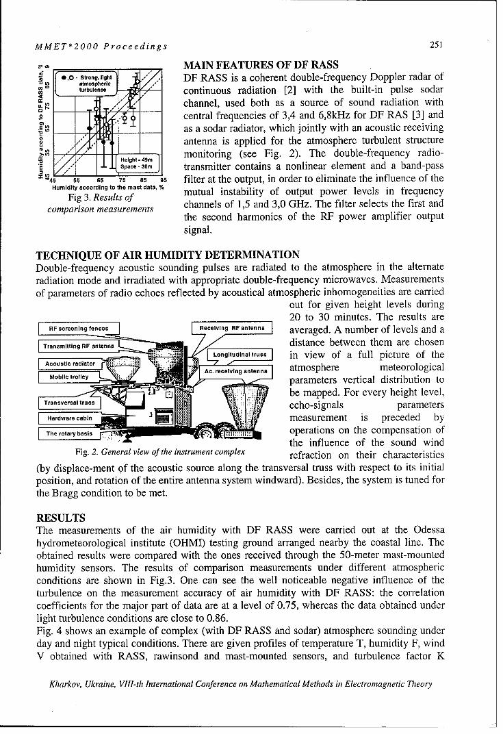
MMET*2000 Proceedings 251
- - MAIN FEATURES OF DF RASS'a 0,0- Strong, light DF RASS is a coherent double-frequency Doppler radar of"u I/ atmosphericU) turbulence continuous radiation [2] with the built-in pulse sodar
-. -O channel, used both as a source of sound radiation with0 central frequencies of 3,4 and 6,8kHz for DF RAS [3] and
as a sodar radiator, which jointly with an acoustic receiving44 antenna is applied for the atmosphere turbulent structure
- ,/,gh.4monitoring (see Fig. 2). The double-frequency radio-• •" /Height -4mIE - Space - 36m transmitter contains a nonlinear element and a band-pass
.45 55 65 75 85 95 filter at the output, in order to eliminate the influence of theHumidity according to the mast data, % mutual instability of output power levels in frequency
Fig 3. Results of channels of 1,5 and 3,0 GHz. The filter selects the first andcomparison measurements the second harmonics of the RF power amplifier output
signal.
TECHNIQUE OF AIR HUMIDITY DETERMINATIONDouble-frequency acoustic sounding pulses are radiated to the atmosphere in the alternateradiation mode and irradiated with appropriate double-frequency microwaves. Measurementsof parameters of radio echoes reflected by acoustical atmospheric inhomogeneities are carried
out for given height levels during20 to 30 minutes. The results are
RFscreening feReceiving RF antenna averaged. A number of levels and aT i adistance between them are chosen
SLongitudinsi truss in view of a full picture of the
Ac. receiving antenna atmosphere meteorologicalMobile trolley parameters vertical distribution to
" _I - -- be mapped. For every height level,Ta sversa truss
echo-signals parametersHrwr measurement is preceded by
SThe rotary basis operations on the compensation ofthe influence of the sound wind
Fig. 2. General view of the instrument complex refraction on their characteristics
(by displace-ment of the acoustic source along the transversal truss with respect to its initialposition, and rotation of the entire antenna system windward). Besides, the system is tuned forthe Bragg condition to be met.
RESULTSThe measurements of the air humidity with DF RASS were carried out at the Odessahydrometeorological institute (OHMI) testing ground arranged nearby the coastal line. Theobtained results were compared with the ones received through the 50-meter mast-mountedhumidity sensors. The results of comparison measurements under different atmosphericconditions are shown in Fig.3. One can see the well noticeable negative influence of theturbulence on the measurement accuracy of air humidity with DF RASS: the correlationcoefficients for the major part of data are at a level of 0.75, whereas the data obtained underlight turbulence conditions are close to 0.86.Fig. 4 shows an example of complex (with DF RASS and sodar) atmosphere sounding underday and night typical conditions. There are given profiles of temperature T, humidity F, windV obtained with RASS, rawinsond and mast-mounted sensors, and turbulence factor K
Kharkov, Ukraine, VIII-th International Conference on Mathematical Methods in Electromagnetic Theory

252 MMET*2000 Proceedings
obtained with sodar. To the right of K, the behavior of the first and second frequency echo-signals amplitudes under light turbulence is shown.
It is clearly seen from Fig.4, that under daytime conditions, when the values ofturbulence factor (K) consi-derably exceed the night ones, the confidence interval of RASdata in the average three times exceeds the night-time one, being well correlated with that ofwind data. It can be concluded from this that under strong turbulence, when operating in thealternate radiation mode, radioacoustic soundings of the first and the second frequency takeplace in different turbulent situations, what deteriorates DF RASS results.
In order to weaken the influence of turbulence on the DF RASS results, the authorspropose for the DF RAS hardware to be reconstructed for operation in the double-frequencysynchronous radiation mode. Accordingly, the technique of the air humidity determinationshould be improved. In this case, the humidity and with it the air refractivity at radiofrequencies can be defined with the accuracy as high as the radiosonde one.
CONCLUSIONSThe atmospheric turbulence is a main error source of air humidity measurement with DFRASS. The improvement of DF RAS equipment and technique of air humidity determinationcan give one the power instrument of defining the air refractivity at radio frequencies.
2501 1I I I I I I • I io I I- -•
-[ Rawinsonld H - 4 / Double-____°_ " •--I frequency
200 ----- 4 RASSMas
E 15 SODAR1.c:AR~ :F .4-0 f'q1
.( - 4.30 4"100 Humidity, F . Turbulence factor, K'
50 d Temperature, T Wind, V e
A A Ad
0~~~~ _I m-±. niltd,0 ,' X., j 4114 16 18 20 22 24 T1.C 234567V/msI 22 2 I 1 Ii 1 2 3 4 5 6 75V/ms 1 Amplitude, V
30 50 70 90 F/% 0 20 40 K/ms"1
Fig. 4. Example of complex sounding under night and daytime conditions
ACKNOWLEDGEMENTSWe thank all the staff of OHMI scientific laboratory and especially its leader Javorsky A.Y.for the help in carrying out our investigations.
REFERENCES[ I ] ANSI S 1. 26-1978 (ASA 23-1978).American national standard.[2] Ulyanov Y. N. Dual frequency radioacoustic system / Proc. VII all union symp. On laserand acoust. atm. sounding. Tomsk, 1984, v. II, p. 196-199. (in Russian).[3] Proshkin E. G. Radioacoustic sounding in atmospheric boundary layer investigations/Proc. ISARS" 96, Moscow, p 6.105-6.108.
Kharkov, Ukraine, VIII-th International Conference on Mathematical Methods in Electromagnetic Theory

MMET*2000 Proceedings 253
LIDAR SIGNAL MODEL FROM REMOTE AEROSOL FORMATIONSIN DOUBLE SCATTERING APPROACH
Bryukhanova V.V. and Samokhvalov I.V.
Tomsk State University
Radio Physics Department, 36, Lenin Avenue, Tomsk, 634050, Russia; [email protected]
ABSTRACTLidars are applied in many geophysics, meteorology and atmospheric optics research.However, the problem of the lidar data interpretation is not solve yet. It is necessary to takeinto consideration the multiply scattering (MS) when laser radiation propagates in opticaldense aerosol formations.The paper discusses the problem of numerical simulations of the lidar returns that account forcontributions from single and double scattering from dense aerosol formations. We haveanalyzed the lidar equation that was obtained earlier [1] for an inhomogeneous atmospherewith the account for single and double scattering. It is shown in the paper that doublescattering "forward-backward" and "backward-backward" photon trajectories equallycontribute to the backscattering intensity. This significantly simplifies the lidar equation, ifthe sounding pulse penetrates the cloud to the depth that is small as compared with thediameter scattering volume at the cloud top.
INTRODUCTIONWhile studying the propagation of laser radiation through the optically dense aerosolformations, one should take into account the effects of multiple light scattering (MS). Athorough description of MS is possible by the radiation transfer equation. Unfortunately, noanalytical solution of this equation has been so far derived in a general form. The approximatemethods of solving this equation developed up to now such as the Monte-Carlo method andsmall-angle approximation, that are most widely used, enable obtaining quite good results insolving the so-called direct problem, i.e. in calculating the backscattering signals. However,these approaches are unable to analyze the effects of lidar performance parameters and opticalproperties of the medium sounded on the return signal structure and on the intensity ofdifferent orders of multiple scattering as well.In the general form, the lidar return can be presented as a sum of return signals due todifferent orders of multiple scattering
P(r) = p(') (r) + P(2)(r) + ... + P(') (r). (1)
The single scattering return power is described by the lidar equation that is applicable at smalloptical thickness of the media sounded
P( O rr2 X(t, r)a(r)e-2 (r)2)
where, P'l)(r) is the single scattering return power that comes back to the receiving optics of alidar from a scattering volume at the range r; P0 is the power of sounding radiation; A is the
Kharkov, Ukraine, VII!-th International Conference on Mathematical Methods in Electromagnetic Theory

254 MMET*2000 Proceedings
area if the lidar receiving optics; c is the speed of light in air; "to is the sounding pulseduration; X(7t,r) is the backscattering phase function; o(r) is the volume backscatteringcoefficient at the distance r;
rt(r) = Jcx(z)dz is the optical thickness of the sounding path interval from 0 to r; a(z) is the
0volume extinction coefficient that is determined by the scattering coefficient o(z) and theabsorption coefficient ,(z), a(z)= o(z)+ ,(z).In sounding clouds, one ought to take into account higher orders of multiple scattering.However, calculating the higher orders of multiple scattering (i>2) faces some problems inphysical statement of the problem and in calculating the contributions coming into the totalsignal from different orders of multiple scattering. Besides, as the experience shows, it issufficient to consider only double scattering under condition that 't<3.
DOUBLE SCATTERING SIGNAL FROM AEROSOL FORMATIONThe general expression for p(2)(r) has been derived earlier [I] in the following form
p(2)(r) = 6 e-2(r)[II + 12] (3)
7/2 cr(z)y(z,))where I, = f r X(z,y)X(z1,lt-7)sinydydz,
0,, H R(z,y,r)S= f (z)(z) X(z,7)X(z,,7t - y)sin ydydz,
./2 ,,(y) R(z,y,r)
R(z,7,r)= r2 cos 2 -7I + (r 2Z) tanJ2 -),
zi = rZ+(r-z) , ZH(y) r_ý rrHcot2 I
r - zsin 2 2
SPECIFIC FEATURES IN THE FORMATION OF THE DOUBLE SCATTERINGFLUX FROM REMOTE AEROSOL FORMATION
In sounding dense aerosol media, the depth of a laser pulse penetration into a medium is smallas compared with the distance H to the nearest boundary of the medium:
r-H r-H «<<1 (4)r H
In this case the scattering volume is bounded by the plane z=H, from the lidar side. If we dealwith an airborne or a space-based lidar, this plane in determined by the cloud top, forexample. If the condition (6) holds and
r _ H < H. tan 0 ° 2 (5)
then the expression for P(2)(r) can be essentially simplified.
Kharkov, Ukraine, VIJI-th International Conference on Mathematical Methods in Electromagnetic Theory

MMET*2000 Proceedings 255
Thus at [(r-z)/r]<< I we can take zj, in Eq.(5) to be approximately equal to
r(1 -rZtan2 2 N ow we can make the following substitution in Eq.(3)
r-z
H. tan 0o2
and then changing new variables once more
U = . 1g 2 , /2' =r-'y.
After these substitutions the integrals entering the expressions (5) for I'(ý,y) and 12(U,3)become identical. Therefore, expressions (5) can be written in the following form.
p() PoAcrpHtar(O0) 2j~ )n24p(2) (r) = 4 2 e-2 (r) x J f(4)a(4)X'(,7)X(1,n-.y)tan ddy, (6)0cr 0 2
It was taken into account, while writing this formula, that 0•< _< 1 and
4 , = 4 .tan2 _0 = r-H2 ~~H.taI{O0I
If (r-H)>H.tan(00/2), the cross size of the scattering volume for the second order of scatteringwill be determined both by the medium boundary and by the receiver field-of-view angle.The general expression for the lidar return in the double scattering approximation has thefollowing form
c a(ý,)a(T()X(4,,y) X(4 ,7t - y) ta{~
0 0 H2 tan2(0d2dy +
P0AcrpHta4 0/120) 1+ r 2 tan2 (-(7)p( 2) (r) = 4c 2 e-2(r) x 2
4itr2 ,,1,,(y) a(4)r(, )X(,,)X(, - y) taý2j)
fi d~dyy, 0 H2 tan2(j0o2 J]d1+2 H r2
tan2 ij)
where
r. tan0oý2y 1 = 2arctan - 2 -r-H
As is seen from the expression obtained, the return signal due to double scattering, at (r-H)> H.tan(Oo/2), depends on both the depth at which sounding pulse penetrates into the cloudand on the cross size of the scattering volume at the range r from a lidar.We also have simplified Eq. (6) and Eq. (7) in special cases of atmospheric stratification.
REFERENCES
[1] Samokhvalov I.V. H Rep. SA USSR. Ser. PAO. 1979. V. 15. X2 12. C. 1271-1279.
Kharkov, Ukraine, VIII-th International Conference on Mathematical Methods in Electromagnetic Theory

256 MMET*2000 Proceedings
ANALYSIS OF ELECTROMAGNETIC CHARACTERISTICS OFMULTI-LAYERED PERIODIC STRUCTURES
WITH TURNING LAYERS
Dmitry Kokody and Sergey Prosvirnin
Institute of Radio Astronomy of National Academy of Sciences of Ukraine4, Krasnoznamennaya st, Kharkov, 61002, Ukraine,
Fax: 38 0572 476506. E-mail: prosvirnin@ rian.kharkov.na
ABSTRACTThe characteristics of' reflection and transmission of' multi-layered douhle-periodic structures With C - shaped
inclusions in cells are considered. The case with turning of each second layer of the system on 90 degrecs is re-searched. It loosens the dependence of reflection and transmission operators on the polarization of an incidentwave.
INTRODUCTIONIn recent years, much attention has been given to so-called photonic band-gap materials in mi-crowaves. The one type of this structure is double-periodic array with the metal patches of dif-ferent shapes contained in cells. Locating such arrays on dielectric substrates one for the an-other and agglomerate their in three-dimensional structures is possible to obtain broad oftransmission and reflection in the microwave range.The dependence of the operators of reflection and transmission on the polarization of incidentwave was observed under identical orientation of metallic elements on all layers of system.This dependence can be attenuated by turning each second lay on 90 degrees. Absolute valuesof the reflection and transmission coefficients in one propagated wave regime at the polariza-tion of incident wave along axis of array periodic do not differ at this case. The values of coef-
ficients are approximately equal to such in any other polarization.
MATRIX OF REFLECTION AND TRANSMISSION OF ONE LAYERThe array periodic in two directions with complex inclusions in cells is considered. Period ofarray is equal in two direction and designate d,. Plane electromagnetic wave is incident on
layer: k =,exp(-ikiF), where P is the vector of polarization, P=I; k' is the wave vector
of an incident wave, k' = k, k = co4e-10 . The time dependence e1 "1 is supposed. If the peri-
ods of an array are less than a wavelength K=d., /2< 1, both in reflected and in transmittedfields, only the main one is propagated on a normal to array space harmonic:E" = R exp(- ikz), k = 1'exp(ikz).
The vectors R and Tare interlinked to a vector of polarization of incident wave:1= P P, T= iP, where P, t are operators of reflection and transmission [1]. If non propa-
gating space harmonics are not taken into account, the matrices of operators are the following:
S= '2. t = t, , where r t, and r, tr,, are coefficients of reflection and, r,, •, tin. til,." -
transmission of an incident electromagnetic wave, polarized along an axis Ox and Oy, respec-tively. The elements r.,, r,, t.,y t>. determine the transformation of polarization (appearance
Kharkov, Ukraine, VIII-th International Conference on Mathematical Methods in Electronmiagne tic Theory

MMET*2000 Proceedings 257
crosspolarization) after reflection and transmission of an array. They can be calculatedthrough a method described in [2].
OPERATORS OF REFLECTION AND TRANSMISSION FOR THE SYSTEM OFDOUBLE-PERIODIC ARRAY WITH TURNING LAYERSWe consider the arrays of C-shaped strips with following geometrical sizes: radius of a inclu-sion is a=1.25 mm, angular size of a rupture is 2(p=20 degrees, width of strip is 2w=0.1 mm.It allows to arrange a long strip in cell which is smaller than 2 and to get resonance on lowfrequencies. This strip has a form with symmetric layout (see Fig. la), the non-diagonal ele-ments of matrices of reflection and transmission are equal to zero. There is no turn of polari-zation plane at transmitting wave through an array.
y ly The arrays are located on a dielectric substrate in
C C C !C C -)Q. practice. It complicates the calculations, as it is(C i-7 -i-- necessary to consider two cases of incidence of an
c e t)_ electromagnetic wave: on the side of array and onc i c .c Ulu ------ the substrate. A method of solution of a diffractioncrcciO - Ou.) problem in this case is the same as in [2].
Fig. la Fig. l b The system of two arrays one of which is turned on90 degrees is considered. In Fig. la layer without
turn of inclusions, in Fig. lb - with turn is shown. For the first array the matrix of reflection
and transmission are following: r±- = ,1 tJ- K j. For observance of the one-( r+,.)') t,= toP.wave mode only it is not allowed to bring together arrays on very close distances (in our casedistance between arrays L=2.5 mm Fig. 2). The plus-sign means incidence of wave on the sideof array, minus - on a substrate. For the second array the operators r2±,2 -±±
SA differ from first one by the
A T .q changing of diagonal elements.Tq A We can find solution for opera-
i L Rnq 0 h( (n-1)L tors of reflection and transmis-R,q L B sion for the system of two arrays
B ( using a operator method
r r, n-1 pair Ji r, + t,--er2ekl-rie e) t-Fig. 2 Fig. 3 trt-+
(1)
where e is propagator operator e -e & 0 A=L-h. If we construct from such pairs of ar-
rays the complex structure, see Fig.3 we can get recursion relations, similar (1)e= I+ -),<e(I- eke),_,7-,e)-' '-, (2)
Absolute values of elements of matrices of reflection and transmission for two-layer structuresare shown in Fig. 4a. The same characteristics for four-layer structures are shown in Fig. 4b.
Kharkov, Ukraine, VIII-th International Conference on Mathematical Methods in Electromagnetic Theory

258 MMET*2000 Proceedings
02 B 2
0.8 4 k p a G O 2 l W ¢ l O .8 1Z / r . • O
Fig. 4a
o 0 0 0 00 .0.0.... 2 - 4 00 0
Fig. 4b Fig. 5 Fig. 6Graphics of reflection and transmission for the system consists of two and four layers withoutturning ( Fig. 5 and 6). These results coincide with those of [31.CONCLUSIONRather wide zones of reflection and the transmission of incident electromagnetic wave havebeen obtained both for the case with and without turn layers. These zones appear at first due tothe frequency-selection property of each single array and secondly due to a wave interferencebetween layers in the system of arrays. The coefficients of reflection and transmission in acase of incidence of an electromagnetic wave on the side of array and on the substrate differonly by phases.Comparing results obtained at research of structures without turning layers with results ob-tained at usage of turning layers, we can see that in the second case there is no difference invalues of elements of matrix of reflection and transmission with polarization of an incidentwave along one axis of periodicity from values of the same units of operators with polariza-tion of an incident wave along other axis. Similar results are expected to be obtained also byan arbitrary polarization of incident radiation.
REFERENCES[1] T.D.Vasilyeva and S.L.Prosvirnin. Electromagnetic wave diffraction by the plane array of chiralstrip elements of complex shape. Physics of wave processes and radio systems, vol.1, no.4, pp.5-9,1998 (in Russian).[2] S.L.Prosvirnin Transformation of polarization when wave reflection by microstrip array of com-plex shape elements. Radiotechnika i electronika, 1999, v. 44, 6, pp. 68 1-686 (in Russian).[3] S .L.Prosvirnin, S.A.Tretyakov, T.D.Vasilyeva, A.Fourrier-Lamer, SnZoudi. Analysis of reflectionand transmission of electromagnetic waves in complex layered arrays. Helsinki University of Tech-nology, Electromagnetics Laboratory Report Series, Espoo, October 1999, Report 314, 15p.
Kharkov, Ukraine, VIII-th International Conference on Mathematical Methods in Electromagnetic Theory

MMET*2000 Proceedings 259
DIPOLE MODEL OF ELECTROMAGNETIC WAVE PROPAGATION INREGULAR 3D LATTICES OF SCATTERERS
Pavel A. Belov
St. Petersburg Institute of Fine Mechanics and Optics,St. Petersburg, Russia
E-mail: belov @green.ifmo.ru.
ABSTRACT
In this presentation we consider artificial (photonic) crystals formed by dielectric or metallicinclusions arranged in the nodes of a regular three-dimensional lattice with parallelepipedalelementary cell of the general kind. The background medium is an isotropic dielectric.Oblique propagation of plane electromagnetic waves in such a structure is underconsideration. A simple analytical theory of plane-wave propagation which takes into accountfull-wave electromagnetic interactions of all inclusions is developed.
INTRODUCTION
In the literature, this problem has been treated using numerical techniques. Availableanalytical models are restricted to either low-frequency or resonant regimes. Our goal is todevelop an analytical approach valid in a wide frequency range. A simple analytical theory ofplane-wave propagation [1] which takes into account full-wave electromagnetic interactionsof all inclusions is developed. The dipole model of interactions and the local-field approachare used. The main restriction of our theory is the requirement of rather small size of theinclusion compared to the wavelength, which is self-consistent with the dipole assumption ofthe electromagnetic interaction of the lattice. However, our interaction model takes intoaccount the phase shift of the wave not only over a cell but also over the scatterer volume(using high-frequency polarizability). Hence, our theory must describe properly the dispersionat the low-frequency band.
BASIC DISPERSION THEORY
The dispersion equation is obtained from Oseen's cancellation theorem and the condition of
polarization periodicity. The spatial dependence of polarization in the region placed rather far
from the crystal boundary is described by wave vector k (k.,ky,k)_in the form P = 0oe"k 7
(the eigenwaves without the incident wave contribution) and the following equation holds:
-v - (1)Po = J(co)" Z-G(w°,&,,).,)e1 •''' P 1
(m,n,/):*(0,0,0)
Here fP0 is the dipole moment of reference inclusion, iT is polarizability dyadic, G is known
dyadic describing electric field produced by a dipole, &,,,j = (am, bn, cl) T and co is frequency.
For calculation of 3D lattice sums specific method based on Poisson summation formula [4] isused. The layer-layer interactions are considered using the Floquet representation of the fieldproduced by periodically polarized layers, as in [2], including evanescent modes in the model
Kharkov, Ukraine, VIII-th International Conference on Mathematical Methods in Electromagnetic Theory

260 MMET*2000 Proceedings
of interactions of adjacent layers. Electromagnetic interactions of inclusions inside onereference layer considered as in [3,5]. The result of such calculation is:
ZG(w;, - .i ,_,
(m~nI)•(O,0,0)
rC(k,k, ,k-;a,b,c) D(ky,ky,k:;a,b,c) D(k,,k-,k,.;a,c,b)" (2)=D(.,., k., k:;a, b,c) Qk, k, k:,k;b, c, a) D(k, k-,k,.;b, c, a)
Ck.,, k.,, k-; a, b, c)=
+ 2 2 icV, _p,_-c,,,p2 7: eK~ P~q ei e<
2abec° 2 2=-• K 2 - - 1p_ - e 2,,- q2+k 1 -k:
+2a80 Z Z(K2 P/)? K0 (,F,, - K2I1bnJ)+ (3)+ 2,racc0 (K2-p,)<0 nO0
+ (K 2 2 y.![ id bq
27rabcco(K2-p2,,)o K2 -p,_-q2 2n + K2 2 _q
+b Inb K 2 p + + i 2 + ia3e 0 E IMa132)4)7- 2a-3~ ,,,mo /.I 3 M2
D(k.,k, ,k:;a,b,c) =
+i 2 +1,pq,-,-2 +k: +eý 1q- +
2abee° "n-----K 2 - P, -q,: e i(: +-) 1 e; K2 -p, ]+ 1 1 Z P,,P, ,,-K2K, (/P,2,- K2 bn).'sin(kbn)- (4)
7ra-8o (K2-p,)< ro
q0 _ _ _ _ +_ _ q-12ab880o(K---,2 , >_o •K 2 . ..p,,-q~o n-i L K2 p,:,q,: K ,, 2,
2m•2 2r
Here K = -1rco /CI, Pm=1 k. +2un q =k+ k, +a b
This theory gives an analytical model for the effective propagation constant, which can beuniversally applied in a very wide frequency range from the quasi-static regime to the Braggreflection region.
NUMERICAL CALCULATIONS
Numerical calculations was made and dispersion curves for structure under consideration are
obtained. Dispersion curves for crystal formed by spherical inclusions with a/a 3 = 0.2 are
Kharkov, Ukraine, VIII-th International Conference on Mathematical Methods in Electromagnetic Theor,

MMET*2000 Proceedings 261
shown in Fig. 1. (dependance of normalized frequency on wave vector - points F, M, K of firstBrillouin zone have coordinates (0,0,0); (0,1,0); (0,1,1), respectively). For comparison withthe above result we illustrate the band-gap structure of the extremely dense lattice by Fig. 2.(a/a 3 = 1 ). This case has no practical meaning since even for touching dielectric spheres sobig polarizability is not reachable. However, if we would have got the lattice from resonantinclusions (our theory is available for arbitrary dipole scatterers) this value of polarizabilitywould be possible. In this case one could obtain the complete bandgap even for a simple cubiclattice (which does not possess the bandgaps being prepared from simple inclusions such asellipsoids, cubes, etc.). This observation looks like rather important since the photonic crystalswith the same frequency properties as complex lattices provide (such as the diamond oryablonovite lattices) could be obtained, probably, from the simplest lattices of complex-shapeinclusions.
10 10
66
44
r K M r K M F
Fig. 1. Dispersion curves for ala 3 = 0.2 Fig. 2. Dispersion curves for a/a 3 = 1
CONCLUSION
The new approach for simple and prompt numerical calculating the dispersion curves of thephotonic crystals prepared from the smooth dielectric or metallic inclusions with sufficientlysimple shape and small wave size is presented. It is also shown that the primitive cubic latticeof the dipole scatterers with high polarizability can possess a complete photonic bandgap.
REFERENCES
[1]. P.A. Belov, C.R. Simovski, Oblique propagation of electromagnetic waves in regular 3Dlattices of scatterers (dipole approximation), Proc. of SPIE, Vol. 4073, 2000.[2]. C.R. Simovski, P.A. Belov, M.S. Kondratjev, Electromagnetic interaction of chiralparticles in three dimensional arrays, J. Electrom. Waves Applic., Vol. 13, pp. 189-203, 1999.[3]. C.R. Simovski, M.S. Kondratjev, P.A. Belov, S.A. Tretyakov, Interaction effects in two-dimensional bianisotropic arrays, IEEE Trans. Ant. Prop.,Vol. 47, No. 9, pp. 1429-1439, 1999.[4]. Collin R.E., Field Theory of Guided Waves, IEEE Press, NY, Philad., USA, 1991.[5]. P.A. Belov, C.R. Simovski, M.S. Kondratjev, Problem of the local field for plane gridswith bianisotropic particles, Proc. SPIE, Vol. 3039, pp.680-691, 1997.
Kharkov, Ukraine, VIII-th International Conference on Mathematical Methods in Electromagnetic Theory

262 MMET*2000 Proceedings
TRANSIENT RADIO WAVE SCATTERING BY AERATIONZONES
Sergey A. Masalov and Olexander 0. Puzanov
Usykov Institute for Radiophysics and Electronics of NASU12 Proscura St., Kharkiv, 61085 Ukraine,
e-mail: [email protected], [email protected]
It was shown that the availability of water can be detected only by a reflection from capillary fringe situated in the re-gion contiguous with water. One has to take into account this result to more exact determination of the water depth in aground. It has been established the observed pulse acquires a duration above a source pulse. The calculation resultshave shown that measurement errors of frequency dependencies of permittivities and specific conductivities that areused as initial data manifests during calculation of diffraction fields for structures of large depth (that are more than 2-3meters). This is the result of small amplitudes of pulses reflected firom discontinuities lied deep. In fact these errorsbring into occurring of a "false reflection" preceding before reflections from capillary fringe and water. This effectbetokens a violation of the causativity law and is a consequence of the disturbed in some measure connection of realand imaginary parts of complex permittivity. As it is known, this connection is determined after the Kramers-Kronig'relations. On this basis the conclusion is made about the necessity of refinement of source experimental data wherebythis relations in parallel instances.
This paper is devoted to the problem of simulation of nonsinusoidal radiowaves interactionwith a ground. We take into account that humidity is distributed in the ground depth according tothe continuous law. This law, dependent on the influence of atmospheric precipitates and groundwater is ordinary complex and influences essentially on outcomes of radar sounding of the earthsurface. Frequency dependencies of the ground electrical parameters obtained as a result of full-scale measurements are used as input data. Below we show the influence of humidity in the activemoisture exchange subhorizon and in the capillary fringe area on the reflected field character. Weascertain also how measurement errors of the input data influence on calculation results.
The ground areas from the surface down to the groundwater level are referred to as aerationzones (AZ). Their depth can be different depending on local conditions, however the depth deter-mines typical laws of humidity distribution [1,2]. Clearing up of features of videopulses scatteringin AZ in the context of interpretation of data of earth surface sounding is our main purpose.
The method used by us [3,4] consists of finding the solution in the frequency domain usingnormal impedances of partial areas (the source structure is divided into slabs with sufficientlysmall thickness) and it consists also of subsequent transition to the time domain by numericaltaking of the inverse Fourier transformation. We analyze the considered below transients on thebase of the results obtained earlier for more simple cases [4].
1. At first we consider differences in the reflected field character at two different humiditystates of AZ, formed by slabs of sand (1 m in thickness), clay (0.5 m) and water. Suppose that thesingle polar Gaussian pulse of thel0 ns duration is incident on this ground structure. Let us ana-lyze two cases. In the first case we neglect humidity variation, typical for the area of capillaryfringe situated in the near-level subhorizon. At that, suspect that the humidity W of sand and clayis constant down to the boundary of water and is equal to 2.5 %. In the second case assume thatthe area of capillary fringe is bounded completely by the slab of clay, humidity of which increasesgradually from the value W=2.5 % up to the limiting one W= 7 % [5] as approaching the bound-ary of water (Fig. 1).
Time dependences of the reflected field are showed in Fig.2. The dashed line corresponds tothe case of the constant value of humidity, and the continuous line - to the case of continuoushumidity variation. The first observable pulse (Fig. 2a)) is reflected from the upper boundary of
Kharkov, Ukraine, VIII-th International Conference on Mathematical Methods in Electromagnetic Theory

MMET*2000 Proceedings 263
sand. It is quite obvious that its form and amplitude is identical inboth cases. The differences start to appear under reflection fromthe boundary of sand and clay (Point 1 indicated in Fig. 2a) witharrow). One can clearly see the beginning of reflection from wa- Sand
ter, (Point 2), if humidity of clay is constant. If the humidity in-creases gradually, then the precise boundary, designated by the -
break on the time dependence in the previous case, flattens. It is ' Clay
concerned with the fact the increase of clay conductivity reducesto a noticeable increase of its contribution into the reflected field. Water
But this contribution is still smaller than the contribution of water 0 5 I 15
in the first case. Besides radiation reaches water now and returns Humidity W. "7
being attenuated notably. As a consequence of both called rea- Fig. 1. The law of humidity
sons, the amplitude of the reflected pulse diminishes, and owing variation in depth for the two-
to reflection the pulse obtains a superior duration in the all ex- layer aeration zone
tended area of capillary fringe.It is possible to draw a conclusion that the availability of wa- 0.
ter can be detected only by an outgoing pulse reflection from the 0 `
capillary fringe area. The moment of the reflection beginning co- "' iiincides obviously with the reflection from the capillary fringe. It is .3
important to consider the indicated circumstance for more precise 6 t.0
determination of water depth in soil. 0 ,4,, 60 90 IN)
In both cases at the moment of leaving the ground, the pulse n.0. a)
reflected from water is reflected back partially without change of .. ,'its negative polarity. But, as it is possible to see from Fig. 2, hav- 0.0.
ing got to water, the pulse is reflected from it in twice and changes .o,01the polarity for positive. With a constant value of clay humidity ,002one can see breaks on the trailing edge of the main (first) reflec- 1 .0 6. 70 o .0 11. .110 120 130
tion from water, which testify the presence of multiple reflections- b)
over between sand-clay and clay-water boundaries (points 3 and 4 Fp
in Fig. 2a), see also Fig. 2b)). At the same time the trailing edge diffraction fields for the single-
asperities smooth away granting the continuous increase of clay polar Gaussian videopulse of the
humidity 0). This is the consequence of larger losses in the envi- 1l0ns duration for the aeration
ronment, zone with a depth of 1.5 m,2. The representative depth of AZ can be 5-6 meters. Let us formed by the slab of sand (1 m)
analyze features of videopulse interaction with a such zone, as- and clay (0.5 m): the solid line -suming that the subhorizon of active moisture exchange has the at humidity distribution in depthpower of 0.5 meters, the subhorizon of variable humidifying - 4 according to Fig.], the dashedmeters and the near-level subhorizon - 1 meter (such depth of line - at the fixed humiditythe latter is characteristic of clays and loams). Assume that the ab- W=2.5 % of both slabssolute humidity of the first subhorizon varies within the limits of5-2.5 %, humidity of the second one - within the limits of 2.5-3.5 % and of the third one -
within the limits of 2.5-17 %. Consider two cases. Let all AZ be formed by chestnut loam in thefirst case, and let the near-level horizon be represented by clay in the second case. The law of hu-midity variation showed in Fig.3 remains identical in the both cases.
The results of calculations are adduced in Fig.4. It is possible to see that the increase of hu-midity at a depth of 0.5 m under transition from the active moisture exchange subhorizon to thevariable humidifying subhorizon results in the emergence of a negative pulse, following immedi-ately the one reflected from the upper AZ boundary. In both cases these initial parts of the curves,
Kharkov, Ukraine, VIII-th International Conference on Mathematical Methods in Electromagnetic Theory
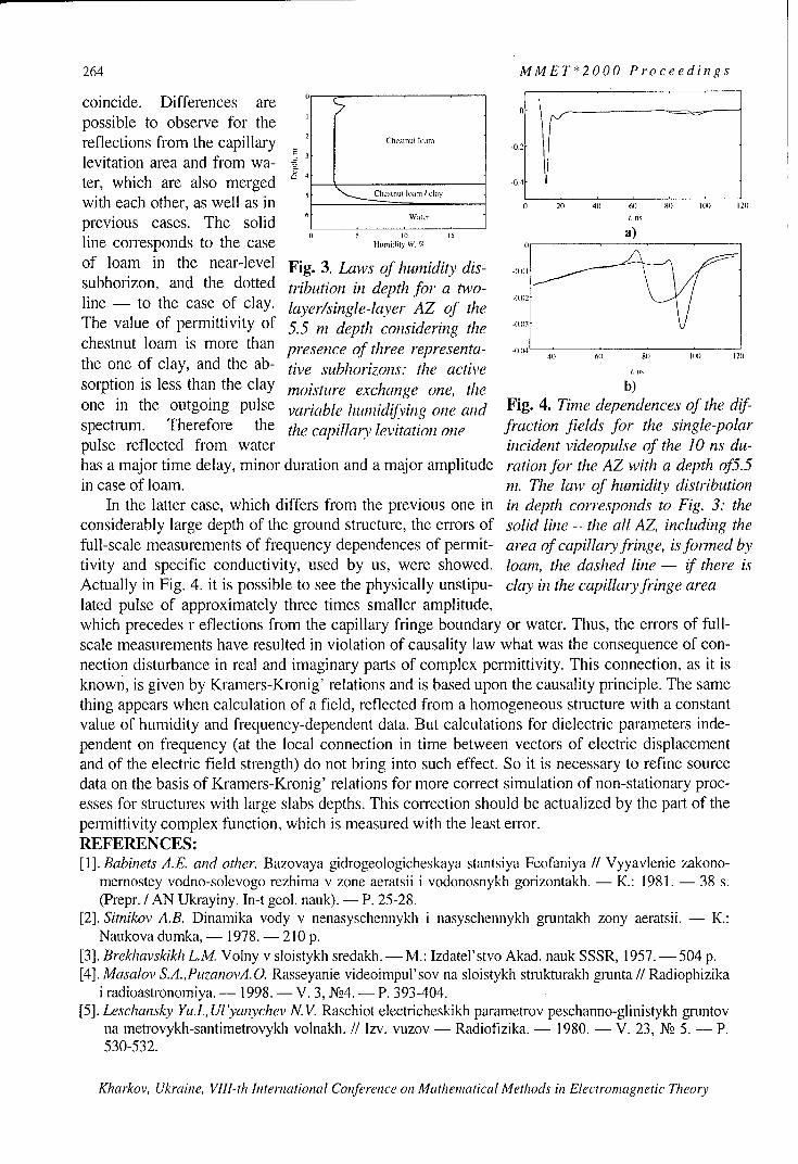
264 MMET*2000 Proceedings
coincide. Differences are
possible to observe for the
reflections from the capillary E Chesnt ..an) -02
levitation area and from wa-ter, which are also merged -. 4
with each other, as well as in uocy0 20 40 60 120
previous cases. The solid 6 ..........; ', a)line corresponds to the case 0 .U ,,di,•' .',,
of loam in the near-level Fig. 3. Laws of humidity dis-subhorizon, and the dotted tribution in depth for a two- "(line - to the case of clay. layer/single-layer AZ of the .03
The value of permittivity of 5.5 m depth considering the "chestnut loam is more than presence of three representa- -)04 4)) 6, 6, (,) 20
the one of clay, and the ab- tive subhorizons: the active ....sorption is less than the clay moisture exchange one, the b)one in the outgoing pulse variable humidifying one and Fig. 4. Time dependences of the dif-spectrum. Therefore the the capillary levitation one fraction fields for the single-polarpulse reflected from water incident videopulse of the 10 ns du-has a major time delay, minor duration and a major amplitude ration for the AZ with a depth of5.5in case of loam. m. The law of humidity distribution
In the latter case, which differs from the previous one in in depth corresponds to Fig. 3: theconsiderably large depth of the ground structure, the errors of solid line - the all AZ, including thefull-scale measurements of frequency dependences of permit- area of capillary fringe, is formed bytivity and specific conductivity, used by us, were showed. loam, the dashed line - if there isActually in Fig. 4. it is possible to see the physically unstipu- clay in the capillaryfringe arealated pulse of approximately three times smaller amplitude,which precedes reflections from the capillary fringe boundary or water. Thus, the errors of full-scale measurements have resulted in violation of causality law what was the consequence of con-nection disturbance in real and imaginary parts of complex permittivity. This connection, as it isknown, is given by Kramers-Kronig' relations and is based upon the causality principle. The samething appears when calculation of a field, reflected from a homogeneous structure with a constantvalue of humidity and frequency-dependent data. But calculations for dielectric parameters inde-pendent on frequency (at the local connection in time between vectors of electric displacementand of the electric field strength) do not bring into such effect. So it is necessary to refine sourcedata on the basis of Kramers-Kronig' relations for more correct simulation of non-stationary proc-esses for structures with large slabs depths. This correction should be actualized by the part of thepermittivity complex function, which is measured with the least error.REFERENCES:[1]. Babinets A.E. and other. Bazovaya gidrogeologicheskaya stantsiya Feofaniya H Vyyavlenie zakono-
mernostey vodno-solevogo rezhima v zone aeratsii i vodonosnykh gorizontakh. - K.: 1981. - 38 s.(Prepr. / AN Ukrayiny. In-t geol. nauk). - P. 25-28.
[2]. Sitnikov A.B. Dinamika vody v nenasyschennykh i nasyschennykh gruntakh zony aeratsii. - K.:Naukova dumka, - 1978. - 210 p.
[3]. Brekhavskikh L.M Volny v sloistykh sredakh. - M.: Izdatel'stvo Akad. nauk SSSR, 1957.- 504 p.[4]. Masalov S.A.,PuzanovA.O. Rasseyanie videoimpul'sov na sloistykh strukturakh grunta H Radiophizika
i radioastronomiya. - 1998. - V. 3, Xo4. - P. 393-404.[5]. Leschansky Yu.l., Ul'yanychev N. V. Raschiot electricheskikh parametrov peschanno-glinistykh gruntov
na metrovykh-santirnetrovykh volnakh. H Izv. vuzov - Radiofizika. - 1980. - V. 23, No 5. - P.530-532.
Kharkov, Ukraine, VIII-th International Conference on Mathematical Methods in Electromagnetic Theory
MMET*2000 Proceedings 265
ANTE ConferNNA
THER
Kharkov, Ukraine, VIII-th International Conference on Mathematical Methods in Electromagnetic Theory

266 MMET*2000 Proceedings
Kharkov, Ukraine, VIII-th International Conference on Mathematical Methods in Electromagnetic Theory

MMET*2000 Proceedings 267
TWO REFLECTOR NON SYMMETRIC SHAPEDANTENNA SYSTEMS
Elman HasanovDepartment of Mathematics, Faculty of Arts and Science, Isik University,TR-80670, Maslak,
Istanbul,TurkeyE-mail: elman @isikun.edu.tr
ABSTRACT
Two reflector antenna systems with non symmetric reflecting surfaces under GO approximation are
investigated. It is shown, that the problem of forming desired far field pattern leades to solving the
system of partial differential equations with respect to mapping functions between wave fronts. One of
these equations is non linear and expresses energy conversation law. It is shown that this equation can
be solved separetly in the class of non smooth functions which has a discontinuty of first kind along a
given curve.
INTRODUCTION
Consider two reflector shaped antenna system. Assume that the ray with coordinates (0, q)eminated
from the point source, placed in the origin after two reflections from mirrors transforms to the ray with
coordinates (x, y). Such a way given system generates a mapping functions x=x(O, o),
y = y(O, (p) between initial spherical and outgoing plane wave fronts (Fig. 1). It can be shown that [1]
these functions satisfy a single quasi linear partial differential equation of the form
a 2 T ax a 2T ax a 2 T ay a 2T _y
aqa+oxq ±-0 (1)ao0x aO a0ax a(p a0•y aO ao00y a(o
where T = In M,
M = (1+cosO) mcoso- xtanoJ + msinO- ytany0j
and m is the total optical length from source to aperture. Relationship between amplitude distrubations,whish governors the shape of the far field pattern, by means of mapping functions
x = x(O, (,) , y = y(O, qp) can be written as
ax Oy y ax -A 2 ( , ) (2)
ao a(9 aoc9 (p A' (x, y)where A, (o, p)/ sin 0 and A2 (x,Iy) are the corresponding amplitude distrubations over initial and
outgoing wave fronts, respectively. Sign "+" corresponds to classical Cassegren system and sign "-" toGregory system ([2]). Equation (2) is a relationship of geometrical nature and can be investigatedseparetly.
Kharkov, Ukraine, VIII-th International Conference on Mathematical Methods in Electromagnetic Theory

268 MMET*2000 Proceedings
FINDING MAPPING FUNCTIONS
Let F and G be bounded and covex regions in (0, V) and (x, y) planes with boundary curves
(O(t),yp(t)) and (x(t ), y(t, )), respectively. t, =t, (t) is transformation of parameter. 0(t), (p(t),
x(t,), y(t,) are differentiable functions, 0• t • T, 0•<t t]TI,0(0)=O(T),
,(O) = (p(T), x(0) = x(T7), y(O)= y(T, ). Let x0(0,(p) be a smooth function defined on the region
F and satisfying conditions
a) x0 (0(, P(t)) = x(t, (W))
b) x 0-± + #0 for(0, () Fb) 00 a 0(
c) from each point of F passes one and only one curve of the family x0 (0, V) = const
Ox 0 y ay Ox 0 A,2(0,_000 Dy 0O D9y AZ(x 0 (0,yV),y) (3)
Substituting x0 (0, (9) into equation (2) we have
For simplicity we shall assume that function A2(x,y) do not contain y implicitly. (3) is a linear
partial differential equation of first order with respect to y(O,)) and can be solved by well knowncharacteristic method. In this case characteristics are the solutions of the system of ordinarydifferential equations
dO _Ox°
- a(4)dr a (p
d - Ox0 (5)dr C90
dy = + A (O, (,)/a)((xO,(0, y)) (6)dz-
(4) and (5) form a Hamilton system with hamiltonian x0 = x0 (0, ). For this reason projections of
solution of (4) - (6) (0(c), (y(r), y(r)) onto (0, y) plane (i.e. the curves (0(t), P(t))) coincide with the
family x0 (0, (o)--- const in this plane. Now let
ý(t, v) = (O(t, v), yP(t, r), y(t, r)) (7)
be a solution of (4)-(6) corresponding to initial curve (O(t),y(t), y(t)). In general case it can not be
guaranteed that ý(tr) can be projected one to one onto the plane (0,y) i.e. be represented in the
form y. Y0 (0 , yp), but it can be shown that each point in F has at least two image on the (7). Thus
(7) is 2 - fold surface over the F. If both folders coincide then we get a solution of the form
Yo = Y0 (0,y)), which together with x0 = X0(0,(p) gives the solution of the problem, i.e.transforms F to G and boundary of F to boundary of G. If these folders do not coincide then usingthem we may construct one valued function over F which satisfies the boundary condition and has adiscontinuity of first kind along certain curve laynig in F . Indeed, let C be any curve transversally
(i.e. without tangency) intersecting all curves of the family x0 (0, y) = const. Curve C divides
region F into two subregions F, and F2 such that F, rF2 =0, F, u F2 = F Over each thesesubregions (7) has two folders. One of these folders is formed from the characteristics outgoing fromthose part of the curve (0(t),y((t), y(t)), which lies in this subregion. Combining parts with such
Kharkov, Ukraine, Vlll-th International Conference on Mathematical Methods in Electromagnetic Theory

MMET*2000 Proceedings 269
properties for each subregions of F we obtain an one valued function y0 = yo (0, ) over F having
discontinuity along the curve C and satisfying y0 (0(t),¢p(t))= y(t1(t)). Illustrate described
procedure on example. Let F = {(O,¢(),02 +(±92 1} and G = {(x,y),x2 + y2 < 1/2}. Assume that
A 2(x, y) =1 and A1 (0,€() = (1+02 + V,2 )2 . Let x0 (0, ¢) be a family of hyperbolas, once covering
region F:
x0 (0, ¢) 20 const (8)/1±02±+¢
Substituting into equation (3) yields
Y (9)00 x/~1 "'-02±--92
Characteristic system isdO= 0(, d + 1+¢2 (10)dr dv
dy = 1 (11)d- 1 + 02 2
After integrating this system , we obtain a conjugate to (8) family of hyperbolas, again once
covering F:
y°0(0,(p)- ( -const•1±02 +92
which together (8) yields solution of the given problem.
Y
Figure 1x
REFERENCES
[1] Gasanov E.E. (Hasanov E.E.), Kinber B.Ye. "On the Transformation of the non - HomocentricalWaves After Two Reflection ,"Soviet Journal of Communication Tech. And Electronics, 34 (1989)No. 1, 67 - 72..[2] Hasanov E.E. Polat B. On the realization of Optical Mappings and Transformation of Amplitudesby means of an Aspherical "Thick" Lens. Inter. Journal of Electron. And Communications (AEU) 54(2000) No.2, 109-113.
Kharkov, Ukraine, VIII-th International Conference on Mathematical Methods in Electromagnetic Theory

270 MMET*2000 Proceedings
FOCUSING SYSTEMS BASED ON MICROSTRIP REFLECTARRAYS
A.O. Kasyanov
Taganrog State University of Radio Engineering44 Nekrasovsky street, GSP-17A, Taganrog, Russia, 347928,
Phone (86344) 61733, E-mail: airpu@ tsure.ru
ABSTRACTFocusing systems constructions and mathematical model are considered. These systems allowrealizing a focussing of antenna feed field by a microstrip reflectarray. The mathematicalmodel is obtained by integral equation method. Besides microstrip reflectarray properties areinvestigated by waveguide simulation experimental method. Seven variants of focusing re-flector are investigated in the given paper. The reflector antenna with a flat focussing systemexperimental model is designed. The measured and calculated patterns of this antenna aregiven. These researches can be used to develop antennas with optimum parameters.
INTRODUCTION
The optical feed circuit application for radiators excitation is a way of reducing the antennaarray cost. Usually these antenna arrays are supplied with such circuits for a radiator feed,which are applied for reflector and lens antennas excitation. Such antenna arrays have little bitlower values of efficiency in comparison to the prototypes, namely, reflector antennas. Butthese antennas allow realizing electronic scanning and they can be made in the form of con-formal-type antennas.
THEORY
In this paper, the application of periodic microstrip antenna array for designing a flat reflectoris considered. Such reflectors can be used as a component of onboard radio engineering sys-tems. Besides they can be used for stationary telecommunication systems, satellite television,etc. Similar principal function of flat reflector is to ensure feed spherical or cylindrical wavetransformation to a plane wave. To achieve this effect it is necessary to realize a feed electro-magnetic wave phase correction. The phase correction is achieved by creation of an additionalphase delay in radiators of antenna array. The phase delay magnitude should be increasedfrom the marginal elements to central radiators. The usually required phase delay magnitude isdetermined by account, that is based on the geometric optics method [I].If the microstrip elements are used as antenna array radiators, it will allow solving the prob-lem of designing a cheap flat reflector in the most convenient way. This way is based on achoice of radiator geometry and its constructive sizes. The mathematical model of a flat infi-nite microstrip reflectarray is developed in the paper [2]. This model allows selecting the re-flectarray radiator parameters on the basis of computing experiment results. The numericalanalysis bases on the following initial parameters: radiator topology, substrate permittivity andpermeability, as well as sizes of an array unit cell. The method based on an integral equationsystem solution was selected as the analysis method. The magnetic field integral equationswere formulated concerning magnetic currents surface density distributions on the antennaarray aperture. This antenna array is excited by the incident plane wave. The numerical analy-sis results are scattering fields and reflection factor of the reflectarray.
Kharkov, Ukraine, VIII-th International Conference on Mathematical Methods in Electromagnetic Theory

MMET*2000 Proceedings 271
NUMERICAL RESULTS
First of all we investigate a possibility of a necessary phase delay realization with a reflectionfrom a reflectarray of the non-loaded radiators. To solve the formulated problem, we shallchange topology and sizes of the strip elements and to define a copolarization reflection factorphase. The principal problem of these numerical experiments is selecting such variants, thatensure the needed phase delay. Therefore calculations were carried out in a case, when the ar-ray-exciting plane wave is incident along the normal direction. However, the flat reflector de-sign requires that the incident wave angle variation is taken into account. An each reflectarrayradiator and its feed mutual location determine this angle. We analyze the application possi-bility of several reflectarray types as a flat focusing reflector. These arrays differ by the type ofthe used radiator. First we shall analyze the reflectarray, whose radiators have the simpleshape microstrip elements.The microstrip vibrators have the simplest shape. We have calculated and measured such ar-rays reflection factors. The relation between the phase delays and vibrators relative length wasdefined in these researches. The calculation [1] and experimental results allowed making aconclusion, that printed strip dipole arrays are suitable for a flat focusing reflector design. Thereflection factor phase variation velocity is greatest by a resonant length of the vibrator. Be-sides, in this case phase varies in significant limits. However, high phase characteristic steep-ness can reduce to the unstable numerical solution. This circumstance complicates the de-signing of such reflector because of the high requirements to its performance accuracy. Even-tually, in this case reflector bandwidth will be the narrowest.The similar calculations in a case, when the microstrip radiators have the square shape, aregiven in [2]. The phase delay variation range in this case is also rather great. In this case, therelation between phase delay and square element relative size was close to linear. Such rela-tion can be obtained only if the reflectarray dielectric substrate is rather thick. This case corre-sponds to the reduced Q-factor value of reflectarray microstrip resonator. The reflector designproblem requires a compromise between a steepness value and possible reflection factor phasevariation range. This compromise is achieved by a choice of a substrate thickness, because inthis case we can control the phase characteristic steepness.We investigated a shape phase characteristic control possibility by additional reflectarray mi-crostrip element complication. This complication is directed on introducing auxiliary fre-quency-dependent elements. The auxiliary elements change the reflectarray resonance andfrequency properties. Let such auxiliary element be a tail. First of all we shall connect a tail toa microstrip vibrator. However, the numerical experiments have shown that the vibrator sup-plied by one or several tails does not allow receiving required parameters.The phase performance shape comes nearer to a desirable form if the tail is connected to themicrostrip element, which has the rectangular or square shape [3]. The reflectarray phase
characteristics are given in Fig. 1. The reflectarray parameters are: dx = 11,7 mm; d, = 16
are steps of array; a = 9,9 mm; b = 7,2 mm - microstrip patch sizes. The " of the sub-strate used is 2,2, and its thickness is 16mm. The microstrip line segment is a tail. This seg-ment width is 0,9 mm. The tail connection place is the middle of that microstrip patch edge,which has a greater size. The free tail edge is left breaked. The relationship between the phaseshift of the field re-radiated from an infinite reflectarray and the length of the connected tail isinvestigated. This is shown by a solid line in Fig.1. It is shown that in this case we manage toensure reflection factor phase regulation over a wide range and to save a phase characteristiclinearity. The phase growth rate appears quite acceptable. Eventually such radiators practically
Kharkov, Ukraine, VIII-th International Conference on Mathematical Methods in Electromagnetic Theory

272 MMET*2000 Proceedings
do not change a crosspolarization level. Thus, they can be recommended for such focusingreflector construction, which will work on linear polarization.It is known [4] that the flat reflector can be made as a printed ring reflectarray. We have donea numerical analysis of such arrays phase characteristics. The relationship between the phaseshift of the field re-radiated from an array and the excited plane wave incident angle was in-vestigated. The numerical analysis has shown that the reflection factor phase varies ratherslowly and smoothly. Actually, we shall consider a reflectarray, which is described in [4]. Letthe excited field have a frequency of 8,5 GHz. If the incident angle varies from 0 up to 45 de-grees, then the phase shift variation will be less than 20 degrees.
Arg(Spp), Deg360:: I ............ - _...................................... 1 ........... - !:: ... -- i~:' -::• -: -"' Ai: ....... .....
300 ..... k 1 ...... ............. ........... :, ..,. ...... ....... i,p 2
240: ................. .................. ...... ......................................
18 0 1 -............
120.-
60__ _ _ _
0 0.1 0.2 0.3 0.4 0.5 k.fJd2,
Fig.1 dl
The calculation results for a square shape microstriploops reflectarray are given in [5]. The relationshipbetween the phase shift of the field re-radiated from an infinite reflectarray and the microstriploop radius was investigated. It is shown that in this case we can control reflection factorphase over a wide phase shifts range. The compromise between a phase characteristic steep-ness value and possible variation range of reflection factor phase is achieved by a choice ofthe reflectarray steps values. Besides the microstrip re-radiators shape allows to expand suchreflectarrays application region. In fact, the microstrip loop is a circular polarization re-radiator. Therefore, in this case a field phase correction is achieved as good as at linear or cir-cular polarization.
Kharkov, Ukraine, VIII-th International Conference on Mathematical Methods in Electromagnetic Theory

MMET*2000 Proceedings 273
MEASUREMENTS
First of all we have selected the design of reflectarray which has the best relationship betweena phase shift and parameters of a reflectarray radiator. This variant was applied for a flat re-flector design. The parabolic antenna is the prototype of such flat reflectarray. The way of feedwavefront correction is the key feature of such antenna. This feature distinguishes our antennafrom a parabolic antenna. The correction of wavefront in a parabolic antenna is carried out,due to the special profile of a reflector. The correction of wavefront in our reflectarray is car-ried out, due to a special choice of a radiator construction. The radiator of an array providesthe required phase shift value of a scattering wave. A flat reflector operating at 9.4 GHz hasbeen designed and fabricated using the screen printing technique. It has a diameter of 25 cmand 0.46 F/D ratio. The substrate is 6 mm thick and permittivity of 2.05. A backfire antennawas used as the feed. This antenna contains active vibrator and wire reflector. These two vi-brators are excited by rectangular waveguide. The whole system is shown in Fig. 2.
0 dB
X• 3.2 cm h=0.2X.
-10 Rcu3a6• .
-30 l ... • measurem ent....
S-30 -1. 1,5 O ,De~g
Fig. 2
The antenna was measured at the 3.2 cm wavelength. Fig. 2 shows the E-plane radiation pat-
tern of the antenna. The pattern has been shown by solid line. It is obtained by scattering fieldsuperposition of single radiators. We have used the "element by element" technique. The rela-tion between the current distribution into radiator and incident angle of its exciting plane wavewas also taken into account.
REFERENCES ;..
[1] Obukhovets V.A., Kasyanov A.0. Phase correcting zonal reflector from flat diffraction mi-crostrip array//Antennas, Radiocommunication Systems and Means (ICARSM'97), Proc. of InIInt. Conf. - Voronezh: VSU, 1997, Vol. 1. P. 174-178.[2] Kasyanov A.O., Obukhovets V.A. Current control in a microstrip array with loaded elements(in Russian) /Radioengineering -- 1995. -- No. 12. -- P.32-36.[3) Zhnang Y., Litva J., Wu C., Wu K.-L. Modeling studies of microstrip reflectarrays//IEE Proc.Microwaves, Antennas and Propag. - 1995. - 142. No. I - P. 7 8-80.
[4] Guo Y.J., Barton S.K. Phase Correcting Zonal Reflector Incorporating Rings. IEEE Transac-tions on Antennas and Propagation, vol. AP-43, 1995, No. 4, p.350-355.[5] Obukhovets V.A. The constructive synthesis problems of reflective type antenna ar-rays//Antennas. -- 1997, vol. 2(39). -- Moscow IPRZHR. -- P. 17-24.
Kharkov, Ukraine, Vlll-th International Conference on Mathematical Methods in Electromagnetic Theory

274 MMET*2000 Proceedings
ANALYSIS METHOD OF THE INPUT IMPEDANCE OF A SPIRALANTENNA WITH GIVEN CONFIGURATION
Mikhail B. Protsenko, Ivan V. Tankov and Valentin V. Gromozdin
Sevastopol State Technical University, Sebastopol, UkraineTel: 0692 235-127, e-mail: [email protected], [email protected]
ABSTRACT
A method of analysis of spiral antenna input impedance is presented. It is based on thegeneralized transmission line theory (TLT) that accounts for the wave nature ofelectromagnetic field. Application of the iterative analysis method of equivalent transmissionline is discussed for the adopted model. Numerical modeling and experimental results for theflat Archimedean spiral antenna input impedance are presented.
INTRODUCTION
The input impedance computation of spiral antennas is a difficult electromagnetic problembecause of lack of a suitable coordinate system, in which the curved wire surface coincideswith one of the coordinate surfaces. In this case, it is impossible to separate the variables inthe electromagnetic field equations [1]. Therefore, empirical data [2] or simplification andapproximation in the formulation of analyzed problem are used in the estimation and analysisof spiral antenna input impedance.Empirical data application is essentially limited because of various antenna designpeculiarities, namely spiral antennas. Therefore, we use the generalized TLT for the analysisof the spiral antenna input impedance in this paper. Here, Kirchgchoff's equations [3] areexplained instead of the Maxwell's equations of the rigorous electromagnetic field theory [1].
INPUT IMPEDANCE MODEL OF SPIRAL ANTENNAS
On the basis of TLT, Kirchgchoff s equations subject to radiation losses are:dU/ds=I.Z; dI/ds=U. Y, ()
where Z, Y are distributed impedance and conductance, respectively.Taking into account, that solution of (1) can be represented in the form of travelling-waveseries in terms of exp(± y s) [3] and boundary conditions the input impedance for a spiral
antenna with a given configuration can be determine with account to the wire length as:
Z = W.[(Z+ W.1hy s)/(W+ Z.thy s)]. (2)where s is the running coordinate on the equivalent line wire axis having the origin at theoutput, W and y are the wave impedance and the electromagnetic-wave propagationconstant along the equivalent line:
W= ,Z. Y, y = Z4.Y.(3)
Taking into account the vector potential method [1], E = -gradV-(j k/ ). A4.
To find the equivalent line parameters, it is necessary to satisfy the current continuity low andthe electromagnetic boundary conditions, namely the tangential component of the electricfield vector is zero at the wire surface, provided that the skin-effect is neglected. Then, wehave (4) and if it suppose that the current flows in the direction of the wire axis if the wire
Kharkov, Ukraine, VIII-th International Conference on Mathematical Methods in Electromagnetic Theory

MMET*2000 Proceedings 275
cross-section is small in comparison with the wavelength and is constant along the axis.Therefore, the deferential operators in (4) can be written as (5)
gradV=-j(k/l4vp) - A; divJ =-j(k/1,[-). p. (4)
gradV = -o .(dU/ds); divJ = dI/ds. (5)where So is the unit vector directed along the wire axis and related to the observation point.Transforming (4) to the Kirchgchoffs equation form (1) we can obtain the equivalent lineparameters on the basis of expressions (5):
W = u6Vo = (-o ,p(- jJs ) ds f G(R) .exp(- jsj ). ds, (6)
yo = j7yj(fG(R)"(Ro,si)" exp(- jys,), ds,_/f G(R). exp(- jys,) ds,) , (7)s S
where G(R) = exp(- jkR)iR is the scalar Green's function of the free space, R is the distancebetween the observation and integration points, the indices of "0" and "1" denote theobservation and integration points, respectively.In general, the equations (6) and (7) are not fully defined because of the presence of ycharacterizing the propagation of the current travelling wave. By using the iterative analysismethod, we can eliminate this uncertainty. In particular, we can use the free-spaceelectromagnetic-wave propagation constant as the first approximation. On the basis of theobtained equation (7), the propagation constant can be recalculated. Such an iterative processcan be continued until the computed values stop changing within a needed accuracy.The dependences of wave impedance and propagation constant are nonlinear because of theradiator inhomogeneity and a usage of infinitely narrow exciting gap model leading to fringepeaks. Let us average the calculated parameters along the wire in order to eliminate thenonlinearity. That is to say:
W S-'f WJ(s) (O).dso; y* = J *(s) -ds,S S
where the symbol "'" denotes the first approximation.
ANALYSIS OF THE INPUT IMPEDANCE OF A SPIRAL ANTENNA
A flat two-arm Archimedean spiral is chosen for the analysis. This antenna can form requireddirectional and polarization characteristics in a wide band [4].The antenna arm is parametrized by the following equations in the Cartesian coordinatesystem: x = a a cos(a), y = a. a sin(a), where a is the spiral constant, a is the windingangle, 0 < a < 2mn, n is the antenna turn number.The Green's function G(R) in (6), (7) and scalar product of the tangential unit vector with thecurrent element dc can be determined for a two-arm spiral antenna as follows:
G(R)=[exp(- jkRo,)/R, 1 ]-[exp(- jkR.02 )/R0 2]; (o-,)=-(-go ) )=cos(fl) (8)
where /• 1 =a C-B. R02 = a,-C +B, C= a 2 + (l ,
B=ia, cos(a- )osa co_8=act sin aS) +cs cosa sin a,, ' lr is thewire radiu cs. a - ,) (=a cg cos ao - ao sin ao - cos a, - al sin a---- I
wire radius.
Kharkov, Ukraine, VIII-th International Conference on Mathematical Methods in Electromagnetic Theory

276 MMET*2000 Proceedings
The parameters R()1, Ro2 and 86 are shown in Fig. 1.The results of numerical modeling are shown in Fig. 2, namely, the frequency
dependences of A,,p,,, and Xi,,,,,, are presented for the following antenna parameters:
a = 0,0222 20 /rad; 0,06 rad • a <_ 12,56 rad; r/a = 0,01. For a comparison, there are theexperimental (x x x) and theoretical results (o o o) computed by the moment method [5] are
also presented for the antenna input impedance.Experimental and theoretical results are in agreement. This is a good evidence that we
have achieved the needed calculation accuracy of the spiral antenna input impedance even inthe first approximation (6), (7).
The input impedance in the studied frequency range is nearly constant. This confirmsthat the suggested current model is justified in the flat-spiral antenna research [4].
It is necessary to note that the presented analysis method has some advantages beforethe other similar methods: first of all, the antenna excitation problem solved by means ofdifferentiation and integration is simpler; besides, one can determine the antenna inputimpedance by iterations with any accuracy.
Ay Zipt' I IOh,, ,
100 .. . periniento00 0 i theoryi(Mol)
R- -theory (TIT) Input
Figure I Geometry of spiral antenna Figure 2 The input impedanceof spiral antenna
REFERENCES
[1] V.V. Nikolskii, Electromagnetics and Propagation, Moscow, Nauka, 1973, (inRussian).
[2] M.S. Juk, Yu.B. Molochkov, Design of Lens, Scanning and Wide-Band Antennas andMicrowave devices, Moscow, Energiya, 1973, (in Russian).
[3] G.Z. Aizenberg, Microwave Antennas, Moscow, Svyaz', 1962, (in Russian).[4] L.M. Lobkova, M.V. Ivashina, L.N. Stepanov, I.V. Tankov "Mathematical Model and
Geometrical Parameters Optimization of the Flat Spiral Antennas of DiverseConfigurations", Proc. of Int. Conf., Sevastopol, Crimea, Ukraine, 1998, pp. 458-46 1.
[5] H. Nakano, K. Hirose, I. Ohshima, and J. Yamauchi "An Integral Equation and ItsApplication to Spiral Antennas on Semi-Infinite Dielectric Materials", IEEE Trans.Antennas Propagat., vol. AP-46, pp. 267-274, Feb. 1998.
Kharkov, Ukraine, Vlll-th International Conference on Mathematical Methods in Electromagnetic Theory

MMET*2000 Proceedings 277
RESEARCH ON NEW ANTENNAS FOR MOBILE RADIOCOMMUNICATIONS
V. V. Ovsyanikov
Dnepropetrovsk State University,49050, Dnepropetrovsk, Naukovy lane 9, korp. 12phone (0562) 43-36-30; e-mail: [email protected]
ABSTRACTResults of consideration of new two-frequency wire antennas for the base stations of mobilesystems of radio communication are presented. It is shown that not for all ratios of the twooperating frequency values the acceptable pattern at the upper one of the combiningfrequencies is provided. The results of study obtained by the methods of integral equation andequivalent transmission line are given.
For widening the base station bandwidth in mobile radio communications, in anumber of cases two-stub and multi-stub wire antennas are applied [1]. However, theircharacteristics are not well studied that is the reason of research on similar antennas byrigorous methods.
A system of two closely located parallel wire antennas (the distance is d << A), whichhave finite thickness (2r, ) and different lengths (2L1 and 2L 2 ), is considered. Here, a set oftwo integral equations (IEs) is written:
f 1 (z')'6 11(z' )dz' + f1 2(z')' 12 (z1z')dz' = F1(z), (-L, • z < L,),-L, .(l)
f , Z' -62 (" ')Z' f'2(-') 62(Z'Z'dZ'= F2 (Z), (.-L 2 • z •! L2 ,
where G(z,z') is the Green's function and F(z) is the excitation function.For the solution of this system, complex currents in each of wires are presented aspolynomials of the N-th power [2] :
Ni N2
I,(z)= EIn(1- z/LIY2; i2(Z)= I2n(1- /L) (2)n=l n=1
Then, by the method of collocations, the system of IEs (1) is reduced to a set of algebraicequations. After the solution of the latter by computer we determine resulting complex inputimpedance (Z, ) of the system of two symmetric wires 2L, and 2L2 , connected in parallel inthe center (z = 0 ) and excited by the generator with a voltage V:
21 ln +l N I Z'2n '2 (3)n=V ~n=l 3
The graphic dependences of the voltage standing wave coefficient, VSWR (Ks),obtained from (3) for electrical length L, two-stub of asymmetrical wire antenna (curve 1),loaded on a feeder having the wave resistance of 50 Ohms is given in Fig.1. It shows thatunlike a usual one-stub asymmetrical wire antenna (curve 2), two-stub one (curve 1) providesat the ratio of the frequencies 1:2 good input parameters (K, <2). The first consecutive
Kharkov, Ukraine, VIIl-th International Conference on Mathematical Methods in Electromagnetic Theory

278 MMET*2000 Proceedings
resonance in this antenna arises at L, 20.242, and the additional second resonance atL,= 2L 2 ý 0.52, where 2 is the wavelength. It arises extremely due to presence of the vibratorL2 close L1 .
60
sog
2 1n (I 2-L-1 I1-2 21n 51 d L22 .
1
0.1 0.2 0.3 0.4 0.•5 0.6 0.7 L1,0.8
Fig 1. VSWR versus electrical length L1 (L2 ) for a two-stub antenna (curve 1) and a one-stubantenna (curve 2).
Consider the current distributions on the both stubs of the two-stub antenna that were obtainedby solving with computer the set of IEs (1) for the antennas with various the ratios offrequencies and the stub lengths (Fig.2).
20 ;1, 1:3
/A
A L ;0 L2 = '5 .......... .........1 : -- --.. .- ;-:10
0 .01 ---- ---- . 1 : 2 --.-- ,--) o lso 2 I l/ ,
0.1 0.2 0.3 0.4 0... .. 0.6 4 0. 7 0.25 l2Fig 2. TS h ersusrelecditricablnthon along 2 o a two-stub antenna:a (curv 2f I ) and a onestu
AconsdrdntoFg2 the current ditrbuiosinthdes bothe stbfrqecf2o the tw-tbatnathatnwere obtpained
bymslvingde withcmue the setunc f of s()foth antenna L.Fo hs ifolwithvar iou the raiost ofs
frequenchies and t stub l ngths (Fig.2). --
Kharkov ----- ~ ~ ~ ~ ~ ~ ~ ~ ~ ~ 2 A222 2 05 0 .402~ 2 022
0.005 -- - -- - - -
0 01D 021 a .5 02 z / l 0 .5 0 b) 0.5'2 1z1A
. 0..a) .. 0 .3 0 .4 1ZI/zI/ 0 . 0.1 .0.2 0.3 0.4 1 0.5 0.6 IZ I/A2
Fig 2. The current distributions along a two-stub antenna: a) 12 2 f,; b) f2 = 3fi.
According to Fig.2, the current amplitudes at the frequency f2 on the standing out parts(LI - L 2 ) of antenna L, are equal, respectively, to -10% and -50% against the currentamplitudes at the frequency 12 of antenna L 2 . From this it follows that in the first case
(Fig.2a) a standing out part (LI - L 2 ) is almost not excited by the current with the frequency
f2, and this current is cut-off in the plane X-X (Fig. 1). Here, at both frequencies f, and f2,
Kharkov, Ukraine, VIII-th International Conference on Mathematical Methods in Electromagnetic Theory
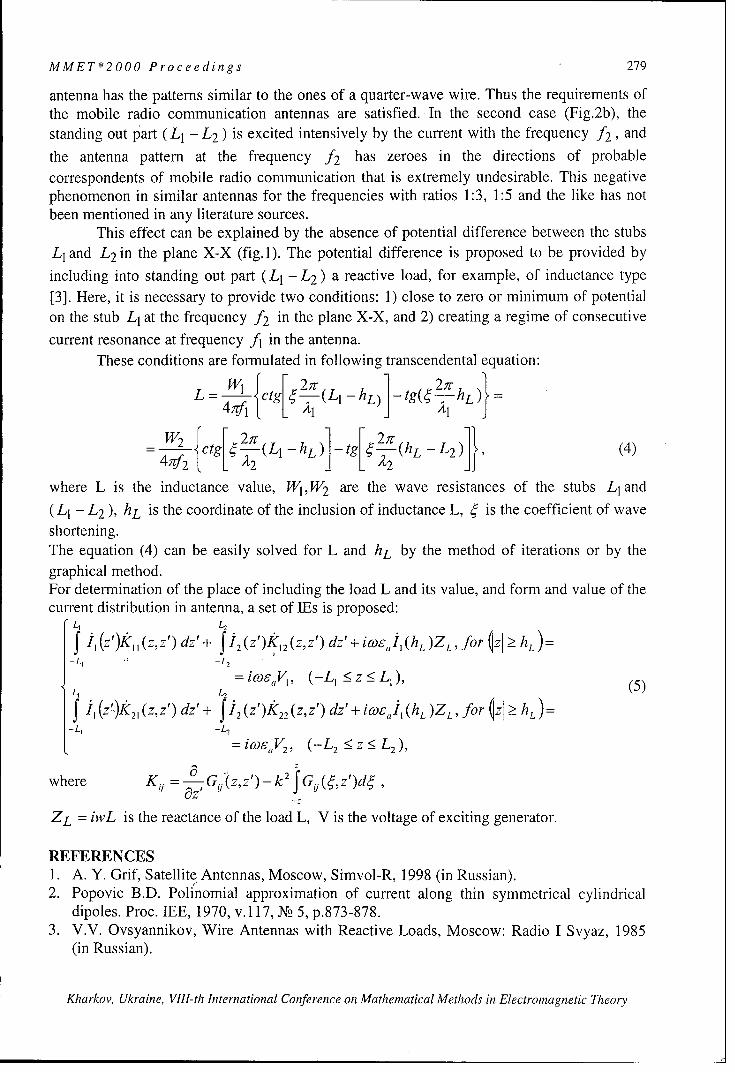
MMET*2000 Proceedings 279
antenna has the patterns similar to the ones of a quarter-wave wire. Thus the requirements ofthe mobile radio communication antennas are satisfied. In the second case (Fig.2b), thestanding out part (L1 - L 2 ) is excited intensively by the current with the frequency f2, and
the antenna pattern at the frequency f2 has zeroes in the directions of probablecorrespondents of mobile radio communication that is extremely undesirable. This negativephenomenon in similar antennas for the frequencies with ratios 1:3, 1:5 and the like has notbeen mentioned in any literature sources.
This effect can be explained by the absence of potential difference between the stubsL1 and L2 in the plane X-X (fig. 1). The potential difference is proposed to be provided by
including into standing out part (L 1 -L 2 ) a reactive load, for example, of inductance type[3]. Here, it is necessary to provide two conditions: 1) close to zero or minimum of potentialon the stub L1 at the frequency f2 in the plane X-X, and 2) creating a regime of consecutive
current resonance at frequency f1 in the antenna.These conditions are formulated in following transcendental equation:
L -EL {ctg[2;T (LI L) gý'
W2 ctg 2g (Ll -hL) -tg[27c (hL - L 2 )]}, (4)
where L is the inductance value, W1,W2 are the wave resistances of the stubs Ll and
(L 1 - L2 ), hL is the coordinate of the inclusion of inductance L, ý is the coefficient of waveshortening.The equation (4) can be easily solved for L and hL by the method of iterations or by thegraphical method.For determination of the place of including the load L and its value, and form and value of thecurrent distribution in antenna, a set of IEs is proposed:
L, L,
-f , (z')k,, (zz') dz'+ i2 (z,')K, 2 (z,z') dz'+ icoel (hL)ZL, for ýz hL)=-L1 , -L 2
= iwoVJ, (-L, < z•< LI), (5)
f 1,(z-)k 21(z,"z') dz'+ f '2 (z')k 22 (z,z') dz'+ icoI, (hL )ZL, for izI _ hL):-L, -L,
=icoeV2, (-L 2 _< z <_ L 2),
where Ki G Jr'-2we e,= --- G(z,,z') k fGu(ý,z')d,
ZL = iwL is the reactance of the load L, V is the voltage of exciting generator.
REFERENCES1. A. Y. Grif, Satellite Antennas, Moscow, Simvol-R, 1998 (in Russian).2. Popovic B.D. Polinomial approximation of current along thin symmetrical cylindrical
dipoles. Proc. IEE, 1970, v.117, N2 5, p. 87 3 -8 7 8 .3. V.V. Ovsyannikov, Wire Antennas with Reactive Loads, Moscow: Radio I Svyaz, 1985
(in Russian).
Kharkov, Ukraine, VIII-th International Conference on Mathematical Methods in Electromagnetic Theory

280 MMET*2000 Proceedings
BLINDNESS ANGLES IN MICROSTRIP PHASED
ARRAYS PATTERNS
A.O.Kasyanov, and V.A.Obukhovets
Taganrog State University of Radio Engineering, Russia.Russia, 347928, Taganrog, GSP-17 A, Nekrasovsky str., 44,
Phone (86344)6-18-83, Fax (86344) 6-50-19, E-mail: [email protected]
ABSTRACT
This report describes the analysis of infinite arrays of printed dipoles. A rigorous andefficient moment method procedure is used to calculate the array impedance versus scanangle. The scan blindness phenomenon is observed and discussed. The analysis uses anequivalent circuit representation at the feed point location in the unit cell, which is derivedfrom the moment method solution of the periodic problem. It is therefore applicable to allscan angles, arbitrary shaped structures, arbitrarily placed feed points, lossy conductors, anddielectric substrates. This rigorous theory capable of predicting the occurrence of blindspots. Measurements from a waveguide simulator of a scan blindness condition confirm thetheory.
INTRODUCTION
This report presents a rigorous but efficient solution to the problem of an infinite planar
array of printed dipole antennas on a grounded dielectric substrate. The model of an infinite
planar array is used because microstrip phased arrays can contain hundreds to thousands of
elements. Such arrays can operate at microwave or millimeter wave frequencies on
dielectric substrates, where surface wave coupling can lead to scan blindness, where no
effective power is transmitted or received by the array. Another point of interest to the array
designer is the variation of antenna impedance with scan angle, which is important for
impedance matching.
Usually a microstrip antenna is excited either by a microstrip feed or a coaxial feed. The
dipoles are assumed to be centerfed, so feed lines are not explicitly considered, although for
thin substrates the effect of a balanced feed line through the substrate should be small. It can
be assumed that the patch is excited by a linearly polarized plane wave [1]. This model
gives result which are valid for most of practical microstrip antennas. It is shown that we
can define the input impedance of microstrip dipole by using this model.
Kharkov, Ukraine, VIII-th International Conference on Mathematical Methods in Electromagnetic Theory
MMET*2000 Proceedings 281
THEORY
The solution process begins by creating Thevenin's equivalent circuit at the feed point
location [2]. To solve for the open-circuit voltage of the equivalent circuit, the problem is
first solved with the feed removed. This is done by solving the moment method integral
equation for the unknown surface density of aperture magnetic current. This current is
approximated by <<rooftop>> function expansion. For an x-directed printed dipole, the open-
circuit voltage V, is then found by integrating the total electric field over the length of the
feed gap Ax. Replacing the feed gap by a perfectly conducting patch gives the short-circuit
current IL,. This involves solving integral equation with the feed gap replaced by a perfectly
conducting patch. From the open-circuit voltage and the short-circuit current, the Thevenin
circuit impedance of the microstrip phased array can be calculated
z-ocI,,-
It should be noted that for both open-circuit voltage and short-circuit current calculations,
the microstrip phased arrays consist only of conducting patches supported by dielectric
substrate. Then it is assumed, that Z,,, is input impedance of phased array microstrip dipole
4. By using 4, we can determine [3]
4, (0, 0) - 4n (0,0)R(4,)+) )
where R is reflection coefficient in feed line connected with microstrip dipole, 0 and q9 is
the phased array scan angles. If R(ObI,(h) = 1, then Ob and (ob! are the microstrip phased
array blindness angles. This rigorous theory is capable of predicting the occurrence of blind
spots.
NUMERICAL RESULTS
This section presents some typical results, in the form of reflection coefficient versus scan
angle and similar relationships of an array element polarizing scattering matrix. An infinite
planar array contains of identical dipoles printed on a grounded dielectric slab. The printed
dipoles parameters are depicted as L and w, where L is the dipole length, w is the dipole
width. The dielectric substrate has the following parameters: 6r is related permittivity, h is
Kharkov, Ukraine, VIII-th International Conference on Mathematical Methods in Electromagnetic Theory

282 MMET*2000 Proceedings
thickness. The dipole array periodicity is d, in E-plane and d 2 in H-plane. Fig. 1 shows
the reflection coefficient magnitude gA (curve 1) and phase arg(R) (curve 2) in E-plane of
scan for c,=2,55, L = 0,392, w = 0,02A, h =0,192, d, xd 2 =0,51552x0,50002. Note
the presence of a unity reflection coefficient magnitude at 0 = 480, where E is the scan
angle. Therefore, in this case the scan blindness angle ®bI is equal 480. Other feature of
relationship 14(0) is Wood's anomaly at 0 = 690. The presence of the last feature is
confirmed by Fig.2 that shows the array elements polarizing scattering matrix SP variation
in scan angle sector. If an incident wave polarization is vertical then index p is equal I
(curves I is magnitude and 2 is phase). The case of a horizontal polarization is shown by
curves: 3 is magnitude and 4 is phase.
JRI, -arg(R), Is arg(S~)dB Deg PPI "' `2 -3 g(PP),
1 2 240 0,9 2270-1 08180. 4 I 180
-15 -i 120 ,1I '- 7 I 90
-20 60"0,7
_ _ _ _0,6 -010 30 50 70 0, Deg 45 53 61 69 77 EDeg
Fig. 1 Fig. 2
It is shown that presented theory is capable of predicting the occurrence of blind spots
REFERENCES
[1] Bailey M.C., Deshpande M.D., Gardiol F. Integral Equation Formulation of MicrostripAntennas /IEEE Trans. on Antennas and Propag. - 1982. - v.30. N4.- P.651-656.[2] Epp L., Chan C.H., Mittra R. Periodic Structures with Time-Varying Loads I/IEEETrans. on Antennas and Propag. - 1992. - v.40. N3.- P.251-256.[3] Pozar D.M. Analysis of an Finite Phased Arrays of Printed Dipoles //IEEE Trans. onAntennas and Propag. - 1985. - v.33. N10.- P.1045-1053.
Kharkov, Ukraine, VIII-th hIternational Conference on Mathematical Methods in Electromagnetic Theory

MMET*2000 Proceedings 283
EXCITATION OF THE INFINITE PERFECT CONDUCTING BICONEWITH IMPEDANCE AZIMUTAL SLOTS
A.A.BeletskyTaganrog State University of Radioengineering
AiRPU dept., TSURE, Nekrasovsky, 44, GSP-17A, Taganrog, Rostov region, Russia, 347928e-mail: [email protected]
ABSTRACTThe problem of the excitation of the infinite perfect conducting bicone with azimuth imped-ance slots on the surface by the arbitrary external sources is considered. The special case ofthe excitation by the homogeneous on azimuth magnetic current loop is investigated compre-hensively. The eigen and complementary conductivities of impedance slots versus slots loca-tion are shown. Transition to the finite bicone radiator problem is considered. The calculatedantenna patterns for several cases are depicted.
INTRODUCTIONThe investigation of the bicone surface electromagnetic properties is of a great interest [1],because it can serve as a basis for designing wideband antennas. To obtain necessary charac-teristics, surface slots with dielectric filling are often used. Although the problem for the coneantenna with azimuth impedance slots is solved in [2], there are still no results for the biconesurface. Here the excitation problem of the infinite perfect conducting cone of arbitrary coneangles with azimuth impedance slots on the surface by arbitrary external sources distributionat one frequency is solved in general form.
THE PROBLEM STATEMENTIn the infinite homogeneous isotropic linear space of known parameters 8 a, P9a there is theinfinite perfect conducting bicone of known arbitrary cone angles Y1, Y 2 (Fig. 1). On the bi-
cone surface there are several azimuth slots at distance R(f) from the bicone apex, whereSf
f = 1,2 is the surface number, s1 = 1,..., M1 , s2 = 1,..., M2 , M1,2 are slots count on the each
surface. The width of the slots AR is small relative to the wave length. On the surface of theslots impedance boundary conditions are fulfilled. The surface impedances of the slots are
denoted as Zsf. The boundary condition for the perfect conductingSf
AZ surface are met on the other bicone surface. Arbitrary external elec-
tric je,p(p) and magnetic jm,p(p) currents distribution of one fre-AR, quency co is given in the volume Vi. The radiation condition are
Rmet at infinity. The problem is to find the electric field intensity andR\.) Rifiiy,
pobep(R,O,,p) the magnetic field strength in the surrounding space.
am). 0 'y ANALYSIS
.•x The solution of the problem is based on the integral relation for theR2 . R. magnetic field strength H(p) [3]. For the auxiliary field Em (q;p),AR( 2).1
\ (2)
H m (q;p) we take the field of the magnetic dipole of direction b
with the moment ImL = 1 located in the point p in presence of theFig. 1
Kharkov, Ukraine, VIII-th International Conference on Mathematical Methods in Electromagnetic Theory

284 MMET*2000 Proceedings
infinite perfect conducting bicone without slots. Using the boundary conditions for the auxil-
iary field we have Em = i0 Ej (0 = 71 or 72 ) on the bicone surface. Out of the slots the sur-
face magnetic current is absent. On the slots surface due to their small width we can write
,lm =,iJm Dividing the slots surface into C sectors of the same angular size Aqp = 27t / C
and assuming the surface magnetic current density on the each sector to be constant we have:M, C M2 C mmnl (2) (2)l)bH(p):f (p) + Im q O sl~c (1i~');p)+ - •J(q•cs" 5(q)
(2 s2,c
S1 =1 c=1 S2 =c=1
wheref () = - f [ je'p(q)Emr(q;p)- jm'p (q)H m (q;p)] dVq (2)
V.
sf +AR/2Sf(())"
sqsf ;p) = sin7f f f (R'm , " ';p)R'dR'chp', (3)Sf ,C f f ,
R(f) -AR/2 cAcpSf
q(,f) is the point on one of the sectors. To obtain the required magnetic field strength H(p)Sf 'c
we must find unknown surface magnetic current densities on all the sectors. Choosing b = i(P
and using the impedance boundary conditions we have H(, = jn, / Z. Putting the observation
point p on the surface of the arbitrary sector we obtain from (1):M1I C M2(C)TM (2) (2) ;P) ! m
Z ( ;m p) + 1(2) )s(;- (p)= (p), (4)s1=1 c=1
s2 =ic=l)
(f) S"(f) •fwhere function p(qs(,); p) = sqsf ; p) when points qsf) and p are the same, it is the ei-
gen conductivity of the sector, and in the case the points are different it is the complementaryconductivity of the sectors. Sequentially putting observation point on each of the sectors weget a linear set of algebraic equations on unknown surface magnetic current densities. Thesolution of the system and the statement (3) gives us the required magnetic field strength. Theelectric field intensity can be then found from the Maxwell's equations directly.
MAGNETIC CURRENT LOOP EXCITATIONConsider the antenna excitation by the magnetic current loop with the homogeneous on azi-muth linear magnetic current density. In this case the required magnetic field density has onlyazimuth component and does not depend on qp coordinate. The auxiliary field can be found bythe vector eigen functions method [4] as it was done in [5]. Numerical calculations of the ownand complementary conductivity versus slots locations were carried out for two slots (one per
surface) on equal distance from the bicone apex (R01) = R(2)) and following parameters val-
ues: 7 1 = 60', 72 = 1200, AR = 0.01k. Obtained results are shown in Fig. 2. Case (a) corre-sponds to the own conductivity, case (b) - to the complementary one. In both figures solidline is used for resistance (real part), and dashed line for susceptance (image part) of the con-ductivity.
Kharkov, Ukraine, VIII-th International Conference on Mathematical Methods in Electromagnetic Theory

MMET*2000 Proceedings 285
TRANSITION TO THE CASE OF A FINITE BICONETo consider the finite bicone radiator problem we used the following condition for the re-quired magnetic field strength H(R, y 1,2, P) = 0 when R - co (in the far zone). In such casethe bicone can be shortened and we can obtain the model of the finite bicone radiator. To sat-isfy this condition one can, for example, choose complex surface impedance of two slotswhile fixing their locations on the bicone. Other slots parameters help us to obtain necessaryantenna pattern. Using this techniques sample antenna patterns (solid line in Fig. 3), as well aspartial patterns of the external source (dashed line) and the slots (dotted line) was calculated.The excitation was made by the magnetic current loop of radius R0 = 0.012, and 00 = 90'.
Slots location was R•1) R R2) = 1.75k, for the case (a) and R1) R 2) = 2.60X for the
case (b).
P11 10 3____ ____
0005
0.1 V lvi-0.05 ll___l___
0.0 -0.10 _0 1 2 3 4 R1,2 /X 0 1 2 3 4 R1, /X1
a bFig. 2. Eigen and complementary slot conductivities
H,p(O) H,,(O) - .
A/m A/m3e-5 .," 3e-5 "".
2e-5 " 2e-5
le-5 *. ..
0 0 __ __ ___60 70 80 90 100 110 0,° 60 70 80 90 100 110 0,0
a bFig. 3. Antenna patterns
CONCLUSIONThe solution of the excitation of the infinite perfect conducting bicone presented here is newand has certain scientific importance. The obtained results can be used for designing and ana-lysing new radiators based on the bicone surface.
REFERENCES[1] Voskresensky D.I., Ponomarev L.I, Filippov V.S. Convex scanning antennas. - M.: Soy. radio,1978. [In Russian][2] Chaplin A.F., Tensin V.S. The field of the loaded circular slots array on the cone.H Radioelectonica, 1982, V.25, '2, pp.71-74. [In Russian][3] Markov G.T., Chaplin A.F. Excitation of the electromagnetic waves. - M.: Radio and Svyaz',1983. - 296 p. [In Russian][4] Stratton J.A. Theory of the electromagnetic. - M., 1948. - 540 p. [In Russian][5] Petrov B.M., Balabuha N.P. Cone excitation by the arbitrary external currents distribution. H Ra-dioelectonica, 1977, V.20, 1 11, pp.10-15. [In Russian]
Kharkov, Ukraine, VIII-th International Conference on Mathematical Methods in Electromagnetic Theory

286 MMET~2 000 Proceedings
3-D ANALYSIS OF THE COMPACT CELLULAR PHONE ANTENNAS
A. Bijamov. K. Tavzarashvili, R. Zaridze, and G. Bit-Babik
LAE, Tbilisi State University, Georgia; e-mail: [email protected]
ABSTRACTCompact adaptive volume-resonant antennas with beam-steering capability can be employedin wireless applications. The described antennas can radiate the energy in desired directionwithin certain range of angles by changing the amplitudes and phases of feeding currents ofthe dipoles printed on the dielectric substrate with a conductive back surface. The improvedefficiency entails a lower RF exposure of the user for equal power emitted compared toconventional cellular phone antennas. The 3-D Method of Integrated Auxiliary Sources(MAS) is employed to study the performance of the presented antenna.
INTRODUCTIONThe majority of the existing antennas for portable mobile communication devices do notsatisfy the requirements of high efficiency. The main reason is that their pattern is omni-directional whereas the radiation of RF energy just in the direction of a base station is enoughfor the reliable communication. The variability of the radiation characteristics of the antennalocated in close proximity to the user body is also a significant drawback and worsens theefficiency of antenna because substantial portion of the total emitted energy is absorbed bythe user in this case. Improvement of the efficiency of antenna increases the lifetime ofrechargeable batteries [I].
MODELA 3-D structure is taken as the model of the antenna (Fig. 1). The dielectric medium withpermittivity E and permeability pu inside the antenna is used to increase the electrical sizesof the antenna for the beam steering. A thin perfectly conducting layer covers the backside toreduce back radiation. The printed dipoles of variable length, width and a gap in their centerwill be used as radiating elements and are fed with different amplitudes and phase shift. Thisgives a beam-steering capability to redirect the RF radiation in desirable direction and reducethe total radiated energy. The number of such dipoles, distances between them, phase shifts offeeding currents, permittivity and permeability of the substrate material as well as the sizes ofthe antenna and the area shielded by the conducting layer are the optimization parameters ofthe antenna.
METHODThe problem is solved using the MAS [2]. According to the general algorithm of the MAS thefields inside and outside the body are represented by auxiliary sources located on the auxiliarysurfaces outside and inside the body, respectively. The currents on auxiliary surfaces(auxiliary sources) are expanded in terms of sub-domain base functions which on the eachsub-area of the auxiliary surface are piece-wise linear along the direction of the current andpiecewise constant in the perpendicular direction. The fields radiated by these auxiliarycurrents inside and outside the antenna must satisfy the appropriate boundary conditions onthe surface. Particularly the tangential components of the total electric and magnetic fieldsmust be continuos on the dielectric surface of the body and the tangential component of thetotal electric field must vanish on the metal parts of the body.
Kharkov, Ukraine, VIII-th International Conference on Mathematical Methods in Electromagnetic Theory

MMET*2000 Proceedings 287
It is known that the MAS gives fast convergence in comparison with singular IntegralEquations and this effect becomes apparent if the all Scattered Field Singularities (SFS) [1-3]are taken into account. That is the case when the auxiliary surface encloses all SFS. In thepresent antenna structure the main SFS are the edge singularities of the printed dipoles andbackside reflector, that due to geometry of the antenna are located directly on the real surface,so that they appear outside the auxiliary surfaces. To overcome the problem with the edgesingularities and fulfil the condition on the edge by the Method of Auxiliary Sources it issufficient to place some of the auxiliary sources of appropriate type close to the mentionedSFS [1-3].The antenna surface is split into rectangular patches. As an auxiliary source a pair of neighborpatches is taken. On such pairs an elementary current is defined, flowing perpendicularly tothe common boundary of the patches. Its magnitude decreases linearly from the common edgeto the ends, where it turns to zero.
RESULTSUsing the described Method the following results in case of rectangular antenna excited in themiddle of the spattered metal vibrator were obtained.
Geometrical sizes of theantenna are as follows:length 5cm, width 5cm,
zI height 0.6cm, rounding radiusfor the edges of substrate 0.2
Scm. Vibrator length 3.6cm,'_width 0. 1cm, excitation
applied at the center of gap 0.9mm. Permittivity of antennaloading is 8, the excitationfrequency 2GHz.
x ,--In Fig 2-4 patterns of theantenna are shown. The next
Fig 1. Antenna geometry Fig 2. Radiation pattern figures 5a and 6a present thenear field distribution of an
90 90120. 60 120 60
159, 0-30 15
1800 FSO
2160 . - ' "330 21 330
240 . 300 240 300270 270
Fig. 3 Radiation pattern in YOZ plane Fig. 4 Radiation pattern in XOY planeMaximum of radiation: 20.83 mV/m at 90 deg Maximum of radiation: 0.75 mV/m at 216 degHalf-power beamwidth: 60.00 deg. at 100 m; Half-power beamwidth: 38.00 deg. at 100 m;
Kharkov, Ukraine, VIII-th International Conference on Mathematical Methods in Electromagnetic Theory

288 MMET*2000 Proceedings
a) b)Fig. 5
Ex field distribution in YOZ plane
a) b)Fig. 6
Ex field distribution in XOZ plane
antenna. Figs. 5b and 6b represent the fields with cut high magnitude levels.
REFERENCES[1] R. Zaridze, G. Bit-Babik, K. Tavzarashvili, A. Bijamov. "The Method of AuxiliarySources Applied to the Analysis of Adaptive Transverse Resonant Antennas." Proc. of theIEEE AP-S Intern. Symp. July 11-16, 1999, Orlando Florida, pp.2524-2527[2] R. Zaridze, G. Bit-Babik, D. Karkashadze, R. Jobava, D. Economou and N. Uzunoglu."The Method of Auxiliary Sources (MAS), Solution of propagation, Diffraction andInverse Problems using MAS. Institute of Communication and Computers Systems,"Athens, Greece, 1998, pp. 52.[3] R. Zaridze, G. Bit-Babik, Ph. Shubitidze, R Jobava, K. Tavzarashvili, D.Karkashadze. "Generalized Method of Auxiliary Sources (MAS) and Applications."Proceedings of the 4-th Conference on Electromagnetic and Light Scattering byNonspherical Particles: Theory and Applications, September 20-21, 1999, Vigo, Spain,pp. 289-296.
Kharkov, Ukraine, VIII-th International Conference on Mathematical Methods in Electromagnetic Theory

MMET*2000 Proceedings 289
MODELING OF A SLOT-EXCITED FLAT DISKMICROSTRIP ANTENNA
N.Y. Bliznyuk, A.I. Nosich
Institute of Radiophysics and Electronics NASUUlitsa Proskury 12, Kharkov 61085, Ukraine
Tel.: 380 572 326129, Fax: 380 572 441105, e-mail: [email protected]
ABSTRACTGalerkin's method combined with the method of analytical regularization in the Hankel-transform domain is used to analyze a circular-disk metallic microstrip antenna excited by ahorizontal magnetic dipole. This method has a controlled accuracy in the resonant range, anda much smaller matrix size in comparison to solutions obtained by direct applications of theMethod of Moments.
INTRODUCTIONWhen microstrip structures are considered, many numerical techniques such as FDTD yieldvery large systems of linear equations. The known numerical solutions and commercial CADpackages based on the integral equations and the conventional method-of-moments (MOM)also require significant CPU time and memory resources [1]. Besides, near the sharpresonances both MOM and FDTD have a well known loss of accuracy [2]. Our methodenables one to reduce noticeably the memory size and the computational time due to a muchsmaller truncated matrix size needed for a practical accuracy, and few numerical integrationsfor filling the matrix.
PROBLEM FORMULATIONConsider the geometrical configuration shown in
Figure 1: a metallic circular disk of zero thickness,separated from the ground plane by a dielectric xsubstrate of thickness h and permittivity -. We shall 0assume that this structure is excited by a horizontalmagnetic dipole (HMD) located on the ground planein the origin of the cylindrical coordinates {p, qP, z} ofthe axis z. Such a source simulates a slot feed. The Figure 1 Geometry of the problemdisk and the ground plane are assumed to be perfectlyelectric conducting (PEC), the lossless substrate and the ground plane being infinite. Allgeometrical and wavelength parameters are dimensionless and normalized by the disk radiusa.The total electromagnetic field {E, H} must satisfy the Maxwell equations in the layeredmedium, the tangential-components continuity at the dielectric surface, the PEC boundaryconditions on the disk and the ground plane, a modified radiation condition, which takes intoaccount the presence of the surface waves, and the edge condition on the disk rim. We shallassume the time dependence in the form e"';.
METHOD OF REGULARIZATIONThe total electromagnetic field components in the free half-space and in the substrate satisfythe Helmholtz-type equations whose general solution in cylindrical coordinates is thefollowing Hankel transform:
Kharkov, Ukraine, VIII International Conference on Mathematical Methods in Electromagnetic Theory

290 MMET*2000 Proceedings
J J, (Kr-)[Fjo-~ -- je~ dK()
0 YoEC
where Kc, y"0 and y, are the radial and vertical components in the free half-space and in the=C2 1 +(. 2 ; ` are th
substrate, respectively, of the wavenumber: k', t) eo •/J +y=.V FO.; are theunknown functions. Further, after satisfying the PEC and continuity boundary conditions andcombining some of the terms we obtain a set of coupled dual integral equations (DIE), as ithas been done in [3]:
J, (Kr)a (ic)dKc =0, r > 10 (2)
J±. (Kr)]±,/J(() [[, (K) -a1 (K)]}dK =H, r •1 (2
SJ (XT)a 2 (K)dK = 0, r > 10 (3)
f JJ2 (Kr){2 )(KC)[ao (K)a 2 (K)]-+fi- (K)[ao (K)- a2 (K)3}dK - 71, r: I(
where o+ = 2 ,, sinh(y0h) - =/0 sinh(y~h)
kaoD,, (K) D, (K)
D,, (K-)=y• sinh(ryh)+ Eyo cosh(y~h), D.(Kc)=ycosh(yh)+ ysinh(yh).
Real zeros of the denominators D,,, and De determine propagation constants of the TM andTE surface wave modes of the lossless substrate that can propagate in the structure considereddue to the excitation. Functions ri 0(K) and lIT2(x-) are determined by excitation and depend
on material and electrical parameters of antenna.In (2)-(3) we introduced the unknown Hankel-transfom of the current densities on the diska0 (K) and a 2 (M). The next step is to transform DIE (2)-(3) into a block infinite matrixequation of the Fredholm second kind that guarantees convergence of numerical solution.Therefore we discretize DIE by using a Galerkin's projection scheme (GPS) with two sets ofjudiciously chosen basis functions that satisfy the edge condition on the disk rim in the imagedomain and provide the analytical Hankel transform:
,7"(K-) = /4n + 2m + 3J,,,,,+ (c)K -2(4)
where m is the order of the Bessel function in DIE. The functions (4) are proportional to thespherical Bessel functions and are orthogonal on the interval K E (0, oo). We expand theunknown functions ao,2 (0) in terms of these bases:
ao0= aS,() a-(K= III= It la (K), (5)
where a, and a2 are unknown expansion coefficients. Further, we extract the free-space disk
static (singular) parts of each of DIE by introducing the function Q(K), such that
,-0+ (K)'= - ' 1 { Q(1C)}, Q(1C) + E) Y"Y'.sinh(y'h) (6)
(hIea l Codn E (K)
Khiarkov, Ukrainie, VIII International Confierence on Mathematical Methods in Electromagnetic Theory

MMET*2000 Proceedings 291
Here, if k - 0, and h/a -- o, f2(KC)= 1 + O(C"-2) as K ->c . Due to both this extraction and
the expansion in terms of functions (4), we can invert analytically and diagonalize the secondequations of each DIE (2)-(3). Here we use the analytical transform, the property oforthogonality of the Bessel functions and obtain a block-type infinite matrix equation in thetransform domain: 0oo 2 2AO2
ka° 1 k-1ki + EaAk, +a_ -Ja, A =;Bk
a2 + -' 2 2 2 2 2-' 2 A O2 (7)II +2an,,,A,, + ak+1- a,, Ak, k-B
where A 8- K)-(K)- Q(K) dKc Ak2in f k /tK
B,, =J K b(kd, Bc =Jc(+ b 2 (kt, m zk,' (1±s), + I¢ to0 0
1I F '0 ~(1-8)K sinh(y~h)] b 1 (1-,e)K 3 sinh(78 h)
It can be shown that Z Ak,, 2 <CX) [3]. Hence, (7) is the second-kind Fredhoim equation in ak.n=0
space of square-summable number sequences 1 2. The solution of (7) is similar to the cases of
the vertical electrical dipole excitation and dielectric disk printed antenna considered in [3,4].Both computer time and memory recourses have been decreased approximately in hundredtimes without a loss of calculation accuracy.
CONCLUSIONSThe method of analytical regularization combined with the Galerkin method has been developed todetermine the fundamental antenna effects of a circular metallic patch antenna on a dielectric substrate
backed by a PEG ground plane and excited by a centered horizontal magnetic dipole. Due to analyticalinversion of the free-space static-part operator, the dual integral equations in transform domain provedpossible to be converted into the infinite matrix equation of the Fredholm second kind. This matrixequation has been solved by means of the efficient numerical procedure. It is stable in the resonantregion and enables one to reduce significantly the machine-time and memory resources.
REFERENCE[1e] J.R. Mosig, R.C. Hall, and F.E. Gardiol, 'Numerical nallysis of Microstrip Patch Antennas", in J.R. James
and P.S. Hall (Eds.), Handbook of Microstrip Antennas, Peter Peregrinus, Lontl, 1989, pp. 39 1-453.[2] G.L. Hower. R.G. Olsen, i.D. Earls, .B. Schnieder, 'Inaccuracies in numerical calculation of scattering near
natural frequencies of penetrable s obje ienE T ranactoson Antennas and Propagation, AP-41, 7,
1993, pp. 982-986.[3] N.Yu. Bliznyuk, A.. Nosich, A. N. Khizhnyak, 'Accurate Computation of a Circular-Disk Antenna
Axisymmetrically Excited by an Electric Dipole', Microwave and Opt. Technol. Lett., May 5, 2000, p.21 1-
216.[4] N.Yu. Bliznyuk, A.I. Nosich, Numerical Modeling of Axially Symmetric Dielectric Disk Antenna exited by
Vertical Electric Dipole, AP2000 Proceedings, Davos, Switzerland, April 2000
Kharkov, Ukraine, VIII International Conference on Mathematical Methods in Electromagnetic Theory

292 MMET*2000 Proceedings
REFLECTIVE TYPE ANTENNA ARRAYSAS THE SMART COVER ELEMENTS
V.A.Obukhovets, A.O.Kasyanov, and S.V.Piven
Taganrog State University of Radio Engineering, Russia.GSP-17 A, Nekrasovsky str., 44, Taganrog, 347928, Russia
Tel.: (86344)6-18-83, Fax (86344) 6-5019, E-mail: vao@ tsure.ru
ABSTRACT
In this paper, the microstrip reflective antenna arrays (RAA) are considered. The possible RAAapplication area is discussed and it is shown that RAA are the very attractive type for smart coverdesigning at microwaves. Computer simulation is made using mathematical model based on peri-odical structures theory and integral equation system solution. Some numerical results presentedprove the possibility of RAA application as smart cover microwave modules.
INTRODUCTION
Reflective type antenna arrays have a series of remarkable properties in comparison with othertypes of antennas. Having practically all possibilities, which are peculiar to antenna arrays of socalled transfer type, RAA differ by a greater simplicity and reduced cost. To their number first ofall it is possible to refer the antenna arrays (including scanning ones) constructed with the use ofoptical type beamforming systems and various types of diffraction gratings. RAA can be fed by afield of an incident plane wave or concentrated source connected with the array port through Y-circulator. The radiators of a reflective array can be loaded by uncoupled loads possessing gener-ally a complex character of an impedance, or by multiport network of a complicated structure - so-called beamforming networks.An angular, polarizing and frequency filters, slowing down systems, etc. can be constructed on thebase of RAA. The microstrip technology is the most perspective one of their manufacturing. In thiscase RAA not only have minimum possible mass and dimensions, but also can be designed as con-formal arrays. It is also possible to make the multiport network as a microstrip printed circuit andplace it on the second layer in immediate proximity from the elements of the array. Array elementscontrol system can be made as another printed circuit board arranged at the next layer. There maybe other layer(s) with some auxiliary elements and circuits. Such RAA packaging are irreplaceableas onboard antenna systems.The potential microstrip reflective array application area is extremely wide: radar, telemetry, com-munication systems, systems of targets identification, ecological monitoring systems, etc. However,in last years the completely new direction, which is capable to join and even to integrate the abovelisted variants of RAA applications, is a very timely topic among the specilaists. That is so-calledsmart covers ("clever covers", "intellectual covers", "smart materials", "smart structures") [1,2].Such covers are supposed to integrate different functions of many devices and to solve a lot numberof problems. They are: creation of flexible rebuilt beamforming antenna systems; systems of sen-sors operating at various frequency bands, signal (pre)processing systems; scattering fields controlsystems, adaptive antenna arrays and adaptive antiradar covers, etc. In USA the problem of devel-oping smart covers was announced as a priority scientific and engineering problem. Under thejudgment of the foreign experts its successful solution will allow in XXI century to ensure themilitary superiority in the world.The reflective microstrip RAA are the most convenient variants of smart covers designing at mi-crowaves. Several possible application of microstrip RAA are considered as the elements of smartcovers for antenna arrays creation, electronically tuned frequency (or angular) selective surfaces,polarization filters, radants, decoupling structures for EM compatibility systems, etc. The numeri-cal simulation was made using simple physical model of RAA re-radiating element (Fig.]). It is
Kharkov, Ukraine, VIIl-th International Conference on Mathematical Methods in Electromagnetic Theory

MMET*2000 Proceedings 293
shown that the model is Floquet channel, where I is the microstrip re-radiating element, 2 is theground plane, 3 and 4 are controllable loads. The dielectric substrate has thickness of h and thevolume V2 . Other RAA parameters d, and d2 are steps of array.
It is shown that RAA re-radiating element consists of"----------------------- conducting plate of arbitrary shape with severalI Floquet channel" shunts which connect the patches both element by
element (Fig.3) and with the screen (Fig.4). Those, •,y V shunts may be short circuits. But some of them may
Z // .Y V 1 , represent diode switches for fields control. In that- -- - case their impedance distribution functions Z,(z)
d ------------- .are none zero ones.S..The diodes (Fig.3) are 2D-type controllable elements.
I• The diodes in Fig.4 are 3D-type controllable ele-ments.
F 3The purpose of the present work is to construct acontrollable RAA mathematical model, and then to
off I T'ii analyze possibilities of scattering fields control by
V 4 d, X such smart cover.Assume that plane electromagnetic wave excites this
1 2 structure. Now it is possible to construct a model of alattice.
MATHEMATICAL MODEL
Microstrip RAA being used as a smart microwave cover has a large number of re-radiating ele-ments. Thus, RAA mathematical model is founded on the concept of periodical structures. The ba-sis of a model is the system of integral equations concerning distribution of surface magnetic cur-
rents J, ,(x, y) in one period aperture of array and electric currents I7(z) on the shunts. The inte-
gral equations system is:
sJ{'(q)[f¾2"(qp) + (F2 1)q,p) + J (q)[F}2 l,(q,p) + F "' (q,p)]}dsq
N 0
+ ' J , (z')-,,(x,,y,,z'1x, y,O)dz - H/. (p),/=! -d
"J{.' (q) [r,2 x(q, p) + ]F 2 -(q, p)] I± J2'(q) [F2'(q p) v f 2 (q, P)}dsq +S.I
N 0 (2)
+ • J 7I' (z')FI),%(x1 , y,,z /x, y,O)dz'= -Hy" (p),/1 -d
f j q) r,2 x+j.,, qr,2),2 {J'(q)Fl•(q /x,, y1,z) 2- (q)F1i(q x,, y,,z)}dsq, +
N 0 (3)+ I fI, .Z, r2:-
(:= )Fi(x/, y, z') / x, y,, z)dz'= 2I a. Z, (z)IL (z)./1-d
Where SA is the unit cell aperture, N is the number of shunts, a is the shunt radius, HX,(P) is
incident plane wave field, F ,)2v,(q /p) are the tensor Green function components. For exterior
Kharkov, Ukraine, VIII-th International Conference on Mathematical Methods in Electromagnetic Theory

294 MMET*2000 Proceedings
(superscript 1) and interior (index 2) areas of the array they are determined from a solution of theappropriate auxiliary problems. Above mentioned currents obtained from system (1) - (3) solutionallows to determine all main performances of RAA.
NUMERICAL RESULTS
The mathematical model allows to analyze numerically the microstrip RAA as functional modulesfor several types of device designing. Integral equation set was solved by the moment method usingthe "rooftop" function currents expansion [3].
Some numerical results of investigating the
Yt d 2 microstrip RAA properties have been
..... ......... ............. ....... .. . .... . . .. 1 shown in [3]. The above mentioned out-
comes concern arrays, in whose structurethere are controllable loads of a 3D-type.
2 Now we shall consider scattering perform-ances of RAA with 2D-type controllable
...... ..... loads. The model of these loads is shown in
0 d X Fig. 2, where I is the microstrip vibrator, 2
Fig.2 1 is the dielectric substrate, and 3 is the re-sistive inclusion. The resistive inclusion is
2D-type controllable load model. The resistive inclusion has a surface resistance R (Ohm/m). TheX-component of an electrical current distribution in a microstrip vibrator with a 2D-type controlla-ble load is shown in Fig. 3. The light strip in Fig.3 is a 2D-type controllable load. Such RAA ele-ment of a polarizing scattering matrix frequency relationships are shown in Fig. 4. The value of asurface resistance R is a parameter in these relationships.
04. 0 ,4-.-.. .
'• •.. •q ~ ~R=:10+10M/M" ' ...
0.4 R=10 OMIM- d1 = d2, d -=lCM
x 04 12 20 28 36 f,rrL,
Fig. 3 Fig. 4
REFERENCES
[I] USAP Join Navy for "Smart" Towed Decoy. Aviation Week and Space Technology, 1995,p.40.[2] FitMimona Bernard. Smarter Weapons. Aerospace. 1995, vol.22, No.7, p. 2 6 -2 9 .[3] Kasyanov A.O., Obukhovets V.A. Current Control in Microstrip Antenna Array with LoadedElements//"Radiotehnika", 1995, No. 12, p. 3 2 -3 6 (in Russian).
Kharkov, Ukraine, VIII-th International Conference on Mathematical Methods in Electromagnetic Theory

MMET*2000 Proceedings 295
EM ANALYSIS OF PBG SUBSTRATE MICROSTRIP CIRCUITSFOR INTEGRATED TRANSMITTER FRONT END
Andrey S. Andrenko, Yukio Ikeda, Kazutomi Mori, and Osami Ishida
Information Technology R&D CenterMitsubishi Electric Corporation
5-1-1 Ofuna, Kamakura, Kanagawa 247-8501, JapanFax: 81-467-41-2519
E-mail: andrey @is].melco.co.ip
ABSTRACTIn this work, electromagnetic analysis of a novel photonic bandgap (PBG) substratemicrostrip line circuit is presented and its applications in integrated antenna amplifiertransmitter front end are discussed. Method-of-Moments based Sonnet Suite has been used forfull-wave 3D electromagnetic simulation of the microstrip on high-density substrate havingrectangular air blocks. It is shown that a single row of air blocks consisting of only 3-5elements of an optimized dimensions produce very steep and wide (up to 10 GHz) bandgapfor microstrip mode. The results obtained demonstrate that such a structure has high potentialfor designing novel low-pass and bandpass filters and integrated amplifier tuning elements.Transmission-line-circuit method has been applied in obtaining analytical conditions ofstopband and passband for the circuit considered. The proposed structure can be mass-produced by micro drilling in a conventional high-density substrate.
INTRODUCTIONDuring the last decade, increasing attention has been focused on the development andapplications of photonic bandgap configurations in RF/microwave integrated devices. Theirapplications include increasing the gain and bandwidth improvement in patch antenna design[1], broad band power amplifier [2], and microwave bandpass filter design [3]. Currently,compact layout and efficient performance are important factors for the development of thenext-generation communications wireless handsets. In integrated transmitter front ends, thedesign of an amplifier output circuit becomes a major issue, as it has to provide both matchingand tuning functions into the active element-antenna configuration. Accurate simulation of theperiodic circuit used is required as it provides deep insight into the propagation and scatteringproperties as well as geometry optimization for the better practical performance. In this paper,we present the EM simulation of PBG-like high-density substrate microstrip circuit anddiscuss its potential for harmonic tuning in a MMIC integrated power amplifier andtransmitter front end design.
ANALYSIS AND DESIGNThe geometry of the structure considered is depicted in Fig. 1. Microstrip PBG circuit isformed by periodic array of material blocks in the substrate. Generally, it is possible to assignany value of dielectric constant to the blocks, both higher and lower of that of the substrate. Inthe present study, we consider rectangular air blocks introduced in alumina substrate
(Er = 10.5 ) for enabling the effects of high/low characteristic impedance distribution along
the circuit as well as local scattering and diffraction within the host dielectric layer.
Kharkov, Ukraine, VIII-th International Conference on Mathematical Methods in Electromagnetic Theory

296 MMET*2000 Proceedings
Method-of Moments based Sonnet simulation suite has been used for the detailed numericalanalysis of scattering and propagation properties of microstrip line on the PBG-like periodicsubstrate because it explicitly incorporates 3-D material blocks in planar dielectric layers ofthe circuit. Simulation data show that, because of microstrip mode field confinement, S-parameters of one-row PBG substrate microstrip are practically identical to those of three-rowstructure of the same geometry. Hence, the size of air blocks used would define the transversedimension of the proposed circuit making it of the order of 2-3 mm.
La
Fig. I. Geometry of a periodic PBG substrate microstrip line.
The example of a 5-element PBG circuit S-parameters is presented in Fig. 2. Deep and widestopband from 7.9 to 17.9 GHz is produced. In this case, if an active device fundamentalfrequency is set at 4 GHz, both second and third harmonics are placed within the circuitstopband and don't reach the antenna integrated with amplifier. Moreover, the phasecharacteristics of the reflected signals have to be taken into account for achieving highefficiency of amplifier considered. Simulation results show that the circuit with S-parameterspresented in Fig. 2 is perfectly short for the second harmonic and very close to open circuitfor the third harmonic. This example demonstrates that an ideal case of amplifier class-Foperation characterized by high efficiency can be provided by an output PBG circuit. It shouldbe noted that the passband and stopband frequencies as well as phase characteristics dependon the period and the size of substrate's air holes and are therefore scalable in a widefrequency range.
The initial circuit design can be based on the Bragg condition, which together with evaluationof phase constant of microstrip mode for two-layer substrate by spectral-domain approachyields the following approximate formula for the central stopband frequency
cf, = -- (1)
4L
It should be noted that (2) can be used only to evaluate the single stopband frequency for thegiven period L, however the other important design parameters of a PBG substrate microstripstructure, such as stopband width and passband frequencies, would be obtained from EMsimulation of an actual periodic configuration. According to transmission matrix approach, thetotal voltage-current transmission matrix of a periodic circuit is defined as
[F7 ]= [F]N, (2)
where [F] is the matrix of one period and N is the number of elements. Defining [F] as a matrixproduct of microstrip over air block and that on the conventional substrate with length ]=L-a andexpressing F -matrix of a two-port circuit in terms of line impedance and phase length yields
Kharkov, Ukraine, VIII-th hIternational Conference on Mathematical Methods in Electromagnetic Theor,

MMET*2000 Proceedings 297
F (cos0, cos0 0 -Csin0 1 sin 00) jZ 0 (cos0j sin 00 +Csin 01 cos0 0 )([F]=jZol(cosO, sin 00 +C-' sin 0, cos0 0 ) (cos0 1 cos0 0 -C-' sin 0, sin 00) (
where 01 = 27ca?-', 00 = 27tlXK,1 C = Z Zo1 and Z1, Z0 are the characteristic impedance ofthe line over air block and substrate, respectively. Substituting (3) into (2) and using relationsbetween S-parameters and A,B,C,D parameters of matrix (2), one can obtain the conditions ofpassband IS1,1 = 0 and stopband IS,11= 1.
...... ........... .• .......
0,8- 'v• -;- -- -- -- - - '
0,6 -
E
S0,4,
0,2 -
0 - v vl >--I v0 4 8 12 16 20
Frequency, (GHz)
Fig. 2. S-parameters of 5-element PBG substrate microstrip circuit with a=6.Omm, b=2.5mm,L=9.5mm. Parameters h and w correspond to 50 Ohm microstrip line.
The formulas and simulation results reveal the fact that the number of passbands on thefrequency axis between origin and the stopband equals the number of elements forming theperiodic structure while the PBG circuit consisting of the very few blocks of the optimizedgeometry produces deep and wide stopband. Calculated distribution of current density alongthe microstrip line shows that within the stopband the current from an input port penetratesonly one period of PBG circuit, which makes it possible to substantially reduce the length ofthe filter considered.
CONCLUSIONSEM simulation of microstrip PBG high-density substrate circuit has been presented. Theresults obtained demonstrate high potential of the proposed structure for the design ofintegrated antenna power amplifier tuning circuits and compact microwave filters.
REFERENCES[1] Y. Qian, R. Coccioli, D. Sievenpiper, V. Radisic, E. Yablonovitch, and T. Itoh, " Amicrostrip patch antenna using novel photonic band-gap structures," Microwave Journal,vol. 42, no. 1, pp. 66-76, Jan. 1999.[2] V. Radisic, Y. Qian, and T. Itoh, "Broad-band power amplifier using dielectricphotonic bandgap structure," IEEE Microwave Guided Wave Lett., vol. 8, no. 1, pp. 13-14, Jan. 1998.[3] M.J. Erro, T. Lopetegi, M.A.G. Laso, D. Benito, M.J. Garde, F. Falcone, and M.Sorolla, "Novel wideband photonic bandgap microstrip structures," 2 9 th EuropeanMicrowave Conf. Proc., Munich, 1999, pp. 345-348.
Kharkov, Ukraine, VIII-th International Conference on Mathematical Methods in Electromagnetic Theory

298 MMET*2000 Proceedings
ANALYZING THE HF FIELD IN THE WAVE ZONE
OF THE ANTENNA USING THE NORMAL-MODE APPROACH
Vitaly V. Khakhinov
Institute of Solar-Terrestrial Physics SD RAS
P.O.Box 4026 Irkutsk, 664033, RussiaE-mail: [email protected]
ABSTRACT
An analysis is made of the overall representation of the HF field as a series of normal modesat wave zone ranges of an arbitrary emitter, based on using Poisson's approximationsummation formula, as a result of which the series of normal modes is transformed to the
integral. Inside the Earth-ionosphere waveguide, the integral is evaluated by the stationaryphase method, and the field is determined by characteristics of two normal modes. At theground, the integral is brought to Fock's diffraction formula, which calculates the field in theregions of geometrical shadow and semi-shadow. The computational formulas make itpossible to use algorithms and programs of the normal mode approach that were developedfor long-range radio paths.
INTRODUCTION
Historically, the normal mode approach was developed in regard to the long-distancecommunication problem [1,2]. It is along long-range radio paths where the signal field isformed by a small number of normal modes. The method affords high versatility and speed innumerical calculations of HF field characteristics within large regions of the Earth-ionospherewaveguide at ranges from one hop to radio echo with many-second-long delays. The mainproblem when using the method at shorter ranges implied the need for summation of a series
of -10 5 normal modes. In [3], authors proposed method of calculation based on transforminga series of normal modes using Poisson's formula. This offers a way of investigating theeffectiveness of the method in calculations at wave zone ranges of the antenna field.
ANALYZING THE HF RADIATION FIELD
Consider the spherical Earth-ionosphere waveguide in the geocentric frame of reference withthe polar axis passing through the emitter center. In the selected waveguide model, anarbitrary j-th component of the electric field represents a series in terms of normal modes:
Ej(r) = pjR,, (y)D,(I, J R,, (o,,),)e (1)
Here r = (r, 0, o) is the radius-vector of the observation point, y = r/a, a is the Earth radius,
Yo = I + h/a, h is the antenna altitude, pj is the polarization factor, D, corresponds to
coefficients characterizing the degree of excitation of normal modes by the antenna with a
given distribution of current I, and R, and v,, are eigenfunctions and values of the radial
boundary-value problem:
Kharkov, Ukraine, VIII-th International Conference on Mathematical Methods in Electromagnetic Theory

MMET*2000 Proceedings 299
R,, (y) =C,, [u(x,, )coK4-ln'V,, v(x,,) sinf -In,}j
(2)v,, = kay, + i v'2n,
2
where x, 2 KkaJ l rY2 dy X11 =XXl(y=0), V,, VK is the reflectance of
the normal mode from the Earth spherical surface, C,, is a normalization factor, and
co,. 2 (x,,)=u(x,)±iv(x,,) is the first and second Airy functions. The number of the waves
combined is -105.First we consider the situation where the observation point lies high above the ground. In thiscase it is appropriate to use asymptotic representations of the Airy functions at large negativevalues of the argument. Radial functions and their derivatives take the form of a WKBsolution, which are representable as the sum of two exponentials. In (1), four terms appearunder the summation sign. We transform (1) using Poisson's formula into a series in terms ofintegrals. The field in the wave zone of the antenna describes the zeros term of the series:
Ej(r) = -0 (3)I =l
Explicit expressions for the amplitudes Wqq and phases Y'q are readily obtained, and are not
given here. Because of the factor ka-10 5 involved in the phases, it is possible to evaluate theintegrals by the stationary phase method. Equations defining stationary points have the nextform:
d Vfq /dn = 0 (4)
Only two equations of four have strict solutions. Let n, and n2 be the solutions to equations
(4). Upon integration in (3), we get:E j(P = o 2- Fq pei(kayq-,'/2)(5E1 (r) = -- .__- i 5
C q=1 Gq
We do not reproduce here the explicit expressions of the quantities involved in (5), but notethe following. By comparing equations (6) with trajectory equations of rays in the wave zoneof the antenna in geometrical optics, we obtain the well-known relations between the spectralparameter of the central normal mode of the wave train that forms the geometrical ray and theangular characteristic of this ray:
Yq = Yb cosAbq = ycosAq = cosA,. (6)These relations can be used to obtain a geometrical-optics interpretation of the quantitiesinvolved in (5). An analogue of F is the antenna beam, G is the factor of sphericaldivergence, and V is Fresnel's reflectance.
ANALYZING THE FIELD AT THE GROUND
We are coming now to the question of the field near the ground. In this case the domain ofvalues of spectral parameters of the normal wave group, describing the field, is defined by theinequality:
Kharkov, Ukraine, VIII-th International Conference on Mathematical Methods in Electromagnetic Theory

300 MMET*2000 Proceedings
l-,,T < 4m/ka, m=(ka/2)1 /3 (7)
In this case it is possible to expand: x,, z x1,, -kh/m.
Upon the transformation of the series (1) by Poisson's formula in (3), we integrate with
respect to Xlz. We consider the two terms in which in the case of an excess of the altitude of
the observation point y an asymptotic expansion of the Airy functions leads to the above-
mentioned WKB solutions describing the field inside the waveguide. Upon factoring theslowly-varying amplitude terms outside the integral sign, and after straightforwardmanipulations, we get:
F,,p j r nJ_•,a dmx,,, - 8Ej - 2ac1 si,, fo0(x,)(0)2 (X,,)- VJ oI(x,,))e dx,,. (8)
~' 2ac 7snThe resulting integral representation for calculating the field at the ground is within the factorsassociated with the selection of the system of units, and the directional patterns are consistentwith the diffraction formulas obtained by V.A.Fock [4]. These formulas are obtained byinvestigating the field of dipole, which elevated over the Earth's spherical surface. Theintegral represents the attenuation factor.
CONCLUSIONS
In the overall representation of the HF field as a series of several tens of thousands of normalmodes, we have included such factors as the Earth sphericity, the antenna characteristics, thedisplacement of the waves as they are reflected from the ground, and the characteristics in theregions of shadow and semi-shadow. At the range of direct visibility, the field is determinedby characteristics of two normal modes. Computational formulas are straightforward, andeach quantity has its interpretation known in the geometrical optics method or in thediffraction theory.
This work was done with support from the RFBR, a grant for leading schools of the Russianfederation No. 00-15-98509.
REFERENCES
[1] Krasnushkin P.E. Normal Mode Approach,, A Applied to the Problem of Long-Range RadioCommunications. Moscow: Izd-vo MGU, 1947, 52 p.[2] Kurkin V.I. Orlov I.I. and Popov V.N. Normal Mode Approach in the HF RadioCommunication peoblem. Moscow: Nauka, 1981, 122 p.[3] Popov V.N. and Potekhin A.P. The structure of the HF impulse field in the Earth-wavegide. In:Issledovaniya po geomagnetizmu, aeronornii i fizike Solntsa. Moscow: Nauka, 1982, v.59, pp. 68-76.[4] Fock V.A. Problems of Diffraction and Propagation of Electromagnetic Waves. Moscow: Sov.Radio, 1970, 520 p.
Kharkov, Ukraine, VII-th International Conference on Matheniatical Methods in Electromagnetic Theory

MMET*2000 Proceedings 301
ACCOUNT OF MUTUAL RESISTANCE OF ARBITRARY SEPARATEDTWO WIRE ANTENNAS
Sergey N. Sorokin, and Vladimir V. SavelyevTaganrog State University of Radioengineering, E-mail [email protected]
22 Chekhov str., Taganrog, 347915, Russia
ABSTRACTIn this work, the task of calculation of a field of the linear antenna arbitrary separated fromfeed points is solved. The received results are used for calculation of mutual resistance be-tween vibrators depending on distance between them.
Let us consider a task of calculating the mutual resistance of vibrators of arbitrary length inthe following statement. Assume a symmetric vibrator of length L1=211 is located in freespace. Here 11 is the length of the vibrator shoulder as shown in Fig.1. We assume, that the
thickness of the vibrator it is much more less thanworking wavelength, and the current in the vibrator is
Z distributed by the sine wave law
d where Ip is the peak value of a current on the vibra-
tor.; 3=2Tv; 2. is the working wavelength."X For short vibrators it can not be achieved in any points
R pq of the vibrator.An expression for calculating the component of a com-
.1 plete field formed by vibrator 1 on the surface of vi-brator 2 must be found. Vibrators 1 and 2 are parallel.
The centre of the second vibrator will defend from points of a feed of the first vibrator ondistance d. On the basis of the received expressions, the mutual resistance of system of twoparallel vibrators must be calculated.
To solve this taks, we shall choose the local system of coordinates. Its beginning iscompatible with points of a feed of the first vibrator, and the axis z is directed along a shoul-der of the vibrator. Then, the longitudinal component of a vector of intensity of an electricalfield will be defined by the following equation
ikWI9,i1 ii -ikRpq
S4 sink(1 - z1 )ie q [1+ U/k 2 ]dz1 , (2)"~ 4 itl Rpq
Where Rpq= Vd2 + z2- 2zZ 2 2 ,d is the distance between the centers of vibra-
tors;161icm is the complex amplitude of a current in the vibrator 1;
z, is the coordinate of an integration point on the surface of the first vibrator;z2 is the coordinate of a supervision point of a field on the surface of the second vi-brator,
Kharkov, Ukraine, VIII-th International Conference on Mathematical Methods in Electromagnetic Theory

302 MMET*2000 Proceedings
3 ý - i/pq-+ 3 R }/Rpq,
pq 7pq pqThe expressions for a component of a intensity vector of the magnetic field can be derivedsimilarly.Using the given expression, the following formula for calculation of mutual resistance of vi-brators with numbers n and m was obtained:
ik W /1 l1Zn71=7 17 ) ) sink(I1n - xn,]) I sink(l1,, - xlI
4 lr s lk (3)
e- ikRpq
R pq
Note, that this expression can be used for calculating the pattern of vertical vibrators arrays[1].The chosen current approximation allows with sufficient accuracy to predict mutual resistanceof thin vibrators. But for vibrators of final thickness this approximation can result in signifi-cant errors even in a case, when length of the vibrator is equal to half of length of a wave of araised field. It occurs because, for vibrators of final thickness, the current distribution alongthe vibrator can differ considerably from the specified one. To increase the accuracy of cal-culations, the current on the vibrator can be represented as decomposition to a series of sys-tem of orthogonal functions. Then, the expression for a current has the form [2]
NI(x) a,, Z II, cos[(2n - 1)ux/ L] , (4)
n--1
where ca,, is the proportionality factor, dependent on the distance between vibrators,I,, is the amplitudes of basic functions, determined from the integrated equation,N is the maximal number of basic functions.
In this case, factors of proportionality should be found from the equation set, into which themutual resistance between vibrators will be entered. In this case, the iterative methods mustbe used. First, we find the current distribution on the single vibrator of final thickness. Sec-ond, by formula (3) we find mutual resistance of vibrators. The third step consist in calculat-ing the correction factors by using the obtained value of mutual resistance. Then we repeatethe second and third steps and obtain the desirable accuracy. The practice shows that 3 - 5 re-currences are enough to obtain a stable value of the correction factors and mutual resistance.The offered method is much easier than a direct solution of a set of integrated equations forseveral vibrators.
REFERENCE[1] Sorokin S. N., Saveljev V. V. Use of computer algebra with account of the electromagneticfields, created by systems of connecting vibrators. // Electromechanics, 1999, X2 4, p. 10 9 -1 11/[2] Computer techniques for electromagnetics. Edited by R. Mittra, University of Illinois, Per-gamon Press, 1973. -4 86p.
Kharkov, Ukraine, VIII-th International Conference on Mathematical Methods in Electromagnetic Theory
MMET*2000 Proceedings 303
MATHEMATICAL MODEL OF RADIATION FROM OPEN-ENDEDCIRCULAR WAVEGUIDE EXCITED BY SYMMETRICAL
TM01 AND TE0 a MODES
A.V. Shishkova, N.N. Gorobets, and L.V. OrlovaKharkov National University, 4 Svobody sq., Kharkov, 61077, Ukraine
E-mail: [email protected]
A mathematical model of the radiation from an open-ended circular waveguide excited by thesymmetrical modes TM01 and TE0O has been developed. Easy to use and reliableapproximation expressions, which allow calculating power radiation pattern both for TM01and TE0O waveguide excitation on the whole observation space, have been obtained. Themathematical model is based on the accurate solution developed by Weinstein. It has beenshown that the approximation absolute error does not exceed 0.6 dB and 1.5 dB till the level -30 dB for TM01 and TE01 modes respectively.
FORMULATION OF THE PROBLEMAt present, the problem concerned with increasing the accuracy of antenna systemcalculations is an important and urgent one for modern microwave engineering.Unfortunately, not so many antenna systems have accurate solution of the radiation problem.One of these is a problem of the radiation from an open-ended circular waveguide. For thefirst time, it was solved by L.A.Weinstein [1]. The radiation characteristics from an open-ended circular waveguide calculated by Weinstein method are well correlated withexperimental data. It should be noted that this technique seems to be the only possibility toextend the range of the radiation theoretical investigation for such an antenna. The well-known aperture methods [2] do not allow to calculate the radiation characteristics for amultimode waveguide, but also give the results different from the experimental ones. Inpractice, the aperture Kirchhoff technique is often used for obtaining the radiationcharacteristics. However, this method produces accurate results only for the main lobe of thepower pattern. It causes essential errors in the description of the side-lobe and backwardradiation. In addition, this method does not allow to obtain phase pattern and to analyze theradiation from a multimode waveguide.It is important to note that characteristics obtained by means of the accurate solution clearlyinterpret the physical processes of diffraction on the open-ended waveguide, namely:I. This method takes into account the reflection of the mode excited in waveguide and the
appearance of the higher-order modes transformed from the forward-propagating mode insome frequency bands. In particular, the TM01 mode can be transformed into TM0 n modesThis fact allows investigating the effect of higher-order modes on the radiationcharacteristics.
2. The accurate theory allows calculating the higher-order mode reflection, caused bydiffraction on the open-ended waveguide.
However, in spite of all obvious advantages of the accurate theory, its practical utilizationfaces some difficulties. The final analytical expression given in [1] can not be used forobtaining the algorithm and the computation program. The difficulties are connected with thecomplex variable function theory and the factorization method used for the boundary problemsolution. The analytical expressions both for power pattern and for phase one have manysingularities, which should be carefully investigated. At last, the expressions for the phasepattern include infinite sums, which can be evaluated by means of hypergeometric digamma
Kharkov, Ukraine, VIII-th International Conference on Mathematical Methods in Electromagnetic Theory
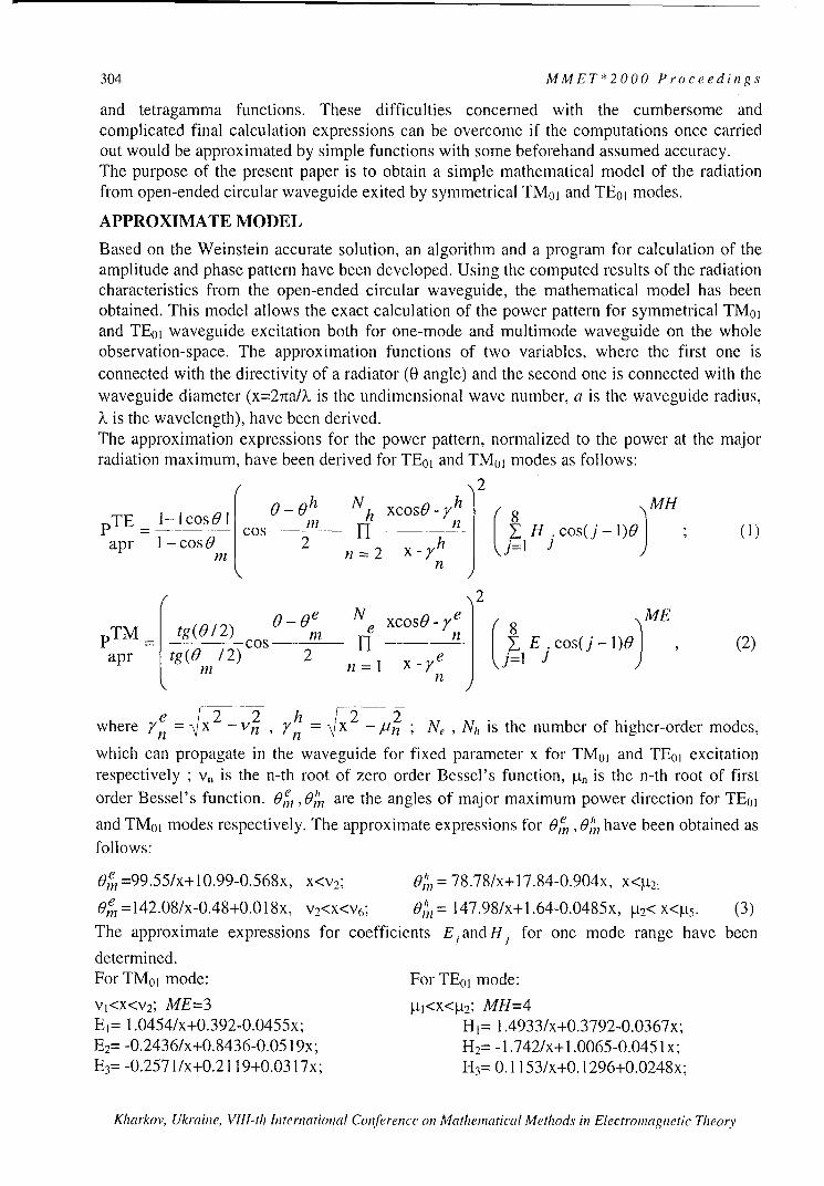
304 MMET*2000 Proceedings
and tetragamma functions. These difficulties concerned with the cumbersome andcomplicated final calculation expressions can be overcome if the computations once carriedout would be approximated by simple functions with some beforehand assumed accuracy.The purpose of the present paper is to obtain a simple mathematical model of the radiationfrom open-ended circular waveguide exited by symmetrical TM01 and TE0O modes.
APPROXIMATE MODEL
Based on the Weinstein accurate solution, an algorithm and a program for calculation of theamplitude and phase pattern have been developed. Using the computed results of the radiationcharacteristics from the open-ended circular waveguide, the mathematical model has beenobtained. This model allows the exact calculation of the power pattern for symmetrical TM01and TE01 waveguide excitation both for one-mode and multimode waveguide on the wholeobservation-space. The approximation functions of two variables, where the first one isconnected with the directivity of a radiator (0 angle) and the second one is connected with thewaveguide diameter (x=27raIA is the undimensional wave number, a is the waveguide radius,k• is the wavelength), have been derived.The approximation expressions for the power pattern, normalized to the power at the majorradiation maximum, have been derived for TE0O and TM01 modes as follows:
2
0 -0 h N h xcos -h 8)MP E - csl Cos In 1-_ -- Y H cos(j - 1)0 " (1)
apr 1 - cosO 2 n = 2
0-Te Nco e" xc hJ MpTM tg(012) 00 Ne xcos0cos j
r Cos l Y-_n E cos(j- 1)0 (2)
apr tg(0 /2) 2 _ jIx J ' einn
where n - h = x2 _ 2 Ne , N1, is the number of higher-order modes,n 2' n ý P
which can propagate in the waveguide for fixed parameter x for TMo0 and TEO, excitationrespectively ; v, is the n-th root of zero order Bessel's function, P-n is the n-th root of firstorder Bessel's function. Oe, are the angles of major maximum power direction for TE01
and TM01 modes respectively. The approximate expressions for Oe, Oe have been obtained asfollows:
0,e =99.55/x+10.99-0.568x, x<v2; M= 78.78/x+17.84-0.904x, x<p-2:
On=142.08/x-0.48+0.0l8x, v2<x<v6 ; III= 147.98/x+1.64-0.0485x, [-t2< x<p.9. (3)The approximate expressions for coefficients EiandH1 for one mode range have been
determined.For TM0 I mode: For TE01 mode:
VI<X<V2; ME=3 Vt1<x<la2; MH=4El= 1.0454/x+0.392-0.0455x; H1= 1.4933/x+0.3792-0.0367x;EB= -0.2436/x+0.8436-0.0519x; H 2= -1.742/x+I1.0065-0.0451 x;E3= -0.2571/x+0.2119+0.0317x; H3= 0.1 153/x+0.1296+0.0248x;
Kharkov, Ukraine, VIII-th International Conference on Mathematical Methods in Electromagnetic Theory

MMET*2000 Proceedings 305
E4= 0.2286/x-0. 1438+0.0488x; H4= 0.0217/x-0. 1192+0.0347x;E5= 0.2046/x-0. 1842+0.0522x-0.0028x 2; H5 = 0.12995/x-0.0409+0.0103x;E 6= 0.1343/x-0.0782+0.0185x-0.00 1 x2; H 6= 0.006/x-0.0371 +0.0063x;E 7= -0.0793/x+0.0697-0.0208x+0.0023x 2; H 7= 0.1 3476/x-0.0361 +0.0038x;E8= -0.048/x+0.0583-0.0182x+0.0018x2. H8= 0.01 633/x-0.0 136+0.00179x.
Since the expressions (1), (2) approximate the normalized pattern, the approximation relationsbetween the power in the main maximum and the excited mode power have been found.These expressions allow computing the non-normalize power pattern.
pO = (-5.0849/x 2+5.5051 /x-2.1425+0.3057x)x/(x-2), x<V2,
p = (-I 1.6569/x 2+8.2601/x-2/2897+0.2426x)x/(x-3.75), x<ht2, (4)
The power radiation characteristics for TEO, and TM01 modes have been computed usingWeinstein's method and the developed mathematical model. The non-normalized powerpatterns calculated by means of the approximate expressions (1), (2) and (4) for TM0 ] modefor three values of x parameter (x=2.5, 5.5, 8.5) are presented in Fig. 1. The solid line is thecharacteristics computed by Weinstein theory; the lines with marker are the patterns obtainedby the developed mathematical model. One can see that the calculations made in terms of theapproximate model exactly describe the radiation sidelobes as well as the main lobe of thepattern. The absolute error of the approximation does not exceed 0.6 dB and 1.5 dB till thelevel -30 dB for TE0O and TM01 modes, respectively.
5 CONCLUSIONA mathematical model of the radiation from
0 - B an open-ended circular waveguide excited
-5- -A 2.5 by symmetrical TEO, and TM01 modes has-o-A 5.5 been developed in a wide frequency
-10 -A 8.5 bandwidth. The model takes into accountfive modes, which arise due to the
-1diffraction on an open-ended waveguide.
" -20 Recently the mathematical model for thea. -radiation from an open-ended circular
-25 waveguide excited by the dominant mode
-30 TE11 has been derived [3]. The model forTE11 mode and the proposed in this paper
-35 mathematical model can be used to derive-4_0 and calculate the radiation characteristics for
0 30 60 90 120 150 180 a waveguide, operating on TMoI+TE0 ],
0, g ra d TE1 I+TM01 or TEB I+TE01 modes.
Fig. 1.
REFERENCES[1] Weinstein L.A. Theory of diffraction and factorization method. Moscow, Soviet Radio Publish,1966 [in Russian].[2] Fradin A.Z. Ultrahigh frequency antennas, Moscow, Soviet Radio Publish, 1957 [in Russian].[3] Gorobets N.N., Orlova L.B., Shishkova A.V. Mathematical model of radiation from open-endedcircular waveguide. Preceeding of III International Conference on Antenna Theory and Techniques,pp. 324-325, Sep., 1999.
Kharkov, Ukraine, VIII-th International Conference on Mathematical Methods in Electromagnetic Theory

306 MMET*2000 Proceedings
RADIATION OF DIELECTRIC-COATED LONGITUDIONAL ANDTRANVERSAL SLOT ANTENNAS IN A PLANE WAVEGUIDE
E.A. Shorokhova, O.S. Rusakova, and V.A. Yashnov
Nizhny Novgorod State University, Radiophysics FacultyGagarina Avn. 23, Nizhny Novgorod, 603600, Russia.Phone: (8312) 65-61-27; e-mail: [email protected]
ABSTRACTIn this paper, a problem of radiation of longitudinal and transversal slot antennas placed onthe circular perfectly conducting cylinder with magnetodielectric coating in a planewaveguide is considered. The calculation reduces to solution of the Helmgolz equations forthe electric and magnetic vector potentials. The solution of the problem is obtained in an ap-proximation of a thin antenna (in relation to the wavelength) and given distribution of electricfield intensity along the slot. Expressions for the electromagnetic field intensity, radiationpower, and conductivity of the longitudinal and transversal slot antennas are obtained. Theyare presented in a form of double series over the eigenfunctions of the perfect planewaveguide and the azimuth eigenfunctions of the cylinder. Such a representation is very con-venient for numerical calculations. Using the expressions obtained the numerical calculationsof real and imaginary parts of the radiation conductivity and impedance are performed. Aninfluence of the magnetodielectric coating and geometrical parameters of the problem on an-tenna characteristics is analysed.
Slot antennas hold a special position in the antenna theory and engineering. They are widelyused as airborne transmitting antenna. Although the study of their characteristics is carried outbeginning with 4 0th years [1], the development of exact and approximate calculation methodsis subject of much current interest [2, 3]. Considerable recent attention has been focussed onradiation peculiarities for the slot dielectric-coated antennas [3]. In the paper we study an in-fluence of magnetodielectric coating on characteristics of longitudinal and transversal slotantennas placed on the surface of a circular perfectly conducting cylinder in a planewaveguide with perfectly conducting walls.The problem geometry is shown in Fig. I for a case of longitudinal slot antenna. Here a is theradius of the cylinder, b is the radius of magnetodielectric cylindrical coating, L is the dis-tance between the perfectly conducting walls of the plane waveguide, d and I are the sizes ofthe slot with a coordinate of its center z0 . It is assumed that coating of the antenna has theralative dielectric permittivity c, and the ralative magnetic permeability pu,, and thewaveguide is filled with a medium determing by the constants 62 and ,u2 . It is suggested thatthe electric field intensities along the slot for the longitudinal and transversal slot antennas arerespectively
E ,(z)= E , cos( (1)
E,, (q') = E0 cosff /Ta j. (2)
Here E0 is the amplitude of the electric field.The problem is decided using the Helmgolz equations for the electric and magnetic vectorpotentials with the Lorenz calibration:
Kharkov, Ukraine, VIII-th International Conference on Mathematical Methods in Electromagnetic Theory

MMET*2000 Proceedings 307
AA, +kA =0, (3)
AFJ +k FJ =0, (4)
where kj = co / 0~1 .0o.t is the wavenumber in coating (j = 1) and in the waveguide
( j = 2 ), co is the circular frequency, co and /u is electric and magnetic constant of the vac-
uum.Z The following boundary conditions are
used:(i) at r=ad_-,- E 0l) =0 , E •l) = - '
z (- (
(for the longitudinal slot antenna)62 e E, =0, E = -EsP 2 P~I I L (p ' Z
(for the transversal slot antenna);(ii) at r=b
E•l)= E (2), E(l)= E2)•0 •0 Z Z
Hl) H 1(2), Hl() = H(2)
2 a 9) ' Z Z2aE 5 adE4 Here Es and E' is given by the expres-
2 b sions (1) and (2). Solutions of the equation(3) and (4) are sought in the form of double
Fig. I series over the eigenfunctions of the planewaveguide with perfectly conducting walls and the azimuth eigenfunctions of the cylinder.Using the expressions obtained for the potentials it can be found electromagnetic fields, ra-diation power and conductivity of the longitudinal and transversal slot antenna.To cite the final formula for the radiation conductivity of the longitudinal slot antenna:
Gk16i () 2 2
7C"3•71 kL ka /8 ,,,
where we use the denotations:
oQ > H 1(>2(jý,,kla){1 dl.} i = ' 'H17 1 a ... t= -ld(2) ul duo,,, (Wl,,,kla)
A, A1 fC( 2) k ( a)t)(2) (Wk 2b)H (2, k b)A H_2)(12nklb
d1 2n [ 1 K l AL' Is II 211 11 2 n k2 b) 51A5 bL C~ K 1 2 A H171(W 1211k1b) ]A 3 HnI (W1 1kla)
Ae I 1 A 4 K 2 n, 6 i HS)(W2nk 2b) A = 1 A2 K'2n I/ 1 H( )(iC 2 k 2b)
A 1 '1n 2 I•2)(K'2 nk 2 b)' A 3 In P-2 ft1 (w2n1 k 2 b)'
H(2J(/1 k b f2()) kb) A2 = A° 1In1 ) m \ In 1 2) * AV0ln A t, A }. [ f.• (2 ) ( W"]-2,- /-7! )(•,) 2) (W)k b) A-3 jA (koL) 2 n2
( 2
AO==nmff H(2)(W 2k b~ -2 _2d 2 n, /7-flT22 11, 1 P, I -2 . koL)
Kk ain, V III•h In•tnaibo (Cinf eka)-n H ')(Mt i,,cka)H o i(ti,,khb),
Kharkov, Ukraine, VIII-th International Conference on Mathematical Methods in Electromagnetic Theory

308 MMET*2000 Proceedings
A,=f~( 1 kbfl~Q 1 ka Wl(W,,1ka)f4 (2)(WI " k b),A 3 1= HV ) •,k"•bI(2)H,)'' k ak)- f)(W,, k, a)H (2)(Wk kjb),
Nueia acltos ftera ato raditio co'nductivit (G')l 1•G] frth'oniuA 4' =\'() W, k •lWInk a ') l (W, k, ia \ (2) ( Iý,,,j
A5 =H 0 "(2)(25 -Hm(Wkkl a)Hm (/k,,k' )- HP')(Wl,, kl~l)SH)(Wlkj),
Numerical calculations of the real part of radiation conductivity (GO• =9 G) for the longitu-
dinal slot antenna as a function of the parameter koL (see Fig.2) have been performed using
formula (5) for the following values of the electrical and geometrical parameters: c, = 5
(solid line), c, = 3 (dotted line), e, I (dash-dot line), 6,= I, a / L = 0.5, b /L = 0.51,
IIL=O.5, d/a=0.O1, zo/L=0.5.
55
6 -.. .. .. . t 3
4
3 -
2
0
2 4 6 8 10 12 14 16 18 20
k,,L
Fig. 2.
Basing on these data the following conclusions can be formulated. Firstly, at frequencieslower than the first critical frequency of the waveguide (koL < ;r) the radiation of the longitu-
dinal slot antenna is unavailable. Secondly, even thin magnetodielectrical coating of the slotantenna has a noticeable influence on its characteristics. In particular, an increase in the an-tenna radiation power is observed with growing c,.
REFERENCES[l] J. R. Wait, "Electromagnetic radiation from cylindrical structures", Pergamon Press, New
York, 1959.[2] Park J.K., Eom H.J. Radiation from multiple circumferential slots on a conducting circular
cylinder. - IEEE Trans. on Antennas Propagat., 1999, vol.47, no.2, pp. 287-292.[3] Ragheb H.A., Johar U.M. Radiation characteristics of an infinite dielectric-coated axially
slotted cylindrical antenna partly embedded in a ground plane. - IEEE Trans. on AntennasPropagat., 1998, vol.46, no.10, pp. 1542-1547.
Kharkov, Ukraine, VIII-th International Conference on Mathematical Methods in Electromagnetic Theory

MMET*2000 Proceedings 309
ANALYSIS OF DISTURBED PATTERN STATISTICALCHARACTERISTICS FOR APODIZED MULTIELEMENT
WAVEGUIDE SLOT ANTENNAS
A.V.Kabanov, and V.V.Lukin
Dept. 504, State Aerospace University, 17 Chkalova St, 61070, Kharkov, UkraineTel. +38 0572 442352, +38 0572 448789, Fax +38 0572 441186
e-mail: [email protected]
The statistical analysis of disturbed patterns for waveguide slot apodized multielementantennas is performed. Both spatially independent and correlated phase errors with variancestypical for practice are considered. The numerical simulation results are obtained for classicalamplitude distributions and apodization functions earlier proposed by authors. It is shown thatthe mean maximal side lobe level of disturbed patterns gradually increase in comparison topotential level due to error influence. However, in the sense of statistical characteristics of themain lobe width and maximal side lobe level for disturbed patterns the proposed apodizationfunctions provide appropriate results.
INTRODUCTION
For waveguide slot multielement antennas the required pattern characteristics are usuallyprovided by means of proper selection of an apodization function (AF), i.e. amplitudedistribution of irradiated field on antenna aperture. In practice, not all known AFs can berealized in waveguide slot antennas because of constructive and technological restrictions [1]imposed by the fact that the slots placed in the waveguide wide wall should have someminimal distance between them. That is why only few known AFs can be implemented,besides, in our paper [1] we have proposed several new AFs that are potentially able to ensurethe maximal side lobe level (MSLL) of antenna pattern within the limits from -30 to -40 dB.In practice, the desired amplitude-phase distribution can be realized with some errors, theyoccur due to slot intercoupling, random shifts of their phase centers with respect to idealpositions and other reasons [2]. This inevitably leads to difference between theoretical andpractically obtained characteristics of antenna pattern. And the latter ones (for disturbedpatterns) are usually worse than potentially reachable. That is why often a question arises howstable are the proposed solutions with respect to degrading factor (noise, errors) influence.Statistical analysis of disturbed patterns [2] can give an answer and provide data necessary foranalysis and practical recommendations.
APPROACH TO DISTURBED PATTERN STATISTICAL ANALYSIS
The influence of errors results in degradation of the majority of the basic characteristics ofantenna pattern. In particular, the pattern main lobe width (MLW) can increase [2], [3]. Butusually this increase is not too large and it does not exceed 1 ... 2% (this dependence isconfirmed by numerical simulation results presented below). The pattern side lobes arecommonly more severely affected by errors and the pattern MSLL can increase by few or eventens dB in comparison to the case of pattern for ideal amplitude phase distribution.Below we consider only the phase errors as a factor supposed to be the dominant forwaveguide slot antennas. Two different cases are exploited: the spatially independent errors(correspond to the value y = 2 in Table) and the spatially correlated phase errors (y = 0.1). An
Kharkov, Ukraine, VIII-th International Conference on Mathematical Methods in Electromagnetic Theory

310 MMET*2000 Proceedings
exponential model [2], [3] of spatial correlation function is used. As it is shown in [2], [3] theinfluence of these types of errors on disturbed pattern statistical characteristics can be ratherdifferent. Besides, in opposite to [2] it was decided to evaluate not the parameters of the meandisturbed pattern but the mean parameters of disturbed patterns. Two values of the phase error
variance o92 0.005 and 0.01 (expressed in rad2) have been analyzed. They are rather typical
for practical applications. It should be noted that this level of phase errors can be consideredas relatively large distortions [3] since the disturbed pattern has practically random behaviorof the side lobes and the mean MSLL is mainly determined by the error variance and the usedAF.The statistical characteristics of disturbed patterns have been analyzed for five AFs: theDolph-Chebyshev AF that potentially provides the MSLL=-40dB (it can not be implementedin waveguide slot antennas but serves for comparison purposes), the Gauss AF (ac,=2 .2 )which is one among the best known AFs that can be implemented, the Kaiser-Bessel AF onpedestal, the AF Cos2 on pedestal 0.1 with optimal parameters, the AF Riss on pedestal [1].The latter three AFs have been proposed by us and their parameters were optimized. Thepotential MSLL and MLW values for the corresponding patterns are given in Table (See rowswith notation "potential"). In simulations we considered the case of equidistant antennas withelement spacing equal to half wavelength and the number of elements N=80. The mean valuesand variances have been estimated for MSLL and MLW of disturbed patterns. They arepresented in Table.
ANALYSIS OF NUMERICAL SIMULATION DATA
Numerical simulation data prove that the phase errors (at least, for the analysed variances oferrors) do not lead to considerable expanding of the pattern main lobe width. It is smaller than0. 1% and the root mean square of this parameter is also much smaller than its mean. That iswhy it is possible to state that the pattern MLW is very stable with respect to error influence.Of course, the larger the error variance the larger the variance of the MLW. Spatiallycorrelated errors usually result in larger variations of the disturbed pattern MLW than thespatially independent errors.On the contrary, the disturbed pattern MSLL is much more affected by the phase errors. It iswell seen that the mean MSLL can differ from potential one by about 3... 12 dB. The mean
2MSLL depends upon phase error variance and it increases by 1.5... 2.5 dB when a,, changes
from 0.005 to 0.01. The MSLL mean value also considerably depends upon are the phase errorspatially correlated or independent. The spatially correlated errors result in larger MSLL meanand variance than spatially independent ones.The most interesting aspect is that all the considered AFs provide the mean MSLLs (for equal
2 and y) that do not differ too much from each other. Only for the AF "Riss on pedestal"
the results are noticeably worse. However, all the other apodization functions producepractically the same results as the Dolph-Chebyshev AF. At the same time the functions "Cos2
on pedestal" and "Gauss, a(-;=2.2" lose to the Dolph-Chebyshev pattern only by 2% in themean MLW. Taking into account the fact that they both can be realized in waveguide slotmultielement antennas, it is possible to state that the proposed apodization functions providevery good characteristics of disturbed patterns which are stable enough with respect to phaseerror influence and it is worth using them in practice.
SKharkov, Ukraine, VIII-th International Conference on Mathematical Methods in Electromagnetic Theory

MMET*2000 Proceedings 311
Table. Numerical simulation results
MSLL MLWand 2 Mean (X× Variance (x10 7 ) Mean (×10-) Variance (X10-7)
yand 0-2MenIVainc e
Dol ph-ChebyshevPotential 0. 1000 (-40.00 dB) 0 3.15612 (1.810) 0
2.0, 0.01 1.1865 (-29.26 dB) 0.99475 3.15809 1.185292.0, 0.005 0.7856 (-31.50 dB) 0.25965 3.15862 1.172430.1, 0.01 1.6913 (-27.72 dB) 10.7710 3.15778 1.046980.1, 0.005 1.0110 (-29.95 dB) 3.61643 3.15674 1.08382
Kaiser-Bessel (with initial. MSLL = -40dB) on pedestal 0.1
Potential 0.2387 (-36.21dB) 0 3.64904 (2.09°) 0
2.0, 0.01 0.9459 (-30.24 dB) 1.24052 3.65023 0.751852.0, 0.005 0.5429 (-32.65 dB) 0.50699 3.64992 0.382340.1, 0.01 1.4163 (-28.48 dB) 14.8791 3.65391 5.169440.1, 0.005 0.8691(-30.60 dB) 4.10893 3.65053 2.86942
Cos 2 on pedestal 0.1.Potential 0.1038 (-39.84 dB) 0 3.28959 (1.890) 0
2.0, 0.01 1.0026 (-29.99 dB) 1.17269 3.29190) 1.211002.0, 0.005 0.5693 (-32.45 dB) 0.32444 3.29065 1.066000.1, 0.01 1.4327 (-28.44 dB) 8.97947 3.29104 1.105100.1, 0.005 0.8150 (-30.89 dB) 2.71024 3.29156 1.19549
Riss on pedestal 0.17.
Potential 0.3135 (-35.04 dB) 0 3.22166 (1.850) 02.0, 0.01 1.8132 (-27.42 dB) 2.89361 3.22161 0.535332.0, 0.005 1.4485 (-28.39 dB) 1.30831 3.22171 0.281510.1, 0.01 2.3560 (-26.29 dB) 15.2454 3.22595 4.187910.1, 0.005 1.7493 (-27.57 dB) 4.81943 3.22237 2.01905
Gauss, aG= 2 .2
Potential 0.3488 (-34.57dB) 0 3.22864 (1.85') 02.0, 0.01 1.1363 (-29.45 dB) 1.45071 3.22700 1.770022.0, 0.005 0.7667 (-31.15 dB) 0.61537 3.22826 1.153770.1, 0.01 1.7354 (-27.61 dB) 9.77945 3.23172 2.495300.1, 0.005 1.1224 (-29.50 dB) 3.02311 3.23196 2.63400
REFERENCES[1] Lukin V.V., Kabanov A.V., Ponomarenko N.N. Apodization functions for antenna arrayswith constructive-technological restrictions: Proceedings of ICATT'99. - Sevastopil, Ukraine,September 1999, pp. 219-224[2] Y.S. Shifrin Statistical antenna theory (State-of-the-art, key development directions). -Kharkov, 1985, 181p.[3] Zelensky A.A., Lukin V.V., Anukhin I.P. Apodized Array Pattern Analysis and Synthesisfor Spatially Independent and Correlated Errors Influence under Constructive andTechnological Restrictions// Proceedings of Intern. Conference PIERS'94, Noordwijk,Netherlands, July 1994, pp.4 4 0 -44 3 .
Kharkov, Ukraine, VIII-th International Conference on Mathematical Methods in Electromagnetic Theory

312 MMET*2000 Proceedings
SHAPED FEED SYSTEMS FOR THE DUAL-REFLECTOR ANTENNAS
Dmitry Y. Razdorkin, and Marina V. Romanenko
Rostov Research Institute of Radiocommunication130 Nansena, Rostov-na-Donu, Russia
Tel.: 34-07-44, E-mail: [email protected]
The multivariable optimization technique for the shaped feed system of the dual-reflectorantennas with the given circularly symmetric main reflector is described. The optimizationcriterion is the gaining of the maximum overall aperture efficiency 27,. Parameters for the
optimum search are the mutual layout of the antenna elements, features of output energydistribution at the aperture and the subreflector profile. On the basis of the carried out analysisof the dual-shaped reflector antennas the technique of the optimum feed system search wasdeveloped for different shapes of the given main reflector. The program application of thealgorithms for the dual-shaped antenna synthesis and algorithms of the optimization isrealized on the C ++.The problem of the shaped feed system design with the high aperture efficiency q,, in all
working frequencies band is very important for the multiband dual-reflector antennas with thelarge electrical aperture sizes ratio (fH /fL = 2-+ 3) and the given circularly symmetric mainreflector. In the present work the minimization of amplitude and phase deviations in the mainreflector aperture is analyzed.
X
X max
So Sr
P3max
rin 1 Ssr
0 Z
Fig. 1. Shaped feed system for the
reflector antenna
The examined technique of the Cassegrain antennas optimization is based on the replacementof its feed system with the feed system from the dual shaped antenna under the condition ofthe insignificant deviation of main and shaped reflector profiles (Fig. 1) [1]. In this case theaperture power density does not change. The only phase error distribution in the antenna
Kharkov, Ukraine, VIII-th International Conference on Mathematical Methods in Electromagnetic Theory

MMET*2000 Proceedings 313
aperture is reason of the aperture efficiency reduction. For the circularly symmetric reflectorantenna the aperture efficiency varies as
fnI.-nx exp( j 2 % A(D(x,p)ýdx
q. = x,,,,,(1)X hil.,
2 fI(x)xdxX.in
where I(x) is the aperture power density, AID(x,p) is the aperture phase distribution, 2I is the
wavelength. The vector p defines the feed system optimized parameters. The technique
described in [1] assumed the feed system optimization only on the irradiation corner of the
main reflector j6max when the uniform amplitude distribution I(x)= const in the aperture is
given. The efficiency of such antenna optimization ceases to be essential to the reflector
diameters D > (200 + 300)A and the relation % = (0,05 ÷0,1).
In the present work, the influence of the amplitude distribution function and the mutual layoutof the synthesized elements of the shaped system on the aperture phase errors and theresulting aperture efficiency is analyzed. In general, the vector of optimized parameters is a
function of the amplitude distribution function I(x), the irradiation angle of the main reflector
edge flmax and the relative displacement of elements
P =P(I (X),f8max5Az. , AZ.r)
Azf = - z Az,, = - Zsr, (2)
where z , z,, are the element positions for the shaped feed system, z', z' are their positions
after optimization.For the analysis of influence of the decaying amplitude distribution on the resulting apertureefficiency with the shaped feed system the distribution is used
I(x): = 1- ,.. 2 (3)
where a = 1- exp(ln(A) 0< a< 1, p N c = {0,1,2,...}, A is the power level at the
aperture edge.The numerical results show that for the antenna with diameters D / 2> 300 the shapedamplitude distribution becomes more effective than the uniform distribution. The use of theshaped feed system with such type of distribution is most efficient at designing of multibandsystems with the large ratio of the high and lower frequencies. If the amplitude distribution isuniform, the aperture efficiency quickly decreases with the frequency increase. Shaping forthe aperture distribution decreases the phase errors in the aperture and makes the antennadesign less critical to the growth of the working frequency (Fig. 2).It is shown that the insignificant change of the feed and subreflector mutual layout fromoriginally calculated by the dual-shaped antenna synthesis algorithm allows the minimizationof the phase aperture distribution errors of the designed antenna as well. This type of theoptimum feed system can be used for the designing antennas with the main reflector diameterup to 200+300 wavelengths and the uniform aperture distribution.Aperture efficiency dependencies for shaped feed systems of different types are shown in Fig.3.
Kharkov, Ukraine, VlII-th International Conference on Mathematical Methods in Electromagnetic Theory

314 MMET*2000 Proceedings
Ila
I'M
0.95 0.8
().90F - - A--0-=45- •
06F/D=0.45
o.75 -- _ -- - - - .- E(X)- oartM., AZý- AZ,,=0.
0(.2 _ __ E(X)=const, Az,, AZ,,-orrrM,
0,0----
1H0 15 2.0 215 30 3.IS , ,
02IX) 40{} 6(w• six) INNX) DI •
Fig. 2. Frequency dependences of the Fig. 3. Dependence of aperture efficiency onaperture efficiency parameters of the optimization
On the basis of the carried out analysis of the dual-shaped reflector antennas, the technique ofthe optimum feed system search was developed for different shapes of the given mainreflector.In the program application of shaped feed systems, the algorithms of one- and multiparametersearch are realized for the optimization of the different feed systems by the criterion of a
maximum overall aperture efficiency. As the derivative of the function 1la determining theoptimization criterion can not be defined analytically, the optimization algorithms can not beimplemented on the gradient method basis. For the one-dimensional optimization (forexample, the optimization of the feed system by the angle of the energy transform) the square-
law approximate algorithm for the function 77a with the subsequent linear optimization isimplemented. For feed systems with the optimum output energy distribution and angle of theenergy transform the program implementations of algorithms coordinated of descent isdesigned on the basis of one-parameter algorithm of linear search. The algorithm of randomsearch with adaptation is used for feed systems optimizing the mutual layout of the units ofthe antenna [3].In case of feed systems inverting the field of the primary feed, the additional optimum searchalgorithm is implemented at the dual-shaped antenna synthesis with inverse boundaryconditions.The program application of the algorithms for the dual-shaped antenna synthesis andalgorithms of the optimization is realized on the C ++.REFERENCES[1] Bandukov V.P., Pokras A.M. Shaped feed system for dual-reflector antenna (In Russian).- Telecommunication. - 1973. - Num. 10. - Pp. 59-63.[2] M.V. Romanenko. The uniform approach to dual-shaped symmetrical reflector system (inRussian). " Antennas, radiocommunication and means " (ICARSM-97), Proceeding of the 3International Conference, Voronezh-May-97. - Pp. 204-214.[3] Rastrigin L.A., Ripa K.K. The adaptation of the random search (in Russian). - Riga:Knowledge - 1978.
Kharkov, Ukraine, VIII-th International Conference on Mathematical Methods in Electromagnetic Theory

MMET*2000 Proceedings 315
COMPLEX MEDIA,
BEAMS AND PLSMAS
Kharkov, Ukraine, VIII-th International Conference on Mathematical Methods in Electromagnetic Theory

316 MMET*2000 Proceedings
Kharkov, Ukraine, VIII-th International Conference on Mathematical Methods in Electromagnetic Theory
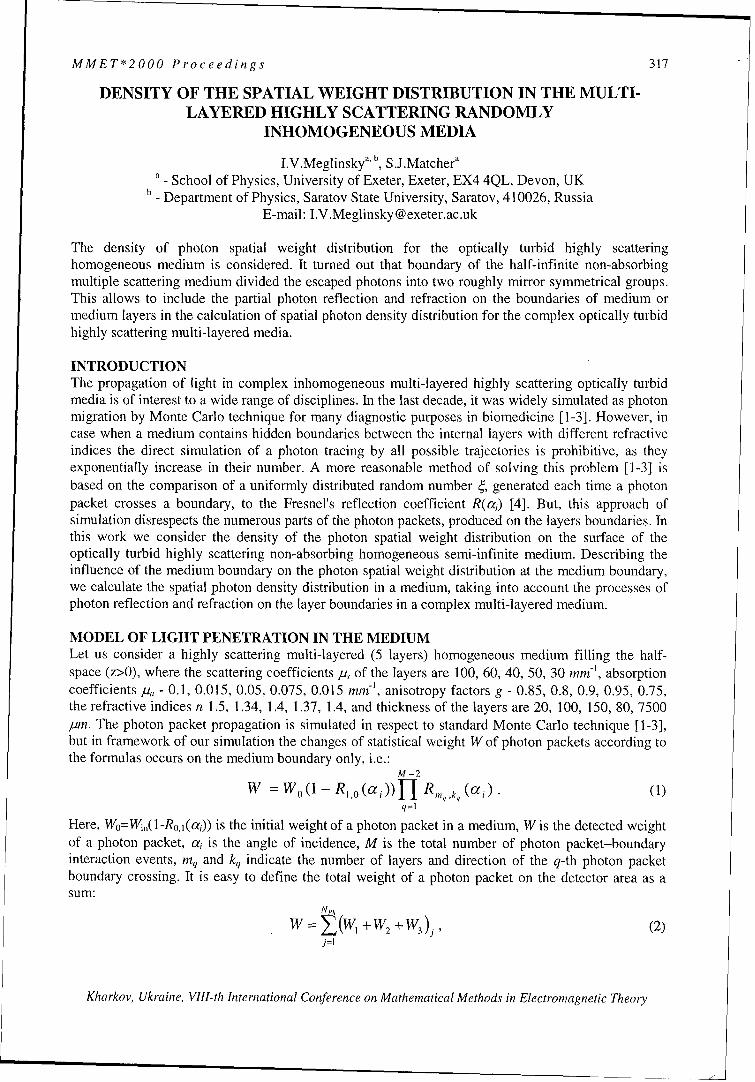
MMET*2000 Proceedings 317
DENSITY OF THE SPATIAL WEIGHT DISTRIBUTION IN THE MULTI-LAYERED HIGHLY SCATTERING RANDOMLY
INHOMOGENEOUS MEDIA
I.V.Meglinsky b, S.J.Matchera, School of Physics, University of Exeter, Exeter, EX4 4QL, Devon, UK
- Department of Physics, Saratov State University, Saratov, 410026, RussiaE-mail: I.V.Meglinsky @exeter.ac.uk
The density of photon spatial weight distribution for the optically turbid highly scatteringhomogeneous medium is considered. It turned out that boundary of the half-infinite non-absorbingmultiple scattering medium divided the escaped photons into two roughly mirror symmetrical groups.This allows to include the partial photon reflection and refraction on the boundaries of medium ormedium layers in the calculation of spatial photon density distribution for the complex optically turbidhighly scattering multi-layered media.
INTRODUCTIONThe propagation of light in complex inhomogeneous multi-layered highly scattering optically turbidmedia is of interest to a wide range of disciplines. In the last decade, it was widely simulated as photonmigration by Monte Carlo technique for many diagnostic purposes in biomedicine [1-3]. However, incase when a medium contains hidden boundaries between the internal layers with different refractiveindices the direct simulation of a photon tracing by all possible trajectories is prohibitive, as theyexponentially increase in their number. A more reasonable method of solving this problem [1-3] isbased on the comparison of a uniformly distributed random number ý, generated each time a photonpacket crosses a boundary, to the Fresnel's reflection coefficient R(ai) [4]. But, this approach ofsimulation disrespects the numerous parts of the photon packets, produced on the layers boundaries. Inthis work we consider the density of the photon spatial weight distribution on the surface of theoptically turbid highly scattering non-absorbing homogeneous semi-infinite medium. Describing theinfluence of the medium boundary on the photon spatial weight distribution at the medium boundary,we calculate the spatial photon density distribution in a medium, taking into account the processes ofphoton reflection and refraction on the layer boundaries in a complex multi-layered medium.
MODEL OF LIGHT PENETRATION IN THE MEDIUMLet us consider a highly scattering multi-layered (5 layers) homogeneous medium filling the half-space (z>0), where the scattering coefficients p,, of the layers are 100, 60, 40, 50, 30 mm-1, absorptioncoefficients A, - 0.1, 0.015, 0.05, 0.075, 0.015 mm-', anisotropy factors g - 0.85, 0.8, 0.9, 0.95, 0.75,the refractive indices n 1.5, 1.34, 1.4, 1.37, 1.4, and thickness of the layers are 20, 100, 150, 80, 7500pin. The photon packet propagation is simulated in respect to standard Monte Carlo technique [1-3],but in framework of our simulation the changes of statistical weight W of photon packets according tothe formulas occurs on the medium boundary only, i.e.:
M-2
W = Wo(1 - R 10o(ai))] Rmnq,k, (ai). (1)q=l
Here, Wo=Win(1-Rol(ai)) is the initial weight of a photon packet in a medium, W is the detected weightof a photon packet, ai is the angle of incidence, M is the total number of photon packet-boundaryinteraction events, mq and k,1 indicate the number of layers and direction of the q-th photon packetboundary crossing. It is easy to define the total weight of a photon packet on the detector area as asum:
N pl,
W =Z(I + W2 +•W ) j, (2)j='
Kharkov, Ukraine, VIII-th International Conference on Mathematical Methods in Electromagnetic Theory

318 MMET*2000 Proceedings
where W, = Wo (I - R,1 0 (a)), W2 = Wo (I - R1,0 (a ))R1,0 (a1 ), and
M,
W3 = W0(l - R.0o(a,))I Rk,, f, (ai), N1,1, is the total number of detected photon packets. As the angleq=1
distributions of the photon packets on the medium boundary are the same for the photon packets which
are once partially reflected on the boundary only PI (a,) and for the photons once refracted and
reflected while escaping the medium P2 (a,) (FIG.1), we can express sum of W, and W 2 as:
(W42 ) g (WI )(Rl10 (at)) (3)
where K...) denotes an average over all photon packets paths.
1 09 ,
0.8..
0, 00×
× • k x x .0A 0. xx x x0. 02 xV
0.1 x xx0/
0 20 40' 600 800 O,
01,r, mii
FIGURE 1. FIGURE 2.Fig. 1.The surface photon escaping angle distribution finction P(a,): (-x-) - for the photon packets once
partially refracted on the boundary while escaping the nedium"; (-0-) - for the photon packets once partiallyreflected and then refracted on the boundary while escaping the medium.Fig. 2. The density of spatial photon. weight distribution W(r) on the boundary of the medium. (+) indicates thedensity of spatial photon weight distribution for photon packets which experienced only two acts of the
interaction on the mnediumn boundary (entering and escaping the medium); (x) shows the density of spatialphoton weight distribution for photon packets, experienced three acts of the interaction with the boundary(partially internal reflection on the sumface of the mnediuni, initial and final refraction); ( -) presents thedistribution W(r) for all other photon packets, experienced more than three acts of the interaction with theboundary.Moreover, the density of photon spatial weights distribution on the medium boundary (i.e. <W]> and
<W.,>, respectively) are roughly mirror symmetrical about ý-" o(l -(R 1.0o(a,))) or approximately 0.462
in current simulation (FIG.2).
In other words, the boundary of the medium works as a semi-transparent mirror, and multiplier
R1,0 (ai) in the second summand W2 of (3) can be considered as the operator responsible for the
symmetry of the parts I and 2 (see FIG.2). But, as the weight of high order boundary interacted photon
packets W3 in (3) is negligible small (see FIG.2), partially reflected on the medium boundary photon
packets might be taken into account with ease:WT(,,(,l, (r) =< W, (r) > (I+ < R,,o (ai ) >) . (4)
Thus, the total spatial photon weight distribution for a complex multi layered medium is:L
W(r) = ,W (r)(0 + k R k.k+. + XkRkk,), (5)
k=1
where k - , Wk(r!) is the amount of the photon weight in the top point r1 of the k-th layer onWk (r,)
the OZ, Wk(r2) is the amount of the photon weight in the last point in the k-th layer on the OZ.
Kharkov, Ukraine, VIII-th International Conference on Mathematical Methods in Electromagnetic Theory
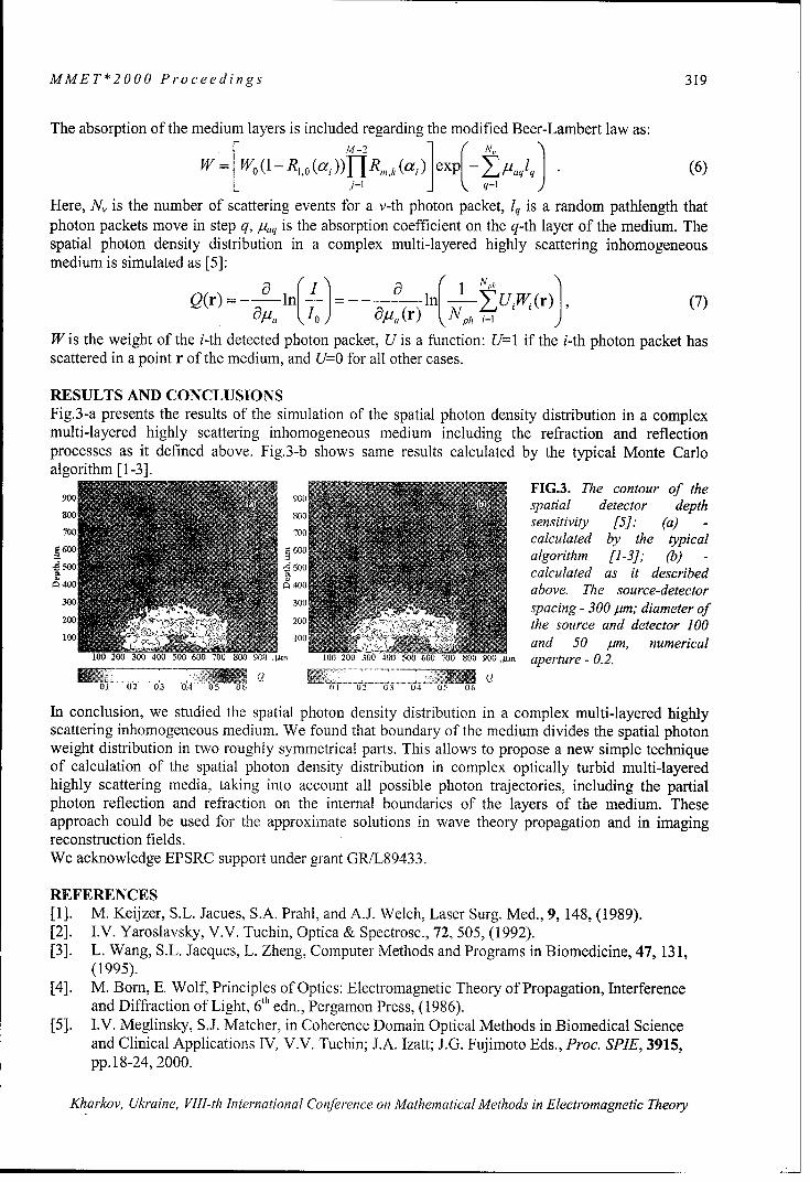
MMET*2000 Proceedings 319
The absorption of the medium layers is included regarding the modified Beer-Lambert law as:W= Wo(1-R 1,o(a ))-IR,4k (ai) exp- I. aqlq (6)
Ij=l q=l
Here, N, is the number of scattering events for a v-th photon packet, 1q is a random pathlength thatphoton packets move in step q, I,,q is the absorption coefficient on the q-th layer of the medium. Thespatial photon density distribution in a complex multi-layered highly scattering inhomogeneousmedium is simulated as [5]:
Q(r) = 0 ln|=,nUi -(r) (7)Q cr -9p,, I0 ap, (r) .Nph i=1'
W is the weight of the i-th detected photon packet, U is a function: U=I if the i-th photon packet hasscattered in a point r of the medium, and U=O for all other cases.
RESULTS AND CONCLUSIONSFig.3-a presents the results of the simulation of the spatial photon density distribution in a complexmulti-layered highly scattering inhomogeneous medium including the refraction and reflectionprocesses as it defined above. Fig.3-b shows same results calculated by the typical Monte Carloalgorithm [1-3].
FIG.3. The contour of then spatial detector depth
800 sensitivity [5]: (a)-4- Mcalculated by the typical
Aýo •algorithm [1-3]; (b) -
calculated as it describedS400 above. The source-detector
Ilk spacing - 300 pim; diameter of200 the source and detector 100100 and 50 Jpm, numerical
100 200 300 400 50000 0 800 S 9 100 ti, 100 200 300 400 500 600 100 800 900 ,wrn aperture - 0.2.
01 02 03 04 05 0U 01 02 03 04 0 u 06
In conclusion, we studied the spatial photon density distribution in a complex multi-layered highlyscattering inhomogeneous medium. We found that boundary of the medium divides the spatial photonweight distribution in two roughly symmetrical parts. This allows to propose a new simple techniqueof calculation of the spatial photon density distribution in complex optically turbid multi-layeredhighly scattering media, taking into account all possible photon trajectories, including the partialphoton reflection and refraction on the internal boundaries of the layers of the medium. Theseapproach could be used for the approximate solutions in wave theory propagation and in imagingreconstruction fields.We acknowledge EPSRC support under grant GR/L89433.
REFERENCES[1]. M. Keijzer, S.L. Jacues, S.A. Prahl, and A.J. Welch, Laser Surg. Med., 9, 148, (1989).[2]. I.V. Yaroslavsky, V.V. Tuchin, Optica & Spectrosc., 72, 505, (1992).[3]. L. Wang, S.L. Jacques, L. Zheng, Computer Methods and Programs in Biomedicine, 47, 131,
(1995).[4]. M. Born, E. Wolf, Principles of Optics: Electromagnetic Theory of Propagation, Interference
and Diffraction of Light, 6th edn., Pergamon Press, (1986).[5]. I.V. Meglinsky, S.J. Matcher, in Coherence Domain Optical Methods in Biomedical Science
and Clinical Applications IV, V.V. Tuchin; J.A. Izatt; J.G. Fujimoto Eds., Proc. SPIE, 3915,pp. 18-24, 2000.
Kharkov, Ukraine, VIII-th International Conference on Mathematical Methods in Electromagnetic Theory

320 MMET*2000 Proceedings
MULTIPLE LIGHT SCATTERING BY RANDOM ANDDETERMINISTIC STRUCTURES.
Irina L. Maksimova
Saratov Department of the Institute of Radioengineering and ElectronicsRussian Academy of Science
38 Zelenaya st., Saratov, 410019, RussiaE-mail: [email protected]
ABSTRACTA numerical study of two-dimensional photonic structures of finite set of parallel cylinders ispresented. A rigorous theory in which each cylinder is characterized by its scattering matrix,which links the diffracted field to the incoming one, is used.
The effects of multiple scattering play a substantial role in light propagation in dense dispersesystems. The mutual interactions of the scatterers complicate the light scattering. A rigoroustheory of multiple scattering has certain disadvantages if compared to the method ofdescribing the radiation propagation in media containing correlated discrete densely packedscatterers. This theory has been intensively developed in late decades because the problemsthat are expected to be solved are of interest for a wide range of scientific disciplines.This paper deals with the problem of calculating the spatial characteristics of laser radiationscattered by layers formed by circular cylinders. To reveal the aspects only due to the spatialorder degree we advantageously restrict ourselves by considering particle systems of high-symmetrical types. We consider light scattering induced by array of L parallel infinitecylinders with precisely specified coordinates immersed in a homogeneous background. Theplane incident wave is normal to the axes of cylinders. The problem is two-dimensional: Thecylinders are infinite in the Z direction and the incident field is also Z invariant.
Z
y
4'/j
kk
The theory is based on a self-consistent approach that identifies incident and scattered fieldsaround each cylinder. The electromagnetic field that is incident upon the surface of the j-thcylinder consists of two parts: the original incident waves Ei,,,.(j) and the scattered fields of
all the other cylinreds EL, (1,j), which can be written as:
Kharkov, Ukraine, VIJI-th International Conference on Mathematical Methods in Electromagnetic Theory

MMET*2000 Proceedings 321
L
E,(j) = Eic (j) + Z E (l, j) (1)
The total incident field Ei (, scattered field Es. 0 and internal field E, 0can be expanded as
n=--o0 /=--Oo n=--oo
where Nj is the vector cylindrical functions, En = (-i)Eo. The interactive scatteringk
coefficients are given by bi = bp where b, are exactly the Mie coefficients for isolated j-th cylinder.From the Graf's addition theorem for Bessel Functions, the, scattering problem is reduced tothe solution of a linear system.
_ L Qo
p, =ne"k' -V L'bA'(J (3)I•j v=--O
Using the asymptotic iteration method we solved this system.The total scattered field in the far field asymptotic can be written as
L
Es°a (o) = ( E/ (. -E° r2 eikr-hr L4oo,0a Z' E E 1,, Ie-i'7,S Zbi e-n'° (4)j~lj-1 n=-w
where 0 is the angle between k10, and k,.
30
0 0 0o00 0
0 0kO 20 :-M. 0 00°o o
0 00 0 2
mc 0 0
10
00 90 180 270 360
Intensity in 0 -direction is
Kak, IU llt I01 r n 2 (5)
Kharkov, Ukraine, VIII-th International Conference on Mathematical Methods in Electromagnetic Theory

322 MMET*2000 Proceedings
30
0 0 00
0 0 00
k. 0 0 200 0 0
0 0 0 0
0 0
1010
0 90 180 270 360
0
The method enables us to give an accurate description of all the characteristics of theelectromagnetic field scattered by a finite set of parallel cylinders and to study the influenceof defects on optical properties of photonic crystals (1). Spectral dependences of thetransmittance of crystal consisting of finite number of cylinders with different spatialstructure are investigated. Special attention is paid to the crystal with defect when somecylinders have been removed from ideal lattice.Spatial characteristics of the scattering intensity from the set of cylinders with fractaldimension are computed. For random structures the dispersion relations are analyzed in quasi-crystalline approximation. The phenomenon of non-linear dependence of effectivepropagation constant on the number density of scatterers is investgated numerically. Themodel of layers formed by closely-packed systems of long cylinders is used to calculate thedegree of circular dichroism of the eye cornea (2).
REFERENCES
[I] G. Tayeb, D. Maystre Rigorous theoretical study of finite-size two-dimensional photoniccrystals doped by microcavities. J. Opt. Soc. Am. A, 1997, v.14, No.12, p.3 3 2 3 -3 3 3 2
[2] V.F. Izotova, I.L. Maksimova, I.S. Nefedov, S.V.Romanov Investigation of Muellermatrices of anisotropic nonhomogenous layers in application to optical model of cornea.Appl. Opt., 1997, v.36, NO.1, p. 164 - 16 9
Kharkov, Ukraine, VIII-th International Conference on Mathematical Methods in Electromagnetic Theory

MMET*2000 Proceedings 323
QUASILINEAR THEORY OF INTERACTION BETWEEN SURFACEPLASMONS AND AN ELECTRON BEAM MOVING PARALLEL
TO A PLASMA SURFACE IN VACUUM
Y.O. Averkov, and V.M. Yakovenko
Institute of Radiophysics and Electronics, National Academy of Sciences of Ukraine12 Acad. Proskura Street, 61085 Kharkov, Ukraine. E-mail: [email protected]
QUASI-LINEAR EQUATIONSLet us consider the homogeneous semiconductor plasma, which is placed into the half-space(y < 0) in the absence of external magnetic field. The nonmonoenergetic electron beammoves along the axis (ox) in the half-space (y > 0) (vacuum) at the velocity of vo. The beam
density nb is assumed to be much less than the semiconductor plasma density n p Besides we
will assume that there are a lot of surface plasma waves which have various wave-vectors 4and various phases and propagate simultaneously on the boundary (y=0) along the axis (ox).From statement of the problem it follows that the excitation of surface plasmons occurs onlydue to movements of the beam electrons along the axis (ox). That is why we will consider theone-dimensional problem and will describe statistics of the beam electrons by the"background" distribution function F(kj) that satisfies to the following normalization condi-tion:
fF(k X) k n'b'rFk dk• (1)S2n
where -fb = nbS is the linear density of the beam electrons, S is the cross-sectional area of theelectron beam. Henceforward at numerical evaluations we will suppose that S cc q- 2 . Takinginto account one-dimensionality of our problem we will hide the index "x" at k x ,qx. Theinitial system of kinetic equations for the averaged distribution function of resonant electronsof the beam Fk and for the distribution function of plasmons Nq (in the case of Nq >> 1 ) is:
"aFk -Y Nq[Wk+q,q(Fk+q -Fk)J(Ek+q -Ek -- h ()q)--Wk,k-q(Fk -Fkq)8 (Ek -Ekl - •h .q)({ (2)aNq NqE Wk+qj(Fk+q - Fk) 8 (Ek+q - Ek - h ()q
at k
where (, = o/ 0 + 1 is the frequency of the slow surface plasmon (c -- o, here c is the
light velocity in vacuum), co = (47re2np/m*)l is the frequency of Langmuir oscillations of
plasma, m* is the effective mass of plasma electrons, so is the dielectric constant of the semi-conductor lattice, Wkq is defined by the following expression [4]:
2 71 12 eh(k -k )_ 2 -- k 'W k,q = - I , W , W kq = ,o-• -- k2 s 0 +l))J'o ,
h~ ~ k moq Ly 2S(F +i1)]'
where kl, k2 are the wave vectors of electrons "before" and "after" scattering, Wkq is the ma-
trix element of Hamiltonian of interactions between an electron beam and an electromagnetic
Kharkov, Ukraine, VlI-th International Conference on Mathematical Methods in Electromagnetic Theory

324 MMET*2000 Proceedings
wave, Ly is the dimension of the system along the axis (oy). Note that EO is equal to its bulk
value for homogeneous isotropic plasma. We assume that the electrons are reflected specu-larly from the boundary.The transition from Eq.(2) to quasi-linear equations [1-3] for Fk and for the spectrum densityof surface plasmons energy eq is carried out on the following assumptions:
Iq/k« << 1, Nq =[6q /IhcOq1 (3)
Actually, this means the transition to the case of diluted plasma in which the relative changeof the momentum of the beam electron at excitation (or absorption) of the plasmon is negligi-ble.Expanding the right-hand side of Eq.(2) with respect to q/k and turning from summationsover q and k to appropriate integrals, we obtain the following system of quasi-linear equa-tions:
at
(4)
OF a (D FJ,at = v ( -v)
where the wave numbers q and the velocities of the electrons v satisfy the following expres-sion coq = qv, which allows to consider the values Fk and eq as the functions of the velocity
v. Thanks to this fact we can hide the indexes "q" and "k" at these values in Eq. (4),
7te2v OF D _2_e2_"
60+ )LY SOv (Dqm 2O(F0 + I)LYS
Let at initial moment of time the functions co(v) and Fo(v) are:
60o(v)=Tp, F_ = F27-nh bexp (V- V o) 2 (5)
where TP is the temperature of semiconductor plasma in energy units, vT, = T -/m0 is the
thermal velocity of the beam electrons, T h is the temperature of the beam electrons in energy
units. The boundaries of the plateau VlV 2 of the distribution function F.,(v) in quasi-equilibrium state are defined by the following continuity conditions:
Fo(vO) = F.(v 1 ), Fo(v 2) = Fo(v 2), (6)where F,, (v) is found from the condition of conservation of resonant electrons.It is clearly that in the case of neglecting of distribution function of plasma electrons the leftboundary of the plateau is v1 = 0. The right boundary v2 and F,, (v) are:
V2 =Vo+ 4 2 v Tlnn2 v° F =7chn. I ~n" v + + ]D. (9).v/-vT ,F v2mo IL ,21VT vJ LTJVT jJ
The energy of oscillations in quasi-equilibrium state -. (v) is:
HaV, U=raeV= ) -t+ 0flh IV3{te[ai{ona Jo o+n va tRaicaMetods] i } (10)
Kharkov, Ukraine, VIII-th International Conference on Mathematical Methods in Electromagnetic Theory

MMET*2000 Proceedings 325
The dependencies of the spectral density of surface plasmons on their phase velocity (in termsof c) e.(v)-eo(v) are shown in Fig.1 at the scale of 1/S for v 0 = 0.05c (solid line) and
vo =0.1c (dash line), Tb = 5000 K.
100- The density of the beam electronsE ; and the plasmon frequency are:
0 80- 1 5b _ 1014 M-3, (, q ;z 5".1012 C-1.803
Fig. 1. shows that at the boundariesCD) 60 /i.60 of the plateaus the conditions
0 7 40 (0) =o, -_0 (v 2 ) 60 take place2•0 and maximums of the spectral den-,20- sity of plasmons are shifted to ini-0ooo o •b..-tial velocity of the beam vo . It
0,00 0,02 0,04 0,06 0,08 0,io 0,12 should be noted that with decreas-V/C ing the beam temperature the
maximum of the plasmon spectrumFig.1. shifts to the initial velocity of the
beam v0 . Besides let us note thatthe spectrum of the surface plasmons qualitatively corresponds to the spectrum in the case ofhomogeneous bulk plasma [5]. The energy loses of the electron beam for the whole relaxationtime is (V0 >> V2 Ž 1):
Ae_ =nbMo (D)(V )-3-1(V2 +0 (11)5o LD (T 4 vo,
CONCLUSIONThus, in the present work the quasi-linear theory of interaction between surface plasmons andnonmonoenergetic electron beam moving parallel to the semiconductor boundary is devel-oped. For the quasi-equilibrium state the distribution function of the beam electrons, thespectrum of the surface plasmons and the value of the power losses of the electron beam forthe whole relaxation time are derived.
REFERENCES[I] V.D.Shapiro. On the influence of the electrostatic instabilities on plasma conductivity andtemperature H/Izvestia Vuzov. Radiofizika. 1961, V.4, No.5, pp.867-874. (In Russian)[2] A.A.Vedenov, E.P.Velihov, R.Z.Sagde-ev. Quasi-linear theory of plasma oscillations //Nuclear Fusion. Supplement. 1962, Part 2, p.4 6 5 -4 7 5 . (In Russian)[3] W.E.Drummond, D.Pines. Non-linear stability of plasma oscillations H Nuclear Fusion.Supplement. 1962, Part 3, p. 10 4 9 -10 57 .[4] N.N.Beletskii, V.M.Svetlichnyi, D.D. Khalameida, V.M.Yakovenko. Super-high fre-quency phenomena in non-homogeneous semiconductors. Kiev, Naukova Dumka, 1991, 216p. (In Russian)[5] A.A.Vedenov, D.D.Rutov. Quasi-linear effects in beam instabilities // Vopr. Teor. Plasmy.1972, No.6, pp. 3-2 1. (In Russian)
Kharkov, Ukraine, VIII-th International Conference on Mathematical Methods in Electromagnetic Theory

326 MMET*2000 Proceedings
INVESTIGATION OF THE PLANE WAVE BEHAVIOR WITHINBIANISOTROPIC MEDIA
K. A. VytovtovRadiophysics Department, Dnipropetrovsk State University
13 Naukova str., Dnipropetrovsk, Ukraine, E-mail: [email protected]
INTRODUCTIONVarious chiral media both isotropic and anisotropic present an increased interest for theoreti-cal and experimental investigation. Isotropic media have been described in detail in [1,2].Theory of chiral-ferrite media have been presented in [3]. Plane wave propagation within bi-anisotropic media has been considered in [4,5]. However, theory of bianisotropic media whennondiagonal terms in chirality tensor and permittivity tensor are not equal to zero has not beenpresented early.
STATEMENT OF THE PROBLEMThe homogeneous lossless bianisotropic media described by the constitutive relations
T (1)
H=j4 E+t/o'h,
where- ~~.6~ 0 __~0
C-- Y . 0 . -=- .., ... 0 (2)0 0 C. 0 0 4:
are considered in this paper. It is assumed that the plane harmonic wave with frequency copropagates along arbitrary direction within considered media.Our purpose is investigation of the wave behavior within these media. At first it is necessaryto obtain and study the analytical expressions of the wavenumbers for arbitrary direction ofwave propagation. Then it is interesting to consider two particular cases: 1) the wave propa-gation along the bianisotropy axis, 2) the wave propagation normally to the bianisotropy axis.Wavenumbers of the eigenwaves. The wavenumbers are obtained starting from the compar-tibility condition of Maxwell's equations, which can be written in following form
a4k 4 +a 3k 3 +a 2k2 +atk +a, =0, (3)wherea4 = A (2,•.:. - .- 4 )cos' a + [ ,. + 6: + . + X - 2.• 4 2 .cos2 a + e,), +
a 3 =j2o/p0 e.,, (_:. - .,.) cos a sin 2 a;2 [,2 2_ +P 2 E ,. P 2_. "2
a 2 = o 0 [(o ,. + .+ .+ o , + 2 poý,...e•x..,. + oý::,.,.-4p0 .,.e.2 _ E.:)cos2 a - .. +2 6, + e+ p 4,e. + Po ., + . .
a , = j 4 a o 0 ,.)e.. , .s c o s a ; a 0 = o 0 .. .... 2 2 + 6 . .
This four order algebraic equation can be solved analytically, although it cannot be reduced tosquare equations. Here we write wavenumbers in analytical form
k+ a 43a2 (-4a20aa4+a'a,+8ata 3 W2_ a 3 (1 2a4 16a2 32a4N 4a4 (4)
a + 3a3 2 __+ __2__3__ 3_____
=00 +2 3 2aa aa a a 3 (5)"2a 4 16a4 32a4 #o 4a 4
Kharkov, Ukraine, VlI-th International Conference on Mathematical Methods in Electromagnetic Theory

MMET*2000 Proceedings 327
were fl, is an arbitrary root of the third order equationP3 +8aa4 - 3a' + ((8a 2a4 -3a )2
8a4 - 256a4
-64aa 3a4 + 256a0 a 4+16a 2a~a 4 -3a4 (-4a2a3a4 +a3 + 8aza42256a 4- -6 64a -0
which can be solved analytically by Kardano-Ferrary's method.Note that there are four different wavenumbers and consequently there are four different ei-genwaves.The expressions of the electromagnetic field components can be obtained directly from Max-well's equations in analytically form, but they are unwieldy and that is why they are not writ-ten here. However it should be noted that in general case the eigenwaves are plane, non-transversal waves, and the ones include all six components of the electromagnetic field.Wave propagation along bianisotropy axis. If a harmonic wave propagates along the bian-isotropy axis then all four wavenumbers are different and four different eigenwaves are withinthe media: two of these are right-circular-polarization waves and other two of these are left-circular-polarization waves. Resulting right-polarization wave is a pulsation as Ik ,1-1k,1 <((1.Analogously, resulting left-polarization wave is a pulsation as Ik, I -1 k 3 1((1. Resulting elec-
tric field is periodic function of space coordinate z.Wave propagation normal two bianisotropy axis. In this case two plane non-transversalwave propagate within bianithotropic media as the equation (3) is bi-square. The expressionsof the field component are obtained directly from Maxwell's equations, but they are not rep-resented here as the ones are very unwieldy. Each of these wave is elliptic polarizated and in-cludes all six field components.
NUMERICAL EXAMPLEFor example, infinite homogeneous medium with uniaxial bianisotropy is considered. Theterms in (2) are e,, =.1.14c,, e.,,= jO.5e0, e.. =1.20c 0, , . =2.54c010-16, ., =jao10-17 ,
:_ = 2.55o1 0-6. Fig.1 shows the dependence of the wavenumbers on the angle betweenbianisotropy axis and propagation direction on frequancy 2GHz. It is interesting that two offour wavenumbers are smaller then the wavenumber of a wave in vacuum on given frequency.Now consider the plane harmonic wave propagating along the bianisotropy axis within con-sidered media. Fig.2 demonstrates the dependence of x- and y-component of the resultingwave electric field on space coordinate z. The wave frequency is 2GHz. Analyzing these re-sults we can see that the x- and y-components are non-harmonic periodic functions of coordi-nate z. The amplitude of the resulting electric field is the periodic function of the space coor-dinate z and the resulting electric field is elliptic polarized. Analogously, it is possible to showthat resulting magnetic field is elliptic polarized and its amplitude is periodic function of z.Let us consider wave propagation normally to the bianisotropy axis. In this case each ellipticpolarized eigenwave includes all six field components. Moreover, one of these waves has aright-elliptic-polarization, the other have left-elliptic-polarization. The ellipses described bythe vectors of the electric field strength are shown in Fig.4. It is important that the wavenum-ber of the right-elliptic-polarized wave is greater than the wavenumber in vacuum and thewavenumber of the left-elliptic-polarized wave is smaller than the wavenumber in vacuum.
Kharkov, Ukraine, VIII-th International Conference on Mathematical Methods in Electromagnetic Theory

328 MMET*2000 Proceedings
52 326
50 k
-38 2-
48a -40?48 1e n oa o
44.
-,44
42 .40540
.4838 -50k
0. 6
-I2
3 4
- ... ..... . ..
0 0.5 1 1.5 2 2.5 3
a) 6)Fig. 1. Dependence of the wavenambers on the angle
1 . 0 .02 l /t I
-0.08:
.0.6 .0.0'q
.0.04:
1.1i
*1 .0.08:
Fig.2. Dependence of x- and y-components of the resulting electric field on coordinate z
too
.200 .
-200
a) b) .
PHc.3.The ellipses described by the electric field strength vectors for the wave propagation normally to the bian-isotropy axis a) a right-elliptic-polarization wave b) a left-elliptic-polarization wave
[1] D. L. Jaggard, A. R. Mickelson, and C. H. Papas, On electromagnetic waves in chiralmedia, Appi. Physics, vol.18, pp.211-216, 1979.[2] I.V.Lindell, A.H.Sihvola, S.A. Tretyakov, A.J.Viitanen, Electromagnetic waves in chi-ral and bi-isotropic media, Boston and London, Artech House, 1994.[3] C.M.Krowne, Nonreciprocal electromagnetic properties of composite chiral-ferrite me-dia.-IEE Proceedings-H.-Microwaves,
antenas and propagation.-vol. 140,N.3, 1993.-[4] A.J.Viitanen, I.V. Lindell, Plane-wave propagation in a uniaxial bianisotropic medium
pp.24-2.8
with an aplication to a polarization transformer.-International Journal of Infrared and Mil-
limeter Waves, vol.1 14.-N. 10, 1993.-pp. 1993-2010.[5] S.A.Tretyakov, A.A.Sochava, Reflection and transmission of plane electromagneticwaves in uniaxial bianisotropic materials.- International Journal of Infrared and MillimeterWaves, vol.1 5.-N.5, 1994.-pp.829-855.
Kharkov, Ukraine, Vlll-th International Conference on Mathematical Methods in Electromagnetic Theory
MMET*2000 Proceedings 329
GAS DISCHARGE SUSTAINED BY THE NONPOTENTIALSYMMETRIC SURFACE WAVE IN MAGNETIZED
HETEROGENEOUS PLASMA COLUMN
SV.P. Olefirl, N.A. Azarenkov', and A.E. Sporov2
'Department of Physics and Technology, Kharkiv National University,61077 Kharkiv, Ukraine2Electro-Physical Scientific & Technical Centre of National Academy of Sciences of Ukraine,
61002 Kharkiv, Shernyshevskogo st. 28, P.O. Box 8812, Ukraine
ABSTRACTThis report is devoted to the research of the dispersion properties, damping rates and radialwave field structure for electromagnetic azimuth-symmetric high-frequency surface wave(SW) in radial inhomogeneous cylindrical waveguide structure with given plasma densityradial profile. The dependence of plasma density axial profile in the discharges sustained bythe considered SW in diffusion controlled regime from the plasma heterogeneity was alsostudied. External steady magnetic field is directed along the axis of the waveguide system.Plasma is considered in hydrodynamic approximation as cold and weakly collisional mediumwith constant value of effective electron-neutral collision frequency for momentum transfer.Axial structure of SW sustained gas discharge was studied for the case when SWcharacteristics and axial electron density vary slightly along the discharge length.
THEORETICAL FORMULATIONThe intensive theoretical and experimental research of gas discharges sustained by high-frequency travelling SW are stipulated by their wide practical using in numerous technologicalapplications. SW, that sustains the discharge, is the eigen wave of discharge structure. This isthe characteristic feature of such discharges and leads to the strong influence of the SWproperties on the axial distribution of discharge parameters. Up to now, the SW properties andgas discharge axial structure were mainly studied for the waveguide structures with uniformplasma filling. However, in real discharge systems plasma density is always inhomogeneousin radial direction and the conditions of upper hybrid resonance may take place at theperiphery of plasma column [ 1 ]. The efficiency of energy transfer from SW into gas dischargeplasma can be increased substantially in such regions, where electromagnetic waves transforminto plasma waves [2]. This process can affect greatly the plasma density axial structure inSW sustained gas discharges. The main aim of this report is to determine the influence ofplasma density radial profile on the SW properties and on the plasma density axial structure inthe discharges sustained by the symmetric SW in diffusion controlled regime.SW considered propagates in magnetized waveguide structure that consists of radialinhomogeneous plasma column with radius RP and the metal waveguide wall with radius Rm
(RP < R,,). External steady magnetic field ho is directed along the axis of the waveguide
structure. Plasma is considered in hydrodynamic approximation as cold and slightly absorbingmedium with constant effective electron - neutral collision frequency v in the dischargevolume. This frequency is much less than SW generator frequency W. Plasma density radialprofile n(r) was chosen in Bessel-like form given by n(r) = n(O) J0 o r Rp'). Heterogeneity
parameter /u varies from pu = 0 (radial homogeneous case) to /. = 2.4 (perfect ambipolardiffusion profile). The SW propagation is governed by the system of Maxwell equations. This
Kharkov, Ukraine, VIII-th International Conference on Mathematical Methods in Electromagnetic Theory

330 MMET*2000 Proceedings
wave possesses all six components of electromagnetic field. In the case of inhomogeneousplasma density radial distribution this system, for arbitrary discharge parameters (plasmadensity radial profile, external magnetic field value, geometrical parameters of dischargestructure), can be solved only with the help of numerical methods. In the case considered,when plasma density, SW wavelength and its amplitude vary slightly along the dischargecolumn at the distances of wave length order, the solution of the system of Maxwell equationsin cylindrical coordinate system (r,'p,z) for SW field components E, can be found inWKB form:
E I(r, q, z,t) E, (r)exp i k3(z')dz'+mqp-ct , (I)
where k 3 and m are axial and azimuth wavenumbers, respectively.
Applying expression (1) to the system considered one can reduce it into the system of fourordinary differential equations for the tangential SW components [2]. General solution of thesystem reduced can be written as the linear combination of two linearly independent vectorsof solutions (E1' 2 , E' , H" , H 12 ), that satisfy the boundary conditions at the axis ofwaveguide system [2]. If r = 0, the tangential components of SW electric and magnetic fieldsturn to zero. The fulfillment of boundary conditions at the waveguide metal wall (vanishing ofSW electric field tangential components) leads to a set of two linear equations. The existenceconditions of this set yield a local dispersion equation in the form:
E, (R,, ) E2 (R, )-E E2 (R,, ) E' (R,, O . (2)
Due to the SW symmetry properties, one can choose such vectors (1,0,0,0) and (0,0,1,0), aslinear independent vectors of solutions [2]. In spite of the low value of collision frequency(v << co) it is necessary to keep imaginary addends in the expressions of the permittivitytensor of magnetized plasma. These imaginary addends enable one to do numerical integrationof the set of ordinary differential equations in the region when upper hybrid resonance occurs.Therefore, the complex local dispersion equation (2) is obtained, the real part of its complexsolution for wavenumber gives wavelength, and imaginary part gives SW damping rate.To solve the dispersion equation (2) one must first solve the system of ordinary differentialequations with the help of Gear method under the fixed values of k3 and W. Then, with the
help of Muller method, one can find the eigen value of k3 or co. To improve the ortogonalproperties of the solution vectors one must use the Godunov ortogonalize procedure on thewhole integration path [3].In the case considered it is possible to obtain axial electron density variation as an intricatefunction of attenuation coefficient. The axial profile of dimensionless density N = 02-2 can
be theoretically determined from the energy balance equation of gas discharge stationary statein diffusion controlled regime [4]. If assume power that maintains an electron in the discharge0 and electron effective collision frequency for momentum transferj v are constant indischarge volume, one can obtain equation that governs plasma density axial distribution inthe form:
d N 2Na (3)d- vc-' (1-(da/dN)Na)' (3
where a = Im(k 3RP) is the dimensionless damping rate and =vz(coR)-' is the
Kharkov, Ukraine, VIII-th International Conference on Mathematical Methods in Electromagnetic Theory

MMET*2000 Proceedings 331
dimensionless axial coordinate [4].
DISCUSSIONUnlike the usual dispersion equation connecting wave frequency and wave length under thefixed value of plasma density, the local dispersion equation in this considered case connectslocal value of plasma density and wavelength under the fixed value of generator frequency Co.The dispersion properties of SW considered are represented in Figs. 1,2. Numbers 1-7 in thefigures correspond to the u value 0.0, 1.0, 1.5, 2.0, 2.2, 2.3 and 2.405,
0,40-0,.0 )- 103-.m(k,R,)
0,5- 0,30. 3
0,4 0.25 •
0,20 40.3-5 0.15.
0.2 010.
0.A 0,05-
0.0 0e00. Rc(k,R)S. . ... . . 0,05
0.5 1.0 1.5 2,'0 0'.5 3.0 3.5 4.0 4.5 0,5 1.0 1.5 2,0 2.5 3,0 3.5 4,0 4,5
Figure 1 Figure 2
respectively. It was shown that SW dispersion characteristics essentially depend on theheterogeneity parameter p. The increasing of the u value leads to the decreasing of SWphase velocity (Fig.1). Damping rate the SW essentially increases with the increasing ofparameter p value (Fig.2). SW damping rate grows sharply in the case when the condition ofupper hybrid resonance is fulfilled at the periphery of plasma column (curve 7 in Fig.2).
The results of numerical investigation of plasma45 column axial structure sustained by symmetric40-N SW are presented in Fig.3. Gradual increasing35- of heterogeneity parameter p leads to growth of25. maximum possible plasma density and to the20- decreasing of discharge length. When upper15. hybrid resonance takes place, the maximum
4o: possible plasma density sharply grows "and5- "-3 2 discharge length greatly decreases due to
0 . 2 3 4 5 6 7 8 effective energy transfer from SW to plasma
Figure 3 electrons.This work was supported by the Science and
Technology Center in Ukraine (STCU, Project #1112).
REFERENCES[I] Peres, M. Fortin, J. Margot, Phys. Plasmas 3, 1754 (1996).[2] Karbushev N.I., Kolosov U.A., Polovkov A.I. Phisica Plasmy, 18, X21, 54 (1992).[3] Godunov S.K. Uspehi Mat. Nauk., 16, p. 171 (1961).[4] M. Moisan, Z. Zakrzewski, Journal of Physics D: Applied Physics, 24 1025 (1991).
Kharkov, Ukraine, VIII-th International Conference on Mathematical Methods in Electromagnetic Theory

332 MMET*2000 Proceedings
HIGH HARMONIC GENERATION INA CLASSICAL ANHARMONIC OSCILLATOR
D. Yu. ChurmakovBelarussian State University
Lubimova 13 -1- 46, Minsk 220117, Belaruse-mail: [email protected]
ABSTRACT
The purpose of this article is to present a calculation of high harmonic generation by aclassical anharmonic oscillator using counter-propagating light. We use the model of quarticanharmonic Duffing oscillator as one of the simplest centrosymmetric system for analysis.
ANHARMONIC OSCILLATOR MODEL DESCRIPTION
The potential of our anharmonic oscillator can be written as
2 X4
V (x )=. o--°x2 ±+ fix (1)2 4
and correspond to the sum of harmonic oscillator potential, of frequency coo and anharmonicquartic term. Consequently the equation of motion is
x e E t)-fix3, (2)me
where 8i parametrizes the anharmonicity; e, me are the electron charge and mass,
respectively. We have considered here E(t) to be the resulting field applied to an atom. Theresulting polarization is assumed to be P = enex, where ne is the electron density.
The characteristic frequency coo is considered to be 10ow corresponding to the typical ratiobetween the ionization potential of a noble gas and photon energy of a, low-frequency laser.According to [2] the anharmonicity parameter ,8 is resonable to choose around 2 x 10" (As)-2
to correspond to the measurements of the third harmonic emission, i.e. the third harmonicamplitude of the Fourier spectrum.
NUMERICAL CALCULATION
Following the scheme suggested in [3], we use two counter-propagating pulses of differentduration r. They were chosen to be of the Gaussian shape
Kharkov, Ukraine, VIII-th International Conference on Mathematical Methods in Electromagnetic Theory

MMET*2000 Proceedings 333
E, 2 (t)= Eo cos(co, t)exp - 21n t - cut , (3)
where superscript (1) corresponds to the first (shorter) pulse, and (2) correspons to the longerone, w being the carrier frequency. The parameters of the pulses are:
T=2"= 2.5fs, r,=2Ofs, T2 = 160fs, I, =1.6xl014 W 12 =4.51,, cut 3.2,)o Sm 2 '
where 41,2 is the peak intensity of the pulses. We study the influence of gas slab length on theharmonic efficiency. For this matter we have performed calculation for a fine grid of lengths.It was found that the efficiency versus gas slab length (the efficiency means the ration ofharmonic amplitude in the presence of counter pulse to that in the absence) can be raised bytwo orders of magnitude.
REFERENCE
[1] Ph. Balcou, A L'Huillier, and D. Eskande, Phys. Rev A v. 53, p. 3456 (1996).[2] J. Peatross, D. D. Meyerhofer, Phys. rev. A, 52, p. 3975 (1995).[3] J.Peatross, S.Voronov, and I. Porkopovich, Optics Express, v.1, p. 108, (1997).[4] J. Peatross, H.V. Fedorov, K.C. Kulander, J. Opt. Soc. Am. B. 12, 863 (1995).[5] A. L'Huillier, L.A. Lompr\'{e}, G. Mainfray et al., in International Conference on
Multiphoton
Kharkov, Ukraine, VIll-th International Conference on Mathematical Methods in Electromagnetic Theory

334 MMET*2000 Proceedings
SIMULATION MODELING OF STATISTICAL CHARACTERISTICSOF THE RADIO WAVE IN A LAYER WITH RANDOM
INHOMOGENEITIES OF DIELECTRIC PERMITTIVITY
N.T. Afanasiev*, S.N. Kolesnik** and M.V. Tinin**Irkutsk State University, 20 Gagarin Blvd., Irkutsk, 664003, Russia
**Irkutsk Military Aviation Engineering Institute
E-mail vmt @ api.isu.runnet.ru
ABSTRACTThis paper presents the methods of generation a random field of dielectric permittivity with agiven correlation function. Results are derived from performing a simulation modeling of themean intensity and a spatial correlation function of the wave field, the dispersion of angles ofarrival, and spatial correlation functions of the amplitude and phase of the wave that haspropagated through the layer with random inhomogeneities of dielectric permittivity. Acomparison is made of the results of calculations of fluctuation characteristics of the radiowave by approximate formulas obtained with the perturbation method with results of asimulation modeling.
Theoretical investigations into fluctuations of parameters of the radio wave that haspropagated through the layer of a randomly-inhomogeneous medium have importantapplications in a number of practical problems, such as space radio communications, radionavigation, remote sensing of terrestrial covers from space, etc. Considerable advances madein geometrical optics calculations of fluctuations of radio wave characteristics have beenachieved mainly owing to perturbation theory. As is known, however, the perturbationmethod has a limited field of application [1]. Therefore, recent trends are toward increaseduse of the simulation modeling techniques where the model of a randomly-inhomogeneousmedium is specified in the form of a random set of localized inhomogeneities of dielectricpermittivity of different scales, and a calculation of fluctuations of radio wave characteristicsis performed by rigorous geometrical optics formulas.This paper presents the results of a numerical simulation of statistical characteristics of theradio wave that has propagated through a randomly-inhomogeneous layer. Calculations werecarried out to the geometrical optics approximation. To generate a random field of dielectric7 permittivity we used a model in the form of the sum of
Gaussian irregularities that is characterized by a Gaussiancorrelation function [2].Fig. I exemplifies one of the realizations of the random fieldof irregularities. In such a model, we calculated numerically(NC) and using the method of small disturbances (MSD)the standard ray deviation ox, the standard angle deviation
U-p, the dispersions of the eikonal, and of the amplitude,
and the correlation function of the field, eikonal, amplitude
J. of the radio wave at the reception point.Fig. 1. The realization of therandom field of irregularities.
Kharkov, Ukraine, VIII-th International Conference on Mathematical Methods in Electromagnetic Theory

MMET*2000 Proceedings 335
0,,km. As an example, Fig. 2 presents the4,5 - dependence of ax on the parameter=t he Lparamete
L2.3,5 L=100km. v=a "-, where C is the
2,53 dispersion of dielectric permittivity,25 L=JO0 km. is the thickness of the layer2
1,5 - with irregularities, and 1=3 km. is the1 --- MSDNC irregularity scale. Fig. 3 is a plot of
0.5 Uop in degrees versus parameter v. It0 , is evident from the figures that the0,03 0,09 0,19 0,33 0,47 V =z S MSD describes reasonably accurately
Fig.2. The dependece of standard ray deviation the behavior of ax up to the values of
on the parameter Y. v ; 0.33 and up up to the values of
v z 0.19, respectively. Furthermore,the oUp dependencies calculated using
0cp the MSD and numerically when3 V > 0.19 behave differently.
2,5 L=100 km. According to the MSD, up continues
1 =3km to increase, while the numerically2 inferred Up8 reaches the saturation
1,5 level. This seems to be due to the fact
1 that the trajectory of rays, while" NC passing through the layer with random
0,5 . MSD irregularities, depait rather strongly
0 , , , . from the undisturbed trajectory.0,03 0,09 0,19 0,33 0,47 - Therefore, the probability that such
rays arrive at the reception points, isFig.3. The dependece of standard angle very low. Besides, it is apparent from
deviation on the parameter Y. Figs. 2 and 3 that a saturation of oUp
sets in when cx becomes of order 1.Fig. 4 illustrates the results of a numerical and asymptotic calculation of the spatialcorrelation function of the eikonal on the parameter V = 0.09. Fig. 5 illustrates the results ofa numerical and asymptotic calculation of the standard eikonal deviation of on the parameterV.
Kharkov, Ukraine, VIII-th International Conference on Mathematical Methods in Electromagnetic Theory

336 MMET*2000 Proceedings
.. ........... ....---- 0 k m -8
7 - NC/86 - -MSD
0.5 0 5
4 -,
- NC 3--- .MSD 2
_ I ---
0 2 3.9 5.9 7 .9 x, km 0 I I
Fig.4. The spatial correlation finc- 0,03 0,09 0,19 0,33 0,47 Y'
tion of the eikonal for v =0.09 Fig.5. The dependence of standardeikonal deviation on the parameter 7.
This work was done with support from the Russian Foundation for Basic Research undergrants Nos. 00-02-17780 and 00-15-98509.
REFERENCES
[1] S.M. Rytov, Yu.A. Kravtsov and V.I. Tatarsky. Introduction to Statistical RadioPhysics. Part 2. Moscow: Nauka, 1978.[2] N.T.Afanasiev, S.N.Kolesnik and M.V.Tinin. Using the Method of Perturbations inRay Problems of Radio Wave Propagation in a Randomly-Inhomogeneous Ionosphere.Abstracts of Papers to the 9th All-Russia Scientific Conference "Propagation of RadioWaves", Kazan, 1999.
Kharkov, Ukraine, Vlll-th International Conference on Mathematical Methods in Electromagnetic Theory

MMET*2000 Proceedings 337
INTERACTION OF NATURAL OSCILLATIONS OF AN OPENRESONATOR WITH AZIMUTHAL SURFACE WAVES OF PLASMA
COLUMN
P.N. Melezhik
Usikov Institute of Radio Physics and Electronics, National Academy of Sciences of Ukraine12 Akad. Proskury Str., Kharkov, 61085, Ukraine
ABSTRACTA mathematically rigorous solution was found for a 2D problem about the natural oscillationsof an open resonator in the form of a metal column with a longitudinal slot containing acircular plasma column inside. The dependences of the decrement of azimuth surface wave(ASW) attenuation on the effective wave number were obtained on the basis of the numericalimplementation, and the interaction between the natural oscillations of the slot cylinder andthe azimuth surface oscillations of the plasma column was analyzed.
SOLUTION OF THE SPECTRAL PROBLEMConsider an open resonator (OR) in the form of a column with the radius a having alongitudinal slot of 20. In the middle of OR, a plasma column with the radius ap1 is located
that has the following parameters: kp, = T, k, = , and ý = v, where cop and coc are theC C C
plasmatic and electron cyclotron frequencies, respectively, and v is the frequency of plasmaelectron collisions. The statements and the solution of the spectral problem are similar tothose described in [1]. As a result, we derive an uniform set of linear algebraic equations of
the second order in the unknowns (x P) p =1,2.J= ,f=-oo =122 ao
x, I YA"i(• p, j =1,2(1
j=l "I=-m
where the matrix elements (k p, j = 1,2 were determined in [I]. It was proven
that the elements of the diagonal matrix Am1 (k) , i = 1,2 at Imf,jnj --> o tend to zero, the same2, - 1221 (k) determine in the domain l2the
as O(m2, 2 ), and the matrices A, 2,, (k) and A, d mo 12t
nuclear, finitely meromorphic in Rk operator-functions. Then, A(k) = AP' 2 is the nuclearp,j=l
operator-function that depends finitely-meromorphically on k e Rk. Hence, the spectrum ofthe complex natural frequencies of the structure under consideration is discrete and finitelymultiple, and k0 is a characteristic number of the operator-function I - A(k) if and only if
k0 satisfies the equation
det(I - A(ko)) = 0, (2)
where det(I - A(k0 )) is the infinitely characteristic determinant of the operator-function
I-A(k).
Kharkov, Ukraine, VIII-th International Conference on Mathematical Methods in Electromagnetic Theory
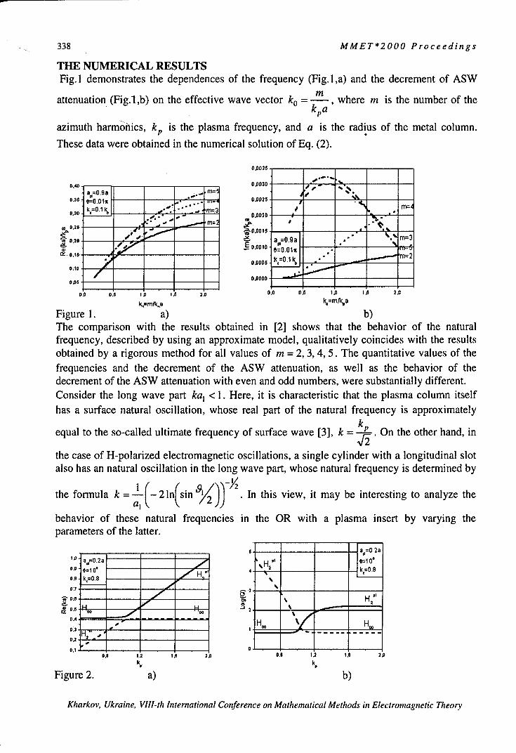
338 MMET*2000 Proceedings
THE NUMERICAL RESULTSFig. 1 demonstrates the dependences of the frequency (Fig. 1,a) and the decrement of ASW
mattenuation (Fig.l,b) on the effective wave vector k0 = -•, where m is the number of the
kp
azimuth harmonics, kp is the plasma frequency, and a is the radius of the metal column.
These data were obtained in the numerical solution of Eq. (2).
0.0035
040 0.0030 -
a=0.9a m=
k,=0.1 m, 4
•:3 k,~O. 1k' _ * .,., m=3 0.0020 si %,,, -
0.25
Sm=3,~ 0.25 0.00I0.o6 )J'••_ o~.oolo e=0.01x ...
c• " 0.0005 k=O~lk, "' m-2
0.05 0,0000
1.0 0.5 1.0 1.5 2.0 0.0 0A 1.0 1.'5 2.5
k-=Mfl/ka k%=mNk~a
Figure 1. a) b)The comparison with the results obtained in [2] shows that the behavior of the naturalfrequency, described by using an approximate model, qualitatively coincides with the resultsobtained by a rigorous method for all values of m = 2, 3, 4, 5. The quantitative values of thefrequencies and the decrement of the ASW attenuation, as well as the behavior of thedecrement of the ASW attenuation with even and odd numbers, were substantially different.Consider the long wave part ka, < 1. Here, it is characteristic that the plasma column itselfhas a surface natural oscillation, whose real part of the natural frequency is approximately
k,equal to the so-called ultimate frequency of surface wave [3], k = L-. On the other hand, in
the case of H-polarized electromagnetic oscillations, a single cylinder with a longitudinal slotalso has an natural oscillation in the long wave part, whose natural frequency is determined by
the formula k = 1(-2In sin '92 . In this view, it may be interesting to analyze the
behavior of these natural frequencies in the OR with a plasma insert by varying theparameters of the latter.
a. a=. 2a
IX ac=O02a ______ ______jH e=.1O00,5 e=10 i H, ______ k=0.8
0.0 k~t=0.8
0.70
0.4 -H Hoc
0.2 0
0.0 1.2 IO 3.0 0.2 1,2 1.0 2.0k, k,
Figure 2. a) b)
Kharkov, Ukraine, Vlll-th International Conference on Mathematical Methods in Electromagnetic Theory

MMET*2000 Proceedings 339
Fig.2 illustrates the dependences of the real parts Re(ka) of these natural frequencies and thedecimal logarithms of Q-factors Log(Q), and the corresponding natural oscillations on theplasma frequency, Proceeding from the behavior both of Re(ka) and Log(Q), it is obviousthat, according to [4], the natural oscillations of the open resonator have an inter-modecoupling with the natural oscillations of the plasma column.
mod(Hj mod(H.)1,0 7 !.
0.5 0.5 7.
2 SA2
0,0 0 .2
-0.5 -0,5
-1,0 .0,5 0,0 0,5 1,0 -1.0 -0,5 0,0 0,5 1"0
X xkp=O.5, Re(ka)=O.12898 kp ~1.,Re(k@)=O.38653
aH) b)
Figure 3.It can be clearly seen in Fig.3 showing the curves of the equal values of the module (IH,1)ofthe full magnetic field H., that is excited in the resonator by an H-polarized planeelectromagnetic wave at the real parts of natural frequencies for a plasma column. Here, thevalues of the plane wave frequency used for forming fields are shown by a dashed line inFig.2,a).As seen, by k, 0.5, up to the coincidence point [4], the field excited in OR is an natural
field of ASW Hf'. By k,= 1, near the coincidence point, the field is hybrid and has
components of the ASW field HfI" and the natural field of OR H0 0 By k, = 2, after the
coincidence, the field in OR corresponds to the H00 oscillation mode of an OR withoutcylinder. Such behavior of natural frequencies and fields, as it was shown in [4], ischaracteristic of the inter-mode oscillation coupling.
REFERENCES[1] A.V. Brovenko, P.N. Melezhik, A.Y. Poyedinchuk, and V.P. Shestopalov.Spectral and diffraction characteristics of open resonators with hyrotropic (plasmatic)inserts. Izvestiya VUZov. Radiophysika, V.36, No.9, p. 1161-1175,1996.[2] V.A. Girka, and N.A. Girka. Radiation of azimuth surface waves from anarrow waveguide slot. Radiotekhnika i Elektronika, V.37, No.3, p.419-422, 1992.[3] A.n. Kondratenko. Surface and volume waves in a limited plasma. Moscow,Energoatomizdat, 1985.[4] P.N. Melezhik, A.Y. Poyedinchuk, Y.A. Tuchkin, and V.P. Shestopalov.About analytical originis of eigemmode coupling. DAoL Akad.Nauk SSSR, V.300,No.6, pp. 1356-1359, 1988
Kharkov, Ukraine, VJII-th International Conference on Mathematical Methods in Electromagnetic Theory
340 MMET*2000 Proceedings
PECULIARITIES IN THE NONLINEAR ELECTROMAGNETICRESPONSE OF A THIN METAL FILM CARRYING A STRONG
DC CURRENT
S.A. Derev'anko, G.B. Tkachev, and V.A. Yampol'skii
Usikov Institute of Radiophysics and Electronics, NASU12 Acad. Proskura St., 61085 Kharkov, Ukraine
E-mail: [email protected]
ABSTRACT
The nonlinear interaction of a DC current flowing in a thin metal film with an external ACelectromagnetic field is studied theoretically. The nonlinearity is due to the influence of theDC magnetic field and the magnetic field of the wave on the form of the electron trajectories.This magnetodynamic mechanism of nonlinearity is typical for pure metals at low tempera-tures. We find that such an interaction causes sharp kinks in the temporal dependence of theAC electric field at the surface of a sample. The phenomenon of amplification of the electro-magnetic signal at the metal surface is also predicted.
INTRODUCTION
It is already known that metals possess quite peculiar nonlinear electrodynamical properties.In metals because of the high concentration of electrons it is rather hard to deviate the systemsignificantly from the equilibrium position. Thus in metals all the mechanisms of nonlinearitytypical for plasma or semiconductors are inefficient. The only effective mechanism in metalsis associated with the influence of the self magnetic field of a current or an electromagneticwave on the trajectories of the charge carriers. This mechanism (which is called the magneto-dynamic mechanism) does not imply a significant departure of the electron subsystem fromthe equilibrium.In the present work we investigate a novel manifestation of the magnetodynamical nonline-arity - the interaction of an external electromagnetic wave with a strong transport DC current,flowing in a thin metal film. We assume that the thickness d of the sample is much less thanthe electron mean free path 1. It is known (see [1]) that in the static case (when the externalAC field is absent) the peculiarities in the nonlinear response of the film are due to the pres-ence of the plane at which the magnetic field changes sign within the sample. The spatiallysign-alternating antisymmetrical field of current entraps a portion of electrons into a potentialwell. The trajectories of such particles are almost flat curves wound around the plane of thesign alternation. At the same time there exist electrons that do collide with the boundaries ofthe metal (fly-trough electrons) with the ratio of the conductivities of fly-through and trapped
electrons being c = (dR)"12 /l, where RocIc is the characteristic radius of curvature of the
electron trajectories in the magnetic field of the current'.
SYet there exists another group of electrons - the surface electrons -that collide only with one of the boundariesof the film (see Fig. 1). In the diffuse-reflection case considered here, their influence on the nonlinear conductiv-ity of metal is negligible and therefore they are disregarded henceforth.
Kharkov, Ukraine, VIII-th International Conference on Mathematical Methods in Electromagnetic Theory

MMET*2000 Proceedings 341
In our problem the external AC magnetic field parallel to the self-field of the current shifts theplane at which the magnetic field changes sign towards one of the faces of the film. That inturn leads to the significant diminution in the conductivity of the trapped carriers. In thissituation the conductivity of metal depends substantially on time and, consequently, strongnonlinear effects in the response of the sample should arise.
FORMULATION AND GEOMETRY OF THE PROBLEM
We consider a metallic film of thickness d along which a DC current I is flowing. The sampleis symmetrically illuminated from both sides by a monochromatic electromagnetic wavewhose vector is collinear with the vector of the self-magnetic field of the current. We intro-duce a coordinate system with the x axis directed along the normal to the faces of the film.The plane x=O corresponds to the center of the sample. The y axis is chosen along the current,and z axis is parallel to the vector of the magnetic field Htot(xt) which is the sum of themagnetic field of the current H(xt) and the magnetic field of the wave h(x, t):
Htot(x,t) = {O,O,H(x,t) + h(x,t)}. (1)We assume that the electron scattering at the boundaries of the sample is diffuse.In this geometry Maxwell's equations have the form
aH, ot(X, t) = 4,r _Ext) _ tot (X,t)a ( = j(x,t), aE(xt) - ajt , (2)ax C ax at '
where j(x,t) and E(x,t) are the y components of the current density and the electric field. Theboundary conditions on Eqs. (2) are
Htot (±d / 2, t) = hm cos cot T H. (3)The symbol H denotes the absolute value of the magnetic field of the current at the surface ofthe metal, and h,, is the amplitude of the wave. The field H is determined by the total current Ivia the relation: H = 2roilcD. The relation between H and hn is arbitrary.We consider the quasistatic situation, when the wave frequency 0o is much lower then the re-laxation frequency v of the charge carriers. Here we assume that the magnetic field of thewave inside the sample is quasiuniform and practically the same as its value at the surface:h(x, t) = hn coswot. In other words, the characteristic scale 3(co) for variations of the alter-nating magnetic field of the wave in metal is much larger than the film thickness d.
NONANALYTIC TIME DEPENDENCE OF THE ELECTRIC FIELD OF THE WAVEAT THE SURFACE OF THE FILM.
The current density j(x,t) is determined by solving Boltzman's transport equation. The trans-port equation is linearized with respect to the electric field E(xt), which is a sum of the uni-form potential field Eo(x, t) and the solenoidal wave field Eso, (x, t):
E(x, t) = Eo + Eso, (x, t). (4)In our problem the nonlinearity is due entirely to the total magnetic field Htot(xt) in theLorentz force. While calculating the current density we restrict our consideration to the lead-ing approximation in the small parameter d/6(co). In such a case as we have said, the magneticfield of the wave, h(x,t), is spatially uniform and is equal to the value at the boundaries of thefilm, h(x,t)= h,, coscot. The electric field E(xt) in this approximation is also independent of
Kharkov, Ukraine, VIII-th International Conference on Mathematical Methods in Electromagnetic Theory

342 MMET*2000 Proceedings
the coordinates and is equal to the potential field Eo(t). For uniform electric and external mag-netic fields the current density of the particles was obtained in Ref.[I].
Inserting this current density (in a
10 E/AE slightly modified form) into Max-well's equations Eq.(2) and appen-"ding boundary conditions Eq.(3) wearrive at a certain boundary problem.
- 2 . 4 6 t One is not able to obtain solution in0 an explicit form and numerical calcu-
2 Nlations should be involved. In thev ! ,present paper we were interested inthe difference
". AE(x, t)=E(,,,(d/2, t) - E.,1 (- d/2,t),-10 the quantity being proportional to the
rate of change of the magnetic fluxFig 1 The difference A E in the values of the electric r a of secof the m a mple
field of the wave at the boundaries of the film as a func- through a cross section of the sample
tion of time at a fixed value of the current (H=300H*) perpendicular to the vector of theand the different amplitudes h./H*. The ratio of the total field H1,,(x.t). Figure 1 shows themean free path I to the film thickness d equals 30. function AE(t) over a wide range of
values of the wave amplitude h, at alarge value of the magnetic field H of the current, when the condition H>>H* holds, with H*being the value of the magnetic field at which the characteristic arc of the electron trajectory(Rd)1/ 2 is equal in order of magnitude to the mean free path 1, i.e. when the inequality 6<<I isfulfilled. The value AE is normalized to the amplitude of the corresponding quantity in theabsence of the transport current AE,. We see that the ratio of the oscillation amplitude AE, tothe linear value AEL does not depend on h,,, One has the following expression for AF,,,:
AE .. _0.83( H 1 (H 12 c 1. (7)
AEL H*- ln(R/d)' H *
The ratio AE,,/AEI, is determined by the value of the magnetic field H of the current and canbe much greater then unity. In other words, there is an amplification of the electric signal atthe surface of the film. At small wave amplitudes (curve 1, h. =H//300 ) the signal is quasi-
harmonic. As h... increases, however, kinks appear on theý function AE(t). Curve 2(h7 = 2H1/3 ) has kinks at the extrema, i.e., at the time when the magnetic field of the wave
h, coscot goes to zero. These features are due to the considerable contribution of the trapped
electrons into the nonlinear conductivity. Curve 3 corresponds to the case hm = 5H/3, where
there are no trapped electrons during a part of the wave period. In that case the function AE(t)contains additional kinks arising at the times of the appearance and disappearance of the planex = x0 (t) at which the total magnetic field changes sign.
REFERENCES[1] E.A. Kaner, N.M. Makarov, I.B. Snapiro, and V.A. Yampol'skii, Zh.Eksp.Teor.Fiz. 87.2166 (1984) [Sov.Phys.Jetp 60, 1275 (1984)].
Kharkov, Ukraine, VIII-th International Conference on Mathematical Methods in Electromagnetic Theory

MMET*2000 Proceedings 343
PROPAGATION OF SURFACE POLARITONS IN FINITESUPERLATTICES WITH DISSIPATION
N.N. Beletskii, and Y.V. BludovInstitute of Radiophysics and Electronics, National Academy of Sciences of Ukraine
12 Acad. Proscura St., Kharkov 61085, UkraineE-mail: [email protected]
ABSTRACTThe paper deals with the theoretical investigation of surface polaritons (SP) in finite superlattice (SL). The SLare considered to be formed of the finite number of parallel two-dimensional electron systems (2DES) which areplaced into the external quantizing magnetic field. The external magnetic field is supposed to be directedperpendicularly to 2DES. It is found that when the dissipation in 2DES is taken into account the new mode of SP- an additional surface polariton (ASP) appears in the spectrum of SP. The properties of ASP depend stronglyupon the value of momentum relaxation frequency v of electrons in 2DES. It is shown that at small values of vwith the increasing of 2DES number in the SL the character of ASP dispersion curve changes. In the case of highvalues of v the effect of separating of ASP's dispersion curve from the usual SP with the increasing of 2DESamount is predicted.
INTRODUCTIONSP in semiconductors with SL are the object of great interest of physicists. The theoreticalinvestigation of SP in SL, consisting of finite number of layers, are of great interest from theexperimental and practical points of view [1-4]. For the finite SL, formed of a finite numberof 2DES, SP were theoretically investigated both in the absence [1] and in the presence ofexternal classical [2] and quantizing [3,4] magnetic field. It was shown that in nondissipativecase the amount of modes of SP spectrum is equal to the number of 2DES in finite SL. Butwhen the dissipation is taken into account [4] the SP spectrum contains an ASP, whichproperties depends strongly upon the value of momentum relaxation frequency v of electronsin 2DES. However in paper [4] the dependence of the ASP properties upon the number of2DES in finite SL has not been investigated.In this paper we consider SL consisting of a finite number M of infinitely extended 2DES,arranged at the equal distance d from each other in planes z = 0, d,..., (M- 1)d. The constant
quantizing magnetic field B is directed perpendicularly to the 2DES along the axis z (the axisof SL). We suppose that 2DES are imbedded into the uniform dielectric medium withdielectric constant F. We admit that the Landau-level filling factor N is equal in all 2DES(N = cn, = (ch/eB) 2 is the magnetic length and n is the electron density in 2DES).
DISPERSION RELATIONTo obtain a dispersion relation, we used solutions of Maxwell's equations for TE- and TM-
waves in media md<z<(m+ 1)d (m= 0,1,..., M- 2), z< 0 and z>(M - 1)d with standard
boundary conditions. The tangential components of the electric field Ex,EY were considered
to be continuous across the interface and the tangential components of the magnetic fieldHx, Hy were considered to be discontinuous across the interface. The values of discontinuity
4n" 4 fffE\are equal to Hx 2 - Hxl = = and
C C
Kharkov, Ukraine, VIII-th International Conference on Mathematical Methods in Electromagnetic Theory

344 MMET*2000 Proceedings
Hy2-/H 4T _ 4' (aE + oýwEy) We obtained the dispersion relation in the
form like in papers [3,4]. Since all effects, we are interested in, take place under conditionkd << 1, the spatial dispersion of 2DES conductivity tensor, obtained in [5], can be neglectedand nonzero components of 2DES conductivity tensor take the form:
2e 2 N7 2e 2h 1+ua2, =- = h 1+22
y=(v-ico)/Q,n=eB/m*cis the cyclotron frequency, m* is the effective mass of
electrons.
NUMERICAL RESULTSAs a model of 2DES we used a heterostructure GaAs/AlGalxAs with parameters:m*=0.068m0 , P=12. When the dissipation is taken into account, we consider that the SPwavenumber k is a real value, but the SP frequency co = co' + ico" is a complex value. Fig.la,b presents spectrum co'(k) (solid curves) and damping oY"(k) (dashed curves) when N=5,M=5, 5 = Qd/c = 0.1 in the cases: (a) F = v/Q = 0.02; (b) F=0. 1. As it can be seen from
Fig. ], at small values of. v the SP spectrum contains ASP (dispersion curve 6). Properties ofusual SP (dispersion curves 1-5), which exist in SL also in nondissipative case, have beendescribed in paper [3]. It should be noticed that at small v the dispersion curve of ASP exists
on the left from the light line co'= kvd (here vd,= c/1- is the velocity of light in thedielectric surrounding 2DES) and has the end-point of the spectrum, defined by the conditionRep = 0. In this case the ASP dispersion curve does not cross usual SP dispersion curves.
Besides that, with the increasing of k the damping of ASP gradually decreases and vanishes atthe end-point of the spectrum. At high values of v the properties of ASP changes entirely. So,in that case the fastest mode of usual SP (dispersion curve I on Fig.la) is split into twobranches. One of them (curve I on Fig.lb) almost coincides with the light line and has theend-point of the spectrum Rep = 0. The second branch in the vicinity of light line is blendedwith the ASP and the resulting dispersion curve 6 has minimum near the light line. Withfurther increasing of v the end-point of dispersion curve I shifts into the lower-frequencyregion and the minimum on dispersion curve 6 becomes smoother.Fig.2a,b presents dispersion curves of ASP for different values of M. The parameters of theSL are the same as in previous case: (a) F=0.02; (b) F=0.1. As one can see from Fig.2a, atsmall values of v and at small values of M the dispersion curve of ASP possesses suchproperties. When the value of k increases, the ASP frequency decreases (except small regionnear end-point of spectrum). With the increasing of M the ASP dispersion curve becomesmore slanting. After exceeding some critical value of M the ASP character changes: withincreasing of k ASP frequency also increases. At higher values of M the ASP dispersion curvebecomes steeper. Notice, that there exists another critical value of M, at which ASP ischaracterized by minimum damping. At high values of v, as one can see from Fig.2b, with theincreasing of M the ASP dispersion curve separates from the fastest mode of usual SP.
Kharkov, Ukraine, VIII-th International Conference on Mathematical Methods in Electromagnetic Theory

MMET*2 000 Proceedings 345
CONCLUSIONSWe have calculated spectrum and damping of SP in finite SL with dissipation. We predictedan effect of changing of ASP properties and a phenomenon of the separating of ASPdispersion curve from the usual SP mode with an increasing amount of 2DES in SL.
1.00 .0-0.0110.
.... -0.02
0.99-0.015 0.99 -00
-* '~'~k~a~Iu~aasa~aAea -002
........ g ff eH fE -0.00 24681 02.46981
... 21 j$ -001 6'
*~ ..... ............ b
-00 5. ..... 416441 * -0.02 - - -
---------- 6 8 10- -006 2' 4. 6M81
-0.01 M=6 15 0.08
-0.2 _____________________ ___________-0.02.____
10.005 a.... =
MM=7
-00 010.M=202
104 10 20 . 1.062. 3.ckfQ M=I5
M=ig.REFERENCES5
(3 luo YV /Urina Junl fPhscs4,10266 (1999)(4]~~~~~~~~~ BMdvYVWIRdopyisadEetonc ,16(98
(5]1 Aronov I1. eesi .. IJPy. odn.0 Mate, 91 196
Khro, kan, IIt Itratoa oneec o aheaia MtosinEetrmgeMcTer

346 MMET*2000 Proceedings
NONLINEAR INTERACTION OF THE WAVESIN PERIODIC SEMICONDUCTING SUPERLATTICE
PLACED IN A MAGNETIC FIELD
A. A. Bulgakov, and 0. V. ShramkovaInstitute of Radiophysics and Electronics, National Academy of Sciences of Ukraine
12 Ac. Proskura St, Kharkov, 61085, UkraineTel:+380 (572) 448-323, Fax:+380 (572) 441105, E-mail: [email protected]
The nonlinear interaction of the waves in layered-periodic semiconductor-dielectric superlat-tice located in a magnetic field is examined in the paper. For the theoretical investigations ofnonlinear processes we use the procedure of "three-wave interaction".
Let us consider the structure, that was derived by a periodic recurring of a semiconductorlayer of a thickness d, and of a dielectric layer with a thickness d2 . Let us direct an axis Z
perpendicularly to boundaries of stratums. The external magnetic field is supposed tohave applied in a direction of an axis OY. Let us examine the distribution of magneto-plasma waves in a plane XOZ, that is perpendicularly to the magnetic field. Then, inconsequence of homogeneity of a medium in a direction OY, it is supposed, that /' = 0.
The result is that the Maxwell's equations disintegrate on the equations for two polari-zations. Let us consider the polarization with the components of the fields Ex, Ez, H dis-
tinct from zero. From the Maxwell's equations with allowance of continuity of a tan-gential components of electromagnetic field on the boundaries of a structure with thehelp of Floquet's theorem we shall receive a dispersion relation
22
coskd= coskzldl cosk 2 d 2 -kf 7 1 k2 (kz + 2k.•z Jz d 2kzlkz f;1 + 2 7 - k IXlF l
sin kzldI sinkz2d 2 , (1)
k=K| k2 1', kz 2 = ! '2 - k12 , 2f1 =2I1l+(0 22~~ -( H 2 01 = -E2O
kis the wave number describing the periodicity (so-called Bloch's wave number); kz7 , kz2
is the wave numbers in a direction Z ; ef is the Voigt's permeability; O0 H, cOp are the cyclo-
tron and plasma frequencies. The influence of the magnetic field in the superlattice is exhib-ited in the area between the frequencies oO01 and wo02, where
Kharkov, Ukraine, VIII-th International Conference on Mathematical Methods in Electromagnetic Theory

MMET*2000 Proceedings 347
((02(001,02 ±2 + 4+ (Ops ,
raps is the frequency of surface plasmon on the semiconductor-dielectric boundary.
We carried out a numerical solution of the equation (1) for a structure with the parameters: thefirst layer is the semiconductor of a type InSb ( F0I= 17.8 ), second layer is the dielectric
(E 2 = 2 ), d, =le-2cm, d2 =1.5e-2cm, Ho = 1000oersted.We obtain the coupling equation [1] with the help of the procedure explained in detail in thework [2], in which the common method of the analysis of three-waves processes in periodicmediums was offered. The procedure is founded on the Green's formula:
b
f [r(L,f) - (L, f)*f]dv= ffj,aa
Sis the linear differential operator, L is the transposed operator, f and f are the eigenfunc-tions of the operators.If the resonant conditions (conditions of synchronism)
(O' + o" - (0 = 0
kx +k - kx = 0 (2)'tL
k' +k"-k+2-d = 0,
L=O, + 1 ... is realize, the equation for the amplitude of the wave k Ck (z) is:dCkdz - Wkk'kk"Ck'Ck". (3)
The equations for two others waves are found by the permutation of the indexes. In the rela-tion (3) Wk,k,,k" is the matrix coefficient. The expression for the coefficient is unwieldy and
can't be shown here. The matrix element is the sum of the four addendum of a shape:cosksd1 - 1 + i. sinksd1
ks
where ks is the one of the combinations kzl + kzj + kz , kzl - kz - kzl, kzl + kzl -kzl
kzl - kzl + kzl , fs is a coefficient defined with the help of the amplitudes of fields of inter-
acting waves.The conditions of interaction of the first and second harmonics with the frequencies O = 0'and 2W' are analyzed in the paper. In this case the conditions of synchronism are:
Kharkov, Ukraine, VIII-th International Conference on Mathematical Methods in Electromagnetic Theory

348 MMET*2000 Proceedings
co = 20o'
k, = 2k . (5)- - 7tL
k=2k'+2--d
The conditions (2) and (5) in the superlattice differ from the homogeneous nonlinear mediumby the presence of the specific law for the Bloch's numbers. The result is the new type of aninteraction:
k=k'-k' =0. (5a)It is possible to observe two types of interaction: 1) the first and second harmonics are locatedin the different allowed bands in an interval of frequencies COO1 - o02; 2) the first harmoniclays in an interval co01 - (002 and the second one lays higher then the 0)02.In the periodic medium Wk,k',k" is a complex magnitude (in homogeneous one Wk,k',k,, is
an imaginary number [3]). The result is the peculiarities in the dynamics of a process of inter-action. Let us mark that Wk,k',k" can be much more (modulo) in periodic medium than in
homogeneous one. In the work is shown that it is connected with the resonance on the periodof a structure. Such value of a resonance is in the forbidden band, where the laws of the syn-chronism don't take place. That is why the maximum of Wk,k,,k" is on the boundary of a
zone. The second factor influencing on the magnitude of Wkk',kk is the equality to zero of
one of k. magnitudes (see (4)). This condition can be considered as a nonlinear resonance.The dependence W2k',k, on frequency is shown in a Fig.1. The numerical solution of equation
(3) is presented in a Fig.2.
1.0 1.00 -
0•0.0 - 0 r0.50 CL /
\ I
o1.0oo 0.00-
8.0E+11 9.OE+1I 1.0E+12 0.00 10.00 20.00
' s" t, S
Fig. I Fig.2REFERENCES[I] A.A. Bulgakov, S.A.Bulgakov, L.Vazquez, "Second harmonic resonant excitation in optical pe
riodic structures with nonlinear anisotropic layers", Phys. Rev. E, v.58, p. 7887-7898, 1998;[2] F.G.Bass, A.A.Bulgakov, "Kinetic and electrodynamic phenomena in classical and quantum
semiconductor superlattices", New-York, Nova Science Publisher Inc., pp. 498, 1997;[3] J.Weiland, H.Wilhelmsson, "Coherent non-linear interaction of waves in plasmas", Oxford,
Pergamon press, pp.224, 1977
Kharkov, Ukraine, Vlll-th International Conference on Mathematical Methods in Electromagnetic Theory
h.

MMET*2000 Proceedings 349
THE BOUNDARY PROBLEMS OF ELECTROMAGNETICTHEORY OF PLANAR CHIRAL STRUCTURES
Gennady G. Goshin and Natalia E. Lugina*
Tomsk State University of Control System and Radioelectronics40 Lenina Ave., Tomsk 634050 Russia (3822) 413643
*Siberian Physical &Technical InstituteI Novosobornaya sq., Tomsk 634050 Russia (3822) 413983
E-mail: [email protected]
ABSTRACT
In this report we present a theoretical investigation of two types of plane structures. One ofthem represents a chiral slab restricted by perfectly conducting screen on its bottom (groundedchiral substrate). Another one is a plane system of isolated line wires located on the groundedchiral substrate. The influence of wire system on waveguide properties of a grounded chiralsubstrate and radiation field of source is investigated.
INTRODUCTION
Chiral structures with different properties continue to attract attention of researchers. Since90-s, the International Conferences on chiral problems take place every year [1, 2]. Theinterest of the researchers concerns the investigation of wire system on a chiral substrate [3,4]. In the present report, the influence of line wire system on waveguide properties of agrounded chiral substrate and radiation field of source is investigated.
STATEMENT OF THE PROBLEM
If edge effects are neglected then for the solution of described above problems we can use themodel that is a flat unbounded chiral slab placed on a screen. One of the possible formulationof the model problems can be follows: chiral slab ix,yj_ oo, -d •_ z <•0 with parametersE2, /I2 ,I (region 2) is located in Cartesian coordinate system x, y, z. Half-space above slabz > 0 presents homogenous media with parameters el, Pt l, where sources are located(fig. 1). We take line source as the traveling wave current distribution along the y axis
je= Ieei'D3(X-Xo)9(z- zo), (1)
1= klfi, kj = co •P 1 1, 8= c/V , V - phase velocity of current wave, c - light velocity. The
wave processes are assumed to be stationary with time dependence e-"'.The boundary conditions for given structures are four conditions of continuity for the
components of full field on the boundary of media and two homogeneous condition on thescreen.
Kharkov, Ukraine, VIII-th International Conference on Mathematical Methods in Electromagnetic Theory

350 MMET*2000 Proceedings
~7.
Z Z
•4i@
X x
Figure 1. Geometry of the model problems
Both problems were solved by means of presentation of fields through potentials ofcircularly polarized waves U±(x,y,z) and using the integral Fourier transformation in
complex plane. Potentials of secondary field in regions I and 2 have the form
U I±(x1 yZ) = e i'll"! A,±(z'r7)e"Zt"-"°'+i"1':,, z> O;
-2 (2)
Uf (x,y,z)l= ehI {A (zX, q)e-lq± + A3 (z, r)e'ql: }l'e "d, -d <z <0,
where q, = _ - 2 _ X2 q± = , _ = k±=k,.( 1 w,.), k, = coV/,2
w, = , = _2 + { =2 . Unknown functions 42..3(Zr q) are determined from
boundary conditions and have complex form.
RESULTS
Analysis of solution has shown that there are excited both continuous and eigenvalue wavespectra in the considered structures. The propagation constants of continuous wave spectrumconnect with the branch points of integrand q, = 0, q± = 0. Asymptotically evaluated in thefar field integrals at z > 0 define characteristics of radiation the under investigation structures,which were calculated for different parameters of problems. Discrete spectrum of waves isdefined by residues in poles of integrand. Dispersion curves of discrete spectrum waves arepresented in the manner of Brilliouin diagrams (fig.2). In particular cases obtained resultscoincide with known ones.
Fulfiled calculations allow to do following physical conclusions:9 unlike homogeneous dielectric slab on a screen in chiral slab occurs the transformationof waves of discrete spectrum in hybrid, but beside wave of main type disappears cut-offon frequency;e chirality increases deceleration of waves of discrete spectrum;
Kharkov, Ukraine, VIII-th International Conference on Mathematical Methods in Electromagnetic Theory

MMET*2000 Proceedings 351
* in the radiation field appears crosspolarized component, at nonphased excitationasymmetry of diagrams are observed.
Located over chiral slab the line wire system in discrete spectrum* is reason of presence of slow wave, which without the line wire system does not exist;* serves by the reason of excitation quick waves in slab;* the wave with the most deceleration can result in unidirectional transform of energy atnonphase excitement;* intensifies an asymmetry of radiation diagrams;* results in absence of radiation in the plane of structure;* results in narrowing the radiation diagrams and reducing a number of lobes.
10 -1
tw*. 4
4- 4-
0=0
0 2 4 6 10 -.• .4 .2 * 2 4 . 8 10
Id %d
Figure 2. Brilliouin diagrams for guided modes in a grounded chiral slubstrate on a screen(left)
and one with wire system (right)(a=1.0,- 2 =2.0, A =Au=1.0O,wo 12Oir Ohm; 1-q =0, 3-q,.=0, 4 -q-=0)
Considered problems are referred to the quasithree dimensional class. However theirdeciding by means of simple integration on q can be dedicated on three-dimensional case.Line wire system in combination with chiral slab can be perspective at the development atmicrowave, for instance, broadband antennas, modulators, valve devices in strip performance.
REFERENCES[1] Proceedings of BIANISOTROPICS'97 International Conference and Workshop onElectromagnetics of Complex Media H Ed. Werner S. Weigihofer. Department of MathematicalUniversity of Glasgow, Great Britain, 5-7 June 1997, 318 p.[2] Proceedings of BIANISOTROPICS'98. The 7th International Conference on Complex Media IIEds. Arne F. Jacob and Jens Reinert. Technische Universitat Braunschweig, 3-6 June 1998, 328 p.[3] Goshin G., Lugina N. The quasithree-dimensional problem on excitation of line wire system on achiral substrate//Proc. 6h Int. Conf. on Math. Methods in EM Theory, Lviv, 1996. - P.316-319.[4] Goshin G., Lugina N. Boundary problem on excitation of spiral wire system on a plane chiralsubstrate//Proc. 71h Int. Conf. on Math. Methods in EM Theory, Kharkov, 1998. - V.2, P.664 -666.
Kharkov, Ukraine, Vlll-th International Conference on Mathematical Methods in Electromagnetic Theory

352 MMET*2000 Proceedings
MATHEMATICAL MODELOF A SPHERICAL FRACTAL EMITTER
Volodymir M. Onufriyenko2), and Eldar I. Veliev J)') Institute of Radiophysics and Electronics, National Academy of Sciences
Ulitsa Proskury, 12, Kharkov, 61085, Ukrainee-mail: veliev @ dut.kharkov.ua
2) State Technical University,Zhukovsky Str., 64, Zaporizhzhya, 69063, Ukraine
e-mail: onufr @ zstu.zaporizhzhe.ua
Abstract. Results of mathematical simulation of a spherical firactal emitter for the first timerepresented. The application of fractional calculation for mathematical model generation isjustified. The a -characteristic of the magnetic field component of a symmetric sphericalemitter and current distribution on a surface is retrieved. The properties of a spherical fractalemitter are defined. The outputs are confirmed by matching of the obtained formulas andgraphs with known data.
IntroductionRise of interest to designing different devices of UHF of a range with fractal structure (see,e.g., [1],) boosted application of fractional calculation (see, e.g., [2]) in the electromagnetictheory [3,4]. Results on learning physical and geometrical properties of fractal fields now areobtained [5,6], in particular, in the radiation theory [7,8].In [6] is shown, that the a -characteristics of a field, which are generated a -dimensional by aHausdorff's measure of the fractal object, can be constructed with the application of fractionalintegration a - I measure (or fractional derivation of a + I measure). The enumeration ofoutcomes of simulation of a spherical emitter further represented.
FormulationThe attempts of measurement of a usual current with density j(P) on a fractal surface unit
dS• inevitably reduce in necessity of input of the fractal cx-characteristic dcJ(P) on a unitdS. Thus,
da J(r)daS = j(1r)l-a p(cx)dS = ja(r)dS
(1)whee ~~a)= 1(a 2itc /2
where ý) = 7(a)2,a/2 is defined by sort of a coating unit; F(.) - Euler's gamma-function.
Let us consider an emitter as a sphere. Let its surface has fractal properties. A fractal current
we set as a thin spherical stratum with radius a. The surface current density jQ( r,O)doesnot depend on a lateral angle. Dependence of a current density on a meridional
corner 0 we set by the a 0 -characteristic DWO 0(0), and dependence on radius by the a)' -
characteristic Dc" R( r):
t (rO) = Dar R( r )DcO0( 0).
Kharkov, Ukraine, VIII-th International Conference on Mathematical Methods in Electromagnetic Theory

MMET*2000 Proceedings 353
At such symmetry the electromagnetic field will have three components, equal to zero, E ý,
H0 and Hr. On an emitter surface a current density is j 0( a, 0) Ho( a, 0 ), and complete
current is J° 0( a,O)= 27tasinO ja ( a,O ).
For determination of a current density j 0 ( r, 0 ) from Maxwell equations, in view of the
indicated symmetry, we obtain the a -characteristic of the magnetic componentT)1 c• •.a a Ro'(kr)- --=r Cn H(2) oDE°®•(O)_
DcpH=aDOrR (kr)OD6®°(0), aI rRnH (kr), D (=Pn(cos0)
(here: Cn - harmonics amplitude; H(2) (kr)- half-integer order Hankel's function;n+'
Pn(cOs )- Legendre polynomials.
According to designed model, the electromagnetic field (2) spherical fractal emitters, as wellas in case of a classical emitter, represents a space n-order harmonic of an electrical wave. Atn=O the field is identically equal to zero. It means, that for the indicated model the emitter isimpossible to create which isotropicly radiates on all directions.The field of an emitter with a space first order harmonic comes nearer to the field diagram ofa linear dipole fractal emitter with length equal to radius of an orb [7, 8].In the total, density of a fractal current looks like
00 C (2,)kr ))oI0 -dOPn (cos0jo'(r,O)= CnOIkrr( H+((0)
n=1 2
RESULTS AND DISCUSSION
In Fig. 1 the radial part Ro'(kr) is shown, and in Fig. 2 - meridional part®No(0), whichdetermine a current density on a surface of an ideal spherical emitter (dashed line) and on asurface of an emitter with fractal properties (solid line).
We score the following: 1) offset of maximas of a( 0 )curves in the side of major corners 0,that reduces in rotational displacement of a polar pattern (it depends on the value of a scalingmetric a); 2) considerable increase of wattless currents, and it reduces in decrease of anefficiency and emitter passband; 3) power reallocation of 2a-poles in emitters petals with
Re R (?cy) hn R (k Y)
0 3185 1 ... ..... .. ....................
S- • n=2
0.25 12
-0.13 -_-__5.5
-0.5 kr - 1 kr
2 4 6 8 0 2 4 6 8
Kharkov, Ukraine, VIII-th International Conference on Mathematical Methods in Electromagnetic Theory

354 MMET*2000 Proceedings
Fig. Ia higher order space harmonic in comparison with classical multipoles; 4) confirmation ofknown experimental datas about offset of the characteristics of an actual emitter, that isstipulated by existence 2' -poles in actual physical systems.
90 90120 6,-. o0 120 6
0,35ED (0)
ISO 0 180 0
270 270
Fig. 2CONCLUSIONThe discussion of calculations results on designed radiation model of a sphere with fractalstructure of surface currents allocation points presence of known properties of a classicalemitter (alternation of phase-al tern ati ng currents; values fissile and wattles currents). Thereare also new effects (rotational displacement of a polar pattern, power reallocation a 2' -polesetc.). The obtained results allow explaining influence of 2' -poles to the form of a polarpattern, on the value of an antenna factor, and also possibility of designing pencil-beam andisotropic emitter.
REFERENCES[l].Fractals in physics. Ed. By L. Pietronero and E. Tosatti.- M.:Mir.- 1988 (originally publishedin English by ICTP Trieste, Italy, 1985).[2].K.B.Oldham and J.Spanier. The Fractional Calculus-New York:Academic Press, 1974.[3]. N. Engheta. Fractional Calculus and Fractional Paradigm in Electromagnetic Theory.Conference Proceedings 1998 International Conference on Mathematical Methods inElectromagnetic Theory (MMET-98), Kharkov, Ukraine, June 2-5,1998, V. 1, pp. 43-49.[4]. V. Onufrienko. New Description of Spatial Harmonics of Surface Waves. ConferenceProceedings 1998 International Conference on Mathematical Methods in Electromagnetic Theory(MMET-98), Kharkov, Ukraine, June 2-5,1998, V. 1, pp.2 19 -2 2 1.[5]. V. Onufrienko. Physical-geometrical interpretation of cx -characteristics of electro-magneticfield. Radiofisika i elektronika. Institute of Radiophysics and Electronics of the National Academyof Sciences of Ukraine, Vol.4, No. 1, pp.7 -10,19 99 (in Ukrainian).[6]. V.M.Onufrienkos Interaction of a Plane Electromagnetic Wave with by Fractal MetallizedSurface. Radiofisika i elektronika. Institute of Radiophysics and Electronics of the NationalAcademy of Sciences of Ukraine, Vol.4, No.2, 1999 (in Ukrainian).[7]. E.I.Veliev and V.M.Onufrienko. Fractal Electrical and Magnetical Radiators. ProceedingsThird International Kharkov Symposium " Physics and Engineering of Millimeter andsubmillimeter waves "' (MSMW 98). V.1 .-Kharkov (Ukraine) .- 1 998.-P. 357-359.[8]. E.I.Veliev and V.M.Onufrienko. Radiation of waves by the fractal surface element.Proceedings of 3rd International Conference Antenna Theory and Techniques (ICATT-99),Sevastopol, Ukraine, 8-11 Sept., 1999, pp.160-161,131-132.
Kharkov, Ukraine, VIII-th International Conference on Mathematical Methods in Electromagnetic Theory
(M E-8,Kakv kanJnL-,98 .1 p2921

MMET*2000 Proceedings 355
ONE-DIMENSIONAL OPTIMIZATION OF SILICON SOLAR CELLS
M.A. Ustyantsev, V.A. Antonova, and G.I. Churyumov
Kharkov Technical University of Radio Electronics14 Lenin Ave., Kharkov 61166, Ukraine
Tel.: +38 0572 409362 Fax: +38 0572 409113E-mail: m.ustyantsev @ieee.org
ABSTRACT
One of the most important problems in the design of modern photo-voltaic cells is increasingtheir efficiency. The solution of this problem is connected with an investigation of new typesof solar cells as well as optimization of the output characteristics of present devices. In thispaper, formulation of the problem and one-dimensional (1D) simulation technique developedfor computer modelling and optimization of the high-efficiency silicon solar cells isdiscussed.
INTRODUCTION
The development of the high-efficiency silicon solar cells has currently been in the center ofattention [1,2]. It is necessary to note that computer modeling of physical effects insemiconductor structures used to design solar cells is one promising approach in order tocarry out a complete theoretical analysis [3,4]. Among the questions which have to be solvedin order to raise the efficiency of the silicon solar cells, it is necessary to mention the onesconnected with optimization of n+-p junction depth, decrease of leakage currents, etc. In thispaper, the problem of optimization of an n' - p junction depth in the silicon solar cells isconsidered.
SILICON SOLAR CELLS MODEL
Schematic drawing of basic structure of a mono-crystal silicon solar cell is shown in Fig. 1. Itis known that the efficiency of the silicon solar cells depends on n+-p junction depth. There isan optimal value of this parameter where solar cell operates most efficiently. This is caused,on the one hand, by a specificity of photon processes taking place in the materials whichare contained in the solar cells, and on the other hand, by the features of their designs.For optimization of a solar cell we used its mathematical model possessing an abrupt n+-pjunction as well as the constant levels of doping on each side of the n+-p junction. As aresult, we can suppose that electric field outside of depletion layer of the n+-p junction isequal to zero (Fig. 1).A parameter that we selected in order to optimize of n+-p junction depth is the total photo-current which is generated by all spectrum of solar radiation. In this case, the n+-p junctiondepth will be optimal at a point on the axis x where the total photo-current has maximum.For the incident light of the wavelength 2 and intensity or flux F(2), electron-hole pairs aregenerated at the distance x from the surface at a rate
G(x)= f c•(k)F(z)[l - R(k)]exp[- ca(kQ)x] dA (1)
Kharkov, Ukraine, VIII-th International Conference on Mathematical Methods in Electromagnetic Theory

356 MMET*2000 Proceedings
where a (2) is the local absorption coefficient; R(2) is the surface reflectivity; F(A) is thedensity of photons.
1
C 3
4
V 5
x
I - collector contact; 2 - antireflection coating; 3 - n'- layer; 4 - p - silicon;5 - back continuous collector contact
Fig. 1 Basic structure of solar cell
Under low injection conditions ID stationary equations are written as [1]:
np 1ldJn
Gn - nP° + 0 (2)Tn e dx
Gp P- -- n ~ 0 (3)Tn e dx
Here, expressions for the photo-current contributions in the p- and n-region, J,, and Jp , aretherefore given by the diffusive currents
Jn (X) =qD dn(x) (4)dx
dp(x) (5)dx
where q is the electron charge; D,,,p is diffusion factor.For n÷-p region we can obtain integro-differentual equation which describes distribution ofholes in n-layer
D d 2 pn Pn - NO + f - (X)F(X)[1 - R(X)] x exp[- c(X)x]d = 0 (6)P d x 2 T p ? ,
Kharkov, Ukraine, VIII-th International Conference on Mathematical Methods in Electromagnetic Theory

MMET*2000 Proceedings 357
where rp the hole lifetime.
A similar integro-differentual equation for the electron distribution in the p-layer can bewritten as
D n P P n PO + f a(X)F(X)[1 - R(k)] x exp[- a(X)x]dX =0 (7)dx2 x 7
Taking into account that equations (6) and (7) have no analytical solution we used thenumerical methods with the following initial conditions:
d(pndxPo) Sp (pn - po ) at x=O. (8)
d(np - npo)Dn dx =Sn (np - npo ) at x=H (9)
P, "-PnO = 0 and np--npo = 0 at x=xi. (10)
The total photo-current as a function of wavelength is then given by the sum of diffusioncurrents in the p-, n- regions and depletion region [1]:
JL = Jp + Jn + Jd1 11
where Idl = qFoT- exp(- ajxP - x,, #)xp(- axP - x, ) (12)
By using the results of numerical solution of equations (6) and (7) in view of (8)-(10),and (12) and substituting their values in (11), we determine the total photo-current of a siliconsolar cell.
REFERENCES
[1] S.M. Sze. Physics of Semiconductor Devices, 2nd edition. John Wiley, 1981.
[2] A.L. Fahrenbruch and R.H. Bube, Fundamentals of Solar Cells, Academic
Press, 1983.
[3] G. Heiser, Armin G. Aberle, Stuart R. Wenham and Martin A. Green. Two-
dimensional numerical simulations of high-efficiency silicon solar cells,
Microelectronics Journal, 26 (1995) 273-286.
[4] Pietro P. Altermatt, Gernot Heiser, Martin A. Green Numerical quantification
and minimization of perimeter losses in high-efficiency silicon solar cells, Progress in
Photovoltaics: Research and Applications,vol.4, 355-367 (1996).
Kharkov, Ukraine, VIII-th International Conference on Mathematical Methods in Electromagnetic Theory

358 MMET*2 000 Proceedings
SIMULATION OF A NON-LINEAR INTERACTION
IN THE COMBINED MAGNETRON
T. 1. Frolova, G. 1. ChuryumovKharkov State University of Radio Electronics
14 Lenin Ave., Kharkov, 61166, UkraineTel.: +380 572 409362, Fax: +380 572 409113
Email: frol ova@ kture.kharkov.ua
ABSTRACTIn the last few years the development of efficient crossed-field tubes is connected with a creation ofnew non-traditional designs. In this paper a mathematical model of new combined magnetron and thefeatures of modes of its operation are discussed.
INTRODUCTIONAn application of new technologies is a promising approach to the problem of development ofadvanced crossed-field tubes. The development of non-traditional crossed-field tubes is a goodexample of usage of this approach [1]. Among the possible advantages of non-traditional designs incomparison with the classical designs of tubes (for instant, magnetron), we can mention a suppressionof interpulsing spurious oscillations in re-entrant beam, self-modulated CFAs, providing their stableoperation in frequency band and the creation of cold cathode, self-modulated, re-entrant beamamplifier [2]. Besides, a considerable advance has been made in studying of new designs of themagnetron oscillators and, in particularly, combined magnetron [3]. However, there is a number ofunclear questions concerning non-linear interaction of two electronic beams with electromagneticwave of the resonant delay line. Their solution cannot be made a priory without theoreticalinvestigations of given interaction mechanism by using self-consistent mathematical models of thetube. The choice of such a mathematical model is determined by a compromise between the list ofproblems, which have to be solved, and possibilities of a hardware. The application of full-scalesimulation allows not only to calculate basic parameters of tubes, and to evaluate their limiting valuesas well as to explain the possible anomalous physical effects and to point out the ways of theirelimination.In this paper, the features of a mathematical model of combined magnetron are discussed.Mathematical modelling of the electron-wave processes is considered in three-dimensionalapproximation on one wavelength with usage of the conditions of a quasi-periodicity (quasi -periodicalmodel [4]).The emphasis is on the study of physical regularities governing the electron-waveinteraction in the tube and on determination of the optimum performance of its operation.
THEORYFig. 1 shows schematically the full classification of crossed field tubes with the azimuthal symmetry.The classical crossed-field tubes with azimuthal symmetry can be considered as electron-wavesystems, in which a re-entrant electron beam interacts with a (synchronous) slow electromagneticwave («<the re-entrant electron beam + RF wave»> systems). As it has been shown in [I1], non-traditionalcrossed-field tubes are the examples of future advanced technologies, which are connected with thecreation of a new design of the tubes. These tubes are defined as electron-wave systems, in which a re-entrant electron beam interacts with two synchronous electromagnetic waves («<re-entrant electronbeam + two RF waves»> systems), or two re-entrant electron beams interact with a synchronouselectromagnetic wave («two re-entrant electron beams + RE wave»> systems).
Kharkov, Ukraine, VIII-th International Conference on Mathemzatical Methods in Electromiagnetic Theory

MMET*2000 Proceedings 359
The angular domain of theCROSSED FIELD interaction space corresponding
DEVICES one wavelength in the combinedI. Imagnetron, schematically, is
CLASSICAL SYSTEMS] NON-TRADITIONAL shown in Fig. 2. There is an"ELECTRON BEAM + SYSTEMS interaction of the inner and outer
HFWAVE" electronic beams with electro-I_ Imagnetic field of the resonant
SYSTEMS "TWO SYSTEMS delay line. A special feature ofELECTRON BEAMS "ELECTRON BEAM+TWO this interaction is that electron
MICROWAVE" MICROWAVES" beams have an opposite sense of___ rotation, i.e. inner beam rotates
CASE OF STRONG CASE OF WEAK around internal cathode clockwiseCOUPLING BETWEEN COUPLING BETWEEN and outer one rotates around
MICROWAVES MICROWAVES external cathode anti-clockwise.
The average drift velocities ofFig. I inner (i) and outer
(o) b ar V AoBo I ' , where Ua is the anode voltage;
2r'o is magnetic field: is the distance
between cathode and anode. Indices (i) and (o)in the expressions above correspond to the inner
S..... . , and outer interaction spaces of the tube,,..- respectively. It is known that the condition of its
-"~. " •" •efficient operation will be the following:"'• j\/, 7 / i +,
resonant....... JeVe e fV - (synchronism condition),resonant i•• i• .................. f+ -
delay line s• c on t where f is the phase velocity of
synchronous spatial harmonic, and indices (+)"and (-) are associated with its rotation clockwise
, and anti-clockwise. There are two operatingintera.cahode ........... .. / \ external cathode modes in the combined magnetron to satisfy the
synchronism condition. In the first case, we have
UI U 0 two power supplies ) and
B =B = const The second caseFig. 2. 0)
(when UJa =-Ua and o •#Bo ) is preferable as it enables one to use a single (in common)
power supply. The possible distribution of the magnetic field in this case can be easily realized using astandard magnet. An example of such distribution is described in [3].The particle-in-cell (PIC) method was chosen as a basis for computer modelling of the non-linearinteraction in combined magnetron. The simulation was carried out in one-wave approximation byusing three-dimensional mathematical model. It was suggested that the distribution of electromagneticfield both in the internal and external interaction spaces of the tube corresponded to the 7t -modeoscillation of the resonant delay line. In this case the resonant electromagnetic field can be presentedas a superposition of two traveling waves having equal amplitudes. Total electromagnetic field (bothits rotational and potential components) in the inner and outer interaction spaces can be written in theform [5]:
Kharkov, Ukraine, VIII-th International Conference on Mathematical Methods in Electromagnetic Theory

360 MMET*2000 Proceedings
-io (ý.t) Z (C+rFE +r + C-rE-r) - grad (D (1)r
where C+r 2 - 1 N J +dV2(co - cor Nr f, (2)
C~r J •e'rE r dg.v3
2(W WrNr dV (3)S2(c) + 09r) Nr v
The expressions (2) and (3) are the equations of excitation. Their solution allows to find the rotationalcomponent of electromagnetic field and to determine the change in time of the amplitudes and phasesof electromagnetic waves propagating in the opposite directions. For the calculation of the space-charge field (potential component of electromagnetic field), it is necessary to solve a Poisson equationin the inner and outer regions of the interaction space.
1•r i,o l~0 + a 2 io 0 2-i,o C9 a2 (g 0 i, 0
K a (92 + aZ 2 0 (4)r ar ar r a3 (' z.0
Solution of equations (2), (3) and (4) enable us to calculate a total electromagnetic field in theinteraction spaces of the tube. The final stage of computer modelling of the physical processes incombined magnetron is a solution of equations of motion for two (inner and outer) electron beams
dt -7 j(Ei'° (F,t) + + o [ o i
dt0 0 (5)
Thus, in this work we have considered a self-consistent system of integro-differential equations,which can be used in a non-linear analysis of the physical processes in combined magnetron. Besides,we have analyzed the features of magnetron operation.
REFERENCES[1] Churyumov G.I., Sergeev G.I. New concepts of development of crossed-field microwavedevices with azimuthal symmetry. Proc. 8-th Int. Symp.Non-Linear Electromagnetic Systems(ISEM-97). 12-14 May, Braunschweig, 1997, p. 295-296.[2] Churyumov G.I., Sergeev G.I. Simulation and modelling of self-modulated re-entrant beamcrossed-field amplifier. IEEE Trans. Electron Devices, vol. 46, May 1999, pp. 1063-1069.[3] Frolova T.I., Churyumov G.I., Sergeev G.I Computer modelling of the electron-waveinteraction in combined magnetron. Proc. I-st Int. Vacuum Electronics Conference (IVEC'2000).2-4 May, Monterey, 2000. pp. 551-554.[4] Yu S.P., Kooyers G.P., Buneman 0. Time-depend computer analysis of electron-waveinterection in crossed field, J. Appl. Physics, 1965, vol.36, 1 8, p.25 50 -2 55 9 .[5] Vaynshteyn L.A., Solnthev V.A. Lectures on Microwave Electronics, Moscow: Sov. Radio,1973 (in Russian).
Kharkov, Ukraine, VIII-th International Conference omi Mathematical Methods in Electromnagnetic Theory

MMET*2000 Proceedings 361
EFFECTIVE ELECTROMAGNETIC PARAMETERSOF STRONGLY FLUCTUATING STATISTICALLY LAYERED
BIANISOTROPIC MEDIUM
A.V. Malyuskin, M. P. Perepechai, S. N. Shulga
Kharkov National University, Department of Theoretical Radiophysics4 Svobody Sq., 61077 Kharkiv, Ukraine
e-mail: [email protected]
ABSTRACT
The macroscopic electromagnetic (EM) response of a strongly fluctuating statistically layeredbianisotropic medium is obtained by using renormalization approach of the strong fluctuationtheory. Extending the existing works for anisotropic media, this paper treats the effectiveconstitutive parameters for a statistically layered bianisotropic medium with randompermittivity and permeability dyads and random tensors of magneto-electric coupling.
INTRODUCTION
The principal element of multiple-scattering theory for an EM field in random media is acalculation of effective constitutive parameters (ECP) of a random medium. The ECPdescribe the properties of a fluctuating medium with respect to a statistically mean field, i.e.the field averaged over fluctuations. Once the ECP are known, one can investigate thepropagation of the mean field within a random medium using the methods developed fordeterministic media. In this paper we determine ECP of a strongly fluctuating statisticallylayered bianisotropic medium in terms of deterministic background medium and thecorrelation functions of random perturbations using renormalized version [1 ] of the random-medium theory. This work can be thought as an extension of the strong-fluctuation theory ofdisordered anisotropic media [2] to a more general class of bianisotropic random media.
THEORY
Bianisotropic media represent a wide class of complex linear media with internal magneto-electric coupling between electric and magnetic fields. In a random bianisotropic medium,constitutive relations that connect random time-harmonic: exp(- icot), electric and magnetic
inductions )r (),r h ) and EM field intensities r (),/Hr R)W have the form
= Z rrr rrr+ý l,, h ý -k '-Rr (1)where the ,r (W)and fr (R?) are the random permittivity and permeability tensors,
respectively, while ýr(R) andc,(,) are the random tensors of magneto-electric
coupling, R=(x,y,z). Statistical geometry of the random medium filling the wholespace-oc <x, y,z < oo is described by statistical moments of all orders for the tensorial
complex-valued random fields[rl)(/)], rI=,, We will consider the fundamental
case, where the mean profile i is independent of r, and may depend on z, while
for any n =2,3,4,... and arbitrary admissible choice of indices j ,kl,j2,k 2,... the n-th
Kharkov, Ukraine, VIII-th International Conference on Mathematical Methods in Electromagnetic Theory

362 MMET*2000 Proceedings
statistical moment (1ljkl (Rt)lnj 2k2 (f2 )1. Tj, k, should depend on ZIz 2,Z 3 ... ,z,, and the
differences r, - r2 ,, r2 - r3 only , 7 = (x, y,O).
The following investigation will be performed using convenient six-vector formalism [3],which have been extensively applied in studying EM phenomena in bianisotropic media. Inthe six-vector notation (1) can be rewritten in compact form
dr =Mr .er (2)
Here, the 6-vectors d, ,e,. and the 6-dyad Mr are determined as
B , Hr= ", M
The 6-dyad Mof the ECP is defined by the conventional identity [1,2]
In line with the renormalization approach of the strong-fluctuation theory, introduce adeterministic background bianisotropic medium with constitutive parameters
Z,(Z), ý(Zý t(Zýz) which form the 6-dyad M. The 6-vector EM field e,, (h) created in such
medium by impressed 6-vector sources j(/R)can be represented in terms of the 6-dyadic
Green's function of the background medium G(R, R')
4n f G i(R,/R')- j (/')t' (4)C
The key detail of the theory is a regularized representation of the Green's 6-dyadic
G(R, Rf')= (I/iko )G(V) 6(R - fi')+ G('9) (RR') (5)that was established in [4]. In (5), the first term corresponds to the singular part of the Greendyadic, G(")is a constant 6-dyadic, and the second term is the regular part of the Greendyadic. The thorough discussion of regularization procedure a reader can found in [4].Treating the random medium as a perturbation of the background medium one can establishan equivalence between the original excitation problem for stochastic EM field and theintegral equation [I, 2]
with respect to a new 6-vector field variable f
and random 6-dyad perturbation
K = (Mr- M). [I+ G('). (•/rM-)]-' (8)
where I is the identity 6-dyad. Introduce an auxiliary 6-dyad K, by the identity(K.f) -= K1. (f) (9)
From (7), (8) and (9) one can obtain the relation between K, and the ECP 6-dyad Me
M,- M = K,+ K, .G".(M -M) (10)
Using the solution of (6) f = [I+ ikoG ('9). K]' .eb, in (9), G('9) fJdR'G(',)(,RF).. is the
integral operator with the 6-dyad kernel G("')(/,/'), we obtain the solution for K,
Kharkov, Ukraine, VIII-th International Conference on Mathematical Methods in Electromagnetic Theor,
kL

MMET*2000 Proceedings 363
Ke = T.- 1( ikoG(rg).)- 1 (11
in terms of the so-called transition operator [5]
T=(K. (1± ik0, G(rg). K)Y) (12)
Unfortunately, the exact expression (11) does not bring the final result because of practicalimpossibility to invert the relevant operators in (11) and (12) both rigorously and in closedform. A feasible representation for K e can be obtained via expanding the right-hand side of
(11) in powers of K
Ke = (K)+ (k0 )2[(K).G(r).<(K)-- (K.G(rg).K)] +... (13)
To assure the fastest rate of convergence of this series, a requirement (K) 0 must be
imposed. This provides also elimination of secular terms, i.e. terms, including at least onemean value (K) as a multiplier. Condition (K) 0 specifies the constitutive parameters of
the background medium that remain unspecified yet. Indeed, due to (8)
((Mr - M)-[1+ G('). (Mr - M)]1)ý 0 (14)
holds. Equation (14) can be easily solved via straightforward manipulations. Reconsideringexpansion (13) we may write it in compact form
00
K e - ZK(') (15)n=2 e
(V n-1. K)~ (V)K(n/' , n =4,5,6,..., V =-ik0 K. G(g),=2
Due to relation (10) analogous expressions arise for the ECP
Me =M+ M- (16)n= 2
.n-2M (23) -Ke (2,3) M(") = Ke - Km) G(+)" im'-. G n = 4,5,6,...
m=2
Representation (16) constitutes the product of our study. It is clear from the analysis thatlocal component of the ECP coincides with the constitutive parameters of the backgroundmedium while arising due to perturbations non-local components of the ECP are given by
the 6-dyad M.
REFERENCES[1] N. P. Zhuck, Phys. Rev. B, vol. 51, N. 21, p. 15636, 1994.[2] N. P. Zhuck , Journ. Electromagn. Waves Appl. N. 7, p. 1653, 1993.[3] I. V. Lindell, A. H. Sihvola, K. Suchy, Journ. Electromagn. Waves Appl. N. 7, p.
1653, 1993.[4] N. P. Zhuck, A. S. Omar, Progress in Electromagnetic Research, vol. 12, Ch. 10, p.
219, 1997[5] M. Lax, Rev. Mod. Phys., vol. 23, N. 4, p. 287, 1951.
Kharkov, Ukraine, VIII-th International Conference on Mathematical Methods in Electromagnetic Theory

364 MMET*2000 Proceedings
REFLECTION OF A LASER BEAMFROM A GYROMAGNETIC LAYER
WITH A MAGNETO-DIELECTRIC SUBSTRATE
Dimrity N. Goryushko*, and Alexander A. Shmat'ko**Kharkov National University, Faculty of Radio Physics
* Ukraine, 61184, Kharkov, Kork st., 44, apt. 115
tel. +38 (0572) 20-57-07, E-mail: [email protected]
** Ukraine, 61077, Kharkov, Svobody sq., 4tel. +38 (0572) 45-71-33, E-mail: Alexandr.A.Shmatkoeuniver.kharkov.ua
ABSTRACTFor the control of laser beam characteristics by means of electrical method, the gyromagneticfilms fixed on a dielectric substrate can be used. The beam scattering on such a structure isconsidered. The spatial distribution of the reflected field in the cross-section is obtained bymeans of the Fourier analysis.
BASIC PARTWave beams are the eigenwaves of laser sources and other optoelectronic devices. In suchsystems, a gyromagnetic film fixed on a dielectric layer can be used as a control eOlement.With the aid of magnetic field applied to the gyromagnetic sample it is possible to modify theparameters of reflected and transmitted beams: the shape of the beam, its curvature andamplitude, direction of the axis of propagation, the magnitude of lateral displacement, etc.
Yr
Xi Xr , /
Yi
0I
MfNETODIELETI
d2
47Y
Fig. 1. The wave beam scattering on the two-layer structure
A two-dimensional problem of the scattering of electromagnetic field of the realistic aperturesin the form of a wave beam on a gyromagnetic ferrite film fixed on a magneto-dielectric layer(fig. 1) is solved. It is formulated for the equation
(A + c 2p1 )E =0, (1)
Kharkov, Ukraine, VIII-th International Conference on Mathematical Methods in Electromagnetic Theory
IL

MMET*2000 Proceedings 365
a 2 AT -iza 0where /L =PT -- , for ferrite i•= Pa T 0.
PT 0 0 AL
As the incident fields, the wave beams with Gaussian (2) and cosine (3) field distributions inthe cross-section are chosen:
ize -e(Xi /w) 2 ' Ix:w/2EwXi (2) E Z ,O c(9) = 0 I, Ixil>w/2 (3)
The EZ- polarization of the initial field is considered, as the case of the HZ- polarization doesnot lead to new phenomena. The solution of the problem is carried out by means of thespectral method with the application of the Fourier analysis. The spectral method enables oneto simplify the problem. The field of the incident wave beam is represented as a superpositionof partial plane monochromatic waves with varying amplitudes that are incident on thestudied structure under different angles, and thus the original problem is reduced to theproblem of scattering of a partial plane electromagnetic wave with specific amplitude on theconsidered structure. Expression for the reflection coefficient of a plane electromagnetic wavefrom a multilayer magneto-dielectric structure is known [3]. The presence of gyrotropy in oneof the layers (gyromagnetic film) results in significant modification of the expression for theplane wave reflection coefficient and, as a result, in changing the transmitted and scatteredfields characteristics. An analytical expression for the reflection coefficient of a plane wavefrom the studied structure is found and, with the aid of the Fourier analysis, the spatialdistribution of the scattered field for two types of the incident field is obtained. In thescattering of the fields of realistic apertures, a number of phenomena is observed, namely:deformation of the field with the distance, lateral and angular displacement of the beam axis,etc. These phenomena, as the analysis shows, are mainly connected to the angular dependenceof the phase and amplitude of the reflection (transmission) coefficient.
3.5
3
2 .5 -J F z
2
1.5
0.5
045 0
Fig.2. The form of the initial gaussian field spatial distribution and the absolute value of the reflection coefficient
The presence of gyrotropy essentially changes the spatial structure of the fields. As anexample, two kinds of initial field distribution are considered and the main features of theirform change during the reflection from a gyromagnetic film with a magneto-dielectricsubstrate are established. In Figs. 4a and 4b, the spatial distributions of the field in the cross-section of the reflected wave beam for different parameters of magnetization c are shown(parameter a depends on the value of the magnetization field). As the figlires demonstrate, atthe increasing of the magnetizing field value the magnitude of the angular displacement of thebeam axis is increased, that is connected to the much stronger angular phase change of the
Kharkov, Ukraine, VIII-th International Conference on Mathematical Methods in Electromagnetic Theory

366 MMET*2000 Proceedings
0.003• Y_ oX 0 003 Ox
000,15 0 0015 -
00
Fig.3. Spatial field distribution in the cross-section for the cosine field distribution for0=55°,O.=0.3,Ltv= 1.9,FF=5, 1 =64=!Lt I=p~4= 1,E3=3.6,/a3=5,d/•.=3/20,d2=] 0•, a) w=52,., b) w=3k..
scattered on the ferrite film field as compared to the magneto-dielectric substrate. Sometimes(Fig. 4a), the splitting of the beam on several beams can be observed. Depending on the ratiobetween the wavelength and the width of the laser beam, the oscillations of the field envelopecan be observed (Figs. 3a, 3b), their amplitude and form varying with the propagation of thefield from the structure. Thus, by changing parameters of a gyrotropic film, namely, adjustingthe magnitude of the magnetization field, it is possible to change the amplitude and the phaseof reflection (transmission) coefficient of the plane wave. This can be used for efficient beamcontrol in the laser and optoelectronic devices.
1 55
5 x
00255 0501
Fig.4. Spatial field distribution in the cross-section of the gaussian beam for(0=490, T= 1. 9,l F=5.F, Is1= 4=1 =4= l 4=,1 ,F 653,=3.6,d3=Oda) =/20,d2=10,b ,w=3X )
a) c=0. 1, b) cc=1.1
REFERENCES[s] R.P. Riesz and R. Simon, "Reflection of a gaussian beam from a dielectric slab", J. Opt. Soc.
Am. Vol.2, No.l 11, (1985)[2] T. Tamir and H.L. Bertoni, "Lateral displacement of optical beams at multilayered andperiodic structures", J. Opt. Soc. Am. 61, 1397-1413, (1971)[3t L.M. Brekhovskikh, Waves in Layered Media, Moscow: AN SSSR Publ., 1957 (in Russian).
Kharkov, Ukraine, Vlas -th anternational Conference on Mathesatical Methods in Electro.agnetic Theory
2.hI 0-E

MMET*2000 Proceedings 367
AUTHORS LIST
Afanasiev N.T. 334 Chen W.-T. 598Aksoy A. 61 Chernish L.I. 676Alexeev G.A. 586 Chernoblavskiy A.A. 406Alpatova A.V. 459 Chernogor L.F. 233,652Alpatova O.V. 193 Chiu C.-C. 598Andrenko A.S. 295 Chtchekaturov V. 137Andriychuk M.I. 604 Chumachenko V.P. 41,512Antonova V.A. 355 Churmakov D. 332Arai H. 163 Churyumov G.I. 355,358Averkov Y.O. 323Ayzatsky M.I. 506Azarenkov N.A. 329
Daniel J.-P. 203I• Daniele V. 432, 441,673
Dautov R. 396Bakunov M.I. 134 Demidtchik V. 709Balachonova N.A. 572 Denisenko P.F. 630Baran R. 218,224 Derevyanko S.A. 340Basarab M.A. 230, 682, 700 Di Fausto M. 68Batrakov D.O. 621 Dikmen F. 202Bekker E.V. 27, 403 Dobrovol'sky S.N. 114Beletskiy N.N. 343 Donchenko V.A. 661Beletsky A.A. 283 Dotsenko 0. 435Belov P.A. 259 Drobakhin 0. 215Benson T.M. 27, 412, 541 Dumin A.N. 125Bijamov A. 286 Dziech W. 218,224Bit-Babik G. 286, 679 Dzyubanov D.A. 633Blinova N. 485Bliznyuk N.Y. 289Bludov Y.V. 343Bondarenko N.V. 685Boriskin A.V. 397 Engheta N. 34Boriskina S.V. 397, 541 Eren San S. 172Borulko V.F. 550 Ermakov G.V. 120, 143Brovenko A.V. 196Bryukhanova V.V. 253Buharov S.V. 583Bulgakov A.A. 346
Fedorenko A.I. 447Fedotov F. 111Filippov Y.F. 547Fisch W. 137
Kharkov, Ukraine, VIII International Conference on Mathematical Methods in Electromagnetic Theory

368 MMET*2000 Proceedings
Floreani M.G. 441 Idemen M. 77Florio I. 68 Ignatenko M.V. 247Freilikher V.D. 131 Ikeda Yukio 295Frich R. 409 Ilinski A.S. 423,456Frolova T.I. 358 Ilyashenko L. 429Fujimoto M. 393 Ishida 0. 295
Ivanilov V.E. 550Ivanov S.A. 153Ivanov V.B. 635
Gaikovich K.P. 241,592, 601Galuza A.A. 140Gandel Y.V. 578Gavrilov S. 61 Jordan V.I. 688Georgiev G.N. 670Georgieva-Grosse M.N. 670Gevorkyan E.A. 150Gildenburg V.B. 134Gilli M. 673 Kabanov A.V. 309Gilman M. 184 Kalaida V.T. 661Girka V. 509 Kalinchenko G. 209Gokov A.M. 655 Kamyshan O.P. 524Gorelyshev S.A. 94 Kamyshan V.V. 524Gorobets N.N. 303 Kapustin Y.U. 169Goryushko D.N. 364 Karchevskii Y. 396, 536Goshin G.G. 349 Karlov D.V. 227Gousenkova A.A. 438 Karlov V.A. 518Greedy S. 412 Kasyanov A. 270Grigorenko Y.I. 633 Kasyanov A.0. 280, 292Grivet S. 673 Kasyanyuk Y.V. 181Gromozdin V.V. 274 Katrich V.A. 125Guseva L.G. 595 Kats A.V. 572, 706
Kazakova N.A. 650Kazanskiy V.B. 497Khakinov V.V. 298Khardikov V.V. 497, 515
Haider S. 468 Khizhnyak A.N. 206Hanson G.W. 54 Khizhnyak N.A. 703Harmuth H.F. 117 Khoroshun V.V. 578Hasanov E. 267 Kim 0. 500Hashimov A.B. 178 Kinoshita M. 557Hinata T. 569 Kirilenko A. 21,482, 503Hosomo T. 569 Kisel N.N. 459
Kisel V.N. 447,459Klimov K.N. 128, 153Kobayashi K. 189, 694Kokody D. 256
Ichige K. 163 Kolesnik A.G. 650
Kharkov, Ukraine, VIII International Conference on Mathematical Methods in Electromagnetic Theory

MMET*2000 Proceedings 369
Kolesnik S.N. 334 Melnikov L. 403Komarov S.A. 491,613 Mikheev A. 184Korotkaya V.G. 215 Minakova L. 479Koshikawa S. 189, 694 Mironov V.L. 613Kostrov L.S. 652 Mori K. 294Kovalenko V. 236 Mospan L. 503Kovtun S.A. 227 Muzychenko A.V. 615Kramarenko K.Y. 703Kravchenko V.F. 230, 682Kuleshov G.I. 630Kulik D. 482Kuryliak D.B. 694 Naidenko V.I. 595Kusaykin A.P. 586 Nazarchuk Z.T. 563,694
Nechitaylo S.V. 453Nerukh A.G. 111,146,158Nickolaenko A.P. 638, 641Nikolaev N.E. 610
Lazorenko O.V. 233 Nosich A.I. 203,429, 541Lerer A. 209 Nozdrin Y.N. 601Lobanova L.S. 697Lugina N.E. 349Lukin K. 117Lukin V.V. 309Lyakhovsky A. 521 Obukhovets V.A 280, 292Lyakhovsky A. 521 Oguzer T. 465Lysak V.V. 406 Okuno Y. 393,557Lysenko V.N.7 633,658 Olefir V.P. 329
O'Neill K. 468Onufrienko V.M. 352, 420Orechov S.V. 453Orlova L.V. 303
Maher A. 426 Osharin A.M. 244Makarov A.I. 544 Oveharenko E.V. 661Maksimova I.L. 320 Ovsyanikov V.V. 277Maksimova N.G. 250 Ovsyannikov 0.1. 181,563Maly S.V. 175Malyshkin P.A. 538Malyuskin A.V. 361Marciniak M. 102, 403Martynenko S.I. 627,655 Panin S.B. 575Martynyuk S. 166 Paulsen K.D. 468Masalov S.A. 236, 262 Pavlenko I. 509Matcher S.J. 317 Perepechai M.P. 361Matsuda T. 393,557 Perov A.O. 123Matsushima A. 488 Petrusenko I.V. 676Mazmanishvili A.S. 140 Pilipchuk V.N. 560Meglinsky I.V. 317 Piven S.V. 292Melezhik P.N. 196, 337 Pivnenko S.N. 125
Kharkov, Ukraine, VIII International Conference on Mathematical Methods in Electromagnetic Theory

370 MMET*2000 Proceedings
Pleshchinskii N.B. 199, 426 Senyk T.D. 563Podlozny V.V. 515 Seredov V.M. 1534Poedinchuk A.Y. 196, 575, 586 Sestroretsky B.V. 128Polyarus A.V. 227 Sestroretsky B.V. 153Popov V.N. 644 SewelliP. 27,412,541Pralat A. 607 Shatrov A.D. 538Pramanick P. 21 Shepilko A.Y. 474Prigoda A. 409 Shepilko Y.V. 474Prokopenko Y.V. 547 Shevchenko V.V. 610Prosvirnin S. 256 Shinkevich B.M. 650Protsenko M.B. 274 Shiozawa T. 86Puzanov A.0. 262 Shishkova A. 303Puzirkov S. 509 Shmat'ko A.A. 364
Shorochova E.A. 306Shramnkov A.Y. 450Shramnkova 0.V. 346Shubitidze F. 468
Rabinowicz L. 641 Shul'ga N.F. 114, 685Radchenko V.V. 203 Shulga S.N. 361Raguin J.-Y 533 Shvets A.V. 589Raskina 0.A. 400 Sidorchuk N.y. 566Razdorkin D.Y. 312 Skazik AlI. 630Reznik A.N. 241, 592, 601 Sliusarova T.I. 420Robert B. 68 Soldatov S.V. 128Rosa A. 68 Sorokin S.N. 301Romanenko M.V. 312 Sorokin V.K. 697Romanova E.A. 27, 403 Speidel J. 409Rozumnenko V.T. 652, 655 Spevak I.S. 572Rud L. 21,479 Sporov A.E. 329Rusakova 0. S. 306 Stadnik A.M. 143Russer P. 137 Stoyanov T.I. 670
Sukharevsky 0.1. 94, 712Sukhoivanov l.A. 406, 409Sukovatov Y.A. 613Sun K. 468
Sadov S. 184Sakamoto H. 488Sakhnenko N. II1Salman A.0. 61Saltykov D.Y. 215 Tanaka K. 47Samokhin A.B. 169 Tanaka M. 47Samokhvalov I.V. 253 Tan'kov I.V. 274Samolchev P.A. 420 Taran V.I. 633Savelyeev V.V. 301 Tarapov S.I. 202Savenko P.O. 604, 618 Tarasov M.M. 621Sazonov A.Z. 94 Tarasov R.P. 423Scherbinin V.V. 491 Tarasov Y.V. 131Schuenemann K. 533 Tavzarashvili K. 286, 679
Kharkov, Ukraine, VIII International Conference on Mathematical Methods in Electromagnetic Theory

MMET*2 000 Proceedings 371
Thumnvongskul T. 86Tinin M.V. 247, 334Tkachenko V. 21 Wiraszka D. 218,224Tkachev G.B. 340Tkachuk K.I1. 453Tokarsky P.L. 444Tolstikov M.V. 635Tretyakov O.A. 125,527 Yachin V.V. 566Trifonov Y. 536 Yakovenko V.M. 323Troitsky A.V. 244 Yakovlev A.V. 54Tuchkin Y.A. 202 Yamasaki T. 569Tumakov D.N. 199, 400 Yampolskii V.A. 340Turbin P.V. 533 Yan M. 47Tiiretken B. 172, 667 Yashina N.P. 149Turk'AS. 512 Yashnov V.'A. 306Tyrnov O.F. 655 Yatsuk L. 485, 521Tyzhnenko A.G. 417 Yatzuk K.P. 553
Yemnelyanov K.M. 158Yoshida T. 47Yukhanov A.Y. 471Yukhanov Y.V. 462, 471
Uchimura Y. 163 Yurasova N.V. 241Ulyanov Y.N. 250 Yushchenko A. 494Urazgildiyev I.R. 221Ustyantsev M.A. 355Utku C. 667
-- Zaginaylov G.J. 533Zagorodnov l.A. 423Zalevsky G,S. 712
Vaks V.L. 241, 592 Zaridze R. 286, 679Van't Klooster K. 68 Zdunek R. 607Vashtalov S. 435 Zharova N.A. 134Vasilets V.A. 94 Zheng Yu 527Vavriv D.M. 93 Zhilin A.V. 601Veliev E.I. 189, 352 Zhironkina A. 485Velychko L.G. 123 Zhivolup T.G. 647Vertiy A. 61 Zhukov S.N. 134Vietzorreck L. 137 Zich R.E. 441Vinogradov S.S. 203Volkova S.A. 560Vorgul 1. 691Voynovskiy 1. 61Vytovtov K.A. 326
Kharkov, Ukraine, VIII International Conference on Mathematical Methods in Electromagnetic Theory

Signed for print 11.08.2000.Format 60x84/8. Edition 100 copies. Volume 1.
Order no. M-2-250700.
Prepared and printed by the KONTRAST Publishing CenterProspekt Lenina 38, room 5, Kharkov, 61166, Ukraine
t./f. +380-572-194913, t. +380-572-304391

AD NUMBER DDTIC ACCESSION"NOTICE
1. REPORT IDENTIFYING INFORMATION
A. ORIGINATING AGENCYS.../ .1 .- L( . ' \ 2;C, . . ... • ,,•&:-.
B. REPORT TITLE AND/OR NUMBER 3. AS.. .... - {i V : / ;•3
C. MONITOR REPORT NUMBER 4 L
0. PREPARED UNDER CONTRACT NUMBER
2. DISTRIBUTION STATEMENT
FIPPAOVEU FOR PUBLIC RELEASE2.)
DISTRIBUTION UNLIMITED
PROCEEDINGS
DTIC rlONS ARE OBSOLETEuJi wo