Shop Manual - Beta Montecarlo (Scorpion for USA) - NJ FIATs!
321
-
Upload
khangminh22 -
Category
Documents
-
view
0 -
download
0
Transcript of Shop Manual - Beta Montecarlo (Scorpion for USA) - NJ FIATs!


BETA MONTECARLO
SHOP MANUAL FOREWORD
HOW TO CONSULT THIS MANUAL
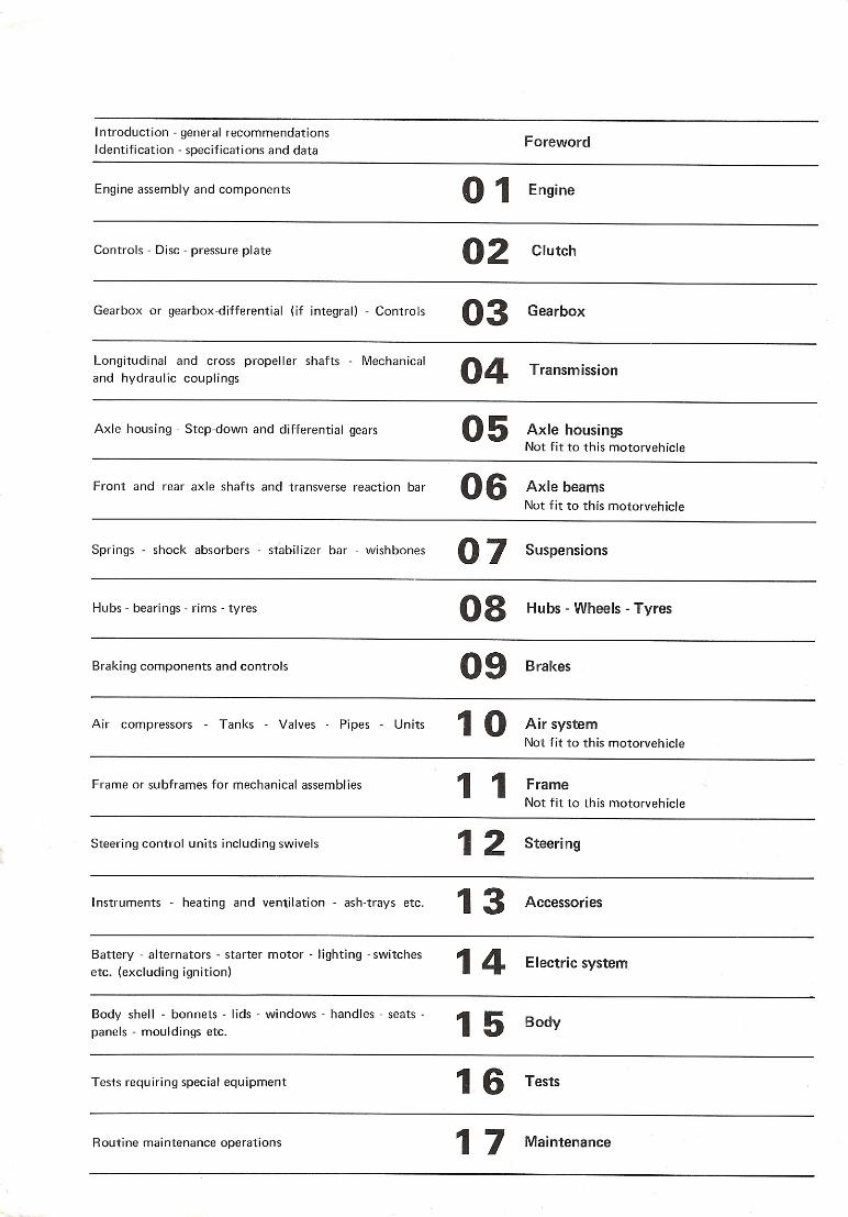
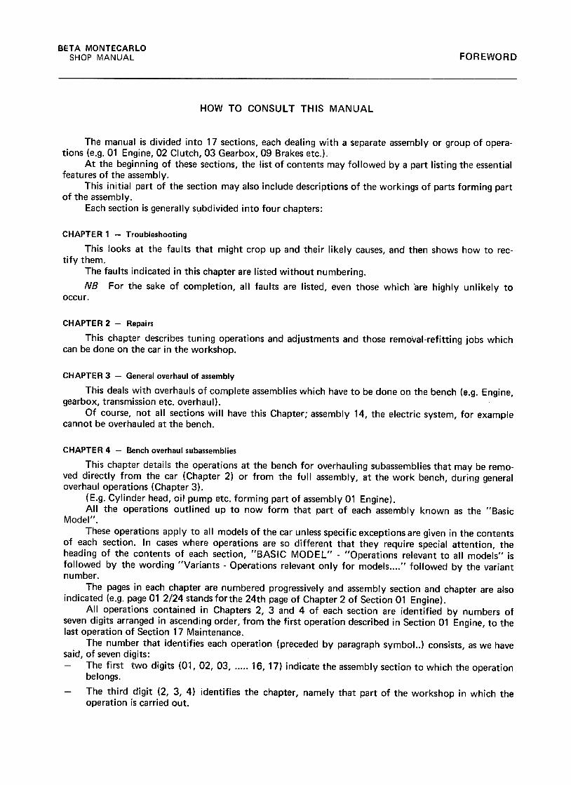
The manual is divided into 17 sections, each dealing with a separate assembly or group of opera-tions (e.g. 01 Engine, 02 Clutch, 03 Gearbox, 09 Brakes etc.).
At the beginning of these sections, the list of contents may followed by a part listing the essentialfeatures of the assembly.
This initial part of the section may also include descriptions of the workings of parts forming partof the assembly.
Each section is generally subdivided into four chapters:
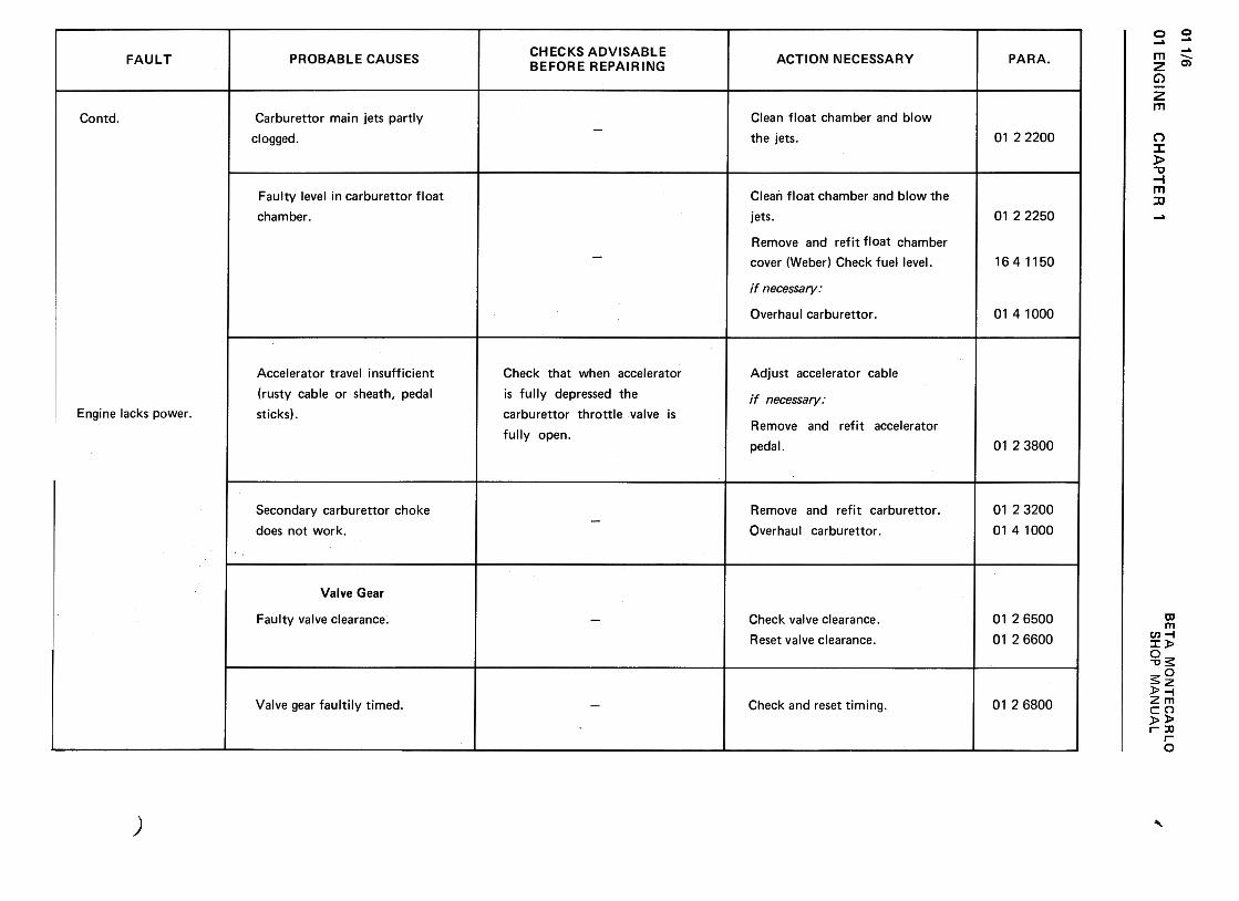
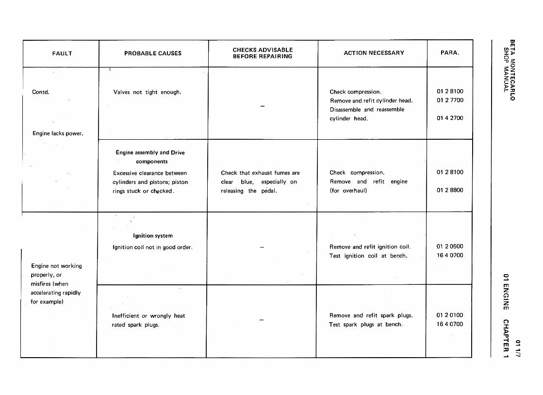
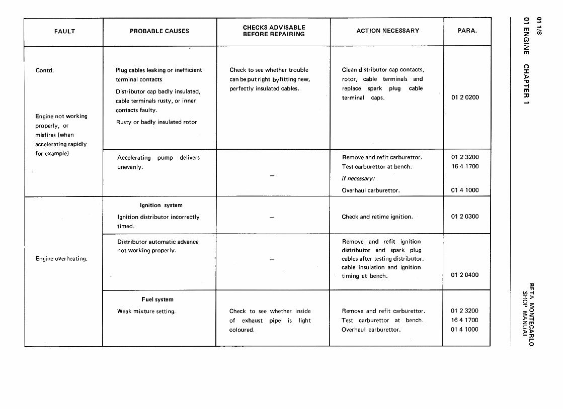
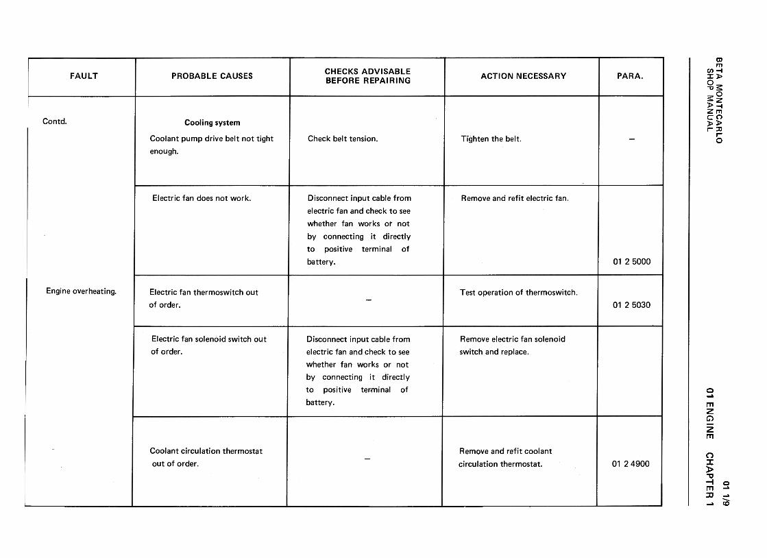
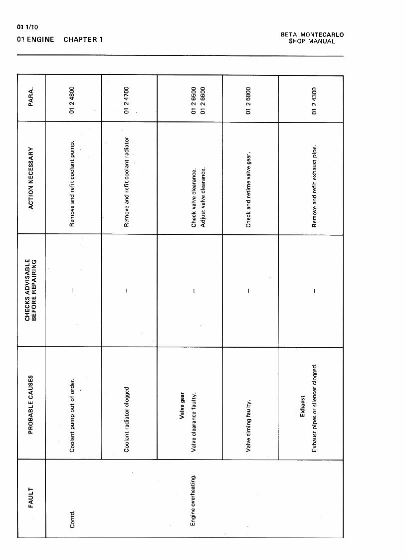
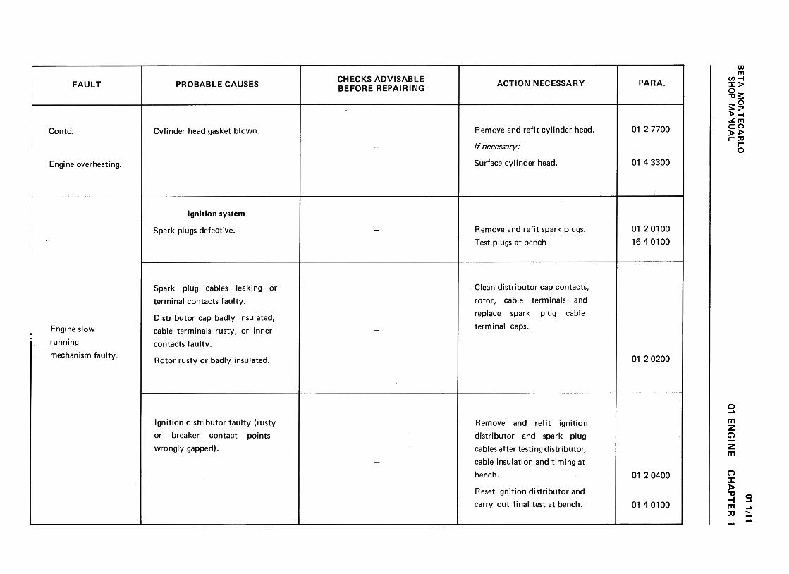
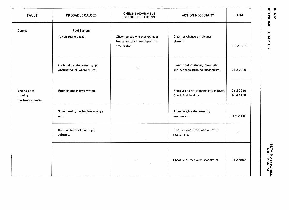
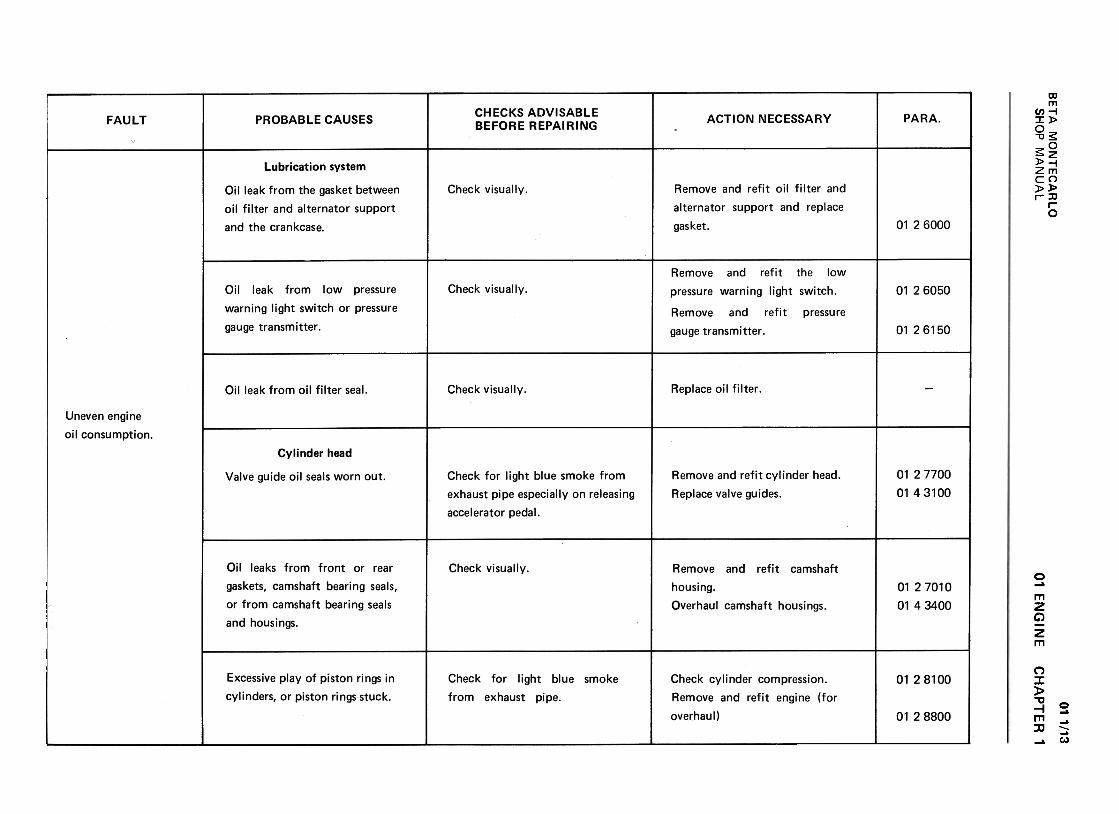
CHAPTER 1 -Troubleshooting
This looks at the faults that might crop up and their likely causes, and then shows how to rec-tify them.
The faults indicated in this chapter are listed without numbering.
NB For the sake of cQmpletion, all faults are listed, even those which are highly unlikely tooccur .
CHAPTER 2 -Repairs
This chapter describes tuning operations and adjustments and those removal-refitting jobs whichcan be done on the car in the workshop.
CHAPTER 3 -General overhaul of assembly
This deals with overhauls of complete assemblies which have to be done Ol:l the bench (e.g. Engine,gearbox, transmission etc. overhaul).
Of course, not all sections will have this Chapter; assembly 14, the electric system, for examplecannot be overhauled at the bench.
CHAPTER 4 -Bench overhaul subassemblies
This chapter details the operations at the bench for overhauling subassemblies that may be remo-ved directly from the car (Chapter 2) or from the full assembly, at the work bench, during generaloverhaul operations (Chapter 3).
(E.g. Cylinder head, oil pump etc. forming part of assembly 01 Engine).All the operations outlined up to now form that part of each assembly known as the "Basic
Model".These operations apply to all models of the car unless specific exceptions are given in the contents
of each section. In cases where operations are so different that they require special attention, theheading of the contents of each section, "BASIC MODEL II -"Operations relevant to all models" isfollowed by the wording "Variants -Operations relevant only for mode1s " followed by the variant
number.The pages in each chapter are numbered progressively and assembly section and chapter are also
indicated (e.g. page 01 2/24 standsforthe 24th page of Chapter 2 of Section 01 Engine).All operations contained in Chapters 2, 3 and 4 of each section are identified by numbers of
seven digits arranged in ascending order, from the first operation described in Section 01 Engine, to thelast operation of Section 17 Maintenance.
The number that identifies each operation (preceded by paragraph symbol..) consists, as we havesaid, of seven digits:
The first two digits (011 02, 03, 16,17) indicate the assembly section to which the operation
belongs.
The third digit (2, 3, 4) identifies the chapter, namely that part of the workshop in which theoperation is carried out.
IIBETA MONTECARLO
SHOP MANUALFOREWORD
The last four digits apply to the operation proper. For example, 01 2 2800 means operation2800 of chapter 2 {third digit) of assembly section 01 {first two digits).
Use the index at the beginning of each section when looking for any operation in particular .This lists the numbers of operations with their corresponding titles, and gives the number of the pagewhere the description can be found.,
All operations described in this manual {with the same serial number) are listed in the Hand-book of times which gives the standard time for performing the operation on the various models ofthe car .
LOOKING UP OPERATIONS
1st eventuality
You know the number of the operation (e.g. § 01 24800) and you wish to find the page where
it is described.
Number 01 2 4800 tells us that the operation should be locked up in Section 01 {first two digits)
Engine in Chapter 2 {third digit).
§ 01 24800 R.R. coolant pump. pag.01 2!14
2nd eventuality
You know what the operation is about (e.g. R.R. front shock absorbers) and you want to findthe number of the operation and the page where it is described.
The operation will obviously be described in Section 07 Suspensions and will. be found in Chapter
2 because the operation can be carried out on the car .
Reading through Chapter 2 operations in the Section 07 index, we find:
§ 0720200 R.R.front suspension pageO72/1
GENERAL RECOMMENDATIONS
Before carrying out any operation:, make sure that all the equipment listed at the end of thedescription as well as that listed at the end of any related operation is available.
Every time a repair is done, replace all those parts which become damaged as a result of it (e.g.gaskets, oil seals, lock plates, washers, "0" rings, and so on).
References to the right or left hand sides, or the front or rear parts of the car, are with respectto the forward direction of the vehicle.
During repairs always observe the most scrupulous cleanliness at the workbench and on the partsin question.
* * *"Whqn new" figures shown on the technical data sheets at the end of this volume, refer to new
parts that!have not yet been used.It gQes without saying that it only needs a little use for these values to undergo slight variations
if only a$ a result of running in, but such variations have nothing to do with wear proper and will inno waydompromise the good performance of the parts.
* * *During removal, repair or general overhaul operations, the fitter will have to decide for himself
whether to accept pieces whose specifications, owing to wear, differ from those given on the datasheets. Of course, the general condition of the car, the assembly under repair and the type of repairbeing carried out should all be allowed for.
IIIBETA MONTECARLO
SHOP MANUAL FOREWORD
Checking and fitting roller bearings
Checking
Checks should be carried out after careful cleaning; first wash with paraffin to remove the bulkierforeign matter.
Then a more thorough wash-down should be done in tanks of clean petrol; finally the bearing isdipped in rectified petrol containing 10% lubricating oil; allow the bearing to dry without using com-pressed air.
Set the bearing spinning while keeping hold of the inner race; if it is not in good condition, vibra-tions and undue noise will be noticed and, when the bearing is spun slowly by hand, minor seizures willbe felt.
The bearing should be rejected if any of the following faults are noticed:
a) marks on races or revolving parts; marks will be easily visible on bearings that can be disassembled;on others, marks will be visible by examining races between balls, against the light;
b) scoring of balls caused by foreign matter abrasion; in the presence of scoring; balls or rollers aregreyish and lose their normal bright surface;
c) bright outer or inner race surface; this means the bearing is spinning in its housing or on the shaft;both housing and shaft should be carefully examined because they are probably damaged;
d) signs of seizure on outer bearing surfaces; generally speaking, rust spots on outer race surfaces donot impair the good operation of the bearing.
Fitting
Heat the bearing in an oil bath at a temperature of 800 -100° C to facilitate fitting on the shaft.This procedure does not apply if the bearing has a plastic cage or if the bearing. isc()f self-lubrica-
ting type.New bearings can be fitted without washing because their protective cover does not impair their
efficient operation.
IV
BETA MONTECARLO
SHOP MANUALFOREWORD~
~'
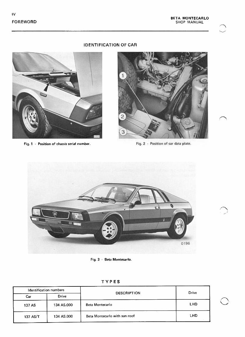
IDENTI FICATION OF CAR
~
Fig. 1 -Position of chassis serial number .
~
-,/
Fig. 3 -Beta Montecarlo.
TYPES
f\,~
vBETA MONTECARLO
SHOP MANUAL FOREWORD
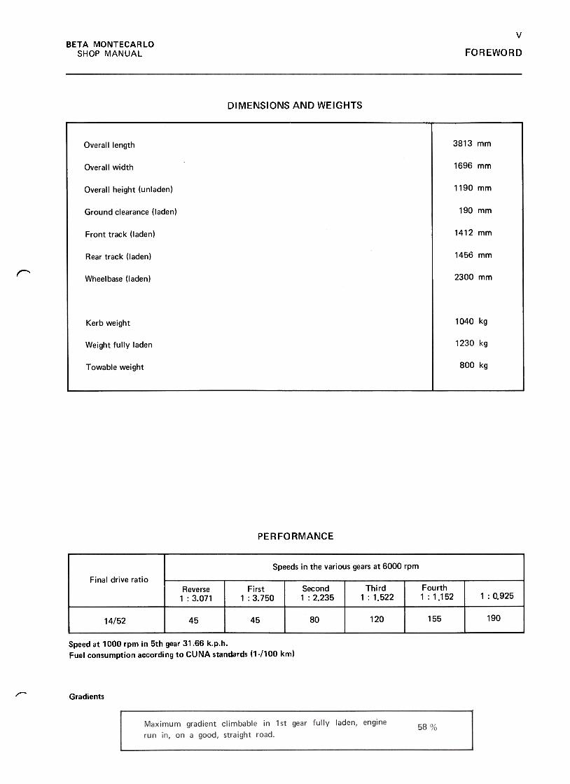
DIMENSIONS AND WEIGHTS
3813 mmOverall length
Overall width 1696 mm
1190 mmOverall height (unladen)
Ground clearance (laden) 190 mm
1412 mmFront track (laden)
1456 mmRear track (laden)
r 2300 mmWheelbase (laden)
1040 kgKerb weight
1230 kgWeight fully laden
800 kgTowable weight
PERFORMANCE
Speeds in the various gears at 6000 rpm
Final drive ratioThird
: 1.522
FourthI: 1.152
Reverse1 : 3.071
First
: 3.750
Second
1 : 2.235 0.925
19015580 12014/52 45 45
Speed at 1000 rpm in Sth gear 31.66 k.p.h.
Fuel consumption according to CUNA standards (1-/100 km)
.,.-- Gradients
VI
BETA MONTECARLO
SHOP MANUALFOREWORD
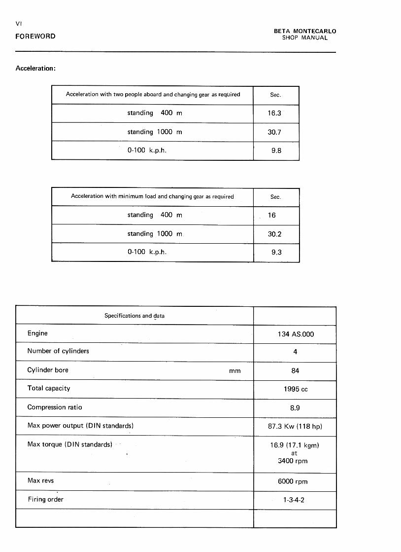
Acceleration :
Acceleration with two people aboard and changing gear as required Sec
standing 400 m 16.3
standing 1000 m 30.7
0-100 k.p.h. 9.8
Acceleration with minimum load and changing gear as required Sec
standing 400 m 16
standing 1000 m 30.2
0-100 k.p.h 9.3
Specifications and ~ata
Engine 134 AS.OOO
Number of cylinders 4
84Cylinder bore mm
Total capacity 1995 cc
8.9Compression ratio
Max power output (DIN standards) 87.3 Kw (118 hp)
Max torque (DIN standards) 16.9 (17.1 kgm)at
3400 rpm
Max revs 6000 rpm
Firing order 1-3-4-2

VII
BETA MONTECARLO
SHOP MANUAL FOREWORD
r
Fig. 4 -Instruments and controls
1. Side air outlets -2. Low and high beam light switch -3. Instrument cluster -4. Windscreen wiper and washer control -5. Central air outlet -6. Ash-tray -7. ciga-rette lighter -8. Glove compartment release lever -9. Glove compartment lock -10. Radio blank -11. Heating and ventilation flow .control lever -12. Gear lever -13. Handbrake -14. Quartz electronic clock -15. Heating and ventilation controllevers -16. Spare switches -17. Horn -18. Accelerator pedal -19. Brake pedal -20. Clutch pedal -21. Fuse box- 22. Boot release control -23. Direction indicatorsswitch -24. Side lights switch.
"'
Fig. 5 -Instrument cluster
1. Speedometer with trip and total distance recorders -2. Hazard signalling systemwarning light (if fitted) -3. Direction indicator tell-tale -4. Electronic rev counter -5. Coolant temperature gauge -6. Blank -7. Oil pressure gauge -8. Blank -9. Alter-nator warning light -10. Low engine oil pressure warning light -11. Handbrake tell-tale (flashing) -12. Engine overheating tell-tale -13. Blank -14. Blank -15. Fuelreserve warning light -16. Fuel gauge -17. Instrument light with intensity adjuster -18. Heated rear window warning light -19. Spare tell-tale -20. Spare tell-taliJ -21. High beam tell-tale -22. Spare tell-tale -23. Side lights on light -24. Trip dl-stance recorder reset.
f\
VIII
BETA MONTECARLO
SHOP MANUALFOREWORD
var. SCORPION
,
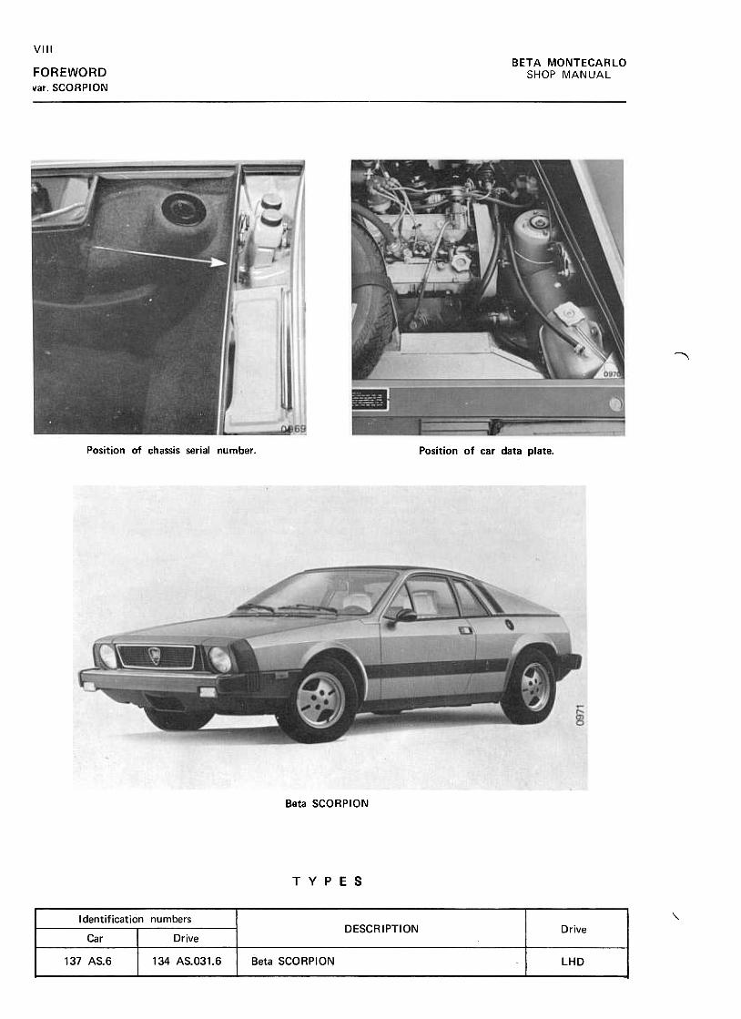
Position of chassis serial number. Position of car data plate.
Beta SCORPION
TYPES
~Identification numbersDESCRIPTION Drive
Car Drive
137 AS.6 134 AS.O31.6 Beta SCORPION LHD
IXBETA MONTECARLO
SHOP MANUAL FOREWORD
var SCORPION
r--
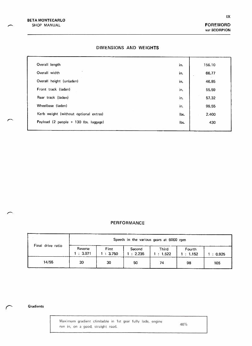
DIMENSIONS AND WEIGHTS
Overall length 156.10in.
Overall width 66.77in.
Overall height (unladen) 46.85in.
Front track (laden) in. 55.59
Rear track (laden) 57.32In.
Wheelbase (laden) 99.55in.
Ibs. 2.400
r"
Kerb weight (without optional extras)
Payload (2 people + 130 Ibs. luggage) Ibs. 430
~
PERFORMANCE
Gradientsr
xBETA MONTECARLO
SHOP MANUALFOREWORD
var. SCORPION
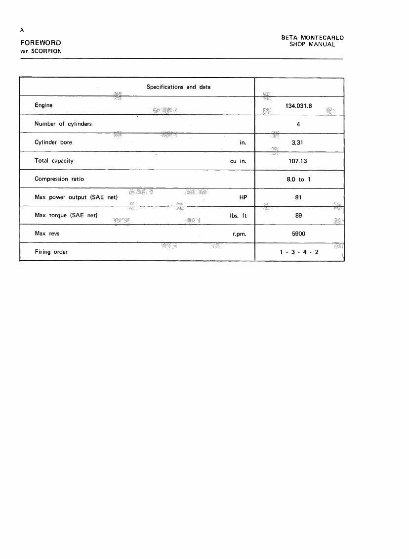
Specifications and data
Engine 134.031.6
Number of cylinders 4
Cylinder bore 3.31
Total capacity cu in. 107.13
Compression ratio 8.0 to 1
Max power output (SAE net) HP 81
Max torque (SAE net) Ibs. ft 89
Max revs 5900r.pm.
3Firing order 4 -2
XI
BETA MONTECARLO
SHOP MANUAL FOREWORD
var. SCORPION~
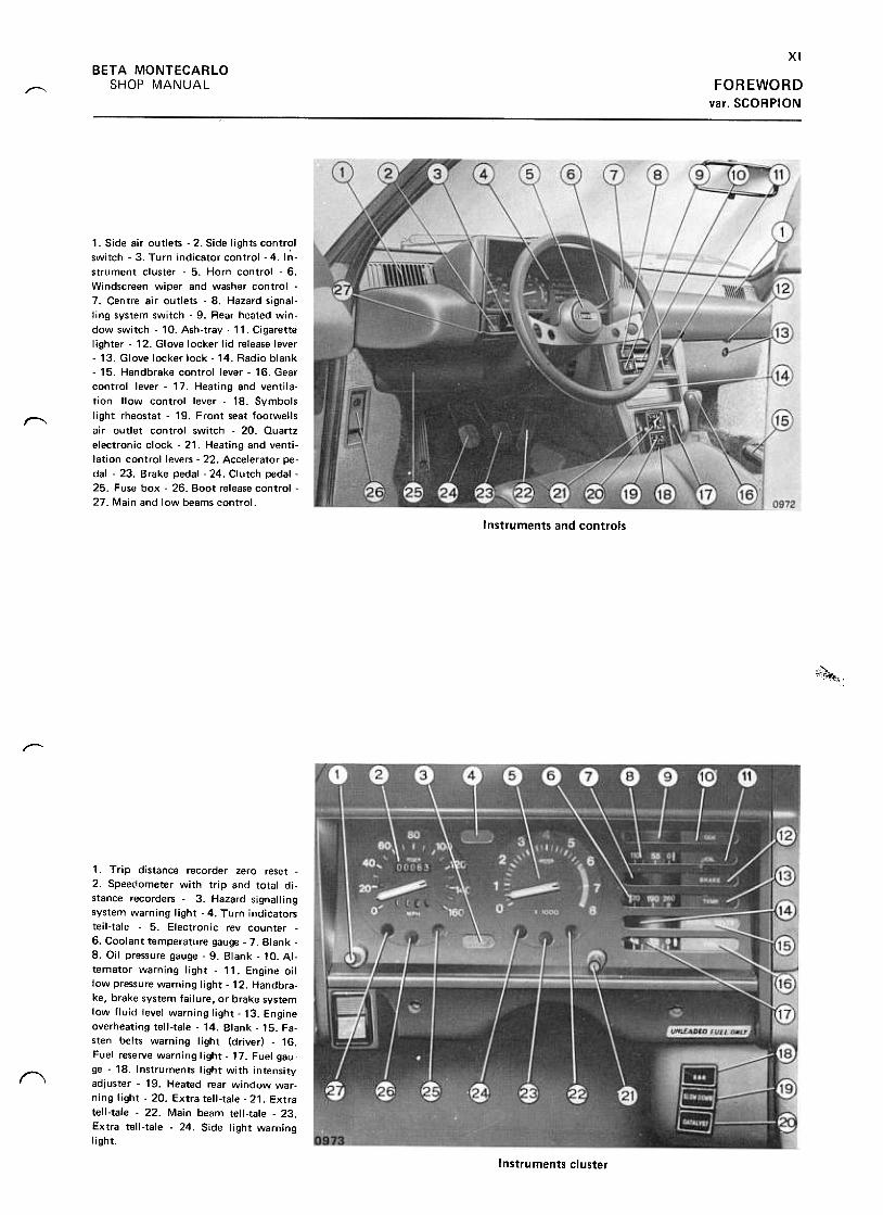
1. Side air outlets -2. Side lights controlswitch -3. Turn indicator control -4. In-Strument cluster -5. Horn control -6.Windscreen wiper and washer control -
7. Centre air outlets -8. Hazard signal-ling system switch -9. Rear heated win-dow switch -10. Ash-tray -11. Cigarettelighter- 12. Glove locker lid release lever-13. Glove locker lock -14. Radio blank-15. Handbrake control lever -16. Gearcontrol lever -17. Heating and ventila-tion flow control lever -18. Symbols
light rheostat -19. Front seat footwellsair outlet control switch -20. Quartzelectronic clock -21. Heating and venti-lation control levers -22. Accelerator pe-dal -23. Brake pedal -24. Clutch pedal -25. Fuse box -26. Boot release control -
27. Main and low beams control.
~
Instruments and controls
"'-~
'~y
,--
1. Trip distance recorder zero reset -
2. Speedometer with trip and total di-
stance recorders -3. Hazard signalling
system warning light -4. Turn indicators
teil-tale -5. Electronic rev counter -
6. Coolant temperature gauge -7. Blank -
8. Oil pressure gauge -9. Blank -10. Al-
ternator warning light -11. Engine oil
low pressure warning light -12. Handbra-
ke, brake system failure, or brake system
low fluid level warning light -13. Engine
overheating tell-tale -14. Blank -15. Fa-
sten belts warning light (driver) -16.
Fuel reserve warning light -17. Fuel gau-
ge -18. Instruments light with intensity
adjuster -19. Heated rear window war-
ning light -20. Extra tell-tale -21. Extra
tell-tale -22. Main beam tell-tale -23.
Extra tell-tale -24. Side light warning
light.
f'\
Instruments cluster
BETA MONTECARLO
SHOP MANUAL 01 ENGINE
Contents
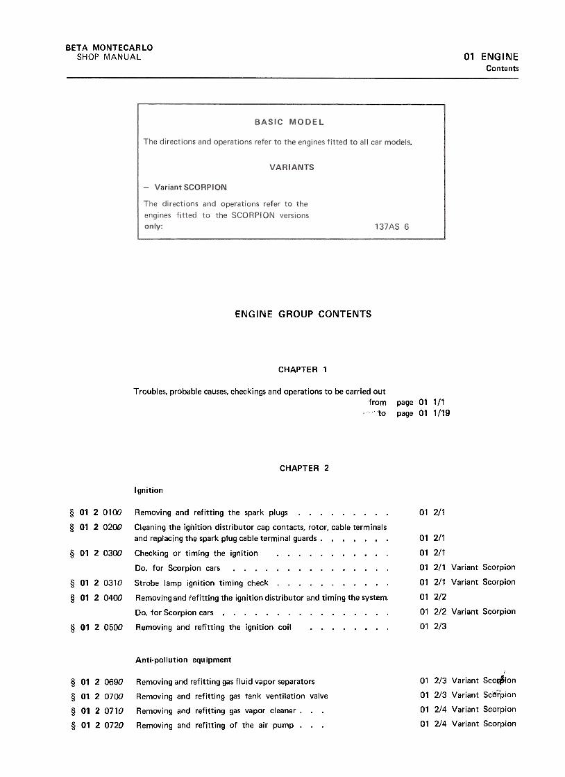
ENGINE GROUP CONTENTS
CHAPTER 1
Troubles, probable causes, checkings and operations to be carried out
from
~c'to
page 01 1/1
page 01 1/19
CHAPTER 2
Ignition
§ 0120100
§ 0120200
01 2/1
§ 0120300
§ 0120310
§ 0120400
01 2/1
01 2/1
01 2/1 Variant Scorpion
01 2/1 Variant Scorpion
01 2/2
01 2/2 Variant Scorpion
01 2/3§ 0120500
Removing and refitting the spark plugs
Cleaning the ignition distributor cap contacts, rotor, cable terminals
and replacing the spark plug cable terminal guards .
Checking or timing the ignition
Do. for Scorpion cars
Strobe lamp ignition timing check
Removing and refitting the ignition distributor and timing the system.
Do. for Scorpion cars
Removing and refitting the ignition coil
Anti-pollution equipment}
01 2/3 Variant Sco~on
01 2/3 Variant Sc~rpion
01 2/4 Variant Scorpion
01 2/4 Variant Scorpion
§ 01 20690
§ 0120700
§ 0120710
§ 0120720
Removing and refitting gas fluid vapor separators
Removing and refitting gas tank ventilation valve
Removing and refitting gas vapor cleaner .
Removing and refitting of the air pump .

2
BETA MONTECARLO
SHOP MANUAL01 ENGINEContents
§ 0120730
01 2/5 Variant Scorpion
01 2/6 Variant Scorpion§ 0120740
§ 012 07BO
01 2/6 Variant Scorpion
§ 0120790
01 2/7 Variant Scorpio[1
§ 0120800
01 2/7 Variant Scorpion
01 2/8 Variant Scorpion
01 2/8 Variant Scorpion
01 2/8 Variant Scorpion
01 2/9 Variant Scorpion
01 2/9 Variant Scorpion
§ 0120810
§ 01 2 0830
§ 0120840
§ 0120850
§ 0120860
§ 0120870
01 2/10 Variant Scorpion
01 2/10 Variant Scorpion
01 2/11 Variant Scorpion
§ 01 2 0880
§ 0120890
Removing and refitting of diverter valve, three-way valve, and three
way electrovalve .
Removing and refitting check valve and exhaust pipe air hose .
Removing and refitting the exhaust gas recirculation valve and pipes
(E.G.R.)
Removing and refitting vacuum thermostat controlling exhaust gas
recirculation valve (E.G. R.)
Removing and refitting electrovalve for cutting out exhaust gas
recirculation valve (E.G.R.) .
Removing and refItting a push-button switch on the gearbox
Removing and refitting fast idler hand control switch .
Removing and refitting fast idler control electrovalve
Renewing the fast idling diaphragm body.
Regulating fast idler
Removing and refitting exhaust gas recirculation (E.G.R.) system
alarm
Removing and refitting accessory gearbox .
Removal and refitting of the electronic speedometer .
Fuel System
§ 0120900
01 2/5
§ 0121100
01 2/5
01 2/3
01 2/6
01 2/6
01 2/6
01 2/7
Variant Scorpion
§ 0121700
§ 0121710
§ 0121800
§ 0121900
§ 0122200
01 2/7
01 2/3 Variant Scorpion
§ 0122250
§ 0122300
01 2/8
01 2/14 Variant Scorpion
01 2/8
01 2/14 Variant Scorpion
§ 0123200
01 2/9
01 2/15 Variant Scorpion
01 2/9
01 2/10
§ 0123710
§ 0123800
Removing !and refitting the fuel gauge transmitter with previous~~
checking ,i .
Removing and refitting the fuel tank complete with fuel gaugetransmitter .
Do. for Scorpion cars .
Cleaning, or renewing the air cleaner element.
Removing and refitting the air cleaner assy .
Removing and refitting the fuel pump (electromechanical) ,
Removing and refitting the fuel cleaner
Cleaning the carburettor float chamber, blowing the jets and settingthe slow-running
Do. for Scorpion cars
Removing and refitting the carburet tor float chamber cover (Webercarburet tors) .
Do. for Scorpion cars .
Setting the engine slow-running
Do. for Scorpion cars
Removing and refitting the carburet tor including setting the engineslow-running .
Do. for Scorpion cars .
Removing and refitting the choke
Removing and refitting the accelerator control cable ,
Exhaust System
§ 0124300 Removing and refitting the exhaust piping assembly.
Do, for Scorpion cars
01 2/11
01 2/17 Variant Scorpion

3BETA MONTECARLO
SHOP MANUAL 01 ENGINE
Contents
Cooling System
§ 0124650
§ 0124700
§ 0124800
§ 0124900
§ 01 25000
§ 0125030
01 2/13
01 2/13
01 2/14
01 2/14
01 2/15
01 2/15
01 2/16§ 0125100
§ 0125110
Draining refilling deaerating the cooling system
Removing and refitting the coolant radiator .
Removing and refitting the coolant pump
Removing and refitting the coolant thermostatic blender
Removing and refitting the motor driven fan
Checking the motor driven fan, thermoswitch and solenoid switch foroperation .
Removing and refitting the motor driven fan control thermoswitch .
Checking working condition of coolant temperature gauge, transmitterand motor driven fan cut-in and cut-out temperature . 01 2/16
r- Lubrication System
§ 01 25600
§ 0125700
§ 0126000
01 2/19
01 2/19
01 2/19
Checking the oil pressure
Removing and refitting the oil pump .
Removing and refitting the oil filter base to renew the gasket .
Valve Gear
§ 0126500
§ 0126600
§ 0126800
01 2/21
01 2/21
, ~-.
""',,~"'r 01 2/23
§ 0126950
01 2/24
§ 0127010
01 2/25
01 2/26§ 0127300
§ 0127500
Checking the tappet clearance .
Setting the valve tappet clearance
Checking and setting the valve gear timing (including checking theignition timing) .
Renewing the timing belt including valve gear timing and checkingthe ignition timing .
Removing and refitting one camshaft housing (intake side), checkingvalve tappets clearance (removing-refitting timing belt excluded) .
Removing and refitting the timing belt stretcher assy .
Removing and refitting the camshaft drive gears, ancillary units shaftdrive gear and timing belt drive gear 01 2/26
Cylinder Head
§ 0127700 Removing and refitting the cylinder head (including checking thevalve tappet clearance, but except for relative setting)
Do. for Scorpion cars
01 2/29
01 2/19 Variant Scorpion
Engine Unit and Motive Components
§ 0128100
§ 0128200
§ 0128300
§ 0128310
§ 0128400
§ 0128600
§ 0128700
§ 0128800
Checking the cylinder compressions .
Renewing the engine mountirig buffer .
Renewing the crankshaft front oil seal.
Renewing the ancillary units drive shaft oil seal
Removing and refitting the engine oil sump .
Removing and refitting the flywheel
Fitting a new crankshaft rear oil seal.
Removing and refitting the engine (complete with gearbox) .
Do. for Scorpion cars
01 2/31
01 2/31
01 2/32
01 2/34
01 2/35
01 2/36
01 2/36
01 2/36
01 2/23 Variant Scorpion
4
BETA MONTECARLO
SHOP MANUAL01 ENGINEContents
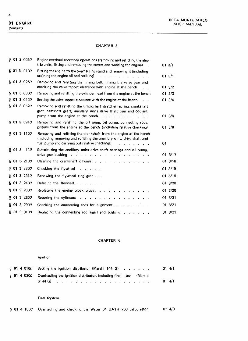
CHAPTER 3
§ 0130010
013/1
§ 013 0100
01 3/1
§ 0130250
01 3/2
01 3/3
01 3/4
§ 0130300
§ 01 30420
§ 0130520
01 316
§ 0130910
01 3/8
§ 0131100
01
§ 013 110
01 3117
01 3118§ 0132100
§ 0132300
§ 0132310
§ 0132400
§ 0132600
§ 0132800
§ 0132900
§ 0133100
Engine overhaul accessory operations (removing and refitting the elec-
tric units, fitting and removing the covers and washing the engine)
Fitting the engine to the overhauling stand and removing it (including
draining the engine oil and refilling)
Removing and refitting the timing belt, timing the valve gear and
checking the valve tappet clearance with engine at the bench
Removing and refittil1g the cylinder head from the engine at the bench
Setting the valve tappet clearance with the engine at the bench
Removing and refitting the timing belt stretcher, spring, crankshaft
gear, camshaft gears, ancillary units drive shaft gear and coolant
pump from the engine at the bench .
Removing and refitting the oil sump, oil pump, connecting rods,
pistons from the engine at the bench (including relative checking)
Removing and refitting the crankshaft from the engine at the bench
(including removing and refitting the ancillary units drive shaft andfuel pump and carrying out relative checkings)
Substituting the ancillary units drive shaft bearings and oil pump,
drive gear bushing
Cleaning the crankshaft oilwavs .
01 3/19
01 3/19
01 3/20
01 3/20
01 3/21
01 3/21
01 3/23
Checking the flywheel. Renewing the flywheel ring gear. .
Refacing the fiywheej
Replacing the engine block plugs. Reboring the cylinders. Checking the connecting rods for alignment. Replacing the connecting rod small end bushing
CHAPTER 4
Ignition
§ 0140100
§ 0140300
01 4/1Setting the ignition distributor (Marelli 144 G) Overhauling the ignition distributor, including final test (Marelli
S144 G) 01 4/1
Fuel System
01 4/3§ 0141000 Overhauling and checking the Weber 34 DATR 200 carburet tor

5BETA MONTECARLO
SHOP MANUAL 01 ENGINE
Contents
Cooling System
§ 0141300 General overhaul of coolant radiator 01 419
Lubrication System
§ 0142500 Overhauling the oil pump 01 4/11
Cylinder Head
§ 0142650
r--91 4/13
§ 01 42700
01
01
01
01
01
§ 0142710
§ 0143100
§ 0143300
§ 0143400
Removing and refitting the camshaft housings from the cylinder head
on the bench. Disassembling and reassembling the cylinder head (including checking
the cylinder head surface for flatness, valves, guides, valve seats and
spring loading)
Refacing the valves and the seats. ...
Renewing the valve guides (including refacing the valves and seats)
Surfacing the cyl inder head. Overhauling a camshaft housing.
4/1
4/1
4/1
4/1
4/1
13
15
17
17
18
BE
TA
M
ON
TE
CA
RLO
w~
..J2ca-~
a:cn--~>
a.C
w~
a:cnW~
a:(..)0w
u.~
wucat-..J:J~11,
(/)w(/)::><
tuw.Ja3<
ta3aa:~ >a:«(/)(/)w(.JwzzO1-(.J« <ta:
<t
a,
>..Q)
......lam
..:.Q
) co
"' -
0 -.-
0 >
-
...t0
co>
- c.
+-'
..."'
o2
+-'
"' ~
coc >
-
E
~...+
-'Q
) co
1- m
.!!? "'
"ia>
c
~
.E+
"' ...
co Q
).c
+"'
Q)
Q)
.c.c
+"'
+"'
c+
"' co
co Q
).c
-+
"' u
Q)
"CQ
) c
"' co
O
a.+
"' :J
"C~
Q
)u
C1
Q)
....c
CO
U
-£ oo~ON~
...CI
'- C
(U
...0 C
"' C
C
...:J0,-,-C
0...'-
-"'
00
>-
~
E
"§"tJ
Clo
'- C
-;;;
Q)
Q) .-
C
...~.-'-
'- 0
CI(U
°oC
t;
~
...
W-
..O+"'
oE~+"'
..ea+
"'(/)
Q)
"'oo"'c:o"+;
(.IQ
)c:c:0(.I...0...Q
)"C...O-.-0~(') o
00
N0)
o:ttO
0
N
o:to:t
o:t
"'co.~uQ)
ccouQ)
"'oo...O~uQ)
..c() ..0...oE..QJ
.
..Oca ...
~
0
...E'-=
..
QJ
QJ
.."C
ca
c: ...
ca "'
QJ
"'5>
ca
O
~E
..
QJ
~0:
(")
.cu...
'~"'co';:.'2g)
Q)
"'o-2"'co.~Q)
cco(.)...0...Q
)"0...O-.-0...~a .s::tJ+
-'
"~"'c:o"~"c:.~+
-''-=Q
)..
"0c:caQ)
>oEQ)
rr
cO'~'c=
01 E
NG
INE
c:~o:0Q)
"'~'+-
.0o 0)cn:J-0)(Jm0.0)
~
<a
Q)
c"'
...
...oo
c:c:
.-
"' 0
Q)
...o
o-c
EQ
) ...
c: Q
)C
I ...
c: .:9
~
-"'-
c0)"u;;=,+
-0)c~:J""5.~...ra0.C
/)
o0...0N...0"'01:I0.
~1-CO
0."'
;;:Q)
1-
"0t:CO
Q)
>oEQ)
~ CH
AP
TE
R
1
.r:uc:Q)
-0..."'Q)
......ca"'CI
:J0.~..ca0."'~UQ
).r:() o0~0v<.0
011/1
SH
OP
M
AN
UA
L
01 E
NG
INE
011/2w~
..Jzm
-~
a:cn--~>
~ow~
a:cnW~
a:U
Qw
u.~
wum ~a:~~>
-a:<t
(I)(I)wuwzzof::u<
t(/)w(/):>«uw.J~«~Oa:a....-J::>~I!.
CH
AP
TE
R
1
"C...coo
"'- "C
"'C
Q+
"' t:
t:u
co .-
~
Et:
"' '-
0 -Q
)u
~
+"'
Q)
c. E
::c
co'-cou
~
u
'-Q)C
I0
-:J+
"'.C""Q
.:J
CO
.c U
~
.;: '-
+"'
"C
CO
.~
t: c.
"C
CO
"'Q
)-U
t:'-CO
.
CO
0
-"'Q
)+",C
.C.
-OQ
)CO
U,-,-U
"iQ
'-c.-Q
}E
"C
§
..Q}
.-Q
} ...
...co '-
..-oo
:!"'C
) c
>c .-~~
...'-
co O
~
c ~
"' co
Q}
c:c
.c. .-.
co~
~E
~(,)
"":J a;
"":JC
)CO
co
:! '+
- 0
'+-
-"' c. ...:!
>
"'(,)
.c ~
co
.-~
(,)~
coco
c ...c.
...c.
O
.~
o c
U)uC
C.8
>"1J
..c Q
)...
"1J C
IIQ
) -
...:JU
"'
Q)
c:'-
.-
8 .?:
Q)
.....c
uQ)
c: -
CII
'-U
8.
...:J .
CII
~-Q
)Q
) c:
.r.-CI
"'.-c:
Q)
Q)
.;; :c
Q)
...CII
(/) ;
U
ooNON.-n
>=c~.c..0>..."':J....oO....0
...."C:J
a..c
....-~..-...:J"'
"'
.-cO
~
.+"'
+"'
t.>t.>
Q
)co
...+
"' ...
c o
0 t.>
~
.~
...a.o
co5
~.c
..
.;: 't:
>+
"' "'
+"'
"' -
.-='
='
"0 ...co
c "'
-0
+"'
....-c
Q)
+"'
.-.-0
"'c
a. c
~
Q)
"0>
- Q
) c
~
0-:;
co t.>
Q)
co u..
-1:1 O
o0-:tONO.'-Q
)
'- -c
co '-
t: oc:
O
.-c:
'-0"' Q)
0
.g E
Q)
'-c:
2?;.-'-C
I C
Oc:
cI>W
-
..;. ~
"'
c: Q
)"'
:c E.-"C
c: c:
o c:
10.+
" O
...O
c: .~
C
lc: :J
.-CI
.c:'+
- "'
"'Q
) :J
.-
~
"C"C
..
"C
10 c:
C-
c: O
t1)
10 "C
.-.!')
c: .~
.s::
"'Q
)IO
C:u
~>
C
lC:
~O
Q
) Q
)E
o .c
c:
Q):J
Q)
II: .c
cn 10
.-
oo~ov~C)
, ...
.-"'..Q)
1;; ...
:c .c
c: ~
0 Q
):E
.c
c: ...
C)
:J.-O:J
>C
Q
...c
....C
) u
>O
"1Jc:.?:-
CQ
"'CO
..
.-0..:J~
" oo8.;r..-
n
BE
TA
M
ON
TE
CA
RLO
o09('\I.-r)>~:Jca'4-0)c:
"E";;c:0";;'C
:0)
C)
c'E';:.c0';:.'C
:,~0>"'0>'-
"0c"'
~u0>.I::()
SH
OP
M
AN
UA
L
BE
TA
M
ON
TE
CA
RLO
w"
..J2m
-«cx:cn--«>
0.O
w«cx:cnW~
cx:U
QW
u.~
wum >"<
t~~wuw22O1-U<
!
<t
a:<t
0.I--I~<t
lL (/)w(/)
::>~uw..JCX
3
~CX
3
O~0--
"C...cou ~"3ca....0(.)c0.+
:..c:0)
o o
o 0
LO
r--o
oN
q-
.-(00.0(,)
.I::
..c:o
~.;;
Q)
.-.cI::CI
....-C
O
't:: .0
Q)
(,)
...
"C
I::I::
.Qco
...Q
) .c:
>
CI
O
.-
E
t;Q
) Q
)a:
1-
EQ)
..."'>"'
-a; .
~
.:.tu.
cCQ
...c-a;~...0~
>"5(0-0-E~0-
"Q;
~LL E
ca '~
~
O
t: +
"' O
'- .-'-
-'+
- ca
'+-
QJ
~
+"'
+"'
c.t:"':J.-Q
J O
C.Q
Jt:t:+
",.cOca
QJ
+"'
'-c
QJ.c.E
(.) (.)
~~
~
.~
(.)
:JC.~
QJ
'+-
"' .c
+"'
'-- (.)
(.) O
-~
QJ+
""-~~
+
"' Q
J ~
~Q
Jt:ca .
t: '-
.-'- -
o:JcaoQJ
(.) .c
+"'
+"'
:J
""-t:o'+-
~cao
E'+
-
L..J (.)
u O
0.E:30.
"'Q;
:3'0-...'+
=QJ
..
"0c(0QJ
>oEQJ
!1:
o000N.-0
~Q)
."tJt
'-~
0
+"'"'
I:+
"' .-
0 '-
I: 0+"'
"' 0
~
E"tJ
'-Q
) Q
)I:
t.-~0)
+"'
I: cn
U1
--
-0Q)
0)0)ou"'+"'
.~..0+"'
+"'
Q)
..:3.!:I..caO
0)0!:...$:o:0"0c:(0...0).cE(00!:tJ...(00~c:(0
.0)
"'
u .~
01 E
NG
INE
o0NN,I
N~0
i-..-la
:JQ
) la
g) -
Q)
g)
>
c
"(; 'E
>
0-+",...laQ
)0)Q
).?:la:> oo00C
DN.-0+
"'Q
)"'Q
)...
"0t:(001t:
"E";:....(0Q
)01Q
)>~>.:¥tJQ
)..co
011/3
SH
OP
M
AN
UA
LC
HA
PT
ER
1
01 EN
GIN
E
011/4w~
.Jz00-<
ta:(/)--<
t>
Q.
Cw
<ta:
(/)W~
a:U
QW
LL~
WU
OO
I--I:)<t
u..
tnwtn:J«uw-Jm«mOCI:
a,
>a:~(/)(/)wuw2<
==
O1-
U~ <t
cr:<
t11.
CH
AP
TE
R
1
Q)
c:
.0>c:Q)
'- .
Q)
"'.r=
"C
+"'
Q)
Q)
Q)
.r=
c.~
"'
.r=Q
) C
)Q
) .-
"' .r=
o +
"'+
"' ca"'
~
Q)
'-u
.-Q
) '+
-.r=
.~
u E
uiC)
:J-c.
.r.
~
~...Q
)to
.ca."'
to
'-=
"'Q
) C
)...:J
"C
-c.c:to
~'-Q
) to
>
a.o
"'
E
Q)
"'
a: ~
...ca~.s::
~CI
c:o...c:
~0
...:E
o
6. ~
-3ca
-.-"'CI
.:!c.
~
"0ca
~c.
...C
/) ~
o o
o 0
M
.-0
0N
"3"
.-to0
t:O:Et:.~0)E.~"Ct:"'
~(.)0).s::(
)
oo~ON.-0~~
u
--"
" .-
>.
Q)
Q)
u
Ec.co"L:
.-c. E
Q
) Q
)
co 0
c. V
)->
C)
0 Q
)-::I
'- C
).->
co
c. co
-C)
-~::IC
V)C
)CO
CO
o C
Q)
-C
.--'-
.-~
O~
O'-C
C.O
Q)
::I,-,-~~
.CQ
)Q)
.-~
~
::I,-,,~
U
'- 'v
0V
)OQ
) -
.-'- C
>
"OC
.C
t:C
Q
) ::I
0 U
U
'-
.-0 C
O
C
'-~
co
0.--C
>
~
'-0
0"00
-u m
~
c: s::
o o
.~
.~.c
.c.21
.21
...Q)
:+::
EQ
) .-"C
"C
c:c:
roro
...0Q
) ...
>
:J0
.cE
.t:
Q)
t:a:
:p
'-Q)
~O0."'~(.)(0Q
)c.C
icw
o0v0N.-0
+"'
"'Q)
+"'
"Cc:(Q'-0+"'
:J.c..:+
"'"'
:c:c:o:E
.r.c:
(.)C
I c:
.-Q)
+"'
.cQ
) +
"'cn
"'
o0~0v~0
~~~\,)q,t:
~
"Cc:ca...0 .
+"'
.c:J
tJ.c
c:.-Q
);:,
.c"'
.-+"'
"C
ca+
"'c:
"'0
Q)
.-+"'
+"'
-.-cac:
c:C
) .-
-+"'
:J :J
ca 0
-E
>Q
) ...
>
...
0 ~ o0M0~.-n
BE
TA
M
ON
TE
CA
RLO
o o
o o
I!) I--.
0 O
N
v.-(0O
.-
..Q)
"C..0[:...0[:
'0u[:O'+-
'cCI
.0(.) .
c: .c
o ~
.+"
Q)
.-.cc:CI
....-C
O
'-=
.0Q
) (.)
'-
"C
c:Oc:
.-co
...
Q)
.c>
C
IO
.-
E
~Q
) Q
)a::
1-
SH
OP
M
AN
UA
L
BE
TA
M
ON
TE
CA
RLO
w~
-Jz03-«a:C
/)--«>0,.
OW
«a:C
/)W~
a:U
OW
u.:l:wU
03 >a:«(I)(I)wuwzzo.-u« <t
a:<t
!1.
1--J~«LL
(/)w(/)::>0:{uw.JID0:{IDOa:0..
};:J ~ .
->]
Q)
-+-'...+
-'.r:
Q)
.-+
-' c.
-
...0Q
) ...Q
).r:
c. ...
+-'
~
Q)
.r: c:
~
Q)
"'~
.r:
.2?Q
) ~
.c
Q)
~"'
C.)
"'0
...+
-' ~
"C
~
~
~C
.) c.
~Q
) ~
~
.r: "'
-
0 :p
.s
CI't:
~
-
-~c. (0
-~
"'
'- ...
(0 U
c. (0
"' ...
E
§O
u
'- -
-(0Q)
~C
I .-
(0 E
~
'-(0
Q)
Q)
...-'-...0~Q
) "'
'- Q
)'-
-~
.c
(.J ~
"'"'.
~
a.rou
c u
ro ro
-roc
cO
.!!!.
.-u
ro E
a.c
'-.-Q
)ro
E
U,-C
I
'- Q
) ::J
O
a.
::J Q
) ~
.c -'-
..: .c
roro
a."'
U
"'
:0 Q
).U
C,-ro
ro O
-
Q)
a.-0
Q)
(..) '-
'-
"0...c:o()
o0NON.-0
EQ)
..."'>"'
"Qj
~LL
Q)
>
Q)
-co .c
.c E
:IO
c:
Q)
.c°Q)
c: ~
..."' co
Q)
.-E.c
c:Q
) -C
I.c ~
.~
"'Q
) :I
OQ
) 0
-"'
:I O
O
c: Q
)
~
c: :I
.C
.) O
"C
~
Q)
C.)
c:.c
"' ~
19
o .-
~[::(0Q)
:J'1-
;0=e"0[::(0Q)
>oEQ)
~"CQ)
0)0)ouQ)
0-'0.co'B:J"'~cco+
"co..Q)
~li::
o0.-.-Nc;
~O0."'~u~Q
)c'61cw
>-cg:J"'.>Q
,"'o.c...Q
J
oS'0QJ
...-0~(.)Q
J.cO .1:...
"§~o:01:1c ,
(0 ...
Q)
'CO
"' 1:1
0 Q
).1:
"'Q
) "'
>
~0
0.
E
EQ
) 0
0=
u
-011)0.0.O"'11)"'0.c'-11)
.c(011)'-
.0~c(0
-0;~LL
oo00N~0
...:Q
)-0...O...000.c0.E:J0.
""Q;
:Ju. 0.E::I0.
~::I-+
"'
~...
"0c:caQ)
>oEQ)
11:
01 E
NG
INE...
0)
;;:0)tJra
""0.0)
0::
"0Q)
CJ
CJ
0u'-Q)
'+=Q)
c""Q)
~'+-'-0Q)
'-~.0'-<0
u
a;1:caQ)
u...
"caQ)
uca
-0.Q)
......"0
...1:1:
Q)
ca E
Q)
Q)
(3 -0;
"00)CI
CI
OU...0)c:ca0)U...
~ "':J(Q.cxQ
)
...Q
).cQ
).c
.~
~u
Q)
) -
"' .c
o ~(Q
~
"'u
Q)
Q)
E.c
:Ju
~ o0,...
N.-,." 011/5
SH
OP
M
AN
UA
LC
HA
PT
ER
'
011/6w"
-Jz00-«a:(/)--«>
~ow«a:(/)w~
a:C
JOW
u.:l:wom >a:<
t(I)(I)wuwzzO1-U<
t
I--I=><t
11.
(/)w(/)=>
~uw.J[0~[0Oa:0- ~"~"-
:s:o:0"0I:"'...Q
).0E"'.I:(J..."'o:;:
.,;...
I: Q
)"'
.~
Q)
Q)
-.I:u
-
"0+"'
t:0u >~...co0."'+"'
.~c=';QE...O+
"'+
"'Q
) .
0:J
Q)
-0 01
...01C
O
OU
U o0NNN.-0 C
HA
PT
ER
1
caO-...0Q
J...:]
.c...ca(Jc:
"'Q;
>
.Q
J '-
-QJ
't:;.C-E:]
caca
.cu.
u OInNNN~0
0LO.-.-"""(0
ooo.-~.-0
QI
~.c
.cE
-a;~
co
>o
.c.p.
:c u-
QI
~
:IC
O
'+-
. c:
o'-
co -~
0
'- '+
- U
Q
I Q
I .c
:O:.c
e
E
Qlu
:Ico
'-- .c'-
.c "C
'-
..coU
c:~
C
- U
co Q
I C
\) -
co >
\')
:J0
QI
>
~
co
->-~
.c
'+-
0'- U
'-
.c:E
QI
~
QI
co. >
..>Q
I :;,
~
0 0
-QI
U
.-U
.~
0)
:c10tJ'-010'-0)
-0;tJtJ10"':J'-C
'<
t+"'
-t:
taQ
) "C
.-Q)
.~
0.*-*-
-~
.r.
"' +
"'t:
taQ)
-.r.Q)
"'>
...
~
0+
"'2
o .c
+"'
tata
CJ
Q)
>-
-"'Q)
+"'
~C
J "'
CJ
CJ
~
.-+"'~
...0 "'
+"'
.co
-
...Q) Q
)
->Q)
-
(JQ)C
O(J
.c ~
CO
+
"'Q
)t:
"C
...Q
) Q
) +
"'.c
"' 0
>
"' ...
>
Q)
.c...+
"'+
"' c.
CO
Q
) .c"C
ot:+
"' +
"' Q
).,
>
'a; c.
~
0(J
3 :J
Q)
Q
>.c u
"' C
O
~
.-u ~
...0)~O0."'
~u!E.
0)t:'61t:III
'-0...10'-Q)
Q)
UU10
...'t'-
.."CC
~
~'0, Q
)q,
>U
0
-q,
E
10c:
Q)~
~
a: a.
o000MN.-0
Q)
~o.ct.)'-0......~:J.c
.'-
~co
'-t.)
0
>
~'-co
..."0
0c:
c:o
(/)t.)
Q)
Q)
0C
/) "C
o o
o o
N
OM
.-
N
~.,
n
~0Q)
'-:J.c'-CQ
.
tJ '-0~
.-Q)
'+-
'-
e :J
.c"'C
'-
c: C
QC
Q
tJ
Q)
:J>
C
Q0
.c
E
~Q
) >
a: O
..QJ
ca tJ
QJ
~~
ca'-
Q)
ca>
Q
J-c;
""(j>
Q
J:?:.ca>.E::!ca
11 oj a;
tJ tJ
c: c:
ro ro
ro ro
Q)
Q)
u u
Q)
Q)
>
>m
m
>
>~
+
"'tJ
Q)
Q)
"'.c
Q)
o a:
o o
o 0
LO
(0(0
(0N
N
0 O
BE
TA
M
ON
TE
CA
RLO
"0Q)
E.;;~.;;":5co*-...coQ
)01Q
)>-;0
> o000(!)N.-a
0)c:
°E0;:;+
"'Q
)"'Q
)...
"Cc:ca~()Q
).c()
"' ~01
EN
GIN
ES
HO
P
MA
NU
AL
BE
TA
M
ON
TE
CA
RlO
W(:J
-J200-<
ta:(/)--<
t>
0-O
w<
ta:(/)W~
a:U
oW
u.~
WU
Oo
>-
a:«(I)(I)wuw22O.-Uod:
<t
[I;<t
a,(/)w(/)::>~uw.JC
J~C
JOa:~1-..J:><
C~
o 0
0 0
.-r-.00
r-.N
N
0 0
-0...1:=0u -§,~0~0)
+"'
.c~.~+"'
0~"'0)>""(0>
"C(UQ)
Q)
.c -.c
~
E"C
Q
)c
"'"'-(U
.>
Q)
c (.)
..O
+
"'"C
"' -.-
c"'
Q)
.Q
)..(U"C
..(UC
."CQ
)Q)
Ec-.c(U
..c
°Q)E
..(.»Q
)Q)
~
O
"' "C
(.) "'
c
Q)E
~=
.c Q
) .->
(.Ja:o (.)
o0,...N~.-0
~~O0."'~u(0Q
)c:
.51c:w
Q)
>0.:O"0
"'c
..(0
c>
Q
)-c.Q
O
E
0.
Q)
E"'
0~
(,)
Q)
c"=cw
oo00N.-0Q
)...c:ca
O"'Q
) >
E
=:J
.~'+
- u
ro
...Q)
"0"'
O..Q
):J
"'0.
ca Q
).c>
<
Q)
Q)
-.cQ
) ...
...:Jca
-
.c ..c
C)
...c:~
.~
u ...ca
Q)
ca Q
).c
.2? ""Q
;u
u ~
c: c:
Q)
0Q
) +
"'"'
$: .-
+"'
c.Q
) .."C
.c "'
Q)
c: ~
Q)
O
uu
+"'
QI
c: "'
.c(g
.-u...c.(g
"C
...
.P.c:O
u (g
~
Q)
"' ~
>
...~.-Q
) +
"'"'
~
"'"'
~Q
) c:
"'u
.-.C)
x-:;: c:
w~
.-
0 ...,
Q)
t:
.c,t:Q)
.+"'
t: .-
0 -
.-Q)
"' ...
"'Q)
..."tJ ~
0. t:
"3
E(O
(Oo
.cu
...Q
) Q
)~
>
~
u o
Q)
E
....C
Q)o
(..) a:
:t:.
oo0000N0
o o
o o
L!) r-..
o o
N
~.-(0C
) .-
.0 .c
(.) (.)t:
t: Q
)o
.c.;;;t:
CQ
.2>
-
.~
.0'1-
(.)Q
)'-
t:"C
O
t: .-...
CQ
.-
Q)
t:C)
>
.-
0E
~Q
) Q
)a:
1-
..QJ
"CO"CE
o
QJ
O...01In
c:>In
...c:
0O
c:
...::.-0&
(,)
c:0....I:01
CI
>c:
-.-"C~
.-
'- c.
o c:
C1I
~
Q)'--
+"'
O-§
g'.E?
o c.
c: >
+
"' E
-"' ca
Q),-Q
)'-C1I
C:Q
)'-Q)X
.-c. :.=
-Q
)C
lO",Q
)c:
'- .-C
J '-
wO
,EI(;1,.2
01 E
NG
INE
o o
o o
.-r-.o
0N
v
.-toO
.-
"'0):J""C
..ctJ~
c
'- Q
)co
.ca."'
co
~
"'Q
) 0)
'- ~
"C
a.cco
~'-Q
) co
>
a.o
"'
E
Q)
"'
II: ~
(0QI
.c>-c,co .
..."'~
~c.
o ~
c (0
QI
c..-"'C
J
'+=
"C
't ~
c (0'-0
CH
AP
TE
R
1
01 1/7
SH
OP
M
AN
UA
L
011/8
01 E
NG
INE
Wf:J
-Jzm
-<
ta:(/)--<
t>
Q.
OW
<ta:
(/)W~
a:(..)0W
u.~
W(..)m(/)w(/)
:J<t
<.J
w-Jm<t
mO~~ >a:~(/)(/)wuw22Of-u4:
<t
1%:
<t
0-.-..J:)«~
CH
AP
TE
R
1
.2? ~
..0
Q)
:J t:
.0
C)
"'..t:
.2?0
..t:: co
Q)
.-t)
-:S>
"CQ
).OQ
).c
...~~
.c
-C
) :J
Q)
.-"'Q
)..t:"' 0
:J >
...0. -...
~Q
)t)t)
.0 Q
)Q
) t:
't.C
coQ)
u r,
n
"0c:oo c:QI
.u;+:
-QI
c:..OCI
c: "'
~
UC
Q
CQ
QI
-c:"' O
QI
U:0
-C
Q
CQ
c:U
.-
CI
E~
..
-QI
0..
"'- "C
Q
)c:
-(J
CQ
.cC
Q
CQ
(Jc:
"'0
-(J
CQ
c: C
1a.
.-:JC
Q
E
-(J
...a....Q
)0
:1t. "'
:J ...a.
.cQ)C
QC
Q.~
:0
a. (J
CQ
"'
.~
(J"C
Q
) "'(U
c: ~
.S
CQ
o-E~
a.
...o
e ~
~ o0NON.'-0
C1
>C
-
.-"C~
.-
'- 0.
O
C
CQ
:S:,-Q
)'--O
.CC
1Q)
...:s: C
-
O
0.
c2:",~E
Q),-Q
)'-CQ
CQ
l'-Q)x
.-0. :0:
""Qj
Q)
C1
O"'
C
.-(.) '-
w5.E
16.E
"0.Q
) ...Q
) O
co c
...-c
0:I C/)
c .."0
.-0 Q
)
>
->
co
"0 :;
co C
/) C
/)..c
2 c
g. ~
>
.;.
(Jco c
-"0:I co
oE
co..c:I..C
/) ..
..cQ)...
0(J
..Q)co
>.~
..c
c ~
c ~
8
a:
o o
o o
N
,...MN
V
.-toO
.-
"''-Q)
.:::""Q
;"00-E:J0-0)c";;
>(0
-'-
c.2!.
Q)
Q)
>u
Q)
u c.
~
~
...0Q)
.I::...u~
c:
.c Q
)
cmu
m
;;: 0
Q)
"C
Q)
c: ...
m
~.cQ
) ...
>
mO
u
E
t:Q
) Q
)a:
!-
o00"'".-t"")'-0+"'
+"'
e~.c'-00
~
c tJ
~
"5~
~
u -E
Q)
Q)
~
>~
0
ooMON.-0>~uQ)
t:E
o
~
u..c"'>
...
"' 0..
c ~
o .c
.;:. .-=
~
"'g)
.-
-1J
co .
.-1J.~
Q
)~
E
.E!
.=-
I:O";;'c,~Q
)E';;Q
)..
"CI:(0~uQ
)-1:(..)
Q)
()c:co>"Cco() .
.->+"'-
co ...
E
8.o
o+
"' ...
~
c.co
C)
...c:o
.-+
"' ~
~
....c
o..:
s:~
+
"'.-oa
~
c: C
) ..."
c:
o ~
.9
o.i=
i c.
:J .-
.-.c +
-'c:
.-.c:C
)~
...C)
+-'
.-"'
~
.-
+-,C
."C"C
.-"' c:
-.-C)~
Q)
c: .
..."C
.-.cc:t:5u
"C
~
Q)
.-c:c:
+-'
+-'
Q)
~
...~
.!E.
.co
+-'
:J +
-'Q
) +
-' -.-"'
c:~
>:J
~.c
.-0
"' C
).-=
Q
) Q
) c:
E
+-'
Q)"'.C
.CE
a:.-~
~
"C
Q
(.) .i=
i
0.t:";;cgQ
).r:.'-Q
)>0Q
)t:
.0,t:It!
o0.".0N.-0
BE
TA
M
ON
TE
CA
RLO
E
~Q
) .-
"' +
-'>
Q
)"'
"'-Q
)Q
) ...
~
~11.
+-'
.~E~(0Q)
~ o o
oo
o 0
Nr--O
MN
v v
..-CO
..-
C)
..-C)
Q)
+"'
"0 .c
.-C)
"' .-
c: -
..."'Q
) .-
.c+"'
Q)
.J!:. c.
:$: .a.
Q)
Q)
+"'
"' "':J
.O
ca
"0+
"' .c
Q)
x ...
~Q
):JC
.) 0
Q)
-.c
-o
u o
u
'- .
o .c(.)
+a:;
c:'-
Q)
='
.0.0~
(.)
ro '-0
.-'- -0
Q)
Q)
'-'-
='
~
Q)
.0...'-
'-
c:='ro
ro .0
(.)'-
Q)ro~
>
(.) ~
0 ro
E
EQ
) "'
Q)
a:Q»
~
0
SH
OP
M
AN
UA
L
BE
TA
M
ON
TE
CA
RLO
WC
-'.Jz00-<
ta:(1)--<
t>
Q.
Ow
<ta:
(l)w~
a:tJQW
LL.:J:wtJmI--I=
>~IL (/)w(/):)~uw-Jm~mO0:0..
>a:«(/)(/)wuwzzO1-U« <
ta:<
t~
"+"'
cou
c:o'onc:0)+
"'+
"'-a;.0~(.)0).c:O....J::C
).;;...oc
E
~Q
) Q
)...c"'>
Q
)"'
>m
.;:
c "C
:: c.
9 E
CJ
:Jc.c .J::
co C
)-:J0
00
c()
"'
...-a;..0Q
J.c:...cQ
J....c:0!
i=
~...~+"'
oc:"'Q)
O"0c:co-.-C
J".:+
"'
giii EQ
)+",>
,+-
o~o~
o...c:
tJ'+
- O
Q
)Q
) +
"' ~
:c.:,(.0'6~
ro tJ
"' .-
tJ ~
~
.'=
§
+"'
tJ O
Q
)
~"C
~C
I+"'
c: c:
c:.-ro
c: .;:;
Q)
+"'C
:rotJ>tJ
'+-
Q)
.-
Q)
~
c: .'=
~
...~
"' .
~tJQ
)~O
>c:
c: O
0.
...
O~
+",tJ
Q)
tJtJQ)
+"'
"' ~
+
"'.-Q
) ~
>
O
~
Q-a;~
.0 o
c"'-tJ.~+
"'tJ0)
-0;+
"';0=0)'-
"0c"'0)>oE0)
oc
oo0IDNO
dlc'-;'(00)
.r.'-0)>00)c'61cU1 .c(.)
.~cn0E...QJ
.c-0c0.~(0...QJ
0.0cnQJ
1-+"'
:J0.cu+"'
.~"'oE'-0..c+
"'
~(0
'-u
0...:
"0+
"' '-
u O
~
-.-w
o 0M0U")
N.-0
:30.c(,)
.~"'"0.0~0)"'5"'~ca-.(,)
~.~
"0
(,) o
.2? -
w
1"1
"C.0c:Q)
Ocnc: .
<U
Q
)-.-tJtJ
<U
..: ""Q
.+
"' Q
)tJ
'-.2!.
"CQ
) c:
Q)
<U
~
.ctJE
.~
Q)
$:a:
"'
EQ
) >
,+-
oQ
)o~o
..."' c
U
'+-
O
Q)
", -
O.-C
Q
-~
"0 c
..0 U
.-
CQ
"'
cU
Q
) ~
!0.
.c ""
U
O
Q)
~"0~
C)
c. c
cc
.-.-C
Q
c Q
)C
Qu>
U
-'+-
Q)
.-C
Q
Q)
'+-
-.-"'
.-U
Q)~
O>
c .-.c
O
c. ...
O
::; U
Q
)U
U
Q
) "'
.c .-Q
) >
O
C
Q
oro~n~
n
01 E
NG
INE
+"'
(Q+"'
~E...Q)
.c+"'
c:o.+:;
.!J.:J
.u
......Q
).-"Cu
...+
"' o
c: *-
(Q
oO
+
"'O
:J
u o
+"'
cca .
-+"'
O
caO
+
"'u
~
.~
E'0-
...e
Q)
.c"C
+
"'c
cca
OQ
) .;;
>
caO
-
E
aQ
) ...
a: .u oo0).".
N..-0
011/9
SH
OP
M
AN
UA
LC
HA
PT
ER
1
01 1/10
w".J2m-~a:(1)--~>c..Ow~a:(I)W~a:UQWu.:I:wum
...
..I=>«u.
(/)w(/)=>ctuw..ImctmO~~
>-0:~(I)(I)w(Jw2
2O
1-(Jcr
<t0:<t~
CHAPTER'
...:Q)
"C...O
-0...:J0
0.
E:J0....c:to
Oo
(..)
ciE~0....cca
""50u...'+=Q)...
-0ccaQ)>0EQ)
0:
o000~N
a
-c...c:o
()
...0...(0
:0(0......c:(0
a0(.)...0;=Q)...
"Cc:(0Q)>0
EQ)
a::
o01"'-.v
N
.-0
"00)0)0)o
u..0...CQ
'5~...cCQ
8u
...cv >Q) 01 -
::!Q) CV> -
"'cV Q)
> ~ro..CVQ)
UQ)>
"'(0~
CIc:
';;10Q)
.r.'-Q)>0Q)c:
.0,c:
LlJ
a; ajt) t)c: c:ro ro
ro roQ) Q)
u uQ) Q)> >
""iO ""i5> >
~ +"'t) w
~Q) .~
.t: "Cu q:
o 00 0LC> toto to
N N~ ~0 ""
>...
:I
ca*-
0)
c
'E';;0)>
""(0~
'-(0Q)C)
Q)>
""(0>Q)
E...Q)'-
"Cc:(0
~uQ)
.cu
o000(0N
a
BETA MONTECARLO
..."'~ca
.c)(
w
oo(V)q-
N-0
"C0)0]0]o
""(3
'a;tJc0)
.in...0
~0.
.0-+","'~10
..cx
ll1
Q)0.
.0.+"'"'~(0
.cxQ)+"''+=Q)...
"Cc:(0Q)
~EQ)
0:
01 ENGINE SHOP MANUAL
BE
TA
M
ON
TE
CA
RLO
W~
-Jzm
-~
a:C
/)--~>
a..O
W~
a:C
/)W~
a:(.)0W
LL~
WU
m >a:<(/)(/)wuw22O1-U~ «~«,..,
(/)w(/):J<
tuw-Jm<
tmOa:d-1-.J:>~~
o0I--.I--.N5c:5:
o:15(l)~"'ca0)
"0ca4).c...(l)"0c>(}-0...c:ou
o0MM-:I"
~
"CroQJ
.r....QJ
"Ct: .
.-"C-ro>
QJ
(J .r.
...QJ
QJ
"C...t:
"C
t: ~
>
.
ro ~
(J
QJ
!:! Q
J>
C
!) (J
0 (.)
roE
C
!) 't:
QJ
I: :J
a: ~
cnC
Ic.;:.co(1)
.c'0;>0(1)c.51cw
EQ)
....Q
)"'
>>
.-
"' ...tJ
~
Q)
0 -
.-Q)
.~
"0~
"'
CI
CI
~"3.~'-to0.C
/)
o o
o o
0 0
N
.;I".-(0n"'C
1:J""C
.~...roC
..r."'
(.)C;0=
Q
)Q
) .c
..."C
'iO
C
"'ro
C1
Q)
:J>
-
o c.
E
t:Q
) Q
)a:
1-
:t!,. "C
Q
}t)
c -
ca ca
.0+
"' ca
c "'
t)0
-t)
cac C
)0.
.-~ca
E
-t)'-o.'-
Q}
0 +
"'+
"' ~
.
~Q
}'-"'.o-caO
..::
.0 0.
ca+
"' ca
"' t)
.~
t)"C
Q
} ca
c.t)
c'-
ca .-
cao-EQ
}+",0.,-
0-O
Q}
Q}
'- '-
>3to-
~
Eo
(I)"ii;
CI
'C:
QJC
tOC
.-.c
.51 §
~c
~
EW
L
o0NON5
...O .
"C
...Q
) Q
) .
CI
...C
"CC
(Q
C
Q)
~
a .-'C
O(Q
.C
..."3
Q)
>
.-O
.A
-.C :J >
>
.-
~(Q
=a...
>-(Q
"'
-
:c",.c2 "C
(Q
...(QU
1rs
a. "'
..c...(Q
ro
>
...C
lC
UC
~
O:J
OE-:J
>""Q
.uo ~
..."'
(Q
:JQ)"'
:J~
.=
:e
...~
......
E...Q
) (Q
...
(Q
Oa.
~
.!!! .c
c O
U)...c~
8a:
01 EN
GIN
E
>..."'"'
...::I
t:
-0>
c.:=
.::I ...
co t)
...co
O
t: .
...0 -
::I t)
"C.c
Q)
..: c.c.
"' Q
) ~
:c: ~
c,
cot:Q
»0
c,.-.c
t:...
.-Ot: C) 0
~
oo~ON.-0
c C
1 '-.
..."C
.o~
oCU
C
.cC
1 C
U
tJ.~
c.
~
C
'- C
C
.c .-0
a>C
1 "
.-E
c .-~
'-
'- ~
...
cu .!!!
c cu
...c. ~
~
.-
.-"' '-
...'1-
~
c ..."'
a>
-.-"' a>
'- c
.v "C
.-~
"C
C",o
CC
U"C
cu
a>
.-
oC
C
CU
'-
cu .;;
'1-
0 ~
2
.1: ~
...'1- v.
C1
"a>
~
C
U
C
..-0
>0.c
"' .-.c
....-a>
a>
tJ
a>
>
Ei:;;:c:cc
~~
a>
.!!! cu
cu a>
a:cu
a:"Cuu.c
u
01 1/11
o0.-0v~
SH
OP
M
AN
UA
LC
HA
PT
ER
1
011/12
w"
.Jzm
-<
{a:(/)--<
{>
0.ow<
{a:(/)w~
a:U
QW
L£.~
Wum >
-a:~(I)(I)wuwzz01-U~ ~a:~0-t--1~<
tIL (/)w(/):J~uw.JC
J~C
JO~0-
-0...coo EQ)
"' -0
>
0)(I)
0101-a;
0~
-
I£. UQ
;c:C
UQ
)U'-4
CH
AP
TE
R
1
...Q)
ccaQ)
u'(5Q)
c.cca.r;(.I...+
-'O
c
c Q
)ca
EQ
) Q
)(3
-0;
+-'
CI
"' C
:J .-
to "'
..c "'Q
JX
...
QJ
c....Q
JQ
J "0
..c C
'a; o
..c ~
:s: tJ
QJ
.!J.Q
J .c
."'
...
OQ
J O
...+-'
+-'
to to...
~
"' Q
JtJ
QJ
-Q
J E
B
..c :J
tJ0-
m oor-.
N5
+"'
Q)
.~
.+
"'C
I Q
)C
"'
C
>C
-
:J C
I
...C, 0
~
...0
~
-;n ...
...OO
"C
:::: Q
)Q
) +
"'...tJ:J'
:J.c
'-...+
"'C
O
~0
()
"' ~
(l) c:
.~
CII
~
.co
9:c
E.C
1~
c:
.c .-
E
§C
II ~
.c ..
U
.~OC
II -
0 "'
~
(l)c:
"'C
II "C
.2? c:
U
"'
o0NNN.-0
ciIt:O'-~-0;>0)'-0)
.0E(0.t:C
J...(0OLL ...Q
)>0()...Q
)..0Eca.c()+
"'caO;;:+"'
:+:
"'Q;
Q)
>...Q
)"C
-
c: "'Q
;ca
:JQ
) -
>
~0
()
E
Q)
Q)
.ca:
o
o 0
I!) I!)
N
.-N
.-
N
o:t.-(00
.-
>~~'0'1-~
E
o "'
-u; 01
°c:
a>C
tOC
0-
.c0-
C
U01
C
a>C
~
E
W
~
>""51t:O'-:s:
E"'"c:ro.ctJQ
J
E0)t:
"c:t:~'-:s: .
~
'0;I/)
~
01
.=I::I:::J...~""in0)I::
.0, E
I:: "'
0) .-
...I::"'
CQ
:J .c
.~
tJ"C
0)
<1'
F o0MNNO
>CIco'-$:0)
~o.c(J'-0..."00)
0)'-
...:I
"'.0
:I'-
0-tO
"0
O
'"
'-Q)
...-(0Q
)~o.ctJ...'+
=~"Cc: "
(0 "~
Q)
C)
>
c:0
";;
E
'a;Q
) "'
11:: !1'
BE
TA
M
ON
TE
CA
RLO
o000(0N.-0
..-0C
Q
QJ
~
E01
0-~
> >
~
~..0..CQ
QJ
01QJ
>'"(0> C
IC°E0;;...la~C
I~>-;a>+"'
~C/)
~...
"0Cla.:.£~.cO
01 E
NG
INE
SH
OP
M
AN
UA
L
BE
TA
M
ON
TE
CA
RLO
w"
-Jz00-«~(/)--«>
~ow«~(/)w~
~U
QW
u.:I:w000 >
-a:<
t(/)(/)wuw22Oi=Ucr ~IX
:
~0-.-..J::><
tLL
(/)w(/)::>~uw-Jm~mOII:0-
c +
'Q
) '-
Q)
0~
c.
+'
c.E
Q
) :I
Q)
.c "'
+'
+'
'-"'
Q)
0>
~
+
'"'
"' co
coc
C)
c .
0 '-
Q)
.-Q)
E?
"'+
' ~
~C
O~
~
-.,
u +
' co
..;(:
.~
E
"C
c.c
occo=
,-co'-
..J '1-
'- u
~Q
)Q)
co +
' .c
Q)
=
+'
-'1--"C'c5
~
~
.2:'(0:J"'>~tJ0>
.r:.() "C
Q
Jc:
uca
ca
'- "Q
.Q
J Q
J+
"' '-
;;: "C
-c:.-caO
+"'
+"'
'-.-0"Q
, c.
'- c.
"C
:Jc:
"'ca
'-0Q
J +
"' .
>
ca +
"'0
c: Q
JE
'- .:.!
QJ
"'Q
J +
"' ca
a: m
o00(0N5
S:
~0
...: :J
-~
"'tJ
"'.~
0)
0) S
: ...
.c "'
Q.
.c CJ .-
.-*-*-
=
0)0)
......C
J ..:
c: 0)
.-"C
"C
c: c:
.~
C:~
cuEcu
~
~cu0)0)
0)...>
...>
0:J
00)
E
~
E
CJ
0) 0)
0) :J
a:~a:~>""(0
:J"'">~uQ
).s::u~
~
:J :J
"' "'
"' "'
QJ
QJ
'- '-
c. c.'-
s: o
o .c(.)+
"' .
.-'-
E
s: 2:,
0 "'
.~'-
+"'
E-.c
C1
"'.-C
~
toto
C1
'-Q
J C
+
"'
-.-QJ
C
C1
-'- ~
.-to -
0 ~
~
0I!)0(0N5
0L!)~(,0N5
(0Q)
"''-Q)
~--=
00Eo'--.-~(0Q
)
5 >ro:1"'">~(.)0).c(
)
~...:.::
"0Q3
uro
""0.Q
3oc
c0)
oc
0-0-
...C
I 0.
C
E0)
~C
"'
0) C
>
00)
UC
-
::) on
"CcoQ)
.r.'-Q)
"Cc:
>
.,;u
Q)
"C.-:J
"a; C
)'-
Q)
"C
>c:
"(0co
>Q
) Q
)>
u
O
coE
ii
Q)
Q)
a: a:
o 0
0 0
r-. ~
r-. M
N
v
O
OCI
CE
.in
O
to...Q
)--
Q)
Q)
...~
C
0 O
E
>"'
-
Q)
""CO
:J .-
-U.c Q
) -
Q.
to+
"' "'
-C.C
Q)Q
)C
lQ)Q
.Q.
...c.
0O
+
"'-+
"' to
"' ...
~:JQ
)U
to
-a;Q
) .c
U.c
X
UU
Q)tO
+"'
~oc:'C
O
~
:5:.c
"'~
~
G)
G)
'C
"'c
-::
'0>
G
)C
.) "0.:;0)G
)>~~
>""iU~"'
.>~(.)Q)
.cO'- cn
cnC
Q
""iO
""iO
Q)Q
)Q)
'-cncn'-
CI
CI
Oc:c:..:
..:+
"' C
Q
CQ
c: Q
) Q
)O
.c.c'-'f-
+"'
+"'
'f- 'f-
EC
QC
Q.c:
.c:O
cncn.,;'-E
EC
I'f-
CQ
C
Q
c:cn
tJ tJ
.u;
~
cn- E
~
Q)+
"'o.c:-Q
),-~
'f-"C-cn
~.-C
Q
'- -
O
CI
O
"'
01 E
NG
INE
o o
..-o0
"3"r-.
MN
"3"
C;
C;
+"'
10 .
.c "'
"' C
1E
.S
10 "'
() :JO
+"'
.c;+
: +
"'Q
) '-
10.c"'
"0 E
C
1010
()
Q)
."5>
~
10
O
.-.cE
"' '-
:J Q
)Q
) 0
>II:
-"' 0
CH
AP
TE
R
1
c: .
.-~"' (.)
C)
:Jc:
....-"'..."'c:
C)
o c:
"' ...
.-c:0.
O'+
- ...
0 "'
>
.5.C
Q
...""Q
. o
Q)
"'.>
...
.-Q)
"' "C
~
c:(.)
=x
>w
u
Q)
~oE"'Q)
:]:c ai0.c.
.cC)
"':]'-
caO
.c
-.-xQ
)~9
E.c
ou
.t: ...0.-
c: -
0.-Q)
cn c:
cnQ)
.-...C
)c.
c:E
Q
)
0 .~
u -Q
)Q
)"C
"C
c: c:
=
(Q>u
Q)
:J>
(Q
~
o .c:
uE
...Q
) Q
)
.C:Q
»
u a:
o
o0.-00N.-0
011/13
o00000NO
SH
OP
M
AN
UA
L

01 EN
GIN
E
011/14
w~
-Jzm
-«a:II>
--«>0,.
ow«a:ll>
W~
a:(.)0W
u.~
wtJQ
)
...-':)«11.
(/)w(/):)~uw..JaJ~aJO~~ >
-1%:
<t
(/)(/)wuw22Oj::U<t «cc«~
CH
AP
TE
R
1
"'~
:I:I
O>
~
ro O
:=
s:(.)~
ro
ro Q
)"'
..0 :=0
'+-
~ro
O.c
.."'
'+-
~
...~
'+
-ro
ro
...cu
."
, >
~
'-c:
ca~
=
t) t)
E
~0
'- .
'-0'-'+
- ca
"' -Q
)~
c:
CI
~
.Q
Q)
-c: >
.-.~=
c."C0'-
Q)
>
'+-
0 .-ca
'+-
'- .c
~
"C
"'t)
"'Q
)'+
- ca
.-.c
.c c:
(..) "'
~
o0M00N0co -
Q)
.-"'
0
.-'+-
0 co
r:.c
"'0
"'
'+-
c~'+
-co >
.r:. ...
"' co
~
-c
.-co
(J...c(J
coQ
) Q
)(J
(Jco
co
""Q.""Q
.-:Q
)Q)C
Ott:
Ir: ~ O.-M00N.-0
cQ
) o
c .-
.-+"'
01 0.
C
EQ
) :J
C
"'Q
) C
>
0Q
) t)
C
-:J
0-0
Eo...-"'~co
.Q
) Q
)
"C-.u;.0
:0Q)
0 Q
)-"'
co~
~
u c
Q)
co.c
...(..)
u
~oE~(00)cn
"0...(00)...
'1-
~cn~t:(0...u -;0Q
J"'
.0..CQ
QJ
..+"'
-.-CQ
.c"'~t:C
Q..(.)Q
J(.)C
Q
""5.Q
J~
oor...00N.-0
EQ)
..."'>"'
-a;~11.
dlc:
~CQ
~~c:CQ
...
"0;~~ >(0:J"'">~(.IQ
J-1:u ooNO~~ro...
-a;~'+-...
~Q)
'-
"0~roQ)
>oEQ)
0::
t:
-0QJ
.-
~
5.t:
EQ
J :3
>
(I)Q
J t:
t: O
::>
"
""Qj
~-c:00)c:.5..5.E0..-"'~tU0)
""Qj ..Ii
~
c:u.
~
>-ca:!"'">~()Q
).cu C
:-co"'"'(1)t)(1)c:"'co
...t)(1)'-'0u
BE
TA
M
ON
TE
CA
RlO
>"P'-cac."'>ca..."'Q
)~o.r:.C
.)'-
.o
c...0...Q
) >
'- -
:J -
.c :J
'- -.-
ca '-
u n
a...+
"'c8Q
J~o.cu+
"''-=Q
J...
"0c(0QJ
>oEQJ
rr:
oo"'MN.-0
SH
OP
M
AN
UA
L
BE
TA
M
ON
TE
CA
RLO
w"
.J2m
-<
ta:(/)--<
t>
c..O
w<
ta:(/)w~
a:U
OW
u.~
wU
Q3
>-Cl:
~(I)(I)wuw22Q1-U4:
~a:~11-
1-..J:><C
"- (I)w(I)=
><t
uw-J00<t
00O~~
o o
oI!)
I!) 0
N
.-0N
N
q-q-
.-(0.-n
.-0
'-Q)
>OtJ'-0+"'
+"'
Q)
+"'
:J.c'-rotJ+
"''i=
-
Q)
Q)
'- >
~
a. .
~
-"'c:
-+"'
ro Q
) a.
:J .-
a. -Q
)>
"
tJ0
~
roE
tJ -
Q)
c.
a. ..c:
a.cx:
u cx:
-0...c:oo
Q)
...z.c
caQ
) >
...Q)
Q)
-:t:
"C.-Q
)"C
Q
)"'
cQ
) -
N
c.V
; O;:.
Q)
ca.~
tJ
-.-0
.-...tJ...Q
)Q
) c.
...~
"'
..c
E
~...0
~ca
u ~
.A
c-O
Q)
.-
~
0.c
EQ
) ~
>
"'Q
) c
c O
::>
tJ
...c:0)
E0)"'Q
)...0)c:(00)
u.~0)u(0
-0.0)......oc:(00)0"0Q
)0101O""(3...Q
)C(0Q
)""(3...
'iOQ)
c'51cw "':Jca.cxQ
)'-Q
).cQ
) .
.c ~
s: uca
Q)
-Q
) .c
"' Q
)
0 '-ca
~
"'u
Q)
Q)
E.c
:J(..)
- o0r-..
('8...~
o 0
00
0 0
N
r-.. 0
M
N.q.q
.-(0.-n
-n
...0QJ
.c...(J:J
c:.c
QJ
....
.c...
ca O
(J ca
QJ
'!- 0
...
QJ+
-:Jc
"C
QJ
...c:
...caca:J(J.c
-Q
J ...:J
>caca
O
(J .c
E
QJ
~
g.'
a:I-O
00E~00~o.;;(0'-Q)
-0;tJtJ(0Q)
.
.~
>"'
'-"'
Q)
Q)
>tJ
=x
Q)
w
-c
>~c
~O
ca
0- -
...0-
CI
C
Cg)
.-
-E
0;:;C.2...
°cCI
"' Q
, .
.--a; ~
Q)(Jca
C:(JQ
).-ca
CI
CI
c: c:
.c:Q
)Q)C
I.c:
.-'Q
; ~
.c:
.c: c:
>
.-
Q)
-"'.c:
ro >
>
.-Q)
>
(J ...
Q)
~
~Q
) "'
0"'
Q)
-0-
CI
ca
~(J.!:
CI
~
c:Q
) c:
.-.c:
.-i.Qo
~
~
c,c:
"E.~c:o"~"c"~...0)"'
"0c:(0~C
J0)
.1:=O
oo(V)
0NO
01 E
NG
INE
Q)
c:.51c:Q
)Q
).~"'"'
.Q
) Q
)tJ
.!!!x
o~
""
E
-0;
aI ~
~
"0>
Q
)"'
...-(0aI
'-~
Q
)I!.
c(0...(.)0~O-1 Q
)>o.c(0"'
~ Q)
c:tO+"'
(.)O"'0Q)
.c".:(.)"'Q)
...0.
.c+"'
.~
-0;Q
) ~
(.) '+
-.!J.
"'00.
Q)
Q)
+"'
I): ~
+"'
Q)
~"'tU0)Q)
utU
-0.Q)
0:+"'
"' ,
::J "C
CQ
-
.c .E
x .-
QJ
~,
CQ
E
8 E
.,;
, +
"'
QI"C
+"'Q
J+
"' C
Q
"' .:L
"' Q
J ::J
"'
>.cC
QC
Q"'
.c C
)
+"'
...x
"' Q
J Q
J
=
"CQ
Jc.C
Q
~
.c .-o
c.x
>
.+"'
w
(,) "C
"'
-::J~
O
C
Q
~*-.c
>
.-xo
~
QJ
-CQ
,
CD
E
3
01 1/15
SH
OP
M
AN
UA
LC
HA
PT
ER
1
01 EN
GIN
E
011/16
w~
-Jzm
-«a:C
/)--«>
c..ow«a:C
/)W~
a:C
JOW
u.~
wum1--':)<
{u..
{1)w{1):>«uw-Jm«mOa:B
. >(%:
<(/)(/)wuw22O1-U<t «a:«no
"Ccou
"'..Q)
tJcQ)
'on..0"'Q)
c.
.0,+
"'"'::1(0
.cxQ)
-0Q)
~tJ(0..(
)
CH
AP
TE
R
1
"'aI00.0...."':I10.cxaI...;0=aI...
"0c:10aI> .
o E
E
$aI
"'a:
~ o0MvN.-0
EQ)
..."'>"'CI
C"'0oU0.E=
'0.>"''0Z ciE:J00+
"'c(0
Oo(.)+
"'~Q
J'--0c(0Q
J>oEQ
J~ o000~NO
0>c.81c0>0>.~"'"'
.0>
0>
(.) .~
x 0
w
c:
..>-
CQ
...
Q)
-C
I :J
Q)
~~
W
>
~CQ
..CQ
WUQ)
~CQ
>
Q)
uc~CQ
Q)
"'i3Q)
0-0-C
Q
"':J'0<
! o0(0(0N.-n
...Q)
.cu...Q)
......"'
...
""Q;
.c ...
Q)
~>
0
..: c
"tJ ...
~
~Q
)C
) C
)c
Q)
.->
...
-coco Q
)>
-0
~Q)
.0Q)
>.~"tJ...ca
-Q
) C
1C
1 I:
Q)
.~>
ca
-Q)
ca .0
>
...
Q)
Q)
U
.r.ca
U-+
"'0.
Q)
Q)
...a:
+"''A
ooMr-.
N.-~
BE
TA
M
ON
TE
CA
RLO
Q)
>.~uQ)
c."'Q)
..."Cc(Q"'...Q
) .
c. ...
c. :3
(Q
0......c(Q
...
Q)
0C
) ~
Q)
"'>
...
-(Q(Q
Q)
>
"' o o
~
oo
~r-.
M
N
~~
~
O
O
...-co.s::
."'
CI
E
.SC
O
"'t)
:J<
I>
0c:
.s::o
....-C
O-.s::<
I>
"'
...E"C
C
Oc:
t)C
O
<I>
ci1
:J>
c:
coO
.-.s::
E"'
...:J
<I>
<I>
O
>
a:-cO
SH
OP
M
AN
UA
L
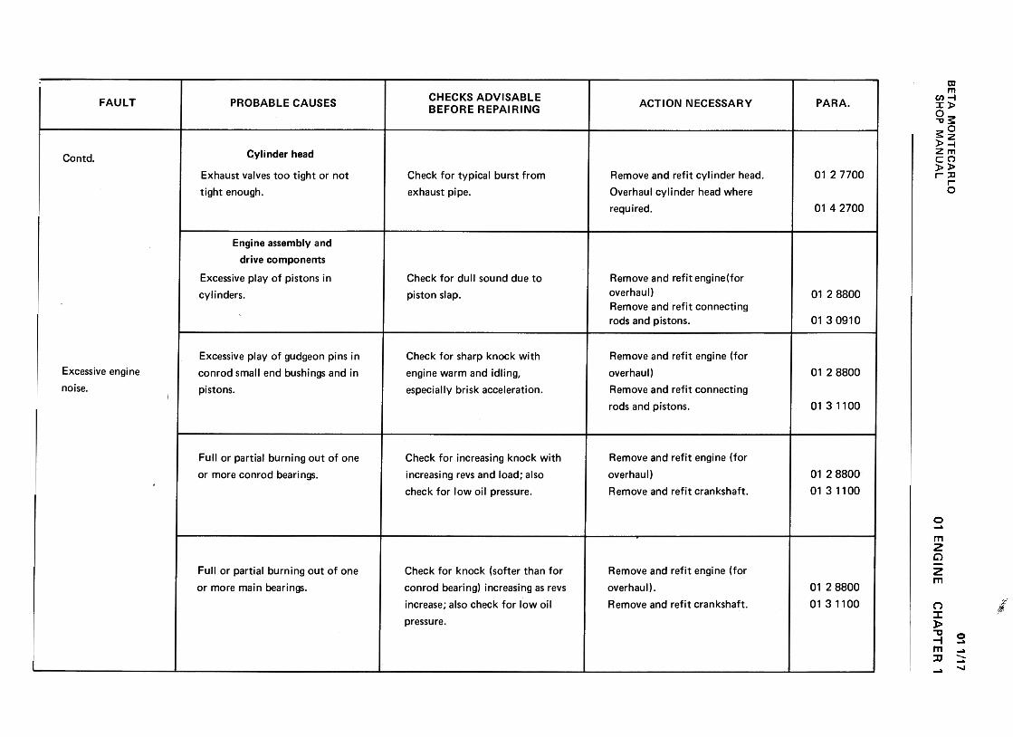
BE
TA
M
ON
TE
CA
RLO
w~
-JzaJ-~
a:C
I)--~>0.
ow~
a:C
l)W~
a:U
QW
u.~
wU
aJ1--J~~IL (I)w(I):J~uw-JC
D~C
DO1%
:0- >Il:<
t(I)(I)wuw22Ot-~ <
ta:<
tn.
-0...c:ou
"C(0 Q
)Q
) '-
.c Q
)'-
.cQ
) ~
-g "C
.-(0-Q
)
~.c
...'-.-Q
)-"C~
.:
"C
-c:
>(0
u
Q)S
-ci>
(OQ
)o
.r. .=
E
t ::I
Q)
>
C"
a: (")
?'
o01'-1'-
N...0Eo...'0-..."'...:J
.cm().c.
.>
C
1)...0.
c.o
...'0-
"'~
:J
() ca
C1)
.c.c
xo
"'
...OI:...O'C
...
IU
-aQ
) .-
.c +
"'
...0Q
) O
'C
+"'
I: "'
.-Q)
>
>
..c:C
J-C
!~
:J
+"'
0"'
I::J
Q)
IU
+"'
.c. .c.
X
C!
W
.~
o0I--.NV.-0
c:'C
.-
c: :I
"'la
c: c:
>
G)
0-c
....c
o .~
Ea.a.
G)E
-.-~
o
0la
u >
G)
G)
lac
.~
""Q.
CI-
Q)
"'
Cw
>..
W
.-Q)
~
'CQ
) C
CJ
:=X
>
W
U
O...<II
~"0"0c~0cn~"0 .
'- 0.
0 !J.
-.-cn~
c
u 0
<II
....c
.~u
0.
oo0000N...0
"- C
IO
.::
-UQ)
Q)
c: c:
.~
c:c:
oQ
) U
"'c:~
~
O
"0 "O
~c:
c: .-
IO-IO
C.
Q)-:;Q
)"O>
10>C
:0
..c: 0
10E
"-
E
"'Q
)Q)Q
)"Oa::~
a::e
0.-0)0MO
.=
.="'
"Cc:
.-c:c.
10c:
"'0
g'Q
) .-
CI.c
"C
"'~
~
CI.o
-.-"C0
c:>
Q
)10 -"'5.iOQ
) E
>
"'.u;
"C
.,j"'
o c:
Q)
...OtJ
c: ...
x o
.~w
tl
0-
.c c
+"'
0
s: .(U
C1
'-~
C
Q
)
9 �
~C
.-U
~
"tI (U
a. C
~
'- (U
"'
(U
.-.c
E
.0"'
'-
'- ~
>
0 >
=
-(UQ
) .-
~
c u
u .-Q
)Q
) C
1 a.
.c C
"'
(JQ)Q
)
Q)
c:"S
Ic:Q
)Q
).~"'"'
"Q
) Q
)t)
"~x
ow
c:
oo0000NO
...O C
I*-
C-;
.+:;
C
9.-CC
I C
C
O0>
U
+"'
~
.~
.0>
*-
"'...0>
C
"C
...OC
"C
~
(U
C
.-
0>-(U
c.>
:JO>
"CO
(U>
CE
.Co(U
0>
~
E
"'
a:>0>
"Ct1
a: .<
?
o0.-.-M.-0
Q)
c:o...0...:I .
0 &
C1
c:c:
..:.-C
Oc:
Q)
Q:I
.Q
"C-OC
O
....-c:t
oC
O
(.)a.
Q)
O
OE:I
...I.L
O
.c...
.§ 0"'
.:.! -.
(JIOQ
)'-
0 -~
C
'"' "'
.:.! 10
"'
C!.Q
eC
"0
a..U
; C
-
m
10 .0
'- "'
>(J
>
>c
Q)
0'-
'- C
! '-
0 c
0'f-
.-'f-"'
.:.! 10
.:.!(J
Q)
(JQ
)'-Q)
.c (J
.cU
,~
t,
o 0
0 0
00 .-
00 .-
N
M
0 O
'- .
0 ~co
-.cQ)
"'c
~.-cC
) co
c '-
Q)
(J
;0=
;0=Q
) Q
)'-
'-
"0 "0
c c
co ~
co
Q)
~
Q)
>
co >
° .c
°E
'-
EQ
)Q)Q
)a::
~
a::
01 E
NG
INEQ
)c:o'+-0...:J0
.C
) ~
c: c:
.c ..:
...ro:J
Q)
.c .c
-c:ro .-
.-ro~
E
0. Q
)
o o
-E:J ...
u. o "'
'- >
O
Q)
-'+
- '-
.-t:
"' O
1U1U
~.c
C3
O+
"' t:
-'-
.-'-Q
) ~
O
+"'
Q)
'+-
'+-0
'- ~
"' tJ
tJ-t:
Q)
~-.ctJ
C3
tJ0
t: 0
t: ..:
"'~
IU
-IU
'- Q
) .
O.C
Q)~
'+-
"C
"' =
'
~
0 IU
"'
tJ'-~"'
Q)t:tJ~
.CO
t:p,U
U
.-
o 0
0 0
00 .-
00 .-
NM
00
0 .::'
'+-
ca-.r:.Q
) "'
t: ~
.-t:CI
cat:
...Q
) U
;;: ;;:
Q)
Q)
"tj "tj
t: t:
ca ...:.
caQ
) "5
Q)
>
ca >
° .r:.
°E
...E
Q)Q
)Q)
oc 'r;
c::
,,~CH
AP
TE
R
1
011/17
SH
OP
M
AN
UA
L
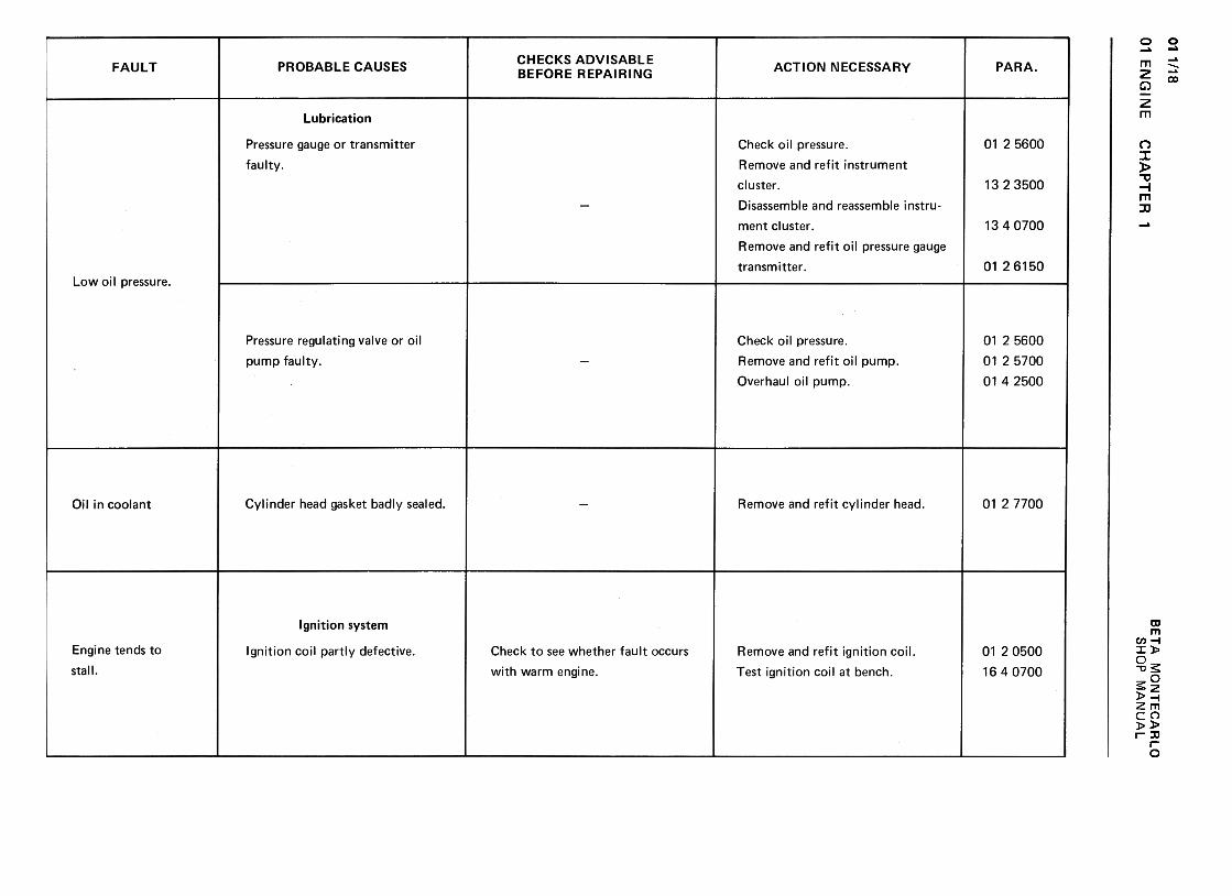
01 1/18
w~
-J2m
-~
a:1/)--~>Q
.O
w~
a:I/)W~
a:C
JOW
u.~
wom1-..J:)«u.
(/)w(/)~<
tC
Jw.Jm<
tmO~d- >a:«(I)(I)wuw22Of-u« «a:«"-
~O';;ca1.1'.:..0~~
o0toLONO C
HA
PT
E
R
1
'-QJ
.E"'cco'-'-0QJ
CI
:JCO
CI
QJ
'- .
:J >
"' "' -
QJ
:J'-
CO
0.- ~
o0InMNM
o0r--0q-M
.Q)
:J C
I'-
:J..."'"'
CI
c: Q
)
...'-c:
Q)
:JQ
) ::c
"'
E
E
~:J
Q)
'-;:,
"' a.
"' "'
c: "'
.-..-Q
) 0
~
...'- ...
:J :-=
"C
:-=
"'Q)
c: Q
)"'
'- -'-
Q)
'v.'-"C
Q
) '-"C
.
a.c: -Q
)c:,-"'
.0 t;
"' 2:,
.-E
:JO
Q
) -Q
) .~
" >
...:
Q)
(.) >
E-O
Q)"'
O(.)
E..."'
...E
"' Q
) """c:
c:
.c Q
) :J
.!!! Q
) Q
) "'
ua:oCE
a:~
0I!).-(0("\1
;;
0)'-~"'"'QJ
'-0.
'0~O.-J
.0"-0QJ
.?:ro>C!
c:.~~:J
.C
! >
QJ
..."-
-:JQ
J ro
"- -.-
a 0.
~
E"-
:J~
0,
o 0
00
0 0
(0 r-..
L!)L!)
L!) N
N
N
.".
n n
n
c.E~c.
..0 ci
QJ
~
~
E
"' Q
J ~
"' ...c.
QJ
c...."0 =
c:: o
"'
.0 Q
J ~
~
>
"'u
o .c::
QJ
E
~.c::
QJ
>()
a: n
...c<0
Oouc5 "0QJ
cuQJ
"'>=0cu
.0+"'
QJ
~"'~"0cuQJ
.c'0:,"0t:
>() 1:1(0Q)
.c...Q)
1:1c:
>()+-'
'+=Q)
...
1:1c:(0Q)
~EQ)
rr:
oo"'"'N...C>
BE
TA
M
ON
TE
CA
RLO
O+"'
"'"0c0)+
"'
0)c.01 =
c (0
w
~
~:Juuo:::::Jco-a;.c+-'
.Q
) Q
).c
c:~
.0.
Q)
c:Q
) Q
)"'
Eo
...+
-' co
.:,t; ~
~
.c.c
.~u
~
Q}
.~+"'
E
~Q
) -
+"'
Q}
"' "C
~
>~
-;=
-0
'-.-ca+
"' c.
.2 =
=C
I O
-(.)CO:~CC
I
.0CJ
.c:
.s=o
~.;:;
Q)
.-.cc:C1
.-CO
'-=
.0~
C
J"C
c:
c: .Q
co Q
) .c
>
C1
O
.-
E
t;Q
) Q
)a:
1-
o o
o 0
I!) I--.
0 O
('II ~
.-co0
.-
01 EN
GIN
ES
HO
P
MA
NU
AL
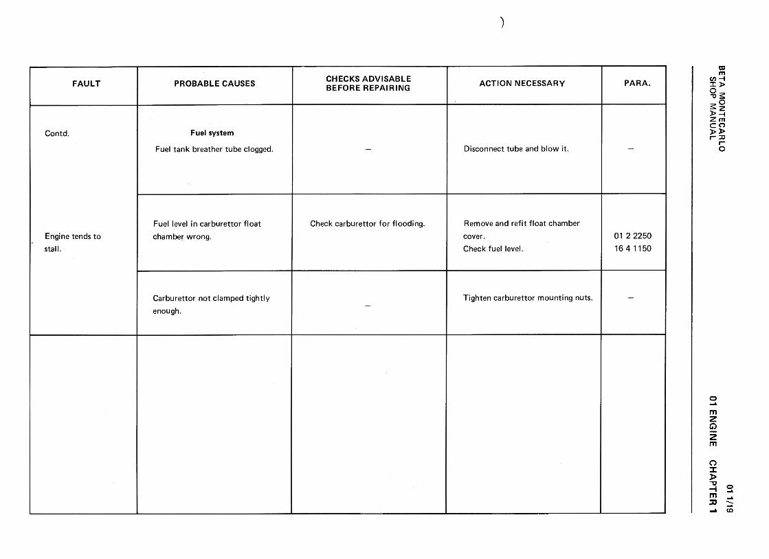
BE
TA
M
ON
TE
CA
RLO
w~
-JzaJ-<
a:C
I)--<>
Q.
ow<a:
Cl)W
~a:
uoW
I1.~
wL)~1-..J~~IL <
I)U
J<
I)::)<(,)U
J..Jm<mO~0--
>-
0:<t
(/)(/)wuw22O1-U<
t
<t
~<t
0-
-0...cou
-cCl>
CI
CI
OUCl>
.QE
:J
GI
+"'
...Cl>
>
.c
-"'GI
Cl>
~
...u.
.Q~c"'+
"'
"Q;
:JlL +
-'
:5:o::0"0c:(0Q
).0:I+
-'+
-'tJQ
)c:c:0tJ"'
0
c,c:
'6o0;;:'-0-'-0......e:J.0~(.)~(.)Q
).c:()...coO-.:1-0......Q
)1-~.c
.1-
C1
CO
t:
tJ 0
t: 1-
.-~-a;
1-,>
Q
)Q
) .c
=
EQ
) C
O~
.r.
u. tJ
o 0
I!) I!)
N
.-N
.-
N
'=I"
.-(00
.-
0..,"'"Ct:0)..,0)t:.a
=t:
caw
~
I..Q)
..cEco.cC
J+
"'coO:+:
+"'
~
""Qj
Q)
>
...Q)
"C
=c:
Q)
co :J
Q)
'+-
>
.~0
...CJ
EQ
)Q)
Q)
~
.ca:
u O
>~.J::C
).;:."CQ
)0.Ero
uoc:'-0Q)
.'-
.J:::J
C)
.c :J
'- 0
ro c:
u Q
)
"'+
"'~c:0)c:
0;:.c:~oEO+"'
+"'
~~-e"'tJc:0)+
"'..c:0)
i=
01 E
NG
INE
011/19
SH
OP
M
AN
UA
LC
HA
PT
ER
'
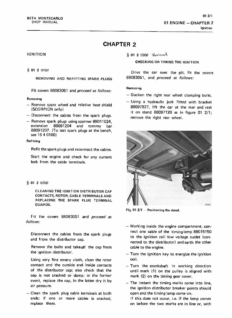
012/1BETA MONTECARLO
SHOP MANUAL 01 ENGINE -CHAPTER 2
Ignition
CHAPTER 2
IGNITION §- 01 2 0300 ,,~'<"'c,.~-\
CHECKING OR TIMING THE IGNITION
§ 0120100
Drive the car over the pit, fit the covers
88083051, and proceed as follows:REMOVING AND REFITTING SPARK PLUGS
Fit covers 88083051 and proceed as follows:Removing
-Slacken the right rear wheel clamping bolts.
-Using a hydraulic jack fitted with bracket
88097827, lift the car at the rear and rest
it on stand 88097120 as in figure 01 2/1;
remove the right rear wheel.
Removing
-Remove spare wheel and relative heat shield
(SCORPION only)
-Disconnect the cables from the spark plugs.
-Remove spark plugs using spanner 88011024,
extension 88091204 and tommy bar
88091207. (To test spark plugs at the bench,
see 1640100)
Refitting
Refit the spark plugs and reconnect the cables.
Start the engine and check for any current
leak from the cable terminals.
§ 0120200
CLEANING THE IGNITION DISTRIBUTOR CAP
CONTACTS, ROTOR,CABLE TERMINALS ANDREPLACING THE SPARK PLUG TERMINAL
GUARDS.
Fig. 01 211 -Positioning the stand.
Fit the covers 88083051 and proceed as
follows:
Disconnect the cables from the spark plugs
and from the distributor cap.
Remove the bolts and takeoff the cap from
the ignition distributor.
Using very fine emery cloth, clean the rotor
contact and the outside and inside contacts
of the distributor cap; also check that the
cap is not cracked or damp: in the former
event, replace the cap, in the latter dry it by
air pressure.
-Working inside the engine compartment, con-
nect one cable of the timing lamp 88015150
to the ignition coil low voltage outlet (con-
nected to the distributor) and earth the other
cable to the engine.
-Turn the ignition key to energize the ignition
coil.
-Turn the crankshaft in working direction
until mark (1) on the pulley is aligned with
mark (2) on the timing gear cover .
-The instant the timing marks come into line,
the ignition distributor breaker points should
open and the timing lamp come on.
If this does not occur, i.e. if the lamp comes
on before the two marks are in line or, with
-Clean the spark plug cable terminals at both
ends; if one or more cables is cracked,
replace them.
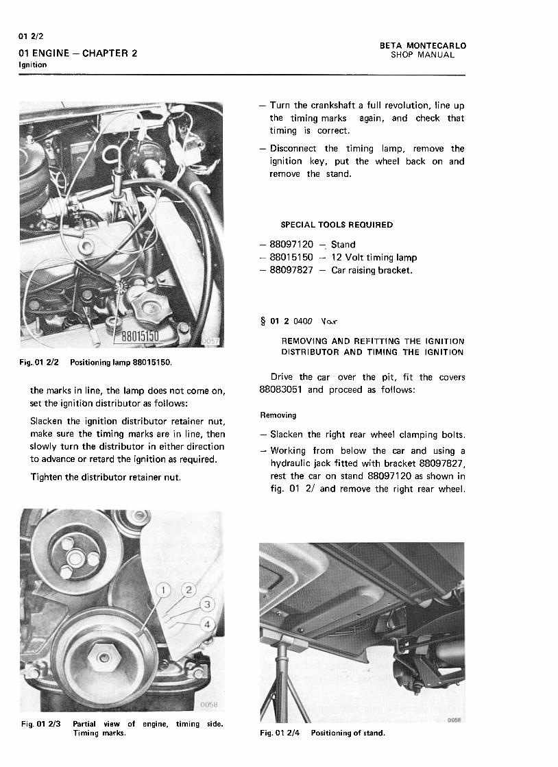
012/2BETA MONTECARLO
SHOP MANUAL01 ENGINE -CHAPTER 2
Ignition
-Turn the crankshaft a full revolution, line up
the timing marks again, and check that
timing is correct.
-Disconnect the timing lamp, remove the
ignition key, put the wheel back on and
remove the stand.
SPECIAL TOOLS REQUIRED
-88097120 -, Stand
-88015150 -12 Volt timing lamp
-88097827 -Car raising bracket.
§ 0120400 \( 0.,1"
REMOVING AND REFITTING THE IGNITION
DISTRIBUTOR AND Tlr."ING THE IGNITION
Fig..O1 2/2 Positioning lamp 88015150.
Drive the car over the pit, fit the covers
88083051 and proceed as follows:the marks in line, the lamp does not come on,
set the ignition distributor as follows:
RemovingSlacken the ignition distributor retainer nut,
make sure the timing marks are in line, then
slowly turn the distributor in either direction
to advance or retard the ignition as required.
-Slacken the right rear wheel clamping bolts.
-Working from below the car and using a
hydraulic jack fitted with bracket 88097827,
rest the car on stand 88097120 as shown in
fig. 01 2/ and remove the right rear wheel.Tighten the distributor retainer nut.
Fig. 01 2/3 Partial view of engine, timing side.Timing marks. Fig. 01 2/4 Positioning of stand.
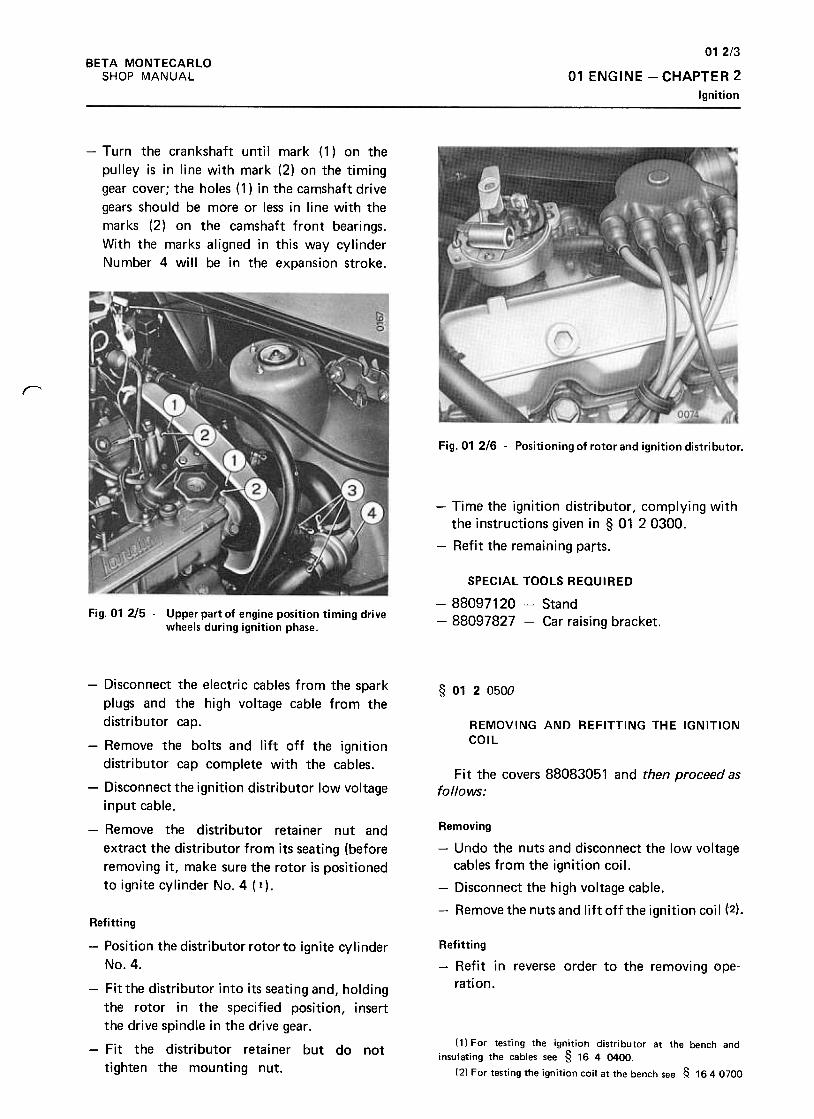
012/3
01 ENGINE -CHAPTER 2
Ignition
BETA MONTECARLO
SHOP MANUAL
-Turn the crankshaft until mark (1) on the
pulley is in line with mark (2) on the timing
gear cover; the holes (1) in the camshaft drive
gears should be more or less in line with the
marks (2) on the camshaft front bearings.
With the marks aligned in this way cylinder
Number 4 will be in the expansion stroke.
r
Fig. 01 216 -Positioning of rotor and ignition distributor.
-Time the ignition distributor, complying with
the instructions given in § 01 2 0300.
-Refit the remaining parts.
Fig. 01 2/5 -Upper part of engine position timing drive
wheels during ignition phase.
SPECIAL TOOLS REQUIRED
-88097120- Stand
-88097827 -Car raising bracket.
§ 0120500
REMOVING ANn REFITTING THE IGNITIONCOil
Fit the covers 88083051 and then proceed asfollows:
-Disconnect the electric cables from the spark
plugs and the high voltage cable from the
distributor cap.
-Remove the bolts and lift off the ignition
distributor cap complete with the cables.
-Disconnect the ignition distributor low voltage
input cable.
-Remove the distributor retainer nut and
extract the distributor from its seating (before
removing it, make sure the rotor is positioned
to ignite cylinder No.4( 1).
Removing
-Undo the nuts and disconnect the low voltage
cables from the ignition coil.
-Disconnect the high voltage cable.
-Remove the nuts and lift off the ignition coil (2).
Refitting
-Refit in reverse order to the removing ope-
rati on .
Refitting
-Position the distributor rotor to ignite cylinder
No.4.
-Fit the distributor into its seating and, holding
the rotor in the specified position, insert
the drive spindle in the drive gear .
-Fit the distributor retainer but do not
tighten the mounting nut.
(1) For testing the ignition distributor at the bench and
insulating the cables see § 16 4 0400.
(2) For testing the ignition coil at the bench see ~ 1640700
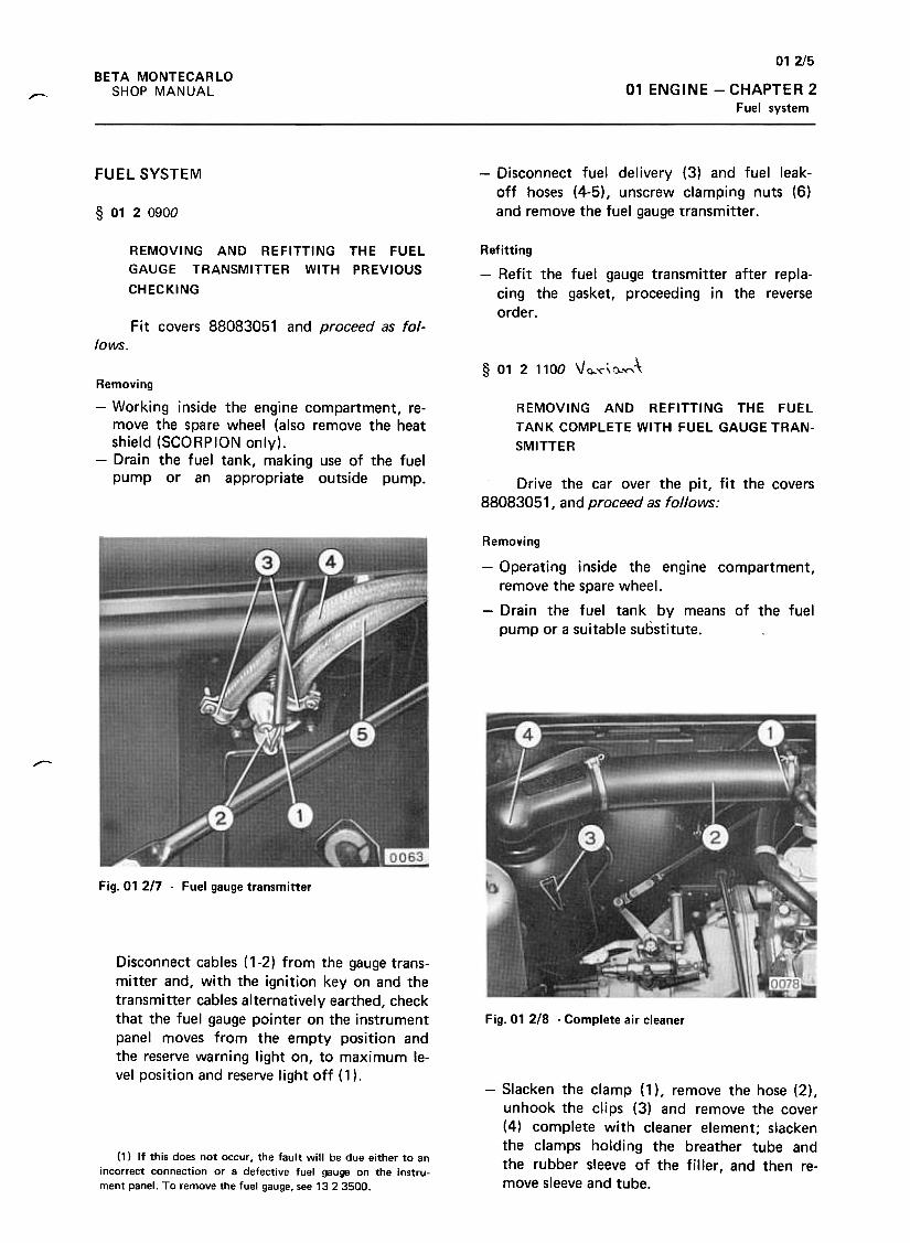
012/5
BETA MONTECARLO
SHOP MANUAL 01 ENGINE -CHAPTER 2
Fuel system--
-Disconnect fuel delivery (3) and fuel leak-
off hoses (4-5), unscrew clamping nuts (6)
and remove the fuel gauge transmitter .
FUEL SYSTEM
§ 012 ogoo
REMOVING AND REFITTING THE FUEL
GAUGE TRANSMITTER WITH PREVIOUS
CHECKING
Refitting
-Refit the fuel gauge transmitter after repla-
cing the gasket, proceeding in the reverse
order .Fit covers 88083051 and proceed as fo/-
lows.
§ 01 2 1100 Vc.'("\().."("\\
REMOVING AND REFITTING THE FUEL
TANK COMPLETE WITH FUEL GAUGE TRAN-
SMITTER
Removing
-Working inside the engine compartment, re-
move the spare wheel (also remove the heat
shield (SCORPION only).
-Drain the fuel tank, making use of the fuel
pump or an appropriate outside pump. Drive the car over the pit, fit the covers88083051, and proceed as follows:
Removing
-Operating inside the engine compartment,
remove the spare wheel.
-Drain the fuel tank by means of the fuel
pump or a suitable substitute.
-
Fig. 01 217 -Fuel gauge transmitter
Disconnect cables ( 1-2) from the gauge trans-mitter and, with the ignition key on and the
transmitter cables alternatively earthed, checkthat the fuel gauge pointer on the instrumentpanel moves from the empty position andthe reserve warning light on, to maximum le-vel position and reserve light off (1 ).
Fig. 01 218 -Complete air cleaner
-Slacken the clamp (1 ), remove the hose (2),unhook the clips (3) and remove the cover(4) complete with cleaner element; slackenthe clamps holding the breather tube andthe rubber sleeve of the filler, and then re-move sleeve and tube.
(1) If this does not occur. the fault will be due either to anincorrect connection or a defective fuel gauge on the instru-ment panel. To remove the fuel gauge, see 1323500.
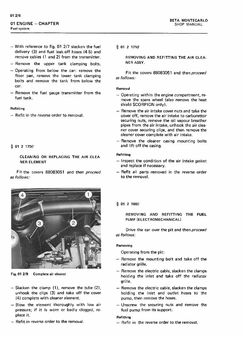
012/6BETA MONTECARLO
SHOP MANUAL01 ENGINE -CHAPTERFuel system
§ 0121710
REMOVING AND REFITTING THE AIR CLEA-
NERASSY.
Fit the covers 88083051 and then proceedas follows:
-With reference to fig. 01 2/7 slacken the fueldelivery (3) and fuel leak-off hoses (4-5) andremove cables ( 1 and 2) from the transmitter .
-Remove the upper tank clamping bolts.
-Operating from below the car: remove thefloor pan, remove the lower tank clampingbolts and remove the tank from below thecar.
-Remove the fuel gauge transmitter from thefuel tank.
Refitting
-Refit in the reverse order to removal.
Removal
-Operating within the engine compartment, re-move the spare wheel (also remove the heatshield SCORPION only).
-Remove the air intake cover nuts and take thecover off, remove the air intake to carburet torsecuring nuts, remove the oil vapour breatherpipes from the air intake, unhook the air clea-ner cover securing clips, and then remove thecleaner cover complete with air intake.
-Remove the cleaner casing mounting boltsand lift off the casing.§ 0121700
CLEANING OR REPLACING THE AIR CLEA.
NER ELEMENT
Fit the covers 88083051 and then proceed
as follows:
Refitting
-Inspect the condition of the air intake gasketand replace if necessary.
-Refit all parts removed in the reverse orderto the removal.
§ 0121800
REMOVING AND REFITTING THE FUEL
PUMP (ELECTROMECHANICAL)
Drive the car over the pit and then proceedas follows:
Fig. 01 2/9 Complete air cleaner
Removing
Operating from the pit:
-Remove the mounting bolt and take off theradiator grille.
-Remove the electric cable, slacken the clampsholding the inlet and take off the radiator
grille.
-Remove the electric cable, slacken the clampsholding the inlet and outlet hoses to thepump, then remove the hoses.
-Unscrew the securing nuts and remove thefuel pump from its support.
-Slacken the clamp (1 ), remove the tube (2),unhook the clips (3) and take off the cover(4) complete with cleaner element.
-Blow the element thoroughly with low airpressure; if it is worn or badly clogged, re-
place it.
-Refit in reverse order to the removal.Refitting
-Refit in the reverse order to the removal.
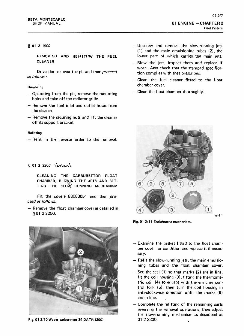
01 2/7
01 ENGINE -CHAPTER 2
Fuel system
BETA MONTECARLO
SHOP MANUAL
§ 0121900
REMOVING AND REFITTING THE FUEL
CLEANER
Drive the car over the pit and then proceedas follows:
-Unscrew and remove the slow-running jets(1) and the main emulsioning tubes (2), thelower part of which carries the main jets.
-Blow the jets, inspect them and replace ifworn. Also check that the stamped specifica-tion complies with that prescribed.
-Clean the fuel cleaner fitted to the floatchamber cover .
-Clean the float chamber thoroughly.Removing
-Operating from the pit, remove the mountingbolts and take off the radiator grille.
-Remove the fuel inlet and outlet hoses fromthe cleaner
-Remove the securing nuts and lift the cleaneroff its support bracket.
Refitting
-Refit in the reverse order to the removal.
§ 0122200 " ~~\ \3.,,"", \
CLEANING THE CARBURETTOR FLOAT
CHAMBER, BLO~NG THE JETS AND SET-
TING THE SLOW" RUNNING MECHANISM
Fit the covers' 88083051 and then pro-ceed as follows:
-Remove the float chamber cover as detailed irr§ 01 2 2250.
0161
Fig.01 2111 Enrichment mechanism.
-Examine the gasket fitted to the float cham-ber cover for condition and replace it if neces-
sary.
-Refit the slow-running jets, the main emulsio-ning tubes and the float chamber cover.
-Set the seal (1) so that marks (2) are in line,fit the coil housing (3) , fitting the thermome-tric coil (4) to engage with the enricher con-trol fork (5), then turn the coil housing inanti-clockwise direction until the marks (6)are in line.
-Complete the refitting of the remaining partsreversing the removal operations, then adjustthe slow-running mechanism as described at0122300. .Fig.01 2110 Weber carburet tor 34 DATA (200)
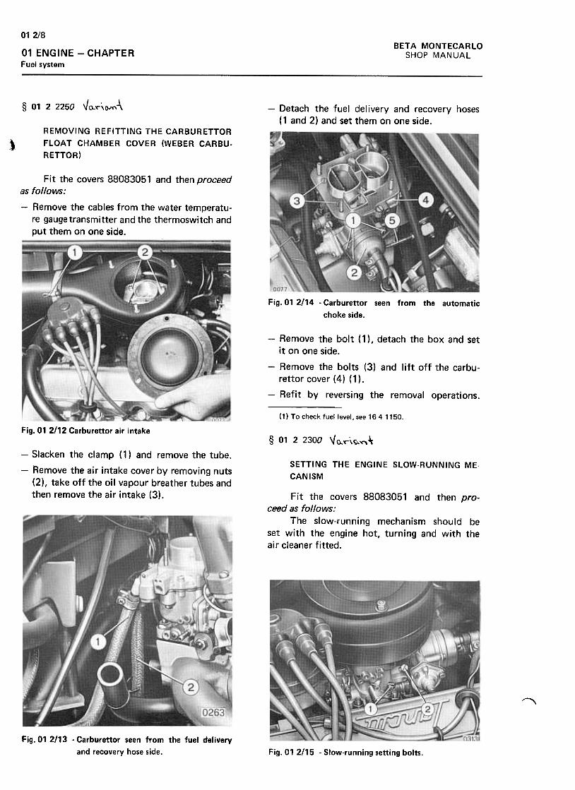
BETA MONTECARLO
SHOP MANUAL
012/8
01 ENGINE -CHAPTER
Fuel system
§ 01 2 2250 Va.~\C-""\-\ -Detach the fuel delivery and recovery hoses
( 1 and 2) and set them on one side.REMOVING REFITTING THE CARBURETTOR
FLOAT CHAMBER COVER (WEBER CARBU-
RETTOR))
Fit the covers 88083051 and then proceedas follows:
-Remove the cables from the water temperatu-re gauge transmitter and the thermoswitch and
put them on one side.
Fig. 01 2114 -Carburettor seen from the automatic
choke side.
-Remove the bolt ( 1) , detach the box and set
it on one side.
-Remove the bolts (3) and lift off the carbu-
rettor cover (4) (1 ).
-Refit by reversing the removal operations.
(1) To check fuel level, see 1641150.
Fig.01 2112 Carburettor air intake§ 01 2 2300 "o.r\~~:Ir
-Slacken the clamp (1) and remove the tube.
-Remove the air intake cover by removing nuts
(2), take off the oil vapour breather tubes and
then remove the air intake (3).
SETTING THE ENGINE SLOW-RUNNING ME.
CANISM
Fit the covers 88083051 and then pro-Geed as follows:
The slow-running mechanism should beset with the engine hot, turning and with theair cleaner fitted.
"'"""'\
Fig. 01 2113 .Carburettor seen from the fuel delivery
and recovery hose side. Fig. 01 2/15 -Slow-running setting bolts.

012/9BETA MONTECARLO
SHOP MANUAL 01 ENGINE CHAPTER 2
Fuel system
-First adjust the primary choke throttle by
means of the bolt (2) until the engine is run-
ning $teadily. Then adjust the bolt (1) untila mixture is found such that the engine turns
quicker and more stably for that throttle set-
ting; finally adjust the bolt (2) again until theengine is turning at the smoothest slow-run-
ning setting.
§ 01 2 3200 \JG. ""'\
REMOVING AND REFITTING THE CARBU
RETTOR WITH ENGINE SlOW.RUNNING SET
TING
Fit the covers 88083051 and then proceedas follows:
J>c~61
Fig. 01 2117 -Enrichment mechanism
Removing
-Set the seal (1) so that marks (2) are in line,fit the coil housing (3), fitting the thermome-tric coil (4) to engage with the enricher con-trol fork (5), then turn the coil housing in
anti-clockwise direction until the marks (6)are in line.
-Complete the refitting of the remaining partsreversing the removal operations.
-When refitting has been completed, set the
slow-running mechanism as described at0122300.
~
Fig. 01 2116 -Carburet tor seen from automatic choke
side.(1) For overhauling the carburet tor see 01 4 1000
§ 0123710
REMOVING AND REFITTING THE CHOKE
Fit the covers 88083051 and then proceedas follows:
-Remove the float chamber cover as detailed,,"
in § 01 2 2250. ;, ,"t"
-Remove the rod (5) from the throttle control
lever and the slow-running cut-off cable.
-Remove the mounting nuts (1) and take out
the carburet tor.
Removing
-Remove the air intake, the fuel delivery and
recovery hoses and the water pipes from theautomatic choke.
-Remove the carburet tor cover completewith choke after removing the securingbolts.
Refitting
-Refit the carburet tor on the induction mani-
fold.t "
i,',
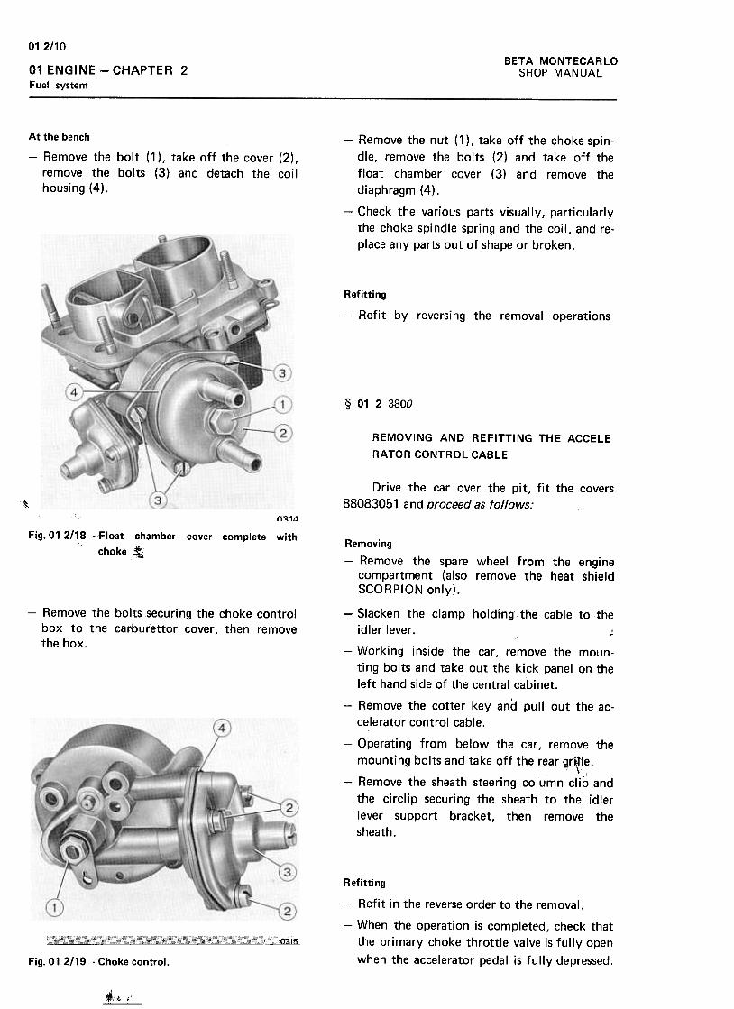
01 2/10
BETA MONTECARLO
SHOP MANUAL01 ENGINE -CHAPTER 2
Fuel system
At the bench
-Remove the bolt (1 ), take off the cover (2),remove the bolts (3) and detach the coil
housing (4).
-Remove the nut (1 ), take off the choke spin-
dle, remove the bolts (2) and take off the
float chamber cover (3) and remove the
diaphragm (4).
-Check the various parts visually, particularly
the choke spindle spring and the coil, and re-
place any parts out of shape or broken.
Refitting
-Refit by reversing the removal operations
§ 0123800
REMOVING AND REFITTING THE ACCELE
RATORCONTROLCABLE
Drive the car over the pit, fit the covers
88083051 and proceed as follows:,,~~
{)~1~
Fig. 01 2118 -F1oat chamber cover complete with
choke :t;Removing
-Remove the spare wheel from the engine
compartment {also remove the heat shieldSCORPION only).
-Remove the bolts securing the choke control
box to the carburet tor cover, then remove
the box.
-Slacken the clamp holding the cable to the
idler lever. ;;
-Working inside the car, remove the moun-
ting bolts and take out the kick panel on the
left hand side of the central cabinet.
-Remove the cotter key and pullout the ac-
celerator control cable.
-Operating from below the car, remove the
mounting bolts and take off the rear ~f~te.,
-Remove the sheath steering column clip and
the circlip securing the sheath to the idler
lever support bracket, then remove the
sheath.
Refitting
-Refit in the reverse order to the removal.
-When the operation is completed, check that
the primary choke throttle valve is fully open
when the accelerator pedal is fully depressed.
~
Fig. 01 2119 -Choke control.
.J i'ifi:"' .
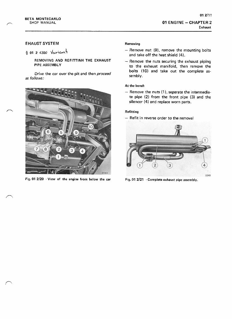
012/11BETA MONTECARLO
SHOP MANUAL 01 ENGINE -CHAPTER 2Exhaust
r--
EHAUSTSYSTEM
§ 01 2 4300 "'0..y-\Q.N"\ -\
REMOVING AND REFITTINH THE EXHAUST
PIPE ASSEMBL y
Removing
-Remove nut (9) , remove the mounting boltsand take off the heat shield (4).
-Remove the nuts securing the exhaust pipingto the exhaust manifold, then remove thebolts (10) and take out the complete as-
sembly.Drive the car over the pit and then proceed
as follows:
At the bench
-Remove the nuts (1 ), separate the intermedia-te pipe (2) from the front pipe (3) and thesilencer (4) and replace worn parts.
"Refitting
-Refit in reverse order to the removal
Fig. 01 2120 -View of the engine from below the car Fig. 01 2121 -Complete exhaust pipe assembly.
~
(\
~
f"
~

012/13
01 ENGINE -CHAPTER 2
Cooling system
BETA MONTECARLO
SHOP MANUAL
COOLING SYSTEM
§ 0124650
DRAINING REFILLING DEAERATING THE
COOLING SYSTEM
-Working inside the engine compartment, fill
the radiator with coolant and start the engine.
-Working in the boot, loosen the drain screw
( 1) ; as soon as coolant starts to drip out,
tighten the drain screw definitively.
-When the operation is completed, top up the
coolant level.Drive the car over the pit, fit the covers
88083051 and proceed as follows:
§ 0124700
REMOVING AND REFITTING THE COOLANT
RADIATOR"Drive the car over the pit, fit the covers
88083051, drain off the coolant as described at01 2 4650, and proceed as follows:
Removing
-Operating from the pit, remove mountingbolts and nuts and take off the shroud bet-ween tunnel and air inlet.
Fig.01 2122 -Coolant circuit drain plugs
-Working from under the car, remove the
plugs (6) and drain the coolant into a contai-
ner before replacing the plugs.~
Fig. 01 2/24 -Radiator seen 'from below the car .
-Remove the cables (1 and 2) from the fancontrol switch.
-Remove the fan motor leads from the con-nection (3) .
-Loosen the clamps and remove the couplings(4 and 5) from the radiator .
-Remove the bolts (6) and take out the radia-tor complete with fan.Fig. 01 2123 -Coolant drain screw on radiator
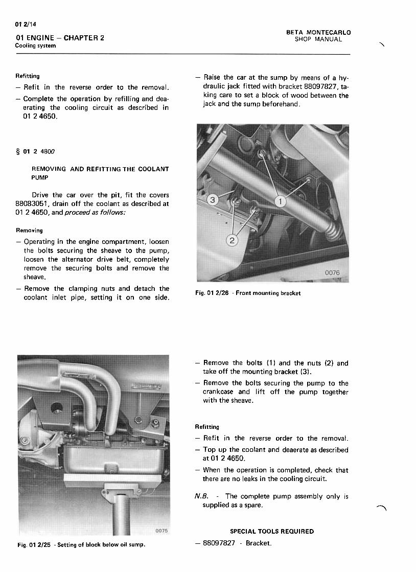
012/14BETA MONTECARLO
SHOP MANUAL01 ENGINE -CHAPTER 2
Cooling system "\
-Raise the car at the sump by means of a hy-
draulic jack fitted with bracket 88097827, ta-king care to set a block of wood between thejack and the sump beforehand.
Refitting
-Refit in the reverse order to the removal.
-Complete the operation by refilling and dea-erating the cooling circuit as described in
0124650.
§ 0124800
REMOVING AND REFITTING THE COOLANT
PUMP
Drive the car over the pit, fit the covers88083051, drain off the coolant as described at01 24650, and proceed as follows:
Removing
-Operating in the engine compartment, loosenthe bolts securing the sheave to the pump,loosen the alternator drive belt, completelyremove the securing bolts and remove the
sheave.
-Remove the clamping nuts and detach thecoolant inlet pipe, setting it on one side.
Fig. 01 2/26 -Front mounting bracket
-Remove the bolts (1) and the nuts (2) andtake off the mounting bracket (3).
-Remove the bolts securing the pump to thecrankcase and lift off the pump togetherwith the sheave.
Refitting
-Refit in the reverse order to the removal.
-Top up the coolant and deaerate as describedat 01 24650.
-When the operation is completed, check that
there are no leaks in the cooling circuit.
N.B. -The complete pump assembly only is
supplied as a spare.~
SPECIAL TOOLS REQUIRED
-88097827 -Bracket.Fig. 01 2125 -Setting of block below oil sump.
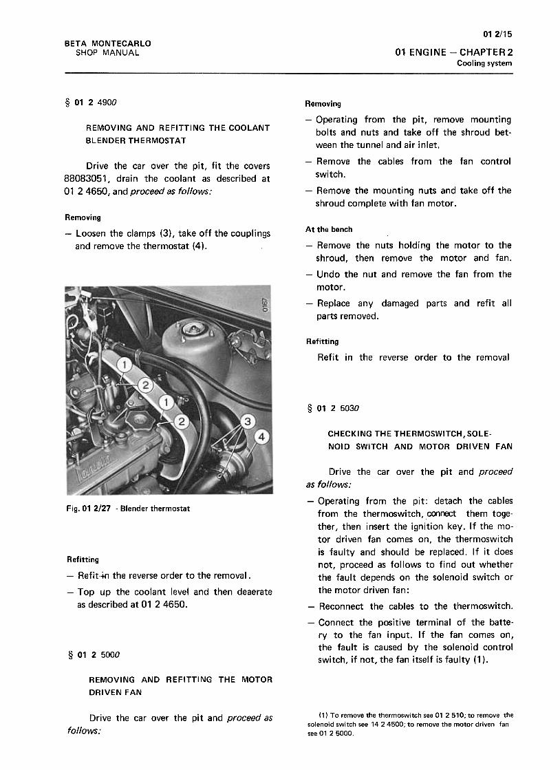
01 2/15
BETA MONTECARLO
SHOP MANUAL 01 ENGINE -CHAPTER 2
Cooling system
§ 0124900
REMOVING AND REFITTING THE COOLANT
BLENDER THERMOSTAT
Drive the car over the pit, fit the covers
88083051, drain the coolant as described at
01 2 4650, and proceed as follows:
Removing
-Operating from the pit, remove mounting
bolts and nuts and take off the shroud bet-
ween the tunnel and air inlet.
-Remove the cables from the fan control
switch.
-Remove the mounting nuts and take off the
shroud complete with fan motor .
Removing
-Loosen the clamps (3) , take off the couplings
and remove the thermostat (4).
At the bench
-Remove the nuts holding the motor to the
shroud, then remove the motor and fan.
-Undo the nut and remove the fan from the
motor .
-Replace any damaged parts and refit all
parts removed.
Refitting
Refit in the reverse order to the removal
§ 0125030
CHECKING THE THERMOSWITCH, SOlE-
NoID SWITCH AND MOTOR DRIVEN FAN
Fig. 01 2127 -Blender thermostat
Refitting
-Refit.~ the reverse order to the removal.
-Top up the coolant level and then deaerate
as described at 01 24650.
Drive the car over the pit and proceed
as follows:
-Operating from the pit: detach the cables
from the thermoswitch, connect them toge-
ther, then insert the ignition key. If the mo-
tor driven fan comes on, the thermoswitch
is faulty and should be replaced. If it does
not, proceed as follows to find out whether
the fault depends on the solenoid switch or
the motor driven fan :
-Reconnect the cables to the thermoswitch.
-Connect the positive terminal of the batte-
ry to the fan input. If the fan comes on,
the fault is caused by the solenoid control
switch, if not, the fan itself is faulty (1 ).§ 01 25000
REMOVING AND REFITTING THE MOTOR
DRIVEN FAN
(1) To remove the thermoswitch see 01 2510; to remove thesolenoid switch see 14 24500; to remove the motor driven fansee 01 2 5000.
Drive the car over the pit and proceed as
follows:
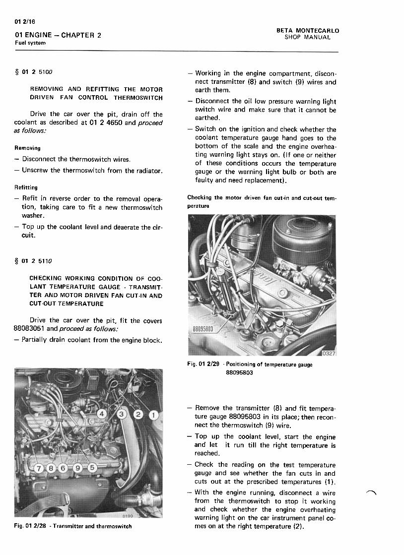
012/16
BETA MONTECARLO
SHOP MANUAL01 ENGINE -CHAPTER 2Fuel system
§ 0125100
REMOVING AND REFITTING THE MOTOR
DRIVEN FAN CONTROL THERMOSWITCH
Drive the car over the pit, drain off thecoolant as described at 01 2 4650 and proceedas follows:
-Working in the engine compartment, discon-nect transmitter (8) and switch (9) wires andearth them.
-Disconnect the oil low pressure warning lightswitch wire and make sure that it cannot beearthed.
-Switch on the ignition and check whether the
coolant temperature gauge hand goes to thebottom of the scale and the engine overhea-
ting warning light stays on. ( If one or neitherof these conditions occurs the temperature
gauge or the warning light bulb or both arefaulty and need replacement) .
Removing
-Disconnect the thermoswitch wires.
-Unscrew the thermoswitch from the radiator .
Checking the motor driven fan cut-in and cut-out tem-
perature
Refitting
-Refit in reverse order to the removal opera-
tion, taking care to fit a new thermoswitch
washer .
-Top up the coolant level and deaerate the cir-
cuit.
§ 0125110
CHECKING WORKING CONDITION OF COO-
lANT TEMPERATURE GAUGE -TRANSMIT "
TER AND MOTOR DRIVEN FAN CUT -IN AND
CUT -OUT TEMPERATURE
Drive the car over the pit, fit the covers88083051 and proceed as follows:
-Partially drain coolant from the engine block.
Fig. 01 2/29 -Positioning of temperature gauge
88095803
-Remove the transmitter (8) and fit tempera-ture gauge 88095803 in its place; then recon-nect the thermoswitch (9) wire.
-Top up the coolant level, start the engineand let it run till the right temperature is
reached.
-Check the reading on the test temperature
gauge and see whether the fan cuts in andcuts out at the prescribed temperatures ( 1) .
-With the engine running, disconnect a wirefrom the thermoswitch to stop it workingand check whether the engine overheating
warning light on the car instrument panel co-mes on at the right temperature (2).
~
Fig. 01 2128 -Transmitter and thermoswitch
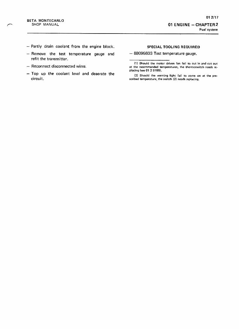
01 2/17
01 ENGINE -CHAPTER2Fuel system
BETA MONTECARLO
SHOP MANUAL~
SPECIAL TOOLING REQUIRED
-88095803 Test temperature gauge.
-Partly drain coolant from the engine block.
-Remove the test temperature gauge and
refit the transmitter .
-Reconnect disconnected wires.
-Top up the coolant level and deaerate the
circuit.
(1) Should the motor driven fan fail to cut in and cut outat the recommended temperatures, the thermoswitch needs re-placing (see 01 25100).
(2) Should the warning light fail to come on at the pre-scribed temperature, the switch (2) needs replacing.
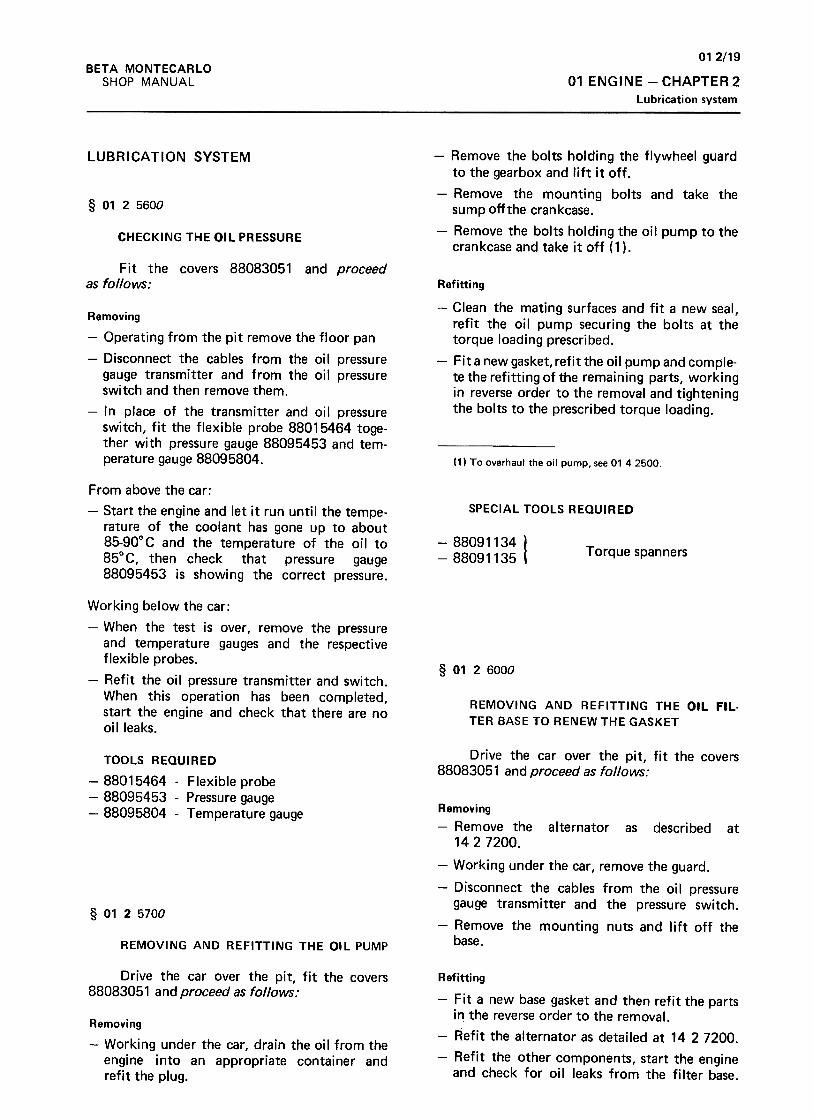
012/19
01 ENGINE -CHAPTER 2
Lubrication system
BETA MONTECARLO
SHOP MANUAL
LUBRICATION SYSTEM
§ 0125600
-Remove the bolts holding the flywheel guard
to the gearbox and lift it off .
-Remove the mounting bolts and take thesump off the crankcase.
-Remove the bolts holding the oil pump to the
crankcase and take it off (1).CHECKING THE OIL PRESSURE
Fit the covers 88083051 and proceedas follows: Refitting
-Clean the mating surfaces and fit a new seal,refit the oil pump securing the bolts at the
torque loading prescribed.
-Fit a new gasket, refit the oil pump and comple-te the refitting of the remaining parts, workingin reverse order to the removal and tighteningthe bolts to the prescribed torque loading.
Removing
-Operating from the pit remove the floor pan
-Disconnect the cables from the oil pressuregauge transmitter and from the oil pressureswitch and then remove them.
-In place of the transmitter and oil pressureswitch, fit the flexible probe 88015464 toge-ther with pressure gauge 88095453 and tem-perature gauge 88095804. (1) To overhaul the oil pump, see 01 42500.
SPECIAL TOOLS REQUIRED
From above the car:
-Start the engine and let it run until the tempe-rature of the coolant has gone up to about85-90°C and the temperature of the oil to85°C, then check that pressure gauge88095453 is showing the correct pressure.
-88091134-88091135 Torque spanners
§ 0126000
Working below the car:
-When the test is over, remove the pressureand temperature gauges and the respectiveflexible probes.
-Refit the oil pressure transmitter and switch.When this operation has been completed,start the engine and check that there are nooil leaks.
REMOVING AND REFITTING THE Oil Fil.TER BASE TO RENEW THE GASKET
Drive the car over the pit, fit the covers88083051 and proceed as follows:
TOOLS REQUIRED
-88015464 -Flexible probe
-88095453 -Pressure gauge
-88095804 -Temperature gauge Removing
-Remove the alternator as described at
1427200.
-Working under the car, remove the guard.
-Disconnect the cables from the oil pressure
gauge transmitter and the pressure switch.
-Remove the mounting nuts and lift off the
base.
§ 0125700
REMOVING AND REFITTING THE OIL PUMP
Drive the car over the pit, fit the covers88083051 a nd proceed as follows :
Refitting
-Fit a new base gasket and then refit the partsin the reverse order to the removal.
-Refit the alternator as detailed at 14 27200.
-Refit the other components, start the engineand check for oil leaks from the filter base.
Removing
-Working under the car, drain the oil from theengine into an appropriate container andrefit the plug.
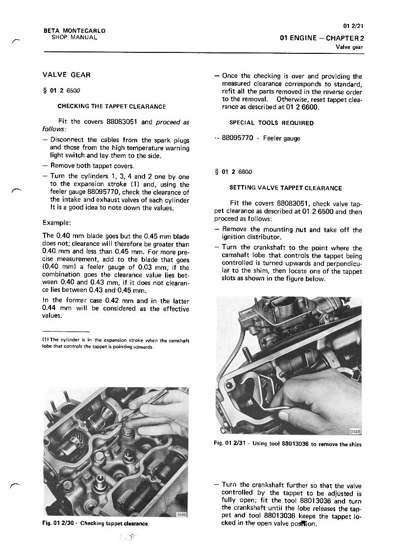
012/21
01 ENGINE -CHAPTER 2
Valve gear
BETA MONTECARLO
SHOP MANUALr
VALVE GEAR -Once the checking is over and providing themeasured clearance corresponds to standard,refit all the parts removed in the reverse orderto the removal. Otherwise, reset tappet clea-rance as described at 01 2 6600.
§ 0126500
CHECKING THE TAPPET CLEARANCE
SPECIAL TOOLS REQUIRED
-88095770 -Feeler gauge
§ 0126600
Fit the covers 88083051 and proceed asfollows:
-Disconnect the cables from the spark plugsand those from the high temperature warninglight switch and lay them to the side.
-Remove both tappet covers.
-Turn the cylinders 1, 3, 4 and 2 one by oneto the expansion stroke ( 1) and, using thefeeler gauge 88095770, check the clearance ofthe intake and exhaust valves of each cylinderIt is a good idea to note down the values.
SETTING VALVE TAPPET CLEARANCE('
Fit the covers 88083051, check valve tap-pet clearance as described at 01 26500 and thenproceed as follows:
-Remove the mounting [1ut and take off theignition distributor .
-Turn the crankshaft to the point where thecamshaft lobe that controls the tappet beingcontrolled is turned upwards and perpendicu-lar to the shim, then locate one of the tappetslots as shown in the figure below.
Example :
The 0.40 mm blade goes but the 0.45 mm bladedoes not; clearance will therefore be greater than0.40 mm and less than 0.45 mm. For more pre-cise measurement, add to the blade that goes(0.40 mm) a feeler gauge of 0.03 mm; if thecombination goes the clearance value lies bet-ween 0.40 and 0.43 mm, if it does not clearan-ce lies between 0.43 and 0.45 mm.
In the former case 0.42 mm and in the latter0.44 mm will be considered as the effectivevalues.
(1) The cylinder is in the expansion stroke when the camshaftlobe that controls the tappet is pointing upwards.
Fig. 01 2/31 -Using tool 88013036 to remove the shim
r -Turn the crankshaft further so that the valvecontrolled by the tappet to be adjusted isfully open; fit the tool 88013036 and turnthe crankshaft until the lobe releases the tap-pet and tool 88013036 keeps the tappet lo-cked in the open valve pogftion.Fig. 01 2/30 -Checking tappet clearance
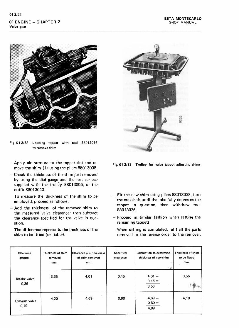
012/22BETA MONTECARLO
SHOP MANUAL01 ENGINE -CHAPTER 2Valve gear
Fig. 01 2/32 Locking tappet with tool 88013036
to remove shim
Fig. 01 2/33 Trolley for valve tappet adjusting shims
-Fit the new shim using pliers 88013038, turnthe crakshaft until the lobe fully depresses the
tappet in question, then withdraw tool
88013036.
-Apply air pressure to the tappet slot and re-
move the shim (1) using the pliers 88013038.
-Check the thickness of the shim Just removedby using the dial gauge and the rest surface
supplied with the trolley 88013055, or the
outfit 88013040.
To measure the thickness of the shim to be
employed, proceed as follows:
-Add the thickness of the removed shim tothe measured valve clearance; then subtractthe clearance specified for the valve in que-
stion.
The difference represents the thickness of the
shim to be fitted (see table).
-Proceed in similar fashion when setting the
remaining tappets.
-When setting is completed, refit all the parts
removed in the reverse order to the removal.
Clearance
gauged
Thickness of shim
removed
mm.
Specified
clearance
Thickness of shim
to be fitted
mm.
Clearance plus thickness
of shim removed
mm.
Calculation to determine
thickness of new shim
0,45 4,01 -
0,45 =
3,56
3,553.65 4,01Intake valve
0,36
4,104,69 0.604,20Exhaust valve
0,49
4,69 -
0,60 =
4,09
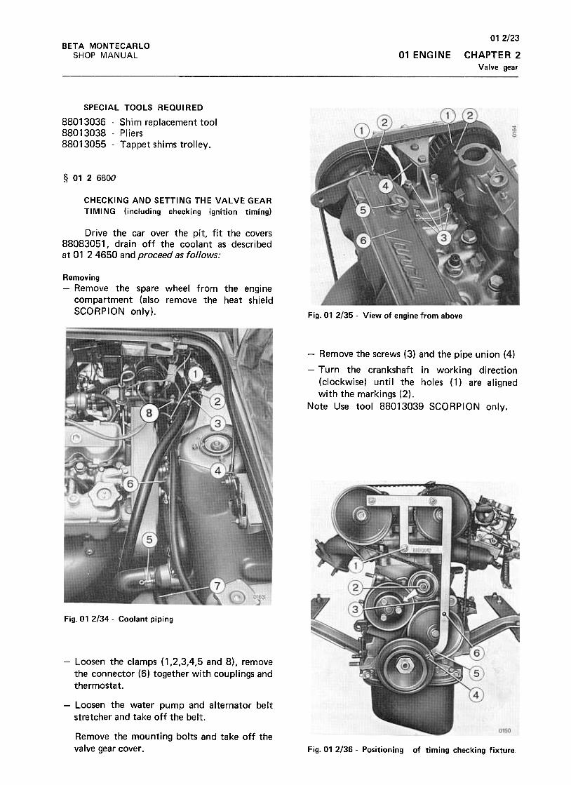
012/23
CHAPTER 2
Valve gear
BETA MONTECARLO
SHOP MANUAL 01 ENGINE
SPECIAL TOOLS REQUIRED
88013036 -Shim replacement tool
88013038 -Pliers
88013055 -Tappet shims trolley.
§ 0126800
CHECKING AND SETTING THE VALVE GEAR
TIMI NG (including checking ignition timing)
Drive the car over the pit, fit the covers88083051, drain off the coolant as describedat 01 24650 and proceed as follows:
Removing-Remove the spare wheel from the engine
compartment (also remove the heat shieldSCORPION only). Fig. 01 2/35 -View of engine from above
-Remove the screws (3) and the pipe union (4)
-Turn the crankshaft in working direction
(clockwise) until the holes (1) are alignedwith the markings (2).
Note Use tool 88013039 SCORPION only.
Fig. 01 2/34- Coolant piping
-Loosen the clamps ( 1,2,3,4,5 and 8) , remove
the connector (6) together with couplings and
thermostat.
-Loosen the water pump and alternator belt
stretcher and take off the belt.
Remove the mounting bolts and take off the
valve gear cover . Fig. 01 2/36 -Positioning of timing checking fixture.
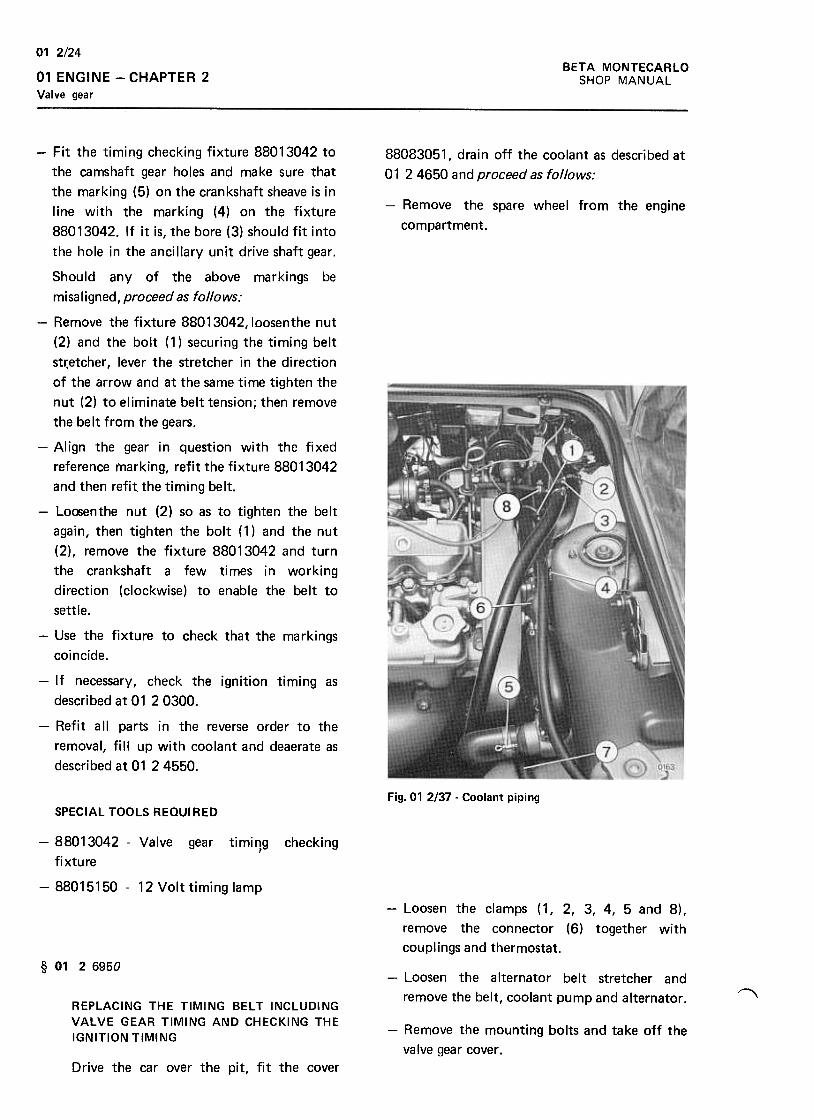
BETA MONTECARLO
SHOP MANUAL
01 2/24
01 ENGINE -CHAPTER 2
Valve gear
88083051, drain off the coolant as described at
01 24650 and proceed as follows:
-Remove the spare wheel from the engine
compartment.
-Fit the timing checking fixture 88013042 to
the camshaft gear holes and make sure that
the marking (5) on the crankshaft sheave is in
line with the marking (4) on the fixture
88013042. If it is, the bore (3) should fit into
the hole in the ancillary unit drive shaft gear.
Should any of the above markings be
misaligned, proceed as follows:
-Remove the fixture 88013042, loosenthe nut
(2) and the bolt (1) securing the timing belt
st~etcher, lever the stretcher in the direction
of the arrow and at the same time tighten the
nut (2) to eliminate belt tension; then remove
the belt from the gears.
-Align the gear in question with the fixed
reference rnarkjng, refit the fixture 88013042
and then refit the timing belt.
-Lo(Senthe nut (2) so as to tighten the belt
again, then tighten the bolt ( 1) and the nut
(2), remove the fixture 88013042 and turn
the crankshaft a few times in working
direction {clockwise) to enable the belt to
settle.
-Use the fixture to check that the markings
coincide.
-If necessary, check the ignition timing as
described at 01 20300.
-Refit all parts in the reverse order to the
removal, fill up with coolant and deaerate as
described at 01 2 4550.
Fig.01 2/37 -Coolant pipingSPECIAL TOOLS REQUIRED
checking-88013042 -Valve gear timing,
fixture
-88015150 -12 Volt timing lamp
-Loosen the clamps (1, 2, 3, 4, 5 and 8),
remove the connector (6) together with
couplings and thermostat.
§ 01 26950-Loosen the alternator belt stretcher and
remove the belt, coolant pump and alternator . ~REPLACING THE TIMING BELT INCLUDINGVALVE GEAR TIMING AND CHECKING THEIGNITION TIMING
-Remove the mounting bolts and take off the
valve gear cover.
Drive the car over the pit, fit the cover
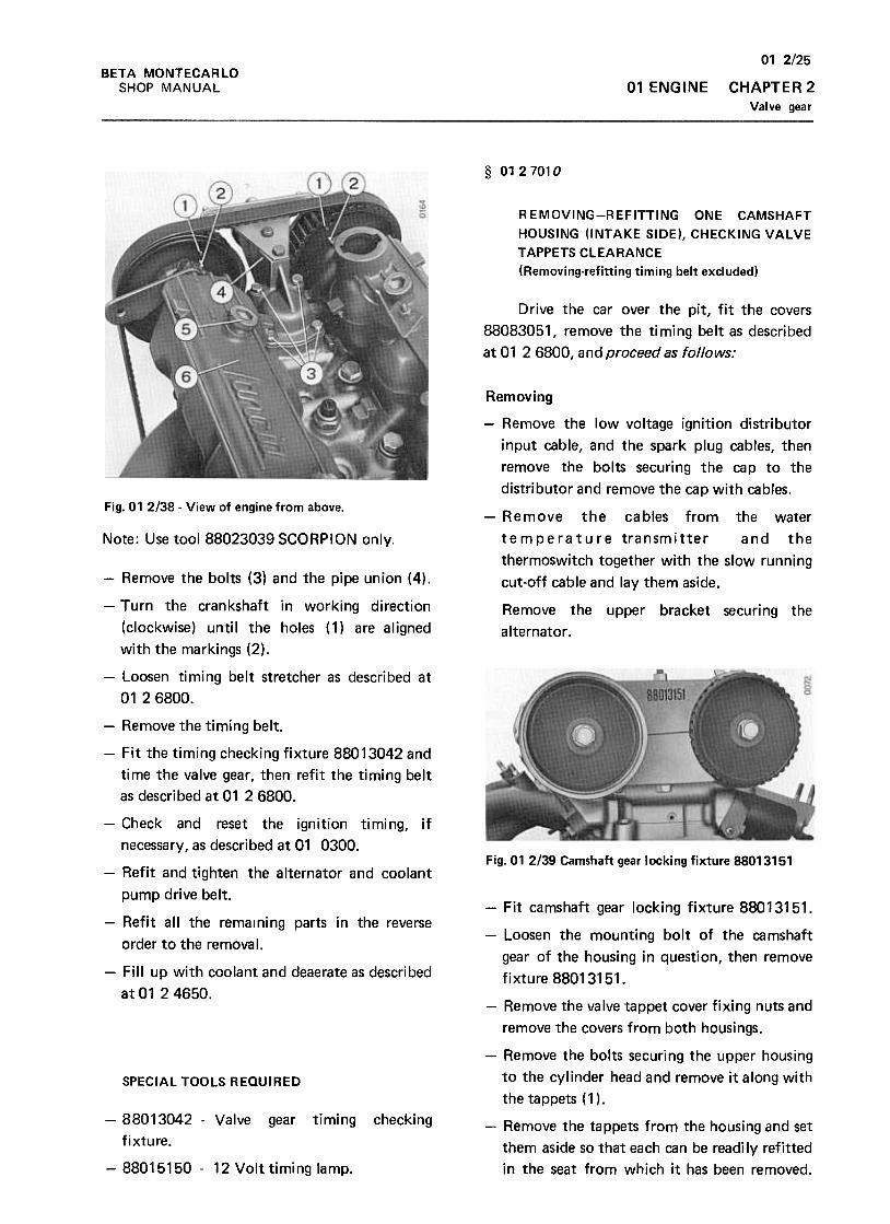
BETA MONTECARLO
SHOP MANUAL 01 ENGINE
01 2/25
CHAPTER 2
Valve gear
§ 0127010
REMOVING-REFITTING ONE CAMSHAFT
HOUSING (INTAKE SIDE), CHECKING VALVE
TAPPETS CLEARANCE
(Removing-refitting timing belt excluded)
Drive the car over the pit, fit the covers
88083051, remove the timing belt as described
at 01 2 6800, and proceed as follows:
Fig. 01 2138 -View of engine from above.
Removing
-Remove the low voltage ignition distributor
input cable, and the spark plug cables, then
remove the bolts securing the cap to the
distributor and remove the cap with cables.
-Remove the cables from the water
temperature transmitter and the
thermoswitch together with the slow running
cut-off cable and lay them aside.
Note: Use tool 88023039 SCORPION only.
Remove the upper bracket securing the
alternator .
-Remove the bolts {3) and the pipe union {4).
-Turn the crankshaft in working direction
{clockwise) until the holes {1) are aligned
with the markings {2).
-Loosen timing belt stretcher as described at
0126800.
-Remove the timing belt.
-Fit the timing checking fixture 88013042 and
time the valve gear, then refit the timing belt
as described at 01 2 6800.
-Check and reset the ignition timing, if
necessary, as described at 01 0300.Fig. 01 2139 Camshaft gear locking fixture 88013151
-Refit and tighten the alternator and coolant
pump drive belt.
-Refit all the remaining parts in the reverse
order to the remova I.
-Fill up with coolant and deaerate as described
at 01 2 4650.
-Fit camshaft gear locking fixture 88013151.
-Loosen the mounting bolt of the camshaft
gear of the housing in question, then remove
fixture 88013151.
-Remove the valve tappet cover fixing nuts and
remove the covers from both housings.
SPECIAL TOOLS REaulRED
checking-88013042 -Valve gear timing
fixture.
-88015150- 12 Volt timing lamp.
-Remove the bolts securing the upper housing
to the cylinder head and remove it along with
the tappets (1 ).
-Remove the tappets from the housing and set
them aside so that each can be readi Iy refitted
in the seat from which it has been removed.
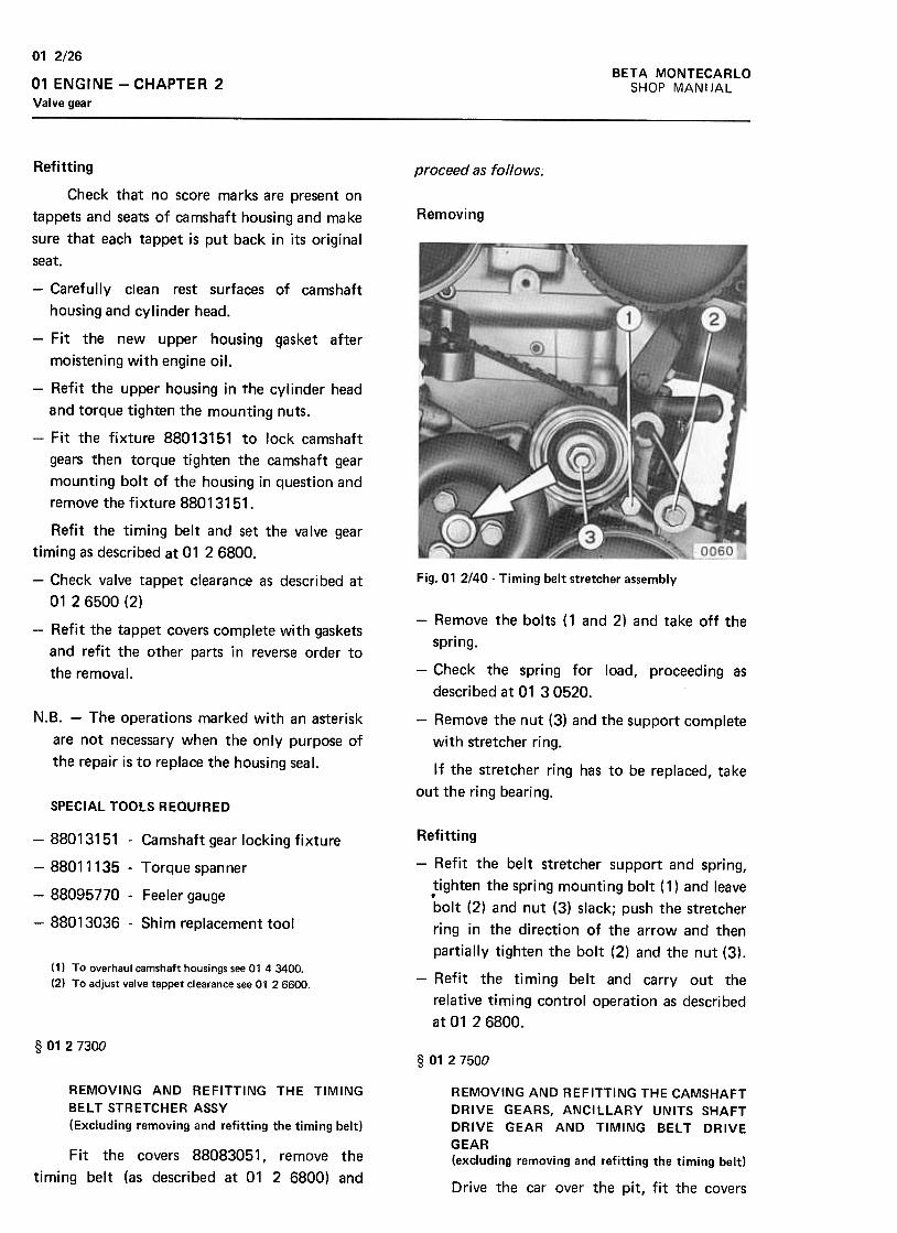
BETA MONTECARLO
SHOP MANI JAL
01 2/26
01 ENGINE -CHAPTER 2
Valve gear
proceed as follows.
Removing
Fig. 01 2/40- Timing belt stretcher assembly
Refitting
Check that no score marks are present on
tappets and seats of camshaft housing and make
sure that each tappet is put back in its original
seat.
-Carefully clean rest surfaces of camshaft
housing and cylinder head.
-Fit the new upper housing gasket after
moistening with engine oil.
-Refit the upper housing in the cylinder head
and torque tighten the mounting nuts.
-Fit the fixture 88013151 to lock camshaft
gears then torque tighten the camshaft gear
mounting bolt of the housing in question and
remove the fixture 88013151.
Refit the timing belt and set the valve gear
timing as described at 01 2 6800.
-Check valve tappet clearance as described at
01 2 6500 (2)
-Refit the tappet covers complete with gaskets
and refit the other parts in reverse order to
the removal.
N.B. -The operations marked with an asterisk
are not necessary when the only purpose of
the repair is to replace the housing seal.
-Remove the bolts ( 1 and 2) and take off the
spring.
-Check the spring for load, proceeding as
described at 01 30520.
-Remove the nut (3) and the support complete
with stretcher ring.
If the stretcher ring has to be replaced, take
out the ring bearing.SPECIAL TOOLS REQUIRED
-88013151 -Camshaft gear locking fixture
-88011135 -Torque spanner
-88095770 -Feeler gauge
-88013036 -Shim replacement tool
(1) To overhaul camshaft housings see 01 43400.
(2) To adjust valve tappet clearance see 01 26600.
Refitting
-Refit the belt stretcher support and spring,
tighten the spring mounting bolt ( 1) and leave.bolt (2) and nut (3) slack; push the stretcher
ring in the direction of the arrow and then
partially tighten the bolt (2) and the nut (3).
-Refit the timing belt and carry out the
relative timing control operation as described
at 01 2 6800.
§ 01 2 7300§ 01 2 7500
REMOVING AND REFITTING THE TIMING
BELT STRETCHER ASSY
(Excluding removing and refitting the timing belt)
Fit the covers 88083051, remove the
timing belt (as described at 01 2 6800) and
REMOVING AND REFITTING THE CAMSHAFT
DRIVE GEARS, ANCILLARY UNITS SHAFT
DRIVE GEAR AND TIMING BELT DRIVE
GEAR(excluding removing and refitting the timing belt)
Drive the car over the pit, fit the covers

01 2/27
CHAPTER 2
Valve gear
BETA MONTECARLO
SHOP MANUAL 01 ENGINE
88083051, remove the timing belt, as described
at 01 26800, and proceed as follows:
Fig. 01 2143 -Right rear arm.
Fig. 01 2141 -Positioning the stand
Remove the bolts (1 and 2) securing the
stablizer bar to the arm, remove the bolts (3)
and pull off the arm (4).Removing
-Slacken the rear right wheel securing bolts.
-Working in the pit, raise the car with the
hydraulic jack fitted with bracket 88097827
and set it on the stand 88097120 as shown in
the figure, then remove the loosened wheel.
Fig. 01 2142 -Retainer 88013151 for locking camshaft
drive gears.
Fig. 01 2/44 -Positioning of retainer 88013347 for
locking crankshaft.
-Remove the flywheel guard and fit the
retainer 88013347 to lock the crankshaft.
-Using the spanner 88091231, take off the nut
holding the sheave to the crankshaft and then
lift off the sheave.
-Working in the engine compartment:
-Lock the camshaft drive gears using the
retainer 88013151 and loosen the mounting
boolts.
-Remove the retainer 88013151, take out the
bolts and remove the camshaft gears.
-Working under the car:
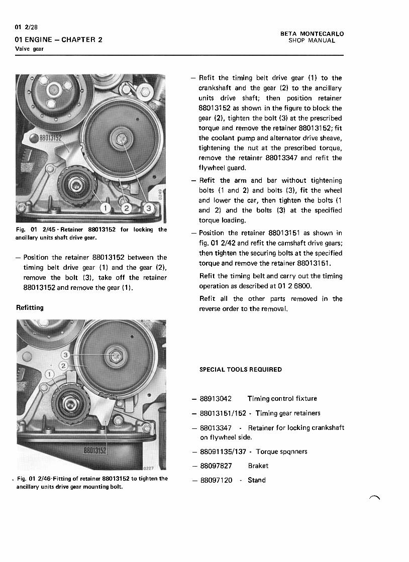
BETA MONTECARLOSHOP MANUAL
01 2/28
01 ENGINE -CHAPTER 2
Valve gear
Fig. 01 2145- Retainer 88013152 for locking the
ancillary units shaft drive gear .
-Position the retainer 88013152 between the
timing belt drive gear ( 1) and the gear (2),
remove the bolt (3), take off the retainer
88013152 and remove the gear (1).
-Refit the timing belt drive gear (1) to the
crankshaft and the gear (2) to the anci Ilary
units drive shaft; then position retainer
88013152 as shown in the figure to block the
gear (2), tighten the bolt (3) at the prescribed
torque and remove the retainer 88013152; fit
the coolant pump and alternator drive sheave,
tightening the nut at the prescribed torque,
remove the retainer 88013347 and refit the
flywheel guard.
-Refit the arm and bar without tightening
bolts (1 and 2) and bolts (3), fit the wheel
and lower the car, then tighten the bolts ( 1
and 2) and the bolts (3) at the specified
torque loading.
-Position the retainer 88013151 as shown in
fig. 01 2/42 and refit the camshaft drive gears;
then tighten the securing bolts at the specified
torque and remove the retainer 88013151.
Refit the timing belt and carry out the timing
operation as described at 01 2 6800.
Refit all the other parts removed in the
reverse order to the removal.Refitting
SPECIAL TOOLS REQUIRED
-88913042 Timing control fixture
-88013151/152 -Timing gear retainers
-88013347 -Retainer for locking crankshaft
on flywheel side.
-88091135/137 -Torque spqnners
-88097827 Braket
-Fig. 01 2/46-Fitting of retainer 88013152 to tighten the
ancillary units drive gear mounting bolt.-88097120 -Stand
~
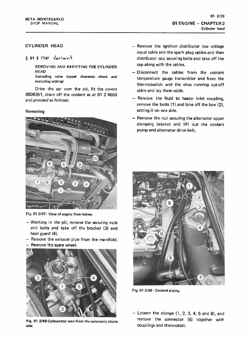
01 2/29
01 ENGINE -CHAPTER 2
Cylinder head
BETA MONTECARLO
SHOP MANUAL
CYLINDER HEAD
§ 01 2 7700 -Jo.~\o.Y\\
REMOVING AND REFITTING THE CYLINDER
HEAD
(including valve tappet clearance check and
excluding setting)
Drive the car over the pit, fit the covers
8808351, drain off the coolant as at 01 24650
and proceed as follows:
Removing
-Remove the ignition distributor low voltage
input cable and the spark plug cables and then
distributor cap securing bolts and take off the
cap along with the cables.
-Disconnect the cables from the coolant
temperature gauge transmitter and from the
thermoswitch and the slow running cut-off
cable and lay them aside.
-Remove the fluid to heater inlet coupling,
remove the bolts (1) and take off the box (2),
setting it on one side.
-Remove the nut securing the alternator upper
clamping bracket and lift out the coolant
pump and alternator drive belt.
Fig. 01 2/47- View of engine from below.
-Working in the pit, remove the securing nuts
and bolts and take off the bracket (3) and
heat guard (4).
-Remove the exhaust pipe from the manifold.
-Remove the spare wheel.
Fig. 01 2149. Coolant piping.
-Loosen the clamps (1, 2, 3, 4, 5 and 8), and
remove the connector (6) together with
couplings and thermostat.Fig. 01 2/48-Carburettor seen from the automatic choke
side.
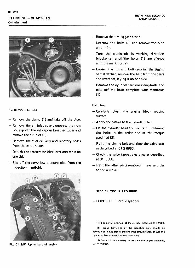
01 2/30
BETA MONTECARLO
SHOP MANUAL01 ENGINE -CHAPTER 2Cylinder head
-Remove the timing gear cover.
-Unscrew the bolts (3) and remove the pipe
union (4).
-Turn the crankshaft in working direction
(clockwise) until "the holes (1) are aligned
with the markings (2).
-Loosen the nut and bolt securing the timing
belt stretcher, remove the belt from the gears
and stretcher, laying it on one side.
-Remove the cylinderhead mounting bolts and
take off the head complete with manifolds
(1 ).
Refit ti ng
Fig. 01 2/50- Air inlet.
-Remove the clamp (1) and take off the pipe.
-Remove the a ir in let cover, unscrew the nuts
(2), slip off the oil vapour breather tubes and
remove the air inlet (3).
-Remove the fuel delivery and recovery hoses
from the carburet tor .
-Carefully clean the engine block mating
surface.
-Apply the gasket to the cylinder head.
-Fit the cylinder head and secure it, tightening
the bolts in the order and at the torque
specified (2).
-Refit the timing belt and time the valve gear
as described at 01 26950.-Detach the accelerator idler lever and set it on
one side.
-Slip off the servo low pressure pipe from the
induction manifold.
-Check the valve tappet clearance as described
at 01 6500.
-Refit the other parts removed in reverse order
to the removal.
SPECIAL TOOLS REQUIRED
-88091135 Torque spanner
(1) For partial overhaul of the cylinder head see 01 42700.
(2) Torque tightening of the mounting bolts should be
carried out in two stages and under no circumstances should the
operation be carried oui in one stage only.
(3) Should it be necessary to set the valve tappet clearance,
see 01 26600.Fig. 01 2/51- Upper part of engine.
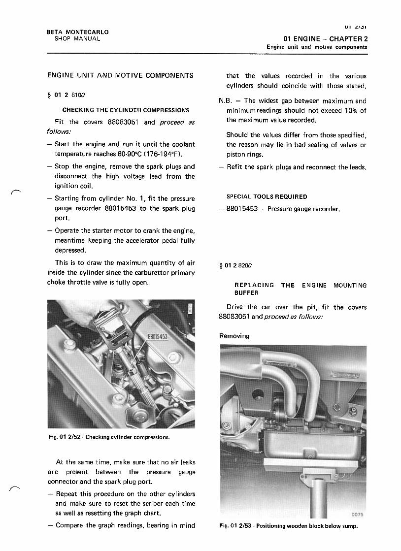
UI ~f"l
01 ENGINE -CHAPTER 2
Engine unit and motive components
BETA MONTECARLO
SHOP MANUAL
ENGINE UNIT AND MOTIVE COMPONENTS that the values recorded in the various
cylinders should coincide with those stated.
§ 0128100
N.B. -The widest gap between maximum and
minimum readings should not exceed 10% of
the maximum value recorded.
Should the values differ from those specified,
the reason may lie in bad sealing of valves or
piston rings.
-Refit the spark plugs and reconnect the leads.
"'SPECIAL TOOLS REQUIRED
-88015453 -Pressure gauge recorder .
CHECKING THE CYLINDER COMPRESSIONS
Fit the covers 88083051 and proceed as
follows:
-Start the engine and run it until the coolant
temperature reaches 80-90°C ( 176-194°F).
-Stop the engine, remove the spark plugs and
disconnect the high voltage lead from the
ignition coil.
-Starting from cylinder No.1, fit the pressure
gauge recorder 88015453 to the spark plug
port.
-Operate the starter motor to crank the engine,
meantime keeping the accelerator pedal fully
depressed.
This is to draw the maximum quantity of air
inside the cylinder since the carburet tor primary
choke throttle valve is fully open.
§ 01 2 8200
REPLACING
BUFFER
THE ENGINE MOUNTING
Drive the car over the pit, fit the covers
88083051 and proceed as follows:
Removing
Fig. 01 2152" Checking cylinder compressions.
r"
At the same time, make sure that no air leaks
are present between the pressure gauge
connector and the spark plug port.
-Repeat this procedure on the other cylinders
and make sure to reset the scriber each time
as well as resetting the graph chart.
-Compare the graph readings, bearing in mind Fig. 01 2153- Positioning wooden block below sump.

BETA MONTECARLO
SHOP MANUAL~
01 2/32
01 ENGINE -CHAPTER 2
Engine unit and motive components
-Working below the car, position the hydraulic
jack with bracket 88097827 below the sump,
insertina a wooden block in between.
-Using the fixture 88032052 at the press,
remove the buffer from the bracket and fit
the new one using the same fixture.
To refit, proceed in the reverse order to the
removal.
SPECIAL TOOLS REQUIRED
-88032052 -Fixture for removing mounting
buffer
-18809827 -Jack bracket
§ 01 28300
REPLACING THE CRANKSHAFT FRONT OIL
SEAL
Drive the car over the pit, fit the covers
88083651, drain off the coolant as described at
01 24650 and proceed as follows:Fig. 01 2/54 -Front engine mounting
-Remove the bolts ( 1) and the nuts (2) and
take off the engine mounting bracket. Removing
-Remove the spare wheel from the engine
compartment (also remove the heat shield
SCORPION only),
'""'
Fig. 01 2/55 .Fixture 88032052 for removing and
fitting mounting buffer . Fig. 01 2156 -Coolant piping
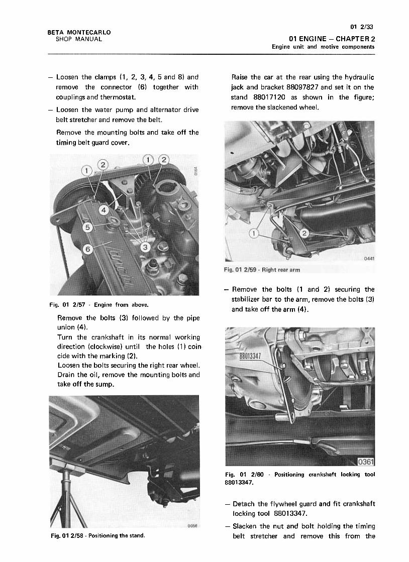
01 2/33
01 ENGINE -CHAPTER 2
Engine unit and motive components
BETA MONTECARLO
SHOP MANUAL
Raise the car at the rear using the hydraulic
jack and bracket 88097827 and set it on the
stand 88017120 as shown in the figure;
remove the slackened wheel.
-Loosen the clamps (1, 2, 3,4, 5 and 8) and
remove the connector (6) together with
couplings and thermostat.
-Loosen the water pump and alternator drive
belt stretcher and remove the belt.
Remove the mounting bolts and take off the
timing belt guard cover .
-Remove the bolts (1 and 2) securing the
stabilizer bar to the arm, remove the bolts (3)
and take off the arm (4).Fig. 01 2157 -Engine from above.
Remove the bolts (3) followed by the pipe
union (4),
Turn the crankshaft in its normal working
direction (clockwise) until the holes (1) coin.
cide with the marking (2).
Loosen the bolts securing the right rear wheel.
Drain the oil, remove the mounting bolts and
take off the sump.
Fig. 01 2160 -Positioning crankshaft locking tool
88013347.
-Detach the flywheel guard and fit crankshaft
locking tool 88013347.
-Slacken the nut and bolt holding the timing
belt stretcher and remove this from theFig. 01 2/58- Positioning the stand.
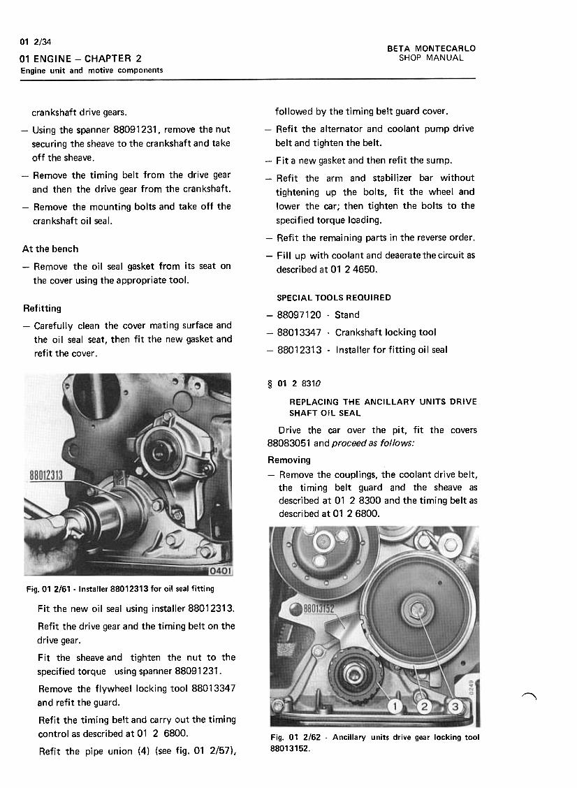
BETA MONTECARLOSHOP MANUAL
01 2/34
01 ENGINE -CHAPTER 2
Engine unit and motive components
crankshaft drive gears.
-Using the spanner 88091231, remove the nut
securing the sheave to the crankshaft and take
off the sheave .
-Remove the timing belt from the drive gear
and then the drive gear from the crankshaft.
-Remove the mounting bolts and take off the
crankshaft oil seal.
followed by the timing belt guard cover.
-Refit the alternator and coolant pump drive
belt and tighten the belt.
-Fit a new gasket and then refit the sump.
-Refit the arm and stabilizer bar without
tightening up the bolts, fit the wheel and
lower the car; then tighten the bolts to the
specified torque loading.
-Refit the remaining parts in the reverse order.
-Fill up with coolant and deaerate the circuit as
described at 01 24650.
At the bench
-Remove the oil seal gasket from its seat on
the cover using the appropriate tool.
Refitting
-Carefully clean the cover mating surface and
the oil seal seat, then fit the new gasket and
refit the cover .
SPECIAL TOOLS REQUIRED
-88097120- Stand
-88013347 -Crankshaft locking tool
-88012313- Installer for fitting oil seal
§ 0128310
REPLACING THE ANCILLARY UNITS DRIVE
SHAFT OIL SEAL
Drive the car over the pit, fit the covers
88083051 and proceed as follows:
Removing
-Remove the couplings, the coolant drive belt,
the timing belt guard and the sheave as
described at 01 2 8300 and the timing belt as
described at 01 26800.
Fig. 01 2161 -Installer 88012313 for oil seal fitting
~
Fig. 01 2162 -Ancillary units drive gear locking tool
88013152.
Fit the new oil seal using installer 88012313.
Refit the drive gear and the timing belt on the
drive gear .
Fit the sheaveand tighten the nut to the
specified torque using spanner 88091231.
Remove the flywheel locking tool 88013347
and refit the guard.
Refit the timing belt and carry out the timing
control as described at 01 2 6800.
Refit the pipe union (4) (see fig. 01 2/57),
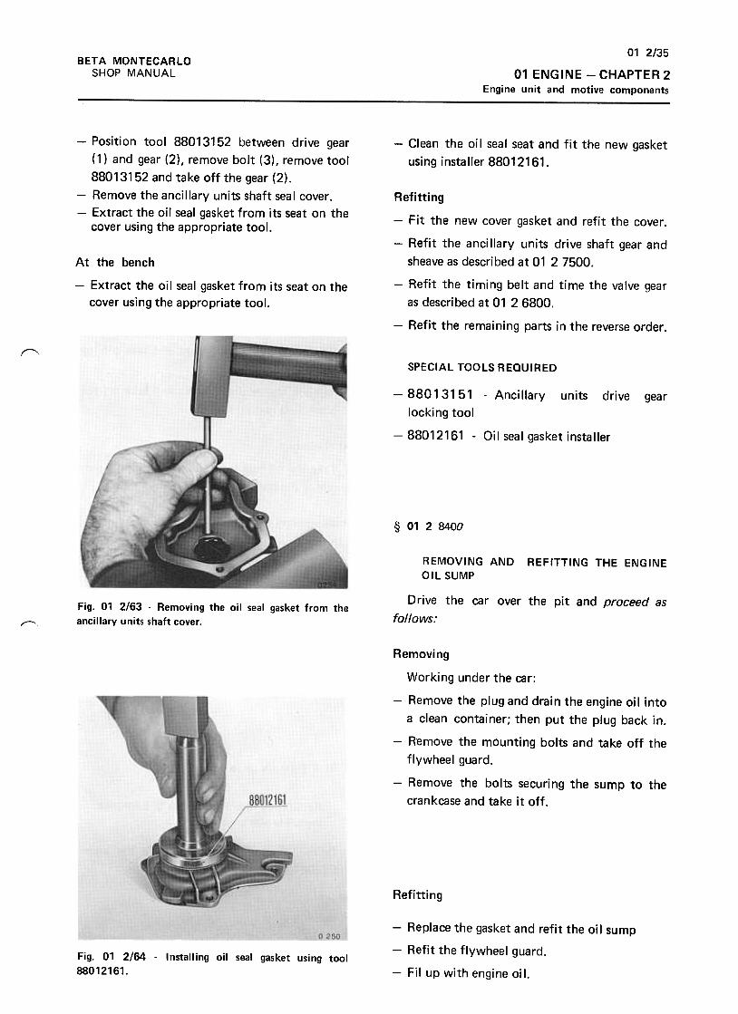
01 2/35
01 ENGINE -CHAPTER 2
Engine unit and motive components
BETA MONTECARLO
SHOP MANUAL
-Position tool 88013152 between drive gear
(1) and gear (2), remove bolt (3), remove tool
88013152 and take off the gear (2).
-Remove the ancillary units shaft seal cover.
-Extract the oil seal gasket from its seat on thecover using the appropriate tool.
-Clean the oil seal seat and fit the new gasket
using installer 88012161.
At the bench
-Extract the oil seal gasket from its seat on the
cover using the appropriate tool.
Refitting
-Fit the new cover gasket and refit the cover.
-Refit the anci Ilary units drive shaft gear and
sheave as described at 01 2 7500.
-Refit the timing belt and time the valve gear
as described at 01 26800.
-Refit the remaining parts in the reverse order.
f"'SPECIAL TOOLS REQUIRED
-88013151 -Ancillary units drive
locking tool
-88012161 -Oil seal gasket installer
gear
§ 0128400
REMOVING AND
OIL SUMPREFITTING THE ENGINE
Drive the car over the pit and proceed as
follows:Fig. 01 2163 -Removing the oil seal gasket from the
ancillary units shaft cover.~
Removing
Working under the car:
-Remove the plug and drain the engine oil into
a clean container; then put the plug back in.
-Remove the mOunting bolts and take off the
flywheel guard.
-Remove the bolts securing the sump to the
crankcase and take it off .
Refitting
-Replace the gasket and refit the oi I sump
-Refit the flywheel guard.
-Fil up with engine oil.
Fig. 01 2/64 -Installing oil seal gasket using tool
88012161.
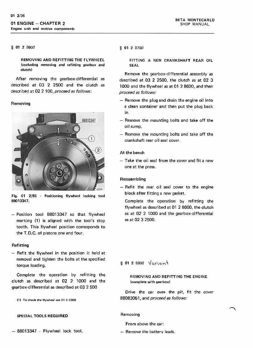
BETA MONTECARLO
SHOP MANUAL
01 2/36
01 ENGINE -CHAPTER 2
Engine unit and motive components
§ 0128600 § 0128700
REMOVING AND REFITTING THE FL YWHEEL
(excluding removing and refitting gearbox and
clutch)
FITTING A NEW CRANKSHAFT REAR OIL
SEAL
After removing the gearbox-differential as
described at 03 2 2500 and the clutch as
described at 02 2 100, proceed as follows:
Removing
Remove the gearbox-differential assembly as
described at 03 2 2500, the clutch as at 02 3
1000 and the flywheel as at 01 2 8600, and then
proceed as follows:
-Remove the plug and drain the engine oil into
a clean container and then put the plug back
in.
-Remove the mounting bolts and take off the
oil sump.
-Remove the mounting bolts and take off the
crankshaft rear oil seal cover.
At the bench
-Take the oil seal from the cover and fit a new
one at the press.
Fig. 01 2165 .Positioning flywheel locking tool
88013347.
Reassembling
-Refit the rear oil seal cover to the engine
block after fitting a new gasket.
Complete the operation by refitting the
flywheel as described at 01 28600, the clutch
as at 02 2 1000 and the gearbox-differential
as at 02 3 2500.
-Position tool 88013347 so that flywheel
marking (1) is aligned with the tool's stop
tooth. This flywheel position corresponds to
the T. D.C. of pistons one and four .
Refitting
-Refit the flywheel in the position it held at
removal and tighten the bolts at the specified
torque loading.§ 01 2 8800 V Q\\0..~-\
Complete the operation by refitting the
clutch as described at 02 2 1000 and the
gearbox-differential as described at 03 2 500
REMOVING AND REFITTING THE ENGINE
(complete with gearbox)
Drive the car over. the pit, fit the cover
88083051, and proceed as follows:( 11 T o check the flywheel see 01 2 2300.
""RemovingSPECIAL TOOLS REQUIRED
-88013347 -Flywheel lock tool.
From above the car:
-Remove the battery leads.
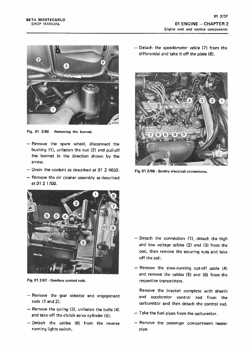
01 2/37
01 ENGINE -CHAPTER 2
Engine unit and motive components
BETA MONTECARLO
SHOP MANUAL
-Detach the speedometer cable (7) from the
differential and take it off the plate (8).
Fig. 01 2/66 Removing the bonnet.
-Remove the spare wheel, disconnect the
bushing (1), unfasten the nut (2) and pulloff
the bonnet in the direction shown by the
arrow.
Fig. 01 2168 -Sundry electrical connections.-Drain the coolant as described at 01 2 4650.
-Remove the air cleaner assembly as described
at0121700.
-Detach the connection (1 ), detach the high
and low voltage cables (2) and (3) from the
coil, then remove the securing nuts and take
off the coil.
-Remove the slow-running cut-off cable (4)
and remove the cables (5) and (6) from the
respective transmitters.Fig. 01 2/67 -Gearbox control rods.
Remove the bracket complete with sheath
and accelerator control rod from the
carburet tor and then detach the control rod.
-Take the fuel pipes from the carburet tor.
-Remove the gear selector and engagement
rods (1 and 2).
-Remove the spring (3), unfasten the bolts (4)
and take off the clutch servo cylinder (5).
-Detach the cables (6) from the reverse
running lights switch.
-Remove the passenger compartment heater
pipe.
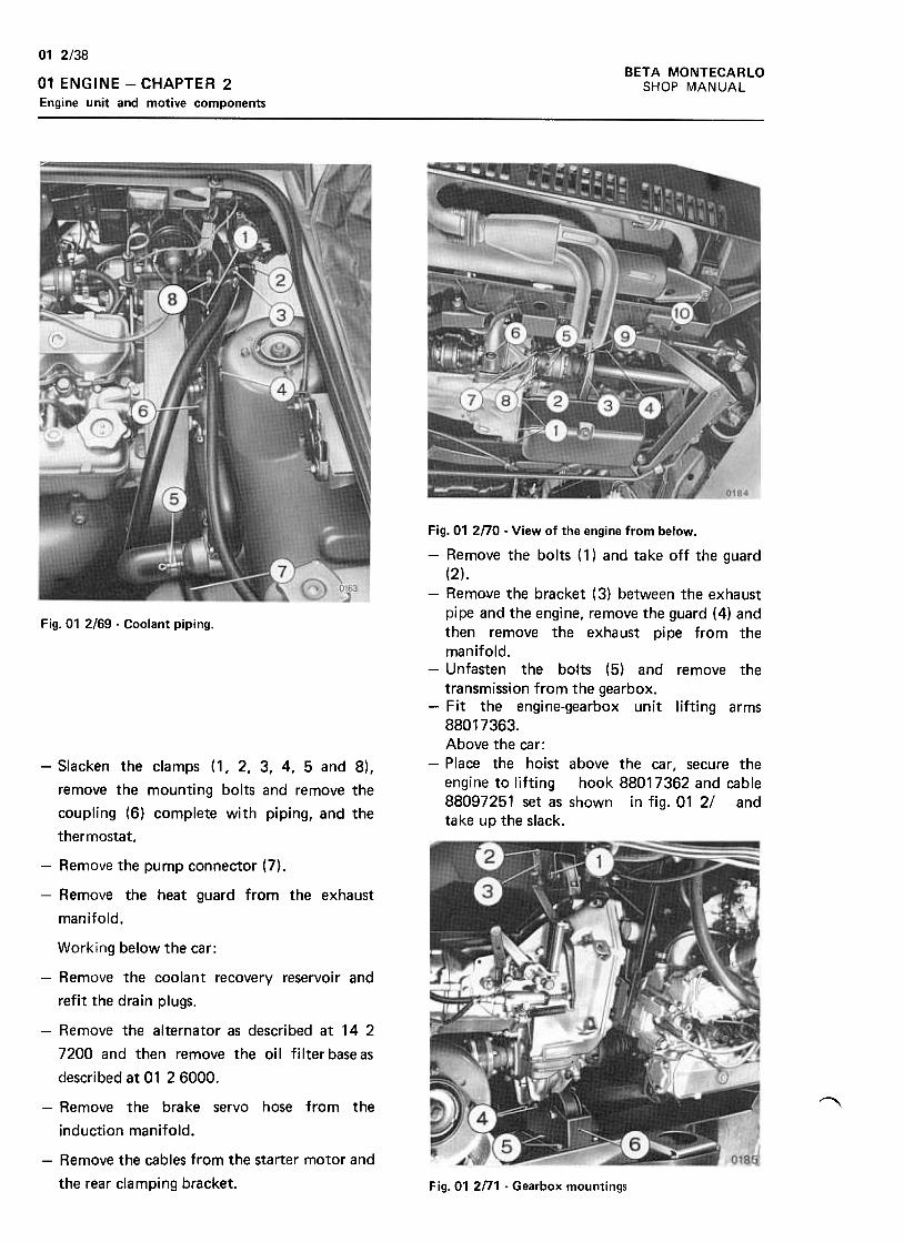
BETA MONTECARLO
SHOP MANUAL
01 2/38
01 ENGINE -CHAPTER 2
Engine unit and motive components
Fig. 01 2169 -Coolant piping.
Fig.01 2no -View of the engine from below.
-Remove the bolts (1) and take off the guard
(2).-Remove the bracket (3) between the exhaust
pipe and the engine, remove the guard (4) andthen remove the exhaust pipe from the
manifold.-Unfasten the bolts (5) and remove the
transmission from the gearbox.-Fit the engine-gearbox unit lifting arms
88017363.Above the car:
-Place the hoist above the car, secure theengine to lifting hook 88017362 and cable88097251 set as shown in fig. 01 2/ andtake up the slack.
-Slacken the clamps (1, 2, 3, 4, 5 and 8),
remove the mounti ng bolts and remove the
coupling (6) complete with piping, and the
thermostat.
-Remove the pump connector (7).
-Remove the heat guard from the exhaust
manifold.
Working below the car:
-Remove the coolant recovery reservoir and
refit the drain plugs.
-Remove the alternator as descri bed at 14 2
7200 and then remove the oi I filter base as
described at 01 26000.
"-Remove the brake servo hose from the
induction manifold.
-Remove the cables from the starter motor and
the rear clamping bracket. Fig.01 2n1 -Gearbox mountings
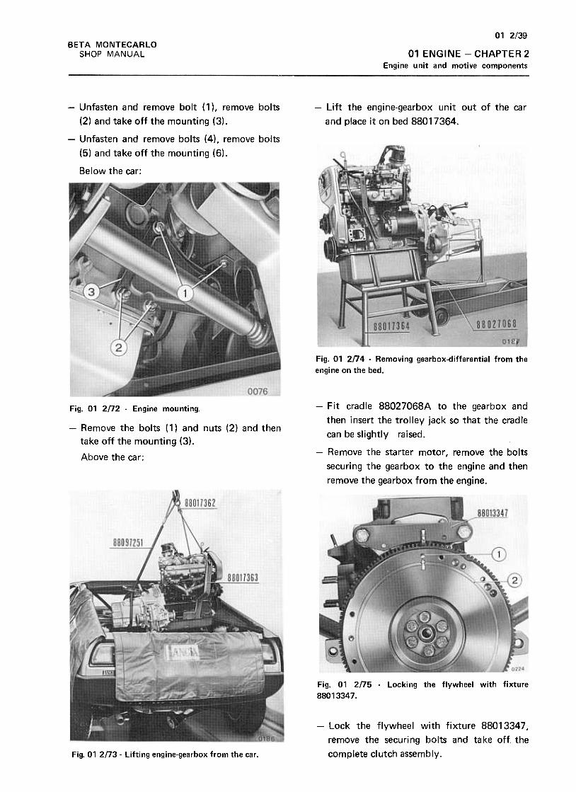
01 2/39
BETA MONTECARLO
SHOP MANUAL 01 ENGINE -CHAPTER 2
Engine unit and motive components
-Lift the engine-gearbox unit out of the car
and place it on bed 88017364.
-Unfasten and remove bolt (1 ), remove bolts
(2) and take off the mounting (3).
-Unfasten and remove bolts (4) , remove bolts
(5) and take off the mounting (6).
Below the car:
Fig. 01 2n4 -Removing gearbox-differential from the
engine on the bed.
Fig. 01 2n2 -Engine mounting.
-Remove the bolts ( 1) and nuts (2) and then
take off the mounting (3).
Above the car:
-Fit cradle 88027068A to the gearbox and
then insert the trolley jack so that the cradle
can be slightly raised.
-Remove the starter motor, remove the bolts
securing the gearbox to the engine and then
remove the gearbox from the engine.
0224
Fig. 01 2n5 .locking the flywheel with fixture
88013347.
-Lock the flywheel with fixture 88013347 I
remove the securing bolts and take off the
complete clutch assembly.Fig. 01 2n3 -Lifting engine-gearbox from the car .
01 2/40
BETA MONTECARLOSHOP MANUAL01 ENGINE -CHAPTER 2
Engine unit and motive components
described at 01 24650.
-When reassembly is completed, start the
engine and check for leaks; then adjust the
slow-running mechanism as described at 01 2
2300.
Refitting
-Refit the clutch assembly using the tool
88023030 for locating the disc.
-Refit the gearbox to the engine, tightening
the mounting bolts to the specified torque
loading.SPECIAL TOOLS REQUIRED
-88017363 -Engine-gearbox unit lifting arms
-88017362 -Engine lifting hook.
-88097251 -Cable
-88027058 -Gearbox support
-88017364 -Bed for detached
engine-gearbox unit.
-88013347 -Crankshaft locking fixture
-88023030 -Clutch disc locating tool.
-Working in reverse order to the removal, refit
the engine"gearbox assembly in the engine
compartment, taking care to tighten bolts
securing the constant velocity joints to the
flanges at the specified torque loading.
-Adjust the gear selector and engagement
levers, tighten the mounting bolts at the
specified torque loading, and then test gear
engagement.
.,- Refill and deaerate the cooring system as
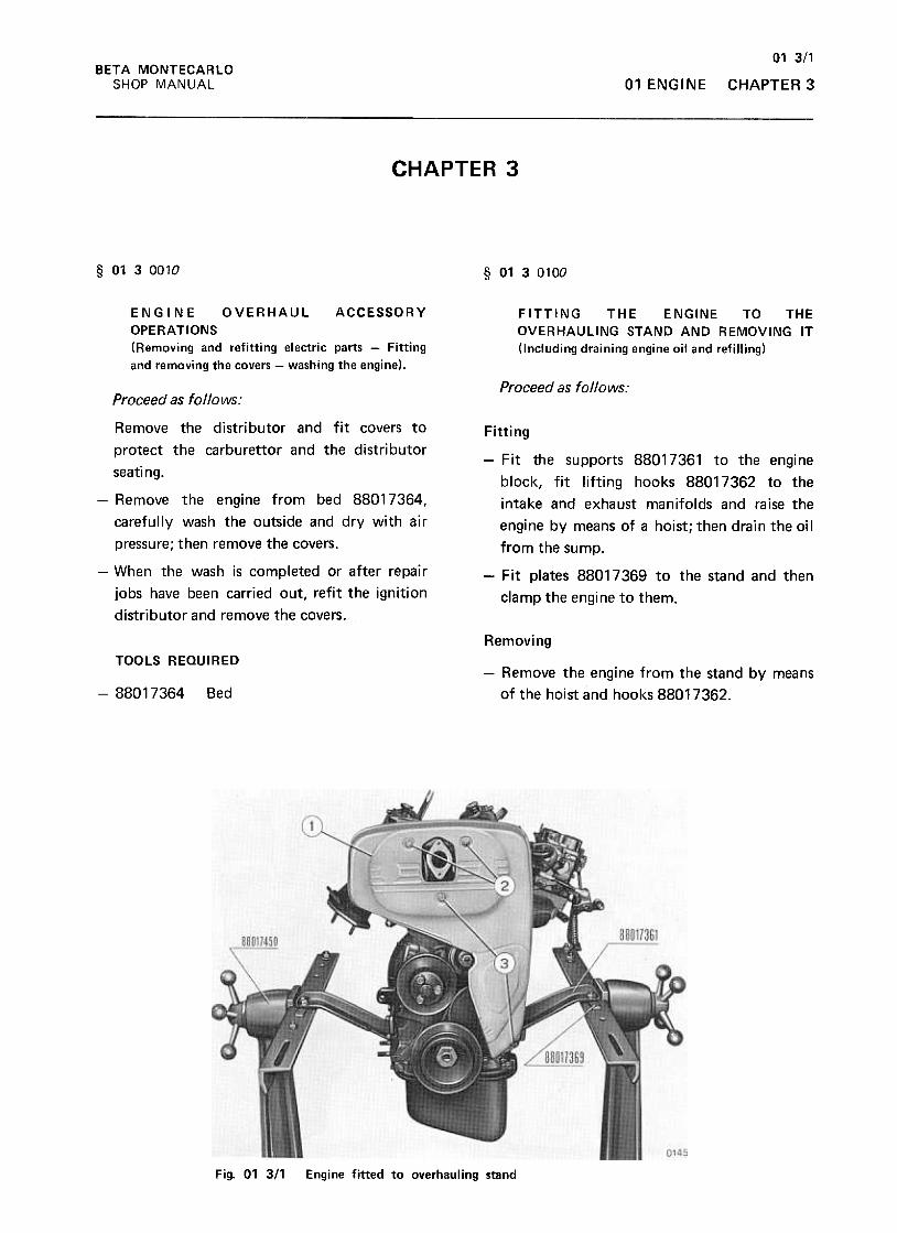
01 3/1
CHAPTER 3
BETA MONTECARLO
SHOP MANUAL 01 ENGINE
CHAPTER 3
§ 0130010 § 0130100
FITTING THE ENGINE TO THE
OVERHAULING STAND AND REMOVING IT
(Including draining engine oil and refilling)
ENGINE OVERHAUL ACCESSORY
OPERATIONS
(Removing and refitting electric parts -Fitting
and removing the covers -washing the engine).
Proceed as follows:Proceed as follows:
Remove the distributor and fit covers to
protect the carburet tor and the distributor
seating.
Fitting
-Remove the engine from bed 88017364,
carefully wash the outside and dry with air
pressure; then remove the covers.
-When the wash is completed or after repair
jobs have been carried out, refit the ignition
distributor and remove the covers.
-Fit the supports 88017361 to the engine
block, fit lifting hooks 88017362 to the
intake and exhaust manifolds and raise the
engine by means of a hoist; then drain the oil
from the sump.
-Fit plates 88017369 to the stand and then
clamp the engine to them.
RemovingTOOLS REQUIRED
-Remove the engine from the stand by means
of the hoist and hooks 88017362.-88017364 Bed
Fig. 01 311 Engine fitted to overhauling stand
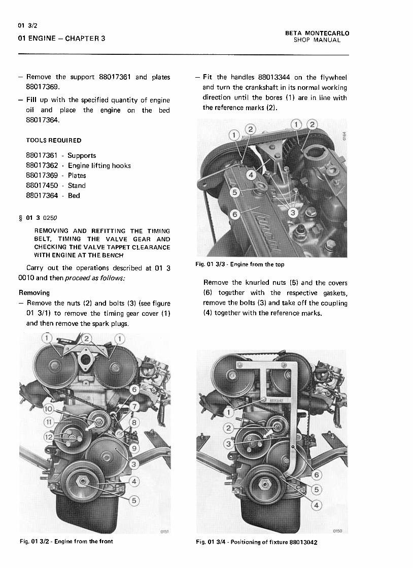
BETA MONTECARLO
SHOP MANUAL
01 3/2
01 ENGINE -CHAPTER 3
-Remove the support 88017361 and plates
88017369.
-Fit the handles 88013344 on the flywheel
and turn the crankshaft in its normal working
direction until the bores (1) are in line with
the reference marks (2).-Fill up with the specified quantity of engine
oil and place the engine on the bed
88017364.
TOOLS REQUIRED
88017361 -Supports
88017362 -Engine lifting hooks
88017369 -Plates
88017450- Stand
88017364- Bed
§ 0130250
REMOVING AND REFITTING THE TIMING
BELT, TIMING THE VALVE GEAR AND
CHECKING THE VALVE TAPPET CLEARANCE
WITH ENGINE AT THE BENCH
Fig. 01 313- Engine from the topCarry out. the operations described at 01 3
0010 and then proceed as follows:Remove the knurled nuts (5) and the covers
(6) together with the respective gaskets,
remove the bolts (3) and take off the coupling
(4) together with the reference marks.
Removing
-Remove the nuts (2) and bolts (3) (see figure
01 3/1) to remove the timing gear cover (1 )
and then remove the spark plugs.
.."W,
.
(.) }1,
0151
Fig. 01 312- Engine from the front Fig. 01 3/4- Positioning of fixture 88013042
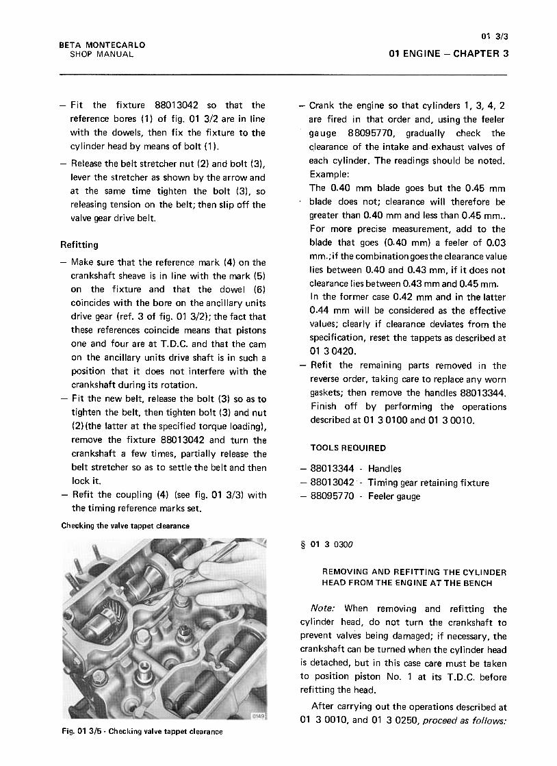
01 3/3
01 ENGINE -CHAPTER 3BETA MONTECARLO
SHOP MANUAL
-Fit the fixture 88013042 so that the
reference bores (1) of fig. 01 3/2 are in line
with the dowels, then fix the fixture to the
cylinder head by means of bolt (1 ).
-Release the belt stretcher nut (2) and bolt (3),
lever the stretcher as shown by the arrow and
at the same time tighten the bolt (3), so
releasing tension on the belt; then slip off the
valve gear drive belt.
Refitting
-Crank the engine so that cylinders 1, 3, 4, 2
are fired in that order and, using the feeler
gauge 88095770, gradually check the
cJearance of the intake and exhaust valves of
each cylinder. The readings should be noted.
Example:The 0.40 mm blade goes but the 0.45 mm
.blade does not; clearance will therefore be
greater than 0.40 mm and less than 0.45 mm..
For more precise measurement, add to the
blade that goes (0.40 mm) a feeler of 0.03
mm.;if the combinationgoesthe clearance value
lies between 0.40 and 0.43 mm, if it does not
clearance lies between 0.43 mm and 0.45 mm.
In the former case 0.42 mm and in the latter
0.44 mm will be considered as the effective
values; clearly if clearance deviates from the
specification, reset the tappets as described at
0130420.
-Refit the remaining parts removed in the
reverse order, ta ki ng care to replace any worn
gaskets; then remove the handles 88013344.
Finish off by performing the operations
described at 01 301 00 and 01 3001 0.
TOOLS REQUIRED
-88013344 -Handles
-88013042 -Timing gear retaining fixture
-88095770 -Feeler gauge
-Make sure that the reference mark (4) on the
crankshaft sheave is in line with the mark (5)
on the fixture and that the dowel (6)
coincides with the bore on the ancillary units
drive gear (ref. 3 of fig. 01 3/2); the fact that
these references coi ncide means that pistons
one and four are at T.D.C. and that the cam
on the ancillary units drive shaft is in such a
position that it does not interfere with the
crankshaft during its rotation.
-Fit the new belt, release the bolt (3) so as to
tighten the belt, then tighten bolt (3) and nut
(2) (the latter at the specified torque loading),
remove the fixture 88013042 and turn the
crankshaft a few times, partially release the
belt stretcher so as to settle the belt and then
lock it.
-Refit the coupling (4) (see fig. 01 3/3) with
the timing reference marks set.
Checking the valve tappet clearance
§ 0130300
REMOVING AND REFITTING THE CYLINDER
HEAD FROM THE ENGINE AT THE BENCH
Note: When removing and refitting the
cylinder head, do not turn the crankshaft to
prevent valves being damaged; if necessary, the
crankshaft can be turned when the cylinder head
is detached, but in this case care must be taken
to position piston No.1 at its T .D.C. before
refitting the head.
After carrying out the operations described at
01 30010, and 01 30250, proceed as follows:Fig. 01 315- Checking valve tappet clearance
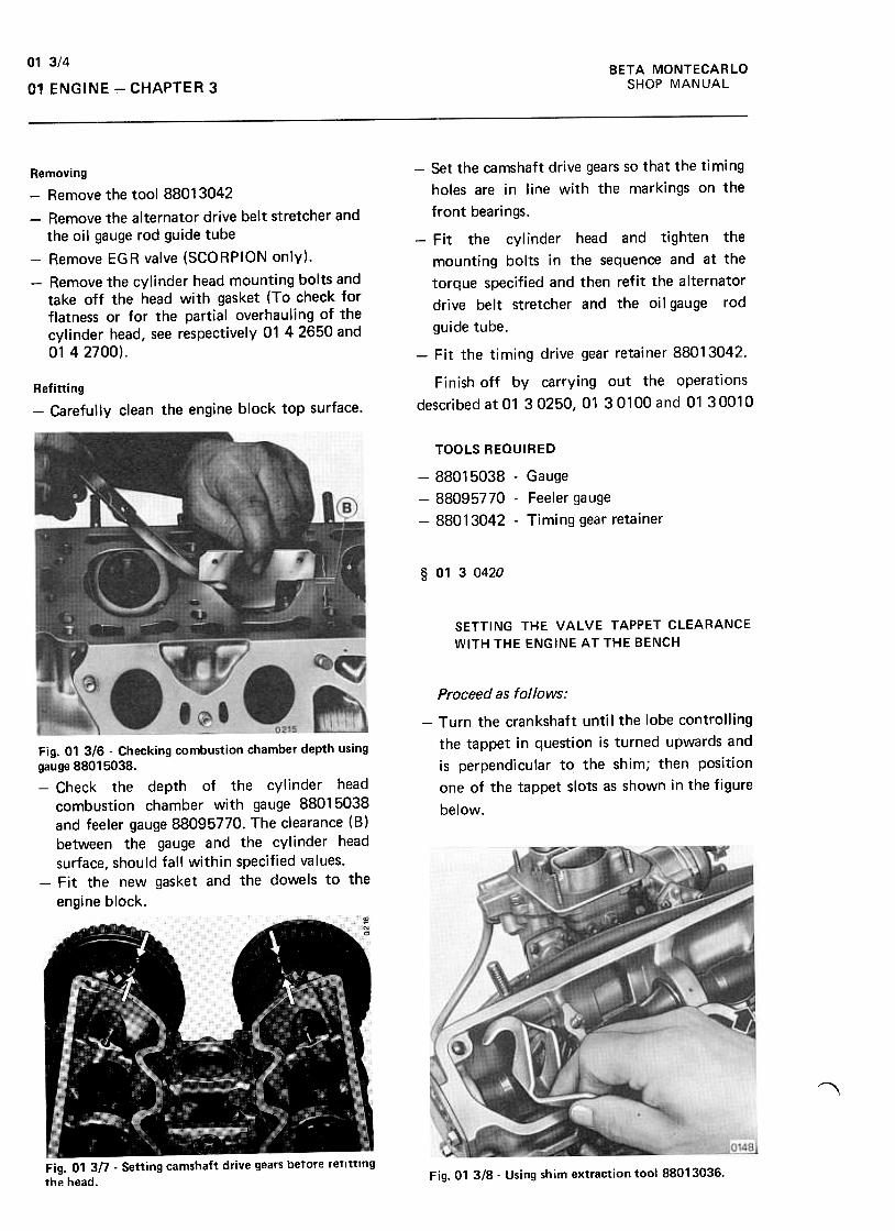
BETA MONTECARLO
SHOP MANUAL
01 3/4
01 ENGINE -CHAPTER 3
Removing
-Remove the tool 88013042
-Remove the alternator drive belt stretcher and
the oil gauge rod guide tube
-Remove EGR valve (SCORPION only).
-Remove the cylinder head mounting bolts and
take off the head with gasket (To check for
flatness or for the partial overhauling of the
cylinder head, see respectively 01 42650 and
01 42700).
-Set the camshaft drive gears so that the timing
holes are in line with the markings on the
front bearings.
-., Fit the cylinder head and tighten the
mounting bolts in the sequence and at the
torque specified and then refit the alternator
drive belt stretcher and the oil gauge rod
guide tube.
-Fil the timing drive gear retainer 88013042.
Finish off by carrying out the operations
described at 01 30250, 01 301 00 and 01 3001 0Refitting
-Carefully clean the engine block top surface.
TOOLS REQUIRED
-88015038- Gauge
-88095770 -Feeler gauge
-88013042 -Timing gear retainer
§ 0130420
SETTING THE VALVE TAPPET CLEARANCE
WITH THE ENGINE AT THE BENCH
Proceed as follows:
-Turn the crankshaft until the lobe controlling
the tappet in question is turned upwards and
is perpendicular to the shim; then position
one of the tappet slots as shown in the figure
below.
Fig. 01 3/6 -Checking combustion chamber depth usinggauge 88015038.-Check the depth of the cylinder head
combustion chamber with gauge 88015038and feeler gauge 88095770. The clearance (8)between the gauge and the cylinder head
surface, should fall within specified values.-Fit the new gasket and the dowels to the
engine block.
,
Fig. 01 3n -Setting camshaft drive gears before refitting
the head.Fig. 01 3/8- Using shim extraction tool 88013036.
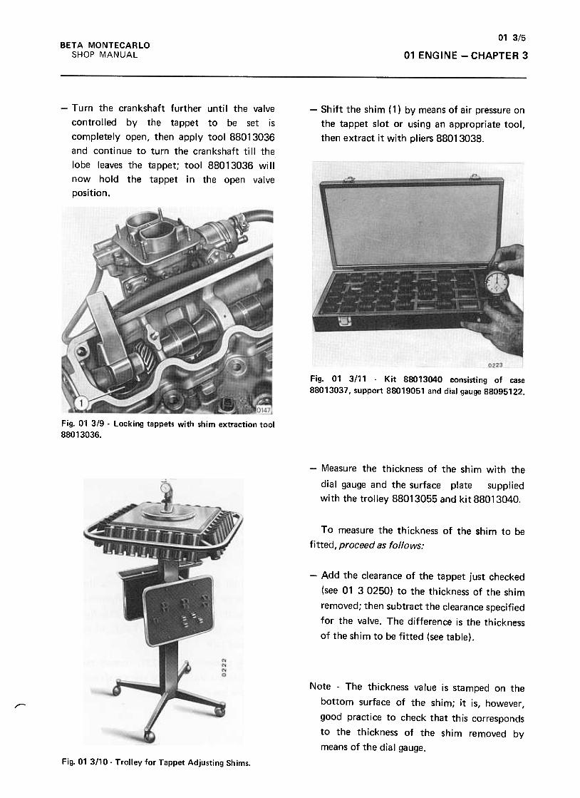
01 3/5
01 ENGINE -CHAPTER 3
BETA MONTECARLO
SHOP MANUAL
-Turn the crankshaft further until the valve
controlled by the tappet to be set is
completely open, then apply tool 88013036
and continue to turn the crankshaft till the
lobe leaves the tappet; tool 88013036 will
now hold the tappet in the open valve
position.
-Shift the shim (1) by means of air pressure on
the tappet slot or using an appropriate tool,
then extract it with pliers 88013038.
Fig. 01 3/11 -Kit 88013040 consisting of case
88013037, support 88019051 and dial gauge 88095122.
Fig. 01 3/9 -locking tappets with shim extraction tool
88013036.
-Measure the thickness of the shim with the
dial gauge and the surface plate supplied
with the trolley 88013055 and kit 88013040.
To measure the thickness of the shim to be
fitted, proceed as follows:
-Add the clearance of the tappet just checked
(see 01 3 0250) to the thickness of the shim
removed; then subtract the clearance specified
for the valve. The difference is the thickness
of the shim to be fitted (see table).
Note -The thickness value is stamped on the
bottom surface of the shim; it is, however ,
good practice to check that this corresponds
to the thickness of the shim removed by
means of the dial gauge.
,
Fig. 01 3110- Trolley for Tappet Adjusting Shims.
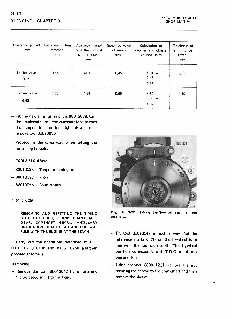
01 3/6
BETA MONTECARLO
SHOP MANUAL01 ENGINE -CHAPTER 3
Clearance gauged
mm
Thickness of shim
removed
mm
Clearance gauged
plus thickness of
shim removed
mm
Specified valve
clearance
mm
Calculation to
determine thickness
of new shim
Thickness of
shim to be
fitted
mm
Intake valve
0,36
3,65 4,01 0,45 3,554,01 -
0,45 -
3,56
Exhaust valve 4,20 4,69 0,60 4,10
0,49
4,69 -
0,60 -
4,09
-Fit the new shim using pliers 88013038, turn
the crankshaft until the camshaft lobe presses
the tappet in question right down, then
remove tool 88013036.
-Proceed in the same way when setting the
remaining tappets.
TOOLS REQUIRED
-88013036 -Tappet retaining tool
-88013038 -Pliers
-88013055 -Shim trolley
§ 0130520
Fig. 01 3112 -Fitting the Aywheel Locking Tool
88013147.REMOVING AND REFITTING THE TIMING
BELT STRETCHER, SPRING, CRANKSHAFT
GEAR, CAMSHAFT GEARS, ANCILLARY
UNITS DRIVE SHAFT GEAR AND COOLANT
PUMP WITH THE ENGINE AT THE BENCH -Fit tool 88013347 in such a way that the
reference marking (1) on the flywheel is in
line with the tool stop tooth. This flywheel
position corresponds with T.D.C. of pistons
one and four .
Carry out the operations described at 01 3
0010,01 30100 and 01 L 0250 andthen
proceed as follows:
-Using spanner 880911231, remove the nut
securing the sheave to the crankshaft and then
remove the sheave.
Removing
-Remove the tool 88013042 by unfastening
the bolt securing it to the head.
~
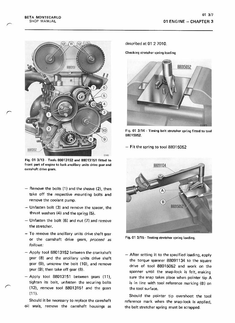
01 3/7
01 ENGINE -CHAPTER 3
BETA MONTECARLO
SHOP MANUAL
r
described at 01 27010.
Checking stretcher spring loading
r
Fig. 01 3114 -Timing belt stretcher spring fitted to tool
88015052.
-Fit the spring to tool 88015052
Fig. 01 3113- Tools 88013152 and 88013151 fitted to
front part of engine to lock ancillary units drive gear and
camshaft drive gears.
Fig.01 3115- Testing stretcher spring loading.
r
-After setting it to the specified loading, apply
the torque spanner 88091134 to the square
drive of tool 88015052 and work on the
spanner unti I the snap-Iock is felt, making
sure the snap takes place when pointer tip A
is in line with tool reference marking (8) on
the tool surface.
Should the pointer tip overshoot the tool
reference mark when the snap-Iock is applied,
the belt stretcher spring must be scrapped.
-Remove the bolts (1) and the sheave (2), then
take off the respective mounting bolts and
remove the coolant pump.
-Unfasten bolt (3) and remove the spacer, the
thrust washers (4) and the spring (5).,
-Unfasten the bolt (6) and nut (7) and remove
the stretcher .
-To remove the ancillary units drive shaft gear
or the camshaft drive gears, proceed as
follows:
-Apply tool 88013152 between the crankshaft
gear (8) and the ancillary units drive shaft
gear (9), unscrew the bolt (10), and remove
gear (9); then take off gear (8).
-Apply tool 88013151 between gears (11 ),
tighten its bolt, unfasten the securing bolts
(12), remove tool 88013151 and the gears
(11 ).
Should it be necessary to replace the camshaft
oil seals, remove the camshaft housings as
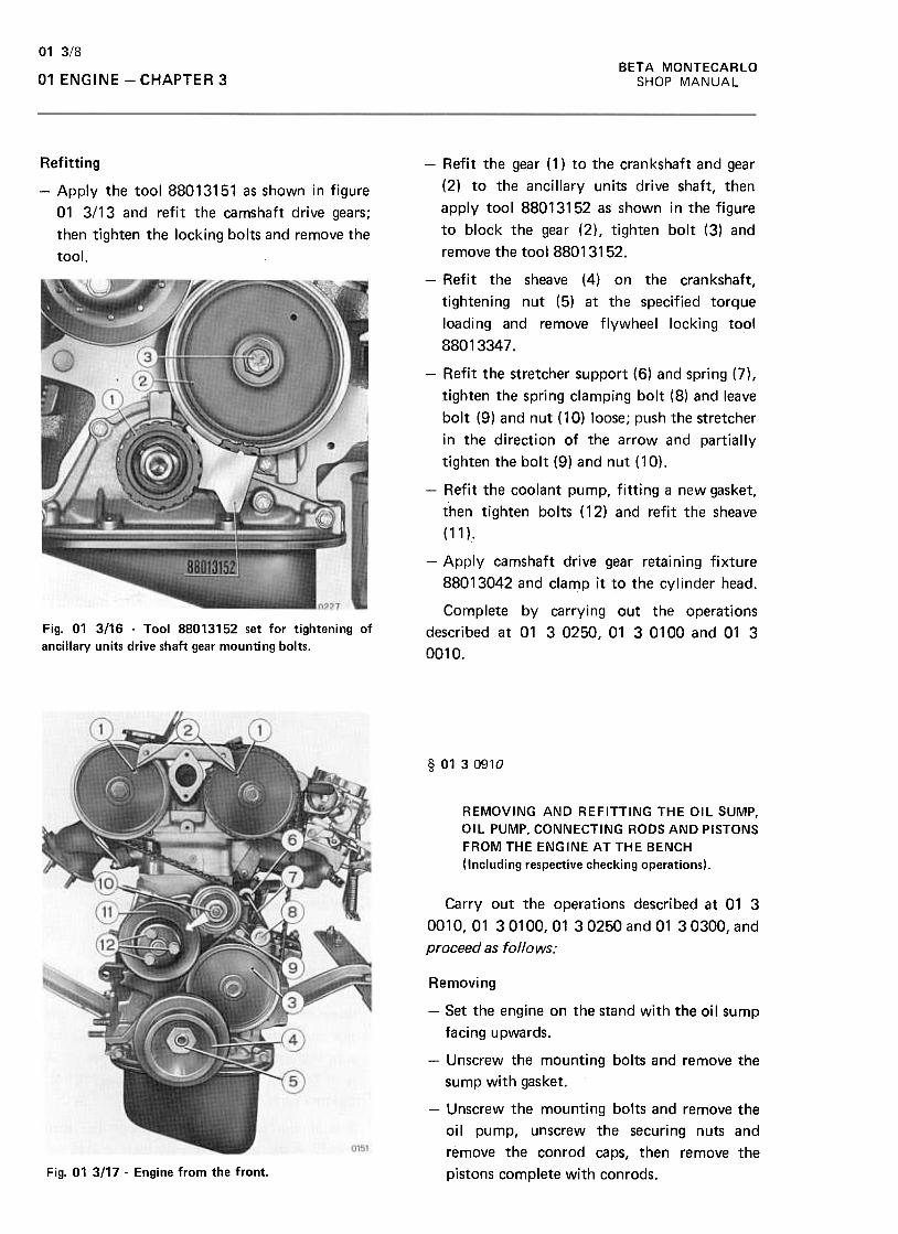
BETA MONTECARLO
SHOP MANUAL
01 3/8
01 ENGINE -CHAPTER 3
Refitting
-Apply the tool 88013151 as shown in figure
01 3/13 and refit the camshaft drive gears;
then tighten the locking bolts and remove the
tool.
-Refit the gear ( 1) to the cran kshaft and gear
(2) to the ancillary units drive shaft, then
apply tool 88013152 as shown in the figure
to block the gear (2), tighten bolt (3) and
remove the tool 88013152.
-Refit the sheave (4) on the crankshaft,
tightening nut (5) at the specified torque
loading and remove flywheel locking tool
88013347.
-Refit the stretcher support (6) and spring (7),
tighten the spring clamping bolt (8) and leave
bolt (9) and nut ( 10) loose; push the stretcher
in the direction of the arrow and partially
tighten the bolt (9) and nut (10).
-Refit the coolant pump, fitting a new gasket,
then tighten bolts ( 12) and refit the sheave
(11 )..
-Apply camshaft drive gear retaining fixture
88013042 and clamp it to the cylinder head.
Complete by carrying out the operationsdescribed at 01 3 0250, 01 3 0100 and 01 3
0010.
Fig. 01 3116 -Tool 88013152 set for tightening of
ancillary units drive shaft gear mounting bolts.
§ 0130910
REMOVING AND REFITTING THE OIL SUMP,
OIL PUMP, CONNECTING RODS AND PISTONS
FROM THE ENGINE AT THE BENCH
(Including respective checking operations).
Carry out the operations described at 01 3
0010, 01 3 0100, 01 3 0250 and 01 3 0300, and
proceed as follows:
Removing
-Set the engine on the stand with the oi I sump
facing upwards.
-Unscrew the mounting bolts and remove the
sump with gasket.
-Unscrew the mounting bolts and remove the
oil pump, unscrew the securing nuts and
remove the con rod caps, then remove the
pistons complete with conrods.Fig. 01 3/17 -Engine from the front.
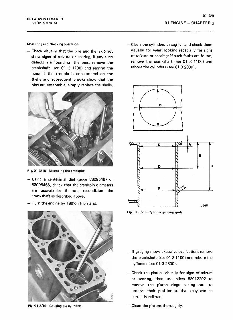
01 3/9
BETA MONTECARLO
SHOP MANUAL 01 ENGINE -CHAPTER 3
-Clean the cylinders throughly and check them
visually for wear, looking especially for signs
of seizure or scoring; if such faults are found,
remove the crankshaft (see 01 3 1100) and
rebore the cylinders (see 01 32800).
Measuring and checking operations
-Check visually that the pins and shells do not
show signs of seizure or scoring; if any such
defects are found on the pins, remove the
crankshaft (see 01 3 1100) and regrind the
pins; if the trouble is encountered on the
shells and subsequent checks show that the
pins are acceptable, simply replace the shells.
Fig.01 3118- Measuring the crankpins.
-Using a centesimal dial gauge 88095467 or
88095466, check that the crankpin diameters
are acceptable; if not, recondition the
crankshaft as described above.
-Turn the engine by 180oon the stand.
Fig. 01 3120 -Cylinder gauging spots.
-If gauging shows excessive ovalization, remove
the crankshaft (see 01 3 1100) and rebore the
cylinders (see 01 32800).
-Check the pistons visually for signs of seizure
or scoring, then use pliers 88012202 to
remove the piston rings, taking care to
observe their position so that they can be
correctly refitted.
-Clean the pistons thoroughly.Fig.01 3119- Gauging the cylinders.
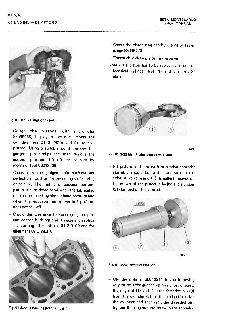
01 3/10BETA MONTECARLO
SHOP MANUAL01 ENGINE -CHAPTER 3
-Check the piston ring gap by means of feeler
gauge 88095770.
-Thoroughly clean piston ring grooves.
Note -If a piston has to be replaced, fit one of
identical cylinder (ref. 1) and pin (ref. 2)
class.
Fig. 01 3121 -Gauging the pistons.
0364
Fig. 01 3/22 bis -Fitting conrod to piston,
-Fit pistons and pins with respective conrods;
assembly should be carried out so that the
exhaust valve mark (1) (smallest recess) on
the crown of the piston is facing the number
(2) stamped on the conrod.
-Gauge the pistons with micrometer
88095468; if play is excessive, rebore the
cylinders (see 01 3 2800) and fit oversize
pistons. Using a suitable point, remove the
gudgeon pin circlips and then remove the
g(.;dgeon pins and lift off the conrods by
means of tool 88012209.
-Check that the gudgeon pin surfaces are
perfectly smooth and show no signs of scoring
or seizure. The mating of gudgeon pin and
piston is considered good when the lubricated
pin can be fitted by simple hand pressure and
when the gudgeon pin in vertical position
does not falloff.
-Check the clearance between gudgeon pins
and conrod bushings and if necessary replace
the bushings (for this see 01 3 3100 and for
alignment 01 32900).
0143
Fig.01 3/23 -Installer 88012211
-Use the installer 88012211 in the following
way to r~fit the gudgeon pin circfips: unscrew
the ring nut (1) and take the threaded pin (3)
from the cylinder (2); fit the circlip (4) inside
the cylinder and then refit the threaded pin,
tighten the ring nut and screw in the threadedFig. 01 3122- Checking piston ring gap.
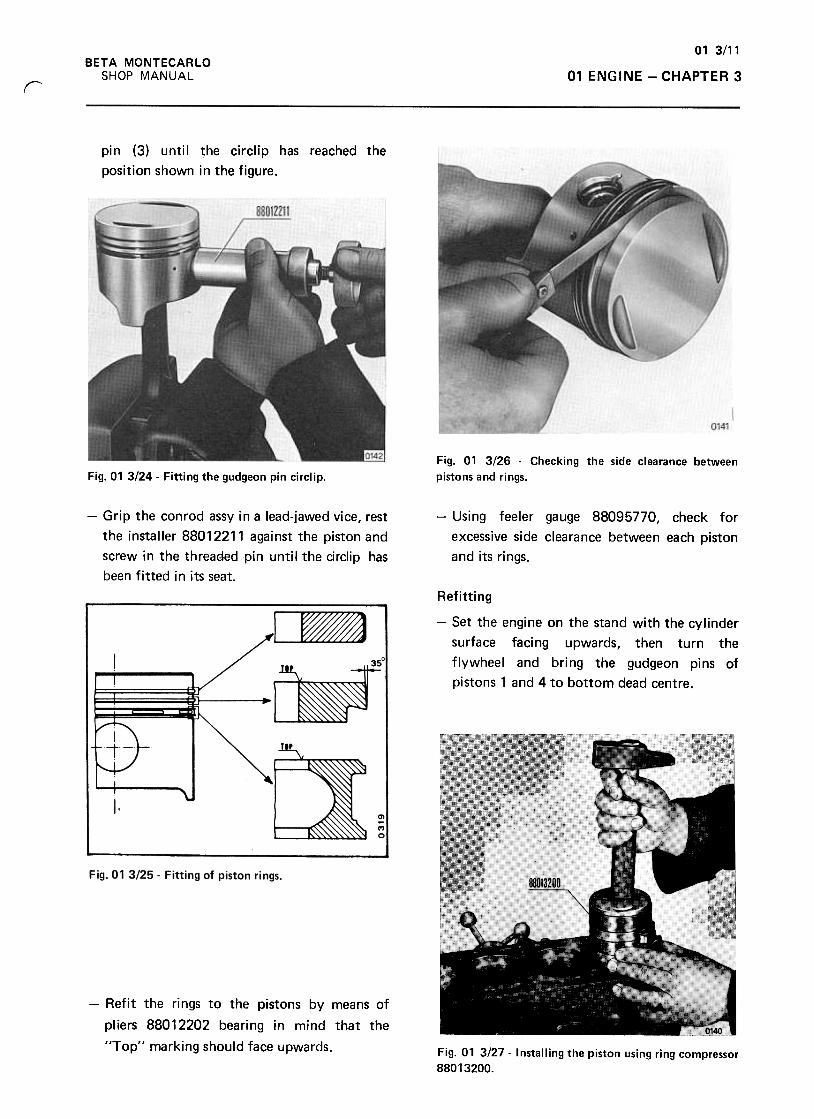
01 3/11
BETA MONTECARLO
SHOP ~J1ANUAL 01 ENGINE -CHAPTER 3r
pin (3) until the circlip has reached the
position shown in the figure.
Fig. 01 3/26 -Checking the side clearance between
pistons and rings.Fig. 01 3124- Fitting the gudgeon pin circlip.
-Using feeler gauge 88095770, check for
excessive side clearance between each piston
and its rings.
-Grip the con rod assy in a lead-jawed vice, rest
the installer 88012211 against the piston and
screw in the threaEied pin until the circlip has
been fitted in its seat.
Refitting
-Set the engine on the stand with the cylinder
surface facing upwards, then turn the
flywheel and bring the gudgeon pins of
pistons 1 and 4 to bottom dead centre.
-Refit the rings to the pistons by means of
pi iers 88012202 beari ng i n mi nd that the
"Top" marking should face upwards. Fig. 01 3/27- Installing the piston using ring compressor
88013200.
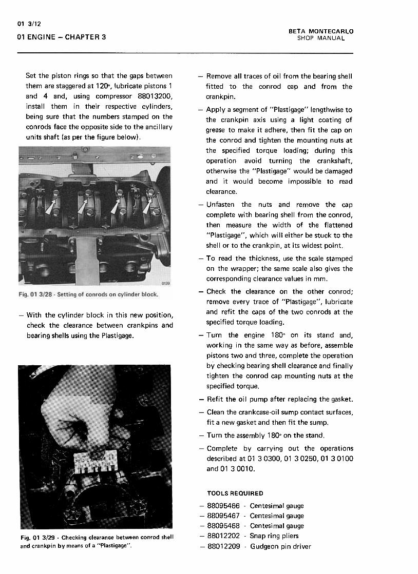
01 3/12
BETA MONTECARLO
SHOP MANUAL01 ENGINE -CHAPTER 3
Set the piston rings so that the gaps between
them are staggered at 120°, lubricate pistons 1
and 4 and, using compressor 88013200,
install them in their respective cylinders,
being sure that the numbers stamped on the
conrods face the opposite side to the ancillary
units shaft (as per the figure below) .
-With the cylinder block in this new position,
check the clearance between crankpins and
bearing shells using the Plastigage.
-Remove all traces of oil from the bearing shell
fitted to the conrod cap and from the
crankpin.
-Apply a segment of "Plastigage" lengthwise to
the crankpin axis using a light coating of
grease to make it adhere, then fit the cap on
the con rod and tighten the mounting nuts at
the specified torque loading; during this
operation avoid turning the crankshaft,
otherwise the "Plastigage" would be damaged
and it would become impossible to read
clearance.
-Unfasten the nuts and remove the cap
complete with bearing shell from the conrod,
then measure the width of the flattened
"Plastigage", which will either be stuck to the
shell or to the crankpin, at its widest point.
-To read the thickness, use the scale stamped
on the wri3pper; the same scale also gives the
corresponding clearance values in mm.
-Check the clearance on the other conrod;
remove every trace of "Plastigage", lubricate
and refit the caps of the two conrods at the
specified torque loading.
-Turn the engine 180° on its stand and,
working in the same way as before, assemble
pistons two and three, complete the operation
by checking bearing shell clearance and finally
tighten the conrod cap mounting nuts at the
specified torque.
-Refit the oil pump after replacing the gasket.
-Clean the crankcase-oil sump contact surfaces,
fit a new gasket and then fit the sump.
-Turn the assembly 180° on the stand.
-Complete by carrying out the operations
described at 01 30300, 01 30250, 01 30100
and0130010.
TOOLS REQUIRED
-88095466 -Centesimal gauge
-88095467 -Centesimal gauge
-88095468 -Centesimal gauge
-88012202 -Snap ring pliers
-88012209 -Gudgeon pin driver
Fig. 01 3129 -Checking clearance between conrod shell
and crankpin by means of a "Plastigage".
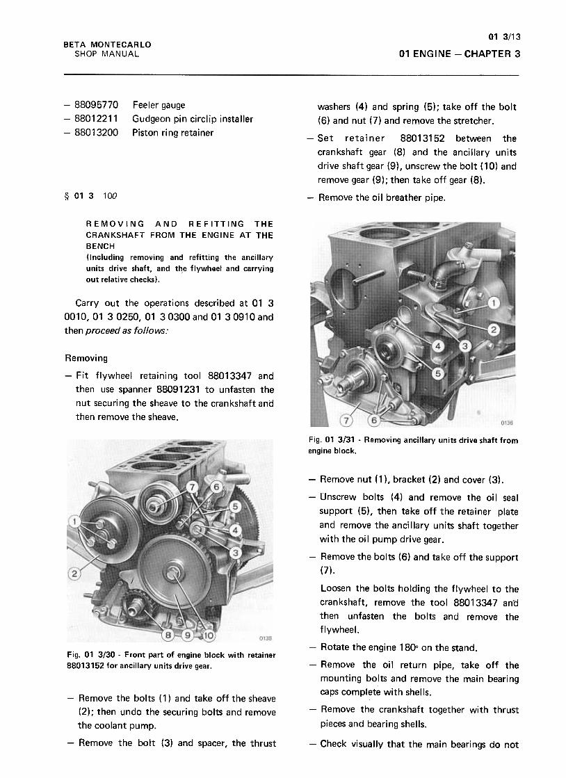
01 3/13
BETA MONTECARLO
SHOP MANUAL 01 ENGINE -CHAPTER 3
-88095770
-88012211
-88013200
Feeler gauge
Gudgeon pin circlip installer
Piston ring retainer
§ 01 3 100
washers (4) and spring (5) ; take off the bolt
(6) and nut (7) and remove the stretcher .
-Set retainer 88013152 between the
crankshaft gear (8) and the ancillary units
drive shaft gear (9) , unscrew the bolt ( 10) and
remove gear (9); then take off gear (8).
-Remove the oil breather pipe.
REMOVING AND REFITTING THE
CRANKSHAFT FROM THE ENGINE AT THE
BENCH
(Including removing and refitting the ancillary
units drive shaft, and the flywheel and carrying
out relative checks).
Carry out the operations described at 01 3
0010, 01 3 0250, 01 30300 and 01 30910 and
then proceed as follows:
Removing
-Fit flywheel retaining tool 88013347 and
then use spanner 88091231 to unfasten the
nut securing the sheave to the crankshaft and
then remove the sheave.
~
(),i1$
Fig. 01 3131 -Removing ancillary units drive shaft from
engine block.
-Remove nut (1 ), bracket (2) and cover (3).
-Unscrew bolts (4) and remove the oil seal
support (5), then take off the retainer plate
and remove the ancillary units shaft together
with the oi I pump drive gear .
-Remove the bolts (6) and take off the support
(7).
Loosen the bolts holding the flywheel to the
crankshaft, remove the tool 88013347 an'd
then unfasten the bolts and remove the
flywheel.0138~
Fig. 01 3130 -Front part of engine block with retainer
88013152 for ancillary units drive gear.
-Rotate the engine 180° on the stand.
-Remove the oil return pipe, take off the
mounting bolts and remove the main bearing
caps complete with shells.
-Remove the crankshaft together with thrust
pieces and bearing shells.
-Remove the bolts (1) and take off the sheave
(2); then undo the securing bolts and remove
the coolant pump.
-Remove the bolt (3) and spacer, the thrust -Check visually that the main bearings do not
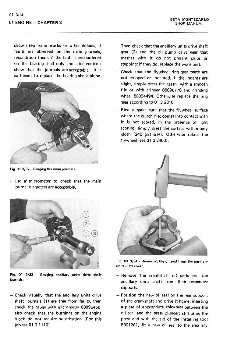
01 3/14
BETA MONTECARLO
SHOP MANUAL01 ENGINE -CHAPTER 3
show deep score marks or other defects; if
faults are observed on the main journals,
recondition them; if the fault is encountered
on the bearing shell only and later controls
show that the journals are acceptable, it is
sufficient to replace the bearing shells alone.
-Then check that the ancillary units drive shaft
gear (2) and the oil pump drive gear that
meshes with it do not present chips or
stepping; if they do, replace the worn part.
-Check that the flywheel ring gear teeth are
not chipped or indented. If the indents are
slight, simply dress the teeth with a smooth
file or with grinder 88096770 and grinding
wheel 88094494. Otherwise replace the ring
gear according to 01 32310.
-Finally make sure that the flywheel surface
where the clutch disc comes into contact with
it is not scored. 'In the presence of light
scoring, simply dress the surface with emery
cloth (240 grit size). Otherwise reface the
flywheel (see 01 32400).
-Use a~ micrometer to check that the main
journal diameters are acceptable.
Fig. 01 3134 -Removing the oil seal from the ancillary
units shaft cover .
Fig. 01 3/33
journals.
Gauging ancillary units drive shaft -Remove the crankshaft oi I seals and the
ancillary units shaft from their respective
supports.
-Check visually that the ancillary units drive
shaft journals ( 1) are free from faults, then
check the gauge with micrometer 88095466;
also check that the bushings on the engine
block do not require substitution (For this
job see 01 31110).
-Position the new oil seal on the rear support
of the crankshaft and drive it home, inserting
a plate of appropriate thickness between the
oil seal and the press plunger; still using the
press and with the aid of the installing tool
8801261, fit a new oil seal to the ancillary
Fig. 01 3132- Gauging the main journals.
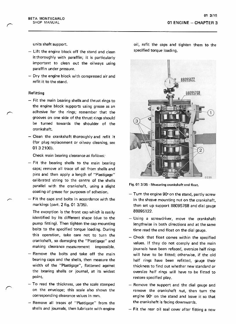
01 3/15
01 ENGINE -CHAPTER 3BETA MONTECARLO
SHOP MANUAL
r
oil, refit the caps and tighten them to the
specified torque loading.
units shaft support.
-Lift the engine block off the stand and clean
it thoroughly with paraffin; it is particularly
important to clean out the oilways using
paraffin under pressure.
-Dry the engine block with compressed air and
refit it to the stand.
"
Fig. 01 3/35- Measuring crankshaft end float.
r--
r
Refitting
-Fit the main bearing shells and thrust rings to
the engine block supports using grease as an
adhesive for the rings; remember that the
grooves on one side of the thrust rings should
be turned towards the shoulder of the
crankshaft.
-Clean the crankshaft thoroughly and refit it
(for plug replacement or oilway cleaning, see
01 32100).
Check main bearing clearance as follows:
-Fit the bearing shells to the main bearing
caps; remove all trace of oil from shells and
pins and then apply a length of "Plastigage"
calibrated string to the centre of the shells
parallel with the crankshaft, using a slight
coating of grease for purposes of adhesion.
-Fit the caps and bolts in accordance with the
markings (part. 2 fig. 01 3/35).
The exception is the front cap which is easily
identified by its different shape (due to the
pump fitting). Then tighten the cap mounting
bolts to the specified torque loading. During
this operation, take care not to turn the
crankshaft, so damaging the "Plastigage" and
making clearance measurement impossible.
-Remove the bolts and take off the main
bearing caps and the shells, then measure the
width of the "Plastigage", flattened against
the bearing shells or journal, at its widest
point.
-To read the thickness, use the scale stamped
on the envelope; this scale also shows the
corresponding clearance values in mm.
-Remove all traces of "Plastigage" from the
shells and journals, then lubricate with engine
-Turn the engine 90° on the stand, partly screw
in the sheave mounting nut on the crankshaft,
then set up support 88095768 and dial gauge
88095122.
-Using a screwdriver, move the crankshaft
lengthwise in both directions and at the same
time read the end float on the dial gauge.
-Check that float comes within the specified
values. If they do not comply and the main
journals have been refaced, oversize half rings
will have to be fitted; otherwise, if the old
half rings have been refitted, gauge their
thickness to find out whether new standard or
oversize half rings will have to be fitted to
restore specified play.
-Remove the support and the dial gauge and
remove the crankshaft nut, then turn the
engine 900 on the stand and leave it so that
the crankshaft is facing downwards.
-Fit the rear oil seal cover after fitting a new
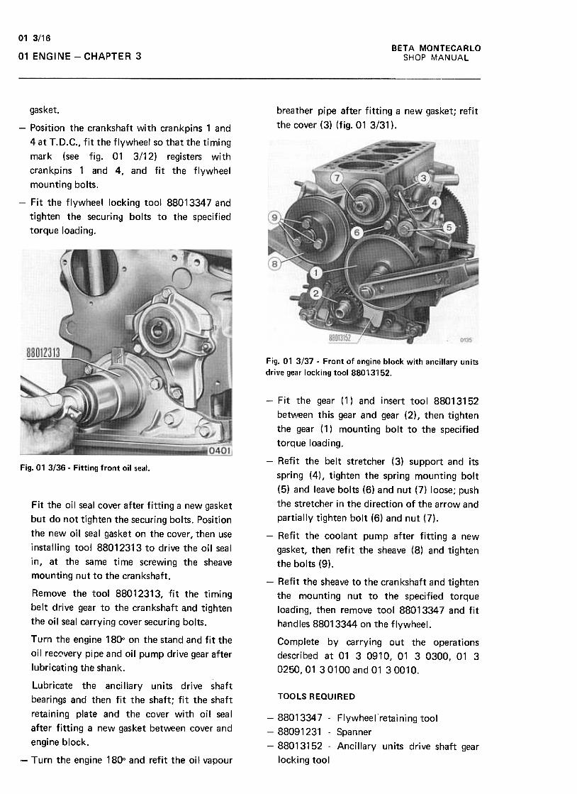
01 3/16
BETA MONTECARLO
SHOP MANUAL01 ENGINE -CHAPTER 3
breather pipe after fitting a new gasket; refit
the cover (3) (fig.01 3/31 ).
gasket.
-Position the crankshaft with crankpins 1 and
4 at T.D.C., fit the flywheel so that the timing
mark (see fig. 01 3/12) registers with
crankpins 1 and 4, and fit the flywheel
mounting bolts.
-Fit the flywheel locking tool 88013347 and
tighten the securin~ bolts to the specified
torque loading.
Fig. 01 3137 -Front of engine block with ancillary units
drive gear locking tool 88013152.
Fig. 01 3/36- Fitting front oil seal.
-Fit the gear (1) and insert tool 88013152
betl11!een this gear and gear (2), then tighten
the gear (1) mounting bolt to the specified
torque loading.
-Refit the belt stretcher (3) support and its
spring (4), tighten the spring mounting bolt
(5) and leave bolts (6) and nut (7) loose; push
the stretcher in the direction of the arrow and
partially tighten bolt (6) and nut (7).
-Refit the coolant pump after fitting a new
gasket, then refit the sheave (8) and tighten
the bolts (9).
-Refit the sheave to the crankshaft and tighten
the mounting nut to the specified torque
loading, then remove tool 88013347 and fit
handles 88013344 on the flywheel.
Complete by carrying out the operations
described at 01 3 0910, 01 3 0300, 01 3
0250, 01 30100 and 01 30010.
Fit the oil seal cover after fitting a new gasket
but do not tighten the securing bolts. Position
the new oil seal gasket on the cover, then use
installing tool 88012313 to drive the oil seal
in, at the same time screwing the sheave
mounting nut to the crankshaft.
Remove the tool 88012313, fit the timing
bett drive gear to the crankshaft and tighten
the oil seat carrying cover securing bolts.
Turn the engine 180° on the stand and fit the
oil rec~very pipe and oil pump drive gear after
lubricating the shank.
Lubricate the ancillary units drive shaft
bearings and then fit the shaft; fit the shaft
retaining plate and the cover with oil seal
after fitting a new gasket between cover and
engine block.
TOOLS REQUIRED
-88013347 -Flywheel retaining tool
-88091231 -Spanner
-88013152 -Ancillary units drive shaft gear
locking tool-Turn the engine 180° and refit the oil vapour
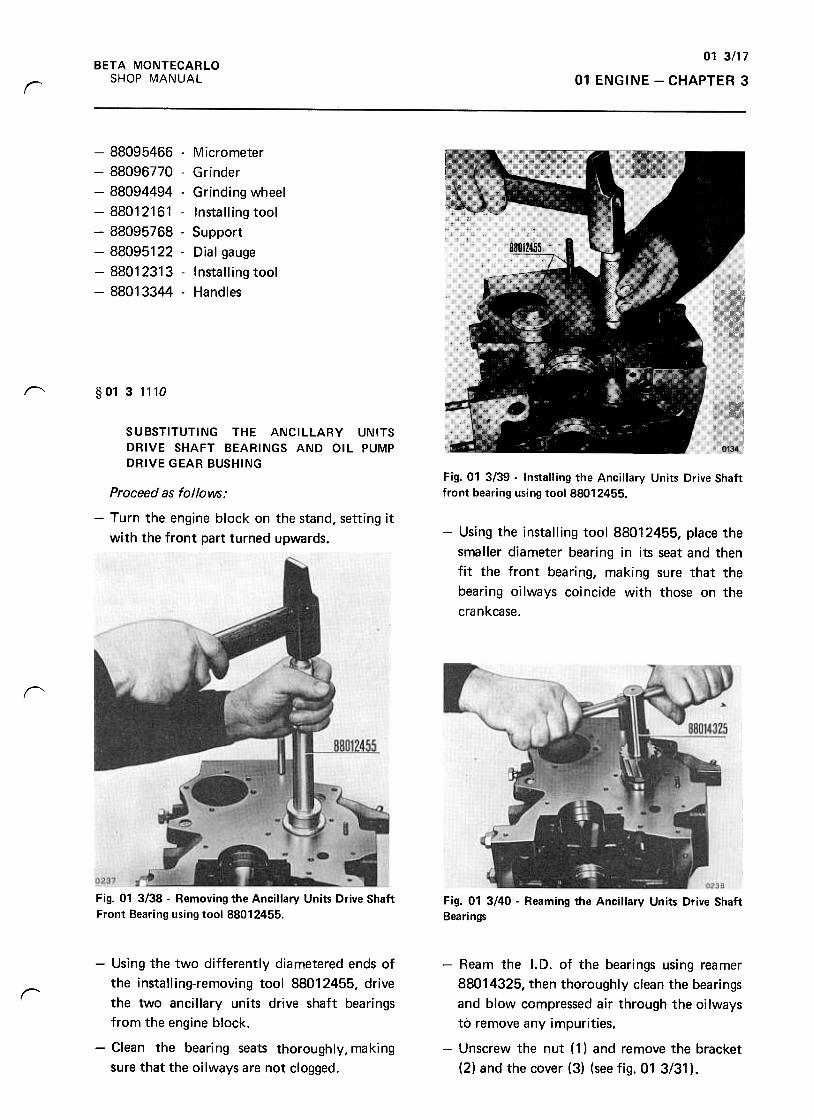
01 3117
01 ENGINE -CHAPTER 3BETA MONTECARLO
SHOP MANUALr
-88095466 -Micrometer
-88096770 -Grinder
-88094494 -Grinding wheel
-88012161 -Installing tool
-88095768- Support
-88095122 -Dial gauge
-88012313- Installing tool
-88013344 -Handles
r--- §O1 31110
SUBSTITUTING THE ANCILLARY UNITS
DRIVE SHAFT BEARINGS AND OIL PUMP
DRIVE GEAR BUSHINGFig. 01 3/39 -Installing the Ancillary Units Drive Shaft
front bearing using tool 88012455.Proceed as follows:
-Turn the engine block on the stand, setting it
with the front part turned upwards. -Using the installing tool 88012455, place the
smaller diameter bearing in its seat and then
fit the front bearing, making sure that the
bearing oilways coincide with those on the
crankcase.
f'
Fig. 01 3138 -Removing the Ancillary Units Drive Shaft
Front Bearing using tool 88012455.Fig. 01 3/40 -Reaming the Ancillary Units Drive Shaft
Bearings
r
-Using the two differently diametered ends of
the installing-removing tool 88012455, drive
the two ancillary units drive shaft bearings
from the engine block.
-Clean the bearing seats thoroughly, making
sure that the oilways are not clogged.
-Ream the I.D. of the bearings using reamer
88014325, then thoroughly clean the bearings
and blow compressed air through the oilways
to remove any impurities.
-Unscrew the nut ( 1) and remove the bracket
(2) and the cover (3) (see fig. 01 3/31 ).
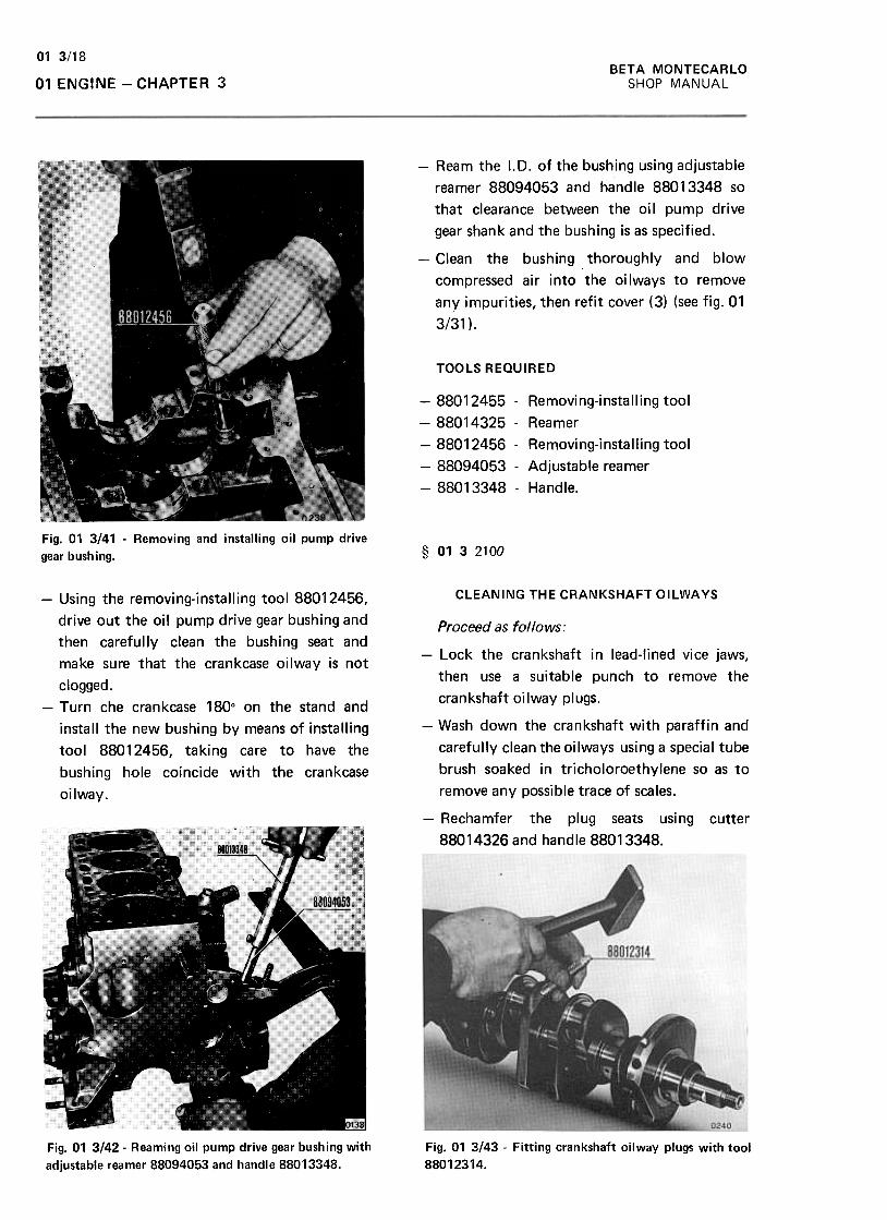
BETA MONTECARLO
SHOP MANUAL
01 3/18
01 ENGINE -CHAPTER 3
-Ream the I.D. of the bushing using adjustable
reamer 88094053 and handle 88013348 so
that clearance between the oil pump drive
gear shank and the bushing is as specified.
-Clean the bushing thoroughly and blow
compressed air into the oilways to remove
any impurities, then refit cover (3) (see fig. 01
3/31 ).
TOOLS REQUIRED
-88012455 -Removing-installing tool
-88014325- Reamer
-88012456 -Removing-installing tool
-88094053 -Adjustable reamer
-88013348 -Handle.
Fig. 01 3141 -Removing and installing oil pump drive
gear bushing. § 0132100
CLEANING THE CRANKSHAFT OILWAYS-Using the removing-installing tool 88012456,
drive out the oil pump drive gear bushing and
then carefully clean the bushing seat and
make sure that the crankcase oilway is not
clogged.-Turn che crankcase 180° on the stand and
install the new bushing by means of installing
tool 88012456, taking care to have the
bushing hole coincide with the crankcase
oilway.
Proceed as follows:
-Lock the crankshaft in lead-Iined vice jaws,
then use a suitable punch to remove the
crankshaft oilway plugs.
-Wash down the crankshaft with paraffin and
carefully clean the oilways using a special tube
brush soaked in tricholoroethylene so as to
remove any possible trace of scales.
-Rechamfer the plug seats using cutter
88014326 and handle 88013348.
Fig. 01 3/42- Reaming oil pump drive gear bushing with
adjustable reamer 88094053 and handle 88013348.
Fig. 01 3143 -Fitting crankshaft oilway plugs with tool
88012314.
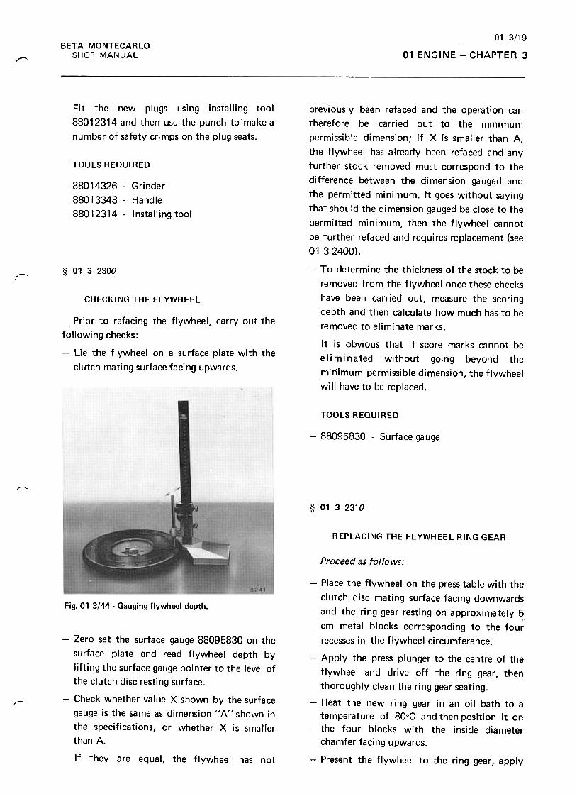
01 3/19
01 ENGINE -CHAPTER 3BETA MONTECARLO
SHOP MANUALr--
Fit the new plugs using installing tool
88012314 and then use the punch to make a
number of safety crimps on the plug seats.
TOOLS REQUIRED
88014326 -Grinder
88013348 -Handle
88012314 -Installing tool
§ 0132300
r
CHECKING THE FL YWHEEL
previously been refaced and the operation can
therefore be carried out to the minimum
permissible dimension; if X is smaller than A,
the flywheel has already been refaced and any
further stock removed must correspond to the
difference between the dimension gauged and
the permitted minimum. It goes without saying
that should the dimension gauged be close to the
permitted minimum, then the flywheel cannot
be further refaced and requires replacement (see
01 32400).
-To determine the thickness of the stock to be
removed from the flywheel once these checks
have been carried out, measure the scoring
depth and then calculate how much has to be
removed to eliminate marks.
It is obvious that if score marks cannot be
eliminated without going beyond the
minimum permissible dimension, the flywheel
will have to be replaced.
Prior to refacing the flywheel, carry out the
following checks:
-Lie the flywheel on a surface plate with the
clutch mating surface facing upwards.
TOOLS REQUIRED
-88095830 -Surface gauge
~
§ 0132310
REPLACING THE FL YWHEEL RING GEAR
Proceed as f01 10 ws:
Fig. 01 3/44- Gauging flywheel depth.
~
-Zero set the surface gauge 88095830 on the
surface plate and read flywheel depth by
lifting the surface gauge pointer to the level of
the clutch disc resting surface.
-Check whether value X shown by the surfacegauge is the same as dimension " A" shown in
the specifications, or whether X is smaller
than A.
If they are equal, the flywheel has not
-Place the flywheel on the press table with the
clutch disc mating surface facing downwards
and the ring gear resting on approximately 5
cm metal blocks corresponding to the four
recesses in the flywheel circumference.
-Apply the press plunger to the centre of the
flywheel and drive off the ring gear, then
thoroughly clean the ring gear seating.
-Heat the new ring gear in an oil bath to a
temperature of 80°C and then position it on
the four blocks with the inside diameter
chamfer facing upwards.
-Present the flywheel to the ring gear, apply

BETA MONTECARLO
SHOP MANUAL
01 3/20
01 ENGINE -CHAPTER 3
B shown in the figure below should be less
than the figure indicated in the respective
technical specifications.
the press plunger to the flywheel centre and
install the ring gear on the flywheel.
-When the operation is completed, swill the
flywheel in paraffin to remove all traces of
oil.
§ 0132400
REFACING THE FL YWHEEL
Fig. 01 3/46- Flywheel
-When the refacing operation has been
completed, remove it from the lathe, take
away the spindle 88023031 and refit the
clutch dowels.
After checking the flywheel (see 01 3 2300),
proceed as follows:
-Withdraw the clutch dowels from the
flywheel, apply spindle 88023031 and secure
it with the flywheel mounting bolts. Then fit
a driving dog and pin to the spindle. To reface
the clutch mating surface so that it is
perfectly perpendicular to the rotation axis.
-' Grip a cylindrical or hexagonal rod of .
diameter 25-30 mm and length 150-200 mm
in the lathe self-centering chuck, incline the
adjustable saddle of the lathe 30° and proceed
to machine a tapered tip that is in perfect
line with the horizontal axis of the lathe.
-Check the alignment by moving the live
centre to the point where it is in contact with
the tapered tip.
TOOLS REQUIRED
-88023031 -Spindle
§ 0132600
REPLACING THE ENGINE BLOCK PLUGS
Fig. 01 3/45- Refacing the flywheel.
-Set the flywheel complete with spindle
88023031 and driving dog on the lathe and
reface the clutch disc mating surface until any
scoring marks present on the surface have
been eliminated; bear in mind that dimension
Proceed as follows:
-Using an appropriate tool, remove the plug to
be substituted and thoroughly clean its
seating in the engine block.
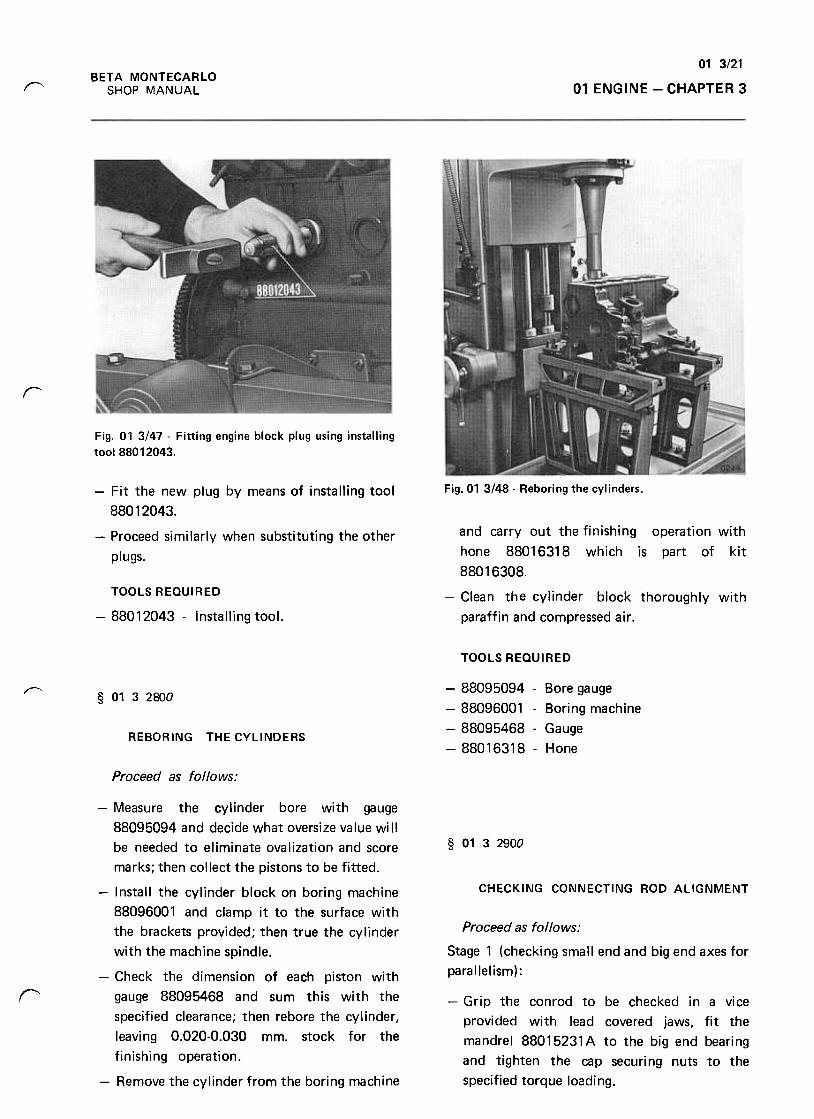
01 3/21
01 ENGINE -CHAPTER 3BETA MONTECARLO
SHOP MANUAL~
r
Fig. 01 3/47 -Fitting engine block plug using installing
too188012043.
Fig.01 3148- Reboring the cylinders.-Fit the new plug by means of installing tool
88012043.
-Proceed similarly when substituting the other
plugs.
and carry out the finishing operation with
hone 88016318 which is part of kit
88016308.
-Clean the cylinder block thoroughly with
paraffin and compressed air .
TOOLS REQUIRED
-88012043 -Installing tool.
TOOLS REQUIRED
-88095094 -Bore gauge
-88096001 -Boring machine
-88095468- Gauge
-88016318- Hone
r"§ 0132800
REBORING THE CYLINDERS
Proceed as follows:
§ 0132900
CHECKING CONNECTING ROD ALIGNMENT
Proceed as follows:
Stage 1 (checking small end and big end axes for
parallelism):
r -Grip the conrod to be checked in a vice
provided with lead covered jaws, fit the
mandrel 88015231 A to the big end bearing
and tighten the cap securing nuts to the
specified torque loading.
-Measure the cylinder bore with gauge
88095094 and decide what oversize value will
be needed to eliminate ovalization and score
marks; then collect the pistons to be fitted.
-Install the cylinder block on boring machine
88096001 and clamp it to the surface with
the brackets provided; then true the cylinder
with the machine spindle.
-Check the dimension of each piston with
gauge 88095468 and sum this with the
specified clearance; then rebore the cylinder,
leaving 0.020-0.030 mm. stock for the
finishing operation.
-Remove the cylinder from the boring machine
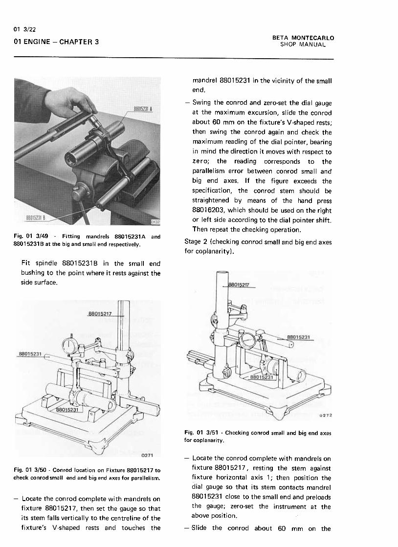
BETA MONTECARLO
SHOP MANUAL
01 3/22
01 ENGINE -CHAPTER 3
mandrel 88015231 in the vicinity of the small
end.
Fig. 01 3/49 -Fitting mandrels 88015231 A and
880152318 at the big and small end respectively.
-Swing the conrod and zero-set the dial gauge
at the maximum excursion, slide the conrod
about 60 mm on the fixture's V-shaped rests;
then swing the conrod again and check the
maximum reading of the dial pointer, bearing
in mind the direction it moves with respect to
zero; the reading corresponds to the
parallelism error between conrod small and
big end axes. If the figure exceeds the
specification, the conrod stem should be
straightened by means of the hand press
88016203, which should be used on the right
or left side according to the dial pointer shift.
Then repeat the checking operation.
Stage 2 (checking con rod small and big end axes
for coplanarity).
Fit spindle 88015231 B in the small end
bushing to the point where it rests against the
side surface.
Fig. 01 3/51 -Checking conrod small and big end axes
for coplanarity.
Fig. 01 3/50 -Conrod location on Fixture 88015217 to
check conrod small end and big end axes for parallelism.
-Locate the con rod complete with mandrels on
fixture 88015217, then set the gauge so that
its stem falls vertically to the centreline of the
fixture's V-shaped rests and touches the
-Locate the conrod complete with mandrels on
fixture 88015217, resting the stem against
fixture horizontal axis 1; then position the
dial gauge so that its stem contacts mandrel
88015231 close to the small end and preloads
the gauge; zero-set the instrument at the
above position.
-Slide the conrod about 60 mm on the
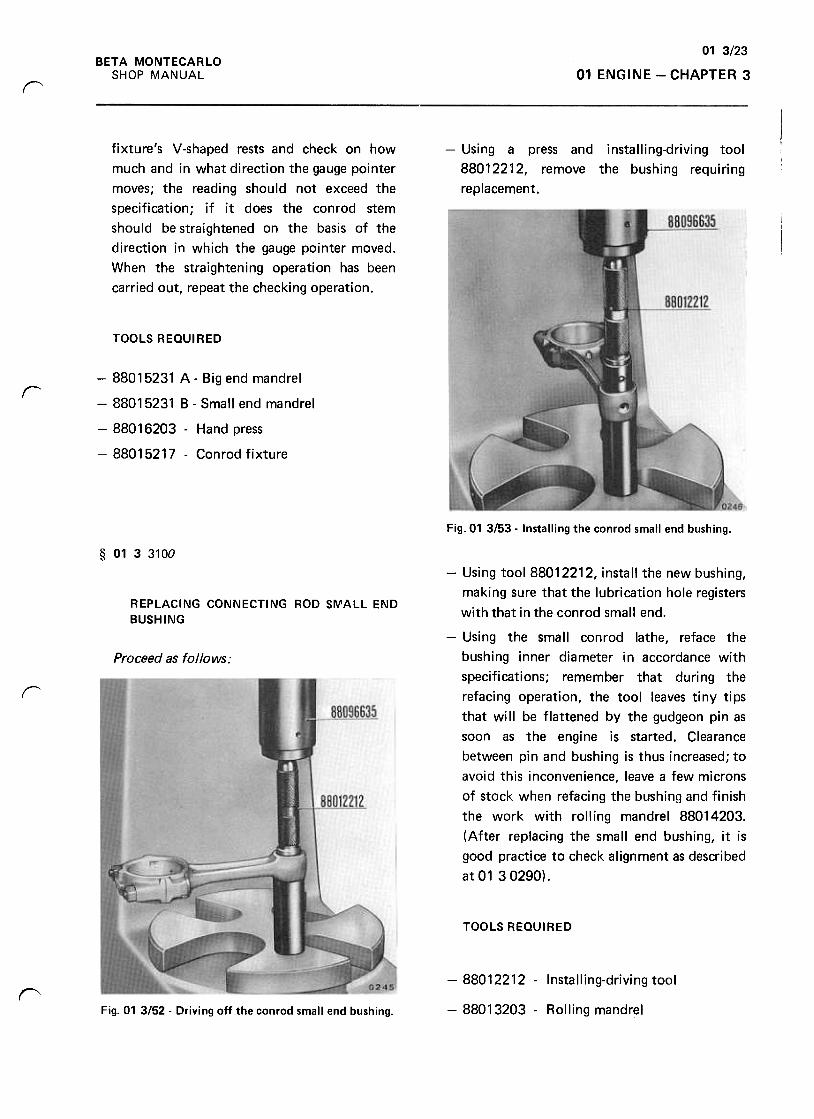
01 3123
01 ENGINE -CHAPTER 3
BETA MONTECARLO
SHOP MANUAL
r
fixture's V-shaped rests and check on how
much and in what direction the gauge pointer
moves; the reading should not exceed the
specification; if it does the conrod stem
should be straightened on the basis of the
direction in which the gauge pointer moved.
When the straightening operation has been
carried out, repeat the checking operation.
-Using a press and installing-driving tool
88012212, remove the bushing requiring
replacement.
TOOLS REQUI RED
r-88015231 A- Big end mandrel
-88015231 B -Small end mandrel
-88016203 -Hand press
-88015217 -Conrod fixture
Fig.01 3153 -Installing the conrod small end bushing.
§ 0133100
REPLACING CONNECTING ROD SMALL END
BUSHING
-Using tool 88012212, install the new bushing,
making sure that the lubrication hole registers
with that in the conrad small end.
-Using the small conrad lathe, reface the
bushing inner diameter in accordance with
specifications; remember that during the
refacing operation, the tool leaves tiny tips
that will be flattened by the gudgeon pin as
soon as the engine is started. Clearance
between pin and bushing is thus increased; to
avoid this inconvenience, leave a few microns
of stock when refacing the bushing and finish
the work with rolling mandrel 88014203.
(After replacing the small end bushing, it is
good practice to check alignment as described
at0130290).
Proceed as follows:
r
TOOLS REQUIRED
-88012212 -Installing-driving tool"-88013203 -Rolling mandrelFig. 01 3152 -Driving off the con rod small end bushing.
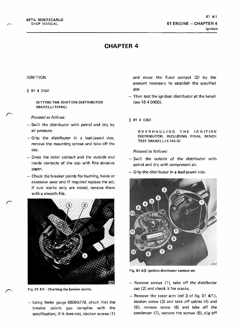
01 4/1
01 ENGINE -CHAPTER 4
Ignition
BETA MONTECARLO
SHOP MANUALr--
CHAPTER 4
IGNITION
§ 0140100
and move the fixed contact (2) by the
amount necessary to establish the specified
gap.
-Then test the ignition distributor at the bench
(see 1640400).SETTING THE IGNITION DISTRIBUTOR
(MARELLI S144G)
~
§ 0140300
Proceed as follows:
-Swill the distributor with petrol and dry by
air pressure. OVERHAULING THE IGNITION
DISTRIBUTOR, INCLUDING FINAL BENCH
TEST (MARELLI S 144 G)
Proceed as follows;
-Swill the outside of the distributor with
petrol and dry with compressed air .
-Grip the distributor in a lead-jawed vice.
-Grip the distributor in a lead-jawed vice,
remove the mounting screws and take off the
cap.
-Dress the rotor contact and the outside and
inside contacts of the cap with fine abrasive
paper .
-Check the breaker points for burning, holes or
excessive wear and if required replace the set;
if rust marks only are noted, remove them
with a smooth file.
r
Fig. 01 4/2 Ignition distributor contact set.
Fig. 01 411 -Checking the breaker points."-Remove screws (1 ), take off the distributor
cap (2) and check it for cracks.
-Remove the rotor arm (ref 3 of fig. 01 4/1 ),
slacken screw (3) and take off cables (4) and
(5); remove screw (6) and take off the
condenser (7), remove the screws (8), slip off
-Using feeler gauge 88095770, check that the
breaker points gap complies with the
specification; if it does not, slacken screws ( 1 )
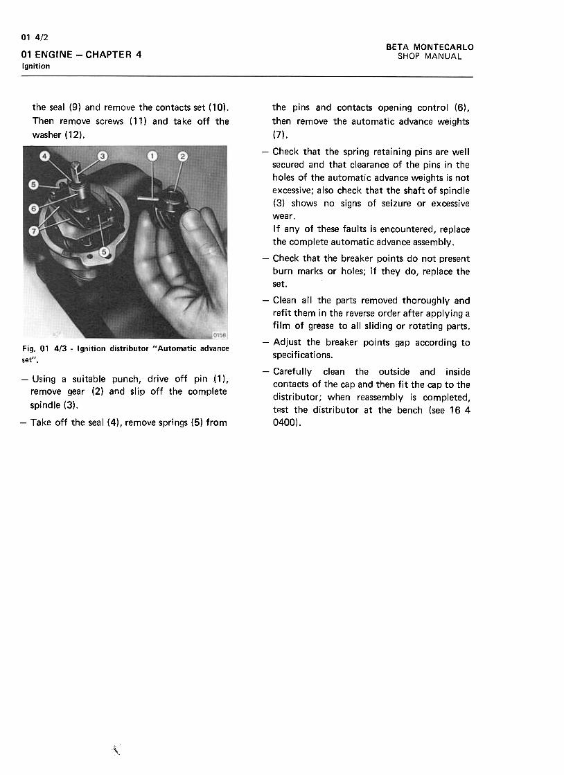
BETA MONTECARLO
SHOP MANUAL
01 4/2
01 ENGINE -CHAPTER 4
Ignition
the seal (9) and remove the contacts set (10).
Then remove screws (11) and take off the
washer (12).
Fig. 01 4/3 -Ignition distributor "Automatic advance
set".
the pins and contacts opening control (6),
then remove the automatic advance weights
(7),
-Check that the spring retaining pins are well
secured and that clearance of the pins in the
holes of the automatic advance weights is not
excessive; also check that the shaft of spindle
(3) shows no signs of seizure or excessive
wear.
If any of these faults is encountered, replace
the complete automatic advance assembly.
-Check that the breaker points do not present
burn marks or holes; if they do, replace the
set.
-Clean all the parts removed thoroughly and
refit them in the reverse order after applying a
film of grease to all sliding or rotating parts.
-Adjust the breaker points gap according to
specifi cati ons.
-Carefully clean the outside and inside
contacts of the cap and then fit the cap to the
distributor; when reassembly is completed,
t~st the distributor at the bench (see 16 4
0400).
-Using a suitable punch, drive off pin ( 1) ,
remove gear (2) and slip off the complete
spindle (3).
-Take off the seal (4), remove springs (5) from
"
,
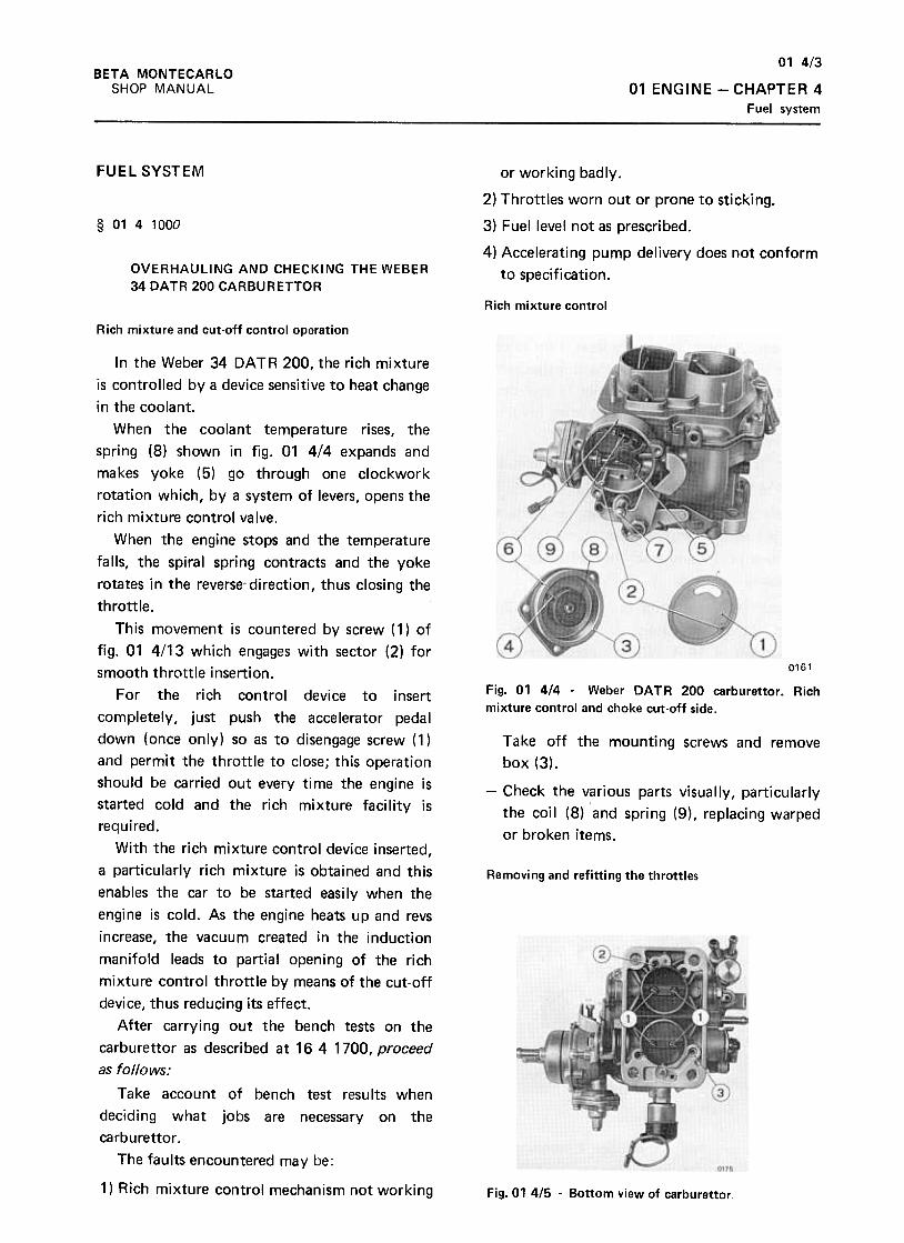
01 4/3
01 ENGINE -CHAPTER 4
Fuel system
BETA MONTECARlO
SHOP MANUAL
FUEL SYSTEM
§ 0141000
or working badly.
2) Throttles worn out or prone to sticking.
3) Fuel level not as prescribed.
4) Accelerating pump delivery does not conform
to specification.OVERHAULING AND CHECKING THE WEBER
34 DATR 200 CARBURETTOR
Rich mixture control
Rich mixture and cut-off control operation
0161
Fig. 01 4/4 -Weber DA TR 200 carburet tor. Rich
mixture control and choke cut-off side.
Take off the mounting screws and remove
box (3).
-Check the various parts visually, particularly
the coil (8) and spring (9), replacing warped
or broken items.
Removing and refitting the throttles
In the Weber 34 DATA 200, the rich mixture
is controlled bya device sensitive to heat change
in the coolant.
When the coolant temperature rises, the
spring (8) shown in fig. 01 4/4 expands and
makes yoke (5) go through one clockwork
rotation which, by a system of levers, opens the
rich mixture control valve.
When the engine stops and the temperature
falls, the spiral spring contracts and the yoke
rotates in the reverse direction, thus closing the
throttle.
This movement is countered by screw (1) of
fig. 01 4/13 which engages with sector (2) for
smooth throttle insertion.
For the rich control device to insert
completely, just push the accelerator pedal
down (once only) so as to disengage screw (1 )
and permit the throttle to close; this operation
should be carried out every time the engine is
started cold and the rich mixture facility is
required.
With the rich mixture control device inserted,
a particularly rich mixture is obtained and this
enables the car to be started easi Iy when the
engine is cold. As the engine heats up and revs
increase, the vacuum created in the induction
manifold leads to partial opening of the rich
mixture control throttle by means of the cut-off
device, thus reducing its effect.
After carrying out the bench tests on the
carburet tor as described at 16 4 1700, proceed
as follows:
Take account of bench test results when
deciding what jobs are necessary on the
carburet tor .
The faults encountered may be:
1) Rich mixture control mechanism not working Fig. 01 4/5 -Bottom view of carburettor
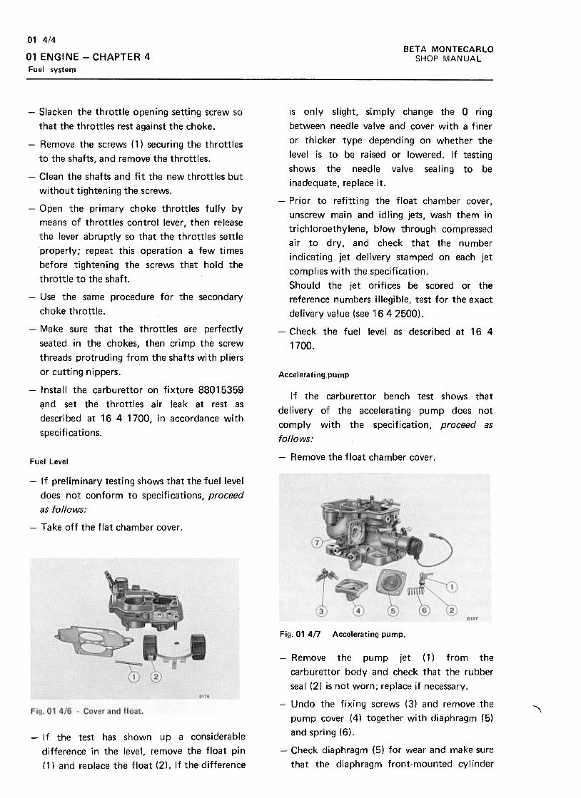
BETA MONTECARLO
SHOP MANUAL
01 4/4
01 ENGINE -CHAPTER 4
Fuel system
is only slight, simply change the a ring
between needle valve and cover with a finer
or thicker type depending on whether the
level is to be raised or lowered. If testing
shows the needle valve sealing to be
inadequate, replace it.
-Prior to refitting the float chamber cover ,
unscrew main and idling jets, wash them in
trichloroethylene, blow through compressed
air to dry, and check that the number
indicating jet delivery stamped on each jet
complies with the specification.
Should the jet orifices be scored or the
reference numbers illegible, test for the exact
delivery value (see 1642500).
-Check the fuel level as described at 16 4
1700.
Accelerating pump
-Slacken the throttle opening setting screw so
that the throttles rest against the choke.
-Remove the screws ( 1) securing the throttles
to the shafts, and remove the throttles.
-Clean the shafts and fit the new throttles but
without tightening the screws.
-Open the primary choke throttles fully by
means of throttles control lever, then release
the lever abruptly so that the throttles settle
properly; repeat this operation a few times
before tightening the screws that hold the
throttle to the shaft.
-Use the same procedure for the secondary
choke throttle.
-Make sure that the throttles are perfectly
seated in the chokes, then crimp the screw
threads protruding from the shafts with pliers
or cutting nippers.
-Install the carburet tor on fixture 88015359
~nd set the throttles air leak at rest as
described at 16 4 1700, in accordance with
specifications.
If the carburet tor bench test shows that
delivery of the accelerating pump does not
comply with the specification, proceed as
follows:
-Remove the float chamber cover.Fuel Level
-If preliminary testing shows that the fuel level
does not conform to specifications, proceed
as follows:
-Take off the flat chamber cover .
Fig. 01 4n Accelerating pump.
,-If the test has shown up a considerabje
difference in the level, remove the float pin
( 1) and reolace the float (2) .If the difference
-Remove the pump jet (1} from the
carburet tor body and check that the rubber
seal (2) is not worn; replace if necessary.
-Undo the fixing screws (3) and remove the
pump cover (4) together with diaphragm (5)
and spring (6).
-Check diaphragm (5) for wear and make sure
that the diaphragm front-mounted cylinder
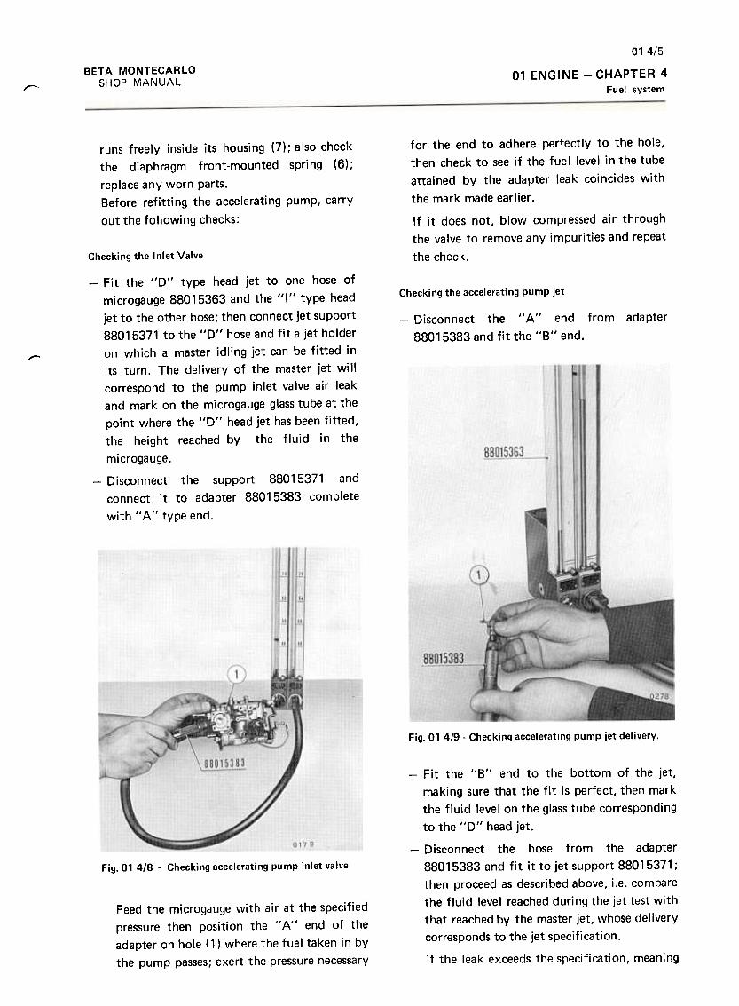
014/5
BETA MONTECARLO
SHOP MANUAL
01 ENGINE -CHAPTER 4
Fuel systemr-
runs freely inside its housing (7); also check
the diaphragm front-mounted spring (6);
replace any worn parts.
Before refitting the accelerating pump, carry
out the following checks:
for the end to adhere perfectly to the hole,
then check to see if the fuel level in the tube
attained by the adapter leak coincides with
the mark made earlier .
If it does not, blow compressed air through
the valve to remove any impurities and repeat
the check.Checking the Inlet Valve
-Fit the "0" type head jet to one hose of
microgauge 88015363 and the "I" type head
jet to the other hose; then connect jet support
88015371 to the "0" hose and fit a jet holder
on which a master idling jet can be fitted in
its turn. The delivery of the master jet will
correspond to the pump inlet valve air leak
and mark on the microgauge glass tube at the
point where the "0" head jet has been fitted,
the height reached by the fluid in the
microgauge.
Checking the accelerating pump jet
from adapter-Disconnect the " A " end
88015383 and fit the "8" end.
".-
-Disconnect the support 88015371 and
connect it to adapter 88015383 complete
with IIA" type end.
Fig. 01 419 -Checking accelerating pump jet delivery.
Q17~
Fig.01 418 -Checking accelerating pump inlet valve
Feed the microgauge with air at the specifiedpressure then position the " A" end of the
adapter on hole (1) where the fuel taken in by
the pump passes; exert the pressure necessary
-Fit the "8" end to the bottom of the jet,
making sure that the fit is perfect, then mark
the fluid level on the glass tube corresponding
to the "D" head jet.
-Disconnect the hose from the adapter
88015383 and fit it to jet support 88015371 ;
then proceed as described above, i.e. compare
the fluid level reached during the jet test with
that reached by the master jet, whose delivery
corresponds to the jet specification.
If the leak exceeds the specification, meaning
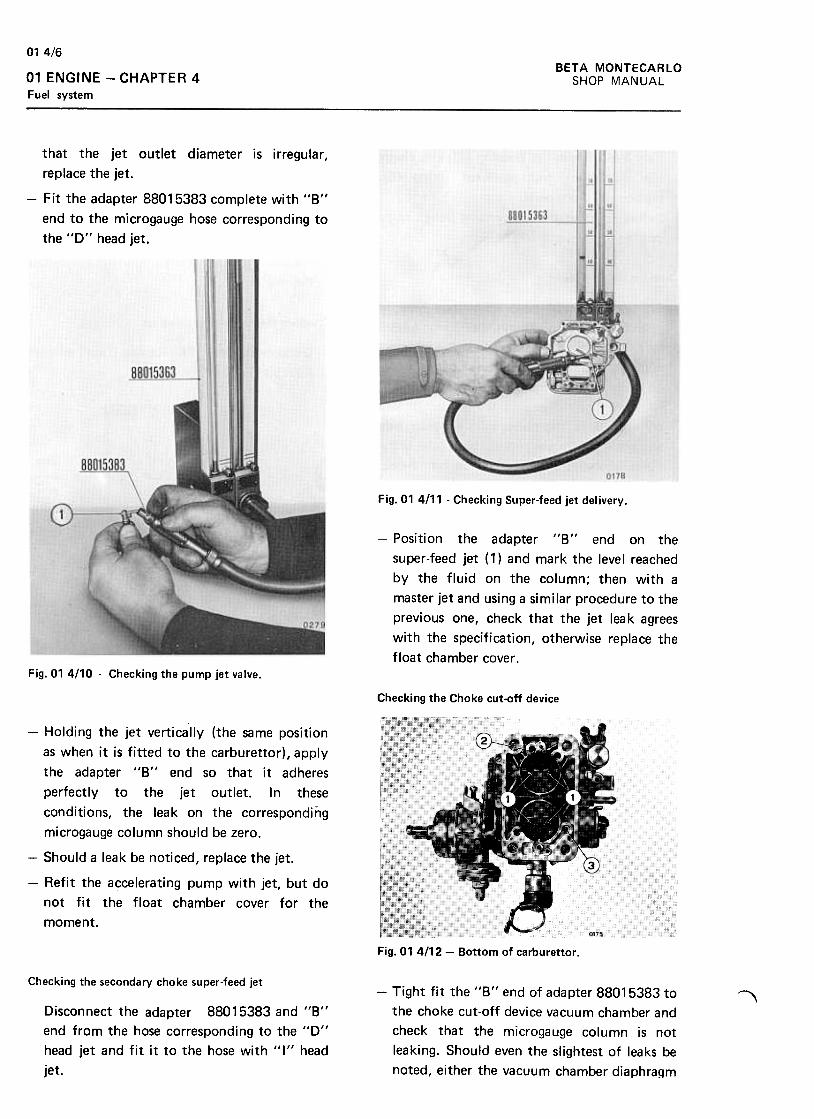
BETA MONTECARLO
SHOP MANUAL
014/6
01 ENGINE -CHAPTER 4
Fuel system
that the jet outlet diameter is irregular ,
replace the jet.
-Fit the adapter 88015383 complete with "8"
end to the microgauge hose corresponding to
the "D" head jet.
Fig.01 4111- Checking Super-feed jet delivery.
-Position the adapter "8" end on the
super-feed jet ( 1) and mark the level reached
by the fluid on the column; then with a
master jet and using a similar procedure to the
previous one, check that the jet leak agrees
with the specification, otherwise replace the
float chamber cover .Fig. 01 4/10 .Checking the pump jet valve.
Checking the Choke cut-off device
-Holding the jet vertically (the same position
as when it is fitted to the carburet tor), apply
the adapter "8" end so that it adheres
perfectly to the jet outlet. In these
conditions, the leak on the corresponding
microgauge column should be zero.
-Should a leak be noticed, replace the jet.
-Refit the accelerating pump with jet, but do
not fit the float chamber cover for the
moment.
Fig. 01 4112 -Bottom of carburettor .
Checking the secondary choke super-feed jet-Tight fit the "8" end of adapter 88015383 to
the choke cut-off device vacuum chamber and
check that the microgauge column is not
leaking. Should even the slightest of leaks be
noted, either the vacuum chamber diaphragm
,Disconnect the adapter 88015383 and 11811
end from the hose corresponding to the "D"
head jet and fit it to the hose with "1" head
jet.
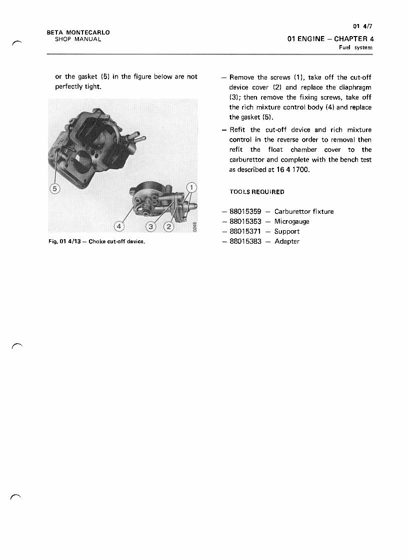
01 4/7
BETA MONTECARLO
SHOP MANUAL 01 ENGINE -CHAPTER 4
Fuel systemr
or the gasket (5) in the figure below are not
perfectly tight.
-Remove the screws (1 ), take off the cut-off
device cover (2) and replace the diaphragm
(3); then remove the fixing screws, take off
the rich mixture control body (4) and replace
the gasket (5) .
-Refit the cut-off device and rich mixture
control in the reverse order to removal then
refit the float chamber cover to the
carburet tor and complete with the bench test
as described at 16 4 1700.
TOOLS REQUIRED
-88015359 -Carburet tor fixture
-88015353 -Microgauge
-88015371 -Support
-88015383 -AdapterFig. 01 4/13- Choke cut-off device.
r
~
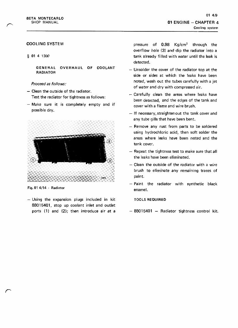
01 4/9
01 ENGINE -CHAPTER 4
Cooling system
BETA MONTECARLO
SHOP MANUAL"
COOLING SYSTEM
§ 0141300
GENERAL
RADIATOR
OVERHAUL OF COOLANT
Proceed as follows:
-Clean the outside of the radiator .
Test the radiator for tightness as follows:
-Make sure it is completely empty and if
possible dry.
pressure of 0.98 Kg/cm2 through the
overflow hole (3) and dip the radiator into a
tank already filled with water until the leak is
detected.
-Unsolder the cover of the radiator top at the
side or sides at which the leaks have been
noted, wash out the tubes carefully with a jet
of water and dry with compressed air .
-Carefully clean the areas where leaks have
been detected, and the edges of the tank and
cover with a flame and wire brush.
-If necessary, straighten out the tank cover and
any tube gills that have been bent.
-Remove any rust from parts to be soldered
using hydrochloric acid, then soft solder the
areas where leaks have been noted and the
tank cover.
-Repeat the tightness test to make sure that all
the leaks have been eliminated.
-Clean the outside of the radiator with a wire
brush to eliminate any remaining traces of
paint.
-Paint the radiator with synthetic black
enamel.Fig. 01 4/14 -Radiator
-Using the expansion plugs included in kit
88015401, stop up coolant inlet and outlet
ports (1) and (2); then introduce air at a
TOOLS REQUIRED
-88015401 -Radiator tightness control kit.
r
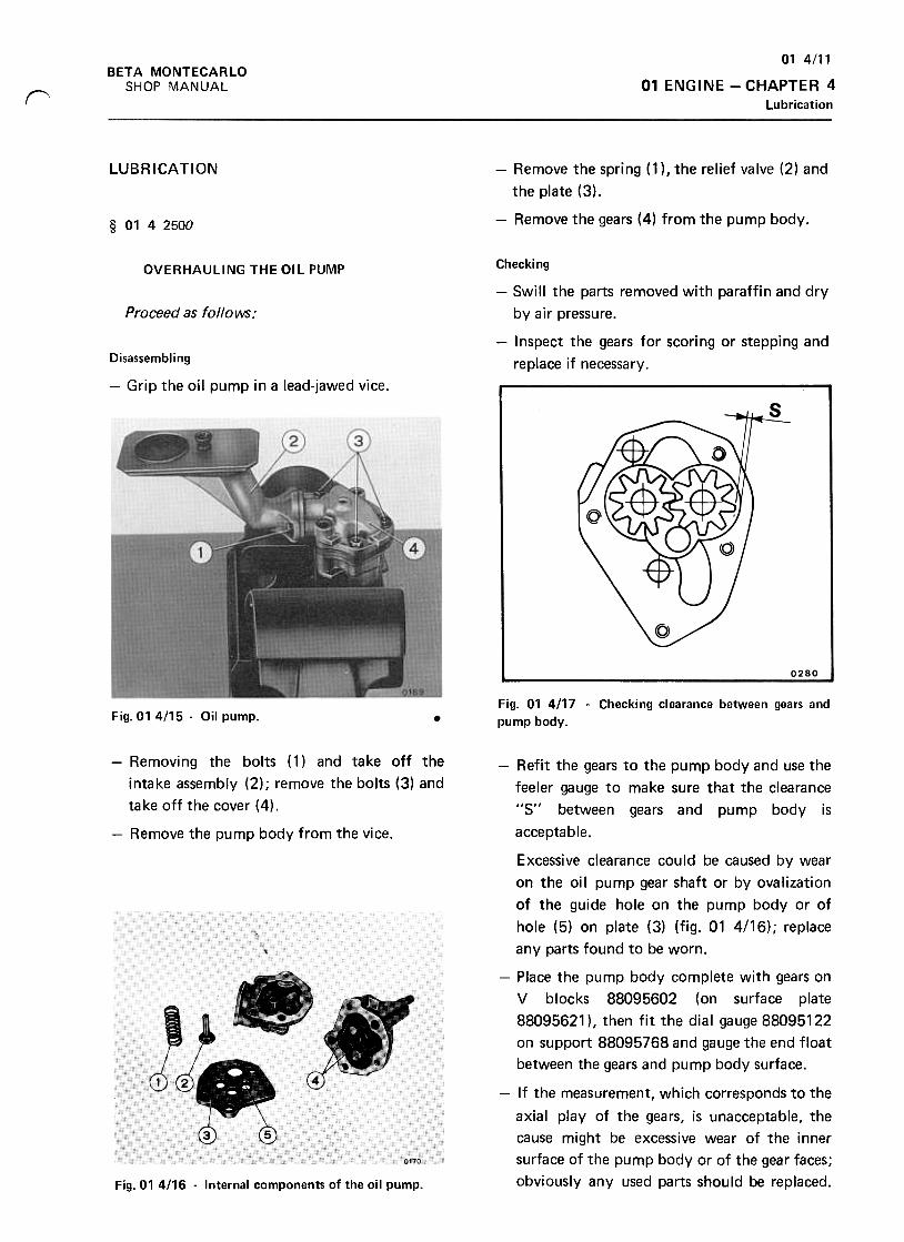
01 4/11
01 ENGINE -CHAPTER 4
Lubrication
BETA MONTECARLO
SHOP MANUALr
LUBRICATION -Remove the spring (1 ), the relief valve (2) and
the plate (3),
-Remove the gears (4) from the pump body.§ 0142500
OVERHAULING THE OIL PUMP
Proceed as follows:
Checking
-Swill the parts removed with paraffin and dry
by air pressure.
-Inspect the gears for scoring or stepping and
replace if necessary.Disassembling
-Grip the oil pump in a lead-jawed vice.
0280
Fig. 01 4/17 -Checking clearance between gears and
pump body.Fig. 014/15 -Oil pump. .
-Refit the gears to the pump body and use the
feeler gauge to make sure that the clearance
"5" between gears and pump body is
acceptable.
-Removing the bolts (1) and take off the
intake assembly (2); remove the bolts (3) and
take off the cover (4),
-Remove the pump body from the vice.
Excessive clearance could be caused by wear
on the oil pump gear shaft or by ovalization
of the guide hole on the pump body or of
hole (5) on plate (3) (fig. 01 4/16) ; replace
any parts found to be worn.
-Place the pump body complete with gears on
V blocks 88095602 (on surface plate
88095621 ), then fit the dial gauge 88095122
on support 88095768 and gauge the end float
between the gears and pump body surface.
-If the measurement, which corresponds to the
axial play of the gears, is unacceptable, the
cause might be excessive wear of the inner
surface of the pump body or of the gear faces;
obviously any used parts should be replaced.Fig. 01 4116 -Internal components of the oil pump.
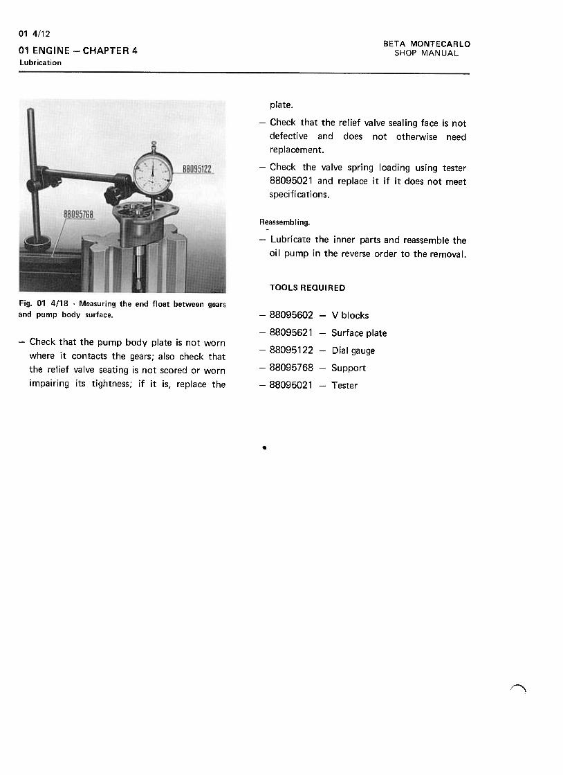
BETA MONTECARLO
SHOP MANUAL
01 4/12
01 ENGINE -CHAPTER 4
lubrication
plate.
-Check that the relief valve sealing face is not
defective and does not otherwise need
replacement.
-Check the valve spring loading using tester
88095021 and replace it if it does not meet
specifications.
Reassembling.
-Lubricate the inner parts and reassemble the
oil pump in the reverse order to the removal.
TOOLS REQUIRED
Fig. 01 4/18 -Measuring the end float between gears
and pump body surface. -88095602 -V blocks
-88095621 -Surface plate
-88095122 -Dial gauge
-88095768 -Support
-88095021 -Tester
-Check that the pump body plate is not worn
where it contacts the gears; also check that
the relief valve seating is not scored or worn
impairing its tightness; if it is, replace the
.
~
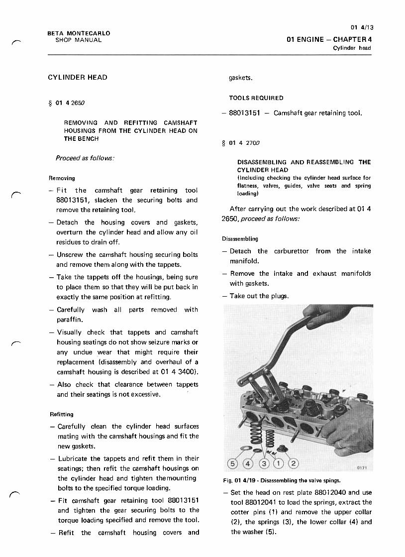
01 4/13
01 ENGINE -CHAPTER 4Cylinder head
BETA MONTECARLO
SHOP MANUALr
CYLINDER HEAD gaskets.
TOOLS REQUIRED§ 01 4 2650
-88013151 -Camshaft gear retaining tool.
REMOVING AND REFITTING CAMSHAFT
HOUSINGS FROM THE CYLINDER HEAD ON
THE BENCH§ 0142700
Proceed as follows:DISASSEMBLING AND REASSEMBLING THE
CYLINDER HEAD
(Including checking the cylinder head surface for
flatness, valves, guides, valve seats and spring
loading)rAfter carrying out the work described at 01 4
2650, proceed as follows:
Removing
-F i t t he camshaft gear retaining tool
88013151, slacken the securing bolts and
remove the retaining tool.
-Detach the housing covers and gaskets,
overturn the cylinder head and allow any oil
residues to dra in off . Disassembling
-Detach the carburet tor from the intake
manifold.
-Remove the intake and exhaust manifolds
with gaskets.
-Take out the plugs.
r
-Unscrew the camshaft housing securing bolts
and remove them along with the tappets.
-Take the tappets off the housings, being sure
to place them so that they wi II be put back in
exactly the same position at refitting.
-Carefully wash all parts removed with
paraffin.
-Visually check that tappets and camshaft
housing seatings do not show seizure marks or
any undue wear that might require their
replacement (disassembly and overhaul of a
camshaft housing is described at 01 4 3400).
-Also check that clearance between tappets
and their seatings is not excessive.
Fig. 01 4119. Disassembling the valve spings.
-Set the head on rest plate 88012040 and use
tool 88012041 to load the springs, extract the
cotter pins ( 1) and remove the upper collar
(2), the springs (3), the lower collar (4) and
the washer ( 5) .
r
Refitting
-Carefully clean the cylinder head surfaces
mating with the camshaft housings and fit the
new gaskets.
-Lubricate the tappets and refit them in their
seatings; then refit the camshaft housings on
the cylinder head and tighten the mounting
bolts to the specified torque loading.
-Fit camshaft gear retaining tool 88013151
and tighten the gear securing bolts to the
torque loading specified and remove the tool.
-Refit the camshaft housing covers and
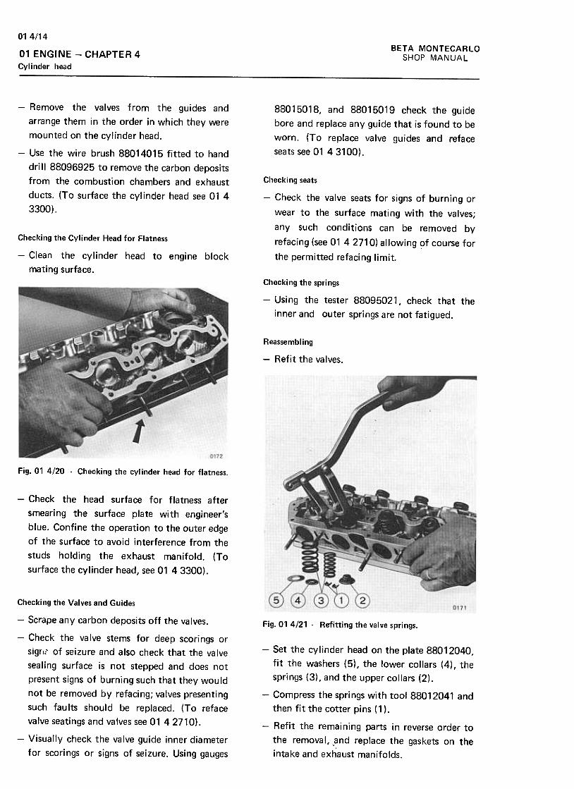
BETA MONTECARLO
SHOP MANUAL
01 4/14
01 ENGINE -CHAPTER 4Cylinder head
88015018, and 88015019 check the guide
bore and replace any guide that is found to be
worn. (To replace valve guides and reface
seats see 01 43100).
-Remove the valves from the guides and
arrange them in the order in which they were
mounted on the cylinder head.
-Use the wire brush 88014015 fitted to hand
dri II 88096925 to remove the carbon deposits
from the combustion chambers and exhaust
ducts. (To surface the cylinder head see 01 4
3300).
Checking seats
-Check the valve seats for signs of burning or
wear to the surface mating with the valves;
any such conditions can be removed by
refacing (see 01 42710) allowing of course for
the permitted refacing limit.
Checking the Cylinder Head for Flatness
-Clean the cylinder head to engine block
mating surface.
Checking the springs
-Using the tester 88095021, check that the
inner and outer springs are not fatigued.
Reassembling
-Refit the valves.
Fig. 01 4!20 -Checking the cylinder head for flatness.
-Check the head surface for flatness after
smearing the surface plate with engineer's
blue. Confine the operation to the outer edge
of the surface to avoid interference from the
studs holding the exhaust manifold. (To
surface the cylinder head, see 01 43300).
Fig. 01 4/21 -Refitting the valve springs.
-Set the cylinder head on the plate 88012040,
fit the washers (5), the lower collars (4), the
springs (3), and the upper collars (2),
-Compress the spri ngs with tool 88012041 and
then fit the cotter pins (1 ).
-Refit the remaining parts in reverse order to
the removal, ,and replace the gaskets on the
intake and exhaust manifolds.
Checking the Valves and Guides
-Scrape any carbon deposits off the valves.
-Check the valve stems for deep scorings or
sigrl~' of seizure and also check that the valve
sealing surface is not stepped and does not
present signs of burning such that they would
not be removed by refacing; valves presenting
such faults should be replaced. (To reface
valve seatings and valves see 01 42710).
-Visually check the valve guide inner diameter
for scorings or signs of seizure. Using gauges
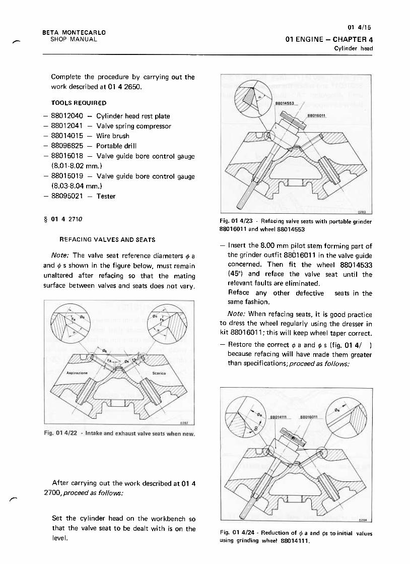
01 4/15
01 ENGINE -CHAPTER 4
Cylinder head
BETA MONTECARLO
SHOP MANUAL,
Complete the procedure by carrying out the
work described at 01 4 2650.
TOOLS REQUIRED
-88012040 -Cylinder head rest plate
-88012041 -Valve spring compressor
-88014015 -Wire brush
-88096825 -Portable drill
-88015018 -Valve guide bore control gauge
(8.01-8.02 mm.)
-88015019 -Valve guide bore control gauge
(8.03-8.04 mm.)
-88095021 -Tester
§ 0142710 Fig. 01 4/23 -Refacing valve seats with portable grinder
88016011 and wheel 88014553
REFACING VALVES AND SEATS
Note: The valve seat reference diameters 1> a
and 1> s shown in the figure below, must remain
unaltered after refacing so that the mating
surface between valves and seats does not vary.
-Insert the 8.00 mm pilot stem forming part of
the grinder outfit 88016011 in the valve guide
concerned. Then fit the wheel 88014533
(45°) and reface the valve seat until the
relevant faults are eliminated.
Reface any other defective seats in the
same fashion.
Note: When refacing seats, it is good practice
to dress the wheel regularly using the dresser in
kit 88016011; this will keep wheel taper correct.
-Restore the correct ~ a and ~ s (fig. 01 4/ )
because refacing will have made them greater
than specifications; proceed as follows:
After carrying out the work described at 01 4
2700, proceed as follows:r
Set the cylinder head on the workbench so
that the valve seat to be dealt with is on the
level.Fig. 01 4/24 -Reduction of <1> a and <1>5 to initial values
using grinding wheel 88014111.
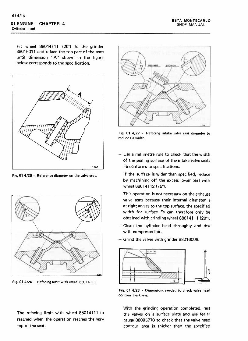
01 4/16
BETA MONTECARLO
SHOP MANUAL01 ENGINE -CHAPTER 4
Cylinder head
Fit wheel 88014111 (20°) to the grinder
88016011 and reface the top part of the seats
until dimension "A" shown in the figure
below corresponds to the specification.
Fig. 01 4/27 -Refacing intake valve seat diameter to
reduce Fa width.
Fig. 01 4/25 .Reference diameter on the valve seat.
//
-Use a millimetre rule to check that the width
of the ~ealing surface of the intake valve seats
Fa conforms to specifications.
If the surface is wider than specified, reduce
by machining off the excess lower part with
wheel 88014112 (75°).
This operation is not necessary on the exhaust
valve seats because their internal diameter is
at right angles to the top surface; the specified
width for surface Fs can therefore only be
obtained with grinding wheel 88014111 (20°).
-Clean the cylinder head throughly and dry
with compressed air .
-Grind the valves with grinder 88016006.
~
.,~N
~T .-!-Fig. 01 4/26 Refacing limit with whee188014111.
Fig. 01 4/28 -Dimensions needed to check valve head
contour thickness.
With the grinding operation completed, rest
the valves on a surface plate and use feeler
gauge 88095770 to check that the valve head
contour area is thicker than the specified
The refacing limit with wheel 88014111 in
reached when the operation reaches the very
top of the seat.
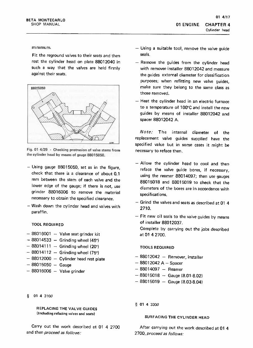
01 4/17
CHAPTER 4
Cylinder head
BETA MONTECARLO
SHOP MANUAL 01 ENGINE
minimum. -Using a suitable tool, remove the valve guide
seals.Fit the reground valves to their seats and then
rest the cylinder head on plate 88012040 in
such a way that the valves are held firmly
against their seats.
-Remove the guides from the cylinder head
with remover-installer 88012042 and measure
the guides external diameter for classification
purposes; when refitting new valve guides,
make sure they belong to the same class as
those removed.
-Heat the cylinder head in an electric furnace
to a temperature of 100°C and install the new
guides by means of installer 88012042 and
spacer 88012042 A.
Note: The internal diameter of the
replacement valve guides supplied have the
specified value but in some cases it might be
necessary to reface then.
-Using gauge 88015050, set as in the figure,
check that there is a clearance of about 0.1
mm between the stem of each valve and the
lower edge of the gauge; if there is not, use
grinder 88016006 to remove the material
necessary to obtain the specified clearance.
.-Wash down the cylinder head and valves with
paraffin.
TOOL REaulRED
-Allow the cylinder head to cool and then
reface the valve guide bores, if necessary,
using the reamer 88014097; then use gauges
88015018 and 88015019 to check that the
diameters of the bores are in accordance with
specifications.
-Grind the valves and seats as described at 01 4
2710.
-Fit new oil seals to the valve guides by means
of installer 88012037.
Complete by carrying out the jobs described
at 01 4 2700.
TOOLS REQUIRED
-88012042 -Remover, installer
-88012042 A -Spacer
-88014097 -Reamer
-88015018 -Gauge (8.01-8.02)
-88015019 -Gauge (8.03-8.04)
-88016001 -Valve seat grinder kit
-88014533 -Grinding wheel (45°}
-88014111 -Grinding wheel (20°}
-88014112- Grinding wheel (75°}
-88012000 -Cylinder head rest plate
-88015050- Gauge
-88016006 -Valve grinder
§ 0143100
§ 0143300
REPLACING THE VALVE GUIDES
(Including refacing valves and seats)SURFACING THE CYLINDER HEAD
Carry out the work described at 01 4 2700
and then proceed as follows:After carrying out the work described at 01 4
2700, proceed as follows:
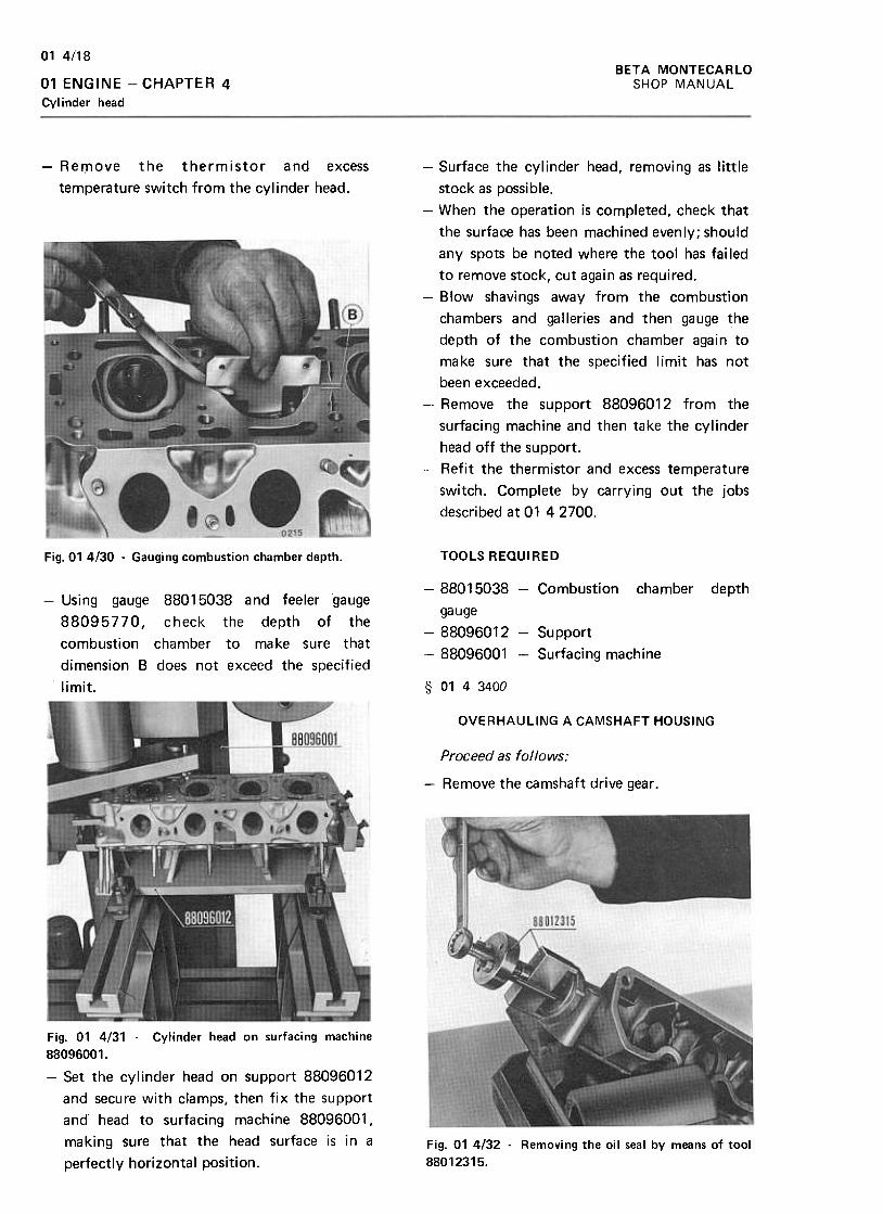
BETA MONTECARLOSHOP MANUAL
01 4!18
01 ENGINE -CHAPTER 4Cylinder head
-Remove the thermistor and excess
temperature switch from the cylinder head.
-Surface the cylinder head, removing as little
stock as possible.
-When the operation is completed, check that
the surface has been machined evenly; should
any spots be noted where the tool has fai led
to remove stock, cut again as required.
-Blow shavings away from the combustion
chambers and galleries and then gauge the
depth of the combustion chamber again to
make sure that the specified limit has not
been exceeded.
-Remove the support 88096012 from the
surfacing machine and then take the cylinder
head off the support.
-Refit the thermistor and excess temperature
switch. Complete by carrying out the jobs
described at 01 42700.
Fig. 01 4/30 -Gauging combustion chamber depth. TOOLS REQUIRED
-88015038 -Combustion chamber
gauge
-88096012- Support
-88096001 -Surfacing machine
depth-Using gauge 88015038 and feeler gauge
88095770, check the depth of the
combustion chamber to make sure that
dimension B does not exceed the specified
limit. § 0143400
OVERHAULING A CAMSHAFT HOUSING
Proceed as follows:
-Remove the camshaft drive gear .
Fig. 01 4/31 -Cylinder head on surfacing machine88096001.
-Set the cylinder head on Support 88096012
and secure with clamps, then fix the support
ana head to surfacing machine 88096001 ,
making sure that the head surface is in a
perfectly horizontal position.
Fig. 01 4132 -Removing the oil seal by means of tool
88012315.
01 4/19BETA MONTECARLO
SHOP MANUAL 01 ENGINE -CHAPTER 4
Cylinder headr
-Fit the new oil seal using installing tool
88012161.
-Use engine oil to lubricate the housing
bearings and then refit the camshaft and the
rear cover after replacing the gasket. Refit the
camshaft drive gear .
TOOLS REQUIRED
-Unscrew the securing nuts, remove the rear
cover (1) and take out the camshaft.
-Using tool 88012315, extract the oil seal
from its seating.
-Wash removed components with paraffin and
dry with compressed air .
-Carefully check the camshaft lobes and
journals for unllsual wear or signs of seizure;
if any are noted, replace the camshaft.
-Check the camshaft housing bearings for deep
score marks or excessive wear, and check that
clearance between journals and bearings is not
excessive.
r---88012315 -Removing tool
-88012161 -Installing tool
~
r-
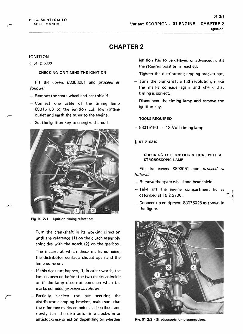
012/1
Variant SCORPION -01 ENGINE -CHAPTER 2
Ignition
BETA MONTECARLO
SHOP MANUAL/'"""
CHAPTER 2
IGNITION
§ 0120300ignition has to be delayed or advanced, until
the required position is reached.
CHECKING OR TIMING THE IGNITION -Tighten the distributor clamping bracket nut.
-Turn the crankshaft a full revolution, make
the marks coincide again and check that
timing is correct.
-Disconnect the timing lamp and remove the
ignition key.
r--TOOLS REQUIRED
Fit the covers 88083051 and proceed as
follows:
-Remove the spare wheel and heat shield.
-Connect one cable of the timing lamp
88015150 to the ignition coil low voltage
outlet and earth the other to the engine.
-Set the ignition key to energize the coil.-88015150 -12 Volt timing lamp
§ 0120310
CHECKING THE IGNITION STROKE WITH A
STROBOSCOPIC LAMP
.-i
Fit the covers 8803051 and proceed as
follows:
-Remove the spare wheel and heat shield.
-Take off the engine compartment lid as
described at 1522700.
-Connect up equipment 88075025 as shown in
the figure.T'
Fig. 01 2/1 Ignition timing references.
Turn the crankshaft in its working direction
unti I the reference ( 1) on the clutch assembly
coincides with the notch (2) on the gearbox.
The instant at which these marks coincide,
the distributor contacts should open and the
lamp come on.
-If this does not happen, if, in other words, the
lamp comes on before the two marks coincide
or if the lamp does not come on when the
marks coincide, proceed as follows:
-PartiaHy slacken the nut securing the
distributor clamping bracket, make sure that
the reference marks coincide as described, and
slowly turn the distributor in a clockwise or
anticlockwise direction depending on whether
r
Fig. 01 2/2. .Stroboscopic lamp connections.
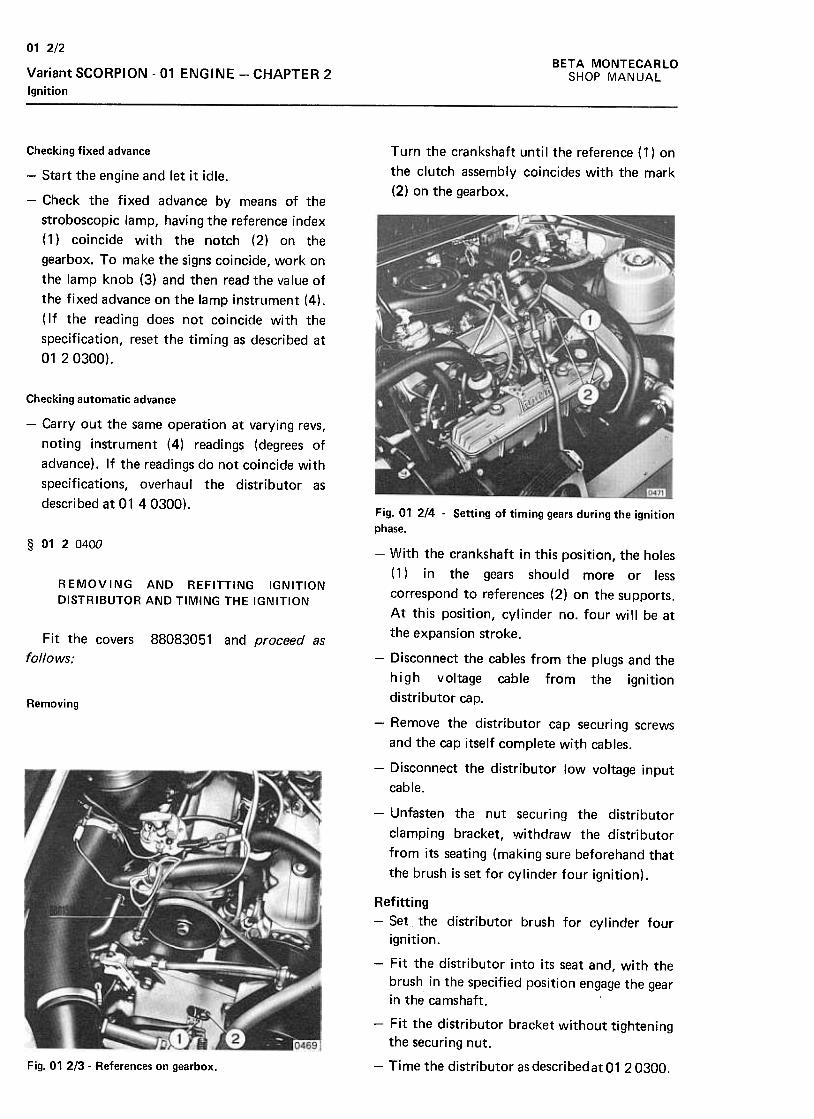
BETA MONTECARLO
SHOP MANUAL
01 2/2
Variant SCORPION -01 ENGINE -CHAPTER 2
Ignition
Turn the crankshaft until the reference (1) on
the clutch assembly coincides with the mark
(2) on the gearbox.
Checking fixed advance
-Start the engine and let it idle.
-Check the fixed advance by means of the
stroboscopic lamp, having the reference index
(1) coincide with the notch (2) on the
gearbox. To make the signs coincide, work on
the lamp knob (3) and then read the value of
the fixed advance on the lamp instrument (4).
( If the reading does not coincide with the
specification, reset the timing as described at
01 20300).
Checking automatic advance
-Carry out the same operation at varying revs,
noting instrument (4) readings (degrees of
advance). If the readings do not coincide with
specifications, overhaul the distributor as
described at 01 40300).
§ D1 20400
REMOVING AND REFITTING IGNITION
DISTRIBUTOR AND TIMING THE IGNITION
Fit the covers
follows;
88083051 and proceed as
Fig. 01 214 -Setting of timing gears during the ignitionphase.
-With the crankshaft in this position, the holes
(1) in the gears should more or less
correspond to references (2) on the supports.
At this position, cylinder no. four will be at
the expansion stroke.
-Disconnect the cables from the plugs and the
high voltage cable from the ignition
distributor cap.Removing
-Remove the distributor cap securing screws
and the cap itself complete with cables.
-Disconnect the distributor low voltage input
cable.
-Unfasten the nut securing the distributor
clamping bracket, \Nithdraw the distributor
from its seating (making sure beforehand that
the brush is set for cylinder four ignition) .
Fig. 01 213- References on gearbox.
Refitting-Set the distributor brush for cylinder four
ignition.
-Fit the distributor into its seat and, with the
brush in the specified position engage the gear
in the camshaft.
-Fit the distributor bracket without tightening
the securing nut.
-Time the distributor as describedat 01 20300.
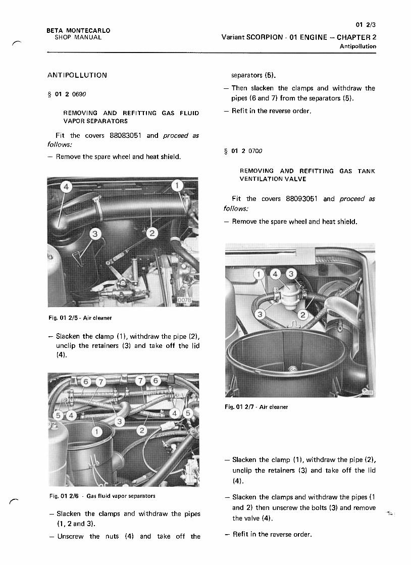
01 2/3
BETA MONTECARLO
SHOP MANUAL Variant SCORPION -01 ENGINE -CHAPTER 2
Antipollutionr
ANTIPOLLUTION
§ 0120690
separators (5).
-Then slacken the clamps and withdraw the
pipes (6 and 7) from the separators (5).
-Refit in the reverse order .REMOVING AND REFITTING GAS FlUID
VAPOR SEPARATORS
§ 0120700
Fit the covers 88083051 and proceed as
follows;
-Remove the spare wheel and heat shield.
REMOVING AND REFITTING GAS TANK
VENTILATION VALVE
Fit the covers 88093051 and proceed as
follows:
-Remove the spare wheel and heat shield.
~
Fig. 01 2/5- Air cleaner
-Slacken the clamp (1 ), withdraw the pipe (2),
unclip the retainers (3) and take off the lid
(4).
Fig. 01 2/7 -Air cleaner
-Slacken the clamp (1 ), withdraw the pipe (2),
unclip the retainers (3) and take off the lid
(4).
-Slacken the clamps and withdraw the pipes (1
and 2) then unscrew the bolts (3) and remove
the valve (4).
Fig. 01 2/6 .Gas fluid vapor separatorsr
-~;;, I
-Refit in the reverse order.
-Slacken the clamps and withdraw the pipes
(1,2and3),
-Unscrew the nuts (4) and take off the
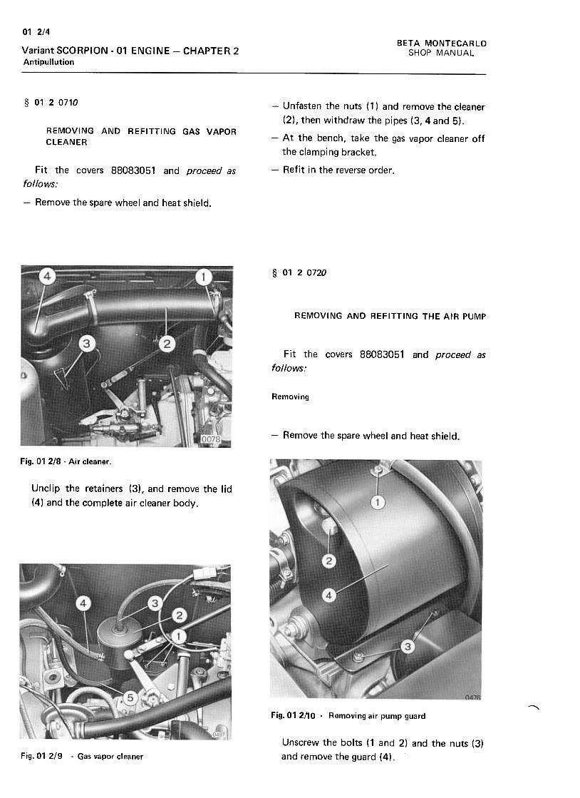
01 2/4
BETA MONTECARLO
SHOP MANUALVariant SCORPION -01 ENGINE -CHAPTER 2Antipullution
§ 0120710
REMOVING AND REFITTING GAS VAPOR
CLEANER
-Unfasten the nuts (1) and remove the cleaner
(2), then withdraw the pipes (3, 4 and 5).
-At the bench, take the gas vapor cleaner off
the clamping bracket.
-Refit i n the reverse order .Fit the covers 88083051 and proceed as
follows;
-Remove the spare wheel and heat shield.
§ 0120720
REMOVING AND REFITTING THE AIR PUMP
Fit the covers 88083051 and proceed as
follows:
Removing
-Remove the spare wheel and heat shield.
Fig. 01 218 .Air cleaner .
Unclip the retainers (3), and remove the lid
(4) and the complete air cleaner body.
~Fig. 01 2!10 .Removing air pump guard
Unscrew the bolts (1 and 2) and the nuts (3)
and remove the guard (4).Fig.01 2/9 .Gas vapor cleaner
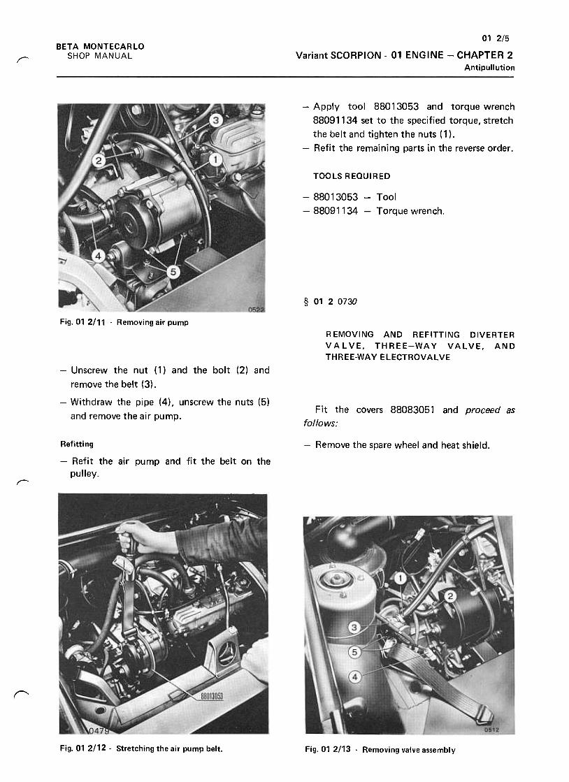
01 2/5
Variant SCORPION -01 ENGINE -CHAPTER 2
Antipullution
BETA MONTECARLO
SHOP MANUALr
-Apply tool 88013053 and torque wrench
88091134 set to the specified torque, stretch
the belt and tighten the nuts ( 1) .
-Refit the remaining parts in the reverse order .
TOOLS REQUIRED
-88013053- Tool
-88091134 -Torque wrench
§ 0120730
Fig. 01 2111 -Removing air pump
R EMOVING AND REFITTING DIVERTER
VALVE, THREE-WAY VALVE, AND
THREE-WAY ELECTROVALVE
-Unscrew the nut (1) and the bolt (2) and
remove the belt (3) .
-Withdraw the pipe (4), unscrew the nuts (5)
and remove the air pump.Fit the covers 88083051 and proceed as
follows:
-Remove the spare wheel and heat shield.Refitting
-Refit the air pump and fit the belt on the
pulley.r
r
Fig. 01 2112 -Stretching the air pump belt. Fig. 01 2113 .Removing valve assembly
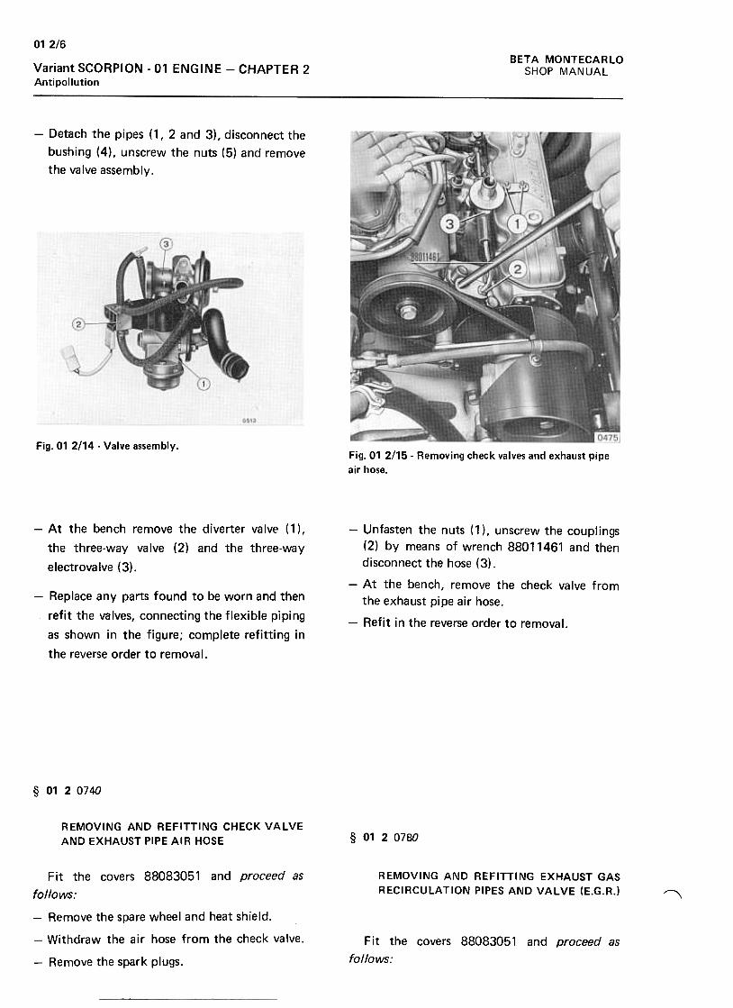
012/6
BETA MONTECARLO
SHOP MANUALVariant SCORPION -01 ENGINE -CHAPTER 2Antipollution
-Detach the pipes (1, 2 and 3), disconnect the
bushing (4), unscrew the nuts (5) and remove
the valve assembly.
Fig. 01 2/14- Valve assembly.Fig.01 2/15- Removing check valves and exhaust pipe
air hose.
-At the bench remove the diverter valve (1),
the three-way valve (2) and the three-way
electrovalve (3).
-Replace any parts found to be worn and then
refit the valves, connecting the flexible piping
as shown in the figure; complete refitting in
the reverse order to removal.
-Unfasten the nuts (1 ), unscrew the couplings
(2) by means of wrench 88011461 and then
disconnect the hose (3).
-At the bench, remove the check valve from
the exhaust pipe air hose.
-Refit in the reverse order to removal.
§ 0120740
REMOVING AND REFITTING CHECK VALVE
AND EXHAUST PIPE AIR HOSE § 0120780
REMOVING AND REFITTING EXHAUST GAS
RECIRCULATION PIPES AND VALVE (E.G.R.I ~
Fit the covers 88083051 and proceed as
follows:
-Remove the spare wheel and heat shield.
-Withdraw the air hose from the check valve.
-Remove the spark plugs.
Fit the covers 88083051 and proceed as
follows:
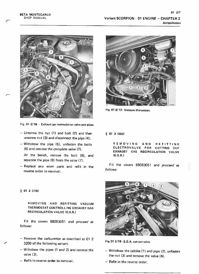
01 2n
Variant SCORPION -01 ENGINE -CHAPTER 2
Antipollution
BETA MONTECARLO
SHOP MANUAL
r
r--
Fig. 01 2/17- Vacuum thermostat.
Fig. 01 2!16 .Exhaust gas recirculation valve and pipes
§ 0120800
REMOVING AND REFITTING
ELECTROVALVE FOR CUTTING OUT
EXHAUST GAS RECIRCULATION VALVE
(E.G.R.)
Fit the covers 88083051 and proceed as
follows:
-Unscrew the nut ( 1) and bolt (2) and then
unscrew nut (3) and disconnect the pipe (4).
-Withdraw the pipe (5), unfasten the bolts
(6) and remove the complete valve (7).
At the bench, remove the bolt (8), and
separate the pipe (9) from the valve (7).
-Replace any worn parts and refit in the
reverse order to removal.
§ 0120790
REMOVING AND REFITTING VACUUM
THERMOSTAT CONTROLLING EXHAUST GAS
RECIRCULATION VALVE (E.G.R.)
Fit the covers 88083051 and proceed as
follows:
F ig. 01 2/18- E.G. R. cut-out valve.1'"'
-Remove the carburet tor as described at 01 2
3200 of the following variant.
-Withdraw the pipes (1 and 2) and remove the
valve (3).
-Refit in reverse order to removal.
-Withdraw the calbles (1) and pipe (2), unfasten
the nut (3) and remove the valve (4).
-Refit i n the reverse order .

BETA MONTECARLO
SHOP MANUAL
01 2/8
Variant SCORPION -01 ENGINE -CHAPTER 2
Antipollution
§ 0120810
REMOVING AND REFITTING A PUSH-BUTTON
SWITCH ON THE GEARBOX
-Unfasten the ring nut (5) and remove the
switch (6), then withdraw the connection
cables.
-Refit in the reverse order.
Fit the covers 88083051 and proceed as
follows: § 01 20840
-Remove the spare wheel and the heat shield.
REMOVING AND REFITTING FAST IDLER
CONTROLELECTROVALVE
Fit the covers 88083051 and proceed as
follows:
-Unhook the spring (2), withdraw the split pin
(3), "unfasten the bolts (4) and remove the
cylinder (5).
-Withdraw the electric cables and remove the
push-button switch requiring repair .
-Refit in the reverse order .
Fig.01 2121 -Carburettor air intake
-Slacken the clamp ( 1) and remove the pipe.
-Take off the air intake cover, remove the nuts
(2) , withdraw the oi I vapor breather pipes and
remove the air intake (3).
§ 0120830
REMOVING AND REFITTING FAST IDLER
HAND CONTROL SWITCH
Proceed as follows:
Fig. 01 2!l.2 Fast idler control electrovalveFig. 01 2!20- Fast idler hand control switch
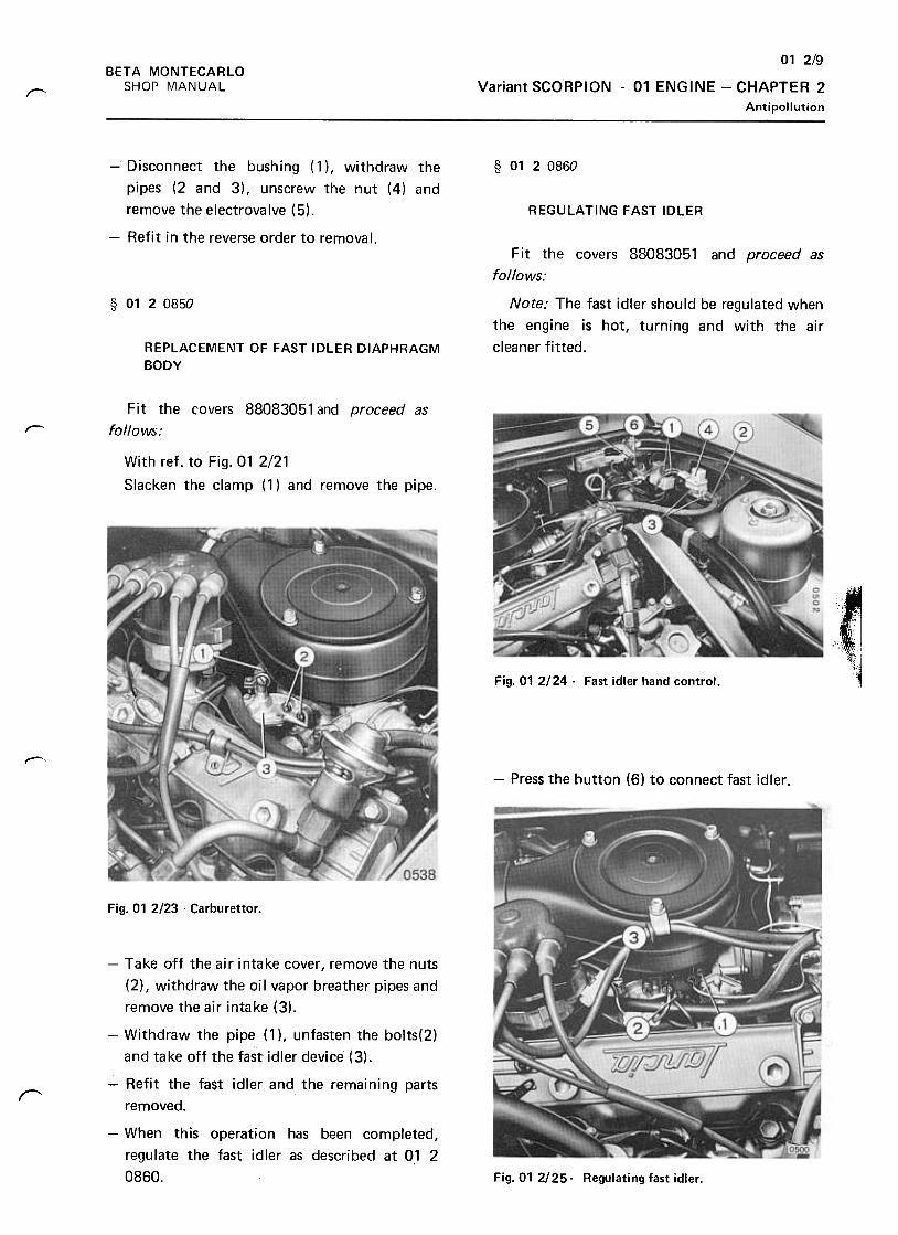
01 2/9
Variant SCORPION -01 ENGINE -CHAPTER 2
Antipollution
BETA MONTECARLO
SHOP MANUALr--
§ 0120860
REGULATING FAST IDLER
-Disconnect the bushing (1 ), withdraw the
pipes (2 and 3), unscrew the nut (4) and
remove the electrovalve (5).
-Refit in the reverse order to removal.
§ 0120850
Fit the covers 88083051 and proceed as
follows:
Note: The fast idler should be regulated when
the engine is hot, turning and with the air
cleaner fitted.REPLACEMENT OF FAST IDLER DIAPHRAGM
BODY
Fit the covers 88083051 and proceed as
follows:r-
With ref. to Fig. 01 2/21
Slacken the clamp (1) and remove the pipe
(Fig.01 2124- Fast idler hand control.
~
-Press the button (6) to connect fast idler .
~
Fig. 01 2/23 .Carburet tor.
"
-Take off the air intake cover, remove the nuts
(2), withdraw the oil vapor breather pipes and
remove the air intake (3).
-Withdraw the pipe (1 ), unfasten the bolts(2)
and take off the fast idler device (3).
-Refit the fast idler and the remaining parts
removed.
-When this operation has been completed,
regulate the fast idler as described at 0,1 2
0860. Fig. 01 2125. Regulating fast idler .
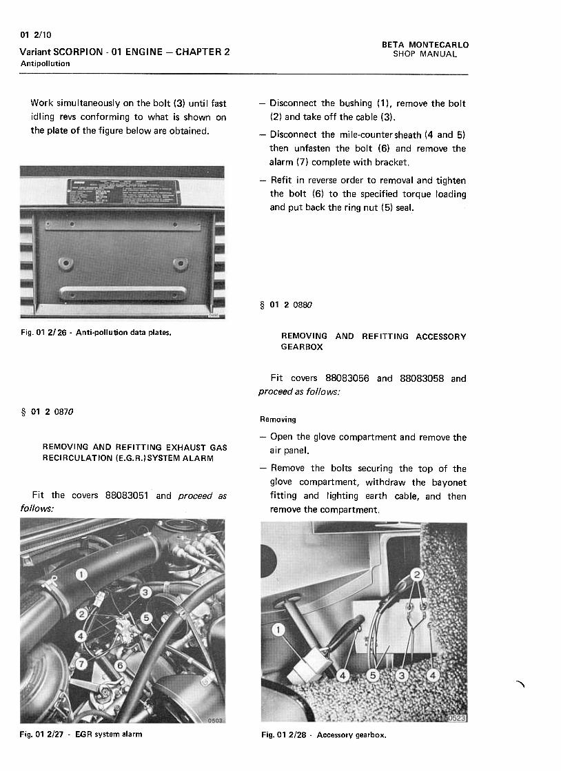
BETA MONTECARLO
SHOP MAr-JUAL
01 2/10
Variant SCORPION -01 ENGINE -CHAPTER 2
Antipollution
Work simultaneously on the bolt (3) until fast
idling revs conforming to what is shown on
the plate of the figure below are obtained.
-Disconnect the bushing (1 ), remove the bolt
(2) and take off the cable (3).
-Disconnect the mile-countersheath (4 and 5)
then unfasten the bolt (6) and remove the
alarm (7) complete with bracket.
-Refit in reverse order to removal and tighten
the bolt (6) to the specified torque loading
and put back the ring nut (5) seal.
§ 0120880
Fig. 01 2/26 -Anti-pollution data plates. REMOVING AND REFITTING ACCESSORY
GEARBOX
Fit covers 88083056 and 88083058 and
proceed as follows:
§ 0120870
Removing
-Open the glove compartment and remove the
air panel.REMOVING AND REFITTING EXHAUST GAS
RECIRCUlATION (E.G.R.)SYSTEM AlARM-Remove the bolts securing the top of the
glove compartment, withdraw the bayonet
fitting and lighting earth cable, and then
remove the compartment.
Fit the covers 88083051 and proceed as
follows:
,
Fig. 01 2/27 .EGR system alarm Fig. 01 2/28 -Accessory gearbox.
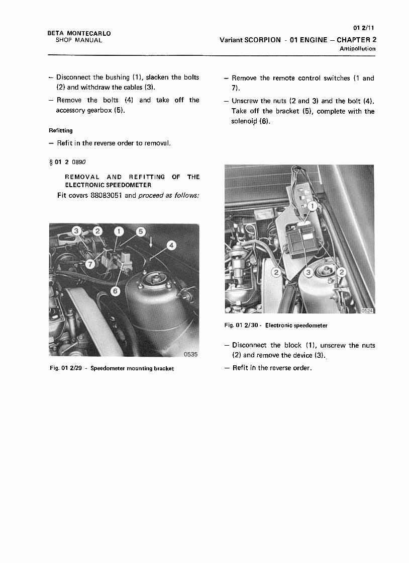
012/11
Variant SCORPION -01 ENGINE -CHAPTER 2
Antipollution
BETA MONTECARLO
SHOP MANUAL
-Remove the remote control switches ( 1 and
7).
-Disconnect the bushing (1 ), slacken the bolts
(2) and withdraw the cables (3).
-Remove the bolts (4) and take off the
accessory gearbox (5).
-Unscrew the nuts (2 and 3) and the bolt (4).
Take off the bracket (5), complete with the
solenoi.d (6).
Refitting
-Refit in the reverse order to removal.
§ 01 2 0890
REMOVAL AND REFITTING OF THE
ELECTRONIC SPEEDOMETER
Fit covers 88083051 and proceed as follows:
Fig. 01 2/30- Electronic speedometer
-Disconnect the block (1), unscrew the nuts
(2) and remove the device (3).
-Refit in the reverse order .Fig. 01 2/29 -Speedometer mounting bracket
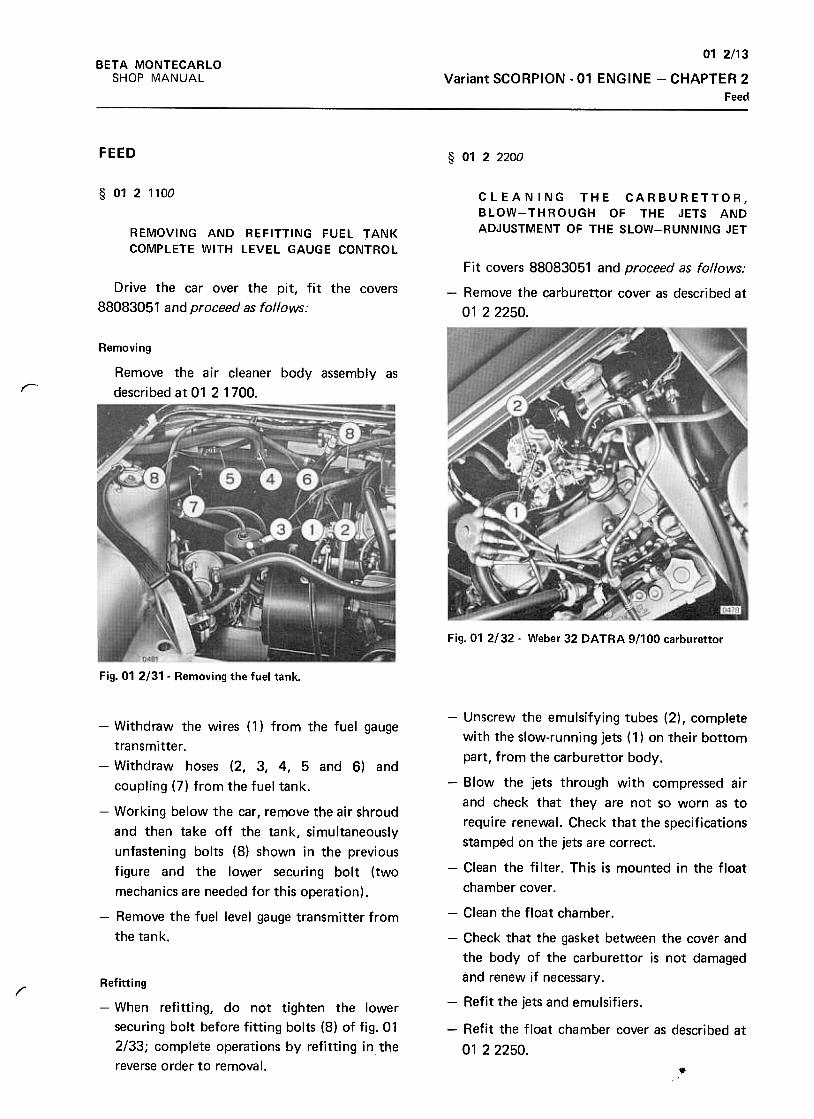
01 2/13
Variant SCORPION -01 ENGINE -CHAPTER 2
Feed
BETA MONTECARLO
SHOP MANUAL
FEED§ 0122200
§ 0121100 CLEANING THE CARBURETTOR,
BLOW-THROUGH OF THE JETS ANDADJUSTMENT OF THE SLOW-RUNNING JETREMOVING AND REFITTING FUEL TANK
COMPLETE WITH LEVEL GAUGE CONTROL
Drive the car over the pit, fit the covers
88083051 and proceed as follows:
Fit covers 88083051 and proceed as follows:
-Remove the carburet tor cover as described at
0122250.
Removing
Remove the air cleaner body assembly as
described at 01 2 1700.r-
Fig.01 2/32- Weber 32 DATRA 9/100 carburet tor
Fig. 01 2/31- Removing the fuel tank.
-Withdraw the wires (1) from the fuel gauge
transmitter .
-Withdraw hoses (2, 3, 4, 5 and 6) and
coupling (7) from the fuel tank.
-Working below the car, remove the air shroud
and then take off the tank, simultaneously
unfastening bolts (8) shown in the previous
figure and the lower securing bolt (two
mechanics are needed for this operation).
-Remove the fuel level gauge transmitter from
the tank.
1""
-Unscrew the emulsifying tubes (2) , complete
with the slow-running jets (1) on their bottom
part, from the carburet tor body.
-Blow the jets through with compressed air
and check that they are not so worn as to
require renewal. Check that the specifications
stamped on the jets are correct.
-Clean the filter. This is mounted in the float
chamber cover.
-Clean the float chamber .
-Check that the gasket between the cover and
the body of the carburet tor is not damaged
and renew if necessary.
-Refit the jets and emulsifiers.
Refitting
-When refitting, do not tighten the lower
securing bolt before fitting bolts (8) of fig. 01
2/33; complete operations by refitting in,the
reverse order to removal.
-Refit the float chamber cover as described at
0122250.
.

BETA MONTECARLO
SHOP MANUAL
012!14
Variant SCORPION -01 ENGINE --CHAPTER 2
Feed
§ 0122250 -Unscrew bolts (9) and remove the carburet tor
cover. Unscrew bolts (5) and take choke cover
(6) off the carburet tor cover. The fuel level
check is described at § 16 4 1150.
REMOVING AND REFITTING THE
CARBURETTOR FLOAT CHA~~BER COVER
(Weber carburet tor)
RefittingFit covers 88083051 and proceed as follows.
-Refit the choke to the carburet tor cover as
follows:Removal
Fig. 01 2/33 -Carburet tor air intake
Fig. 01 2tJ5 Rich mixture control mechanism
-Slacken clamp (1) and slide off the pipe.
-Remove the air intake cover, unscrew the nuts
(2), slide off the oil vapourbreather pipes and
remove the air intake.-F it gasket ( 1) so that the reference marks (2)
coincide, then mount the coil housing (3). Fit
the bimetallic coil (4) into the yoke (5) of the
rich mixture control, then turn the housing
anticlockwise until the reference marks (6)
coincide.
-Refit the remaining components in the reverse
order .
-On completion, set the slow-running
mechanism as described at § 01 22300.
§ 0122300
SETTING
MECHANISM
OF THE SLOW-RUNNING --- ,Fig. 01 2/34- Removal of flexible hoses. Fit covers 88083051 and proceed as follows:
Take off hoses (2,3,4) and leads (7,8).
1r..
Note -Thisoperation must be done with the
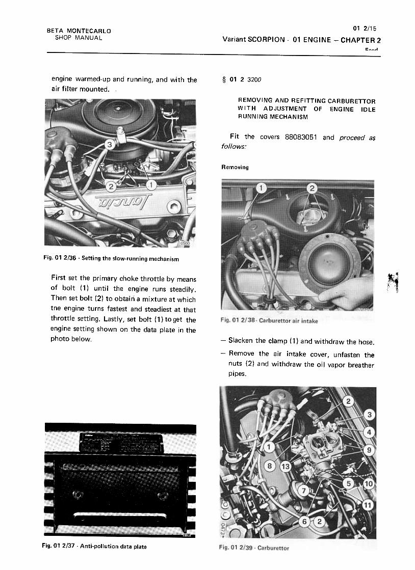
01 2/15
Variant SCORPION -01 ENGINE -CHAPTER 2
Feed
BETA MONTECARLO
SHOP MANUAL
§ 0123200engine warmed-up and running, and with the
air filter mounted.
REMOVING AND REFITTING CARBURETTOR
WITH ADJUSTMENT OF ENGINE IDLE
RUNNING MECHANISM
Fit the covers 88083051 and proceed as
follows:
Removing
Fig. 01 2/36 -Setting the slow-running mechanism
,First set the primary choke throttle by means
of bolt (1) until the engine runs steadily.
Then set bolt (2) to obtain a mixture at which
tne engine turns fastest and steadiest at that
throttle setting. Lastly, set bolt (1)toget the
engine setting shown on the data plate in the
photo below. -Slacken the clamp ( 1) and withdraw the hose.
-Remove the air intake cover, unfasten the
nuts (2) and withdraw the oil vapor breather
pipes.
Fig. 01 2137 -Anti-pollution data plate
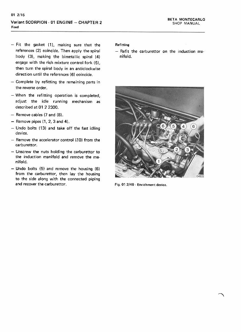
BETA MONTECARLO
SHOP MANUAL
01 2/16
Variant SCORPION -01 ENGINE -CHAPTER 2Feed
Refitting
-Refit the carburet tor on the induction ma-
nifold.
-Fit the gasket (1 ), making sure that the
references (2) coincide. Then apply the spiral
body (3), making the bimetallic spiral (4)
engage with the rich mixture control fork (5),
then turn the spiral body in an anticlockwise
direction until the references (6) coincide.
-Complete by refitting the remaining parts in
the reverse order .
-When the refitting operation is completed,
adjust the idle running mechanism as
described at 01 2 2300.
-Remove cables (7 and (8).
-Remove pipes (1,2,3 and 4).
-Undo bolts (13) and take off the fast idlingdevice.
-Remove the accelerator control ~10) from thecarburet tor .
-Unscrew the nuts holding the carburet tor tothe induction manifold and remove the ma-
nifold.
-Undo bolts (5) and remove the housing (6)from the carburet tor, then lay the housingto the side along with the connected pipingand recover the carburet tor . Fig. 01 2/40 -Enrichment device.
,
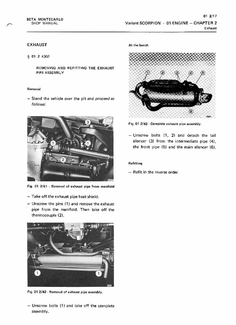
01 2/17
Variant SCORPION -01 ENGINE -CHAPTER 2
Exhaust
BETA MONTECARLO
SHOP MANUAL"
EXHAUST At the bench
§ 0124300
REMOVING AND REFITTING THE EXHAUST
PIPE ASSEMBL y
Removal
-Stand the vehicle over the pit and proceed as
follows:
Fig.01 2/43 -Complete exhaust pipe assembly.
-Unscrew bolts (1, 2) and detach the tail
silencer (3) from the intermediate pipe (4),
the front pipe (5) and the main silencer (6).
Refitting
-Refit in the reverse order.
Fig. 01 2/41 -Removal of exhaust pipe from manifold
-Take off the exhaust pipe heat shield.
-Unscrew the pins (1) and remove the exhaust
pipe from the manifold. Then take off the
thermocouple (2).
Fig. 01 2/42- Removal of exhaust pipe assembly.
-Unscrew bolts (1) and take off the comp~ete
assembly.
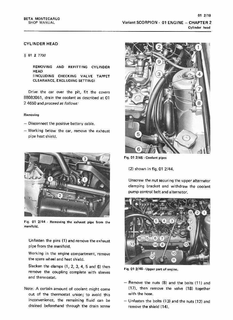
01 2/19
Variant SCORPION -01 ENGINE -CHAPTER 2
Cylinder head
BETA MONTECARLO
SHOP MANUAL
CYLINDER HEAD
§ 01 Z 7700
REMOVING AND REFITTING CYLINDER
HEAD
(INCLUDING CHECKING VALVE TAPPET
CLEARANCE, EXCLUDING SETTING)
Drive the car over the pit, fit the covers
88083051, drain the coolant as described at 01
2 4650 and proceed as follows:
Removing
-Disconnect the positive battery cable.
-Working below the car, remove the exhaust
pipe heat shield.
Fig. 01 2145- Coolant pipes.
(2) shown in fig. 01 2144.
Unscrew the nut securing the upper alternator
clamping bracket and withdraw the coolant
pump control belt and alternator.
Fig. 01 2144 -Removing the exhaust pipe from the
manifold.
Unfasten the pins ( 1) and remove the exhaust
pipe from the manifold.
Working in the engine compartment, remove
the spare wheel and heat shield.
Slacken the clamps (1, 2, 3, 4, 5 and 6) then
remove the coupling complete with sleeves
and thermostat.
-Fig.01 2/46- Upper part of engine.
Note: A certain amount of coolant might come
out of the thermostat union; to avoid this
inconvenience, the remaining fluid can be
drained beforehand through the drain screw
-Remove the nuts (8) and the bolts (11) and
(17), then remove the valve (18) together
with the hose.
-Unfasten the bolts (13) and the nuts (12) and
remove the shield (14).
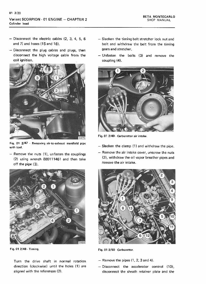
01 2/20
BETA MONTECARLO
SHOP MANUALVariant SCORPION -01 ENGINE -CHAPTER 2
Cyl inder head
-Disconnect the electric cables (2, 3, 4, 5, 6
and 7) and hoses (15and 16).
-Disconnect the plug cables and plugs, then
disconnect the high voltage cable from the
coil ignition.
-Slacken the timing belt stretcher lock nut and
bolt and withdraw the belt from the timing
gears and stretcher .
-Unfasten the bolts (3) and remove the
coupling (4).
Fig.01 2149- Carburet tor air intake.
Fig. 01 2147 -Removing air-to-exhaust manifold pipe
with tool. -Slacken the clamp (1) and withdraw the pipe.
-Remove the air intake cover, unscrew the nuts
(2), withdraw the oil vapor breather pipes and
remove the air intake.
-Remove the nuts (1 ), unfasten the couplings
(2) using wrench 880111461 and then take
off the pipe (3).
Fig. 01 2/48- Timing. Fig. 01 2/50 Carburet tor .
Turn the drive shaft in normal rotation
direction (clockwise) until the holes (1) are
aligned with the references (2).
-Remove the pipes (1,2, 3 and 4).
-Disconnect the accelerator control (10),
disconnect the sheath retainer plate and the
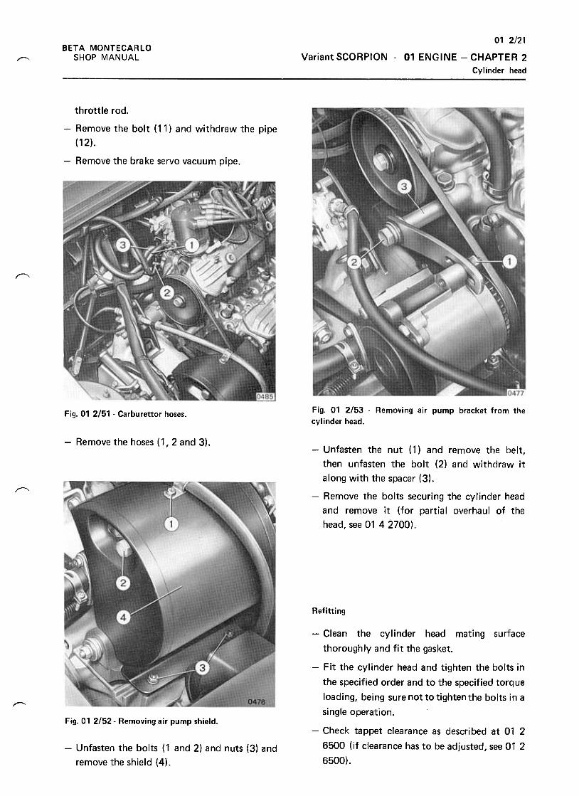
01 2/21
Variant SCORPION -01 ENGINE -CHAPTER 2
Cylinder head
BETA MONTECARLO
SHOP MANUAL~
throttle rod.
-Remove the bolt (11) and withdraw the pipe
(12).
-Remove the brake servo vacuum pipe.
"'
Fig. 01 2/53 -Removing air pump bracket from the
cylinder head.Fig. 01 2/51 -Carburettor hoses.
-Remove the hoses (1,2 and 3).
, ,
-Unfasten the nut (1) and remove the belt,
then unfasten the bolt (2) and withdraw it
along with the spacer (3),
-Remove the bolts securing the cylinder head
and remove it (for partial overhaul of the
head, see 01 42700).
Refitting
-Clean the cylinder head mating surface
thoroughly and fit the gasket.
-Fit the cylinder head and tighten the bolts in
the specified order and to the specified torque
loading, being sure not to'tightenthe bolts in a
single operation..,.-
Fig. 01 2!52- Removing air pump shield.
-Check tappet clearance as described at 01 2
6500 (if clearance has to be adjusted, see 01 2
6500).
-Unfasten the bolts (1 and 2) and nuts (3) and
remove the shield (4).
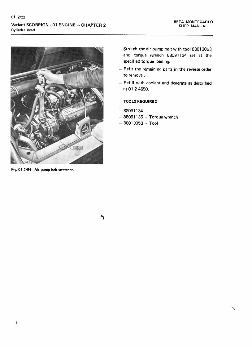
BETA MONTECARLO
SHOP MANUAL
01 2/22
Variant SCORPION -01 ENGINE -CHAPTER 2
Cylinder head
-Stretch the air pump belt with tool 88013053
and torque wrench 88091134 set at the
specified torque loading.
-Refit the remaining parts in the reverse order
to remova I.
-Refill with coolant and deaerate as described
at 01 24650.
TOOLS REQUIRED
-88091134
-88091135 -Torque wrench
-88013053 -Tool
Fig. 01 2/54 -Air pump belt stretcher .
~1
\
1!
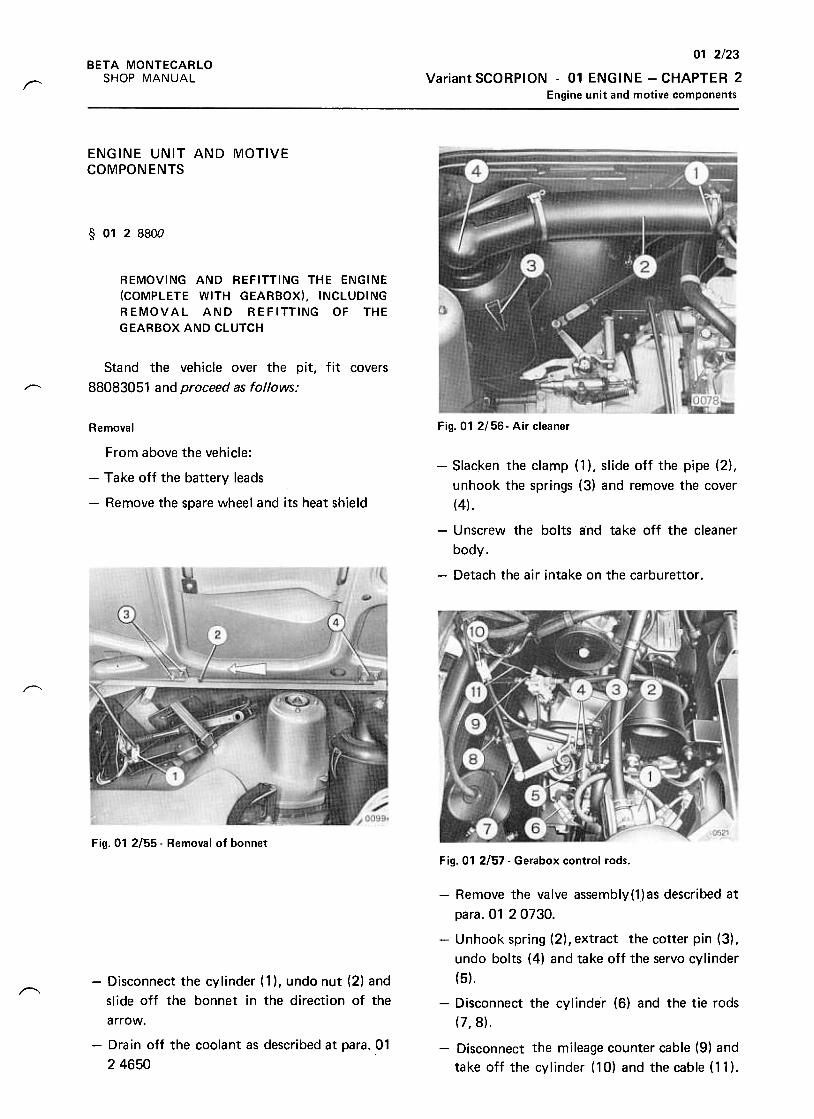
01 2/23
Variant SCORPION -01 ENGINE -CHAPTER 2
Engine unit and motive components
BETA MONTECARLO
SHOP MANUALr
ENGINE UNIT AND MOTIVECOMPONENTS
§ 0128800
REMOVING AND REFITTING THE ENGINE
(COMPLETE WITH GEARBOX), INCLUDING
REMOVAL AND REFITTING OF THE
GEARBOX AND CLUTCH
Stand the vehicle over the pit, fit covers
88083051 and proceed as follows:r--
Fig. 01 2/56- Air cleanerRemoval
From above the vehicle:
-Take off the battery leads
-Remove the spare wheel and its heat shield
-Slacken the clamp (1 ), slide off the pipe (2),
unhook the sprtngs (3) and remove the cover
(4),
-Unscrew the bolts and take off the cleaner
body,
-Detach the air intake on the carburet tor .
~
Fig. 01 2155- Removal of bonnet
Fig. 01 2/57- Gerabox control rods.
r---
-Remove the valve assembly(1)as described at
para. 01 20730.
-Unhook spring (2), extract the cotter pin (3) ,
undo bolts (4) and take off the servo cylinder
(5).
-Disconnect the cylinder (6) and the tie rods
(7,8).
-Disconnect the cylinder ( 1 ), undo nut (2) and
slide off the bonnet in the direction of the
arrow.
-Drain off the coolant as described at para. 01
2 4650
-Disconnect the mileage counter cable (9) and
take off the cylinder (10) and the cable (11),
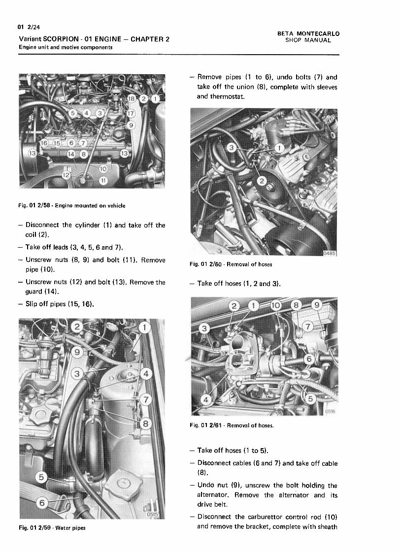
BETA MONTECARLO
SHOP MANUAL
01 2/24
Variant SCORPION -01 ENGINE -CHAPTER 2
Engine unit and motive components
-Remove pipes (1 to 6), undo bolts (7) and
take off the union (8), complete with sleeves
and thermostat.
Fig. 01 2/58- Engine mounted on vehicle
Fig. 01 2160 -Removal of hoses
-Take off hoses (1,2 and 3).
-Disconnect the cylinder (1) and take off the
coil (2),
-Take off leads (3, 4, 5, 6 and 7).
-Unscrew nuts (8, 9) and bolt (11 ). Remove
pipe (10).
-Unscrew nuts (12) and bolt (13). Remove the
guard (14).
-Slip off pipes (15,16).
Fig. 01 2/61 -Removal of hoses.
-Take off hoses (1 to 5).
-Disconnect cables (6 and 7) and take off cable
(8).
-Undo nut (9), unscrew the bolt holding the
alternator. Remove the alternator and its
drive belt.
-Disconnect the carburet tor control rod (10)
and remove the bracket, complete with sheathFig. 01 2159 -Water pipes
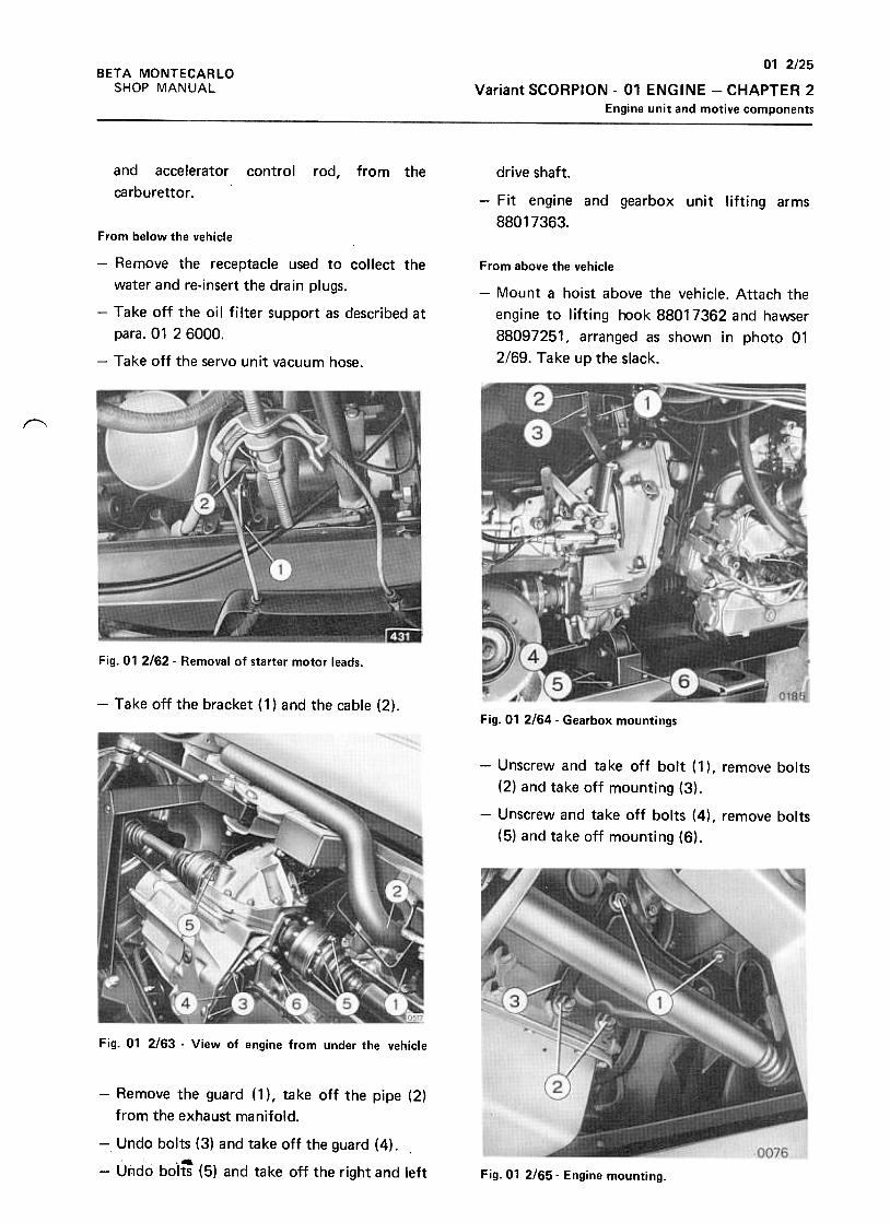
01 2/25
Variant SCORPION -01 ENGINE -CHAPTER 2
Engine unit and motive components
BETA MONTECARLO
SHOP MANUAL
and accelerator
carburet tor .
control rod, from the drive shaft.
-Fit engine and gearbox unit lifting arms
88017363.
From above the vehicle
-Mount a hoist above the vehicle. Attach the
engine to lifting hook 88017362 and hawser
88097251, arranged as shown in photo 01
2/69. Take up the slack.
From below the vehicle
-Remove the receptacle used to collect the
water and re-insert the drain plugs.
-Take off the oil filter support as described at
para. 01 2 6000.
-Take off the servo unit vacuum hose.
~
Fig. 01 2162- Removal of starter motor leads.
-Take off the bracket (1) and the cable (2).Fig. 01 2/64. Gearbox mountings
-Unscrew and take off bolt (1 ), remove bolts
(2) and take off mounting (3),
-Unscrew and take off bolts (4), remove bolts
(5) and take off mounting (6).
Fig. 01 2163 -View of engine from under the vehicle
-Remove the guard (1 ), take off the pipe (2)
from the exhaust manifold.
-Undo bolts (3) and take off the guard (4)..4
-Undo bolts (5) and take off the right and left Fig. 01 2/65- Engine mounting.
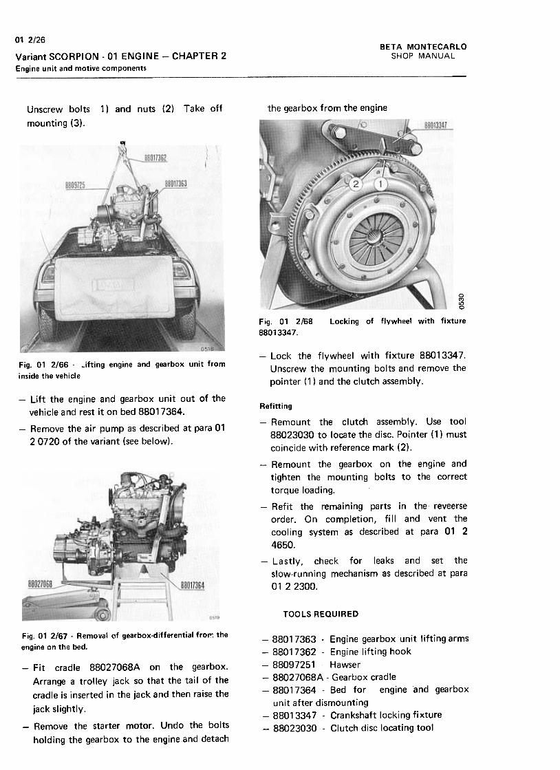
012/26BETA MONTECARLO
SHOP MANUALVariant SCORPION -01 ENGINE -CHAPTER 2
Engine unit and motive components
Take off the gearbox from the engineUnscrew bolts
mounting (3).
1) and nuts (2)
w
0MI!)0
Fig. 01 2/68
88013347.
Locking of flywheel with fixture
-Lock the flywheel with fixture 88013347.
Unscrew the mounting bolts and remove the
pointer (1) and the clutch assembly.
Lifting engine and gearbox unit fromFig. 01 2/66 -
inside the vehicle
-Lift the engine and gearbox unit out of the
vehicle and rest it on bed 88017364.
-Remove the air pump as described at para 01
20720 of the variant (see below).
Refitting
-Remount the clutch assembly. Use tool
88023030 to locate the disc. Pointer (1) must
coincide with reference mark (2).
-Remount the gearbox on the engine and
tighten the mounting bolts to the correct
torque loading.
-Refit the remaining parts in the reveerse
order. On completion, fill and vent the
cooling system as described at para 01 2
4650.
-Lastly, check for leaks and set the
slow-running mechanism as described at para
0122300.
TOOLS REQUIRED
Fig. 01 2/67 -Removal of gearbox-differential fro~ the
engine on the bed.
-Fit cradle 88027068A on the gearbox.
Arrange a trolley jack so that the tail of the
cradle is inserted in the jack and then raise the
jack slightly.
-88017363 -Engine gearbox unit lifting arms
-88017362 -Engine lifting hook
-88097251 .Hawser
-88027068A -Gearbox cradle
-88017364- Bed for engine and gearbox
unit after dismounting
-88013347 -Crankshaft locking fixture
-88023030 -Clutch disc locating tool-Remove the starter motor. Undo the bolts
holding the gearbox to the engine and detach
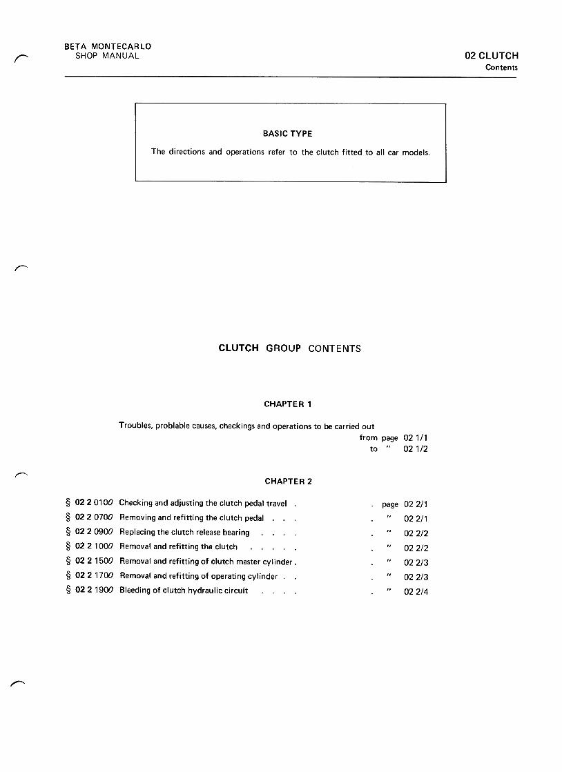
BETA MONTECARLO
SHOP MANUAL 02 CLUTCHContents
r
I'"""'
CLUTCH GROUP CONTENTS
CHAPTER 1
Troubles, problable causes, checkings and operations to be carried out
from page 021/1to " 02 1/2
~CHAPTE R 2
.page 022/1
022/1
02 2/2
02 2/2
02 2/3
02 2/3
02 2/4
§ 02 20100 Checking and adjusting the clutch pedal travel.
§ 022 0700 Removing and refitting the clutch pedal. .
§ 022 0900 Replacing the clutch release bearing
§ 02 2 1000 Removal and refitting the clutch
§ 022 1500 Removal and refitting of clutch master cylinder .
§ 0221700 Removal and refitting of operating cylinder .
§ 02 2 1900 Bleeding of clutch hydraulic circuit
r--
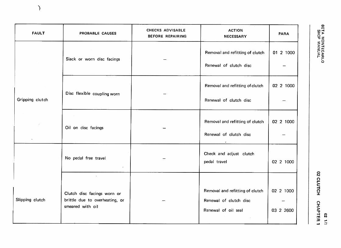
".-.
BE
TA
M
ON
TE
CA
RLO
w
C-'
-J 2
m
-<
{ a:
(/) -
-<{
>
a..C
W
<{
a:
(/) W
~
a:U
O
W
u.~
W
U
m >-
2 IX
:O
~
-<I)
1- r.?
U
W~
UW2
1-..J:)ctLL (/)w(/):)ctuw-Ja)cta)0~~ <
t~<
tdo
..c:tJ+"'
~"'t)
'001C".jj+
"':.=
-Q
)'-
-0C(0~oEQ)
OC
oooN.-0
<II
0)c:'u10-U<
II
:.0c:'-0~'-0~U..!2(/)
(,)I/)
:0..r::.(,)+
"'~"(3
't-o~s:0)c:0)
a:
.c(J+"'
~u'00)c"+:i
+"'
~Q)
...
"'0cra~oEQ)
a::
oo0NNO
I:...0~01I:
""0..:J0U0)
.0"X0)'+
-UII)
0
..cu...~u0)c:.0.0..L:(9 u(/)
:0.cu+"'
:Iu-0(0:s:Q
)c:Q
)~
.c(.)+
":Ju-O01c:";:;+
"~~-0c:ro~oEQ
)O
C
oo0NNO
(I)C>
c:"u(0-(,)(I)
'-5c:oa
u"'
:0..cu+-'
;j
u-Oro~(!)c:(!)
rr::
..c:u+"'
~ut)~:0-<0
-0c<0
~u(1)..c:u
"'Q;
>E+-'
Q)
Q)
'--(0-0Q
)0.
O7
""Q)
>~ro-0a.>0.
oo0NNO
02 CLU
TC
H..cu...:Ju-O0'>~'+:;
...:.=~"0~10~0EQ
)a: oo0NNO
...0
...0
,C
)c
c
0 ~
~
Cl)
~C
II ~
C)
>
-C
0
.-
.-0Uca 0
~
U
Cl)
.§:
.~
:J
"'C
"'C
"'CCl)
~
Cl)
...U
-ca
...t:: C
l):J
.-
E
U
..0 C
II
0!:u;j"'(30)c:
'0.00
[i) u"'
:0.cu+"'
~"'tj
-0~Q)
c::Q
)0:
ca(1)U
)
'(5Oca~(1)c:(1)
0::
oo(0NNMO
02 1/1
SH
OP
M
AN
UA
LC
HA
PT
ER
'
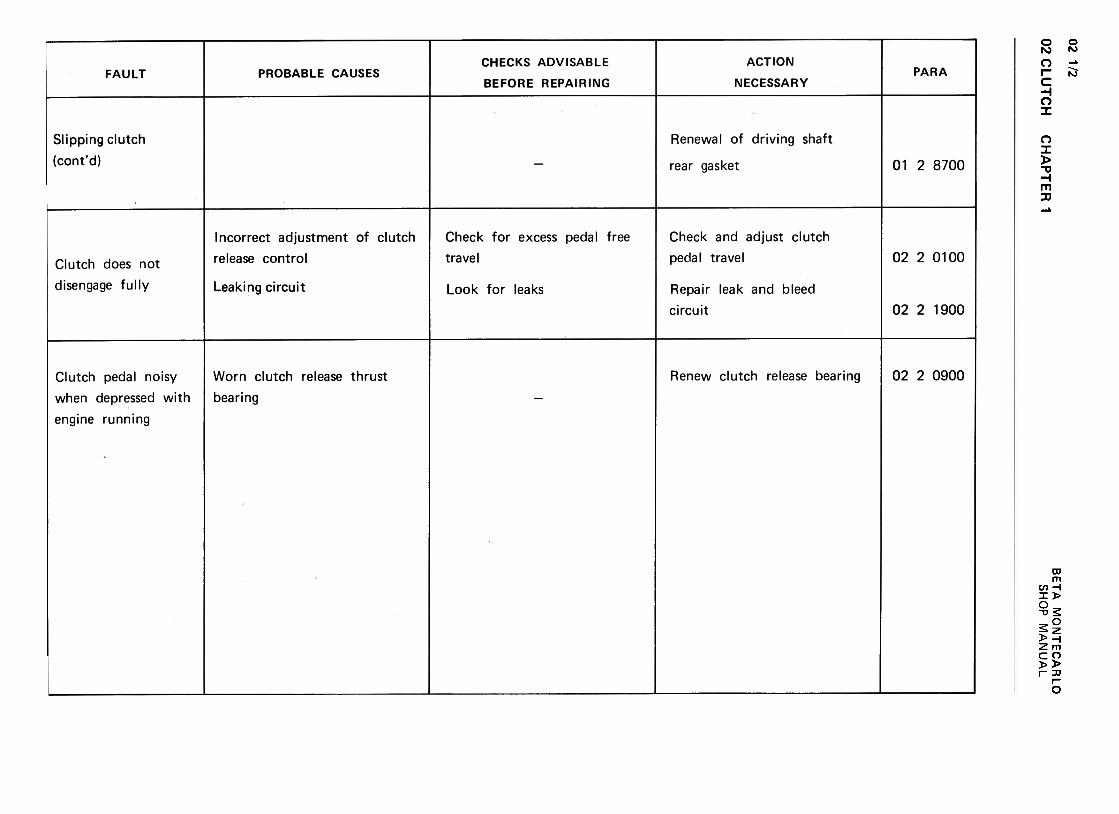
02 C
LUT
CH
02 1/2
>2
a:O
<
t-(I)1-
(I)U
W
<t
UW2
w
~-J
2aJ
-<
t a:
(/) -
-<t
>
~C
W
<t
a:
(/) W
~
a:U
O
W
u.Z
W
U
m
<t
a:<t
"-<I)
w<I)
:)<t
uw.JaI<taI
Oa:0.t-.J:>«11.
.cu...:]uC
)-~
-0
.-.0. ...
0. ~
:=
0U
) -~
...-'0..c:In0")c.>.~-0-0~Q
JcQ
Joc C
HA
PT
ER
1
+-'
(1)~V
)C
1J01'-C
1J(1)'-
oo~00N.-0
..c.(J...:J
u-0...c:Q)
E...C/)
-:J
O
"C
...!0
c:o...(J(J~
5!
o !0
(J ~
c: !i'
Q)
Q)
'-,+
-(0""0Q
)c."'"'Q
)uxQ
)
'-0'+-
~u Q
)Q
) >
.c (0
u b
.cu+"'
:Ju1;;.~-0(0
-
-0 ~
~
(0(0
...+
"'~u
(0Q
) u
.c Q
)u
0-
o0.-0NNO
Oc ~
"' :J
Q)
-0""0
Q)
01.c
10U
01C
:J Q
)-"'o
:0 +"
':;~'uC)
c~100)-J cn~10Q
)
...0'+-
~OO-1 -00.)~.D-0c:ro
~ro0.)
'- +
-''ro
'30.
u0.)
'-a:
'u oo0}NNO
o00')ONNO
..r::.>
.-
"' ~
.0c:: -0
C)
~
c::"'
.-ro
(!) c::
-0 '-
c::(!)
c. ~
c. (!)
'--0
..r::. (!)
u c::
c::(!)
.-~
..r::.
C)
-~
c::u
~
ro
0)c.~ro<1>
..0<1>
(/)ro
~<1>
...
..r:.(.)...:Ju:s:<
1>c<1>
oc1;)~'-
..c.(1)U
)ro(1)
(1)'-..c.u~u
01CC
.-
'- '-
0 ro
~
~
BE
TA
M
ON
TE
CA
RlO
SH
OP
M
AN
UA
L

02 2/1
02 CLUTCH -CHAPTER 2BETA MONTECARLO
SHOP MANUAL
f"
CHAPTER 2
§O2 20100
CHECKING AND ADJUSTMENT OF CLUTCH
PEDAL TRAVEL
Fit covers 88083051 and proceed as follows:
-Check that the free travel distance of the
clutch pedal is within the permitted range.
Fig. 02 2/2 -Fixture 88023036 in position for unhooking
clutch pedal spring.
-Extract the split pin (2), remove the cover (3)
and take off the pipe (4).
-Unscrew the bolts (5) and remove the master
cylinder (6) together with the plate (7) and
the push rod (8).Fig. 02211 -Adjustment of clutch pedal travel
-If adjustment is necessary, loosen the nut ( 1 )
and turn nut (2) in the direction required to
shorten or lengthen the pedal travel to the
correct distance.
§ 0220700
REMOVAL AND REFITTING OF THE CLUTCH
PEDAL(not including removal and refitting the pedal
bearing)
Removed the pedal bearing as describet at
para 12 2 1400 and proceed as follows:r--,
Fig. 02 213- Pedal bearingRemoval
Fit fixture 88023036 as shown in the figure
and unhook the spring (1 )
-Unscrew nut (1) and slide off clutch pedal
(2).
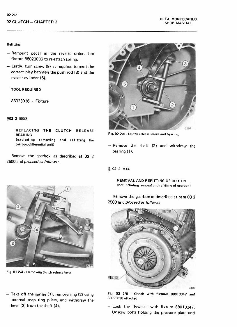
BETA MONTECARLO
SHOP MANUAL
022/2
02 CLUTCH -CHAPTER 2
Refitting
-Remount pedal in the reverse order. Use
fixture 88023036 to re-attach spring.
-Lastly, turn screw (9) as required to reset the
correct play between the push rod (8) and the
master cylinder (6).
TOOL REaulRED
88023036 -Fixture
§O2 20900
Fig. 02 2/5 -Clutch release sleeve and bearing.
-Remove the shaft {2) and withdraw the
bearing {1 ).Remove the gearbox as described at 03 2
2500 and proceed as follows:
§ 0221000
REMOVAL AND REFITTING OF CLUTCH
(not including removal and refitting of gearbox)
Remove the gearbox as described at para 03 2
2500 and proceed as follows:
Fig. 01 214 -Removing clutch release lever
~
0403
Fig. 02 2/6 -Clutch with fixtures 88013347 and
88023030 attached-Take off the spring (1 ), remove ring (2) using
external snap ring pliers, and withdraw the
lever (3) from the shaft (4). -Lock the flywheel with fixture 88013347.
Unscrw bolts holding the pressure plate and
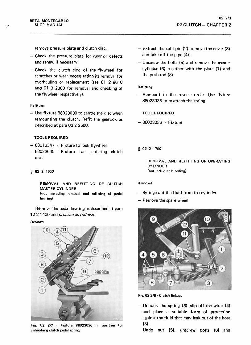
02 2/3
02 CLUTCH -CHAPTER 2BETA MONTECARLO
SHOP MANUALr
-Extract the split pin (2), remove the cover (3)
and take off the pipe (4).
-Unscrew the bolts (5) and remove the master
cylinder (6) together with the plate (7) and
the push rod (8).
remove pressure plate and clutch disc.
-Check the pressure plate for wear or defects
and renew if necessary.
-Check the clutch side of the flywheel for
scratches or wear necessitating its removal for
overhauling or replacement (see 01 2 8610
and 01 3 2300 for removal and checking of
the flywheel respectively).
Refitting
-Remount in the reverse order. Use fixture
88023036 to re-attach the spring.
Refitting
-Use fixture 88023030 to centre the disc when
remounting the clutch. Refit the gearbox as
described at para 03 2 2500.
TOOL REQUIRED
-88023036 -Fixture
TOOLS REQUIRED
-88013347 -Fixture to lock flywheel
-88023030 -Fixture for centering clutch
disc.
§ 0221700
REMOVAL AND REFITTING OF OPERATING
CYLINDER
(not including bleeding)§ 0221500
RemovalREMOVAL AND REFITTING OF CLUTCH
MASTER CYLINDER
(not including removal and refitting of pedal
bearing)
-Syringe out the fluid from the cylinder
-Remove the spare wheel
Remove the pedal bearing as described at para
12 2 1400 and proceed as follows:
Removal
Fig. 02 2/8 -Clutch linkage
-Unhook the spring (3), slip off the wires (4)
and place a suitable form of protection
against the fluid that may leak out of the hose
(8).
Undo nut (5), unscrew bolts (6) andFig. 02 2!7 -Fixture 88023036 in position for
unhooking clutch pedal spring
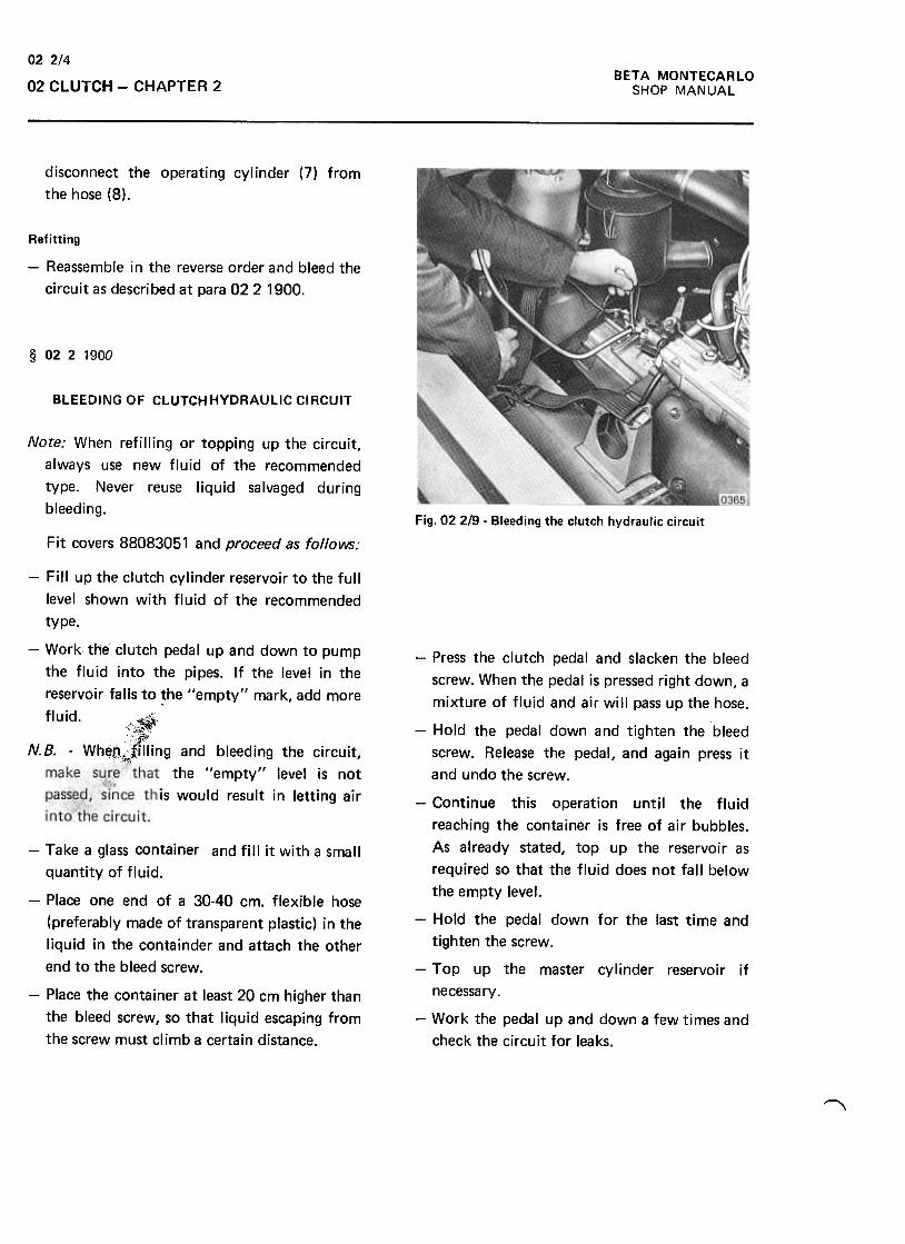
BETA MONTECARLO
SHOP MANUAL
022/4
02 CLUTCH -CHAPTER 2
disconnect the operating cylinder (7) from
the hose (8).
Refitting
-Reassemble in the reverse order and bleed the
circuit as descri bed at para 02 2 1900.
§ 0221900
BLEEDING OF CLUTCH HYDRAULIC CIRCUIT
Note: When refilling or topping up the circuit,
always use new fluid of the recommended
type. Never reuse liquid salvaged during
bleeding.Fig. 02 2/9- Bleeding the clutch hydraulic circuit
Fit covers 88083051 and proceed as follows:
-Fill up the clutch cylinder reservoir to the full
level shown with fluid of the recommended
type.
-Work theC clutch pedal up and down to pump
the fluid into the pipes. If the level in the
reservoir falls to ~he "empty" mark, add more
fluid. c".,s:c;;j~,,~~.
N.B. -Wheo"tffiing and bleeding the circuit,c~
make the "empty" level is not
this would result in letting air
-Take a glass container and fill it with a small
quantity of fluid.
-Place one end of a 30-40 cm. flexible hose
(preferably made of transparent plastic) in the
liquid in the containder and attach the other
end to the bleed screw.
-Place the container at least 20 cm higher than
the bleed screw, so that liquid escaping from
the screw must climb a certain distance.
-Press the clutch pedal and slacken the bleed
screw. When the pedal is pressed right down, a
mixture of fluid and air will pass up the hose.
-Hold the pedal down and tighten the bleed
screw. Release the pedal, and again press it
and undo the screw.
-Continue this operation until the fluid
reaching the container is free of air bubbles.
As already stated, top up the reservoir as
required so that the fluid does not fall below
the empty level.
-Hold the pedal down for the last time and
tighten the screw.
-Top up the master cylinder reservoir if
necessary.
-Work the pedal up and down a few times and
check the circuit for leaks.
"
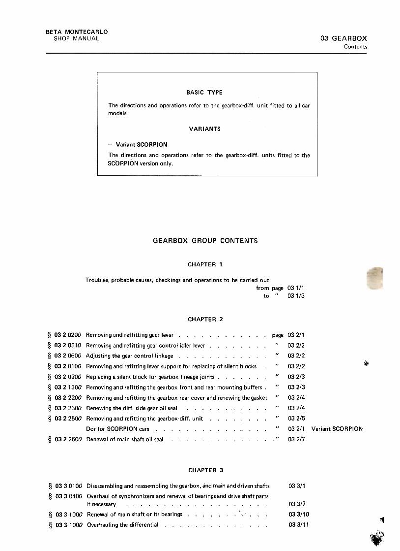
BETA MONTECARLO
SHOP MANUAL 03 GEARBOXContents
GEARBOX GROUP CONTENTS
CHAPTER 1
Troubles. probable causes, checkings and operations to be carried out
from page 031/1to " 031/3
CHAPTER 2
~
page§ 0320200 Removing and reffitting gear lever. § 032 0510 Removing and refitting gear control idler lever. § 032 0600 Adjusting the gear control linkage. § 032 0100 Removing and refitting lever support for replacing of silent blocks
§ 032 0200 Replacing a silent block for gearbox lineage joints. § 032 1300 Removing and refitting the gearbox front and rear mounting buffers .
§ 032 2200 Removing and refitting the gearbox rear cover and renewing the gasket
§ 0322300 Renewing the diff. side gear oil seal. § 0322500 Removing and refitting the gearbox-diff. unit. ...
Dor for SCORPION cars. § 032 2600 Renewal of main shaft oil seal.
CHAPTER 3
033/1
03. 3/7
033/10
03 3/11
§ 03 3 0100 Disassembling and reassembling the gearbox, and main and driven shafts
§ 033 0400 Overhaul of synchronizers and renewal of bearings and drive shaft parts
if necessary
§ 033 1000 Renewal of main shaft or its bearings
§ 033 1000 Overhauling the differential~
~
03
03
03
03
03
03
03
03
03
03
03
2/1
2/2
2/2
2/2
2/3
2/3
2/4
2/4
2/5
2/1 Variant SCORPION
2/7
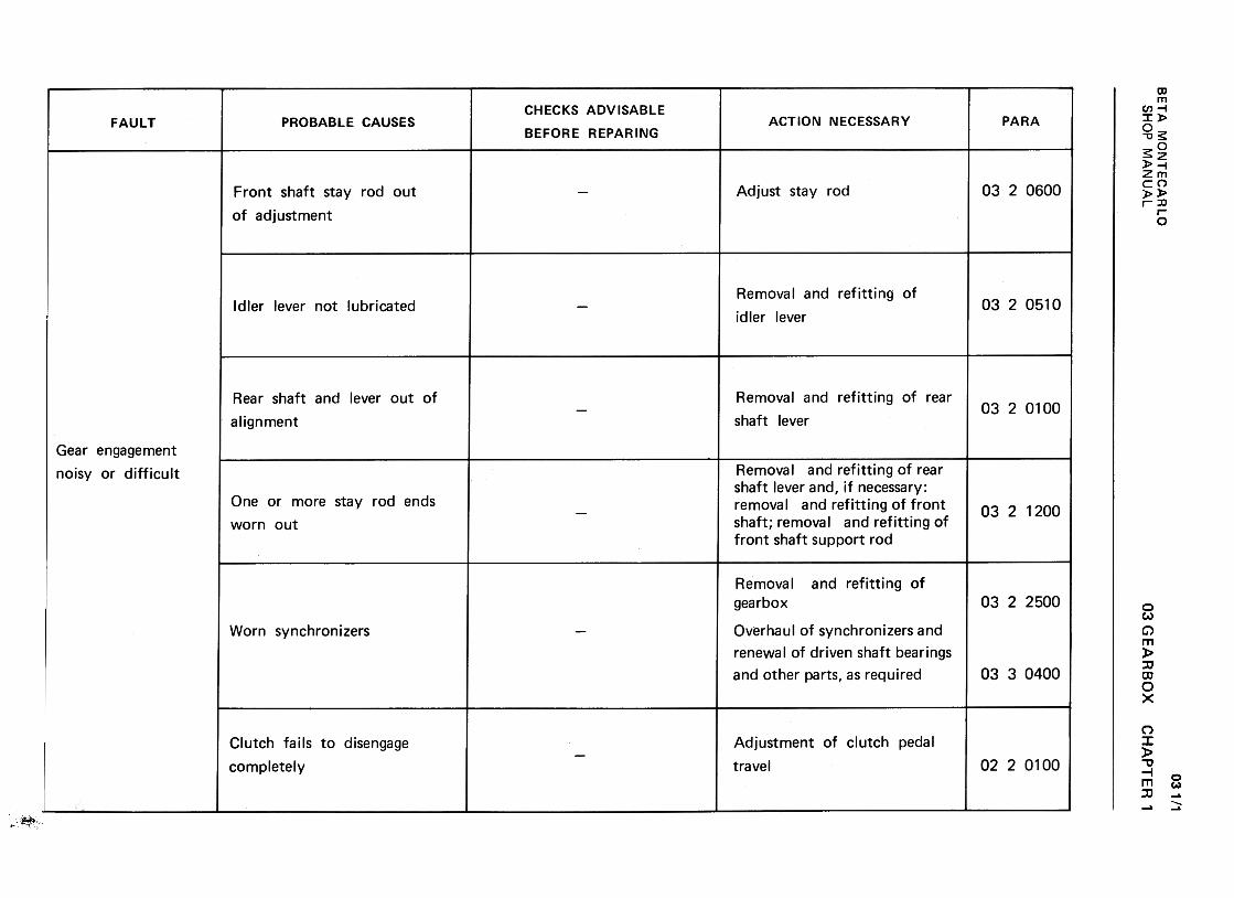
BE
TA
M
ON
TE
CA
RLO
w-J (0?
CX
I Z
<t
-(/)
I):-<
t>
0,.
C
W<
t I):
(/) W
~
I):U
O
W
L&.
%
WU
m
>CI:
<t(I)
(I)wuw22Q1-U<3:
~~~d.1-..J:)<~ (/)w(/):>~uw-Jm~mO~0..
-0O'->(0"'~:J
~ o0CD
ONMn+"'
:JO-00'->ro+"'
+"'
(/) c:
+"'
0>
-Ero +
"'0!:
(/)(/)
:J,-
+"'
-0c:
ro0
-
It o
-001c:
";;.~-0)'-
-0c:CO
'-0)C
O
>>
0)
0 -
E
'-
0) ~
OC
:-g
0~LOON(Y
)0"0a.I+
-'
'8.~..0:]+
-'OI::'-a.I>
~'-.E!.
~
...coQ
)...
'+-00)
.~......~Q
)...
-0cco ...Q
)co
>>
~
oE
.::::Q
) co
a: .c"'
-O+"~0'-Q)
>Q)
"01=:
(0+"
-+"(0
1=:
.1=:
Q)
(I) E
'- 1=
:(0
0")Q
) .-
a: m
oo.--0NMO
+"'
+"'
-c
~Q
) r.J
E
~-Q
) .-
0'11:)ca0'1
'-c
oQ
)
'- ~
ca .-
Q)
0(9
I::
{I)"0cQ
)
"0O'->~+"'
{I)
Q)
'-0E
+"'
::J'-
00
cQ
) '-
c 0
O
:S:
ro c:O
C1>
..0
C)
>
c:
oro C
/)0
.A
.-C
1 y.
'f- ~
c:C1>
C1C
1>'"'
.-U
c: 0
C1>
.-"tJ
.~
c: ~
c:
C1>
.--ro
O
,C1>
Q
.
"tJ"tJ Q
.
c: c:
"tJ>ro
~
roroc:OC
/)ro
E
-C1>
-
ro>-C
1>.F
:.>
C
1>
ro C
/)
0- >
.,
E-t:'°
C1>
~E
'+co§
a: C
1>~
C
/) C
/)-
o0NNMO
cn"C
C
'Ic:
c:O
co
.~cn
co "C
C'I
...Q)
Q)
c:Q
).D...
N
.-
.+:I
.-+-'
~
+-'
c: .-
Oco
'-'-
..c:Q
)Q
) c:
cn(,)
c: ~
"C
c:Q)
-c:
»cn-cn
.-+-'
.v... ...
-"C
coo-c..
co X
~
0
...
>0
-Q)
°.D
~
co..C:
E...
...:s: b
Q)
co Q
) Q
)C
[:Q)
>
c:"C
C'lO
Q)c:
'- "'
0f?;NNMO
03 GE
AR
BO
X
(I)...Q
)N"c:o...
..cuc:>(I)c:...0$:
oovoMMo
CH
AP
TE
R'
ro"U(1)0.
.I:CJ
:Ju,+
-0c(1)Ecn
-:J
(1).~
>
"U
ro
<!
b
(1)01ro01C(1)
.~-0O...(/)=
>
ro -
-(1)...
..c ~
() a.
~
E-oU
Q o0.--
0NN0
031/1
cfic
\;.
SH
OP
M
AN
UA
L
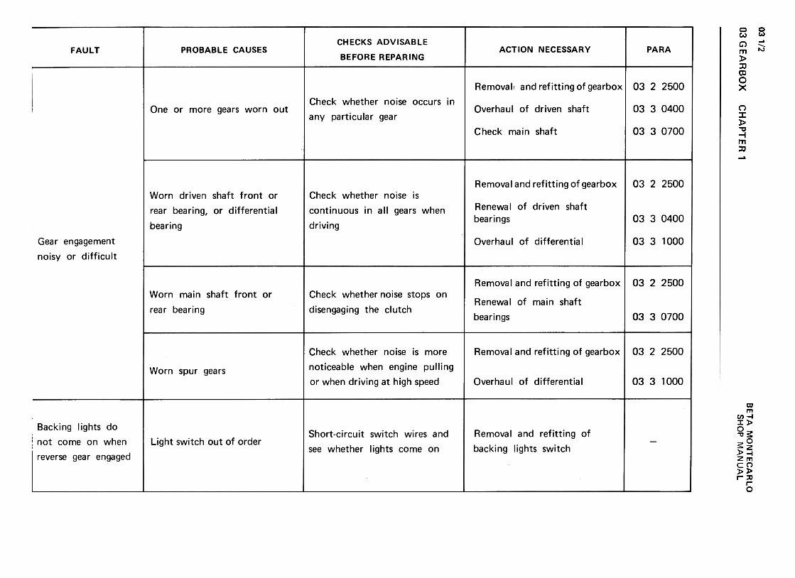
03 G E
AR
BO
X
031/2w.J ~
m
z<
t -
(/) a:
-<t
>
Q.
c w
<t
a:
(/) w
~
a:u
Ow
u.
~
wo
m
(I)w(I):)<
{uw.Jm<
{mO~~ >a:<t
{1){1)wuw22O...U~ ~a:~no.....J:)«lL
ooI.!)NNMOXO.0'-'0Q
)0>
'+-00>C';:.+"'
;;:Q)
'--0C10~oEQ)
rr:
c:U)
'-:JuuOQ)
U)
.-'-0 co
c: Q
)01
'-Q)
'-.c:
CO
""3Q
) U
.c: .-
s: tC
O.¥.
Q.
UQ)
>.c:
c:(.)
(n
o0v0MMC)
CH
AP
TE
R'
...-(I!.c"'c:Q
)>..:"'0
't-o:J(I!.c'-Q
)>0...~Oc:'-0~U
I'-(QQ
)0")
Q)
'-0E'-0Q)
c:O
+-'
-(0.r:."'c:(0E~uQ
).r:.
O o01"'-0MMC
)
ooL!)N("II
MOx0.0...roQ)
01-001c:.~+
"';+
:Q)
...-0c:ro~0EQ
)O
C
'- -
O
.!2+"'
+"'
cc
Q)
O
'-'-
Q)
'+-
;
+"'
"C'+
-<0
'-.c
OIIIC
C
1Q
) C
>
.-.-'-'-
<0
"CQ
)C1.D
C
C
.~'-
'- <
0
O<
OQ
)S
~
.D
+"'
'+-ro
.c"'c:QJ
>'.:-0'0-"'~
g>Q
J .-c:
'-Q
J ~
0: n
I::Q)
.l:::s:"'
"'...Q
) ~
"' Q
).-0>OI::
=~...Q
) I::
.l::Q)
"'.l::
:J:s:
0:J 0>
~
I:: I::
(.) .;;
.-:0Q
) I::
.-
.l:: O
...
u u
-0
oovoMMO
(00;;c:Q
)...Q
)'+
-'+
-
:0b::J(0
..c:...Q
)>0 ooo(V
)
(V)
0
+"'
+"'
-c
:J(I)
(.)
E
;.=-
(I) 0-
01l;)~
'-
C
O(I)
'- >In
(0 .-
(I) 0
~
t""
ooL!)NNMOx0.0'-~0)0')
'00')c';:....
;.=0)'-
"0c~~>oE0)rr-
...0c:o...
--co.ccn
0)c:
c:"ro
.~E
~.Q
c:O
co$:
~
c:OCI)
a.ot; .cu
Q)
CI)
~
.0 u
c:...Q)
Q)
.c.c Q)
C1
.c c:
:s: .c,ca
~
C1
U
c:Q
) Q
).c
.~O
l:1
-(0~Inc:(0E-0
In~
~
(I) .~
c: (0
(I) (I)
a: n o0I'"-.
OMMn
ool!)NNMO
C)
Q)
c:
0 =
"0
E:JQ
)
c. Q
)c.(/)
Q)
(/).-c:
.!:Q
) .-C
)(/)
C)
.-.-c:
.!:
oQ)+
"c:
~c:
...Q)
C)
Q)
.!: c:
.!: :s:
.>+
"' .-
Q)
....!:
Q)
"0
:s: :c
c:~
Q
)~
Q
) .!:
u u
>Q
) .ij
>.!:
0 ...
u h
0
x0.D'-ro0)0)'+
-00)c0;:.+
-';.=0)'-
"0cro~0E0)oc
"'...caQ)
0">
...:J0."'c:...0~
<0
";;c0)...0)
--"-'6
-0:J<0
.c...0)>0 oooMMO
BE
TA
M
ON
TE
CA
RLO
""0c:
Q)
Q)
CJ
O
~
~""0
:s: c:
!tJ c:
Q)
~
O
'-C
J ro
.-Q)
Q)
E
CJ
g:' °
5!.-u
'-~
Q
)u
>roO
Q)
a)c:h "tJc:ro c:
"' 0
e; Q
).-E:s:
o..c:
uC
.J "'
+-'
+-'
c::s:
C)
"' :=
+-'
:J Q
)C
.J ..c:
...+-'
.-Q)
C;'
..c:t
:s:o..c:
Q)
U>
(!)"'
-00)c 0!:
0;; u
+"'
+"'
:.:: .~
~
<I)
"0 J!!.
c 0!:
10 o~
~
0)0
CE
~
(1) u
a: 10.-0
'-QJ
"'0'-0'0+";j0.r:.u+"
.~"'+"
.r:.0)'I
SH
OP
M
AN
UA
L
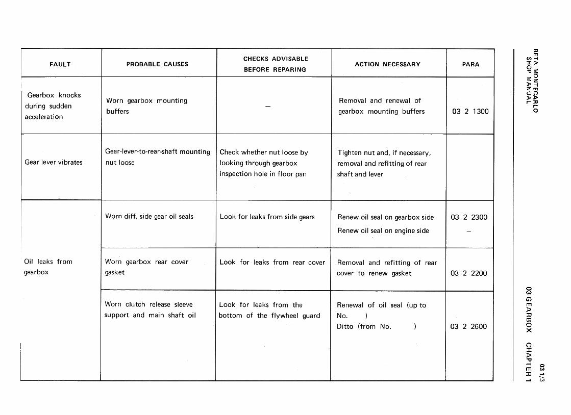
BE
TA
M
ON
TE
CA
RlO
w..J C
-'ID
2
<t
-(/)
a:-<
t>
~
C
w<
t a:
(/) w
~
a:U
a
W
IL.~
w
U
ID
1-.J=>~u.
U)
wU)
:J<tuw..Jm<t
mO~Q.
>a:<t(/)
(/)wuw22Q1-U<
t «a:«0-
cn~C
J c
O
Q)
c -a
c~
-a
o::]
.-x
cn ~
O
0>
~
..Qc- ...ro .-Q
)Q
) ...C
J,n ::] C
J'-' -a ro 0>~';;~;:,
oEx0.0'-("00.)0>
(/)'-
~
0.)'-
-0
-
s .5
-~0 Q
)-
--co :J
S:
.c
Q)
0')c:
c:Q
) .-
...+-'
c:
"'0 :J
c: O
co E
~
xo
o
E
-eQ
) co
a: Q
)r"T
\
oo(Y)
N(Y)
0
C)
c.:+:J
c:JOE-ca..c:"'.:.caQ
)...6.:.
Q)
Q)
"'>
0
~
0.:.ca Q
) :J
('J c
>
c:.c
CtI
c.Q
) x
...(/)
o o
° .c
°0
...
CtI
~+
-' Q
) ~
::J C
) ...
c: .c:
Q)
...C)
-Q
) ::J
O.c:
O
.c:+
-' ...c:
~
-:5 °
~
C)
..;::c:
u~
.-Q
)u
~
c.Q
) 0
(/)
.C:oc:
u
>
'-'-
caca
Q)
(/) '-
(/)Q
) '1-
u O
Q)
C)
C
C'1-
.-+-'
-+-'
"'C
~C
Q)'-
ca'-Q)
+-'
"'C
>:J
C
~C
ca
"'CC
ro
CQ
»ca+
-' 0
+-'
..cE
'1-
C) ca
.-Q)
..c1-
'- "'
InQ)
+-'
~'-.0">'-Q
)>~'-~Q
)~
"'roQ)
"'
.0...roQ)
01Q)
"0.V;
'4-'4-
::0:
c:...0S
In'-ro(1)0)
(1)"0'iiiEo'--In~ro(1)
'-0-~o0-3 Q)
-0'ViXO.0'-coQ)
0"]c:0coQ
)"'
'0~Q)
c:Q)
rr-
ooMNNMO
Q)
""0.inQ
)c'51cQ
)
cO(0Q)
C/)
.05:Q)
cQ)
rr-
Eo'--"'~
x
ca O
aJ .0
-'-ca
0- aJ
O
rn
...Q)
>Ou...coQ)
...xo..0...coQ)
0)+
-'c:
Q)
...~O
tn
$ ~
'-Q)
>ou'-(0~Eo'--"'~(0Q
)
'-0-~o0-J '-caQ)
'-
'+-0
+"'
CI
Q)
c: ~
.-"':::::
ca.-C
I'+
-~
~Q)
"0 c:
c: Q
)ca
'-0ca
+"'
>0 '-
E
~Q
) 0
Cl:
U o0NNNMO
03 GE
AR
BO
X
CI>
.0
>CI>
...
CI>
-
-C1J
C/)
..c:
CI>
C
/)
'c'ci c:
CI>
.-
-C1J
~
E
..c: "C
u c:
...C1J
:Ju '-0
c: c.
'- c.
0 :J
s ", "'C'-ro::)
QJ
CI
..c: -
+-'
QJ
QJ
E
..c:
O
:s:'-
>'1-
-'1-
"'~
Q
Jro
..c:~
+
-'
'1-'-
o0'1-
E
~
oo
+-'
0 +
-'
-J ~
O+"'
0.~CtI
0>II)-0.0
z
-E0- O'-
CtI
-~
-
0>
Oc
.+"'
0>
O
.~cx:zo
o0CD
NNC")
0
CH
AP
TE
R
1
03 1/3
SH
OP
M
AN
UA
L
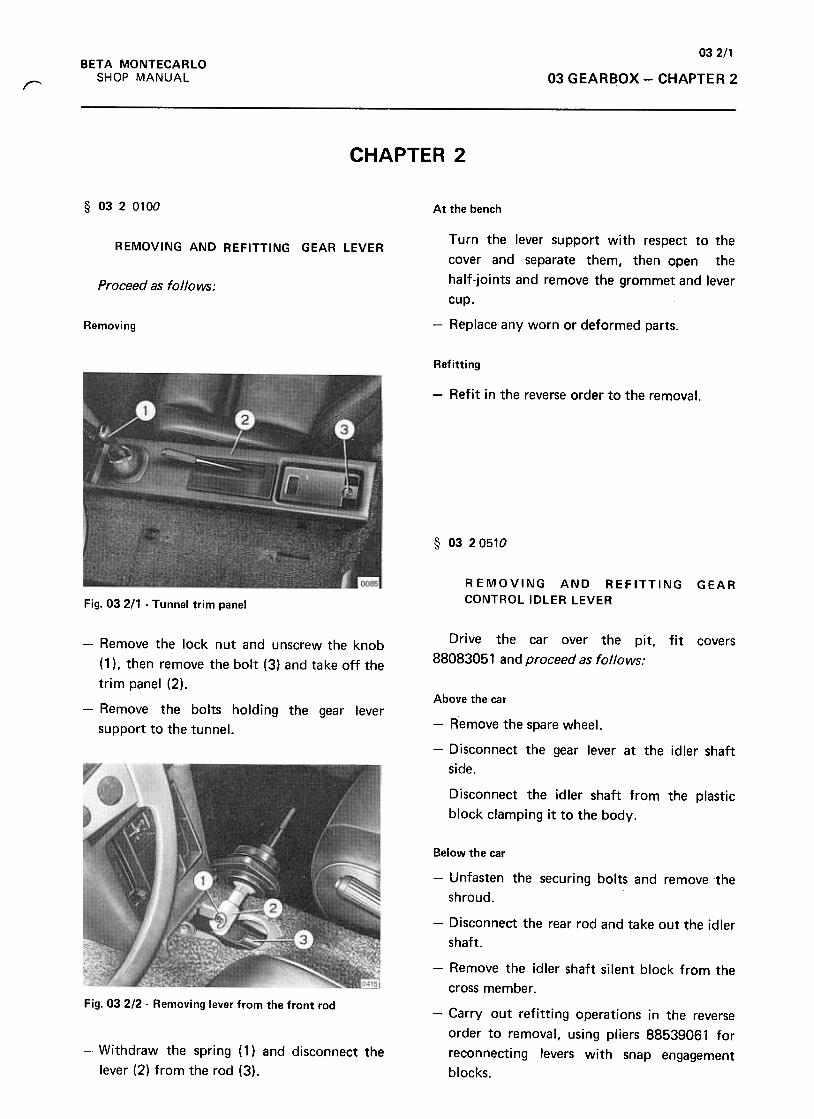
032/1BETA MONTECARLO
SHOP MANUAL 03 GEARBOX -CHAPTER 2r
CHAPTER 2
§ 0320100 At the bench
Turn the lever support with respect to the
cover and separate them, then open the
half-joints and remove the grommet and lever
cup.
REMOVING AND REFITTING GEAR LEVER
Proceed as follows:
Removing -Replace any worn or deformed parts.
Refitting
-Refit in the reverse order to the removal,
§ 03 20510
REMOVING AND REFITTING
CONTROL IDLER LEVERGEAR
Fig. 03 211 -Tunnel trim panel
Drive the car over the pit,
88083051 and proceed as follows:
fit covers-Remove the lock nut and unscrew the knob
(1 ), then remove the bolt (3) and take off the
trim panel (2),Above the car
-Remove the bolts holding the gear lever
support to the tunnel. -Remove the spare wheel.
-Disconnect the gear lever at the idler shaft
side.
Disconnect the idler shaft from the plastic
block clamping it to the body.
Below the car
-Unfasten the securing bolts and remove 1he
shroud.
-Disconnect the rear rod and take out the idler
shaft.
Fig. 032/2- Removing lever from the front rod
-Remove the idler shaft silent block from the
cross member .
-Carry out refitting operations in the reverse
order to removal, using pliers 88539061 for
reconnecting levers with snap engagement
blocks.
-Withdraw the spring (1) and disconnect the
lever (2) from the rod (3).
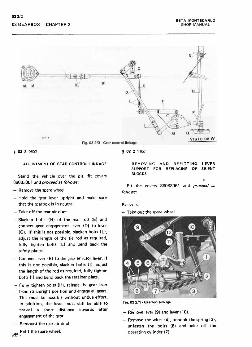
032/2BETA MONTECARLO
SHOP MANUAL03 GEARBOX -CHAPTER 2
§ 0320600 § 0321100
ADJUSTMENT OF GEAR CONTROL LINKAGE REMOVING AND REFITTING
SUPPORT FOR REPLACING OF
BLOCKS
LEVER
SILENT
Fit the covers 88083051 and proceed as
follows:
Removing
-Take out the spare wheel.
Fig. 03 2/4 -Gearbox linkage
-Remove lever (9) and lever ( 10) .
-Remove the wires (4), unhook the spring (3),
unfasten the bolts (6) and take off the
operating cylinder (7),
Stand the vehicle over the pit, fit covers
88083051 and proceed as follows:
-Remove the spare wheel
-Hold the gear lever upright and make sure
that the gearbox is in neutral
-Take off the rear air duct
-Slacken bolts (H) of the rear rod (8) and
connect gear engagement lever (0) to lever
(G). If this is not possible, slacken bolts (L),
adjust the length of the tie rod as required,
fu Ily tighten bolts ( L) and bend back the
safety plates.
-Connect lever (E) to the gear selector lever. If
this is not possible, slacken bolts (I), adjust
the length of the rod as required, fully tighten
bolts ( I) and bend back the retainer plate.
-Fully tighten bolts (H), release the gear le.,,~r
from its upright position and engage all gears.
This must be possible without undue effort.
In addition, the lever must still be able to
t r a vel a short distance i nwards after
engagement of the gear.
-Remount the rear air duct
,~;~efit the spare wheel.
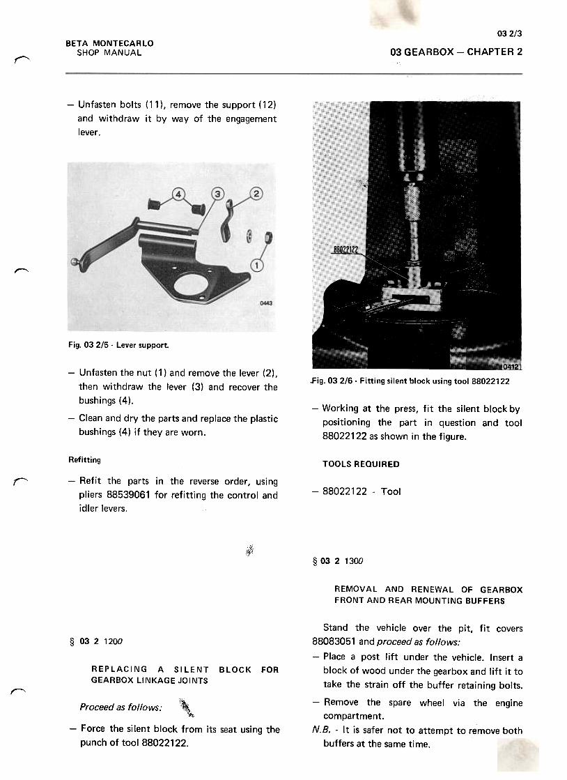
032/3BETA MONTECARLO
SHOP MANUAL 03 GEARBOX -CHAPTER 2"'
-Unfasten bolts ( 11) , remove the support ( 12)
and withdraw it by way of the engagement
lever.
"""""
Fig. 03 215 -Lever support.
.Fig. 03 2/6. Fitting silent block using tool 88022122
-Working at the press, fit the silent block by
positioning the part in question and tool
88022122 as shown in the figure.
-Unfasten the nut ( 1) and remove the lever (2) I
then withdraw the lever (3) and recover the
bushings (4).
-Clean and dry the parts and replace the plastic
bushings (4) if they are worn.
TOOLS REQUIRED
r
Refitting
-Refit the parts in the reverse order, using
pliers 88539061 for refitting the control and
idler levers.
-88022122 -Tool
~
§ 03 2 1300
REMOVAL AND RENEWAL OF GEARBOX
FRONT AND REAR MOUNTING BUFFERS
§ 0321200
REPLACING A SILENT
GEARBOX LINKAGE JOINTS
BLOCK FOR
""
Proceed as follows: '\c"~,
-Force the silent block from its seat using the
punch of tool 88022122.
Stand the vehicle over the pit, fit covers
88083051 and proceed as follows:
-Place a post lift under the vehicle. Insert a
block of wood under the gearbox and lift it to
take the strain off the buffer retaining bolts.
-Remove the spare wheel via the engine
compartment.N. B. -It is safer not to attempt to remove both
buffers at the same time.
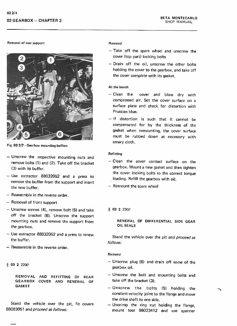
032/4BETA MONTECARlO
SHOP MANUAL03 GEARBOX -CHAPTER 2
Removal of rear support Removal
-Take off the spare wheel and unscrew the
cover (top part) locking bolts
-Drain off the oil, unscrew the other bolts
holding the cover to the gearbox, and take off
the cover complete with its gasket.
At the bench
-Clean th e cover and blow dry with
compressed air. Set the cover surface on a
surface plate and check for distortion with
Prussian blue.
-If distortion is such that it cannot be
compensated for by the thickness of the
gasket when remounting, the cover surface
must be rubbed down as necessary with
emery cloth.Fig. 03 2n .Gearbox mounting buffers
Refitting
-Clean the cover contact surface on the
gearbox. Mount ~ new gasket and then tighten
the cover locking bolts to the correct torque
loading. Refill the gearbox with oil.
-Remount the spare wheel
§ 0322300
RENEWAL OF DIFFERENTIAL SIDE GEAR
OIL SEALS
Stand the vehicle over the pit and proceed as
follows:
-Unscrew the respective mounting nuts and
remove bolts (1) and (2). Take off the bracket
(3) with its buffer.
-Use extractor 88032052 and a press to
remove the buffer from the support and insert
the new buffer .
-Reassemble in the reverse order .
-Removal of front support
-Unscrew screws (4), remove bolt (5) and take
off the bracket (6). Unscrew the support
mounting nuts and remove the support from
the gearbox.
-Use extractor 88032052 and a press to renew
the buffer .
-Reassemble in the reverse order.
Removal
§ 0322200
R EMOV AL AND REFITTING OF REAR
GEARBOX COVER AND RENEWAL OF
GASKET
~
Stand the vehicle over the pit, fit covers
88083051 and proceed as follows:
-Unscrew plug (6) and drain off some of the
gearpox oil.
-Unscrew the bolt and mounting bolts and
take off the bracket (3).
-Unscrew the bolts (5) holding the
constant-velocity joint to the flange and move
the drive shaft to one side.
-Uncrimp the ring nut holding the flange,
mount tool 88023412 and use spanner
-
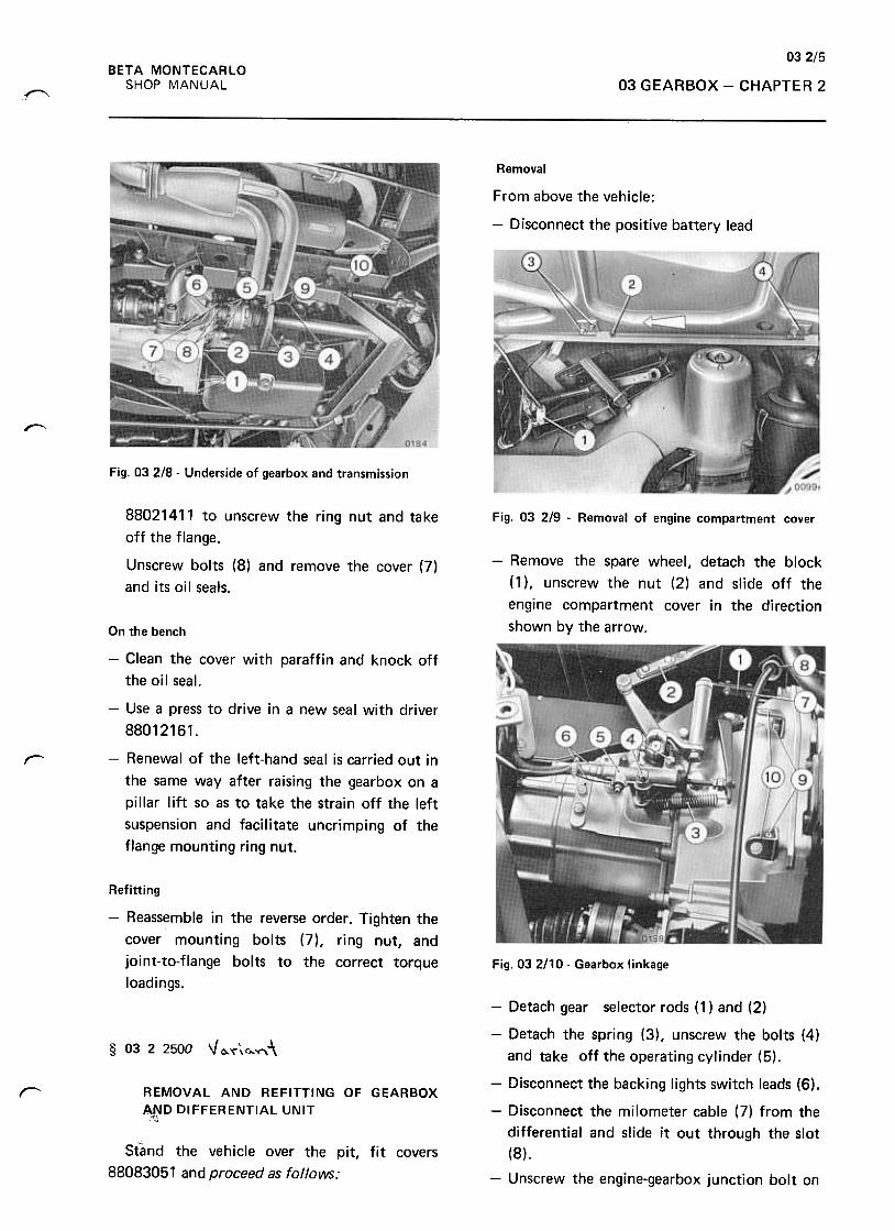
03 2/5
BETA MONTECARLO
SHOP MANUAL 03 GEARBOX -CHAPTER 2~
Removal
From above the vehicle:
-Disconnect the positive battery lead
r""'
Fig. 03 2/8 .Underside of gearbox and transmission
Fig. 03 2/9 .Removal of engine compartment cover
-Remove the spare wheel, detach the block
(1), unscrew the nut (2) and slide off the
engine compartment cover in the direction
shown by the arrow.
88021411 to unscrew the ring nut and take
off the flange.
Unscrew bolts (8) and remove the cover (7)
and its oi I seats.
On the bench
-Clean the cover with paraffin and knock off
the oil seal.
-Use a press to drive in a new seal with driver
88012161.
-Renewal of the left-hand seal is carried out in
the same way after raising the gearbox on a
pillar lift so as to take the strain off the left
suspension and facilitate uncrimping of the
flange mounting ring nut.
r
Refitting
-Reassemble in the reverse order. Tighten the
cover mounting bolts (7), ring nut, and
joint-to-flange bolts to the correct torque
loadings.
Fig. 032!10- Gearbox linkage
§ 03 2 2500 V0..'<"\0..~-\
r REMOVAL AND REFITTING OF GEARBOX
"~D DIFFERENTIAL UNIT"'
Stand the vehicle over the pit, fit covers
88083051 and proceed as follolNS:
-Detach gear selector rods (1) and (2)
-Detach the spring (3), unscrew the bolts (4)
and take off the operating cylinder (5),
-Disconnect the backing lights switch leads (6),
-Disconnect the milometer cable (7) from the
differential and slide it out through the slot
(8),
-Unscrew the engine-gearbox junction bolt on
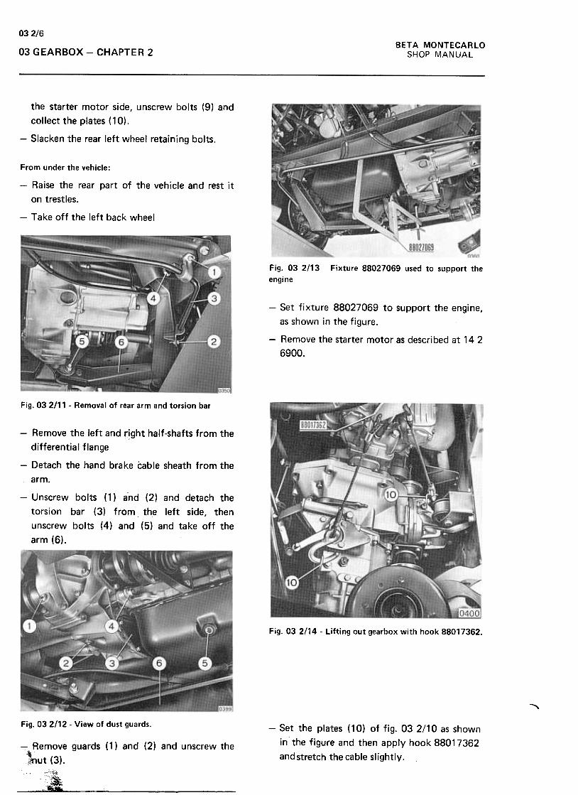
03 2/6
BETA MONTECARLO
SHOP MANUAL03 GEARBOX -CHAPTER 2
the starter motor side, unscrew bolts (9) and.
collect the plates (10).
-Slacken the rear left wheel retaining bolts.
From under the vehicle:
-Raise the rear part of the vehicle and rest it
on trestles.
-Take off the left back wheel
Fig. 03 2/13
engine
Fixture 88027069 used to support the
-Set fixture 88027069 to support the engine,
as shown in the figure.
-Remove the starter motor as described at 14 2
6900.
Fig. 03 2111 -Removal of rear arm and torsion bar
-Remove the left and rjght half-shafts from the
differential flange
-Detach the hand brake cable sheath from the
arm.
-Unscrew bolts (1) and (2) and detach the
torsion bar (3) from the left side, then
unscrew bolts (4) and (5) and take off the
arm (6).
Fig. 03 2/14 -Lifting out gearbox with hook 88017362.
,Fig. 032/12- View of dust guards.
-Set the plates ( 10) of fig. 03 2/10 as shown
in the figure and then apply hook 88017362
and stretch the cable slightly.-Remove guards (1) and (2) and unscrew the
'\}~ut (3).
-"7i
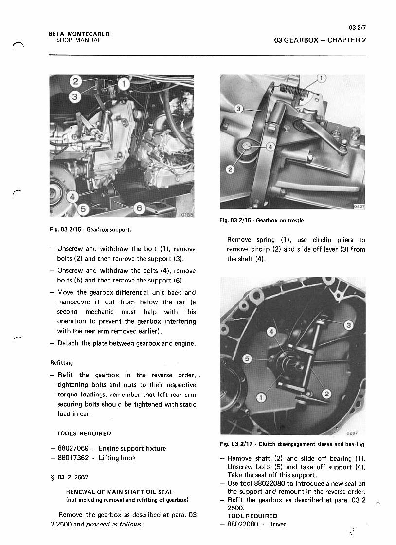
03 2/7BETA MONTECARLO
SHOP MANUAL 03 GEARBOX -CHAPTER 2~
r
Fig. 03 2116 -Gearbox on trestle
Fig. 03 2/15 -Gearbox supports
Remove spring [1 ), use circlip pliers to
remove circlip (2) and slide off lever (3) from
the shaft (4).
~
-Unscrew and withdraw the bolt ( 1) , remove
bolts (2) and then remove the support (3).
-Unscrew and withdraw the bolts (4), remove
bolts (5) and then remove the support (6),
-Move the gearbox-differential unit back and
manoeuvre it out from below the car (a
second mechanic must help with this
operation to prevent the gearbox interfering
with the rear arm removed earlier).
-Detach the plate between gearbox and engine.
Refitting
-Refit the gearbox in the reverse order, -
tightening bolts and nuts to their respective
torque loadings; remember that left rear arm
securing bolts should be tightened with static
load in car.
TOOLS REQUIRED
Fig. 03 2/17 -Clutch disengagement sleeve and bearing.-88027069 -Engine support fixture
-88017362 -Lifting hook
§ 0322600
RENEWAL OF MAIN SHAFT OIL SEAL
(not including removal and refitting of gearbox)""
Remove the gearbox as described at para. 03
2 2500 and proceed as follows:
-Remove shaft (2) and slide off bearing (1 ).
Unscrew bolts (5) and take off support (4).
Take the seal off this support.
-Use tool 88022080 to introduce a new seal on
the support and remount in the reverse order.
-Refit the gearbox as described at para. 03 2
2500.
TOOL REQUIRED
-88022080 -Driver
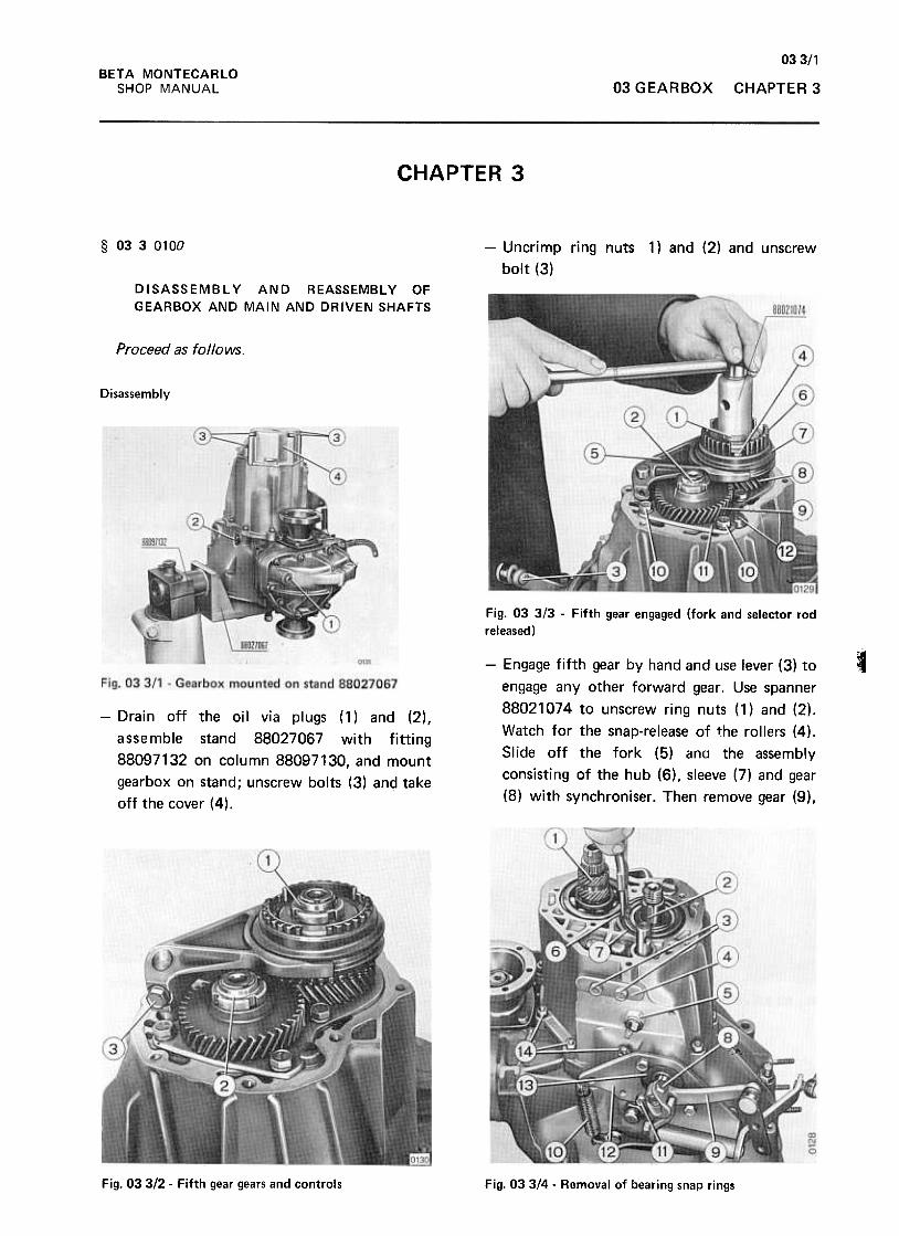
03 3/1BETA MONTECARLO
SHOP MANUAL 03 GEARBOX CHAPTER 3
CHAPTER 3
§ 0330100 1) and (2) and unscrew-Uncrimp ring nuts
bolt (3)
DISASSEMBLY AND REASSEMBLY OF
GEARBOX AND MAIN AND DRIVEN SHAFTS
Proceed as follows.
Disassembly
Fig. 03 3/3 -Fifth gear engaged (fork and selector rod
released)
--Engage fifth gear by hand and use lever (3) to
engage any other forward gear. Use spanner
88021074 to unscrew ring nuts (1) and (2).
Watch for the snap-release of the rollers (4).
Slide off the fork (5) ana the assembly
consisting of the hub (6), sleeve (7) and gear
(8) with synchroniser. Then remove gear (9),
-Drain off the oil via plugs (1) and (2),
assemble stand 88027067 with fitting
88097132 on column 88097130, and mount
gearbox on stand; unscrew bolts (3) and take
off the cover (4).
Fig. 03 312 -Fifth gear gears and controls Fig. 03 314 -Removal of bearing snap rings
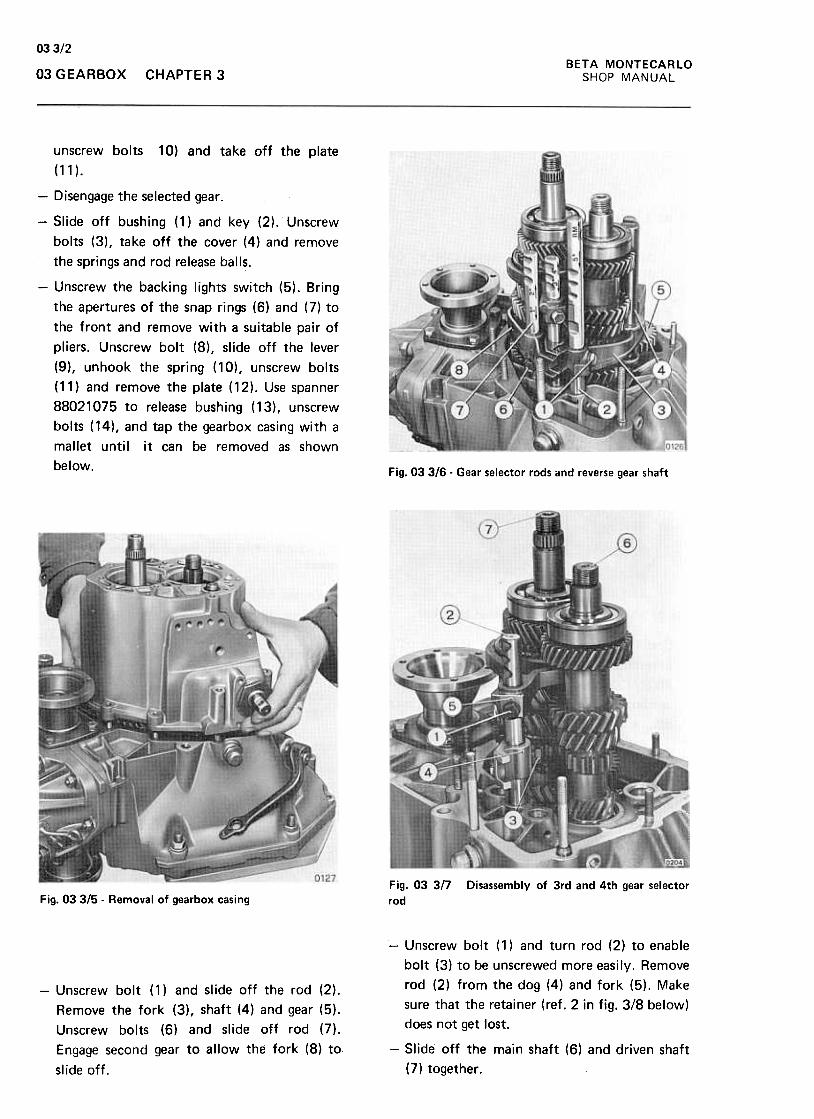
03 312BETA MONTECARLO
SHOP MANUAL03 G EARBOX CHAPTER 3
unscrew bolts
(11 ).
10) and take off the plate
-Disengage the selected gear.
-Slide off bushing (1) and key (2). Unscrew
bolts (3), take off the cover (4) and remove
the springs and rod release balls.
-Unscrew the backing lights switch (5). Bring
the apertures of the snap rings (6) and (7) to
the front and remove with a suitable pair of
pliers. Unscrew bolt (8), slide off the lever
(9), unhook the spring (10), unscrew bolts
( 11 ) and remove the plate ( 12) .Use span ner
88021075 to release bushing (13), unscrew
bolts (14), and tap the gearbox casing with a
mallet until it can be removed as shown
below.Fig. 03 316 -Gear selector rods and reverse gear shaft
Fig. 03 3/7
rod
Disassembly of 3rd and 4th gear selectorFig. 03 315 -Removal of gearbox casing
-Unscrew bolt (1) and slide off the rod (2).
Remove the fork (3), shaft (4) and gear (5).
Unscrew bolts (6) and slide off rod (7).
Engage second gear to allow the fork (8) to
slide off.
-Unscrew bolt (1) and turn rod (2) to enable
bolt (3) to be unscrewed more easily. Remove
rod (2) from the dog (4) and fork (5). Make
sure that the retainer (ref. 2 in fig. 3/8 below)
does not get lost.
-Slide off the main shaft (6) and driven shaft
(7) together.
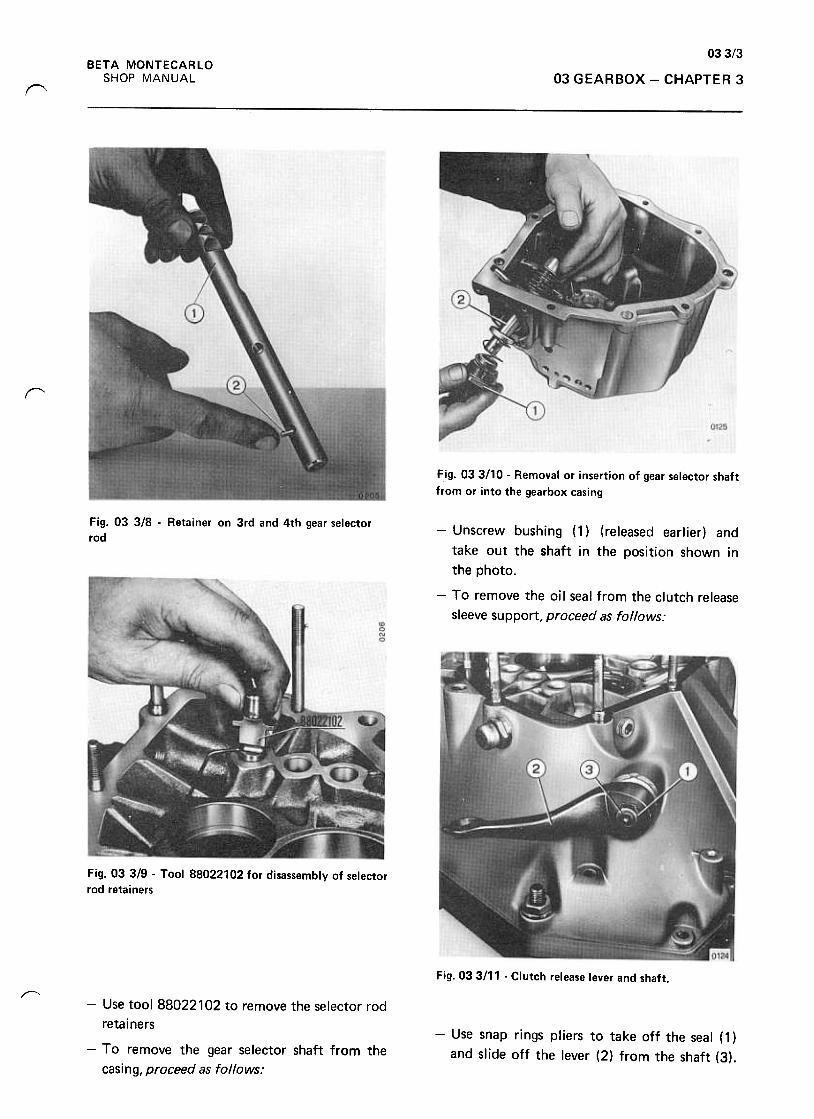
033/3BETA MONTECARLO
SHOP MANUAL 03 GEARBOX -CHAPTER 3("""'\
r
Fig. 033!10 -Removal or insertion of gear selector shaft
from or into the gearbox casing
Fig. 03 3/8 -Retainer on 3rd and 4th gear selector
rod-Unscrew bushing (1) (released earlier) and
take out the shaft in the position shown in
the photo.
-To remove the oil seal from the clutch release
sleeve support, proceed as follows:
Fig. 03 319 -Tool 88022102 for disassembly of selector
rod retainers
Fig. 033111 -Clutch release lever and shaft.
I"""""
-Use snap rings pliers to take off the seal (1 )
and slide off the lever (2) from the shaft (3).
-Use tool 88022102 to remove the selector rod
retainers
-To remove the gear selector shaft from the
casing, proceed as follows:
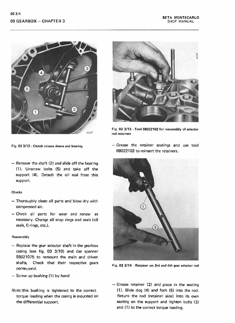
BETA MONTECARLO
SHOP MANUAL
033/4
03 GEARBOX -CHAPTER 3
Fig. 03 3/13 -Tool 88022102 for reassembly of selector
rod retainers
-Grease the retainer seatings and use tool
88022102 to reinsert the retainers.
Fig. 033/12. Clutch release sleeve and bearing
-Remove the shaft (2) and slide off the bearing
(1 ). Unscrew bolts (5) and take off the
support (4). Detach the oil seal from this
support.
Checks
-Thoroughly clean all parts and blow dry with
compressed air .
-Check all parts for wear and renew as
necessary. Change all snap rings and seals (oil
seals, O rings, etc.).
Reassembly
Fig. 03 3114 -Retainer on 3rd and 4th gear selector rod
-Replace the gear selector shaft in the gearbox
casing (see fig. 03 3/10) and use spanner
88021075 to remount the main and driven
shafts. Check that their respective gears
corres:Jond.
-Screw up bushing (1) by hand
-Grease retainer (2) and place in the seating
(1 ). Slide dog (4) and fork (5) into the rod.
Return the rod (retainer side) into its own
seating on the support and tighten bolts (3)
and (1) to the correct torque loading.
Note:this bushing is tightened to the correct
torque loading when the casing is mounted on
the differential support.
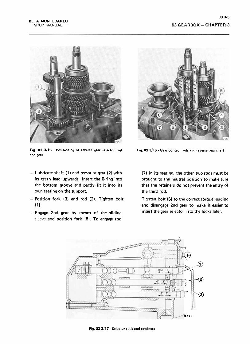
03 3/5BETA MONTECARLO
SHOP MANUAL 03 GEARBOX -CHAPTER 3
Fig. 03 3/15
and gear
Positioning of reverse gear selector rod Fig. 03 3/16 -Gear control rods and reverse gear shaft
(7) in its seating, the other two rods must be
brought to the neutral position to make sure
that the retainers do not prevent the entry of
the third rod.
Tighten bolt (6) to the correct torque loading
and disengage 2nd gear to make it easier to
insert the gear selector into the locks later .
-Lubricate shaft ( 1) and remount gear (2) with
its teeth lead upwards. Insert the O-ring into
the bottom groove and partly fit it into its
own seating on the support.
-Position fork (3) and rod (2). Tighten bolt
(1 ).
-Engage 2nd gear by means of the sliding
sleeve and position fork (8). To engage rod
.~
Jj)lit" / II ( ) ,,=\.1 RM 5.
--I
,1i1
@ -@
'"'T:--"'! --@
rO273
Fig. 033/17- Selector rods and retainers
& .i-
~-~~~-
'1-~co;--- "'II.-1'
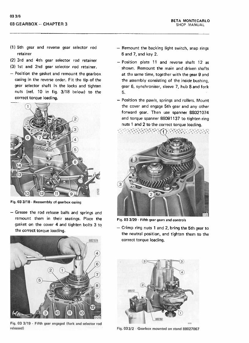
03 3/6
BETA MONTECARLO
SHOP MANUAL03 GEARBOX ~ CHAPTER 3
-Remount the backing light switch, snap rings
6 and 7, and key 2.
(1) 5th gear and reverse gear selector rod
retainer
(2) 3rd and 4th gear selector rod retainer
(3) 1st and 2nd gear selector rod retainer.
-Position the gasket and remount the gearbox
casing in the reverse order. Fit the tip of the
gear selector shaft in the locks and tighten
nuts (ref. 10 in fig. 3/18 below) to the
correct torque loading..~~-~-~~~c~".~~"C~~~~~~
-Position plate 11 and reverse shaft 12 as
shown. Remount the main and driven shafts
at the same time, together with the gear 9 and
the assembly consisting of the inside bushing,
gear 6, synchroniser, sleeve 7, hub 8 and fork
5.
-Position the pawls, springs and rollers. Mount
the cover and engage 5th gear and any other
forward gear. Then use spanner 88021074
and torque spanner 88091137 to tighten ring
nuts 1 and 2 to the correct torque loading.
~
"'(\J0
Fig. 03 3/18 -Reassembly of gearbox casing
-Grease the rod release balls and springs and
remount them in their seatings. Place the
gasket on the cover 4 and tighten bolts 3 to
the correct torque loading.
Fig. 03 3120- Fifth gear gears and controls
-Crimp ring nuts 1 and 2, bring the 5th gear to
the neutral position, and tighten them to the
correct torque loading.
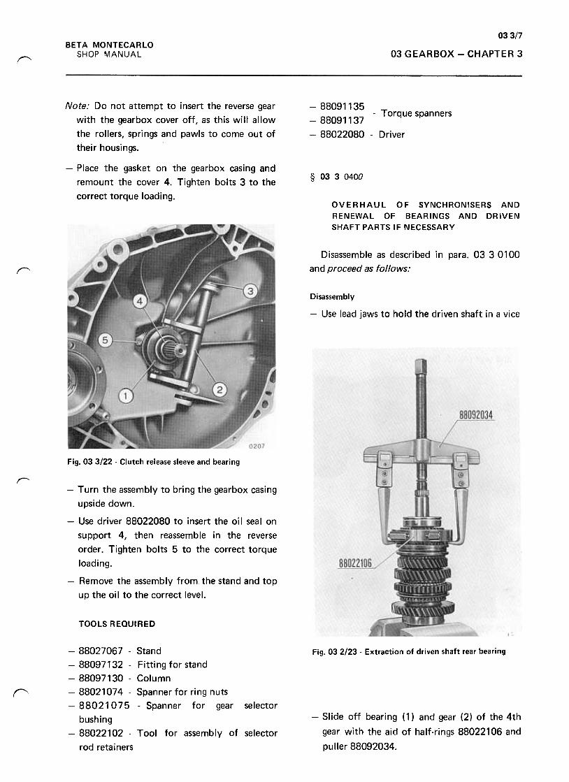
03 3/7BETA MONTECARLO
SHOP MANUAL 03 GEARBOX -CHAPTER 3('
Note: Do not attempt to insert the reverse gear
with the gearbox cover off, as this will allow
the rollers, springs and pawls to come out of
their housings.
-88091135-88091137 -Torque spanners
-88022080 -Driver
-Place the gasket on the gearbox casing and
remount the cover 4. Tighten bolts 3 to the
correct torque loading.
§ 0330400
OVERHAUL OF SYNCHRONISERS AND
RENEWAL OF BEARINGS AND DRIVEN
SHAFT PARTS IF NECESSARY
Disassemble as described in para. 03 3 0100
and proceed as follows:1'"""""
Disassembly
-Use lead jaws to hold the driven shaft in a vice
Fig. 033/22 -Clutch release sleeve and bearing
r'-Turn the assembly to bring the gearbox casing
upside down.
-Use driver 88022080 to insert the oil seal on
support 4, then reassemble in the reverse
order. Tighten bolts 5 to the correct torque
loading.
-Remove the assembly from the stand and top
up the oil to the correct level.
TOOLS REQUIRED
Fig. 03 2123 -Extraction of driven shaft rear bearing
f"'
-Slide off bearing (1) and gear (2) of the 4th
gear with the aid of half-rings 88022106 and
puller 88092034.
-88027067- Stand
-88097132- Fittingforstand
-88097130- Column
-88021074 -Spanner for ring nuts
-88021075 -Spanner for gear selector
bushing
-88022102 -Tool for assembly of selector
rod retainers
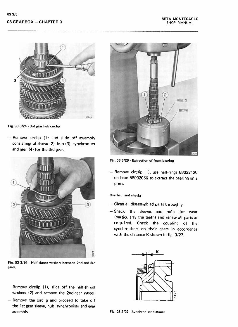
03 3/8BETA MONTECARLO
SHOP MANUAL03 GEARBOX -CHAPTER 3
~
.;(3
Fig. 03 3124 .3rd gear hub circlip
-Remove circlip (1) and slide off assembly
consistings of sleeve (2), hub (3), synchroniser
and gear (4) for the 3rd gear.
Fig. 03 3126 -Extraction of front bearing
-Remove circlip (1), use half-rings 88022120
on base 88032056 to extract the bearing on a
press.
Overhaul and checks
-Clean all disassembled parts throughly
-Sheck the sleeves and hubs for wear
(particularly the teeth) and renew all parts as
required. Check the coupling of the
synchronisers on their gears in accordance
with the distance K shown in fig. 3/27.
Fig. 03 3/26 -Half-thrust washers between 2nd and 3rd
gears.
Remove circlip (1 ), slide off the half-thrust
washers (2) and remove the 2nd-gear wheel.
-Remove the circlip and proceed to take off
the 1 st gear sleeve, hub, synchroniser and gear
assembly. Fig. 032/27 -Synchroniser distance
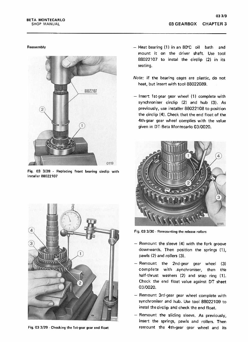
03319BETA MONTECARLO
SHOP 1\1ANUAL 03 G EARBOX CHAPTER 3
Reassembly -Heat bearing (1) in an 80"C oil bath and
mount it on the driver shaft. Use tool
88022107 to instal the circlip (2) in its
seating.
Note: if the bearing cages are plastic, do not
heat, but insert with tool 88022089.
-Insert 1st-gear gear wheel (1) complete with
synchroniser circlip (2) and hub (3). As
previously, use installer 88022108 to position
the circlip (4). Check that the end float of the
4th-gear gear wheel complies with the value
given in Dr -Beta Montecarlo 03/0020.
Fig. 03 3/28 -Replacing front bearing circlip with
installer 88022107
Fig. 033130 -Remounting the release rollers
-Remount the sleeve (4) with the fork groove
downwards. Then position the springs (1 ),
pawls (2) and rollers (3).
-Remount the 2nd-gear gear wheel (3)
complete with ,synchroniser, then th"e
half-thrust washers (2) and snap ring (1 ).
Check the end float value against DT sheet
03/0020.
-Remount 3rd-gear gear wheel complete with
synchroniser and hub. Use tool 88022109 to
instal thecirclip and check the end float.
-Remount the sliding sleeve. As previously,
insert the springs, pawls and rollers. Then
remount the 4th-gear gear wheel and itsFig. 033/29- Checking the 1st-gear gear end float
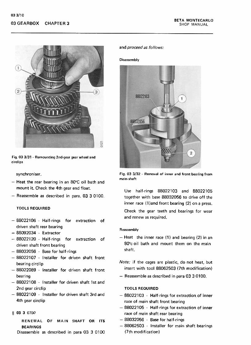
033/1 0
BETA MONTECARLO
SHOP MANUAL03 GEARBOX CHAPTE R 3
and proceed as follows:
Disassembly
Fig. 033/31 .Remounting 2nd-gear gear wheel and
circlips
Fig. 03 3/32 -Removal of inner and front bearing from
main shaftsynchroniser .
Use half-rings 88022103 and 88022105
together with base 88032056 to drive off the
inner race ( 1 )and front bearing (2) on a press.
-Heat the rear bearing in an 80°C oil bath and
mount it. Check the 4th gear end float.
-Reassemble as described in para. 03 3 0100.
TOOLS REQUIREDCheck the gear teeth and bearings for wear
and renew as required.
Reassembly
-Heat the inner race (1) and bearing (2) in an
800c oil bath and mount them on the main
shaft.
Note: if the cages are plastic, do not heat, but
insert with tool 88062503 (7th modification)
-Reassemble as described in para 03 30100.
-88022106 -Half-rings for extraction of
driven shaft rear bearing
-88092034 -Extractor
-88022120 -Half-rings for extraction of
driven shaft front bearing
-88032056 -Base for half-rings
-88022107 -Installer for driven shaft front
bearing circlip
-88022089 -Installer for driven shaft front
bearing
-88022108 -Installer for driven shaft 1st and
2nd gear circlip
-88022109 -Installer for driven shaft 3rd and
4th gear circlip
TOOLS REQUIRED
-88022103 -Half-rings for extraction. of inner
race of main shaft front bearing
-88022105 -Half-rings for extraction of inner
race of main shaft rear bearing
-88032056 -Base for half-rings
-88062503 -Installer for main shaft bearings
(7th modification)
§ 0330700
RENEWAL OF MAIN SHAFT OR ITS
BEARINGS
Disassemble as described in para 03 3 0100
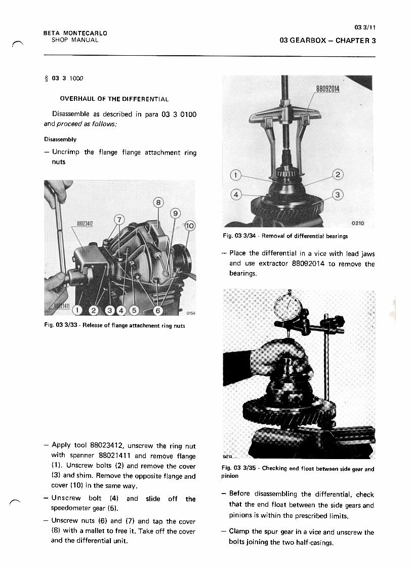
033/11BETA MONTECARLO
SHOP MANUAL 03 GEARBOX -CHAPTER 3r-"
§ 0331000
OVERHAUL OF THE DIFFERENTIAL
Disassemble as described in para 03 3 0100
and proceed as follows:
Disassembly
-Uncrimp the flange flange attachment ring
nuts
Fig. 03 3134 -Removal of differential bearings
-Place the differential in a vice with lead jaws
and use extractor 88092014 to remove the
bearings.
"
Fig. 03 3/33 -Release of flange attachment ring nuts
Fig. 03 3/35 .Checking end float between side gear and
pinion
r
-Apply tool 88023412, unscrew the ring nut
with spanner 88021411 and remove flange
(1 ). Unscrew bolts (2) and remove the cover
(3) and shim. Remove the opposite flange and
cover (10) in the same way.
-Unscrew bolt (4) and slide off the
speedometer gear (5).
-Unscrew nuts (6) and (7) and tap the cover
(8) with a mallet to free it. Take off the cover
and the differential unit.
-Before disassembling the differential, check
that the end float between the side gears and
pinions is within the prescribed limits.
-Clamp the spur gear in a vice and unscrew the
bolts joining the two half-casings.
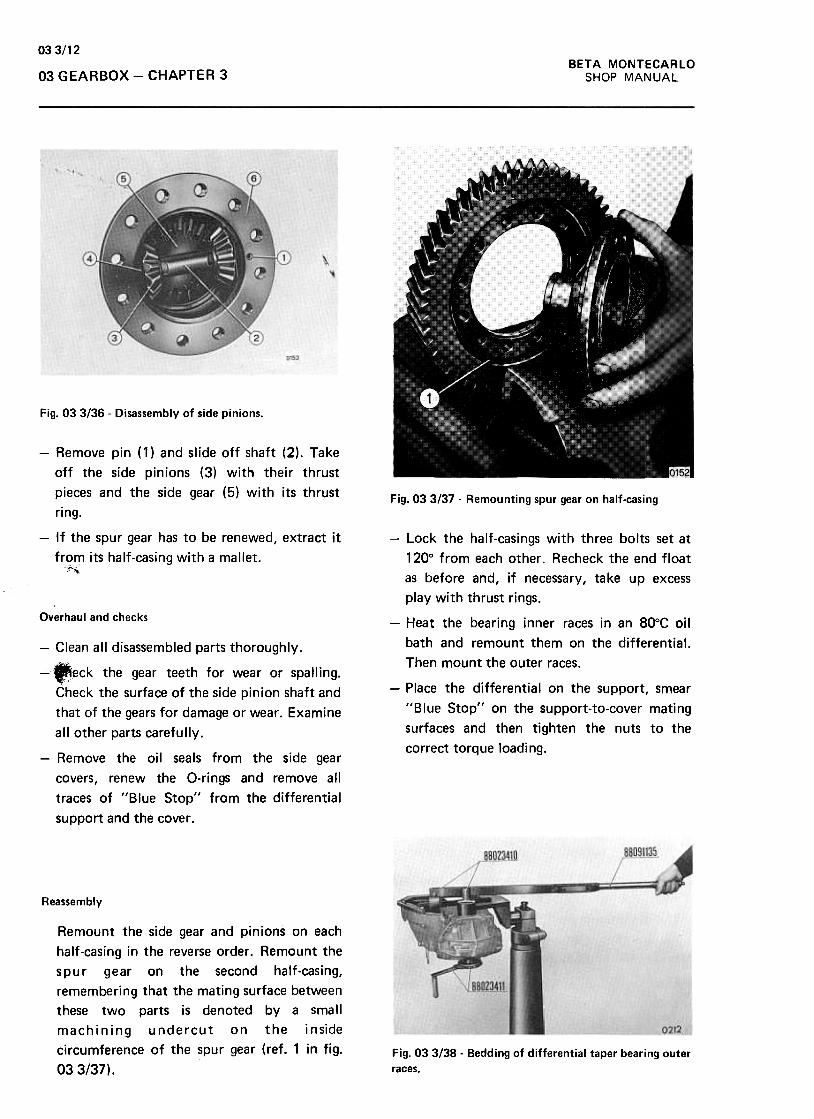
BETA MONTECARLO
SHOP MANUAL
033/12
03 GEARBOX -CHAPTER 3
Fig. 03 3136 -Disassembly of side pinions.
Fig. 033/37 -Remounting spur gear on half-casing
-Remove pin (1) and slide off shaft (2). Take
off the side pinions (3) with their thrust
pieces and the side gear (5) with its thrust
ring.
-If the spur gear has to be renewed, extract it
from its half-casing with a mallet.~~
Overhaul and checks
-Lock the half-casings with three bolts set at
120° from each other. Recheck the end float
as before and, if necessary, take up excess
play with thrust rings.
-Heat the bearing inner races in an 80°C oil
bath and remount them on the differential.
Then mount the outer races.
-Place the differential on the support, smear
"Blue Stop" on the support-to-cover mating
surfaces and then tighten the nuts to the
correct torque loading.
-Clean all disassembled parts thoroughly.
--eck the gear teeth for wear or spalling.
Check the surface of the side pinion shaft and
that of the gears for damage or wear. Examine
all other parts carefully.
-Remove the oil seals from the side gear
covers, renew the O-rings and remove all
traces of "Blue Stop" from the differential
support and the cover .
Reassembly
Remount the side gear and pinions on each
half-casing in the reverse order. Remount the
spur gear on the second half-casing,
remembering that the mating surface between
these two parts is denoted by a small
machining undercut on the inside
circumference of the spur gear (ref. 1 in fig.
033/37),
Fig. 03 3/38- Bedding of differential taper bearing outer
races.
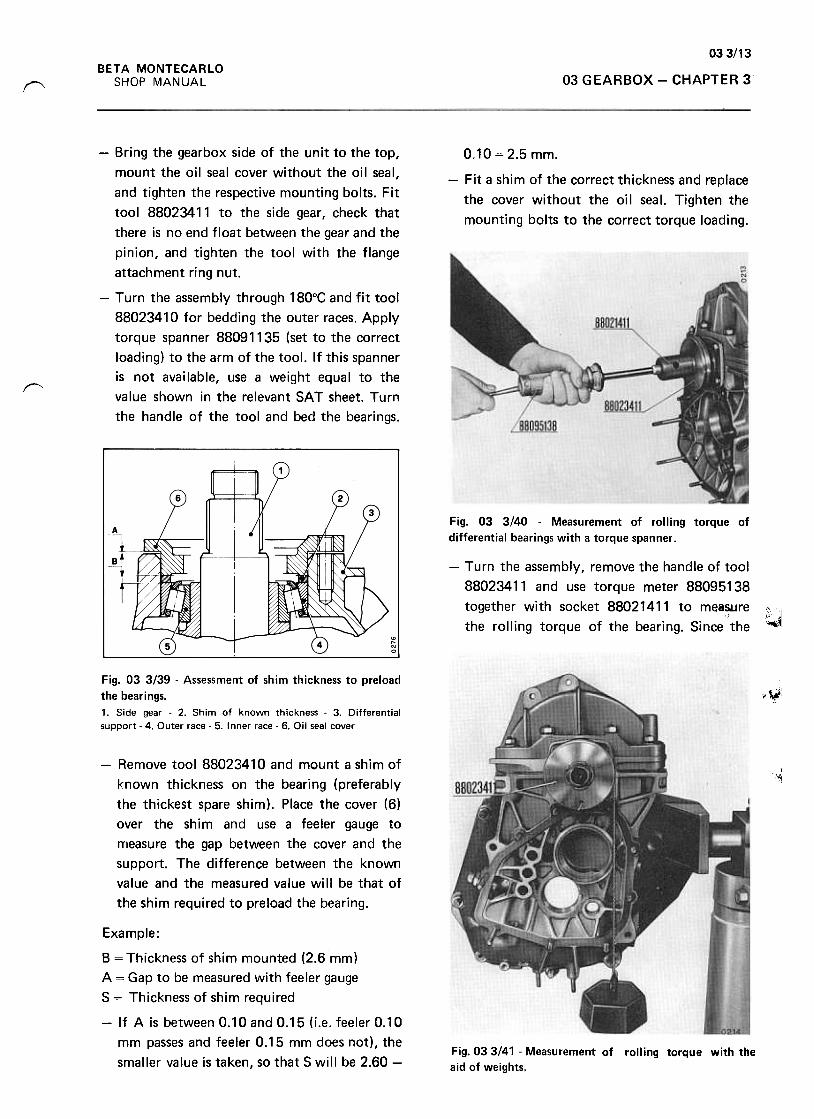
033/13BETA MONTECARLO
SHOP MANUAL 03 GEARBOX -CHAPTER 3"'
0.10 = 2.5 mm.
-Fit a shim of the correct thickness and replace
the cover without the oil seal. Tighten the
mounting bolts to the correct torque loading.
-Bring the gearbox side of the unit to the top,
mount the oil seal cover without the oil seal,
and tighten the respective mounting bolts. Fit
tool 88023411 to the side gear, check that
there is no end float between the gear and the
pinion, and tighten the tool with the flange
attachment ring nut.
-Turn the assembly through 180°C and fit tool
88023410 for bedding the outer races. Apply
torque spanner 88091135 (set to the correct
loading) to the arm of the tool. If this spanner
is not available, use a weight equal to the
value shown in the relevant SAT sheet. Turn
the handle of the tool and bed the bearings.
~
Fig. 03 3/40 -Measurement of rolling torque of
differential bearings with a torque spanner .
-Turn the assembly, remove the handle of tool
88023411 and use torque meter 88095138
together. with socket 8802141.1 to .mea~re ;{.~the rolling torque of the bearing. Since the ,..
.¥Fig. 03 3/39 -Assessment of shim thickness to preload
the bearings.
1. Side gear. 2. Shim of known thickness. 3. Differentialsupport -4. Outer race -5. Inner race -6. Oil seal cover
-Remove tool 88023410 and mount a shim of
known thickness on the bearing (preferably
the thickest spare shim). Place the cover (6)
over the shim and use a feeler gauge to
measure the gap between the cover and the
support. The difference between the known
value and the measured value will be that of
the shim required to preload the bearing.
,'1;~
~
Example:
B = Thickness of shim mounted (2.6 mm)
A = Gap to be measured with feeler gauge
S = Thickness of shim required
-If A is between 0.10 and 0.15 (i.e. feeler 0.10
mm passes and feeler 0.15 mm does not), the
smaller value is taken, so that S will be 2.60 -Fig. 033141 -Measurement of rolling torque with theaid of weights.
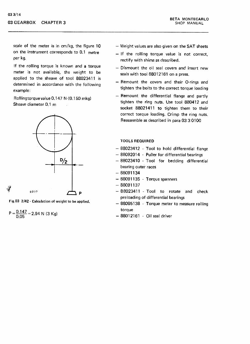
033/14BETA MONTECARLO
SHOP MANUAL03 GEARBOX CHAPTER 3
-Weightvalues are also given on the SAT sheets
-If the rolling torque value is not correct,
rectify with shims as described.
-Dismount the oil seal covers and insert new
seals with tool 88012161 on a press.
-Remount the covers and their O-rings and
tighten the bolts to the correct torque loading
-Remount the differential flange and partly
tighten the ring nuts. Use tool 880412 and
socket 88021411 to tighten them to their
correct torque loading. Crimp the ring nuts.
Reassemble as described in para 0330100
scale of the meter is in cm/kg, the figure 10
on the instrument corresponds to 0.1 metre
per kg.
If the rolling torque is known and a torque
meter is not available, the weight to be
applied to the sheave of tool 88023411 is
determined in accordance with the following
example :
Rollingtorque value 0.147 N,(0.150 mkg)
Sheave diameter 0.1 m
1Fig.O3 2142. Calculation of weight to be applied.
TOOLS REQUIRED
-88023412 -Tool to hold differential flange
-88092014 -Puller for differential bearings
-88023410 -Tool for bedding differential
bearing outer races
-88091134
-88091135 -Torque spanners
-88091137
-88023411 -Tool to rotate and check
preloading of differential bearings
-88095138 -Torque meter to measure rolling
torque
-88012161 -Oil seal driver
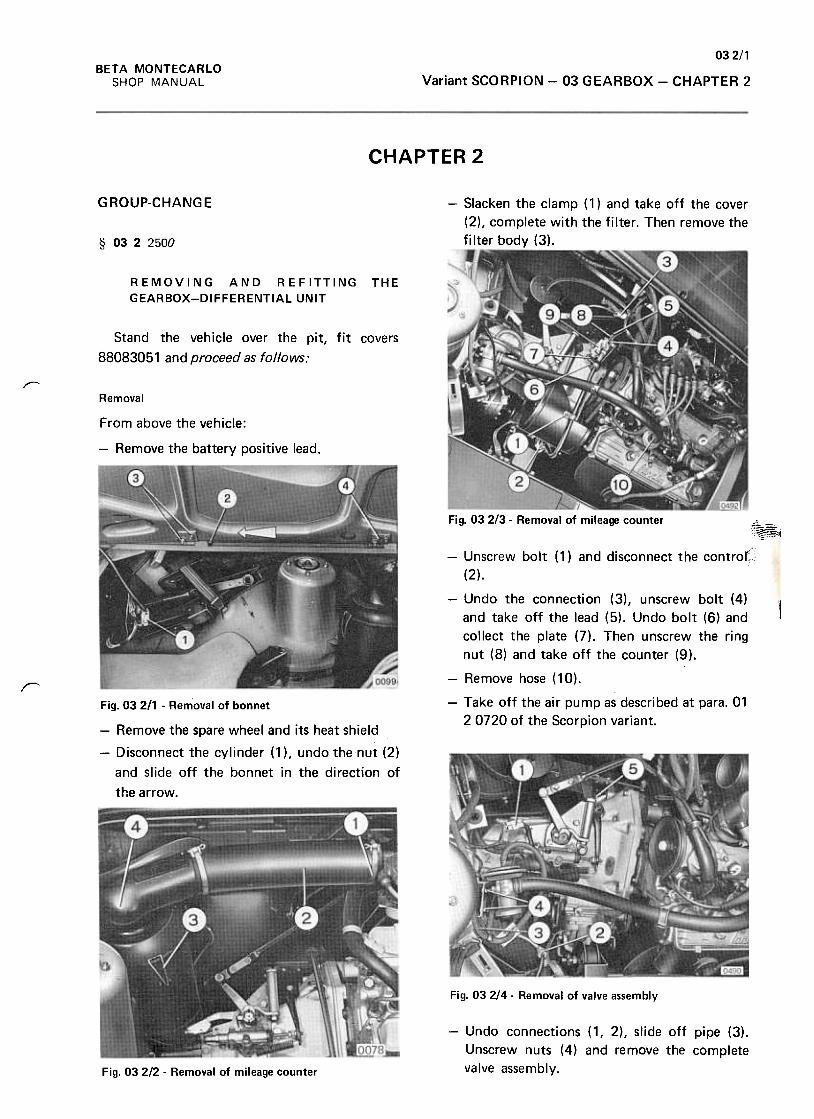
032/1BETA MONTECARLO
SHOP MANUAL Variant SCORPION -03 GEARBOX -CHAPTER 2
CHAPTER 2
G ROUP-CHANG E -Slacken the clamp ( 1) and take off the cover
(2), complete with the filter. Then remove the
filter body (3).§ 0322500
REMOVING AND REFITTING
GEARBOX-DIFFERENTIAL UNIT
THE
Stand the vehicle over the pit, fit covers
88083051 and proceed as follows:
r-
Removal
From above the vehicle:
-Remove the battery positive lead.
Fig. 032/3 -Removal of mileage counter
f~
1
r
-Unscrew bolt (1) and disconnect the contro~:'
(2).
-Undo the connection (3), unscrew bolt (4)
and take off the lead (5). Undo bolt (6) and
collect the plate (7). Then unscrew the ring
nut (8) and take off the counter (9).
-Remove hose (10).
-Take off the air pump as described at para. 01
2 0720 of the Scorpion variant.Fig. 03 211 -Removal of bonnet
-Remove the spare wheel and its heat shield
-Disconnect the cylinder (1 ), undo the nut (2)
and slide off the bonnet in the direction of
the arrow.
Fig. 032/4 -Removal of valve assembly
-Undo connections (1, 2), slide off pipe (3).
Unscrew nuts (4) and remove the complete
valve assembly.Fig. 03 2/2 -Removal of mileage counter
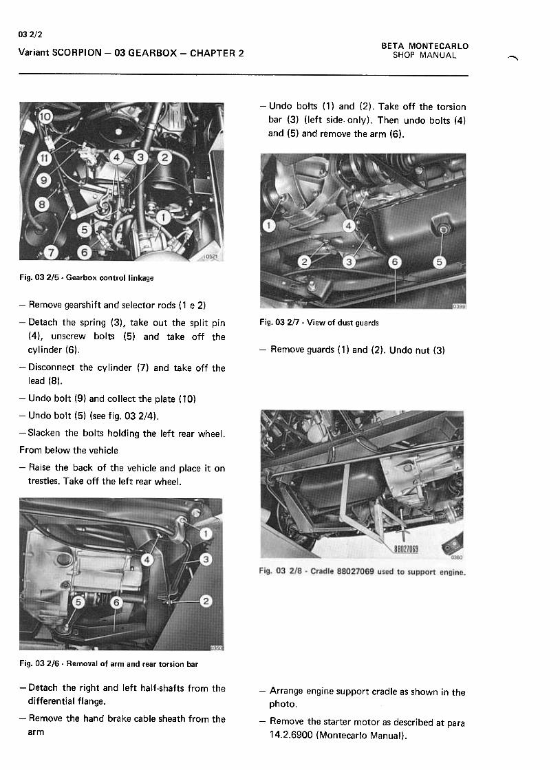
03 2/2
BETA MONTECARLO
SHOP MANUALVariant SCORPION -03 GEARBOX -CHAPTER 2~
-Undo bolts (1) and (2). Take off the torsion
bar (3) (left side- only). Then undo bolts (4)
and (5) and remove the arm (6).
Fig. 03 215 .Gearbox control linkage
Fig. 03 2/7 -View of dust guards
-Remove guards (1) and (2). Undo nut (3)
-Remove gearshift and selector rods (1 e 2)
-Detach the spring (3), take out the split pin
(4), unscrew bolts (5) and take off the
cylinder (6).
-Disconnect the cylinder (7) and take off the
lead (8).
-Undo bolt (9) and collect the plate (10)
-Undo bolt (5) (see fig. 032/4).
-Slacken the bolts holding the left rear wheel.
From below the vehicle
-Raise the back of the vehicle and place it on
trestles. Take off the left rear wheel.
Fig. 03 216 -Removal of arm and rear torsion bar
-Detach the right and left half-shafts from the
differential flange.
-Remove the hand brake cable sheath from the
arm
-Arrange engine support cradle as shown in the
photo.
-Remove the starter motor as described at para
14.2.6900 (Montecarlo Manual).
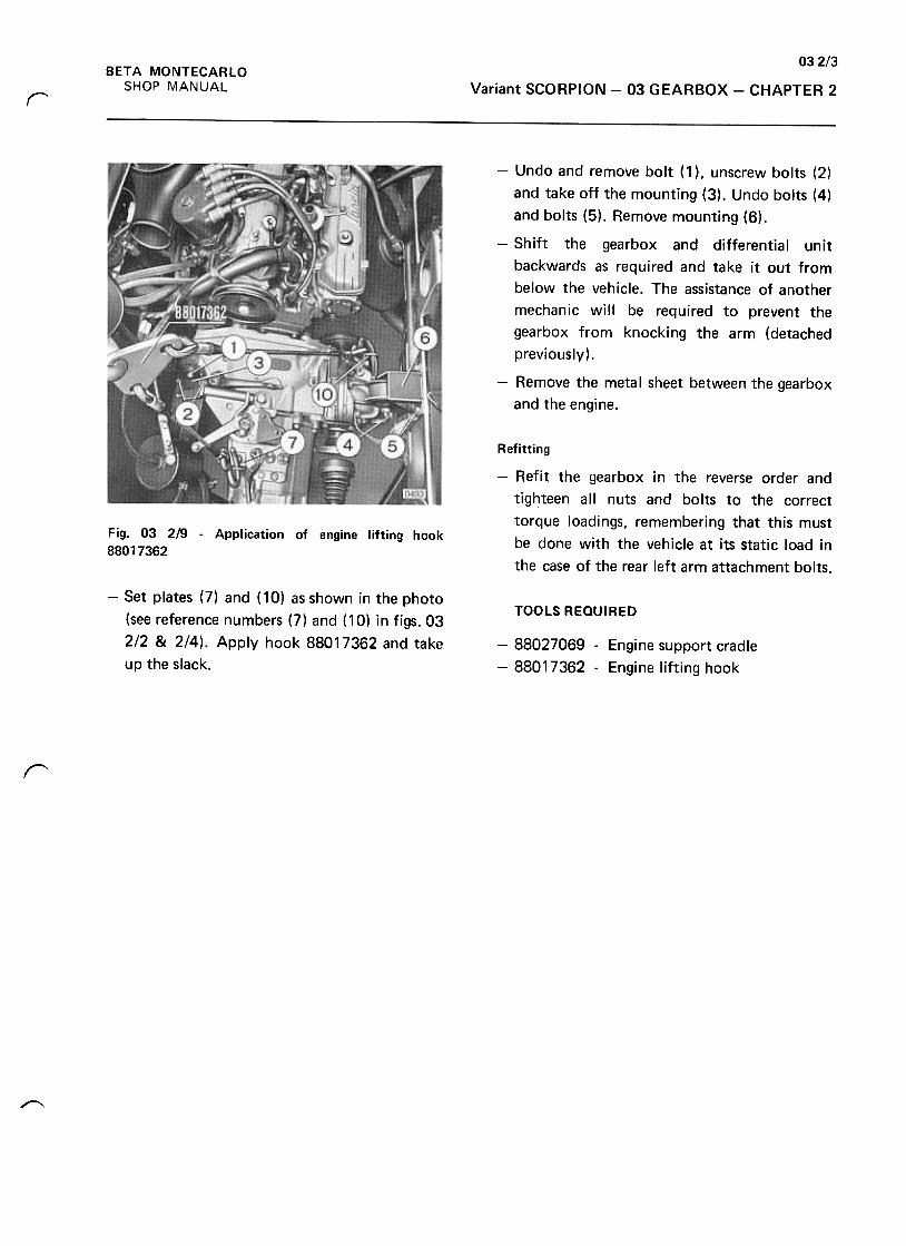
032/3BETA MONTECARLO
SHOP MANUAL Variant SCORPION -03 GEARBOX -CHAPTER 2r
-Undo and remove bolt (1 ), unscrew bolts (2)
and take off the mounting (3). Undo bolts (4)
and bolts (5). Remove mounting (6).
-Shift the gearbox and differential unit
backwards as required and take it out from
below the vehicle. The assistance of another
mechanic will be required to prevent the
gearbox from knocking the arm (detached
previously).
-Remove the metal sheet between the gearbox
and the engine.
Refitting
-Refit the gearbox in the reverse order and
tighteen all nuts and bolts to the correct
torque loadings, remembering that this must
be done with the vehicle at its static load in
the case of the rear left arm attachment bolts.
Fig. 03 219 -Application of engine lifting hook
88017362
-Set plates (7) and ( 10) as shown in the photo
(see reference numbers (7) and (10) in figs. 03
2/2 & 2/4). Apply hook 88017362 and take
up the slack.
TOOLS REQUIRED
-88027069 -Engine support cradle
-88017362 -Engine lifting hook
~
r
~
BETA MONTECARLO
SHOP MANUAL 04 TRANSMISSIONContents
TRANSMISSION GROUP CONTENTS
CHAPTER 1
page 041/1Troubles, probable causes, checkings and operations to be carried out
CHAPTER 2
page 042/1
042/1
042/2
§ 04 2 0100 Removal and refitting a front wheel drive shaft
§ 04 2 0120 Renewal of a constant velocity joint dust guard
§ 042 1000 Removal and refitting a shaft with flange and joint on the wheel side
~
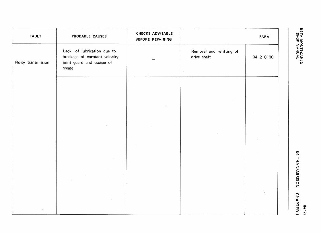
BE
TA
M
ON
TE
CA
RLO
w
"-J
2m
-
<{
IX:
(/) -
-<{
>
0,.C
w
<{
IX:
(/) w
~
IX:
U
OW
II.
~
WU
m >a:
z ~
0 (/)
-(/)1-
wu
u~
wz
1-..J=
>«u. (I)w(I):)«uw-Jm«mO~~ ~a:~""
>+-'
0 .-
+-'
u -
o o
Q)
-
:J~Q
)""0
Q.
c: E
<
80
ro C
/).-+
-' Q
)+
-' C
/)ro
c: ""0
.~
s:! c:ro
.D:J-""0O
...ro
oQ):J
~0"1Q
)~
+
-' C
/)
~roc:rou
Q)
.-~
ro...orn-.J
.D
.~
'+-001c:
0;:.
'+-Q
)...
""0c:ro '+
-roro
..I::>
(I)
0E
~Q
) 0-
a:-S
oo~ON~0
c:o.in(/)
.E(/)c:ro'-+"'
>(/)
.07
04 TR
AN
SM
ISS
ION
CH
AP
TE
R'
041/1
SH
OP
M
AN
UA
L
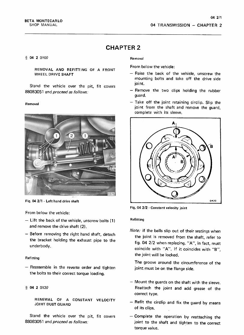
042/1BETA MONTECARLO
SHOP MANUAL 04 TRANSMISSION -CHAPTER 2
CHAPTER 2
§ 0420100 Removal
REMOVAL AND REFITTING OF A FRONT
WHEEL DRIVE SHAFT
Stand the vehicle over the pit, fit covers
88083051 and proceed as follows:
From below the vehicle:
-Raise the back of the vehicle, unscrew themounting bolts and take off the drive side
joint.
-Remove the two clips holding the rubber
guard.
-Take off the joint retaining circlip. Slip thejoint from the shaft and remove the guard,complete with its sleeve.
Removal
Fig. 04 211 -Left hand drive shaft
Fig. 04 2/2 .Constant velocity joint
Refitting
Note: if the balls slip out of their seatings when
the joint is removed from the shaft, refer tofig. 04 2/2 when replacing. " A ", in fact, must
coincide with " A". If it coincides with "8",
the joint will be locked.
From below the vehicle:
-Lift the back of the vehicle, unscrew bolts ( 1 )
and remove the drive shaft (2).
-Before removing the right hand shaft, detach
the bracket holding the exhaust pipe to the
underbody.
RefittingThe groove around the circumference of the
joint must be on the flange side.-Reassemble in the reverse order and tighten
the bolts to their correct torque loading.
-Mount the guards on the shaft with the sleeve.
Reattach the joint and add grease of the
correct type.
§ 0420120
RENEWAL OF A CONSTANT VELOCITY
JOINT DUST GUARD-Refit the circlip and fix the guard by means
of its clips.
Stand the vehicle over the pit, fit covers
88083051 and proceed as follows:
-Comp'ete the operation by reattaching the
joint to the shaft and tighten to the correct
tprque value.

04 2/2
BETA MONTECARLO
SHOP MANUAL04 TRANSMISSION -CHAPTER 2
§ 0420500
REMOVAL AND REFITTING A SHAFT WITH
FLANGE AND JOINT ON THE WHEEL SIDE
Stand the vehicle over the pit, fit covers
88083051 and proceed as follows:
Removal
From above the vehicle:
-Slacken the bolts holding the wheel
From below the vehicle:
Fig. 042/3 -Release of bearing to-hub nut.-Lift the back of the vehicle and rest it on
trestle 88097120.
-Unscrew the bolts holding the joint to the
flange and move the joint to one side.
-Apply tool 88052009 and remove shaft with
flange.
From above the vehicle:
Refitting
-Reassemble in the reverse order and tighten
the bolts and the nut to their correct torque
loading.
-Remove the wheel.
-Uncri mp the tab of the nut holdi ng the
bearing on the wheel hub
-Apply arm 88053151 to the flange and
unscrew the nut.

SEC 05
Axle Housings
Axle housing - Step-down and differential gears
(Not Fitted to This Vehicle)

SEC 06
Axle Beams
Front and rear axle shafts and transverse reaction bar
(Not Fitted to This Vehicle)
BETA MONTECARLO
SHOP MANUAL 07 SUSPENSION
Contents
SUSPENSION GROUP CONTENTS
CHAPTER 1
Troubles, probable causes, checkings and operations to be carried out
from page 071/1
to page 07 1/3
CHAPTER 2
page
Front Suspension
§ 07 2 0200 Removing and refitting the front suspension
§ 07 2 0700 Removing and refitting the front suspension arms .
§ 0720800 Renewing the ball joint of a front suspension arm .
§ 07 2 0900 Renewing the front suspension arm silent blocks
§ 072 1100 Removing and refitting the front stabilizer bar .
§ 07 2 1300 Renewing the front stabilizer bar centre and end mounting buffers
§ 07 2 1700 Removing and refitting the stabilizer bar and suspension arms from the subframe on the
stand 07 218
07
07
07
07
07
07
Rear Suspension
§ 07 2 2000 Removing and refitting the rear suspension crossmember
§ 0722200 Renewing the rear stabilizer bar silent blocks
§ 0722300 Removing and refitting the rear stabilizer bar
§ 0722310 Renewing the rear stabilizer bar end ball joint .
§ 07 2 2400 Removing and refitting the rear suspension strut
§ 07 2 2600 Removing and refitting the rear suspension transverse links
CHAPTER 4
page 074/1
07 4/3
074/4
074/5
07 4/7
07 4/8
074/9
§ 0740120 Checking a front suspension arm for alignment .
§ 07 4 0900 Renewing the rear suspension transverse link sile~t blocks (up to car No.
§ 0740910 Do. (from car No. ) .
§ 07 4 1000 Disassembling and reassembling the right, or left-hand front suspension
§ 07 4 1100 Disassembling and reassembling the right, or left-hand rear suspension
§ 07 4 1200 Disassembling and reassembling a front, or rear suspension strut .
§ 074 1210 Renewing the buffer valve
07
07
07
07
07
07
2/1
2/1
2/3
2/3
2/5
2/6
2/11
2/12
2/14
2/14
2/15
2/17
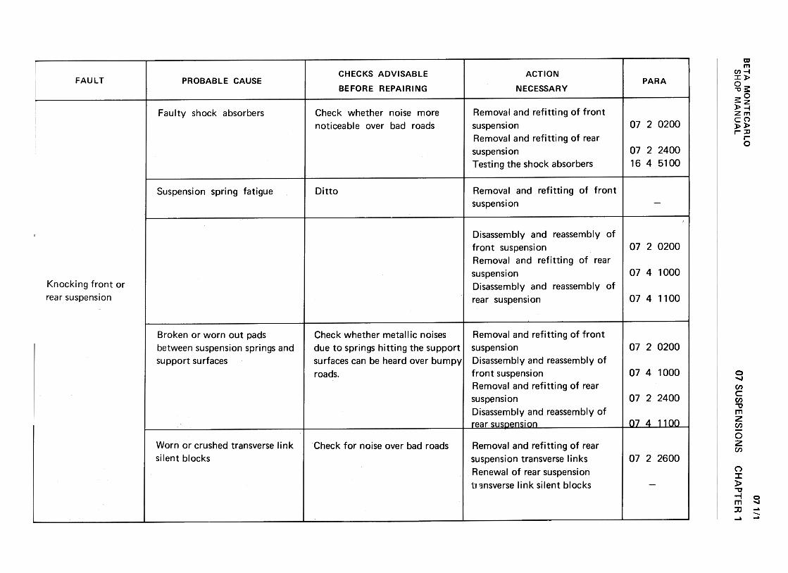
BE
TA
M
ON
TE
CA
RLO
w
<-'
..J z
[%3
-<
t a:
(/) -
-<t
>
Q.
c w
<t
a:
(/) w
~
a:u
Ow
I£.
~
wo
m >z
~O
<
t-(/)1-
(/)(,)
w<
t (,)w2
1-..1:;)«lL w(/)=
>~uw..JIn~InO~~ ~a:~~
"''-QJ
..0'-0"'..0ro
~u0.!:"'>+"'
~rou...
Q)
'- "'
O"tJ
E
~'-Q
).~
"tJ
O
roc:
..0
'- '-
Q)
Q)
..c: >
+"'
0Q
)..c:
Q)
~::c
ro~
Q
)tJ
tJQ
) .;;,
..c: O
u ~
o0NON, 0
0000~.-
NL!)
N~
r tO
0.-
+-'
c 0 ro
(/)
Q)
Q)
co
o C
J C
J ~
C
C
..c.+
:J .+
:J ro
+-'
+-'
~--UQ
) Q
)0
"0 "C
~
C
Crocroc~
-0-0+-,
ro .-ro
.->
(/)
>
(/) C
J
oCoC
CE
Q)
EQ
) .-
c. C
.+-'
(/)Q
)(/)Q)(/)Q
)a:~
a:~1-
Q)
:J0).+
-ro-0)I:.~0.V
)
I:O.iiiI:Q)
0.V
):J
(/) O+-'
+-'
a +"'
co...'+
-
'+-00)
c"+"'
+"'
~Q)
...
-0cro c0
ro "in
>
c0
Q)
E
0.Q
) "'
a: ~
o0NON~0
ooovI--.O
...0+-'
c:c:
OO
0-
..."'-c:0)
0)c:
0.0-
"'~
::J
u "'
0 ...
c: ro
~
!1>
--0 ...O10
~
~
~..c
-..cE
o
EC
I>
CI>
(f) C
1 (f)
(f) c:
(f)10
.-10C
I>
CI>
'+-=
"tJ c:
CI>
"tJ
c:o... c:c:
10 .-10
O~
"tJ
.->
C
I>
c: >
(f)
::oc.IOc:::0~
(f) o
c.E
:]
ro .-E
(f)
CI>
(f)
>
(f) C
I>
:](f)
0 ~
(f)
(f)(f)
(f)IO
c:Ec.I0...
.~
O
CI>
~
.~
10
Q~
(I:",Q~
oo.q-
1'--0
>'-
a.
(I) 8.
EaJ
a. :J
.~
:J .D
O
(I) '-
CaJaJ
>u
.c O
-C1"O
roC'-
roaJ
aJE
.~
.c
'- .c
aJaJ
(I) .D
-:S~
CaJ
.-ro.cC
.U~
(I)
(I)aJ .
~
O
U
(I)U
ro"O
aJ aJ
't: ro
.C:J:JO
U"O
",,-
o0NOC'i
r-.o"0~~C
/IC
)C
/I ~
"'C
..:~
c.
C.C
/I+
-' ~
;:, o
o .-C
/I C
/I~
~
a.>
...a.>
uO
c.
~~
C
/I 't
...a ;:,
O
C/I
~
+-'
~
a.>
...a.>
a.>
O
~
~
c.o
+-'
c....a.>
;:,
Q)
.a "'
ooo.q-
""'0 07 S
US
PE
NS
ION
S
oo~NN~0
+"'
'+-
'+-
c °
'- °
O
>
~
>'-
-Q)
-'+
- .D
'-
.D'+
- E
'+
- E
° Q
) O
Q
)
C)
"' C
) "'
c "'
c "'
.-~
.-~+
"' Q
) +
"' Q
)+
"' '-
+"'
'-
;.:: "'C
c;.:: "'C
e coe
cc~
.-~
"'C
>~
"O
>c
-Q)C
-
~c..C
a.~c..c
-oE
"'-oE
~
.--~
.-"'
>"'
>cQ
)", cQ
)oQ
)~+
",oQ)~
Ea.~
cEa.~
Q)
"' .!!!
O
Q)
~
.!!!
c:~0.;:c:"'o
~
.:r.c:QJ
cn'-QJ
>cnc:~'-
"'CQJ
..c:cn
cn
:J.:r.'-
uu
O'-
-O
..Q
c: '-
c:
O~
~
.cn
...10 "'
Q)
"' C
~
...~
O
U
-C
.U;
OO
.-C
~
-Q)
C)Q
)a C
"'
"' C
.+J
...::J Q
)
...Q)",-
.->
.-
"'-"'
...
Q)C
IO~
...IOQ
)
C
"0 ~
.-
~--
CC
OQ
)
~0-~10
.U;
10 Q
)>
C
~
>
OQ
)Q)",
Ea.cc"'
Q)
CI'
Q)
::J a:
::;
a: "'
"'"t)caO...
"t)ca..0...Q
)>OQ
)"'
.0c:...0-~uQ)
~0
oo(0NNr-.o
CH
AP
TE
R
1
071/1
SH
OP
M
AN
UA
L

07 SU
SP
EN
SIO
NS
071/2w
~.J
z1%
) -
« a:
(/) -
-«>
0.c
w«
a:
(/) w
~
a:(.)
Ow
u.
~
wl.)
1%)
>z
I!:O
~
-(/)1-
(/)u
w~
uwz
w(I):><
tuw.JaJ<
taJO~~ «(I:«~1-..J:)ctLL
"'~uO::cc:~.in...~.a...~"'-"'.a
~~
-"'
:Jc:
.aco
c:
~
m
U)
-0(00...
-0(0.D...0)>O0)U
)
.0c...0-~u0).r.u '-co.D'-C
1).~.-U
).D
'-
co C
1)+
""+-
U)'+
-+
"' ~
c.D0
"0~
c
'+-
C1)
O
"0cco
co
~
C1)
C1)
'-c
+"'
C1)
ca:
C1)
u
...0...cc
OO
.-
...cn-cO
'IQ)
c c.
-.-cn
-0~
:J
,u
cn ...
0 ...c
c co
O~
Q
) u
CH
AP
TE
R
1
ooMNr-..O
+"c0...
--0C)
C.~+"
-0.>...
"0 ...
C
coco-O
...co
0.>>
"'
0:=
E:O
0.>
coa:
t: o0.-.-N~0
...
~...Q)
.~:0~"'...~Q)
...~
"'
o~u
~E:s:.D
Q)
c c
Q)
Q)
a::="'
o0NNN""0
...~Q)
...
-00)c:
.~:.=Q)
...
"0 ...
c: ~
~..c
...~
Q
)>
(/)
0=E:o
Q)
~0:
~ ooMNNr-.o
"'c:.0.~ro.0E...10c:>10""0.(1)>.in"'(1)UxUJ +"'
c:2.~,.!:1E'-'~-0~~QJ
cQJ
rr-
>~ro0):J ...
0" ro
c:"'
~
0
0 0
~
>+
",0).~
c:
0.0
0 "'
z...:J-"'
+"'
c Q
.e
~-uE
t::
o ~
~
:E:.
'- +
"'O
cO
"0 .-
a.I "'
0) c
ro a.I
E
Q.
ro "'
Q
~
BE
TA
M
ON
TE
CA
RlO
o0NON""'0
-
...oc:
>c:
° -0
'- .D
.-
::: E
~
0 (l)
~C
) ~
"'
c: co
:!.-(l)
"'~
'-
...'+
=
"0 c:
(l) c:
O'-
co~
"0 >
...c:
c: ::c
"a;co
O
-
-co .-E
'-
>
~
~
°0
(l) "'
...
Ea.co..c:
~.
"' .~
C
)-:!
0.-
a: "'
ooovf""a
SH
OP
M
AN
UA
L
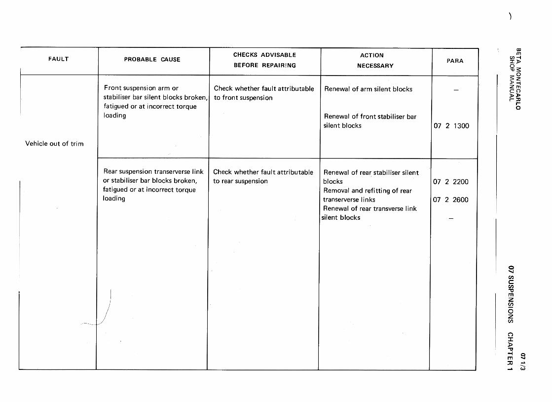
-
BE
TA
M
ON
TE
CA
RLO
w
C-'
-' 2
[D
-.<
t 0:
(/) -
-<t
>
~C
W
<t
0:
(/) w
~
0:(..)
OW
II.
~
WU
m >a:
z <
tO
(/)
-(/)1-
wu
u<
t wz
1-..J::J<
tIL w(/):)8w.Jm«mOa:~ ~~~
QJ
..aro+-'
:J..a.L:+
-'+
-'ro+-'
-c:J O
ro .-
'+-
V)
'- c
QJ
QJ
.c c.
+-'
V)
QJ
:J.c
V)
:s: +
-'c
~
0(.J
'-Q
J,+-
.c o
u
C/)
.:)£.(.JO.0+-'
c0)
.u;E'-(0
-0~0)c0)
~
c:Q)
.:,(. Q
)0
~'-
C"
.D
'-(/)
0'-.:,( O
u O
u
E
::c ~
'- '-
t1J O
c:C
:uQ
) c:
O
=
.-.-(/)(/) c:
'- t1J
Q)
t1J '-
a..Do
(/) '-
~Q
)"CC
)(/)
(/) Q
) c:
:=
~
.-c:
.-C)
"CO
.D
..;;
t1J'-
~
t1J O
LL. "'
-.-~
'-ro..0'-Q
).!!!
::0.<9
cn~cO'-'0-'0-
cn
o~u
ro.2s:..0Q
) ~
c c
Q)
Q)
a:="' oo(V
)
Nr...O
E"L:
'+-0:)0Q
)
"'(3
:cQ)
>
..)£c: -
Q)
.-c:
-:J
Q)Q
)C"
"' ..)£
...
...o o
Q)
~..Q
Q
) "'
CJ
"' ..)£
Q)
c: C
J ...
ro O
...0
Q
CJ
c:c: 0
ro .v;
..Q
ro
c: Q) ~
o
a. .-
"'-"tJ-
:J :.c
Q)
c.
"' ro
:J .-
C)"tJ
ro "'
.;:. ro
Q)...roo
a:Q,,- ~..cro:J..c.cro...:J
c:
~
0'-
.ina.>
c:
..c: a.>c.
a.>
"'..c:
:J~
"''-
~
rou
a.>a.>
'-
..c: O
O
~ o0NNNr-.o
o0<0
NNf"-.0
~
~Q
) ...c
-~.-Q)
V)
...Q)
V)
~
O
~.->:=
0)
V)
..0 c
c~
.-~t:::
...V
) .-V
) ~
...
~
~
c ~
Q)
.-Q)
..."'0 V
)
-c~-~
O
~
...O
uQ
) -O
~
~
>
~
-
~V
)~~
~..c
Q)
~uE
I/) Q
) c
c c
c
Q)O
Q)~
Q)Q
)C
I::aCI:;:..C
I:=V
)
07 SU
SP
EN
SIO
NS
CH
AP
TE
R'
07 1/3
SH
OP
M
AN
UA
L
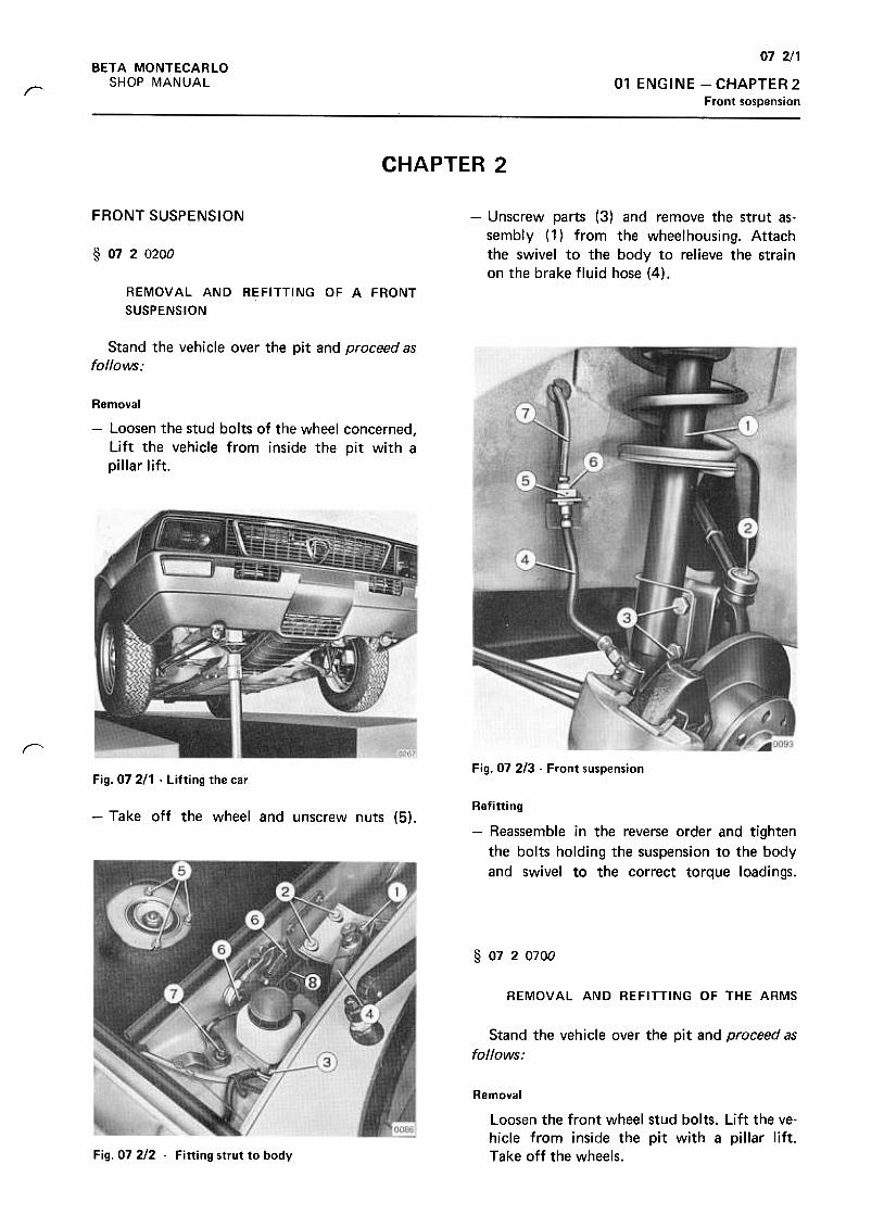
07 2/1BETA MONTECARLO
SHOP MANUAL 01 ENGINE -CHAPTER 2
Front sospension~
CHAPTER 2
FRONT SUSPENSION -Unscrew parts (3) and remove the strut as-sembly (1) from the wheelhousing. Attachthe swivel to the body to relieve the strainon the brake fluid hose (4).
§ 0720200
REMOVAL AND REFITTING OF A FRONT
SUSPENSION
Stand the vehicle over the pit and proceed asfollows;
Removal
-Loosen the stud bolts of the wheel concerned,
lift the vehicle from inside the pit with a
pillar lift.
rFig. 07 2/3 -Front suspension
Fig. 07 211 -Lifting the car
-Take off the wheel and unscrew nuts (5).Refitting
-Reassemble in the reverse order and tighten
the bolts holding the suspension to the body
and swivel to the correct torque loadings.
§ 0720700
REMOVAL AND REFITTING OF THE ARMS
Stand the vehicle over the pit and proceed as
follows:
Removal
Loosen the front wheel stud bolts. Lift the ve-hicle from inside the pit with a pillar lift.Take off the wheels.Fig. 07 212 -Fitting strut to body
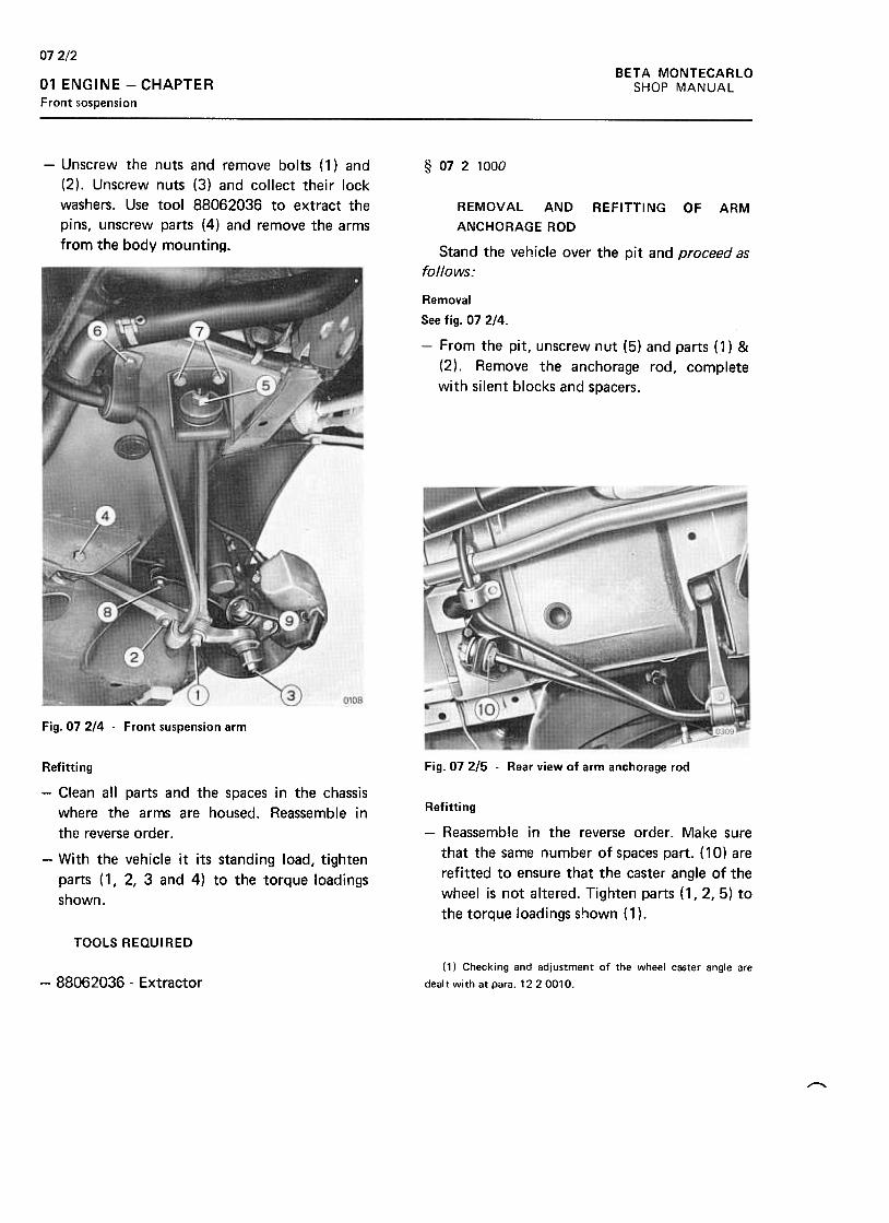
072/2BETA MONTECARLO
SHOP MANUAL01 ENGINE -CHAPTERFront sospension
-Unscrew the nuts and remove bolts ( 1) and
(2). Unscrew nuts (3) and collect their lock
washers. Use tool 88062036 to extract the
pins, unscrew parts (4) and remove the arms
from the body mounting.
§ 0721000
REMOVAL AND REFITTING OF ARM
ANCHORAGE ROD
Stand the vehicle over the pit and proceed as
follows:
Removal
See fig. 07 2/4.
-From the pit, unscrew nut (5) and parts (1) &
(2). Remove the anchorage rod, complete
with silent blocks and spacers.
Fig. 07 2/4 -Front suspension arm
Fig. 07 215 -Rear view of arm anchorage rod
Refitting
-Reassemble in the reverse order. Make sure
that the same number of spaces part. ( 10) are
refitted to ensure that the caster angle of the
wheel is not altered. Tighten parts (1,2,5) to
the torque loadings shown ( 1 ).
Refitting
-Clean all parts and the spaces in the chassis
where the arms are housed. Reassemble in
the reverse order .
-With the vehicle it its standing load, tighten
parts (1,2,3 and 4) to the torque loadings
shown.
TOOLS REQUI RED
(1) Checking and adjustment of the wheel caster angle are
dealt with at para. 12 2 0010.-88062036 -Extractor
,
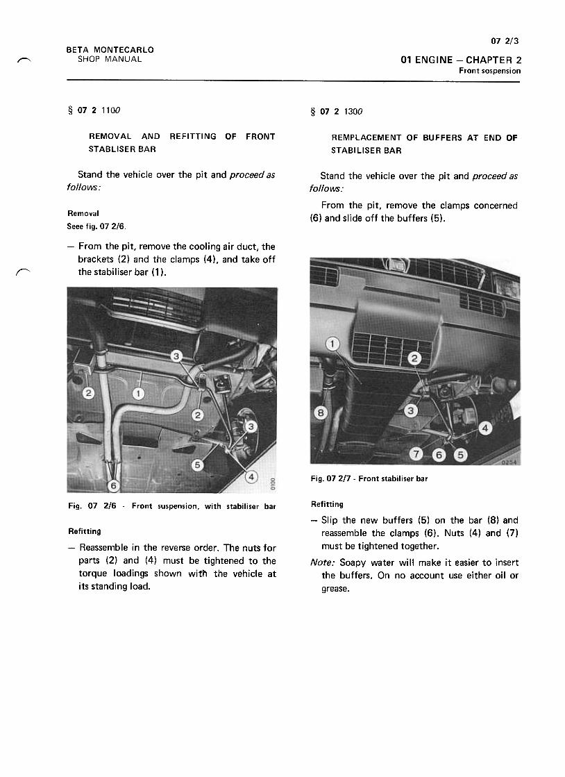
072/3BETA MONTECARLO
SHOP MANUAL 01 ENGINE -CHAPTER 2Front sospension
~
§ 0721100 § 0721300
REMOVAL AND
STABLISER BAR
REFITTING OF FRONT REMPLACEMENT OF BUFFERS AT END OF
STABILISER BAR
Stand the vehicle over the pit and proceed as
follows:Stand the vehicle over the pit and proceed as
fo//olNS :
From the pit, remove the clamps concerned
(6) and slide off the buffers (5).Removal
Seee fig. 07 2/6.
-From the pit, remove the cooling air duct, the
brackets (2) and the clamps (4), and take off
the stabiliser bar (1 )."
Fig. 07217 -Front stabiliser bar
Fig. 07 216 -Front suspension, with stabiliser bar
Refitting
-Reassemble in the reverse order. The nuts for
parts (2) and (4) must be tightened to the
torque loadings shown with the vehicle at
its standing load.
Refitting
-Slip the new buffers (5) on the bar (8) and
reassemble the clamps (6). Nuts (4) and (7)
must be tightened together .
Note: Soapy water will make it easier to insert
the buffers. On no account use either oil or
grease.
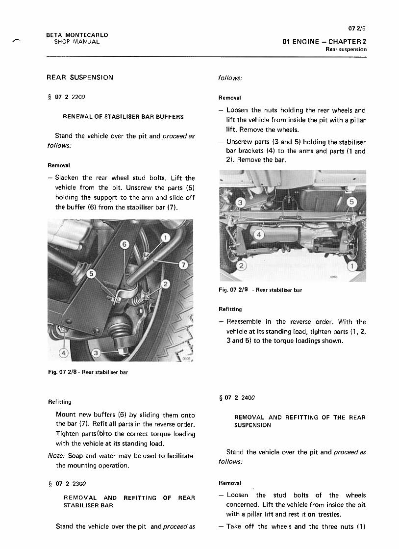
07 2/5
BETA MONTECARLO
SHOP MANUAL 01 ENGINE -CHAPTER2Rear suspension
"
REAR SUSPENSION follows:
§ 0722200
RENEWAL OF STABILISER BAR BUFFERS
Stand the vehicle over the pit and proceed as
follows:
Removal
-Loosen the nuts holding the rear wheels and
lift the vehicle from inside the pit with a pillar
lift. Remove the wheels.
-Unscrew parts (3 and 5) holding the stabiliser
bar brackets (4) to the arms and parts (1 and
2). Remove the bar.Removal
-Slacken the rear wheel stud bolts. Lift the
vehicle from the pit. Unscrew the parts (5)
holding the support to the arm and slide off
the buffer (6) from the stabiliser bar (7).
Fig. 07 219 -Rear stabiliser bar
Refitting
-Reassemble in the reverse order. With the
vehicle at its standing load, tighten parts (1,2,
3 and 5) to the torque loadings shown.
Fig. 07 218 -Rear stabiliser bar
§ 07 2 2400Refitting
Mount new buffers (6) by sliding them onto
the bar (7). Refit all parts in the reverse order.
Tighten parts(5)to the correct torque loading
with the vehicle at its standing load.
REMOVAL AND REFITTING OF THE REAR
SUSPENSION
Stand the vehicle over the pit and proceed as
follows:Note: Soap and water may be used to facilitate
the mounting operation.
§ 0722300
REMOVAL ANDSTABILISER BAR
REFITTING OF REAR
Removal
-Loosen the stud bolts of the wheels
concerned. Lift the vehicle from inside the pit
with a pillar lift and rest it on trestles.
-Take off the wheels and the three nuts ( 1 )Stand the vehicle over the pit and proceed as
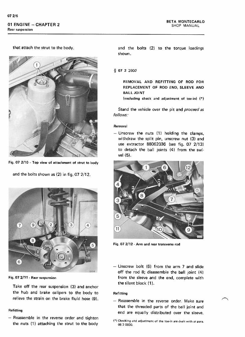
07 2/6
BETA MONTECARLO
SHOP MANUAL01 ENGINE -CHAPTER 2Rear suspension
that attach the strut to the body. and the bolts (2) to the torque loadings
shown.
§ 0722600
REMOVAL AND REFITTING OF ROD FOR
REPLACEMENT OF ROD END, SLEEVE AND
BALL JOINT
(excluding check and adjustment of toe-in) (*)
Stand the vehicle over the pit and proceed as
follows:
Removal
-Unscrew the nuts ( 1) holding the clamps,
withdraw the split pin, unscrew nut (3) and
use extractor 88062036 (see fig. 07 2/13)
to detach the ball joints (4) from the swi-
vel (5).
Fig. 07 2110 -Top view of attachment of strut to body
and the bolts shown as (2) in fig. 072/12.
Fig. 072/12- Arm and rear transverse rod
-Unscrew bolt (6) from the arm 7 and slide
off the rod 8; disassemble the ball joint (4)
from the sleeve and the end, complete with
the silent block (1 ).
Fig. 07 2111 -Rear suspension
Take off the rear suspension (3) and anchor
the hub and brake calipers to the body to
relieve the strain on the brake fluid hose (9). ~
Refitting
-Reassemble in the reverse order. Make sure
that the threaded parts of the ball joint and
end are equally distributed over the sleeve.Refitting
-Reassemble in the reverse order and tighten
the nuts (1) attaching the strut to the body(*) Checking and adjustment of the toe-in are dealt with at para.
08 2 0600.
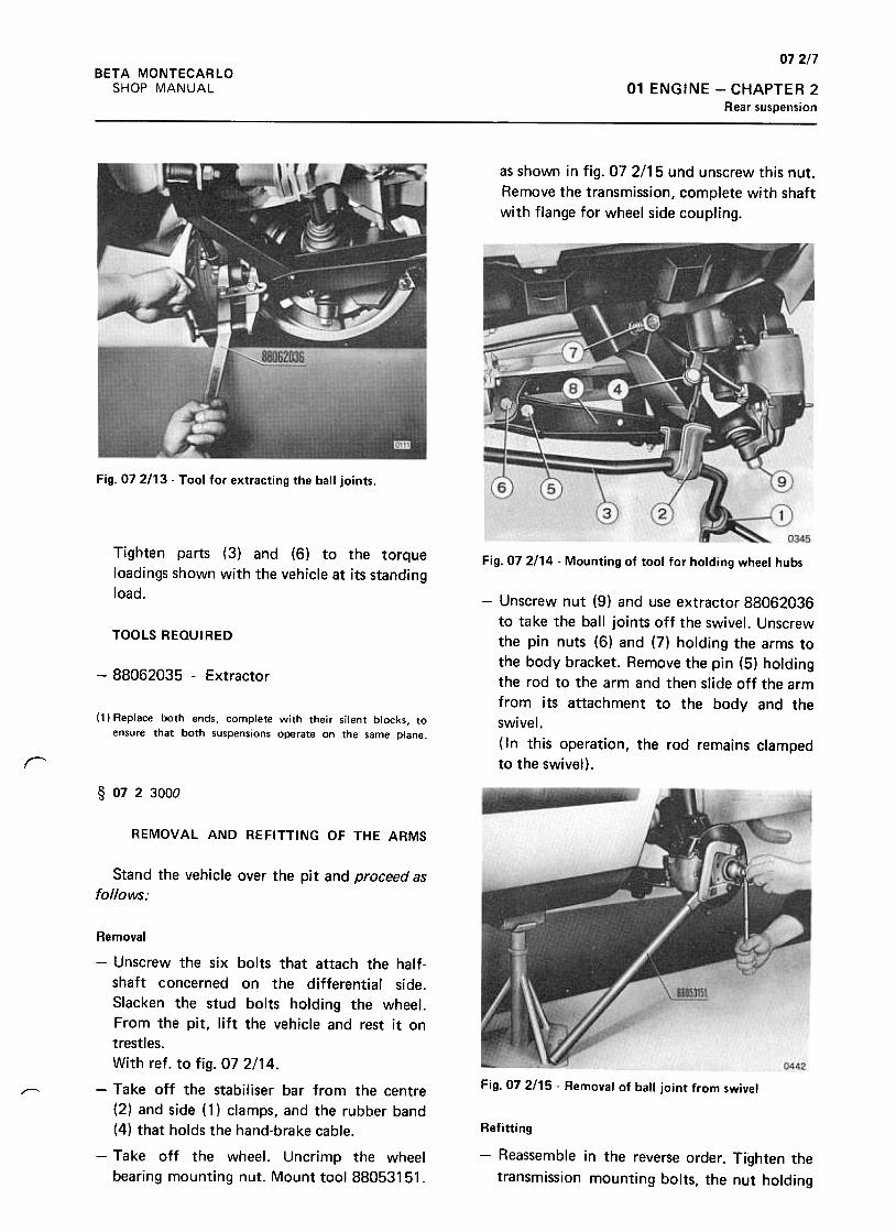
072/7BETA MONTECARLO
SHOP MANUAL 01 ENGINE -CHAPTER 2
Rear suspension
as shown in fig. 07 2/15 und unscrew this nut.
Remove the transmission, complete with shaft
with flange for wheel side coupling.
Fig. 072113 -Tool for extracting the ball joints.
Tighten parts (3) and (6) to the torque
loadings shown with the vehicle at its standing
load.
Fig. 07 2114 -Mounting of tool for holding wheel hubs
TOOLS REQUIRED
-88062035 -Extractor
(1) Replace both ends, complete with their silent blocks, toensure that both suspensions operate on the same plane.
-Unscrew nut (9) and use extractor 88062036
to take the ball joints off the swivel. Unscrew
the pin nuts (6) and (7) holding the arms to
the body bracket. Remove the pin (5) holding
the rod to the arm and then slide off the arm
from its attachment to the body and the
swivel.
( In this operation, the rod remains clamped
to the swivel).r
§ 0723000
REMOVAL AND REFITTING OF THE ARMS
Stand the vehicle over the pit and proceed as
follows:
Fig. 07 2/15 -Removal of ball joint from swivelr-"
Removal
-Unscrew the six bolts that attach the half-
shaft concerned on the differential side.
Slacken the stud bolts holding the wheel.
From the pit, lift the vehicle and rest it on
trestles.
With ref. to fig. 07 2/14.
-Take off the stabiliser bar from the centre
(2) and side (1) clamps, and the rubber band
(4) that holds the hand-brake cable.
-Take off the wheel. Uncrimp the wheel
bearing mounting nut. Mount tool 88053151.
Refitting
-Reassemble in the reverse order. Tighten the
transmission mounting bolts, the nut holding

BETA MONTECARLO
SHOP MANUAL
072/8
01 ENGINE -CHAPTER
Rear suspension
the wheel bearing, and parts (1, 2, 5, 6, 7 and
9) to the correct torque loadings, with the
vehicle at its standing load.
TOOLS REQUIRED
-88053151 -Lever for holding wheel hubs
-88062036 -Ball joint extractor
§ 0723100
Fig. 07 2117 -Removal of the silent blocks
REPLACEMENT OF
BLOCKS
REAR ARM SILENTAssembly
-Clean the seatings of the blocks in the arm.
Insert the new blocks with the aid of
extractor 88032121 -5a, with its parts assem-
bled as shown in the figure. The correct axial
position of the block will be obtained by
screwing the tool fully down.
Stand the vehicle over the pit and proceed as
follows:
-Lift the vehicle and rest it on trestles.
Remove the centre (1) and side (2) clamps
holding the stabiliser bar (3). Remove the
rubber band (4). Unscrew the nuts from pins
(6) & (7) and remove them. Slide off the arm,
complete with the silent blocks, from its
fittings.
Fig. 07 2/18 -Insertion of silent blocks into the arm.
-With the vehicle at its standing load tighten
the bolts holding the stabiliser bar side
clamp and parts (6 & 7) holding the arm on
the correct torque loadings.
-Repeat these operations to replace the blocks
on the other arm.Fig. 072/16- Rear arm
~-Fit extractor 88042121,5 in the blocks, as
shown in the figure, and remove them.TOOLS REQUIRED
Silent block extractor and88042121 -5a
inserterNote: the blocks must be replaced on both arms.
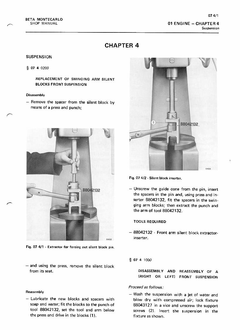
074/1BETA MONTECARLO
SHOP MANUAL 01 ENGINE -CHAPTER 4
Suspension~
CHAPTER 4
SUSPENSION
§ 0740200
REPLACEMENT OF SWINGING ARM SILENT
BLOCKS FRONT SUSPENSION
Disassembly
-Remove the spacer from the silent block by
means of a press and punch;
r
Fig. 074/2 -Silent block inserter .
-Unscrew the guide cone from the pin, insert
the spacers in the pin and, using press and in-
serter 88042132, fit the spacers in the swin-
ging arm blocks; then extract the punch and
the arm of tool 88042132.
r--
TOOLS REQUIRED
-88042132 -Front arm silent block extractor-
inserter.
Fig. 07 411 .Extractor for forcing out silent block pin.
§ 0741000
-and using the press, remove the silent block
from its seat. DISASSEMBL y
(RIGHT OR
AND REASSEMBLY OF A
LEFT) FRONT SUSPENSION
Proceed as follows:
-Wash the suspension with a jet of water and
blow dry with compressed air; lock fixture
88043127 in a vice and unscrew the support
screws (2). Insert the suspension in the
fixture as shown .
Reassembly
-Lubricate the new blocks and spacers with
soap and water; fit the blocks to the punch of
tool 88042132, set the tool and arm below
the press and drive in the blocks (1 ).
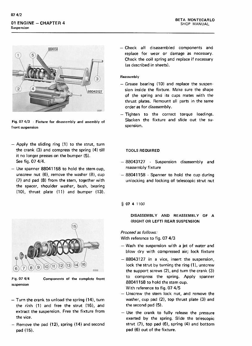
074/2BETA MONTECARLO
SHOP MANUAL01 ENGINE -CHAPTER 4
Suspension
-Check all disassembled components and
replace for wear or damage as necessary.
Check the coil spring and replace if necessary
(as described in sheets).
Reassembly
-Grease bearing ( 10) and replace the suspen-
sion inside the fixture. Make sure the shape
of the spring and its cups mates with the
thrust plates. Remount all parts in the same
order as for disassembly.
-Tighten to the correct torque loadings.
Slacken the fixture and slide out the su-
spension.Fig. 074/3 -Fixture for disassembly and assembly of
front suspension
TOOLS REQUIRED
-Apply the sliding ring (1) to the strut, turn
the crank (3) and compress the spring (4) till
it no longer presses on the bumper (5).
See fig. 07 4/4.
-Use spanner 88041158 to hold the stem cup,
unscrew nut (6), remove the washer (8), cup
(7) and pad (8) from the stem, together with
the spacer, shoulder washer, bush, bearing
(10), thrust plate (11) and bumper (13).
-88043127 -Suspension disassembly and
reassembly fixture
-88041158 -Spanner to hold the cup during
unlocking and locking of telescopic strut nut
§ 0741100
DISASSEMBLY AND REASSEMBLY OF A
(RIGHT OR LEFT) REAR SUSPENSION
Fig. 07 4/4
suspension
Components of the complete front
Proceed as follows:
With reference to fig. 07 4/3
-Wash the suspension with a jet of water and
blow dry with compressed air; lock fixture
-88043127 in a vice, insert the suspension,
lock the strut by turning the ring (1 ), unscrew
the support screws (2), and turn the crank (3)
to compress the spring. Apply spanner
88041158 to hold the stem cup.
With reference to fig. 07 4/5
-Unscrew the stem lock nut, and remove the
washer, cup pad (2), top thrust plate (3) and
the second pad (5).
-Use the crank to fully release the pressure
exerted by the spring. Slide the telescopic
strut (7), top pad (6), spring (4) and bottom
pad (6) out of the fixture.
-Turn the crank to unload the spring (14), turn
the rinh (1) and free the strut (16), and
extract the suspension. Free the fixture from
the vice.
-Remove the pad (12), spring (14) and second
pad (15).
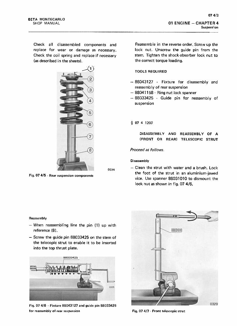
074/3BETA MONTECARlO
SHOP MANUAL 01 ENGINE -CHAPTER 4
Suspens;on
Reassemble in the reverse order. SCre\N up the
lock nut. Unscrew the guide pin from the
stem. Tighten the shock-absorber lock nut to
the correct torque loading.
Check all disassembled components and
replace for wear or damage as necessary.
Check the coil spring and replace if necessary
(as described in the sheets).~ '
1;,
TOOLS REQUIRED
-88043127 -Fixture for disassembly and
reassembly of rear suspension
-88041158 -Ring nut lock spanner
-88033425 -Guide pin for reassembly of
suspension
§ 0741200
DISASSEMBL y AND REASSEMBL Y OF A
(FRONT OR REAR) TELESCOPIC STRUT
Proceed as follows.
Disassembly
-Clean the strut with water and a brush. Lock
the foot of the strut in an aluminium-jawed
vice. Use spanner 88031010 to dismount the
lock nut as shown in fig. 074/6.
0334
Fig. 07 415 -Rear suspension components
Reassembly
-When reassembling line the pin (1) up with
reference (8),
-Screw the guide pin 88033425 on the stem of
the telecopic strut to enable it to be inserted
into the top thrust plate.
Fig. 07416 -Fixture 88043127 and guide pin 88033425
for reassembly of rear suspension Fig. 07 417 -Front telescopic strut
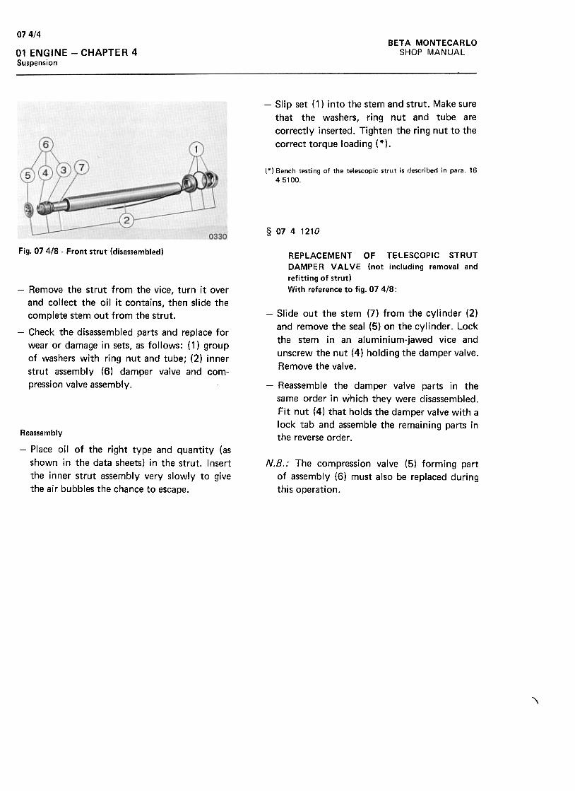
07 4/4BETA MONTECARLO
SHOP MANUAL01 ENGINE -CHAPTER 4
Suspension
-Slip set (1) into the stem and strut. Make sure
that the washers, ring nut and tube are
correctly inserted. Tighten the ring nut to the
correct torque loading (*).
(*) Bench testing of the telescopic strut is described in para. 16
45100.
§ 0741210
Fig. 07 418 -Front strut (disassembled)REPLACEMENT OF TELESCOPIC STRUT
DAMPER VALVE (not including removal and
refitting of strut)
With reference to fig. 07 418 :
-Slide out the stem (7) from the cylinder (2)
and remove the seal (5) on the cylinder. Lock
the stem in an aluminium-jawed vice and
unscrew the nut (4) holding the damper valve.
Remove the valve.
-Remove the strut from the vice, turn it over
and collect the oil it contains, then slide the
complete stem out from the strut.
-Check the disassembled parts and replace for
wear or damage in sets, as follows: (1) group
of washers with ring nut and tube; (2) inner
strut assembly (6) damper valve and com-
pression valve assembly. -Reassemble the damper valve parts in the
same order in which they were disassembled.
Fit nut (4) that holds the damper valve with a
lock tab and assemble the remaining parts in
the reverse order .Reassembly
-Place oil of the right type and quantity (as
shown in the data sheets) in the strut. Insert
the inner strut assembly very slowly to give
the air bubbles the chance to escape.
N.B.: The compression valve (5) forming part
of assembly (6) must also be replaced during
this operation.
,
BETA MONTECARLO
SHOP MANUAL 08 WHEELS -HUBS -TYRES -CHAPTER 1
Contents
HUBS, WHEELS AND TYRES GROUP CONTENTS
CHAPTER 1
Troubles. probable causes, checkings and operations-to be carried out
from page 08 1/1
to page 081/2
CHAPTER 2
§ 08 2 01 DO Removing and refitting of swivel complete with flange and front wheel hub bearing
§ 08 2 04DO Removing and refitting the rear carrier complete with hub wheel and bearing .
page 082/1
082/1
CHAPTER 4
..084/1
084/2
084/4
§ 0840300 Renewing of front wheel hub, or the bearing. § 084 0700 Renewing of rear hub bearing and carrier. § 0840900 Balancing the loose wheels by means of CEMB l1ll, or l1 Ell type balancing machine
~
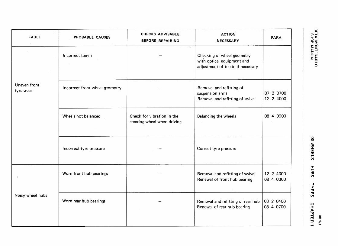
BE
TA
M
ON
TE
CA
RLO
w
(:3..J
zID
-
<t
cx:(/)
--<
t>
Q
.C
W
<t
cx:
(/) W
~
cx:(,)
OW
I!.
~
WU
ID >
2 ~
O
<t
-(I)1-
(I)U
W
<t
Uw2
1-..J:>~LL (I)w(I)=>
<t
C.J
w.Ja1<t
a1O~0- ~a:~0.
c:dolo+-'
+-'
u111......0uc:
>'-CIJ
"'
C:'-0~
...c:: C
JaJ
CIJ
aJ
E
...c::O
c::
-aJ
aJ .-
C>
E
.S
wC
.a,aJ
.-O..c
:J ...
~g-
--o0 C
IJ ...
CJ
c::C
>
.-aJc::
...
.-c. E
~
0 ...
CJ
-"'aJ
:J~0
O
~
~
co...c ~
~
~0)
0)c
...:J'i?:
>'-+"'
Q)
E0Q)
CJ
""0)Q
)..c:::s:+
"'c::O'-
-+"'
uQ)
'-'-0uc::
0000r-..oO
~
NN
r-..N0..-
(!)>.~V
I--0
0C
) C
)c::
c::.~
.~
'i=V
I'i=(!)
E(!)
'- '-
1:J'-1:Jc::
ro c::
ro c::
ro-0-ro
.-ro>
V
I >
0 c::
0
E
~
E(!)
VI
(!)
cr:~cr:
oo0")ov00O-0Q
)ucroro
.0Oc"'
""Q;
Q)
.!:s
CI
Q)
.=..c
>+
-' .-...
C"'0
C
CO
Q
)c
"'c;; $:
.0 Q
).-Q
)>
..c
O
$:'1-
CI
~
CU
..:
Q)
Q)
..c Q
)U
t:
"'-0;Q
J..!::~Q
J..!::
011:=
.U1:=.!2.ca
ro
08 WH
EE
LS
Q)
I-:)t/)t/)Q)
1-0.Q)
I->+-'
+-'
uQ)
1-1-0u~ Q)
'-::3(/)(/)Q
)'-0.
Q)
'->+"'
+"'
(.J~'-0u
HU
BSC/)
0)c:
".:roQ)
..0
..0~..c:
c:o...-c:...0s ~
C
1.-c:~
.~
"' ro
'1- aJ
O..Q
C1..Q
c: :J
.+:i
.c
'1- c:
aJ O
"0'1-C
:'I-ro
O
ro ro
>
~O
aJ
E
c:aJ
aJa:a:
0000OC
Y)
q-o
Nq-
No0
.-n
TY
RE
S"'.0:J..cQ
JQ
J..c~>"''07
"'0)c:
"L:coQ)
.D.D~..c:'-coQ
)'-c:'-0s .D~..c'-ro
C)
Q)
c:'-
.-'--roO
Q
)C
).D.s
.D...~.~
..c
-'-Q)
ro'-
Q)
"0 '-
c: -
ro O
ro ro
>
s:o
Q)
E
c:Q
) Q
)~
n-
0000~r-.
00N~
000000 C
HA
PT
ER
'
081/1
SH
OP
M
AN
UA
L
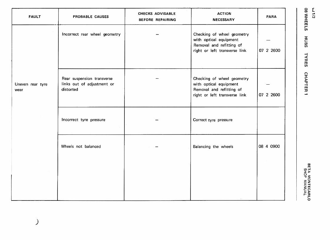
08 WH
EE
LS
"J 1 /2
w
"..1
za3
-<
t a:
(/) -
-<t
>
0..c
w<
t a:
(/) w
~
a:u
ow
u.
~
wu
a3 >z
0:O
«
-(/)1-
(/)u
w«
uwz
....J::)«I!.
(I)w(I):>~uw-Jm~mO~4. «1%:
«0-
>'-.,.Q)
Eo~-a:;Q
).c~'-(0Q
)'-.,.uQ
)'-'-0uc >...~~
c:
E-.-
0-
0 +
"'Q
)C:C
>~
c>Q
)c:...E
.-Q
)-
a.+"'>
Q) +"'
U)
Q)
.-~
c:..C
:~Q
)ro>
0""
>
Q)
+"'
"tJ--c:+
"'O
~ro't
C>
.+
:J --
c:a.ro....-0
>
0~
0
(J..c:E
+"'
Q)
+"'
..c:..c:
.-Q)
C>
u ~
a:
.;::
HU
BS
oo(0NNr-.O
TY
RE
SC
HA
PT
ER
'
Q)
'-"'
0'-Q
) +
">
c:
"' Q
)
~
E'-
+"
+"
"'~c:
.-
o"'C.-~"'c:
'f-Q
) o
a."'
+"
~
~
"'C"'
0 Q
)+
"'-'-
"' 0
~~
+" c:
"'a:
-"'C
>'- ~
"W
CE
-.-
0-
0 +
"'
Q)C
O)~
O)Q
)C'-E
.-Q
)-
a.+
"'>
Q)
+"'
CI)
Q)
.-~
C.c:JQ
)CO
>C
"'-'->
Q
) +
"'
-0---+
"'o
CO
'--
uroQ)
0) ..p
--C
a.ro'-.-0
>
0~
0
u.cE
+"'
Q)
+"'
.c.c
.-Q)
0)
u ~
a:
.~
QJ
'->+-'
'-la~~QJ
>
'-Q
J la
::3 ~
o0<0
NN""0
Q)
'-:)C/)
C/)
~a.
Q)
'->+-'
+-'
(,)Q
)'-'-0(,)c: Q
)...:J"'"'e0.Q
)...>uQ
)......oo
o00">O~00O-0Q
)C
Jc:roro
..0...oc:I/)
"'Q)
Q)
..c:
:$ "'""Q
;Q
)..c:~Q
)..c:+
-'
0)c:
'uc:.}E
.ca
ro
BE
TA
M
ON
TE
CA
RLO
~
SH
OP
M
AN
UA
L
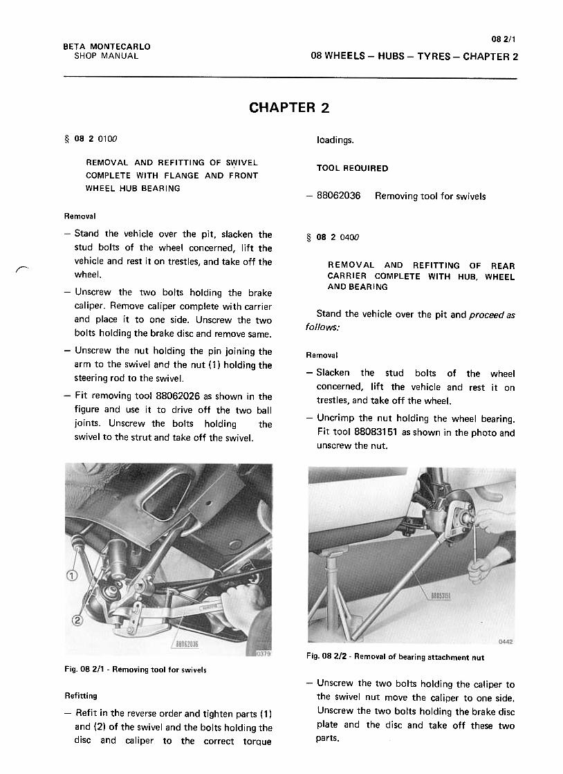
082/1BETA MONTECARLO
SHOP MANUAL 08 WHEELS -HUBS -TYRES -CHAPTER 2
CHAPTER 2
§ 0820100 loadings.
REMOVAL AND REFITTING OF S~IVEL
COMPLETE WITH FLANGE AND FRONT
WHEEL HUB BEARING
TOOL REQUIRED
-88062036 Removing tool for swivels
§ 0820400
R EMOV AL AND REFITTING OF REAR
CARRIER COMPLETE WITH HUB, WHEEL
AND BEARING
r
Stand the vehicle over the pit and proceed as
follows:
Removal
-Slacken the stud bolts of the wheel
concerned, lift the vehicle and rest it on
trestles, and take off the wheel.
-Uncrlmp the nut holding the wheel bearing.
Fit tool 88083151 as shown in the photo and
unscrew the nut.
Removal
-Stand the vehicle over the pit, slacken the
stud bolts of the wheel concerned, lift the
vehicle and rest it on trestles, and take off the
wheel.
-Unscrew the two bolts holding the brake
caliper. Remove caliper complete with carrier
and place it to one side. Unscrew the two
bolts holding the brake disc and remove same.
-Unscrew the nut holding the pin joining the
arm to the swivel and the nut {1) holding the
steering rod to the swivel.
-Fit removing tool 88062026 as shown in the
figure and use it to drive off the two ball
joints. Unscrew the bolts holding the
swivel to the strut and take off the swivel.
Fig. 08212- Removal of bearing attachment nut
Fig. 08 211 -Removing tool for swivels
-Unscrew the two bolts holding the caliper to
the swivel nut move the caliper to one side.
Unscrew the two bolts holding the brake disc
plate and the disc and take off these two
parts.
Refitting
-Refit in the reverse order and tighten parts ( 1 )
and (2) of the swivel and the bolts holding the
disc and caliper to the correct torque
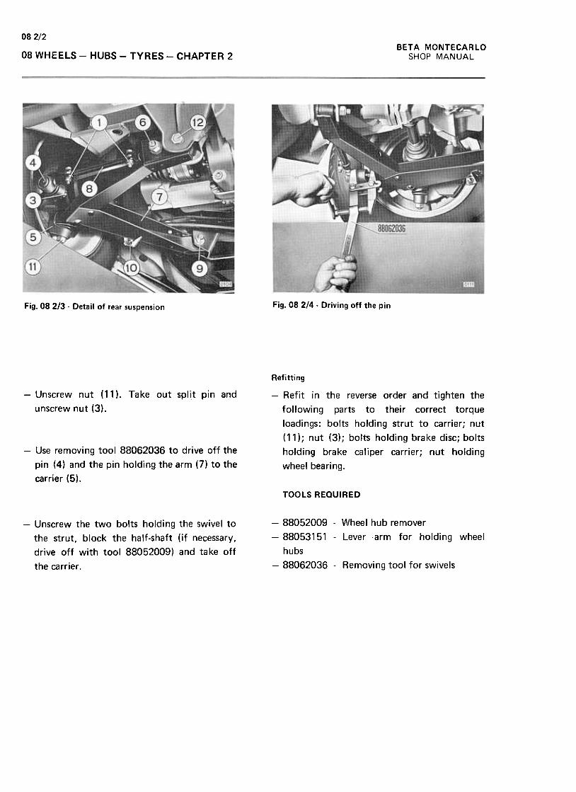
08 2/2
BETA MONTECARLO
SHOP MANUAL08 WHEELS -HUBS -TYRES -CHAPTER 2
Fig. 08 2/4 -Driving off the pinFig. 08 2/3 -Detail of rear suspension
-Unscrew nut (11 ). Take out split pin and
unscrew nut (3).
Refitting
-Refit in the reverse order and tighten the
following parts to their correct torque
loadings: bolts holding strut to carrier; nut
( 11) ; nut (3) ; bolts holding brake disc; bolts
holding brake caliper carrier; nut holding
wheel bearing.
-Use removing tool 88062036 to drive off the
pin (4) and the pin holding the arm (7) to the
carrier (5).
TOOLS REQUIRED
-Unscrew the two bolts holding the swivel to
the strut, block the half-shaft (if necessary,
drive off with tool 88052009) and take off
the carrier .
-88052009 -Wheel hub remover
-88053151 -Lever arm for holding wheel
hubs
-88062036 -Removing tool for swivels
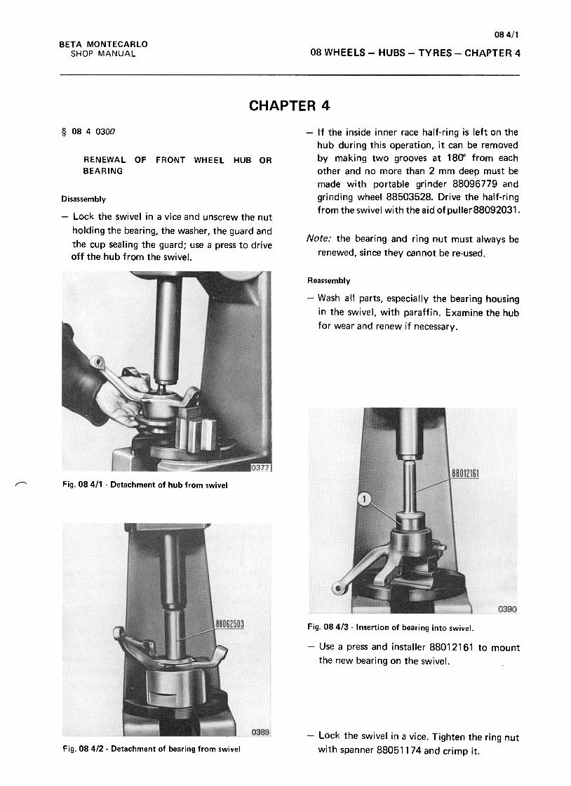
084/1BETA MONTECARLO
SHOP MANUAL 08 WHEELS -HUBS -TYRES -CHAPTER 4
CHAPTER 4
§ 0840300 -If the inside inner race half-ring is left on the
hub during this operation, it can be removed
by making two grooves at 18(1' from each
other and no more than 2 mm deep must be
made with portable grinder 88096779 and
grinding wheel 88503528. Drive the half-ring
from the swivel with the aid ofpuller88092031.
RENEWAL OF FRONT WHEEL HUB OR
BEARING
Disassembly
-Lock the swivel in a vice and unscrew the nut
holding the bearing, the washer, the guard and
the cup sealing the guard; use a press to driveoff the hub from the swivel.
Note: the bearing and ring nut must always be
renewed, since they cannot be re-used.
Reassembly
-Wash all parts, especially the bearing housing
in the swivel, with paraffin. Examine the hub
for wear and renew if necessary.
r-- Fig. 08 4/1 -Detachment of hub from swivel
Fig. 084/3 -Insertion of bearing into swivel.
-Use a press and installer 88012161 to mount
the new bearing on the swivel.
-Lock the swivel in a vice. Tighten the ring nut
with spanner 88051174 and crimp it.Fig. 08 412 -Detachment of bearing from swivel
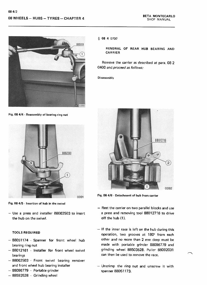
BETA MONTECARLO
SHOP MANUAL
08 4/2
08 WHEELS -HUBS -TYRES -CHAPTER 4
§ 0840700
RENEWAL OF REAR HUB BEARING AND
CARRIER
Remove the carrier as described at para. 08 2
0400 and proceed as follows:
Disassembly
Fig. 08414- Reassembly of bearing ring nut
Fig. 08 416 -Detachment of hub from carrier
Fig. 08415- Insertion of hub in the swivel
-Rest the carrier on two parallel blocks and use
a press and removing tool 88012716 to drive
off the hub (1 ).
-Use a press and installer 88062503 to insert
the hub on the swivel.
-If the inner race is left on the hub during this
operation, two grooves at 180° from each
other and no more than 2 mm deep must be
made with portable grinder 88096779 and
grinding wheel 88503528. Puller 88092031
can then be used to remove the race.
TOOLS REaulRED
"'
-88051174- Spanner for front wheel hub
bearing ring nut
-88012161 -Installer for front wheel swivel
bearings
-88062503 -Front swivel bearing remover
and front wheel hub bearing installer
-88096779 -Portable grinder
-88593528 -Grinding wheel
-Uncrimp the ring nut and unscrew it with
spanner 88051173.

08 4/3
BETA MONTECARLO
SHOP MANUAL 08 WHEELS -HUBS -TYRES -CHAPTER 4
Reassembly
-Wash all parts, especially the bearing housing
in the carrier, with paraffin. Examine the hub
for wear and renew if necessary.
-Use a press and installer 88052018 to mount
the new bearing in the carrier.
Fig. 08 4/7 -Datachment of ring nut from carrier .
0394
Fig. 084/9 -Insertion of bearing in the carrier
-Lock the carrier in a vice. Tighten the ring nut
with spanner 88051173 and crimp it.
-Use a press and installer 88022080 to insert
the hub in the carrier.
TOOLS REQUIRED
0395Fig. 08418- Detachment of bearing from carrier
-Use a press and removing tool 88022080 to
drive bearing (1) from the carrier (2).
Note: the bearings and their ring nuts must
always be renewed, since they cannot be
re-used.
-88096779 -Portable grinder
-88503528 -Grinding wheel
-88051173 -Spanner for rear wheel hub
bearing ring nut
-88012716- Removing tool to take rear wheel
hubs from carriers
-88052818- Installer to insert bearings in
rear wheel carriers
-88022080 -Installer for insertion of hub in
carrier
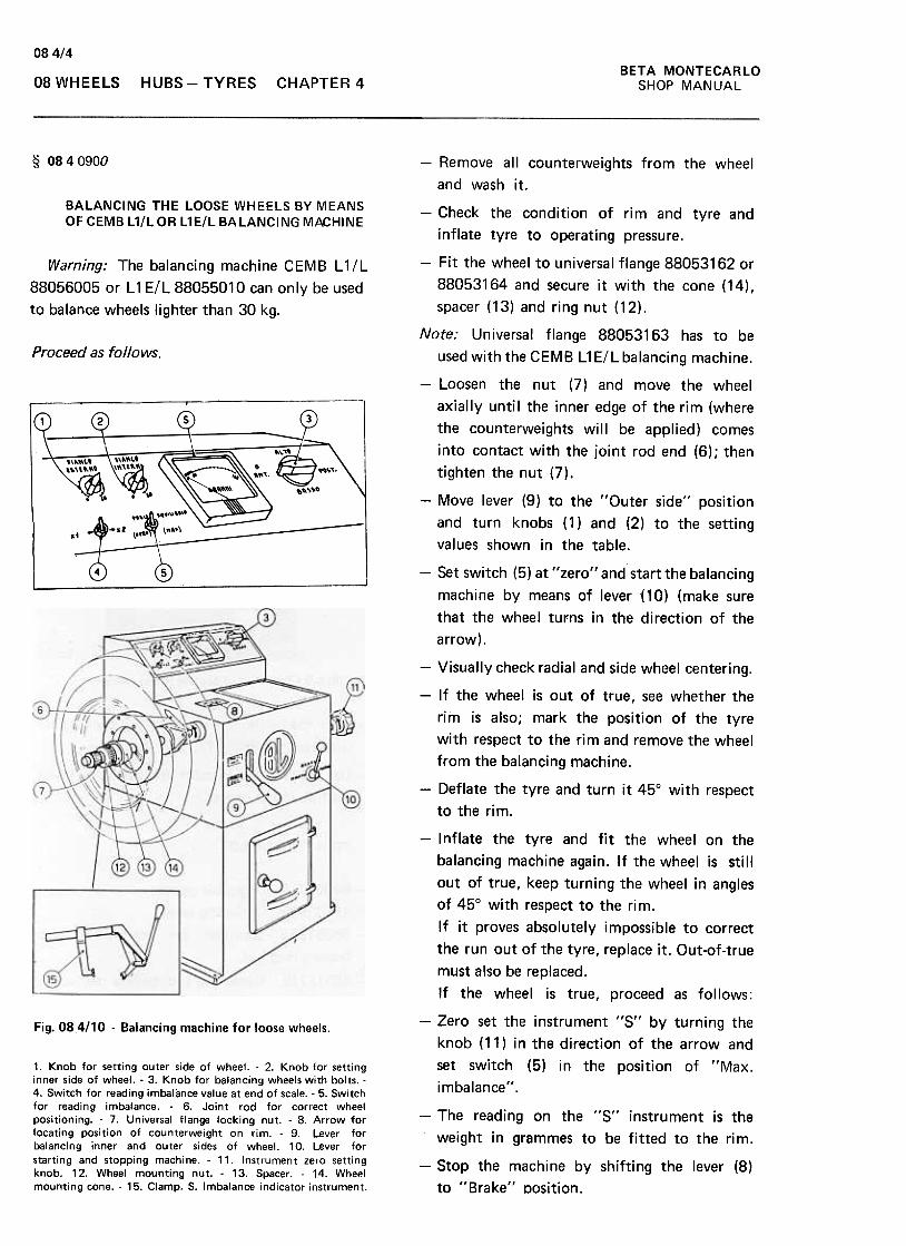
084/4BETA MONTECARLO
SHOP MANUAL08 WHEELS HUBS- TYRES CHAPTER 4
§ 0840900
BALANCING THE LOOSE WHEELS BY MEANSOF CEMB L1/L OR L1E/L BALANCING MACHINE
Warning; The balancing machine CEMB L11L
88056005 or L 1 ElL 88055010 can only be used
to balance wheels lighter than 30 kg.
Proceed as follows.
-Remove all counterweights from the wheel
and wash it.
-Check the condition of rim and tyre and
inflate tyre to operating pressure.
-Fit the wheel to universal flange 88053162 or
88053164 and secure it with the cone (14),
spacer (13) and ring nut (12).
Note: Universal flange 88053163 has to be
used with the CEMB L1 ElL balancing machine.
-Loosen the nut (7) and move the wheel
axially until the inner edge of the rim (where
the counterweights will be applied) comes
into contact with the joint rod end (6); then
tighten the nut (7).
-Move lever (9) to the "Outer side" posit)on
and turn knobs (1) and (2) to the setting
values shown in the table.
-Set switch (5) at "zero" and start the balancing
machine by means of lever {10) (make sure
that the wheel turns in the direction of the
arrow).
-Visually check radial and side wheel centering.
-If the wheel is out of true, see whether the
rim is also; mark the position of the tyre
with respect to the rim and remove the wheel
from the balancing machine.
-Deflate the tyre and turn it 45° with respect
to the rim.
-I nflate the tyre and fit the wheel on the
balancing machine again. If the wheel is still
out of true, keep turning the wheel in angles
of 45° with respect to the rim.
If it proves absolutely impossible to correct
the run out of the tyre, replace it. Out-of-true
must also be replaced.
If the wheel is true, proceed as follows:
-Zero set the instrument "5" by turning the
knob (11) in the direction of the arrow and
set switch (5) in the position of "Max.
imbalance".
Fig. 08.4/10 -Balancing machine for loose wheels.
1. Knob for setting outer side of wheel. -2. Knob for settinginner side of wheel. -3. Knob for balancing wheels with bolts. -4. Switch for reading imbalance value at end of scale. -5. Switchfor reading imbalance. -6. Joint rod for correct wheelpositioning. -7. Universal flange locking nut. -8. Arrow forlocating position of counterweight on rim. -9. Lever forbalancing inner and outer sides of wheel. 10. Lever forstarting and stopping machine. -11. Instrument zero settingknob. 12. Wheel mounting nut. -13. Spacer. -14. Wheelmounting cone. -15. Clamp. S. Imbalance indicator instrument.
-The reading on the "5" instrument is the
weight in grammes to be fitted to the rim.
-5top the machine by shifting the lever (8)
to "Brake" Dosition.
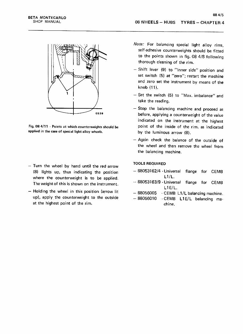
08 4/5
BETA MONTECARlO
SHOP MANUAL 08 WHEELS -HUBS TYRES- CHAPTER 4
Note: For balancing special light alloy rims,
self-adhesive counterweights should be fitted
to the points shown in fig. 08 4/8 following
thorough cleaning of the rim.
-Shift lever (9) to "Inner side" position and
set switch (5) at "zero"; restart the machine
and zero set the instrument by means of the
knob (11).
Fig. 08 4111 -Points at which counterweights should be
applied in the case of special light alloy wheels.
-Set the switch (5) to "Max. imbalance" and
take the reading.
-Stop the balancing machine and proceed as
before, applying a counterweight of the value
indicated on the instrument at the highest
point of the inside of the rim. as indicated
by the luminous arrow (8).
-Again check the balance of the outside of
the wheel and then remove the wheel from
the balancing machine.
-Turn the wheel by hand until the red arrow
(8) lights up, thus indicating the position
where the counterweight is to be applied.
The weight of this is shown on the instrument.
-Holding the wheel in this position (arrow lit
up), apply the counterweight to the outside
at the highest point of the rim.
TOOLS REQUIRED
-8805316214- Universal flange for CEMB
L1IL.
-8805316319- Universal flange for CEMB
L 1 El L .
-88056005 -CEMB L 11L balancing machine.
-88056010 -CEMB L1EIL balancing ma-
chine.
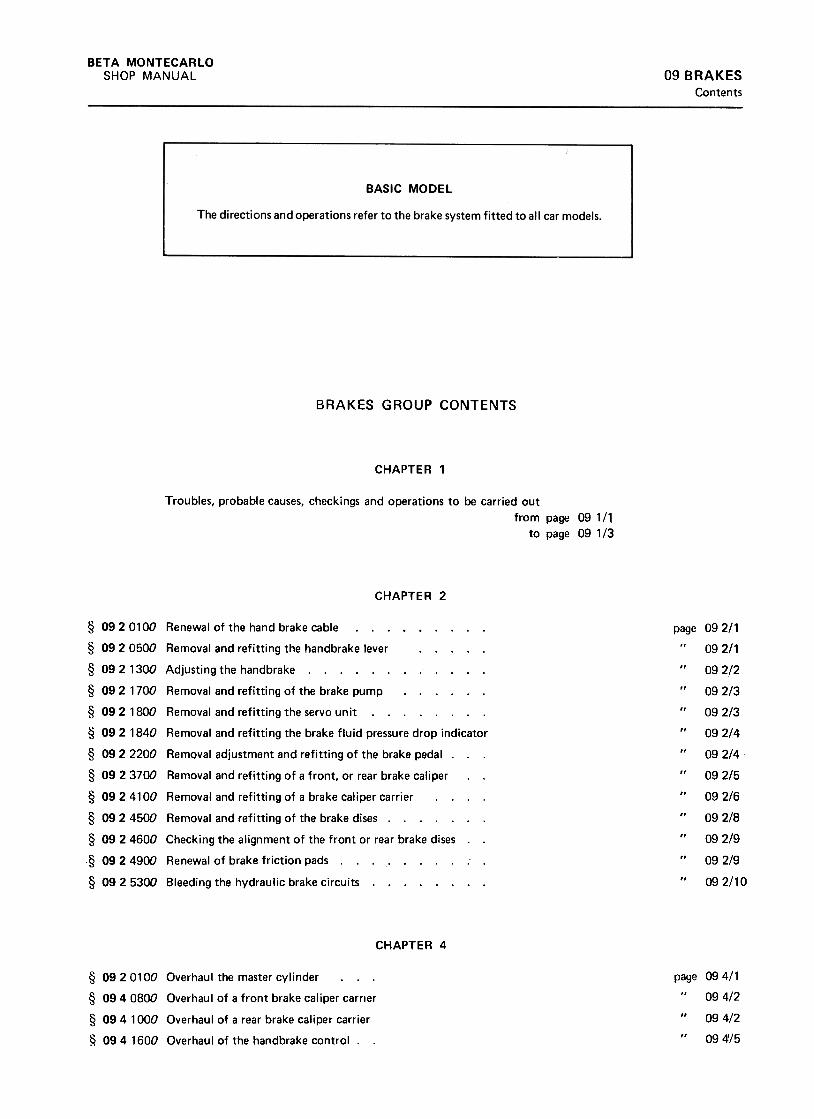
BETA MONTECARLO
SHOP MANUAL 09 BRAKESContents
BRAKES GROUP CONTENTS
CHAPTER 1
Troubles, probable causes, checkings and operations to be carried out
from page 09 1/1
to page 091/3
CHAPTER 2
page§ 09 2 0100 Renewal of the hand brake cable. § 092 0500 Removal and refitting the handbrake lever. § 092 1300 Adjusting the handbrake § 092 1700 Removal and refitting of the brake pump. § 092 1800 Removal and refitting the servo unit. ...
§ 09 2 1840 Removal and refitting the brake fluid pressure drop indicator
§ 09 2 2200 Removal adjustment and refitting of the brake pedal. .
§ 09 2 3700 Removal and refitting of a front, or rear brake caliper
§ 0924100 Removal and refitting of a brake caliper carrier
§ 09 2 4500 Removal and refitting of the brake dises § 09 2 4600 Checking the alignment of the front or rear brake dises ..
§ 09 2 4900 Renewal of brake friction pads. ; .
§ 0925300 Bleeding the hydraulic brake circuits.
CHAPTER 4
page 094/1
094/2
09 4/2
09 4!/5
§ 09 2 0100 Overhaul the master cylinder
§ 0940800 Overhaul of a front brake caliper carrier
§ 094 1000 Overhaul of a rear brake caliper carrier
§ 09 4 1600 Overhau I of the handbrake control. .
09
09
09
09
09
09
09
09
09
09
09
09
09
2/1
2/1
2/2
2/3
2/3
2/4
2/4
2/5
2/6
2/8
2/9
2/9
2/10
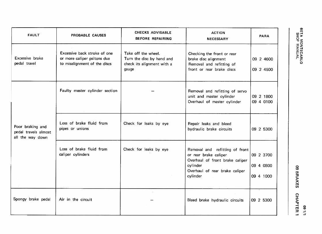
BE
TA
M
ON
TE
CA
RLO
w
C-'
..J z
ID
-«
a:(/)
--«>
c..C
W
« a:
(/) W
~
a:U
O
W
11.~
W
(..) m >
2 c:
O
~
~
~U
w
~
UW2
1-..J~«U-
(I)w(I):>«uw.JaJ«aJO~a, <
t(I:<
t~
Q)
C/)
c Q
) u
o ~
.~
-"'C"'C
O
C/)
Q)
Q)
c ..c
~.s+
"o
.--'-
C/)
0+
" a.
C/)
+"
~
~
cu
a. Q
)co
=
E.C
cocu
0)Q
) .-
>
Q)
-
.-'- co
C/)
0C
/)
C/)
.-
Q)
E
E
ux '-
ow
o
+"
0)~(IJ'-
-
.0 0)>
0) (IJ
>
'-.-+
-'01)01)-0)
(IJU
"O
~
~
-0 ro
~..c
ro +
-'""C
.-
~
~.ro
+-'
""Qj
..c ~
Q)
>
Q)
..C..cE
~
u §,
Q)
"' .-
..c .--
+-'
""C
ro
'+-
Q)
.f!3'+
- ..c
.-
o+-'~
Q)
Q)~
uC')
~
...Q)
;:,ro
;:, ..c
roI-I-O
r'f1 o0(0vN0")0
...ro -"'
Q)
0 (.)
..."'01
.-0
c: "C
c: .;:.
Q)
c: Q
) .~
~
oE-ro
Q)
...c
01Q
) -'"'
....r:.roC
:roro
Q)
01 ~
...
c: .--
.-"C
ro0...
~
>(.)
Q)
0Q
) ~
E
.-ro c:
~
...Q)
0
U..cC
:...- ooL!)"'"
N0")a
c:o.,0:;u0)(/)
'-0)-0c:
>u'-0)(/)caE>~ca
LL 0>...(l) ...
"' (l)
"'0'+
- ...c:
o (l)
.-
"'0-O
'IC:(;
c: .-
.~
>
...+
-' u
(l).-+
-''+
- "'
(l) ...~
...$ E
"'0 ~
c:E
'+-
~
o
ro"'0"'3>
c:
~0
~
..c:E
+-'
....-(l)
(l) c:
>a:::1O 000000.-
.-0
N~
0')0)00
Eo...'1-
~~;;:III
Q)
c:~
0
la 0-
...c:..0
~
'1- ...
o 0
III III
III Q
)O
0.
-J 0-~
""0 't!.
Q)
.-Q
) :J
-u..c ...
.u""0c:
Q)
ro~ro
C/)
...~
..cro
~
.~
...:J.-roro
...c.""0Q
) >
a:..c
0)>0)>.0"'~ro0)'-0-.-
~u0)..c()
+-'
"'
"'C°c:
c:E$:
co -OC
O"'C
CI
"'c:
->.-Q
) C
O~
>
~
CO
CO
~.a
+-'
Q)
-.c...C
O
+-'
O"'C
O
Q)
=c..a.m oo(V
)Ln
N0")0
Eo...'4-
"0:J~
(/I...
QJ
QJ
~"Oro
c:...0-
.0>C
.)'4-0
...QJ
(/I 0.
(/I .-
0-..J
~
aJ>aJ>.0V)
~(0aJ...0-~uaJ..cO
o01"'-cry
N0')0
oo000v0)n 09 BR
AK
ES
+"
'-CO
Q
) '-
a. Q
)
~
.-a.ro
:=-tJ
roO
tJ
Q)
C)
~
Q)
C
ro ~
.-'- '-
ro::::
Q)
..c '-
.-a. ..c
-.-+"
Q)roc
'-'-
O
rotJ
'- Q
)Q
)- ,-
"0C~
- -
ro ~
°
°
..c-ro
::J'-::J'->
~roQ
)roQ)
OQ
).C"O
.C"O
E'-'-c'-c
Q)
.-Q)
.-
Q),-»»
a:oouou
ooo~0>O
CH
AP
TE
R1
ro-0Q
)0.
Q)
~ro.....0>0)c:O0.C
/)
.~~f:'u0).r.~L-~ ooMI:C
)
N0">O!!;
'S(J...'(3,~:Jca..."'0>.cQ
)~ca.....0"'0Q
)Q
)
In
091/1
SH
OP
M
AN
UA
L
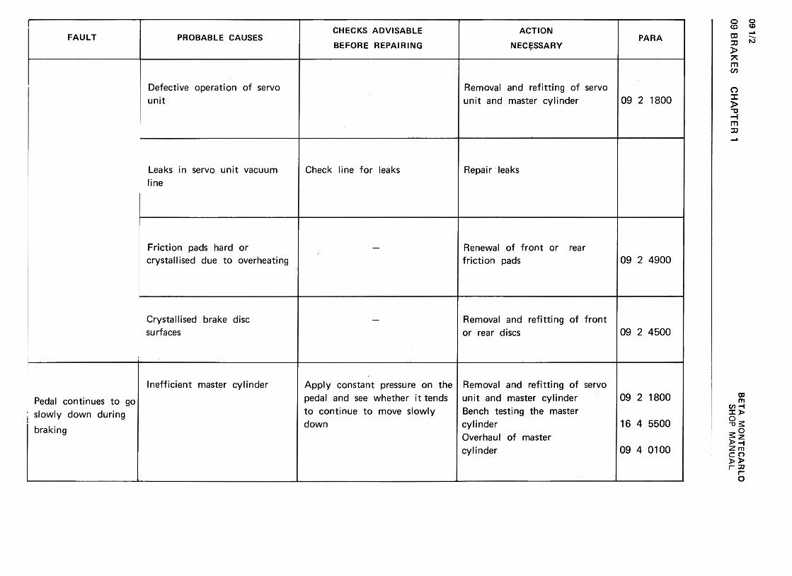
09 1/2
w
(0?-J
za3
-~
a:
(/) -
-~>
~c
w~
a:
(/) w
~
a:(,)
Ow
I!.
~
w(,)
a3 >z
1%:
O
<t
-(I)1-
(I)u
w.
<t
uwz
1--J::>«~ (/)w(/):><
tuw-J1%
)<
t1%
)Oa:4. ~a:~~
0>'-0)"'0c00.;:;C
IJ'-~00)>0.;:;u0)
+-'
0-
0) c
O
-,
0>'-QJ
V)
-'-0 Q
J"0
C")
c:c:
:=
.->:::: C
.)~
'-
~
QJ
+"
"0 'tJ
c: E
co
-"0co c:
~
co
E
.~Q
J c:
a: ~
CH
AP
TE
R'
oo00N0")0
E~~uro>c:~0>'-QJ
(I)c:(I)~ro
QJ
QJ
c:-I:= (I)~ro111
...O'1-111c:
~u111.c:O "'~coQ
)
'-'ro0.Q
)occ:
0>
0 c:
'+:.
~u
roro
'-
--0ro-0
'-
<11
0
a. oa
-u
<11
.-:J -
ci)'-0~
...0...c:0...-(I)-"'00
(00.
~
§0)
.-c:
t0)
.-0:.:::
...ro~
oo0")q-
N0)0C)
c:
.+:;
~Q)
..c:'-Q
)'-
>°
O
"'C
O'-
+-'
~..c: Q
):J
"'"'C"'C~
"'CC
.Q)
"'c::=
°ro.-+
-'+
-' "'
u.->'-
'-
u. u
u.~"0Q)
~CIJ
'--0"0Q
).~=
"'
CIJ
Q)
+-'
u"'
CIJ
>'1-
'- '-
u :J"'
c:o...~0C
)c:
.~'i=Cl)
...
"C
"'c:
u"'ro
.-"Cro
...>
ro
O
Cl)
E
...C
l) ...
a: o o01.!>
~N0)0
...Q)
"'0c:
>u...Q)
+"<II
~E+"c:Q)
"u~-Q)
c: Q)
..c cn
+-,"'C
c:C
:Q»
0+-'-
...~Q
) .-0
'- -
::J '-
cncn
Q)
cn ..c
Q)
Q)...>
,-Q)O
o...CE
...~C
:Q)°
~Q
)...cncnQ
)c:0
"'C
::J
(,) c:
.Sro
...>
c:
o.roOc:
o."'C(,)~
«Q)O
Oo "'C
oo00
N0")0 BE
TA
M
ON
TE
CA
RLO
0C')
C')
o c:
+"' .-
"' :J
QJ
"C:Jc:
c:.+
=-
~c:
OO
"C
u C
')>
c:
""CO
~~
"CO
roQ
J O
...";i;-O
ooL!)L!)
q-(0
0>'-Cl)
"'
'f- '-
'-0
Cl)
Cl)
"'C
t:C
1 C
ro
C
.-E
.-->
'-Cl)
.~
U
Cl)
'f-..c:
"'C
l) '-
ro
'-2!, E
"' C
1"'C
ro
C
'f-~
E
.;;.
0"'
-~
Cl)
ro '-:]'-
>
C
Cl)
ro C
l)
Oro..C
:"'C..c:"'C
EU
C'-C
.~
C
==
C
l) =
=
Cl) C
C
l) >0>
>
c::]cnu u
o0.-0"'"0)0
09 BR
AK
ES
SH
OP
M
AN
UA
L

BE
TA
M
ON
TE
CA
RLO
w
~-J
2aJ
-<
t a:
(/) -
-<t
>
0..C
w
<t
a:
(/) w
~
a:U
O
W
11.~
W
U
aJ >2
a:O
<
t
i=
~U
W
<t
UW7
1-.J~~L1.
(/)w(/)::>«uw-J00«00O~11.
«a:«0.
0)...oE...O0)cOcO0)(/IC
1J (/I
0) u
...(/I0)
.--0...O
0)
~-C
1J0-0 (/)"Croc.cO
Q
).~
c
u Q
).-=
>
-.s::."C
~
c O
ro '-0
(/)-U
.S::.
(/) u
:c .-=+
"'.S
::..s::.(/)
+"'
ro .-
s ~
Q)
~
01+
.I C.~
E~
""0C
fI-+
.I-~~
01
0. .-...
~
...01.~
0
.S
~+
.1~Q
) -(0
>
Q)
...--0
'-0aJc::o'+-0c::o.;:,ro'-aJ
V)
c. '-
0 ~
aJ :=
>
ro.;:,
uuaJ
aJ'+
- '-
aJ 0
Q
E o01'"-.(Y
)
N0)0
oo000v0)0
+-'
co...'+
-...
ro C
1I ...
0. C
1IC
1 =
0.
C
ro =
.-U
ro+
-' U
+-'
.-+-'
'+-
C
...C
1I O
ro
:::~~
~"C
~
U
U
C
.-'+-
0 '+
- O
ro-O-O
-ro
.D
.D-U
-ro
~
...~
...>
...roC1lroC
1lO
~..c"C
..c"CE
~
...C
...CC
1I .-C1I
.-C
1I ...>
>
>
>
a:oOoO
O
ooo~0")0
..0>
O
~
O10
0...
.0-0-0
c: +
"'
c:1O~
10--.C
o>-
>
0>
O>
~O
'I.~
+
"' c:
(/) .-
0>
..~
UO
>IO
><
>..
UJ.S
?.o
"'0c:la.c-0C
Ic:'+
:;+
-'Q
)"'
'-Q)
+-'
>U
Q
)Q
)-'-'-
Q)
O~
U
lac:
'--.-0 Q
)~~..0~~Q
)..c:+
"'
-0+"'
cQ)
E+"'
"'~:0<!:
oo(V)
N0>O
09 BR
AK
ES
CH
AP
TE
R
1
09 1/3
SH
OP
M
AN
UA
L
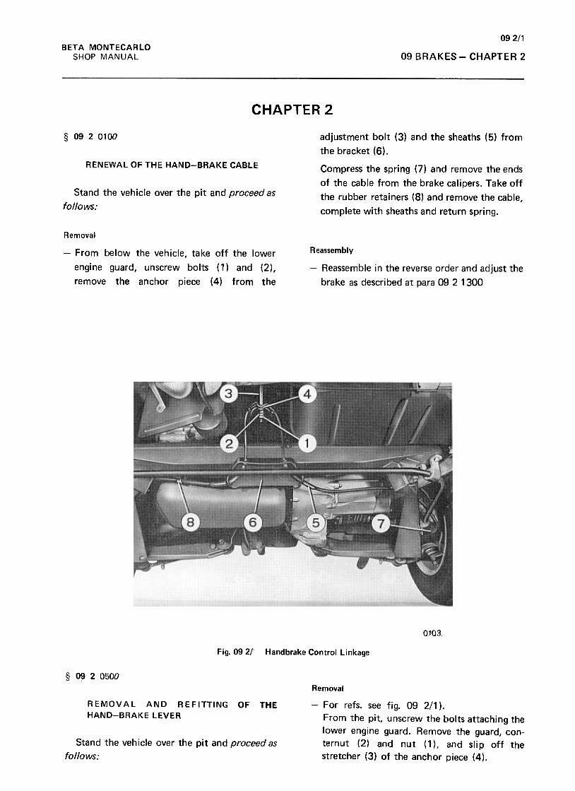
092/1BETA MONTECARLO
SHOP MANUAL 09 BRAKES -CHAPTER 2
CHAPTER 2
§ 0920100 adjustment bolt (3) and the sheaths (5) from
the bracket (6).
RENEWALOFTHEHAND-BRAKECABLE Compress the spring (7) and remove the ends
of the cable from the brake calipers. Take off
the rubber retainers (8) and remove the cable,
complete with sheaths and return spring.
Stand the vehicle over the pit and proceed as
follows:
Removal
Reassembly-From below the vehicle, take off the lower
engine guard, unscrew bolts (1) and (2),
remove the anchor piece (4) from the
-Reassemble in the reverse order and adjust the
brake as described at para 09 2 1300
0103
Fig. 092/' Handbrake Control Linkage
§ 0920500
REMOVAL AND REFITTING
HAND-BRAKELEVEROF THE
Removal
-For refs. see fig. 09 2/1 ).
From the pit, unscrew the bolts attaching the
lower engine guard. Remove the guard, con-
ternut (2) and nut (1 ), and slip off the
stretcher (3) of the anchor piece (4).
Stand the vehicle over the pit and proceed as
follows:
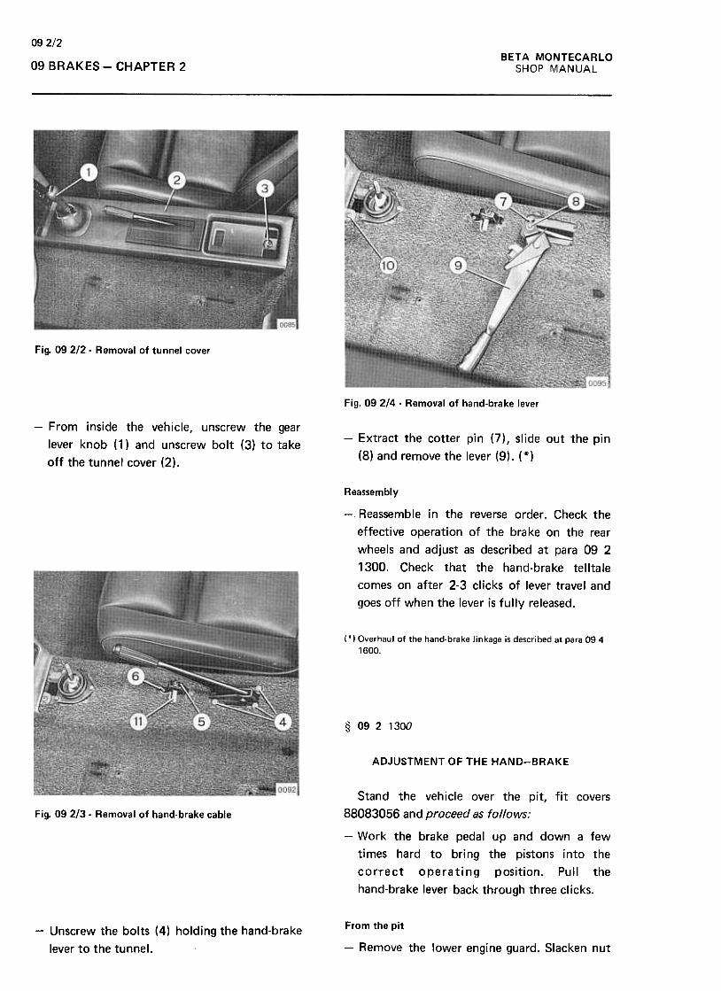
09 2/2
BETA MONTECARLO
SHOP MANUAL09 BRAKES -CHAPTER 2
Fig. 09212- Removal of tunnel cover
Fig. 09 2/4 -Removal of hand-brake lever
-From inside the vehicle, unscrew the gear
lever knob (1) and unscrew bolt (3) to take
off the tunnel cover (2).
-Extract the cotter pin (7), slide out the pin
(8) and remove the lever (9). (*)
Reassembly
-Reassemble in the reverse order. Check the
effective operation of the brake on the rear
wheels and adjust as described at para 09 2
1300. Check that the hand-brake telltale
comes on after 2-3 clicks of lever travel and
goes off when the 1ever is fully released.
(*) Overhaul of the hand-brake linkage is described at para 0941600.
§ 0921300
ADJUSTMENT OF THE HAND-BRAKE
Fig. 09 2/3- Removal of hand-brake cable
Stand the vehicle over the pit, fit covers
88083056 and proceed as follows:
-Work the brake pedal up and down a few
times hard to bring the pistons into the
correct operating position. Pull the
hand-brake lever back through three clicks.
From the pit-Unscrew the bolts (4) holding the hand-brake
lever to the tunnel. -Remove the lower engine guard. Slacken nut
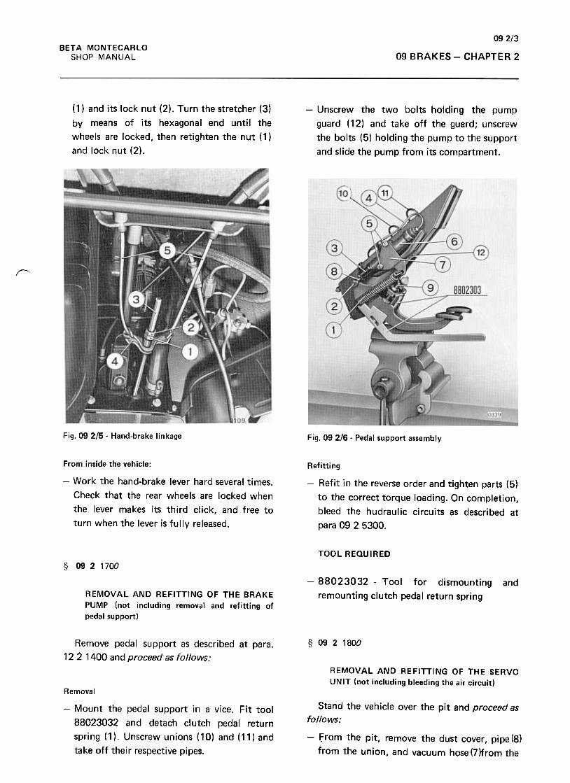
09 2/3
BETA MONTECARLO
SHOP MANUAL 09 BRAKES -CHAPTER 2
(1) and its lock nut (2). Turn the stretcher (3)
by means of its hexagonal end until the
wheels are locked, then retighten the nut ( 1 )
and lock nut (2).
-Unscrew the two bolts holding the pump
guard (12) and take off the guard; unscrew
the bolts (5) holding the pump to the support
and slide the pump from its compartment.
~
Fig. 09 2/5- Hand-brake linkage Fig. 09 2/6 -Pedal support assembly
From inside the vehicle:
-Work the hand-brake lever hard several times.
Check that the rear wheels are locked when
the lever makes its third click, and free to
turn when the lever is fully released.
Refitting
-Refit in the reverse order and tighten parts (5)
to the correct torque loading. On completion,
bleed the hudraulic circuits as described at
para 09 2 5300.
TOOL REaulRED
§ 0921700
-88023032 -Tool for dismounting
remounting clutch pedal return spring
and
REMOVAL AND REFITTING OF THE BRAKE
PUMP (not including removal and refitting of
pedal support)
§ 0921800Remove pedal support as described at para.
12 2 1400 and proceed as follows:
REMOVAL AND REFITTING OF THE SERVOUNIT (not including bleeding the air circuit)
Stand the vehicle over the pit and proceed as
follows:
Removal
-Mount the pedal support in a vice. Fit tool
88023032 and detach clutch pedal return
spring (1 ). Unscrew unions (10) and (11) and
take off their respective pipes.
-from the pit, remove the dust cover, pipe (8)
from the union, and vacuum hose (7)from the

092/4BETA MONTECARLO
SHOP MANUAL09 BRAKES -CHAPTER 2
Removal
-For refs. see fig. 09 2/7,
-From the pit, remove the dust apron,
electrical lead (1) and the four brake fluid
pipe unions (2). Collect the fluid. Unscrew
bolt (4) and take off the indicator (3).
servo 6. Unscrew the three nuts 5 holding the
servo on the bracket of the support and slide
off the support.
Remove pipe 9 from the union and take off
the servo.
Refitting
-Remount the new indicator in the reverse
order and tighten the four unions (2).
(*) Bleeding the brake circuit is described at para 0925300.
§ 0922200
REMOVAL, ADJUSTMENT AND REFITTING
OF THE BRAKE PEDAL (not including removal
and refitting of the pedal support)
Fig. 09 217- Servo unit and brake fluid pressure drop
indicator Remove pedal support as described at para 12
2 1400 and proceed as follows;
Removal
Refitting
Remount the new servo in the reverse order
and bleed the brake circuit as described at
para 09 2 5300.
TOOL REQUIRED
-88051006 -Spanner for brake pipe unions
§ 09 2 1840
REMOVAL AND REFITTING OF BRAKE
FLUID PRESSURE DROP INDICATOR (not
including bleeding the circuit) (*)
Stand the vehicle over the pit and proceed as
follows:
Fig. 09 2/8 -Servo unit and brake fluid pressure drop
indicator .
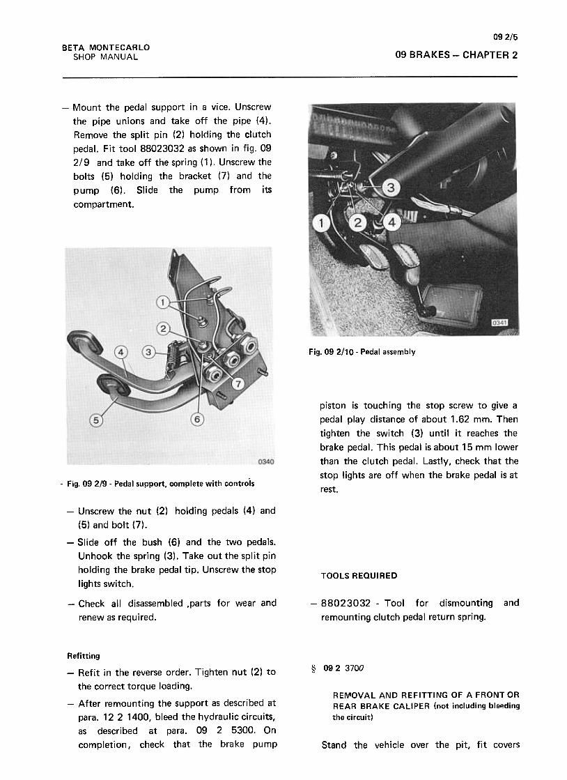
09 2/5BETA MONTECARLO
SHOP MANUAL 09 BRAKES -CHAPTER 2
-Mount the pedal support in a vice. Unscrew
the pipe unions and take off the pipe (4).
Remove the split pin (2) holding the clutch
pedal. Fit tool 88023032 as shown in fig. 09
2/9 and ta ke off the spri ng ( 1 ) .U nscrew the
bolts (5) holding the bracket (7) and the
pump (6). Slide the pump from its
compartment.
Fig. 09 2110. Pedal assembly
piston is touching the stop screw to give a
pedal play distance of about 1.62 mm. Then
tighten the switch (3) until it reaches the
brake pedal. This pedal is about 15 mm lower
than the clutch pedal. Lastly, check that the
stop lights are off when the brake pedal is at
rest.-Fig. 09 2/9 -Pedal support, complete with controls
-Unscrew the nut (2) holding pedals (4) and
(5) and bolt (7).
-Slide off the bush (6) and the two pedals.
Unhook the spring (3). Take out the split pin
holding the brake pedal tip. Unscrew the stop
lights switch.TOOLS REQUIRED
-Check all disassembled ,parts for wear and
renew as required.
-88023032 -Tool for dismounting
remounting clutch pedal return spring.
and
§ 09 2 3700
RE~OVAL AND REFITTING OF A FRONT OR
REAR BRAKE CALIPER (not including bleF!ding
the circuit)
Refitting
-Refit in the reverse order. Tighten nut (2) to
the correct torque loading.
-After remounting the support as described at
para. 122 1400, bleed the hydraulic circuits,
as described at para. 09 2 5300. On
completion, check that the brake pump Stand the vehicle over the pit, fit covers
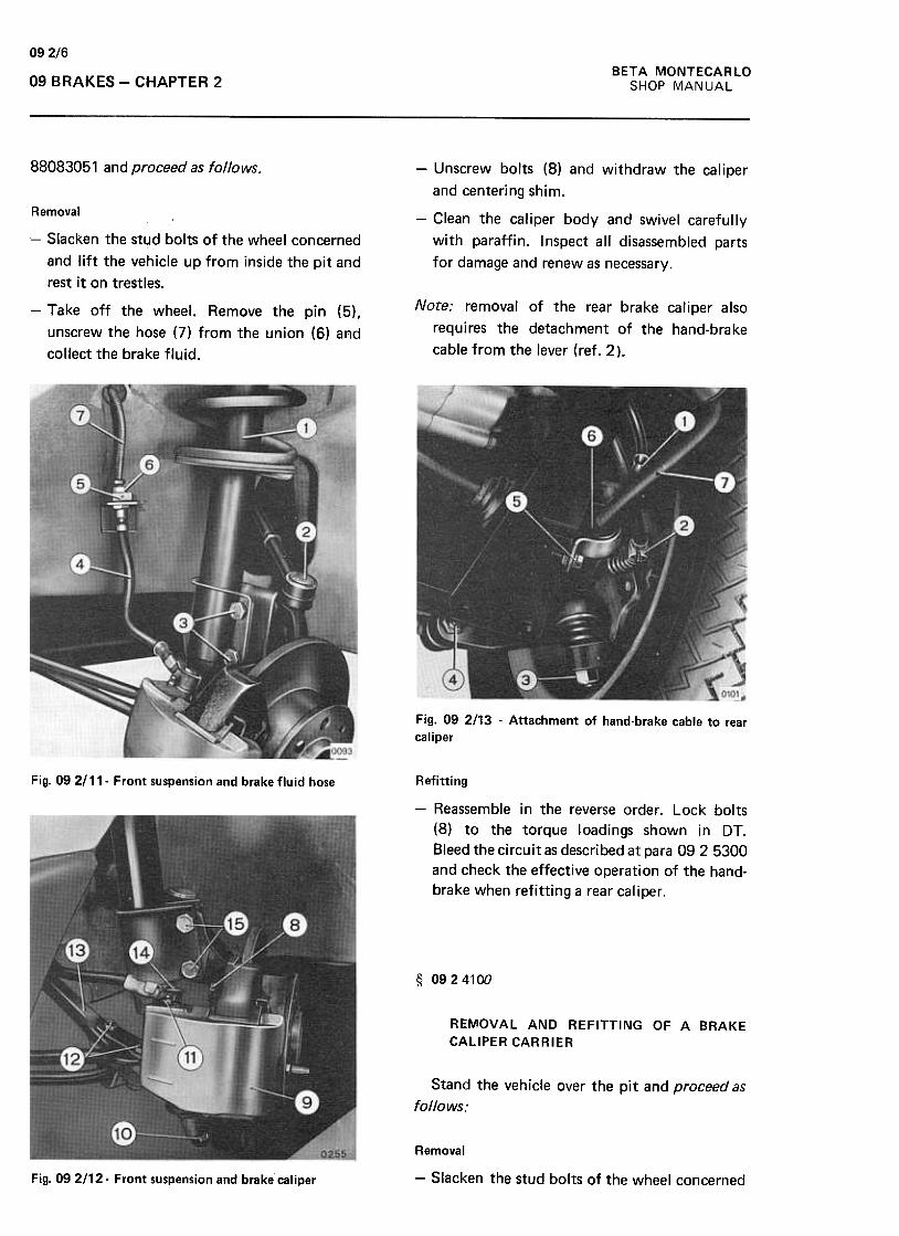
09 2/6
BETA MONTECARLO
SHOP MANUAL09 BRAKES -CHAPTER 2
88083051 and proceed as follows. -Unscrew bolts (8) and withdraw the caliper
and centering shim.
-Clean the calipey body and swivel carefully
with paraffin. Inspect all disassembled parts
for damage and renew as necessary.
Note: removal of the rear brake caliper also
requires the detachment of the hand-brake
cable from the lever (ref. 2).
Removal
-Slacken the stud bolts of the wheel concerned,
and lift the vehicle up from inside the pit and
rest it on trestles.
-Take off the wheel. Remove the pin (5),
unscrew the hose (7) from the union (6) and
collect the brake fluid.
Fig. 09 2113 -Attachment of hand-brake cable to rear
caliper
RefittingFig. 09 2111- Front suspension and brake fluid hose
-Reassemble in the reverse order. Lock bolts
(8) to the torque loadings shown in DT.
Bleed the circuit as described at para 0925300
and check the effective operation of the hand-
brake when refitting a rear caliper.
§ 0924100
REMOVAL AND REFITTING OF A BRAKE
CALIPER CARRIER
Stand the vehicle over the pit and proceed as
follows:
Fig. 09 2/12- Front suspension and brake caliper
Removal
-Slacken the stud bolts of the wheel concerned

092/7BETA MONTECARLO
SHOP MANUAL 09 BRAKES -CHAPTER 2r-
and lift the vehicle up from inside the pit and
rest it on trestles.
-Take off the wheel and follow the sequence
of operations shown in the photos below.
Collect the brake fluid.
r
Fig. 09 2/16- Removal of retainer pad
Fig. 092/14 -Removal of brake fluid hose from union
r
Fig. 09 2117. Front caliper carrier
Note: removal of a rear carrier also requires the
detachment of the hand-brake cable from the
lever (ref. 2 in fig. 092/13) and disconnection
of the fluid hose from the caliper instead of
the underbody bracket. Overhaul of the
carrier is described at para. 09 4 0800 & 1000r-,
Refitting
-Refit in the reverse order. Bleed the circuit
involved as described at para 09 2 5300, and
.
Fig. 092/15 Withdrawal of friction pads cotter
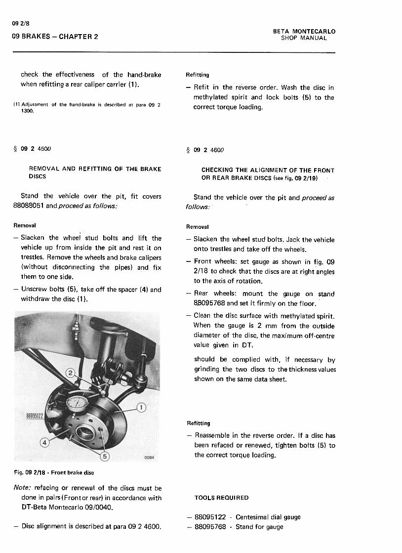
BETA MONTECARLO
SHOP MANUAL
09 2/8
09 BRAKES -CHAPTER 2
check the effectiveness of the hand-brake
when refitting a rear caliper carrier (1 ).
Refitting
-Refit in the reverse order. Wash the disc in
methylated spirit and lock bolts (5) to the
correct torque loading.(1) Adjustment of the hand-brake is described at para 09 21300.
§ 0924500 § 0924600
REMOVAL AND REFITTING OF THE BRAKE
DISCSCHECKING THE ALIGNMENT OF THE FRONT
OR REAR BRAKE DISCS (see fig. 092!19)
Stand the vehicle over the pit, fit covers
88088051 and proceed as follows;Stand the vehicle over the pit and proceed as
follows:
Removal
-Slacken the wheel stud bolts and lift the
vehicle up from inside the pit and rest i.t on
trestles. Remove the wheels and brake calipers
(without disconnecting the pipes) and fix
them to one side.
-Unscr~w bolts (5), take off the spacer (4) and
withdraw the disc (1 ).
Removal
-Slacken the wheel stud bolts. Jack the vehicle
onto trestles and take off the wheels.
-Front wheels: set gauge as shown in fig. 09
2/18 to check that the discs are at right angles
to the axis of rotation.
-Rear wheels: mount the gauge on stand
8.8095768 and set it firmly on the floor.
-Clean the disc surface with methylated spirit.
When the gauge is 2 mm from the outside
diameter of the disc, the maximum off-centre
value given in DT.
should be complied with, if necessary by
grinding the two discs to the thickness values
shown on the same data sheet.
~
Refitting
-Reassemble in the reverse order. If a disc has
been refaced or renewed, tighten bolts (5) to
the correct torque loading.
Fig. 092118 -Front brake disc
Note: refacing or renewal of the discs must be
done in pairs (Frontor rear) in accordance with
DT -Beta Montecarlo 09/0040.
TOOLS REQUIRED
-88095122 -Centesimal dial gauge
-88095768 -Stand for gauge-Disc alignment is described at para 09 2 4600.
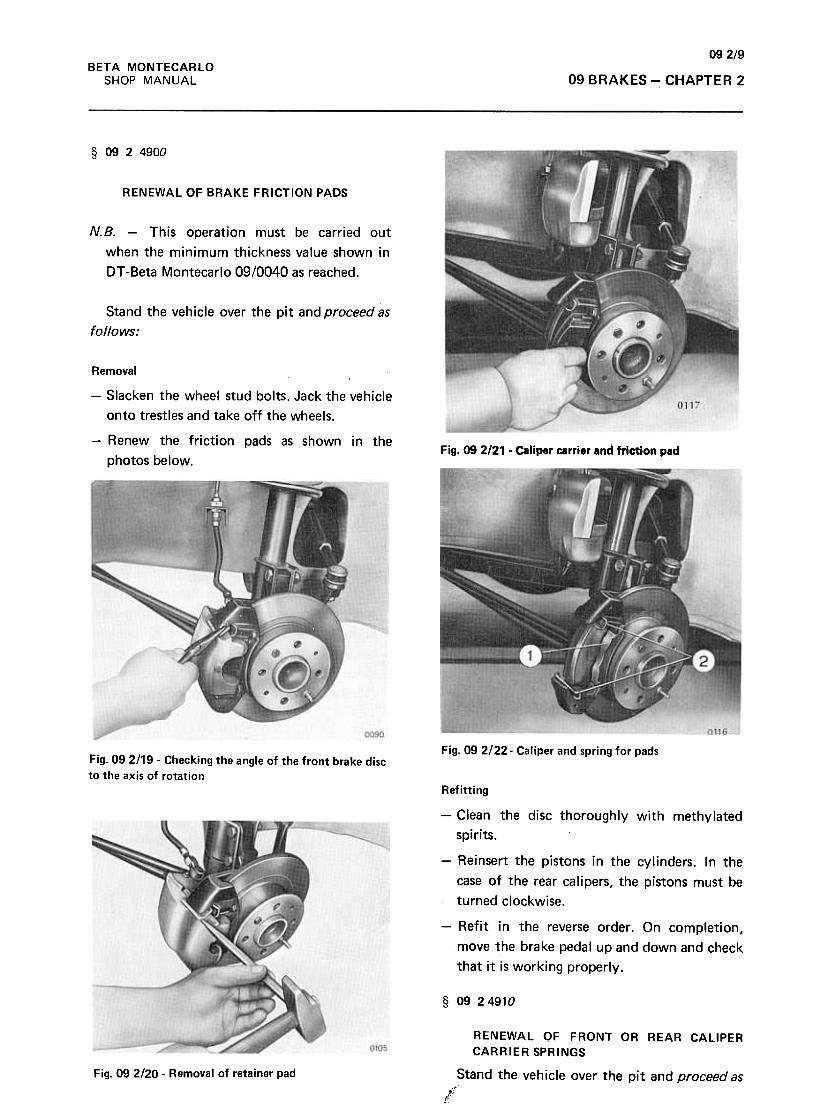
09 2/9
BETA MONTECARLO
SHOP MANUAL 09 BRAKES -CHAPTER 2
§ 0924900
RENEWAL OF BRAKE FRICTION PADS
N.B. -This operation must be carried out
when the minimum thickness value shown in
DT -Beta Montecarlo 09/0040 as reached.
Stand the vehicle over the pit and proceed as
follows:
Removal
-Slacken the wheel stud bolts. Jack the vehicle
onto trestles and take off the wheels.
-Renew the friction pads as shown in the
photos below.Fig. 09 2121 .Caliper carrier and friction pad
Fig. 09 2122- Caliper and spring for padsFig. 09 2119 -Checking the angle of the front brake disc
to the axis of rotation
Refitting
-Clean the disc thoroughly with methylated
spirits.
-Reinsert the pistons in the cylinders. In the
case of the rear calipers, the pistons must be
turned clockwise.
-Refit in the reverse order. On completion,
move the brake pedal up and down and check
that it is working properly.
§ 09 24910
Fig. 09 2/20 -Removal of retainer pad
RENEWAL OF FRONT OR REAR CALIPER
CARRIER SPRINGS
Stand the vehicle over the pit and proceed asJC
K:t
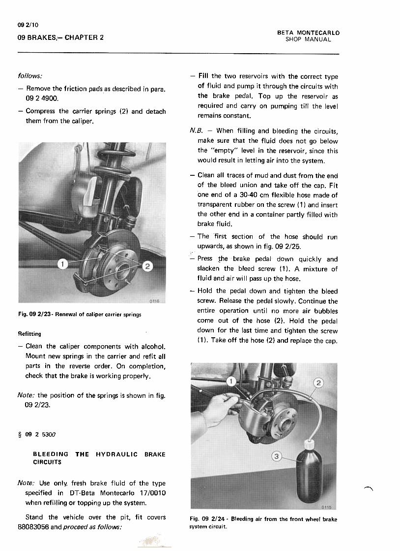
092/1 0
BETA MONTECARLO
SHOP MANUAL09 BRAKES,- CHAPTER 2
-Fill the two reservoirs with the correct type
of fluid and pump it through the circuits with
the brake pedal. Top up the reservoir as
required and carryon pumping till the level
remains constant.
follows:
-Remove the friction pads as described in para.
09 2 4900.
-Compress the carrier springs (2) and detach
them from the caliper.
N.B. -When filling and bleeding the circuits,
make sure that the fluid does not go below
the "empty" level in the reservoir, since this
would result in letting air into the system.
-Clean all traces of mud and dust from the end
of the bleed union and take off the cap. Fit
one end of a 30-40 cm flexible hose made of
transparent rubber on the screw (1) and insert
the other end in a container partly filled with
brake fluid.
-The first section of the hose should run
upwards, as shown in fig. 09 2/25.
-Press !he brake pedaj down quickly and
slacken the bleed screw ( 1) .A mixture of
fluid and air will pass up the hose.
-Hold the pedal down and tighten the bleed
screw. Release the pedal slowly. Continue the
entire operation until no more air bubbles
come out of the hose (2). Hold the pedal
down for the last time and tighten the screw
(1 ). Take off the hose (2) and replace the cap.
Fig. 09 2!23. Renewal of cal iper carrier spri ngs
Refitting
-Clean the caliper components with alcohoJ.
Mount new springs in the carrier and refit all
parts in the reverse order. On completion,
check that the brake is working properly.
Note: the position of the springs is shown in fig.
09 2123.
§ 09 2 5300
BLEEDING
CIRCUITS
THE HYDRAULIC BRAKE
Note: Use onl~ fresh brake fluid of the type
specified in DT -Beta Montecarlo 17 10010
when refilling or topping up the system.
"
Stand the vehicle over the pit, fit covers
88083056 and proceed as follows:Fig. 09 2!24 -Bleeding air from the front wheel brake
system circuit.
092/11BETA MONTECARLO
SHOP MANUAL 09 BRAKES- CHAPTER 2
-Top up the reservoirs if necessary.
-Work the brake pedal at its nqrmal braking
force for 2-3 min and check the entire system
for leaks.
-Repeat these operations on the other brake
calipers. On each occasion, make sure that
there is enough fluid in the reservoir .
-If a certain degree of sponginess remains when
the brake pedal is pressed down after all four
circuits have been bled, the entire operation
will have to be repeated on the four bleed
screws.
TOOLS REQUIRED
-88083051 -Covers
-88083056

094/1BETA MONTECARLO
SHOP MANUAL 09 BRAKES -CHAPTER 4
CHAPTER 4
§ 0940100
OVERHAUL OF THE MASTER CYLINDER (noti ncluding removal and refitting the pedal
assembly)
Remove the cylinder as described at para. 09
2 1700 and proceed as follows:
-From inside the body: take out the piston
return spring (9), the cup (12), the spring
(10), the cylinder seal (13), the spacer (26),
the piston (11 ), the floating spacer (8), the
washer ( 15) , the piston return spring ( 18) , the
cup (19), the spring (20), the seal (22), the
spacer (25), the piston (21) and the seal (23).
-Check that the pistons s lide freely in the
cylinder and that the inside of the pump body
and the outside of the pistons have a shiny
surface and are free from scratches, etc.
-Replace if necessary.
Refitting
-Reassemble the pistons. Renew the seals if
necessary. Replace the front circuit parts in
the cylinder in the reverse order. Tighten the
piston by means of bolt (24) and repeat these
operations for the back cylinder.
-On completion, check that the cylinder and
its circuits work properly and bleed the
braking system (1)
Fig. 09 4/1 -Master cylinder
-Mount the cylinder in a lead-jawed vice.
Remove connections (4) and (6) and pipe
unions (5) and (7). Unscrew the stop screws
( 16) and (24) , the locking plug and washer ( 1 )
and the guard (3).(1) Bench testing of the master cylinder is dealt with at para
16.4.5500.
(2) (3)~15 (&) T \8) l;i9 ! 10 !1 ,
I I I F:" "! 1
II
-F'i" .///
,'
G
" '"
\~/f\(!!J ~~
Fig. 09412 -Section of master cylinder
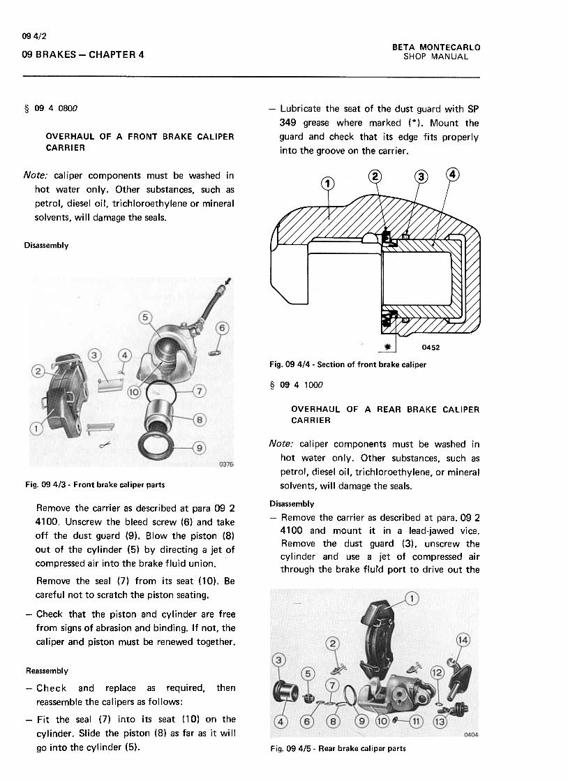
09 4/2
BETA MONTECARLO
SHOP MANUAL09 BRAKES -CHAPTER 4
§ 0940800 ~ Lubricate the seat of the dust guard with SP
349 grease where marked (*), Mount the
guard and check that its edge fits properly
into the groove on the carrier .
OVERHAUL OF A FRONT BRAKE CALIPER
CARRIER
Note: caliper components must be washed in
hot water only. Other substances, such as
petrol, diesel oil, trichloroethylene or mineral
solvents, will damage the seals.
Disassembly
§ 0941000
OVERHAUL OF A REAR BRAKE CALIPER
CARRIER
Note: caliper components must be washed in
hot water on Iy .Other substances, such as
petrol, diesel oil, trichloroethylene, or mineral
solvents, will damage the seals.Fig. 09413- Front brake caliper parts
Disassembly
-Remove the carrier as described at para. 092
4100 and mount it in a lead-jawed vice.
Remove the dust guard (3), unscrew the
cylinder and use a jet of compressed air
through the brake flufd port to drive out the
Remove the carrier as described at para 09 2
4100. Unscrew the bleed screw (6) and take
off the dust guard (9). Blow the piston (8)
out of the cylinder (5) by directing a jet of
compressed air into the brake fluid union.
Remove the seal (7) from its seat (10). Be
careful not to scratch the piston seating.
-Check that the piston and cylinder are free
from signs of abrasion and binding. If not, the
caliper and piston must be renewed together .
Reassembly
-Check and replace as required, then
reassemble the calipers as follows:
-Fit the seal (7) into its seat (10) on the
cylinder. Slide the piston (8) as far as it will
go into the cylinder (5). Fig. 09415 -Rear brake caliper parts
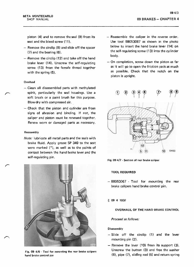
094/3BETA MONTECARLO
SHOP MANUAL 09 BRAKES -CHAPTER 4
-Reassemble the caliper in the reverse order.
Use tool 88053067 as shown in the photo
below to insert the hand brake lever ( 14) on
the self-regulating screw ( 13) into the cylinder
body.
piston (4) and to remove the seal (9) from its
seat and the bleed screw (11 ).
-Remove the circlip (8) and slide off the spacer
(7) and the bearing (6).
-'-Remove the circlip (12) and take off the hand
brake lever (14). Unscrew the self-regulating
screw (13) from the female thread together
with the spring (5).
-On completion, screw down the piston as far
as it will go to open the friction pads as much
as possible. Check that the notch on the
piston is upright.
~~Cf~~CP"~G)~
Overhaul
-Clean all disassembled parts with methylated
spirit, particularly the seal housings. Use a
soft brush or a paint brush for this purpose.
Blowdry with compressed air.
-Check that the piston and cylinder are from
signs of abrasion and binding. If not, the
caliper and piston must be renewed together.
Renew worn or damaged parts as necessary.
Reassembly
Note: lubricate all metal parts and the seals with
brake fluid. Apply grease SP 349 to the seat
were marked (*), as well as to the points of
contact between the hand brake lever and the
self-regulating pin.Fig. 09 4/7 -Section of rear brake caliper
r
TOOL REQUIRED
-88053067 -Tool for mounting the rear
brake calipers hand brake control pin.
§ 0941600
OVERHAUL OF THE HAND BRAKE CONTROL
Proceed as follows:
~
Disassembly
-Slide off the circlip (1) and the lever
mounting pin (2),
-Remove the lever (10) from its support (3).
Unscrew the button (3) and free the washer
(8), pipe (7), sliding rod (5) and return springFig. 09 4/6 .Tool for mounting the rear brake calipers
hand brake control pin

094/4BETA MONTECARLO
SHOP MANUAL09 BRAKES -CHAPTER 4
(6), and the toothed sector (4). Overhaul
Check all parts and renew as necessary if worn
or damaged.
Reassembly
-Reassemble in the reverse order. Grease the
toothed sector .
-On completion, check that the sector and
sliding rod work properly.Fig. 09 418 -Hand brake lever

SEC 10
Air System
Air compressors - Tanks - Valves - Pipes - Units
(Not Fitted to This Vehicle)

SEC 11
Frame
Frame or subframes for mechanical assemblies
(Not Fitted to This Vehicle)

BETA MONTECARLO
SHOP MANUAL 12 STEERINGContents
STEERING GROUP CONTENTS
CHAPTER 1
Troubles, probable causes, checkings and operations to be carried out
from page 121/1
to page 121/3
CHAPTER 2
page§ 122 1000 Removal and refitting of the steering wheel. § 122 1300 Removal and refitting of jointed steering column jacket. § 12 2 1400 Removal and refitting of pedal support assembly. § 122 1600 Removal and refitting of jointed steering column from and on its jacket
§ 1221700 Renewal of jointed section of steering column. ...
§ 12 2 1900 Removal and refitting the anti-theft steering wheel lock .
§ 1222500 Removal and refitting of rack housing. ...
§ 1223900 Renewal of a (right, or left) steering rod ball joint. ...
§ 1224000 Removing and refitting a swivel.
CHAPTER 4
§ 1240300 Overhaul of rack housing page 12 4/1
22/1
22/1
22/1
22/2
22/2
22/3
22/3
22/4
22/5
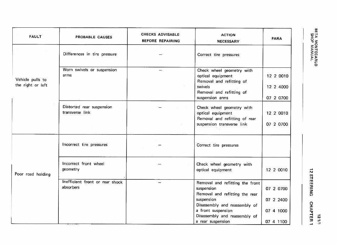
BE
TA
M
ON
TE
CA
RLO
w
~.J
zQ
) -
<t
a:(I)
--<
t>
Q
.c
w<
t a:
(I) w
~
a:u
Ow
I!.
~
wu
Q) >
2 C
I:O
~
-(/)1-
(/)U
W
~
UW2
1--':)<t
11.
(/)w(/)::>~uw-JID~IDOa:~
«a:«a,
(I)...:J"'"'(I)...0.(I)...
':;:.
c:"'(I)uc:~(I)
--3
"'aJ'-:J"'"'aJ'-0.
~0;:.+
-'uaJ'-'-0O
c:O'Vic:Q)
0."':J"''-0"'-0;>'~"'c:
"''-
E0
'-
:$: ca O..-0ONN
0-0)
~
...-0
:300 .c0)
0>U
0.:
:E
0)O
).c>
ooovNN
I~
--o o
~
CI
CI
C
CQ
)E
O
C'i=
'i=
Q)Q
),Q>
Q
)",C
I E
E
-c."tJ "tJ...
Q)
.-c c
roQ
) :J
.c 0"'
ro ro
c
~Q
)- -0
ro ro
.-
~ro>
.!!!.>~
UU
°Q)O
Q)
Q)
.+:;.
E
.~
E
c.
.CC
.Q)~
Q)~
Uoa:",a:",
oo, ON, 0
I:0°v;I:(1)c.(/)::!(/)
...~ro
I:(1)
0-
"0 ~
(1) ...
+"'
(1)...>0
(/)+
"' I:
.!!? ro
O
~ 0~o0NN
...(0..c:
Q)
+"'
...
.~
-~O
c>
=
...CI
+"'
C
Q)
Q)
.-V)
E+
"' ...
+"'
+"'
Q)
oc:;=>
Q)Q
)Q)V
)C
I E
...~
-a."C...
Q)
.-c +
"'
Q)
:J
..c:0-(Oc
>Q
)-o>
(0
.--
>V
)
~
(0 c
(.J (.J
0 Q
)
Q)
.~
E
a...c:a.Q
)V)
uoa:a
o0, 0N, 0
II)Q)
...:JII)II)Q)
...0.Q
)...
.~...uQ)
......Ouc (/)Q)
'-;j(/)(/)~0.
Q)
'-
.~+"'
uQ)
'-'-0O
aJaJ.I::~+
-'co'-
-+-'
>C
J '-
aJ +
-''-
aJ
a E
CJ
O-=
~
..c:+
"
.~>'-+"Q)
E
+'
O
t:Q
) Q
)
C)E
-c.Q)
.-Q
) :J
..c: C
":s:
Q)
~
rou
uQ
) .+
:...c:
c.u
o O.-00NN 12 ST
EE
RIN
G
0)~:0O..c.
"'0(00...
...000..,
~uO..c."''-roQ
)'-'-0+"'
c:o'--+
"'c:
"'Q
) '-
.-Q)
u..c.-'-:I:
oQ
) "'
c:..Cro oor-..ONr-..n
oo.qoNN""'"0
CH
AP
TE
R'
ooo~r-..o
+-'
c: '-
'f- -
0 co
0 0
'- Q
)-'-
>
>Q
) Q
) :c
:c£
£ E
E
Q)
Q)
CJ
CJ
"' "'
c: c:
"' "'
co co
+-'
+-'
Q)
c:Q
) +
-' +
-' '-
'-~
~
0
c:Q
) Q
) "0
.cn "0
0'-
'- c:
c: c:
.cn"0
"0 co
Q)
co c:
c: c:
>~
>~
co c:
co c:-
:J- "'
0 O
..C"'..C
:J";;;.-ro.-E
E
",'v"'
"' +
-'
>c:>
c:Q)c:Q
),-oQ
)oQ)~
o~co
E
a.E
a.co '-
CO
Q
)~
. "'
~.
"' "'
-"' '-
~
~
:J (!:~
(!:",Qm
Q~
12 1/1
oo..-..-~1"'-0
SH
OP
M
AN
UA
L
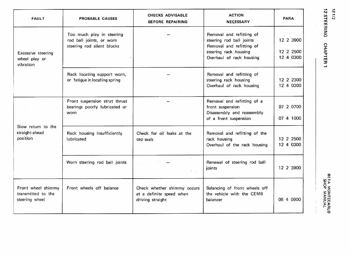
12 S
TE
ER
ING
121/2w
~..J
zQ
J -
~
0:(/)
--~>
~c
w~
0:
(/) w
~
0:u
Ow
LL
~
W(.J
m >a:z
«0
(/)-(/)1-
wu
u.«
w2
1--1::>«11.
(/)w(/):><t
uw-Jm<t
mO~~ «a:«0.
C)
c (/)
.~
c ~
QJ
'- t.)
QJ
0 0
+-'>
-(/)
>
..a
C
'- +
-'0
CQJ
>
,-(tJ
(/) .(j;
-+-'0.
.S
"'C0
0.c
'-t.)~
=C
)E
(tJ c
..a .-'-
0 "'C
~
00+-,
1- '-
"'
o00")(V
)
NN
CH
AP
TE
R'
--C)
o o
CC
/I .c;;
C)'E
C)C
)~C
.-C
-0
.-0
+-'
+-'
~
C/I
~---
o~
(l) -(l)
u'-
co '-
..c co
..c ,
'-"'C
"'C
~c"'C
cubcoococo'-
'-
coC)coC
)~>
c>cco
O
.-0 c
E'-
E'-'-
(l) (l)
(l)
(l) (l)
(l) (l)
>
a:~a:~
o
0000L!)(")N
O
N","
NN0)c:
°~Q)
'-Q
) 0
+"'
(I) >ca
Q)
-c:.~
a.
0(I)
0-(1)-+
",Q
)Q)ca
uQ),-
x..C:..0
w
~
0:;-
-C)
O
c:
..Cii
C)-::]
c: 0
.-c: -
+"
.-~+
" cn
.-::]-
O~
(l) u
c: ro...
-g~-
ro16°...
""t:oC)::]
>
c: ro
O
c:
E
(l) (l)
(l) (l)
>
Cl:t:o
c:'-0 C
1~
.S'-a.
'- "'
0 C
1
a.c:a.
.-:J
~"'
U
C1..2
.S
c:C
O Q
JU
:J
0 C
1-.;J~
C
OU
'f-C
O
'-a:
o 0000(V)
(V)
NO
N~
NN
"' O
:J..."C..c
C1)
rou:J
.-c"'
:J
c:O
>.C
ii ~c:
0
~O
"' c.
:J "'
"' C
1
=
c:c: O
ro
O
...C1)
:>LL. ..c
:>
oor-..ONr-..o
co :?:
-..QO
EQ)
CI
C/)
~c:
C/)
'-.-C
O
O+
"' Q
) .-
+"'
'- C
/)'i=
c:
Q)
c: "'C
Q
)
'-Oc:a.
"'C
.iii C
O
~c:
c: C
/)Q
) >
CO
a.-+"'
C/)
..Q
c:
co:JEo
>C
/)Q)'-
0 C
/) -
E+
"' C
/)
c:coco
Q)
0 .~
a:'-a
-
-0
ooovr...o
Q)
..c:...0...
"Cc
ro'-
Q)
:J ..c:
...roQ
) ,
~'-
..c: O
:s: .~
:~O
ro
"'-'-
0(/)
t: Q
.
>"+:.
c(I)'u;;:'+
-:J"'c0>c'in:J-o0
(I)0!:
+-'
(0~
.~
u '-
(O.D
(l: :J
QJ
..c:+
-'
+-'
(0"'~(0Q
J
.0'-0'+-~
~
~u
"'Q
J a.
..c: (0
U
u 0000I.!)MN
O
NV
NN
Cl)
C)
.c .=
+-'
U)
-~o o.c
~
~.-u+
-' ro
+-'
...:;=C
l) C
l)c+
-'"'C
C
)c:
c: -
ro .-0U
)-~
-ro O
~
>
.c ro
O
.cE
~
'cj,
Cl)
u >
(I:~O
(0.0""0O'-01c:.~Q
)Q
)"'
-0(0~
"'Q
) c:
c:Q
) .-0(I:
.-
(I)+
-'I:
'0,-ro..0-0O...0)I:
'~Q)
Q)
+-'
(I)I:...os
oo0)(Y)
NN
BE
TA
M
ON
TE
CA
RLO
>E
wE
~.-+
-'~cn
O
-+
-' ww
~""0~
~w
$:$:
,E
01
+-,E
c:c:
cn ';:
oC:w
,-rowI.L.
'- +
-'"
(!)t)c:roro
-0'+-
'+-0(/I
(!)(!)
.!:5:c:0...
~ "'...:JuuO
c>
Q
)
E
~E.-"C.!:
Q)
"' Q
)c.
..."' +
-'Q
) .!:
.!: Q
) C
)+
-' +
-' .-
Q)
.-ro
.!:Cp
~
'i=
"'Q
)
~"C
~~
ro
.>.!:
.-
u~-c
--OaJ
.!!!.~a.lLUa.lU
..c:s:
a.I..c:
c:O..c:
'- -.-
-s:O
a.I
C)U
c: .-'-c:
a.IU
a.I
Uc:>
c:ro
ro-a.l-ro
..c: ro
aJ ~ oo0")0.".
00O
SH
OP
M
AN
UA
L
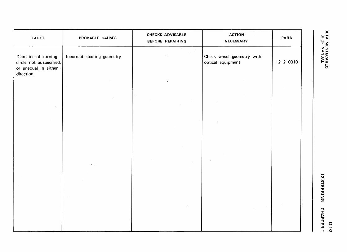
BE
TA
M
ON
TE
CA
RLO
w
"-J
z00
-<
t a:
(I) -
-<t
>
0..c
w<
t a:
~
M!
u O
w
u.~
w
u 00
>2
a:O
«
-cn1-
cnU
w
« UwZ
(/)w(/)::><
tuw-Jm<
tmOcx:Ii.,
«(I:«c..
1-..J:><t
IL
.c+-'
s:>'-+-'
Q)
E
+-'
O
c:Q
) Q
)C
>
E
-c.Q)
.-Q
) ~
.c C
"s:
Q)
~
(IJC
) C
)Q
) .~
.c c.
u c"C
...
CJ
.~
Q)
c:-..c:c:
u .-
...Q)
Q)
::] a.cn
c:cn
.--(00
-(0...0
::] c:
Q)c:C
"oQ
) .-
Q)Q
)c:t)E
-::]
Q)
(0 u
...
0 .u
a "'Q
>'-QJ
EoQJ
0)
0)c:".:Q
JQ
J<
I)
u~'-0uc:
O.--00NN
12 ST
EE
RIN
GC
HA
PT
ER
1
121/3
SH
OP
M
AN
UA
L
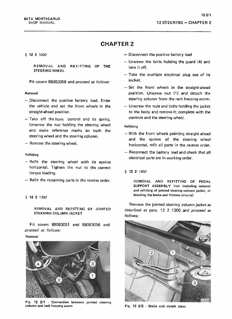
122/1BETA MONTECARLO
SHOP MANUAL 12 STEERING -CHAPTER 2
CHAPTER 2
§ 1221000
REMOVAL ANDSTEERING WHEEL
REFITTING OF THE
Fit covers 88083058 and proceed as follows:
Removal
-Disconnect the positive battery lead
-Unscrew the bolts holding the guard (4) and
take it off .
-Take the multiple electrical plug out of its
socket.
-Set the front wheels in the stralght-ahead
position. Unscrew nut (1) and detach the
steering column from the rack housing worm.
-Unscrew the nuts and bolts holding the jacket
to the body and remove. it; complete with the
controls and the steering wheel.
Refitting
-Disconnect the positive battery lead. Enter
the vehicle and set the front wheels in the
straight-ahead position.
-Take off the horn- control and its spring.
Unscrew the nut holding the steering wheel
and make reference marks on both the
steering wheel and the steering column.
-Remove the steering wheel.
-With the front wheels pointing straight ahead
and the spokes of the steering wheel
horizontal, refit all parts in the reverse order.
-Reconnect the battery lead and check that all
electrical parts are in working order.
§ 1221400
Refitting
-Refit the steering wheel with its spokes
horizontal. Tighten the nut to the correct
torque loading.
-Refit the remaining parts in the reverse order. REMOVAL AND REFITTING OF PEDAL
SUPPORT ASSEMBL y (not including removal
and refitting of jointed steering column jacket, or
bleeding the brake and friction circuits)§ 1221300
Remove the jointed steering column jacket as
described at para. 12 2 1300 and proceed as
follows:
REMOVAL AND REFITTING OF JOINTED
STEERING COLUMN JACKET
Fit covers 88083051 and 88083056 and
proceed as follows:
Removal
Fig. 12 211 -Connection between jointed steeringcolumn and rack housing worm Fig. 12 212 -Brake and clutch pipes
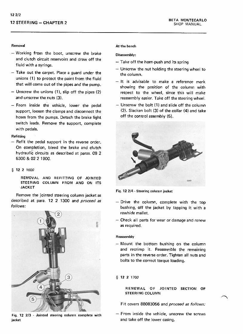
BETA MONTECARLO
SHOP MANUAL
122/2
12 STEERING -CHAPTER 2
At the bench
Disassembly:
-Take off the horn-push and its spring
-Unscrew the nut holding the steering wheel to
the column.
-It is advisable to make a reference mark
showing the position of the column with
respect to the wheel, since this will make
reassembly easier. Take off the steering wheel.
-Unscrew the bolt (1) and slide off the column
(2). Slacken bolt (3) of the collar (4) and take
off the control assembly (5).
Removal
-Working from the boot, unscrew the brake
and clutch circuit reservoirs and draw off the
fluid with a syringe.
-Take out the carpet. Place a guard under the
unions (1) to protect the paint from the fluid
that will come out of the pipes and the pump.
-Unscrew the unions (1 ), slip off the pipes (2)
and unscrew the nuts (3).
-From inside the vehicle, lower the pedal
support, loosen the clamps and disconnect the
hoses from the pumps. Detach the brake light
switch leads. Remove the support, complete
with pedals.
Refitting-Refit the pedal support in the reverse order .
On completion, bleed the brake and clutch
hydraulic circuits as described at paras. 09 2
5300 & 02 2 1900.
§ 1221600
REMOVAL AND REFITTING OF JOINTED
STEERING COLUMN FROM AND ON ITS
JACKETFig. 12214- Steering column jacket
Remove the jointed steering column jacket as
described at para. 12 2 1300 and proceed as
follows:-Drive the column, complete with the top
bushing, off the jacket by tapping it with a
rawhide mallet.
-Check all parts for wear or damage and renew
as required.
Reassembly
-Mount the bottom bushing on the column
and recrimp it. Reassemble the remaining
parts in the reverse order. Tighten all nuts and
bolts to the correct torque loading.
§ 1221700
RENEWAL OF JOINTED SECTION OF
STEERING COLUMN~
Fit covers 88083056 and proceed as follows:
-From inside the vehicle, unscrew the screws
and take off the lower casing.
Fig. 12 2/3 -Jointed steering column complete with
jacket
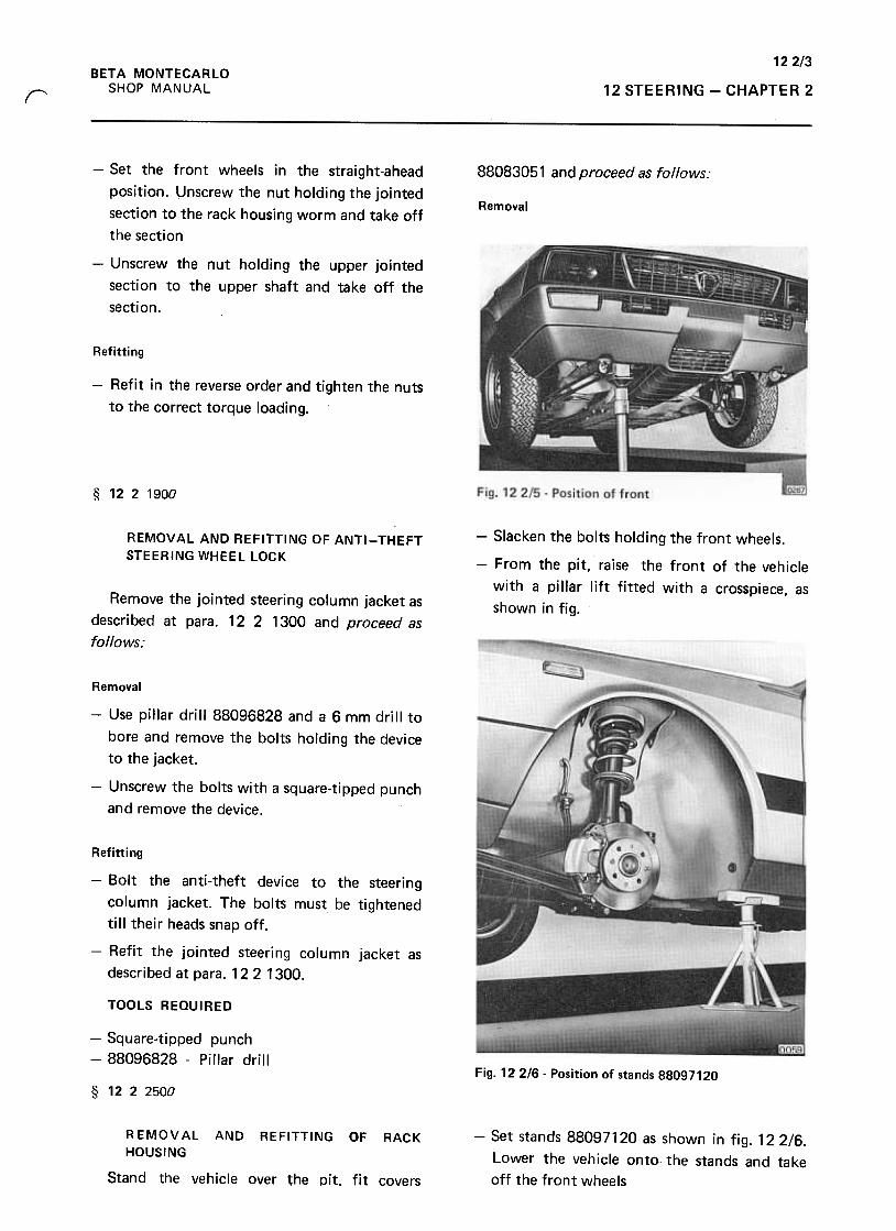
12 2/3BETA MONTECARLO
SHOP MANUAL 12 STEERING -CHAPTER 2r
88083051 and proceed as follows:
Removal
-Set the front wheels in the straight-ahead
position. Unscrew the nut holding the jointed
section to the rack housing worm and take off
the section
-Unscrew the nut holding the upper jointed
section to the upper shaft and take off the
section.
Refitting
-Refit in the reverse order and tighten the nuts
to the correct torque loading.
§ 1221900
REMOVAL AND REFITTING OF ANTI-THEFT
STEERING WHEEL LOCK
-Slacken the bolts holding the front wheels.
-From the pit, raise the front of the vehicle
with a pillar lift fitted with a crosspiece, as
shown in fig.Remove the jointed steering column jacket as
described at para. 12 2 1300 and proceed as
follows:
Removal
-Use pillar drill 88096828 and a 6 mm drill to
bore and remove the bolts holding the device
to the jacket.
-Unscrew the bolts with a square-tipped punch
and remove the device.
Refitting
-Bolt the anti-theft device to the steering
column jacket. The bolts must be tightened
till their heads snap off.
-Refit the jointed steering column jacket as
described at para. 12 2 1300.
TOOLS REQUIRED
-Square-tipped punch-88096828 -Pillar drill
Fig. 122/6- Position of stands 88097120
§ 1222500
-Set stands 88097120 as shown in fig. 12 2/6.
Lower the vehicle onto the stands and take
off the front wheels
R EMOV AL AND REFITTING OF RACK
HOUSING
Stand the vehicle over ~he pit. fit covers
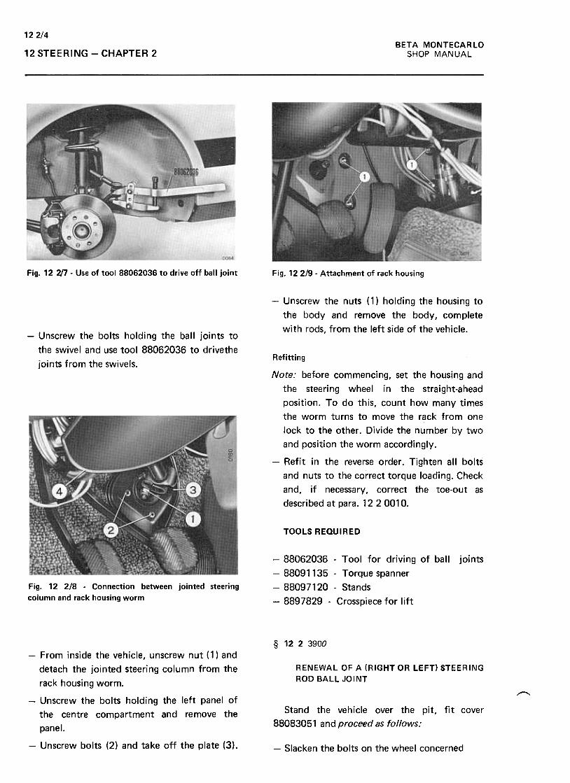
122/4BETA MONTECARLO
SHOP MANUAL12 STEERING -CHAPTER 2
Fig. 12 'JJ7 -Use of tool 88062036 to drive off ball joint Fig. 122/9- Attachment of rack housing
-Unscrew the nuts (1) holding the housing to
the body and remove the body, complete
with rods, from the left side of the vehicle.-Unscrew the bolts holding the ball joints to
the swivel and use tool 88062036 to drivethe
joints from the swivels.Refitting
Note: before commencing, set the housing and
the steering wheel in the straight-ahead
position. To do this, count how many times
the worm turns to move the rack from one
lock to the other. Divide the number by two
and position the worm accordingly.
-Refit in the reverse order. Tighten all bolts
and nuts to the correct torque loading. Check
and, if necessary, correct the toe-out as
described at para. 12 2 0010.
TOOLS REQUIRED
joints
Fig. 12 2/8 -Connection between jointed steering
column and rack housing worm
-88062036 -Tool for driving of ball
-88091135 -Torque spanner
-88097120 -Stands
-8897829 -Crosspiece for lift
§ 1223900
RENEWAL OF A (RIGHT OR LEFT) STEERING
ROD BALL JOINT
~
Stand the vehicle over the pit, fit cover
88083051 and proceed as follows:
-From inside the vehicle, unscrew nut (1) and
detach the jointed steering column from the
rack housing worm.
-Unscrew the bolts holding the left panel of
the centre compartment and remove the
panel.
-Unscrew bolts (2) and take off the plate (3). -Slacken the bolts on the wheel concerned
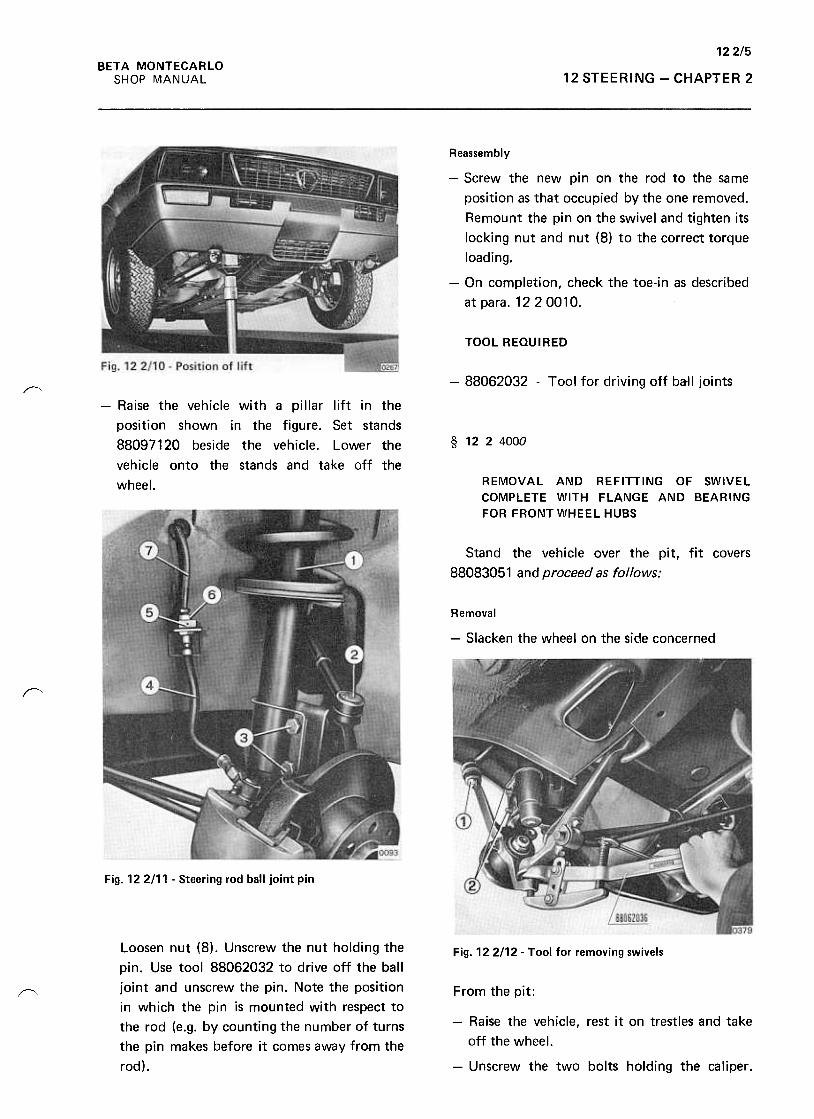
122/5BETA MONTECARLO
SHOP MANUAL 12 STEERING -CHAPTER 2
Reassembly
-Screw the new pin on the rod to the same
position as that occupied by the one removed.
Remount the pin on the swivel and tighten its
locking nut and nut (8) to the correct torque
loading.
-On completion, check the toe-in as described
at para. 1220010.
TOOL REQUIRED
-88062032 -Tool for driving off ball joints~
-Raise the vehicle with a pillar lift in the
position shown in the figure. Set stands
88097120 beside the vehicle. Lower the
vehicle onto the stands and take off the
wheel.
§ 1224000
REMOVAL AND REFITTING OF SWIVEL
COMPLETE WITH FLANGE AND BEARING
FOR FRONT WHEEL HUBS
Stand the vehicle over the pit, fit covers
88083051 and proceed as follows:
Removal
-Slacken the wheel on the side concerned
~
Fig. 12 2/11 -Steering rod ball joint pin
Loosen nut (8). Unscrew the nut holding the
pin. Use tool 88062032 to drive off the ball
joint and unscrew the pin. Note the position
in which the pin is mounted with respect to
the rod (e.g. by counting the number of turns
the pin makes before it comes away from the
rod).
Fig. 122112 -Tool for removing swivels
From the pit:r"'
-Raise the vehicle, rest it on trestles and take
off the wheel.
-Unscrew the two bolts holding the caliper.
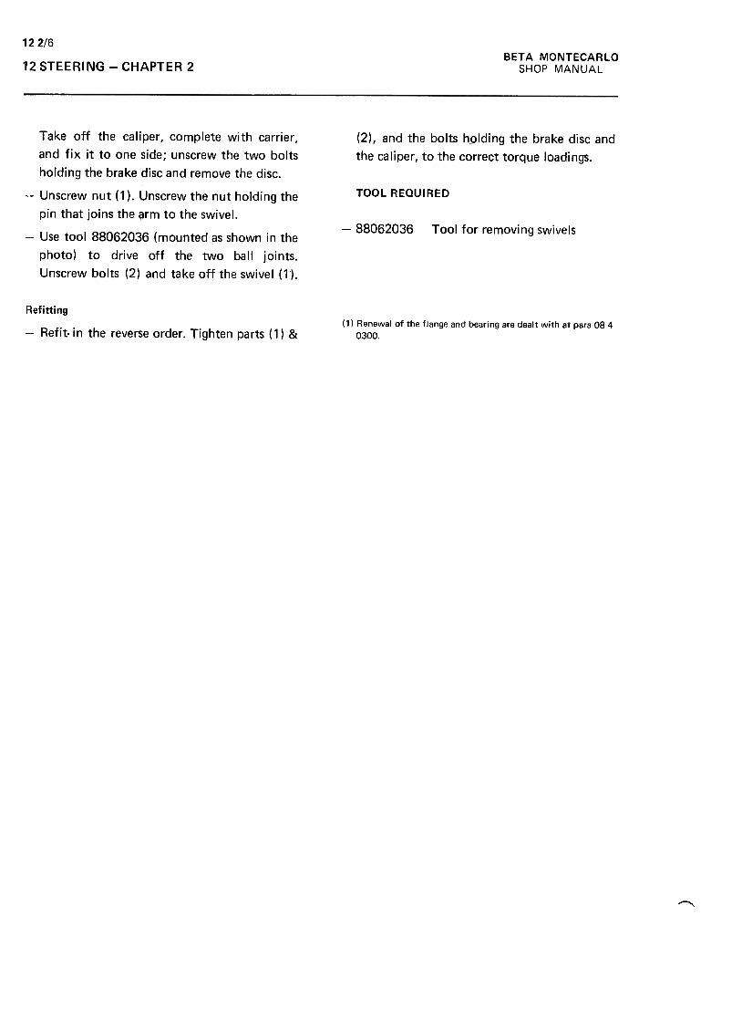
12 2/6BETA MONTECARLO
SHOP MANUAL12 STEERING -CHAPTER 2
(2) , and the bolts h-olding the brake disc and
the caliper, to the correct torque loadings.
TOOL REQUIRED
-88062036 Tool for removing swivels
Take off the caliper, complete with carrier,
and fix it to one side; unscrew the two bolts
holding the brake disc and remove the disc.
-Unscrew nut ( 1 ). Unscrew the nut holding the
pin that joins the arm to the swivel.
-Use tool 88062036 (mounted as shown in the
photo) to drive off the two ball joints.
Unscrew bolts (2) and take off the swivel (1),
( 1) Renewal of the flange and bearing are dealt with at para 084
0300.
Refitting
-Refit in the reverse order. Tighten parts (1) &
"""""
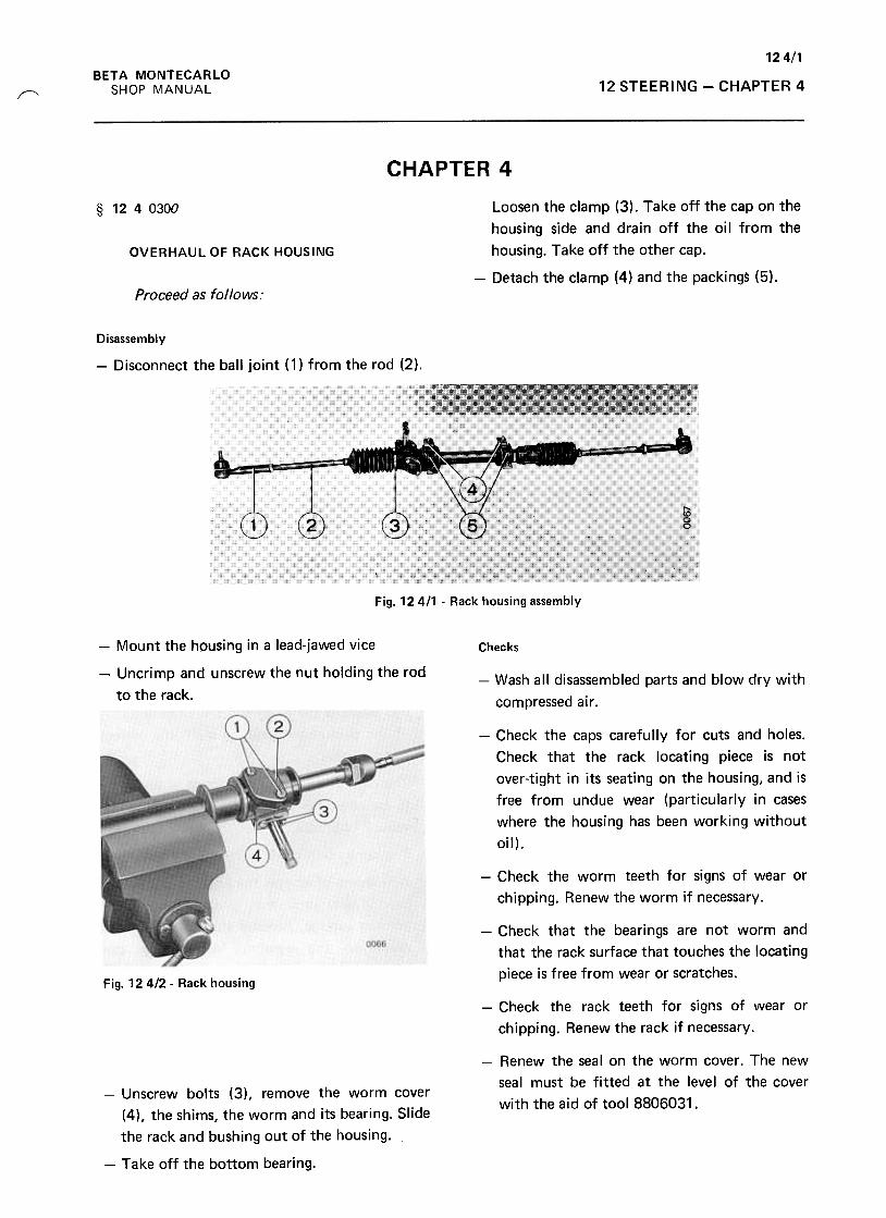
124/1
BETA MONTECARLO
SHOP MANUAL 12 STEERING -CHAPTER 4/"'
CHAPTER 4
§ 1240300
OVERHAUL OF RACK HOUSING
Loosen the clamp (3). Take off the cap on the
housing side and drain off the oil from the
housing. Take off the other cap.
-Detach the clamp (4) and the packings (5).Proceed as follows:
Disassembly
-Disconnect the ball joint (1) from the rod (2),
Fig. 12 4/1 -Rack housing assembly
Checks-Mount the housing in a lead-jawed vice
-Uncrimp and unscrew the nut holding the rod
to the rack.-Wash all disassembled parts and blow dry with
compressed air .
-Check the caps carefully for cuts and holes.
Check that the rack locating piece is not
over-tight in its seating on the housing, and is
free from undue wear (particularly in cases
where the housing has been working without
oil).
-Check the worm teeth for signs of wear or
chipping. Renew the worm if necessary.
-Check that the bearings are not worm and
that the rack surface that touches the locating
piece is free from wear or scratches.Fig. 12 412 -Rack housing
-Check the rack teeth for signs of wear or
chipping. Renew the rack if necessary.
-Renew the seal on the worm cover. The new
seal must be fitted at the level of the cover
with the aid of tool 8806031.-Unscrew bolts (3), remove the worm cover
(4), the shims, the worm and its bearing. Slide
the rack and bushing out of the housing.
-Take off the bottom bearing.
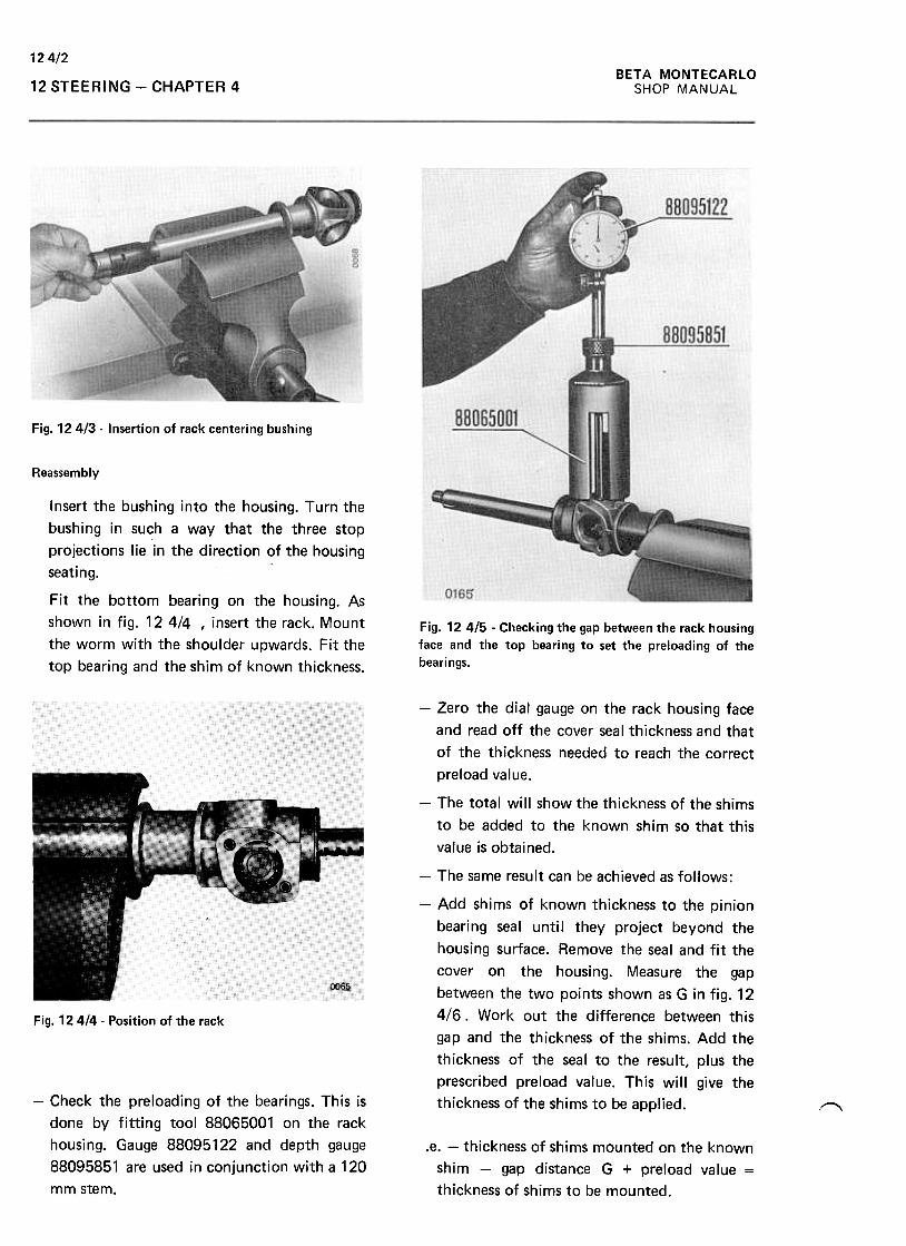
124/2BETA MONTECARLO
SHOP MANUAL12 STEERING -CHAPTER 4
Fig. 124/3. Insertion of rack centering bushing
~
Reassembly
Insert the bushing into the housing. Turn the
bushing in such a way that the three stop
projections lie in the direction of the housing
seating.
Fit the bottom bearing on the housing. As
shown in fig. 12 414 , insert the rack. Mount
the worm with the shoulder upwards. Fit the
top bearing and the shim of known thickness.
Fig. 12 4/5 -Checking the gap between the rack housing
face and the top bearing to set the preloading of the
bearings.
-Zero the dial gauge on the rack housing face
and read off the cover seal thickness and that
of the thickness needed to reach the correct
preload value.
-The total will show the thickness of the shims
to be added to the known shim so that this
value is obtained.
-The same result can be achieved as follows:
-Add shims of known thickness to the pinion
bearing seal until they project beyond the
housing surface. Remove the seal and fit the
cover on the housing. Measure the gap
between the two points shown as G in fig. 12
4/6. Work out the difference between this
gap and the thickness of the shims. Add the
thickness of the seal to the result, plus the
prescribed preload value. This will give the
thickness of the shims to be applied.
Fig. 12 414 -Position of the rack
-Check the preloading of the bearings. This is
done by fitting tool 88065001 on the rack
housing. Gauge 88095122 and depth gauge
88095851 are used in conjunction with a 120
mm stem.
~
.e. -thickness of shims mounted on the known
shim -gap distance G + preload value =
thickness of shims to be mounted.
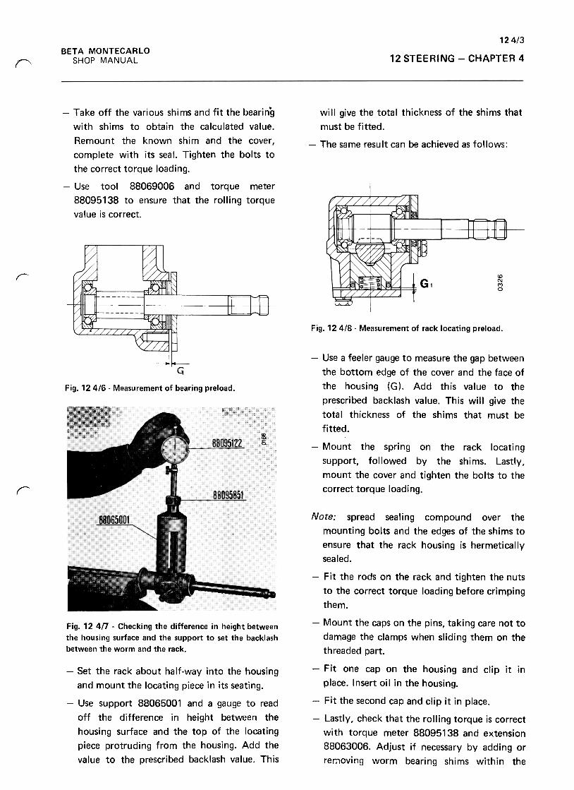
12 4/3BETA MONTECARLO
SHOP MANUAL 12 STEERING -CHAPTER 4r
will give the total thickness of the shims that
must be fitted.
-The same result can be achieved as follows:
-Take off the various shims and fit the bearing
with shims to obtain the calculated value.
Remount the known shim and the cover ,
complete with its seal. Tighten the bolts to
the correct torque loading.
-Use tool 88069006 and torque meter
88095138 to ensure that the rolling torque
value is correct.
r
Fig. 124/8- Measurement of rack locating preload.
Fig. 124/6- Measurement of bearing preload.
-Use a feeler gauge to measure the gap between
the bottom edge of the cover and the face of
the housing (G). Add this value to the
prescribed backlash value. This will give the
total thickness of the shims that must be
fitted.
-Mount the spring on the rack locating
support, followed by the shims. Lastly,
mount the cover and tighten the bolts to the
correct torque loading.r
Fig. 124/7 -Checking the difference in height between
the housing surface and the support to set the backlash
between the worm and the rack.
-Set the rack about half-way into the housing
and mount the locating piece in its seating.
-Use support 88065001 and a gauge to read
off the difference in height between the
housing surface and the top of the locating
piece protruding from the housing. Add the
value to the prescribed backlash value. This
Note: spread sealing compound over the
mounting bolts and the edges of the shims to
ensure that the rack housing is hermetically
sealed.
-Fit the rods on the rack and tighten the nuts
to the correct torque loading before crimping
them.
-Mount the caps on the pins, taking care not to
damage the clamps when sliding them on the
threaded part.
-Fit one cap on the housing and clip it in
place. Insert oil in the housing.
-Fit the second cap and clip it in place.
-Lastly, check that the rolling torque is correct
with torque meter 88095138 and extension
88063006. Adjust if necessary by adding or
rer:1oving worm bearing shims within the
12414BETA MONTECARLO
SHOP MANUAL12 STEERING -CHAPTER 4
limits of the prescribed
maximum preloading values.
andminir'{lum -88063006 -Torque meter extension for
measurement of rolling torque
-88065001 -Tool used in checking rack
housing clearances
-88091134 -Torque spanner
-88095122- -Dial gauge
-88095851 -Depth gauge
TOOLS REQUIRED
-88062031 -Installer for rack housing cover
seal.
-88095138 -Torque meter
~
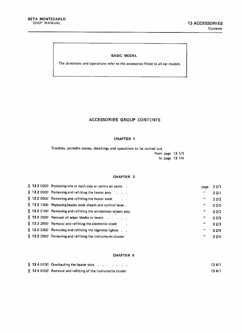
BETA MONTECARLO
SHOP MANUAL 13 ACCESSORIES
Contents
ACCESSORIES GROUP CONTENTS
CHAPTER 1
Troubles, probable causes, checkings and operations to be carried out
from page 13 1/1
to page 131/4
CHAPTER 2
page§ 1320200 Replacing one or both side or centre air vents .
§ 1320500 Removing and refitting the heater assy
§ 1320900 Removing and refitting the heater cock
§ 13 2 1300 Replacing. heater cock sheath and control lever .
§ 1322100 Removing and refitting the windscreen w!pers assy
§ 1322500 Renewal of wiper blades or levers. ...
§ 1322900 Removal and refitting the electronic clock
§ 1323300 Removing and refitting the cigarette lighter. .
§ 13 23500 Removing and refitting the instruments cluster
CHAPTER 4
134/1
134/1
§ 1340100 Overhauling the heater core. § 1340700 Removal and refitting of the instruments cluster
32/1
32/1
32/2
32/2
32/2
32/3
32/3
;3 2/4
32/4

BE
TA
M
ON
TE
CA
RLO
w
"'..J
za)
-«
!1:(/)
--«>
0,.
O
w«
!1:
(/) w
~
!1:u
Ow
u.
~
wu
a)
>z
a:O
<
t
i=
~u
w<
t uw~
<t
(I:<t
0..
(I)w(I):><
tuw-JID<
tIDOO
Cdo1-.J:>«LL
aJ.Qco
-uO
'-;:;
°c:°.c:u
co'-
aJaJ.c:"'coaJ
c..c:
co
-o"tJc:
co co
~
"'aJ
'-c:
aJaJ
>a:~
-~
0
t.)Q)Q
»J::"0~t.)
.-Q)
"' 0.
Q)-
Q)
0-J::
'-.~
+
-' 0.
J::Q)
+-'
C1
>roc:
Q)
0. .a;
J::ro..0+
-' +
-'"'
Q)
Q) .-
"0 J::
'-.-+
-' Q
)"'
+-'
"0
C:'-roQ
)Q
) Q
) +
-'
EJ::J::~
+-'
Q)
oQ)Q
)o.'-
J:: J::
O
LL ~
...ro C
1)
"O:C
c ro
ro u
a. ...
ro O.c
C1)
roC1)
ro.cC
1) "'
.c
...>
C
1)
"0-c:J
C1)
ro-LL
n
oo~N(Y)
'-0
(0E(I)
'--(0~
~
'- '-
0) 0)>
(0 0-
0)-I~
oo0")ONM0.(0'-Q
)
(0Q)
..c:
'+-0(0~Q)
c:Q)
cr:0.ca...'-Q
)...caQ
).!:>...:]cau
'-0+"'
ca
~~'-CI>
+"'
caCI>
..c>+"'
:Jca,.
0000L!').-00N
~
MM
...Q)
+"'
caQ)
..c: ...0
-+"'
0 .~"'0
C)
cat:
...
.+::-
.~
8 Q
)
-~
+"'
Q)
'w
caQ)
"'O..c:
"'0 ~
t: -
ca ...0Q
)-+
"'-caca:J>
Q)ca
o..C:..c:
E
"'0 ~
Q)t:>
a:(nO
'-(1)
la(1).c'!-00>c:
.~;.::(1)'--0c:la1a.Z
->
.0
0 E
E
(1)(1)
<1'
a: 'td
"'0.10
-+-'
c:aJ>-0aJEE.~...O-0aJ"'0O
ooU")
ONcry
13 AC
CE
SS
OR
IES
Eo'--"'S
: ~
O
c:-cu->'-.-cu(1]
'-+"'
O
c:z
~
ooNONM+-'
c:0)>~+-'
c:0)u'f-O~:s:0)c:0)
rr--0III(/)0U0-ro
~+-'
c:III>ro...+
-'c:III
U
CH
AP
TE
R1
Q)
"0'C;;
'+-001~'~+"
:.::e"0~(0(0>0 "'
E
+"
Q)
~
CI:
~
Eo'-'+
-"'$:0 "'
-+-'
'+-
c:
'- Q
).->"'
Q)
0 ""0
z .~
-0Q)
roQ)
(/)>"i::Q)
0.O'-0.
oc(/)
cQ)
>Q)
-0cn
o0NONM
131/1
SH
OP
M
AN
UA
L
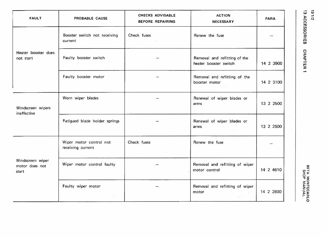
13 AC
CE
SS
OR
IES
131/2w
~..J
zm
-
<t
~(I)
--<
t>
~
Q
w<
t ~
(I) w
~
~(,J
Ow
II.
~
wu
In >z
a:O
<
t-(/)1-
(/)u
w<
t uwz
1-..J=
»«u. w(/):)~uw-Im~mO~0- <
{a:<
{"-
01c:
0>"a;U0)'-...Oc:
~U...
°~II)'- ...
~
c:II)
0)0
t:0
:JQ
) U
"'Q)
"':]'+
-
~uQ)
.cO Q)
"':J-Q
)0!:+
"'
s:Q)
c:Q)
oc
CH
AP
TE
R
1
"'~-0'-0)"'o0 ..0
'-(0'- 0)
"'
(0 0)
o
:r: ~ .!:u.~V
I...Q
)V
I00.0>::J'0
II Q)
..c+"'
-O~..c
.-u+"'
+"'
+"'
.-
:;:: ~
Q)
"''-
'--c
$c:
"'ro
O-Oro..C>0
'-E
$
Q)
roa:
Q)
.c oo0)cry
N~
Q)
.c+"'
-00)c:
.~+"'
-.=Q)
-02c: o
!0 E
!0 ...
>
Q)
0 +
"'
E
~Q
) o
a:~
'-00E'-Q)
CI)
00.0>:JC1J
u..
o0.-(V)
N.q-
"'w-0ca::0'-w0.
.~c:'-0~
'-0"'Q)
-0~:0'-Q)
0.
.~'+-0~~Q
) "'
t: E
Q)
'-a:
"'
ooLl)NNM
"''-~°§c Q
)Q
) >
Q)
0-'- (.)
(.)
"' Q
)"0-c-0-
Q)
~
.~
cn0'>c:
";:0.cn...Q
)-00..c:
Q)
-0ro..0-0Q
)~0'>
".;:;ro
I.L '-0"'0)-0(0::0'-0)0.
.~-0~0) "'
c: E
0) '-
a: ..,
o0I!)NNC
")
"'0)"':J
-~u0).cu
(!)(/I::3
'1-(!).c...s:(!)[:(!)r:r::
oc:
O...c: o
c:u
C1I
...O
:JU
OE
~>C
1I .-
0.. C
1I.-U
~
~
...0) +
-'c.
00-
c:~
(/)c:
0)0)
00)-0...u
...(/)
0 +
-'-0
+-'
...
C:oro
~
E
t:
>:Jro-aL-c:ouL-ooEL-(I)0.
~ '-(!)..9-S
:
-0C)
c:
.+"+-'
:.::~"tJ 0
c: '-
ro +
-'
c:-0ro
u
>0 '-
E
.8(!)
o
a: E
;
BE
TA
M
ON
TE
CA
RLO
O.-(0vNV
...Q)
0.
"~-O01c:
";:."~-Q
)...
"0c:~~>0 ...
E
EQ
) 0
[I: E
...O+-'
0E...aJ0.
"§>+-'
:J10LL
oo00NNV
SH
OP
M
AN
UA
L
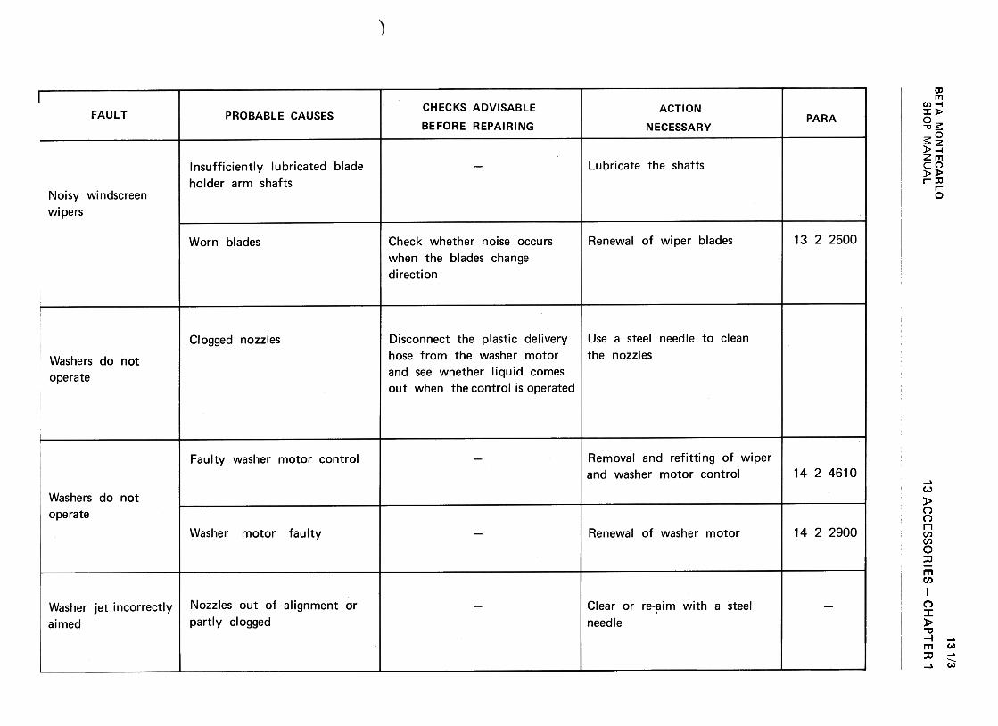
BE
TA
M
ON
TE
CA
RLO
w
(!)--1
zm
-
<t
a:(/)
--<
t>
0,.
c w
<t
a:
(/) w
~
a:u
Ow
LL.
~
wu
m >-
2 a:
O
~-C
/)1-
C/)
U
W~
Uw~
1--J::><t
IL (/)w(/):)~uw..JC
I)~C
I)0~a. «~«Q
.
0/)-(0..c.0/)
a>..c.
a>(0u.~.0:J-1'1)-c~..c-c'1)rou..:
CII
..c ;:]-
ro..c
>
CII
~
E'1)
"-.-roU~
"--'1);:]-CC
II-c:
o-..c
c:Q)
Q)
'-u"'-0c:
.~>
~"'
Q)
.-0.O
0-
z ~
ooL!)NNMII)aJ""0.!J.-0'-aJa.
"§:'1-0(0s:aJc:aJrr:"'0)"tJ~:0c:...0:$:
"''-:Juu Q
)O
C
>c:
Q)
ro.~
..c:
O
uc:
"''-
Q)
Q)
"tJ..c:.!E
.+
"'.0Q
)..c:>
Q)c:
>
-:5 o
~
.~u
c: u
~Q
)Q)
-..c: '-
>
.-
0>"'0
ccaQ)
u0+"'
Q)
-0Q)
Q)
c-UIQ)
Q)
Q)-
+"'
NU
I N0
ca C
Q)
Q)
UI..c:
:J
-c
Q)
>
"' '-'-Q
)ca
Q)°E
'->
Q
)
.-
°O
0.
-u O
~
E
"'
-c .-
u '-
.3 -
.-Q)
0
c ...,
'-"'
"' caca-c:
C.~
'-OQ
) u
Q)Q
).CQ
).c.c
c
Q)
.c
E~
c:
u Q
)
Q)°Q
).CC
:'-Q):>
c:-"':>Ou
Q)
-c "'
"' ;:)
.-° c:
°O
.c
(D
(/)~NNOc"tJ~01O(3
+"'
Oc:0"0(/) 0)
'- +
"'0)
co.c:
'-(/)
0)
~
~
e+"'
c:0CJ
'-0+"'
0E'-0>..c:C
/)ros:
~:JroLL '-(!)a.
.~
-oo
~c:C
) o
c: u
..p '-
.-0~
O-o
Ec:
'-ro
(!).c:
-"'ro ro
~
~
E-o
(!) c:
a: ro
O..-to~N~
13 AC
CE
SS
OR
IES
-C
HA
PT
ER
1
OcO"'0~
Q)
Q)
..c: ~
"' Q
)ro
0.~
0
o00")NN"""...Q
)..c"'ro
~ >+-'
:Jca-'-0'0F ...O+
"'0E...0)
..c"'(I]
:s:
'+-0~0)c:0)
cr:
...0+"'
~Q)
E~0)
ca-0
"0Q)
+"'
0)::3
0)o
o
(I) u
~
>N
-N
+
"'0
...
z ~
""Q)
0)01)
10
..c:
.~E10.
ci>'-'-0
0)'-
-
10 "'0
0) 0)
-0)
U
h
>~C.)
~...0C.)
c.~...O)-c
..c 0)
~
E:$:
.cn
131/3
SH
OP
M
AN
UA
L
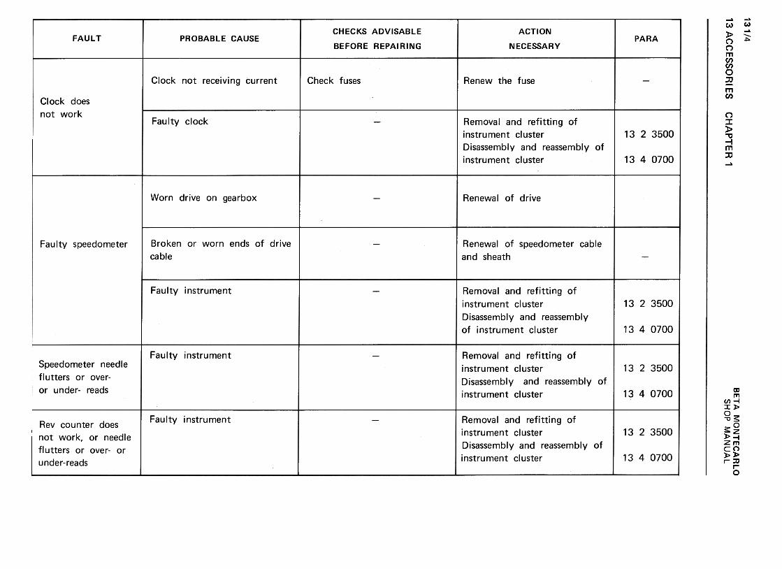
13 AC
CE
SS
OR
IES
131/4w
~..J
z03
-«
CC
(I) -
-«>
Q.
C
W«
CC
(I) W
~
CC
U
OW
I£.
~
WU
03 >
z 0:
O
«-(/)1-
(/)u
w«
uw2
1-.J~«~ w(/):>«uw-8m«mO~a, «a:«do
(/)Q)
(/):J'!-~uQ
)..c:u Q
)"':J
'4-Q)
..c+-'
~Q)
c:Q)
occ:(11'-'-:Ju0>c:
'>"a;u(11'-oc:
~uOO
"'Q)
o~-0
...0~
~
u0 -0u
c: CH
AP
TE
R'
~(.)ou>+"'
:JcaLL
ooL!)cry
Ncry~
-0>
-:co EQ
)C
J V
)~
V
).-ro+
-' Q
)+
-' '-
'- '-
:;:Q)~
Q)
Q)
+-'
'-' +
-''-V
)~V
)~
ro ~
"'Ou
u~
>
ro+-,-+
-,~
.c
~
-Q)E
Q)
~E
Q)E
o~V
)~E
'-V)'-
+-'
ro +
-'
V)
Q)
V)
.-V)
a: -s
a ,~ oor--O~M
x0-0'-(1]
~c:0Q)
>.~"'0c:'-0s Q)
>.~""0
-
0CIJ
~Q)
c:Q)
cc
(1)>".:
-0-0(/)-0c:(1)
c:'-0~'-0c:(1) (1)
~-O
.D'-
ro(])
u
Cl)
..0tou'-Cl)
+"'
Cl)
Eo-0Cl)
Cl)
0."'
'+-..c:o
+"'
to-C
l)to..c::s:
"'C
l)t::
-0C
l) t::
a: ~
...(1)+
-'(1)Eo-0(1)(1)a.tn>+-'
;j(0U
-
c:Q)
E~'-(/Ic:>~!0
LL
ooI!)MNM
>
-..co E
C)
~c:
C/)
'-.-ro
Q)
+"'
Q)
+"'
+"'
'- '-
C/)
:+:
Q)
::JQ
)+"""C
-,-C
/)c:(J::J'"C
-ro+"'
c:(J
c:>
Q
)ro+
"'-E
c: ..c
roQ)E
2>
EQ
)+"'
o ::J
C/)
C/)
E'-C
/)C:
+"'
ro .-
Q)
C/)
.~
a: -s
o b oor-..0~M
+-'
cQ)
E:J...+
-'(I)c>+-'
:Jcau...
Q)
"tJQ)
,Q
) '-
"'I:
Q)
"tJ>
ro
'-OQ
)Q
) '-
+"'
'-Q
)O
.E
~
O
"' "tJ
"tJ~1:
Q)
+"'
:JQ
) +
"'c.
:J '-
rl'1 ::=
0
ooL.()MNM
'+-0>::c
'+-
Eo
a.I(/)
C)
(/)c
ro.-a.I...,+
-a.l-Ca.l
a.I ...c
......(/)
-(/):J
.u :J
-gu>u
ro c
.D
c
-a.I E
a.I
~
E
a.I E
O:J(/):J
E...(/)
......ro
...a.I
(/) .~
(/)
[t: .s
o .S
BE
TA
M
ON
TE
CA
RLO
oor---OvM.-
...c:Q)
E~......(I)c:>...~ro
U.,
Q)
-'-"'
~
0Q
) Q
) ,
OC
:'-"0
Q)
'- >
'- o
oQ
) "'
'-"0C
:~O
ro:)
'- Q
)o
° "'
'-u~
'-~~
r;?,
Q)
>
"0Q
)o:)c:a:c:~
:)
ooI!)MNM
'+-0>
'+-
..Q0
E(l)C
) (/)
c (/)
.-ca...(l)...'-
'- '-
~(l)
(l)(l) '-
(/) c
(/)~
~
"'C-ca-
c u
>
u
ca c
..Q
c
-(l) E
(l)
~
E
(l) E
o ~
~
~
E'-ca'-
...(/) ...
(l) (/)
.-(/)a:
-s: o
,!;:
oor-..o~M
SH
OP
M
AN
UA
L
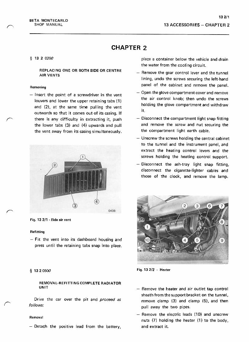
132/1BETA MONTECARLO
SHOP MANUAL 13 ACCESSORIES -CHAPTER 2f"
CHAPTER 2
§ 1320200
REPLACING ONE OR BOTH SIDE OR CENTRE
AIR VENTS
Removing
-Insert the point of a screwdriver in the vent
louvers and lower the upper retaining tabs (1 )
and (2), at the same time pulling the vent
outwards so that it comes out of its casing. If
there is any difficulty in extracting it, push
the lower tabs (3) and (4) upwards and pull
the vent away from its casing simultaneously.
r
place a container below the vehicle and drain
the water from the cooling circuit.
-Remove the gear control lever and the tunnel
lining, undo the screws securing the left-hand
panel of the cabinet and remove the panel.
-Open the glove compartment cover and remove
the air control knob; then undo the screws
holding the glove compartment and withdraw
it.
-Disconnect the compartment light snap fitting
and remove the screw and nut securing the
the compartment light earth cable.
-Unscrew the screws holding the central cabinet
to the tunnel and the instrument panel, and
extract the heating control levers and the
screws holding the heating control support.
-Disconnect the ash-tray light snap fitting,
disconnect the cigarette-Iighter cables and
those of the clock, and remove the lamp.
rFig. 13 211 .Side air vent
Refitting
-Fit the vent into its dashboard housing and
press until the retaining tabs snap into place.
Fig. 13 2/2 -Heater§ 1320500
REMOVAL-REFITTING COMPLETE RADIATORUNIT
Drive the car over the pit and proceed as
follows:r
-Remove the heater and air outlet tap control
sheath from the support bracket on the tunnel,
remove clamp (3) and clamp (5), and then
pu II away the two pi pes.
-Remove the electric leads ( 10) and unscrew
nuts (7) holding the heater (1) to the body,
and extract it.
Removal
-Detach the positive lead from the battery,
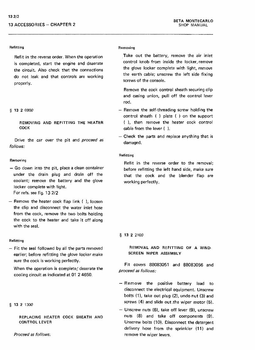
132/2BETA MONTECARLO
SHOP MANUAL13 ACCESSORIES -CHAPTER 2
Refitting Removing
Take out the battery, remove the air inlet
control knob from inside the locker, remove
the glove locker complete with light, remove
the earth cable; unscrew the left side fixing
screws of the console.
Refit in the reverse order. When the operation
is completed, start the engine and deaerate
the circuit. Also check that the connections
do not leak and that controls are working
properly.
Remove the cock control sheath securing clip
and casing union, pull off the control lever
rod.
§ 1320900
REMOVING AND REFITTING THE HEATER
COCK
-Remove the self-threading screw holding the
control sheath ( ) plate ( ) on the support
( ), then remove the heater cock control
cable from the lever ( ).
-Check the parts and replace anything that is
damaged.Drive the car over the pit and proceed as
follows:
Refitting
RemovingRefit in the reverse order to the removal;
before refitting the left hand side, make sure
that the cock and the blender flap are
working perfectly.
-Go down into the pit, place a clean container
under the drain plug and drain off the
coolant; remove the battery and the glove
locker complete with light.
For refs. see fig. 13 2/2
-Remove the heater cock flap link ( ), loosen
the clip and disconnect the water inlet hose
from the cock, remove the two bolts holding
the cock to the heater and take it off along
with the seal.
§ 1322100
REMOVAL AND REFITTING OF A WIND-
SCREEN WIPER ASSEMBL y
Refitting
-Fit the seal followed by all the parts removed
earlier; before refitting the glove locker make
sure the cock is working perfectly.Fit covers 88083051 and 88083056 and
proceed as follows:When the operation is complete: deaerate the
cooling circuit as indicated at 01 24650.
§ 1321300
-Remove the positive battery lead to
disconnect the electrical equipment. Unscrew
bolts (1), take out plug (2), undo nut (3) and
screws (4) and slide out .the wiper motor (5).
-Unscrew nuts (6), take off lever (9), unscrew
nuts (8) and take off components (9).
Unscrew bolts ( 10) .Disconnect the detergent
delivery hose from the sprinkler (11) and
remove the wiper levers.
REPLACING HEATER COCK SHEATH AND
CONTROL LEVER
Proceed as follows;
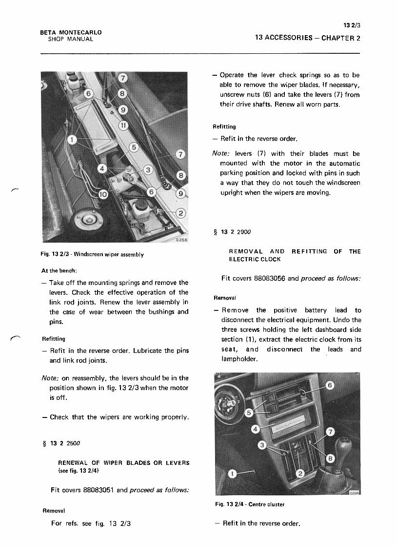
132/3BETA MONTECARLO
SHOP MANUAL 13 ACCESSORIES -CHAPTER 2
-Operate the lever check spri ngs so as to be
able to remove the wiper blades. If necessary,
unscrew nuts (6) and take the levers (7) from
their drive shafts; Renew all worn parts.
Refitting
-Refit in the reverse order .
Note: levers (7) with their blades must be
mounted with the motor in the automatic
parking position and locked with pins in such
a way that they do not touch the windscreen
upright when the wipers are moving./"--
§ 1322900
REMOVAL AND
ELECTRIC CLOCK
REFITTING OF THEFig. 13 2/3 -Windscreen wiper assembly
Fit covers 88083056 and proceed as follows:
At the bench:
-Take off the mounting springs and remove the
levers. Check the effective operation of the
link rod joints. Renew the lever assembly in
the case of wear between the bushings and
pins.
Removal
-R e m ove the positive battery lead to
disconnect the electrical equipment. Undo the
three screws holding the left dashboard side
section (1 ), extract the electric clock from its
seat, and disconnect the leads and
lampholder .
r Refitting
-Refit in the reverse order. Lubricate the pins
and link rod joints.
Note: on reassembly, the levers should be in the
position shown in fig. 132/3 when the motor
is off.
-Check that the wipers are working properly.
§ 1322500
RENEWAL OF WIPER BLADES OR LEVERS
(see fig. 132!4)
Fit covers 88083051 and proceed as follows:
Fig. 13 214 .Centre clusterRemoval
For refs. see fig. 13 2/3 -Refit in the reverse order .

132/4BETA MONTECARLO
SHOP MANUAL13 ACCESSORIES -CHAPTER 2
§ 1323300 -Take off the fuse cover (2) and speedometer
sheath.
REMOVAL ANDCIGARETTE LIGHTER
REFITTING OF THE
Fit cover 88083056 and proceed as follows:
Removal
Remove the positive battery lead to
disconnect the electical equipment. Take off
the left dashboard side section, disconnect the
lighter leads from their snap fittings, unscrew
the ring nut holding the lighter and withdraw
the latter.
Refitting
-Refit in the reverse order and check that the
lighter works properly. Fig. 13 216casings.
Fuse cover and steering column half-
§ 1323500
Partly withdraw the cluster and disconnect
the terminals.
Remove the cluster (10).
REMOVAL AND REFITTING OF THE
INSTRUMENT CLUSTER (speedometer, rev
counter, fuel gauge, oil pressure gauge, radiator
temperature telltale)
At the bench
-Slide off the side paddings (4), unscrew
screws (5) and slide the instruments from
their support.Fit covers 88083056 and proceed as follows;
Removal
Remove the positive battery lead to
disconnect the electrical equipment. Unscrew
screws (1).
Fig. 132/7 -Rear view of instruments cluster
-Refit in the reverse order and check that the
instruments work properly.
(*1 Disassembly and reassembly of the cluster is described at
para. 13 4 0700.Fig. 132/5- Instrument cluster
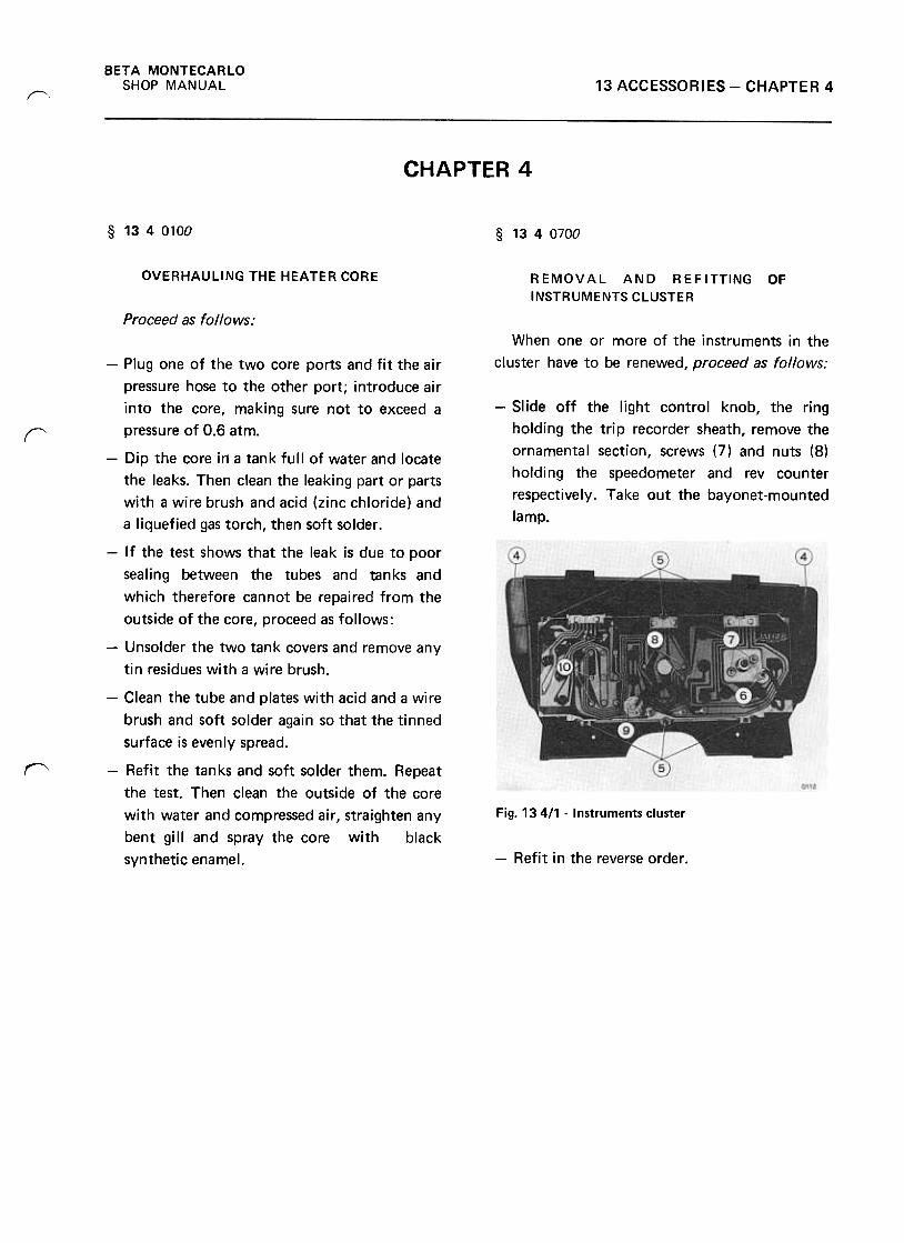
BETA MONTECARLO
SHOP MANUAL 13 ACCESSORIES -CHAPTER 4~
CHAPTER 4
§ 1340100 § 1340700
OVERHAULING THE HEATER CORE REMOVAL AND REFITTING OF
INSTRUMENTS CLUSTER
Proceed as follows:
When one or more of the instruments in the
cluster have to be renewed, proceed as follows:
-Slide off the light control knob, the ring
holding the trip recorder sheath, remove the
ornamental section, screws (7) and nuts (8)
holding the speedometer and rev counter
respectively. Take out the bayonet-mounted
lamp.
r
"
-Plug one of the two core ports and fit the air
pressure hose to the other port; introduce air
into the core, making sure not to exceed a
pressure of 0.6 atm.
-Dip the core in a tank full of water and locate
the leaks. Then clean the leaking part or parts
with a wire brush and acid (zinc chloride) and
a liquefied gas torch, then soft solder.
-If the test shows that the leak is due to poor
sealing between the tubes and tanks and
which therefore cannot be repaired from the
outside of the core, proceed as follows:
-Unsolder the two tank covers and remove any
tin residues with a wire brush.
-Clean the tube and plates with acid and a wire
brush and soft solder again so that the tinned
surface is evenly spread.
-Refit the tan ks and soft solder them. Repeat
the test. Then clean the outside of the core
with water and compressed air, straighten any
bent gill and spray the core with black
synthetic enamel.
Fig. 13 411 -Instruments cluster
-Refit in the reverse order.
BETA MONTECARLO
SHOP MANUAL 14 ELECTRIC SYSTEM
Contents
VARIANTS
-Variant SCORPION
The directions and operations refer to the electric system fittt!d to the
SCORPION versions only 137 AS 6.
ELECTRIC SYSTEM GROUP CONTENTS
CHAPTER 1
Troubles, probable causes, checkings and operations to be carried out
from page 141/1
to page 141/5
CHAPTER 2
page 142/1
14 2/2
14 2/2
14 2/1
14 2/2
142/3
Variant SCORPION
142!3
142!12
142!1
142!4
142!4
142!5
§ 1420100 Checking the alignment and aiming the headlamps using optical
equipment .
§ 142 0400 Checking the battery charge and cleaning the terminals .
§ 142 1000 Removing and refitting a right, or left front beam unit, including
renwal of the bulb
Do for SCORPION cars
§ 1422800 Removing and refitting the windscreen motor .
§ 1423100 Removing and refitting the heating and ventilation booster motor
§ 1424610 Removing and refitting the windscreen wipers, turn indicators andheadlamps controls .
§ 1426000 Removing and refitting the fuse holder
§ 1426800 Removing and refitting headlight fitter motor .
§ 1426900 Removing and refitting the fuse holder
§ 1427200 Removing and refitting the alternator .
§ 1427500 Removing and refitting the voltage regulator
Variant SCORPION
CHAPTER 4
page§ 1440420 Overhauling the starter motor
§ 1440520 Renewing the starter motor field coil
§ 1440800 Overhaul of the alternator
§ 1440900 Recharging the battery. ...
44/1
44/4
44/4
44/6
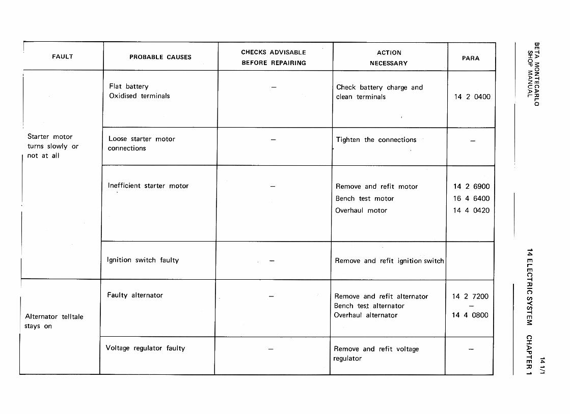
BE
TA
M
ON
TE
CA
RLO
w
~..J
200
-~
C
C(/)
--~>
a..C
W
~
CC
(/) W
~
CC
U
Ow
u.
~
WU
00 >
z a:
O
«-(I)1-
(I)u
w«
uwz
1-..J::>0:{~ (/)w(/)::>~uw-1aJ~aJO~0-- <
!a:<
!0.-
"'Cc:ro(l)C')
...ro.!:u
"'
>-
...roc:
(l) .-
:::: E
ro ...
..c (l)...
~
c:u
ro(l)
(l).!:-u
u(/)cac:E
>
......Q
)Q
) ~
"O
ca Q
).0
o~"00-ca
xLL:o
oo.;tON.;t
1.-0
1.-0
>+
-'-0
~
-E
0
"(Q1.- -c;;
+-'
(1) (/)
(0+
-'1.-
c: +
-'(0
1.- 0
+-'
:3 c:
U)
+-'
'-0+"'
oE'-Q)
"'
1: c:
(0 0
+"'
.-"'
+"'
CJ
Q)
Q)
"' c:
0 c:
0 0
-.J u
01)~O";:.uQ
)~~0uQ
)~+
-'
~Q)
+-'
~01i=
...0oE...Q)
...ro(/I
c:Q)
'(3~-Q)
c:
o o
oo
0 N
Q')~
~(.0
(.0 O
N
~
~
~(.0~
...0+-'
oE+-'
...;.::
0Q
) +
-' ...
...o 0
-0 E
b
c: +
-' E
ro V
)Q
)Q
) +
-' :J
>
roo.c.cE
u ...
c: Q
)Q
) Q
) >
a:(X)o
14 ELE
CT
RIC
S
YS
TE
M
>~::Jcg
-..c:u...
.~(I)
[::0.~"c:0)
..cu...
.~"'c:O".i:J
c:0)
...
'i=Q)
'-
"0c:(0Q)
>oEQ)
rr
...O+"'
(0c'-0)+
"'
(0>+"'
:J(0u. o0Nr-..
Nq-'-0...ro~'-Q)
...'-0
ro ...'-
...roo.-~
...
'+-
'- ro
~
Q)
~'--Q
)"'0
ro ...
~
~ro
onQ)-
Q)
~
:J>
ro
0.!:.!:E
U
'-~
Q
)Q
)Q»
a:roO
oo00O~~0)ro
"'Qj
...O
c
~
0c...III0)
>~
ro
« ~
CH
AP
TE
R
1
>+-'
:J(0-...0+
-'(0:JC
IQ
)...Q
)C
I(0+-'
a:> 0)0)(1]+
-'
a>+-'
~0)...
"'0c(1]...
0) 0
>
+-'
0 (1]
E"3
0) 0)
oc ~ 14111
SH
OP
M
AN
UA
L
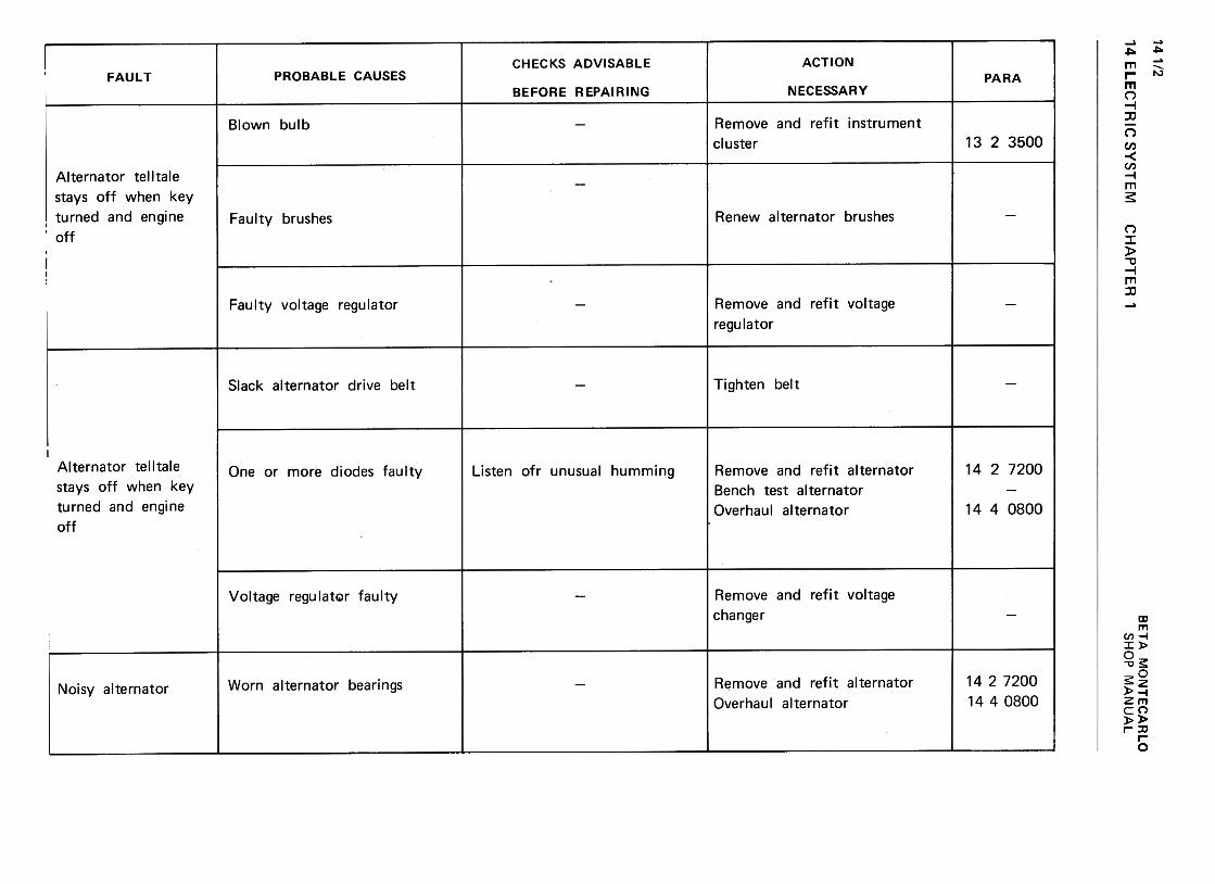
141/2
14 ELE
CT
RIC
S
YS
TE
M
zO1-Uct:
w.JaI«(I)>c«(I)~uw~Q
(/)w(/):=
1«uw.JID«IDO~~1--J:J~LL ~[I:~
>~<t
~wuwz"z0:<t
0.w0:w0:Ou..wm
.D:J.Dc:~offi
...cQ)
E:J'-...(/)c...
;.;:Q)
'-
-0ccaQ)
>
'-0
Q)
E
t:Q
) :J
a:o
o0L!)MNM
>Q)
Q)
Q) ~
c:
ro .51
c: c:
-Q)Q
)Q
)..c:
~"tJ
...c:O
'+
- ~
'+-
~
O
"0E
"'
Q)
Q»E
,+-
~
::J '+
-~
~
0
(I)0)
.c(I)~--
.0--0coc--0)co~0)c0)oc"'aJ..c"':J'-.0>+
"'
:J10U
-., CH
AP
TE
R
1...O+-'
la:J010)...0)01la+-'
a>>+-'
:JlaL1 Q
)01"'
0>'i=Q)
...
'"0c:"'...
Q)
0>
0
"'
E
""3Q
) 01
a: ~
+-'
"""Q)
.0Q)
>
.~"'0'-0+-'
<0
c'-Q)
+-'
ro~u<0
i/5 +"'
""Q)
.0c:Q)
+"'
..c:0)
i=
>(l) (l)
(l) .:),(.
c:
ro .5>
+-'
c: c:
-(l) (l)
(l).r::.
+-'s:-o
...c:O
-.-co
+-'-.-co
O
-0E
"'
(l)
(l»E-.-
+-'
co ~
-.-
~t:+
-'o
o o
o 0
N
00r-..
10
N
v
v v
0)c:
'EE~..c:
ro~II)~c:~...'0c:Q
)+
-'II)
::1>+"'
:Jca-"'Q
J"0O:0Q
J...0E...0Q
Jc:
O ...0+"'
10C...Q)
+"'
...-010
+"'
...
+",100
.-C
+"'
10Q
)Q)C
...+"'
...-Q
)'"C
10
+"'
C+
",ro10
"'Q)-
Q)
+"'
~>
10
0..C..c
EU
...
C
Q)
Q)Q
»C
:a)O
>+"'
~'0'+
-...()+"'
'0~01Q)
...
Q)
01'0+"'
0> QJ
0)ro+"'
a>+"'
;;:QJ
...
"'0croQJ
...>
Q
JO
0)
E
c
QJ~
a: " B
ET
A
MO
NT
EC
AR
LO
0000No0
r-..O
N~
~~
.,-.-
...0+-'
roc...
~ro ...
+-'
0.-+
-'-roQ
) cQ
)"0
+-'
c ""(0
roQ)
~>
ro
o.c
E
'a;Q
) >
a:o"'01C.~ro0)-0...O+
-'roC...
SroC...0~
'-010c:'-0)
-;0>U)
.0z
SH
OP
M
AN
UA
L
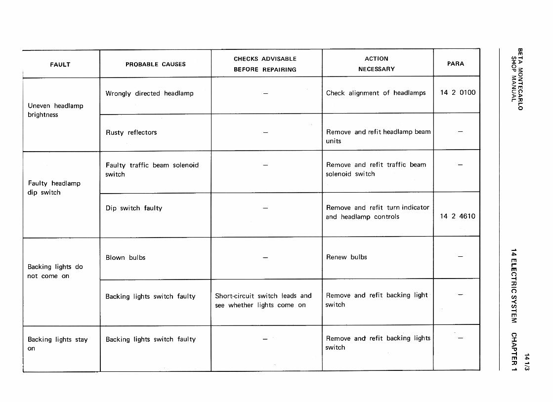
BE
TA
M
ON
TE
CA
RLO
>z
~0
0:(-(/)1-
(/)u
w0:(
uw:;:0
w
C-'
..J z
Q)
-~
0:
(/) -
-~>
c..c
w~
0:
(/) w
~
0:u
Ow
I!.
:t w
u m
«cx:«0-(I)w(I)::!«uw-Jm«mO~0.1-.J:)<
t11-
o0.--0N~c.Ero=
0roQJ
~""0QJ
+-'
uQJ
...
:0>"'6>c:o...
s "'0.Ero
-0roQ)
.c-0...c:Q)
Ec:0)ro
~(.)Q
).cu
a.E(0"0(0(1)
"'..t:
"'(1)c:
c:(1) >
..t:
(1) 0)
c: .-...
:)..0
EcoQ)
.00.Eco
"'0coQ)
..r:.
:;:~"'0c:co~0 "'
E
.~Q
) c:
0: ~
II)0+-'
u(I)~(I)
>+-'
II):JC
I:
-0.0c:0)0(/)Ero0).0u~'f-ro...+
-'
>.c:
+-'
u-+
-'::J
0-ro
s:u.
"'
EroC!)
..cu;;:-ro'-+
"'
+"'
;;:C!).r:.
'- u+"'
""C
.-c::
~ro
In
C!)~
>
oo
c::
E
C!)
C!)o
CI:
"'
0.Eto"0to.c111
u.c
+-'
>
"§"+
-' "'
:J 0.
to .-
LL."C
>:J'0-..c:u.~C
/)00O ...0rou::ac:c:.!!!....0:)
...c:.~
0
-uQ)
...c."'0
Ec:
roro-
"'0Q
) ro
>
Q)
o..C:
E"'0
Q)
c:C
(: ~ O.-(,0
"'"N"'"
14 ELE
CT
RIC
S
YS
TE
M
"'..0:J..0~Q
)c:Q
)~~..0:J..0c:5:o(i5
o-0"'+"'
c..c
00)=
Q
)O
)Ec
00-
u~u
+"'
(0 0
ro r-
..I::.~01c:
~U~~~""0c:roIII>0 ..I::
E
£III
.-
a: ~"'
"'0c: c:
ca O
"' Q
J
~
EQ
J O
-C.)
..c: "'
C.)
.~
..c:
:s: .~
"' -'-
.-QJ
:J..c:C
.) '-
QJ
c:
:i :s:
'-0 Q
J..c:
QJ
U)
"'
>+-'
~co-..cu+
-'
.~."."+-'
..c0)0)c:
~ucom
CH
AP
TE
R
1
"'+-'
..c.~0')c:
~u(0.0+
-'~~"tJc:(0Q
)>o..CE
!+
!iQ
) .-
0: ~"'
>::3co-.!:u.~"'"'.!:C
)
C)
c:
~ucoC
Q>(0+"'
C/)
C/)
+"'
.c0)
0)c:
~u(0 c:
a) 0
141/3
SH
OP
M
AN
UA
L

14 ELE
CT
RIC
S
YS
TE
M
141/4w
"..J
2Q
) -
« 0:
(/) -
-«>
Q..
C
w«
0:
(/) W
~
0:(.J
OW
11.
~
WU
M >
2 a:
O
0:(~
~
U
W0:(
UW~
1-..J::>«u..
(I)w(I):)<
tuw.JQ
]<
tQ
]0~0- ~a:~a,
"'5'-+"'
c:OCJ
II)'-0+"'
<0
CJ
:0c:>+"'
:J<0
u, (/)'-0cat.)
::0c:
~Q)
'-
"'0c:caQ)-
>
oo
'-
E
'EQ
) 0
a: t.)
O.-.to"'"N"'"
"'...
.s~CIJ
...u
o:c
s:c0-
+-'
o
c c
...:J O
I-"P
..cu...
.~"''-(1)..c"'ro~>...:JroLL ...
~!e'i=~Q
Jc:Q
Jrr-
..c:u+"'
.~"'
CH
AP
TE
R
1
"'0'-+-'
c:ouI/)'-0+-'
cau:0c:>+-'
:JcaU
-.,
...0"-'cou::ccc...'0:J
..."-'
"-'c.~
0
-uQ)
...a."0
Ec
coco-
"0Q
) co
>
Q)
o.c
E"O
Q)
cC
l: m 0~(0~N~
.:Jt.'-0
-~Q)
+"'
u"'
c: 0
'-roC:
0 u
+"'
"'ro
"'0 Q
)u
0.-c:
"'0"'0
roc:
-.-Q
) 0
0) '-
c: c:
+"'
'-roC:
:J .c
o1-
u u
..c:u.~"'
a'-~ou>:JcaLL c:Q
)Q
)-'-
0(.)
'-"'
"'C
c:
.s o
~
(.)
'-Q)
;;: >
Q)
co'-
'-c."'C
"'
c:"'Cco
c:Q
) co
>0 "'
E
~Q
) c.
a: .~ O.-<
0vNV
"''-Q)
0.
°~
.¥.'-c:
oQ
) ~
~CJ
"' 0
"0 c:
c:0-
0
SoP
>:Jro-...00E"'...0.10.
~
c:Q)
Q)
'-u"'-ac:
.~+-'
;;:Q)
'-'-
-a o
c: +
-'ro
OQ
) E
>
"'0
'-E
Q
)a.
Q)
.-a:
~ oo00NN~
Q)
>";:;uQ)
-Q)
"0O...t::0ut::...oT 0...c:ou"'c:...0.c~Q
)...
"0c:caQ)
>0EQ)
0=
+"'
oc:0"0(I)c: ~
'- '-
0 0
I ~
"'0'0cQ)
a"'"'c'-0..c'+=Q)
'-
"'0c(IJQ
)>
..c
0 u
E
,~Q
) ~
cr: "'
>+-'
:Jca-.cu+
-'
.§"'
"0.0cQ)
a"'"'c...O:r:
>+-'
:J~C/)
c...o:1:: ~c:'-0..c:
(1)..c:+
-'
+-'
:.::(1)'-
"'0c:(0(1)>oE(1)
~
..c:u+-'
.~"'
"'0OcaI
O"'~O"'0c.~'- >
(0!::.aI
~
a:~ ~O""0c.~'-roQJ
'-
'+=~
..cu
""0 .~
c ~
ro C
/)
QJ""0
>
.-0
0E
c
QJ
~a:
o"'
BE
TA
M
ON
TE
CA
RLO
$: ~
o 0
"0"0.
~c: '-
~Q
J '-
+-'
0
,-1S$:
ro '-
QJ'+
-+-'
a:QJO"0
c:
0...+
-'cOu...Q
)+
-'C
IIO...
-Q)
-0~
~0
--0
:Jc:
ro.--~
~
...Uro
.'!::Q
) ~
a: "'
~o-0c.~...roQ)
...
'.i=~
Q)
u
-0 .~
c "'
ro...
Q)
Q)
>
0 '8
E.t:
Q)
Q)
a:~
SH
OP
M
AN
UA
L
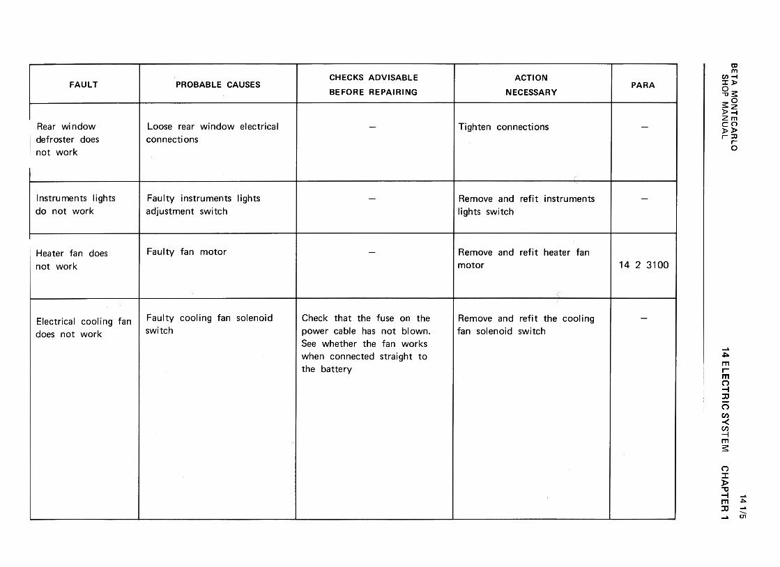
BE
TA
M
ON
TE
CA
RlO
w
~.J
z~
-
<t
0:(/)
--<
t>
~
c w
<t
0:
(/) w
~
0:(.)
Ow
11.
~
wu
~ >z
0:O
«
-(/)1-
(/)u
w«
uwz
.....J::>~u.
(/)w(/)::>«uw.Jm«mO~a, «a:«"-
~
~o
0
"'0"'0c:
'- ~
.5 Q
J '-
>
o
'-'8~C
1J '-Q
J a::Q
JO71 .,-
rou..:...uQ)
-a;~O"Cc:
.~(/)
'- c:
ro O
Q)
.-'-
...uQ
) Q
)(/)
c:O
c:
O
O-.J
u
CII
c:o.~U(1)c:c:0Uc:(1)..c:01
i=
CI)
.!:.~.¥.
CI)
...0~
$:
E
:J O
...c:C
I)c:
o-~ "'
..c:0)
~..c:
c u
QJ
E
.~
:J "'
..."' c
c Q
J
.-E>
"':J:J
.~C
O-o
LL (tI
'I!.cQ
)E::J...(/)
.s\+:Q)
...
"'C..c
c u
ro Q
) .~
>
(/)0
(/)E
Q
)..C
a: .~
c:ro-'-~ro0)..c:
+"'
:+:0)'-
""0c:ro0)>0 '-
E
£0)
00:
F
'-0oEc<0
'+->::J<0
LLtnQ)
O""0c:ro~-'-
0Q
; ~
+-'
ro +
-'Q
) 0
I c:
o0.-(V)
NV
-0'0c:(!)0II)c:ca-0)c:
O0u>..I::
+-'
u-+
-':J
0-ca
~U
- "'
(l) .
..cl::lnO~
~ '-
~
.2 O
o.D
~..C
C)
(l) I::
.roInO
(tj'-~
I::
-In(l) ~
(l)
"'0
..c..c..C(l)
(l) '-
(.)(l)
(l)
(tj.D..C
I::>-
..c (tj
I:: ~
(.) (l)
0 ~
..c (.)
~
'- >
(tj
(.) (l)
>
I:: .D
(l) ~
(l)
o..C
O
~
..c (l)
O..(f);;£
C)
cO0uQ)
.c+-'.c
u+
-' +
-'
:;:: .~
~
"'
""C""C
c .-
ro Oc
Q)
~>
o
o "'
E
cQ
) ro
c:-c:ca-0)c:
:=-:0!
O
...o
ou
s:
ca +
"'u
O".:
c:+
"'u
"'0)
0)-0W
-a
14 ELE
CT
RIC
S
YS
TE
MC
HA
PT
ER
'
141/5
SH
OP
M
AN
UA
L

142/1BETA MONTECARLO
SHOP MANUAL 14 ELECTRIC SYSTEM -CHAPTER 2
CHAPTER 2
§ 1420100
CHECKING ALIGNMENT AND AIMING
HEADLAMPS USING OPTICAL EQUIPMENT
Proceed as follows:
-Set the unladen car on a perfectly flat floor I
check tyre pressure and make sure that the
suspensions are in good condition.
Fig. 14 2/2
88075020
Datum lines on screen of equipment
-The intersection of the horizontal and slanted
edges of the bright spot should coincide with
the V-V vertical on the screen, or otherwise
lie between verticals V-V and S-S (left-hand
low beam headlamp).Fig. 14 2/1 -Checking headlamp alignment with
equipment 88075020
Fig. 142/3. Headlamp aiming screws
-If this does not occur, adjust screw (1) as
necessary. (
-Set the front wheels in straight ahead position
and place equipment 88075020 in front of
one low beam head lamp. The centre of the
equipment lens should be in line with the
centre of the headlamp and about 300 mm
from it. The lower cross bar should be
touching both front wheels.
-Turn the low beams on and check that the
horizontal edge of the bright spot is parallel
with the horizontal lines on the screen and
the slanted edge is parallel with the sloping
lines.
-For vertical alignment, check that the
horizontal edge of the bright spot registers
with line No.10 below line O-C-O on the
screen. If it does not, adjust the screw (2) as
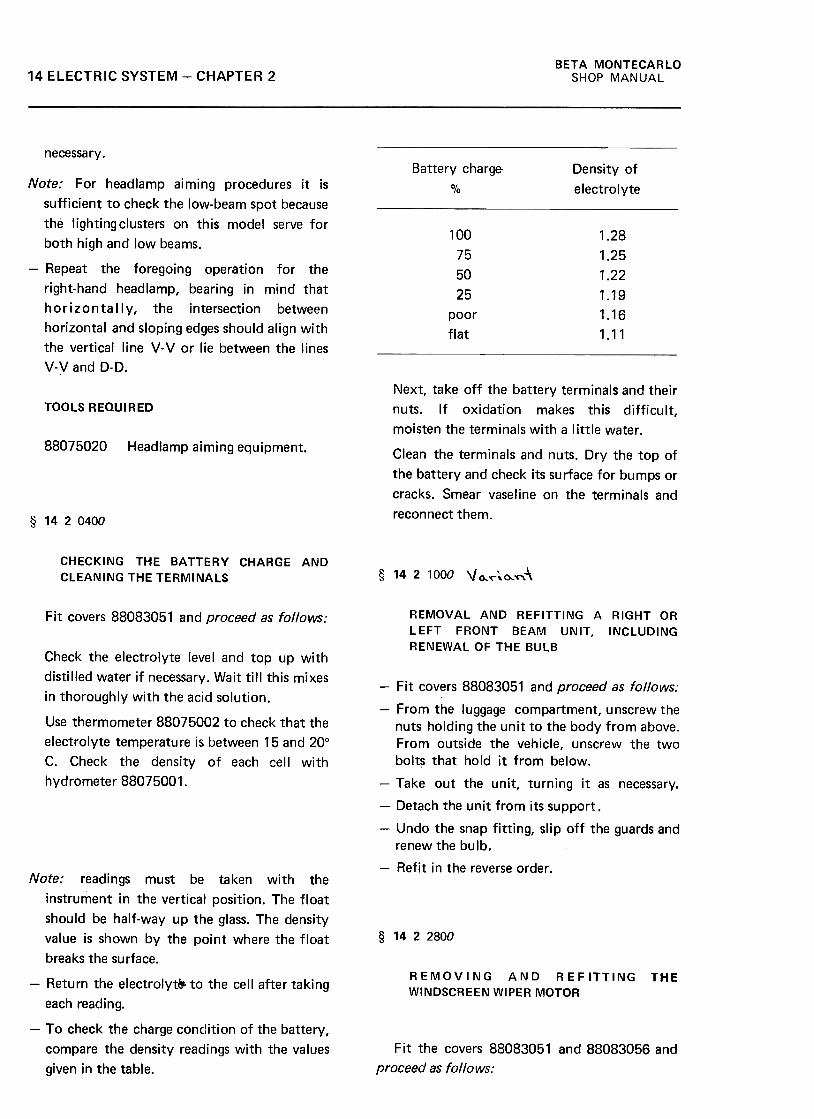
BETA MONTECARLO
SHOP MANUAL14 ELECTRIC SYSTEM -CHAPTER 2
necessary.
Battery charge-
%
Density of
electrolyte
100
75
50
25
poor
flat
1.28
1.25
1.22
1.19
1.16
1.11
Note: For headlamp aiming procedures it is
sufficient to check the low-beam spot because
the lighting clusters on this model serve for
both high and low beams.
-Repeat the foregoing operation for the
right-hand headlamp, bearing in mind that
horizonta Ily, the intersection between
horizontal and sloping edges should align with
the vertical line V-V or lie between the lines
V-V and 0-0.
TOOLS REQUIRED
88075020 Headlamp aiming equipment.
Next, take off the battery terminals and their
nuts. If oxidation makes this difficult,
moisten the terminals with a little water.
Clean the terminals and nuts. Dry the top of
the battery and check its surface for bumps or
cracks. Smear vaseline on the terminals and
reconnect them.§ 1420400
CHECKING THE BATTERY CHARGE AND
CLEANING THE TERMINALS § 14 2 1000 \jo.~~0..,,",~
REMOVAL AND REFITTING A RIGHT OR
LEFT FRONT BEAM UNIT, INCLUDING
RENEWAL OF THE BULB
Fit covers 88083051 and proceed as follows:
Check the electrolyte level and top up with
distilled water if necessary. Wait till this mixes
in thoroughly with the acid solution.
Use thermometer 88075002 to check that the
electrolyte temperature is between 15 and 20°
C. Check the density of each cell with
hydrometer 88075001.
-Fit covers 88083051 and proceed as follows:
-From the luggage compartment, unscrew thenuts holding the unit to the body from above.From outside the vehicle, unscrew the twobolt~ that hold it from below.
-Take out the unit, turning it as necessary.
-Detach the unit from its support .
-Undo the snap fitting, slip off the guards andrenew the bulb.
-Refit in the reverse order .
§ 1422800
REMOVING AND REFITTING
WINDSCREEN WIPER MOTORTHE
Note: readings must be taken with the
instrument In the vertical position. The float
should be half-way up the glass. The density
value is shown by the point where the float
breaks the surface.
-Return the electrolyts. to the cell after taking
each reading.
-To check the charge condition of the battery,
compare the density readings with the values
given in the table.
Fit the covers 88083051 and 88083056 and
proceed as follows:
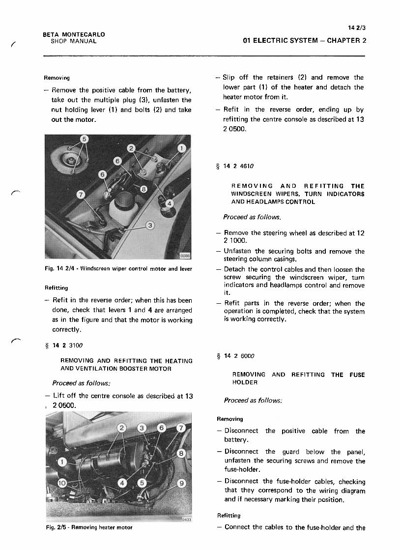
142/3BETA MONTECARLO
SHOP MANUAL 01 ELECTRIC SYSTEM -CHAPTER 2(
Removing
-Remove the positive cable from the battery,
take out the multiple plug (3), unfasten the
nut holding lever (1) and bolts (2) and take
out the motor .
-Slip off the retainers (2) and remove the
lower part (1) of the heater and detach the
heater motor from it.
-Refit in the reverse order, endi ng up by
refitting the centre console as described at 13
2 0500.
§ 1424610
REMOVING AND REFITTING THE
WINDSCREEN WIPERS, TURN INDICATORS
AND HEADLAMPS CONTROL
r
Proceed as follows.
Fig. 14 2/4 -Windscreen wiper control motor and lever
Refitting
-Refit in the reverse order; when this has been
done, check that levers 1 and 4 are arranged
as in the figure and that the motor is working
correctly.
-Remove the steering wheel as described at 12
2 1000.
-Unfasten the securing bolts and remove the
steering column casings.
-Detach the control cables and then loosen the
screw securing the windscreen wiper, turn
indicators and headlamps control and remove
it.
-Refit parts in the reverse order; when the
operation is completed, check that the system
is working correctly.
r§ 1423100
§ 1426000
REMOVING AND REFITTING THE HEATING
AND VENTILATION BOOSTER MOTORREMOVING AND REFITTING THE FUSE
HOLDERProceed as follows:
-Lift off the centre console as described at 13
I 20500.Proceed as follows:
Removing
-Disconnect the positive cable from the
battery.
-Disconnect the guard below the panel,
unfasten the securing screws and remove the
fuse-holder .
-Disconnect the fuse-holder cables, checking
that they correspond to the wiring diagram
and if necessary marking their position.
Refitting
-Connect the cables to the fuse-holder and theFig. 2/5- Removing heater motor
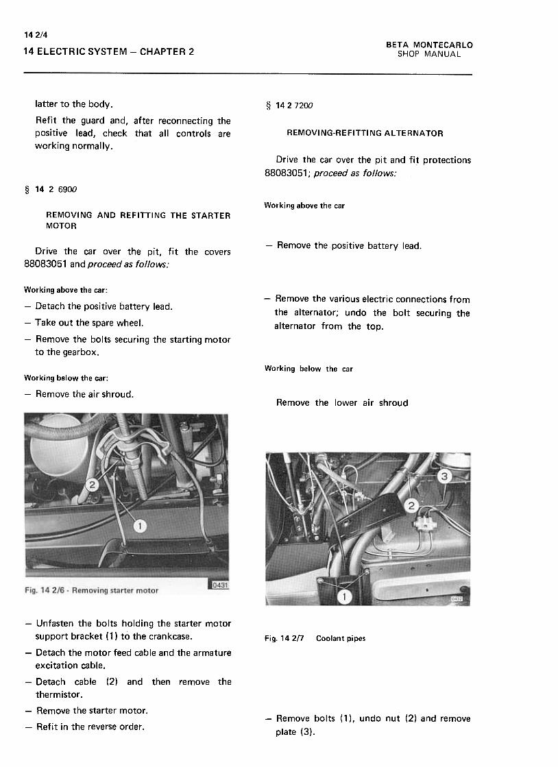
BETA MONTECARLO
SHOP MANUAL
142/4
14 ELECTRIC SYSTEM -CHAPTER 2
§ 1427200latter to the body.
Refit the guard and, after reconnecting the
positive lead, check that all controls are
working normally.
REMOVING-REFITTING AL TERNATOR
Drive the car over the pit and fi~ protections
88083051; proceed as follows:
§ 1426900
Working above the carREMOVING AND REFITTING THE STARTER
MOTOR
-Remove the positive battery lead.Drive the car over the pit, fit the covers
88083051 and proceed as follows:
-Remove the various electric connections from
the alternator; undo the bolt securing the
alternator from the top.
Working above the car:
-Detach the positive battery lead.
-Take out the spare wheel.
-Remove the bolts securing the starting motor
to the gearbox.
Working below the car
Working below the car:
-Remove the air shroud.Remove the lower air shroud
Fig. 142/7 Coolant pipes
-Unfasten the bolts holding the starter motor
support bracket ( 1) to the crankcase.
-Detach the motor feed cable and the armature
excitation cable.
-Detach cable (2) and then remove the
thermistor .
-Remove the starter motor.
-Refit in the reverse order .-Remove bolts ( 1 ), undo nut (2) and remove
plate (3).
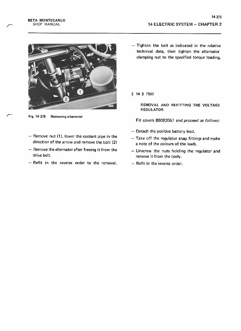
142/5
14 ELECTRIC SYSTEM -CHAPTER 2
BETA MONTECARLO
SHOP MANUALr
-Tighten the belt as indicated in the relative
technical data, then tighten the alternator
clamping nut to the specified torque loading.
§ 1427500
REMOVAL AND REFITTING THE VOLTAGE
REGULATOR
I"""-'Fig. 142/8 Removing alternator
Fit covers 88083051 and proceed as follows;
-Remove nut (1 ), lower the coolant pipe in the
direction of the arrow and remove the bolt (2)
-Remove the alternator after freeing it from the
drive belt.
-Refit in the reverse order to the removal.
-Detach the positive battery lead.
-Take off the regulator snap fittings and make
a note of the colours of the leads.
-Unscrew the nuts holding the regulator and
remove it from the body.
-Refit in the reverse order .
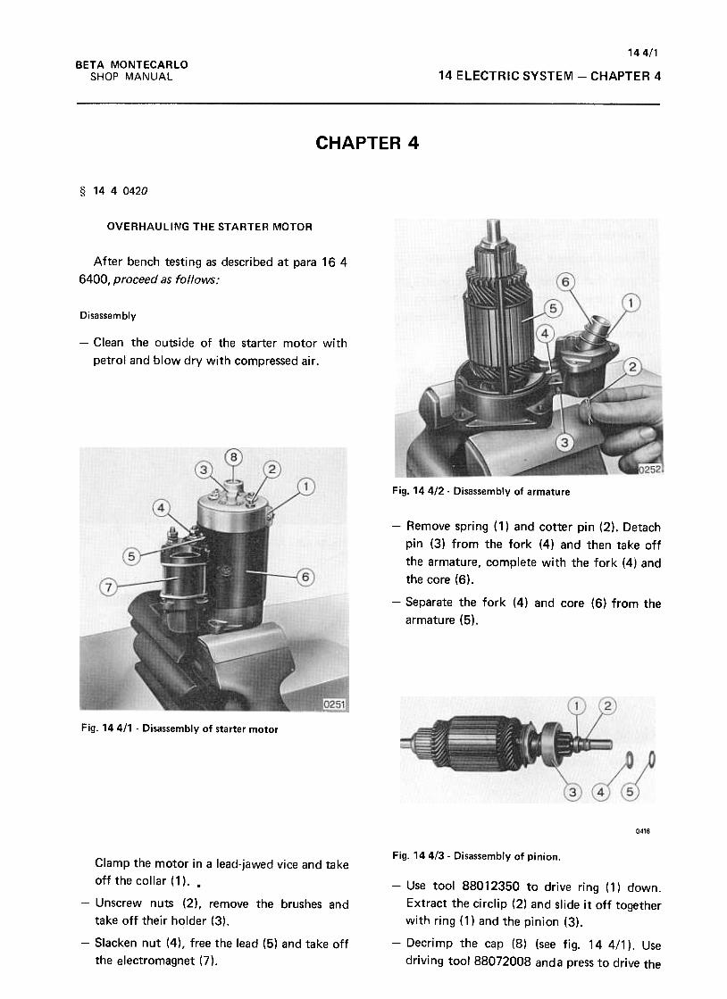
144/1BETA MONTECARLO
SHOP MANUAL 14 ELECTRIC SYSTEM -CHAPTER 4
CHAPTER 4
§ 1440420
OVERHAULING THE STARTER MOTOR
After bench testing as described at para 16 4
6400, proceed as follows:
Disassembly
-Clean the outside of the starter motor with
petrol and blow dry with compressed air.
Fig. 14412- Disassembly of armature
-Remove spring (1) and cotter pin (2). Detach
pin (3) from the fork (4) and then take off
the armature, complete with the fork (4) and
the core (6).
-Separate the fork (4) and core (6) from the
armature (5).
Fig. 144/1 -Disassembly of starter motor
0416
Fig. 144/3- Disassembly of pinion.Clamp the motor in a lead-jawed vice and take
off the collar (1). .
-Unscrew nuts (2), remove the brushes and
take off their holder (3).
-Slacken nut (4), free the lead (5) and take off
the electromagnet (7).
-Use tool 88012350 to drive ring (1) down.
Extract the circlip (2) and slide it off together
with ring (1) and the pinion (3).
-Decrimp the cap (8) (see fig. 14 4/1 ). Use
driving tool 88072008 anda press to drive the
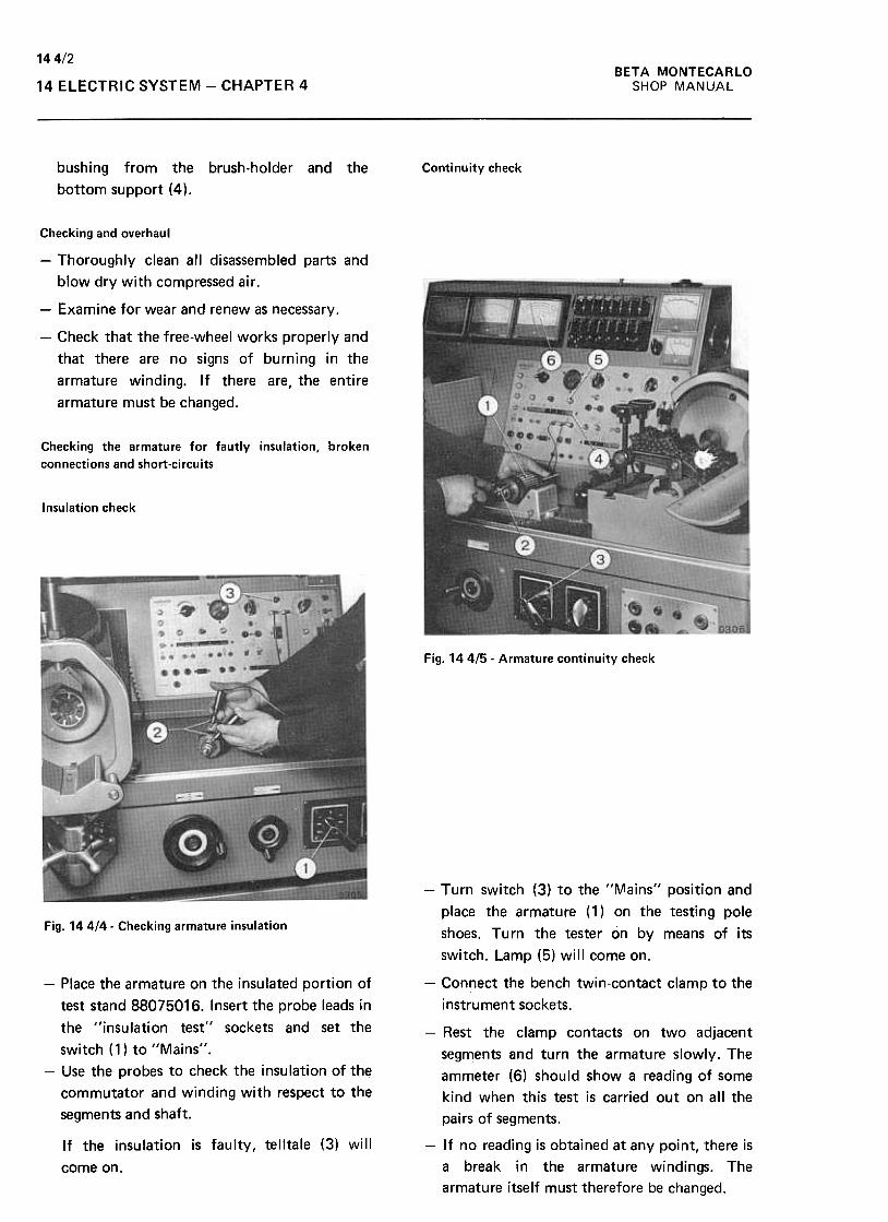
144/2BETA MONTECARLO
SHOP MANUAL14 ELECTRIC SYSTEM -CHAPTER 4
bushing from the brush-holder and the
bottom support (4).
Continuity check
Checking and overhaul
-Thoroughly clean all disassembled parts and
blow dry with compressed air.
-Examine for wear and renew as necessary.
-Check that the free-wheel works properly and
that there are no signs of burning in the
armature winding. If there are, the entire
armature must be changed.
Checking the armature tor tautly insulation, broken
connections and short-circuits
Insulation check
Fig. 144/5- Armature continuity check
-Turn switch (3) to the IllV1ains'l position and
place the armature ( 1) on the testing pole
shoes. Turn the tester on by means of its
switch. Lamp (5) will come on.
Fig. 14414- Checking armature insulation
-Place the armature on the insulated portion of
test stand 88075016. Insert the probe leads in
the "insulation test" sockets and set the
switch (1) to "Mains".
-Use the probes to check the insulation of the
commutator and winding with respect to the
segments and shaft.
If the insulation is faulty, telltale (3) will
come on.
-Connect the bench twin-contact clamp to the
instrument sockets.
-Rest the clamp contacts on two adjacent
segments and turn the armature slowly. The
ammeter (6) should show a reading of some
kind when this test is carried out on all the
pairs of segments.
-If no reading is obtained at any point, there is
a break in the armature windings. The
armature itself must therefore be changed.
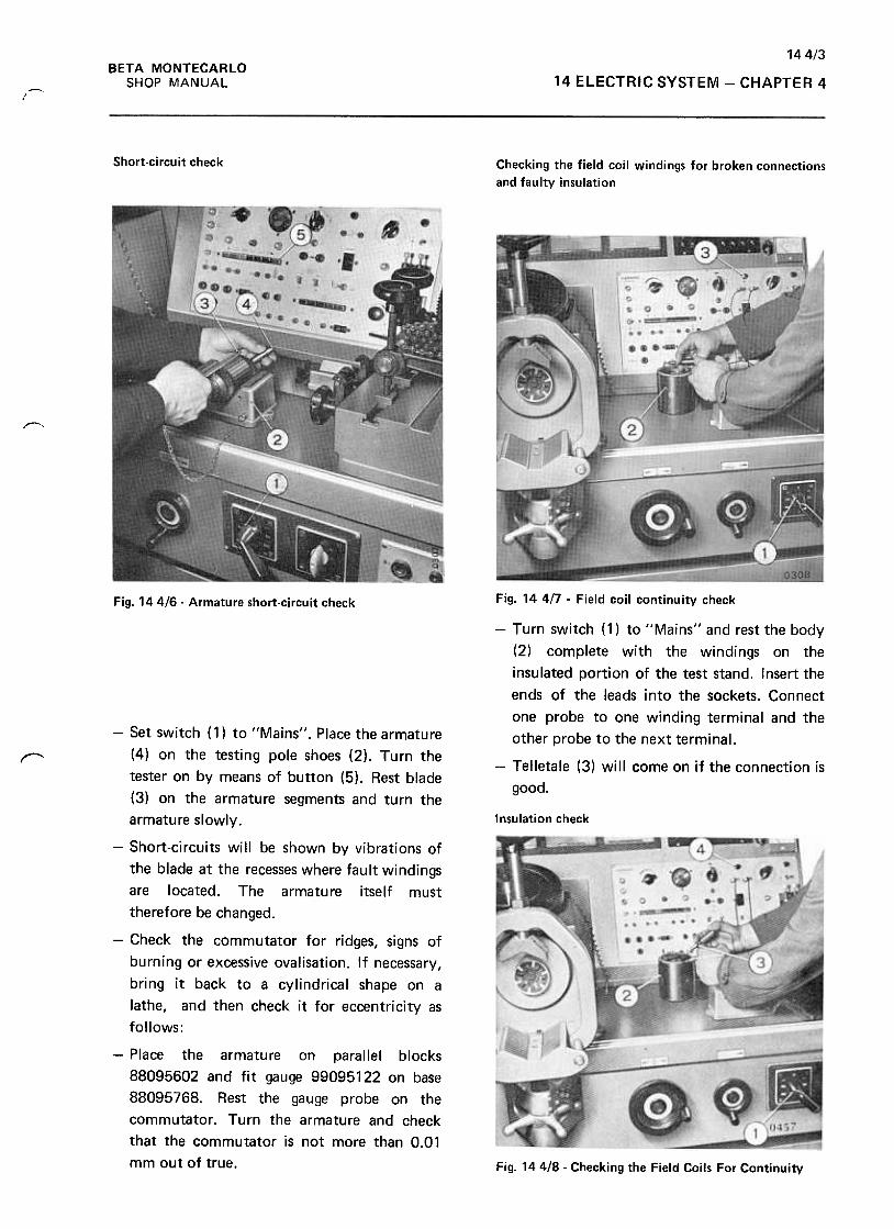
14413BETA MONTECARLO
SHOP MANUAL 14 ELECTRIC SYSTEM -CHAPTER 4r""I
Short-circuit check Checking the field coil windings for broken connections
and faulty insulation
~
Fig. 14 4n -Field coil continuity checkFig. 144/6- Armature short-circuit check
~
-Turn switch (1) to "Mains" and rest the body
(2) complete with the wind1ngs on the
insulated portion of the test stand. Insert the
ends of the leads into the sockets. Connect
one probe to one winding terminal and the
other probe to the next terminal.
-Telletale (3) will come on if the connection is
good.
Insulation check
-Set switch (1) to "Mains". Place the armature
(4) on the testing pole shoes (2). Turn the
tester on by means of button (5). Rest blade
(3) on the armature segments and turn the
armature slowly.
-Short-circuits will be shown by vibrations of
the blade at the recesses where fault windings
are located. The armature itself must
therefore be changed.
-Check the commutator for ridges, signs of
burning or excessive ovalisation. If necessary,
bring it back to a cylindrical shape on a
lathe, and then check it for eccentricity as
follows:
-Place the armature on parallel blocks
88095602 and fit gauge 99095122 on base
88095768. Rest the gauge probe on the
commutator. Turn the armature and check
that the commutator is not more than 0.01
mm out of true. Fig. 144/8- Checking the Field Coils For Continuity
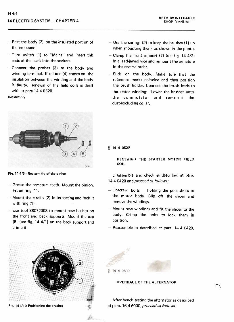
144/4BETA MONTECARLO
SHOP MANUAL14 ELECTRIC SYSTEM -CHAPTER 4
-Rest the body (2) on the insulated portion of
the test stand.
-Turn switch (1) to "Mains" and insert thb
ends of the leads into the sockets.
-Connect the probes (3) to the body and
winding terminal. If telltale (4) comes on, the
insulation between the winding and the body
is faulty. Renewal of the field coils is dealt
with at para 14 4 0520.
Reassembly
-Use the springs (2) to keep the brushes ( 1) up
when mounting them, as shown in the photo.
-Clamp the front support (7) (see fig. 144/2)
in a lead-jawed vice and remount the armature
in the reverse order.
-Slide on the body. Make sure that the
reference marks coincide and then position
the brush holder. Connect the brush leads to
the stator windings. Lower the brushes onto
the commutator and remount the
dust-excludingcollar .
§ 1440520
RENEWING THE STARTER MOTOR FIELD
COIL
Fig. 144/9- Reassembly of the pinion Disassemble and check as described at para.
14 4 0420 and proceed as follows:-Grease the armature teeth. Mount the pinion.
Fit on ring (1).
-Mount the circlip (2) in its seating and lock it
with ring (1).
-Use tool 88072008 to mount new bushes on
the front and back supports. Mount the cap
(8) (see fig. 14 4/1) on the back support and
crimp it.
-Unscrew bolts holding the pole shoes to
the motor body. Slip off the shoes and
remove the windings.
-Mount new windings and fit the shoes to the
body. Crimp the bolts to lock them in
position.
-Reassemble as described at para. 14 4 0420.
OVERHAUL OF THE ALTERNATOR "After bench testing the alternator as described
at para. 16 4 6000, proceed as follows:
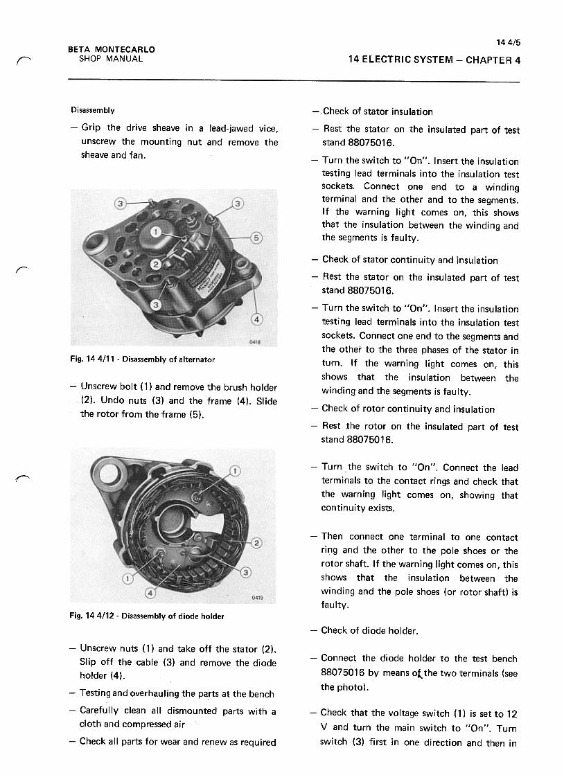
144/5BETA MONTECARLO
SHOP MANUALr 14 ELECTRIC SYSTEM -CHAPTER 4
Disassembly
-Grip the drive sheave in a lead-jawed vice,
unscrew the mounting nut and remove the
sheave and fan.
-Check of stator insulation
-Rest the stator on the insulated part of test
stand 88075016.
-Turn the switch to "an". Insert the insulation
testing lead terminals into the insulation test
sockets. Connect one end to a winding
terminal and the other and to the segments.
If the warning light comes on, this shows
that the insulation between the winding and
the segments is faulty.
r
Fig. 14 4111 -Disassembly of alternator
-Unscrew bolt ( 1 ) and remove the brush holder
(2). Undo nuts (3) and the frame (4). Slide
the rotor from the frame (5).
-Check of stator continuity and insulation
-Rest the stator on the insulated part of test
stand 88075016.
-Turn the switch to "an". Insert the insulation
testing lead terminals into the insulation test
sockets. Connect one end to the segments and
the other to the three phases of the stator in
turn. If the warning light comes on, this
shows that the insulation between the
winding and the segments is faulty.
-Check of rotor continuity and insulation
-Rest the rotor on the insulated part of test
stand 88075016.
-Turn the switch to "an". Connect the lead
terminals to the contact rings and check that
the warning light comes on, showing that
continuityexists.
f'
-Then connect one terminal to one contact
ring and the other to the pole shoes or the
rotor shaft. If the warning light comes on, this
shows that the insulation between the
winding and the pole shoes (or rotor shaft) is
faulty.Fig. 144112- Disassemb1y of diode holder
-Check of diode holder.
-Connect the diode holder to the test bench
88075016 by means ol the two terminals (see
the photo).
-Check that the voltage switch ( 1) is set to 12
V and turn the main switch to "an". Turn
switch (3) first in one direction and then in
-Unscrew nuts (1) and take off the stator (2).
Slip off the cable (3) and remove the diode
holder (4).
-Testing and overhauling the parts at the bench
-Carefully clean all dismounted parts with a
cloth and compressed air
-Check all parts for wear and renew as required
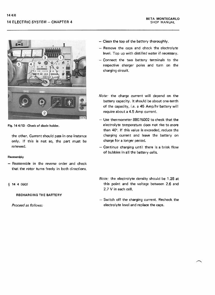
BETA MONTECARLO
SHOP MANUAL
144/6
14 ELECTRIC SYSTEM -CHAPTER 4
-Clean the top of the battery thoroughly.
-Remove the caps and check the electrolyte
level. Top up with distilled water if necessary.
-Connect the two battery terminals to the
respective charger poles and turn on the
charging circuit.
Note: the charge current will depend on the
battery capacity. It should be about one-tenth
of the capacity, i.e. a 45 Amp/hr battery will
require about a 4.5 Amp current.
Fig. 144/13- Check of diode holder.
the other. Current should pass in one instance
only. If this is not so, the part must be
renewed.
-Use thermometer 88075002 to check that the
electrolyte temperature does not rise to more
than 40°. If this value is exceeded, reduce the
charging current and leave the battery on
charge for a longer period.
-Continue charging until there is a brisk flow
of bubbles in all the battery cells.
Reassembly
-Reassemble in the reverse order and check
that the rotor turns freely in both directions.
Note: the electrolyte density should be 1.28 at
this point and the voltage between 2.6 and
2.7 V in each cell.
§ 1440900
RECHARGING THE BATTERY
-Switch off the charging current. Recheck the
electrolyte level and replace the caps.Proceed as follows:
~

14 2/1BETA MONTECARLO
SHOP MANUAL VARIANT SCORPION -14 ELECTRIC SYSTEM -CHAPTER 2
ElECTRIC SYSTEM
CHAPTER 2
-Unfasten the bolts (1 ), rotate the headlight in
the direction of the arrow, disconnect the
cable and remove the reflector .§ 1421000
REMOVING AND REFITTING LIGHTING
CLUSTER fright and left)
Fit the covers 88083051 and proceed as
follows:
/'
Removing
-Turn on the position lights so as to lift the
headlights and then disconnect the battery
cables.
Fig. 142/3 -Removing headlight support.
-Unfasten the bolts ( 1) and (2) working from
inside the front bonnet, remove the bo1t (3)
and take off the support assembly.
Refitting
-Refit in the reverse order to removal, then
check headlight aiming as described at 14 2
0100.r
§ 1426800
Fig. 14 211 -lighting cluster
-Unfasten the bolts ( 1) and (2) and remove the
framing (3).REMOVING AND REFITTING HEADLIGHT
LIFTER MOTOR
Fit the covers 88083051 and proceed as
follows:
Removing
-Turn on the position lights so as to lift the
headlights and then disconnect the battery
cables.
-Remove the luggage compartment light fitting
and the left-hand carpeting.Fig. 142/2- Paraboloid reflector securing bolts.
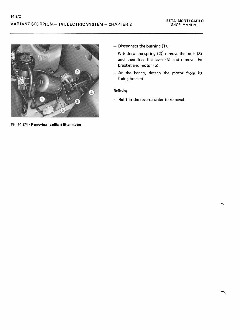
142/2BETA MONTECARLO
SHOP MANUALVARIANT SCORPION -14 ELECTRIC SYSTEM -CHAPTER 2
-Disconnect the bushing (1 ).
-Withdraw the spring (2): remove the bolts (3)
and then free the lever (4) and remove the
bracket and motor (5),
-At the bench, detach the motor from its
fixing bracket.
Refitting
-Refit in the reverse order to removal.
Fig. 142/4. Removing headlight lifter motor.
"'\
~
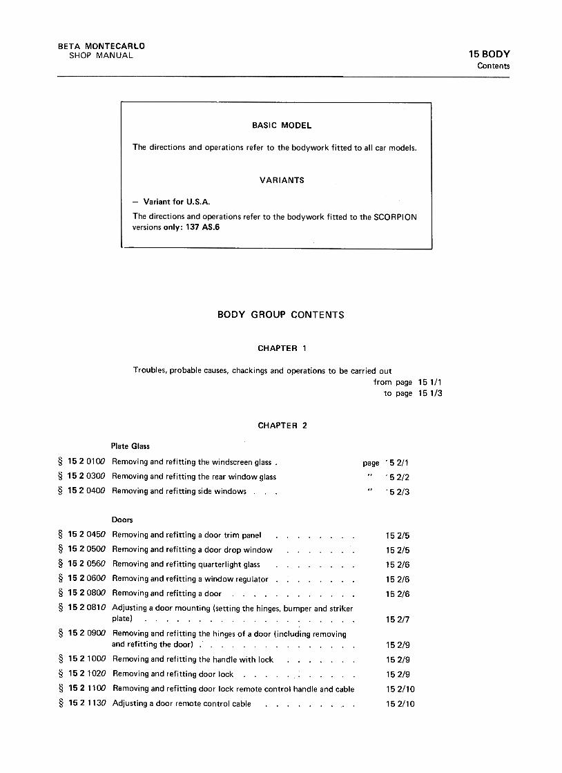
BETA MONTECARLO
SHOP MANUAL 15 BODY
Contents
BODY GROUP CONTENTS
CHAPTER 1
Troubles, probable causes, chackings and operations to be carried out
from page 151/1
to page 151/3
CHAPTER 2
Plate Glass
§ 152 0100 Removing and refitting the windscreen glass .
§ 1520300 Removing and refitting the rear window glass
§ 15 2 0400 Removing and refitting side windows .
page
15 2/5
15 2/5
15 2/6
15 2/6
15 2/6
152/7
15 2/9
15 2/9
152/9
152/10
152/10
Doors
§ 1520450 Removing and refitting a door trim panel
§ 1520500 Removing and refitting a door drop window
§ 152 0560 Removing and refitting quarterlight glass
§ 1520600 Removing and refitting a window regulator .
§ 152 0800 Removing and refitting a door
§ 1520810 Adjusting a door mounting (setting the hinges, bumper and striker
plate)
§ 1520900 Removing and refitting the hinges of a door (including removing
and refitting the door) .
§ 15 2 1000 Removi ng and refit ti ng the handle with lock
§ 152 1020 Removing and refitting door lock
§ 152 1100 Removing and refitting door lock remote control handle and cable
§ 15 2 1130 Adjusting a door remote control cable
52/1
52/2
52/3
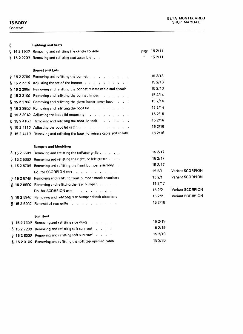
BETA MONTECARLO
SHOP MANUAL15 BODYContents
page 152/11
15 2/11
§ Paddings and Seats
§ 152 1900 Removing and refitting the centre console
§ 1522200 Removing and refitting seat assembly. .
152/13
152/13
152/13
152/14
152/14
152/14
15 2/15
152/16
152/16
152/16
Bonnet and Lids
§ 1522700 Removing and refitting the bonnet, , ., , ., ..
§ 15 2 2710 Adjusti ng the set of the bonnet. .
§ 15 2 2800 Removing and refitting the bonnet release cable and sheath
§ 152 31 DO Removing and refitting the bonnet hinges. , ..
§ 1523700 Removing and refitting the glove locker cover lock
§ 1523900 Removing and refitting the boot lid. ...
§ 1523910 Adjusting the boot lid mounting. , ...
§ 15241DO Removing and refitting the boot lid lock .., .0,
§ 15 2 4110 Adjusting the boot lid catch. , .
§ 1524410 Removing and refitting the boot lid release cable and sheath
152/17
152/17
152/17
15 2/1
15 2/1
152/17
152/2
15 2/2
152/18
Variant SCORPION
Variant SCORPION
Variant SCORPION
Variant SCORPION
Bumpers and Mouldings
§ 1525500 Removing and refitting the radiator grille. ...
§ 152 5600 Removing and refitting the right, or left gutter .
§ 1525700 Removing and refitting the front bumper assembly
Do. for SCORPION cars. § 1525740 Removing and refitting front bumper shock absorbers
§ 152 5900 Removing and refitting the rear bumper. .
Do. for SCORPION cars. § 152 5940 Removing and refitting rear bumper shock absorbers
§ 1526200 Renewal of rear grille
152/19
152/19
152/19
152/20
Sun Roof
§ 1527300 Removing and refitting side wing. ..
§ 1527200 Removing and refitting soft sun roof. ...
§ 1528000 Removing and refitting soft sun roof .
§ 152 3100 Removing and refitting the soft top opening catch
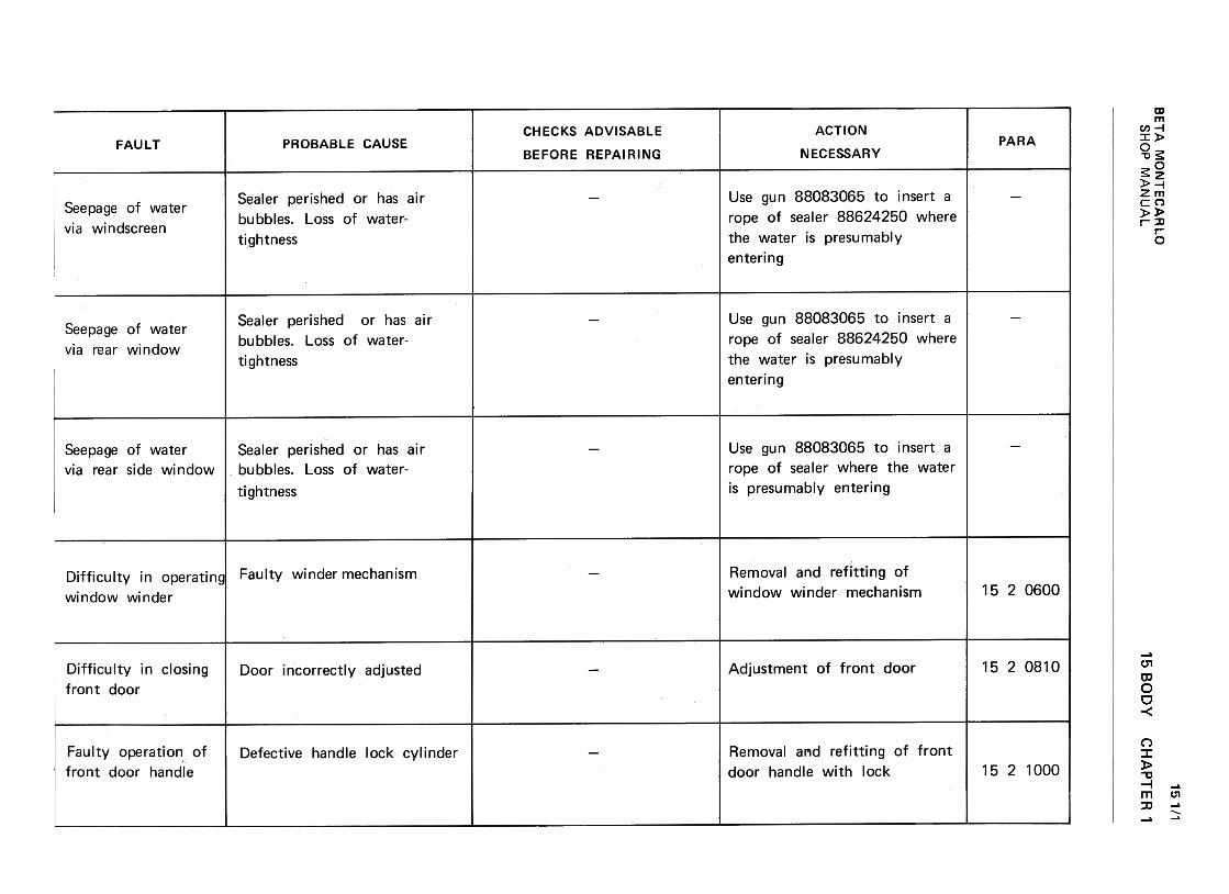
BE
TA
M
ON
TE
CA
RLO
>z
CI:
O
<t
-(I)1-
(I)u
w<
t uw2
w
{:3-J
zcc
-<
t a:
(/) -
-<t
>
~c
w<
t a:
(/) w
~
a:u
Ow
I!.
~
w(.)
cc
<t
0:<t
Il.1--J:)«u,
w(I)::>~uw.JIn~InOa:0-
'-ro ,'-
V)
Q)
ro ...
..I:: ro
'- ~
0-0
"0Q)
V)
..I:: V
)V
) °
.~
-JQ
)a.
.V)
V)
V)
'- ~
~
Q).C
...ro.c..l::Q
):JCI
(/) n
.~
a.>C
IJ ...a.>
+"'.C
~
~C
/I
C:o
.-L!") ~
ON
..0+
"' oq-
CIJ
L!")~E
<ooo~
0 00
a.>M
...
00 ...c.
o ~
C
/I00
CIJ
.-
00 ~
...a.>
C:,+
-+"'C
):JO
CIJc:
C)
~
..:a.>
a.>
a.>
c. a.>
+
"'
C/lO
.CC
::J
...+"'
Q)
'-~co c:
~
Q)
Q)
'-
-uO
"'
"0Q
) c:
01 .-
~
~Q
) C
O~
.~
'-ca"' ,
ca '-
.c 2!;ca
'- ~
0-
"'0 O
Q)
"'.c
"'"'
0.~
...J
Q)
a. ."'
"' "'
,-Q)Q
)Q
) ::c
c:
ro..c.:EQ
):JC)
CJ)
.n ..p
Q)
ro '-Q
)r::.
Q;
~(/)
.s 9
~
ON
..CV
ro
L!)~E
c.o co
~o
co Q
)(Y
) '-
co'-c.o
~
(/)co
ro .-
co~'-
Q)
c: C
):Joroc:C
) ~
..:
Q)
Q)
Q)C
.Q)
(/) O
..r::.
c:
::) '-
Q)
'-~
3ro
03
"0c:-0-0
3
Q)
'-0>
ro
ro ~
0.Q
) ro
r~
.->
'-CIJ
,'-C
/) (!)
CIJ
+"'
..c: C
IJ
'- ~
0,+-
"'0 °
(!) C
/)..c:
C/)
C/)
°.~
-.J
(!)a. .C
/)C
/) C
/)
'- (!)
(!)(!)
::0 c:
-..a
+"'
CIJ
..c:
(!) :J
~
(/) ..a
.;::,
'-ro
(!)+
-'+
-' ro
'Q)
~cnc:
(!)c:
O
+-'
C>
+-'
(!) c:
'- .~
L!) (!)
(!)c.o..C
:+-'
0 ~
c:
M
(!)
00'->o.E
!.-O
Oro..C
00 (!)
rocn
Ec:
'"1- :J
:JOcn
C>
(!)
(!) '-
(!) c.
c.cn
O:J
, o~
~O,--0Q
J c:
+-'
0-ro
~~
QJ
--00 °v;
QJ
'-0)
roro
QJ
0. '-
QJ
~
o~
'f- ~
0 .-c:
C)
co
c:.C:
.-(.)Q
).E
E
Q)
'- '-Q
)
"C"C
c: c:
co .-~
~
~o
oE
"Cc:
Q)
.-a:
~
E(I)c:(0..c:uQ
)E'-Q
)"0c:
.~>+-'
~(0~~c";:.
CtI
'-Q)
0.O
'-Q
)c
-0"-
c
>
"§"+
"'""3
~u
0,+
=-0
~
c
O
"§"
o0C.D
ONI!)
15 BO
DY
O.-000NI!)...o0"0+"'
c:0...--0+
"'c:0)
E"':J:0<
:r:
0'1c:
'iii0uc:'-
>
O+
-' O
--0~u +
-'~
c:
~
oO
..:::
"'00)+
-'(I):J
:cro>'Pu0)......Ouc.-...ooO
CH
AP
TE
R
1
-0 Q
)
c:'=c
0 c:
.-co~
.!:'-8.
'00
0""0>+"'
+"'
:J c:
co e
LJ..-
+"'
cO'---0
.Y.
C)
(.Jc
0.~
-
+"'
.-.r:.-+
"'Q
) .-
'- ~
"C
Q)
f:-ca "Cc
-ca~.r:.
o '-
E
oQ
) 0
c:"C
...(1)l:Jc:
>u~uO~l:Jc:<0
.c(1)>.~u(1)
-(1)0
oooNI!)
151/1
SH
OP
M
AN
UA
L
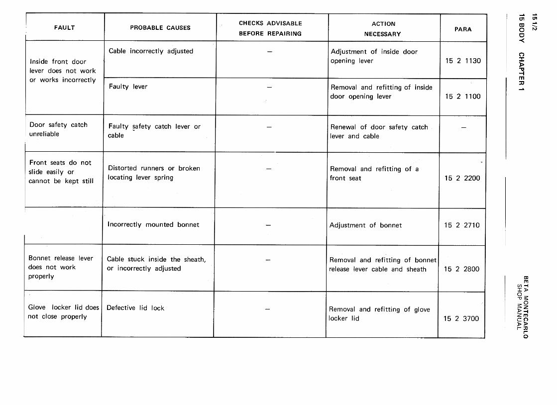
15 BO
DY
151/2w
"-I
zC
J -
~
CI:
(/) -
-~>
~c
w~
C
I:
(/) w
~
CI:
u O
w
u.~
w
u C
J >2
a:O
«
j:: ~
U
w«
Uw~
1-..J~~f'- (/Jw(/J::)«uw.J[0«[0Oa:n. ~~~d,
-0aJ+
--"':J
:0ca>""+:.
(.JaJ'-'-0(.Jc:aJ
::5ca() '-00-0Q
J-0'V
ic:
-.-0 '-Q
J>
c: Q
JQ
J-E
01c:
"' ,-
:J c:
,~
QJ
-0 0.
<!
0
CH
AP
TE
R'
0M.-.-NL!)
~
>'-
-0
t.)'->
Q)
0 >
'-
0 O
"0 0
uc:
c:c:0
~
"''-
0 ~
-"0 O
~
'- ~
.-Q)
"' >
'-
c: ~
n
...(!)>(!)
>+"'
::Jla
~
Q)
"'0.u;c:
-0C1
c:..jj
...."t:
Q)
->Q)
Q)
"'0 C
1c:
.Sca
c:Q)
-a.~
00E
O
Q)
0C
I:"'0 o0.-.-NLn
0!:(,)ca(,)>Q
J QJ
--ca.aV
) ca
'- -
0 ~
o c
O
::J
...0...Q)
>Q)
~ucau>Q)
'1-cacn/
>Q
)"'3:0ca
cau.
u
..c.ucou>Q
)'+
-coC/)
'-0 Q
)0-
"'O.a
co'+
- U
°
"'0-c:co
co
~Q)
'-c:
Q)
Q)
>a:
Q)
caJ~0'-.a'-
0!O
c
V)
..:'-
c.aJ
V)
cc '-
:J aJ
'- >aJ
"tJaJ 0!
+"
c
O
..j;j+
" ro
V)
u
.-oo~ (0-OC
Ic:
'.j:;
:.=Q)
'-
"0c:(0 (0
(0 Q
)>
tII
0 E c:
Q)
0a:..::: o0NNNLn
+"'
=O
+
"'c
In+"'
O,-a.
"'OoQ
)~
~>
Q)
ro=.c
Q)
InIn
roQ)
+"'
+"'
oc
Q)
co"t:J
c'-
.-roU
- "'ij;
u
~c:c:O.0"'0~c:::J0E>'"+
='
u~......0uc: +"'
aIc:c:0.0-0+"'
c:aIE+"'
(I):J
:0-<
1'
0..-""NNI!)
...Q)
>Q)
Q)~
"' ...
CIJ
0..P
. :5:
Q)
>-
0-c: ...
Q)
Q)
c: "'
0.
c:Q)0
0 0
...((!-n~
..c-+
-'roQ
J..cC
/I
QJ"0
..c Q
J+
-' +
-'C
/IQ
J .~
"0"0.u;
roc:
>
.:¥.~u
u
:;) ~
+-'
...C
/I O
QJ
u-c:..c
.-
ro ...
u o
+"'
Q)
C..r::.
c +
"'O
ro
.0 Q
)
..r::.-voOO
)"'Cc
~
.£ Q
)
:.:::cQ
) ro
'- u
"'C
'-c
Q)
ro >
-~ro>
Q)
O
voE
~
Q)-
a: ~ oo00NNU")
BE
TA
M
ON
TE
CA
RLO
"'QJ
O-0 >
-o""C.-Q
J-0.'-
0Q
J '-
~
0.uO
Q
J-"'
0Q
J u
>0 +
-'-0~
h
~c.>O"0a>>.~c.>a>
'+-a>
O
(I)>O0)
-O0)c:
";;.
'i=(I)'-
-0c:!0-0
ro=>O
'-
E~
(I) u
0:: O oor...MNL!)
SH
OP
M
AN
UA
L
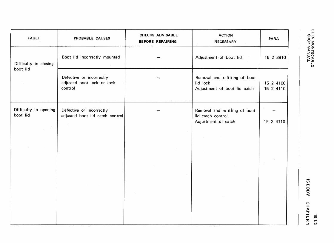
BE
TA
M
ON
TE
CA
RLO
w
~-I
200
-«
cx:(I)
--«>
0..C
w
« cx:
(I) w
~
cx:U
O
W
u.~
W
U
~ >z
a:O
<
t
~
~u
w<
t uwz
1-.J:)~lL (/)w(/)::>0:{uw-Im0:{mO~~ ~(1:~~
"'0Q)
+-'
c:JOE>~uQ)
'-'-0uc~+-'
ooro ;g+"'
o0..0-0+"'
c:0)E+"'
(I):J
:0<! 0-0>MNID
CI
~°onoU~~"'0
3:=C.)
0- ::::
0
0- 0
0..0
~u0>
-~
...
U
0Q
)t~0
UU
0
c: -+
-'...oo
o..cQ
).~
"'0
+-,Q
)-U
+
-' 0
Q)
"' ...
'+-
:J +
-'Q
) .~
c:
0"'00co
u
000..-
vvNN
L!)L!)
O
.cO
u
.c ~u
-O
"tJC
)c: .;;.
00~
..c
Q)
"tJ 0
c: ca
c:Q)
ro .::t.
E>
u
o o
"'
E
-::]
Q)"tJ:C
a:==
<t:
0)c:
'C:Q)
0-0c:
Z;--c
:J -
u0- +
-'-0:=
o
o~
0...c:°u
:?:..c:u
u Q) ro
...u...O
"Uu
.-c:
-
...°°
°..cQ
).~
"UQ
)u Q
) (/)
'+-
:;,Q
) .-
Q~ +-'
o0.D'4-00)c:.-.L::.~
(J
.-+-'
'4- -(tJ
C1>
0
(J'-
'-+-,'4-
"Cc:O
c: o
(tJ (J
+-'
c:-.L::.
C1>
~
(J E
o 'ro
+-'
E
(J ~
C1>
.~
"C"C
a:==
«
0..-..-~NlC
)
15 BO
DY
CH
AP
TE
R
1
151/3
SH
OP
M
AN
UA
L
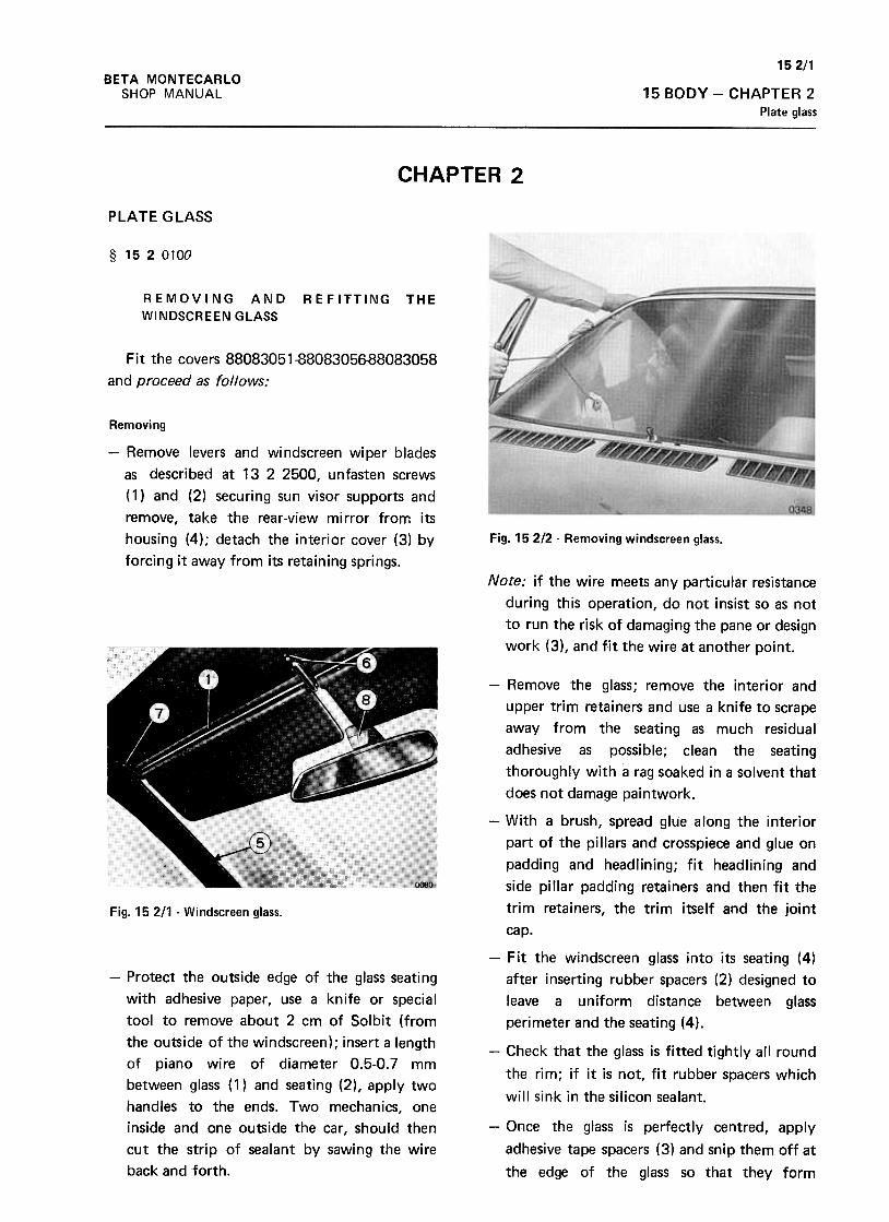
152/1BETA MONTECARLO
SHOP MANUAL 15 BODY -CHAPTER 2
Plate glass
CHAPTER 2
PLATE GLASS
§ 1520100
REMOVING AND
WINDSCREEN GLASS
REFITTING THE
Fit the covers 88083051-8808305688083058
and proceed as follows:
Removing
-Remove levers and windscreen wiper blades
as described at 13 2 2500, unfasten screws
( 1) and (2) securing sun visor supports and
remove, take the rear-view mirror from its
housing (4); detach the interior cover (3) by
forcing it away from its retaining springs.
Fig. 15212- Removing windscreen glass.
Note: if the wire meets any particular resistance
during this operation, do not insist so as not
to run the risk of damagfng the pane or design
work (3), and fit the wire at another point.
Fig. 15 2/1 -Windscreen glass.
-Protect the outside edge of the glass seating
with adhesive paper, use a knife or special
tool to remove about 2 cm of Solbit (from
the outside of the windscreen); insert a length
of piano wire of diameter 0.5-0.7 mm
between glass (1) and seating (2), apply two
handles to the ends. Two mechanics, one
inside and one outside the car, should then
cut the strip of sealant by sawing the wire
back and forth.
-Remove the glass; remove the interior and
upper trim retainers and use a knife to scrape
away from the seating as much residual
adhesive as possible; clean the seating
thoroughly with a rag soaked in a solvent that
does not damage paintwork.
-With a brush, spread glue along the interior
part of the pillars and crosspiece and glue on
padding and headlining; fit headlining and
side pillar padding retainers and then fit the
trim retainers, the trim itself and the joint
cap.
-Fit the windscreen glass into its seating (4)
after inserting rubber spacers (2) designed to
leave a uniform distance between glass
perimeter and the seating (4).
-Check that the glass is fitted tightly all round
the rim; if it is not, fit rubber spacers which
will sink in the silicon sealant.
-Once the glass is perfectly centred, apply
adhesive tape spacers (3) and snip them off at
the edge of the glass so that they form
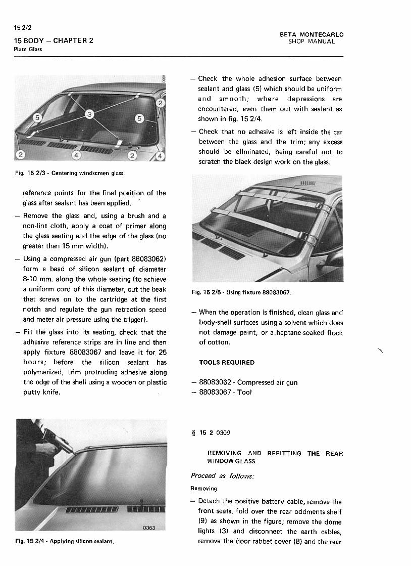
152/2BETA MONTECARLO
SHOP MANUAL15 BODY -CHAPTER 2Plate Glass
-Check the whole adhesion surface between
sealant and glass (5) which should be uniform
and smooth; where depressions are
encountered, even them out with sealant as
shown in fig. 15 2/4.
-Check that no adhesive is left inside the car
between the glass and the trim; any excess
should be eliminated, being careful not to
scratch the black design work on the glass.
Fig. 15 2/3 -Centering windscreen glass.
Fig. 152/5- Using fixture 88083067.
-When the operation is finished, clean glass and
body-shell surfaces using a solvent which does
not damage paint, or a heptane-soaked flock
of cotton .
reference points for the final position of the
glass after sealant has been applied.
-Remove the glass and, using a brush and a
non-lint cloth, apply a coat of primer along
the glass seating and the edge of the glass (no
greater than 15 mm width),
-Using a compres~ed air gun (part 88083062)
form a bead of silicon sealant of diameter
8-10 mm. along the whole seating (to achieve
a uniform cord of this diameter, cut the beak
that s-crews on to the cartridge at the first
notch and regulate the gun retraction speed
and meter air pressure using the trigger).
-Fit the glass into its seating, check that the
adhesive reference strips are in line and then
apply fixture 88083067 and leave it for 25
hours; before the silicon sealant has
polymerized, trim protruding adhesive along
the edge of the shell using a wooden or plastic
putty knife.
"\
TOOLS REQUIRED
-88083062- Compressed air gun
-88083067- Tool
§ 1520300
REMOVING AND REFITTING THE REAR
WINDOW GlASS
Proceed as follows:
Removing
-Detach the positive battery cable, remove the
front seats, fold over the rear oddments shelf
(9) as shown in the figure; remove the dome
lights (3) and disconnect the earth cables,
remove the door rabbet cover (8) and the rearFig. 15214- Applying silicon sealant.
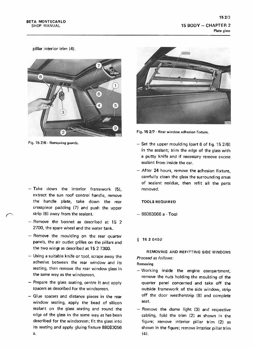
152/3BETA MONTECARLO
SHOP MANUAL 15 BODY -CHAPTER 2Plate glass
pillar interior trim (4).
Fig. 15 2n -Rear window adhesion fixture.
Fig. 152/6- Removing guards. -Set the upper moulding (part 6 of fig. 152/6)
in the sealant; trim the edge of the glass with
a putty knife and if necessary remove excess
sealant from inside the car.
-After 24 hours, remove the adhesion fixture,
carefully clean the glass the surrounding areas
of sealant residue, then refit all the parts
removed.
TOOLS REQUIRED
-88083066 a- Toolr
§ 1520400
-Take down the interior framework (5),
extract the sun roof control handle, remove
the handle plate, take down the rear
crosspiece padding (7) and push the upper
strip (6) away from the sealant.
-Remove the bonnet as described at 15 2
2700, the spare wheel and the water tank.
-Remove the moulding on the rear quarter
panels, the air outlet grilles on the pillars and
the two wings as described at 15 2 7300.
-Using a suitable knife or tool, scrape away the
adhesive between the rear window and its
seating, then remove the rear window glass in
the same way as the windscreen.
-Prepare the glass seating, centre it and apply
spacers as described for the windscreen.
-Glue spacers and distance pieces in the rear
window seating, apply the bead of silicon
sealant on the glass seating and round the
edge of the glass in the same way as has been
described for the windscreen; fit the glass into
its seating and apply gluing fixture 88083056
a.
REMOVING AND REFITTING SIDE WINDOWS
Proceed as follows:
Removing
-Working inside the engine compartment,
remove the nuts holding the moulding of the
quarter panel concerned and take off the
outside framework of the side window, strip
off the door weatherstrip (8) and complete
seat.
-Remove the dome light (3) and respective
cabling, fold the trim (2) as shown in the
figure; remove interior pillar trim (2) as
shown in the figure; remove interior pillartrim
(4).

152/4BETA MONTECARLO
SHOP MANUAL15 BODY -CHAPTER 2
Plate glass
-Trim excess sealant, clean the glass and refit
all parts removed in the reverse order.
Fig. 15 218 .Parts to be removed inside the car .
Fig. 15 219 -Side window adhesion fixture.
Take out the glass as described at 1520200.
Prepare the glass, the seating, centering and
spacing as described at 15 2 0300 and make
sure that there is a constant clearance of 3
mm between the glass and its seating.
Glue as described for the windscreen, apply
fixture 88083056 b and leave standing for 24
hours.
TOOLS REQUIRED
-88083066 b- Side window adhesion fixture.
~
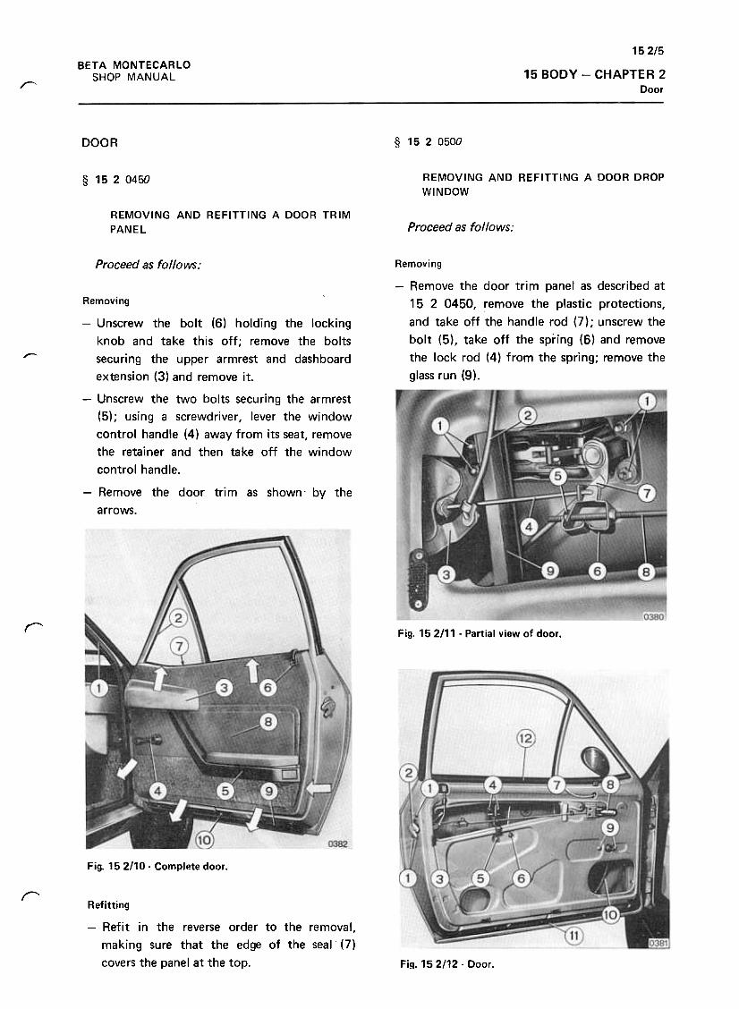
152/5
15 BODY -CHAPTER 2Door
BETA MONTECARLO
SHOP MANUAL"
DOOR § 1520500
REMOVING AND REFITTING A DOOR DROP
WINDOW§ 1520450
REMOVING AND REFITTING A DOOR TRIM
PANEL Proceed as follows:
Proceed as follows: Removing
-Remove the door trim panel as described at
15 2 0450, remove the plastic protections,
and take off the handle rod (7) ; unscrew the
bolt (5), take off the spring (6) and remove
the lock rod (4) from the spring; remove the
glass run (9).
,..-
Removing
-Unscrew the bolt (6) holding the locking
knob and take this off; remove the bolts
securing the upper armrest and dashboard
extension (3) and remove it.
-Unscrew the two bolts securing the armrest
(5); using a screwdriver, lever the window
control handle (4) away from its seat, remove
the retainer and then take off the window
control handle.
-Remove the door trim as shown- by the
arrows.
r Fig. 15 2111 -Partial view of door .
Fig. 152110- Complete door.
rRefitting
-Refit in the reverse order to the removal,
making sure that the edge of the seal (7)
covers the panel at the top. Fig. 152/12- Door.
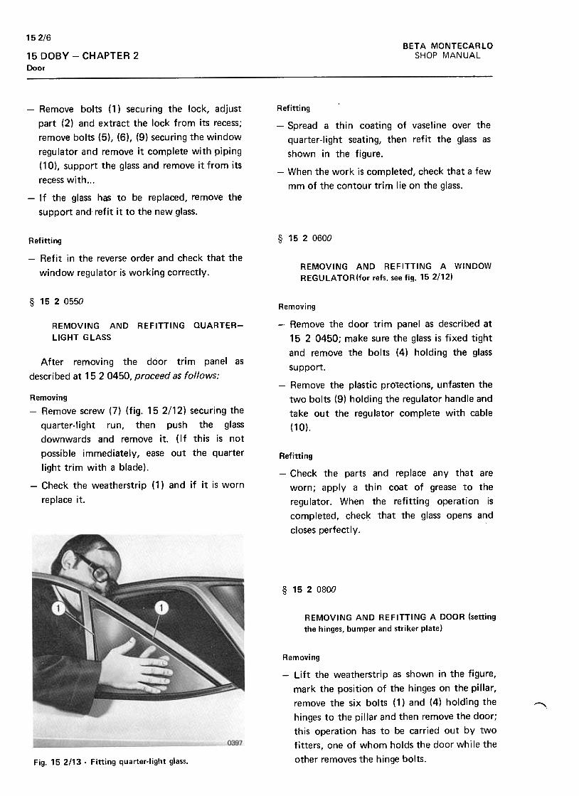
15 2/6
BETA MONTECARLO
SHOP MANUAL15 DOBY -CHAPTER 2Door
Refitting
-Spread a thin coating of vaseline over the
quarter-Iight seating, then refit the glass as
shown in the figure.
-When the work is completed, check that a few
mm of the contour trim lie on the glass.
-Remove bolts (1) securing the lock, adjust
part (2) and extract the lock from its recess;
remove bolts (5), (6), (9) securing the window
regulator and remove it complete with piping
( 10) , su pport the glass and remove it from its
recess with...
-If the glass has to be replaced, remove the
support and refit it to the new glass.
§ 1520600Refitting
-Refit in the reverse order and check that the
window regulator is working correctly.REMOVING AND REFITTING A WINDOW
REGULATOR(for refs. see fig. 152!12)
§ 1520550
Removing
-Remove the door trim panel as described at
15 2 0450; make sure the glass is fixed tight
and remove the bolts (4) holding the glass
support.
REMOVING AND REFITTING OUARTER-
llGHT GlASS
After removing the door trim panel as
described at 15 2 0450, proceed as follows:-Remove the plastic pro1ections, unfasten the
two bolts (9) holding the regulator handle and
take out the regulator complete with cable
(10).
Refitting
-Check the parts and replace any that are
worn; apply a thin coat of grease to the
regulator. When the refitting operation is
completed, check that the glass opens and
closes perfectly.
Removing-Remove screw (7) (fig. 15 2/12) securing the
quarter-Iight run, then push the glass
downwards and remove it. (If this is not
possible immediately, ease out the quarter
light trim with a blade).
-Check the weatherstrip (1) and if it is worn
replace it.
§ 1520800
REMOVING AND REFITTING A DOOR (setting
the hinges, bumper and striker plate)
Removing
-Lift the weatherstrip as shown in the figure,
mark the position of the hinges on the pillar,
remove the six bolts (1) and (4) holding the
hinges to the pillar and then remove the door;
this operation has to be carried out by two
fitters, one of whom holds the door while the
other removes the hinge bolts.
~
Fig. 152/13 -Fitting quarter-Iight glass.
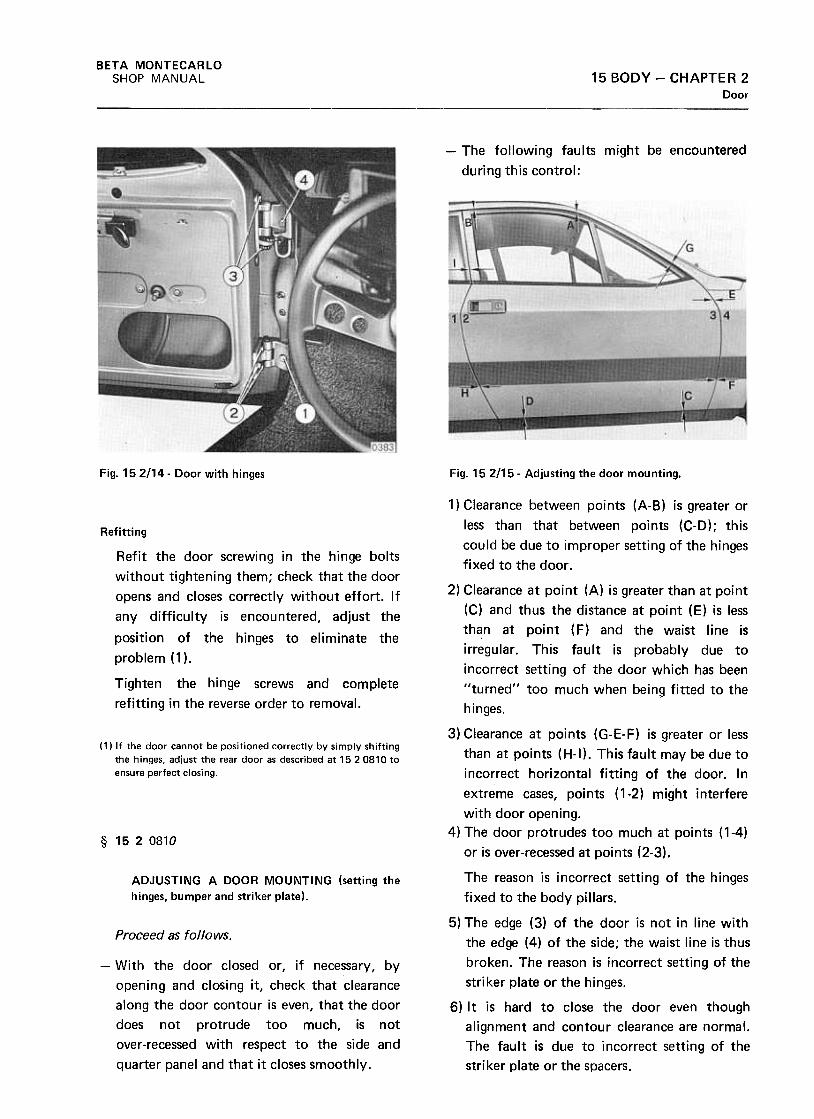
BETA MONTECARLO
SHOP MANUAL 15 BODY -CHAPTER 2Door
-The following faults might be encountered
during this control:
Fig. 152114- Door with hinges Fig. 15 2115- Adjusting the door mounting.
1) Clearance between points (A-B) is greater or
less than that between points (C-D); this
could be due to improper setting of the hinges
fixed to the door.
Refitting
2) Clearance at point (A) is greater than at point
(C) and thus the distance at point (E) is less
th~n at point ( F) and the waist line is
irregular. This fault is probably due to
incorrect setting of the door which has been
llturned'l too much when being fitted to the
hinges.
Refit the door screwing in the hinge bolts
without tightening them; check that the door
opens and closes correctly without effort. If
any difficulty is encountered, adjust the
position of the hinges to eliminate the
problem (1 ).
Tighten the hinge screws and complete
refitting in the reverse order to removal.
( 1) If the door cannot be positioned correctly by simply shiftingthe hinges, adjust the rear door as described at 1520810 toensure perfecr closing.
§ 1520810
ADJUSTING A DOOR MOUNTING (setting the
hinges, bumper and striker plate).
Proceed as follows.
-With the door closed or, if necessary, by
opening and closing it, check that clearance
along the door contour is even, that the door
does not protrude too much, is not
over-recessed with respect to the side and
quarter panel and that it closes smoothly.
3) Clearance at points (G-E-F) is greater or less
than at points (H-I). This fault may be due to
incorrect horizontal fitting of the door. In
extreme cases, points ( 1-2) might interfere
with door opening.
4) The door protrudes too much at points (1-4)
or is over-recessed at points (2-3).
The reason is incorrect setting of the hinges
fixed to the body pillars.
5) The edge (3) of the door is not in line with
the edge (4) of the side; the waist line is thus
broken. The reason is incorrect setting of the
striker plate or the hinges.
6) It is hard to close the door even though
alignment and contour clearance are normal.
The fault is due to incorrect setting of the
striker plate or the spacers.

15 2/8BETA MONTECARLO
SHOP MANUAL15 BODY -CHAPTER 2
Door
hinges until the faults have been eliminated;
then tighten the bolts and check that the
faults have in fact been removed.
-To eliminate the faults noted at points (5)
and (6), work directly on the striker plate or
spacers, slackening the mounting bolts or
increasing or reducing the number of spacers.
To eliminate the faults noted at points (1) -
(2) -(3) -(4) , proceed as follows:
-Remove the door trim panel; slacken the bolts
securing the hinges to the door, shift the door
with respect to the hinges so as to get rid of
the faults, then tighten the bolts again.
-If this is not enough, slacken the bolts
securing the hinges to the pillar and move the
--
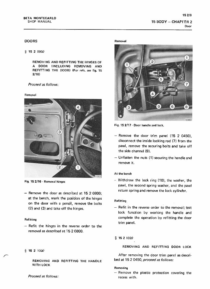
152/9BETA MONTECARLO
SHOP MANUAL 15 BODY -CHAPTER 2Door
DOORS Removal
§ 1520900
REMOVING AND REFITTING THE HINGES OF
A DOOR (INCLUDING REMOVING AND
REFITTING THE DOOR) (For refs. see fig. 15
2!10)
Proceed as follows:
Removal
Fig. 152/17. Door handle and lock.
-Remove the door trim panel (15 2 0450),
disconnect the inside locking rod (7) from the
pawl, remove the securing bolts and take off
the side channel (9),
-Unfasten the nuts ( 1) securing the handle and
remove it.
At the bench
-Withdraw the lock ring (10), the washer, the
pawl, the second spring washer, and the pawl
return spring and remove the lock cylinder.
Fig. 152116 -Removal hinges
-Remove the door as described at 15 2 0800;
at the bench, mark the position of the hinges
on the door with a pencil, remove the bolts
(2) and (3) and take off the hinges.
Refitting
-Refit in the reverse order to the removal; test
lock function by working the handle and
complete the operation by refitting the door
trim panel.Refitting
-Refit the hinges in the reverse order to the
removal as described at 1520800.
§ 1521020
REMOVING AND REFITTING DOOR LOCK
§ 1521000
After removing the door trim panel as descri-
bed at 15 2 0450, proceed as follows:r
REMOVING AND REFITTING THE HANDLE
WITH LOCKRemoving-Remove the plastic protection covering the
recess with.Proceed as follows:
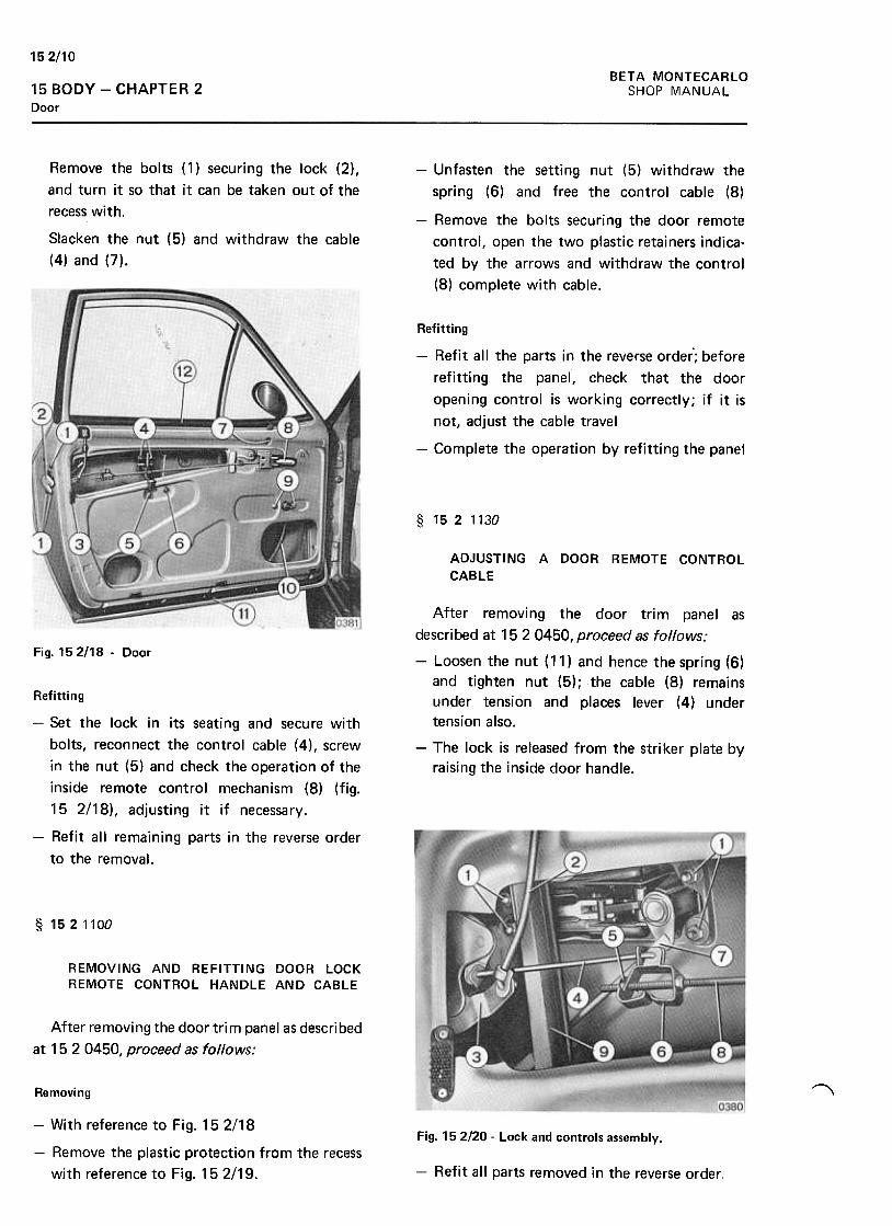
152110
BETA MONTECARLO
SHOP MANUAL15 BODY -CHAPTER 2Door
-Unfasten the setting nut (5) withdraw the
spring (6) and free the control cable (8)
-Remove the bolts securing the door remote
control, open the two plastic retainers indica-
ted by the arrows and withdraw the control
(8) complete with cable.
Remove the bolts (1) securing the lock (2),
and turn it so that it can be taken out of the
recess with.
Slacken the nut (5) and withdraw the cable
(4) and (7).
Refitting
-Refit all the parts in the reverse order'; before
refitting the panel, check that the door
opening control is working correctly; if it is
not, adjust the cable travel
-Complete the operation by refitting the panel
§ 1521130
ADJUSTING A DOOR REMOTE CONTROL
CABLE
Fig. 152118 .Door
After removing the door trim panel as
described at 152 0450, proceed as follows:
-Loosen the nut (11) and hence the spring (6)
and tighten nut (5); the cable (8) remains
under tension and places lever (4) under
tension also.
-The lock is released from the striker plate by
raising the inside door handle.
Refitting
-Set the lock in its seating and secure with
bolts, reconnect the control cable (4), screw
in the nut (5) and check the operation of the
inside remote control mechanism (8) (fig.
152/18), adjusting it if necessary.
-Refit all remaining parts in the reverse order
to the removal.
§ 1521100
REMOVING AND REFITTING DOOR LOCKREMOTE CONTROL HANDLE AND CABLE
After removing the door trim panel as described
at 15 2 0450, proceed as follows:
~Removing
Fig. 152120- Lock and controls assembly.-With reference to Fig. 15 2/18
-Remove the plastic protection from the recess
with reference to Fig. 15 2/19. -Refit all parts removed in the reverse order,
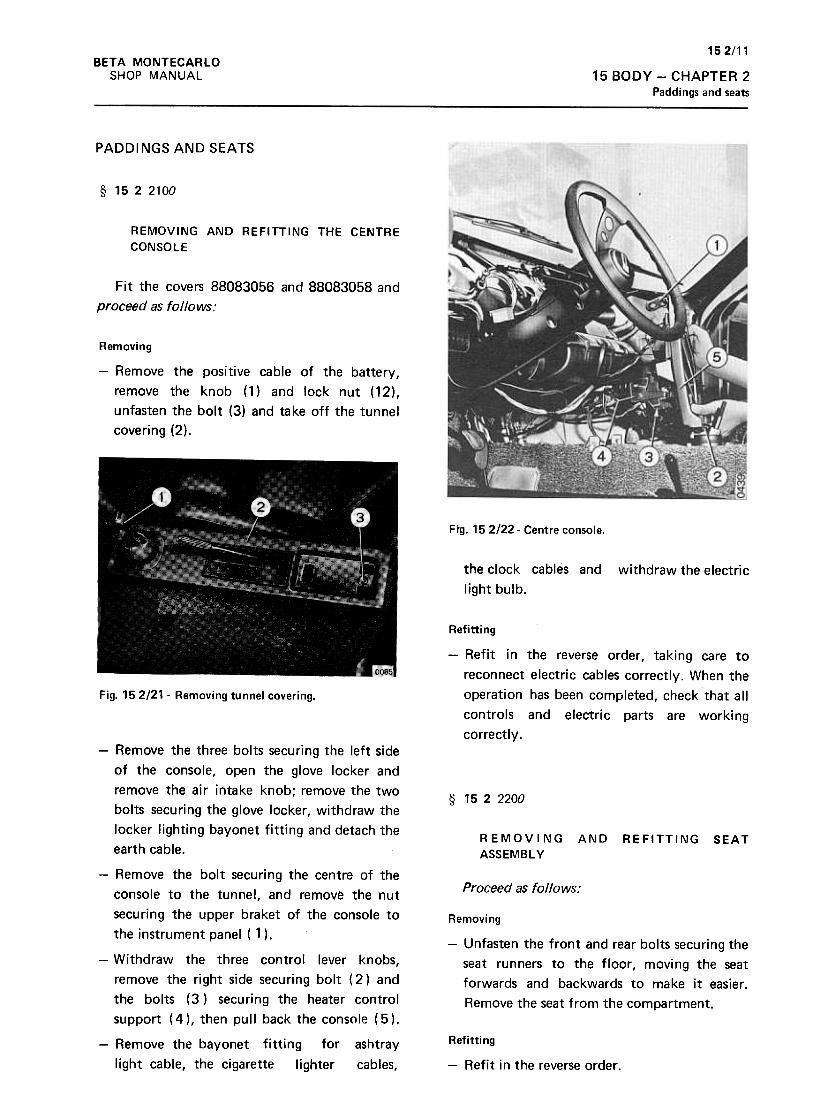
152/11BETA MONTECARLO
SHOP MANUAL 15 BODY -CHAPTER 2
Paddings and seats
PADDINGS AND SEATS
§ 1522100
REMOVING AND REFITTING THE CENTRE
CONSOLE
Fit the covers 88083056 and 88083058 and
proceed as follows:
Removing
-Remove the positive cable of the battery,
remove the knob (1) and lock nut (12),
unfasten the bolt (3) and take off the tunnel
covering (2).
Fig. 15 2122- Centre console.
the clock cables and
light bulb.
withdraw the electric
Refitting
-Refit in the reverse order, taking care to
reconnect electric cables correctly. When the
operation has been completed, check that all
controls and electric parts are working
correctly.
Fig. 152/21- Removing tunnel covering.
§ 1522200
REMOVING
ASSEMBLY
AND REFITTING SEAT
Proceed as follows:
Removing
-Unfasten the front and rear bolts securing the
seat runners to the floor, moving the seat
forwards and backwards to make it easier.
Remove the seat from the compartment.
-Remove the three bolts securing the left side
of the console, open the glove locker and
remove the air intake knob; remove the two
bolts securing the glove locker, withdraw the
locker lighting bayonet fitting and detach the
earth cable.
-Remove the bolt securing the centre of the
console to the tunnel, and remove the nut
securing the upper braket of the console to
the instrument panel ( 1 ).
-Withdraw the three contro1 lever knobs,
remove the right side securing bolt ( 2) and
the bolts (3 ) securing the heater control
support ( 4 ), then pull back the console ( 5 ).
-Remove the bayonet fitting for ashtray
light cable, the cigarette lighter cables,
Refitting
-Refit in the reverse order.
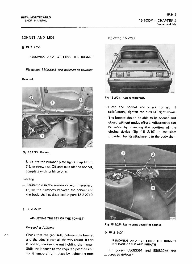
152/13
15 BODY -CHAPTER 2Bonnet and lids
BETA MONTECARLO
SHOP MANUAL
BONNET AND LIDS (3) of fig. 152/23.
§ 1522700
REMOVING AND REFITTING THE BONNET
Fit covers 88083051 and proceed as follows:
Removal
Fig. 15 2/24- Adjusting bonnet.
-Close the bonnet and check its set. If
satisfactory, tighten the nuts (4) right down.
-The bonnet should be able to be opened and
closed without undue effort. Adjustments can
be made by changing the position of the
closing device (fig. 15 2/19) in the slots
provided for its attachment to the body shell.
Fig. 15 2123 -Bonnet.
-Slide off the number plate lights snap fitting
(1 ), unscrew nut (2) and take off the bonnet,
complete with its hinge pins.
Refitting
-Reassemble in the reverse order. If necessary,
adjust the distances between the bonnet and
the body shell as described at para 1522710.
§ 1522710
ADJUSTING THE SET OF THE BONNET
Fig. 152/25- Rear closing device for bonnet.Proceed as follows:
§ 1522800
r- -Check that the gap (A-B) between the bonnet
and the edge is even all the way round. If this
is not so, slacken the nut holding the hinges.
Shift the bonnet to the required position and
fix it temporarily in place by tightening nuts
REMOVING AND REFITTING THE BONNET
RELEASE CABLE AND SHEATH
Fit covers 88083051
proceed as follows:and 88083056 and

152/14BETA MONTECARLO
SHOP MANUAL15 BODY -CHAPTER 2
Bonnet and lids
that they fit with the marks made--On removal.
Return the bonnet to its place and if
necessary, adjust its position as described at
para 1522710.
Removal
-Detach the cable from the lock
-From inside the vehicle, unscrew the bolt
holding the assembly to the body and remove,
complete with sheath and cable.
Refitting
-Reassemble in the reverse order and check
that the opening mechanism works properly.§ 1523700
REMOVING AND REFITTING THE GLOVE
LOCKER COVER LOCK
§ 1523100 Fit covers 88083056 and 88083058 and
proceed as follows:
REMOVING AND REFITTING THE BONNET
HINGESRemoval
-Open the glove locker cover. Unscrew the
bolts holding the lock to the cover and
remove the lock.
Fit covers 88083051 and proceed as follows:
Removal
Refitting
-Reassemble in the reverse order. Check that
the lock closes properly.
§ 1523900
REMOVING AND REFITTING THE BOOT LID
Proceed as follows:
For references, see fig. 15 2/27
Removal
Fig. 152126- Bonnet.-Slide off the snap rings (1 ), unhook the spring
(2), extract pins (3) from the hinges (4), and
remove the lid. Two persons are needed for
this operation.
-Remove the bonnet as described at para. 152
2700 and unscrew nuts (4). Before detaching
the hinges mark their position to make
reassemblyeasier. Remove the hinges (3).
~
Refitting
At the bench
-Remove the air intake strips (5) and the two
screws holding the support arm block (6).-Remount new hinges in the reverse order so
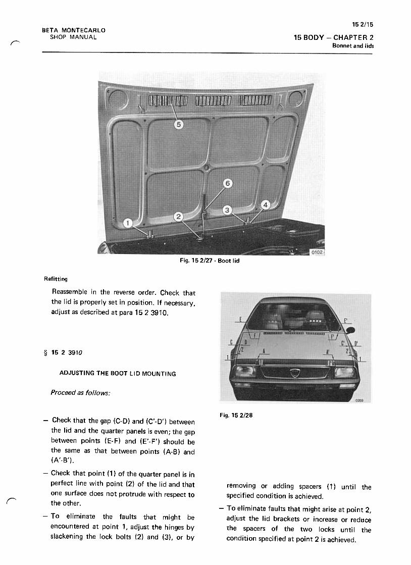
152/15BETA MONTECARLO
SHOP MANUAL 15 BODY -CHAPTER 2
Bonnet and lidsr
Fig. 152/27 -Boot lid
Refitting
Reassemble in the reverse order. Check that
the lid is properly set in position. It necessary,
adjust as described at para 1523910.
§ 1523910
ADJUSTING THE BOOT LID MOUNTING
Proceed as follows:
Fig. 15 2/28
r
removing or adding spacers (1) until the
specified condition is achieved.
-To eliminate faults that might arise at point 2,
adjust the lid brackets or increase or reduce
the spacers of the two locks unti I the
condition specified at point 2 is achieved.
-Check that the gap (C-D) and (C'-D') between
the lid and the quarter panels is even; the gap
between points (E-F) and (E'-F') should be
the same as that between points (A-B) and
(A'-B').
-Check that point (1) of the quarter panel is in
perfect line with point (2) of the lid and that
one surface does not protrude with respect to
the other .
-To eliminate the faults that might be
encountered at point 1, adjust the hinges by
slackening the lock bolts (2) and (3), or by
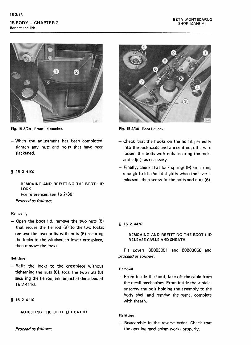
152/16BETA MONTECARLO
SHOP MANUAL15 BODY -CHAPTER 2
Bonnet and lids
Fig. 152/29- Front lid bracket. Fig. 152/30- Boot lid lock.
-When the adjustment has been completed,
tighten any nuts and bolts that have been
slackened.
-Check that the hooks on the lid fit perfectly
into the Jock seats and are centred; otherwise
loosen the bolts with nuts securing the locks
and adju$t as necessary.
-Finally, check that lock springs (9) are strong
enough to lift the lid slightly when the lever is
released, then screw in the bolts and nuts (6).
§ 1524100
REMOVING AND REFITTING THE BOOT LID
LOCK
For references, see 15 2/30
Proceed as follows:
Removing
-Open the boot lid, remove the two nuts (8)
that secure the tie rod (9) to the two loeks;
remove the two bolts with nuts (6) securing
.the locks to the windscreen lower crosspiece,
then remove the locks.
§ 1524410
REMOVING AND REFITTING THE BOOT LID
RELEASE CABLE AND SHEATH
Fit covers 88083051- and 88083056 and
proceed as follows:Refitti ng
-Refit the locks to the crosspiece without
tightening the nuts (6), lock the two nuts (8)
securing the tie rod, and adjust as described at
15 2 411 0.
Removal
-From inside the boot, take off the cable from
the recall mechanism. From inside the vehicle,
unscrew the bolt holding the assembly to the
body shell and remove the same, complete
with sheath.§ 1524110
ADJUSTING THE BOOT LID CATCHRefitting
-Reassemble in the reverse order. Check that
the opening mechanism works properly.Proceed as follows:
152/17BETA MONTECARLO
SHOP MANUAL 15 BODY -CHAPTER 2Bumpers and mouldings
BUMPERS AND MOULDINGS § 1525700
§ 1525500 REMOVING AND REFITTING THE FRONT
BUMPER ASSEMBL y
REMOVING AND REFITTING THE RADIATOR
GRILLE OR RENEWAL OF THE MOULDING
OR BADG E
Drive the car over the pit and proce~d as
follows:
Proceed as follows:
Removal
-Undo the bolts holding the gri lie to the body
and take off the grille, complete with
moulding and badge.
Removing
-Working in the pit, detach the air duct,
remove the four bolts securing the bumper to
the wheelhouse panel side brackets, remove
the bayonet couplings from the front bumper
headlight cables.
-Pull away the two air intake grilles (fixed by
pressure to the four teeth), remove the two
bolts holding the bumper to the front
brackets, and remove the bumper .
At the bench
-Undo the nuts holding the moulding to the
grille and remove the moulding.
-Undo the nuts holding the badge to the grille
and take off the badge. At the bench
-Unscrew the bolts securing the front lights
and take them off the bumper. (To replace
bulbs there is no need to remove- the body of
the light, just the front).
Refitting
-Reassemble in the reverse order and remount
the grille.
Refitting
-Refit in the reverse order, check that the
clearance between bumper, gri lie and quarter
panels is constant, and then tighten up nuts
and bolts on the brackets.
§ 1525600
REMOVING AND REFITTING A RIGHT OR
LEFT GUTTER
Proceed as follows:§ 1525900
RemovalREMOVING AND REFITTING THE REAR
BUMPER-Unscrew the screws holding the gutter to the
body and take it off .
Fit covers 88083051 and proceed as follows:
Refitting
Removal-If signs of seepage are noted, apply suitable
strips of caulking compound. Reassemble the
gutter in the reverse order.
-Raise the lid of the boot and take out the
spare wheel.
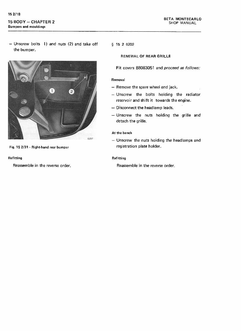
152/18BETA MONTECARLO
SHOP MANUAL15 BODY -CHAPTER 2
Bumpers and mouldings
-Unscrew bolts
the bumper.
1) and nuts (2) and take off § 1526200
RENEWAL OF REAR GRILLE
Fit covers 88083051 and proceed as follows:
Removal
-Remove the spare wheel and jack.
-Unscrew the bolts holding the radiator
reservoir and shift it towards the engine.
-Disconnect the headlamp leads.
-Unscrew the nuts holding the grille and
detach the grille.
At the bench
-Unscrew the nuts holding the headlamps and
registration plate holder .Fig. 15 2/31 -Right-hand rear bumper
Refitting Refitting
Reassemble in the reverse order . Reassemble in the reverse order.
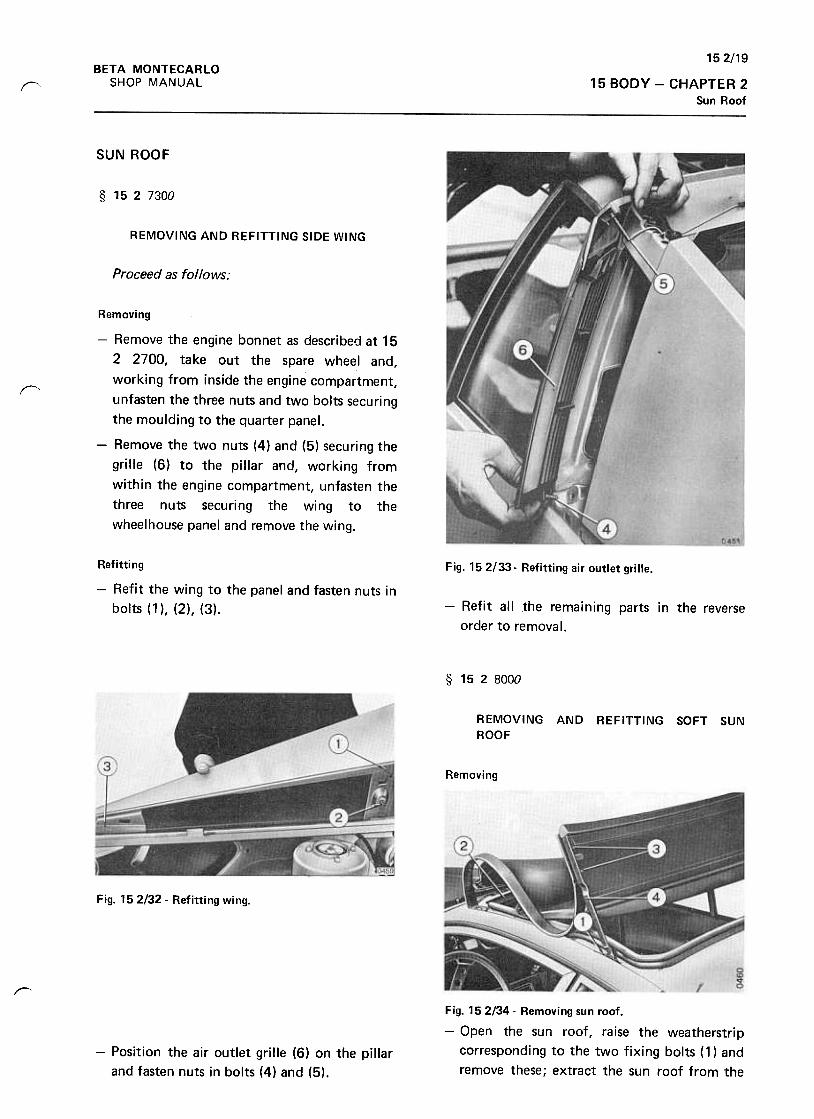
152/19BETA MONTECARLO
SHOP MANUAL 15 BODY -CHAPTER 2Sun Roof
f"
SUN ROOF
§ 1527300
REMOVING AND REFITTING SIDE WING
Proceed as follows:
r
Removing
-Remove the engine bonnet as described at 15
2 2700, take out the spare wheel and,
working from inside the engine compartment,
unfasten the three nuts and two bolts securing
the moulding to the quarter panel.
-Remove the two nuts (4) and (5) securing the
grille (6) to the pillar and, working from
within the engine compartment, unfasten the
three nuts securing the wing to the
wheelhouse panel and remove the wing.
Fig. 152/33. Refitting air outlet grille.Refitting
-Refit the wing to the panel and fasten nuts in
bolts (1 ), (2), (3). -Refit all the remaining parts in the reverse
order to removal.
§ 1528000
REMOVING AND REFITTING SOFT SUNROOF
Removing
Fig. 152/32- Refitting wing.
r-
Fig. 152/34- Removing sun roof.
-Open the sun roof, raise the weatherstrip
corresponding to the two fixing bolts (1) and
remove these; extract the sun roof from the
-Position the air outlet grille (6) on the pillar
and fasten nuts in bolts (4) and (5).

152/20BETA MONTECARLO
SHOP MANUAL15 BODY -CHAPTER 2Sun Roof
front crosspiece (2) ; remove the bolts (3)
securing the stretcher (4) and then remove the
complete sun roof.
Refitting
-Refit in the reverse order. When this
operation is completed, make sure the roof is
set correctly and check closing.
§ 1528100
REMOVING AND REFITTING THE SOFT TOP
OPENING CATCH
Fit covers 88083056 and proceed as follows: Fig. 15 2136 -Soft top opening catch
Removal -From the engine compartment, unscrew the
nuts holding the stale air escape grilles and
remove the grilles.
-Unscrew bolts (1) and remove the strikers (2)
and their rods (see fig. 15 2/36) .
Turn the handle (1) as shown by the arrow
and raise the top.
Remove the handle (1) by turning it
downwards and take off the flashing (2).
-Slacken nuts (1) and unscrew bolts (2) before
taking off the catch (3) (see fig. 152/35).
Fig. 15 2!37 -Soft top latching device
Refitting
-Reassemble in the reverse order and check
that the catch works.Fig. 152/35. Soft top opening handle
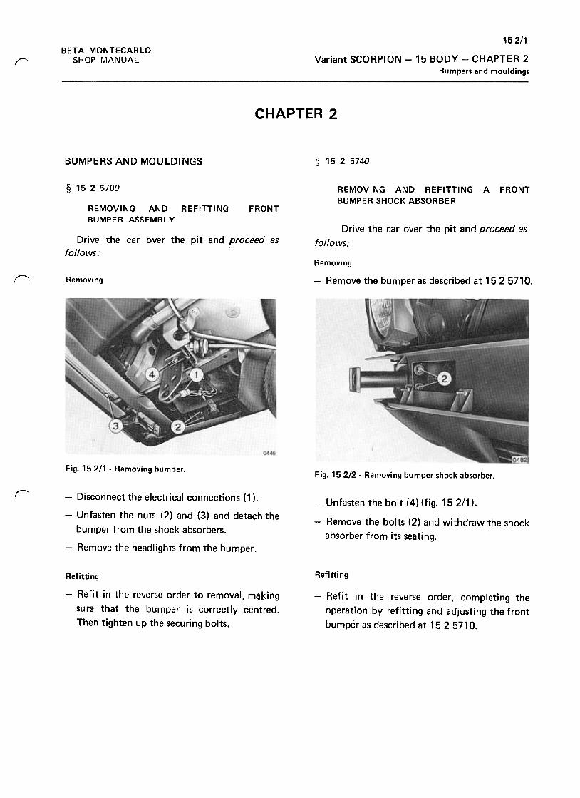
152/1BETA MONTECARLO
SHOP MANUAL Variant SCORPION -15 BODY -CHAPTER 2
Bumpers and mouldingsr
CHAPTER 2
BUMPERS AND MOULDINGS § 1525740
§ 1525700 REMOVING AND REFITTING A FRONT
BUMPER SHOCK ABSORBERREMOVING ANDBUMPER ASSEMBLY
REFITTING FRONT
Drive the car over the pit and proceed as
follows:Drive the car over the pit and proceed as
follows:Removing
f\ Removing -Remove the bumper as described at 152 5710.
Fig. 15 211 -Removing bumper .Fig. 152/2- Removing bumper shock absorber .
r-Unfasten the bolt (4) (fig. 15 2/1 ).
-Remove the bolts (2) and withdraw the shock
absorber from its seating.
-Disconnect the electrical connections (1 ).
-Unfasten the nuts (2) and (3) and detach the
bumper from the shock absorbers.
-Remove the headlightS from the bumper.
RefittingRefitting
-Refit in the reverse order to removal, making
sure that the bumper is correctly centred.
Then tighten up the securing bolts.
-Refit in the reverse order I completing the
operation by refitting and adjusting the front
bumper as described at 1525710.
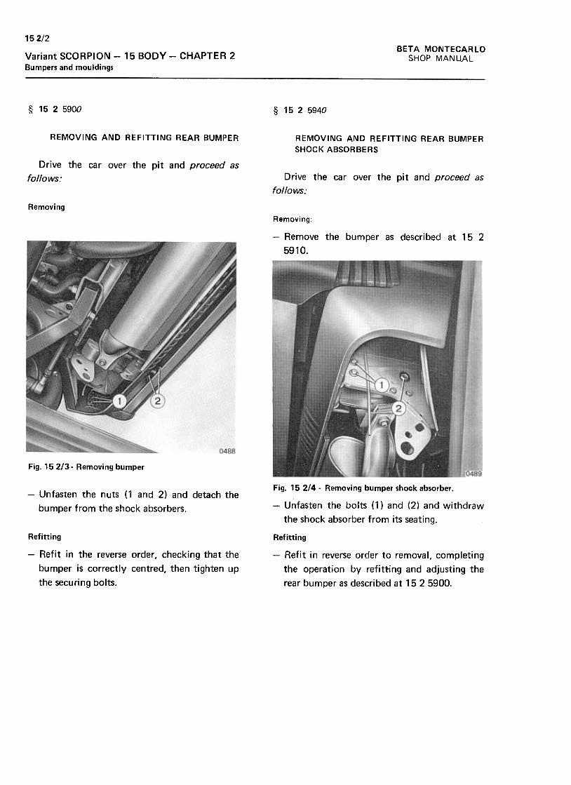
15 2/2
BETA MONTECARLO
SHOP MANUALVariant SCORPION -15 BODY -CHAPTER 2
Bumpers and mouldings
§ 1525900 § 1525940
REMOVING AND REFITTING REAR BUMPER REMOVING AND REFITTING REAR BUMPER
SHOCK ABSORBERS
Drive the car over the pit and proceed as
follows: Drive the car over the pit and proceed as
follows:
Removing
Removing:
-Remove the bumper as described at 15 2
5910.
Fig. 152/3. Removing bumper
-Unfasten the nuts (1 and 2) and detach the
bumper from the shock absorbers.
Fig. 152/4. Removing bumper shock absorber.
-Unfasten the bolts (1) and (2) and withdraw
the shock absorber from its seating.
Refitting
-Refit in the reverse order, checking that the
bumper is correctly centred, then tighten up
the securing bolts.
Refitting
-Refit in reverse order to removal, completing
the operation by refitting and adjusting the
rear bumper as described at 15 2 5900.
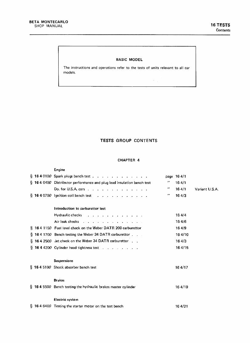
BETA MONTECARLO
SHOP MANUAL 16 TESTSContents
TESTS GROUP CONTENTS
CHAPTER 4
page 164/1
16 4/1
16 4/1
164/3
Engine
§ 1640100 Spark plugs bench test. § 1640400 Distributor performance and plug lead insulation bench test
Do. for U.S.A. cars. § 1640700 Ignition coil bench test. Variant U.S.A.
164/4
164/6
164/9
164/10
164/3
164/15
Introduction to carburet tor test
Hydraulic checks. Air leak checks. ...
§ 164 1150 Fuel level check on the Weber DATA 200 carburet tor
§ 164 1700 Bench testing the Weber 34 DATA carburet tor ..
§ 1642500 Jet check on the Weber 34 DATA carburet tor ..
§ 1644200 Cylinder head tightness test .
Suspensions
§ 164 5100 Shock absorber bench test 164/17
Brakes
§ 1645500 Bench testing the hydraulic brakes master cylinder 164/19
Electric system
§ 1646400 Testing the starter motor on the test bench 164/21
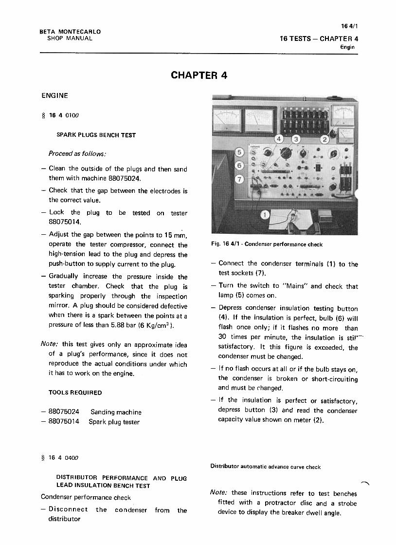
164/1BETA MONTECARLO
SHOP MANUAL 16 TESTS -CHAPTER 4
Engin
CHAPTER 4
ENGINE
§ 1640100
SPARK PLUGS BENCH TEST
Proceed as follows:
Fig. 164/1 -Condenser performance check
-Connect the condenser terminals (1) to the
test sockets (7).
-Clean the outside of the plugs and then sand
them with machine 88075024.
-Check that the gap between the electrodes is
the correct value.
-Lock the plug to be tested on tester
88075014.
-Adjust the gap between the points to 15 mm,
operate the tester compressor, connect the
high-tension lead to the plug and depress the
push-button to supply current to the plug.
-Gradually increase the pressure inside the
tester chamber. Check that the plug is
sparking properly through the inspection
mirror. A plug should be considered defective
when there is a spark between the points at a
pressure of less than 5.88 bar (6 Kg/cm2 ).
Note: this test gives only an approximate idea
of a plug's performance, since it does not
reproduce the actual conditions under which
it has to work on the engine.
TOOLS REQUIRED
-Turn the switch to "Mains" and check that
lamp (5) comes on.
-Depress condenser insulation testing button
(4). If the insulation is perfect, bulb (6) will
flash once only; if it flashes no more than
30 times per minute, the insulation is stiJV satisfactory. It this figure is exceeded, the
condenser must be changed.
-If no flash occurs at all or if the bulb stays on,
the condenser is broken or short-circuiting
and must be changed.
-If the insulation is perfect or satisfactory,
depress button (3) and read the condenser
capacity value shown on meter (2).
-88075024
-88075014Sanding machine
Spark plug tester
§ 1640400
Distributor automatic advance curve check
"'Note: these instructions refer to test benches
fitted with a protractor disc and a strobe
device to display the breaker dwell angle.
DISTRIBUTOR PERFORMANCE AND PLUGLEAD INSULATION BENCH TEST
Condenser performance check
-Disconnect the condenser from the
distributor
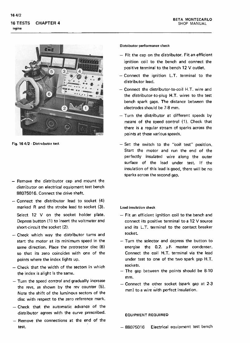
164/2BETA MONTECARLO
SHOP MANUAL16 TESTS
ngine
CHAPTER 4
Distributor performance check
-Fit the cap on the distributor. Fit an efficient
ignition coil to the bench and connect the
positive terminal to the bench 12 V outlet.
-Connect the ignition L. T .terminal to the
djstributor lead.
-Connect the distributor-to-coil H.T. wire and
the distributor-to-plug H.T. wires to the test
bench spark gaps. The distance between the
electrodes should be 7-8 mm.
-Turn the distributor at different speeds by
means of the speed control (1). Check that
there is a regular stream of sparks across the
points at these various speeds.
Fig. 16412- Distrubutor test. -Set the switch to the "coil test'l position.
Start the motor and run the end of the
perfectly insulated wire along the outer
surface of the lead under test. If the
insulation of this lead is good, there will be no
sparks across the second gap.
-Remove the distributor cap and mount the
distributor on electrical equipment test bench
88075016. Connect the drive shaft.
-Connect the distributor lead to socket (4)
marked R and the strobe lead to socket (3).
Select 12 V on the socket holder plate.
Depress button ( 1 ) to i nsert the voltmeter and
short-circuit the socket (2r.
Lead insulation check
-Fit an efficient ignition coil to the bench and
connect its positive terminal to a 12 V source
and its L. T. terminal to the contact breaker
socket.
-Turn the selector and depress the button to
energise the 0.2. .u F- master condenser .
Connect the coil H. T. terminal via the lead
under test to one of the two spark gap H. T.
sockets.
-The gap between the points should be 8-10
mm.
-Connect the other socket (spark gap at 2-3
mm) to a wire with perfect insulation.
-Check which way the distributor turns and
start the motor at its minimum speed in the
same direction. Place the protractor disc (6)
so that its zero coincides with one of the
points where the index lights up.
-Check that the width of the sectors in which
the index is alight is the same.
-Turn the speed control and gradually increase
the revs, as shown by the rev counter (5).
Note the shift of the luminous sectors of the
disc with respect to the zero reference mark.
-Check that the automatic advance of the
distributor agrees with the curve prescribed.EQUIPMENT REQUIRED
-Remove the connections at the end of the
test. Electrical equipment test bench-88075016
164/3
16 TESTS -CHAPTER 4
Engine
BETA MONTECARLO
SHOP MANUAL
§ 1640700
IGNITION COIL BENCH TEST
-Turn the selector and depress the button to
energise the O.2.J1F master condenser.
Connect the coil H.T. terminal to the spark
gap H.T. socket. The gap between the points
should be 8-10 mm.
-Set the switch to the "coil test" position.
Start the motor and check that the correct
values are obtained when the coil is operating
at various speeds.
Proceed as follows:
-Mount the coil on the bench and connect its
positive terminal to the bench 12 V socket.
Connect the other terminal to the breaker
socket.
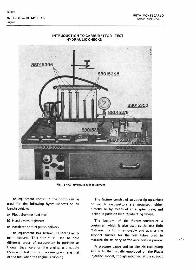
BETA MONTECARLO
SHOP MANUAL
16 4/4
16 TESTS -CHAPTER 4
Engine
INTRUDUCTION TO CARBURETTOR TESTHYDRAULIC CHECKS
Fig. 164/3- Hydraulic test equipment
The fixture consist of an upper tip-up surface
on which carburet tors are mounted, either
directly or by means of an adapter plate, and
locked in position bya rapid-acting device.
The bottom of the fixture consists of a
container, which is also used as the test fluid
reservoir. Its lid is removable and acts as the
support surface for the test tubes used to
measure the delivery of the acceleration pumps.
A pressure gauge and an electric fuel pump
similar to that usually employed on the Flavia
injection model, though modified at the cut-out
The equipment shown in the photo can be
used for the following hydraulic, tests on all
lancia vehicles:
a) Float chamber fuel level
b) Needle valve tightness
c) Acceleration fuel pump delivery
The equipment has fixture 88015370 as its
main feature. This fixture is used to hold
different types of carburet tor in position as
though they were on the engine, and supply
them with test fluid at the same pressure as that
of the fuel when the engine is running.
"'
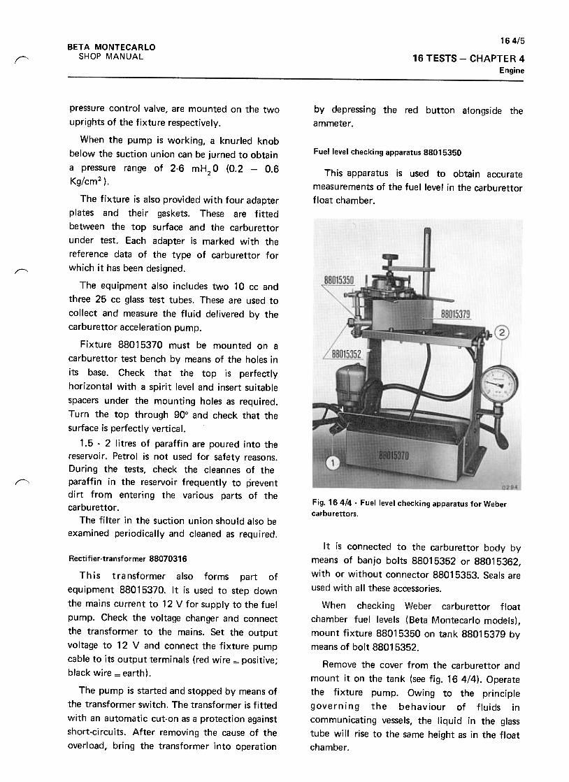
16 4/5
BETA MONTECARLO
SHOP MANUAL 16 TESTS -CHAPTER 4
Enginer
by depressing the red button alongside the
ammeter,
Fuel level checking apparatus 88015350
This apparatus is used to obtain accurate
measurements of the fuel level in the carburet tor
float chamber .
r"
1'-"-'
Fig. 16414- Fuel level checking apparatus for Weber
carbu rettors.
pressure control valve, are mounted on the two
uprights of the fixture respectively.
When the pump is working, a knurled knob
below the suction union can be jurned to obtain
a pressure range of 2-6 mH2O (0.2 -0.6
Kg/cm2 ) .
The fixture is also provided with four adapter
plates and their gaskets. These are fitted
between the top surface and the carburet tor
under test. Each adapter is marked with the
reference data of the type of carburet tor for
which it has been designed.
The equipment also includes two 10 cc and
three 25 cc glass test tubes. These are used to
collect and measure the fluid delivered by the
carburet tor acceleration pump.
Fixture 88015370 must be mounted on a
carburet tor test bench by means of the holes in
its base. Check that the top is perfectly
horizontal with a spirit level and insert suitable
spacers under the mounting holes as required.
Turn the top through 90° and check that the
surface is perfectly vertical.
1.5 -2 litres of paraffin are poured into the
reservoir. Petrol is not used for safety reasons.
During the tests, check the cleannes of the
paraffin in the reservoir frequently to prevent
dirt from entering the various parts of the
carburet tor .
The filter in the suction union should also be
examined periodically and cleaned as required.
It is connected to the carburet tor body by
means of banjo bolts 88015352 or 88015362,
with or without connector 88015353. Seals are
used with all these accessories.
When checking Weber carburet tor float
chamber fuel levels (Beta ~.~ontecarlo models),
mount fixture 88015350 on tank 88015379 by
means of bolt 88015352.
Remove the cover from the carburet tor and
mount it on the tank (see fig. 164/4). Operate
the fixture pump. Owing to the principle
governing the behaviour of fluids in
communicating vessels, the liquid in the glass
tube will rise to the same height as in the float
chamber.
Rectifier-transformer 88070316
This transformer also forms part of
equipment 88015370. It is used to step down
the mains current to 12 V for supply to the fuel
pump. Check the voltage changer and connect
the transformer to the mains. Set the output
voltage to 12 V and connect the fixture pump
cable to its output terminals (red wire = positive;
black wire = earth).
The pump is started and stopped by means of
the transformer switch. The transformer is fitted
with an automatic cut-on as a protection against
short-circuits. After removing the cause of the
overload, bring the transformer into operation
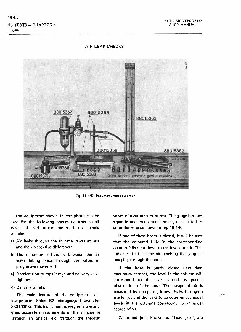
BETA MONTECARLO
SHOP MANUAL
16 4/6
16 TESTS -CHAPTER 4
Engine
AI R LEAK CHECKS
Fig. 164/5- Pneumatic test equipment
valves of a carburet tor at rest. The gauge has two
separate and independent scales, each fitted to
an outlet hose as shown in fig. 164/5.
If one of these hoses is closed, it will be seen
that the coloured fluid in the corresponding
column falls right down to the lowest mark. This
indicates that all the air reaching the gauge is
escaping through the hose.
If the hose is partly closed (less than
maximum escape), the level in the column will
correspond to the leak caused by partial
obstruction of the hose. The escape of air is
measured by comparing known leaks through a
master jet and the leaks to be determined. Equal
levels in the columns correspond to an equal
escape of air.
The equipment shown in the photo can be
used for the following pneumatic tests on all
types of carburet tor mounted on lancia
vehicles:
a) Air leaks through the throttle valves at rest
and their respective differences
b) The maximum difference between the air
leaks taking place through the valves in
progressive movement.
c) Acceleration pumps intake and delivery valve
tightness.
d) Delivery of jets.
The main feature of the equipment is a
low-pressure Solex 82 microgauge (flowmeter
88015363). This instrument is very sensitive and
gives accurate measurements of the air passing
through an orifice, e.g. through the throttle
1'""""'\
Calibrated jets, known as "head jets", are
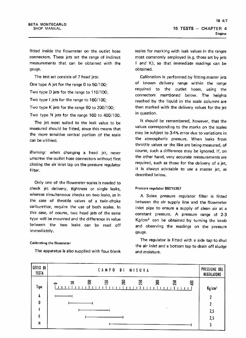
16 4/7
BETA MONTECARLO
SHOP MANUAL 16 TESTS -CHAPTER 4
Engine
scales for marking with leak values in the ranges
most commonly employed (e.g. those set by jets
I and K), so that immediate readings can be
obtained.
Calibration is performed by fitting master jets
of known delivery range within the range
required to the outlet hoses, using the
connectors mentioned below. The heights
reached by the liquid in the scale columns are
then marked with the delivery values for the jet
in question.
It should be remembered, however, that the
values corresponding to the marks on the scales
may be subject to 3-4% error due to variations in
the atmospheric pressure. When leaks from
throttle valves or the like are being measured, of
course, such a difference may be ignored. If, on
the other hand, very accurate measurements are
required, such as those for the delivery of a jet,
it is always advisable to use a master jet, as
described below.
fitted inside the flowmeter on the outlet hose
connectors. These jets set the range of indirect
measurements that can be obtained with the
gauge.
The test set consists of 7 head jets :
One type A jet for the range 0 to 50/100;
Two type D jets for the range to 110/100;
Two type I jets for the range to 160/100 ;
Two type K jets for the range 90 to 200/100;
Two type N jets for the range 160 to 400/100.
The jet most suited to the leak value to be
measured should be fitted, since this means that
the more sensitive central portion of the scale
can be utilised.
Warning: when changing a head jet, never
unscrew the outlet hose connectors without first
closing the air inlet tap on the pressure regulator
filter.
Only one of the flowmeter scales is needed to
check jet delivery, tightness or single leaks,
whereas simultaneous checks on two leaks, as in
the case of throttle valves of a twin-choke
carburet tor, require the use of both scales. In
this case, of course, two head jets of the same
type will be mounted and the difference in value
between the two leaks can be read off
immediately.
Pressure regulator 88015367
A Solex pressure regulator filter is fitted
between the air supply line and the flowmeter
inlet pipe to ensure a supply of clean air at a
constant pressure. A pressure range of 2-3
Kg/cm2 can be obtained by turning the knob
and observing the readings on the pressure
gauge.
The regulator is fitted with a side tap to shut
the air inlet and a bottom tap to drain off sludge
and moisture.
Calibrating the flowmeter
The apparatus is also supplied with four blank
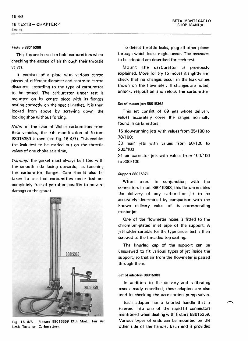
16 4/8
BETA MONTECARLO
SHOP MANUAL16 TESTS -CHAPTER 4
Engine
To detect throttle leaks, plug all other places
through which leaks might occur. The measures
to be adopted are described for each test.
Mount the carburet tor as previously
explained. Move (or try to move) it slightly and
check that no changes occur in the leak values
shown on the flowmeter. If changes are noted,
unlock, resposition and relock the carburet tor.
Fixture 88015359
This fixture is used to hold carburet tors when
checking the escape of air through their throttle
valves.
It consists of a plate with various centre
pieces of different diameter and centre-to-centre
distances, according to the type of carburet tor
to be tested. The carburet tor under test is
mounted on its centre piece with its flanges
resting correctly on the special gasket. It is then
locked from above by screwing down the
locking shoe without forcing.
Set of master jets 88015368
Note: in the case of Weber carburet tors from
Beta vehicles, the 7th modification of fixture
88015359 is used (see fig. 164/7). This enables
the leak test to be carried out on the throttle
valves of one choke at a time.
This set consist of 69 jets whose delivery
values accurately cover the ranges normally
found in carburet tors:
15 slow-running jets with values from 35/100 to
70/100;
33 main jets with values from 50/100 to
200/100 ;
21 air corrector jets with values from 100/100
to 300/100Warning: the gasket must always be fitted with
the smooth side facing upwards, i.e. touching
the carburet tor flanges. Care should also be
taken to see that carburet tors under test are
completely free of petrol or paraffin to prevent
damage to the gasket.
Support 88015371
When used in conjunction with the
connectors in set 88015393, this fixture enables
the delivery of any carburet tor jet to be
accurately determined by comparison with the
known delivery value of its corresponding
master jet.
One of the flowmeter hoses is fitted to the
chromium-plated inlet pipe of the support. A
jet-holder suitable for the type under test is then
screwed to the threaded top seating.
The knurled cap of the support can be
unscrewed to fit various types of jet inside the
support, so that air from the flowmeter is passed
through them.
Set of adapters 88015383
In addition to the delivery and calibrating
tests already described, these adapters are also
used in checking the acceleration pump valves.
Each adapter has a knurled handle that is
screwed into one of the rapid-fit connectors
mentioned when dealing with fixture 88015359.
Various types of ends can be mounted on the
other side of the handle. Each end is provided
""
Fig. 16 4/6 -Fixture 88015359 (7th Mod.) For Air
Leak Tests on Carburettors.
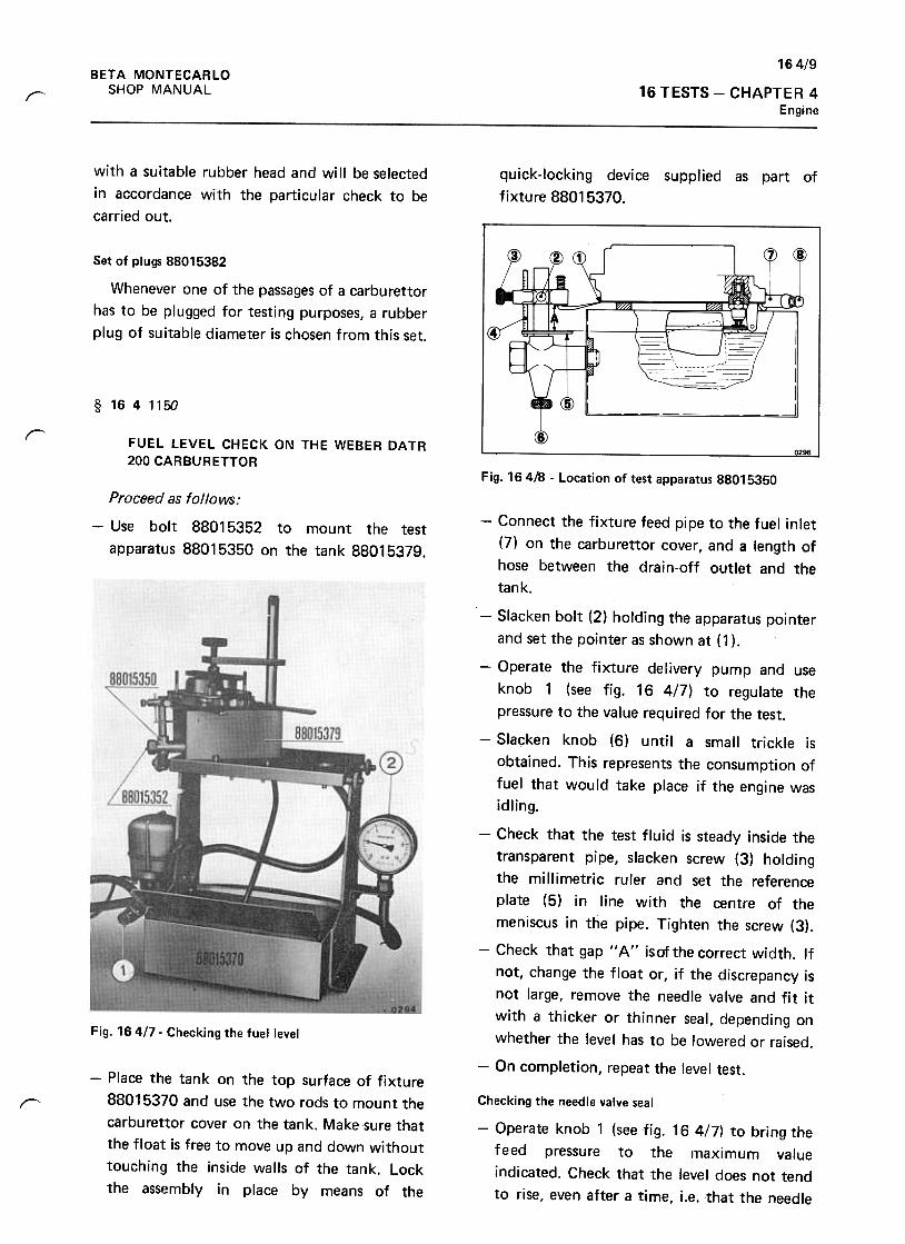
16 4/9
BETA MONTECARLO
SHOP MANUAL 16 TESTS -CHAPTER 4Engine
r
with a suitable rubber head and will be selected
in accordance with the particular check to be
carried out.
quick-Iocking device supplied as part of
fixture 88015370.
Set of plugs 88015382
Whenever one of the passages of a carblJrettor
has to be plugged for testing purposes, a rubber
plug of suitable diameter is chosen from this set.
§ 1641150
r FUEL LEVEL CHECK ON THE WEBER DATR
200 CARBURETTORFig. 164/8 -Location of test apparatus 88015350
Proceed as follows:
-Use bolt 88015352 to mount the test
apparatus 88015350 on the tank 88015379.
Fig. 164/7- Checking the fuel level
-Connect the fixture feed pipe to the fuel inlet
(7) on the carburet tor cover, and a length of
hose between the drain-off outlet and the
tank.
-Slacken bolt (2) holding the apparatus pointer
and set the pointer as shown at (1 ).
-Operate the fixture delivery pump and use
knob 1 (see fig. 16 4/7) to regulate the
pressure to the value required for the test.
-Slacken knob (6) until a small trickle is
obtained. This represents the consumption of
fuel that would take place if the engine was
idling.
-Check that the test fluid is steady inside the
transparent pipe, slacken screw (3) holding
the millimetric ruler and set the reference
plate (5) in line with the centre of the
meniscus in the pipe. Tighten the screw (3).
-Check that gap "A" isofthecorrect width. If
not, change the float or, if the discrepancy is
not large, remove the needle valve and fit it
with a thicker or thinner seal, depending on
whether the level has to be lowered or raised.
-On completion, repeat the level test.-Place the tank on the top surface of fixture
88015370 and use the two rods to mount the
carburet tor cover on the tank. Make sure that
the float is free to move up and down without
touching the inside walls of the tank. Lock
the assembly in place by means of the
~ Checking the needle valve seal
-Operate knob 1 (see fig. 16 4/7) to bring the
feed pressure to the maximum value
indicated. Check that the level does not tend
to rise, even after a time, j.e. that the needle
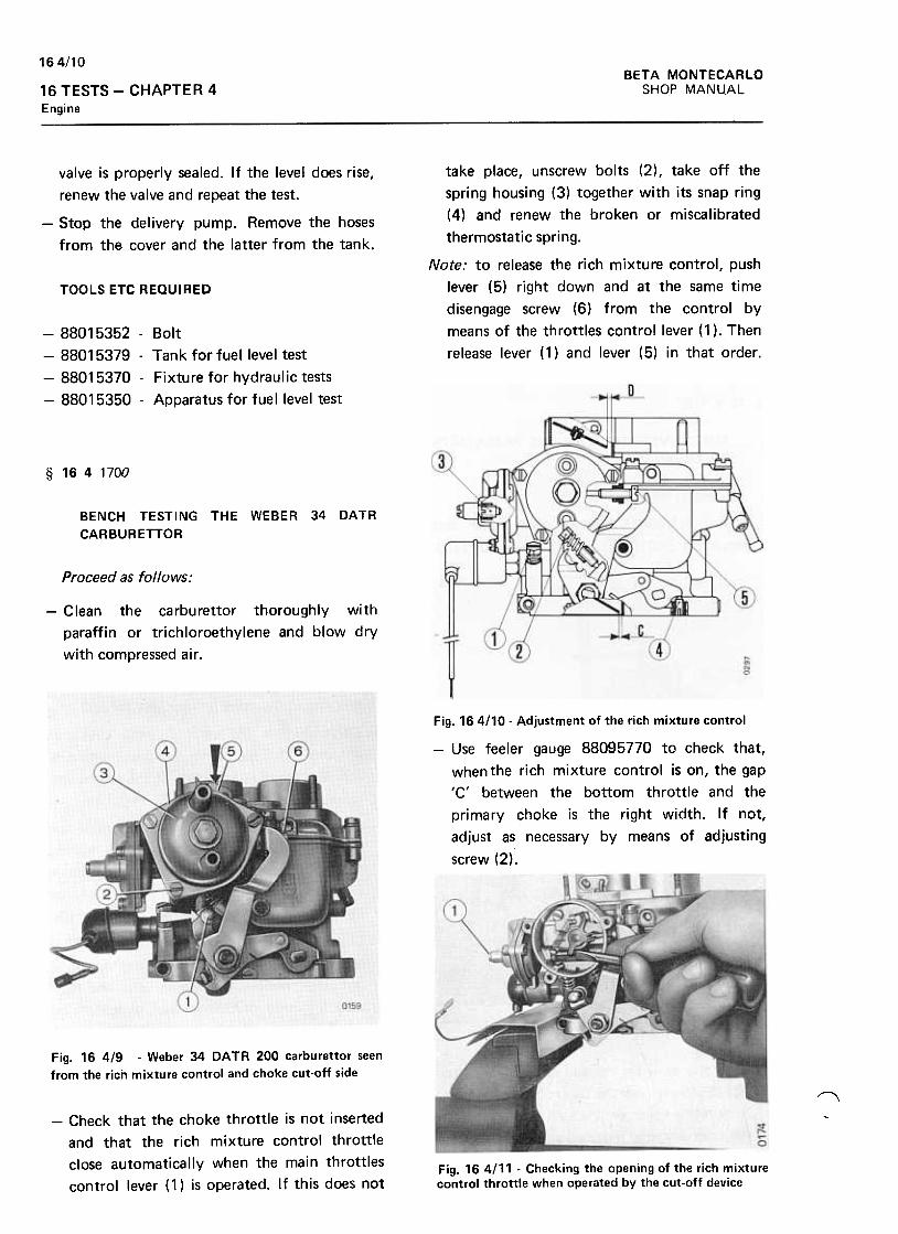
BETA MONTECARLO
SHOP MANUAL
164/10
16 TESTS -CHAPTER 4
Engine
valve is properly sealed. If the level does rise,
renew the valve and repeat the test.
-Stop the delivery pump. Remove the hoses
from the cover and the latter from the tank.
take place, unscrew bolts (2) , take off the
spring housing (3) together with its snap ring
(4) and renew the broken or miscalibrated
thermostatic spring.
Note: to release the rich mixture control, push
lever (5) right down and at the same time
disengage screw (6) from the control by
means of the throttles control lever (1 ). Then
release lever (1) and lever (5) in that order.
TOOLS ETC REQUIRED
-88015352 -Bolt
-88015379 -Tank tor tuellevel test
-88015370 -Fixture tor hydraulic tests
-88015350 -Apparatus tor tuellevel test
§ 1641700
BENCH TESTING THE WEBER 34 DATR
CARBURETTOR
Proceed as follows:
-Clean the carburet tor thoroughly with
paraffin or trichloroethylene and blow dry
with compressed air.
Fig. 164110- Adjustment of the rich mixture control
-Use feeler gauge 88095770 to check that,
whenthe rich mixture control is on, the gap
'C' between the bottom throttle and the
primary choke is the right width. If not,
adjust as necessary by means of adjusting
screw (2).
Fig. 16 4/9 -Weber 34 DATA 200 carburet tor seen
from the rich mixture control and choke cut-off side
I'\
-Check that the choke throttle is not inserted
and that the rich mixture control throttle
close automatically when the main throttles
control lever ( 1) is operated. If this does not
~
Fig. 16 4111 -Checking the opening of the rich mixturecontrol throttle when operated by the cut-off device
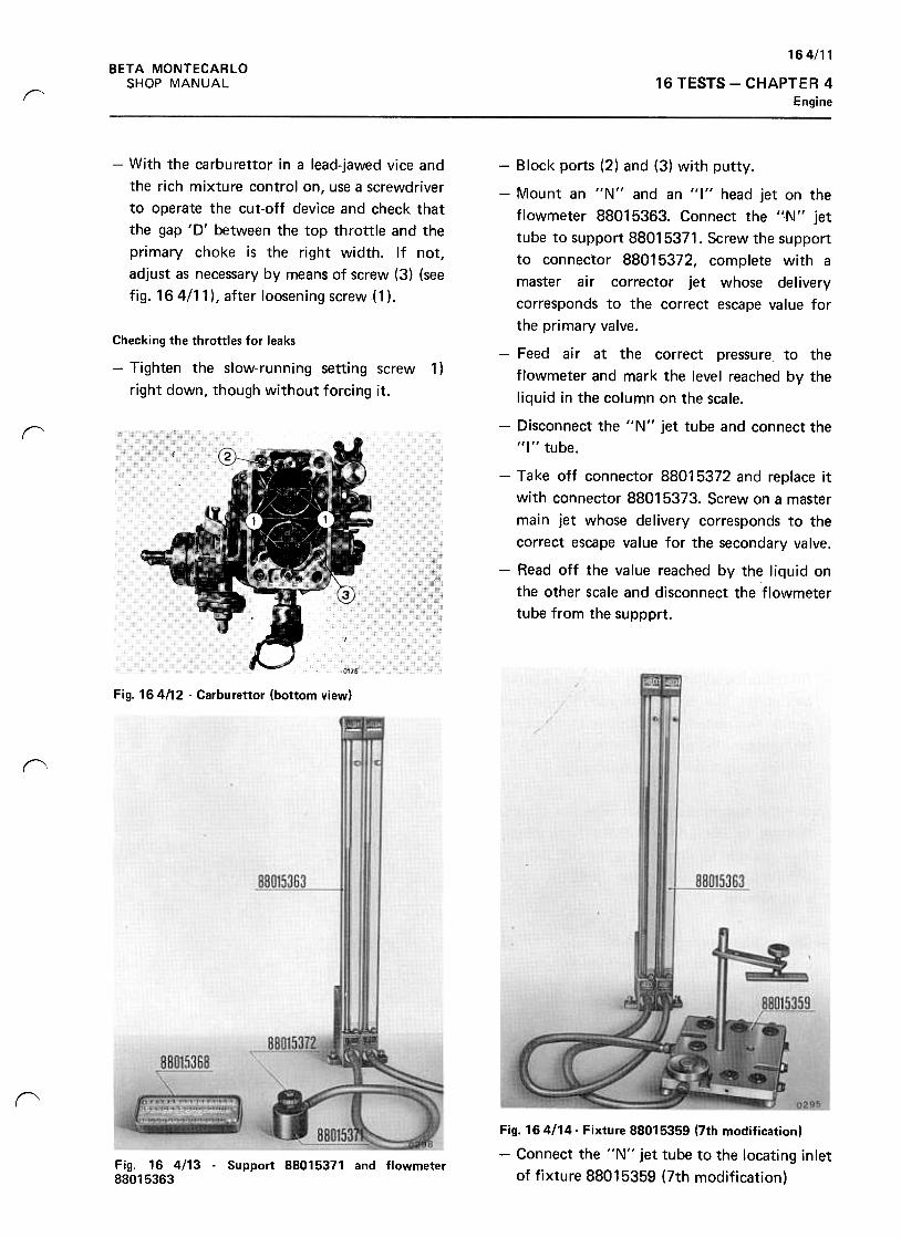
164/11BETA MONTECARLO
SHOP MANUAL 16 TESTS -CHAPTER 4
Enginer
-With the carburet tor in a lead-jawed vice and
the rich mixture control on, use a screwdriver
to operate the cut-off device and check that
the gap '0' between the top throttle and the
primary choke is the right width. If not,
adjust as necessary by means of screw (3) (see
fig. 164/11 ), after loosening screw { 1 ).
Checking the throttles for leaks
-Tighten the slow-running setting screw
right down, though without forcing it.
1 )
r
-Block ports (2) and (3) with putty.
-Mount an "N" and an "I" head jet on the
flowmeter 88015363. Connect the "1\1" jet
tube to support 88015371. Screw the support
to connector 88015372, complete with a
master air corrector jet whose delivery
corresponds to the correct escape value for
the primary valve.
-Feed air at the correct pressure to the
flowmeter and mark the level reached by the
liquid in the column on the scale.
-Disconnect the "N" jet tube and connect the
"I" tube.
-Take off connector 88015372 and replace it
with connector 88015373. Screw on a master
main jet whose delivery corresponds to the
correct escape value for the secondary valve.
-Read off the value reached by the liquid on
the other scale and disconnect the flowmeter
tube from the suppprt.
Fig. 164/12 -Carburettor (bottom view)
(\
~
Fig. 164/14- Fixture 88015359 (7th modification)
-Connect the "N" jet tube to the locating inlet
of fixture 88015359 (7th modification)Fig. 16 4113 -Support 88015371 and flowmeter88015363
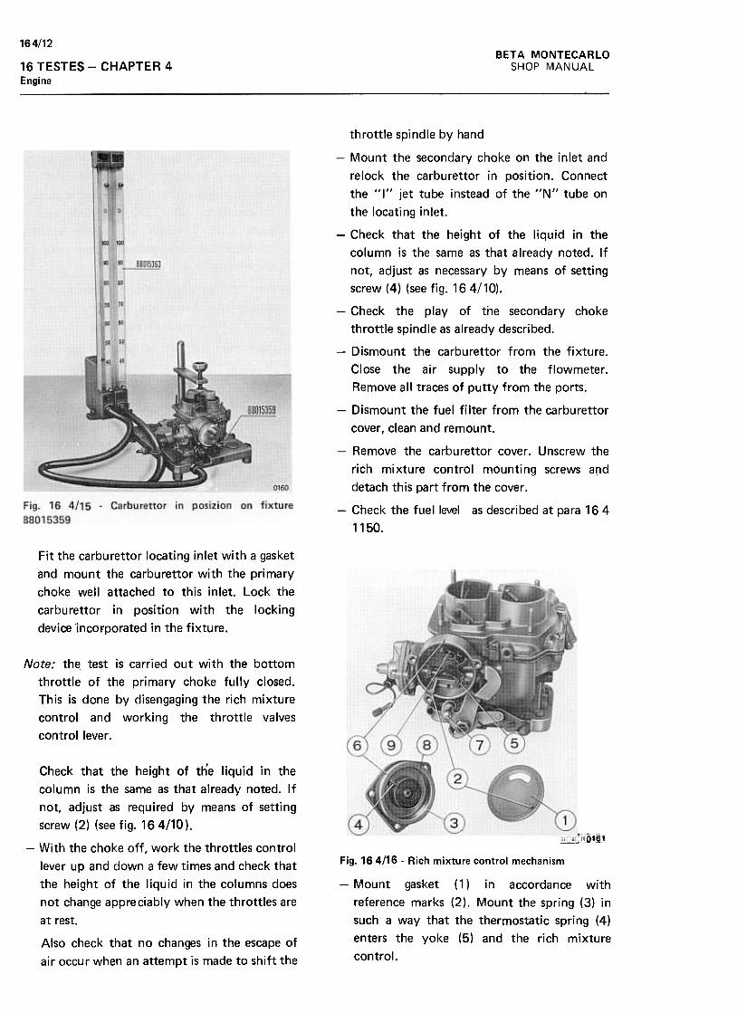
164/12BETA MONTECARLO
SHOP MANUAL16 TESTES -CHAPTER 4
Engine
throttle spindle by hand
-Mount the secondary choke on the inlet and
relock the carburet tor in position. Connect
the "I" jet tube instead of the "N" tube on
the locating inlet.
-Check that the height of the liquid in the
column is the same as that already noted. If
not, adjust as necessary by means of setting
screw (4) (see fig. 164/10).
-Check the play of the secondary choke
throttle spindle as already described.
-Dismount the carburet tor from the fixture.
Close the air supply to the flowmeter.
Remove all traces of putty from the ports.
-Dismount the fuel filter from the carburet tor
cover, clean and remount.
-Remove the carburet tor cover. Unscrew the
rich mixture control mounting screws and
detach this part from the cover.
-Check the tuellevel as described at para 164
1150.
Fit the carburet tor locating inlet with a gasket
and mount the carburet tor with the primary
choke well attached to this inlet. Lock the
carburet tor in position with the locking
device Incorporated in the fixture.
Note: the test is carried out with the bottom
throttle of the primary choke fully closed.
This is done by disengaging the rich mixture
control and working the throttle valves
control lever .
Check that the height of the liquid in the
column is the same as that alread\' noted. If
not, adjust as required by means of setting
screw (2) (see fig. 164/10 ).
~
-With the choke off, work the throttles control
lever up and down a few times and check that
the height of the liquid in the columns does
not change appreciably when the throttles are
at rest.
Fig. 164/16 -Rich mixture control mechanism
-Mount gasket (1) in accordance with
reference marks (2), Mount the spring (3) in
such a way that the thermostatic spring (4)
enters the yoke (5) and the rich mixture
control.Also check that no changes in the escape of
air occur when an attempt is made to shift the
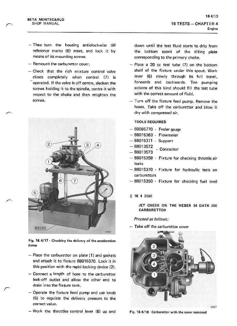
164/13BETA MONTECARLO
SHOP MANUAL 16 TESTS -CHAPT E R 4
Engine(\
-Then turn the housing anticlockwise till
reference marks (6) meet, and lock it by
means of its mounting screws.
-Remount the carburet tor cover.
-Check that the rich mixture control valve
closes completely when control (7) is~ operated. If the valve is off centre, slacken the
screws holding it to the spindle, centre it with
respect to the choke and then retighten the
screws.
down until the test fluid starts to drip from
the bottom spont of the tilting plate
corresponding to the primary choke.
-Place a 20 cc test tube (7) on the bottom
shelf of the fixture under this spout. Work
lever (6) slowly through its full travel,
forwards and backwards. Ten pumping
actions of this kind should fill the test tube
with the correct amount of fluid.
-Turn off the fixture feed pump. Remove the
hoses. Take off the carburet tor and blow it
dry with compressed air.r-"
TOOLS REQUIRED
-88095770 -Feeler gauge
-88015363 -Flowmeter
-88015371 -Support
-88013572-Connector
-88013573
-88015359 -Fixture for checking throttle air
leaks
-88015370 -Fixture for hydraulic tests on
ca rbu rettors
-88015350 -Fixture for checking fuel level
§ 1642500
~
JET CHECK ON THE WEBEA 34 DATA 200CAABUAETTOA
Proceed as follows:
-Take off the carburet tor cover
Fig. 164117. Checking the delivery of the acceleration
pump
r
-Place the carburet tor on plate ( 1) and gaskets
and attach it to fixture 88015370. Lock it in
this position with the rapid-Iocking device (2),
-Connect a leng1h of hose to the carburet tor
leak-off outlet and allow the other end to
drain into the fixture tank.
-Operate the fixture feed pump and use' knob
(5) to regulate the delivery pressure to the
correct value.
-Work the throttles control lever (6) up and Fig. 164/18- Carburettor with the cover removed
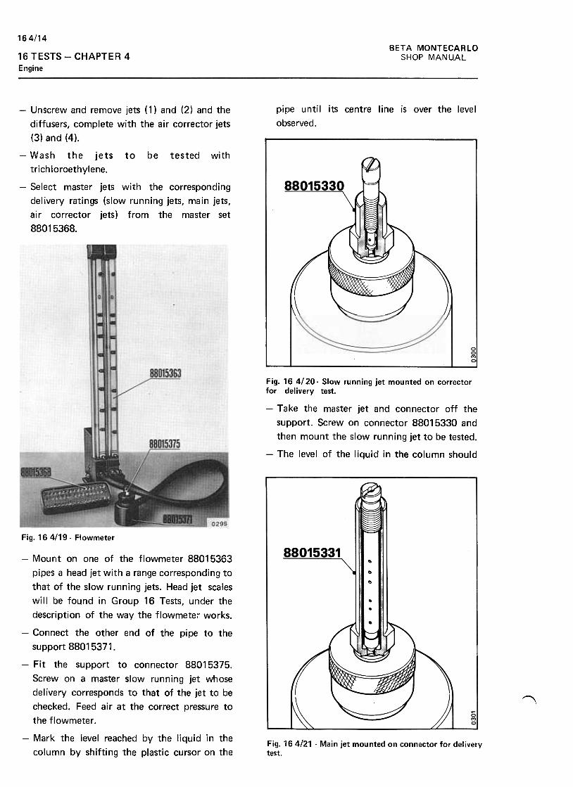
164/14BETA MONTECARLO
SHOP MANUAL16 TESTS -CHAPTER 4
Engine
pipe until its centre line is over the level
observed.
~
-Unscrew and remove jets (1) and (2) and the
diffusers, complete with the air corrector jets
(3) and (4).
-Wash the jets to be tested with
trich loroethylene.
-Select master jets with the corresponding
delivery ratings (slow running jets, main jets,
air corrector jets) from the master set
88015368.
Fig. 164/20- Slow running jet mounted on correctorfor delivery test.
-Take the master jet and connector off the
support. Screw on connector 88015330 and
then mount the slow running jet to be tested.
-The level of the liquid in the column should
".
Fig. 164/19- Flowmeter
~
~~
~
II ~I
-Mount on one of the flowmeter 88015363
pipes a head jet with a range corresponding to
that of the slow running jets. Head jet scales
will be found in Group 16 Tests, under the
description of the way the flowmetel works.
-Connect the other end of the pipe to the
support 88015371.
-Fit the support to connector 88015375.
Screw on a master slow running jet whose
delivery corresponds to that of the jet to be
checked. Feed air at the correct pressure to
the flowmeter .
-Mark the level reached by the liquid in the
column by shifting the plastic cursor on theFig. 164/21 -Main jet mounted on connector for deliverytest.
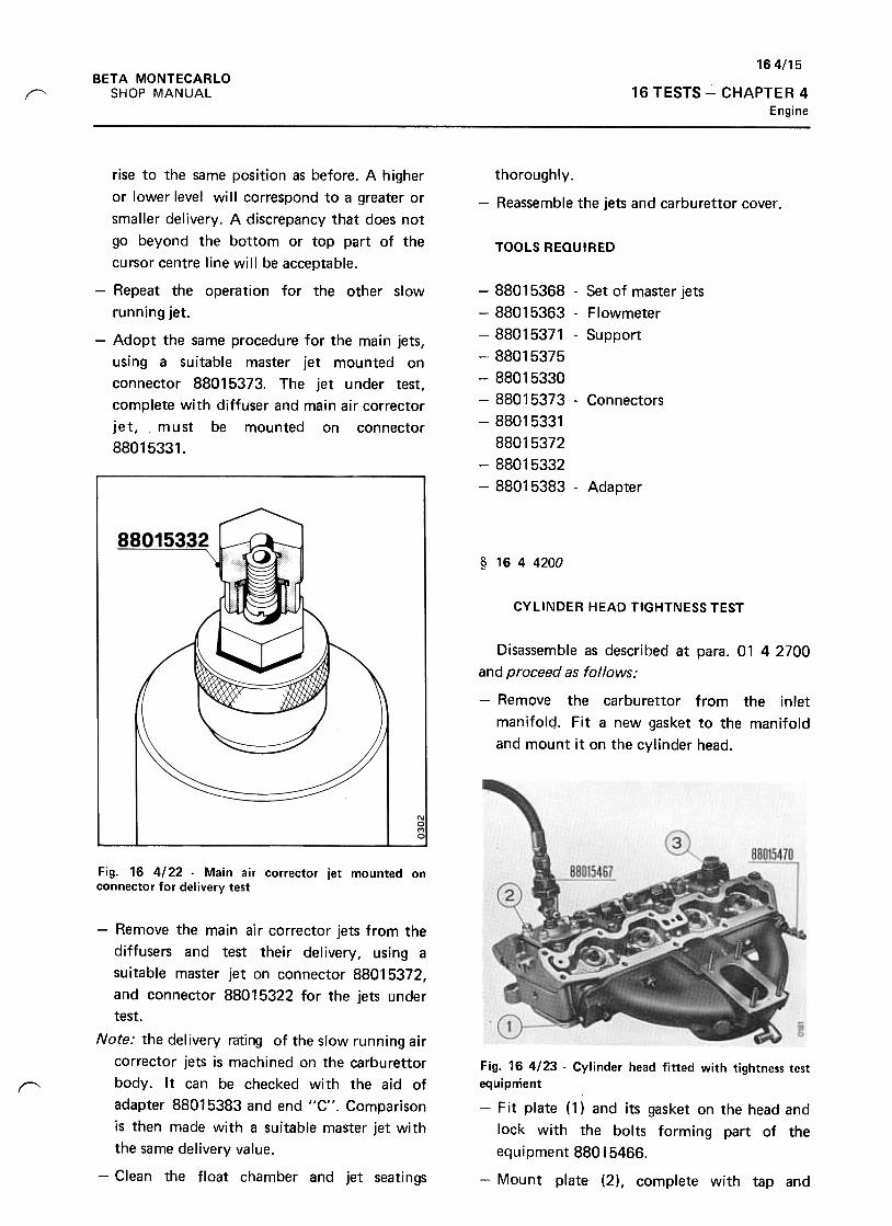
164/15BETA MONTECARLO
SHOP MANUAL 16 TESTS -CHAPTER 4
Engine
r
thoroughly.
-Reassemble the jets and carburet tor cover .
TOOLS REQUIRED
rise to the same position as before. A higher
or lower level will correspond to a greater or
smaller delivery. A discrepancy that does not
go beyond the bottom or top part of the
cursor centre line will be acceptable.
-Repeat the operation for the other slow
running jet.
-Adopt the same procedure for the main jets,
using a suitable master jet mounted on
connector 88015373. The jet under test,
complete with diffuser and main air corrector
jet, must be mounted on connector
88015331.
-88015368 -Set of master jets
-88015363 -Flowmeter
-88015371 -Support
-88015375
-88015330
-88015373 -Connectors
-88015331
88015372
-88015332
-88015383- Adapter
§ 1644200
CYLINDER HEAD TIGHTNESS TEST
Disassemble as described at para. 01 4 2700
and proceed as follows;
-Remove the carburet tor from the inlet
manifolq. Fit a new gasket to the manifold
and mount it on the cylinder head.-- / /
Fig. 16 4/22 -Main air corrector jet mounted onconnector for delivery test
"
-Remove the main air corrector jets from the
diffusers and test their delivery, using a
suitable master jet on connector 88015372,
and connector 88015322 for the jets under
test.
Note: the delivery rating of the slow running air
corrector jets is machined on the carburet tor
body. It can be checked with the aid of
adapter 88015383 and end "C". Comparison
is then made with a suitable master jet with
the same delivery value.
-Clean the float chamber and jet seatings
Fig. 16 4123 -Cylinder head fitted with tightness test
equipnient
-F it plate ( 1) and its gasket on the head and
lock with the bolts forming part of the
equipment 88015466.
-Mount plate (2), complete with tap and
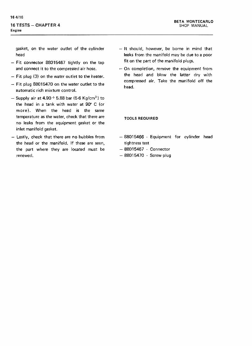
164/16BETA MONTECARLO
SHOP MANUAL16 TESTS -CHAPTER 4
Engine
-It should, however, be borne in mind that
leaks from the manifold may be due to a poor
fit on the part of the manifold plugs.
-On completion, remove the equipment from
the head and blow the latter dry with
compressed air. Take the manifold off the
head.
TOOLS REQUIRED
gasket, on the water outlet of the cylinder
head
-Fit connector 88015467 tightly on the tap
and connect it to the compressed air hose.
-Fit plug (3) on the water outlet to the heater .
-Fit plug 88015470 on the water outlet to the
automatic rich mixture control.
-Supply air at 4.907 5.88 bar (5-6 Kg/cm2) to
the head in a tank with water at 90° C (or
more). When the head is the same
tempera~ure as the water, check that there are
no leaks from the equipment gasket or the
inlet manifold gasket.
-Lastly, check that there are no bubbles from
the head or the manifold. If these are seen,
the part where they are located must be
renewed.
-88015466 -Equipment for cylinder head
tightness test
-88015467 -Connector
-88015470 -Screw plug
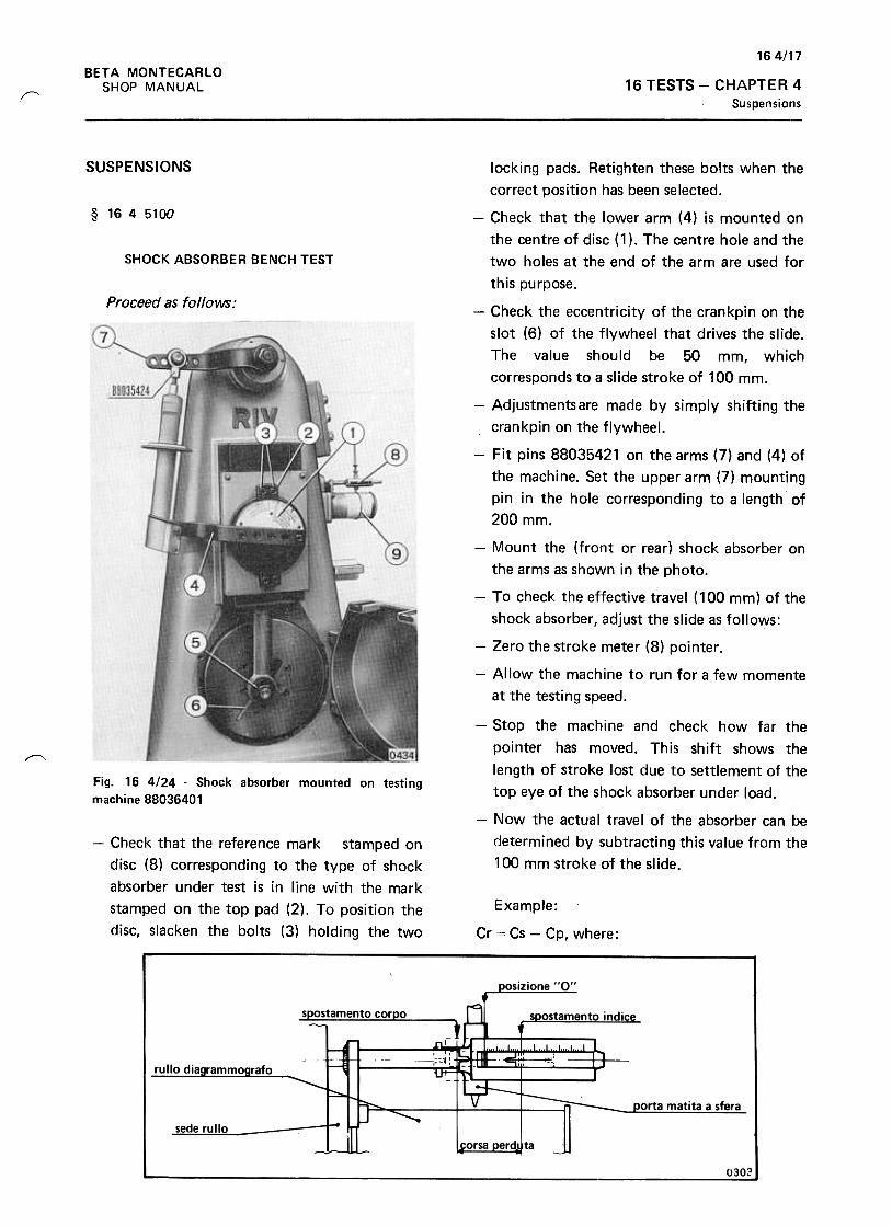
164/17BETA MONTECARlO
SHOP MANUAL 16 TESTS -CHAPTER 4
Suspensions("'
SUSPENSIONS
§ 1645100
SHOCK ABSORBER BENCH TEST
Proceed as follows:
locking pads. Retighten these bolts when the
correct position has been selected.
-Check that the lower arm (4) is mounted on
the centre of disc (1 ). The centre hole and the
two holes at the end of the arm are used for
this purpose.
-Check the eccentricity of the crankpin on the
slot (6) of the flywheel that drives the slide.
The value should be 50 mm, which
corresponds to a slide stroke of 100 mm.
-Adjustmentsare made by simply shifting the
crankpin on the flywheel.
-Fit pins 88035421 on the arms (7) and (4) of
the machine. Set the upper arm (7) mounting
pin in the hole corresponding to a length of
200 mm.
-Mount the (front or rear) shock absorber on
the arms as shown in the photo.
-To check the effective travel (100 mm) of the
shock absorber, adjust the slide as follows:
-Zero the stroke meter (8) pointer.
-Allow the machine to run for a few momente
at the testing speed.
~
Fig. 16 4/24 -Shock absorber mounted on testing
machine 88036401
-Stop the machine and check how far the
pointer has moved. This shift shows the
length of stroke lost due to settlement of the
top eye of the shock absorber under load.
-Now the actual travel of the absorber can be
determined by subtracting this value from the
100 mm stroke of the slide.
-Check that the reference mark stamped on
disc (8) corresponding to the type of shock
absorber under test is in line with the mark
stamped on the top pad (2). To position the
disc, slacken the bolts (3) holding the two
Example:
Cr = Cs -Cp, where:
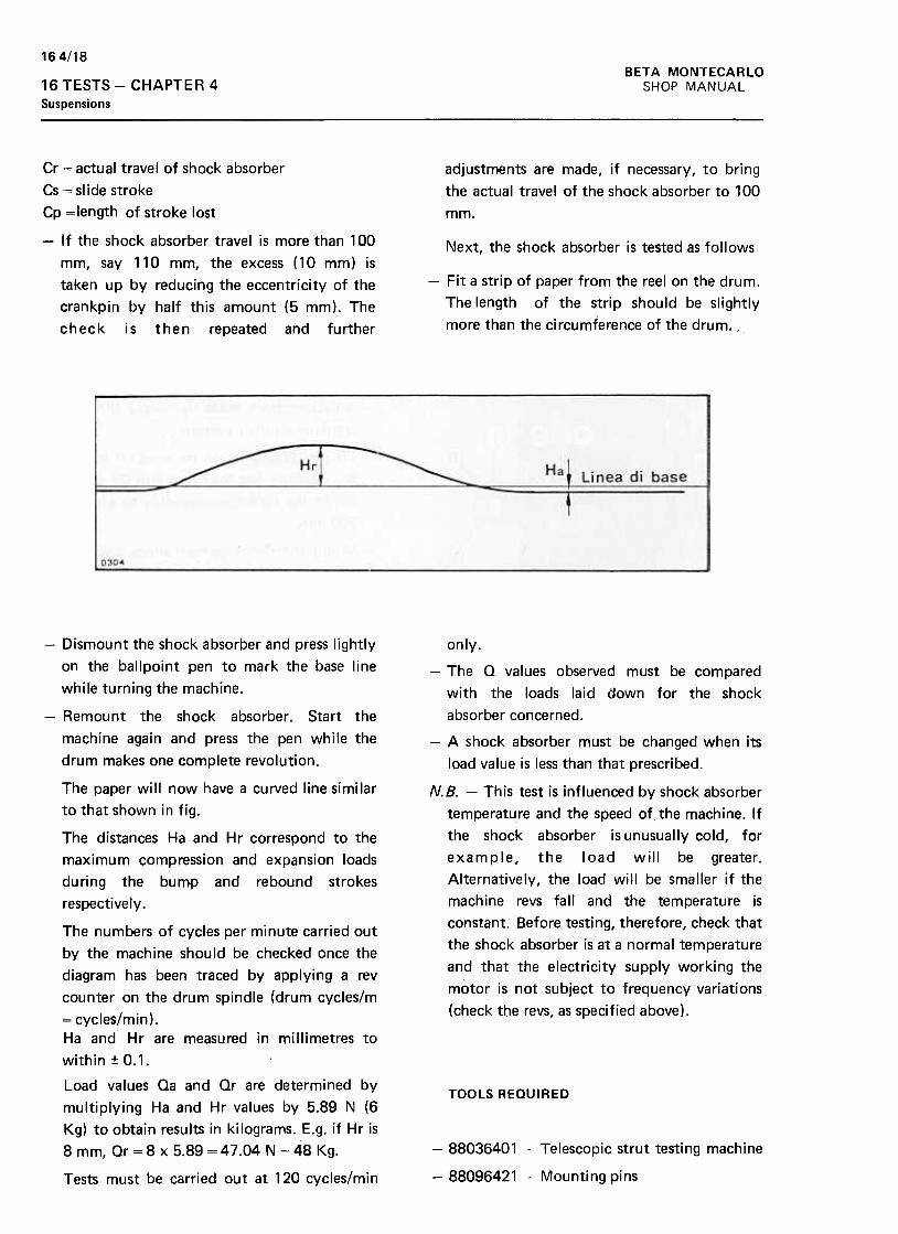
164/18BETA MONTECARLO
SHOP MANUAL16 TESTS -CHAPTER 4
Suspensions
adjustments are made, if necessary, to bring
the actual travel of the shock absorber to 100
mm.
Cr = actual travel of shock absorber
Cs ~ si ide stroke
Cp =length of stroke lost
-If the shock absorber travel is more than 100
mm, say 110 mm, the excess (10 mm) is
taken up by reducing the eccentricity of the
crankpin by half this amount (5 mm). The
check is then repeated and further
Next, the shock absorber is tested as follows
-Fit a strip of paper from the reel on the drum.
The length of the strip should be slightly
more than the circumference of the drum. .
-Dismount the shock absorber and press lightly
on the ballpoint pen to mark the base line
while turning the machine.
-Remount the shock absorber. Start the
machine again and press the pen while the
drum makes one complete revolution.
only.
-The Q values observed must be compared
with the loads laid down for the shock
absorber concerned.
-A shock absorber must be changed when its
load value is less than that prescribed.
N.B. -This test is influenced by shock absorber
temperature and the speed of the machine. If
the shock absorber is unusually cold, for
example, the load will be greater.
Alternatively, the load will be smaller if the
machine revs fall and the temperature is
constant. Before testing, therefore, check that
the shock absorber is at a normal temperature
and that the electricity supply working the
motor is not subject to frequency variations
(check the revs, as specified above).
TOOLS REQUIRED
-88036401 -Telescopic strut testing machine
-88096421 -Mounting pins
The paper will now have a curved line similar
to that shown in fig.
The distances Ha and Hr correspond to the
maximum compression and expansion loads
during the bump and rebound strokes
respectively.
The numbers of cycles per minute carried out
by the machine should be checked once the
diagram has been traced by applying a rev
counter on the drum spindle (drum cycles/m
= cycles/min).
Ha and Hr are measured in millimetres to
within :to.1.
Load values Oa and Or are determined by
multiplying Ha and Hr values by 5.89 N (6
Kg) to obtain results in kilograms. E.g. if Hr is
8 mm, Or = 8 x 5.89 = 47.04 N = 48 Kg.
Tests must be carried out at 120 cycles/min
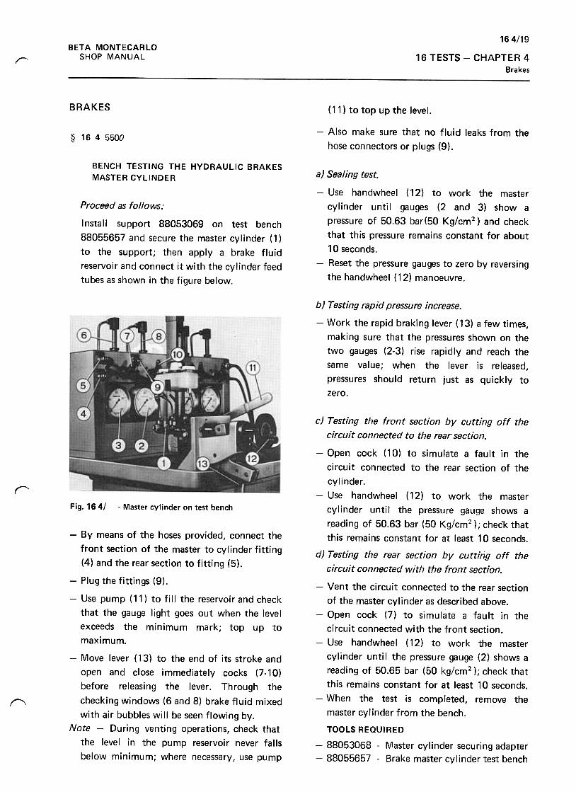
164/19BETA MONTECARLO
SHOP MANUAL 16 TESTS -CHAPTER 4Brakes
r
BRAKES (11) to top up the level.
-Also make sure that no fluid leaks from the
hose connectors or plugs (9).§ 1645500
BENCH TESTING THE HYDRAULIC BRAKES
MASTER CYLINDER
Proceed as follows:
Install support 88053069 on test bench
88055657 and secure the master cylinder (1 )
to the support; then apply a brake fluid
reservoir and connect it with the cylinder feed
tubes as shown in the figure below.
a) Sealing test.
-Use handwheel (12) to work the master
cylinder until gauges (2 and 3) show a
pressure of 50.63 bar(50 Kg/cm2) and check
that this pressure remains constant for about
10 seconds.
-Reset the pressure gauges to zero by reversing
the handwheel ( 12) manoeuvre.
b) Testing rapid pressure increase.
-Work the rapid braking lever ( 13) a few times,
making sure that the pressures shown on the
two gauges (2-3) rise rapidly and reach the
same value; when the lever is released,
pressures should return just as quickly to
zero.
rFig. 164/ -Master cylinder on test bench
(',
-By means of the hoses provided, connect the
front section of the master to cylinder fitting
(4) and the rear section to fitting (5).
-Plug the fittings (9).
-Use pump (11) to fill the reservoir and check
that the gauge light goes out when the level
exceeds the minimum mark; top up to
maximum.
-Move lever ( 13) to the end of its stroke and
open and close immediately cocks (7-10)
before releasing the lever. Through the
checking windows (6 and 8) brake fluid mixed
with air bubbles will be seen flowing by.
Note -During venting operations, check that
the level in the pump reservoir never falls
below minimum; where necessary, use pump
c) Testing the front section by cutting off the
circuit connected to the rear section.
-Open cock (10) to simulate a fault in the
circuit connected to the rear section of the
cylinder.
-Use handwheel (12) to work the master
cylinder until the pressure gauge shows a
reading of 50.63 bar (50 Kg/cm2 ); check that
this remains constant for at least 10 seconds.
d) Testing the rear section by cutting off the
circuit connected with the front section.
-Vent the circuit connected to the rear section
of the master cylinder as described above.
-Open cock (7) to simulate a fault in the
circuit connected with the front section.
-Use handwheel (12) to work the master
cylinder until the pressure gauge (2) shows a
reading of 50.65 bar (50 kg/cm2 ); check that
this remains constant for at least 10 seconds.
-When the test is completed, remove the
master cylinder from the bench.
TOOLS REQUIRED
-88053068 -Master cylinder securing adapter
-88055657 -Brake master cylinder test bench
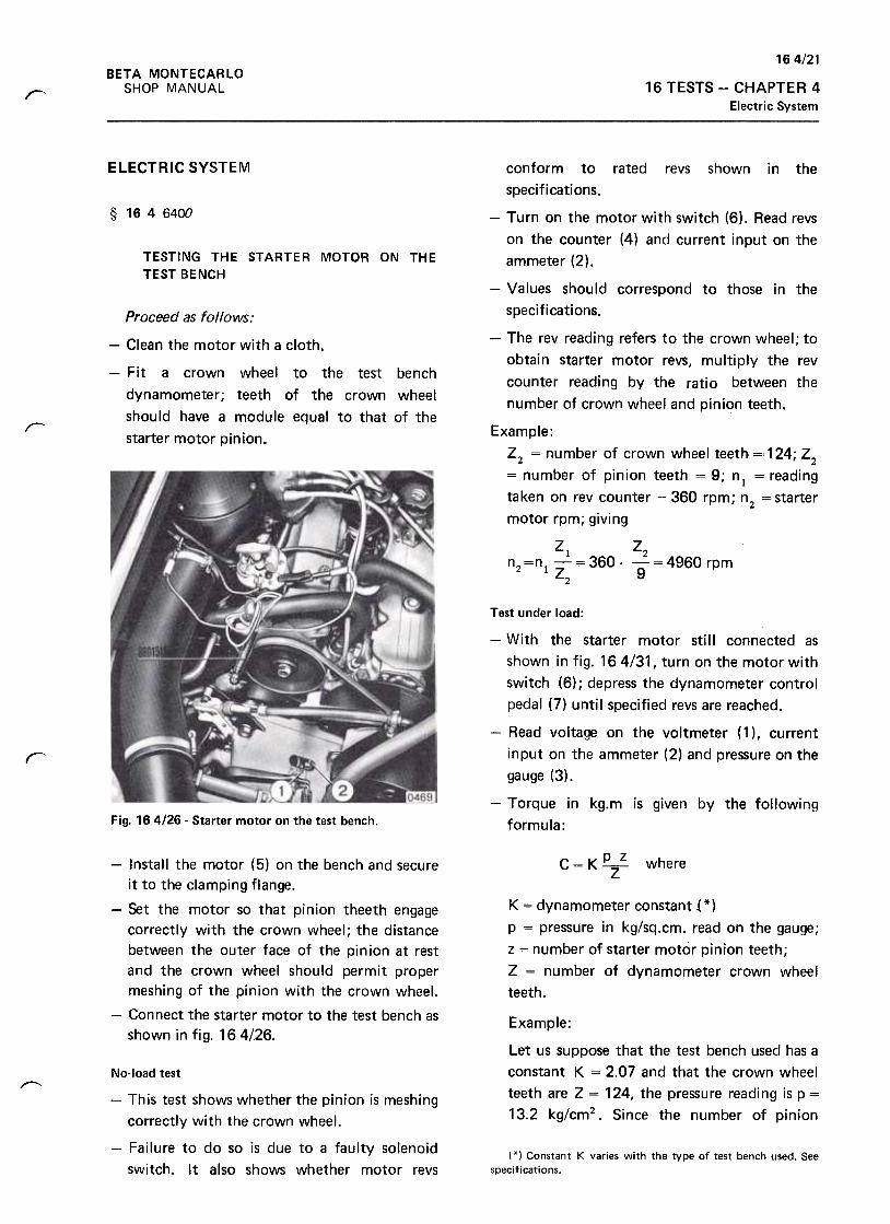
164/21BETA MONTECARLO
SHOP MANUAL 16TESTS- CHAPTER 4
Electric System~
ELECTRIC SYSTEM
§ 1646400
TESTING THE STARTER MOTOR ON THE
TEST BENCH
Proceed as follows:
conform to rated revs shown in the
specifications.
-Turn on the motor with switch (6). Read revs
on the counter (4) and current input on the
ammeter (2).
-Values should correspond to those in the
specifications.
-The rev reading refers to the crown wheel; to
obtain starter motor revs, multiply the rev
counter reading by the ratio between the
number of crown wheel and pinion teeth.
-Clean the motor with a cloth.
-Fit a crown wheel to the test bench
dynamometer; teeth of the crown wheel
should have a module equal to that of the
starter motor pinion.r Example:
Z2 = number of crown wheel teeth =,124; Z2
= number of pinion teeth = 9; nl = reading
taken on rev counter = 360 rpm; n2 = starter
motor rpm; giving
Zl Z2'0'= 360 .-= 4960 rpm
9
n =n1 -Z2 2
,
Test under load:
-With the starter motor still connected as
shown in fig. 16 4/31, turn on the motor with
switch (6); depress the dynamometer control
pedal (7) until specified revs are reached.
-Read voltage on the voltmeter (1 ), current
input on the ammeter (2) and pressure on the
gauge (3) .
-Torque in kg.m is gjven by the following
formula:Fig. 164/26- Starter motor on the test bench.
C=K~
Z
where-Install the motor (5) on the bench and secure
it to the clamping flange.
-Set the motor so that pinion theeth engage
correctly with the crown wheel; the distance
between the outer face of the pinion at rest
and the crown wheel should permit proper
meshing of the pinion with the crown wheel.
-Connect the starter motor to the test bench as
shown in fig. 164126.
K = dynamometer constant i *)
p = pressure in kg/sq.cm. read on the gauge;
z = number of starter motor pinion teeth;
Z = number of dynamometer crown wheel
teeth.
Example:
Let us suppose that the test bench used has aconstant K = 2.07 and that the crown wheel
teeth are Z = 124, the pressure reading is p =
13.2 kg/cm2. Since the number of pinion
,-- No-load test
-This test shows whether the pinion is meshing
correctly with the crown wheel.
-Failure to do so is due to a faulty solenoid
switch. It also shows whether motor revs
( * ) Constant K varies with the type of test bench used. See
specifications.
164/22
BETA MONTECARLO
SHOP MANUAL16 TESTS -CHAPTER 4
Electric System
VJl
VL
= I. where
teeth is z = 9, we have
C=K.p.z:Z=2,07.13.9:124=1.1 mkg.
The torque value found must conform to
specifications. I = Ammeter reading
V n = Rated voltage
VL = Voltmeter reading
Example
Let us suppose the ammeter reading to be I =
310 A and the voltmeter reading to be VI = 8
V; since rated voltage is V n = 9 V and rated
current In = 335- 360 At we have:
= I x Vn : VI = 310 x 9: 8 = 349 A
TOOLS REQUIRED
Short circuit test
-With the starter motor (5) connected as
shown in fig. 16 4/31, turn on switch (6) and
depress the dynamometer control pedal (7) to
stop the motor for an instant (5 sec max).
-rake the. reading on the pressure gauge (3)
while the motor is stalled.
Static torque is calculated as in the previous
test and shoutd agree with the value given in
the specifications.
The current and voltage readings may differ
from the rated values given in the
specifications depending on the charge state
of the test bench battery.
The current value to be compared with rated
current shown In the specifications is thus
given by the following formula: -88075016 -Electric units test bench
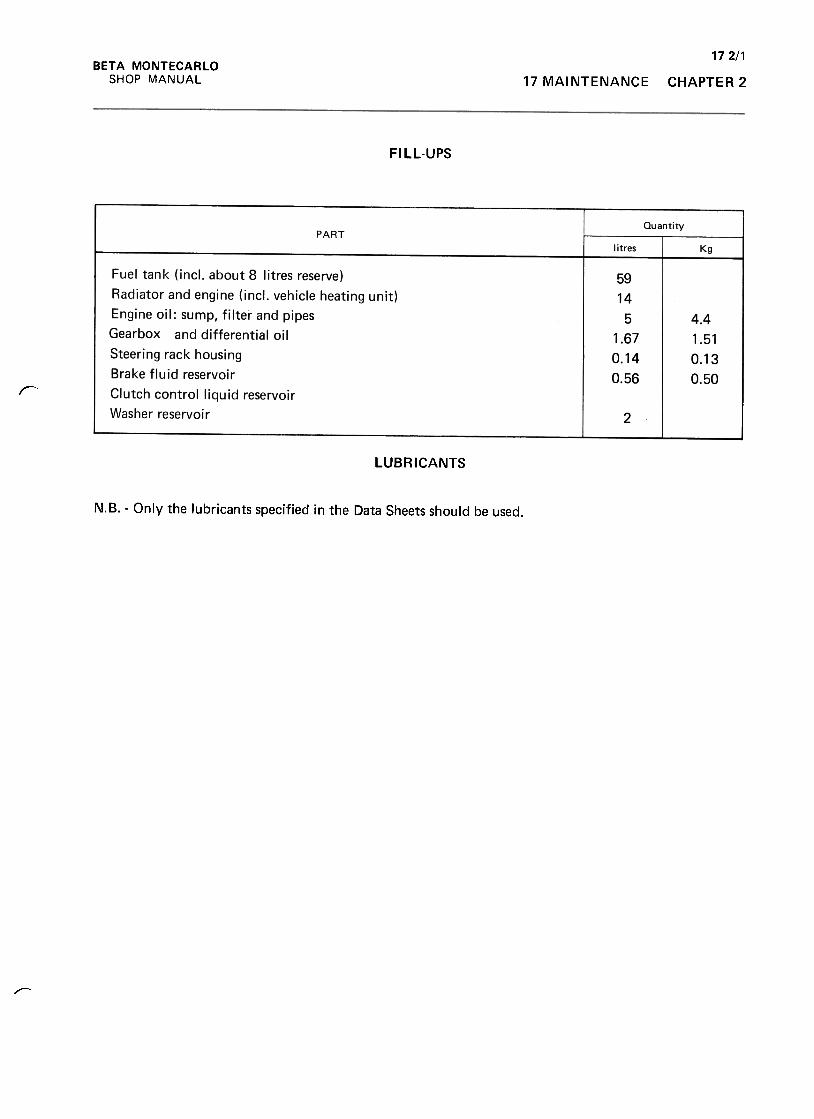
172/1BETA MONTECARLO
SHOP MANUAL 17 MAINTENANCE CHAPTER 2
FILL-UPS
QuantityPART
litres Kg
59
14
5
1.67
0.14
0.56
Fuel tank (incl. about 8 litres reserve)
Radiator and engine (incl. vehicle heating unit)
Engine oil: sump, filter and pipes
Gearbox and differential oil
Steering rack housing
Brake fluid reservoir
Clutch control liquid reservoir
Washer reservoir
4.4
1.51
0.13
0.50r
2
LUBRICANTS
N.B. -Only the lubricants specified in the Data Sheets should be used.
r-
172/2BETA MONTECARLO
SHOP MANUAL17 MAINTENANCE -CHAPTER 2
§ 1720010
PRE-DELIVERY MAKEREADY OPERATIONS
ON NEW VEHICLES
their proper places.
-Unpack and mount the hub caps. Mount the
front and rear number plate holders and
registration plates.
-Place the Owner's Handbook and the Lancia
Service Organisation Book in the glove locker.The following operations must be performed
Checking of level$
§ 1720050
SERVICING COUPON (Jobs to be performed
after 2000.3000 Km)
-Check and top up, if necessary; engine oil,
gearbox oil; brake master cylinder fluid
reservoir; cooling system overflow tank;
windscreen washer reservoir; battery
electrolyte (use distilled water).
-Check tyre pressures, including that of the
spare wheel.
Operational checks
-Check the operation of the windscreen wipers
and washers. See that the washer jets are
properly aimed.
-Check that the turn indicator lights, side
lights, headlights, stop and backing lights
work properly.
The following operations must be performed :
-Road test (on reception). This includes the
following checks when on the move:
operation of dashboard telltales and controls;
free travel of brake and clutch pedals;
efficiency of the hand brake on a steep slope,
or on attempting to break away from a
standstill; automatic cut-in of electric fan.
-Check for leaks from brake and clutch control
pipes (pedals inside the vehicle), windscreen
washer (front compartment), and cooling and
fuel circuits.Washing
-Wash the outside of the vehicle using any
commercially available neutral soap. Rinse
thoroughly.
Rear end of vehicle
-Remove the spare wheel. Take off the air
cleaner cover, clean the fi Iter and replace the
cover .
-Take off the distributor cap, clean the points
and set the opening of the contact breaker
points. Remove the plugs, clean them and
check the spark gap. Check the ignition stroke
and adjust as required.
-Check and, if necessary, adjust the alternator
drive belt tension.
-Check that the cylinder head mounting bolts
are at the correct torque loading. The engine
must be cold when this operation is carried
out.
-Next, check that the clearance of the inlet
and exhaust valves is correct. Once again, the
engine must be cold. Note: adjustment of
these clearances is not provided for in the
servicinQ coupon.
Cleaning the outside and inside of the vehicle
-Blowout the boot with compressed air. Clean
the linings with a cloth soaked in petrol.
-Blowout the interior with compressed air.
Clean the inside fittings, including the carpets,
with a cloth soaked in rectified p~trol.
-Clean the inside of the bonnet. Use a cloth
soaked in petrol to clean the ribs and
channels.
-Use a cloth soaked in alcohol to clean the
inside and outside of the windows and
windscreen.
-Clean the outside of the vehicle thoroughly.
Pay particular attention to the radiator grille,
front and rear lights, bumpers, mouldings and
handles.
-Fit the jack. spare wheel cover and tool kit in
172/3BETA MONTECARLO
SHOP MANUAL 17 MAINTENANCE CHAPTER 2
Refit the distributor cap and plugs.
Under the vehicle
-Check for leaks from the engine, gearbox and
differential unit, suspension struts, and brake
pipes. Make sure that the constant velocity
joint guards, the suspension ball joints, the
control linkage joints, and the steering
housing guards are not damaged.
-Check that the exhaust pipes and manifold
are firmly fastened.
-Check that the bolts holding the front bar
silent blocks are tightened to the correct
torque loading.
-Check that the bolts holding the rear bar
silent blocks are tightened to the correct
torque loading.
-Start the engine and leave it running until the
temperature required for setting the
slow-running mechanism is reached.
-Lubricate the front and rear bonnet release
controls, the seat sliders and the door locks
and hinges.
-Check that the bolts holding the door lock
blocks are tight.
-Set the slow-running mechanism
-Change the engine and differential oil.
-Check and, if necessary, top up: battery
electrolyte; washer fluid; coolant overflow
tank; brake master cylinder and clutch servo
control reservoirs.
-Check tyre pressure, including that of the
spare wheel. The tyres must be cold.
-Top up the differential.
-.Top up the engine oil. Run the engine for a
short period and recheck the level 2-3 minutes
after turning off the engine.
-Replace the spare wheel.
-Road test (for approval).
Top and bottom of the vehicle
-Check the hand brake travel. Adjust if more
than 3-4 clicks are heard before the brake
operates.
172/4BETA MONTECARLO
SHOP MANUAL17 MAINTENANCE -CHAPTER 2
Note: Time 20.0 minutes
Workshop
Operations required: Para. 17 2 0200 Nos.
12-12-14-18. Time 80.0 minutes.
Total time for 5000 km maintenance: 20 + 80 =
100.0 minutes.
The chart lists the periodic maintenance
operations carried out after various numbers of
kilometres at Service Stations or Workshops.
The time required for these operations
(marked by an X) is given in the schedule of
times in accordance with the paragraph numbers
shown at the head of each column.
It will be obvious that the overall time needed
to perform the tasks at any given mileage will be
the sum of the times shown.
At 30,000 Km
Service Station
Operations required: Para. 17 2 1100 Nos. 1 to
5. Time 50.0 minutes.
Workshop
Operations required: Para. 17 2 1200 Nos.
6-8-10-11-12-13-14-18. Time 260.0 minutes.
Total time for 30,000 Km maintenance: 50 +260 = 310 minutes.
Example:At 5000 Km
Service Station
Operations required: Para. 1720100 Nos. 1-5.
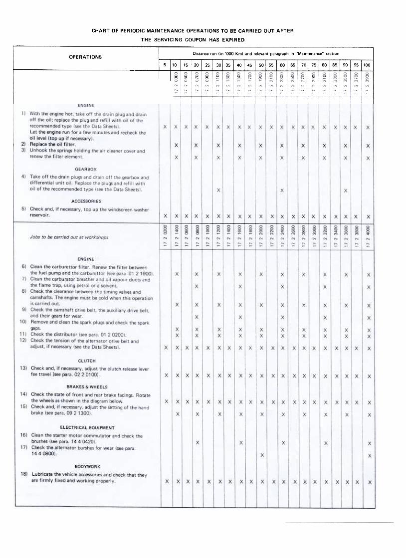
CHART OF PERIODIC MAINTENANCE OPERATIONS TO BE CARRIED OUT AFTER
THE SERVICING COUPON HAS EXPIRED
Distance run (in '000 Km) and relevant paragraph in "Maintenance" sectionOPERATIONS
60 I 65 I 70 I 75 I 80 I 85 I 90 I 95 i 1005 i 10 15 30 I 35 I 40 I 45 I 50 , 55
0~ON"
Jobs to be carried out at service stations