Shape recognition of CAD models via iterative slippage analysis
13
Computer-Aided Design 55 (2014) 13–25 Contents lists available at ScienceDirect Computer-Aided Design journal homepage: www.elsevier.com/locate/cad Shape recognition of CAD models via iterative slippage analysis ✩ Bing Yi a , Zhenyu Liu a,∗ , Jianrong Tan a , Fengbei Cheng a , Guifang Duan a , Ligang Liu b a State Key Lab of CAD&CG, Zhejiang University, Hangzhou, 310027, China b University of Science and Technology of China, Hefei, 230026, China highlights • We present a new shape recognition method by iterative slippage analysis. • The exact normal is found to be one of the key points for slippage analysis. • The appropriate region is found to be the other key points for slippage analysis. • A knowledge guided region growing method is used to get the appropriate region. • An iterative normal modification method is used to obtain the exact normal. article info Article history: Received 31 July 2012 Accepted 28 April 2014 Keywords: Shape recognition Slippage analysis Basic primitives abstract A new slippage analysis method for recognizing basic primitive surfaces of CAD models is presented in this paper. Obtaining the exact normal and searching the appropriate local region of each point are found to be the key steps for determining the local slippage motion type. First, the tensor voting-based boundary point recognition method is integrated to preprocess the original points. Then, the local slippage analysis method is used to initialize the point type. Furthermore, the appropriate region of each point is acquired by the region growing method. Meanwhile, the middle level information (the basic primitive surface types and the representative parameters) is found, guiding the modification of the normal of each point and the iterative detection of the surface types. Finally, the middle level information-based smooth method is introduced to refine the boundary of each basic primitive surface. The empirical results show that the proposed algorithm is efficient and robust for recognizing primitive shapes from CAD models of mechanical parts. © 2014 Elsevier Ltd. All rights reserved. 1. Introduction With the rapid development of 3D digital data acquisition devices, we can obtain all the point cloud of 3D models easily and rebuild the triangular meshes with high accuracy. This is recently called reverse engineering, which provides a new way to create massive complex 3D models. However, due to the loss of middle level and high level model information (symmetry, parallelism, perpendicularity, etc.), such meshes are too raw to be directly used in the subsequent processes, such as CAD model reconstruction, and convergent-type CAE. With the virtual explosion in the amount of raw data available for designer, the critical problem shifts to obtain the middle level and high level information through this ✩ This paper has been recommended for acceptance by Karthik Ramani, PhD. ∗ Corresponding author. E-mail address: [email protected] (Z. Liu). data and adopt it to improve the efficiency for redesigning a new product [1]. The key processes to detect the middle level and high level model information from existing 3D point clouds are mesh segmentation and shape recognition [2–6]. Recently, a lot of researches have been done on shape seg- mentation and recognition. Most previous approaches are based on the local model information like curvature or boundary detec- tion. However, even with the segmented surface patches, it is also difficult to get the middle level model information, let alone the high level model information. Realizing that a lot of mechanical parts consist of basic primitives, such as plane, sphere, cylinder, cone, extrusion, revolution, helix, nowadays, many researchers have attempted to segment the CAD models into basic primitives [7–13]. The existing primitive shape fitting approaches likely con- front the following problems: (1) hardly can recognize all the basic primitives, such as plane, sphere, cylinder, cone, extrusion, revolu- tion, and helix; (2) hardly can obtain the middle level information of the basic primitives, such as the center and radius of a sphere, the normal and position of a plane, etc; (3) sensitivity to numerical http://dx.doi.org/10.1016/j.cad.2014.04.008 0010-4485/© 2014 Elsevier Ltd. All rights reserved.
Transcript of Shape recognition of CAD models via iterative slippage analysis

Computer-Aided Design 55 (2014) 13–25
Contents lists available at ScienceDirect
Computer-Aided Design
journal homepage: www.elsevier.com/locate/cad
Shape recognition of CAD models via iterative slippage analysis✩
Bing Yi a, Zhenyu Liu a,∗, Jianrong Tan a, Fengbei Cheng a, Guifang Duan a, Ligang Liu b
a State Key Lab of CAD&CG, Zhejiang University, Hangzhou, 310027, Chinab University of Science and Technology of China, Hefei, 230026, China
h i g h l i g h t s
• We present a new shape recognition method by iterative slippage analysis.• The exact normal is found to be one of the key points for slippage analysis.• The appropriate region is found to be the other key points for slippage analysis.• A knowledge guided region growing method is used to get the appropriate region.• An iterative normal modification method is used to obtain the exact normal.
a r t i c l e i n f o
Article history:Received 31 July 2012Accepted 28 April 2014
Keywords:Shape recognitionSlippage analysisBasic primitives
a b s t r a c t
A new slippage analysis method for recognizing basic primitive surfaces of CAD models is presentedin this paper. Obtaining the exact normal and searching the appropriate local region of each point arefound to be the key steps for determining the local slippage motion type. First, the tensor voting-basedboundary point recognitionmethod is integrated to preprocess the original points. Then, the local slippageanalysis method is used to initialize the point type. Furthermore, the appropriate region of each point isacquired by the region growing method. Meanwhile, the middle level information (the basic primitivesurface types and the representative parameters) is found, guiding themodification of the normal of eachpoint and the iterative detection of the surface types. Finally, the middle level information-based smoothmethod is introduced to refine the boundary of each basic primitive surface. The empirical results showthat the proposed algorithm is efficient and robust for recognizing primitive shapes from CAD models ofmechanical parts.
© 2014 Elsevier Ltd. All rights reserved.
1. Introduction
With the rapid development of 3D digital data acquisitiondevices, we can obtain all the point cloud of 3D models easily andrebuild the triangular meshes with high accuracy. This is recentlycalled reverse engineering, which provides a new way to createmassive complex 3D models. However, due to the loss of middlelevel and high level model information (symmetry, parallelism,perpendicularity, etc.), suchmeshes are too raw to be directly usedin the subsequent processes, such as CAD model reconstruction,and convergent-type CAE.With the virtual explosion in the amountof raw data available for designer, the critical problem shifts toobtain the middle level and high level information through this
✩ This paper has been recommended for acceptance by Karthik Ramani, PhD.∗ Corresponding author.
E-mail address: [email protected] (Z. Liu).
http://dx.doi.org/10.1016/j.cad.2014.04.0080010-4485/© 2014 Elsevier Ltd. All rights reserved.
data and adopt it to improve the efficiency for redesigning a newproduct [1]. The key processes to detect the middle level and highlevel model information from existing 3D point clouds are meshsegmentation and shape recognition [2–6].
Recently, a lot of researches have been done on shape seg-mentation and recognition. Most previous approaches are basedon the local model information like curvature or boundary detec-tion. However, even with the segmented surface patches, it is alsodifficult to get the middle level model information, let alone thehigh level model information. Realizing that a lot of mechanicalparts consist of basic primitives, such as plane, sphere, cylinder,cone, extrusion, revolution, helix, nowadays, many researchershave attempted to segment the CAD models into basic primitives[7–13]. The existing primitive shape fitting approaches likely con-front the following problems: (1) hardly can recognize all the basicprimitives, such as plane, sphere, cylinder, cone, extrusion, revolu-tion, and helix; (2) hardly can obtain the middle level informationof the basic primitives, such as the center and radius of a sphere,the normal and position of a plane, etc; (3) sensitivity to numerical

14 B. Yi et al. / Computer-Aided Design 55 (2014) 13–25
noise inherently embedded within the obtained 3D point clouds.Therefore, we propose a new slippage analysis method to robustrecognize shape primitives of mechanical parts. We discover thatthe key processes for slippage shape segmentation are the exactnormal and the appropriate region selection of each point. The ex-istences of noise in point cloud obtained by 3D digital data acquisi-tion devices and sharp edges inmechanical objectsmake it difficultto find the exact normal of each point. Thus, we introduce the ten-sor voting method to classify the point type into a plane, a sharpedge and a corner. Meanwhile, the detected point type improvesthe efficiency of the surface type segmenting and recognizing. Fur-thermore, we use the knowledge-based region growing method toget the exact region for each primitive patch, and then adopt theextended RANSAC method to obtain the middle level information,which iteratively guides the normal modification and the shaperecognition.
2. Related work
Mesh segmentation has been extensively studied in the pastyears. The goal of segmentation is to cluster the mesh model intomeaningful parts. However, it is hard to propose a segmentationapproach that can segment all kinds of models into appropriateparts, due to the application field difference [14,15]. In computergraphics, the region growing method, the watershed method, theK -means method, the mesh shift method, the shape diameterfunction method, and the rand walk method have been wellstudied [16–21]. But these approaches cannot be directly appliedto segment mechanical parts. Várady et al. [2] provide a detailedsurvey in the reconstruction of mechanical parts and underlinethat the surface type recognition and surface fitting are the specificissues for reconstructing a B-rep model. Agathos et al. [22] presentan exhaustive overview of 3Dmesh segmentation both on surface-based methods, which segment the part into basic primitives, andon volume-based methods, which segment the part into differentvolumes or features.We roughly group the relatedworks into threecategories: low level information-based surface segmentation,middle level and high level information-based shape classification,and robust shape recognition.Low level information-based surface segmentation.Many traditionalsegmentation methods use the local level information such asthe Gaussian curvature or the mean curvature to segment themodel. One of the most popular segmentation methods is regiongrowing. This method selects a set of seed points and merges theneighbor points to a patch which has the same local properties,such as principle curvatures. However, it is difficult to find theexact seeds and therewill be over segmentation in the transition oftwo patches [23,24]. Lavoué et al. [25,26] extend this algorithm byusing a robust curvature tensor to guide the region growing andintroduce a boundary score to rectify the patch boundaries. Kimet al. [27] introduce the tensor voting-based mesh segmentationmethod. The point type is recognized first by the robust tensorvoting theory. Then, the mesh data with additional attribute suchas color information is clustered into several patches by thek-means algorithm. However, the local information-based regiongrowing method cannot segment all the basic primitives, and it ismuch difficult to obtain themiddle level and high level informationof mechanical parts.Middle level and high level information-based shape classification.Recently, many researches have realized that shape features playimportant roles in the segmentation of man-made objects. Cohen-Steiner et al. [28] propose a segmentation algorithm, called varia-tion shape approximation. This algorithm iteratively fit planes andpartition triangles to the regions until the convergence. Wu et al.[29] extend this algorithm by using not only planes, but also cylin-ders, spheres, and rolling ball surfaces for the fittings. Yan et al.
[11,12] propose an iterative method for mesh segmentation by fit-ting quadric surfaces. However, these methods partition the en-tire surface into parts approximated by shape proxies; thus thecomplex surface will also be assigned primitives. Attene et al. [8,9]introduce a hierarchical mesh segmentation method to detectprimitive geometries. The algorithm generates a binary tree ofclustering and iterativelymerges the local neighbor points into onesingle primitive cluster based on the approximationmethod. Thesefitting approaches require users to input the number of regionsfirst, but it is difficult to find the appropriate number of regionsbefore mesh segmentation. Protopsaltis et al. [30] introduce theplanar cross section to reconstructing CAD models from the pointclouds. However, the cross section should be along a principal axis,and the feature intersections and cross section along a sweep tra-jectory are ignored. Sellamani et al. [31] propose a robust methodto approximate sweep shape by using prominent cross section.Goyal et al. [32] adopt the prominent cross section to extract highlevel, volumetric information from mesh models. However, it isdifficult to reconstruct a mechanical part with multiple sweepcomponents and intersections between them. Furthermore, themanufacture and function features of mechanical parts are com-posed of basic geometry primitives; thus, the classified sweepcomponents need further process to be converted to semanticmanufacture features.Robust primitive shape recognition. Most of traditional mesh seg-mentationmethods aim to segment the surface into different parts,and some try to classify the mesh by the surface type. However,how to robust recognize the primitive shape from point clouds ischallenging. Benjamin et al. [33] propose a heat walk algorithmto segment triangle meshes, which is robust to a variety of noisefactors. Fang et al. [34] adopt the heat mean signature to robustsegment the surface which satisfies the perceptually consistentmesh segmentation conditions. However, the heat kernel-basedmethod cannot be used to segment themechanical parts into basicprimitives. Golovinskiy et al. [35] propose a system for recognizingobjects in 3D point clouds of urban environments. The graph-cut algorithm is adopt to segment the point clouds into differentpatches, and then a trained classifiermodel is used to recognize thesegmented patches. However, it is difficult to propose an appropri-ate shape features that can recognize all the objects from the pointclouds. Lafarge et al. [36] proposed a multi-label Markov RandomField formulation, which is based on the principle curvature, tosegment the surface into patches, and then use a primitive-fittingmethod to classify the basic primitives. However, this method isless competitive for recognizing shape from models, which arestrongly corrupted by noise. Décoret et al. [37] extend the stan-dard Hough transform and employ it to identify planes for bill-board clouds of triangle meshes. However, this method exhibitspoor run-time performance on recognizing basic primitive fromlarge or complex mechanical part because of the high computa-tional demand of the Hough transform. Schnabel et al. [10] presenta shape detection method in point cloud based on the RANSACmethod. They demonstrate a robust algorithm that used randomsamples and the middle level information to cluster basic primi-tive shapes. However, the basic primitives adopted in this methodare not suitable for building all the mechanical models. Gelfandet al. [13] propose a slippable motion-based hierarchical cluster-ing method. They introduce a rigid motion to segment mechani-cal objects into planes, spheres, cylinders, linear extrusion surfaces,surfaces of revolution and helical surfaces. We certify that the ex-act normal estimation and the choice of neighborhood point setof each point are the key tips for the slippage-based segmenta-tion method theoretically and practically, and employ the RANSACmethod to obtain the middle level parameters of each basic prim-itive, guiding the modification of the normal of each point and theiterative shape recognition of mechanical parts.

B. Yi et al. / Computer-Aided Design 55 (2014) 13–25 15
Table 1Methods for recognizing the basic primitive.
Surface type Recognize method Geometry property How to recognize
Plane Gauss map Normal distribution One pointSlippage Number of slippage 3Curvature kmax, kmin kmax = kmin = 0
Sphere Gauss map Normal distribution All the sphereSlippage Number of slippage 3Curvature kmax, kmin kmax = kmin = const
Cylinder Gauss map Normal distribution A great circleSlippage Number of slippage 2Curvature kmax, kmin kmax = const, kmin = 0
Cone Gauss map Normal distribution A small circleSlippage Number of slippage 1Curvature kmax, kmin kmax = const, kmin = 0
Helix Gauss map Normal distribution UncertainSlippage Number of slippage 1Curvature kmax, kmin kmax = 0, kmin = 0
Revolution Gauss map Normal distribution Parallel great circleSlippage Number of slippage 1Curvature kmax, kmin kmax = 0, kmin = 0
Extrusion Gauss map Normal distribution A dense circleSlippage Number of slippage 1Curvature kmax, kmin kmax = 0, kmin = 0
The remainder of this article is organized as follows. In Sec-tion 3, the local slippage analysis-based shape segmentationmethod is briefly reviewed, and the method for recognizing thebasic primitives of mechanical models is described; then the exactnormal and the appropriate local region of each point is proved tobe the key points for local slippage analysis. Then, Section 4 intro-duces the iterative shape recognition method in detail, where themiddle level information is used to guide the shape recognition andthe normalmodification. And the experimental results of recogniz-ing basic primitives from CAD and CAE models are demonstratedin Section 5. Finally, the conclusion and future work are outlinedin Section 6.
3. Shape slippage analysis revisited
Most mechanical parts are composed of basic primitives, whichcan be segmented by applying the local rigid motion type. Gelfandet al. [13] demonstrate slippage signatures to cluster engineeringmodels into basic primitives. We extend the slippage analysis-based method to recognize basic primitives and prove that theexact normal and the appropriate local regions are the key issuesfor slippage analysis.
3.1. Slippage analysis and shape recognition
3.1.1. Slippage analysisLetM be a set of triangles {ti}mi=1that constitute a mesh surface.
We want to segment it into several middle level surface patchesdenoted by S = {ti}ni=1, where
ki=1 Si = M and Si
Sj = ∅ for
any i = j. And each patch can be described as a basic primitive.We also employ the representative parameters such as spherecenter, sphere radius, plane normal, cylinder axis, etc., for the basicprimitives.
Gelfand et al. [13] introduce a surface descriptor, which is basedon the surface behavior under different kinds of rigid motion.And the rigid motion M(t) can be decomposed into two time-vary motions: the rotation part R(t) and the translation part T (t).Applying a differential to the rigid motion equation of each point,the instantaneous velocity of point x can be expressed as follows:
v(x) = r × x + t (1)
where r = (rx, ry, rz) is a 3 × 1 vector of rotation around x, y, andz axes and t = (tx, ty, tz) is a translation vector. Then the rigidmotion type is defined as follows:
• If r = 0, the motion M is a translation with constant velocityalong the direction t .
• If r · t = 0, the motion M is a rotation with constant angularvelocity.
• If r · t = 0, the motionM is a uniform helical motion.
According to the approximation of the kinematic surface, a slip-page signature of each patch is defined to segment the surfacemesh. And applying the rigid motion to a small patch, a minimiza-tion equation of a set of points is defined to find the slippable mo-tion type.
min[r t]
ni=1
((r × pi + t) · ni)2. (2)
Eq. (2) is a least-squares problem, which can be solved as alinear system Cx = 0, where C is a covariance matrix of secondpartial derivatives of the objective function with respect to themotion parameter. Then the mesh model can be segmented intobasic primitives based on the eigen value of matrix C .
3.1.2. Shape recognitionWith the slippage motion analysis, the mechanical objects can
be segmented into different shape types. The plane and sphere are3-slippage motion surfaces. The cylinder is the 2-slippage motionsurface. The cone, helix, revolution and extrusion are 1-slippagemotion surfaces. There may be a non-kinematic surface with0-slippagemotion. However, only with the number of the slippagemotion, it is very difficult to recognize the basic primitives. Byanalyzing the design and manufacture processes of mechanicalobjects,we classify all the surfaces ofmechanical objects into seventypes: plane, sphere, cylinder, cone, extrusion, revolution, helix,as shown in Table 1. There are also kinds of freeform surfaces inmechanical objects, which are non-kinematic surfaces. We easilyclassify those freeform surfaces into non-slippage type (or have notbeen recognized surface).
In order to recognize all the basic primitives, we introducetwo more methods to assist the shape recognition: the Gauss

16 B. Yi et al. / Computer-Aided Design 55 (2014) 13–25
Fig. 1. Relation of the noise points and the exact points in the local surface (pi isa point on the ideal surface, and pi1 represents the scanned point. O defines theoriginal point of the Cartesian coordinate system. tu, tv, n symbolize the directionof the max curvature, the min curvature and the normal respectively).
map method and the principle curvature. With the kmax and kmincurvature, we can robustly recognize the plane, sphere, cylinder,cone by the curvature difference. To consolidate the results ofsurface type segmentation and classification, we also introduceGauss map method for the normal distribution of the basicprimitive is different, when mapping to the unit sphere. The shaperecognition method can be seen in Table 1.
3.2. Key issues for slippage analysis
3.2.1. Normal influence on slippage analysisFrom Eq. (2), we can find that the point position and point
normal are the only two variations of the slippage-based shaperecognition. For the effect of noise, it is difficult to get the exactpoint of the original shape, and it is even more difficult to obtainthe exact normal of each point. Lots of researchers have studied thenormal estimatemethod for point cloud in computer graphics. Thetraditional normal estimation methods are based on plane fitting,quadric surface fitting, triangle-based area weighted average andtriangle-based angleweighted average. Grimmet al. [38] propose apoint set analysis approach that uses a combination of local surfacemodels and one-rings to produce robust surface normal estimationfor non-uniformly sampled, noisy point data. But without themiddle level and high level information, it is also hard to get theexact normal of points in a smooth surface, let alone in kindsof sharp corners, sharp edges, which are only C0 continuous. Inorder to get the exact point normal, we introduce iterative middlelevel information-based normal modification method, which willbe described in detail in Section 4.2.4. Here we just illustrate thenormal effects on slippage shape segmentation.
In the local surface of a point pi, the noise can be decomposedinto a portion along the direction of the normal and the directionsof the principle curvatures (as shown in Fig. 1).
pi1 = pi + α · tu + β · tv + δ · n (3)
where pi is a point on the ideal surface, and pi1 represents thescanned point. O defines the original point of the Cartesian coor-dinate system. tu, tv, n symbolize the direction of the max curva-ture, themin curvature and the normal respectively. If the scannedpoints are dense enough, the component of the noise in the tangentplane can be ignored for it has little influence on the slippage shapesegmentation. So, Eq. (3) can be expressed as follows:
pi1 ≈ pi + δ · n. (4)
Substitute this into Eq. (2), the result is shown as follows.
(r × pi1 + t) · ni = [r × (pi + δn) + t] · ni
= (r × pi + r × δn + t) · ni
= r × pi · ni + r × δn · ni + t · ni
= r × pi · ni + δr × n · ni + t · ni
= r × pi · ni + t · ni
= (r × pi + t) · ni. (5)
Eq. (5) shows that if we can get the exact normal of each point,and the scanned data is dense enough, the noise will have littleeffect on the shape recognition. Though the scanned data are withmuch noise and are raw, we can also refine the shape recognizingresult by iteratively modifying the approximated normal of eachpoint. Fig. 2 shows the normal influence on the slippage shaperecognition of fandisk model. We use only 1-ring neighborhood ofthe points to approximate the normal and to compute the slippagemotion type of each point. And for the sharp corner and sharpedge points, we split them into several points according to thenumber of the neighbor surface. Each point is added a Gaussiannoise (σ is the ratio of the distance between the point and theoriginal point to themaxmodel length) along the normal direction.Fig. 2(b) and (c) show the original normal-based initial slippageshape recognition result and the triangle area weighted normal-based one respectively.
3.2.2. Neighborhood choice influence on slippage analysisThe slippage shape detectionmethod is based on finding a point
set that minimizes the motion along the normal for each point.Getting the exact neighbor point set of each point is found tobe the other key process for slippage shape recognition. Whena small local neighbor is selected for each point, it would beincorrectly recognized as high slippage shape type. If a large scaleneighbor point set is chosen, it would be incorrectly recognizedas low slippage shape type. Gelfand et al. [13] also find theneighborhood influence on the slippage shape recognition. Theychoose the nearest 30 vertices to initialize the slippagemotion typeof each point, and then define a similarity score to merge smallpatches into large patches based on the number of the slippagemotion and the motion eigenvectors. If the chosen point set is notsuitable for segmenting the surface correctly, they choose a largerneighborhood and try the segmentation method again.
To get the exact point region for slippage shape recognition, weemploy an adaptive region growing method guided by the mid-dle level information, which would be elaborated in Section 4.2.3.Here, we just illustrate the influence of neighbor point choosing indetecting the basic primitive by region growing. Fig. 3(a) shows theshape recognizing result of fandiskmodel by the proposedmethodusing a small neighbor (1-ring neighbor) for each point. It segmentsmost of the cylinder into 3-slippage shape. With the neighbor sizegrowing, more and more cylinder points are correctly recognizedas 2-slippage shape type. However, it cannot recognize all the slip-page shape type by reason of the cylinder radius non-uniformityand the cylinder surface incompletion. Keeping on increasing thepoint’s neighbor size, it would recognize most cylinder points, butincorrectly recognizes high slippage shape as low slippage shape,which are obviously shown in Fig. 3(c) and (d).
4. Shape recognition of CAD models
In this section, we describe the implementation details of thepresented algorithm. Our algorithm aims to recognize the basicprimitives of mechanical parts by extending the slippage motion-based shape detection method. The shape recognition algorithmconsists of three main steps: (1) preprocessing and initialization;

B. Yi et al. / Computer-Aided Design 55 (2014) 13–25 17
(a) Slippage shape recognition result of fandisk model with 1-ring neighborhood of eachpoint to compute the slippage type.
(b) Slippage shape recognition result of fandisk with the original normal and with Gaussian noise along the normal.
(c) Slippage shape recognition result of fandisk with area weighted estimated normal and with Gaussian noise along the normal.
Fig. 2. Points normal influence of the slippage shape type (red is the 3-slippage motion surface, yellow is the 2-slippage motion surface, green is the one motion surface,blue is the non-kinematic surface). (For interpretation of the references to color in this figure legend, the reader is referred to the web version of this article.)

18 B. Yi et al. / Computer-Aided Design 55 (2014) 13–25
(a) 1-ring (b) 3-ring (c) 5-ring (d) 10-ring
Fig. 3. Points neighbor influence of the slippage shape recognition result of fandisk (red is the 3-slippage motion surface, yellow is the 2-slippage motion surface, green isthe 1-slippage motion surface, blue is the non-kinematic surface). (For interpretation of the references to color in this figure legend, the reader is referred to the web versionof this article.)
Fig. 4. Flowchart of the iterative slippage shape recognition framework.
(2) iterative shape recognition; and (3) the surface boundaryrectification. The flowchart of our algorithm is shown in Fig. 4.
4.1. Preprocessing and initialization
4.1.1. Sharp feature detectionAs we have formulated in Section 3, the key processes for
slippage motion detecting are to get the exact normal and to findthe exact neighbor size of each point. However, it is difficult to findthe exact normal of each point in the sharp edge of mechanicalobjects.We adopt the feature preservedmesh smoothmethod [39]to smooth the originalmodel, which is strongly corrupted by noise,and then employ a robust tensor voting-based feature detectingmethod to classify all the points into a corner, a sharp edge, and
a plane. More detail about tensor voting-based feature detectingmethod could refer to the related papers [40,41]. For the sharpedge and corner points are C0 continuous, we set them to be non-kinematic surface points. Then, we only need to detect the slippagemotion type of plane points.
4.1.2. Local slippage analysisAs shown in Fig. 3, the result of the slippage-based shape seg-
mentation method is sensitive to the chosen neighbor size of eachpoint. A small size will make the local point to get more slippagemotions, which can be decreased by growing the chosen neighborto an appropriate size. On the contrary, with a larger neighbor size,the slippagemotionwould be reduced,which is dilemma to be cor-rected to the right slippage motion type. So, we choose the 1-ring

B. Yi et al. / Computer-Aided Design 55 (2014) 13–25 19
Fig. 5. Middle level information of basic primitives (the point and the normal for the plane; the center point and the sphere radius for the sphere; the axis direction, the axisposition and the radius for the cylinder; the apex point, the axis direction and the cone-apex angle for the cone; the extrude direction, and the base curve for the extrusion;the rotation axis, the axis position and the base curve for the revolution; the rotation direction and the axis position for the helix).
neighbor of each point and adopt the triangle-based area weightedaverage-based normal estimation method to initialize the surfacetype. The original shape recognized point type is also used to avoidchoosing the corner edge and sharp edge, which would mess theslippage shape recognition.
4.2. Iterative shape recognition
As we have mentioned in Section 3.2, it is difficult to rec-ognize basic primitives by the local neighbor and inaccuratenormal-based slippage analysis method; therefore, we employ theiterative method to recognize basic primitives exactly and ro-bustly. The pipeline of the proposed iterative shape recognitionmethod is: first, the surface recognition method is adopted to rec-ognize the basic primitive for each patch. Then, the knowledge-based region growing method is used to grow each recognizedpatch step by step. Furthermore, the extended RANSAC method isintroduced to obtain the middle level information for each patch,and then the middle level information is used to modify the nor-mal of each point.We iteratively used thismethod to recognize thebasic primitives until the iterative number or the normal tolerantis achieved.
4.2.1. Surface type recognitionWe use the methods shown in Table 1 to recognize the shape
type of each patch. Compared with slippage shape detection,curvature and the Gaussian image normal distribution are moredifficult and less robust when recognizing the surface types, sowe use the local slippage motion detecting method as the basicmethod. The local curvature and the normal distribution differenceassist in recognizing the surface types. And the information of thecurvature also helps to guide knowledge-based region growing.
4.2.2. Knowledge guided region growingWe adopt the adaptive region growing method to get the
exact neighbor size for the shape type recognition. We grow each
recognized primitive shape patches by adding in the neighborpoints. First, the sharp edge and corner point in the neighbor pointsare ignored. Then, we merge the growing neighbor points, whichhave the same slippage type with the original point set. And weeliminate the points whose principle curvature is greater than thesurface type threshold. Finally, we only retain the points which fitthe surface’s middle level information within the threshold (thethresholds of normal and d parameter for the plane; the thresholdsof radius and normal for the cylinder; the thresholds of radiusand normal for the sphere; the thresholds of cone-apex angle andnormal for the cone; the threshold of the slippagemotion directionfor extrusion, revolution and helix).
4.2.3. Middle level information detection of basic primitivesWith the slippage motion type, the normal distribution, and
point’s curvature, we can segment the surface into basic primitivestheoretically. Because of the noise of the scanned data, the surfacewill be segmented into lots of small patches. So we introducethe middle level information detecting method to find the basicparameters of each surface and use this information to guide thenormal modification.
We extend the RANSAC-based shape detection method toget the middle level information of the basic primitives [10].We compute the middle level information of the plane, sphere,cylinder, and cone surface similar to the method proposed by [10],and add the detection method for extrusion, revolution and helix,which is shown in Fig. 5. The details of shape parameters detectionmethod for extrusion, revolution and helix are shown as follows:
• Extrusion: extrusion is a complex surface, which can be definedby the extrude direction l, and the base curve b (as shown inFig. 5(e)). And the slippage motion-based mesh segmentationmethodwould detect the translation or rotation direction easilyfor 1-slippage surfaces. So, the extrusion direction can beextracted by the slippage motion detect matrix, and the eigenvector of the small eigen value defines the slippage motiondirection. For the extrusion is a translation slippage surface,

20 B. Yi et al. / Computer-Aided Design 55 (2014) 13–25
Fig. 6. Middle level information-based normalmodification: (a) axonometric drawing of a plane; (b) axonometric drawing of a sphere; (c) axonometric drawing of a cylinder;(d) axonometric drawing of a cone; (e) front view of a plane; (f) front view of a sphere; (g) front view of a cylinder; (h) front view of a cone (the blue arrow is the exactlocal normal; the black arrow is the estimated normal; the pink arrow is the modified normal for every iteration). (For interpretation of the references to color in this figurelegend, the reader is referred to the web version of this article.)
the second three parts of the eigen vector define the extrusiondirection. Then the surface is projected onto the plane whosenormal is parallel with the translation direction. Finally, theextrusion base is obtained by fitting the curve in the plane.
• Revolution: the rotation axis, the axis position and the basecurve b fully define a revolution surface (as shown in Fig. 5(f)).We acquire the rotation direction as mentioned above. For it isa rotation slippage surface, the axis direction is the first threeparts of the eigen vector. Then we project all the points tothe plane whose normal is parallel with the rotation axis. Bycomputing the center of the point in the projection plane, weget the position of the axis. And with a plane through the axis,the intersection points compose the base curve.
• Helix: as for the helix surface, the most important middle levelinformation is the translation and rotation direction. For thetranslation direction is perpendicular to the rotation direction,we easily compute the rotation direction and the axis positionas mentioned above.
4.2.4. Middle level information-based normal modificationBecause of the influence of noise, it is difficult to get the exact
normal for each point in the scanned point cloud. So, we employthe iterative normal modification method, which is guided by thesurface type and the middle level information. Most mechanicalparts are composed of plane, sphere, cylinder and cone, whichare high slippage motion shapes and are more sensitive to thepoint normal. A fewobjects contain extrusion, revolution andhelix,which are 1-slippage shape, and can be classified by the kinematicmotion type and the motion direction easily. Then, our methoditeratively modifies the estimated normal of the basic shape typesuch as the plane, sphere, cylinder, cone (as shown in Fig. 6). Thedetails of the normal modification are shown as follows:
• Plane: in the middle level information detecting method whichis discussed above, we get the local normal of the point set, asit is shown in Fig. 6(a)(e) with a blue arrow. Then we iterativelymodify the normal: nnew = nold + λ(np − nold), where np is
the detected plane normal of the local point set, and λ is theparameter of the normal modification. We only need to set thenumber of iteration and the modification parameter.
• Sphere: as for the sphere, we detect the sphere center by thelocal neighbor point set. Then the normal of each point can beexpressed as: nc =
pi−c∥pi−c∥ . So we adjust the point normal as the
plane. Fig. 6(b)(f) show the normalmodification. The blue arrowis the exact local normal; the black arrow is the estimated nor-mal; the pink arrow is the modified normal for every iteration.And c is the sphere center.
• Cylinder: for each point in the cylinder, the normal is perpen-dicular to the axis. Together with the middle level informationsuch as the axis direction and position for the local point set,we get the exact normal by projecting the point and the axisposition into the plane which pasts the point and parallels tothe axis (as shown in Fig. 6(g)). The exact normal is in the samedirection as the vector from the center c to this point. Then weadjust the normal as mentioned above.
• Cone: to get the exact normal of each point in the cone, we usethe cone-apex position and the cone axis. Projecting the pointsinto the plane defined by the cone axis and the point, and lin-ing the point and the cone-apex, the normal is in the directionperpendicular to the line (as shown in Fig. 6(h)). Thenwe adjustthe normal as mentioned above.
4.3. Surface boundary rectification
Our shape recognition method extracts basic primitives andgives good qualitative results in terms of nature and dispositionof the segmented regions. Nevertheless, our method, like most ofthe existing methods, does not extract perfect boundaries, due tothe disturbance of the noise. But we have got the middle levelinformation of all the primitive patches, so we propose a middlelevel information-based boundary rectification method.
For there may exist fragment segments and non-smoothingboundary in the original segmented patches, we compute the total
B. Yi et al. / Computer-Aided Design 55 (2014) 13–25 21
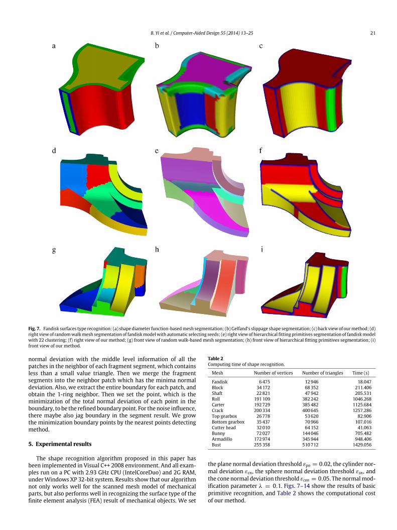
Fig. 7. Fandisk surfaces type recognition: (a) shape diameter function-basedmesh segmentation; (b) Gelfand’s slippage shape segmentation; (c) back viewof ourmethod; (d)right viewof randomwalkmesh segmentation of fandiskmodelwith automatic selecting seeds; (e) right viewof hierarchical fitting primitives segmentation of fandiskmodelwith 22 clustering; (f) right view of our method; (g) front view of randomwalk-based mesh segmentation; (h) front view of hierarchical fitting primitives segmentation; (i)front view of our method.
normal deviation with the middle level information of all thepatches in the neighbor of each fragment segment, which containsless than a small value triangle. Then we merge the fragmentsegments into the neighbor patch which has the minima normaldeviation. Also, we extract the entire boundary for each patch, andobtain the 1-ring neighbor. Then we set the point, which is theminimization of the total normal deviation of each point in theboundary, to be the refined boundary point. For the noise influence,there maybe also jag boundary in the segment result. We growthe minimization boundary points by the nearest points detectingmethod.
5. Experimental results
The shape recognition algorithm proposed in this paper hasbeen implemented in Visual C++ 2008 environment. And all exam-ples run on a PC with 2.93 GHz CPU (IntelCoreDuo) and 2G RAM,underWindows XP 32-bit system. Results show that our algorithmnot only works well for the scanned mesh model of mechanicalparts, but also performs well in recognizing the surface type of thefinite element analysis (FEA) result of mechanical objects. We set
Table 2Computing time of shape recognition.
Mesh Number of vertices Number of triangles Time (s)
Fandisk 6475 12946 18.047Block 34172 68352 211.406Shaft 22821 47942 205.531Roll 191109 382242 1046.268Carter 192729 385482 1125.684Crack 200334 400645 1257.286Top gearbox 26778 53620 82.906Bottom gearbox 35437 70966 107.016Cutter head 32010 64152 41.063Bunny 72027 144046 705.482Armadillo 172974 345944 948.406Bust 255358 510712 1429.056
the plane normal deviation threshold εpn = 0.02, the cylinder nor-mal deviation εcn, the sphere normal deviation threshold εsn, andthe cone normal deviation threshold εcon = 0.05. The normalmod-ification parameter λ = 0.1. Figs. 7–14 show the results of basicprimitive recognition, and Table 2 shows the computational costof our method.

22 B. Yi et al. / Computer-Aided Design 55 (2014) 13–25
Fig. 8. Block surfaces type recognition: (a) random walk mesh segmentation with automatic selecting seeds; (b) k-means segmentation method with 16 clustering; (c)hierarchical fitting primitives segmentation method with 16 clustering; (d) our model surface type recognition method.
Fig. 9. Shaft of compressor surfaces type recognition: (a) front view of hierarchical fitting primitives segmentation method with 20 clustering; (b) front view of k-meanssegmentationmethod with 20 clustering; (c) front view of our model surface type recognitionmethod; (d) back view of hierarchical fitting primitives method; (e) back viewof k-means method; (f) back view of our method.
Fig. 10. Primitive shape recognition of complex models. (Left: rolling stage, middle: carter, right: crack).
Fig. 11. Cutter head of shield machine’s finite elements analysis result surface type recognition. (Left: the mesh model for the finite elements analysis, middle: the stressanalysis result, right: the surface type recognition result of our method).

B. Yi et al. / Computer-Aided Design 55 (2014) 13–25 23
Fig. 12. Top gearbox of gear reducer’s finite elements analysis result surface type recognition. (Left: the mesh model for the finite elements analysis, middle: the stressanalysis result, right: the surface type recognition result of our method).
Fig. 13. Bottom gearbox of gear reducer’s finite elements analysis result surface type recognition. (Left: the mesh model for the finite elements analysis, middle: the stressanalysis result, right: the surface type recognition result of our method).
Fig. 14. Shape recognition of artificial models. (Left: bunny, middle: armadillo, right: bust).
5.1. Shape recognition of CAD models
Fig. 7 shows the surface type recognition result of fandisk byourmethod. The result is comparedwith shape diameter function-based mesh partition method, random walk-based mesh segmen-tation method, slippage shape segmentation method, and fittingprimitives-based hierarchical segmentation method. Here we setthe iterations of normalmodification to be 10, for there are scanneddata meshes, which have noise. And we set the max region grow-ing neighbor size to be 6, for that the sampled points of the fandiskmodel are not too much. Fig. 7(a)–(c) show the result of shape di-ameter function-basedmesh segmentationmethod, Gelfand’s slip-page shape segmentationmethod, andour surface type recognitionmethod respectively.We successfully recognize the surface type inthe sharp edge. We also recognize the plane in the left part of themodel, and recognize the plane and cone from the right patches.Fig. 7(d),(g),(e),(h),(f),(i) show the result of random walk-basedmesh segmentation, fitting primitives-based hierarchical segmen-tation method and our method respectively. We set the clusternumber of the fitting primitives-based hierarchical segmentationmethod to be 22, whose segmentation result is mostly similar toours, and automatically select 22 seeds for random walk-basedmesh segmentation. Fig. 7(d)–(f) show that our method can ex-actly recognize the cylinder in the middle of the model, and alsocan recognize the plane in the bottom between two cylinder parts.
Fig. 7(g)–(i) show our method can recognize small part of cylindersurface type, but the fitting primitives-based hierarchical segmen-tationmethodwill segment it into two parts. The recognized resultin the right part of themodel shows that ourmethod can recognizethe cone and plane exactly, where the fitting primitives-based hi-erarchical segmentation method segment the three patches intoone patch.
Figs. 8 and 9 give more comparisons of recognition result onblock mesh and shaft mesh of compressor by the random walk-basedmesh segmentationmethod, the fitting primitives-based hi-erarchical segmentation method, the k-means method and ourmethod. Fig. 8 shows that the k-means method just segmentsmodel into distance-based nearby patches, and never considersthe surface type. The random walk-based segmentation methodimproperly segments the models into parts without interactiveselecting of seeds. The fitting primitives-based hierarchical seg-mentation method and our method will segment model surfaceinto basic primitives. And our method can even recognize all thebasic primitives and will automatically recognize all the surfaceswithout inputting the number of clustering. Fig. 9 shows a seg-mentation result of the complex shaft of a compressor. Our ap-proach can recognize all the basic primitive surface types thoughthe nearby surfaces are smooth transition. Our method would rec-ognize the freeform surfaces into non-slippage shape types.
Fig. 10 shows the shape recognition results of complex me-chanical models. Ourmethod successfully recognizes the cylinders

24 B. Yi et al. / Computer-Aided Design 55 (2014) 13–25
and planes for roll models. The cones, planes, and cylinders of thecarte model are also recognized by our method. Our method isalso adopted to recognize the cylinders, planes, and cones for crackmodels. The results show that our method is appropriate for au-tomatically recognizing basic primitives for complex mechanicalparts.
5.2. Shape recognition of CAE models
Figs. 11–13 show more surface type recognition results of FEAmesh model using our method. We set the normal modificationiterations to be 5, for there are mesh data with little noise. Andwe set the max neighbor size of region growing to be 8, for meshpoints are sparse in low curvature but dense in high curvature.Figs. 11(a), 12(a), 13(a) show the original mesh of cutter head ofshield machine, top and bottom gearbox of gear reducer, respec-tively. Fig. 11(b) gives the stress analysis result of the cutter head ofthe shield machine with Abaqus software. Figs. 12(b), 13(b) showthe stress analysis results of the top and bottom gearbox of gear re-ducer with Ansys software. Figs. 11(c), 12(c), 13(c) give the recog-nition result of ourmethod,whichproves that ourmethod is robustand exact in recognizing the basic primitives. The obtained surfacetype and the middle level information will progress the analysisresult model merging and a couple model building with differentphysical fields.
5.3. Shape recognition of artificial models
Fig. 14 shows the shape recognition results of artificial modelsusing our method. The bunny and armadillo models are inappro-priately fitted into parts, for that the artificialmodels are composedof complex shape parts, not the basic primitives. The shape recog-nition result of bust model shows that our method recognizes therotation surface on the bottom part models exactly, and also inap-propriate fits the upper parts model into primitives.
6. Conclusion and future work
We present a new shape recognition approach for the CADmodel based on slippage analysis. By analyzing the slippagemotion-based segmentationmethod, we prove that the normal es-timating and the neighbor point set choosing of each point arethe principle steps for slippage motion detection theoretically andpractically. For the normal of each point in point cloud is difficult toestimate exactly, we define the sharp points of mechanical parts tobe non-slippage points, avoiding the disturbing of mesh segmen-tation. Then, with the middle level parameter of basic primitives,we iteratively adjust the point normal and obtain the appropriateregions of each point by region growing. Finally, we detect all thebasic primitives exactly. The empirical results show that the pro-posed algorithm is efficient and robust for shape recognition of theCAD models and CAE meshes of mechanical parts.
With the output of the shape recognition method, there maybeprovides an available way to convert mesh surfaces to B-repeven CSG models for CAD/CAM/CAE modeling. With the middlelevel information and recognized basic surface types, it will beconvenient to capture the global structures of mechanical parts,such as symmetries, parallelism, perpendicularity, coplanarity,coaxial, etc. However, there are also freeform surfaces in complexmechanical parts; we simply recognize them as non-slippagesurfaces. To recognize and classify the freeform surface is alsoworthy to study in the future.
Acknowledgments
The support of National Natural Science Foundation of China(51075357, 61070071), National Basic Research 973 Program ofChina (2011CB706503), Science Fund for Creative Research Groupsof National Natural Science Foundation of China (51221004) incarrying out this research is gratefully acknowledged.
References
[1] Chandrasegaran S, Ramani K, Sriram R, Horváth I, Bernard A, Harik R, et al.The evolution, challenges, and future of knowledge representation in productdesign systems. Comput Aided Des 2013;45(2):204–28.
[2] Várady T, Martin R, Cox J. Reverse engineering of geometric modelsanintroduction. Comput Aided Des 1997;29(4):255–68.
[3] Iyer N, Jayanti S, Lou K, Kalyanaraman Y, Ramani K. Three-dimensional shapesearching: state-of-the-art review and future trends. Comput Aided Des 2005;37(5):509–30.
[4] Ke Y, Fan S, ZhuW, Li A, Liu F, Shi X. Feature-based reversemodeling strategies.Comput Aided Des 2006;38(5):485–506.
[5] Chang K, Chen C. 3D shape engineering and design parameterization. ComputAided Des Appl 2011;5(8):681–92.
[6] Béniére R, Subsol G, Gesquiére G, Breton F, Puecha W. A comprehensiveprocess of reverse engineering from 3Dmeshes to CADmodels. Comput AidedDes 2013;45(11):1382–93.
[7] Marshall D, Lukacs G, Martin R. Robust segmentation of primitives from rangedata in the presence of geometric degeneracy. IEEE Trans Pattern Anal MachIntell 2001;23(3):304–14.
[8] AtteneM, Patané G. Hierarchical structure recovery of point-sampled surfaces.Comput Graph Forum 2010;29(6):1905–20.
[9] Attene M, Falcidieno B, Spagnuolo Michela. Hierarchical mesh segmentationbased on fitting primitives. Vis Comput 2006;22(3):181–93.
[10] Schnabel R,Wahl R, Klein R. Efficient RANSAC for point-cloud shape detection.Comput Graph Forum 2007;26(2):214–26.
[11] Yan D, Liu Y, Wang W. Quadric surface extraction by variational shapeapproximation. In: 4th international conference on geometricmodeling. 2006.p. 73–86.
[12] Yan D, Wang W, Liu Y, Yang Z. Variational mesh segmentation via quadricsurface fitting. Comput Aided Des 2012;44(11):1072–82.
[13] Gelfand N, Guibas L. Shape segmentation using local slippage analysis. In:Eurographics symposium on geometric processing. 2004. p. 219–28.
[14] Shamir A. A survey on mesh segmentation techniques. Comput Graph Forum2008;27(6):1539–56.
[15] Chen X, Golovinskiy A, Funkhouser T. A benchmark for 3Dmesh segmentation.ACM Trans Graph 2009;28(3):73:1–73:12.
[16] Vieira M, Shimada K. Surface mesh segmentation and smooth surfaceextraction through region growing. Comput Aided Geom Design 2005;22(8):771–92.
[17] Jagannathan A, Miller E. Three-dimensional surface mesh segmentation usingcurvedness-based region growing approach. IEEE Trans Pattern Anal MachIntell 2007;29(12):2195–204.
[18] Mangan A, Whitaker R. Partitioning 3D surface meshes using watershedsegmentation. IEEE Trans Vis Comput Graphics 1999;5(4):308–21.
[19] Yamauchi H, Lee S, Lee Y, Ohtake Y, Belyaev A, Seidel H. Feature sensitivemesh segmentation with mean shift. In: Shape modeling international. 2005.p. 236–43.
[20] Shapira L, Shamir A, Cohen-Or D. Consistent mesh partitioning and skeletoni-sation using the shape diameter function. Vis Comput 2008;24(4):249–59.
[21] Lai Y, Hu S, Martin R, Rosin P. Fast mesh segmentation using random walks.In: Proceedings of ACM symposium on solid and physical modeling. 2008.p. 183–91.
[22] Agathos A, Pratikakis I, Perantonis S, Sapidis N, Azariadis P. 3d meshsegmentationmethodologies for cad applications. Computer AidedDesign andApplications 2007;4(6):827–41.
[23] Zhang Y, Paik J, Koschan A, Abidi M. A simple and efficient algorithm forpart decomposition of 3d triangulated models based on curvature analysis.In: Proceedings of the international conference on image processing. 2002.p. 273–76.
[24] Zuckerberger E, Tal A, Shlafman S. Polyhedral surface decomposition withapplications. Comput Graph 2002;26(5):733–43.
[25] Lavoué G, Dupont F, Baskurt A. A new cad mesh segmentation method basedon curvature tensor analysis. Comput Aided Des 2005;37(10):975–87.
[26] Lavoué G, Dupont F, Baskurt A. Curvature tensor based triangle mesh segmen-tation with boundary rectification. In: Computer graphics international. 2004.p. 10–25.
[27] Kim H, Choi H, Lee K. Feature detection of triangular meshes based on tensorvoting theory. Comput Aided Des 2009;41(1):47–58.
[28] Cohen-Steiner D, Alliez P, Desbrun M. Variational shape approximation. ACMTrans Graph 2004;23(3):905–14.
[29] Wu J, Kobbelt L. Structure recovery via hybrid variational surface approxima-tion. In: Proceedomgs of eurographics. 2005. p. 277–84.
[30] Protopsaltis A, Fudos I. A feature-based approach to re-engineering CADmodels from cross sections. Computer Aided Design and Application 2010;7(5):739–57.

B. Yi et al. / Computer-Aided Design 55 (2014) 13–25 25
[31] Sellamani S, Muthuganapathy R, Kalyanaraman Y, Murugappan S, Goyal M,Ramani K, et al. PCS: prominent cross-sections for mesh models. ComputerAided Design and Application 2010;7(4):601–20.
[32] Goyal M, Murugappan S, Piya C, Benjamin W, Fang Y, Liu M, et al. Towardslocally and globally shape-aware reverse 3D modeling. Comput Aided Des2012;44(6):537–53.
[33] Benjamin W, Polk A, Vishwanathan S, Ramani K, Walk Heat. Robustsalient segmentation of non-rigid shapes. Comput Graph Forum 2011;30(7):2097–106.
[34] Fang Y, Sun M, Kim M, Ramani K. Heat-mapping: a robust approach towardperceptually consistent mesh segmentation. In: IEEE conference on computervision and pattern recognition. 2011. p. 2145–52.
[35] Golovinskiy A, Kim V, Funkhouser T. Shape-based recognition of 3D pointclouds in urban environments. In: IEEE International conference on computervision. 2009. p. 2154–61.
[36] Lafarge F, Keriven R, Bredif M. Insertion of 3D-primitives in mesh-basedrepresentations: towards compact models preserving the details. IEEE TransImage Process 2010;19(7):1683–94.
[37] Décoret X, Durand F, Sillion F, Dorsey J. Billboard clouds for extreme modelsimplification. In: Proceedings of the ACM siggraph. 2003. p. 689–96.
[38] Grimm C, Smart W. Shape classification and normal estimation for non-uniformly sampled, noisy point data. Comput Graph 2011;35(4):904–15.
[39] Jones T, Durand F, Desbrun M. Non-iterative, feature-preserving meshsmoothing. ACM Trans Graph 2003;22(3):943–9.
[40] Medioni G, Tang Ch, Lee M. Tensor voting: theory and applications. URL:http://citeseerx.ist.psu.edu/view doc/summary?doi=10.1.1.41.9125 (accessed26.07.12).
[41] TongW, Tang Ch. Robust estimation of adaptive tensors of curvature by tensorvoting. IEEE Trans Pattern Anal Mach Intell 2005;27(3):1–16.